Embed Size (px)
Citation preview

337-229-4864 | www.gator-tail.com337-229-4864 | www.gator-tail.com
Owner s Manual’
On behalf of the entire Gator-Tail crew, we thank you for purchasing our shallow water outboard. We built it with quality, pride and the desire to give you the best motor for your money. You had the chance to buy the others, but you chose us, and that is something we don’t take lightly. With that, you can rest assured we stand behind our product and are here for you for the long haul, ready to help with any questions you may have.
We hope you enjoy your new Gator-Tail Outboard. Once again, thanks for making us your choice!
Sincerely,
The Gator-Tail Crew
Table of Contents
1
Safety
Assembly
Service & Maintenance
Troubleshooting
Operation
2
3
4-6
7
8-9
10-13Appendix - Electrical Diagrams, Grease, Actuator Servicing
2
1. Read and understand the entire instruction manual before you operate your Gator-tail.
2. Also read and understand your engine instruction manual.
3. Never run your motor without the safety lanyard attached to your wrist or belt loop.
4. Operate your Gator-Tail from a seated position, unless you install a grab bar in your boat to operate standing up.
5. Never run your Gator-Tail in an enclosed area. Gas fumes can be hazardous to your health.
6. Keep guards in place and in working condition.
7. Don't engage the propeller into gear when out of the water.
8. Keep children away. All passengers should be seated when riding in a Gator-Tail.
9. It is recommended that you always wear an U.S. Coast Guard approved life jacket when operating the Gator-Tail.
10. Wear proper apparel. Do not wear loose clothing, gloves, neckties, rings, bracelets, or other jewelry which may get caught in moving parts. Non-slip footwear is also recommended.
11. Never perform maintenance on your Gator-Tail while the engine is running. To avoid accidents remove the ignition key when not in use.
12. Never leave machine running unattended.
13. Do not operate your Gator-Tail if you are under the influence of drugs of alcohol or medication that could affect your ability to use the machine.
14. Never touch the engine or muffler during or immediately after operation. Components can become extremely hot and could cause severe burns.
15. Never jump obstacles with your Gator-Tail.
Safety
3
Assembly
NOTICE! YOUR ENGINE IS SHIPPED WITHOUT OIL!! NOTICE!
Check crate for any physical damage and report the damage to the shipping company as soon as possible.
Do not start your Gator Tail without filling with oil! (see engine owner's manual for oil type and amount)
Remove the sides of the crate for easy access to engine.We recommend you use an engine hoist to lift engine from crate; attach the hoist to the two lift eyes on top of engine.
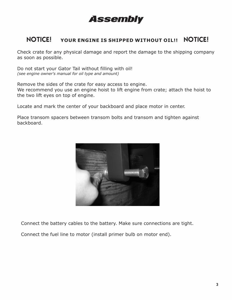
Locate and mark the center of your backboard and place motor in center.
Place transom spacers between transom bolts and transom and tighten against backboard.
Connect the battery cables to the battery. Make sure connections are tight.
Connect the fuel line to motor (install primer bulb on motor end).
4
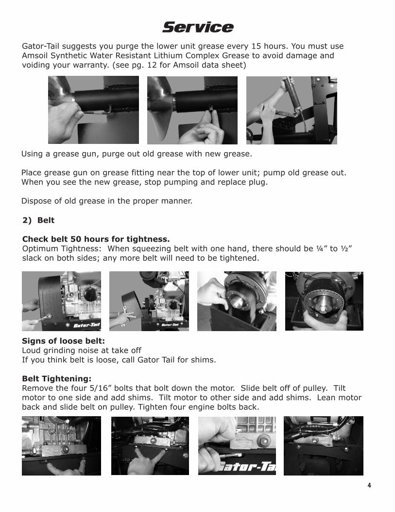
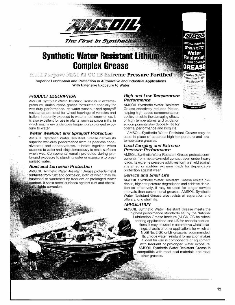
ServiceGator-Tail suggests you purge the lower unit grease every 15 hours. You must use Amsoil Synthetic Water Resistant Lithium Complex Grease to avoid damage and voiding your warranty. (see pg. 12 for Amsoil data sheet)
Using a grease gun, purge out old grease with new grease.
Place grease gun on grease fitting near the top of lower unit; pump old grease out. When you see the new grease, stop pumping and replace plug.
Dispose of old grease in the proper manner.
2) Belt
Check belt 50 hours for tightness.Optimum Tightness: When squeezing belt with one hand, there should be ¼” to ½” slack on both sides; any more belt will need to be tightened.
Signs of loose belt:Loud grinding noise at take offIf you think belt is loose, call Gator Tail for shims.
Belt Tightening:Remove the four 5/16” bolts that bolt down the motor. Slide belt off of pulley. Tilt motor to one side and add shims. Tilt motor to other side and add shims. Lean motor back and slide belt on pulley. Tighten four engine bolts back.

5
3) Propeller
Inspect propeller after every trip and check for looseness. A sign of a loose prop is the prop rocking left to right. If the prop is loose, tighten to 60 ft/lbs torque.
4) Throttle
Throttle should always have about 1/8 turn slack before the engine RPM's raise. This is important to maintain a low idle. Throttle slide should be lubricated with spray or grease to prevent stiffness (every ten hours). If this procedure is neglected, this will result in premature cable failure.
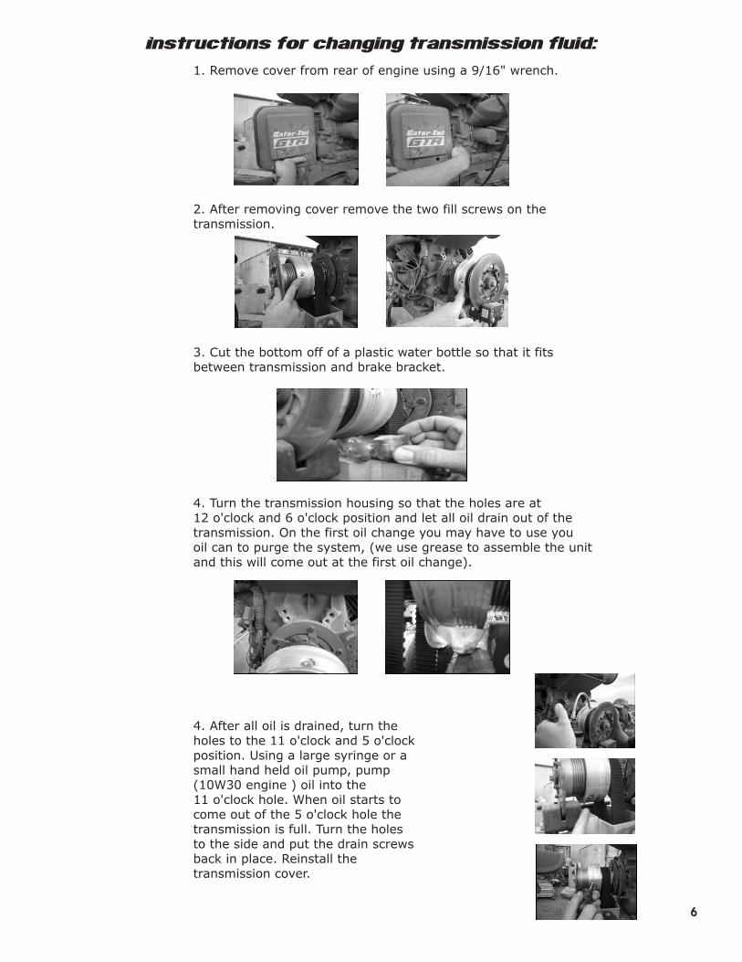
Instructions for changing transmission fluid:
1. Remove cover from rear of engine using a 9/16" wrench.
2. After removing cover remove the two fill screws on the transmission.
3. Cut the bottom off of a plastic water bottle so that it fits between transmission and brake bracket.
4. Turn the transmission housing so that the holes are at 12 o'clock and 6 o'clock position and let all oil drain out of the transmission. On the first oil change you may have to use you oil can to purge the system, (we use grease to assemble the unit and this will come out at the first oil change).
4. After all oil is drained, turn the holes to the 11 o'clock and 5 o'clock position. Using a large syringe or a small hand held oil pump, pump (10W30 engine ) oil into the 11 o'clock hole. When oil starts to come out of the 5 o'clock hole the transmission is full. Turn the holes to the side and put the drain screws back in place. Reinstall the transmission cover.
6
7
Troubleshooting
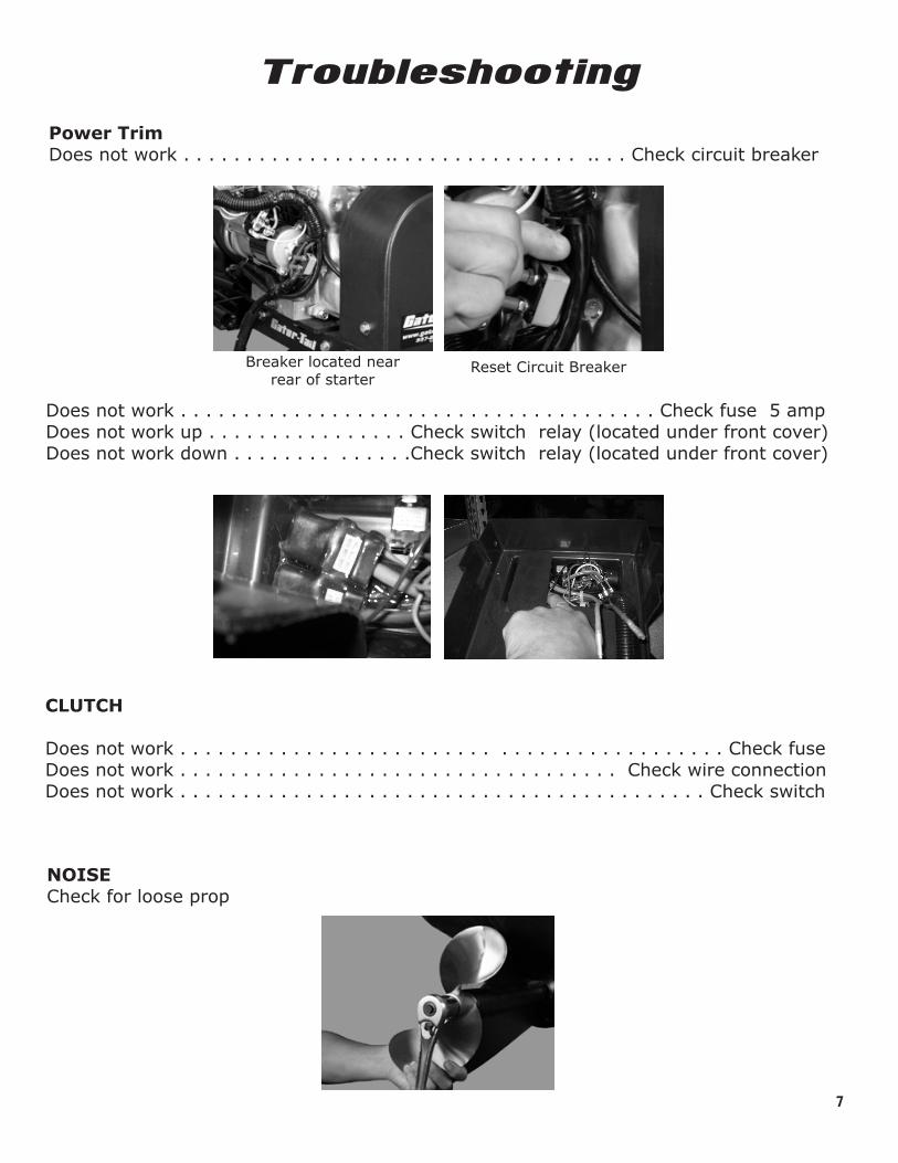
Power TrimDoes not work . . . . . . . . . . . . . . . . .. . . . . . . . . . . . . . . .. . . Check circuit breaker
Reset Circuit BreakerBreaker located near rear of starter
Does not work . . . . . . . . . . . . . . . . . . . . . . . . . . . . . . . . . . . . . . Check fuse 5 ampDoes not work up . . . . . . . . . . . . . . . . Check switch relay (located under front cover)Does not work down . . . . . . . . . . . . . .Check switch relay (located under front cover)
CLUTCH
Does not work . . . . . . . . . . . . . . . . . . . . . . . . . . . . . . . . . . . . . . . . . . . Check fuseDoes not work . . . . . . . . . . . . . . . . . . . . . . . . . . . . . . . . . . . Check wire connectionDoes not work . . . . . . . . . . . . . . . . . . . . . . . . . . . . . . . . . . . . . . . . . . Check switch
NOISECheck for loose prop
Operation
8
Startup Procedure
1. Pump primer bulb until firm2. Pull choke3. Check to see if engagement switch is in start position (this is also neutral)4. Start engine5. Let engine warm up before operating
Running Procedure
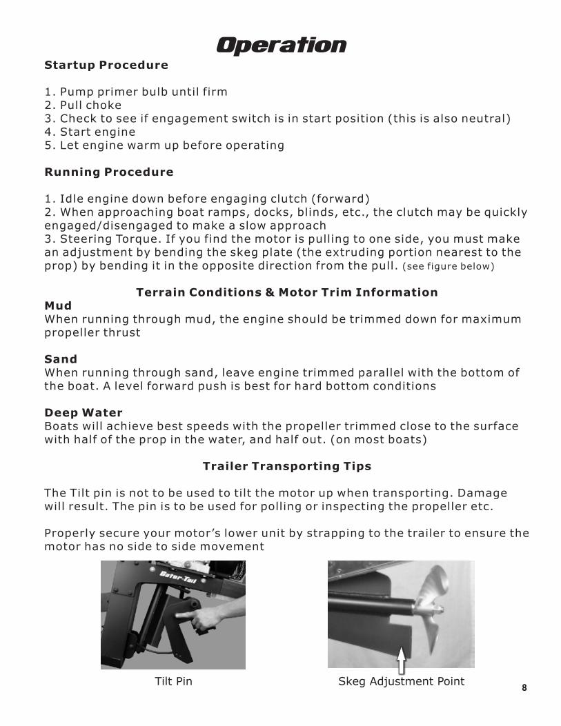
1. Idle engine down before engaging clutch (forward)2. When approaching boat ramps, docks, blinds, etc., the clutch may be quickly engaged/disengaged to make a slow approach3. Steering Torque. If you find the motor is pulling to one side, you must make an adjustment by bending the skeg plate (the extruding portion nearest to the prop) by bending it in the opposite direction from the pull. (see figure below)
Terrain Conditions & Motor Trim InformationMudWhen running through mud, the engine should be trimmed down for maximum propeller thrust
SandWhen running through sand, leave engine trimmed parallel with the bottom of the boat. A level forward push is best for hard bottom conditions
Deep WaterBoats will achieve best speeds with the propeller trimmed close to the surface with half of the prop in the water, and half out. (on most boats)
Trailer Transporting Tips
The Tilt pin is not to be used to tilt the motor up when transporting. Damage will result. The pin is to be used for polling or inspecting the propeller etc.
Properly secure your motor’s lower unit by strapping to the trailer to ensure the motor has no side to side movement
Tilt Pin Skeg Adjustment Point
Reverse Operation
Bleeding Instructions
To engage reverse, put the motor in neutral and squeeze the reverse lever. The lever must be squeezed or pulled for the reverse gear to work. DO NOT engage the motor into reverse while the motor is in forward. This will void your warranty and can damage the transmission.
After 15 hours of use, you must change the fluid in the transmission.
Your transmission is engaged using a hydraulic system. If for some reason the lever loses resistance, follow the following procedure for bleeding the system.
Be sure all hydraulic connections are secure. Never use Teflon tape to seal the fittings in the castings. An appropriate Teflon paste like that used from the manufacturer is recommended. The high pressure tubing should be inserted completely into the cap and ferrule. Use only type “H” high pressure nylon tubing. From finger tight, the fitting cap should be tightened 2 turns. This should leave a gap of about 0.50” between the cap and the hex part of the fitting body.
Remove the filler plug from the master cylinder top and for standard systems, fill reservoir with DOT-5 silicone brake fluid only! The filler plug must be left loose all during the bleeding process so do not replace it tightened. Stroke the master cylinder lever arm a full stroke and open the bleed screws on the caliper for about 2 seconds then close. Allow the master cylinder arm to return the the rest position and wait approximately 15 to 20 seconds to allow for the fluid in the reservoir to transfer into the bore of the master cylinder thought the transfer port. Repeat the process of stroking the master cylinder again. Open and close the bleed screw the same as before. Allow the master cylinder lever arm return to rest and wait again. It typically takes about 4 strokes to fill the bore of the master cylinder. Check the reservoir for fluid and keep topped up.
Continue this procedure until a more firm pedal is realized and the brake pads begin to move. At this point the procedure changes. You should now have a shorter master cylinder to stroke to work with as the pads are making contact with the rotor. From this point on, open and close only one bleed screw for a very short time. Basically open and close the bleed screw about as fast as possible. Do not be concerned if you get only fluid. Repeating the process, continue to pump the master cylinder rapidly, hold firm and open a bleed screw. Continue this process until satisfied that this half of the caliper is bled. Repeat the process on the other caliper half until bled. If a large amount of fluid is allowed to escape from the bleed screw during this process, you will most likely draw air into the system causing a spongy pedal. The reason for this you would inadvertently cause a strong vacuum in the power side of the system with no means for the master cylinder piston to get back to the resting position where the transfer port reservoir is uncovered.
When finished, check the reservoir for the proper fluid level which is about a 1/16” below the bottom of the master cylinder cap threads. Replace the filler plug and finger tighten only. Check all hydraulic connections for fluid leaks.
9
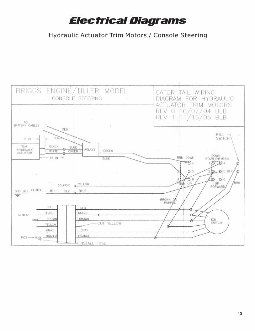
Electrical Diagrams
Hydraulic Actuator Trim Motors / Console Steering
10

Electrical DiagramsHydraulic Actuator Trim Motors / Briggs Engine Tiller Models
11
12
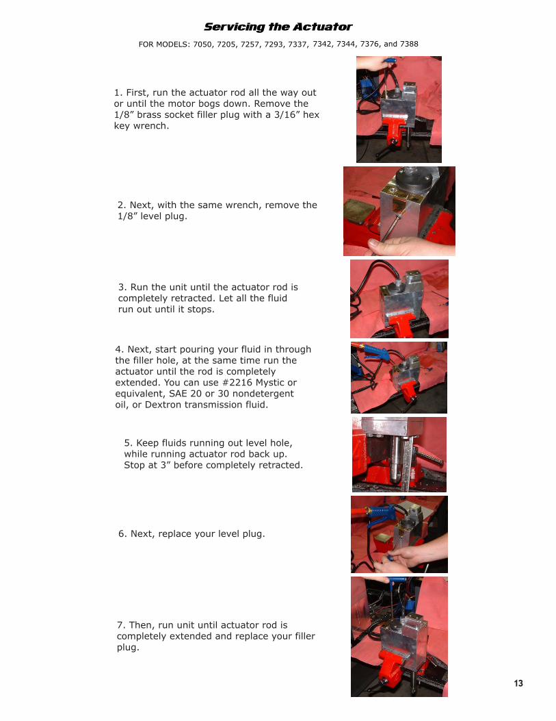
1. First, run the actuator rod all the way out or until the motor bogs down. Remove the 1/8” brass socket filler plug with a 3/16” hex key wrench.
2. Next, with the same wrench, remove the 1/8” level plug.
3. Run the unit until the actuator rod iscompletely retracted. Let all the fluidrun out until it stops.
Servicing the Actuator
FOR MODELS: 7050, 7205, 7257, 7293, 7337, 7342, 7344, 7376, and 7388
4. Next, start pouring your fluid in through the filler hole, at the same time run theactuator until the rod is completely extended. You can use #2216 Mystic or equivalent, SAE 20 or 30 nondetergentoil, or Dextron transmission fluid.
5. Keep fluids running out level hole, while running actuator rod back up. Stop at 3” before completely retracted.
6. Next, replace your level plug.
7. Then, run unit until actuator rod iscompletely extended and replace your fillerplug.
13