Embed Size (px)
Citation preview
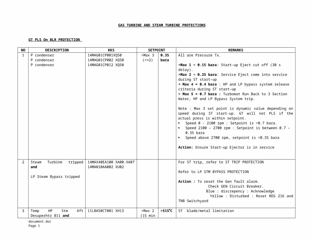
GAS TURBINE AND STEAM TURBINE PROTECTIONS
GT PLS On BLR PROTECTION
NO DESCRIPTION KKS SETPOINT REMARKS1 P condenser
P condenser P condenser
14MAG01CP001XQ5014MAG01CP002 XQ5014MAG01CP012 XQ50
>Max 3(>=2)
0.35bara
All are Pressure Tx.
<Max 1 = 0.15 bara: Start-up Eject cut off (30 s delay).<Max 2 = 0.25 bara: Service Eject come into service during ST start-up< Max 4 = 0.4 bara : HP and LP bypass system release criteria during ST start-up> Max 5 = 0.7 bara : Turbomat Run Back to 3 Section Water, HP and LP Bypass System trip.
Note : Max 3 set point is dynamic value depending onspeed during ST start-up. GT will not PLS if theactual press is within setpoint. Speed 0 - 2100 rpm : Setpoint is <0.7 bara. Speed 2100 – 2700 rpm : Setpoint is between 0.7 –
0.35 bara Speed above 2700 rpm, setpoint is <0.35 bara
Action: Ensure Start-up Ejector is in service
2 Steam Turbine trippedand
LP Steam Bypass tripped
14MAX40EA100 XA00.XA0714MAN10AA002 XU02
For ST trip, refer to ST TRIP PROTECTION
Refer to LP STM BYPASS PROTECTION Action : To reset the Gen fault alarm. Check GEN Circuit Breaker. Blue : discrepency : Acknowledge Yellow : Disturbed : Reset REG 216 andTNB Switchyard
3 Temp HP Stm AftDesuperhtr B11 and
11LBA50CT001 XH13 >Max 2(15 min
>5150C ST blade/metal limitation
document.doc Page 1
Temp Turbine ExhaustGT11 11MBA30CT902 XH13
delay)> 5100C
Action : Ensure HP Water Inj CV in Auto mode SOV andCV are opened.
Manually regulate HP Stm WaterInjection Bypass Manual Vlv.
4 Level HP Steam Drum B11and
Level HP Steam Drum B11(5s) and Level HP Steam Drum B11(5s) and
11HAD50CL903A XH15 or11HAD50CL903B XH1511HAD50CL905 XU1511HAD50CL904 XU15
>Max 3(>=2)
356 mm Reason : To prevent carry over of wet steam to the ST
>Max 1 = 150 mm : Alarm ; Evaporator SOV Drain open on Auto.>Max 2 = 225 mm : HP Feed Water Filling Vlv, SOV and HP header SOV shut (Either signal : From CL003 or CL005)>Min 2 = -868 mm : GT PLST (CL003 or CL005)
CL003A/CL003B : Level Tx : For POS level indication (Average of 2 Tx)CL004 : Hydratect : For Max 3(Hi Hi Hi)CL005 : Hydrastep : For all level signalsCL008 : Hydratect : For Min 2 (Lo Lo, Lo)
5 Level LP Steam Drum B11 and
Level LP Steam Drum B11(5s) and Level LP Steam Drum B11(5s) and
11HAD10CL903A XH15 or11HAD10CL903B XH1511HAD10CL905 XU1511HAD10CL904 XU15
>Max 3(>=2)
279 mm >Max 1 = 225 mm : Alarm>Max 2 = 254 mm : ????>Min 2 = -737 mm : Level low : Not allow for a longoperation
6 Steam Turbine tripped or
HP Steam Hdr SOV CSclose and
HP Steam Bypass B11tripped
14MAX40EA100 XA00.XA0711LBA50AA050 XB00.XB0211MAN50AA002 XU03
Tripped
CS-closedTripped
HP steam pressure will increase rapidly. GT PLS toprevent HP circuit Safety Vlv blowing.
7 Steam Turbine trippedand
LP Steam Bypass B11tripped
14MAX40EA100 XA00.XA0711MAN10AA002 XU02
Tripped
Tripped
LP steam pressure will increase rapidly GT PLS toprevent LP circuit Safety Vlv blowing.
document.doc Page 2
document.doc Page 3
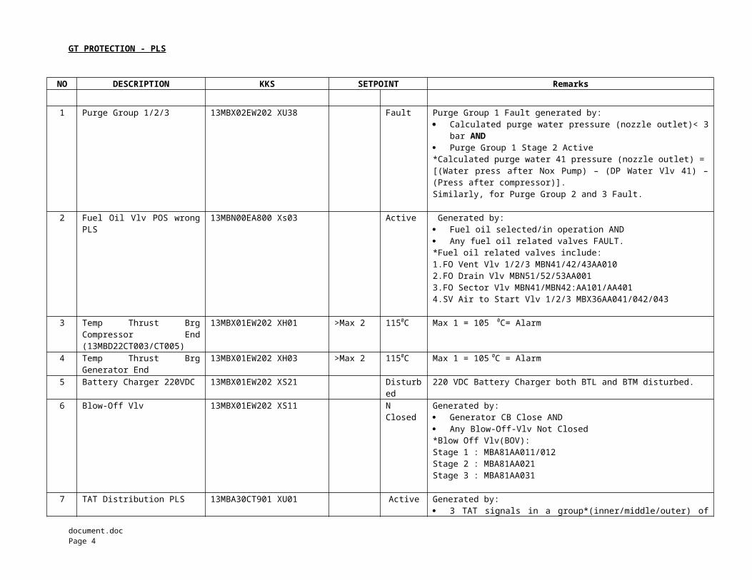
GT PROTECTION - PLS
NO DESCRIPTION KKS SETPOINT Remarks
1 Purge Group 1/2/3 13MBX02EW202 XU38 Fault Purge Group 1 Fault generated by: Calculated purge water pressure (nozzle outlet)< 3
bar AND Purge Group 1 Stage 2 Active *Calculated purge water 41 pressure (nozzle outlet) =[(Water press after Nox Pump) – (DP Water Vlv 41) –(Press after compressor)].Similarly, for Purge Group 2 and 3 Fault.
2 Fuel Oil Vlv POS wrongPLS
13MBN00EA800 Xs03 Active Generated by: Fuel oil selected/in operation AND Any fuel oil related valves FAULT.*Fuel oil related valves include:1.FO Vent Vlv 1/2/3 MBN41/42/43AA0102.FO Drain Vlv MBN51/52/53AA0013.FO Sector Vlv MBN41/MBN42:AA101/AA4014.SV Air to Start Vlv 1/2/3 MBX36AA041/042/043
3 Temp Thrust BrgCompressor End(13MBD22CT003/CT005)
13MBX01EW202 XH01 >Max 2 1150C Max 1 = 105 0C= Alarm
4 Temp Thrust BrgGenerator End
13MBX01EW202 XH03 >Max 2 1150C Max 1 = 105 0C = Alarm
5 Battery Charger 220VDC 13MBX01EW202 XS21 Disturbed
220 VDC Battery Charger both BTL and BTM disturbed.
6 Blow-Off Vlv 13MBX01EW202 XS11 NClosed
Generated by: Generator CB Close AND Any Blow-Off-Vlv Not Closed*Blow Off Vlv(BOV):Stage 1 : MBA81AA011/012Stage 2 : MBA81AA021Stage 3 : MBA81AA031
7 TAT Distribution PLS 13MBA30CT901 XU01 Active Generated by: 3 TAT signals in a group*(inner/middle/outer) of
document.doc Page 4
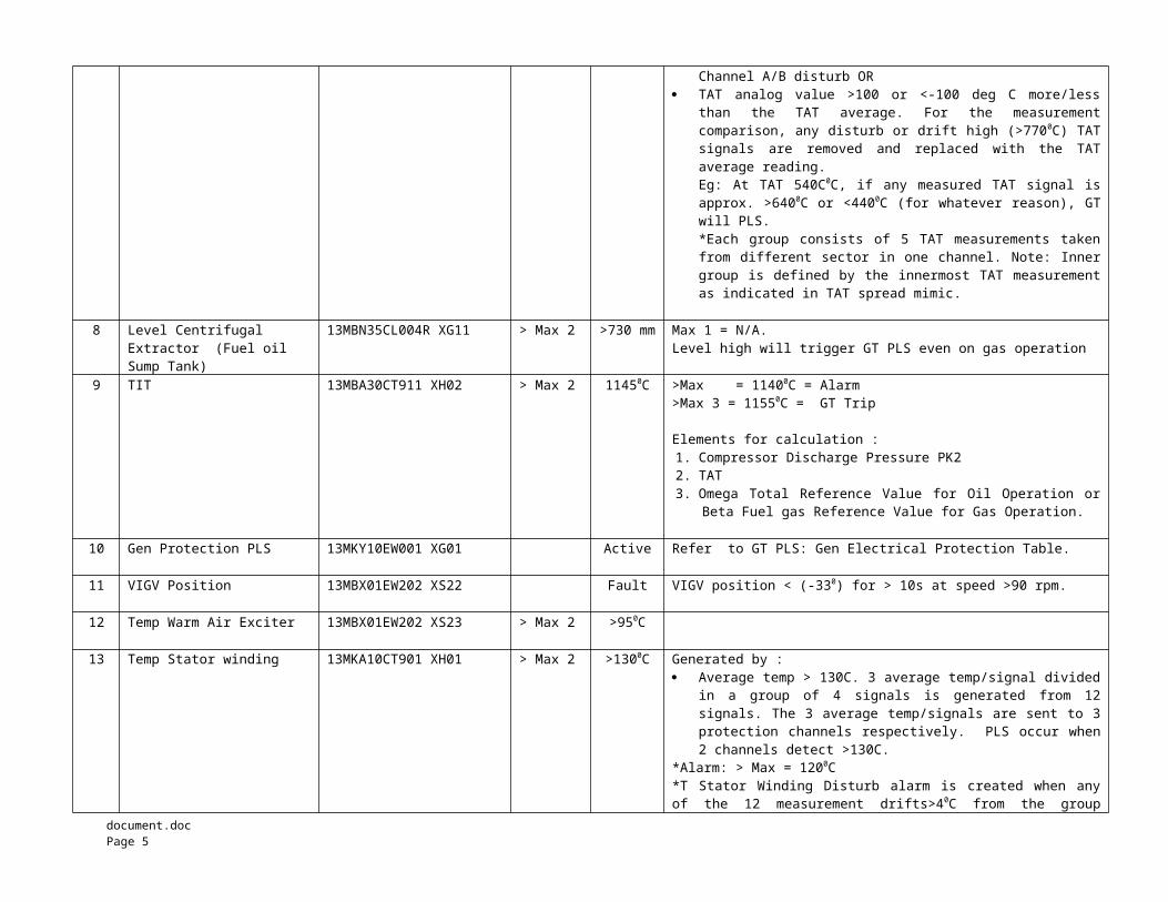
Channel A/B disturb OR TAT analog value >100 or <-100 deg C more/less
than the TAT average. For the measurementcomparison, any disturb or drift high (>7700C) TATsignals are removed and replaced with the TATaverage reading.Eg: At TAT 540C0C, if any measured TAT signal isapprox. >6400C or <4400C (for whatever reason), GTwill PLS.*Each group consists of 5 TAT measurements takenfrom different sector in one channel. Note: Innergroup is defined by the innermost TAT measurementas indicated in TAT spread mimic.
8 Level Centrifugal Extractor (Fuel oil Sump Tank)
13MBN35CL004R XG11 > Max 2 >730 mm Max 1 = N/A.Level high will trigger GT PLS even on gas operation
9 TIT 13MBA30CT911 XH02 > Max 2 11450C >Max = 11400C = Alarm>Max 3 = 11550C = GT Trip
Elements for calculation :1. Compressor Discharge Pressure PK22. TAT3. Omega Total Reference Value for Oil Operation or
Beta Fuel gas Reference Value for Gas Operation.
10 Gen Protection PLS 13MKY10EW001 XG01 Active Refer to GT PLS: Gen Electrical Protection Table.
11 VIGV Position 13MBX01EW202 XS22 Fault VIGV position < (-330) for > 10s at speed >90 rpm.
12 Temp Warm Air Exciter 13MBX01EW202 XS23 > Max 2 >950C
13 Temp Stator winding 13MKA10CT901 XH01 > Max 2 >1300C Generated by : Average temp > 130C. 3 average temp/signal divided
in a group of 4 signals is generated from 12signals. The 3 average temp/signals are sent to 3protection channels respectively. PLS occur when2 channels detect >130C.
*Alarm: > Max = 1200C *T Stator Winding Disturb alarm is created when anyof the 12 measurement drifts>40C from the group
document.doc Page 5
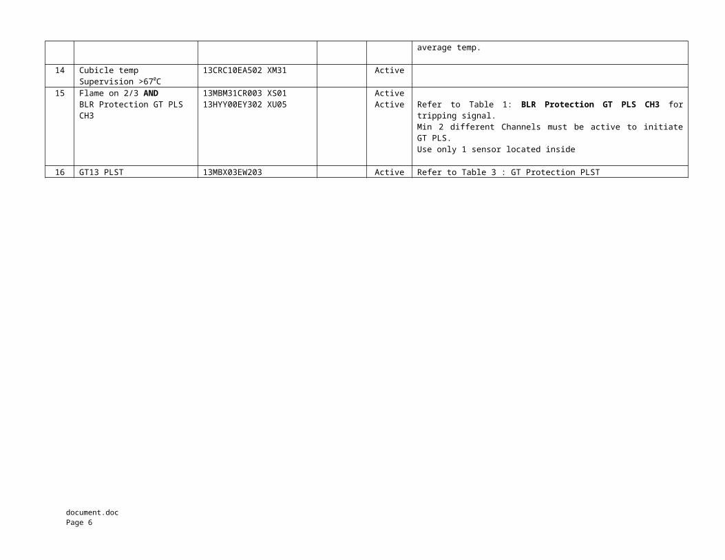
average temp.
14 Cubicle temp Supervision >670C
13CRC10EA502 XM31 Active
15 Flame on 2/3 ANDBLR Protection GT PLS CH3
13MBM31CR003 XS0113HYY00EY302 XU05
ActiveActive Refer to Table 1: BLR Protection GT PLS CH3 for
tripping signal. Min 2 different Channels must be active to initiateGT PLS.Use only 1 sensor located inside
16 GT13 PLST 13MBX03EW203 Active Refer to Table 3 : GT Protection PLST
document.doc Page 6

GT PLS On GT ELECTRICAL PROTECTION
NO DESCRIPTION STATUS ANSI-CODE
CHANNEL REMARKS
FROM GT GENERATOR MKA10
1 Generator Differential Protection 87G Chan. A
2 95% Stator Ground Fault Protection 59GN Chan. A
3 100% Rotor Ground Fault ProtectionAND
Start-up Isolator
64GNNot closed
Chan. BChan. B
4 Busbar Ground Fault Protection AND Gen. Circuit Breaker
59NB.1Closed
Chan. B
5 Gen Protection A+B (Process EGATROL) Failure Chan. B
FROM GT EXTERNAL BINARY INPUTS
6 Rotor Ground Fault Protection. Step 2 64F..2 Chan. A
FROM STEP-UP TRANSFORMER BAT10
7 Gen Step-up Tranf. HV/LV Winding Temp,Step 2
49T Chan. B
8 Gen Step-up Tranf. Oil Temp, Step 2 26T Chan. B
FROM UNIT AUX. TRANSFORMER BBT10
9 Unit Aux Tranf. Oil Temp Relay 26UAT Chan. B
10 Unit Aux Tranf. Over-load Relay 49UAT Chan. B
document.doc Page 7
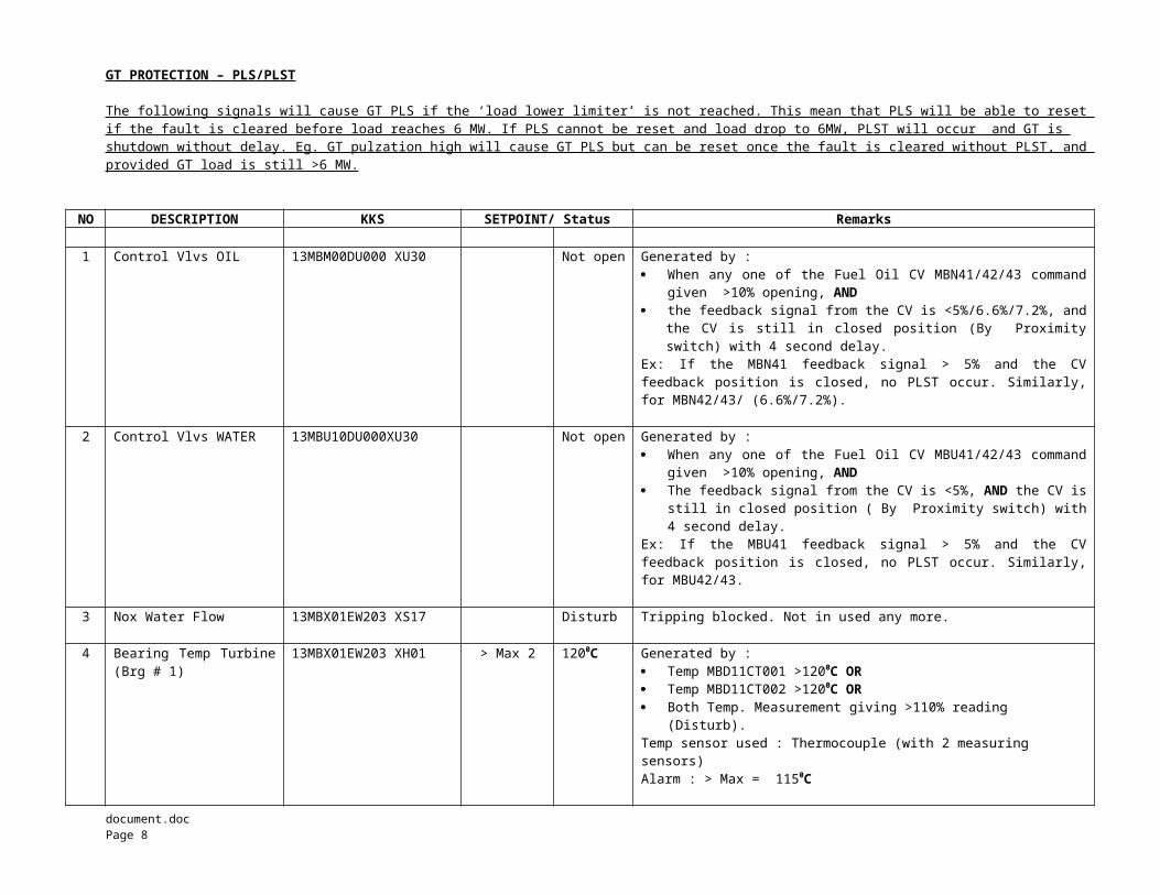
GT PROTECTION – PLS/PLST
The following signals will cause GT PLS if the ‘load lower limiter’ is not reached. This mean that PLS will be able to reset if the fault is cleared before load reaches 6 MW. If PLS cannot be reset and load drop to 6MW, PLST will occur and GT is shutdown without delay. Eg. GT pulzation high will cause GT PLS but can be reset once the fault is cleared without PLST, and provided GT load is still >6 MW.
NO DESCRIPTION KKS SETPOINT/ Status Remarks
1 Control Vlvs OIL 13MBM00DU000 XU30 Not open Generated by : When any one of the Fuel Oil CV MBN41/42/43 command
given >10% opening, AND the feedback signal from the CV is <5%/6.6%/7.2%, and
the CV is still in closed position (By Proximityswitch) with 4 second delay.
Ex: If the MBN41 feedback signal > 5% and the CVfeedback position is closed, no PLST occur. Similarly,for MBN42/43/ (6.6%/7.2%).
2 Control Vlvs WATER 13MBU10DU000XU30 Not open Generated by : When any one of the Fuel Oil CV MBU41/42/43 command
given >10% opening, AND The feedback signal from the CV is <5%, AND the CV is
still in closed position ( By Proximity switch) with4 second delay.
Ex: If the MBU41 feedback signal > 5% and the CVfeedback position is closed, no PLST occur. Similarly,for MBU42/43.
3 Nox Water Flow 13MBX01EW203 XS17 Disturb Tripping blocked. Not in used any more.
4 Bearing Temp Turbine(Brg # 1)
13MBX01EW203 XH01 > Max 2 1200C Generated by : Temp MBD11CT001 >1200C OR Temp MBD11CT002 >1200C OR Both Temp. Measurement giving >110% reading
(Disturb).Temp sensor used : Thermocouple (with 2 measuring sensors)Alarm : > Max = 1150C
document.doc Page 8
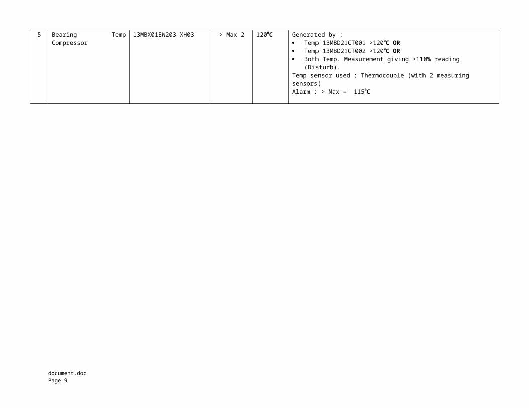
5 Bearing TempCompressor
13MBX01EW203 XH03 > Max 2 1200C Generated by : Temp 13MBD21CT001 >1200C OR Temp 13MBD21CT002 >1200C OR Both Temp. Measurement giving >110% reading
(Disturb).Temp sensor used : Thermocouple (with 2 measuring sensors)Alarm : > Max = 1150C
document.doc Page 9
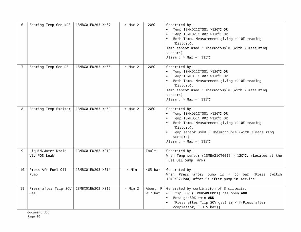
6 Bearing Temp Gen NDE 13MBX01EW203 XH07 > Max 2 1200C Generated by : Temp 13MKD21CT001 >1200C OR Temp 13MKD21CT002 >1200C OR Both Temp. Measurement giving >110% reading
(Disturb).Temp sensor used : Thermocouple (with 2 measuring sensors)Alarm : > Max = 1150C
7 Bearing Temp Gen DE 13MBX01EW203 XH05 > Max 2 1200C Generated by : Temp 13MKD11CT001 >1200C OR Temp 13MKD11CT002 >1200C OR Both Temp. Measurement giving >110% reading
(Disturb).Temp sensor used : Thermocouple (with 2 measuring sensors)Alarm : > Max = 1150C
8 Bearing Temp Exciter 13MBX01EW203 XH09 > Max 2 1200C Generated by : Temp 13MKD51CT001 >1200C OR Temp 13MKD51CT002 >1200C OR Both Temp. Measurement giving >110% reading
(Disturb). Temp sensor used : Thermocouple (with 2 measuring
sensors)Alarm : > Max = 1150C
9 Liquid/Water Drain Vlv POS Leak
13MBX01EW203 XS13 Fault Generated by : When Temp sensor (13MBA31CT001) > 1200C. (Located at theFuel Oil Sump Tank)
10 Press Aft Fuel Oil Pump
13MBX01EW203 XS14 < Min <65 bar Generated by : When Press after pump is < 65 bar (Press Switch13MBN32CP00) after 5s after pump in service.
11 Press after Trip SOVGas
13MBX01EW203 XS15 < Min 2 About P<17 bar
Generated by combination of 3 criteria: Trip SOV (13MBP40CP001) gas open AND Beta gas30% >min AND (Press after Trip SOV gas) is < [(Press after
compressor) + 3.5 bar)]document.doc Page 10
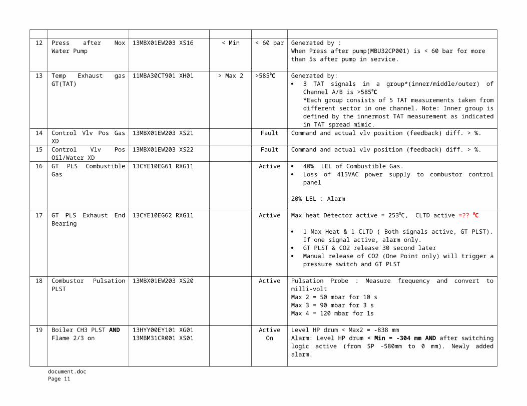
12 Press after NoxWater Pump
13MBX01EW203 XS16 < Min < 60 bar Generated by : When Press after pump(MBU32CP001) is < 60 bar for more than 5s after pump in service.
13 Temp Exhaust gasGT(TAT)
11MBA30CT901 XH01 > Max 2 >5850C Generated by: 3 TAT signals in a group*(inner/middle/outer) of
Channel A/B is >5850C*Each group consists of 5 TAT measurements taken fromdifferent sector in one channel. Note: Inner group isdefined by the innermost TAT measurement as indicatedin TAT spread mimic.
14 Control Vlv Pos GasXD
13MBX01EW203 XS21 Fault Command and actual vlv position (feedback) diff. > %.
15 Control Vlv PosOil/Water XD
13MBX01EW203 XS22 Fault Command and actual vlv position (feedback) diff. > %.
16 GT PLS CombustibleGas
13CYE10EG61 RXG11 Active 40% LEL of Combustible Gas. Loss of 415VAC power supply to combustor control
panel
20% LEL : Alarm
17 GT PLS Exhaust EndBearing
13CYE10EG62 RXG11 Active Max heat Detector active = 2530C, CLTD active =?? 0C
1 Max Heat & 1 CLTD ( Both signals active, GT PLST).If one signal active, alarm only.
GT PLST & CO2 release 30 second later Manual release of CO2 (One Point only) will trigger a
pressure switch and GT PLST
18 Combustor PulsationPLST
13MBX01EW203 XS20 Active Pulsation Probe : Measure frequency and convert tomilli-voltMax 2 = 50 mbar for 10 sMax 3 = 90 mbar for 3 sMax 4 = 120 mbar for 1s
19 Boiler CH3 PLST ANDFlame 2/3 on
13HYY00EY101 XG0113MBM31CR001 XS01
ActiveOn
Level HP drum < Max2 = -838 mmAlarm: Level HP drum < Min = -304 mm AND after switchinglogic active (from SP –580mm to 0 mm). Newly addedalarm.
document.doc Page 11
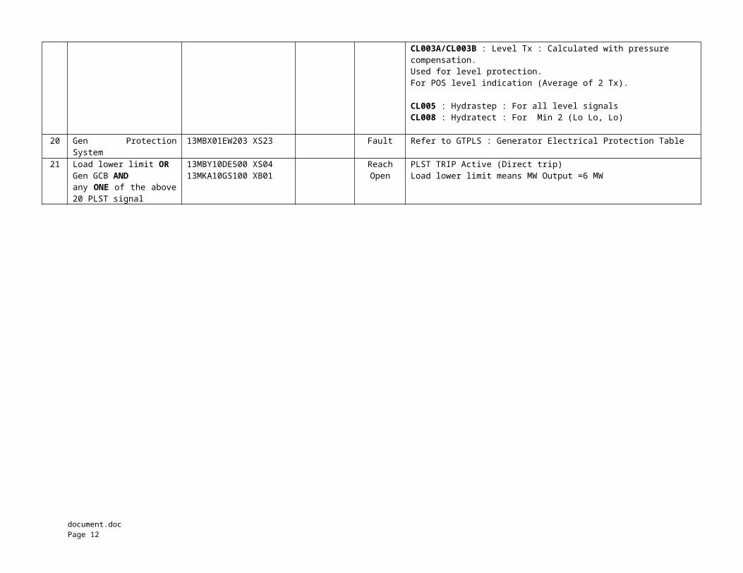
CL003A/CL003B : Level Tx : Calculated with pressure compensation. Used for level protection.For POS level indication (Average of 2 Tx).
CL005 : Hydrastep : For all level signalsCL008 : Hydratect : For Min 2 (Lo Lo, Lo)
20 Gen ProtectionSystem
13MBX01EW203 XS23 Fault Refer to GTPLS : Generator Electrical Protection Table
21 Load lower limit ORGen GCB AND any ONE of the above20 PLST signal
13MBY10DE500 XS0413MKA10GS100 XB01
ReachOpen
PLST TRIP Active (Direct trip)Load lower limit means MW Output =6 MW
document.doc Page 12
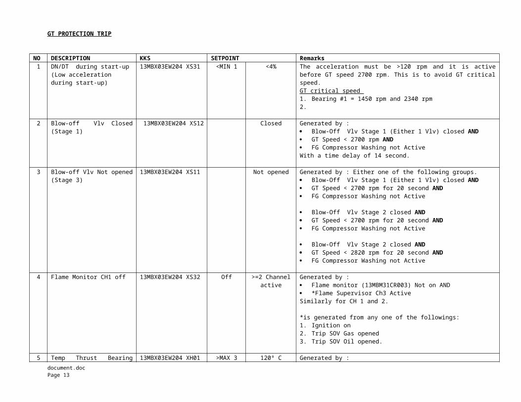
GT PROTECTION TRIP
NO DESCRIPTION KKS SETPOINT Remarks1 DN/DT during start-up
(Low acceleration during start-up)
13MBX03EW204 XS31 <MIN 1 <4% The acceleration must be >120 rpm and it is activebefore GT speed 2700 rpm. This is to avoid GT criticalspeed. GT critical speed 1. Bearing #1 = 1450 rpm and 2340 rpm2.
2 Blow-off Vlv Closed(Stage 1)
13MBX03EW204 XS12 Closed Generated by : Blow-Off Vlv Stage 1 (Either 1 Vlv) closed AND GT Speed < 2700 rpm AND FG Compressor Washing not ActiveWith a time delay of 14 second.
3 Blow-off Vlv Not opened(Stage 3)
13MBX03EW204 XS11 Not opened Generated by : Either one of the following groups. Blow-Off Vlv Stage 1 (Either 1 Vlv) closed AND GT Speed < 2700 rpm for 20 second AND FG Compressor Washing not Active
Blow-Off Vlv Stage 2 closed AND GT Speed < 2700 rpm for 20 second AND FG Compressor Washing not Active
Blow-Off Vlv Stage 2 closed AND GT Speed < 2820 rpm for 20 second AND FG Compressor Washing not Active
4 Flame Monitor CH1 off 13MBX03EW204 XS32 Off >=2 Channelactive
Generated by : Flame monitor (13MBM31CR003) Not on AND *Flame Supervisor Ch3 Active Similarly for CH 1 and 2.
*is generated from any one of the followings:1. Ignition on2. Trip SOV Gas opened3. Trip SOV Oil opened.
5 Temp Thrust Bearing 13MBX03EW204 XH01 >MAX 3 120º C Generated by :document.doc Page 13
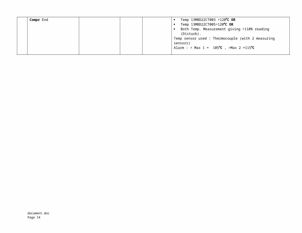
Compr End Temp 13MBD22CT003 >1200C OR Temp 13MBD22CT005>1200C OR Both Temp. Measurement giving >110% reading
(Disturb).Temp sensor used : Thermocouple (with 2 measuring sensors)Alarm : > Max 1 = 1050C , >Max 2 =1150C
document.doc Page 14
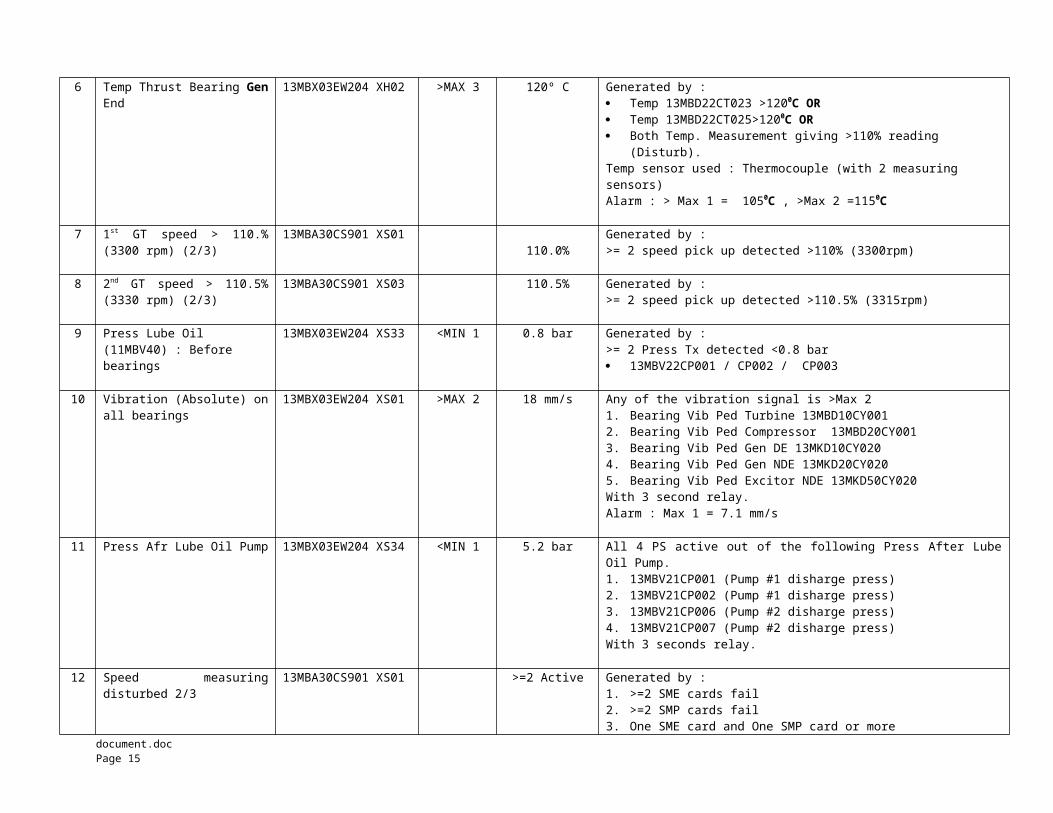
6 Temp Thrust Bearing GenEnd
13MBX03EW204 XH02 >MAX 3 120º C Generated by : Temp 13MBD22CT023 >1200C OR Temp 13MBD22CT025>1200C OR Both Temp. Measurement giving >110% reading
(Disturb).Temp sensor used : Thermocouple (with 2 measuring sensors)Alarm : > Max 1 = 1050C , >Max 2 =1150C
7 1st GT speed > 110.%(3300 rpm) (2/3)
13MBA30CS901 XS01110.0%
Generated by :>= 2 speed pick up detected >110% (3300rpm)
8 2nd GT speed > 110.5%(3330 rpm) (2/3)
13MBA30CS901 XS03 110.5% Generated by :>= 2 speed pick up detected >110.5% (3315rpm)
9 Press Lube Oil (11MBV40) : Before bearings
13MBX03EW204 XS33 <MIN 1 0.8 bar Generated by :>= 2 Press Tx detected <0.8 bar 13MBV22CP001 / CP002 / CP003
10 Vibration (Absolute) onall bearings
13MBX03EW204 XS01 >MAX 2 18 mm/s Any of the vibration signal is >Max 21. Bearing Vib Ped Turbine 13MBD10CY0012. Bearing Vib Ped Compressor 13MBD20CY0013. Bearing Vib Ped Gen DE 13MKD10CY0204. Bearing Vib Ped Gen NDE 13MKD20CY0205. Bearing Vib Ped Excitor NDE 13MKD50CY020With 3 second relay.Alarm : Max 1 = 7.1 mm/s
11 Press Afr Lube Oil Pump 13MBX03EW204 XS34 <MIN 1 5.2 bar All 4 PS active out of the following Press After LubeOil Pump.1. 13MBV21CP001 (Pump #1 disharge press)2. 13MBV21CP002 (Pump #1 disharge press)3. 13MBV21CP006 (Pump #2 disharge press)4. 13MBV21CP007 (Pump #2 disharge press)With 3 seconds relay.
12 Speed measuringdisturbed 2/3
13MBA30CS901 XS01 >=2 Active Generated by : 1. >=2 SME cards fail2. >=2 SMP cards fail3. One SME card and One SMP card or more
document.doc Page 15
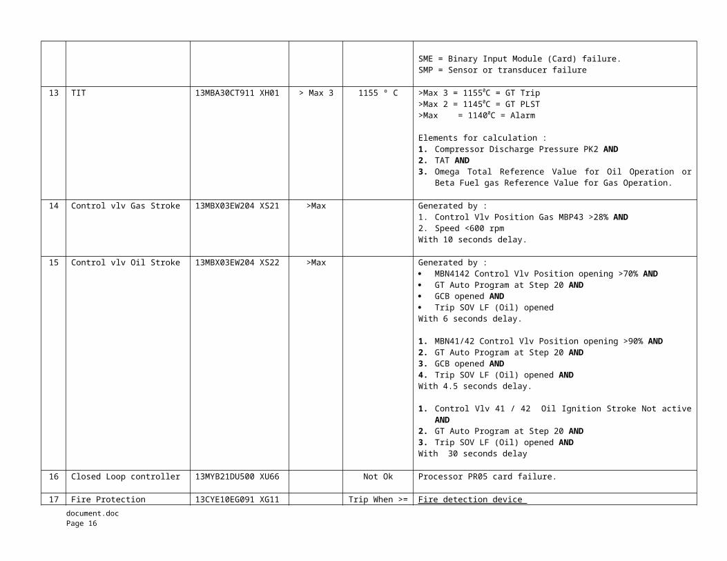
SME = Binary Input Module (Card) failure.SMP = Sensor or transducer failure
13 TIT 13MBA30CT911 XH01 > Max 3 1155 º C >Max 3 = 11550C = GT Trip >Max 2 = 11450C = GT PLST>Max = 11400C = Alarm
Elements for calculation :1. Compressor Discharge Pressure PK2 AND2. TAT AND3. Omega Total Reference Value for Oil Operation or
Beta Fuel gas Reference Value for Gas Operation.
14 Control vlv Gas Stroke 13MBX03EW204 XS21 >Max Generated by : 1. Control Vlv Position Gas MBP43 >28% AND 2. Speed <600 rpmWith 10 seconds delay.
15 Control vlv Oil Stroke 13MBX03EW204 XS22 >Max Generated by : MBN4142 Control Vlv Position opening >70% AND GT Auto Program at Step 20 AND GCB opened AND Trip SOV LF (Oil) opened With 6 seconds delay. 1. MBN41/42 Control Vlv Position opening >90% AND2. GT Auto Program at Step 20 AND3. GCB opened AND4. Trip SOV LF (Oil) opened ANDWith 4.5 seconds delay.
1. Control Vlv 41 / 42 Oil Ignition Stroke Not activeAND
2. GT Auto Program at Step 20 AND3. Trip SOV LF (Oil) opened ANDWith 30 seconds delay
16 Closed Loop controller 13MYB21DU500 XU66 Not Ok Processor PR05 card failure.
17 Fire Protection 13CYE10EG091 XG11 Trip When >= Fire detection device document.doc Page 16
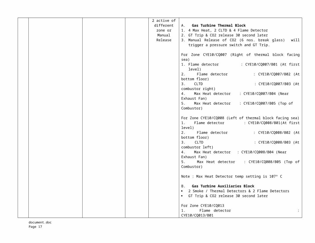
2 active ofdifferentzone orManualRelease
A. Gas Turbine Thermal Block 1. 4 Max Heat, 2 CLTD & 4 Flame Detector2. GT Trip & CO2 release 30 second later3. Manual Release of CO2 (6 nos. break glass) will
trigger a pressure switch and GT Trip.
For Zone CYE10/CQ007 (Right of thermal block facingsea)1. Flame detector : CYE10/CQ007/B01 (At first
level)2. Flame detector : CYE10/CQ007/B02 (Atbottom floor)3. CLTD : CYE10/CQ007/B03 (Atcombustor right)4. Max Heat detector : CYE10/CQ007/B04 (Near Exhaust Fan)5. Max Heat detector : CYE10/CQ007/B05 (Top of Combustor)
For Zone CYE10/CQ008 (Left of thermal block facing sea)1. Flame detector : CYE10/CQ008/B01(At firstlevel)2. Flame detector : CYE10/CQ008/B02 (Atbottom floor)3. CLTD : CYE10/CQ008/B03 (Atcombustor left)4. Max Heat detector : CYE10/CQ008/B04 (Near Exhaust Fan)5. Max Heat detector : CYE10/CQ008/B05 (Top ofCombustor)
Note : Max Heat Detector temp setting is 107º C B. Gas Turbine Auxiliaries Block 2 Smoke / Thermal Detectors & 2 Flame Detectors GT Trip & CO2 release 30 second later
For Zone CYE10/CQ0131. Flame detector :CYE10/CQ013/B01
document.doc Page 17

2. Thermal Heat detector : CYE10/CQ013/B02
For Zone CYE10/CQ0141. Flame detector :CYE10/CQ014/B012. Thermal Heat detector : CYE10/CQ014/B02
18 Local PB Trip 13MBX03EW204 XS35 Active PB ; located at E Module Local Control Panel
19 PB Emergency stop atAux Blk
11MBX00EU002RXG11 Trip PB located next to Propane Gas Panel.
20 PLST Trip CH active 11EW203XU01 Active 17 possible cause of PLST. Refer to GT Protection PLST Table
21 PB Remote Trip 13MBX03EW204 XS36 Active PB located at CCR control desk & release button
22 Boiler Purge Trip 13MBX03EW204 XS41 Active Generated by :1. Flame 2/3 Not 0n AND 2. Either >= 1 of the following signals
GT speed <750 rpmVIGV Position Not open (Not at 0 degree)Water Purge Order On AND
3. GT Auto Program at STEP 13 Active.Note : Boiler Purge Trip will not be active after 5minutes (i.e. when the purging has completed)
22 Pulsation Trip 13MBX03EW204 XS02 > Max 5 > 150 mbar GT trip immediately without delay.Pulsation Probe : Measure frequency and convert to Minivolt(?)Max 2 = 50 mbar for 10 sMax 3 = 90 mbar for 3 sMax 4 = 120 mbar for 1s
23 PLS / PLST SupervisionActive
13MBX03EW204 XS42 Active PLS / PLST Supervision will only become active afterPLS 2/3 (from PLS CH2) has been active for 3 minutes
document.doc Page 18
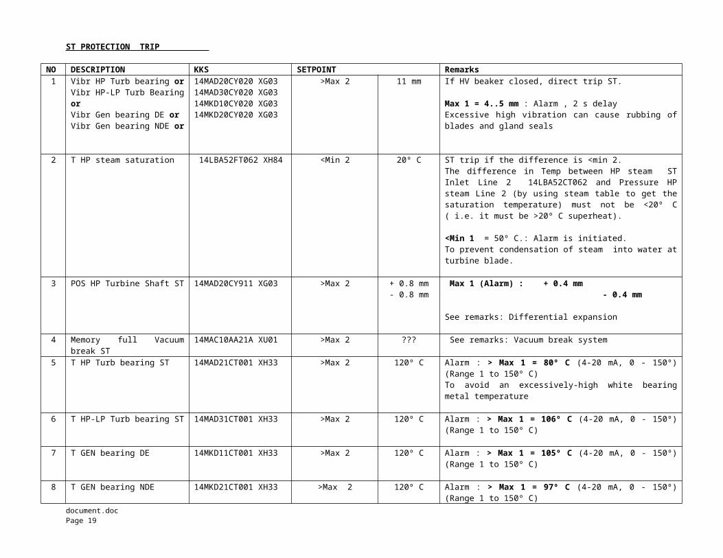
ST PROTECTION TRIP
NO DESCRIPTION KKS SETPOINT Remarks1 Vibr HP Turb bearing or
Vibr HP-LP Turb BearingorVibr Gen bearing DE orVibr Gen bearing NDE or
14MAD20CY020 XG0314MAD30CY020 XG0314MKD10CY020 XG0314MKD20CY020 XG03
>Max 2 11 mm If HV beaker closed, direct trip ST.
Max 1 = 4..5 mm : Alarm , 2 s delayExcessive high vibration can cause rubbing ofblades and gland seals
2 T HP steam saturation 14LBA52FT062 XH84 <Min 2 20º C ST trip if the difference is <min 2.The difference in Temp between HP steam STInlet Line 2 14LBA52CT062 and Pressure HPsteam Line 2 (by using steam table to get thesaturation temperature) must not be <20º C( i.e. it must be >20º C superheat).
<Min 1 = 50º C.: Alarm is initiated.To prevent condensation of steam into water atturbine blade.
3 POS HP Turbine Shaft ST 14MAD20CY911 XG03 >Max 2 + 0.8 mm- 0.8 mm
Max 1 (Alarm) : + 0.4 mm - 0.4 mm
See remarks: Differential expansion
4 Memory full Vacuumbreak ST
14MAC10AA21A XU01 >Max 2 ??? See remarks: Vacuum break system
5 T HP Turb bearing ST 14MAD21CT001 XH33 >Max 2 120º C Alarm : > Max 1 = 80º C (4-20 mA, 0 - 150º)(Range 1 to 150º C)To avoid an excessively-high white bearingmetal temperature
6 T HP-LP Turb bearing ST 14MAD31CT001 XH33 >Max 2 120º C Alarm : > Max 1 = 106º C (4-20 mA, 0 - 150º)(Range 1 to 150º C)
7 T GEN bearing DE 14MKD11CT001 XH33 >Max 2 120º C Alarm : > Max 1 = 105º C (4-20 mA, 0 - 150º)(Range 1 to 150º C)
8 T GEN bearing NDE 14MKD21CT001 XH33 >Max 2 120º C Alarm : > Max 1 = 97º C (4-20 mA, 0 - 150º)(Range 1 to 150º C)
document.doc Page 19
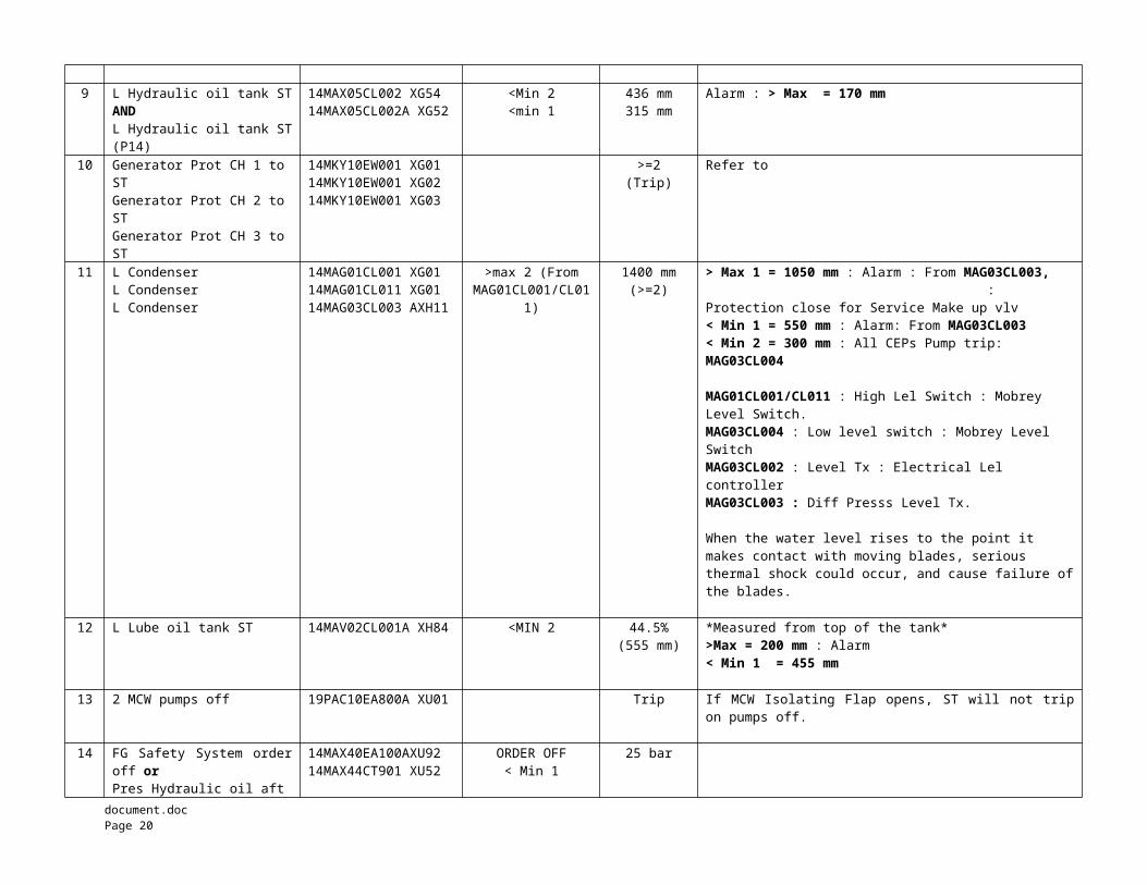
9 L Hydraulic oil tank STAND L Hydraulic oil tank ST(P14)
14MAX05CL002 XG5414MAX05CL002A XG52
<Min 2<min 1
436 mm315 mm
Alarm : > Max = 170 mm
10 Generator Prot CH 1 to ST Generator Prot CH 2 to ST Generator Prot CH 3 to ST
14MKY10EW001 XG0114MKY10EW001 XG0214MKY10EW001 XG03
>=2(Trip)
Refer to
11 L Condenser L Condenser L Condenser
14MAG01CL001 XG0114MAG01CL011 XG0114MAG03CL003 AXH11
>max 2 (FromMAG01CL001/CL01
1)
1400 mm(>=2)
> Max 1 = 1050 mm : Alarm : From MAG03CL003, : Protection close for Service Make up vlv< Min 1 = 550 mm : Alarm: From MAG03CL003< Min 2 = 300 mm : All CEPs Pump trip: MAG03CL004
MAG01CL001/CL011 : High Lel Switch : Mobrey Level Switch.MAG03CL004 : Low level switch : Mobrey Level SwitchMAG03CL002 : Level Tx : Electrical Lel controllerMAG03CL003 : Diff Presss Level Tx.
When the water level rises to the point it makes contact with moving blades, serious thermal shock could occur, and cause failure ofthe blades.
12 L Lube oil tank ST 14MAV02CL001A XH84 <MIN 2 44.5%(555 mm)
*Measured from top of the tank*>Max = 200 mm : Alarm < Min 1 = 455 mm
13 2 MCW pumps off 19PAC10EA800A XU01 Trip If MCW Isolating Flap opens, ST will not tripon pumps off.
14 FG Safety System orderoff orPres Hydraulic oil aft
14MAX40EA100AXU9214MAX44CT901 XU52
ORDER OFF< Min 1
25 bar
document.doc Page 20
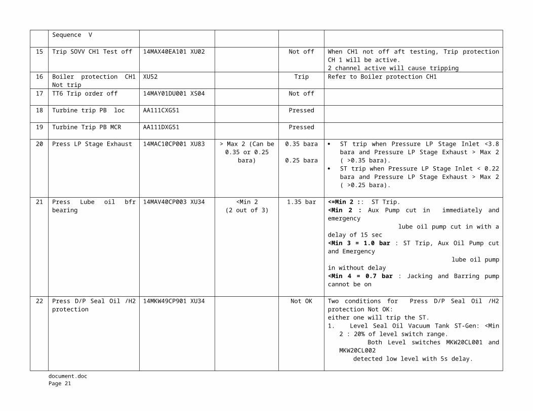
Sequence V
15 Trip SOVV CH1 Test off 14MAX40EA101 XU02 Not off When CH1 not off aft testing, Trip protectionCH 1 will be active.2 channel active will cause tripping
16 Boiler protection CH1Not trip
XU52 Trip Refer to Boiler protection CH1
17 TT6 Trip order off 14MAY01DU001 XS04 Not off
18 Turbine trip PB loc AA111CXG51 Pressed
19 Turbine Trip PB MCR AA111DXG51 Pressed
20 Press LP Stage Exhaust 14MAC10CP001 XU83 > Max 2 (Can be0.35 or 0.25
bara)
0.35 bara
0.25 bara
ST trip when Pressure LP Stage Inlet <3.8bara and Pressure LP Stage Exhaust > Max 2( >0.35 bara).
ST trip when Pressure LP Stage Inlet < 0.22bara and Pressure LP Stage Exhaust > Max 2( >0.25 bara).
21 Press Lube oil bfrbearing
14MAV40CP003 XU34 <Min 2(2 out of 3)
1.35 bar <=Min 2 :: ST Trip.<Min 2 : Aux Pump cut in immediately andemergency lube oil pump cut in with adelay of 15 sec<Min 3 = 1.0 bar : ST Trip, Aux Oil Pump cutand Emergency lube oil pumpin without delay<Min 4 = 0.7 bar : Jacking and Barring pumpcannot be on
22 Press D/P Seal Oil /H2protection
14MKW49CP901 XU34 Not OK Two conditions for Press D/P Seal Oil /H2protection Not OK: either one will trip the ST.1. Level Seal Oil Vacuum Tank ST-Gen: <Min
2 : 20% of level switch range. Both Level switches MKW20CL001 and
MKW20CL002 detected low level with 5s delay.
document.doc Page 21
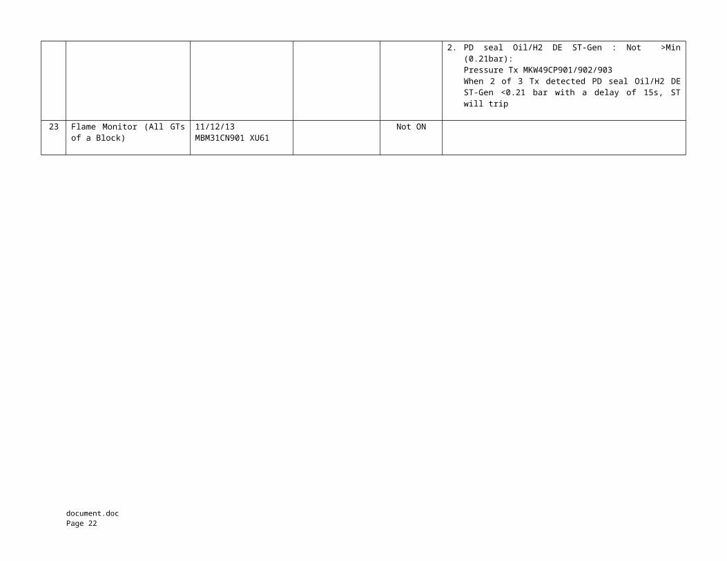
2. PD seal Oil/H2 DE ST-Gen : Not >Min(0.21bar):Pressure Tx MKW49CP901/902/903When 2 of 3 Tx detected PD seal Oil/H2 DEST-Gen <0.21 bar with a delay of 15s, STwill trip
23 Flame Monitor (All GTs
of a Block)11/12/13MBM31CN901 XU61
Not ON
document.doc Page 22
Notes :
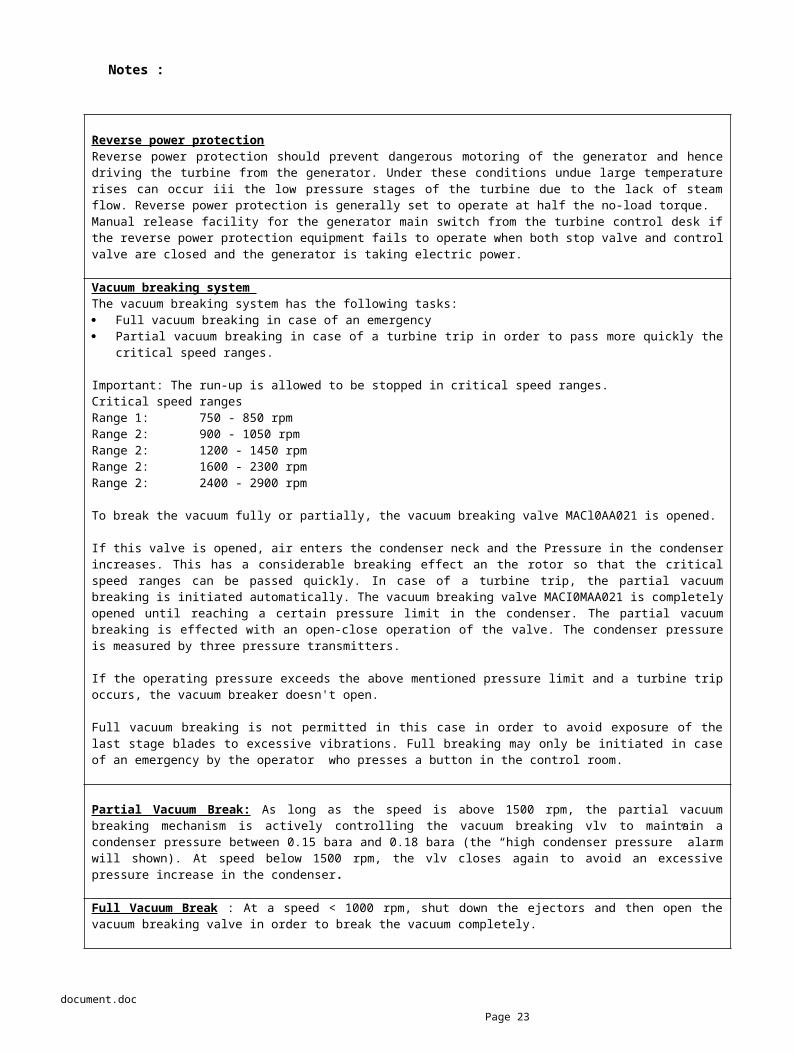
Reverse power protectionReverse power protection should prevent dangerous motoring of the generator and hencedriving the turbine from the generator. Under these conditions undue large temperaturerises can occur iii the low pressure stages of the turbine due to the lack of steamflow. Reverse power protection is generally set to operate at half the no-load torque.Manual release facility for the generator main switch from the turbine control desk ifthe reverse power protection equipment fails to operate when both stop valve and controlvalve are closed and the generator is taking electric power.
Vacuum breaking system The vacuum breaking system has the following tasks: Full vacuum breaking in case of an emergency Partial vacuum breaking in case of a turbine trip in order to pass more quickly the
critical speed ranges.
Important: The run-up is allowed to be stopped in critical speed ranges. Critical speed ranges Range 1: 750 - 850 rpm Range 2: 900 - 1050 rpm Range 2: 1200 - 1450 rpm Range 2: 1600 - 2300 rpm Range 2: 2400 - 2900 rpm
To break the vacuum fully or partially, the vacuum breaking valve MACl0AA021 is opened.
If this valve is opened, air enters the condenser neck and the Pressure in the condenserincreases. This has a considerable breaking effect an the rotor so that the criticalspeed ranges can be passed quickly. In case of a turbine trip, the partial vacuumbreaking is initiated automatically. The vacuum breaking valve MACI0MAA021 is completelyopened until reaching a certain pressure limit in the condenser. The partial vacuumbreaking is effected with an open-close operation of the valve. The condenser pressureis measured by three pressure transmitters.
If the operating pressure exceeds the above mentioned pressure limit and a turbine tripoccurs, the vacuum breaker doesn't open.
Full vacuum breaking is not permitted in this case in order to avoid exposure of thelast stage blades to excessive vibrations. Full breaking may only be initiated in caseof an emergency by the operator who presses a button in the control room.
Partial Vacuum Break: As long as the speed is above 1500 rpm, the partial vacuumbreaking mechanism is actively controlling the vacuum breaking vlv to maintain acondenser pressure between 0.15 bara and 0.18 bara (the “high condenser pressure” alarmwill shown). At speed below 1500 rpm, the vlv closes again to avoid an excessivepressure increase in the condenser.
Full Vacuum Break : At a speed < 1000 rpm, shut down the ejectors and then open thevacuum breaking valve in order to break the vacuum completely.
document.doc Page 23
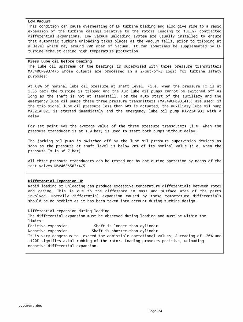
Low VacuumThis condition can cause overheating of LP turbine blading and also give rise to a rapidexpansion of the turbine casings relative to the rotors leading to fully- contracteddifferential expansions. Low vacuum unloading system are usually installed to ensurethat automatic turbine unloading takes places as the vacuum falls, prior to tripping ata level which may around 700 mbar of vacuum. It ran sometimes be supplemented by LPturbine exhaust casing high temperature protection.
Press Lube oil before bearingThe lube oil upstream of the bearings is supervised with three pressure transmittersMAV40CP003/4/5 whose outputs are processed in a 2-out-of-3 logic for turbine safetypurposes:
At 60% of nominal lube oil pressure at shaft level, (i.e. when the pressure Tx is at1.35 bar) the turbine is tripped and the Aux lube oil pumps cannot be switched off aslong as the shaft is not at standstill. For the auto start of the auxiliary and theemergency lube oil pumps these three pressure transmitters (MAV40CP0031415) are used: ifthe trip signal lube oil pressure less than 60% is actuated, the auxiliary lube oil pumpMAV21AP021 is started immediately and the emergency lube oil pump MAV21AP031 with adelay.
For set point 40% the average value of the three pressure transducers (i.e. when thepressure transducer is at 1.0 bar) is used to start both pumps without delay.
The jacking oil pump is switched off by the lube oil pressure supervision devices assoon as the pressure at shaft level is below 20% of its nominal value (i.e. when thepressure Tx is <0.7 bar).
All three pressure transducers can be tested one by one during operation by means of thetest valves MAV40AA503/4/5.
Differential Expansion HPRapid loading or unloading can produce excessive temperature differentials between rotorand casing. This is due to the difference in mass and surface area of the partsinvolved. Normally differential expansion caused by these temperature differentialsshould be no problem as it has been taken into account during turbine design.
Differential expansion during loading The differential expansion must be observed during loading and must be within the limits.Positive expansion Shaft is longer than cylinderNegative expansion Shaft is shorter-than cylinder It is very dangerous to exceed the admissible operational values. A reading of -20% and+120% signifies axial rubbing of the rotor. Loading provokes positive, unloading negative differential expansion.
document.doc Page 24
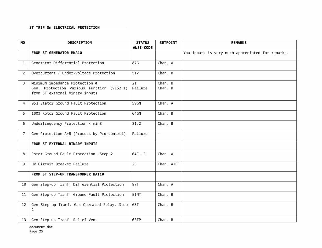
ST TRIP On ELECTRICAL PROTECTION
NO DESCRIPTION STATUSANSI-CODE
SETPOINT REMARKS
FROM ST GENERATOR MKA10 You inputs is very much appreciated for remarks.
1 Generator Differential Protection 87G Chan. A
2 Overcurrent / Under-voltage Protection 51V Chan. B
3 Minimum impedance Protection &Gen. Protection Various Function (V152.1)from ST external binary inputs
21Failure
Chan. BChan. B
4 95% Stator Ground Fault Protection 59GN Chan. A
5 100% Rotor Ground Fault Protection 64GN Chan. B
6 Underfrequency Protection < min3 81.2 Chan. B
7 Gen Protection A+B (Process by Pro-control) Failure -
FROM ST EXTERNAL BINARY INPUTS
8 Rotor Ground Fault Protection. Step 2 64F..2 Chan. A
9 HV Circuit Breaker Failure 25 Chan. A+B
FROM ST STEP-UP TRANSFORMER BAT10
10 Gen Step-up Tranf. Differential Protection 87T Chan. A
11 Gen Step-up Tranf. Ground Fault Protection 51NT Chan. B
12 Gen Step-up Tranf. Gas Operated Relay. Step2
63T Chan. B
13 Gen Step-up Tranf. Relief Vent 63TP Chan. Bdocument.doc Page 25
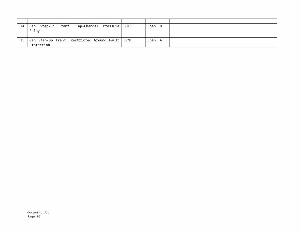
14 Gen Step-up Tranf. Tap-Changer PressureRelay
63TC Chan. B
15 Gen Step-up Tranf. Restricted Ground FaultProtection
87NT Chan. A
document.doc Page 26
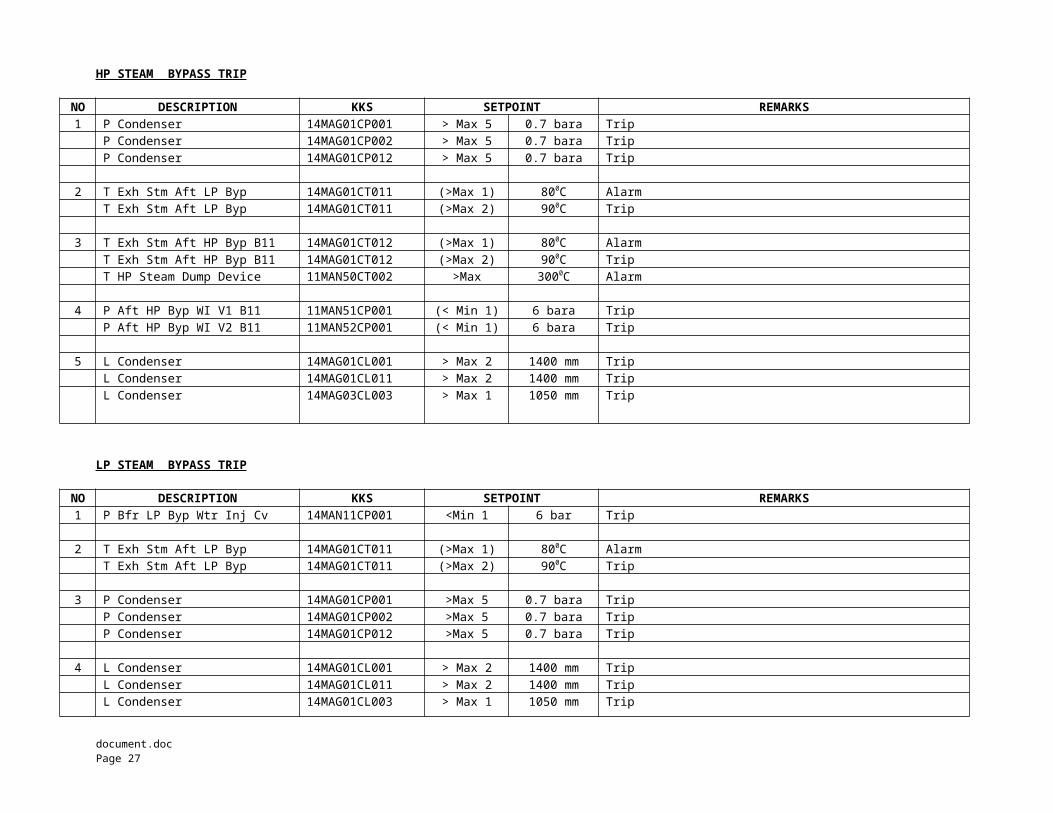
HP STEAM BYPASS TRIP
NO DESCRIPTION KKS SETPOINT REMARKS1 P Condenser 14MAG01CP001 > Max 5 0.7 bara Trip
P Condenser 14MAG01CP002 > Max 5 0.7 bara TripP Condenser 14MAG01CP012 > Max 5 0.7 bara Trip
2 T Exh Stm Aft LP Byp 14MAG01CT011 (>Max 1) 800C AlarmT Exh Stm Aft LP Byp 14MAG01CT011 (>Max 2) 900C Trip
3 T Exh Stm Aft HP Byp B11 14MAG01CT012 (>Max 1) 800C AlarmT Exh Stm Aft HP Byp B11 14MAG01CT012 (>Max 2) 900C TripT HP Steam Dump Device 11MAN50CT002 >Max 3000C Alarm
4 P Aft HP Byp WI V1 B11 11MAN51CP001 (< Min 1) 6 bara TripP Aft HP Byp WI V2 B11 11MAN52CP001 (< Min 1) 6 bara Trip
5 L Condenser 14MAG01CL001 > Max 2 1400 mm TripL Condenser 14MAG01CL011 > Max 2 1400 mm TripL Condenser 14MAG03CL003 > Max 1 1050 mm Trip
LP STEAM BYPASS TRIP
NO DESCRIPTION KKS SETPOINT REMARKS1 P Bfr LP Byp Wtr Inj Cv 14MAN11CP001 <Min 1 6 bar Trip
2 T Exh Stm Aft LP Byp 14MAG01CT011 (>Max 1) 800C AlarmT Exh Stm Aft LP Byp 14MAG01CT011 (>Max 2) 900C Trip
3 P Condenser 14MAG01CP001 >Max 5 0.7 bara TripP Condenser 14MAG01CP002 >Max 5 0.7 bara TripP Condenser 14MAG01CP012 >Max 5 0.7 bara Trip
4 L Condenser 14MAG01CL001 > Max 2 1400 mm TripL Condenser 14MAG01CL011 > Max 2 1400 mm TripL Condenser 14MAG01CL003 > Max 1 1050 mm Trip
document.doc Page 27
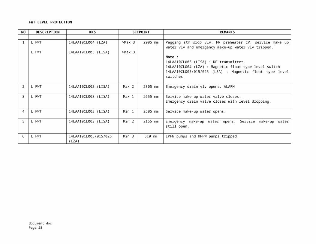
FWT LEVEL PROTECTION
NO DESCRIPTION KKS SETPOINT REMARKS
1 L FWT
L FWT
14LAA10CL004 (LZA)
14LAA10CL003 (LISA)
>Max 3
>max 3
2905 mm Pegging stm srop vlv, FW preheater CV, service make upwater vlv and emergency make-up water vlv tripped.
Note :14LAA10CL003 (LISA) : DP transmitter.14LAA10CL004 (LZA) : Magnetic float type level switch14LAA10CL005/015/025 (LZA) : Magnetic float type levelswitches.
2 L FWT 14LAA10CL003 (LISA) Max 2 2805 mm Emergency drain vlv opens. ALARM
3 L FWT 14LAA10CL003 (LISA) Max 1 2655 mm Service make-up water valve closes.Emergency drain valve closes with level dropping.
4 L FWT 14LAA10CL003 (LISA) Min 1 2505 mm Service make-up water opens.
5 L FWT 14LAA10CL003 (LISA) Min 2 2155 mm Emergency make-up water opens. Service make-up waterstill open.
6 L FWT 14LAA10CL005/015/025(LZA)
Min 3 510 mm LPFW pumps and HPFW pumps tripped.
document.doc Page 28