Embed Size (px)
Citation preview
Warner GT-300
Installation and Troubleshooting GuideP-2102-WE819-0329
An Altra Industrial Motion Company
2 Warner Electric • 800-825-9050 P-2102-WE • 819-0329
Terminology . . . . . . . . . . . . . . . . . . . . . . . . . . . . . . . . .2
GT300 Components . . . . . . . . . . . . . . . . . . . . . . . . 2-4
Mounting Requirements . . . . . . . . . . . . . . . . . . . . . . 5-6
Anti-Rotation Examples . . . . . . . . . . . . . . . . . . . . . . 7-9
Troubleshooting Checklist . . . . . . . . . . . . . . . . . . 10-11
Electrical Evaluation . . . . . . . . . . . . . . . . . . . . . . . 12-13
This guide applies to Warner Electric GT-300 (GT780 frame) clutches and clutch/brakes used on power equipment .
Commercial GT780 is available in a range of Bore sizes, Pulley & output hub configurations .
This clutch/brake consists of an electromagnetic clutch with a mechanical brake which activates automatically when the clutch is turned off .
In addition to these general procedures, any applicable OEM general and safety procedures must also be followed .
Failure to follow these instructions may result in product damage, equipment damage, and serious or fatal injury to personnel.
GT-300 (GT780 frame) Bearing Mounted Electric Clutch Terminology and Components:
(See Figure 1 on page 3 .)
1. Rotor Generally, the input of the clutch includes a keyed hub which mates with the keyway in the crank shaft . The rotor transmits the torque from the crankshaft (driving shaft) to the armature assembly (output) .
2. Armature Assembly Generally, the output of the clutch consists of a disk, springs and pulley (or output flange) . With power applied the armature transmits torque from the rotor to the driven load . Power from the armature disk is transmitted to the pulley or flange by means of the leaf springs .
3. Field Assembly The clutch “power” source contains the coil which generates magnetic attractive force .
4. Brake Ring The brake ring is affixed to the field shell and provides the brake torque when the clutch is disengaged . The brake ring is not present if the assembly is a clutch only .
5. Anti-rotation Tab Anti-rotation tab prevents the field from rotating with the crankshaft . If the field is bolted rigidly or if its axial movement is restricted the field bearing will be preloaded and fail prematurely .
6. Clamp Washer (Provided by customer) A single .250 inch (6 .35 mm) minimum thick steel washer must be used between the clutch and the crank shaft retaining bolt
A washer less than .250 inch (6.35 mm) thick will deform and allow the clamping load to be lost, resulting in damage to the clutch and/or the crankshaft and possible personal injury due to clutch separating from the shaft. Multiple thinner washers are not acceptable.
Warner Electric • 800-825-9050 P-2102-WE • 819-0329 3
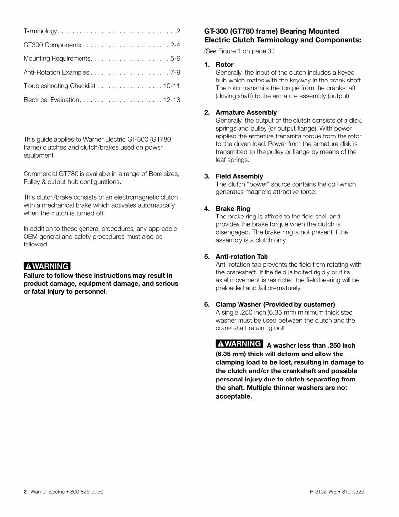
Typical Engine Installations with Output Pulley/or Bolt on Hub
Reverse Mount: Figure 1 refers to the pulley or flange being mounted towards the engine . The recommended shaft engagement for this configuration is 2 .5 to 3 .75 inches . This is recommended because it reduces the overhung load on the engine shaft . (Contact Warner Electric if minimum engagement can not be met .)
Standard Mount: Figure 2 refers to the pulley or flange hub being mounted away from the engine . The recommended shaft engagement for this configuration is 3 .0 to 3 .75 inches to insure shaft support under armature bearing .
See Anti-Rotation Examples on pages 7-9
The Anti-Rotation device must allow both axial and radial free-play. If the field is bolted rigidly or if its axial movement is restricted (see Figure 3), the bearing in the field assembly will be improperly loaded and may fail prematurely.
3-Field
6-.250 Min. Clamp Washer (customer supplied)
Field Bearing
7/16-20 Grade 8 bolt min (customer supplied)
1-Rotor
Reverse MountFigure 1
Standard MountFigure 2
5-Anti-Rotation Tab
2-Armature Assy.
4-Brake Ring
Typical Output (Pulley or Flange)
InputInput
Shaft End and Washer must not touch
Shaft End and Washer must not touch
Mounting Bolt must not “bottom” in the drilled and tapped shaft .
Always bottom the clutch against a flat surface; never against a radius
Figure 3
4 Warner Electric • 800-825-9050 P-2102-WE • 819-0329
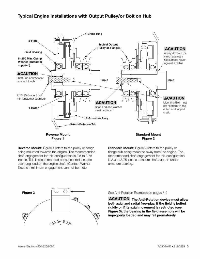
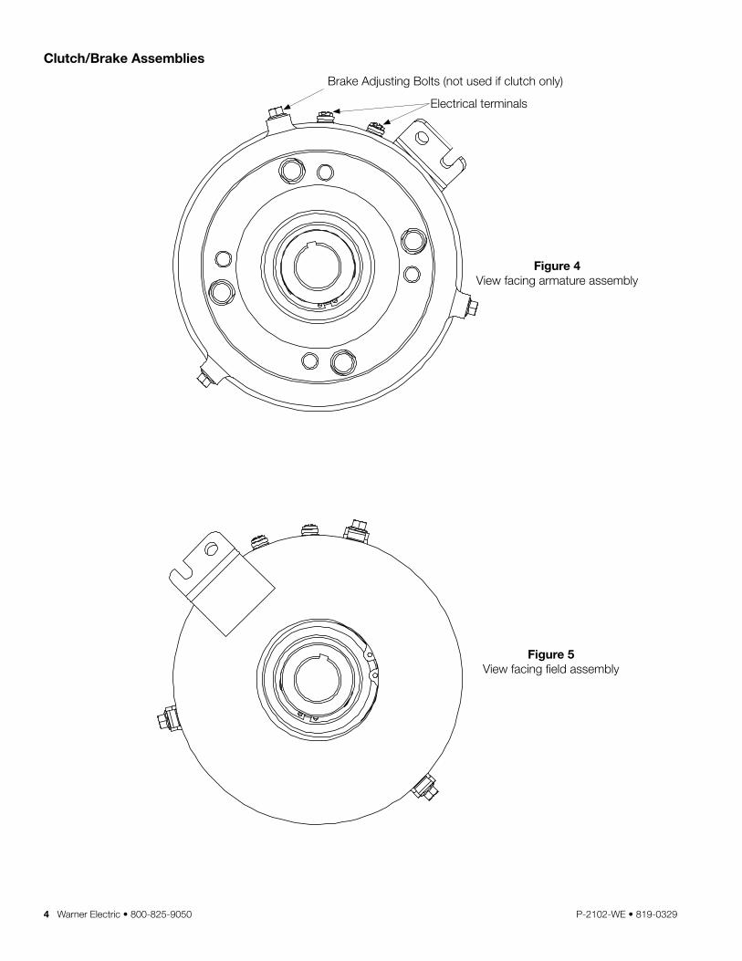
Clutch/Brake Assemblies
Figure 4 View facing armature assembly
Figure 5 View facing field assembly
Brake Adjusting Bolts (not used if clutch only)
Electrical terminals
Warner Electric • 800-825-9050 P-2102-WE • 819-0329 5
Mounting Requirements For A Successful
Clutch Application/Installation
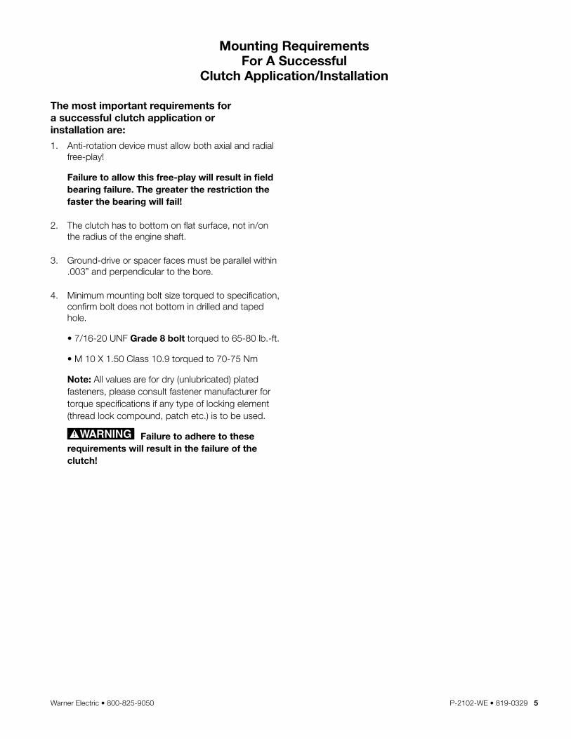
The most important requirements for a successful clutch application or installation are:
1 . Anti-rotation device must allow both axial and radial free-play!
Failure to allow this free-play will result in field bearing failure. The greater the restriction the faster the bearing will fail!
2 . The clutch has to bottom on flat surface, not in/on the radius of the engine shaft .
3 . Ground-drive or spacer faces must be parallel within .003” and perpendicular to the bore .
4 . Minimum mounting bolt size torqued to specification, confirm bolt does not bottom in drilled and taped hole .
• 7/16-20 UNF Grade 8 bolt torqued to 65-80 lb .-ft .
• M 10 X 1 .50 Class 10 .9 torqued to 70-75 Nm
Note: All values are for dry (unlubricated) plated fasteners, please consult fastener manufacturer for torque specifications if any type of locking element (thread lock compound, patch etc .) is to be used .
Failure to adhere to these requirements will result in the failure of the clutch!
6 Warner Electric • 800-825-9050 P-2102-WE • 819-0329
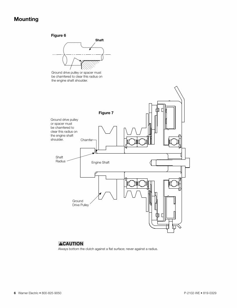
Mounting
Figure 6
Figure 7
Always bottom the clutch against a flat surface; never against a radius .
Ground drive pulley or spacer must be chamfered to clear this radius on the engine shaft shoulder .
Engine Shaft
Shaft Radius
Chamfer
Ground Drive Pulley
Ground drive pulley or spacer must be chamfered to clear this radius on the engine shaft shoulder .
ShaftShoulder
GroundDrivePulley
Shaft end andD-drivespacer mustnot touch
D-drive Spacer
Engine Shaft
Failure to torque boltto requirements willdegrade clamping andcan allow the clutch toseparate from theshaft, causing risk ofpersonal injury.
Thread size Torque ft.lb. Torque N-m3/8-24" UNF 45-49 ft.lb. 61-66 N-m7/16-20" UNF 55-60 ft.lb. 75-81 N-mM 10 X 1.50 40-48 ft.lb. 55-65 N-m
Ground drive pulley or spacermust be chamfered to clear thisradius on the engine shaftshoulder.
Shaft
Ground Drive Spacer(or spacer if no ground
round
drive used)
Always bottom the clutch against a flat surface; never against radius.
Note:Must have faces parallel to each other(within .003") and be perpendicularto the bore.
Note: All values are for dry (unlubricated) plated bolts, please consult fastener manufacturer if any type of lockingelement (thread lock compound, patch etc.) is to be used.
Grade ClassGrade 8
Grade 5 or 8Grade 10.9
Shaft
Warner Electric • 800-825-9050 P-2102-WE • 819-0329 7
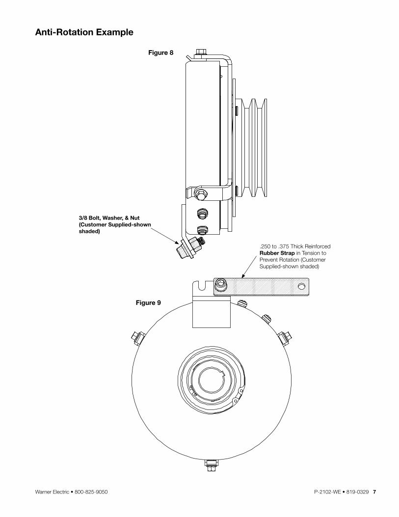
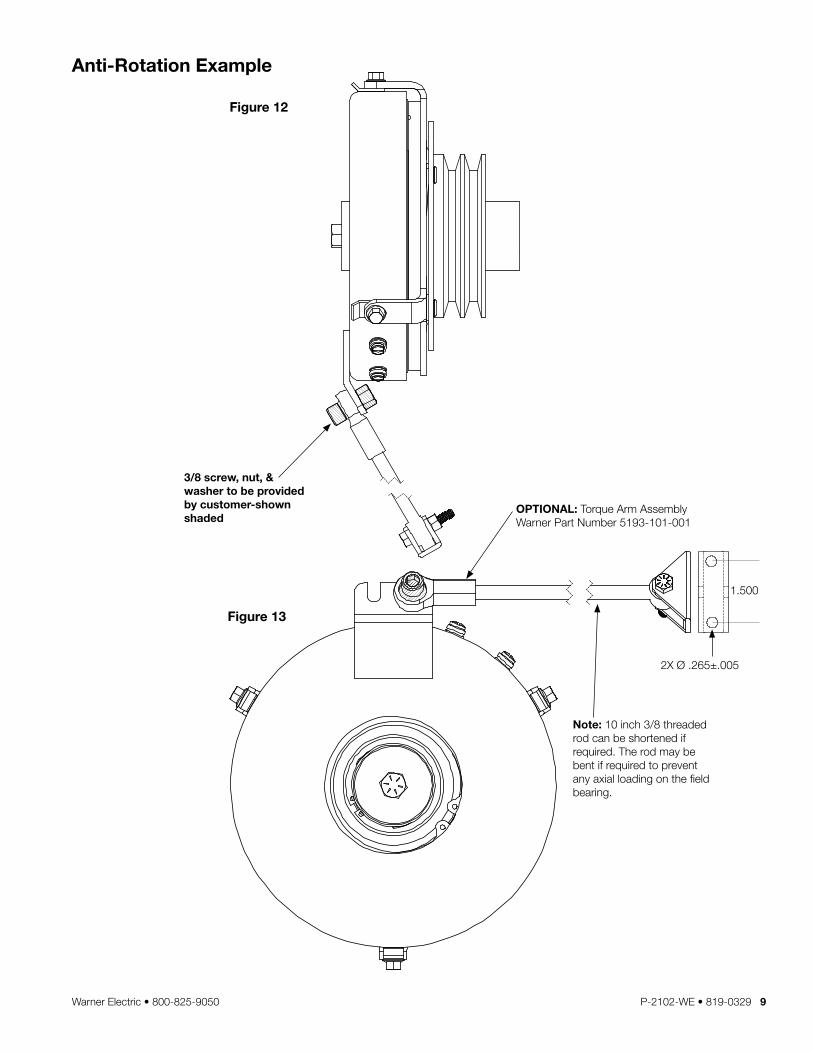
Anti-Rotation Example
Figure 8
Figure 9
3/8 Bolt, Washer, & Nut (Customer Supplied-shown shaded)
.250 to .375 Thick Reinforced Rubber Strap in Tension to Prevent Rotation (Customer Supplied-shown shaded)
8 Warner Electric • 800-825-9050 P-2102-WE • 819-0329
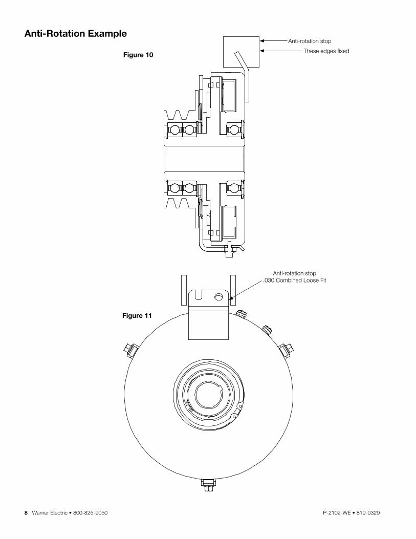
Anti-Rotation Example
Figure 10
Figure 11
These edges fixed
Anti-rotation stop
Anti-rotation stop .030 Combined Loose Fit
Warner Electric • 800-825-9050 P-2102-WE • 819-0329 9
Anti-Rotation Example
Figure 12
Figure 13
Note: 10 inch 3/8 threaded rod can be shortened if required . The rod may be bent if required to prevent any axial loading on the field bearing .
OPTIONAL: Torque Arm Assembly Warner Part Number 5193-101-001
3/8 screw, nut, & washer to be provided by customer-shown shaded
1 .500
2X Ø .265± .005
10 Warner Electric • 800-825-9050 P-2102-WE • 819-0329
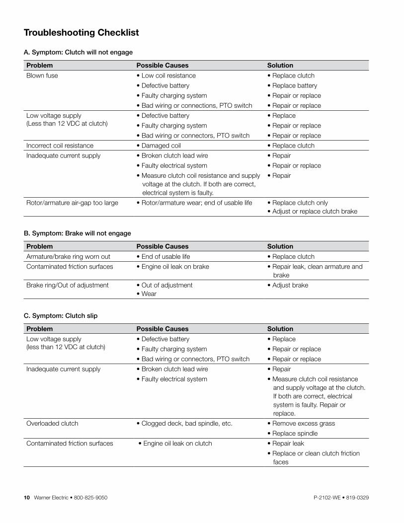
Troubleshooting Checklist
A. Symptom: Clutch will not engage
Problem Possible Causes Solution
Blown fuse • Low coil resistance • Replace clutch
• Defective battery • Replace battery
• Faulty charging system • Repair or replace
• Bad wiring or connections, PTO switch • Repair or replace
Low voltage supply (Less than 12 VDC at clutch)
• Defective battery • Replace
• Faulty charging system • Repair or replace
• Bad wiring or connectors, PTO switch • Repair or replace
Incorrect coil resistance • Damaged coil • Replace clutch
Inadequate current supply • Broken clutch lead wire • Repair
• Faulty electrical system • Repair or replace
• Measure clutch coil resistance and supply voltage at the clutch . If both are correct, electrical system is faulty .
• Repair
Rotor/armature air-gap too large • Rotor/armature wear; end of usable life • Replace clutch only• Adjust or replace clutch brake
B. Symptom: Brake will not engage
Problem Possible Causes Solution
Armature/brake ring worn out • End of usable life • Replace clutch
Contaminated friction surfaces • Engine oil leak on brake • Repair leak, clean armature and brake
Brake ring/Out of adjustment • Out of adjustment• Wear
• Adjust brake
C. Symptom: Clutch slip
Problem Possible Causes Solution
Low voltage supply (less than 12 VDC at clutch)
• Defective battery • Replace
• Faulty charging system • Repair or replace
• Bad wiring or connectors, PTO switch • Repair or replace
Inadequate current supply • Broken clutch lead wire • Repair
• Faulty electrical system • Measure clutch coil resistance and supply voltage at the clutch . If both are correct, electrical system is faulty . Repair or replace .
Overloaded clutch • Clogged deck, bad spindle, etc . • Remove excess grass
• Replace spindle
Contaminated friction surfaces • Engine oil leak on clutch • Repair leak
• Replace or clean clutch friction faces
Warner Electric • 800-825-9050 P-2102-WE • 819-0329 11
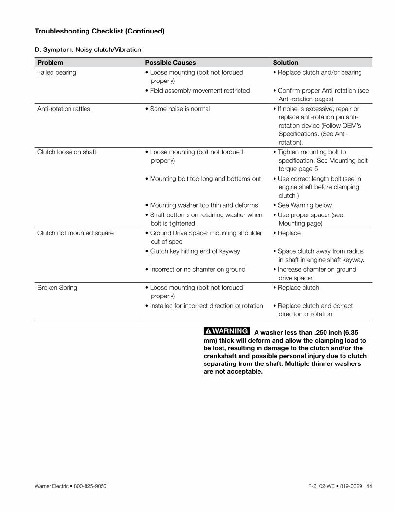
Troubleshooting Checklist (Continued)
D. Symptom: Noisy clutch/Vibration
Problem Possible Causes Solution
Failed bearing • Loose mounting (bolt not torqued properly)
• Replace clutch and/or bearing
• Field assembly movement restricted • Confirm proper Anti-rotation (see Anti-rotation pages)
Anti-rotation rattles • Some noise is normal • If noise is excessive, repair or replace anti-rotation pin anti-rotation device (Follow OEM’s Specifications . (See Anti-rotation) .
Clutch loose on shaft • Loose mounting (bolt not torqued properly)
• Tighten mounting bolt to specification . See Mounting bolt torque page 5
• Mounting bolt too long and bottoms out • Use correct length bolt (see in engine shaft before clamping clutch )
• Mounting washer too thin and deforms • See Warning below
• Shaft bottoms on retaining washer when bolt is tightened
• Use proper spacer (see Mounting page)
Clutch not mounted square • Ground Drive Spacer mounting shoulder out of spec
• Replace
• Clutch key hitting end of keyway • Space clutch away from radius in shaft in engine shaft keyway .
• Incorrect or no chamfer on ground • Increase chamfer on ground drive spacer .
Broken Spring • Loose mounting (bolt not torqued properly)
• Replace clutch
• Installed for incorrect direction of rotation • Replace clutch and correct direction of rotation
A washer less than .250 inch (6.35 mm) thick will deform and allow the clamping load to be lost, resulting in damage to the clutch and/or the crankshaft and possible personal injury due to clutch separating from the shaft. Multiple thinner washers are not acceptable.
12 Warner Electric • 800-825-9050 P-2102-WE • 819-0329
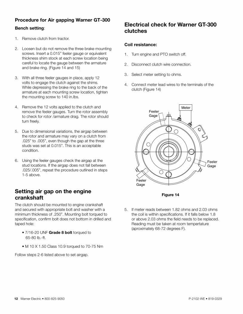
Electrical check for Warner GT-300 clutches
Coil resistance:
1 . Turn engine and PTO switch off .
2 . Disconnect clutch wire connection .
3 . Select meter setting to ohms .
4 . Connect meter lead wires to the terminals of the clutch (Figure 14)
5 . If meter reads between 1 .82 ohms and 2 .03 ohms the coil is within specifications . If it falls below 1 .8 or above 2 .03 ohms the field needs to be replaced . Reading must be taken at room tempertature (aproximately 68-72 degrees F) .
Procedure for Air gapping Warner GT-300
Bench setting:
1 . Remove clutch from tractor .
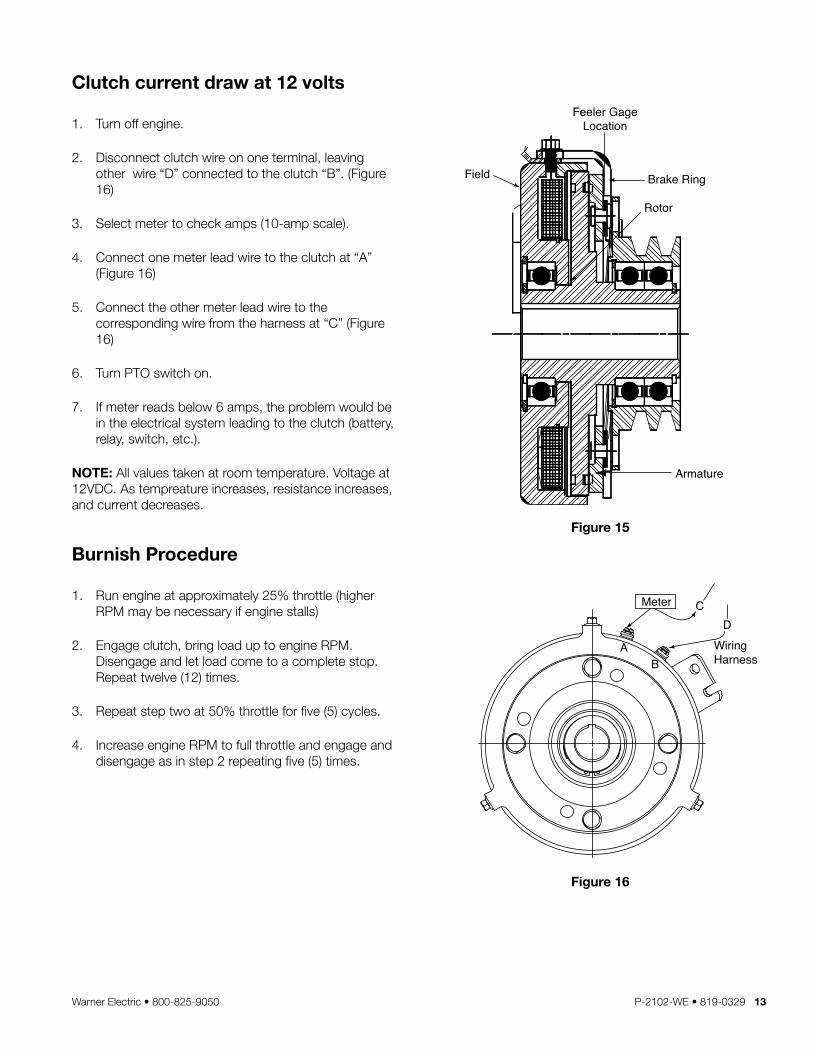
2 . Loosen but do not remove the three brake mounting screws . Insert a 0 .015” feeler gauge or equivalent thickness shim stock at each screw location being careful to locate the gauge between the armature and brake ring . (Figure 14 and 15)
3 . With all three feeler gauges in place, apply 12 volts to engage the clutch against the shims . While depressing the brake ring to the back of the armature at each mounting screw location, tighten the mounting screw to 140 in .lbs .
4 . Remove the 12 volts applied to the clutch and remove the feeler gauges . Turn the rotor assembly to check for rotor /armature drag . The rotor should turn freely .
5 . Due to dimensional variations, the airgap between the rotor and armature may vary on a clutch from .025” to .005”, even though the gap at the three studs was set at 0 .015” . This is an acceptable condition .
6 . Using the feeler gauges check the airgap at the stud locations . If the airgap does not fall between .025/ .005”, repeat the procedure outlined in steps 1-5 above .
Setting air gap on the engine crankshaftThe clutch should be mounted to engine crankshaft and secured with appropriate bolt and washer with a minimum thickness of .250” . Mounting bolt torqued to specification, confirm bolt does not bottom in drilled and taped hole:
• 7/16-20 UNF Grade 8 bolt torqued to 65-80 lb .-ft .
• M 10 X 1 .50 Class 10 .9 torqued to 70-75 Nm
Follow steps 2-6 listed above to set airgap .
Feeler Gage
Feeler Gage
Feeler Gage
Meter
Figure 14
Warner Electric • 800-825-9050 P-2102-WE • 819-0329 13
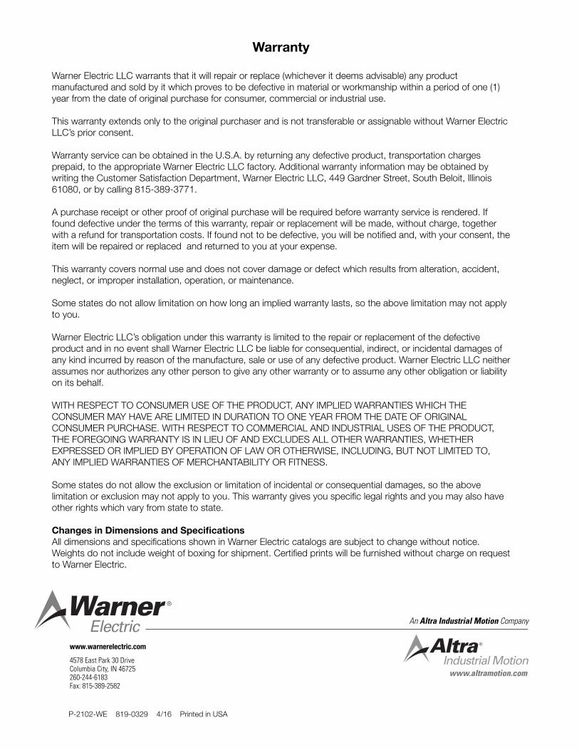
Clutch current draw at 12 volts
1 . Turn off engine .
2 . Disconnect clutch wire on one terminal, leaving other wire “D” connected to the clutch “B” . (Figure 16)
3 . Select meter to check amps (10-amp scale) .
4 . Connect one meter lead wire to the clutch at “A” (Figure 16)
5 . Connect the other meter lead wire to the corresponding wire from the harness at “C” (Figure 16)
6 . Turn PTO switch on .
7 . If meter reads below 6 amps, the problem would be in the electrical system leading to the clutch (battery, relay, switch, etc .) .
NOTE: All values taken at room temperature . Voltage at 12VDC . As tempreature increases, resistance increases, and current decreases .
Burnish Procedure
1 . Run engine at approximately 25% throttle (higher RPM may be necessary if engine stalls)
2 . Engage clutch, bring load up to engine RPM . Disengage and let load come to a complete stop . Repeat twelve (12) times .
3 . Repeat step two at 50% throttle for five (5) cycles .
4 . Increase engine RPM to full throttle and engage and disengage as in step 2 repeating five (5) times .
Field
Feeler GageLocation
Brake Ring
Rotor
Armature
Meter C
AB
WiringHarness
D
Figure 15
Figure 16
Warranty
Warner Electric LLC warrants that it will repair or replace (whichever it deems advisable) any product manufactured and sold by it which proves to be defective in material or workmanship within a period of one (1) year from the date of original purchase for consumer, commercial or industrial use .
This warranty extends only to the original purchaser and is not transferable or assignable without Warner Electric LLC’s prior consent .
Warranty service can be obtained in the U .S .A . by returning any defective product, transportation charges prepaid, to the appropriate Warner Electric LLC factory . Additional warranty information may be obtained by writing the Customer Satisfaction Department, Warner Electric LLC, 449 Gardner Street, South Beloit, Illinois 61080, or by calling 815-389-3771 .
A purchase receipt or other proof of original purchase will be required before warranty service is rendered . If found defective under the terms of this warranty, repair or replacement will be made, without charge, together with a refund for transportation costs . If found not to be defective, you will be notified and, with your consent, the item will be repaired or replaced and returned to you at your expense .
This warranty covers normal use and does not cover damage or defect which results from alteration, accident, neglect, or improper installation, operation, or maintenance .
Some states do not allow limitation on how long an implied warranty lasts, so the above limitation may not apply to you .
Warner Electric LLC’s obligation under this warranty is limited to the repair or replacement of the defective product and in no event shall Warner Electric LLC be liable for consequential, indirect, or incidental damages of any kind incurred by reason of the manufacture, sale or use of any defective product . Warner Electric LLC neither assumes nor authorizes any other person to give any other warranty or to assume any other obligation or liability on its behalf .
WITH RESPECT TO CONSUMER USE OF THE PRODUCT, ANY IMPLIED WARRANTIES WHICH THE CONSUMER MAY HAVE ARE LIMITED IN DURATION TO ONE YEAR FROM THE DATE OF ORIGINAL CONSUMER PURCHASE . WITH RESPECT TO COMMERCIAL AND INDUSTRIAL USES OF THE PRODUCT, THE FOREGOING WARRANTY IS IN LIEU OF AND EXCLUDES ALL OTHER WARRANTIES, WHETHER EXPRESSED OR IMPLIED BY OPERATION OF LAW OR OTHERWISE, INCLUDING, BUT NOT LIMITED TO, ANY IMPLIED WARRANTIES OF MERCHANTABILITY OR FITNESS .
Some states do not allow the exclusion or limitation of incidental or consequential damages, so the above limitation or exclusion may not apply to you . This warranty gives you specific legal rights and you may also have other rights which vary from state to state .
Changes in Dimensions and SpecificationsAll dimensions and specifications shown in Warner Electric catalogs are subject to change without notice . Weights do not include weight of boxing for shipment . Certified prints will be furnished without charge on request to Warner Electric .
www.altramotion.com
An Altra Industrial Motion Company
P-2102-WE 819-0329 4/16 Printed in USA
www.warnerelectric.com
4578 East Park 30 DriveColumbia City, IN 46725260-244-6183Fax: 815-389-2582


