Embed Size (px)
Citation preview

INSTRUCTION BOOKMD2010, 2020, 2030, 2040
Maintenance ManualThis Owner’s Manual contains brief operating instructionsin the form of a maintenance schedule containing text andillustrations
For the “Do-It-Yourselfer” we have put together a morecomprehensive Maintenance Manual which describes theengine and its fuel, lubricating and cooling systems, etc. inmore detail. The Maintenance Manual also provides hintson the tools you will need.
The Maintenance Manual can be bought from your VOLVOPENTA retailer.
SafetyPreparations
We have put together the checklist below (to which youcan, of course, add your own notes) in order that you mayenjoy trouble-free running.
It is, of course, important that the engine, its equipment andthe boat in general are maintained according to theinstructions given in order to avoid breakdowns.
Travel plans
– Do you have a current nautical chart for the plannedvoyage?
– Have you taken note of the weather forecast for thearea in which you will be travelling?
– Have you calculated the distance?– Have you calculated the amount of fuel you will need?– Where can you buy fuel on your journey?– Do your relatives know of your travel plans?
The boat’s equipment
– Rescue equipment such as lifejackets and distressrockets.Does everyone on board know where they are?
– Spare parts on board, e.g. water pump wheel(impeller) for the seawater pump.
– Tools which suit the equipment– Full fire extinguishers.
The environmentWe invest large amounts of money in ensuring that ourengines are as environmentally friendly as possible. Wehope, therefore, that you as a boat owner will continue tohelp keep our environment clean.
As regards changes of oil and oil and/or fuel filters, it isimportant that used oil or discarded filters do not maketheir way into ordinary rubbish. Used filters always containa small amount of oil or fuel even when they have beenemptied.
Always hand in used filters and oil to a service orenvironmental station which has special containers forproducts which can be harmful to the environment.Used batteries should also be handed in here.
AB VOLVO PENTATechnical Information
Volvo Penta reserve the right to make changes© AB VOLVO PENTA
Welcome on board!You have chosen a boat with all the comfort you could everwish for, plus an engine with maximum safety which will beextremely economical to run. We welcome you to ourworldwide service network.
Read this before you cast off from shoreWe advise you to read through this Owner’s Manual even ifyou are used to the sea and have previously pilotedvarious types of boat. Some things may be different to whatyou are used to.
Warranties and ServiceProvided with each engine is a description of the warrantywe issue for our product. The warranty card you receiveshould be filled in and returned to VOLVO PENTA by yoursales representative: this is important both for us and foryou. Make sure this is done, because we may refuse toundertake repairs on the warranty because the date ofdelivery cannot be verified.
Some markets have other warranty conditions whichreplace or supplement the VOLVO PENTA warranty.
Diesel fuelUse “Autodiesel” diesel oil. An inferior fuel may causebreakdowns.
Lubricating oilsOnly use lubricating oils of the quality recommended in“Technical Data”.
MaintenanceThere are a number of maintenance instructions listed inthis Owner’s Manual. If these are not carried out in goodtime, your engine may become less reliable and lesseconomical to run afterwards. Contact an authorisedVOLVO PENTA service workshop if you are unable to carryout the prescribed maintenance yourself.
It is important that you always use original parts in order tomaintain VOLVO PENTA quality. It will be worth it in thelong run.
VOLVO PENTA has developed an extensive network ofretailers in order to be able to provide services and spareparts.
Always state the complete type designation and serialnumber when ordering spare parts
Safety instructionsWhen you see this symbol before an item of text, itmeans that there is a danger of injury or damageunless the instructions are followed.
1
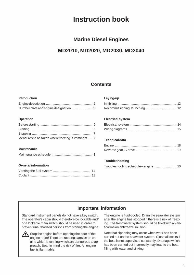
Instruction book
Marine Diesel Engines
MD2010, MD2020, MD2030, MD2040
Contents
Introduction
Engine description ................................................... 2Number plate and engine designation ....................... 3
Operation
Before starting ......................................................... 6Starting .................................................................... 6Stopping .................................................................. 7Measures to be taken when freezing is imminent ..... 7
Maintenance
Maintenance schedule ............................................. 8
General information
Venting the fuel system ......................................... 11Coolant .................................................................. 11
Laying-up
Inhibiting ................................................................ 12Recommissioning, launching .................................. 12
Electrical system
Electrical system ................................................... 14Wiring diagrams ..................................................... 15
Technical data
Engine ................................................................... 18Reverse gear, S-drive ............................................ 19
Troubleshooting
Troubleshooting schedule – engine ........................ 20
Important informationStandard instrument panels do not have a key switch.The operator’s cabin should therefore be lockable and/or a lockable main switch should be used in order toprevent unauthorised persons from starting the engine.
Stop the engine before opening the door of theengine room! There are rotating parts on an en-gine which is running which are dangerous to ap-proach. Bear in mind the risk of fire. All enginefuel is flammable.
The engine is fluid-cooled. Drain the seawater systemafter the engine has stopped if there is a risk of freez-ing. The freshwater system should be filled with an an-ticorrosion antifreeze solution.
Note that siphoning may occur when work has beencarried out on the seawater system. Close all cocks ifthe boat is not supervised constantly. Drainage whichhas been carried out incorrectly may lead to the boatfilling with water and sinking.
2
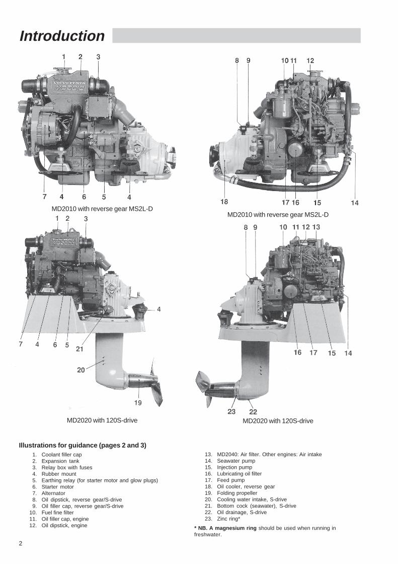
Introduction
MD2010 with reverse gear MS2L-DMD2010 with reverse gear MS2L-D
MD2020 with 120S-drive MD2020 with 120S-drive
Illustrations for guidance (pages 2 and 3)1. Coolant filler cap2. Expansion tank3. Relay box with fuses4. Rubber mount5. Earthing relay (for starter motor and glow plugs)6. Starter motor7. Alternator8. Oil dipstick, reverse gear/S-drive9. Oil filler cap, reverse gear/S-drive
10. Fuel fine filter11. Oil filler cap, engine12. Oil dipstick, engine
13. MD2040: Air filter. Other engines: Air intake14. Seawater pump15. Injection pump16. Lubricating oil filter17. Feed pump18. Oil cooler, reverse gear19. Folding propeller20. Cooling water intake, S-drive21. Bottom cock (seawater), S-drive22. Oil drainage, S-drive23. Zinc ring*
* NB. A magnesium ring should be used when running infreshwater.
3
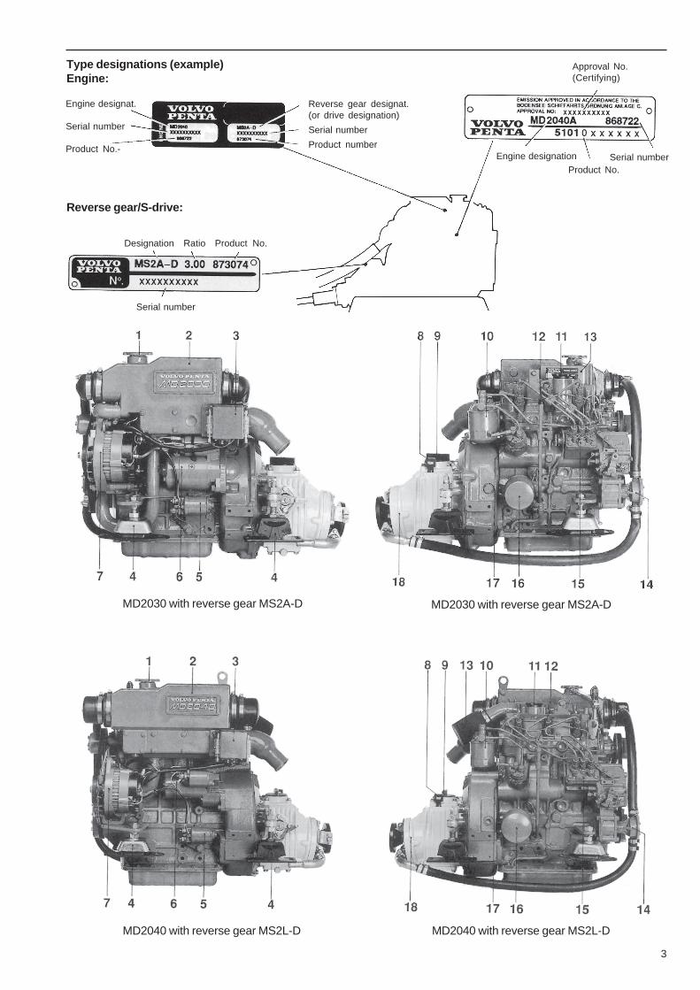
MD2030 with reverse gear MS2A-D MD2030 with reverse gear MS2A-D
MD2040 with reverse gear MS2L-D MD2040 with reverse gear MS2L-D
Serial number
Type designations (example)Engine:
Engine designat.
Serial number
Product No.-
Reverse gear designat.(or drive designation)
Serial number
Product number
Reverse gear/S-drive:
Approval No.(Certifying)
Engine designation
Product No.Serial number
Designation Ratio Product No.
4
Instruments
➡
➡
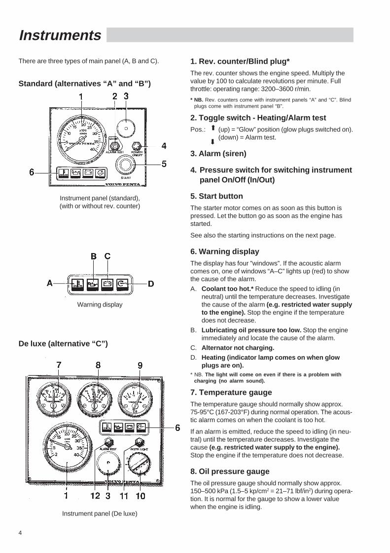
1. Rev. counter/Blind plug*The rev. counter shows the engine speed. Multiply thevalue by 100 to calculate revolutions per minute. Fullthrottle: operating range: 3200–3600 r/min.
* NB. Rev. counters come with instrument panels “A” and “C”. Blindplugs come with instrument panel “B”.
2. Toggle switch - Heating/Alarm testPos.: (up) = “Glow” position (glow plugs switched on).
(down) = Alarm test.
3. Alarm (siren)
4. Pressure switch for switching instrumentpanel On/Off (In/Out)
5. Start buttonThe starter motor comes on as soon as this button ispressed. Let the button go as soon as the engine hasstarted.
See also the starting instructions on the next page.
6. Warning displayThe display has four ”windows”. If the acoustic alarmcomes on, one of windows “A–C” lights up (red) to showthe cause of the alarm.
A. Coolant too hot.* Reduce the speed to idling (inneutral) until the temperature decreases. Investigatethe cause of the alarm (e.g. restricted water supplyto the engine). Stop the engine if the temperaturedoes not decrease.
B. Lubricating oil pressure too low. Stop the engineimmediately and locate the cause of the alarm.
C. Alternator not charging.D. Heating (indicator lamp comes on when glow
plugs are on).* NB. The light will come on even if there is a problem with
charging (no alarm sound).
7. Temperature gaugeThe temperature gauge should normally show approx.75-95°C (167-203°F) during normal operation. The acous-tic alarm comes on when the coolant is too hot.
If an alarm is emitted, reduce the speed to idling (in neu-tral) until the temperature decreases. Investigate thecause (e.g. restricted water supply to the engine).Stop the engine if the temperature does not decrease.
8. Oil pressure gaugeThe oil pressure gauge should normally show approx.150–500 kPa (1.5–5 kp/cm2 = 21–71 lbf/in2) during opera-tion. It is normal for the gauge to show a lower valuewhen the engine is idling.
There are three types of main panel (A, B and C).
Standard (alternatives “A” and “B”)
Instrument panel (standard),(with or without rev. counter)
Warning display
De luxe (alternative “C”)
Instrument panel (De luxe)
5
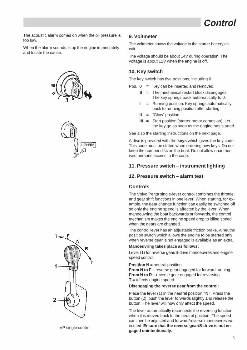
Control
VP single control
9. VoltmeterThe voltmeter shows the voltage in the starter battery cir-cuit.
The voltage should be about 14V during operation. Thevoltage is about 12V when the engine is off.
10. Key switchThe key switch has five positions, including 0:
Pos. 0 = Key can be inserted and removed.
S = The mechanical restart block disengages.The key springs back automatically to 0.
I = Running position. Key springs automaticallyback to running position after starting.
II = “Glow” position.
III = Start position (starter motor comes on). Letthe key go as soon as the engine has started.
See also the starting instructions on the next page.
A disc is provided with the keys which gives the key code.This code must be stated when ordering new keys. Do notkeep the number disc on the boat. Do not allow unauthor-ised persons access to the code.
11. Pressure switch – instrument lighting
12. Pressure switch – alarm test
ControlsThe Volvo Penta single-lever control combines the throttleand gear shift functions in one lever. When starting, for ex-ample, the gear change function can easily be switched offso only the engine speed is affected by the lever. Whenmanoeuvring the boat backwards or forwards, the controlmechanism makes the engine speed drop to idling speedwhen the gears are changed.
The control lever has an adjustable friction brake. A neutralposition switch which allows the engine to be started onlywhen reverse gear is not engaged is available as an extra.
Manoeuvring takes place as follows:
Lever (1) for reverse gear/S-drive manoeuvres and enginespeed control.
Position N = neutral position.From N to F – reverse gear engaged for forward running.From N to R – reverse gear engaged for reversing.T = affects engine speed.
Disengaging the reverse gear from the control:
Place the lever (1) in the neutral position “N” . Press thebutton (2), push the lever forwards slightly and release thebutton. The lever will now only affect the speed.
The lever automatically reconnects the reversing functionwhen it is moved back to the neutral position. The speedcan then be adjusted and forward/reverse manoeuvres ex-ecuted. Ensure that the reverse gear/S-drive is not en-gaged unintentionally.
The acoustic alarm comes on when the oil pressure istoo low.
When the alarm sounds, stop the engine immediatelyand locate the cause.
6
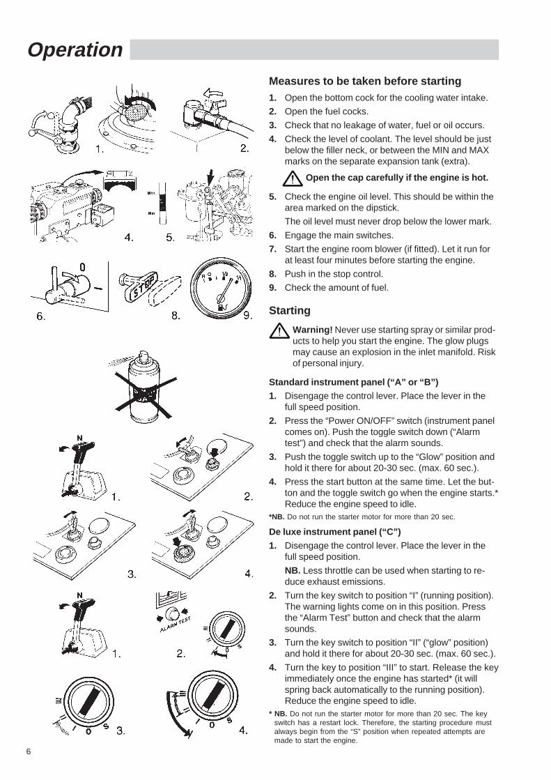
OperationMeasures to be taken before starting1. Open the bottom cock for the cooling water intake.
2. Open the fuel cocks.
3. Check that no leakage of water, fuel or oil occurs.
4. Check the level of coolant. The level should be justbelow the filler neck, or between the MIN and MAXmarks on the separate expansion tank (extra).
Open the cap carefully if the engine is hot.
5. Check the engine oil level. This should be within thearea marked on the dipstick.
The oil level must never drop below the lower mark.
6. Engage the main switches.
7. Start the engine room blower (if fitted). Let it run forat least four minutes before starting the engine.
8. Push in the stop control.
9. Check the amount of fuel.
Starting
Warning! Never use starting spray or similar prod-ucts to help you start the engine. The glow plugsmay cause an explosion in the inlet manifold. Riskof personal injury.
Standard instrument panel (“A” or “B”)1. Disengage the control lever. Place the lever in the
full speed position.
2. Press the “Power ON/OFF” switch (instrument panelcomes on). Push the toggle switch down (“Alarmtest”) and check that the alarm sounds.
3. Push the toggle switch up to the “Glow” position andhold it there for about 20-30 sec. (max. 60 sec.).
4. Press the start button at the same time. Let the but-ton and the toggle switch go when the engine starts.*Reduce the engine speed to idle.
*NB. Do not run the starter motor for more than 20 sec.
De luxe instrument panel (“C”)
1. Disengage the control lever. Place the lever in thefull speed position.
NB. Less throttle can be used when starting to re-duce exhaust emissions.
2. Turn the key switch to position “I” (running position).The warning lights come on in this position. Pressthe “Alarm Test” button and check that the alarmsounds.
3. Turn the key switch to position “II” (“glow” position)and hold it there for about 20-30 sec. (max. 60 sec.).
4. Turn the key to position “III” to start. Release the keyimmediately once the engine has started* (it willspring back automatically to the running position).Reduce the engine speed to idle.
* NB. Do not run the starter motor for more than 20 sec. The keyswitch has a restart lock. Therefore, the starting procedure mustalways begin from the “S” position when repeated attempts aremade to start the engine.
7
The following applies to all engines regardless of thetype of instrument panel:
NB: The starter motor must never be switched onwhen the engine is running. The starter motor andthe flywheel ring gear may be seriously damaged.
5. Warm up the engine at low speed and under lowload. Do not race the engine when it is cold.
6. Monitor the instruments/warning display during op-eration. Stop the engine and check the cause of anyabnormal readings or if a warning light comes on.
The engine must not be run if the oil pressure istoo low or the coolant temperature too high.
NB. For maximum fuel economy, avoid running on fullthrottle. The maximum cruising speed is the maximumspeed reached minus approx. 300 r/min.
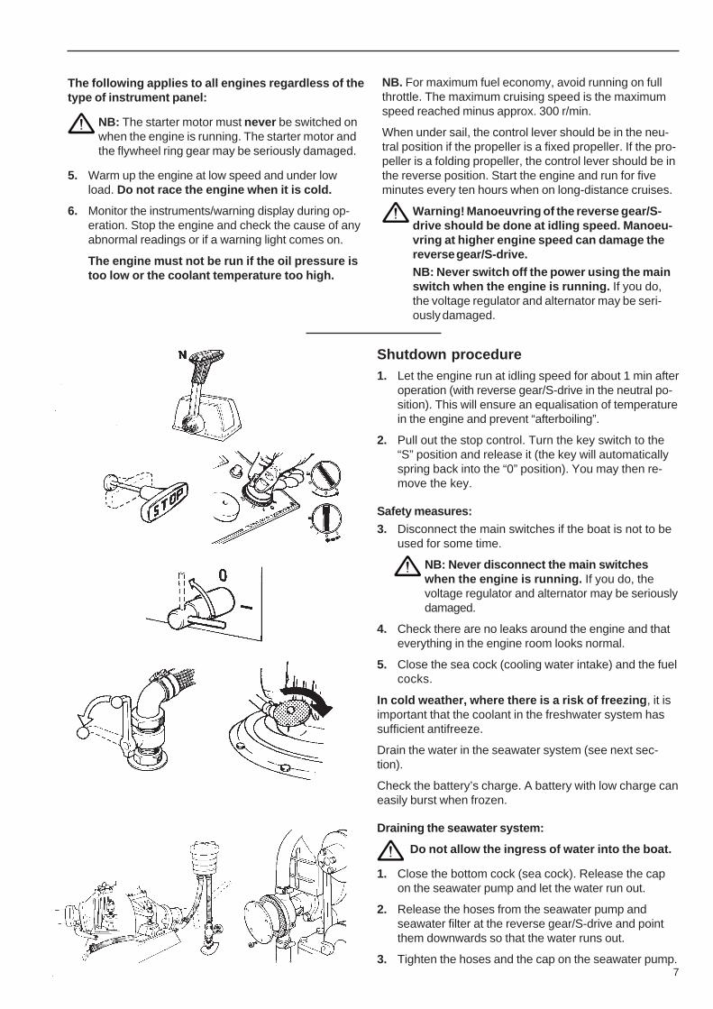
When under sail, the control lever should be in the neu-tral position if the propeller is a fixed propeller. If the pro-peller is a folding propeller, the control lever should be inthe reverse position. Start the engine and run for fiveminutes every ten hours when on long-distance cruises.
Warning! Manoeuvring of the reverse gear/S-drive should be done at idling speed. Manoeu-vring at higher engine speed can damage thereverse gear/S-drive.NB: Never switch off the power using the mainswitch when the engine is running. If you do,the voltage regulator and alternator may be seri-ously damaged.
Shutdown procedure1. Let the engine run at idling speed for about 1 min after
operation (with reverse gear/S-drive in the neutral po-sition). This will ensure an equalisation of temperaturein the engine and prevent “afterboiling”.
2. Pull out the stop control. Turn the key switch to the“S” position and release it (the key will automaticallyspring back into the “0” position). You may then re-move the key.
Safety measures:
3. Disconnect the main switches if the boat is not to beused for some time.
NB: Never disconnect the main switcheswhen the engine is running. If you do, thevoltage regulator and alternator may be seriouslydamaged.
4. Check there are no leaks around the engine and thateverything in the engine room looks normal.
5. Close the sea cock (cooling water intake) and the fuelcocks.
In cold weather, where there is a risk of freezing , it isimportant that the coolant in the freshwater system hassufficient antifreeze.
Drain the water in the seawater system (see next sec-tion).
Check the battery’s charge. A battery with low charge caneasily burst when frozen.
Draining the seawater system:
Do not allow the ingress of water into the boat.
1. Close the bottom cock (sea cock). Release the capon the seawater pump and let the water run out.
2. Release the hoses from the seawater pump andseawater filter at the reverse gear/S-drive and pointthem downwards so that the water runs out.
3. Tighten the hoses and the cap on the seawater pump.
8
MaintenanceNB: Stop the engine and cut the power usingthe main switches before service work is be-gun!
General description for MD 2010, MD 2020, MD 2030and MD2040.
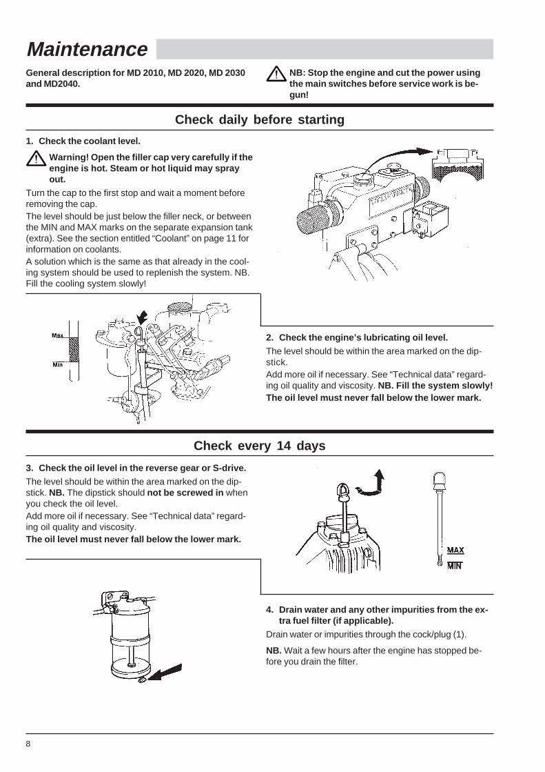
1. Check the coolant level.
Warning! Open the filler cap very carefully if theengine is hot. Steam or hot liquid may sprayout.
Turn the cap to the first stop and wait a moment beforeremoving the cap.The level should be just below the filler neck, or betweenthe MIN and MAX marks on the separate expansion tank(extra). See the section entitled “Coolant” on page 11 forinformation on coolants.A solution which is the same as that already in the cool-ing system should be used to replenish the system. NB.Fill the cooling system slowly!
2. Check the engine’s lubricating oil level.
The level should be within the area marked on the dip-stick.Add more oil if necessary. See “Technical data” regard-ing oil quality and viscosity. NB. Fill the system slowly!The oil level must never fall below the lower mark.
Check every 14 days
3. Check the oil level in the reverse gear or S-drive.
The level should be within the area marked on the dip-stick. NB. The dipstick should not be screwed in whenyou check the oil level.Add more oil if necessary. See “Technical data” regard-ing oil quality and viscosity.The oil level must never fall below the lower mark.
4. Drain water and any other impurities from the ex-tra fuel filter (if applicable).
Drain water or impurities through the cock/plug (1).
NB. Wait a few hours after the engine has stopped be-fore you drain the filter.
Check daily before starting
9
MD2010, MD2020 MD2030, MD2040
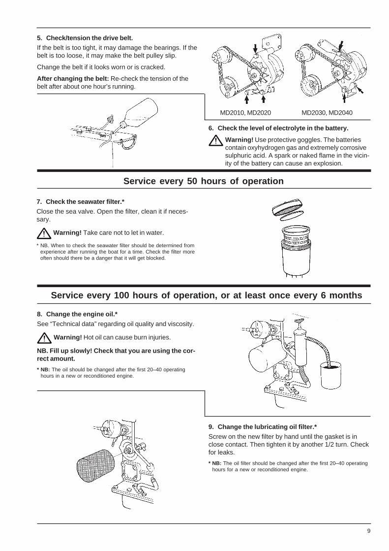
5. Check/tension the drive belt.If the belt is too tight, it may damage the bearings. If thebelt is too loose, it may make the belt pulley slip.
Change the belt if it looks worn or is cracked.
After changing the belt: Re-check the tension of thebelt after about one hour’s running.
6. Check the level of electrolyte in the battery.
Warning! Use protective goggles. The batteriescontain oxyhydrogen gas and extremely corrosivesulphuric acid. A spark or naked flame in the vicin-ity of the battery can cause an explosion.
Service every 50 hours of operation
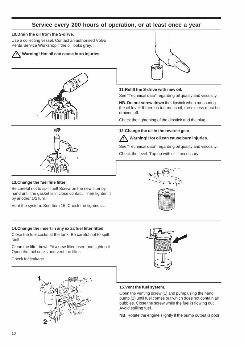
7. Check the seawater filter.*
Close the sea valve. Open the filter, clean it if neces-sary.
Warning! Take care not to let in water.
* NB. When to check the seawater filter should be determined fromexperience after running the boat for a time. Check the filter moreoften should there be a danger that it will get blocked.
Service every 100 hours of operation, or at least once every 6 months
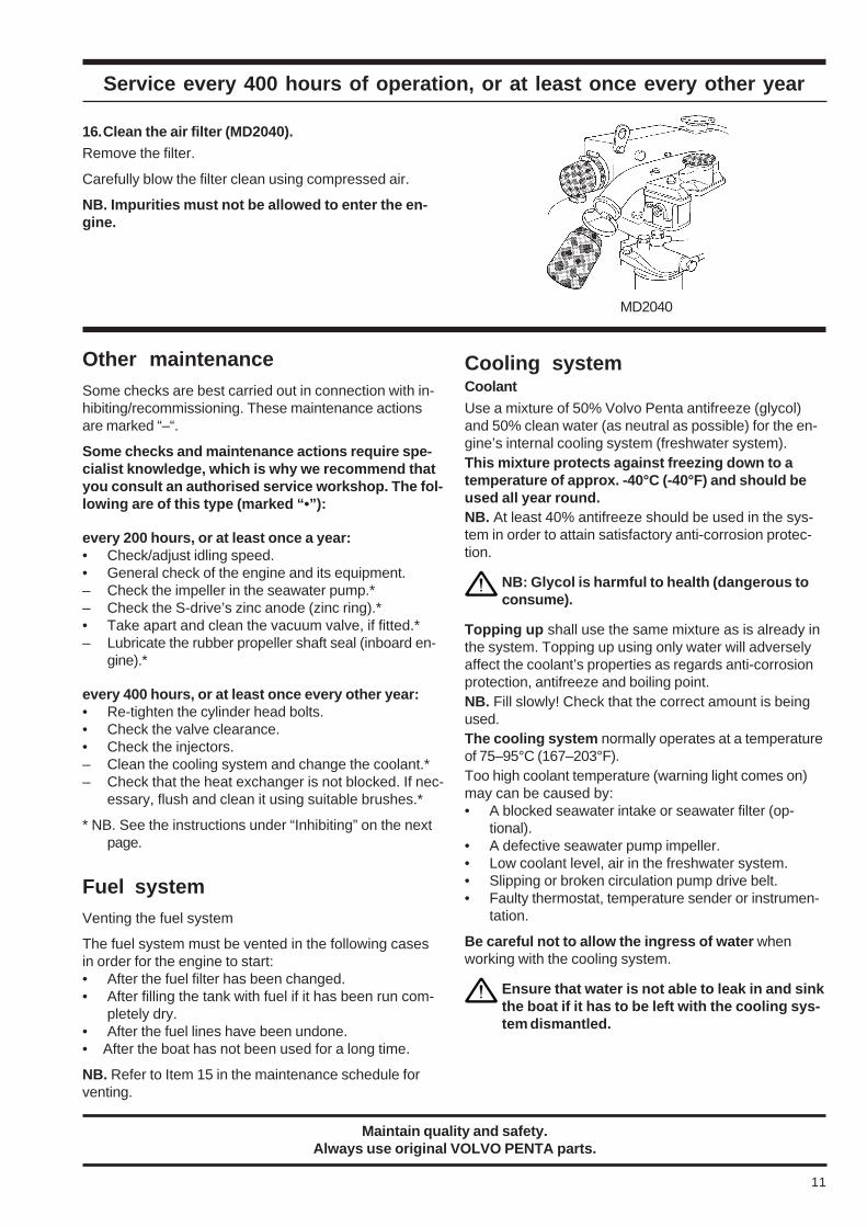
8. Change the engine oil.*
See “Technical data” regarding oil quality and viscosity.
Warning! Hot oil can cause burn injuries.
NB. Fill up slowly! Check that you are using the cor-rect amount.
* NB: The oil should be changed after the first 20–40 operatinghours in a new or reconditioned engine.
9. Change the lubricating oil filter.*
Screw on the new filter by hand until the gasket is inclose contact. Then tighten it by another 1/2 turn. Checkfor leaks.
* NB: The oil filter should be changed after the first 20–40 operatinghours for a new or reconditioned engine.
10
Service every 200 hours of operation, or at least once a year
10.Drain the oil from the S-drive.
Use a collecting vessel. Contact an authorised VolvoPenta Service Workshop if the oil looks grey.
Warning! Hot oil can cause burn injuries.
11.Refill the S-drive with new oil.See “Technical data” regarding oil quality and viscosity.
NB. Do not screw down the dipstick when measuringthe oil level. If there is too much oil, the excess must bedrained off.
Check the tightening of the dipstick and the plug.
12.Change the oil in the reverse gear.
Warning! Hot oil can cause burn injuries.
See “Technical data” regarding oil quality and viscosity.
Check the level. Top up with oil if necessary.
13.Change the fuel fine filter.
Be careful not to spill fuel! Screw on the new filter byhand until the gasket is in close contact. Then tighten itby another 1/2 turn.
Vent the system. See Item 15. Check the tightness.
14.Change the insert in any extra fuel filter fitted.
Close the fuel cocks at the tank. Be careful not to spillfuel!
Clean the filter bowl. Fit a new filter insert and tighten it.Open the fuel cocks and vent the filter.
Check for leakage.
15.Vent the fuel system.
Open the venting screw (1) and pump using the handpump (2) until fuel comes out which does not contain airbubbles. Close the screw while the fuel is flowing out.Avoid spilling fuel.
NB. Rotate the engine slightly if the pump output is poor.
11
MD2040
Service every 400 hours of operation, or at least once every other year
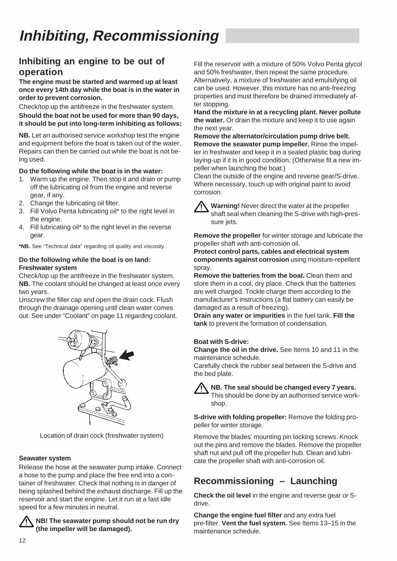
16.Clean the air filter (MD2040).Remove the filter.
Carefully blow the filter clean using compressed air.
NB. Impurities must not be allowed to enter the en-gine.
Other maintenanceSome checks are best carried out in connection with in-hibiting/recommissioning. These maintenance actionsare marked “–“.
Some checks and maintenance actions require spe-cialist knowledge, which is why we recommend thatyou consult an authorised service workshop. The fol-lowing are of this type (marked “•”):
every 200 hours, or at least once a year:• Check/adjust idling speed.• General check of the engine and its equipment.– Check the impeller in the seawater pump.*– Check the S-drive’s zinc anode (zinc ring).*• Take apart and clean the vacuum valve, if fitted.*– Lubricate the rubber propeller shaft seal (inboard en-
gine).*
every 400 hours, or at least once every other year:• Re-tighten the cylinder head bolts.• Check the valve clearance.• Check the injectors.– Clean the cooling system and change the coolant.*– Check that the heat exchanger is not blocked. If nec-
essary, flush and clean it using suitable brushes.*
* NB. See the instructions under “Inhibiting” on the nextpage.
Fuel systemVenting the fuel system
The fuel system must be vented in the following casesin order for the engine to start:• After the fuel filter has been changed.• After filling the tank with fuel if it has been run com-
pletely dry.• After the fuel lines have been undone.• After the boat has not been used for a long time.
NB. Refer to Item 15 in the maintenance schedule forventing.
Cooling systemCoolant
Use a mixture of 50% Volvo Penta antifreeze (glycol)and 50% clean water (as neutral as possible) for the en-gine’s internal cooling system (freshwater system).This mixture protects against freezing down to atemperature of approx. -40°C (-40°F) and should beused all year round.NB. At least 40% antifreeze should be used in the sys-tem in order to attain satisfactory anti-corrosion protec-tion.
NB: Glycol is harmful to health (dangerous toconsume).
Topping up shall use the same mixture as is already inthe system. Topping up using only water will adverselyaffect the coolant’s properties as regards anti-corrosionprotection, antifreeze and boiling point.NB. Fill slowly! Check that the correct amount is beingused.The cooling system normally operates at a temperatureof 75–95°C (167–203°F).Too high coolant temperature (warning light comes on)may can be caused by:• A blocked seawater intake or seawater filter (op-
tional).• A defective seawater pump impeller.• Low coolant level, air in the freshwater system.• Slipping or broken circulation pump drive belt.• Faulty thermostat, temperature sender or instrumen-
tation.
Be careful not to allow the ingress of water whenworking with the cooling system.
Ensure that water is not able to leak in and sinkthe boat if it has to be left with the cooling sys-tem dismantled.
Maintain quality and safety.Always use original VOLVO PENTA parts.
12
Inhibiting, Recommissioning
Inhibiting an engine to be out ofoperationThe engine must be started and warmed up at leastonce every 14th day while the boat is in the water inorder to prevent corrosion.Check/top up the antifreeze in the freshwater system.Should the boat not be used for more than 90 days,it should be put into long-term inhibiting as follows:
NB. Let an authorised service workshop test the engineand equipment before the boat is taken out of the water.Repairs can then be carried out while the boat is not be-ing used.
Do the following while the boat is in the water:1. Warm up the engine. Then stop it and drain or pump
off the lubricating oil from the engine and reversegear, if any.
2. Change the lubricating oil filter.3. Fill Volvo Penta lubricating oil* to the right level in
the engine.4. Fill lubricating oil* to the right level in the reverse
gear.
*NB. See “Technical data” regarding oil quality and viscosity.
Do the following while the boat is on land:Freshwater systemCheck/top up the antifreeze in the freshwater system.NB. The coolant should be changed at least once everytwo years.Unscrew the filler cap and open the drain cock. Flushthrough the drainage opening until clean water comesout. See under “Coolant” on page 11 regarding coolant.
Location of drain cock (freshwater system)
Seawater systemRelease the hose at the seawater pump intake. Connecta hose to the pump and place the free end into a con-tainer of freshwater. Check that nothing is in danger ofbeing splashed behind the exhaust discharge. Fill up thereservoir and start the engine. Let it run at a fast idlespeed for a few minutes in neutral.
NB! The seawater pump should not be run dry(the impeller will be damaged).
Fill the reservoir with a mixture of 50% Volvo Penta glycoland 50% freshwater, then repeat the same procedure.Alternatively, a mixture of freshwater and emulsifying oilcan be used. However, this mixture has no anti-freezingproperties and must therefore be drained immediately af-ter stopping.Hand the mixture in at a recycling plant. Never pollutethe water. Or drain the mixture and keep it to use againthe next year.Remove the alternator/circulation pump drive belt.Remove the seawater pump impeller. Rinse the impel-ler in freshwater and keep it in a sealed plastic bag duringlaying-up if it is in good condition. (Otherwise fit a new im-peller when launching the boat.)Clean the outside of the engine and reverse gear/S-drive.Where necessary, touch up with original paint to avoidcorrosion.
Warning! Never direct the water at the propellershaft seal when cleaning the S-drive with high-pres-sure jets.
Remove the propeller for winter storage and lubricate thepropeller shaft with anti-corrosion oil.Protect control parts, cables and electrical systemcomponents against corrosion using moisture-repellentspray.Remove the batteries from the boat. Clean them andstore them in a cool, dry place. Check that the batteriesare well charged. Trickle charge them according to themanufacturer’s instructions (a flat battery can easily bedamaged as a result of freezing).Drain any water or impurities in the fuel tank. Fill thetank to prevent the formation of condensation.
Boat with S-drive:Change the oil in the drive. See Items 10 and 11 in themaintenance schedule.Carefully check the rubber seal between the S-drive andthe bed plate.
NB. The seal should be changed every 7 years.This should be done by an authorised service work-shop.
S-drive with folding propeller: Remove the folding pro-peller for winter storage.
Remove the blades’ mounting pin locking screws. Knockout the pins and remove the blades. Remove the propellershaft nut and pull off the propeller hub. Clean and lubri-cate the propeller shaft with anti-corrosion oil.
Recommissioning – LaunchingCheck the oil level in the engine and reverse gear or S-drive.
Change the engine fuel filter and any extra fuelpre-filter. Vent the fuel system. See Items 13–15 in themaintenance schedule.
13
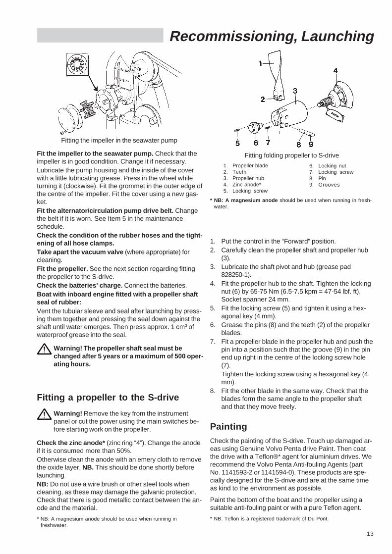
Recommissioning, Launching
Fit the impeller to the seawater pump. Check that theimpeller is in good condition. Change it if necessary.Lubricate the pump housing and the inside of the coverwith a little lubricating grease. Press in the wheel whileturning it (clockwise). Fit the grommet in the outer edge ofthe centre of the impeller. Fit the cover using a new gas-ket.Fit the alternator/circulation pump drive belt. Changethe belt if it is worn. See Item 5 in the maintenanceschedule.Check the condition of the rubber hoses and the tight-ening of all hose clamps.Take apart the vacuum valve (where appropriate) forcleaning.Fit the propeller. See the next section regarding fittingthe propeller to the S-drive.Check the batteries’ charge. Connect the batteries.Boat with inboard engine fitted with a propeller shaftseal of rubber:Vent the tubular sleeve and seal after launching by press-ing them together and pressing the seal down against theshaft until water emerges. Then press approx. 1 cm3 ofwaterproof grease into the seal.
Warning! The propeller shaft seal must bechanged after 5 years or a maximum of 500 oper-ating hours.
Fitting a propeller to the S-drive
Warning! Remove the key from the instrumentpanel or cut the power using the main switches be-fore starting work on the propeller.
Check the zinc anode* (zinc ring “4”). Change the anodeif it is consumed more than 50%.Otherwise clean the anode with an emery cloth to removethe oxide layer. NB. This should be done shortly beforelaunching.NB: Do not use a wire brush or other steel tools whencleaning, as these may damage the galvanic protection.Check that there is good metallic contact between the an-ode and the material.
* NB: A magnesium anode should be used when running infreshwater.
1. Put the control in the “Forward” position.2. Carefully clean the propeller shaft and propeller hub
(3).3. Lubricate the shaft pivot and hub (grease pad
828250-1).4. Fit the propeller hub to the shaft. Tighten the locking
nut (6) by 65-75 Nm (6.5-7.5 kpm = 47-54 lbf. ft).Socket spanner 24 mm.
5. Fit the locking screw (5) and tighten it using a hex-agonal key (4 mm).
6. Grease the pins (8) and the teeth (2) of the propellerblades.
7. Fit a propeller blade in the propeller hub and push thepin into a position such that the groove (9) in the pinend up right in the centre of the locking screw hole(7).Tighten the locking screw using a hexagonal key (4mm).
8. Fit the other blade in the same way. Check that theblades form the same angle to the propeller shaftand that they move freely.
PaintingCheck the painting of the S-drive. Touch up damaged ar-eas using Genuine Volvo Penta drive Paint. Then coatthe drive with a Teflon®* agent for aluminium drives. Werecommend the Volvo Penta Anti-fouling Agents (partNo. 1141593-2 or 1141594-0). These products are spe-cially designed for the S-drive and are at the same timeas kind to the environment as possible.
Paint the bottom of the boat and the propeller using asuitable anti-fouling paint or with a pure Teflon agent.
* NB. Teflon is a registered trademark of Du Pont.
Fitting folding propeller to S-drive
1. Propeller blade2. Teeth3. Propeller hub4. Zinc anode*5. Locking screw
6. Locking nut7. Locking screw8. Pin9. Grooves
* NB: A magnesium anode should be used when running in fresh-water.
Fitting the impeller in the seawater pump
14
Launching, Electrical system
All anti-fouling paints are poisonous and by definitionmore or less harmful to our marine environment. Avoidsuch products. Most countries have a legislation whichcontrols the usage of anti-fouling boat bottom paints. Al-ways make sure you follow these regulations! Insome countries it is forbidden to use anti-fouling paintson leisure crafts, e.g. in freshwater.
We recommend simple Teflon treatment in combinationwith mechanical cleaning a few times during the season,especially in the case of smaller boats which are easy tolift.
This may be impractical for larger boats. Also, if the boatis in water which promotes fouling, an anti-fouling paintmay need to be used after all. In this case, use a purecopper-based anti-fouling paint which contains copperthiocyanate (not copper oxide) .
Tin-based paints (TBT paints) must not be used!
Bear in mind the legislation in force for the area inwhich the boat is used.
NB. Unsuitable bottom paints may cause great corrosiondamage to the S-drive.
Warning! Do not paint the zinc anode (zincring) in front of the propeller. Leave a 10 mm(0.4 in) margin without anti-fouling paintaround the S-drive.
Launch the boat when the paint has dried.
Electrical system
Stop the engine and cut the power using themain switches before working on the electricalsystem.
Batteries
NB: Follow the stipulated safety regulations when charg-ing batteries. Always break the charging current beforethe charging clamps are removed.
Warning! When charging, the batteries give off hy-drogen gas which forms oxyhydrogen gas with air.This gas is inflammable and extremely explosive.
Always use protective goggles and gloves whenhandling batteries.
The battery electrolyte contains strongly corrosiveacid. Should this acid come into contact with theskin, wash with soap and plenty of water. Shouldthe battery acid come into contact with the eyes,immediately rinse with copious amounts of waterand contact your doctor immediately.
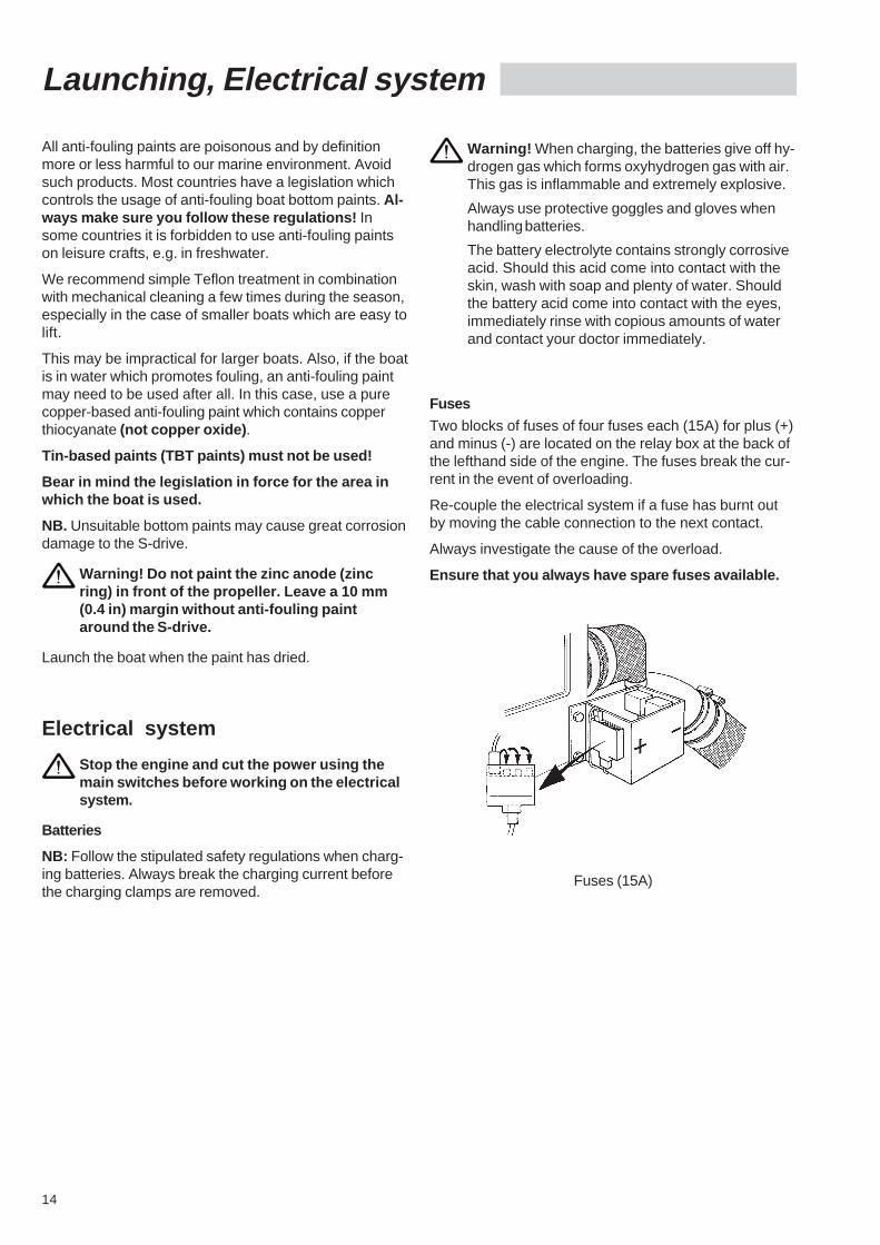
Fuses
Two blocks of fuses of four fuses each (15A) for plus (+)and minus (-) are located on the relay box at the back ofthe lefthand side of the engine. The fuses break the cur-rent in the event of overloading.
Re-couple the electrical system if a fuse has burnt outby moving the cable connection to the next contact.
Always investigate the cause of the overload.
Ensure that you always have spare fuses available.
Fuses (15A)
15
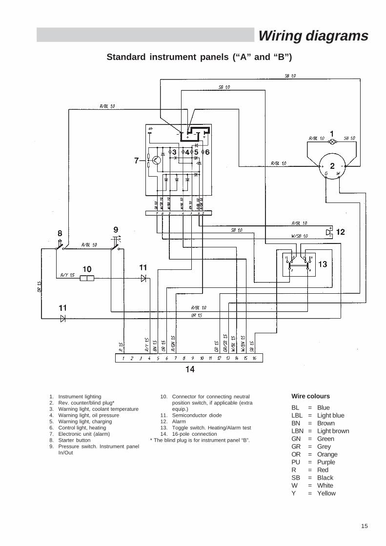
Wiring diagramsStandard instrument panels (“A” and “B”)
1. Instrument lighting2. Rev. counter/blind plug*3. Warning light, coolant temperature4. Warning light, oil pressure5. Warning light, charging6. Control light, heating7. Electronic unit (alarm)8. Starter button9. Pressure switch. Instrument panel
In/Out
10. Connector for connecting neutralposition switch, if applicable (extraequip.)
11. Semiconductor diode12. Alarm13. Toggle switch. Heating/Alarm test14. 16-pole connection
* The blind plug is for instrument panel “B”.
Wire colours
BL = BlueLBL = Light blueBN = BrownLBN = Light brownGN = GreenGR = GreyOR = OrangePU = PurpleR = RedSB = BlackW = WhiteY = Yellow
16
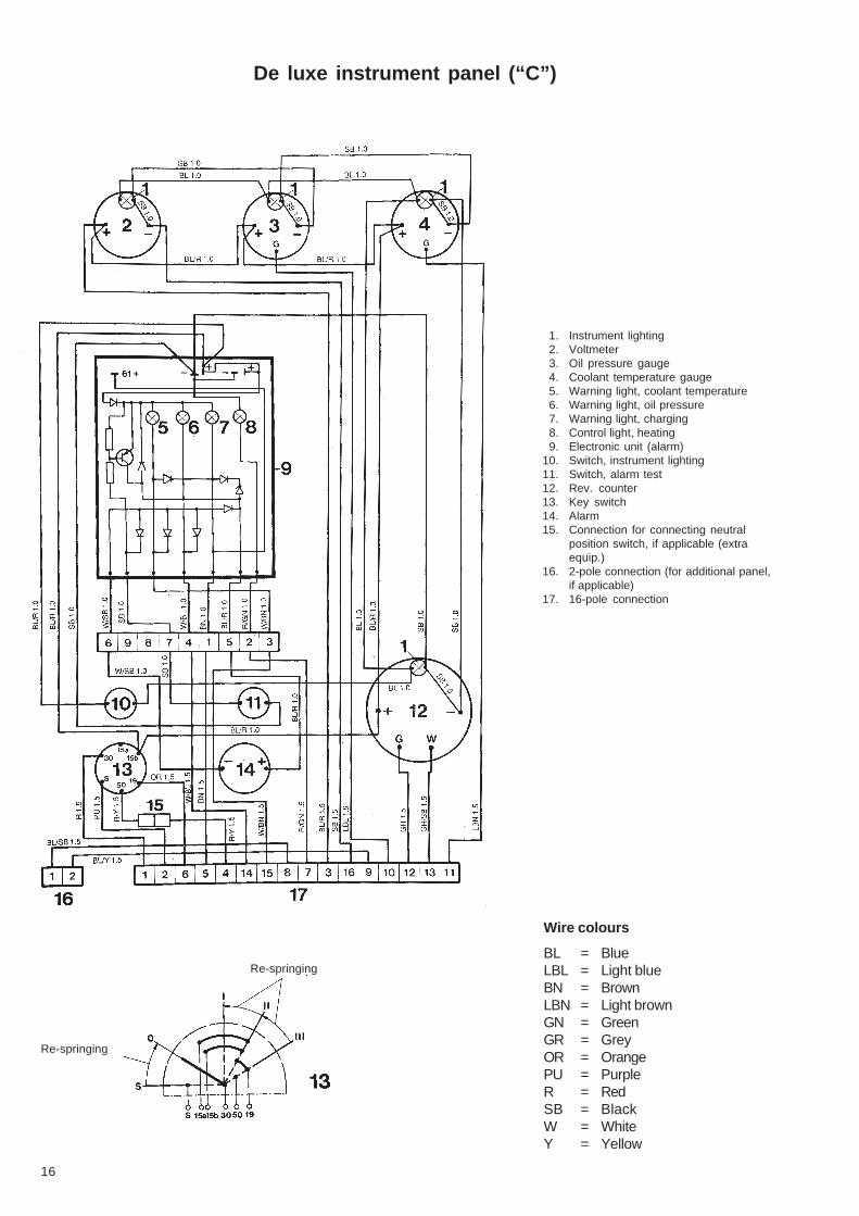
De luxe instrument panel (“C”)
1. Instrument lighting2. Voltmeter3. Oil pressure gauge4. Coolant temperature gauge5. Warning light, coolant temperature6. Warning light, oil pressure7. Warning light, charging8. Control light, heating9. Electronic unit (alarm)
10. Switch, instrument lighting11. Switch, alarm test12. Rev. counter13. Key switch14. Alarm15. Connection for connecting neutral
position switch, if applicable (extraequip.)
16. 2-pole connection (for additional panel,if applicable)
17. 16-pole connection
Re-springing
Re-springing
Wire colours
BL = BlueLBL = Light blueBN = BrownLBN = Light brownGN = GreenGR = GreyOR = OrangePU = PurpleR = RedSB = BlackW = WhiteY = Yellow
17
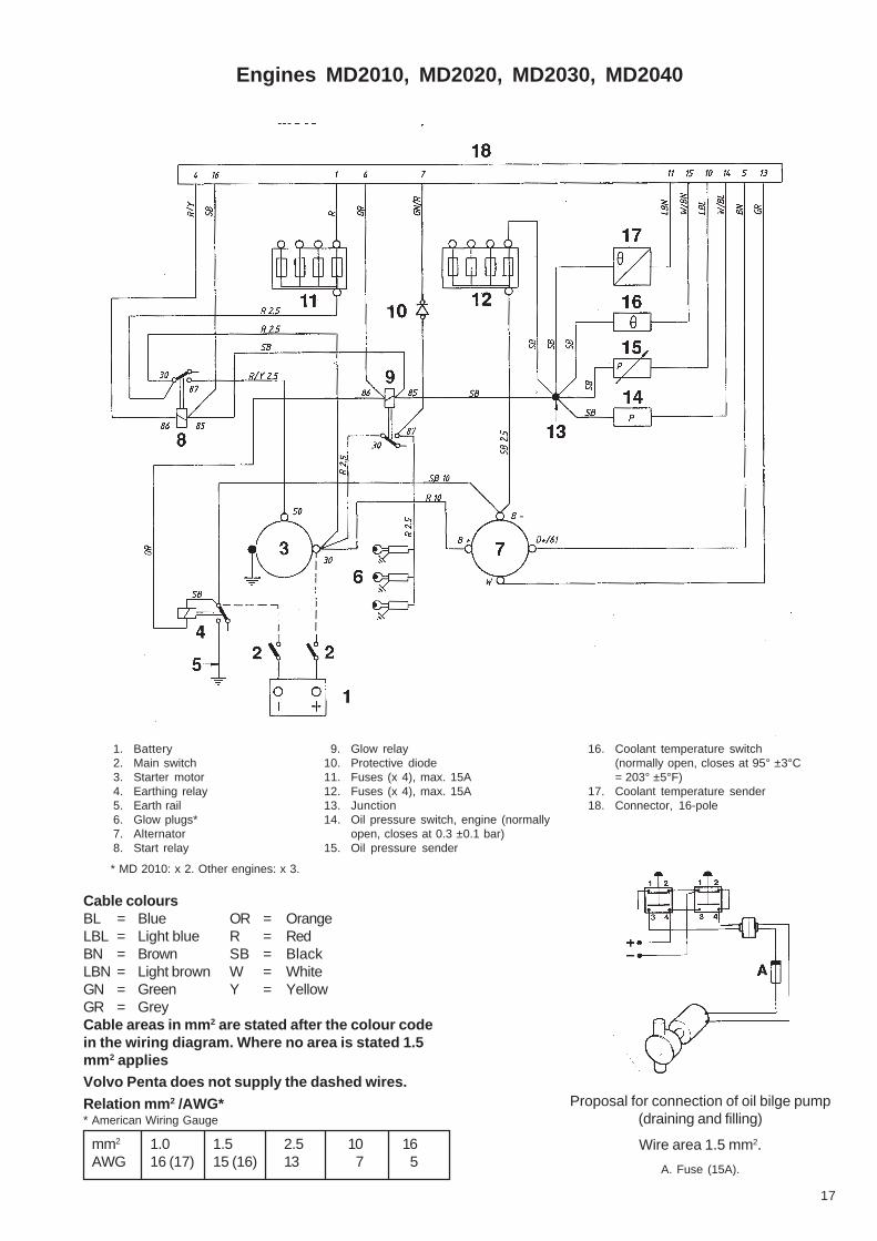
Cable coloursBL = Blue OR = OrangeLBL = Light blue R = RedBN = Brown SB = BlackLBN = Light brown W = WhiteGN = Green Y = YellowGR = GreyCable areas in mm 2 are stated after the colour codein the wiring diagram. Where no area is stated 1.5mm 2 appliesVolvo Penta does not supply the dashed wires.
Relation mm 2 /AWG** American Wiring Gauge
mm2 1.0 1.5 2.5 10 16AWG 16 (17) 15 (16) 13 7 5
Proposal for connection of oil bilge pump(draining and filling)
Wire area 1.5 mm2.
A. Fuse (15A).
Engines MD2010, MD2020, MD2030, MD2040
1. Battery2. Main switch3. Starter motor4. Earthing relay5. Earth rail6. Glow plugs*7. Alternator8. Start relay
9. Glow relay10. Protective diode11. Fuses (x 4), max. 15A12. Fuses (x 4), max. 15A13. Junction14. Oil pressure switch, engine (normally
open, closes at 0.3 ±0.1 bar)15. Oil pressure sender
16. Coolant temperature switch(normally open, closes at 95° ±3°C= 203° ±5°F)
17. Coolant temperature sender18. Connector, 16-pole
* MD 2010: x 2. Other engines: x 3.
18
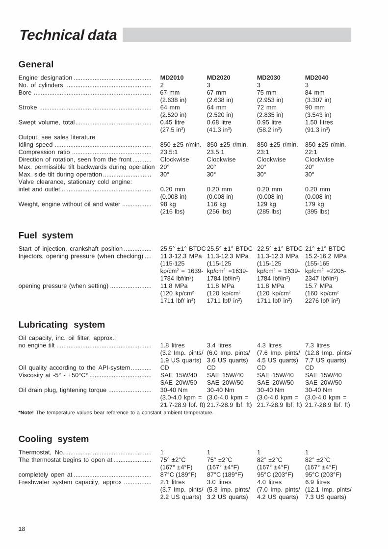
Technical data
GeneralEngine designation ............................................. MD2010 MD2020 MD2030 MD2040No. of cylinders .................................................. 2 3 3 3Bore .................................................................... 67 mm 67 mm 75 mm 84 mm
(2.638 in) (2.638 in) (2.953 in) (3.307 in)Stroke ................................................................. 64 mm 64 mm 72 mm 90 mm
(2.520 in) (2.520 in) (2.835 in) (3.543 in)Swept volume, total ............................................ 0.45 litre 0.68 litre 0.95 litre 1.50 litres
(27.5 in3) (41.3 in3) (58.2 in3) (91.3 in3)Output, see sales literatureIdling speed ........................................................ 850 ±25 r/min. 850 ±25 r/min. 850 ±25 r/min. 850 ±25 r/min.Compression ratio .............................................. 23.5:1 23.5:1 23:1 22:1Direction of rotation, seen from the front ........... Clockwise Clockwise Clockwise ClockwiseMax. permissible tilt backwards during operation 20° 20° 20° 20°Max. side tilt during operation ............................ 30° 30° 30° 30°Valve clearance, stationary cold engine:inlet and outlet .................................................... 0.20 mm 0.20 mm 0.20 mm 0.20 mm
(0.008 in) (0.008 in) (0.008 in) (0.008 in)Weight, engine without oil and water ................. 98 kg 116 kg 129 kg 179 kg
(216 lbs) (256 lbs) (285 lbs) (395 lbs)
Fuel systemStart of injection, crankshaft position ................ 25.5° ±1° BTDC 25.5° ±1° BTDC 22.5° ±1° BTDC 21° ±1° BTDCInjectors, opening pressure (when checking) .... 11.3-12.3 MPa 11.3-12.3 MPa 11.3-12.3 MPa 15.2-16.2 MPa
(115-125 (115-125 (115-125 (155-165kp/cm2 = 1639- kp/cm2 =1639- kp/cm2 = 1639- kp/cm2 =2205-1784 lbf/in2) 1784 lbf/in2) 1784 lbf/in2) 2347 lbf/in2)
opening pressure (when setting) ........................ 11.8 MPa 11.8 MPa 11.8 MPa 15.7 MPa(120 kp/cm2 (120 kp/cm2 (120 kp/cm2 (160 kp/cm2
1711 lbf/ in2) 1711 lbf/ in2) 1711 lbf/ in2) 2276 lbf/ in2)
Lubricating systemOil capacity, inc. oil filter, approx.:no engine tilt ....................................................... 1.8 litres 3.4 litres 4.3 litres 7.3 litres
(3.2 Imp. pints/ (6.0 Imp. pints/ (7.6 Imp. pints/ (12.8 Imp. pints/1.9 US quarts) 3.6 US quarts) 4.5 US quarts) 7.7 US quarts)
Oil quality according to the API-system............ CD CD CD CDViscosity at -5° - +50°C* .................................... SAE 15W/40 SAE 15W/40 SAE 15W/40 SAE 15W/40
SAE 20W/50 SAE 20W/50 SAE 20W/50 SAE 20W/50Oil drain plug, tightening torque ......................... 30-40 Nm 30-40 Nm 30-40 Nm 30-40 Nm
(3.0-4.0 kpm = (3.0-4.0 kpm = (3.0-4.0 kpm = (3.0-4.0 kpm =21.7-28.9 lbf. ft) 21.7-28.9 lbf. ft) 21.7-28.9 lbf. ft) 21.7-28.9 lbf. ft)
*Note! The temperature values bear reference to a constant ambient temperature.
Cooling systemThermostat, No. .................................................. 1 1 1 1The thermostat begins to open at ...................... 75° ±2°C 75° ±2°C 82° ±2°C 82° ±2°C
(167° ±4°F) (167° ±4°F) (167° ±4°F) (167° ±4°F)completely open at ............................................. 87°C (189°F) 87°C (189°F) 95°C (203°F) 95°C (203°F)Freshwater system capacity, approx ................ 2.1 litres 3.0 litres 4.0 litres 6.9 litres
(3.7 Imp. pints/ (5.3 Imp. pints/ (7.0 Imp. pints/ (12.1 Imp. pints/2.2 US quarts) 3.2 US quarts) 4.2 US quarts) 7.3 US quarts)
19
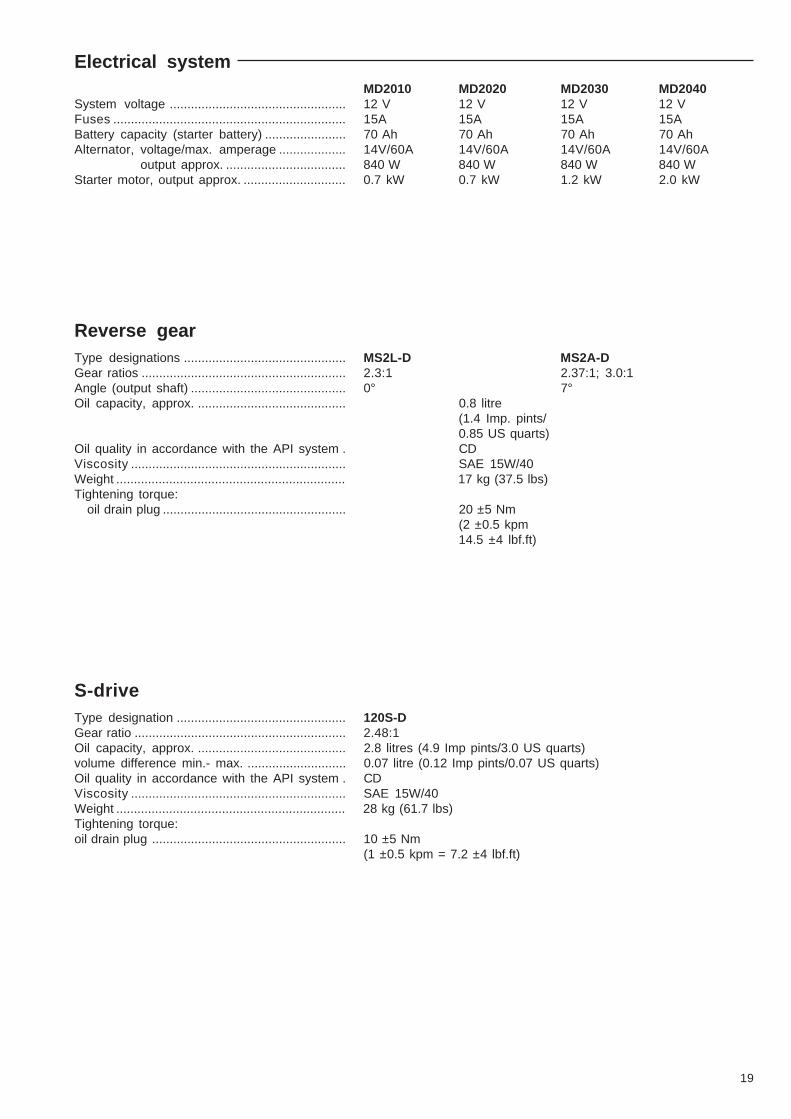
Electrical systemMD2010 MD2020 MD2030 MD2040
System voltage .................................................. 12 V 12 V 12 V 12 VFuses .................................................................. 15A 15A 15A 15ABattery capacity (starter battery) ....................... 70 Ah 70 Ah 70 Ah 70 AhAlternator, voltage/max. amperage ................... 14V/60A 14V/60A 14V/60A 14V/60A
output approx. .................................. 840 W 840 W 840 W 840 WStarter motor, output approx. ............................. 0.7 kW 0.7 kW 1.2 kW 2.0 kW
Reverse gearType designations .............................................. MS2L-D MS2A-DGear ratios .......................................................... 2.3:1 2.37:1; 3.0:1Angle (output shaft) ............................................ 0° 7°Oil capacity, approx. .......................................... 0.8 litre
(1.4 Imp. pints/0.85 US quarts)
Oil quality in accordance with the API system . CDViscosity ............................................................. SAE 15W/40Weight ................................................................. 17 kg (37.5 lbs)Tightening torque:
oil drain plug .................................................... 20 ±5 Nm(2 ±0.5 kpm14.5 ±4 lbf.ft)
S-driveType designation ................................................ 120S-DGear ratio ............................................................ 2.48:1Oil capacity, approx. .......................................... 2.8 litres (4.9 Imp pints/3.0 US quarts)volume difference min.- max. ............................ 0.07 litre (0.12 Imp pints/0.07 US quarts)Oil quality in accordance with the API system . CDViscosity ............................................................. SAE 15W/40Weight ................................................................. 28 kg (61.7 lbs)Tightening torque:oil drain plug ....................................................... 10 ±5 Nm
(1 ±0.5 kpm = 7.2 ±4 lbf.ft)
20
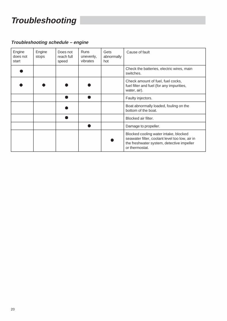
Troubleshooting
Troubleshooting schedule – engine
Enginedoes notstart
Enginestops
Does notreach fullspeed
Runsunevenly,vibrates
Getsabnormallyhot
Cause of fault
Check the batteries, electric wires, mainswitches.
Check amount of fuel, fuel cocks,fuel filter and fuel (for any impurities,water, air).
Faulty injectors.
Boat abnormally loaded, fouling on thebottom of the boat.
Blocked air filter.
Damage to propeller.
Blocked cooling water intake, blockedseawater filter, coolant level too low, air inthe freshwater system, detective impelleror thermostat.
Owner
Name: .........................................................................Tel.: ...........................................
Address: ........................................................................................................................
Nearest Volvo Penta Service Dealer
Name: ....................................................................... Tel.: ...........................................
Address: ........................................................................................................................
Engine
Engine type: ..................................................................................................................
Serial No.: .....................................................................................................................
Reverse gear/S-drive
Type: ...................................................................... Ratio: ...........................................
Serial No.: .....................................................................................................................

7735
333-
2E
nglis
h08
-199
3