Embed Size (px)
Citation preview
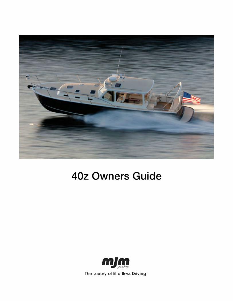
40z Owners Guide

“Believe me, my young friend, said the water rat solemnly, there is nothing, absolutely nothing, half so much worth doing as simply messing about in boats. Simply messing...nothing seems really to matter. That's the charm of it. Whether you get away, or whether you don't, whether you arrive at your destination or whether you reach somewhere else, or whether you never get anywhere at all, you're always busy, and you never do anything in particular...”
…The Wind in the Willows by Kenneth Grahame

Dear 40z Owner
Congratulations on becoming an owner of an MJM 40z. We’re dedicated to making it the world’s best in class. As you read this guide and share cruising adventures, we hope you’ll discover our mission has been accomplished. MJMs are made of epoxy, Kevlar, Eglass and Corecell. They are the most fuel-efficient yachts of their size by a wide margin. We’ve set the quality bar on the top rung in selecting our equipment suppliers and cabinetmakers. It’s one of only two 40-footers certified ISO Category A Ocean, the highest rating achievable for seaworthiness. It leads the boating industry with the most advanced technology. Standard MJM 40z specifications are unusually complete in terms of equipment and amenities. The boats are safe, reliable, easy to handle by one person, and are high performers. Last but not least, and our number 1 design mandate, they’re beautiful. Primary to this Owners Guide, and in terms of authority, are two large binders with equipment supplier owner manuals and warranties. These documents contain an enormous amount of important information. Please keep them accessible for reference when you have an issue or question not covered in detail by this guide. You can download most of them from their websites for an iPad and install them on the Raymarine display.
This guide reflects our experience from building over 200 MJMs. I personally have spent more than 6000 hours cruising on MJM yachts so I wanted to impart some advice and background information along with the “how to do it.” You will see these comments in the blue sidebars. As you enjoy your new boat, remember that much of the equipment contains computer chips that can sometime have glitches that can be corrected with a re-boot. With proper safety precautions and good weather planning, I’m sure you will spend many enjoyable hours on your new yacht.
Robert I. Johnstone Founder and CEO (401) 862-4367 [email protected]

QUICK START GUIDE
Following is a departure checklist for an experienced captain who is familiar with the information in this guide and the accompanying binders.
Check Systems ☐ Check ENGINE and GENERATOR raw water strainers (a flashlight is helpful to see into the strainers), seacocks, coolant, engine oil and drive oil. (See Daily Engine Check, page 6.) Look for loose belts, wires, oil drips and bilge water. ☐ Check SEAKEEPER and AIR CONDITIONING raw water strainers.
Get Set ☐ Turn off the SHORE 1 and SHORE 2 breakers at the 120V AC panel. Then do 1 or 2 below.
1. If you plan to use the GENERATOR underway to power the SEAKEEPER or the AIR CONDITIONER, start the GENERATOR. (See page 22.) Start the SEAKEEPER. (See page 29.)
2. If don’t plan to use the GENERATOR underway, turn on the INVERTER/CHARGER to provide power to 120V AC circuits. (See page 25.)
☐ With the HOUSE BATTERY switch on, ensure at least 12.2V. Turn on TRIM TABS, ELECTRONICS, HORN, WIPERS and other breakers for equipment you anticipate using, such as NAVIGATION LIGHTS and SEARCHLIGHT. ☐ Turn off breakers at shore side power pedestal first, then disconnect shore power cord, phone, TV and dock water if connected, Screw caps in place, close shore power cover and stow cables.
Get Underway ☐ Turn on ENGINE BATTERY switches at the top of the 120V AC panel. At the helm push the IGNITION BUTTON for each engine (it lights up). Wait until the Volvo Penta ENGINE CONTROL DISPLAY shows gauges, start ENGINES by pressing the START/STOP buttons under the IGNITION buttons. (See page 8.)
Ensure people, equipment, lines and hoses aren’t in the water and everything is clear of moving parts before you start the engine. ☐ At the top of the Raymarine screen (if set up) drag down the supplementary data bar showing RPM, coolant temperature, oil pressure, drive oil pressure and nmpg fuel efficiency.
If voltage is too low to crank the engines, see Starting with Low Batteries, page 38. If the battery is low, you should not leave the dock until you diagnose and correct the
problem. ☐ Check the Plexiglas top of the raw water strainers above the engines to ensure that raw water is flowing.
☐ Check IPS JOYSTICK. Push lower left DOCKING button and listen for a confirming beep. Test operation with a slight tap in any direction. Check that the steering turns smoothly. Check TRIM TAB function and set for planing speeds under 25 knots (60% with two people aboard).
☐ Check fuel levels, oil temperature and oil pressure. (See Operating Parameters, page 9.)
☐ If everything is in order, cast off dock lines. When maneuvering with the IPS JOYSTICK, a light touch (taps and nudges) on the joystick is usually the most effective.
Confirm that no one is on the foredeck or in the water.

CE CERTIFICATION CERTIFICATE NO. BBBW003 AUTHORITY: ADDRESS: International Marine Certification Institute Rue Abbe Cuypers 3 B-1040 Bruxelles. Belgique PHONE +32-2-741-2418 WEBSITE www.imci.org CLASSIFICATION ISO CE Mark Design Category A Ocean (EC Directive 94/25/EC)
for craft designed for offshore voyages (1) where the vessel is correctly handled in the sense of good seamanship and operated at a speed appropriate to the prevailing sea state and (2) with significant wave heights above 4 m (calculations are based on 7 m) and wind speeds in excess of Beaufort Force 8, but excluding abnormal conditions, e.g. hurricanes.
CAPACITY PERSONS Maximum 16 Persons PERSONS/GEAR Maximum Load 3518 kg
RECEIPT BY OWNER In compliance with ISO 10240:1995(E) the owner hereby certifies receipt of this manual and has read and agrees to the terms of the Builder’s Limited Warranty included herein. NAME Signature
Printed Name(s) and Date
BOAT Boat Name and Hull Number
CONTACT INFORMATI0N Street Address
City, State, Zip
Mobile Phone
Please sign one of the two copies of this page and return it in the attached stamped envelope to MJM Yachts, 39 Washington Street. Newport, RI 02840.
TABLE OF CONTENTS
1 INTRODUCTION 1
1.1 Purpose and Limitations ......................... 11.2 Standard Specifications ......................... 11.3 Conventions ......................................... 1
2 SAFETY and some USCG REQUIREMENTS 22.1 Binder Manuals ..................................... 22.2 Standard Equipment .............................. 22.3 Commissioning Package Safety Items ..... 32.4 USCG required equipment ..................... 32.5 Additional Safety Equipment ................... 32.6 Some Additional USCG Requirements .... 32.7 Fuel Shut-off Valves .............................. 42.8 Fire Suppression ................................... 42.9 Notices ................................................ 42.10 Emergency and Thru Hull Diagram .......... 5
3 PROPULSION 63.1 Engines ................................................ 63.2 Daily Engine Check ............................... 63.3 Starting the Engines .............................. 83.4 Stopping the Engines ............................ 93.5 New Engine Break-in ............................. 93.6 Auxiliary Stop ........................................ 93.7 Operating Parameters ............................ 93.8 Leaving the Boat ................................. 103.9 Volvo Penta D6 IPS Engines ................. 11
4 INSTRUMENTS AND CONTROLS 124.1 Helm Station ....................................... 124.2 Engine/Shift Control Levers .................. 124.3 Joystick .............................................. 134.4 Electronics ......................................... 144.5 Compass Heading and Calibration ........ 154.6 Trim Tabs ........................................... 154.7 Searchlight ......................................... 154.8 Autopilot ............................................. 164.9 Single Engine Steering ......................... 164.10 MultiFunction Dislay (MFD) ................... 164.11 Console Switch Panel ......................... 164.12 Windshield Operation .......................... 17
5 ELECTRICAL SYSTEMS 185.1 Electrical Safety ................................. 185.2 Electrical Power .................................. 185.3 Shore Power ....................................... 195.4 Fuse Locatons .................................... 195.5 24-Hour Circuits ................................. 195.6 The 12V DC Panel ............................... 205.7 The 120V AC Panel ............................. 215.8 Northern Lights Generator (O p t i o n ) ..... 225.9 Corrosion Protection ............................ 235.10 Generator Component Locations .......... 24
5.11 Victron Inverter/Charger ....................... 255.12 Bonding ............................................. 25
6 WATER SYSTEMS 266.1 Fresh Water ........................................ 266.2 Hot Water ........................................... 266.3 Gray Water ......................................... 276.4 Raw Water .......................................... 28
7 SEAKEEPER GYROSTABILIZER (Option) 297.1 To Start the Gyro ................................ 297.2 Activate/De-activate ............................ 29
8 EQUIPMENT, APPLIANCES and FINISHES 308.1 Anchor Windlass ................................. 308.2 Anchor Washdown .............................. 308.3 Fusion Multi-media Player .................... 308.4 Privacy/Sunscreen Curtains (Option) ..... 318.5 Transom Door and Seat (Option) .......... 318.6 Vacuum Cleaner ................................. 318.7 Cooktop ............................................. 328.8 Microwave .......................................... 328.9 Refrigerator ......................................... 328.10 Freezer .............................................. 328.11 TVs (optional) ...................................... 328.12 Vacuum Flush Head System ................ 338.13 Air Conditioning (Optional) ................... 338.14 Finishes ............................................. 34
9 APPENDIX 359.1 The Top 10 Causes of Engine Failure .... 359.2 Diesel Operation ................................. 369.3 Starting with Low Batteries ................... 389.4 Winter Storage .................................... 399.5 Spring Commissioning ......................... 409.6 Hauling Out and Blocking ..................... 409.7 Trailer Loading Checklist ...................... 409.8 Fuel Consumption ............................... 419.9 Routine Maintenance ........................... 429.10 Boat Lift and Bunk Offsets ................... 439.11 Systems Location Plan ........................ 449.12 Systems Key ...................................... 459.13 Wiring Diagrams ................................. 469.14 Fuse Locations & Specifications ........... 479.15 Fuel Consumption Log. ....................... 489.16 Boston Boatworks Limited Warranty ..... 49
10THE MJM TEAM 5310.1 Bob Johnstone ................................... 5310.2 Chris Hughes ..................................... 5310.3 Doug Zurn .......................................... 5310.4 Scott Smith ........................................ 5410.5 Mark Lindsay ..................................... 5410.6 Steve Burke ....................................... 54
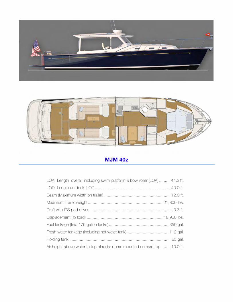
MJM 40z
LOA: Length overall including swim platform & bow roller (LOA) ......... 44.3 ft. LOD: Length on deck (LOD ................................................................. 40.0 ft.
Beam (Maximum width on trailer) ......................................................... 12.0 ft. Maximum Trailer weight ................................................................ 21,800 lbs. Draft with IPS pod drives ...................................................................... 3.3 ft.
Displacement (½ load) ................................................................. 18,900 lbs. Fuel tankage (two 175 gallon tanks) ................................................... 350 gal.
Fresh water tankage (including hot water tank) .................................... 112 gal. Holding tank ...................................................................................... 25 gal.
Air height above water to top of radar dome mounted on hard top ....... 10.0 ft.
Chapter 1, Introduction, MJM 40z Owner’s Manual page 1
1 INTRODUCTION
1.1 PURPOSE AND LIMITATIONS This purpose of this Owners Guide and the equipment suppliers’ manuals in the accompanying binders is to provide you with an overview of the yacht’s equipment, operation, systems and maintenance. The people at MJM and Boston Boat Works have taken pains to edit this guide for accuracy in good faith. But most of these topics will require further study and learning. As captain of a vessel you assume extensive responsibilities for safe operations and the safety of your crew. No document that intends to cover yacht equipment and operation will ever be complete or even accurate in all respects. Since we frequently make changes to improve our yachts we assume no responsibility for missing information or errors in the following information. This document doesn’t replace common sense or qualify you in safety practices, boat handling or navigation skills. Mastering these systems and the skills of seamanship is your responsibility. If this is your first yacht, or if you’re changing from a different type of yacht, get instruction and experience before assuming command. Your dealer, yacht club, marina or the US Power Squadron https://www.usps.org are all good resources that can recommend schools and instruction. Although this guide and the accompanying binders describe systems on the boat, they don’t qualify you to work on them. When they need attention, please use qualified mechanics. If you question the information or are unsure about an action, check with the equipment supplier, a qualified person or us.
The Appendix includes other useful information. And there’s a chapter on the people who create MJM yachts you can contact if you need help. Study these resources to understand how to operate your yacht safely.
The operation of a powerboat can be dangerous. Pay careful attention to safety notices in this guide and in the manuals in the binders.
Keep this guide in a secure place on the boat. If you sell the yacht, please give this copy to the new owner.
1.2 STANDARD SPECIFICATIONS You may download the latest version of this guide and the standard specifications for a MJM40z from http://www.mjmyachts.com/40z to install on your computer, an iPad or navigation electronics.
1.3 CONVENTIONS When we reference a specific device or item of equipment on the boat, it will be in all caps, such as HOUSE BATTERY.
As we describe each device we often use the following order. 1. BREAKER PANEL settings 2. Function, what it does 3. Directions for use 4. Advice or comments in a sidebar 5. The URL for the manual if available
This guide is published in accordance with ISO standard 10240:1995E Small Craft - Owner’s Manual. Please contact us if you have a question about the material in this book, if you find a conflict between this material and the material in the binders or if you find an error or important omission on the following pages please contact Customer Service at Boston Boat Works.
…R.I.J.
Chapter 2. Safety, MJM 40z Owner’s Guide page 2
2 SAFETY and some USCG REQUIREMENTS
2.1 BINDER MANUALS The equipment suppliers’ manuals in the accompanying binders have many safety notices that relate to their products, their operation and maintenance and their use in the boat. Ensure that you understand this essential information before you operate the boat. Spend time reviewing the safety procedures, how safety equipment works and where It’s stowed. Instruct guests in safety procedures.
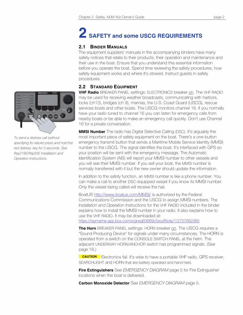
2.2 STANDARD EQUIPMENT VHF Radio BREAKER PANEL settings: ELECTRONICS breaker on. The VHF RADIO may be used for receiving weather broadcasts, communicating with harbors, locks (ch13), bridges (ch 9), marinas, the U.S. Coast Guard (USCG), rescue services boats and other boats. The USCG monitors channel 16. If you normally have your radio tuned to channel 16 you can listen for emergency calls from nearby boats or be able to make an emergency call quickly. Don’t use Channel 16 for a private conversation. MMSI Number The radio has Digital Selective Calling (DSC). It’s arguably the most important piece of safety equipment on the boat. There’s a one-button emergency transmit button that sends a Maritime Mobile Service Identity (MMSI) number to the USCG. The signal identifies the boat. It’s interfaced with GPS so your position will be sent with the emergency message. The Automatic Identification System (AIS) will report your MMSI number to other vessels and you will see their MMSI number. If you sell your boat, the MMSI number is normally transferred with it but the new owner should update the information.
In addition to the safety function, an MMSI number is like a phone number. You can make a call to another DSC-equipped vessel if you know its MMSI number. Only the vessel being called will receive the hail. BoatUS http://www.boatus.com/MMSI/ is authorized by the Federal Communications Commission and the USCG to assign MMSI numbers. The Installation and Operation Instructions for the VHF RADIO included in the binder explains how to install the MMSI number in your radio. It also explains how to use the VHF RADIO. It may be downloaded at: https://raymarine.app.box.com/s/grwg60669c5sozf6iolq/1/2757682985
The Horn BREAKER PANEL settings: HORN breaker on. The USCG requires a “Sound Producing Device” for signals under many circumstances. The HORN is operated from a switch on the CONSOLE SWITCH PANEL at the helm. The adjacent UNDERWAY HORN/ANCHOR switch has programmed signals. (See page 16.)
Electronics fail. It’s wise to have a portable VHF radio, GPS receiver, SEARCHLIGHT and HORN that are battery operated and hand held. Fire Extinguishers See EMERGENCY DIAGRAM page 5 for Fire Extinguisher locations when the boat is delivered. Carbon Monoxide Detector See EMERGENCY DIAGRAM page 5.
To send a distress call (without specifying its nature) press and hold the red distress key for 3 seconds. See Ray218E/Ray55E Installation and Operation Instructions.
Chapter 2. Safety, MJM 40z Owner’s Guide page 3
Companionway Hatch Board or Closure A companionway board with the label “DON’T REMOVE WHILE UNDERWAY” is provided to comply with ISO requirements for cockpit draining and to prevent large waves from crashing down into the cockpit, running forward and entering the interior of the boat if the companionway door is not securely closed.
2.3 COMMISSIONING PACKAGE SAFETY ITEMS The Commissioning Package Option, if purchased with your boat, will have:
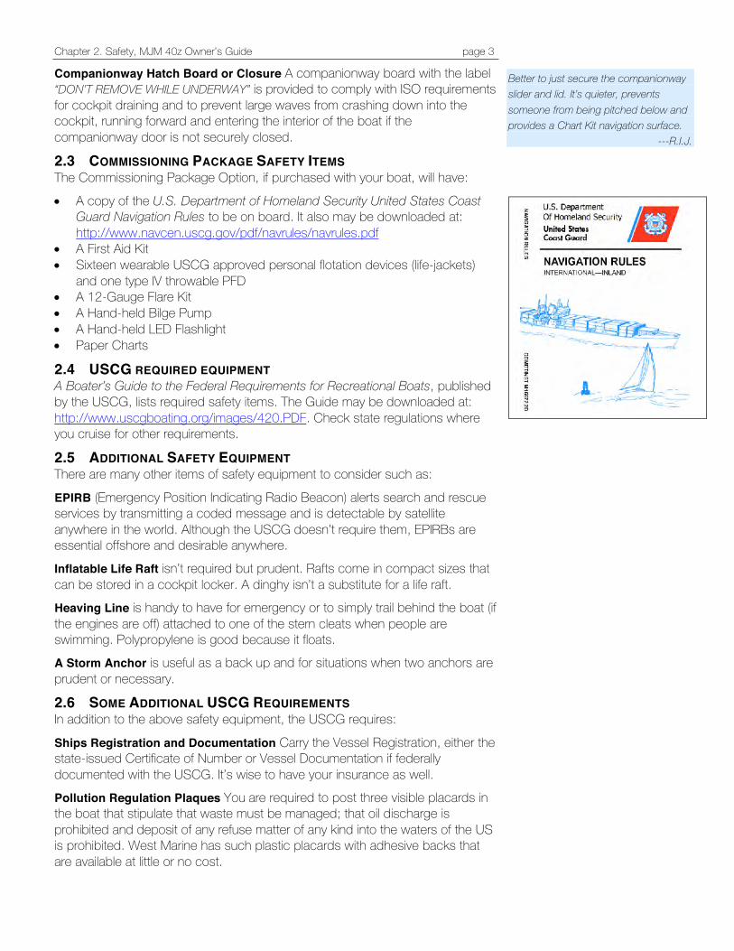
• A copy of the U.S. Department of Homeland Security United States Coast Guard Navigation Rules to be on board. It also may be downloaded at: http://www.navcen.uscg.gov/pdf/navrules/navrules.pdf
• A First Aid Kit • Sixteen wearable USCG approved personal flotation devices (life-jackets)
and one type IV throwable PFD • A 12-Gauge Flare Kit • A Hand-held Bilge Pump • A Hand-held LED Flashlight • Paper Charts
2.4 USCG REQUIRED EQUIPMENT A Boater’s Guide to the Federal Requirements for Recreational Boats, published by the USCG, lists required safety items. The Guide may be downloaded at: http://www.uscgboating.org/images/420.PDF. Check state regulations where you cruise for other requirements.
2.5 ADDITIONAL SAFETY EQUIPMENT There are many other items of safety equipment to consider such as:
EPIRB (Emergency Position Indicating Radio Beacon) alerts search and rescue services by transmitting a coded message and is detectable by satellite anywhere in the world. Although the USCG doesn’t require them, EPIRBs are essential offshore and desirable anywhere. Inflatable Life Raft isn’t required but prudent. Rafts come in compact sizes that can be stored in a cockpit locker. A dinghy isn’t a substitute for a life raft. Heaving Line is handy to have for emergency or to simply trail behind the boat (if the engines are off) attached to one of the stern cleats when people are swimming. Polypropylene is good because it floats. A Storm Anchor is useful as a back up and for situations when two anchors are prudent or necessary.
2.6 SOME ADDITIONAL USCG REQUIREMENTS In addition to the above safety equipment, the USCG requires:
Ships Registration and Documentation Carry the Vessel Registration, either the state-issued Certificate of Number or Vessel Documentation if federally documented with the USCG. It’s wise to have your insurance as well. Pollution Regulation Plaques You are required to post three visible placards in the boat that stipulate that waste must be managed; that oil discharge is prohibited and deposit of any refuse matter of any kind into the waters of the US is prohibited. West Marine has such plastic placards with adhesive backs that are available at little or no cost.
Better to just secure the companionway slider and lid. It’s quieter, prevents someone from being pitched below and provides a Chart Kit navigation surface.
---R.I.J.

Chapter 2. Safety, MJM 40z Owner’s Guide page 4
2.7 FUEL SHUT-OFF VALVES The first thing to do if there is a fuel fire or leak is stop engines and close fuel shut-off valves by turning them perpendicular to the hose. They are located over the fuel tanks under the pilothouse seats. If there is fuel in the bilges, close valves, find the source of the leak and then clean bilges.
2.8 FIRE SUPPRESSION An automatic, heat-activated, fire suppression system is installed in the engine compartment. It can be activated manually at the helm station. To prevent the engines from evacuating the fire suppression agent when it discharges, the system will shut off engines, blowers and generator. Override the shutdown feature to restart the engine after repair. Refer to the manual for maintenance instruction. (See page 12 and refer to the manual in the binders.) Hand-held fire extinguishers (see Emergency Diagram page 5 for locations) are rated to fight type A, B & C fires. To extinguish a fire, first cut the source of fuel to the fire. In a diesel fuel fire, turn off the fuel tank valves. In an electrical fire, turn off the HOUSE BATTERY switch.
Fire safety begins with prevention. Reduce fire risk with these guidelines: • Don’t allow debris or oily rags to collect anywhere. • Check bilges for oil or diesel fuel regularly. • Shut down unnecessary circuits when leaving the boat. • Don’t leave heat-producing appliances or equipment unattended. • Inspect fire suppression equipment regularly and learn how to use it.
Exhaust gas contains carbon monoxide. It’s colorless, odorless and lethal. Avoid inhaling. Inspect the exhaust system regularly. Idling engines at a mooring or at a dock isn’t good for the engine and may allow gasses to accumulate in the cockpit or cabin.
Don’t work on any mechanical or electrical equipment unless you’re qualified. Electrical current and moving parts are dangerous and can be lethal.
2.9 NOTICES Denotes a reminder of safety practices or directs attention to unsafe
practices which could result in personal injury or damage to the craft or components.
Denotes a hazard that exists which can result in injury or death if proper precautions aren’t taken.
Denotes an existing extreme intrinsic hazard that would result in high probability of death or irreparable injury if proper precautions aren’t taken.
Starboard FUEL SHUT OFF
Port FUEL and GENERATOR FUEL SHUT OFF
FIRE SUPPRESSION system and stern BILGE PUMP Fire needs oxygen to burn, so if a fire should occur in an enclosed area, the best course of action may be to exit the area and seal it from the outside by closing means of air intake.
…R.I.J.
Chapter 2. Safety, MJM 40z Owner’s Guide page 5
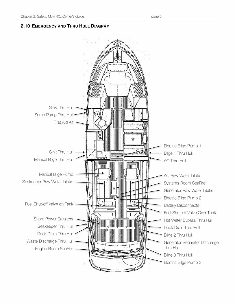
2.10 EMERGENCY AND THRU HULL DIAGRAM
Sink Thru Hull Sump Pump Thru Hull
First Aid Kit
Sink Thru Hull
Manual Bilge Thru Hull
Manual Bilge Pump Seakeeper Raw Water Intake
Fuel Shut-off Valve on Tank
Shore Power Breakers
Seakeeper Thru Hull
Deck Drain Thru Hull Waste Discharge Thru Hull
Engine Room SeaFire
Electric Bilge Pump 1 Bilge 1 Thru Hull
AC Thru Hull AC Raw Water Intake
Systems Room SeaFire Generator Raw Water Intake
Electric Bilge Pump 2 Battery Disconnects Fuel Shut-off Valve Over Tank
Hot Water Bypass Thru Hull Deck Drain Thru Hull
Bilge 2 Thru Hull Generator Separator Discharge Thru Hull
Bilge 3 Thru Hull Electric Bilge Pump 3

Chapter 3. Propulsion, MJM 40z Owner’s Guide page 6
3 PROPULSION
3.1 ENGINES The MJM 40z is propelled by twin Volvo diesel 370 or 435 HP D6 engines with 24 overhead valves, turning, via IPS transmissions, forward-facing counter-rotating duo-prop propellers. (See Top 10 Causes of Engine Failure, page 35, and Diesel Operation, page 36.)
3.2 DAILY ENGINE CHECK There is an excellent MJM video on YouTube titled Daily Engine Check on an MJM 40z. Go to: https://www.youtube.com/watch?v=bibZRDwHfyI&feature=youtube Open Main Engine Hatch BREAKER PANEL settings: ENGINE HATCH breaker on.
Move the side deck chairs out of the way and ensure the cockpit door latch is clear before raising the hatch.
Activate COCKPIT ENGINE HATCH lift with black toggle switch in the starboard cockpit seat locker.
Ensure that side doors are either completely open or completely closed before raising the ENGINE HATCH. The door handle is positioned so it fits in the AIR INTAKE cavity when the door is open. (See adjacent image.)
Diesel engines use a lot of air for combustion. The engine of the 40z gets air through AIR INTAKE grills under the cockpit coaming, both port and starboard. Be sure that these aren’t blocked with gear on deck when starting or underway.
COCKPIT DOOR and AIR INTAKES
Chapter 3. Propulsion, MJM 40z Owner’s Guide page 7
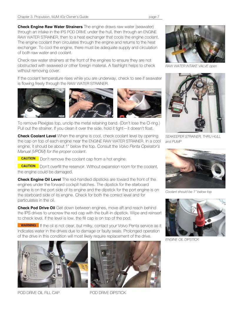
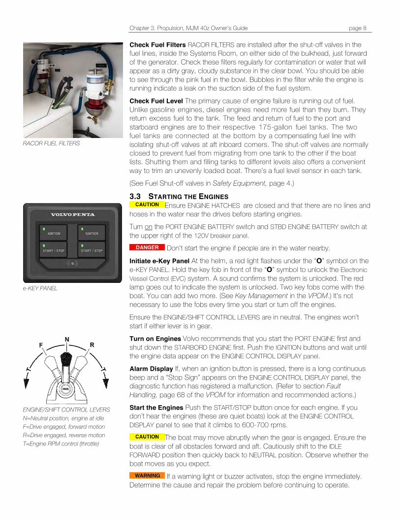
Check Engine Raw Water Strainers The engine draws raw water (seawater) through an intake in the IPS POD DRIVE under the hull, then through an ENGINE RAW WATER STRAINER, then to a heat exchanger that cools the engine coolant. The engine coolant then circulates through the engine and returns to the heat exchanger. To cool the engine, there must be adequate supply and circulation of both raw water and coolant. Check raw water strainers at the front of the engines to ensure they are not obstructed with seaweed or other foreign material. A flashlight helps to check without removing cover.
If the coolant temperature rises while you are underway, check to see if seawater is flowing freely through the RAW WATER STRAINER.
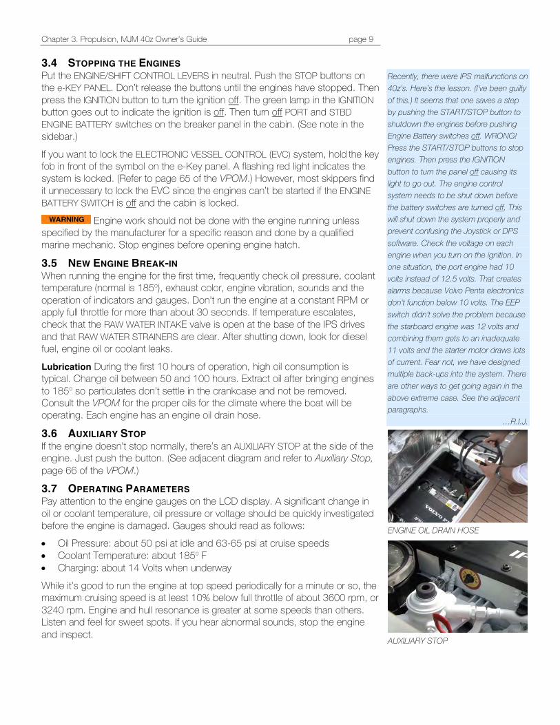
To remove Plexiglas top, unclip the metal retaining band. (Don’t lose the O-ring.) Pull out the strainer. If you clean it over the side, hold it tight—it doesn’t float. Check Coolant Level When the engine is cool, check coolant level by opening the cap on top of each engine near the ENGINE RAW WATER STRAINER. In a cool engine, it should be about 1” below the top. Consult the Volvo Penta Operator’s Manual (VPOM) for the proper coolant.
Don’t remove the coolant cap from a hot engine. Don’t overfill the reservoir. Without expansion room for the coolant,
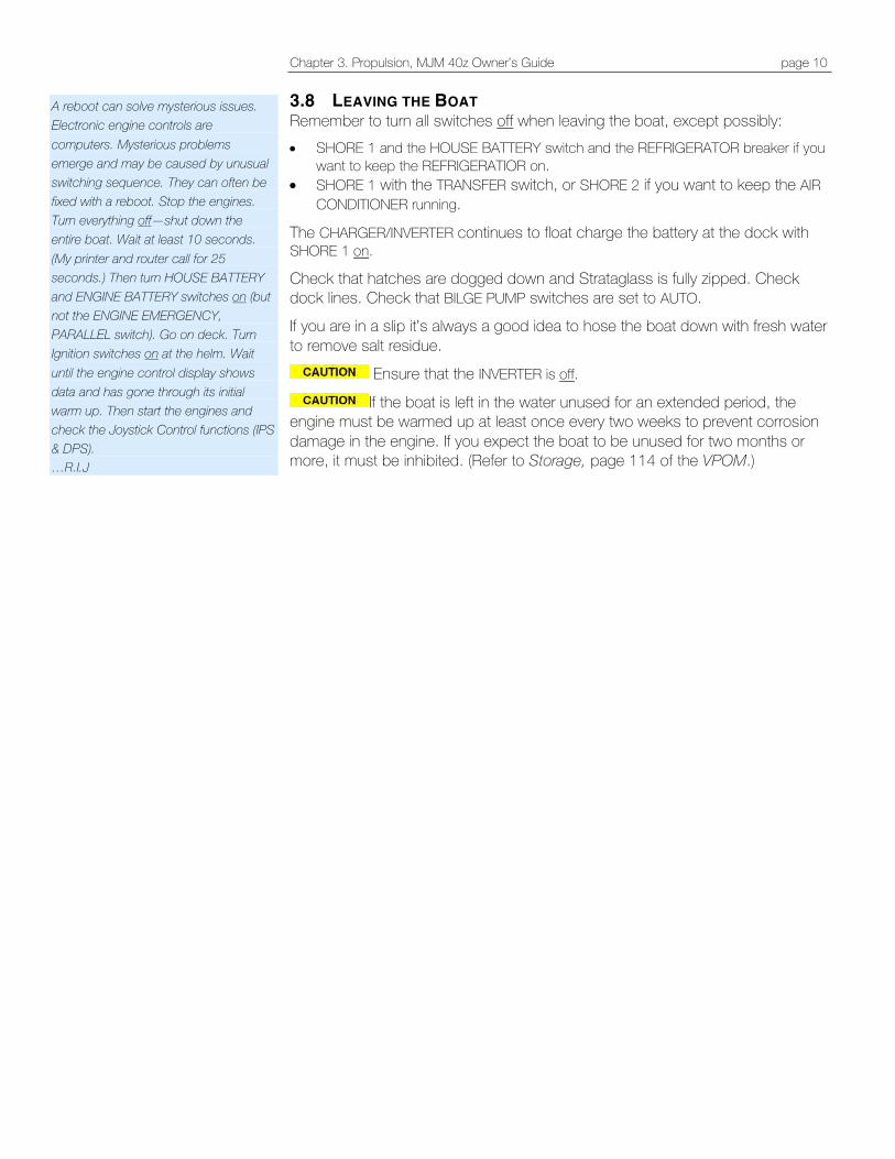
the engine could be damaged. Check Engine Oil Level The red-handled dipsticks are toward the front of the engines under the forward cockpit hatches. The dipstick for the starboard engine is on the port side of its engine and the dipstick for the port engine is on the starboard side of its engine. Check for both the correct level and for particulates in the oil. Check Pod Drive Oil Get down between engines, move aft and reach behind the IPS drives to unscrew the red cap with the built-in dipstick. Wipe and reinsert to check level. If the level is low, the fill cap is on top of the pod.
If the oil is not clear, but milky, contact your Volvo Penta service as it indicates water in the drives due to damage or faulty seals. Prolonged operation of the drive in this condition will most likely require replacement of the drive.
POD DRIVE OIL FILL CAP POD DRIVE DIPSTICK
RAW WATER INTAKE VALVE open
SEAKEEPER STRAINER, THRU HULL and PUMP
Coolant should be 1” below top
ENGINE OIL DIPSTICK
Chapter 3. Propulsion, MJM 40z Owner’s Guide page 8
Check Fuel Filters RACOR FILTERS are installed after the shut-off valves in the fuel lines, inside the Systems Room, on either side of the bulkhead, just forward of the generator. Check these filters regularly for contamination or water that will appear as a dirty gray, cloudy substance in the clear bowl. You should be able to see through the pink fuel in the bowl. Bubbles in the filter while the engine is running indicate a leak on the suction side of the fuel system. Check Fuel Level The primary cause of engine failure is running out of fuel. Unlike gasoline engines, diesel engines need more fuel than they burn. They return excess fuel to the tank. The feed and return of fuel to the port and starboard engines are to their respective 175-gallon fuel tanks. The two fuel tanks are connected at the bottom by a compensating fuel line with isolating shut-off valves at aft inboard corners. The shut-off valves are normally closed to prevent fuel from migrating from one tank to the other if the boat lists. Shutting them and filling tanks to different levels also offers a convenient way to trim an unevenly loaded boat. There’s a fuel level sensor in each tank. (See Fuel Shut-off valves in Safety Equipment, page 4.)
3.3 STARTING THE ENGINES Ensure ENGINE HATCHES are closed and that there are no lines and
hoses in the water near the drives before starting engines. Turn on the PORT ENGINE BATTERY switch and STBD ENGINE BATTERY switch at the upper right of the 120V breaker panel.
Don’t start the engine if people are in the water nearby.
Initiate e-Key Panel At the helm, a red light flashes under the “O” symbol on the e-KEY PANEL. Hold the key fob in front of the “O” symbol to unlock the Electronic Vessel Control (EVC) system. A sound confirms the system is unlocked. The red lamp goes out to indicate the system is unlocked. Two key fobs come with the boat. You can add two more. (See Key Management in the VPOM.) It’s not necessary to use the fobs every time you start or turn off the engines. Ensure the ENGINE/SHIFT CONTROL LEVERS are in neutral. The engines won’t start if either lever is in gear. Turn on Engines Volvo recommends that you start the PORT ENGINE first and shut down the STARBORD ENGINE first. Push the IGNITION buttons and wait until the engine data appear on the ENGINE CONTROL DISPLAY panel. Alarm Display If, when an ignition button is pressed, there is a long continuous beep and a “Stop Sign” appears on the ENGINE CONTROL DISPLAY panel, the diagnostic function has registered a malfunction. (Refer to section Fault Handling, page 68 of the VPOM for information and recommended actions.) Start the Engines Push the START/STOP button once for each engine. If you don’t hear the engines (these are quiet boats) look at the ENGINE CONTROL DISPLAY panel to see that it climbs to 600-700 rpms.
The boat may move abruptly when the gear is engaged. Ensure the boat is clear of all obstacles forward and aft. Cautiously shift to the IDLE FORWARD position then quickly back to NEUTRAL position. Observe whether the boat moves as you expect.
If a warning light or buzzer activates, stop the engine immediately. Determine the cause and repair the problem before continuing to operate.
RACOR FUEL FILTERS
e-KEY PANEL
ENGINE/SHIFT CONTROL LEVERS N=Neutral position, engine at idle F=Drive engaged, forward motion R=Drive engaged, reverse motion T=Engine RPM control (throttle)
Chapter 3. Propulsion, MJM 40z Owner’s Guide page 9
3.4 STOPPING THE ENGINES Put the ENGINE/SHIFT CONTROL LEVERS in neutral. Push the STOP buttons on the e-KEY PANEL. Don’t release the buttons until the engines have stopped. Then press the IGNITION button to turn the ignition off. The green lamp in the IGNITION button goes out to indicate the ignition is off. Then turn off PORT and STBD ENGINE BATTERY switches on the breaker panel in the cabin. (See note in the sidebar.)
If you want to lock the ELECTRONIC VESSEL CONTROL (EVC) system, hold the key fob in front of the symbol on the e-Key panel. A flashing red light indicates the system is locked. (Refer to page 65 of the VPOM.) However, most skippers find it unnecessary to lock the EVC since the engines can’t be started if the ENGINE BATTERY SWITCH is off and the cabin is locked.
Engine work should not be done with the engine running unless specified by the manufacturer for a specific reason and done by a qualified marine mechanic. Stop engines before opening engine hatch.
3.5 NEW ENGINE BREAK-IN When running the engine for the first time, frequently check oil pressure, coolant temperature (normal is 185o), exhaust color, engine vibration, sounds and the operation of indicators and gauges. Don’t run the engine at a constant RPM or apply full throttle for more than about 30 seconds. If temperature escalates, check that the RAW WATER INTAKE valve is open at the base of the IPS drives and that RAW WATER STRAINERS are clear. After shutting down, look for diesel fuel, engine oil or coolant leaks.
Lubrication During the first 10 hours of operation, high oil consumption is typical. Change oil between 50 and 100 hours. Extract oil after bringing engines to 185o so particulates don’t settle in the crankcase and not be removed. Consult the VPOM for the proper oils for the climate where the boat will be operating. Each engine has an engine oil drain hose.
3.6 AUXILIARY STOP If the engine doesn’t stop normally, there’s an AUXILIARY STOP at the side of the engine. Just push the button. (See adjacent diagram and refer to Auxiliary Stop, page 66 of the VPOM.)
3.7 OPERATING PARAMETERS Pay attention to the engine gauges on the LCD display. A significant change in oil or coolant temperature, oil pressure or voltage should be quickly investigated before the engine is damaged. Gauges should read as follows: • Oil Pressure: about 50 psi at idle and 63-65 psi at cruise speeds • Coolant Temperature: about 185o F • Charging: about 14 Volts when underway
While it’s good to run the engine at top speed periodically for a minute or so, the maximum cruising speed is at least 10% below full throttle of about 3600 rpm, or 3240 rpm. Engine and hull resonance is greater at some speeds than others. Listen and feel for sweet spots. If you hear abnormal sounds, stop the engine and inspect.
Recently, there were IPS malfunctions on 40z's. Here’s the lesson. (I’ve been guilty of this.) It seems that one saves a step by pushing the START/STOP button to shutdown the engines before pushing Engine Battery switches off. WRONG! Press the START/STOP buttons to stop engines. Then press the IGNITION button to turn the panel off causing its light to go out. The engine control system needs to be shut down before the battery switches are turned off, This will shut down the system properly and prevent confusing the Joystick or DPS software. Check the voltage on each engine when you turn on the ignition. In one situation, the port engine had 10 volts instead of 12.5 volts. That creates alarms because Volvo Penta electronics don't function below 10 volts. The EEP switch didn’t solve the problem because the starboard engine was 12 volts and combining them gets to an inadequate 11 volts and the starter motor draws lots of current. Fear not, we have designed multiple back-ups into the system. There are other ways to get going again in the above extreme case. See the adjacent paragraphs.
…R.I.J.
ENGINE OIL DRAIN HOSE
AUXILIARY STOP
Chapter 3. Propulsion, MJM 40z Owner’s Guide page 10
3.8 LEAVING THE BOAT Remember to turn all switches off when leaving the boat, except possibly: • SHORE 1 and the HOUSE BATTERY switch and the REFRIGERATOR breaker if you
want to keep the REFRIGERATIOR on. • SHORE 1 with the TRANSFER switch, or SHORE 2 if you want to keep the AIR
CONDITIONER running.
The CHARGER/INVERTER continues to float charge the battery at the dock with SHORE 1 on. Check that hatches are dogged down and Strataglass is fully zipped. Check dock lines. Check that BILGE PUMP switches are set to AUTO. If you are in a slip it’s always a good idea to hose the boat down with fresh water to remove salt residue.
Ensure that the INVERTER is off.
If the boat is left in the water unused for an extended period, the engine must be warmed up at least once every two weeks to prevent corrosion damage in the engine. If you expect the boat to be unused for two months or more, it must be inhibited. (Refer to Storage, page 114 of the VPOM.)
A reboot can solve mysterious issues. Electronic engine controls are computers. Mysterious problems emerge and may be caused by unusual switching sequence. They can often be fixed with a reboot. Stop the engines. Turn everything off—shut down the entire boat. Wait at least 10 seconds. (My printer and router call for 25 seconds.) Then turn HOUSE BATTERY and ENGINE BATTERY switches on (but not the ENGINE EMERGENCY, PARALLEL switch). Go on deck. Turn Ignition switches on at the helm. Wait until the engine control display shows data and has gone through its initial warm up. Then start the engines and check the Joystick Control functions (IPS & DPS). …R.I.J
Chapter 3. Propulsion, MJM 40z Owner’s Guide page 11
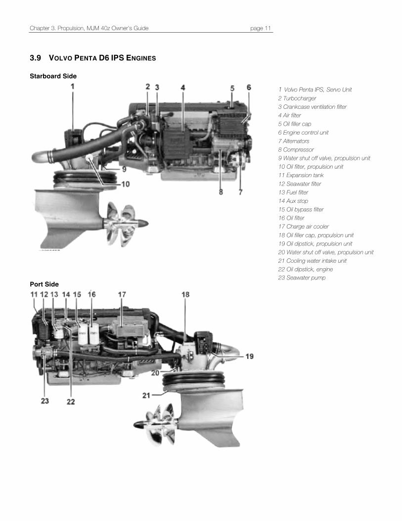
3.9 VOLVO PENTA D6 IPS ENGINES Starboard Side
Port Side
1 Volvo Penta IPS, Servo Unit 2 Turbocharger 3 Crankcase ventilation filter 4 Air filter 5 Oil filler cap 6 Engine control unit 7 Alternators 8 Compressor 9 Water shut off valve, propulsion unit 10 Oil filter, propulsion unit 11 Expansion tank 12 Seawater filter 13 Fuel filter 14 Aux stop 15 Oil bypass filter 16 Oil filter 17 Charge air cooler 18 Oil filler cap, propulsion unit 19 Oil dipstick, propulsion unit 20 Water shut off valve, propulsion unit 21 Cooling water intake unit 22 Oil dipstick, engine 23 Seawater pump
Chapter 4, Instruments and Controls, MJM 40z Owner’s Guide page 12
4 INSTRUMENTS AND CONTROLS
The following material includes selected summaries of the Volvo Penta Operator’s Manual (VPOM) included in the binders. Please read the entire manual for safety instructions. There are frequent page references to the VPOM in the following paragraphs.
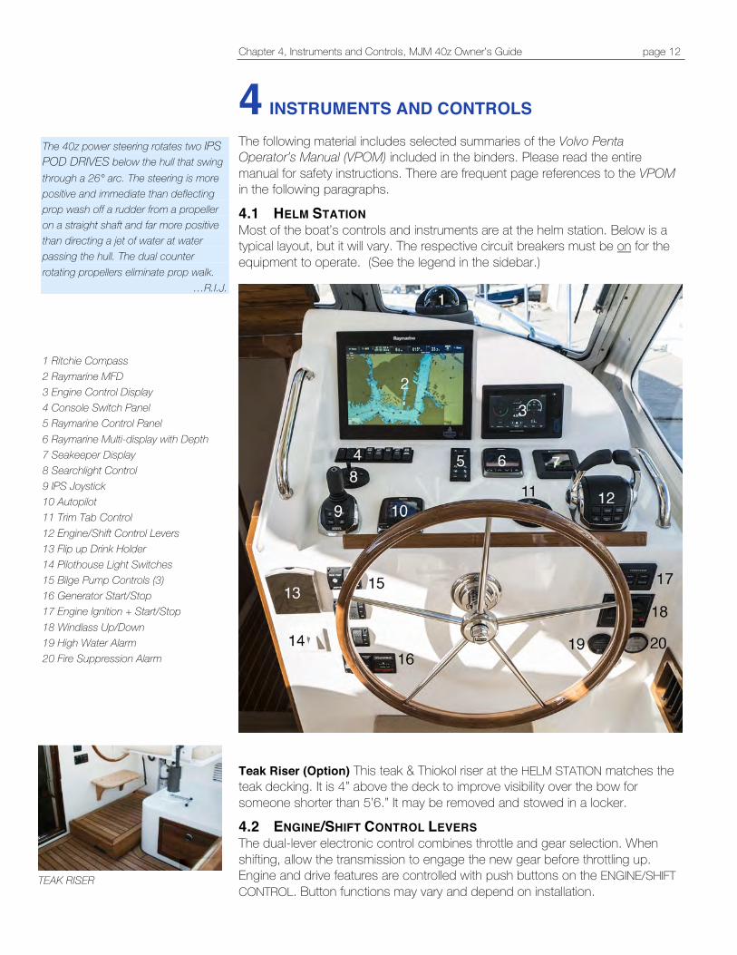
4.1 HELM STATION Most of the boat’s controls and instruments are at the helm station. Below is a typical layout, but it will vary. The respective circuit breakers must be on for the equipment to operate. (See the legend in the sidebar.)
Teak Riser (Option) This teak & Thiokol riser at the HELM STATION matches the teak decking. It is 4” above the deck to improve visibility over the bow for someone shorter than 5’6.” It may be removed and stowed in a locker.
4.2 ENGINE/SHIFT CONTROL LEVERS The dual-lever electronic control combines throttle and gear selection. When shifting, allow the transmission to engage the new gear before throttling up. Engine and drive features are controlled with push buttons on the ENGINE/SHIFT CONTROL. Button functions may vary and depend on installation.
The 40z power steering rotates two IPS POD DRIVES below the hull that swing through a 26° arc. The steering is more positive and immediate than deflecting prop wash off a rudder from a propeller on a straight shaft and far more positive than directing a jet of water at water passing the hull. The dual counter rotating propellers eliminate prop walk.
…R.I.J. 1 Ritchie Compass 2 Raymarine MFD 3 Engine Control Display 4 Console Switch Panel 5 Raymarine Control Panel 6 Raymarine Multi-display with Depth 7 Seakeeper Display 8 Searchlight Control 9 IPS Joystick 10 Autopilot 11 Trim Tab Control 12 Engine/Shift Control Levers 13 Flip up Drink Holder 14 Pilothouse Light Switches 15 Bilge Pump Controls (3) 16 Generator Start/Stop 17 Engine Ignition + Start/Stop 18 Windlass Up/Down 19 High Water Alarm 20 Fire Suppression Alarm
TEAK RISER
Chapter 4, Instruments and Controls, MJM 40z Owner’s Guide page 13
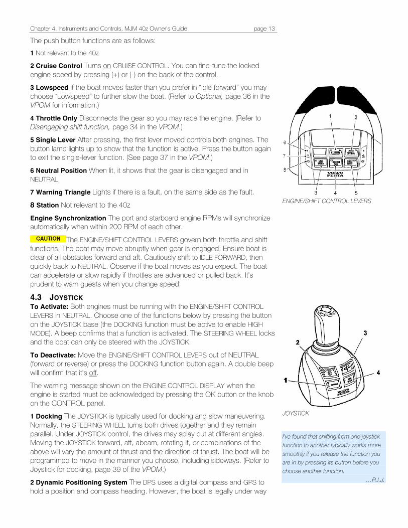
The push button functions are as follows: 1 Not relevant to the 40z
2 Cruise Control Turns on CRUISE CONTROL. You can fine-tune the locked engine speed by pressing (+) or (-) on the back of the control. 3 Lowspeed If the boat moves faster than you prefer in “idle forward” you may choose “Lowspeed” to further slow the boat. (Refer to Optional, page 36 in the VPOM for information.)
4 Throttle Only Disconnects the gear so you may race the engine. (Refer to Disengaging shift function, page 34 in the VPOM.) 5 Single Lever After pressing, the first lever moved controls both engines. The button lamp lights up to show that the function is active. Press the button again to exit the single-lever function. (See page 37 in the VPOM.)
6 Neutral Position When lit, it shows that the gear is disengaged and in NEUTRAL. 7 Warning Triangle Lights if there is a fault, on the same side as the fault.
8 Station Not relevant to the 40z
Engine Synchronization The port and starboard engine RPMs will synchronize automatically when within 200 RPM of each other.
The ENGINE/SHIFT CONTROL LEVERS govern both throttle and shift functions. The boat may move abruptly when gear is engaged: Ensure boat is clear of all obstacles forward and aft. Cautiously shift to IDLE FORWARD, then quickly back to NEUTRAL. Observe if the boat moves as you expect. The boat can accelerate or slow rapidly if throttles are advanced or pulled back. It’s prudent to warn guests when you change speed.
4.3 JOYSTICK To Activate: Both engines must be running with the ENGINE/SHIFT CONTROL LEVERS in NEUTRAL. Choose one of the functions below by pressing the button on the JOYSTICK base (the DOCKING function must be active to enable HIGH MODE). A beep confirms that a function is activated. The STEERING WHEEL locks and the boat can only be steered with the JOYSTICK.
To Deactivate: Move the ENGINE/SHIFT CONTROL LEVERS out of NEUTRAL (forward or reverse) or press the DOCKING function button again. A double beep will confirm that it’s off. The warning message shown on the ENGINE CONTROL DISPLAY when the engine is started must be acknowledged by pressing the OK button or the knob on the CONTROL panel. 1 Docking The JOYSTICK is typically used for docking and slow maneuvering. Normally, the STEERING WHEEL turns both drives together and they remain parallel. Under JOYSTICK control, the drives may splay out at different angles. Moving the JOYSTICK forward, aft, abeam, rotating it, or combinations of the above will vary the amount of thrust and the direction of thrust. The boat will be programmed to move in the manner you choose, including sideways. (Refer to Joystick for docking, page 39 of the VPOM.) 2 Dynamic Positioning System The DPS uses a digital compass and GPS to hold a position and compass heading. However, the boat is legally under way
ENGINE/SHIFT CONTROL LEVERS
JOYSTICK I’ve found that shifting from one joystick function to another typically works more smoothly if you release the function you are in by pressing its button before you choose another function.
…R.I.J.
Chapter 4, Instruments and Controls, MJM 40z Owner’s Guide page 14
and the helm station must be supervised. Moving the ENGINE/SHIFT CONTROL LEVERS out of NEUTRAL, or pressing the DPS button will deactivate DPS. The DPS can be activated when boat speed is below 3 knots and remains active up to 12 hours. The DPS view shows on the ENGINE CONTROL DISPLAY panel when activated. If you browse to another view, it will return after a few moments. (Refer to Dynamic Positioning System, page 48 of the VPOM.)
The boat may move abruptly when DPS is activated as it returns the boat to where the button was pushed. 3 Joystick Driving Unavailable with standard Raymarine electronic package
4 High Mode In windy weather or current when you need more oomph, press the HIGH MODE function (the DOCKING function must be active). Disengage the function by pressing the button again. A double beep will sound to confirm that high mode is deactivated, the light will go out and the system will return to docking. (Refer to Joystick for docking, page 41 of the VPOM.)
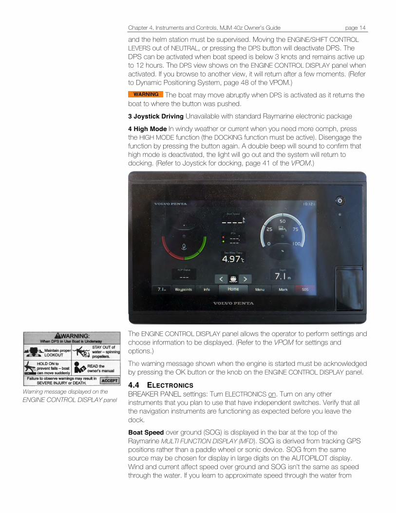
The ENGINE CONTROL DISPLAY panel allows the operator to perform settings and choose information to be displayed. (Refer to the VPOM for settings and options.)
The warning message shown when the engine is started must be acknowledged by pressing the OK button or the knob on the ENGINE CONTROL DISPLAY panel.
4.4 ELECTRONICS BREAKER PANEL settings: Turn ELECTRONICS on. Turn on any other instruments that you plan to use that have independent switches. Verify that all the navigation instruments are functioning as expected before you leave the dock. Boat Speed over ground (SOG) is displayed in the bar at the top of the Raymarine MULTI FUNCTION DISPLAY (MFD). SOG is derived from tracking GPS positions rather than a paddle wheel or sonic device. SOG from the same source may be chosen for display in large digits on the AUTOPILOT display. Wind and current affect speed over ground and SOG isn’t the same as speed through the water. If you learn to approximate speed through the water from
Warning message displayed on the ENGINE CONTROL DISPLAY panel
Chapter 4, Instruments and Controls, MJM 40z Owner’s Guide page 15
RPM on the tachometer, you can compare it to SOG to determine the effect of wind and current.
4.5 COMPASS HEADING AND CALIBRATION The yacht is equipped with three devices that display bearing: 1. The RITCHIE COMPASS on the dash 2. The AUTOPILOT DIGITAL COMPASS 3. The GPS COG (Course Over Ground) on the MFD
When you are underway, these three sources should agree within a degree or so. If they don’t, employ a professional compass adjuster. The DIGITAL COMPASS SENSOR is located on a stringer outboard to starboard under the cabin sole. Open the cabin sole hatch and look aft to access it.
Don’t store ferrous items such as tools in the locker near the DIGITAL COMPASS SENSOR or on the dash by the RITCHIE COMPASS.
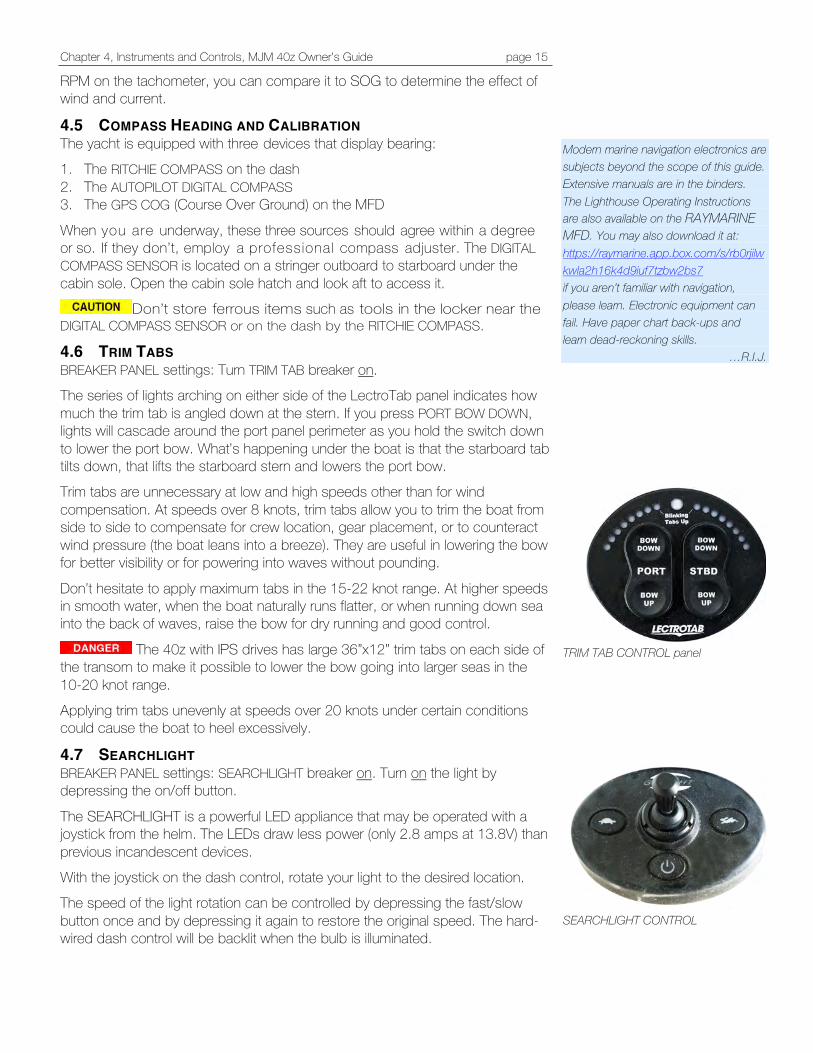
4.6 TRIM TABS BREAKER PANEL settings: Turn TRIM TAB breaker on. The series of lights arching on either side of the LectroTab panel indicates how much the trim tab is angled down at the stern. If you press PORT BOW DOWN, lights will cascade around the port panel perimeter as you hold the switch down to lower the port bow. What’s happening under the boat is that the starboard tab tilts down, that lifts the starboard stern and lowers the port bow. Trim tabs are unnecessary at low and high speeds other than for wind compensation. At speeds over 8 knots, trim tabs allow you to trim the boat from side to side to compensate for crew location, gear placement, or to counteract wind pressure (the boat leans into a breeze). They are useful in lowering the bow for better visibility or for powering into waves without pounding.
Don’t hesitate to apply maximum tabs in the 15-22 knot range. At higher speeds in smooth water, when the boat naturally runs flatter, or when running down sea into the back of waves, raise the bow for dry running and good control.
The 40z with IPS drives has large 36”x12” trim tabs on each side of the transom to make it possible to lower the bow going into larger seas in the 10-20 knot range. Applying trim tabs unevenly at speeds over 20 knots under certain conditions could cause the boat to heel excessively.
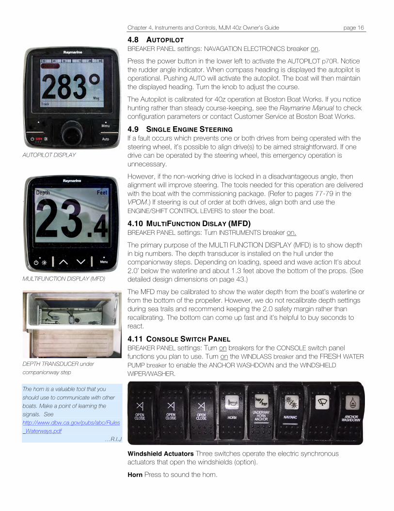
4.7 SEARCHLIGHT BREAKER PANEL settings: SEARCHLIGHT breaker on. Turn on the light by depressing the on/off button.
The SEARCHLIGHT is a powerful LED appliance that may be operated with a joystick from the helm. The LEDs draw less power (only 2.8 amps at 13.8V) than previous incandescent devices. With the joystick on the dash control, rotate your light to the desired location. The speed of the light rotation can be controlled by depressing the fast/slow button once and by depressing it again to restore the original speed. The hard-wired dash control will be backlit when the bulb is illuminated.
Modern marine navigation electronics are subjects beyond the scope of this guide. Extensive manuals are in the binders. The Lighthouse Operating Instructions are also available on the RAYMARINE MFD. You may also download it at: https://raymarine.app.box.com/s/rb0rjilwkwla2h16k4d9iuf7tzbw2bs7 if you aren’t familiar with navigation, please learn. Electronic equipment can fail. Have paper chart back-ups and learn dead-reckoning skills.
…R.I.J.
TRIM TAB CONTROL panel
SEARCHLIGHT CONTROL
Chapter 4, Instruments and Controls, MJM 40z Owner’s Guide page 16
4.8 AUTOPILOT BREAKER PANEL settings: NAVAGATION ELECTRONICS breaker on. Press the power button in the lower left to activate the AUTOPILOT p70R. Notice the rudder angle indicator. When compass heading is displayed the autopilot is operational. Pushing AUTO will activate the autopilot. The boat will then maintain the displayed heading. Turn the knob to adjust the course. The Autopilot is calibrated for 40z operation at Boston Boat Works. If you notice hunting rather than steady course-keeping, see the Raymarine Manual to check configuration parameters or contact Customer Service at Boston Boat Works.
4.9 SINGLE ENGINE STEERING If a fault occurs which prevents one or both drives from being operated with the steering wheel, it’s possible to align drive(s) to be aimed straightforward. If one drive can be operated by the steering wheel, this emergency operation is unnecessary. However, if the non-working drive is locked in a disadvantageous angle, then alignment will improve steering. The tools needed for this operation are delivered with the boat with the commissioning package. (Refer to pages 77-79 in the VPOM.) If steering is out of order at both drives, align both and use the ENGINE/SHIFT CONTROL LEVERS to steer the boat.
4.10 MULTIFUNCTION DISLAY (MFD) BREAKER PANEL settings: Turn INSTRUMENTS breaker on.
The primary purpose of the MULTI FUNCTION DISPLAY (MFD) is to show depth in big numbers. The depth transducer is installed on the hull under the companionway steps. Depending on loading, speed and wave action It’s about 2.0’ below the waterline and about 1.3 feet above the bottom of the props. (See detailed design dimensions on page 43.)
The MFD may be calibrated to show the water depth from the boat’s waterline or from the bottom of the propeller. However, we do not recalibrate depth settings during sea trails and recommend keeping the 2.0 safety margin rather than recalibrating. The bottom can come up fast and it’s helpful to buy seconds to react.
4.11 CONSOLE SWITCH PANEL BREAKER PANEL settings: Turn on breakers for the CONSOLE switch panel functions you plan to use. Turn on the WINDLASS breaker and the FRESH WATER PUMP breaker to enable the ANCHOR WASHDOWN and the WINDSHIELD WIPER/WASHER.
Windshield Actuators Three switches operate the electric synchronous actuators that open the windshields (option).
Horn Press to sound the horn.
AUTOPILOT DISPLAY
MULTIFUNCTION DISPLAY (MFD)
DEPTH TRANSDUCER under companionway step The horn is a valuable tool that you should use to communicate with other boats. Make a point of learning the signals. See http://www.dbw.ca.gov/pubs/abc/Rules_Waterways.pdf
…R.I.J
Chapter 4, Instruments and Controls, MJM 40z Owner’s Guide page 17
Underway Horn / Anchor Press forward end of rocker switch to automatically sound a one prolonged blast every 2 minutes when operating in low or restricted visibility. When at anchor or stopped and making no way through the water, press the aft end of the rocker switch to sound 2 prolonged blasts every 2 minutes. Windshield Wipers • One push to the on position will start three motors in synchronized interval. • One more push to momentary will run three motors slow speed
synchronized. One more push will run three motors fast speed synchronized.
• One more push starts from interval and so on. • One long push from off to momentary will start one motor in interval (wiper 1).
One more push will run one motor slow speed. • One more push will run one motor fast speed. • One more push starts one motor from interval and so on. When running, push switch to momentary more than one second and washer will start. If the wiper motors get overloaded the power automatically breaks. Push switch to off, then to on and motor will start again.
If the wiper’s washer system is to be used in sub-freezing temperatures, a separate system must be installed which uses anti-freeze. NAV/ANC Press the forward end of rocker switch to turn on the RED and GREEN NAVIGATION LIGHTS and the STEAMING LIGHT on the hard top over the pilothouse. Press the aft end of rocker switch to turn on the ANCHOR LIGHTS.
Anchor Washdown With windlass switch on, press switch to spray fresh water on the anchor rode when retrieving anchor.
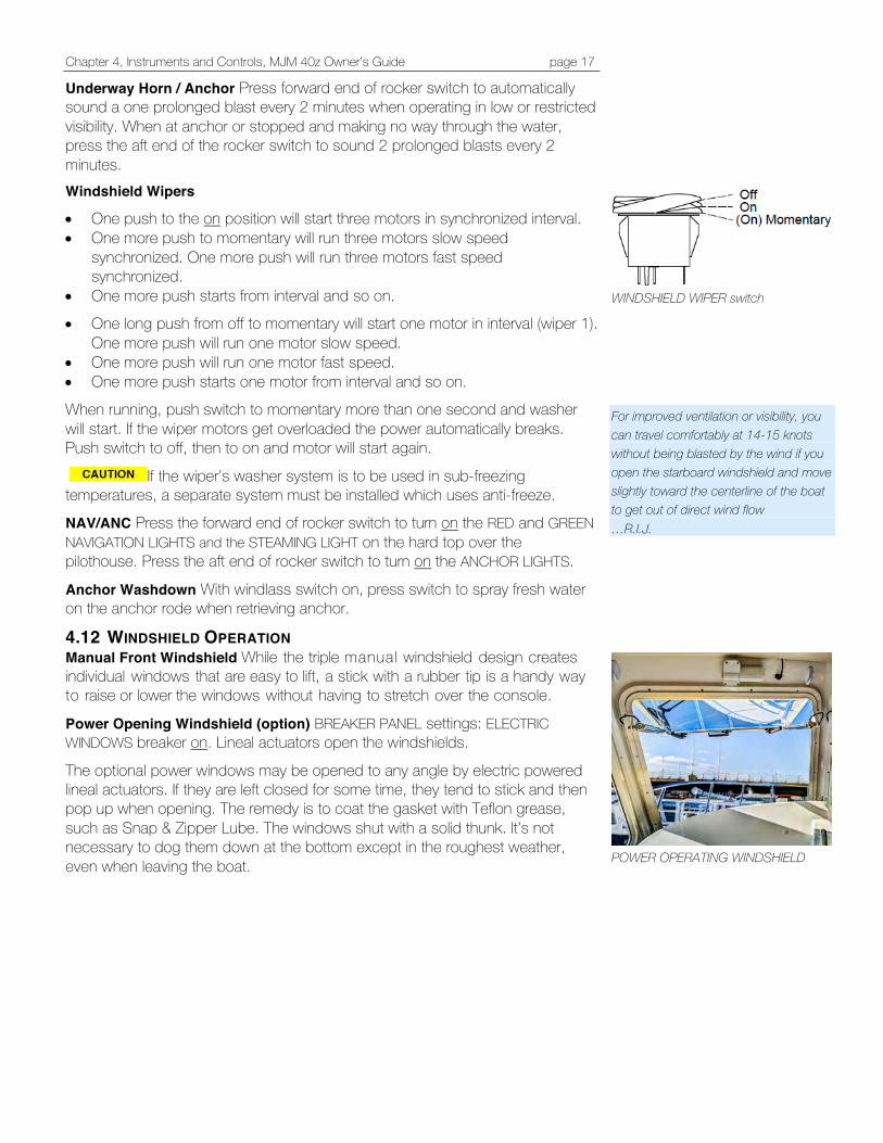
4.12 WINDSHIELD OPERATION Manual Front Windshield While the triple manual windshield design creates individual windows that are easy to lift, a stick with a rubber tip is a handy way to raise or lower the windows without having to stretch over the console.
Power Opening Windshield (option) BREAKER PANEL settings: ELECTRIC WINDOWS breaker on. Lineal actuators open the windshields.
The optional power windows may be opened to any angle by electric powered lineal actuators. If they are left closed for some time, they tend to stick and then pop up when opening. The remedy is to coat the gasket with Teflon grease, such as Snap & Zipper Lube. The windows shut with a solid thunk. It’s not necessary to dog them down at the bottom except in the roughest weather, even when leaving the boat.
WINDSHIELD WIPER switch
For improved ventilation or visibility, you can travel comfortably at 14-15 knots without being blasted by the wind if you open the starboard windshield and move slightly toward the centerline of the boat to get out of direct wind flow …R.I.J.
POWER OPERATING WINDSHIELD
Chapter 5, Electrical Systems, MJM 40z Owner’s Guide page 18
5 ELECTRICAL SYSTEMS
AC and DC electricity can be lethal. Don’t work on the boat’s electrical system if you aren’t a qualified marine electrician.
5.1 ELECTRICAL SAFETY Please read and understand the safety precautions in the included National Marine Manufacturers Association (NMMA) publication, Sportfish, Cruisers, Yachts: Owner’s Manual concerning electrical safety. For more reading, there is Boatowner’s Mechanical and Electrical Manual by Nigel Calder and Boat Owner’s Illustrated Electrical Handbook by Charlie Wing.
5.2 ELECTRICAL POWER The MJM 40z includes both 12-volt direct current (DC) and 120-volt alternating current (AC). 12-Volt DC Most of the boat’s electrical devices use 12V DC. It’s stored in AGM absorbed-glass mat no-maintenance batteries as follows: • Two Group 8D, 245 amp-hour HOUSE BATTERIES • Two Group 31,105 amp-hour PORT and STBD ENGINE BATTERIES • One Group 27, 95 amp-hour GENERATOR BATTERY (if optional
generator is present) The Victron INVERTER/CHARGER is factory set for AGM batteries.
Don’t try to open the batteries. Other than keeping them charged, stored and clean (especially between the terminals), there’s no maintenance required.
Don’t let the voltage fall below 12 volts. Sensitive electronics may fail to function.
120-Volt AC Two different sources can provide 120V AC to the INVERTER/CHARGER to charge the batteries and provide power to the 120V AC circuits. 1. SHORE POWER 1 2. The NORTHERN LIGHTS GENERATOR (option) 120-volt AC power provides power for the SEAKEEPER, COOKTOP, MICROWAVE, TV, AIR CONDITIONING, WATER HEATER and OUTLET/RECEPTACLES. There are SPARE BREAKERS that may be added for other devices. A 20-amp circuit with a ground fault circuit interrupter (GFCI) outlet/receptacle ser ves the AC OUTLET/RECEPTACALS. The GENERATOR and SHORE POWER 1 provide power to the INVERTER/CHARGER that charges the batteries and provides power to the 120V AC circuits at the left side of the 120V breaker panel. SHORE POWER 2 bypasses the INVERTER/CHARGER and provides 120V AC directly to the right side of the 120V breaker panel.
Only one GFCI OUTLET/RECEPTACLE is in the circuit with other non-GFCI outlet/receptacles. If the 120-VOLT BREAKER on the electrical panel is on and there is no power at the AC OUTLET/ RECEPTACLES, the circuit interrupter may have tripped. Press the reset button on the GFCI OUTLET/ RECEPTACLE.
…R.I.J.

Chapter 5, Electrical Systems, MJM 40z Owner’s Guide page 19
5.3 SHORE POWER There are two ways to provide shore power. A single 30A 125V shore power cable plugged in to SHORE POWER INLET 1 in the transom (shown in the adjacent photograph) will provide power to breakers at the left side of the 120V AC panel.
Two 30A 125V shore power cables connected to 30A 125V volt sockets at the dock and plugged into SHORE POWER INLET 1 AND SHORE POWER INLET 2 will provide power to breakers on both sides of the 120V AC panel. The transfer switch should be off. Even if it is on, 120V AC won’t be transferred to the left panel from the right panel.
Instead of two 30A 125V volt sockets at the dock, there may be a single 50A 225V socket. In that case, use a Y adapter that splits the power for two 30A 125V shore power cables. (See adjacent image.) Charging The batteries will accept a charge from 120V shore power through the INVERTER/CHARGER if SHORE POWER 1 is on even if the HOUSE BATTERY switch is off. Transfer Switch If SHORE POWER 2 isn’t connected, the TRANSFER SWITCH transfers power from the left side of the 120V AC BREAKER panel to the right side. However, the circuits on the right side are for high amp loads. If you use the TRANSFER SWITCH with SHORE POWER 1 alone, the circuits that can be successfully powered are limited. Operating the AIR CONDITIONING, the COOKTOP and the WATER HEATER together would overload the circuit. If you overload the shore power circuit and trip the breaker you may reset it by pushing the switches on the SHORE POWER BREAKER BOX. It’s outboard under the port cockpit hatch cover. (See sidebar.) If you plan to use more than one of the AIR CONDITIONING systems at the same time, it would be best to supply the circuits on the right side of the panel with the GENERATOR or SHORE POWER 2 that bypasses the INVERTER/CHARGER. The left side 120V AC circuits may also be supplied from the HOUSE BATTERIES with the INVERTER/CHARGER. (See page 25.)
5.4 FUSE LOCATONS (See the Appendix, Page 46.)
5.5 24-HOUR CIRCUITS The connection block for the 24-hour circuits is forward in the starboard pilothouse settee locker. The 24-hour circuits (shown in the sidebar) bypass the breaker panel, HOUSE, ENGINE and GENERATOR switches and are connected directly to the HOUSE BATTERY. They are: • BILGE PUMPS (3 connections) • HIGH WATER ALARM • EMERGENCY PARALLEL • STEREO MEMORY
The EMERGENCY PARALLEL connection enables the EMERGENCY PARALLEL switch on the 12V DC panel. The STEREO MEMORY connection provides a trickle charge to maintain the clocks and user settings.
Disconnecting shore power with INVERTER left on will discharge the HOUSE BATTERIES over time. (See page 25.)
SHORE POWER INLET 1 is connected. None at SHORE POWER INLET 2. The receptacle on right is for Ethernet and coax TV connections.
SHORE POWER BREAKER BOX
A Y adapter can split 50A 220V shore power to two 30A 125V shore power cables.
24-HOUR CIRCUITS connection terminal

Chapter 5, Electrical Systems, MJM 40z Owner’s Guide page 20
5.6 THE 12V DC PANEL The 12V DC panel includes circuit breakers for all 12V DC equipment except the 24-hour circuits that are permanently connected to the HOUSE BATTERY. (See page 19.) The breakers are lighted and labeled. Spares are available for future installations.
The TOGGLE switch below the digital display on the 12V DC panel shows volts or amps for the HOUSE BATTERIES in position 1 and the GENERATOR BATTERY in position 2. Position 3 is not connected. ENGINE BATTERY volts and amps are displayed on the Volvo ENGINE CONTROL DISPLAY. Press the > and < buttons under the display to show volts or amps. The center button dims the display. The switch between the HOUSE BATTERY and the GEN BATTERY raises and lowers the dining table. The HOUSE BATTERY switch and the GENERATOR BATTERY switch are at the upper right of the 12V DC panel. Turning on the HOUSE BATTERY switch provides power to the individual breakers at the panel. Turning on the GENERATOR BATTERY switch provides power to start the optional GENERATOR. The GEN. EMERG. PARALLEL switch combines the GENERATOR BATTERY with the HOUSE BATTERY BANK. Turn on the FRESH WATER PUMP breaker to activate the gauge that indicates the fresh water level on the lower right of the 120V AC panel that is displayed on the next page.
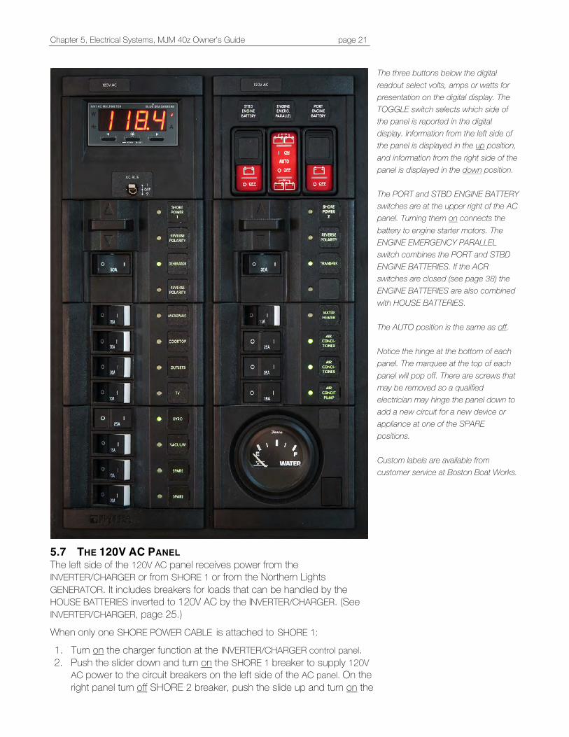
Chapter 5, Electrical Systems, MJM 40z Owner’s Guide page 21
5.7 THE 120V AC PANEL The left side of the 120V AC panel receives power from the INVERTER/CHARGER or from SHORE 1 or from the Northern Lights GENERATOR. It includes breakers for loads that can be handled by the HOUSE BATTERIES inverted to 120V AC by the INVERTER/CHARGER. (See INVERTER/CHARGER, page 25.) When only one SHORE POWER CABLE is attached to SHORE 1: 1. Turn on the charger function at the INVERTER/CHARGER control panel. 2. Push the slider down and turn on the SHORE 1 breaker to supply 120V
AC power to the circuit breakers on the left side of the AC panel. On the right panel turn off SHORE 2 breaker, push the slide up and turn on the
The three buttons below the digital readout select volts, amps or watts for presentation on the digital display. The TOGGLE switch selects which side of the panel is reported in the digital display. Information from the left side of the panel is displayed in the up position, and information from the right side of the panel is displayed in the down position. The PORT and STBD ENGINE BATTERY switches are at the upper right of the AC panel. Turning them on connects the battery to engine starter motors. The ENGINE EMERGENCY PARALLEL switch combines the PORT and STBD ENGINE BATTERIES. If the ACR switches are closed (see page 38) the ENGINE BATTERIES are also combined with HOUSE BATTERIES. The AUTO position is the same as off. Notice the hinge at the bottom of each panel. The marquee at the top of each panel will pop off. There are screws that may be removed so a qualified electrician may hinge the panel down to add a new circuit for a new device or appliance at one of the SPARE positions. Custom labels are available from customer service at Boston Boat Works.
Chapter 5, Electrical Systems, MJM 40z Owner’s Guide page 22
TRANSFER switch to supply 120V AC power to circuit breakers on the right side.
The 120V AC panel has reverse polarity indicators. If an AC supply is wired incorrectly, either aboard the boat or shore side, a dangerous shock situation could exist. If the reverse polarity lights are illuminated, disconnect that source of power and engage a qualified marine electrician and notify the marina dock master if in a slip.
5.8 NORTHERN LIGHTS GENERATOR (O P T I O N ) The Northern Lights Operator’s Manual OM673L3 is included in the binders.
Pre-Start Check List The daily pre-start checklist for the generator diesel engine is similar to the main engines.
1. Close seacock, clean the sea strainer (the cap should be hand tightened) and reopen the seacock.
2. Check the coolant. Remove the front panel. The manifold should be full to the cap and the bottle should have coolant in it. You should be able to see some coolant in the clear overflow bottle.
3. Check that the oil level is within the waffled area on the stick. Always add the same viscosity of oil that is in the crankcase.
4. Look to see that there are no loose belts or wires and that there is no oil or fuel in the pan under the GENERATOR.
Don’t remove the coolant cap from a hot engine.
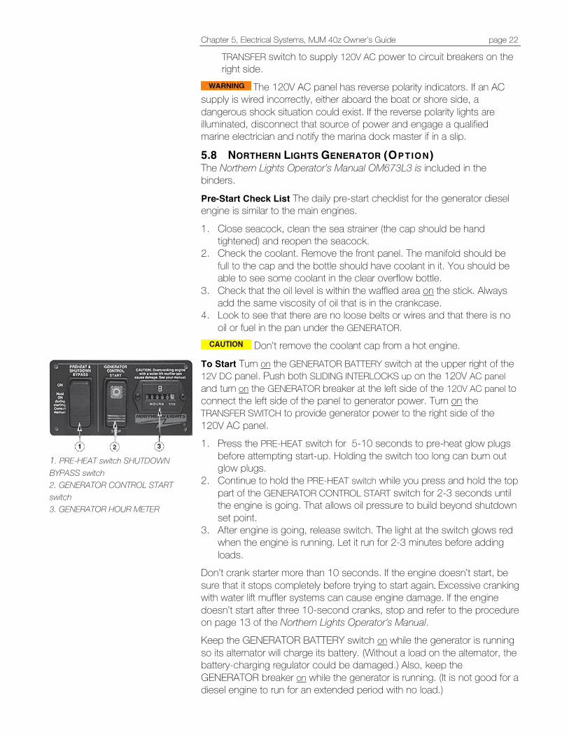
To Start Turn on the GENERATOR BATTERY switch at the upper right of the 12V DC panel. Push both SLIDING INTERLOCKS up on the 120V AC panel and turn on the GENERATOR breaker at the left side of the 120V AC panel to connect the left side of the panel to generator power. Turn on the TRANSFER SWITCH to provide generator power to the right side of the 120V AC panel. 1. Press the PRE-HEAT switch for 5-10 seconds to pre-heat glow plugs
before attempting start-up. Holding the switch too long can burn out glow plugs.
2. Continue to hold the PRE-HEAT switch while you press and hold the top part of the GENERATOR CONTROL START switch for 2-3 seconds until the engine is going. That allows oil pressure to build beyond shutdown set point.
3. After engine is going, release switch. The light at the switch glows red when the engine is running. Let it run for 2-3 minutes before adding loads.
Don’t crank starter more than 10 seconds. If the engine doesn’t start, be sure that it stops completely before trying to start again. Excessive cranking with water lift muffler systems can cause engine damage. If the engine doesn’t start after three 10-second cranks, stop and refer to the procedure on page 13 of the Northern Lights Operator’s Manual. Keep the GENERATOR BATTERY switch on while the generator is running so its alternator will charge its battery. (Without a load on the alternator, the battery-charging regulator could be damaged.) Also, keep the GENERATOR breaker on while the generator is running. (It is not good for a diesel engine to run for an extended period with no load.)
1. PRE-HEAT switch SHUTDOWN BYPASS switch 2. GENERATOR CONTROL START switch 3. GENERATOR HOUR METER
Chapter 5, Electrical Systems, MJM 40z Owner’s Guide page 23
After the generator starts, there is a short delay, then about 120V should show on the digital display at the top left of the 120V AC panel. (The toggle switch under the display is in the up position.) If the TRANSFER switch is pressed, there is a 2-minute delay before power is available on the right side of the panel. If the generator starts but no AC voltage is seen at the panel, ensure that the SLIDING INTERLOCKS at the top of the 120V AC panel are up and that the GENERATOR breaker is on. If so, there is a possibility the generator was overloaded and the AC breaker at the GENERATOR CONTROL BOX on top of the GENERATOR tripped. Open the generator cover and reset (pull up) the AC OUTPUT CIRCUIT breaker. (See item 14, page 24.)
To Stop Turn off breakers for 120V loads and run the generator for 2 or 3 minutes without a load to allow it to cool. Press and hold the lower part of the GENERATOR CONTROL AND START switch (the STOP position) until the engine stops. Break-in The first 100 hours are critical to an engine’s life and performance. Vary the loads with minimal idling to help seat engine components properly. Check engine temperature and oil pressure gauges frequently. Oil consumption is greater during break-in; piston rings take time to seat. Oil Changes Change engine oil and filter at 50 hours and again at 100 hours, then at every 250 hours. (Consult page 17 of the Operator’s Manual for oil recommendation, oil change details and instructions.) During intermittent cold weather operation, change oil every 100 hours or six weeks, whichever comes first. Change oil at any seasonal change in temperature when a new viscosity is required. Engine capacity with new oil filter is 3.3 quarts (3.1 liters). Change the oil filter with every oil change. Remove old oil after engine reaches operating temperature to ensure metal particles are in suspension and not lying in bottom.
5.9 CORROSION PROTECTION In addition to transom anodes, there are two engine anodes plus an iron anode in the exhaust cavity of the drive. Inspect the engine anodes periodically and at oil changes. (See page 99 of the VPOM.) Remove the surface corroded areas and replace when they are deteriorated by 50%, otherwise corrosion of the cooling system will occur and water leakage or parts breakage will result. Be sure to close the raw water intakes at the base of drives before removing a plug to replace an anode. The frequency of anode replacement varies with the seawater characteristics and stray electrical current in marinas. An electrical short either on the boat or an adjacent boat can accelerate corrosion. Be sure to use genuine Volvo anodes with the proper alloy for the waters where the boat is used. The props and propulsion unit are coated with anti-fouling, corrosion protection paint. When the boat is hauled, inspect and recoat scratches with the same paint (contact customer service at Boston BoatWorks to determine current paint specification) or remove the existing paint entirely before applying a different product.
GENERATOR FUEL PRE-FILTER is behind the generator against the bulkhead
Use your generator! You’ve heard that diesels like to be run. Engines that have been we l l maintained with good hours are better than those with few hours. Dealing with refurbished injectors, water-pump replacements, cooling-system rehabs and new hoses, etc., can be costly if you don’t run it enough. Ideally, run it for at least 20 minutes with a good load (air conditioning systems and/or a Seakeeper are good examples) every time you take your boat out. The list of evils for an underemployed genset is frightening. Salt-laden air can corrode windings of the generator unit itself and sneak into engine cylinders, bringing rust to cylinder walls and piston rings. Salt-laden moisture can build up in the oil, creating acidic havoc. Fuel may turn to shellac or gum around the injectors. Lesson here: use your generator!
…R.I.J.
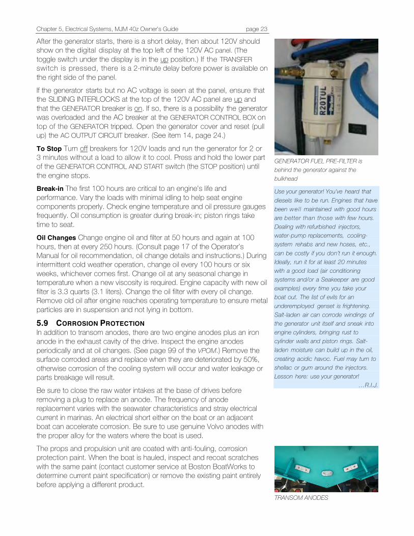
TRANSOM ANODES
Chapter 5, Electrical Systems, MJM 40z Owner’s Guide page 24
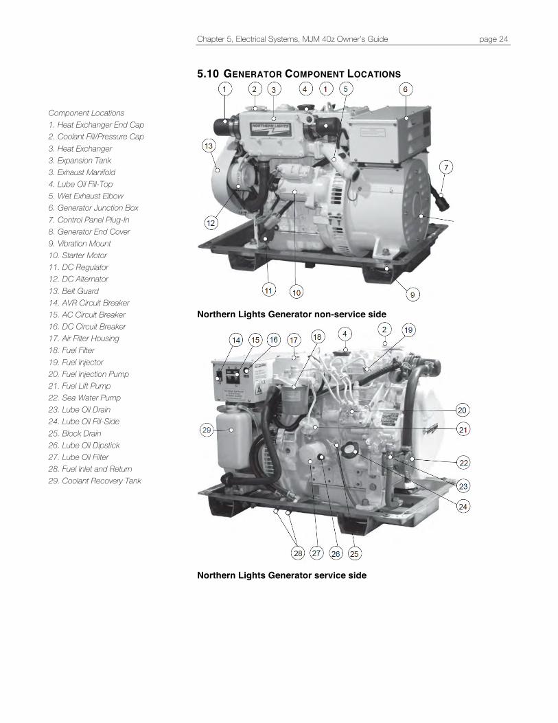
5.10 GENERATOR COMPONENT LOCATIONS
Northern Lights Generator non-service side
Northern Lights Generator service side
Component Locations 1. Heat Exchanger End Cap 2. Coolant Fill/Pressure Cap 3. Heat Exchanger 3. Expansion Tank 3. Exhaust Manifold 4. Lube Oil Fill-Top 5. Wet Exhaust Elbow 6. Generator Junction Box 7. Control Panel Plug-In 8. Generator End Cover 9. Vibration Mount 10. Starter Motor 11. DC Regulator 12. DC Alternator 13. Belt Guard 14. AVR Circuit Breaker 15. AC Circuit Breaker 16. DC Circuit Breaker 17. Air Filter Housing 18. Fuel Filter 19. Fuel Injector 20. Fuel Injection Pump 21. Fuel Lift Pump 22. Sea Water Pump 23. Lube Oil Drain 24. Lube Oil Fill-Side 25. Block Drain 26. Lube Oil Dipstick 27. Lube Oil Filter 28. Fuel Inlet and Return 29. Coolant Recovery Tank
Chapter 5, Electrical Systems, MJM 40z Owner’s Guide page 25
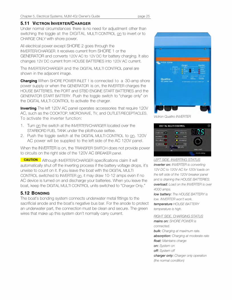
5.11 VICTRON INVERTER/CHARGER Under normal circumstances there is no need for adjustment other than switching the toggle at the DIGITAL MULTI CONTROL on to invert or to CHARGE ONLY with shore power. All electrical power except SHORE 2 goes through the INVERTER/CHARGER. It receives current from SHORE 1 or the GENERATOR and converts 120V AC to 12V DC for battery charging. It also changes 12V DC current from HOUSE BATTERIES into 120V AC current. The INVERTER/CHARGER and the DIGITAL MULTI CONTROL panel are shown in the adjacent image.
Charging When SHORE POWER INLET 1 is connected t o a 30-amp shore power supply or when the GENERATOR is on, the INVERTER charges the HOUSE BATTERIES, the PORT and STBD ENGINE START BATTERIES and the GENERATOR START BATTERY. Push the toggle switch to “charge only” on the DIGITAL MULTI CONTROL to activate the charger.
Inverting The left 120V AC panel operates accessories that require 120V AC, such as the COOKTOP, MICROWAVE, TV, and OUTLET/RECEPTACLES. To activate the inverter function: 1. Turn on the switch at the INVERTER/CHARGER located over the
STARBORD FUEL TANK under the pilothouse settee. 2. Push the toggle switch at the DIGITAL MULTI CONTROL to on. 120V
AC power will be supplied to the left side of the AC 120V panel.
When the INVERTER is on, the TRANSFER SWITCH does not provide power to circuits on the right side of the 120V AC BREAKER panel.
Although INVERTER/CHARGER specifications claim it will automatically shut off the inverting process if the battery voltage drops, it’s unwise to count on it. If you leave the boat with the DIGITAL MULTI CONTROL switched to INVERTER on, it may draw 10-12 amps even if no AC device is turned on and discharge your batteries. When you leave the boat, keep the DIGITAL MULTI CONTROL units switched to “Charger Only.”
5.12 BONDING The boat’s bonding system connects underwater metal fittings to the sacrificial anode and the boat’s negative bus bar. For the anode to protect an underwater part, the connection must be clean and secure. The green wires that make up this system don’t normally carry current.
Victron Quattro INVERTER
LEFT SIDE, INVERTING STATUS inverter on: INVERTER is converting 12V DC to 120V AC for 120V loads on the left side of the 120V breaker panel and is draining the HOUSE BATTERIES. overload: Load on the INVERTER is over 4000 amps. low battery: The HOUSE BATTERY is low. INVERTER won’t work. temperature HOUSE BATTERY temperature is high.
RIGHT SIDE, CHARGING STATUS mains on: SHORE POWER is connected. bulk: Charging at maximum rate. absorption: Charging at moderate rate float: Maintains charge on: System on off: System off charger only: Charger only operation (the normal condition)

Chapter 5, Water Systems, MJM 40z Owner’s Guide page 26
6 WATER SYSTEMS
6.1 FRESH WATER BREAKER PANEL settings: FRESH WATER PUMP breaker on. Fresh water may be supplied from two sources:
1. A 100-gallon FRESH WATER TANK under the pilothouse sole is filled through a deck fill fitting on the starboard side near the helm labeled WATER. Air is vented as the tank fills. The FRESH WATER GAUGE is located at the right bottom corner of the 120 V AC breaker panel.
2. A DOCKSIDE HOSE INLET at port in the cockpit (see sidebar) bypasses the FRESH WATER TANK and the FRESH WATER PUMP to provide dockside water and dockside pressure. Don’t try to fill the tank with it; a check valve keeps the dock water supply from backing up into the FRESH WATER TANK.
Don’t leave the boat for any length of time with the DOCKSIDE HOSE INLET connected. If it were left on and a fitting failed, the boat’s bilge pumps would work continuously to pump it out. Fresh Water Pump A Johnson Aqua Jet WPS 10.4 Duo 12V FRESH WATER PUMP provides fresh water pressure. The pump is in the pilothouse port settee locker. It runs when a faucet, the head, anchor chain wash, wiper wash, showers, etc., are used. It has two switches to maintain pressure in a useable range so the pump doesn’t switch on every time fresh water is used. When pressure drops below the minimum, the pressure switches turn the pumps on and build pressure to the maximum. The pumps have outlet check valves that maintain pressure when pumps are off. The pump is protected from sediment by an in-line strainer mounted adjacent to the pump. Check and clean the strainer periodically. If the pump runs continuously, a faucet might be open. The transom shower valve is a frequent culprit. If nothing is on, check that the FRESH WATER TANK has water. Then look for leaks in the lines. An air bubble in the line may defeat a pressure switch and cause the pump to fail to operate. Opening a faucet and turning the FRESH WATER breaker off for a moment and on may fix it. If that doesn’t work, attach a hose to the DOCKSIDE HOSE INLET and run water through various fresh water outlets.
6.2 HOT WATER Water is heated in the HOT WATER TANK two ways: 1. With an electrical immersion element 2. With an internal heat exchanger that uses hot coolant from the engine
heat exchanger (when the engine is running)
The 13-gallon HOT WATER TANK is under the port pilothouse settee. It’s part of the freshwater system and doesn’t need separate filling. If you want hot water and haven’t run the engine, turn on the WATER HEATER breaker on the right side of 120V AC panel. The WATER HEATER is a high-load appliance and will require the GENERATOR to be on or SHORE
DOCKSIDE HOSE INLET with a hose connected
Johnson Aqua Jet WPS 10.4 Duo 12V FRESH WATER PUMP
INDEL ISOTEMP 13-gallon HOT WATER TANK
Chapter 5, Water Systems, MJM 40z Owner’s Guide page 27
POWER 2 connected or SHORE POWER 1 to be on with the TRANSFER SWITCH turned on. (The Inverter will not provide power to WATER HEATER on the right side of the 120V AC panel.) There is no specified periodic maintenance, but it’s wise to Inspect connections and clamps periodically. If you don’t get hot water from the immersion heater, press the reset button under the white cover at the right side of tank. See sidebar and the Indel Isotemp Owner’s Manual in the binders.
The lines carrying hot coolant from the engine to the HOT WATER TANK have shut-off valves. They must be open for the engine to heat the tank water. They may be closed for service. Water Purifier The General Ecology Seagull WATER PURIFIER in the galley is an excellent water purifier. It’s used on many airlines and by the military. General Ecology, Inc., states that Seagull IV purification systems meet the EPA guide standard protocol for microbiological purifiers for bacteria, cysts and viruses and excels at removing chemical and aesthetic contaminants, including herbicides, pesticides, chlorine and foul tastes, odors and colors. The purifier has a cartridge in a stainless pressure vessel under the sink. Replace it if reduced water flow indicates that it’s clogged, if any particulates are seen in the water, if there is any taste in the water or at least annually. The filter is rated for 1000 gallons, equal to about 15 water tanks. The replacement cartridge is Seagull IV X-1 Residential Replacement Cartridge RS-1SG and can be bought online.
https://generalecology.com/category_products.php?category_name_url=in-home
Clear the fresh water system of antifreeze before running water through the cartridge.
6.3 GRAY WATER Sumps GRAY WATER SUMP BOXES collect water from the shower drain, sinks, the dish locker drain, AIR CONDITIONER condensate, bilge pumps, and deck run-off. Gray water can be legally discharged overboard. The sump pump switch on the 12V DC pane l p rov ides power to a pump with a float switch to empty the tank. It runs through port and starboard common drains in the transom. Remove the tank cover and clean tank and strainers periodically. Gray water sump boxes are located:
• Under the hatch in the cabin sole between the shower and head • Below the bottom companionway step
Common Gray Water Drains To minimize through-hull penetrations, a common drain is used on port and starboard sides. Items that drain into the common drains include HATCH GUTTERS, GALLEY & HEAD SINKS, DECK DRAINS, SUMP TANK and AIR CONDITIONING discharge. Ensure that these drain outlets aren’t obstructed—especially when AIR CONDITIONING is running. They are located in the transom under the swim platform.
GENERAL ECOLOGY SEAGULL WATER PURIFIER Mary and I credit our good health to using this system in all our boats and homes for the past 37 years.
…R.I.J
GRAY WATER SUMP
Reset Button
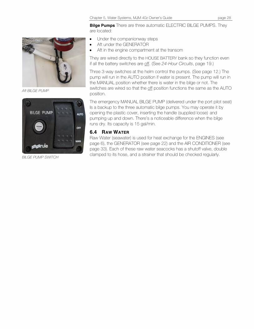
Chapter 5, Water Systems, MJM 40z Owner’s Guide page 28
Bilge Pumps There are three automatic ELECTRIC BILGE PUMPS. They are located:
• Under the companionway steps • Aft under the GENERATOR • Aft in the engine compartment at the transom They are wired directly to the HOUSE BATTERY bank so they function even if all the battery switches are off. (See 24-Hour Circuits, page 19.) Three 3-way switches at the helm control the pumps. (See page 12.) The pump will run in the AUTO position if water is present. The pump will run in the MANUAL position whether there is water in the bilge or not. The switches are wired so that the off position functions the same as the AUTO position. The emergency MANUAL BILGE PUMP (delivered under the port pilot seat) Is a backup to the three automatic bilge pumps. You may operate it by opening the plastic cover, inserting the handle (supplied loose) and pumping up and down. There’s a noticeable difference when the bilge runs dry. Its capacity is 15 gal/min.
6.4 RAW WATER Raw Water (seawater) is used for heat exchange for the ENGINES (see page 6), the GENERATOR (see page 22) and the AIR CONDITIONER (see page 33). Each of these raw water seacocks has a shutoff valve, double clamped to its hose, and a strainer that should be checked regularly.
Aft BILGE PUMP
BILGE PUMP SWITCH
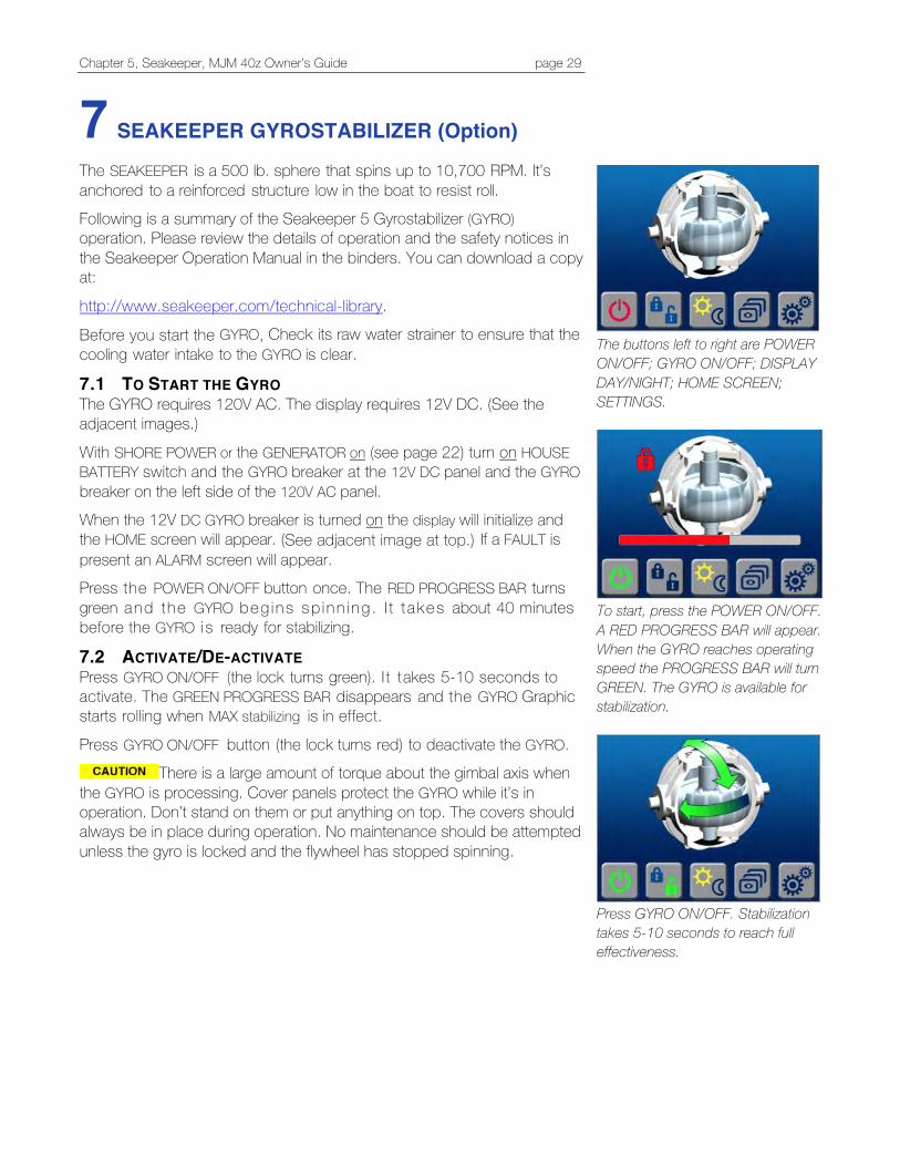
Chapter 5, Seakeeper, MJM 40z Owner’s Guide page 29
7 SEAKEEPER GYROSTABILIZER (Option)
The SEAKEEPER is a 500 lb. sphere that spins up to 10,700 RPM. It’s anchored to a reinforced structure low in the boat to resist roll. Following is a summary of the Seakeeper 5 Gyrostabilizer (GYRO) operation. Please review the details of operation and the safety notices in the Seakeeper Operation Manual in the binders. You can download a copy at:
http://www.seakeeper.com/technical-library.
Before you start the GYRO, Check its raw water strainer to ensure that the cooling water intake to the GYRO is clear.
7.1 TO START THE GYRO The GYRO requires 120V AC. The display requires 12V DC. (See the adjacent images.)
With SHORE POWER or the GENERATOR on (see page 22) turn on HOUSE BATTERY switch and the GYRO breaker at the 12V DC panel and the GYRO breaker on the left side of the 120V AC panel. When the 12V DC GYRO breaker is turned on the display will initialize and the HOME screen will appear. (See adjacent image at top.) If a FAULT is present an ALARM screen will appear. Press the POWER ON/OFF button once. The RED PROGRESS BAR turns green and the GYRO beg ins sp inn ing . I t t akes about 40 minutes before the GYRO is ready for stabilizing.
7.2 ACTIVATE/DE-ACTIVATE Press GYRO ON/OFF (the lock turns green). I t takes 5-10 seconds to activate. The GREEN PROGRESS BAR disappears and the GYRO Graphic starts rolling when MAX stabilizing is in effect.
Press GYRO ON/OFF button (the lock turns red) to deactivate the GYRO. There is a large amount of torque about the gimbal axis when
the GYRO is processing. Cover panels protect the GYRO while it’s in operation. Don’t stand on them or put anything on top. The covers should always be in place during operation. No maintenance should be attempted unless the gyro is locked and the flywheel has stopped spinning.
The buttons left to right are POWER ON/OFF; GYRO ON/OFF; DISPLAY DAY/NIGHT; HOME SCREEN; SETTINGS.
To start, press the POWER ON/OFF. A RED PROGRESS BAR will appear. When the GYRO reaches operating speed the PROGRESS BAR will turn GREEN. The GYRO is available for stabilization.
Press GYRO ON/OFF. Stabilization takes 5-10 seconds to reach full effectiveness.
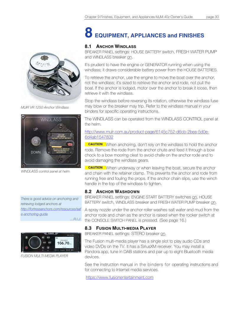
Chapter 9 Finishes, Equipment, and Appliances MJM 40z Owner’s Guide page 30
8 EQUIPMENT, APPLIANCES and FINISHES
8.1 ANCHOR WINDLASS BREAKER PANEL settings: HOUSE BATTERY switch, FRESH WATER PUMP and WINDLASS breaker on.
It’s prudent to have the engine or GENERATOR running when using the windlass; it draws considerable battery power from the HOUSE BATTERIES.
To retrieve the anchor, use the engine to move the boat over the anchor, not the windlass; it’s sized to retrieve the anchor and rode, not pull the boat. If the anchor is lodged, motor over the anchor to break it loose, then retrieve it with the windlass. Stop the windlass before reversing its rotation, otherwise the windlass fuse may blow or the breaker may trip. Refer to the windlass manual in your binders for specific operating instructions.
The WINDLASS can be operated from the WINDLASS CONTROL panel at the helm. http://www.muir.com.au/product-page/6145c752-d6cb-2bea-5d0e-6d4ab1547832
When anchoring, don’t rely on the windlass to hold the anchor rode. Remove the rode from the anchor chute and feed it through a bow chock to a bow mooring cleat to avoid chafe on the anchor rode and to avoid damaging the windlass gears.
When underway or when leaving the boat, secure the anchor and chain with the retainer clamp. This prevents the anchor and rode from running free and fouling the props. If the anchor chain slips, use the winch handle in the top of the windlass to tighten.
8.2 ANCHOR WASHDOWN BREAKER PANEL settings: ENGINE START BATTERY switches on, HOUSE BATTERY switch, WINDLASS breaker and FRESH WATER PUMP breaker on. A spray nozzle under the anchor roller washes salt water and mud from the anchor rode and chain as the anchor is raised when the rocker switch at the CONSOLE SWITCH PANEL is pressed. (See page 16.)
8.3 FUSION MULTI-MEDIA PLAYER BREAKER PANEL settings: STERO breaker on. The Fusion multi-media player has a single slot to play audio CDs and video DVDs on the TV. It has a SiriusXM receiver. You may install a Pandora app, tune in DAB stations and pair up to eight Bluetooth media devices.
See the instruction manual in the binders for operating instructions and for connecting to Internet media services.
https://www.fusionentertainment.com
MUIR VR 1250 Anchor Windlass
WINDLASS control panel at helm
There is good advice on anchoring and retrieving lodged anchors at http://fortressanchors.com/resources/safe-anchoring-guide
…R.I.J.
FUSION MULTI-MEDIA PLAYER
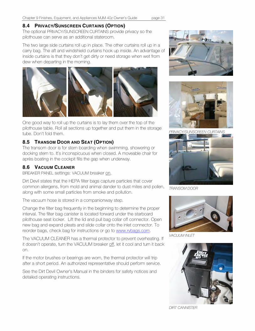
Chapter 9 Finishes, Equipment, and Appliances MJM 40z Owner’s Guide page 31
8.4 PRIVACY/SUNSCREEN CURTAINS (OPTION) The optional PRIVACY/SUNSCREEN CURTAINS provide privacy so the pilothouse can serve as an additional stateroom.
The two large side curtains roll up in place. The other curtains roll up in a carry bag. The aft and windshield curtains hook up inside. An advantage of inside curtains is that they don’t get dirty or need storage when wet from dew when departing in the morning.
One good way to roll up the curtains is to lay them over the top of the pilothouse table. Roll all sections up together and put them in the storage tube. Don’t fold them.
8.5 TRANSOM DOOR AND SEAT (OPTION) The transom door is for stern boarding when swimming, showering or docking stern to. It’s inconspicuous when closed. A moveable chair for après boating in the cockpit fills the gap when underway.
8.6 VACUUM CLEANER BREAKER PANEL settings: VACUUM breaker on, Dirt Devil states that the HEPA filter bags capture particles that cover common allergens, from mold and animal dander to dust mites and pollen, along with some small particles from smoke and pollution.
The vacuum hose is stored in a companionway step. Change the filter bag frequently in the beginning to determine the proper interval. The filter bag canister is located forward under the starboard pilothouse seat locker. Lift the lid and pull bag collar off connector. Open new bag and expand pleats and slide collar onto the inlet connector. To reorder bags, check bag for instructions or go to www.rvbags.com. The VACUUM CLEANER has a thermal protector to prevent overheating. If it doesn’t operate, turn the VACUUM breaker off, let it cool and turn it back on. If the motor brushes or bearings are worn, the thermal protector will trip after a short period. An authorized representative should perform service. See the Dirt Devil Owner’s Manual in the binders for safety notices and detailed operating instructions.
PRIVACY/SUNSCREEN CURTAINS
TRANSOM DOOR
VACUUM INLET
DIRT CANNISTER
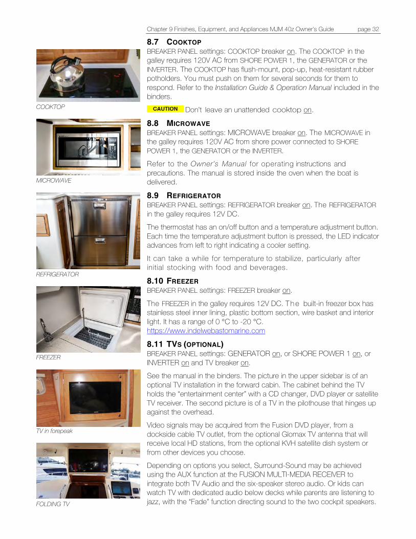
Chapter 9 Finishes, Equipment, and Appliances MJM 40z Owner’s Guide page 32
8.7 COOKTOP BREAKER PANEL settings: COOKTOP breaker on. The COOKTOP in the galley requires 120V AC from SHORE POWER 1, the GENERATOR or the INVERTER. The COOKTOP has flush-mount, pop-up, heat-resistant rubber potholders. You must push on them for several seconds for them to respond. Refer to the Installation Guide & Operation Manual included in the binders.
Don’t leave an unattended cooktop on.
8.8 MICROWAVE BREAKER PANEL settings: MICROWAVE breaker on. The MICROWAVE in the galley requires 120V AC from shore power connected to SHORE POWER 1, the GENERATOR or the INVERTER. Refer to the Owner’s Manual for operating instructions and precautions. The manual is stored inside the oven when the boat is delivered.
8.9 REFRIGERATOR BREAKER PANEL settings: REFRIGERATOR breaker on. The REFRIGERATOR in the galley requires 12V DC. The thermostat has an on/off button and a temperature adjustment button. Each time the temperature adjustment button is pressed, the LED indicator advances from left to right indicating a cooler setting.
It can take a while for temperature to stabilize, particularly after initial stocking with food and beverages.
8.10 FREEZER BREAKER PANEL settings: FREEZER breaker on.
The FREEZER in the galley requires 12V DC. T h e built-in freezer box has stainless steel inner lining, plastic bottom section, wire basket and interior light. It has a range of 0 °C to -20 °C. https://www.indelwebastomarine.com
8.11 TVS (OPTIONAL) BREAKER PANEL settings: GENERATOR on, or SHORE POWER 1 on, or INVERTER on and TV breaker on. See the manual in the binders. The picture in the upper sidebar is of an optional TV installation in the forward cabin. The cabinet behind the TV holds the “entertainment center” with a CD changer, DVD player or satellite TV receiver. The second picture is of a TV in the pilothouse that hinges up against the overhead. Video signals may be acquired from the Fusion DVD player, from a dockside cable TV outlet, from the optional Glomax TV antenna that will receive local HD stations, from the optional KVH satellite dish system or from other devices you choose. Depending on options you select, Surround-Sound may be achieved using the AUX function at the FUSION MULTI-MEDIA RECEIVER to integrate both TV Audio and the six-speaker stereo audio. Or kids can watch TV with dedicated audio below decks while parents are listening to jazz, with the “Fade” function directing sound to the two cockpit speakers.
COOKTOP
MICROWAVE
REFRIGERATOR
FREEZER
TV in forepeak
FOLDING TV
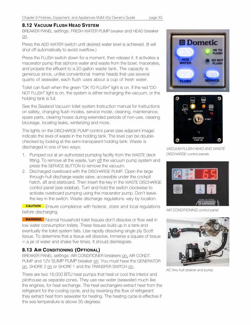
Chapter 9 Finishes, Equipment, and Appliances MJM 40z Owner’s Guide page 33
8.12 VACUUM FLUSH HEAD SYSTEM BREAKER PANEL settings: FRESH WATER PUMP breaker and HEAD breaker on.
Press the ADD WATER switch until desired water level is achieved. (It will shut off automatically to avoid overflow.)
Press the FLUSH switch down for a moment, then release it. It activates a macerator pump that siphons water and waste from the bowl, macerates, and propels the effluent to a 20-gallon waste tank. The capacity is generous since, unlike conventional marine heads that use several quarts of seawater, each flush uses about a cup of fresh water.
Toilet can flush when the green “OK TO FLUSH” light is on. If the red “DO NOT FLUSH” light is on, the system is either recharging the vacuum, or the holding tank is full. See the Sealand Vacuum toilet system Instruction manual for instructions on safety, changing flush modes, service mode, cleaning, maintenance, spare parts, clearing hoses during extended periods of non-use, clearing blockage, locating leaks, winterizing and more.
The lights on the DISCHARGE PUMP control panel (see adjacent image) indicate the level of waste in the holding tank. The level can be double-checked by looking at the semi-transparent holding tank. Waste is discharged in one of two ways: 1. Pumped out at an authorized pumping facility from the WASTE deck
fitting. To remove all the waste, turn off the vacuum pump system and press the SERVICE BUTTON to remove the vacuum.
2. Discharged overboard with the DISCHARGE PUMP. Open the large through-hull discharge waste valve, accessible under the cockpit hatch, aft and starboard. Then insert the key in the WASTE DISCHARGE control panel (see sidebar). Turn and hold the switch clockwise to activate overboard pumping using the macerator pump. Don’t leave the key in the switch. Waste discharge regulations vary by location.
Ensure compliance with federal, state and local regulations before discharging.
Normal household toilet tissues don’t dissolve or flow well in low water consumption toilets. These tissues build up in a tank and eventually the toilet system fails. Use rapidly dissolving single ply Scott tissue. To determine that a tissue will dissolve, immerse a square of tissue in a jar of water and shake five times. It should disintegrate.
8.13 AIR CONDITIONING (OPTIONAL) BREAKER PANEL settings: AIR CONDITIONER breakers on, AIR CONDT. PUMP and 12V SUMP PUMP breaker on. You must have the GENERATOR on, SHORE 2 on or SHORE 1 and the TRANSFER SWITCH on. There are two 16,000 BTU heat pumps that heat or cool the interior and pilothouse as separate zones. They use raw water (seawater) much like the engines, for heat exchange. The heat exchangers extract heat from the refrigerant for the cooling cycle, and by reversing the flow of refrigerant they extract heat from seawater for heating. The heating cycle is effective if the sea temperature is above 35 degrees.
VACUUM FLUSH HEAD AND WASTE DISCHARGE control panels
AIR CONDITIONING control panel
AC thru hull strainer and pump

Chapter 9 Finishes, Equipment, and Appliances MJM 40z Owner’s Guide page 34
There’s an intake seacock, R A W W A T E R strainer and pump located in the systems room under the pilothouse. They should be checked frequently and are the first things to check if the unit fails to deliver heat or cooling.
Programming Procedure There’s a wide range of options for controlling the AC system. You can set it to heat mode, cool mode or automatic mode; set it to cycle on and off for humidity control when the boat is unused; control fan speeds, view service history and hour meter and set many more options. For a full explanation of the options, controls and the programing procedure, see the users manual. Programmable Parameters The default parameters may be changed. Once new values are entered and memorized, the factory defaults are overwritten and the new parameters become the default values. You can restore the original factory default parameters manually. A summary of the parameters, the permitted values and original factory default settings are listed in Table 2, page 12 of the manual in the binders. When used with optional electric heat, the fan remains on for four minutes after the heater cycles off even if fan is set to cycled operation.
8.14 FINISHES Hull paint The 40z hull is painted with Awlcraft 2000 color and three coats of clear Awlcraft. Awlgrip states that while it doesn’t hurt to wax it, it doesn’t help and can create a maintenance problem.
The cabin deck and cabinetwork are finished in clear Awlgrip. See the Awlgrip website for care and maintenance advice.
http://www.awlgrip.com Corian Instructions for maintaining Corian counter tops are in the binders and at: http://www.dupont.com/products-and-services/construction-materials/surface-design-materials/brands/corian-solid-surfaces.html?src=gg-kg_surfaces-us_corian&gclid=CP2jrr3Vx9ECFVg6gQod2AkK0g Strataglass Don’t use chemicals or brushes to clean; use only mild soap and a sponge or a soft rag. If the curtains are scratched a mild polishing compound (a white cream similar to what is used on Awlgrip) can be hand applied to remove them. Test a small, unobtrusive area first. (See the Strataglass Care and Maintenance website.) http://www.strataglass.com/strataglass-care-and-maintenance It’s best to leave the curtains in place, even when trucking. If they’re removed, store them flat or rolled together with towels or paper between layers. To avoid creases, don’t fold.
UltraLeather Upholstery The standard UltraLeather upholstery is water resistant, but don’t use chemicals or brushes to clean, only mild soap and a sponge or a soft rag. Stidd Seats See http://stidd.com/support/ for maintenance recommendations. The Stidd seats swivel and lower for a sociable setting. Slide the seats forward before swiveling so the seat doesn’t jam into the pilothouse walls.
Gull droppings on the hardtop that drizzle down the side curtains after a rain or heavy dew have an acid that can, over time, etch the Strataglass curtains. Be sure to clean frequently. There is one known instance with a 36z that was moored in Chilmark on Martha’s Vineyard.
…R.I.J.
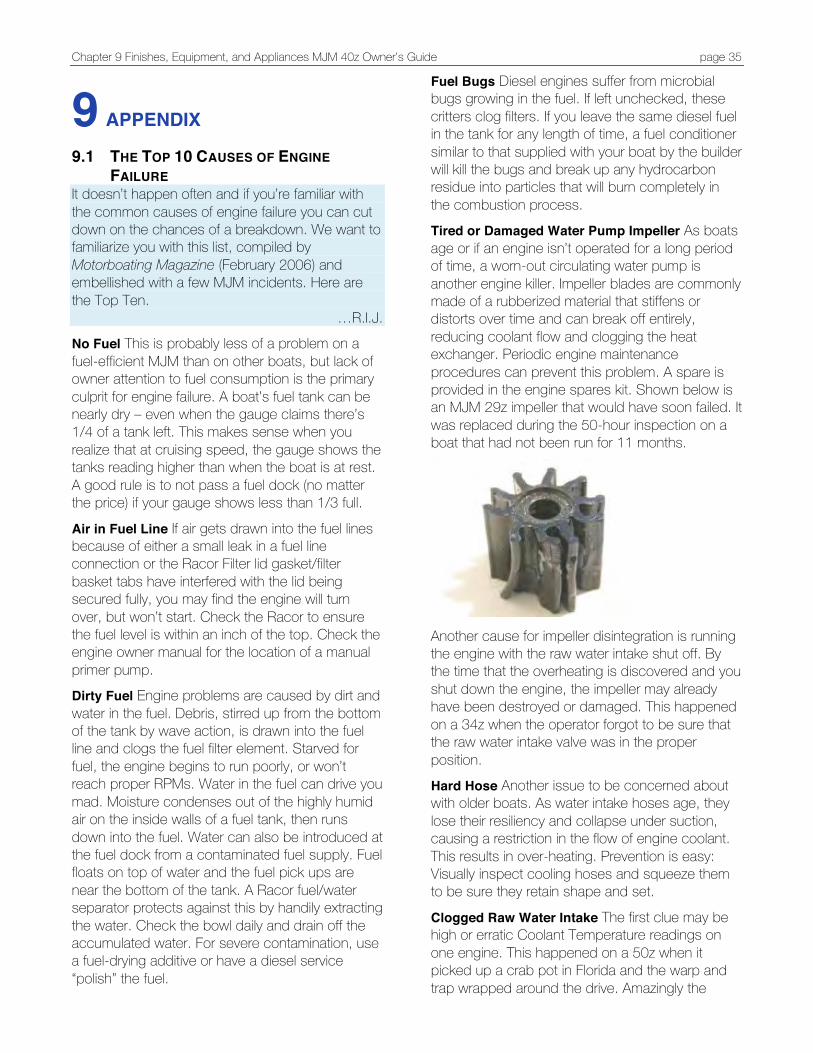
Chapter 9 Finishes, Equipment, and Appliances MJM 40z Owner’s Guide page 35
9 APPENDIX
9.1 THE TOP 10 CAUSES OF ENGINE FAILURE
It doesn’t happen often and if you’re familiar with the common causes of engine failure you can cut down on the chances of a breakdown. We want to familiarize you with this list, compiled by Motorboating Magazine (February 2006) and embellished with a few MJM incidents. Here are the Top Ten.
…R.I.J. No Fuel This is probably less of a problem on a fuel-efficient MJM than on other boats, but lack of owner attention to fuel consumption is the primary culprit for engine failure. A boat’s fuel tank can be nearly dry – even when the gauge claims there’s 1/4 of a tank left. This makes sense when you realize that at cruising speed, the gauge shows the tanks reading higher than when the boat is at rest. A good rule is to not pass a fuel dock (no matter the price) if your gauge shows less than 1/3 full.
Air in Fuel Line If air gets drawn into the fuel lines because of either a small leak in a fuel line connection or the Racor Filter lid gasket/filter basket tabs have interfered with the lid being secured fully, you may find the engine will turn over, but won’t start. Check the Racor to ensure the fuel level is within an inch of the top. Check the engine owner manual for the location of a manual primer pump. Dirty Fuel Engine problems are caused by dirt and water in the fuel. Debris, stirred up from the bottom of the tank by wave action, is drawn into the fuel line and clogs the fuel filter element. Starved for fuel, the engine begins to run poorly, or won’t reach proper RPMs. Water in the fuel can drive you mad. Moisture condenses out of the highly humid air on the inside walls of a fuel tank, then runs down into the fuel. Water can also be introduced at the fuel dock from a contaminated fuel supply. Fuel floats on top of water and the fuel pick ups are near the bottom of the tank. A Racor fuel/water separator protects against this by handily extracting the water. Check the bowl daily and drain off the accumulated water. For severe contamination, use a fuel-drying additive or have a diesel service “polish” the fuel.
Fuel Bugs Diesel engines suffer from microbial bugs growing in the fuel. If left unchecked, these critters clog filters. If you leave the same diesel fuel in the tank for any length of time, a fuel conditioner similar to that supplied with your boat by the builder will kill the bugs and break up any hydrocarbon residue into particles that will burn completely in the combustion process. Tired or Damaged Water Pump Impeller As boats age or if an engine isn’t operated for a long period of time, a worn-out circulating water pump is another engine killer. Impeller blades are commonly made of a rubberized material that stiffens or distorts over time and can break off entirely, reducing coolant flow and clogging the heat exchanger. Periodic engine maintenance procedures can prevent this problem. A spare is provided in the engine spares kit. Shown below is an MJM 29z impeller that would have soon failed. It was replaced during the 50-hour inspection on a boat that had not been run for 11 months.
Another cause for impeller disintegration is running the engine with the raw water intake shut off. By the time that the overheating is discovered and you shut down the engine, the impeller may already have been destroyed or damaged. This happened on a 34z when the operator forgot to be sure that the raw water intake valve was in the proper position. Hard Hose Another issue to be concerned about with older boats. As water intake hoses age, they lose their resiliency and collapse under suction, causing a restriction in the flow of engine coolant. This results in over-heating. Prevention is easy: Visually inspect cooling hoses and squeeze them to be sure they retain shape and set.
Clogged Raw Water Intake The first clue may be high or erratic Coolant Temperature readings on one engine. This happened on a 50z when it picked up a crab pot in Florida and the warp and trap wrapped around the drive. Amazingly the
Chapter 9 Finishes, Equipment, and Appliances MJM 40z Owner’s Guide page 36
RPMs weren’t effected nor the IPS function (a wonderfully resilient system!). Subsequently all new MJMs are being equipped with warp cutters. Things like discarded plastic Baggies, weeds, etc., can also plug up the raw-water intake on the drives. You can avoid this problem by visually inspecting the strainer basket. Good water flow should exist without evidence of lots of air. When removing debris, be sure to properly replace the seal, otherwise the pump will lose suction. Smearing the seal with Vaseline or other marine-grade grease helps. No Water Circulation If upon starting the engine at idle you don’t see water circulating in the strainer: (1) Stop the engine, (2) Check to see that both intake and raw water outgo valves are open at the drives, (3) Fill the strainer basket container with water, re-seal the strainer and turn on the engine again to deal with a possible air lock, (4) race the engine in neutral momentarily, (5) dive over the side to see if a plastic bag or other debris is covering the intake, (6) Inspect the impeller which pumps water through the engine. Hard Knocks Collision with an underwater obstacle that damages the propulsion system. Often you can still operate the boat at low RPM to return to port, being careful to avoid excessive vibration that might otherwise compound the damage by damaging the drives. The problem may be corrected in a day or so without hauling by an experienced diver who has access to a prop shop where the blades can be repaired and the prop re-balanced and recoated with PropSpeed, then re-installed. Bad Battery Marine starting batteries die from old age and neglect. Keep the terminals and posts clean from that green corrosion that builds up, restricting the flow of current – preventing them from fully charging. Periodically have your batteries tested to determine their condition and expected longevity. The 40z is equipped with a “parallel” switch, which can be turned on to employ the 400 ampere-hour house banks in starting the engine.
Stale Gasoline Not applicable Sagging Belt As V-belts wear, they stretch and begin to slip. Consequently, alternators and water pumps don’t spin to their full speed. Batteries may not fully charge and coolant circulates sluggishly. The solution is to check belt tension regularly and tighten belts when necessary. Drive belts can also
snap. The only way to avoid this malady is to replace them once they begin to show wear. Some spare belts are provided in the engine spares kit.
9.2 DIESEL OPERATION What Diesel Mechanics Wish Every Boat Owner Knew The following is edited from an article by Captain Bernie Weiss at www.AtlanticYachtDelivery.com.
To run well, a diesel engine requires only clean fuel, clean lubricating oil, coolant, and lots of air. Below are ten important maintenance issues that diesel mechanics wish their customers knew: Don’t baby the engine Diesels don’t like to idle in neutral, or even in gear at low speeds; they do like to work hard under load. Generally, 10% less than the maximum RPM is the best cruising RPM. Excessive idling leads to gradual build-up of detrimental varnish on the cylinders, and deposits of soot and carbon on the engine’s valves and in the exhaust system, particularly at the manifold injection elbow where raw cooling water exiting the engine mates with the exhaust gases. Run it hard. However...after running at cruising RPM for several hours, a brief cool-down at idle speed, with no load, is beneficial. A few minutes is enough.
Give your engine clean fuel Fuel is contaminated when it contains water, sediment, other solids, or biological organisms, some of which thrive in diesel fuel. To minimize contamination, don’t store your boat for the winter or let it sit around for weeks at a time with fuel tanks only partly full. A full tank minimizes condensation of water vapor on the tank’s interior and the growth of microorganisms. Fuel filters trap sediment, sludge, water and organic material and should be changed at periodic intervals. Be conservative in your estimate of fuel consumption When underway, don’t delay refueling to the point where you have expended nearly all the fuel in the tank. The last 20% should be held in reserve. To suck up the last few gallons is to chance sucking up water (tank condensate), sludge, and other contaminants - perhaps even air - into your fuel lines. Know how to vent (“bleed”) the air out of your fuel system Air locks in diesel fuel systems are a fact of life. The typical diesel fuel system operates with a lift pump (a vacuum pump) that lifts or sucks fuel out of the tank, draws it through the pump,
Chapter 9 Finishes, Equipment, and Appliances MJM 40z Owner’s Guide page 37
then sends it to the filters and injectors, where the injector pump sends fuel to the individual cylinders for combustion. Whenever you open the fuel line between the tank and the engine (for example, to change a filter element) air enters the line. Air may also be sucked into the fuel line through cracked seals and gaskets, poorly fitted connectors and clamps, via the pick-up tube in the fuel tank, etc. This air must be removed, because even a tiny air bubble in the fuel line will block the flow of fuel, and without fuel, the engine won’t start; if running, air in the fuel line will cause it to stop. To clear your fuel line of air, you must vent or “bleed” it out. Consult your engine’s manual to identify the bleeding nuts; paint them with white nail polish so you can easily find them again, in the dark, at sea. Given decent access to the engine, bleeding or venting air is a simple procedure that everyone should be able to perform. Using the engine manual, teach yourself how to do this. Be diligent about checking your lube oil and oil filter Diesel engines are rough on oil and usually require more frequent oil and oil filter changes than comparable gasoline engines. Follow the engine manual’s recommendation for service intervals. Carry spares on board. Between oil changes, use the dipstick to check the oil level. Top it off as necessary from your on-board lube oil inventory, but don’t exceed the “full” mark on the dipstick; more isn’t better. If you get erratic RPM readings or can’t reach high RPMs, most likely you need to replace one or both Racor fuel filters.
Minimize risk of fire Diesel engines vibrate a lot, and the typical marine diesel has a lot of wiring and hoses attached to it, crossing it, behind it and near it. Over time, as the engine vibrates, the fasteners may loosen and fail, the wiring and hoses droop or fall. One hates to see a loose hose or wire (such as the primary wiring harness, or the power supply to your fuel pump, or a hose to the hydraulic pump) cross and contact a hot exhaust manifold, for example; this could be a prescription for fire due to abrasion of insulation around wire, or chafing through the wall of a hose. From time to time, inspect your engine compartment for these potential risks. Add chafing protection, replace worn insulation, and supplement the fasteners if necessary. Consider rerouting wires and hoses where appropriate Know how to trouble-shoot the cooling system Since overheating is a common problem,
familiarize yourself with engine’s cooling systems: the raw water (sea-water) system, as well as the fresh water (internal circulating coolant) system. The most likely causes of overheating are:
• Raw-water valve closed. • Raw-water through-hull blocked externally.
Check for a plastic bag, or a clump of sea grass or other material, covering or plugging the inlet.
• Cover of Raw Water Strainer improperly secured allowing air in.
• Momentary air pocket preventing ingest of air under boat. Reverse engine or stop and restart.
• Raw-water filter / strainer clogged with sediment, sand, goo, grass, or living critters such as barnacles, jellyfish, and algae.
• Defective or destroyed impeller in raw water pump. The impeller should be replaced every year or two, as the rubber vanes become brittle with age and may snap off.
• Heat exchanger dirty or clogged up with sediment and other deposits. The entire raw water cooling system should be flushed periodically to remove salt and sediment deposits.
• Exhaust elbow restricted by carbon deposits or other solids, reducing discharge of cooling water and exhaust gases. Routinely run the boat at high RPM for several minutes to clear.
• Thermostat stuck closed; likely will require removal or replacement. (Note: Some diesel engines operate OK - temporarily - without a thermostat.) Coolant temperature of 170-180o F is normal.
• Low level of coolant (50-50 mix of antifreeze-water). Coolant levels should be checked routinely at the expansion tank, adding more as needed. Don’t overfill (coolant). Alarm usually sounds if coolant level is too low.
• Broken or slipping V-belt, which drives the water pumps and the alternator. Even a new belt deserves re-tensioning and inspection. Suspect slippage or wear if you see dark “belt dust” settling at the engine’s base. Belt tension is OK if pressure deflects the belt by about 1/2 inch.
• Overloading of the engine: Rope wrapped around propeller shaft, dirty bottom, fouled propeller, or air leaks in the raw water-cooling
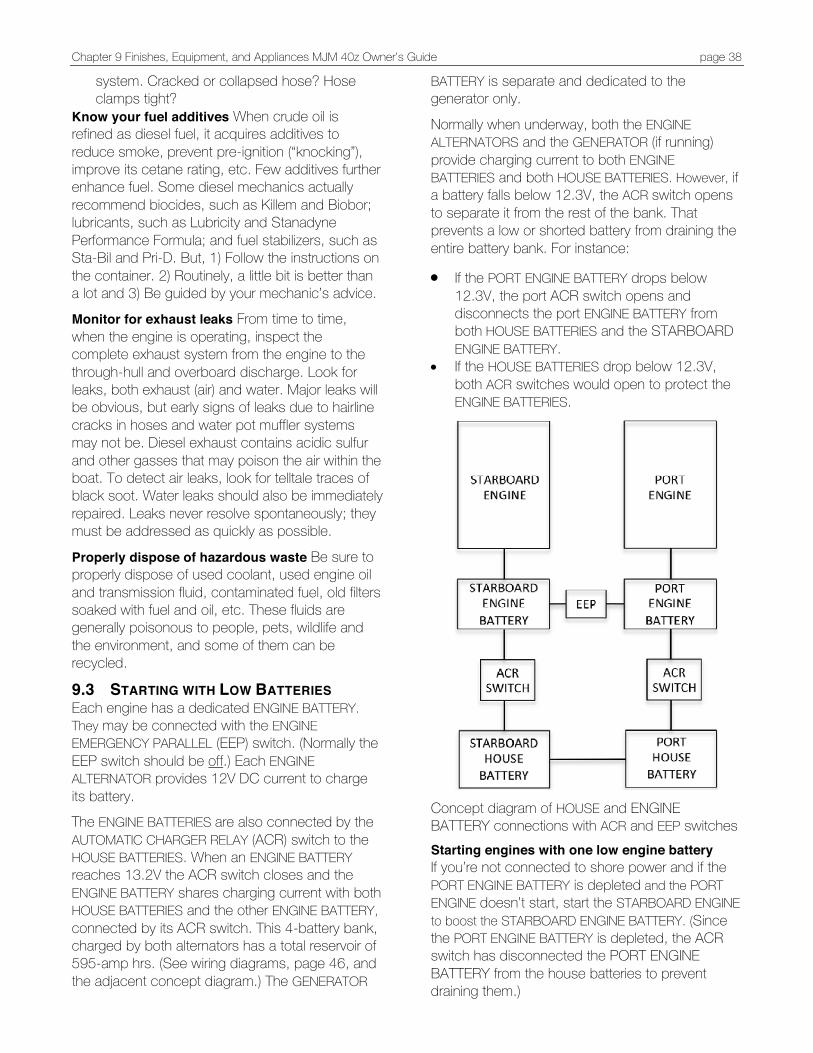
Chapter 9 Finishes, Equipment, and Appliances MJM 40z Owner’s Guide page 38
system. Cracked or collapsed hose? Hose clamps tight?
Know your fuel additives When crude oil is refined as diesel fuel, it acquires additives to reduce smoke, prevent pre-ignition (“knocking”), improve its cetane rating, etc. Few additives further enhance fuel. Some diesel mechanics actually recommend biocides, such as Killem and Biobor; lubricants, such as Lubricity and Stanadyne Performance Formula; and fuel stabilizers, such as Sta-Bil and Pri-D. But, 1) Follow the instructions on the container. 2) Routinely, a little bit is better than a lot and 3) Be guided by your mechanic’s advice. Monitor for exhaust leaks From time to time, when the engine is operating, inspect the complete exhaust system from the engine to the through-hull and overboard discharge. Look for leaks, both exhaust (air) and water. Major leaks will be obvious, but early signs of leaks due to hairline cracks in hoses and water pot muffler systems may not be. Diesel exhaust contains acidic sulfur and other gasses that may poison the air within the boat. To detect air leaks, look for telltale traces of black soot. Water leaks should also be immediately repaired. Leaks never resolve spontaneously; they must be addressed as quickly as possible.
Properly dispose of hazardous waste Be sure to properly dispose of used coolant, used engine oil and transmission fluid, contaminated fuel, old filters soaked with fuel and oil, etc. These fluids are generally poisonous to people, pets, wildlife and the environment, and some of them can be recycled.
9.3 STARTING WITH LOW BATTERIES Each engine has a dedicated ENGINE BATTERY. They may be connected with the ENGINE EMERGENCY PARALLEL (EEP) switch. (Normally the EEP switch should be off.) Each ENGINE ALTERNATOR provides 12V DC current to charge its battery. The ENGINE BATTERIES are also connected by the AUTOMATIC CHARGER RELAY (ACR) switch to the HOUSE BATTERIES. When an ENGINE BATTERY reaches 13.2V the ACR switch closes and the ENGINE BATTERY shares charging current with both HOUSE BATTERIES and the other ENGINE BATTERY, connected by its ACR switch. This 4-battery bank, charged by both alternators has a total reservoir of 595-amp hrs. (See wiring diagrams, page 46, and the adjacent concept diagram.) The GENERATOR
BATTERY is separate and dedicated to the generator only. Normally when underway, both the ENGINE ALTERNATORS and the GENERATOR (if running) provide charging current to both ENGINE BATTERIES and both HOUSE BATTERIES. However, if a battery falls below 12.3V, the ACR switch opens to separate it from the rest of the bank. That prevents a low or shorted battery from draining the entire battery bank. For instance: • If the PORT ENGINE BATTERY drops below
12.3V, the port ACR switch opens and disconnects the port ENGINE BATTERY from both HOUSE BATTERIES and the STARBOARD ENGINE BATTERY.
• If the HOUSE BATTERIES drop below 12.3V, both ACR switches would open to protect the ENGINE BATTERIES.
Concept diagram of HOUSE and ENGINE BATTERY connections with ACR and EEP switches Starting engines with one low engine battery If you’re not connected to shore power and if the PORT ENGINE BATTERY is depleted and the PORT ENGINE doesn’t start, start the STARBOARD ENGINE to boost the STARBOARD ENGINE BATTERY. (Since the PORT ENGINE BATTERY is depleted, the ACR switch has disconnected the PORT ENGINE BATTERY from the house batteries to prevent draining them.)
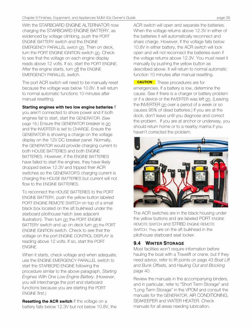
Chapter 9 Finishes, Equipment, and Appliances MJM 40z Owner’s Guide page 39
With the STARBOARD ENGINE ALTERNATOR now charging the STARBOARD ENGINE BATTERY, as evidenced by voltage climbing, push the PORT ENGINE BATTERY switch and the ENGINE EMERGENCY PARALLEL switch on. Then on deck, turn the PORT ENGINE IGNITION switch on. Check to see that the voltage on each engine display reads above 12 volts. If so, start the PORT ENGINE. After the engine starts, turn off the ENGINE EMERGENCY PARALLEL switch. The port ACR switch will need to be manually reset because the voltage was below 10.8V. It will return to normal automatic functions 10 minutes after manual resetting.
Starting engines with two low engine batteries If you aren’t connected to shore power and if both engines fail to start, start the GENERATOR. (See page 18.) Ensure the GENERATOR breaker is on and the INVERTER is set to CHARGE. Ensure the GENERATOR is showing a charge on the voltage display on the 12V DC breaker panel. Normally, the GENERATOR would provide charging current to both HOUSE BATTERIES and both ENGINE BATTERIES. However, if the ENGINE BATTERIES have failed to start the engines, they have likely dropped below 12.3V and tripped their ACR switches so the GENERATOR’S charging current is charging the HOUSE BATTERIES but current will not flow to the ENGINE BATTERIES. To reconnect the HOUSE BATTERIES to the PORT ENGINE BATTERY, push the yellow button labeled PORT ENGINE REMOTE SWITCH on top of a small black box located on the aft bulkhead under the starboard pilothouse hatch (see adjacent illustration). Then turn on the PORT ENGINE BATTERY switch and up on deck turn on the PORT ENGINE IGNITION switch. Check to see that the voltage on the port ENGINE CONTROL DISPLAY is reading above 12 volts. If so, start the PORT ENGINE.
When it starts, check voltage and when adequate, use the ENGINE EMERGENCY PARALLEL switch to start the STARBORD ENGINE following the procedure similar to the above paragraph, Starting Engines With One Low Engine Battery. (However, you will interchange the port and starboard functions because you are starting the PORT ENGINE first.)
Resetting the ACR switch If the voltage on a battery falls below 12.3V but not below 10.8V, the
ACR switch will open and separate the batteries. When the voltage returns above 12.3V in either of the batteries it will automatically reconnect and share charge. However, If the voltage falls below 10.8V in either battery, the ACR switch will lock open and will not reconnect the batteries even if the voltage returns above 12.3V. You must reset it manually by pushing the yellow button as described above. It will return to normal automatic function 10 minutes after manual resetting.
These procedures are for emergencies. If a battery is low, determine the cause. See if there is a charger or battery problem or if a device or the INVERTER was left on. (Leaving the INVERTER on over a period of a week or so causes 95% of dead batteries.) If you are at the dock, don’t leave until you diagnose and correct the problem. If you are at anchor or underway, you should return home or to a nearby marina if you haven’t corrected the problem.
The ACR switches are in the black housing under the yellow buttons and are labeled PORT ENGINE REMOTE SWITCH and STRBD ENGINE REMOTE SWITCH. They are on the aft bulkhead in the pilothouse starboard seat locker.
9.4 WINTER STORAGE Most facilities won’t require information before hauling the boat with a Travelift or crane, but if they need advice, refer to lift points on page 43 Boat Lift and Bunk Offsets, and Hauling Out and Blocking page 40. Review the manuals in the accompanying binders, and in particular, refer to “Short Term Storage” and “Long Term Storage” in the VPOM and consult the manuals for the GENERATOR, AIR CONDITIONING, SEAKEEPER and WATER HEATER. Check manuals for all areas needing lubrication.
Chapter 9 Finishes, Equipment, and Appliances MJM 40z Owner’s Guide page 40
Underwater hardware Power-wash the bottom and check thru hulls and seacocks for growth. (Inspection of underwater hardware may avoid a problem in the future.) Replace anodes if necessary. Drain water Flush the engines and the generator engine and the heat exchangers with fresh water. Remove engine drain plugs to prevent freezing water from damaging the engine.
Drain the FRESH WATER TANK, WINDSHIELD WASHER, WATER HEATER, HOLDING TANK, GRAY WATER TANK, ANCHOR WASHDOWN, AIR CONDITIONER, HEAD, ICE MAKER and the plumbing lines and run non-toxic antifreeze, through the systems to purge water that could freeze.
Replace oil Drain and replace oil in engines, generator IPS Drives, and Seakeeper and change filters.
Engine oil drains away in storage, leaving engine components exposed and vulnerable to corrosion. Moisture and acids in old oil pit bearings and internal engine parts. Use a fogging oil to coat internal components. Warm up the engine to 185o before draining oil so heavier metal particles are picked up and flushed out.
Lubrication Find grease fittings and service them with marine grease. Most fittings are in the steering mechanism area. Fuel Fill the fuel tank (a full tank prevents water condensation). Add fuel stabilizer to prevent deterioration. Batteries Set a trickle charge to keep batteries topped off.
9.5 SPRING COMMISSIONING Commission engines and drives Review the manuals in the accompanying binders and in particular, refer to the VPOM and consult the manuals for the GENERATOR, AIR CONDITIONING and SEAKEEPER. Fresh water system Commission the fresh water system: the FRESH WATER TANK, WINDSHIELD WASHER, WATER HEATER, HOLDING TANK, GRAY WATER TANK, ANCHOR WASHDOWN, AIR CONDITIONER, HEAD and ICE MAKER. Check pumps, operate the systems and check for leaks.
Paint Apply anti-fouling paint to the IPS drives, the props and the bottom if needed.
9.6 HAULING OUT AND BLOCKING Refer to the illustration titled Boat Lift & Bunk Offsets in the Appendix page 43 before lifting the boat with a Travelift or a crane with straps. The fore and aft lift points are approximately abeam of the windshield and the aft end of the hard top respectively. Weight-bearing supports should be at the keel (centerline of the boat) and chines (edges).
Point-loading flat areas other than centerline and chine or setting the weight of the hull on supports of insufficient area may damage the hull. A 6-8 ft. metal “V” Channel should be placed under the keel forward of the transom on top of a trailer support point between the drives to avoid point-loading the laminate.
9.7 TRAILER LOADING CHECKLIST 1. Place cockpit & pilothouse cushions below on
island berth. 2. Remove canvas from bimini, detach aft legs
and hinge the main hoop forward against the hardtop. Secure the short legs, pad the main hoop where it touches the hardtop (AC hose), secure the hoop to handrails with fender whips.
3. Hinge down VHF antenna and reverse tape it to starboard handrail. Hinge down running light and tighten.
4. Remove KVH or FLIR tower and seal hardtop openings and wire connections. Wrap domes and strut in blanket. Park it in a pilothouse locker, or shower, braced with throw pillows.
5. Max height over road is 13’6” if standard radar dome is bolted to hardtop without strut.
6. Wrap plastic around horn trumpets. 7. Face searchlight aft and secure the anchor
chain grabber. 8. Latch all cabinet doors, drawers and fridge. 9. Don’t apply adhesive tape to any surface,
particularly ultra leather. 10. Turn off all battery switches and make sure the
INVERTER is off. 11. Never permit the boat to be loaded stern first
or you will spend a lifetime cleaning the boat! 12. Shrink-wrapping isn’t recommended. It can do
damage if it breaks loose. 13. Exchange contact information with the driver
and the destination yard so you may maintain contact.

Chapter 9 Finishes, Equipment, and Appliances MJM 40z Owner’s Guide page 41
14. In addition to aft and midship supports in locations seen on the previous page, support the boat under the bow, forward of any straps.
15. Leaving side and aft pilothouse curtains in place best protects the boat interior.
16. Lock companionway door. Advise driver and receiving yard on the combination.
9.8 FUEL CONSUMPTION The data in the adjacent chart was obtained in Jan-Feb 2009 from three separate runs in three separate locations: Boston Harbor, near Captiva FL, and near Miami during the Boat Show. Volvo-Penta technicians conducted two of the runs. Displacement Assuming similar hull designs, fuel efficiency is a function of the power-to-weight ratios. Less weight equals less fuel for a given HP. Dry and empty weight of the boat was 16,000 lbs. Each run was made with the boat at approximately 21,000 lbs. that included approximately 3/4 full tanks, 1400 lbs. of cruising gear and 2-4 people.
Propulsion System Test runs were done on 40z #1 powered with an IPS 500 propulsion system consisting of twin D6 370 HP diesel engines and stern drives.
Range of Efficient Operation Nautical miles per gallon remain fairly constant from 9 to 27 knots. Cruising Speed Volvo Penta suggests that in suitable conditions, 10% below open throttle (about 3200 RPM at 30 knots) is optimum cruising speed. The data below would indicate that 2900-3000 RPM at 28-knots would be more efficient. Sour Spot The 40z seems to have a huge “Sweet Spot” and one small “Sour Spot” at about 1700 rpm at just over 10 knots where the most power is applied to overcome resistance before the boat achieves a plane. Notice that the boat is no more efficient at that point than at 30 knots.
When underway fuel may run back in the tank where the fuel level sensor is located. It may then indicate more fuel than is actually there; it’s wise to fill up when you get down to 1/3 tank.
FUEL EFFICIENCY RANGE TIME
RPM GPH KTS NMPG NMRANGE Secs*
600 0.6 4.8 7.6 2392
1000 2.3 6.7 3.0 937 1200 3.5 7.6 2.2 684
1300 3.9 8.0 2.1 646 1400 4.7 8.2 1.8 555 1500 6.8 9.3 1.4 428
1600 7.8 9.5 1.2 384 1700 9.5 10.0 1.1 333 2.5*
1800 9.7 13.1 1.4 425 1900 10.6 14.3 1.3 425 2000 12.7 15.1 1.2 374
2200 14.8 17.9 1.2 380 2400 17.6 20.9 1.2 374 5.3*
2600 20.5 24.0 1.2 370 2800 22.9 26.9 1.2 370
3000 26.4 30.0 1.1 357 9.5* 3200 30.5 32.8 1.1 339
3400 35.7 36.1 1.0 319
3500 38.5 37.7 1.0 308 *Seconds required to reach the indicated speed.
Volvo technicians said, “This is a Ferrari!” as I mashed the throttles forward to hit 20 knots in 5.3 seconds from a standstill. No wonder, that’s on a par with some “thunder” boats and about what it takes a Mercedes SL550 to hit 60 mph (52 knots).
…R.I.J.
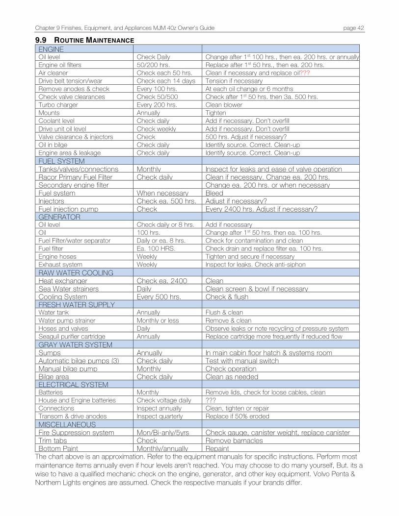
Chapter 9 Finishes, Equipment, and Appliances MJM 40z Owner’s Guide page 42
9.9 ROUTINE MAINTENANCE ENGINE Oil level Check Daily Change after 1st 100 hrs., then ea. 200 hrs. or annually Engine oil filters
Aor C;eamer
D
50/200 hrs. Replace after 1st 50 hrs., then ea. 200 hrs. Air cleaner
ddd
Check each 50 hrs. Clean if necessary and replace oil??? Drive belt tension/wear
Check each 14 days Tension if necessary Remove anodes & check Every 100 hrs. At each oil change or 6 months Check valve clearances Check 50/500 Check after 1st 50 hrs. then 3a. 500 hrs. Turbo charger Every 200 hrs. Clean blower Mounts Annually Tighten Coolant level Check daily Add if necessary. Don’t overfill Drive unit oil level Check weekly Add if necessary. Don’t overfill Valve clearance & injectors Check 500 hrs. Adjust if necessary? Oil in bilge Check daily Identify source. Correct. Clean-up Engine area & leakage Check daily Identify source. Correct. Clean-up FUEL SYSTEM Tanks/valves/connections Monthly Inspect for leaks and ease of valve operation Racor Primary Fuel Filter Check daily Clean if necessary. Change ea. 200 hrs. Secondary engine filter Change ea. 200 hrs. or when necessary Fuel system When necessary Bleed Injectors Check ea. 500 hrs. Adjust if necessary? Fuel injection pump Check Every 2400 hrs. Adjust if necessary? GENERATOR Oil level Check daily or 8 hrs. Add if necessary Oil 100 hrs. Change after 1st 50 hrs. then ea. 100 hrs. Fuel Filter/water separator Daily or ea. 8 hrs. Check for contamination and clean Fuel filter Ea. 100 HRS. Check drain and replace filter ea. 100 hrs. Engine hoses Weekly Tighten and secure if necessary Exhaust system Weekly Inspect for leaks. Check anti-siphon RAW WATER COOLING SYSTEM
Heat exchanger Check ea. 2400
hrs. Clean
Sea Water strainers Daily Clean screen & bowl if necessary Cooling System Every 500 hrs. Check & flush FRESH WATER SUPPLY Water tank Annually Flush & clean Water pump strainer Monthly or less Remove & clean Hoses and valves Daily Observe leaks or note recycling of pressure system Seagull purifier cartridge Annually Replace cartridge more frequently if reduced flow GRAY WATER SYSTEM Sumps Annually In main cabin floor hatch & systems room Automatic bilge pumps (3) Check daily Test with manual switch Manual bilge pump Monthly Check operation Bilge area Check daily Clean as needed ELECTRICAL SYSTEM Batteries Monthly Remove lids, check for loose cables, clean House and Engine batteries Check voltage daily ??? Connections Inspect annually Clean, tighten or repair Transom & drive anodes Inspect quarterly Replace if 50% eroded MISCELLANEOUS Fire Suppression system Mon/Bi-anly/5yrs Check gauge, canister weight, replace canister Trim tabs Check
Daily/monthly Remove barnacles
Bottom Paint Monthly/annually Repaint The chart above is an approximation. Refer to the equipment manuals for specific instructions. Perform most maintenance items annually even if hour levels aren’t reached. You may choose to do many yourself, But. its a wise to have a qualified mechanic check on the engine, generator, and other key equipment. Volvo Penta & Northern Lights engines are assumed. Check the respective manuals if your brands differ.
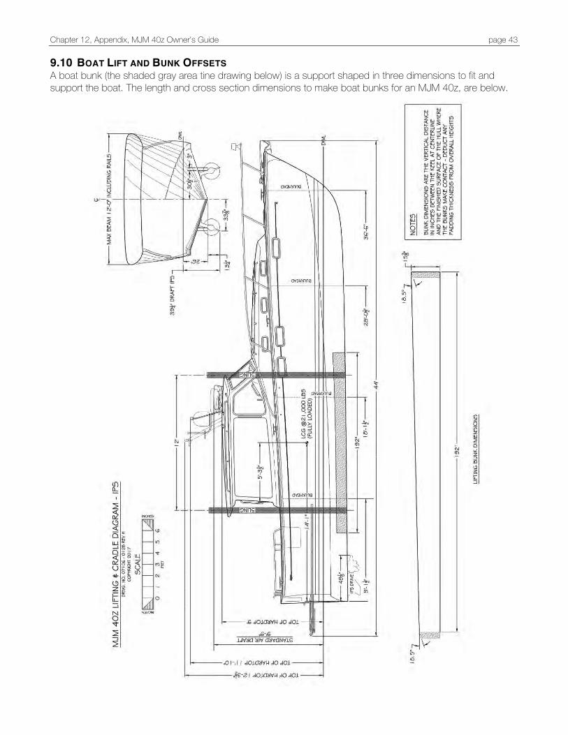
Chapter 12, Appendix, MJM 40z Owner’s Guide page 43
9.10 BOAT LIFT AND BUNK OFFSETS A boat bunk (the shaded gray area tine drawing below) is a support shaped in three dimensions to fit and support the boat. The length and cross section dimensions to make boat bunks for an MJM 40z, are below.
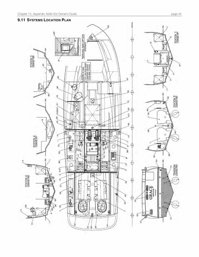
Chapter 12, Appendix, MJM 40z Owner’s Guide page 44
9.11 SYSTEMS LOCATION PLAN

Chapter 12, Appendix, MJM 40z Owner’s Guide page 45
9.12 SYSTEMS KEY The System Location Plan (above) and the System Key are the baseline configuration for the MJM40z. There are modifications due to continuous improvement and individual customization. Your boat will have some differences.
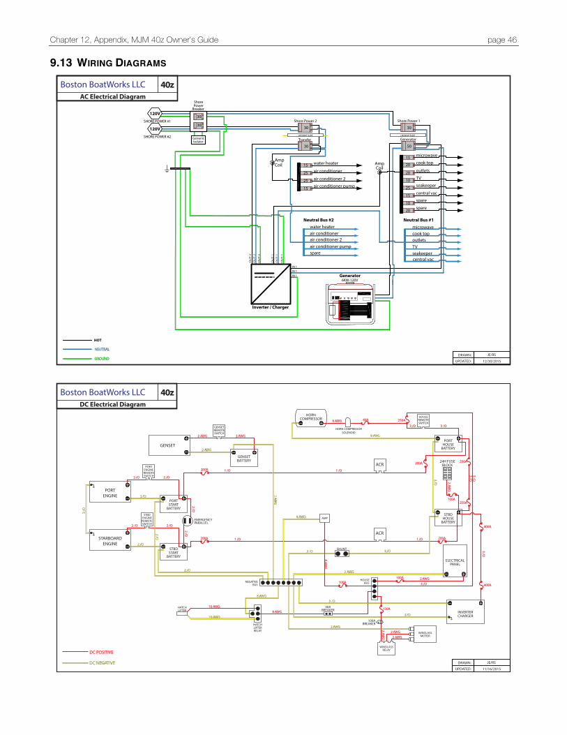
Chapter 12, Appendix, MJM 40z Owner’s Guide page 46
9.13 WIRING DIAGRAMS
Shore PowerBreaker
water heater
air conditioner
air conditioner 2air conditioner pump
Inverter / Charger
6KW-120VGenerator
microwave
cook top
outlets
TVseakeeper
water heaterair conditionerair conditioner 2
spareair conditioner pump
cook topoutletsTVseakeeper
microwave
IN 1IN 1IN 1
AmpCoil Amp
Coil
Generator
Shore Power 2
Transfer
Neutral Bus #1 Neutral Bus #2
OU
T 1
OU
T 1
OU
T 2
OU
T 2
OU
T 2
OU
T 1
15
15
20
20
25central vac
central vac
spare
spare
15
10
20
10
15
25
30
30
30
25
LOCKOUT SLIDE LOCKOUT SLIDE
30 50
Shore Power 1
30
12/30/2015
JE/RSDRAWN:
UPDATED:
HOT
NEUTRAL
GROUND
GalvanicIsolator
SHORE POWER #1
120V
SHORE POWER #2
120V
AC Electrical Diagram 40zBoston BoatWorks LLC
PORTENGINE
STBDSTART
BATTERY
STARBOARDENGINE
PORTSTART
BATTERY
PORTENGINEREMOTESWITCH
GENSETREMOTESWITCH
STBDENGINEREMOTESWITCH
GENSET
HORN COMPRESSORSOLENOID
GENSETBATTERY
HORNCOMPRESSOR
ACR
ACR
AMP
WINDLASSRELAY
HATCHLIFTERRELAY
HATCHLIFTER
NEGATIVEBUS
HOUSEBUS
WINDLASSMOTOR
PORTHOUSE
BATTERY
STBDHOUSE
BATTERY
ELECTRICALPANEL
INVERTERCHARGER
SHUNT
2 AWG
8 AWG2 AWG2 AWG
2 AWG
8 AWG
8 AWG
8 AWG
8 AWG
10 AWG
10 AWG8 AWG
2 AWG
2 AWG
2 AWG
2 AWG
2 AWG2 AWG
2 AWG
2 /O
2 /O
2 /O
2 /O
2 /O
2 /O
3 /O
3 /O
1 /O
3 /O
3 /O
1 /O
3 /O3 /O
3 /O3 /O
3 /O
3 /O
3 /O
2 /O
2 /O
2 /O
2 /O
2 /O
1 /O
1 /O200A
200A 200A
40ABREAKER
100ABREAKER
130A
400A
400A
100A
250A100A
250A200A
250A40A
EMERGENCYPARALLEL
100A
DC POSITIVE
DC NEGATIVE11/16/2015
JE/RSDRAWN:
UPDATED:
HOUSEREMOTESWITCH
24H FUSEBLOCK
DC Electrical Diagram 40zBoston BoatWorks LLC
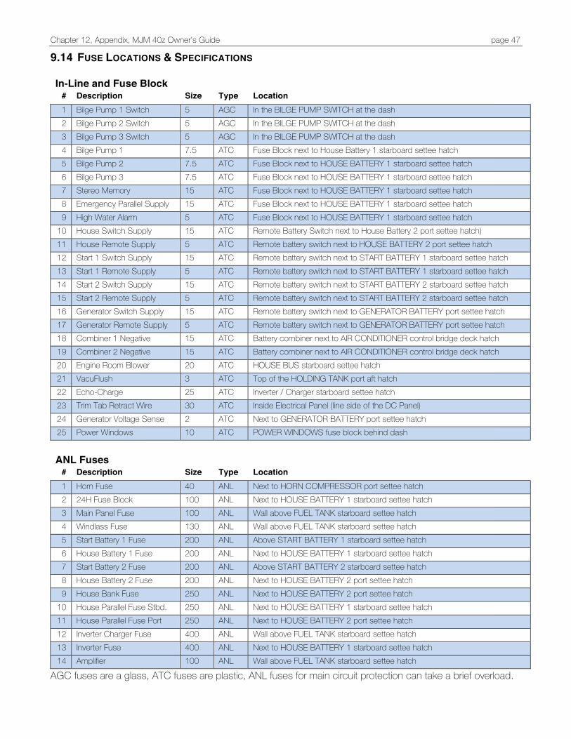
Chapter 12, Appendix, MJM 40z Owner’s Guide page 47
9.14 FUSE LOCATIONS & SPECIFICATIONS
In-Line and Fuse Block # Description Size Type Location 1 Bilge Pump 1 Switch 5 AGC In the BILGE PUMP SWITCH at the dash 2 Bilge Pump 2 Switch 5 AGC In the BILGE PUMP SWITCH at the dash 3 Bilge Pump 3 Switch 5 AGC In the BILGE PUMP SWITCH at the dash 4 Bilge Pump 1 7.5 ATC Fuse Block next to House Battery 1 starboard settee hatch 5 Bilge Pump 2 7.5 ATC Fuse Block next to HOUSE BATTERY 1 starboard settee hatch 6 Bilge Pump 3 7.5 ATC Fuse Block next to HOUSE BATTERY 1 starboard settee hatch 7 Stereo Memory 15 ATC Fuse Block next to HOUSE BATTERY 1 starboard settee hatch 8 Emergency Parallel Supply 15 ATC Fuse Block next to HOUSE BATTERY 1 starboard settee hatch 9 High Water Alarm 5 ATC Fuse Block next to HOUSE BATTERY 1 starboard settee hatch
10 House Switch Supply 15 ATC Remote Battery Switch next to House Battery 2 port settee hatch) 11 House Remote Supply 5 ATC Remote battery switch next to HOUSE BATTERY 2 port settee hatch 12 Start 1 Switch Supply 15 ATC Remote battery switch next to START BATTERY 1 starboard settee hatch 13 Start 1 Remote Supply 5 ATC Remote battery switch next to START BATTERY 1 starboard settee hatch 14 Start 2 Switch Supply 15 ATC Remote battery switch next to START BATTERY 2 starboard settee hatch 15 Start 2 Remote Supply 5 ATC Remote battery switch next to START BATTERY 2 starboard settee hatch 16 Generator Switch Supply 15 ATC Remote battery switch next to GENERATOR BATTERY port settee hatch 17 Generator Remote Supply 5 ATC Remote battery switch next to GENERATOR BATTERY port settee hatch 18 Combiner 1 Negative 15 ATC Battery combiner next to AIR CONDITIONER control bridge deck hatch
Battery combiner next to AIR ConDITIonER control bridge deck hatccchaadfaasfsaaf
19 Combiner 2 Negative 15 ATC Battery combiner next to AIR CONDITIONER control bridge deck hatch
20 Engine Room Blower 20 ATC HOUSE BUS starboard settee hatch 21 VacuFlush 3 ATC Top of the HOLDING TANK port aft hatch 22 Echo-Charge 25 ATC Inverter / Charger starboard settee hatch 23 Trim Tab Retract Wire 30 ATC Inside Electrical Panel (line side of the DC Panel) 24 Generator Voltage Sense 2 ATC Next to GENERATOR BATTERY port settee hatch 25 Power Windows 10 ATC POWER WINDOWS fuse block behind dash
ANL Fuses
# Description Size Type Location 1 Horn Fuse 40 ANL Next to HORN COMPRESSOR port settee hatch 2 24H Fuse Block 100 ANL Next to HOUSE BATTERY 1 starboard settee hatch 3 Main Panel Fuse 100 ANL Wall above FUEL TANK starboard settee hatch 4 Windlass Fuse 130 ANL Wall above FUEL TANK starboard settee hatch 5 Start Battery 1 Fuse 200 ANL Above START BATTERY 1 starboard settee hatch 6 House Battery 1 Fuse 200 ANL Next to HOUSE BATTERY 1 starboard settee hatch 7 Start Battery 2 Fuse 200 ANL Above START BATTERY 2 starboard settee hatch 8 House Battery 2 Fuse 200 ANL Next to HOUSE BATTERY 2 port settee hatch 9 House Bank Fuse 250 ANL Next to HOUSE BATTERY 2 port settee hatch
10 House Parallel Fuse Stbd. 250 ANL Next to HOUSE BATTERY 1 starboard settee hatch 11 House Parallel Fuse Port 250 ANL Next to HOUSE BATTERY 2 port settee hatch 12 Inverter Charger Fuse 400 ANL Wall above FUEL TANK starboard settee hatch 13 Inverter Fuse 400 ANL Next to HOUSE BATTERY 1 starboard settee hatch 14 Amplifier 100 ANL Wall above FUEL TANK starboard settee hatch
AGC fuses are a glass, ATC fuses are plastic, ANL fuses for main circuit protection can take a brief overload.

Chapter 12, Appendix, MJM 40z Owner’s Guide page 48
9.15 FUEL CONSUMPTION LOG.
Date Location Engine Hours
Hours Since Last Fill
Gals To Fill GPH Comment
Chapter 12, Appendix, MJM 40z Owner’s Guide page 49
9.16 BOSTON BOATWORKS LIMITED WARRANTY
Manufacturer's Sole and Limited Warranty for Pleasurecraft A. General. This document sets forth the sole and limited warranty, which Boston BoatWorks, LLC ("The Manufacturer") is giving you in connection with the "Vessel" which you are acquiring. It is the only warranty being given by the Manufacturer and should be reviewed carefully together with manuals and other instructional material provided by the Manufacturer before you take delivery of the Vessel.
B. Basic Warranty. The Manufacturer warrants that the Vessel (except for Excluded items described below and when Properly Used, will be free of defects in material and workmanship for a period of twelve (12) months from delivery of the Vessel to you by an Authorized Dealer. If you sell the Vessel during this period, your buyer may receive the benefit of the balance of the warranty by agreeing to be bound by its terms. c. Extended Warranty for Structure. In addition to the foregoing warranty, the Manufacturer warrants that the stringer systems, structural bulkheads and composite laminates of the Vessel (except for Excluded items) and when the Vessel is Properly *Used and Maintained, will be free of defects in material and workmanship for a period of five (5) years from delivery date by an Authorized Dealer. This warranty may be transferred to your buyer in the same manner as the Basic Warranty. *Improper over-the-road trucking of the vessel can cause local damage to the centerline of the boat requiring a localized FRP repair. Use authorized MJM trucking companies for moving your boat or contact Boston Boat Works' customer service managers for proper trucking information PRIOR to engaging with another trucking provider for boat transport. D. Extended Warranty Against Osmotic Blistering. In addition to the foregoing warranties, the Manufacturer warrants that any gelcoat surfaces of the Vessel below the waterline won’t blister when the Vessel is Properly Used for a period often (10) years from delivery date by an Authorized Dealer. This warranty may be transferred to your buyer on the same manner as the Basic Warranty.
E. Dealers. The name and address of Authorized Dealers is available from the Manufacturer. The Manufacturer doesn’t authorize the Dealer, or any other person, to assume for the Manufacturer any liability in connection herewith or any liability or expense incurred in the repairing of its products other than those expressly authorized by the Manufacturer in writing. F. Excluded Items. The Manufacturer gives no warranty as to:
a. Paints, varnishes, gelcoats (except where included in paragraph D above) exterior wood, vinyls, fabrics, glass, chrome plating or anodized or other finishes or surface coatings because of the varying quality of these items manufactured by others and the effect resulting from different climactic and use conditions
b. Engines, mechanical equipment, pumps, batteries, heating, plumbing, refrigeration, electronic components, masts, or other components manufactured by other than the Manufacturer, or the cost of removal or re-installment of the part and disassembly, or reassembly of the unit of which it is a component. c. All items not installed by the Manufacturer or altered after their installation, and items installed or altered by Authorized Dealers.
d. Other than upon first being delivered, leaks in or around hatches, companionways, deck hardware or other leaks which are above the waterline. e. Damage to the Vessel (including, but not limited to, wet core) caused by leakage around decks, hardware or other accessories attached to, or incorporated into, the Vessel.
f. Speed, fuel consumption or other performance characteristics, because they are estimated and not guaranteed.
G. Proper Use. The warranties contained herein are expressly conditioned upon your Proper Use of the Vessel. This means that you must use the Vessel solely as a pleasure craft (no commercial use) and operate it as directed in and after reviewing the manuals provided by the original equipment manufacturer and the Manufacturer, and perform maintenance to the Vessel as recommended in the manuals and as required by periodic inspections by an Authorized Dealer or Service Center.
Chapter 12, Appendix, MJM 40z Owner’s Guide page 50
H. Warranty Claims. To make a claim under this warranty you must do the following a. Report the defect to the Manufacturer or Authorized Dealer within 48 hours after discovery, and when possible prior to incurring any expense, identifying the Vessel and submitting photographs (email digital preferred).
b. Make the Vessel available for inspection by the Manufacturer or Authorized Dealer when requested.
c. Make the vessel available for repairs, if required, by the Manufacturer or Authorized Dealer.
d. Major components, such as engines, generators, air-conditioners, electronics, and appliances, for example, are warranted by the manufacturer of the component. They have authorized service dealers in most major boating markets. The Manufacturer or Dealer will identify such service dealers upon request.
I. Repair or Replacement. The manufacturer shall perform its obligations under this warranty by, at its option, repairing or replacing (at Manufacturer's expense) the defective part or component. Parts or components replaced will become the property of the Manufacturer. The replacement of parts o components won’t extend the warranty but the replacement parts and components will be covered for the balance of the warranty period. You shall be responsible for returning the Vessel to Manufacturer at its plant or at a marina or to such other repair facility that the Manufacturer shall designate, at your sole expense. J. Specification Changes. The manufacturer reserves the right to make changes in design, equipment, layout or construction without notice or being obligated to incorporate such changes in previous products. K. Registration Cards. The Manufacturer recommends that you immediately fill out and return the Warranty Registration Card for the Vessel. Cards should be sent to:
Boston BoatWorks, LLC 333 Terminal Street Charlestown, MA 02129 ATTN: Customer Service
L. The information contained on this card will enable the Manufacturer to more quickly process any warranty claims and to comply with the Federal
Boating Safety Act. Should you sell the Vessel, the Manufacturer recommends that your buyer also fill or a Warranty Registration Card. M. Exclusion of Implied Warranties. The foregoing warranty is intended to be in lieu of all other warranties, express or implied. In part, due to the hazardous, life-threatening environment, capable of overwhelming vessels of any size, that the Vessel will operate in, THE MANUFACTURER OR ITS DEALER DISCLAIMS ALL IMPLIED WARRRANTIES INCLUDING WARANTIES OF MERCHANTABILITY AND FITNESS FOR A PARTICULAR USE. In some jurisdictions, the Manufacturer is prohibited from excluding or limiting implied warranties. In those jurisdictions, the Manufacturer expressly limits any implied warranties to the greatest extent and to the shortest duration allowed by law. N. Limitation of Damages. THE MANUFACTUER OR ITS DEALER DISCLAIMS ANY LIABILITY TO YOU FOR INCIDENTAL, CONSEQUENTIAL OR INDIRECT DAMAGES TO YOU, including loss of use, loss of revenue, travel expenses, transportation charges, food or lodging charges or loss of personal property. In some jurisdictions, the Manufacturer is prohibited from excluding or limiting implied warranties. In those jurisdictions, the Manufacturer expressly limits any implied warranties to the greatest extent and to the shortest duration allowed by law. o. Whole Agreement. This warranty is the sole warranty given to you by the Manufacturer. Authorized Dealers aren’t authorized to make changes to this warranty. Any questions about the warranty should be directed to the Manufacturer. If you do bring a claim against the Manufacturer that is related to the Vessel, you must bring it in the Courts for the State of Massachusetts.
Chapter 12, Appendix, MJM 40z Owner’s Guide page 51
Limited Warranty Registration Card Within 30 days after delivery or transfer to new owner, this form must be sent to: Boston BoatWorks, LLC 333 Terminal Street Charlestown, MA 02129 ATTN: Customer Service _________________ _____________ _________________________________________ _____/_____/_____ MJM Model Hull # (HIN) US-EOU Authorized Dealer Date Purchased
Owner{s): ___________________________________________ ______________________________________________ First name Last name
___________________________________________ ______________________________________________ First name Last name
___________________________________ _________________________________________ ____ ________ Address City State Zip ___________________________________ ___________________________ ___________________________ Primary phone Mobile phone email ___________________________________________ ___________________________ ___________________ Boat Name Hailing Port I have read and agree to the conditions outlined in the Limited Warranty, which was attached hereto: _________________________________________________________________________ _____/_____/_____ Owner(s) Signature(s) Date
Chapter 12, Appendix, MJM 40z Owner’s Guide page 52
Warranty Claim Application Form Boston Boat Works, LLC This form has the same info as the Pre-Approval form. 256 Marginal Street, East Boston MA 02128 Phone: (617) 561-9111 Fax: (617) 561-9222 Date: Boat name Hull # Dealer/service Boat Owner Address Address
Address continued Address Continued
Phone # & email Phone Number & e-mail Fax Boat Location
Contact person Delivery Date
Description of Defect (please attach photos)
Description of Corrective Action (please attach invoices) Labor hrs
Labor rate
Labor cost
Material cost
Total Cost
All claims require prior approval by BBW Customer Service using the Pre-Approval Form
Date Approved Amount Approved Approved by
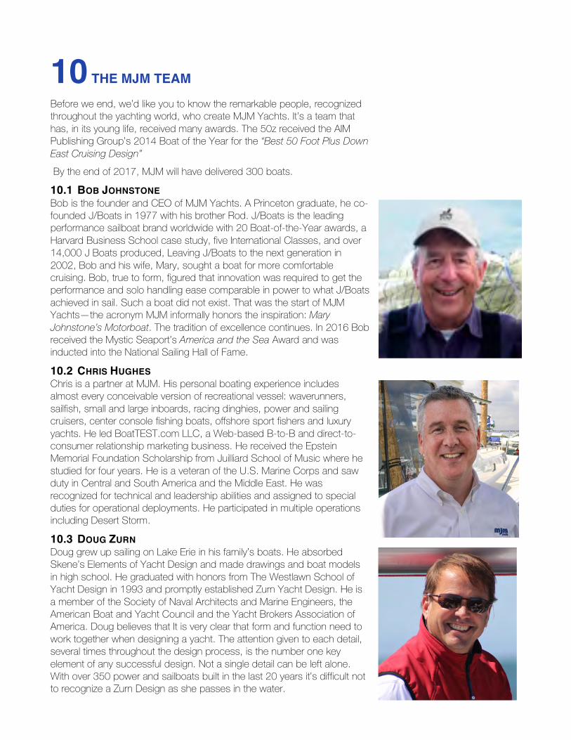
10 THE MJM TEAM
Before we end, we’d like you to know the remarkable people, recognized throughout the yachting world, who create MJM Yachts. It’s a team that has, in its young life, received many awards. The 50z received the AIM Publishing Group’s 2014 Boat of the Year for the “Best 50 Foot Plus Down East Cruising Design” By the end of 2017, MJM will have delivered 300 boats.
10.1 BOB JOHNSTONE Bob is the founder and CEO of MJM Yachts. A Princeton graduate, he co-founded J/Boats in 1977 with his brother Rod. J/Boats is the leading performance sailboat brand worldwide with 20 Boat-of-the-Year awards, a Harvard Business School case study, five International Classes, and over 14,000 J Boats produced, Leaving J/Boats to the next generation in 2002, Bob and his wife, Mary, sought a boat for more comfortable cruising. Bob, true to form, figured that innovation was required to get the performance and solo handling ease comparable in power to what J/Boats achieved in sail. Such a boat did not exist. That was the start of MJM Yachts—the acronym MJM informally honors the inspiration: Mary Johnstone’s Motorboat. The tradition of excellence continues. In 2016 Bob received the Mystic Seaport’s America and the Sea Award and was inducted into the National Sailing Hall of Fame.
10.2 CHRIS HUGHES Chris is a partner at MJM. His personal boating experience includes almost every conceivable version of recreational vessel: waverunners, sailfish, small and large inboards, racing dinghies, power and sailing cruisers, center console fishing boats, offshore sport fishers and luxury yachts. He led BoatTEST.com LLC, a Web-based B-to-B and direct-to-consumer relationship marketing business. He received the Epstein Memorial Foundation Scholarship from Juilliard School of Music where he studied for four years. He is a veteran of the U.S. Marine Corps and saw duty in Central and South America and the Middle East. He was recognized for technical and leadership abilities and assigned to special duties for operational deployments. He participated in multiple operations including Desert Storm.
10.3 DOUG ZURN Doug grew up sailing on Lake Erie in his family’s boats. He absorbed Skene’s Elements of Yacht Design and made drawings and boat models in high school. He graduated with honors from The Westlawn School of Yacht Design in 1993 and promptly established Zurn Yacht Design. He is a member of the Society of Naval Architects and Marine Engineers, the American Boat and Yacht Council and the Yacht Brokers Association of America. Doug believes that It is very clear that form and function need to work together when designing a yacht. The attention given to each detail, several times throughout the design process, is the number one key element of any successful design. Not a single detail can be left alone.With over 350 power and sailboats built in the last 20 years it’s difficult not to recognize a Zurn Design as she passes in the water.

The MJM Team, MJM 40z Owners Manual page 54
10.4 SCOTT SMITH Scott is a founder of Boston BoatWorks. He studied bio-medical engineering at Boston University and worked in the financial industry at Boston Financial Data Services and Shawmut Bank. He formed Boston BoatWorks with Mark Lindsay to combine his passions as a life-long sailor, sailing competitor, technophile and entrepreneur. BBW has brought boatbuilding back to the place where famous clipper ships were built. Scott's active interest in contributing to community, harbor and business issues has led him to participate over the years as a Director of the East Boston Chamber of Commerce, Chairman of the East Boston Economic Development Council, Founder and trustee of East Boston's not-for-profit sailing program, Piers Park Sailing, Inc., Member of the Boston Redevelopment Authority's Municipal Harbor Planning Advisory Committee and Trustee of The Boston Harbor Association,
10.5 MARK LINDSAY Mark is a founder of Boston BoatWorks. He spent much of his youth in an old boat shop watching a septuagenarian build lobster boats. At 14 he built a Sunfish and two years later won a Sunfish championship. He studied architecture at the U of Penn and MIT and began his boat-building career. One of the first to realize the strength-to-weight characteristic of vacuum bagged epoxy, carbon fiber and Kevlar, he made boats lighter, stronger and faster. His boats provided championships for many competitors—including himself. With technological support from Sikorsky Aircraft, DuPont and Hexcel Corporations, Mark pushed the envelope, building many exotic yachts with storied naval architects and yachtsmen. He provided specialized components for boats from Optimist prams to America's Cup boats. He teaches boatbuilding to 9th graders, is chief measurer for the Sonar Class, and Chairman of the Management Committee for the New Hampshire Appalachian Mountain Club Camp.
10.6 STEVE BURKE Steve is the structural engineer for MJM boats. He graduated from the University of Michigan department of Naval Architecture and Marine Engineering. He began his career as a Naval Architect with hull design and structural engineering for hydrofoils, ships and submarines for Boeing and General Dynamics. In 1990, Steve turned to composite materials for the aerospace, naval, oceanographic and offshore energy communities. As the marine composites engineer at TPI, Steve was responsible for structural and project management for J/Boats.