Embed Size (px)
Citation preview
Rev. “F”

M380 Owner’s Manual__________________________________________________________________________________
Rev. “F”
THIS PAGE IS INTENTIONALLY LEFT BLANK

IMPORTANT CUSTOMER NOTE: Please note that this is preliminary copy of the
Express 4500 Owner Manual. Material has not yet been validated for correctness and accuracy.
NOTE: This information was correct at time of printing. For any vendor changes made to equipment and/or manual after printing date refer to the actual vendor owner manual supplied with coach.

This publication is the exclusive proper of Blue Bird Corporation. It is to be used only by Blue Bird personnel or authorized Blue Bird distributor personnel or customers at authorized locations. It is against the law to copy, reproduce or transmit (including, without limitation, electronic transmission over any network) any part of this information except as permitted by the Copyright Act of the United States (Title 17, United States Code). Blue Bird Corporation holds proprietary rights on this information. The images and data contained in this publication may not be manipulated in any way. The images and data contained herein may not be imported into any program for any use other than for viewing or printing without the express written permission of Blue Bird Corporation. The information provided in this manual is accurate to the best of its knowledge at the time of printing. In keeping with its policy of continual product improvement, Blue Bird reserves the right to change product information without notice and without incurring obligation. The user assumes full responsibility for the use of any information obtained herein.
©2003 Blue Bird Corporation. All Rights Reserved.
Table of Contents Introduction Introduction.................................................................................................................... Introduction 1 Warranty Information ................................................................................................Introduction 2-11 1 – Safety/Security Features 1-1 Safety Features ........................................................................................................ 1-1-1 – 1-1-8 1-2 Security Features ................................................................................................... 1-2-1 – 1-2-28 2 – Instruments and Controls 2-1 Dash and Monitor Panels ......................................................................................... 2-1-1 – 2-1-7 2-2 Driver and Co-Pilots Areas ....................................................................................... 2-2-1 – 2-2-2 3 – Starting/Driving 3-1 Engine – Starting and Driving ................................................................................... 3-1-1 – 3-1-3 3-2 Towing – Starting and Driving................................................................................... 3-2-1 – 3-2-2 4 – Interior/Exterior Systems 4-1 Interior Storage......................................................................................................... 4-1-1 – 4-1-1 4-2 Exterior Storage........................................................................................................ 4-2-1 – 4-2-2 4-3 12 kW Generator ...................................................................................................... 4-3-1 – 4-3-4 4-4 30/50 Amp 110 Volt-Operation ................................................................................. 4-4-1 – 4-4-7 4-5 3000 Watt Inverter .................................................................................................. 4-5-1 – 4-5-14 4-6 Battery Systems ....................................................................................................... 4-6-1 – 4-6-2 4-7 Leveling System ....................................................................................................... 4-7-1 – 4-7-3 4-8 Awning Operation ................................................................................................... 4-8-1 – 4-8-12 4-9 Slide-Out Operation.................................................................................................. 4-9-1 – 4-9-5 4-10 Heating Systems .............................................................................................. 4-10-1 – 4-10-14 4-11 AC/Heat Pumps.................................................................................................. 4-11-1 – 4-11-1 4-12 Fresh Water System........................................................................................... 4-12-1 – 4-12-4 4-13 Waste System .................................................................................................... 4-13-1 – 4-13-9 4-14 LPG System ....................................................................................................... 4-14-1 – 4-14-4 4-15 Air Pressure System........................................................................................... 4-15-1 – 4-15-3 4-16 Appliances........................................................................................................ 4-16-1 – 4-16-29 4-17 Fans, Vents and Exhaust ................................................................................... 4-17-1 – 4-17-1 4-18 Video and Audio Equipment ............................................................................. 4-18-1 – 4-18-97 4-19 Electronic Step ................................................................................................... 4-19-1 – 4-19-3 5 – Maintenance/Service 5-1 Engine, Transmission, Chassis – Maintenance/Service ........................................... 5-1-1 – 5-1-3 5-2 Generator – Maintenance/Service .......................................................................... 5-2-1 – 5-2-18 6 – Service Procedures 6-1 Normal Maintenance Replacement Parts ................................................................. 6-1-1 – 6-1-4 6-2 Chassis Service Procedures..................................................................................... 6-2-1 – 6-2-3 7 – Interior/Exterior Care 7-1 Interior/Exterior Care ................................................................................................ 7-1-1 – 7-1-2 8 – Chassis Specifications 8-1 Chassis Specifications.............................................................................................. 8-1-1 – 8-1-2 8-2 Electrical Systems Specifications ..................................................................................... to come 8-3 Capacities................................................................................................................. 8-3-1 – 8-3-1 9 – Checklists 9-1 Checklists ................................................................................................................. 9-1-1 – 9-1-3 10 – Authorized Service Centers 10-1 Authorized Service Centers................................................................................ 10-1-1 – 10-1-8

M380 Owner’s Manual__________________________________________________________________________________
Rev. “F”
THIS PAGE IS INTENTIONALLY LEFT BLANK
Introduction________________________________________________M380 Owner’s Manual
Rev. “F” Introduction-1
Introduction______________________________________
Welcome Dear Wanderlodge Owner:
Thanks for choosing a Wanderlodge!
We want to personally welcome you to our Family of Friends and we invite you
to visit us at our Fort Valley facilities whenever you wish. We are always happy
to see you and we are deeply interested in your experiences as you use and
enjoy your Wanderlodge motor home. We recognize that it is our relationship to
you, the Wanderlodge owner, which contributes most to the prestige of
ownership of this finest over-the-road motor home.
We trust that as you become more intimately acquainted with your new motor
home, the sound, careful thoughts behind every aspect of its design will become
increasingly evident and your initial decision to choose Wanderlodge will be
positively reinforced with every mile.
We encourage that you take the time to become familiar with this introduction
section before taking your first trip in your new motor home. Inside you will
find information that will be beneficial on future trips with your motor home
such as: vehicle loading, emergency exits, safety information, etc.
We acknowledge the good faith you have demonstrated in our product. All of us
at Wanderlodge take great pride in our handiwork and want to do everything
possible to engender in you what has become the Wanderlodge experience; the
deep satisfaction that comes from years of a sure confidence of having chosen
the very best.
Introduction________________________________________________M380 Owner’s Manual
Rev. “F” Introduction-2
Limited Warranty Blue Bird Wanderlodge (Wanderlodge), a division of Blue Bird Body Company, warrants each Wanderlodge to the original purchaser to be free from defects in material and workmanship under normal use and service within the limits described below:
1. For a period of (3) years or 36,000 miles, whichever occurs first, from date of delivery to the original purchaser, Wanderlodge® warrants the: a. Chassis frame rails and cross members to be free from defects in structural integrity
(breaking or cracking). b. Body shell (those structural metal components welded or riveted together forming floor,
sidewalls, roof, front and rear sections) to be free from defects in structural integrity (breaking or cracking) including rust-through.
c. Paint adhesion to the body shell (those structural components forming side walls, roof, front and rear sections). Paint failures caused by corrosive atmospheric conditions and road chemicals are specifically not covered.
2. For a period of three (3) years from date of delivery to the original purchaser, Wanderlodge
warrants the steer and drive axles (tag axle not included), excluding brakes and wheel ends. 3. For a period of two (2) years from the date of delivery to the original purchaser warrants all
other components installed by Blue Bird and Wanderlodge, except diesel engines, automatic transmissions, tires and batteries, which are warranted by their manufacturers.
For demonstrators, the delivery date to the dealer will be the warranty start date. Mileage accumulated by the factory or dealer apply to any warranty mileage limits stated above. This limited warranty applies to the original purchaser during the warranty period. A transfer request and fee are required within thirty (30) days of resale to transfer the warranty. Wanderlodge’s obligation covered in this limited warranty is limited to the repair or replacement of such parts as shall, under normal use and service, appear to have been defective in workmanship or material. Without restricting the generality of this limitation, loss of use, commercial loss, towing charges, lodging, telephone calls, inconvenience, and loss of time are specifically not covered. This warranty shall not apply to any parts or components which must be repaired or replaced during the warranty period as a result of what is, in the opinion of Wanderlodge, normal wear and/or deterioration in the course of normal operations and use, accident damage, misuse and/or abuse. If distributors, dealers or customers have any vehicle modifications or equipment installations performed without the written approval of Wanderlodge to the extent the modifications or equipment installations adversely affect other vehicle components or performance, Wanderlodge shall not accept any product liability or claims under the terms of the limited warranty. These claims become the sole responsibility of the company performing the modifications and/or installations.
Introduction________________________________________________M380 Owner’s Manual
Rev. “F” Introduction-3
ANY IMPLIED WARRANTIES, INCLUDING THOSE OF MERCHANTABILITY OR FITNESS, ARE LIMITED TO THE WARRANTY PERIOD OF THIS WRITTEN WARRANTY. WANDERLODGE SHALL NOT BE LIABLE FOR INCIDENTAL OR CONSEQUENTIAL DAMAGES RESULTING FROM BREACH OF THIS WRITTEN WARRANTY OR ANY IMPLIED WARRANTY. NO PERSON, INCLUDING SALESPEOPLE, DEALERS, SERVICE CENTERS, OR FACTORY REPRESENTATIVES OF WANDERLODGE, IS AUTHORIZED TO MAKE ANY REPRESENTATION OR WARRANTY CONCERNING WANDERLODGE PRODUCTS EXCEPT TO REFER TO THIS LIMITED WARRANTY. Wanderlodge reserves the right to make changes in design and changes or improvements upon its products without imposing any obligations upon itself to install the same upon products therefore manufactured. Defects shall be repaired promptly after discovery of the defect and within the warranty period as stated herein. All claims for warranty adjustments must be received by Wanderlodge not later than 30 days after the repair date, and shall be channeled through an authorized Wanderlodge dealer or factory representative. Any suit alleging a breach of this limited warranty or any other alleged warranty must be filed within one year of breach. All rights under this limited warranty shall be governed by the law of Georgia, U.S.A.
Wanderlodge® / One Wanderlodge Way / Fort Valley, Georgia 31030 / (478) 825-2021
NOTE: This information was correct at time of printing. For any vendor changes made to equipment and/or manual after printing date refer to the actual vendor owner manual supplied with motor home.
Introduction________________________________________________M380 Owner’s Manual
Rev. “F” Introduction-4
Introduction This section of your Owner’s Manual contains general hints and recommendations for using your motor home. Checklists and suggestions are offered which cover just about every phase of motor home travel. The remaining sections of this manual describe the operation and use of the individual items and systems which comprise your motor home. Manufacturer’s manuals for components and appliances are included in your owner’s kit. Please refer to these for more detailed information. We hope that this manual will help answer questions that may arise about the use, operation and maintenance of your motor home. Any suggestions or recommendations that you might have for including or expanding on material of interest will be carefully considered for incorporation in future publications. We are always interested in providing our motor home owners with the most current and comprehensive information about our product.
Some Other Thoughts to Consider • Automobile insurance to cover you and your family. • Avoid cash. Use traveler’s checks and credit cards wherever possible. • Confirm reservations well in advance of arrival. • Make a clothing check list for everyone.
Citizen’s Band Transceiver You might also bear in mind that your motor home is equipped with a CB unit (Citizen’s Band receiver-transmitter) In the event of an emergency situation which requires outside assistance; remember to call for help on Channel 9. This channel is restricted to emergency use only and it is monitored 24 hours per day! Don’t hesitate to use your CB if you see someone else in need of assistance.
Hot Weather Operation Wherever possible, choose a shaded parking site so that the motor home will be cooler during the hottest part of the day. The optional patio awning will be especially useful in lowering inside temperature. Air conditioning units are indispensable in hot climates. Keep in mind that their proper operation depends on adequate line voltage. Low voltage causes motors to run hotter and reduces compressor motor life. Supply voltage in some campgrounds may not be as high as necessary, especially where there are heavy loads on the lines from other air conditioners. Check the right hand overhand auxiliary panel 120 VAC meters when in doubt.
Cold Weather Operation If frost or condensation accumulates in closets or cabinets during long periods of cold weather operation, leave the doors to these areas slightly ajar to provide air circulation. Be sure that roof vents are open when using the gas cook top.
Introduction________________________________________________M380 Owner’s Manual
Rev. “F” Introduction-5
Campground Courtesy Don’t forget the “Golden Rule”. Being considerate of your neighbors will help make friends. A few of the “do’s” and “don’ts” are: • Good housekeeping – put all litter in the proper receptacles and leave your site neat and clean. • Don’t allow your water or sewer hook-ups to leak. • Respect your neighbor’s desire to retire at an early hour. Avoid loud noises and bright lights
after dark. • Drive slowly through camp areas at any hour for the safety of pedestrians.
Insurance As with your automobile, it is important that you have adequate protection with insurance coverage for personal liability, property damage, comprehensive, collision, medical payments, loss of use, etc. Canadian and Mexican Insurance
Insurance for travel in Canada can usually be covered by your present U.S. policy for the recreational vehicle, often at no extra cost. Consult your individual company for procedures and be sure of your coverage before entry.
For travel in Mexico (at the present time), there are no U.S. insurance companies that can provide recognized Mexican coverage, with the exception of that required for travel through a narrow strip of Mexican territory in and around parts of entry and the U.S./Mexican border.
Mexican insurance is controlled and rates are set by the Mexican government. There are several reliable companies handling Mexican insurance, with similar rates for the necessary coverage. The principle differences between them are the “fringe benefits”, received in the form of informational travelogues and other helpful information, such as dining places considered acceptable for sanitary conditions, fuel stations, and so on.
Some insurance services include detailed route maps with “where to stay” recommendations and “things to see” mile-by-mile (or kilometer-by-kilometer post). While the rates set by Mexico may seem quite expensive at first glance, you usually end up not spending quite as much as expected because you can usually arrange to hold your state-side policy in abeyance during the same period you are in Mexico, thus not having to pay unnecessarily for double coverage. In addition, you may be able to obtain substantial refunds on the Mexican collision insurance after your return to the U.S. Be sure to obtain a certification from the park operator at each location in Mexico to certify the dates that your motor home was parked there. If your motor home is parked for most of the time, instead of constantly traveling, your refund may be a major portion of the original cost. This feature is referred to as the ‘in-storage” credit. (It is a good idea to always check with your insurance company before taking a trip to find out whether applicable insurance rules and regulations have changed. Keep up to date on your coverage.)
Carry insurance papers at all times!
Safety Considerations Using LP Gas
Check for leaks at the connections on the LP gas system soon after purchase and initial filling of the LP tank; continued periodic checks of the system are recommended. Even though the manufacturer and dealer have already made tests for leakage, this check is advisable because of the vibrations encountered during travel. Apply a soapy water solution to the outside of gas piping connections to find gas leakage (bubbles). Do not use products that contain ammonia or chlorine. Usually, tightening of connections will be sufficient. If not, ask your authorized dealer service to make the needed repairs.
Introduction________________________________________________M380 Owner’s Manual
Rev. “F” Introduction-6
Liquefied Petroleum Gas (LPG) is heavier than air. Leaking gas tends to flow to low places, and will sometimes pocket in a low area. LP gas can usually be detected by an identifiable odor characteristic to garlic.
▲CAUTION: Never light a match or allow any open flame in the presence of leaking gas! Be sure that the main LP gas supply valve is closed or galley panel switch is OFF during refueling to prevent accidental ignition of gas fumes by appliance ignitors.
WARNING: When motor home is to be stored in a confined area, turn off the LPG at the main tank shutoff valve, or more conveniently, at the galley systems control panel. Your Wanderlodge has been provided with an automatic 80% fill valve to protect you from the dangers of an overfilled LPG tank.
Electrical Systems
Your motor home has been engineered and checked for your complete electrical system safety. Circuit breakers and fuses are installed to protect electrical circuits from overloading. Before making modifications or additions to the electrical system, consult your dealer for assistance in obtaining a safe and secure installation.
Do not “jump” circuit protectors!
Emergency Stops
Always carry road flares and/or reflective triangular highway warning markers for emergency warning display. Pull off the roadway as far as possible when changing flats or for other emergency situations. Turn on your hazard warning flashers when parked alongside a roadway, even if only for a short while. Have your motor home occupants leave the vehicle and stand clear of the area when parked on the edge of a highway.
In Case of Tire Blowout
Michelin Tire Corporation has tested extensively and recommends the following when a blowout occurs:
1. Quickly step on the gas 2. Adjust steering as needed. 3. Stay off the brakes. 4. Keep driving until you find a safe place to pull over.
Engine Exhaust Gas
Avoid inhaling exhaust gases because they contain carbon monoxide, which by itself is colorless and odorless. Carbon monoxide is a dangerous gas that can cause unconsciousness and is potentially lethal. If at any time you suspect that any exhaust fumes are entering the passenger compartment, have the cause determined and corrected as soon as possible.
The best protection against carbon monoxide entry into the vehicle body is properly maintained engine exhaust system, body and ventilation system. It is a good practice to have the exhaust system and body inspected by a competent mechanic each time the vehicle is raised for lubrication or oil change. It should also be inspected whenever a change is noticed in the sound of the exhaust system, and if the exhaust system, underbody or rear of the vehicle has been damaged.
To allow proper operation of the vehicle’s ventilation system, keep ventilation inlets clear of snow, leaves or other obstructions.
Sitting in a parked vehicle with the engine on for extending periods, without proper ventilation, is not recommended!
Introduction________________________________________________M380 Owner’s Manual
Rev. “F” Introduction-7
More Safety Considerations
• Sanitize fresh water supply system periodically.
• Prevent water connection fittings from contacting the ground or drain the hose to reduce chances of contamination.
• Consider using a qualified technician for repairing gas or electrical appliances.
• Check fire extinguishers periodically for proper charge.
• Avoid overloading your vehicle.
• Be careful not to cause an improper load distribution which can adversely affect road ability.
• Ensure that tires are in good condition and properly inflated at all times.
• Under-inflated tires overheat and are prone to blowouts!
• Check and tighten wheel lug nuts; manufacturer recommends after first 50-100 miles and every 1,000 miles thereafter.
Emergency Exits Sliding windows, which can be easily opened, may be used as an emergency exit. Squeeze the window latch and slide the window open. Emergency exit windows are identified by an EXIT decal on the glass.
Owner’s Manual Requirements
The minimum required educational information in the owner’s manual shall include:
1. A sample of the weight label’s contents affixed to the unit as appropriate.
2. An explanation of the following:
• Vehicle weight distribution
• How to weigh the vehicle
These definitions:
Gross Axle Weight Rating (GAWR)
Gross Combination Weight Rating (GCWR)
Gross Vehicle Weight Rating (GVWR)
Unloaded Vehicle Weight (UVW)
Net Carrying Capacity (NCC)
3. Towing guidelines.
MOTOR HOME WEIGHT INFORMATION
Model ________________________________________________________________
GVWR ________________________________________________________________
UVW ________________________________________________________________
NCC ________________________________________________________________
GCWR ________________________________________________________________
Introduction________________________________________________M380 Owner’s Manual
Rev. “F” Introduction-8
GVWR
(Gross Vehicle Weight Rating) means the maximum permissible weight of this motor home. The GVWR is equal to or greater than the sum of the Unloaded Vehicle Weight plus the Net Carrying Capacity.
UVW
(Unloaded Vehicle Weight) means the weight of this motor home as built at the factory with full fuel, engine oil, and coolants. The UVW does not include cargo, fresh water, LP gas, occupants, or dealer installed accessories.
NCC
(Net Carrying Capacity) means the maximum weight of all occupants including the driver, personal belongings, food, fresh water, LP gas, tools, tongue weight of towed vehicle, dealer installed accessories, etc., that can be carried by this motor home.
(NCC is equal to or less than GVWR minus UVW).
GCWR
(Gross Combination Weight Rating) means the value specified by the motor home manufacturer as the maximum allowable loaded weight of this motor home with its towed trailer or towed vehicle.
This motor home is capable of carrying up to 98 gallons of fresh water (including water heater) for a total of 816 pounds. Reference: Weight of fresh water is 8.33 lbs./gal.; Weight of LP gas is 4.5 lbs./gal. (average).
CONSULT WEIGHT DECAL LOCATED IN MOTOR HOME
FOR ACTUAL WEIGHTS
Vehicle Loading The Federal Certification Label, located inside and above the driver’s windshield between the sun visor mounting brackets describes the maximum weight-carrying capacities of your motor home and for each axle, respectively abbreviated by “GVWR” and “GAWR”.
The Gross Vehicle Weight Rating (GVWR) is the maximum motor home weight allowable with all systems filled and with passengers and supplies aboard.
Each axle also has a maximum load-bearing capacity referred to as the Gross Axle Weight Rating (GAWR).
The load capacity is the difference between the GVWR and the actual weight. This means that the total weight of all food, clothing, other supplies and passengers must not permit the load capacity to be exceeded.
To find the actual weight, with the motor home fully loaded, drive to a scale and read the weight on the front and rear wheels separately to determine axle loading. The load on each axle should not exceed its GAWR. If weight ratings are exceeded, move or remove items to bring all weights below the ratings.
When loading your motor home, store heavy gear first. Be sure to keep heavy gear on or as close to the floor as possible. Heavy items should be stored centrally to distribute the weight evenly between the front and the rear axles. Store only light objects on high shelves. Distribute weight to obtain even side-to-side balance of the loaded unit. Secure loose items to prevent weight shifts that could adversely affect the balance and road ability of the vehicle.
Introduction________________________________________________M380 Owner’s Manual
Rev. “F” Introduction-9
Motor Home Service – Replacement Parts A paint color label is located adjacent to the Federal Certification Label above the pilot’s sun visor.
Data plates located on the rear of the chassis (raise rear engine compartment door for access) provide information useful for identifying your motor home if you are planning on ordering parts. Identification plates provide information such as:
1. Body Serial Number
2. Model Year
3. Body Service Number
4. Chassis Serial Number
5. Chassis Service Number
Economical Driving How you drive, where you drive and when you drive – these factors all have an effect on determining how many miles you can get from a gallon of fuel. Careful maintenance will also contribute to fuel economy.
Frequent stops and starts during a trip diminish miles per gallon. Planning even short shopping trips so you can take advantage of through-streets to avoid the traffic lights. Pace your driving like the professional drivers to avoid unnecessary stops.
An idling engine also consumes fuel. If you are faced with more than a few minutes wait, and you are not in traffic, it may be advisable to shut off the engine and re-start later.
A properly lubricated vehicle means less friction between moving parts. Consult the maintenance schedules for proper lubricants, lubrication intervals and general motor home maintenance scheduling.
Fuel economy is also related directly to the amount of work accomplished by the engine. Heavier loads require more power: Keep excess weight to a minimum.
Cellular Phone Wiring A roof mounted antenna and wiring (terminals in driver’s area) are supplied for cellular phone hookup.
Fog Lights Clear fog lamps are mounted stationary in the front bumper. The fog lamps illuminate only with low beam headlights, provided the dash switch is activated.
Traveling in Your Motor Home NOTE: 1. Overall height is approximately 12 ½ feet. This breaks down to: Tip of exhaust pipe 143”, roofing 135”, A/C 148”, satellite antenna dome 151” (12’-7”). 2. It is recommended that compartment doors be locked so they do not open while in transit. There are many modern recreational vehicle parks with good facilities, including State, County and Federal Parks, where electrical, water and sewer connections are readily available. Directories are published which describe these parks in detail, and list available services and hookups.
Introduction________________________________________________M380 Owner’s Manual
Rev. “F” Introduction-10
On overnight short weekend trips, your motor home has more than adequate holding tanks and water supply capacity in the event that campgrounds or parking sites are not equipped with these facilities.
On longer trips, where sewer connections and utility hookups are unavailable, it will be necessary to stop from time to time to dispose of holding tank wastes and replenish the water supply. Many gas stations (chain and individually-owned) have installed sanitary dumping stations for just this purpose.
When stopping for the night, park the motor home in a location that is relatively level and where the ground is firm. This will ensure your comfort as well as the leveling of your refrigerator (for most efficient operation).
Making a long trip is not very different from making a weekend excursion since everything you need is right at hand and you are home wherever you travel. When packing for an extended trip, try to avoid taking nonessential items.
When planning to stay in the same location for several days, weeks, or even months, be sure to maintain the motor home level. Use the leveling jacks system for this purpose. (See Leveling Jacks in Section 4-7 of this manual).
Hook up to the water supply by attaching the water hose to the commercial water supply inlet.
Plug the electrical cable into the shoreline receptacle. Be sure to observe all grounding and connection precautions!
Connect sewage hookup into the disposal facility.
Winter Traveling Certain precautions should be taken when traveling in your motor home during the cold winter months. Keep these suggestions in mind:
• Provide heat in the motor home at all times.
• Have a plentiful supply of LPG and diesel.
• If your stay is longer than overnight and you do not use the generator, try to have a shoreline hooked up to outside AC power.
• Minimize your use of electricity if 120 vac is unavailable.
• Leave cabinet doors and wardrobe doors slightly open at night to allow for proper air circulation.
Remember that low temperatures in combination with high winds will cause an equivalent chill temperature much below that indicated by your thermometer. For instance, with an outside temperature of zero degrees and a wind velocity of 10 miles per hour the equivalent chill temperature would be -20 degrees Fahrenheit!
There is no substitute for common sense when traveling in cold weather.
General Storage Notes Drawing draperies will reduce fading of rugs and upholstery. Leaving an air freshener agent will minimize odors from plastics and other materials. Slight opening of windows and vents will allow air circulation without worry of water entering. Covering wheels to eliminate direct rays of the sun on tires will reduce sidewall cracking. NOTE: Remove all items from the motor home that may freeze, including canned foods, miscellaneous liquids, etc. Remove all contents of the refrigerator/freezer, clean unit and leave doors ajar.
Introduction________________________________________________M380 Owner’s Manual
Rev. “F” Introduction-11
Reporting Safety Defects If you believe your vehicle has a safety defect which could cause a crash or could cause injury or death, you should immediately inform the National Highway Traffic Safety Administration (NHTSA) in addition to notifying Blue Bird Wanderlodge.
If NHTSA receives similar complaints, it may open an investigation, and if it finds that a safety defect exists in a group of vehicles it may order a recall and remedy campaign. However, NHTSA cannot become involved in individual problems between you, your dealer, or Blue Bird Wanderlodge.
To contact NHTSA, you may either call the Auto Safety Hotline toll free at 1-800-424-9393 (or 366-0123 in Washington, D.C., area). Or write to: NHTSA, U.S. Department of Transportation, Washington, D.C. 20590. You can also obtain other information about Motor Vehicle Safety from the hotline.

M380 Owner’s Manual__________________________________________________________________________________
Rev. “F”
THIS PAGE IS INTENTIONALLY LEFT BLANK
M380 Owner’s Manual______________________________________________Safety and Security - Safety Features – 1-1
Rev. “F” 1-1-1
1-1 Safety Features______________________________________ 1-1.1 Seat Belts and Restraint Systems 1-1.1.1 Pilot and Co-Pilot Seats The seatbelts in the pilot and co-pilot area use a 3-point system built into the seat itself. Seatbelts can be operated by grasping the shoulder buckle and moving it diagonally across the body buckling it into the red and black receptacle. To remove simply press red button located at receptacle on seatbelt. Seatbelts automatically retract. 1-1.1.2 Living Room Area Two lap belts are provided at the sofa area in living room. These are manual non-retracting lap belts. These belts are operated by sitting between the belts and manually latching over your waist. Be sure to pull snug to your waist. An improperly adjusted seatbelt can be hazardous. To remove, simply press red button on seatbelt buckle. NOTE: these are the only four approved areas for seating while motor home is in transit. 1-1.2 Smoke Alarm
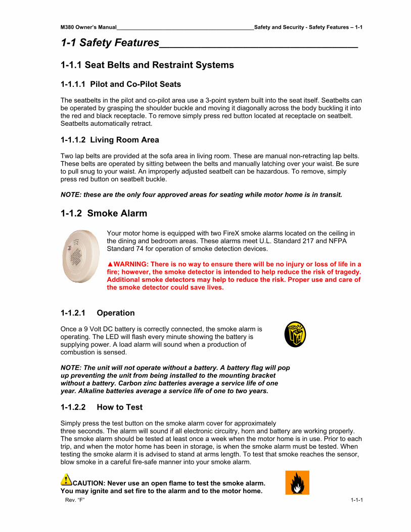
Your motor home is equipped with two FireX smoke alarms located on the ceiling in the dining and bedroom areas. These alarms meet U.L. Standard 217 and NFPA Standard 74 for operation of smoke detection devices. ▲WARNING: There is no way to ensure there will be no injury or loss of life in a fire; however, the smoke detector is intended to help reduce the risk of tragedy. Additional smoke detectors may help to reduce the risk. Proper use and care of the smoke detector could save lives.
1-1.2.1 Operation Once a 9 Volt DC battery is correctly connected, the smoke alarm is operating. The LED will flash every minute showing the battery is supplying power. A load alarm will sound when a production of combustion is sensed. NOTE: The unit will not operate without a battery. A battery flag will pop up preventing the unit from being installed to the mounting bracket without a battery. Carbon zinc batteries average a service life of one year. Alkaline batteries average a service life of one to two years. 1-1.2.2 How to Test Simply press the test button on the smoke alarm cover for approximately three seconds. The alarm will sound if all electronic circuitry, horn and battery are working properly. The smoke alarm should be tested at least once a week when the motor home is in use. Prior to each trip, and when the motor home has been in storage, is when the smoke alarm must be tested. When testing the smoke alarm it is advised to stand at arms length. To test that smoke reaches the sensor, blow smoke in a careful fire-safe manner into your smoke alarm.
CAUTION: Never use an open flame to test the smoke alarm. You may ignite and set fire to the alarm and to the motor home.
1-1 - Safety and Security - Safety Features______________________________________________M380 Owner’s Manual
1-1-2 Rev. “F”
1-1.2.3 Maintenance A smoke alarm is designed to be as maintenance free as possible. However, there are some simple steps to perform in order to keep the smoke alarm working properly: • Test the smoke alarm once a week. • Keep a supply of 9 Volt DC batteries on hand. • Vacuum the slots in the cover and sides with a soft brush attachment every month. Test the
smoke alarm once the unit has been vacuumed. • The smoke alarm should be cleaned every six months to help keep the unit working efficiently. • The smoke alarm will beep once a minute when a low battery condition exists. The battery must
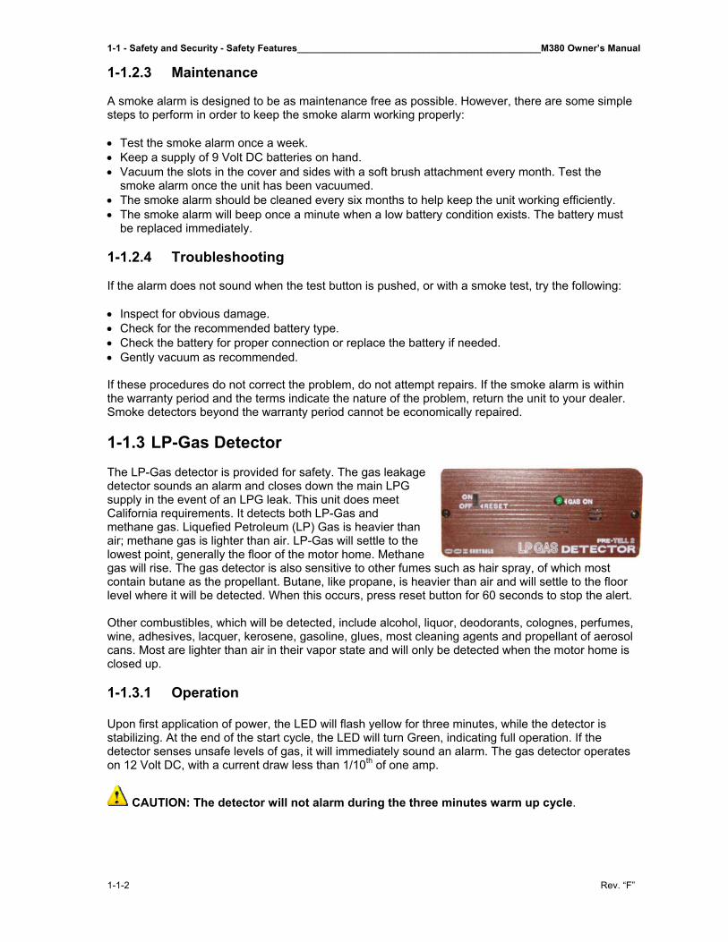
be replaced immediately. 1-1.2.4 Troubleshooting If the alarm does not sound when the test button is pushed, or with a smoke test, try the following: • Inspect for obvious damage. • Check for the recommended battery type. • Check the battery for proper connection or replace the battery if needed. • Gently vacuum as recommended. If these procedures do not correct the problem, do not attempt repairs. If the smoke alarm is within the warranty period and the terms indicate the nature of the problem, return the unit to your dealer. Smoke detectors beyond the warranty period cannot be economically repaired. 1-1.3 LP-Gas Detector The LP-Gas detector is provided for safety. The gas leakage detector sounds an alarm and closes down the main LPG supply in the event of an LPG leak. This unit does meet California requirements. It detects both LP-Gas and methane gas. Liquefied Petroleum (LP) Gas is heavier than air; methane gas is lighter than air. LP-Gas will settle to the lowest point, generally the floor of the motor home. Methane gas will rise. The gas detector is also sensitive to other fumes such as hair spray, of which most contain butane as the propellant. Butane, like propane, is heavier than air and will settle to the floor level where it will be detected. When this occurs, press reset button for 60 seconds to stop the alert. Other combustibles, which will be detected, include alcohol, liquor, deodorants, colognes, perfumes, wine, adhesives, lacquer, kerosene, gasoline, glues, most cleaning agents and propellant of aerosol cans. Most are lighter than air in their vapor state and will only be detected when the motor home is closed up. 1-1.3.1 Operation Upon first application of power, the LED will flash yellow for three minutes, while the detector is stabilizing. At the end of the start cycle, the LED will turn Green, indicating full operation. If the detector senses unsafe levels of gas, it will immediately sound an alarm. The gas detector operates on 12 Volt DC, with a current draw less than 1/10th of one amp.
CAUTION: The detector will not alarm during the three minutes warm up cycle.
M380 Owner’s Manual______________________________________________Safety and Security - Safety Features – 1-1
Rev. “F” 1-1-3
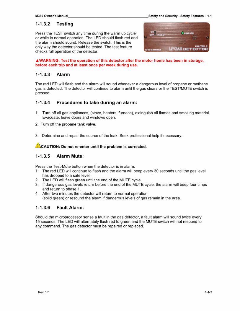
1-1.3.2 Testing Press the TEST switch any time during the warm up cycle or while in normal operation. The LED should flash red and the alarm should sound. Release the switch. This is the only way the detector should be tested. The test feature checks full operation of the detector.
▲WARNING: Test the operation of this detector after the motor home has been in storage, before each trip and at least once per week during use. 1-1.3.3 Alarm The red LED will flash and the alarm will sound whenever a dangerous level of propane or methane gas is detected. The detector will continue to alarm until the gas clears or the TEST/MUTE switch is pressed. 1-1.3.4 Procedures to take during an alarm: 1. Turn off all gas appliances, (stove, heaters, furnace), extinguish all flames and smoking material.
Evacuate, leave doors and windows open.
2. Turn off the propane tank valve.
3. Determine and repair the source of the leak. Seek professional help if necessary.
CAUTION: Do not re-enter until the problem is corrected.
1-1.3.5 Alarm Mute: Press the Test-Mute button when the detector is in alarm. 1. The red LED will continue to flash and the alarm will beep every 30 seconds until the gas level
has dropped to a safe level. 2. The LED will flash green until the end of the MUTE cycle. 3. If dangerous gas levels return before the end of the MUTE cycle, the alarm will beep four times
and return to phase 1. 4. After two minutes the detector will return to normal operation
(solid green) or resound the alarm if dangerous levels of gas remain in the area.
1-1.3.6 Fault Alarm: Should the microprocessor sense a fault in the gas detector, a fault alarm will sound twice every 15 seconds. The LED will alternately flash red to green and the MUTE switch will not respond to any command. The gas detector must be repaired or replaced.
1-1 - Safety and Security - Safety Features______________________________________________M380 Owner’s Manual
1-1-4 Rev. “F”
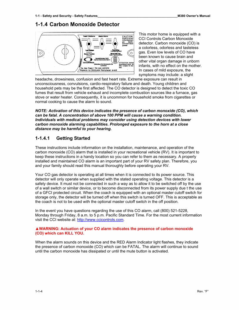
1-1.4 Carbon Monoxide Detector
This motor home is equipped with a CCI Controls Carbon Monoxide detector. Carbon monoxide (CO) is a colorless, odorless and tasteless gas. Even low levels of CO have been known to cause brain and other vital organ damage in unborn infants, with no effect on the mother. In cases of mild exposure, the symptoms may include: a slight
headache, drowsiness, confusion and fast heart rate. Extreme exposure can result in unconsciousness, convulsions, cardio-respiratory failure and death. Young children and household pets may be the first affected. The CO detector is designed to detect the toxic CO fumes that result from vehicle exhaust and incomplete combustion sources like a furnace, gas stove or water heater. Consequently, it is uncommon for household smoke from cigarettes or normal cooking to cause the alarm to sound. NOTE: Activation of this device indicates the presence of carbon monoxide (CO), which can be fatal. A concentration of above 100 PPM will cause a warning condition. Individuals with medical problems may consider using detection devices with lower carbon monoxide alarming capabilities. Prolonged exposure to the horn at a close distance may be harmful to your hearing. 1-1.4.1 Getting Started These instructions include information on the installation, maintenance, and operation of the carbon monoxide (CO) alarm that is installed in your recreational vehicle (RV). It is important to keep these instructions in a handy location so you can refer to them as necessary. A properly installed and maintained CO alarm is an important part of your RV safety plan. Therefore, you and your family should read this manual thoroughly before operating your RV. Your CO gas detector is operating at all times when it is connected to its power source. This detector will only operate when supplied with the stated operating voltage. This detector is a safety device. It must not be connected in such a way as to allow it to be switched off by the use of a wall switch or similar device, or to become disconnected from its power supply due t the use of a GFCI protected circuit. When the coach is equipped with an optional master cutoff switch for storage only, the detector will be turned off when this switch is turned OFF. This is acceptable as the coach is not to be used with the optional master cutoff switch in the off position. In the event you have questions regarding the use of this CO alarm, call (800) 521-5228, Monday through Friday, 8 a.m. to 5 p.m. Pacific Standard Time. For the most current information visit the CCI website at: http://www.ccicontrols.com. ▲WARNING: Actuation of your CO alarm indicates the presence of carbon monoxide (CO) which can KILL YOU. When the alarm sounds on this device and the RED Alarm Indicator light flashes, they indicate the presence of carbon monoxide (CO) which can be FATAL. The alarm will continue to sound until the carbon monoxide has dissipated or until the mute button is activated.
M380 Owner’s Manual______________________________________________Safety and Security - Safety Features – 1-1
Rev. “F” 1-1-5
If alarm sounds: 1. Press the MUTE button. 2. Call for emergency services. (fire department 911) 3. Immediately move to fresh air outside or by an open door or window. Do a head count to
check that all persons are accounted for. Do not re-enter the premises or move away from the open door or window until the emergency service personnel have arrived, the premises have been aired out, and your alarm returns to its normal condition.
4. After following steps 1-3, if your alarm reactivates within a 24 hour period, repeat steps 1-3 and call a qualified appliance technician.
Have the technician investigate for sources of CO from fuel burning equipment and appliances, and inspect for proper operation of this equipment. If problems are identified during this inspection have the equipment and appliances serviced immediately. NOTE: Any combustion equipment or appliance not inspected by the technician and consult the manufacturer’s instructions, or contact the manufacturers directly, for more information about CO safety of this equipment. Make sure that motor vehicles are not, and have not been, operating in an attached garage or adjacent to the residence.
CAUTION: This alarm will only indicate the presence of carbon monoxide (CO) gas at the sensor. CO gas may be present in other areas of the RV. 1-1.4.2 Operation The CO alarm will only detect CO gas if the proper power is supplied. Once power is supplied (or re-supplied) to the alarm, it will perform a brief warm-up and self-check process before beginning to monitor for carbon monoxide gas.
CAUTION: This alarm will only indicate the presence of carbon monoxide gas at the sensor. Carbon monoxide gas may be present in other areas. 1-1.4.3 CO Alarm Indicator Lights and Conditions Power. Once 12 volts DC power is supplied, the GREEN power indicator will turn on indicating the alarm is ready to detect CO gas. Alarm Condition. When CO gas is present in alarm concentrations, an alarm will sound and the RED alarm indicator light will flash. The detector will continue to alarm until the CO gas has dissipated or until the MUTE button is momentarily pressed. If the MUTE button is pressed during an alarm condition, the alarm will stop sounding and the RED alarm indicator light will also stop flashing. If CO gas is still present in alarm concentrations, the alarm will resume within a few minutes depending on the concentration. Fault/Low Voltage. In addition to sounding an alarm when CO gas reaches a specific concentration at the gas sensor, the CO alarm also performs two other valuable functions:
1. An automatic self diagnostic system check (called supervision) on the alarm’s electronics to ensure reliable, trouble-free operation.
2. Acts as a low voltage indicator for the battery that supplies voltage to the alarm. Fault Condition. In the event the CO alarm senses a fault in its electronics, the ORANGE Fault indicator light will illuminate continuously (not flashing) and then sound a beep once every five seconds. The GREEN power indicator will then turn off, indicating that the alarm is no longer monitoring for CO gas. If such action should occur, call CCI Controls for assistance during normal business hours. (8 a.m. to 5 p.m. PST). Low Voltage Condition. This CO alarm has been designed to operate from a 12 volt DC power source. Without the correct voltage, the CO alarm may not detect carbon monoxide at the gas sensor. In the event that the CO alarm senses that a low voltage condition exists, the ORANGE
1-1 - Safety and Security - Safety Features______________________________________________M380 Owner’s Manual
1-1-6 Rev. “F”
Low Voltage indicator will illuminate continuously (not flashing) and then sound a beep once every sixty seconds. The GREEN Power indicator light will then turn off indicating that the alarm is no longer monitoring for CO gas. In many instances, low voltage is an indication that the battery supplying voltage to the CO alarm needs recharging. If recharging your battery does not cause the ORANGE Low Voltage Indicator to turn off and the GREEN Power Indicator to turn on, call CCI Controls for assistance during normal business hours. (8 a.m. to 5 p.m. PST) NOTE: Unlike the separate indicator lights for the GREEN power and the RED alarm, the Fault and Low Voltage conditions share the same ORANGE indicator light. Mute/Self-Test. The Mute/Self-Test button serves two purposes: (1) to mute or silence the alarm and (2) to perform a self-test. See Alarm Condition above and Testing Your CO Alarm. 1-1.4.4 Testing Your CO Alarm ▲WARNING: Test alarm operation after vehicle has been in storage, before each trip, and at least once per week during use. It is important to test your CO alarm regularly. To test the electronics of the CO alarm, press and release the test button. The alarm should sound a beep four times and the RED alarm indicator light will flash four times. In addition, the indicator lights are also tested. The GREEN power indicator light will turn off and the ORANGE Fault/Low Voltage indicator light will illuminate temporarily. If the CO alarm does not respond in this manner, then refer to the troubleshooting section. 1-1.4.5 Cleaning Use a vacuum cleaner to remove dust or any other buildup on the detector. Do not wash. Wipe the detector with a damp cloth and dry it with a towel. Do not open the detector for cleaning. Do not paint the detector. It is recommended that the carbon monoxide detector be replaced every 10 years.
M380 Owner’s Manual______________________________________________Safety and Security - Safety Features – 1-1
Rev. “F” 1-1-7
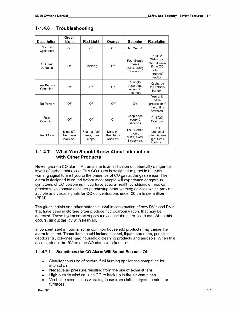
1-1.4.6 Troubleshooting
Description Green Light Red Light Orange Sounder Resolution
Normal Operation
On Off Off No Sound
CO Gas Detected On Flashing Off
Four Beeps then a
pulse, every 5 seconds.
Follow "What you
should know if the CO
alarm sounds" section
Low Battery Condition Off Off On
A single beep once every 60 seconds.
Recharge the vehicle
battery.
No Power Off Off Off Off
You only have
protection if the unit is powered.
Fault Condition Off Off On
Beep once every 5 seconds
Call CCI Controls.
Test Mode Dims off, then turns back on.
Flashes four times, then
stops.
Dims on, then turns back off.
Four Beeps then a
pulse, every 5 seconds.
Unit functional
when Green light turns back on.
1-1.4.7 What You Should Know About Interaction
with Other Products Never ignore a CO alarm. A true alarm is an indication of potentially dangerous levels of carbon monoxide. This CO alarm is designed to provide an early warning signal to alert you to the presence of CO gas at the gas sensor. The alarm is designed to sound before most people will experience dangerous symptoms of CO poisoning. If you have special health conditions or medical problems, you should consider purchasing other warning devices which provide audible and visual signals for CO concentrations under 30 parts per million (PPM). The glues, paints and other materials used in construction of new RV’s and RV’s that have been in storage often produce hydrocarbon vapors that may be detected. These hydrocarbon vapors may cause the alarm to sound. When this occurs, air out the RV with fresh air. In concentrated amounts, some common household products may cause the alarm to sound. These items could include alcohol, liquor, kerosene, gasoline, deodorants, colognes, and household cleaning products and aerosols. When this occurs, air out the RV an dthe CO alarm with fresh air. 1-1.4.7.1 Sometimes the CO Alarm Will Sound Because Of:
• Simultaneous use of several fuel burning appliances competing for internal air.
• Negative air pressure resulting from the use of exhaust fans • High outside wind causing CO to back up in the air vent pipes • Vent pipe connections vibrating loose from clothes dryers, heaters or
furnaces
1-1 - Safety and Security - Safety Features______________________________________________M380 Owner’s Manual
1-1-8 Rev. “F”
• Obstructed vent pipes or unvented fuel burning appliances • Temperature inversions which can trap exhaust gases near the ground. • Car or RV idling nearby
IMPORTANT NOTES: Some products may prevent or delay your CO gas alarm from detecting carbon monoxide. Therefore, your CO gas alarm should not be:
• Installed too low where items such as water and other household chemicals can pollute the sensor
• Covered, obstructed or painted • Exposed to sulfur products or powders of any kind
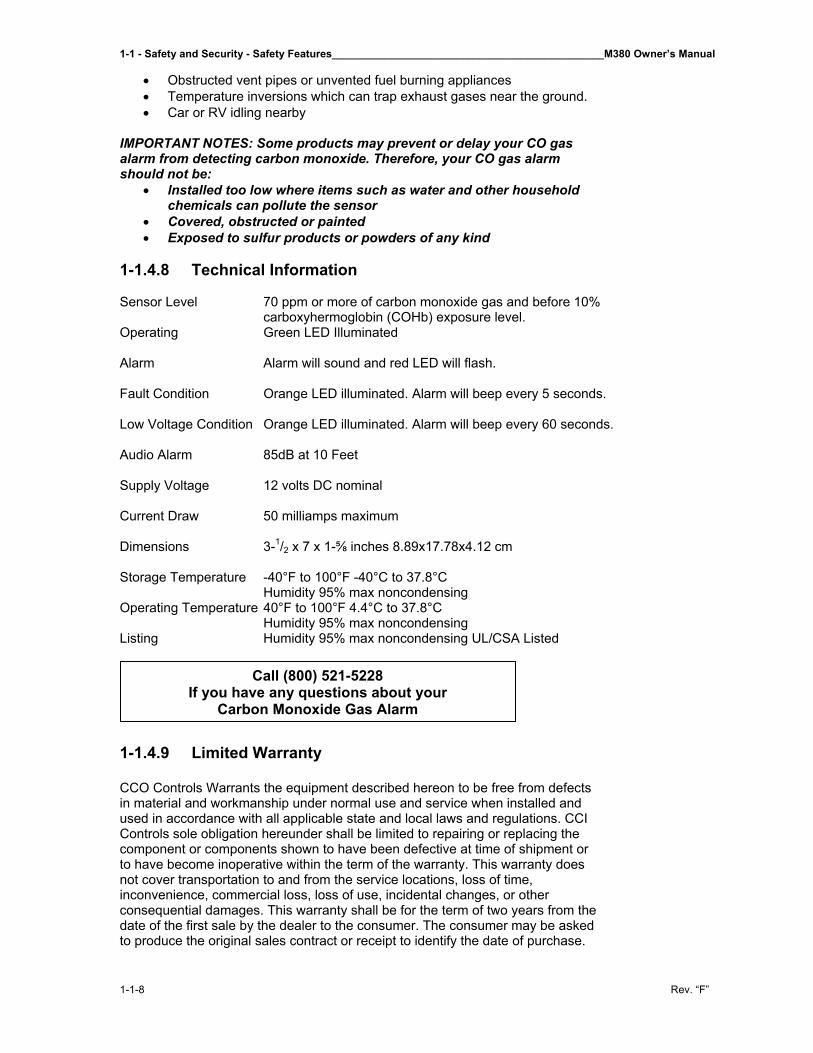
1-1.4.8 Technical Information Sensor Level 70 ppm or more of carbon monoxide gas and before 10%
carboxyhermoglobin (COHb) exposure level. Operating Green LED Illuminated Alarm Alarm will sound and red LED will flash. Fault Condition Orange LED illuminated. Alarm will beep every 5 seconds. Low Voltage Condition Orange LED illuminated. Alarm will beep every 60 seconds. Audio Alarm 85dB at 10 Feet Supply Voltage 12 volts DC nominal Current Draw 50 milliamps maximum Dimensions 3-1/2 x 7 x 1-⅝ inches 8.89x17.78x4.12 cm Storage Temperature -40°F to 100°F -40°C to 37.8°C Humidity 95% max noncondensing Operating Temperature 40°F to 100°F 4.4°C to 37.8°C Humidity 95% max noncondensing Listing Humidity 95% max noncondensing UL/CSA Listed
1-1.4.9 Limited Warranty CCO Controls Warrants the equipment described hereon to be free from defects in material and workmanship under normal use and service when installed and used in accordance with all applicable state and local laws and regulations. CCI Controls sole obligation hereunder shall be limited to repairing or replacing the component or components shown to have been defective at time of shipment or to have become inoperative within the term of the warranty. This warranty does not cover transportation to and from the service locations, loss of time, inconvenience, commercial loss, loss of use, incidental changes, or other consequential damages. This warranty shall be for the term of two years from the date of the first sale by the dealer to the consumer. The consumer may be asked to produce the original sales contract or receipt to identify the date of purchase.
Call (800) 521-5228 If you have any questions about your
Carbon Monoxide Gas Alarm
M380 Owner’s Manual______________________________________________Safety and Security - Safety Features – 1-1
Rev. “F” 1-1-9
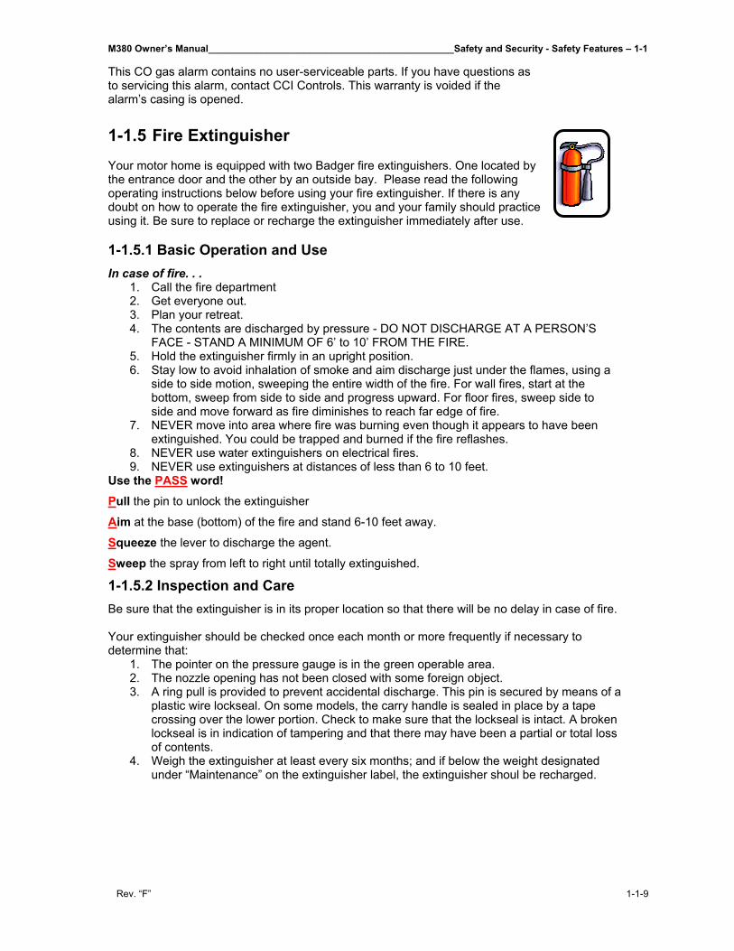
This CO gas alarm contains no user-serviceable parts. If you have questions as to servicing this alarm, contact CCI Controls. This warranty is voided if the alarm’s casing is opened. 1-1.5 Fire Extinguisher Your motor home is equipped with two Badger fire extinguishers. One located by the entrance door and the other by an outside bay. Please read the following operating instructions below before using your fire extinguisher. If there is any doubt on how to operate the fire extinguisher, you and your family should practice using it. Be sure to replace or recharge the extinguisher immediately after use. 1-1.5.1 Basic Operation and Use In case of fire. . .
1. Call the fire department 2. Get everyone out. 3. Plan your retreat. 4. The contents are discharged by pressure - DO NOT DISCHARGE AT A PERSON’S
FACE - STAND A MINIMUM OF 6’ to 10’ FROM THE FIRE. 5. Hold the extinguisher firmly in an upright position. 6. Stay low to avoid inhalation of smoke and aim discharge just under the flames, using a
side to side motion, sweeping the entire width of the fire. For wall fires, start at the bottom, sweep from side to side and progress upward. For floor fires, sweep side to side and move forward as fire diminishes to reach far edge of fire.
7. NEVER move into area where fire was burning even though it appears to have been extinguished. You could be trapped and burned if the fire reflashes.
8. NEVER use water extinguishers on electrical fires. 9. NEVER use extinguishers at distances of less than 6 to 10 feet.
Use the PASS word! Pull the pin to unlock the extinguisher
Aim at the base (bottom) of the fire and stand 6-10 feet away.
Squeeze the lever to discharge the agent.
Sweep the spray from left to right until totally extinguished.
1-1.5.2 Inspection and Care Be sure that the extinguisher is in its proper location so that there will be no delay in case of fire. Your extinguisher should be checked once each month or more frequently if necessary to determine that:
1. The pointer on the pressure gauge is in the green operable area. 2. The nozzle opening has not been closed with some foreign object. 3. A ring pull is provided to prevent accidental discharge. This pin is secured by means of a
plastic wire lockseal. On some models, the carry handle is sealed in place by a tape crossing over the lower portion. Check to make sure that the lockseal is intact. A broken lockseal is in indication of tampering and that there may have been a partial or total loss of contents.
4. Weigh the extinguisher at least every six months; and if below the weight designated under “Maintenance” on the extinguisher label, the extinguisher shoul be recharged.
1-1 - Safety and Security - Safety Features______________________________________________M380 Owner’s Manual
1-1-10 Rev. “F”
1-1.5.3 Fire Classification Symbols If your extinguisher bears these A, B or C symbols it can be used on the following fire types.
Ordinary Combustibles: Can be used on paper, cloth, wood, upholstery, and other ordinary combustibles. Flammable Liquids: Can be used on gasoline, oil, grease, and other flammable liquids. Electrical Equipment: Can be used on live electrical equipment. Combustible Cooking Media: For use on cooking appliances that use combustible cooking media (vegetable or animal oils and fats).
FIRE EXTINGUISHER AND AGENTS
TYPE EXTINGUISHER BASIC AGENT MAY BE USED ON
Regular (ordinary) Dry Chemical Sodium Bicarbonate
Multi-Purpose (ABC) Dry Chemical Ammonium Phospate
Purple "K" Dry Chemical Potassium Bicarbonate
Carbon Dioxide An Inert Gas
Water Tap Water
Halotron 1 Vaporizing Liquid
(WC-25)
(WC-10)
Wet Chemical Potassium Acetate Solution
(WC-100 & WC-250)
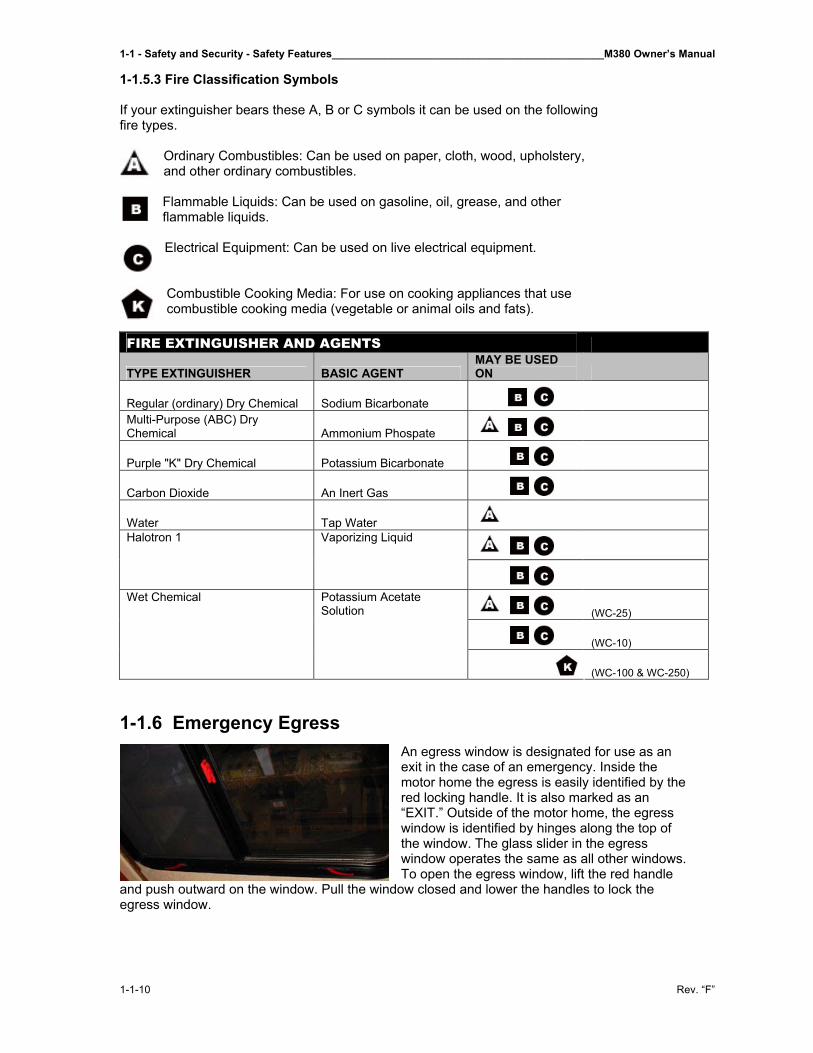
1-1.6 Emergency Egress
An egress window is designated for use as an exit in the case of an emergency. Inside the motor home the egress is easily identified by the red locking handle. It is also marked as an “EXIT.” Outside of the motor home, the egress window is identified by hinges along the top of the window. The glass slider in the egress window operates the same as all other windows. To open the egress window, lift the red handle
and push outward on the window. Pull the window closed and lower the handles to lock the egress window.
M380 Owner’s Manual______________________________________________Safety and Security - Safety Features – 1-1
Rev. “F” 1-1-11
1-1.6.1 Maintenance The egress window should be opened twice a year to ensure proper operation. Over time, the rubber seal will tend to stick to the egress window. Occasional operation will help prevent the rubber seal from sticking. 1-1.7 Engine Brake 1-1.7.1 What is it? Engine braking systems are designed to supplement a standard wheel braking system. These devices are not designed to bring the motor home to a complete stop; however, they can assist in controlling the speed of the motor home. Use of the engine braking system can save on costly service brake repairs. The “C” (Cummins) brake is an engine-braking device that operates on a different principle than an exhaust brake. An engine brake functions by releasing the engine’s compression. The effect of the engine brake increases with engine speed. When the engine brake is activated, the Allison transmission automatically downshifts, utilizing the gear selected and maximizing the engine braking effect. When the foot switch is activated, an electrical signal is sent to the engine’s ECM (electronic control module). The ECM controls a hydraulic circuit that then opens the exhaust valves near the end of the compression stroke. The potential engine braking power depends on turbocharger boost pressure, engine speed, compression ratio, injector timing and when the exhaust valves open. 1-1.7.2 Where is it? Located on the driver’s left console is a High/Low switch. This switch allows for the selection of different levels of engine braking power. Selecting “LOW” activates the engine brake on three cylinders. Selecting the “HI” setting activates the engine brake on six cylinders. 1-1.7.3 How do you turn it on? The engine brake will not be enabled when: • The cruise control is active. • The engine speed goes below 850 RPM. • An electronic fault code is active. 1-1.7.4 How do you turn it off? The throttle sensor is a component part of the accelerator pedal assembly and deactivates the engine brakes when the throttle is applied. Applying the service brakes while in cruise control will disengage the cruise control and enable the engine brakes. The engine brake foot switch will not disengage the cruise control. Use the engine brake when going down a hill, freeway or off ramp. The engine brake will allow the engine temperature to drop while going downhill. NOTE: Idle the engine 3 to 5 minutes at approximately 1000 RPM to warm the engine before activating the engine brakes. Do not operate the engine brakes until the engine oil temperature is above 30°C (86° F). ▲WARNING: The engine brake is designed to assist the motor home service brakes.
1-1 - Safety and Security - Safety Features______________________________________________M380 Owner’s Manual
1-1-12 Rev. “F”
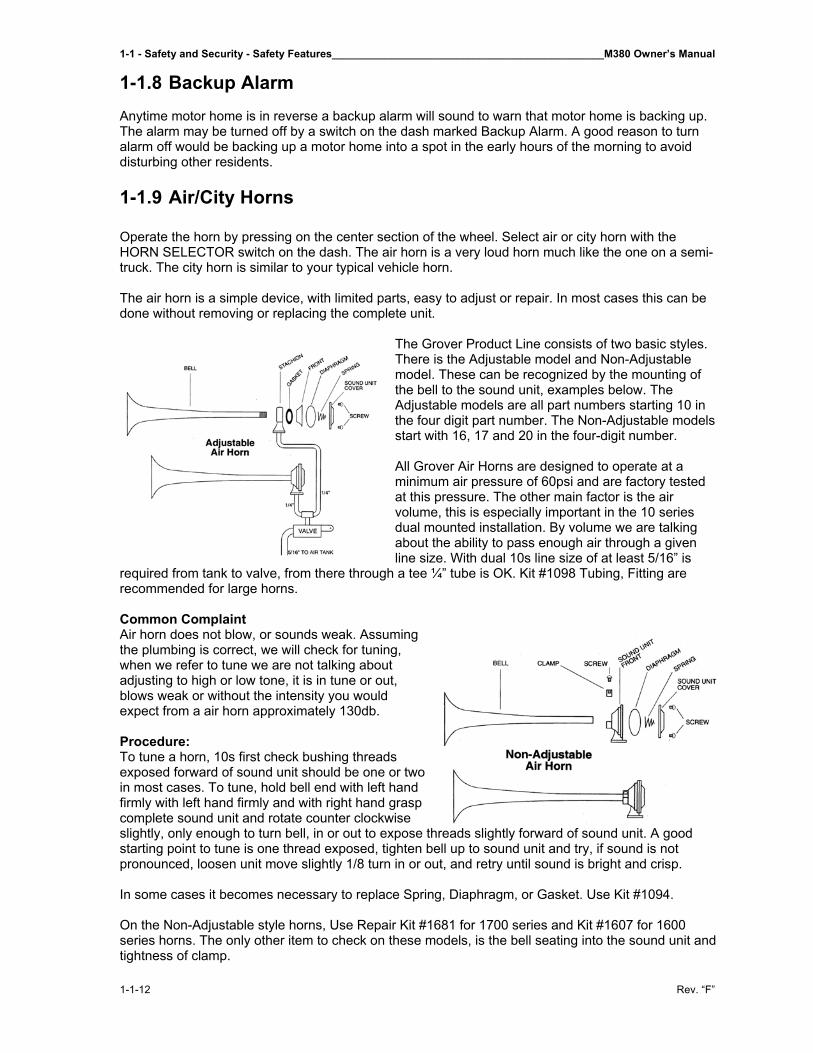
1-1.8 Backup Alarm Anytime motor home is in reverse a backup alarm will sound to warn that motor home is backing up. The alarm may be turned off by a switch on the dash marked Backup Alarm. A good reason to turn alarm off would be backing up a motor home into a spot in the early hours of the morning to avoid disturbing other residents. 1-1.9 Air/City Horns Operate the horn by pressing on the center section of the wheel. Select air or city horn with the HORN SELECTOR switch on the dash. The air horn is a very loud horn much like the one on a semi-truck. The city horn is similar to your typical vehicle horn. The air horn is a simple device, with limited parts, easy to adjust or repair. In most cases this can be done without removing or replacing the complete unit.
The Grover Product Line consists of two basic styles. There is the Adjustable model and Non-Adjustable model. These can be recognized by the mounting of the bell to the sound unit, examples below. The Adjustable models are all part numbers starting 10 in the four digit part number. The Non-Adjustable models start with 16, 17 and 20 in the four-digit number. All Grover Air Horns are designed to operate at a minimum air pressure of 60psi and are factory tested at this pressure. The other main factor is the air volume, this is especially important in the 10 series dual mounted installation. By volume we are talking about the ability to pass enough air through a given line size. With dual 10s line size of at least 5/16” is
required from tank to valve, from there through a tee ¼” tube is OK. Kit #1098 Tubing, Fitting are recommended for large horns. Common Complaint Air horn does not blow, or sounds weak. Assuming the plumbing is correct, we will check for tuning, when we refer to tune we are not talking about adjusting to high or low tone, it is in tune or out, blows weak or without the intensity you would expect from a air horn approximately 130db. Procedure: To tune a horn, 10s first check bushing threads exposed forward of sound unit should be one or two in most cases. To tune, hold bell end with left hand firmly with left hand firmly and with right hand grasp complete sound unit and rotate counter clockwise slightly, only enough to turn bell, in or out to expose threads slightly forward of sound unit. A good starting point to tune is one thread exposed, tighten bell up to sound unit and try, if sound is not pronounced, loosen unit move slightly 1/8 turn in or out, and retry until sound is bright and crisp. In some cases it becomes necessary to replace Spring, Diaphragm, or Gasket. Use Kit #1094. On the Non-Adjustable style horns, Use Repair Kit #1681 for 1700 series and Kit #1607 for 1600 series horns. The only other item to check on these models, is the bell seating into the sound unit and tightness of clamp.
M380 Owner’s Manual______________________________________________Safety and Security - Safety Features – 1-1
Rev. “F” 1-1-13
1-1.9.1 Backup Lights Backup lights are similar to vehicle backup lights. They engage when the motor home is in reverse to warn motor home is backing up. 1-1.10 Landing Lights There are three sets of landing lights. Two are on the left side of the motor home, two are on the right side of the motor home, and two are on the rear of the motor home. They may be switched on or off by selecting one of three buttons marked REAR LAND, LEFT LAND, or RIGHT LAND, on the panel just to the left of the main instrument panel on the dash. A common use would be to aid owner in various operations performed such as loading the motor home, entertaining, or anytime light is needed in that area of the motor home. The reverse landing lights will only operate while the motor home is in reverse or neutral. They will not operate if motor home is in drive. 1-1.11 Spot Lights The spotlights are located on the roof in the front of the motor home. They are operated by and on/off switch and toggle switch used for directional purposes on the right hand side of the dash beside the ignition switch. 1-1.12 Vehicle Loading The Federal Certification Label, located inside and above the driver’s windshield between the sun visor mounting brackets describes the maximum weight-carrying capacities of your motor home and for each axle, respectively abbreviated by “GVWR” and “GAWR.”
The Gross Vehicle Weight Rating (GVWR) is the maximum motor home weight allowable with all systems filled and with passengers and supplies aboard.
Each axle also has a maximum load-bearing capacity referred to as the Gross Axle Weight Rating (GAWR).
The load capacity is the difference between the GVWR and the actual weight. This means that the total weight of all food, clothing, other supplies and passengers must not permit the load capacity to be exceeded.
To find the actual weight, with the motor home fully loaded, drive to a scale, read the weight on the front, and rear wheels separately to determine axle loading. The load on each axle should not exceed its GAWR. If weight ratings are exceeded, move or remove items to bring all weights below the ratings.
When loading your motor home, store heavy gear first. Be sure to keep heavy gear on or as close to the floor as possible. Heavy items should be stored centrally to distribute the weight evenly between the front and the rear axles. Store only light objects on high shelves. Distribute weight to obtain even side-to-side balance of the loaded unit. Secure loose items to prevent weight shifts that could adversely affect the balance and road ability of the vehicle.
1-1 - Safety and Security - Safety Features______________________________________________M380 Owner’s Manual
1-1-14 Rev. “F”
1-1.12.1 Motor Home Weight Information Model ________________________________________________________________
GVWR ________________________________________________________________
UVW ________________________________________________________________
NCC ________________________________________________________________
GCWR ________________________________________________________________
GVWR
(Gross Vehicle Weight Rating) means the maximum permissible weight of this motor home. The GVWR is equal to or greater than the sum of the Unloaded Vehicle Weight plus the Net Carrying Capacity.
UVW
(Unloaded Vehicle Weight) means the weight of this motor home as built at the factory with full fuel, engine oil, and coolants. The UVW does not include cargo, fresh water, LP gas, occupants, or dealer installed accessories.
NCC
(Net Carrying Capacity) means the maximum weight of all occupants including the driver, personal belongings, food, fresh water, LP gas, tools, tongue weight of towed vehicle, dealer installed accessories, etc., that can be carried by this motor home.
(NCC is equal to or less than GVWR minus UVW).
GCWR
(Gross Combination Weight Rating) means the value specified by the motor home manufacturer as the maximum allowable loaded weight of this motor home with its towed trailer or towed vehicle.
This motor home is capable of carrying up to 100 gallons of fresh water (including water heater) for a total of 830 pounds. Reference: Weight of fresh water is 8.3 lbs./gal.; Weight of LP gas is 4.2 lbs./gal. (average).
NOTE: Consult weight decal located in motor home for actual weights.
M380 Owner’s Manual____________________________________________Safety and Security - Security Features – 1-2
Rev. “F” 1-2-1
1-2 Security Features_____________________________________
1-2.1 Electric Compartment Locks 1-2.1.1 Entrance Door Dead Bolt Lock Operation The entrance door has an automotive style two position catch. The second position is required for FMVSS certification. For maximum security and minimum wind noise be sure the door is fully closed. A dead bolt lock is also provided for your security; however, it will only engage and retract if the door is fully closed. Should you inadvertently open the automotive latch with the dead bolt engaged, you will have to shut the door to retract the dead bolt. Dead bolt can be activated from switches located on the upper right hand dash panel; the entrance door systems control panel, and the bedroom control panel. 1-2.2 Keyless Entry/Security Your motor home is equipped with a Keyless Entry system. There are two possible models that your motor home may have, the Crime Guard System or the Black Widow System, depending on when you purchased your motor home. These are operated much like that of a keyless entry system in an automobile. 1-2.3 Black Widow Security System If your motor home is equipped with the Black Widow Security System basic directions for operation are as follows: 1-2.3.1 About Your Black Widow Security System The security systems combine the benefits of easy-to-use convenience with “no nonsense” protection of person and property. Please review this manual to become familiar with your Black Widow vehicle security system. To operate your security system, the three principle components are first described: the Remote Control Transmitter, the Red Status Indicator Light, and the Easy Valet™ Switch. 1-2.3.2 Standard Features The system has the following standard features:
• 5-button remote transmitter • Status indicator (LED) • Valet/Service mode switch • Remote Start capabilities • Extended Range Receiver • Multi-tone siren (120 dB) • Dual stage impact detector • Remote panic • Valet mode • Remote chirp delete
• Remote sensor bypass • Passive or active arming • Stop and Go Feature • Auto Cold Start • Flashing Parking Lights • Auto Rearm • Passive/Active Arming • Bay Door Release • Rear Engine Door Release
1-1 - Safety and Security - Security Features____________________________________________M380 Owner’s Manual
1-2-2 Rev. “F”
1-2.3.3 Optional Features This system has many optional features that may require additional parts and/or labor. Please contact your dealer for more details.
• Remote keyless entry (Door lock/unlock)
• Illuminated entry • LCD FM 2-way Remote • Horn honk
• Window roll-up • Back up battery • Additional sensors: glass
breakage/microwave
NOTE: Some features may not be appropriate for certain models. Automatic transmission and electronic fuel injection are required, on models using this system. 1-2.3.4 Remote Transmitter Functions Button 1 Arms the system and locks the doors*. Button 1 also activates the Panic feature. Button 2 Disarms the system and unlocks the doors*. Button 3 Activates the Bay Door Release feature. Button 4 Activates the Remote Start Feature. Button 5 Auxiliary Shift Key. Button 5 then 4 Activates the 2nd auxiliary function. 1-2.3.5 Arming Operation To arm the system press transmitter button 1:
• The siren will chirp once. • The parking lights will flash once. • The doors will lock*. • The LED will turn solid for 10 seconds then start flashing slowly, the system is now armed.
While the system is armed the alarm will trigger if:
• A door is opened. • The bay door is opened. • The shock sensor detects an impact to the vehicle.
When the alarm is triggered the siren will sound, the parking lights will flash, and the horn will honk*. If the alarm is triggered while the remote start is engaged, the remote start will immediately shut down. 1-2.3.6 Passive Arming The passive arming feature allows the system to arm automatically without user intervention. This programmable feature may be enabled during installation. To arm the system passively:
1. Turn the ignition key off. 2. Exit the vehicle and close all doors. • The LED will start flashing rapidly to indicate that the system is preparing to arm. (The system
can be armed at any time by pressing transmitter button 1.) • The siren will chirp 30 seconds after the last door is closed to indicate the system is now
armed. • The doors will lock‡*
*Optional feature The ignition must have been on for at least 10 seconds prior to exiting the vehicle or Passive Arming will be bypassed. ‡ If the Passive Locking feature was enabled during installation.
M380 Owner’s Manual____________________________________________Safety and Security - Security Features – 1-2
Rev. “F” 1-2-3
1-2.3.7 Disarming Operation • To disarm the system press transmitter
button 2. • The siren will chirp twice ¥ • The parking lights will flash twice. ¥
• The doors will unlock. † • The dome light will turn on for 30
seconds. *
¥ if the siren was triggered while away, the system will respond with 3 chirps and 3 parking light features. † If the Passenger Unlock Feature is enabled, pressing the unlock button will unlock only the driver’s door. Pressing the unlock button again unlocks all doors. 1-2.3.8 Tamper Alert If the alarm was triggered while away from the vehicle, the siren will chirp 3 times on disarming for tamper indication. After disarming the alarm, enter vehicle and turn ignition on. The LED will flash the zone that was triggered 5 times (see LED chart). 1-2-3.9 Auto Rearm The Auto Rearm feature allows the system to automatically re-arm itself in the event the system is disarmed and ignition is not turned on within 30 seconds. NOTE: This programmable feature may be disabled during installation. The Passive Arming feature and Auto Rearm feature are related. In order to disable the Auto Rearm feature, the Passive Arming feature must also be disabled during installation. This feature will not work on vehicles with the illuminated entry feature enabled. 1-2.3.10 Silent Arming/Disarming Press transmitter button 5 (the Shift Button) then the Arm or Disarm button for one-time silent operation. 1-2.3.11 Chirp Delete For full time silent operation, the ARM/DISARM chirps can be permanently disabled. This feature must be programmed during installation. 1-2.3.12 Ignition Lock* The ignition locking feature allows the doors to automatically lock when the ignition key is turned on, and automatically unlock when the ignition key is turned off. This feature may be disabled during installation. 1-2.3.13 Remote Panic In the event of an emergency (PANIC) situation, the system’s siren can be triggered for 45 seconds to attract attention. To activate the Panic Feature, press transmitter button 1 for 3 seconds:
• The siren will sound. • The parking lights will flash.
Press button 1 to exit panic mode and rearm the system. Press button 2 to exit panic mode and disarm the system. The Panic Feature will operate when the ignition is on. 1-2.3.14 Emergency Override If the transmitter becomes lost or fails to operate, the system can be disarmed by using the emergency override feature. To override the system: 1. Enter the vehicle.
• Because the system is armed, the siren will sound. 2. Turn on the ignition key. 3. Press the Valet switch for 5 seconds.
• The siren will stop sounding. • Starter defeat bypassed.*Optional feature The ignition must have been on for at least 10 seconds prior to exiting the vehicle or Passive Arming will be bypassed. ‡ If the Passive Locking feature was enabled during installation.
1-1 - Safety and Security - Security Features____________________________________________M380 Owner’s Manual
1-2-4 Rev. “F”
1-2.3.15 Valet Mode When the system is placed into the Valet Mode the security system will be disabled. However, the optional keyless entry and remote start features will still function if installed. NOTE: Remote Start feature may be disabled during valet mode if programmed during installation. To enter the Valet Mode: 1. Be sure the system is disarmed. 2. Turn the ignition key on. 3. Press and hold the valet/service mode switch for 3 seconds.
• The siren will chirp once. • The LED will turn on solid indicating the system is in Valet Mode.
To exit Valet Mode: 1. Turn the ignition key on. 2. Press and hold the valet/service mode switch for 3 seconds.
• The LED will turn off. • The Siren will chirp 2 times.
1-2.3.16 Bay Door Release Press button 3 for approximately 2 seconds to open the bay door. 1-2.3.17 Bay Door Disarm The Bay Door Disarm feature allows the alarm to disarm automatically whenever transmitter button 3 is used to activate the optional trunk release. This eliminates having to first, disarm the alarm before activating the bay door release. NOTE: The feature is programmed during installation. 1-2.3.18 Remote Sensor Bypass To arm the system and bypass the shock sensor, press button 1 to arm, then within 2 seconds press button 2 again. The siren will chirp 5 times and sensors will be ignored until the system is disarmed and rearmed. 1-2.3.19 Optional Secure Override Code If your system was programmed to override with a personal override code-pressing the override switch from 1 to 15 times. To disarm the system with your personal override code please use the following steps: 1. Open Door, Alarm system will trigger 2. Turn ignition key to on. 3. Press the override switch to the selected number of times and hold on the last one for 5 seconds
until the alarm turns off.
M380 Owner’s Manual____________________________________________Safety and Security - Security Features – 1-2
Rev. “F” 1-2-5
1-2.3.20 Remote Starting the Motor Home IMPORTANT: Only start the motor home in a well ventilated area. Do not use in a closed garage or indoors. Be sure to familiarize yourself with all features prior to using this product. To remote start the motor home: Press the transmitter button 4 for 3 seconds.
• The parking lights turn on. • Approximately 2 seconds later the system will attempt to start the motor home. • Once the motor home has started, the heater or air conditioner will turn on and run for the
pre-programmed time (15 or 25 minutes). If the engine fails to start on the first attempt, it will repeat the starting procedure 2 more times. If the vehicle fails to start after a total of 3 times the system will shut down.
• Driving motor home after Remote Starting: Unlock the door by pressing button 2 on the remote transmitter. Enter motor home, turn ignition key to the on position. NOTE: Do not turn the key all the way to the start position as you may damage the starter. Once the ignition key is turned to the on position, press the brake pedal and shift the motor home into the proper gear and you may now drive the motor home. NOTE: If brake pedal is pressed prior to turning on ignition, engine will turn off). 1-2.3.21 Remote Engine Shutdown If the motor home has been remotely started and you desire to turn the vehicle off, simply press and hold button 4 on the remote transmitter for three seconds. After the motor has turned off the doors will relock. This feature must be programmed during installation. 1-2.3.22 Auto Cold Start This feature allows the system to start and run the motor home every one or two hours (selectable by the installer) for a period of 24 hours. This allows the engine to remain at an operational temperature in extremely cold weather. Auto Cold Start must be enabled during installation or it cannot be engaged. Engaging the Auto Cold Start feature: To turn Auto Cold Start on: 1. Press and hold the brake pedal. 2. While holding the brake pedal down, push the Valet switch and transmitter button 2 for two
seconds. • The parking lights will flash four times to indicate the Cold Start feature is engaged.
3. Release the brake pedal. Disengaging the Auto Cold Start feature: The Auto Cold Start feature can be deactivated in one of three ways:
• Press the brake pedal. • Turn on the ignition. • Remote start the motor home using the transmitter.
1-2.3.24 Stop and Go The Stop and Go features allows the motor home to remain running without use of the ignition key during short stops.
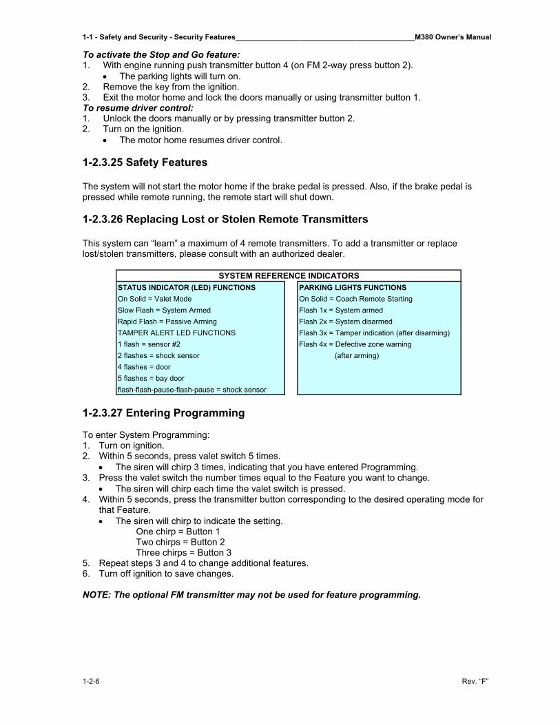
1-1 - Safety and Security - Security Features____________________________________________M380 Owner’s Manual
1-2-6 Rev. “F”
To activate the Stop and Go feature: 1. With engine running push transmitter button 4 (on FM 2-way press button 2).
• The parking lights will turn on. 2. Remove the key from the ignition. 3. Exit the motor home and lock the doors manually or using transmitter button 1. To resume driver control: 1. Unlock the doors manually or by pressing transmitter button 2. 2. Turn on the ignition.
• The motor home resumes driver control. 1-2.3.25 Safety Features The system will not start the motor home if the brake pedal is pressed. Also, if the brake pedal is pressed while remote running, the remote start will shut down. 1-2.3.26 Replacing Lost or Stolen Remote Transmitters This system can “learn” a maximum of 4 remote transmitters. To add a transmitter or replace lost/stolen transmitters, please consult with an authorized dealer.
1-2.3.27 Entering Programming To enter System Programming: 1. Turn on ignition. 2. Within 5 seconds, press valet switch 5 times.
• The siren will chirp 3 times, indicating that you have entered Programming. 3. Press the valet switch the number times equal to the Feature you want to change.
• The siren will chirp each time the valet switch is pressed. 4. Within 5 seconds, press the transmitter button corresponding to the desired operating mode for
that Feature. • The siren will chirp to indicate the setting.
One chirp = Button 1 Two chirps = Button 2 Three chirps = Button 3
5. Repeat steps 3 and 4 to change additional features. 6. Turn off ignition to save changes. NOTE: The optional FM transmitter may not be used for feature programming.
STATUS INDICATOR (LED) FUNCTIONS PARKING LIGHTS FUNCTIONSOn Solid = Valet Mode On Solid = Coach Remote StartingSlow Flash = System Armed Flash 1x = System armedRapid Flash = Passive Arming Flash 2x = System disarmedTAMPER ALERT LED FUNCTIONS Flash 3x = Tamper indication (after disarming)1 flash = sensor #2 Flash 4x = Defective zone warning2 flashes = shock sensor (after arming)4 flashes = door5 flashes = bay doorflash-flash-pause-flash-pause = shock sensor
SYSTEM REFERENCE INDICATORS
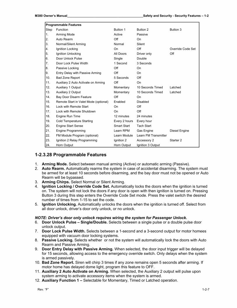
M380 Owner’s Manual____________________________________________Safety and Security - Security Features – 1-2
Rev. “F” 1-2-7
1-2.3.28 Programmable Features 1. Arming Mode. Select between manual arming (Active) or automatic arming (Passive). 2. Auto Rearm. Automatically rearms the system in case of accidental disarming. The system must
be armed for at least 10 seconds before disarming, and the bay door must not be opened or Auto Rearm will be bypassed.
3. Arming Chirps. Select Normal or Silent Arming. 4. Ignition Locking / Override Code Set. Automatically locks the doors when the ignition is turned
on. The system will not lock the doors if any door is open with then ignition is turned on. Pressing Button 3 during this step enters the Override Code Set mode. Press the valet switch the desired number of times from 1-15 to set the code.
5. Ignition Unlocking. Automatically unlocks the doors when the ignition is turned off. Select from all door unlock, driver’s door only unlock, or no unlock.
NOTE: Driver’s door only unlock requires wiring the system for Passenger Unlock. 6. Door Unlock Pulse – Single/Double. Selects between a single pulse or a double pulse door
unlock output. 7. Door Lock Pulse Width. Selects between a 1-second and a 3-second output for motor homees
equipped with vacuum door locking systems. 8. Passive Locking. Selects whether or not the system will automatically lock the doors with Auto
Rearm and Passive Arming. 9. Door Entry Delay with Passive Arming. When selected, the door input trigger will be delayed
for 15 seconds, allowing access to the emergency override switch. Only delays when the system is armed passively.
10. Bad Zone Report. Siren will chirp 3 times if any zone remains open 5 seconds after arming. If motor home has delayed dome light, program this feature to OFF.
11. Auxiliary 2 Auto Activate on Arming. When selected, the Auxiliary 2 output will pulse upon system arming to activate accessory items when the system is armed.
12. Auxiliary Function 1 – Selectable for Momentary, Timed or Latched operation.
Step Function Button 1 Button 2 Button 31. Arming Mode Active Passive2. Auto Rearm Off On3. Normal/Silent Arming Normal Silent4. Ignition Locking On Off Override Code Set5. Ignition Unlocking All Doors Driver only Off6. Door Unlock Pulse Single Double7. Door Lock Pulse Width 1 Second 3 Seconds8. Passive Locking Off On9. Entry Delay with Passive Arming Off On10. Bad Zone Report 5 Seconds Off11. Auxiliary 2 Auto Activate on Arming Off On12. Auxiliary 1 Output Momentary 10 Seconds Timed Latched13. Auxiliary 2 Output Momentary 10 Seconds Timed Latched14. Bay Door Disarm Feature Off On15. Remote Start in Valet Mode (optional) Enabled Disabled16. Lock with Remote Start On Off17. Lock with Remote Shutdown On Off18. Engine Run Time 12 minutes 24 minutes19. Cold Temperature Starting Every 2 hours Every hour20. Engine Start Sense Smart Start Tach Start21. Engine Programming Learn RPM Gas Engine Diesel Engine22. FM Module Program (optional) Learn Module Learn FM Transmitter23. Ignition 2 Relay Programming Ignition 2 Accessory 2 Starter 224. Horn Output Horn Output Ignition 3 Output
Programmable Features
1-1 - Safety and Security - Security Features____________________________________________M380 Owner’s Manual
1-2-8 Rev. “F”
When Momentary operation is selected, the system will provide an output for as long as the Transmitter button is held. When Latched operation is selected, the system will provide an output that turns on when the transmitter button is pressed and turns off when the transmitter button is pressed again. When Timed operation is selected, the system will provide an output that turns on for 10 seconds each time the transmitter button is pressed. If the button is pressed again during the 10 seconds, the output will turn off.
13. Auxiliary Function 2 – Selectable for Momentary, Timed, or Latched operation. 14. Bay Door Disarm Feature. When selected, activating the Auxiliary 1 function to open the bay
door will automatically disarm the system. 15. Remote Start in Valet Mode. Determines if the remote start feature will operate when the alarm
is set for valet mode. 16. Lock with Remote Start. Automatically locks the doors after successfully remote starting. 17. Lock with Remote Shutdown. Automatically locks the doors 5 seconds after the remote start is
shut down. 18. Engine Run Time. Selects between 12 and 24 minutes run cycle. 19. Cold Temperature Starting. Allows the vehicle to automatically start and run every 2 hours or
every hour for severe cold weather. 20. Engine Start Sense. Selects between Smart Start for tachless operation, or Tach Start for actual
RPM monitored starting. (see Step #21) 21. Engine Programming. Pressing transmitter button 1 “learns” the RPM. For diesel vehicles, after
learning Tach signal enter step #21 again and set for diesel by pressing button 3. 22. FM Transmitter Module. Pressing button 1 learns the add-on FM module ID so the FM
transmitter can operate the system. Pressing button 2 learns the FM transmitter. After pressing button 2 on the AM remote, press transmitter button 1 on each FM remote (max 2).
23. Ignition 2 Relay Programming. Selects between second ignition, second accessory, or second starter output operation for heavy gauge BROWN wire.
24. Horn Output. Selects between horn output or ignition 3 output for the horn wire.
Engine Programming for Remote Start In order for the system to properly start and run the motor home, the unit must be able to determine if the motor home is cranking or if the engine is actually running. This system is equipped with two means of detecting the engine’s run status: Smart Start and Tach Start. The Smart Start feature detects the engine’s run status using specially designed software that interprets certain characteristics of the engine, and does not require a connection to the motor home’s tachometer wire. This feature allows a faster installation, but may not be compatible with all motor homees, or under extreme temperatures. The Tach Start feature requires connection to the motor homes tachometer wire, or an injector wire if the tach wire is not available. The Tach Start feature provides reliable operation with virtually any vehicle and in severe temperature extremes. When the Tach Start feature is selected, the vehicle’s tach signal must be “learned” through system programming. (see below)
To Program the Tach Start feature: 1. Enter System Programming, (see Entering Programming) 2. Program Step #20 to Tach Start using transmitter button 2. 3. Re-enter system programming, and go to Step #21. 4. Immediately start the vehicle with the key to avoid the programming sequence timing out. 5. Press transmitter button 1 to learn the vehicle’s tach signal.
• The siren will chirp and the LED will flash once if the tach was learned. • The siren will chirp and the LED will flash 5 times if the tach was not learned.
6. Turn off ignition to save settings. The default setting for the engine mode is Gas Engine. For diesel vehicles, the engine type for Step #21 must be set to Diesel Engine. When programmed for diesel engines, the BLUE/YELLOW wire
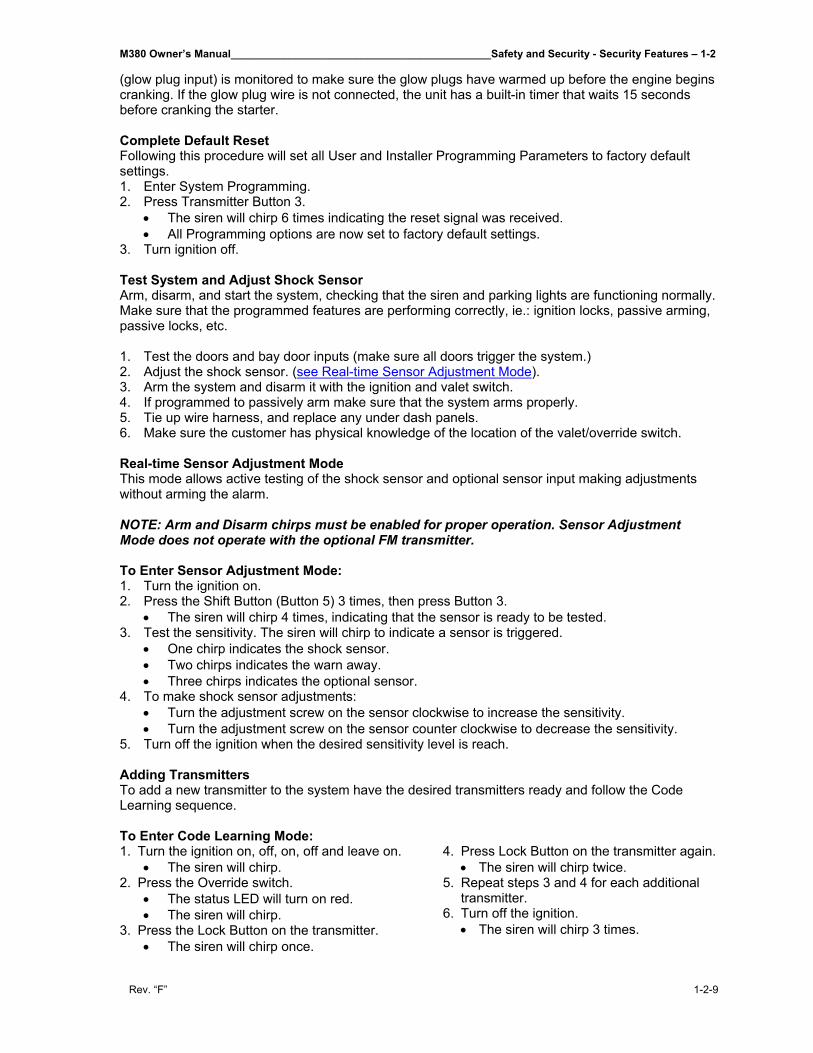
M380 Owner’s Manual____________________________________________Safety and Security - Security Features – 1-2
Rev. “F” 1-2-9
(glow plug input) is monitored to make sure the glow plugs have warmed up before the engine begins cranking. If the glow plug wire is not connected, the unit has a built-in timer that waits 15 seconds before cranking the starter. Complete Default Reset Following this procedure will set all User and Installer Programming Parameters to factory default settings. 1. Enter System Programming. 2. Press Transmitter Button 3.
• The siren will chirp 6 times indicating the reset signal was received. • All Programming options are now set to factory default settings.
3. Turn ignition off.
Test System and Adjust Shock Sensor Arm, disarm, and start the system, checking that the siren and parking lights are functioning normally. Make sure that the programmed features are performing correctly, ie.: ignition locks, passive arming, passive locks, etc.
1. Test the doors and bay door inputs (make sure all doors trigger the system.) 2. Adjust the shock sensor. (see Real-time Sensor Adjustment Mode). 3. Arm the system and disarm it with the ignition and valet switch. 4. If programmed to passively arm make sure that the system arms properly. 5. Tie up wire harness, and replace any under dash panels. 6. Make sure the customer has physical knowledge of the location of the valet/override switch.
Real-time Sensor Adjustment Mode This mode allows active testing of the shock sensor and optional sensor input making adjustments without arming the alarm. NOTE: Arm and Disarm chirps must be enabled for proper operation. Sensor Adjustment Mode does not operate with the optional FM transmitter.
To Enter Sensor Adjustment Mode: 1. Turn the ignition on. 2. Press the Shift Button (Button 5) 3 times, then press Button 3.
• The siren will chirp 4 times, indicating that the sensor is ready to be tested. 3. Test the sensitivity. The siren will chirp to indicate a sensor is triggered.
• One chirp indicates the shock sensor. • Two chirps indicates the warn away. • Three chirps indicates the optional sensor.
4. To make shock sensor adjustments: • Turn the adjustment screw on the sensor clockwise to increase the sensitivity. • Turn the adjustment screw on the sensor counter clockwise to decrease the sensitivity.
5. Turn off the ignition when the desired sensitivity level is reach.
Adding Transmitters To add a new transmitter to the system have the desired transmitters ready and follow the Code Learning sequence. To Enter Code Learning Mode: 1. Turn the ignition on, off, on, off and leave on.
• The siren will chirp. 2. Press the Override switch.
• The status LED will turn on red. • The siren will chirp.
3. Press the Lock Button on the transmitter. • The siren will chirp once.
4. Press Lock Button on the transmitter again. • The siren will chirp twice.
5. Repeat steps 3 and 4 for each additional transmitter.
6. Turn off the ignition. • The siren will chirp 3 times.
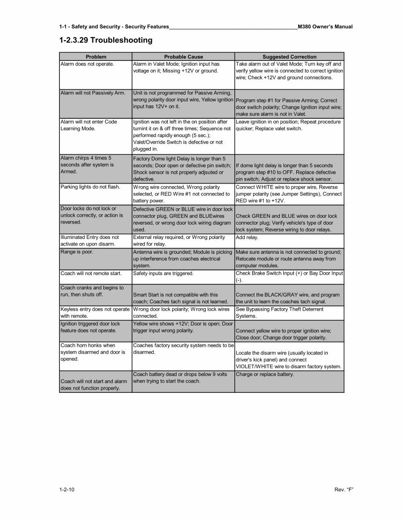
1-1 - Safety and Security - Security Features____________________________________________M380 Owner’s Manual
1-2-10 Rev. “F”
1-2.3.29 Troubleshooting
Problem Probable Cause Suggested CorrectionAlarm does not operate. Alarm in Valet Mode; Ignition input has
voltage on it; Missing +12V or ground.Take alarm out of Valet Mode; Turn key off and verify yellow wire is connected to correct ignition wire; Check +12V and ground connections.
Alarm will not Passively Arm. Unit is not programmed for Passive Arming, wrong polarity door input wire, Yellow ignition input has 12V+ on it.
Program step #1 for Passive Arming; Correct door switch polarity; Change Ignition input wire; make sure alarm is not in Valet.
Alarm will not enter Code Learning Mode.
Ignition was not left in the on position after turnint it on & off three times; Sequence not performed rapidly enough (5 sec.); Valet/Override Switch is defective or not plugged in.
Leave ignition in on position; Repeat procedure quicker; Replace valet switch.
Alarm chirps 4 times 5 seconds after system is Armed.
Factory Dome light Delay is longer than 5 seconds; Door open or defective pin switch; Shock sensor is not properly adjsuted or defective.
If dome light delay is longer than 5 seconds program step #10 to OFF. Replace defective pin switch; Adjust or replace shock sensor.
Parking lights do not flash. Wrong wire connected, Wrong polarity selected, or RED Wire #1 not connected to battery power.
Connect WHITE wire to proper wire, Reverse jumper polarity (see Jumper Settings), Connect RED wire #1 to +12V.
Door locks do not lock or unlock correctly, or action is reversed.
Defective GREEN or BLUE wire in door lock connector plug, GREEN and BLUEwires reversed, or wrong door lock wiring diagram used.
Check GREEN and BLUE wires on door lock connector plug; Verify vehicle's type of door lock system; Reverse wiring to door relays.
Illuminated Entry does not activate on upon disarm.
External relay required, or Wrong polarity wired for relay.
Add relay.
Range is poor. Antenna wire is grounded; Module is picking up interference from coaches electrical system.
Make sure antenna is not connected to ground; Relocate module or route antenna away from computer modules.
Coach will not remote start. Safety inputs are triggered. Check Brake Switch Input (+) or Bay Door Input (-).
Coach cranks and begins to run, then shuts off. Smart Start is not compatible with this
coach; Coaches tach signal is not learned.Connect the BLACK/GRAY wire, and program the unit to learn the coaches tach signal.
Keyless entry does not operate with remote.
Wrong door lock polarity; Wrong lock wires connected.
See Bypassing Factory Theft Deterrent Systems.
Ignition triggered door lock feature does not operate.
Yellow wire shows +12V; Door is open; Door trigger input wrong polarity. Connect yellow wire to proper ignition wire;
Close door; Change door trigger polarity.Coach horn honks when system disarmed and door is opened.
Coaches factory security system needs to be disarmed. Locate the disarm wire (usually located in
driver's kick panel) and connect VIOLET/WHITE wire to disarm factory system.
Coach will not start and alarm does not function properly.
Coach battery dead or drops below 9 volts when trying to start the coach.
Charge or replace battery.
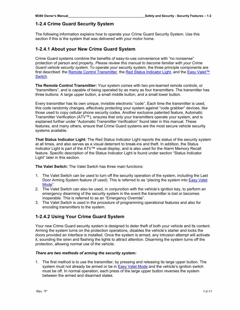
M380 Owner’s Manual____________________________________________Safety and Security - Security Features – 1-2
Rev. “F” 1-2-11
1-2.4 Crime Guard Security System The following information explains how to operate your Crime Guard Security System. Use this section if this is the system that was delivered with your motor home. 1-2.4.1 About your New Crime Guard System Crime Guard systems combine the benefits of easy-to-use convenience with “no nonsense” protection of person and property. Please review this manual to become familiar with your Crime Guard vehicle security system. To operate your security system, the three principle components are first described: the Remote Control Transmitter, the Red Status Indicator Light, and the Easy Valet™ Switch. The Remote Control Transmitter: Your system comes with two pre-learned remote controls, or “transmitters”, and is capable of being operated by as many as four transmitters. The transmitter has three buttons: A large upper button, a small middle button, and a small lower button. Every transmitter has its own unique, invisible electronic “code”. Each time the transmitter is used, this code randomly changes, effectively protecting your system against “code grabber” devices, like those used to copy cellular phone security codes. Another exclusive patented feature, Automatic Transmitter Verification (ATV™), ensures that only your transmitters operate your system, and is explained further under “Automatic Transmitter Verification” found later in this manual. These features, and many others, ensure that Crime Guard systems are the most secure vehicle security systems available. That Status Indicator Light: The Red Status Indicator Light reports the status of the security system at all times, and also serves as a visual deterrent to break-ins and theft. In addition, the Status Indicator Light is part of the ATV™ visual display, and is also used for the Alarm Memory Recall feature. Specific description of the Status Indicator Light is found under section “Status Indicator Light” later in this section. The Valet Switch: The Valet Switch has three main functions: 1. The Valet Switch can be used to turn off the security operation of the system, including the Last
Door Arming System feature (if used). This is referred to as “placing the system into Easy Valet Mode”.
2. The Valet Switch can also be used, in conjunction with the vehicle’s ignition key, to perform an emergency disarming of the security system in the event the transmitter is lost or becomes inoperable. This is referred to as an “Emergency Override”.
3. The Valet Switch is used in the procedure of programming operational features and also for encoding transmitters to the system.
1-2.4.2 Using Your Crime Guard System
Your new Crime Guard security system is designed to deter theft of both your vehicle and its content. Arming the system turns on the protection operations, disables the vehicle’s starter and locks the doors provided an interface is installed. Once the system is armed, any intrusion attempt will activate it, sounding the siren and flashing the lights to attract attention. Disarming the system turns off the protection, allowing normal use of the vehicle.
There are two methods of arming the security system:
1. The first method is to use the transmitter, by pressing and releasing its large upper button. The
system must not already be armed or be in Easy Valet Mode and the vehicle’s ignition switch must be off. In normal operation, each press of the large upper button reverses the system between the armed and disarmed states.
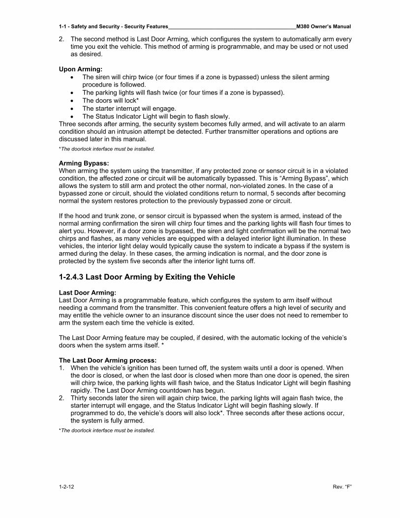
1-1 - Safety and Security - Security Features____________________________________________M380 Owner’s Manual
1-2-12 Rev. “F”
2. The second method is Last Door Arming, which configures the system to automatically arm every time you exit the vehicle. This method of arming is programmable, and may be used or not used as desired.
Upon Arming: • The siren will chirp twice (or four times if a zone is bypassed) unless the silent arming
procedure is followed. • The parking lights will flash twice (or four times if a zone is bypassed). • The doors will lock* • The starter interrupt will engage. • The Status Indicator Light will begin to flash slowly.
Three seconds after arming, the security system becomes fully armed, and will activate to an alarm condition should an intrusion attempt be detected. Further transmitter operations and options are discussed later in this manual. *The doorlock interface must be installed. Arming Bypass: When arming the system using the transmitter, if any protected zone or sensor circuit is in a violated condition, the affected zone or circuit will be automatically bypassed. This is “Arming Bypass”, which allows the system to still arm and protect the other normal, non-violated zones. In the case of a bypassed zone or circuit, should the violated conditions return to normal, 5 seconds after becoming normal the system restores protection to the previously bypassed zone or circuit. If the hood and trunk zone, or sensor circuit is bypassed when the system is armed, instead of the normal arming confirmation the siren will chirp four times and the parking lights will flash four times to alert you. However, if a door zone is bypassed, the siren and light confirmation will be the normal two chirps and flashes, as many vehicles are equipped with a delayed interior light illumination. In these vehicles, the interior light delay would typically cause the system to indicate a bypass if the system is armed during the delay. In these cases, the arming indication is normal, and the door zone is protected by the system five seconds after the interior light turns off. 1-2.4.3 Last Door Arming by Exiting the Vehicle Last Door Arming: Last Door Arming is a programmable feature, which configures the system to arm itself without needing a command from the transmitter. This convenient feature offers a high level of security and may entitle the vehicle owner to an insurance discount since the user does not need to remember to arm the system each time the vehicle is exited. The Last Door Arming feature may be coupled, if desired, with the automatic locking of the vehicle’s doors when the system arms itself. * The Last Door Arming process: 1. When the vehicle’s ignition has been turned off, the system waits until a door is opened. When
the door is closed, or when the last door is closed when more than one door is opened, the siren will chirp twice, the parking lights will flash twice, and the Status Indicator Light will begin flashing rapidly. The Last Door Arming countdown has begun.
2. Thirty seconds later the siren will again chirp twice, the parking lights will again flash twice, the starter interrupt will engage, and the Status Indicator Light will begin flashing slowly. If programmed to do, the vehicle’s doors will also lock*. Three seconds after these actions occur, the system is fully armed.
*The doorlock interface must be installed.
M380 Owner’s Manual____________________________________________Safety and Security - Security Features – 1-2
Rev. “F” 1-2-13
NOTES: • If a door is reopened during the thirty-second period between the first and second set
of double chirps, the countdown will stop and reset. When the reopened door is closed again, the 30-second countdown starts over again at the beginning.
• Last Door Arming is separate from, and does not effect the operation of arming by using the transmitter.
• All protected points must be closed or otherwise in a non-violated state for the Last Door Arming sequence to start. Unlike active arming from the transmitter, the system cannot bypass an open or detected zone and arm itself.
To temporarily prevent the system from arming itself:
• Place the system in Valet Mode using the Valet Switch. • Leave a vehicle door open. Although this varies depending on the vehicle, in many cases
turning on the interior light will be detected by the system as an open door. • Although the system will not Last Door Arm while the ignition is on, leaving the ignition key
turned on without the engine running is not recommended.
1-2.4.4 System Armed and Activated
While the system is in the armed state: • The Status Indicator Light will be flashing slowly to confirm that the system is armed, and also
serve as a visual deterrent. • The starter interrupt circuit is engaged. • Protected zones are being monitored for intrusion attempts.
Should activation into the alarm condition occur: • The changing-tone electronic siren will loudly sound. • The parking and interior lights will flash. • The doors will lock,* regardless of their locked or unlocked status. This feature is unique – if
the system detects that a door is opened, it waits until the door is closed before relocking it, denying the thief reentry.
An activated alarm condition has a duration of 30 seconds (60 is optional) unless the system is disarmed using the transmitter or the Easy Valet™ switch. If all protected zones are secure at the end of the alarm condition, the system will stop and rearm automatically, ready to detect another entry attempt. If a protected zone is still violated at the end of the alarm condition, the system will reactivate for up to two additional alarm cycles. After the third alarm cycle the system will automatically rearm and bypass the open zone until that zone returns to a normal “non-violated” state.
• Once the system resets after it has been activated, upon disarming the audible and visual confirmation will change to indicate the activation. This is the “Activation Alert”, which is explained in the Activation Alert section later in this manual.
*The doorlock interface must be installed.
1-2.4.5 Disarming the System
There are three methods of disarming the security system: 1. The first method is to press and release the transmitter’s large upper button to disarm the system.
This is the normal “daily use” method. 2. The second method is to press and release twice within 5 seconds the transmitter’s small middle
button. This is “silent disarming”. 3. The third method is for emergencies, should the transmitter become lost or inoperable. This is the
“Emergency Override”, and uses the ignition key and Valet Switch. 1-2.4.6 Remote Disarming by Transmitter
To Disarm the System: Press and release the large upper button. The siren will chirp once to confirm disarming. The parking lights will flash once to confirm disarming. The doors will unlock.
1-1 - Safety and Security - Security Features____________________________________________M380 Owner’s Manual
1-2-14 Rev. “F”
To Silently Disarm the System: First press and release the small middle button, then press and release the small middle button again. The parking lights will flash once to confirm disarming. The doors will unlock. Upon Disarming:
• The siren will chirp once (or three times if an alarm activation occurred) unless the silent disarming procedure is followed.
• The parking and interior lights will flash once (then, if programmed, illuminate for 30 seconds or until the vehicle’s ignition is turned on).
• The doors will unlock, either all doors or driver’s door only. • The starter interrupt will disengage. • The Status Indicator Light will show one of these features or conditions:
- Flashing rapidly = Automatic Rearming feature is in progress. - Off = System disarmed (Automatic Rearming feature not selected). - Flash/Pause = Indicates violated zone if system has been activated.
*The doorlock interface, in either standard form or driver’s door priority form, must be installed.
Safety Disarm Feature:
Pressing and releasing the large upper button while the system is activated into the alarm condition will disarm the system, but the doors will remain locked. This is the “Safety Disarm” feature, which allows the vehicle to remain secure, even though an activated system has been disarmed. Safety disarm will also cancel Automatic Rearming. This feature is also very useful when the vehicle is exposed to environmental conditions, such as storms, trains or heavy vehicles, which may cause false activations. Safety Disarm is a temporary “one time” operation, which occurs only while the system is activated. To remotely unlock the doors after a Safety Disarm, simply arm, then disarm the system again.
Activation Alert: If the system experiences an alarm condition and resets itself, upon disarming the siren will chirp three times and the parking lights will flash three times instead of the normal one chirp and one light flash. Additionally, the Status Indicator Light will be flashing a “Zone Violation Code”, when the alarm condition activation occurred, the Status Indicator Light changes from flashing slowly to flashing two to four times between pausing to indicate which protected zone was violated.
• The Zone Violation code will continue to be displayed until the vehicle’s ignition is turned on. • The Status Indicator Light will display the Zone Violation Code in place of fast flashes
indicating Automatic Rearming. • Should the system be rearmed before the ignition clears the Zone Violation Code memory,
the Status Indicator Light shows the normal slow flashing. • The system can store up to two consecutive Zone Violation Codes. If more activations
occurred, the two most recent codes are displayed.
Automatic Rearming: Automatic Rearming is a programmable feature, which ensures that your system is never inadvertently disarmed. It is possible to accidentally or unknowingly operate the transmitter from a pocket or purse. You may not even be aware of an accidental disarming due to the enhanced operating distance offered by the Extended Range Transmitter. How it Works: Whenever the system is disarmed by the transmitter, this feature starts a 90 second countdown, which is indicated by a rapidly flashing Status Indicator Light. During this 90-second period, if no protected entry points are opened and the vehicle’s ignition is NOT turned on, the system will automatically arm itself at the end of the countdown. If desired, the system can also be programmed to automatically relock the doors when this occurs.
M380 Owner’s Manual____________________________________________Safety and Security - Security Features – 1-2
Rev. “F” 1-2-15
Automatic Rearming Notes: • Turning the vehicle’s ignition on cancels Automatic Rearming. • Opening a door will suspend the 90-second countdown. • All protected zones must remain non-violated during the 90 second Automatic Rearming
period. For example, if a vehicle door is opened during the 90-second period, the countdown will stop. When the door is closed, the system resets and starts a new 90-second countdown period.
• The Automatic Rearming sequence is indicated by a fast flashing Status Indicator Light, unless the system has been activated, in which case an Alarm Condition Memory Recall code will flash instead. The ignition switch must be turned on to erase Zone Violation Code.
• If the system is disarmed while it is activated (siren sounding and lights flashing) Safety Disarm will cancel the Automatic Rearming for that disarming operation only. The next time the system is armed, Automatic Rearming will be initiated upon the subsequent disarming.
1-2.4.7 Disarming by Emergency Override
Emergency Override: In the event that your transmitter is lost, damaged, or its batteries have become exhausted, the Valet Switch and the vehicle’s ignition key may be used to disarm the system. Please note that for this operation the pressing of the Valet Switch may be customized; this is the SecureCode feature, the programming of which is described in “Feature #2 745i³ Programmable Features found later in this manual. The following Emergency Override instructions reflect the SecureCode entry of the Valet Switch as the “as received” default setting of “1 press”. Instead of “1 press” of the Valet Switch, a customized programming of the SecureCode would require from 2 to 12 presses.
To Disarm the System without using a Transmitter: 1. With the system in the armed condition, enter the vehicle via the driver’s door (be aware that the
system will activate an alarm condition when the door is opened). 2. Using the ignition key, turn the vehicle’s ignition on. 3. Within 5 seconds, enter the SecureCode by pressing and releasing the Valet Switch once. The
system will disarm.
If the SecureCode entry of the Valet Switch is the “as received” default setting of “1 press”, the system will disarm the moment the Valet Switch is released from the single press. If a customized SecureCode has been programmed, the system will disarm a few seconds after the correct entry. If an incorrect entry is made, the system will not disarm. A procedure, which is separate, but similar, to an Emergency Override, is the Easy Valet Mode, which prevents the system from performing any automatic arming operations, which may be programmed to occur. See section “Easy Valet Mode” later in this manual.
1-2.4.8 Remote Panic To Activate Panic: Press and hold the large upper button for 3 seconds.
To Deactivate Panic: Press and release the large upper button.
Upon Activating Panic:
• The electronic siren will sound. • The vehicle’s exterior parking lights will flash. • The vehicle’s doors will unlock*
- The Panic feature is designed for situations in which the user feels threatened and/or a need to attract attention.
- Panic can be activated anytime, whether the vehicle’s ignition is turned on or off, and has a 30 second duration (60 seconds is optional) unless it is deactivated using the remote control.
1-1 - Safety and Security - Security Features____________________________________________M380 Owner’s Manual
1-2-16 Rev. “F”
- At the end of the Panic cycle the system will reset, enter the armed state, and lock the doors*
*The door lock interface must be installed. If the vehicle has been configured for Driver’s Door Priority, Panic will unlock the driver’s door. 1-2.4.9 Easy Valet Mode
Easy Valet Mode: This allows you to turn off all of the “alarm” operations of the security system while retaining the remote convenience features such as Keyless Entry, Panic, and the Auxiliary Outputs. The system may only be placed into Easy Valet when it’s disarmed; if armed, an Emergency Override must be performed before placing into Easy Valet Mode. Once the system is in Easy Valet Mode, it cannot become armed from the transmitter, Last Door Arming, or Automatic Rearming. Although both use the Valet Switch, Easy Valet Mode and Emergency Override are two similar, but different procedures. Emergency Override disarms an armed and activated system, and requires the ignition key. Easy Valet Mode turns off the alarm operations of the disarmed system, but without the need of the ignition key. Easy Valet mode is designed for situations in which it is not convenient for the security portion of the system to be operational. For example, during extended stopovers for vehicle servicing, maintenance, valet parking, washing, etc. The Valet Switch is in the Status Indicator Light/Valet Switch Assembly. The installed has the option of utilizing an additional, separate Valet Switch should mounting in a hidden location be desired. Please become familiar with the location of the Easy Valet Switch. To Enter “Easy Valet” Mode: With the system disarmed, press and hold the valet switch for 2 seconds.
• The siren will chirp twice, the parking lights will flash twice and the Status Indicator Light will illuminate solid red to confirm that the system is in Easy Valet mode.
• To remind the user that the system is in Easy Valet Mode, the siren will chirp once every time the vehicle’s ignition is turned off.
To Exit “Easy Valet” Mode: Press and release the valet switch.
• The Status Indicator Light will turn off to confirm exit from Easy Valet mode.
1-2.4.10 Status Indicator Light The red Status Indicator Light visually confirms the status of the system and provides a high level of visual deterrence. Additionally, the Status Indicator Light is also part of the patented Automatic Transmitter Verification feature and the Alarm Condition Memory Recall feature. The Status Indicator Light, which shares a housing assembly with the Valet Switch, is normally mounted in a location where it can be easily seen by the driver, as well as from outside the vehicle. Security System Status: The primary function of the Status Indicator Light is to indicate the status of the security system: 1. Off = The system is disarmed and not performing automatic functions. 2. On Constant = The system is in the Easy Valet Mode. 3. Flashing Slow = The system is fully armed. 4. Flashing Fast = Last Door Arming or Automatic Rearming is in progress.
Automatic Transmitter Verification: For the first 10 seconds after the vehicle’s ignition is turned on, the Status Indicator Light will flash a number of times equal to the number of transmitters that are capable of operating the system:
M380 Owner’s Manual____________________________________________Safety and Security - Security Features – 1-2
Rev. “F” 1-2-17
5. 1 Flash/pause = 1 transmitter is programmed. 6. 2 Flashes/pause = 2 transmitters are programmed. 7. 3 Flashes/pause = 3 transmitters are programmed. 8. 4 Flashes/pause = 4 transmitters are programmed. Alarm Condition Memory Recall: If the system enters an alarm condition, the red Status Indicator Light will stop flashing slowly and begin to flash in sequence to indicate which protected zone caused the alarm condition. The Status Indicator Light will flash and pause to indicate which protected zone was violated while the system is still armed, after it’s disarmed, and until the vehicle’s ignition is turned on. The system’s Alarm Condition Memory Recall circuit can store two consecutive zone violations. If there have been multiple violations, the Status Indicator Light will replay the two most recent violations in the order in which the occurred. 9. 2 Flashes/Pause = System was triggered through the hood or trunk. 10. 3 Flashes/Pause = System was triggered through the door. 11. 4 Flashes/Pause = System was triggered by the sensor.
NOTE: Turning on the ignition will clear the Alarm Condition Memory Recall. 1-2.4.11 Glass Breakage and 2-Zone Impact Sensor
Sensors: The Crime Guard 745i³ security system is equipped with a Glass Breakage and Dual-Zone Infrasonic Impact Sensor to increase the effectiveness of the system. The impact sensor is just one in a comprehensive line of available sensors. Other available option is: piezo shock sensors, and microwave/radar sensors, which can detect motion inside and outside the vehicle.
• The Crime Guard 745i³ control module features dual auxiliary sensor ports, which easily allows the addition of a further optional sensor.
• The system will automatically bypass the sensor zone if it is triggered five times during a single armed period. If desired, this feature can be programmed to not operate.
Prewarning Detection Circuit: When the sensor’s prewarn zone is violated the security system will respond by chirping the siren three times and relocking all of the doors* If the prewarn circuit is triggered five times while the system is armed, the circuit will automatically shutdown until the security system is disarmed and armed again. 1-2.4.12 Remote Sensor Bypass To Activate Remote Sensor Bypass: Arm the system, then within 4 seconds press and release the small lower button. The siren will chirp twice to confirm arming the siren then chirps once to confirm sensor bypass. The parking lights will flash twice to confirm arming. The doors will lock upon arming.* Remote Sensor Bypass allows the option of “turning off” the sensor anytime the system is armed using the transmitter. When the sensor is bypassed, only the sensor zone is bypassed and all other protected zones will remain fully operational and vigilant. The sensor zone will reset to its normal operation the next time the system arms. *The doorlock interface must be installed. 1-2.4.13 Backup Battery This security system is equipped with a backup battery inside the control module. The backup batter will provide an alternative power source to operate the Crime Guard system if the vehicle’s battery is disconnected. A built-in protection circuit will not allow the backup battery to supply power into the vehicle’s electrical system. While operating on the backup battery, the system will not have the flashing lights output, the Status Indicator Light, nor power any sensors in order to conserve power. The siren will continue to operate
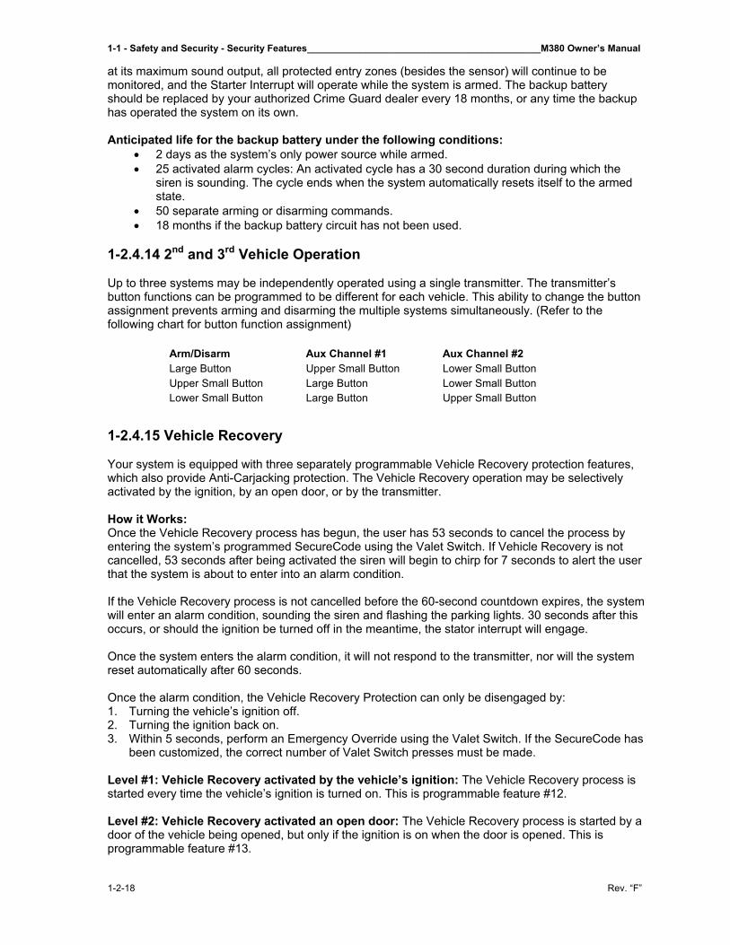
1-1 - Safety and Security - Security Features____________________________________________M380 Owner’s Manual
1-2-18 Rev. “F”
at its maximum sound output, all protected entry zones (besides the sensor) will continue to be monitored, and the Starter Interrupt will operate while the system is armed. The backup battery should be replaced by your authorized Crime Guard dealer every 18 months, or any time the backup has operated the system on its own. Anticipated life for the backup battery under the following conditions:
• 2 days as the system’s only power source while armed. • 25 activated alarm cycles: An activated cycle has a 30 second duration during which the
siren is sounding. The cycle ends when the system automatically resets itself to the armed state.
• 50 separate arming or disarming commands. • 18 months if the backup battery circuit has not been used.
1-2.4.14 2nd and 3rd Vehicle Operation Up to three systems may be independently operated using a single transmitter. The transmitter’s button functions can be programmed to be different for each vehicle. This ability to change the button assignment prevents arming and disarming the multiple systems simultaneously. (Refer to the following chart for button function assignment)
1-2.4.15 Vehicle Recovery
Your system is equipped with three separately programmable Vehicle Recovery protection features, which also provide Anti-Carjacking protection. The Vehicle Recovery operation may be selectively activated by the ignition, by an open door, or by the transmitter.
How it Works: Once the Vehicle Recovery process has begun, the user has 53 seconds to cancel the process by entering the system’s programmed SecureCode using the Valet Switch. If Vehicle Recovery is not cancelled, 53 seconds after being activated the siren will begin to chirp for 7 seconds to alert the user that the system is about to enter into an alarm condition.
If the Vehicle Recovery process is not cancelled before the 60-second countdown expires, the system will enter an alarm condition, sounding the siren and flashing the parking lights. 30 seconds after this occurs, or should the ignition be turned off in the meantime, the stator interrupt will engage. Once the system enters the alarm condition, it will not respond to the transmitter, nor will the system reset automatically after 60 seconds. Once the alarm condition, the Vehicle Recovery Protection can only be disengaged by: 1. Turning the vehicle’s ignition off. 2. Turning the ignition back on. 3. Within 5 seconds, perform an Emergency Override using the Valet Switch. If the SecureCode has
been customized, the correct number of Valet Switch presses must be made.
Level #1: Vehicle Recovery activated by the vehicle’s ignition: The Vehicle Recovery process is started every time the vehicle’s ignition is turned on. This is programmable feature #12.
Level #2: Vehicle Recovery activated an open door: The Vehicle Recovery process is started by a door of the vehicle being opened, but only if the ignition is on when the door is opened. This is programmable feature #13.
Arm/Disarm Aux Channel #1 Aux Channel #2Large Button Upper Small Button Lower Small ButtonUpper Small Button Large Button Lower Small ButtonLower Small Button Large Button Upper Small Button
M380 Owner’s Manual____________________________________________Safety and Security - Security Features – 1-2
Rev. “F” 1-2-19
Level #3: Vehicle Recovery activated using a remote control: The Vehicle Recovery process is started by pressing holding the transmitter’s small lower button for 3 seconds, but only if the vehicle’s ignition is on. This is programmable feature #14.
1-2.4.16 Automatic Transmitter Verification The patented ATV™ technology, which is standard on all Crime Guard models, is the only defense against an inherent weakness found in any remote-controlled vehicle security system. In all such systems, allowance is made for multiple transmitters to operate the system. In a matter of seconds, anyone familiar with the programming procedure can easily code their own unauthorized transmitter into the system. Although every vehicle remote-controlled keyless entry or security system is susceptible, Crime Guard security systems audibly alerts you if the system’s programming mode has been accessed and visually informs you at all times of the number of remote controls capable of operating your system. Someday this technology will be standard on all remote-controlled keyless entry and security systems; today, only the most advanced systems offer this complete protection. How it Works: Audible ATV™ Warning: Anytime the system has a transmitter programmed, for 48 hours thereafter the siren will emit a brief series of chirps every time the vehicle’s ignition is turned on. This audible warning alerts you that the system has had transmitter programming activity. Please note that the audible ATV™ Warning, in addition to the extended Status Indicator Light visual display, will be active for the first 48 hours after the system is installed. Visual ATV™: In normal everyday use, for a period of 10 seconds after the vehicle’s ignition is turned on, the system’s Status Indicator Light reports the total number transmitters, which can operate the system. However, if the ATV™ Warning has been activated, this visual display period is extended to 90 seconds. For example: After turning on the vehicle’s ignition, if the Status Indicator light flashes twice between pauses, two transmitters are programmed to operate the system. If the indication were three flashes between pauses, three transmitters are capable of operating the system. In the event that the ATV™ Warning is activated, or if the Status Indicator Light shows a different number of authorized transmitters, you can easily reprogram your transmitter to eliminate the threat. To do so, refer to section To Custom Program a New SecureCode later in this manual. Personal Security Advisement: Only recently have law enforcement authorities discovered the prevalence of this type of theft, as it is virtually undetectable. In most of these cases, the theft of personal items from the vehicle has been dismissed as the owner’s failure to lock the vehicle’s doors! 1-2.4.17 Programming the 745i³ The Crime Guard 745i³ is a sophisticated, yet flexible security and convenience system. Many of its operations may be configured as the user desires. “Programming Mode” allows you the ability to configure 20 operational features. Another programming level allows you to add transmitters to operate your system, and an additional programming level enables you customize the Secure Code. Your vehicle ignition key and the Valet Switch are used to enter the Programming Mode, following the three steps listed below. Once in Programming Mode, the Valet Switch is used to access the desired feature, and the transmitter is then used to change the chosen feature’s status. During the process, the siren and the Status Indicator Light indicate certain conditions of Programming Mode and the chosen feature’s status. Once the system is in Programming Mode, the Valet Switch is then pressed and released the number of times equal to the feature number, which is to be accessed for programming. After pressing the Valet Switch as many times as the feature number, the siren will chirp the same number of times and the Status Light will also flash the same number, between pauses. Once the feature has been selected its status, or setting, can be chosen by pressing the appropriate button on the transmitter. Basically, pressing the transmitter’s large upper button turns the feature on,
1-1 - Safety and Security - Security Features____________________________________________M380 Owner’s Manual
1-2-20 Rev. “F”
or pressing the transmitter’s small lower button turns the feature off. Features which are not “on or off” features, such as the alarm duration of 30 to 60 seconds, are noted otherwise. To Enter Programming Mode: 1. Turn the vehicle’s ignition on. 2. Turn the ignition off. 3. Within 5 seconds, press and release the Valet Switch 5 times.
- The siren will chirp then sound briefly and the Status Light will flash to confirm that the system is entering Programming Mode.
- Once in Programming Mode, if 10 seconds of no programming activity occurs, the system will exit Programming Mode. Programming activity is the pressing of the Valet Switch or pressing a transmitter button once a feature is accessed.
To Access a Feature: 4. Within 10 seconds, press and release the Valet Switch the same number of times as the desired
feature’s number. - The siren will chirp and the Status Light will flash as many times as the Valet Switch was
pressed to indicate the feature number which is now accessed.
To Change a Feature: 5. After accessing the desired feature, within 10 seconds, press and release either the transmitter’s
large upper button or the small lower button. - Pressing the large upper button turns the feature on; the siren will chirp once and the Status
Light will turn on. - Pressing the small lower button turns the feature off, the siren will chirp twice and the Status
Light will turn off.
To Access and Change further Features: 6. If there are more features to be programmed, within 10 seconds of the previous action press and
release the Valet Switch the same number of times as the next desired feature’s number. - Again the siren will chirp and the Status Light will flash as many times as the Valet Switch
was pressed to indicate the new features numbers which is now accessed. - Use the transmitter as described in Step 5 to change the newly accessed feature as desired. - Repeat this Step 6 for each additional feature until all features are programmed.
To Exit Programming Mode: 7. Allow 10 seconds to pass without performing any programming actions; or turn the vehicle’s
ignition on. - The siren will sound briefly and the Status Light will go out to confirm that the system is
exiting Programming mode.
IMPORTANT NOTE: Once the system is in Programming Mode, if at any time 10 seconds elapse without programming activity, the system will automatically exit Programming Mode. To prevent the system from prematurely exiting Programming Mode, the feature can be entered again by pressing the Valet Switch, or if a feature is accessed, by pressing either of the buttons. Features can be selected in any order as desired.
The following pages explain each of the programmable features in detail, including how to program transmitters and how to customize your system’s SecureCode. Following the features explanation is a convenient feature programming checklist, which greatly simplifies the feature programming process.
1-2.4.18 The 745i³ Programmable Features
Feature #1 Transmitter Programming Mode The first level in the programmable features menu is Transmitter Programming Mode, by which additional or replacement transmitters can be programmed to operate the system. It is important to note that when a transmitter is programmed into the system, the ATV Warning is activated and all previous transmitter codes in the system’s memory are deleted.

M380 Owner’s Manual____________________________________________Safety and Security - Security Features – 1-2
Rev. “F” 1-2-21
If a third or fourth transmitter is to be added to operate the system, all of the transmitters must be programmed into the system’s memory at the same time, as the first new transmitter code entered will erase the existing transmitter codes. Therefore, if your system should ever be compromised by the addition of an authorized transmitter, the ATV feature will warn you. By simply reprogramming all of your transmitters into the system, the unauthorized transmitter will be erased. To program a transmitter: Follow Steps 1 to 4 under Programming the 745i³; at Step 4 the Valet Switch will be pressed and released one time only. The system’s response will be one siren chirp, and the Status Light flashing one time, pausing, and then repeating. Within 10 seconds, press and release the large upper button of the transmitter. The system confirms “learning” the transmitter’s codes chirping the siren once. Repeat this action with each transmitter to be programmed. Only the large upper button of the transmitter needs pressing and release; all of the other transmitter button’s operations will be learned automatically. To program a transmitter to a “2nd” or “3rd” system: Up to three Crime Guard systems may be independently operated using a single transmitter. To accomplish this, the transmitter’s button functions are different for each of the vehicles. This prevents Arming or Disarming the multiple systems simultaneously when all are within range of the transmitter. To program a transmitter for 2nd or 3rd systems, when programming press and release either of the small buttons instead of the large upper button. The system will automatically assign the transmitter’s other functions in a different order. The following chart shows button function assignment. Arm/Disarm Auxiliary Output #2 Auxiliary Output #3Large Button Small Button Small ButtonSmall Button Large Button Small ButtonSmall Button Large Button Small Button
Only the “Arm/Disarm” button is pressed when programming.
Feature #2 Secure Code Programming Mode (Factory Default Setting: 1 Press) SecureCode is a unique patented feature, which allows you to custom, select the number of Valet Switch presses which would be required in order to perform an Emergency Override. Instead of “1 press” of the Valet Switch, a customized programming of the SecureCode would require from 2 to 12 presses. If any of the three Vehicle Recovery features are utilized, a customized SecureCode would require that the correct SecureCode entry of Valet Switch be made to cancel the Vehicle Recovery activation. The “as received” factory default setting of “1 press” is the most convenient, as an Emergency Override will occur instantly when the Valet Switch is pressed, but it is not as secure as a customized setting. When a customized SecureCode has been programmed, the system will disarm a few seconds after the correct entry. To custom program a new SecureCode: Follow Steps 1 through 4 in the section for Programming the 745i³; at Step 4 the Valet Switch will be pressed and released two times. The system’s response will be two siren chirps, and the Status Light flashing twice, pausing, then repeating. Within 10 seconds, press and release the transmitter’s large upper button; the siren will chirp twice to confirm system is ready to accept the new SecureCode entry. Now press and release the Valet Switch the desired number of times. The SecureCode can be programmed for 1 to 12 presses, but the entry must be made within 5 seconds. Wait for the siren to chirp the same number of times as the Valet Switch presses to confirm the new SecureCode entry. IMPORTANT: If no additional features need to be programmed, exit Programming Mode by allowing the 10 second time limit to expire without any further programming activity. Do not exit Programming Mode by turning on the ignition switch.
1-1 - Safety and Security - Security Features____________________________________________M380 Owner’s Manual
1-2-22 Rev. “F”
Feature #3 Chirp Confirmation (Factory Default Setting On) This feature allows the permanent removal of the system’s chirping the siren as an audible confirmation when performing functions such as Arming and Disarming. Please note that utilizing this feature to remove the confirmation chirps does not effect siren chirping operations associated with the ATV Warning, sensor prewarning or Programming Mode. Changing Chirp Confirmation: Follow Steps 1 through 4 in the section for Programming the 745i³; at Step 4 the Valet Switch will be pressed and released three times. The system’s response will be three siren chirps, and the Status Light flashing three times, pausing, then repeating. Within 10 sections, press and release the transmitter’s large upper button to turn the Chirp Confirmation on (the siren will chirp once) or the small lower button to turn the Chirp Confirmation off (the siren will chirp twice). Feature #4 30 or 60 Section Alarm Duration (Factory Default Setting 30 Seconds) This feature allows the option of a 30 or 60 second Alarm Duration, which is when the system has activated in Armed state, sounding the siren and flashing the parking lights. Changing the Alarm Duration: Follow Steps 1 through 4 in the section for Programming the 745i³, at Step 4 the Valet Switch will be pressed and released four times. The system’s response will be four siren chirps, and the Status Light flashing four times, pausing, then repeating. Within 10 seconds, press and release the transmitter’s large upper button to set the Alarm Duration for 30 seconds (the siren will chirp once) or the small lower button to set the Alarm Duration for 60 seconds (the siren will chirp twice) Feature #5 Automatic Sensor Zone Bypass (Factory Default Setting On) This feature configures the system to automatically bypass the sensor protection zone if the sensor should be triggered five times during a single Armed state. If the sensor is bypassed, it will be reinstated the next time the system becomes Armed. Programming Automatic Sensor Zone Bypass: Follow Steps 1 through 4 in the section for Programming the 745i³; at Step 4 the Valet Switch will be pressed and released five times. The system’s response will be five siren chirps, and the Status Light flashing five times, pausing, then repeating. Within 10 seconds, press and release the transmitter’s large upper button to turn the Automatic Sensor Zone Bypass feature on (the siren will chirp once) or the small lower button to turn this feature off (the siren will chirp twice). Feature #6 Auxiliary Output #2 Also Disarms System (Factory Default Setting On) This feature configures the Auxiliary Output #2 to automatically Disarm the system at the same when it is used. Programming Auxiliary Channel #2 Disarms System: Follow Steps 1 through 4 in the section for Programming the 745i³, at Step 4 the Valet Switch will be pressed and released six times. The system’s response will be six siren chirps, and the Status Light flashing six times, pausing, then repeating. Within 10 seconds, press and release the transmitter’s large upper button to have the system Disarm when Auxiliary Output #2 is used (the siren will chirp once) or the small lower button to have Auxiliary Output #2 not Disarm the system when it is used (the siren will chirp twice). Feature #7 Last Door Arming (Factory Default Setting On) This feature configures the system to automatically Arm itself 30 seconds after the vehicle’s last door is closed.
M380 Owner’s Manual____________________________________________Safety and Security - Security Features – 1-2
Rev. “F” 1-2-23
Programming Last Door Arming: Follow Steps 1 through 4 in the second for Programming the 745i³, at Step 4 the Valet Switch will be pressed and released seven times. The system’s response will be seven siren chirps, and the Status Light flashing seven times, pausing, then repeating. Within 10 seconds, press and release the transmitter’s large upper button to turn on Last Door Arming (the siren will chirp once) or the small lower button to turn off Last Door Arming (the siren will chirp twice). Feature #8 Doors Lock with Last Door Arming (Factory Default Setting Off) This feature adds the automatic locking of the doors to the previous feature, Last Door Arming. If this feature is turned on, the doors will lock when the system becomes armed 30 seconds after closing the last door. Feature #7 must be turned on for this feature to operate. Programming Door Locks with Last Door Arming: Follow Steps 1 through 4 in the second for Programming the 745i³, at Step 4 the Valet Switch will be pressed and released eight times. The system’s response will be eight siren chirps, and the Status Light flashing eight times, pausing, then repeating. Within 10 seconds, press and release the transmitter’s large upper button to turn on the Door Locks with Last Door Arming feature (the siren will chirp once) or the small lower button to turn off the feature (the siren will chirp twice). Feature #9 Parking Light Illumination Upon Disarm (Factory Default Setting Off) This feature configures the system to illuminate the vehicle’s parking and dome lights for 30 seconds when it is Disarmed. Otherwise, if this feature is turned off, the lights will flash once upon Disarming the system. Programming Parking Light Illumination Upon Disarm: Follow Steps 1 through 4 in the second for Programming the 745i³, at Step 4 the Valet Switch will be pressed and released nine times. The system’s response will be nine siren chirps, and the Status Light flashing nine times, pausing, then repeating. Within 10 seconds, press and release the transmitter’s large upper button to have the parking lights turn on for 30 seconds when the system is Disarmed (the siren will chirp once) or the small lower button to have the parking lights only flash once when the system is Disarmed (the siren will chirp twice). Feature #10 Starter Interrupt Operates in Valet Mode (Factory Default Setting Off) This feature configures the system to engage the starter interrupt circuit when the remote transmitter is used to lock the vehicle’s doors while the system is in Valet Mode. When this is done, the transmitter must be used to unlock the doors or an Emergency Override must be performed to disengage the starter interrupt. Programming Starter Interrupt Operates in Valet Mode Follow Steps 1 through 4 in the second for Programming the 745i³, at Step 4 the Valet Switch will be pressed and released ten times. The system’s response will be ten siren chirps, and the Status Light flashing ten times, pausing, then repeating. Within 10 seconds, press and release the transmitter’s large upper button to turn this feature on (the siren will chirp once) or the small lower button to turn this feature off (the siren will chirp twice). Feature #11 Door Lock/Unlock Pulse Duration (Factory Default Setting .8 Second) The feature offers the selection of a .8 second or a 3 second pulse duration of the system’s door lock outputs. Certain vehicles have power door locking systems, which are vacuum operated, and thus requires a longer output pulse from the Crime Guard System. While use of this feature is determined by the type of vehicle the system is installed in, this feature does save the owners of such vehicles the added expense of a special adapter.
1-1 - Safety and Security - Security Features____________________________________________M380 Owner’s Manual
1-2-24 Rev. “F”
Programming Door Lock/Unlock Pulse Duration: Follow Steps 1 through 4 in the second for Programming the 745i³, at Step 4 the Valet Switch will be pressed and released eleven times. The system’s response will be eleven siren chirps, and the Status Light flashing eleven times, pausing, then repeating. Within 10 seconds, press and release the transmitter’s large upper button to configure the door lock pulse for .8 second (the siren will chirp once) or the small lower button to configure the door lock pulse for 3 seconds (the siren will chirp twice). Feature #12 Ignition Activated Vehicle Recovery Factory Default Setting Off) The Vehicle Recovery feature activates the system into an alarm condition automatically in the event that you are forced from your car. “Ignition Activated” Vehicle Recovery is one of three methods of activating this feature, which is explained in the Vehicle Recovery section of this manual. Programming Ignition Activated Vehicle Recovery: Follow Steps 1 through 4 in the second for Programming the 745i³, at Step 4 the Valet Switch will be pressed and released twelve times. The system’s response will be twelve siren chirps, and the Status Light flashing twelve times, pausing, then repeating. Within 10 seconds, press and release the transmitter’s large upper button to turn on Ignition Activated Vehicle Recovery (the siren will chirp once) or the small lower button to turn this feature off (the siren will chirp twice). Feature #13 Door Activated Vehicle Recovery (Factory Default Setting Off) The Vehicle Recovery feature activates the system into an alarm condition automatically in the event that you are forced from your car. “Door Activated” Vehicle Recovery is one of three methods of activating this feature, which is explained in the Vehicle Recovery section earlier in this manual. Programming Door Activated Vehicle Recovery: Follow Steps 1 through 4 in the second for Programming the 745i³, at Step 4 the Valet Switch will be pressed and released thirteen times. The system’s response will be thirteen siren chirps, and the Status Light flashing thirteen times, pausing, then repeating. Within 10 seconds, press and release the transmitter’s large upper button to turn on the Door Activated Vehicle Recovery feature (the siren will chirp once) or the small lower button to turn this feature off (the siren will chirp twice). Feature #14 Transmitter Activated Vehicle Recovery (Factory Default Setting Off) This form of the Vehicle Recovery feature gives you the option of activated the Vehicle Recovery operation from the transmitter in the event that you are forced from your car. “Transmitter Activated” Vehicle Recovery is one of three methods of activating this feature, which is explained in the Vehicle Recovery second found earlier in this manual. Programming Transmitter Activated Anti Car-Jacking: Follow Steps 1 through 4 in the second for Programming the 745i³, at Step 4 the Valet Switch will be pressed and released fourteen times. The system’s response will be fourteen siren chirps, and the Status Light flashing fourteen times, pausing, then repeating. Within 10 seconds, press and release the transmitter’s large upper button to turn on the Transmitter Activated Vehicle Recovery feature (the siren will chirp once) or the small button to turn this feature off (the siren will chirp twice). Feature #15 Automatic Rearming (Factory Default Setting On) This feature prevents your system from being disarmed accidentally, configuring the system to automatically rearm itself 90 seconds after it has been Disarmed by the transmitter. The operation of the Automatic Rearming feature is explained in more detail in the Automatic Rearming Notes second earlier in this manual.
M380 Owner’s Manual____________________________________________Safety and Security - Security Features – 1-2
Rev. “F” 1-2-25
Programming Automatic Rearming: Follow Steps 1 through 4 in the second for Programming the 745i³, at Step 4 the Valet Switch will be pressed and released fifteen times. The system’s response will be fifteen siren chirps, and the Status Light flashing fifteen times, pausing, then repeating. Within 10 seconds, press and release the transmitter’s large upper button to turn on the Automatic Rearming feature (the siren will chirp once) or the small lower button to turn the Automatic Rearming feature off (the siren will chirp twice). Feature #16 Doors Lock with Automatic Rearm (Factory Default Setting On) This feature adds the automatic locking of the doors to the previous feature, Automatic Rearming. If this feature is turned on, the doors will lock when the system rearms itself 90 seconds after being disarmed by the transmitter. Feature #15 must be turned on for this feature to operate. Programming Door Locks with Automatic Rearming: Follow Steps 1 through 4 in the second for Programming the 745i³, at Step 4 the Valet Switch will be pressed and released sixteen times. The system’s response will be sixteen siren chirps, and the Status Light flashing sixteen times, pausing, then repeating. Within 10 seconds, press and release the transmitter’s large upper button to turn this feature on (the siren will chirp once) or the small lower button to turn this feature off (the siren will chirp twice). Feature #17 3/45 Second Arming Delay (Factory Default Setting 3 Second) This feature determines how long after the Arming confirmation chirp that the system becomes fully med. The Arming Delay applies to the system Arming regardless if it occurs from using the transmitter, Last Door Arming or Automatic Rearming. Programming 3/45 Second Arming Delay: Follow Steps 1 through 4 in the second for Programming the 745i³, at Step 4 the Valet Switch will be pressed and released seventeen times. The system’s response will be seventeen siren chirps, and the Status Light flashing seventeen times, pausing, then repeating. Within 10 seconds, press and release the transmitter’s large upper button to configure the system with a 3 second Arming Delay (the siren will chirp once) or the small lower button to configure the system with a 45 second Arming Delay (the siren will chirp twice). Feature #18 Door Locks When Ignition Is Turned On (Factory Default Setting On) This feature configures the system to automatically lock the vehicle’s doors every time that the ignition switch is turned on. An exception to this would be if feature #21 is turned on, and a door being open when the ignition switch is turned on. The two following features, #19 and #20 control the automatic unlocking operation. Programming Door Locks When Ignition is Turned On: Follow Steps 1 through 4 in the second for Programming the 745i³, at Step 4 the Valet Switch will be pressed and released eighteen times. The system’s response will be eighteen siren chirps, and the Status Light flashing eighteen times, pausing, then repeating. Within 10 seconds, press and release the transmitter’s large upper button to turn on “Door Locks When Ignition Turned On” (the siren will chirp once) or the small lower cotton to turn this feature off (the siren will chirp twice). Feature #19 Unlock #1 When Ignition is Turned Off (Factory Default Setting On) This feature configures the system to automatically unlock the vehicle’s doors every time that the ignition switch is turned off. An exception to this would be if feature #21 is turned on, and a door being open when the ignition switch is turned off. If the system is installed without the Driver’s Door Priority unlock interface, this feature unlocks all of the doors when the ignition switch is turned off. If Driver’s
1-1 - Safety and Security - Security Features____________________________________________M380 Owner’s Manual
1-2-26 Rev. “F”
Door Priority is installed, this feature controls the driver’s door only, and the following feature will control the automatic unlocking of the other doors. Programming Unlock #1 When Ignition is Turned Off: Follow Steps 1 through 4 in the second for Programming the 745i³, at Step 4 the Valet Switch will be pressed and released nineteen times. The system’s response will be nineteen siren chirps, and the Status Light flashing nineteen times, pausing, then repeating. Within 10 seconds, press and release the transmitter’s large upper button to turn on “Unlock #1 When Ignition Turned Off” (the siren will chirp once) or the small lower button to turn this feature off (the siren will chirp twice). Feature #20 Unlock #2 When Ignition is Turned Off (Factory Default Setting Off) As explained for the previous feature, this feature controls the automatic unlocking of all doors except the driver’s door if Driver’s Door Priority is installed. Programming Unlock #2 When Ignition is Turned Off: Follow Steps 1 through 4 in the second for Programming the 745i³, at Step 4 the Valet Switch will be pressed and released twenty times. The system’s response will be twenty siren chirps, and the Status Light flashing twenty times, pausing, then repeating. Within 10 seconds, press and release the transmitter’s large upper button to turn on “Unlock #2 When Ignition Turned Off” (the siren will chirp once) or the small lower button to turn this feature off (the siren will chirp twice). Feature #21 Open Door Bypass Of Ignition Locking (Factory Default Setting On) This feature cancels the automatic locking or unlocking of the vehicle’s doors when the ignition switch is turned on or off if one of the doors is open. This feature can be useful, for example, for leaving others within a locked vehicle when only the driver exits the vehicle. Features #18, #19, or #20 must be turned on for this feature to operate. Programming Open Door Bypass Of Ignition Locking: Follow Steps 1 through 4 in the second for Programming the 745i³, at Step 4 the Valet Switch will be pressed and released twenty one times. The system’s response will be twenty-one siren chirps, and the Status Light flashing twenty one times, pausing, then repeating. Within 10 seconds, press and release the transmitter’s large upper button to turn on “Open Door Bypass Of Ignition Locking” (the siren will chirp once) or the small lower button to turn this feature off (the siren will chirp twice). Feature #22 1 or 2 Button Transmitter Operation (Factory Default Setting 1 Button Operation) This feature changes the configuration of how the transmitter operates the system. In the factory default setting of “1 Button Operation”, a single transmitter button alternates Arming and Disarming the system with every press of the button. When this feature is programmed to the “2 Button Operation” one of the transmitter’s buttons will only Arm the system, and a second button will only disarm the system. An optional transmitter with four buttons, Omega part number #105-05, is available from your Crime Guard dealer or directly from Omega Research and Development. The following pages will show the system’s operation with either type of transmitter. Programming Transmitter 1 or 2 Button Operation: Follow Steps 1 through 4 in the second for Programming the 745i³, at Step 4 the Valet Switch will be pressed and released twenty two times. The system’s response will be twenty-two siren chirps, and the Status Light flashing twenty two times, pausing, then repeating. Within 10 seconds, press and release the transmitter’s large upper button to configure the system for “1 Button Operation” (the siren will chirp once) or the small lower button to configure the system for “2 Button Operation” (the siren will chirp twice).
M380 Owner’s Manual____________________________________________Safety and Security - Security Features – 1-2
Rev. “F” 1-2-27
1-2.4.19 Transmitter “2 Button” Operation Programmable feature #22 changes the configuration of how the transmitter operates the system. In the factory default setting of “1 Button Operation”, a single transmitter button alternates Arming and Disarming the system with every press of the button. When this feature is programmed to the “2 Button Operation” setting, one of the transmitter’s buttons will only Arm the system, and a second button will only disarm the system. An optional transmitter with four buttons is available; an order form is available in your Manufacturer’s Manual from Crime Guard that was provided with your motor home. To Arm the System: (3 button transmitter) Press and release the large upper button. The siren will chirp twice to confirm arming of system. The parking lights flash twice to confirm arming and the doors will lock, or Press and release the “Arm/Lock Button (optional 4 button transmitter). To Disarm the System: (3 button transmitter) Press and release the small center button. With Driver’s Door Priority, again press and release the small center button to unlock the remaining doors. The siren will chirp once to confirm disarming, the parking lights will flash once to confirm disarming and the doors will unlock provided the door lock interface is installed. Or, press and release the “Disarm/Unlock” Button (4 button transmitter). With Driver’s Door Priority, again press and release the “Disarm/Unlock” Button to unlock the remaining doors. To Activate “Enhanced Panic”: (3 button transmitter) “Enhanced Panic” allows you to activate Remote Panic from either the Arming button or Disarming button; the former locks the doors and the latter unlocks the doors when Remote Panic is activated. Press and hold for 3 seconds the large upper button or the small center button. The siren sounds and the parking lights will flash. The doors will lock or unlock provided the door lock interface is installed. Or, press and hold for 3 seconds the “Arm/Lock” Button or the “Disarm/Unlock” Button (optional 4 button transmitter). To Deactivate Panic: Press and release either button. To Silently Arm and Disarm the System: (3 button transmitter) Silent Arming and Silent Disarming are both operated by double-pressing the same transmitter button. Press and release the small lower button twice. The parking lights will flash twice and the doors will unlock provided the door lock interface is installed. Or, press and release the “Auxiliary Output #2” Button twice (optional 4 button transmitter). To Activate Auxiliary Output #2: (3 button transmitter) Press and hold the small lower button for three seconds. If armed, the system will disarm, with 3 siren chirps. If the system is not armed, confirmation is one siren chirp. The doors will unlock if the door lock interface is installed. Or, press and hold the “Auxiliary Output #2” Button for three seconds. (optional 4 button transmitter). To Activate Auxiliary Output #3: (3 button transmitter) Press and hold the large upper and small lower buttons for three seconds. Or, press and hold the “Auxiliary Output #3” Button for three seconds, (optional 4 button transmitter). To Activate Remote Sensor Bypass: (3 button transmitter) Press and release the large upper button to arm, then press and release the small lower button. The siren will chirp twice to confirm arming. The siren then chirps once to confirm sensor bypass. The parking lights will flash to confirm arming. The doors will unlock upon arming providing you have installed the door lock interface. Or, press and release the “Arm/Lock” Button to Arm, then press and release the “Auxiliary Output #2” Button, (optional 4 button transmitter).

1-1 - Safety and Security - Security Features____________________________________________M380 Owner’s Manual
1-2-28 Rev. “F”
1-2.5 Entrance Door Air Lock An air-operated lock is installed at the top of the entrance door for a tight seal. This lock engages automatically when the unit is put in drive after reaching 3 mph. This lock also disengages when unit drops below 3 mph. An override switch is located on the main dash panel. This keeps door locked all the time until the unlock switch is manually pushed.
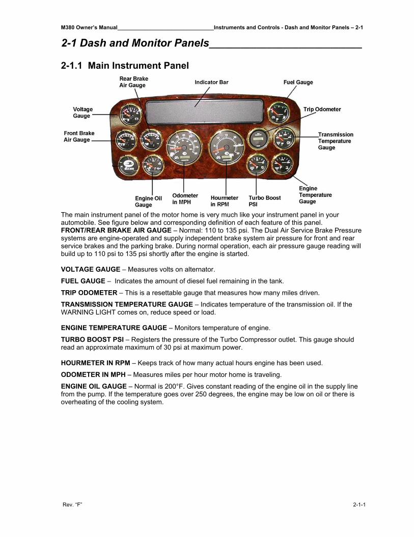
M380 Owner’s Manual________________________________Instruments and Controls - Dash and Monitor Panels – 2-1
Rev. “F” 2-1-1
2-1 Dash and Monitor Panels_____________________________ 2-1.1 Main Instrument Panel
The main instrument panel of the motor home is very much like your instrument panel in your automobile. See figure below and corresponding definition of each feature of this panel. FRONT/REAR BRAKE AIR GAUGE – Normal: 110 to 135 psi. The Dual Air Service Brake Pressure systems are engine-operated and supply independent brake system air pressure for front and rear service brakes and the parking brake. During normal operation, each air pressure gauge reading will build up to 110 psi to 135 psi shortly after the engine is started. VOLTAGE GAUGE – Measures volts on alternator.
FUEL GAUGE – Indicates the amount of diesel fuel remaining in the tank.
TRIP ODOMETER – This is a resettable gauge that measures how many miles driven.
TRANSMISSION TEMPERATURE GAUGE – Indicates temperature of the transmission oil. If the WARNING LIGHT comes on, reduce speed or load. ENGINE TEMPERATURE GAUGE – Monitors temperature of engine.
TURBO BOOST PSI – Registers the pressure of the Turbo Compressor outlet. This gauge should read an approximate maximum of 30 psi at maximum power. HOURMETER IN RPM – Keeps track of how many actual hours engine has been used.
ODOMETER IN MPH – Measures miles per hour motor home is traveling.
ENGINE OIL GAUGE – Normal is 200°F. Gives constant reading of the engine oil in the supply line from the pump. If the temperature goes over 250 degrees, the engine may be low on oil or there is overheating of the cooling system.
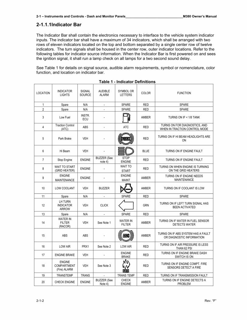
2-1 – Instruments and Controls - Dash and Monitor Panels________________________________M380 Owner’s Manual
2-1-2 Rev. “F”
2-1.1.1Indicator Bar The Indicator Bar shall contain the electronics necessary to interface to the vehicle system indicator inputs. The indicator bar shall have a maximum of 34 indicators, which shall be arranged with two rows of eleven indicators located on the top and bottom separated by a single center row of twelve indicators. The turn signals shall be housed in the center row, outer indicator locations. Refer to the following tables for indicator source information. When the Indicator Bar is first powered on and sees the ignition signal, it shall run a lamp check on all lamps for a two second sound delay. See Table 1 for details on signal source, audible alarm requirements, symbol or nomenclature, color function, and location on indicator bar.
Table 1 - Indicator Definitions
LOCATION INDICATOR LIGHTS
SIGNAL SOURCE
AUDIBLE ALARM
SYMBOL OR LETTERS COLOR FUNCTION
1 Spare N/A - SPARE RED SPARE 2 Spare N/A - SPARE RED SPARE
3 Low Fuel INSTR. ECU -
AMBER TURNS ON IF < 1/8 TANK
4 Traction Control (ATC) ABS - ATC RED TURNS ON FOR DIAGNOSTICS, AND
WHEN IN TRACTION CONTROL MODE
5 Park Brake VEH -
RED TURNS ON IF HI BEAM HEADLIGHTS ARE ON
6 Hi Beam VEH -
BLUE TURNS ON IF ENGINE FAULT
7 Stop Engine ENGINE BUZZER (See note 4)
STOP ENGINE RED TURNS ON IF ENGINE FAULT
8 WAIT TO START (GRID HEATER) ENGINE -
WAIT TO START
RED TURNS ON WHEN ENGINE IS TURNING ON THE GRID HEATERS
9 ENGINE
MAINTENANCE ENGINE -
ENGINE MAINT
AMBER TURNS ON IF ENGINE NEEDS MAINTENANCE
10 LOW COOLANT VEH BUZZER
AMBER TURNS ON IF COOLANT IS LOW
11 Spare N/A - SPARE RED SPARE
12 LH TURN
INDICATOR ARROW
VEH CLICK
GRN TURNS ON IF LEFT TURN SIGNAL HAS BEEN ACTIVATED
13 Spare N/A - SPARE RED SPARE
14 WATER IN
FILTER (RACOR)
VEH See Note 1 WATER IN FILTER AMBER TURNS ON IF WATER IN FUEL SENSOR
DETECTS WATER
15 ABS ABS -
AMBER TURNS ON IF ABS SYSTEM HAS A FAULT OR DIAGNOSTIC INFORMATION
16 LOW AIR PRX1 See Note 2 LOW AIR RED TURNS ON IF AIR PRESSURE IS LESS THAN 62 PSI
17 ENGINE BRAKE VEH - ENGINE BRAKE RED TURNS ON IF ENGINE BRAKE DASH
SWITCH IS ON
18 ENGINE
COMPARTMENT (Fire) ALARM
VEH See Note 3
RED TURNS ON IF ENGINE COMPT. FIRE SENSORS DETECT A FIRE
19 TRANSTEMP TRANS - TRANS TEMP RED TURNS ON IF TRANSMISSION FAULT
20 CHECK ENGINE ENGINE BUZZER (See Note 4)
CHECK ENGINE AMBER TURNS ON IF ENGINE DETECTS A
PROBLEM
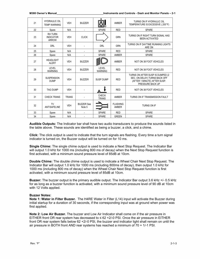
M380 Owner’s Manual________________________________Instruments and Controls - Dash and Monitor Panels – 2-1
Rev. “F” 2-1-3
21 HYDRAULIC OIL TEMP WARNING VEH BUZZER
AMBER TURNS ON IF HYDRAULIC OIL
TEMPERATURE IS EXCESSIVE (.200°F)
22 Spare N/A - SPARE RED SPARE
23 RH TURN
INDICATOR ARROW
VEH CLICK
GRN TURNS ON IF RIGHT TURN SIGNAL HAS BEEN ACTIVATED
24 DRL VEH - DRL GRN TURNS ON IF DAYTIME RUNNING LIGHTS ARE ON
25 Spare N/A - SPARE RED SPARE 26 Spare N/A - SPARE AMBER SPARE
27 HEADLIGHT ALERT VEH BUZZER
AMBER NOT ON 38 FOOT VEHICLES
28 LEVEL WARNING VEH BUZZER LEVEL
WARNING RED NOT ON 38 FOOT VEHICLES
29 SUSPENSION DUMP VEH BUZZER SUSP DUMP RED
TURNS ON AFTER SUSP IS DUMPED (2 SEC. ON DELAY) TURNS BACK OFF
(AFTER 1 MINUTE) AFTER SUSP. PRESSURE BACK UP
30 TAG DUMP VEH -
RED NOT ON 38 FOOT VEHICLES
31 CHECK TRANS TRANS - CHECK TRANS AMBER TURNS ON IF TRANSMISSION FAULT
32 TV ANT/SAFELINE VEH BUZZER See
Note 5
FLASHING AMBER TURNS ON IF
33 Spare N/A - SPARE RED SPARE 34 Spare N/A - SPARE GREEN SPARE
Audible Outputs: The Indicator bar shall have two audio transducers to produce the sounds listed in the table above. These sounds are identified as being a buzzer, a click, and a chime. Click: The click output is used to indicate that the turn signals are flashing. Every time a turn signal indicator is turned on, the Buzzer output will be turned on for 10 ms. Single Chime: The single chime output is used to indicate a Next Stop Request. The Indicator Bar will output 1.0 kHz for 1000 ms (including 800 ms of decay) when the Next Stop Request function is first activated, with a minimum sound pressure level of 85dB at 10cm. Double Chime: The double chime output is used to indicate a Wheel Chair Next Stop Request. The Indicator Bar will output 1.0 kHz for 1000 ms (including 800ms of decay), then output 1.0 kHz for 1000 ms (including 800 ms of decay) when the Wheel Chair Next Stop Request function is first activated, with a minimum sound pressure level of 85dB at 10cm. Buzzer: The buzzer output is the primary audible output. The Indicator Bar output 3.6 kHz +/- 0.5 kHz for as long as a buzzer function is activated, with a minimum sound pressure level of 90 dB at 10cm with 12 Volts applied. Buzzer Notes: Note 1: Water in Filter Buzzer. The H4RE Water in Filter (L14) input will activate the Buzzer during initial startup for a duration of 30 seconds, if the corresponding input was at ground when power was first applied. Note 2: Low Air Buzzer. The buzzer and Low Air Indicator shall come on if the air pressure in EITHER front OR rear system has decreased to ≤ 62 +2/-0 PSI. Once the air pressure in EITHER front OR rear system falls below 62 +2/-0 PSI, the buzzer and indicator light shall remain on until the air pressure in BOTH front AND rear systems has reached a minimum of 70 + 1/-1 PSI.
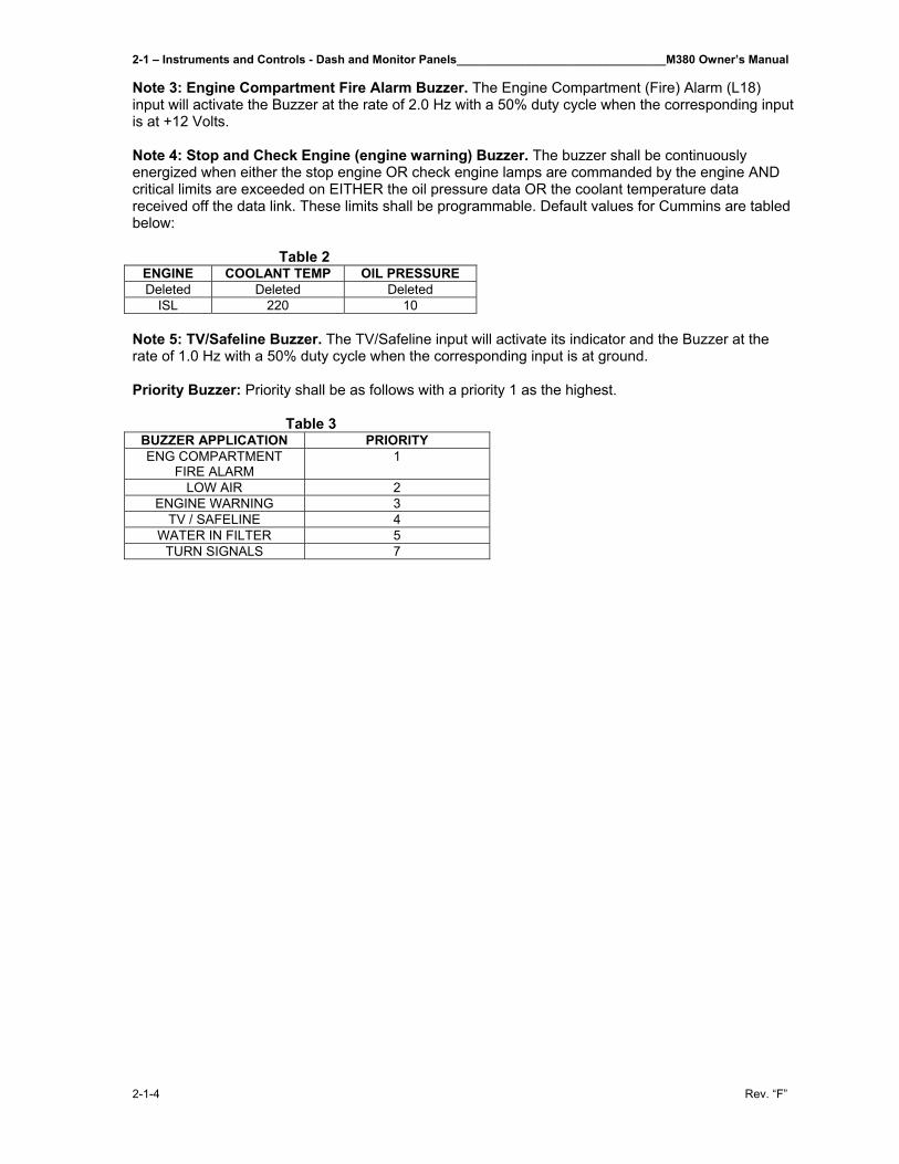
2-1 – Instruments and Controls - Dash and Monitor Panels________________________________M380 Owner’s Manual
2-1-4 Rev. “F”
Note 3: Engine Compartment Fire Alarm Buzzer. The Engine Compartment (Fire) Alarm (L18) input will activate the Buzzer at the rate of 2.0 Hz with a 50% duty cycle when the corresponding input is at +12 Volts. Note 4: Stop and Check Engine (engine warning) Buzzer. The buzzer shall be continuously energized when either the stop engine OR check engine lamps are commanded by the engine AND critical limits are exceeded on EITHER the oil pressure data OR the coolant temperature data received off the data link. These limits shall be programmable. Default values for Cummins are tabled below:
Table 2 ENGINE COOLANT TEMP OIL PRESSURE Deleted Deleted Deleted
ISL 220 10 Note 5: TV/Safeline Buzzer. The TV/Safeline input will activate its indicator and the Buzzer at the rate of 1.0 Hz with a 50% duty cycle when the corresponding input is at ground. Priority Buzzer: Priority shall be as follows with a priority 1 as the highest.
Table 3 BUZZER APPLICATION PRIORITY ENG COMPARTMENT
FIRE ALARM 1
LOW AIR 2 ENGINE WARNING 3
TV / SAFELINE 4 WATER IN FILTER 5
TURN SIGNALS 7
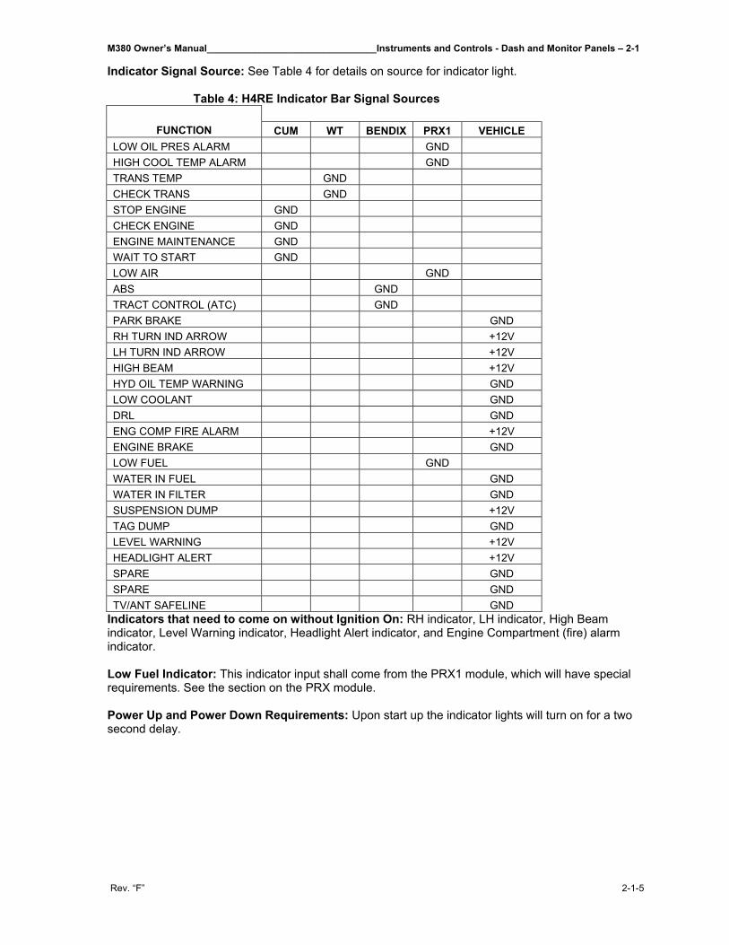
M380 Owner’s Manual________________________________Instruments and Controls - Dash and Monitor Panels – 2-1
Rev. “F” 2-1-5
Indicator Signal Source: See Table 4 for details on source for indicator light.
Table 4: H4RE Indicator Bar Signal Sources
FUNCTION CUM WT BENDIX PRX1 VEHICLE LOW OIL PRES ALARM GND HIGH COOL TEMP ALARM GND TRANS TEMP GND CHECK TRANS GND STOP ENGINE GND CHECK ENGINE GND ENGINE MAINTENANCE GND WAIT TO START GND LOW AIR GND ABS GND TRACT CONTROL (ATC) GND PARK BRAKE GND RH TURN IND ARROW +12V LH TURN IND ARROW +12V HIGH BEAM +12V HYD OIL TEMP WARNING GND LOW COOLANT GND DRL GND ENG COMP FIRE ALARM +12V ENGINE BRAKE GND LOW FUEL GND WATER IN FUEL GND WATER IN FILTER GND SUSPENSION DUMP +12V TAG DUMP GND LEVEL WARNING +12V HEADLIGHT ALERT +12V SPARE GND SPARE GND TV/ANT SAFELINE GND
Indicators that need to come on without Ignition On: RH indicator, LH indicator, High Beam indicator, Level Warning indicator, Headlight Alert indicator, and Engine Compartment (fire) alarm indicator. Low Fuel Indicator: This indicator input shall come from the PRX1 module, which will have special requirements. See the section on the PRX module. Power Up and Power Down Requirements: Upon start up the indicator lights will turn on for a two second delay.
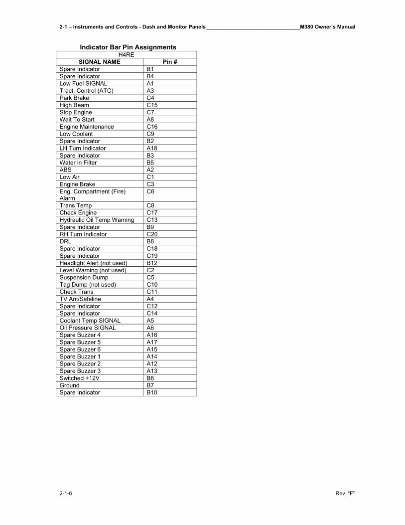
2-1 – Instruments and Controls - Dash and Monitor Panels________________________________M380 Owner’s Manual
2-1-6 Rev. “F”
Indicator Bar Pin Assignments
H4RE SIGNAL NAME Pin #
Spare Indicator B1 Spare Indicator B4 Low Fuel SIGNAL A1 Tract. Control (ATC) A3 Park Brake C4 High Beam C15 Stop Engine C7 Wait To Start A8 Engine Maintenance C16 Low Coolant C9 Spare Indicator B2 LH Turn Indicator A18 Spare Indicator B3 Water in Filter B5 ABS A2 Low Air C1 Engine Brake C3 Eng. Compartment (Fire) Alarm
C6
Trans Temp C8 Check Engine C17 Hydraulic Oil Temp Warning C13 Spare Indicator B9 RH Turn Indicator C20 DRL B8 Spare Indicator C18 Spare Indicator C19 Headlight Alert (not used) B12 Level Warning (not used) C2 Suspension Dump C5 Tag Dump (not used) C10 Check Trans C11 TV Ant/Safeline A4 Spare Indicator C12 Spare Indicator C14 Coolant Temp SIGNAL A5 Oil Pressure SIGNAL A6 Spare Buzzer 4 A16 Spare Buzzer 5 A17 Spare Buzzer 6 A15 Spare Buzzer 1 A14 Spare Buzzer 2 A12 Spare Buzzer 3 A13 Switched +12V B6 Ground B7 Spare Indicator B10
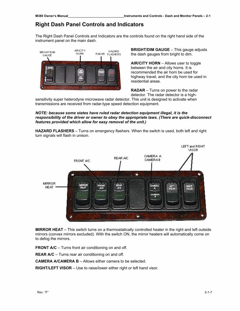
M380 Owner’s Manual________________________________Instruments and Controls - Dash and Monitor Panels – 2-1
Rev. “F” 2-1-7
Right Dash Panel Controls and Indicators The Right Dash Panel Controls and Indicators are the controls found on the right hand side of the instrument panel on the main dash.
BRIGHT/DIM GAUGE – This gauge adjusts the dash gauges from bright to dim. AIR/CITY HORN – Allows user to toggle between the air and city horns. It is recommended the air horn be used for highway travel, and the city horn be used in residential areas. RADAR – Turns on power to the radar detector. The radar detector is a high-
sensitivity super heterodyne microwave radar detector. This unit is designed to activate when transmissions are received from radar-type speed detection equipment. NOTE: because some states have ruled radar detection equipment illegal, it is the responsibility of the driver or owner to obey the appropriate laws. (There are quick-disconnect features provided which allow for easy removal of the unit.) HAZARD FLASHERS – Turns on emergency flashers. When the switch is used, both left and right turn signals will flash in unison.
MIRROR HEAT – This switch turns on a thermostatically controlled heater in the right and left outside mirrors (convex mirrors excluded). With the switch ON, the mirror heaters will automatically come on to defog the mirrors. FRONT A/C – Turns front air conditioning on and off.
REAR A/C – Turns rear air conditioning on and off.
CAMERA A/CAMERA B – Allows either camera to be selected.
RIGHT/LEFT VISOR – Use to raise/lower either right or left hand visor.
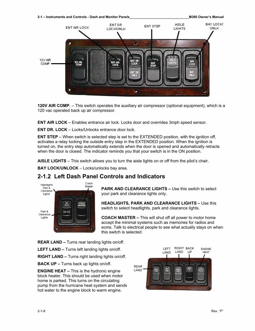
2-1 – Instruments and Controls - Dash and Monitor Panels________________________________M380 Owner’s Manual
2-1-8 Rev. “F”
120V AIR COMP. – This switch operates the auxiliary air compressor (optional equipment), which is a 120 vac operated back up air compressor.
ENT AIR LOCK – Enables entrance air lock. Locks door and overrides 3mph speed sensor.
ENT DR. LOCK – Locks/Unlocks entrance door lock.
ENT STEP – When switch is selected step is set to the EXTENDED position, with the ignition off, activates a relay locking the outside entry step in the EXTENDED position. When the ignition is turned on, the entry step automatically extends when the door is opened and automatically retracts when the door is closed. The indicator reminds you that your switch is in the ON position. AISLE LIGHTS – This switch allows you to turn the aisle lights on or off from the pilot’s chair.
BAY LOCK/UNLOCK – Locks/unlocks bay area.
2-1.2 Left Dash Panel Controls and Indicators PARK AND CLEARANCE LIGHTS – Use this switch to select your park and clearance lights only. HEADLIGHTS, PARK AND CLEARANCE LIGHTS – Use this switch to select headlights, park and clearance lights. COACH MASTER – This will shut off all power to motor home accept the minimal systems such as memories for radios and ecms. Talk to electrical people to see what actually stays on when this switch is selected.
REAR LAND – Turns rear landing lights on/off.
LEFT LAND – Turns left landing lights on/off. RIGHT LAND – Turns right landing lights on/off.
BACK UP – Turns back up lights on/off. ENGINE HEAT – This is the hydronic engine block heater. This should be used when motor home is parked. This turns on the circulating pump from the hurricane heat system and sends hot water to the engine block to warm engine.
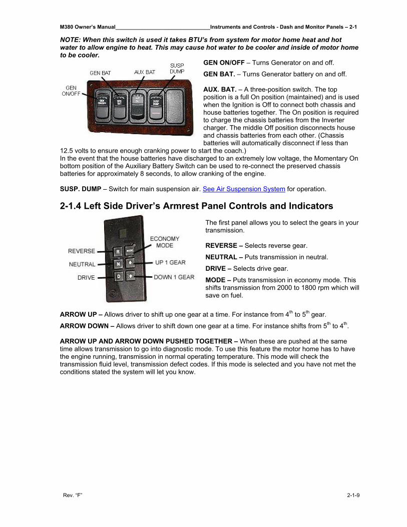
M380 Owner’s Manual________________________________Instruments and Controls - Dash and Monitor Panels – 2-1
Rev. “F” 2-1-9
NOTE: When this switch is used it takes BTU’s from system for motor home heat and hot water to allow engine to heat. This may cause hot water to be cooler and inside of motor home to be cooler.
GEN ON/OFF – Turns Generator on and off.
GEN BAT. – Turns Generator battery on and off. AUX. BAT. – A three-position switch. The top position is a full On position (maintained) and is used when the Ignition is Off to connect both chassis and house batteries together. The On position is required to charge the chassis batteries from the Inverter charger. The middle Off position disconnects house and chassis batteries from each other. (Chassis batteries will automatically disconnect if less than
12.5 volts to ensure enough cranking power to start the coach.) In the event that the house batteries have discharged to an extremely low voltage, the Momentary On bottom position of the Auxiliary Battery Switch can be used to re-connect the preserved chassis batteries for approximately 8 seconds, to allow cranking of the engine. SUSP. DUMP – Switch for main suspension air. See Air Suspension System for operation. 2-1.4 Left Side Driver’s Armrest Panel Controls and Indicators
The first panel allows you to select the gears in your transmission. REVERSE – Selects reverse gear.
NEUTRAL – Puts transmission in neutral. DRIVE – Selects drive gear. MODE – Puts transmission in economy mode. This shifts transmission from 2000 to 1800 rpm which will save on fuel.
ARROW UP – Allows driver to shift up one gear at a time. For instance from 4th to 5th gear.
ARROW DOWN – Allows driver to shift down one gear at a time. For instance shifts from 5th to 4th. ARROW UP AND ARROW DOWN PUSHED TOGETHER – When these are pushed at the same time allows transmission to go into diagnostic mode. To use this feature the motor home has to have the engine running, transmission in normal operating temperature. This mode will check the transmission fluid level, transmission defect codes. If this mode is selected and you have not met the conditions stated the system will let you know.
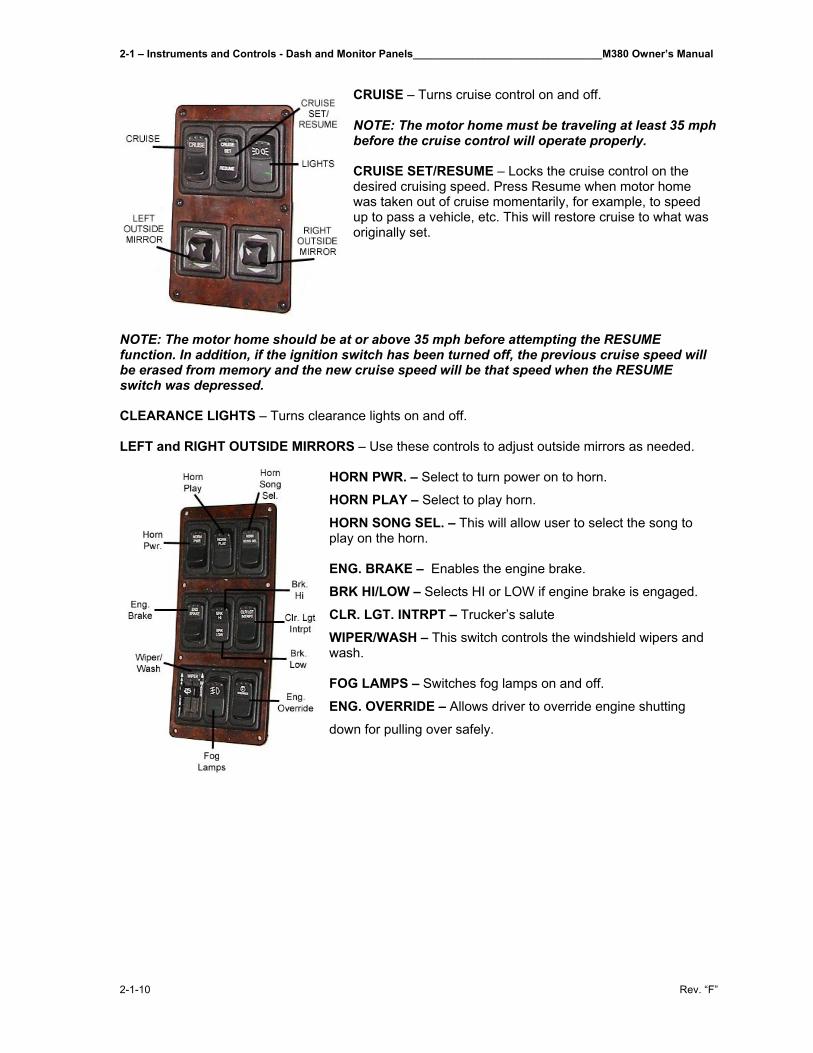
2-1 – Instruments and Controls - Dash and Monitor Panels________________________________M380 Owner’s Manual
2-1-10 Rev. “F”
CRUISE – Turns cruise control on and off. NOTE: The motor home must be traveling at least 35 mph before the cruise control will operate properly. CRUISE SET/RESUME – Locks the cruise control on the desired cruising speed. Press Resume when motor home was taken out of cruise momentarily, for example, to speed up to pass a vehicle, etc. This will restore cruise to what was originally set.
NOTE: The motor home should be at or above 35 mph before attempting the RESUME function. In addition, if the ignition switch has been turned off, the previous cruise speed will be erased from memory and the new cruise speed will be that speed when the RESUME switch was depressed. CLEARANCE LIGHTS – Turns clearance lights on and off. LEFT and RIGHT OUTSIDE MIRRORS – Use these controls to adjust outside mirrors as needed.
HORN PWR. – Select to turn power on to horn.
HORN PLAY – Select to play horn.
HORN SONG SEL. – This will allow user to select the song to play on the horn. ENG. BRAKE – Enables the engine brake. BRK HI/LOW – Selects HI or LOW if engine brake is engaged. CLR. LGT. INTRPT – Trucker’s salute WIPER/WASH – This switch controls the windshield wipers and wash. FOG LAMPS – Switches fog lamps on and off. ENG. OVERRIDE – Allows driver to override engine shutting
down for pulling over safely.
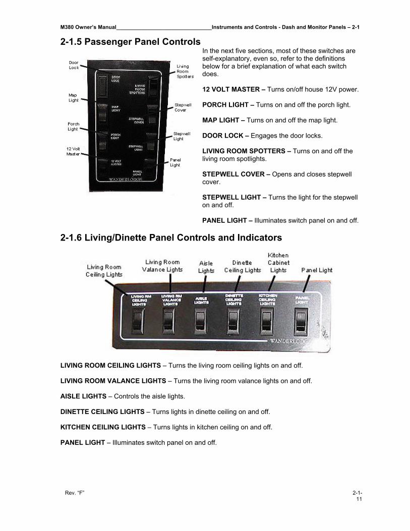
M380 Owner’s Manual________________________________Instruments and Controls - Dash and Monitor Panels – 2-1
Rev. “F” 2-1-11
2-1.5 Passenger Panel Controls In the next five sections, most of these switches are self-explanatory, even so, refer to the definitions below for a brief explanation of what each switch does. 12 VOLT MASTER – Turns on/off house 12V power. PORCH LIGHT – Turns on and off the porch light. MAP LIGHT – Turns on and off the map light. DOOR LOCK – Engages the door locks. LIVING ROOM SPOTTERS – Turns on and off the living room spotlights. STEPWELL COVER – Opens and closes stepwell cover. STEPWELL LIGHT – Turns the light for the stepwell on and off.
PANEL LIGHT – Illuminates switch panel on and off.
2-1.6 Living/Dinette Panel Controls and Indicators
LIVING ROOM CEILING LIGHTS – Turns the living room ceiling lights on and off. LIVING ROOM VALANCE LIGHTS – Turns the living room valance lights on and off. AISLE LIGHTS – Controls the aisle lights. DINETTE CEILING LIGHTS – Turns lights in dinette ceiling on and off. KITCHEN CEILING LIGHTS – Turns lights in kitchen ceiling on and off. PANEL LIGHT – Illuminates switch panel on and off.
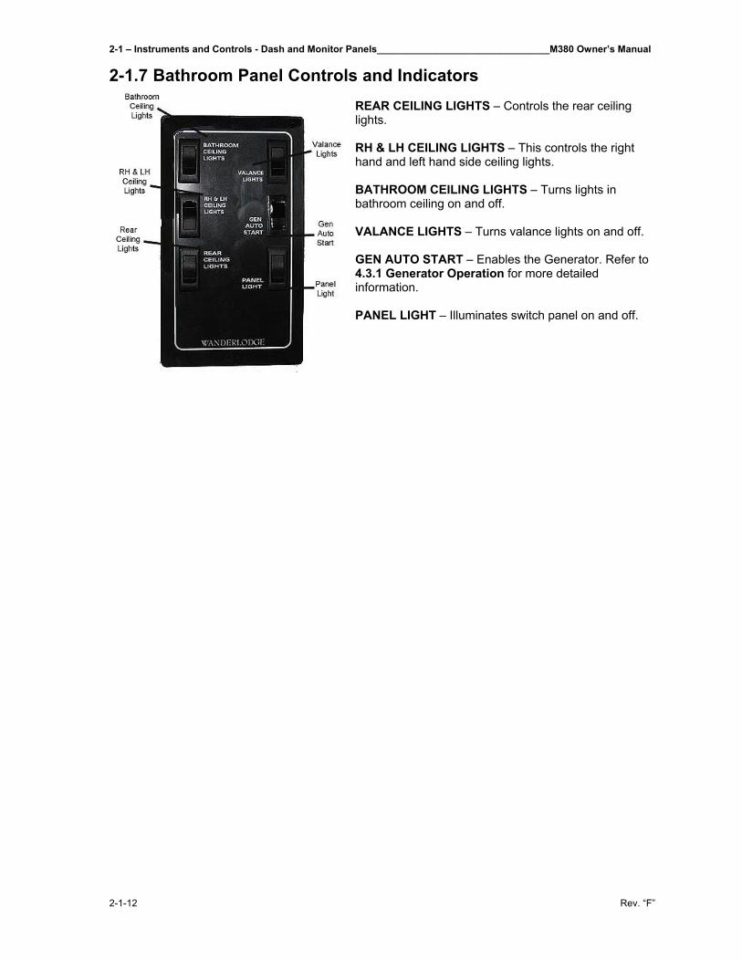
2-1 – Instruments and Controls - Dash and Monitor Panels________________________________M380 Owner’s Manual
2-1-12 Rev. “F”
2-1.7 Bathroom Panel Controls and Indicators REAR CEILING LIGHTS – Controls the rear ceiling lights. RH & LH CEILING LIGHTS – This controls the right hand and left hand side ceiling lights. BATHROOM CEILING LIGHTS – Turns lights in bathroom ceiling on and off. VALANCE LIGHTS – Turns valance lights on and off. GEN AUTO START – Enables the Generator. Refer to 4.3.1 Generator Operation for more detailed information. PANEL LIGHT – Illuminates switch panel on and off.
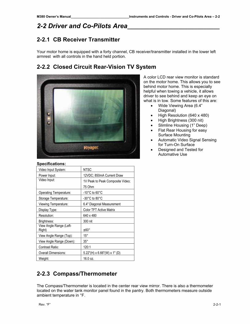
M380 Owner’s Manual________________________________Instruments and Controls - Driver and Co-Pilots Area – 2-2
Rev. “F” 2-2-1
2-2 Driver and Co-Pilots Area_____________________________ 2-2.1 CB Receiver Transmitter Your motor home is equipped with a forty channel, CB receiver/transmitter installed in the lower left armrest with all controls in the hand held portion. 2-2.2 Closed Circuit Rear-Vision TV System
A color LCD rear view monitor is standard on the motor home. This allows you to see behind motor home. This is especially helpful when towing a vehicle, it allows driver to see behind and keep an eye on what is in tow. Some features of this are:
• Wide Viewing Area (6.4” Diagonal)
• High Resolution (640 x 480) • High Brightness (300 nit) • Slimline Housing (1” Deep) • Flat Rear Housing for easy
Surface Mounting • Automatic Video Signal Sensing
for Turn-On Surface • Designed and Tested for
Automative Use
Specifications: Video Input System: NTSC Power Input: 12VDC; 850mA Current Draw
1V Peak to Peak Composite Video; Video Input:
75 Ohm Operating Temperature: -10°C to 60°C Storage Temperature: -30°C to 80°C Viewing Temperature: 6.4" Diagonal Measurement Display Type: Color TFT Active Matrix Resolution: 640 x 480 Brightness: 300 nit View Angle Range (Left-Right) ±60° View Angle Range (Top): 15° View Angle Range (Down): 35° Contrast Ratio: 120:1 Overall Dimensions: 5.22"(H) x 6.66"(W) x 1" (D) Weight: 16.0 oz.
2-2.3 Compass/Thermometer The Compass/Thermometer is located in the center rear view mirror. There is also a thermometer located on the water tank monitor panel found in the pantry. Both thermometers measure outside ambient temperature in °F.
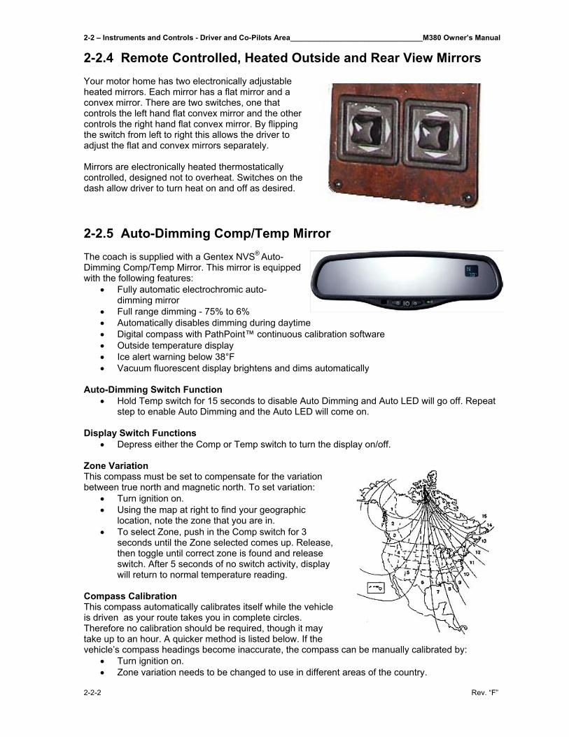
2-2 – Instruments and Controls - Driver and Co-Pilots Area________________________________M380 Owner’s Manual
2-2-2 Rev. “F”
2-2.4 Remote Controlled, Heated Outside and Rear View Mirrors Your motor home has two electronically adjustable heated mirrors. Each mirror has a flat mirror and a convex mirror. There are two switches, one that controls the left hand flat convex mirror and the other controls the right hand flat convex mirror. By flipping the switch from left to right this allows the driver to adjust the flat and convex mirrors separately. Mirrors are electronically heated thermostatically controlled, designed not to overheat. Switches on the dash allow driver to turn heat on and off as desired. 2-2.5 Auto-Dimming Comp/Temp Mirror The coach is supplied with a Gentex NVS® Auto-Dimming Comp/Temp Mirror. This mirror is equipped with the following features:
• Fully automatic electrochromic auto-dimming mirror
• Full range dimming - 75% to 6% • Automatically disables dimming during daytime • Digital compass with PathPoint™ continuous calibration software • Outside temperature display • Ice alert warning below 38°F • Vacuum fluorescent display brightens and dims automatically
Auto-Dimming Switch Function
• Hold Temp switch for 15 seconds to disable Auto Dimming and Auto LED will go off. Repeat step to enable Auto Dimming and the Auto LED will come on.
Display Switch Functions
• Depress either the Comp or Temp switch to turn the display on/off. Zone Variation This compass must be set to compensate for the variation between true north and magnetic north. To set variation:
• Turn ignition on. • Using the map at right to find your geographic
location, note the zone that you are in. • To select Zone, push in the Comp switch for 3
seconds until the Zone selected comes up. Release, then toggle until correct zone is found and release switch. After 5 seconds of no switch activity, display will return to normal temperature reading.
Compass Calibration This compass automatically calibrates itself while the vehicle is driven as your route takes you in complete circles. Therefore no calibration should be required, though it may take up to an hour. A quicker method is listed below. If the vehicle’s compass headings become inaccurate, the compass can be manually calibrated by:
• Turn ignition on. • Zone variation needs to be changed to use in different areas of the country.
M380 Owner’s Manual________________________________Instruments and Controls - Driver and Co-Pilots Area – 2-2
Rev. “F” 2-2-3
• For a different Zone selection, push in the Comp switch for 3 seconds until the Zone selection comes up. Release, then toggle until correct zone is found and release switch.
• To re-calibrate, hold the Comp switch for 6 seconds until CAL is displayed. Drive your vehicle in at least 3 circles, allowing 45 seconds to complete one circle.
Temperature Function
• Push Temp switch for 3 seconds until display blinks °F or °C. Release, then toggle Temp switch to select between °F and °C. After 5 seconds of no switch activity, display will return to normal temperature reading.
Ice Feature Display will indicate “ICE” to alert driver of potential driving hazard when temperatures are below 38°F. ▲WARNING: Do not locate a cellular antenna within 24” of the mirror. 2-2.6 Entrance Door Electric Lock The entrance door electric lock is operated by the right hand dash mounted switch that controls entry door locks. 2-2.7 Entrance Door Air Lock The entrance door air lock is controlled by a signal generated by transmission which energizes the door air lock solenoid when motor home reaches 3 mph. There is also a switch located on the right hand dash panel which will override 3mph signal and lock the doors. When this switch is selected the motor home will not unlock automatically when it comes to a stop. Since this sound can be loud and annoying this feature will alleviate that problem when motor home is in stop-and-go traffic. 2-2.8 Six-Way Power Seats and Seat Belts The seats in the motor home are Villa. They are mounted on a six way adjustable power and swivel base with electrically operated lumbar support. The seat is covered in Ultraleather. 2-2.9 RoadRelay™ 4 2-2.9.1 Introduction The RoadRelay™ 4 vehicle monitoring system may be purchased for your coach as an option. The RoadRelay™ 4 is a vehicle monitoring system that helps drivers perform better and helps owners collect important information about the operation and performance of their coach. Driver benefits include fuel economy feedback information (see Leg Information section), estimated time of arrival (see Estimated Time of Arrival (ETA) section), a built-in clock with alarm (see Using the Clock and Using the Alarm sections), driver coaching and driver information pop-ups (see Pop-ups section), and many other features. For protection of the vehicle and the property it is carrying, the antitheft feature (see Antitheft section) can be used. To help service the vehicle, information from the engine control module can be viewed (see Vehicle Monitor section). To help troubleshoot vehicle problems, fault information is displayed when a fault occurs and then stored for later access by service personnel (see Fault Information section). Maintenance is assisted by the use of periodic maintenance pop-ups and stored service information (see Scheduled Maintenance and Service History sections).
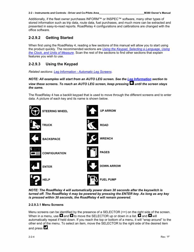
2-2 – Instruments and Controls - Driver and Co-Pilots Area________________________________M380 Owner’s Manual
2-2-4 Rev. “F”
Additionally, if the fleet owner purchases INFORM™ or INSPEC™ software, many other types of stored information such as trip data, route data, fuel purchases, and much more can be extracted and presented in easy-to-read reports. RoadRelay 4 configurations and calibrations are changed with the office software. 2-2.9.2 Getting Started When first using the RoadRelay 4, reading a few sections of this manual will allow you to start using the product quickly. The recommended sections are Using the Keypad, Selecting a Language, Using the Clock, and Units of Measure. Scan the rest of the sections to find other sections that explain features you wish to use. 2-2.9.3 Using the Keypad Related sections: Leg Information - Automatic Leg Screens. NOTE: All examples will start from an AUTO LEG screen. See the Leg Information section to view these screens. To reach an AUTO LEG screen, keep pressing until the screen stays the same. The RoadRelay 4 has a backlit keypad that is used to move through the different screens and to enter data. A picture of each key and its name is shown below.
NOTE: The RoadRelay 4 will automatically power down 30 seconds after the keyswitch is turned off. The RoadRelay 4 may be powered by pressing the ENTER key. As long as any key is pressed within 30 seconds, the RoadRelay 4 will remain powered. 2-2.9.3.1 Menu Screens Menu screens can be identified by the presence of a SELECTOR (<=) on the right side of the screen. When in a menu, use and to move the SELECTOR up or down in a list. and will automatically repeat if held down. If you reach the top or bottom of a menu, it will “wrap around” to the other end of the menu. To select an item, move the SELECTOR to the right side of the desired item and press .

M380 Owner’s Manual________________________________Instruments and Controls - Driver and Co-Pilots Area – 2-2
Rev. “F” 2-2-5
Example: To see a menu screen, press the key. The SELECTOR is to the right of the item to be selected. Press to return to the previous screen. 2-2.9.3.2 Entry Screens Entry screens can be identified by the presence of a CURSOR (blinking rectangle) on the screen. Use , , , , , , , , , and to enter numbers. The numbers appear in the upper left-hand corner of the key. When the first key is pressed, the old numbers will disappear and the new number will be updated as keys are pressed. When you are finished entering all numbers, press . If you want to undo the last key-press, use . If you wish to leave a screen and not modify the number the number, keep pressing until the screen is gone. When on an entry screen, you may not be able to “jump” between menus because the key is presently interpreted to be number entry. Use to exit the screen, and normal functioning will return. Example: Press ; move the SELECTOR until it is to the right of “Time.” Press . You will see the present RoadRelay 4 time and a blinking CURSOR. Press any key with a number on it. The screen will now show the number you have presently selected. Press several times to discard the change and return to the AUTO LEG screen. 2-2.9.3.3 Up/Down Entry Screens Some screens use to move through a set of possible choices. The screen changes to show the new choice when and are pressed. Example: Press ; move the SELECTOR until it is to the right of “Time Format.” Press . You will see the present time format. Press and to see the format switch between 12 and 24 hours. Press several times to discard any change and return to the AUTO LEG screen. 2-2.9.3.4 Data Screens Screens showing data, such as the leg or vehicle monitor, will update every second. If data is unavailable or invalid, the screen will have question marks in place of numerical data. 2-2.9.3.5 Changing Display Brightness from AUTO LEG The RoadRelay 4 has five levels of brightness (including OFF). When in an AUTO LEG screen, pressing will increase the display brightness; pressing will decrease the brightness. When at the lowest level (OFF), any key press will turn the display on at the lowest brightness level. The RoadRelay 4 saves separate brightness settings - one if the headlights are OFF, you can adjust the setting for headlights being off. If the headlights are ON, you may adjust the setting for headlights being on. 2-2.9.4 Leg Information Related sections: Driver ID, Using the Clock, Estimated Time of Arrival (ETA), Units of Measure, Trip Information. A “leg” is data collected since the last time the leg information was reset. A leg has less information than a trip. Leg information can not be retrieved using office software. It is only used for driver feedback.
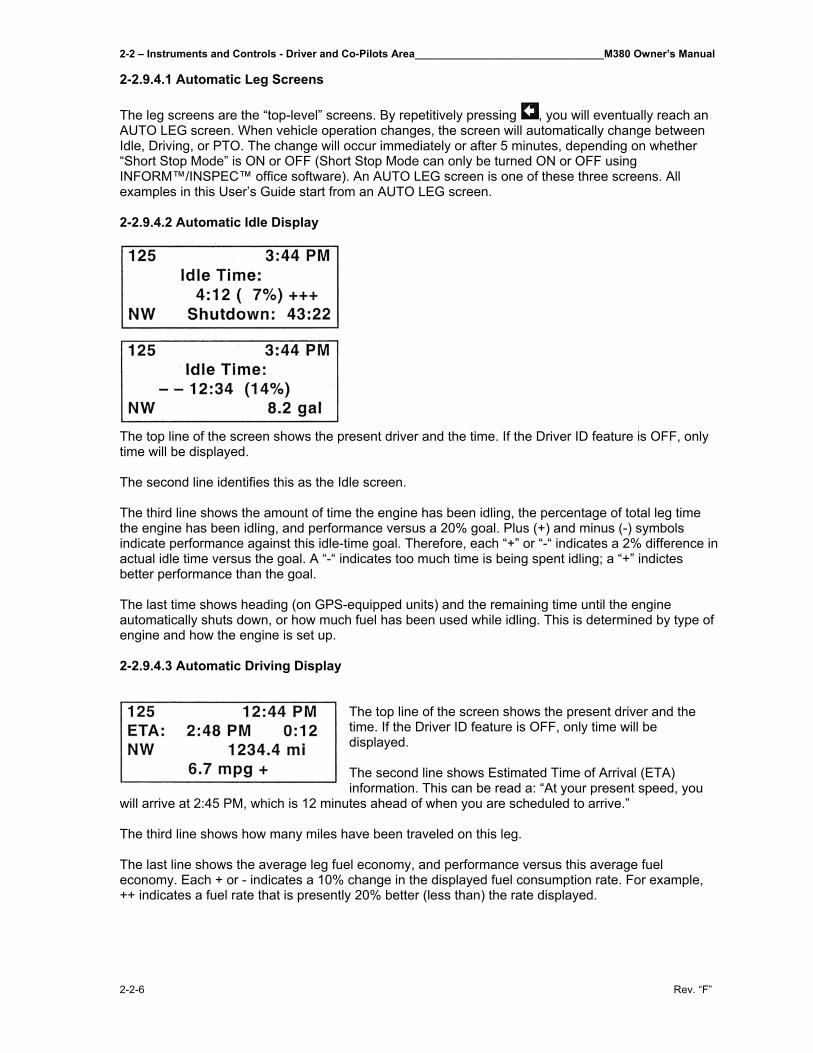
2-2 – Instruments and Controls - Driver and Co-Pilots Area________________________________M380 Owner’s Manual
2-2-6 Rev. “F”
2-2.9.4.1 Automatic Leg Screens The leg screens are the “top-level” screens. By repetitively pressing , you will eventually reach an AUTO LEG screen. When vehicle operation changes, the screen will automatically change between Idle, Driving, or PTO. The change will occur immediately or after 5 minutes, depending on whether “Short Stop Mode” is ON or OFF (Short Stop Mode can only be turned ON or OFF using INFORM™/INSPEC™ office software). An AUTO LEG screen is one of these three screens. All examples in this User’s Guide start from an AUTO LEG screen. 2-2.9.4.2 Automatic Idle Display
The top line of the screen shows the present driver and the time. If the Driver ID feature is OFF, only time will be displayed. The second line identifies this as the Idle screen. The third line shows the amount of time the engine has been idling, the percentage of total leg time the engine has been idling, and performance versus a 20% goal. Plus (+) and minus (-) symbols indicate performance against this idle-time goal. Therefore, each “+” or “-“ indicates a 2% difference in actual idle time versus the goal. A “-“ indicates too much time is being spent idling; a “+” indictes better performance than the goal. The last time shows heading (on GPS-equipped units) and the remaining time until the engine automatically shuts down, or how much fuel has been used while idling. This is determined by type of engine and how the engine is set up. 2-2.9.4.3 Automatic Driving Display
The top line of the screen shows the present driver and the time. If the Driver ID feature is OFF, only time will be displayed. The second line shows Estimated Time of Arrival (ETA) information. This can be read a: “At your present speed, you
will arrive at 2:45 PM, which is 12 minutes ahead of when you are scheduled to arrive.” The third line shows how many miles have been traveled on this leg. The last line shows the average leg fuel economy, and performance versus this average fuel economy. Each + or - indicates a 10% change in the displayed fuel consumption rate. For example, ++ indicates a fuel rate that is presently 20% better (less than) the rate displayed.
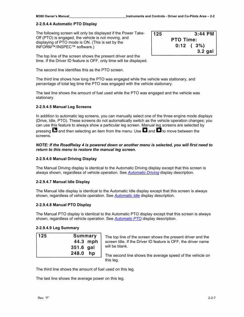
M380 Owner’s Manual________________________________Instruments and Controls - Driver and Co-Pilots Area – 2-2
Rev. “F” 2-2-7
2-2.9.4.4 Automatic PTO Display The following screen will only be displayed if the Power Take-Off (PTO) is engaged, the vehicle is not moving, and displaying of PTO mode is ON. (This is set by the INFORM™/INSPEC™ software.) The top line of the screen shows the present driver and the time. If the Driver ID feature is OFF, only time will be displayed. The second line identifies this as the PTO screen. The third line shows how long the PTO was engaged while the vehicle was stationary, and percentage of total leg time the PTO was engaged with the vehicle stationary. The last line shows the amount of fuel used while the PTO was engaged and the vehicle was stationary. 2-2.9.4.5 Manual Leg Screens In addition to automatic leg screens, you can manually select one of the three engine mode displays (Drive, Idle, PTO). These screens do not automatically switch as the vehicle operation changes; you can use this feature to always show a particular leg screen. Manual leg screens are selected by pressing and then selecting an item from the menu. Use and to move between the screens. NOTE: If the RoadRelay 4 is powered down or another menu is selected, you will first need to return to this menu to restore the manual leg screen. 2-2.9.4.6 Manual Driving Display The Manual Driving display is identical to the Automatic Driving display except that this screen is always shown, regardless of vehicle operation. See Automatic Driving display description. 2-2.9.4.7 Manual Idle Display The Manual Idle display is identical to the Automatic Idle display except that this screen is always shown, regardless of vehicle operation. See Automatic Idle display description. 2-2.9.4.8 Manual PTO Display The Manual PTO display is identical to the Automatic PTO display except that this screen is always shown, regardless of vehicle operation. See Automatic PTO display description. 2-2.9.4.9 Leg Summary
The top line of the screen shows the present driver and the screen title. If the Driver ID feature is OFF, the driver name will be blank. The second line shows the average speed of the vehicle on this leg.
The third line shows the amount of fuel used on this leg. The last line shows the average power on this leg.
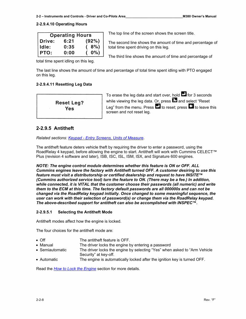
2-2 – Instruments and Controls - Driver and Co-Pilots Area________________________________M380 Owner’s Manual
2-2-8 Rev. “F”
2-2.9.4.10 Operating Hours
The top line of the screen shows the screen title. The second line shows the amount of time and percentage of total time spent driving on this leg. The third line shows the amount of time and percentage of
total time spent idling on this leg. The last line shows the amount of time and percentage of total time spent idling with PTO engaged on this leg. 2-2.9.4.11 Resetting Leg Data
To erase the leg data and start over, hold for 3 seconds while viewing the leg data. Or, press and select “Reset Leg” from the menu. Press to reset; press to leave this screen and not reset leg.
2-2.9.5 Antitheft Related sections: Keypad - Entry Screens, Units of Measure. The antitheft feature deters vehicle theft by requiring the driver to enter a password, using the RoadRelay 4 keypad, before allowing the engine to start. Antitheft will work with Cummins CELECT™ Plus (revision 4 software and later), ISB, ISC, ISL, ISM, ISX, and Signature 600 engines. NOTE: The engine control module determines whether this feature is ON or OFF. ALL Cummins engines leave the factory with Antitheft turned OFF. A customer desiring to use this feature must visit a distributorship or certified dealership and request to have INSITE™ (Cummins authorized service tool) turn the feature to ON. (There may be a fee.) In addition, while connected, it is VITAL that the customer choose their passwords (all numeric) and write them to the ECM at this time. The factory default passwords are all 000000s and can not be changed via the RoadRelay keypad initially. Once changed to some meaningful sequence, the user can work with their selection of password(s) or change them via the RoadRelay keypad. The above-described support for antitheft can also be accomplished with INSPEC™. 2-2.9.5.1 Selecting the Antitheft Mode Antitheft modes affect how the engine is locked. The four choices for the antitheft mode are: • Off The antitheft feature is OFF. • Manual The driver locks the engine by entering a password • Semiautomatic The driver locks the engine by selecting “Yes” when asked to “Arm Vehicle
Security” at key-off. • Automatic The engine is automatically locked after the ignition key is turned OFF. Read the How to Lock the Engine section for more details.
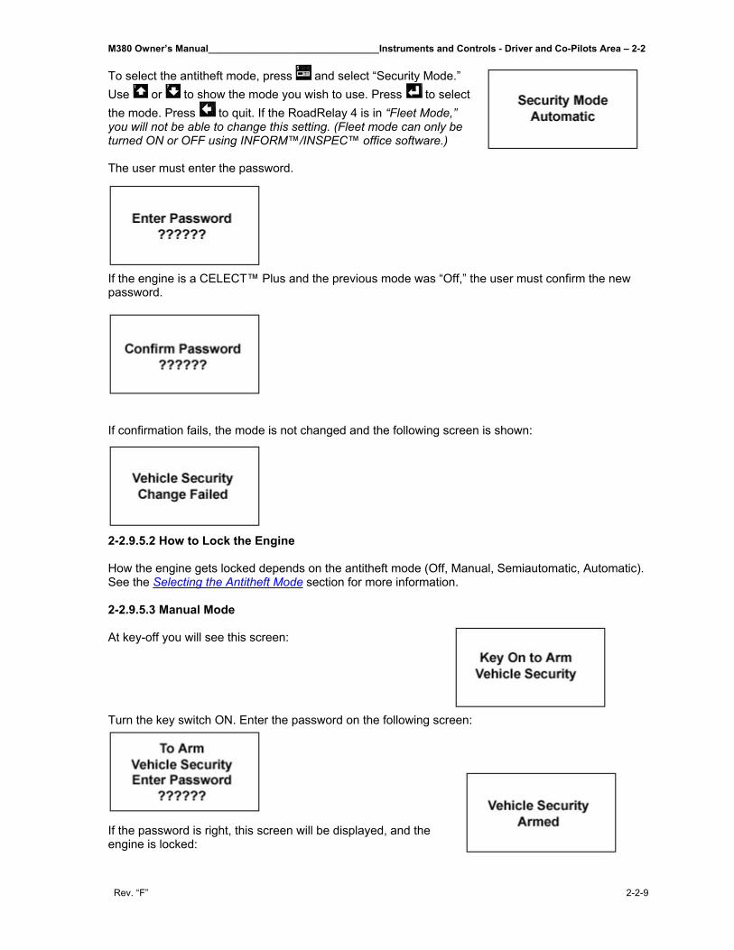
M380 Owner’s Manual________________________________Instruments and Controls - Driver and Co-Pilots Area – 2-2
Rev. “F” 2-2-9
To select the antitheft mode, press and select “Security Mode.” Use or to show the mode you wish to use. Press to select the mode. Press to quit. If the RoadRelay 4 is in “Fleet Mode,” you will not be able to change this setting. (Fleet mode can only be turned ON or OFF using INFORM™/INSPEC™ office software.) The user must enter the password.
If the engine is a CELECT™ Plus and the previous mode was “Off,” the user must confirm the new password.
If confirmation fails, the mode is not changed and the following screen is shown:
2-2.9.5.2 How to Lock the Engine How the engine gets locked depends on the antitheft mode (Off, Manual, Semiautomatic, Automatic). See the Selecting the Antitheft Mode section for more information. 2-2.9.5.3 Manual Mode At key-off you will see this screen: Turn the key switch ON. Enter the password on the following screen:
If the password is right, this screen will be displayed, and the engine is locked:
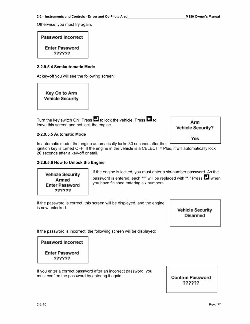
2-2 – Instruments and Controls - Driver and Co-Pilots Area________________________________M380 Owner’s Manual
2-2-10 Rev. “F”
Otherwise, you must try again.
2-2.9.5.4 Semiautomatic Mode At key-off you will see the following screen:
Turn the key switch ON. Press to lock the vehicle. Press to leave this screen and not lock the engine. 2-2.9.5.5 Automatic Mode In automatic mode, the engine automatically locks 30 seconds after the ignition key is turned OFF. If the engine in the vehicle is a CELECT™ Plus, it will automatically lock 20 seconds after a key-off or stall. 2-2.9.5.6 How to Unlock the Engine
If the engine is locked, you must enter a six-number password. As the password is entered, each “?” will be replaced with “*.” Press when you have finished entering six numbers.
If the password is correct, this screen will be displayed, and the engine is now unlocked. If the password is incorrect, the following screen will be displayed:
If you enter a correct password after an incorrect password, you must confirm the password by entering it again.
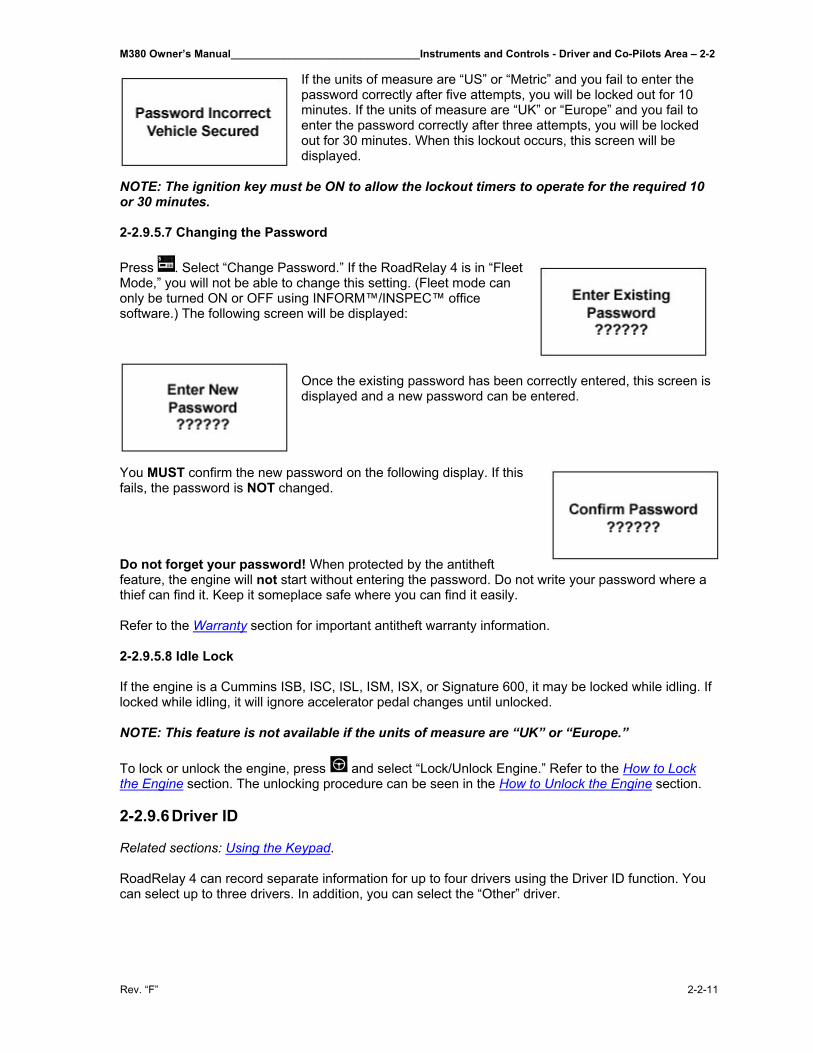
M380 Owner’s Manual________________________________Instruments and Controls - Driver and Co-Pilots Area – 2-2
Rev. “F” 2-2-11
If the units of measure are “US” or “Metric” and you fail to enter the password correctly after five attempts, you will be locked out for 10 minutes. If the units of measure are “UK” or “Europe” and you fail to enter the password correctly after three attempts, you will be locked out for 30 minutes. When this lockout occurs, this screen will be displayed.
NOTE: The ignition key must be ON to allow the lockout timers to operate for the required 10 or 30 minutes. 2-2.9.5.7 Changing the Password Press . Select “Change Password.” If the RoadRelay 4 is in “Fleet Mode,” you will not be able to change this setting. (Fleet mode can only be turned ON or OFF using INFORM™/INSPEC™ office software.) The following screen will be displayed:
Once the existing password has been correctly entered, this screen is displayed and a new password can be entered.
You MUST confirm the new password on the following display. If this fails, the password is NOT changed. Do not forget your password! When protected by the antitheft feature, the engine will not start without entering the password. Do not write your password where a thief can find it. Keep it someplace safe where you can find it easily. Refer to the Warranty section for important antitheft warranty information. 2-2.9.5.8 Idle Lock If the engine is a Cummins ISB, ISC, ISL, ISM, ISX, or Signature 600, it may be locked while idling. If locked while idling, it will ignore accelerator pedal changes until unlocked. NOTE: This feature is not available if the units of measure are “UK” or “Europe.” To lock or unlock the engine, press and select “Lock/Unlock Engine.” Refer to the How to Lock the Engine section. The unlocking procedure can be seen in the How to Unlock the Engine section. 2-2.9.6 Driver ID Related sections: Using the Keypad.
RoadRelay 4 can record separate information for up to four drivers using the Driver ID function. You can select up to three drivers. In addition, you can select the “Other” driver.
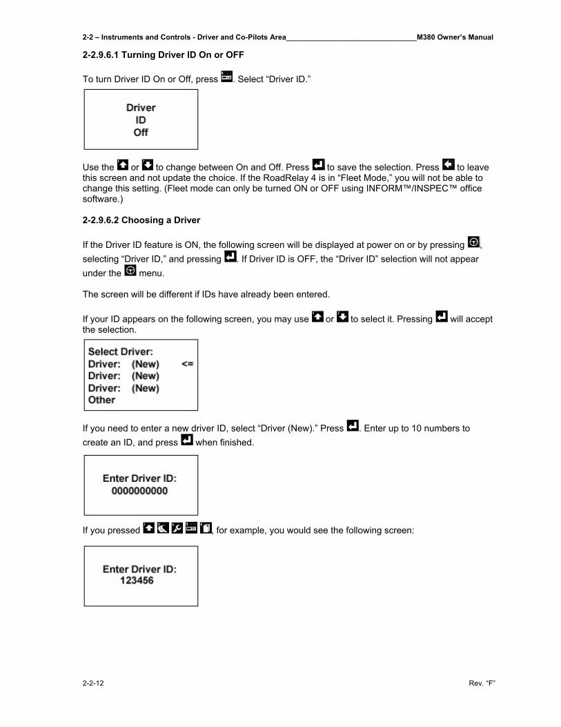
2-2 – Instruments and Controls - Driver and Co-Pilots Area________________________________M380 Owner’s Manual
2-2-12 Rev. “F”
2-2.9.6.1 Turning Driver ID On or OFF To turn Driver ID On or Off, press . Select “Driver ID.”
Use the or to change between On and Off. Press to save the selection. Press to leave this screen and not update the choice. If the RoadRelay 4 is in “Fleet Mode,” you will not be able to change this setting. (Fleet mode can only be turned ON or OFF using INFORM™/INSPEC™ office software.) 2-2.9.6.2 Choosing a Driver If the Driver ID feature is ON, the following screen will be displayed at power on or by pressing , selecting “Driver ID,” and pressing . If Driver ID is OFF, the “Driver ID” selection will not appear under the menu. The screen will be different if IDs have already been entered. If your ID appears on the following screen, you may use or to select it. Pressing will accept the selection.
If you need to enter a new driver ID, select “Driver (New).” Press . Enter up to 10 numbers to create an ID, and press when finished.
If you pressed , for example, you would see the following screen:
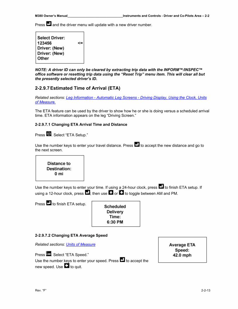
M380 Owner’s Manual________________________________Instruments and Controls - Driver and Co-Pilots Area – 2-2
Rev. “F” 2-2-13
Press and the driver menu will update with a new driver number.
NOTE: A driver ID can only be cleared by extracting trip data with the INFORM™/INSPEC™ office software or resetting trip data using the “Reset Trip” menu item. This will clear all but the presently selected driver’s ID. 2-2.9.7 Estimated Time of Arrival (ETA) Related sections: Leg Information - Automatic Leg Screens - Driving Display, Using the Clock, Units of Measure. The ETA feature can be used by the driver to show how he or she is doing versus a scheduled arrival time. ETA information appears on the leg “Driving Screen.” 2-2.9.7.1 Changing ETA Arrival Time and Distance Press . Select “ETA Setup.” Use the number keys to enter your travel distance. Press to accept the new distance and go to the next screen.
Use the number keys to enter your time. If using a 24-hour clock, press to finish ETA setup. If using a 12-hour clock, press ; then use or to toggle between AM and PM. Press to finish ETA setup. 2-2.9.7.2 Changing ETA Average Speed Related sections: Units of Measure Press . Select “ETA Speed.” Use the number keys to enter your speed. Press to accept the new speed. Use to quit.
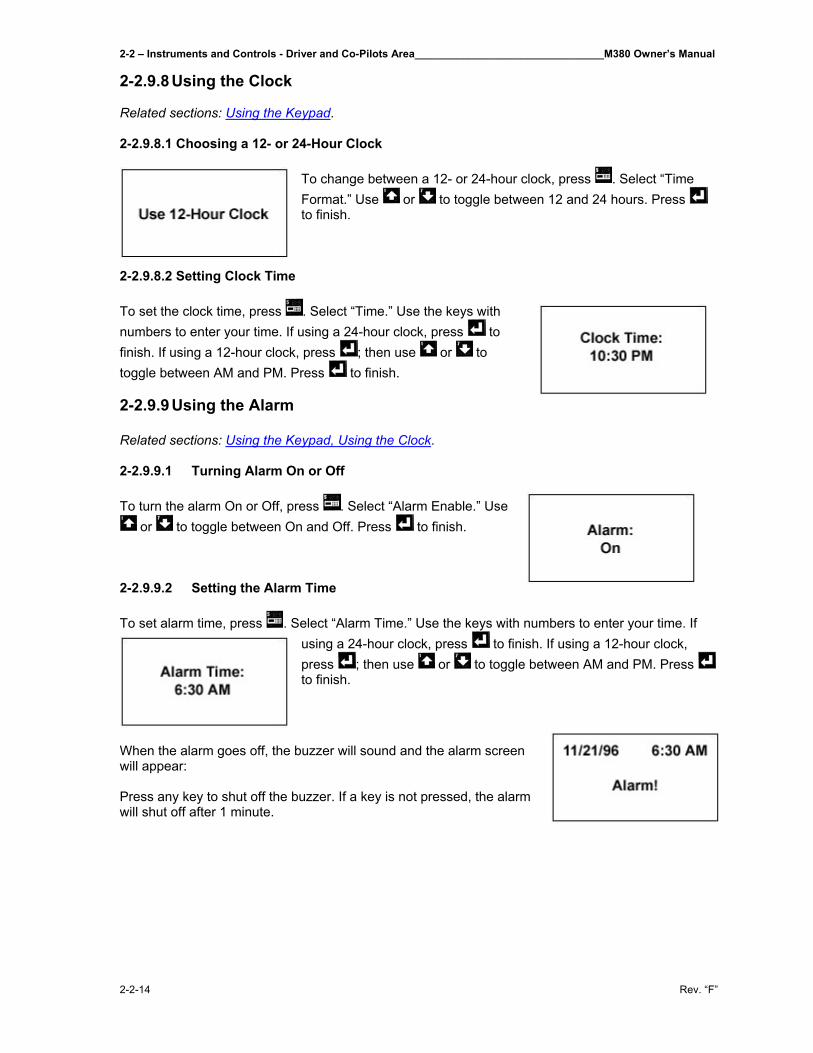
2-2 – Instruments and Controls - Driver and Co-Pilots Area________________________________M380 Owner’s Manual
2-2-14 Rev. “F”
2-2.9.8 Using the Clock Related sections: Using the Keypad. 2-2.9.8.1 Choosing a 12- or 24-Hour Clock
To change between a 12- or 24-hour clock, press . Select “Time Format.” Use or to toggle between 12 and 24 hours. Press to finish.
2-2.9.8.2 Setting Clock Time To set the clock time, press . Select “Time.” Use the keys with numbers to enter your time. If using a 24-hour clock, press to finish. If using a 12-hour clock, press ; then use or to toggle between AM and PM. Press to finish. 2-2.9.9 Using the Alarm Related sections: Using the Keypad, Using the Clock. 2-2.9.9.1 Turning Alarm On or Off To turn the alarm On or Off, press . Select “Alarm Enable.” Use
or to toggle between On and Off. Press to finish. 2-2.9.9.2 Setting the Alarm Time To set alarm time, press . Select “Alarm Time.” Use the keys with numbers to enter your time. If
using a 24-hour clock, press to finish. If using a 12-hour clock, press ; then use or to toggle between AM and PM. Press to finish.
When the alarm goes off, the buzzer will sound and the alarm screen will appear: Press any key to shut off the buzzer. If a key is not pressed, the alarm will shut off after 1 minute.
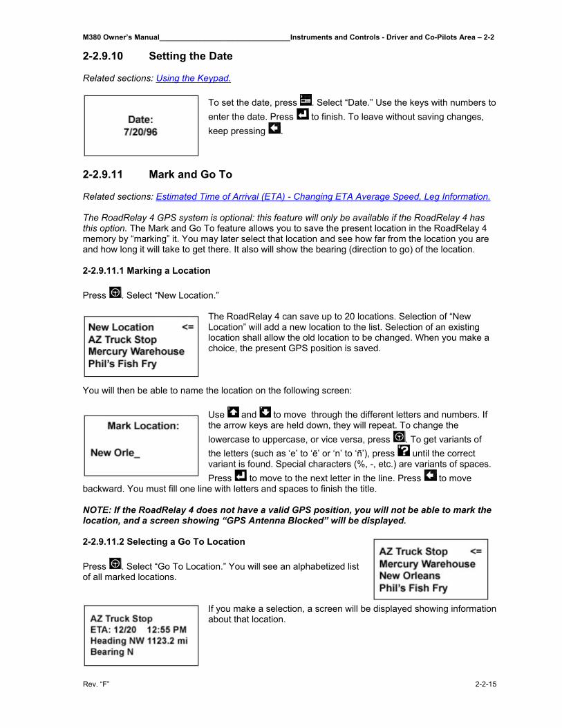
M380 Owner’s Manual________________________________Instruments and Controls - Driver and Co-Pilots Area – 2-2
Rev. “F” 2-2-15
2-2.9.10 Setting the Date Related sections: Using the Keypad.
To set the date, press . Select “Date.” Use the keys with numbers to enter the date. Press to finish. To leave without saving changes, keep pressing .
2-2.9.11 Mark and Go To Related sections: Estimated Time of Arrival (ETA) - Changing ETA Average Speed, Leg Information. The RoadRelay 4 GPS system is optional: this feature will only be available if the RoadRelay 4 has this option. The Mark and Go To feature allows you to save the present location in the RoadRelay 4 memory by “marking” it. You may later select that location and see how far from the location you are and how long it will take to get there. It also will show the bearing (direction to go) of the location. 2-2.9.11.1 Marking a Location Press . Select “New Location.”
The RoadRelay 4 can save up to 20 locations. Selection of “New Location” will add a new location to the list. Selection of an existing location shall allow the old location to be changed. When you make a choice, the present GPS position is saved.
You will then be able to name the location on the following screen:
Use and to move through the different letters and numbers. If the arrow keys are held down, they will repeat. To change the lowercase to uppercase, or vice versa, press . To get variants of the letters (such as ‘e’ to ‘ë’ or ‘n’ to ‘ñ’), press until the correct variant is found. Special characters (%, -, etc.) are variants of spaces. Press to move to the next letter in the line. Press to move
backward. You must fill one line with letters and spaces to finish the title. NOTE: If the RoadRelay 4 does not have a valid GPS position, you will not be able to mark the location, and a screen showing “GPS Antenna Blocked” will be displayed. 2-2.9.11.2 Selecting a Go To Location Press . Select “Go To Location.” You will see an alphabetized list of all marked locations.
If you make a selection, a screen will be displayed showing information about that location.
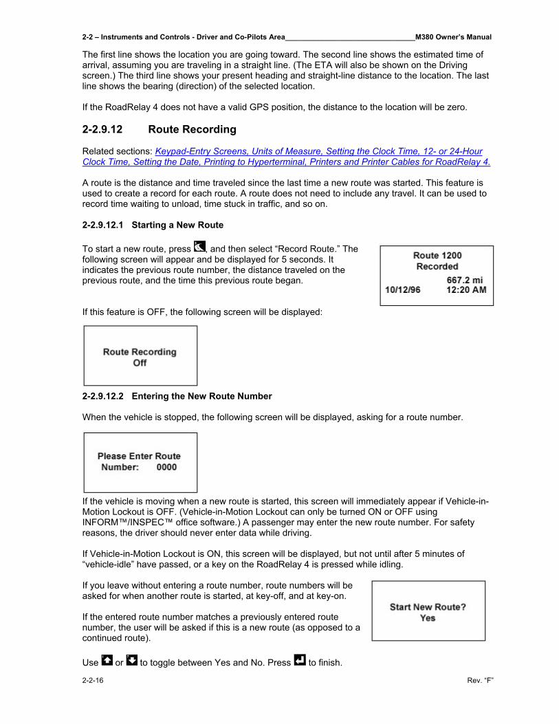
2-2 – Instruments and Controls - Driver and Co-Pilots Area________________________________M380 Owner’s Manual
2-2-16 Rev. “F”
The first line shows the location you are going toward. The second line shows the estimated time of arrival, assuming you are traveling in a straight line. (The ETA will also be shown on the Driving screen.) The third line shows your present heading and straight-line distance to the location. The last line shows the bearing (direction) of the selected location. If the RoadRelay 4 does not have a valid GPS position, the distance to the location will be zero. 2-2.9.12 Route Recording Related sections: Keypad-Entry Screens, Units of Measure, Setting the Clock Time, 12- or 24-Hour Clock Time, Setting the Date, Printing to Hyperterminal, Printers and Printer Cables for RoadRelay 4. A route is the distance and time traveled since the last time a new route was started. This feature is used to create a record for each route. A route does not need to include any travel. It can be used to record time waiting to unload, time stuck in traffic, and so on. 2-2.9.12.1 Starting a New Route To start a new route, press , and then select “Record Route.” The following screen will appear and be displayed for 5 seconds. It indicates the previous route number, the distance traveled on the previous route, and the time this previous route began. If this feature is OFF, the following screen will be displayed:
2-2.9.12.2 Entering the New Route Number When the vehicle is stopped, the following screen will be displayed, asking for a route number.
If the vehicle is moving when a new route is started, this screen will immediately appear if Vehicle-in-Motion Lockout is OFF. (Vehicle-in-Motion Lockout can only be turned ON or OFF using INFORM™/INSPEC™ office software.) A passenger may enter the new route number. For safety reasons, the driver should never enter data while driving. If Vehicle-in-Motion Lockout is ON, this screen will be displayed, but not until after 5 minutes of “vehicle-idle” have passed, or a key on the RoadRelay 4 is pressed while idling. If you leave without entering a route number, route numbers will be asked for when another route is started, at key-off, and at key-on. If the entered route number matches a previously entered route number, the user will be asked if this is a new route (as opposed to a continued route). Use or to toggle between Yes and No. Press to finish.
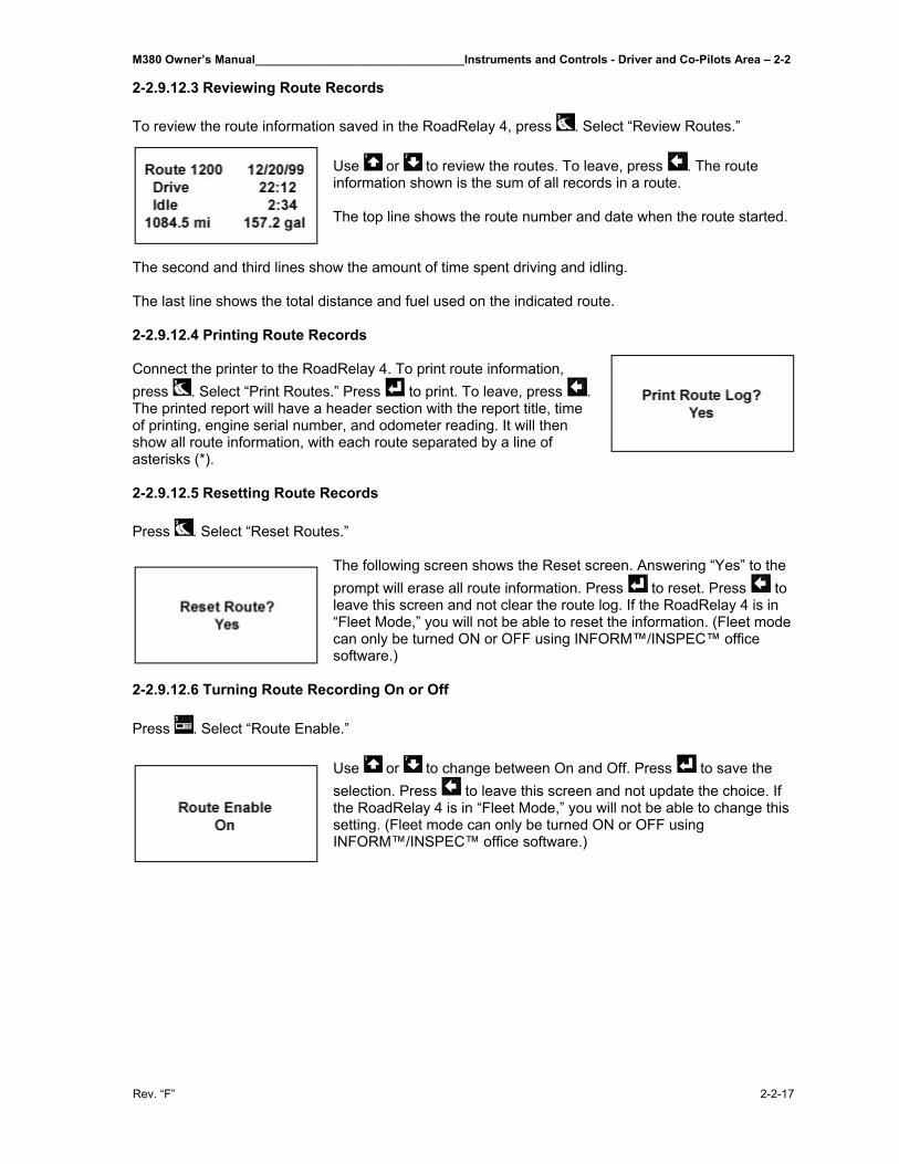
M380 Owner’s Manual________________________________Instruments and Controls - Driver and Co-Pilots Area – 2-2
Rev. “F” 2-2-17
2-2.9.12.3 Reviewing Route Records To review the route information saved in the RoadRelay 4, press . Select “Review Routes.”
Use or to review the routes. To leave, press . The route information shown is the sum of all records in a route. The top line shows the route number and date when the route started.
The second and third lines show the amount of time spent driving and idling. The last line shows the total distance and fuel used on the indicated route. 2-2.9.12.4 Printing Route Records Connect the printer to the RoadRelay 4. To print route information, press . Select “Print Routes.” Press to print. To leave, press . The printed report will have a header section with the report title, time of printing, engine serial number, and odometer reading. It will then show all route information, with each route separated by a line of asterisks (*). 2-2.9.12.5 Resetting Route Records Press . Select “Reset Routes.”
The following screen shows the Reset screen. Answering “Yes” to the prompt will erase all route information. Press to reset. Press to leave this screen and not clear the route log. If the RoadRelay 4 is in “Fleet Mode,” you will not be able to reset the information. (Fleet mode can only be turned ON or OFF using INFORM™/INSPEC™ office software.)
2-2.9.12.6 Turning Route Recording On or Off Press . Select “Route Enable.”
Use or to change between On and Off. Press to save the selection. Press to leave this screen and not update the choice. If the RoadRelay 4 is in “Fleet Mode,” you will not be able to change this setting. (Fleet mode can only be turned ON or OFF using INFORM™/INSPEC™ office software.)
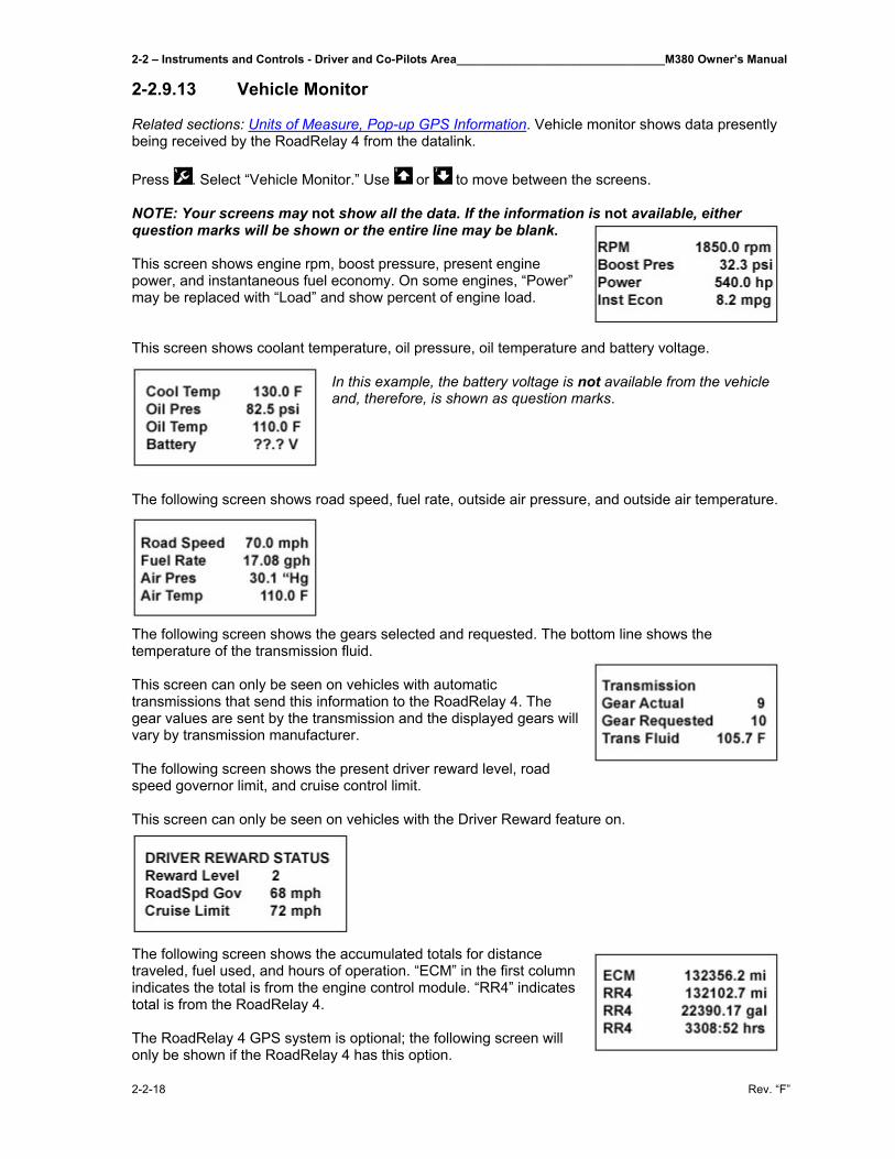
2-2 – Instruments and Controls - Driver and Co-Pilots Area________________________________M380 Owner’s Manual
2-2-18 Rev. “F”
2-2.9.13 Vehicle Monitor Related sections: Units of Measure, Pop-up GPS Information. Vehicle monitor shows data presently being received by the RoadRelay 4 from the datalink. Press . Select “Vehicle Monitor.” Use or to move between the screens. NOTE: Your screens may not show all the data. If the information is not available, either question marks will be shown or the entire line may be blank. This screen shows engine rpm, boost pressure, present engine power, and instantaneous fuel economy. On some engines, “Power” may be replaced with “Load” and show percent of engine load. This screen shows coolant temperature, oil pressure, oil temperature and battery voltage.
In this example, the battery voltage is not available from the vehicle and, therefore, is shown as question marks.
The following screen shows road speed, fuel rate, outside air pressure, and outside air temperature.
The following screen shows the gears selected and requested. The bottom line shows the temperature of the transmission fluid. This screen can only be seen on vehicles with automatic transmissions that send this information to the RoadRelay 4. The gear values are sent by the transmission and the displayed gears will vary by transmission manufacturer. The following screen shows the present driver reward level, road speed governor limit, and cruise control limit. This screen can only be seen on vehicles with the Driver Reward feature on.
The following screen shows the accumulated totals for distance traveled, fuel used, and hours of operation. “ECM” in the first column indicates the total is from the engine control module. “RR4” indicates total is from the RoadRelay 4. The RoadRelay 4 GPS system is optional; the following screen will only be shown if the RoadRelay 4 has this option.
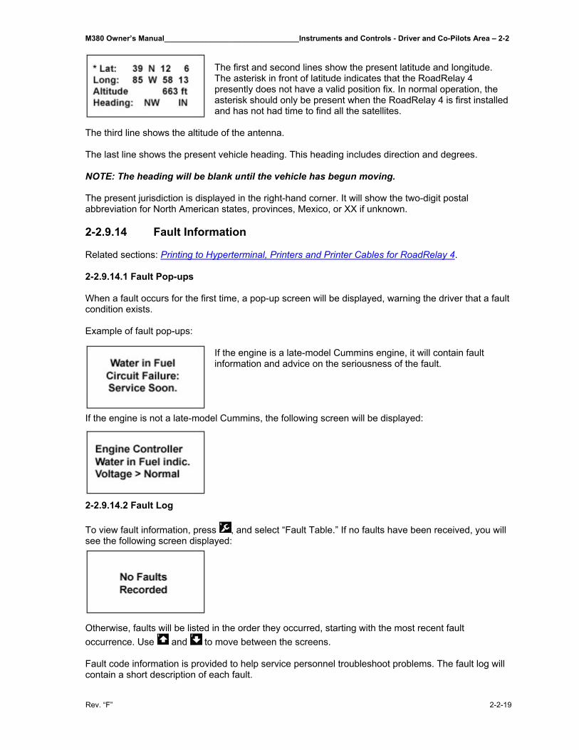
M380 Owner’s Manual________________________________Instruments and Controls - Driver and Co-Pilots Area – 2-2
Rev. “F” 2-2-19
The first and second lines show the present latitude and longitude. The asterisk in front of latitude indicates that the RoadRelay 4 presently does not have a valid position fix. In normal operation, the asterisk should only be present when the RoadRelay 4 is first installed and has not had time to find all the satellites.
The third line shows the altitude of the antenna. The last line shows the present vehicle heading. This heading includes direction and degrees. NOTE: The heading will be blank until the vehicle has begun moving. The present jurisdiction is displayed in the right-hand corner. It will show the two-digit postal abbreviation for North American states, provinces, Mexico, or XX if unknown. 2-2.9.14 Fault Information Related sections: Printing to Hyperterminal, Printers and Printer Cables for RoadRelay 4. 2-2.9.14.1 Fault Pop-ups When a fault occurs for the first time, a pop-up screen will be displayed, warning the driver that a fault condition exists. Example of fault pop-ups:
If the engine is a late-model Cummins engine, it will contain fault information and advice on the seriousness of the fault.
If the engine is not a late-model Cummins, the following screen will be displayed:
2-2.9.14.2 Fault Log To view fault information, press , and select “Fault Table.” If no faults have been received, you will see the following screen displayed:
Otherwise, faults will be listed in the order they occurred, starting with the most recent fault occurrence. Use and to move between the screens. Fault code information is provided to help service personnel troubleshoot problems. The fault log will contain a short description of each fault.
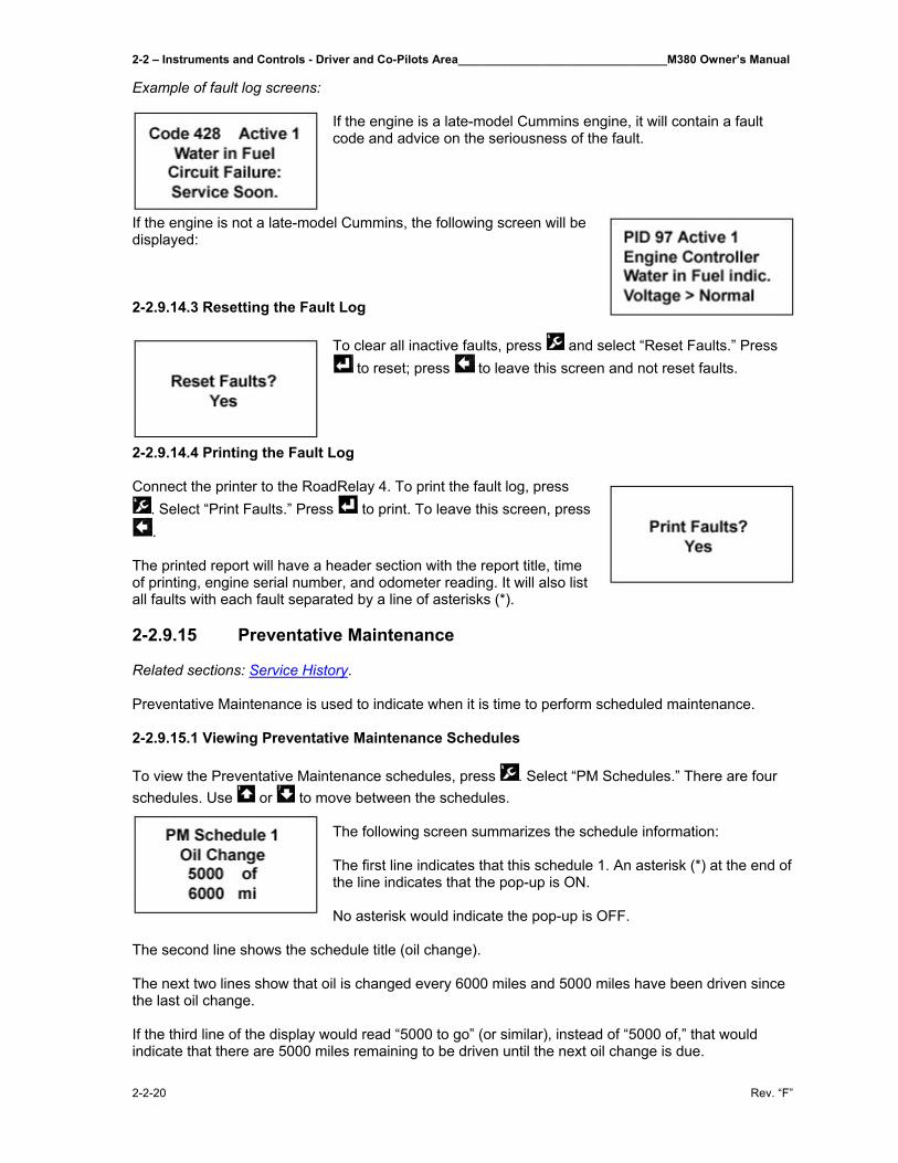
2-2 – Instruments and Controls - Driver and Co-Pilots Area________________________________M380 Owner’s Manual
2-2-20 Rev. “F”
Example of fault log screens: If the engine is a late-model Cummins engine, it will contain a fault code and advice on the seriousness of the fault.
If the engine is not a late-model Cummins, the following screen will be displayed: 2-2.9.14.3 Resetting the Fault Log
To clear all inactive faults, press and select “Reset Faults.” Press to reset; press to leave this screen and not reset faults.
2-2.9.14.4 Printing the Fault Log Connect the printer to the RoadRelay 4. To print the fault log, press
. Select “Print Faults.” Press to print. To leave this screen, press .
The printed report will have a header section with the report title, time of printing, engine serial number, and odometer reading. It will also list all faults with each fault separated by a line of asterisks (*). 2-2.9.15 Preventative Maintenance Related sections: Service History. Preventative Maintenance is used to indicate when it is time to perform scheduled maintenance. 2-2.9.15.1 Viewing Preventative Maintenance Schedules To view the Preventative Maintenance schedules, press . Select “PM Schedules.” There are four schedules. Use or to move between the schedules.
The following screen summarizes the schedule information: The first line indicates that this schedule 1. An asterisk (*) at the end of the line indicates that the pop-up is ON. No asterisk would indicate the pop-up is OFF.
The second line shows the schedule title (oil change). The next two lines show that oil is changed every 6000 miles and 5000 miles have been driven since the last oil change. If the third line of the display would read “5000 to go” (or similar), instead of “5000 of,” that would indicate that there are 5000 miles remaining to be driven until the next oil change is due.
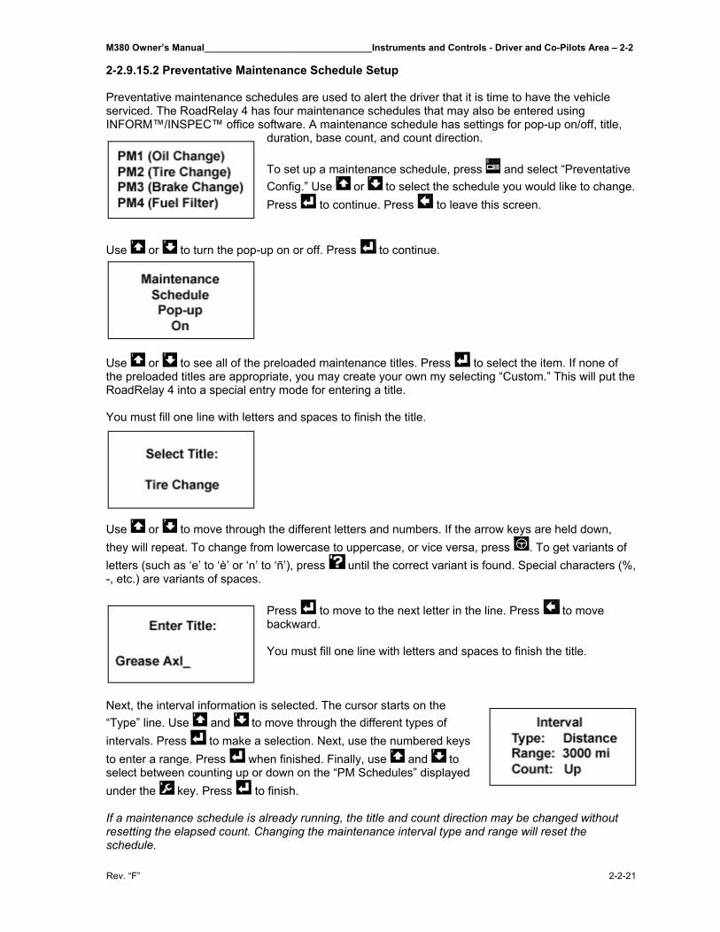
M380 Owner’s Manual________________________________Instruments and Controls - Driver and Co-Pilots Area – 2-2
Rev. “F” 2-2-21
2-2.9.15.2 Preventative Maintenance Schedule Setup Preventative maintenance schedules are used to alert the driver that it is time to have the vehicle serviced. The RoadRelay 4 has four maintenance schedules that may also be entered using INFORM™/INSPEC™ office software. A maintenance schedule has settings for pop-up on/off, title,
duration, base count, and count direction. To set up a maintenance schedule, press and select “Preventative Config.” Use or to select the schedule you would like to change. Press to continue. Press to leave this screen.
Use or to turn the pop-up on or off. Press to continue.
Use or to see all of the preloaded maintenance titles. Press to select the item. If none of the preloaded titles are appropriate, you may create your own my selecting “Custom.” This will put the RoadRelay 4 into a special entry mode for entering a title. You must fill one line with letters and spaces to finish the title.
Use or to move through the different letters and numbers. If the arrow keys are held down, they will repeat. To change from lowercase to uppercase, or vice versa, press . To get variants of letters (such as ‘e’ to ‘è’ or ‘n’ to ‘ñ’), press until the correct variant is found. Special characters (%, -, etc.) are variants of spaces.
Press to move to the next letter in the line. Press to move backward. You must fill one line with letters and spaces to finish the title.
Next, the interval information is selected. The cursor starts on the “Type” line. Use and to move through the different types of intervals. Press to make a selection. Next, use the numbered keys to enter a range. Press when finished. Finally, use and to select between counting up or down on the “PM Schedules” displayed under the key. Press to finish. If a maintenance schedule is already running, the title and count direction may be changed without resetting the elapsed count. Changing the maintenance interval type and range will reset the schedule.
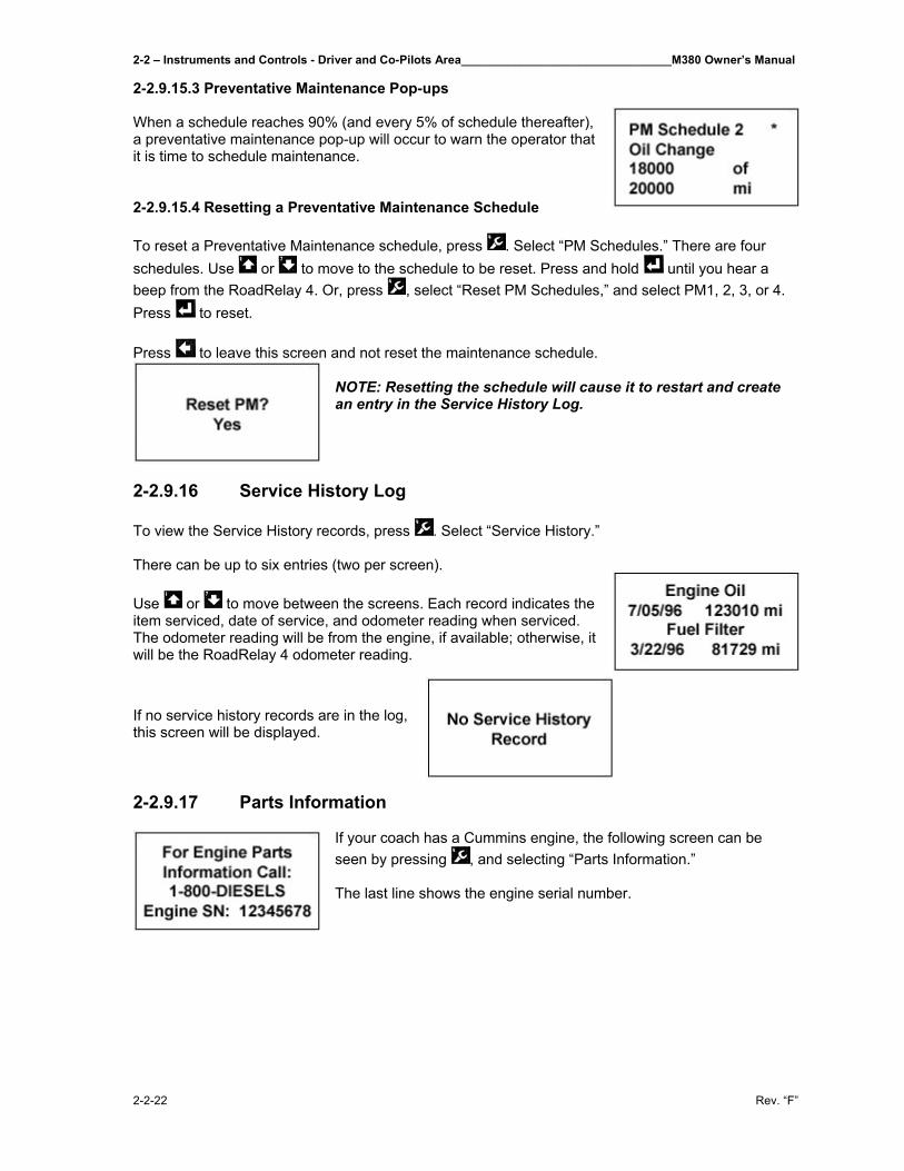
2-2 – Instruments and Controls - Driver and Co-Pilots Area________________________________M380 Owner’s Manual
2-2-22 Rev. “F”
2-2.9.15.3 Preventative Maintenance Pop-ups When a schedule reaches 90% (and every 5% of schedule thereafter), a preventative maintenance pop-up will occur to warn the operator that it is time to schedule maintenance. 2-2.9.15.4 Resetting a Preventative Maintenance Schedule To reset a Preventative Maintenance schedule, press . Select “PM Schedules.” There are four schedules. Use or to move to the schedule to be reset. Press and hold until you hear a beep from the RoadRelay 4. Or, press , select “Reset PM Schedules,” and select PM1, 2, 3, or 4. Press to reset. Press to leave this screen and not reset the maintenance schedule.
NOTE: Resetting the schedule will cause it to restart and create an entry in the Service History Log.
2-2.9.16 Service History Log To view the Service History records, press . Select “Service History.” There can be up to six entries (two per screen). Use or to move between the screens. Each record indicates the item serviced, date of service, and odometer reading when serviced. The odometer reading will be from the engine, if available; otherwise, it will be the RoadRelay 4 odometer reading.
If no service history records are in the log, this screen will be displayed. 2-2.9.17 Parts Information
If your coach has a Cummins engine, the following screen can be seen by pressing , and selecting “Parts Information.” The last line shows the engine serial number.
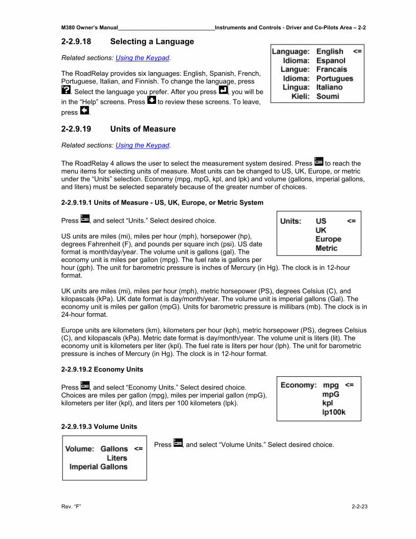
M380 Owner’s Manual________________________________Instruments and Controls - Driver and Co-Pilots Area – 2-2
Rev. “F” 2-2-23
2-2.9.18 Selecting a Language Related sections: Using the Keypad. The RoadRelay provides six languages: English, Spanish, French, Portuguese, Italian, and Finnish. To change the language, press
. Select the language you prefer. After you press , you will be in the “Help” screens. Press to review these screens. To leave, press . 2-2.9.19 Units of Measure Related sections: Using the Keypad. The RoadRelay 4 allows the user to select the measurement system desired. Press to reach the menu items for selecting units of measure. Most units can be changed to US, UK, Europe, or metric under the “Units” selection. Economy (mpg, mpG, kpl, and lpk) and volume (gallons, imperial gallons, and liters) must be selected separately because of the greater number of choices. 2-2.9.19.1 Units of Measure - US, UK, Europe, or Metric System Press , and select “Units.” Select desired choice. US units are miles (mi), miles per hour (mph), horsepower (hp), degrees Fahrenheit (F), and pounds per square inch (psi). US date format is month/day/year. The volume unit is gallons (gal). The economy unit is miles per gallon (mpg). The fuel rate is gallons per hour (gph). The unit for barometric pressure is inches of Mercury (in Hg). The clock is in 12-hour format. UK units are miles (mi), miles per hour (mph), metric horsepower (PS), degrees Celsius (C), and kilopascals (kPa). UK date format is day/month/year. The volume unit is imperial gallons (Gal). The economy unit is miles per gallon (mpG). Units for barometric pressure is millibars (mb). The clock is in 24-hour format. Europe units are kilometers (km), kilometers per hour (kph), metric horsepower (PS), degrees Celsius (C), and kilopascals (kPa). Metric date format is day/month/year. The volume unit is liters (lit). The economy unit is kilometers per liter (kpl). The fuel rate is liters per hour (lph). The unit for barometric pressure is inches of Mercury (in Hg). The clock is in 12-hour format. 2-2.9.19.2 Economy Units Press , and select “Economy Units.” Select desired choice. Choices are miles per gallon (mpg), miles per imperial gallon (mpG), kilometers per liter (kpl), and liters per 100 kilometers (lpk). 2-2.9.19.3 Volume Units
Press , and select “Volume Units.” Select desired choice.
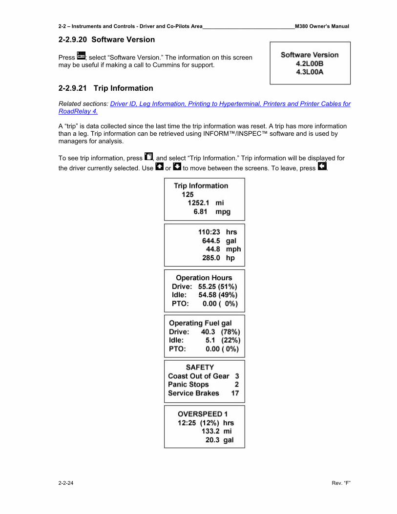
2-2 – Instruments and Controls - Driver and Co-Pilots Area________________________________M380 Owner’s Manual
2-2-24 Rev. “F”
2-2.9.20 Software Version Press ; select “Software Version.” The information on this screen may be useful if making a call to Cummins for support. 2-2.9.21 Trip Information Related sections: Driver ID, Leg Information, Printing to Hyperterminal, Printers and Printer Cables for RoadRelay 4. A “trip” is data collected since the last time the trip information was reset. A trip has more information than a leg. Trip information can be retrieved using INFORM™/INSPEC™ software and is used by managers for analysis. To see trip information, press , and select “Trip Information.” Trip information will be displayed for the driver currently selected. Use or to move between the screens. To leave, press .
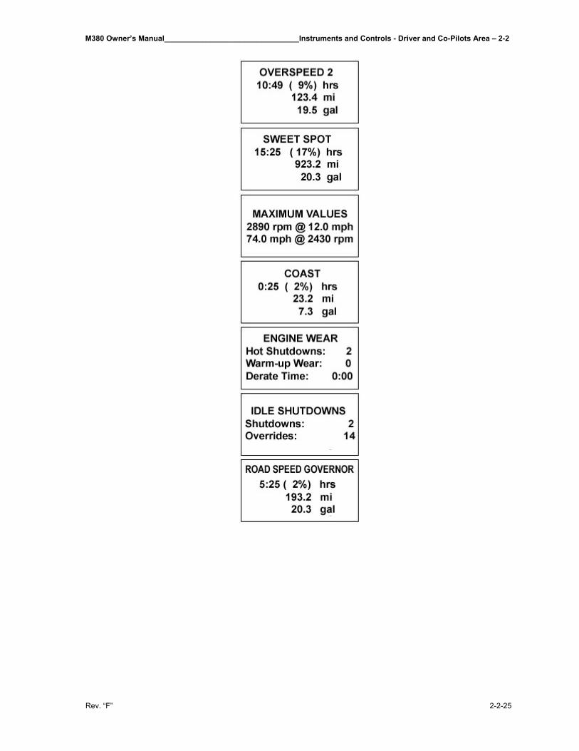
M380 Owner’s Manual________________________________Instruments and Controls - Driver and Co-Pilots Area – 2-2
Rev. “F” 2-2-25
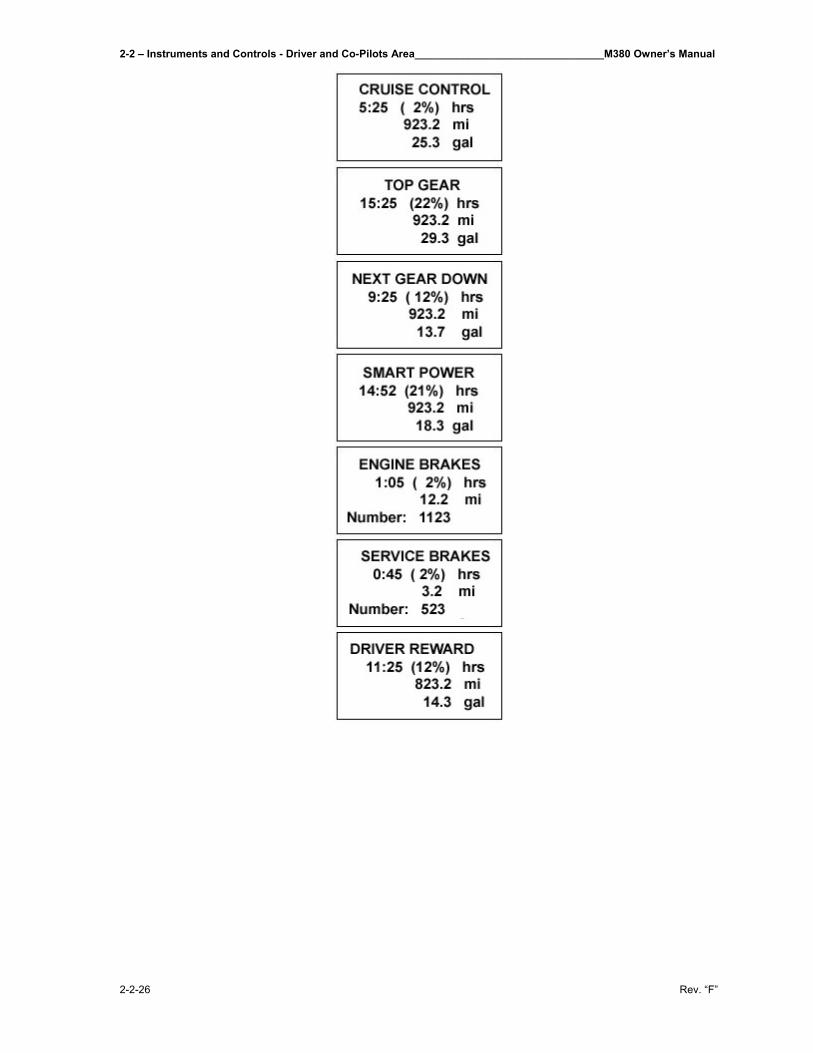
2-2 – Instruments and Controls - Driver and Co-Pilots Area________________________________M380 Owner’s Manual
2-2-26 Rev. “F”
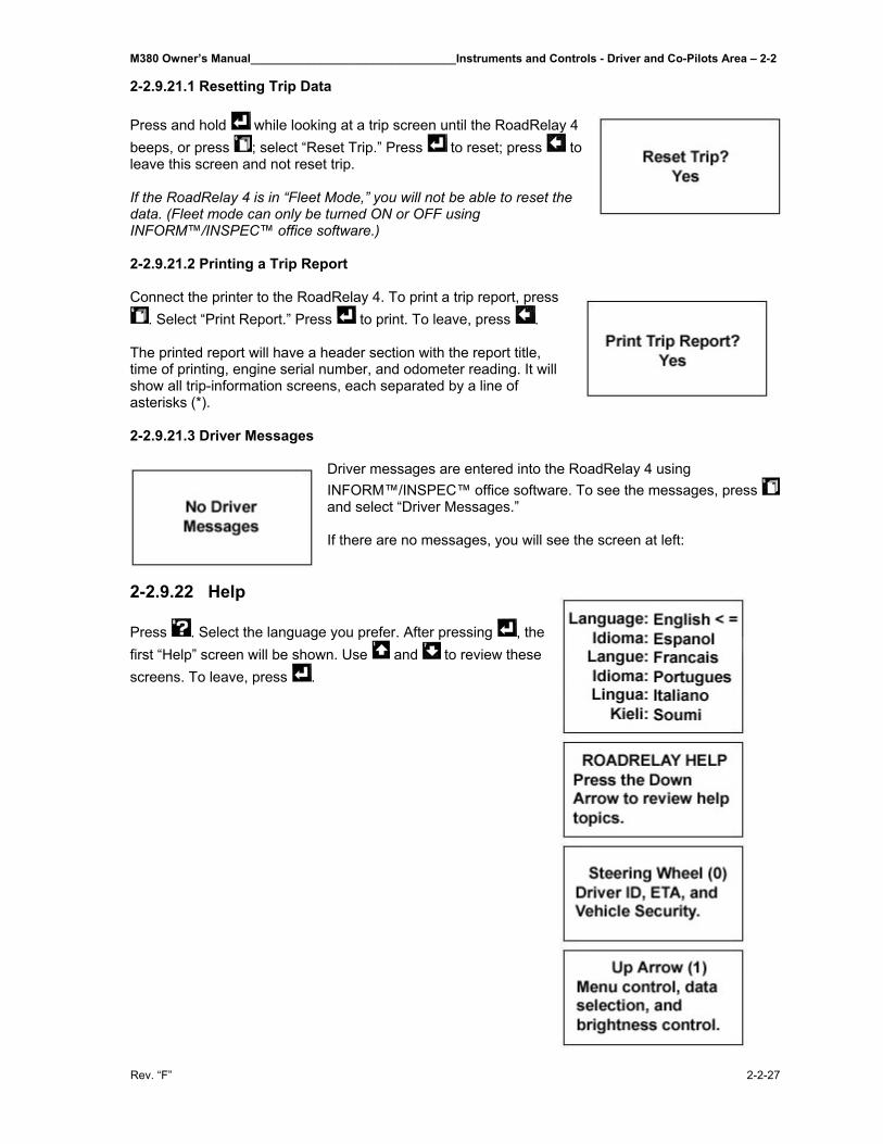
M380 Owner’s Manual________________________________Instruments and Controls - Driver and Co-Pilots Area – 2-2
Rev. “F” 2-2-27
2-2.9.21.1 Resetting Trip Data Press and hold while looking at a trip screen until the RoadRelay 4 beeps, or press ; select “Reset Trip.” Press to reset; press to leave this screen and not reset trip. If the RoadRelay 4 is in “Fleet Mode,” you will not be able to reset the data. (Fleet mode can only be turned ON or OFF using INFORM™/INSPEC™ office software.) 2-2.9.21.2 Printing a Trip Report Connect the printer to the RoadRelay 4. To print a trip report, press
. Select “Print Report.” Press to print. To leave, press . The printed report will have a header section with the report title, time of printing, engine serial number, and odometer reading. It will show all trip-information screens, each separated by a line of asterisks (*). 2-2.9.21.3 Driver Messages
Driver messages are entered into the RoadRelay 4 using INFORM™/INSPEC™ office software. To see the messages, press and select “Driver Messages.” If there are no messages, you will see the screen at left:
2-2.9.22 Help Press . Select the language you prefer. After pressing , the first “Help” screen will be shown. Use and to review these screens. To leave, press .
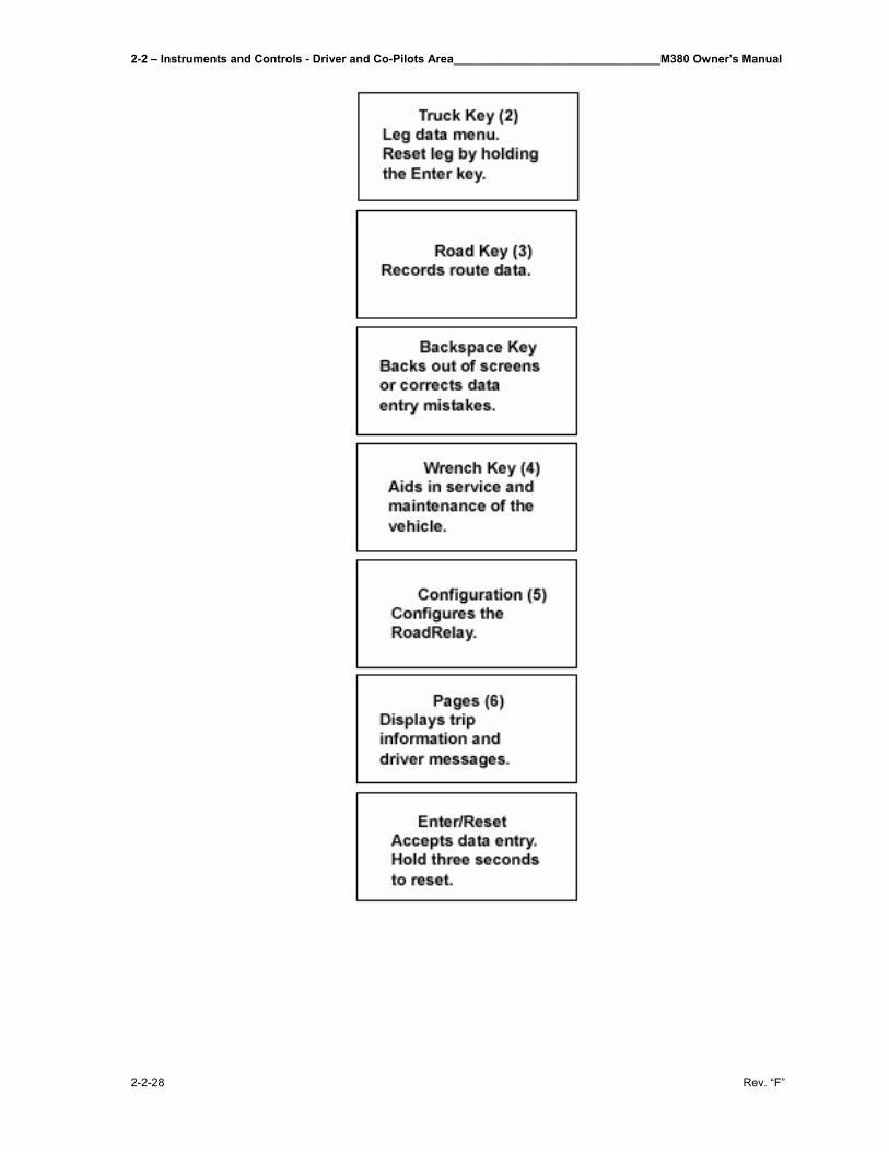
2-2 – Instruments and Controls - Driver and Co-Pilots Area________________________________M380 Owner’s Manual
2-2-28 Rev. “F”
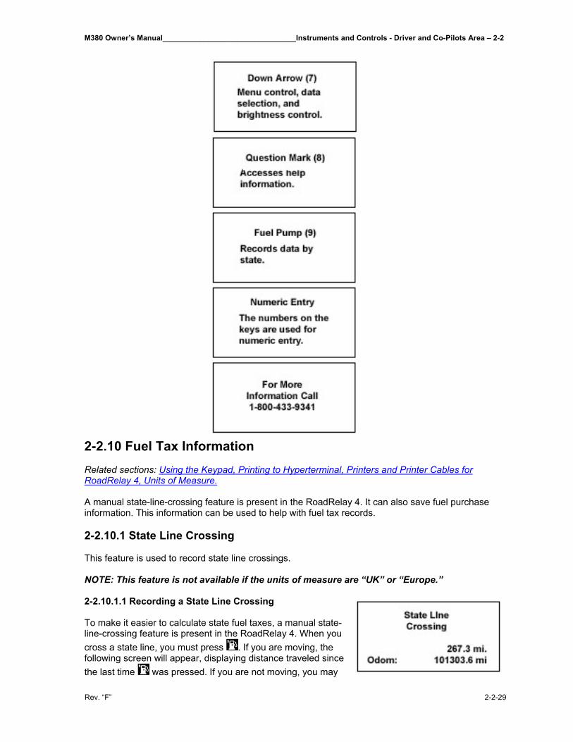
M380 Owner’s Manual________________________________Instruments and Controls - Driver and Co-Pilots Area – 2-2
Rev. “F” 2-2-29
2-2.10 Fuel Tax Information Related sections: Using the Keypad, Printing to Hyperterminal, Printers and Printer Cables for RoadRelay 4, Units of Measure. A manual state-line-crossing feature is present in the RoadRelay 4. It can also save fuel purchase information. This information can be used to help with fuel tax records. 2-2.10.1 State Line Crossing This feature is used to record state line crossings. NOTE: This feature is not available if the units of measure are “UK” or “Europe.” 2-2.10.1.1 Recording a State Line Crossing To make it easier to calculate state fuel taxes, a manual state-line-crossing feature is present in the RoadRelay 4. When you cross a state line, you must press . If you are moving, the following screen will appear, displaying distance traveled since the last time was pressed. If you are not moving, you may
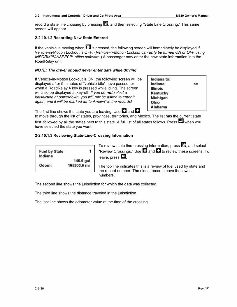
2-2 – Instruments and Controls - Driver and Co-Pilots Area________________________________M380 Owner’s Manual
2-2-30 Rev. “F”
record a state line crossing by pressing , and then selecting “State Line Crossing.” This same screen will appear. 2-2.10.1.2 Recording New State Entered If the vehicle is moving when is pressed, the following screen will immediately be displayed if Vehicle-in-Motion Lockout is OFF. (Vehicle-in-Motion Lockout can only be turned ON or OFF using INFORM™/INSPEC™ office software.) A passenger may enter the new state information into the RoadRelay unit. NOTE: The driver should never enter data while driving. If Vehicle-in-Motion Lockout is ON, the following screen will be displayed after 5 minutes of “vehicle-idle” have passed, or when a RoadRelay 4 key is pressed while idling. The screen will also be displayed at key-off. If you do not select a jurisdiction at powerdown, you will not be asked to enter it again, and it will be marked as “unknown” in the records! The first line shows the state you are leaving. Use and to move through the list of states, provinces, territories, and Mexico. The list has the current state first, followed by all the states next to this state. A full list of all states follows. Press when you have selected the state you want. 2-2.10.1.3 Reviewing State-Line-Crossing Information
To review state-line-crossing information, press , and select “Review Crossings.” Use and to review these screens. To leave, press . The top line indicates this is a review of fuel used by state and the record number. The oldest records have the lowest numbers.
The second line shows the jurisdiction for which the data was collected. The third line shows the distance traveled in the jurisdiction. The last line shows the odometer value at the time of the crossing.
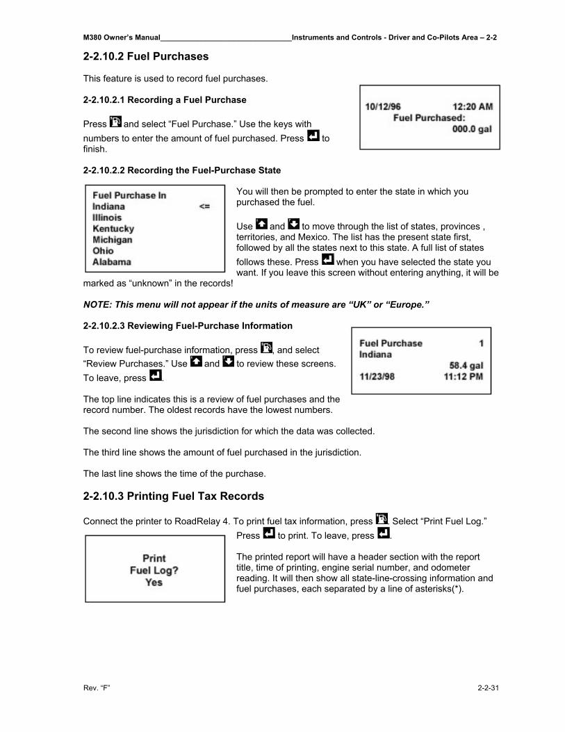
M380 Owner’s Manual________________________________Instruments and Controls - Driver and Co-Pilots Area – 2-2
Rev. “F” 2-2-31
2-2.10.2 Fuel Purchases This feature is used to record fuel purchases. 2-2.10.2.1 Recording a Fuel Purchase Press and select “Fuel Purchase.” Use the keys with numbers to enter the amount of fuel purchased. Press to finish. 2-2.10.2.2 Recording the Fuel-Purchase State
You will then be prompted to enter the state in which you purchased the fuel. Use and to move through the list of states, provinces , territories, and Mexico. The list has the present state first, followed by all the states next to this state. A full list of states follows these. Press when you have selected the state you want. If you leave this screen without entering anything, it will be
marked as “unknown” in the records! NOTE: This menu will not appear if the units of measure are “UK” or “Europe.” 2-2.10.2.3 Reviewing Fuel-Purchase Information To review fuel-purchase information, press , and select “Review Purchases.” Use and to review these screens. To leave, press . The top line indicates this is a review of fuel purchases and the record number. The oldest records have the lowest numbers. The second line shows the jurisdiction for which the data was collected. The third line shows the amount of fuel purchased in the jurisdiction. The last line shows the time of the purchase. 2-2.10.3 Printing Fuel Tax Records Connect the printer to RoadRelay 4. To print fuel tax information, press . Select “Print Fuel Log.”
Press to print. To leave, press . The printed report will have a header section with the report title, time of printing, engine serial number, and odometer reading. It will then show all state-line-crossing information and fuel purchases, each separated by a line of asterisks(*).
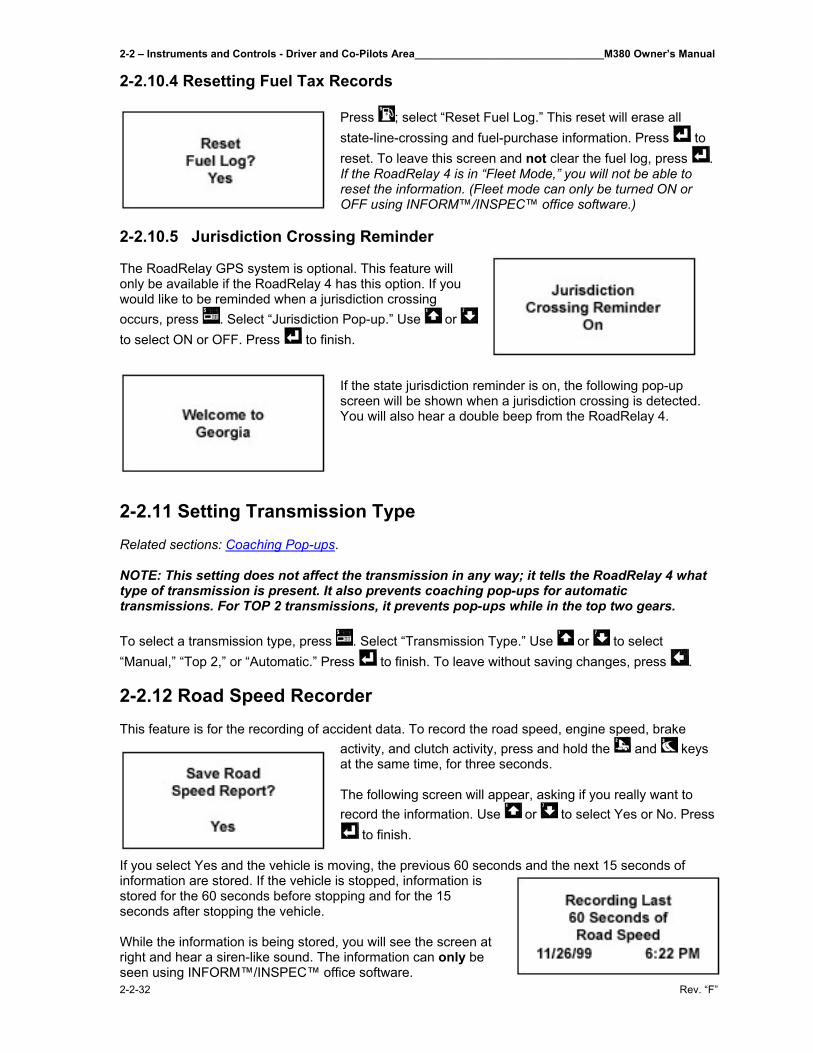
2-2 – Instruments and Controls - Driver and Co-Pilots Area________________________________M380 Owner’s Manual
2-2-32 Rev. “F”
2-2.10.4 Resetting Fuel Tax Records
Press ; select “Reset Fuel Log.” This reset will erase all state-line-crossing and fuel-purchase information. Press to reset. To leave this screen and not clear the fuel log, press . If the RoadRelay 4 is in “Fleet Mode,” you will not be able to reset the information. (Fleet mode can only be turned ON or OFF using INFORM™/INSPEC™ office software.)
2-2.10.5 Jurisdiction Crossing Reminder The RoadRelay GPS system is optional. This feature will only be available if the RoadRelay 4 has this option. If you would like to be reminded when a jurisdiction crossing occurs, press . Select “Jurisdiction Pop-up.” Use or to select ON or OFF. Press to finish.
If the state jurisdiction reminder is on, the following pop-up screen will be shown when a jurisdiction crossing is detected. You will also hear a double beep from the RoadRelay 4.
2-2.11 Setting Transmission Type Related sections: Coaching Pop-ups. NOTE: This setting does not affect the transmission in any way; it tells the RoadRelay 4 what type of transmission is present. It also prevents coaching pop-ups for automatic transmissions. For TOP 2 transmissions, it prevents pop-ups while in the top two gears. To select a transmission type, press . Select “Transmission Type.” Use or to select “Manual,” “Top 2,” or “Automatic.” Press to finish. To leave without saving changes, press . 2-2.12 Road Speed Recorder This feature is for the recording of accident data. To record the road speed, engine speed, brake
activity, and clutch activity, press and hold the and keys at the same time, for three seconds. The following screen will appear, asking if you really want to record the information. Use or to select Yes or No. Press
to finish.
If you select Yes and the vehicle is moving, the previous 60 seconds and the next 15 seconds of information are stored. If the vehicle is stopped, information is stored for the 60 seconds before stopping and for the 15 seconds after stopping the vehicle. While the information is being stored, you will see the screen at right and hear a siren-like sound. The information can only be seen using INFORM™/INSPEC™ office software.
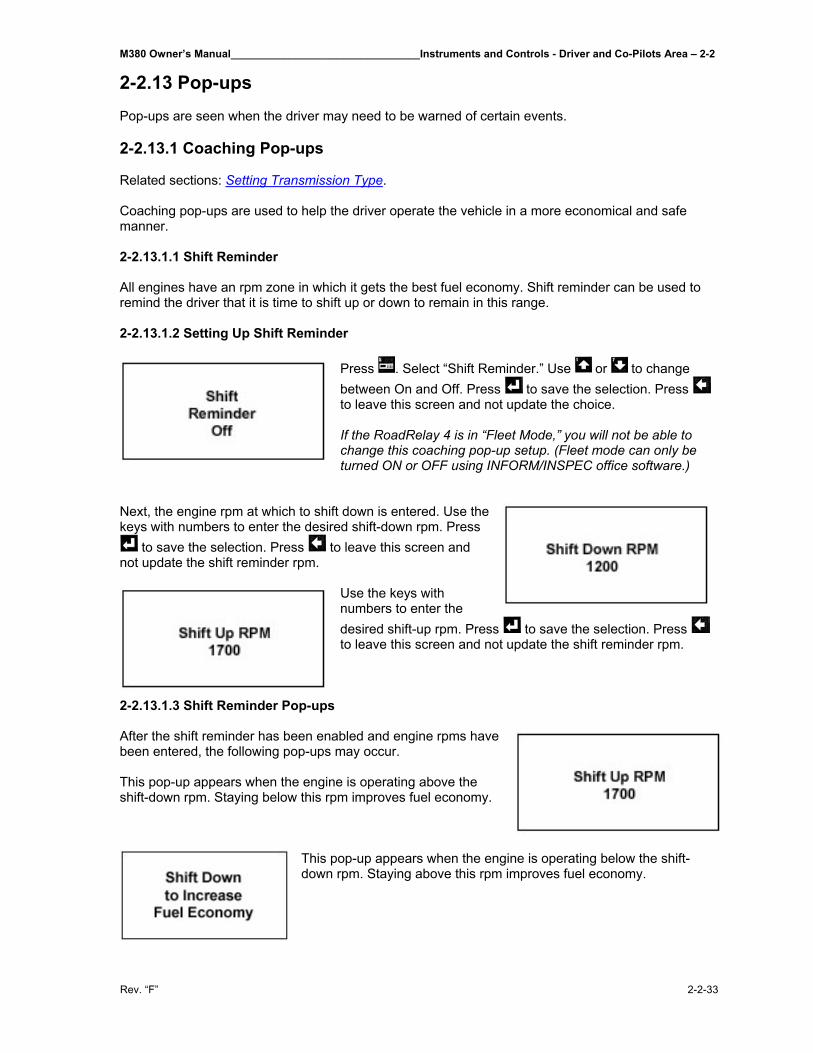
M380 Owner’s Manual________________________________Instruments and Controls - Driver and Co-Pilots Area – 2-2
Rev. “F” 2-2-33
2-2.13 Pop-ups Pop-ups are seen when the driver may need to be warned of certain events. 2-2.13.1 Coaching Pop-ups Related sections: Setting Transmission Type. Coaching pop-ups are used to help the driver operate the vehicle in a more economical and safe manner. 2-2.13.1.1 Shift Reminder All engines have an rpm zone in which it gets the best fuel economy. Shift reminder can be used to remind the driver that it is time to shift up or down to remain in this range. 2-2.13.1.2 Setting Up Shift Reminder
Press . Select “Shift Reminder.” Use or to change between On and Off. Press to save the selection. Press to leave this screen and not update the choice. If the RoadRelay 4 is in “Fleet Mode,” you will not be able to change this coaching pop-up setup. (Fleet mode can only be turned ON or OFF using INFORM/INSPEC office software.)
Next, the engine rpm at which to shift down is entered. Use the keys with numbers to enter the desired shift-down rpm. Press
to save the selection. Press to leave this screen and not update the shift reminder rpm.
Use the keys with numbers to enter the desired shift-up rpm. Press to save the selection. Press to leave this screen and not update the shift reminder rpm.
2-2.13.1.3 Shift Reminder Pop-ups After the shift reminder has been enabled and engine rpms have been entered, the following pop-ups may occur. This pop-up appears when the engine is operating above the shift-down rpm. Staying below this rpm improves fuel economy.
This pop-up appears when the engine is operating below the shift-down rpm. Staying above this rpm improves fuel economy.
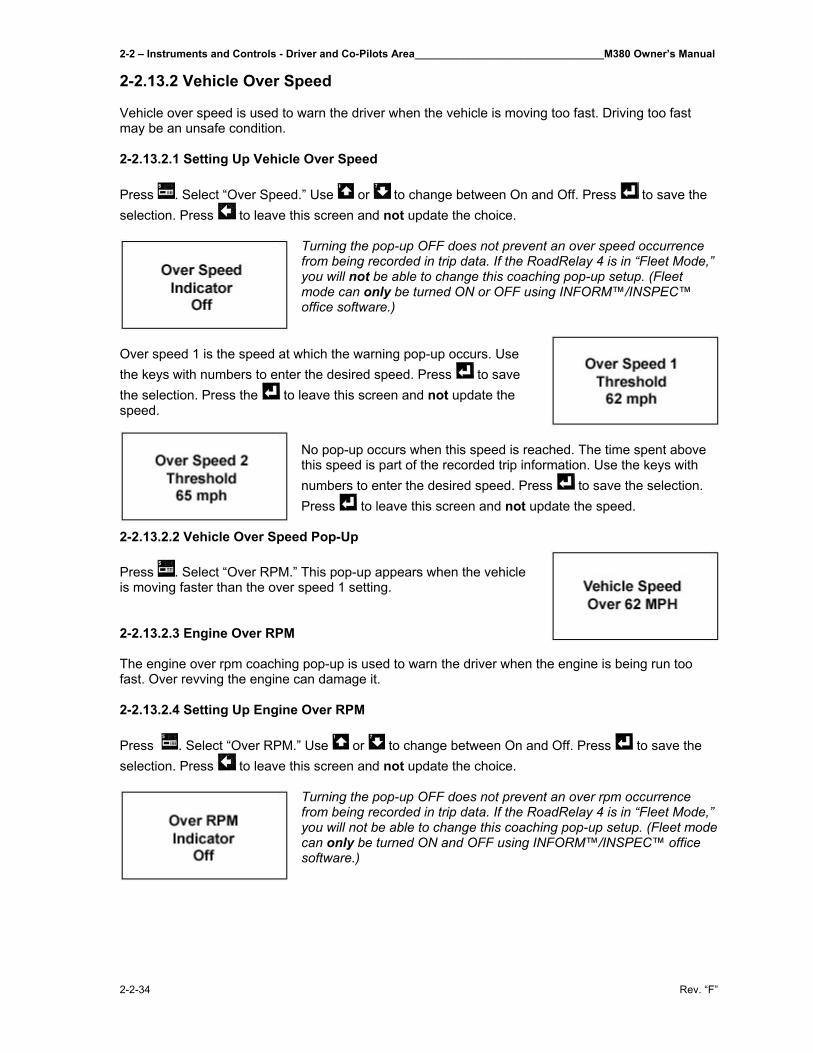
2-2 – Instruments and Controls - Driver and Co-Pilots Area________________________________M380 Owner’s Manual
2-2-34 Rev. “F”
2-2.13.2 Vehicle Over Speed Vehicle over speed is used to warn the driver when the vehicle is moving too fast. Driving too fast may be an unsafe condition. 2-2.13.2.1 Setting Up Vehicle Over Speed Press . Select “Over Speed.” Use or to change between On and Off. Press to save the selection. Press to leave this screen and not update the choice.
Turning the pop-up OFF does not prevent an over speed occurrence from being recorded in trip data. If the RoadRelay 4 is in “Fleet Mode,” you will not be able to change this coaching pop-up setup. (Fleet mode can only be turned ON or OFF using INFORM™/INSPEC™ office software.)
Over speed 1 is the speed at which the warning pop-up occurs. Use the keys with numbers to enter the desired speed. Press to save the selection. Press the to leave this screen and not update the speed.
No pop-up occurs when this speed is reached. The time spent above this speed is part of the recorded trip information. Use the keys with numbers to enter the desired speed. Press to save the selection. Press to leave this screen and not update the speed.
2-2.13.2.2 Vehicle Over Speed Pop-Up Press . Select “Over RPM.” This pop-up appears when the vehicle is moving faster than the over speed 1 setting. 2-2.13.2.3 Engine Over RPM The engine over rpm coaching pop-up is used to warn the driver when the engine is being run too fast. Over revving the engine can damage it. 2-2.13.2.4 Setting Up Engine Over RPM Press . Select “Over RPM.” Use or to change between On and Off. Press to save the selection. Press to leave this screen and not update the choice.
Turning the pop-up OFF does not prevent an over rpm occurrence from being recorded in trip data. If the RoadRelay 4 is in “Fleet Mode,” you will not be able to change this coaching pop-up setup. (Fleet mode can only be turned ON and OFF using INFORM™/INSPEC™ office software.)
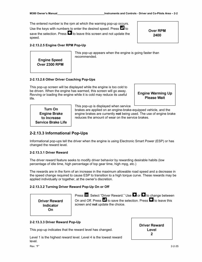
M380 Owner’s Manual________________________________Instruments and Controls - Driver and Co-Pilots Area – 2-2
Rev. “F” 2-2-35
The entered number is the rpm at which the warning pop-up occurs. Use the keys with numbers to enter the desired speed. Press to save the selection. Press to leave this screen and not update the speed. 2-2.13.2.5 Engine Over RPM Pop-Up
This pop-up appears when the engine is going faster than recommended.
2-2.13.2.6 Other Driver Coaching Pop-Ups This pop-up screen will be displayed while the engine is too cold to be driven. When the engine has warmed, this screen will go away. Revving or loading the engine while it is cold may reduce its useful life.
This pop-up is displayed when service brakes are applied on an engine-brake-equipped vehicle, and the engine brakes are currently not being used. The use of engine brake reduces the amount of wear on the service brakes.
2-2.13.3 Informational Pop-Ups Informational pop-ups tell the driver when the engine is using Electronic Smart Power (ESP) or has changed the reward level. 2-2.13.3.1 Driver Reward The driver reward feature seeks to modify driver behavior by rewarding desirable habits (low percentage of idle time, high percentage of top gear time, high mpg, etc.) The rewards are in the form of an increase in the maximum allowable road speed and a decrease in the speed change required to cause ESP to transition to a high torque curve. These rewards may be applied individually or together, at the owner’s discretion. 2-2.13.3.2 Turning Driver Reward Pop-Up On or Off
Press . Select “Driver Reward.” Use or to change between On and Off. Press to save the selection. Press to leave this screen and not update the choice.
2-2.13.3.3 Driver Reward Pop-Up This pop-up indicates that the reward level has changed. Level 1 is the highest reward level. Level 4 is the lowest reward level.
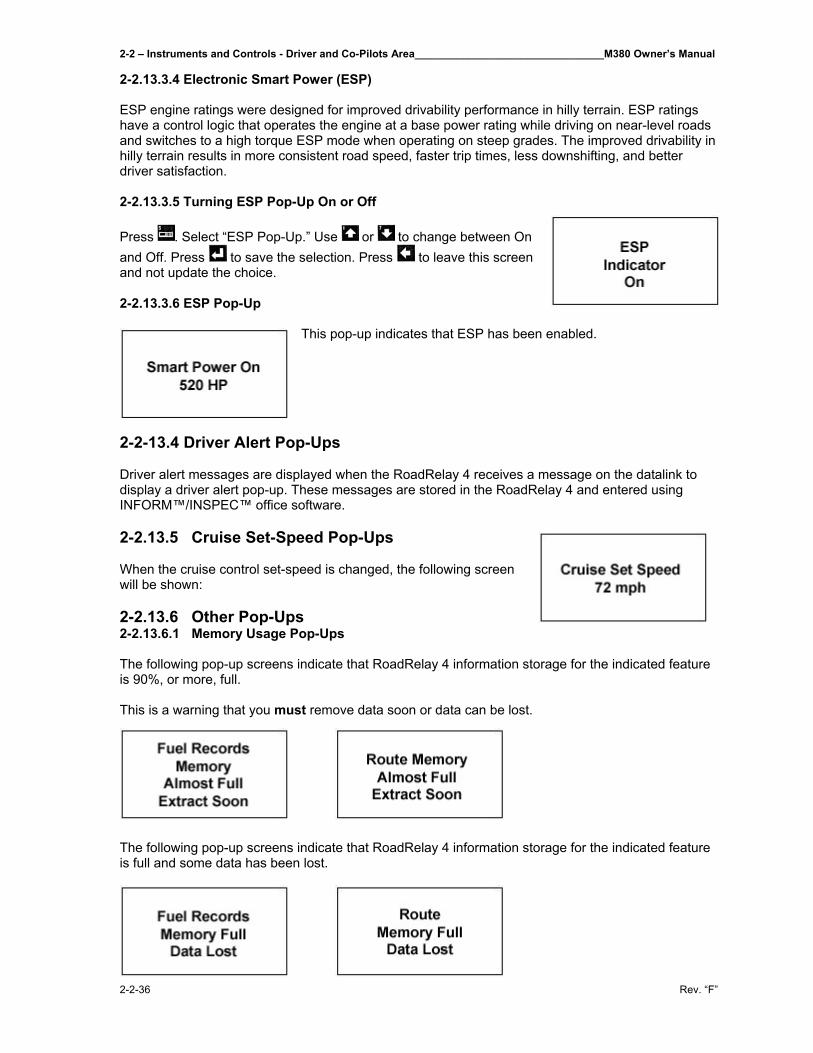
2-2 – Instruments and Controls - Driver and Co-Pilots Area________________________________M380 Owner’s Manual
2-2-36 Rev. “F”
2-2.13.3.4 Electronic Smart Power (ESP) ESP engine ratings were designed for improved drivability performance in hilly terrain. ESP ratings have a control logic that operates the engine at a base power rating while driving on near-level roads and switches to a high torque ESP mode when operating on steep grades. The improved drivability in hilly terrain results in more consistent road speed, faster trip times, less downshifting, and better driver satisfaction. 2-2.13.3.5 Turning ESP Pop-Up On or Off Press . Select “ESP Pop-Up.” Use or to change between On and Off. Press to save the selection. Press to leave this screen and not update the choice. 2-2.13.3.6 ESP Pop-Up
This pop-up indicates that ESP has been enabled.
2-2-13.4 Driver Alert Pop-Ups Driver alert messages are displayed when the RoadRelay 4 receives a message on the datalink to display a driver alert pop-up. These messages are stored in the RoadRelay 4 and entered using INFORM™/INSPEC™ office software. 2-2.13.5 Cruise Set-Speed Pop-Ups When the cruise control set-speed is changed, the following screen will be shown: 2-2.13.6 Other Pop-Ups 2-2.13.6.1 Memory Usage Pop-Ups The following pop-up screens indicate that RoadRelay 4 information storage for the indicated feature is 90%, or more, full. This is a warning that you must remove data soon or data can be lost.
The following pop-up screens indicate that RoadRelay 4 information storage for the indicated feature is full and some data has been lost.
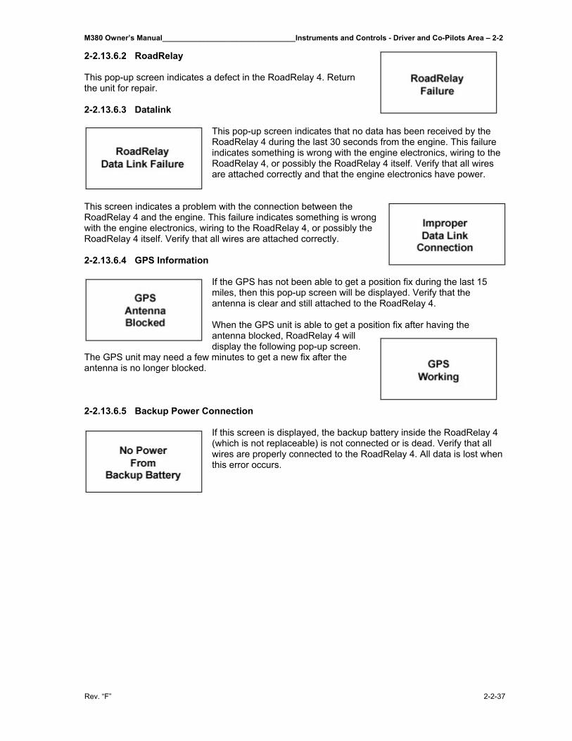
M380 Owner’s Manual________________________________Instruments and Controls - Driver and Co-Pilots Area – 2-2
Rev. “F” 2-2-37
2-2.13.6.2 RoadRelay This pop-up screen indicates a defect in the RoadRelay 4. Return the unit for repair. 2-2.13.6.3 Datalink
This pop-up screen indicates that no data has been received by the RoadRelay 4 during the last 30 seconds from the engine. This failure indicates something is wrong with the engine electronics, wiring to the RoadRelay 4, or possibly the RoadRelay 4 itself. Verify that all wires are attached correctly and that the engine electronics have power.
This screen indicates a problem with the connection between the RoadRelay 4 and the engine. This failure indicates something is wrong with the engine electronics, wiring to the RoadRelay 4, or possibly the RoadRelay 4 itself. Verify that all wires are attached correctly. 2-2.13.6.4 GPS Information
If the GPS has not been able to get a position fix during the last 15 miles, then this pop-up screen will be displayed. Verify that the antenna is clear and still attached to the RoadRelay 4. When the GPS unit is able to get a position fix after having the antenna blocked, RoadRelay 4 will display the following pop-up screen.
The GPS unit may need a few minutes to get a new fix after the antenna is no longer blocked. 2-2.13.6.5 Backup Power Connection
If this screen is displayed, the backup battery inside the RoadRelay 4 (which is not replaceable) is not connected or is dead. Verify that all wires are properly connected to the RoadRelay 4. All data is lost when this error occurs.
2-2 – Instruments and Controls - Driver and Co-Pilots Area________________________________M380 Owner’s Manual
2-2-38 Rev. “F”
2-2.14 Printing to Hyperterminal Hyperterminal is a program included with the Windows™ operating system. It is a communications program that will allow you to download the RoadRelay information to your PC using an extraction harness and serial cable. You can then generate printed reports of the RoadRelay 4 data using the downloaded electronic files. To connect the RoadRelay 4 to the PC, you will need a RoadRelay extraction harness (Cummins Part Number 4003775) and a serial cable to connect to your PC. The extraction harness has a female, 9-pin DB connector. You must acquire the extraction harness and serial cable elsewhere. They are not included with the RoadRelay 4 unit. To launch Hyperterminal:
1. Select Start|Programs|Accessories|Hyperterminal|HyperTerminal. 2. The program will ask for a name. Enter the desired file name. 3. You will then be asked to select a serial port to which to connect. Choose the appropriate
port. 4. Then set the port settings as follows:
9600 Bits per second; 8 Data bits, Parity None; Stop bits 1; and Flow control None. After connecting the cables and starting Hyperterminal, you can copy the data from the RoadRelay 4 to your PC. The output will appear in the Hyperterminal window. Save the file by selecting File|Save As; then name the file appropriately to its contents; for example. “RR4data.txt.” 2-2.15 Environmental Information The RoadRelay 4 is designed to operate within a temperature range of -40° to 85°C [-40° to 185°F]. It will operate from a voltage supply of 7.5 to 40 VDC. 2-2.16 Cleaning the RoadRelay 4 Do not use petroleum-based solvents or cleaners. Do not use abrasive cleansers or materials on the faceplate. They can cause scratches. Most standard household cleaners are suitable for use on the RoadRelay 4. 2-2.17 Troubleshooting and Technical Support Related sections: Software Version. Always check all wiring to the RoadRelay 4 if you are having problems. Do not open the RoadRelay 4. Doing so will void any warranty you may have. The RoadRelay 4 has no user-serviceable parts. If you believe the unit is properly wired and still not working, call Technical Support at 1-800-433-9341 in the USA and Canada, 0 800-286646 in the UK, +1-812-377-8136 for international calls. To make your call go as smoothly as possible, please have the following information handy when you call:
• Make and model of the vehicle in which the RoadRelay 4 is installed. • Engine type (for example, ’91 Cummins N14) • Software version of your RoadRelay 4 • Transmission type • Any electronic systems on the vehicle (for example, ABS).
M380 Owner’s Manual________________________________Instruments and Controls - Driver and Co-Pilots Area – 2-2
Rev. “F” 2-2-39
2-2.18 Warranty 2-2.18.1 COVERAGE Products Warranted This warranty applies to New RoadRelay™, INRANGE™, and INFORM™/INSPEC™ Products (Products) sold by Cummins Engine Company, Inc. (hereinafter ‘Cummins’) and delivered to the first user on or after October 23, 1998, anywhere in the world where Cummins-approved service is available*. Base Warranty The Base Warranty covers any failure of the Products that results, under normal use and service, from defects in material or workmanship (Warrantable Failure). This Coverage begins with the sale of the Product by Cummins and ends 1 (one) year from the date of delivery of the Products to the first user. Consumer Products This warranty on Consumer Products in the United States is a LIMITED warranty. CUMMINS IS NOT RESPONSIBLE FOR INCIDENTAL OR CONSEQUENTIAL DAMAGES. Any implied warranties applicable to Consumer Products in the United States terminate concurrently with the expiration of the express warranties applicable to such products. In the United States, some states do not allow the exclusion of incidental or consequential damages, or limitations on how long an implied warranty lasts, so the limitations or exclusions herein may not apply to you. This warranty is made to the first Owner in the chain of distribution, and Coverage continues until the end of the period of Coverage. 2-2.18.2 Cummins Responsibilities During the Base Warranty Cummins will pay for all parts and labor needed to repair the damage to the Products resulting from a Warrantable Failure. Cummins will pay for the Products including, but not limited to: Associated harnesses and installation materials, RoadRelay™, Lightbox, Scrolling Message Sign, Bravo Box, Reporgramming Tools, INRANGE™ Data Link and Trailer Tags, and INFORM™/INSPEC™ Dongle that are not reusable due to the Warrantable Failure. Cummins warrants that the CD-ROM and disk containing the Licensed Software shall be free from defects in material or workmanship for a period of ninety (90) days from the date of delivery to Licensee. Cummins also warrants that the Licensed Software shall be delivered free of any rightful claim of infringement of any copyright, trademark, trade secret, or other proprietary right of any third party. In the event the engine does not start because of a malfunction of the Cummins Antitheft feature anytime during the warranty period, Cummins will repair or replace the feature when the vehicle is brought to an authorized Cummins Repair Facility or a mechanic, authorized by Cummins, visits the vehicle. This is Cummins sole obligation and your sole remedy. 2-2.18.3 Owner Responsibilities During the Base Warranty Owner must deliver the Products to the repair location. Owner is responsible for the cost of the Products provided during warranty repairs unless such items are not reusable due to the Warrantable Failure.
2-2 – Instruments and Controls - Driver and Co-Pilots Area________________________________M380 Owner’s Manual
2-2-40 Rev. “F”
At the time when the parts are installed, Owner is responsible for the preparation of a written record containing the following:
1. The date of installation of the Product(s) 2. The engine serial number 3. The engine miles, kilometers, or hours of operation 4. The Product(s) installed 5. The location of the Product(s) in the application.
The purpose of this record is to protect Owner’s interests and support any claim for a Warrantable Failure. Owner is responsible for the operation and maintenance of the Products as specified in the applicable User’s Guide. Owner is also responsible for providing proof that all recommended maintenance has been performed. Before the expiration of the warranty, Owner must notify a Cummins Distributor, Authorized Dealer, or other repair location* approved by Cummins of any Warrantable Failure, and deliver the Products to such facility for repair. Owner is responsible for communication expenses, meals, lodging, and similar costs incurred as a result of a Warrantable Failure. Owner is responsible for non-Product repairs and for “downtime” expenses, passenger delays, cargo damage, fines, all applicable taxes, all business costs, and other losses resulting from a Warrantable Failure. Owner is responsible for Antitheft Feature repairs due to incorrect passwords, including lack of RoadRelay™ display caused by use of the RoadRelay™ outside of specific operating temperatures. LIMITATIONS The Licensed Software and any and all updates thereto are licensed “As Is” with the exception of the warranties specifically provided herein. Cummins does not claim and does not warrant that the Licensed Software will run error-free. WITH THE EXCEPTION OF THE WARRANTIES PROVIDED HEREIN, CUMMINS DISCLAIMS ALL WARRANTIES, EITHER EXPRESS OR IMPLIED, REGARDING THE LICENSED SOFTWARE, ITS MERCHANTABILITY OR ITS FITNESS FOR ANY PARTICULAR PURPOSE, AND CUMMINS WILL NOT OTHERWISE BE LIABLE FOR INDIRECT, INCIDENTAL, OR INCONSEQUENTIAL DAMAGES RESULTING FROM LICENSEES USE OF THE LICENSED SOFTWARE INCLUDING WITHOUT LIMITATION, ANY DAMAGE TO ELECTRONIC CONTROL MODULES, COMPUTERS OR ASSOCIATED EQUIPMENT, OR FOR ANY ERROR OR DEFECT IN THE LICENSED SOFTWARE. CUMMINS SOLE AND EXCLUSIVE LIABILITY SHALL NOT EXCEED THE TOTAL AGGREGATE PAYMENTS BY LICENSEE TO CUMMINS WITH RESPECT TO THE LICENSED SOFTWARE. Cummins is not responsible for radio frequency interference. Cummins is not responsilble for failures or damage resulting from what Cummins determines to be abuse, neglect, including, but not limited to: incorrect operation and maintenance as stated in the appropriate user’s guide and installation guide, use of cleaners other than a moist cloth to clean RoadRelay™ keypads, displays, and enclosures. This warranty does not apply to Products that bear the name of another company. The Product(s) and parts used to repair a Warrantable Failure may be new Cummins parts, Cummins-approved rebuilt parts, or repaired parts. Cummins is not responsible for failures resulting from the use of parts not approved by Cummins. A new Cummins or Cummins-approved rebuilt part used to repair a Warrantable Failure assumes the identity of the part it replaced and is entitled to the remaining coverage hereunder.
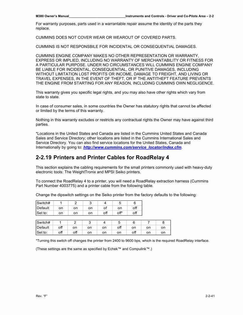
M380 Owner’s Manual________________________________Instruments and Controls - Driver and Co-Pilots Area – 2-2
Rev. “F” 2-2-41
For warranty purposes, parts used in a warrantable repair assume the identity of the parts they replace. CUMMINS DOES NOT COVER WEAR OR WEAROUT OF COVERED PARTS. CUMMINS IS NOT RESPONSBILE FOR INCIDENTAL OR CONSEQUENTIAL DAMAGES. CUMMINS ENGINE COMPANY MAKES NO OTHER REPRESENTATION OR WARRANTY, EXPRESS OR IMPLIED, INCLUDING NO WARRANTY OF MERCHANTABILITY OR FITNESS FOR A PARTICULAR PURPOSE. UNDER NO CIRCUMSTANCES WILL CUMMINS ENGINE COMPANY BE LIABLE FOR INCIDENTAL, CONSEQUENTIAL, OR PUNITIVE DAMAGES, INCLUDING WITHOUT LIMITATION LOST PROFITS OR INCOME, DAMAGE TO FREIGHT, AND LIVING OR TRAVEL EXPENSES, IN THE EVENT OF THEFT, OR IF THE ANTITHEFT FEATURE PREVENTS THE ENGINE FROM STARTING FOR ANY REASON, INCLUDING CUMMINS OWN NEGLIGENCE. This warranty gives you specific legal rights, and you may also have other rights which vary from state to state. In case of consumer sales, in some countries the Owner has statutory rights that cannot be affected or limited by the terms of this warranty. Nothing in this warranty excludes or restricts any contractual rights the Owner may have against third parties. *Locations in the United States and Canada are listed in the Cummins United States and Canada Sales and Service Directory; other locations are listed in the Cummins International Sales and Service Directory. You can also find service locations for the United States, Canada and Internationally by going to: http://www.cummins.com/service_locator/index.cfm. 2-2.19 Printers and Printer Cables for RoadRelay 4 This section explains the cabling requirements for the small printers commonly used with heavy-duty electronic tools: The WeightTronix and MPSI Seiko printers. To connect the RoadRelay 4 to a printer, you will need a RoadRelay extraction harness (Cummins Part Number 4003775) and a printer cable from the following table. Change the dipswitch settings on the Seiko printer from the factory defaults to the following:
*Turning this switch off changes the printer from 2400 to 9600 bps, which is the required RoadRelay interface. (These settings are the same as specified by Echek™ and Compulink™.)
Switch# 1 2 3 4 5 6Default on on on of on offSet to: on on on off off* off
Switch# 1 2 3 4 5 6 7 8Default off on on on off on on onSet to: off off on on on off on on
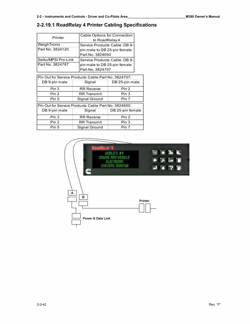
2-2 – Instruments and Controls - Driver and Co-Pilots Area________________________________M380 Owner’s Manual
2-2-42 Rev. “F”
2-2.19.1 RoadRelay 4 Printer Cabling Specifications
PrinterCable Options for Connection
to RoadRelay 4WeighTronixPart No. 3824120
Seiko/MPSI Pro-LinkPart No. 3824787
Service Products Cable: DB 9-pin male to DB 25-pin female Part No. 3824650Service Products Cable: DB 9-pin male to DB 25-pin female Part No. 3824707
DB 9-pin male Signal DB 25-pin male
Pin 3 RR Receive Pin 2Pin 2 RR Transmit Pin 3Pin 5 Signal Ground Pin 7
Pin Out for Service Products Cable Part No. 3824707:
DB 9-pin male Signal DB 25-pin female
Pin 3 RR Receive Pin 2Pin 2 RR Transmit Pin 3Pin 5 Signal Ground Pin 7
Pin Out for Service Products Cable Part No. 3824650:
M380 Owner’s Manual____________________________________________________Starting and Driving - Engine – 3-1
Rev. “F” 3-1-1
3-1 Engine_____________________________________________ The M380 Motor Home is equipped with a Cummins ISL 400 HP @ 2000 RPM engine. This is a four cycle, in line turbo/air to air charger cooled engine. It has six cylinders and the stroke and bore is 4.49 x 5.69, with a displacement of 543 cubic inches (8.9 liters) and a compression ratio of 16.6:1. For more specifications see below: Maximum (net) BHP @ RPM – 400 HP (373KW)/2000 Maximum (net) Torque @ RPM – 1200 lb. ft. @ 1300 Maximum Governor RPM – Load 2200 RPM, No load 2330 RPM Governor – Electronic Crankcase Capacity – Dry 29 quarts Cooling System Capacity – 72 quarts – includes:
- Engine - Radiator - Heater/Defroster - Hurricane Heat System & all pipes
Water Pump Capacity @ Engine RPM – 83 gallons per minute @ 2200. Air Filter – Dry type – FARR ECO-SM 99842-007, single storage, disposable canister. Transmission – Allison 3000 MH electronic 6 speed World transmission. Gears Ratios First 3.49 Second 1.86 Third 1.41 Fourth 1.00 Fifth .75 Sixth .65 Reverse 5.03 Torque Converter TC – 421 – 1.77 stall ratio Lubricant Capacity 29 qt. refill Bell house size SAE #2 Drive line SPL 170 Spicer Turning Radius *Curb Radius – 29.7 ft. **Wall Radius – 35 ft. *Curb radius is the minimum radius of turn to the outside edge of the front tire. **Wall radius is the minimum radius of turn to the outside edge of the front bumper.
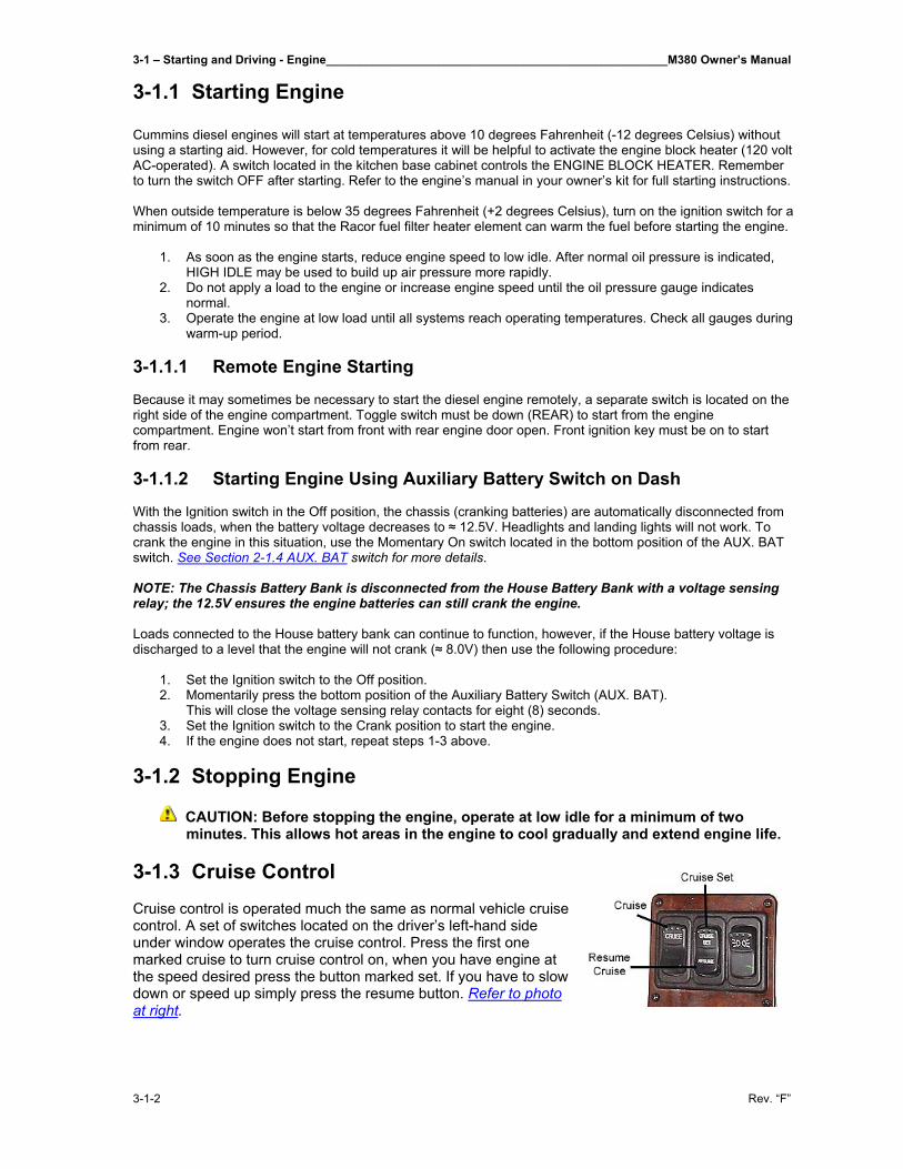
3-1 – Starting and Driving - Engine____________________________________________________M380 Owner’s Manual
3-1-2 Rev. “F”
3-1.1 Starting Engine Cummins diesel engines will start at temperatures above 10 degrees Fahrenheit (-12 degrees Celsius) without using a starting aid. However, for cold temperatures it will be helpful to activate the engine block heater (120 volt AC-operated). A switch located in the kitchen base cabinet controls the ENGINE BLOCK HEATER. Remember to turn the switch OFF after starting. Refer to the engine’s manual in your owner’s kit for full starting instructions. When outside temperature is below 35 degrees Fahrenheit (+2 degrees Celsius), turn on the ignition switch for a minimum of 10 minutes so that the Racor fuel filter heater element can warm the fuel before starting the engine.
1. As soon as the engine starts, reduce engine speed to low idle. After normal oil pressure is indicated, HIGH IDLE may be used to build up air pressure more rapidly.
2. Do not apply a load to the engine or increase engine speed until the oil pressure gauge indicates normal.
3. Operate the engine at low load until all systems reach operating temperatures. Check all gauges during warm-up period.
3-1.1.1 Remote Engine Starting Because it may sometimes be necessary to start the diesel engine remotely, a separate switch is located on the right side of the engine compartment. Toggle switch must be down (REAR) to start from the engine compartment. Engine won’t start from front with rear engine door open. Front ignition key must be on to start from rear. 3-1.1.2 Starting Engine Using Auxiliary Battery Switch on Dash With the Ignition switch in the Off position, the chassis (cranking batteries) are automatically disconnected from chassis loads, when the battery voltage decreases to ≈ 12.5V. Headlights and landing lights will not work. To crank the engine in this situation, use the Momentary On switch located in the bottom position of the AUX. BAT switch. See Section 2-1.4 AUX. BAT switch for more details. NOTE: The Chassis Battery Bank is disconnected from the House Battery Bank with a voltage sensing relay; the 12.5V ensures the engine batteries can still crank the engine. Loads connected to the House battery bank can continue to function, however, if the House battery voltage is discharged to a level that the engine will not crank (≈ 8.0V) then use the following procedure:
1. Set the Ignition switch to the Off position. 2. Momentarily press the bottom position of the Auxiliary Battery Switch (AUX. BAT).
This will close the voltage sensing relay contacts for eight (8) seconds. 3. Set the Ignition switch to the Crank position to start the engine. 4. If the engine does not start, repeat steps 1-3 above.
3-1.2 Stopping Engine
CAUTION: Before stopping the engine, operate at low idle for a minimum of two minutes. This allows hot areas in the engine to cool gradually and extend engine life.
3-1.3 Cruise Control Cruise control is operated much the same as normal vehicle cruise control. A set of switches located on the driver’s left-hand side under window operates the cruise control. Press the first one marked cruise to turn cruise control on, when you have engine at the speed desired press the button marked set. If you have to slow down or speed up simply press the resume button. Refer to photo at right.

M380 Owner’s Manual____________________________________________________Starting and Driving - Engine – 3-1
Rev. “F” 3-1-3
3-1.3.1 High Idle When the engine is cold, the engine can be placed in the high idle state by turning on the cruise control and increasing the engine RPM to 1200 RPM. This can also be achieved while you are sitting with engine running but not in gear.

M380 Owner’s Manual__________________________________________________________________________________
Rev. “F”
THIS PAGE IS INTENTIONALLY LEFT BLANK
M380 Owner’s Manual____________________________________________________Starting and Driving - Towing – 3-2
Rev. “F” 3-2-1
3-2 Towing____________________________________________ 3-2.1 Receiver Type Trailer Hitch This is a 10,000 pounds rated capacity and 1,000 pounds tongue weight capacity receiver type hitch. When using the rear hitch remember that the motor home is intended for towing light loads. The motor home is designed to be used primarily as a recreational vehicle, towing will affect durability and economy. Your safety and satisfaction require proper use. Avoid excessive loads or any other abuse. Do not use the motor home to tow anything until it has been driven 500 miles (800 kilometers). Weight pushing down on the rear hitch must not exceed 1,000 pounds. We recommend weighing the motor home, as it will be operated to be certain that there is proper weight distribution. When weighing the motor home be sure to take the passenger locations into consideration. Total weight of the motor home and any vehicle towed by it must not exceed the GCWR.
▲WARNING: Any trailer being towed by the motor home must have adequate brakes. Failure to follow these instructions will create a safety hazard and may result in an accident. 3-2.2 Trailer Draw Bar Hitch Removable receiver type draw bar with a 2” diameter chrome hitch ball. The 2” ball provided is rated at 5,000 pounds. 3-2.3 Trailer Plug The female receptacle is installed in the rear of the motor home and wired into the electrical system. The male portion is supplied loose in the motor home for installation by the owner on the tow with separate signals vehicle. The wiring is a five-wire system for turn signals and brakes with 4-wire adapter installed. The tow harness wires are color-coded:
1. Brown, 12 gauge – tail lights 2. White, 12 gauge – ground 3. Black, 14 gauge – right turn signal
4. Yellow, 14 gauge – left turn signal 5. Black w/white stripes, 14 gauge –
brake light.
3-2.4 Tow Hooks Two tow eyes are located at the front of the motor home. Removable tow hooks are stored on generator tray in front of motor home. Insert hooks into receivers and secure with pins provided. NOTE: If towing a vehicle from tow hooks generator door panel must be removed prior to towing. 3-2.5 Having Your Motor Home Towed 3-2.5.1 Towing Procedures It is recommended that if a towing company is called make sure they use a stinger (an arm that goes under motor home and hooks to front cross member).
3-2 – Starting and Driving - Towing____________________________________________________M380 Owner’s Manual
3-2-2 Rev. “F”
The towing company may need to locate the air nipple to release the air brakes. The air nipple is located in the outside roadside front electrical compartment and should only be used by towing personnel. If the motor home ever needs to be towed, use the following instructions:
• Secure any loose or protruding parts if the motor home is damaged. • Inspect points of attachment on a disabled motor home. If attachment points are damaged,
select other attachment points at a substantial frame structural member. • Never allow anyone to go under a motor home while it is being lifted by towing equipment
unless the disabled motor home is adequately supported by safety stands. • Do not tow the motor home from the rear. Towing from the rear will cause the front tires and
suspension to be seriously overloaded, possibly resulting in a tire or front suspension failure. Rear frame extensions are not designed to withstand loads imposed by lifting the rear of the motor home.
• If rear wheels are disabled, place the motor home on a flat bed trailer or use a heavy-duty dolly under the rear wheels and tow from the front of the motor home.
• The drive shaft must be removed to protect transmission. ▲WARNING: In the event the motor home requires towing ensure all precautions are followed. The driveline must be disconnected and the mud flap may need to be removed. Wanderlodge Motor home Corporation will not cover damage to the motor home from a towing company. 3-2.5.2 Disabling the Parking Brake
• Block wheels securely before attempting this procedure. • Remove the plug from the center of rear brake can. • Remove the caging tool from its holder on the rear brake can and insert it into the hole. Turn
the tool clockwise to engage. • Use a wrench to tighten the nut down, which compresses the internal spring, releasing the
brake. • Repeat for the other side. • After towing, or when air pressure is again available, loosen the nut and remove the tool.
Return the tool to its original location and replace plug. • Repeat for the other side.
▲WARNING: Do not attempt to dissemble brake canisters without special tools and without having studies specific manufacturer’s instructions. Canisters contain springs under very high tension. Improper handling could result in component damage or personal injury. 3-2.5.3 Towing Without a Stinger
Make sure the tow truck can safely pull the weight of the motor home. Give the towing company the weight of your motor home when you call them. If your motor home is going to be towed without a stinger do the following:
• Wrap chains around both A-arms or the front axle on each side. • Pass the chains beneath the tow bar below the bumper. • Position a 6” x 6” piece of lumber between the ends of main frame rails and the tow vehicle
transfer plate to maintain clearance to body parts. • Attach safety chains, which are completely independent of the primary lifting device, to the
main frame rails. • When the motor home is under tow allow enough room between the front of the motor home
and the rear of the tow vehicle while turning corners.
M380 Owner’s Manual____________________________Interior and Exterior Systems Operation - Interior Storage – 4-1
Rev. “F” 4-1-1
4-1 Interior Storage_____________________________________ Your motor home comes equipped with the finest cabinets. There is storage located in cabinets, closets and under the bed, except for slide-out cross-island beds (see note below). 4-1.2 Cabinets Cabinets in the motor home have positive latches. This keeps them closed when moving designed to keep things inside when in over-the-road-use. What this means is a little force needs to be used when opening them up. 4-1.2.1 Cleaning Cabinets The motor home cabinets are finished with a high quality nitro-cellulose lacquer. Select a non-alcohol based cleaner for cleaning cabinets. Cleaners recommended for cleaning cabinets are Pledge, Endust, etc. IMPORTANT: Do not use any alcohol based cleaners. They will dull and strip the finish of the wood. 4-1.3 Closets At least one full-length hanging closet is standard in each floor plan. A 12 VDC light fixture in the ceiling of the closet is standard. Closet lighting is automatic when swinging doors are opened. Swinging doors provide access. Sliding doors in bedroom closets have manually switched lights. 4-1.4 Under Bed The 38 ft. Wanderlodge M380 island bed provides storage underneath the bed. This storage is accessed with the assistance of gas cylinders. This area is carpeted with the floor carpet selected for the remainder of the bedroom. NOTE: Slide-out cross-island beds do not have storage underneath due to the slide-out mechanism. 4-1.4.1 Accessing Under Bed Storage Under bed storage area in island beds is accessed by a hinged bed board. Gas cylinders are installed on bed board for easy operation. Storage area is carpeted using floor carpet selected per each interior. 4-1.5 Overhead Cabinet A full-length overhead cabinet is installed over the head of the bed.

M380 Owner’s Manual__________________________________________________________________________________
Rev. “F”
THIS PAGE IS INTENTIONALLY LEFT BLANK
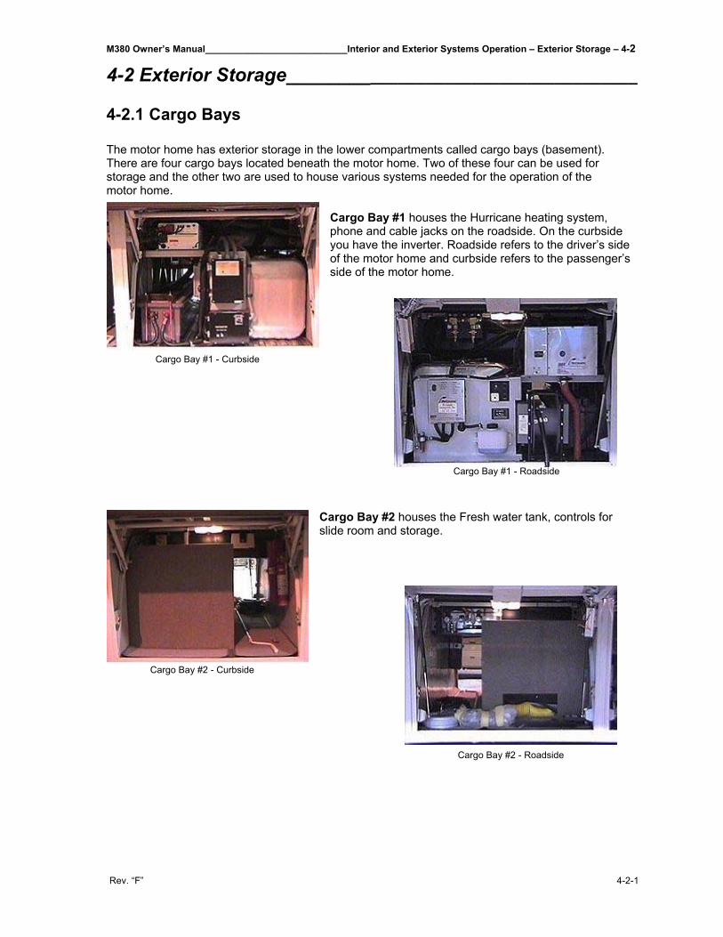
M380 Owner’s Manual___________________________Interior and Exterior Systems Operation – Exterior Storage – 4-2
Rev. “F” 4-2-1
4-2 Exterior Storage_____________________________________ 4-2.1 Cargo Bays
The motor home has exterior storage in the lower compartments called cargo bays (basement). There are four cargo bays located beneath the motor home. Two of these four can be used for storage and the other two are used to house various systems needed for the operation of the motor home.
Cargo Bay #1 houses the Hurricane heating system, phone and cable jacks on the roadside. On the curbside you have the inverter. Roadside refers to the driver’s side of the motor home and curbside refers to the passenger’s side of the motor home.
Cargo Bay #2 houses the Fresh water tank, controls for slide room and storage.
Cargo Bay #1 - Curbside
Cargo Bay #1 - Roadside
Cargo Bay #2 - Curbside
Cargo Bay #2 - Roadside
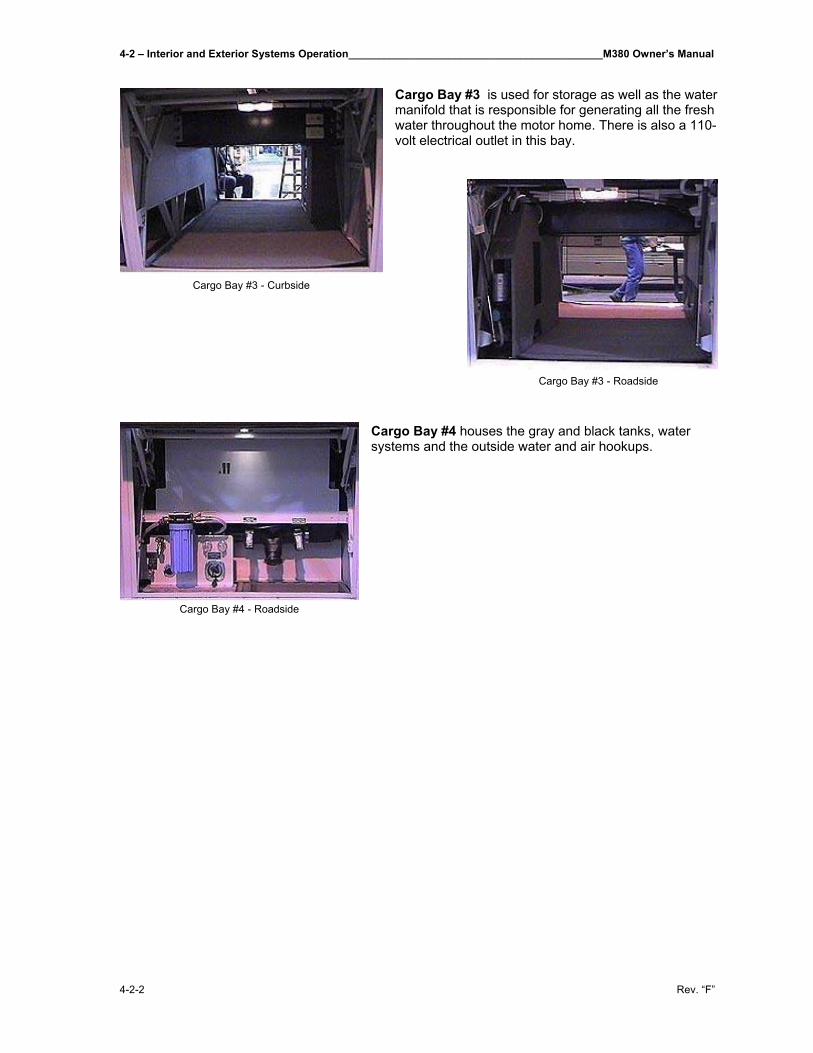
4-2 – Interior and Exterior Systems Operation___________________________________________M380 Owner’s Manual
4-2-2 Rev. “F”
Cargo Bay #3 is used for storage as well as the water manifold that is responsible for generating all the fresh water throughout the motor home. There is also a 110-volt electrical outlet in this bay.
Cargo Bay #4 houses the gray and black tanks, water systems and the outside water and air hookups.
Cargo Bay #3 - Curbside
Cargo Bay #3 - Roadside
Cargo Bay #4 - Roadside
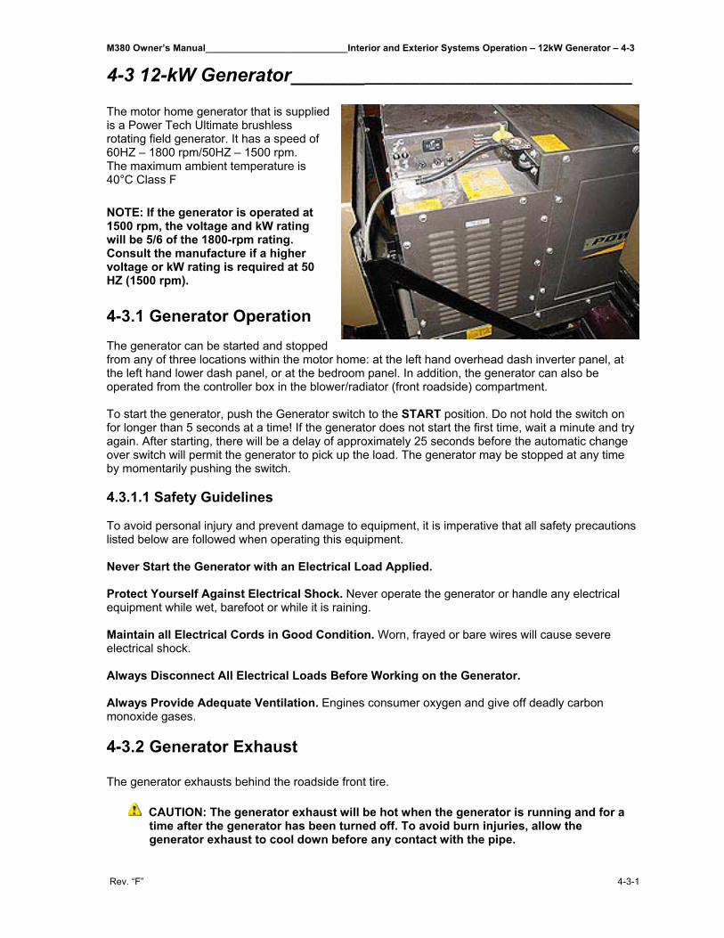
M380 Owner’s Manual___________________________Interior and Exterior Systems Operation – 12kW Generator – 4-3
Rev. “F” 4-3-1
4-3 12-kW Generator____________________________________ The motor home generator that is supplied is a Power Tech Ultimate brushless rotating field generator. It has a speed of 60HZ – 1800 rpm/50HZ – 1500 rpm. The maximum ambient temperature is 40°C Class F NOTE: If the generator is operated at 1500 rpm, the voltage and kW rating will be 5/6 of the 1800-rpm rating. Consult the manufacture if a higher voltage or kW rating is required at 50 HZ (1500 rpm). 4-3.1 Generator Operation The generator can be started and stopped from any of three locations within the motor home: at the left hand overhead dash inverter panel, at the left hand lower dash panel, or at the bedroom panel. In addition, the generator can also be operated from the controller box in the blower/radiator (front roadside) compartment. To start the generator, push the Generator switch to the START position. Do not hold the switch on for longer than 5 seconds at a time! If the generator does not start the first time, wait a minute and try again. After starting, there will be a delay of approximately 25 seconds before the automatic change over switch will permit the generator to pick up the load. The generator may be stopped at any time by momentarily pushing the switch. 4.3.1.1 Safety Guidelines To avoid personal injury and prevent damage to equipment, it is imperative that all safety precautions listed below are followed when operating this equipment. Never Start the Generator with an Electrical Load Applied. Protect Yourself Against Electrical Shock. Never operate the generator or handle any electrical equipment while wet, barefoot or while it is raining. Maintain all Electrical Cords in Good Condition. Worn, frayed or bare wires will cause severe electrical shock. Always Disconnect All Electrical Loads Before Working on the Generator. Always Provide Adequate Ventilation. Engines consumer oxygen and give off deadly carbon monoxide gases. 4-3.2 Generator Exhaust The generator exhausts behind the roadside front tire.
CAUTION: The generator exhaust will be hot when the generator is running and for a time after the generator has been turned off. To avoid burn injuries, allow the generator exhaust to cool down before any contact with the pipe.

4-3 – Interior and Exterior Systems Operation – 12kW Generator___________________________M380 Owner’s Manual
4-3-2 Rev. “F”
4-3.3 Air Cleaner 4-3.3.1 Periodic Cleaning and Inspection: Clean and inspect generator every 200 hours of normal operating time. If the generator is in a harsh environment clean and inspect it more frequently. If dirt and grease build up, the generator will run hotter and lose efficiency. This reduces the life of the generator. 4-3.3.2 Cleaning Remove all dust, dirt, oil and grease build-up from external surfaces. Direct a low-pressure air hose (25 psi max) through fan opening to blow dirt and grease from internal components. Clean inside control box checking for loose or damaged lead wires and loose components. NOTE: Do not remove internal generator parts or the warranty is void. 4-3.4 Spare Parts Always include the name of the part, quantity of each part ordered and the serial and model numbers from the generator set when ordering parts or have any questions. 4-3.5 Resistance Chart KW 7 8 10 12 MARKS COLORMAIN STATOR 0.5 0.5 0.5 0.5 U1-V1 or U2-V2 BBMAIN ROTOR 1.9 1.9 2 2.2 *** ***EXCITER STATOR 83.5 86.9 87.4 89 F1-F2 R-WEXCITER ROTOR 33.8 33.8 33.8 34 *** ***AUX. PHASE 2.5 2.5 1.6 1.5 AW Y-YBATT. CHARGE 0.5 0.5 0.5 0.5 CH W W-W
BLUEBROWN
0.4 ***SENSING WINDING 0.4 0.4 0.4
NOTE: These values are resistance measurements in Ohms at 77°F; note the readings will vary depending on ambient temperature. None of these tests should ground at any time. Feel free to call Power Tech Service Dept. for any questions you may have. For faster service make sure you have your model and serial number upon calling. 4-3.6 Troubleshooting 4-3.6.1 Visual Examination Inspect the generator visually. Look for obvious evidence such as burned areas, pinched wires and cracked insulation. All connections should be fastened securely. Check the operating speed, inspect the unit to be certain it was correctly assembled and connected upon installation.
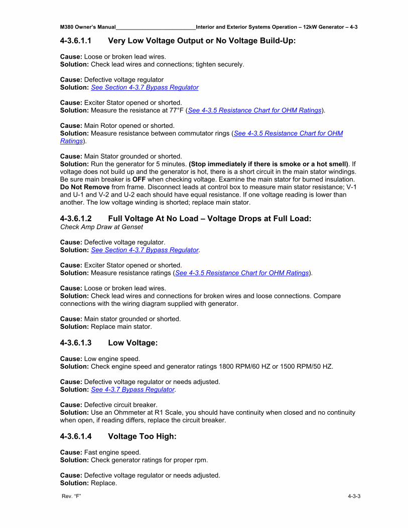
M380 Owner’s Manual___________________________Interior and Exterior Systems Operation – 12kW Generator – 4-3
Rev. “F” 4-3-3
4-3.6.1.1 Very Low Voltage Output or No Voltage Build-Up: Cause: Loose or broken lead wires. Solution: Check lead wires and connections; tighten securely. Cause: Defective voltage regulator Solution: See Section 4-3.7 Bypass Regulator Cause: Exciter Stator opened or shorted. Solution: Measure the resistance at 77°F (See 4-3.5 Resistance Chart for OHM Ratings). Cause: Main Rotor opened or shorted. Solution: Measure resistance between commutator rings (See 4-3.5 Resistance Chart for OHM Ratings). Cause: Main Stator grounded or shorted. Solution: Run the generator for 5 minutes. (Stop immediately if there is smoke or a hot smell). If voltage does not build up and the generator is hot, there is a short circuit in the main stator windings. Be sure main breaker is OFF when checking voltage. Examine the main stator for burned insulation. Do Not Remove from frame. Disconnect leads at control box to measure main stator resistance; V-1 and U-1 and V-2 and U-2 each should have equal resistance. If one voltage reading is lower than another. The low voltage winding is shorted; replace main stator. 4-3.6.1.2 Full Voltage At No Load – Voltage Drops at Full Load: Check Amp Draw at Genset Cause: Defective voltage regulator. Solution: See Section 4-3.7 Bypass Regulator. Cause: Exciter Stator opened or shorted. Solution: Measure resistance ratings (See 4-3.5 Resistance Chart for OHM Ratings). Cause: Loose or broken lead wires. Solution: Check lead wires and connections for broken wires and loose connections. Compare connections with the wiring diagram supplied with generator. Cause: Main stator grounded or shorted. Solution: Replace main stator. 4-3.6.1.3 Low Voltage: Cause: Low engine speed. Solution: Check engine speed and generator ratings 1800 RPM/60 HZ or 1500 RPM/50 HZ. Cause: Defective voltage regulator or needs adjusted. Solution: See 4-3.7 Bypass Regulator. Cause: Defective circuit breaker. Solution: Use an Ohmmeter at R1 Scale, you should have continuity when closed and no continuity when open, if reading differs, replace the circuit breaker. 4-3.6.1.4 Voltage Too High: Cause: Fast engine speed. Solution: Check generator ratings for proper rpm. Cause: Defective voltage regulator or needs adjusted. Solution: Replace.
4-3 – Interior and Exterior Systems Operation – 12kW Generator___________________________M380 Owner’s Manual
4-3-4 Rev. “F”
4-3.6.1.5 Uncontrollable Voltage: Cause: Defective voltage regulator. Solution: See 4-3.7 Bypass Regulator Cause: Incorrect engine adjustment. Solution: Check engine operation, speed, fuel lines and injector. 4-3.6.1.6 Voltage Spikes Appearing in Sine Waves: Check Amp Draw at Genset. Cause: Defective voltage regulator. Solution: Replace. Cause: Incorrect engine adjustment, fuel line, or poor fuel. Solution: Change fuel filter and check engine speed. Cause: Loose Connections. Solution: Inspect all connections. Cause: Bad ground connection. Solution: Inspect all ground connections. 4-3.7 Bypass Regulator Inside your control box there is a six-wire plug that plugs into your voltage regulator. To bypass this regulator for trouble shooting: Unplug from voltage regulator, take the red wire and run to 12 volt positive, take the white wire run to a good ground, make sure the generator is under NO LOAD, (flip circuit breakers off). Start unit up and check voltage, with no regulator your voltage should range anywhere between 112 volts to 125 volts, if so replace voltage regulator. Adjust voltage higher or lower with adjustment screw on top regulator. NOTE: It’s very important that voltage remains within specifications of unit.
M380 Owner’s Manual________________Interior and Exterior Systems Operation – 30/50 Amp 110-Volt Operation – 4-4
Rev. “F” 4-4-1
4-4 120 VAC Power Distribution System__________________ The M380 120VAC Power Distribution System consists of two primary power sources and one secondary power source. The primary sources are the 120/240V, 100/50A, 1-Phase, 3-wire Shoreline Power input and the 120/240V, 100/50A, 1-phase, 3-wire, 12.5KW Generator input. The secondary power source is a 120V, 25A, 1-phase, 3KW Inverter that converts 12VDC battery energy to 120VAC power. An Auto-Transfer switch selects one of the two primary power sources and connects the power source to the 120/240V, 100/50A, 1-phase, 3-wire Load Center. The Load Center consists of a set of twelve circuit breakers, which distribute the power from the selected primary power source; and a set of twelve circuit breakers, which distribute power from the secondary power source. The Inverter has its own internal transfer switch which selects the Inverter generated 120VAC power source or the pass through primary power source. In the event of an Inverter failure, the Inverter Bypass Breaker and the Inverter Bypass Switch isolate the Inverter from the 120V Power Distribution System, while providing the Inverter supplied loads with 120V from the selected power source. Reference Documents: 0063859 Block Diagram, M380 120VAC Power Distribution System 0049560 Wiring Diagram, M380 120VAC Power Distribution 4-4.1 Description of Two Power Sources
The M380 120VAC Power Distribution System supplies the motor home from two sources of 120/240V, 100/50A, 1-phase, 3-wire, 12KW AC power: the Shoreline (Utility) connection and the onboard diesel Generator. A typical house has a 120/240V, 200/100A, 1-phase, 3-wire, 24KW main utility power connection. Since the motor home has half the available power as that of a typical house, the user must manage the number of 120V loads that are in use at one time; i.e. all 120V loads cannot be turned on at the same time. There are two 120V, 50A power lines that supply AC loads; i.e. each line can supply 50A to AC loads. The load current can be monitored on the ammeters located in the Entry Door Overhead Transition box. The Shoreline and Generator are connected to the Automatic Transfer Switch inputs; the Transfer Switch line outputs are connected to the Load Center main terminal lugs. The Load Center has 24 pole spaces, which are separated into two groups - 12 poles for Shore/Generator circuit breakers and 12 poles for Inverter circuit breakers. The Inverter has its own internal transfer switch, which selects the Inverter's 120V power inverted from the 12V House Battery Bank or the Shore/Generator power from the External Automatic Transfer Switch. If the Inverter is turned Off, the internal transfer switch defaults to the Shore/Generator power source. The Inverter can be isolated from the 120V power distribution system by opening the Inverter Bypass Breaker and moving the Inverter Bypass Switch to the OFF or BYPASS position. The Auto Transfer Switch, Load Center, Inverter, Bypass Breaker, & Bypass Switch are located in Bay 1 and are accessible from the right side of the motor home. 4-4.1.1 Shoreline Power The motor home is connected to Shoreline or Utility Power through the standard exterior 120/240V receptacle located at the left rear corner or through the optional 120/240V Power Cord Reel located in Bay 1-Left. The 120V Power System is designed to connect to 240V, 50A, 1-phase, 3-wire power pedestal typically provided by recreational vehicle parks. An adapter cable is provided to connect a park's 120V, 30A, 1-phase, 2-wire receptacle to the motor home's 120/240V, 3-wire power cord. The adapter connects the hot legs, L1 & L2, together so both lines split the available 30A current (3.6KW);
4-4 – Interior and Exterior Systems Operation - 30/50 Amp 110-Volt Operation________________M380 Owner’s Manual
4-4-2 Rev. “F”
i.e. the available current is significantly reduced. In this situation, it is advisable to use the onboard generator. Many recreational vehicle lots are equipped with 120V, 20A, 2.4KW or 120V, 30A, 3.6KW two wire receptacles. This greatly reduces the number of appliances that can be operated at one time. When connecting to an unknown power pedestal, it is advisable to turn the Main circuit breakers, CB1-B and CB2-A, to the Off position to avoid damage to appliances and equipment connected to the motor home Power Distribution System. Check the Shoreline Reverse Polarity Panel to confirm the power pedestal is wired correctly. Then turn the Main circuit breakers to the on position 4-4.1.2 Shoreline Reverse Polarity Panel The Shoreline Reverse Polarity Panel indicates when the Shoreline Power connection is correctly wired or if one of the hot lines is wired incorrectly to the neutral terminal at the recreational vehicle park receptacle. If the park receptacle is incorrectly wired, do NOT connect the motor home to the receptacle and notify the park management. The Shoreline Reverse Polarity Panel is located in Bay 1-Left. 4-4.1.3 Shoreline Safeline Alarm The Shoreline Safeline Alarm indicates when the motor home's Shoreline power cord is connected to the recreational vehicle park receptacle and the ignition switch is turned to the On position. When this occurs, an alarm inside the motor home emits a beeping sound and a light on the dash. 4-4.1.4 Generator Power The onboard generator provides two separate lines of 120V, 50A, 6KW per line of power. The load current on each line is displayed on the two AC ammeters located in the curbside (right) overhead transition box. The generator can be started from three interior locations: (1) the Inverter Remote Control panel, (2) the Generator Start switch in the lower front dash, and (3) the bedroom switch panel. The generator can also be started using the Start switch located at the generator control panel. Refer to Section 4.3 for detailed generator operation instructions. 4-4.1.5 Automatic Transfer Switch The Shoreline and Generator are connected to the inputs of the Automatic Transfer Switch. The Generator input take precedence over the Shoreline input; i.e. if the Generator is running while Shoreline voltage is present, the Transfer Switch selects the Generator input. If the Generator voltage is not present, then the Automatic Transfer Switch selects the Shoreline input. The transfer from the Shoreline to the Generator input is delayed 30-60 seconds. This delay allows the Generator to start and stabilize. Note: the Generator starts only if the generator auto-start feature on the Inverter is set to detect loss of Shoreline power or manual start is initiated. The default state of the Transfer Switch is the Shoreline position. The Transfer Switch monitors the Generator voltage and selects the Generator position when it detects the Generator voltage.
M380 Owner’s Manual________________Interior and Exterior Systems Operation – 30/50 Amp 110-Volt Operation – 4-4
Rev. “F” 4-4-3
4-4.1.6 AC Load Center The AC Load Center is a 120/240V, 50A, 1-phase, 3-wire, split bus power distribution panel. The line outputs of the Automatic Transfer Switch are connected to the Load Center main 50A circuit breakers CB1-B & CB2-A. The Load Center split bus configuration separates the circuit breakers into two sets: (1) the Shoreline/Generator breakers, and (2) the Inverter breakers. The loads connected to the circuit breakers CB3-A/B through CB6-A/B can only be operated when the Shoreline/Generator power is available. The loads connected to CB7-A, CB8-B, CB9-A/B through CB12-A/B can be operated when the Inverter is turned On and the House batteries are charged or when the Shoreline/Generator power is available. The types of circuit breakers are tandem style - two breakers that occupy one pole space. Each pole space is designated by a number suffix with each tandem breaker designated with an "A" or "B" suffix; e.g. CB1-A & CB1-B. The Load Center has two separate power legs (lines): L1 and L2. Odd numbered breakers are attached to L1; even numbered breakers are attached to L2. The ammeters in the Entry Door Overhead Transition cabinet monitor the L1 & L2 currents and are used to load manage the appliances or lights that are turned On at one time. If the Shoreline power is 240V, 50A, 3-wire, then each line is limited to 50A. If the Generator is operating, then the line current is limited to 50A each.
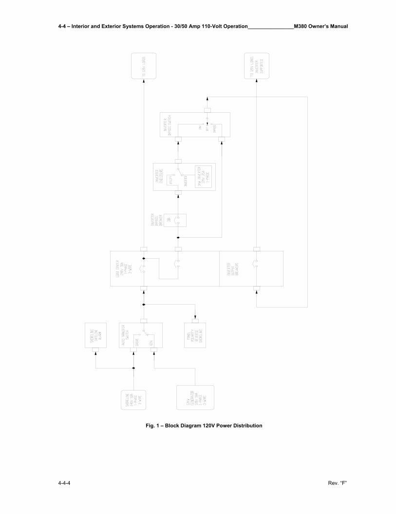
4-4 – Interior and Exterior Systems Operation - 30/50 Amp 110-Volt Operation________________M380 Owner’s Manual
4-4-4 Rev. “F”
Fig. 1 – Block Diagram 120V Power Distribution
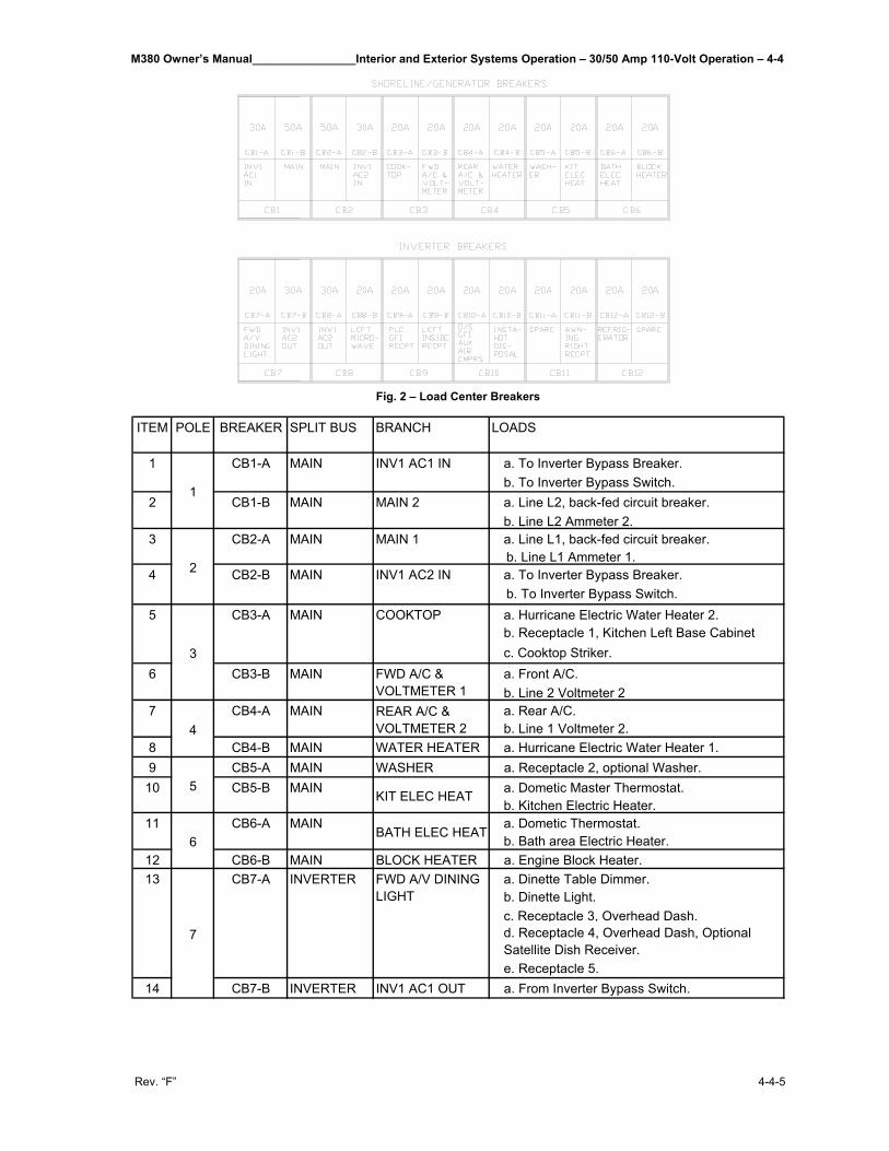
M380 Owner’s Manual________________Interior and Exterior Systems Operation – 30/50 Amp 110-Volt Operation – 4-4
Rev. “F” 4-4-5
Fig. 2 – Load Center Breakers
ITEM POLE BREAKER SPLIT BUS BRANCH LOADS
a. To Inverter Bypass Breaker.b. To Inverter Bypass Switch.a. Line L2, back-fed circuit breaker.b. Line L2 Ammeter 2.a. Line L1, back-fed circuit breaker.
b. Line L1 Ammeter 1.a. To Inverter Bypass Breaker.
b. To Inverter Bypass Switch.a. Hurricane Electric Water Heater 2.b. Receptacle 1, Kitchen Left Base Cabinetc. Cooktop Striker.a. Front A/C.b. Line 2 Voltmeter 2a. Rear A/C.b. Line 1 Voltmeter 2.
8 CB4-B MAIN WATER HEATER a. Hurricane Electric Water Heater 1.9 CB5-A MAIN WASHER a. Receptacle 2, optional Washer.
a. Dometic Master Thermostat.b. Kitchen Electric Heater.a. Dometic Thermostat.b. Bath area Electric Heater.
12 CB6-B MAIN BLOCK HEATER a. Engine Block Heater.a. Dinette Table Dimmer.b. Dinette Light.c. Receptacle 3, Overhead Dash.d. Receptacle 4, Overhead Dash, Optional Satellite Dish Receiver.e. Receptacle 5.
14 CB7-B INVERTER INV1 AC1 OUT a. From Inverter Bypass Switch.
BATH ELEC HEAT
13
7
CB7-A INVERTER FWD A/V DINING LIGHT
116
CB6-A MAIN
REAR A/C & VOLTMETER 2
510 CB5-B MAIN KIT ELEC HEAT
74
CB4-A MAIN
COOKTOP
6 CB3-B MAIN FWD A/C & VOLTMETER 1
5
3
CB3-A MAIN
MAIN 1
4 CB2-B MAIN INV1 AC2 IN
3
2
CB2-A MAIN
INV1 AC1 IN
2 CB1-B MAIN MAIN 2
1
1
CB1-A MAIN
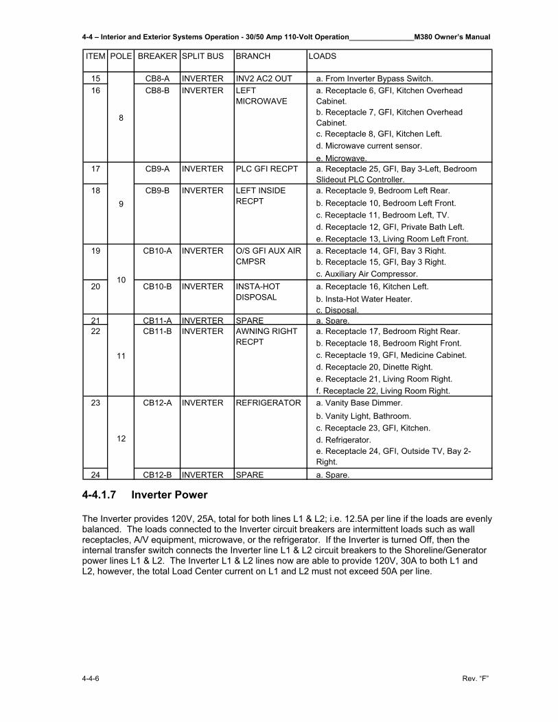
4-4 – Interior and Exterior Systems Operation - 30/50 Amp 110-Volt Operation________________M380 Owner’s Manual
4-4-6 Rev. “F”
ITEM POLE BREAKER SPLIT BUS BRANCH LOADS
15 CB8-A INVERTER INV2 AC2 OUT a. From Inverter Bypass Switch.a. Receptacle 6, GFI, Kitchen Overhead Cabinet.b. Receptacle 7, GFI, Kitchen Overhead Cabinet.c. Receptacle 8, GFI, Kitchen Left.d. Microwave current sensor.e. Microwave.
17 CB9-A INVERTER PLC GFI RECPT a. Receptacle 25, GFI, Bay 3-Left, Bedroom Slideout PLC Controller.a. Receptacle 9, Bedroom Left Rear.b. Receptacle 10, Bedroom Left Front.c. Receptacle 11, Bedroom Left, TV.d. Receptacle 12, GFI, Private Bath Left.e. Receptacle 13, Living Room Left Front.a. Receptacle 14, GFI, Bay 3 Right.b. Receptacle 15, GFI, Bay 3 Right.c. Auxiliary Air Compressor.a. Receptacle 16, Kitchen Left.b. Insta-Hot Water Heater.c. Disposal.
21 CB11-A INVERTER SPARE a. Spare.a. Receptacle 17, Bedroom Right Rear.b. Receptacle 18, Bedroom Right Front.c. Receptacle 19, GFI, Medicine Cabinet.d. Receptacle 20, Dinette Right.e. Receptacle 21, Living Room Right.f. Receptacle 22, Living Room Right.a. Vanity Base Dimmer.b. Vanity Light, Bathroom.c. Receptacle 23, GFI, Kitchen.d. Refrigerator.e. Receptacle 24, GFI, Outside TV, Bay 2-Right.
24 CB12-B INVERTER SPARE a. Spare.
AWNING RIGHT RECPT
23
12
CB12-A INVERTER REFRIGERATOR
11
22 CB11-B INVERTER
O/S GFI AUX AIR CMPSR
20 CB10-B INVERTER INSTA-HOT DISPOSAL
19
10
CB10-A INVERTER
LEFT MICROWAVE
918 CB9-B INVERTER LEFT INSIDE
RECPT
8
16 CB8-B INVERTER
4-4.1.7 Inverter Power The Inverter provides 120V, 25A, total for both lines L1 & L2; i.e. 12.5A per line if the loads are evenly balanced. The loads connected to the Inverter circuit breakers are intermittent loads such as wall receptacles, A/V equipment, microwave, or the refrigerator. If the Inverter is turned Off, then the internal transfer switch connects the Inverter line L1 & L2 circuit breakers to the Shoreline/Generator power lines L1 & L2. The Inverter L1 & L2 lines now are able to provide 120V, 30A to both L1 and L2, however, the total Load Center current on L1 and L2 must not exceed 50A per line.
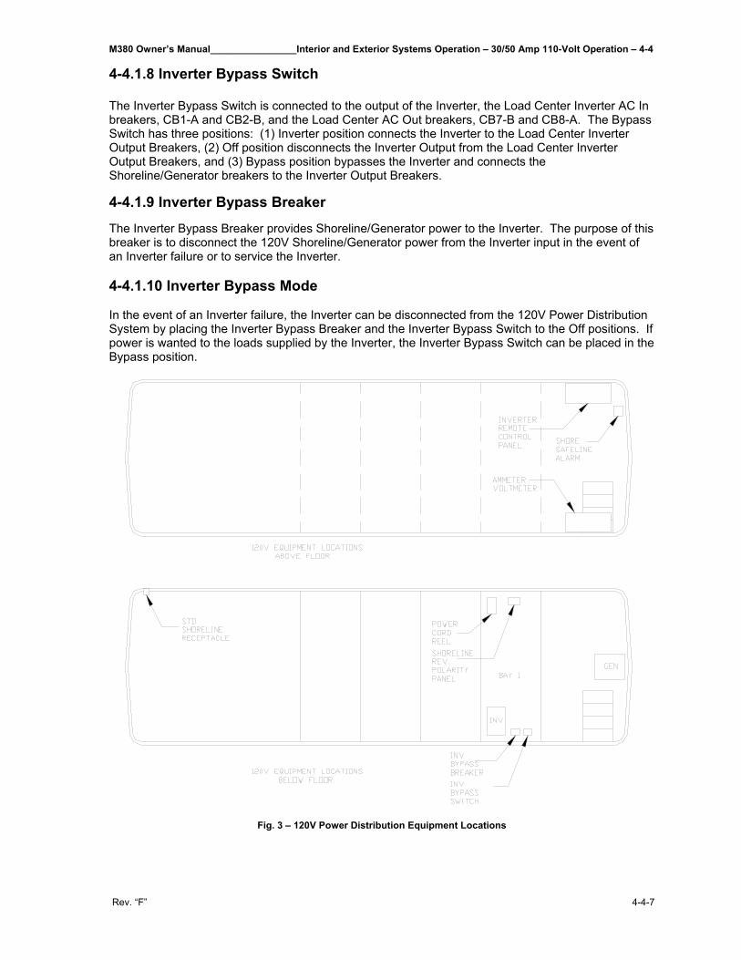
M380 Owner’s Manual________________Interior and Exterior Systems Operation – 30/50 Amp 110-Volt Operation – 4-4
Rev. “F” 4-4-7
4-4.1.8 Inverter Bypass Switch The Inverter Bypass Switch is connected to the output of the Inverter, the Load Center Inverter AC In breakers, CB1-A and CB2-B, and the Load Center AC Out breakers, CB7-B and CB8-A. The Bypass Switch has three positions: (1) Inverter position connects the Inverter to the Load Center Inverter Output Breakers, (2) Off position disconnects the Inverter Output from the Load Center Inverter Output Breakers, and (3) Bypass position bypasses the Inverter and connects the Shoreline/Generator breakers to the Inverter Output Breakers.
4-4.1.9 Inverter Bypass Breaker
The Inverter Bypass Breaker provides Shoreline/Generator power to the Inverter. The purpose of this breaker is to disconnect the 120V Shoreline/Generator power from the Inverter input in the event of an Inverter failure or to service the Inverter. 4-4.1.10 Inverter Bypass Mode In the event of an Inverter failure, the Inverter can be disconnected from the 120V Power Distribution System by placing the Inverter Bypass Breaker and the Inverter Bypass Switch to the Off positions. If power is wanted to the loads supplied by the Inverter, the Inverter Bypass Switch can be placed in the Bypass position.
Fig. 3 – 120V Power Distribution Equipment Locations
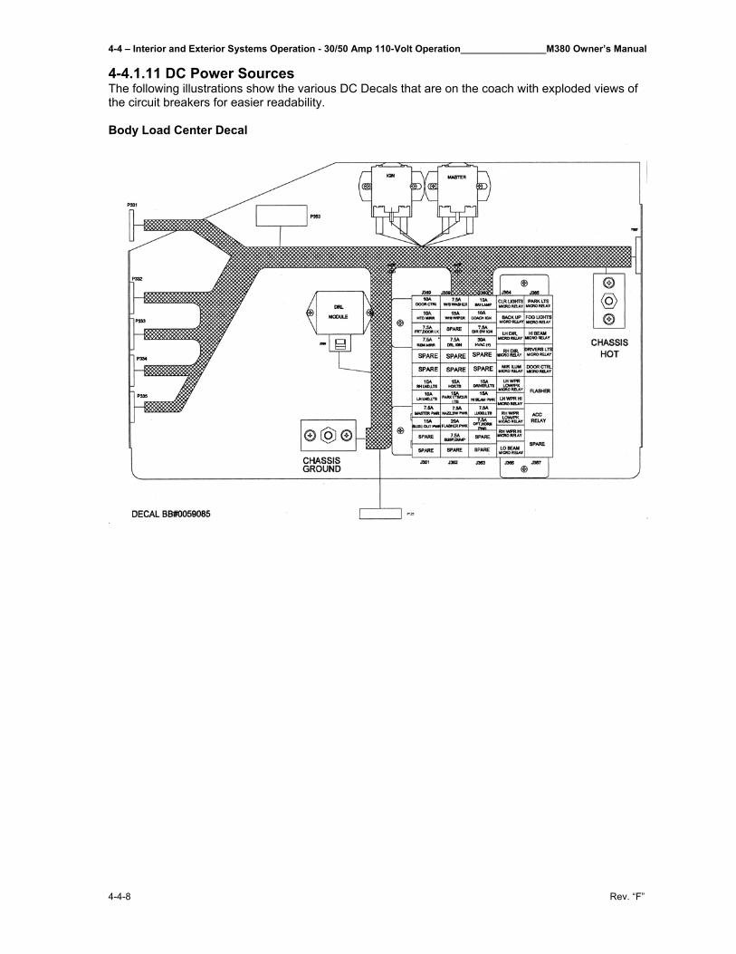
4-4 – Interior and Exterior Systems Operation - 30/50 Amp 110-Volt Operation________________M380 Owner’s Manual
4-4-8 Rev. “F”
4-4.1.11 DC Power Sources The following illustrations show the various DC Decals that are on the coach with exploded views of the circuit breakers for easier readability. Body Load Center Decal
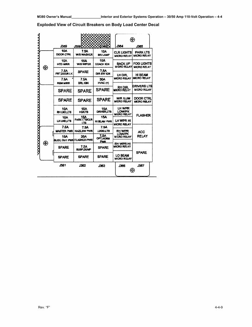
M380 Owner’s Manual________________Interior and Exterior Systems Operation – 30/50 Amp 110-Volt Operation – 4-4
Rev. “F” 4-4-9
Exploded View of Circuit Breakers on Body Load Center Decal
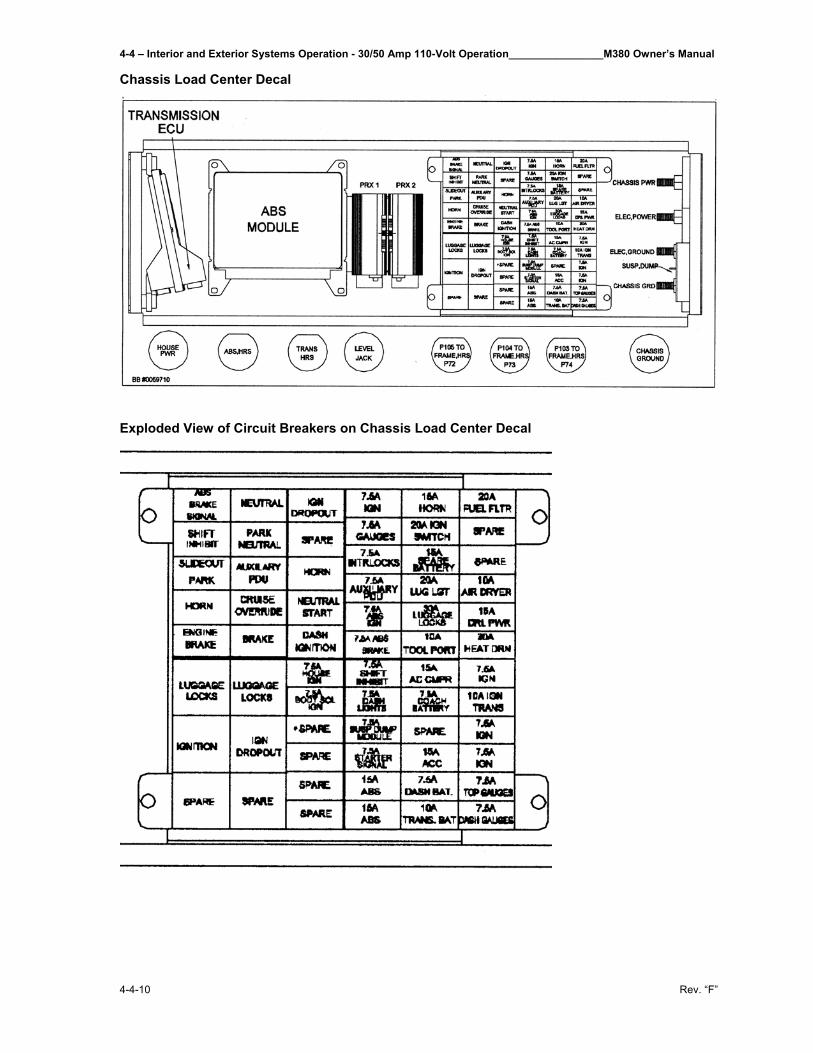
4-4 – Interior and Exterior Systems Operation - 30/50 Amp 110-Volt Operation________________M380 Owner’s Manual
4-4-10 Rev. “F”
Chassis Load Center Decal
Exploded View of Circuit Breakers on Chassis Load Center Decal
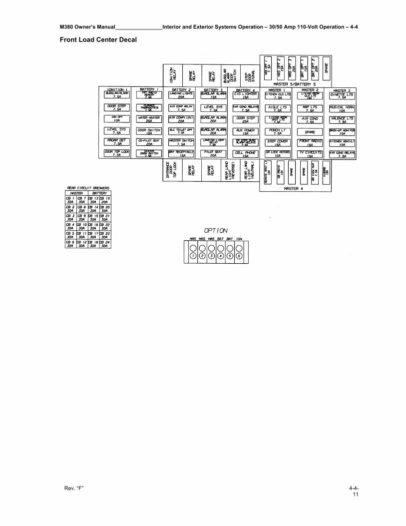
M380 Owner’s Manual________________Interior and Exterior Systems Operation – 30/50 Amp 110-Volt Operation – 4-4
Rev. “F” 4-4-11
Front Load Center Decal
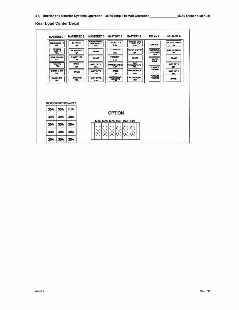
4-4 – Interior and Exterior Systems Operation - 30/50 Amp 110-Volt Operation________________M380 Owner’s Manual
4-4-12 Rev. “F”
Rear Load Center Decal
M380 Owner’s Manual___________________________________Interior and Exterior Systems Operation - Inverter – 4-5
Rev. “F” 4-5-1
4-5 Inverter___________________________________________ The motor home is equipped with an Inverter manufactured by Trace Engineering. This is a very important system within the motor home. This system can pull power out of 12-volt batteries and convert it to 120 VAC to run appliances. It can also can pull 120 VAC power and convert it to 12 volt as needed to change the house batteries when connected to 120 VAC shore power or generator. Lights on the motor home use 12 volt and appliance use 120. This is useful when you are some place that does not have plug-ins or you cannot run generator for some reason. For example, maybe the park you are in has rules that state no running generator after a certain time; this is where your inverter would come in handy. 4-5.1 Remote Control Panel The remote control panel is mounted above driver’s seat over the right door panel. Some features of the remote control panel are listed below: • Simple menu driven programming for full control of all inverter/charger functions. • A three-level menu to prevent accidental setting changes. • Meters to display voltage and current. • RJ11 phone jack connection to inverter. • Internal memory to retain inverter/charger menu settings even with a loss of power. • An intelligent battery fuel gauge displaying percent of battery charge and the time left to run. • Error message and informative information displays used to optimize system performance. • Remote ON/OFF inverter operation. 4-5.1.1 On/Off Control The inverter portion of the inverter/charger can be switched OFF or ON using the remote control. The standby charger in the inverter is automatic and always ready and available for charging whenever ac power is applied. 4-5.1.2 Meters The RC7GS remotes feature several meters that monitor the operating conditions of the power center. These meters include: Average Shunt Amps, Battery Voltage, Inverter-Charger Current, AC Output Voltage, AC Input Amps, Battery Temperature, Transformer Temperature, FET Temperature, and Estimated Battery Capacity. 4-5.1.3 Controls The RC7GS allow the inverter to be switched ON or OFF with the press of a push button on the remote. Both devices can be used to configure the inverter/charger to the specific system and preferences including Battery Capacity, Battery Type, Charger Rate, Low Battery Cutout, Shore Power Amps, External Shunt, Fuel gage Cutout, and Display Contrast. In addition, the RC7GS starts and stops of the genset automatically or manually, allows the setting of generator make and model, sets a “quiet time” during which the genset will not start automatically, and has manual overrides for auto gen start.
4-5 – Interior and Exterior Systems Operation – Inverter__________________________________M380 Owner’s Manual
4-5-2 Rev. ”F”
4-5.1.4 RC7GS Setup Menu The RC7GS (Generator Start) features several additional setup menu selections related to automatic generator starting, stopping and generator quiet time. To access the setup menu hold the up and down arrows down together till you hear a chirp. You are now in the setup menu. IMPORTANT NOTE: Your coach is delivered with specific, initial settings set up on your inverter. These were specifically designed for this coach and in the event of a loss of power these settings must be restored. See following chart as a guide for returning settings to their original setup.
4-5.1.4.1 Set Clock Some generator functions are based on the time of day. The clock must be properly set to ensure the programmed function will perform at the correct time. The clock uses 24-hour time and ranges from 00:00 to 23:59. To access the Set Clk menu, scroll down past the generator menus by pressing the DOWN arrow. A flashing cursor appears below (and behind) the hour (H) or minute (M) characters in the display. Every eight seconds the cursor alternates positions. When the cursor is under the hour digit, press the Settings push button to increment the hours to the current hour (00 to 23). When the cursor is under the minute’s digit, press the Settings push button to increment the minutes to the current minute (0 to 59). Press and hold the Settings push button to quickly increment the time, or press and release to increment the selected digit by one unit at a time. 4-5.1.4.2 Select Genset After setting the clock, press the UP arrow once to access the Select Genset menu. Select the type and model of the generator (Powertech 12KW) by pressing the Settings push button (RIGHT arrow) until the genset’s name and model is displayed in the LCD readout.
CAUTION: Other 30 through 80 are reserved for future use and must not be selected. 4-5.1.4.3 Generator Auto Start After setting the clock and selecting a generator, set the parameters for automatically starting the genset based upon a battery voltage or State-of-Charge (SOC). Press the UP arrow and scroll through the menus to access the Generator Auto Start menu. Press the Settings push button (RIGHT arrow) until the required setting is in the LCD display. The required setting should read battery voltage. NOTE: The Auto Gen parameters cannot be set unless the clock is set-up first.
Menu Item Restore To:Search Sense About 5W loadAuto LBCO OnBattery Capacity 500 A-hrsBattery Type AGMCharge Rate 90%Set Shore Power 30 AmpsRC7 Setup Last KeyLCD Contrast Max ContrastExternal Shunt NoneFuel Gage Cutout 10.3VDC=0%SOCSelect Genset Power Tech 2-WireGenerator Start Auto at 11.0 VDCGenerator Stop Auto at 90% SOCBegin Gen Quiet 21:00End Gen Quiet 09:00
Original Settings Delivered with Coach
M380 Owner’s Manual___________________________________Interior and Exterior Systems Operation - Inverter – 4-5
Rev. “F” 4-5-3
NOTE: The default Generator Start selection is Manual (Push On). This setting disables all automatic start functions. Any other selection from the Generator Start menu, enables the RC7GS to automatically start the generator based upon the battery’s state-of-charge. 4-5.1.4.4 Generator Stop The RC7GS can be configured to shut down the generator automatically when the batteries reach 90 to 99% SOC, or when the charger initiates the Absorption or the Float mode of charging. Refer to the inverter/charger’s Operators manual for a detailed description on charging modes. The default is Manual (Push Off). The generator can be stopped at any time by accessing the user menu until the “Gen Start/Stop: Press (On/Off)” menu is displayed. Press the ON/OFF push button on the RC7GS front panel until the generator stops. NOTE: The generator will start immediately if the auto-start parameters are still met. The generator can be started or stopped at any time by pressing the DOWN arrow push button (User Menu) until the Gen Start/Stop menu is displayed. Press and hold the On/Off push button on the RC7GS front panel until the generator starts or stops. Release the push button as soon as the generator starts. If the inverter/charger senses an ac supply while the remote control On/Off push button is pressed, it will shut down the generator. NOTE: If the genset is manually started from the remote, a manual override is initiated and the generator will NOT stop automatically. Shut down the generator manually. 4-5.1.4.5 Begin Gen Quiet and End Gen Quiet The period of time during which the generator is prevented from starting automatically can be defined using the RC7GS. To specify the begin quiet time, scroll to the Begin Gen Quiet: 00:00 by using the UP and DOWN arrow push buttons. Set the Begin Gen Quiet start time. The selected digit for hours or minutes will be underlined and highlighted (refer to 4-5.1.4.1 Set Clock section for details on setting the time). Press the DOWN arrow to access the End Gen Quiet 00:00 menu and select the appropriate end time. NOTE: Setting begin and end time to 00:00 defeats the quiet time mode. NOTE: If the generator is running at the begin quiet time, it will be shut down automatically. If the auto-start parameters are met during quiet time, the buzzer will sound and the LCD displays the message “Gen Quiet Fault.” The generator will start automatically at the end of the quiet time. 4-5.1.4.6 Saving Setup Choices Once the setup options are complete, press and hold both the UP and DOWN arrow push buttons until the display clears (approximately 5 seconds). The setup choices will be saved in nonvolatile memory 20 seconds after exiting the Setup menu. If no other actions are taken. These settings will be preserved until changed. NOTE: The GenStart settings will not be saved if the RC7GS is disconnected or dc power is lost.
IMPORTANT NOTE: If Auto Gen Start is enabled the generator cannot be started from any remote starts in coach. Generator can be started by disabling Auto Gen Start or by manually starting from the RC7GS Remote Panel.
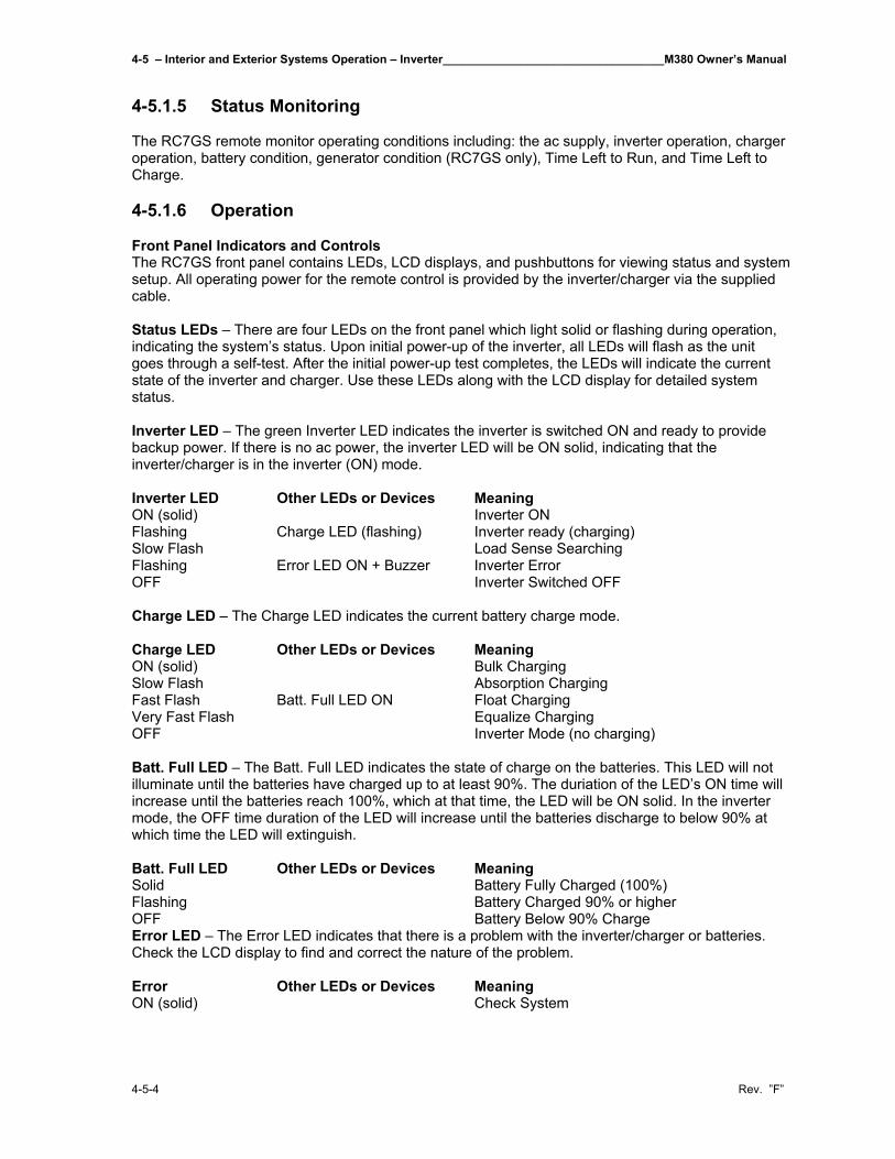
4-5 – Interior and Exterior Systems Operation – Inverter__________________________________M380 Owner’s Manual
4-5-4 Rev. ”F”
4-5.1.5 Status Monitoring The RC7GS remote monitor operating conditions including: the ac supply, inverter operation, charger operation, battery condition, generator condition (RC7GS only), Time Left to Run, and Time Left to Charge. 4-5.1.6 Operation Front Panel Indicators and Controls The RC7GS front panel contains LEDs, LCD displays, and pushbuttons for viewing status and system setup. All operating power for the remote control is provided by the inverter/charger via the supplied cable. Status LEDs – There are four LEDs on the front panel which light solid or flashing during operation, indicating the system’s status. Upon initial power-up of the inverter, all LEDs will flash as the unit goes through a self-test. After the initial power-up test completes, the LEDs will indicate the current state of the inverter and charger. Use these LEDs along with the LCD display for detailed system status. Inverter LED – The green Inverter LED indicates the inverter is switched ON and ready to provide backup power. If there is no ac power, the inverter LED will be ON solid, indicating that the inverter/charger is in the inverter (ON) mode. Inverter LED Other LEDs or Devices Meaning ON (solid) Inverter ON Flashing Charge LED (flashing) Inverter ready (charging) Slow Flash Load Sense Searching Flashing Error LED ON + Buzzer Inverter Error OFF Inverter Switched OFF Charge LED – The Charge LED indicates the current battery charge mode. Charge LED Other LEDs or Devices Meaning ON (solid) Bulk Charging Slow Flash Absorption Charging Fast Flash Batt. Full LED ON Float Charging Very Fast Flash Equalize Charging OFF Inverter Mode (no charging) Batt. Full LED – The Batt. Full LED indicates the state of charge on the batteries. This LED will not illuminate until the batteries have charged up to at least 90%. The duriation of the LED’s ON time will increase until the batteries reach 100%, which at that time, the LED will be ON solid. In the inverter mode, the OFF time duration of the LED will increase until the batteries discharge to below 90% at which time the LED will extinguish. Batt. Full LED Other LEDs or Devices Meaning Solid Battery Fully Charged (100%) Flashing Battery Charged 90% or higher OFF Battery Below 90% Charge Error LED – The Error LED indicates that there is a problem with the inverter/charger or batteries. Check the LCD display to find and correct the nature of the problem. Error Other LEDs or Devices Meaning ON (solid) Check System
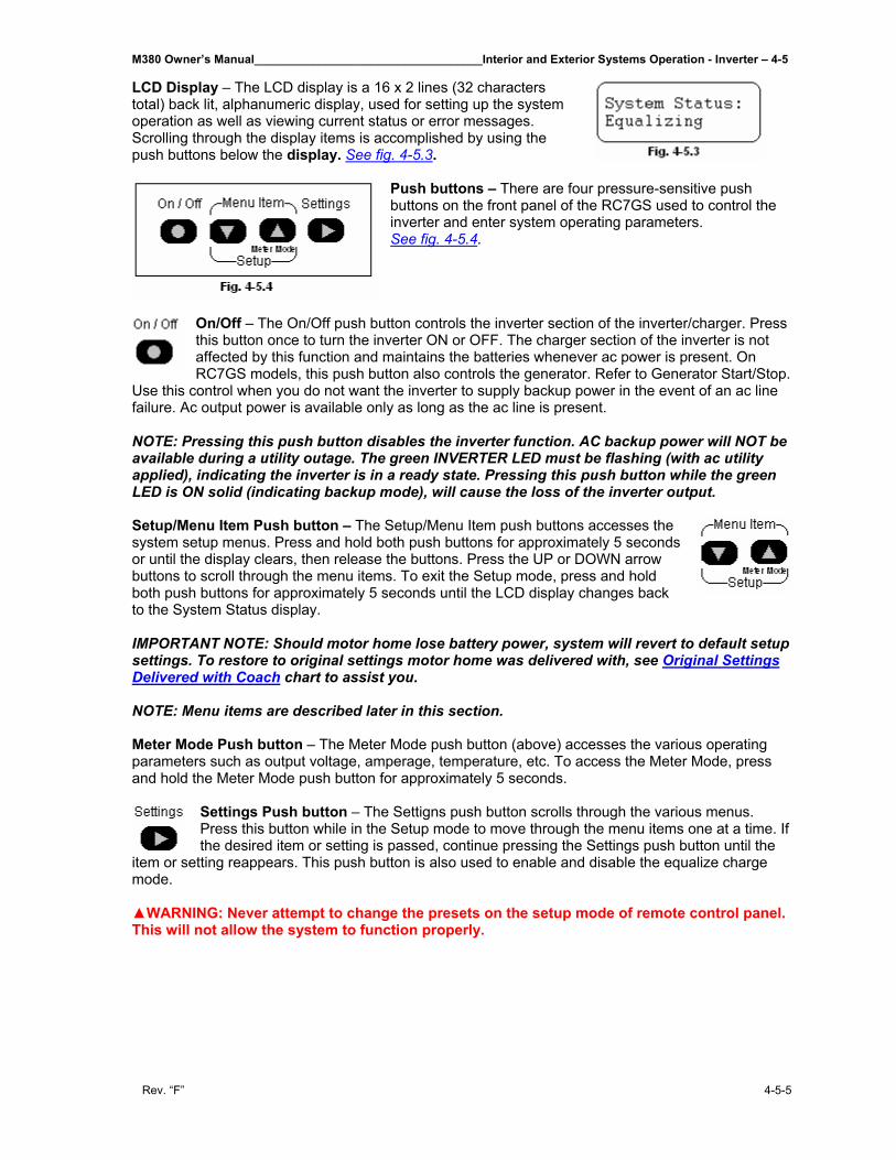
M380 Owner’s Manual___________________________________Interior and Exterior Systems Operation - Inverter – 4-5
Rev. “F” 4-5-5
LCD Display – The LCD display is a 16 x 2 lines (32 characters total) back lit, alphanumeric display, used for setting up the system operation as well as viewing current status or error messages. Scrolling through the display items is accomplished by using the push buttons below the display. See fig. 4-5.3.
Push buttons – There are four pressure-sensitive push buttons on the front panel of the RC7GS used to control the inverter and enter system operating parameters. See fig. 4-5.4.
On/Off – The On/Off push button controls the inverter section of the inverter/charger. Press this button once to turn the inverter ON or OFF. The charger section of the inverter is not affected by this function and maintains the batteries whenever ac power is present. On RC7GS models, this push button also controls the generator. Refer to Generator Start/Stop.
Use this control when you do not want the inverter to supply backup power in the event of an ac line failure. Ac output power is available only as long as the ac line is present. NOTE: Pressing this push button disables the inverter function. AC backup power will NOT be available during a utility outage. The green INVERTER LED must be flashing (with ac utility applied), indicating the inverter is in a ready state. Pressing this push button while the green LED is ON solid (indicating backup mode), will cause the loss of the inverter output. Setup/Menu Item Push button – The Setup/Menu Item push buttons accesses the system setup menus. Press and hold both push buttons for approximately 5 seconds or until the display clears, then release the buttons. Press the UP or DOWN arrow buttons to scroll through the menu items. To exit the Setup mode, press and hold both push buttons for approximately 5 seconds until the LCD display changes back to the System Status display. IMPORTANT NOTE: Should motor home lose battery power, system will revert to default setup settings. To restore to original settings motor home was delivered with, see Original Settings Delivered with Coach chart to assist you. NOTE: Menu items are described later in this section. Meter Mode Push button – The Meter Mode push button (above) accesses the various operating parameters such as output voltage, amperage, temperature, etc. To access the Meter Mode, press and hold the Meter Mode push button for approximately 5 seconds.
Settings Push button – The Settigns push button scrolls through the various menus. Press this button while in the Setup mode to move through the menu items one at a time. If the desired item or setting is passed, continue pressing the Settings push button until the
item or setting reappears. This push button is also used to enable and disable the equalize charge mode. ▲WARNING: Never attempt to change the presets on the setup mode of remote control panel. This will not allow the system to function properly.
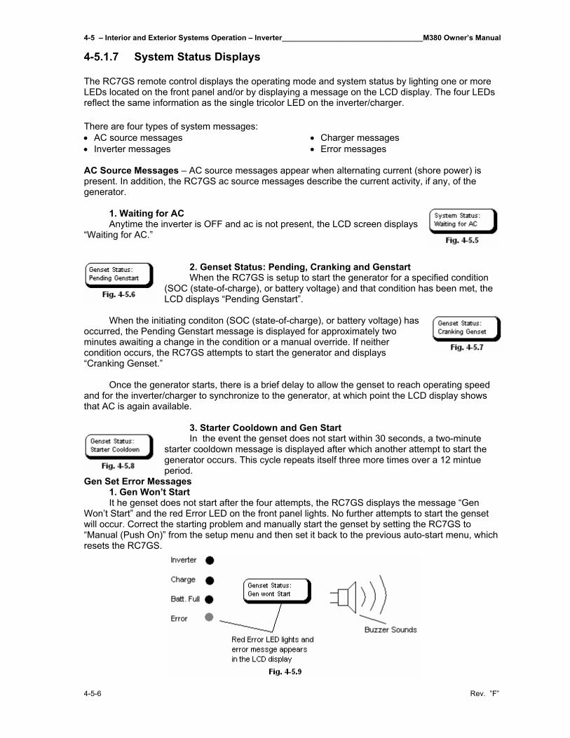
4-5 – Interior and Exterior Systems Operation – Inverter__________________________________M380 Owner’s Manual
4-5-6 Rev. ”F”
4-5.1.7 System Status Displays The RC7GS remote control displays the operating mode and system status by lighting one or more LEDs located on the front panel and/or by displaying a message on the LCD display. The four LEDs reflect the same information as the single tricolor LED on the inverter/charger. There are four types of system messages: • AC source messages • Inverter messages
• Charger messages • Error messages
AC Source Messages – AC source messages appear when alternating current (shore power) is present. In addition, the RC7GS ac source messages describe the current activity, if any, of the generator. 1. Waiting for AC Anytime the inverter is OFF and ac is not present, the LCD screen displays “Waiting for AC.”
2. Genset Status: Pending, Cranking and Genstart When the RC7GS is setup to start the generator for a specified condition (SOC (state-of-charge), or battery voltage) and that condition has been met, the LCD displays “Pending Genstart”.
When the initiating conditon (SOC (state-of-charge), or battery voltage) has occurred, the Pending Genstart message is displayed for approximately two minutes awaiting a change in the condition or a manual override. If neither condition occurs, the RC7GS attempts to start the generator and displays “Cranking Genset.” Once the generator starts, there is a brief delay to allow the genset to reach operating speed and for the inverter/charger to synchronize to the generator, at which point the LCD display shows that AC is again available.
3. Starter Cooldown and Gen Start In the event the genset does not start within 30 seconds, a two-minute starter cooldown message is displayed after which another attempt to start the generator occurs. This cycle repeats itself three more times over a 12 mintue period.
Gen Set Error Messages 1. Gen Won’t Start It he genset does not start after the four attempts, the RC7GS displays the message “Gen Won’t Start” and the red Error LED on the front panel lights. No further attempts to start the genset will occur. Correct the starting problem and manually start the genset by setting the RC7GS to “Manual (Push On)” from the setup menu and then set it back to the previous auto-start menu, which resets the RC7GS.
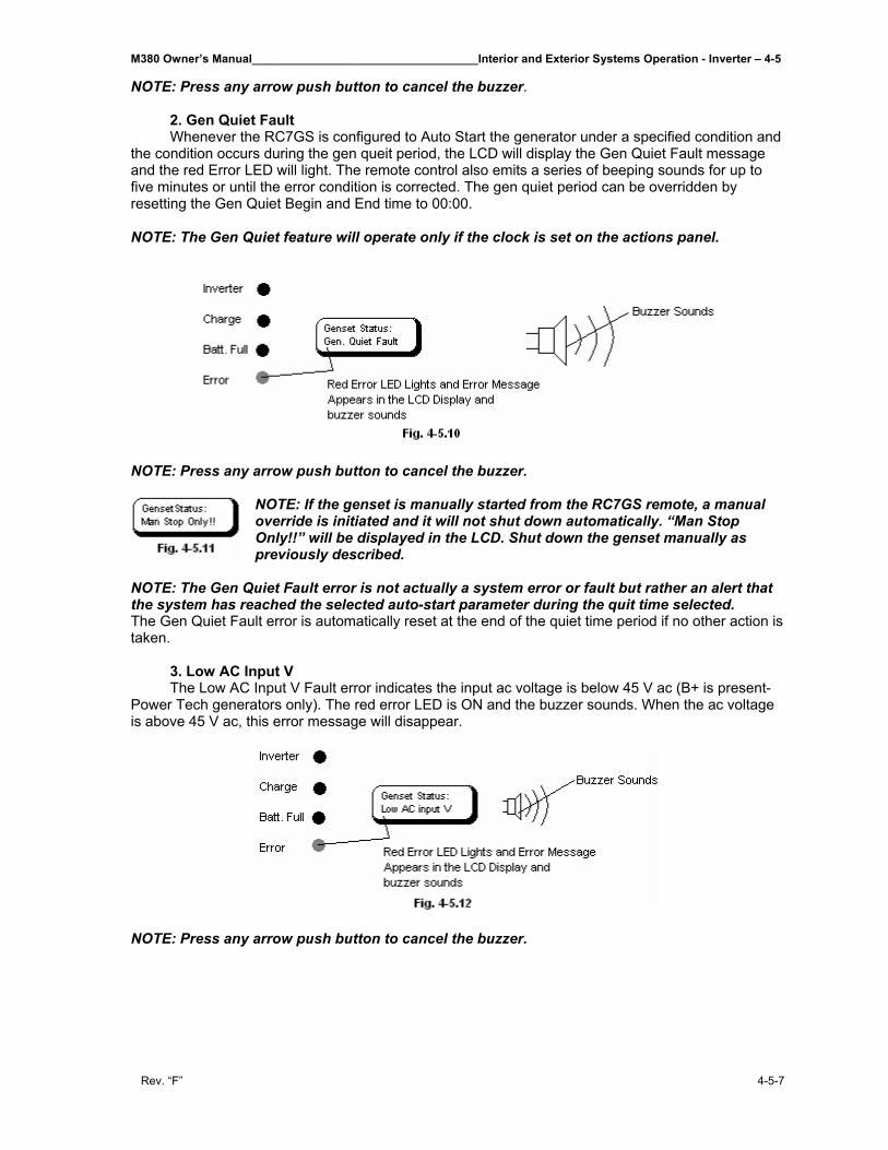
M380 Owner’s Manual___________________________________Interior and Exterior Systems Operation - Inverter – 4-5
Rev. “F” 4-5-7
NOTE: Press any arrow push button to cancel the buzzer. 2. Gen Quiet Fault Whenever the RC7GS is configured to Auto Start the generator under a specified condition and the condition occurs during the gen queit period, the LCD will display the Gen Quiet Fault message and the red Error LED will light. The remote control also emits a series of beeping sounds for up to five minutes or until the error condition is corrected. The gen quiet period can be overridden by resetting the Gen Quiet Begin and End time to 00:00. NOTE: The Gen Quiet feature will operate only if the clock is set on the actions panel. NOTE: Press any arrow push button to cancel the buzzer.
NOTE: If the genset is manually started from the RC7GS remote, a manual override is initiated and it will not shut down automatically. “Man Stop Only!!” will be displayed in the LCD. Shut down the genset manually as previously described.
NOTE: The Gen Quiet Fault error is not actually a system error or fault but rather an alert that the system has reached the selected auto-start parameter during the quit time selected. The Gen Quiet Fault error is automatically reset at the end of the quiet time period if no other action is taken. 3. Low AC Input V The Low AC Input V Fault error indicates the input ac voltage is below 45 V ac (B+ is present-Power Tech generators only). The red error LED is ON and the buzzer sounds. When the ac voltage is above 45 V ac, this error message will disappear. NOTE: Press any arrow push button to cancel the buzzer.
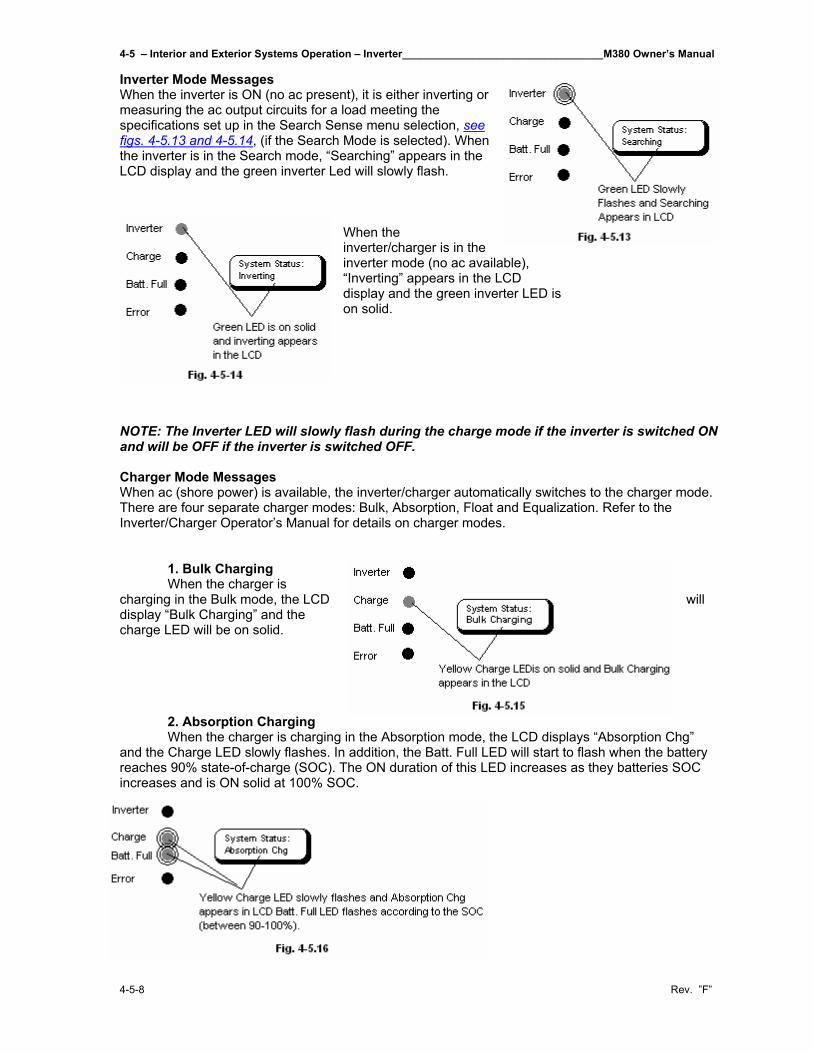
4-5 – Interior and Exterior Systems Operation – Inverter__________________________________M380 Owner’s Manual
4-5-8 Rev. ”F”
Inverter Mode Messages When the inverter is ON (no ac present), it is either inverting or measuring the ac output circuits for a load meeting the specifications set up in the Search Sense menu selection, see figs. 4-5.13 and 4-5.14, (if the Search Mode is selected). When the inverter is in the Search mode, “Searching” appears in the LCD display and the green inverter Led will slowly flash.
When the inverter/charger is in the inverter mode (no ac available), “Inverting” appears in the LCD display and the green inverter LED is on solid.
NOTE: The Inverter LED will slowly flash during the charge mode if the inverter is switched ON and will be OFF if the inverter is switched OFF. Charger Mode Messages When ac (shore power) is available, the inverter/charger automatically switches to the charger mode. There are four separate charger modes: Bulk, Absorption, Float and Equalization. Refer to the Inverter/Charger Operator’s Manual for details on charger modes. 1. Bulk Charging When the charger is charging in the Bulk mode, the LCD will display “Bulk Charging” and the charge LED will be on solid. 2. Absorption Charging When the charger is charging in the Absorption mode, the LCD displays “Absorption Chg” and the Charge LED slowly flashes. In addition, the Batt. Full LED will start to flash when the battery reaches 90% state-of-charge (SOC). The ON duration of this LED increases as they batteries SOC increases and is ON solid at 100% SOC.
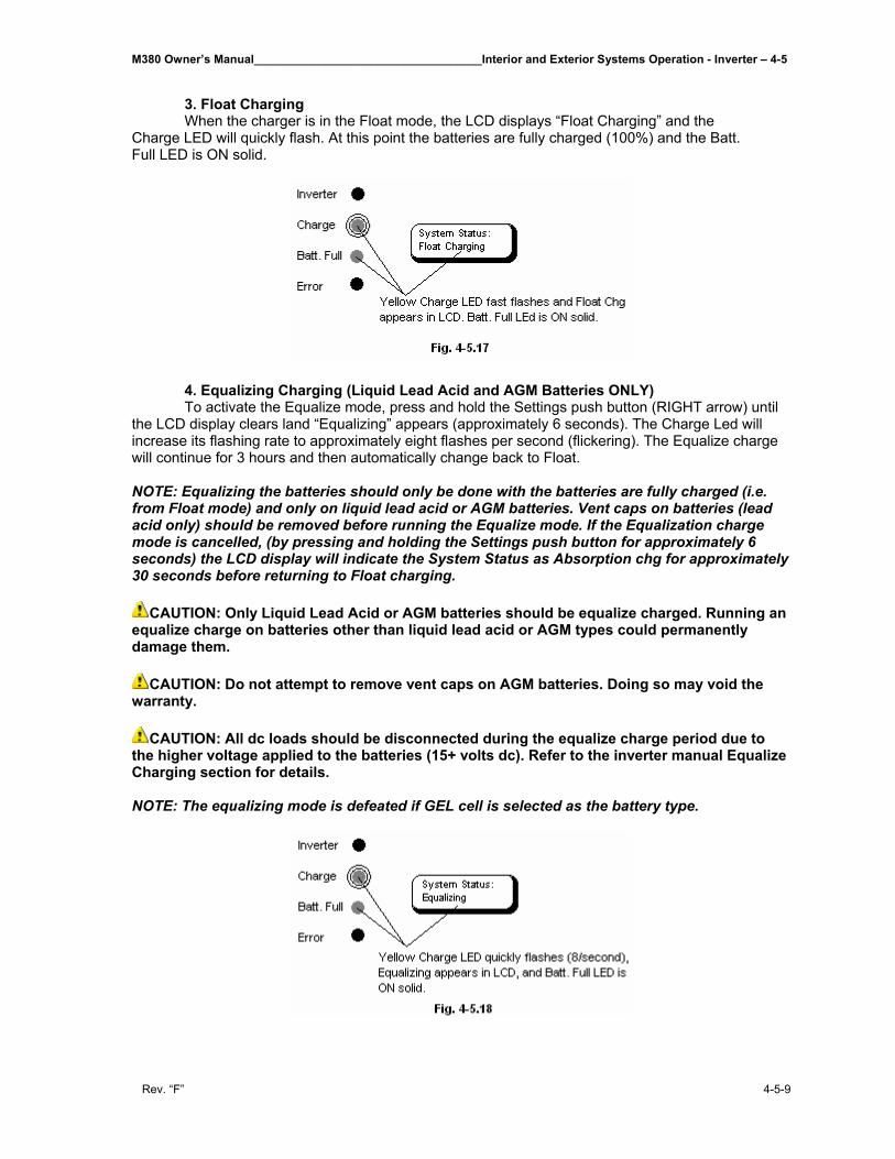
M380 Owner’s Manual___________________________________Interior and Exterior Systems Operation - Inverter – 4-5
Rev. “F” 4-5-9
3. Float Charging When the charger is in the Float mode, the LCD displays “Float Charging” and the Charge LED will quickly flash. At this point the batteries are fully charged (100%) and the Batt. Full LED is ON solid. 4. Equalizing Charging (Liquid Lead Acid and AGM Batteries ONLY) To activate the Equalize mode, press and hold the Settings push button (RIGHT arrow) until the LCD display clears land “Equalizing” appears (approximately 6 seconds). The Charge Led will increase its flashing rate to approximately eight flashes per second (flickering). The Equalize charge will continue for 3 hours and then automatically change back to Float. NOTE: Equalizing the batteries should only be done with the batteries are fully charged (i.e. from Float mode) and only on liquid lead acid or AGM batteries. Vent caps on batteries (lead acid only) should be removed before running the Equalize mode. If the Equalization charge mode is cancelled, (by pressing and holding the Settings push button for approximately 6 seconds) the LCD display will indicate the System Status as Absorption chg for approximately 30 seconds before returning to Float charging.
CAUTION: Only Liquid Lead Acid or AGM batteries should be equalize charged. Running an equalize charge on batteries other than liquid lead acid or AGM types could permanently damage them.
CAUTION: Do not attempt to remove vent caps on AGM batteries. Doing so may void the warranty.
CAUTION: All dc loads should be disconnected during the equalize charge period due to the higher voltage applied to the batteries (15+ volts dc). Refer to the inverter manual Equalize Charging section for details. NOTE: The equalizing mode is defeated if GEL cell is selected as the battery type.
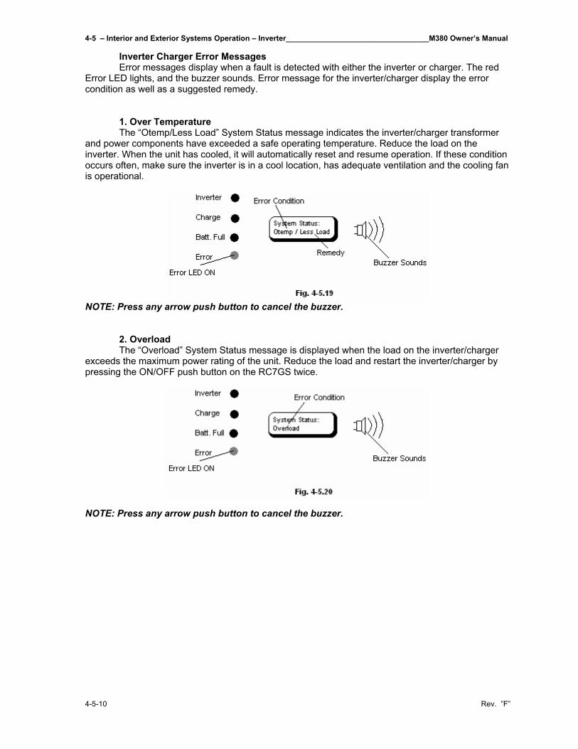
4-5 – Interior and Exterior Systems Operation – Inverter__________________________________M380 Owner’s Manual
4-5-10 Rev. ”F”
Inverter Charger Error Messages Error messages display when a fault is detected with either the inverter or charger. The red Error LED lights, and the buzzer sounds. Error message for the inverter/charger display the error condition as well as a suggested remedy. 1. Over Temperature The “Otemp/Less Load” System Status message indicates the inverter/charger transformer and power components have exceeded a safe operating temperature. Reduce the load on the inverter. When the unit has cooled, it will automatically reset and resume operation. If these condition occurs often, make sure the inverter is in a cool location, has adequate ventilation and the cooling fan is operational. NOTE: Press any arrow push button to cancel the buzzer. 2. Overload The “Overload” System Status message is displayed when the load on the inverter/charger exceeds the maximum power rating of the unit. Reduce the load and restart the inverter/charger by pressing the ON/OFF push button on the RC7GS twice. NOTE: Press any arrow push button to cancel the buzzer.
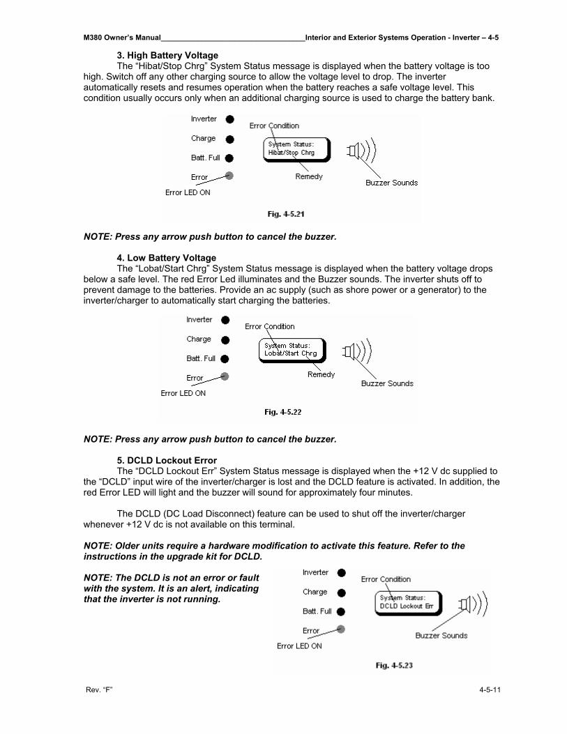
M380 Owner’s Manual___________________________________Interior and Exterior Systems Operation - Inverter – 4-5
Rev. “F” 4-5-11
3. High Battery Voltage The “Hibat/Stop Chrg” System Status message is displayed when the battery voltage is too high. Switch off any other charging source to allow the voltage level to drop. The inverter automatically resets and resumes operation when the battery reaches a safe voltage level. This condition usually occurs only when an additional charging source is used to charge the battery bank. NOTE: Press any arrow push button to cancel the buzzer. 4. Low Battery Voltage The “Lobat/Start Chrg” System Status message is displayed when the battery voltage drops below a safe level. The red Error Led illuminates and the Buzzer sounds. The inverter shuts off to prevent damage to the batteries. Provide an ac supply (such as shore power or a generator) to the inverter/charger to automatically start charging the batteries. NOTE: Press any arrow push button to cancel the buzzer. 5. DCLD Lockout Error The “DCLD Lockout Err” System Status message is displayed when the +12 V dc supplied to the “DCLD” input wire of the inverter/charger is lost and the DCLD feature is activated. In addition, the red Error LED will light and the buzzer will sound for approximately four minutes. The DCLD (DC Load Disconnect) feature can be used to shut off the inverter/charger whenever +12 V dc is not available on this terminal. NOTE: Older units require a hardware modification to activate this feature. Refer to the instructions in the upgrade kit for DCLD. NOTE: The DCLD is not an error or fault with the system. It is an alert, indicating that the inverter is not running.
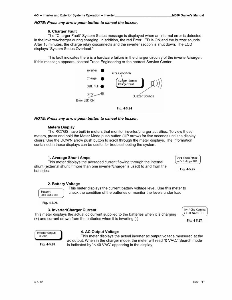
4-5 – Interior and Exterior Systems Operation – Inverter__________________________________M380 Owner’s Manual
4-5-12 Rev. ”F”
NOTE: Press any arrow push button to cancel the buzzer. 6. Charger Fault The “Charger Fault” System Status message is displayed when an internal error is detected in the inverter/charger during charging. In addition, the red Error LED is ON and the buzzer sounds. After 15 minutes, the charge relay disconnects and the inverter section is shut down. The LCD displays “System Status Overload.” This fault indicates there is a hardware failure in the charger circuitry of the inverter/charger. If this message appears, contact Trace Engineering or the nearest Service Center. NOTE: Press any arrow push button to cancel the buzzer. Meters Display The RC7GS have built-in meters that monitor inverter/charger activities. To view these meters, press and hold the Meter Mode push button (UP arrow) for five seconds until the display clears. Use the DOWN arrow push button to scroll through the meter displays. The information contained in these displays can be useful for troubleshooting the system. 1. Average Shunt Amps This meter displays the averaged current flowing through the internal shunt (external shunt if more than one inverter/charger is used) to and from the batteries. 2. Battery Voltage
This meter displays the current battery voltage level. Use this meter to check the condition of the batteries or monitor the levels under load.
3. Inverter/Charger Current This meter displays the actual dc current supplied to the batteries when it is charging (+) and current drawn from the batteries when it is inverting (-)
4. AC Output Voltage This meter displays the actual inverter ac output voltage measured at the ac output. When in the charger mode, the meter will read “0 VAC.” Search mode is indicated by “< 40 VAC” appearing in the display.
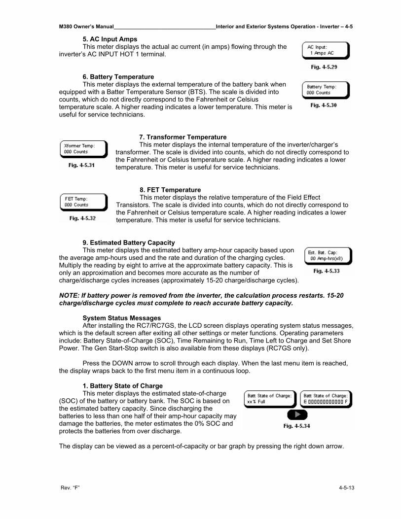
M380 Owner’s Manual___________________________________Interior and Exterior Systems Operation - Inverter – 4-5
Rev. “F” 4-5-13
5. AC Input Amps This meter displays the actual ac current (in amps) flowing through the inverter’s AC INPUT HOT 1 terminal. 6. Battery Temperature This meter displays the external temperature of the battery bank when equipped with a Batter Temperature Sensor (BTS). The scale is divided into counts, which do not directly correspond to the Fahrenheit or Celsius temperature scale. A higher reading indicates a lower temperature. This meter is useful for service technicians.
7. Transformer Temperature This meter displays the internal temperature of the inverter/charger’s transformer. The scale is divided into counts, which do not directly correspond to the Fahrenheit or Celsius temperature scale. A higher reading indicates a lower temperature. This meter is useful for service technicians.
8. FET Temperature This meter displays the relative temperature of the Field Effect Transistors. The scale is divided into counts, which do not directly correspond to the Fahrenheit or Celsius temperature scale. A higher reading indicates a lower temperature. This meter is useful for service technicians.
9. Estimated Battery Capacity This meter displays the estimated battery amp-hour capacity based upon the average amp-hours used and the rate and duration of the charging cycles. Multiply the reading by eight to arrive at the approximate battery capacity. This is only an approximation and becomes more accurate as the number of charge/discharge cycles increases (approximately 15-20 charge/discharge cycles). NOTE: If battery power is removed from the inverter, the calculation process restarts. 15-20 charge/discharge cycles must complete to reach accurate battery capacity. System Status Messages After installing the RC7/RC7GS, the LCD screen displays operating system status messages, which is the default screen after exiting all other settings or meter functions. Operating parameters include: Battery State-of-Charge (SOC), Time Remaining to Run, Time Left to Charge and Set Shore Power. The Gen Start-Stop switch is also available from these displays (RC7GS only). Press the DOWN arrow to scroll through each display. When the last menu item is reached, the display wraps back to the first menu item in a continuous loop. 1. Battery State of Charge This meter displays the estimated state-of-charge (SOC) of the battery or battery bank. The SOC is based on the estimated battery capacity. Since discharging the batteries to less than one half of their amp-hour capacity may damage the batteries, the meter estimates the 0% SOC and protects the batteries from over discharge. The display can be viewed as a percent-of-capacity or bar graph by pressing the right down arrow.
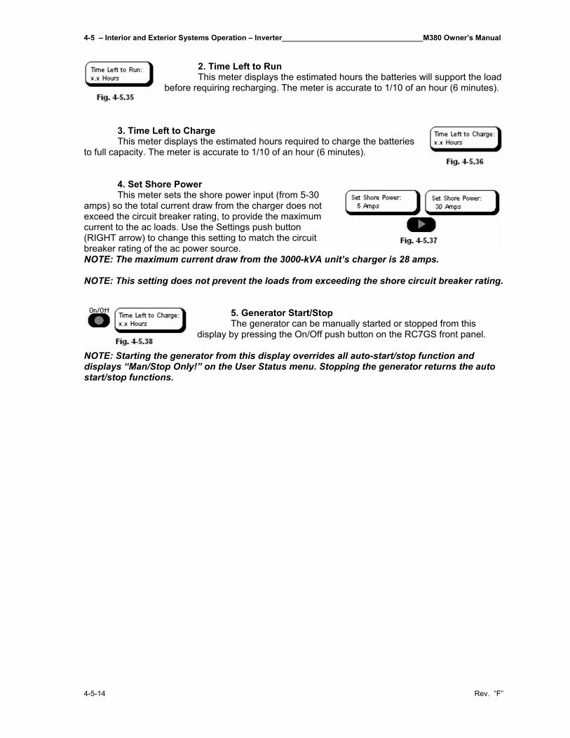
4-5 – Interior and Exterior Systems Operation – Inverter__________________________________M380 Owner’s Manual
4-5-14 Rev. ”F”
2. Time Left to Run This meter displays the estimated hours the batteries will support the load before requiring recharging. The meter is accurate to 1/10 of an hour (6 minutes).
3. Time Left to Charge This meter displays the estimated hours required to charge the batteries to full capacity. The meter is accurate to 1/10 of an hour (6 minutes). 4. Set Shore Power This meter sets the shore power input (from 5-30 amps) so the total current draw from the charger does not exceed the circuit breaker rating, to provide the maximum current to the ac loads. Use the Settings push button (RIGHT arrow) to change this setting to match the circuit breaker rating of the ac power source. NOTE: The maximum current draw from the 3000-kVA unit’s charger is 28 amps. NOTE: This setting does not prevent the loads from exceeding the shore circuit breaker rating.
5. Generator Start/Stop The generator can be manually started or stopped from this display by pressing the On/Off push button on the RC7GS front panel.
NOTE: Starting the generator from this display overrides all auto-start/stop function and displays “Man/Stop Only!” on the User Status menu. Stopping the generator returns the auto start/stop functions.
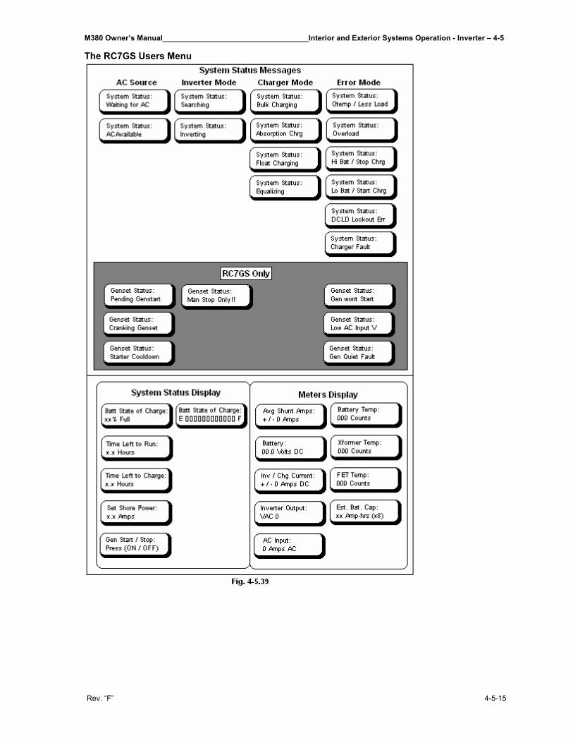
M380 Owner’s Manual___________________________________Interior and Exterior Systems Operation - Inverter – 4-5
Rev. “F” 4-5-15
The RC7GS Users Menu

M380 Owner’s Manual__________________________________________________________________________________
Rev. “F”
THIS PAGE IS INTENTIONALLY LEFT BLANK

M380 Owner’s Manual___________________________Interior and Exterior Systems Operation – Battery Systems – 4-6
Rev. “F” 4-6-1
4-6 Battery Systems_____________________________________ 4-6.1 Chassis Batteries Two 12-volt maintenance free 810 CCA batteries wired parallel produce power for starting the motor home engine. 4-6.2 Battery Charger One 160-Amp battery charger (integral with the Trace 3000 inverter) operates when a source of 120 volts of AC is supplied from either shoreline or generator. The charger is connected to the motor home batteries. Enabling the auxiliary battery switch on the lower dash may also charge the engine batteries. 4-6.3 Generator Battery A separate 12V rated at 530 CCA battery is installed for starting the generator. 4-6.4 House Batteries The house battery system consists of three Lifeline 4D AGM batteries with an Amp-Hour rating of 210 alt each. With the Lifeline batteries you get:
• Aircraft class cell construction: Lowers internal resistance for high repeated engine start current. Withstands shock and vibration much better than standard flooded or gelled
electrolyte designs. • Twice as many discharge/charge cycles as the leading gel battery depending on depth of
discharges. • Faster recharge, no current limitations with voltage regulated recharging • Much better charge retention than low cost, flooded cell types, even at high ambient
temperature. • Full recharge after 30 days storage in a full discharge condition (77°F rating). • Less than 3% per month self discharge at 77°F (25°C); less at lower temperatures. • Sealed construction with absorbed electrolyte-no shipment restrictions, submersible without
damage; install in any position; no need for watering. • Cell safety vent valves-pressure regulated, non-removable. • Rugged, non-marring polypropylene (copolymer) case/cover. • Safety-even during severe overcharge the Lifeline AGM battery produces less than 2%
hydrogen gas (4.1% is required for flammability in air)
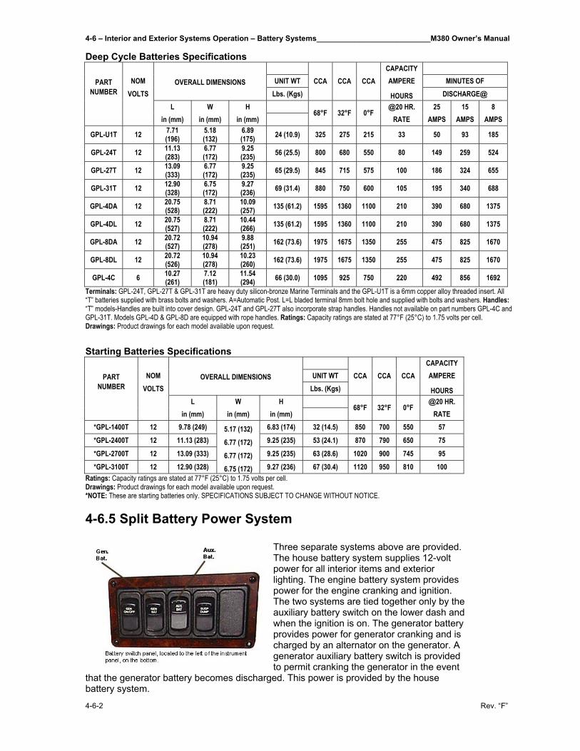
4-6 – Interior and Exterior Systems Operation – Battery Systems___________________________M380 Owner’s Manual
4-6-2 Rev. “F”
Deep Cycle Batteries Specifications CAPACITY
PART NOM OVERALL DIMENSIONS UNIT WT AMPERE MINUTES OF VOLTS Lbs. (Kgs)
CCA CCA CCA
HOURS DISCHARGE@ L W H @20 HR. 25 15 8
NUMBER
in (mm) in (mm) in (mm) 68°F 32°F 0°F
RATE AMPS AMPS AMPS
GPL-U1T 12 7.71 (196)
5.18 (132)
6.89 (175) 24 (10.9) 325 275 215 33 50 93 185
GPL-24T 12 11.13 (283)
6.77 (172)
9.25 (235) 56 (25.5) 800 680 550 80 149 259 524
GPL-27T 12 13.09 (333)
6.77 (172)
9.25 (235) 65 (29.5) 845 715 575 100 186 324 655
GPL-31T 12 12.90 (328)
6.75 (172)
9.27 (236) 69 (31.4) 880 750 600 105 195 340 688
GPL-4DA 12 20.75 (528)
8.71 (222)
10.09 (257) 135 (61.2) 1595 1360 1100 210 390 680 1375
GPL-4DL 12 20.75 (527)
8.71 (222)
10.44 (266) 135 (61.2) 1595 1360 1100 210 390 680 1375
GPL-8DA 12 20.72 (527)
10.94 (278)
9.88 (251) 162 (73.6) 1975 1675 1350 255 475 825 1670
GPL-8DL 12 20.72 (526)
10.94 (278)
10.23 (260) 162 (73.6) 1975 1675 1350 255 475 825 1670
GPL-4C 6 10.27 (261)
7.12 (181)
11.54 (294) 66 (30.0) 1095 925 750 220 492 856 1692
Terminals: GPL-24T, GPL-27T & GPL-31T are heavy duty silicon-bronze Marine Terminals and the GPL-U1T is a 6mm copper alloy threaded insert. All “T” batteries supplied with brass bolts and washers. A=Automatic Post. L=L bladed terminal 8mm bolt hole and supplied with bolts and washers. Handles: “T” models-Handles are built into cover design. GPL-24T and GPL-27T also incorporate strap handles. Handles not available on part numbers GPL-4C and GPL-31T. Models GPL-4D & GPL-8D are equipped with rope handles. Ratings: Capacity ratings are stated at 77°F (25°C) to 1.75 volts per cell. Drawings: Product drawings for each model available upon request.
Starting Batteries Specifications
CAPACITY
PART NOM OVERALL DIMENSIONS UNIT WT AMPERE VOLTS Lbs. (Kgs)
CCA CCA CCA
HOURS L W H @20 HR.
NUMBER
in (mm) in (mm) in (mm) 68°F 32°F 0°F
RATE *GPL-1400T 12 9.78 (249) 5.17 (132) 6.83 (174) 32 (14.5) 850 700 550 57 *GPL-2400T 12 11.13 (283) 6.77 (172) 9.25 (235) 53 (24.1) 870 790 650 75 *GPL-2700T 12 13.09 (333) 6.77 (172) 9.25 (235) 63 (28.6) 1020 900 745 95 *GPL-3100T 12 12.90 (328) 6.75 (172) 9.27 (236) 67 (30.4) 1120 950 810 100
Ratings: Capacity ratings are stated at 77°F (25°C) to 1.75 volts per cell. Drawings: Product drawings for each model available upon request. *NOTE: These are starting batteries only. SPECIFICATIONS SUBJECT TO CHANGE WITHOUT NOTICE. 4-6.5 Split Battery Power System
Three separate systems above are provided. The house battery system supplies 12-volt power for all interior items and exterior lighting. The engine battery system provides power for the engine cranking and ignition. The two systems are tied together only by the auxiliary battery switch on the lower dash and when the ignition is on. The generator battery provides power for generator cranking and is charged by an alternator on the generator. A generator auxiliary battery switch is provided to permit cranking the generator in the event
that the generator battery becomes discharged. This power is provided by the house battery system.
M380 Owner’s Manual___________________________Interior and Exterior Systems Operation – Battery Systems – 4-6
Rev. “F” 4-6-3
4-6.6 Battery Maintenance Your motor home is equipped with separate engine and house battery systems for greater assurance that there will be sufficient voltage to crank the motor home engine. Three engine batteries are located in the engine compartment on the curbside. The three house batteries are located in the first luggage bay. The house and engine batteries are charged from either the alternator or the inverter battery charger. The auxiliary battery switch is in the ON position in order for the inverter battery charger to operate, either the generator must be running or the motor home must be connected to a shoreline supply. To make sure that the batteries are always ready for use, periodically check and charge them as necessary. A dirty battery may eventually dissipate its charge through conductive surface contamination. Clean the engine battery top surfaces with a damp cloth and dry thoroughly. Check that battery terminals and associated battery jumper terminals are tight and free of corrosion. To clean terminals, neutralize corrosive deposits with a solution of baking soda, rinse with clear water, and dry. Note that commercial type spray-on battery cleaners are available at automotive supply stores. Use as directed to keep the batteries clean. Spray-on cable and terminal protective coatings are also available, easy to use, and effective. The house batteries are located in a sealed, vented, battery box in Bay 1.
CAUTION: Avoid sparking of any form in the vicinity of the batteries.
CAUTION: Do not wear metal rings, watches or jewelry when working on or near the batteries, cable, solenoids or chassis wiring. These can short out electrical wiring and cause injury. 4-6.7 Battery Storage in Freezing Weather Batteries that are not kept fully charged must be given protection against freezing. Partially charged batteries will freeze at low temperatures, so batteries must either be left charged or removed from the vehicle and stored in a warm location. The motor home can be left connected to the shoreline AC supply and the inverter battery charger will keep the motor home batteries charged. NOTE: The inverter must be turned on to charge the batteries. NOTE: Even in a warm location it is advisable to keep the batteries charged to prevent deterioration. The engine batteries are the sealed type and require no electrolyte service. Coat battery terminals with lubricant or protective coating.
4-6 – Interior and Exterior Systems Operation – Battery Systems___________________________M380 Owner’s Manual
4-6-4 Rev. “F”
4-6.8 Battery Terminals and Jump Starting The proper procedure for jump-starting, using the Wanderlodge® engine batteries, is as follows:
1. Turn off all main battery-operated accessories in both vehicles such as the lights, radio, etc.
2. Connect one end of the positive-coded jumper cable to the positive (+) battery terminal, and the opposite end of the cable to the positive (+) terminal on the other battery.
3. Connect one end of the negative-coded jumper cable to the negative (-) terminal on the other battery and the opposite end of the cable to the Wanderlodge engine block.
4. Once the engine of the disable vehicle is started and brought up to idle, reverse the above procedure to remove the jumper cables. Always remove the jumper cable connected to the Wanderlodge engine block terminal first to prevent sparks at the other battery.
CAUTION: Avoid sparks in the vicinity of a charging battery. The gas
produced is explosive.
M380 Owner’s Manual___________________________Interior and Exterior Systems Operation - Leveling System – 4-7
Rev. “F” 4-7-1
4-7 Leveling System____________________________________ Your motor home comes equipped with a “Big Foot” Hydraulic Leveling System from Quadra Manufacturing, Inc. The “BIG FOOT” Leveling System is the finest available in the industry today. Many of its features are not available on other systems. We take great pride in offering you a system which when operated and maintained properly, provides many years of trouble free use. The system is like anything mechanical; if you follow the basic operating procedures and keep the system properly maintained it will give you higher quality and more consistent performance. 4-7.1 Operating Instructions for Automatic Control Panel with
Manual Option: 1. Turn Power Switch On NOTE: Immediately upon power initialization the system will enter a 30-second self-diagnostic mode, indicated by the Directional LEDS and the Level Indicator flashing. Upon completion of this mode, one or two Directional LEDS will be lit with one flashing. A lit LED indicates the end and/or side of the vehicle that is low. If the vehicle is in a level position, only the Level Light will flash. 2. Select Auto or Manual Mode by pressing the corresponding touch pad. Operate Air Dump by engaging Air Dump switch located on the dash panel. If Auto Mode was selected, proceed to “Automatic Mode” Step 3. If Manual Mode was selected, turn to “Extending Levelers Individually” AUTOMATIC MODE: 3. WAIT WHILE WATCHING THE PANEL. The system will lower both legs at the lowest end of the vehicle. When the first leg reaches the ground it will cause the system to sense motion and stop. Next, each leg will be lowered individually confirming ground contact by causing the system to sense motion. The system will then repeat the process for the other end of the vehicle. 4. WAIT WHILE WATCHING THE PANEL The system will repeat Step 3 for the other end of the vehicle then level the vehicle in all other directions. Completion of this process is indicated by illumination of the Level Light.
4-7.1.1 Retracting Levelers while in Automatic Mode IMPORTANT! After the levelers are retracted make a visual check to be sure all legs are retracted before moving the unit! Determine if the power to the Control Panel was left on or turned off, and proceed as follows: If the Control Panel Power Was Turned On: Press the Retract Pad and release. All legs will automatically retract and cause the All-Up LED to light. If the Control Panel Power Was Turned Off: Turn power on and wait for the system to go through a 30-second self-diagnostic mode, indicated by the Directional LEDS and the Level Indicator flashing. Press the Retract Pad and hold in until all levelers are completely retracted as indicated by the All-Up LED being lit.
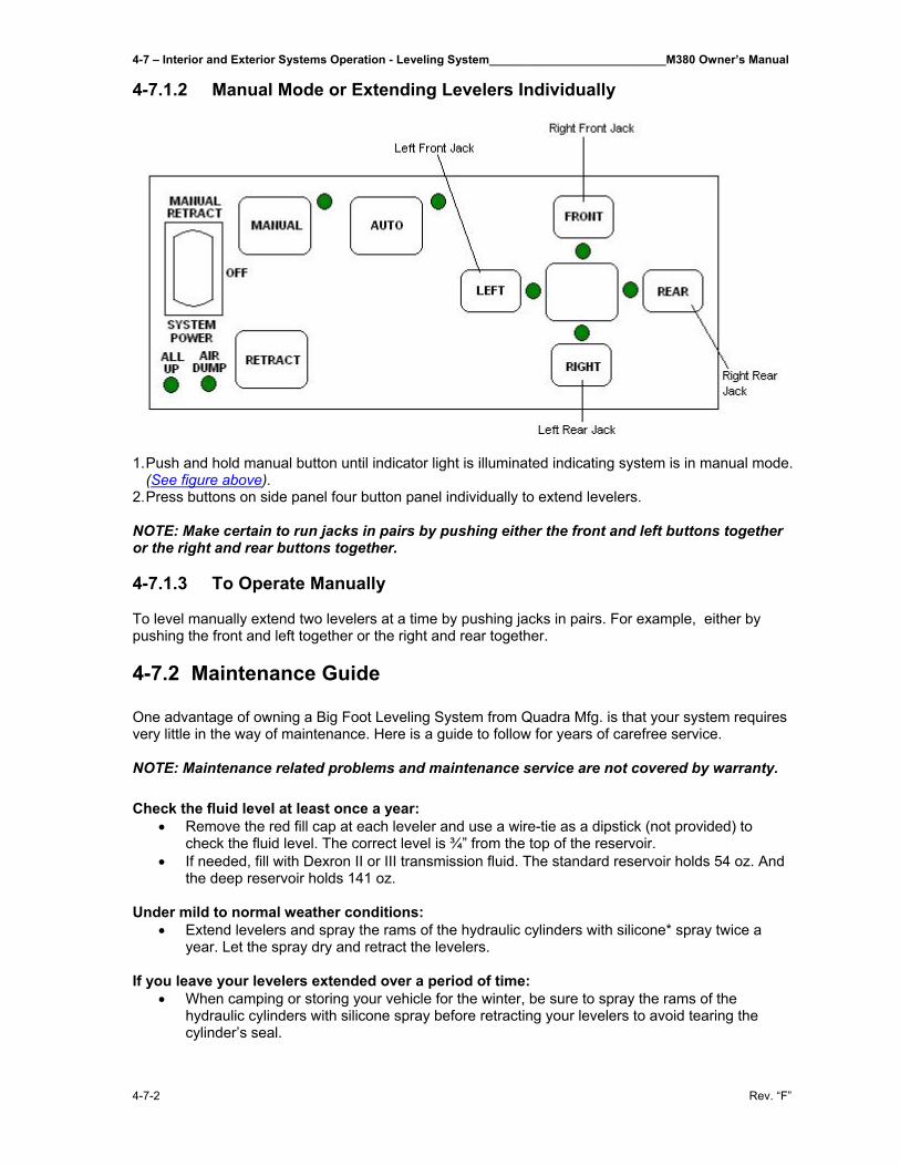
4-7 – Interior and Exterior Systems Operation - Leveling System___________________________M380 Owner’s Manual
4-7-2 Rev. “F”
4-7.1.2 Manual Mode or Extending Levelers Individually
1. Push and hold manual button until indicator light is illuminated indicating system is in manual mode.
(See figure above). 2. Press buttons on side panel four button panel individually to extend levelers. NOTE: Make certain to run jacks in pairs by pushing either the front and left buttons together or the right and rear buttons together.
4-7.1.3 To Operate Manually To level manually extend two levelers at a time by pushing jacks in pairs. For example, either by pushing the front and left together or the right and rear together. 4-7.2 Maintenance Guide One advantage of owning a Big Foot Leveling System from Quadra Mfg. is that your system requires very little in the way of maintenance. Here is a guide to follow for years of carefree service. NOTE: Maintenance related problems and maintenance service are not covered by warranty. Check the fluid level at least once a year:
• Remove the red fill cap at each leveler and use a wire-tie as a dipstick (not provided) to check the fluid level. The correct level is ¾” from the top of the reservoir.
• If needed, fill with Dexron II or III transmission fluid. The standard reservoir holds 54 oz. And the deep reservoir holds 141 oz.
Under mild to normal weather conditions:
• Extend levelers and spray the rams of the hydraulic cylinders with silicone* spray twice a year. Let the spray dry and retract the levelers.
If you leave your levelers extended over a period of time:
• When camping or storing your vehicle for the winter, be sure to spray the rams of the hydraulic cylinders with silicone spray before retracting your levelers to avoid tearing the cylinder’s seal.
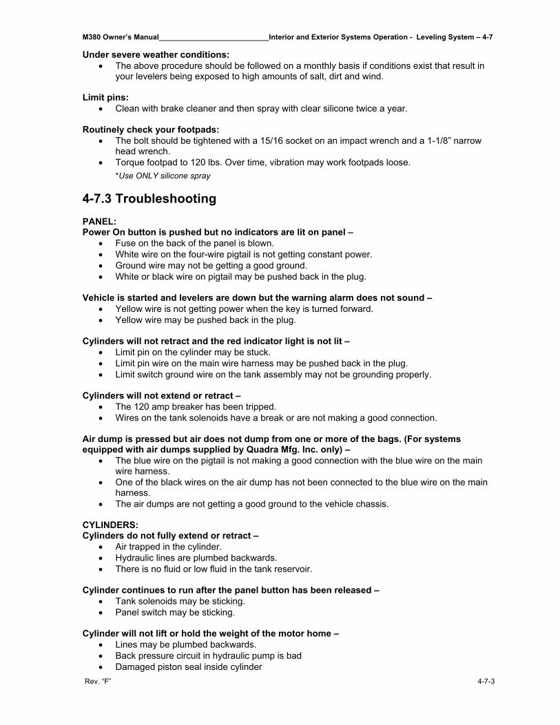
M380 Owner’s Manual___________________________Interior and Exterior Systems Operation - Leveling System – 4-7
Rev. “F” 4-7-3
Under severe weather conditions: • The above procedure should be followed on a monthly basis if conditions exist that result in
your levelers being exposed to high amounts of salt, dirt and wind. Limit pins:
• Clean with brake cleaner and then spray with clear silicone twice a year. Routinely check your footpads:
• The bolt should be tightened with a 15/16 socket on an impact wrench and a 1-1/8” narrow head wrench.
• Torque footpad to 120 lbs. Over time, vibration may work footpads loose. *Use ONLY silicone spray
4-7.3 Troubleshooting PANEL: Power On button is pushed but no indicators are lit on panel –
• Fuse on the back of the panel is blown. • White wire on the four-wire pigtail is not getting constant power. • Ground wire may not be getting a good ground. • White or black wire on pigtail may be pushed back in the plug.
Vehicle is started and levelers are down but the warning alarm does not sound –
• Yellow wire is not getting power when the key is turned forward. • Yellow wire may be pushed back in the plug.
Cylinders will not retract and the red indicator light is not lit –
• Limit pin on the cylinder may be stuck. • Limit pin wire on the main wire harness may be pushed back in the plug. • Limit switch ground wire on the tank assembly may not be grounding properly.
Cylinders will not extend or retract –
• The 120 amp breaker has been tripped. • Wires on the tank solenoids have a break or are not making a good connection.
Air dump is pressed but air does not dump from one or more of the bags. (For systems equipped with air dumps supplied by Quadra Mfg. Inc. only) –
• The blue wire on the pigtail is not making a good connection with the blue wire on the main wire harness.
• One of the black wires on the air dump has not been connected to the blue wire on the main harness.
• The air dumps are not getting a good ground to the vehicle chassis. CYLINDERS: Cylinders do not fully extend or retract –
• Air trapped in the cylinder. • Hydraulic lines are plumbed backwards. • There is no fluid or low fluid in the tank reservoir.
Cylinder continues to run after the panel button has been released –
• Tank solenoids may be sticking. • Panel switch may be sticking.
Cylinder will not lift or hold the weight of the motor home –
• Lines may be plumbed backwards. • Back pressure circuit in hydraulic pump is bad • Damaged piston seal inside cylinder

M380 Owner’s Manual__________________________________________________________________________________
Rev. “F”
THIS PAGE IS INTENTIONALLY LEFT BLANK
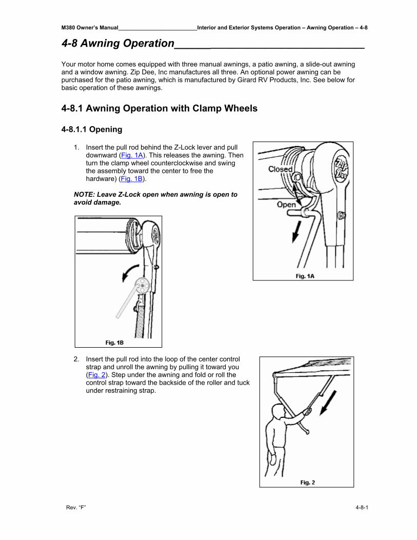
M380 Owner’s Manual__________________________Interior and Exterior Systems Operation – Awning Operation – 4-8
Rev. “F” 4-8-1
4-8 Awning Operation___________________________________ Your motor home comes equipped with three manual awnings, a patio awning, a slide-out awning and a window awning. Zip Dee, Inc manufactures all three. An optional power awning can be purchased for the patio awning, which is manufactured by Girard RV Products, Inc. See below for basic operation of these awnings. 4-8.1 Awning Operation with Clamp Wheels 4-8.1.1 Opening
1. Insert the pull rod behind the Z-Lock lever and pull downward (Fig. 1A). This releases the awning. Then turn the clamp wheel counterclockwise and swing the assembly toward the center to free the hardware) (Fig. 1B).
NOTE: Leave Z-Lock open when awning is open to avoid damage.
2. Insert the pull rod into the loop of the center control strap and unroll the awning by pulling it toward you (Fig. 2). Step under the awning and fold or roll the control strap toward the backside of the roller and tuck under restraining strap.
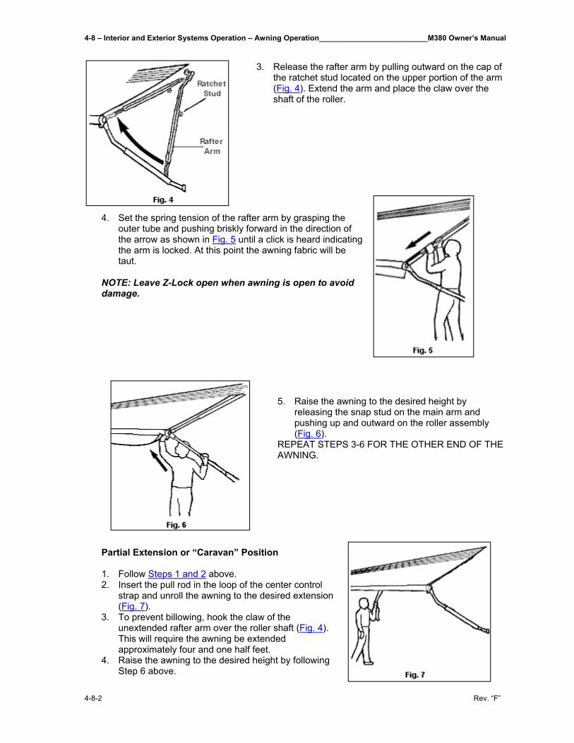
4-8 – Interior and Exterior Systems Operation – Awning Operation__________________________M380 Owner’s Manual
4-8-2 Rev. “F”
3. Release the rafter arm by pulling outward on the cap of
the ratchet stud located on the upper portion of the arm (Fig. 4). Extend the arm and place the claw over the shaft of the roller.
4. Set the spring tension of the rafter arm by grasping the outer tube and pushing briskly forward in the direction of the arrow as shown in Fig. 5 until a click is heard indicating the arm is locked. At this point the awning fabric will be taut.
NOTE: Leave Z-Lock open when awning is open to avoid damage.
5. Raise the awning to the desired height by releasing the snap stud on the main arm and pushing up and outward on the roller assembly (Fig. 6).
REPEAT STEPS 3-6 FOR THE OTHER END OF THE AWNING.
Partial Extension or “Caravan” Position 1. Follow Steps 1 and 2 above. 2. Insert the pull rod in the loop of the center control
strap and unroll the awning to the desired extension (Fig. 7).
3. To prevent billowing, hook the claw of the unextended rafter arm over the roller shaft (Fig. 4). This will require the awning be extended approximately four and one half feet.
4. Raise the awning to the desired height by following Step 6 above.
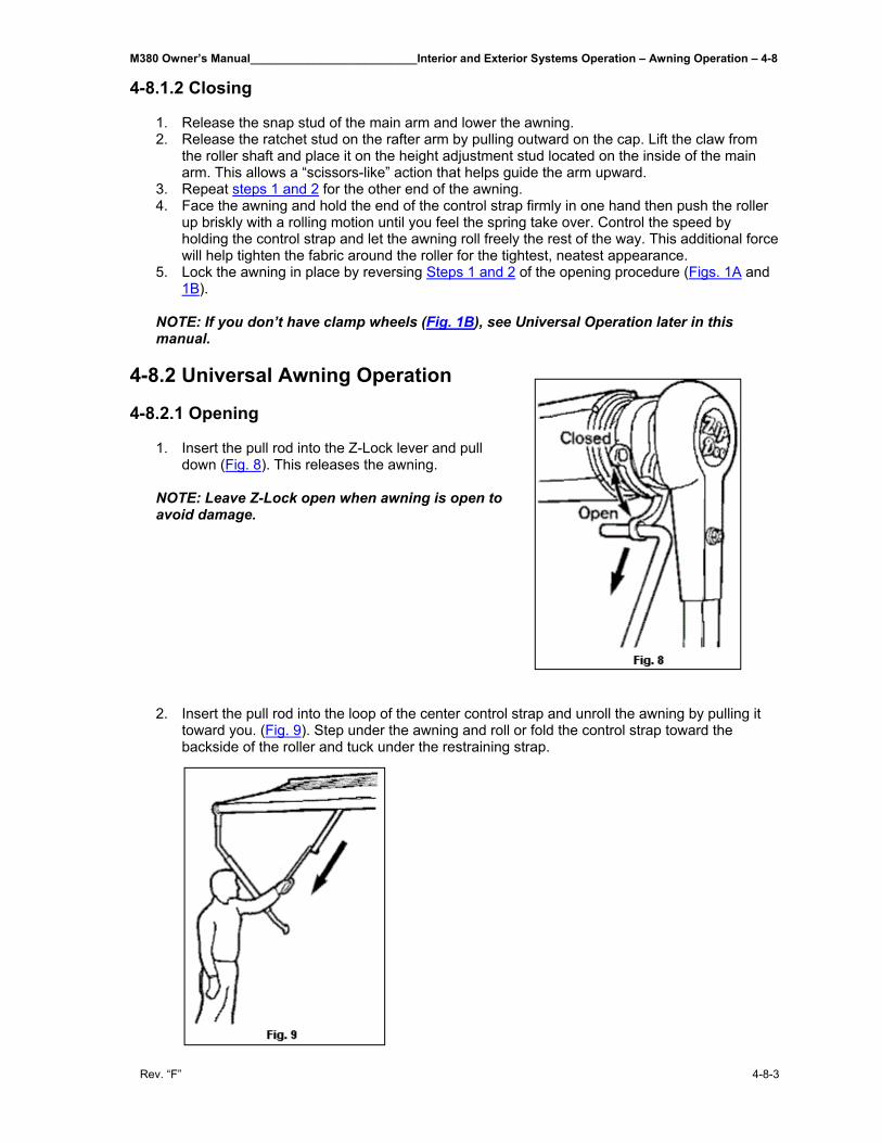
M380 Owner’s Manual__________________________Interior and Exterior Systems Operation – Awning Operation – 4-8
Rev. “F” 4-8-3
4-8.1.2 Closing 1. Release the snap stud of the main arm and lower the awning. 2. Release the ratchet stud on the rafter arm by pulling outward on the cap. Lift the claw from
the roller shaft and place it on the height adjustment stud located on the inside of the main arm. This allows a “scissors-like” action that helps guide the arm upward.
3. Repeat steps 1 and 2 for the other end of the awning. 4. Face the awning and hold the end of the control strap firmly in one hand then push the roller
up briskly with a rolling motion until you feel the spring take over. Control the speed by holding the control strap and let the awning roll freely the rest of the way. This additional force will help tighten the fabric around the roller for the tightest, neatest appearance.
5. Lock the awning in place by reversing Steps 1 and 2 of the opening procedure (Figs. 1A and 1B).
NOTE: If you don’t have clamp wheels (Fig. 1B), see Universal Operation later in this manual.
4-8.2 Universal Awning Operation
4-8.2.1 Opening 1. Insert the pull rod into the Z-Lock lever and pull
down (Fig. 8). This releases the awning. NOTE: Leave Z-Lock open when awning is open to avoid damage. 2. Insert the pull rod into the loop of the center control strap and unroll the awning by pulling it
toward you. (Fig. 9). Step under the awning and roll or fold the control strap toward the backside of the roller and tuck under the restraining strap.
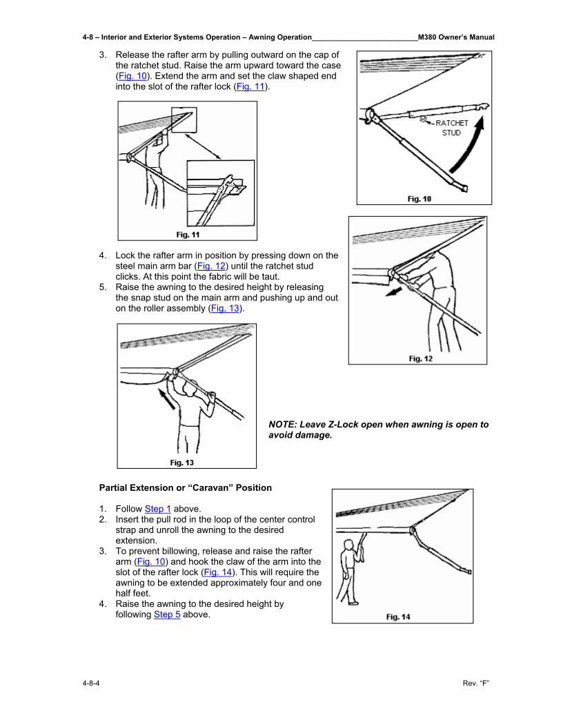
4-8 – Interior and Exterior Systems Operation – Awning Operation__________________________M380 Owner’s Manual
4-8-4 Rev. “F”
3. Release the rafter arm by pulling outward on the cap of the ratchet stud. Raise the arm upward toward the case (Fig. 10). Extend the arm and set the claw shaped end into the slot of the rafter lock (Fig. 11).
4. Lock the rafter arm in position by pressing down on the steel main arm bar (Fig. 12) until the ratchet stud clicks. At this point the fabric will be taut.
5. Raise the awning to the desired height by releasing the snap stud on the main arm and pushing up and out on the roller assembly (Fig. 13).
NOTE: Leave Z-Lock open when awning is open to avoid damage.
Partial Extension or “Caravan” Position 1. Follow Step 1 above. 2. Insert the pull rod in the loop of the center control
strap and unroll the awning to the desired extension.
3. To prevent billowing, release and raise the rafter arm (Fig. 10) and hook the claw of the arm into the slot of the rafter lock (Fig. 14). This will require the awning to be extended approximately four and one half feet.
4. Raise the awning to the desired height by following Step 5 above.
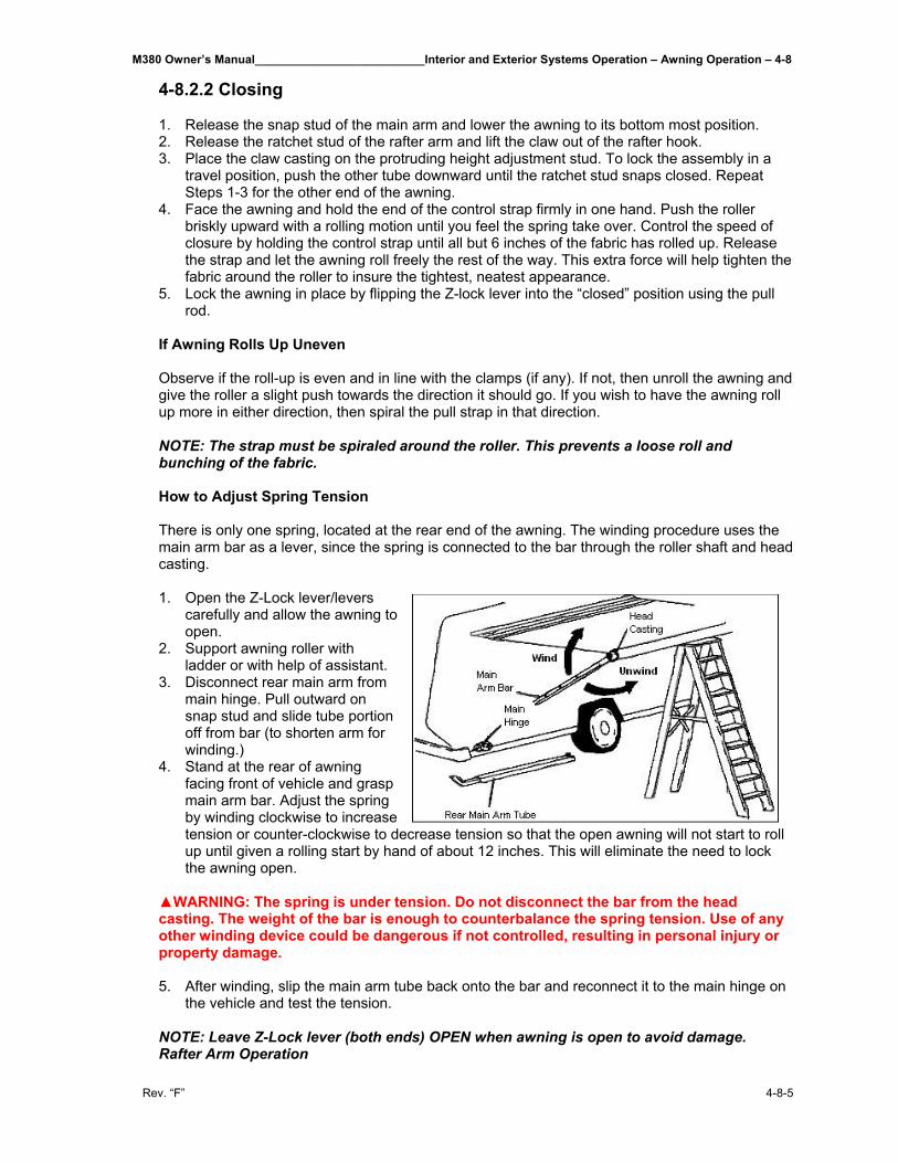
M380 Owner’s Manual__________________________Interior and Exterior Systems Operation – Awning Operation – 4-8
Rev. “F” 4-8-5
4-8.2.2 Closing 1. Release the snap stud of the main arm and lower the awning to its bottom most position. 2. Release the ratchet stud of the rafter arm and lift the claw out of the rafter hook. 3. Place the claw casting on the protruding height adjustment stud. To lock the assembly in a
travel position, push the other tube downward until the ratchet stud snaps closed. Repeat Steps 1-3 for the other end of the awning.
4. Face the awning and hold the end of the control strap firmly in one hand. Push the roller briskly upward with a rolling motion until you feel the spring take over. Control the speed of closure by holding the control strap until all but 6 inches of the fabric has rolled up. Release the strap and let the awning roll freely the rest of the way. This extra force will help tighten the fabric around the roller to insure the tightest, neatest appearance.
5. Lock the awning in place by flipping the Z-lock lever into the “closed” position using the pull rod.
If Awning Rolls Up Uneven Observe if the roll-up is even and in line with the clamps (if any). If not, then unroll the awning and give the roller a slight push towards the direction it should go. If you wish to have the awning roll up more in either direction, then spiral the pull strap in that direction. NOTE: The strap must be spiraled around the roller. This prevents a loose roll and bunching of the fabric. How to Adjust Spring Tension There is only one spring, located at the rear end of the awning. The winding procedure uses the main arm bar as a lever, since the spring is connected to the bar through the roller shaft and head casting. 1. Open the Z-Lock lever/levers
carefully and allow the awning to open.
2. Support awning roller with ladder or with help of assistant.
3. Disconnect rear main arm from main hinge. Pull outward on snap stud and slide tube portion off from bar (to shorten arm for winding.)
4. Stand at the rear of awning facing front of vehicle and grasp main arm bar. Adjust the spring by winding clockwise to increase tension or counter-clockwise to decrease tension so that the open awning will not start to roll up until given a rolling start by hand of about 12 inches. This will eliminate the need to lock the awning open.
▲WARNING: The spring is under tension. Do not disconnect the bar from the head casting. The weight of the bar is enough to counterbalance the spring tension. Use of any other winding device could be dangerous if not controlled, resulting in personal injury or property damage. 5. After winding, slip the main arm tube back onto the bar and reconnect it to the main hinge on
the vehicle and test the tension. NOTE: Leave Z-Lock lever (both ends) OPEN when awning is open to avoid damage. Rafter Arm Operation
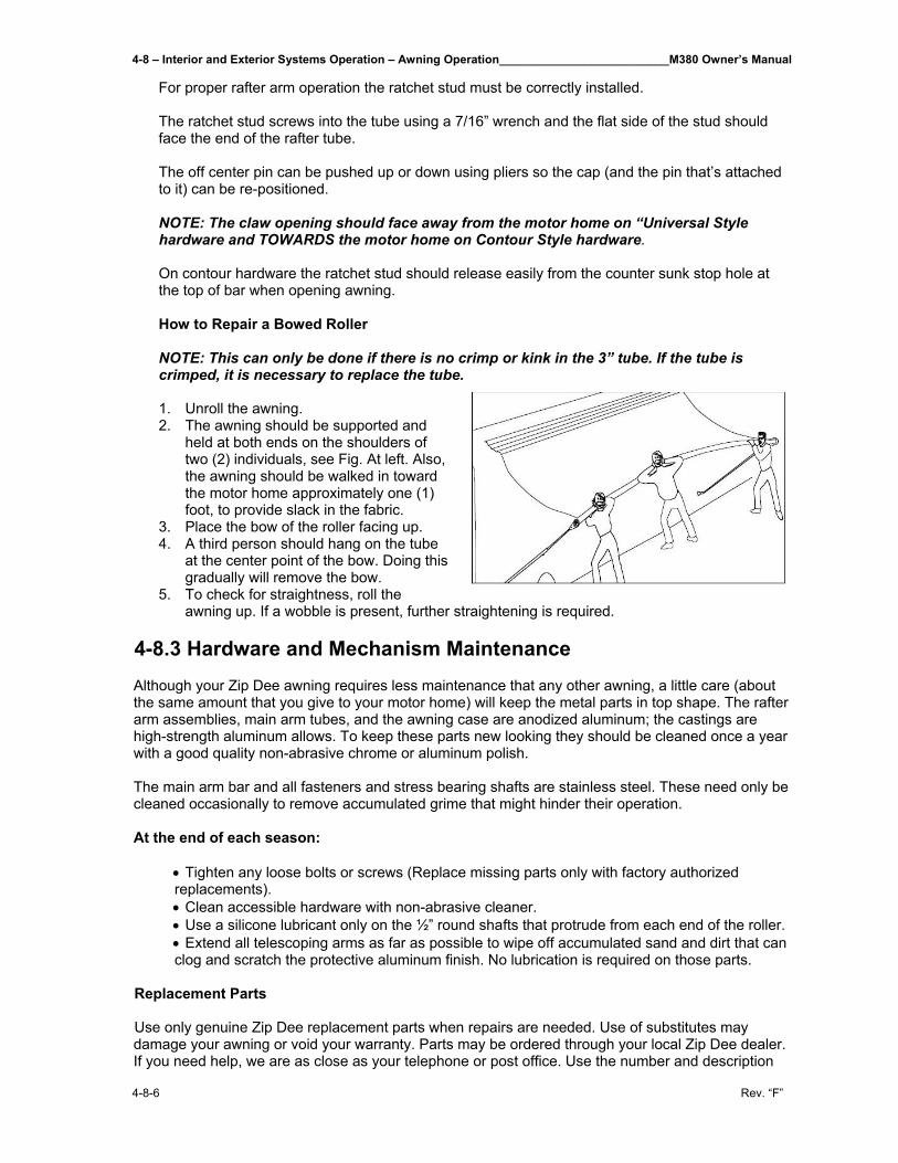
4-8 – Interior and Exterior Systems Operation – Awning Operation__________________________M380 Owner’s Manual
4-8-6 Rev. “F”
For proper rafter arm operation the ratchet stud must be correctly installed. The ratchet stud screws into the tube using a 7/16” wrench and the flat side of the stud should face the end of the rafter tube. The off center pin can be pushed up or down using pliers so the cap (and the pin that’s attached to it) can be re-positioned. NOTE: The claw opening should face away from the motor home on “Universal Style hardware and TOWARDS the motor home on Contour Style hardware. On contour hardware the ratchet stud should release easily from the counter sunk stop hole at the top of bar when opening awning. How to Repair a Bowed Roller NOTE: This can only be done if there is no crimp or kink in the 3” tube. If the tube is crimped, it is necessary to replace the tube. 1. Unroll the awning. 2. The awning should be supported and
held at both ends on the shoulders of two (2) individuals, see Fig. At left. Also, the awning should be walked in toward the motor home approximately one (1) foot, to provide slack in the fabric.
3. Place the bow of the roller facing up. 4. A third person should hang on the tube
at the center point of the bow. Doing this gradually will remove the bow.
5. To check for straightness, roll the awning up. If a wobble is present, further straightening is required.
4-8.3 Hardware and Mechanism Maintenance
Although your Zip Dee awning requires less maintenance that any other awning, a little care (about the same amount that you give to your motor home) will keep the metal parts in top shape. The rafter arm assemblies, main arm tubes, and the awning case are anodized aluminum; the castings are high-strength aluminum allows. To keep these parts new looking they should be cleaned once a year with a good quality non-abrasive chrome or aluminum polish. The main arm bar and all fasteners and stress bearing shafts are stainless steel. These need only be cleaned occasionally to remove accumulated grime that might hinder their operation. At the end of each season:
• Tighten any loose bolts or screws (Replace missing parts only with factory authorized replacements). • Clean accessible hardware with non-abrasive cleaner. • Use a silicone lubricant only on the ½” round shafts that protrude from each end of the roller. • Extend all telescoping arms as far as possible to wipe off accumulated sand and dirt that can clog and scratch the protective aluminum finish. No lubrication is required on those parts.
Replacement Parts Use only genuine Zip Dee replacement parts when repairs are needed. Use of substitutes may damage your awning or void your warranty. Parts may be ordered through your local Zip Dee dealer. If you need help, we are as close as your telephone or post office. Use the number and description
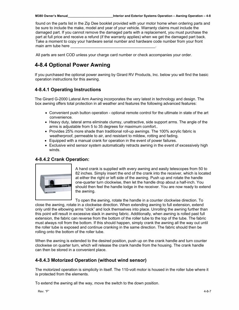
M380 Owner’s Manual__________________________Interior and Exterior Systems Operation – Awning Operation – 4-8
Rev. “F” 4-8-7
found on the parts list in the Zip Dee booklet provided with your motor home when ordering parts and be sure to include the make, model and year of your vehicle. Warranty claims must include the damaged part. If you cannot remove the damaged parts with a replacement, you must purchase the part at full price and receive a refund (if the warranty applies) when we get the damaged part back. Take a moment to copy your hardware serial number and hardware code number from your front main arm tube here _______________________________________. All parts are sent COD unless your charge card number or check accompanies your order.
4-8.4 Optional Power Awning If you purchased the optional power awning by Girard RV Products, Inc. below you will find the basic operation instructions for this awning. 4-8.4.1 Operating Instructions The Girard G-2000 Lateral Arm Awning incorporates the very latest in technology and design. The box awning offers total protection in all weather and features the following advanced features:
• Convenient push button operation - optional remote control for the ultimate in state of the art convenience.
• Heavy duty, lateral arms eliminate clumsy, unattractive, side support arms. The angle of the arms is adjustable from 5 to 35 degrees for maximum comfort..
• Provides 25% more shade than traditional roll-up awnings. The 100% acrylic fabric is weatherproof, permeable to air, and resistant to mildew, rotting and fading.
• Equipped with a manual crank for operation in the event of power failures. • Exclusive wind sensor system automatically retracts awning in the event of excessively high
winds. 4-8.4.2 Crank Operation:
A hand crank is supplied with every awning and easily telescopes from 50 to 82 inches. Simply insert the end of the crank into the receiver, which is located at either the right or left side of the awning. Push up and rotate the handle one-quarter turn clockwise, then let the handle drop about a half-inch. You should then feel the handle lodge in the receiver. You are now ready to extend the awning. To open the awning, rotate the handle in a counter clockwise direction. To
close the awning, rotate in a clockwise direction. When extending awning to full extension, extend only until the elbowing arms “click” and lock themselves into place. Unrolling the awning further than this point will result in excessive slack in awning fabric. Additionally, when awning is rolled past full extension, the fabric can reverse from the bottom of the roller tube to the top of the tube. The fabric must always roll from the bottom. If this should happen, simply crank the awning all the way out until the roller tube is exposed and continue cranking in the same direction. The fabric should then be rolling onto the bottom of the roller tube. When the awning is extended to the desired position, push up on the crank handle and turn counter clockwise on quarter turn, which will release the crank handle from the housing. The crank handle can then be stored in a convenient place. 4-8.4.3 Motorized Operation (without wind sensor) The motorized operation is simplicity in itself. The 110-volt motor is housed in the roller tube where it is protected from the elements. To extend the awning all the way, move the switch to the down position.
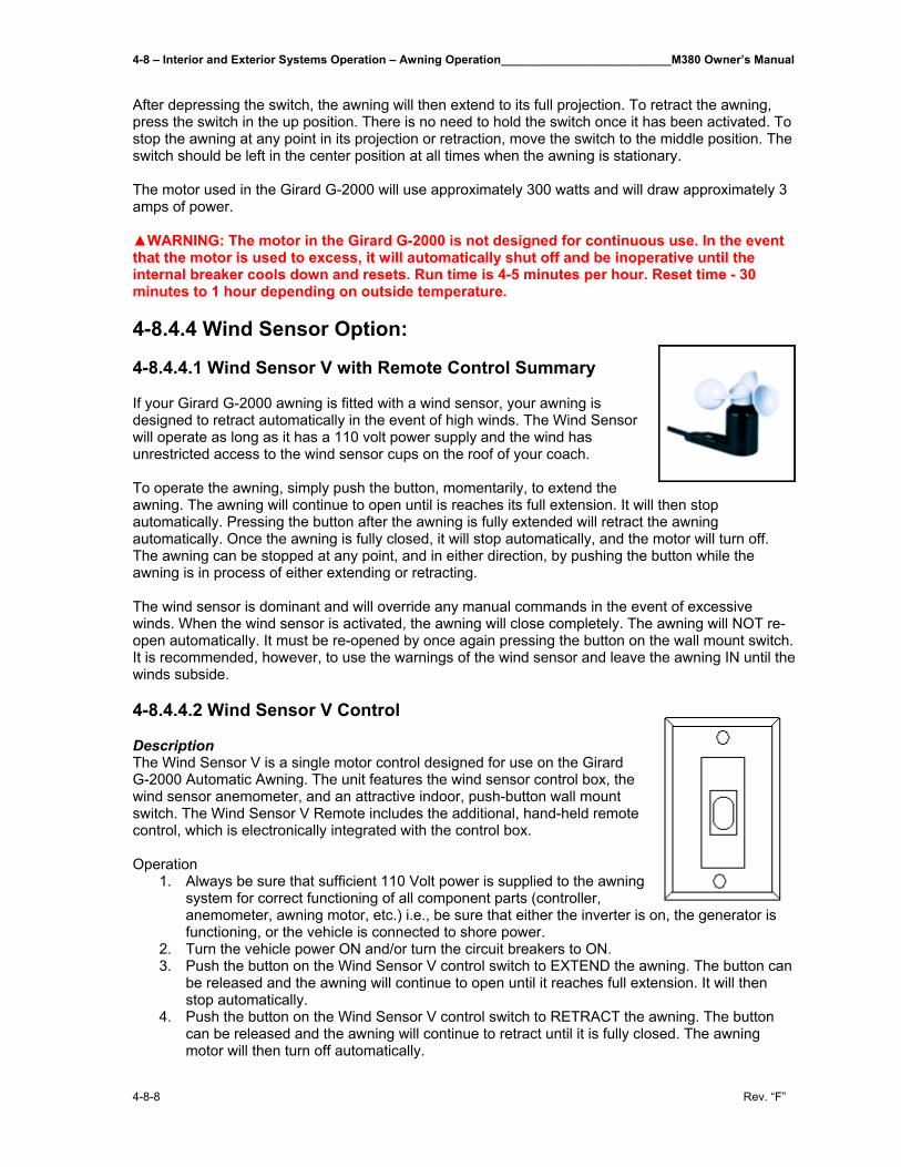
4-8 – Interior and Exterior Systems Operation – Awning Operation__________________________M380 Owner’s Manual
4-8-8 Rev. “F”
After depressing the switch, the awning will then extend to its full projection. To retract the awning, press the switch in the up position. There is no need to hold the switch once it has been activated. To stop the awning at any point in its projection or retraction, move the switch to the middle position. The switch should be left in the center position at all times when the awning is stationary. The motor used in the Girard G-2000 will use approximately 300 watts and will draw approximately 3 amps of power. ▲WARNING: The motor in the Girard G-2000 is not designed for continuous use. In the event that the motor is used to excess, it will automatically shut off and be inoperative until the internal breaker cools down and resets. Run time is 4-5 minutes per hour. Reset time - 30 minutes to 1 hour depending on outside temperature. 4-8.4.4 Wind Sensor Option: 4-8.4.4.1 Wind Sensor V with Remote Control Summary If your Girard G-2000 awning is fitted with a wind sensor, your awning is designed to retract automatically in the event of high winds. The Wind Sensor will operate as long as it has a 110 volt power supply and the wind has unrestricted access to the wind sensor cups on the roof of your coach. To operate the awning, simply push the button, momentarily, to extend the awning. The awning will continue to open until is reaches its full extension. It will then stop automatically. Pressing the button after the awning is fully extended will retract the awning automatically. Once the awning is fully closed, it will stop automatically, and the motor will turn off. The awning can be stopped at any point, and in either direction, by pushing the button while the awning is in process of either extending or retracting. The wind sensor is dominant and will override any manual commands in the event of excessive winds. When the wind sensor is activated, the awning will close completely. The awning will NOT re-open automatically. It must be re-opened by once again pressing the button on the wall mount switch. It is recommended, however, to use the warnings of the wind sensor and leave the awning IN until the winds subside. 4-8.4.4.2 Wind Sensor V Control Description The Wind Sensor V is a single motor control designed for use on the Girard G-2000 Automatic Awning. The unit features the wind sensor control box, the wind sensor anemometer, and an attractive indoor, push-button wall mount switch. The Wind Sensor V Remote includes the additional, hand-held remote control, which is electronically integrated with the control box. Operation
1. Always be sure that sufficient 110 Volt power is supplied to the awning system for correct functioning of all component parts (controller, anemometer, awning motor, etc.) i.e., be sure that either the inverter is on, the generator is functioning, or the vehicle is connected to shore power.
2. Turn the vehicle power ON and/or turn the circuit breakers to ON. 3. Push the button on the Wind Sensor V control switch to EXTEND the awning. The button can
be released and the awning will continue to open until it reaches full extension. It will then stop automatically.
4. Push the button on the Wind Sensor V control switch to RETRACT the awning. The button can be released and the awning will continue to retract until it is fully closed. The awning motor will then turn off automatically.
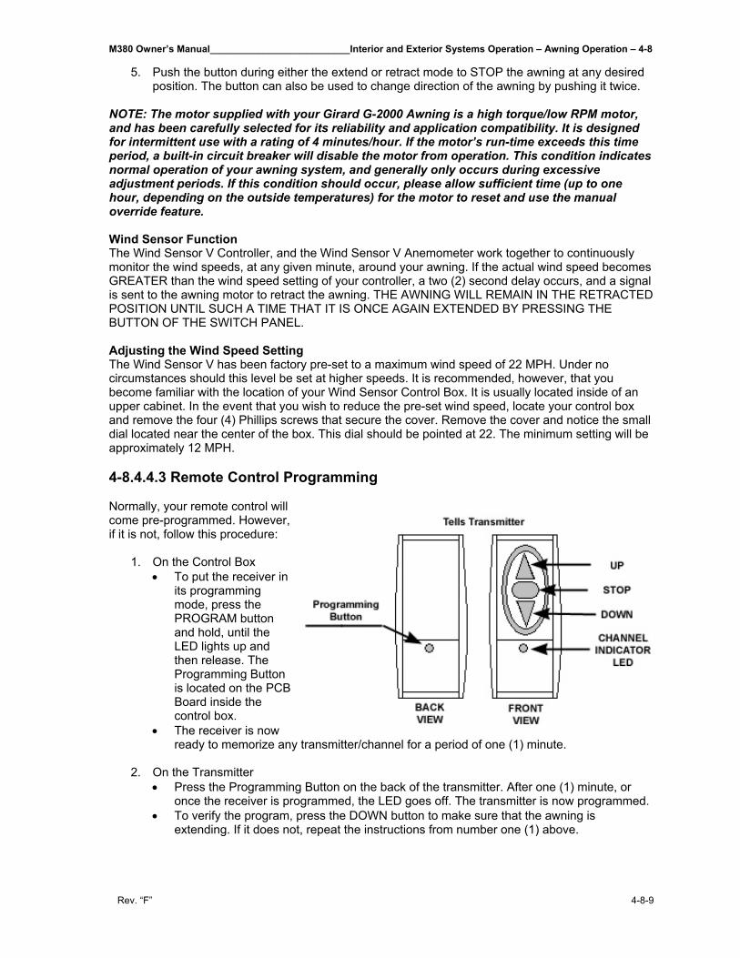
M380 Owner’s Manual__________________________Interior and Exterior Systems Operation – Awning Operation – 4-8
Rev. “F” 4-8-9
5. Push the button during either the extend or retract mode to STOP the awning at any desired position. The button can also be used to change direction of the awning by pushing it twice.
NOTE: The motor supplied with your Girard G-2000 Awning is a high torque/low RPM motor, and has been carefully selected for its reliability and application compatibility. It is designed for intermittent use with a rating of 4 minutes/hour. If the motor’s run-time exceeds this time period, a built-in circuit breaker will disable the motor from operation. This condition indicates normal operation of your awning system, and generally only occurs during excessive adjustment periods. If this condition should occur, please allow sufficient time (up to one hour, depending on the outside temperatures) for the motor to reset and use the manual override feature. Wind Sensor Function The Wind Sensor V Controller, and the Wind Sensor V Anemometer work together to continuously monitor the wind speeds, at any given minute, around your awning. If the actual wind speed becomes GREATER than the wind speed setting of your controller, a two (2) second delay occurs, and a signal is sent to the awning motor to retract the awning. THE AWNING WILL REMAIN IN THE RETRACTED POSITION UNTIL SUCH A TIME THAT IT IS ONCE AGAIN EXTENDED BY PRESSING THE BUTTON OF THE SWITCH PANEL. Adjusting the Wind Speed Setting The Wind Sensor V has been factory pre-set to a maximum wind speed of 22 MPH. Under no circumstances should this level be set at higher speeds. It is recommended, however, that you become familiar with the location of your Wind Sensor Control Box. It is usually located inside of an upper cabinet. In the event that you wish to reduce the pre-set wind speed, locate your control box and remove the four (4) Phillips screws that secure the cover. Remove the cover and notice the small dial located near the center of the box. This dial should be pointed at 22. The minimum setting will be approximately 12 MPH. 4-8.4.4.3 Remote Control Programming Normally, your remote control will come pre-programmed. However, if it is not, follow this procedure:
1. On the Control Box • To put the receiver in
its programming mode, press the PROGRAM button and hold, until the LED lights up and then release. The Programming Button is located on the PCB Board inside the control box.
• The receiver is now ready to memorize any transmitter/channel for a period of one (1) minute.
2. On the Transmitter
• Press the Programming Button on the back of the transmitter. After one (1) minute, or once the receiver is programmed, the LED goes off. The transmitter is now programmed.
• To verify the program, press the DOWN button to make sure that the awning is extending. If it does not, repeat the instructions from number one (1) above.
4-8 – Interior and Exterior Systems Operation – Awning Operation__________________________M380 Owner’s Manual
4-8-10 Rev. “F”
4-8.4.4.4 Remote Control Operation Single channel transmitter: • Press the UP, DOWN, or STOP button. →The programmed RTS receivers are activated. Four channels transmitter: • Select the channel of the motor module you wish to control. →The corresponding LED is blinking during 3 seconds (the channel is still memorized for 30s and
then the transmitter returns to channel 1). • Press the UP, DOWN or STOP button. →The programmed RTS receivers are activated. Battery Life The transmitters are filled with a 3V battery (type 2430) which provides about three years operation assuming 4 operations per day. When the battery becomes discharged, the control LED no longer lights up when a command is sent, and the command is not carried out. The module has an integrated backup control under the programming button. It operates by successive presses: raising, stop, lowering, stop. How to Change the Battery:
• Remove the back cover of the transmitter with a screwdriver. • Slide the battery out of its housing by pushing it with a screwdriver. • Insert the new battery
4-8.4.5 Setting Motor Limits IF THE AWNING DOES NOT CLOSE COMPLETELY, and there is no apparent binding of any awning components, then the fabric has most likely stretched or shifted slightly over time. This can be easily corrected by adjusting the motor limits. This will allow the awning roller tube to run a split second longer to draw the awning fabric in tighter.
The Adjustment: • The MO (manual override) motor has manual limit switches for both the OUT (extend) and the
IN (retract). • The limit switches are adjusted by inserting the black plastic key (supplied) or a 5/32” / 4mm
Allen wrench into the appropriate hole on the underside of the motor. • The motor is usually located at the front of the awning inside the roller tube. The limit switches
can be accessed by opening the awning a few feet, and are located above, at the end of the roller tube in the exposed end of the motor. These switches will appear as (2) hex shaped holes. You will also see a double arrow with a (+) and (-) sign next to each switch.
• The IN limit is the switch located closest to the vehicle side. The Girard G-2000 provides an exclusive current limiting device (MS-1) which detects the current increase as the awning box closes, and then shuts off power to the motor. This device eliminates the need or frequency for future in-bound limit switch adjustments. If this adjustment is still required however, and the awning box does not close completely, then this switch should be adjusted. To make the awning close MORE, first turn your main awning wall switch or wind sensor switch to the IN (retract) position. Place the plastic adjustment tool or Allen wrench into the switch and turn toward the (+) direction. This action will create a tighter fit as the awning box closes. Listen carefully to the motor to assure that the current limiting device has shut power off to the motor.
M380 Owner’s Manual__________________________Interior and Exterior Systems Operation – Awning Operation – 4-8
Rev. “F” 4-8-11
• The OUT limit is the switch located in the outer most location. This switch is factory pre-set so that the motor stops turning at the precise moment that the arms reach full extension. If further adjustment is required however, and to make the awning extend more and to release more fabric, first, place the main awning wall switch or wind sensor switch to the OUT (extend) position and extend the awning until the motor stops. Place the plastic adjustment tool or Allen wrench into the limit switch and turn toward the (+) arrow. The awning will “follow” as you turn. Turn switch until awning reaches full extension and the arms “click” into their locked position. To make the awning extend LESS, turn switch toward the (-) arrow, bring the awning in a few inches, then re-extend to see the new stop location.
• To adjust IN Limits: Use the INNER most switch (+) closes more (-) closes less • To adjust OUT Limits: Use the OUTER most switch. (+) extends more (-) extends
less. NOTE: If motor is mounted on LEFT end of the awning, the functions of the limit switches will be reversed.
4-8.4.6 Lead Rail Adjustments 4-8.4.6.1 Lateral Shifting of Lead Rail Tools Required:
• 5mm (3/16”) Allen Wrench • Phillips Screwdriver • Rubber Mallet • 1/8” Drill Bit and Drill Motor
The Lead Rail has shifted toward the front or toward the rear of the awning casing, preventing the awning from closing properly.
1. Open the awning about 2 feet. 2. Locate the connection bracket at the forward most portion of the arm at the Lead Rail. (Item
#43 of Exploded view). Using an Allen Wrench, loosen the center set screw on this bracket, by ¾ turn, which un-tightens this bracket from the Lead Rail. Repeat for all arms. Do NOT loosen the offset leveling screw found on the upper corner of the bracket assembly.
3. With a Phillips Head Screwdriver, remove the (2) fabric set screws (Item #50 of Exploded View) which secure the fabric to the Lead Rail.
4. Close the awning to about 4 inches and, using a rubber mallet, tap on the end of the Lead Rail, allowing it to shift relative to the fabric and arm attachments.
5. Close the awning to check for proper alignment. 6. Re-open the awning to about 2 feet and re-tighten set screws at each arm connection. Finish
by replacing both fabric set screws.
NOTE: These screws should be located approx. ¾” from the edge of the fabric. If the adjustment process places either of these 2 screws further than this point, drill new holes (1/8” dia), and re-install fabric screws.
7. Close the awning completely to check for final fit.
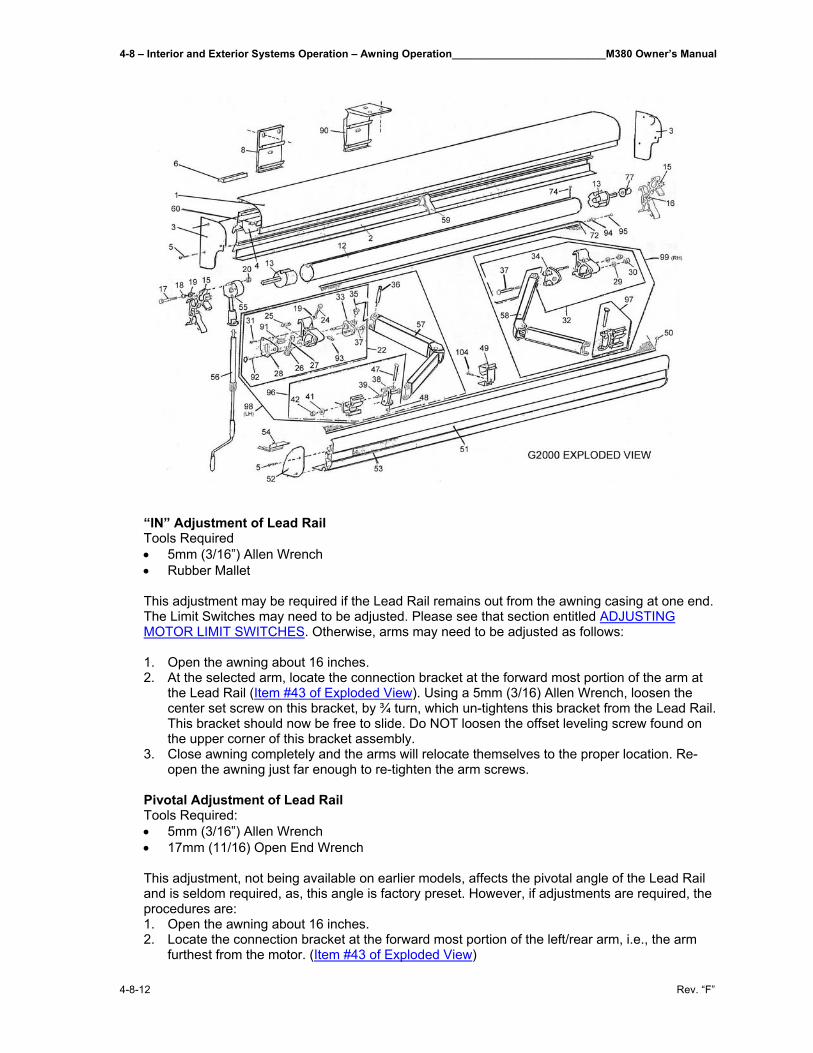
4-8 – Interior and Exterior Systems Operation – Awning Operation__________________________M380 Owner’s Manual
4-8-12 Rev. “F”
“IN” Adjustment of Lead Rail Tools Required • 5mm (3/16”) Allen Wrench • Rubber Mallet This adjustment may be required if the Lead Rail remains out from the awning casing at one end. The Limit Switches may need to be adjusted. Please see that section entitled ADJUSTING MOTOR LIMIT SWITCHES. Otherwise, arms may need to be adjusted as follows: 1. Open the awning about 16 inches. 2. At the selected arm, locate the connection bracket at the forward most portion of the arm at
the Lead Rail (Item #43 of Exploded View). Using a 5mm (3/16) Allen Wrench, loosen the center set screw on this bracket, by ¾ turn, which un-tightens this bracket from the Lead Rail. This bracket should now be free to slide. Do NOT loosen the offset leveling screw found on the upper corner of this bracket assembly.
3. Close awning completely and the arms will relocate themselves to the proper location. Re-open the awning just far enough to re-tighten the arm screws.
Pivotal Adjustment of Lead Rail Tools Required: • 5mm (3/16”) Allen Wrench • 17mm (11/16) Open End Wrench This adjustment, not being available on earlier models, affects the pivotal angle of the Lead Rail and is seldom required, as, this angle is factory preset. However, if adjustments are required, the procedures are: 1. Open the awning about 16 inches. 2. Locate the connection bracket at the forward most portion of the left/rear arm, i.e., the arm
furthest from the motor. (Item #43 of Exploded View)
M380 Owner’s Manual__________________________Interior and Exterior Systems Operation – Awning Operation – 4-8
Rev. “F” 4-8-13
3. The “pivoting” style connection bracket can be identified by having one set screw in the center of the bracket, in addition to a second set screw at the upper portion of the pivoting section of the bracket assembly. The non-pivoting style bracket has two set screws, in-line, in the center of the bracket.
4. If the pivoting style bracket is present, grasp the Lead Rail with one hand and manually pivot, up and down, the Lead Rail on this bracket. It should pivot freely. If it does not pivot freely, loosen slightly, the large lock nut on the end of the horizontal bolt that fastens these two pivoting brackets together. This should free the two brackets and allow a pivot between them. Repeat for each arm, if necessary.
5. Using the awning switch and motor, close the awning to about 3”. Check the angle of the Lead Rail in relation to the awning casing. The Lead Rail should approach the awning casing with the TOP portion of the Lead Rail striking the casing FIRST. From the TOP of the Lead Rail, a 10 degree angle should occur as it angles away from the awning casing. If this angle is not present, again open the awning to about 18”. Locate the UPPER set screw in the pivoting portion of the connection bracket. Using a 5mm (3/16”) allen wrench, turn this set screw (counterclockwise) to achieve the desired 10 degree angle. Repeat this procedure for each of the arm connections, assuring that the proper angle and “free pivot” condition is maintained.
Height Adjustment of Arms (see Exploded View - Item No. 37) Tools Required: • 19mm (3/4”) Open End Wrench • 10mm (3/8”) Open End Wrench
This adjustment may be required if, as the awning Lead Rail closes into the awning casing, the “elbow” of one of the arms is hanging downward, hitting the bottom of the casing. This adjustment is usually required after an Arm replacement.
1. Open the awning about 18 inches. 2. At the selected turn, loosen the (2) Locknuts located at the side of the upper arm
connection using a 19mm (3/4”) Open End Wrench. 3. See Item No. 92 in Exploded View. Locate the smaller adjustment bolt located directly
under the rear Locknut that was just loosened. Place a 10mm (3/8”) Open End Wrench around this bolt head, and rotate the wrench in a TIGHTEN direction to RAISE the arm. Slight rotation is all that is necessary. Likewise, LOOSENING the bolt will LOWER the arm. As this adjustment is being performed, keep in mind that after re-tightening the Locknuts, the arm will raise slightly further.
4. Tighten the (2) locknuts located on the side of the arm connection. 5. Close the awning completely, and check for proper fit.
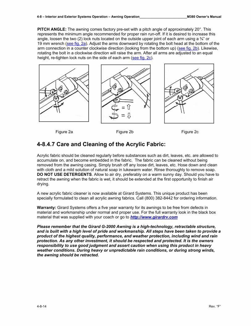
4-8 – Interior and Exterior Systems Operation – Awning Operation__________________________M380 Owner’s Manual
4-8-14 Rev. “F”
PITCH ANGLE: The awning comes factory pre-set with a pitch angle of approximately 20°. This represents the minimum angle recommended for proper rain run-off. If it is desired to increase this angle, loosen the two (2) lock nuts located on the outside upper joint of each arm using a ¾” or 19 mm wrench (see fig. 2a). Adjust the arms downward by rotating the bolt head at the bottom of the arm connection in a counter clockwise direction (looking from the bottom up) (see fig. 2b). Likewise, rotating the bolt in a clockwise direction will raise the arm. After all arms are adjusted to an equal height, re-tighten lock nuts on the side of each arm (see fig. 2c).
Figure 2a Figure 2b Figure 2c 4-8.4.7 Care and Cleaning of the Acrylic Fabric: Acrylic fabric should be cleaned regularly before substances such as dirt, leaves, etc. are allowed to accumulate on, and become embedded in the fabric. The fabric can be cleaned without being removed from the awning casing. Simply brush off any loose dirt, leaves, etc. Hose down and clean with cloth and a mild solution of natural soap in lukewarm water. Rinse thoroughly to remove soap. DO NOT USE DETERGENTS. Allow to air dry, preferably on a warm sunny day. Should you have to retract the awning when the fabric is wet, it should be extended at the first opportunity to finish air drying. A new acrylic fabric cleaner is now available at Girard Systems. This unique product has been specially formulated to clean all acrylic awning fabrics. Call (800) 382-8442 for ordering information. Warranty: Girard Systems offers a five year warranty for its awnings to be free from defects in material and workmanship under normal and proper use. For the full warranty look in the black box material that was supplied with your coach or go to http://www.girardrv.com Please remember that the Girard G-2000 Awning is a high-technology, retractable structure, and is built with a high level of pride and workmanship. All steps have been taken to provide a product of the highest quality, performance, and weather protection, including wind and rain protection. As any other investment, it should be respected and protected. It is the owners responsibility to use good judgment and assert caution when using this product in heavy weather conditions. During heavy or unpredictable rain conditions, or during strong winds, the awning should be retracted.
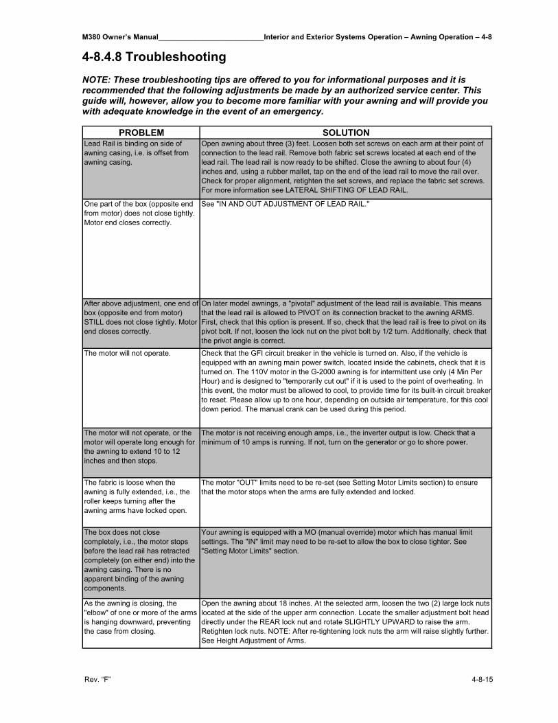
M380 Owner’s Manual__________________________Interior and Exterior Systems Operation – Awning Operation – 4-8
Rev. “F” 4-8-15
4-8.4.8 Troubleshooting NOTE: These troubleshooting tips are offered to you for informational purposes and it is recommended that the following adjustments be made by an authorized service center. This guide will, however, allow you to become more familiar with your awning and will provide you with adequate knowledge in the event of an emergency.
PROBLEM SOLUTIONLead Rail is binding on side of awning casing, i.e. is offset from awning casing.
Open awning about three (3) feet. Loosen both set screws on each arm at their point of connection to the lead rail. Remove both fabric set screws located at each end of the lead rail. The lead rail is now ready to be shifted. Close the awning to about four (4) inches and, using a rubber mallet, tap on the end of the lead rail to move the rail over. Check for proper alignment, retighten the set screws, and replace the fabric set screws. For more information see LATERAL SHIFTING OF LEAD RAIL.
One part of the box (opposite end from motor) does not close tightly. Motor end closes correctly.
See "IN AND OUT ADJUSTMENT OF LEAD RAIL."
After above adjustment, one end of box (opposite end from motor) STILL does not close tightly. Motor end closes correctly.
On later model awnings, a "pivotal" adjustment of the lead rail is available. This means that the lead rail is allowed to PIVOT on its connection bracket to the awning ARMS. First, check that this option is present. If so, check that the lead rail is free to pivot on its pivot bolt. If not, loosen the lock nut on the pivot bolt by 1/2 turn. Additionally, check that the privot angle is correct.
The motor will not operate. Check that the GFI circuit breaker in the vehicle is turned on. Also, if the vehicle is equipped with an awning main power switch, located inside the cabinets, check that it is turned on. The 110V motor in the G-2000 awning is for intermittent use only (4 Min Per Hour) and is designed to "temporarily cut out" if it is used to the point of overheating. In this event, the motor must be allowed to cool, to provide time for its built-in circuit breaker to reset. Please allow up to one hour, depending on outside air temperature, for this cool down period. The manual crank can be used during this period.
The motor will not operate, or the motor will operate long enough for the awning to extend 10 to 12 inches and then stops.
The motor is not receiving enough amps, i.e., the inverter output is low. Check that a minimum of 10 amps is running. If not, turn on the generator or go to shore power.
The fabric is loose when the awning is fully extended, i.e., the roller keeps turning after the awning arms have locked open.
The motor "OUT" limits need to be re-set (see Setting Motor Limits section) to ensure that the motor stops when the arms are fully extended and locked.
The box does not close completely, i.e., the motor stops before the lead rail has retracted completely (on either end) into the awning casing. There is no apparent binding of the awning components.
Your awning is equipped with a MO (manual override) motor which has manual limit settings. The "IN" limit may need to be re-set to allow the box to close tighter. See "Setting Motor Limits" section.
As the awning is closing, the "elbow" of one or more of the arms is hanging downward, preventing the case from closing.
Open the awning about 18 inches. At the selected arm, loosen the two (2) large lock nuts located at the side of the upper arm connection. Locate the smaller adjustment bolt head directly under the REAR lock nut and rotate SLIGHTLY UPWARD to raise the arm. Retighten lock nuts. NOTE: After re-tightening lock nuts the arm will raise slightly further. See Height Adjustment of Arms.
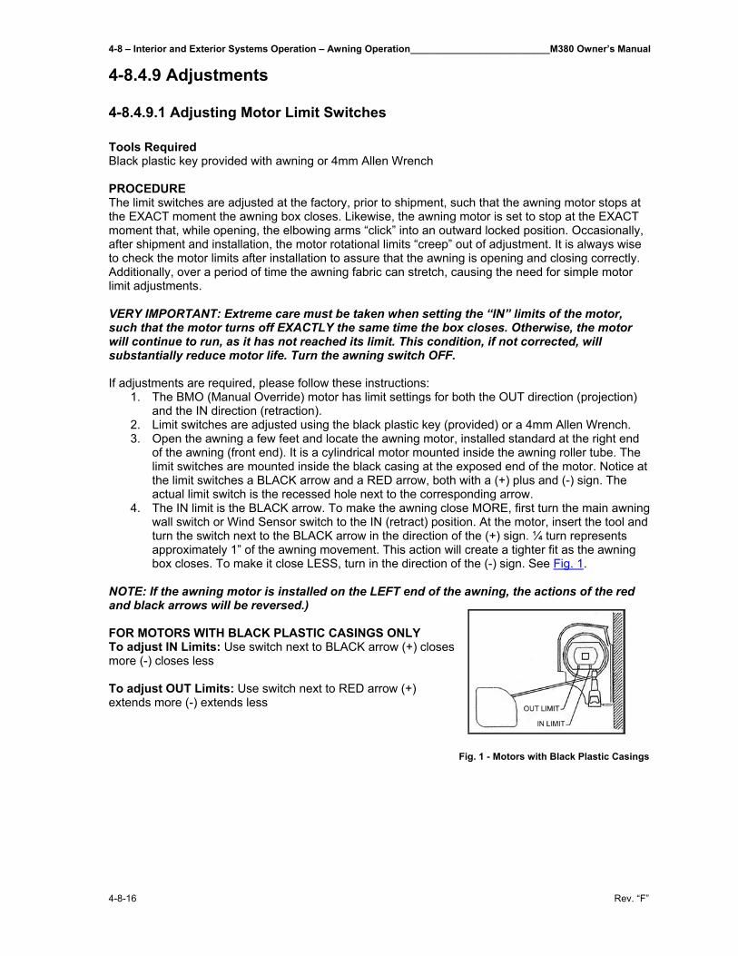
4-8 – Interior and Exterior Systems Operation – Awning Operation__________________________M380 Owner’s Manual
4-8-16 Rev. “F”
4-8.4.9 Adjustments 4-8.4.9.1 Adjusting Motor Limit Switches Tools Required Black plastic key provided with awning or 4mm Allen Wrench PROCEDURE The limit switches are adjusted at the factory, prior to shipment, such that the awning motor stops at the EXACT moment the awning box closes. Likewise, the awning motor is set to stop at the EXACT moment that, while opening, the elbowing arms “click” into an outward locked position. Occasionally, after shipment and installation, the motor rotational limits “creep” out of adjustment. It is always wise to check the motor limits after installation to assure that the awning is opening and closing correctly. Additionally, over a period of time the awning fabric can stretch, causing the need for simple motor limit adjustments. VERY IMPORTANT: Extreme care must be taken when setting the “IN” limits of the motor, such that the motor turns off EXACTLY the same time the box closes. Otherwise, the motor will continue to run, as it has not reached its limit. This condition, if not corrected, will substantially reduce motor life. Turn the awning switch OFF. If adjustments are required, please follow these instructions:
1. The BMO (Manual Override) motor has limit settings for both the OUT direction (projection) and the IN direction (retraction).
2. Limit switches are adjusted using the black plastic key (provided) or a 4mm Allen Wrench. 3. Open the awning a few feet and locate the awning motor, installed standard at the right end
of the awning (front end). It is a cylindrical motor mounted inside the awning roller tube. The limit switches are mounted inside the black casing at the exposed end of the motor. Notice at the limit switches a BLACK arrow and a RED arrow, both with a (+) plus and (-) sign. The actual limit switch is the recessed hole next to the corresponding arrow.
4. The IN limit is the BLACK arrow. To make the awning close MORE, first turn the main awning wall switch or Wind Sensor switch to the IN (retract) position. At the motor, insert the tool and turn the switch next to the BLACK arrow in the direction of the (+) sign. ¼ turn represents approximately 1” of the awning movement. This action will create a tighter fit as the awning box closes. To make it close LESS, turn in the direction of the (-) sign. See Fig. 1.
NOTE: If the awning motor is installed on the LEFT end of the awning, the actions of the red and black arrows will be reversed.) FOR MOTORS WITH BLACK PLASTIC CASINGS ONLY To adjust IN Limits: Use switch next to BLACK arrow (+) closes more (-) closes less To adjust OUT Limits: Use switch next to RED arrow (+) extends more (-) extends less
Fig. 1 - Motors with Black Plastic Casings
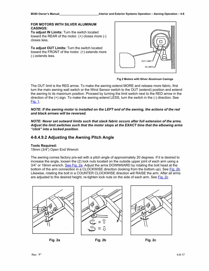
M380 Owner’s Manual__________________________Interior and Exterior Systems Operation – Awning Operation – 4-8
Rev. “F” 4-8-17
FOR MOTORS WITH SILVER ALUMINUM CASINGS: To adjust IN Limits: Turn the switch located toward the REAR of the motor. (+) closes more (-) closes less. To adjust OUT Limits: Turn the switch located toward the FRONT of the motor. (+) extends more (-) extends less.
Fig 2 Motors with Silver Aluminum Casings
The OUT limit is the RED arrow. To make the awning extend MORE and release more fabric, first turn the main awning wall switch or the Wind Sensor switch to the OUT (extend) position and extend the awning to its maximum position. Proceed by turning the limit switch next to the RED arrow in the direction of the (+) sign. To make the awning extend LESS, turn the switch in the (-) direction. See Fig. 1. NOTE: If the awning motor is installed on the LEFT end of the awning, the actions of the red and black arrows will be reversed. NOTE: Never set outward limits such that slack fabric occurs after full extension of the arms. Adjust the limit switches such that the motor stops at the EXACT time that the elbowing arms “click” into a locked position. 4-8.4.9.2 Adjusting the Awning Pitch Angle Tools Required: 19mm (3/4”) Open End Wrench The awning comes factory pre-set with a pitch angle of approximately 20 degrees. If it is desired to increase the angle, loosen the (2) lock nuts located on the outside upper joint of each arm using a 3/4” or 19mm wrench. See Fig. 2a. Adjust the arms DOWNWARD by rotating the bolt head at the bottom of the arm connection in a CLOCKWISE direction (looking from the bottom up). See Fig. 2b. Likewise, rotating the bolt in a COUNTER CLOCKWISE direction will RAISE the arm. After all arms are adjusted to the desired height, re-tighten lock nuts on the side of each arm. See Fig. 2c
Fig. 2a Fig. 2b Fig. 2c
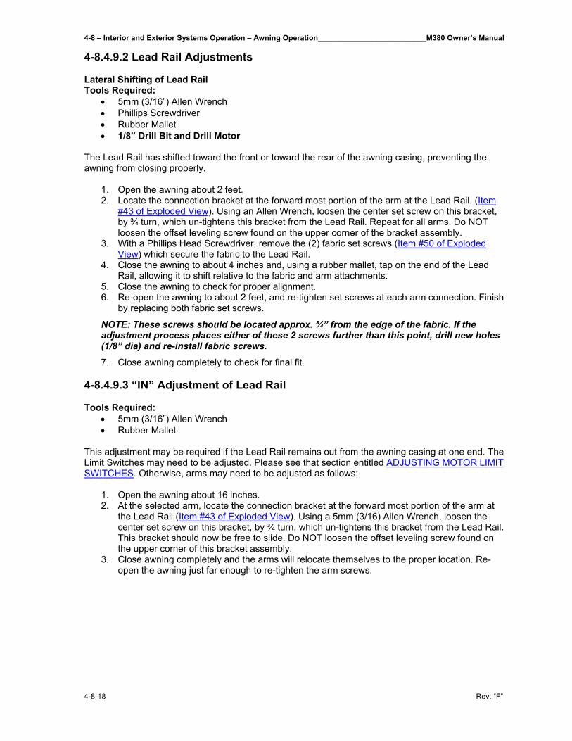
4-8 – Interior and Exterior Systems Operation – Awning Operation__________________________M380 Owner’s Manual
4-8-18 Rev. “F”
4-8.4.9.2 Lead Rail Adjustments Lateral Shifting of Lead Rail Tools Required:
• 5mm (3/16”) Allen Wrench • Phillips Screwdriver • Rubber Mallet • 1/8” Drill Bit and Drill Motor
The Lead Rail has shifted toward the front or toward the rear of the awning casing, preventing the awning from closing properly.
1. Open the awning about 2 feet. 2. Locate the connection bracket at the forward most portion of the arm at the Lead Rail. (Item
#43 of Exploded View). Using an Allen Wrench, loosen the center set screw on this bracket, by ¾ turn, which un-tightens this bracket from the Lead Rail. Repeat for all arms. Do NOT loosen the offset leveling screw found on the upper corner of the bracket assembly.
3. With a Phillips Head Screwdriver, remove the (2) fabric set screws (Item #50 of Exploded View) which secure the fabric to the Lead Rail.
4. Close the awning to about 4 inches and, using a rubber mallet, tap on the end of the Lead Rail, allowing it to shift relative to the fabric and arm attachments.
5. Close the awning to check for proper alignment. 6. Re-open the awning to about 2 feet, and re-tighten set screws at each arm connection. Finish
by replacing both fabric set screws.
NOTE: These screws should be located approx. ¾” from the edge of the fabric. If the adjustment process places either of these 2 screws further than this point, drill new holes (1/8” dia) and re-install fabric screws.
7. Close awning completely to check for final fit.
4-8.4.9.3 “IN” Adjustment of Lead Rail Tools Required:
• 5mm (3/16”) Allen Wrench • Rubber Mallet
This adjustment may be required if the Lead Rail remains out from the awning casing at one end. The Limit Switches may need to be adjusted. Please see that section entitled ADJUSTING MOTOR LIMIT SWITCHES. Otherwise, arms may need to be adjusted as follows:
1. Open the awning about 16 inches. 2. At the selected arm, locate the connection bracket at the forward most portion of the arm at
the Lead Rail (Item #43 of Exploded View). Using a 5mm (3/16) Allen Wrench, loosen the center set screw on this bracket, by ¾ turn, which un-tightens this bracket from the Lead Rail. This bracket should now be free to slide. Do NOT loosen the offset leveling screw found on the upper corner of this bracket assembly.
3. Close awning completely and the arms will relocate themselves to the proper location. Re-open the awning just far enough to re-tighten the arm screws.
M380 Owner’s Manual__________________________Interior and Exterior Systems Operation – Awning Operation – 4-8
Rev. “F” 4-8-19
4-8.4.9.4 Pivotal Adjustment of Lead Rail Tools Required:
• 5mm (3/16”) Allen Wrench • 17mm (11/16) Open End Wrench
This adjustment, not being available on earlier models, affects the pivotal angle of the Lead Rail and is seldom required, as, this angle is factory preset. However, if adjustments are required, the procedures are:
1. Open the awning about 16 inches. 2. Locate the connection bracket at the forward most portion of the left/rear arm, i.e., the arm
furthest from the motor. (Item #43 of Exploded View). 3. The “pivoting” style connection bracket can be identified by having one set screw in the
center of the bracket, in addition to a second set screw at the upper portion of the pivoting section of the bracket assembly. The non-pivoting style bracket has two set screws, in-line, in the center of the bracket.
4. If the pivoting style bracket is present, grasp the Lead Rail with one hand and manually pivot, up and down, the Lead Rail on this bracket. It should pivot freely. If it does not pivot freely, loosen slightly, the large lock nut on the end of the horizontal bolt that fastens these two pivoting brackets together. This should free the two brackets and allow a pivot between them. Repeat for each arm, if necessary.
5. Using the awning switch and motor, close the awning to about 3”. Check the angle of the Lead Rail in relation to the awning casing. The Lead Rail should approach the awning casing with the TOP portion of the Lead Rail striking the casing FIRST. From the TOP of the Lead Rail, a 10 degree angle should occur as it angles away from the awning casing. If this angle is not present, again open the awning to about 18”. Locate the UPPER set screw in the pivoting portion of the connection bracket. Using a 5mm (3/16”) Allen Wrench, turn this set screw (counterclockwise) to achieve the desired 10 degree angle. Repeat this procedure for each of the arm connections, assuring that the proper angle and “free pivot” condition is maintained.
4-8.4.9.5 Height Adjustment of Arms (see Exploded View - Item No. 37) Tools Required:
• 19mm (3/4”) Open End Wrench • 10mm (3/8”) Open End Wrench
This adjustment may be required if, as the awning Lead Rail closes into the awning casing, the “elbow” of one of the arms is hanging downward, hitting the bottom of the casing. This adjustment is usually required after an Arm replacement. 1. Open the awning about 18 inches. 2. At the selected arm, loosen the (2) Locknuts located at the side of the upper arm connection
using a 19mm (3/4”) Open End Wrench. 3. See Exploded View Item #92. Locate the smaller adjustment bolt located directly under the
rear Locknut that was just loosened. Place a 10mm (3/8”) Open End Wrench around this bolt head, and rotate the wrench in a TIGHTEN direction to RAISE the arm. Slight rotation is all that is necessary. Likewise, LOOSENING the bolt will LOWER the arm. As this adjustment is being performed, keep in mind that after re-tightening the Locknuts, the arm will raise slightly further.
4. Tighten the (2) locknuts located on the side of the arm connection. 5. Close the awning completely, and check for proper fit.

M380 Owner’s Manual__________________________________________________________________________________
Rev. “F”
THIS PAGE IS INTENTIONALLY LEFT BLANK
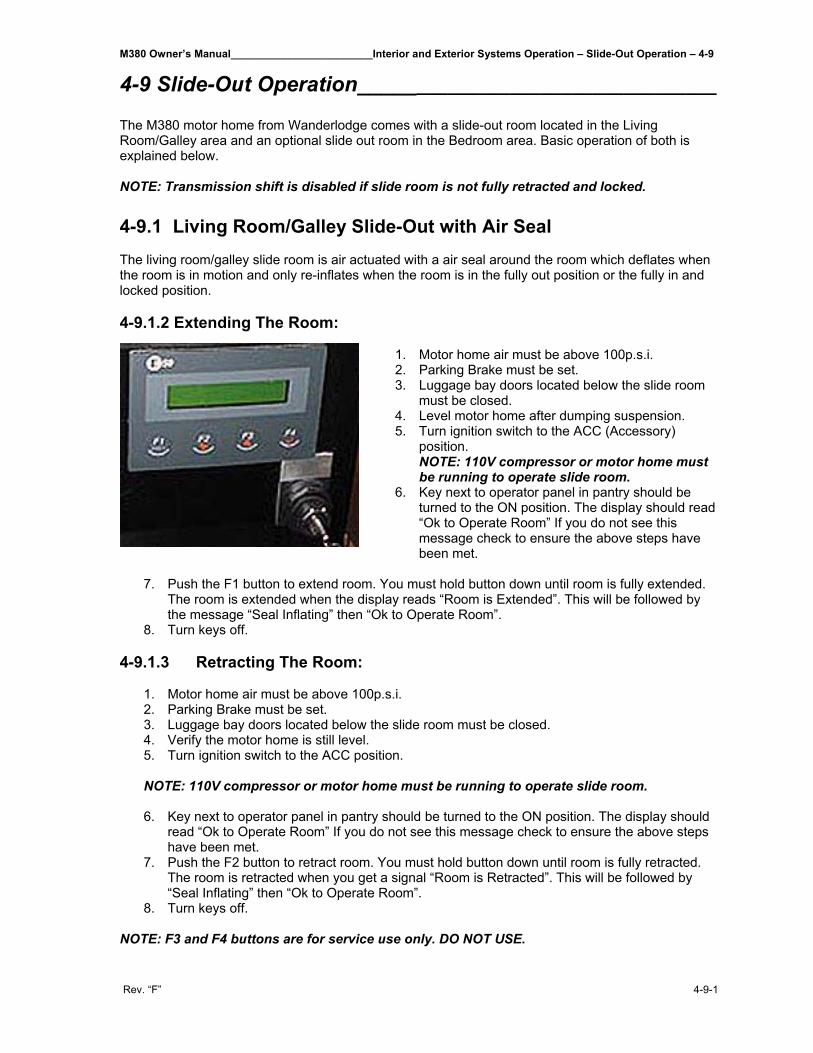
M380 Owner’s Manual________________________Interior and Exterior Systems Operation – Slide-Out Operation – 4-9
Rev. “F” 4-9-1
4-9 Slide-Out Operation__________________________________ The M380 motor home from Wanderlodge comes with a slide-out room located in the Living Room/Galley area and an optional slide out room in the Bedroom area. Basic operation of both is explained below. NOTE: Transmission shift is disabled if slide room is not fully retracted and locked. 4-9.1 Living Room/Galley Slide-Out with Air Seal The living room/galley slide room is air actuated with a air seal around the room which deflates when the room is in motion and only re-inflates when the room is in the fully out position or the fully in and locked position. 4-9.1.2 Extending The Room:
1. Motor home air must be above 100p.s.i. 2. Parking Brake must be set. 3. Luggage bay doors located below the slide room
must be closed. 4. Level motor home after dumping suspension. 5. Turn ignition switch to the ACC (Accessory)
position. NOTE: 110V compressor or motor home must be running to operate slide room.
6. Key next to operator panel in pantry should be turned to the ON position. The display should read “Ok to Operate Room” If you do not see this message check to ensure the above steps have been met.
7. Push the F1 button to extend room. You must hold button down until room is fully extended.
The room is extended when the display reads “Room is Extended”. This will be followed by the message “Seal Inflating” then “Ok to Operate Room”.
8. Turn keys off. 4-9.1.3 Retracting The Room:
1. Motor home air must be above 100p.s.i. 2. Parking Brake must be set. 3. Luggage bay doors located below the slide room must be closed. 4. Verify the motor home is still level. 5. Turn ignition switch to the ACC position. NOTE: 110V compressor or motor home must be running to operate slide room. 6. Key next to operator panel in pantry should be turned to the ON position. The display should
read “Ok to Operate Room” If you do not see this message check to ensure the above steps have been met.
7. Push the F2 button to retract room. You must hold button down until room is fully retracted. The room is retracted when you get a signal “Room is Retracted”. This will be followed by “Seal Inflating” then “Ok to Operate Room”.
8. Turn keys off.
NOTE: F3 and F4 buttons are for service use only. DO NOT USE.
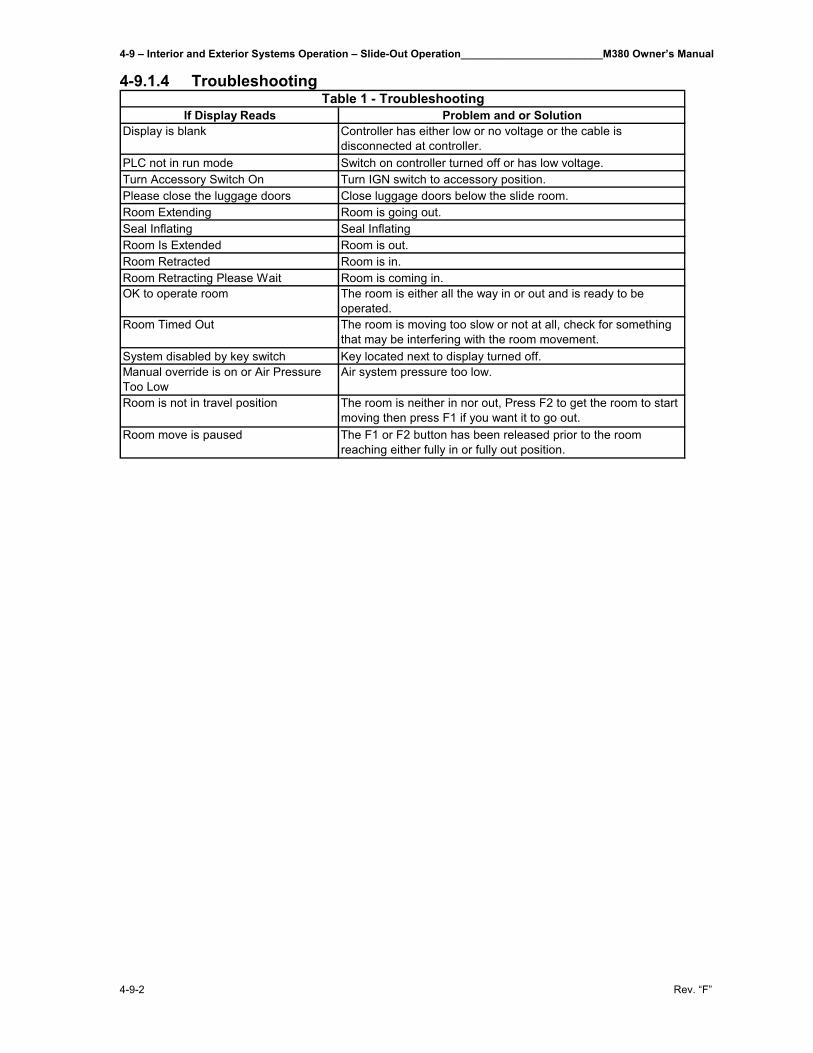
4-9 – Interior and Exterior Systems Operation – Slide-Out Operation________________________M380 Owner’s Manual
4-9-2 Rev. “F”
4-9.1.4 Troubleshooting
If Display Reads Problem and or SolutionDisplay is blank Controller has either low or no voltage or the cable is
disconnected at controller.PLC not in run mode Switch on controller turned off or has low voltage.Turn Accessory Switch On Turn IGN switch to accessory position.Please close the luggage doors Close luggage doors below the slide room.Room Extending Room is going out.Seal Inflating Seal InflatingRoom Is Extended Room is out.Room Retracted Room is in.Room Retracting Please Wait Room is coming in.OK to operate room The room is either all the way in or out and is ready to be
operated.Room Timed Out The room is moving too slow or not at all, check for something
that may be interfering with the room movement.System disabled by key switch Key located next to display turned off.Manual override is on or Air Pressure Too Low
Air system pressure too low.
Room is not in travel position The room is neither in nor out, Press F2 to get the room to start moving then press F1 if you want it to go out.
Room move is paused The F1 or F2 button has been released prior to the room reaching either fully in or fully out position.
Table 1 - Troubleshooting
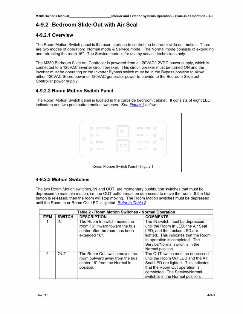
M380 Owner’s Manual________________________Interior and Exterior Systems Operation – Slide-Out Operation – 4-9
Rev. “F” 4-9-3
4-9.2 Bedroom Slide-Out with Air Seal 4-9.2.1 Overview The Room Motion Switch panel is the user interface to control the bedroom slide out motion. There are two modes of operation: Normal mode & Service mode. The Normal mode consists of extending and retracting the room 16". The Service mode is for use by service technicians only. The M380 Bedroom Slide out Controller is powered from a 120VAC/12VDC power supply, which is connected to a 120VAC inverter circuit breaker. This circuit breaker must be turned ON and the inverter must be operating or the Inverter Bypass switch must be in the Bypass position to allow either 120VAC Shore power or 120VAC generator power to provide to the Bedroom Slide out Controller power supply. 4-9.2.2 Room Motion Switch Panel The Room Motion Switch panel is located in the curbside bedroom cabinet. It consists of eight LED indicators and two pushbutton motion switches. See Figure 1 below.
4-9.2.3 Motion Switches The two Room Motion switches, IN and OUT, are momentary pushbutton switches that must be depressed to maintain motion; i.e. the OUT button must be depressed to move the room. If the Out button is released, then the room will stop moving. The Room Motion switches must be depressed until the Room In or Room Out LED is lighted. Refer to Table 2.
Table 2 - Room Motion Switches - Normal Operation ITEM SWITCH DESCRIPTION COMMENTS
1 IN The Room In switch moves the room 16" inward toward the bus center after the room has been extended 16".
The IN switch must be depressed until the Room In LED, the Air Seal LED, and the Locked LED are lighted. This indicates that the Room In operation is completed. The Service/Normal switch is in the Normal position.
2 OUT The Room Out switch moves the room outward away from the bus center 16" from the Normal In position.
The OUT switch must be depressed until the Room Out LED and the Air Seal LED are lighted. This indicates that the Room Out operation is completed. The Service/Normal switch is in the Normal position.
Room Motion Switch Panel - Figure 1
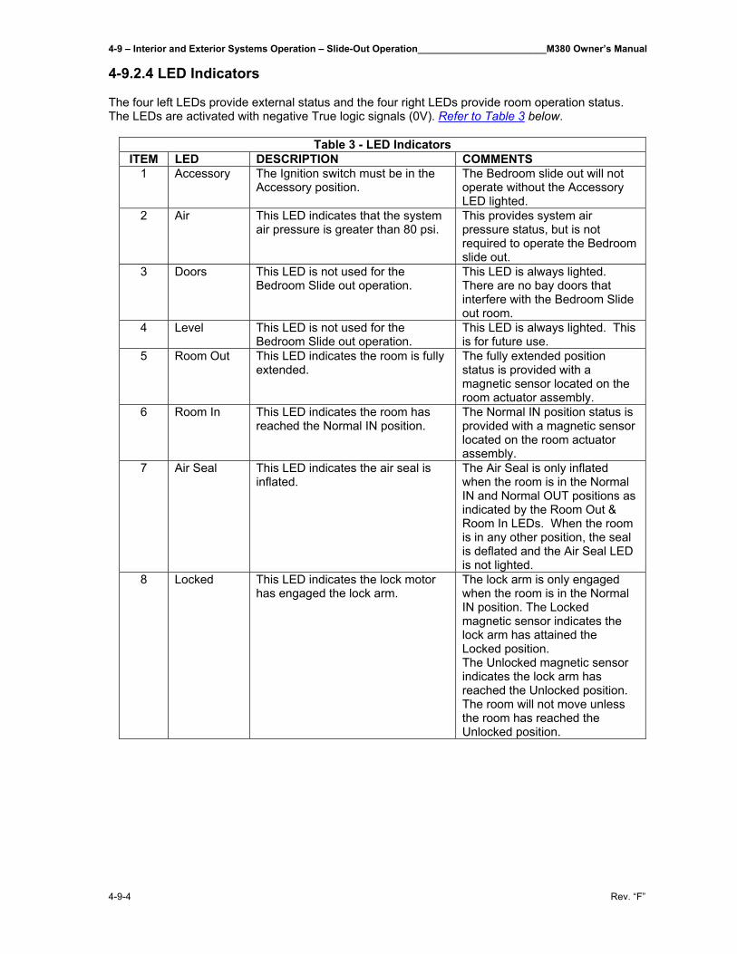
4-9 – Interior and Exterior Systems Operation – Slide-Out Operation________________________M380 Owner’s Manual
4-9-4 Rev. “F”
4-9.2.4 LED Indicators The four left LEDs provide external status and the four right LEDs provide room operation status. The LEDs are activated with negative True logic signals (0V). Refer to Table 3 below.
Table 3 - LED Indicators ITEM LED DESCRIPTION COMMENTS
1 Accessory The Ignition switch must be in the Accessory position.
The Bedroom slide out will not operate without the Accessory LED lighted.
2 Air This LED indicates that the system air pressure is greater than 80 psi.
This provides system air pressure status, but is not required to operate the Bedroom slide out.
3 Doors This LED is not used for the Bedroom Slide out operation.
This LED is always lighted. There are no bay doors that interfere with the Bedroom Slide out room.
4 Level This LED is not used for the Bedroom Slide out operation.
This LED is always lighted. This is for future use.
5 Room Out This LED indicates the room is fully extended.
The fully extended position status is provided with a magnetic sensor located on the room actuator assembly.
6 Room In This LED indicates the room has reached the Normal IN position.
The Normal IN position status is provided with a magnetic sensor located on the room actuator assembly.
7 Air Seal This LED indicates the air seal is inflated.
The Air Seal is only inflated when the room is in the Normal IN and Normal OUT positions as indicated by the Room Out & Room In LEDs. When the room is in any other position, the seal is deflated and the Air Seal LED is not lighted.
8 Locked This LED indicates the lock motor has engaged the lock arm.
The lock arm is only engaged when the room is in the Normal IN position. The Locked magnetic sensor indicates the lock arm has attained the Locked position. The Unlocked magnetic sensor indicates the lock arm has reached the Unlocked position. The room will not move unless the room has reached the Unlocked position.
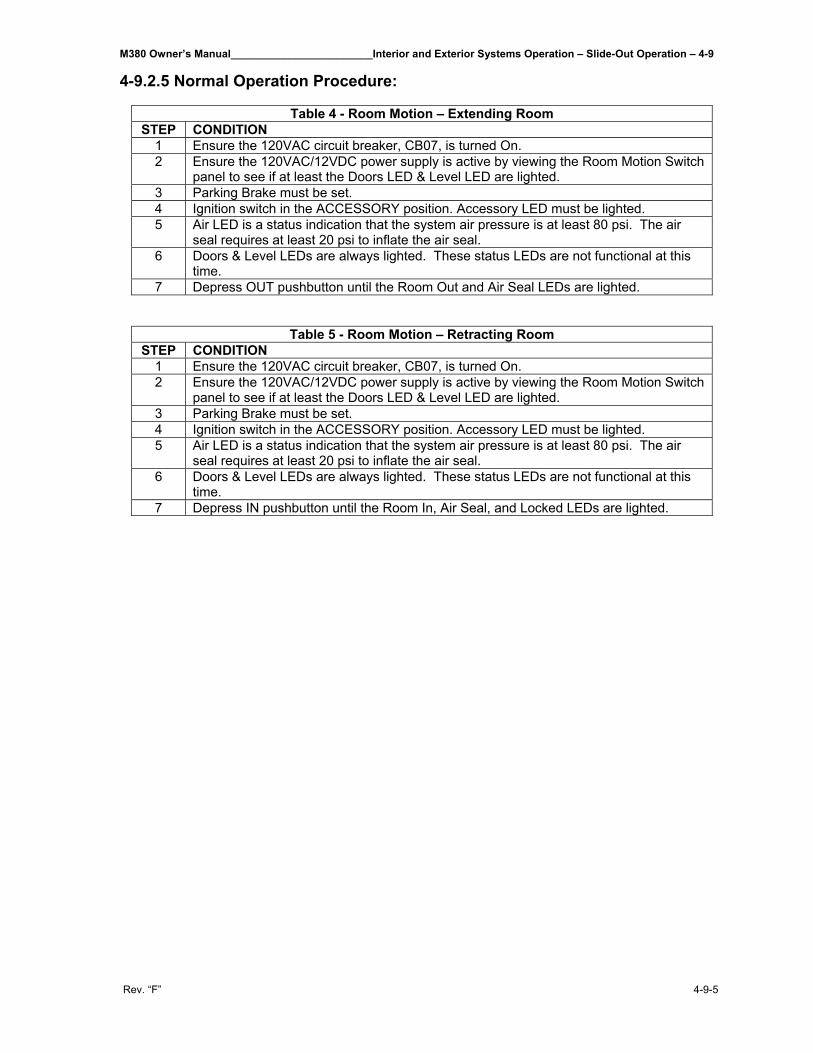
M380 Owner’s Manual________________________Interior and Exterior Systems Operation – Slide-Out Operation – 4-9
Rev. “F” 4-9-5
4-9.2.5 Normal Operation Procedure:
Table 4 - Room Motion – Extending Room STEP CONDITION
1 Ensure the 120VAC circuit breaker, CB07, is turned On. 2 Ensure the 120VAC/12VDC power supply is active by viewing the Room Motion Switch
panel to see if at least the Doors LED & Level LED are lighted. 3 Parking Brake must be set. 4 Ignition switch in the ACCESSORY position. Accessory LED must be lighted. 5 Air LED is a status indication that the system air pressure is at least 80 psi. The air
seal requires at least 20 psi to inflate the air seal. 6 Doors & Level LEDs are always lighted. These status LEDs are not functional at this
time. 7 Depress OUT pushbutton until the Room Out and Air Seal LEDs are lighted.
Table 5 - Room Motion – Retracting Room STEP CONDITION
1 Ensure the 120VAC circuit breaker, CB07, is turned On. 2 Ensure the 120VAC/12VDC power supply is active by viewing the Room Motion Switch
panel to see if at least the Doors LED & Level LED are lighted. 3 Parking Brake must be set. 4 Ignition switch in the ACCESSORY position. Accessory LED must be lighted. 5 Air LED is a status indication that the system air pressure is at least 80 psi. The air
seal requires at least 20 psi to inflate the air seal. 6 Doors & Level LEDs are always lighted. These status LEDs are not functional at this
time. 7 Depress IN pushbutton until the Room In, Air Seal, and Locked LEDs are lighted.

M380 Owner’s Manual__________________________________________________________________________________
Rev. “F”
THIS PAGE IS INTENTIONALLY LEFT BLANK
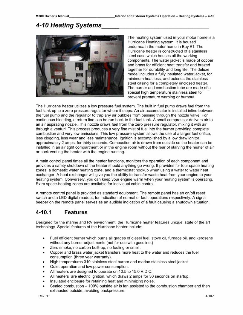
M380 Owner’s Manual__________________________Interior and Exterior Systems Operation – Heating Systems – 4-10
Rev. “F” 4-10-1
4-10 Heating Systems__________________________________
The heating system used in your motor home is a Hurricane Heating system. It is housed underneath the motor home in Bay #1. The Hurricane heater is constructed of a stainless steel case which houses all the working components. The water jacket is made of copper and brass for efficient heat transfer and brazed together for durability and long life. The deluxe model includes a fully insulated water jacket, for minimum heat loss, and extends the stainless steel casing for a completely enclosed heater. The burner and combustion tube are made of a special high temperature stainless steel to prevent premature warping or burnout.
The Hurricane heater utilizes a low pressure fuel system. The built in fuel pump draws fuel from the fuel tank up to a zero pressure regulator where it stops. An air accumulator is installed inline between the fuel pump and the regulator to trap any air bubbles from passing through the nozzle valve. For continuous bleeding, a return line can be run back to the fuel tank. A small compressor delivers air to an air aspirating nozzle. This nozzle draws fuel from the zero pressure regulator, mixing it with air through a venturi. This process produces a very fine mist of fuel into the burner providing complete combustion and very low emissions. This low pressure system allows the use of a larger fuel orifice, less clogging, less wear and less maintenance. Ignition is accomplished by a low draw ignitor, approximately 2 amps, for thirty seconds. Combustion air is drawn from outside so the heater can be installed in an air tight compartment or in the engine room without the fear of starving the heater of air or back venting the heater with the engine running. A main control panel times all the heater functions, monitors the operation of each component and provides a safety shutdown of the heater should anything go wrong. It provides for four space heating zones, a domestic water heating zone, and a thermostat hookup when using a water to water heat exchanger. A heat exchanger will give you the ability to transfer waste heat from your engine to your heating system. Conversely, you can keep your engine warm when your heating system is operating. Extra space-heating zones are available for individual cabin control. A remote control panel is provided as standard equipment. The remote panel has an on/off reset switch and a LED digital readout, for indication of normal or fault operations respectively. A signal beeper on the remote panel serves as an audible indication of a fault causing a shutdown situation. 4-10.1 Features Designed for the marine and RV environment, the Hurricane heater features unique, state of the art technology. Special features of the Hurricane heater include:
• Fuel efficient burner which burns all grades of diesel fuel, stove oil, furnace oil, and kerosene without any burner adjustments (not for use with gasoline.)
• Zero smoke, no carbon built-up, no fouling or smell. • Copper and brass water jacket transfers more heat to the water and reduces the fuel
consumption (three year warranty). • High temperatures 310 stainless steel burner and marine stainless steel jacket. • Quiet operation and low power consumption. • All heaters are designed to operate on 10.5 to 15.0 V.D.C. • All heaters are electric ignition, which draws 2 amps for 30 seconds on startup. • Insulated enclosure for retaining heat and minimizing noise. • Sealed combustion – 100% outside air is fan assisted to the combustion chamber and then
exhausted outside, avoiding backpressure.
4-10 – Interior and Exterior Systems Operation – Heating Systems__________________________M380 Owner’s Manual
4-10-2 Rev. “F”
• Optional bottom exhaust – mostly used in motor homes. • Includes four zone heating control for up to four thermostats. • Completely modular and field serviceable (user friendly). • Hookups and connections are easily accessible. • Electronically controlled. Safety features include four-second shutdown in case of failure,
LED digital readout on the electronic control panel for indicating faults, aquastats for monitoring water temperatures and a photodiode to monitor the flame.
• Complete with remote control panel with ON/OFF reset button, LED digital readout, and signal horn.
• Jumper for constant pump circulation (Automatic cycling when off). • All heaters cycle at an operating temperature of 180°F (82°C) with overheat cutout set at
195°F (90.5°C). • Air accumulator installed in the fuel line to collect air bubbles and prevent them from reaching
the burner and causing nuisance shutdowns.
The Hurricane Hydronic Heating Systems have been tested to UL 307A “Liquid Fuel-Burning Appliance for Manufactured Homes and Recreational Vehicles” and is listed by Testing Engineers International Inc. – Listing Services (TEI-LS) for Recreational Vehicle and marine use.
4-10.2 Operation 4-10.2.1 Starting the Heater The major steps in starting the heater are as follows:
1. Turn on the ON/OFF control switch, located on the remote indicator panel. 2. Turn up the zone thermostat to a setting higher than room temperature. 3. Start the heater by switching the service switch to ON. This switch is located on the side of
the electronic control box located next to the unit in the bay.
4-10.2.2 Signs of Normal Operation When the heater is operating normally:
• The ignitor will glow and the combustion air intake fan and the circulating pump begin to run. Whenever the pump is running, the green LED at the bottom of the LED display will be on.
• A few seconds later, the fuel pump starts delivering fuel to the regulator, the compressor
turns ON, the fuel valve opens, and fuel is drawn to the air aspirating nozzle. The fuel is atomized and sprayed into the combustion chamber to start combustion.
After the ignition period (about 10 seconds), the ignitor shuts OFF, and the burner continues to operate. The heater will operate until all the zone thermostats are satisfied, or until the heater reaches its normal water operating temperature of 180°F. Once the normal operating temperature is reached, the burner itself will cycle off and the combustion fan will operate for an additional two minutes to purge the burner. If a zone thermostat, domestic water heater aquastat, or engine heat exchanger aquastat is not satisfied, the circulating pump will continue to operate. If a thermostat cannot be satisfied by the residual heat in the system, and the water temperature drops, the burner will restart and cycle until all thermostats are satisfied. Once all thermostats are satisfied, the heater will go through the two minute purge, and the circulating pump will ease. The circulating pump will operate if the remote switch and any zone thermostat or the domestic water aquastat are on. The circulating pump will be activated independently by the engine heat aquastat. After the heater has been running for a little while, the water outlet of the heater case should become warm. If the water hose leaving the outlet of the heater does not warm up immediately after the pump comes on, water is not circulating properly and air may be in the system. Turn the heater OFF immediately and check water circulation, refer to Section 4-10.6.11 Water Filling Procedure later in this manual.
M380 Owner’s Manual__________________________Interior and Exterior Systems Operation – Heating Systems – 4-10
Rev. “F” 4-10-3
4-10.2.3 Main Control Board Operation Once the heater is operating normally, you must check the operating safety functions of the main board. To make sure the safety functions work properly, place your hand over the air intake inlet to the compressor, this will snuff out the flame. If you continue to block the air intake inlet, the heater will try to restart two more times and failing to do so will shut it down, stopping the compressor and fuel pump. The board will display a code 7. Reset the fault and the heater will continue with normal operation. 4-10.2.3 Stopping the Heater (For Seasonal Purposes) NEVER shut off the power to the heater using the circuit breaker or a master switch, or disconnect the battery while the heater is running. Doing so will cause serious damage to the heater, which will not be covered under warranty. To turn the Heater OFF, turn OFF, the ON/OFF control switch, located on the remote indicator panel. The room thermostat or the remote indicator panel ON/OFF switch can be turned ON or OFF at any time, without harming the heater. The heater will automatically run through the purge cycle, which takes about two minutes. 4-10.2.4 Stopping the Heater (For Maintenance) To shut down the heater totally, for maintenance purposes:
1. Turn OFF, the ON/OFF control switch, located on the remote indicator panel. 2. Turn OFF, the service switch on the electronic control box. 3. Wait until the heater has completed the purge cycle and turned itself OFF. 4. Disconnect the power supply.
4-10.2.5 Resetting the Fault When a fault occurs and has been corrected, you can reset the fault by switching the service switch on the side of the main control box located next to the unit in the bay, or the remote control switch OFF, then ON again. This will reset the fault and the diagnostic code. 4-10.2.6 Stopping the Heaters (When coach is left for extended periods of time) There are two heating systems supplied with the motor home. The Hydronic heat system has two thermostats located in the bathroom and the galley. The bay electric heater has a thermostat located in bay 2, right. If the Auto Gen-Start feature on the Inverter is Off and coach is unused for a period of time, (more than a day), be sure that all three thermostats are set to the full Off position (the thermostat Off state has a detent position at the end of the full counterclockwise rotation). If not turned to full Off position and motor home gets below 50°F, the hydronic heater pump turns On and the bay electric heaters turn On, thus draining the battery. To use the Auto Gen-Start function on the inverter, refer to Section 4-5.1.4.3 in the Inverter section of this manual. 4-10.3 Heat Exchanger Operation If your motor home is equipped with a heat exchanger to pre-heat your engine and recycle waste engine heat, follow these procedures. To pre-heat your engine: Turn on the heater by a manual switch or timer wired to the jumper W-W terminal, located in the control box. If the heat exchanger is mounted upright, close to and near the bottom of the engine, it will transfer heat to the engine’s cooling system through gravity circulation. A more positive solution is to install a pump on the engine side of the heat exchanger wired to the A-A pump terminals located in the control box, on the main board in series with a master switch.
4-10 – Interior and Exterior Systems Operation – Heating Systems__________________________M380 Owner’s Manual
4-10-4 Rev. “F”
To use waste engine heat for space and domestic water heating: 1. Install a switch, and/or an aquastat (part #1027), on the engine supply line to the heat
exchanger, and wire to the A-A terminals on the main control board. 2. Turn OFF, the ON/OFF control switch, located on the remote indicator panel. This will stop
the burner from operating, but all other heater functions will operate normally. 3. Start your engine. 4. When the engine aquastat heats up to its preset temperatures, it will automatically switch on
the circulating pump of the heating system. All other functions of the system will operate normally.
5. The circulating pump will continue to operate until the engine aquastat has cooled down. A manual switch can be wired in series with this aquastat to shut down the pump sooner if required.
4-10.4 Domestic Water Operation If your water heater is connected to the Hurricane heating system and its controlling aquastat (part #1024) is wired to the W-W terminals on the main board, it will cycle the heater and the water pump. A manual switch can be wired in series with this aquastat to shut down the operation if desired. A bypass loop can be plumbed in for summer operation.
CAUTION: Where there is a chance of contamination of your domestic water when using a heating system, use antifreeze specifically intended for hydronic heating systems. Inhibited propylene glycol is recommended. Do not use automotive, ethylene glycol, or any undiluted or petroleum based antifreeze as they can cause severe personal injury should antifreeze leak into your potable water supply. Double wall heat exchangers are available for potable water which will prevent contamination in the event of an internal leak.
4-10.5 Troubleshooting 4-10.5.1 Overview The electronic board consists of a flash micro controller programmed to monitor the timing and safety function of the heater. Each time the board is energized by a call for heat, it will check its own circuits for any problems. Should a problem exist, the board will shut down. You can easily monitor your Hurricane heater’s operation by checking the electronic control box. Any fault or problem will be immediately picked up by the control board and an LED diagnostic code indicator will light up to pinpoint the fault. Once the fault has been corrected, it can be reset by switching the service or remote switch OFF, then ON again. The diagnostic codes are described below. 4-10.5.2 Power On (Green) The POWER ON indicator is lit whenever the service switch on the control box is ON and if the remote panel is switched ON, a small red LED near the lower right hand side of the digit on the remote panel will also glow. If this light does not come on, check to see if the service switch is ON. If the power on light does NOT come on: Check for a blown fuse.
M380 Owner’s Manual__________________________Interior and Exterior Systems Operation – Heating Systems – 4-10
Rev. “F” 4-10-5
4-10.5.3 Burner On No diagnostic code will be displayed on the main board or the remote panel when the burner is ON and operating normally. A small red LED will glow near the right hand side of the digital readout on the main board located on the unit in the upper left hand corner, indicating it is ON. 4-10.5.4 - Service Switch Off The service switch is switched OFF.
- The burner will shut down if it has been running. - The diagnostic code, will be displayed. - The control board will purge the system with the combustion fan and circulating pump
for two minutes. At the end of the purge period, the system will power down and will go into a low power consumption mode (10mA max.). There will not be any display or LED’s lit.
4-10.5.5 – Remote Switch Off The remote panel is switched OFF.
- The burner will shut down. - The diagnostic code, will be displayed. - The control board will purge the system with the combustion fan and the circulating
pump for two minutes. If the remote switch is put in the ON position, the control board resumes operation and a small red LED glows near the lower right hand corner of the digit. If there is no diagnostic code displayed or small LED glowing: 1. Make sure the service switch is ON. 2. Make sure the remote switch cable is plugged into the control box and remote switch. 3. Make sure the remote rocker switch is working. 4. Check the cable continuity.
4-10.5.6 – Heater Cycling (Normal Operation) The operating aquastat installed on the water jacket has been satisfied.
- The burner will shut down. - The diagnostic code, will be displayed. - The control board will purge the burner with the combustion fan for two minutes and
then stop. The circulating pump will run until the last thermostat is satisfied, then will purge for two minutes and stop.
- To maintain the system temperature the operating aquastat will cycle the burner off at 185°F (85°C) and on again at 150°F (65°C).
- If the heater cools and fails to resume operation and the diagnostic code continues to be displayed, the aquastat is faulty or has an open connection.
4-10 – Interior and Exterior Systems Operation – Heating Systems__________________________M380 Owner’s Manual
4-10-6 Rev. “F”
4-10.5.7 – Thermostats Off (Normal Operation) All thermostats and aquastats are satisfied.
- The burner will shut down.
- The diagnostic code, will be displayed. - The control board will purge the system with the combustion fan and the circulating
pump for two minutes. When any thermostat or aquastat calls for heat, the heater will resume normal operation.
- If the heater fails to resume operations, check the thermostat and their connections.
4-10.5.8 – Voltage Low or High The battery or power supply voltage is below 10.5Vdc or above 15.5Vdc.
- The burner will shut down. - The diagnostic code, will be displayed. - The buzzer will sound for 10 seconds. - The control board will purge the system with the combustion fan and circulating pump
for two minutes while it is checking if the voltage fault is still present. If the voltage fault has cleared, the control board resets the alarm and restarts the burner. If the condition has not cleared by the end of the purge period, the diagnostic code remains displayed. The control board continues to check the voltage every half hour until the voltage fault clears and then restarts the burner. To manually reset the fault, switch the service switch or the remote panel switch OFF then ON again.
4-10.5.9 – Overheat The high temperature limit has been reached.
- The burner will shut down. - The diagnostic code, will be displayed. - The buzzer will sound for 10 seconds. - The control board will purge the system with the combustion fan and the circulating
pump for two minutes while it is checking if the overheat condition exists. If the condition exists, the diagnostic code will continue to be displayed.
- In order to restart the burner, first check the circulating pump, the level of the coolant, and the movement of the coolant while the circulating pump is running. Then reset the fault after the water has cooled down by switching the service switch or the remote panel switch OFF then ON again. If it does not reset, check for faulty aquastat and proper ground.
If a number diagnostic code lights up and the heater is not in an overheat condition, check the ground from the heater to the battery. The ground should be a minimum 10 AWG and connected directly to the battery.
4-10.5.10 – Fuse Blown One of the fuses on the control board has blown.
- The burner will shut down. - The diagnostic code, will be displayed. - The buzzer will sound for 10 seconds. - The control board will purge the system with the combustion fan and the circulating
pump for two minutes while it is checking for a blown fuse.

M380 Owner’s Manual__________________________Interior and Exterior Systems Operation – Heating Systems – 4-10
Rev. “F” 4-10-7
If a blown fuse exists, the diagnostic code will continue to be displayed. - In order to restart the burner, replace any blown fuses with one of the proper size.
Then reset the fault by switching the service switch or the remote panel switch OFF then ON again.
4-10.5.11 – Fuel Pump/Solenoid The fuel pump or fuel solenoid has shorted.
- The burner will shut down. - The diagnostic code, will be displayed. - The buzzer will sound for 10 seconds. - The control board will purge the system with the combustion fan and the circulating
pump for two minutes. - In order to restart the burner, check the fuel pump and solenoid for a short circuit.
Then reset the fault by switching the service switch OFF and ON again. The remote panel switch does not reset short circuit faults.
4-10.5.12 – Ignitor The ignitor is open or shorted.
- The burner will shut down. - The diagnostic code, will be displayed. - The buzzer will sound for 10 seconds. - The control board will purge the system with the combustion fan and the circulating
pump for two minutes. - In order to restart the burner, check the ignitor and connections. Then reset the fault
by switching the service switch or the remote panel switch OFF then ON again if the ignitor is open or by the service switch only if the ignitor is shorted.
The remote panel switch does not reset a short circuit fault.
4-10.5.13 – Combustion Fan The combustion fan is open or shorted.
- The burner will shut down. - The diagnostic code, will be displayed. - The buzzer will sound for 10 seconds. - The control board will purge, with the circulating pump for two minutes. - In order to restart the burner, check the combustion fan. Then reset the fault by
switching the service switch or the remote panel switch OFF then ON again if the combustion fan is open or by the service switch only if the combustion fan has shorted.
The remote panel switch does not reset a short circuit fault.
4-10 – Interior and Exterior Systems Operation – Heating Systems__________________________M380 Owner’s Manual
4-10-8 Rev. “F”
4-10.5.14 – Water Pump The water pump is shorted.
- The burner will shut down. - The diagnostic code, will be displayed. - The buzzer will sound for 10 seconds. - The control board will purge with the combustion fan for two minutes. - In order to restart the burner, check the water pump. Then reset the fault by switching
the service switch OFF then ON again. The remote panel switch does not reset a short circuit fault.
4-10.5.15 – Flame Out The flame went out or did not ignite.
- The burner will shut down. - The diagnostic code, will be displayed. - The control board will try to restart the burner two more times. After three
unsuccessful ignition attempts, the buzzer will sound for 10 seconds. - The control board will purge with the combustion fan and circulating pump for two
minutes. The diagnostic code will continue to be displayed. The single most common reason for flame out faults is when air gets into the fuel system. This is normally caused by loose fittings or when your fuel supply is teed off a fuel line used by your engine or generator. As air accumulates and passes through the nozzle, it interrupts the fuel and shuts down the burner. When this happens, it may be necessary to reset the fault a few times to ensure all air has passed through the system. If the burner resumes normal operation, you must find the source of the air leak, otherwise, this fault will continue to occur. An Air Accumulator has been installed to collect the air before it reaches the nozzle. Check regularly and bleed if necessary. Air which is collected is an indication of a leak somewhere in the fuel system. 1. Check the fuel supply. The fuel pump will chatter if there is no fuel or when air is
passing through the pump. Check the Air Accumulator for air and bleed if necessary. Check connections between the fuel tank and fuel pump and the regulator and nozzle for air leaks. Find source of air entry and repair. Make sure the nozzle or fuel filter is not clogged.
2. Check the air line hoses for any restriction of air flow through the compressor. Restrictions may be caused by a crimped hose, clogged air filter, or a loose or leaking air hose from the compressor outlet to the nozzle. Check the air filter inlet for any obstructions.
3. Make sure the air pressure of the compressor with the nozzle installed, is at 8 to 90 psig for CO-20/32 models and 10 to 12 psig for CO-45/65, and 14 to 16 psig for CO-85/105 models.
4. Check for negative pressure in the area around the heater. When the engine is running, it can draw air back through the heater’s exhaust pipe. All intake air and exhaust connections must be tight.
5. Check for restrictions or leaks in the combustion air intake hose or exhaust pipe. 6. Check for open circuit on fuel pump/solenoid and compressor.
- To restart the burner, check the fuel supply, check for air in the fuel line, and clean the nozzle. Then reset the fault by switching the service switch or the remote switch OFF then ON again.
7. If when reset, the board shuts down without trying to restart the burner the board is defective.
M380 Owner’s Manual__________________________Interior and Exterior Systems Operation – Heating Systems – 4-10
Rev. “F” 4-10-9
4-10.5.16 – Compressor The air compressor has shorted.
- The burner will shut down - The diagnostic code, will be displayed. - The buzzer will sound for 10 seconds. - The control board will purge the system with the combustion fan and the circulating
pump for two minutes. - In order to restart the burner, check the air compressor. Then reset the fault by
switching the service switch OFF then ON again. The remote panel switch does not reset a short circuit fault.
4-10.5.17 – Bypass Mode
The bypass mode is a service feature to be used by authorized service personnel only. The bypass mode overrides the remote switch, voltage fault, fuse blown fault, flame out fault, open ignitor fault, open fan fault, and thermostats. All these safety devices will be bypassed for five minutes.
- While in the bypass mode, the diagnostic code, will be displayed and the Power ON LED will flash rapidly.
- If the heater cycling aquastat is satisfied or the overheat limit is reached, the burner stops and purges for two minutes while displaying the diagnostic codes: C-heater cycling or 1-overheat, and the Power ON LED flashes slowly. You must wait for the heater to cool before continuing in the bypass mode. The bypass mode times out in five minutes. After the first three minutes running, it automatically purges for the last two minutes.
4-10.5.18 Water Pump On (Green) The green light located directly under the LED digit on the main board turns on whenever the circulating water pump is energized. 4-10.5.19 Remote Panel The remote panel consists of an ON/OFF reset switch, an LED diagnostic digit, and fault buzzer. The diagnostic digit matches the main control board which refers to the diagnostic codes as explained previously in this section. A small red LED glows when the switch is on, which also indicates that the service switch is ON. The small buzzer sounds for 10 seconds to alert you of a fault. 4-10.5.20 LCD Readout Remote Panel (Optional) This panel displays the diagnostic explanation which matches up to the diagnostic code on the main board. A small buzzer sounds for 10 seconds to alert you of a fault. 4-10.5.21 Flame Sensor Module The Flame Sensor consists of a sealed module with a photodiode aimed at the flame, a red LED indicator light and 3 wires, white (+), black (-), and green (signal) connected to the main board. Under normal operating conditions whenever the burner ignition begins, the red LED flashes once indicating the white and black wires are connected and the module is receiving power and working properly. Once the burner is ignited, the LED begins to flicker like a flame. If for any reason the flame is extinguished, the flickering stops and the board shuts down the heater. If the green (signal) wire is disconnected, the board shuts down. If all wires are properly connected with module flashing and the board still shuts down, diagnostic code Flame Out, the board may be defective.
4-10 – Interior and Exterior Systems Operation – Heating Systems__________________________M380 Owner’s Manual
4-10-10 Rev. “F”
4-10.5.22 Reduced Output The heater may run without faulting, but at a reduced output. If this is noticed, it could be caused by the following:
1. High altitude 2. Dirty nozzle 3. Defective regulator 4. Too small a nozzle 5. Poor water circulation 6. Ash deposit in combustion chamber
4-10.5.23 Smokey, Smelly Exhaust The heater may run without faulting, but you may experience signs of soot, exhaust smoke and/or a pungent smell. This is usually caused by the wrong fuel to air mixture. This can be affected by the following:
1. Low voltage 2. High altitude 3. Dirty compressor air filter 4. Low compressor air output 5. Restricted combustion air flow (intake hose/exhaust hose/combustion chamber) 6. Low combustion fan output (defective motor/wrong rotation/dirty fan blade) 7. Partially clogged grooves in nozzle distributor.
4-10.5.24 Hot Water is Coming Out Cool This may be a sign that the Mixing Valve is not set to the proper setting. Look through the 3/8” x 1” Inspection Slot on the front of the Hurricane Heat case, if setting is not at 4, it will need to be adjusted. To adjust setting, remove cover from case and manually turn knob to highest setting (4), replace cover. NOTE: If there is no slot on the Hurricane case then this is not the cause of the cool water. Unit may need to be serviced. 4-10.6 Maintenance 4-10.6.1 The First Few Weeks About two weeks after your Hurricane heater has been running, you should conduct a general inspection of the entire system. Check for any leaks in the exhaust, fuel, or water systems. Tighten all clamps. 4-10.6.2 Adding Antifreeze Once the system has been filled with water and purged of all air during the installation procedure, you need to operate the heater at normal temperatures and then check for water leaks. If you do not find any, add antifreeze to lubricate the pump and prevent the water system from corroding or freezing in cold weather. To do this see Section 4-10.6.11 Water Filling Procedures later in this manual.
M380 Owner’s Manual__________________________Interior and Exterior Systems Operation – Heating Systems – 4-10
Rev. “F” 4-10-11
CAUTION: Where there is a chance of contamination of your domestic water when using a heating system, use antifreeze specifically intended for hydronic heating systems. Inhibited propylene glycol is recommended. Do not use automotive, ethylene glycol, or any undiluted or petroleum based antifreeze as they can cause severe personal injury. It is very important that you never use water only as a coolant. We recommend that you add a mixture of 50% water and 50% antifreeze. NEVER use more than a 50/50 mixture, since the added viscosity of the antifreeze solution will cause circulation problems. Your antifreeze/water mixture should be changed every three years. Antifreeze does wear out and can become very acidic. A coolant conditioner should be added to the water system, to keep the coolant alkaline and not acidic, see section 4-10.6.9 Protecting Hydronic Heating Systems later in this manual. These inhibitors also prevent the coolant from forming calcium scales. Conditioners are available from diesel engine manufacturers to maintain water stability and prolong heater life. If a conditioner is not installed in your system, check the pH level yearly. The components inside the heater should not normally require maintenance, except for periodic checks for obvious problems, such as leaks or overheating. 4-10.6.3 Nozzle Nozzle problems such as clogging results in a poor flame, small and blue. Carefully disassemble. Hold nozzle and turn stem counter clockwise. Clean distributor orifice and air slots of any debris using solvent and high pressure air. Check O-rings for nicks and replace if in doubt. A leaking O-ring allows air into the fuel causing popping of the flame. 4-10.6.4 Fuel Lines and Filter You should check your filter every season to determine if it needs replacement. The frequency depends largely on the quality of fuel you’ve been using. 4-10.6.5 Combustion Chamber The quality of the fuel varies and some ash is left in the chamber after combustion. The burner and combustion tube must be removed and the combustion chamber vacuumed clean ever 1000 hours. If this is neglected, the exhaust becomes restricted and causes the combustion chamber to burn out. The exhaust pipe should be checked and also be vacuumed, if required. 4-10.6.6 Checking Hoses and Tubes Every so often, check all water hoses and tubes for leaks or weak points. Tighten all clamps and replace any sections of worn hose immediately.
CAUTION: Never let the water pump run dry. This causes irreparable damage to the pump and voids the warranty. 4-10.6.7 Electrical System The electronic control panel should not normally require servicing, except for the following: • Make sure that all your connections are secure. • Periodically, do a voltage test to ensure that you are getting 12 volts from the battery. • Check for corrosion of wires.
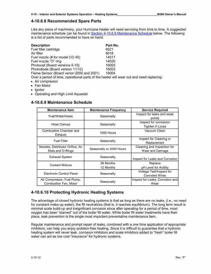
4-10 – Interior and Exterior Systems Operation – Heating Systems__________________________M380 Owner’s Manual
4-10-12 Rev. “F”
4-10.6.8 Recommended Spare Parts Like any piece of machinery, your Hurricane heater will need servicing from time to time. A suggested maintenance schedule can be found in Section 4-10.6.9 Maintenance Schedule below. The following is a list of parts recommended to have on hand. Description Part No. Fuel filter cartridge 6021 Air filter 6018 Fuel nozzle (# for model CO 45) 14017 Fuel nozzle “O” ring 14025 Photocell (Board versions 5-10) 16002 Photodiode (Board version 11/12) 16003 Flame Sensor (Board verion 2000 and 2001) 16004 Over a period of time, operational parts of the heater will wear out and need replacing: • Air compressor • Fan Motor • Ignitor • Operating and High Limit Aquastat 4-10.6.9 Maintenance Schedule
4-10.6.10 Protecting Hydronic Heating Systems The advantage of closed hydronic heating systems is that as long as there are no leaks, (i.e., no need for constant make-up water), the fill neutralizes (that is, it reaches equilibrium). The long term result is minimal scale build-up and insignificant corrosion since after operating for a period of time, most oxygen has been “starved” out of the boiler fill water. While boiler fill water treatments have their place, leak prevention is the single most important preventative maintenance item. Regular maintenance and prompt repair of leaks, combined with a one time application of appropriate inhibitors, can help you enjoy problem-free heating. Since it is difficult to guarantee that a hydronic heating system will never leak, corrosion inhibitors and scale inhibitors added to “fresh” boiler fill water can act as low cost “insurance” for hydronic systems.
Maintenance Item Maintenance Frequency Service Required
Fuel/WaterHoses Seasonally Inspect for leaks and weak points
Inspect for corrossionTighten if Loose
Combustion Chamber and Exhaust 1000 Hours Vacuum Clean
Fuel Filter Seasonally Inspect for Cleaning or Replacement
Nozzles, Distributor Orifice, Air Slots and O-Rings Seasonally or 2000 Hours Cleaning and Inspection for
Wear and Damage
Exhaust System Seasonally Inspect for Leaks and Corrosion36 Months Replace12 Months pH Level for Acidity
Electronic Control Panel Seasonally Voltage Test/Inspect for Corroded Wires
Air Compressor, Fuel Pump, Combustion Fan, Motor Seasonally Inspect for Leaks, Corrosion and
Wear
Hose Clamps Seasonally
Coolant Mixture
M380 Owner’s Manual__________________________Interior and Exterior Systems Operation – Heating Systems – 4-10
Rev. “F” 4-10-13
Causes of Scale Tap water is the most typical source selected for boiler fill water. Water contains dissolved solids such as magnesium and calcium which when heated becomes much less soluble and forms scale. Scale comes out of solution in the largest amounts where the temperature is highest in the system (i.e., the boiler heat exchanger). As the scale builds up, noise and cold spots develop since scales plug up water channels and acts as an insulator that impedes proper heater transfer. Acidity and Corrosion Corrosion is the result of metal oxidizing (that is, metals reacting with oxygen-rich boiler fill water). The acidity of any liquid (including water) is a good indicator of how much corrosion will actually take place. As a rule of thumb, boiler fill water should have a pH greater than 7 and less than 10.5. The key to preventing corrosion is to make sure that the heating system is free of leaks and there is no need to replace it with fresh, oxygen rich boiler fill water. Corrosion inside a hydronic heating system stops quite quickly as the fill water stabilizes and becomes oxygen-starved. The pH should be measured at least annually. Since most hydronic heating systems are comprised of different metals (e.g., iron, copper, etc.) and since boiler fill water is an electrolyte (that is, it will conduct electrical current), electro-chemical reactions (“galvanic” reactions) can take place. As the fill water stabilizes, however, it becomes a very weak electrolyte, so galvanic corrosion rarely becomes a problem – as long as the system remains leak-free. Preventative Treatments Corrosion and scale inhibitors are relatively inexpensive. Ideally, they should be applied, once only, at the time of a new installation or whenever a system has been completely drained. Boiler water treatment specialists almost unanimously agree that the prevention of leaks and the elimination of the need for frequent boiler water make-up are top priorities for hydronic systems. 4-10.6.11 Water Filling Procedure After your system has been completely installed, filled with straight water, purged of all air, and operating for a period of time at normal operating temperatures, you should now double check all connections for leaks. If no leaks are found, the system can be drained and filled with a 50/50 mixture of antifreeze and water.
CAUTION: Where there is a chance of contamination of your domestic water when using a heating system, use antifreeze specifically intended for hydronic heating systems. Inhibited propylene glycol is recommended. Do not use automotive, ethylene glycol, or any undiluted or petroleum based antifreeze as they can cause severe personal injury. To fill the system use a separate self priming pressure pump with a hose on the suction side. Put the hose into a 5 gallon container. Remove the systems hose from the outlet of the expansion tank, which is feeding the systems circulating pump and attach it to the outlet of the self priming pressure pump. Remove the hose from the inlet of the expansion tank and hang it into the 5 gallon container. Make a final check to ensure all of the air vents and drains are closed. Pour a mixture of antifreeze and water into the container and start the pump. As the mixture is pumped out, slowly add more mixture keeping the level above the inlet of the suction hose until all air has been expelled and the mixture starts coming out of the return hose hanging in the container. This flushes the system of any debris and purges the lines of air. Continue to run the pump for about 15 minutes. When no more air is being expelled, stop the pump and reconnect the lines to the expansion tank. Top off the expansion tank with the mixture and turn on the system’s circulating pump with the jumper, located on the main control board just right of the pump fuse, marked “Circ. Pump Override”. When the jumper is on, the pump will run continuously and the bottom LED will be lit.

4-10 – Interior and Exterior Systems Operation – Heating Systems__________________________M380 Owner’s Manual
4-10-14 Rev. “F”
Check for a good flow through the expansion tank and double check all joints for leaks. Open and close all air vents to eliminate any remaining air bubbles. Recheck the mixture level and circulation in the expansion tank.
CAUTION: Make sure you have a good, quiet circulation of water through the heater. Check the pump to make sure it does not run dry. If the heater has air pockets trapped in the water jacket when it is turned on, it could overheat and damage the unit. None of this is covered by warranty.
M380 Owner’s Manual_______________Interior and Exterior Systems Operation – Air Conditioning/Heat Pumps – 4-11
Rev. “F” 4-11-1
4-11 Air Conditioning/Heat Pumps________________________ 4-11.1 System Description Air conditioners are located in the living room and bedroom areas. A wall mounted master thermostat is located in the dinette area to control all units. Remote temperature sensors are located in the kitchen/dinette area and bedroom. The air conditioners are operable from 120 VAC source (generator or shoreline power). Each air conditioning unit is also a heat pump. Condensate Drains - Separate drain lines are provided for each air conditioning unit to route condensation from the roof to the ground through the body side walls. 4-11.2 Electric Heat An electric forced air heater is located in the bath, controlled by remote thermostat. A second electric heater is located in the kitchen. 4-11.3 Automotive Air and Heat System The dash heat and air system are a separate HVAC system designed to meet the latest refrigerant requirements. This unit provides the ability to mix heat and air to provide defrosting capability.

M380 Owner’s Manual__________________________________________________________________________________
Rev. “F”
THIS PAGE IS INTENTIONALLY LEFT BLANK
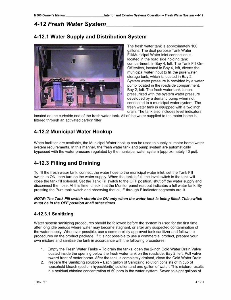
M380 Owner’s Manual_______________________Interior and Exterior Systems Operation – Fresh Water System – 4-12
Rev. “F” 4-12-1
4-12 Fresh Water System________________________________ 4-12.1 Water Supply and Distribution System
The fresh water tank is approximately 100 gallons. The dual purpose Tank Water Fill/Municipal Water inlet connection is located in the road side holding tank compartment, in Bay 4, left. The Tank Fill On-Off switch, located in Bay 4, left, diverts the municipal water input to fill the pure water storage tank, which is located in Bay 2. System water pressure is provided by a water pump located in the roadside compartment, Bay 2, left. The fresh water tank is non-pressurized with the system water pressure developed by a demand pump when not connected to a municipal water system. The fresh water tank is equipped with a two inch drain. The tank also includes level indicators,
located on the curbside end of the fresh water tank. All of the water supplied to the motor home is filtered through an activated carbon filter. 4-12.2 Municipal Water Hookup When facilities are available, the Municipal Water hookup can be used to supply all motor home water system requirements. In this manner, the fresh water tank and pump system are automatically bypassed with the water pressure regulated by the municipal water system (approximately 40 psi). 4-12.3 Filling and Draining To fill the fresh water tank, connect the water hose to the municipal water inlet, set the Tank Fill switch to ON, then turn on the water supply. When the tank is full, the level switch in the tank will close the tank fill solenoid. Set the Tank Fill switch to the OFF position, shut off the water supply and disconnect the hose. At this time, check that the Monitor panel readout indicates a full water tank. By pressing the Pure tank switch and observing that all, E through F indicator segments are lit. NOTE: The Tank Fill switch should be ON only when the water tank is being filled. This switch must be in the OFF position at all other times. 4-12.3.1 Sanitizing Water system sanitizing procedures should be followed before the system is used for the first time, after long idle periods where water may become stagnant, or after any suspected contamination of the water supply. Whenever possible, use a commercially approved tank sanitizer and follow the procedures on the product package. If it is not possible to use a commercial product, prepare your own mixture and sanitize the tank in accordance with the following procedures:
1. Empty the Fresh Water Tanks – To drain the tanks, open the 2-inch Cold Water Drain Valve located inside the opening below the fresh water tank on the roadside, Bay 2, left. Pull valve toward front of motor home. After the tank is completely drained, close the Cold Water Drain.
2. Prepare the Sanitizing solution – Each gallon of Sanitizing solution consists of ¼ cup of household bleach (sodium hypochlorite) solution and one gallon of water. This mixture results in a residual chlorine concentration of 50 ppm in the water system. Seven to eight gallons of
4-12 – Interior and Exterior Systems Operation – Fresh Water System_______________________M380 Owner’s Manual
4-12-2 Rev. “F”
sanitizing solution will be adequate for the M380 fresh water tank. (Approximately 100 gallons).
3. Add sanitizing solution to water tank – Remove deck lid plug in the curbside close out panel. Remove 3/4 inch plug from the side of the tank in the curb side luggage compartment and pour the solution into the tank. Reinstall the plug in the tank.
4. Fill tank to capacity – Connect the hose to the municipal water inlet, turn on the Tank Fill Switch and fill the water tanks completely. Shut off the hose and turn off the Tank Fill switch. Turn on the water pumps. Open each faucet (hot and cold), and run the water until a distinct odor of chlorine can be detected. Shut off the water pump.
5. Allow the system to stand – Let stand for at least 4 hours when disinfecting with 50 ppm residual chlorine. If a shorter time period is desired, then a 100 ppm chlorine concentration should be permitted to stand in the system for at least one hour.
6. Drain tanks – Open the Cold Water Drain valve (as in Step 1), and allow the tank to drain completely.
7. Refill tanks – Close the Cold Water Drain valve and turn on the water supply to the municipal water inlet. Turn on the Tank Fill switch and fill the tank completely. When the tank is full, turn off the Tank Fill switch, shut off the water supply and disconnect the hose. Then replace the fill cap and turn on the water pump. When water flows from the opened faucets, close them and open the other faucets until water flows. This flushes the system, removing trapped air from piping and ensures that the fresh water supply is ready for use.
CAUTION: Do not permit sanitizing or antifreeze solutions to enter water filter.
8. Repeat steps 6 and 7 until the chlorine smell and taste is no longer present at the faucets.
4-12.3.2 Water Filter Replacement
Depending upon the condition of the municipal water used, the filter media will degrade with use. The only practical way to determine when replacement is required is to go by the sense of taste. It is recommended that the filter be changed after prolonged storage.
4-12.3.3 Water Heater
With the Hurricane system at operating temperature, the domestic water is automatically heated as it is being used. Open any hot water faucet and a continuous supply of domestic hot water will be present within a few seconds. This is accomplished by the Hurricane’s domestic hot water zones, which are an integral part of the heating system. A mixer valve has been installed to ensure that excessively hot water does not flow to the faucets.
CAUTION: The mixer valve is not an anti-scald device. Always exercise reasonable caution
when using hot water. CAUTION: Do not turn the Hurricane’s unit off if the outside temperature is 32°F or lower
when the potable water system is not drained.
4-12.3.4 Water Pump
The water pump is located in the road side luggage compartment (bay 2, left). The pump employs state-of-the-art electronics to automatically control motor speed. The pump adjusts its speed as you open and close water fixtures. If the pump has been out of service for a period of time, it is advisable to open a faucet before turning them on. When water flows steadily from the opened faucet, close the faucet and observe that the pump shuts off when the system becomes pressurized. (It may also be necessary to bleed the air from the other faucets as well.) When the fresh water supply tank level is low or empty, shut the pump off to prevent possible damage to the pump motor. In addition to integral motor overload protection; the pump mechanism is also protected from damage by the presence of a filter at the water pump inlet. The filter should be cleaned periodically. Under normal usage, the water pump should require no periodic maintenance other than ensuring that the input water supply is properly filtered of particles that could damage the pump mechanism.
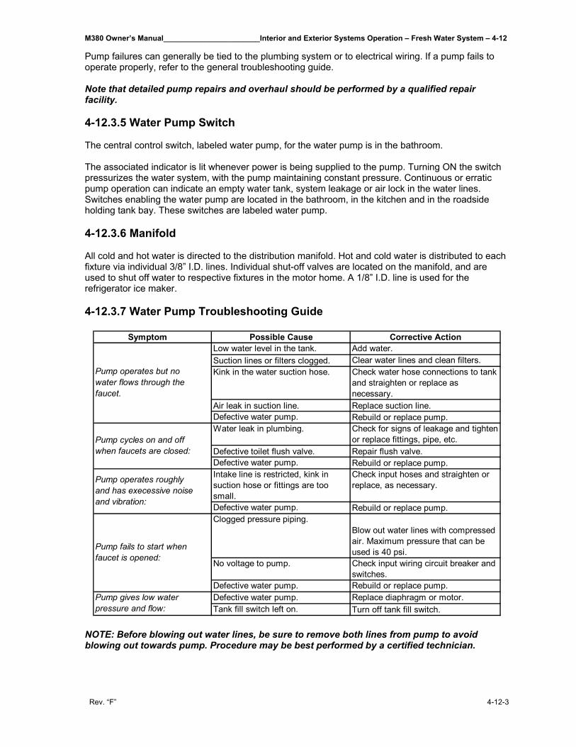
M380 Owner’s Manual_______________________Interior and Exterior Systems Operation – Fresh Water System – 4-12
Rev. “F” 4-12-3
Pump failures can generally be tied to the plumbing system or to electrical wiring. If a pump fails to operate properly, refer to the general troubleshooting guide. Note that detailed pump repairs and overhaul should be performed by a qualified repair facility. 4-12.3.5 Water Pump Switch The central control switch, labeled water pump, for the water pump is in the bathroom. The associated indicator is lit whenever power is being supplied to the pump. Turning ON the switch pressurizes the water system, with the pump maintaining constant pressure. Continuous or erratic pump operation can indicate an empty water tank, system leakage or air lock in the water lines. Switches enabling the water pump are located in the bathroom, in the kitchen and in the roadside holding tank bay. These switches are labeled water pump. 4-12.3.6 Manifold All cold and hot water is directed to the distribution manifold. Hot and cold water is distributed to each fixture via individual 3/8” I.D. lines. Individual shut-off valves are located on the manifold, and are used to shut off water to respective fixtures in the motor home. A 1/8” I.D. line is used for the refrigerator ice maker. 4-12.3.7 Water Pump Troubleshooting Guide
NOTE: Before blowing out water lines, be sure to remove both lines from pump to avoid blowing out towards pump. Procedure may be best performed by a certified technician.
Symptom Possible Cause Corrective ActionLow water level in the tank. Add water.Suction lines or filters clogged. Clear water lines and clean filters.Kink in the water suction hose. Check water hose connections to tank
and straighten or replace as necessary.
Air leak in suction line. Replace suction line.Defective water pump. Rebuild or replace pump.Water leak in plumbing. Check for signs of leakage and tighten
or replace fittings, pipe, etc.Defective toilet flush valve. Repair flush valve.Defective water pump. Rebuild or replace pump.Intake line is restricted, kink in suction hose or fittings are too small.
Check input hoses and straighten or replace, as necessary.
Defective water pump. Rebuild or replace pump.Clogged pressure piping.
Blow out water lines with compressed air. Maximum pressure that can be used is 40 psi.
No voltage to pump. Check input wiring circuit breaker and switches.
Defective water pump. Rebuild or replace pump.Defective water pump. Replace diaphragm or motor.Tank fill switch left on. Turn off tank fill switch.
Pump gives low water pressure and flow:
Pump operates but no water flows through the faucet.
Pump cycles on and off when faucets are closed:
Pump fails to start when faucet is opened:
Pump operates roughly and has execessive noise and vibration:
4-12 – Interior and Exterior Systems Operation – Fresh Water System_______________________M380 Owner’s Manual
4-12-4 Rev. “F”
4-12.4 Winterizing If you are planning on storing your motor home in an unheated area during cold weather, it is necessary to winterize the water system to prevent damage from freezing conditions. Winterizing procedures are covered in the following paragraphs. 4-12.4.1 Draining and Winterizing the Fresh Water Supply System The following procedures show the use of the various drain valves and controls to winterize the fresh water system.
1. Open the main circuit breaker box (located in bedroom) and turn off the Water Heater and Instant Hot circuit breakers.
2. Turn on Water Pump switch (located in bathroom) and open all faucets (galley sink, lavatory, shower, outside hose connection and toilet water valve – after depressing pedal insert block to maintain position). Note that the outside water faucet should always be left open when freezing temperatures are expected. Also, remove drain plugs at rear of toilet and at bottom of Instant Hot. Refer to the Icemaker and Toilet Manuals for winterizing these units.)
3. Open the Cold and Hot Water Drain valves located in roadside Bay 2 left, luggage compartment. Open 2” water tank drain valve in road side first luggage compartment, Bay 1 left.
4. Allow water to drain completely before proceeding to the next step. 5. Turn off water pump switch. 6. Unroll coiled hose under road side end of fresh water tank. Hose is connected to valve
assembly under tank (Bay 2, left). 7. Feed open end of hose into container of RV antifreeze. Approximately 3 to 5 gallons required. 8. Close the valve on the suction line coming from the fresh water tank and open the valve from
the RV antifreeze line. 9. Close all fresh water manifold valves. Except the top hot water valve. 10. Turn on fresh water pump. Make sure RV antifreeze is moving into pump and into the
manifold. Be ready to close the cold water drain valve, under manifold exiting the floor, when antifreeze exits the line under motor home. Also close hot water drain at this time.
11. Continue to run pump to fill the water heater and the hot water side of the manifold until antifreeze exits the hot water valve left open in step 9.
12. Open the hot water drain valve, closed in step 10, and close it again when antifreeze exits the hot water drain line.
13. Turn pump off at this time and close the valve on the antifreeze line. Stow hose in original location.
14. Make sure all the interior and exterior faucets, as well as, the ice maker, toilet and clothes washer are open.
15. At this point, the only water remaining in the system is contained in the P traps beneath the lavatory sink, shower drain, and kitchen sink (clothes washer optional). To prevent this water from freezing and damaging traps, put one pint of RV system anti-freeze into each drain. See WASTE SYSTEM winterizing.
NOTE: When reactivating the system, make sure (optional) Instant Hot is full of water before switching on.
M380 Owner’s Manual____________________________Interior and Exterior Systems Operation - Waste System – 4-13
Rev. “F” 4-13-1
4-13 Waste System_____________________________________ Your motor home comes with a Traveler® Fine China Toilet. Some important information for the use and care of your toilet is as follows:
1. Do not use chlorine or caustic chemicals, such as laundry bleach or drain opening types, in the system. These products damage the seals in toilets and dump valves.
2. Do not permit foreign objects (paper towels, paper cups, diapers, sanitary napkins, etc.) to be flushed through the toilet.
3. Mechanical seal toilets, like SeaLand’s Traveler unit, are designed to only discharge directly into a holding tank. Horizontal pipe runs as found in conventional residential or commercial plumbing systems cannot be accommodated.
4. Traveler toilet bowl and flush seals must be regularly cleaned and winterized according to “Proper Cleaning and Maintenance” and “Winterizing” procedures found later in this section, or your warranty coverage may be voided. See owner’s manual for specifics.
4-13.1 How to Use To prepare the Traveler toilet for use, check to be sure that water supply to the toilet is connected. Turn on water supply and check system for leaks. Flush toilet and check for leaks. To properly use the Traveler toilet, follow these simple instructions:
1. To add water to the toilet, lift or raise the flush lever until desired water level is reached. Generally, more water is required only when flushing solids.
2. To flush toilet, push lever all the way down until contents leave toilet bowl. Water flow pressures vary at different locations, therefore holding the flush lever down for 4-8 seconds may be required. We require a minimum flow to the toilet or two gpm (7.6 lpm) for proper rim and bowl wash.
3. Release flush lever by allowing it to snap back, which permits positive sealing around the flush ball.
4. A small amount of water should remain in bowl. NOTE: Holding flush lever down longer than necessary results in excessive water usage.
4-13.2 Proper Cleaning and Maintenance The Traveler toilet should be cleaned regularly for maximum sanitation and operational efficiency. You can clean it just as you would a household toilet. Do not use caustic chemicals, such as drain opening types, as they will damage the seals. BOWL CLEANING: For stubborn stains, use Brilliance™ liquid toilet bowl cleaner. SeaLand manufactures this especially for use with Traveler toilets. In certain locations where water is hard, a build-up of lime may dull the toilet bowl finish. Restore the shine with Brilliance cleaner. If you cannot find Brilliance in your area, contact SeaLand for your nearest dealer. If Brilliance is not available, you can also use Barkeepers Friend® cleanser. It is not necessary to vigorously scrub with either product. Please follow label instructions. SEAL CLEANING: After an extended time, mineral deposits from hard water can build up under the edge of the rubber bowl seal, resulting in a slow leak down of water from the bowl. To prevent this mineral build-up, periodically clean under the bowl seal with Brilliance cleanser.
1. Shut off water supply. 2. Apply cleanser onto a cleaning brush, open the flush ball by pressing on flush lever, and
scrub under the seal. Make sure to push brush bristles between bottom of seal and top of flush ball surface to scrub all parts of seal that are exposed to flush ball.
3. Close ball and wait 2-3 minutes.
4-13 – Interior and Exterior Systems Operation – Waste System____________________________M380 Owner’s Manual
4-13-2 Rev. “F”
4. Open flush ball. Use brush and water to rinse away cleanser and loosened deposits.
4-13.3 Winterizing At the end of each season, the Traveler toilet should be winterized for storage, by either draining or using potable water-safe antifreeze in the system. To drain:
1. Thoroughly flush system with fresh water. 2. Empty holding tank. 3. Shut off water supply to toilet(s), and remove inlet waterline.
Do not remove brass cap on bottom of valve. 4. Press flush lever until all water is drained from toilet(s)
To use antifreeze: 1. See steps 1-15 in the section 4-12.2.1 Draining and Winterizing the Fresh Water Supply
System. 2. Empty holding tank.
NOTE: Use nontoxic antifreeze designated for potable water systems.
CAUTION: Never use automotive-type antifreeze in freshwater systems.
4-13.4 Deodorants and Special Tissue Your Traveler toilet requires the regular addition of a deodorant product to reduce malodors and to help break down holding tank contents. Several factors should be considered in selecting a deodorant product. Liquid or Dry: Liquid products obviously work more quickly by readily going into solution. Dry power formulations, on the other hand, have the advantage of required less storage space and are less likely to leak if the package is inadvertently damaged. Formaldehyde versus Non-Formaldehyde: SeaLand manufacturers both types of deodorants. Formaldehyde formulas (such as SeaLand® brand) control odor very effectively at all temperatures and with all degrees of water hardness. Secure® brand, which is formaldehyde free and manufactured by SeaLand, is similarly effective, but may cost a bit more. How Much Deodorant and How to Add it: The deodorant is added directly into the toilet bowl, then flushed into the holding tank. Follow bottle or package instructions. Conditions of extremely warm weather, longer waste holding time and larger tank capacities may require more deodorant treatment. In addition, to maintain optimum efficiency in odor control, the waste holding tank should be cleaned thoroughly at least once or more each season depending on use. Why Wouldn't You Use Household Toilet Paper in Your Traveler Toilet? Household tissues often contain adhesives, which bond together the paper fibers from which the tissue is made. The adhesive prevent the tissue from breaking apart, and their use in “ultra-low flow” systems can cause system clogging. SeaLand tissue is especially designed for use in low water toilet systems. Its rapid dissolving properties minimize the amount of residual paper in the holding tank and allow deodorizers to work more efficiently. SeaLand versus Other Brands: SeaLand Technology constantly strives to provide our system owners with effective products that have minimal environmental impact and good value. Many deodorant products do not measure up to our standards of performance and value.
M380 Owner’s Manual____________________________Interior and Exterior Systems Operation - Waste System – 4-13
Rev. “F” 4-13-3
4-13.5 Finding SeaLand Products If you are having trouble finding SeaLand products and have access to the Internet, you can find them at http://www.sealandtechnology.com. 4-13.6 Service Tip Checking for water leaks behind or under toilets or other appliances can make it difficult to locate the source. Dripping water at room temperature makes it difficult to feel wetness. Taking four or five sheets of toilet tissue and wiping all seams and waterline connections offers a simple means of locating the general area of the leakage. Start at the top of the unit since gravity will cause a leak to run downward. When the tissue meets the leaking water, it will immediately change its texture.
4-13 – Interior and Exterior Systems Operation – Waste System____________________________M380 Owner’s Manual
4-13-4 Rev. “F”
4-13.7 Troubleshooting Guide
Problem Possible Cause Service Instructions1. Toilet emits odor (flush ball closed).
a. No water in overflow trap (evaporated). a. Add water through overflow holes.
a. Odor emitting from base of toilet. a. Use SeaLand brand deodorants.b. Plugged holding tank vent line. b. Clear obstructions from vent line.a. Loose camp ring. a. Tighten clamp ring adjusting nut.b. Improper seal around flush ball due to dirt or debris or underside of Tef
b. Inspect flush ball and underside of Teflon® seal for foreign objects.
c. Worn or damaged seal. c. Replace seal.d. Worn or damaged flush ball. d. Replace flush ball.e. Cracked half clamps. e. Cracked half clamps.a. Clamp ring is over tightened, causing too much tension on seal and flush ball.
a. Loosen clamp ring.
b. Weak or defective spring cartridge. b. Check spring tension by letting up on flush lever suddenly. If lever does not snap back, replace spring cartridge.
c. Worn or damaged flush ball or shaft.c. If lever snaps back but flush ball does not close completely, replace the flush ball and shaft.
a. Dirt lodged in water valve seal. a. Disassemble and clean water valve.b. Cam strap is bent down, holding water valve open. b. Bend front of camp strap up about 1/16" (1.6mm).
c. Worn or defective water valve. c. Replace water valve assembly.d. Worn or defective spring cartridge. d. Replace spring cartridge.
6. Hand spray unit leaks water when toilet is flushed.
a. Decorative metal sleeve on spray nozzle is too long to allow the valve to securely close.
a. Remove the plug in the center of the spray nozzle. Loosen screw under plug 1/4 turn and replace ring.
a. Low water pressure. a. Check incoming water pressure.b. Water valve clogged. b. Remove and clean filter screen located on inlet of
water valve.a. Loose connection. a. Tighten bottom cap, inlet fitting and outlet hose
clamp.b. Worn or defective water valve. b. Replace water valve.
c. Water line connection not seated properly. c. Remove water line and assembly correctly.
d. Stripped threads. d. Replace water valve.e. Seal is worn or missing. e. Replace water valve.f. Valve body cracked. f. Replace water valve..a. Toilet loose. a. Tighten toilet mounting bolts.
b. Worn or defective toilet mounting floor seal.b. Replace floor seal between floor flange and toilet base.
c. Worn or defective base. c. Replace base assembly.d. Worn or defective floor flange. d. Replace floor flange.a. Loose hose connection. a. Tighten hose connections.b. Loose vacuum breaker.
b. Tighten vacuum breaker to bowl connection.
c. Worn or defective vacuum breaker. c. Replace vacuum breaker.d. Cracked or defective toilet bowl. d. Replace toilet bowl.
11. Flush ball does not open completely.
a. Loosen mounting bolts and center toilet over flange. Replace floor flange with one of the following: 345889 3" MPT
345892 3" Socket 343765 3" Spigot
Low profile units only.
a. Flush ball interferes with floor flange.
7. Water does not enter toilet bowl properly.
8. Water leaking from water valve.
9. Water leaking from bottom of toilet base.
10. Water leaking from rear of toilet bowl.
2. Toilet emits odor (flush ball open).
3. Water will not stay in bowl.
4. Plastic flush ball will not close completely.
5. Water does not shut off in toilet (toilet overflows).
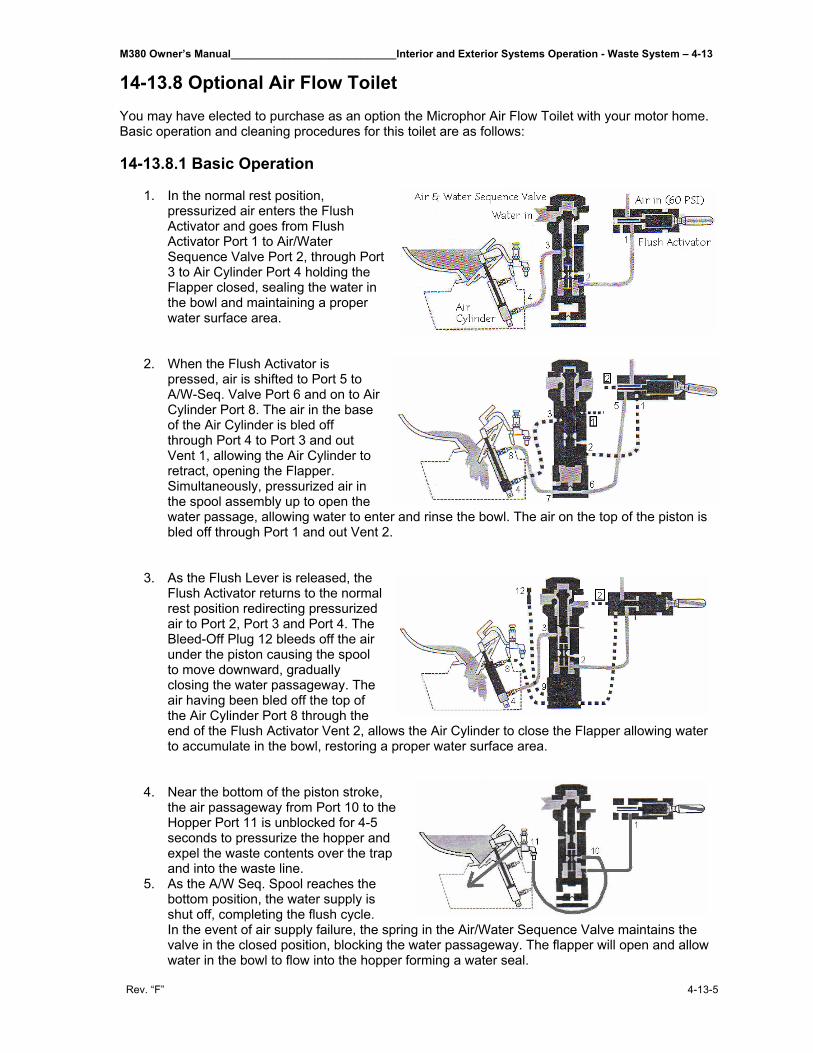
M380 Owner’s Manual____________________________Interior and Exterior Systems Operation - Waste System – 4-13
Rev. “F” 4-13-5
14-13.8 Optional Air Flow Toilet You may have elected to purchase as an option the Microphor Air Flow Toilet with your motor home. Basic operation and cleaning procedures for this toilet are as follows: 14-13.8.1 Basic Operation
1. In the normal rest position, pressurized air enters the Flush Activator and goes from Flush Activator Port 1 to Air/Water Sequence Valve Port 2, through Port 3 to Air Cylinder Port 4 holding the Flapper closed, sealing the water in the bowl and maintaining a proper water surface area.
2. When the Flush Activator is
pressed, air is shifted to Port 5 to A/W-Seq. Valve Port 6 and on to Air Cylinder Port 8. The air in the base of the Air Cylinder is bled off through Port 4 to Port 3 and out Vent 1, allowing the Air Cylinder to retract, opening the Flapper. Simultaneously, pressurized air in the spool assembly up to open the water passage, allowing water to enter and rinse the bowl. The air on the top of the piston is bled off through Port 1 and out Vent 2.
3. As the Flush Lever is released, the
Flush Activator returns to the normal rest position redirecting pressurized air to Port 2, Port 3 and Port 4. The Bleed-Off Plug 12 bleeds off the air under the piston causing the spool to move downward, gradually closing the water passageway. The air having been bled off the top of the Air Cylinder Port 8 through the end of the Flush Activator Vent 2, allows the Air Cylinder to close the Flapper allowing water to accumulate in the bowl, restoring a proper water surface area.
4. Near the bottom of the piston stroke, the air passageway from Port 10 to the Hopper Port 11 is unblocked for 4-5 seconds to pressurize the hopper and expel the waste contents over the trap and into the waste line.
5. As the A/W Seq. Spool reaches the bottom position, the water supply is shut off, completing the flush cycle. In the event of air supply failure, the spring in the Air/Water Sequence Valve maintains the valve in the closed position, blocking the water passageway. The flapper will open and allow water in the bowl to flow into the hopper forming a water seal.
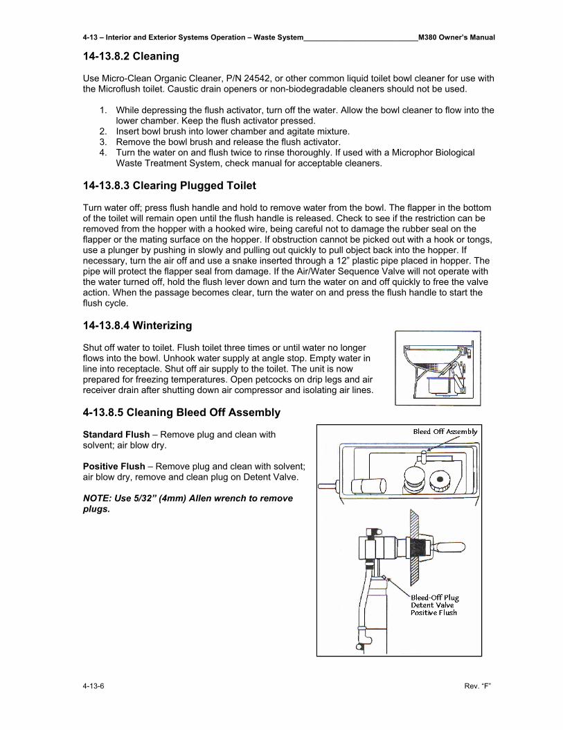
4-13 – Interior and Exterior Systems Operation – Waste System____________________________M380 Owner’s Manual
4-13-6 Rev. “F”
14-13.8.2 Cleaning
Use Micro-Clean Organic Cleaner, P/N 24542, or other common liquid toilet bowl cleaner for use with the Microflush toilet. Caustic drain openers or non-biodegradable cleaners should not be used.
1. While depressing the flush activator, turn off the water. Allow the bowl cleaner to flow into the
lower chamber. Keep the flush activator pressed. 2. Insert bowl brush into lower chamber and agitate mixture. 3. Remove the bowl brush and release the flush activator. 4. Turn the water on and flush twice to rinse thoroughly. If used with a Microphor Biological
Waste Treatment System, check manual for acceptable cleaners.
14-13.8.3 Clearing Plugged Toilet
Turn water off; press flush handle and hold to remove water from the bowl. The flapper in the bottom of the toilet will remain open until the flush handle is released. Check to see if the restriction can be removed from the hopper with a hooked wire, being careful not to damage the rubber seal on the flapper or the mating surface on the hopper. If obstruction cannot be picked out with a hook or tongs, use a plunger by pushing in slowly and pulling out quickly to pull object back into the hopper. If necessary, turn the air off and use a snake inserted through a 12” plastic pipe placed in hopper. The pipe will protect the flapper seal from damage. If the Air/Water Sequence Valve will not operate with the water turned off, hold the flush lever down and turn the water on and off quickly to free the valve action. When the passage becomes clear, turn the water on and press the flush handle to start the flush cycle. 14-13.8.4 Winterizing
Shut off water to toilet. Flush toilet three times or until water no longer flows into the bowl. Unhook water supply at angle stop. Empty water in line into receptacle. Shut off air supply to the toilet. The unit is now prepared for freezing temperatures. Open petcocks on drip legs and air receiver drain after shutting down air compressor and isolating air lines.
4-13.8.5 Cleaning Bleed Off Assembly Standard Flush – Remove plug and clean with solvent; air blow dry. Positive Flush – Remove plug and clean with solvent; air blow dry, remove and clean plug on Detent Valve. NOTE: Use 5/32” (4mm) Allen wrench to remove plugs.
M380 Owner’s Manual____________________________Interior and Exterior Systems Operation - Waste System – 4-13
Rev. “F” 4-13-7
4-13.8.6 Air System Design Filter-regulators are available in a variety of sizes and types. Their purpose is to remove water and foreign matter from the air line and to maintain a constant pressure of 60-65 psi to the toilet. The following steps must be observed to assure moisture will be removed from the air line.
1. Drain air compressor receiver regularly. Most water tends to accumulate at this point. 2. Install drip legs with condensate drains at all low points in air piping. 3. Whenever possible, grade all air lines back to the air receiver or drip leg assembly and drain
regularly. 4. The air supply to the toilet must be taken from the top of the main or branch air line.
4-13.8.6 Troubleshooting
Your Microflush® toilet is designed to give you years of trouble-free operation. Please check the following before beginning any service or repair.
Water supply: 1. Is the water turned on? 2. Is the water pressure between 20 and 50 psi for pressure water system? 3. Is there 6 feet minimum of head for gravity systems? Fluctuating or high water pressure can cause intermittent problems with the
toilet operation. Check the water pressure at different times of the day (i.e., early morning, noon, evening) to determine if you have fluctuating or high water pressure. A pressure-reducing valve installed on the incoming water line will assure you have even pressure. Make sure no check valve is installed before the Air/Water Sequence Valve.
Air system: 1. Is the air turned on? 2. Is the air pressure set at a constant 60-65 psi? 3. Do you have any air leaks or kinks in the air system? 4. Do you have water in the air system? This usually causes irregular timing.
Drain the compressor tank and check the filter regulator and drip leg(s) for water. To check for water in Air/Water Seq. Valve, remove Bleed-Off Plug, put finger over screw opening and flush. If water is present, it will squirt out. If water is detected, then the air cylinder and airlines must also be drained.
Cycle time: 1. Is the flapper cycle time set correctly at 4-7 seconds? 2. Is the bleed off assembly plug blocked? Remove, clean and reinstall.
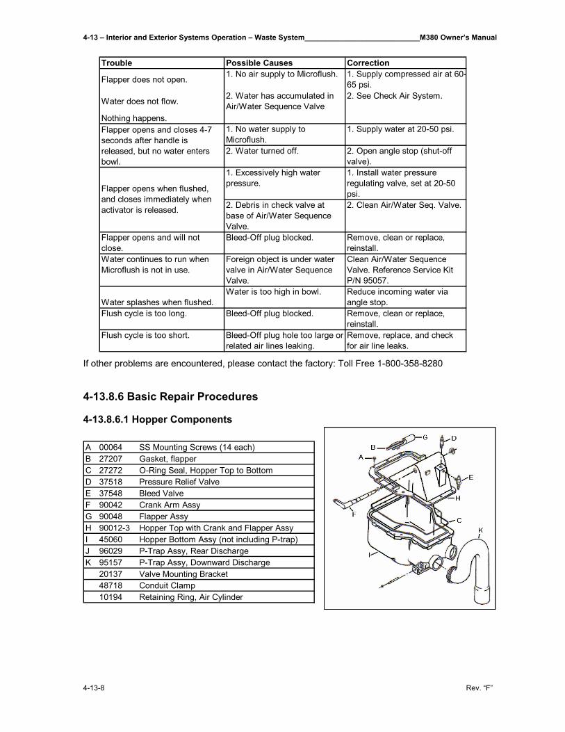
4-13 – Interior and Exterior Systems Operation – Waste System____________________________M380 Owner’s Manual
4-13-8 Rev. “F”
If other problems are encountered, please contact the factory: Toll Free 1-800-358-8280 4-13.8.6 Basic Repair Procedures 4-13.8.6.1 Hopper Components
Trouble Possible Causes Correction
Flapper does not open. 1. No air supply to Microflush. 1. Supply compressed air at 60-65 psi.
Water does not flow. 2. Water has accumulated in Air/Water Sequence Valve
2. See Check Air System.
Nothing happens.1. No water supply to Microflush.
1. Supply water at 20-50 psi.
2. Water turned off. 2. Open angle stop (shut-off valve).
1. Excessively high water pressure.
1. Install water pressure regulating valve, set at 20-50 psi.
2. Debris in check valve at base of Air/Water Sequence Valve.
2. Clean Air/Water Seq. Valve.
Flapper opens and will not close.
Bleed-Off plug blocked. Remove, clean or replace, reinstall.
Water continues to run when Microflush is not in use.
Foreign object is under water valve in Air/Water Sequence Valve.
Clean Air/Water Sequence Valve. Reference Service Kit P/N 95057.
Water splashes when flushed.Water is too high in bowl. Reduce incoming water via
angle stop.Flush cycle is too long. Bleed-Off plug blocked. Remove, clean or replace,
reinstall.Flush cycle is too short. Bleed-Off plug hole too large or
related air lines leaking.Remove, replace, and check for air line leaks.
Flapper opens and closes 4-7 seconds after handle is released, but no water enters bowl.
Flapper opens when flushed, and closes immediately when activator is released.
A 00064 SS Mounting Screws (14 each)B 27207 Gasket, flapperC 27272 O-Ring Seal, Hopper Top to BottomD 37518 Pressure Relief ValveE 37548 Bleed ValveF 90042 Crank Arm AssyG 90048 Flapper AssyH 90012-3 Hopper Top with Crank and Flapper AssyI 45060 Hopper Bottom Assy (not including P-trap)J 96029 P-Trap Assy, Rear DischargeK 95157 P-Trap Assy, Downward Discharge
20137 Valve Mounting Bracket48718 Conduit Clamp10194 Retaining Ring, Air Cylinder
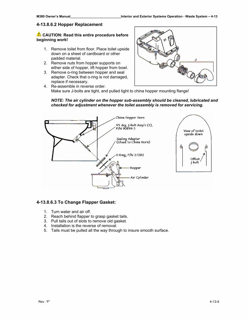
M380 Owner’s Manual____________________________Interior and Exterior Systems Operation - Waste System – 4-13
Rev. “F” 4-13-9
4-13.8.6.2 Hopper Replacement
CAUTION: Read this entire procedure before beginning work!
1. Remove toilet from floor. Place toilet upside down on a sheet of cardboard or other padded material.
2. Remove nuts from hopper supports on either side of hopper, lift hopper from bowl.
3. Remove o-ring between hopper and seal adapter. Check that o-ring is not damaged, replace if necessary.
4. Re-assemble in reverse order. Make sure J-bolts are tight, and pulled tight to china hopper mounting flange! NOTE: The air cylinder on the hopper sub-assembly should be cleaned, lubricated and checked for adjustment whenever the toilet assembly is removed for servicing.
4-13.8.6.3 To Change Flapper Gasket:
1. Turn water and air off. 2. Reach behind flapper to grasp gasket tails. 3. Pull tails out of slots to remove old gasket. 4. Installation is the reverse of removal. 5. Tails must be pulled all the way through to insure smooth surface.
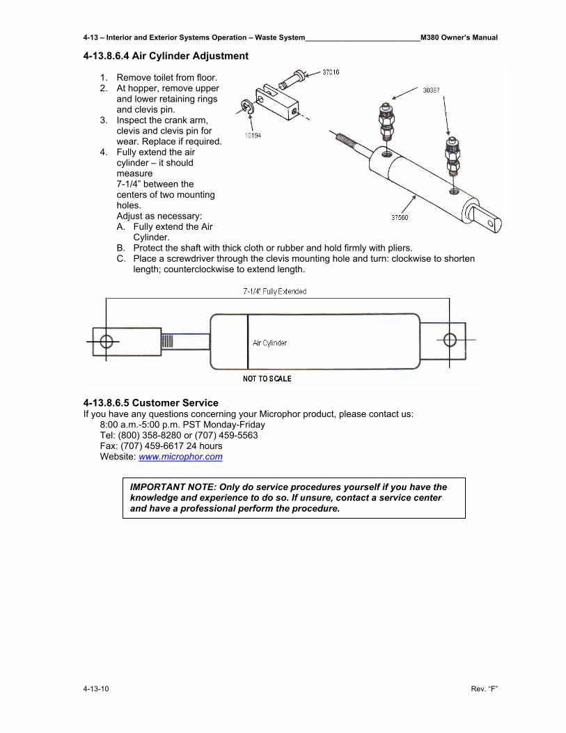
4-13 – Interior and Exterior Systems Operation – Waste System____________________________M380 Owner’s Manual
4-13-10 Rev. “F”
4-13.8.6.4 Air Cylinder Adjustment 1. Remove toilet from floor. 2. At hopper, remove upper
and lower retaining rings and clevis pin.
3. Inspect the crank arm, clevis and clevis pin for wear. Replace if required.
4. Fully extend the air cylinder – it should measure 7-1/4” between the centers of two mounting holes. Adjust as necessary: A. Fully extend the Air
Cylinder. B. Protect the shaft with thick cloth or rubber and hold firmly with pliers. C. Place a screwdriver through the clevis mounting hole and turn: clockwise to shorten
length; counterclockwise to extend length.
4-13.8.6.5 Customer Service If you have any questions concerning your Microphor product, please contact us:
8:00 a.m.-5:00 p.m. PST Monday-Friday Tel: (800) 358-8280 or (707) 459-5563 Fax: (707) 459-6617 24 hours Website: www.microphor.com
IMPORTANT NOTE: Only do service procedures yourself if you have the knowledge and experience to do so. If unsure, contact a service center and have a professional perform the procedure.
M380 Owner’s Manual______________________________Interior and Exterior Systems Operation - LPG System – 4-14
Rev. “F” 4-14-1
4-14 LPG System_______________________________________ The motor home is equipped with a permanently mounted 30 gallon (102 pounds of fuel-net) LP gas tank, which is the energy source for the cooktop (range) and an alternative source for the refrigerator. 4-14.1 LPG Tank and Controls The LPG supply tank is located in an unlocked compartment behind the rear axle on the passenger side of the motor home. LPG system controls include a main gas service valve, solenoid shut-off valve, two stage pressure regulator, filler connection with Auto Stop (80%) fill valve, 20% vapor (stop filling when liquid appears) valve, and the pressure relief valve. ▲WARNING: When the motor home is to be stored in a confined area, turn off the LPG at the main tank shutoff valve. With the LPG leak detector, this may now be accomplished by turning off the LPG Master Switch on the galley panel. LPG tank level can be monitored at the tank monitor panel located in the pantry. 4-14.1.1 Fuel Requirements Liquefied petroleum gas is a material composed of various hydrocarbons such as propane, butane, or a mixture thereof. In its gaseous form (vaporized), it is colorless and has a garlic-scented additive to ensure detection. In addition to being highly inflammable, it is also dangerous to inhale. For ease of transportation and storage, LPG is compressed into a liquid state and stored in this form within the LPG tank. As fuel is used, vapor passes from the top of the tank into the two-stage pressure regulator and to the various gas appliances. Appliances do not function if the LP gas does not vaporize. Butane does not vaporize below 32 degrees Fahrenheit (the freezing point of water), but propane continues to vaporize down to 44 degrees below zero. Propane has become the main type of LP gas used in RVs in recent years. Your LP supplier has the correct type or blend for your locale. If your travels take you into an area where climate differs, ask your LP dealer for his recommendations. The names of LP suppliers can be found in the yellow pages of the telephone directory under “Gas-Liquefied Petroleum-Bottled & Bulk.” Many campgrounds now have LP gas fill facilities, as do some service stations. Prevent condensation and possible regulator or line freeze-ups when filling the tank by requesting the dealer to add a small amount of methyl alcohol to the fill up. A common mixture is one ounce of methyl alcohol to each 20 pounds of LPG. NOTE: Liquefied petroleum gas is heavier than air. 4-14.2 Filling the LP Gas Tank When the tank is being filled, the service valve must be closed and the 80% liquid level valve (20% vapor valve) must be open. The 80% auto stop fill valve may close before liquid appears at the 80% liquid level valve, but if liquid does appear, stop filling immediately; the tank is filled to its LP capacity. Close the liquid level valve. Do not use a wrench to tighten this valve or the service valve; they are designed to be closed leak-tight by hand. If you cannot hand-tighten properly, the valve probably needs repair or replacement.
CAUTION: Be sure that the main LPG supply is shut off during refueling to prevent accidental ignition of gas fumes by appliance igniters.
CAUTION: All gas appliances must be cut off before filling the LPG tank. Check gas lines and fittings periodically for tightness and leakage.
4-14 – Interior and Exterior Systems Operation - LPG System______________________________M380 Owner’s Manual
4-14-2 Rev. “F”
4-14.2.1 Regulator The two-stage pressure regulator regulates the pressure of the LPG supplied to the appliances. The regulator functions automatically and is factory-preset to provide the correct line pressure. Do not attempt to tamper with or reset the regulator! Even a small variation above the normal gas line pressure can be sufficient to create a dangerous situation and cause possible damage to individual appliance components. If there is any doubt about the regulator setting, it can be checked by your Wanderlodge dealer or LPG supplier. The correct setting is 11-14 inch water column. 4-14.2.2 Operation To operate any LPG appliance, the main gas (Service) valve must be open. In addition, individual valves at each appliance must be opened prior to use. When first used, or after a refill, there may be some air in the gas lines, which escapes, when you open a range burner or similar LP gas valve. The air may extinguish your match or igniter the first time or two before you get ignition. Remember, too, that when you close the tank’s service valve some of the gas will remain in the lines. To completely bleed the lines of gas, close the tank’s service valve and light a range burner to use up the excess. When the flame burns out, turn the range burner off. 4-14.3 Checking for Leaks Periodically check the LP system for possible leakage. Do not wait for an alarm condition to occur before correcting a leak! Although the entire system and associated appliances undergo extensive factory testing for leakage, road shocks and heavy vibrations may loosen or damage piping or fittings. Leaks will usually become noticeable by the characteristic odor of the garlic-scented gas additive. To check, turn off all burners and pilot lights. Open all doors and windows. Open LPG tank service valve and use an ammonia and chlorine free soap-bubble solution on all connections. Any bubbles are evidence of leakage. NOTE: The gas leakage detectors may momentarily sound an alarm when the engine is initially started or when a heavy electrical load is placed on the system. Further, the ultra sensitive response of these units may also cause an alarm to be given in the presence of certain pressurized-can sprays or cleaning agents. Do not assume! Always determine the reason for this vital alarm being given! 4-14.4 LPG Consumption Most gas appliances are intermittently operated; however, operation during cold weather conditions does cause heavy consumption. The amount of LPG consumption depends on the total use and the manner in which these appliances are used. Note that each gallon (4 1/4 lb.) of LPG fuel produces approximately 91,500 BTUs of heat energy. The LPG tank used in your motor home will furnish over 2.1 million BTUs. For your guidance in estimating your anticipated fuel consumption, the following is a listing of typical appliance consumption ratings when the appliance is operated for one hour: Refrigerator: 1,500 BTUs Cooktop Burners 5,200 BTUs each
M380 Owner’s Manual______________________________Interior and Exterior Systems Operation - LPG System – 4-14
Rev. “F” 4-14-3
4-14.5 LPG System Warnings ▲WARNING: LP gas containers are not be placed or stored inside the vehicle. LP gas containers are equipped with safety devices, which relieve excessive pressure by discharging gas to the atmosphere. NOTE: The compartment the LPG tank is located in is NOT intended for storage – Do not place any items on, under or around the LPG tank. ▲WARNING: It is not safe to use cooking appliances for comfort heat. This warning label has been located in the cooking area to remind you to provide an adequate supply of fresh air for combustion. Unlike homes, the amount of oxygen supply is limited due to the size of the recreational vehicle, and proper ventilation when using the cooking appliance(s) will avoid dangers of asphyxiation. It is especially important that cooking appliances not be used for comfort heating as the danger of asphyxiation is greater when the appliance is used for long periods of time. Cooking appliances need fresh air for safe operation. Before operation:
1. Open overhead vent or turn on exhaust fan. 2. Open window.
A warning label has been located near the LP gas container. This label reads: ▲WARNING: Do not fill container(s) to more than 80 percent of capacity. Overfilling the LP gas container can result in uncontrolled gas flow, which can cause fire or explosion. A properly filled container will contain approximately 80 percent of its volume as liquid LP gas. ▲WARNING: Portable fuel-burning equipment, including wood and charcoal grills and stoves, are not be used inside the recreational vehicle. The use of this equipment inside the recreational vehicle may cause fires or asphyxiation. ▲WARNING: Do not bring or store LP gas containers, gasoline or other flammable liquids inside the vehicle because a fire or explosion may result. The following label has been placed in the vehicle near the range area: IF YOU SMELL GAS
1. Extinguish any open flames, pilot lights and all smoking materials. 2. Do not touch electrical switches. 3. Shut off the gas supply at the tank valve(s) or gas supply connection. 4. Open doors and other ventilating openings. 5. Leave the area until odor clears. 6. Have the gas system checked and leakage source corrected before using again.
LP gas regulators must always be installed with the diaphragm vent facing downward. This minimizes any chances of vent blockage, which could result in excessive gas pressure causing fire or explosion. ▲WARNING: Never check for leaks with an open flame. Do not check copper plumbing lines for leaks using ammoniated or chlorinated household-type detergents. These can cause cracks to form on the line and brass fittings. If the leak cannot be located, take the unit to your Wanderlodge dealer or LPG supplier.
4-14 – Interior and Exterior Systems Operation - LPG System______________________________M380 Owner’s Manual
4-14-4 Rev. “F”
4-14.6 LPG Leak Detector System The system has been developed to the point where it is unique; it shuts off the LP gas at the high-pressure source, yet holds the valve open to provide ample appliance flow with a minimum amount of current usage. Three components make up the system:
1. Gas Detection Control Unit: mounted in toe kick of the kitchen base cabinet. This is the “brains” of the system and provides an electrical signal to the solenoid valve when LPG service is required.
2. Solenoid Valve: installed in the high pressure LPG line feeding the two-stage regulator. It is a “normally closed” solenoid valve and has a special winding of 22 ohms (approximate) resistance, so it uses very little current in the “hold open” position. In order to close the valve, it is only necessary to break the circuit. This provides a “fail-safe” feature in the event of loss of 12-volt power.
3. LPG Master switch: located on the galley panel.
The following events will result in an open/low voltage circuit and allow the solenoid valve to close and shut off the LPG supply:
1. Pushing the switch to “OFF” on the LPG MASTER switch or the Gas Detection Control Unit. Green light will go out.
2. The Gas Detection Control Unit senses the presence of LP gas (or can be triggered by a propane lighter or even hair spray!). Green light goes out, Red light comes on, along with audible signal.
3. The Electronic Master switch is turned off. Green light will go out. NOTE: System is not Master Switch Activated. In order to restore LP gas flow to the motor home, use the following procedures corresponding to the events above:
1. Push switch on the LPG MASTER and the Gas Detection Control Unit to “ON.” Green light will come on.
2. Correct the cause of LP gas leak or determine if other fumes caused the shut down. Green light will come on.
3. Turn Electronic Master Switch on. Green light will come on.
NOTE: Because of the presence of an excess flow valve in the LPG tank outlet (safety feature); sometimes an appliance may not relight after a shutdown. In this circumstance, wait five (5) minutes for LPG pressures to equalize before relighting.
M380 Owner’s Manual_______________________Interior and Exterior Systems Operation – Air Pressure System – 4-15
Rev. “F” 4-15-1
4-15 Air Pressure System________________________________ 4-15.1 Description and Operation An engine-driven compressor supplies the air pressure system on your motor home. It provides pneumatic power for brakes, suspension, and numerous accessories. This complex, but efficient system is not intended to be totally leak free. After overnight parking, you may notice a significant loss of pressure on the air pressure front/rear gauge, or in systems connected to auxiliary air. This condition is normal, and in fact, our air leakage tolerance is tighter than most manufacturers within the heavy-duty equipment industry. Once the engine is running, the engine-driven compressor will quickly build up the system to the correct pressure. 4-15.1.1 Air Brakes Your motor home is equipped with dual service air brake systems for front and rear, with integral fail/safe operation; and manual/automatic rear spring (parking) brakes. The service brakes are completely independent systems, each including a reservoir and separate distribution lines and valves. The reservoirs are pressurized from a single compressor. Both service brake systems are brought into operation each time the brake treadle is depressed to slow or stop the motor home. Reservoir pressure for each service brake system is monitored by a respective pressure gauge on the front panel; system failure(s) are indicated by low-pressure readings, illumination of the Low Air failure lamp and sounding of buzzer. 4-15.1.2 Operation When the motor home is parked, and the engine off, the rear spring brake will normally be set by operating the parking brake. The spring brakes cannot be fully released until the air pressure is above 65 psi. These brakes are in the released position when the control is pushed in. In the event that there is a loss of air pressure, the spring brakes will set automatically at the brake-applied position, and will not release until the air reserve has again built up to required value. Consequently, there will be a normal delay, after the motor home is first started, while the compressor builds up pressure before the brakes can be released and the motor home driven. When the brake treadle is depressed to slow or stop the motor home, reservoir air is applied simultaneously to both front and rear service brakes to effect the braking action. The spring brakes are held in a released position by the air pressure supplied from the associated reservoir tank.
CAUTION: Do not attempt to drive the motor home until system pressure is above 90 psi. 4-15.1.3 Brake Failures To compensate for normal lining wear, each brake system is individually self-adjusting. Fail/safe features provide protection against brake system failures. If the front brakes fail, operating the brake treadle still activates the rear service brakes to provide stopping capability. If a failure occurs in the rear, the front service brakes and rear spring brakes provide braking action. In the unlikely event of a failure where both service-braking systems are disabled, the rear spring brakes will apply automatically and bring the vehicle to a stop. As a safety factory, the motor home should not be moved until any type of brake failure is corrected. NOTE: With the front brake system service reservoir fully charged, enough air pressure is available to provide for four full releases of the rear spring brakes. This will allow the motor home to be brought to a safe position until repairs can be accomplished.
4-15 – Interior and Exterior Systems Operation – Air Pressure System_______________________M380 Owner’s Manual
4-15-2 Rev. “F”
4-15.1.4 Anti-Lock Brakes In addition to the above, a four-channel anti-lock brake system for the steer and drives axles are installed. In the event one of the wheels begins to lock up under severe braking conditions, the anti-lock system will detect this situation and gradually remove air pressure from the brake chamber until the wheel begins to turn. This will help assure smooth braking action and minimize wheel lockup. 4-15.1.5 Air Suspension System Air suspension bags cushion the front and rear axles. Ride height is automatically maintained by height control valves. Dumping these air bags when the vehicle is parked allows the rubber bumpers to come together and eliminate vehicle springiness. A switch, located on the lower left side of the LOWER DASH PANEL, controls dumping and filling of air bags. The SUSP. DUMP switch controls the front and rear suspension. NOTE: The accessory air tank must contain at least 65 psi pressure for the DUMP switch to function. The accessory air tank pressure does not register on the dash air pressure gauges. Moving the SUSP. DUMP switch away from the UP position applies air pressure to air pilot-operated valves on the suspension system. The pilot air shifts the valves, cutting off the air supply to the air bags and allows the air in the bags to escape. After the suspension system has been dumped and the ignition is turned on, a buzzer and a warning pilot light is illuminated on the dash to warn the driver that the system is dumped and not to drive the vehicle until the SUSP. DUMP switch is set to the UP position. Refer to the manual in your owner’s kit for additional information and maintenance instructions. 4-15.1.6 Additional Air-Operated Equipment Besides providing the compressed air supply for the motor home braking and suspension systems, the compressor also provides the air supply for the stepwell cover and entrance door lock, all via separately controlled solenoid switches operated from the dash, or at other locations throughout the motor home. (This compressed air source is furnished from the front right side reservoir.) A compressed air outlet fitting and air gun are contained in a rear storage compartment on the road side of the motor home, convenient for inflating tires, and so on. A Schrader valve (air connection) is available in the engine compartment to allow the air system to be pressurized from a “shop” source without the necessity of starting the engine.
M380 Owner’s Manual_______________________Interior and Exterior Systems Operation – Air Pressure System – 4-15
Rev. “F” 4-15-3
4-15.1.7 Compressed Air System Air Dryer The air dryer unit collects and removes moisture and contaminants from the compressor air output before the air reaches the reservoirs. This unit is different from a reservoir drain or an after cooler in that it provides dry air for the brake system by eliminating the possible accumulation of condensate in the system reservoirs. Note that each reservoir also has a drain cock on the bottom for draining accumulated moisture. This assures a long maintenance-free life for air brake system components due to the removal of system contaminants. The air dryer is located between the compressor discharge (output) line and the compressed air reservoirs. A safety valve mounted in the air dryer housing assembly protects against excessive pressure buildup. The desiccant cartridge and pleated paper oil filters are easily removable and replaceable as a complete serviceable unit. The desiccant “Beads” which provide the drying action have a large capacity for absorption due to their combined surface area. In addition, an internal thermostatically controlled heating element prevents freeze ups on the purge rail valve when the unit is used during sub-freezing temperatures. Purging of the dryer is automatic, exhausting combined oil and water residue to the atmosphere. At the same time that the contaminants are purged, the reverse airflow across the desiccant material removes the accumulated moisture and reactivates the desiccant. Refer to Bendix Air Dryer Service Data Manual for more detailed information.

M380 Owner’s Manual__________________________________________________________________________________
Rev. “F”
THIS PAGE IS INTENTIONALLY LEFT BLANK
M380 Owner’s Manual_______________________________Interior and Exterior Systems Operation - Appliances- 4-16
Rev. “G” 4-16-1
4-16 Appliances___________________________________________ 4-16.1 Refrigerator Your motor home comes equipped with a Dometic Refrigerator for LP-Gas and Electric Operation. 4-16.1.1 Start Up Instructions • A continuous 12-volt DC supply must be available for the electric control to function. • Press the main power ON/OFF button (1) to the DOWN position. • Press the TEMPERATURE SELECTOR button (3) until the lamp at the desired setting is
illuminated. 4-16.1.2 AES/Auto Mode NOTE: AES is Dometic’s term for Automatic Energy Selection Switch. What this does if this switch is turned on, the refrigerator will search for a 110 source first, if it doesn’t find one, then it will go to gas. If the switch is turned off it will automatically go to gas and bypass the AES Mode. 1. Press the AES/AUTO/GAS mode selector button (2) to turn ON the AES/AUTO lamp (B). If 120
volts is available, the AC mode indicator lamp (A) will illuminate indicating AC operation. If 120 volts AC is not available, the GAS indicator lamp (C) will illuminate, indicating the control has automatically switched to the GAS mode.
2. If the CHECK indicator lamp (D) illuminates and the GAS mode indicator lamp (C) is off, the
controls have failed to ignite the burner in the GAS mode. GAS operation may be reset by pressing the main power ON/OFF button (1) to the OFF then ON position. (See step 2 under GAS MODE).
3. Press the TEMPERATURE SELECTOR button (3) until the lamp at the desired position is
illuminated. 4-16.1.3 Gas Mode 1. Press the AES/AUTO/GAS mode selector button (2) to turn OFF the AES/AUTO lamp
(B). The GAS mode indicator lamp (C) will illuminate. Within 45 seconds the burner should be ignited and operating normally.
2. On the initial refrigerator start-up, it may take longer than 45 seconds to allow air to be
purged from the gas line. If the gas does not ignite within 45 seconds the CHECK indicator lamp (D) will illuminate and the GAS mode indicator lamp (C) will go off.
To reset when the CHECK indicator lamp (D) is illuminated, press the main power ON/OFF button (1) to the OFF and then ON position. NOTE: Do not continue to reset Gas operation if the CHECK indicator lamp continues to be illuminated after several tries. 3. Press the TEMPERATURE SELECTOR button (3) until the lamp at the desired
position is illuminated.
4-16 – Interior and Exterior Systems Operation - Appliances______________________________M380 Owner’s Manual
4-16-2 Rev. ”G”
4-16.1.4 Thermostat The thermostat on the refrigerator controls both the gas and electric operation, thereby eliminating the necessity of resetting each time a different energy source is employed. After the initial start-up, the thermostat should be moved from “COLDEST” to the desired temperature setting, usually at mid setting. 4-16.1.5 To Shut Off The Refrigerator The refrigerator may be shut off while in any mode of operation by pressing the main power ON/OFF button to the UP (OFF) position. This shuts off all DC power to the refrigerator, including the interior light. 4-16.1.6 Description of Operating Modes AES/AUTO Mode When operating in the AES/AUTO mode, the AES/AUTO mode indicator lamp (B) will illuminate. The control system will automatically select between AC and GAS operation with AC having priority over GAS. Either the AC indicator lamp (A) or the GAS indicator lamp (C) will illuminate depending on the energy source selected by the control system. If the control system is operating with AC energy and it then becomes unavailable, the system will automatically switch to GAS. As soon as AC becomes available again the control will switch back to AC regardless of the status of GAS operation. Gas Mode When operating in the GAS mode the AES/AUTO mode indicator lamp (B) will be off and the GAS mode indicator lamp (C) will be illuminated. This mode provides LP gas operation only. The control system will activate the ignition system and will attempt to light the burner for a period of approximately 45 seconds. If unsuccessful, the CHECK indicator lamp (D) will illuminate and the GAS mode indicator lamp (C) will turn off. To restart GAS operation, press the main power ON/OFF button (1) to the OFF and then ON position. The control system will attempt a new 45 seconds ignition sequence. If the refrigerator has not been used for a long time or the LP tanks have just been refilled, air may be trapped in the supply lines. To purge the air from the lines may require resetting the main power ON/OFF button (1) three or four times. If repeated attempts fail to start the LP gas operation, check to make sure that the LP gas supply tanks are not empty and all manual shutoff valves in the lines are open. If the problem is still not corrected, contact a service center for assistance. If the control is switched to AC operation while the CHECK indicator lamp is on, it will function properly, but the CHECK indicator lamp will not go off until the main power ON/OFF button is pressed to the OFF then ON position. Limp Mode of Operation This control system contains a feature where it will continue to operate the cooling system in the event of a failure of a major operating component. Two different modes of operation can occur in this category. If for some reason the display module becomes non-functional, the control system will revert to full automatic operation selecting the best energy source available with AC, GAS priority. The temperature of the refrigerator will be maintained at the MID position within normal temperature tolerances. The power module will continually attempt to reestablish operation of the display module. The second limp mode of operation will execute when a failure of the temperature sensing device or associated electronic circuitry occurs. If this should occur, the control system will operate on
M380 Owner’s Manual_______________________________Interior and Exterior Systems Operation - Appliances- 4-16
Rev. “G” 4-16-3
the energy source selected via the control panel. The cooling unit will run continuously on the selected energy source. The refrigerator will continue to operate in this mode indefinitely or until a new sensor is installed and the system is reset. 4-16.1.7 How to Use the Refrigerator Food Storage Compartment The food storage compartment is completely closed and unventilated, which is necessary to maintain the required low temperature for food storage. Consequently, foods having a strong odor or those that absorb odors easily should be covered. Vegetables, salads, etc. should be covered to retain their crispness. The coldest positions in the refrigerator are under the cooling fins and at the bottom of the refrigerator. The warmer areas are on the upper door shelves. This should be considered when placing different types of food in the refrigerator. When the refrigerator is heavily loaded, it will take a longer time to lower the temperature; therefore, to get maximum efficiency the refrigerator and food items should be pre-cooled prior to loading. The shelves should not be covered with paper or plastic, and the food items should be arranged so air can circulate freely. Two door shelves are equipped with fingers. The fingers are designed to prevent large containers (1/2 gallon milk or juice) from shifting or spilling while traveling. Frozen Food Storage Compartment Quick frozen soft fruits and ice cream should be placed in the coldest part of the compartment, which is on the top freezer shelf. Frozen vegetables, may be stored in any part of the compartment. This compartment is not designed for deep or quick-freezing of food. Meat or fish, whether raw or prepared, can be stored in the frozen food storage compartment provided they are pre-cooled first in the refrigerator. They can be stored about three times longer in the frozen food compartment as compared to the fresh food compartment. To prevent food from drying out, keep it in covered dishes, containers, plastic bags or wrapped in aluminum foil. Total Refrigerated Volume is 12 cu. ft. Ice Making Ice cubes can be made in the ice trays placed in the freezer compartment. The trays should be filled with water to within ¼” (5mm) from the top. For faster ice making, the trays should be placed in direct contact with the freezer shelves. Ice will be made more rapidly if the thermostat is set at its highest position. It is a good idea to do this a few hours before the anticipated need for ice, but be sure to move the thermostat back to normal setting, usually about mid setting when the ice is formed. Food in the fresh food compartment may be frozen if the setting is left on “COLDEST” position. Defrosting Shut off the refrigerator by pressing the main power ON/OFF button to the UP (OFF) position. Empty the refrigerator, leaving the drip tray under the finned evaporator, and the cabinet and freezer doors open. Filling the ice trays with hot water and placing them on the freezer shelves can reduce defrosting time. When all the frost has melted, dry the interior of the refrigerator and freezer with a clean cloth. Replace all food and set the thermostat to the COLDEST temperature setting for a few hours. Then reset the thermostat to the desired setting, usually at mid setting.
CAUTION: DO NOT use a hot air blower. Permanent damage could result from warping the metal or plastic parts. DO NOT use a knife or an ice pick, or other sharp tools to remove frost from the freezer shelves. They can create a leak in the ammonia system.
4-16 – Interior and Exterior Systems Operation - Appliances______________________________M380 Owner’s Manual
4-16-4 Rev. ”G”
Cleaning Cleaning the refrigerator is usually done after it is defrosted or put into storage. To clean the interior liner of the refrigerator, use lukewarm weak soda solution. Use only warm water to clean the finned evaporator, ice trays and shelves. NEVER use strong chemicals or abrasives to clean these parts, as the protective surfaces will be damaged. It is important to always keep the refrigerator clean. Shut Off – Storage Procedure Shut off the refrigerator by pressing the main power ON/OFF button to the UP (OFF) position. If the refrigerator will not be in operation for a period of weeks, it should be emptied, defrosted, cleaned and the doors left ajar. The ice trays should also be dried and kept outside the cabinet. ▲WARNING: Do not store explosive substances in the refrigerator, such as cigarette lighter gas, petrol, ether or the like. NOTE: Sodium chromate is used for corrosion protection (less than 2 weight % of the coolant). Climate Control Heater During the summer months of high temperatures and humidity, the metal frame between the freezer and fresh food compartments may have water droplets forming. The number of water droplets will increase if the vehicle isn’t air conditioned during these months. This refrigerator comes standard with a 12-volt (DC) climate control that will evaporate the water droplets when they form. To have the climate control on, you position the switch (F) located beneath the top decoration panel that houses the control panel to ON. The climate control can be left on continuously or only used when temperatures require it. NOTE: The climate control will draw 12 volts DC power continuously when in the ON position. It should be turned OFF when a charging source is not available. Low Ambient Switch All RV absorption refrigerators, while similar, operate a little differently than your home refrigerator. Dometic designers and engineers have equipped your refrigerator with an exclusive feature that allows for trouble-free operation in low ambient temperature (like below 50ºF) for extended periods of time. Simply turn on the low ambient switch located beneath the top decoration panel that houses the control panel. Once the outdoor temperature is above 50ºF, the low ambient switch should be turned off. ELECTRIC EQUIPMENT Cartridge Heater An electric heater mounted in a pocket of the boiler system supplies the heat necessary for the operation of an absorption-cooling unit. This model is equipped with two electrical heaters for 120 volt AC. To replace the heater proceed as follows:
1. Disconnect the wall plug, and the 12-volt wires. 2. Remove the protection cover 3. Remove the power module cover 4. Disconnect the heater leads. 5. With a pair of pliers unfold the lug holding the lid of the boiler
casing and open the lid. 6. Remove some insulation wool so that the heater is accessible. 7. Turn and lift the heater out of its pocket. 8. Fit the new heater into the pocket.
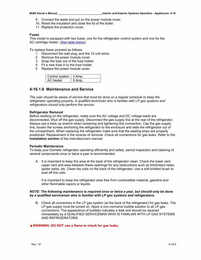
M380 Owner’s Manual_______________________________Interior and Exterior Systems Operation - Appliances- 4-16
Rev. “G” 4-16-5
9. Connect the leads and put on the power module cover. 10. Reset the insulation and close the lid of the boiler. 11. Replace the protection cover.
Fuses This model is equipped with two fuses, one for the refrigerator control system and one for the AC cartridge heater. (See table below). To replace fuses proceed as follows:
1. Disconnect the wall plug, and the 12-volt wires. 2. Remove the power module cover. 3. Snap the fuse out of the fuse holder. 4. Fit a new fuse in to the fuse holder. 5. Replace the power module cover.
Control system 3 Amp AC heater 5 Amp
4-16.1.8 Maintenance and Service The user should be aware of service that must be done on a regular schedule to keep the refrigerator operating properly. A qualified technician who is familiar with LP gas systems and refrigerators should only perform the service. Refrigerator Removal Before working on the refrigerator, make sure the AC voltage and DC voltage leads are disconnected. Shut off the gas supply. Disconnect the gas supply line at the rear of the refrigerator. Always use a back up wrench when loosening and tightening this connection. Cap the gas supply line, loosen the screws anchoring the refrigerator to the enclosure and slide the refrigerator out of the compartment. When replacing the refrigerator make sure that the sealing strips are properly positioned. Replacement is the reverse of removal. Check all connections for gas leaks. Refer to the Installation section of the manufacturers manual. Periodic Maintenance To keep your Dometic refrigerator operating efficiently and safely, period inspection and cleaning of several components once or twice a year is recommended.
A. It is important to keep the area at the back of the refrigerator clean. Check the lower vent, upper vent and area between these openings for any obstructions such as bird/insect nests, spider webs, etc. Clean the coils on the back of the refrigerator. Use a soft bristled brush to dust off the coils.
It is important to keep the refrigerator area free from combustible material, gasoline and other flammable vapors or liquids.
NOTE: The following maintenance is required once or twice a year, but should only be done by a qualified serviceman who is familiar with LP gas systems and refrigerators.
B. Check all connectors in the LP gas system (at the back of the refrigerator) for gas leaks. The LP gas supply must be turned on. Apply a non-corrosive bubble solution to all LP gas connections. The appearance of bubbles indicates a leak and should be repaired immediately by a QUALIFIED SERVICEMAN WHO IS FAMILIAR WITH LP GAS SYSTEMS AND REFRIGERATORS.
▲WARNING: DO NOT use a flame to check for gas leaks.
4-16 – Interior and Exterior Systems Operation - Appliances______________________________M380 Owner’s Manual
4-16-6 Rev. ”G”
C. Check the AES control system by connecting/disconnecting 120-volt AC power, start/stop the engine, etc. Compare the operation with the operation described in description of operating modes.
D. The LP gas pressure should be checked and the main regulator re-adjusted if pressure is
incorrect. The correct operating pressure is 11 inches of water column. The correct place to take the LP gas pressure is at the test port just head of the burner jet.
E. Inspect the flue baffle. It should be reasonably clean and free of soot. Heavy soot formation
indicates improper functioning of the burner. The flue and burner both require cleaning in the following manner: 1. Unplug the refrigerator power cord from the 120-volt AC outlet. 2. Disconnect or shut off the 12-volt power to the refrigerator. 3. Turn manual shutoff valve to OFF. 4. Remove cover from the burner housing. 5. Disconnect the wire from the high voltage electrode. 6. Remove the burner mounting screws and remove the burner assembly. 7. Remove the wire and the flue baffle from the top of flue tube. Clean the flue from the top
using a flue brush. Blowing compressed air into the flue will not properly clean soot and scale out of the flue tube. Replace the flue baffle.
8. Clean burner tube with a brush. Blow out burner with compressed air. 9. Before removing burner jet, clean burner area of soot and scale that fell out of the flue
tube. Remove the burner jet. Soak the jet in wood alcohol and blow it out with compressed air. Re-install and tighten burner jet.
NOTE: The color of the flame shall be clear blue over the slots of the burner.
▲WARNING: DO NOT use a wire or pin when cleaning the burner jet as damage can occur to the precision opening. This can cause damage to the refrigerator or create a fire hazard.
10. Reinstall burner, being careful that the end of the burner fits into the slot on the burner
bracket. Check to make sure slots are centered under the flue tube and the thermocouple is positioned properly (tip of thermocouple extends over two slots of burner).
11. Be sure to reconnect the wire to high voltage electrode. Check the electrode for proper location and gap.
12. Turn on manual gas shutoff valve and check all fittings for leaks. 13. Connect 120-volt power cord to the outlet and reconnect or turn on the 12-volt DC
power. 14. Check LP gas safety shutoff.
TROUBLESHOOTING The Refrigerator Does Not Cool Properly
A. Burner jet clogged.
Clean. (See section Maintenance and Service, Item 2, Periodic Maintenance, paragraph E, items 1-14).
B. Check level of refrigerator. C. Venting problem.
Restriction in airflow across cooling unit. D. Heavy frost buildup on evaporator fins.
Defrost. E. Flue baffle not inserted properly in flue tube. F. Improperly set thermostat.
See section 4-16.1.4 Thermostat. G. Burner dirty.
Clean. See section Maintenance and Service, Item 2, Periodic Maintenance, paragraph E, items 1-14.
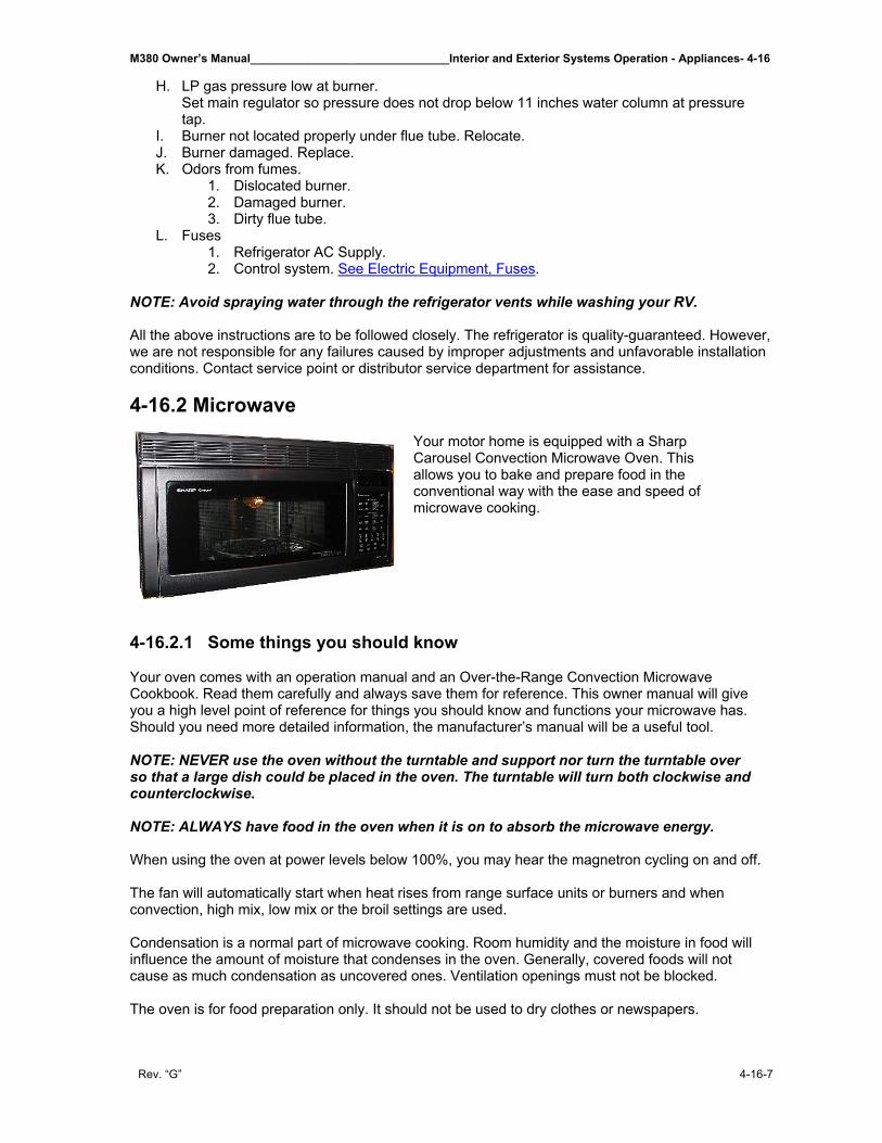
M380 Owner’s Manual_______________________________Interior and Exterior Systems Operation - Appliances- 4-16
Rev. “G” 4-16-7
H. LP gas pressure low at burner. Set main regulator so pressure does not drop below 11 inches water column at pressure tap.
I. Burner not located properly under flue tube. Relocate. J. Burner damaged. Replace. K. Odors from fumes.
1. Dislocated burner. 2. Damaged burner. 3. Dirty flue tube.
L. Fuses 1. Refrigerator AC Supply. 2. Control system. See Electric Equipment, Fuses.
NOTE: Avoid spraying water through the refrigerator vents while washing your RV.
All the above instructions are to be followed closely. The refrigerator is quality-guaranteed. However, we are not responsible for any failures caused by improper adjustments and unfavorable installation conditions. Contact service point or distributor service department for assistance. 4-16.2 Microwave
Your motor home is equipped with a Sharp Carousel Convection Microwave Oven. This allows you to bake and prepare food in the conventional way with the ease and speed of microwave cooking.
4-16.2.1 Some things you should know Your oven comes with an operation manual and an Over-the-Range Convection Microwave Cookbook. Read them carefully and always save them for reference. This owner manual will give you a high level point of reference for things you should know and functions your microwave has. Should you need more detailed information, the manufacturer’s manual will be a useful tool. NOTE: NEVER use the oven without the turntable and support nor turn the turntable over so that a large dish could be placed in the oven. The turntable will turn both clockwise and counterclockwise. NOTE: ALWAYS have food in the oven when it is on to absorb the microwave energy. When using the oven at power levels below 100%, you may hear the magnetron cycling on and off. The fan will automatically start when heat rises from range surface units or burners and when convection, high mix, low mix or the broil settings are used. Condensation is a normal part of microwave cooking. Room humidity and the moisture in food will influence the amount of moisture that condenses in the oven. Generally, covered foods will not cause as much condensation as uncovered ones. Ventilation openings must not be blocked. The oven is for food preparation only. It should not be used to dry clothes or newspapers.
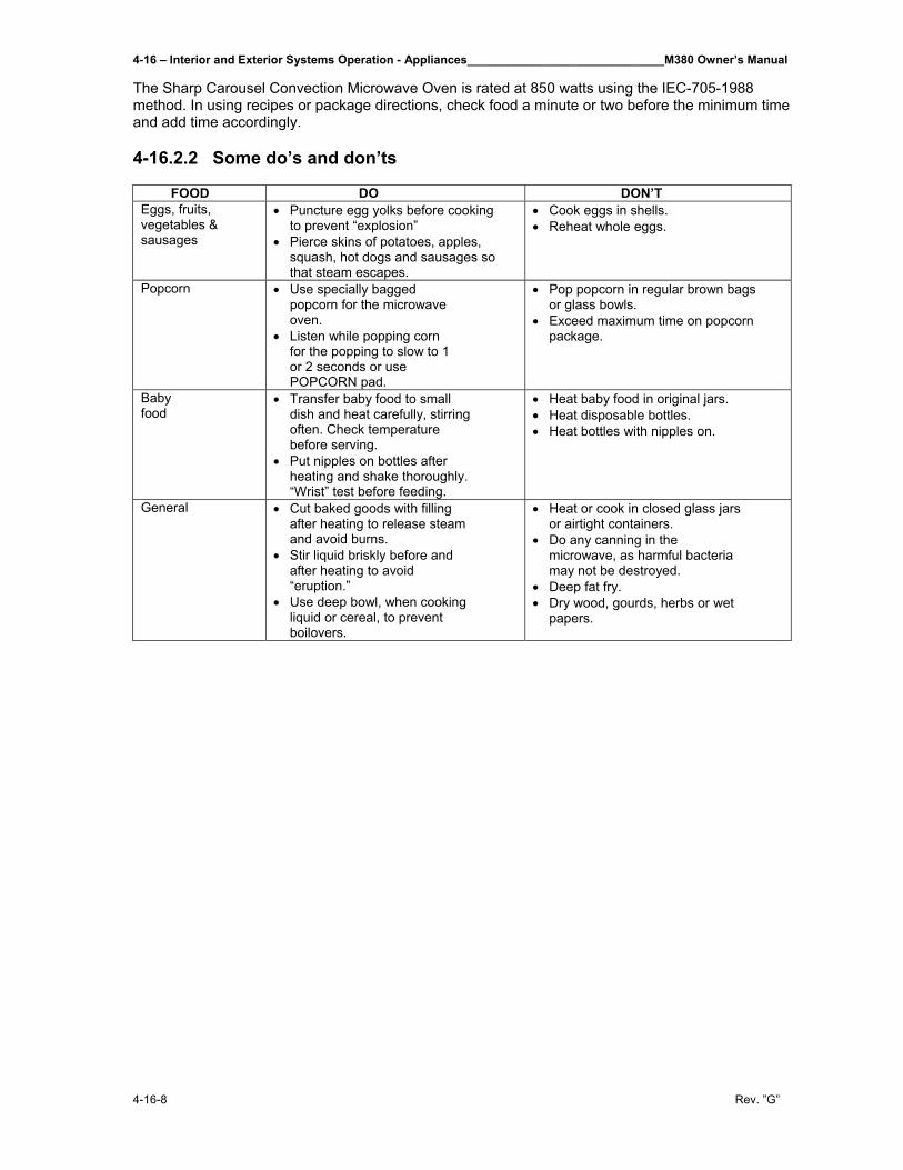
4-16 – Interior and Exterior Systems Operation - Appliances______________________________M380 Owner’s Manual
4-16-8 Rev. ”G”
The Sharp Carousel Convection Microwave Oven is rated at 850 watts using the IEC-705-1988 method. In using recipes or package directions, check food a minute or two before the minimum time and add time accordingly. 4-16.2.2 Some do’s and don’ts
FOOD DO DON’T Eggs, fruits, vegetables & sausages
• Puncture egg yolks before cooking to prevent “explosion”
• Pierce skins of potatoes, apples, squash, hot dogs and sausages so that steam escapes.
• Cook eggs in shells. • Reheat whole eggs.
Popcorn • Use specially bagged popcorn for the microwave oven.
• Listen while popping corn for the popping to slow to 1 or 2 seconds or use POPCORN pad.
• Pop popcorn in regular brown bags or glass bowls.
• Exceed maximum time on popcorn package.
Baby food
• Transfer baby food to small dish and heat carefully, stirring often. Check temperature before serving.
• Put nipples on bottles after heating and shake thoroughly. “Wrist” test before feeding.
• Heat baby food in original jars. • Heat disposable bottles. • Heat bottles with nipples on.
General • Cut baked goods with filling after heating to release steam and avoid burns.
• Stir liquid briskly before and after heating to avoid “eruption.”
• Use deep bowl, when cooking liquid or cereal, to prevent boilovers.
• Heat or cook in closed glass jars or airtight containers.
• Do any canning in the microwave, as harmful bacteria may not be destroyed.
• Deep fat fry. • Dry wood, gourds, herbs or wet
papers.
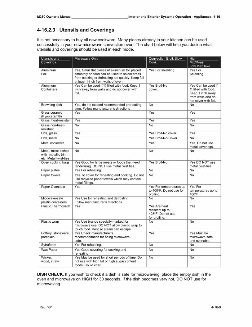
M380 Owner’s Manual_______________________________Interior and Exterior Systems Operation - Appliances- 4-16
Rev. “G” 4-16-9
4-16.2.3 Utensils and Coverings It is not necessary to buy all new cookware. Many pieces already in your kitchen can be used successfully in your new microwave convection oven. The chart below will help you decide what utensils and coverings should be used in each mode.
Utensils and Coverings
Microwave Only Convection Broil, Slow Cook
High Mix/Roast Low Mix/Bake
Aluminum Foil
Yes, Small flat pieces of aluminum foil placed smoothly on food can be used to shield areas from cooking or defrosting too quickly. Keep foil at least 1 inch from walls of oven.
Yes For shielding Yes For Shielding
Aluminum Containers
Yes Can be used if ¾ filled with food. Keep 1 inch away from walls and do not cover with foil.
Yes Broil-No cover.
Yes Can be used if ¾ filled with food. Keep 1 inch away from walls and do not cover with foil.
Browning dish Yes, do not exceed recommended preheating time. Follow manufacturer’s directions
No No
Glass ceramic (Pyroceram®)
Yes Yes Yes
Glass, heat-resistant Yes Yes Yes Glass non-heat-resistant
No No No
Lids, glass Yes Yes Broil-No cover. Yes Lids, metal No Yes Broil-No-Cover No Metal cookware No Yes Yes, Do not use
metal coverings. Metal, misc: dishes with metallic trim, etc. Metal twist-ties
No No No
Oven cooking bags Yes Good for large meats or foods that need tenderizing. DO NOT use metal twist ties.
Yes Broil-No Yes DO NOT use metal twist-ties.
Paper plates Yes For reheating. No No Paper towels Yes To cover for reheating and cooking. Do not
use recycled paper towels which may contain metal fillings.
No No
Paper Ovenable Yes Yes For temperatures up to 400ºF. Do not use for broiling.
Yes For temperatures up to 400ºF.
Micowave-safe plastic containers
Yes Use for reheating and defrosting. Follow manufacturer’s directions.
No No
Plastic Thermoset® Yes Yes Are heat resistant up to 425ºF. Do not use for broiling.
Yes
Plastic wrap Yes Use brands specially marked for microwave use. DO NOT allow plastic wrap to touch food. Vent so steam can escape.
No No
Pottery, stoneware, porcelain
Yes Check manufacturer’s recommendation for being microwave-safe.
Yes Yes Must be microwave-safe and ovenable.
Sytrofoam Yes For reheating. No No Wax Paper Yes Good covering for cooking and
reheating. No No
Wicker, wood, straw
Yes May be used for short periods of time. Do not use with high fat or high sugar content foods. Could char.
No No
DISH CHECK. If you wish to check if a dish is safe for microwaving, place the empty dish in the oven and microwave on HIGH for 30 seconds. If the dish becomes very hot, DO NOT use for microwaving.
4-16 – Interior and Exterior Systems Operation - Appliances______________________________M380 Owner’s Manual
4-16-10 Rev. ”G”
4-16.2.4 To Set the Clock Suppose you want to enter the correct time of day 12:30 (a.m. or p.m.)
1. Touch the CLOCK pad. You will see the display read ENTER TIME.
2. Enter the correct time of day by touching the numbers in sequence. For example, you would enter 1230.
3. Touch the CLOCK pad. Time should be set. This is a 12-hour clock. If you attempt to enter an incorrect clock time, ERROR will appear in the display. Touch the STOP/CLEAR pad and re-enter the time. If the electrical power supply to your microwave oven should be interrupted, the display will intermittently show SHARP SIMPLY THE BEST PRESS CLEAR AND PRESS CLOCK after the power is reinstated. If this occurs during cooking, the program will be erased. The time of day will also be erased. Simply touch STOP/CLEAR pad and reset the clock for the correct time of day. NOTE: Your oven can be programmed with the door open except for START/TOUCH ON, MINUTE PLUS, SENSOR REHEAT and POPCORN. 4-16.2.5 Stop/Clear Touch the STOP/CLEAR pad to:
1. Erase if you make a mistake during programming. 2. Cancel kitchen timer. 3. Stop the oven temporarily during cooking. 4. Return the time of day to the display. 5. Cancel a program during cooking, touch twice.
4-16.2.6 Turntable On/Off For most cooking, the turntable should be on; however, the turntable can be turned off so that it does not rotate when extra large dishes, such as the popular 13”x9”x2” glass utility casserole, are used. The casserole should be placed on the turntable so that it is level. Supposes you want to cook lasagna in such a 13”x9”x2” casserole for 45 minutes on 40% power.
1. Touch TURNTABLE ON/OFF pad and note TURNTABLE OFF in the display.
2. Enter cooking time – 4500 3. Enter power level – 4 4. Touch START/TOUCH ON pad
NOTE: The door can be opened for checking food and the turntable will stay in the off position. After checking, close door and touch START/TOUCH ON to resume cooking. The turntable will stay off for one minute after door is opened when time-of-day appears in the display. It is possible to reprogram the oven during that minute without touching the TURNTABLE ON/OFF pad. The display always indicates whether the turntable is off or on. THE TURNTABLE SHOULD ALWAYS BE ON WHEN USING THE SPECIAL FEATURES. On/Off function can be used with manual cooking modes and Sensor Reheat. Turntable off condition will automatically change to on condition when you select auto cooking except Sensor Reheat and CompuBake.
M380 Owner’s Manual_______________________________Interior and Exterior Systems Operation - Appliances- 4-16
Rev. “G” 4-16-11
When cooking large quantities of food, which cannot be stirred, it is best to use a lower power level such as 40 or 50%. You may speed cooking of large amounts by programming 5 to 10 minutes on 100% power (HIGH) followed by the desired time on lower power. You may wish to reverse a large casserole once during cooking; simple open door, reposition casserole, close door and touch START/TOUCH ON. 4-16.2.7 Multiple Sequence Cooking The oven can be programmed for up to 4 automatic cooking sequences for the microwave mode and 3 automatic cooking sequences for convection mode, switching from one setting to another automatically. Sometimes cooking directions tell you to start on one power level and then change to a different power level. Your oven can do this automatically. Suppose you want to cook roast beef for 5 minutes at 90% and then continue to cook for 30 minutes at 50%.
1. Touch the POWER LEVEL pad once. 2. Touch POWER LEVEL number for 90% - 9. 3. Enter cooking time of 5 minutes – 500 4. Touch POWER LEVEL pad again. 5. Touch POWER LEVEL number for 50% - 5 6. Enter cooking time of 30 minutes – 3000 7. Touch START/TOUCH ON pad.
NOTE: 1. If POWER LEVEL pad is touched twice, HIGH will be displayed. 2. If 100% is selected as the final sequence, it is not necessary to touch the
POWER LEVEL pad 3. If you wish to know the power level, simply touch the
POWER LEVEL pad. As long as your finger is touching the POWER LEVEL pad, the power level will be displayed.
4-16.2.8 Time Cooking-Microwave Your oven can be programmed for 99 minutes 99 seconds (99:99). Always enter the seconds after the minutes, even if they are both zeros. Suppose you want to cook for 5 minutes at 100%.
1. Enter cooking time. For example, 5 minutes would be 500. 2. Touch START pad. If no POWER LEVEL is selected from the
POWER LEVEL pad then the microwave will default to 100%. Suppose you want to defrost for 5 minutes at 30% with the turntable on.
1. Enter defrosting time of 5 minutes – 500. 2. Touch POWER LEVEL pad. Enter the power level of 30%,
which would be 3. 3. Touch START pad.
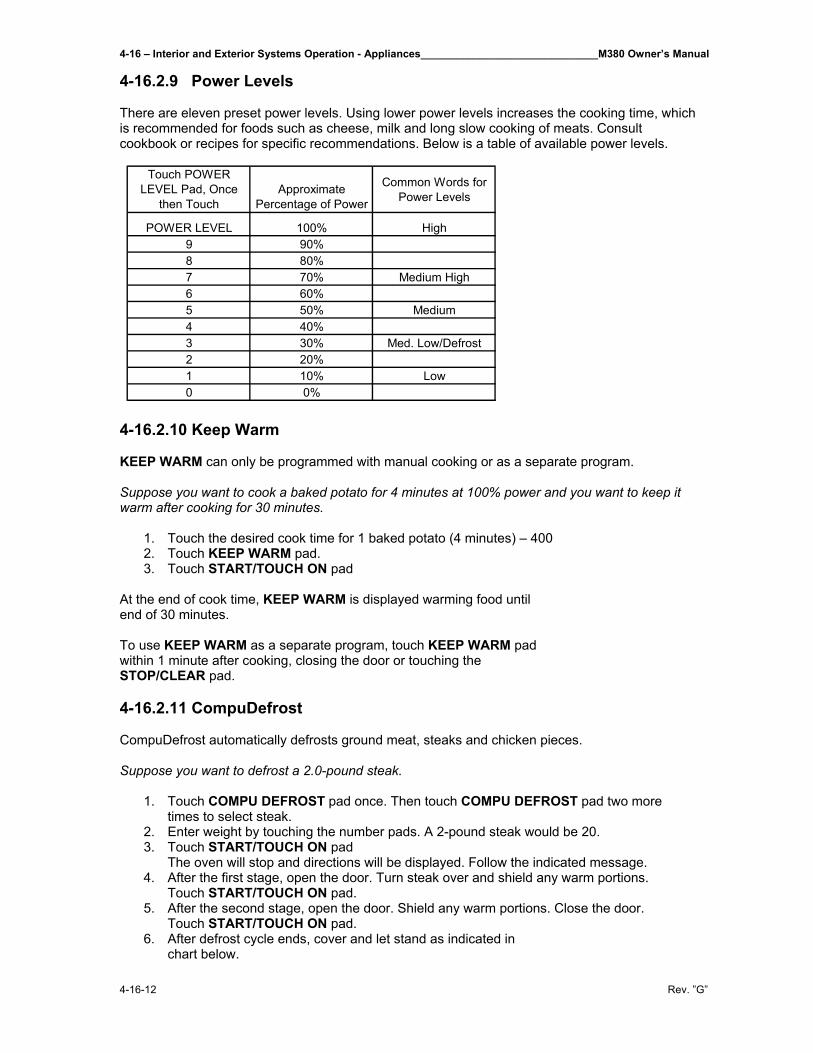
4-16 – Interior and Exterior Systems Operation - Appliances______________________________M380 Owner’s Manual
4-16-12 Rev. ”G”
4-16.2.9 Power Levels There are eleven preset power levels. Using lower power levels increases the cooking time, which is recommended for foods such as cheese, milk and long slow cooking of meats. Consult cookbook or recipes for specific recommendations. Below is a table of available power levels.
4-16.2.10 Keep Warm KEEP WARM can only be programmed with manual cooking or as a separate program. Suppose you want to cook a baked potato for 4 minutes at 100% power and you want to keep it warm after cooking for 30 minutes.
1. Touch the desired cook time for 1 baked potato (4 minutes) – 400 2. Touch KEEP WARM pad. 3. Touch START/TOUCH ON pad
At the end of cook time, KEEP WARM is displayed warming food until end of 30 minutes. To use KEEP WARM as a separate program, touch KEEP WARM pad within 1 minute after cooking, closing the door or touching the STOP/CLEAR pad. 4-16.2.11 CompuDefrost CompuDefrost automatically defrosts ground meat, steaks and chicken pieces. Suppose you want to defrost a 2.0-pound steak.
1. Touch COMPU DEFROST pad once. Then touch COMPU DEFROST pad two more times to select steak.
2. Enter weight by touching the number pads. A 2-pound steak would be 20. 3. Touch START/TOUCH ON pad
The oven will stop and directions will be displayed. Follow the indicated message. 4. After the first stage, open the door. Turn steak over and shield any warm portions.
Touch START/TOUCH ON pad. 5. After the second stage, open the door. Shield any warm portions. Close the door.
Touch START/TOUCH ON pad. 6. After defrost cycle ends, cover and let stand as indicated in
chart below.
Touch POWER LEVEL Pad, Once
then TouchApproximate
Percentage of Power
Common Words for Power Levels
POWER LEVEL 100% High9 90%8 80%7 70% Medium High6 60%5 50% Medium4 40%3 30% Med. Low/Defrost2 20%1 10% Low0 0%
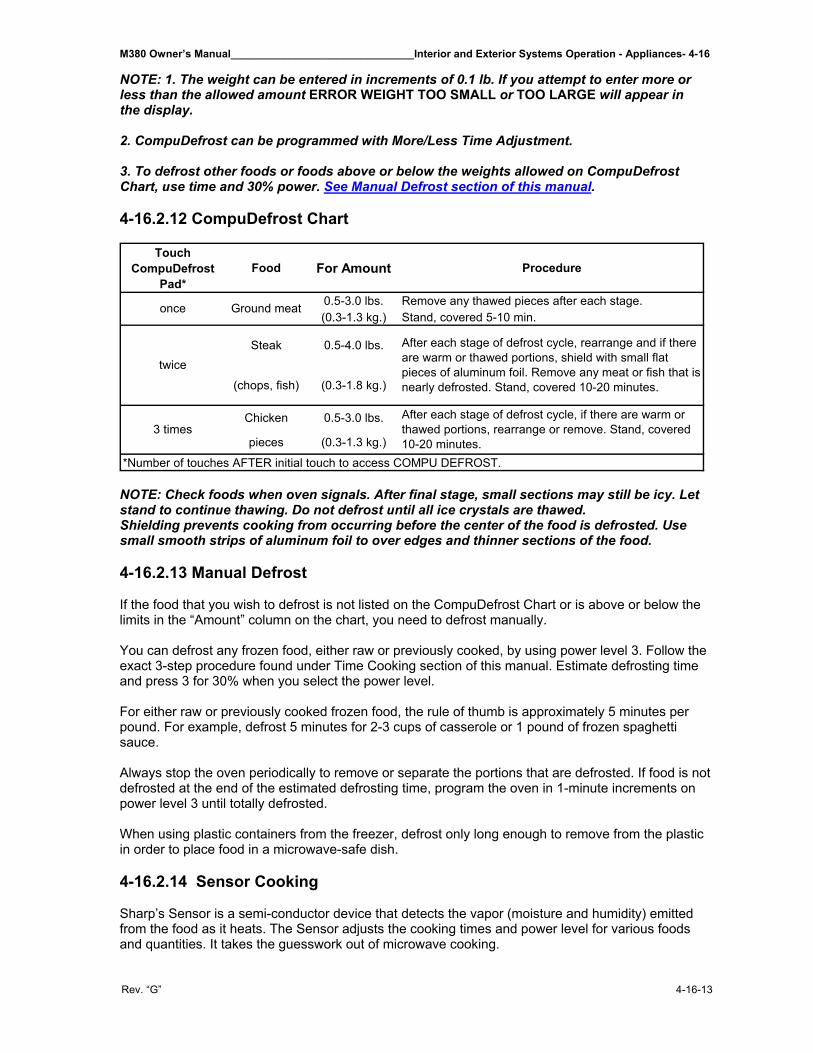
M380 Owner’s Manual_______________________________Interior and Exterior Systems Operation - Appliances- 4-16
Rev. “G” 4-16-13
NOTE: 1. The weight can be entered in increments of 0.1 lb. If you attempt to enter more or less than the allowed amount ERROR WEIGHT TOO SMALL or TOO LARGE will appear in the display. 2. CompuDefrost can be programmed with More/Less Time Adjustment. 3. To defrost other foods or foods above or below the weights allowed on CompuDefrost Chart, use time and 30% power. See Manual Defrost section of this manual. 4-16.2.12 CompuDefrost Chart
Touch CompuDefrost
Pad*Food For Amount Procedure
0.5-3.0 lbs. Remove any thawed pieces after each stage.(0.3-1.3 kg.) Stand, covered 5-10 min.
Steak 0.5-4.0 lbs.
(chops, fish) (0.3-1.8 kg.)
Chicken 0.5-3.0 lbs.
pieces (0.3-1.3 kg.)3 times
After each stage of defrost cycle, if there are warm or thawed portions, rearrange or remove. Stand, covered 10-20 minutes.
*Number of touches AFTER initial touch to access COMPU DEFROST.
once Ground meat
twice
After each stage of defrost cycle, rearrange and if there are warm or thawed portions, shield with small flat pieces of aluminum foil. Remove any meat or fish that is nearly defrosted. Stand, covered 10-20 minutes.
NOTE: Check foods when oven signals. After final stage, small sections may still be icy. Let stand to continue thawing. Do not defrost until all ice crystals are thawed. Shielding prevents cooking from occurring before the center of the food is defrosted. Use small smooth strips of aluminum foil to over edges and thinner sections of the food. 4-16.2.13 Manual Defrost If the food that you wish to defrost is not listed on the CompuDefrost Chart or is above or below the limits in the “Amount” column on the chart, you need to defrost manually. You can defrost any frozen food, either raw or previously cooked, by using power level 3. Follow the exact 3-step procedure found under Time Cooking section of this manual. Estimate defrosting time and press 3 for 30% when you select the power level. For either raw or previously cooked frozen food, the rule of thumb is approximately 5 minutes per pound. For example, defrost 5 minutes for 2-3 cups of casserole or 1 pound of frozen spaghetti sauce. Always stop the oven periodically to remove or separate the portions that are defrosted. If food is not defrosted at the end of the estimated defrosting time, program the oven in 1-minute increments on power level 3 until totally defrosted. When using plastic containers from the freezer, defrost only long enough to remove from the plastic in order to place food in a microwave-safe dish. 4-16.2.14 Sensor Cooking Sharp’s Sensor is a semi-conductor device that detects the vapor (moisture and humidity) emitted from the food as it heats. The Sensor adjusts the cooking times and power level for various foods and quantities. It takes the guesswork out of microwave cooking.
4-16 – Interior and Exterior Systems Operation - Appliances______________________________M380 Owner’s Manual
4-16-14 Rev. ”G”
Using Sensor Settings: 1. Room temperature should not exceed 95ºF. 2. Be sure the exterior of the cooking container and the interior of the oven are dry. Wipe off
any moisture with a dry cloth or paper towel. 3. Sensor cooking can only be entered within 1 minute after cooking, opening and closing the
door or touching the STOP/CLEAR pad. 4. During the first part of sensor cooking, SENSOR, REHEAT FROZEN ENTRÉE POPCORN
BAKED POTATO SOFT HARD FRESH VEG. FROZEN VEG. BACON FISH HOT DOGS will appear on display. Do not open the oven door or touch STOP/CLEAR during this part of the cooking cycle. The measurement of vapor will be interrupted. If this occurs, ERROR will appear and sensor cooking will be interrupted. To continue cooking, touch the STOP/CLEAR pad and select cooking time and power. When sensor detects the vapor emitted from the food, remainder of cooking time will appear. Door may be opened when remaining cooking time appears on display. At the time, you may stir or season food, as desired.
5. Check food for doneness after cooking with sensor settings. If additional time is needed, continue to cook with variable power and time.
6. If the sensor does not detect vapor, ERROR will appear and the oven will shut off. 7. At the end of any cycle, open oven door or touch STOP/CLEAR pad. The time of day will
reappear on the display. 8. Any sensor setting can be programmed with More or Less Time Adjustment.
Selecting Foods:
1. The sensor works with foods at normal storage temperature. For example, foods for reheating would be at refrigerator temperature and potatoes for baking would be room temperature.
2. More or less food than the quantity listed in the charts should be cooked by time and variable power.
Covering Foods: Some foods work best when covered. Use the cover recommended in the chart for these foods.
1. Casserole lid. 2. Plastic wrap: Use plastic wrap recommended for microwave cooking. Cover dish loosely;
allow approximately ½ inch to remain uncovered to allow steam to escape. Plastic wrap should not touch food.
3. Paper towel: Use paper towels to absorb excess fat and moisture when cooking bacon and potatoes. Line the turntable when baking potatoes.
4. Wax paper: Cover dish completely; fold excess wrap under dish to secure. If dish is wider than paper, overlap two pieces at least one inch to cover.
4-16.2.15 Instant Sensors Your oven has Instant Sensor Popcorn and Instant Sensor Reheat buttons. To use any of the Instant Sensors, simply touch the chosen pad. The oven will start automatically. Any sensor setting can be programmed with More/Less Time Adjustment. See More/Less Time Adjustment section in this manual. 4-16.2.16 Instant Sensor Reheat Turntable on: You can reheat many foods by touching just one pad. You don’t need to calculate reheating time or power level. To reheat food with turntable on, simply touch the SENSOR REHEAT pad. Turntable off: You may reheat using an 11”x8”x2” or 13”x9”x2” casserole with the turntable off. First touch TURNTABLE ON/OFF and note indicator. Then touch SENSOR REHEAT. The display will indicate turntable off and oven will start automatically. After cooking, LET STAND COVERED will be displayed.
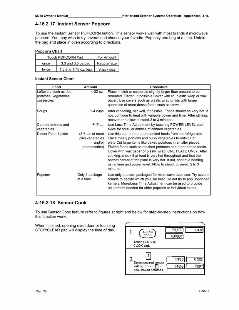
M380 Owner’s Manual_______________________________Interior and Exterior Systems Operation - Appliances- 4-16
Rev. “G” 4-16-15
4-16.2.17 Instant Sensor Popcorn To use the Instant Sensor POPCORN button. This sensor works well with most brands if microwave popcorn. You may wish to try several and choose your favorite. Pop only one bag at a time. Unfold the bag and place in oven according to directions. Popcorn Chart
For Amount
once 3.0 and 3.5 oz.bag Regular size
twice 1.5 and 1.75 oz. bag Snack size
Touch POPCORN Pad
Instant Sensor Chart
4-16.2.18 Sensor Cook To use Sensor Cook feature refer to figures at right and below for step-by-step instructions on how this function works. When finished, opening oven door or touching STOP/CLEAR pad will display the time of day.
Food Amount ProcedureLeftovers such as rice, potatoes, vegetables, casseroles
4-32 oz. Place in dish or casserole slightly larger than amount to be reheated. Flatten, if possible.Cover with lid, plastic wrap or wax paper. Use covers such as plastic wrap or lids with larger quantities of more dense foods such as stews.
Soups 1-4 cups After reheating, stir well, if possible. Foods should be very hot. If not, continue to heat with variable power and time. After stirring, recover and allow to stand 2 to 3 minutes.
Canned entrees and vegetables
4-16 oz. Use Less Time Adjustment by touching POWER LEVEL pad twice for small quantities of canned vegetables.
Dinner Plate 1 plate (3-6 oz. of meat plus vegetables
and/or potatoes/rice)
Use this pad to reheat precooked foods from the refrigerator. Place meaty portions and bulky vegetables to outside of plate.Cut large items like baked potatoes in smaller pieces. Flatten foods such as mashed potatoes and other dense foods. Cover with wax paper or plastic wrap. ONE PLATE ONLY. After cooking, check that food is very hot throughout and that the bottom center of the plate is very hot. If not, continue heating using time and power level. Allow to stand, covered, 2 to 3 minutes.
Popcorn Only 1 package at a time
Use only popcorn packaged for microwave oven use. Try several brands to decide which you like best. Do not try to pop unpopped kernels. More/Less Time Adjustment can be used to provide adjustment needed for older popcorn or individual tastes.
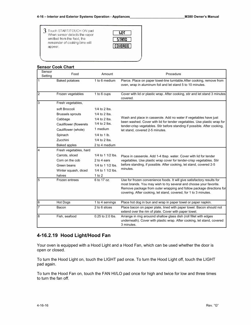
4-16 – Interior and Exterior Systems Operation - Appliances______________________________M380 Owner’s Manual
4-16-16 Rev. ”G”
Sensor Cook Chart Sensor Setting Food Amount Procedure
1 Baked potatoes 1 to 6 medium Pierce. Place on paper towel-line turntable.After cooking, remove from oven, wrap in aluminum foil and let stand 5 to 10 minutes.
2 Frozen vegetables 1 to 6 cups Cover with lid or plastic wrap. After cooking, stir and let stand 3 minutes covered.
3
soft Broccoli 1/4 to 2 lbs.Brussels sprouts 1/4 to 2 lbs.Cabbage 1/4 to 2 lbs.Cauliflower (flowerets 1/4 to 2 lbs.
Cauliflower (whole) 1 medium
Spinach 1/4 to 1 lb.Zucchini 1/4 to 2 lbs.Baked apples 2 to 4 medium
4 Fresh vegetables, hardCarrots, sliced 1/4 to 1 1/2 lbs.Corn on the cob 2 to 4 earsGreen beans 1/4 to 1 1/2 lbs.Winter squash, diced 1/4 to 1 1/2 lbs.halves 1 to 2
5 Frozen entrees 6 to 17 oz. Use for frozen convenience foods. It will give satisfactory results for most brands. You may wish to try several and choose your favorite. Remove package from outer wrapping and follow package directions for covering. After cooking, let stand, covered, for 1 to 3 minutes.
6 Hot Dogs 1 to 4 servings Place hot dog in bun and wrap in paper towel or paper napkin.7 Bacon 2 to 6 slices Place bacon on paper plate, lined with paper towel. Bacon should not
extend over the rim of plate. Cover with paper towel.8 Fish, seafood 0.25 to 2.0 lbs. Arrange in ring arouond shallow glass dish (roll fillet with edges
underneath). Cover with plastic wrap. After cooking, let stand, covered 3 minutes.
Fresh vegetables,
Wash and place in casserole. Add no water if vegetables have just been washed. Cover with lid for tender vegetables. Use plastic wrap for tender-crisp vegetables. Stir before standing if possible. After cooking, let stand, covered 2-5 minutes.
Place in casserole. Add 1-4 tbsp. water. Cover with lid for tender vegetables. Use plastic wrap cover for tender-crisp vegetables. Stir before standing, if possible. After cooking, let stand, covered 2-5 minutes.
4-16.2.19 Hood Light/Hood Fan Your oven is equipped with a Hood Light and a Hood Fan, which can be used whether the door is open or closed. To turn the Hood Light on, touch the LIGHT pad once. To turn the Hood Light off, touch the LIGHT pad again. To turn the Hood Fan on, touch the FAN HI/LO pad once for high and twice for low and three times to turn the fan off.
M380 Owner’s Manual_______________________________Interior and Exterior Systems Operation - Appliances- 4-16
Rev. “G” 4-16-17
4-16.2.20 Convection/Automatic Mix Cooking This section of this manual gives you specific cooking instructions and procedures. Please consult your Sharp Carousel Convection Microwave Cookbook for helpful hints for convection and combination cooking. The oven should not be used without the turntable in place, and it should never be restricted so that it cannot rotate. You may remove the turntable when preheating the oven and when preparing food to be cooked directly on the turntable. Convection Cooking During convection heating, hot air is circulated throughout the oven cavity to brown and crisp foods quickly and evenly. This oven can be programmed for ten different convection cooking temperatures for up to 99 minutes, 99 seconds. 4-16.2.21 To Cook with Convection Suppose you want to cook at 350ºF, for 25 minutes.
1. Touch CONVEC pad. 2. Touch number pad for desired temperature (Ex. Pad 6 for 350ºF.) 3. Enter cooking time. For 25 minutes, push 2500. 4. Touch START/TOUCH ON pad.
4-16.2.22 To Preheat and Cook with Convection Your oven can be programmed to combine preheating and convection cooking operations. You can preheat at the same temperature as the convection temperature or change it to a higher or lower temperature. Suppose you want to preheat until 350ºF, and then cook 25 minutes at 375º F, convection.
1. Touch PREHEAT pad. 2. Touch number pad for desired temperature (Ex. Pad 6 for 350ºF). 3. Touch CONVEC then touch number pad for temperature. (Ex. Pad 7 for 375ºF). 4. Enter number pads for cooking time. For instance for 25 minutes press 2500. 5. Touch START/TOUCH ON pad.
When the oven reaches the programmed temperature, it will automatically hold at the preheat temperature for 30 minutes and then the display will change to time of day. Whenever STOP/CLEAR pad is touched during this 30-minute period, PRESS CONVEC or PRESS MIX will be displayed and cooking mode and time can be entered. NOTE: To preheat and cook with the same temperature, enter the same temperature in steps 2 and 3. 4-16.2.23 To Broil In the BROIL setting, preheating is automatic. Just enter the actual broiling time and wait for preheat to be over before adding food. (Preset 450º F). Oven temperature cannot be changed. Suppose you want to broil a ham steak for 15 minutes.
1. Touch BROIL pad. 2. Touch number pads to enter cooking time. For 15 minutes, enter 1500. 3. Touch START/TOUCH On pad.
4-16 – Interior and Exterior Systems Operation - Appliances______________________________M380 Owner’s Manual
4-16-18 Rev. ”G”
4-16.2.24 To Slow Cook Slow Cook is a preset at 300ºF. Slow Cook is programmed for 4 hours. Oven temperature can be changed to temperatures below 300ºF. Simply touch the SLOW COOK pad and touch the desired numbered pad with temperature below 300ºF. 4-16.2.25 Automatic Mix Cooking This oven has two pre-programmed settings that make it easy to cook with both convection heat and microwave automatically.
Oven Temperature Microwave PowerHIGH MIX 325ºF 30%LOW MIX 325ºF 10%
With the exception of those foods that cook best by convection heating alone, most foods are well suited to mix cooking using either LOW MIX/BAKE or HIGH MIX/ROAST. The marriage of these two cooking methods produces juicy meats, moist and tender cakes and fine textured breads, all with just the right amount of browning and crispness. The temperatures can be changed, however, the microwave power cannot. The oven temperature can be changed from 100ºF, to 450ºF. To change the temperature, first touch HIGH MIX or LOW MIX, then touch the same pad again. When the display says SELECT TEMP touch desired temperature pad. Example: HIGH MIX, HIGH MIX, pad 7 and START. The mix temperature will change automatically. 4-16.2.26 To Cook with Automatic Mix Suppose you want to bake a cake at low mix for 20 minutes.
1. Touch LOW MIX BAKE pad 2. Touch number pads to select time. To select 20 minutes push
2000 At the end of the baking time, 1 long tone will sound and END will be displayed. 4-16.2.27 To Preheat and Cook with Automatic Mix Your oven can be programmed to combine preheating and Automatic Mix cooking operations. You can preheat at the same temperature as the present combination temperature or change it to a different temperature. Suppose you want to preheat until 350ºF, and then cook 25 minutes on 325ºF. Low Mix bake.
1. Touch PREHEAT pad 2. Touch number pad for desired temperature, for instance for 350ºF touch Pad 6. 3. Touch LOW MIX BAKE pad 4. Touch number pads to enter cooking time. Ex. 25 minutes would be 2500. 5. Touch START/TOUCH ON pad.
After cook cycle is completed, one long tone will sound and END will be displayed.
M380 Owner’s Manual_______________________________Interior and Exterior Systems Operation - Appliances- 4-16
Rev. “G” 4-16-19
4-16.2.28 Special Features This section of this manual offers instructions for preparing 12 popular foods using Compu-Broil, CompuRoast and CompuBake. After selecting the desired feature, follow the directions indicated in the display. For helpful hints, simply touch CUSTOM HELP anytime HELP is lighted in the display. 4-16.2.29 CompuRoast CompuRoast automatically roasts chicken, turkey, turkey breast or pork. Suppose you want to roast a 2.5-pound chicken.
1. Touch COMPU ROAST pad. 2. Touch number pad to select meat you are roasting. For instances, chicken would
be Pad 1. 3. Touch number pad to enter the weight of the meat. Ex. A 2.5-pound chicken
would be 25. 4. Touch START/TOUCH ON pad.
After COMPU ROAST cycle ends, a long tone will sound. LET STAND COVERED FOR 5-10 MIN. will be displayed. NOTE:
1. CompuRoast can be programmed with More/Less Time Adjustment. See More/Less Time section of this manual.
2. If you attempt to enter more or less than the allowed weight ERROR WEIGHT TOO LARGE PRESS CLEAR or ERROR WEIGHT TOO SMALL PRESS CLEAR will appear in the display.
3. To roast other food or foods above or below the weights allowed in the chart below, check the Sharp Carousel Convection Microwave Cookbook’s Combination Roasting Chart.
CompuRoast Chart
Setting Food Amount Procedure1-8 pieces
1/4 lb. each0.5 to 3.0 lbs.
Use this setting to broil hamburger patties. Place on low rack.
Arrange pieces on low rack. After cooking, let stand 3-5 minutes. Dark meat should be 180ºF, and white meat should be 170ºF.
Season as desired. Place on low rack. After the cycle ends, cover with foil and let stand 10 minutes. Internal temperature of white meat should be 170ºF.Boneless pork loin is recommended because it cooks evenly. Place on a low rack. After cooking, remove from oven, cover with foil and allow to stand 5-10 minutes. Internal temperature should be 160ºF.
1 Hamburgers
2 Chicken pieces
3 Steaks 0.5 to 2.0 lbs.
4 Fish Steaks 0.5 to 2.0 lbs.
4-16 – Interior and Exterior Systems Operation - Appliances______________________________M380 Owner’s Manual
4-16-20 Rev. ”G”
4-16.2.30 CompuBake CompuBake automatically bakes cakes, brownies, muffins and French fries. Suppose you want to bake a 13”x9”x2” cake.
1. Touch COMPU BAKE pad. Note: Turntable function is automatically turned OFF.
2. Touch number pad. For instance for a cake touch Pad 1. 3. Touch STRAT/TOUCH ON pad.
After CompuBake preheat cycle ends. Four tones will sound. The display will read PREHEAT OVER PLACE FOOD IN OVEN. Open door, place the cake pan inside.
4. Close door and touch START/TOUCH ON pad. After COMPU BAKE cycle ends, one long tone will sound. In addition, END will be displayed.
NOTE:
1. ComuBake can be programmed with More/Less Time Adjustment. See More/Less Time in this manual.
2. To bake other food, see the Sharp Carousel Convection Microwave Cookbook’s Baking Section.
CompuBake Chart
Setting Food Pan Size/Qty Rack Procedure
Low
Low
Ideal for packaged cake mix or your own recipe for 13"x9"x2" pan. Prepare according to package or recipe directions and place in a greased and floured 13"x9"x2" baking pan. After the preheat is over, place pan in oven centerd on low rack. Cool before frosting and serving.
Ideal for packaged brownie mix or your own recipe for 13"x9"x2" pan. Prepare according to package or recipe directions and place in a greased and floured 13"x9"x2" baking pan. After the preheat is over, place pan in oven centered on low rack. Cool before cutting into service pieces.
Ideal for packaged muffin mix or your own recipe for 12 medium size muffins. Prepare according to package or recipe directions and place in one 12-cup muffin pan. After the preheat is over, place pan in oven centered on low rack.
Use frozen prepared French Fries. No preheat is required for the French Fries baking procedure. Place French Fries on cookie sheet on low rack. For shoestring potatoes, touch POWER LEVEL pad twice to enter less time before touching START pad.
1 Cake 13"x9"x2" Low
2 Brownies 13"x9"x2" Low
3 Muffins 12 cup
4 French Fries 3 to 24 oz. Cookie sheet to hold
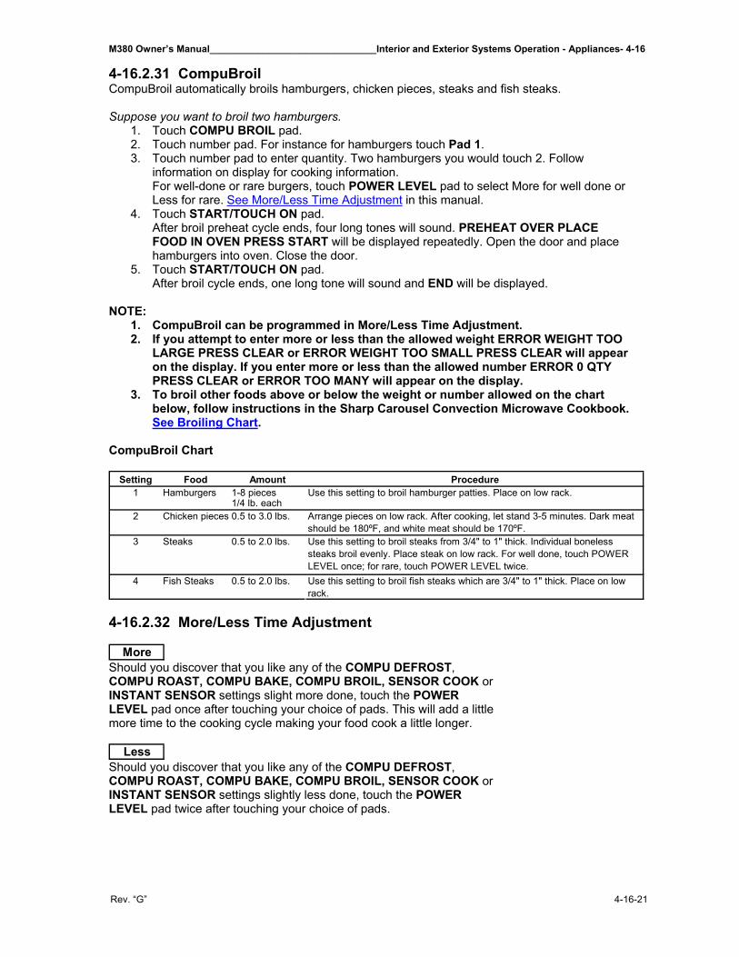
M380 Owner’s Manual_______________________________Interior and Exterior Systems Operation - Appliances- 4-16
Rev. “G” 4-16-21
4-16.2.31 CompuBroil CompuBroil automatically broils hamburgers, chicken pieces, steaks and fish steaks. Suppose you want to broil two hamburgers.
1. Touch COMPU BROIL pad. 2. Touch number pad. For instance for hamburgers touch Pad 1. 3. Touch number pad to enter quantity. Two hamburgers you would touch 2. Follow
information on display for cooking information. For well-done or rare burgers, touch POWER LEVEL pad to select More for well done or Less for rare. See More/Less Time Adjustment in this manual.
4. Touch START/TOUCH ON pad. After broil preheat cycle ends, four long tones will sound. PREHEAT OVER PLACE FOOD IN OVEN PRESS START will be displayed repeatedly. Open the door and place hamburgers into oven. Close the door.
5. Touch START/TOUCH ON pad. After broil cycle ends, one long tone will sound and END will be displayed.
NOTE:
1. CompuBroil can be programmed in More/Less Time Adjustment. 2. If you attempt to enter more or less than the allowed weight ERROR WEIGHT TOO
LARGE PRESS CLEAR or ERROR WEIGHT TOO SMALL PRESS CLEAR will appear on the display. If you enter more or less than the allowed number ERROR 0 QTY PRESS CLEAR or ERROR TOO MANY will appear on the display.
3. To broil other foods above or below the weight or number allowed on the chart below, follow instructions in the Sharp Carousel Convection Microwave Cookbook. See Broiling Chart.
CompuBroil Chart
Setting Food Amount Procedure1 Hamburgers 1-8 pieces
1/4 lb. each2 Chicken pieces 0.5 to 3.0 lbs.
3 Steaks 0.5 to 2.0 lbs.
4 Fish Steaks 0.5 to 2.0 lbs.
Use this setting to broil hamburger patties. Place on low rack.
Arrange pieces on low rack. After cooking, let stand 3-5 minutes. Dark meat should be 180ºF, and white meat should be 170ºF.Use this setting to broil steaks from 3/4" to 1" thick. Individual boneless steaks broil evenly. Place steak on low rack. For well done, touch POWER LEVEL once; for rare, touch POWER LEVEL twice.Use this setting to broil fish steaks which are 3/4" to 1" thick. Place on low rack.
4-16.2.32 More/Less Time Adjustment
More Should you discover that you like any of the COMPU DEFROST, COMPU ROAST, COMPU BAKE, COMPU BROIL, SENSOR COOK or INSTANT SENSOR settings slight more done, touch the POWER LEVEL pad once after touching your choice of pads. This will add a little more time to the cooking cycle making your food cook a little longer.
Less Should you discover that you like any of the COMPU DEFROST, COMPU ROAST, COMPU BAKE, COMPU BROIL, SENSOR COOK or INSTANT SENSOR settings slightly less done, touch the POWER LEVEL pad twice after touching your choice of pads.
4-16 – Interior and Exterior Systems Operation - Appliances______________________________M380 Owner’s Manual
4-16-22 Rev. ”G”
4-16.2.33 Kitchen Timer Suppose you want to time a 3-minute long distance phone call.
1. Touch KITCHEN TIMER pad. 2. Enter time, for instance a 3 minute long phone call would be
300. 3. Touch START pad
4-16.2.34 Minute Plus Minute Plus allows you to cook for a minute at 100% by simply touching the MINUTE PLUS pad. You can also extend cooking time in multiples of 1 minute by repeatedly touching the MINUTE PLUS pad during manual cooking using microwave, convection, mix or broil. Suppose you want to heat a cup of soup for one minute. Simply touch the MINUTE PLUS pad once. NOTE: Touch MINUTE PLUS pad within 1 minute after cooking, closing the door, touching the STOP/CLEAR pad or during cooking. Minute Plus cannot be used to start the oven if any program is on display. Minute Plus cannot be used with SPECIAL FEATURES. 4-16.2.35 Touch On Touch On allows you to cook at 100% power by touching the START/TOUCH ON continuously. Touch On is ideal for melting cheese, bring milk to just below boiling, etc. The maximum cooking time is 3 minutes. Suppose you want to melt cheese on a piece of toast.
1. Continuously touch START/TOUCH ON pad. The cooking time will begin counting up. 2. When the cheese is melted to desired degree, remove finger from START/TOUCH ON
pad. Oven stops immediately. NOTE:
1. Note time it takes for frequently used foods and program that time in the future. 2. Touch TOUCH ON pad within 1 minute after cooking, opening and closing the
door or touching the STOP/CLEAR pad. 3. Touch On can only be used 3 times in a row. If more times are needed, open and
close door or touch STOP/CLEAR. NOTE: For all Special Features refer to the Manufacturer’s Manual supplied with your microwave. 4-16.2.36 Cleaning and Care Exterior The outside surface is precoated metal and plastic. Clean the outside with mild soap and water; rinse and dry with a soft cloth. Do not use any type of household or abrasive cleaner. Touch Control Panel Care should be taken in cleaning the touch control panel. If the control panel becomes soiled, open the oven door to inactivate the control panel before cleaning. Wipe the panel with a cloth dampened slightly with water only. Dry with a soft cloth. Do not scrub or use any sort of chemical cleaners. Avoid the use of excess water. Close the door and touch STOP/CLEAR.
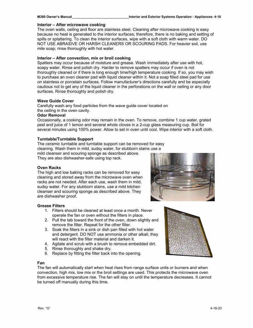
M380 Owner’s Manual_______________________________Interior and Exterior Systems Operation - Appliances- 4-16
Rev. “G” 4-16-23
Interior – After microwave cooking The oven walls, ceiling and floor are stainless steel. Cleaning after microwave cooking is easy because no heat is generated to the interior surfaces; therefore, there is no baking and setting of spills or splattering. To clean the interior surfaces, wipe with a soft cloth with warm water. DO NOT USE ABRASIVE OR HARSH CLEANERS OR SCOURING PADS. For heavier soil, use mile soap; rinse thoroughly with hot water. Interior – After convection, mix or broil cooking Spatters may occur because of moisture and grease. Wash immediately after use with hot, soapy water. Rinse and polish dry. Harder to remove spatters may occur if oven is not thoroughly cleaned or if there is long enough time/high temperature cooking. If so, you may wish to purchase an oven cleaner pad with liquid cleaner within it. Not a soap filled steel pad for use on stainless or porcelain surfaces. Follow manufacturer’s directions carefully and be especially cautious not to get any of the liquid cleaner in the perforations on the wall or ceiling or any door surfaces. Rinse thoroughly and polish dry. Wave Guide Cover Carefully wash any food particles from the wave guide cover located on the ceiling in the oven cavity. Odor Removal Occasionally, a cooking odor may remain in the oven. To remove, combine 1 cup water, grated peel and juice of 1 lemon and several whole cloves in a 2-cup glass measuring cup. Boil for several minutes using 100% power. Allow to set in oven until cool. Wipe interior with a soft cloth. Turntable/Turntable Support The ceramic turntable and turntable support can be removed for easy cleaning. Wash them in mild, sudsy water, for stubborn stains use a mild cleanser and scouring sponge as described above. They are also dishwasher-safe using top rack. Oven Racks The high and low baking racks can be removed for easy cleaning and stored away from the microwave oven when racks are not needed. After each use, wash them in mild, sudsy water. For any stubborn stains, use a mild kitchen cleanser and scouring sponge as described above. They are dishwasher proof. Grease Filters
1. Filters should be cleaned at least once a month. Never operate the fan or oven without the filters in place.
2. Pull the tab toward the front of the oven, down slightly and remove the filter. Repeat for the other filter.
3. Soak the filters in a sink or dish pan filled with hot water and detergent. DO NOT use ammonia or other alkali; they will react with the filter material and darken it.
4. Agitate and scrub with a brush to remove embedded dirt. 5. Rinse thoroughly and shake dry. 6. Replace by fitting the filter back into the opening.
Fan The fan will automatically start when heat rises from range surface units or burners and when convection, high mix, low mix or the broil settings are used. This protects the microwave oven from excessive temperature rise. The fan will stay on until the temperature decreases. It cannot be turned off manually during this time.
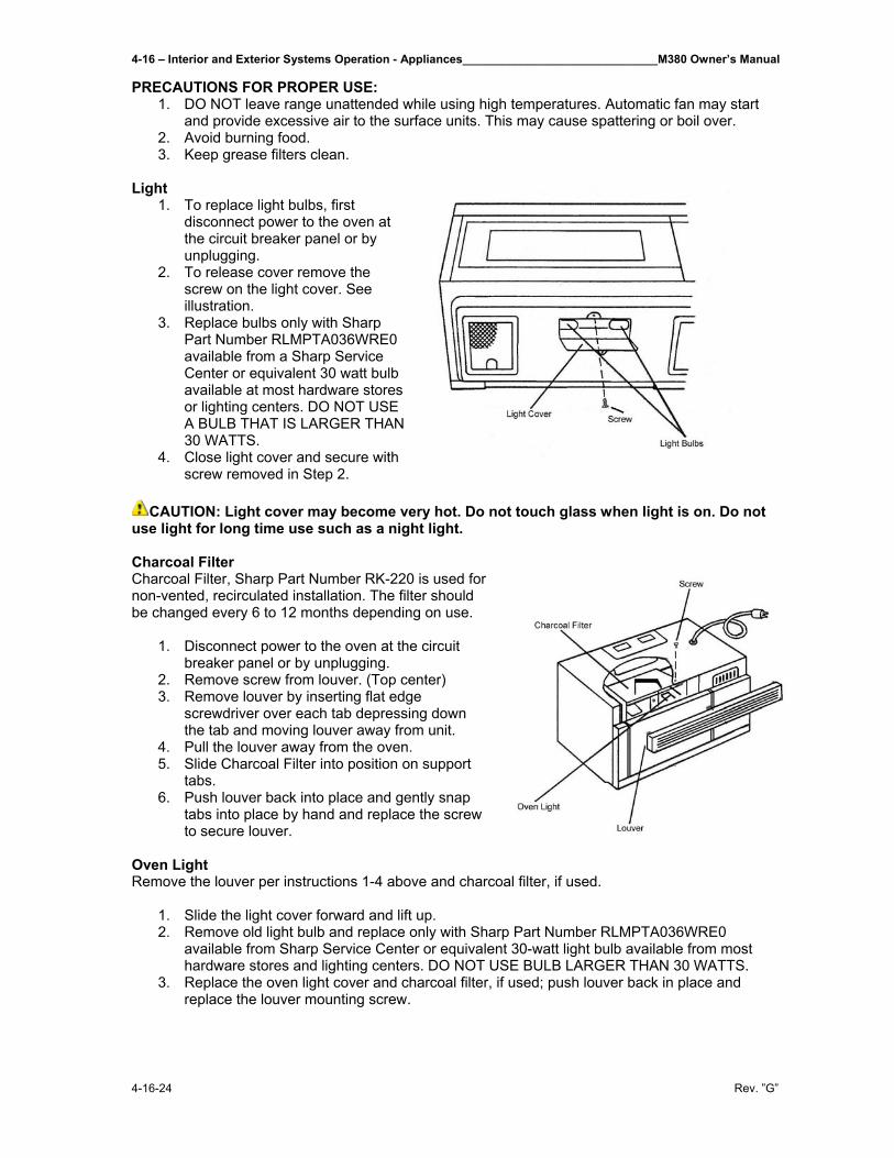
4-16 – Interior and Exterior Systems Operation - Appliances______________________________M380 Owner’s Manual
4-16-24 Rev. ”G”
PRECAUTIONS FOR PROPER USE: 1. DO NOT leave range unattended while using high temperatures. Automatic fan may start
and provide excessive air to the surface units. This may cause spattering or boil over. 2. Avoid burning food. 3. Keep grease filters clean.
Light
1. To replace light bulbs, first disconnect power to the oven at the circuit breaker panel or by unplugging.
2. To release cover remove the screw on the light cover. See illustration.
3. Replace bulbs only with Sharp Part Number RLMPTA036WRE0 available from a Sharp Service Center or equivalent 30 watt bulb available at most hardware stores or lighting centers. DO NOT USE A BULB THAT IS LARGER THAN 30 WATTS.
4. Close light cover and secure with screw removed in Step 2.
CAUTION: Light cover may become very hot. Do not touch glass when light is on. Do not
use light for long time use such as a night light. Charcoal Filter Charcoal Filter, Sharp Part Number RK-220 is used for non-vented, recirculated installation. The filter should be changed every 6 to 12 months depending on use.
1. Disconnect power to the oven at the circuit breaker panel or by unplugging.
2. Remove screw from louver. (Top center) 3. Remove louver by inserting flat edge
screwdriver over each tab depressing down the tab and moving louver away from unit.
4. Pull the louver away from the oven. 5. Slide Charcoal Filter into position on support
tabs. 6. Push louver back into place and gently snap
tabs into place by hand and replace the screw to secure louver.
Oven Light Remove the louver per instructions 1-4 above and charcoal filter, if used.
1. Slide the light cover forward and lift up. 2. Remove old light bulb and replace only with Sharp Part Number RLMPTA036WRE0
available from Sharp Service Center or equivalent 30-watt light bulb available from most hardware stores and lighting centers. DO NOT USE BULB LARGER THAN 30 WATTS.
3. Replace the oven light cover and charcoal filter, if used; push louver back in place and replace the louver mounting screw.
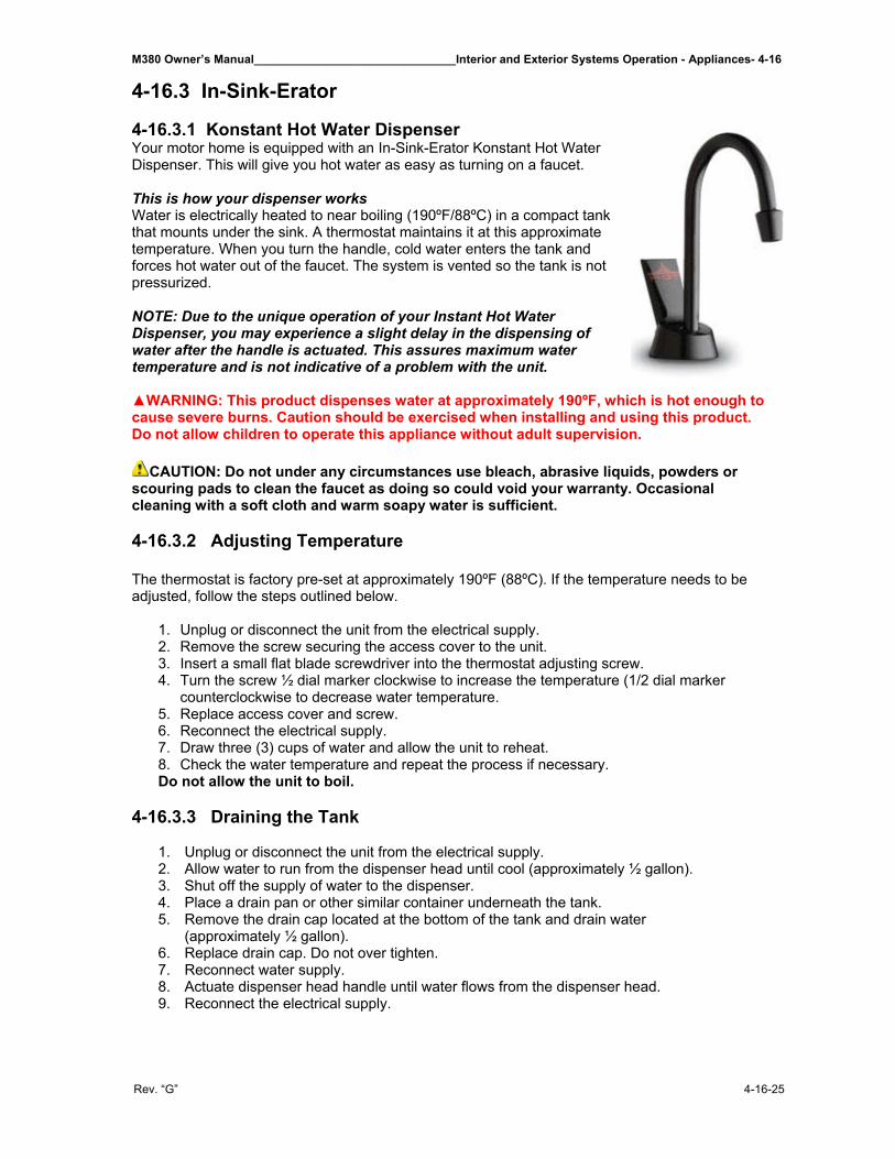
M380 Owner’s Manual_______________________________Interior and Exterior Systems Operation - Appliances- 4-16
Rev. “G” 4-16-25
4-16.3 In-Sink-Erator 4-16.3.1 Konstant Hot Water Dispenser Your motor home is equipped with an In-Sink-Erator Konstant Hot Water Dispenser. This will give you hot water as easy as turning on a faucet. This is how your dispenser works Water is electrically heated to near boiling (190ºF/88ºC) in a compact tank that mounts under the sink. A thermostat maintains it at this approximate temperature. When you turn the handle, cold water enters the tank and forces hot water out of the faucet. The system is vented so the tank is not pressurized. NOTE: Due to the unique operation of your Instant Hot Water Dispenser, you may experience a slight delay in the dispensing of water after the handle is actuated. This assures maximum water temperature and is not indicative of a problem with the unit. ▲WARNING: This product dispenses water at approximately 190ºF, which is hot enough to cause severe burns. Caution should be exercised when installing and using this product. Do not allow children to operate this appliance without adult supervision.
CAUTION: Do not under any circumstances use bleach, abrasive liquids, powders or scouring pads to clean the faucet as doing so could void your warranty. Occasional cleaning with a soft cloth and warm soapy water is sufficient. 4-16.3.2 Adjusting Temperature The thermostat is factory pre-set at approximately 190ºF (88ºC). If the temperature needs to be adjusted, follow the steps outlined below.
1. Unplug or disconnect the unit from the electrical supply. 2. Remove the screw securing the access cover to the unit. 3. Insert a small flat blade screwdriver into the thermostat adjusting screw. 4. Turn the screw ½ dial marker clockwise to increase the temperature (1/2 dial marker
counterclockwise to decrease water temperature. 5. Replace access cover and screw. 6. Reconnect the electrical supply. 7. Draw three (3) cups of water and allow the unit to reheat. 8. Check the water temperature and repeat the process if necessary. Do not allow the unit to boil.
4-16.3.3 Draining the Tank
1. Unplug or disconnect the unit from the electrical supply. 2. Allow water to run from the dispenser head until cool (approximately ½ gallon). 3. Shut off the supply of water to the dispenser. 4. Place a drain pan or other similar container underneath the tank. 5. Remove the drain cap located at the bottom of the tank and drain water
(approximately ½ gallon). 6. Replace drain cap. Do not over tighten. 7. Reconnect water supply. 8. Actuate dispenser head handle until water flows from the dispenser head. 9. Reconnect the electrical supply.
4-16 – Interior and Exterior Systems Operation - Appliances______________________________M380 Owner’s Manual
4-16-26 Rev. ”G”
4-16.3.4 Seasonal Storage Seasonal storage of the unit is recommended if the unit is to be left unattended for long periods of time (typically more than two weeks) particularly if the unit could be exposed to freezing temperatures.
1. Unplug or disconnect the unit from the electrical supply. 2. Allow water to run from the dispenser head until cool (approximately ½ gallon). 3. Shut off the supply of water to the dispenser. 4. Place a drain pan or other similar container underneath the sink. 5. Remove the drain cap located on the bottom of the tank and drain water (approximately ½
gallon). 6. Replace drain cap. Do not over tighten.
CAUTION: Remember – do not reconnect the electrical supply unless the tank is
completely filled with water and water flows from the dispenser head. 4-16.3.5 Cleaning Use only a soft cloth and warm soapy water to clean the dispenser head and tank. The use of harsh cleaning agents containing acids, alkalines and organic solvents can destroy the dispenser head and tank finishes.
M380 Owner’s Manual_______________________________Interior and Exterior Systems Operation - Appliances- 4-16
Rev. “G” 4-16-27
4-16.3.6 Troubleshooting Guide 4-16.4 Seaward Cook top The M380 is supplied with the Seaward Cook top, Princess Model 2276 RV unit. Basic information concerning operating and maintaining your cook top are as follows: 4-16.4.1 What To Do if You Smell Gas
• Evacuate all persons from the vehicle. • Shut off the gas supply at the gas container or source. • Do not touch any electrical switch, or use any phone or radio in the vehicle. • Do not start the vehicle’s engine or electrical generator. • Contact the nearest gas supplier or qualified service technician for repair. • If you cannot reach a gas supplier or qualified service technician, contact nearest fire
department. • Do not turn on the gas supply until the gas leak(s) has been repaired.
4-16.4.2 Carbon Monoxide Poisoning
• Do not use any cooking appliance for space heating because of potential danger to occupants of the vehicle and damage to the cook top.
• A window or air vent should be open slightly while using any cooking appliance. Gas flame consumes oxygen which must be replaced to assure proper combustion and prevent carbon monoxide.
NOTE: Be sure you know where the main gas shut off valve is located so that you will know how and where to turn off the gas supply when necessary. 4-16.4.3 To Light the Burners
1. Push down the knob and turn counterclockwise to “IGNITE” position. 2. Hold the knob down fully until the spark ignites the gas and continue to hold the knob
down for approximately 5 to 10 seconds. The thermocouple will be heated to activate the safety mechanism.
3. Release the knob and set to desired setting. 4. To turn off the burner flame, turn the knob clockwise to “OFF” position.
CAUTION • Be sure your cook top is installed properly. • Do not operate cook top if it is damaged or not working properly. • Do not store flammable materials on or near the cook top. • Never leave lit burners unattended. A boil over may result, causing smoke or fire. • Do not use your cook top for warming or heating the room. • The handle of utensil should be positioned so that it is turned inward but not extending
over adjacent burner. • To reduce the risk of burns and ignition of flammable materials, the burner flame should
not extend beyond the edge of the cooking utensil. • Grease is flammable. Never allow grease to collect around top burners or cook top
surface. Wipe spillovers immediately. • Only certain types of glass, glass/ceramic, earthware, or other glazed utensils are
suitable for cook top use without breaking due to sudden change in temperature. • Do not use water on grease fire. Smother the fire or flame or use baking soda,
multipurpose dry chemical or foam type fire extinguisher.
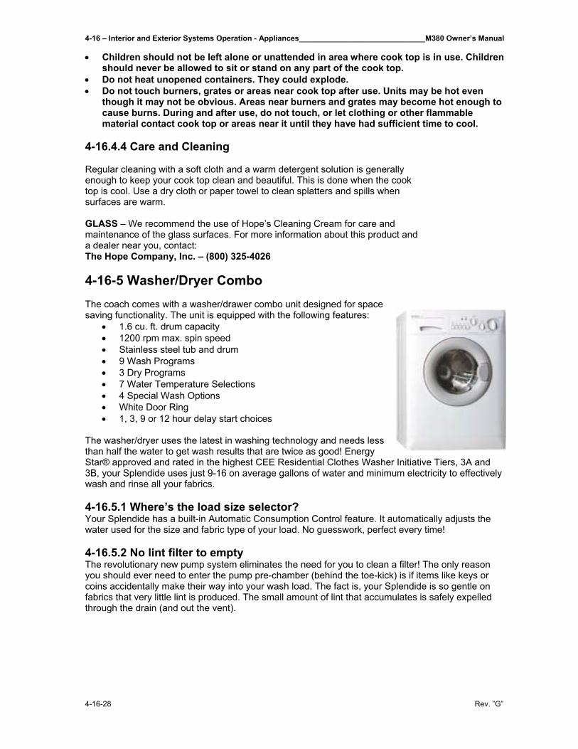
4-16 – Interior and Exterior Systems Operation - Appliances______________________________M380 Owner’s Manual
4-16-28 Rev. ”G”
• Children should not be left alone or unattended in area where cook top is in use. Children should never be allowed to sit or stand on any part of the cook top.
• Do not heat unopened containers. They could explode. • Do not touch burners, grates or areas near cook top after use. Units may be hot even
though it may not be obvious. Areas near burners and grates may become hot enough to cause burns. During and after use, do not touch, or let clothing or other flammable material contact cook top or areas near it until they have had sufficient time to cool.
4-16.4.4 Care and Cleaning Regular cleaning with a soft cloth and a warm detergent solution is generally enough to keep your cook top clean and beautiful. This is done when the cook top is cool. Use a dry cloth or paper towel to clean splatters and spills when surfaces are warm. GLASS – We recommend the use of Hope’s Cleaning Cream for care and maintenance of the glass surfaces. For more information about this product and a dealer near you, contact: The Hope Company, Inc. – (800) 325-4026 4-16-5 Washer/Dryer Combo The coach comes with a washer/drawer combo unit designed for space saving functionality. The unit is equipped with the following features:
• 1.6 cu. ft. drum capacity • 1200 rpm max. spin speed • Stainless steel tub and drum • 9 Wash Programs • 3 Dry Programs • 7 Water Temperature Selections • 4 Special Wash Options • White Door Ring • 1, 3, 9 or 12 hour delay start choices
The washer/dryer uses the latest in washing technology and needs less than half the water to get wash results that are twice as good! Energy Star® approved and rated in the highest CEE Residential Clothes Washer Initiative Tiers, 3A and 3B, your Splendide uses just 9-16 on average gallons of water and minimum electricity to effectively wash and rinse all your fabrics. 4-16.5.1 Where’s the load size selector? Your Splendide has a built-in Automatic Consumption Control feature. It automatically adjusts the water used for the size and fabric type of your load. No guesswork, perfect every time! 4-16.5.2 No lint filter to empty The revolutionary new pump system eliminates the need for you to clean a filter! The only reason you should ever need to enter the pump pre-chamber (behind the toe-kick) is if items like keys or coins accidentally make their way into your wash load. The fact is, your Splendide is so gentle on fabrics that very little lint is produced. The small amount of lint that accumulates is safely expelled through the drain (and out the vent).
M380 Owner’s Manual_______________________________Interior and Exterior Systems Operation - Appliances- 4-16
Rev. “G” 4-16-29
4-16.5.3 What kind of detergent should be used? Use only detergents that are “low-sudsing” to prevent excess foam from building up and spilling out over the floor. These detergents are sometimes called HE or “High Efficiency” power detergents. You only need to use 1 to 2 tablespoons of powder to get your laundry spotlessly clean. Using liquid detergents is not recommended because they produce too much foam. But, if you prefer to use a liquid detergent, do not use more than 1 tablespoon.
Splendide recommends you use their washing powder available at http://www.splendide.com/accessories.htm So advantages to using this powder are:
• 100% Natural • Super-concentrated • RV/Marine Septic & Gray Water Safe • Low Sudsing, Quick Dissolving • Safe for Sensitive Skin • Protects Your Machine

M380 Owner’s Manual__________________________________________________________________________________
Rev. “F”
THIS PAGE IS INTENTIONALLY LEFT BLANK
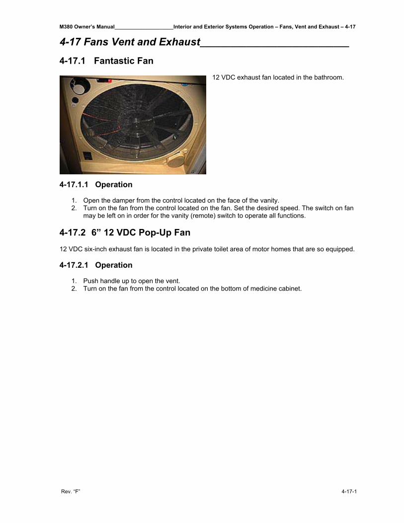
M380 Owner’s Manual____________________Interior and Exterior Systems Operation – Fans, Vent and Exhaust – 4-17
Rev. “F” 4-17-1
4-17 Fans Vent and Exhaust_____________________________
4-17.1 Fantastic Fan
12 VDC exhaust fan located in the bathroom.
4-17.1.1 Operation
1. Open the damper from the control located on the face of the vanity. 2. Turn on the fan from the control located on the fan. Set the desired speed. The switch on fan
may be left on in order for the vanity (remote) switch to operate all functions.
4-17.2 6” 12 VDC Pop-Up Fan 12 VDC six-inch exhaust fan is located in the private toilet area of motor homes that are so equipped. 4-17.2.1 Operation
1. Push handle up to open the vent. 2. Turn on the fan from the control located on the bottom of medicine cabinet.

M380 Owner’s Manual__________________________________________________________________________________
Rev. “F”
THIS PAGE IS INTENTIONALLY LEFT BLANK
M380 Owner’s Manual________________Interior and Exterior Systems Operation – Video and Audio Equipment – 4-18
Rev. “G” 4-18-1
4-18 Video and Audio Equipment ____________________________ Each motor home comes equipped with a Kenwood Sirrius Satellite Ready Radio and a Bose 3-2-1 Home Entertainment System. 4-18.1 Bose 3-2-1 Home Entertainment System Your motor home also comes equipped with a Bose 3-2-1 CD, DVD & Radio with surround sound. This has 2 speakers and 1 sub-woofer. 4-18.1.1 Basic Operation The Bose® 3-2-1 home entertainment system offers superb sound, elegance, and simplicity in an advanced home audio setup. Using Bose proprietary signal processing technology, the 3-2-1 system provides improved spaciousness from stereo recordings, and bold movie effects from surround-encoded materials. Yet its few parts require little labor to set up, so you can enjoy your new system’s performance right away. Your system includes: • Integrated AM/FM tuner and DVD/CD player in a small console • Small, easy-to-place shelf speakers and an attractive floor-standing Acoustimass® module • Easy-to-use infrared remote control • Console input jacks for connecting other source components (such as a VCR, DSS, CD
changer, or tape deck) Picking out discs – The DVD/CD player built into the 3-2-1 media center can play the following types of discs identified by the corresponding logo: • Video DVDs • Audio CDs • CD-R and CD-R/Ws • MP3 on CD NOTE: For complete connection directions and for directions on connecting additional equipment to your system refer to the Bose Manual in your owner kit. Check for region code compatibility For any DVD player and DVD disc to be compatible, their region code numbers must match. These numbers are allocated according to where the player and disc are sold. Check the region code number on the bottom of the media center. Then be sure to choose only DVD discs that show the same region number on the disc label or front cover. For example, a Region 1 DVD player should display the following mark 4-18.1.2 Using your 3-2-1 System
Press the On/Off button on the remote control to turn the media center on. There is a similar Power button located on the top of the media center. NOTE: To turn on components connected to the media center, use the remote for that specific component or its power switch. Neither the Model 3-2-1 remote nor the media center can turn components, such as the TV or a VCR, on or off. However, you do have the option of using a universal remote (new enough to include codes for the Bose Model 3-2-1 System) or a programmable “learning” remote to control this system.
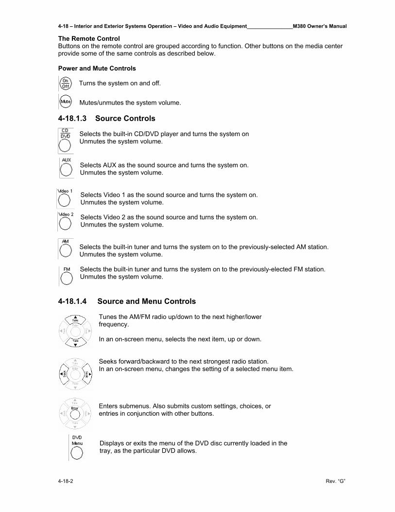
4-18 – Interior and Exterior Systems Operation – Video and Audio Equipment________________M380 Owner’s Manual
4-18-2 Rev. “G”
The Remote Control Buttons on the remote control are grouped according to function. Other buttons on the media center provide some of the same controls as described below. Power and Mute Controls
Turns the system on and off.
Mutes/unmutes the system volume.
4-18.1.3 Source Controls Selects the built-in CD/DVD player and turns the system on Unmutes the system volume.
Selects AUX as the sound source and turns the system on. Unmutes the system volume.
Selects Video 1 as the sound source and turns the system on. Unmutes the system volume.
Selects Video 2 as the sound source and turns the system on. Unmutes the system volume.
Selects the built-in tuner and turns the system on to the previously-selected AM station. Unmutes the system volume.
Selects the built-in tuner and turns the system on to the previously-elected FM station. Unmutes the system volume.
4-18.1.4 Source and Menu Controls
Tunes the AM/FM radio up/down to the next higher/lower frequency. In an on-screen menu, selects the next item, up or down. Seeks forward/backward to the next strongest radio station. In an on-screen menu, changes the setting of a selected menu item. Enters submenus. Also submits custom settings, choices, or entries in conjunction with other buttons.
Displays or exits the menu of the DVD disc currently loaded in the tray, as the particular DVD allows.
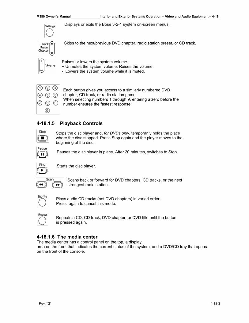
M380 Owner’s Manual________________Interior and Exterior Systems Operation – Video and Audio Equipment – 4-18
Rev. “G” 4-18-3
Displays or exits the Bose 3-2-1 system on-screen menus. Skips to the next/previous DVD chapter, radio station preset, or CD track. Raises or lowers the system volume. + Unmutes the system volume. Raises the volume. - Lowers the system volume while it is muted.
Each button gives you access to a similarly numbered DVD chapter, CD track, or radio station preset. When selecting numbers 1 through 9, entering a zero before the number ensures the fastest response.
4-18.1.5 Playback Controls
Stops the disc player and, for DVDs only, temporarily holds the place where the disc stopped. Press Stop again and the player moves to the beginning of the disc. Pauses the disc player in place. After 20 minutes, switches to Stop. Starts the disc player.
Scans back or forward for DVD chapters, CD tracks, or the next strongest radio station.
Plays audio CD tracks (not DVD chapters) in varied order. Press again to cancel this mode. Repeats a CD, CD track, DVD chapter, or DVD title until the button is pressed again.
4-18.1.6 The media center The media center has a control panel on the top, a display area on the front that indicates the current status of the system, and a DVD/CD tray that opens on the front of the console.
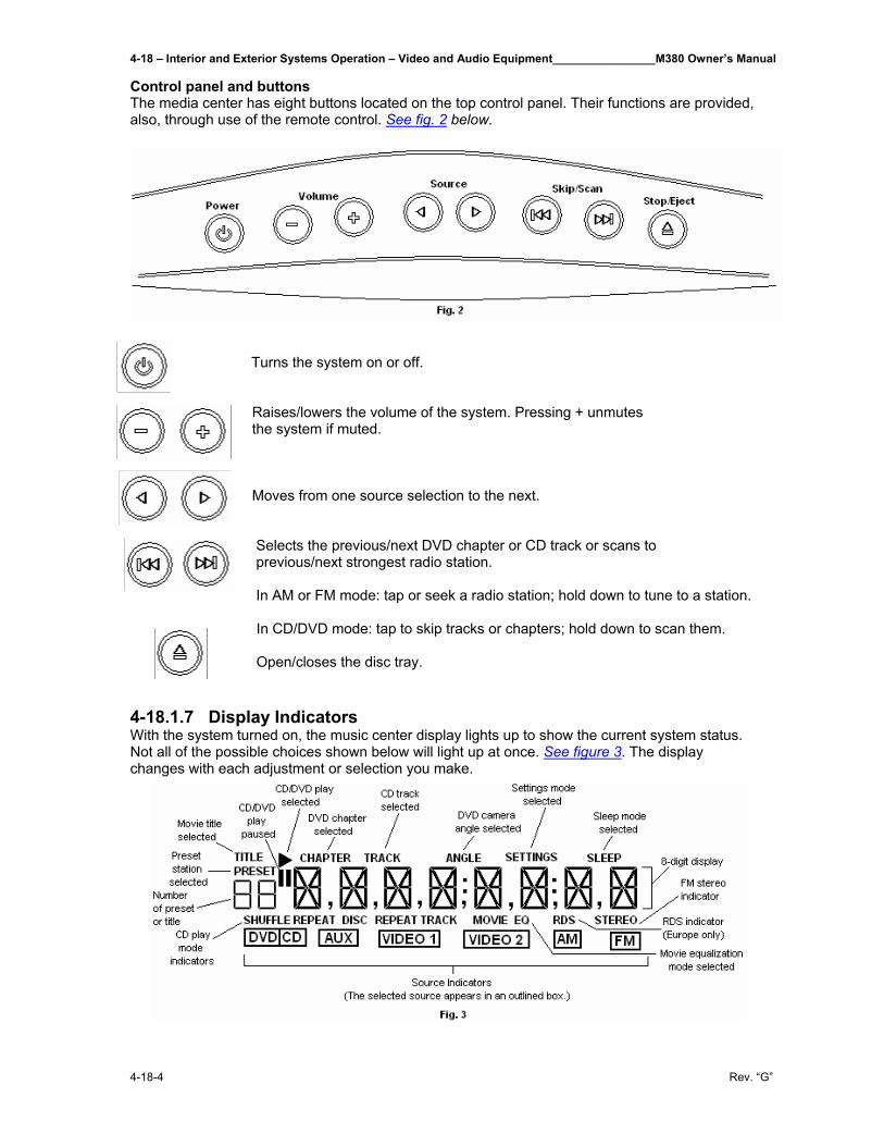
4-18 – Interior and Exterior Systems Operation – Video and Audio Equipment________________M380 Owner’s Manual
4-18-4 Rev. “G”
Control panel and buttons The media center has eight buttons located on the top control panel. Their functions are provided, also, through use of the remote control. See fig. 2 below.
Turns the system on or off.
Raises/lowers the volume of the system. Pressing + unmutes the system if muted. Moves from one source selection to the next. Selects the previous/next DVD chapter or CD track or scans to previous/next strongest radio station. In AM or FM mode: tap or seek a radio station; hold down to tune to a station.
In CD/DVD mode: tap to skip tracks or chapters; hold down to scan them. Open/closes the disc tray.
4-18.1.7 Display Indicators With the system turned on, the music center display lights up to show the current system status. Not all of the possible choices shown below will light up at once. See figure 3. The display changes with each adjustment or selection you make.
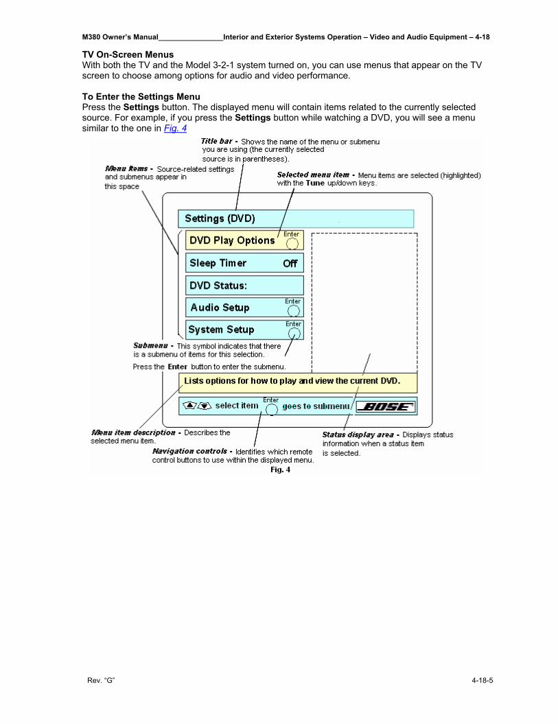
M380 Owner’s Manual________________Interior and Exterior Systems Operation – Video and Audio Equipment – 4-18
Rev. “G” 4-18-5
TV On-Screen Menus With both the TV and the Model 3-2-1 system turned on, you can use menus that appear on the TV screen to choose among options for audio and video performance. To Enter the Settings Menu Press the Settings button. The displayed menu will contain items related to the currently selected source. For example, if you press the Settings button while watching a DVD, you will see a menu similar to the one in Fig. 4
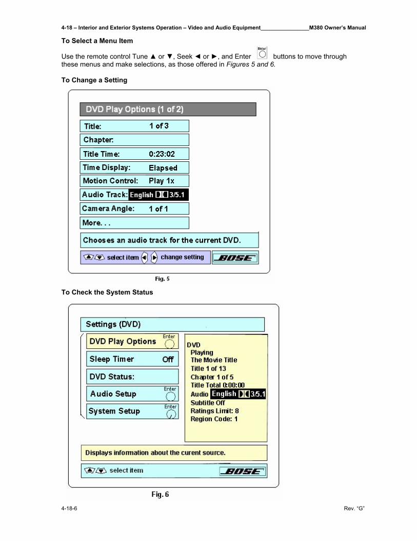
4-18 – Interior and Exterior Systems Operation – Video and Audio Equipment________________M380 Owner’s Manual
4-18-6 Rev. “G”
To Select a Menu Item Use the remote control Tune ▲ or ▼, Seek ◄ or ►, and Enter buttons to move through these menus and make selections, as those offered in Figures 5 and 6. To Change a Setting
To Check the System Status
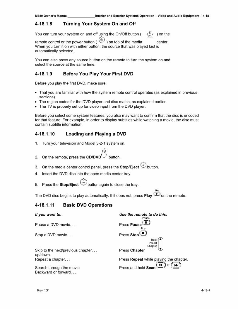
M380 Owner’s Manual________________Interior and Exterior Systems Operation – Video and Audio Equipment – 4-18
Rev. “G” 4-18-7
4-18.1.8 Turning Your System On and Off You can turn your system on and off using the On/Off button ( ) on the
remote control or the power button ( ) on top of the media center. When you turn it on with either button, the source that was played last is automatically selected. You can also press any source button on the remote to turn the system on and select the source at the same time. 4-18.1.9 Before You Play Your First DVD Before you play the first DVD, make sure: • That you are familiar with how the system remote control operates (as explained in previous
sections). • The region codes for the DVD player and disc match, as explained earlier. • The TV is properly set up for video input from the DVD player. Before you select some system features, you also may want to confirm that the disc is encoded for that feature. For example, in order to display subtitles while watching a movie, the disc must contain subtitle information. 4-18.1.10 Loading and Playing a DVD 1. Turn your television and Model 3-2-1 system on.
2. On the remote, press the CD/DVD button.
3. On the media center control panel, press the Stop/Eject button.
4. Insert the DVD disc into the open media center tray.
5. Press the Stop/Eject button again to close the tray.
The DVD disc begins to play automatically. If it does not, press Play on the remote. 4-18.1.11 Basic DVD Operations If you want to: Use the remote to do this:
Pause a DVD movie. . . Press Pause
Stop a DVD movie. . . Press Stop
Skip to the next/previous chapter. . . Press Chapter up/down. Repeat a chapter. . . Press Repeat while playing the chapter.
Search through the movie Press and hold Scan Backward or forward. . .
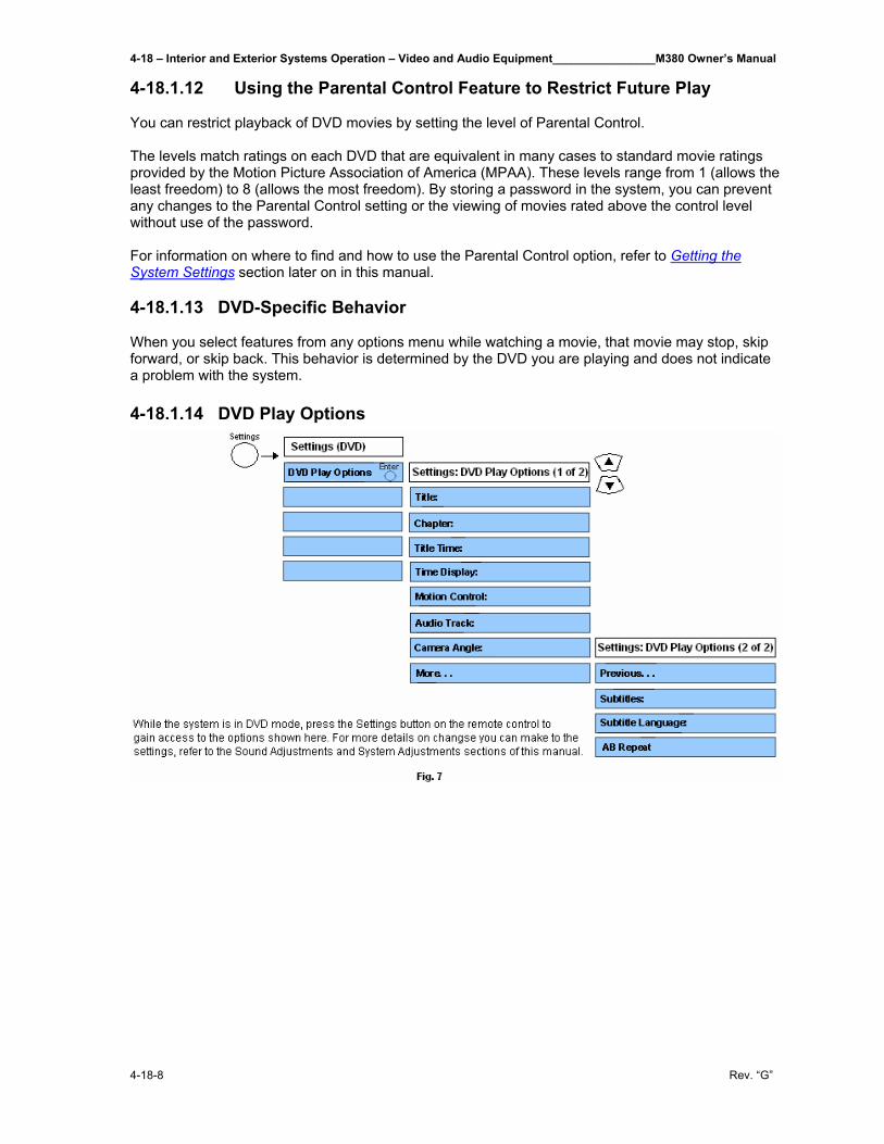
4-18 – Interior and Exterior Systems Operation – Video and Audio Equipment________________M380 Owner’s Manual
4-18-8 Rev. “G”
4-18.1.12 Using the Parental Control Feature to Restrict Future Play You can restrict playback of DVD movies by setting the level of Parental Control. The levels match ratings on each DVD that are equivalent in many cases to standard movie ratings provided by the Motion Picture Association of America (MPAA). These levels range from 1 (allows the least freedom) to 8 (allows the most freedom). By storing a password in the system, you can prevent any changes to the Parental Control setting or the viewing of movies rated above the control level without use of the password. For information on where to find and how to use the Parental Control option, refer to Getting the System Settings section later on in this manual. 4-18.1.13 DVD-Specific Behavior When you select features from any options menu while watching a movie, that movie may stop, skip forward, or skip back. This behavior is determined by the DVD you are playing and does not indicate a problem with the system. 4-18.1.14 DVD Play Options
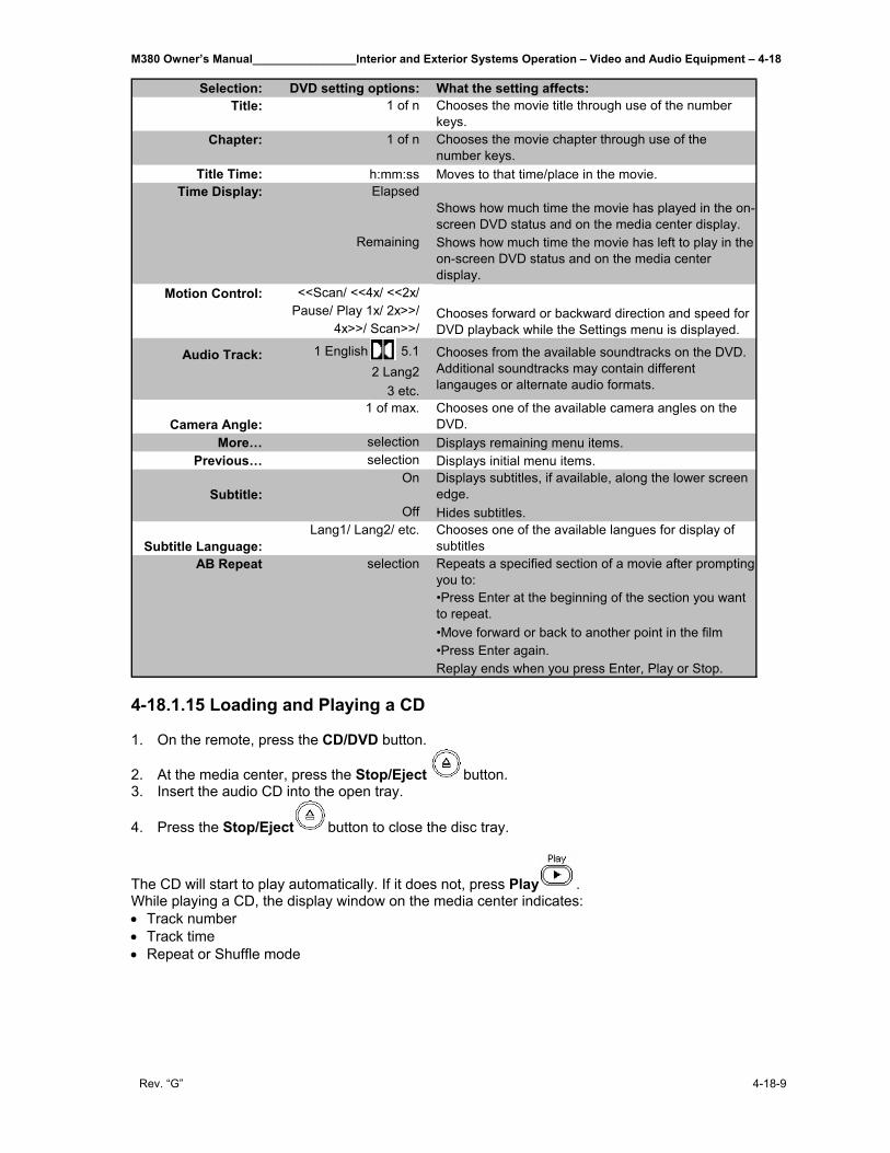
M380 Owner’s Manual________________Interior and Exterior Systems Operation – Video and Audio Equipment – 4-18
Rev. “G” 4-18-9
Selection: DVD setting options: What the setting affects:Title: 1 of n Chooses the movie title through use of the number
keys.Chapter: 1 of n Chooses the movie chapter through use of the
number keys.Title Time: h:mm:ss Moves to that time/place in the movie.
Time Display: ElapsedShows how much time the movie has played in the on-screen DVD status and on the media center display.
Remaining Shows how much time the movie has left to play in the on-screen DVD status and on the media center display.
Motion Control: <<Scan/ <<4x/ <<2x/Pause/ Play 1x/ 2x>>/
4x>>/ Scan>>/
Audio Track: 1 English 5.12 Lang2
3 etc.
Camera Angle:1 of max. Chooses one of the available camera angles on the
DVD.More… selection Displays remaining menu items.
Previous… selection Displays initial menu items.
Subtitle:On Displays subtitles, if available, along the lower screen
edge.Off Hides subtitles.
Subtitle Language:Lang1/ Lang2/ etc. Chooses one of the available langues for display of
subtitlesRepeats a specified section of a movie after prompting you to:•Press Enter at the beginning of the section you want to repeat.•Move forward or back to another point in the film•Press Enter again.Replay ends when you press Enter, Play or Stop.
Chooses from the available soundtracks on the DVD. Additional soundtracks may contain different langauges or alternate audio formats.
Chooses forward or backward direction and speed for DVD playback while the Settings menu is displayed.
selectionAB Repeat
4-18.1.15 Loading and Playing a CD 1. On the remote, press the CD/DVD button.
2. At the media center, press the Stop/Eject button. 3. Insert the audio CD into the open tray.
4. Press the Stop/Eject button to close the disc tray.
The CD will start to play automatically. If it does not, press Play . While playing a CD, the display window on the media center indicates: • Track number • Track time • Repeat or Shuffle mode
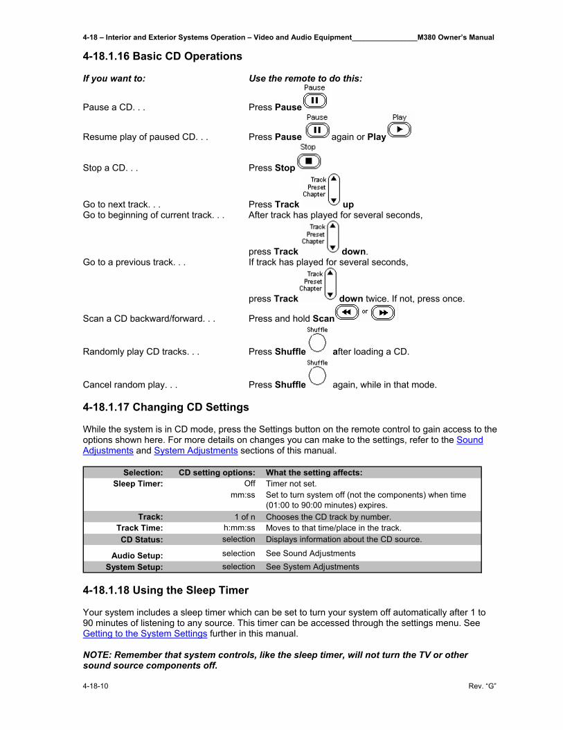
4-18 – Interior and Exterior Systems Operation – Video and Audio Equipment________________M380 Owner’s Manual
4-18-10 Rev. “G”
4-18.1.16 Basic CD Operations If you want to: Use the remote to do this:
Pause a CD. . . Press Pause
Resume play of paused CD. . . Press Pause again or Play
Stop a CD. . . Press Stop
Go to next track. . . Press Track up Go to beginning of current track. . . After track has played for several seconds,
press Track down. Go to a previous track. . . If track has played for several seconds,
press Track down twice. If not, press once.
Scan a CD backward/forward. . . Press and hold Scan
Randomly play CD tracks. . . Press Shuffle after loading a CD.
Cancel random play. . . Press Shuffle again, while in that mode. 4-18.1.17 Changing CD Settings While the system is in CD mode, press the Settings button on the remote control to gain access to the options shown here. For more details on changes you can make to the settings, refer to the Sound Adjustments and System Adjustments sections of this manual.
Selection: CD setting options: What the setting affects:Off Timer not set.
mm:ss Set to turn system off (not the components) when time (01:00 to 90:00 minutes) expires.
Track: 1 of n Chooses the CD track by number.Track Time: h:mm:ss Moves to that time/place in the track.CD Status: selection Displays information about the CD source.
Audio Setup: selection See Sound AdjustmentsSystem Setup: selection See System Adjustments
Sleep Timer:
4-18.1.18 Using the Sleep Timer Your system includes a sleep timer which can be set to turn your system off automatically after 1 to 90 minutes of listening to any source. This timer can be accessed through the settings menu. See Getting to the System Settings further in this manual. NOTE: Remember that system controls, like the sleep timer, will not turn the TV or other sound source components off.
M380 Owner’s Manual________________Interior and Exterior Systems Operation – Video and Audio Equipment – 4-18
Rev. “G” 4-18-11
4-18.1.19 Using the Radio
Press or on the remote to select the radio tuner. If the system is off, this will turn it on to the most recently selected station in that band. Tuning You can tune to a radio station in the following ways: If you want to: Do this:
Switch bands Press or on the remote for the band you want.
Seek the strongest stations Press and hold Seek ◄ or ► on the remote until the radio begins seeking. Release to stop at the next strongest station. To stop sooner, briefly press Seek ◄ or ► again as soon as the first seek operation stops.
Manually tune to a station Press Tune ▲ or ▼ on the remote.
Select a preset station Press Preset or Press that number on the keypad. While the system is in the AM or FM mode, you can press the Settings button on the remote control to gain access to the options available for that band. Your TV should be one, also. For more details on changes you can make to the settings, refer to the Sound Adjustments and System Adjustments sections of this manual. 4-18.1.20 Stored Preferred Stations as Preset Selections For radio stations that you listen to regularly, you can assign a Preset number (1-25 in the AM band and 1-25 in FM) to tune to them quickly. To store a particular station: 1. Tune to that station using the Tune, Seek or Scan buttons on the remote. 2. Press and hold Enter until the media center display blinks and displays a preset number.
• To accept that number assignment for the station, press Enter.
• Select a different number using to assign it to the station. Then press Enter. NOTE: If you want to change the station assigned to a particular preset number, you must first delete the station already assigned to it. To erase the station assigned to a particular preset number: 1. Tune to the station and press Enter. 2. When ERASE? appears on the media center display, press Play or Enter. The preset number should now be available for storing a different station. Selecting a preset station You can select preset stations using the remote control or the on-screen settings menu. To select a preset with the remote control: • Using the numbered keys on the remote control, press the number(s) for the preset station you
want to hear. • Press Preset up or down to change the preset number.
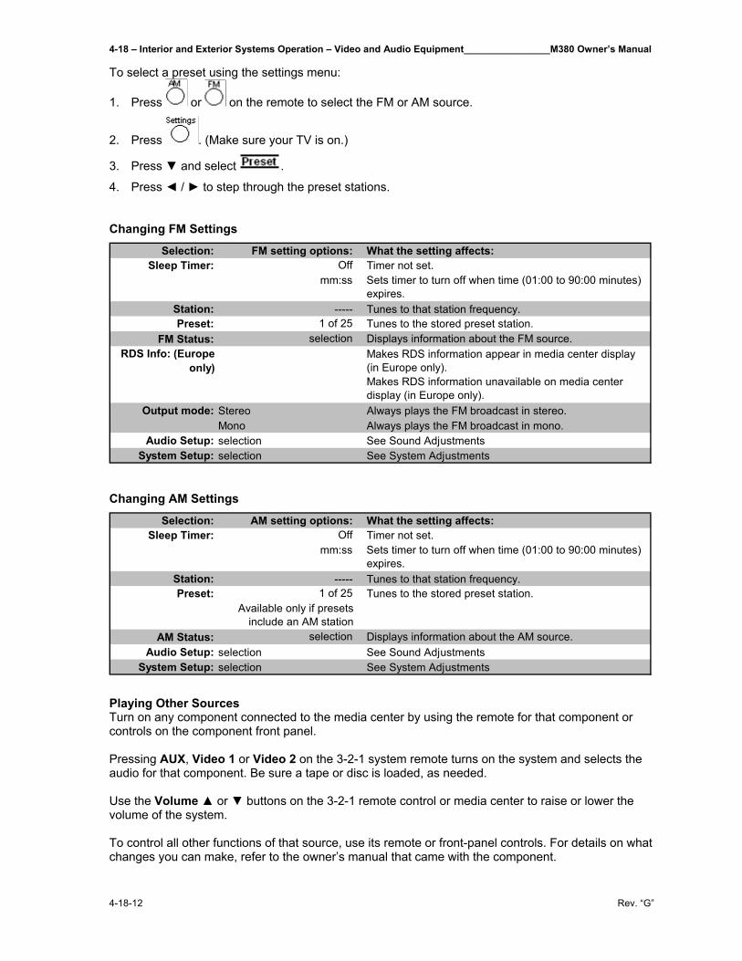
4-18 – Interior and Exterior Systems Operation – Video and Audio Equipment________________M380 Owner’s Manual
4-18-12 Rev. “G”
To select a preset using the settings menu:
1. Press or on the remote to select the FM or AM source.
2. Press . (Make sure your TV is on.)
3. Press ▼ and select .
4. Press ◄ / ► to step through the preset stations.
Changing FM Settings
Selection: FM setting options: What the setting affects:Off Timer not set.
mm:ss Sets timer to turn off when time (01:00 to 90:00 minutes) expires.
Station: ----- Tunes to that station frequency.Preset: 1 of 25 Tunes to the stored preset station.
FM Status: selection Displays information about the FM source.Makes RDS information appear in media center display (in Europe only).Makes RDS information unavailable on media center display (in Europe only).
Output mode: Stereo Always plays the FM broadcast in stereo.Mono Always plays the FM broadcast in mono.
Audio Setup: selection See Sound AdjustmentsSystem Setup: selection See System Adjustments
Sleep Timer:
RDS Info: (Europe only)
Changing AM Settings
Selection: AM setting options: What the setting affects:Off Timer not set.
mm:ss Sets timer to turn off when time (01:00 to 90:00 minutes) expires.
Station: ----- Tunes to that station frequency.Preset: 1 of 25 Tunes to the stored preset station.
Available only if presets include an AM station
AM Status: selection Displays information about the AM source.Audio Setup: selection See Sound Adjustments
System Setup: selection See System Adjustments
Sleep Timer:
Playing Other Sources Turn on any component connected to the media center by using the remote for that component or controls on the component front panel. Pressing AUX, Video 1 or Video 2 on the 3-2-1 system remote turns on the system and selects the audio for that component. Be sure a tape or disc is loaded, as needed. Use the Volume ▲ or ▼ buttons on the 3-2-1 remote control or media center to raise or lower the volume of the system. To control all other functions of that source, use its remote or front-panel controls. For details on what changes you can make, refer to the owner’s manual that came with the component.
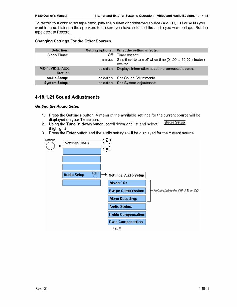
M380 Owner’s Manual________________Interior and Exterior Systems Operation – Video and Audio Equipment – 4-18
Rev. “G” 4-18-13
To record to a connected tape deck, play the built-in or connected source (AM/FM, CD or AUX) you want to tape. Listen to the speakers to be sure you have selected the audio you want to tape. Set the tape deck to Record. Changing Settings For the Other Sources
Selection: Setting options: What the setting affects:Off Timer not set.
mm:ss Sets timer to turn off when time (01:00 to 90:00 minutes) expires.
VID 1, VID 2, AUX Status:
selection Displays information about the connected source.
Audio Setup: selection See Sound AdjustmentsSystem Setup: selection See System Adjustments
Sleep Timer:
4-18.1.21 Sound Adjustments Getting the Audio Setup
1. Press the Settings button. A menu of the available settings for the current source will be displayed on your TV screen.
2. Using the Tune ▼ down button, scroll down and list and select (highlight)
3. Press the Enter button and the audio settings will be displayed for the current source.
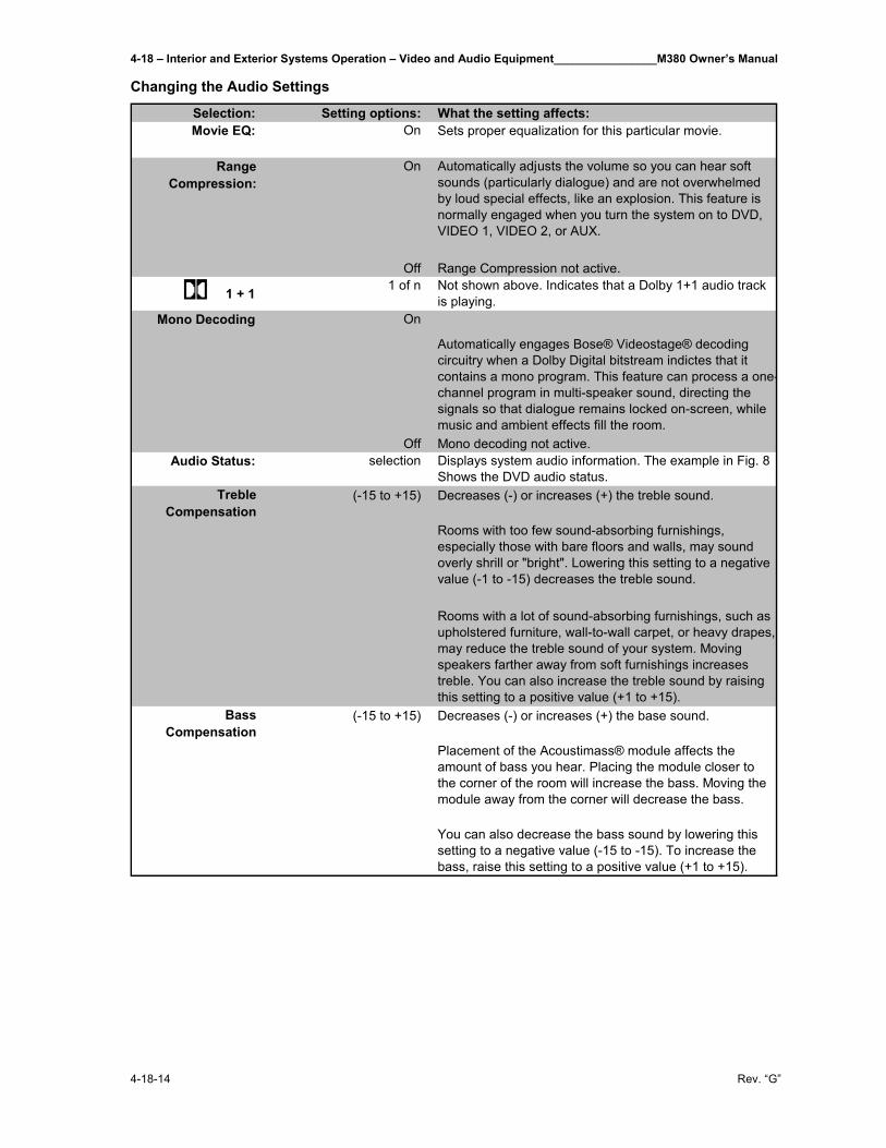
4-18 – Interior and Exterior Systems Operation – Video and Audio Equipment________________M380 Owner’s Manual
4-18-14 Rev. “G”
Changing the Audio Settings
Selection: Setting options: What the setting affects:On Sets proper equalization for this particular movie.
On Automatically adjusts the volume so you can hear soft sounds (particularly dialogue) and are not overwhelmed by loud special effects, like an explosion. This feature is normally engaged when you turn the system on to DVD, VIDEO 1, VIDEO 2, or AUX.
Off Range Compression not active.
1 + 1 1 of n Not shown above. Indicates that a Dolby 1+1 audio track is playing.
On
Automatically engages Bose® Videostage® decoding circuitry when a Dolby Digital bitstream indictes that it contains a mono program. This feature can process a one-channel program in multi-speaker sound, directing the signals so that dialogue remains locked on-screen, while music and ambient effects fill the room.
Off Mono decoding not active.Audio Status: selection Displays system audio information. The example in Fig. 8
Shows the DVD audio status.(-15 to +15) Decreases (-) or increases (+) the treble sound.
Rooms with too few sound-absorbing furnishings, especially those with bare floors and walls, may sound overly shrill or "bright". Lowering this setting to a negative value (-1 to -15) decreases the treble sound.
Rooms with a lot of sound-absorbing furnishings, such as upholstered furniture, wall-to-wall carpet, or heavy drapes, may reduce the treble sound of your system. Moving speakers farther away from soft furnishings increases treble. You can also increase the treble sound by raising this setting to a positive value (+1 to +15).
(-15 to +15) Decreases (-) or increases (+) the base sound.
Placement of the Acoustimass® module affects the amount of bass you hear. Placing the module closer to the corner of the room will increase the bass. Moving the module away from the corner will decrease the bass.
You can also decrease the bass sound by lowering this setting to a negative value (-15 to -15). To increase the bass, raise this setting to a positive value (+1 to +15).
Bass Compensation
Movie EQ:
Range Compression:
Mono Decoding
Treble Compensation
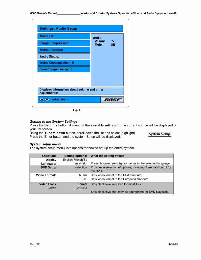
M380 Owner’s Manual________________Interior and Exterior Systems Operation – Video and Audio Equipment – 4-18
Rev. “G” 4-18-15
Getting to the System Settings Press the Settings button. A menu of the available settings for the current source will be displayed on your TV screen. Using the Tune▼ down button, scroll down the list and select (highlight) Press the Enter button and the system Setup will be displayed. System setup menu The system setup menu lists options for how to set up the entire system.
Selection: Setting options: What the setting affects:Display
Language:English/French/Sp
anish/etc. Presents on-screen display menus in the selected language.DVD Setup selection Provides a selection of options, including Parental Control for
the DVD.NTSC Sets video format to the USA standard.
PAL Sets video format to the European standard.
Normal Sets black level required for most TVs.Extended
Sets black level that may be appropriate for DVD playback.
Video Format:
Video Black Level:
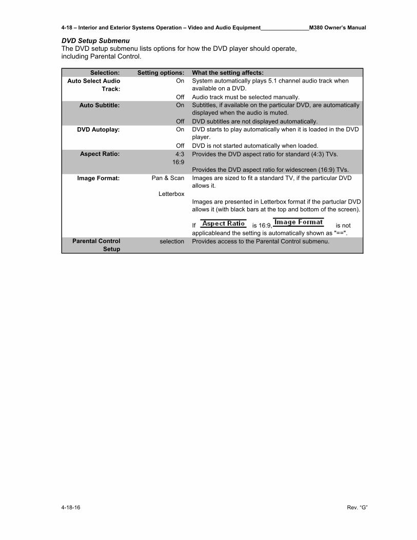
4-18 – Interior and Exterior Systems Operation – Video and Audio Equipment________________M380 Owner’s Manual
4-18-16 Rev. “G”
DVD Setup Submenu The DVD setup submenu lists options for how the DVD player should operate, including Parental Control.
Selection: Setting options: What the setting affects:On System automatically plays 5.1 channel audio track when
available on a DVD.Off Audio track must be selected manually.On Subtitles, if available on the particular DVD, are automatically
displayed when the audio is muted.Off DVD subtitles are not displayed automatically.On DVD starts to play automatically when it is loaded in the DVD
player.Off DVD is not started automatically when loaded.4:3 Provides the DVD aspect ratio for standard (4:3) TVs.
16:9Provides the DVD aspect ratio for widescreen (16:9) TVs.
Pan & Scan Images are sized to fit a standard TV, if the particular DVD allows it.
LetterboxImages are presented in Letterbox format if the partuclar DVD allows it (with black bars at the top and bottom of the screen).
If is 16:9, is not applicableand the setting is automatically shown as "==".
Parental Control Setup
selection Provides access to the Parental Control submenu.
Image Format:
Auto Select Audio Track:
Auto Subtitle:
DVD Autoplay:
Aspect Ratio:
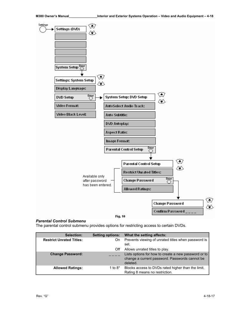
M380 Owner’s Manual________________Interior and Exterior Systems Operation – Video and Audio Equipment – 4-18
Rev. “G” 4-18-17
Parental Control Submenu The parental control submenu provides options for restricting access to certain DVDs.
Selection: Setting options: What the setting affects:On Prevents viewing of unrated titles when password is
set.Off Allows unrated titles to play.
Change Password: _ _ _ _ Lists options for how to create a new password or to change a current password. Passwords cannot be deleted.
Allowed Ratings: 1 to 8* Blocks access to DVDs rated higher than the limit. Rating 8 means no restriction.
Restrict Unrated Titles:
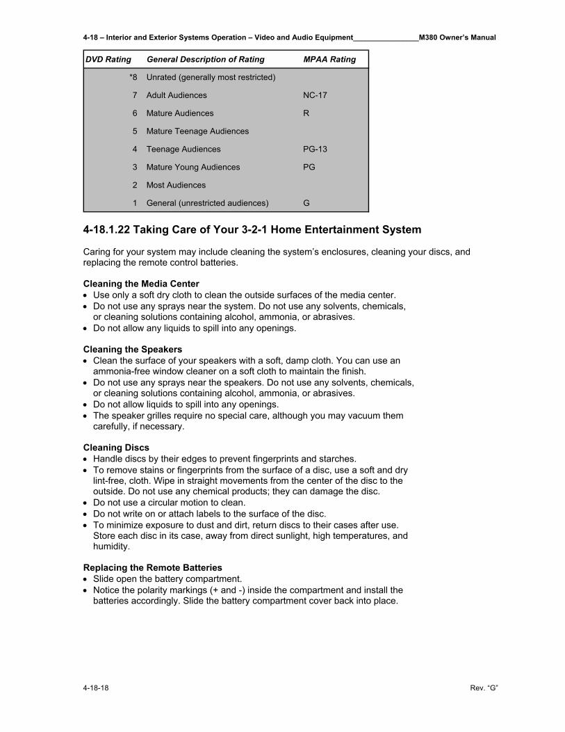
4-18 – Interior and Exterior Systems Operation – Video and Audio Equipment________________M380 Owner’s Manual
4-18-18 Rev. “G”
DVD Rating General Description of Rating MPAA Rating
*8 Unrated (generally most restricted)
7 Adult Audiences NC-17
6 Mature Audiences R
5 Mature Teenage Audiences
4 Teenage Audiences PG-13
3 Mature Young Audiences PG
2 Most Audiences
1 General (unrestricted audiences) G
4-18.1.22 Taking Care of Your 3-2-1 Home Entertainment System Caring for your system may include cleaning the system’s enclosures, cleaning your discs, and replacing the remote control batteries. Cleaning the Media Center • Use only a soft dry cloth to clean the outside surfaces of the media center. • Do not use any sprays near the system. Do not use any solvents, chemicals,
or cleaning solutions containing alcohol, ammonia, or abrasives. • Do not allow any liquids to spill into any openings. Cleaning the Speakers • Clean the surface of your speakers with a soft, damp cloth. You can use an
ammonia-free window cleaner on a soft cloth to maintain the finish. • Do not use any sprays near the speakers. Do not use any solvents, chemicals,
or cleaning solutions containing alcohol, ammonia, or abrasives. • Do not allow liquids to spill into any openings. • The speaker grilles require no special care, although you may vacuum them
carefully, if necessary. Cleaning Discs • Handle discs by their edges to prevent fingerprints and starches. • To remove stains or fingerprints from the surface of a disc, use a soft and dry
lint-free, cloth. Wipe in straight movements from the center of the disc to the outside. Do not use any chemical products; they can damage the disc.
• Do not use a circular motion to clean. • Do not write on or attach labels to the surface of the disc. • To minimize exposure to dust and dirt, return discs to their cases after use.
Store each disc in its case, away from direct sunlight, high temperatures, and humidity.
Replacing the Remote Batteries • Slide open the battery compartment. • Notice the polarity markings (+ and -) inside the compartment and install the
batteries accordingly. Slide the battery compartment cover back into place.
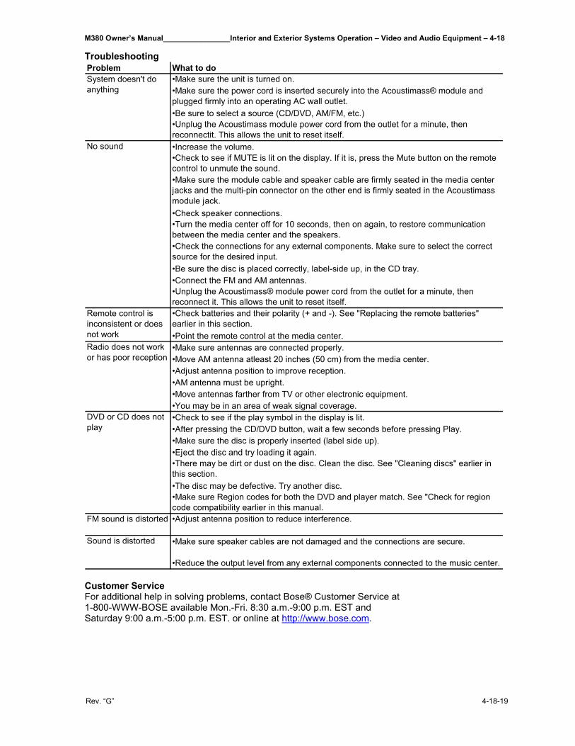
M380 Owner’s Manual________________Interior and Exterior Systems Operation – Video and Audio Equipment – 4-18
Rev. “G” 4-18-19
Troubleshooting Problem What to do
•Make sure the unit is turned on.•Make sure the power cord is inserted securely into the Acoustimass® module and plugged firmly into an operating AC wall outlet.•Be sure to select a source (CD/DVD, AM/FM, etc.)•Unplug the Acoustimass module power cord from the outlet for a minute, then reconnectit. This allows the unit to reset itself.•Increase the volume.•Check to see if MUTE is lit on the display. If it is, press the Mute button on the remote control to unmute the sound.•Make sure the module cable and speaker cable are firmly seated in the media center jacks and the multi-pin connector on the other end is firmly seated in the Acoustimass module jack.•Check speaker connections.•Turn the media center off for 10 seconds, then on again, to restore communication between the media center and the speakers.•Check the connections for any external components. Make sure to select the correct source for the desired input.•Be sure the disc is placed correctly, label-side up, in the CD tray.•Connect the FM and AM antennas.•Unplug the Acoustimass® module power cord from the outlet for a minute, then reconnect it. This allows the unit to reset itself.•Check batteries and their polarity (+ and -). See "Replacing the remote batteries" earlier in this section.•Point the remote control at the media center.•Make sure antennas are connected properly.•Move AM antenna atleast 20 inches (50 cm) from the media center.•Adjust antenna position to improve reception.•AM antenna must be upright.•Move antennas farther from TV or other electronic equipment.•You may be in an area of weak signal coverage.•Check to see if the play symbol in the display is lit.•After pressing the CD/DVD button, wait a few seconds before pressing Play.•Make sure the disc is properly inserted (label side up).•Eject the disc and try loading it again.•There may be dirt or dust on the disc. Clean the disc. See "Cleaning discs" earlier in this section.•The disc may be defective. Try another disc.•Make sure Region codes for both the DVD and player match. See "Check for region code compatibility earlier in this manual.
FM sound is distorted •Adjust antenna position to reduce interference.
•Make sure speaker cables are not damaged and the connections are secure.
•Reduce the output level from any external components connected to the music center.
DVD or CD does not play
Sound is distorted
System doesn't do anything
No sound
Remote control is inconsistent or does not workRadio does not work or has poor reception
Customer Service For additional help in solving problems, contact Bose® Customer Service at 1-800-WWW-BOSE available Mon.-Fri. 8:30 a.m.-9:00 p.m. EST and Saturday 9:00 a.m.-5:00 p.m. EST. or online at http://www.bose.com.
4-18 – Interior and Exterior Systems Operation – Video and Audio Equipment________________M380 Owner’s Manual
4-18-20 Rev. “G”
4-18.2 The Kenwood Sirius Satellite Ready Radio This system is mounted in the driver area and is satellite ready. There is an optional receiver owner can purchase to pick up satellite radio stations. This is a AM/FM/Single Play CD/Cassette radio and a four-channel amplifier with a total power output of 200 watts driving two satellite speakers located in the living/kitchen areas. The stereo television is also coupled into this system. This unit can play MP3 (MPEG1, 2, 2.5 Audio Layer 3). Note, however, that the MP3 recording media and formats acceptable are limited. When writing MP3, pay attention to the following restrictions. 4-18.2.1 General Information Acceptable Media The MP3 recording media acceptable to this unit are CD-ROM, CD-R, and CD-RW. When using CD-RW, do full format not quick format to prevent malfunction. Acceptable Medium Formats The following formats are available for the media used in this unit. The maximum number of characters used for file name including the delimiter (“.”) and three-character extension are indicated in parentheses. • ISO 9660 Level 1 (12 characters) • ISO 9660 Level 2 (31 characters) • Joliet (64 characters) • Romeo (128 characters) Up to 200 characters can be displayed in the long file name format. For a list of available characters see the instruction manual of the writing software and the section Entering file and folder names below. The media reproducible on this unit has the following limitations: • Maximum number of directory levels: 8 • Maximum number of files per folder: 255 • Maximum number of characters for folder name: 64 • Maximum number of folders: 50 MP3 written in the formats other than the above may not be successfully played and their file names or folder names are not properly displayed. Settings For Your MP3 Encoder and CD Writer Do the following setting when compressing audio data in MP3 data with the MP3 encoder.
• Transfer bit rate: 8-320 kbps • Sampling frequency: 8, 11.025, 12, 16, 22.05, 24, 32, 44.1, 48 kHz
When you use your CD writer to record MP3 up to the maximum disc capacity, disable additional writing. For recording on an empty disc up to the maximum capacity at once, check Disc at Once.
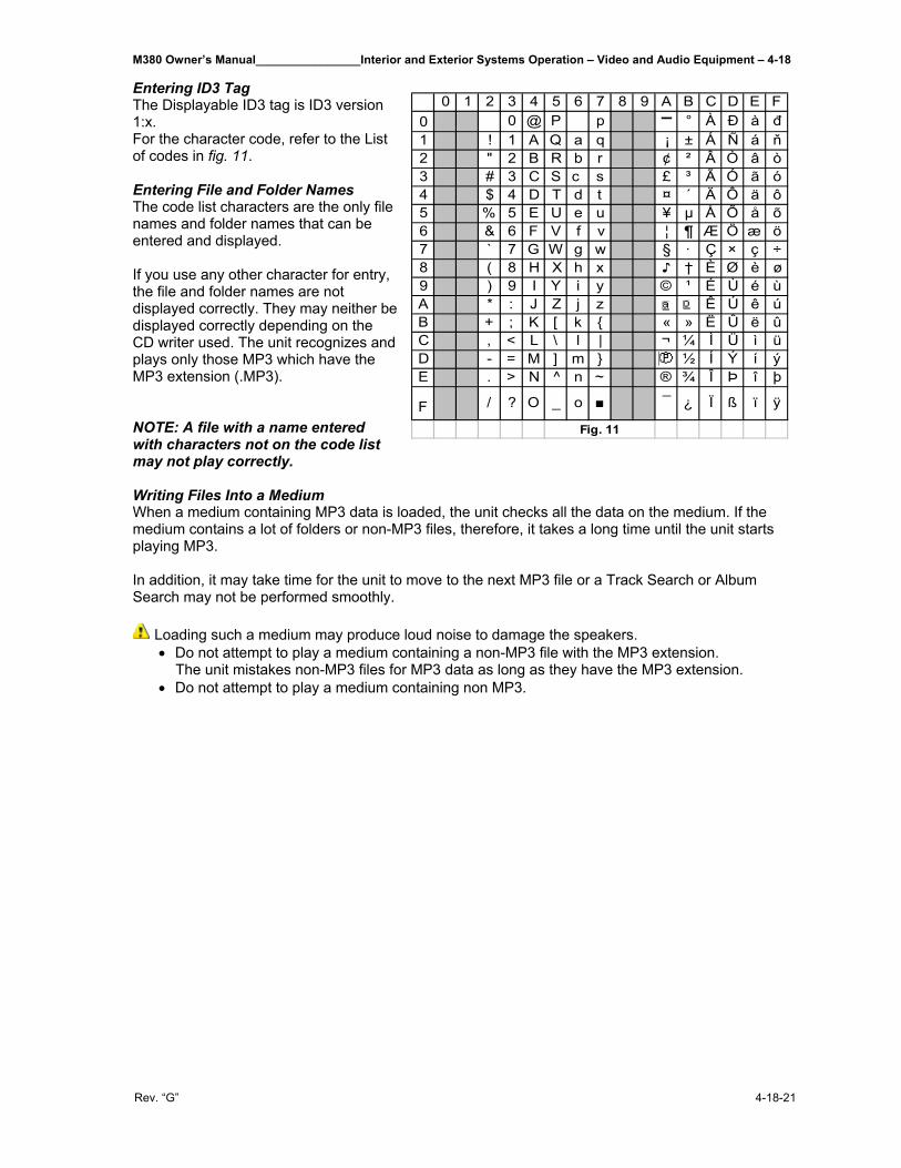
M380 Owner’s Manual________________Interior and Exterior Systems Operation – Video and Audio Equipment – 4-18
Rev. “G” 4-18-21
Entering ID3 Tag The Displayable ID3 tag is ID3 version 1:x. For the character code, refer to the List of codes in fig. 11. Entering File and Folder Names The code list characters are the only file names and folder names that can be entered and displayed. If you use any other character for entry, the file and folder names are not displayed correctly. They may neither be displayed correctly depending on the CD writer used. The unit recognizes and plays only those MP3 which have the MP3 extension (.MP3). NOTE: A file with a name entered with characters not on the code list may not play correctly. Writing Files Into a Medium When a medium containing MP3 data is loaded, the unit checks all the data on the medium. If the medium contains a lot of folders or non-MP3 files, therefore, it takes a long time until the unit starts playing MP3. In addition, it may take time for the unit to move to the next MP3 file or a Track Search or Album Search may not be performed smoothly.
Loading such a medium may produce loud noise to damage the speakers. • Do not attempt to play a medium containing a non-MP3 file with the MP3 extension. The unit mistakes non-MP3 files for MP3 data as long as they have the MP3 extension. • Do not attempt to play a medium containing non MP3.
0 1 2 3 4 5 6 7 8 9 A B C D E F0 0 @ P p ▬ ° À Đ à đ1 ! 1 A Q a q ¡ ± Á Ñ á ň2 " 2 B R b r ¢ ² Â Ò â ò3 # 3 C S c s £ ³ Ã Ó ã ó4 $ 4 D T d t ¤ ´ Ä Ô ä ô5 % 5 E U e u ¥ µ Å Õ å õ6 & 6 F V f v ¦ ¶ Æ Ö æ ö7 ` 7 G W g w § · Ç × ç ÷8 ( 8 H X h x ♪ † È Ø è ø9 ) 9 I Y i y © ¹ É Ù é ùA * : J Z j z Ê Ú ê úB + ; K [ k { « » Ë Û ë ûC , < L \ l | ¬ ¼ Ì Ü ì üD - = M ] m } ½ Í Ý í ýE . > N ^ n ~ ® ¾ Î Þ î þ
F / ? O _ o ■ ¯ ¿ Ï ß ï ÿ
Fig. 11
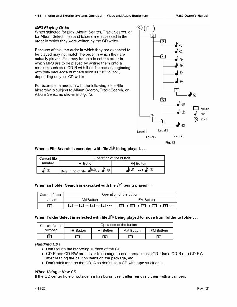
4-18 – Interior and Exterior Systems Operation – Video and Audio Equipment________________M380 Owner’s Manual
4-18-22 Rev. “G”
MP3 Playing Order When selected for play, Album Search, Track Search, or for Album Select, files and folders are accessed in the order in which they were written by the CD writer. Because of this, the order in which they are expected to be played may not match the order in which they are actually played. You may be able to set the order in which MP3 are to be played by writing them onto a medium such as a CD-R with their file names beginning with play sequence numbers such as “01” to “99”, depending on your CD writer. For example, a medium with the following folder/file hierarchy is subject to Album Search, Track Search, or Album Select as shown in Fig. 12. When a File Search is executed with file ♪ being played. . .
When an Folder Search is executed with file ♪ being played. . .
When Folder Select is selected with file ♪ being played to move from folder to folder. . .
Handling CDs • Don’t touch the recording surface of the CD. • CD-R and CD-RW are easier to damage than a normal music CD. Use a CD-R or a CD-RW
after reading the caution items on the package, etc. • Don’t stick tape on the CD. Also don’t use a CD with tape stuck on it.
When Using a New CD If the CD center hole or outside rim has burrs, use it after removing them with a ball pen.
AM Button FM ButtonOperation of the buttonCurrent folder
number
| Button | Button
Beginning of file --> -->
Operation of the buttonCurrent file number
| Button | Button AM Button FM ButtomCurrent folder
numberOperation of the button
M380 Owner’s Manual________________Interior and Exterior Systems Operation – Video and Audio Equipment – 4-18
Rev. “G” 4-18-23
CD Accessories Don’t use disc type accessories. CD Cleaning Clean from the center of the disc and move outward. Removing CDs When removing CDs from this unit pull them out horizontally. CDs That Can’t Be Used • CDs that aren’t round can’t be used. • CDs with coloring on the recording surface or that are dirty can’t be used. • This unit can only play the CDs with the following logos.
It may not correctly play discs which do not have one of these marks. • A CD-R or CD-RW that hasn’t been finalized can’t be played. (For the finalization process refer to
your CD-R/CD-RW writing software, and your CD-R/CD-RW recorder instruction manual.) CD Storage • Don’t place them in direct sunlight (On the seat or dashboard etc.) and where the temperature is
high. • Store CDs in their cases. 4-18.2.2 Basic Operation 4-18.2.2.1 Power Turning On the Power Press the [SRC] button. When the power is ON, the <Security Code> is displayed as “CODE ON” or “CODE OFF” Turning OFF the Power Press the [SRC] button for at least 1 second. 4-18.2.2.2 Selecting the Source Press the [SRC] button.
4-18.2.2.3 Volume Increasing Volume Turn the [VOL] knob clockwise. Decreasing Volume Turn the [VOL] knob counterclockwise
Source required DisplayTuner "TUNER"CD "COMPACT DISC"/CD"External disc (Optional accessory) "DISC-CH"/"DISC"Auxiliary input "AUX"Standby (illumination only mode) "ALL OFF"
4-18 – Interior and Exterior Systems Operation – Video and Audio Equipment________________M380 Owner’s Manual
4-18-24 Rev. “G”
4-18.2.2.4 System Q You can recall the best sound setting preset for different types of music.
1. Select the source to set. Press the [SRC] button.
2. Select the Sound type Press the [System Q] button. Each time the button is pressed the sound setting switches.
NOTE: • User memory: The values set on the <Audio Control> • Each setting value is changed with the <Speaker Setting> First select the speaker type with the Speaker setting. 4-18.2.2.5 Audio Control
1. Select the source for adjustment
Press the [SRC] button.
2. Enter Audio Control mode Press the [AUD] button for at least 1 second.
3. Select the Audio item for adjustment Press the [FM] or [AM] button. Each time the button is pressed the items that can be adjusted switch as shown below.
4. Adjust the Audio Item Press the [| ] or [ |] button.
Source setting DisplayFlat "Flat"/"FLAT"User memory "User"/"USER"Rock "Rock"/"ROCK"Pops "Pops"/"POPS"Easy "Easy"/"EASY"Top 40 "Top 40"/"TOP 40"Jazz "Jazz"/"JAZZ"
M380 Owner’s Manual________________Interior and Exterior Systems Operation – Video and Audio Equipment – 4-18
Rev. “G” 4-18-25
NOTE: • According to the Bass Q Factor setting value, the frequencies that can be set in Bass Center Frequency change as shown below.
• When the bass extend is set to ON, low frequency response is extended by 20%. • Volume offset: Each source’s volume can be set as a difference from the
basic volume. • Loudness: Compensating for low and high tones during low volume. • *Function of the KDC-X569/X469 **Function of the KDC-X569/MP522/MPV622/MPV6022/X469/422/4022 ***Function of the KDC-MP522/MPV622/MPV6022/422/4022
5. Exit Audio Control Mode Press the [AUD] button.
4-18.2.2.6 Speaker Setting Fine-tuning so that the System Q value is optimal when setting the speaker type.
1. Enter Standby Press the [SRC] button. Select the “ALL OFF” display
2. Enter Speaker Setting Mode Press the [System Q] button.
Adjustment Item Display RangeBass CenterFrequencyBass Level "Bass"/"BAS" -8 - +8Bass Q Factor* "Bass Q" 1.00/1.25/1.50/2.00Bass Extend* "Bass EXT" ON/OFFMiddle CenterFrequency*Middle Level "Middle"/"MID" -8 - +8Middle Q Factor "Middle Q" 1.0/2.0Treble CenterFrequency*Treble Level "Treble"/"TRE" -8 - +8Balance "Balance"/"BAL" Left 15 - Right 15Fader "Fader"/"FAD" Rear 15 - Front 15Non-Fading Level* "NF Level" -15 - +15
"HPF F" Through/40/60/80/100/120/150/180/220 Hz
"HPF R" Through/40/60/80/100/120/150/180/220 Hz
Front/Rear High Pass Filter*** "HPF" Through/200 Hz
Non-FadingLow Pass Filter**"V-Offset"/"V-OFF" "V-Offset"/"V-OFF" -8 - 0Loudness "LOUD" ON/OFF
Front High Pass Filter*
Rear High Pass Filter*
"LPF NF" 50/80/120/Through Hz
"TRE F" 10.0/12.5/15.0/17.5 kHz
"Bass F" 60/70/80/100 or 150 Hz
"MID F" 0.5/1.0/1.5/2.0 kHz
Bass Q Factor Bass Center Frequency1.00/1.25/1.50 60/70/80/1002.00 60/70/80/150
4-18 – Interior and Exterior Systems Operation – Video and Audio Equipment________________M380 Owner’s Manual
4-18-26 Rev. “G”
3. Select the Speaker type Press the [| ] or [ |] button. Each time the button is pressed the setting switches as shown below.
In Speaker Setting Mode
4. Exit Speaker Setting mode Press the [System Q] button.
Function of the KDC-X569/MP522/MPV622/MPV6022/469/422/4022 4-18.2.2.7 Non-Fading Output Turning the Non-fading output ON or OFF. Press the [NF] button for at least 1 second. Each time the button is pressed Non-fading output switches ON or OFF. When it’s ON, “NF ON” is displayed. 4-18.2.2.8 Switching Display Switching the information displayed.
Press the [DISP] button. Each time the button is pressed the display switches as shown below.
In Tuner source
In CD & External disc source KDC-X569/MP522/MPV622/MPV6022/X469/422/4022:
KDC-3022/322:
Speaker type DisplayOFF "SP OFF"For 5 & 4 in. speaker "SP 5/4 inch"/"SP 5/4"For 6 & 6x9 in. speaker "SP6*9/6inch"/"SP 6*9/6"For the OEM speaker "SP O.E.M."/"SP OEM"
Information DisplayStation name "SNPS"Frequency "BAND+FREQ"/"BAND+F"Clock
Information DisplayTrack Time "P-Time"Disc Name "DNPS"Disc Title "DISC-TITLE"Track Title "TRACK-TITLE"
Information DisplayDisc title (in External disc source) "D-TITLE"Track title (In External disc source) "T-TITLE"Track number & Play time "P-TIME"Disc name "DNPS"
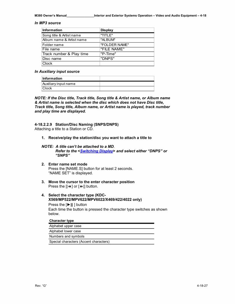
M380 Owner’s Manual________________Interior and Exterior Systems Operation – Video and Audio Equipment – 4-18
Rev. “G” 4-18-27
In MP3 source
In Auxiliary input source
NOTE: If the Disc title, Track title, Song title & Artist name, or Album name & Artist name is selected when the disc which does not have Disc title, Track title, Song title, Album name, or Artist name is played, track number and play time are displayed.
4-18.2.2.9 Station/Disc Naming (SNPS/DNPS) Attaching a title to a Station or CD.
1. Receive/play the station/disc you want to attach a title to NOTE: A title can’t be attached to a MD.
Refer to the <Switching Display> and select either “DNPS” or “SNPS”
2. Enter name set mode
Press the [NAME.S] button for at least 2 seconds. “NAME SET” is displayed.
3. Move the cursor to the enter character position Press the [| ] or [ |] button.
4. Select the character type (KDC-X569/MP522/MPV622/MPV6022/X469/422/4022 only) Press the [►|| ] button Each time the button is pressed the character type switches as shown below.
Information DisplaySong title & Artist name "TITLE"Album name & Artist name "ALBUM"Folder name "FOLDER NAME"File name "FILE NAME"Track number & Play time "P-Time"Disc name "DNPS"Clock
InformationAuxiliary input nameClock
Character typeAlphabet upper caseAlphabet lower caseNumbers and symbolsSpecial characters (Accent characters)
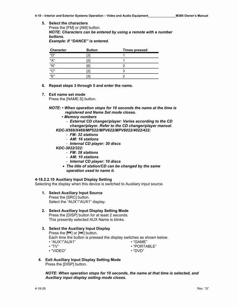
4-18 – Interior and Exterior Systems Operation – Video and Audio Equipment________________M380 Owner’s Manual
4-18-28 Rev. “G”
5. Select the characters Press the [FM] or [AM] button. NOTE: Characters can be entered by using a remote with a number buttons. Example: If “DANCE” is entered.
6. Repeat steps 3 through 5 and enter the name. 7. Exit name set mode
Press the [NAME.S] button. NOTE: • When operation stops for 10 seconds the name at the time is registered and Name Set mode closes. • Memory numbers
- External CD changer/player: Varies according to the CD changer/player. Refer to the CD changer/player manual.
KDC-X569/X469/MP522/MPV622/MPV6022/4022/422: - FM: 32 stations - AM: 16 stations - Internal CD player: 30 discs
KDC-3022/322: - FM: 28 stations - AM: 10 stations - Internal CD player: 10 discs
• The title of station/CD can be changed by the same operation used to name it.
4-18.2.2.10 Auxiliary Input Display Setting Selecting the display when this device is switched to Auxiliary input source.
1. Select Auxiliary Input Source Press the [SRC] button. Select the “AUX”/”AUX1” display.
2. Select Auxiliary Input Display Setting Mode Press the [DISP] button for at least 2 seconds. This presently selected AUX Name is blinks.
3. Select the Auxiliary Input Display Press the [ ] or [ ] button. Each time the button is pressed the display switches as shown below.
• “AUX”/”AUX1” • “TV” • “VIDEO”
• “GAME” • “PORTABLE” • “DVD”
4. Exit Auxiliary Input Display Setting Mode
Press the [DISP] button. NOTE: When operation stops for 10 seconds, the name at that time is selected, and Auxiliary input display setting mode closes.
Character Button Times pressed"D" [3] 1"A" [2] 1"N" [6] 2"C" [2] 3"E" [3] 2
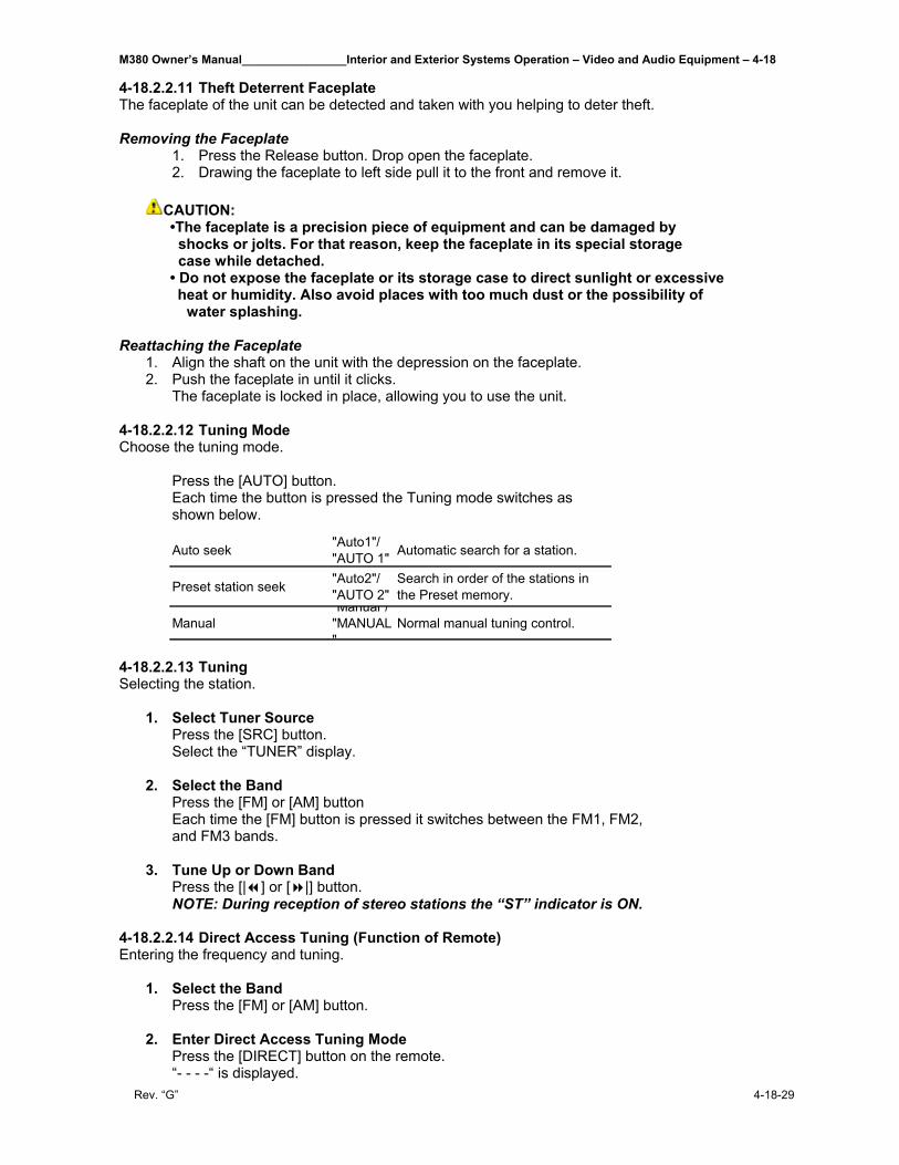
M380 Owner’s Manual________________Interior and Exterior Systems Operation – Video and Audio Equipment – 4-18
Rev. “G” 4-18-29
4-18.2.2.11 Theft Deterrent Faceplate The faceplate of the unit can be detected and taken with you helping to deter theft. Removing the Faceplate
1. Press the Release button. Drop open the faceplate. 2. Drawing the faceplate to left side pull it to the front and remove it.
CAUTION: •The faceplate is a precision piece of equipment and can be damaged by shocks or jolts. For that reason, keep the faceplate in its special storage case while detached. • Do not expose the faceplate or its storage case to direct sunlight or excessive heat or humidity. Also avoid places with too much dust or the possibility of water splashing.
Reattaching the Faceplate 1. Align the shaft on the unit with the depression on the faceplate. 2. Push the faceplate in until it clicks.
The faceplate is locked in place, allowing you to use the unit.
4-18.2.2.12 Tuning Mode Choose the tuning mode. Press the [AUTO] button. Each time the button is pressed the Tuning mode switches as shown below.
4-18.2.2.13 Tuning Selecting the station.
1. Select Tuner Source Press the [SRC] button. Select the “TUNER” display.
2. Select the Band Press the [FM] or [AM] button Each time the [FM] button is pressed it switches between the FM1, FM2, and FM3 bands.
3. Tune Up or Down Band Press the [| ] or [ |] button. NOTE: During reception of stereo stations the “ST” indicator is ON.
4-18.2.2.14 Direct Access Tuning (Function of Remote) Entering the frequency and tuning.
1. Select the Band Press the [FM] or [AM] button.
2. Enter Direct Access Tuning Mode Press the [DIRECT] button on the remote. “- - - -“ is displayed.
Auto seek "Auto1"/ "AUTO 1" Automatic search for a station.
Preset station seek "Auto2"/ "AUTO 2"
Search in order of the stations in the Preset memory.
ManualManual /
"MANUAL"
Normal manual tuning control.

4-18 – Interior and Exterior Systems Operation – Video and Audio Equipment________________M380 Owner’s Manual
4-18-30 Rev. “G”
3. Enter the Frequency Press the number buttons on the remote. Example: Desired frequency Press button92.1 MHz (FM) [0], [9], [2], [1]810 kHz (AM) [0], [8], [1], [0]
Canceling Direct Access Tuning Press the [DIRECT] button on the remote.
4-18.2.2.15 Station Preset Memory Putting the station in the memory.
1. Select the Band Press the [FM] or [AM] button.
2. Select the Frequency to Put in the Memory Press the [| ] or [ |] button.
3. Put the Frequency in the Memory Press the desired [1] - [6] button for at least 2 seconds. The preset number display blinks 1 time. On each band, 1 station can be put in the memory on each [1]-[6] button.
4-18.2.2.16 Auto Memory Entry Putting a station with good reception in the memory automatically.
1. Select the band for Auto Memory Entry Press the [FM] or [AM] button.
2. Open Auto Memory Entry Press the [AME] button for at least 2 seconds. When 6 stations that can be received are put in the memory Auto Memory Entry closes.
4-18.2.2.17 Preset Tuning Calling up the stations in the memory.
1. Select the Band Press the [FM] or [AM] button.
2. Call Up the Station Press the desired [FM] or [AM] button
4-18.2.2.18 Playing CD & MP3 When there is no disc inserted
1. Drop open the faceplate Press the Release button.
2. Insert a Disc. 3. Press the faceplate on the left side, and return it to its former
position.
CAUTION: When the faceplate has been dropped open, it might interfere with the shift lever or something else. If this happens, pay attention to safety and move the shift lever or take an appropriate action, then operate the unit.
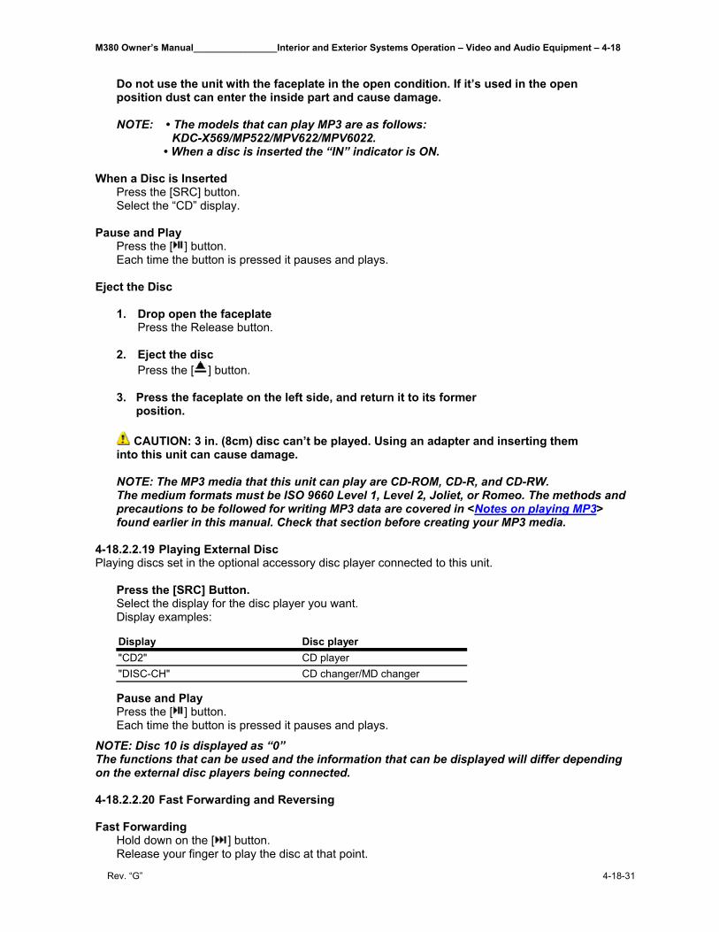
M380 Owner’s Manual________________Interior and Exterior Systems Operation – Video and Audio Equipment – 4-18
Rev. “G” 4-18-31
Do not use the unit with the faceplate in the open condition. If it’s used in the open position dust can enter the inside part and cause damage. NOTE: • The models that can play MP3 are as follows: KDC-X569/MP522/MPV622/MPV6022. • When a disc is inserted the “IN” indicator is ON.
When a Disc is Inserted Press the [SRC] button. Select the “CD” display.
Pause and Play Press the [ ] button. Each time the button is pressed it pauses and plays.
Eject the Disc 1. Drop open the faceplate
Press the Release button.
2. Eject the disc Press the [ ] button.
3. Press the faceplate on the left side, and return it to its former position.
CAUTION: 3 in. (8cm) disc can’t be played. Using an adapter and inserting them
into this unit can cause damage.
NOTE: The MP3 media that this unit can play are CD-ROM, CD-R, and CD-RW. The medium formats must be ISO 9660 Level 1, Level 2, Joliet, or Romeo. The methods and precautions to be followed for writing MP3 data are covered in <Notes on playing MP3> found earlier in this manual. Check that section before creating your MP3 media.
4-18.2.2.19 Playing External Disc Playing discs set in the optional accessory disc player connected to this unit. Press the [SRC] Button. Select the display for the disc player you want.
Display examples:
Pause and Play Press the [ ] button. Each time the button is pressed it pauses and plays.
NOTE: Disc 10 is displayed as “0” The functions that can be used and the information that can be displayed will differ depending on the external disc players being connected. 4-18.2.2.20 Fast Forwarding and Reversing Fast Forwarding Hold down on the [ ] button. Release your finger to play the disc at that point.
Display Disc player"CD2" CD player"DISC-CH" CD changer/MD changer
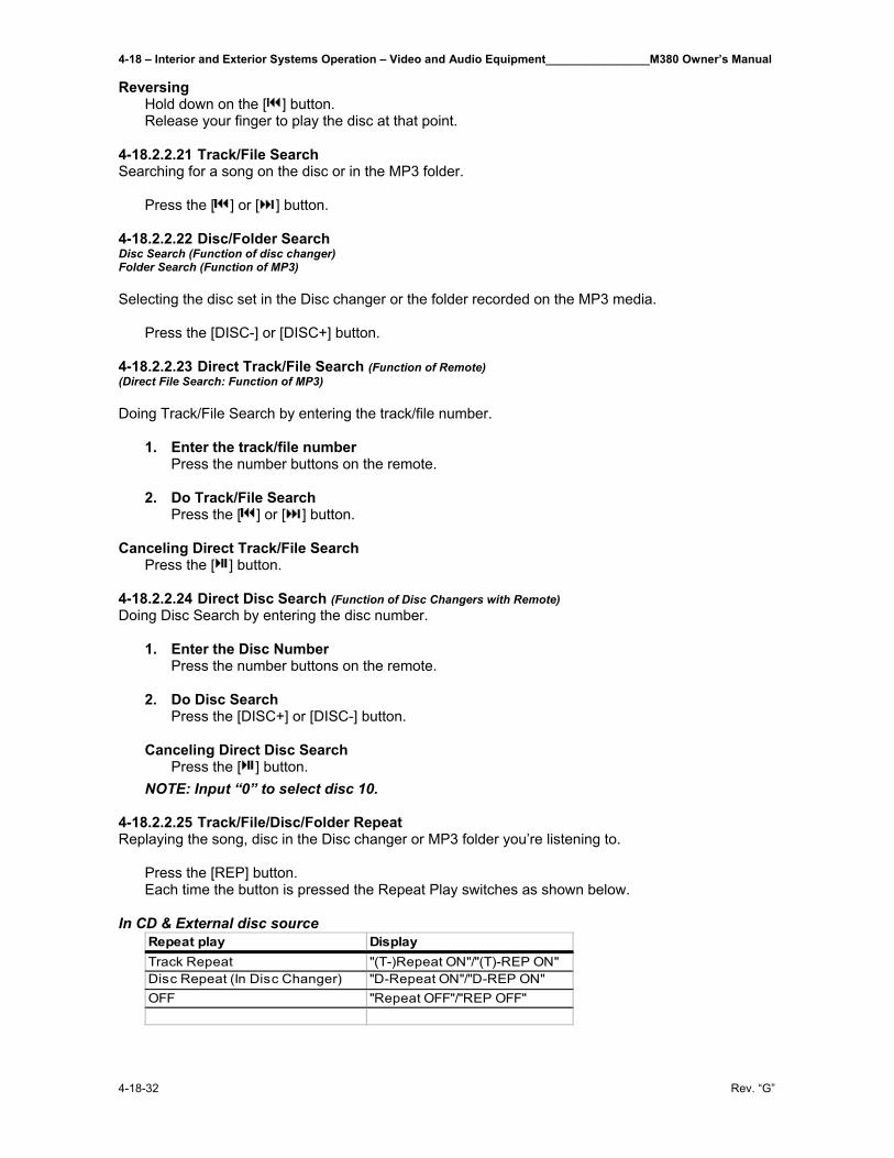
4-18 – Interior and Exterior Systems Operation – Video and Audio Equipment________________M380 Owner’s Manual
4-18-32 Rev. “G”
Reversing Hold down on the [ ] button. Release your finger to play the disc at that point. 4-18.2.2.21 Track/File Search Searching for a song on the disc or in the MP3 folder. Press the [ ] or [ ] button. 4-18.2.2.22 Disc/Folder Search Disc Search (Function of disc changer) Folder Search (Function of MP3) Selecting the disc set in the Disc changer or the folder recorded on the MP3 media. Press the [DISC-] or [DISC+] button. 4-18.2.2.23 Direct Track/File Search (Function of Remote) (Direct File Search: Function of MP3) Doing Track/File Search by entering the track/file number.
1. Enter the track/file number Press the number buttons on the remote.
2. Do Track/File Search Press the [ ] or [ ] button.
Canceling Direct Track/File Search Press the [ ] button. 4-18.2.2.24 Direct Disc Search (Function of Disc Changers with Remote) Doing Disc Search by entering the disc number.
1. Enter the Disc Number Press the number buttons on the remote.
2. Do Disc Search Press the [DISC+] or [DISC-] button.
Canceling Direct Disc Search Press the [ ] button. NOTE: Input “0” to select disc 10.
4-18.2.2.25 Track/File/Disc/Folder Repeat Replaying the song, disc in the Disc changer or MP3 folder you’re listening to. Press the [REP] button. Each time the button is pressed the Repeat Play switches as shown below. In CD & External disc source
Repeat play DisplayTrack Repeat "(T-)Repeat ON"/"(T)-REP ON"Disc Repeat (In Disc Changer) "D-Repeat ON"/"D-REP ON"OFF "Repeat OFF"/"REP OFF"
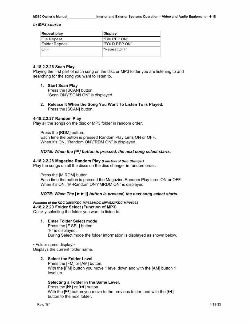
M380 Owner’s Manual________________Interior and Exterior Systems Operation – Video and Audio Equipment – 4-18
Rev. “G” 4-18-33
In MP3 source
4-18.2.2.26 Scan Play Playing the first part of each song on the disc or MP3 folder you are listening to and searching for the song you want to listen to.
1. Start Scan Play Press the [SCAN] button. “Scan ON”/”SCAN ON” is displayed.
2. Release It When the Song You Want To Listen To is Played. Press the [SCAN] button.
4-18.2.2.27 Random Play Play all the songs on the disc or MP3 folder in random order. Press the [RDM] button. Each time the button is pressed Random Play turns ON or OFF. When it’s ON, “Random ON”/”RDM ON” is displayed. NOTE: When the [ ] button is pressed, the next song select starts. 4-18.2.2.28 Magazine Random Play (Function of Disc Changer) Play the songs on all the discs on the disc changer in random order. Press the [M.RDM] button. Each time the button is pressed the Magazine Random Play turns ON or OFF. When it’s ON, “M-Random ON”/”MRDM ON” is displayed.
NOTE: When The [►►||] button is pressed, the next song select starts.
Function of the KDC-X569/KDC-MP522/KDC-MPV622/KDC-MPV6022 4-18.2.2.29 Folder Select (Function of MP3) Quickly selecting the folder you want to listen to.
1. Enter Folder Select mode Press the [F.SEL] button. “F” is displayed. During Select mode the folder information is displayed as shown below.
<Folder name display> Displays the current folder name.
2. Select the Folder Level Press the [FM] or [AM] button. With the [FM] button you move 1 level down and with the [AM] button 1 level up. Selecting a Folder in the Same Level. Press the [ ] or [ ] button. With the [ ] button you move to the previous folder, and with the [ ] button to the next folder.
Repeat play DisplayFile Repeat "File REP ON"Folder Repeat "FOLD REP ON"OFF "Repeat OFF"
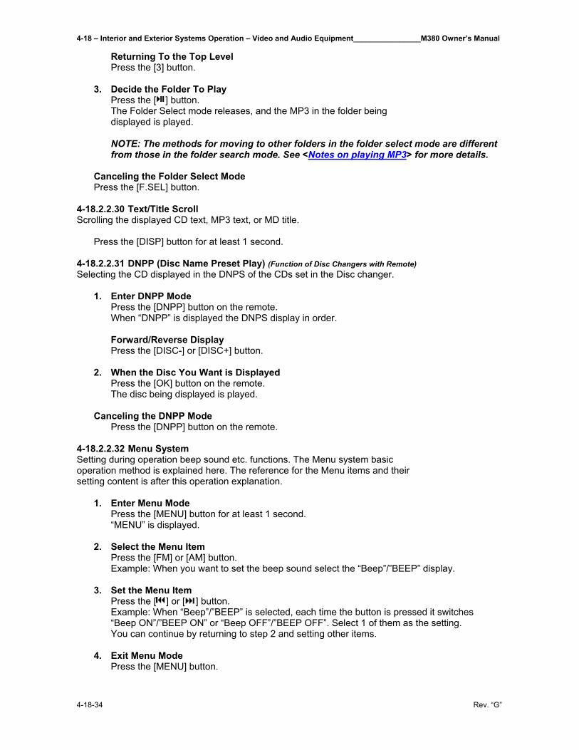
4-18 – Interior and Exterior Systems Operation – Video and Audio Equipment________________M380 Owner’s Manual
4-18-34 Rev. “G”
Returning To the Top Level Press the [3] button.
3. Decide the Folder To Play Press the [ ] button. The Folder Select mode releases, and the MP3 in the folder being displayed is played. NOTE: The methods for moving to other folders in the folder select mode are different from those in the folder search mode. See <Notes on playing MP3> for more details.
Canceling the Folder Select Mode Press the [F.SEL] button.
4-18.2.2.30 Text/Title Scroll Scrolling the displayed CD text, MP3 text, or MD title. Press the [DISP] button for at least 1 second. 4-18.2.2.31 DNPP (Disc Name Preset Play) (Function of Disc Changers with Remote) Selecting the CD displayed in the DNPS of the CDs set in the Disc changer.
1. Enter DNPP Mode Press the [DNPP] button on the remote. When “DNPP” is displayed the DNPS display in order.
Forward/Reverse Display Press the [DISC-] or [DISC+] button.
2. When the Disc You Want is Displayed Press the [OK] button on the remote. The disc being displayed is played.
Canceling the DNPP Mode Press the [DNPP] button on the remote.
4-18.2.2.32 Menu System Setting during operation beep sound etc. functions. The Menu system basic operation method is explained here. The reference for the Menu items and their setting content is after this operation explanation.
1. Enter Menu Mode Press the [MENU] button for at least 1 second. “MENU” is displayed.
2. Select the Menu Item Press the [FM] or [AM] button. Example: When you want to set the beep sound select the “Beep”/”BEEP” display.
3. Set the Menu Item Press the [ ] or [ ] button. Example: When “Beep”/”BEEP” is selected, each time the button is pressed it switches “Beep ON”/”BEEP ON” or “Beep OFF”/”BEEP OFF”. Select 1 of them as the setting. You can continue by returning to step 2 and setting other items.
4. Exit Menu Mode Press the [MENU] button.
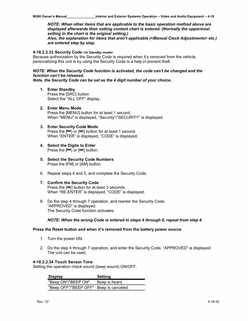
M380 Owner’s Manual________________Interior and Exterior Systems Operation – Video and Audio Equipment – 4-18
Rev. “G” 4-18-35
NOTE: When other items that are applicable to the basic operation method above are displayed afterwards their setting content chart is entered. (Normally the uppermost setting in the chart is the original setting.) Also, the explanation for items that aren’t applicable (<Manual Clock Adjustments> etc.) are entered step by step.
4-18.2.2.33 Security Code <In Standby mode> Because authorization by the Security Code is required when it’s removed from the vehicle, personalizing this unit is by using the Security Code is a help in prevent theft. NOTE: When the Security Code function is activated, the code can’t be changed and the function can’t be released. Note, the Security Code can be set as the 4 digit number of your choice.
1. Enter Standby Press the [SRC] button Select the “ALL OFF” display.
2. Enter Menu Mode Press the [MENU] button for at least 1 second. When “MENU” is displayed, “Security”/”SECURITY” is displayed.
3. Enter Security Code Mode Press the [ ] or [ ] button for at least 1 second. When “ENTER” is displayed, “CODE” is displayed.
4. Select the Digits to Enter Press the [ ] or [ ] button.
5. Select the Security Code Numbers Press the [FM] or [AM] button.
6. Repeat steps 4 and 5, and complete the Security Code. 7. Confirm the Security Code
Press the [ ] button for at least 3 seconds. When “RE-ENTER” is displayed, “CODE” is displayed.
8. Do the step 4 through 7 operation, and reenter the Security Code. “APPROVED” is displayed. The Security Code function activates. NOTE: When the wrong Code is entered in steps 4 through 6, repeat from step 4.
Press the Reset button and when it’s removed from the battery power source
1. Turn the power ON. 2. Do the step 4 through 7 operation, and enter the Security Code. “APPROVED” is displayed.
The unit can be used.
4-18.2.2.34 Touch Sensor Tone Setting the operation check sound (beep sound) ON/OFF.
Display Setting"Beep ON"/"BEEP ON" Beep is heard."Beep OFF"/"BEEP OFF" Beep is canceled.
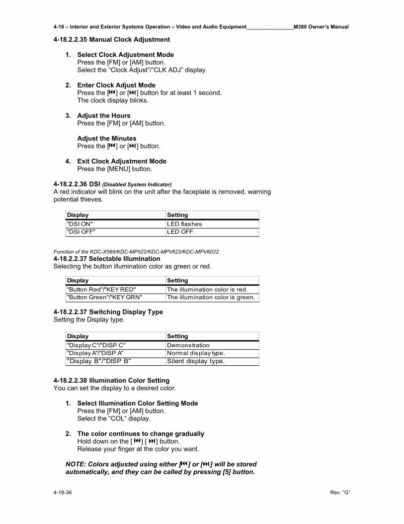
4-18 – Interior and Exterior Systems Operation – Video and Audio Equipment________________M380 Owner’s Manual
4-18-36 Rev. “G”
4-18.2.2.35 Manual Clock Adjustment
1. Select Clock Adjustment Mode Press the [FM] or [AM] button. Select the “Clock Adjust”/”CLK ADJ” display.
2. Enter Clock Adjust Mode Press the [ ] or [ ] button for at least 1 second. The clock display blinks.
3. Adjust the Hours Press the [FM] or [AM] button. Adjust the Minutes Press the [ ] or [ ] button.
4. Exit Clock Adjustment Mode Press the [MENU] button.
4-18.2.2.36 DSI (Disabled System Indicator) A red indicator will blink on the unit after the faceplate is removed, warning potential thieves.
Function of the KDC-X569/KDC-MP522/KDC-MPV622/KDC-MPV6022 4-18.2.2.37 Selectable Illumination Selecting the button illumination color as green or red.
4-18.2.2.37 Switching Display Type Setting the Display type.
4-18.2.2.38 Illumination Color Setting You can set the display to a desired color.
1. Select Illumination Color Setting Mode Press the [FM] or [AM] button. Select the “COL” display.
2. The color continues to change gradually
Hold down on the [ ] [ ] button. Release your finger at the color you want.
NOTE: Colors adjusted using either [ ] or [ ] will be stored automatically, and they can be called by pressing [5] button.
Display Setting"DSI ON" LED flashes"DSI OFF" LED OFF.
Display Setting"Button Red"/"KEY RED" The illumination color is red."Button Green"/"KEY GRN" The illumination color is green.
Display Setting"Display C"/"DISP C" Demonstration"Display A"/"DISP A" Normal display type."Display B"/"DISP B" Silent display type.
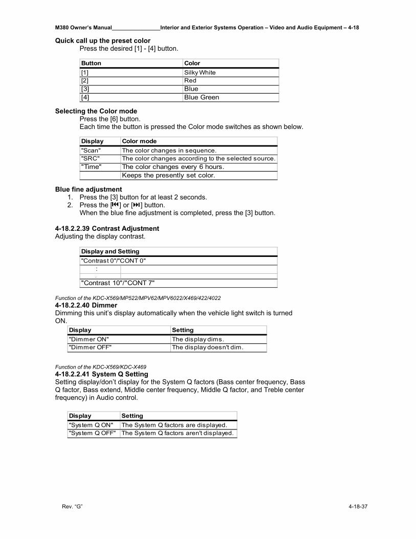
M380 Owner’s Manual________________Interior and Exterior Systems Operation – Video and Audio Equipment – 4-18
Rev. “G” 4-18-37
Quick call up the preset color Press the desired [1] - [4] button.
Selecting the Color mode
Press the [6] button. Each time the button is pressed the Color mode switches as shown below.
Blue fine adjustment
1. Press the [3] button for at least 2 seconds. 2. Press the [ ] or [ ] button.
When the blue fine adjustment is completed, press the [3] button.
4-18.2.2.39 Contrast Adjustment Adjusting the display contrast. Function of the KDC-X569/MP522/MPV62/MPV6022/X469/422/4022 4-18.2.2.40 Dimmer Dimming this unit’s display automatically when the vehicle light switch is turned ON.
Function of the KDC-X569/KDC-X469 4-18.2.2.41 System Q Setting Setting display/don’t display for the System Q factors (Bass center frequency, Bass Q factor, Bass extend, Middle center frequency, Middle Q factor, and Treble center frequency) in Audio control.
Button Color[1] Silky White[2] Red[3] Blue[4] Blue Green
Display Color mode"Scan" The color changes in sequence."SRC" The color changes according to the selected source."Time" The color changes every 6 hours.
Keeps the presently set color.
Display and Setting"Contrast 0"/"CONT 0" :
.
"Contrast 10"/"CONT 7"
Display Setting"Dimmer ON" The display dims."Dimmer OFF" The display doesn't dim.
Display Setting"System Q ON" The System Q factors are displayed."System Q OFF" The System Q factors aren't displayed.
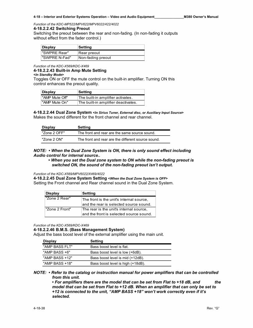
4-18 – Interior and Exterior Systems Operation – Video and Audio Equipment________________M380 Owner’s Manual
4-18-38 Rev. “G”
Function of the KDC-MP522/MPV622/MPV6022/422/4022 4-18.2.2.42 Switching Preout Switching the preout between the rear and non-fading. (In non-fading it outputs without effect from the fader control.)
Function of the KDC-X569/KDC-X469 4-18.2.2.43 Built-in Amp Mute Setting <In Standby Mode> Toggles ON or OFF the mute control on the built-in amplifier. Turning ON this control enhances the preout quality.
4-18.2.2.44 Dual Zone System <In Sirius Tuner, External disc, or Auxiliary Input Source> Makes the sound different for the front channel and rear channel.
Display Setting"Zone 2 OFF" The front and rear are the same source sound.
"Zone 2 ON" The front and rear are the different source sound. NOTE: • When the Dual Zone System is ON, there is only sound effect including Audio control for internal source.. • When you set the Dual zone system to ON while the non-fading preout is switched ON, the sound of the non-fading preout isn’t output. Function of the KDC-X569/MPV6022/X469/4022 4-18.2.2.45 Dual Zone System Setting <When the Dual Zone System is OFF> Setting the Front channel and Rear channel sound in the Dual Zone System. Function of the KDC-X569/KDC-X469 4-18.2.2.46 B.M.S. (Bass Management System) Adjust the bass boost level of the external amplifier using the main unit.
NOTE: • Refer to the catalog or instruction manual for power amplifiers that can be controlled from this unit.
• For amplifiers there are the model that can be set from Flat to +18 dB, and the model that can be set from Flat to +12 dB. When an amplifier that can only be set to +12 is connected to the unit, “AMP BASS +18” won’t work correctly even if it’s selected.
Display Setting"SWPRE Rear" Rear preout"SWPRE N-Fad" Non-fading preout
Display Setting"AMP Mute Off" The built-in amplifier activates."AMP Mute On" The built-in amplifier deactivates.
Display Setting"AMP BASS FLT" Bass boost level is flat."AMP BASS +6" Bass boost level is low (+6dB)."AMP BASS +12" Bass boost level is mid (+12dB)."AMP BASS +18" Bass boost level is high (+18dB).
Display Setting"Zone 2 Rear" The front is the unit's internal source,
and the rear is selected source sound."Zone 2 Front" The rear is the unit's internal source,
and the front is selected source sound.
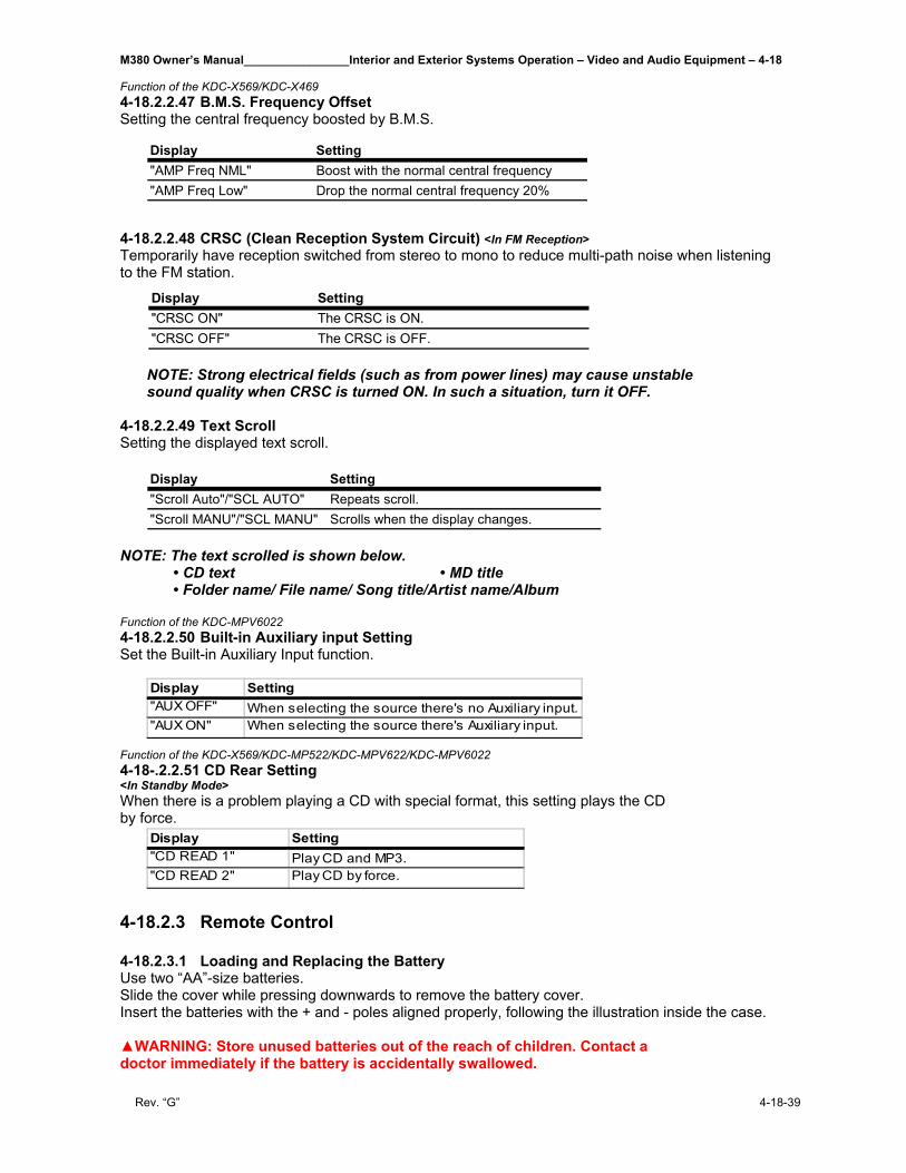
M380 Owner’s Manual________________Interior and Exterior Systems Operation – Video and Audio Equipment – 4-18
Rev. “G” 4-18-39
Function of the KDC-X569/KDC-X469 4-18.2.2.47 B.M.S. Frequency Offset Setting the central frequency boosted by B.M.S.
4-18.2.2.48 CRSC (Clean Reception System Circuit) <In FM Reception> Temporarily have reception switched from stereo to mono to reduce multi-path noise when listening to the FM station.
NOTE: Strong electrical fields (such as from power lines) may cause unstable sound quality when CRSC is turned ON. In such a situation, turn it OFF.
4-18.2.2.49 Text Scroll Setting the displayed text scroll.
Display Setting"Scroll Auto"/"SCL AUTO" Repeats scroll."Scroll MANU"/"SCL MANU" Scrolls when the display changes.
NOTE: The text scrolled is shown below. • CD text • MD title • Folder name/ File name/ Song title/Artist name/Album Function of the KDC-MPV6022 4-18.2.2.50 Built-in Auxiliary input Setting Set the Built-in Auxiliary Input function.
Function of the KDC-X569/KDC-MP522/KDC-MPV622/KDC-MPV6022 4-18-.2.2.51 CD Rear Setting <In Standby Mode> When there is a problem playing a CD with special format, this setting plays the CD by force.
4-18.2.3 Remote Control 4-18.2.3.1 Loading and Replacing the Battery Use two “AA”-size batteries. Slide the cover while pressing downwards to remove the battery cover. Insert the batteries with the + and - poles aligned properly, following the illustration inside the case. ▲WARNING: Store unused batteries out of the reach of children. Contact a doctor immediately if the battery is accidentally swallowed.
Display Setting"AMP Freq NML" Boost with the normal central frequency"AMP Freq Low" Drop the normal central frequency 20%
Display Setting"CRSC ON" The CRSC is ON."CRSC OFF" The CRSC is OFF.
Display Setting"AUX OFF" When selecting the source there's no Auxiliary input."AUX ON" When selecting the source there's Auxiliary input.
Display Setting"CD READ 1" Play CD and MP3."CD READ 2" Play CD by force.
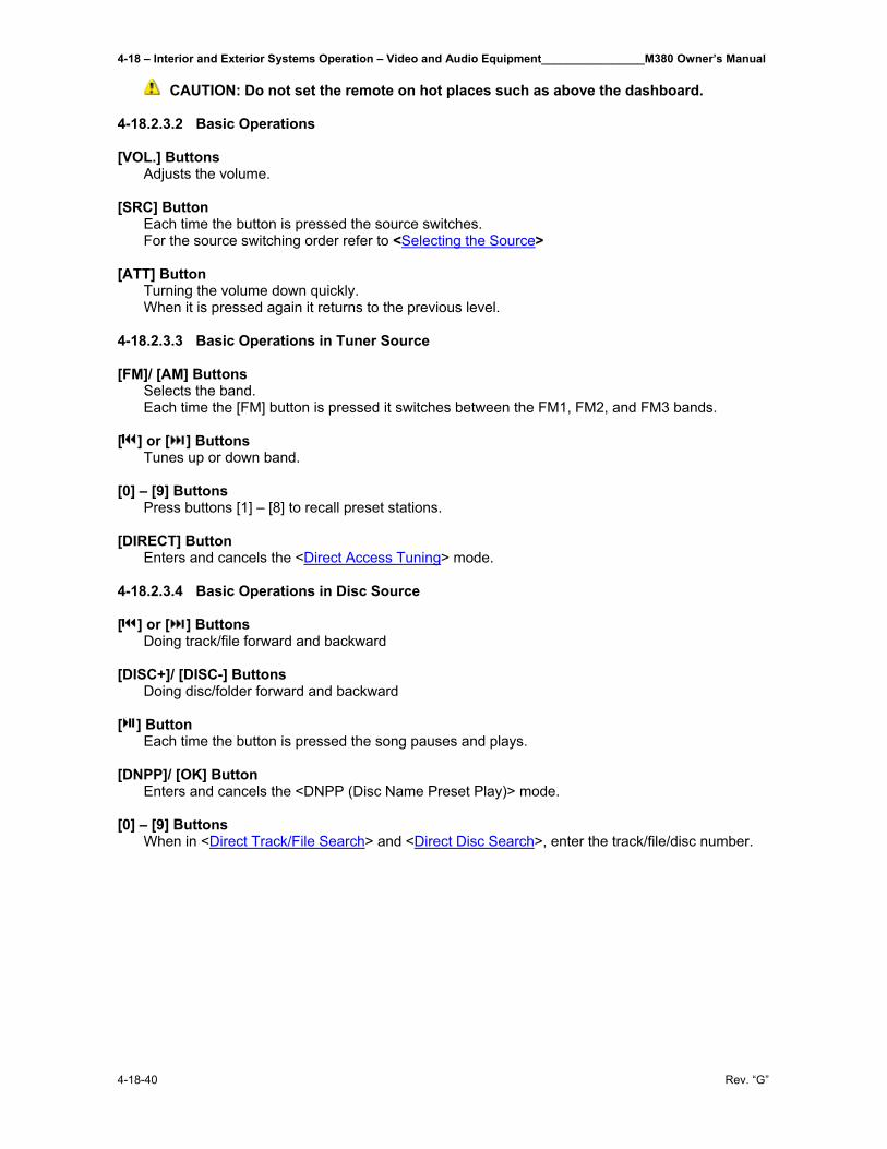
4-18 – Interior and Exterior Systems Operation – Video and Audio Equipment________________M380 Owner’s Manual
4-18-40 Rev. “G”
CAUTION: Do not set the remote on hot places such as above the dashboard.
4-18.2.3.2 Basic Operations [VOL.] Buttons Adjusts the volume. [SRC] Button Each time the button is pressed the source switches. For the source switching order refer to <Selecting the Source> [ATT] Button Turning the volume down quickly. When it is pressed again it returns to the previous level. 4-18.2.3.3 Basic Operations in Tuner Source [FM]/ [AM] Buttons Selects the band. Each time the [FM] button is pressed it switches between the FM1, FM2, and FM3 bands. [ ] or [ ] Buttons Tunes up or down band. [0] – [9] Buttons Press buttons [1] – [8] to recall preset stations. [DIRECT] Button Enters and cancels the <Direct Access Tuning> mode. 4-18.2.3.4 Basic Operations in Disc Source [ ] or [ ] Buttons Doing track/file forward and backward [DISC+]/ [DISC-] Buttons Doing disc/folder forward and backward [ ] Button Each time the button is pressed the song pauses and plays. [DNPP]/ [OK] Button Enters and cancels the <DNPP (Disc Name Preset Play)> mode. [0] – [9] Buttons When in <Direct Track/File Search> and <Direct Disc Search>, enter the track/file/disc number.
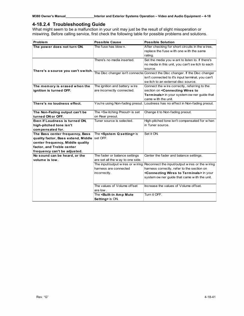
M380 Owner’s Manual________________Interior and Exterior Systems Operation – Video and Audio Equipment – 4-18
Rev. “G” 4-18-41
4-18.2.4 Troubleshooting Guide What might seem to be a malfunction in your unit may just be the result of slight misoperation or miswiring. Before calling service, first check the following table for possible problems and solutions.
Problem Possible Cause Possible SolutionThe power does not turn ON. The fuse has blow n. After checking for short circuits in the w ires,
replace the fuse w ith one w ith the same rating.
There's no media inserted. Set the media you w ant to listen to. If there's no media in this unit, you can't sw itch to each source.
The Disc changer isn't connectedConnect the Disc changer. If the Disc changer isn't connected to it's input terminal, you can't sw itch to an external disc source.
The memory is erased when the ignition is turned OFF.
The ignition and battery w ire are incorrectly connected.
Connect the w ire correctly, referring to the section on <Connecting Wires to Terminals> in your system ow ner guide that came w ith the unit.
There's no loudness effect. You're using Non-fading preout. Loudness has no effect in Non-fading preout.
The Non-Fading output can't be turned ON or OFF.
The <Sw itching Preout> is set on Rear preout.
Change it to Non-fading preout.
Even if Loudness is turned ON, high-pitched tone isn't compensated for.
Tuner source is selected. High-pitched tone isn't compensated for w hen in Tuner source.
The Bass center frequency, Bass quality factor, Bass extend, Middle center frequency, Middle quality factor, and Treble center frequency can't be adjusted.
The <System Q setting> is set OFF.
Set it ON.
The fader or balance settings are set all the w ay to one side.
Center the fader and balance settings.
The input/output w ires or w iring harness are connected incorrectly.
Reconnect the input/output w ires or the w iring harness correctly, refer to the section on <Connecting Wires to Terminals> in your system ow ner guide that came w ith the unit.
The values of Volume offset are low .
Increase the values of Volume offset.
The <Built-in Amp Mute Setting> is ON.
Turn it OFF.
There's a source you can't switch.
No sound can be heard, or the volume is low.
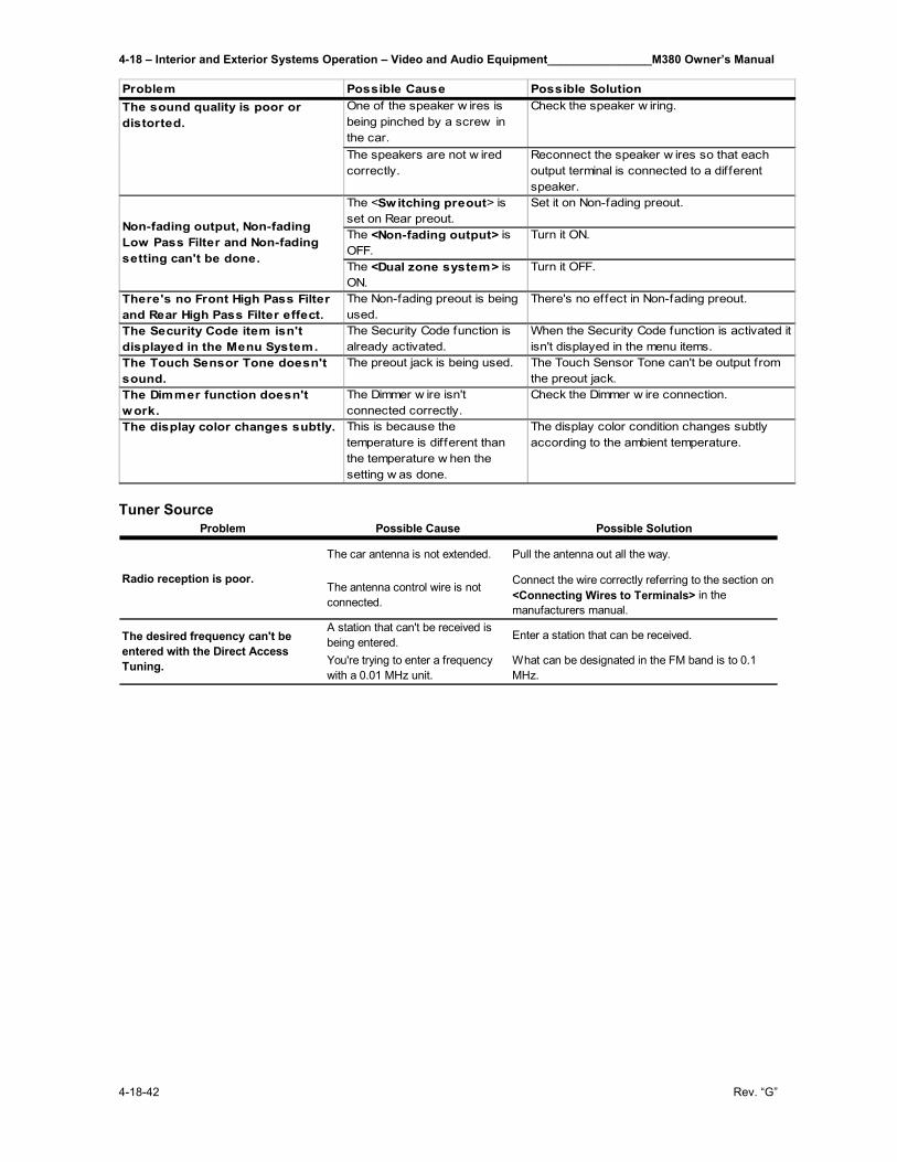
4-18 – Interior and Exterior Systems Operation – Video and Audio Equipment________________M380 Owner’s Manual
4-18-42 Rev. “G”
Tuner Source
Problem Possible Cause Possible Solution
The car antenna is not extended. Pull the antenna out all the way.
The antenna control wire is not connected.
Connect the wire correctly referring to the section on <Connecting Wires to Terminals> in the manufacturers manual.
A station that can't be received is being entered. Enter a station that can be received.
You're trying to enter a frequency with a 0.01 MHz unit.
What can be designated in the FM band is to 0.1 MHz.
Radio reception is poor.
The desired frequency can't be entered with the Direct Access Tuning.
Problem Possible Cause Possible SolutionOne of the speaker w ires is being pinched by a screw in the car.
Check the speaker w iring.
The speakers are not w ired correctly.
Reconnect the speaker w ires so that each output terminal is connected to a different speaker.
The <Switching preout> is set on Rear preout.
Set it on Non-fading preout.
The <Non-fading output> is OFF.
Turn it ON.
The <Dual zone system> is ON.
Turn it OFF.
There's no Front High Pass Filter and Rear High Pass Filter effect.
The Non-fading preout is being used.
There's no effect in Non-fading preout.
The Security Code item isn't displayed in the Menu System.
The Security Code function is already activated.
When the Security Code function is activated it isn't displayed in the menu items.
The Touch Sensor Tone doesn't sound.
The preout jack is being used. The Touch Sensor Tone can't be output from the preout jack.
The Dimmer function doesn't work.
The Dimmer w ire isn't connected correctly.
Check the Dimmer w ire connection.
The display color changes subtly. This is because the temperature is different than the temperature w hen the setting w as done.
The display color condition changes subtly according to the ambient temperature.
Non-fading output, Non-fading Low Pass Filter and Non-fading setting can't be done.
The sound quality is poor or distorted.
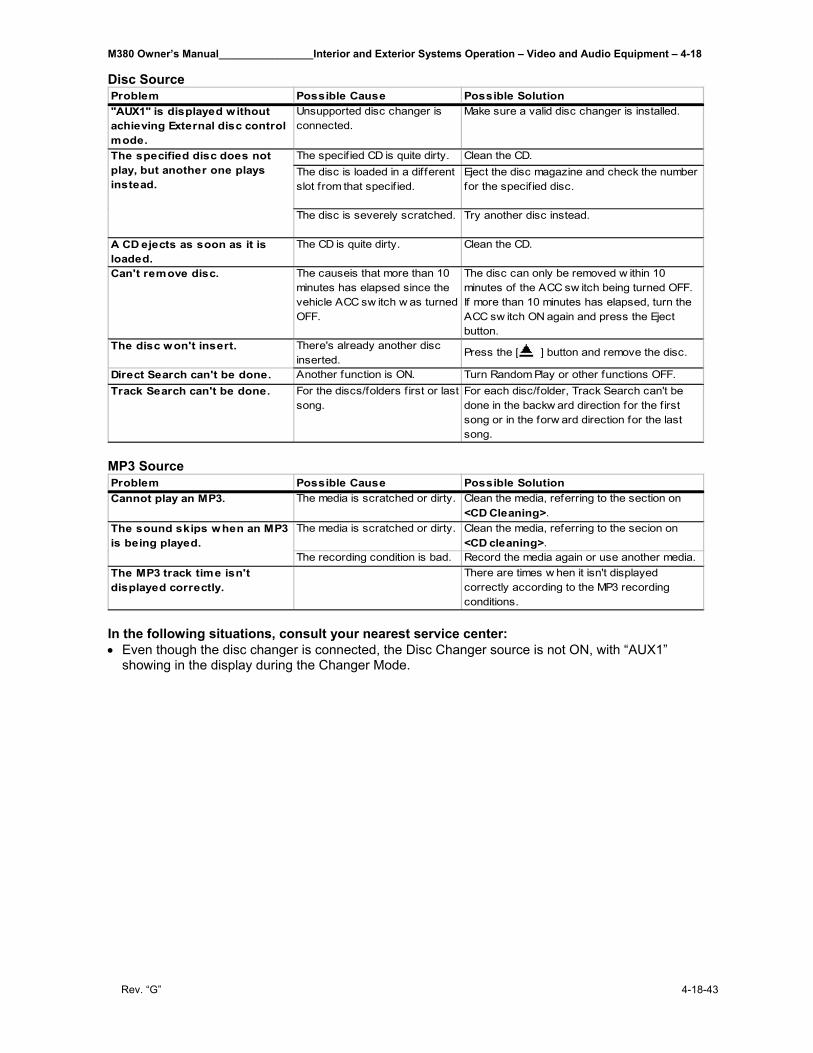
M380 Owner’s Manual________________Interior and Exterior Systems Operation – Video and Audio Equipment – 4-18
Rev. “G” 4-18-43
Disc Source
MP3 Source
In the following situations, consult your nearest service center: • Even though the disc changer is connected, the Disc Changer source is not ON, with “AUX1”
showing in the display during the Changer Mode.
Problem Possible Cause Possible Solution"AUX1" is displayed without achieving External disc control mode.
Unsupported disc changer is connected.
Make sure a valid disc changer is installed.
The specif ied CD is quite dirty. Clean the CD.The disc is loaded in a different slot from that specif ied.
Eject the disc magazine and check the number for the specified disc.
The disc is severely scratched. Try another disc instead.
A CD ejects as soon as it is loaded.
The CD is quite dirty. Clean the CD.
Can't remove disc. The causeis that more than 10 minutes has elapsed since the vehicle ACC sw itch w as turned OFF.
The disc can only be removed w ithin 10 minutes of the ACC sw itch being turned OFF. If more than 10 minutes has elapsed, turn the ACC sw itch ON again and press the Eject button.
The disc won't insert. There's already another disc inserted.
Press the [ ] button and remove the disc.
Direct Search can't be done. Another function is ON. Turn Random Play or other functions OFF.Track Search can't be done. For the discs/folders first or last
song.For each disc/folder, Track Search can't be done in the backw ard direction for the f irst song or in the forw ard direction for the last song.
The specified disc does not play, but another one plays instead.
Problem Possible Cause Possible SolutionCannot play an MP3. The media is scratched or dirty. Clean the media, referring to the section on
<CD Cleaning>.The media is scratched or dirty. Clean the media, referring to the secion on
<CD cleaning>.The recording condition is bad. Record the media again or use another media.
The MP3 track time isn't displayed correctly.
There are times w hen it isn't displayed correctly according to the MP3 recording conditions.
The sound skips when an MP3 is being played.
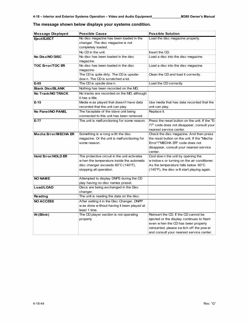
4-18 – Interior and Exterior Systems Operation – Video and Audio Equipment________________M380 Owner’s Manual
4-18-44 Rev. “G”
The message shown below displays your systems condition.
Message Displayed Possible Cause Possible SolutionNo disc magazine has been loaded in the changer. The disc magazine is not completely loaded.
Load the disc magazine properly.
No CD in the unit. Insert the CD.No Disc/NO DISC No disc has been loaded in the disc
magazine.Load a disc into the disc magazine.
No disc has been loaded in the disc magazine.
Load a disc into the disc magazine.
The CD is quite dirty. The CD is upside-dow n. The CD is scratched a lot.
Clean the CD and load it correctly.
E-05 The CD is upsdie dow n. Load the CD correctlyBlank Disc/BLANK Nothing has been recorded on the MD.No Track/NO TRACK No tracks are recorded on the MD, although
it has a title.E-15 Media w as played that doesn't have data
recorded that the unit can play.Use media that has data recorded that the unit can play.
No Panel/NO PANEL The faceplate of the slave unit being connected to this unit has been removed.
Replace it.
E-77 The unit is malfunctioning for some reason. Press the reset button on the unit. If the "E-77" code does not disappear, consult your nearest service center.
Mecha Error/MECHA ER Something is w rong w ith the disc magazine. Or the unit is malfunctioning for some reason.
Check the disc magazine. And then press the reset button on the unit. If the "Mecha Error"/"MECHA ER" code does not disappear, consult your nearest service center.
Hold Error/HOLD ER The protective circuit in the unit activates w hen the temperature inside the automatic disc changer exceeds 60°C (140°F), stopping all operation.
Cool dow n the unit by opening the w indow s or turning on the air conditioner. As the temperature falls below 60°C (140°F), the disc w ill start playing again.
NO NAME Attempted to display DNPS during the CD play having no disc names preset.
Load/LOAD Discs are being exchanged in the Disc changer.
Reading The unit is reading the data on the disc.NO ACCESS After setting it in the Disc Changer, DNPP
w as done w ithout having it been played at least 1 time.
IN (Blink) The CD player section is not operating properly
Reinsert the CD. If the CD cannot be ejected or the display continues to flash even w hen the CD has been properly reinserted, please sw itch off the pow er and consult your nearest service center.
Eject/EJECT
TOC Error/TOC ER
M380 Owner’s Manual________________Interior and Exterior Systems Operation – Video and Audio Equipment – 4-18
Rev. “G” 4-18-45
4-18.3 Television, Bedroom _________________________________ Your motor home comes with 2, 20” Sony Trinitron® Color TVs mounted in the motor home. 4-18.3.1 Features Some of the features you will enjoy include: • Flat CRT – new technologically advanced screen for optimal picture quality. • Parental Control – A tool for parents to help monitor what their children watch on TV by establishing
rating limits. • Favorite Channel – Instant access to your favorite channels with the touch of a button. • Universal Remote Control – Program your remote control to operate your connected cable box,
VCR, digital satellite receiver, or DVD player. • Energy Star® - a recognized symbol of energy efficiency. • S Video – A video input that offers enhanced picture quality. • Direct MTS – Allows direct access to changing your Multi-Channel TV Sound: Stereo, Mono, or
Auto-SAP (Second Audio Program) with the touch of a button. • Trilingual Menus – Choose between English, French or Spanish menus. • Front Pad Controls – Allows access to the on-screen menus without the use of a remote control. • Front A/V Inputs – A quick connection for video games, camcorders, stereo/mono equipment, or
headphones. IMPORTANT NOTE: When using two remotes with two receivers you must program second remote to a different address. To program 2nd remote:
1. Press MENU 2. Go into System Setup
Preferences Receiver I.D. Hold down the SAT & MUTE keys at the same time for 2 minutes. Enter 005 and press SAT key (this will lock address in remote) Press Select key and this will lock address in receiver. This will change receiver I.D. from 01 to 05 Exit out of MENU
NOTE: Second remote should be already programmed in the coach upon delivery. If however, programming is lost or if you are still experiencing interference with the second remote, you can program remote to a different frequency such as 006 or higher to alleviate problem. Follow same steps as above replacing 005 with 006. This will change receiver I.D. from 01 to 06 or whatever number you program in. Do not program second remote any lower than 005, you will still encounter interference. If you need customer assistance call Hughes Consumer Center at 800-274-8995 for help.
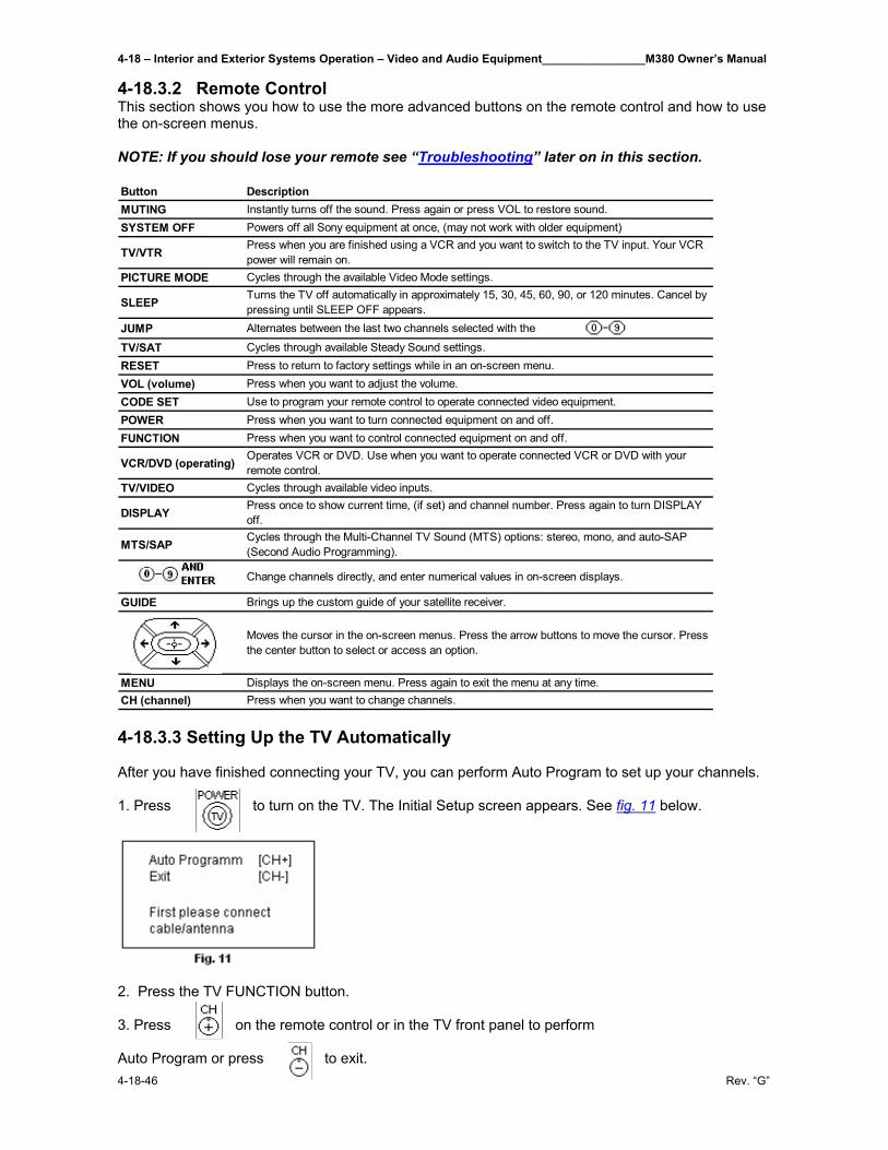
4-18 – Interior and Exterior Systems Operation – Video and Audio Equipment________________M380 Owner’s Manual
4-18-46 Rev. “G”
4-18.3.2 Remote Control This section shows you how to use the more advanced buttons on the remote control and how to use the on-screen menus. NOTE: If you should lose your remote see “Troubleshooting” later on in this section. Button DescriptionMUTING Instantly turns off the sound. Press again or press VOL to restore sound.SYSTEM OFF Powers off all Sony equipment at once, (may not work with older equipment)
TV/VTRPress when you are finished using a VCR and you want to switch to the TV input. Your VCR power will remain on.
PICTURE MODE Cycles through the available Video Mode settings.
SLEEPTurns the TV off automatically in approximately 15, 30, 45, 60, 90, or 120 minutes. Cancel by pressing until SLEEP OFF appears.
JUMP Alternates between the last two channels selected with the buttons.
TV/SAT Cycles through available Steady Sound settings.RESET Press to return to factory settings while in an on-screen menu.VOL (volume) Press when you want to adjust the volume.CODE SET Use to program your remote control to operate connected video equipment.POWER Press when you want to turn connected equipment on and off.FUNCTION Press when you want to control connected equipment on and off.
VCR/DVD (operating)Operates VCR or DVD. Use when you want to operate connected VCR or DVD with your remote control.
TV/VIDEO Cycles through available video inputs.
DISPLAYPress once to show current time, (if set) and channel number. Press again to turn DISPLAY off.
MTS/SAPCycles through the Multi-Channel TV Sound (MTS) options: stereo, mono, and auto-SAP (Second Audio Programming).
Change channels directly, and enter numerical values in on-screen displays.
GUIDE Brings up the custom guide of your satellite receiver.
Moves the cursor in the on-screen menus. Press the arrow buttons to move the cursor. Press the center button to select or access an option.
MENU Displays the on-screen menu. Press again to exit the menu at any time.CH (channel) Press when you want to change channels. 4-18.3.3 Setting Up the TV Automatically After you have finished connecting your TV, you can perform Auto Program to set up your channels. 1. Press to turn on the TV. The Initial Setup screen appears. See fig. 11 below.
2. Press the TV FUNCTION button. 3. Press on the remote control or in the TV front panel to perform Auto Program or press to exit.
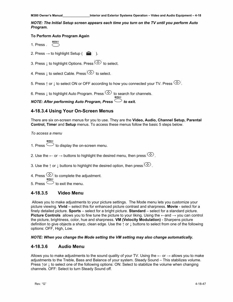
M380 Owner’s Manual________________Interior and Exterior Systems Operation – Video and Audio Equipment – 4-18
Rev. “G” 4-18-47
NOTE: The Initial Setup screen appears each time you turn on the TV until you perform Auto Program. To Perform Auto Program Again 1. Press . 2. Press → to highlight Setup ( ). 3. Press ↓ to highlight Options. Press to select. 4. Press ↓ to select Cable. Press to select. 5. Press ↑ or ↓ to select ON or OFF according to how you connected your TV. Press . 6. Press ↓ to highlight Auto Program. Press to search for channels.
NOTE: After performing Auto Program, Press to exit. 4-18.3.4 Using Your On-Screen Menus There are six on-screen menus for you to use. They are the Video, Audio, Channel Setup, Parental Control, Timer and Setup menus. To access these menus follow the basic 5 steps below. To access a menu
1. Press to display the on-screen menu. 2. Use the ← or → buttons to highlight the desired menu, then press . 3. Use the ↑ or ↓ buttons to highlight the desired option, then press . 4. Press to complete the adjustment.
5. Press to exit the menu. 4-18.3.5 Video Menu Allows you to make adjustments to your picture settings. The Mode menu lets you customize your picture viewing. Vivid – select this for enhanced picture contrast and sharpness. Movie - select for a finely detailed picture. Sports – select for a bright picture. Standard – select for a standard picture. Picture Controls allows you to fine tune the picture to your liking. Using the ←and → you can control the picture, brightness, color, hue and sharpness. VM (Velocity Modulation) - Sharpens picture definition to give objects a sharp, clean edge. Use the ↑ or ↓ buttons to select from one of the following options: OFF, High, Low. NOTE: When you change the Mode setting the VM setting may also change automatically. 4-18.3.6 Audio Menu Allows you to make adjustments to the sound quality of your TV. Using the ← or → allows you to make adjustments to the Treble, Bass and Balance of your system. Steady Sound – This stabilizes volume. Press ↑or ↓ to select one of the following options: ON: Select to stabilize the volume when changing channels. OFF: Select to turn Steady Sound off.
4-18 – Interior and Exterior Systems Operation – Video and Audio Equipment________________M380 Owner’s Manual
4-18-48 Rev. “G”
NOTE: Press for direct Steady Sound settings. Effect: Press ↑ or ↓ to select one of the following options: SRS: Produces a dynamic three dimension sound for stereo audio signals,
(KV-24FV12 only). Simulated: Simulates theater quality sound for stereo programs, (KV-24FV12 only). Surround: Add a surround-like effect to mono programs, (KV-20FV12 only). Off: Normal stereo or mono reception. The Video Menu has 3 options to select from: MTS, Speaker and Audio Out. MTS Multi-Channel Sound: Press ↑ or ↓ to select one of the following options: Stereo: Select when viewing a broadcast in stereo. Mono: Select to reduce noise in areas of poor reception. Auto-SAP: Select to have the TV automatically to a Second Audio Program
(SAP) when a signal is received.
Speaker (Custom selection of audio output source): ON: Select to listen to the sound from the TV speakers with or without a separate stereo system. OFF: Select to turn off the TV speakers and listen to the TV’s sound only through external audio system speakers. Audio Out (use to control the TV’s volume through a stereo): Audio Out can only be set when speakers are set to OFF. Variable: Adjust the volume through your TV. Fixed: Adjust the TV volume through a connected stereo.
NOTE: If your TV is set to Auto-SAP, some programs may be muted or distorted. If your TV does not output sound, change your Audio setting to Stereo or Mono.
NOTE: Press for direct MTS settings (Stereo, Mono, Auto-SAP). NOTE: Audio Out can only be set when Speaker is set to OFF. 4-18.3.7 Channel Setup Menu Allows you to customize your channel settings. Favorite Channel (Quick access to favorite channels) – With the Favorite Channel menu open: 1. Press to select. 2. Use the ↑ or ↓ buttons to select Auto or Manual (selecting Auto will display in gray
the last five channels accessed by the buttons). 3. When in Manual, press ← then ↓ to select the position (1-5) where you want to set
a favorite channel. Then press . 4. Using the ↑ or ↓ buttons, select the desired channel.
5. Press then , the TV will change to the channel entered. NOTE: To use Favorite Channel: Exit all menus and press . Press ↑ or ↓ to move the cursor to the desired channel number and press .
Channel Fix – 2-6: Select when you want to control all channel selection through a cable box or
VCR. Select the appropriate channel (usually 3 or 4) and use the cable box’s or VCR’s remote control for channel selection. Video: Select from available video inputs when you have connected video Equipment (e.g. satellite receiver) and you want your TV fixed to it. OFF: Channel Fix is not set.
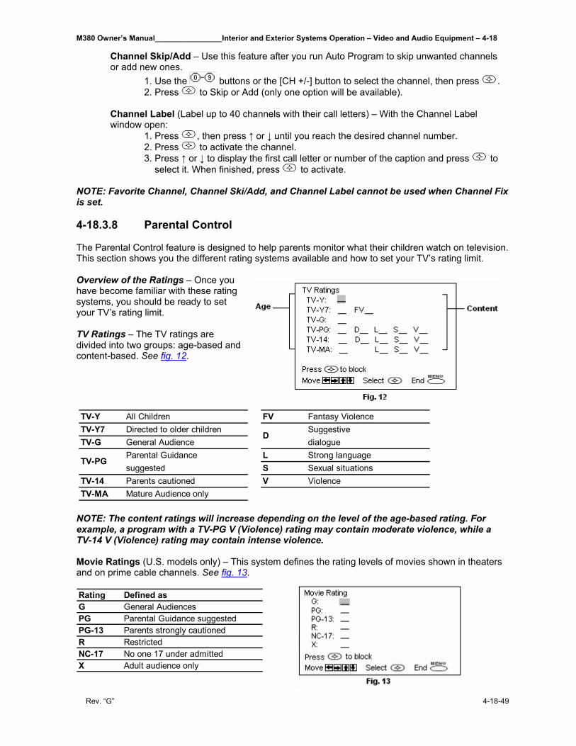
M380 Owner’s Manual________________Interior and Exterior Systems Operation – Video and Audio Equipment – 4-18
Rev. “G” 4-18-49
Channel Skip/Add – Use this feature after you run Auto Program to skip unwanted channels or add new ones. 1. Use the buttons or the [CH +/-] button to select the channel, then press . 2. Press to Skip or Add (only one option will be available). Channel Label (Label up to 40 channels with their call letters) – With the Channel Label window open: 1. Press , then press ↑ or ↓ until you reach the desired channel number. 2. Press to activate the channel. 3. Press ↑ or ↓ to display the first call letter or number of the caption and press to
select it. When finished, press to activate. NOTE: Favorite Channel, Channel Ski/Add, and Channel Label cannot be used when Channel Fix is set. 4-18.3.8 Parental Control The Parental Control feature is designed to help parents monitor what their children watch on television. This section shows you the different rating systems available and how to set your TV’s rating limit. Overview of the Ratings – Once you have become familiar with these rating systems, you should be ready to set your TV’s rating limit. TV Ratings – The TV ratings are divided into two groups: age-based and content-based. See fig. 12.
NOTE: The content ratings will increase depending on the level of the age-based rating. For example, a program with a TV-PG V (Violence) rating may contain moderate violence, while a TV-14 V (Violence) rating may contain intense violence. Movie Ratings (U.S. models only) – This system defines the rating levels of movies shown in theaters and on prime cable channels. See fig. 13. Rating Defined asG General AudiencesPG Parental Guidance suggestedPG-13 Parents strongly cautionedR RestrictedNC-17 No one 17 under admittedX Adult audience only
TV-Y All Children FV Fantasy ViolenceTV-Y7 Directed to older children SuggestiveTV-G General Audience dialogue
Parental Guidance L Strong languagesuggested S Sexual situations
TV-14 Parents cautioned V ViolenceTV-MA Mature Audience only
TV-PG
D
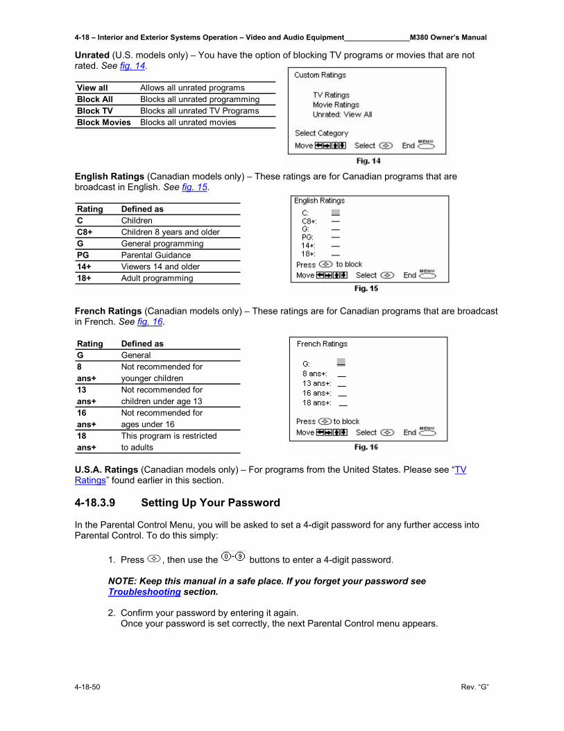
4-18 – Interior and Exterior Systems Operation – Video and Audio Equipment________________M380 Owner’s Manual
4-18-50 Rev. “G”
Unrated (U.S. models only) – You have the option of blocking TV programs or movies that are not rated. See fig. 14. View all Allows all unrated programsBlock All Blocks all unrated programmingBlock TV Blocks all unrated TV ProgramsBlock Movies Blocks all unrated movies English Ratings (Canadian models only) – These ratings are for Canadian programs that are broadcast in English. See fig. 15. Rating Defined asC ChildrenC8+ Children 8 years and olderG General programmingPG Parental Guidance14+ Viewers 14 and older18+ Adult programming French Ratings (Canadian models only) – These ratings are for Canadian programs that are broadcast in French. See fig. 16. Rating Defined asG General8 Not recommended forans+ younger children13 Not recommended forans+ children under age 1316 Not recommended forans+ ages under 1618 This program is restrictedans+ to adults U.S.A. Ratings (Canadian models only) – For programs from the United States. Please see “TV Ratings” found earlier in this section. 4-18.3.9 Setting Up Your Password In the Parental Control Menu, you will be asked to set a 4-digit password for any further access into Parental Control. To do this simply: 1. Press , then use the buttons to enter a 4-digit password. NOTE: Keep this manual in a safe place. If you forget your password see
Troubleshooting section. 2. Confirm your password by entering it again. Once your password is set correctly, the next Parental Control menu appears.
M380 Owner’s Manual________________Interior and Exterior Systems Operation – Video and Audio Equipment – 4-18
Rev. “G” 4-18-51
4-18.3.10 Setting the Rating You can change the Rating by selecting one of the Lock options. 1. Move the cursor to Lock and press . If you are not familiar with the Parental Guidelines rating system, use one of the
following preselected categories to simplify the rating selections, Child, Youth, Young Adult.
2. Use the ↑or ↓ buttons to select the desired rating and press . Rating TV will allow a maximum rating of:
Child TV-Y, TV-G, G (U.S. models only), G (Canadian models only)
Youth TV-PG, PG (U.S. models only), PG (Canadian models only)
Young Adult TV-14, PG-13 (U.S. models only), 14+ (Canadian models only)
Custom Select to set more restrictive ratings (see next section)
OFF No rating limit
4-18.3.11 Using the Custom Menu Before setting Custom ratings, see the “Overview of the Ratings” section earlier in this manual for a description of the available rating systems.
Follow the instructions on the screen to make your custom ratings.
NOTE: Once you have blocked a rating or content, all higher ratings or content will be automatically blocked. 4-18.3.12 Changing Your Password 1. Use the ↑ or ↓ buttons to move the cursor to Change Password and press . 2. Follow steps 1 and 2 for “Setting Up Your Password” on previous page. Information for Parents - To view a program that exceeds the TV rating
Press , then use the buttons to enter your password.
NOTE: Entering your password to view a blocked program will temporarily turn Lock to OFF. To reactivate your Lock settings, turn the TV off and then back on. The TV will return to the settings that you have selected. 4-18.3.13 Using the Timer Menu This allows you to set the clock on your TV and program scheduled viewing using Timer 1 and Timer 2. Current Time 1. Press ↑ or ↓ to select the current time, the press . (If you are in Daylight Savings Time,
be sure to set the Daylight Saving mode in “Yes”). 2. Press ↑ or ↓ to enter the correct time, then press .
4-18 – Interior and Exterior Systems Operation – Video and Audio Equipment________________M380 Owner’s Manual
4-18-52 Rev. “G”
3. Press to exit the menu. Timer 1 and Timer 2 (Scheduled viewing) – With the menu open, set cursor on Timer 1 or Timer 2: 1. Press ↑ or ↓ to select Timer 1 or Timer 2, then press . 2. Press ↑ or ↓ to enter your time and channel of preference, then press .
3. Press to exit the menu. NOTE: You must set the Current Time before you can use Timer 1 and Timer 2. NOTE: You can set the Timer to ON, OFF, or Set. Once the timer is set, you can turn it on or off without having to go through the settings. 4-18.3.14 Daylight Savings YES: Select in spring to compensate for Daylight Saving. NO: Select in fall at the end of Daylight Saving. NOTE: When you perform Auto Program, all Timer 1 and Timer 2 settings will be cleared. NOTE: Any loss of power will cause Current Time, Timer 1 and Timer 2 settings to be cleared. 4-18.3.15 Using the Setup Menu Allows you to program your channels, label video inputs, select menu languages, or run a demo of the menus.
Caption Vision (Closed Captioning) – Allows you to select from three closed caption modes (for programs that are broadcast with closed caption).
Press ↑ or ↓ to select one of the following options: CC1, 2, 3, 4: Displays printed dialogue and sound effects of a program. TXT1, 2, 3, 4: Displays network/station information. XDS (Extended Data Services): Displays information about the network and current program, if available. OFF: Caption vision is not activated.
Video Label (Label connected equipment) – With the Video Label window open:
1. Press ↑ or ↓ to access the input you want to label and press . 2. Press ↑ or ↓ to choose a label and press .
Language – Display all menus in your language of choice. Use the ↑ or ↓ buttons to select desired language and press .
Demo – Press to run a demonstration of the on-screen menus. 4-18.3.16 Options Menu The Options menu offers other setup options.
Cable ON: Select if you are receiving cable channels with a CATV cable. OFF: Select if you are using a TV antenna.
NOTE: After changing your cable settings, you will need to perform Auto Program.
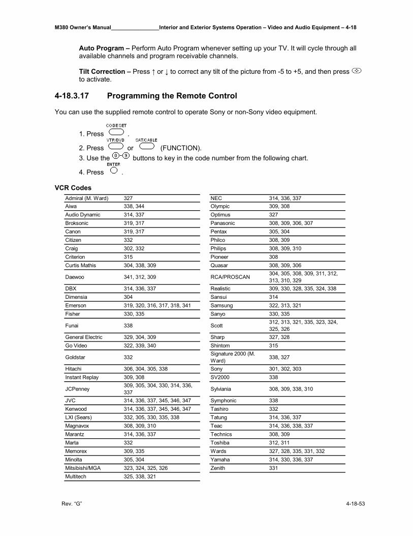
M380 Owner’s Manual________________Interior and Exterior Systems Operation – Video and Audio Equipment – 4-18
Rev. “G” 4-18-53
Auto Program – Perform Auto Program whenever setting up your TV. It will cycle through all available channels and program receivable channels. Tilt Correction – Press ↑ or ↓ to correct any tilt of the picture from -5 to +5, and then press to activate.
4-18.3.17 Programming the Remote Control You can use the supplied remote control to operate Sony or non-Sony video equipment.
1. Press .
2. Press or (FUNCTION). 3. Use the buttons to key in the code number from the following chart.
4. Press . VCR Codes
Admiral (M. Ward) 327 NEC 314, 336, 337Aiwa 338, 344 Olympic 309, 308Audio Dynamic 314, 337 Optimus 327Broksonic 319, 317 Panasonic 308, 309, 306, 307Canon 319, 317 Pentax 305, 304Citizen 332 Philco 308, 309Craig 302, 332 Philips 308, 309, 310Criterion 315 Pioneer 308Curtis Mathis 304, 338, 309 Quasar 308, 309, 306
Daewoo 341, 312, 309 RCA/PROSCAN 304, 305, 308, 309, 311, 312, 313, 310, 329
DBX 314, 336, 337 Realistic 309, 330, 328, 335, 324, 338Dimensia 304 Sansui 314Emerson 319, 320, 316, 317, 318, 341 Samsung 322, 313, 321Fisher 330, 335 Sanyo 330, 335
Funai 338 Scott312, 313, 321, 335, 323, 324, 325, 326
General Electric 329, 304, 309 Sharp 327, 328Go Video 322, 339, 340 Shintom 315
Goldstar 332Signature 2000 (M. Ward) 338, 327
Hitachi 306, 304, 305, 338 Sony 301, 302, 303Instant Replay 309, 308 SV2000 338
JCPenney309, 305, 304, 330, 314, 336, 337 Sylviania 308, 309, 338, 310
JVC 314, 336, 337, 345, 346, 347 Symphonic 338Kenwood 314, 336, 337, 345, 346, 347 Tashiro 332LXI (Sears) 332, 305, 330, 335, 338 Tatung 314, 336, 337Magnavox 308, 309, 310 Teac 314, 336, 338, 337Marantz 314, 336, 337 Technics 308, 309Marta 332 Toshiba 312, 311Memorex 309, 335 Wards 327, 328, 335, 331, 332Minolta 305, 304 Yamaha 314, 330, 336, 337Mitsibishi/MGA 323, 324, 325, 326 Zenith 331Multitech 325, 338, 321
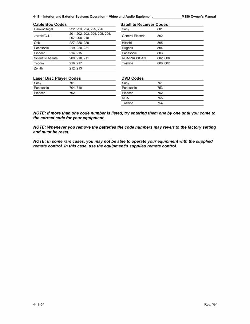
4-18 – Interior and Exterior Systems Operation – Video and Audio Equipment________________M380 Owner’s Manual
4-18-54 Rev. “G”
Cable Box Codes Satellite Receiver Codes Hamlin/Regal 222, 223, 224, 225, 226 Sony 801
Jerrold/G.I.201, 202, 203, 204, 205, 206, 207, 208, 218 General Electtric 802
Oak 227, 228, 229 Hitachi 805Panasonic 219, 220, 221 Hughes 804Pioneer 214, 215 Panasonic 803Scientific Atlanta 209, 210, 211 RCA/PROSCAN 802, 808Tocom 216, 217 Toshiba 806, 807Zenith 212, 213 Laser Disc Player Codes DVD Codes Sony 701 Sony 751Panasonic 704, 710 Panasonic 753Pioneer 702 Pioneer 752
RCA 755Toshiba 754
NOTE: If more than one code number is listed, try entering them one by one until you come to the correct code for your equipment. NOTE: Whenever you remove the batteries the code numbers may revert to the factory setting and must be reset. NOTE: In some rare cases, you may not be able to operate your equipment with the supplied remote control. In this case, use the equipment’s supplied remote control.
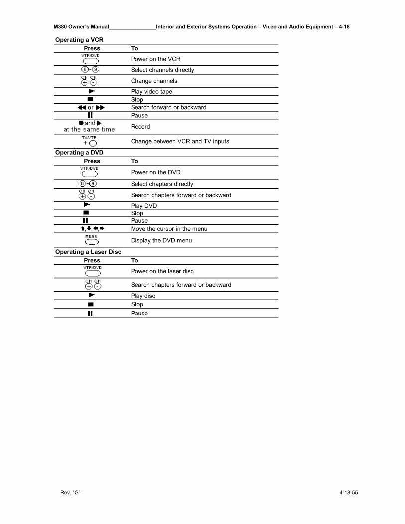
M380 Owner’s Manual________________Interior and Exterior Systems Operation – Video and Audio Equipment – 4-18
Rev. “G” 4-18-55
Press To
Power on the VCR
Select channels directly
Change channels
Play video tapeStopSearch forward or backwardPause
Record
Change between VCR and TV inputs
Press To
Power on the DVD
Select chapters directly
Search chapters forward or backward
Play DVDStopPause
, , , Move the cursor in the menu
Display the DVD menu
Press To
Power on the laser disc
Search chapters forward or backward
Play discStopPause
Operating a VCR
Operating a DVD
Operating a Laser Disc
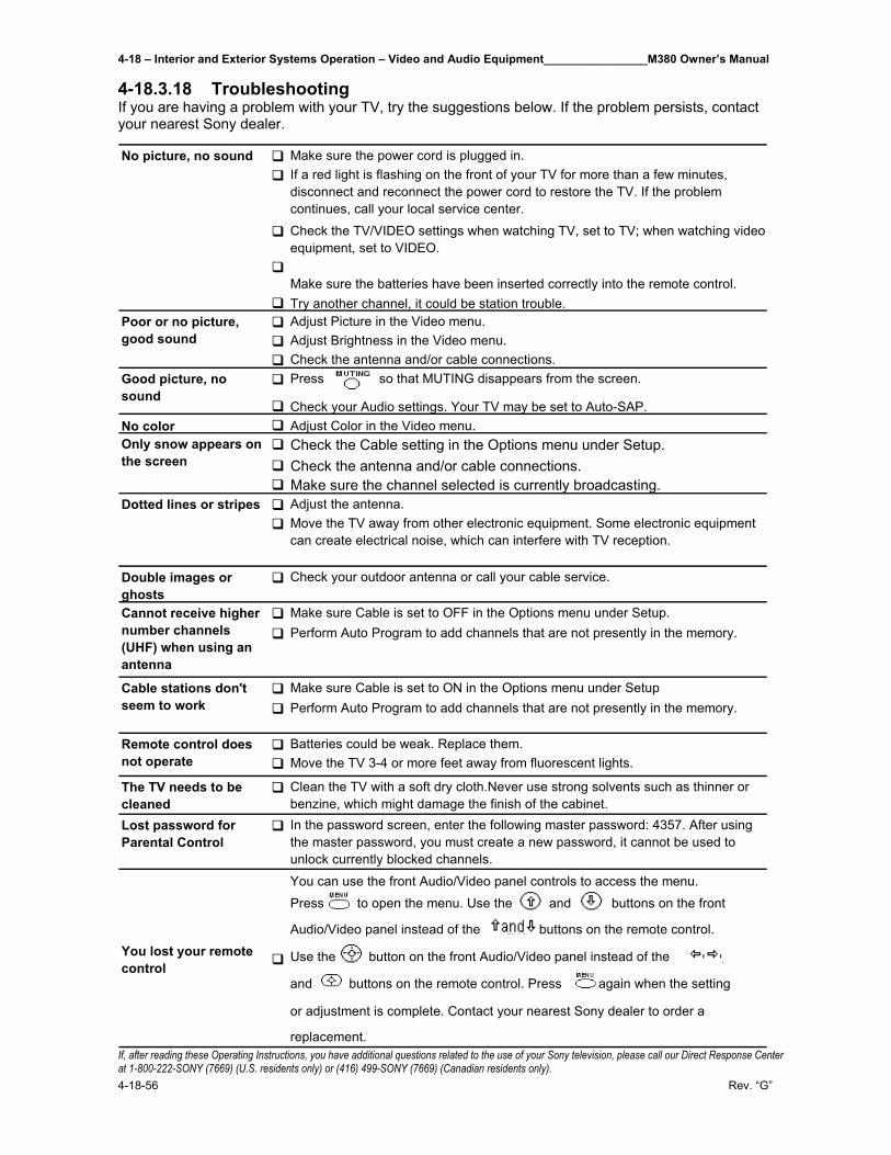
4-18 – Interior and Exterior Systems Operation – Video and Audio Equipment________________M380 Owner’s Manual
4-18-56 Rev. “G”
4-18.3.18 Troubleshooting If you are having a problem with your TV, try the suggestions below. If the problem persists, contact your nearest Sony dealer.
If, after reading these Operating Instructions, you have additional questions related to the use of your Sony television, please call our Direct Response Center at 1-800-222-SONY (7669) (U.S. residents only) or (416) 499-SONY (7669) (Canadian residents only).
Make sure the power cord is plugged in.If a red light is flashing on the front of your TV for more than a few minutes, disconnect and reconnect the power cord to restore the TV. If the problem continues, call your local service center.
Check the TV/VIDEO settings when watching TV, set to TV; when watching video equipment, set to VIDEO.
Make sure the batteries have been inserted correctly into the remote control.Try another channel, it could be station trouble.Adjust Picture in the Video menu.Adjust Brightness in the Video menu.Check the antenna and/or cable connections.Press so that MUTING disappears from the screen.
Check your Audio settings. Your TV may be set to Auto-SAP.No color Adjust Color in the Video menu.
Check the Cable setting in the Options menu under Setup.Check the antenna and/or cable connections.Make sure the channel selected is currently broadcasting.Adjust the antenna.Move the TV away from other electronic equipment. Some electronic equipment can create electrical noise, which can interfere with TV reception.
Double images or ghosts
Check your outdoor antenna or call your cable service.
Make sure Cable is set to OFF in the Options menu under Setup.Perform Auto Program to add channels that are not presently in the memory.
Make sure Cable is set to ON in the Options menu under SetupPerform Auto Program to add channels that are not presently in the memory.
Batteries could be weak. Replace them.Move the TV 3-4 or more feet away from fluorescent lights.
The TV needs to be cleaned
Clean the TV with a soft dry cloth.Never use strong solvents such as thinner or benzine, which might damage the finish of the cabinet.
Lost password for Parental Control
In the password screen, enter the following master password: 4357. After using the master password, you must create a new password, it cannot be used to unlock currently blocked channels.
You can use the front Audio/Video panel controls to access the menu.
Press to open the menu. Use the and buttons on the front
Audio/Video panel instead of the and buttons on the remote control.
Use the button on the front Audio/Video panel instead of the ,
and buttons on the remote control. Press again when the setting
or adjustment is complete. Contact your nearest Sony dealer to order a
replacement.
You lost your remote control
No picture, no sound
Poor or no picture, good sound
Good picture, no sound
Only snow appears on the screen
Dotted lines or stripes
Cannot receive higher number channels (UHF) when using an antenna
Cable stations don't seem to work
Remote control does not operate
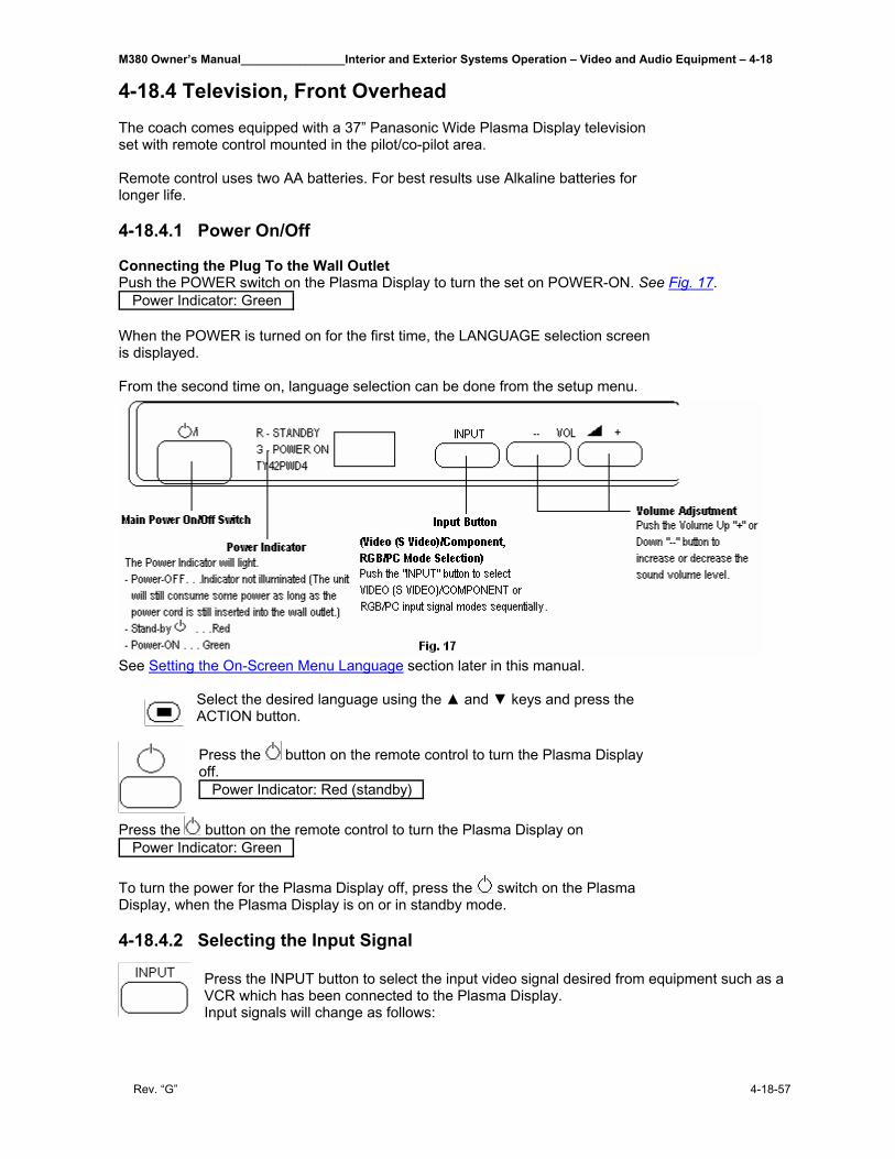
M380 Owner’s Manual________________Interior and Exterior Systems Operation – Video and Audio Equipment – 4-18
Rev. “G” 4-18-57
4-18.4 Television, Front Overhead The coach comes equipped with a 37” Panasonic Wide Plasma Display television set with remote control mounted in the pilot/co-pilot area. Remote control uses two AA batteries. For best results use Alkaline batteries for longer life. 4-18.4.1 Power On/Off Connecting the Plug To the Wall Outlet Push the POWER switch on the Plasma Display to turn the set on POWER-ON. See Fig. 17.
Power Indicator: Green When the POWER is turned on for the first time, the LANGUAGE selection screen is displayed. From the second time on, language selection can be done from the setup menu.
See Setting the On-Screen Menu Language section later in this manual.
Select the desired language using the ▲ and ▼ keys and press the ACTION button. Press the button on the remote control to turn the Plasma Display off.
Power Indicator: Red (standby)
Press the button on the remote control to turn the Plasma Display on Power Indicator: Green
To turn the power for the Plasma Display off, press the switch on the Plasma Display, when the Plasma Display is on or in standby mode. 4-18.4.2 Selecting the Input Signal
Press the INPUT button to select the input video signal desired from equipment such as a VCR which has been connected to the Plasma Display. Input signals will change as follows:
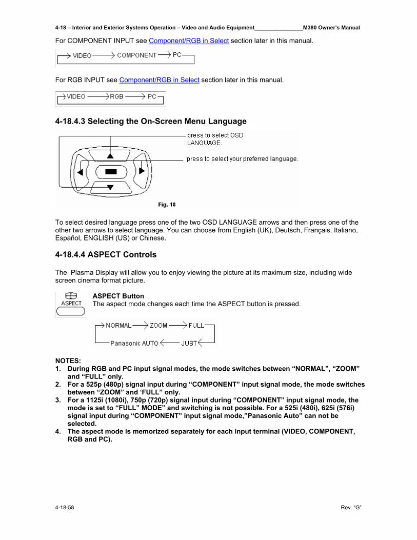
4-18 – Interior and Exterior Systems Operation – Video and Audio Equipment________________M380 Owner’s Manual
4-18-58 Rev. “G”
For COMPONENT INPUT see Component/RGB in Select section later in this manual.
For RGB INPUT see Component/RGB in Select section later in this manual.
4-18.4.3 Selecting the On-Screen Menu Language
To select desired language press one of the two OSD LANGUAGE arrows and then press one of the other two arrows to select language. You can choose from English (UK), Deutsch, Français, Italiano, Español, ENGLISH (US) or Chinese. 4-18.4.4 ASPECT Controls The Plasma Display will allow you to enjoy viewing the picture at its maximum size, including wide screen cinema format picture.
ASPECT Button The aspect mode changes each time the ASPECT button is pressed.
NOTES: 1. During RGB and PC input signal modes, the mode switches between “NORMAL”, “ZOOM”
and “FULL” only. 2. For a 525p (480p) signal input during “COMPONENT” input signal mode, the mode switches
between “ZOOM” and ‘FULL” only. 3. For a 1125i (1080i), 750p (720p) signal input during “COMPONENT” input signal mode, the
mode is set to “FULL” MODE” and switching is not possible. For a 525i (480i), 625i (576i) signal input during “COMPONENT” input signal mode,”Panasonic Auto” can not be selected.
4. The aspect mode is memorized separately for each input terminal (VIDEO, COMPONENT, RGB and PC).
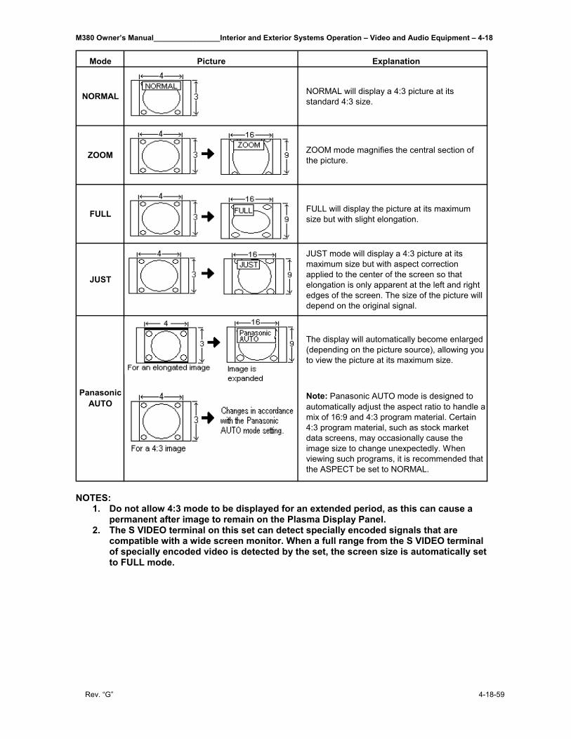
M380 Owner’s Manual________________Interior and Exterior Systems Operation – Video and Audio Equipment – 4-18
Rev. “G” 4-18-59
Mode Picture Explanation
NORMAL NORMAL will display a 4:3 picture at its standard 4:3 size.
ZOOM ZOOM mode magnifies the central section of the picture.
FULL FULL will display the picture at its maximum size but with slight elongation.
JUST
JUST mode will display a 4:3 picture at its maximum size but with aspect correction applied to the center of the screen so that elongation is only apparent at the left and right edges of the screen. The size of the picture will depend on the original signal.
The display will automatically become enlarged (depending on the picture source), allowing you to view the picture at its maximum size.
Note: Panasonic AUTO mode is designed to automatically adjust the aspect ratio to handle a mix of 16:9 and 4:3 program material. Certain 4:3 program material, such as stock market data screens, may occasionally cause the image size to change unexpectedly. When viewing such programs, it is recommended that the ASPECT be set to NORMAL.
Panasonic AUTO
NOTES:
1. Do not allow 4:3 mode to be displayed for an extended period, as this can cause a permanent after image to remain on the Plasma Display Panel.
2. The S VIDEO terminal on this set can detect specially encoded signals that are compatible with a wide screen monitor. When a full range from the S VIDEO terminal of specially encoded video is detected by the set, the screen size is automatically set to FULL mode.
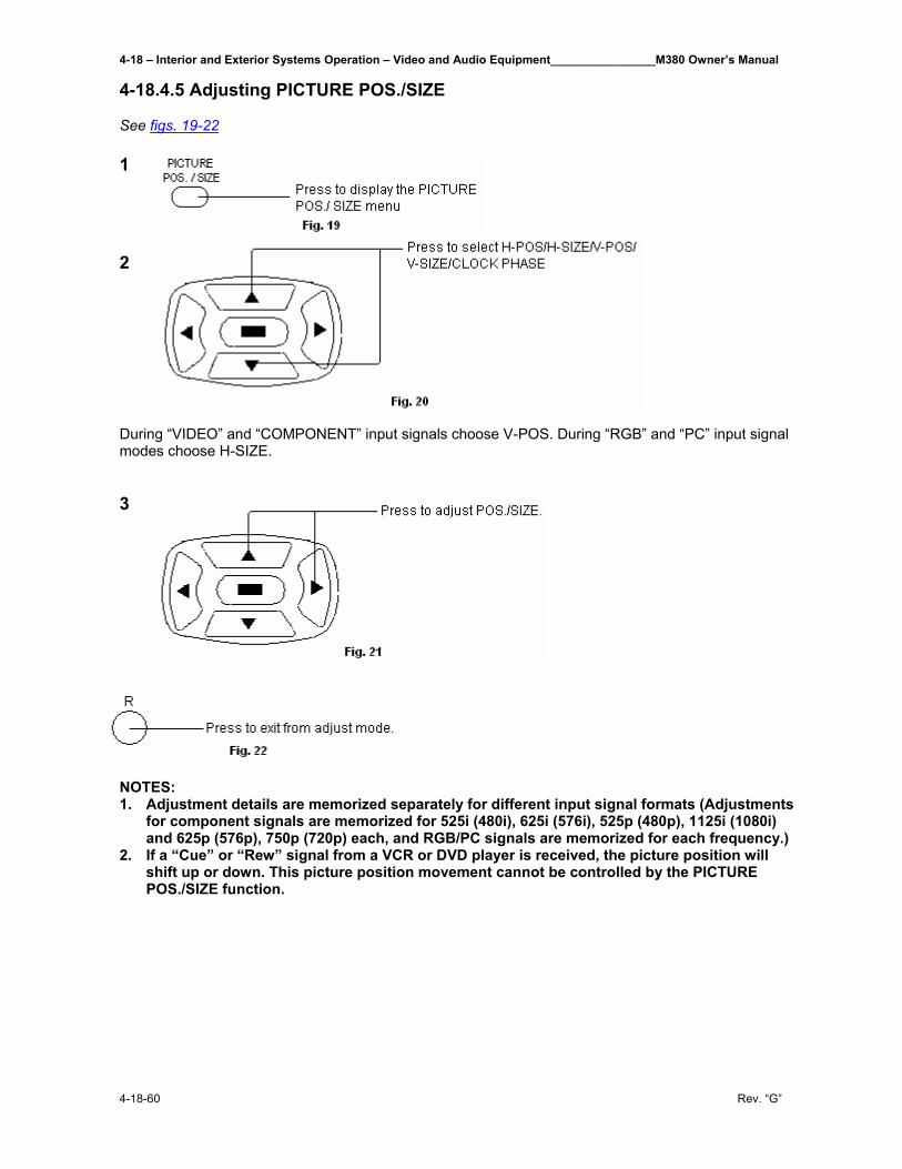
4-18 – Interior and Exterior Systems Operation – Video and Audio Equipment________________M380 Owner’s Manual
4-18-60 Rev. “G”
4-18.4.5 Adjusting PICTURE POS./SIZE See figs. 19-22 1
2
During “VIDEO” and “COMPONENT” input signals choose V-POS. During “RGB” and “PC” input signal modes choose H-SIZE. 3
NOTES: 1. Adjustment details are memorized separately for different input signal formats (Adjustments
for component signals are memorized for 525i (480i), 625i (576i), 525p (480p), 1125i (1080i) and 625p (576p), 750p (720p) each, and RGB/PC signals are memorized for each frequency.)
2. If a “Cue” or “Rew” signal from a VCR or DVD player is received, the picture position will shift up or down. This picture position movement cannot be controlled by the PICTURE POS./SIZE function.
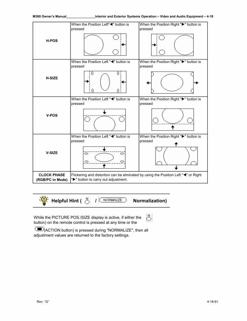
M380 Owner’s Manual________________Interior and Exterior Systems Operation – Video and Audio Equipment – 4-18
Rev. “G” 4-18-61
H-POS
When the Position Left" " button is pressed
When the Position Right " " button is pressed
H-SIZE
When the Position Left " " button is pressed
When the Position Right " " button is pressed
V-POS
When the Position Left " " button is pressed
When the Position Right " " button is pressed
V-SIZE
When the Position Left " " button is pressed
When the Position Right " " button is pressed
CLOCK PHASE (RGB/PC in Mode)
Flickering and distortion can be elminated by using the Position Left " " or Right " " button to carry out adjustment.
Helpful Hint ( / Normalization)
While the PICTURE POS./SIZE display is active, if either the (N button) on the remote control is pressed at any time or the
(ACTION button) is pressed during "NORMALIZE", then all adjustment values are returned to the factory settings.
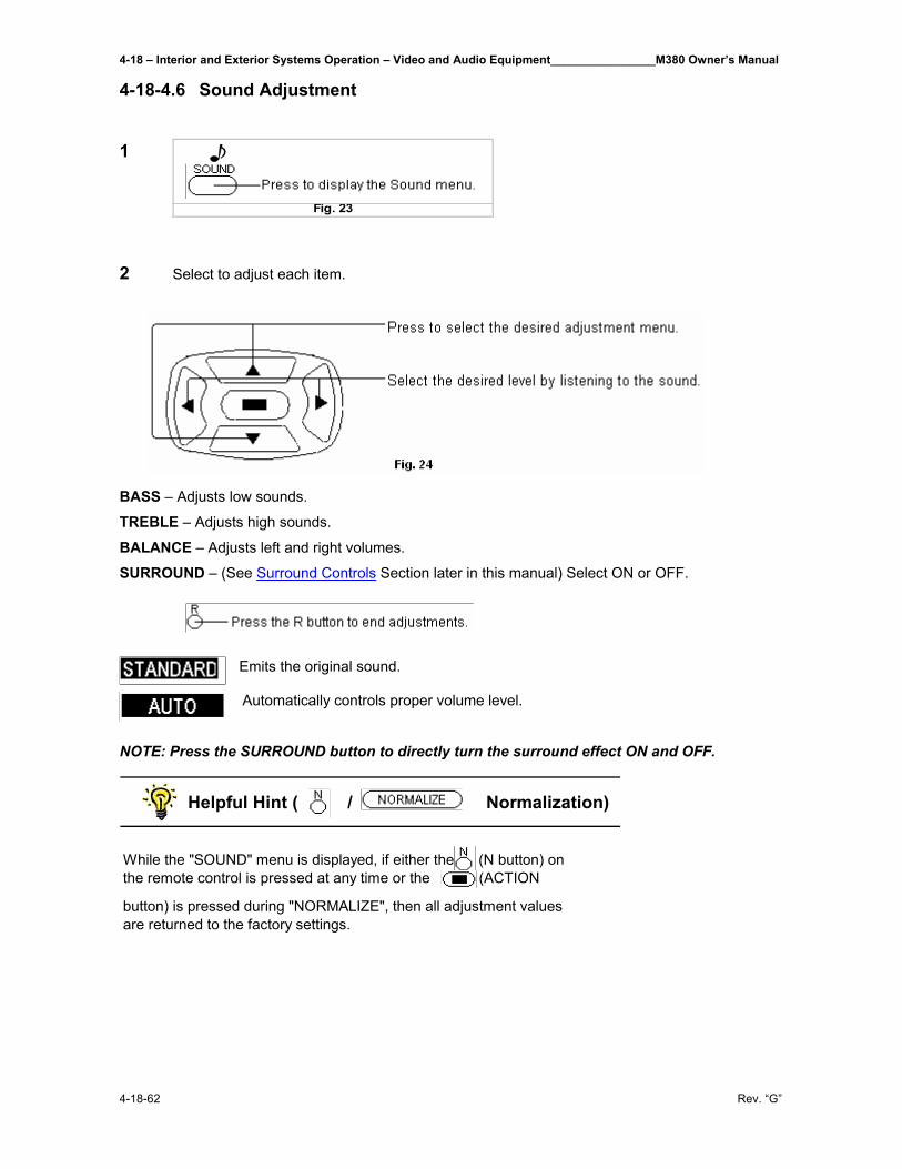
4-18 – Interior and Exterior Systems Operation – Video and Audio Equipment________________M380 Owner’s Manual
4-18-62 Rev. “G”
4-18-4.6 Sound Adjustment 1 2 Select to adjust each item.
BASS – Adjusts low sounds.
TREBLE – Adjusts high sounds.
BALANCE – Adjusts left and right volumes.
SURROUND – (See Surround Controls Section later in this manual) Select ON or OFF.
Emits the original sound. Automatically controls proper volume level.
NOTE: Press the SURROUND button to directly turn the surround effect ON and OFF.
Helpful Hint ( / Normalization)
While the "SOUND" menu is displayed, if either the (N button) on the remote control is pressed at any time or the (ACTION
button) is pressed during "NORMALIZE", then all adjustment values are returned to the factory settings.
Fig. 23
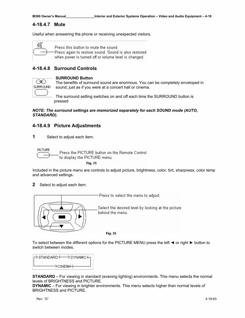
M380 Owner’s Manual________________Interior and Exterior Systems Operation – Video and Audio Equipment – 4-18
Rev. “G” 4-18-63
4-18.4.7 Mute Useful when answering the phone or receiving unexpected visitors.
4-18.4.8 Surround Controls
SURROUND Button The benefits of surround sound are enormous. You can be completely enveloped in sound; just as if you were at a concert hall or cinema. The surround setting switches on and off each time the SURROUND button is
pressed NOTE: The surround settings are memorized separately for each SOUND mode (AUTO, STANDARD). 4-18.4.9 Picture Adjustments 1 Select to adjust each item.
Included in the picture menu are controls to adjust picture, brightness, color, tint, sharpness, color temp and advanced settings. 2 Select to adjust each item.
To select between the different options for the PICTURE MENU press the left ◄ or right ► button to switch between modes.
STANDARD – For viewing in standard (evening lighting) environments. This menu selects the normal levels of BRIGHTNESS and PICTURE. DYNAMIC – For viewing in brighter environments. This menu selects higher than normal levels of BRIGHTNESS and PICTURE.
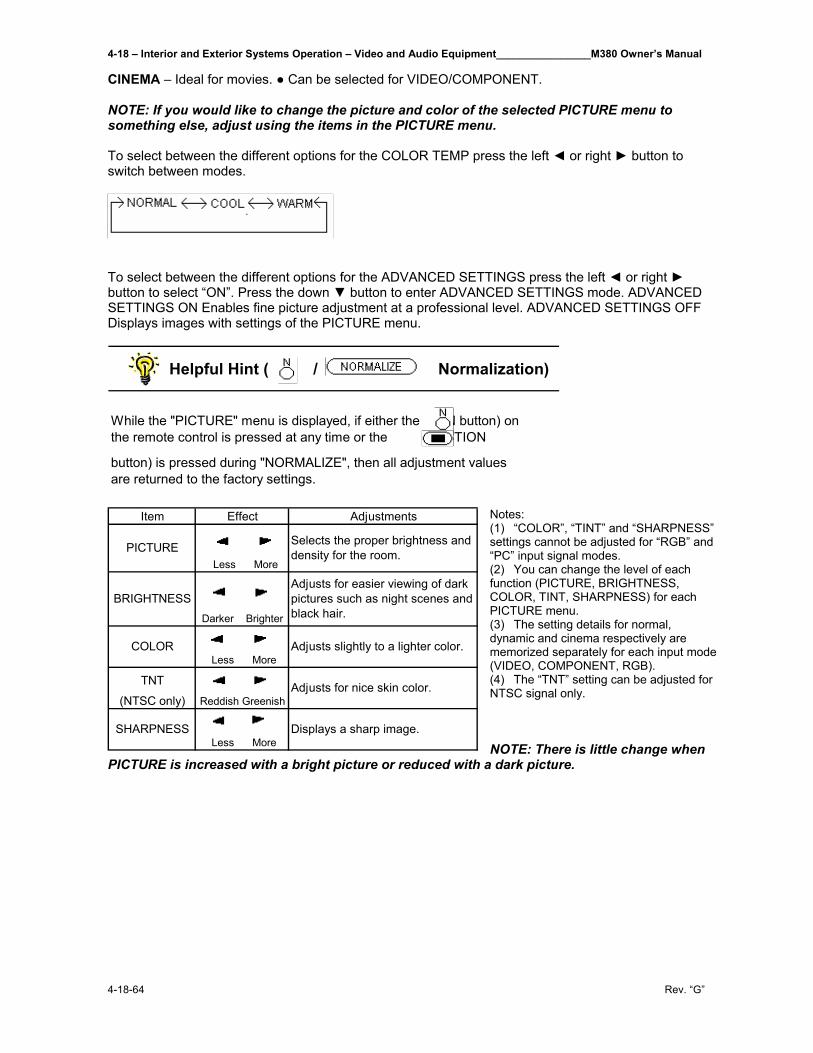
4-18 – Interior and Exterior Systems Operation – Video and Audio Equipment________________M380 Owner’s Manual
4-18-64 Rev. “G”
CINEMA – Ideal for movies. ● Can be selected for VIDEO/COMPONENT. NOTE: If you would like to change the picture and color of the selected PICTURE menu to something else, adjust using the items in the PICTURE menu. To select between the different options for the COLOR TEMP press the left ◄ or right ► button to switch between modes.
To select between the different options for the ADVANCED SETTINGS press the left ◄ or right ► button to select “ON”. Press the down ▼ button to enter ADVANCED SETTINGS mode. ADVANCED SETTINGS ON Enables fine picture adjustment at a professional level. ADVANCED SETTINGS OFF Displays images with settings of the PICTURE menu.
Helpful Hint ( / Normalization)
While the "PICTURE" menu is displayed, if either the (N button) on the remote control is pressed at any time or the (ACTION
button) is pressed during "NORMALIZE", then all adjustment values are returned to the factory settings.
Notes: (1) “COLOR”, “TINT” and “SHARPNESS” settings cannot be adjusted for “RGB” and “PC” input signal modes. (2) You can change the level of each function (PICTURE, BRIGHTNESS, COLOR, TINT, SHARPNESS) for each PICTURE menu. (3) The setting details for normal, dynamic and cinema respectively are memorized separately for each input mode (VIDEO, COMPONENT, RGB). (4) The “TNT” setting can be adjusted for NTSC signal only. NOTE: There is little change when
PICTURE is increased with a bright picture or reduced with a dark picture.
Item Effect Adjustments
Less More
Darker Brighter
Less More
TNT
(NTSC only) Reddish Greenish
Less More
COLOR
SHARPNESS
Selects the proper brightness and density for the room.
Adjusts for easier viewing of dark pictures such as night scenes and black hair.
Adjusts slightly to a lighter color.
Adjusts for nice skin color.
Displays a sharp image.
PICTURE
BRIGHTNESS
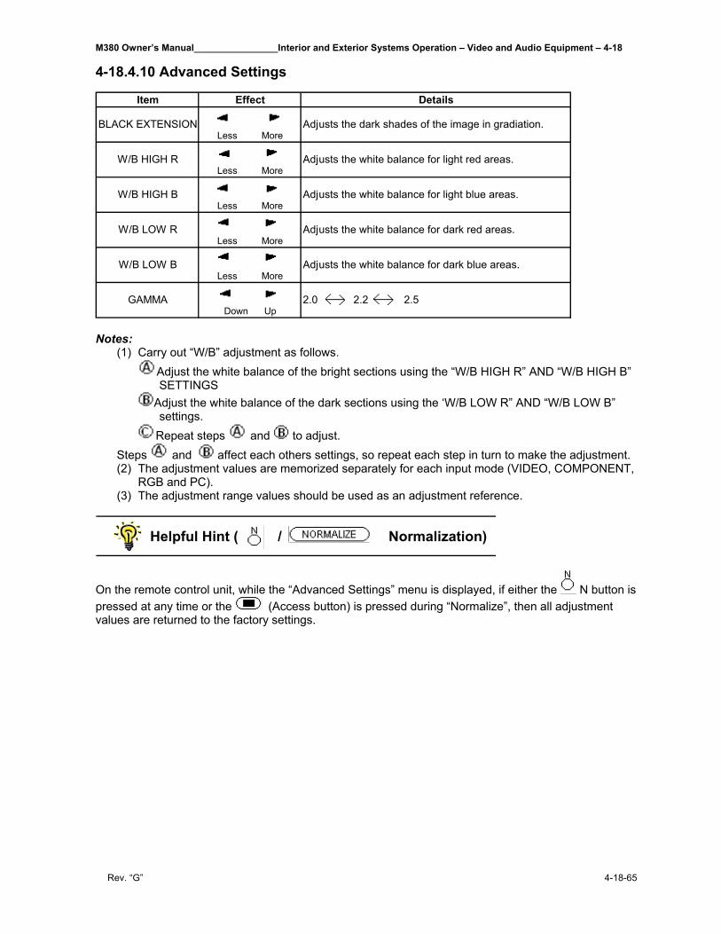
M380 Owner’s Manual________________Interior and Exterior Systems Operation – Video and Audio Equipment – 4-18
Rev. “G” 4-18-65
4-18.4.10 Advanced Settings
Item Effect Details
Less More
Less More
Less More
Less More
Less More
Down Up
Adjusts the white balance for dark blue areas.
2.0 2.2 2.5
BLACK EXTENSION
W/B HIGH R
Adjusts the dark shades of the image in gradiation.
Adjusts the white balance for light red areas.
Adjusts the white balance for light blue areas.
Adjusts the white balance for dark red areas.
W/B HIGH B
W/B LOW R
W/B LOW B
GAMMA
Notes:
(1) Carry out “W/B” adjustment as follows. Adjust the white balance of the bright sections using the “W/B HIGH R” AND “W/B HIGH B” SETTINGS
Adjust the white balance of the dark sections using the ‘W/B LOW R” AND “W/B LOW B” settings.
Repeat steps and to adjust. Steps and affect each others settings, so repeat each step in turn to make the adjustment. (2) The adjustment values are memorized separately for each input mode (VIDEO, COMPONENT,
RGB and PC). (3) The adjustment range values should be used as an adjustment reference.
Helpful Hint ( / Normalization)
On the remote control unit, while the “Advanced Settings” menu is displayed, if either the N button is pressed at any time or the (Access button) is pressed during “Normalize”, then all adjustment values are returned to the factory settings.
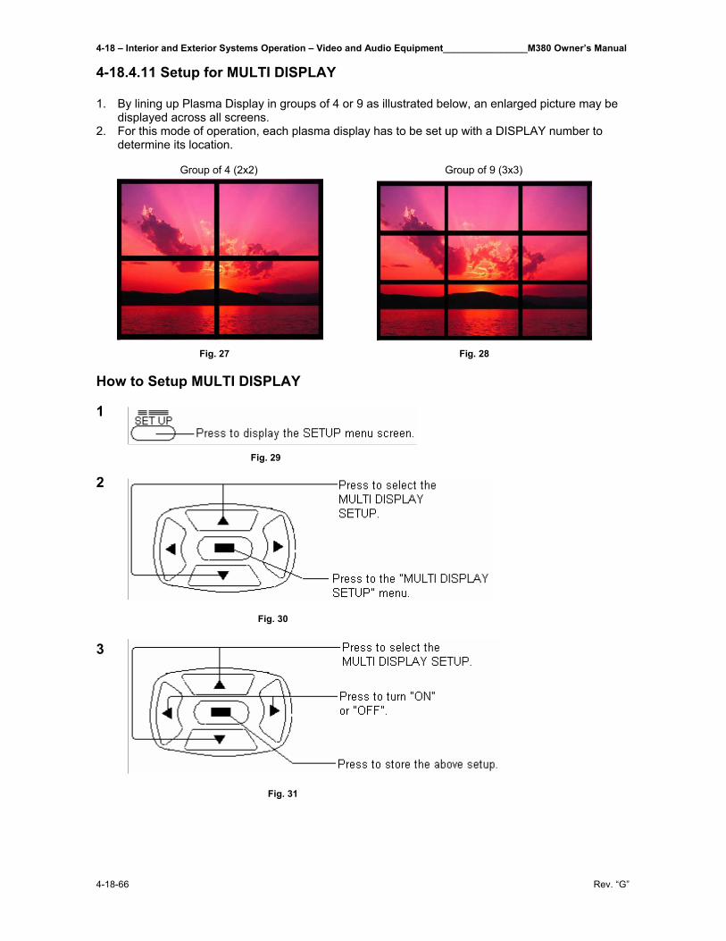
4-18 – Interior and Exterior Systems Operation – Video and Audio Equipment________________M380 Owner’s Manual
4-18-66 Rev. “G”
4-18.4.11 Setup for MULTI DISPLAY 1. By lining up Plasma Display in groups of 4 or 9 as illustrated below, an enlarged picture may be
displayed across all screens. 2. For this mode of operation, each plasma display has to be set up with a DISPLAY number to
determine its location. Group of 4 (2x2) Group of 9 (3x3)
Fig. 27 Fig. 28
How to Setup MULTI DISPLAY 1 Fig. 29 2 Fig. 30 3 Fig. 31
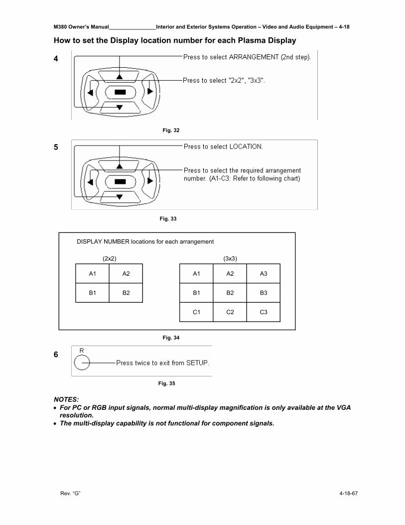
M380 Owner’s Manual________________Interior and Exterior Systems Operation – Video and Audio Equipment – 4-18
Rev. “G” 4-18-67
How to set the Display location number for each Plasma Display 4 Fig. 32 5 Fig. 33
Fig. 34 6 Fig. 35 NOTES: • For PC or RGB input signals, normal multi-display magnification is only available at the VGA
resolution. • The multi-display capability is not functional for component signals.
A1 A2 A1 A2 A3
B1 B2 B1 B2 B3
C1 C2 C3
DISPLAY NUMBER locations for each arrangement
(2x2) (3x3)
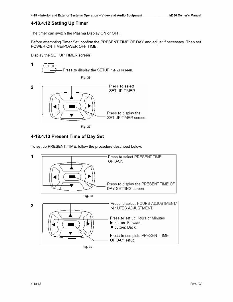
4-18 – Interior and Exterior Systems Operation – Video and Audio Equipment________________M380 Owner’s Manual
4-18-68 Rev. “G”
4-18.4.12 Setting Up Timer The timer can switch the Plasma Display ON or OFF. Before attempting Timer Set, confirm the PRESENT TIME OF DAY and adjust if necessary. Then set POWER ON TIME/POWER OFF TIME. Display the SET UP TIMER screen 1 Fig. 36 2 Fig. 37 4-18.4.13 Present Time of Day Set To set up PRESENT TIME, follow the procedure described below. 1 Fig. 38 2 Fig. 39
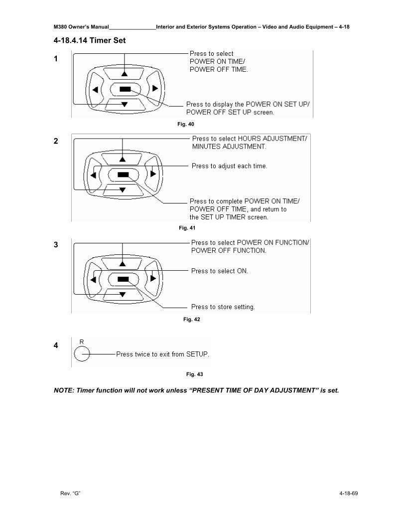
M380 Owner’s Manual________________Interior and Exterior Systems Operation – Video and Audio Equipment – 4-18
Rev. “G” 4-18-69
4-18.4.14 Timer Set 1 Fig. 40 2 Fig. 41 3 Fig. 42 4 Fig. 43 NOTE: Timer function will not work unless “PRESENT TIME OF DAY ADJUSTMENT” is set.
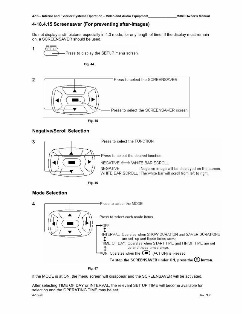
4-18 – Interior and Exterior Systems Operation – Video and Audio Equipment________________M380 Owner’s Manual
4-18-70 Rev. “G”
4-18.4.15 Screensaver (For preventing after-images) Do not display a still picture, especially in 4:3 mode, for any length of time. If the display must remain on, a SCREENSAVER should be used. 1 Fig. 44 2 Fig. 45 Negative/Scroll Selection 3 Fig. 46 Mode Selection 4 Fig. 47 If the MODE is at ON, the menu screen will disappear and the SCREENSAVER will be activated. After selecting TIME OF DAY or INTERVAL, the relevant SET UP TIME will become available for selection and the OPERATING TIME may be set.
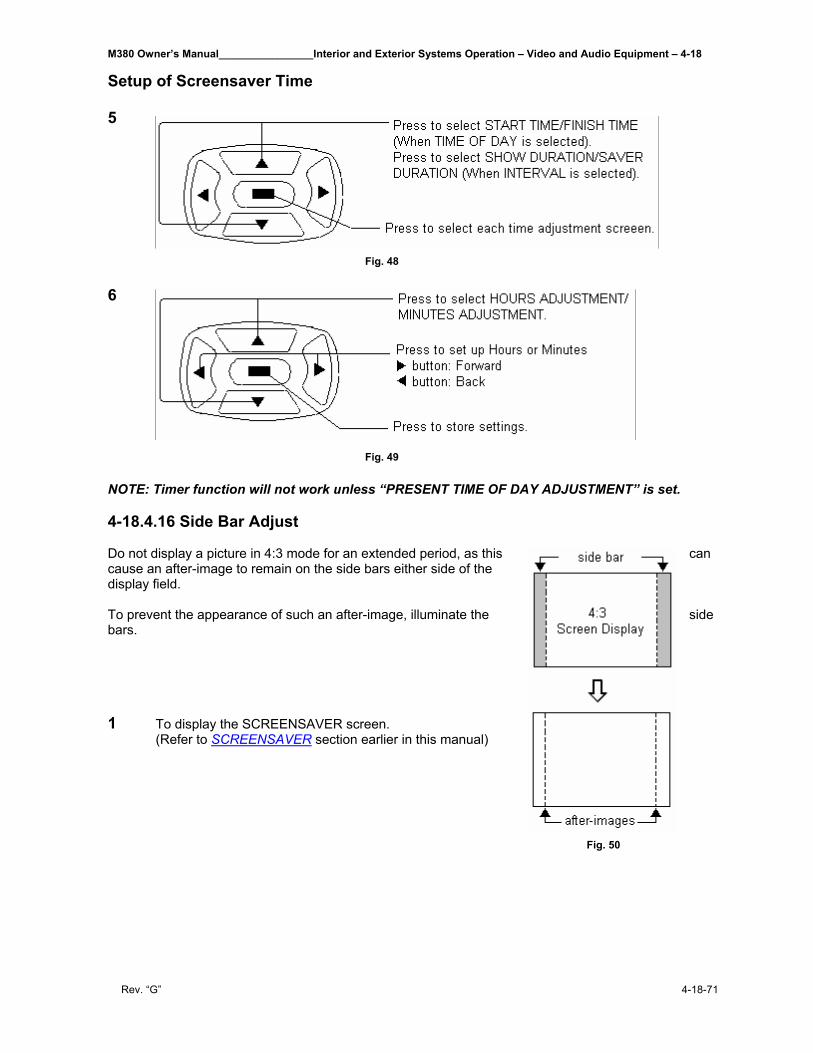
M380 Owner’s Manual________________Interior and Exterior Systems Operation – Video and Audio Equipment – 4-18
Rev. “G” 4-18-71
Setup of Screensaver Time 5 Fig. 48 6 Fig. 49 NOTE: Timer function will not work unless “PRESENT TIME OF DAY ADJUSTMENT” is set. 4-18.4.16 Side Bar Adjust Do not display a picture in 4:3 mode for an extended period, as this can cause an after-image to remain on the side bars either side of the display field. To prevent the appearance of such an after-image, illuminate the side bars. 1 To display the SCREENSAVER screen.
(Refer to SCREENSAVER section earlier in this manual)
Fig. 50
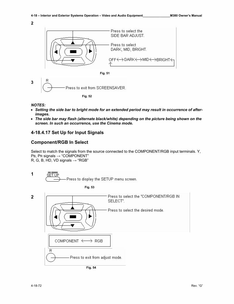
4-18 – Interior and Exterior Systems Operation – Video and Audio Equipment________________M380 Owner’s Manual
4-18-72 Rev. “G”
2 Fig. 51 3 Fig. 52 NOTES: • Setting the side bar to bright mode for an extended period may result in occurrence of after-
images. • The side bar may flash (alternate black/white) depending on the picture being shown on the
screen. In such an occurrence, use the Cinema mode.
4-18.4.17 Set Up for Input Signals Component/RGB In Select Select to match the signals from the source connected to the COMPONENT/RGB input terminals. Y, PB, PR signals → “COMPONENT” R, G, B, HD, VD signals → “RGB” 1 Fig. 53 2 Fig. 54
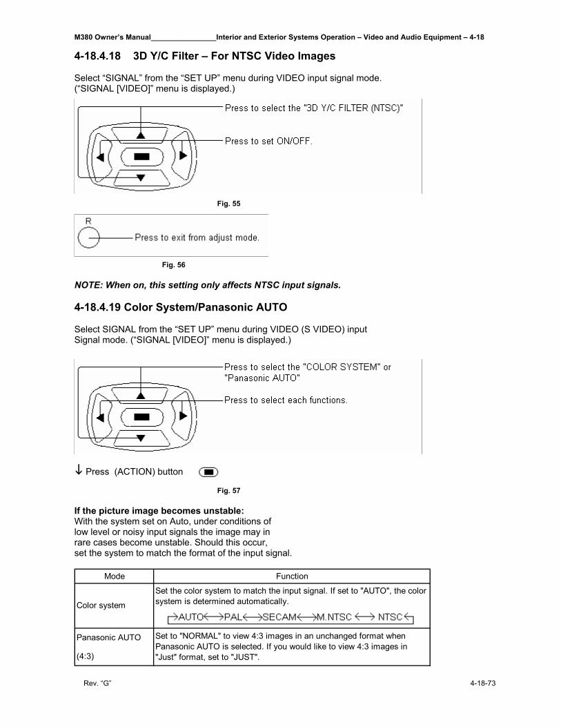
M380 Owner’s Manual________________Interior and Exterior Systems Operation – Video and Audio Equipment – 4-18
Rev. “G” 4-18-73
4-18.4.18 3D Y/C Filter – For NTSC Video Images Select “SIGNAL” from the “SET UP” menu during VIDEO input signal mode. (“SIGNAL [VIDEO]” menu is displayed.)
Fig. 55
Fig. 56 NOTE: When on, this setting only affects NTSC input signals. 4-18.4.19 Color System/Panasonic AUTO Select SIGNAL from the “SET UP” menu during VIDEO (S VIDEO) input Signal mode. (“SIGNAL [VIDEO]” menu is displayed.)
Press (ACTION) button Fig. 57 If the picture image becomes unstable: With the system set on Auto, under conditions of low level or noisy input signals the image may in rare cases become unstable. Should this occur, set the system to match the format of the input signal.
Mode Function
Set the color system to match the input signal. If set to "AUTO", the color system is determined automatically.
Panasonic AUTO
(4:3)
Color system
Set to "NORMAL" to view 4:3 images in an unchanged format when Panasonic AUTO is selected. If you would like to view 4:3 images in "Just" format, set to "JUST".
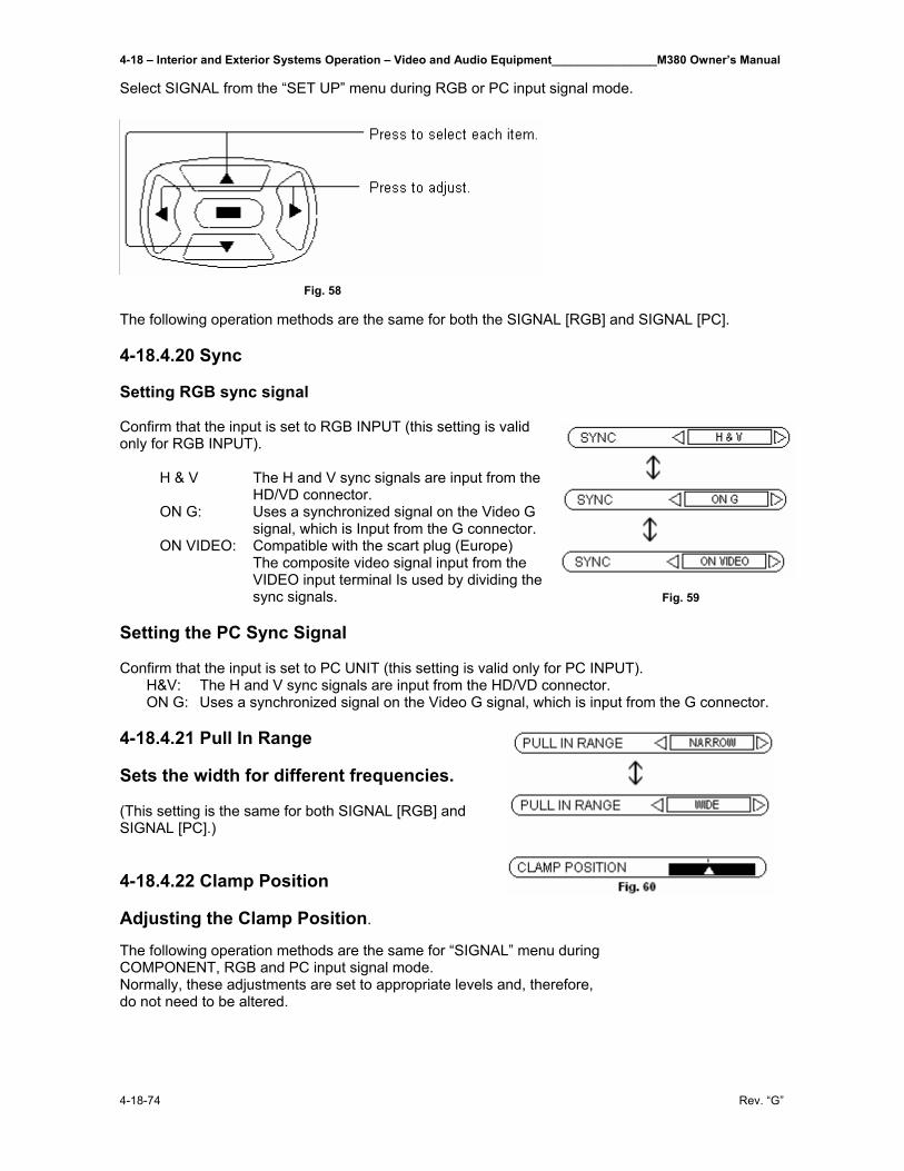
4-18 – Interior and Exterior Systems Operation – Video and Audio Equipment________________M380 Owner’s Manual
4-18-74 Rev. “G”
Select SIGNAL from the “SET UP” menu during RGB or PC input signal mode.
Fig. 58 The following operation methods are the same for both the SIGNAL [RGB] and SIGNAL [PC]. 4-18.4.20 Sync Setting RGB sync signal Confirm that the input is set to RGB INPUT (this setting is valid only for RGB INPUT). H & V The H and V sync signals are input from the HD/VD connector. ON G: Uses a synchronized signal on the Video G signal, which is Input from the G connector. ON VIDEO: Compatible with the scart plug (Europe) The composite video signal input from the VIDEO input terminal Is used by dividing the sync signals. Fig. 59 Setting the PC Sync Signal Confirm that the input is set to PC UNIT (this setting is valid only for PC INPUT). H&V: The H and V sync signals are input from the HD/VD connector. ON G: Uses a synchronized signal on the Video G signal, which is input from the G connector. 4-18.4.21 Pull In Range Sets the width for different frequencies. (This setting is the same for both SIGNAL [RGB] and SIGNAL [PC].) 4-18.4.22 Clamp Position Adjusting the Clamp Position. The following operation methods are the same for “SIGNAL” menu during COMPONENT, RGB and PC input signal mode. Normally, these adjustments are set to appropriate levels and, therefore, do not need to be altered.
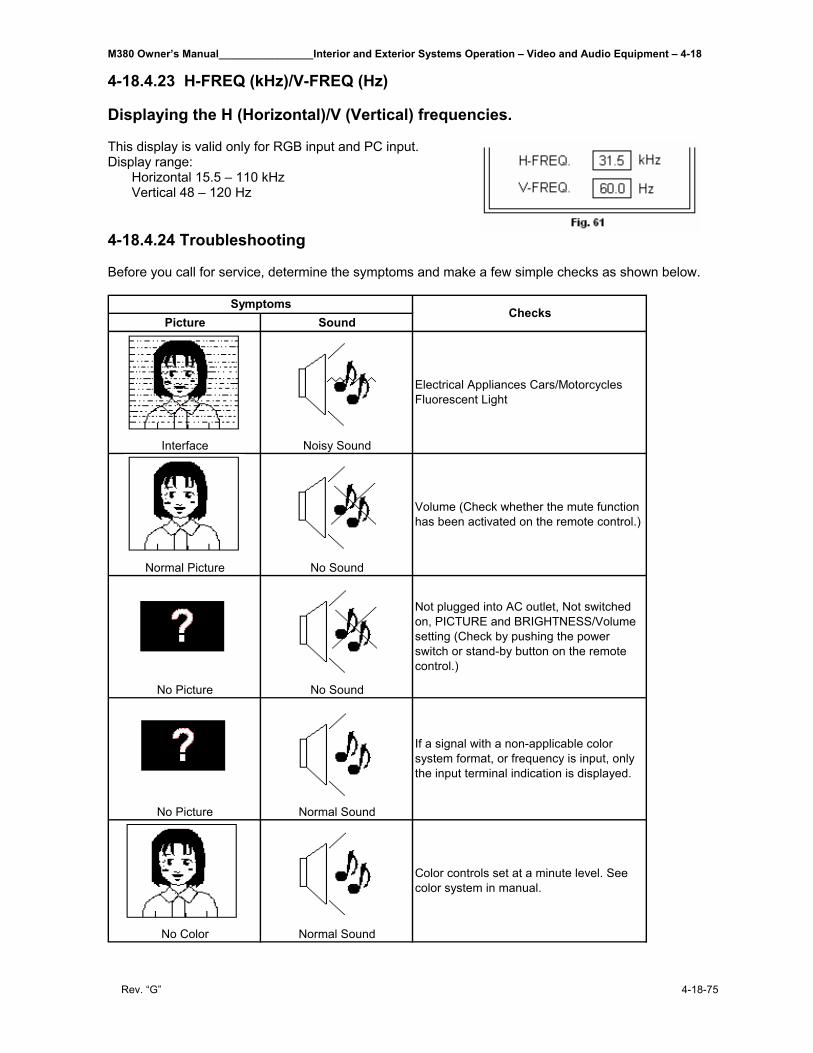
M380 Owner’s Manual________________Interior and Exterior Systems Operation – Video and Audio Equipment – 4-18
Rev. “G” 4-18-75
4-18.4.23 H-FREQ (kHz)/V-FREQ (Hz) Displaying the H (Horizontal)/V (Vertical) frequencies. This display is valid only for RGB input and PC input. Display range: Horizontal 15.5 – 110 kHz Vertical 48 – 120 Hz 4-18.4.24 Troubleshooting Before you call for service, determine the symptoms and make a few simple checks as shown below.
Picture Sound
Interface Noisy Sound
Normal Picture No Sound
No Picture No Sound
No Picture Normal Sound
No Color Normal Sound
Not plugged into AC outlet, Not switched on, PICTURE and BRIGHTNESS/Volume setting (Check by pushing the power switch or stand-by button on the remote control.)
If a signal with a non-applicable color system format, or frequency is input, only the input terminal indication is displayed.
Color controls set at a minute level. See color system in manual.
SymptomsChecks
Electrical Appliances Cars/Motorcycles Fluorescent Light
Volume (Check whether the mute function has been activated on the remote control.)
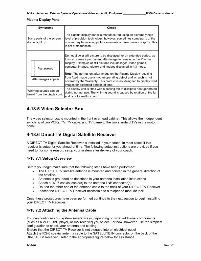
4-18 – Interior and Exterior Systems Operation – Video and Audio Equipment________________M380 Owner’s Manual
4-18-76 Rev. “G”
Plasma Display Panel
Symptoms Check
Some parts of the screen do not light up
The plasma display panel is manufactured using an extremely high level of precision technology, however, sometimes some parts of the screen may be missing picture elements or have luminous spots. This is not a malfunction.
Do not allow a still picture to be displayed for an extended period, as this can cause a permanent after-image to remain on the Plasma Display. Examples of still pictures include logos, video games, computer images, teletext and images displayed in 4:3 mode.
After-images appear
Note: The permanent after-image on the Plasma Display resulting from fixed image use is not an operating defect and as such is not covered by the Warranty. This product is not designed to display fixed images for extended periods of time.
Whirring sounds can be heard from the display unit.
The display unit is fitted with a cooling fan to dissipate heat generated during normal use. The whirring sound is caused by rotation of the fan and is not a malfunction.
4-18.5 Video Selector Box The video selector box is mounted in the front overhead cabinet. This allows the independent switching of two VCRs, TV, TV cable, and TV game to the two standard TVs in the motor home. 4-18.6 Direct TV Digital Satellite Receiver A DIRECT TV Digital Satellite Receiver is installed in your coach. In most cases if this receiver is setup for you ahead of time. The following setup instructions are provided if you need to, for some reason, setup your system after delivery of your coach. 4-18.7.1 Setup Overview Before you begin make sure that the following steps have been performed:
• The DIRECT TV satellite antenna is mounted and pointed in the general direction of the satellite.
• Antenna is grounded as described in your antenna installation instructions • Attach a RG-6 coaxial cable(s) to the antenna LNB connector(s) • Routed the other end of the antenna cable to the back of your DIRECT TV Receiver. • Placed the DIRECT TV Receiver accessible to a telephone modular jack.
Once these procedures have been performed continue to the next section to begin installing your DIRECT TV Receiver. 4-18.7.2 Attaching the Antenna Cable You can configure your system several ways, depending on what additional components (such as a VCR, DVD player, or A/V receiver) you select. For now, however, use the simplest configuration to check your antenna and cabling. Ensure that the DIRECT TV Receiver is not plugged into an electrical outlet Attach the RG-6 coaxial antenna cable to the SATELLITE IN connector on the back of the DIRECT TV Receiver. Refer to the appropriate figure below for assistance.
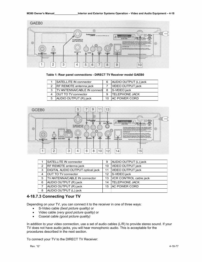
M380 Owner’s Manual________________Interior and Exterior Systems Operation – Video and Audio Equipment – 4-18
Rev. “G” 4-18-77
Table 1: Rear panel connections - DIRECT TV Receiver model GAEB0
4-18.7.3 Connecting Your TV Depending on your TV, you can connect it to the receiver in one of three ways:
• S-Video cable (best picture quality) or • Video cable (very good picture quality) or • Coaxial cable (good picture quality)
In addition to your video connection, use a set of audio cables (L/R) to provide stereo sound. If your TV does not have audio jacks, you will hear monophonic audio. This is acceptable for the procedures described in the next section. To connect your TV to the DIRECT TV Receiver:
1 SATELLITE IN connector 6 AUDIO OUTPUT (L) jack2 RF REMOTE antenna jack 7 VIDEO OUTPUT jack3 TV ANTENNA/CABLE IN connecto 8 S-VIDEO jack4 OUT TO TV connector 9 TELEPHONE JACK5 AUDIO OUTPUT (R) jack 10 AC POWER CORD
1 SATELLITE IN connector 9 AUDIO OUTPUT (L) jack2 RF REMOTE antenna jack 10 VIDEO OUTPUT jack3 DIGITAL AUDIO OUTPUT optical jack 11 VIDEO OUTPUT jack4 OUT TO TV connector 12 S-VIDEO jack5 TV ANTENNA/CABLE IN connector 13 VCR CONTROL cable jack6 AUDIO OUTPUT (R) jack 14 TELEPHONE JACK7 AUDIO OUTPUT (R) jack 15 AC POWER CORD8 AUDIO OUTPUT (L) jack
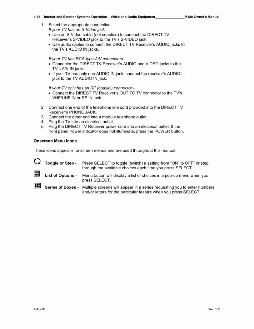
4-18 – Interior and Exterior Systems Operation – Video and Audio Equipment________________M380 Owner’s Manual
4-18-78 Rev. “G”
1. Select the appropriate connection: If your TV has an S-Video jack - • Use an S-Video cable (not supplied) to connect the DIRECT TV
Receiver’s S-VIDEO jack to the TV’s S-VIDEO jack. • Use audio cables to connect the DIRECT TV Receiver’s AUDIO jacks to
the TV’s AUDIO IN jacks. If your TV has RCA-type A/V connectors - • Connector the DIRECT TV Receiver’s AUDIO and VIDEO jacks to the
TV’s A/V IN jacks. • If your TV has only one AUDIO IN jack, connect the receiver’s AUDIO L
jack to the TV AUDIO IN jack. If your TV only has an RF (coaxial) connector - • Connect the DIRECT TV Receiver’s OUT TO TV connector to the TV’s
VHF/UHF IN or RF IN jack.
2. Connect one end of the telephone line cord provided into the DIRECT TV Receiver’s PHONE JACK.
3. Connect the other end into a module telephone outlet. 4. Plug the TV into an electrical outlet. 5. Plug the DIRECT TV Receiver power cord into an electrical outlet. If the
front panel Power indicator does not illuminate, press the POWER button.
Onscreen Menu Icons These icons appear in onscreen menus and are used throughout this manual:
Toggle or Step - Press SELECT to toggle (switch) a setting from “ON” to OFF” or step through the available choices each time you press SELECT.
List of Options - Menu button will display a list of choices in a pop-up menu when you press SELECT.
Series of Boxes - Multiple screens will appear in a series requesting you to enter numbers and/or letters for the particular feature when you press SELECT.
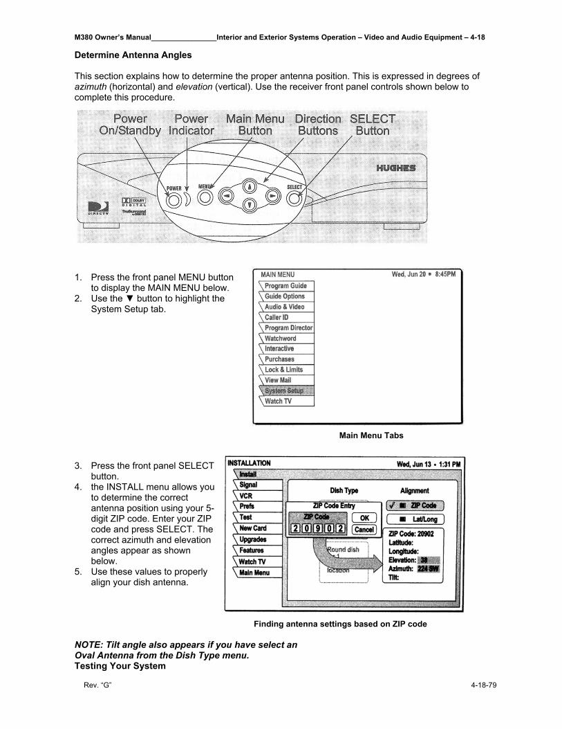
M380 Owner’s Manual________________Interior and Exterior Systems Operation – Video and Audio Equipment – 4-18
Rev. “G” 4-18-79
Determine Antenna Angles This section explains how to determine the proper antenna position. This is expressed in degrees of azimuth (horizontal) and elevation (vertical). Use the receiver front panel controls shown below to complete this procedure.
1. Press the front panel MENU button
to display the MAIN MENU below. 2. Use the ▼ button to highlight the
System Setup tab. Main Menu Tabs 3. Press the front panel SELECT
button. 4. the INSTALL menu allows you
to determine the correct antenna position using your 5-digit ZIP code. Enter your ZIP code and press SELECT. The correct azimuth and elevation angles appear as shown below.
5. Use these values to properly align your dish antenna.
Finding antenna settings based on ZIP code NOTE: Tilt angle also appears if you have select an Oval Antenna from the Dish Type menu. Testing Your System
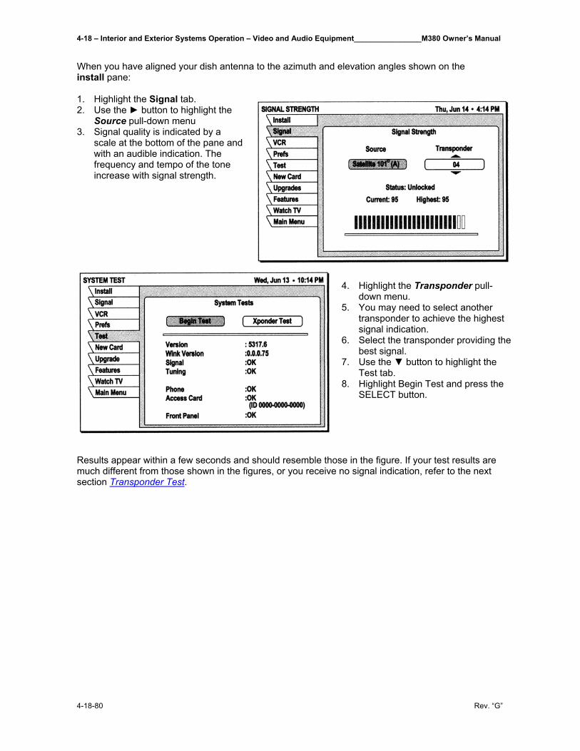
4-18 – Interior and Exterior Systems Operation – Video and Audio Equipment________________M380 Owner’s Manual
4-18-80 Rev. “G”
When you have aligned your dish antenna to the azimuth and elevation angles shown on the install pane: 1. Highlight the Signal tab. 2. Use the ► button to highlight the
Source pull-down menu 3. Signal quality is indicated by a
scale at the bottom of the pane and with an audible indication. The frequency and tempo of the tone increase with signal strength.
4. Highlight the Transponder pull-
down menu. 5. You may need to select another
transponder to achieve the highest signal indication.
6. Select the transponder providing the best signal.
7. Use the ▼ button to highlight the Test tab.
8. Highlight Begin Test and press the SELECT button.
Results appear within a few seconds and should resemble those in the figure. If your test results are much different from those shown in the figures, or you receive no signal indication, refer to the next section Transponder Test.
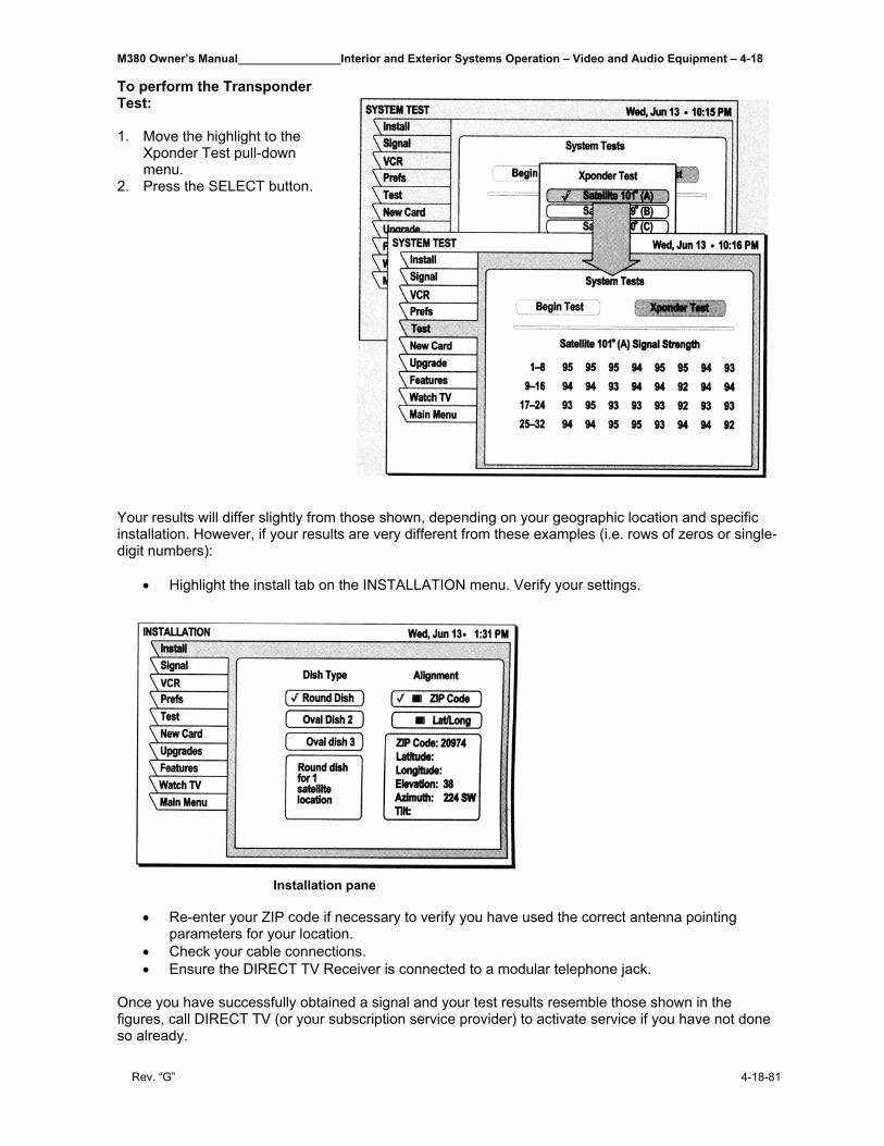
M380 Owner’s Manual________________Interior and Exterior Systems Operation – Video and Audio Equipment – 4-18
Rev. “G” 4-18-81
To perform the Transponder Test: 1. Move the highlight to the
Xponder Test pull-down menu.
2. Press the SELECT button.
Your results will differ slightly from those shown, depending on your geographic location and specific installation. However, if your results are very different from these examples (i.e. rows of zeros or single-digit numbers):
• Highlight the install tab on the INSTALLATION menu. Verify your settings.
Installation pane
• Re-enter your ZIP code if necessary to verify you have used the correct antenna pointing parameters for your location.
• Check your cable connections. • Ensure the DIRECT TV Receiver is connected to a modular telephone jack.
Once you have successfully obtained a signal and your test results resemble those shown in the figures, call DIRECT TV (or your subscription service provider) to activate service if you have not done so already.
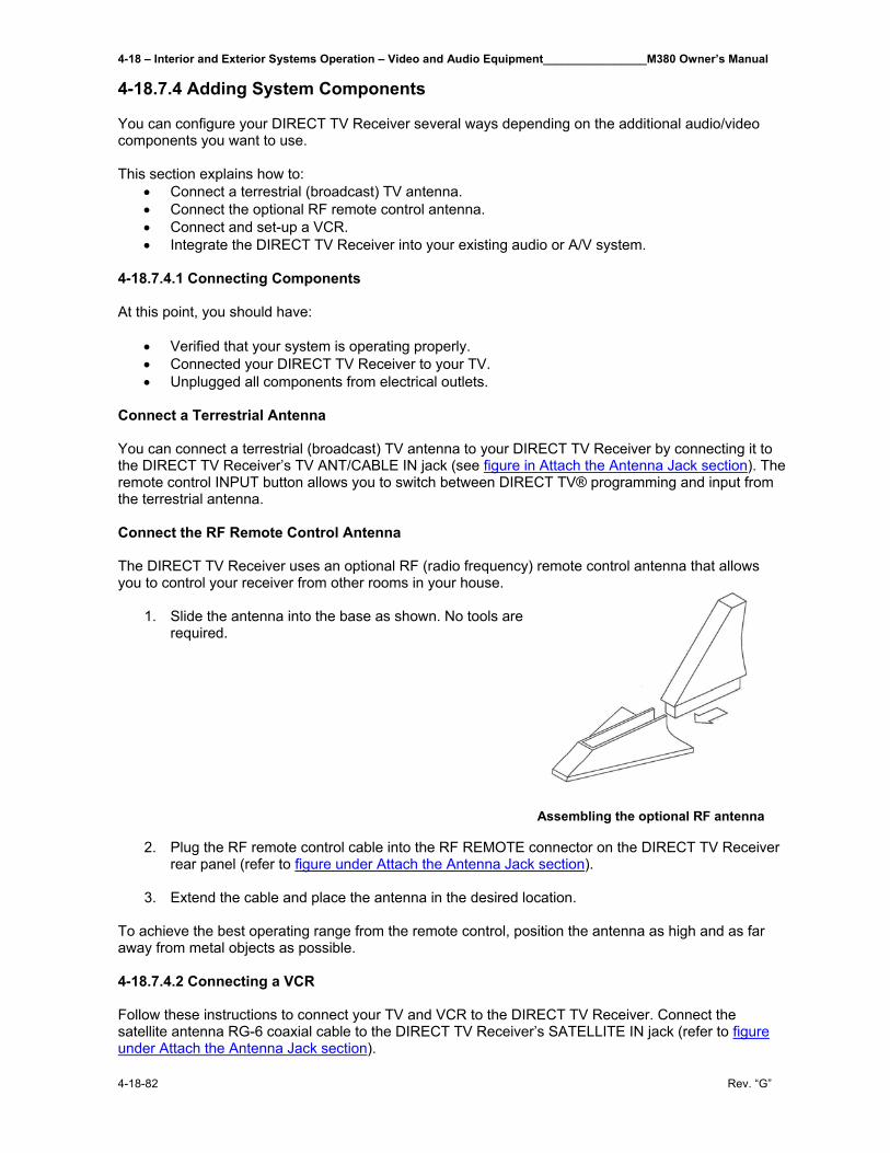
4-18 – Interior and Exterior Systems Operation – Video and Audio Equipment________________M380 Owner’s Manual
4-18-82 Rev. “G”
4-18.7.4 Adding System Components You can configure your DIRECT TV Receiver several ways depending on the additional audio/video components you want to use. This section explains how to:
• Connect a terrestrial (broadcast) TV antenna. • Connect the optional RF remote control antenna. • Connect and set-up a VCR. • Integrate the DIRECT TV Receiver into your existing audio or A/V system.
4-18.7.4.1 Connecting Components At this point, you should have:
• Verified that your system is operating properly. • Connected your DIRECT TV Receiver to your TV. • Unplugged all components from electrical outlets.
Connect a Terrestrial Antenna You can connect a terrestrial (broadcast) TV antenna to your DIRECT TV Receiver by connecting it to the DIRECT TV Receiver’s TV ANT/CABLE IN jack (see figure in Attach the Antenna Jack section). The remote control INPUT button allows you to switch between DIRECT TV® programming and input from the terrestrial antenna. Connect the RF Remote Control Antenna The DIRECT TV Receiver uses an optional RF (radio frequency) remote control antenna that allows you to control your receiver from other rooms in your house.
1. Slide the antenna into the base as shown. No tools are required.
Assembling the optional RF antenna
2. Plug the RF remote control cable into the RF REMOTE connector on the DIRECT TV Receiver rear panel (refer to figure under Attach the Antenna Jack section).
3. Extend the cable and place the antenna in the desired location.
To achieve the best operating range from the remote control, position the antenna as high and as far away from metal objects as possible. 4-18.7.4.2 Connecting a VCR Follow these instructions to connect your TV and VCR to the DIRECT TV Receiver. Connect the satellite antenna RG-6 coaxial cable to the DIRECT TV Receiver’s SATELLITE IN jack (refer to figure under Attach the Antenna Jack section).
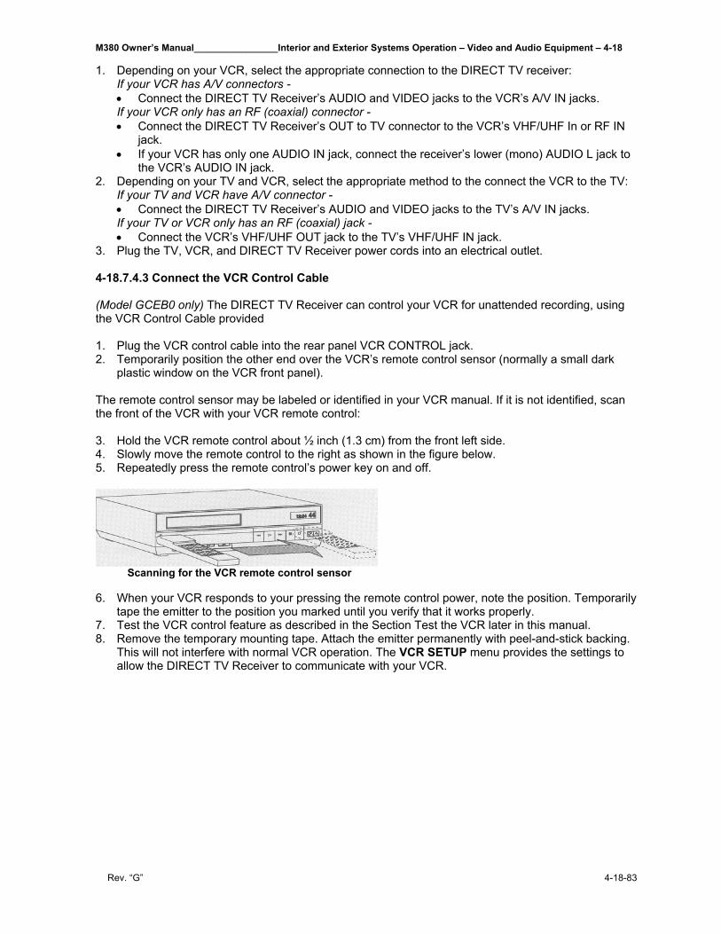
M380 Owner’s Manual________________Interior and Exterior Systems Operation – Video and Audio Equipment – 4-18
Rev. “G” 4-18-83
1. Depending on your VCR, select the appropriate connection to the DIRECT TV receiver: If your VCR has A/V connectors - • Connect the DIRECT TV Receiver’s AUDIO and VIDEO jacks to the VCR’s A/V IN jacks. If your VCR only has an RF (coaxial) connector - • Connect the DIRECT TV Receiver’s OUT to TV connector to the VCR’s VHF/UHF In or RF IN
jack. • If your VCR has only one AUDIO IN jack, connect the receiver’s lower (mono) AUDIO L jack to
the VCR’s AUDIO IN jack. 2. Depending on your TV and VCR, select the appropriate method to the connect the VCR to the TV:
If your TV and VCR have A/V connector - • Connect the DIRECT TV Receiver’s AUDIO and VIDEO jacks to the TV’s A/V IN jacks. If your TV or VCR only has an RF (coaxial) jack - • Connect the VCR’s VHF/UHF OUT jack to the TV’s VHF/UHF IN jack.
3. Plug the TV, VCR, and DIRECT TV Receiver power cords into an electrical outlet. 4-18.7.4.3 Connect the VCR Control Cable (Model GCEB0 only) The DIRECT TV Receiver can control your VCR for unattended recording, using the VCR Control Cable provided 1. Plug the VCR control cable into the rear panel VCR CONTROL jack. 2. Temporarily position the other end over the VCR’s remote control sensor (normally a small dark
plastic window on the VCR front panel). The remote control sensor may be labeled or identified in your VCR manual. If it is not identified, scan the front of the VCR with your VCR remote control: 3. Hold the VCR remote control about ½ inch (1.3 cm) from the front left side. 4. Slowly move the remote control to the right as shown in the figure below. 5. Repeatedly press the remote control’s power key on and off.
Scanning for the VCR remote control sensor 6. When your VCR responds to your pressing the remote control power, note the position. Temporarily
tape the emitter to the position you marked until you verify that it works properly. 7. Test the VCR control feature as described in the Section Test the VCR later in this manual. 8. Remove the temporary mounting tape. Attach the emitter permanently with peel-and-stick backing.
This will not interfere with normal VCR operation. The VCR SETUP menu provides the settings to allow the DIRECT TV Receiver to communicate with your VCR.
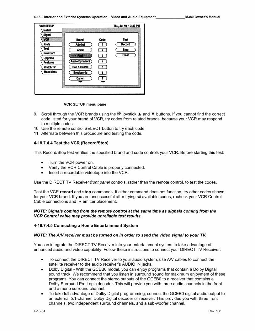
4-18 – Interior and Exterior Systems Operation – Video and Audio Equipment________________M380 Owner’s Manual
4-18-84 Rev. “G”
VCR SETUP menu pane 9. Scroll through the VCR brands using the joystick ▲ and ▼ buttons. If you cannot find the correct
code listed for your brand of VCR, try codes from related brands, because your VCR may respond to multiple codes.
10. Use the remote control SELECT button to try each code. 11. Alternate between this procedure and testing the code. 4-18.7.4.4 Test the VCR (Record/Stop) This Record/Stop test verifies the specified brand and code controls your VCR. Before starting this test:
• Turn the VCR power on. • Verify the VCR Control Cable is properly connected. • Insert a recordable videotape into the VCR.
Use the DIRECT TV Receiver front panel controls, rather than the remote control, to test the codes. Test the VCR record and stop commands. If either command does not function, try other codes shown for your VCR brand. If you are unsuccessful after trying all available codes, recheck your VCR Control Cable connections and IR emitter placement. NOTE: Signals coming from the remote control at the same time as signals coming from the VCR Control cable may provide unreliable test results. 4-18.7.4.5 Connecting a Home Entertainment System NOTE: The A/V receiver must be turned on in order to send the video signal to your TV. You can integrate the DIRECT TV Receiver into your entertainment system to take advantage of enhanced audio and video capability. Follow these instructions to connect your DIRECT TV Receiver.
• To connect the DIRECT TV Receiver to your audio system, use A/V cables to connect the satellite receiver to the audio receiver’s AUDIO IN jacks.
• Dolby Digital - With the GCEB0 model, you can enjoy programs that contain a Dolby Digital sound track. We recommend that you listen in surround sound for maximum enjoyment of these programs. You can connect the stereo outputs of the GCEB0 to a receiver that contains a Dolby Surround Pro Logic decoder. This will provide you with three audio channels in the front and a mono surround channel.
• To take full advantage of Dolby Digital programming, connect the GCEB0 digital audio output to an external 5.1-channel Dolby Digital decoder or receiver. This provides you with three front channels, two independent surround channels, and a sub-woofer channel.
M380 Owner’s Manual________________Interior and Exterior Systems Operation – Video and Audio Equipment – 4-18
Rev. “G” 4-18-85
1. Connect the satellite antenna RG-6 coaxial cable to the DIRECT TV Receiver’s SATELLITE IN
jack. 2. Connect the DIRECT TV Receiver’s A/V jacks to the VCR and A/V receiver’s A/V jacks. 3. AUX, optical connection, and digital output connections - If your audio receiver has coaxial or
optical digital connectors, connect the appropriate type of cable to the DIRECT TV Receiver’s DIGTAL AUDIO OUT for two-channel digital stereo. If your A/V receiver is also capable of decoding Dolby Digital, use this connection in order to listen in full 5.1-channel surround sound. Additional audio information begins in the Adjusting Audio and Video section later in this manual.
4. Connect the VCR’s A/V OUT jacks to a pair of the A/V receiver’s A/V In jacks. 5. Connect the A/V receiver’s MONITOR OUT jack to the TV’s VIDEO IN jack. 6. Plug the components into an electrical outlet. NOTE: If you have connected a VCR to your entertainment system in a way that routes the satellite receiver’s signal to your VCR before it reaches the TV. You may see a distorted picture if you try to record a copy-protected program. A Can’t Tape symbol in the screen banner identifies these programs. If this occurs, simply stop recording and the picture will automatically correct itself.
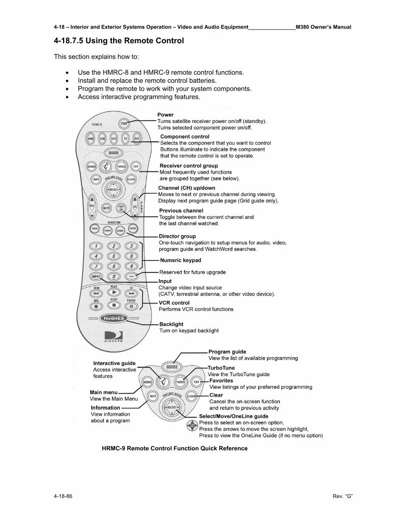
4-18 – Interior and Exterior Systems Operation – Video and Audio Equipment________________M380 Owner’s Manual
4-18-86 Rev. “G”
4-18.7.5 Using the Remote Control This section explains how to:
• Use the HMRC-8 and HMRC-9 remote control functions. • Install and replace the remote control batteries. • Program the remote to work with your system components. • Access interactive programming features.
HRMC-9 Remote Control Function Quick Reference
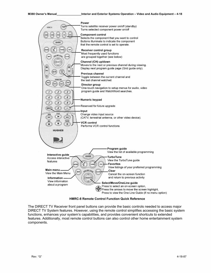
M380 Owner’s Manual________________Interior and Exterior Systems Operation – Video and Audio Equipment – 4-18
Rev. “G” 4-18-87
HMRC-8 Remote Control Function Quick Reference The DIRECT TV Receiver front panel buttons can provide the basic controls needed to access major DIRECT TV System features. However, using the remote control simplifies accessing the basic system functions, enhances your system’s capabilities, and provides convenient shortcuts to extended features. Additionally, most remote control buttons can also control other home entertainment system components.
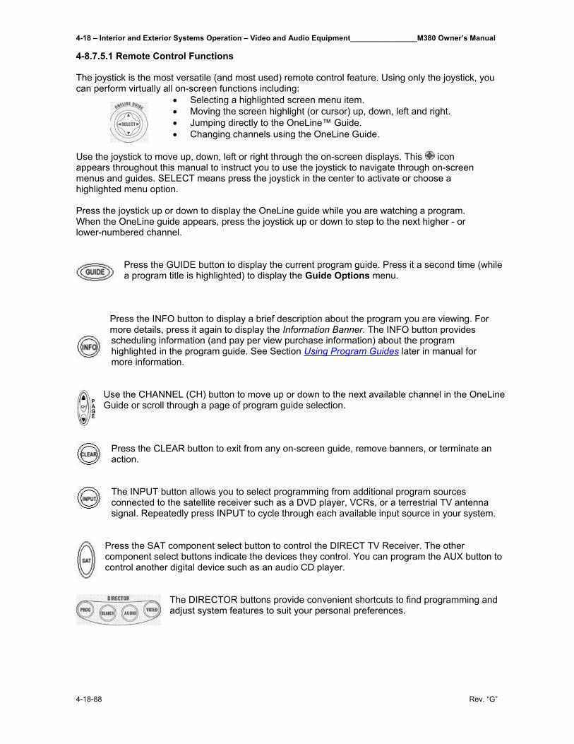
4-18 – Interior and Exterior Systems Operation – Video and Audio Equipment________________M380 Owner’s Manual
4-18-88 Rev. “G”
4-8.7.5.1 Remote Control Functions The joystick is the most versatile (and most used) remote control feature. Using only the joystick, you can perform virtually all on-screen functions including:
• Selecting a highlighted screen menu item. • Moving the screen highlight (or cursor) up, down, left and right. • Jumping directly to the OneLine™ Guide. • Changing channels using the OneLine Guide.
Use the joystick to move up, down, left or right through the on-screen displays. This icon appears throughout this manual to instruct you to use the joystick to navigate through on-screen menus and guides. SELECT means press the joystick in the center to activate or choose a highlighted menu option. Press the joystick up or down to display the OneLine guide while you are watching a program. When the OneLine guide appears, press the joystick up or down to step to the next higher - or lower-numbered channel.
Press the GUIDE button to display the current program guide. Press it a second time (while a program title is highlighted) to display the Guide Options menu.
Press the INFO button to display a brief description about the program you are viewing. For more details, press it again to display the Information Banner. The INFO button provides scheduling information (and pay per view purchase information) about the program highlighted in the program guide. See Section Using Program Guides later in manual for more information.
Use the CHANNEL (CH) button to move up or down to the next available channel in the OneLine Guide or scroll through a page of program guide selection.
Press the CLEAR button to exit from any on-screen guide, remove banners, or terminate an action.
The INPUT button allows you to select programming from additional program sources connected to the satellite receiver such as a DVD player, VCRs, or a terrestrial TV antenna signal. Repeatedly press INPUT to cycle through each available input source in your system.
Press the SAT component select button to control the DIRECT TV Receiver. The other component select buttons indicate the devices they control. You can program the AUX button to control another digital device such as an audio CD player.
The DIRECTOR buttons provide convenient shortcuts to find programming and adjust system features to suit your personal preferences.
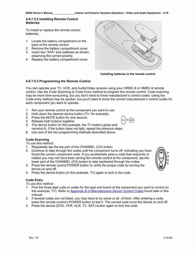
M380 Owner’s Manual________________Interior and Exterior Systems Operation – Video and Audio Equipment – 4-18
Rev. “G” 4-18-89
4-8.7.5.2 Installing Remote Control Batteries To install or replace the remote control batteries: 1. Locate the battery compartment on the
back of the remote control. 2. Remove the battery compartment cover. 3. Insert two “AAA” size batteries as shown,
observing the correct polarity. 4. Replace the battery compartment cover.
Installing batteries in the remote control
4-8.7.5.3 Programming the Remote Control You can operate your TV, VCR, and Audio/Video receiver using your HRMC-8 or HMRC-9 remote control. Use the Code Scanning or Code Entry method to program the remote control. Code scanning may be more time-consuming, but you don’t need to know manufacturer’s control codes. Using the Code entry method may be quicker, but you’ll need to know the correct manufacturer’s control codes for each component you want to operate. 1. Aim your remote control at the component you want to use. 2. Hold down the desired device button (TV, for example). 3. Press the MUTE button for one second. 4. Release both buttons together. 5. The device button (in this example, the TV button) glows and remains lit. If the button does not light, repeat the previous steps. 6. Use one of the two programming methods described above. Code Scanning To use this method: 1. Repeatedly tap the top part of the CHANNEL (CH) button. 2. Continue to step through the codes until the component turns off, indicating you have
found the correct component code. If you accidentally pass a code that responds or realize you may not have been aiming the remote control at the component, tap the lower part of the CHANNEL (CH) button to step backward through the codes.
3. Press the remote control POWER button to verify the proper code by turning the device on and off.
4. Press the device button (in this example, TV) again to lock in the code. Code Entry To use this method: 1. Find the three-digit code or codes for the type and brand of the component you want to control (in
this example, TV). Refer to Appendix B of Manufacturers Device Control Codes found later in this manual.
2. If several codes are not listed, you may have to try some or all of them. After entering a code, press the remote control’s POWER button to test it. The correct code turns the device on and off.
3. Press the device (DVD, VCR, AUX, TV, SAT) button again to lock the code.

4-18 – Interior and Exterior Systems Operation – Video and Audio Equipment________________M380 Owner’s Manual
4-18-90 Rev. “G”
4-8.7.5.4 Using DIRECT TV INTERACTIVE™ powered by Wink Communications®
DIRECT TV INTERACTIVE™ powered by Wink Communications® is a free, easy-to-use service that allows you to interact with the television shows and advertisements. When the blinking
symbol appears in the upper left part of your screen, you know that the program you’re watching has been enhanced with DIRECT TV INTERACTIVE™.
Simply press the button on your remote control. You can use your remote control to access up-to-the-minute sports scores, news and weather, get program trivia, respond to offers during commercials, and purchase products, all while watching TV.
Select the DIRECT TV INTERACTIVE™ Center menu bar, then follow the simple directions provided on the subsequent screens. 4-8.7.6 Using the Menus This section describes:
• How to find the menus you need to perform common tasks. • Using the Program Director • How to purchase pay per view events. • How to set and modify preferences.
The table below lists the MAIN MENU tabs, their submenus, and what they do.
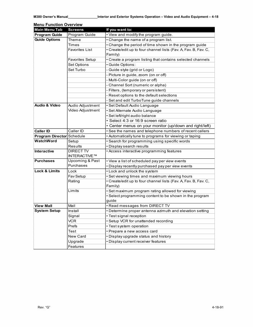
M380 Owner’s Manual________________Interior and Exterior Systems Operation – Video and Audio Equipment – 4-18
Rev. “G” 4-18-91
Menu Function Overview
Main Menu Tab Screens If you want to:Program Guide Program Guide • View and modify the program guide.
Theme • Change the name of a program list.Times • Change the period of time shown in the program guideFavorites List • Create/edit up to four channel lists (Fav. A, Fav. B, Fav. C,
Family)Favorites Setup • Create a program listing that contains selected channelsSet Options • Guide Options:Set Turbo - Guide style (grid or Logo)
- Picture in guide, zoom (on or off)- Multi-Color guide (on or off)- Channel Sort (numeric or alpha)- Filters, (temporary or persistent)- Reset options to the default selections- Set and edit TurboTune guide channels
Audio Adjustment • Set Default Audio Language• Set Alternate Audio Language• Set left/right audio balance• Select 4:3 or 16:9 screen ratio• Center menus on your monitor (up/down and right/left)
Caller ID Caller ID • See the names and telephone numbers of recent callersProgram Director Schedule • Automatically tune to programs for viewing or taping
Setup • Search for programming using specific wordsResults • Display search results
Interactive DIRECT TV INTERACTIVE™
• Access interactive programming features
• View a list of scheduled pay per view events• Display recently purchased pay per view events
Lock • Lock and unlock the systemFav Setup • Set viewing times and maximum viewing hoursRating • Create/edit up to four channel lists (Fav. A, Fav. B, Fav. C,
Family)• Set maximum program rating allowed for viewing• Select programming content to be shown in the program guide
View Mall Mail • Read messages from DIRECT TVInstall • Determine proper antenna azimuth and elevation settingSignal • Test signal receptionVCR • Setup VCR for unattended recordingPrefs • Test system operationTest • Prepare a new access cardNew Card • Display upgrade status and historyUpgrade • Display current receiver featuresFeatures
System Setup
Upcoming & Past Purchases
Purchases
Lock & Limits
Limits
Guide Options
Video AdjustmentAudio & Video
WatchWord
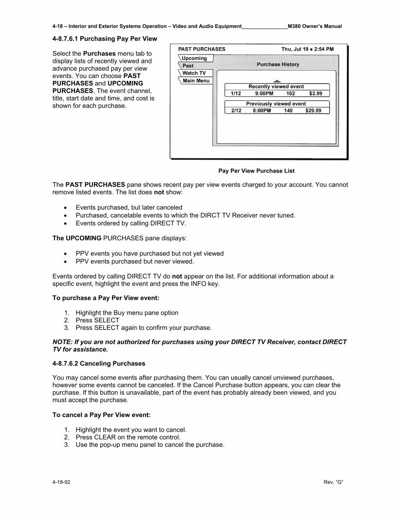
4-18 – Interior and Exterior Systems Operation – Video and Audio Equipment________________M380 Owner’s Manual
4-18-92 Rev. “G”
4-8.7.6.1 Purchasing Pay Per View Select the Purchases menu tab to display lists of recently viewed and advance purchased pay per view events. You can choose PAST PURCHASES and UPCOMING PURCHASES. The event channel, title, start date and time, and cost is shown for each purchase.
Pay Per View Purchase List The PAST PURCHASES pane shows recent pay per view events charged to your account. You cannot remove listed events. The list does not show:
• Events purchased, but later canceled • Purchased, cancelable events to which the DIRCT TV Receiver never tuned. • Events ordered by calling DIRECT TV.
The UPCOMING PURCHASES pane displays:
• PPV events you have purchased but not yet viewed • PPV events purchased but never viewed.
Events ordered by calling DIRECT TV do not appear on the list. For additional information about a specific event, highlight the event and press the INFO key. To purchase a Pay Per View event:
1. Highlight the Buy menu pane option 2. Press SELECT 3. Press SELECT again to confirm your purchase.
NOTE: If you are not authorized for purchases using your DIRECT TV Receiver, contact DIRECT TV for assistance. 4-8.7.6.2 Canceling Purchases You may cancel some events after purchasing them. You can usually cancel unviewed purchases, however some events cannot be canceled. If the Cancel Purchase button appears, you can clear the purchase. If this button is unavailable, part of the event has probably already been viewed, and you must accept the purchase. To cancel a Pay Per View event:
1. Highlight the event you want to cancel. 2. Press CLEAR on the remote control. 3. Use the pop-up menu panel to cancel the purchase.
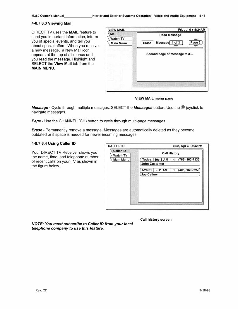
M380 Owner’s Manual________________Interior and Exterior Systems Operation – Video and Audio Equipment – 4-18
Rev. “G” 4-18-93
4-8.7.6.3 Viewing Mail DIRECT TV uses the MAIL feature to send you important information, inform you of special events, and tell you about special offers. When you receive a new message, a New Mail icon appears at the top of all menus until you read the message. Highlight and SELECT the View Mail tab from the MAIN MENU.
VIEW MAIL menu pane
Message - Cycle through multiple messages. SELECT the Messages button. Use the joystick to navigate messages. Page - Use the CHANNEL (CH) button to cycle through multi-page messages. Erase - Permanently remove a message. Messages are automatically deleted as they become outdated or if space is needed for newer incoming messages. 4-8.7.6.4 Using Caller ID Your DIRECT TV Receiver shows you the name, time, and telephone number of recent calls on your TV as shown in the figure below.
Call history screen NOTE: You must subscribe to Caller ID from your local telephone company to use this feature.
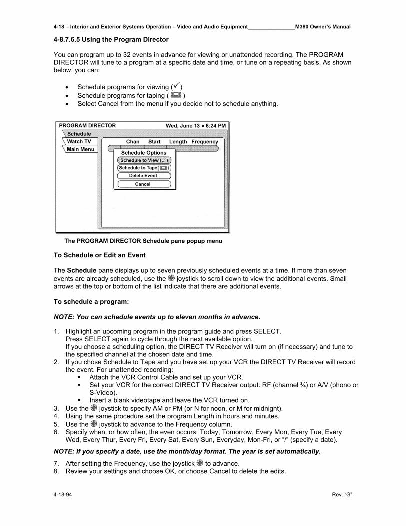
4-18 – Interior and Exterior Systems Operation – Video and Audio Equipment________________M380 Owner’s Manual
4-18-94 Rev. “G”
4-8.7.6.5 Using the Program Director You can program up to 32 events in advance for viewing or unattended recording. The PROGRAM DIRECTOR will tune to a program at a specific date and time, or tune on a repeating basis. As shown below, you can:
• Schedule programs for viewing ( ) • Schedule programs for taping ( ) • Select Cancel from the menu if you decide not to schedule anything.
The PROGRAM DIRECTOR Schedule pane popup menu To Schedule or Edit an Event The Schedule pane displays up to seven previously scheduled events at a time. If more than seven events are already scheduled, use the joystick to scroll down to view the additional events. Small arrows at the top or bottom of the list indicate that there are additional events. To schedule a program: NOTE: You can schedule events up to eleven months in advance. 1. Highlight an upcoming program in the program guide and press SELECT.
Press SELECT again to cycle through the next available option. If you choose a scheduling option, the DIRECT TV Receiver will turn on (if necessary) and tune to the specified channel at the chosen date and time.
2. If you chose Schedule to Tape and you have set up your VCR the DIRECT TV Receiver will record the event. For unattended recording:
Attach the VCR Control Cable and set up your VCR. Set your VCR for the correct DIRECT TV Receiver output: RF (channel ¾) or A/V (phono or
S-Video). Insert a blank videotape and leave the VCR turned on.
3. Use the joystick to specify AM or PM (or N for noon, or M for midnight). 4. Using the same procedure set the program Length in hours and minutes. 5. Use the joystick to advance to the Frequency column. 6. Specify when, or how often, the even occurs: Today, Tomorrow, Every Mon, Every Tue, Every
Wed, Every Thur, Every Fri, Every Sat, Every Sun, Everyday, Mon-Fri, or “/” (specify a date).
NOTE: If you specify a date, use the month/day format. The year is set automatically.
7. After setting the Frequency, use the joystick to advance. 8. Review your settings and choose OK, or choose Cancel to delete the edits.
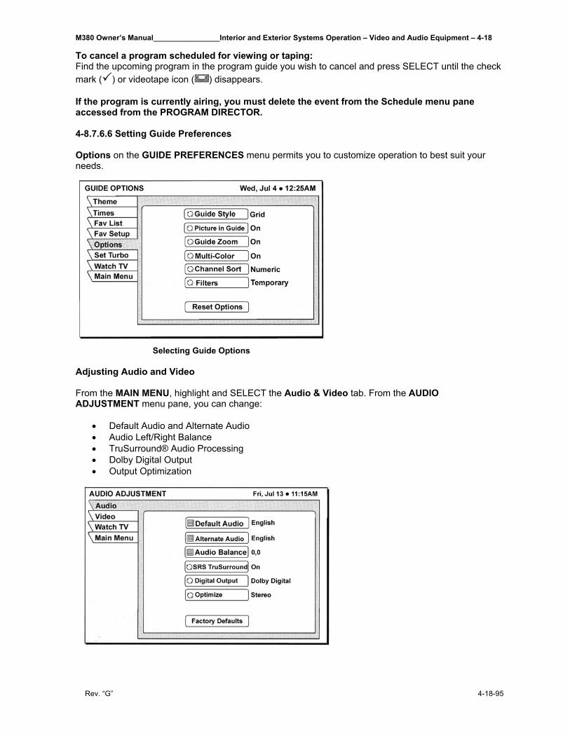
M380 Owner’s Manual________________Interior and Exterior Systems Operation – Video and Audio Equipment – 4-18
Rev. “G” 4-18-95
To cancel a program scheduled for viewing or taping: Find the upcoming program in the program guide you wish to cancel and press SELECT until the check mark ( ) or videotape icon ( ) disappears. If the program is currently airing, you must delete the event from the Schedule menu pane accessed from the PROGRAM DIRECTOR. 4-8.7.6.6 Setting Guide Preferences Options on the GUIDE PREFERENCES menu permits you to customize operation to best suit your needs.
Selecting Guide Options Adjusting Audio and Video From the MAIN MENU, highlight and SELECT the Audio & Video tab. From the AUDIO ADJUSTMENT menu pane, you can change:
• Default Audio and Alternate Audio • Audio Left/Right Balance • TruSurround® Audio Processing • Dolby Digital Output • Output Optimization
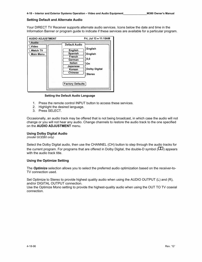
4-18 – Interior and Exterior Systems Operation – Video and Audio Equipment________________M380 Owner’s Manual
4-18-96 Rev. “G”
Setting Default and Alternate Audio Your DIRECT TV Receiver supports alternate audio services. Icons below the date and time in the Information Banner or program guide to indicate if these services are available for a particular program.
Setting the Default Audio Language
1. Press the remote control INPUT button to access these services. 2. Highlight the desired language. 3. Press SELECT.
Occasionally, an audio track may be offered that is not being broadcast, in which case the audio will not change or you will not hear any audio. Change channels to restore the audio track to the one specified on the AUDIO ADJUSTMENT menu. Using Dolby Digital Audio (model GCEB0 only) Select the Dolby Digital audio, then use the CHANNEL (CH) button to step through the audio tracks for the current program. For programs that are offered in Dolby Digital, the double-D symbol ( ) appears with the audio track title. Using the Optimize Setting The Optimize selection allows you to select the preferred audio optimization based on the receiver-to-TV connection used. Set Optimize to Stereo to provide highest quality audio when using the AUDIO OUTPUT (L) and (R), and/or DIGITAL OUTPUT connection. Use the Optimize Mono setting to provide the highest-quality audio when using the OUT TO TV coaxial connection.
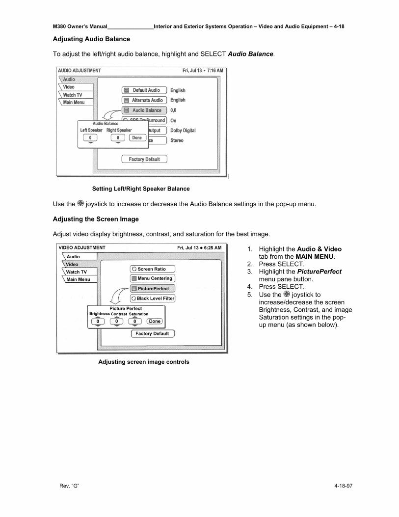
M380 Owner’s Manual________________Interior and Exterior Systems Operation – Video and Audio Equipment – 4-18
Rev. “G” 4-18-97
Adjusting Audio Balance To adjust the left/right audio balance, highlight and SELECT Audio Balance.
Setting Left/Right Speaker Balance Use the joystick to increase or decrease the Audio Balance settings in the pop-up menu. Adjusting the Screen Image Adjust video display brightness, contrast, and saturation for the best image.
1. Highlight the Audio & Video
tab from the MAIN MENU. 2. Press SELECT. 3. Highlight the PicturePerfect
menu pane button. 4. Press SELECT. 5. Use the joystick to
increase/decrease the screen Brightness, Contrast, and image Saturation settings in the pop-up menu (as shown below).
Adjusting screen image controls
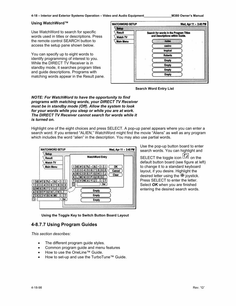
4-18 – Interior and Exterior Systems Operation – Video and Audio Equipment________________M380 Owner’s Manual
4-18-98 Rev. “G”
Using WatchWord™ Use WatchWord to search for specific words used in titles or descriptions. Press the remote control SEARCH button to access the setup pane shown below. You can specify up to eight words to identify programming of interest to you. While the DIRECT TV Receiver is in standby mode, it searches program titles and guide descriptions. Programs with matching words appear in the Result pane.
Search Word Entry List NOTE: For WatchWord to have the opportunity to find programs with matching words, your DIRECT TV Receiver must be in standby mode (Off). Allow the system to look for your words while you sleep or while you are at work. The DIRECT TV Receiver cannot search for words while it is turned on. Highlight one of the eight choices and press SELECT. A pop-up panel appears where you can enter a search word. If you entered “ALIEN,” WatchWord might find the movie “Aliens” as well as any program which includes the word “alien” in the description. You may also use partial words.
Use the pop-up button board to enter search words. You can highlight and
SELECT the toggle icon on the default button board (see figure at left) to change it to a standard keyboard layout, if you desire. Highlight the desired letter using the joystick. Press SELECT to enter the letter. Select OK when you are finished entering the desired search words.
Using the Toggle Key to Switch Button Board Layout 4-8.7.7 Using Program Guides This section describes:
• The different program guide styles. • Common program guide and menu features • How to use the OneLine™ Guide. • How to set-up and use the TurboTune™ Guide.
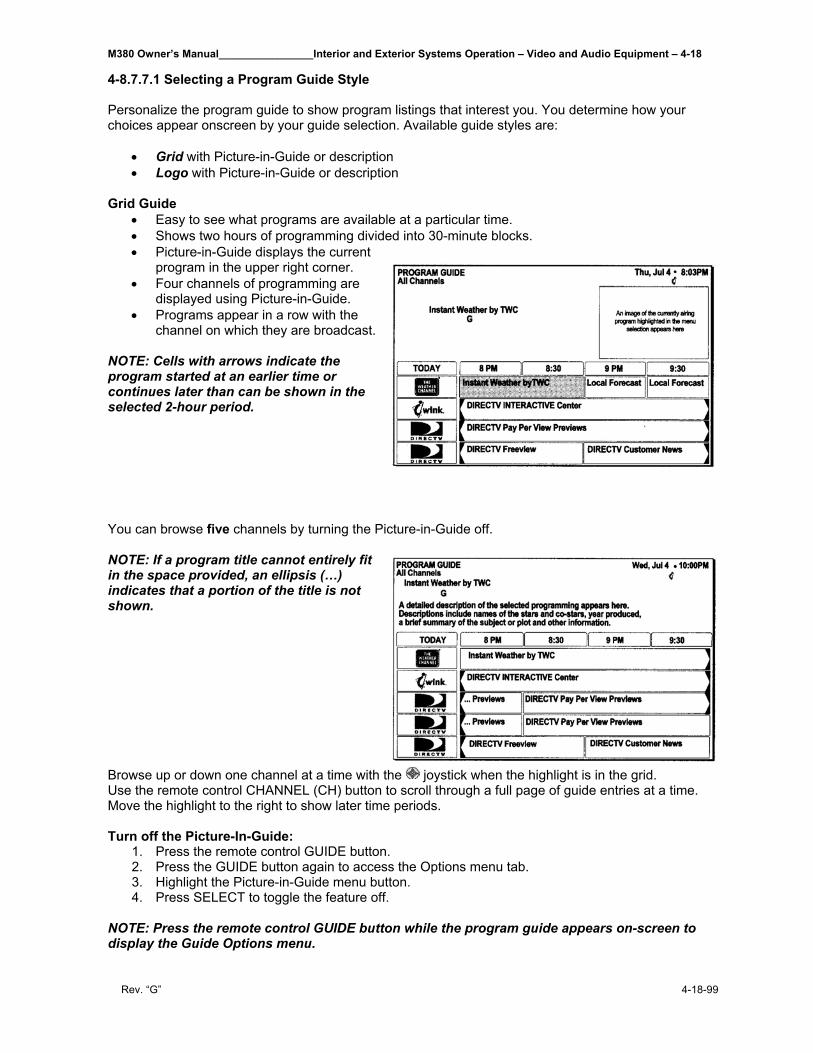
M380 Owner’s Manual________________Interior and Exterior Systems Operation – Video and Audio Equipment – 4-18
Rev. “G” 4-18-99
4-8.7.7.1 Selecting a Program Guide Style Personalize the program guide to show program listings that interest you. You determine how your choices appear onscreen by your guide selection. Available guide styles are:
• Grid with Picture-in-Guide or description • Logo with Picture-in-Guide or description
Grid Guide
• Easy to see what programs are available at a particular time. • Shows two hours of programming divided into 30-minute blocks. • Picture-in-Guide displays the current
program in the upper right corner. • Four channels of programming are
displayed using Picture-in-Guide. • Programs appear in a row with the
channel on which they are broadcast. NOTE: Cells with arrows indicate the program started at an earlier time or continues later than can be shown in the selected 2-hour period. You can browse five channels by turning the Picture-in-Guide off. NOTE: If a program title cannot entirely fit in the space provided, an ellipsis (…) indicates that a portion of the title is not shown. Browse up or down one channel at a time with the joystick when the highlight is in the grid. Use the remote control CHANNEL (CH) button to scroll through a full page of guide entries at a time. Move the highlight to the right to show later time periods. Turn off the Picture-In-Guide:
1. Press the remote control GUIDE button. 2. Press the GUIDE button again to access the Options menu tab. 3. Highlight the Picture-in-Guide menu button. 4. Press SELECT to toggle the feature off.
NOTE: Press the remote control GUIDE button while the program guide appears on-screen to display the Guide Options menu.
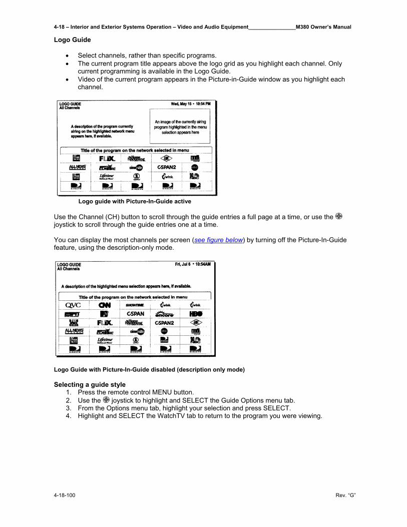
4-18 – Interior and Exterior Systems Operation – Video and Audio Equipment________________M380 Owner’s Manual
4-18-100 Rev. “G”
Logo Guide
• Select channels, rather than specific programs. • The current program title appears above the logo grid as you highlight each channel. Only
current programming is available in the Logo Guide. • Video of the current program appears in the Picture-in-Guide window as you highlight each
channel.
Logo guide with Picture-In-Guide active Use the Channel (CH) button to scroll through the guide entries a full page at a time, or use the joystick to scroll through the guide entries one at a time. You can display the most channels per screen (see figure below) by turning off the Picture-In-Guide feature, using the description-only mode.
Logo Guide with Picture-In-Guide disabled (description only mode) Selecting a guide style
1. Press the remote control MENU button. 2. Use the joystick to highlight and SELECT the Guide Options menu tab. 3. From the Options menu tab, highlight your selection and press SELECT. 4. Highlight and SELECT the WatchTV tab to return to the program you were viewing.
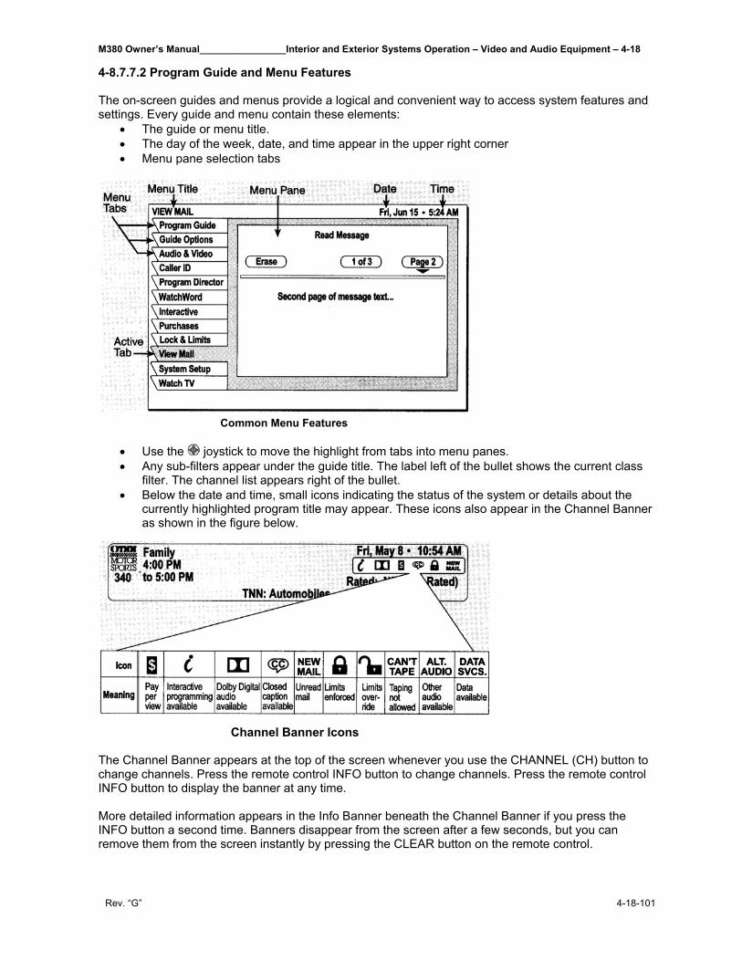
M380 Owner’s Manual________________Interior and Exterior Systems Operation – Video and Audio Equipment – 4-18
Rev. “G” 4-18-101
4-8.7.7.2 Program Guide and Menu Features The on-screen guides and menus provide a logical and convenient way to access system features and settings. Every guide and menu contain these elements:
• The guide or menu title. • The day of the week, date, and time appear in the upper right corner • Menu pane selection tabs
Common Menu Features
• Use the joystick to move the highlight from tabs into menu panes. • Any sub-filters appear under the guide title. The label left of the bullet shows the current class
filter. The channel list appears right of the bullet. • Below the date and time, small icons indicating the status of the system or details about the
currently highlighted program title may appear. These icons also appear in the Channel Banner as shown in the figure below.
Channel Banner Icons The Channel Banner appears at the top of the screen whenever you use the CHANNEL (CH) button to change channels. Press the remote control INFO button to change channels. Press the remote control INFO button to display the banner at any time. More detailed information appears in the Info Banner beneath the Channel Banner if you press the INFO button a second time. Banners disappear from the screen after a few seconds, but you can remove them from the screen instantly by pressing the CLEAR button on the remote control.
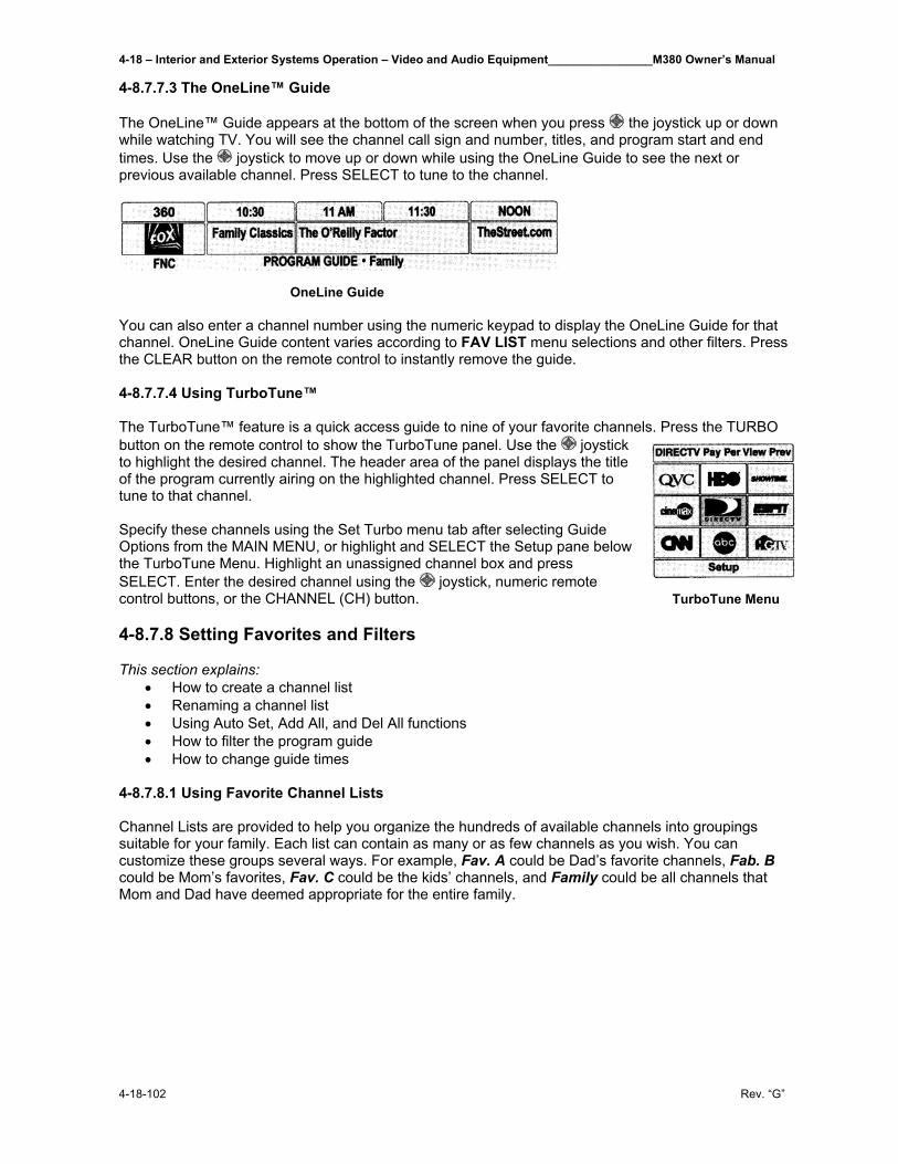
4-18 – Interior and Exterior Systems Operation – Video and Audio Equipment________________M380 Owner’s Manual
4-18-102 Rev. “G”
4-8.7.7.3 The OneLine™ Guide The OneLine™ Guide appears at the bottom of the screen when you press the joystick up or down while watching TV. You will see the channel call sign and number, titles, and program start and end times. Use the joystick to move up or down while using the OneLine Guide to see the next or previous available channel. Press SELECT to tune to the channel.
OneLine Guide You can also enter a channel number using the numeric keypad to display the OneLine Guide for that channel. OneLine Guide content varies according to FAV LIST menu selections and other filters. Press the CLEAR button on the remote control to instantly remove the guide. 4-8.7.7.4 Using TurboTune™ The TurboTune™ feature is a quick access guide to nine of your favorite channels. Press the TURBO button on the remote control to show the TurboTune panel. Use the joystick to highlight the desired channel. The header area of the panel displays the title of the program currently airing on the highlighted channel. Press SELECT to tune to that channel. Specify these channels using the Set Turbo menu tab after selecting Guide Options from the MAIN MENU, or highlight and SELECT the Setup pane below the TurboTune Menu. Highlight an unassigned channel box and press SELECT. Enter the desired channel using the joystick, numeric remote control buttons, or the CHANNEL (CH) button. TurboTune Menu 4-8.7.8 Setting Favorites and Filters This section explains:
• How to create a channel list • Renaming a channel list • Using Auto Set, Add All, and Del All functions • How to filter the program guide • How to change guide times
4-8.7.8.1 Using Favorite Channel Lists Channel Lists are provided to help you organize the hundreds of available channels into groupings suitable for your family. Each list can contain as many or as few channels as you wish. You can customize these groups several ways. For example, Fav. A could be Dad’s favorite channels, Fab. B could be Mom’s favorites, Fav. C could be the kids’ channels, and Family could be all channels that Mom and Dad have deemed appropriate for the entire family.
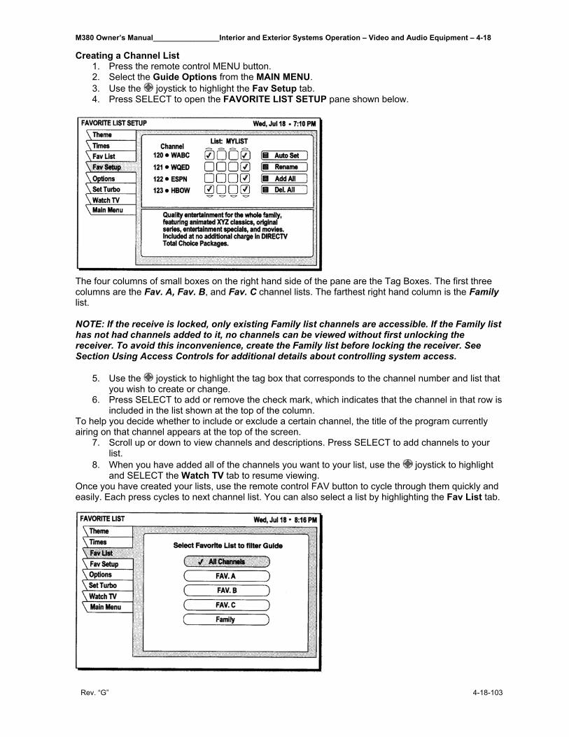
M380 Owner’s Manual________________Interior and Exterior Systems Operation – Video and Audio Equipment – 4-18
Rev. “G” 4-18-103
Creating a Channel List 1. Press the remote control MENU button. 2. Select the Guide Options from the MAIN MENU. 3. Use the joystick to highlight the Fav Setup tab. 4. Press SELECT to open the FAVORITE LIST SETUP pane shown below.
The four columns of small boxes on the right hand side of the pane are the Tag Boxes. The first three columns are the Fav. A, Fav. B, and Fav. C channel lists. The farthest right hand column is the Family list. NOTE: If the receive is locked, only existing Family list channels are accessible. If the Family list has not had channels added to it, no channels can be viewed without first unlocking the receiver. To avoid this inconvenience, create the Family list before locking the receiver. See Section Using Access Controls for additional details about controlling system access.
5. Use the joystick to highlight the tag box that corresponds to the channel number and list that you wish to create or change.
6. Press SELECT to add or remove the check mark, which indicates that the channel in that row is included in the list shown at the top of the column.
To help you decide whether to include or exclude a certain channel, the title of the program currently airing on that channel appears at the top of the screen.
7. Scroll up or down to view channels and descriptions. Press SELECT to add channels to your list.
8. When you have added all of the channels you want to your list, use the joystick to highlight and SELECT the Watch TV tab to resume viewing.
Once you have created your lists, use the remote control FAV button to cycle through them quickly and easily. Each press cycles to next channel list. You can also select a list by highlighting the Fav List tab.
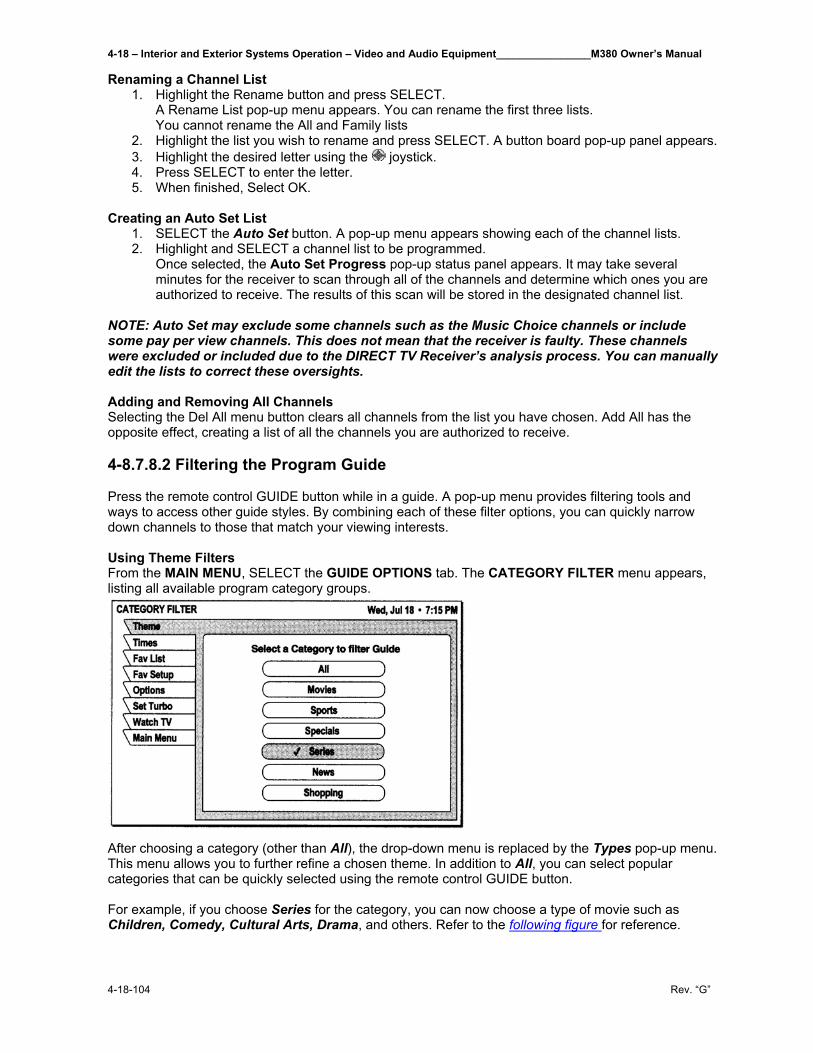
4-18 – Interior and Exterior Systems Operation – Video and Audio Equipment________________M380 Owner’s Manual
4-18-104 Rev. “G”
Renaming a Channel List 1. Highlight the Rename button and press SELECT.
A Rename List pop-up menu appears. You can rename the first three lists. You cannot rename the All and Family lists
2. Highlight the list you wish to rename and press SELECT. A button board pop-up panel appears. 3. Highlight the desired letter using the joystick. 4. Press SELECT to enter the letter. 5. When finished, Select OK.
Creating an Auto Set List
1. SELECT the Auto Set button. A pop-up menu appears showing each of the channel lists. 2. Highlight and SELECT a channel list to be programmed.
Once selected, the Auto Set Progress pop-up status panel appears. It may take several minutes for the receiver to scan through all of the channels and determine which ones you are authorized to receive. The results of this scan will be stored in the designated channel list.
NOTE: Auto Set may exclude some channels such as the Music Choice channels or include some pay per view channels. This does not mean that the receiver is faulty. These channels were excluded or included due to the DIRECT TV Receiver’s analysis process. You can manually edit the lists to correct these oversights. Adding and Removing All Channels Selecting the Del All menu button clears all channels from the list you have chosen. Add All has the opposite effect, creating a list of all the channels you are authorized to receive. 4-8.7.8.2 Filtering the Program Guide Press the remote control GUIDE button while in a guide. A pop-up menu provides filtering tools and ways to access other guide styles. By combining each of these filter options, you can quickly narrow down channels to those that match your viewing interests. Using Theme Filters From the MAIN MENU, SELECT the GUIDE OPTIONS tab. The CATEGORY FILTER menu appears, listing all available program category groups.
After choosing a category (other than All), the drop-down menu is replaced by the Types pop-up menu. This menu allows you to further refine a chosen theme. In addition to All, you can select popular categories that can be quickly selected using the remote control GUIDE button. For example, if you choose Series for the category, you can now choose a type of movie such as Children, Comedy, Cultural Arts, Drama, and others. Refer to the following figure for reference.
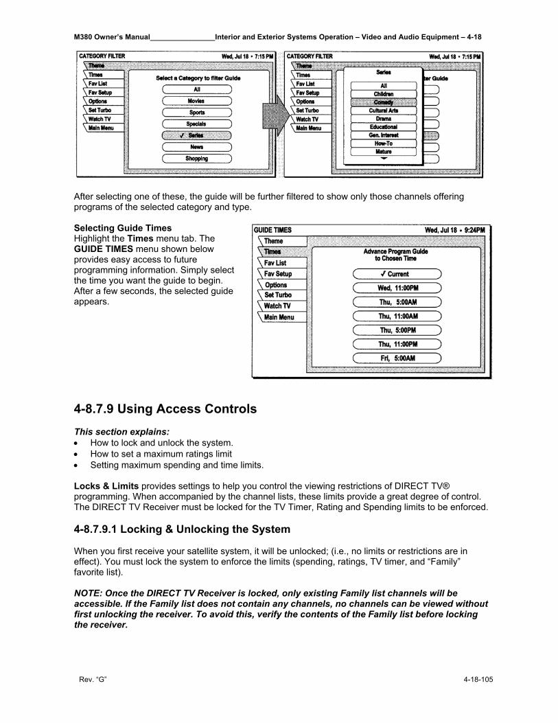
M380 Owner’s Manual________________Interior and Exterior Systems Operation – Video and Audio Equipment – 4-18
Rev. “G” 4-18-105
After selecting one of these, the guide will be further filtered to show only those channels offering programs of the selected category and type. Selecting Guide Times Highlight the Times menu tab. The GUIDE TIMES menu shown below provides easy access to future programming information. Simply select the time you want the guide to begin. After a few seconds, the selected guide appears. 4-8.7.9 Using Access Controls This section explains: • How to lock and unlock the system. • How to set a maximum ratings limit • Setting maximum spending and time limits. Locks & Limits provides settings to help you control the viewing restrictions of DIRECT TV® programming. When accompanied by the channel lists, these limits provide a great degree of control. The DIRECT TV Receiver must be locked for the TV Timer, Rating and Spending limits to be enforced. 4-8.7.9.1 Locking & Unlocking the System When you first receive your satellite system, it will be unlocked; (i.e., no limits or restrictions are in effect). You must lock the system to enforce the limits (spending, ratings, TV timer, and “Family” favorite list). NOTE: Once the DIRECT TV Receiver is locked, only existing Family list channels will be accessible. If the Family list does not contain any channels, no channels can be viewed without first unlocking the receiver. To avoid this, verify the contents of the Family list before locking the receiver.
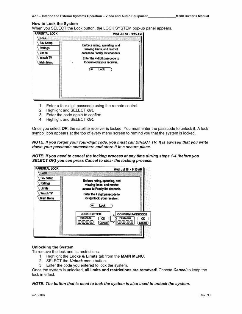
4-18 – Interior and Exterior Systems Operation – Video and Audio Equipment________________M380 Owner’s Manual
4-18-106 Rev. “G”
How to Lock the System When you SELECT the Lock button, the LOCK SYSTEM pop-up panel appears.
1. Enter a four-digit passcode using the remote control. 2. Highlight and SELECT OK. 3. Enter the code again to confirm. 4. Highlight and SELECT OK.
Once you select OK, the satellite receiver is locked. You must enter the passcode to unlock it. A lock symbol icon appears at the top of every menu screen to remind you that the system is locked. NOTE: If you forget your four-digit code, you must call DIRECT TV. It is advised that you write down your passcode somewhere and store it in a secure place. NOTE: If you need to cancel the locking process at any time during steps 1-4 (before you SELECT OK) you can press Cancel to clear the locking process.
Unlocking the System To remove the lock and its restrictions:
1. Highlight the Locks & Limits tab from the MAIN MENU. 2. SELECT the Unlock menu button. 3. Enter the code you entered to lock the system.
Once the system is unlocked, all limits and restrictions are removed! Choose Cancel to keep the lock in effect. NOTE: The button that is used to lock the system is also used to unlock the system.
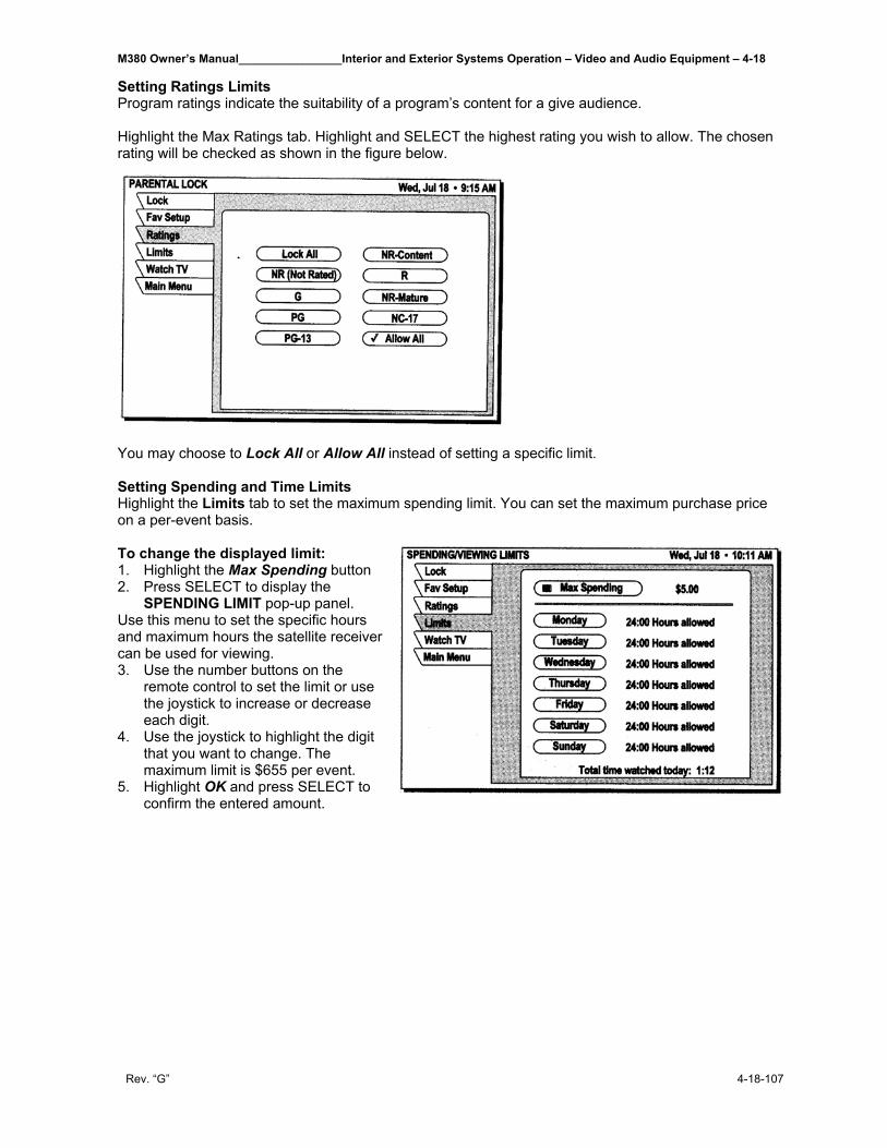
M380 Owner’s Manual________________Interior and Exterior Systems Operation – Video and Audio Equipment – 4-18
Rev. “G” 4-18-107
Setting Ratings Limits Program ratings indicate the suitability of a program’s content for a give audience. Highlight the Max Ratings tab. Highlight and SELECT the highest rating you wish to allow. The chosen rating will be checked as shown in the figure below.
You may choose to Lock All or Allow All instead of setting a specific limit. Setting Spending and Time Limits Highlight the Limits tab to set the maximum spending limit. You can set the maximum purchase price on a per-event basis. To change the displayed limit: 1. Highlight the Max Spending button 2. Press SELECT to display the
SPENDING LIMIT pop-up panel. Use this menu to set the specific hours and maximum hours the satellite receiver can be used for viewing. 3. Use the number buttons on the
remote control to set the limit or use the joystick to increase or decrease each digit.
4. Use the joystick to highlight the digit that you want to change. The maximum limit is $655 per event.
5. Highlight OK and press SELECT to confirm the entered amount.
4-18 – Interior and Exterior Systems Operation – Video and Audio Equipment________________M380 Owner’s Manual
4-18-108 Rev. “G”
4-8.7.10 Frequently Asked Questions Questions? Did we forget to tell you something? We have compiled some of the most common questions and their answers here. Q I had a signal but now I am getting a message “Searching for satellite signal. To access related
utilities, press SELECT.” What happened? A Rain clouds and snow can affect the satellite signal reception. This loss of signal is temporary. Also
check for new growth on trees and bushes that could be blocking the signal. One other possibility is that the wind or someone has moved the satellite dish antenna.
Q Why can’t I control my TV? A Before you can control your TV, VCR, or any other device besides your satellite receiver, you must
program your remote control to match your different devices. See Section Using the Remote Control in this manual for specific instructions. If you have already successfully programmed your remote control, try pressing the appropriate device key to put your remote in the proper mode. Then try controlling that device. For example if you are trying to control the VCR press the VCR button on the remote and then try controlling the VCR. Also, make sure that the batteries in the remote control are good.
Q My satellite receiver does not respond when I press keys. What’s wrong? A Most likely, if the front panel keys work but the remote control doesn’t work, try pressing the SAT
button before trying to control the digital satellite receiver. If that doesn’t work, press the SAT and MUTE buttons together and try again. If that doesn’t work, or if the front panel buttons don’t work either, unplug your digital satellite receiver for 30 seconds, then plug it back in. Your satellite receiver is a computing device. It is susceptible to erratic changes in power and/or signal, just as any other computer, and these sudden changes can cause it to become “confushed.”
Q Some channels look good, while others freeze or indicate that no signal is available. What’s wrong? A The most common cause for this behavior relate to an improperly grounded satellite cable. Check
the cable between your digital satellite receiver and the satellite dish antenna. Confirm that RG-6 (not RG-59) cable is used and does not exceed 100 feet in length. Longer cable runs require amplification. This special amplifier is available from your dealer.
Q How can I watch one channel while recording another? A With only one digital satellite receiver, unfortunately, you can’t. Each receiver can only decode one
channel at a time. Q I’m getting a message to call some extension. Why? A There are many different reasons for this. If you want to watch the channel that is displaying the
message, call DIRECT TV at 1-800-531-5000. Q Why don’t I have an on-screen offer to purchase pay per view programs? A There are three possibilities; your digital satellite receiver must be connected to a phone line and it
is not, or DIRECT TV doesn’t realize that your phone line is connected or has disabled your ability to make on-screen purchases. Call DIRECT TV at 1-800-531-5000 for assistance.
M380 Owner’s Manual________________Interior and Exterior Systems Operation – Video and Audio Equipment – 4-18
Rev. “G” 4-18-109
Q Can I receive my local TV programs through my digital satellite receiver? A There are three ways to receive local programming:
1. If you are in an area where local programming is available via satellite and have the proper satellite dish antenna, contact DIRECT TV to arrange for the necessary subscription package.
2. Install a traditional antenna (i.e., roof mounted, rabbit ears). 3. Arrange for basic or “lifeline” cable TV service from your local cable company.
If you select item 1 above, your local programming appears in the program guide like any other
channel. For options 2 or 3, connect the local signal to the IN FROM ANTENNA jack on the back of your digital satellite receiver. Use the INPUT key to switch between DIRECT TV® programming and local programming provided on the OUT TO TV connector.
Q If I have questions about my satellite system or need to have it serviced, who should I call? A For issues regarding your equipment, contact Hughes Consumer Care Center directly at 1-800-
274-8995, or if you prefer, call your dealer first. They are most familiar with your installation and needs. Also, they are likely to be local to you.
If you need assistance with your subscription, such as adding channels, contact DIRECT TV at 1-800-531-5000. Q I think I set an event to record on my VCR, but when I played the tape back nothing was there.
What could be wrong? A There are several possible reasons for this. First, check that the VCR was programmed correctly
and left turned on and the input matches the output from your digital satellite receiver. Confirm that you were authorized to tape the chosen program.
Q Why do I need to connect the satellite receiver to a telephone line? A The telephone connection is used by the satellite receiver to report purchase activity to DIRECT TV. Q I picked up my telephone and it was making a hissing and squealing sound. Why? A Your digital satellite receiver was reporting any pay per view activity that may have occurred. This
rarely happens and only lasts for a minute or so. Q What if my question isn’t listed here? A Call your dealer or Hughes Consumer Care Center at 1-800-274-8995. We will do our very best to
answer your questions.
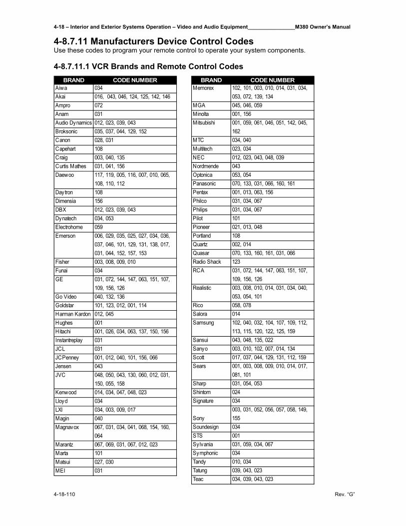
4-18 – Interior and Exterior Systems Operation – Video and Audio Equipment________________M380 Owner’s Manual
4-18-110 Rev. “G”
4-8.7.11 Manufacturers Device Control Codes Use these codes to program your remote control to operate your system components. 4-8.7.11.1 VCR Brands and Remote Control Codes
BRAND CODE NUMBERAiwa 034Akai 016, 043, 046, 124, 125, 142, 146Ampro 072Anam 031Audio Dynamics 012, 023, 039, 043Broksonic 035, 037, 044, 129, 152Canon 028, 031Capehart 108Craig 003, 040, 135Curtis Mathes 031, 041, 156Daewoo 117, 119, 005, 116, 007, 010, 065,
108, 110, 112Daytron 108Dimensia 156DBX 012, 023, 039, 043Dynatech 034, 053Electrohome 059Emerson 006, 029, 035, 025, 027, 034, 036,
037, 046, 101, 129, 131, 138, 017, 031, 044, 152, 157, 153
Fisher 003, 008, 009, 010Funai 034GE 031, 072, 144, 147, 063, 151, 107,
109, 156, 126Go Video 040, 132, 136Goldstar 101, 123, 012, 001, 114Harman Kardon 012, 045Hughes 001Hitachi 001, 026, 034, 063, 137, 150, 156Instantreplay 031JCL 031JCPenney 001, 012, 040, 101, 156, 066Jensen 043JVC 048, 050, 043, 130, 060, 012, 031,
150, 055, 158Kenwood 014, 034, 047, 048, 023Lloyd 034LXI 034, 003, 009, 017Magin 040Magnavox 067, 031, 034, 041, 068, 154, 160,
064Marantz 067, 069, 031, 067, 012, 023Marta 101Matsui 027, 030MEI 031
BRAND CODE NUMBERMemorex 102, 101, 003, 010, 014, 031, 034,
053, 072, 139, 134MGA 045, 046, 059Minolta 001, 156Mitsubishi 001, 059, 061, 046, 051, 142, 045,
162MTC 034, 040Multitech 023, 034NEC 012, 023, 043, 048, 039Nordmende 043Optonica 053, 054Panasonic 070, 133, 031, 066, 160, 161Pentax 001, 013, 063, 156Philco 031, 034, 067Philips 031, 034, 067Pilot 101Pioneer 021, 013, 048Portland 108Quartz 002, 014Quasar 070, 133, 160, 161, 031, 066Radio Shack 123RCA 031, 072, 144, 147, 063, 151, 107,
109, 156, 126Realistic 003, 008, 010, 014, 031, 034, 040,
053, 054, 101Rico 058, 078Salora 014Samsung 102, 040, 032, 104, 107, 109, 112,
113, 115, 120, 122, 125, 159Sansui 043, 048, 135, 022Sanyo 003, 010, 102, 007, 014, 134Scott 017, 037, 044, 129, 131, 112, 159Sears 001, 003, 008, 009, 010, 014, 017,
081, 101Sharp 031, 054, 053Shintom 024Signature 034
Sony003, 031, 052, 056, 057, 058, 149, 155
Soundesign 034STS 001Sylvania 031, 059, 034, 067Symphonic 034Tandy 010, 034Tatung 039, 043, 023Teac 034, 039, 043, 023
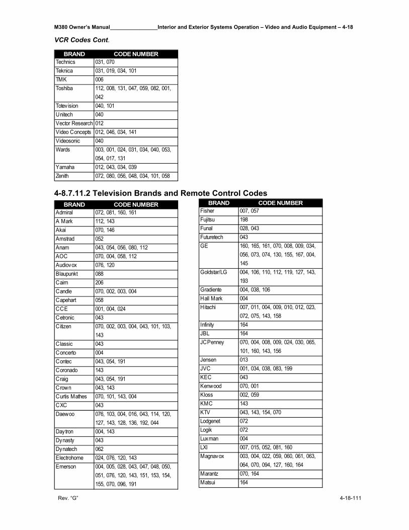
M380 Owner’s Manual________________Interior and Exterior Systems Operation – Video and Audio Equipment – 4-18
Rev. “G” 4-18-111
VCR Codes Cont.
4-8.7.11.2 Television Brands and Remote Control Codes BRAND CODE NUMBER
Admiral 072, 081, 160, 161A Mark 112, 143Akai 070, 146Amstrad 052Anam 043, 054, 056, 080, 112AOC 070, 004, 058, 112Audiovox 076, 120Blaupunkt 088Cairn 206Candle 070, 002, 003, 004Capehart 058CCE 001, 004, 024Cetronic 043Citizen 070, 002, 003, 004, 043, 101, 103,
143Classic 043Concerto 004Contec 043, 054, 191Coronado 143Craig 043, 054, 191Crown 043, 143Curtis Mathes 070, 101, 143, 004CXC 043Daewoo 076, 103, 004, 016, 043, 114, 120,
127, 143, 128, 136, 192, 044Daytron 004, 143Dynasty 043Dynatech 062Electrohome 024, 076, 120, 143Emerson 004, 005, 028, 043, 047, 048, 050,
051, 076, 120, 143, 151, 153, 154, 155, 070, 096, 191
BRAND CODE NUMBERTechnics 031, 070Teknica 031, 019, 034, 101TMK 006Toshiba 112, 008, 131, 047, 059, 082, 001,
042Totev ision 040, 101Unitech 040Vector Research 012Video Concepts 012, 046, 034, 141Videosonic 040Wards 003, 001, 024, 031, 034, 040, 053,
054, 017, 131Yamaha 012, 043, 034, 039Zenith 072, 080, 056, 048, 034, 101, 058
BRAND CODE NUMBERFisher 007, 057Fujitsu 198Funal 028, 043Futuretech 043GE 160, 165, 161, 070, 008, 009, 034,
056, 073, 074, 130, 155, 167, 004, 145
Goldstar/LG 004, 106, 110, 112, 119, 127, 143, 193
Gradiente 004, 038, 106Hall Mark 004Hitachi 007, 011, 004, 009, 010, 012, 023,
072, 075, 143, 158Infinity 164JBL 164JCPenney 070, 004, 008, 009, 024, 030, 065,
101, 160, 143, 156Jensen 013JVC 001, 034, 038, 083, 199KEC 043Kenwood 070, 001Kloss 002, 059KMC 143KTV 043, 143, 154, 070Lodgenet 072Logik 072Luxman 004LXI 007, 015, 052, 081, 160Magnavox 003, 004, 022, 059, 060, 061, 063,
064, 070, 094, 127, 160, 164Marantz 070, 164Matsui 164
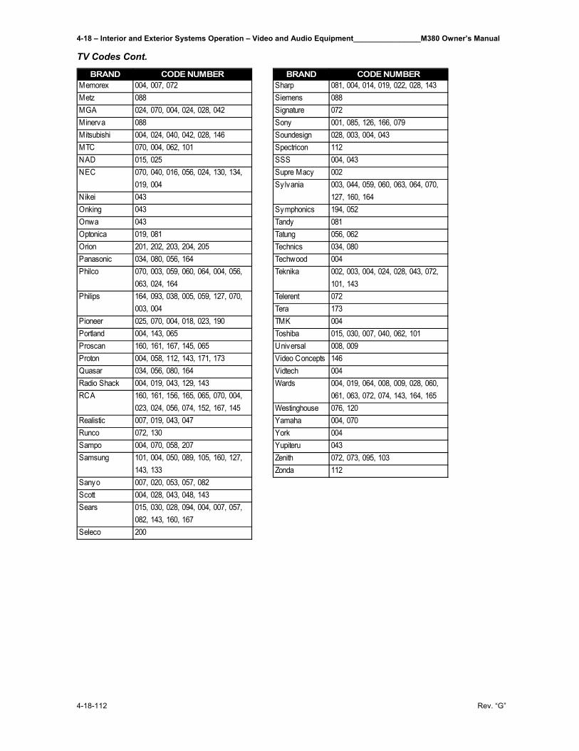
4-18 – Interior and Exterior Systems Operation – Video and Audio Equipment________________M380 Owner’s Manual
4-18-112 Rev. “G”
TV Codes Cont.
BRAND CODE NUMBERMemorex 004, 007, 072Metz 088MGA 024, 070, 004, 024, 028, 042Minerva 088Mitsubishi 004, 024, 040, 042, 028, 146MTC 070, 004, 062, 101NAD 015, 025NEC 070, 040, 016, 056, 024, 130, 134,
019, 004Nikei 043Onking 043Onwa 043Optonica 019, 081Orion 201, 202, 203, 204, 205Panasonic 034, 080, 056, 164Philco 070, 003, 059, 060, 064, 004, 056,
063, 024, 164Philips 164, 093, 038, 005, 059, 127, 070,
003, 004Pioneer 025, 070, 004, 018, 023, 190Portland 004, 143, 065Proscan 160, 161, 167, 145, 065Proton 004, 058, 112, 143, 171, 173Quasar 034, 056, 080, 164Radio Shack 004, 019, 043, 129, 143RCA 160, 161, 156, 165, 065, 070, 004,
023, 024, 056, 074, 152, 167, 145Realistic 007, 019, 043, 047Runco 072, 130Sampo 004, 070, 058, 207Samsung 101, 004, 050, 089, 105, 160, 127,
143, 133Sanyo 007, 020, 053, 057, 082Scott 004, 028, 043, 048, 143Sears 015, 030, 028, 094, 004, 007, 057,
082, 143, 160, 167Seleco 200
BRAND CODE NUMBERSharp 081, 004, 014, 019, 022, 028, 143Siemens 088Signature 072Sony 001, 085, 126, 166, 079Soundesign 028, 003, 004, 043Spectricon 112SSS 004, 043Supre Macy 002Sylvania 003, 044, 059, 060, 063, 064, 070,
127, 160, 164Symphonics 194, 052Tandy 081Tatung 056, 062Technics 034, 080Techwood 004Teknika 002, 003, 004, 024, 028, 043, 072,
101, 143Telerent 072Tera 173TMK 004Toshiba 015, 030, 007, 040, 062, 101Universal 008, 009Video Concepts 146Vidtech 004Wards 004, 019, 064, 008, 009, 028, 060,
061, 063, 072, 074, 143, 164, 165Westinghouse 076, 120Yamaha 004, 070York 004Yupiteru 043Zenith 072, 073, 095, 103Zonda 112
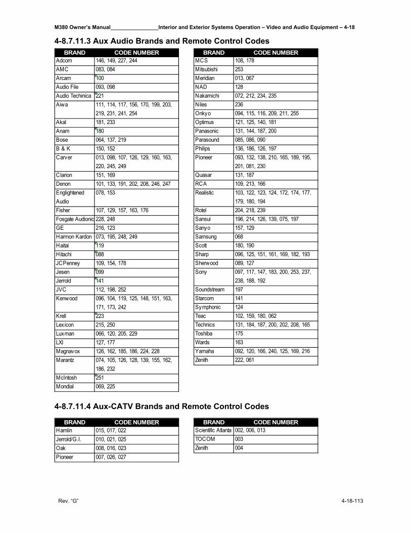
M380 Owner’s Manual________________Interior and Exterior Systems Operation – Video and Audio Equipment – 4-18
Rev. “G” 4-18-113
4-8.7.11.3 Aux Audio Brands and Remote Control Codes
4-8.7.11.4 Aux-CATV Brands and Remote Control Codes
BRAND CODE NUMBERAdcom 146, 149, 227, 244AMC 083, 084Arcam 100Audio File 093, 098Audio Techinica 221Aiwa 111, 114, 117, 156, 170, 199, 203,
219, 231, 241, 254Akal 181, 233Anam 180Bose 064, 137, 219B & K 150, 152Carver 013, 098, 107, 126, 129, 160, 163,
220, 245, 249Clarion 151, 169Denon 101, 133, 191, 202, 208, 246, 247Englightened Audio
078, 153
Fisher 107, 129, 157, 163, 176Fosgate Audionic 228, 248GE 216, 123Harmon Kardon 073, 195, 248, 249Haitai 119Hitachi 088JCPenney 109, 154, 178Jesen 099Jerrold 141JVC 112, 198, 252Kenwood 096, 104, 119, 125, 148, 151, 163,
171, 173, 242Krell 223Lexicon 215, 250Luxman 066, 120, 205, 229LXI 127, 177Magnavox 126, 162, 185, 186, 224, 228Marantz 074, 105, 126, 128, 139, 155, 162,
186, 232McIntosh 251Mondial 069, 225
BRAND CODE NUMBERMCS 108, 178Mitsubishi 253Meridian 013, 067NAD 128Nakamichi 072, 212, 234, 235Niles 236Onkyo 094, 115, 116, 209, 211, 255Optimus 121, 125, 140, 181Panasonic 131, 144, 187, 200Parasound 085, 086, 090Philips 136, 186, 126, 197Pioneer 093, 132, 138, 210, 165, 189, 195,
201, 081, 230Quasar 131, 187RCA 109, 213, 166Realistic 103, 122, 123, 124, 172, 174, 177,
179, 180, 194Rotel 204, 218, 239Sansui 196, 214, 126, 139, 075, 197Sanyo 157, 129Samsung 068Scott 180, 190Sharp 096, 125, 151, 161, 169, 182, 193Sherwood 089, 127Sony 097, 117, 147, 183, 200, 253, 237,
238, 188, 192Soundstream 197Starcom 141Symphonic 124Teac 102, 159, 180, 062Technics 131, 184, 187, 200, 202, 208, 165Toshiba 175Wards 163Yamaha 092, 120, 166, 240, 125, 169, 216Zenith 222, 061
BRAND CODE NUMBERHamlin 015, 017, 022Jerrold/G.I. 010, 021, 025Oak 008, 016, 023Pioneer 007, 026, 027
BRAND CODE NUMBERScientific Atlanta 002, 006, 013TOCOM 003Zenith 004
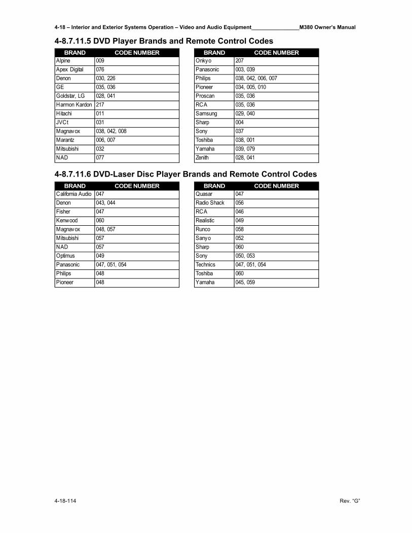
4-18 – Interior and Exterior Systems Operation – Video and Audio Equipment________________M380 Owner’s Manual
4-18-114 Rev. “G”
4-8.7.11.5 DVD Player Brands and Remote Control Codes
4-8.7.11.6 DVD-Laser Disc Player Brands and Remote Control Codes
BRAND CODE NUMBERAlpine 009Apex Digital 076Denon 030, 226GE 035, 036Goldstar, LG 028, 041Harmon Kardon 217Hitachi 011JVCt 031Magnavox 038, 042, 008Marantz 006, 007Mitsubishi 032NAD 077
BRAND CODE NUMBEROnkyo 207Panasonic 003, 039Philips 038, 042, 006, 007Pioneer 034, 005, 010Proscan 035, 036RCA 035, 036Samsung 029, 040Sharp 004Sony 037Toshiba 038, 001Yamaha 039, 079Zenith 028, 041
BRAND CODE NUMBERCalifornia Audio 047Denon 043, 044Fisher 047Kenwood 060Magnavox 048, 057Mitsubishi 057NAD 057Optimus 049Panasonic 047, 051, 054Philips 048Pioneer 048
BRAND CODE NUMBERQuasar 047Radio Shack 056RCA 046Realistic 049Runco 058Sanyo 052Sharp 060Sony 050, 053Technics 047, 051, 054Toshiba 060Yamaha 045, 059

DIR
EC
TV
®
HD
RE
CE
IVE
RU
SE
R G
UID
E
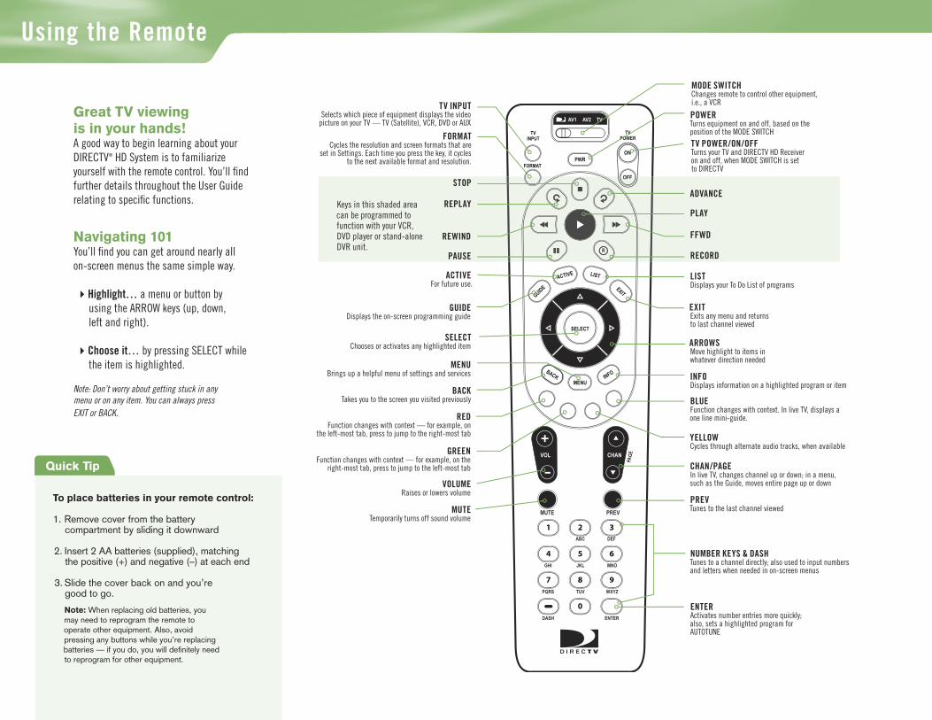
Section Name
R
MENU
1 2 3
4 5 6
7 8 9
0
VOL
MUTE PREV
DEFABC
JKL MNOGHI
TUV WXYZPQRS
DASH ENTER
CHAN
PAG
E
INFOBACK
ON
AV1 AV2 TV
OFF
TVPOWER
TVINPUT
FORMAT
EXIT
LIST
GUIDE
ACTIVE
SELECT
PWR
RR
OFFOFF
MODE SWITCH Changes remote to control other equipment, i.e., a VCR
TV POWER/ON/OFF Turns your TV and DIRECTV HD Receiver on and off, when MODE SWITCH is set to DIRECTV
TV INPUTSelects which piece of equipment displays the video
picture on your TV — TV (Satellite), VCR, DVD or AUX
To place batteries in your remote control:
1. Remove cover from the battery compartment by sliding it downward
2. Insert 2 AA batteries (supplied), matching
the positive (+) and negative (–) at each end 3. Slide the cover back on and you’re
good to go.
Note: When replacing old batteries, you may need to reprogram the remote to operate other equipment. Also, avoid pressing any buttons while you’re replacing batteries — if you do, you will defi nitely need to reprogram for other equipment.
Quick Tip
BLUE Function changes with context. In live TV, displays a one line mini-guide.
ADVANCE
PLAY
RECORD
FFWD
STOP
REPLAY
REWIND
PAUSE
ACTIVEFor future use.
GUIDEDisplays the on-screen programming guide
EXIT Exits any menu and returns to last channel viewed
ARROWS Move highlight to items in whatever direction needed
INFO Displays information on a highlighted program or item
SELECTChooses or activates any highlighted item
MENUBrings up a helpful menu of settings and services
BACKTakes you to the screen you visited previously
REDFunction changes with context — for example, on
the left-most tab, press to jump to the right-most tab
CHAN/PAGEIn live TV, changes channel up or down; in a menu, such as the Guide, moves entire page up or down
PREVTunes to the last channel viewed
YELLOWCycles through alternate audio tracks, when available
NUMBER KEYS & DASHTunes to a channel directly; also used to input numbers and letters when needed in on-screen menus
GREENFunction changes with context — for example, on the
right-most tab, press to jump to the left-most tab
VOLUME Raises or lowers volume
MUTE Temporarily turns off sound volume
LIST Displays your To Do List of programs
Keys in this shaded area can be programmed to function with your VCR, DVD player or stand-alone DVR unit.
Great TV viewing is in your hands!A good way to begin learning about your DIRECTV® HD System is to familiarize yourself with the remote control. You’ll fi nd further details throughout the User Guide relating to specifi c functions.
Navigating 101You’ll fi nd you can get around nearly all on-screen menus the same simple way.
4Highlight… a menu or button by using the ARROW keys (up, down, left and right).
4Choose it… by pressing SELECT while the item is highlighted.
Note: Don’t worry about getting stuck in any menu or on any item. You can always press EXIT or BACK.
POWER Turns equipment on and off, based on the position of the MODE SWITCHFORMAT
Cycles the resolution and screen formats that are set in Settings. Each time you press the key, it cycles
to the next available format and resolution.
Using the Remote
ENTER Activates number entries more quickly; also, sets a highlighted program for AUTOTUNE

Section Title

Table of Contents
Chapter 1 – IntroductionWelcome ............................................................................................................. 2About Your User Guide ..................................................................................... 3Defining High-Definitition ............................................................................... 4
Chapter 2 – Getting Connected Making the Right Connections .......................................................................14 Safety & Care ....................................................................................................15 Helpful Hardware References ..........................................................................18 Getting Familiar ...............................................................................................24 Choose the Setup That Suits You ................................................................... 28 Guided Setup and Activation ..........................................................................32 Options For Changing Video Output .............................................................33
Chapter 3 – What’s On Watching TV .................................................................................................... 40 The Guide .........................................................................................................43 Autotune ...........................................................................................................45 Pay Per View ......................................................................................................47
Chapter 4 – The Quick Menu What’s On the MENU? .................................................................................. 50 Settings ..............................................................................................................51 Audio Options ..................................................................................................55 Category Sort ....................................................................................................56 Pay Per View ......................................................................................................57 Find By ..............................................................................................................58 Date & Time ..................................................................................................... 60 Favorites ............................................................................................................61 Previous Channels ............................................................................................62 Caller ID & Messages .......................................................................................63 Parental Controls ..............................................................................................65
Chapter 5 – Other Information Perform a Code Search ....................................................................................70 Troubleshooting ................................................................................................71 Limited Warranty ............................................................................................ 84 FCC Customer Information ........................................................................... 90 Registration Information .................................................................................94 Index .................................................................................................................96

Section Title
1
2 Welcome
3 About Your User Guide
4 Defining High-Definition
Chapter 1

2
WelcomeCongratulations on choosing the best entertainment experience around!
With its astounding variety of channels and choices and unbeatable high-definition technology… DIRECTV® HD service offers everything you’d want in your television experience. You can expect more than ever before, with access to over 225 channels including our awesome HD selections and over 30 premium movie channels, with something sure to please everyone in the family. DIRECTV Pay Per View offers a handy choice in recent hit movies, plus exciting live sports, concerts and specials. There are exclusive sports subscriptions for every taste and team. Even access to 36 commercial-free music channels!
To deliver this unique programming and enhance your entertainment experience, the DIRECTV® HD Receiver has been designed to be simple and user-friendly. You’ll find that most features are self-explanatory, with on-screen directions to lead you through them.
So, welcome to the family. You’re sure to discover that using and watching TV is more exciting and enjoyable than ever.
Welcome
Introduction
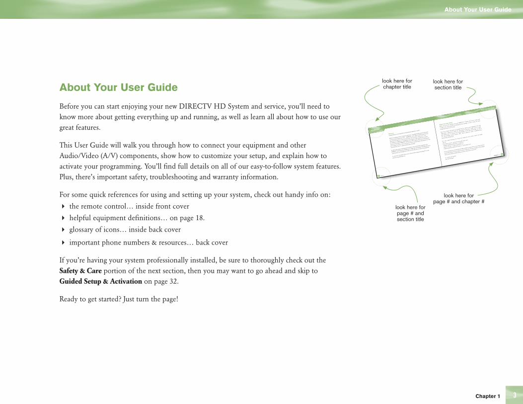
3
Introduction
About Your User Guide
Chapter 1 6
look here for section title
look here for page # and chapter #
About Your User Guide
Before you can start enjoying your new DIRECTV®hhh System and service, you’ll need
to know more about getting everything up and running, as well as learn all about
navigating around our TV world.
This User’s Guide will walk you through how to connect your equipment and other
audio/video components, show the personalized fine-tunes you’ll need to make,
and explain how to activate your programming. You’ll f ind full details on all of
our easy-to-follow system features. Plus, there’s important safety, troubleshooting
and warranty information.
For some quick references for using and setting up your system, check out handy
info on:
• the remote control…on the manual inside front cover
• helpful equipment definitions…on page 10
• glossary of icons…on the inside back cover
• important phone numbers & resources…on the back cover
If you’re having your system professionally installed, you may want to just jump ahead to
our Guided Setup section on page 30 and go from there. Be sure, though, to thoroughly
check out the Safety and Precautions portion of the next section first!
So, ready to get started?
Just turn the page!
Welcome6
Welcome
Congratulations on choosing the best entertainment experience around!
With its astounding variety of channels and choices, crisp digital-quality picture and sound,
and one-of-a-kind sports and events … DIRECTV® service offers everything you’d want in
your television experience. You can expect more than ever before, with access to over
225 channels, including over 30 premium movie channels, with something sure to please
everyone in the family. DIRECTV® Pay Per View offers a handy choice in recent hit movies,
plus exciting live sports, concerts and specials. There’s exclusive sports subscriptions for every
taste and team. Even 31 commercial-free music channels!
To deliver this unique programming and enhance your entertainment experience, the
DIRECTV® System has been designed to be simple and user-friendly. You’ll fi nd that most
system features are self-explanatory, with on-screen directions to lead you through them.
So, welcome to the family. You’re sure to discover that using and watching TV is easier
and more enjoyable than ever
look here for chapter title
look here for page # and section title
About Your User Guide
Before you can start enjoying your new DIRECTV HD System and service, you’ll need to know more about getting everything up and running, as well as learn all about how to use our great features.
This User Guide will walk you through how to connect your equipment and other Audio/Video (A/V) components, show how to customize your setup, and explain how to activate your programming. You’ll fi nd full details on all of our easy-to-follow system features. Plus, there’s important safety, troubleshooting and warranty information.
For some quick references for using and setting up your system, check out handy info on:
4 the remote control… inside front cover
4 helpful equipment defi nitions… on page 18.
4 glossary of icons… inside back cover
4 important phone numbers & resources… back cover
If you’re having your system professionally installed, be sure to thoroughly check out the Safety & Care portion of the next section, then you may want to go ahead and skip to Guided Setup & Activation on page 32.
Ready to get started? Just turn the page!
About Your User Guide
Chapter 1

4 Defining High-Definition
Introduction
Defining High-Definition
What is HD, and how does it differ from regular TV? To learn more, here’s some helpful information about high-definition and your DIRECTV HD Receiver.
Types of TV Broadcasts
Analog TV is the type of TV broadcast you may be most familiar with. If you get your broadcasts via a standard off-air antenna, it’s the type you receive, and most broadcasts from local cable companies are analog as well.
Digital TV is a newer system for broadcasting TV signals delivering higher quality audio and video. “Digital TV” refers to a television that can receive and display digital images.
4 SDTV (standard definition TV) is digital TV that offers a high picture quality that is better than older analog televisions. An SDTV can display an image at a resolution of 480i.
4 EDTV (enhanced definition TV) is digital TV that can display a higher resolution picture than SDTV. An EDTV can display at 480i or 480p.
4 HDTV (high definition TV) is digital TV that can provide the highest quality picture, at resolutions 1080i, 720p, 480p, or 480i.
See “Resolutions and Interlacing” on page 6, for an explanation of display resolutions.

5 25 Chapter 1
Defining High-Definition
Equipment You’ll Need
To view HD programming, you’ll need, in addition to your DIRECTV HD Receiver:
4 A high-definition TV set (or HDTV monitor)
4 A triple LNB 18” x 20” DIRECTV Multi-Satellite dish antenna
To enjoy select HD programming available on off-air local channels, you will also need an off-air antenna (sold separately) connected to your DIRECTV HD Receiver. This is possible only in cities where local broadcast stations make digital TV programs, such as high-definition, available; reception may vary based on your geographic location.
What You Can Watch
With the DIRECTV HD Receiver, you have access to all types of televised programming, including:
4 DIRECTV high-definition and standard-definition digital programming via satellite, including local channels if offered in your area (DIRECTV service subscription required).
4 Local digital TV channels, including any local HD broadcasts shown in your area, available via an off-air antenna.
6
Resolution & Interlacing
Two elements that determine the quality of a TV picture are:
ResolutionFor TV equipment and broadcasts, resolution is defined by the number of horizontal lines displayed to make up each frame of a video image. The more lines of resolution used to compose each frame, the more detailed and sharp the picture. Standard TV resolution uses 480 horizontal lines to make up each video frame; HDTV uses either 720 or 1080 lines to compose each frame.
Interlaced & ProgressiveIf you’ve ever looked very closely at your TV, you have noticed the picture is actually made up of many lines scanning across the screen. The set of lines that make up a complete image are called a “frame.” Like a child’s flipbook where the image seems to move as the pages change, your TV displays video by changing these frames at a rate 60 frames per second.
The term “interlacing” refers to whether each of those frames contains all of the lines of image, or every other line. Interlaced signals take every other line from 2 frames, each lasting 1/60th of a second, and combine them into one frame lasting 1/30th of a second. In this way, interlacing tricks the eye into thinking it’s seeing twice the resolution that’s actually being displayed. In non-interlaced video, referred to as “progressive scan” video, frames are displayed every 1/60th of a second containing all of the lines of video information.
The specifications for video resolution are usually stated by giving the number of horizontal lines (480, 720 or 1080, as described above) followed by either the letter “i” (for interlaced) or “p” (for progressive scan). Most standard TV broadcasts are 480i; some DVDs and non-HDTV digital broadcasts use 480p. Specification for HDTV broadcasts and equipment requires either 1080i or 720p. While there’s some debate as to whether it’s preferred to have more lines interlaced or fewer lines progressively scanned, it’s generally accepted that 1080i is the highest quality video format.
Defining High-Definition
Introduction

7
Aspect Ratio
In addition to resolution and interlacing, a television picture is also defined by the aspect ratio of its broadcasts—referring to the shape of the screen as defined by the ratio of the screen’s width to its height.
For analog TV, the aspect ratio is 4 units wide by 3 units high (usually written 4:3). This is the familiar shape of conventional TVs—slightly wider than they are tall. SDTV and EDTV can be either 4:3 or 16:9. For HDTV broadcasts, the aspect ratio is 16:9—nearly twice as wide as it is tall. This is, not coincidentally, more like the shape of movies shown in theaters, which makes HD an ideal format for viewing movies on TV.
Screen Formats
What if you’re watching a nearly square-shaped 4:3 broadcast on a 16:9 TV, or vice versa? The DIRECTV HD Receiver lets you choose from a variety of screen formats to deal with those scenarios. You can set up your preferences for format during guided setup. You can change these settings at any time.
See the next page for your options.
Chapter 1
Defining High-Definition

8
4:3 TVs showing 16:9 programs
For a standard 4:3 TV showing a wide screen program, the program is too wide to fit on the screen. To alleviate this, choose:
LetterboxWith this format, the 16:9 image is shrunk until the entire width of the program fits on your TV. Since the aspect ratio of the program is maintained, the image is no longer tall enough to fill your screen, so gray or black bars are seen at the top and bottom of the screen. To change the bar color, access the HDTV screen in System Setup as described above, then select the desired bar color option under the TV Ratio tab. See your TV owner manual for information on the best color for your set.
FullIn the Full setting, 16:9 images are stretched to fit the height of the screen. But, instead of adding bars to the top and bottom, the 16:9 program image is stretched vertically until it’s tall enough to fill the screen. Your entire screen will be full, but the program images are stretched to compensate.
ZoomThis format crops (cuts off) the left and right portions of the 16:9 frame so it fits the 4:3 screen.
Introduction
Defining High-Definition
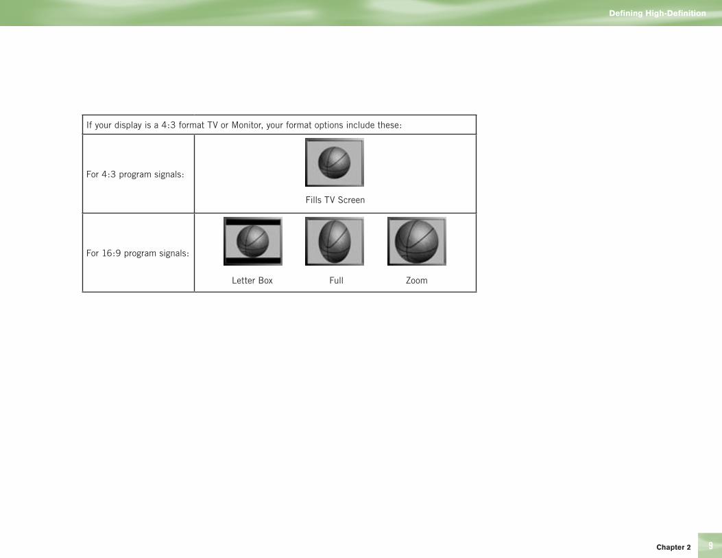
Chapter 2 9
Defining High-Definition
If your display is a 4:3 format TV or Monitor, your format options include these:
For 4:3 program signals:
Fills TV Screen
For 16:9 program signals:
Letter Box Full Zoom

10
16:9 TVs showing 4:3 programs
For a wide screen 16:9 TV showing a standard 4:3 TV program, the program is too tall to fit the screen. Your choices here include:
Pillar boxThe 4:3 aspect ratio is maintained, the image is no longer wide enough to fill the screen, so gray or black bars are seen at the left and right edges. To change the bar color, access the HDTV screen in System Setup as described above, then select the desired bar color option under the TV Ratio tab.
FullIn this setting, instead of adding bars to the sides, the 4:3 program image is stretched horizontally until it’s wide enough to fill the screen. Your entire screen will be full, but the images are a little stretched to compensate.
ZoomThis format crops (cuts off) the top and bottom of a 4:3 frame, keeping the 4:3 ratio intact.
Introduction
Defining High-Definition
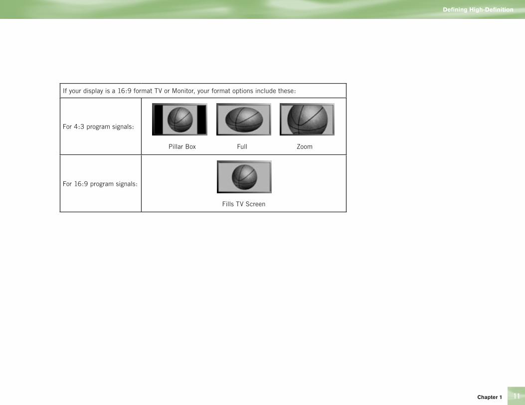
11
Defining High-Definition
Chapter 1
If your display is a 16:9 format TV or Monitor, your format options include these:
For 4:3 program signals:
Pillar Box Full Zoom
For 16:9 program signals:
Fills TV Screen

12
Dolby® Digital 5.1
The recommended audio format for HDTV is Dolby® Digital 5.1.
This format offers five discrete channels of mid- and high-range digital audio, plus one channel of low-frequency (subwoofer) audio for use by A/V receivers capable of decoding the 5.1 channel signal. The audio signals are broken into left-front, center, right-front, left-rear, right-rear and low-frequency. The result, when your DIRECTV HD Receiver is connected to a compatible Dolby Digital 5.1 channel A/V receiver and speaker setup, is an experience that gives you much of the dynamic range, 360-degree imaging and sonic excitement of a real theater.
Not all TV programs are broadcast using Dolby Digital 5.1. For DIRECTV programming, shows broadcast using this high-quality audio standard are indicated by the words Dolby Digital in the Channel Banner (see page 41) and Program Guide (see page 43).
If you are using the Digital Audio Output (Optical, Coax or HDMI) from your DIRECTV HD Receiver to a digital audio (A/V) receiver or TV, you can set your preference by going here:
1) While in Live TV press MENU.
2) From the Quick Menu, SELECT Settings.
3) Scroll down to Setup and press SELECT.
4) Scroll down to Audio, and press SELECT.
5) Scroll up to the tabs and scroll over to Digital Audio and press SELECT.
6) Scroll to Dolby Digital and SELECT On or Off. If you set this to “Off”, then the audio on the Digital Outputs will always be in PCM (L/R Stereo).
7) If you set the Dolby Digital to “On”, then you should also setup the Digital Output.
8) Scroll to Digital Output and presse SELECT:
— Dolby Digital: if you want programs to be heard in Dolby Digital when available
— PCM if you want programs (with and without Dolby Digital) to be heard in L/R stereo only.
Introduction
Defining High-Definition

14 Making the Right Connections
15 Safety & Care
18 Helpful Hardware References
24 Getting Familiar
28 Choose the Setup That Suits You
32 Guided Setup and Activation
33 Options For Changing Video Output
Chapter 2

14
Making the Right Connections
Ready to connect your DIRECTV® HD Receiver and your other components?
Whether you’re having your system professionally installed or handling it yourself, be sure to read over the following few pages to familiarize yourself with some important tips for safety and care.
Before you begin
Your satellite dish antenna must be installed before you can begin following the procedures in this User Guide. (Professional installation is highly recommended.) Your dish needs to be mounted in a position where it has access to the satellite signals, and RG-6 coaxial cables must be run into the room(s) where your receiver(s) will be located. If you choose to install the dish yourself, see the separate instruction manual that came with your satellite dish antenna.
Package Contents
The following items are included with your DIRECTV HD Receiver:
4 A/V cables (RCA type) 4 Access card
4 S-Video cable 4 User Guide
4 Phone cord 4 RF/IR Remote with 2 batteries
4 Power cord 4 Component Video cables (YPbPr)
4 RF Remote antenna
Making the Right Connections
Getting Connected
POWER
DIRECTV®HD Receiver H10
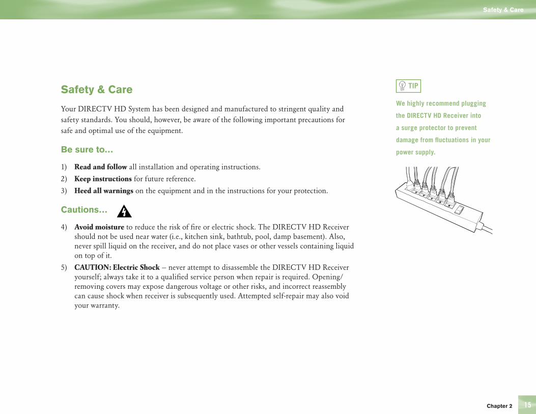
15
Safety & Care
Your DIRECTV HD System has been designed and manufactured to stringent quality and safety standards. You should, however, be aware of the following important precautions for safe and optimal use of the equipment.
Be sure to…
1) Read and follow all installation and operating instructions.
2) Keep instructions for future reference.
3) Heed all warnings on the equipment and in the instructions for your protection.
Cautions…
4) Avoid moisture to reduce the risk of fire or electric shock. The DIRECTV HD Receiver should not be used near water (i.e., kitchen sink, bathtub, pool, damp basement). Also, never spill liquid on the receiver, and do not place vases or other vessels containing liquid on top of it.
5) CAUTION: Electric Shock — never attempt to disassemble the DIRECTV HD Receiver yourself; always take it to a qualified service person when repair is required. Opening/removing covers may expose dangerous voltage or other risks, and incorrect reassembly can cause shock when receiver is subsequently used. Attempted self-repair may also void your warranty.
Safety & Care
Chapter 2
TIP
We highly recommend plugging
the DIRECTV HD Receiver into
a surge protector to prevent
damage from fluctuations in your
power supply.

16
6) Have your DIRECTV HD Receiver professionally serviced (do not attempt to service it yourself ) if:
4 The power supply cord or plug is damaged or frayed
4 Liquid has spilled into the product or it has been exposed to water
4 The receiver has been dropped or damaged
4 The receiver exhibits a distinct change in performance
4 The receiver does not operate normally when you follow operating instructions as described in this manual and its Troubleshooting section.
7) Protect your components from power surges by connecting all the components before plugging any power cords into the wall outlet. Use of a surge protector is also recommended.
8) Don’t overload power outlets or extension cords, which can result in the risk of fire or shock. It’s also important to use only the type of power source indicated on the marking label or in this manual.
9) Always unplug the DIRECTV HD Receiver, TV and other equipment before you connect or disconnect any cables.
10) Always unplug your DIRECTV HD Receiver before moving it. Also, unplug it during lightning storms or when unused for long periods of time.
11) Protect power cords by routing them so they will not be walked on or pinched in any way.
12) Avoid audio hum or interference by inserting all cable plugs firmly into their jacks. Also, place Audio/Video (A/V) cables to the sides of the TV back panel rather than down the middle once connected. Try not to coil any twin-lead cables and keep them away from A/V cables as much as possible.
Note to Satellite Dish Installer
This reminder is provided to call your attention to articles 810 and 820 of the 2002 National Electrical Code. Refer to article 810, in particular 810-1 and 810-15, for required grounding of the metal structure of the dish antenna. Refer also to the 810-2 which, by reference to article 820, requires that the satellite dish coaxial cable shield be connected to the grounding system of the building as close to the point of cable entry as practical.
Getting Connected
Safety & Care
17
13) Do not drop your DIRECTV HD Receiver and always move it with care.
14) Place it on a flat, hard surface — do not operate the DIRECTV HD Receiver on a carpet or other padded surface. Ensure that the rack or cabinet the receiver is placed on is stable, and not subject to being tipped over.
15) Ensure proper ventilation — the slots on top of the DIRECTV HD Receiver must be left uncovered to allow proper airflow to the unit. Blocking the airflow to the unit could impair performance or damage your receiver and other components.
16) Do not stack electronic components or other objects on top of the DIRECTV HD Receiver. Also, do not stack the receiver on top of a “hot component” such as an audio power amplifier.
17) Avoid heat — do not place the DIRECTV HD Receiver near heat sources such as radiators, heat registers, stoves or other appliances.
18) Never insert objects of any kind into any openings in the DIRECTV HD Receiver (other than the DIRECTV Access Card as detailed in next pages).
19) Clean your receiver with a soft cloth or the dusting attachment of your vacuum cleaner, removing dust from the ventilation holes on the top and bottom. Avoid alcohol or oil-based furniture solvents — a non-abrasive, anti-static cleaner/polisher is recommended.
20) Use only manufacturer authorized accessories and parts.
IMPORTANT: Be sure not to place
your DIRECTV HD Receiver near
anything WET or HOT!
Important
This device incorporates an anticopy process technology that is protected by U.S. patents and other intellectual property rights. The anticopy process is licensed for non-commercial, home use only. Reverse engineering or disassembly is prohibited. FCC Regulations state that unauthorized changes or modifications to this equipment may void the user’s authority to operate it.
Chapter 2
Care of Your Receiver
POWER
DIRECTV®HD Receiver H10
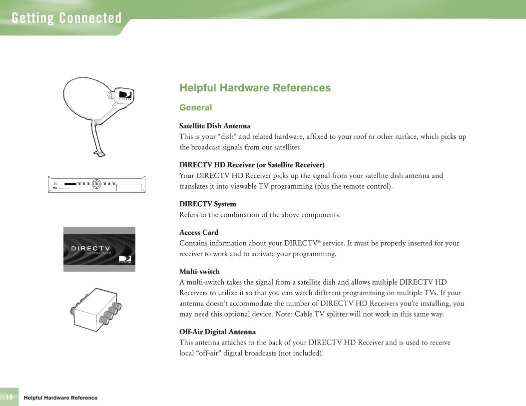
18
Helpful Hardware References
General
Satellite Dish AntennaThis is your “dish” and related hardware, affixed to your roof or other surface, which picks up the broadcast signals from our satellites.
DIRECTV HD Receiver (or Satellite Receiver)Your DIRECTV HD Receiver picks up the signal from your satellite dish antenna and translates it into viewable TV programming (plus the remote control).
DIRECTV SystemRefers to the combination of the above components.
Access CardContains information about your DIRECTV® service. It must be properly inserted for your receiver to work and to activate your programming.
Multi-switchA multi-switch takes the signal from a satellite dish and allows multiple DIRECTV HD Receivers to utilize it so that you can watch different programming on multiple TVs. If your antenna doesn’t accommodate the number of DIRECTV HD Receivers you’re installing, you may need this optional device. Note: Cable TV splitter will not work in this same way.
Off-Air Digital AntennaThis antenna attaches to the back of your DIRECTV HD Receiver and is used to receive local “off-air” digital broadcasts (not included).
Getting Connected
Helpful Hardware Reference
POWER
DIRECTV®HD Receiver H10
D I R E C T V

19
Digital Cables & Connections
HDMI Jack and CableHDMI stands for High-Definition Multimedia Interface. It offers a high-quality connection that combines the video and audio signal into a single cable.
The HDMI jack uses HDCP content protection to allow you to view HD programming that has been encoded using the HDCP protection system. For the best access to HD programming at the highest available resolution, connect this to an HDTV that supports HDCP technology.
DVI (Digital Video Interface) is an older digital connection standard that has been replaced by HDMI and is compatible with HDMI. DVI carries video only. You can also use an HDMI to DVI converter (not included), which also carries video only, so must be used with audio cables to receive the audio signal.
Component Video Output (YPbPr)The component connector provides high-quality video for your HDTV system. Component video is also referred to as “ YPbPr.” It uses three separate cables—with connectors colored green, red and blue—one for each component of the HD video signal. Note that not all cables come
with your digital satellite
receiver; you may need to
purchase additional cables
depending on your setup.
HDMI cable not included.
Chapter 2
Helpful Hardware Reference
Pr PbY

20
Digital Audio Outputs (Optical Jack and Cable) The Digital Audio Optical cable provides the best quality audio. The jack and cable use light to send digital audio data to A/V receivers equipped to receive and interpret it. The jack and cable (cable not included) must be aligned before plugging in, and may be covered by protective caps, which must be removed before making connections.
Digital Audio Outputs (Coaxial Jack and Cable) Coaxial digital audio jacks and cables (cable not included) send digital audio data to A/V receivers equipped with coaxial digital audio input jacks. Coaxial cable provides a high quality audio signal over copper wire.
Helpful Hardware References
Getting Connected
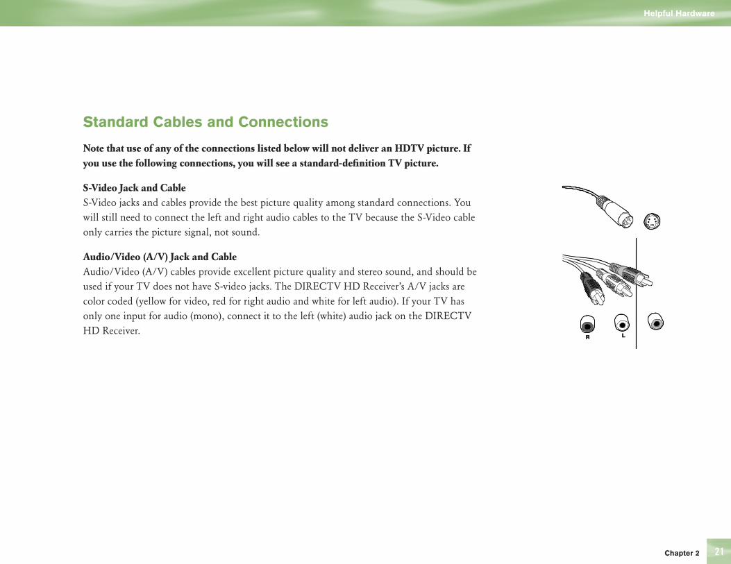
21
Standard Cables and Connections
Note that use of any of the connections listed below will not deliver an HDTV picture. If you use the following connections, you will see a standard-definition TV picture.
S-Video Jack and CableS-Video jacks and cables provide the best picture quality among standard connections. You will still need to connect the left and right audio cables to the TV because the S-Video cable only carries the picture signal, not sound.
Audio/Video (A/V) Jack and Cable Audio/Video (A/V) cables provide excellent picture quality and stereo sound, and should be used if your TV does not have S-video jacks. The DIRECTV HD Receiver’s A/V jacks are color coded (yellow for video, red for right audio and white for left audio). If your TV has only one input for audio (mono), connect it to the left (white) audio jack on the DIRECTV HD Receiver.
Helpful Hardware
Chapter 2
LLRR
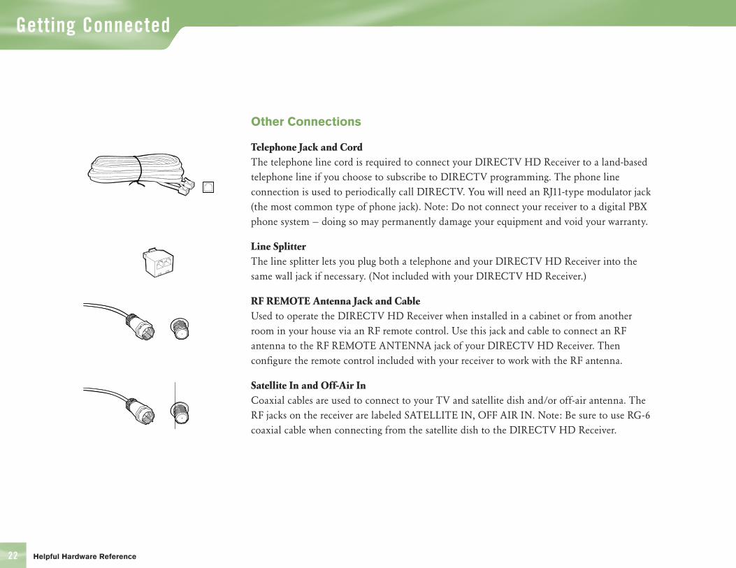
22
Other Connections
Telephone Jack and Cord The telephone line cord is required to connect your DIRECTV HD Receiver to a land-based telephone line if you choose to subscribe to DIRECTV programming. The phone line connection is used to periodically call DIRECTV. You will need an RJ11-type modulator jack (the most common type of phone jack). Note: Do not connect your receiver to a digital PBX phone system — doing so may permanently damage your equipment and void your warranty.
Line SplitterThe line splitter lets you plug both a telephone and your DIRECTV HD Receiver into the same wall jack if necessary. (Not included with your DIRECTV HD Receiver.)
RF REMOTE Antenna Jack and CableUsed to operate the DIRECTV HD Receiver when installed in a cabinet or from another room in your house via an RF remote control. Use this jack and cable to connect an RF antenna to the RF REMOTE ANTENNA jack of your DIRECTV HD Receiver. Then configure the remote control included with your receiver to work with the RF antenna.
Satellite In and Off-Air InCoaxial cables are used to connect to your TV and satellite dish and/or off-air antenna. The RF jacks on the receiver are labeled SATELLITE IN, OFF AIR IN. Note: Be sure to use RG-6 coaxial cable when connecting from the satellite dish to the DIRECTV HD Receiver.
Getting Connected
Helpful Hardware Reference

23Chapter 2
Optional Audio/Video and Electronics
Switch BoxA small box that lets you connect multiple devices to your TV, allowing you to switch easily between your DIRECTV programming, VCR, DVD player, game system, etc.
A/V ReceiverMore sophisticated than a switch box, it provides all the same advantages, and may offer additional features such as the ability to hook up to multiple speakers.
Surge ProtectorDevices that protect electronic equipment from power fluctuations. Highly recommended to prevent damage to your DIRECTV HD System.
Dolby® Digital (AC-3) AudioRecorded on six separate channels which can be heard on six different speakers. To enjoy Dolby® Digital audio, you’ll need to connect your receiver (via an optical audio cable) to an A/V receiver capable of supporting it.
Dolby® Surround Sound/Dolby Pro LogicRecorded on two channels which can be heard on two or more speakers. You will also need to connect your DIRECTV HD Receiver to a Dolby® Surround Sound supporting A/V receiver (using R and L audio cables or an optical audio cable).
Helpful Hardware Reference
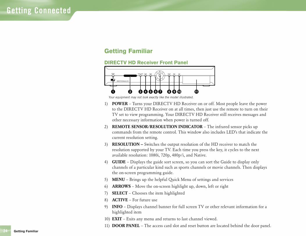
24
Getting Familiar
DIRECTV HD Receiver Front Panel
1) POWER – Turns your DIRECTV HD Receiver on or off. Most people leave the power to the DIRECTV HD Receiver on at all times, then just use the remote to turn on their TV set to view programming. Your DIRECTV HD Receiver still receives messages and other necessary information when power is turned off.
2) REMOTE SENSOR/RESOLUTION INDICATOR – The infrared sensor picks up commands from the remote control. This window also includes LED’s that indicate the current resolution setting.
3) RESOLUTION – Switches the output resolution of the HD receiver to match the resolution supported by your TV. Each time you press the key, it cycles to the next available resolution: 1080i, 720p, 480p/i, and Native.
4) GUIDE – Displays the guide sort screen, so you can sort the Guide to display only channels of a particular kind such as sports channels or movie channels. Then displays the on-screen programming guide.
5) MENU – Brings up the helpful Quick Menu of settings and services
6) ARROWS – Move the on-screen highlight up, down, left or right
7) SELECT – Chooses the item highlighted
8) ACTIVE – For future use
9) INFO – Displays channel banner for full screen TV or other relevant information for a highlighted item
10) EXIT – Exits any menu and returns to last channel viewed.
11) DOOR PANEL – The access card slot and reset button are located behind the door panel.
Getting Connected
Getting Familiar
Your equipment may not look exactly like the model illustrated.
POWER
DIRECTV®HD Receiver H10
1 2 3 4 5 76 8 9 10 11
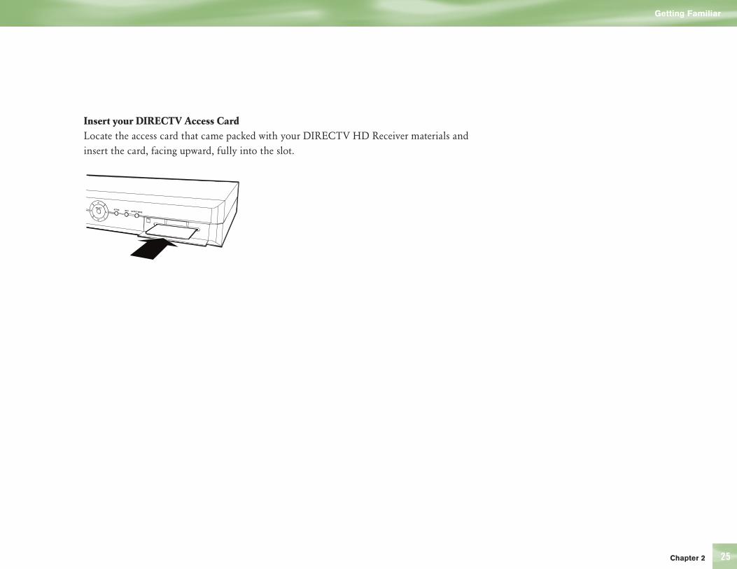
25
Insert your DIRECTV Access CardLocate the access card that came packed with your DIRECTV HD Receiver materials and insert the card, facing upward, fully into the slot.
Chapter 2
Getting Familiar
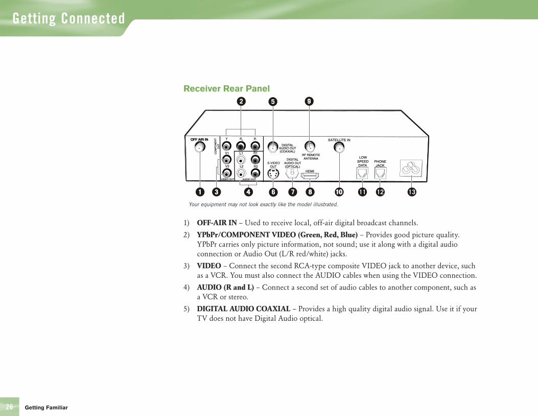
26
Receiver Rear Panel
1) OFF-AIR IN – Used to receive local, off-air digital broadcast channels.
2) YPbPr/COMPONENT VIDEO (Green, Red, Blue) – Provides good picture quality. YPbPr carries only picture information, not sound; use it along with a digital audio connection or Audio Out (L/R red/white) jacks.
3) VIDEO – Connect the second RCA-type composite VIDEO jack to another device, such as a VCR. You must also connect the AUDIO cables when using the VIDEO connection.
4) AUDIO (R and L) – Connect a second set of audio cables to another component, such as a VCR or stereo.
5) DIGITAL AUDIO COAXIAL – Provides a high quality digital audio signal. Use it if your TV does not have Digital Audio optical.
OFF AIR INOFF AIR IN
33331111 22
22
4444 6666
55
77 8888
9999
10101100 1211 13
Your equipment may not look exactly like the model illustrated.
Getting Familiar
Getting Connected
27
6) S-VIDEO – Provides the best non-digital picture quality, better than VIDEO RCA-type or RF coaxial jacks. If your TV has an S-Video jack, use it along with the audio jacks (S-Video only carries picture information, not sound) to connect to your TV.
7) DIGITAL AUDIO OPTICAL – Provides the best digital-quality audio signal.
8) HDMI – Provides a higher quality HD picture than YPbPr/component video.
9) RF REMOTE ANTENNA – Used to receive the signal from your remote when it’s being used as an RF remote.
10) SATELLITE IN – Use to connect the DIRECTV HD Receiver to the satellite dish antenna.
11) LOW SPEED DATA – You can connect your receiver to future services and accessories as they become available. Additional hardware may be required.
12) PHONE – Connects the DIRECTV HD Receiver to a telephone line. The DIRECTV HD Receiver requires a land-based telephone line connection to communicate periodically with your program provider.
13) AC POWER INLET – Use to connect the power cord for your DIRECTV HD Receiver.
Getting Familiar
Chapter 2

28
Choose the Setup That Suits You
There are several ways to connect your receiver to match your particular equipment setup and to gain optimum signal quality. The following pages illustrate some of the most common setups. Keep in
mind that the back panels of your TV and other equipment may not exactly match those illustrated.
Connecting Your DIRECTV HD Receiver to a TV with an HDMI Input
1) Connect your satellite dish antenna to the DIRECTV HD Receiver. Connect the RG-6 coaxial cable from your satellite dish to the jack labeled SATELLITE IN on the DIRECTV HD Receiver.
2) Connect the off-air antenna to the DIRECTV HD Receiver (optional). Connect the off-air antenna to the jack labeled OFF-AIR IN on your receiver. When you run the Guided Setup, be sure to select the Satellite & Antenna button when you reach the Satellite Dish & Off-Air Antenna screen.
3) Connect the video from the DIRECTV HD Receiver to your TV. Connect the HDMI cables to the HDMI jacks on the receiver and your TV. Note: HDMI cable is not included with HD Receiver.
4) Connect the audio from the HD Receiver to your TV. Connect the white (L) and red (R) RCA-type cables from the DIRECTV HD Receiver to your TV. Note: you can also connect either optical or coaxial audio cable from your receiver to your audio equipment if they support those formats.
5) Connect the DIRECTV HD Receiver to a land-based phone line. Plug one end of the telephone cord into a phone jack on your wall (or into a phone splitter that is plugged into a phone jack) and the other end into the PHONE JACK on the back of the DIRECTV HD Receiver.
6) Connect the RF remote antenna to the DIRECTV HD Receiver (optional). If you want to use your remote without having to point it at the receiver, such as from another room, or in a setup where objects are likely to block the beam from your remote to your DIRECTV HD Receiver (such as the receiver is in a cabinet with a door), then plug the RF remote antenna into the RF REMOTE ANTENNA jack on your receiver. Your receiver defaults to IR functionality. To activate RF functionality go to the System Setup screen, choose REMOTE in the left menu. Select IR/RF Setup button and follow the on screen instructions.
7) Plug all power cords into electrical outlets.
When working with cables, be
sure to connect corresponding
outputs and inputs (Video OUT
to Video IN, Right Audio OUT
to Right Audio IN, etc.). Never
connect an IN to an IN or an OUT
to an OUT.
All A/V jacks and inputs are
color coded. Always match the
color of the plug to the same
color of the jack.
OUT IN
TIP
Choose the Setup That Suits You
Getting Connected
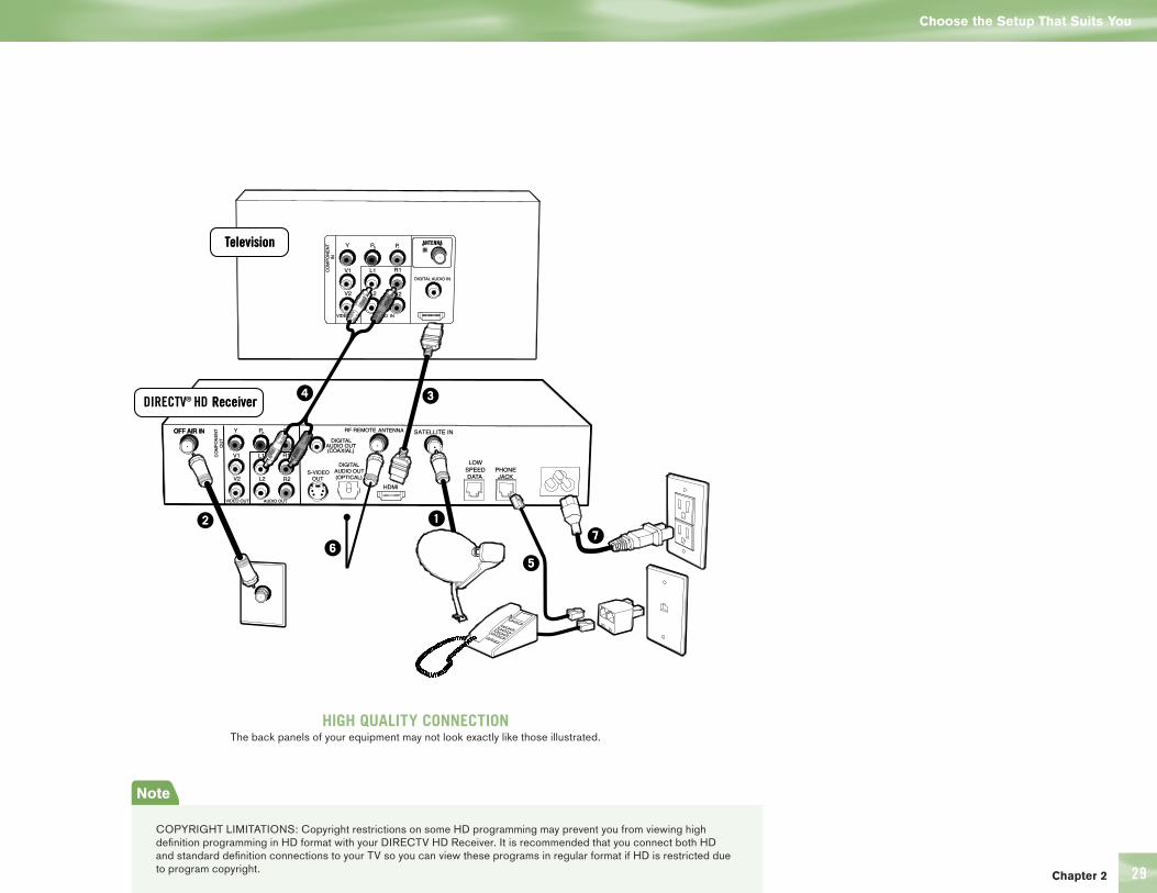
29
OFF AIR INOFF AIR IN
����
��
��
����
��
��������������������
���������������� ��� ���������
HIGH QUALITY CONNECTIONThe back panels of your equipment may not look exactly like those illustrated.
Note
COPYRIGHT LIMITATIONS: Copyright restrictions on some HD programming may prevent you from viewing high definition programming in HD format with your DIRECTV HD Receiver. It is recommended that you connect both HD and standard definition connections to your TV so you can view these programs in regular format if HD is restricted due to program copyright.
Chapter 2
Choose the Setup That Suits You

30
Note
COPYRIGHT LIMITATIONS: Copyright restrictions on some HD programming may prevent you from viewing high definition programming in HD format with your DIRECTV HD Receiver. It is recommended that you connect both HD and standard definition connections to your TV so you can view these programs in regular format if HD is restricted due to program copyright.
Connecting your DIRECTV HD Receiver to an HDTV with YPbPr Component Video and Digital Audio Inputs
1) Connect your satellite dish antenna to the DIRECTV HD Receiver. Connect the RG-6 coaxial cable from your satellite dish to the jack labeled SATELLITE IN on the DIRECTV HD Receiver.
2) Connect the off-air antenna to the DIRECTV HD Receiver (optional). Connect the antenna to the jack labeled OFF-AIR IN on your receiver. When you run the Guided Setup, be sure to select the Satellite & Antenna button when you reach the Satellite Dish & Off-Air Antenna screen.
3) Connect the DIRECTV HD Receiver to your TV (video). Connect one end of the Component video cables to the COMPONENT OUT video jacks on the DIRECTV HD Receiver. Connect the other end of the component video cable to the component input on your TV, making sure to correctly match the red, green and blue connectors.
4) Connect the audio from the HD Receiver to your TV. Connect the white (L) and red (R) RCA-type cables from the DIRECTV HD Receiver to your TV. Note: you can also connect either optical or coaxial audio cable from your receiver to your audio equipment if they support those formats.
5) Connect the DIRECTV HD Receiver to a land-based phone line. Plug one end of a telephone cord into a phone jack on your wall (or into a phone splitter that is plugged into a phone jack) and the other end into the PHONE JACK on the back of the DIRECTV HD Receiver.
6) Connect the RF remote antenna to the DIRECTV HD Receiver (optional). If you want to use your remote without having to point it at the receiver, such as from another room, or in a setup where objects are likely to block the beam from your remote to your DIRECTV HD Receiver (such as the receiver is in a cabinet with a door), then plug the RF remote antenna into the RF REMOTE ANTENNA jack on your receiver. Your receiver defaults to IR functionality. To activate RF functionality go to the System Setup screen, choose REMOTE in the menu on the left. Select IR/RF setup button and follow the on screen instructions.
7) Plug all power cords into electrical outlets.
Choose the Setup That Suits You
Getting Connected
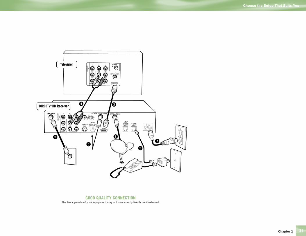
Chapter 2 31
OFF AIR INOFF AIR IN
����
��
��
����
��
��������������������
���������������� ��� ���������
GOOD QUALITY CONNECTIONThe back panels of your equipment may not look exactly like those illustrated.
Choose the Setup That Suits You

32
Guided Setup and Activation
Now that your receiver and equipment are all hooked up and plugged in, you’re ready to finish all the details to begin receiving your DIRECTV service.
1) Make sure the MODE SWITCH on the remote control is set to DIRECTV.
2) Press TV POWER ON. The DIRECTV HD Receiver will turn on (after you program the remote for your TV, the TV will also turn on when you press this button while the MODE SWITCH is set to DIRECTV).
3) Turn on your TV.
4) You should see the Display Language screen. This begins Guided Setup which will walk you through the steps necessary to finish setting up your equipment.
HDTV settings in Guided Setup
Several screens in the Guided Setup process are related to HDTV. These are some things to note about them.
4 TV Ratio Screen: the Screen Format setting offers the options defined on page 7. This setting can be changed easily while watching TV by using the FORMAT button on the remote (this is explained further on the following page).
4 Resolution Screen: the TV Resolution setting should be set to display resolutions that your TV can support. By including in this setting resolutions your TV does not support, it will be possible to lose video and audio when adjusting your receiver to optimize reception quality while watching TV. If your TV supports 1080i, 720p, 480i and 480p resolutions, you can set TV Resolution to All. With this setting, you will be able to turn on Native which lets the receiver automatically adjust resolution to match the resolution of individual TV programs as they are tuned.
4 Primary Local Network: If you’ve chosen to set up both your Satellite Dish and Off-Air Antenna, you will see this screen near the end of Guided Setup. The receiver will use the ZIP code you enter on this screen to determine what locally broadcast digital stations are available to you. Setting up a Secondary Local Network is optional; it can be useful if you
Want to finish setting up some
of the functions later? Just
press MENU on your remote,
press SELECT on Settings then
select Setup.
TIP
Getting Connected
Guided Setup and Activation

Chapter 2 33
are located between two network areas and intend to receive programming from both via your off-air antenna.
4 Guided Setup Complete: the final screen in the Guided Setup process. If you’re setting up both your dish and antenna, the receiver will need to reset at this point in order to receive program guide information for the digital off-air channels in your area. After the reset, many of these channels will appear in the guide. If you need to remove some of the channels from the guide or there are channels you expect to receive locally that are missing, you can make adjustments for these channels in System Setup. Press MENU on the remote, select Settings, then Setup, then Sat & Ant in the left menu option on the left side. Follow the instructions on screen.
Options For Changing Video Output
In order to optimize the display of programs on your television, you may occasionally need to change the resolution and/or screen format. There are two buttons that can be used to make changes: the FORMAT button on the remote control and the RESOLUTION button on the front panel of the receiver.
FORMAT Button on your remote Pressing this button will cycle the resolutions that you’ve indicated in System Setup as being supported by your TV. In addition, it will cycle the three available screen formats in conjunction with each individual resolution. Available screen formats are based on the TV Aspect Ratio you set in System Setup. With each press, a small on screen message will let you know what the current resolution/format setting is. For example, if you indicated that your TV supports only 1080i and 480i/p and it is a 16:9 television, the cycle of settings for the FORMAT key are as follows:
1st press: 480i/p/Full 5th press: 1080i/Zoom 2nd press: 480i/p/Zoom 6th press: 480i/p/Pillar Box 3rd press: 1080i/Pillar Box 7th press: repeat cycle 4th press: 1080i/Full
Guided Setup and Activation
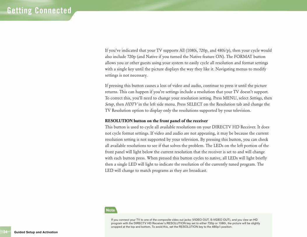
34
If you’ve indicated that your TV supports All (1080i, 720p, and 480i/p), then your cycle would also include 720p (and Native if you turned the Native feature ON). The FORMAT button allows you or other guests using your system to easily cycle all resolution and format settings with a single key until the picture displays the way they like it. Navigating menus to modify settings is not necessary.
If pressing this button causes a loss of video and audio, continue to press it until the picture returns. This can happen if you’re settings include a resolution that your TV doesn’t support. To correct this, you’ll need to change your resolution setting. Press MENU, select Settings, then Setup, then HDTV in the left side menu. Press SELECT on the Resolution tab and change the TV Resolution option to display only the resolutions supported by your television.
RESOLUTION button on the front panel of the receiver This button is used to cycle all available resolutions on your DIRECTV HD Receiver. It does not cycle format settings. If video and audio are not appearing, it may be because the current resolution setting is not supported by your television. By pressing this button, you can check all available resolutions to see if that solves the problem. The LEDs on the left portion of the front panel will light below the current resolution that the receiver is set to and will change with each button press. When pressed this button cycles to native, all LEDs will light briefly then a single LED will light to indicate the resolution of the currently tuned program. The LED will change to match programs as they are broadcast.
Note
If you connect your TV to one of the composite video out jacks (VIDEO OUT, S-VIDEO OUT), and you view an HD program with the DIRECTV HD Receiver’s RESOLUTION key set to either 720p or 1080i, the picture will be slightly cropped at the top and bottom. To avoid this, set the RESOLUTION key to the 480p/i position.
Guided Setup and Activation
Getting Connected
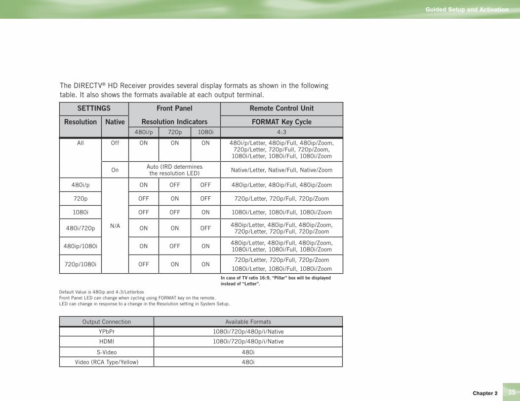
Chapter 2 35
SETTINGS Front Panel
Resolution Indicators
Remote Control Unit
Resolution Native FORMAT Key Cycle480i/p 720p 1080i 4:3
All Off ON ON ON 480i/p/Letter, 480ip/Full, 480ip/Zoom, 720p/Letter, 720p/Full, 720p/Zoom,
1080i/Letter, 1080i/Full, 1080i/Zoom
On Auto (IRD determines the resolution LED) Native/Letter, Native/Full, Native/Zoom
480i/p
N/A
ON OFF OFF 480ip/Letter, 480ip/Full, 480ip/Zoom
720p OFF ON OFF 720p/Letter, 720p/Full, 720p/Zoom
1080i OFF OFF ON 1080i/Letter, 1080i/Full, 1080i/Zoom
480i/720p ON ON OFF 480ip/Letter, 480ip/Full, 480ip/Zoom, 720p/Letter, 720p/Full, 720p/Zoom
480ip/1080i ON OFF ON 480ip/Letter, 480ip/Full, 480ip/Zoom, 1080i/Letter, 1080i/Full, 1080i/Zoom
720p/1080i OFF ON ON720p/Letter, 720p/Full, 720p/Zoom
1080i/Letter, 1080i/Full, 1080i/Zoom In case of TV ratio 16:9, “Pillar” box will be displayed
instead of “Letter”.
Default Value is 480ip and 4:3/LetterboxFront Panel LED can change when cycling using FORMAT key on the remote.LED can change in response to a change in the Resolution setting in System Setup.
Output Connection Available Formats
YPbPr 1080i/720p/480p/i/Native
HDMI 1080i/720p/480p/i/Native
S-Video 480i
Video (RCA Type/Yellow) 480i
The DIRECTV® HD Receiver provides several display formats as shown in the following table. It also shows the formats available at each output terminal.
Guided Setup and Activation
36
Getting Connected
Guided Setup and Activation
Using Your IR/RF Remote to Control Your DIRECTV HD Receiver
The remote control included with your DIRECTV HD Receiver works in either IR (infrared) or RF (radio frequency). IR is the “typical” type of remote you are already familiar with from other remotes you may have — the remote must be pointed at the device for it to respond. RF allows you to operate the DIRECTV HD Receiver without having to point your remote directly at it, such as when the receiver is installed in a cabinet, or you use the remote from another room in your house. The operating range of the remote is up to 200 feet, with some possible decrease due to weak batteries or obstacles such as walls in your house. Your RF will be addressed to only one receiver, so will not affect other receivers in your home.
To setup your remote for RF, press the MENU key, press SELECT on Settings, then select Remote from the left menu. Press SELECT on the IR/RF Setup button. Follow the onscreen instructions to configure your remote.
Chapter 2 37
Receiving Local “Off-Air” Broadcast Channels
The DIRECTV HD Receiver can tune to both satellite and locally transmitted, off-air broadcast HD channels, and will display these local channels in the Guide. In order to receive off-air channels, attach an off-air antenna to the OFF-AIR IN as instructed in the “Getting Connected” section (page 28). During the Guided Setup process, be sure to select the Satellite & Antenna button when you reach the Satellite Dish & Off-Air Antenna screen and follow the on-screen instructions.
If you didn’t setup an off-air antenna during the guided setup, you must enter your location into the receiver using the Local Network Area screens in order to receive Program Guide information for local off-air broadcast channels. When you enter your ZIP code, if there is more than one network area available, your receiver will show your options. Pick the one closest to you as your primary network area. In some cases, there may be more than two cities displayed. You may decide to also enter a secondary local network if more than one is available to you, but this is optional.
To scan for off-air channels and set up the local network areas after Guided Setup, do the following:
1. Press MENU.
2. Press SELECT on Settings in the Quick Menu.
3. Select Setup in the Quick Menu.
4. Select Sat & Ant from the options on the left menu.
5. Press SELECT on the Antenna Setup button. If you have not selected your local networks yet, select the Local Networks button and follow the instructions until you are done.
6. Select the Scan for Channels button to have the receiver scan local off-air frequencies.
When the receiver has finished scanning for channels, you are given the chance to edit local off-air channels to remove channels from the Guide that you don’t watch, or those that have poor reception.
Guided Setup and Activation
38
Don’t Wait, Activate!Once all the setup processes are complete, all that’s left to do is activate your DIRECTV service. Before you make the call, be sure to:
4 Tune to Channel 100 and be sure you’re picking up a satellite signal (DIRECTV channel). 4 Have on hand your service address, social security number and a valid major credit card. 4 Note your access card and receiver ID numbers (find these by pressing MENU, then go to
Settings and press SELECT. Then go to Setup and press SELECT).
All ready? Just call 1-800-DIRECTV (1-800-347-3288) and pick the programming package that’s right for you. Easy!
Getting Connected
Don’t Wait, Activate

Section Title
Chapter 3 39
40 Watching TV
43 The Guide
45 Autotune
47 Pay Per View
Chapter 3

40
Use your handy Channel Lineup
(included in your Welcome
package) to find the numbers
of all the channels.
Watching TV
Now that everything’s set up, you’re ready to grab your remote and get clicking!
With the MODE SWITCH to the left (under the DIRECTV logo), press TV POWER ON. To access the channel of your choice, simply key in its numbers on your remote (the channel will appear in a few seconds, or press ENTER after the numbers and it will appear right away). You can also navigate to different channels through the Guide, covered in detail starting on page 43. Keep in mind, either way, you’ll only be able to access those channels in your chosen DIRECTV® programming package.
Use the black keys on the left side of your remote control to adjust volume up or down (VOL) or mute the sound (MUTE). The black keys on the right side can take you to the next channel numerically up or down (CHAN), or jump to the previous channel you watched (PREV).
TIP
What’s On
Watching TV
Chapter 3 41
The Channel Banner
Any time you tune to a channel, you’ll see the channel banner appear across the top of the screen. This banner holds all sorts of useful information and options:
1) Current date & time Displays the day, date and current time.
2) DIRECTV Channel The logo, number and call letters of the station you’re currently viewing.
3) Program The title, start and stop times and rating of the current program.
4) Current Favorites Identifies Favorite Channels List currently in use. (See Favorite Channels on page 61 for complete details.)
5) Audio options Displays brightly if alternate audio options are available. (See Icons on the inside back page and Audio Options on page 55 for more details.)
6) Messages Displays brightly if there are new messages in Caller ID & Messages. (See Icons on the inside back page and Caller ID & Messages on page 63 for details.)
7) Parental Controls Indicates the overall lock status of the receiver. It’s either locked, unlocked, or temporarily unlocked. (See complete details on Parental Controls on page 65.).
Chapter 3
The channel banner gives you
information on the channel and show
you are currently watching. The
banner depicted here displays
during channel tuning by either
pressing CHAN or PREV or by entering
the channel number.
1 2 3 4 5 6 7
The Channel Banner
42
To remove the channel banner from the screen, you can always press EXIT. The banner will disappear on its own — or time out — after a few seconds.
You can also view the channel banner for a program you’re watching or that you’ve highlighted by pressing INFO. For more detailed information, SELECT Get More Info button to check out additional showings, purchase pay per view or set up an Autotune (Autotune described on page 45.)
Music Channels
You’ll find, as part of your great DIRECTV programming, dozens of enjoyable, continuous, commercial-free music channels with something for every taste. Tune to these just as you would to any channel. You’ll see a special Channel Banner on these that initially displays its channel description (i.e., “Alternative,” “Today’s Country”). As information is received, current song information will appear in the banner, including song title, artist and record company. Click on More Info for additional details.
To see program details, at any time
press INFO on your remote (press
a second time to clear). Select Get
More Info button to see additional
program information.
What’s On
The Channel Banner
Dolby Digital
Chapter 3 43
4
2
1
3
The Guide
Overview of the DIRECTV Advanced Program Guide®
The Guide is your helpful tool that displays listings of current and upcoming programs. Find out what’s on (now or later), change the channel, find and purchase a pay per view movie or event, even do a special search for a program you’re interested in. You’ll find program information for the current time slot and forward for a total of 90 minutes displayed – and information for up to the next seven days.
The Guide displays most of the channel banner items, plus:
1) Picture In Graphic (PIG)
2) Time slots (with half-hour headings)
3) Channel number and call letters
4) Program listings
Getting Around in the Guide
1) Press the GUIDE key on your remote.
2) You can choose how you want to sort the Guide. Select all channels, or only those in a specific category by using the up and down arrow keys on the remote to highlight your choice.
3) Press SELECT to view current listings.
When you display the Guide – or when
performing other tasks – you’ll see
a small video picture, the Picture In
Graphic (PIG), of the last channel you
were watching in the upper right-hand
corner of the screen. So, no matter what
you’re doing, you don’t miss a thing!
TIP
The Guide
44
4) Navigating through the Guide is simple:
4 The UP, DOWN, LEFT and RIGHT arrow keys move you through the listings and time slots. Highlighting a program will show you its description.
4 Use the CHAN key up or down to move through channels, a full page up or down.
4 Press the RED or GREEN keys to move horizontally through the time slots a full screen forward or back.
5) To tune to a program that is on now, highlight the program and press SELECT. Selecting a future program displays the info screen for that program. Selecting a channel tab tunes the PIG to that channel. Pressing INFO on it will display an INFO screen for that channel.
Like more information on a program? You can always press INFO when you’ve highlighted a show in the Guide to view a more in-depth description – pressing SELECT on a future program will get you there, too. This screen also gives you the choice to see what other showings of the program there may be, even set your receiver to automatically tune in (see Autotune on page 45).
Info Screen
R
MENU
1 2 3
4 5 6
7 8 9
0
VOL
MUTE PREV
DEFABC
JKL MNOGHI
TUV WXYZPQRS
DASH ENTER
CHAN
PAGE
INFOBACK
ON
AV1 AV2 TV
OFF
TVPOWER
TVINPUT
EXIT
LIST
GUIDE
ACTIVE
SELECT
PWR
Highlight an item by using the arrow
keys to scroll LEFT, RIGHT, UP or
DOWN. Press SELECT to access the
information or channel.
The Guide
What’s On
Chapter 3 45
Autotune
A great way to catch all your favorites
Is there a favorite show you keep missing, or a movie you’ve been meaning to watch? Like to make sure you don’t miss the big game? You’ll want to try the Autotune feature – and let your TV tune itself in to the programs you choose.
Set your DIRECTV® HD Receiver to autotune to any show on a channel you receive within the Guide grid’s timeframe, and it will automatically turn on and tune in when the time comes.
Here’s how it works.
1) While in the Guide, highlight a program that interests you.
2) Find what you want, then press INFO. The full description of that show will be displayed, plus you’ll see the Autotune option on the left side of the screen.
3) Highlight and select Autotune.
4) Set the options to your liking, then select the Set Autotune button, then OK on the confirmation screen.
Try one-touch convenience with
One-Touch Autotune. Just highlight
a program in the Guide and press
ENTER on your remote. You’ll see the
autotune icon ( ) appear next to
the title. Press ENTER a second time
to cancel the autotune. Keep in mind
– you won’t be able to customize your
autotuning the one-touch way.
TIP
Autotune
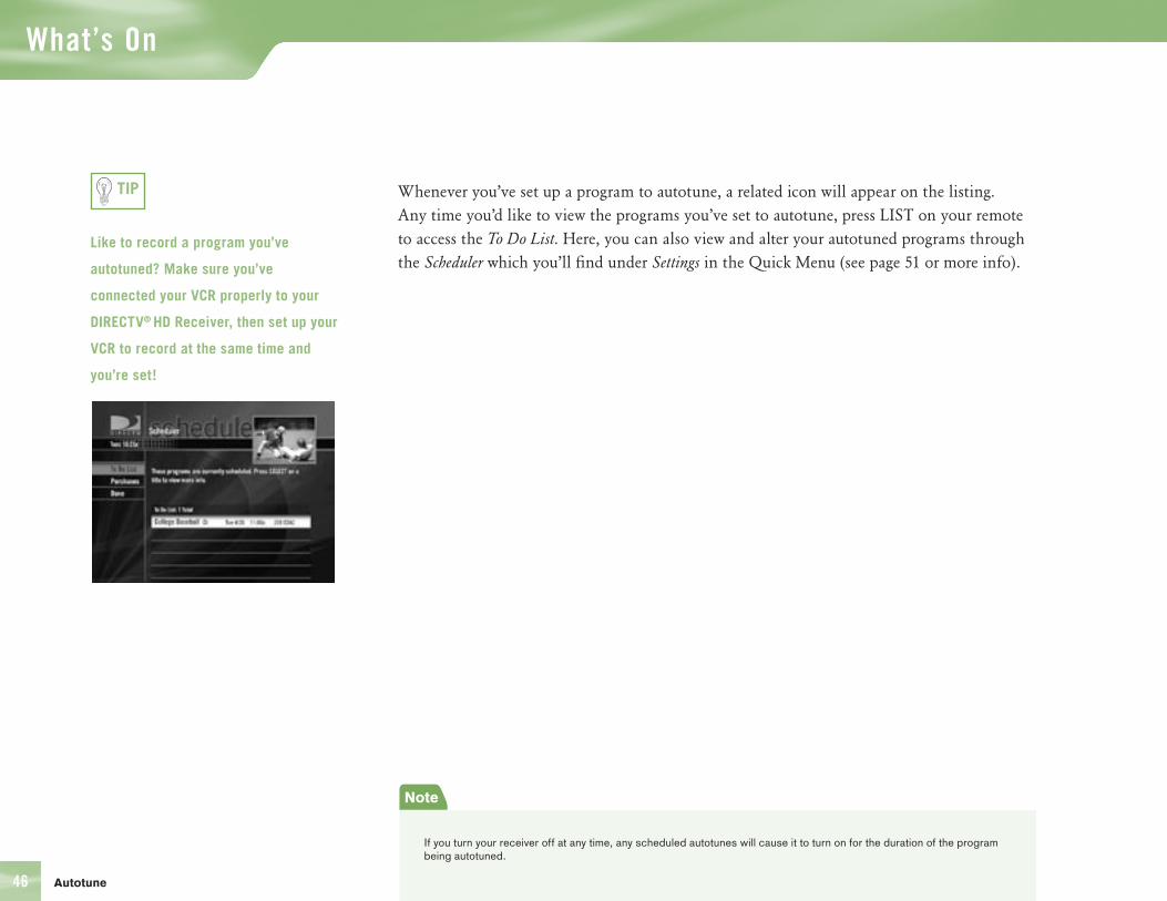
What’s On
46
Whenever you’ve set up a program to autotune, a related icon will appear on the listing. Any time you’d like to view the programs you’ve set to autotune, press LIST on your remote to access the To Do List. Here, you can also view and alter your autotuned programs through the Scheduler which you’ll find under Settings in the Quick Menu (see page 51 or more info).
Like to record a program you’ve
autotuned? Make sure you’ve
connected your VCR properly to your
DIRECTV® HD Receiver, then set up your
VCR to record at the same time and
you’re set!
TIP
Note
If you turn your receiver off at any time, any scheduled autotunes will cause it to turn on for the duration of the program being autotuned.
Autotune
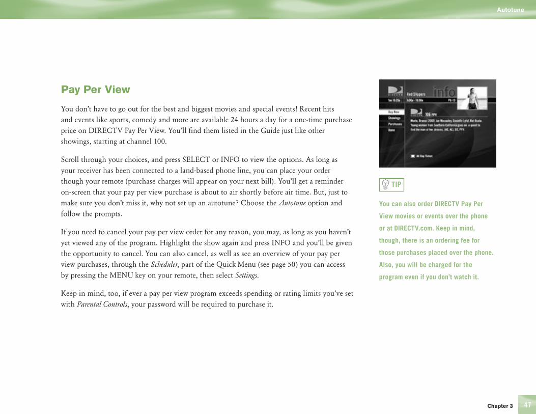
Chapter 3 47
Pay Per View
You don’t have to go out for the best and biggest movies and special events! Recent hits and events like sports, comedy and more are available 24 hours a day for a one-time purchase price on DIRECTV Pay Per View. You’ll find them listed in the Guide just like other showings, starting at channel 100.
Scroll through your choices, and press SELECT or INFO to view the options. As long as your receiver has been connected to a land-based phone line, you can place your order though your remote (purchase charges will appear on your next bill). You’ll get a reminder on-screen that your pay per view purchase is about to air shortly before air time. But, just to make sure you don’t miss it, why not set up an autotune? Choose the Autotune option and follow the prompts.
If you need to cancel your pay per view order for any reason, you may, as long as you haven’t yet viewed any of the program. Highlight the show again and press INFO and you’ll be given the opportunity to cancel. You can also cancel, as well as see an overview of your pay per view purchases, through the Scheduler, part of the Quick Menu (see page 50) you can access by pressing the MENU key on your remote, then select Settings.
Keep in mind, too, if ever a pay per view program exceeds spending or rating limits you’ve set with Parental Controls, your password will be required to purchase it.
You can also order DIRECTV Pay Per
View movies or events over the phone
or at DIRECTV.com. Keep in mind,
though, there is an ordering fee for
those purchases placed over the phone.
Also, you will be charged for the
program even if you don’t watch it.
TIP
Autotune


Section Title
Chapter 4 49
50 What’s On the MENU?
51 Settings
55 Audio Options
56 Category Sort
57 Pay Per View
58 Find By
60 Date & Time
61 Favorites
62 Previous Channels
63 Caller ID & Messages
65 Parental Controls
Chapter 4

The Quick Menu
50
What’s on the MENU?
All sorts of great things!
With the MENU key on your remote, accessing useful information and many handy features is a snap with the Quick Menu. Some of the items you’ll see depend on which screen is currently displayed. For instance, if you access the Quick Menu while viewing the Guide, you’ll find an option to filter programs by category. Other options, such as Settings, appear anytime you bring up the Quick Menu, regardless of your current screen. Whenever you access the Quick Menu, the header across the top of the Quick Menu will read “Quick Menu.”
To remove the Quick Menu from the screen at any time, simply press EXIT to return to live TV, or press the MENU key again to go back to where you were.
So, let’s start with some of the most commonly used features — ones you’ll use to enhance your viewing experience.
What’s on the Menu
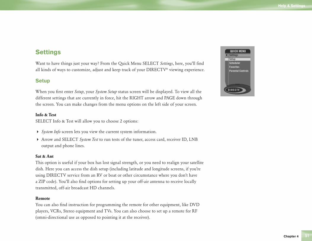
Chapter 4 51
Settings
Want to have things just your way? From the Quick Menu SELECT Settings, here, you’ll find all kinds of ways to customize, adjust and keep track of your DIRECTV® viewing experience.
Setup
When you first enter Setup, your System Setup status screen will be displayed. To view all the different settings that are currently in force, hit the RIGHT arrow and PAGE down through the screen. You can make changes from the menu options on the left side of your screen.
Info & TestSELECT Info & Test will allow you to choose 2 options:
4 System Info screen lets you view the current system information.
4 Arrow and SELECT System Test to run tests of the tuner, access card, receiver ID, LNB output and phone lines.
Sat & AntThis option is useful if your box has lost signal strength, or you need to realign your satellite dish. Here you can access the dish setup (including latitude and longitude screens, if you’re using DIRECTV service from an RV or boat or other circumstance where you don’t have a ZIP code). You’ll also find options for setting up your off-air antenna to receive locally transmitted, off-air broadcast HD channels.
RemoteYou can also find instruction for programming the remote for other equipment, like DVD players, VCRs, Stereo equipment and TVs. You can also choose to set up a remote for RF (omni-directional use as opposed to pointing it at the receiver).
Help & Settings

The Quick Menu
52
AudioThis screen allows you to make changes to your language audio setting. The default audio language for your system is English. Press SELECT on the language options to find and choose a new one. Audio language settings only affect programs with a Secondary Audio Program (SAP) in the language you’ve selected. The setting does not alter the language used on-screen. SELECT the tabs by scrolling up to the top of the screen. Select the Digital Audio tab to set preferences for Dolby Digital. See page 12 for setting instructions.
DisplayDisplay lets you customize certain viewing aspects. By selecting the Interface tab, you can adjust the timeout of the on-screen channel banner, as well as choose menu language preferences and Time Zone and Daylight Savings Time settings. Select Captioning to adjust display preferences for closed captioning. You can turn captioning on or off, as well as select the language and font size, style, color and background color for captioning.
HDTVHere you’ll have the opportunity to adjust some of your HD settings. Choose the TV Ratio tab to set the aspect ratio of your TV or change screen format and bar color. (See page 7 for details.) Select Resolution to adjust your system to display only those resolutions your TV supports. Centering allows you to move placement of video and menus on screen.
Access CardFollow the on-screen directions here to replace your access card. You will need your old and new access cards to complete this procedure.
ResetThis screen offers directions for restarting the receiver, resetting all settings to factory defaults, or resetting everything, which clears all data from the receiver and restarts to Guided Setup. Certain safety measures are included so changes can’t be made accidentally. You should only perform a reset if instructed by a DIRECTV Customer Service Representative.
??Help & Settings
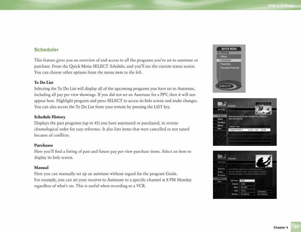
Chapter 4 53
Scheduler
This feature gives you an overview of and access to all the programs you’ve set to autotune or purchase. From the Quick Menu SELECT Scheduler, and you’ll see the current status screen. You can choose other options from the menu item to the left.
To Do ListSelecting the To Do List will display all of the upcoming programs you have set to Autotune, including all pay per view showings. If you did not set an Autotune for a PPV, then it will not appear here. Highlight program and press SELECT to access its Info screen and make changes. You can also access the To Do List from your remote by pressing the LIST key.
Schedule HistoryDisplays the past programs (up to 45) you have autotuned or purchased, in reverse chronological order for easy reference. It also lists items that were cancelled or not tuned because of conflicts.
PurchasesHere you’ll find a listing of past and future pay per view purchase items. Select an item to display its Info screen.
ManualHere you can manually set up an autotune without regard for the program Guide. For example, you can set your receiver to Autotune to a specific channel at 8 PM Monday regardless of what’s on. This is useful when recording to a VCR.
Help & Settings
The Quick Menu
54
Favorites
Check the current status of your Favorites list(s) by clicking here, and make changes if you like. See page 61 for more details.
Parental Controls
Check the current restrictions of your Parental Controls by clicking here, and make any adjustments. See page 65 for more details.
Help & Settings
Chapter 4 55
Audio Options
Audio Options
Some programs have alternate audio available (such as other language tracks or Dolby Digital). You can set the default so that when ever a program has alternate audio available, it automatically plays this audio, or you can change the alternate audio temporarily for the program you are watching.
To change the default audio:
1) While in Live TV press MENU.
2) From the Quick Menu, SELECT Settings
3) Scroll down to Setup and press SELECT
4) Scroll down to Audio, and press SELECT
5) Pressing SELECT on the Default Audio option. Scroll down and SELECT the audio language that you want as a default.
To temporarily change the audio:
1) While in Live TV press MENU
2) From the Quick Menu , scroll down to Audio Options and press SELECT
3) Scroll to the audio track you prefer and press SELECT.
This will temporarily change the audio. Once the program is over or you change the channel the audio will change back to the default settings.
NOTE: You may also cycle through all available audio tracks for a tuned program by pressing the yellow key on the remote.

The Quick Menu
56
Category Sort
This handy tool lets you temporarily arrange the Guide to view only programs in a particular category such as Movies, Sports or News.
1) While in the Guide, press MENU
2) Arrow to Category Sort and press SELECT
3) Select the genre you want, and you’ll be able to further narrow your choices by subcategories (i.e., Movies, Comedy). The Guide fitting the description will appear.
4) Simply scroll through to find a program you like. Programs with a left arrow to the left of the title are presently playing. SELECT a presently playing show to tune to it or SELECT a future program, and you’ll see its related info screen and have the opportunity to autotune it or see other showings.
Just press GUIDE to return to the regular Guide, or EXIT to return to live TV.
Category Sort
Chapter 4 5757
Pay Per View
This option enables you to check out DIRECTV® Pay Per View listings by category.
1) While in the Guide, press MENU.
2) Arrow down to Pay Per View and press SELECT.
3) You will see three choices for sorting the listings. Choose All to display all current options. Movies will give you listings of all current movies available. Pick Special Events to see available events such as sports, comedy specials and more.
4) A list of PPV will appear. Select a current program to tune to it, or select a future program and you will be presented with other options (Buy, set an Autotune or list other Showings).
Just highlight and select a pay per
view item from your list if you’d like to
schedule a viewing. See page 45 page
47 for more details.
TIP
Pay Per View
The Quick Menu
58
Find By
Would you like to locate a particular program, movie or sports event you want to see — even shows starring a favorite actor, or games with your favorite team? Find by offers some easy ways to spot just what you want.
1) Press MENU.
2) Scroll down to Find by and press SELECT. You’ll see options to direct your search.
3) You can find a program by Title, Person, Keyword or Channel.
4 Choose Title if you know the name of the program you’re looking for. Just scroll through and select the letters of the alphabet that spell the name until you see it appear in the list.
4 Choose the Person search option if you’re looking for any programs that feature a particular actor/actress or director. Select the letters of his or her last name until you see the name appear. Select the name. You can narrow the search for programs by selecting categories.
4 If you don’t know the name of a program, but know one of the words of a title… or, if you’re looking for a certain subject matter… try Keyword. Spell out the name of the word or words you want, following the prompts (i.e., “Chicago Cubs” if you’re searching for ballgames).
4 Select Channel to find a particular channel by the call letters (i.e., HBO®) then select the channel to see the full programming listing.
Want to find your program quicker?
Narrow your search by selecting
subcategories – just follow the prompts.
Keep in mind, when you search with
Find by, only those programs slated to
air within the Guide’s number of days
of programming supported by your
receiver will appear on your list.
Find By
TIP
TIP

Chapter 4 59
4) Once you’ve found a program you’re after, all you have to do is highlight and select the title to display when the program is on.
5) If the program listed is currently on, then selecting it will tune to it. If the program is upcoming, the selecting it will bring you to the info screen. Here, you’ll have the opportunity to set an autotune for the program.
Recent FindsIf you’d like to view all of the programs you’ve recently searched. You can always go back to repeat a search for a found item for any new listings available — just select the item to try again. You can also easily mark and delete any Finds you no longer want.
Find By
The Quick Menu
60
Date & Time
Here’s a convenient way to look several days ahead in the Guide, without having to scroll through pages of programs.
You can quickly see what’s on during a specific day or time.
1) While the Guide press MENU. 2) Then scroll down to Date & Time and press SELECT.
3) You’ll find the current day and next seven days listed. Choose the date you’re interested in.
4) Scroll through and select the hour you want. The Guide will now display programs for the date and time you selected.
If you find something you like, press ENTER for a one-touch autotune or INFO to view and set autotune options.
Date & Time
Chapter 4 61
The normal, or default, setting for the
channels you can view in the Guide is
All Channels, or all available channels
on DIRECTV service — whether or not
you receive them in your programming
package. You may choose to use your
current favorites list by selecting
Current Item in the left menu of the
favorites screen. Or you may choose
another favorite item in the Quick
Menu.
TIP
Favorites
Favorites
Wouldn’t it be nice to have all the channels you like best, right-at-hand? Or a grouping of family channels just for the kids?
Favorites allows you to set up special, customized List of Channels that shows only those channels you choose both in the Guide and while channel surfing Live TV.
1) Press MENU to get to the Quick Menu.
2) Select Settings, then Favorites.
3) SELECT a custom list on the left side of the screen.
4 Select the box next to the channel you want on a custom list (press SELECT again to delete it).
4 Use Add All or Remove All to save time when choosing a lot of channels.
4 Scroll through the channels, or key them in directly using NUMBERS on the remote to access what you’re looking for. Once you’ve decided on the channels for your list, select the Name Tab.
4) To name your custom list, arrow over to the Name List tab and press SELECT
4 Use the onscreen keypad to name your custom list — “Kids” or “Joe” or whatever you like.
4 When you are done, go to Update Name and press SELECT.
When you’re using a Favorites list, the Guide will only display those channels you’ve chosen — and you’ll also only see those channels when you use CHAN UP/DOWN on your remote.
Keep in mind, no matter what Favorites list you’re currently using, you can still always access any channel you receive by keying in its channel number on your remote. You can also edit or delete a list at any time.

The Quick Menu
62
Previous Channels
While watching live TV, you can easily surf between your four most recent channels when you select Previous Channels from the Quick Menu — perfect for keeping up with different games, or tracking breaking news.
Select Previous Channels, and a list will appear showing up to the last four channels viewed. Just highlight and select any channel from the list to tune to it, or press INFO while a channel is highlighted to see further details.
Don’t forget — you can always tune to the prior channel you were watching just by pressing
PREV on your remote!
Previous Channels
Chapter 4 63
Caller ID & Messages
Here you’ll be able to access communications from DIRECTV. If you have Caller ID service*, you can also view phone calls you’ve received.
Caller ID
Here you can turn Caller ID on and off, set the number of calls kept in your log and view past calls
To turn Caller ID on and off:
1) Press MENU to get to the Quick Menu.
2) Go to Calls & Msgs and press SELECT.
3) SELECT the Turn On/Off Notice to toggle Caller ID on and off.
To access the other CALLER ID Call Log settings:
1) Press MENU to get to the Quick Menu.
2) Go to Calls & Msgs and press SELECT.
3) Next SELECT Caller ID then Go There.
4) Select Caller ID in the left menu.
Remember, you must already have
Caller ID service from your phone
company to use this feature!
TIP
*You must subscribe to this service through your local telephone company.
Caller ID & Messages
The Quick Menu
64
4 Choose the Service tab. Here you can choose to turn Caller ID on or off, set the number of calls to keep in your log, and turn notification on or off.
4 The Call Log tab displays your recent incoming calls. Highlight and select a name, and you have the opportunity to call the number or delete that listing from your log. If you call the number, you will have to pick up your phone to speak.
Unless you’ve turned off the Notification option, you’ll see a notice on your TV screen whenever a call comes in.
Messages
You’ll be able to view a listing of titles of any current messages waiting for you.
1) Press MENU to get to the Quick Menu.
2) Go to Calls & Msgs and press SELECT.
3) Next SELECT Go There.
4) Select Messages in the left menu.
5) Simply highlight a message and press SELECT to read, then you’ll have the choice to save or delete them.
The messages icon will appear brightly
on your channel banner whenever
there’s any new or unread message in
your Inbox.
TIP
Caller ID & Messages
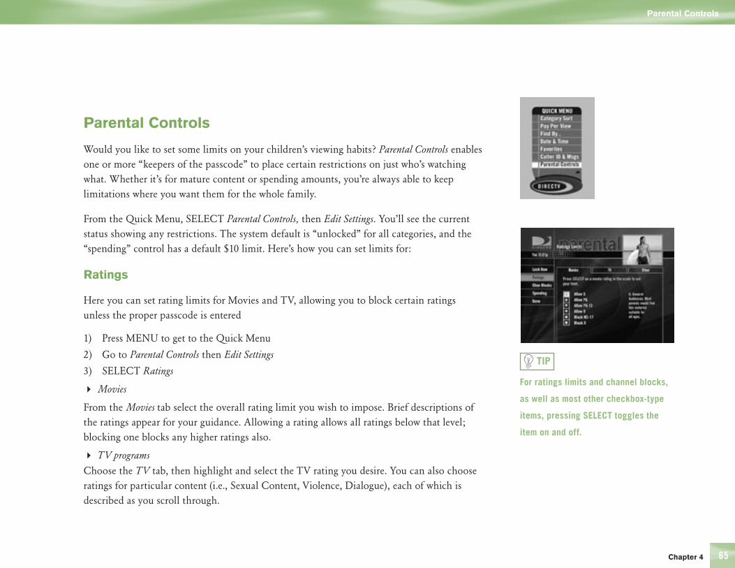
Chapter 4 65
Parental Controls
Would you like to set some limits on your children’s viewing habits? Parental Controls enables one or more “keepers of the passcode” to place certain restrictions on just who’s watching what. Whether it’s for mature content or spending amounts, you’re always able to keep limitations where you want them for the whole family.
From the Quick Menu, SELECT Parental Controls, then Edit Settings. You’ll see the current status showing any restrictions. The system default is “unlocked” for all categories, and the “spending” control has a default $10 limit. Here’s how you can set limits for:
Ratings
Here you can set rating limits for Movies and TV, allowing you to block certain ratings unless the proper passcode is entered
1) Press MENU to get to the Quick Menu
2) Go to Parental Controls then Edit Settings
3) SELECT Ratings
4 Movies
From the Movies tab select the overall rating limit you wish to impose. Brief descriptions of the ratings appear for your guidance. Allowing a rating allows all ratings below that level; blocking one blocks any higher ratings also.
4 TV programs
Choose the TV tab, then highlight and select the TV rating you desire. You can also choose ratings for particular content (i.e., Sexual Content, Violence, Dialogue), each of which is described as you scroll through.
For ratings limits and channel blocks,
as well as most other checkbox-type
items, pressing SELECT toggles the
item on and off.
TIP
Parental Controls
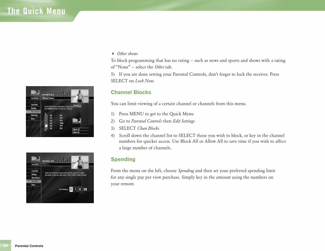
The Quick Menu
66
4 Other shows
To block programming that has no rating — such as news and sports and shows with a rating of “None” — select the Other tab.
5) If you are done setting your Parental Controls, don’t forget to lock the receiver. Press SELECT on Lock Now.
Channel Blocks
You can limit viewing of a certain channel or channels from this menu.
1) Press MENU to get to the Quick Menu
2) Go to Parental Controls then Edit Settings
3) SELECT Chan Blocks
4) Scroll down the channel list to SELECT those you wish to block, or key in the channel numbers for quicker access. Use Block All or Allow All to save time if you wish to affect a large number of channels.
Spending
From the menu on the left, choose Spending and then set your preferred spending limit for any single pay per view purchase. Simply key in the amount using the numbers on your remote.
Parental Controls
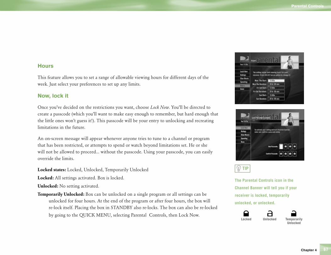
Chapter 4 67
Hours
This feature allows you to set a range of allowable viewing hours for different days of the week. Just select your preferences to set up any limits.
Now, lock it
Once you’ve decided on the restrictions you want, choose Lock Now. You’ll be directed to create a passcode (which you’ll want to make easy enough to remember, but hard enough that the little ones won’t guess it!). This passcode will be your entry to unlocking and recreating limitations in the future.
An on-screen message will appear whenever anyone tries to tune to a channel or program that has been restricted, or attempts to spend or watch beyond limitations set. He or she will not be allowed to proceed... without the passcode. Using your passcode, you can easily override the limits.
Locked states: Locked, Unlocked, Temporarily Unlocked
Locked: All settings activated. Box is locked.
Unlocked: No setting activated.
Temp orarily Unlocked: Box can be unlocked on a single program or all settings can be unlocked for four hours. At the end of the program or after four hours, the box will re-lock itself. Placing the box in STANDBY also re-locks. The box can also be re-locked
by going to the QUICK MENU, selecting Parental Controls, then Lock Now.
The Parental Controls icon in the
Channel Banner will tell you if your
receiver is locked, temporarily
unlocked, or unlocked.
TIP
Locked Unlocked Temporarily Unlocked
Parental Controls

The Quick Menu
68
Let me in…!
Don’t worry — temporarily or permanently unlocking is easy. To temporarily unlock a particular program:
1) When any controls are currently activated, a message with the option to Unlock Now will appear if you try to tune to a restricted program.
2) SELECT Unlock Now and enter the password.
For more unlock options:
1) Go to the MENU.
2) Then SELECT Parental Controls.
3) Various options for unlocking temporarily or permanently will appear. SELECT one and enter your password.
Note: If you have Parental Controls set and temporarily unlocked, turning the receiver power off will relock the box.
You can change your passcode, at any time.
1) Go to the MENU.
2) Then SELECT Parental Controls.
3) Then SELECT Edit Settings.
4) Scroll down to Passcode and SELECT.
5) You will need to enter you old passcode before creating a new one.
Parental Controls

Section Title
Chapter 5 69
70 Perform a Code Search
71 Troubleshooting
84 Limited Warranty
90 FCC Customer Information
94 Registration Information
96 Index
Chapter 5

Other Information
70
Perform a Code Search on Your Remote Control
If you were not able to find a code for your brand of TV or component, then you can try a code search. This process may take up to 30 minutes.
1) First turn on the TV or component.
2) Move the slide switch near the top of the remote control to the appropriate position.
3) Point the remote away from your DIRECTV® HD Receiver and components. Press and hold MUTE and SELECT buttons at the same time until the light above the Mode Switch at the top of the remote flashes twice (about 5 seconds).
4) Enter one of the following 4 digits
TV: 9 9 1 1 VCR or DVD: 9 9 1 2 Stereo: 9 9 1 3
5) Press the PWR key on the remote control.
6) Point the remote to the TV or component and press CHAN UP. Repeatedly press the CHAN UP until the TV or component turns off.
7) When the TV or component turns off, the press SELECT.
Note: If the light flashes 3 times before the TV or component responds, then you’ve cycled all codes and, unfortunately, the code you need is not available. You must then use the remote that came with your TV or component.
Perform a Code Search
Chapter 5 71
Troubleshooting
Many problems can be corrected by performing a simple reset of the DIRECTV HD Receiver. If you experience the following:
4 Image freezes
4 Audio freezes
4 Blank screen
4 Won’t respond to front panel button or remote control
Try one of these:
4 Press the red RESET button behind the access panel door on the front of the DIRECTV HD Receiver, then wait for program guide information to be acquired.
4 If the problems persist, try unplugging the power cord of the DIRECTV HD Receiver for 15 seconds to 2 minutes, then plug it in again.
4 Running the System Test (later in this section) can also help you diagnose and solve many common problems.
System UpgradesYour DIRECTV HD Receiver is able to receive upgrades or modifications to some of its features and functions. These modifications will occur automatically, usually at times when the receiver would likely be turned off. If your receiver is on when an upgrade or modification is sent, you may experience a disruption in reception for a minute or two. Your reception should return to normal after the modification is complete. Your receiver must be plugged in to receive any upgrades. Do not unplug your receiver while an upgrade is in progress. Please consult the Upgrade Menu to find a schedule of upgrades or modifications planned by DIRECTV.
Note
If you prefer, we can provide you with the name of an Authorized Service Representative who will visit your home for a fee to set up your digital satellite receiver and instruct you on its operation. For details about this service, call 1-800-DIRECTV or visit DIRECTV.com.
You can find additional
troubleshooting help at
DIRECTV.com.
TIP
Troubleshooting
Other Information
72
DIRECTV HD Receiver Problems
Progress bar freezes during Satellite Data Acquisition This is normal. The progress bar times out after two minutes. If your screen is still blank for two minutes after the progress bar times out, follow these steps to restart your receiver:
1) Press the red RESET button behind the access panel door on the front of the DIRECTV HD Receiver.
2) Wait for program guide information to be acquired.
Wrong picture, blue screen, snow, scrambled picture or black/blank pictureThe DIRECTV HD Receiver and most TVs and VCRs let you toggle between video sources. If you don’t see the signal you think you should be seeing, try using these keys to toggle between the signals.
4 Press the TV/VCR key on the VCR remote or on the VCR’s front panel.
4 Press the TV INPUT key on the remote control.
Any of the above actions switches the source of the video signal from satellite signals to the antenna or cable signal, and vice versa. If problems persist, turn off all equipment that is connected to your TV, wait a few minutes, then turn the DIRECTV HD Receiver back on.
It is also possible your DIRECTV HD Receiver is not configured properly for your HDTV. Press the FORMAT key on your remote or the RESOLUTION key on the receiver front panel to cycle through the available resolutions. The RESOLUTION key cycles through all resolutions, including Native. The FORMAT key cycles only through resolutions you’ve set in the Settings screen, and it also cycles through screen formats (letterbox, pillar box, zoom, etc.) based upon the Aspect Ratio you set in the Settings screen (4:3 or 16:9).
TroubleshootingTroubleshooting
Chapter 5 73
Problems with Caller ID4 You must subscribe to Caller ID service through your local phone company.
Also, check to be sure your Caller ID feature is turned on (see page 63).
4 If you are plugging your receiver to a wireless phone jack, note that it typically does not transmit Caller ID information and you may need a special wireless phone jack to use with Caller ID service. See the user’s manual that came with the wireless phone jack to see if it transmits Caller ID information. If it doesn’t, either connect the phone line directly to a standard wall-mount phone jack or install a wireless phone jack that transmits Caller ID information.
DIRECTV HD Receiver will not turn on4 Check to make sure the power cord is plugged into the DIRECTV HD Receiver and the
wall outlet.
4 Check the wall receptacle (or extension cord) to make sure it is “live” by plugging in something else.
4 Make sure the remote control is on DIRECTV mode, and press TV POWER ON.
4 Press TV POWER ON, then press it a second time.
4 Check batteries in remote control.
4 Be sure remote control is pointed at remote sensor, and the front of the receiver is not blocked.
4 Unplug the receiver. Wait five minutes. Plug it in again.
Troubleshooting
Troubleshooting

Other Information
74
Turns off while playing4 Electronic protection circuit may have been activated because of a power surge. Wait 30
seconds, then turn on again.
4 Unplug DIRECTV HD Receiver for a few minutes, then plug back in. If this happens frequently, the voltage in your house may be abnormally high or low.
4 Consider using a surge protector or line conditioner.
4 If your TV turns off while playing, and other lights/appliances in your house do too, you may have blown a circuit breaker or be experiencing a power outage.
4 Consult an electrician if the problem is frequent or severe, especially if other household appliances or electronics are affected.
DIRECTV HD Receiver turns on or changes channels unexpectedlyAn autotune may have been activated. See page 45.
Top and bottom of program image is cut offIf you connect your TV to one of the composite video out jacks (Video Out, S-Video Out or TV Out), and you view a high-definition program with the DIRECTV HD Receiver’s RESOLUTION button set to either 720p or 1080i, the picture will be slightly cropped at the top and bottom. To avoid this problem, set the RESOLUTION button to the 480p/i position by pressing the RESOLUTION key on the front panel of your DIRECTV HD Receiver.
The message “(Due to) Copyright restrictions…” appears on-screenThis means that the program you’re trying to watch may not be viewable on some outputs. Use a different connection from the DIRECTV HD Receiver to your TV (see page 28 for details).
Troubleshooting

Chapter 5 75
Closed caption displays overlapIf you turn on closed captions on both your DIRECTV HD Receiver and your TV, you may see overlapping closed captions. To avoid this, turn on closed captions on only one or the other, not both.
Left/right side of screen doesn’t match with TV in HDMI/Component modeYour particular brand of TV may use a different screen offset. Press the MENU key, then press SELECT on Settings. Select the HDTV item in the left menu, then select the Centering tab on the HDTV screen. Follow the onscreen instructions to adjust the left/right side of the screen.
Audio, no videoVideo mode set to 720p, TV only supports 1080i. Also, if your receiver is set to Native mode, some programs are in 720p and might not show video when viewed. To fix this problem, change the output mode to 480p or 1080i only. Change the output mode in System Setup as follows:
4 Press MENU.
4 Press SELECT on Settings in the Quick Menu.
4 Select Setup in the Quick Menu.
4 Select HDTV from the left menu.
4 Select the Resolution tab.
4 Select a TV resolution option that shows the resolutions supported by your TV.
4 You can also change the Native option on this screen.
Troubleshooting

Other Information
76
Loss of local, off-air (ATSC) channelsThe following conditions may cause loss of local, off-air channels:
Your local broadcast time may have changed.
Many digital broadcasts are not aired 24 hours per day.
The signal strength for your local station may not be strong enough due to atmospheric conditions, obstructions, or antenna location. If you are using a directional antenna for local stations, try orienting your antenna differently or placing it in a different location. The HD antenna included with your receiver is omnidirectional and does not need to be oriented, however, if your receiver is in a stereo cabinet or other enclosure, it may weaken the signal.
To check the off-air signal strength, do the following:.
4 Press MENU.
4 Press SELECT on Settings in the Quick Menu.
4 Select Setup in the Quick Menu.
4 Select Sat & Ant from the left menu.
4 Press SELECT on the Antenna Setup.
4 Press SELECT on the Antenna Signal meter.
If the signal strength for the desired channel or channels is low, try relocating or re-orienting your antenna. You may also try selecting a different primary or secondary network area.
No program information on some off-air channelsNot all program information is available for all areas. See your local newspaper or a printed TV schedule for listings.
Troubleshooting
Chapter 5 77
Aspect ratio problems. Why do I see black bars and gray bars?Your aspect ratio and screen format may be set improperly for your TV or the program you are watching. Press the FORMAT key on your remote to cycle through the available settings. You may have to change the display settings in System Setup as follows:
4 Press MENU on the remote.
4 Press SELECT on Settings,
4 Select Setup.
4 Select HDTV.
Then,
If watching a 4:3 program on a 16:9 screen, the picture will be too tall to fit the screen. Choose one of the following:
4 “Pillar box” shrinks the picture until the height of the program fits the screen. The picture is no longer wide enough to fit the screen, so black/gray bars are on the left and right of the screen.
4 “Full” or “Pan/Scan” stretches the picture horizontally until it’s wide enough to fit the screen. There are no black/gray bars, but the picture is distorted.
4 “Zoom” magnifies the picture, keeping the 4:3 aspect ratio, until the screen is full. There is no distortion, but the top and bottom of the picture are cut off.
If watching a 16:9 program on a 4:3 screen, the picture will be too wide to fit the screen. Choose one of these settings:
4 “Letterbox” shrinks the height of the picture. This results in black/gray bars at the top and bottom of the screen.
4 “Full” or “Pan/Scan” shrinks the width of the picture, so the picture is stretched vertically until it fits the screen. There are no black/gray bars, but picture is distorted.
4 “Zoom” magnifies the picture, keeping the 16:3 aspect ratio, until the screen is full. There is no distortion, but the left and right side of picture are cut off.
Troubleshooting

Other Information
78
Cannot change black bars. Many broadcasters transmit black bars as part of the video for a program. Only black bars generated by the receiver can be changed.
Color looks wrong (dark areas, everything is red, green, or blue, or skin tones are washed out) 4 If the dark areas are bars at the edges of the screen, it is probably due to the aspect ratio
setting. (See page 7).
4 Make sure component video cables are connected properly. The component cables (YPbPr) deliver color. The three YPbPr jacks are usually color-coded green, blue, and red. The red, blue and green cables could be mixed. If using these cables, make sure they haven’t come loose.
4 Try new YPbPr cables.
4 Reset your receiver by pressing the red reset button.
4 If reset doesn’t fix the problem, this is a TV calibration problem. Refer to your TV’s User Guide, troubleshooting manual or customer service for help.
Blank screen4 Check that all components connected to the input jacks are turned on.
4 Try another channel.
4 Your DIRECTV HD Receiver may be hooked incorrectly to the TV. Press the INFO button on the front panel of the DIRECTV HD Receiver to see if the channel banner appears. If it does not, check the Setup and Connections section for instructions about connecting your satellite receiver. If the DIRECTV HD Receiver is connected to the RF input of your TV makes sure that the TV channel matches the 3/4 RF switch on the back panel.
4 Press the TV INPUT key on the remote to make sure your TV input is set to the TV input your DIRECTV HD Receiver is connected to.
4 Press the POWER button on the front of the DIRECTV HD Receiver.
4 Press the red RESET button behind the door on the front panel of the DIRECTV HD Receiver.
Troubleshooting
Chapter 5 79
Temporary loss of the satellite signal or Searching for Satellite Signal message4 Your satellite system may be experiencing rain fade, a temporary loss of the satellite signal
due to unusually heavy rain clouds or rainfall. Rain fade is usually brief, lasting only as long as the heavy rain cloud condition persists.
4 Your dish may be blocked. Check that something is not blocking the dish.
Partial programming loss/channels missing from the Guide/channel is in the Guide but can’t be tuned4 Your satellite dish antenna may be incorrectly configured. Check the dish type set in your
receiver’s preferences and change if necessary. Press the MENU key on the remote control, then select Settings then Setup. In the next menu, select Sat & Ant, then Repeat Satellite Dish Setup. Follow the steps. From the Satellite Dish Type screen, make sure the proper dish type is selected (round, oval with a dual LNB or oval with a triple LNB).
4 The channels might be excluded from the Favorites list currently in use. Press MENU on the remote, select Favorites, then All Channels.
Troubleshooting
Other Information
80
Remote Control Problems
Problems with the remote control4 Check that nothing is between the remote control and the remote sensor.
4 Make sure the remote control is in DIRECTV mode. Slide the mode switch to the DIRECTV position so the remote will control the DIRECTV HD Receiver.
4 Check the batteries in the remote control. They may be weak, dead or installed incorrectly. Try replacing batteries. IMPORTANT: Don’t press any remote control keys while replacing the batteries unless you are resetting the remote! If you press a remote control key while replacing the batteries, you may need to reprogram the remote to operate other devices. Reprogramming may also be required if dead or weak batteries have been allowed to remain in the remote.
4 If you’re entering a channel number that is less than four digits long, the receiver might wait two seconds before tuning to the channel. Press ENTER after entering a channel number to tune immediately.
4 If you are trying to operate a device other than the DIRECTV HD Receiver that you have programmed the remote to control, make sure you first move the slide switch to the corresponding position for that device (AV1 or AV2). The indicator light for the component you’re trying to control should light up when you press a valid key for that component. If it doesn’t, make sure the input switch is clicked into the correct position.
4 The remote may need to be reset. Press and hold MUTE and SELECT until the light flashes twice. Enter 9-8-1 using the number on the remote. The light will flash twice. If necessary, reprogram the remote.
Your remote and DIRECTV Receiver must both be in the same mode, IR or RF. To ensure both are set correctly do the following. Using the buttons on the front of your receiver, press the MENU button, then go to System Setup, then go to Remote, then to IR/RF Setup. Choose either IR or RF and follow the directions.
A remote control indicator light starts flashingThe batteries in the remote control are running low and should be replaced soon. (Note that when you replace the batteries, you may have to reprogram your remote to control other devices.)
Troubleshooting

Chapter 5 81
TV Problems
Blank screen4 Check that the components connected to the input jacks are turned on.
4 Try another channel.
4 See “Wrong picture, bluescreen...” and Receiver will not turn on” on page 72.
TV turns on or changes channels unexpectedly4 An Autotune may have been activated.
4 Your TV’s timer may have been activated.
4 Check your TV owner’s manual.
No video with TV connected to HMDI jackIf your TV has an HMDI input jack but is not HDCP compatible, you may not be able to view video from your DIRECTV HD Receiver’s HDMI OUT jack. Connect your TV using another video output jack on the receiver.
Note
If your TV is connected with just coaxial cables, you only need to tune to Channel 3 or 4.
Troubleshooting
Other Information
82
Running the System Test
The System Test allows you to run a basic diagnostics check on your DIRECTV HD Receiver. If you are experiencing any trouble with your receiver, run the system test. It will also allow you to get your access card and receiver ID numbers or to initiate diagnostic procedures on your digital satellite receiver.
First make sure that:4 All connections — jacks, cables, etc. — are in place correctly (see Chapter Two,
Getting Connected, for more information)
4 There are batteries in the remote control, and they are working correctly
4 The access card is installed in the DIRECTV HD Receiver.
Follow these steps to run the diagnostics system test on your DIRECTV HD Receiver.
1) Turn on your TV and the DIRECTV HD Receiver.
2) Slide the mode switch to the DIRECTV position to put the remote control in satellite receiver-controlling mode, then press MENU to bring up the Quick Menu.
3) Select Settings.
4) Select Setup, then Info & Test.
5) Use arrow keys to highlight the System Test tab, then press SELECT on Run Test.
6) If your system does not pass the system test, check any of these potential trouble areas: cabling, pointing the satellite dish, phone connection and access card.
7) If you continue to have problems, call DIRECTV Customer Service at 1-800-DIRECTV.
You should run a system test several times before concluding that there is a problem. Occasional fluctuations in the phone line or satellite signal can give temporary false readings.
Troubleshooting

Chapter 5 83
Fine-Tuning the Signal
If you self-installed your satellite dish antenna, you may have already used Guided Setup to find the dish-pointing coordinates, acquire and fine-tune the signal and run a system test. If you need to run Guided Setup again, select Settings from the Quick Menu, then select Guided Setup. Next, press SELECT on Sat & Ant, then select Repeat Satellite Setup.
Troubleshooting
Other Information
84
LIMITED 90 DAY WARRANTY
DIRECTV warrants your DIRECTV HD Receiver (Model Number: H10) and any included accessories against defects in material or workmanship for a period of ninety (90) days after the date of purchase.
WHO IS COVERED? You must have proof of purchase to receive warranty service. A sales receipt or other document showing that you purchased the product is considered proof of purchase. THIS LIMITED WARRANTY EXTENDS ONLY TO THE ORIGINAL CONSUMER PURCHASER OR ANY PERSON RECEIVING THE DIRECTV HD Receiver AS A GIFT FROM THE ORIGINAL CONSUMER PURCHASER AND TO NO OTHER PURCHASER OR TRANSFEREE. THIS WARRANTY DOES NOT EXTEND TO COMMERCIAL USERS. THIS PRODUCT IS NOT AUTHORIZED FOR USE OUTSIDE THE UNITED STATES AND ANY SUCH USE VOIDS THIS WARRANTY.
WHAT IS COVERED? Warranty coverage begins the day you purchase the product. For ninety (90) days from the purchase date, at the option of DIRECTV, the DIRECTV HD Receiver will be repaired or replaced with a new, repaired, refurbished or comparable product (whichever is deemed necessary) if it becomes defective or inoperative. This exchange is done without charge to you for parts and labor. You will be responsible for the cost of shipping to and from the location designated by DIRECTV. If DIRECTV cannot reasonably repair or replace the Receiver then DIRECTV may, at its sole discretion, refund the price you paid for the product or the current retail price of the product.
All products, including replacement products, are covered only for the original warranty period. When the warranty on the original product expires, the warranty on the replacement product also expires. After ninety (90) days from the date of purchase, you pay for the replacement of all parts, and for all labor charges.
Limited Warranty

Chapter 5 85
SOME STATES DO NOT ALLOW LIMITATIONS ON HOW LONG AN IMPLIED WARRANTY LASTS, SO THE ABOVE LIMITATION MAY NOT APPLY TO YOU. WHAT IS EXCLUDED?
Your warranty does NOT cover:
4 Labor charges for installation or setup of the product.
4 Installation, performance of, or repair of: audio/video cabling, telephone line, or accessory attachments used with the product.
4 Product replacement because of misuse, accident, lightning damage, unauthorized repair, or other cause not within the control of DIRECTV.
4 Incidental or consequential damages resulting from the product. SOME STATES DO NOT ALLOW THE EXCLUSION OF INCIDENTAL OR CONSEQUENTIAL DAMAGES, SO THE ABOVE EXCLUSION MAY NOT APPLY TO YOU.
4 Any modifications or other changes to the product, including but not limited to software or hardware modification in any way other than as expressly authorized by DIRECTV will void this limited warranty. Except in the case of hardware or software provided by DIRECTV, installing software modifications, “hacks” or utilizing service access or “back doors” will void this limited warranty.
4 Reception transmission problems caused by signal conditions, telephone line, or cable or antenna systems outside the unit.
4 A product that has been modified or adapted to enable it to operate in any country other than the country for which it was designed, manufactured, approved and/or authorized, or repair of products damaged by these modifications.
4 A product used for commercial or institutional purposes.
4 DIRECTV makes no warranty that the access connection will be a local (not long distance) phone call.
4 The continued provisioning of any of the programming and other services delivered through the Receiver including but not limited to television programming, show information, program guide data, and scheduling information.
Limited Warranty
Other Information
86
MAKE SURE YOU KEEP... Please keep your sales receipt or other document showing proof of purchase. Attach it to this User Guide and keep both nearby. Also keep the original box and packing material in case you need to return your product.
BEFORE REQUESTING REPAIR SERVICE... Please check the troubleshooting section of this guide. This may save you a call to DIRECTV Customer Care.
TO GET WARRANTY SERVICE... Warranty service will be provided by DIRECTV. If you believe you need service for your Receiver, contact DIRECTV at 1-800-DIRECTV. A representative will go through a diagnostic checklist with you. If it is determined that the product needs to be returned for service or exchanged, you will receive a return authorization number. The representative will give you complete shipping details.
TO GET OUT-OF-WARRANTY SERVICE... To obtain out-of-warranty service contact DIRECTV at 1-800-DIRECTV for information on the possibility of and any costs for repair or replacement of out-of-warranty products.
Limited Warranty

Chapter 5 87
ALL WARRANTIES IMPLIED BY LAW, INCLUDING ANY IMPLIED WARRANTIES OF MERCHANTABILITY AND FITNESS FOR A PARTICULAR PURPOSE ARE EXPRESSLY LIMITED TO THE DURATION OF THIS EXPRESS LIMITED WARRANTY.
WITH THE EXCEPTION OF ANY WARRANTIES IMPLIED BY THE LAW OF ANY STATE OF THE U.S.A., THIS EXPRESS LIMITED WARRANTY IS EXCLUSIVE AND IN LIEU OF ALL OTHER WARRANTIES, GUARANTEES, AGREEMENTS AND SIMILAR OBLIGATIONS OF DIRECTV. REPAIR OR REPLACEMENT AS PROVIDED IN THIS LIMITED WARRANTY IS THE EXCLUSIVE REMEDY UNDER THIS LIMITED WARRANTY. IN NO EVENT WILL DIRECTV BE LIABLE FOR ANY AMOUNT GREATER THAN THE RETAIL PRICE OF THE DIRECTV HD Receiver. DIRECTV SHALL NOT BE LIABLE FOR ANY INCIDENTAL OR CONSEQUENTIAL DAMAGES FOR BREACH OF ANY EXPRESS OR IMPLIED WARRANTY ON THE DIRECTV HD Receiver.
SOME STATES DO NOT ALLOW LIMITATIONS ON WARRANTIES, SO THE ABOVE LIMITATIONS MAY NOT APPLY TO YOU. THIS WARRANTY GIVES YOU SPECIFIC LEGAL RIGHTS. YOU MAY HAVE OTHER RIGHTS WHICH VARY FROM STATE TO STATE.
DIRECTV, Inc. 2230 E. Imperial Hwy El Segundo, CA 90245 1-800-DIRECTV
Limited Warranty

Other Information
88
Note
*A fee of $49 for standard receiver equipment, $249 for DIRECTV DVR or Ultimate TV equipment, or $400 for HD equipment will be charged to your DIRECTV bill if the defective equipment that we are re-placing for you is not returned within 30 calendar days. The plan will provide a return box for the defective equipment and even pick up the shipping costs. You’ll receive replacement equipment in about 72 hours.
DIRECTV PROTECTION PLAN
DIRECTV PROTECTION PLAN
Protect your DIRECTV® System with the DIRECTV PROTECTION PLAN. For a low monthly fee, the DIRECTV PROTECTION PLAN covers the components of your DIRECTV System, giving you peace of mind and comprehensive support to ensure that you and your family enjoy nonstop DIRECTV® entertainment.
DIRECTV PROTECTION PLAN BENEFITSYour DIRECTV Limited Warranty provides certain remedies for this receiver during the stated coverage term. The DIRECTV PROTECTION PLAN provides comprehensive coverage for your entire DIRECTV System, including:
4 In home service calls when needed
4 Power surge related repairs
4 Cables, switches, and associated wiring throughout home
4 Dish antenna realignments
4 Replacement of defective equipment (if problem can not be resolved over the phone)*
4 Defective remote control replacements
4 24-hour Technical Support
4 All parts and labor for repair
Limited Warranty

Chapter 5 89
Get ALL THAT FOR JUST $5.99 a month for accounts with standard DIRECTV Receivers and only $7.99 a month for accounts with DIRECTV® DVR, DIRECTV HD Receivers, or DIRECTV Receivers with UltimateTV Service. This one low monthly fee covers every DIRECTV component and receiver on your account.
SIGN UP FOR THE DIRECTV PROTECTION PLAN TODAYIf you have standard DIRECTV HD Receiver(s), visit DIRECTV.com and SIGN IN using the simple steps below or call 1-800-DIRECTV.
1. SIGN IN with your user name and password, or click on the “Register now” link and go through the easy steps, then continue with Step 2.
2. SELECT Option B, and then click the “Next” button at the bottom of the page.
3. SCROLL down to Step 3 (Add Additional Services) and SELECT “DIRECTV PROTECTION PLAN,” then CLICK on the “Next” button.
4. REVIEW your change and CLICK on the “Accept These Changes” button.
If you have a DIRECTV® DVR, DIRECTV HD Receiver, DIRECTV Receiver with UltimateTV Service, please call 1-800-DIRECTV to sign up.
The DIRECTV PROTECTION PLAN is offered by AIG Warranty Guard and underwritten by New Hampshire Insurance Company on behalf of DIRECTV where authorized by law. Certain limitations apply. Pricing, terms and conditions of the DIRECTV PROTECTION PLAN are subject to change. Full terms and conditions will be mailed to you prior to service billing and are available at DIRECTV.com. (Note: Annual payment option no longer available.)
Limited Warranty
Other Information
90
FCC Information Declaration of Conformity—Standards to which Conformity is declared: FCC Part 15
This device complies with Part 15 of the FCC Rules. Operation is subject to the following two conditions: (1) this device may not cause harmful interference, and (2) this device must accept any interference received, including interference that may cause undesired operation.
Responsible Party:
DIRECTV, Inc. 2230 E. Imperial Hwy El Segundo, CA 90245 1-800-DIRECTV
4 Trade Name: DIRECTV
4 Type of Equipment: HD Satellite Receiver
4 Model Number: H10
Federal Communications Commission (FCC): This equipment complies with both Part 15 and Part 68 of the FCC rules.
Your DIRECTV HD Receiver complies with the limits for a Class B digital device, pursuant to Part 15 of the FCC rules. These limits are designed to provide reasonable protection against harmful interference in a residential installation. This equipment generates, uses, and can radiate radio frequency energy and, if not installed and used in accordance with the instructions, may cause harmful interference to radio communications. However there is no guarantee that interference will not occur in a particular installation. If this equipment does cause harmful interference to radio or television reception, which can be determined by removing and applying power to the equipment, the user is encouraged to try to correct the interference by one or more of the following measures:
FCC Customer Information
Chapter 5 91
4 Reorient or relocate the receiving satellite dish antenna.
4 Increase the separation between the equipment and the DIRECTV HD Receiver.
4 Connect the equipment into an outlet on a circuit different from that to which the DIRECTV HD Receiver is connected.
4 Consult the dealer or an experienced radio/TV technician for help.
The user may find the following booklet, prepared by the Federal Communications Commission, helpful: “How to Identify and Resolve Radio and TV Interference Problems.” This booklet is available from the U.S. Government Printing Office, Washington, DC. To meet FCC requirement, only peripherals (computer input/output devices, terminals, printers, etc.) certified to comply with Class B limits may be attached to this device. Operation with non-certified peripherals is likely to result in interference to radio and TV reception. To meet FCC requirements, shielded cables are required to connect the device to a personal computer, peripheral, or other Class B certified device.
This equipment complies with Part 68 of the FCC Rules and the requirements adopted by ACTA. On the back of this equipment is a label that contains a product identifier in the format US:AAAEQ##TXXXX. If requested, this information must be provided to your telephone company. A plug and jack used to connect this equipment to the premises wiring and telephone network must comply with the applicable FCC Part 68 rules and requirements adopted by ACTA. A compliant telephone cord and modular plug is provided with this product. It is designed to be connected to a compatible modular jack that is also compliant. See installation instructions for details.
The REN is used to determine the number of devices that may connect to a telephone line. Excessive RENs on a telephone line may result in the devices not ringing in response to an incoming call. In most but not all areas, the sum of the RENs should not exceed five (5.0)
FCC Customer Information

Other Information
92
To be certain of the number of devices that may be connected to a line, as determined by the total RENs, contact your local telephone company. The REN for this product is part of the product identifier that has the format US:AAAEQ##TXXXX. The digits represented by ## are the REN without the decimal point (e.g., 03 is a REN of 0.3).
If this DIRECTV HD Receiver causes harm to the telephone network, the telephone company will notify you in advance that temporary discontinuance of service may be required. But if advance notice isn’t practical, the telephone company will notify the customer as soon as possible. Also, you will be advised of your right to file a complaint with the FCC if you believe it is necessary.
The telephone company may make changes in its facilities, equipment, operations or procedures that could affect the proper functioning of your equipment. If they do, you will be notified in advance in order for you to make necessary modifications to maintain uninterrupted service.
If trouble is experienced with this unit, for repair or warranty information, please contact DIRECTV Customer Care at the address and phone number listed below. If the equipment is causing harm to the network, the telephone company may request that you disconnect the equipment until the problem is resolved.
DIRECTV, Inc. 2230 E. Imperial Hwy El Segundo, CA 90245 1-800-DIRECTV
FCC Customer Information

Chapter 5 93
DO NOT DISASSEMBLE THIS EQUIPMENT. It does not contain any user-serviceable components.
We recommend the installation of an AC surge arrester in the AC outlet to which this equipment is connected. Telephone companies report that electrical surges, typically lightning transients, are very destructive to customer terminal equipment connected to AC power sources.
FCC Customer Information

Other Information
94
Registration Information
Product Registration
Please fill out the product registration card (packed separately) and return it immediately, or register online at DIRECTV.com. Returning the card allows us to contact you if needed.
Product Information
Keep your sales receipt to obtain warranty parts and service and for proof of purchase. Attach it here and record the serial and model numbers in case you need them. These numbers are located on the product.
Model No. ___________________________________________________________Serial No. ____________________________________________________________Purchase Date: ________________________________________________________Dealer/Address/Phone: _________________________________________________Access Card: __________________________________________________________Receiver ID: __________________________________________________________
Registration Information

Other Information
96 Index
Index
AAccess Card 17, 18, 25, 52, 94Alternate Audio i, 41, 55, 99Analog Tv 4ARROWS i, 24Aspect Ratio 7, 33, 72ATSC 76Audio Hum 16Audio Options iii, 41, 49, , 55Autotune iii, 39, 42, 44, 45, 46,
47, 53, 57, 81, 99
BBack Panel 16, 78Batteries i, 14, 36, 73, 80, 82Blocking
Program Content 65Buttons i, 33, 70, 80
CCaller ID iii, 41, 49, 63, 64, 73Category Sort iii, 49, 56Channel Banner 12, 41, 42, 67Channel Blocks 66Connections iii, 13, 14, 19, 21, 22, 78
DDate & Time iii, 49, 60Digital Audio 12, 20, 26Digital TV 4DIRECTV HD Receiver Problems 72
DIRECTV Mode 73, 80DIRECTV PROTECTION PLAN 88– 89Disable
notification 64Dish-pointing Coordinates 83Display
Formats 4, 9, 11, 24, 32–35, 37, 43, 44, 52, 53, 57, 59, 60, 61, 77
Dolby Digital 12, 52, 55, 99DVI 19
EEntering
Latitude and Longitude 51EXIT
Button i
FFactory Defaults 52Favorites iii, 41, 49, 54, 61, 79FCC Information 90Find By iii, 49, 58, 59Fine-Tuning the Signal 83FORMAT button 32, 33, 34Front Panel 33, 34, 71, 72, 74, 78, 99Full Screen. See also Aspect Ratio
GGuide i, iii, 1, 3, 12, 14, 24, 37, 39, 40,
43, 44, 45, 47, 50, 53, 56, 57, 58, 60, 61, 78, 79, 86, 99
Guided Setup iii, 3, 13, 28, 30, 32, 33, 34, 35, 36, 37, 52, 83
HHDMI 12, 19, 27, 28, 35, 75, 81HDTV 4–8, 10, 12, 19, 21, 30, 32,
34, 52, 72, 75, 77, 99Highlight And Select 57, 59, 62, 65High Definition 4, 29, 30, 99Hours 67
IIcons 41Interlacing 4, 6
JJacks and Cables
Digital cables and connections 20, 21
LLanguage 32Latitude and Longitude 51Letterbox 72, 99Locking the System
Lock Now 66, 67
MMENU Button iMessages
Caller ID iii, 41, 49, 63, 64, 73Mode Switch 80, 82Movie
Ratings 65MUTE Button i
Chapter 5 97
NNotification
Caller ID 64
PParental Control 99Passcode 65, 67, 68Pay Per View 42, 43, 47, 53, 57, 66, 99Pillar Box 72Power surges 16Previous Channels iii, 49, 62Programming
Order 33, 37, 47, 53, 92Tuning To 80
program details 42Program Guide Advanced 12, 37Progressive 6Purchases 53
QQuick Menu iii, 12, 24, 37, 46, 47, 50,
51, 53, 55, 61, 62, 63, 64, 65, 66, 75, 76, 82, , 83
RRatings 65Receiver Rear Panel 26Recent Finds 59Recording 53Remote Control
Buttons iProblems 80Programming 35, 70, 80
Reset 52, 78. See also Troubleshooting Factory Defaults
Resolution 6, 32, 34, 35, 52, 75RF Antenna 22RF REMOTE 22, 27, 28, 30
SSatellite Data Acquisition 72Satellite Setup 83Scheduler 46, 47, 53, 99Schedule History 53Screen Format 33, 52, 77Scrolling 52SDTV 4, 7Searching
For Programs 58Settings 51Setup 51Showings 42, 44, 47, 53, 56Signal Strength 51, 76Spending 47, 65, 66.
See also Parental ControlsSystem Info 51System Test 51, 71, 82
TTemporarily
Unlocking The System 68, 99Timer 81Time Zone 52To Do List i, 46, 53Troubleshooting 71
Tuning to a programAutotune iii, 39, 42, 44, 45, 46,
47, 53, 57, 81, 99Turn On/Off Notice 63TV Aspect Ratio 33TV Problems 81TV Ratings 65
UUnblocking Channels
Channel Blocks 66Unblocking Program Content.
See also Parental ControlsUser Profile
Spending Limit 66Viewing Hours 67
VVideo Output iii, 13, 19, 33Viewing Hours 67.
See also Parental Controls
WWARRANTY 84
YYPbPr 14, 19, 26, 27, 30, 35, 78
ZZoom 8, 9, 10, 11, 33, 35, 77
Index

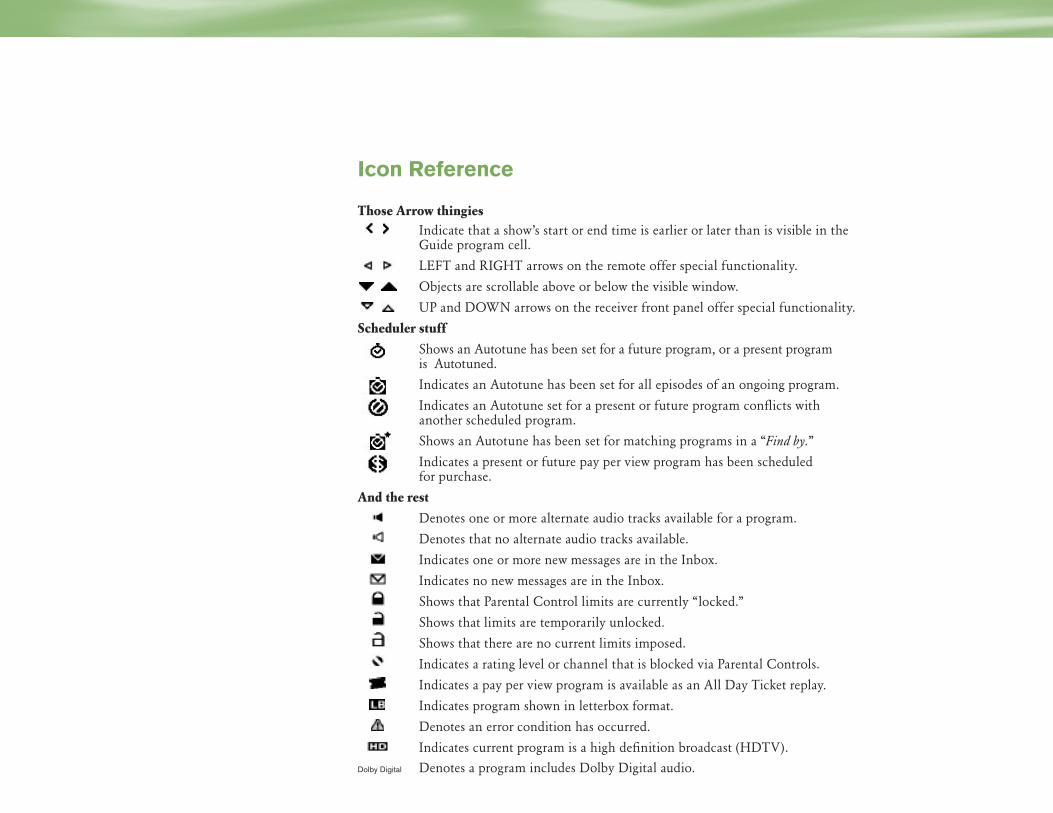
Icon Reference
Those Arrow thingies Indicate that a show’s start or end time is earlier or later than is visible in the
Guide program cell.
LEFT and RIGHT arrows on the remote offer special functionality.
Objects are scrollable above or below the visible window.
UP and DOWN arrows on the receiver front panel offer special functionality.
Scheduler stuff
Shows an Autotune has been set for a future program, or a present program is Autotuned.
Indicates an Autotune has been set for all episodes of an ongoing program.
Indicates an Autotune set for a present or future program conflicts with another scheduled program.
Shows an Autotune has been set for matching programs in a “Find by.”
Indicates a present or future pay per view program has been scheduled for purchase.
And the rest
Denotes one or more alternate audio tracks available for a program.
Denotes that no alternate audio tracks available.
Indicates one or more new messages are in the Inbox.
Indicates no new messages are in the Inbox.
Shows that Parental Control limits are currently “locked.”
Shows that limits are temporarily unlocked.
Shows that there are no current limits imposed.
Indicates a rating level or channel that is blocked via Parental Controls.
Indicates a pay per view program is available as an All Day Ticket replay.
Indicates program shown in letterbox format.
Denotes an error condition has occurred.
Indicates current program is a high definition broadcast (HDTV).
Dolby Digital Denotes a program includes Dolby Digital audio.

We’re always here to help!
DIRECTV is firmly committed to offering the highest quality in customer service and support.Please let us know if you have any questions or concerns.
When you call DIRECTV, you’ll need to provide your receiver’s access card number and modelnumber and your DIRECTV account number.
If you’ve already checked the Troubleshooting section and need assistance with:
4Connecting your receiver to your TV or other equipment
4Guided setup
4A receiver that is not functioning properly even after restarting
4Other questions regarding the receiver or remote control
4Activating or using a feature of DIRECTV programming
4Understanding an on-screen message regarding your service
call 1-800-DIRECTV.
Also find information about DIRECTV products and services at DIRECTV.com.
DIRECTV programming sold separately. ACTIVATION OF PROGRAMMING MAY BE SUBJECT TO CREDIT APPROVAL AND REQUIRES VALID SERVICE ADDRESS, SOCIAL SECURITY NUMBER AND/ORMAJOR CREDIT CARD. DEPOSIT OR PREPAYMENT MAY BE REQUIRED. Programming subject to change. DIRECTV services not available outside the U.S. DIRECTV programming is soldseparately and independently of DIRECTV System hardware. A valid programming subscription is required to operate DIRECTV System hardware. Activate your DIRECTV programmingtoday at 1-800-DIRECTV (1-800-347-3288). Dolby and the double-D symbols are trademarks of Dolby Laboratories. ©2004 DIRECTV, Inc. DIRECTV, the Cyclone Design logo andADVANCED PROGRAM GUIDE are registered trademarks of DIRECTV, Inc.
M380 Owner’s Manual___________________________Interior and Exterior Systems Operation – Electronic Step – 4-19
Rev. “F” 4-19-1
4-19 Electronic Step____________________________________ 4-19.1 Description and Operation The motor home is equipped with a single electronic step that automatically extends when motor home door is open and also has a switch just inside the door that enables the step as well. The control unit is essentially a current sensor as well as a switching device. When the motor assembly moves the step tread to its extended position, or stops moving because of an obstruction such as a curb or the binding of a damaged or bent step frame, the motor draws a larger amount of current. The control unit “senses” the larger current draw and shuts off power to the motor. All control units are equipped with an “ignition override system”. This system is designed so that the vehicle will not be driven with the step in the extended position. When the step is locked in the extended position, the door is closed, and the ignition is turned on, the ignition override system will engage and then the step will automatically retract. The “Last Out” feature is another safety feature designed to extend the step when the door is opened for the first time after the vehicle ignition is turned off, even if the power switch is turned off. When the ignition is switched on, the function of the power switch is disabled and the step will always extend when the door is opened and retract when the door is closed. NOTE: Follow the instructions in this manual carefully. Failure to do so may result in damage to the step control, the motor and/or the vehicle wiring. Such damage may also result in voiding the warranty. 4-19.1.1 Operating the Step 1. After the installation is complete and with the entrance door open, turn the power switch on.
NOTE: Some steps are not equipped with a power switch. They are activated only with a door switch.
2. Close the door. The step should retract and lock in the “up” position. 3. Open the door. The step should extend and lock in the “down” position with the understep light on.
NOTE: The understep light is not available on all step models.
4. If your step is equipped with a power switch, turn it off. The step should remain in the extended
position with the understep light off when the door is closed. Turning off the power with the step retracted will hold the step in a retracted position as well.
5. With the power switch off, the step extended, and the entrance door closed, turn on the vehicle ignition. The ignition override system will go into effect and the step will automatically retract.
NOTE: If the yellow wire from the four-way connector is not connected to an ignition power source, the ignition safety system will be inoperative and the step will remain in the extended position. In this case, the power switch must be turned on for the step to retract.
▲WARNING: If the vehicle is driven with the step in the extended position, there is the possibility of causing major damage to both the step and the vehicle.
6. Turn the vehicle ignition off and open the door. The step will extend and lock in the “down”
position. This is the “Last Out” feature.

4-19 – Interior and Exterior Systems Operation – Electronic Step___________________________M380 Owner’s Manual
4-19-2 Rev. “F”
7. The “Last Out” feature is only operative the first time the door is opened after the vehicle ignition is turned off.
When the vehicle ignition is on, the step will always activate with the door movement, regardless of the power switch position. NOTE: If the yellow wire from the four-way connector is not connected to an ignition power source, the “Last Out” feature will not operate. BE SAFE. ALWAYS LOOK BEFORE YOU STEP OUT OF YOUR VEHICLE.
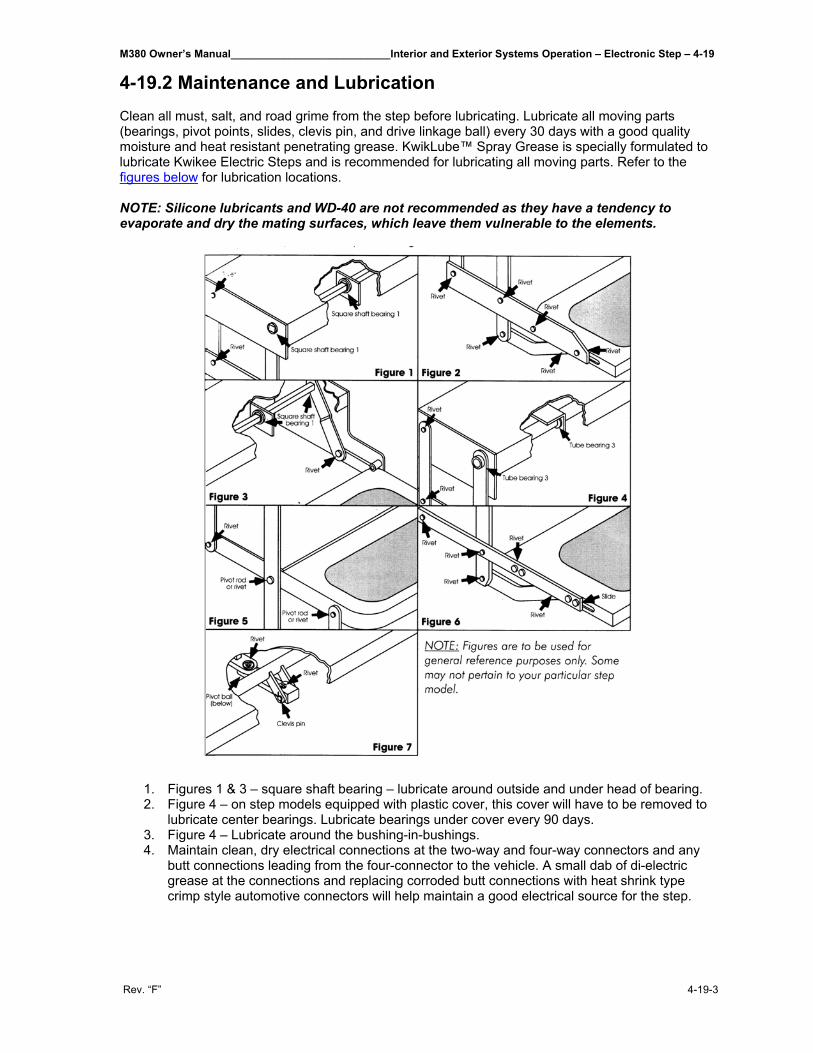
M380 Owner’s Manual___________________________Interior and Exterior Systems Operation – Electronic Step – 4-19
Rev. “F” 4-19-3
4-19.2 Maintenance and Lubrication
Clean all must, salt, and road grime from the step before lubricating. Lubricate all moving parts (bearings, pivot points, slides, clevis pin, and drive linkage ball) every 30 days with a good quality moisture and heat resistant penetrating grease. KwikLube™ Spray Grease is specially formulated to lubricate Kwikee Electric Steps and is recommended for lubricating all moving parts. Refer to the figures below for lubrication locations. NOTE: Silicone lubricants and WD-40 are not recommended as they have a tendency to evaporate and dry the mating surfaces, which leave them vulnerable to the elements.
1. Figures 1 & 3 – square shaft bearing – lubricate around outside and under head of bearing. 2. Figure 4 – on step models equipped with plastic cover, this cover will have to be removed to
lubricate center bearings. Lubricate bearings under cover every 90 days. 3. Figure 4 – Lubricate around the bushing-in-bushings. 4. Maintain clean, dry electrical connections at the two-way and four-way connectors and any
butt connections leading from the four-connector to the vehicle. A small dab of di-electric grease at the connections and replacing corroded butt connections with heat shrink type crimp style automotive connectors will help maintain a good electrical source for the step.

M380 Owner’s Manual__________________________________________________________________________________
Rev. “F”
THIS PAGE IS INTENTIONALLY LEFT BLANK
M380 Owner’s Manual____________________Maintenance/Service Procedures – Engine, Transmission, Chassis – 5-1
Rev. “F” 5-1-1
5-1 Engine, Transmission and Chassis____________________ 5-1.1 General Inspection To ensure safety and convenience and to minimize operating costs, the Operator should establish a routine inspection regimen. Any suspected malfunctions or defects should be reported to maintenance personnel and corrected before further operation of the vehicle. Daily Inspection
• Check fuel level. • Drain air tanks (cold weather). • Check engine oil level. • Check coolant level. • Check automatic transmission fluid level.
Outside the motor home: • Clean the windshield, mirrors, front windows, headlights, taillights, directional lights, and stop
lights. • Check that the exhaust tailpipe is not obstructed. • Check tire pressure and treads. • Check for missing wheel lug nuts. • Ensure that area under the motor home is clear. • Inspect the general outside appearance for cleanliness. Identifying markings (license plate,
motor home number, etc.) must be clean and clear. • Ensure that exterior mirrors are clean and properly adjusted.
Inside the motor home: • Inspect for general cleanliness of seats and floors. • Make sure steps and aisles are dry and unobstructed. • Verify that all emergency exits open and close properly. • Check emergency equipment and first aid kit. • Make sure that fire extinguisher is in place and properly charged. • Clean windows and windshield around driver’s area. • Ensure that exterior mirrors and clean and properly adjusted.
Starting the engine: 1. Be sure parking brakes are on. 2. Put transmission in neutral. 3. With key switched on, check fuel gauge. Check brake warning buzzer or light, and neutral
safety switch. 4. Start engine. Look and listen for trouble signs; check gauges.
With the engine running, check (from driver’s seat): • Mirrors, interior and stepwell lights, and service door seal. • Watch for any unusual feeling or sound from steering, brakes, and other controls. See that
brake pedal has normal height and feel and that the brake gauge is reading correctly. • Check Parking Brake operation by releasing and resetting it. • Check horn, defroster and heater blowers, and windshield wiper operation. • Check signals and lights for proper operation before driving away:
- Right and left turn signals in front and rear. - Flasher warning lights in front and rear. - Headlight high and low beams. - Stoplights and taillights. - Hazard flasher.
5 – Maintenance/Service Procedures – Engine, Transmission, Chassis______________________M380 Owner’s Manual
5-1-2 Rev. “F”
Final check while the motor home is starting to move: • Check that seatbelt is secure. • Check that brake action feels sure and positive; not spongy. • Watch for any unusual feeling, behavior, or noises in steering and check that the bus is
generally under control and tracking straight. • Brake to a stop and check all gauges. REMEMBER: Safety on the road depends on you. Observe weather and road conditions and drive accordingly. Be physically and mentally alert. When backing up near pedestrians or in congested areas, use outside monitor or director. Look around before driving away from where you are parked and observe all traffic rules and regulations.
Weekly Inspection: • Adjust brakes. • Drain air tanks (warm weather). • Check tire tread and inflation pressure. • Inspect seat belts and buckles. • Inspect outside lights for proper operation.
5-1.2 Maintenance Schedule Monthly or 1,000 Miles
• Inspect all emergency equipment and mounting fasteners. Inspect fire extinguisher to see if fully charged, and check contents of first aid kit(s) for freshness, sterility, full supply, and expiration dates.
• Inspect tires for correct pressure, and check for signs of wear. Torque outer wheel nuts to 450-500 foot-pounds (610-675 N•m).
• Inspect window latches and slides for proper operation and secure closure. • Inspect seat frames for secure attachment to the floor and wall.
Monthly or 3,000 Miles
• Check fuel system (Drain fuel and contaminants, if required). • Check battery water level. • Inspect brake chambers.
3 Months or 5,000 Miles
• Lubricate all hinges and window latches for ease of operation. • Lubricate all window channels with silicone or graphite. • Change main heater air filter (depending on operating conditions). • Lubricate hinge and latch mechanisms on access doors. • Inspect heater valves to verify proper function. • Change engine oil and oil filter. • Inspect fuel cap, tank, and fuel lines. • Inspect engine fuel tank vents. • Inspect engine air filter, replace if required. • Inspect driveshaft. • Lubricate universal joint and slip joint. • Lubricate brake camshaft, king pins, tie rod ends, and slack adjusters.
M380 Owner’s Manual____________________Maintenance/Service Procedures – Engine, Transmission, Chassis – 5-1
Rev. “F” 5-1-3
3 Months or 24,000 Miles
• Inspect Bendix air dryer. • Check for loose or disconnected electrical connections and damaged wiring. • Check the vehicle brake warning system. • 6 Months or 6,000 Miles • Check lubricant level in rear axle. • Inspect rear axle vent. • Clean and/or replace air compressor filters. • Check power steering fluid level. • Lubricate steering drag rod. • Check single and double check valves. • Lubricate spring pin. • Inspect alternator. • Clean battery posts. • Disassemble and clean the air compressor governor and repair, as required. • Clean and lube treadle valve. • Change engine fuel filter. • Clean and lubricate accelerator treadle valve.
12 Months or 12,000 Miles
• Complete Quarterly Maintenance Checklist. • Bleed all air from heaters. • Tighten all heater hose clamps. • Check heater hoses, motor wheels, and fans on heaters. • Clean heater core. • Inspect power steering pump. • Inspect steering gear. • Lubricate steering column. • Check front and rear suspension bolt torque. • Inspect suspension system and components. • Inspect radiator hoses. • Pressure-test engine cooling system. • Check heater panels and housing.
12 Months or 24,000 Miles
• Check air tank pop-off valves. • Change automatic transmission filter. • Change internal automatic transmission filter. • Inspect automatic transmission vent. • Change power steering reservoir filter. • Change lubricant in rear axle.
24 Months or 24,000 Miles
• Clean radiator. • Change thermostat. • Clean relay valves, spring brake valves, parking brake valves, and quick release valves. • Clean pressure protection valves.
These checklists are suggested. They do not replace or supersede local or state required driver inspection procedure.
5 – Maintenance/Service Procedures – Engine, Transmission, Chassis______________________M380 Owner’s Manual
5-1-4 Rev. “F”
5-1.3 Engine Quick Reference Guide 5-1.3.1 Cooling Routine Maintenance Recommendations
• Check every 18,000 miles/6 months • Change coolant filter every 18,000 miles/6 months • Drain and flush system every 72,000 miles/2 years and refille with heavy-duty coolant. Use a
50/50 mix of water and antifreeze. NOTE: Always use antifreeze. In addition to freeze protection, antifreeze is essential for overheat and corrosion protection. The supplemental coolant additive (SCA) is required with the ISL Engine. Definition of Heavy-Duty Coolant
A combination of 50/50 water and low silicate antifreeze (ethylene glycol or propylene glycol are acceptable). Protects to -34°F. Freeze protection decreases above 68% antifreeze. Antifreeze must meet ASTM D4985 (GM6038M) specs.
How to Test Coolant Concentration
Refractometer Fleetguard #C2800 is recommended vs. floating ball due to accuracy. Water Quality Requirements Calcium/Magnesium Max. 170ppm as CaC03+MgCO3 Chloride Max. 40ppm as Cl Sulfur Max. 100ppm as SO4 A conservative approach to cooling system maintenance would include an analysis of your home base tap water supply. Your Cummins distributor can provide this service as well as sample bottles and other coolant test devices. Consider using pre-formulated antifreeze when on the road or when water quality is unknown. The use of distilled water is also acceptable. Pre-formulated Antifreeze and Supplemental Coolant Additives (SCA)
Pre-formulated antifreeze, such as Fleetguard Compleat, offers a vehicle owner the convenience of a pre-mixed antifreeze solution containing high quality water and the correct chemical balance of antifreeze and SCA.
5-1.3.2 Lubricating Oil Routine Maintenance Recommendations Oil Drain Interval Fleetguard Filter 18,000 miles/1 year LF 9009 Replace oil filter at EVERY oil drain interval. Multigrade vs. Straight Weight
High quality 15W40 oil API CG-4 or CH-4 is recommended. Why multigrade? • Reduced deposit formation • Improved cranking in low ambient temperatures. • Shortens time-to-block pressure in low ambients. • Improved lubrication during high temperature operation.
Synthetic Oil
May be used in ISL engines provided they meet performance and chemical requirements.
M380 Owner’s Manual____________________Maintenance/Service Procedures – Engine, Transmission, Chassis – 5-1
Rev. “F” 5-1-5
Recommended for use in ambient temperatures consistently below -13°F (-25°C) for improved engine cranking and flowability. Should NOT BE USED to extend oil drain intervals.
Engine Break-In Oil Special break-in oil should not be used. If synthetic or synthetic blend oil has been used prior to an engine rebuild, petroleum-based oil should be used for the first oil change interval, after which use of synthetic oil can be resumed.
Supplemental Oil Additives Supplemental oil additives such as friction-reducers and graphitizers should not be used unless the oil supplier can provide evidence of satisfactory performance. If there is any doubt about suitability of an oil, consult the oil manufacturer for a definitive recommendation, or data to establish that the oil has performed satisfactorily in Cummins engines.
Oil Analysis Oil Analysis, as a method to extend drain intervals, is NOT recommended. Different methods of
measuring soot, lack of correlation among testing labs, and differing driving patterns and idle time are the basis of the recommendation.
5-1.3.3 Fuel Routine Maintenance Recommendations
Fuel filter should be changed at EVERY oil change. Fleetguard fuel filter:
Spin-on Filter #FS 1022# Cummins P/N 3944269 *Denotes to transfer water sensor to new filter. Low Sulfur Fuel and Fuel Lubricity
Fuel additives for lubricity are NOT required by Cummins when using commercially available low sulfur #2 diesel fuel or #1/#2 winter blend diesel fuels.
Biocide Treatment
A biocide or fungicide can help when fuels are prone to contamination with bacteria or fungus (black slime).
Other Fuel Additives
Any fuel additive product should be accompanied with performance data supporting its performance and benefit. Engine failures caused by incorrect fuel are NOT covered under warranty. It is not the policy of Cummins to test, approve or endorse any product not manufactured or sold by Cummins.
5-1.3.4 Extended Shutdown Start Procedure
When starting an engine that has been setting idle for more than 30 days:
1. Engine oil pressure must be indicated on gauge within 15 seconds after starting. If oil pressure does NOT register within 15 seconds after starting, shut off engine immediately and follow the instructions in the chart below.
2. Idle engine three to five minutes before operating under load.
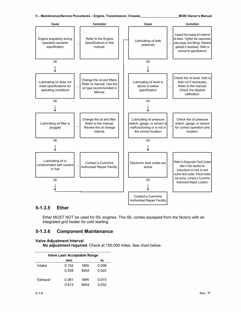
5 – Maintenance/Service Procedures – Engine, Transmission, Chassis______________________M380 Owner’s Manual
5-1-6 Rev. “F”
Cause Correction Cause Correction
Engine angularity during operation exceeds
specification….
Refer to the Engine Specifications in this
manual.
Lubricating oil leak (external) ….
Inspect the engine for external oil leaks. Tighten the capscrews,pipe plugs, and fittings. Replace gaskets if necessary. Refer to
manual for specifications.
OK OK
↓ ↓
Lubricating oil does not meet specifications for operating conditions
….
Change the oil and filters. Refer to manual. Use the oil type recommended in
Manual.
Lubricating oil level is above or below
specification….
Check the oil level. Add or drain oil if necessary. Refer to the manual. Check the dipstick
calibration.
OK OK
↓ ↓
Lubricating oil filter is plugged ….
Change the oil and filter. Refer to the manual.
Review the oil change interval.
Lubricating oil pressure switch, gauge, or sensor is malfunctioning or is not in
the correct location
….
Check the oil pressure switch, gauge, or sensor for correct operation and
location.
OK OK
↓ ↓
Lubricating oil is contaminated with coolant
or fuel…. Contact a Cummins
Authorized Repair Facility.Electronic fault codes are
active ….
OK OK
↓ ↓Contact a Cummins
Authorized Repair Facility
Refer to Diagnostic Fault Codes later in this section for
instructions on how to read active fault codes. If fault codes are active, contact a Cummins Authorized Repair Location.
5-1.3.5 Ether
Ether MUST NOT be used for ISL engines. The ISL comes equipped from the factory with an integrated grid heater for cold starting.
5-1.3.6 Component Maintenance Valve Adjustment Interval
No adjustment required. Check at 150,000 miles. See chart below.
Valve Lash Acceptable Range mm in Intake 0.152 MIN 0.006 0.559 MAX 0.022 Exhaust 0.381 MIN 0.015 0.813 MAX 0.032
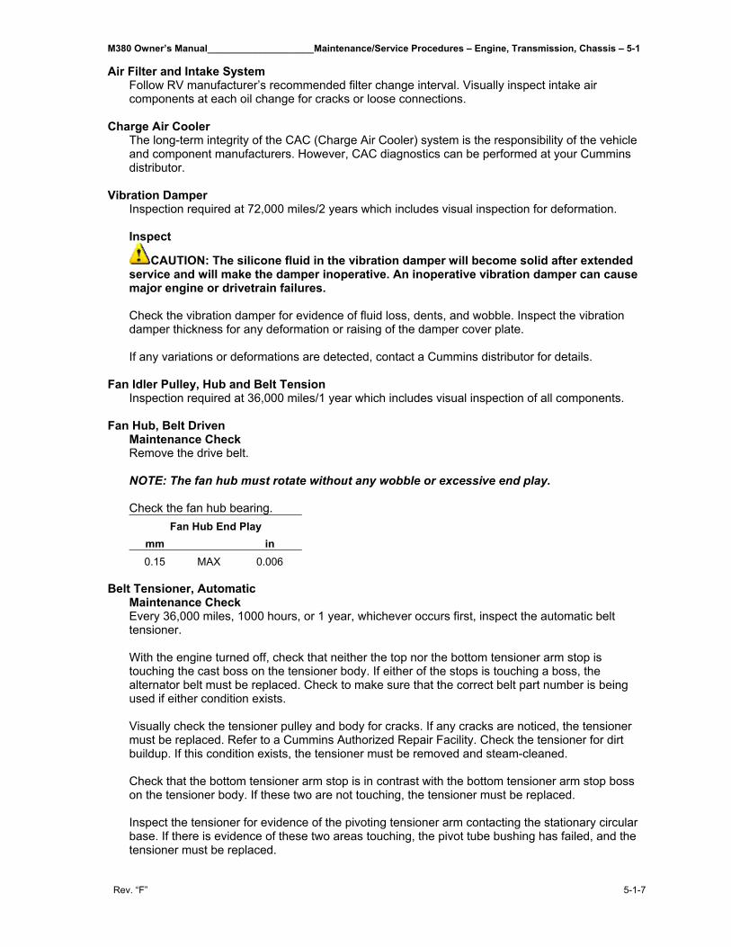
M380 Owner’s Manual____________________Maintenance/Service Procedures – Engine, Transmission, Chassis – 5-1
Rev. “F” 5-1-7
Air Filter and Intake System Follow RV manufacturer’s recommended filter change interval. Visually inspect intake air components at each oil change for cracks or loose connections.
Charge Air Cooler
The long-term integrity of the CAC (Charge Air Cooler) system is the responsibility of the vehicle and component manufacturers. However, CAC diagnostics can be performed at your Cummins distributor.
Vibration Damper
Inspection required at 72,000 miles/2 years which includes visual inspection for deformation. Inspect
CAUTION: The silicone fluid in the vibration damper will become solid after extended service and will make the damper inoperative. An inoperative vibration damper can cause major engine or drivetrain failures. Check the vibration damper for evidence of fluid loss, dents, and wobble. Inspect the vibration damper thickness for any deformation or raising of the damper cover plate. If any variations or deformations are detected, contact a Cummins distributor for details.
Fan Idler Pulley, Hub and Belt Tension Inspection required at 36,000 miles/1 year which includes visual inspection of all components.
Fan Hub, Belt Driven Maintenance Check Remove the drive belt. NOTE: The fan hub must rotate without any wobble or excessive end play. Check the fan hub bearing.
Fan Hub End Play mm in 0.15 MAX 0.006
Belt Tensioner, Automatic
Maintenance Check Every 36,000 miles, 1000 hours, or 1 year, whichever occurs first, inspect the automatic belt tensioner. With the engine turned off, check that neither the top nor the bottom tensioner arm stop is touching the cast boss on the tensioner body. If either of the stops is touching a boss, the alternator belt must be replaced. Check to make sure that the correct belt part number is being used if either condition exists. Visually check the tensioner pulley and body for cracks. If any cracks are noticed, the tensioner must be replaced. Refer to a Cummins Authorized Repair Facility. Check the tensioner for dirt buildup. If this condition exists, the tensioner must be removed and steam-cleaned. Check that the bottom tensioner arm stop is in contrast with the bottom tensioner arm stop boss on the tensioner body. If these two are not touching, the tensioner must be replaced. Inspect the tensioner for evidence of the pivoting tensioner arm contacting the stationary circular base. If there is evidence of these two areas touching, the pivot tube bushing has failed, and the tensioner must be replaced.
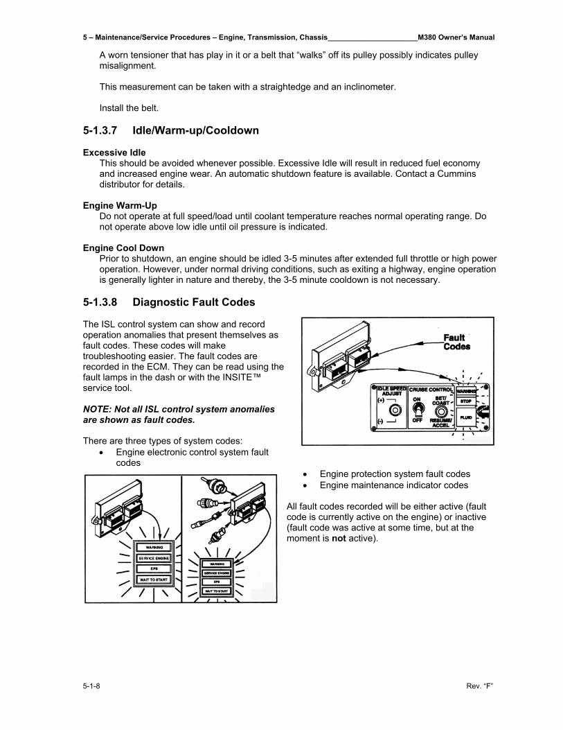
5 – Maintenance/Service Procedures – Engine, Transmission, Chassis______________________M380 Owner’s Manual
5-1-8 Rev. “F”
A worn tensioner that has play in it or a belt that “walks” off its pulley possibly indicates pulley misalignment. This measurement can be taken with a straightedge and an inclinometer. Install the belt.
5-1.3.7 Idle/Warm-up/Cooldown Excessive Idle
This should be avoided whenever possible. Excessive Idle will result in reduced fuel economy and increased engine wear. An automatic shutdown feature is available. Contact a Cummins distributor for details.
Engine Warm-Up
Do not operate at full speed/load until coolant temperature reaches normal operating range. Do not operate above low idle until oil pressure is indicated.
Engine Cool Down
Prior to shutdown, an engine should be idled 3-5 minutes after extended full throttle or high power operation. However, under normal driving conditions, such as exiting a highway, engine operation is generally lighter in nature and thereby, the 3-5 minute cooldown is not necessary.
5-1.3.8 Diagnostic Fault Codes The ISL control system can show and record operation anomalies that present themselves as fault codes. These codes will make troubleshooting easier. The fault codes are recorded in the ECM. They can be read using the fault lamps in the dash or with the INSITE™ service tool. NOTE: Not all ISL control system anomalies are shown as fault codes. There are three types of system codes:
• Engine electronic control system fault codes
• Engine protection system fault codes • Engine maintenance indicator codes
All fault codes recorded will be either active (fault code is currently active on the engine) or inactive (fault code was active at some time, but at the moment is not active).
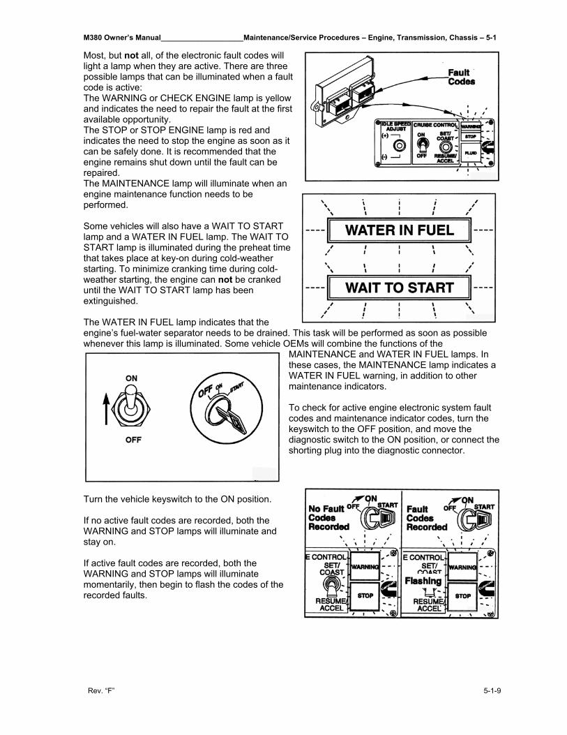
M380 Owner’s Manual____________________Maintenance/Service Procedures – Engine, Transmission, Chassis – 5-1
Rev. “F” 5-1-9
Most, but not all, of the electronic fault codes will light a lamp when they are active. There are three possible lamps that can be illuminated when a fault code is active: The WARNING or CHECK ENGINE lamp is yellow and indicates the need to repair the fault at the first available opportunity. The STOP or STOP ENGINE lamp is red and indicates the need to stop the engine as soon as it can be safely done. It is recommended that the engine remains shut down until the fault can be repaired. The MAINTENANCE lamp will illuminate when an engine maintenance function needs to be performed. Some vehicles will also have a WAIT TO START lamp and a WATER IN FUEL lamp. The WAIT TO START lamp is illuminated during the preheat time that takes place at key-on during cold-weather starting. To minimize cranking time during cold-weather starting, the engine can not be cranked until the WAIT TO START lamp has been extinguished. The WATER IN FUEL lamp indicates that the engine’s fuel-water separator needs to be drained. This task will be performed as soon as possible whenever this lamp is illuminated. Some vehicle OEMs will combine the functions of the
MAINTENANCE and WATER IN FUEL lamps. In these cases, the MAINTENANCE lamp indicates a WATER IN FUEL warning, in addition to other maintenance indicators. To check for active engine electronic system fault codes and maintenance indicator codes, turn the keyswitch to the OFF position, and move the diagnostic switch to the ON position, or connect the shorting plug into the diagnostic connector.
Turn the vehicle keyswitch to the ON position. If no active fault codes are recorded, both the WARNING and STOP lamps will illuminate and stay on. If active fault codes are recorded, both the WARNING and STOP lamps will illuminate momentarily, then begin to flash the codes of the recorded faults.
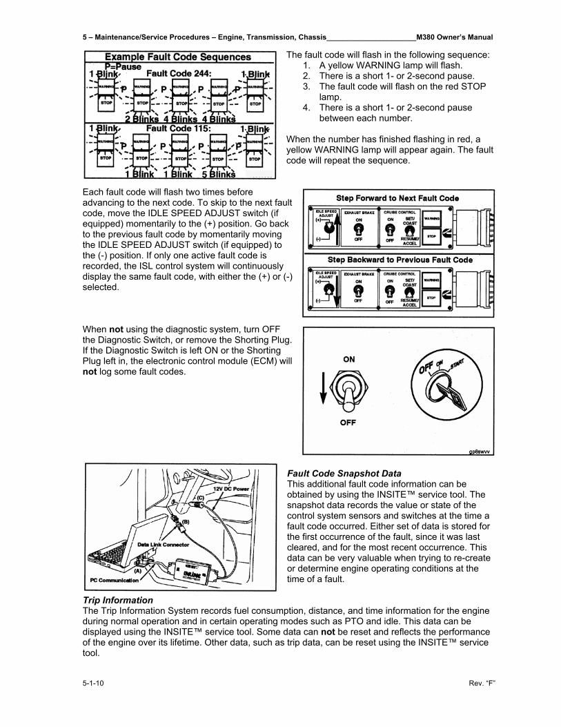
5 – Maintenance/Service Procedures – Engine, Transmission, Chassis______________________M380 Owner’s Manual
5-1-10 Rev. “F”
The fault code will flash in the following sequence: 1. A yellow WARNING lamp will flash. 2. There is a short 1- or 2-second pause. 3. The fault code will flash on the red STOP
lamp. 4. There is a short 1- or 2-second pause
between each number. When the number has finished flashing in red, a yellow WARNING lamp will appear again. The fault code will repeat the sequence.
Each fault code will flash two times before advancing to the next code. To skip to the next fault code, move the IDLE SPEED ADJUST switch (if equipped) momentarily to the (+) position. Go back to the previous fault code by momentarily moving the IDLE SPEED ADJUST switch (if equipped) to the (-) position. If only one active fault code is recorded, the ISL control system will continuously display the same fault code, with either the (+) or (-) selected. When not using the diagnostic system, turn OFF the Diagnostic Switch, or remove the Shorting Plug. If the Diagnostic Switch is left ON or the Shorting Plug left in, the electronic control module (ECM) will not log some fault codes.
Fault Code Snapshot Data This additional fault code information can be obtained by using the INSITE™ service tool. The snapshot data records the value or state of the control system sensors and switches at the time a fault code occurred. Either set of data is stored for the first occurrence of the fault, since it was last cleared, and for the most recent occurrence. This data can be very valuable when trying to re-create or determine engine operating conditions at the time of a fault.
Trip Information The Trip Information System records fuel consumption, distance, and time information for the engine during normal operation and in certain operating modes such as PTO and idle. This data can be displayed using the INSITE™ service tool. Some data can not be reset and reflects the performance of the engine over its lifetime. Other data, such as trip data, can be reset using the INSITE™ service tool.
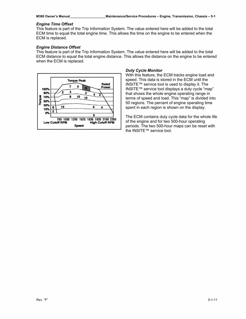
M380 Owner’s Manual____________________Maintenance/Service Procedures – Engine, Transmission, Chassis – 5-1
Rev. “F” 5-1-11
Engine Time Offset This feature is part of the Trip Information System. The value entered here will be added to the total ECM time to equal the total engine time. This allows the time on the engine to be entered when the ECM is replaced. Engine Distance Offset This feature is part of the Trip Information System. The value entered here will be added to the total ECM distance to equal the total engine distance. This allows the distance on the engine to be entered when the ECM is replaced.
Duty Cycle Monitor With this feature, the ECM tracks engine load and speed. This data is stored in the ECM until the INSITE™ service tool is used to display it. The INSITE™ service tool displays a duty cycle “map” that shows the whole engine operating range in terms of speed and load. This “map” is divided into 50 regions. The percent of engine operating time spent in each region is shown on the display. The ECM contains duty cycle data for the whole life of the engine and for two 500-hour operating periods. The two 500-hour maps can be reset with the INSITE™ service tool.

M380 Owner’s Manual__________________________________________________________________________________
Rev. “F”
THIS PAGE IS INTENTIONALLY LEFT BLANK
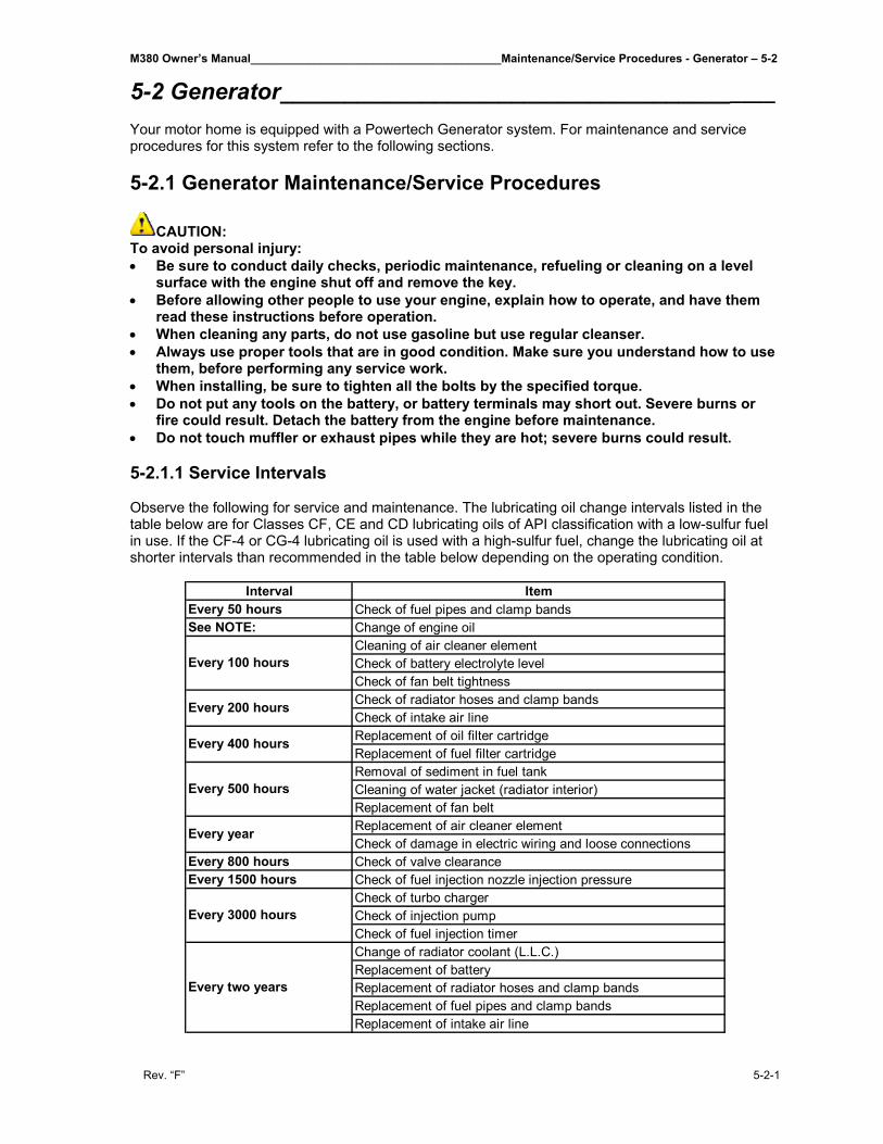
M380 Owner’s Manual_______________________________________Maintenance/Service Procedures - Generator – 5-2
Rev. “F” 5-2-1
5-2 Generator_______________________________________ Your motor home is equipped with a Powertech Generator system. For maintenance and service procedures for this system refer to the following sections. 5-2.1 Generator Maintenance/Service Procedures
CAUTION: To avoid personal injury: • Be sure to conduct daily checks, periodic maintenance, refueling or cleaning on a level
surface with the engine shut off and remove the key. • Before allowing other people to use your engine, explain how to operate, and have them
read these instructions before operation. • When cleaning any parts, do not use gasoline but use regular cleanser. • Always use proper tools that are in good condition. Make sure you understand how to use
them, before performing any service work. • When installing, be sure to tighten all the bolts by the specified torque. • Do not put any tools on the battery, or battery terminals may short out. Severe burns or
fire could result. Detach the battery from the engine before maintenance. • Do not touch muffler or exhaust pipes while they are hot; severe burns could result. 5-2.1.1 Service Intervals Observe the following for service and maintenance. The lubricating oil change intervals listed in the table below are for Classes CF, CE and CD lubricating oils of API classification with a low-sulfur fuel in use. If the CF-4 or CG-4 lubricating oil is used with a high-sulfur fuel, change the lubricating oil at shorter intervals than recommended in the table below depending on the operating condition.
Interval ItemEvery 50 hours Check of fuel pipes and clamp bandsSee NOTE: Change of engine oil
Cleaning of air cleaner elementCheck of battery electrolyte levelCheck of fan belt tightnessCheck of radiator hoses and clamp bandsCheck of intake air lineReplacement of oil filter cartridgeReplacement of fuel filter cartridgeRemoval of sediment in fuel tankCleaning of water jacket (radiator interior)Replacement of fan beltReplacement of air cleaner elementCheck of damage in electric wiring and loose connections
Every 800 hours Check of valve clearanceEvery 1500 hours Check of fuel injection nozzle injection pressure
Check of turbo chargerCheck of injection pumpCheck of fuel injection timerChange of radiator coolant (L.L.C.)Replacement of batteryReplacement of radiator hoses and clamp bandsReplacement of fuel pipes and clamp bandsReplacement of intake air line
Every year
Every 3000 hours
Every two years
Every 100 hours
Every 200 hours
Every 400 hours
Every 500 hours
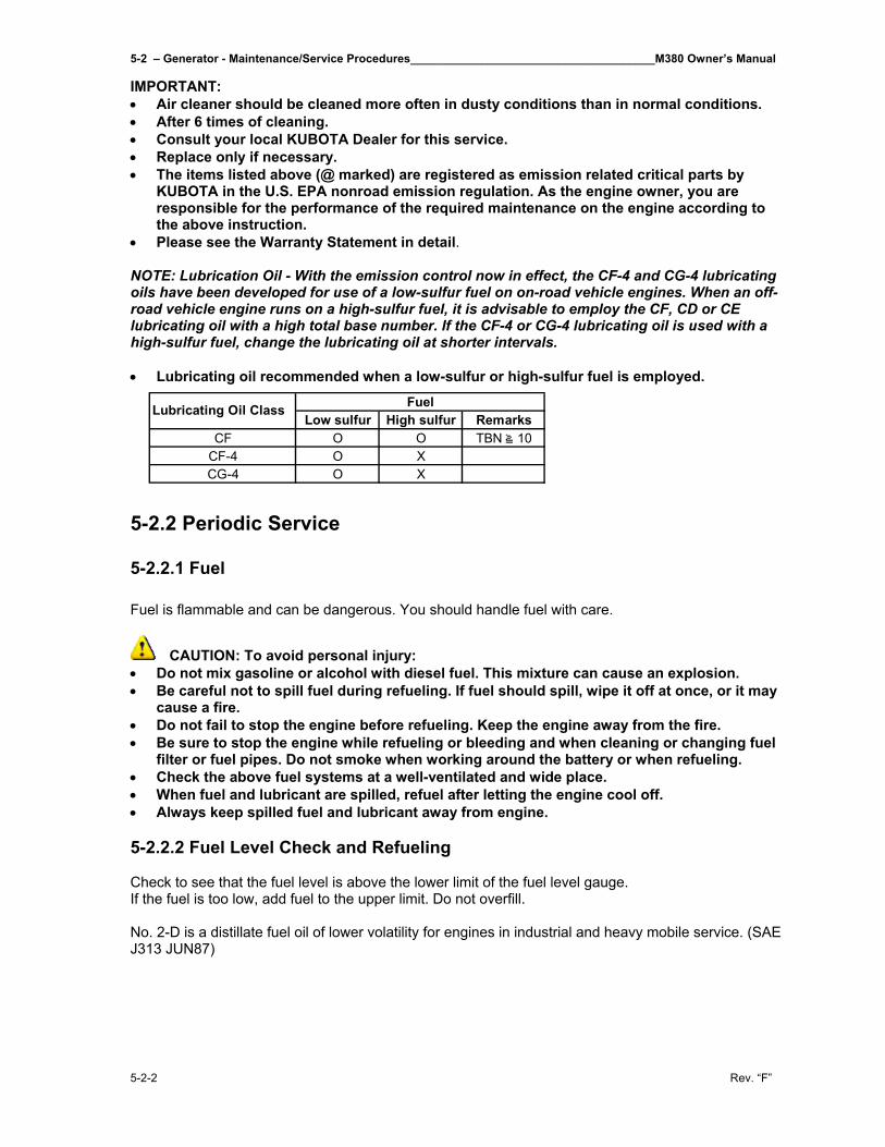
5-2 – Generator - Maintenance/Service Procedures______________________________________M380 Owner’s Manual
5-2-2 Rev. “F”
IMPORTANT: • Air cleaner should be cleaned more often in dusty conditions than in normal conditions. • After 6 times of cleaning. • Consult your local KUBOTA Dealer for this service. • Replace only if necessary. • The items listed above (@ marked) are registered as emission related critical parts by
KUBOTA in the U.S. EPA nonroad emission regulation. As the engine owner, you are responsible for the performance of the required maintenance on the engine according to the above instruction.
• Please see the Warranty Statement in detail. NOTE: Lubrication Oil - With the emission control now in effect, the CF-4 and CG-4 lubricating oils have been developed for use of a low-sulfur fuel on on-road vehicle engines. When an off-road vehicle engine runs on a high-sulfur fuel, it is advisable to employ the CF, CD or CE lubricating oil with a high total base number. If the CF-4 or CG-4 lubricating oil is used with a high-sulfur fuel, change the lubricating oil at shorter intervals. • Lubricating oil recommended when a low-sulfur or high-sulfur fuel is employed.
5-2.2 Periodic Service 5-2.2.1 Fuel
Fuel is flammable and can be dangerous. You should handle fuel with care.
CAUTION: To avoid personal injury: • Do not mix gasoline or alcohol with diesel fuel. This mixture can cause an explosion. • Be careful not to spill fuel during refueling. If fuel should spill, wipe it off at once, or it may
cause a fire. • Do not fail to stop the engine before refueling. Keep the engine away from the fire. • Be sure to stop the engine while refueling or bleeding and when cleaning or changing fuel
filter or fuel pipes. Do not smoke when working around the battery or when refueling. • Check the above fuel systems at a well-ventilated and wide place. • When fuel and lubricant are spilled, refuel after letting the engine cool off. • Always keep spilled fuel and lubricant away from engine. 5-2.2.2 Fuel Level Check and Refueling Check to see that the fuel level is above the lower limit of the fuel level gauge. If the fuel is too low, add fuel to the upper limit. Do not overfill. No. 2-D is a distillate fuel oil of lower volatility for engines in industrial and heavy mobile service. (SAE J313 JUN87)
Low sulfur High sulfur RemarksCF O O TBN 10
CF-4 O XCG-4 O X
FuelLubricating Oil Class
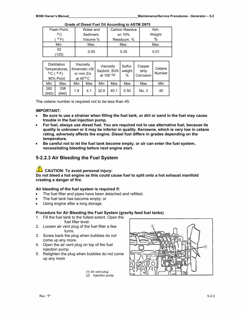
M380 Owner’s Manual_______________________________________Maintenance/Service Procedures - Generator – 5-2
Rev. “F” 5-2-3
The cetane number is required not to be less than 45. IMPORTANT: • Be sure to use a strainer when filling the fuel tank, or dirt or sand in the fuel may cause
trouble in the fuel injection pump. • For fuel, always use diesel fuel. You are required not to use alternative fuel, because its
quality is unknown or it may be inferior in quality. Kerosene, which is very low in cetane rating, adversely affects the engine. Diesel fuel differs in grades depending on the temperature.
• Be careful not to let the fuel tank become empty, or air can enter the fuel system, necessitating bleeding before next engine start.
5-2.2.3 Air Bleeding the Fuel System
CAUTION: To avoid personal injury: Do not bleed a hot engine as this could cause fuel to split onto a hot exhaust manifold creating a danger of fire. Air bleeding of the fuel system is required if: • The fuel filter and pipes have been detached and refitted. • The fuel tank has become empty; or • Using engine after a long storage. Procedure for Air Bleeding the Fuel System (gravity feed fuel tanks) 1. Fill the fuel tank to the fullest extent. Open the
fuel filter level. 2. Loosen air vent plug of the fuel filter a few
turns. 3. Screw back the plug when bubbles do not
come up any more. 4. Open the air vent plug on top of the fuel
injection pump. 5. Retighten the plug when bubbles do not come
up any more
(1) Air vent plug (2) Injection pump
Flash Point, Water and Carbon Residue Ash. C Sediment, on 10% Weight
( F) Volume % Residuum, % %Min. Max. Max. Max.52
(125)
Grade of Diesel Fuel Oil According to ASTM D975
0.05 0.35 0.01
Min Max Min Max Min Max Max Max Min282 338
(540) (640)
Viscosity Sayboit, SUS
at 100 F
Distillation Temperatures,
C ( F)
Viscosity Kinematic cSt
or mm 2/s90% Point at 40 C
Sulfur, weight
%
Copper strip
Corrosion
Cetane Number
1.9 4.1 32.6 40.1 0.50 No. 3 40
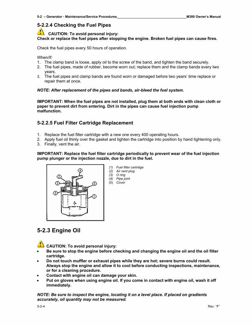
5-2 – Generator - Maintenance/Service Procedures______________________________________M380 Owner’s Manual
5-2-4 Rev. “F”
5-2.2.4 Checking the Fuel Pipes CAUTION: To avoid personal injury:
Check or replace the fuel pipes after stopping the engine. Broken fuel pipes can cause fires.
Check the fuel pipes every 50 hours of operation.
When/If: 1. The clamp band is loose, apply oil to the screw of the band, and tighten the band securely. 2. The fuel pipes, made of rubber, become worn out; replace them and the clamp bands every two
years. 3. The fuel pipes and clamp bands are found worn or damaged before two years’ time replace or
repair them at once.
NOTE: After replacement of the pipes and bands, air-bleed the fuel system.
IMPORTANT: When the fuel pipes are not installed, plug them at both ends with clean cloth or paper to prevent dirt from entering. Dirt in the pipes can cause fuel injection pump malfunction.
5-2.2.5 Fuel Filter Cartridge Replacement
1. Replace the fuel filter cartridge with a new one every 400 operating hours. 2. Apply fuel oil thinly over the gasket and tighten the cartridge into position by hand tightening only. 3. Finally, vent the air. IMPORTANT: Replace the fuel filter cartridge periodically to prevent wear of the fuel injection pump plunger or the injection nozzle, due to dirt in the fuel.
(1) Fuel filter cartridge (2) Air vent plug (3) O ring (4) Pipe joint (5) Cover
5-2.3 Engine Oil
CAUTION: To avoid personal injury: • Be sure to stop the engine before checking and changing the engine oil and the oil filter
cartridge. • Do not touch muffler or exhaust pipes while they are hot; severe burns could result.
Always stop the engine and allow it to cool before conducting inspections, maintenance, or for a cleaning procedure.
• Contact with engine oil can damage your skin. • Put on gloves when using engine oil. If you come in contact with engine oil, wash it off
immediately.
NOTE: Be sure to inspect the engine, locating it on a level place. If placed on gradients accurately, oil quantity may not be measured.
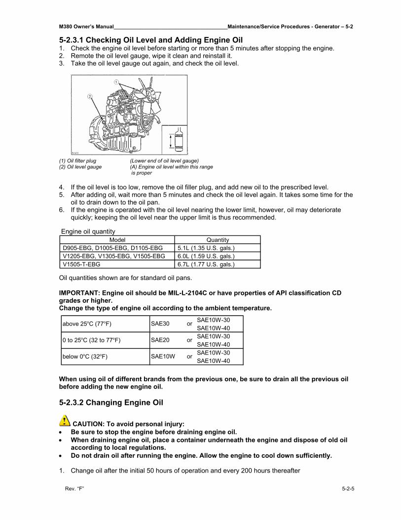
M380 Owner’s Manual_______________________________________Maintenance/Service Procedures - Generator – 5-2
Rev. “F” 5-2-5
5-2.3.1 Checking Oil Level and Adding Engine Oil 1. Check the engine oil level before starting or more than 5 minutes after stopping the engine. 2. Remote the oil level gauge, wipe it clean and reinstall it. 3. Take the oil level gauge out again, and check the oil level.
(1) Oil filter plug (Lower end of oil level gauge) (2) Oil level gauge (A) Engine oil level within this range
is proper
4. If the oil level is too low, remove the oil filler plug, and add new oil to the prescribed level. 5. After adding oil, wait more than 5 minutes and check the oil level again. It takes some time for the
oil to drain down to the oil pan. 6. If the engine is operated with the oil level nearing the lower limit, however, oil may deteriorate
quickly; keeping the oil level near the upper limit is thus recommended.
Oil quantities shown are for standard oil pans. IMPORTANT: Engine oil should be MIL-L-2104C or have properties of API classification CD grades or higher. Change the type of engine oil according to the ambient temperature.
When using oil of different brands from the previous one, be sure to drain all the previous oil before adding the new engine oil. 5-2.3.2 Changing Engine Oil
CAUTION: To avoid personal injury: • Be sure to stop the engine before draining engine oil. • When draining engine oil, place a container underneath the engine and dispose of old oil
according to local regulations. • Do not drain oil after running the engine. Allow the engine to cool down sufficiently. 1. Change oil after the initial 50 hours of operation and every 200 hours thereafter
Model Quantity D905-EBG, D1005-EBG, D1105-EBG 5.1L (1.35 U.S. gals.) V1205-EBG, V1305-EBG, V1505-EBG 6.0L (1.59 U.S. gals.) V1505-T-EBG 6.7L (1.77 U.S. gals.)
Engine oil quantity
SAE10W-30SAE10W-40SAE10W-30SAE10W-40SAE10W-30SAE10W-40
or
or
or
above 25oC (77oF)
0 to 25oC (32 to 77oF)
below 0oC (32oF)
SAE30
SAE20
SAE10W
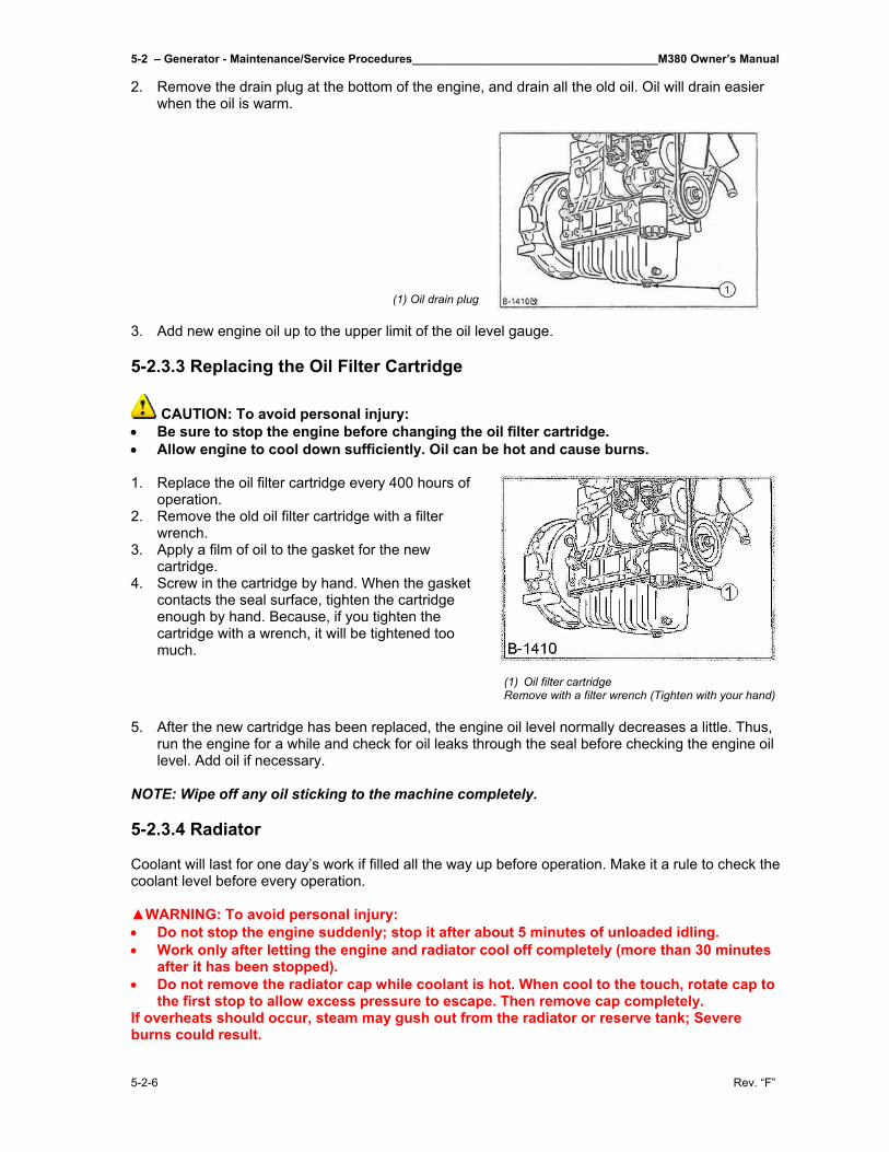
5-2 – Generator - Maintenance/Service Procedures______________________________________M380 Owner’s Manual
5-2-6 Rev. “F”
2. Remove the drain plug at the bottom of the engine, and drain all the old oil. Oil will drain easier when the oil is warm.
(1) Oil drain plug 3. Add new engine oil up to the upper limit of the oil level gauge. 5-2.3.3 Replacing the Oil Filter Cartridge
CAUTION: To avoid personal injury: • Be sure to stop the engine before changing the oil filter cartridge. • Allow engine to cool down sufficiently. Oil can be hot and cause burns. 1. Replace the oil filter cartridge every 400 hours of
operation. 2. Remove the old oil filter cartridge with a filter
wrench. 3. Apply a film of oil to the gasket for the new
cartridge. 4. Screw in the cartridge by hand. When the gasket
contacts the seal surface, tighten the cartridge enough by hand. Because, if you tighten the cartridge with a wrench, it will be tightened too much.
(1) Oil filter cartridge Remove with a filter wrench (Tighten with your hand)
5. After the new cartridge has been replaced, the engine oil level normally decreases a little. Thus,
run the engine for a while and check for oil leaks through the seal before checking the engine oil level. Add oil if necessary.
NOTE: Wipe off any oil sticking to the machine completely. 5-2.3.4 Radiator Coolant will last for one day’s work if filled all the way up before operation. Make it a rule to check the coolant level before every operation. ▲WARNING: To avoid personal injury: • Do not stop the engine suddenly; stop it after about 5 minutes of unloaded idling. • Work only after letting the engine and radiator cool off completely (more than 30 minutes
after it has been stopped). • Do not remove the radiator cap while coolant is hot. When cool to the touch, rotate cap to
the first stop to allow excess pressure to escape. Then remove cap completely. If overheats should occur, steam may gush out from the radiator or reserve tank; Severe burns could result.
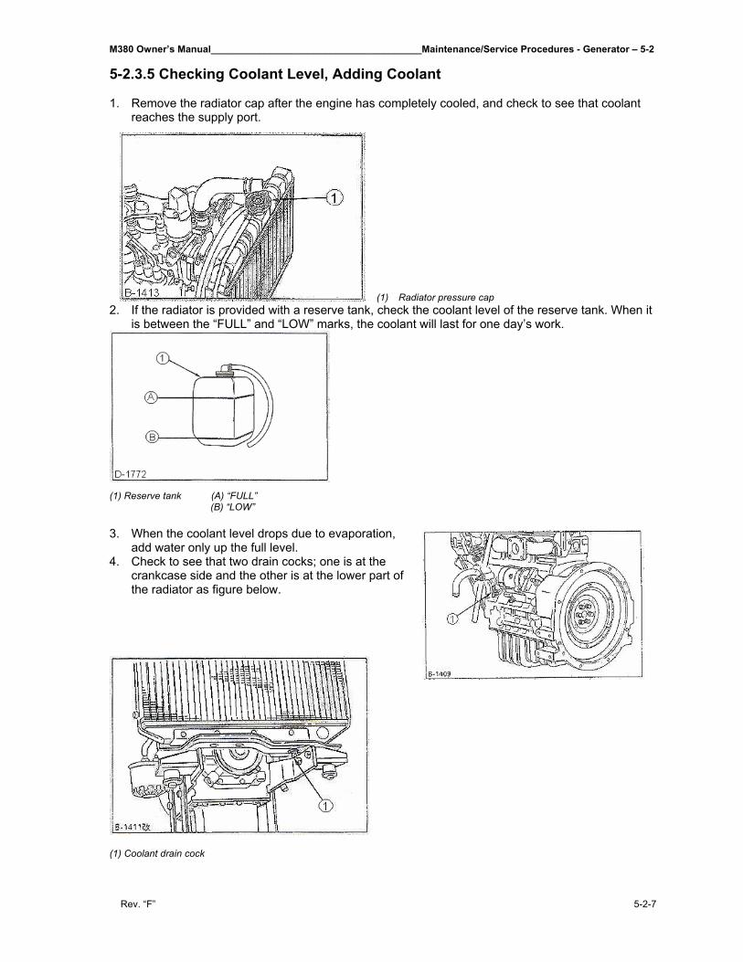
M380 Owner’s Manual_______________________________________Maintenance/Service Procedures - Generator – 5-2
Rev. “F” 5-2-7
5-2.3.5 Checking Coolant Level, Adding Coolant 1. Remove the radiator cap after the engine has completely cooled, and check to see that coolant
reaches the supply port. (1) Radiator pressure cap
2. If the radiator is provided with a reserve tank, check the coolant level of the reserve tank. When it is between the “FULL” and “LOW” marks, the coolant will last for one day’s work.
(1) Reserve tank (A) “FULL” (B) “LOW” 3. When the coolant level drops due to evaporation,
add water only up the full level. 4. Check to see that two drain cocks; one is at the
crankcase side and the other is at the lower part of the radiator as figure below.
(1) Coolant drain cock
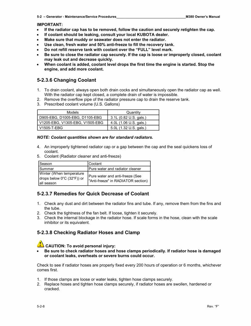
5-2 – Generator - Maintenance/Service Procedures______________________________________M380 Owner’s Manual
5-2-8 Rev. “F”
IMPORTANT: • If the radiator cap has to be removed, follow the caution and securely retighten the cap. • If coolant should be leaking, consult your local KUBOTA dealer. • Make sure that muddy or seawater does not enter the radiator. • Use clean, fresh water and 50% anti-freeze to fill the recovery tank. • Do not refill reserve tank with coolant over the “FULL” level mark. • Be sure to close the radiator cap securely. If the cap is loose or improperly closed, coolant
may leak out and decrease quickly. • When coolant is added, coolant level drops the first time the engine is started. Stop the
engine, and add more coolant. 5-2.3.6 Changing Coolant 1. To drain coolant, always open both drain cocks and simultaneously open the radiator cap as well.
With the radiator cap kept closed, a complete drain of water is impossible. 2. Remove the overflow pipe of the radiator pressure cap to drain the reserve tank. 3. Prescribed coolant volume (U.S. Gallons)
NOTE: Coolant quantities shown are for standard radiators. 4. An improperly tightened radiator cap or a gap between the cap and the seal quickens loss of
coolant. 5. Coolant (Radiator cleaner and anti-freeze)
5-2.3.7 Remedies for Quick Decrease of Coolant 1. Check any dust and dirt between the radiator fins and tube. If any, remove them from the fins and
the tube. 2. Check the tightness of the fan belt. If loose, tighten it securely. 3. Check the internal blockage in the radiator hose. If scale forms in the hose, clean with the scale
inhibitor or its equivalent. 5-2.3.8 Checking Radiator Hoses and Clamp
CAUTION: To avoid personal injury: • Be sure to check radiator hoses and hose clamps periodically. If radiator hose is damaged
or coolant leaks, overheats or severe burns could occur. Check to see if radiator hoses are properly fixed every 200 hours of operation or 6 months, whichever comes first. 1. If those clamps are loose or water leaks, tighten hose clamps securely. 2. Replace hoses and tighten hose clamps securely, if radiator hoses are swollen, hardened or
cracked.
Models Quantity D905-EBG, D1005-EBG, D1105-EBG 3.1L (0.82 U.S. gals.) V1205-EBG, V1305-EBG, V1505-EBG 4.0L (1.06 U.S. gals.) V1505-T-EBG 5.0L (1.32 U.S. gals.)
Season CoolantSummer Pure water and radiator cleanerWinter (When temperature drops below 0oC (32oF)) or all season
Pure water and anti-freeze (See "Anti-freeze" in RADIATOR section)
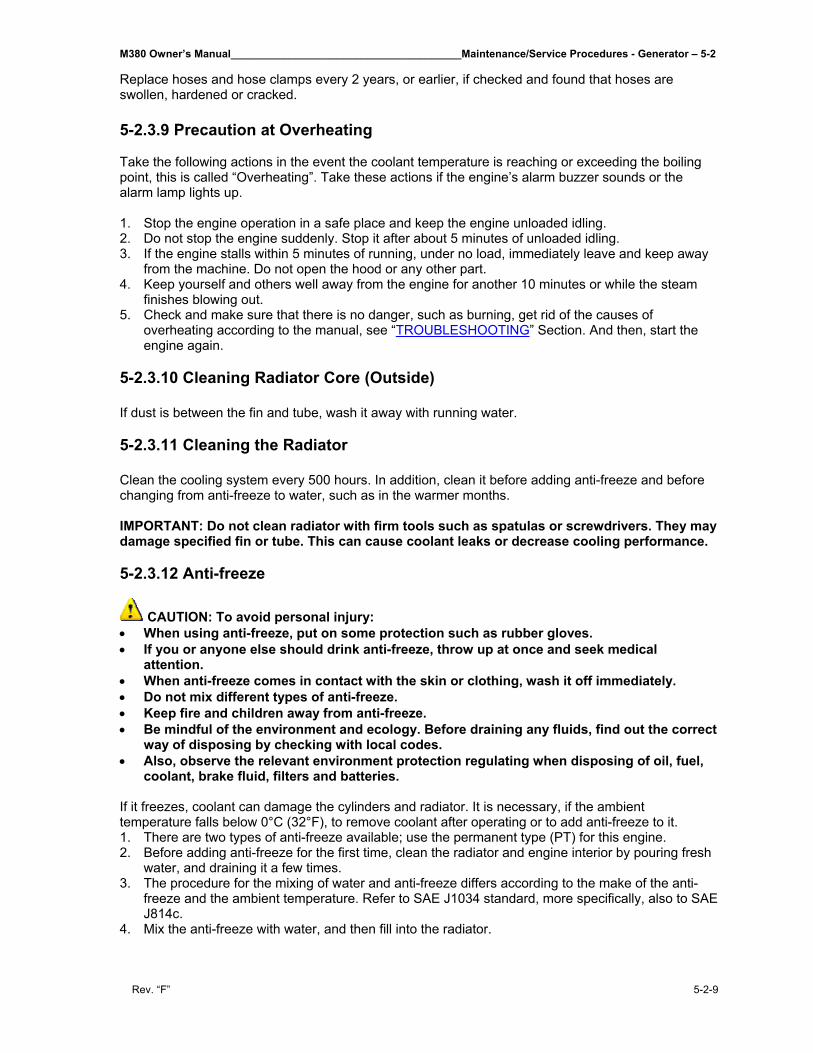
M380 Owner’s Manual_______________________________________Maintenance/Service Procedures - Generator – 5-2
Rev. “F” 5-2-9
Replace hoses and hose clamps every 2 years, or earlier, if checked and found that hoses are swollen, hardened or cracked. 5-2.3.9 Precaution at Overheating Take the following actions in the event the coolant temperature is reaching or exceeding the boiling point, this is called “Overheating”. Take these actions if the engine’s alarm buzzer sounds or the alarm lamp lights up. 1. Stop the engine operation in a safe place and keep the engine unloaded idling. 2. Do not stop the engine suddenly. Stop it after about 5 minutes of unloaded idling. 3. If the engine stalls within 5 minutes of running, under no load, immediately leave and keep away
from the machine. Do not open the hood or any other part. 4. Keep yourself and others well away from the engine for another 10 minutes or while the steam
finishes blowing out. 5. Check and make sure that there is no danger, such as burning, get rid of the causes of
overheating according to the manual, see “TROUBLESHOOTING” Section. And then, start the engine again.
5-2.3.10 Cleaning Radiator Core (Outside) If dust is between the fin and tube, wash it away with running water. 5-2.3.11 Cleaning the Radiator Clean the cooling system every 500 hours. In addition, clean it before adding anti-freeze and before changing from anti-freeze to water, such as in the warmer months. IMPORTANT: Do not clean radiator with firm tools such as spatulas or screwdrivers. They may damage specified fin or tube. This can cause coolant leaks or decrease cooling performance. 5-2.3.12 Anti-freeze
CAUTION: To avoid personal injury: • When using anti-freeze, put on some protection such as rubber gloves. • If you or anyone else should drink anti-freeze, throw up at once and seek medical
attention. • When anti-freeze comes in contact with the skin or clothing, wash it off immediately. • Do not mix different types of anti-freeze. • Keep fire and children away from anti-freeze. • Be mindful of the environment and ecology. Before draining any fluids, find out the correct
way of disposing by checking with local codes. • Also, observe the relevant environment protection regulating when disposing of oil, fuel,
coolant, brake fluid, filters and batteries. If it freezes, coolant can damage the cylinders and radiator. It is necessary, if the ambient temperature falls below 0°C (32°F), to remove coolant after operating or to add anti-freeze to it. 1. There are two types of anti-freeze available; use the permanent type (PT) for this engine. 2. Before adding anti-freeze for the first time, clean the radiator and engine interior by pouring fresh
water, and draining it a few times. 3. The procedure for the mixing of water and anti-freeze differs according to the make of the anti-
freeze and the ambient temperature. Refer to SAE J1034 standard, more specifically, also to SAE J814c.
4. Mix the anti-freeze with water, and then fill into the radiator.
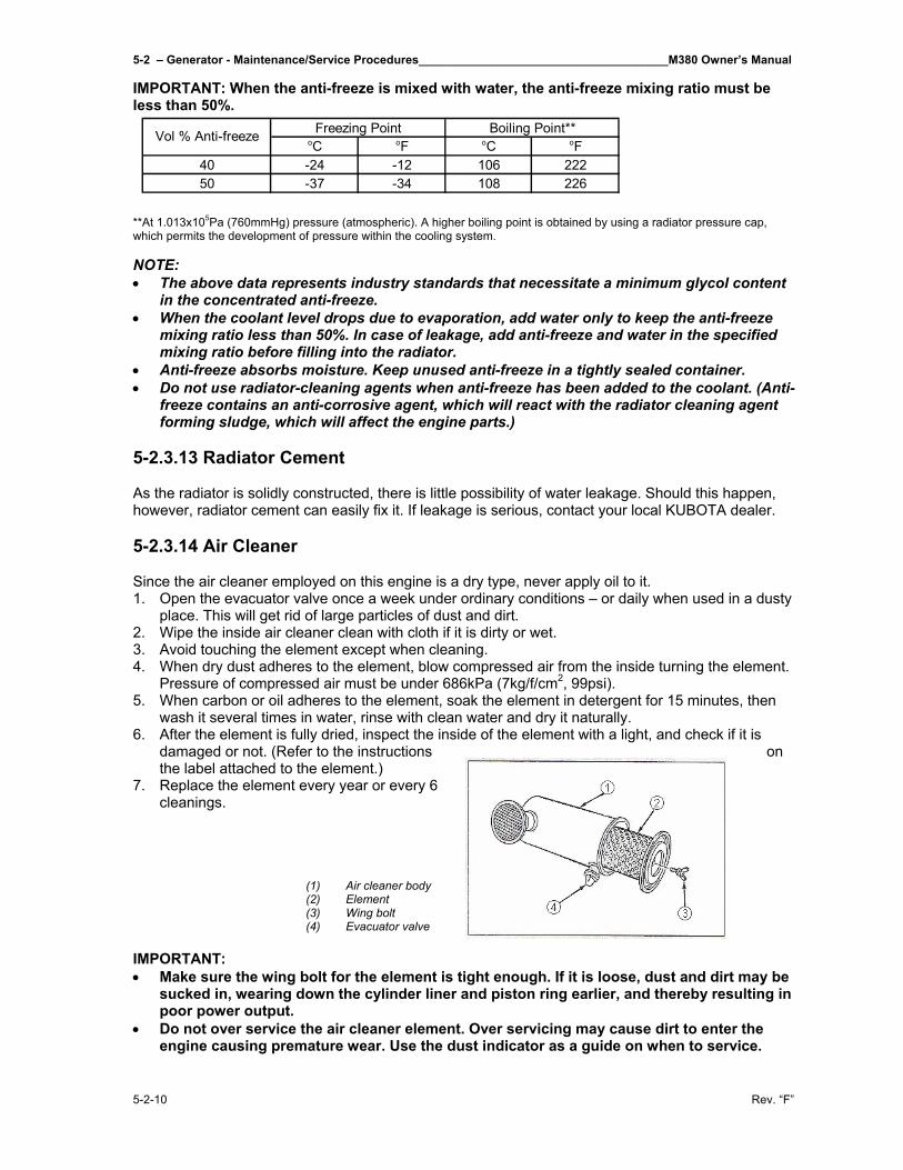
5-2 – Generator - Maintenance/Service Procedures______________________________________M380 Owner’s Manual
5-2-10 Rev. “F”
IMPORTANT: When the anti-freeze is mixed with water, the anti-freeze mixing ratio must be less than 50%.
**At 1.013x10⁵Pa (760mmHg) pressure (atmospheric). A higher boiling point is obtained by using a radiator pressure cap, which permits the development of pressure within the cooling system. NOTE: • The above data represents industry standards that necessitate a minimum glycol content
in the concentrated anti-freeze. • When the coolant level drops due to evaporation, add water only to keep the anti-freeze
mixing ratio less than 50%. In case of leakage, add anti-freeze and water in the specified mixing ratio before filling into the radiator.
• Anti-freeze absorbs moisture. Keep unused anti-freeze in a tightly sealed container. • Do not use radiator-cleaning agents when anti-freeze has been added to the coolant. (Anti-
freeze contains an anti-corrosive agent, which will react with the radiator cleaning agent forming sludge, which will affect the engine parts.)
5-2.3.13 Radiator Cement As the radiator is solidly constructed, there is little possibility of water leakage. Should this happen, however, radiator cement can easily fix it. If leakage is serious, contact your local KUBOTA dealer. 5-2.3.14 Air Cleaner Since the air cleaner employed on this engine is a dry type, never apply oil to it. 1. Open the evacuator valve once a week under ordinary conditions – or daily when used in a dusty
place. This will get rid of large particles of dust and dirt. 2. Wipe the inside air cleaner clean with cloth if it is dirty or wet. 3. Avoid touching the element except when cleaning. 4. When dry dust adheres to the element, blow compressed air from the inside turning the element.
Pressure of compressed air must be under 686kPa (7kg/f/cm2, 99psi). 5. When carbon or oil adheres to the element, soak the element in detergent for 15 minutes, then
wash it several times in water, rinse with clean water and dry it naturally. 6. After the element is fully dried, inspect the inside of the element with a light, and check if it is
damaged or not. (Refer to the instructions on the label attached to the element.)
7. Replace the element every year or every 6 cleanings.
(1) Air cleaner body (2) Element (3) Wing bolt (4) Evacuator valve
IMPORTANT: • Make sure the wing bolt for the element is tight enough. If it is loose, dust and dirt may be
sucked in, wearing down the cylinder liner and piston ring earlier, and thereby resulting in poor power output.
• Do not over service the air cleaner element. Over servicing may cause dirt to enter the engine causing premature wear. Use the dust indicator as a guide on when to service.
oC oF oC oF40 -24 -12 106 22250 -37 -34 108 226
Freezing Point Boiling Point**Vol % Anti-freeze
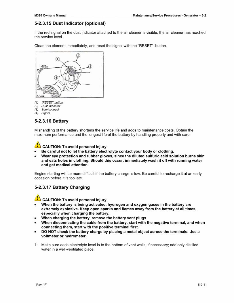
M380 Owner’s Manual_______________________________________Maintenance/Service Procedures - Generator – 5-2
Rev. “F” 5-2-11
5-2.3.15 Dust Indicator (optional) If the red signal on the dust indicator attached to the air cleaner is visible, the air cleaner has reached the service level. Clean the element immediately, and reset the signal with the “RESET” button.
(1) “RESET” button (2) Dust indicator (3) Service level (4) Signal 5-2.3.16 Battery Mishandling of the battery shortens the service life and adds to maintenance costs. Obtain the maximum performance and the longest life of the battery by handling properly and with care.
CAUTION: To avoid personal injury: • Be careful not to let the battery electrolyte contact your body or clothing. • Wear eye protection and rubber gloves, since the diluted sulfuric acid solution burns skin
and eats holes in clothing. Should this occur, immediately wash it off with running water and get medical attention.
Engine starting will be more difficult if the battery charge is low. Be careful to recharge it at an early occasion before it is too late. 5-2.3.17 Battery Charging
CAUTION: To avoid personal injury: • When the battery is being activated, hydrogen and oxygen gases in the battery are
extremely explosive. Keep open sparks and flames away from the battery at all times, especially when charging the battery.
• When charging the battery, remove the battery vent plugs. • When disconnecting the cable from the battery, start with the negative terminal, and when
connecting them, start with the positive terminal first. • DO NOT check the battery charge by placing a metal object across the terminals. Use a
voltmeter or hydrometer. 1. Make sure each electrolyte level is to the bottom of vent wells, if necessary; add only distilled
water in a well-ventilated place.
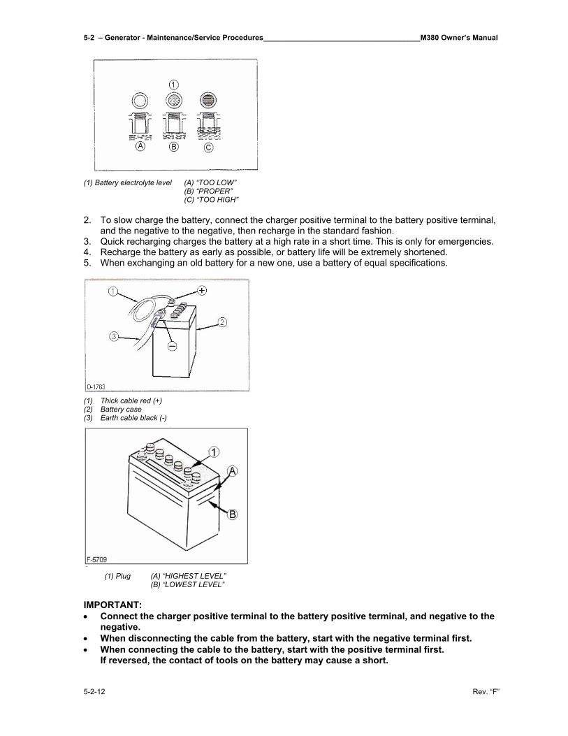
5-2 – Generator - Maintenance/Service Procedures______________________________________M380 Owner’s Manual
5-2-12 Rev. “F”
(1) Battery electrolyte level (A) “TOO LOW” (B) “PROPER” (C) “TOO HIGH” 2. To slow charge the battery, connect the charger positive terminal to the battery positive terminal,
and the negative to the negative, then recharge in the standard fashion. 3. Quick recharging charges the battery at a high rate in a short time. This is only for emergencies. 4. Recharge the battery as early as possible, or battery life will be extremely shortened. 5. When exchanging an old battery for a new one, use a battery of equal specifications.
(1) Thick cable red (+) (2) Battery case (3) Earth cable black (-)
(1) Plug (A) “HIGHEST LEVEL” (B) “LOWEST LEVEL”
IMPORTANT: • Connect the charger positive terminal to the battery positive terminal, and negative to the
negative. • When disconnecting the cable from the battery, start with the negative terminal first. • When connecting the cable to the battery, start with the positive terminal first.
If reversed, the contact of tools on the battery may cause a short.
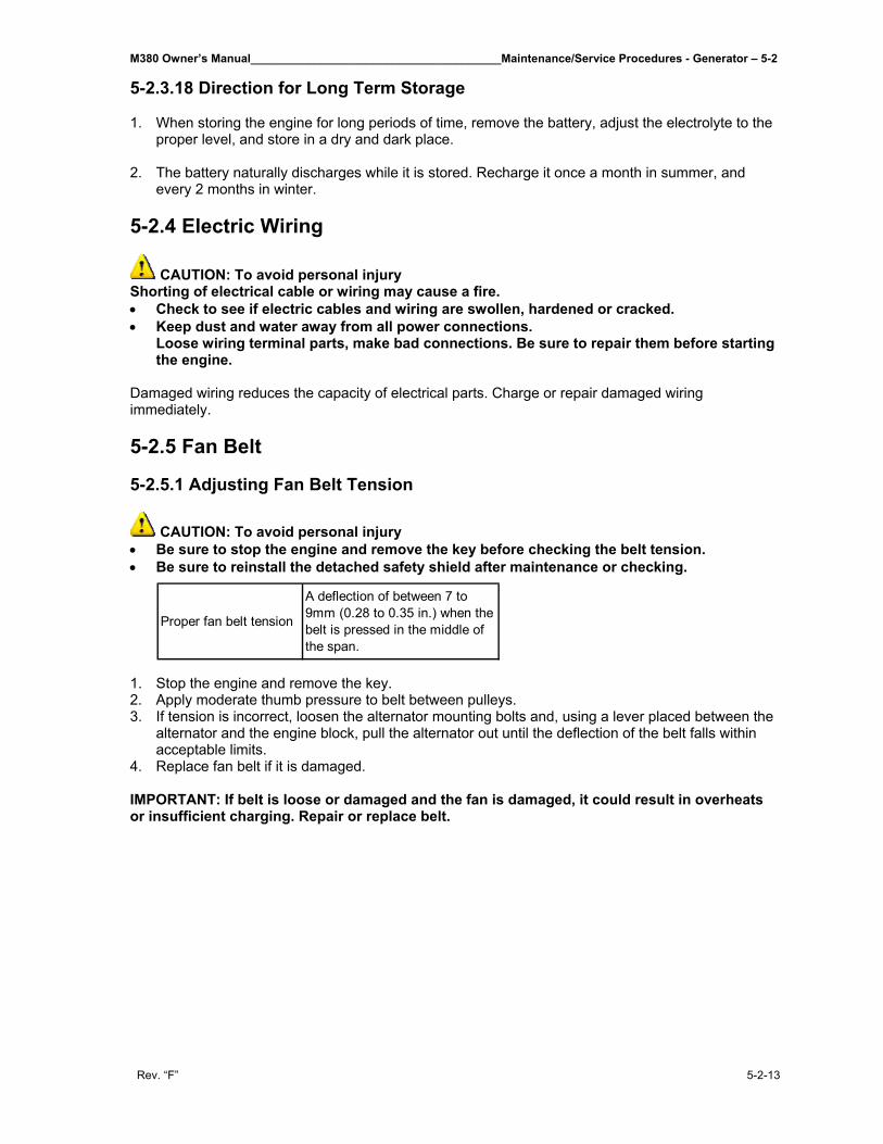
M380 Owner’s Manual_______________________________________Maintenance/Service Procedures - Generator – 5-2
Rev. “F” 5-2-13
5-2.3.18 Direction for Long Term Storage
1. When storing the engine for long periods of time, remove the battery, adjust the electrolyte to the proper level, and store in a dry and dark place.
2. The battery naturally discharges while it is stored. Recharge it once a month in summer, and
every 2 months in winter.
5-2.4 Electric Wiring
CAUTION: To avoid personal injury Shorting of electrical cable or wiring may cause a fire. • Check to see if electric cables and wiring are swollen, hardened or cracked. • Keep dust and water away from all power connections.
Loose wiring terminal parts, make bad connections. Be sure to repair them before starting the engine.
Damaged wiring reduces the capacity of electrical parts. Charge or repair damaged wiring immediately.
5-2.5 Fan Belt
5-2.5.1 Adjusting Fan Belt Tension
CAUTION: To avoid personal injury • Be sure to stop the engine and remove the key before checking the belt tension. • Be sure to reinstall the detached safety shield after maintenance or checking.
1. Stop the engine and remove the key. 2. Apply moderate thumb pressure to belt between pulleys. 3. If tension is incorrect, loosen the alternator mounting bolts and, using a lever placed between the
alternator and the engine block, pull the alternator out until the deflection of the belt falls within acceptable limits.
4. Replace fan belt if it is damaged.
IMPORTANT: If belt is loose or damaged and the fan is damaged, it could result in overheats or insufficient charging. Repair or replace belt.
Proper fan belt tension
A deflection of between 7 to 9mm (0.28 to 0.35 in.) when the belt is pressed in the middle of the span.
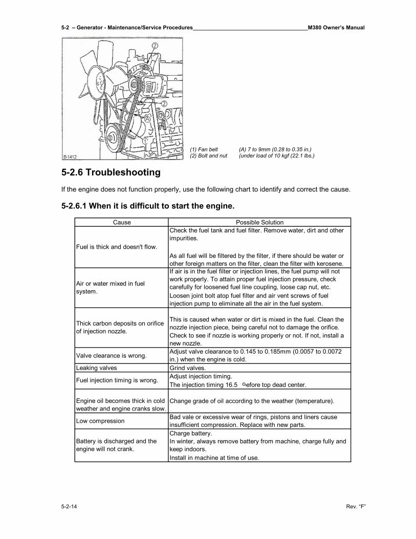
5-2 – Generator - Maintenance/Service Procedures______________________________________M380 Owner’s Manual
5-2-14 Rev. “F”
(1) Fan belt (A) 7 to 9mm (0.28 to 0.35 in.) (2) Bolt and nut (under load of 10 kgf (22.1 lbs.)
5-2.6 Troubleshooting If the engine does not function properly, use the following chart to identify and correct the cause. 5-2.6.1 When it is difficult to start the engine.
Cause Possible SolutionCheck the fuel tank and fuel filter. Remove water, dirt and other impurities.
As all fuel will be filtered by the filter, if there should be water or other foreign matters on the filter, clean the filter with kerosene.If air is in the fuel filter or injection lines, the fuel pump will not work properly. To attain proper fuel injection pressure, check carefully for loosened fuel line coupling, loose cap nut, etc. Loosen joint bolt atop fuel filter and air vent screws of fuel injection pump to eliminate all the air in the fuel system.
This is caused when water or dirt is mixed in the fuel. Clean the nozzle injection piece, being careful not to damage the orifice.Check to see if nozzle is working properly or not. If not, install a new nozzle.
Valve clearance is wrong. Adjust valve clearance to 0.145 to 0.185mm (0.0057 to 0.0072 in.) when the engine is cold.
Leaking valves Grind valves.Adjust injection timing.The injection timing 16.5 before top dead center.
Engine oil becomes thick in cold weather and engine cranks slow.
Change grade of oil according to the weather (temperature).
Low compression Bad vale or excessive wear of rings, pistons and liners cause insufficient compression. Replace with new parts.Charge battery.In winter, always remove battery from machine, charge fully and keep indoors.Install in machine at time of use.
Fuel injection timing is wrong.
Battery is discharged and the engine will not crank.
Fuel is thick and doesn't flow.
Air or water mixed in fuel system.
Thick carbon deposits on orifice of injection nozzle.
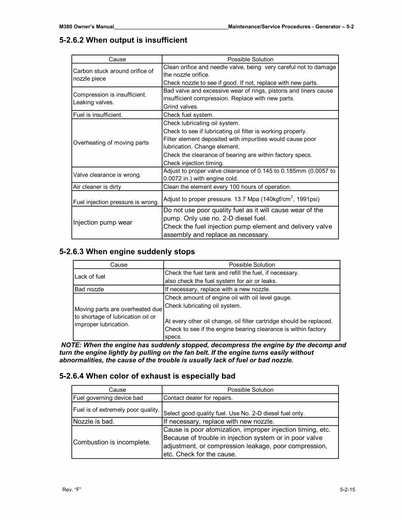
M380 Owner’s Manual_______________________________________Maintenance/Service Procedures - Generator – 5-2
Rev. “F” 5-2-15
5-2.6.2 When output is insufficient
5-2.6.3 When engine suddenly stops
NOTE: When the engine has suddenly stopped, decompress the engine by the decomp and turn the engine lightly by pulling on the fan belt. If the engine turns easily without abnormalities, the cause of the trouble is usually lack of fuel or bad nozzle. 5-2.6.4 When color of exhaust is especially bad
Cause Possible SolutionClean orifice and needle valve, being very careful not to damage the nozzle orifice.Check nozzle to see if good. If not, replace with new parts.Bad valve and excessive wear of rings, pistons and liners cause insufficient compression. Replace with new parts.Grind valves.
Fuel is insufficient. Check fuel system.Check lubricating oil system.Check to see if lubricating oil filter is working properly.Filter element deposited with impurities would cause poor lubrication. Change element.Check the clearance of bearing are within factory specs.Check injection timing.
Valve clearance is wrong. Adjust to proper valve clearance of 0.145 to 0.185mm (0.0057 to 0.0072 in.) with engine cold.
Air cleaner is dirty Clean the element every 100 hours of operation.
Fuel injection pressure is wrong. Adjust to proper pressure. 13.7 Mpa (140kgf/cm2, 1991psi)
Do not use poor quality fuel as it will cause wear of the pump. Only use no. 2-D diesel fuel.Check the fuel injection pump element and delivery valve assembly and replace as necessary.
Carbon stuck around orifice of nozzle piece
Compression is insufficient. Leaking valves.
Overheating of moving parts
Injection pump wear
Cause Possible SolutionCheck the fuel tank and refill the fuel, if necessary.also check the fuel system for air or leaks.
Bad nozzle If necessary, replace with a new nozzle.Check amount of engine oil with oil level gauge.Check lubricating oil system.
At every other oil change, oil filter cartridge should be replaced.Check to see if the engine bearing clearance is within factory specs.
Moving parts are overheated due to shortage of lubrication oil or improper lubrication.
Lack of fuel
Cause Possible SolutionFuel governing device bad Contact dealer for repairs.
Fuel is of extremely poor quality. Select good quality fuel. Use No. 2-D diesel fuel only.Nozzle is bad. If necessary, replace with new nozzle.
Combustion is incomplete.
Cause is poor atomization, improper injection timing, etc. Because of trouble in injection system or in poor valve adjustment, or compression leakage, poor compression, etc. Check for the cause.
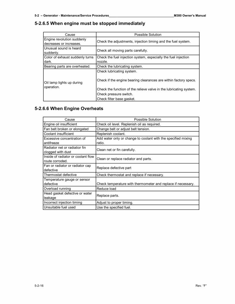
5-2 – Generator - Maintenance/Service Procedures______________________________________M380 Owner’s Manual
5-2-16 Rev. “F”
5-2.6.5 When engine must be stopped immediately
5-2.6.6 When Engine Overheats
Cause Possible SolutionEngine revolution suddenly decreases or increases. Check the adjustments, injection timing and the fuel system.
Unusual sound is heard suddenly. Check all moving parts carefully.
Color of exhaust suddenly turns dark.
Check the fuel injection system, especially the fuel injection nozzle.
Bearing parts are overheated. Check the lubricating system.Check lubricating system.
Check if the engine bearing clearances are within factory specs.
Check the function of the relieve valve in the lubricating system.Check pressure switch.Check filter base gasket.
Oil lamp lights up during operation.
Cause Possible SolutionEngine oil insufficient Check oil level. Replenish oil as required.Fan belt broken or elongated Change belt or adjust belt tension.Coolant insufficient Replenish coolant.Excessive concentration of antifreeze
Add water only or change to coolant with the specified mixing ratio.
Radiator net or radiatior fin clogged with dust Clean net or fin carefully.
Inside of radiator or coolant flow route corroded. Clean or replace radiator and parts.
Fan or radiator or radiator cap defective Replace defective part
Thermostat defective Check thermostat and replace if necessary.Temperature gauge or sensor defective Check temperature with thermometer and replace if necessary.Overload running Reduce loadHead gasket defective or water leakage Replace parts.
Incorrect injection timing Adjust to proper timing.Unsuitable fuel used Use the specified fuel.
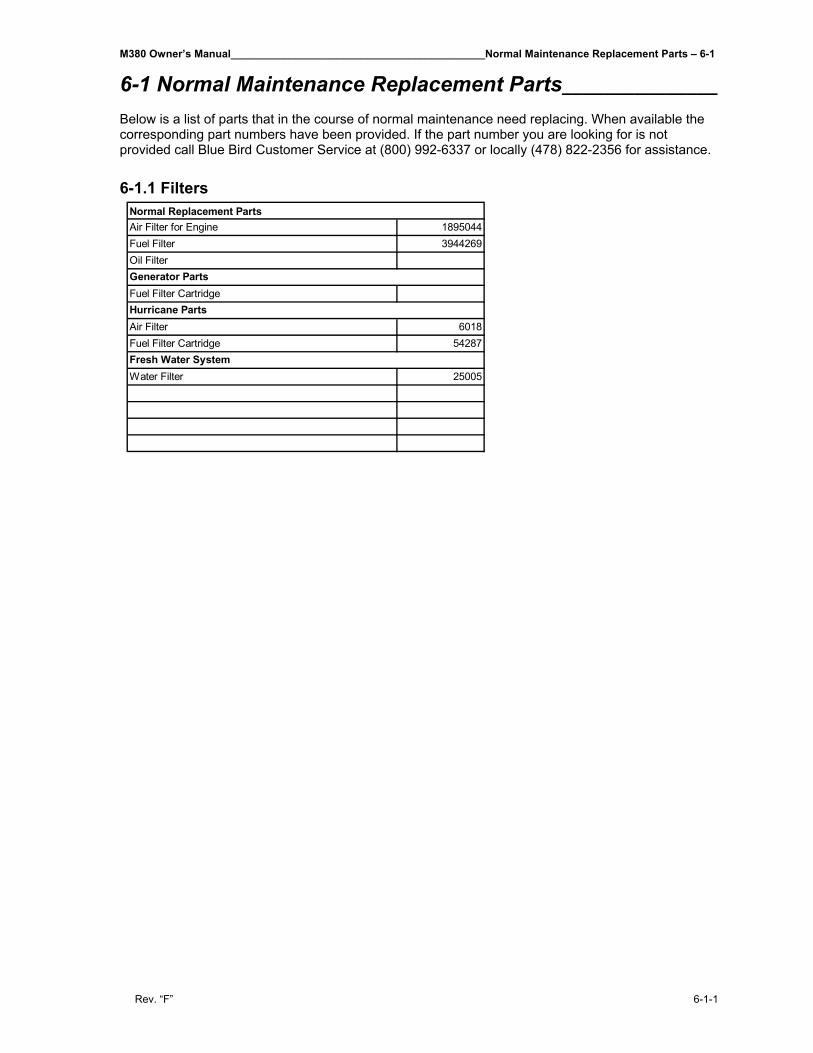
M380 Owner’s Manual___________________________________________Normal Maintenance Replacement Parts – 6-1
Rev. “F” 6-1-1
6-1 Normal Maintenance Replacement Parts_______________ Below is a list of parts that in the course of normal maintenance need replacing. When available the corresponding part numbers have been provided. If the part number you are looking for is not provided call Blue Bird Customer Service at (800) 992-6337 or locally (478) 822-2356 for assistance. 6-1.1 Filters
Air Filter for Engine 1895044Fuel Filter 3944269Oil Filter
Fuel Filter Cartridge
Air Filter 6018Fuel Filter Cartridge 54287
Water Filter 25005
Normal Replacement Parts
Generator Parts
Hurricane Parts
Fresh Water System
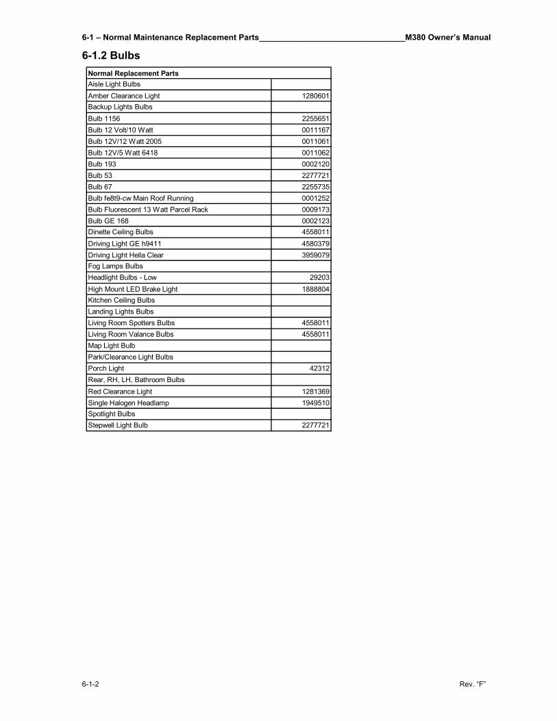
6-1 – Normal Maintenance Replacement Parts________________________________M380 Owner’s Manual
6-1-2 Rev. “F”
6-1.2 Bulbs
Aisle Light BulbsAmber Clearance Light 1280601Backup Lights BulbsBulb 1156 2255651Bulb 12 Volt/10 Watt 0011167Bulb 12V/12 Watt 2005 0011061Bulb 12V/5 Watt 6418 0011062Bulb 193 0002120Bulb 53 2277721Bulb 67 2255735Bulb fe8t9-cw Main Roof Running 0001252Bulb Fluorescent 13 Watt Parcel Rack 0009173Bulb GE 168 0002123Dinette Ceiling Bulbs 4558011Driving Light GE h9411 4580379Driving Light Hella Clear 3959079Fog Lamps BulbsHeadlight Bulbs - Low 29203High Mount LED Brake Light 1888804Kitchen Ceiling BulbsLanding Lights BulbsLiving Room Spotters Bulbs 4558011Living Room Valance Bulbs 4558011Map Light BulbPark/Clearance Light BulbsPorch Light 42312Rear, RH, LH, Bathroom BulbsRed Clearance Light 1281369Single Halogen Headlamp 1949510Spotlight BulbsStepwell Light Bulb 2277721
Normal Replacement Parts

M380 Owner’s Manual___________________________________________Normal Maintenance Replacement Parts – 6-1
Rev. “F” 6-1-3
6-1.3 Fuses
Backup Lights FuseLanding Lights FuseHeadlight FuseFog Lamp FusePark/Clearance Light FuseSpotlight FuseMap Light FuseAuto 50 Amp 0015990100 Amp - Mega 0041531125 Amp - Mega 0006151200 Amp - Mega 1864362300 Amp - Mega 1864362
Fuses
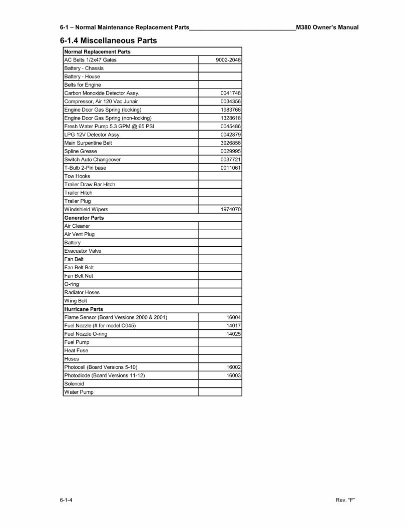
6-1 – Normal Maintenance Replacement Parts________________________________M380 Owner’s Manual
6-1-4 Rev. “F”
6-1.4 Miscellaneous Parts
AC Belts 1/2x47 Gates 9002-2046Battery - ChassisBattery - HouseBelts for EngineCarbon Monoxide Detector Assy. 0041748Compressor, Air 120 Vac Junair 0034356Engine Door Gas Spring (locking) 1983766Engine Door Gas Spring (non-locking) 1328616Fresh Water Pump 5.3 GPM @ 65 PSI 0045486LPG 12V Detector Assy. 0042879Main Surpentine Belt 3926856Spline Grease 0029995Switch Auto Changeover 0037721T-Bulb 2-Pin base 0011061Tow HooksTrailer Draw Bar HitchTrailer HitchTrailer PlugWindshield Wipers 1974070
Air CleanerAir Vent PlugBatteryEvacuator ValveFan BeltFan Belt BoltFan Belt NutO-ringRadiator HosesWing Bolt
Flame Sensor (Board Versions 2000 & 2001) 16004Fuel Nozzle (# for model C045) 14017Fuel Nozzle O-ring 14025Fuel PumpHeat FuseHosesPhotocell (Board Versions 5-10) 16002Photodiode (Board Versions 11-12) 16003SolenoidWater Pump
Hurricane Parts
Generator Parts
Normal Replacement Parts
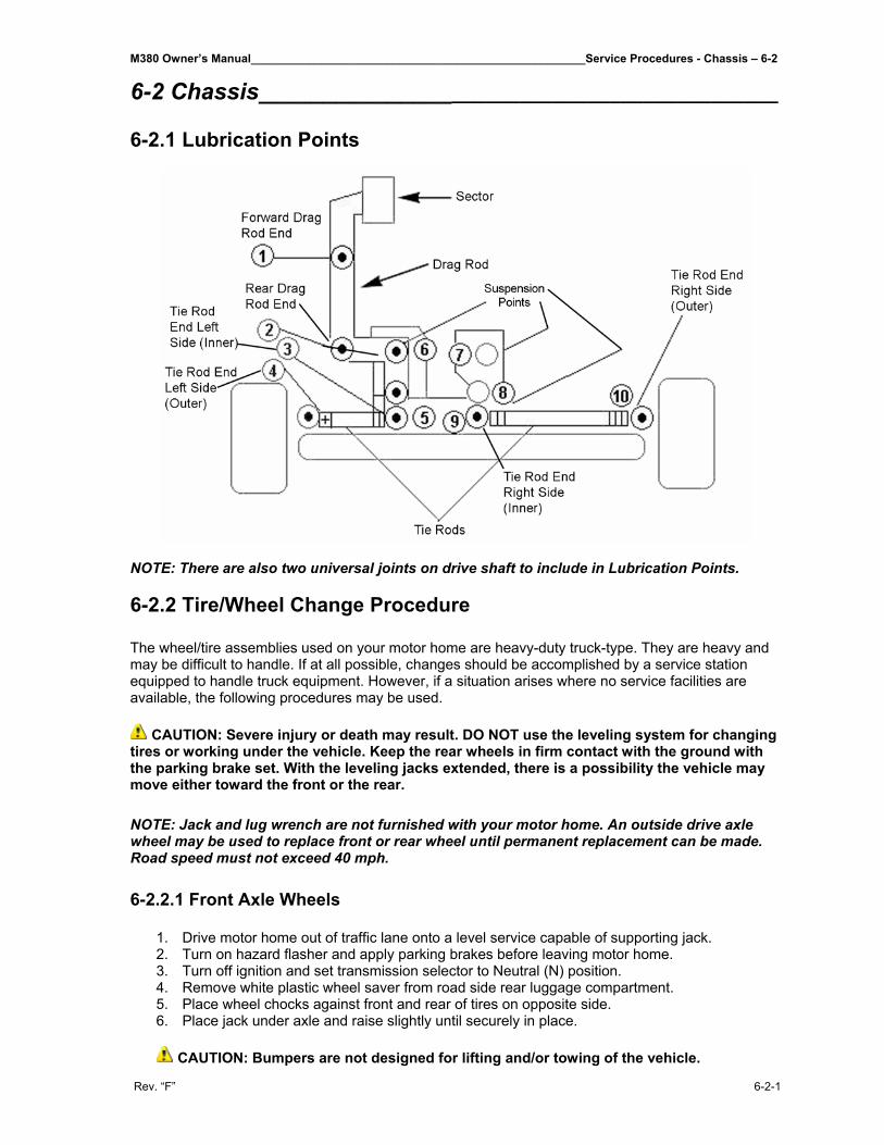
M380 Owner’s Manual____________________________________________________Service Procedures - Chassis – 6-2
Rev. “F” 6-2-1
6-2 Chassis____________________________________________ 6-2.1 Lubrication Points
NOTE: There are also two universal joints on drive shaft to include in Lubrication Points. 6-2.2 Tire/Wheel Change Procedure The wheel/tire assemblies used on your motor home are heavy-duty truck-type. They are heavy and may be difficult to handle. If at all possible, changes should be accomplished by a service station equipped to handle truck equipment. However, if a situation arises where no service facilities are available, the following procedures may be used.
CAUTION: Severe injury or death may result. DO NOT use the leveling system for changing tires or working under the vehicle. Keep the rear wheels in firm contact with the ground with the parking brake set. With the leveling jacks extended, there is a possibility the vehicle may move either toward the front or the rear. NOTE: Jack and lug wrench are not furnished with your motor home. An outside drive axle wheel may be used to replace front or rear wheel until permanent replacement can be made. Road speed must not exceed 40 mph. 6-2.2.1 Front Axle Wheels
1. Drive motor home out of traffic lane onto a level service capable of supporting jack. 2. Turn on hazard flasher and apply parking brakes before leaving motor home. 3. Turn off ignition and set transmission selector to Neutral (N) position. 4. Remove white plastic wheel saver from road side rear luggage compartment. 5. Place wheel chocks against front and rear of tires on opposite side. 6. Place jack under axle and raise slightly until securely in place.
CAUTION: Bumpers are not designed for lifting and/or towing of the vehicle.
6-2 – Service Procedures - Chassis____________________________________________________M380 Owner’s Manual
6-2-2 Rev. “F”
7. Pull off lug nut covers. 8. Install wheel saver. NOTE: It is recommended that the wheel saver be used when loosening or torquing lug nuts. 9. Loosen lug nuts slightly, then jack up motor home until tire is clear of ground. Solidly support
the vehicle under the main frame rails with jack stands or blocks before working under or around the motor home.
NOTE: Lug nuts on right side of motor home are right hand threaded (turn counter-clockwise to loosen, clockwise to tighten); lug nuts on driver’s side of motor home are left hand threaded (turn clockwise to loosen, counter-clockwise to tighten). 10. Remove lug nuts and wheel assembly. 11. Install spare and replace lug nuts. Tighten progressively in the sequence shown on lug nut
tightening sequence diagram, starting with #1 and proceeding to #10. Final torque will be 450 to 500 foot-pounds. Wheel must be on the ground for final torque.
12. Snap front hub cover into front wheel opening after front lug nuts have been properly torqued. 13. Place lug nut covers on all lug nuts. Make certain that these nut covers fit snugly. This is
accomplished by squeezing the dimpled sides together before installing. 14. Lower motor home to ground and remove jack and handle. 15. Replace wheel saver, lug wrench, jack and handles in storage compartment and tie down to
prevent road noise. Return damaged wheel/tire assembly to holder and have it repaired as soon as possible.
16. Remove and stow wheel chocks. 17. Turn off hazard flasher before returning to traffic.
6-2.2.2 Drive Axle Dual Wheels 1. Repeat steps 1 through 10, Front Axle Wheels. 2. Loosen inner lug nuts (studs with square heads), if inner wheel is to be replaced. 3. Remove outer lug nuts from the (5) studs which have lock rings and slide hub cover over
remaining lug nuts. 4. Remove the (5) remaining lug nuts and wheel. 5. Remove inner lug nuts and inner wheel, if inner wheel is to be replaced. 6. Install replacement wheel and inner lug nuts. Tighten progressively, in the sequence shown
on lug nut tightening diagram, starting with #1 and proceeding with #10. Final torque should be between 450 and 500 foot-pounds.
7. Install outer wheel (or replacement wheel) and lug nuts over inner lug nuts marked 1, 3, 7, 9 and 6. Torque nuts in the following sequence, 1, 7, 6, 3 and 9 to between 450 and 500 foot pounds.
8. Install hub cover over the (5) lug nuts holding wheel to hub. Place lock rings and lug nuts on remaining inner lug nuts 10, 5, 2, 4 and 8.
9. Replace wheel saver. 10. Torque nuts in the following sequence 10, 2, 8, 5 and 4 to between 450 and 500 foot-pounds.
Wheel must be on the ground for final torque. 11. Return to step 13 of Front Axle Wheels and continue. NOTE: When checking torque on dual wheels loosen all outside lug nuts. Check torque on inner lug nuts (studs with square heads) for torque value shown above, then torque outer lug nuts to value shown above.
M380 Owner’s Manual____________________________________________________Service Procedures - Chassis – 6-2
Rev. “F” 6-2-3
6-2.3 Tire Inflation – Towing – Trailer
6-2.3.1 Tire Inflation
Under-inflation causes needless tire wear and promotes excessive fuel consumption. Check tire pressures on a regular basis.
The Federal Certification Label shows the cold tire inflation pressures necessary to support the Gross Axle Weight Ratings. These pressures can be reduced to greatly improve the ride quality after the actual axle weights have been determined (see Vehicle Loading in the Introduction section). The chart below is taken from the Michelin Tire Data Book and shows the recommended tire inflation pressures for various axle weights. If any axle weight is on the borderline, always use the higher pressure. Be sure weight is distributed evenly side to side.
psi 70 75 80 85 90 95 100 105 110 115S 9,410 9,980 10,560 11,140 11,740 12,310 12,910 13,480 14,060 14,780D 16,840 17,860 18,960 20,030 21,130 22,190 23,220 24,220 25,220 26,440
lbs.
LOADS PER AXLE (lbs.) AT DIFFERENT PRESSURES2 TIRES: SINGLE (S) 4 TIRES: DUAL (D)
INFLATIONS PRESSURE (psi)
MICHELIN SIZE - 12r-22.5 MAX. SPEED - 65 MPH
In addition, a tire inflation information plate is located inside the road side luggage compartment near the air gauge and hose. These are normal pressures as long as the axle weights are not in excess of those shown. 6-2.3.2 Towing Two towing eyes are provided behind the upper part of the generator door. Remove generator panel for access.
CAUTION: Do not tow a vehicle equipped with Allison automatic transmission unless the drive shaft has been removed, or the rear wheels raised from the ground. Do not attempt to tow unit by front axle or crossmember. Damage to wiring and/or air lines can result because of proximity of these items to front crossmember. Do not tow with generator tray extended. Do not tow by the bumpers. Air pressure is required to release brakes. 6-2-3.3 Trailer Hitch Capacity The Receiver Type Hitch and Drawbar are rated for a 10,000 lb. maximum towing capacity and a 1,000 lb. maximum tongue weight capacity. Standard equipment includes a 2” hitch ball with a 1” shank rated for a 5,000 lb. maximum towing capacity and 500 lb. maximum tongue weight. Hitch ball nut must be torqued to 200 ft. lb. NOTE: For more towing capacity, we offer an optional 2 5/16” hitch ball with a 1 1/4” shank rated for a 10,000 lb. maximum towing capacity and a 1,000 lb. maximum tongue weight. Hitch ball nut must be torqued to 200 ft. lb.

M380 Owner’s Manual__________________________________________________________________________________
Rev. “F”
THIS PAGE IS INTENTIONALLY LEFT BLANK
M380 Owner’s Manual________________________________________________________Interior and Exterior Care – 7-1
Rev. “F” 7-1-1
7-1 Interior/Exterior Care_______________________________ 7-1.1 Cabinets The M380 Motor Home comes with several cabinets. These are finished with a high quality nitro-cellulose lacquer. Select a non-alcohol based cleaner for cleaning cabinets. Cleaners recommended for cleaning cabinets are Pledge, Endust, etc. IMPORTANT: Do not use any alcohol based cleaners. They will dull and strip the finish of the wood. 7-1.2 Countertops 7-1.2.1 Kitchen Countertops The countertops are made of Centura solid surfacing material with decorative bullnose edge. Bottom row of bullnose edge is an accent color. Use cleaning agents recommended for Centura or Corian countertops. 7-1.2.2 Bathroom Vanity The vanity top and bowl are a molded one-piece Thermolite material. A combination chrome/brass single level faucet is standard. This countertop can be cleaned with any non-abrasive cleaner designed for this type of vanity. 7-1.3 Carpet Carpet is standard for all areas of the motor home except the bathroom and kitchen. In addition loose carpet mats are included to be used on the stops. Bathroom and kitchen areas have a laminated wood or tile look floor with acoustical padding. Carpets can be cleaned with any standard carpet cleaners. 7-1.4 Wood Floors Use any cleaner recommended for cleaning of wood laminate floors. 7-1.5 Sofa A 78” Villa sleeper sofa is standard. Sofa is covered in fabric. Includes two throw pillows and two arm covers. Sofa can be cleaned with any standard sofa cleaner such as Woolite, etc. 7-1.6 Tables Living room tables are oak wood with Centura material on the counter top to match those throughout the motor home. Clean wood area with any standard furniture polish and the counter tops may be cleaned with the same material that is used to clean the kitchen countertops.
7-1 – Interior and Exterior Care_______________________________________________________M380 Owner’s Manual
7-1-2 Rev. “F”
7-1.7 Window Shades Shades should be kept in the closed or up position when not in use to maintain pleat retention and minimize dirt and soil build-up. Do not store shades in the down position. This may cause some loss of pleat retention if the shades are not operated on a consistent basis. Shades can be easily cared for by simply dusting or using a vacuum cleaner attachment. Do not use spot remover, household cleaners or detergents to remove soiled spots, as these may cause damage or fading to the fabric. NOTE: If you store your coach for an extended period of time, store shades in the up position and cover your windows with additional protection such as cardboard. 7-1.8 Exterior Paint The exterior of the motor home can be cleaned with the same non-abrasive cleaners used to clean your automobile. 7-1.9 Polished Wheels The polished wheels can be cleaned with any cleaner designed to clean automotive polished aluminum wheels. 7-1.10 Glass Use standard glass cleaner for cleaning windows on the motor home. 7-1.11 Awnings There are two kinds of awnings supplied with your motor home. A automatic awning manufactured by Girard R.V. Products and a manual type manufactured by Zip Dee. Both awnings supplied with your motor home are constructed of 100% acrylic fabric that is weatherproof, permeable to air and resistant to mildew, rotting and fading. Acrylic fabric should be cleaned regularly before substances such as dirt, leaves, etc. are allowed to accumulate on, and become embedded in the fabric. The fabric can be cleaned without being removed from the awning. Simply brush off any loose dirt, leaves, etc. Hose down and clean with cloth and mild solution of natural soap in lukewarm water. Rinse thoroughly to remove soap. DO NOT USE DETERGENTS. Allow to air dry, preferably on a warm sunny day. Should you have to retract the awning when the fabric is wet, it should be extended at the first opportunity to finish air drying.
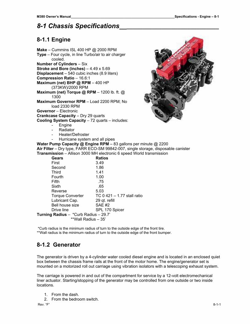
M380 Owner’s Manual_________________________________________________________Specifications - Engine – 8-1
Rev. “F” 8-1-1
8-1 Chassis Specifications_______________________________ 8-1.1 Engine Make – Cummins ISL 400 HP @ 2000 RPM Type – Four cycle, in line Turbo/air to air charger
cooled. Number of Cylinders – Six Stroke and Bore (inches) – 4.49 x 5.69 Displacement – 540 cubic inches (8.9 liters) Compression Ratio – 16.6:1 Maximum (net) BHP @ RPM – 400 HP
(373KW)/2000 RPM Maximum (net) Torque @ RPM – 1200 lb. ft. @
1300 Maximum Governor RPM – Load 2200 RPM; No
load 2330 RPM Governor – Electronic Crankcase Capacity – Dry 29 quarts Cooling System Capacity – 72 quarts – includes:
- Engine - Radiator - Heater/Defroster - Hurricane system and all pipes
Water Pump Capacity @ Engine RPM – 83 gallons per minute @ 2200 Air Filter – Dry type, FARR ECO-SM 99842-007, single storage, disposable canister Transmission – Allison 3000 MH electronic 6 speed World transmission Gears Ratios First 3.49 Second 1.86 Third 1.41 Fourth 1.00 Fifth .75 Sixth .65 Reverse 5.03 Torque Converter TC 0 421 – 1.77 stall ratio Lubricant Cap. 29 qt. refill Bell house size SAE #2 Drive line SPL 170 Spicer Turning Radius – *Curb Radius – 29.7’ **Wall Radius – 35’ *Curb radius is the minimum radius of turn to the outside edge of the front tire. **Wall radius is the minimum radius of turn to the outside edge of the front bumper. 8-1.2 Generator The generator is driven by a 4-cylinder water cooled diesel engine and is located in an enclosed quiet box between the chassis frame rails at the front of the motor home. The engine/generator set is mounted on a motorized roll out carriage using vibration isolators with a telescoping exhaust system. The carriage is powered in and out of the compartment for service by a 12-volt electromechanical liner actuator. Starting/stopping of the generator may be controlled from one outside or two inside locations.
1. From the dash. 2. From the bedroom switch.
8-1 – Specifications – Engine_________________________________________________________M380 Owner’s Manual
8-1-2 Rev. “F”
Remote gauges are included in the pilot overhead area to monitor the generator operation. The generator has an alternator and 12-volt battery for cranking the generator. There is also an auxiliary generator battery switch on the dash that will permit starting the generator in the event that the generator battery becomes discharged. This cranking power is obtained from the house battery system. 8-1.3 Vehicle Dimensions The motor home measures 37’7” long by 102” wide. The wheelbase is 248” centerline front axle to centerline rear axle. 8-1.4 Wheels and Tires 8-1.4.1 Tires Tubeless 12R-22.5 16-ply rating Load range H Michelin steel cord radial single front and dual drive. 8-1.4.2 Wheels 10-stud hub-piloted disc with 22.5x8.25 rims, polished aluminum, single front, dual drive, turned to the outside.
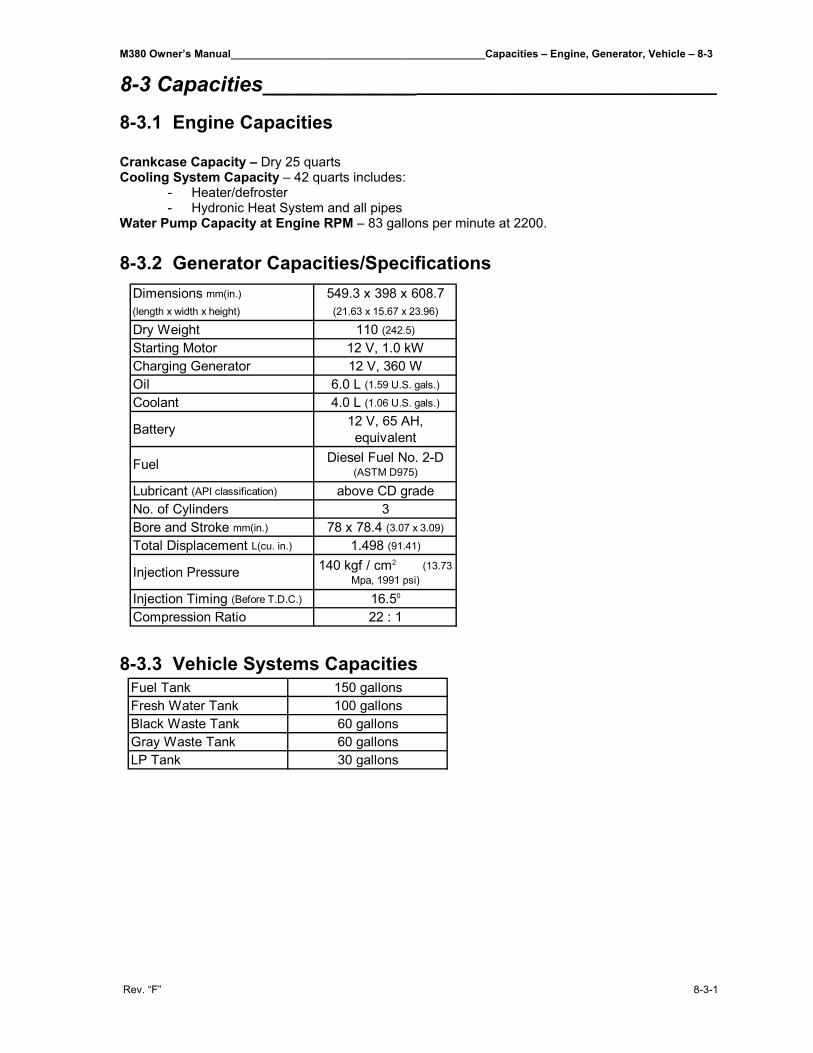
M380 Owner’s Manual___________________________________________Capacities – Engine, Generator, Vehicle – 8-3
Rev. “F” 8-3-1
8-3 Capacities__________________________________________ 8-3.1 Engine Capacities Crankcase Capacity – Dry 25 quarts Cooling System Capacity – 42 quarts includes:
- Heater/defroster - Hydronic Heat System and all pipes
Water Pump Capacity at Engine RPM – 83 gallons per minute at 2200. 8-3.2 Generator Capacities/Specifications
8-3.3 Vehicle Systems Capacities
Dimensions mm(in.) 549.3 x 398 x 608.7(length x width x height) (21.63 x 15.67 x 23.96)
Dry Weight 110 (242.5)
Starting Motor 12 V, 1.0 kWCharging Generator 12 V, 360 WOil 6.0 L (1.59 U.S. gals.)
Coolant 4.0 L (1.06 U.S. gals.)
Battery 12 V, 65 AH, equivalent
Fuel Diesel Fuel No. 2-D (ASTM D975)
Lubricant (API classification) above CD gradeNo. of Cylinders 3Bore and Stroke mm(in.) 78 x 78.4 (3.07 x 3.09)
Total Displacement L(cu. in.) 1.498 (91.41)
Injection Pressure 140 kgf / cm2 (13.73 Mpa, 1991 psi)
Injection Timing (Before T.D.C.) 16.50
Compression Ratio 22 : 1
Fuel Tank 150 gallonsFresh Water Tank 100 gallonsBlack Waste Tank 60 gallonsGray Waste Tank 60 gallonsLP Tank 30 gallons

M380 Owner’s Manual__________________________________________________________________________________
Rev. “F”
THIS PAGE IS INTENTIONALLY LEFT BLANK
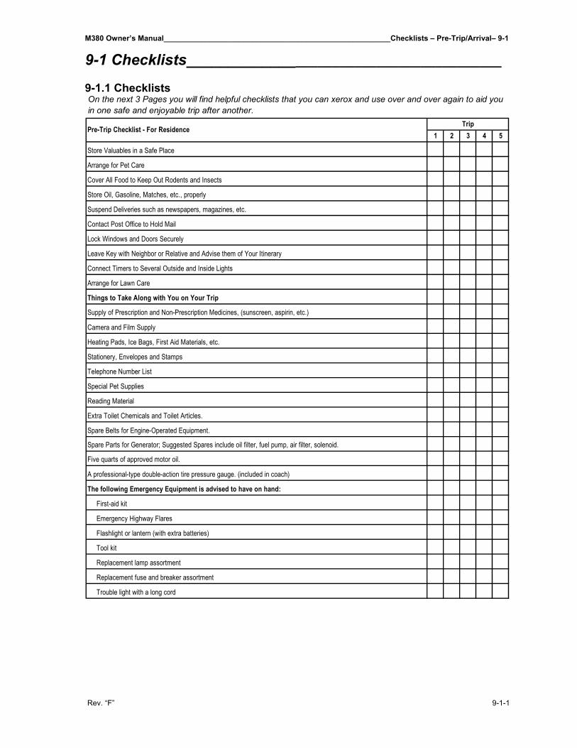
M380 Owner’s Manual______________________________________________________Checklists – Pre-Trip/Arrival– 9-1
Rev. “F” 9-1-1
9-1 Checklists_________________________________________ 9-1.1 Checklists
1 2 3 4 5Trip
Pre-Trip Checklist - For Residence
Replacement fuse and breaker assortment
Trouble light with a long cord
Emergency Highway Flares
Flashlight or lantern (with extra batteries)
Tool kit
Replacement lamp assortment
Spare Parts for Generator; Suggested Spares include oil filter, fuel pump, air filter, solenoid.
A professional-type double-action tire pressure gauge. (included in coach)
The following Emergency Equipment is advised to have on hand:
First-aid kit
Five quarts of approved motor oil.
On the next 3 Pages you will find helpful checklists that you can xerox and use over and over again to aid you in one safe and enjoyable trip after another.
Extra Toilet Chemicals and Toilet Articles.
Spare Belts for Engine-Operated Equipment.
Store Valuables in a Safe Place
Arrange for Pet Care
Cover All Food to Keep Out Rodents and Insects
Store Oil, Gasoline, Matches, etc., properly
Suspend Deliveries such as newspapers, magazines, etc.
Contact Post Office to Hold Mail
Lock Windows and Doors Securely
Leave Key with Neighbor or Relative and Advise them of Your Itinerary
Connect Timers to Several Outside and Inside Lights
Arrange for Lawn Care
Things to Take Along with You on Your Trip
Supply of Prescription and Non-Prescription Medicines, (sunscreen, aspirin, etc.)
Special Pet Supplies
Reading Material
Camera and Film Supply
Heating Pads, Ice Bags, First Aid Materials, etc.
Stationery, Envelopes and Stamps
Telephone Number List
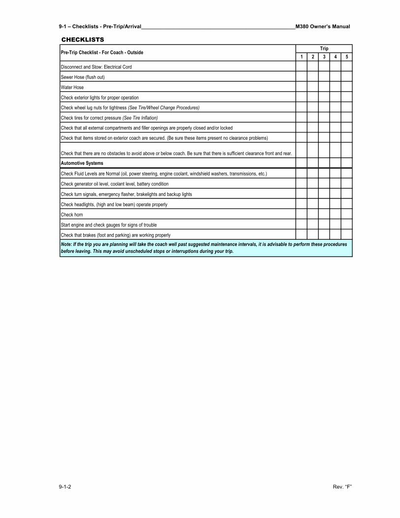
9-1 – Checklists - Pre-Trip/Arrival_____________________________________________________M380 Owner’s Manual
9-1-2 Rev. “F”
1 2 3 4 5
Note: If the trip you are planning will take the coach well past suggested maintenance intervals, it is advisable to perform these procedures before leaving. This may avoid unscheduled stops or interruptions during your trip.
Check turn signals, emergency flasher, brakelights and backup lights
Check headlights, (high and low beam) operate properly
Check horn
Start engine and check gauges for signs of trouble
Automotive Systems
Check Fluid Levels are Normal (oil, power steering, engine coolant, windshield washers, transmissions, etc.)
Check generator oil level, coolant level, battery condition
Check that brakes (foot and parking) are working properly
Check tires for correct pressure (See Tire Inflation)
Check that all external compartments and filler openings are properly closed and/or locked
Check that items stored on exterior coach are secured. (Be sure these items present no clearance problems)
Check that there are no obstacles to avoid above or below coach. Be sure that there is sufficient clearance front and rear.
Sewer Hose (flush out)
Water Hose
Check exterior lights for proper operation
Check wheel lug nuts for tightness (See Tire/Wheel Change Procedures)
TripPre-Trip Checklist - For Coach - Outside
CHECKLISTS
Disconnect and Stow: Electrical Cord
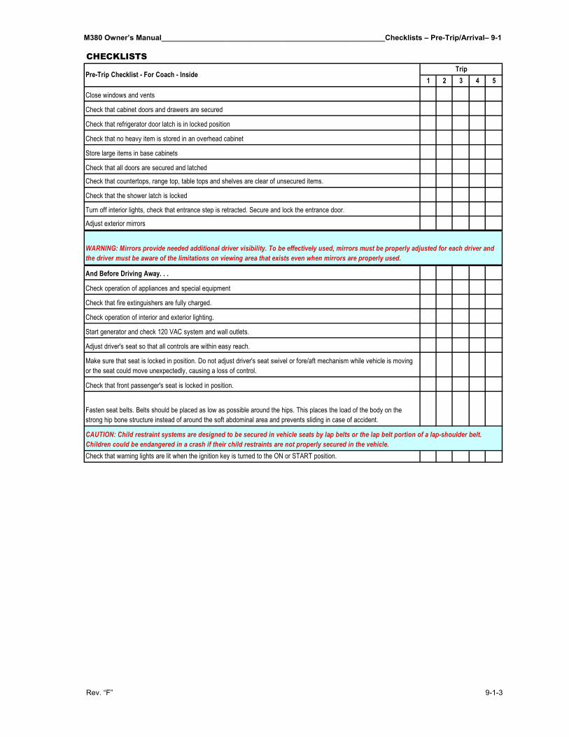
M380 Owner’s Manual______________________________________________________Checklists – Pre-Trip/Arrival– 9-1
Rev. “F” 9-1-3
1 2 3 4 5Trip
Pre-Trip Checklist - For Coach - Inside
CHECKLISTS
Check that warning lights are lit when the ignition key is turned to the ON or START position.
Make sure that seat is locked in position. Do not adjust driver's seat swivel or fore/aft mechanism while vehicle is moving or the seat could move unexpectedly, causing a loss of control.
Check that front passenger's seat is locked in position.
Fasten seat belts. Belts should be placed as low as possible around the hips. This places the load of the body on the strong hip bone structure instead of around the soft abdominal area and prevents sliding in case of accident.
CAUTION: Child restraint systems are designed to be secured in vehicle seats by lap belts or the lap belt portion of a lap-shoulder belt. Children could be endangered in a crash if their child restraints are not properly secured in the vehicle.
Close windows and vents
Check that cabinet doors and drawers are secured
Check that refrigerator door latch is in locked position
Check that no heavy item is stored in an overhead cabinet
Turn off interior lights, check that entrance step is retracted. Secure and lock the entrance door.
Adjust exterior mirrors
Store large items in base cabinets
Check that all doors are secured and latched
Check that countertops, range top, table tops and shelves are clear of unsecured items.
Check that the shower latch is locked
Adjust driver's seat so that all controls are within easy reach.
WARNING: Mirrors provide needed additional driver visibility. To be effectively used, mirrors must be properly adjusted for each driver and the driver must be aware of the limitations on viewing area that exists even when mirrors are properly used.
Check operation of appliances and special equipment
Check that fire extinguishers are fully charged.
Check operation of interior and exterior lighting.
Start generator and check 120 VAC system and wall outlets.
And Before Driving Away. . .

M380 Owner’s Manual__________________________________________________________________________________
Rev. “F”
THIS PAGE IS INTENTIONALLY LEFT BLANK
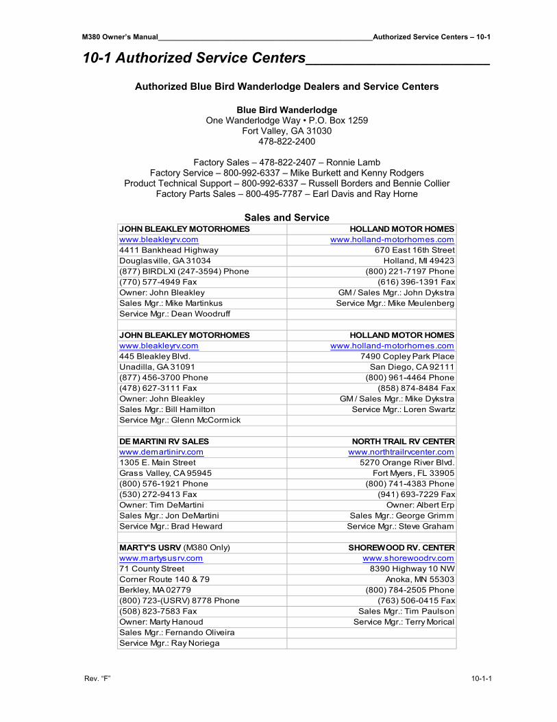
M380 Owner’s Manual_____________________________________________________Authorized Service Centers – 10-1
Rev. “F” 10-1-1
10-1 Authorized Service Centers__________________________
Authorized Blue Bird Wanderlodge Dealers and Service Centers
Blue Bird Wanderlodge One Wanderlodge Way • P.O. Box 1259
Fort Valley, GA 31030 478-822-2400
Factory Sales – 478-822-2407 – Ronnie Lamb
Factory Service – 800-992-6337 – Mike Burkett and Kenny Rodgers Product Technical Support – 800-992-6337 – Russell Borders and Bennie Collier
Factory Parts Sales – 800-495-7787 – Earl Davis and Ray Horne
Sales and Service
JOHN BLEAKLEY MOTORHOMES HOLLAND MOTOR HOMESwww.bleakleyrv.com www.holland-motorhomes.com4411 Bankhead Highway 670 East 16th StreetDouglasville, GA 31034 Holland, MI 49423(877) BIRDLXI (247-3594) Phone (800) 221-7197 Phone(770) 577-4949 Fax (616) 396-1391 FaxOwner: John Bleakley GM / Sales Mgr.: John DykstraSales Mgr.: Mike Martinkus Service Mgr.: Mike MeulenbergService Mgr.: Dean Woodruff
JOHN BLEAKLEY MOTORHOMES HOLLAND MOTOR HOMESwww.bleakleyrv.com www.holland-motorhomes.com445 Bleakley Blvd. 7490 Copley Park PlaceUnadilla, GA 31091 San Diego, CA 92111(877) 456-3700 Phone (800) 961-4464 Phone(478) 627-3111 Fax (858) 874-8484 FaxOwner: John Bleakley GM / Sales Mgr.: Mike DykstraSales Mgr.: Bill Hamilton Service Mgr.: Loren SwartzService Mgr.: Glenn McCormick
DE MARTINI RV SALES NORTH TRAIL RV CENTERwww.demartinirv.com www.northtrailrvcenter.com1305 E. Main Street 5270 Orange River Blvd.Grass Valley, CA 95945 Fort Myers, FL 33905(800) 576-1921 Phone (800) 741-4383 Phone(530) 272-9413 Fax (941) 693-7229 FaxOwner: Tim DeMartini Owner: Albert ErpSales Mgr.: Jon DeMartini Sales Mgr.: George GrimmService Mgr.: Brad Heward Service Mgr.: Steve Graham
MARTY'S USRV (M380 Only) SHOREWOOD RV. CENTERwww.martysusrv.com www.shorewoodrv.com71 County Street 8390 Highway 10 NWCorner Route 140 & 79 Anoka, MN 55303Berkley, MA 02779 (800) 784-2505 Phone(800) 723-(USRV) 8778 Phone (763) 506-0415 Fax(508) 823-7583 Fax Sales Mgr.: Tim PaulsonOwner: Marty Hanoud Service Mgr.: Terry MoricalSales Mgr.: Fernando OliveiraService Mgr.: Ray Noriega
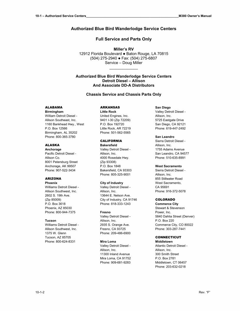
10-1 – Authorized Service Centers_____________________________________________________M380 Owner’s Manual
10-1-2 Rev. “F”
Authorized Blue Bird Wanderlodge Service Centers
Full Service and Parts Only
Miller’s RV
12912 Florida Boulevard Baton Rouge, LA 70815 (504) 275-2940 Fax: (504) 275-6807
Service – Doug Miller _____________
Authorized Blue Bird Wanderlodge Service Centers
Detroit Diesel – Allison And Associate DD-A Distributors
Chassis Service and Chassis Parts Only
ALABAMA ARKANSAS San DiegoBirmingham Little Rock Valley Detroit Diesel -William Detroit Diesel - United Engines, Inc. Allison, Inc.Allison Southeast, Inc. 9401 I-30 (Zip 72209) 5725 Eastgate Drive1160 Bankhead Hwy., West P.O. Box 192720 San Diego, CA 92121P.O. Box 12566 Little Rock, AR 72219 Phone: 619-447-2492Birmingham, AL 35202 Phone: 501-562-5565Phone: 800-365-3780 San Leandro
CALIFORNIA Sierra Detroit Diesel -ALASKA Bakersfield Allison, Inc.Anchorage Valley Detroit Diesel - 1755 Adams AvenuePacific Detroit Diesel - Allison, Inc. San Leandro, CA 94577Allison Co. 4000 Rosedale Hwy. Phone: 510-635-89918001 Petersburg Street (Zip 93308)Anchorage, AK 99507 P.O. Box 1848 West SacramentoPhone: 907-522-3434 Bakersfield, CA 93303 Sierra Detroit Diesel -
Phone: 805-325-9001 Allison, Inc.ARIZONA 855 Stillwater RoadPhoenix City of Industry West Sacramento,Williams Detroit Diesel - Valley Detroit Diesel - CA 95691Allison Southwest, Inc. Allison, Inc. Phone: 916-372-50782602 S. 19th Ave. 13644 E. Nelson Ave.(Zip 85009) City of Industry, CA 91746 COLORADOP.O. Box 3618 Phone: 818-333-1243 Commerce CityPhoenix, AZ 85030 Stewart & StevensonPhone: 800-944-7375 Fresno Power, Inc.
Valley Detroit Diesel - 5840 Dahlia Street (Denver)Tucson Allison, Inc. P.O. Box 220Williams Detroit Diesel - 2935 S. Orange Ave. Commerce City, CO 80022Allison Southwest, Inc. Fresno, CA 93725 Phone: 303-287-74411375 W. Glenn Phone: 209-486-6900Tucson, AZ 85705 CONNECTICUTPhone: 800-624-8331 Mira Loma Middletown
Valley Detroit Diesel - Atlantic Detroit Diesel -Allison, Inc. Allison, Inc.11300 Inland Avenue 300 Smith StreetMira Loma, CA 91752 P.O. Box 2781Phone: 909-681-9283 Middletown, CT 06457
Phone: 203-632-0218
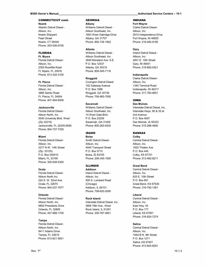
M380 Owner’s Manual_____________________________________________________Authorized Service Centers – 10-1
Rev. “F” 10-1-3
CONNECTICUT cont. GEORGIA INDIANANoank Albany Fort WayneAtlantic Detroit Diesel - Williams Detroit Diesel - Clarke Detroit Diesel -Allison, Inc. Allison Southeast, Inc. Allison, Inc.Noank Shipyard 1803 West Oakridge Drive 2610 Independence DrivePearl Street Albany, GA 31707 Fort Wayne, IN 46825Noank, CT 06340 Phone: 800-736-1952 Phone: 219-482-9185Phone: 203-536-6726
Atlanta GaryFLORIDA Williams Detroit Diesel - Inland Detroit Diesel -Ft. Myers Allison Southeast, Inc. Allison, Inc.Florida Detroit Diesel - 2849 Moreland Ave. S.E. 2601 E. 15th StreetAllison, Inc. P.O. Box 12537 Gary, IN 464012305 Rockfille Road Atlanta, GA 30315 Phone: 219-882-0421Ft. Myers, FL 33916 Phone: 800-545-7116Phone: 813-332-3100 Indianapolis
Ringgold Clarke Detroit Diesel -Ft. Pierce Covington Detroit Diesel Allison, Inc.Florida Detroit Diesel - 102 Gateway Avenue 1340 Terminal RoadAllison, Inc. P.O. Box 1088 Indianapolis, IN 462173885 Selvitz Road Ringgold, GA 30736 Phone: 317-783-6651Ft. Pierce, FL 34954 Phone: 706-965-7000Phone: 407-464-6006 IOWA
Savannah Des MoinesJacksonville Williams Detroit Diesel - Interstate Detroit Diesel, Inc.Florida Detroit Diesel - Allison Southeast, Inc. Interstate Hwys. 80 & 35 atAllison North, Inc. 14 West Gate Blvd. 2nd Avenue5040 University Blvd. West P.O. Box 23209 P.O. Box 4007(Zip 32216) Savannah, GA 31405 Des Moines, IA 50333Jacksonville, FL 32245-6595 Phone: 800-283-9332 Phone: 515-286-4800Phone: 904-737-7330
IDAHO KANSASMiami Boise ColbyFlorida Detroit Diesel - Smith Detroit Diesel - Central Detroit Diesel -Allison, Inc. Allison, Inc. Allison, Inc.2277 N.W. 14th Street 4045 Transport Street 1920 Thielen Ave.(Zip: 33125) P.O. Box 5715 P.O. Box 445P.O. Box 350010 Boise, ID 83705 Colby, KS 67701Miami, FL 33195 Phone: 208-345-1500 Phone: 913-462-8211Phone: 305-638-5300
ILLINOIS Great BendOcala Addison Central Detroit Diesel -Florida Detroit Diesel - Inland Detroit Diesel - Allison, Inc.Allison North Inc. Allison, Inc. 625 E. 10th Street224 S. W. 52nd Ave. 500 S. Lombard Road P.O. Box 691Ocala, FL 32674 (Chicago) Great Bend, KS 67530Phone: 904-237-7977 Addison, IL 60101 Phone: 316-792-1361
Phone: 708-620-2000Orlando LiberalFlorida Detroit Diesel - Rock Island Central Detroit Diesel -Allison North, Inc. Interstate Detroit Diesel, Inc. Allison, Inc.6850 Presidents Drive 3806 78th Ave., West East Hwy. 54Orlando, FL 32809 Rock Island, IL 61201 P.O. Box 177Phone: 407-888-1700 Phone: 309-787-4601 Liberal, KS 67901
Phone: 316-624-7274TampaFlorida Detroit Diesel - SalinaAllison North, Inc. Central Detroit Diesel -8411 Adamo Drive Allison, Inc.Tampa, FL 33619 1944-B N. 9th StreetPhone: 813-621-5651 P.O. Box 1271
Salina, KS 67401Phone: 913-825-8291
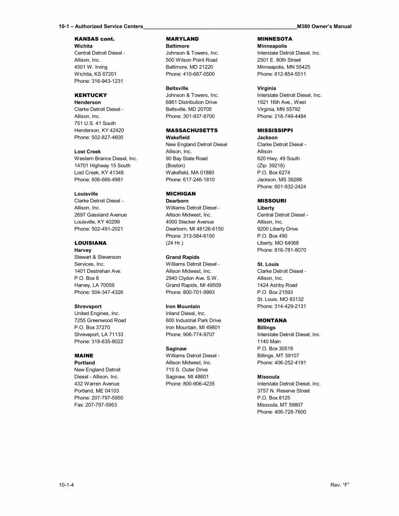
10-1 – Authorized Service Centers_____________________________________________________M380 Owner’s Manual
10-1-4 Rev. “F”
KANSAS cont. MARYLAND MINNESOTAWichita Baltimore MinneapolisCentral Detroit Diesel - Johnson & Towers, Inc. Interstate Detroit Diesel, Inc.Allison, Inc. 500 Wilson Point Road 2501 E. 80th Street4501 W. Irving Baltimore, MD 21220 Minneapolis, MN 55425Wichita, KS 67201 Phone: 410-687-0500 Phone: 612-854-5511Phone: 316-943-1231
Beltsville VirginiaKENTUCKY Johnson & Towers, Inc. Interstate Dietroit Diesel, Inc.Henderson 6861 Distribution Drive 1921 16th Ave., WestClarke Detroit Diesel - Beltsville, MD 20705 Virginia, MN 55792Allison, Inc. Phone: 301-937-8700 Phone: 218-749-4484751 U.S. 41 SouthHenderson, KY 42420 MASSACHUSETTS MISSISSIPPIPhone: 502-827-4600 Wakefield Jackson
New England Detroit Diesel Clarke Detroit Diesel -Lost Creek Allison, Inc. AllisonWestern Brance Diesel, Inc. 90 Bay State Road 620 Hwy. 49 South14701 Highway 15 South (Boston) (Zip: 39218)Lost Creek, KY 41348 Wakefield, MA 01880 P.O. Box 6274Phone: 606-666-4981 Phone: 617-246-1810 Jackson, MS 39288
Phone: 601-932-2424Louisville MICHIGANClarke Detroit Diesel - Dearborn MISSOURIAllison, Inc. Williams Detroit Diesel - Liberty2697 Gassland Avenue Allison Midwest, Inc. Central Detroit Diesel -Louisville, KY 40299 4000 Stecker Avenue Allison, Inc.Phone: 502-491-2021 Dearborn, MI 48126-6150 9200 Liberty Drive
Phone: 313-584-6150 P.O. Box 490LOUISIANA (24 Hr.) Liberty, MO 64068Harvey Phone: 816-781-8070Stewart & Stevenson Grand RapidsServices, Inc. Williams Detroit Diesel - St. Louis1401 Destrehan Ave. Allison Midwest, Inc. Clarke Detroit Diesel -P.O. Box 8 2940 Clydon Ave. S.W. Allison, Inc.Harvey, LA 70059 Grand Rapids, MI 49509 1424 Ashby RoadPhone: 504-347-4326 Phone: 800-701-9993 P.O. Box 21593
St. Louis, MO 83132Shreveport Iron Mountain Phone: 314-429-2131United Engines, Inc. Inland Diesel, Inc.7255 Greenwood Road 600 Industrial Park Drive MONTANAP.O. Box 37270 Iron Mountain, MI 49801 BillingsShreveport, LA 71133 Phone: 906-774-9707 Interstate Detroit Diesel, Inc.Phone: 318-635-8022 1140 Main
Saginaw P.O. Box 30518MAINE Williams Detroit Diesel - Billings, MT 59107Portland Allison Midwest, Inc. Phone: 406-252-4191New England Detroit 715 S. Outer DriveDiesel - Allison, Inc. Saginaw, MI 48601 Missoula432 Warren Avenue Phone: 800-906-4235 Interstate Detroit Diesel, Inc.Portland, ME 04103 3757 N. Reserve StreetPhone: 207-797-5950 P.O. Box 8125Fax: 207-797-5953 Missoula, MT 59807
Phone: 406-728-7600
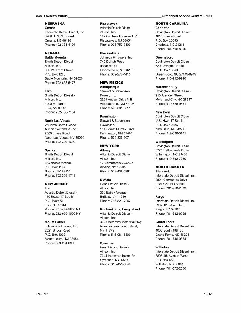
M380 Owner’s Manual_____________________________________________________Authorized Service Centers – 10-1
Rev. “F” 10-1-5
NEBRASKA Piscataway NORTH CAROLINAOmaha Atlantic Detroit Diesel - CharlotteInterstate Detroit Diesel, Inc. Allison, Inc. Covington Detroit Diesel -6969 S. 107th Street 169 Old New Brunswick Rd. 1815 Starita RoadOmaha, NE 68128 Piscataway, NJ 08854 P.O. Box 26653Phone: 402-331-4104 Phone: 908-752-7100 Charlotte, NC 28213
Phone: 704-596-8000NEVADA PleasantvilleBattle Mountain Johnson & Towers, Inc. GreensboroSmith Detroit Diesel - 740 Delilah Road Covington Detroit Diesel -Allison, Inc. (Rear Bldg.) 6200 Swiggett Road680 W. Front Street Pleasantville, NJ 08232 P.O. Box 18949P.O. Box 1288 Phone: 609-272-1415 Greensboro, NC 27419-8949Battle Mountain, NV 89820 Phone: 910-292-9240Phone: 702-635-5477 NEW MEXICO
Albuquerque Morehead CityElko Stewart & Stevenson Covington Detroit Diesel -Smith Detroit Diesel - Power, Inc. 210 Arendell StreetAllison, Inc. 2929 Vassar Drive N.E. Morehead City, NC 285574900 E. Idaho Albuquerque, NM 87107 Phone: 919-726-9881Elko, NV 89801 Phone: 505-881-3511Phone: 702-738-7154 New Bern
Farmington Covington Detroit Diesel -North Las Vegas Stewart & Stevenson U.S. Hwy. 17 SouthWilliams Detroit Diesel - Power,Inc. P.O. Box 12626Allison Southwest, Inc. 1515 West Murray Drive New Bern, NC 285602680 Losee Road Farmington, NM 87401 Phone: 919-638-3161North Las Vegas, NV 89030 Phone: 505-325-5071Phone: 702-399-1890 Wilmington
NEW YORK Covington Detroit Diesel Sparks Albany 6725 Netherlands DriveSmith Detroit Diesel - Atlantic Detroit Diesel - Wilmington, NC 28405Allison, Inc. Allison, Inc. Phone: 919-392-72208 Glendale Avenue 17 Commercial AvenueP.O. Box 1167 Albany, NY 12205 NORTH DAKOTASparks, NV 89431 Phone: 518-438-5961 BismarckPhone: 702-359-1713 Interstate Detroit Diesel, Inc.
Buffalo 3801 Commerce DriveNEW JERSEY Penn Detroit Diesel - Bismarck, ND 58501Lodi Allison, Inc. Phone: 701-258-2303Atlantic Detroit Diesel - 350 Bailey Avenue180 Route 17 South Buffalo, NY 14210 FargoP.O. Box 950 Phone: 716-823-7242 Interstate Detroit Diesel, Inc.Lodi, NJ 07644 3902 12th Ave. NorthPhone: 201-489-5800 NJ Ronkonkoma, Long Island Fargo, ND 58102Phone: 212-665-1500 NY Atlantic Detroit Diesel - Phone: 701-282-6558
Allison, Inc.Mount Laurel 3025 Veterans Memorial Hwy. Grand ForksJohnson & Towers, Inc. Ronkonkoma, Long Island, Interstate Detroit Diesel, Inc.2021 Briggs Road NY 11779 1003 South 48th St.P.O. Box 4000 Phone: 516-981-5800 Grand Forks, ND 58201Mount Laurel, NJ 08054 Phone: 701-746-0354Phone: 609-234-6990 Syracuse
Penn Detroit Diesel - WillistonAllison, Inc. Interstate Detroit Diesel, Inc.7044 Interstate Island Rd. 3805 4th Avenue WestSyracuse, NY 13209 P.O. Box 880Phone: 315-451-3840 Williston, ND 58801
Phone: 701-572-2000
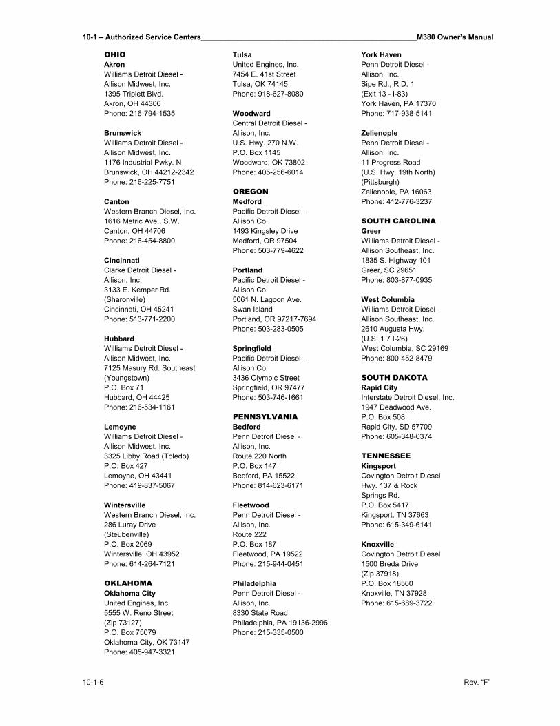
10-1 – Authorized Service Centers_____________________________________________________M380 Owner’s Manual
10-1-6 Rev. “F”
OHIO Tulsa York HavenAkron United Engines, Inc. Penn Detroit Diesel -Williams Detroit Diesel - 7454 E. 41st Street Allison, Inc.Allison Midwest, Inc. Tulsa, OK 74145 Sipe Rd., R.D. 11395 Triplett Blvd. Phone: 918-627-8080 (Exit 13 - I-83)Akron, OH 44306 York Haven, PA 17370Phone: 216-794-1535 Woodward Phone: 717-938-5141
Central Detroit Diesel -Brunswick Allison, Inc. ZelienopleWilliams Detroit Diesel - U.S. Hwy. 270 N.W. Penn Detroit Diesel -Allison Midwest, Inc. P.O. Box 1145 Allison, Inc.1176 Industrial Pwky. N Woodward, OK 73802 11 Progress RoadBrunswick, OH 44212-2342 Phone: 405-256-6014 (U.S. Hwy. 19th North)Phone: 216-225-7751 (Pittsburgh)
OREGON Zelienople, PA 16063Canton Medford Phone: 412-776-3237Western Branch Diesel, Inc. Pacific Detroit Diesel -1616 Metric Ave., S.W. Allison Co. SOUTH CAROLINACanton, OH 44706 1493 Kingsley Drive GreerPhone: 216-454-8800 Medford, OR 97504 Williams Detroit Diesel -
Phone: 503-779-4622 Allison Southeast, Inc.Cincinnati 1835 S. Highway 101Clarke Detroit Diesel - Portland Greer, SC 29651Allison, Inc. Pacific Detroit Diesel - Phone: 803-877-09353133 E. Kemper Rd. Allison Co.(Sharonville) 5061 N. Lagoon Ave. West ColumbiaCincinnati, OH 45241 Swan Island Williams Detroit Diesel -Phone: 513-771-2200 Portland, OR 97217-7694 Allison Southeast, Inc.
Phone: 503-283-0505 2610 Augusta Hwy.Hubbard (U.S. 1 7 I-26)Williams Detroit Diesel - Springfield West Columbia, SC 29169Allison Midwest, Inc. Pacific Detroit Diesel - Phone: 800-452-84797125 Masury Rd. Southeast Allison Co.(Youngstown) 3436 Olympic Street SOUTH DAKOTAP.O. Box 71 Springfield, OR 97477 Rapid CityHubbard, OH 44425 Phone: 503-746-1661 Interstate Detroit Diesel, Inc.Phone: 216-534-1161 1947 Deadwood Ave.
PENNSYLVANIA P.O. Box 508Lemoyne Bedford Rapid City, SD 57709Williams Detroit Diesel - Penn Detroit Diesel - Phone: 605-348-0374Allison Midwest, Inc. Allison, Inc.3325 Libby Road (Toledo) Route 220 North TENNESSEEP.O. Box 427 P.O. Box 147 KingsportLemoyne, OH 43441 Bedford, PA 15522 Covington Detroit DieselPhone: 419-837-5067 Phone: 814-623-6171 Hwy. 137 & Rock
Springs Rd.Wintersville Fleetwood P.O. Box 5417Western Branch Diesel, Inc. Penn Detroit Diesel - Kingsport, TN 37663286 Luray Drive Allison, Inc. Phone: 615-349-6141(Steubenville) Route 222P.O. Box 2069 P.O. Box 187 KnoxvilleWintersville, OH 43952 Fleetwood, PA 19522 Covington Detroit DieselPhone: 614-264-7121 Phone: 215-944-0451 1500 Breda Drive
(Zip 37918)OKLAHOMA Philadelphia P.O. Box 18560Oklahoma City Penn Detroit Diesel - Knoxville, TN 37928United Engines, Inc. Allison, Inc. Phone: 615-689-37225555 W. Reno Street 8330 State Road(Zip 73127) Philadelphia, PA 19136-2996P.O. Box 75079 Phone: 215-335-0500Oklahoma City, OK 73147Phone: 405-947-3321
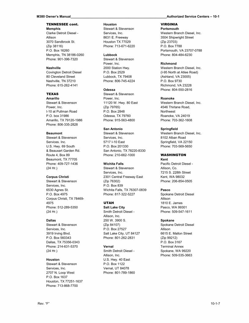
M380 Owner’s Manual_____________________________________________________Authorized Service Centers – 10-1
Rev. “F” 10-1-7
TENNESSEE cont. Houston VIRGINIAMemphis Stewart & Stevenson PortsmouthClarke Detroit Diesel - Services, Inc. Western Branch Diesel, Inc.Allison 8631 E. Freeway 3504 Shipwright Street3070 Sandbrook St. Houston TX 77029 (Zip 23703)(Zip 38116) Phone: 713-671-6220 P.O. Box 7788P.O. Box 16260 Portsmouth, VA 23707-0788Memphis, TN 38186-0260 Lubbock Phone: 804-484-6230Phone: 901-396-7320 Stewart & Stevenson
Power, Inc. RichmondNashville 2000 Station Hwy. Western Branch Diesel, Inc.Covington Detroit Diesel P.O. Box 2529 (I-95 North at Atlee Road)80 Cleveland Street Lubbock, TX 79408 (Ashland, VA 23005)Nashville, TN 37210 Phone: 806-745-4224 P.O. Box 9730Phone: 615-262-4141 Richmond, VA 23228
Odessa Phone: 804-550-2816TEXAS Stewart & StevensonAmarillo Power, Inc. RoanokeStewart & Stevenson 11120 W. Hwy. 80 East Western Branch Diesel, Inc.Power, Inc. (Zip 79765) 4546 Thirlane Road,I-10 at Pullman Road P.O. Box 2848 NorthwestP.O. box 31986 Odessa, TX 79760 Roanoke, VA 24019Amarillo, TX 79120-1986 Phone: 915-563-4800 Phone: 703-362-1608Phone: 806-335-2828
San Antonio SpringfieldBeaumont Stewart & Stevenson Western Branch Diesel, Inc.Stewart & Stevenson Services, Inc. 8102 Alban RoadServices. Inc. 5717 I-10 East Springfield, VA 22150U.S. Hwy. 69 South P.O. Box 201330 Phone: 703-569-5650& Beauxart Garden Rd. San Antonio, TX 78220-8330Route 4, Box 89 Phone: 210-662-1000 WASHINGTONBeaumont, TX 77705 KentPhone: 409-727-1436 Wichita Falls Pacific Detroit Diesel -(24 Hr.) Stewart & Stevenson Allison, Co.
Services, Inc. 7215 S. 228th StreetCorpus Christi 2301 Central Freeway East Kent, WA 98032Stewart & Stevenson (Zip 76302) Phone: 206-854-0505Services, Inc. P.O. Box 8396530 Agnes St. Wichita Falls, TX 76307-0839 PascoP.O. Box 4975 Phone: 817-322-5227 Spokane Detroit DieselCorpus Christi, TX 78469- Allison4975 UTAH 1810 E. JamesPhone: 512-289-5350 Salt Lake City Pasco, WA 99301(24 Hr.) Smith Detroit Diesel - Phone: 509-547-1611
Allison, Inc.Dallas 250 W. 3900 S. SpokaneStewart & Stevenson (Zip 84107) Spokane Detroit DieselServices, Inc. P.O. Box 27527 Allison3919 Irving Blvd. Salt Lake City, UT 84127 6615 E. Mallon StreetP.O. Box 560343 Phone: 801-262-2831 (Zip 99212)Dallas, TX 75356-0343 P.O. Box 3167Phone: 214-631-5370 Vernal Terminal Annex(24 Hr.) Smith Detroit Diesel - Spokane, WA 99220
Allison, Inc. Phone: 509-535-3663Houston U.S. Hwy. 40 EastStewart & Stevenson P.O. Box 1122Services, Inc. Vernal, UT 840782707 N. Loop West Phone: 801-789-1860P.O. Box 1637Houston, TX 77251-1637Phone: 713-868-7700
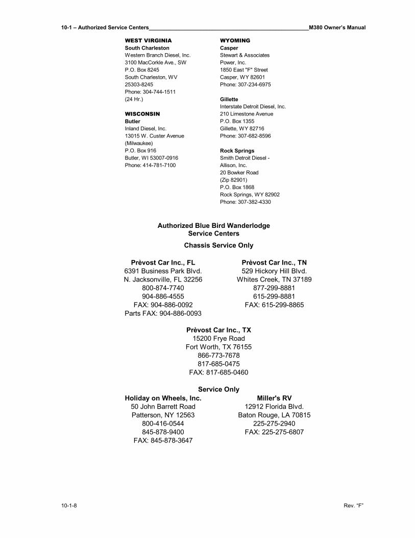
10-1 – Authorized Service Centers_____________________________________________________M380 Owner’s Manual
10-1-8 Rev. “F”
WEST VIRGINIA WYOMINGSouth Charleston CasperWestern Branch Diesel, Inc. Stewart & Associates3100 MacCorkle Ave., SW Power, Inc.P.O. Box 8245 1850 East "F" StreetSouth Charleston, WV Casper, WY 8260125303-8245 Phone: 307-234-6975Phone: 304-744-1511(24 Hr.) Gillette
Interstate Detroit Diesel, Inc.WISCONSIN 210 Limestone AvenueButler P.O. Box 1355Inland Diesel, Inc. Gillette, WY 8271613015 W. Custer Avenue Phone: 307-682-8596(Milwaukee)P.O. Box 916 Rock SpringsButler, WI 53007-0916 Smith Detroit Diesel -Phone: 414-781-7100 Allison, Inc.
20 Bowker Road(Zip 82901)P.O. Box 1868Rock Springs, WY 82902Phone: 307-382-4330
Authorized Blue Bird Wanderlodge Service Centers
Prèvost Car Inc., FL Prèvost Car Inc., TN6391 Business Park Blvd. 529 Hickory Hill Blvd.N. Jacksonville, FL 32256 Whites Creek, TN 37189
800-874-7740 877-299-8881904-886-4555 615-299-8881
FAX: 904-886-0092 FAX: 615-299-8865Parts FAX: 904-886-0093
Holiday on Wheels, Inc. Miller's RV50 John Barrett Road 12912 Florida Blvd.Patterson, NY 12563 Baton Rouge, LA 70815
800-416-0544 225-275-2940845-878-9400 FAX: 225-275-6807
FAX: 845-878-3647
Chassis Service Only
Prèvost Car Inc., TX15200 Frye Road
Fort Worth, TX 76155866-773-7678817-685-0475
FAX: 817-685-0460
Service Only
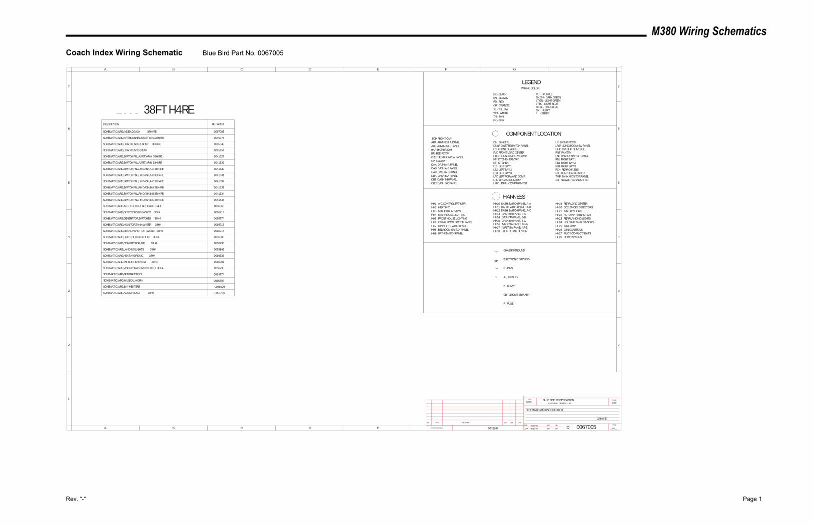
M380 Wiring Schematics
Rev. “-“ Page 1
Coach Index Wiring Schematic Blue Bird Part No. 0067005
SCHEMATIC,WRG,INTERCONNECT,BATT CIRC 38H4RE
SCHEMATIC,WRG,INDEX,COACH
DESCRIPTION
NONE12857N
0067005
HARNESS
COMPONENT LOCATION
LEGENDWIRING COLOR
2003 38FT H4RE
SCHEMATIC,WRG,INDEX,COACH 38H4RE
SCHEMATIC,WRG,LOAD CENTER,FRONT 38H4RE
SCHEMATIC,WRG,LOAD CENTER,REAR
SCHEMATIC,WRG,SWITCH PNL,A/RST,AR-A 38H4RE
SCHEMATIC,WRG,SWITCH PNL,A/RST,AR-B 38H4RE
SCHEMATIC,WRG,SWITCH PNL,LH DASH,A-A 38H4RE
SCHEMATIC,WRG,SWITCH PNL,LH DASH,A-B 38H4RE
SCHEMATIC,WRG,SWITCH PNL,LH DASH,A-C 38H4RE
SCHEMATIC,WRG,SWITCH PNL,RH DASH,B-A 38H4RE
SCHEMATIC,WRG,SWITCH PNL,RH DASH,B-B 38H4RE
SCHEMATIC,WRG,SWITCH PNL,RH DASH,B-C 38H4RE
BB PART #
0067005
0040778
0065349
0065254
0041527
0041529
0041530
0041531
0041532
0041533
0041534
0041535
CHASSIS GROUND
ELECTRONIC GROUND
P - PINS
J - SOCKETS
K - RELAY
CB - CIRCUIT BREAKER
F - FUSE
BK - BLACKBN - BROWNRD - REDOR - ORANGEYL - YELLOWWH - WHITETN - TANPK - PINK
PU - PURPLEDK GN - DARK GREEN
LT BL - LIGHT BLUE
GY - GRAY/ - STRIPE
LT GN - LIGHT GREEN
DK BL - DARK BLUE
HH19 REAR LOAD CENTERHH20 CO2/SMOKE DETECTORSHH21 AIR/CITY HORNHH22 AUTO WATER SHUT OFFHH23 REAR LANDING LIGHTSHH24 HOLDING TANK SENSORSHH25 AIR COMPHH26 GEN CONTROLSHH27 PILOT/CO-PILOT SEATSHH28 POWER VISORS
38H4RE
0066713SCHEMATIC,WRG,DETECTORS,LP GAS/CO 38H4
0066363SCHEMATIC,WRG,A/C CTRL,FRT & RR,COACH H4RE
0066774
0066715
0066714
0066303
0066298
SCHEMATIC,WRG,GENERATOR,SWITCHES 38H4
SCHEMATIC,WRG,MONITOR,TANK,WATER 38H4
SCHEMATIC,WRG,SEN/VLV,SHUT-OFF,WATER 38H4
SCHEMATIC,WRG,SEATS,PILOT/CO-PILOT 38H4
SCHEMATIC,WRG,COMPRESSOR,AIR 38H4
ARA ARM REST A PANELARB ARM REST B PANELBAR BATH ROOMBR BED ROOMBRSP BED ROOM SW PANELCP COCKPITDAA DASH A-A PANELDAB DASH A-B PANELDAC DASH A-C PANELDBA DASH B-A PANELDBB DASH B-B PANELDBC DASH B-C PANEL
DN DINETTEDNSP DINETTE SWITCH PANELFC FRONT CHASSISFLC FRONT LOAD CENTERHBC HOUSE BATTERY COMPKP KITCHEN PANTRYKT KITCHENLB1 LEFT BAY 1LB2 LEFT BAY 2LB3 LEFT BAY 3LFC LEFT FORWARD COMPLPC LP GAS FILL COMPLPFC LP FILL COMPARTMENT
LR LIVING ROOMLRSP LIVING ROOM SW PANELOHC OVERHD COMSOLEPNT PANTRYPSP PANTRY SWITCH PANELRB1 RIGHT BAY 1RB2 RIGHT BAY 2RB3 RIGHT BAY 3RCH REAR CHASSISRLC REAR LOAD CENTERTMP TANK MONITOR PANELSEF SHOWER EXHAUST FAN
HH1 A/C CONTROL,FRT & RRHH2 HEAT,HYDHH3 MIRROR,REAR VIEWHH4 REAR HOUSE LIGHTINGHH5 FRONT HOUSE LIGHTINGHH6 LIVING ROOM SWITCH PANELHH7 DINNETTE SWITCH PANELHH8 BEDROOM SWITCH PANELHH9 BATH SWITCH PANEL
HH10 DASH SWITCH PANEL A-AHH11 DASH SWITCH PANEL A-BHH12 DASH SWITCH PANEL A-CHH13 DASH SW PANEL B-AHH14 DASH SW PANEL B-BHH15 DASH SW PANEL B-CHH16 A/RST SW PANEL AR-AHH17 A/RST SW PANEL AR-BHH18 FRONT LOAD CENTER
0065866
0066335
0066301
0066296
SCHEMATIC,WRG,LANDING LIGHTS 38H4
SCHEMATIC,WRG,HEAT,HYDRONIC 38H4
SCHEMATIC,WRG,MIRROR,REAR VIEW 38H4
SCHEMATIC,WRG,VISOR,POWER,WINDSHIELD 38H4
FCP FRONT CAP
SS06/03/03
06/13/03 SW0042247
SCHEMATIC,WRG,GENERATOR,KSI 0064774
SCHEMATIC,WRG,MUSICAL HORN 0066302
SCHEMATIC,WRG,AUDIO VIDEO 38H4
0066909SCHEMATIC,WRG,BAY HEATERS
0067296
INACTIVATES NOS.
LET. WAS REVISIONS DR. APP. CCN
SCALEBLUE BIRD CORPORATIONFORT VALLEY GEORGIA, U.S.A.
CCN
DR.
APP. BY
BY
DPAGE
__OF__
1
2
3
4
5
A B C D E F G H
B C D E
5
4
3
2
6 6
77
A
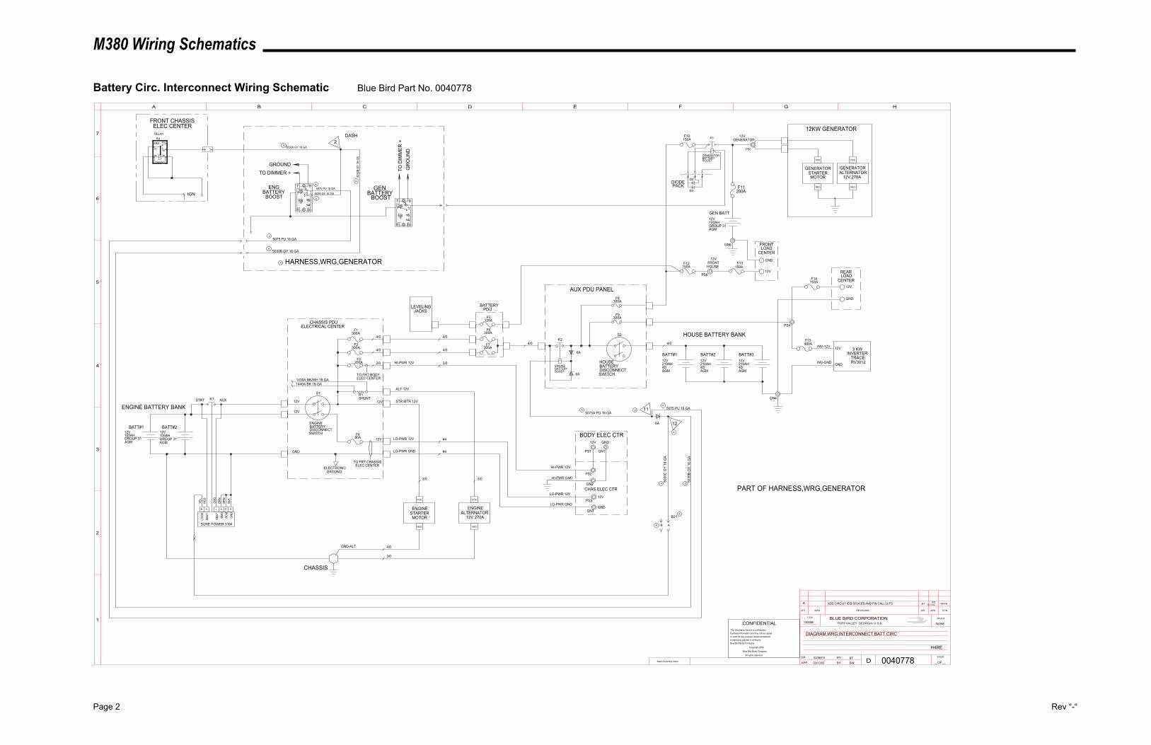
M380 Wiring Schematics
Page 2 Rev “-“
Battery Circ. Interconnect Wiring Schematic Blue Bird Part No. 0040778
9732B1
108
64
5B 72B 3
9
1
64
5B
8 10
105AH12V
AGMGROUP 31 GROUP 31
AGM
12V105AH
BATT#2BATT#1
ELECTRONICGROUND
12V
GND
80A
TO FRT CHASSISELEC CENTER
12V
12V
BATTERYDISCONNECTSWITCH
NEG
12V 270AALTERNATOR
ENGINE
POS
STARTER
NEG
MOTOR
POS
ENGINE
GND-ALT
CHASSIS
CHASSIS PDUELECTRICAL CENTER
BATTERY
SWITCHDISCONNECT
BATT#1
4D210AH12V
AGM
BATT#2
4D210AH12V
AGM4DAGM
12V210AH
BATT#3
4/0
4/0
4/0
4/0
4/0
2/0
4/0
HOUSE BATTERY BANK
AUX PDU PANEL
SURE POWER 3104
TO FRT BODYELEC CENTER
HI-PWR 12V
HI-PWR 12V
ALT 12V
STR MTR 12V
2/0
LO-PWR 12V
LO-PWR GND
LO-PWR 12V
LO-PWR GND
HI-PWR GND
GND12V
12V
GND
BODY ELEC CTR
CHAS ELEC CTR
#4
#4
4/0
3/0
3/0
3/0
3 KWINVERTER
INV-GND GND
INV-12V 12V
TRACERV3012
R1SHUNT
ENGINEBATTERYBOOST
400A
B K J A D H
LOC
K
SBAT
ABAT
BMD
RC
M
GN
D
YEL
RED
OR
G
BRN
BRN
BLK
STRT AUX 12VK1
125A
NEG
GENERATOR
POS
12V 270AALTERNATORSTARTER
NEG
MOTOR
POS
GENERATOR
12KW GENERATOR
GEN BATT
100AH12V
AGMGROUP 31
200A
GENERATORBATTERYBOOST
150A
150A
FRONTLOAD
CENTER
GND
12V
FRONTHOUSE
12V
12V
REARLOAD
CENTER12V
GND
LEVELING
150A
150A
ENGBATTERY
GROUNDTO DIMMER +
JACKS
PS1 GN1
PS2
GN2
PS3
GN3
GN4
PS4
PS6
GN6
PS6
GENERATORK4
BOOST BOOST
F10 K3
F11
ENGINE BATTERY BANK
F1
F2
F3200A
S1
1439A BK/WH 18 GA1440A BK 18 GA
ENGINE
F4
F5
F6
F7K2
F8
F9
S2
HOUSE
F12 F13
F14
F15
BATTERYPDU
6A
6A
6A
5075 PU 16 GA
5030B GY 16 GA
5030 GY 16 GA
5075 PU 16 GA
5030A GY 16 GA
5030
B G
Y 16
GA
HARNESS,WRG,GENERATOR
5075A PU 16 GA5075 PU 16 GA
12
11
5030
C G
Y 16
GA
5030
B G
Y 16
GA
AB
B21
A ADD CIRCUIT ID'S,SPLICES,AND PIN CALLOUTS BTSW
6/17/03 12857M
PART OF HARNESS,WRG,GENERATOR
INACTIVATES NOS.
LET. WAS REVISIONS DR. APP. CCN
SCALEBLUE BIRD CORPORATIONFORT VALLEY GEORGIA, U.S.A.
CCN
DR.
APP. BY
BYD
PAGE
__OF__
1
2
3
4
5
A B C D E F G H
6
7
0040778
DIAGRAM,WRG,INTERCONNECT,BATT,CIRC
02/06/03
03/13/03BTSW
13055B NONECONFIDENTIALThe information hereon is confidentialbusiness information and may not be copiedor used for any purpose unless permissionis expressly granted in writing byBlue Bird Body Company.
Copyright 2002
Blue Bird Body Company
All rights reserved
H4RE
87A
3087
8586
MINI
BCD
D3
D2
300A
300A
300A
300A
300A
300A
2
IGN
FRONT CHASSISELEC CENTER
DASHRELAY
GENBATTERY
DIODEPACK
GR
OU
ND
TO D
IMM
ER +
A
AA
A
A
A
A
A
A
A
A
A A
A
A
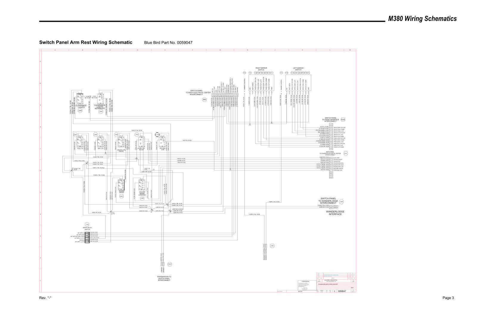
M380 Wiring Schematics
Rev. “-“ Page 3
Switch Panel Arm Rest Wiring Schematic Blue Bird Part No. 0059047
8
5B4
6
1
932B
7
10
8
5B1
932B
7
1046
8
5B4
6
1
932B
7
10
12857J3/11/03
SWEAUPDATED SPLICES TO MATCH HARNESS. ADDED----A
-----------
---WIRES 1208Y,1333X,1333Y-----
INACTIVATES NOS.
LET. WAS REVISIONS DR. APP. CCN
SCALEBLUE BIRD CORPORATIONFORT VALLEY GEORGIA, U.S.A.
CCN
DR.
APP.
BY
BY EPAGE
__OF__
1
2
3
4
5
6
7
8
9
10
11
A B C D E F G H J K L M
0059047
DIAGRAM,WRG,SWITCH PANEL,ARM REST
10/09/02
11/19/02
EA
SW
13032W NONE
1 1
CONFIDENTIALThe information hereon is confidential
business information and may not be copied
or used for any purpose unless permission
is expressly granted in writing by
Blue Bird Body Company.
Copyright 2002
Blue Bird Body Company
All rights reserved
38H4
0037223
SWITCH HSWITCH A
SWITCH ASWITCH A SWITCH A SWITCH H
1504 GY 18 GA1529 BN 18 GA1528 OR 18 GA
SWITCH H SWITCH H
1517
B LT
BL/
BK 1
8 G
A
1517
D L
T BL
/BK
18 G
A
1517
C L
T BL
/BK
18 G
A
SWITCH H
1427 PU 18 GA
1333E LT BL 18 GA
1333
G L
T BL
18
GA
1333
S LT
BL
16 G
A
1333
F LT
BL
18 G
A13
33D
LT
BL 1
8 G
A
1208X WH 16 GA
1208E WH 18 GA1208G WH 18 GA1208C WH 18 GA
AB
146
11185
124
10973
ABCD
AB
TRANSMISSION TOSWITCH PANELINTERCONNECT
7 8 9 10 11 12 13 14 5 6 2 3
123654
8
7
1315BBN 16 GA
1315CBN 16 GA
1310
A D
K G
N/B
K 16
GA
1208
H W
H 1
8 G
A
1208
J W
H 1
8 G
A13
33H
LT
BL 1
8 G
A
1310
B D
K G
N/B
K 16
GA
1333C LT BL 18 GA
1333C LT BL 18 GA
1333K LT BL 18 GA
1333G LT BL 18 GA1333B LT BL 18 GA
1206
E W
H 1
8 G
A
1308
A BK
18
GA
1212
B W
H 1
8 G
A13
33J
LT B
L 18
GA
1208
K W
H 1
8 G
A
1308
B BK
18
GA
1212
C W
H 1
8 G
A12
08L
WH
18
GA
1208W WH 16 GA
1504
GY
18 G
A
1206
C W
H 1
8 G
A
1206
D W
H 1
8 G
A
1208
C W
H 1
8 G
A
1208
D W
H 1
8 G
A
1208
E W
H 1
8 G
A
1206
B W
H 1
8 G
A13
33B
LT B
L 18
GA
1529
BN
18
GA
1528
OR
18
GA
1333
D L
T BL
18
GA
1208
D W
H 1
8 G
A
1333R LT BL 18 GA
1333P LT BL 18 GA1333A LT BL 16 GA1333M LT BL 16 GA
1333S LT BL 16 GA
CRUISE ON/OFFCRUISE SETCRUISE RES/ACELENGINE BRK HIGHENGINE BRK LOWENG BRK ON/OFF
ELEC GND
STOP ENG OVR
1504 GY 18 GA1529 BN 18 GA1528 OR 18 GA
1517C LT BL/BK 18 GA1517B LT BL/BK 18 GA1517A LT BL/BK 18 GA
1206A WH 18 GA
1427 PU 18 GA
DRVS CONV UP & DNDRVS CONV COMMDRVS CONV L & RDRVS FLAT UP & DNDRVS FLAT L & RDRVS FLAT COMMPASS CONV UP & DNPASS CONV COMMPASS CONV L & RPASS FLAT UP & DNPASS FLAT L & RPASS FLAT COMM2116A OR 18 GA
2118 BN 18 GA2120 RD/BK 18 GA
2122 DK GN/BK 18 GA2116B OR 18 GA
2124 YL 18 GA2117A OR 18 GA
2119 BN 18 GA2021 RD/BK 18 GA
2123 DK GN/BK 18 GA2117B OR 18 GA
2125 YL 18 GA
PK L
TSC
L LT
SU
PG
ND
FOG
LT
SWD
RV
LT S
WD
IMM
ER O
UTP
UT
+SW
PN
L LT
S G
ND
CL
LT R
ETR
EMO
TE M
IR +
REM
OTE
MIR
-
INT
WPR
RET
UR
N (L
OAD
)
GN
D
IGN
PASS
FLA
T U
P &
DN
PASS
FLA
T L
& R
PASS
FLA
T C
OM
M
GN
D
IGN
PASS
CO
NV
UP
& D
N
PASS
CO
NV
L &
R
PASS
CO
NV
CO
MM
DIM
MER
CO
NTR
OL
1315
A BN
16
GA
1310
B D
K G
N/B
K 16
GA
1212
A W
H 1
8 G
A13
08A
BK 1
8 G
A13
08B
BK 1
8 G
A13
33A
LT B
L 16
GA
1208
A W
H 1
6 G
A13
10A
DK
GN
/BK
16 G
A11
48A
BK 1
8 G
A12
08B
WH
18
GA
2102
C R
D 1
8 G
A
1208
R W
H 1
8 G
A
1148
B BK
18
GA
2120
RD
/BK
18 G
A
2118
BN
18
GA
2116
A O
R 1
8 G
A
1208
S W
H 1
8 G
A
1148
C B
K 18
GA
2124
YL
18 G
A
2122
DK
GN
/BK
18 G
A
2116
B O
R 1
8 G
A
1333
R L
T BL
18
GA
SWITCH PANELTO CHASSIS ELECTRICAL CENTER
INTERCONNECT
SWITCH PANEL
INTERCONNECTTO FRONT INTERFACE
SWITCH PANELTO BODY ELECTRICAL CENTER
INTERCONNECT
CLEARANCELIGHTS
CLEARANCELIGHTS
INTERRUPT
FOG LTS DRV LTSCRUISE CTRL
ON/OFF
CRUISE CTRLRES/SET
STO ENGOVR
ENGINEBRAKE ENGINE
BRAKELOW/HIGH
INT WPR (+)INT WPR GND
INT WPR RETURN (LOAD)INT WPR (+) L.E.D.
2102A BK 18 GA1208P WH 18 GA2102C RD 18 GA1333T LT BL 18 GA
1208N WH 18 GA1333M LT BL 16 GA DIMMER +
DIMMER -
WANDERLODGEINTERFACE
SWITCH PANELTO WANDERLODGE
INTERCONNECT
1208
M W
H 1
8 G
A
1333
L LT
BL
18 G
AD
IMM
ER -
DIM
MER
+
1315
A BN
16
GA
1208
P W
H 1
8 G
AIN
T W
PR G
ND
4 1
INT
WPR
(+)
2102
A BK
18
GA
P330
J108
J354
P351
WIPER DELAYSWITCH
J352
J353
J348 J347
J349 J350 J342 J343
J345J346
J344
T10 T18T25
EF
2102W BK 18 GA1208T WH 18 GA
WASHERINT WPR (-) L.E.D.
2102
W B
K 18
GA
15
WAS
HER
ENG
BR
AKE
IND
ICAT
OR
(-)
5
4
3
1
2
6
7
8
2 3 4 5 6 7 8 9 98765432
T23T21 T20T17 T15T13T11
2117
B O
R 1
8 G
A
2123
DK
GN
/BK
18 G
A
2125
YL
18 G
A
1333
P LT
BL
18 G
A
2117
A O
R 1
8 G
A
2119
BN
18
GA
2021
RD
/BK
18 G
A
DR
VS C
ON
V C
OM
M
DR
VS C
ON
V L
& R
DR
VS C
ON
V U
P &
DN
DIM
MER
CO
NTR
OL
DR
VS F
LAT
CO
MM
DR
VS F
LAT
L &
R
DR
VS F
LAT
UP
& D
N
RIGHT MIRRORSWITCH
LEFT MIRRORSWITCH
T12 T22 T14 T19 T24 T16 T8 T9
(NO
T U
SED
)
(NO
T U
SED
)
11
1517
E LT
BL/
BK 1
8 G
A
9
AB J336
DIM
MER
CO
NTR
OL
DIM
MER
CO
NTR
OL
9101112
15
132
8
5B1
932B
7
1046
8
5B
1
93
2B
7
10
4
6
8
5B
1
93
2B
7
10
4
6
8
5B1
932B
7
1046
8
5B1
932B
7
104
6
101333W LT BL 16 GA
1333Y LT BL 18 GA
12
1208
L W
H 1
8 G
A
1208
H W
H 1
8 G
A
1208
F W
H 1
8 G
A
1208K WH 18 GA
1208Y WH 18 GA1208A WH 16 GA1208N WH 18 GA
1208Y WH 18 GA
1333X LT BL 18 GA
11
5B4
6
1
932B
7
8 10
A
A
A
A
A
A
A
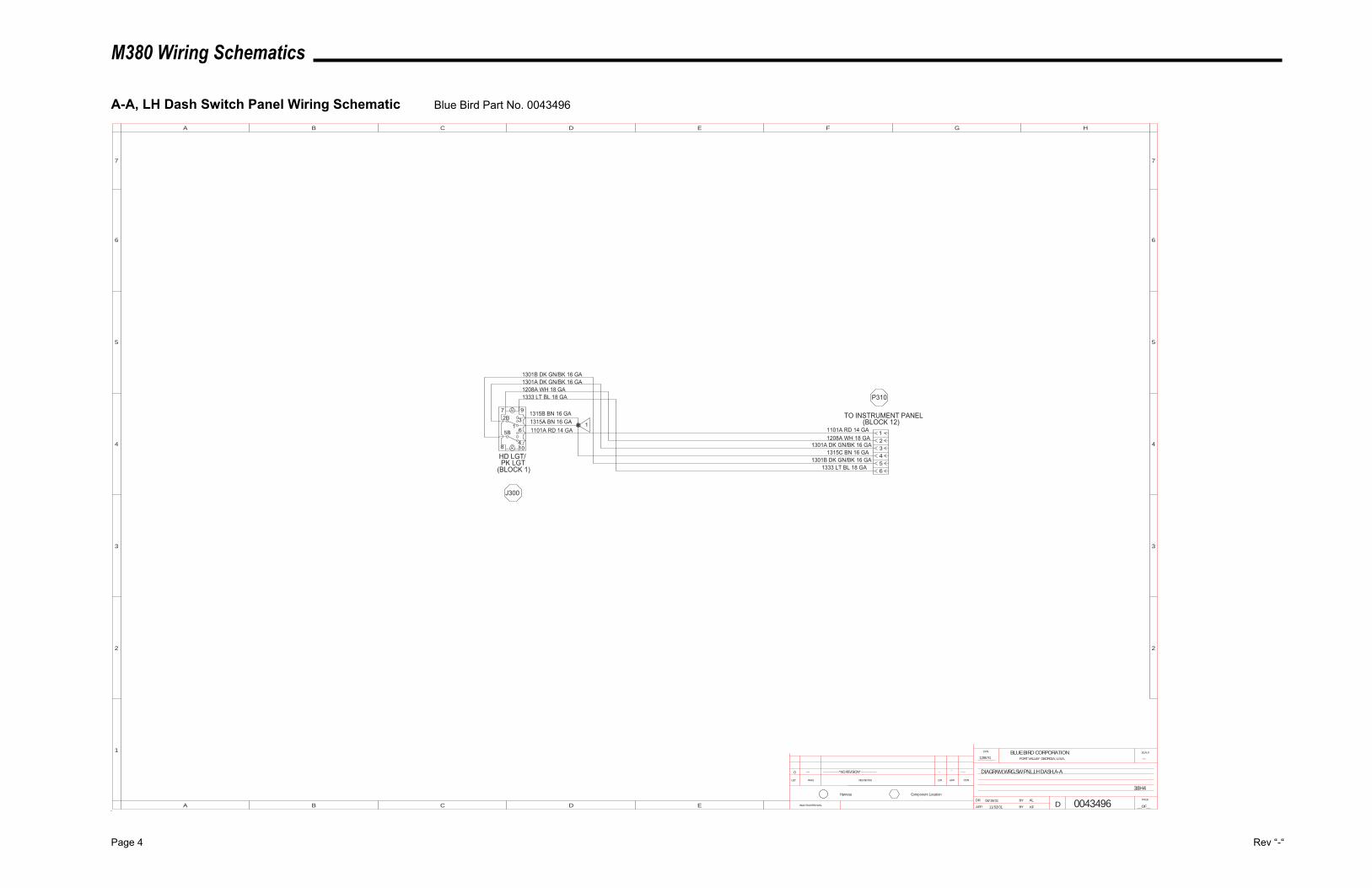
M380 Wiring Schematics
Page 4 Rev “-“
A-A, LH Dash Switch Panel Wiring Schematic Blue Bird Part No. 0043496
4
65B
8 10
97
32B1
DIAGRAM,WRG,SW PNL,LH DASH,A-A
---12857G
38H4
KF
AL
11/02/01
08/19/01 0043496INACTIVATES NOS.
LET. WAS REVISIONS DR. APP. CCN
SCALEBLUE BIRD CORPORATIONFORT VALLEY GEORGIA, U.S.A.
CCN
DR.
APP. BY
BY
DPAGE
__OF__
1
2
3
4
5
A B C D E F G H
B C D E
5
4
3
2
6 6
77
A
Component LocationHarness
0 --- ---------------*NO REVISION*--------------- ----
------
1101A RD 14 GA1208A WH 18 GA
1301A DK GN/BK 16 GA1315C BN 16 GA
TO INSTRUMENT PANEL(BLOCK 12)
3
12
456
1301B DK GN/BK 16 GA
1101A RD 14 GA
1315B BN 16 GA1315A BN 16 GA
HD LGT/PK LGT
(BLOCK 1)
1333 LT BL 18 GA
1301A DK GN/BK 16 GA1301B DK GN/BK 16 GA
1
J300
P310
1333 LT BL 18 GA
1208A WH 18 GA
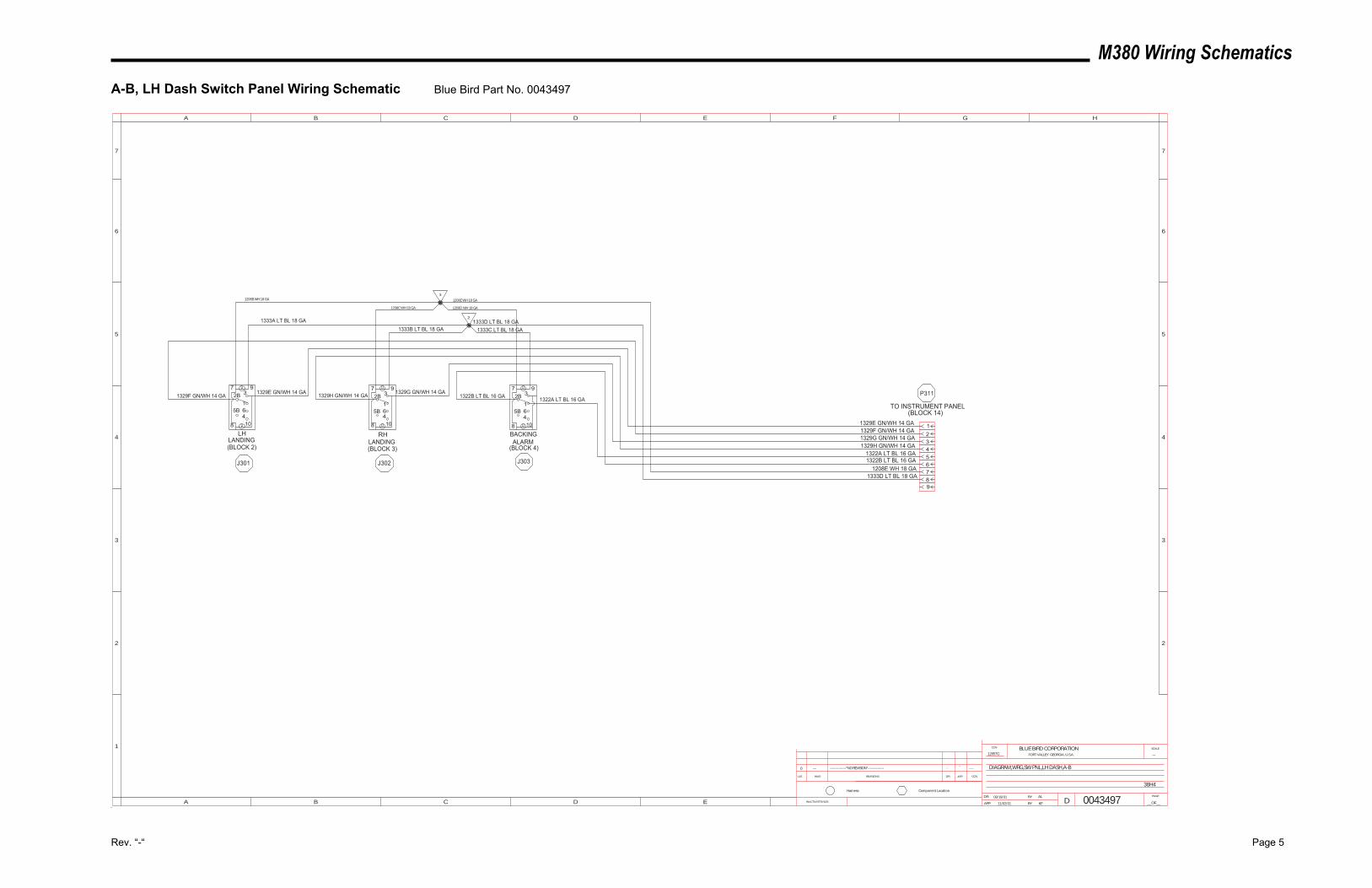
M380 Wiring Schematics
Rev. “-“ Page 5
A-B, LH Dash Switch Panel Wiring Schematic Blue Bird Part No. 0043497
461
2B
5B
37 9
108
461
2B
5B
37 9
108461
2B
5B
37 9
108
DIAGRAM,WRG,SW PNL,LH DASH,A-B
---12857G
38H4
KF
AL
11/02/01
08/19/01 0043497INACTIVATES NOS.
LET. WAS REVISIONS DR. APP. CCN
SCALEBLUE BIRD CORPORATIONFORT VALLEY GEORGIA, U.S.A.
CCN
DR.
APP. BY
BY
DPAGE
__OF__
1
2
3
4
5
A B C D E F G H
B C D E
5
4
3
2
6 6
77
A
Component LocationHarness
0 --- ---------------*NO REVISION*--------------- ----
------
1329E GN/WH 14 GA1329F GN/WH 14 GA1329G GN/WH 14 GA1329H GN/WH 14 GA
1322B LT BL 16 GA
TO INSTRUMENT PANEL(BLOCK 14)
3
12
456789
1322A LT BL 16 GA
1208E WH 18 GA1333D LT BL 18 GA
LHLANDING(BLOCK 2)
RHLANDING(BLOCK 3)
BACKINGALARM
(BLOCK 4)
1329F GN/WH 14 GA1329E GN/WH 14 GA 1329H GN/WH 14 GA 1329G GN/WH 14 GA
1208B WH 18 GA
1208C WH 18 GA
1333A LT BL 18 GA1333B LT BL 18 GA 1333C LT BL 18 GA
1333D LT BL 18 GA
1208D WH 18 GA
1208E WH 18 GA
3
2
1322A LT BL 16 GA1322B LT BL 16 GA P311
J303J302J301
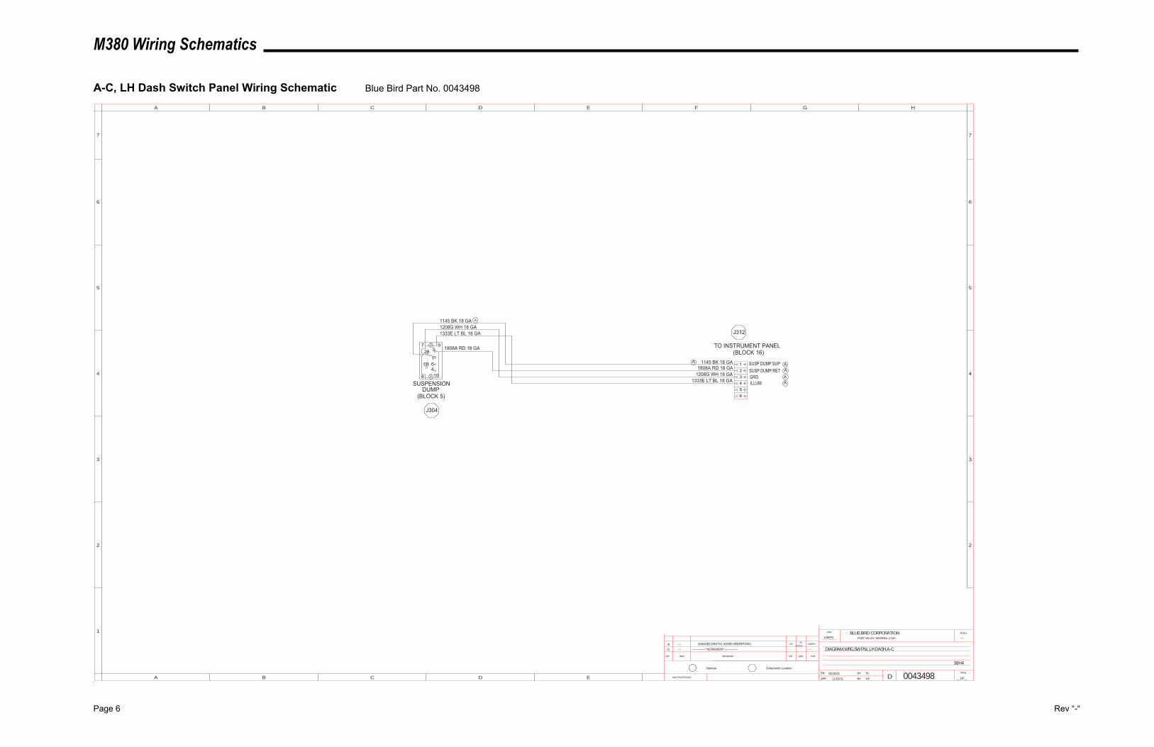
M380 Wiring Schematics
Page 6 Rev “-“
A-C, LH Dash Switch Panel Wiring Schematic Blue Bird Part No. 0043498
461
2B
5B
37 9
108
12857HAL
OSCHANGED CIRUIT ID; ADDED DESCRIPTIONS.---A
DIAGRAM,WRG,SW PNL,LH DASH,A-C
---12857G
38H4
KF
AL
11/02/01
08/19/01 0043498
7/23/02
INACTIVATES NOS.
LET. WAS REVISIONS DR. APP. CCN
SCALEBLUE BIRD CORPORATIONFORT VALLEY GEORGIA, U.S.A.
CCN
DR.
APP. BY
BY
DPAGE
__OF__
1
2
3
4
5
A B C D E F G H
B C D E
5
4
3
2
6 6
77
A
Component LocationHarness
0 --- ---------------*NO REVISION*--------------- ----
------
1145 BK 18 GA1808A RD 18 GA
1208G WH 18 GA1333E LT BL 18 GA
TO INSTRUMENT PANEL(BLOCK 16)
3
12
456
1808A RD 18 GA
SUSPENSIONDUMP
(BLOCK 5)
1333E LT BL 18 GA
1145 BK 18 GA1208G WH 18 GA
J312
J304
SUSP DUMP SUPSUSP DUMP RETGRDILLUM
AAA
A
A
A
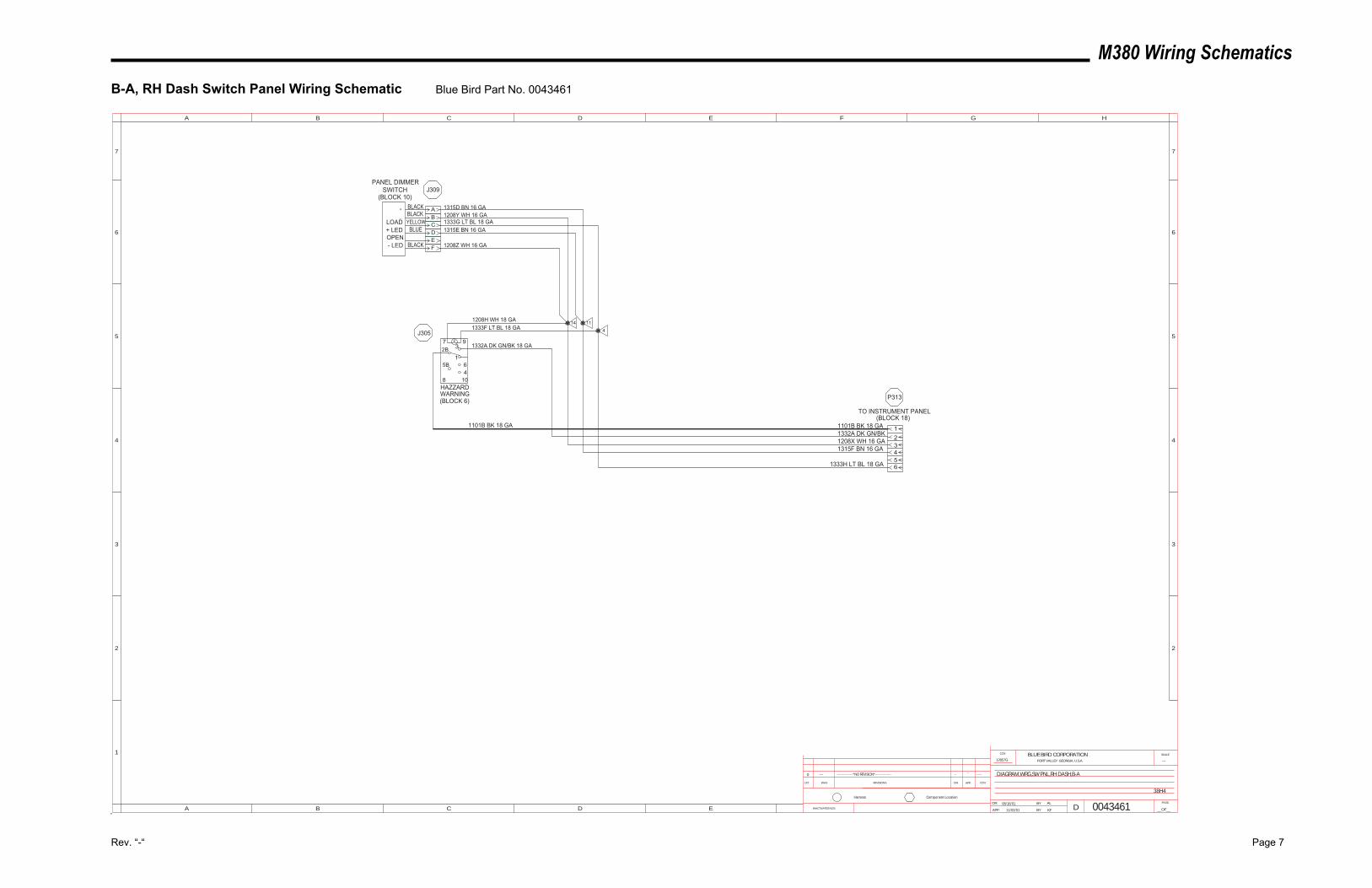
M380 Wiring Schematics
Rev. “-“ Page 7
B-A, RH Dash Switch Panel Wiring Schematic Blue Bird Part No. 0043461
8
5B1
932B
7
1046
DIAGRAM,WRG,SW PNL,RH DASH,B-A
---12857G
38H4
KF
AL
11/02/01
08/16/01 0043461INACTIVATES NOS.
LET. WAS REVISIONS DR. APP. CCN
SCALEBLUE BIRD CORPORATIONFORT VALLEY GEORGIA, U.S.A.
CCN
DR.
APP. BY
BY
DPAGE
__OF__
1
2
3
4
5
A B C D E F G H
B C D E
5
4
3
2
6 6
77
A
Component LocationHarness
0 --- ---------------*NO REVISION*--------------- ----
------
1315D BN 16 GA
1333G LT BL 18 GA1315E BN 16 GA
HAZZARDWARNING(BLOCK 6)
PANEL DIMMERSWITCH
(BLOCK 10)
1101B BK 18 GA1332A DK GN/BK1208X WH 16 GA1315F BN 16 GA
1333H LT BL 18 GA
1208Y WH 16 GA
1208Z WH 16 GA
1208H WH 18 GA1333F LT BL 18 GA
1332A DK GN/BK 18 GA
1101B BK 18 GA
ABCDEF
YELLOWBLACKBLACK
BLUE
BLACK
+
_
LOAD+ LEDOPEN- LED
TO INSTRUMENT PANEL(BLOCK 18)
14 11
4
3
12
456
J309
J305
P313
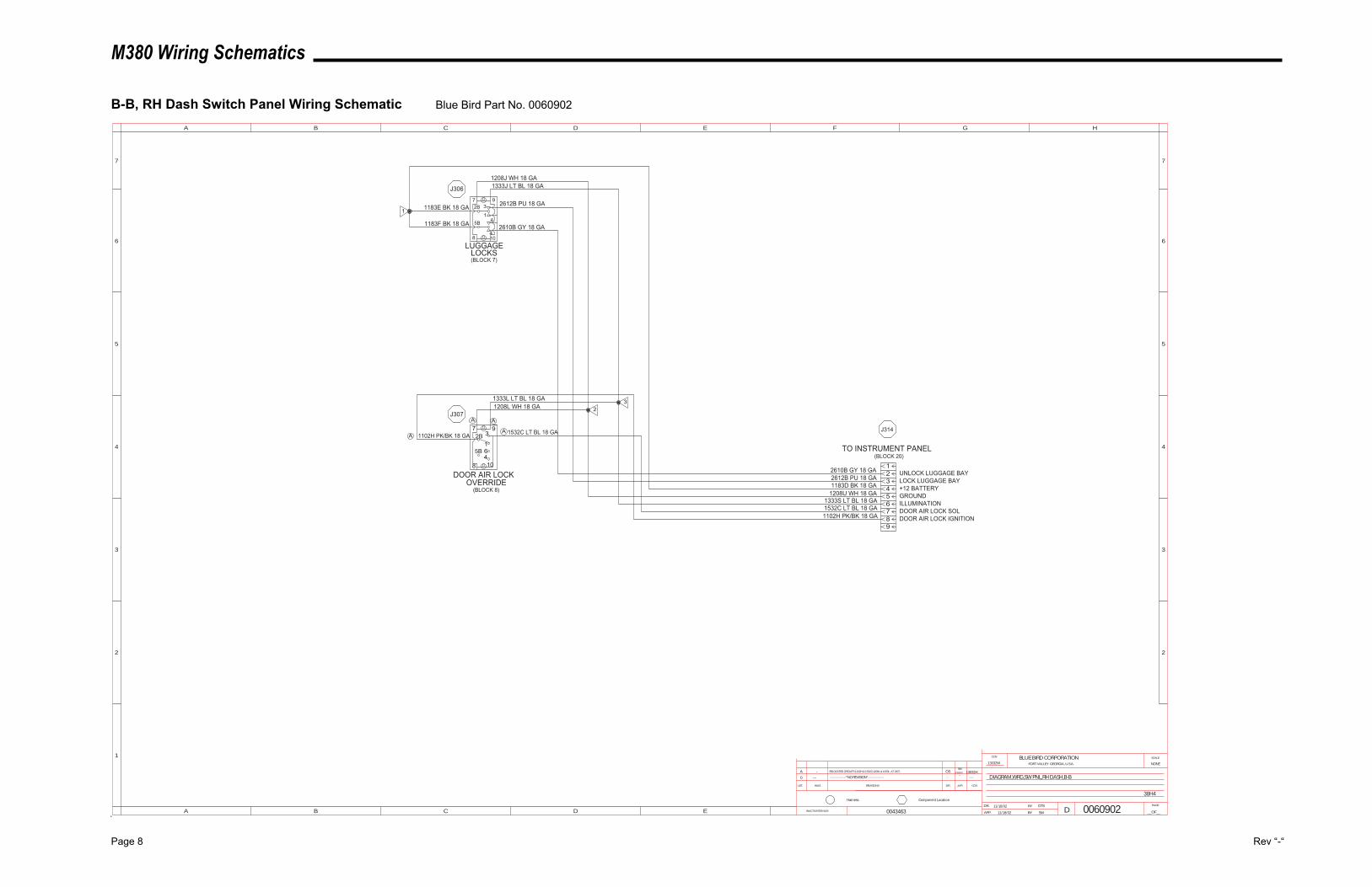
M380 Wiring Schematics
Page 8 Rev “-“
B-B, RH Dash Switch Panel Wiring Schematic Blue Bird Part No. 0060902
461
2B
5B
37
108
4/29/03
DIAGRAM,WRG,SW PNL,RH DASH,B-B
NONE13032W
38H4
SW
DTS
11/18/02
11/18/02 0060902INACTIVATES NOS.
LET. WAS REVISIONS DR. APP. CCN
SCALEBLUE BIRD CORPORATIONFORT VALLEY GEORGIA, U.S.A.
CCN
DR.
APP. BY
BY
DPAGE
__OF__
1
2
3
4
5
A B C D E F G H
B C D E
5
4
3
2
6 6
77
A
Component LocationHarness
0 --- ---------------*NO REVISION*--------------- ----
------
2610B GY 18 GA2612B PU 18 GA1183D BK 18 GA
1333S LT BL 18 GA
TO INSTRUMENT PANEL(BLOCK 20)
3
12
456789
1208U WH 18 GA
1532C LT BL 18 GA1102H PK/BK 18 GA
1532C LT BL 18 GA1102H PK/BK 18 GA
LUGGAGELOCKS(BLOCK 7)
DOOR AIR LOCKOVERRIDE
(BLOCK 8)
9
4
65B
8 10
9732B
1
2610B GY 18 GA
2612B PU 18 GA
1333J LT BL 18 GA1208J WH 18 GA
1183E BK 18 GA
1183F BK 18 GA
1333L LT BL 18 GA1208L WH 18 GA 2
3
J306
J307
J314
1
UNLOCK LUGGAGE BAYLOCK LUGGAGE BAY+12 BATTERYGROUNDILLUMINATIONDOOR AIR LOCK SOLDOOR AIR LOCK IGNITION
0043463
A - RELOCATED CIRCUITS 1102H & 1532C;1208L & 1333L AT J307. OS 13032HSW
AA
A A
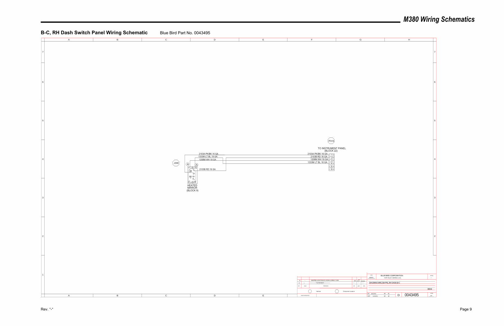
M380 Wiring Schematics
Rev. “-“ Page 9
B-C, RH Dash Switch Panel Wiring Schematic Blue Bird Part No. 0043495
461
2B
5B
37 9
108
4/29/03
DIAGRAM,WRG,SW PNL,RH DASH,B-C
---12857G
38H4
KF
AL
11/02/01
08/19/01 0043495INACTIVATES NOS.
LET. WAS REVISIONS DR. APP. CCN
SCALEBLUE BIRD CORPORATIONFORT VALLEY GEORGIA, U.S.A.
CCN
DR.
APP. BY
BY
DPAGE
__OF__
1
2
3
4
5
A B C D E F G H
B C D E
5
4
3
2
6 6
77
A
Component LocationHarness
0 --- ---------------*NO REVISION*--------------- ----
------
2103A PK/BK 16 GA2103B RD 16 GA1208M WH 18 GA
1333M LT BL 18 GA
TO INSTRUMENT PANEL(BLOCK 22)
3
12
456
HEATEDMIRROR
(BLOCK 9)
2103A PK/BK 16 GA1333M LT BL 18 GA1208M WH 18 GA
2103B RD 16 GA
J308
P315
A - SWAPPED LOCATIONS OF 1333M & 1208M AT J308. OS 13032HSW
AA
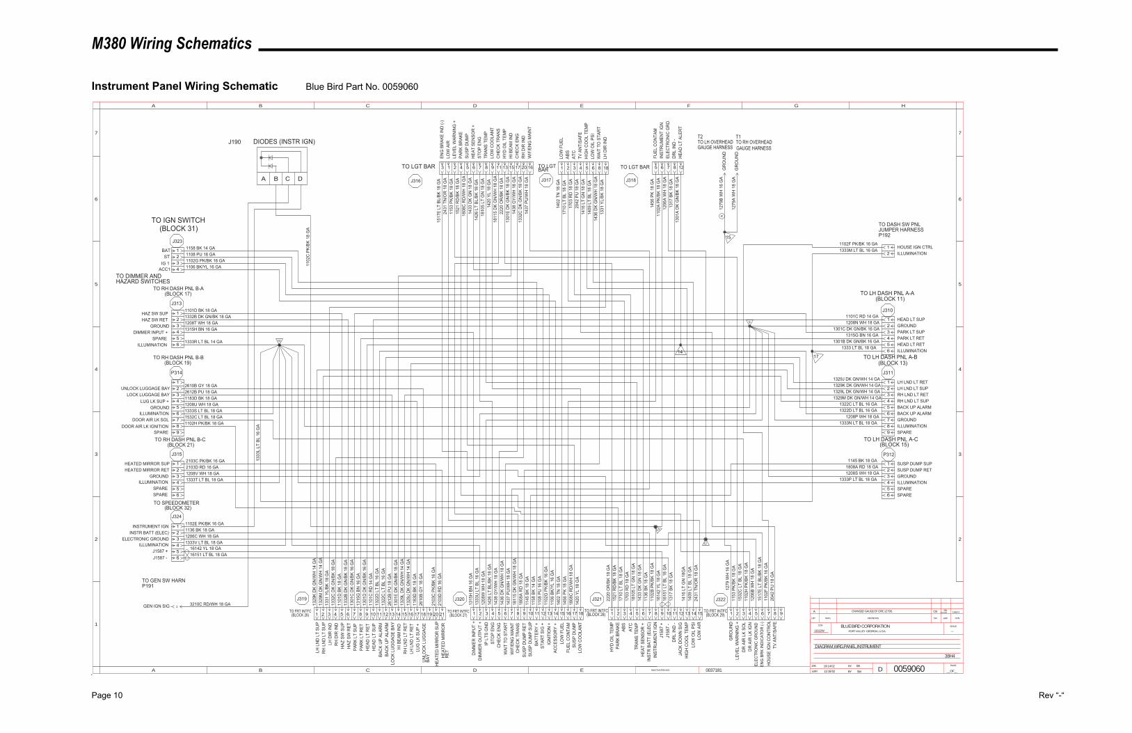
M380 Wiring Schematics
Page 10 Rev “-“
Instrument Panel Wiring Schematic Blue Bird Part No. 0059060
3/11/03SW
12857J
0037181
38H4
---13032W
SW
EA
11/18/02
10/14/02 0059060
DIAGRAM,WRG,PANEL,INSTRUMENT
INACTIVATES NOS.
LET. WAS REVISIONS DR. APP. CCN
SCALEBLUE BIRD CORPORATIONFORT VALLEY GEORGIA, U.S.A.
CCN
DR.
APP. BY
BY
DPAGE
__OF__
1
2
3
4
5
A B C D E F G H
B C D E
5
4
3
2
6 6
77
A
181716151413121110987654321 151413121110987654321 654321
123456
4321
654321
789
123456
654321
212019181716151413121110987654321
TO IGN SWITCH(BLOCK 31)
J323
J313
TO RH DASH PNL B-A(BLOCK 17)
TO RH DASH PNL B-B(BLOCK 19)
P314
J315
TO RH DASH PNL B-C(BLOCK 21)
J324
TO SPEEDOMETER(BLOCK 32)
5 6
TO LH DASH PNL A-C(BLOCK 15)
P312
J311
TO LH DASH PNL A-B(BLOCK 13)
TO LH DASH PNL A-A(BLOCK 11)
J310
654321
987
123456
654321
J319
TO FRT INTFC(BLOCK 26)
J320
TO FRT INTFC(BLOCK 27)
J321
TO FRT INTFC(BLOCK 28)
J322
TO FRT INTFC(BLOCK 29)
9
10
13
12
BATST
IG 1 ACC1
HAZ SW SUPHAZ SW RET
GROUNDDIMMER INPUT +
SPAREILLUMINATION
UNLOCK LUGGAGE BAYLOCK LUGGAGE BAY
LUG LK SUP +GROUND
ILLUMINATIONDOOR AIR LK SOL
DOOR AIR LK IGNITIONSPARE
HEATED MIRROR SUPHEATED MIRROR RET
GROUNDILLUMINATION
SPARESPARE
INSTRUMENT IGNINSTR BATT (ELEC)
ELECTRONIC GROUNDILLUMINATION
J1587 +J1587 -
HYD
OIL
TEM
PPA
RK
BRAK
EAB
SAT
CTR
ANS
TEM
PH
EAT
SEN
SOR
+IN
STR
BAT
T (E
LEC
)IN
STR
UM
ENT
IGN
J158
7 +
J158
7 -
DR
L IN
D -
JAC
K D
OW
N S
IGH
IGH
CO
OL
TEM
PLO
W O
IL P
SILO
W A
IR
GR
OU
ND
LEVE
L W
ARN
ING
+D
R A
IR L
K SO
LD
R A
IR L
K IG
NEL
ECTR
ON
IC G
RO
UN
DEN
G B
RK
IND
ICAT
OR
(-)
LH L
ND
LT
SUP
DIM
MER
INPU
T +
RH
LN
D L
T SU
PLH
DIR
IND
RH
DIR
IND
HAZ
SW
SU
PH
AZ S
W R
ETPA
RK
LT S
UP
PAR
K LT
RET
HEA
D L
T R
ETH
EAD
LT
SUP
BAC
K U
P AL
ARM
BAC
K U
P AL
ARM
LOC
K LU
GG
AGE
BAY
HI B
EAM
IND
RH
LN
D L
T R
ETLH
LN
D L
T R
ETLU
G L
K SU
P +
UN
LOC
K LU
GG
AGE
BAY
HEA
TED
MIR
RO
R S
UP
HEA
TED
MIR
RO
RR
ET
DIM
MER
OU
TPU
T +
IP L
TS G
ND
STO
P EN
GC
HEC
K EN
GW
AIT
TO S
TAR
TW
IF/E
NG
MAI
NT
CH
ECK
TRAN
SSU
SP D
UM
P R
ETSU
SP D
UM
P SU
PBA
TTER
Y +
STAR
T SI
G +
IGN
ITIO
N +
ACC
ESSO
RY
+LO
W F
UEL
FUEL
CO
NTA
MSU
SP D
UM
PLO
W C
OO
LAN
T
LOW
OIL
PSI
HIG
H C
OO
L TE
MP
1409
LT
BL 1
8 G
A14
16 L
T G
N 1
8 G
A
HEAD LT SUP
LH LND LT RET
SUSP DUMP SUP
GROUNDPARK LT SUPPARK LT RETHEAD LT RETILLUMINATION
LH LND LT SUPRH LND LT RETRH LND LT SUPBACK UP ALARMBACK UP ALARMGROUNDILLUMINATIONSPARE
SUSP DUMP RETGROUNDILLUMINATIONSPARESPARE
1101C RD 14 GA1208N WH 18 GA
1301C DK GN/BK 16 GA1315G BN 16 GA
1301B DK GN/BK 16 GA
1329J DK GN/WH 14 GA1329K DK GN/WH 14 GA1329L DK GN/WH 14 GA1329M DK GN/WH 14 GA
1322C LT BL 16 GA1322D LT BL 16 GA
1208P WH 18 GA1333N LT BL 18 GA
1145 BK 18 GA1808A RD 18 GA1208S WH 18 GA
1333P LT BL 18 GA
1329
K D
K G
N/W
H 1
4 G
A13
29M
DK
GN
/WH
14
GA
1331
YL/
BK 1
8 G
A13
32C
DK
GN
/BK
18 G
A11
01D
BK
18 G
A13
32B
DK
GN
/BK
18 G
A13
01C
DK
GN
/BK
16 G
A13
15G
BN
16
GA
1301
D D
K G
N/B
K 16
GA
1101
C R
D 1
4 G
A13
22D
LT
BL 1
6 G
A13
22C
LT
BL 1
6 G
A26
12B
PU 1
8 G
A13
01E
DK
GN
/BK
18 G
A13
29L
DK
GN
/WH
14
GA
1329
J D
K G
N/W
H 1
4 G
A11
83D
BK
18 G
A26
10B
GY
18 G
A
2103
C P
K/BK
16
GA
2103
D R
D 1
6 G
A
1315
H B
N 1
6 G
A13
33U
LT
BL 1
6 G
A12
08W
WH
18
GA
1426
LT
BL/B
K 18
GA
1438
GY/
WH
18
GA
1436
DK
GN
/WH
18
GA
1437
PU
/WH
18
GA
1811
5 D
K G
N/W
H 1
8 G
A18
08A
RD
18
GA
1145
BK
18 G
A11
58 B
K 14
GA
1108
PU
16
GA
1102
G P
K/BK
16
GA
1106
BK/
YL 1
6 G
A14
02 T
N 1
8 G
A14
56 P
K 18
GA
1808
C R
D/W
H 1
8 G
A14
20 Y
L 18
GA
2220
OR
/BK
18 G
A15
21 R
D/B
K 18
GA
1710
LT
BL 1
8 G
A17
03 R
D 1
8 G
A18
105
LT G
N 1
8 G
A14
33 D
K G
N 1
8 G
A11
36 B
K 18
GA
1102
B PK
/BK
18 G
A16
142
YL 1
8 G
A16
151
LT B
L 18
GA
1317
BK
18 G
A
1416
LT
GN
18G
A14
09 L
T BL
18
GA
2431
TN
/OR
18
GA
1153
PK/
BK 1
8 G
A15
32C
LT
BL 1
8 G
A11
02H
PK/
BK 1
8 G
A12
06B
WH
18
GA
1158 BK 14 GA1108 PU 16 GA1102G PK/BK 16 GA1106 BK/YL 16 GA
1101D BK 18 GA1332B DK GN/BK 18 GA1208T WH 18 GA1315H BN 16 GA
1333R LT BL 14 GA
2610B GY 18 GA2612B PU 18 GA1183D BK 18 GA1208U WH 18 GA1333S LT BL 18 GA1532C LT BL 18 GA1102H PK/BK 18 GA
2103C PK/BK 16 GA2103D RD 16 GA1208V WH 18 GA1333T LT BL 18 GA
1102E PK/BK 16 GA1136 BK 18 GA1206C WH 18 GA1333V LT BL 18 GA
16142 YL 18 GA16151 LT BL 18 GA
ABS
LOW
FU
EL17
10 L
T BL
18
GA
1402
TN
18
GA
1 2
ATC
3
1703
RD
18
GA
LH D
IR IN
D13
31 Y
L/BK
18
GA
18
1436
DK
GN
/WH
18
GA
WAI
T TO
STA
RT
8
2042
PU
18
GA
TV A
NT/
SAFE
4
HEA
T SE
NSO
R +
LOW
AIR
LEVE
L W
ARN
ING
+PA
RK
BRAK
E
HI B
EAM
IND
SUSP
DU
MP
1433
DK
GN
18
GA
2431
TN
/OR
18
GA
1153
PK/
BK 1
8 G
A15
21 R
D/B
K 18
GA
1301
E D
K G
N/B
K 18
GA
1808
C R
D/W
H 1
8 G
A
TO LGT BAR
J316
5 15421 6
1426
LT
BL/B
K 18
GA
1810
5 LT
GN
18
GA
1811
5 D
K G
N/W
H 1
8 G
A
1438
GY/
WH
18
GA
2220
OR
/BK
18 G
A
STO
P EN
GTR
ANS
TEM
P
CH
ECK
TRAN
S
CH
ECK
ENG
HYD
OIL
TEM
P
13 171187
1420
YL
18 G
A
1332
C D
K G
N/B
K 18
GA
LOW
CO
OLA
NT
RH
DIR
IND
9 20 TO LGT BAR
J317
FUEL
CO
NTA
M
DR
L IN
D -
1456
PK
18 G
A
1317
BK
18 G
A
85
1206
A W
H 1
8 G
A11
02A
PK/B
K 18
GA
ELEC
TRO
NIC
GR
DIN
STR
UM
ENT
IGN
76TO LGT BAR
J318
12
HEA
D L
T AL
ERT
1333 LT BL 18 GA
1333
L LT
BL
16 G
A
1279
WH
16
GA
GR
OU
ND
GR
OU
ND
1279
A W
H 1
8 G
A
1279
B W
H 1
6 G
A
T2TO LH OVERHEADGAUGE HARNESS
T1TO RH OVERHEADGAUGE HARNESS
A B C D
GEN IGN SIG 3210C RD/WH 18 GA
TO GEN SW HARNP191
1102
C P
K/BK
18
GA
DIODES (INSTR IGN)J190
1517
E LT
BL/
BK 1
8 G
A
3
ENG
BR
AKE
IND
(-)
1517
E LT
BL/
BK 1
8 G
A
16
WIF
/EN
G M
AIN
T14
37 P
U/W
H 1
8 G
A
14
1301
A D
K G
N/B
K 18
GA
17
21
ILLUMINATIONHOUSE IGN CTRL
1333M LT BL 16 GA1102F PK/BK 16 GA
TO DASH SW PNLJUMPER HARNESSP192
1
15
TO DIMMER ANDHAZARD SWITCHES
7 8 9
1102
F PK
/BK
16 G
A20
42 P
U 1
8 G
AH
OU
SE IG
N C
ON
TRO
LTV
AN
T/SA
FE
A - CHANGED GAUGE OF CIRC 1279B. OS
A
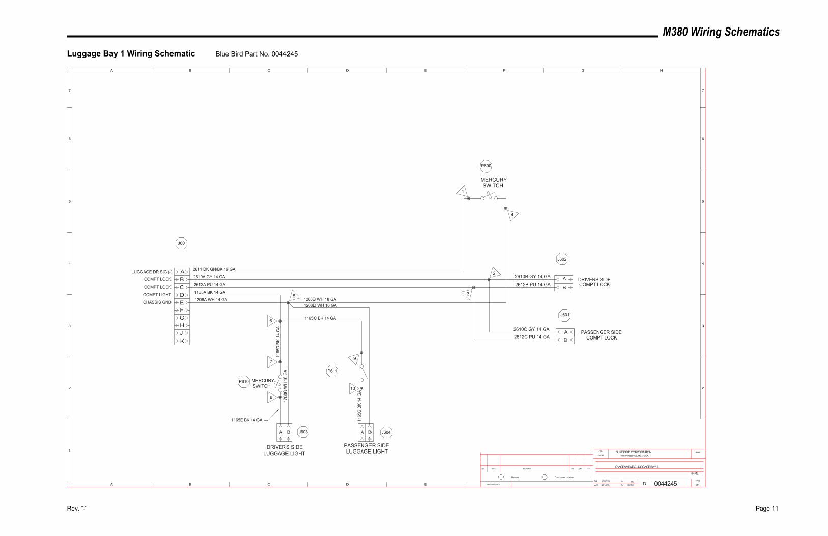
M380 Wiring Schematics
Rev. “-“ Page 11
Luggage Bay 1 Wiring Schematic Blue Bird Part No. 0044245
C
AB
DEFGHJK
2611 DK GN/BK 16 GA
2610A GY 14 GA
2612A PU 14 GA
1165A BK 14 GA
1208A WH 14 GA
1
4
2
35
10
9
8
7
6
1208B WH 18 GA1208D WH 16 GA
1165C BK 14 GA
1165
G B
K 14
GA
1208
C W
H 1
6 G
A
1165
D B
K 14
GA 2610C GY 14 GA
2612B PU 14 GA2610B GY 14 GA
LUGGAGE DR SIG (-)
COMPT LOCK
COMPT LOCK
COMPT LIGHT
CHASSIS GND
J80
J602
P600
J601
J604
P611
J603
P610
DRIVERS SIDELUGGAGE LIGHT
PASSENGER SIDELUGGAGE LIGHT
PASSENGER SIDECOMPT LOCK
DRIVERS SIDECOMPT LOCK
0044245
DIAGRAM,WRG,LUGGAGE BAY 1
10/16/01
10/16/01
OS
KLFRYE
12857B
H4RE
A
B
A B A B
A
B2612C PU 14 GA
INACTIVATES NOS.
LET. WAS REVISIONS DR. APP. CCN
SCALEBLUE BIRD CORPORATIONFORT VALLEY GEORGIA, U.S.A.
CCN
DR.
APP. BY
BY
DPAGE
__OF__
1
2
3
4
5
A B C D E F G H
B C D E
5
4
3
2
6 6
77
A
Component LocationHarness
MERCURYSWITCH
MERCURYSWITCH
1165E BK 14 GA
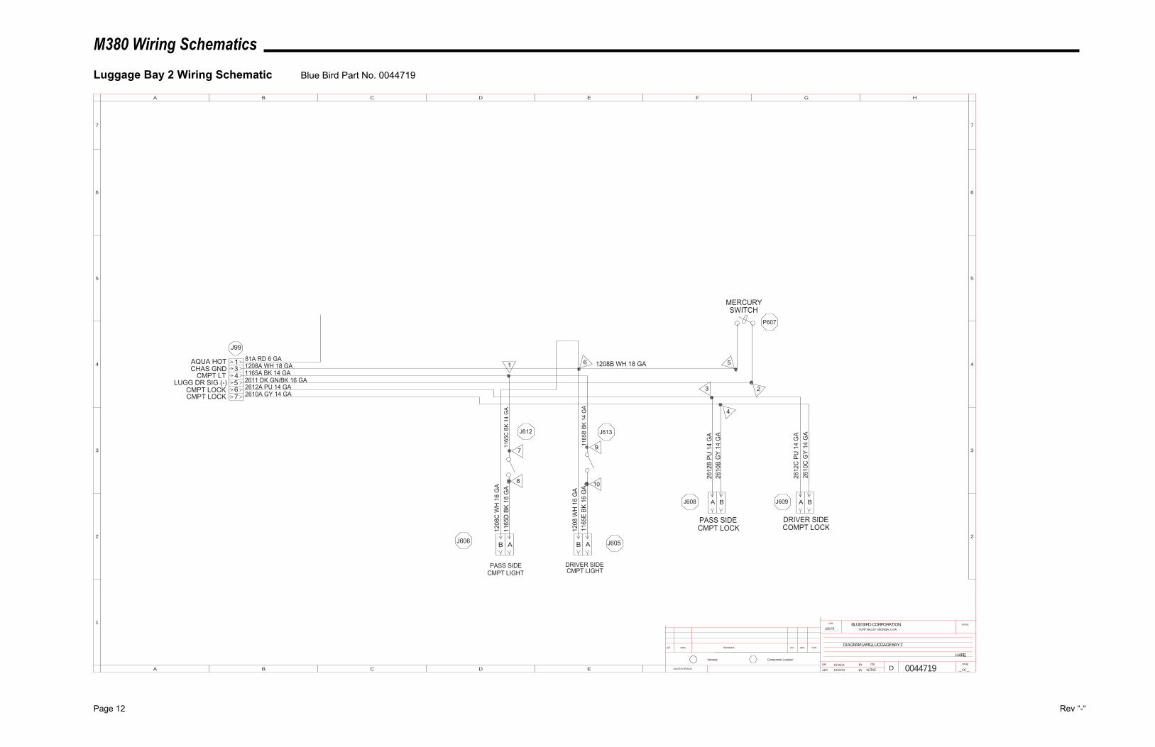
M380 Wiring Schematics
Page 12 Rev “-“
Luggage Bay 2 Wiring Schematic Blue Bird Part No. 0044719
4
13
567
AQUA HOTCHAS GND
CMPT LTLUGG DR SIG (-)
CMPT LOCKCMPT LOCK
J99
81A RD 6 GA1208A WH 18 GA1165A BK 14 GA2611 DK GN/BK 16 GA2612A PU 14 GA2610A GY 14 GA
PASS SIDECMPT LIGHT
DRIVER SIDECMPT LIGHT
PASS SIDECMPT LOCK
DRIVER SIDECOMPT LOCK
2
561
3
4
J606 J605
J608 J609
J613J612
P607
1208B WH 18 GA
1208
C W
H 1
6 G
A
1208
WH
16
GA
1165
E BK
16
GA
1165
B BK
14
GA
1165
D B
K 16
GA
1165
C B
K 14
GA
2612
B PU
14
GA
2610
B G
Y 14
GA
2612
C P
U 1
4 G
A26
10C
GY
14 G
A
0044719
12857B
10/16/01
10/16/01
OS
KLFRYE
DIAGRAM,WRG,LUGGAGE BAY 2
H4RE
7
8
9
10
INACTIVATES NOS.
LET. WAS REVISIONS DR. APP. CCN
SCALEBLUE BIRD CORPORATIONFORT VALLEY GEORGIA, U.S.A.
CCN
DR.
APP. BY
BY
DPAGE
__OF__
1
2
3
4
5
A B C D E F G H
B C D E
5
4
3
2
6 6
77
A
Component LocationHarness
AB AB
A B A B
MERCURYSWITCH
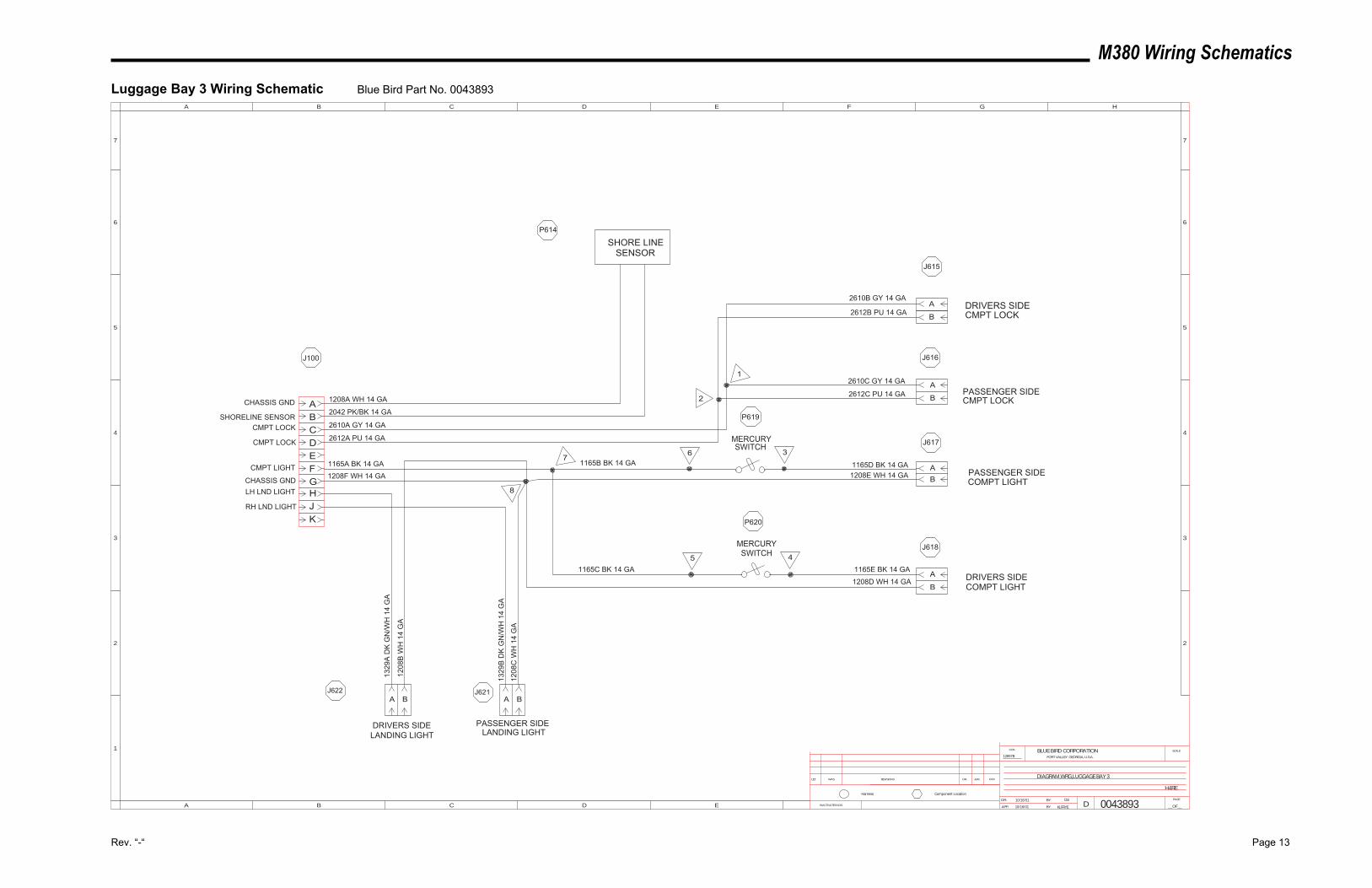
M380 Wiring Schematics
Rev. “-“ Page 13
Luggage Bay 3 Wiring Schematic Blue Bird Part No. 0043893
C
AB
DEFGHJK
SHORE LINESENSOR
J100
P614
J615
J616
J617
J618
J621J622
1208A WH 14 GA
2042 PK/BK 14 GA
2610A GY 14 GA
2612A PU 14 GA
5 4
36
1
2
7
8
DRIVERS SIDELANDING LIGHT
PASSENGER SIDELANDING LIGHT
DRIVERS SIDECOMPT LIGHT
PASSENGER SIDECOMPT LIGHT
PASSENGER SIDECMPT LOCK
DRIVERS SIDECMPT LOCK
2610B GY 14 GA
2612B PU 14 GA
2610C GY 14 GA
2612C PU 14 GA
1208E WH 14 GA
1208D WH 14 GA
1165C BK 14 GA
1208
C W
H 1
4 G
A
1208
B W
H 1
4 G
A
1208F WH 14 GA1165A BK 14 GA 1165B BK 14 GA
CHASSIS GND
SHORELINE SENSORCMPT LOCK
CMPT LOCK
CMPT LIGHT
CHASSIS GNDLH LND LIGHT
RH LND LIGHT
1329
A D
K G
N/W
H 1
4 G
A
1329
B D
K G
N/W
H 1
4 G
A
1165D BK 14 GA
1165E BK 14 GA
0043893
12857B
OS
KLFRYE10/16/01
10/16/01
DIAGRAM,WRG,LUGGAGE BAY 3
H4RE
A
B
A
B
AB
A
B
A BA B
P620
P619
INACTIVATES NOS.
LET. WAS REVISIONS DR. APP. CCN
SCALEBLUE BIRD CORPORATIONFORT VALLEY GEORGIA, U.S.A.
CCN
DR.
APP. BY
BY
DPAGE
__OF__
1
2
3
4
5
A B C D E F G H
B C D E
5
4
3
2
6 6
77
A
Component LocationHarness
MERCURYSWITCH
MERCURYSWITCH
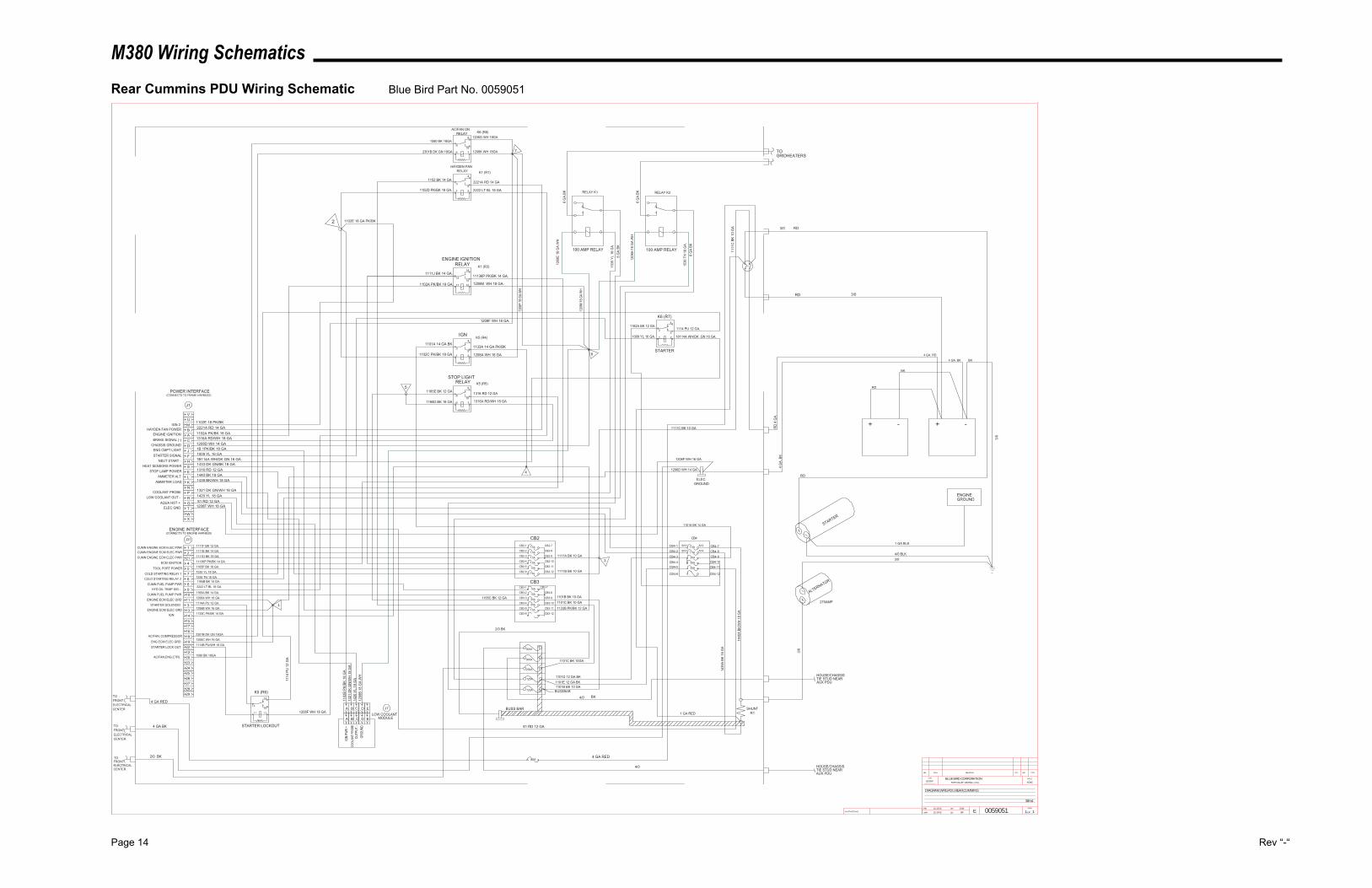
M380 Wiring Schematics
Page 14 Rev “-“
Rear Cummins PDU Wiring Schematic Blue Bird Part No. 0059051
1102A PK/BK 18 GA1316A RD/WH 18 GA1208D WH 14 GA1B 1PK/BK 16 GA1009 YL 16 GA1B114A WH/DK GN 16 GA1433 DK GN/BK 18 GA1316 RD 12 GA1440 BK 18 GA1439 BK/WH 18 GA
1321 DK GN/WH 18 GA1420 YL 18 GA81 RD 12 GA
1206F WH 16 GA
ECM IGNITION
CUMN FUEL PUMP PWR
CUMN FUEL PUMP PWRENGINE ECM ELEC GRD
STARTER SOLENOIDENGINE ECM ELEC GRD
CUMN ENGINE ECM ELEC PWRCUMN ENGINE ECM ELEC PWR
1206B WH 16 GA.1114A PU 12 GA.1206A WH 16 GA.1165A BK 14 GA.
1165B BK 14 GA.
11136P PK/BK 14 GA.1111D BK 16 GA.1111E BK 14 GA.
191816171514133
1110986754
212
J31
ENGINE INTERFACE(CONNECTS TO ENGINE HARNESS)
1111F BK 12 GA.1CUMN ENGINE ECM ELEC PWR7.5A
7.5A
7.5A
10A
10A
10A
20A
25A
7.5A
1111J BK 14 GA.
1102A PK/BK 18 GA. 1208M WH 18 GA.
11136P PK/BK 14 GA.
1101D 12 GA BK
1
ELECGROUND
1111C BK 10 GA
1206D WH 14 GA.
+ + --
4 G
A. B
K
STARTER
ALTERNATOR
RD
RD
BK
RD
BK4 GA. BK4 GA. RD
CHASSIS GROUNDBRAKE SIGNAL (-)ENGINE IGNITION
HAYDEN FAN POWER BACDJFHS
POWER INTERFACE(CONNECTS TO FRAME HARNESS)
J1
1182A BK 12 GA.
1009 YL 16 GA. 18114A WH/DK .GN 16 GA.
1114 PU 12 GA.
ENGINE IGNITIONRELAY
ENG ECM ELEC GRD 1206C WH 16 GA.
CB2-7
CB2-8
CB2-9
CB2-10
CB2-11
CB2-12
CB3-8
CB3-9
CB3-10
CB3-11
CB3-12
STARTER
3/0
1 GA BLK
ENGINEGROUND
4/0 BLK
STOP LIGHTRELAY
CB2-1
CB2-2
CB2-3
CB2-4
CB2-5
CB2-6
CB3-7CB3-1
CB3-2
CB3-3
CB3-4
CB3-5
CB3-6
1165F BK 18 GA.TOOL PORT POWER
RD
4 G
A.
COLD STARTING RELAY 1COLD STARTING RELAY 2
E
STARTER SIGNALNEUT START -
STOP LAMP POWER
125A
200A
300A
6
1208
H 1
8 G
A.W
H
100 AMP RELAY
6 G
A.BK
100 AMP RELAY
1536
TN
18
GA.
1535
YL
18 G
A.
6 G
A.BK
1208
E 18
GA.
WH
6 G
A BK
6 G
A BK
RELAY K2RELAY K1
TOGRIDHEATERS
LK
AMMETER ALTAMMETER LOAD
1440
A BK
/WH
18
GA
1439
A BK
18
GA
A13
A14B14
B13
HEAT SENSORS POWER
1152 BK 14 GA
1102D PK/BK 18 GA.
2221A RD 14 GA
2222 LT BL 18 GA
2222 LT BL 18 GAHYD OIL TEMP SIG -
SHUNTR1
HAYDEN FANRELAY
N
ENG CMPT LIGHT
7.5A
A B C D E
IGN
PWR
+CO
OLAN
T PRO
BEOU
TPUT
-GR
OUND
1102
B PK
/BK
18 G
A
1208
B 18
GA.
WH
PR
COOLANT PROBELOW COOLANT OUT -
1420
YL
18 G
A13
21 D
K G
N/W
H 1
8 G
A
IGN
G
MIGN 2
1535 YL 18 GA.1536 TN 18 GA.
IGN 1133C PK/BK 14 GA
1101A 14 GA BK1133A 14 GA PK/BK
1208A WH 18 GA.
20A
RD
1 GA RED
1102E 18 GA PK/BK
30A
1101C BK 10 GA1101B BK 10 GA
LOW COOLANTMODULE
AQUA HOT +
30A
81 RD 12 GA
1101E 12 GA BK
4/0 BK
3/0
HOUSE/CHASSISTIE STUD NEARAUX PDU
3/0
3/0
3/0
1208F WH 18 GA.
1208F WH 18 GA
22 1114B PU/WH 18 GASTARTER LOCK OUT
80A
4 GA RED
4 GA BK STARTER LOCKOUT
4 GA RED
2/0 BK
TOFRONTELECTRICALCENTER
TOFRONTELECTRICALCENTER
BUSS BAR
TELEC GND
1133B PK/BK 12 GA
UV
X
TOFRONTELECTRICALCENTER
2/0 BK
2827262524232012
29 K5 (R6)
1114
PU
12
GA
EDCBA
2
K1 (R1)
K1 (R3)
K5 (R4)
1102C PK/BK 18 GA
K5 (R5)
1165E BK 12 GA5
1165D BK 18 GA
1316 RD 12 GA
1316A RD/WH 18 GA
9
108
6 7
4
1165C BK 12 GA
1101C BK 10GA
1101B BK 10 GA
1111
C B
K 10
GA
1206F WH 16 GA.
1101A BK 14 GA
CB4-1
CB4-2
CB4-3
CB4-5CB4-4
CB4-6
CB4-7
CB4-8CB4-9
CB4-10
CB4-11
CB4-12
31111A BK 10 GA
1111B BK 10 GA
CB2
7.5A 7.5A
270AMP
1
11
1 1
7.5A
AC/FAN ONRELAY
2301B DK GN 18GA
1580 BK 18GA
AC/FAN, COMPRESSOR
AC/FAN,ENG,CTRL
2301B DK GN 18GA
1580 BK 18GA
1208K WH 18GA
1206G WH 18GAK6 (R8)
CB3
CB4
J7
K6 (R7)
9
108
6 7
14
1513
11 12
7
1208
M 18
GA.
WH
1208
P 18
GA.
WH
300A
4/0 HOUSE/CHASSISTIE STUD NEARAUX PDU
4
53
1 2
4
53
1 2
4
53
1 2
4
53
1 2
13032W
DIAGRAM,WRG,PDU,REAR,CUMMINS
11/18/02 CVM
SW 0059051
38H4
NONE
1 111/18/02INACTIVATES NOS.
LET. WAS REVISIONS DR. APP. CCN
SCALEBLUE BIRD CORPORATIONFORT VALLEY GEORGIA, U.S.A.
CCN
DR.
APP.
BY
BY EPAGE
__OF__
BUSSBAR
125A
1102E 18 PK/BK2221A RD 14 GA
W
M
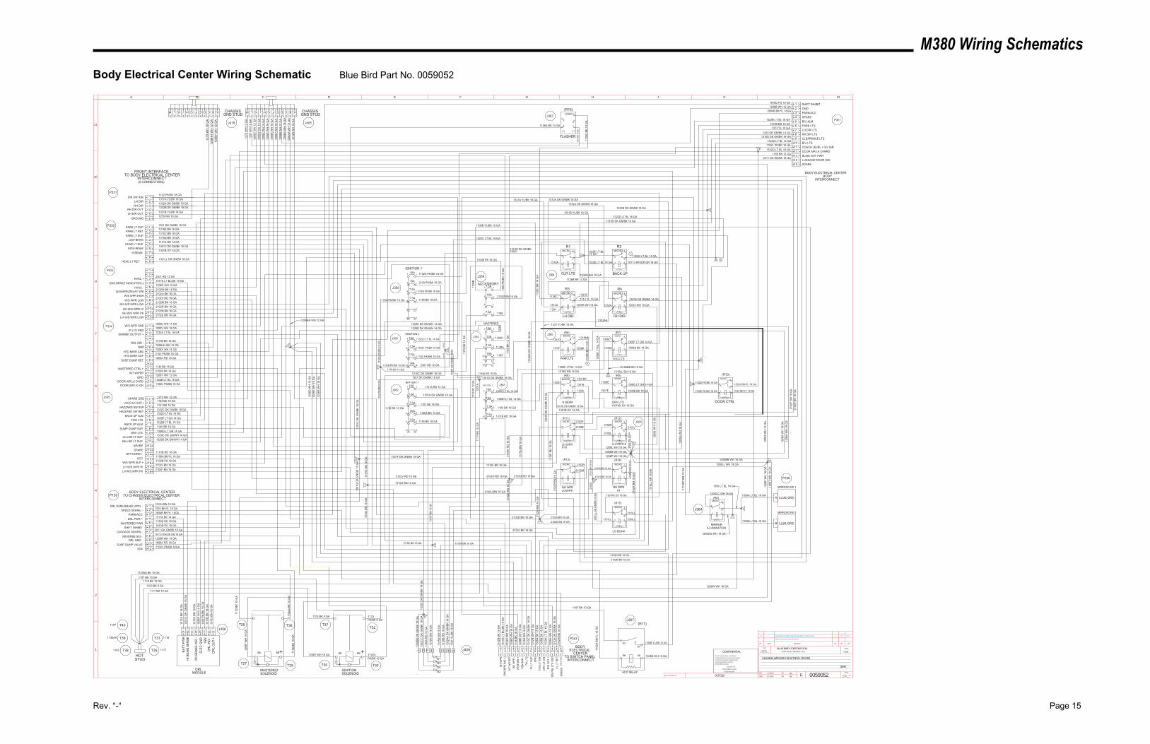
M380 Wiring Schematics
Rev. “-“ Page 15
Body Electrical Center Wiring Schematic Blue Bird Part No. 0059052
C ABDEFGHJKLMC ABDEFGHJKLMOS
-
3/11/03SW 12857JCHANGED GA,REROUTED,OR DELETED 1315NN,1315C,----A
--1322G,1322D,ADDED SPLICE 23.-----
INACTIVATES NOS.
LET. WAS REVISIONS DR. APP. CCN
SCALEBLUE BIRD CORPORATIONFORT VALLEY GEORGIA, U.S.A.
CCN
DR.
APP.
BY
BY EPAGE
__OF__
1
2
3
4
5
6
7
8
9
10
11
A B C D E F G H J K L M
0059052
DIAGRAM,WRG,BODY ELECTRICAL CENTER
11/18/02
11/18/02
CM
SW
13032W NONE
1 1
CONFIDENTIALThe information hereon is confidential
business information and may not be copied
or used for any purpose unless permission
is expressly granted in writing by
Blue Bird Body Company.
Copyright 2002
Blue Bird Body Company
All rights reserved
38H4
0037220
7.5A
1322C LT BL 14 GA
1133PK/BK 8 GA
10A
7.5A
1126B BK 14 GA
1126A BK 14 GA20A
7.5A 1101 BK 18 GA
15A 1301A DK GN/BK 16 GA
1315
F BN
16
GA
1101A RD 14 GA15A
15A
1308F LT GN 14 GA
CHASSISGND STUD
1301E DK GN/BK 18 GA
1308
E LT
BL
14 G
A
IGNITIONSOLENOID
1315
A BN
16
GA
PK L
TS13
10C
DK
GN
/BK
16 G
A12
12B
WH
18
GA
CL
LT S
UP
GN
D
CL
LT R
ET13
10A
DK
GN
/BK
16 G
A
FOG
LT
SWD
RV
LT S
W
1308
A BK
18
GA
1308
B BK
18
GA
MASTEREDSOLENOID
10A
10A
7.5A
15A
7.5A
30A
7.5A
1315F BN 16 GA
2102D BN 16 GA 2102
G B
N 1
6 G
A
2102
P BN
16
GA
2102S BN 16 GA
2102K BN 16 GA
10A
2102
L BN
18
GA
2102
H R
D 1
8 G
A
2102Q RD 18 GA
1208
J W
H 1
8 G
A
1208
K W
H 1
8 G
A12
08H
WH
18
GA
1208
Z W
H 1
4 G
A
1208M WH 18 GA1208P WH 18 GA
1208L WH 18 GA 1208
N W
H 1
8 G
A12
08Q
WH
18
GA
15A
2103 PK/BK 16 GA
1333
A LT
BL
16 G
AD
IM O
UT
+12
08A
WH
18
GA
SW P
NL
LTS
GN
D
1208W WH 18 GA
1208
F W
H 1
8 G
A
BODY
TO SWITCH PANELINTERCONNECT
ELECTRICALCENTER
BODY ELECTRICAL CENTERBODY
INTERCONNECT
1179
BK
14 G
A
7.5A
1317A BK 14 GA
CA B D E F G H
1317
A BK
14
GA
1301
G D
K G
N/B
K 18
GA
1315
H B
N 1
8 G
A12
08R
WH
14
GA
1168
PK/
BK 1
8 G
A13
17B
BK 1
8 G
A13
15J
BN 1
6 G
A
DRLMODULE
1208R WH 14 GA
DRL PWR +
DRL GND -
DRL PARK BRAKE APPL -1315H BN 18 GA
BATT
PW
RH
I BEA
M S
ENSE
PK B
RAK
E IN
D -
ELEC
GN
DIG
ND
RL
IND
-D
RL
OU
T +
15A
1130B RD 18 GAMASTERED PWR
1106B YL/BK 10 GA
1106
A BK
/YL
16 G
A
ACC RELAY
BODY ELECTRICAL CENTERTO CHASSIS ELECTRICAL CENTER
INTERCONNECT
1208
E W
H 1
8 G
A11
48 B
K 18
GA
1208
D W
H 1
8 G
A21
02C
RD
18
GA
REM
MIR
-R
EM M
IR +
INT
WPR
-IN
T W
R R
ET
1517
E LT
BL/
BK 1
8 G
AEN
G B
RK
IND
(-)
7.5A
10A
1208
G W
H 1
8 G
A
SPEED SIGNAL - 1532 BK/YL 18 GA
DOOR CTRL
LUGGAGE DOORS -REVERSE SIG -
18113 WH/DK GN 18 GA
2611 DK GN/BK 18 GA
1102A PK/BK 18 GA
1165
1130A
1329C DK GN/WH 14 GA1329D DK GN/WH 14 GA
1148 BK 18 GA
1322C LT BL 14 GA
1102 PK/BK 18 GA
2301 RD 12 GA
1308C LT BL 14 GA
1308D LT BL 14 GA
1183 BK 18 GA
1101B RD 18 GA
1168
2102D BN 16 GA1133A PK/BK 10 GA
1133B PK/BK 10 GA
1116 BK 10 GA
1331A YL/BK 18 GA1332A DK GN/BK 18 GA
LH DIRRH DIR
1102 PK/BK 18 GADIR SW IGN
RH DIR OUTLH DIR OUT 1331B YL/BK 18 GA
1332B DK GN/BK 18 GA
HAZZARD SW SUP1101 BK 18 GA1332C DK GN/BK 18 GAHAZZARD SW RET
1301 DK GN/BK 16 GAPARK LT SUP
1315E BN 16 GAPARK LT RETPARK LT SUP
1315C BN 16 GA
LOW BEAMHEAD LT SUP
1315D BN 16 GA1101A RD 14 GA
HIGH BEAM1301C DK GN/BK 18 GA
H BEAM1301B GY 14 GA
SPARE GRD 1270 WH 12 GA1183 BK 18 GALUGG LK SUP +
HVAC +2301 RD 12 GA
1208C WH 12 GAHVAC -
2102U BN 16 GAW/S WPR HIGH
2102V RD 18 GAW/S WPR LOW
RH W/S WPR LOWRH W/S WPR HIRH W/S WPR PK
LH W/S WPR LOW
2102M BN 16 GA2102R BN 16 GA2102N BN 16 GA2102E BN 16 GA
1208U WH 14 GAW/S WPR GND
HTD MIRR SUPHTD MIRR GND
2103 PK/BK 16 GA1208X WH 14 GA
1333A LT BL 16 GADIMMER OUTPUT +
IP LTS GND1208V WH 18 GA
SUSP DUMP RET1808A RD 18 GA
1130 BK 18 GAMASTERED CTRL +
1208Y WH 12 GAGRD
FRONT INTERFACETO BODY ELECTRICAL CENTER
INTERCONNECT(5 CONNECTORS)
1317B BK 18 GADRL IND -
2102B BK 18 GA
1102H PK/BK 18 GA1532B LT BL 18 GA
DOOR AIR LK IGNDOOR AIR LK OVRD
INT WIPER
123456
123456789
123456789
101112
123456789
101112131415
123456789
101112131415161718
BACK UP ALMFOG LTS
BACK UP ALMSUMP DUMP SUP
DRV LTSLH LND LT SUPRH LND LT SUP
OPT HORN +ACC
W/S WPR SUP +LH W/S WPR HI
LH W/S WPR PK 2102F BN 16 GA
1322D LT BL 16 GA
1308F LT GN 14 GA1322B LT BL 16 GA1145 BK 18 GA1308G LT GN 14 GA1329C DK GN/WH 14 GA1329D DK GN/WH 14 GA
1101B RD 18 GA1106A BK/YL 16 GA1102B PK 18 GA2102J BN 16 GA
SPARESPARE
1103 BK 8 GA
1130
BK
18 G
A
H G F E D C B A
D1D3D4D2
2102
B BK
18
GA
INT
WPR
1106B YL/BK 10 GA
1208S WH 18 GA
1532A BK/YL 18 GA
1532 BK/YL 18 GA
123456789
101112131415
GNDPARK/ACCSPAREB/U ALM
LH DIR LTSRH DIR LTSCLEARANCE LTSB/U LTS
DOOR AIR LK OVRRDSLIDE OUT PWRLUGGAGE DOOR SIG -SPARE
1208B WH 12 GA
1322B LT BL 16 GA1315B BN 16 GA
1313 YL 14 GA
1323 DK GN/BK 14 GA1310D DK GN/BK 16 GA
1322A LT BL 14 GA
1532D LT BL 18 GA1165 BK 12 GA
2611 DK GN/BK 18 GA
IGNITION 1
IGNITION 2
BATTERY 1BATTERY 2
MASTERED
ACCESSORY
CLR LTS
LH DIR RH DIR
PARK LTS FOG LTS
H BEAM DRV LTS
LH WPRK10
LH WPR HI
RH WPRLOW/PK
RH WPRHI
1270
WH
12
GA
1207
WH
18
GA
1208
C W
H 1
2 G
A12
08U
WH
14
GA
1208
Z W
H 1
4 G
A12
08X
WH
14
GA
1208
A W
H 1
8 G
A12
08V
WH
18
GA
1208
B W
H 1
2 G
A12
08W
WH
18
GA
1208
AA W
H 1
2 G
A12
12B
WH
18
GA
1332
BB D
K G
N/B
K 18
GA
1332
CC
DK
GN
/BK
18 G
A11
30A
RD
18
GA
1315
K BN
16
GA
1315
F BN
16
GA
1315
A BN
16
GA
1130
B R
D 1
8 G
A13
32AA
DK
GN
/BK
18 G
A13
31 Y
L/BK
18
GA
1331A YL/BK 18 GA
1331A 1332A
1301D1315NN
1315F 1208K 1315MM
1315
G B
N 1
6 G
A
1315
J BN
16
GA
1315
D B
N 1
6 G
A
1315G BN 16 GA
1301F DK GN/BK 18 GA
1301
G D
K G
N/B
K 18
GA
1301
C D
K G
N/B
K 18
GA
1301B
1301B GY 14 GA
1126
C B
K 14
GA
2102M
2102M BN 16 GA
2102
R B
N 1
6 G
A
2102N BN 16 GA
2102N
2102E 2102J
2102J BN 16 GA
2102F
1208
D W
H 1
8 G
A12
08E
WH
18
GA
1208
S W
H 1
8 G
A
1322D LT BL 16 GA
1308G LT GN 14 GA
2102V RD 18 GA
1301D DK GN/BK 16 GA1301 DK GN/BK 16 GA
R1
R3
(R6)
(R8)
(R11)
(R13) (R14)
(R12)
(R9)
(R7)
R4
R2
1331B1313 YL 14 GA
1332
AA D
K G
N/B
K 18
GA
1332AA
2102V RD 18 GA
1329C
1168
PK/
BK 1
8 G
A11
65 B
K 12
GA
1130A RD 18 GA
1102B PK 18 GA
1117
BK
10 G
A11
32 B
K 10
GA
1310
G13
10C
1310C DK GN/BK 16 GA (R10)
1208
F W
H 1
8 G
A12
08T
WH
18
GA
1208BB WH 18 GA
1102CPK/BK 16 GA
1315E BN 16 GA 1315A BN 16 GA
1179 BK 14 GA
1133
A PK
/BK
10 G
A11
33 P
K/BK
8 G
A
1301
A
1308C
1308A BK 18 GA
2102T BN 18 GA
2102U BN 16 GA
2102
U
2102S BN 16 GA
2102L
2102K
2102
C R
D 1
8 G
A
1301
F D
K G
N/B
K 18
GA
1308D
1208L 1301E
1308E
1308B BK 18 GA
13311208H WH 18 GA
1332B DK GN/BK 18 GA
1323A DK GN/BK 14 GA
1208J WH 18 GA
1322F LT BL 14 GA
1322E LT BL 18 GA
1322G LT BL 14 GA
1310D DK GN/BK 16 GA
1208G WH 18 GA
1310A
1310A DK GN/BK 16 GA
BACK UP
4
7
3
2
6
5
9
10
15
8
12
11
13
14
8
54
9
123
7
1315G BN 16 GA1308C LT BL 14 GA
1315
NN
BN
14
GA
1126C
1106
B
18113 WH/DK GN 18 GA
1331B YL/BK 18 GA
1332A DK GN/BK 18 GA
1132
BK
10 G
A
1107 BK 10 GA
1130
AA B
K 10
GA
HOTSTUD
1116 BK 10 GA
1130AA BK 10 GA
1103 BK 8 GA
1117 BK 10 GA
1107 BK 10 GA
1 2 3 4 5 6 7 8 9 10 11 12 13 14 15
PARK LTS
LO BEAM
(R15)
1301KK
1301KK GY 16 GA
1301KK GY 16 GA
1315LL BN 18 GA
1301
LL D
K G
N/B
K 18
GA
1208LL WH 18 GA
1315
LL B
N 1
8 G
A
1315LL
1208LL
HEAD LT RET1301LL DK GN/BK 18 GA
1301LL
16
J360
J362
J359
J361
J363
J364
J365
J366
P353
P357
P331
P332
P333
P334
J335
P120
J356
J406
J367
J405
T40
T39
T38
T31
T35
T28
T27
T36
T29
T37
T30 T33
T32
6
10
1208T WH 18 GA
1107
1130AA
1103
1116
1117
1208HH WH 12 GAGRD
J419
CHASSISGND STUD
1208
Y W
H 1
2 G
A12
08H
H W
H 1
2 G
A
2102
W B
K 18
GA
WAS
HER
(DEL
AY S
W)
2102W BK 18 GAWASHER (DELAY SW)
2102
E BN
16
GA
2102
F BN
16
GA
1332
C D
K G
N/B
K 18
GA
17
1279 WH 16 GA
1279
WH
16
GA
GROUND
ENG BRAKE INDICATOR (-)1517E LT BL/BK 18 GA
J358
SHIFT INHIBIT1810D PU 18 GA
1810D PU 18 GA SHIFT INHIBIT
1102F PK/BK 18 GACOACH LEVEL +12V IGN
20
12IGN1102C PK/BK 16GA
MICRO 4
53
1 2
MIRRORILLUMINATION
(R5)
1315
PP B
N 1
8 G
A
1208CC WH 18 GA 1350A LT BL 18 GAILLUM,(GRD)
ILLUM,(GRD)
MIRROR SW 1
MIRROR SW 221
22
1350B LT BL 18 GA
J364
P336
B
A
FLASHER
1126A BK 14 GA
1207
WH
18 G
A
1126
C B
K 14
GA
(R16)
J367
1
2
3
4
7
10
9
8
1102H PK/BK 18 GA7.5A
8
7 1
2
9 3
10 4
1
2
3
4
7
8
9
10
511
19
7 1
8 2
9 3
10 4
7 1
8 2
9 3
10 4
7 1
8 2
9 3
10 4
1145 BK 18 GA7.5A
(R17)
1102F PK/BK 18 GA7.5A
5
43
2 1
LOAD
(-)(+)
2604B BK/YL 18GAPARK/ACC
2604B BK/YL 18GA
18
1310G DK GN/BK 18GA
1310
F D
K G
N/B
K 18
GA
12 6
11
12
5
6
1329
D
12
11 5
6
1808A RD 18 GASUSP DUMP VALVE
23
MICRO 4
53
1 2
MICRO 4
53
1 2
MICRO 4
53
1 2
MICRO 4
53
1 2
MICRO 4
53
1 2
MICRO 4
53
1 2
MICRO 4
53
1 2
MICRO 4
53
1 2
MICRO 4
53
1 2
MICRO 4
53
1 2
MICRO 4
53
1 2
MICRO 4
53
1 2
MICRO 4
53
1 2
MICRO 4
53
1 2
8685 +8685 +
3087
8586
A
1102D PK/BK 18 GA
1102E PK/BK 18 GA
1208AA WH 12 GA
1315MM BN 18 GA
1331 YL/BK 18 GA
1350 LT BL 18 GA
1208GG WH 18 GA
A
A
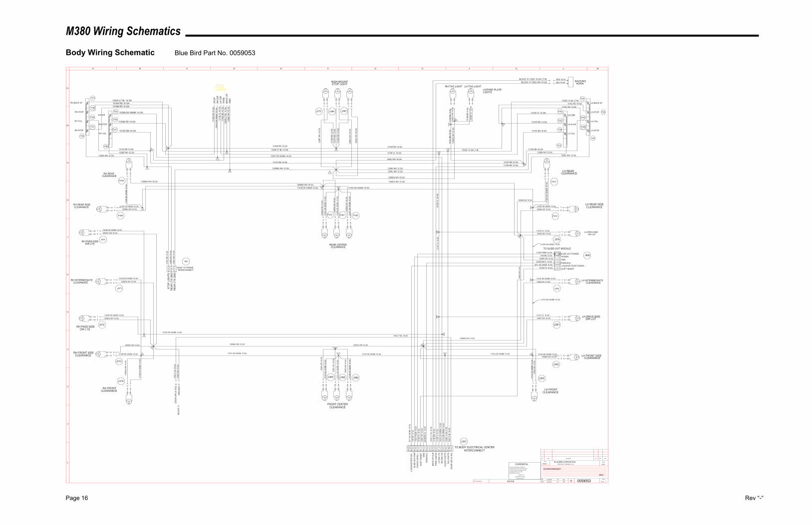
M380 Wiring Schematics
Page 16 Rev “-“
Body Wiring Schematic Blue Bird Part No. 0059053
INACTIVATES NOS.
LET. WAS REVISIONS DR. APP. CCN
SCALEBLUE BIRD CORPORATIONFORT VALLEY GEORGIA, U.S.A.
CCN
DR.
APP.
BY
BY EPAGE
__OF__
1
2
3
4
5
6
7
8
9
10
11
A B C D E F G H J K L M
0059053
DIAGRAM,WRG,BODY
11/19/02
11/19/02
PN
SW
13032W NONE
1 1
CONFIDENTIALThe information hereon is confidential
business information and may not be copied
or used for any purpose unless permission
is expressly granted in writing by
Blue Bird Body Company.
Copyright 2002
Blue Bird Body Company
All rights reserved
38H4
0037218
B/U
LIG
HTS
HIGH MOUNTSTOP LIGHT
LH REARCLEARANCE
LH REAR SIDECLEARANCE
LH INTERMEDIATECLEARANCE
LH FRONT SIDECLEARANCE
LH FRONTCLEARANCE
FRONT CENTERCLEARANCE
REAR CENTERCLEARANCE
RH FRONTCLEARANCE
RH FRONT SIDECLEARANCE
RH INTERMEDIATECLEARANCE
RH REAR SIDECLEARANCE
RH REARCLEARANCE
1322
E 14
GA
LT B
L
1322D 14 GA LT BL
BACKINGHORN
RED 16 GABLK 16 GA
1322A LT BL 14 GA
1310
M D
K G
N/B
K 16
GA
1310
L D
K G
N/B
K 16
GA
1310
K D
K G
N/B
K 16
GA
1310
H D
K G
N/B
K 16
GA
1310G DK GN/BK 16 GA
1310F DK GN/BK 16 GA
1310E DK GN/BK 16 GA
1310
D D
K G
N/B
K 16
GA
1310R DK GN/BK 16 GA
1310Q DK GN/BK 16 GA
1310
S D
K G
N/B
K 16
GA
1310
C D
K G
N/B
K 16
GA
1310
B D
K G
N/B
K 16
GA
1310
A D
K G
N/B
K 16
GA
1310
J D
K G
N/B
K 16
GA
CLE
AR L
IGH
TSR
H D
IR L
TSLH
DIR
LTS
1323
C D
K G
N/B
K 14
GA
1313
B YL
14
GA
1323B DK GN/BK 14 GA
1315
E BN
16
GA
PAR
K LI
GH
TS
1315D BN 16 GA
RH DIR
RH STOP
RH TAIL
RH BACK UP
RH STOP
RH TAIL
RH STOP
1310P DK GN/BK 16 GA
1310
N D
K G
N/B
K 16
GA
1315A BN 16 GA
STO
P LI
GH
TS13
16C
RD
12
GA
1316A RD 14 GA1316B RD 14 GA
1316M RD 14 GA
1316N RD 12 GA
1316
E R
D 1
4 G
A13
16F
RD
14
GA
1316
G R
D 1
4 G
A
BAC
K U
P AL
M13
22C
LT
BL 1
6 G
A
1208
B W
H 1
0 G
A12
08C
WH
10
GA
REA
R L
TS G
ND
REA
R L
TS G
ND
1208A WH 12 GA1208P WH 12 GA
1208
F W
H 1
8 G
A
1208
G W
H 1
8 G
A
1208
H W
H 1
8 G
A
1208K WH 12 GA1208L WH 12 GA
1208
V W
H 1
2 G
A
1208JA WH 12 GA1208HA WH 12 GA
1208KA WH 12 GA
1208LA WH 12 GA
1208M WH 16 GA
1208N WH 16 GA
1208S WH 16 GA
1208
U W
H 1
6 G
A
1208
Z W
H 1
6 G
A
1208
Y W
H 1
6 G
A
1208
X W
H 1
6 G
A
1208
GA
WH
16
GA
1208FA WH 16 GA
1208DA WH 16 GA
1208BA WH 16 GA
1208AA WH 16 GA
BODY TO FRAMEINTERCONNECT
TO BODY ELECTRICAL CENTERINTERCONNECT
GN
D
1532
LT
BL 1
8 G
AD
OO
R A
IR L
K SO
L
CO
ACH
LEV
EL +
1102F PK/BK 18 GA SLIDE OUT POWER
1102
F PK
/BK
18 G
A
1532
LT
BL 1
8 G
A
1208
D W
H 1
8 G
AD
OO
R A
IR L
K SO
L
STO
PR
H D
IRLH
DIR
PAR
KBA
CK
UP
GN
D
1316
D R
D 1
6 G
A13
23A
DK
GN
/BK
16 G
A13
136
YL 1
6 G
A13
15B
BN 1
6 G
A13
22B
LT B
L 14
GA
1208
E W
H 1
6 G
A
POWERGND
LUGGAGE DOOR SIGNAL -
1165 BK 12 GA1208R WH 12 GA
2611 DK GN/BK 18 GA
SLID
E O
UT
PWR
1165
BK
12 G
A26
11 D
K G
N/B
K 18
GA
LUG
GAG
E BO
X SI
G -
1313D YL 16 GA
1313C YL 16 GA
1208Q WH 16 GA
1208T WH 16 GA
LH DRVS SIDEDIR LGT
LH DRVS SIDEDIR LGT
1208CA WH 16 GA
1208EA WH 16 GA
1323E DK GN/BK 16 GA
1323G DK GN/BK 14 GA
1323D DK GN/BK 16 GA
RH PASS SIDEDIR LTS
RH PASS SIDEDIR LTS
1208ZA WH 16 GA
1315
L BN
16
GA
LICENSE PLATELIGHTS
12
12
12 1212
1212
12
1 2
12
12
1 2
12
12
12
1 21 2
12
1 2
12
12
12
12
LH DIR
LH STOP
LH TAIL
LH BACK UP
LH STOP
LH TAIL
LH STOP
26
18
27
15
28
24
29
22
23
21
20
19
17
16
11
12
1413
10
8
9
76
5
1
2
3
4
A B C
1322F LT BL 14 GA
1323F DK GN/BK 14 GA
1208MA WH 10 GA
1316K RD 12 GA
13136 YL 16 GA
1315F BN 16 GA
1208BA WH 16 GA1310Z DK GN/BK 16 GA 1310X DK GN/BK 16 GA
1208J WH 16 GA
1208
QA
WH
16
GA
1208
PA W
H 1
6 G
A
1208
NA
WH
16
GA
1208
ZA W
H 1
6 G
A
BLOCK 15 1322C 16 GA LT BLBLOCK 15 1208J WH 16 GA
1322D 14 GA LT BL1316J RD 14 GA
1316L RD 14 GA
1313A YL 14 GA
1316H RD 14 GA
1315C BN 16 GA
1315K BN 16 GA1208K WH 12 GA
1208L WH 12 GA
1313
E YL
16
GA
1313
F YL
16
GA
1208
KA W
H 12
GA
1208RA WH 16 GA1310U DK GN/BK 16 GA
1532 LT BL 18 GA
GR
OU
ND
1310T DK GN/BK 16 GA 1310Y DK GN/BK 16 GA
14 13 11 1 2 3 4 5 6 7 8 9 10 12
25
TO SLIDE-OUT MODULE
213456
J374
J373
J372
J371
P87
J370
P369
P368
J375 J389 J390
P377
P378
J379
J408
J380
J381
J382
J383
J357
J386J385J384
P376 P387 P388
T50
T41
T46
T47T51
T45
T42
T48
T49
T43
T52
T54
T53
T44
T55
T56
T57
T58
BLOCK 12
CONNECTORTO TRAILER
1810
D P
U 1
6 G
A
1810D PU 16 GA SHIFT INHIBIT
SHIF
T IN
HIB
IT
31
30
1315
N B
N 1
6 G
A12
08ZC
WH
16
GA
1315
M B
N 1
6 G
A
1208
ZB W
H 1
6 G
A
RH TAG LIGHT LH TAG LIGHT
PARK/ACC
PAR
K/AC
C
15
BLO
CK
11
2604B BK/YL 18 GA
2604
B BK
/YL
18 G
A
1310W DK GN/BK 16 GA
1310V DK GN/BK 16 GA
1315F BN 16 GA1315E BN 16 GA
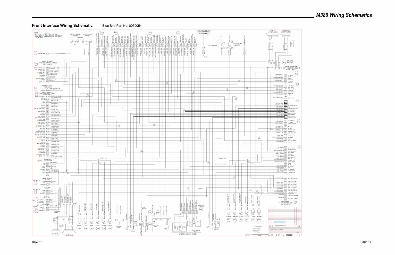
M380 Wiring Schematics
Rev. “-“ Page 17
Front Interface Wiring Schematic Blue Bird Part No. 0059054
---TWISTED PAIR SYMBOL, & CHGD WIRE GAUGES.-----
FOR DETAILS. DTO4-3P-P007. SEE DIMENSIONAL DRAWING INTERCONNECT USING DEUTSCH CONNECTOR1. DATA LINK CONNECTORS J411 & J412NOTES:
DIAGRAM,WRG,FRONT INTERFACE
NONE13032W
38H4
SW
MattP
11/20/02
11/20/02 0059054
ROAD RELAY
ROAD RELAY
A ---- ADDED CKTS 1301N,16142D,16151D & CONN P450,P451 EA 12857JSW3/11/03
B ---- ADDED CKTS 2108D,AND BLOCK 49A BT SW4/29/03
13032H
INACTIVATES NOS.
LET. WAS REVISIONS DR. APP. CCN
SCALEBLUE BIRD CORPORATIONFORT VALLEY GEORGIA, U.S.A.
CCN
DR.
APP.
BY
BY EPAGE
__OF__
CONFIDENTIALThe information hereon is confidential
business information and may not be copied
or used for any purpose unless permission
is expressly granted in writing by
Blue Bird Body Company.
Copyright 2002
Blue Bird Body Company
All rights reserved
DIRECTIONALSWITCH
LH D
IRIN
DR
H D
IR IN
D
1331
C Y
L/BK
18
GA
1332
E D
K G
N/B
K 18
GA
1331A YL/BK 18 GA1332B DK GN/BK 18 GA
LH DIRRH DIR
1102B PK/BK 18 GADIR SW IGN
DRIVING FOG PARK LH DIR
RH DIR PARK FOG DRIVING
RH DIR OUTLH DIR OUT
1332
A D
K G
N/B
K 14
GA
1308
C L
T G
N 1
4 G
A
1331B YL/BK 18 GA
1332C DK GN/BK 18 GA
HAZZARD SW SUP
HAZ
ZAR
D S
W S
UP
1101B BK 18 GA
1101
B BK
18
GA
HAZ
Z SW
RET
1332D DK GN/BK 18 GA
1332
D D
K G
N/B
K 18
GA
HAZZARD SW RET
1301E DK GN/BK 16 GAPARK LT SUP
1301
E D
K G
N/B
K 16
GA
PAR
K LT
SU
PPA
RK
LT R
ET
1315C BN 16 GAPARK LT RET
1315
C B
N 1
6 G
A
PARK LIGHTS1315D BN 16 GA
1315
A BN
14
GA
1308
L LT
GN
14
GA
HEA
D L
T R
ET
HI BEAM LO BEAM
HI BEAMLO BEAM
LOW BEAMHEAD LT SUP
HEA
D L
T SU
P
MOM
OPT
ICAL
HO
RN
HIG
H B
EAM
LH D
IR
RH
DIR
1301
C D
K G
N/B
K 14
GA
1301
H D
K G
N/B
K 16
GA
1301
A D
K G
N/B
K 14
GA
1315E BN 16 GA1101A RD 14 GA
1101
A R
D 1
4 G
A
1308
A LT
GN
14
GA
1308
D L
T G
N 1
4 G
A
1332
B D
K G
N/B
K 18
GA
1102
B PK
/BK
18 G
A13
31A
YL/B
K 18
GA
1301
M D
K G
N/B
K 16
GA
1101
C R
D 1
8 G
A
HIGH BEAM1301F DK GN/BK 16 GA
1331
YL/
BK 1
4 G
A
1308
B LT
GN
14
GA
H BEAM1301G GY 14 GA
1301
B D
K G
N/B
K 14
GA
1301
D D
K G
N/B
K 14
GA
1301
J D
K G
N/B
K 18
GA
H B
EAM
IND
1322
A LT
BL
16 G
ABA
CK
UP
ALM
BAC
K U
P AL
M13
22B
LT B
L 16
GA
LH L
ND
LT
SUP
RH
LN
D L
T SU
P
RH
LN
D L
T R
ETLH
LN
D L
T R
ET
1329
A D
K G
N/W
H 1
4 G
A13
29B
DK
GN
/WH
14
GA
1329
C D
K G
N/W
H 1
4 G
A13
29D
DK
GN
/WH
14
GA
LOC
K LU
GG
AGE
BAY
LUG
G L
K SU
P +
UN
LOC
K LU
GG
AGE
BAY
HTD
MIR
R S
UP
2612
PU
14
GA
1183
BK
18 G
A
1183 BK 18 GA
2610
GY
14 G
A
2103
A PK
/BK
16 G
A
LUGG LK SUP +
HVAC +2301B RD 12 GA
2301
B R
D 1
2 G
A
2301
A YL
12
GA
1208K WH 12 GAHVAC -
1208
K W
H 1
2 G
A
1301
K D
K G
N/B
K 16
GA
2102
K BK
18
GA
1102
D P
K 18
GA
2102H BN 18 GA
2102
H B
N 1
8 G
A21
02J
RD
18
GA
2102
A BK
18
GA
1208
EE W
H 1
8 G
AG
RO
UN
D
W/S WPR HIGH2102J RD 18 GA
W/S WPR LOWRH W/S WPR LOWRH W/S WPR HIRH W/S WPR PKLH W/S WPR LOW
LH W/S WPRMOTOR
RH W/S WPRMOTOR
2102B BN 16 GA2102C BN 16 GA2102D BN 16 GA2102E BN 16 GA
2102
E BN
16
GA
2102
F BN
16
GA
2102
G B
N 1
6 G
A
2102
B BN
16
GA
2102
C B
N 1
6 G
A21
02D
BN
16
GA
1208U WH 14 GAW/S WPR GND
1208
L W
H 1
6 G
A
1208
H W
H 1
6 G
A
HTD
MIR
R R
ET
HTD MIRR SUPHTD MIRR GND
2103A PK/BK 16 GA1208W WH 14 GA
2103
B R
D 1
6 G
A
2103
C R
D 1
6 G
A
1315
F BN
16
GA
DIM
MER
INPU
T +
DIM
MER
OU
TPU
T +
1333
A LT
BL
16 G
A
1333B LT BL 16 GA DIMMER OUTPUT +IP LTS GND
1208V WH 18 GA
1208
V W
H 1
8 G
AIP
LTS
GN
DST
OP
ENG
CH
ECK
ENG
WAI
T TO
STA
RT
WIF
/EN
G M
AIN
TC
HEC
K TR
ANS
1426
LT
BL/B
K 18
GA
1438
GY/
WH
18
GA
1436
DK
GN
/WH
18
GA
1437
PU
/WH
18
GA
1811
5 D
K G
N/W
H 1
8 G
A
SUSP
DU
MP
RET
1808
A R
D 1
8 G
A
SUSP DUMP RET1808A RD 18 GA
1145
BK
18 G
ASU
SP D
UM
P SU
PBA
TTER
Y +
STAR
T SI
G +
IGN
ITIO
N +
ACC
ESSO
RY
+
1158
BK
14 G
A10
08 P
U 1
4 G
A11
02F
PK/B
K 14
GA
1106
C B
K/YL
16
GA
1402
TN
18
GA
LOW
FU
ELFU
EL C
ON
TAM
SUSP
DU
MP
1420
YL
18 G
A
HYD
OIL
TEM
P22
20 O
R/B
K 18
GA
1521
C R
D/B
K 18
GA
PAR
K BR
AKE
ABS
ATC
TRAN
S TE
MP
1710
A LT
BL
18 G
A17
03B
RD
18
GA
1810
5 LT
GN
18
GA
HEA
T SE
NSO
RS
+14
33C
DK
GN
18
GA
PASS HTDMIRROR
1130 BK 18 GA MASTERED CTRL +
MAS
TER
ED C
TRL
1130
BK
18 G
A
1208
Q W
H 1
4 G
A
1208
P W
H 1
4 G
A
1208
S W
H 1
4 G
A
1208
R W
H 1
4 G
A
1208
N W
H 1
4 G
A
1208
M W
H 1
4 G
A
1208
J W
H 1
8 G
A
1208
D W
H 1
4 G
A
1208
E W
H 1
4 G
A
1208
B W
H 1
4 G
A
1208
C W
H 1
4 G
A
1208
F W
H 1
4 G
A
1208
G W
H 1
4 G
A
1208X WH 12 GAGRD
1333
C L
T BL
18
GA
FRONT INTERFACETO BODY ELECTRICAL CENTER
INTERCONNECT
FRONT INTERFACE TOINSTRUMENT PANEL
INTERCONNECT
GR
OU
ND
1444
TN
/OR
18
GA
1443
OR
18
GA
1442
PU
/WH
18
GA
1206
A W
H 1
8 G
A
1206
G W
H 1
8 G
A
ENG DIAG SWENG DIAG SW
INC/DEC
1206
A W
H 1
8 G
A
GRD1208MM WH 18 GA1185 BK 18 GA
16142B YL 18 GA16151B LT BL 18 GA
BATTJ1939 +J1939 -
J1939 SHLD
J1587 -J1587 +
DIAGNOSTICCONNECTOR
ABCDEFGHJ
1208
CC
WH
18
GA
1521
B R
D/B
K 18
GA
2108
C T
N/B
K 18
GA
STEERING COLUMN SWITCH
1317
B BK
18
GA
DRVS CONV UP & DN
DRVS CONV COMM
DRVS CONV L & R
DRVS FLAT UP & DN
DRVS FLAT L & R
DRVS FLAT COMM
PASS CONV UP & DN
PASS CONV COMM
123456789
101112
PASS CONV L & RPASS FLAT UP & DN
PASS FLAT L & R
PASS FLAT COMM
2117A OR 18 GA
2119 BN 18 GA
2021 RD/BK 18 GA
2117 OR 18 GA
2125 YL 18 GA
2124 YL 18 GA
2116 OR 18 GA
2122 DK GN/BK 18 GA
2120 RD/BK 18 GA
2116A OR 18 GA
2124
YL
18 G
A21
16 O
R 1
8 G
A
2122
DK
GN
/BK
18 G
A
2120
RD
/BK
18 G
A21
18 B
N 1
8 G
A
2116
A O
R 1
8 G
A
1208
T W
H 1
8 G
A
DRIVERSMIRROR
PASSENGERMIRROR
1234
123123
RH FLATMIRROR MOTOR
RH CONVEXMIRROR MOTOR
YL GNBLBNRD
BLBNRDGNORYL
OR
1 2 3 4
1 2 3 1 2 3
LH FLATMIRROR MOTOR
LH CONVEXMIRROR MOTOR
YLGNBL BN RD
BL BN RD GNOR YL
OR
SWITCH PANELTO FRONT INTERFACE
INTERCONNECT
1317B BK 18 GA DRL IND -
DR
L IN
D -
2102K BK 18 GA
ENG
BR
AKE
IND
(-)
SERVICE BRAKESWITCH
1208
Z W
H 1
8 G
A
1316
RD
18
GA
2431
TN
/OR
18
GA
1409
LT
BL 1
8 G
A14
16 L
T G
N 1
8 G
A
LOW
AIR
LOW
OIL
PSI
HIG
H C
OO
L TE
MP
JAC
KS D
OW
N -
SPAR
E
DR
AIR
LK
IGN
DR
AIR
LK
SOL
1810
PU
18
GA
1102
J PK
/BK
18 G
A15
32 L
T BL
18
GA
1102J PK/BK 18 GA1532 LT BL 18 GA
DOOR AIR LOCK IGNDOOR AIR LK SOL
1206
E W
H 1
8 G
AEL
EC G
ND
J158
7 -
1615
1A L
T BL
18
GA
1614
2A Y
L 18
GA
J158
7 +
INST
BAT
T (E
LEC
)11
36 B
K 18
GA
1102
E PK
/BK
18 G
AIN
ST IG
N
INT WIPER
13
15 3 4 13 1416 10 9111 5 6
1208
A W
H 1
8 G
A
1 2 3 4 5 6 7 8 9 10 11 12 13 14 15 16 17 18 19 20 21 1 2 3 4 5 6 7 8 9 10 11 12 13 14 15 16 17 18 1 2 3 4 5 6 7 8 9 10 11 12 13 14 154321 5 6
1415
2123 DK GN/BK 18 GA
2118 BN 18 GA
123456
123456789
123456789101112
123456789
101112131415
123456789
101112131415161718
BACK UP ALMFOG LTSBACK UP ALMSUSP DUMP SUPDRV LTSLH LND LT SUPRH LND LT SUP
OPT HORN +ACCW/S WPR SUP +LH W/S WPR HILH W/S WPR PK2102G BN 16 GA
4
2108
TN
/WH
18
GA
1322A LT BL 16 GA1308E LT GN 14 GA1322B LT BL 16 GA
1145 BK 18 GA
1308F LT GN 18 GA1329A DK GN/WH 14 GA1329B DK GN/WH 14 GA
1101C RD 18 GA1106A BK/YL 16 GA
1102D PK 18 GA2102F BN 16 GA
SPARESPARE
LOW
CO
OL
SIG
-
17
21201918
16151413121110987654312 16142C YL 18 GAJ1587 +
222324252627282930313233393734
J1587 - 16151C LT BL 18 GA1444 TN/OR 18 GAENG DIAG SW
DIAG INC 1442 PU/WH 18 GA1443 OR 18 GADIAG DEC
1703B RD 18 GAATC TELLTALEWIF/ENG MAINT 1437 PU/WH 18 GA
1426 LT BL/BK 18 GASTOP ENGCHECK ENG 1438 GY/WH 18 GA
1436 DK GN/WH 18 GAWAIT TO START
2220 OR/BK 18 GAHYD OIL TEMP
HEAT SENSORS - 1433C DK GN 18 GA1710 LT BL 18 GAABS TELLTALE
LOW COOL SIG - 1420 YL 18 GA1208CC WH 18 GAPARK BRAKE SUP -
PARK BRAKE RET - 1521A RD/BK 18 GA1206D WH 18 GAELEC GND
JACKS DOWN -1810 PU 18 GA1808C RD/WH 18 GA
SUSPENSION DUMPSVC BRK PSI SW RET 1316 RD 18 GA
1208Z WH 18 GASVC BRK PSI SW SUPLOW FUEL
1402 TN 18 GA1416 LT GN 18 GAHIGH COOL TEMP
LOW OIL PSI1409 LT BL 18 GA2431 TN/OR 18 GA
LOW AIRINST IGN
1102E PK/BK 18 GA1136 BK 18 GA
INST BATT (ELEC)DIAG GND 1208MM WH 18 GA
1185 BK 18 GADIAG POS
HORN SIGNAL - 2108 TN/WH 18 GA2108C TN/BK 18 GAHORN SIGNAL +
TRANS TEMP 18105 LT GN 18 GA18115 DK GN/WH 18 GACHECK TRANS
FRONT INTERFACECHASSIS ELECTRICAL CENTER
INTERCONNECT
FRONT INTERFACECHASSIS ELECTRICAL CENTER
INTERCONNECT
1008 PU 14 GASTART SIG +
HVAC RET2301A YL 12 GA1456 PK 14 GA
WATER CONTAM LTBATTERY +
1158 BK 14 GAIGNITION +
ACCESSORY +1106B BK/YL 14 GA1329C DK GN/WH 14 GARH LND LT RET
LH LND LT RET 1329D DK GN/WH 14 GA2612 PU 14 GA
LOCK LUGGAGE BAYUNLOCK LUGGAGE BAY
2610 GY 14 GAABCDEFGHJK
1102F PK/BK 14 GA
2
1
1208BB WH 10 GA 1208BB WH 10 GA
1206
G W
H 1
8 G
A
2103D RD 18 GA
8
7
311
10
5
12
2019
15
1318
21
17
16
9
WAS
HER
MTR
2102
M B
K 18
GA
1 2
1456
PK
14 G
A18
08C
RD
/WH
18
GA
HEAD LT RET1301LL DK GN/BK 18 GA
22
J106
J107
P341
J399 J401 J400 P398 P397
J326
P327 P328
J329 P394 P395 J392 J393 J396
J330
P335
J334
J333
J332
J331
P321P320P319P322
J325
T5
T7T6
T4
T3
T2T1
PARK BRAKESWITCH
HORNBUTTON
1 2 3
GRD
HVACPWR
A/C
ON
-OFF
1 2
HVAC ILLUMPWR
GRD
STEERINGCOLUMN
J408
T59 T60
T61 T62
J409
J410
T63T64
SERVICE BRAKESWITCH
1208FF WH 18 GA
1316B RD 18 GA
1YL1GN1SHLD
1YL
J411CBA
1GN1SHLDJ1939 SHLD
J1939 -J1939 +
J1939 +J1939 -
J1939 SHLD 2SHLD2GN2YLA
BC
J412
J413
CBAJ1939 +
2YL2GN2SHLD
J1939 SHLDJ1939 -
DATA LINK(BLUE)
DATA LINK(TERMINATOR)
DATA LINK NODE(ORANGE)
(SEE NOTE 1)
(SEE NOTE 1)
A B C D E F G H
ABCDEFGH
1208HH WH 12 GA
23
1208
GG
WH
10
GA
2125
YL
18 G
A
2117
2123
2021
211921
17A
ABS DIAGN SWT65 T66
1208JJ WH 18 GA
1710B LT BL 18 GA
24
1208JJ WH 18 GA
J417
J418
WASHER (DELAY SW)2102W BK 18 GA
252102W BK 18 GA
1279 WH 16 GA
1279
WH
16
GA
GROUND
1517
E LT
BL/
BK 1
8 G
A
1517E LT BL/BK 18 GAENG BRAKE IND (-)
HOUSE IGNT71 1102H PK/BK 14 GA
26
0037182
BLO
CK
41
BLO
CK
49A
120 _
18113B RD 18 GAREVERSENEUTRAL
18114C WH/DK GN 18 GA4041
P440BA 18114C WH/DK GN 18 GA
18113B RD 18 GAREVERSENEUTRAL
INTERLOCKSLANDING LIGHTS
GROUND
987
42
SHORELINE SENSOR 2042 PU 18 GA
SHO
REL
INE
SEN
SOR
2042
PU
18
GA
1102
C P
K/BK
16
GA
HO
USE
IGN
CO
NTR
OL
1102A PK/BK 16 GAHOUSE IGN CONTROL
ABS OFFROAD SWITCH
MUD & SNOW SWITCH
KYSO
R
1301N DK GN/BK 18 GA
AB 16151D LT BL 18 GA
16142D YL 18 GA
J1587 LOJ1587 HIP450
P451 A 1301N DK GN/BK 18 GAHEADLIGHT
A B
TO L
IGH
TIN
G,U
PPER
FRO
NT
AIR
,CIT
Y,H
OR
N21
08D
TN
/WH
18
GA
A B
A B
A B A B A B
A B A B A BA BA B
A B A B
WP
R H
I
WP
R L
O
OFF
WIPER
INT
WAS
HER
HO
RN
541 2 3
LOW H
IPA
RK
541 2 3
LOW H
IPA
RK
A
A
A
AA
A
B
A
A
A
A A
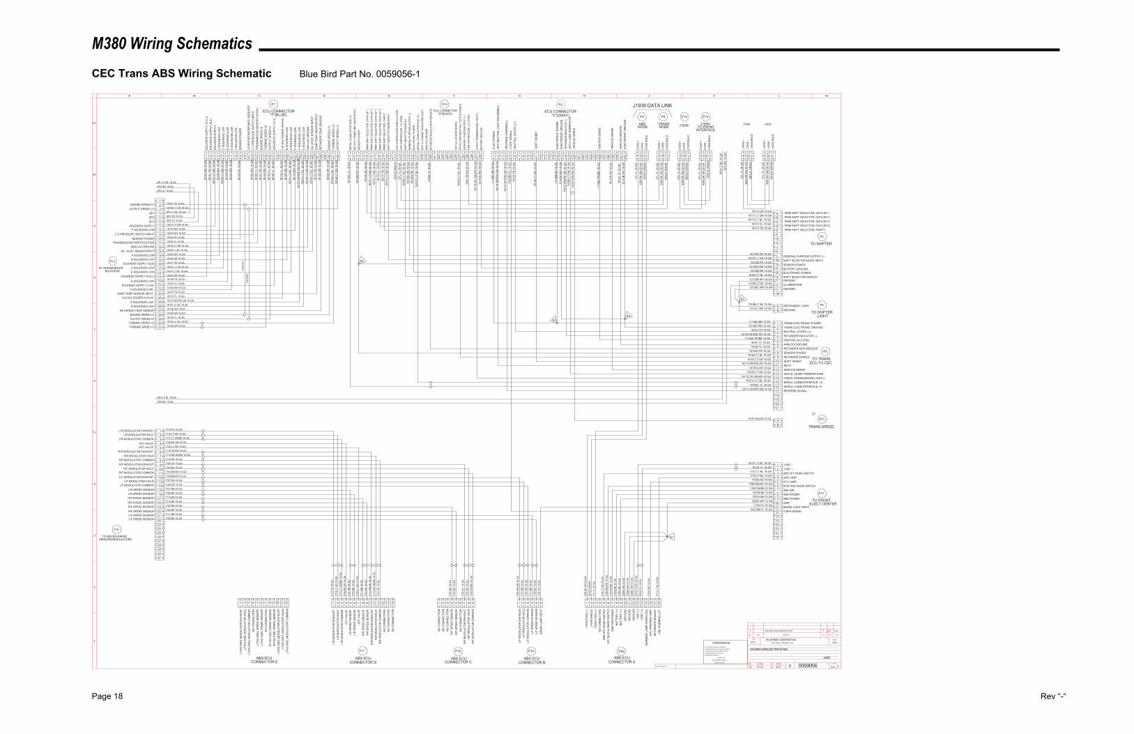
M380 Wiring Schematics
Page 18 Rev “-“
CEC Trans ABS Wiring Schematic Blue Bird Part No. 0059056-1
12/04/02 21
NONE
H4RE
0059056SWolfe
MattP12/04/02
DIAGRAM,WRG,CEC,TRANS/ABS
12857F
INACTIVATES NOS.
LET. WAS REVISIONS DR. APP. CCN
SCALEBLUE BIRD CORPORATIONFORT VALLEY GEORGIA, U.S.A.
CCN
DR.
APP.
BY
BY EPAGE
__OF__
1
2
3
4
5
6
7
8
9
10
11
A B C D E F G H J K L M
CONFIDENTIALThe information hereon is confidential
business information and may not be copied
or used for any purpose unless permission
is expressly granted in writing by
Blue Bird Body Company.
Copyright 2002
Blue Bird Body Company
All rights reserved
TO TRANSMISSIONBULKHEAD
P12
1
1L/
TAG
AXE
L M
OD
ULA
TOR
EXH
AUST
ABS ECUCONNECTOR E
SOLE
NO
ID S
UPP
LY (A
,D,J
)1
1810
2 O
R 1
8 G
A
P1
ECU CONNECTOR"T"(BLUE)
INSTRUMENT LIGHTA
P2
TO SHIFTER
1812
1 TN
18
GA
2SO
LEN
OID
SU
PPLY
(B,E
)SO
LEN
OID
SU
PPLY
318
107
LT G
N 1
8 G
A18
120
WH
18
GA
4A
SOLE
NO
ID,L
OW
C S
OLE
NO
ID,L
OW
518
103
LT G
N 1
8 G
A18
129
TN 1
8 G
A6
E SO
LEN
OID
,LO
WG
SO
LEN
OID
,LO
W7
1810
4 W
H 1
8 G
A
8J
SOLE
NO
ID,L
OW
SEN
SOR
PO
WER
918
124
PK 1
8 G
A
10LE
VER
RET
ARD
ER M
OD
. REQ
UES
T11
1816
2 W
H 1
8 G
A12
C-3
PR
ESSU
RE
SWIT
CH
INPU
TTR
ANSM
ISSI
ON
IDEN
TIFI
CAT
ION
1318
195
YL 1
8 G
A18
141
TN 1
8 G
A14
ENG
INE
SPEE
D H
ITU
RBI
NE
SPEE
D H
I15
1814
9 O
R 1
8 G
A18
139
YL 1
8 G
A16
OU
TPU
T SP
EED
HI
SOLE
NO
ID S
UPP
LY (C
,G)
1718
130
YL 1
8 G
A
18H
,N S
OL
POW
ER (H
,N-H
I)19
1811
6 YL
18
GA
1812
8 O
R 1
8 G
A20
B SO
LEN
OID
,LO
WD
SO
LEN
OID
,LO
W21
1813
1 LT
BL
18 G
A18
110
WH
18
GA
22F
SOLE
NO
ID,L
OW
H S
OLE
NO
ID L
OW
2318
127
WH
/DK
GN
18
GA
1810
1 LT
BL
18 G
A24
N S
OLE
NO
ID,L
OW
ANAL
OG
GR
OU
ND
2518
135
LT G
N 1
8 G
A18
165
LT B
L 18
GA
26O
IL L
EVEL
SEN
SOR
INPU
TSU
MP
TEM
P SE
NSO
R IN
PUT
2718
147
TN 1
8 G
A18
138
OR
18
GA
28R
ETAR
DER
TEM
P SE
NSO
R29
1815
0 O
R 1
8 G
A30
ENG
INE
SPEE
D L
OTU
RBI
NE
SPEE
D L
O31
1814
0 LT
BL
18 G
A18
148
LT G
N 1
8 G
A32
OU
TPU
T SP
EED
LO
BATT
ERY
GR
OU
ND
3212
143G
WH
18
GA
1811
5 D
K G
N/W
H 1
8 G
A31
CH
ECK
TRAN
SMIS
SIO
N L
IGH
T(-)
30
2GN
DK
GN
20
GA
29C
AN C
ON
TRO
LLER
, LO
(J19
39)
GEN
ERAL
PU
RPO
SE IN
PUT
(-)28
1816
3 LT
BL
18 G
A27
GPI
6(-)
DIF
FER
ENTI
AL C
LUTC
H E
NAB
LEG
PI 1
2(-)
ENG
INE
BRAK
E262524232221
RET
ARD
ER M
OD
ULA
TIO
N R
EQU
EST
2018
164
YL 1
8 G
A19
ANAL
OG
GR
OU
ND
GPO
7(-)
RAN
GE
IND
ICAT
OR
LIG
HT
18
1615
1C L
T BL
18
GA
17SE
RIA
L C
OM
M IN
TER
FAC
E, L
OEL
ECTR
ON
IC P
OW
ER16
1813
6D B
K 18
GA
1817
6A O
R 1
8 G
A15
GEN
ERAL
PU
RPO
SE O
UTP
UT
(-)SH
IFT
SELE
CTO
R D
ISPL
AY14
1818
0 LT
BL
18 G
A2Y
L YL
20
GA
13C
AN C
ON
TRO
LLER
, HI (
J193
9)C
AN C
ON
TRO
LLER
SH
IELD
(J19
39)
122S
HLD
DR
AIN
11SH
IFT
SELE
CTO
R M
OD
E IN
PUT
1018
175
LT G
N 1
8 G
A18
174
TN 1
8 G
A9
PRIM
SH
IFT
SELE
CTO
R, P
ARIT
YPR
IM S
HIF
T SE
LEC
TOR
, DAT
A BI
T 8
818
173
YL 1
8 G
A18
172
LT B
L 18
GA
7PR
IM S
HIF
T SE
LEC
TOR
, DAT
A BI
T 4
PRIM
SH
IFT
SELE
CTO
R, D
ATA
BIT
26
1817
1 LT
GN
18
GA
1817
0 O
R 1
8 G
A5
PRIM
SH
IFT
SELE
CTO
R, D
ATA
BIT
1
4
1812
4B P
K 18
GA
3SE
NSO
R P
OW
ERIS
O 9
141
CO
MM
LIN
K (D
IAG
NO
STIC
)2
ECU CONNECTOR"S"(BLACK)
P15
1614
2C Y
L 18
GA
1SE
RIA
L C
OM
M IN
TER
FAC
E, H
I
ELEC
PO
WER
111
136C
BK
18 G
A
P16
ECU CONNECTOR"V"(GRAY)
1811
4 W
H/D
K G
N 1
8 G
A2
GPO
NEU
TRAL
(FAS
T ID
LE/K
NEE
L) -
318
113
WH
/DK
GN
18
GA
4R
EVER
SE W
ARN
ING
(-)3
MPH
SIG
NAL
515
32 B
K/YL
18
GA
1812
3 TN
18
GA
6N
EUTR
AL (S
TAR
T) (+
)7 8 9 10
SHIF
T IN
HIB
IT11
1815
5 LT
GN
18
GA
12 13 14 1511
136B
BK
18 G
A16
ELEC
TRO
NIC
PO
WER
ELEC
TRO
NIC
GR
OU
ND
1712
143A
WH
18
GA
1812
5 W
H/D
K G
N 1
8 G
A18
RET
ARD
ER IN
DIC
ATO
R (-
)GP
O 5(-
) SUM
P TE
MPER
ATUR
E19
1810
5 LT
GN
18
GA
20VE
HIC
LE S
PEED
21 22 23 24 2511
146C
PK/
BK 1
8 G
A26
IGN
ITIO
N S
ENSE
27 28SE
RVI
CE
BRAK
E29
1813
7A O
R 1
8 G
A
30AN
ALO
G G
RO
UN
D31
1816
1 YL
18
GA
1214
3B W
H 1
8 G
A32
ELEC
TRO
NIC
GR
OU
ND
2ENGINE SPEED HI 18141 TN 18 GA18148 LT GN 18 GAOUTPUT SPEED LO 3
4SP1 SP1 LT BL 18 GASP2 RD 18 GASP2 5
6SP3 SP3 YL 18 GA18107 LT GN 18 GASOLENOID SUPPLY 7
8F SOLENOID,LOW 18110 WH 18 GA18162 WH 18 GAC-3 PRESSURE SWITCH INPUT 9
10SENSOR POWER 18124 PK 18 GA18195 YL 18 GATRANSMISSION IDENTIFICATION 11
12ANALOG GROUND 18135 LT GN 18 GA18165 LT BL 18 GAOIL LEVEL SENSOR INPUT 13
14A SOLENOID,LOW 18120 WH 18 GA18128 OR 18 GAB SOLENOID,LOW 15
16SOLENOID SUPPLY (B,E) 18121 TN 18 GA18103 LT GN 18 GAC SOLENOID,LOW 17
18D SOLENOID,LOW 18131 LT BL 18 GA18102 OR 18 GASOLENOID SUPPLY (A,D,J) 19
20E SOLENOID,LOW 18129 TN 18 GA18130 YL 18 GASOLENOID SUPPLY (C,G) 21
22G SOLENOID,LOW 18104 WH 18 GA18147 TN 18 GASUMP TEMP SENSOR INPUT 23
24H,N SOL POWER (H,N-HI) 18116 YL 18 GA18127 WH/DK GN 18 GAH SOLENOID LOW 25
26N SOLENOID,LOW 18101 LT BL 18 GA18138 OR 18 GARETARDER TEMP SENSOR 27
28ENGINE SPEED LO 18150 OR 18 GA18139 YL 18 GAOUTPUT SPEED HI 29
30TURBINE SPEED LO 18140 LT BL 18 GA18149 OR 18 GATURBINE SPEED HI 31
SP1 LT BL 18 GASP2 RD 18 GASP3 YL 18 GA
1333B LT BL 18 GA1212LL WH 18 GA
B GROUND
PRIM SHIFT SELECTOR, DATA BIT 4C18172 LT BL 18 GA
18173 YL 18 GAD PRIM SHIFT SELECTOR, DATA BIT 8
PRIM SHIFT SELECTOR, PARITYE18174 TN 18 GA
FGHJK
GENERAL PURPOSE OUTPUT (-)L18176A OR 18 GA18175 LT GN 18 GA M SHIFT SELECTOR MODE INPUT
SENSOR POWERN18124D PK 18 GA12143G WH 18 GA P BATTERY GROUND
ELECTRONIC POWERR18136D BK 18 GA18180 LT BL 18 GA S SHIFT SELECTOR DISPLAY
GROUNDT1212AB WH 18 GA1333B LT BL 18 GA U ILLUMINATION
GROUNDV1212AC WH 18 GA
W
PRIM SHIFT SELECTOR, DATA BIT 2B18171 LT GN 18 GA
18170 OR 18 GAA PRIM SHIFT SELECTOR, DATA BIT 1
P9
TO SHIFTERLIGHT
S2
TRANS ELECTRONIC POWER111136A BK 12 GA12143C WH 12 GA 2 TRANS ELECTRONIC GROUND
NEUTRAL (START) (+)318123 TN 18 GA18125 WH/DK GN 18 GA 4 RETARDER INDICATOR (-)
IGNITION (ALLISON)511146C PK/BK 18 GA18161 YL 18 GA 6 ANALOG GROUND
RETARDER MOD REQUEST718164 YL 18 GA
18124C PK 18 GA 8 SENSOR POWERRETARDER ENABLE9
18163 LT BL 18 GA18155 LT GN 18 GA 10 SHIFT INHIBIT
NEUT -1118114 WH/DK GN 18 GA
18137A OR 18 GA 12 SERVICE BRAKEGPO 5(-) SUMP TEMPERATURE13
18105 LT GN 18 GA18115 DK GN/WH 18 GA 14 CHECK TRANSMISSION LIGHT(-)
SERIAL COMM INTERFACE, LO1516151C LT BL 18 GA
16142C YL 18 GA 16 SERIAL COMM INTERFACE, HIREVERSE SIGNAL -17
18113 WH/DK GN 18 GA
18
P6
TO TRANSECU TO CEC
S5
J193
9 +
A1Y
L YL
20
GA
1GN
DK
GN
20
GA
BJ1
939
-J1
939
SHLD
C1S
HLD
DR
AIN
2SH
LD D
RAI
NC
J193
9 SH
LDJ1
939
-B
2GN
DK
GN
20
GA
2YL
YL 2
0 G
AA
J193
9 +
ABSNODE
TRANSNODE
J1939 DATA LINK
S3S4
L/TA
G A
XEL
MO
DU
LATO
R H
OLD
2 3L/
TAG
AXE
L M
OD
ULA
TOR
CO
MM
ON
NO
CO
NN
ECTI
ON
4 5L/
TAG
AXE
L SP
EED
SEN
SOR
L/TA
G A
XEL
SPEE
D S
ENSO
R6 7
NO
CO
NN
ECTI
ON
R/T
AG A
XEL
SPEE
D S
ENSO
R8 9
R/T
AG A
XEL
SPEE
D S
ENSO
RL/
TAG
AXE
L M
OD
ULA
TOR
EXH
AUST
10 11L/
TAG
AXE
L M
OD
ULA
TOR
HO
LDL/
TAG
AXE
L M
OD
ULA
TOR
CO
MM
ON
12
1714
PK
16 G
A12
R/R
MO
DU
LATO
R C
OM
MO
NR
/R M
OD
ULA
TOR
HO
LD11
1715
DK
GN
/BK
16 G
A17
16 T
N/O
R 1
6 G
A10
R/R
MO
DU
LATO
R E
XHAU
STR
/R S
PEED
SEN
SOR
917
12 B
K 18
GA
1713
BN
18
GA
8R
/R S
PEED
SEN
SOR
ATC
VAL
VE7
1735
LT
GN
16
GA
1720
BK
18 G
A6
L/R
SPE
ED S
ENSO
RL/
R S
PEED
SEN
SOR
517
21 B
N 1
8 G
A17
36 D
K G
N 1
6 G
A4
ATC
VAL
VEL/
R M
OD
ULA
TOR
CO
MM
ON
317
17 L
T G
N/B
K 16
GA
1718
LT
GN
16
GA
2L/
R M
OD
ULA
TOR
HO
LDL/
R M
OD
ULA
TOR
EXH
AUST
117
19 P
U 1
6 G
A
NO
CO
NN
ECTI
ON
13 14N
O C
ON
NEC
TIO
NN
O C
ON
NEC
TIO
N15 1
NO
CO
NN
ECTI
ON
NO
CO
NN
ECTI
ON
2 3R
/F S
PEED
SEN
SOR
417
02 B
N 1
8 G
A17
22 B
K 18
GA
5R
/F S
PEED
SEN
SOR
NO
CO
NN
ECTI
ON
617
05 G
Y 16
GA
7R
/F M
OD
ULA
TOR
EXH
AUST
R/F
MO
DU
LATO
R H
OLD
817
04 B
K 16
GA
1703
BK/
WH
16
GA
9R
/F M
OD
ULA
TOR
CO
MM
ON
1734
PU
18
GA
6BR
AKE
LAM
P IN
PUT
L/F
SPEE
D S
ENSO
R5
1709
BK
18 G
A17
11 B
N 1
8 G
A4
L/F
SPEE
D S
ENSO
RL/
F M
OD
ULA
TOR
CO
MM
ON
317
06 O
R 1
6 G
A17
07 B
N 1
6 G
A2
L/F
MO
DU
LATO
R H
OLD
L/F
MO
DU
LATO
R E
XHAU
ST1
1708
BN
/OR
16
GA
15W
ARN
ING
LAM
P IN
TER
LOC
K
J158
7 (+
)14
1614
2 YL
18
GA
1615
1 LT
BL
18 G
A13
J158
7 (-)
1GN
DK
GN
20
GA
1J1
939/
J192
2 (-)
J193
9 SH
IELD
21S
HLD
DR
AIN
1YL
YL 2
0 G
A3
J193
9/J1
922
(+)
NO
CO
NN
ECTI
ON
417
31 L
T BL
18
GA
5AB
S O
FF R
OAD
SW
ITC
HAT
C M
UD
& S
NO
W S
WIT
CH
617
88 R
D/W
H 1
8 G
A11
63 P
K/BK
16
GA
7IG
NIT
ION
PO
WER
BATT
ERY
(+)
817
01B
BK 1
2 G
A17
01A
BK 1
2 G
A9
BATT
ERY
(+)
GR
OU
ND
1012
08A
WH
12
GA
1208
B W
H 1
2 G
A11
GR
OU
ND
GR
OU
ND
1212
08C
WH
12
GA
ATC
WAR
NIN
G L
AMP
1617
03A
RD
18
GA
17R
ETAR
DER
DIS
ABLE
ABS
WAR
NIN
G L
GT
1817
10 L
T BL
18
GA
P17
ABS ECUCONNECTOR D
P18
ABS ECUCONNECTOR C
P19
ABS ECUCONNECTOR B
P20
ABS ECUCONNECTOR A
NO
CO
NN
ECTI
ON
313029282726252423222120191817161514131211109876543
1719 PU 16 GAL/R MODULATOR EXHAUST21
P10
TO ABS BULKHEADSENSORS/MODULATORS
L/R MODULATOR HOLD 1718 LT GN 16 GA1717 LT GN/BK 16 GAL/R MODULATOR COMMON
ATC VALVE 1736 DK GN 16 GA1735 LT GN 16 GAATC VALVE
R/R MODULATOR EXHAUST 1716 TN/OR 16 GA1715 DK GN/BK 16 GAR/R MODULATOR HOLD
R/R MODULATOR COMMON 1714 PK 16 GA1705 GY 16 GAR/F MODULATOR EXHAUST
R/F MODULATOR HOLD 1704 BK 16 GA1703 BK/WH 16 GAR/F MODULATOR COMMON
L/F MODULATOR EXHAUST 1708 BN/OR 16 GA1707 BN 16 GAL/F MODULATOR HOLD
L/F MODULATOR COMMON 1706 OR 16 GA1721 BN 18 GAL/R SPEED SENSOR
L/R SPEED SENSOR 1720 BK 18 GA1713 BN 18 GAR/R SPEED SENSOR
R/R SPEED SENSOR 1712 BK 18 GA1702 BN 18 GAR/F SPEED SENSOR
R/F SPEED SENSOR 1722 BK 18 GA1711 BN 18 GAL/F SPEED SENSOR
L/F SPEED SENSOR 1709 BK 18 GA
TO FRONTELECT CENTER
P11
15
14
13
3 MPH SIGNAL121532 BK/YL 18 GA
1734 PU 18 GA11 BRAKE LIGHT INPUT
GND101208D WH 12 GA1701A BK 12 GA
9 ABS POWERABS POWER8
1701B BK 12 GA1163 PK/BK 16 GA
7 ABS IGNMUD AND SNOW SWITCH6
1788 RD/WH 18 GA1703A RD 18 GA
5 ATC LAMPABS LAMP4
1710 LT BL 18 GA1731 LT BL 18 GA
3 ABS OFF ROAD SWITCHJ1587 +2
16142 YL 18 GA16151 LT BL 18 GA
1 J1587 -
S1
SP5 RD 18 GASP4 LT BL 18 GA
P3 P4
TWIS
TED
TWIS
TED
P14P13
SP5
RD
18
GA
SP4
LT B
L 18
GA
J1939TO FRONTJ1939
J193
9 +
A4Y
L YL
20
GA
4GN
DK
GN
20
GA
BJ1
939
-J1
939
SHLD
C4S
HLD
DR
AIN
4SH
LD D
RAI
NC
J193
9 SH
LDJ1
939
-B
4GN
DK
GN
20
GA
4YL
YL 2
0 G
AA
J193
9 +
INTERFACE
192021
16
17
18
J193
9 +
A3Y
L YL
20
GA
3GN
DK
GN
20
GA
BJ1
939
-J1
939
SHLD
C3S
HLD
DR
AIN
3SH
LD D
RAI
NC
J193
9 SH
LDJ1
939
-B
3GN
DK
GN
20
GA
3YL
YL 2
0 G
AA
J193
9 +
J1939 J1939
TRANS SPEED
P21
BA
18157 WH/GN 18 GA
1815
7 W
H/G
N 1
8 G
A
A ADD CIRCUIT 18157 FROM P16 TO P21 BT SW4/29/03 13032H
A
A
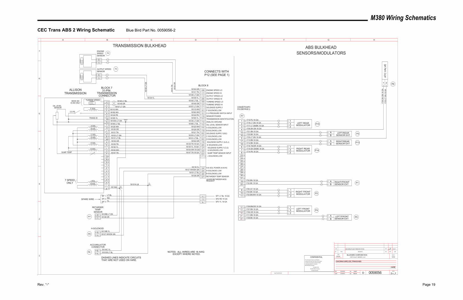
M380 Wiring Schematics
Rev. “-“ Page 19
CEC Trans ABS 2 Wiring Schematic Blue Bird Part No. 0059056-2
EVU
FXDWNYGJHBMAKLCPQRSTZabcdefg
AB
A
AB
AB
AB
B
2823
2930317891011121314151617181920212223
24252627
1
13032H4/29/03SWBTADD CIRCUIT 18157 FROM P16 TO P21A
12/04/02 22
NONE
H4RE
0059056SWolfe
MattP12/04/02
DIAGRAM,WRG,CEC,TRANS/ABS
13032W
INACTIVATES NOS.
LET. WAS REVISIONS DR. APP. CCN
SCALEBLUE BIRD CORPORATIONFORT VALLEY GEORGIA, U.S.A.
CCN
DR.
APP. BY
BY
DPAGE
__OF__
1
2
3
4
5
A B C D E F G H
6
7
CONFIDENTIALThe information hereon is confidential
business information and may not be copied
or used for any purpose unless permission
is expressly granted in writing by
Blue Bird Body Company.
Copyright 2002
Blue Bird Body Company
All rights reserved
ENGINE SPEED LOENGINE SPEED HIOUTPUT SPEED LOOUTPUT SPEED HITURBINE SPEED LOTURBINE SPEED HISOLENOID SUPPLYF SOLENOID,LOWC-3 PRESSURE SWITCH INPUTSENSOR POWERTRANSMISSION IDENTIFICATIONANALOG GROUNDOIL LEVEL SENSOR INPUTA SOLENOID,LOWB SOLENOID,LOWSOLENOID SUPPLY (B,E)C SOLENOID,LOWD SOLENOID,LOWSOLENOID SUPPLY (A,D,J)E SOLENOID,LOWSOLENOID SUPPLY (C,G)G SOLENOID,LOWSUMP TEMP SENSOR INPUT
ENGINESPEEDSENSOR
OUTPUT SPEEDSENSOR
31-PINTRANSMISSION
CONNECTOR
BLOCK 8
NOTES: ALL WIRES ARE 18 AWG EXCEPT WHERE NOTED.
ALLISONTRANSMISSION
18150 OR18141 TN
18148 LT GN18139 YL
18140 LT BL
18107 LT GN18110 WH18162 WH18124 PK18195 YL
18135 LT GN18165 LT BL
18120 WH18128 OR18121 TN
18103 LT GN18131 LT BL
18102 OR18129 TN 18 GA18130 YL 18 GA18104 WH 18 GA18147 TN 18 GA
18149 OR
18116 YL
18101 LT BL
H,N SOL POWER (H,N-HI)
N SOLENOID,LOW
TURBINE SPEED
F SOL
C3 PS
OIL LEVELSENSOR
TRANS ID
A SOL
B SOL
C SOL
D SOL
E SOL
G SOL
N SOL
J SOL
SUMP TEMP
7 SPEEDONLY
MD/B 300B 400 ONLY
J SOLENOID,LOW
18135B LT GN18138 OR
18116C YL18101B LT BL
SENSOR
RETARDERTEMP
ACCUMULATORCONNECTOR
2
3
1
18127 WH/DK GN
18138 OR
H SOLENOID LOW
RETARDER TEMP SENSORLEVER RETARDER MOD. REQUEST
P3
P4
P7
18116B YL18127 WH/DK GNP8
H-SOLENOID
P6
BLOCK 7
DASHED LINES INDICATE CIRCUITSTHAT ARE NOT USED ON H4RE.
SP1 LT BL 18 GASP2 RD 18 GASP3 YL 18 GA
SP 1SP 2SP 3 YL
RDLT BL
18135A LT GN
18147 TN18104 WH18130 YL18129 TN
18102 OR18131 LT BL18103 LT GN18121 TN
18128 OR18120 WH18165 LT BL
18195 YL18124 PK18162 WH18110 WH
18107 LT GN18149 OR18140 LT BL
18139 YL
1814
8 LT
GN
1814
1 TN
1815
0 O
R
456
18116A18101A LB
132
LEFT FRONTMODULATOR
RIGHT FRONTMODULATOR
231
132
RIGHT REARMODULATOR
LEFT REARMODULATOR
231
AB
LEFT/REARSENSOR EXT.
RIGHT/REARSENSOR EXT.B
A
AB
RIGHT/FRONTSENSOR EXT.
LEFT/FRONTSENSOR EXT.B
A P5
P1
P3
P13
P4
P2
P15
P14
1 2
ATC
VA
LVE
1736
DK
GN
16
GA
1735
LT
GN
16
GA
P6
1719 PU 16 GA1718 LT GN 16 GA1717 LT GN/BK 16 GA1736 DK GN 16 GA1721 BN 18 GA1720 BK 18 GA1735 LT GN 16 GA1713 BN 18 GA1712 BK 18 GA1716 TN/OR 16 GA1715 DK GN/BK 16 GA1714 PK 16 GA
1702 BN 18 GA1722 BK 18 GA
1705 GY 16 GA1704 BK 16 GA1703 BK/WH 16 GA
1708 BN/OR 16 GA1707 BN 16 GA1706 OR 16 GA1711 BN 18 GA1709 BK 18 GA
1234
15165
1718678
1920
91011
1213142122
P7
232425262728293031
CONNECTS WITHP12 (SEE PAGE 1)
CONNECTS WITHP10 (SEE PAGE 1)
TRANSMISSION BULKHEAD ABS BULKHEADSENSORS/MODULATORS
SPARE WIRE
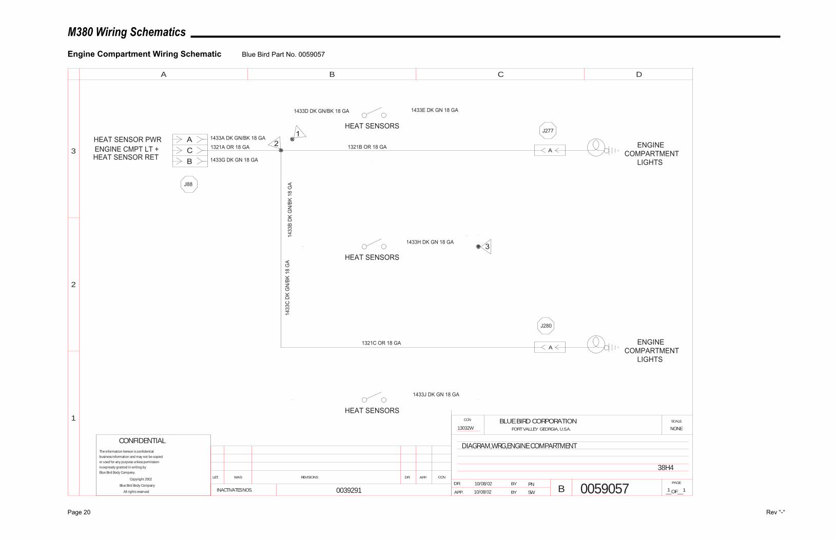
M380 Wiring Schematics
Page 20 Rev “-“
Engine Compartment Wiring Schematic Blue Bird Part No. 0059057
LET. WAS REVISIONS DR. APP. CCN
SCALEBLUE BIRD CORPORATIONFORT VALLEY GEORGIA, U.S.A.
CCN
DR.
APP. BY
BY
BPAGE
__OF__
1
2
3
A B C D
INACTIVATES NOS.
DIAGRAM,WRG,ENGINE COMPARTMENT
1 110/08/02
10/08/02
PN
SW
13032W NONE
0059057
CONFIDENTIALThe information hereon is confidential
business information and may not be copied
or used for any purpose unless permission
is expressly granted in writing by
Blue Bird Body Company.
Copyright 2002
Blue Bird Body Company
All rights reserved
38H4
ENGINECOMPARTMENT
LIGHTS
HEAT SENSORS
ENGINECOMPARTMENT
LIGHTS
HEAT SENSORS
HEAT SENSORS
ACB
HEAT SENSOR PWR
HEAT SENSOR RETENGINE CMPT LT +
1433A DK GN/BK 18 GA
1433
B D
K G
N/B
K 18
GA
1433
C D
K G
N/B
K 18
GA
1433D DK GN/BK 18 GA 1433E DK GN 18 GA
1433H DK GN 18 GA
1433G DK GN 18 GA
1433J DK GN 18 GA
1321A OR 18 GA 1321B OR 18 GA
1321C OR 18 GA
J88
J277
J280
12
3
A
A
0039291
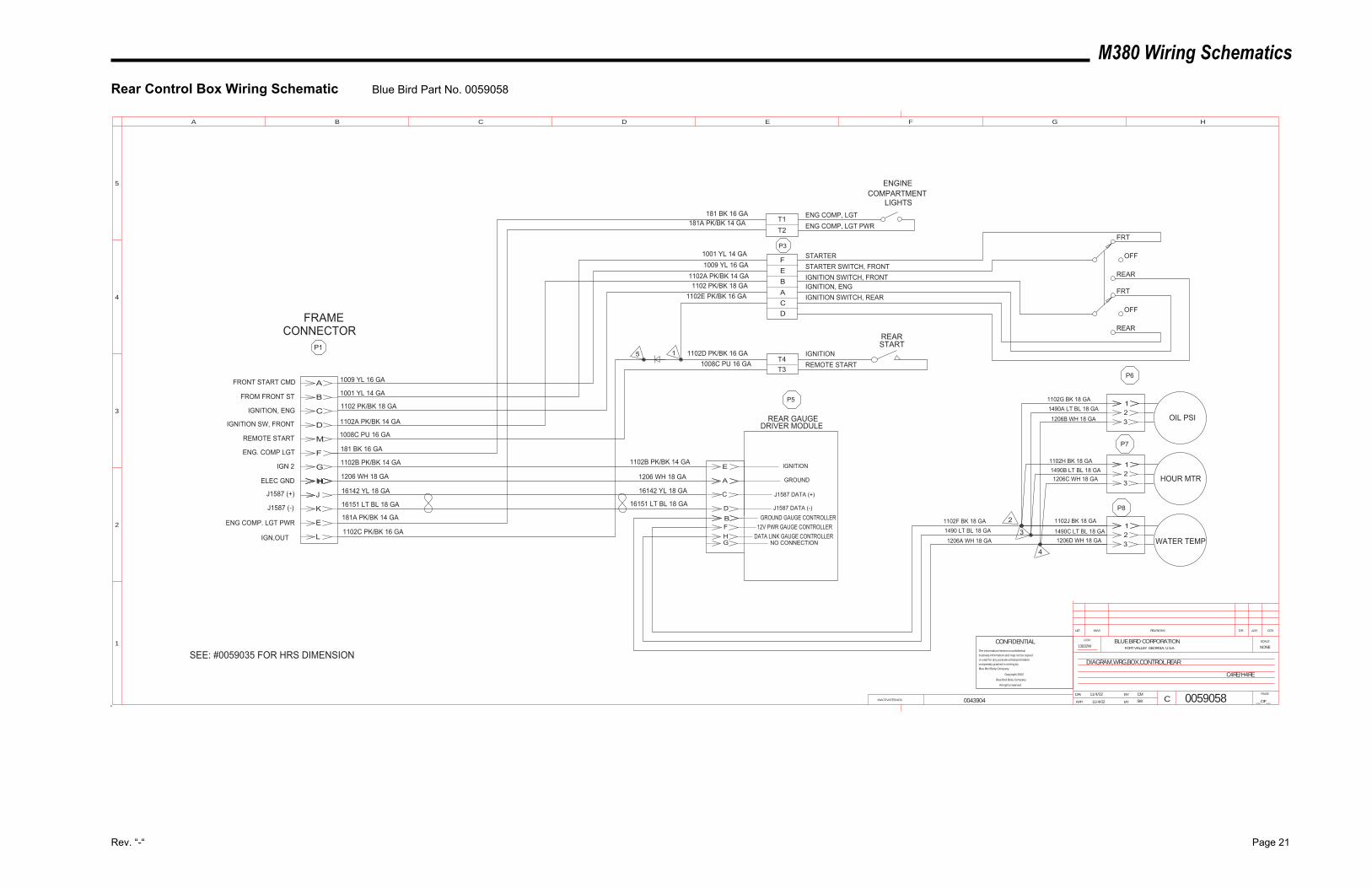
M380 Wiring Schematics
Rev. “-“ Page 21
Rear Control Box Wiring Schematic Blue Bird Part No. 0059058
A
B
C
D
M
F
G
HHH A
E
1
1
1B
All rights reserved
Blue Bird Body Company
Copyright 2002
Blue Bird Body Company.
is expressly granted in writing by
or used for any purpose unless permission
business information and may not be copied
The information hereon is confidential
CONFIDENTIAL
SW11/4/02
SEE: #0059035 FOR HRS DIMENSION
C4RE/H4RE
CM11/4/02
NONE13032W
0059058
DIAGRAM,WRG,BOX,CONTROL,REAR
INACTIVATES NOS.
LET. WAS REVISIONS DR. APP. CCN
SCALEBLUE BIRD CORPORATIONFORT VALLEY GEORGIA, U.S.A.
CCN
DR.
APP. BY
BY
CPAGE
__OF__
1
2
3
4
5
A B C D E F G H
FRONT START CMD
FROM FRONT ST
IGNITION, ENG
IGNITION SW, FRONT
FRAMECONNECTOR
REMOTE START
P1
J
FEBA
T4T3
T2181A PK/BK 14 GA
1001 YL 14 GA1009 YL 16 GA
1102A PK/BK 14 GA1102 PK/BK 18 GA
1102D PK/BK 16 GA1008C PU 16 GA
1009 YL 16 GA
1001 YL 14 GA
1102 PK/BK 18 GA
1102A PK/BK 14 GA
1008C PU 16 GA
P3
T1181 BK 16 GA
181 BK 16 GAENG. COMP LGT
CD
K
1
1102B PK/BK 14 GA
1206 WH 18 GA
16142 YL 18 GA
16151 LT BL 18 GA
IGN 2
ELEC GND
J1587 (+)
J1587 (-)
OIL PSI
HOUR MTR
WATER TEMP
D
C
23
32
23
REAR GAUGEDRIVER MODULE
FH
1102G BK 18 GA
1102H BK 18 GA
1102J BK 18 GA
1490B LT BL 18 GA
1490C LT BL 18 GA
1490A LT BL 18 GA
1206B WH 18 GA
1206C WH 18 GA
1206D WH 18 GAG 1206A WH 18 GA
1490 LT BL 18 GA1102F BK 18 GA
IGNITION
GROUND
J1587 DATA (+)
J1587 DATA (-)GROUND GAUGE CONTROLLER
12V PWR GAUGE CONTROLLERDATA LINK GAUGE CONTROLLER
NO CONNECTION
E
L
ENG COMP. LGT PWR
IGN,OUT3
2
1102B PK/BK 14 GA
1206 WH 18 GA
16142 YL 18 GA
16151 LT BL 18 GA
181A PK/BK 14 GA
1102C PK/BK 16 GA
1102E PK/BK 16 GA
P5
P6
P7
P8
4
FRT
OFF
REAR
FRT
REAR
OFF
ENG COMP, LGTENG COMP, LGT PWR
STARTER
IGNITIONREMOTE START
STARTER SWITCH, FRONTIGNITION SWITCH, FRONTIGNITION, ENGIGNITION SWITCH, REAR
REARSTART
ENGINECOMPARTMENT
LIGHTS
5
0043904
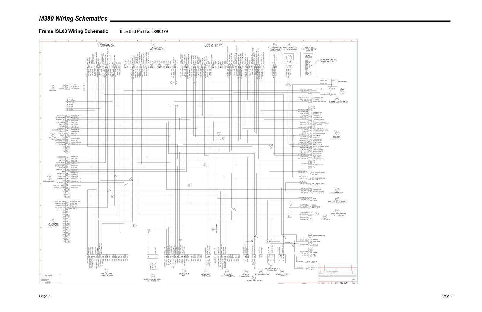
M380 Wiring Schematics
Page 22 Rev “-“
Frame ISL03 Wiring Schematic Blue Bird Part No. 0066179
MERC
URY
SWIT
CH
08/19/03 11
NONE
38H4
0066179SW
CM05/05/03
DIAGRAM,WRG,FRAME,ISL03
12857R
INACTIVATES NOS.
LET. WAS REVISIONS DR. APP. CCN
SCALEBLUE BIRD CORPORATIONFORT VALLEY GEORGIA, U.S.A.
CCN
DR.
APP.
BY
BY EPAGE
__OF__
1
2
3
4
5
6
7
8
9
10
11
A B C D E F G H J K L M
CONFIDENTIALThe information hereon is confidential
business information and may not be copied
or used for any purpose unless permission
is expressly granted in writing by
Blue Bird Body Company.
Copyright 2002
Blue Bird Body Company
All rights reserved
2
71
15
16
REAR DOOR MERCURYSW WORKING
J95
J94
HTD DRAIN VALVE(WET TANK)
HTD DRAIN VALVE(RR BRAKE TANK)
J83
1181
D PK
/BK
14 G
A
1208
K W
H 14
GA
1181
E PK
/BK
14 G
A
1208
J WH
14 G
A
BA10
09D
PU 16
GA
1001
YL 1
4 GA
GROU
NDA
1208
S W
H 16
GA
1519
B RD
/WH
16 G
AB C
J85
WATER INFUEL SENSOR
1456
PK
16 G
ALIG
HT+1
2 V
FUEL
FILT
ERFU
EL FI
LTER
GRO
UND
1208
N W
H 14
GA
HEATED FUEL FILTER
J84
BA15
19A
RD/W
H 14
GA
2221
A RD
12 G
AA B
P98
HAYDEN FAN PWR
1208
C W
H 12
GA
1208M WH 14 GA AIR DRYER
P81
BA1181A PK/BK 14 GA
BAA BLUGGAGE
COMPARTMENT 2
P99
14PL
UGPL
UG1312
PLUG
PLUG
1110PL
UGPL
UG98
PLUG
2610
C GY
14 G
ACO
MPAR
TMEN
T LOC
K76
COMP
ARTM
ENT L
OCK
2612
C PU
14 G
A26
11C
DK G
N/BK
16 G
ALU
GGAG
E DO
OR S
IGNA
L-54
COMP
ARTM
ENT L
IGHT
1165
C BK
14 G
A12
08Y
WH
14 G
ACH
ASSI
S GR
OUND
32PL
UG
81A
RD 6
GAAQ
UA H
OT1
1421
A LT
GN
18 G
A14
17A
LT B
L 18 G
A
CGE
N CO
OL TE
MPGE
N OI
L TEM
PBA
SEND
ER R
ETUR
N
J82
GEN/FRAMEINTERFACE
1206
B W
H 18
GA
ENGINE COMPARTMENT
P881433A DK GN/BK 16 GA
1433 DK GN 18 GAA HEAT SENSOR POWER
HEAT SENSORBC ENGINE COMPARTMENT LIGHT181 BK 16 GA
SP7 OR 16 GASP6 BK 12 GASP5 BK 14 GASP4 RD 12 GASP3 LT BL 14 GASP2 LT GN 14 GA
YL1 YL 20 GA
J1939 CONN
J89+ J1939 A
SP1 YL 14 GA
B- J1939J1939 SHIELD C
GN1 DK GN 20 GASHLD1 DRAIN 20 GA
REAR SUSPENSIONPRESSURE SW
J91
1153E BN/OR 16 GA B
1153B PK 16 GA A
1153D BN/OR 16 GA1153A PK 16 GA
CHASSIS GROUNDFRONT
1208D WH 10 GA
COOLANT LEVEL PROBE
P89PROBEA1321 DK GN/WH 16 GA
B GROUND1208L WH 18 GA
BODY HARNESS
J87
CHASSIS GROUNDREAR
1208B WH 10 GA1208A WH 10 GA
1208H WH 12 GA1208W WH 10 GA CHASSIS GROUND
REAR
1208B WH 10 GA1208A WH 10 GA
C REAR LIGHTING GROUNDREAR LIGHTING GROUNDB
1316 RD 12 GA A STOP LAMP POWER
FRONTSUSPENSIONPRESSURE SW
PLUG
O QPL
UG
1208
R W
H 14
GA
ACH
AS G
NDSH
ORE
LINE
SENS
ORB
2042
PU
14 G
A26
10D
GY 14
GA
CCO
MPAR
TMEN
T LOC
KCO
MPAR
TMEN
T LOC
KD
2612
D PU
14 G
A
EPL
UGCO
MPAR
TMEN
T LIG
HTF
1165
D BK
14 G
A12
08Z W
H 14
GA
GCH
ASSI
S GR
OUND
LH LA
NDIN
G LT
H13
29G
DK G
N/W
H 14
GA
1329
H DK
GN/
WH
14 G
AJ
RH LA
NDIN
G LT
PLUG
K LPL
UGPL
UGM N
PLUG
PLUG
P RPL
UGPL
UGS T
PLUG
PLUG
U VPL
UGPL
UGW X
PLUG
3RD LUGGAGECOMPARTMENT
P100
P80
1ST LUGGAGECOMPARTMENT
PLUG XWPLUG
PLUG VUPLUG
PLUG TSPLUG
PLUG R
PPLUG
PLUG NMPLUG
PLUG LKPLUG
PLUG JHPLUGGF
CHASSIS GROUND E 1208G WH 14 GA1165A BK 14 GADCOMPARTMENT LIGHT
COMPARTMENT LOCK C 2612A PU 14 GA2610A GY 14 GABCOMPARTMENT LOCK
LUGGAGE DOOR SIGNAL- A 2611A DK GN/BK 16 GA
PLUG Q
OPLUG
1329E DK GN/WH 14 GA
PLUG O
QPLUG
1206P WH 16 GAAFUEL SENDER GRD12V AIR COMP B 2035 RD 14 GA
1403 PU 16 GACFUEL GAUGELEVELING JACK ACC D 1106A BK/YL 14 GA
2050 RD 14 GAELEVELING JACK BATTPARK BRAKE NEUT (-) F 2052 LT BL 16 GA
1807 RD 14 GAGHWH BATTERYJACKS DOWN SIG (-) H 1810A PU 16 GA
2604A BK/YL 16 GAJSPARECHASSIS GROUND K 1208X WH 14 GA
2610B GY 14 GALLUGGAGE LOCKSLUGGAGE LOCKS M 2612B PU 14 GA
NLH LANDING LTS
RH LANDING LTS P 1329C DK GN/WH 14 GA
2611B DK GN/BK 16 GARLUGGAGE DOOR SIGNAL (-)STPLUG
PLUG UVPLUG
PLUG WXPLUG
FUELCOMPARTMENT
P79
J86
REAR PDUPANEL
PLUG XWPLUG
PLUG VUPLUG
ELEC GROUND T 1206C WH 16 GA1433A DK GN/BK 16 GASHEAT SENSOR POWER
LOW COOLANT OUT - R 1420 YL 16 GA1321 DK GN/WH 16 GAPCOOLANT PROBE
PLUG N
1102D PK/BK 14 GAMIGNITION 2AMMETER ALT L 1440 BK 16 GA
1439 BK/WH 16 GAKAMMETER LOADENGINE COMPARTMENT LIGHT J 181A PK/BK 14 GA
18114 WH/GN 16 GAHNEUTRAL SRARTAQUA HOT G 81 RD 12 GA
1009B YL 16 GAFSTART SIG (+)STOP LAMP POWER E 1316 RD 12 GA
1208E WH 12 GADCHASSIS GROUNDSVC BRAKE APPLIED C 1316A RD/WH 16 GA
2221A RD 12 GABHAYDEN FAN POWER
1102
J PK/
BK 16
GA
ENGINE IGNITION A
HORN
P772107A LT GN 16 GA1208T WH 16 GA
AB
HIGH NOTE
LOW NOTE
CAT 3126BTHROTTLE POSITION
SENSOR
ISB/ISC THROTTLEPOSITION SENSOR
J75
IDLE VALIDATIONSWITCHES
P76
GN
BL
OR
NC
NO
1527
OR/
WH
18 G
A15
14 LT
GN/
WH
18 G
A15
26 P
K 18
GA
(CUMMINS ONLY)
ACB
1526
PK
18 G
A15
14 W
H/GN
18 G
A15
27 O
R/W
H 18
GA
A B C
CBA
CBA
PWM(PULSE WIDTHMODULATED)
1206
F WH
18 G
AA B
1534
DK
GN/B
K 18
GA
1533
YL/R
D 18
GA
C
STOP
ENG
INE
OVER
RIDE
4714
27 P
U 18
GA
1517
B LT
BL/W
H 18
GA
46EN
GINE
BRA
KE H
IGH
45
1517
C LT
BL/B
K 18
GA
44EN
GINE
BRA
KE O
N/OF
F SW
ITCH
CRUI
SE C
ONTR
OL R
ESUM
E43
1528
OR
18 G
A15
29 B
N 18
GA
42CR
UISE
CON
TROL
SET
CRUI
SE C
ONTR
OL O
N/OF
F SW
ITCH
4115
04 G
Y 16
GA
1420
YL 1
6 GA
40LO
W C
OOLA
NT O
UT -
PLUG
39
1433
DK
GN 18
GA
38HE
AT S
ENSO
RHY
D OI
L TEM
P LA
MP37
2220
OR/
BK 16
GA
36PL
UGW
AIT T
O ST
ART (
DIES
EL)
3514
36 D
K GN
/WH
18 G
A14
38 G
Y/W
H 16
GA
34CH
ECK
ENGI
NE LA
MPEN
GINE
STO
P LA
MP33
1426
LT B
L/BK
18 G
A14
37 P
U/W
H 18
GA
32EN
GINE
MAI
NT./W
ATER
IN FU
EL LA
MPOI
L PRE
SSUR
E SI
GNAL
3130PL
UG
PLUG
1918SU
SPEN
SION
DUM
PAL
T17
1440
BK
16 G
A14
39 B
K/W
H 16
GA
16LO
ADGE
N CO
OL TE
MP15
1421
A LT
GN
18 G
A14
17A
LT B
L 18 G
A14
GEN
OIL T
EMP
ENG
BRAK
E13
1811
9 YL 1
8 GA
1102
G PK
/BK
16 G
A12
IGNI
TION
2FU
EL G
AUGE
1114
03 P
U 16
GA
181
14 W
H/GN
16 G
A10
REMO
TE S
TART
J158
7 DAT
ALIN
K (+
)9
1614
2A Y
L 18 G
A16
151A
LT B
L 18 G
A8
J158
7 DAT
ALIN
K (-)
CRUI
SE O
VERR
IDE
717
01A
LT B
L 18 G
A13
16A
RD/W
H 16
GA
6SV
C BR
AKE
APPL
IED
LUGG
AGE
DOOR
SIG
-5
2611
DK
GN/B
K 16
GA
2604
A BK
/YL 1
6 GA
4CO
ACH
LEVE
L (-)
JACK
S DO
WN
SIG
(-)3
1810
A PU
16 G
A12
06 W
H 18
GA
2SW
ITCH
GROU
NDA/
C ON
/OFF
SW
ITCH
123
01 D
K GN
16 G
A
P74CHASSIS PDUINTERCONNECT
20PL
UGPL
UG21 22
PLUG
PLUG
23 24PL
UGPL
UG25 26
PLUG
ENGI
NE D
IAGN
OSTIC
ON/
OFF S
WITC
H27
1444
TN/O
R 18
GA
1442
PU/
WH
18 G
A28
IDLE
/DIA
G IN
CREM
ENT
IDLE
/DIA
G DE
CREM
ENT
2914
43 O
R 18
GA
YL1 Y
L 20 G
A29
+ J19
39J1
939 S
HIEL
D28
SHLD
1 DRA
IN 20
GA
GN1 D
K GN
20 G
A27
- J19
39PL
UG2625
PLUG
PLUG
2423PL
UGPL
UG2221
PLUG
PLUG
20
CHASSIS PDUINTERCONNECT
P73
1PL
UGPL
UG2 3
PLUG
PLUG
413
29 D
K GN
/WH
14 G
A5
LH LA
NDIN
G LT
SRH
LAND
ING
LTS
613
29A
DK G
N/W
H 14
GA
2107
A LT
GN
16 G
A7
HORN
POW
ERIG
NITIO
N SW
, FRO
NT8
1102
C PK
/BK
14 G
A11
53C
BN/O
R 16
GA
9SU
SPEN
SION
PRE
SSUR
EST
ARTE
R SW
, FRO
NT10
1009
A YL
16 G
A20
52 LT
BL 1
6 GA
11PK
BRA
KE N
EUTR
AL(-)
SUSP
ENSI
ON P
RESS
URE
1211
53 P
K 16
GA
1206
P W
H 16
GA
13FU
EL S
ENSO
R GR
OUND
WAT
ER C
ONTA
M. LA
MP14
1456
PK
16 G
A
15PL
UGPL
UG16 17
PLUG
PLUG
18 19PL
UG
SP5
19SP
5 BK
14 G
ASP
4 RD
12 G
A18
SP4
SP3
17SP
3 LT B
L 14 G
A26
12 P
U 14
GA
16LU
GGUG
E LO
CKS
SP2
15SP
2 LT G
N 14
GA
2610
GY
14 G
A14
LUGG
AGE
LOCK
SSP
113
SP1 Y
L 14 G
A11
65 B
K 12
GA
12LU
GGUG
E CO
MPAR
TMEN
T LIG
HTLE
VELIN
G JA
CK A
CC11
1106
A BK
/YL 1
4 GA
1181
PK/
BK 12
GA
10HE
ATED
DRA
IN V
ALVE
LEVE
LING
JACK
BAT
T9
2050
RD
14 G
ASP
6 BK
12 G
A8
SP6
AIR
DRYE
R7
1181
A PK
/BK
14 G
A12
08R
WH
14 G
A6
SHOR
ELIN
E SE
NSOR
GND
SP7
5SP
7 ORG
16 G
A20
42 P
U 14
GA
4SH
OREL
INE
SENS
ORHW
H BA
TT3
1807
RD
14 G
A20
35 R
D 14
GA
212
V AI
R CO
MPFU
EL FI
LTER
115
19 R
D/W
H 14
GA
P72 CHASSIS PDUINTERCONNECT
REAR STARTBOX
P92
1517C LT BL/BK 18 GA1533 YL/RD 18 GA
1534 DK GN/BK 18 GA1206D WH 18 GA
1442 PU/WH 18 GA1443 OR 18 GA
1444 TN/OR 18 GA1526 PK 18 GA
1514 LT GN/WH 18 GA1527 OR/WH 18 GA
1426 LT BL/BK 18 GA1438 GY/WH 16 GA
16142B YL 18 GA16151B LT BL 18 GA
1528 OR 18 GA1529 BN 18 GA1504 GY 16 GA
1436 DK GN/WH 18 GA
2220 OR/BK 16 GA1437 PU/WH 18 GA
1427 PU 18 GA2301 DK GN 16 GA
18119 YL 18 GA1701A LT BL 18 GA
1517B LT BL/WH 18 GA
PLUG3534 PLUG
OIL PRESSURE SIGNAL3332 PLUG
PLUG3130 ENGINE BRAKE ENABLE
IDLE VALIDATION 22928 IDLE VALIDATION 1
SW/ELEC GROUND2726 IDLE/DIAG INCREMENT
IDLE/DIAG DECREMENT2524 ENG ON/OFF DIAG.
THROTTLE (+5V CUMMINS,+8V CAT)2322 THROTTLE POSITION
THROTTLE RETURN2120 ENGINE STOP LAMP
CHECK ENGINE LAMP1918 J1587 DATALINK (+)
J1587 DATALINK (-)1716 CRUISE CONTROL RESUME
CRUISE CONTROL SET1514 CRUISE CONTROL ON/OFF SWITCH
WAIT TO START (DIESEL)1312 PLUG
HYD OIL TEMP LAMP1110 ENGINE MAINT./WATER IN FUEL LAMP
PLUG98 STOP ENGINE OVERRIDE
A/C ON/OFF SWITCH76 ENGINE BRAKE
BRAKE SIGNAL (-)54 ENGINE BRAKE HIGH32 PLUG
PLUG1
PLUG
PLUG
PLUG
PLUG
PLUG
PLUG
XPL
UGPL
UGWV
PLUG
UTSRPNM10
09C
PU 16
GA
1102B PK/BK 16 GA
LJ1
587 (
-)K
1615
1G LT
BL 1
8 GA
1614
2G Y
L 18 G
AJ
J158
7 (+)
ELEC
GND
H12
06A
WH
16 G
A11
02E
PK/B
K 14
GA
GIG
NITIO
N 2
ENG
COMP
T LT (
OUT)
F18
1 BK
16 G
A18
1A P
K/BK
14 G
AE
ENG
COMP
T LT S
UP (+
)IG
N SW
FRT
D11
02C
PK/B
K 14
GA
1102
A PK
/BK
16 G
AC
ENG
IGNI
TION
STAR
T SIG
(+)
B10
01 Y
L 14 G
A10
09A
YL 16
GA
AST
ART S
IG (+
) FRT
J161
FRAME/ENGINEINTERCONNECT
(CONNECTS TO ENGINE HARNESS)
9
21
14
19
18
17
12
11
13
8
5
4
3
10
20
WIR
E G
A C
HAN
GE
1208F WH 18 GA
1808
A RD
18 G
A
1808A RD 18 GA
1208F WH 18 GASUSP,DUMP
1570
TN 18
GA
1570 TN 18 GA
REMO
TE S
TART
IGN(
REAR
)
PLUGPLUG
ISOLATOR LOCK SIGNAL
6
ISOLATOR RELAYP110
BA1208P WH 16 GA
CDEFGH
5030C GY 16 GA
1208U WH 16 GA
1208V WH 16 GA
JK
1104 OR 16 GA1103 RD 16 GA
22
1208Q WH 16 GA
ISOLATE RELAY BATTERY
ISOLATE RELAY AUX
1103 RD 16 GA
1104 OR 16 GA
1517A LT BL/WH 18 GA
1517
A LT
BL/W
H 18
GA
0059049
BATTAUXGROUND
GROUND
LOCK SIGNALGROUND
5030C GY 18 GA
JUMPER HARNESSFOR CAT 3126B
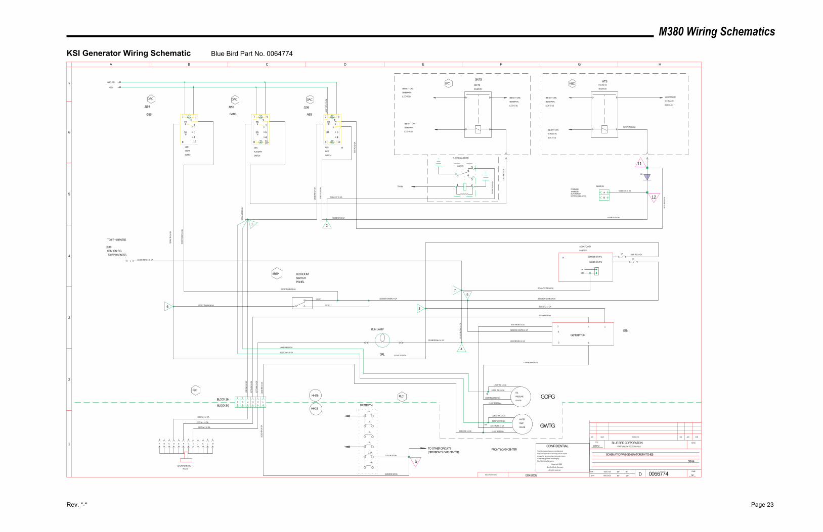
M380 Wiring Schematics
Rev. “-“ Page 23
KSI Generator Wiring Schematic Blue Bird Part No. 0064774
MICRO 4
53
1 2
COM GEN START 1
NO GEN START 2
GY
WH
123
4
5 6
3208 BK/WH 14 GA
3207 PK/BK 14 GA
1275 WH 14 GA
3205B RD 14 GA
OIL
PRESSURE
GAUGE
WATER
TEMP
GAUGE
GOPG
GWTG
GENERATOR
3202A DK GN/PK 14 GA
1260
WH
14
GA
1277
WH
16
GA
1275
WH
14
GA
GRL
RUN LAMP
GNTS
GEN TIE
SOLENOID
HTSHOUSE TIE
SOLENOIDSEE BATT CIRC
SCHEMATIC
(LOC G-31)
SEE BATT CIRC
SCHEMATIC
(LOC G-31)
SEE BATT CIRC
SCHEMATIC
(LOC G-31)
SEE BATT CIRC
SCHEMATIC
(LOC G-31)
SEE BATT CIRC
SCHEMATIC
(LOC G-31)
SEE BATT CIRC
SCHEMATIC
(LOC G-31)
1261
WH
16
GA
BATTERY 4
FRONT LOAD CENTER
GROUND
+12V
J154
DAC DAC
J155 J156
DAC
GEN
START
SWITCH
GEN
AUX BATT
SWITCH
AUX
BATT
SWITCH
LFC HBC
AC/DC POWER
INVERTER
3205 RD 14 GA
FLCHH26
HH18
BLOCK 16
BLOCK 80
FLC
3202B DK GN/BK 14 GA
BEDROOMSWITCHPANEL
BRSP
3205
A T
N 1
4 G
A
3203
TN
/WH
14
GA
1260
A W
H 1
6 G
A
1261
B W
H 1
4 G
A
5030
GY
16 G
A
3203 TN/WH 14 GA
0066774BT06/17/03
SCHEMATIC,WRG,GENERATOR,SWITCHES
38H4
12857M
SW06/12/03
3210A RD/WH 14 GA
3202B DK GN/BK 14 GA
3210 RD/WH 14 GA3210B RD/WH 14 GA
PI
1 2
4
5
GSS GABS ABS
3205A TN 14 GA
GEN
3205C TN/WH 14 GA6 3202C
3202D
7
J188GEN IGN SIGTO I/P HARNESS
TO I/P HARNESS
3210C RD/WH 18 GA
INACTIVATES NOS.
LET. WAS REVISIONS DR. APP. CCN
SCALEBLUE BIRD CORPORATIONFORT VALLEY GEORGIA, U.S.A.
CCN
DR.
APP. BY
BY
DPAGE
__OF__
1
2
3
4
5
A B C D E F G H
6
7
1
10
7
2B3
9
1
6
4
5B
810
7
2B3
9
1
6
4
5B
8
1
2B3
7 9
108
5B 6
4
3
5A
5A
3210
D R
D/W
H 1
4 G
A
5 4 3 2 1
1206B WH 16 GA
1206C WH 16 GA
1181
D B
K 16
GA
1260 WH 14 GA
1275 WH 14 GA
1277 WH 16 GA
--A
--A
1181
D B
K 16
GA
1181 BK 16 GA
1181D BK 16 GA
TO OTHER CIRCUITS(SEE FRONT LOAD CENTER)
1260E WH 16 GA
1260D WH 16 GA
3208 BK/WH 14 GA
1181E BK 16 GA
1260G WH 16 GA
1260F WH 16 GA
S9
S103207 PK/BK 14 GA
1181F BK 16 GA1181D BK 16 GA
5075
PU
16
GA
5030A GY 16 GA
11
12
5075
PU
16
GA
5030C GY 16 GA
B
A
BLOCK 21
TO FRAMEHARNESSSURE POWERBATTERY ISOLATOR
6A
5075A PU 16 GA
0043002
5030B GY 16 GA 5030B GY 16 GA
ELECTRICAL CENTER
TO IGN
1332
E LT
/BL
16 G
A
B4
5030
A G
Y 16
GA
CONFIDENTIALThe information hereon is confidential
business information and may not be copied
or used for any purpose unless permission
is expressly granted in writing by
Blue Bird Body Company.
Copyright 2002
Blue Bird Body Company
All rights reserved
6
6
CA B D E F G H J K L M
GROUND STUDB12A
--A
--A
--A
7.5A
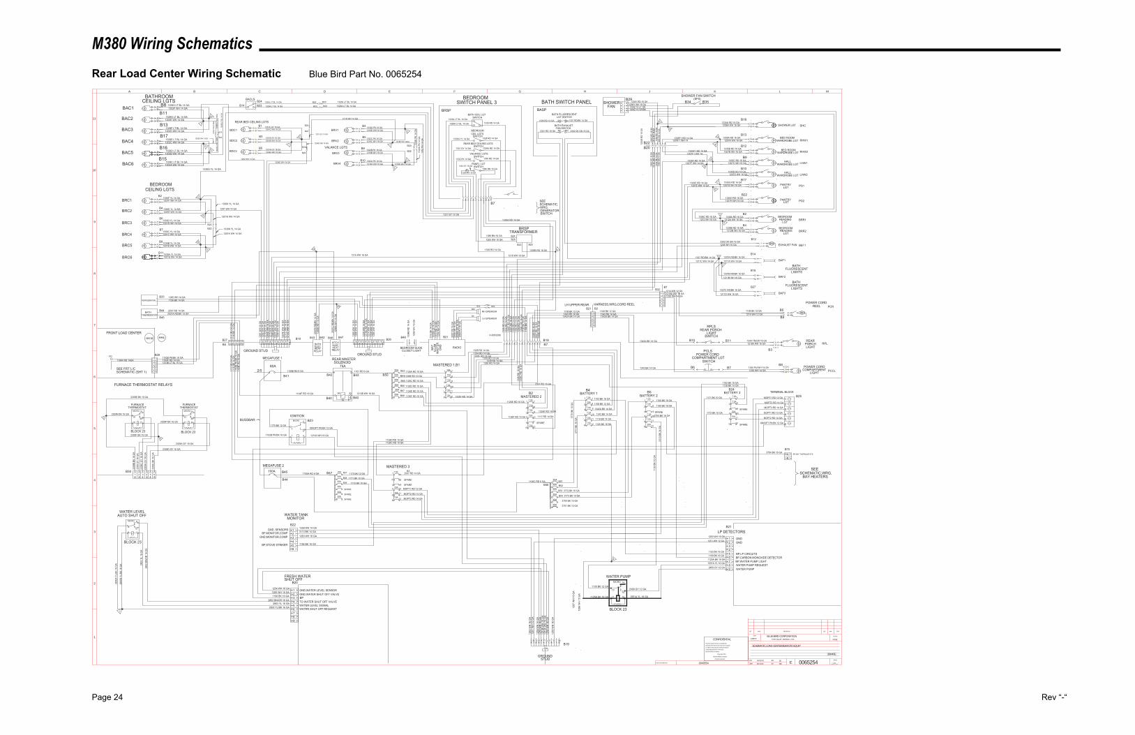
M380 Wiring Schematics
Page 24 Rev “-“
Rear Load Center Wiring Schematic Blue Bird Part No. 0065254
30A
30A
INACTIVATES NOS.
LET. WAS REVISIONS DR. APP. CCN
SCALEBLUE BIRD CORPORATIONFORT VALLEY GEORGIA, U.S.A.
CCN
DR.
APP.
BY
BY EPAGE
__OF__
1
2
3
4
5
6
7
8
9
10
11
A B C D E F G H J K L M
0065254
SCHEMATIC,LOAD CENTER,REAR,STD EQUIP
06/03/03
06/10/03
SS
SW
12857N NONE
- -
CONFIDENTIALThe information hereon is confidential
business information and may not be copied
or used for any purpose unless permission
is expressly granted in writing by
Blue Bird Body Company.
Copyright 2002
Blue Bird Body Company
All rights reserved
38H4RE
0040554
PANEL LGTSWITCH
VALANCE LGTSSWITCH
REAR BED CEILING LGTSSWITCH
BEDROOM
SWITCHCEIL LGTS
BATH CEIL LGTSWITCH
BATH FLUORESCENTLGT SWITCH
BATH EXHAUSTFAN SWITCH
PCLS
RPLSREAR PORCH
LIGHTSWITCH
POWER CORDCOMPARTMENT LGT
SWITCH
BRV4
BRV3
BRV2
BRV1
BDC3
BDC2
BDC1
BRC6
BRC5
BRC4
BRC3
BRC2
BRC1
BAC6
BAC5
BAC4
BAC3
BAC2
BAC1
B5
B3
B1
B10
B8
B5
B3
B11
B9
B7
B6
B4
B15
B16
B17
B13
B11
REAR BED CEILING LGTS
VALANCE LGTS
BATHROOMCEILING LGTS
BAF2
B15BATH
FLUORESCENTLIGHTS
B14
BAF1
BRR2
B4BEDROOM
LGTREADINGA
B
BA BEDROOM
LGTREADING
B2
BRR1
BEF1
PD1
LHW2
LHW1
RHW2
RHW1
SHC
B18AB
B12
B17
B10
B9
B12
B13
PANTRYLGT
AB
BA HALL
WARDROBE LGT
EXHAUST FAN
HALLWARDROBE LGT
AB
SHOWER LGT
BED ROOMWARDROBE LGTA
B
BA BED ROOM
WARDROBE LGT
BRSP BASP
GROUNDSTUD
MLKJHGFEDBA C
B19
POWER CORD
LIGHTCOMPARTMENT PCCL
RPLREAR
LIGHTPORCHA
B
PCRPOWER CORD
REEL
BRSPTRANSFORMER
BA PANTRY
LGT PD2
B27
BAF3
BATHFLUORESCENT
LIGHTS1337C RD/BK 16 GA
1211D WH 16 GA1
2
2
1
1
2
1337B RD/BK 16 GA1211B WH 16 GA
1337A RD/BK 16 GA1211A WH 16 GA
1337 RD/BK 14 GA1211C WH 14 GA
13
1
12
2302 DK GN 16 GA1208 WH 16 GA
1212B WH 16 GA1338B RD 16 GA
1212A WH 16 GA1338A RD 16 GA
2
31338C RD 16 GA
1212 WH 16 GA
1335H RD 16 GA1207H WH 16 GA
1207G WH 16 GA1335G RD 16 GA
1335D RD 16 GA1207D WH 16 GA
1335C RD 16 GA1207C WH 16 GA
1335B RD 16 GA1207B WH 16 GA
1335A RD 16 GA1207A WH 16 GA
1334A RD 16 GA1206A WH 16 GA
12
8
9
11
8
12
1335F1 RD 14 GA
13
14
1207F1 WH 141334
RD
14
GA
1206
WH
14
GA
1338
C R
D 1
6 G
A12
12 W
H 1
6 G
A
SWITCH PANEL 3 BATH SWITCH PANEL
12111098765421 3
1329J LT BL 14 GA
1329A LT BL 14 GA
1330G YL 14 GA
1331 GY 14 GA
1332 PK 14 GA
10
5
1329H LT BL 14 GA1202F WH 14 GA
4 7
9
11
1332D PK 16 GA1218D WH 16 GA
1218C WH 16 GA1332C PK 16 GA
1332B PK 16 GA
1332A PK 16 GA1218A WH 16 GA
1218B WH 16 GA
B21330F YL 14 GA
1330E YL 14 GA
1330D YL 14 GA
1330C YL 14 GA
1330B YL 14 GA
1330A YL 14 GA
1201F WH 14 GA
1201E WH 14 GA
1201D WH 14 GA
1201C WH 14 GA
1201B WH 14 GA
1201A WH 14 GA
5
10
6
7
6
4
1205 WH 16 GA1380 BN 16 GA
1328 RD 14 GA
31 2 4 5 6 7 8 9 10 11 12
GROUND STUD
CA B D E F G H J K L M 13 14 15A B
1328
RD
14
GA
1334
RD
14
GA
1335
F R
D 1
4 G
A
2301 RD 16 GA
1336 RD 14 GA 1337 RD/BK 14 GA
2302 DK GN 16 GA
2301
RD
16
GA
1335
RD
14
GA
1350
RD
14
GA
1336
RD
14
GA
1338
C R
D 1
6 G
A
1339
RD
14
GA
3
12
456
1334Y RD 16 GA1206Y WH 16 GA1334Z 16 LT GN1206Z 16 OR/BK
B8
1329G LT BL 14 GA
1329F LT BL 14 GA
1329E LT BL 14 GA
1329D LT BL 14 GA
1329C LT BL 14 GA
1202E WH 14 GA
1202D WH 14 GA
1202C WH 14 GA
1202B WH 14 GA
1202A WH 14 GA
1331C GY 16 GA
1331B GY 16 GA
1331A GY 16 GA
1204C WH 16 GA
1204B WH 16 GA
1204A WH 16 GA
IGN
1 2 3 4 5 6
WATER LEVELAUTO SHUT OFF
31 2 4 5 6
FURNACETHERMOSTAT
FURNACETHERMOSTAT
2309F BK 16 GA
2309E BK 16 GA
2309N BK 16 GA
2309D GY 16 GA
2309
A G
Y 16
GA
2309
C G
Y 16
GA
2309
GY
16 G
A23
09B
BK 1
6 G
A
3
12
456789
1254 WH 16 GA1255 WH 16 GA
2800 YL/BK 16 GA
2802 BN/OR 16 GA2803 YL 16 GA
FRESH WATERSHUT OFF
80A
B4
MASTERED 2
1107 RD 6 GA1106B RD 6 GA
REAR MASTER SOLENOID
75A
1104F RD 16 GA 1213B WH 16 GA
1126E RD 10 GA
MASTERED 1,B1
IGNITION
100A
1126B RD 10 GA
1126A RD 10 GA30A
10A
10A
7.5A
7.5A
7.5A
7.5A
7.5A
7.5A
15A
7.5A
20A
7.5A
30A
30A
7.5A
7.5A
7.5A
20A
B51
B52
B53 3772 BK 10 GA
B54 3773 BK 10 GA
SPARE
BOPT2 RD 14 GA
BOPT1 RD 12 GA
MOPT3 RD 14 GA
MOPT2 RD 14 GA
MOPT1 RD 12 GA
TERMINAL BLOCKBATTERY 3
FURNACE THERMOSTAT RELAYS
654
21
3
WATER TANKMONITOR
LP DETECTORS
3
12
456789
BATTERY 2
1190 BK 16 GA
654321
BEDROOMCEILING LGTS
1202
K W
H 1
4GA
1329
K LT
BL
14G
A13
29K
LT B
L 14
GA
1329
B LT
BL
14 G
A
1329J LT BL 14 GA
1329A LT BL 14 GA
1330G YL 14 GA
1201 WH 14 GA
1 2B20B22
5B20
B22
1
1202 WH 14 GA1204D WH 14 GA
B20
B22
B22
B20
6
7
1218K WH 14GA
1218K WH 14 GA
1332
K PK
14
GA
B20
B223 4
1334
B R
D 1
6 G
A
1295
WH
16
GA
FRONT LOAD CENTER
B28
SEE FRT L/CSCHEMATIC (SHT 1)
1102B PK/BK 16 GA
1201
WH
14
GA
1202
WH
14
GA
1218
WH
14
GA
1204
D W
H 1
4 G
A12
15 W
H 1
6 G
A12
06 W
H 1
4 G
A12
07F
WH
14
GA
1208
WH
16
GA
1211
C W
H 1
4 G
A12
12C
WH
16
GA
1117
RD
14
GA
1116
BK
14 G
A11
02B
PK/B
K 16
GA
1104
F R
D 1
6 G
A
1102B PK/BK 16 GA 1213A WH 16 GA
1259 WH 14 GA3113 BK 14 GA
1263 WH 16 GA
B20
B22
2800
A YL
/BK
16 G
A 2803
YL
16 G
A
2802
BN
/OR
16
GA
1239
WH
14
GA
1219
A W
H 1
6 G
A12
14 W
H 1
2 G
A12
20 W
H 1
4 G
A12
95 W
H 1
6 G
A
1335F RD 14 GA
1263
WH
16
GA
1259
WH
14
GA
1255
WH
16
GA
1213
B W
H 1
6 G
A12
13A
WH
16
GA
1254
WH
16
GA
1250
WH
16
GA
B21
1250 WH 16 GA
1103 BK 16 GA1100 BK 16 GA
1125A BK 16 GA1551A YL 16 GA
1328 RD 14 GA1334 RD 14 GA1335F RD 14 GA
1335 RD 14 GA1339 RD 14 GA
1350 RD 14 GA
1336
RD
16
GA
1338
C R
D 1
6 G
A
2301 RD 16 GA
1117 RD 14 GA7.5A
7.5A
7.5A
1108 BK 12 GA
1342A BK 14 GA
1343 BK 14 GA
1116 BK 14 GA
1125 BK 16 GA
1100 BK 16 GA
3704 BK 16 GA
3113
BK
14 G
A
30A
30A
30A
BEDROOM
1335 RD 14 GA
1328 RD 14 GA
1339A RD 14 GA
1350 RD 14 GA
1380 BN 16 GA1333 GY 16 GA
1205 WH 16 GA
21339B RD 16 GA
1215 WH 16 GA
B24B26
B23 B25
H-0053308
1108
BK
12 G
A
1343 BK 14 GA1342A BK 14 GA
1108 BK 12 GA1343 BK 14 GA1342A BK 14 GA
1108 BK 12 GA
1344 TN/OR 16 GA
1345 PU/WH 14 GA
1214 WH 12 GA
1219A WH 16 GA
1220 WH 14 GA
1214 WH 12 GA1219A WH 16 GA1220 WH 14 GA
B10 B11
B6 B7B8
B3
1338
C R
D 1
6 G
A12
12C
WH
16
GA
1334
RD
14
GA
1206
WH
14
GA 1207F1 WH 14
1335F1 RD 14 GA
1335F RD 14 GA
3
16
8
9
B20
B20
1215 WH 16 GA
B181207
E W
H 1
4 G
A
B30
3
MICRO 19
2018
16 17
MICRO 24
2523
21 22
BLOCK 23 BLOCK 23
B8
1
2800
B YL
/BK
16 G
A
GND,WATER LEVEL SENSORGND,WATER SHUT OFF VALVEBPTO WATER SHUT OFF VALVEWATER LEVEL SIGNALWATER SHUT OFF REQUEST
1190 BK 16 GA
BLOCK 23
MICRO 9
108
6 7GND, SENSORS
BP,MONITOR,COMPGND,MONITOR,COMP
1182 BK 16 GABP,STOVE STRIKER
30A
MOPT3 RD 14 GA
MASTERED 3
IGNOPT PK/BK 12 GA
B41
MEGAFUSE 1
2/0B42
B40
B43
B40
B50
1170 BK 12 GA
30A
30A
30A
20A
30A
B47 1170 BK 12 GAB57
B58
B59
1171 BK 10 GA
1172 BK 10 GA
SPARE
SPARE
SPARE
1106A RD 6 GA
MEGAFUSE 2
B57.5A
20A
15A
1171 BK 10 GA 1
2
3
4
5
6IGNOPT PK/BK 12 GA
SPARE
B25
MOPT1 RD 12 GA
MOPT2 RD 14 GA
1126C RD 10 GA
1126D RD 10 GA
B63
B64
B65
B66
B67
B68
30A
30A
30A1126E RD 10 GA
1126F RD 10 GA
1126D RD 10 GA1126C RD 10 GA
B3
1126F RD 10 GA
7.5A 1335E RD 14 GA
B19B7
1207E WH 14 GA1335E RD 14 GA
B22
1207F WH 14 GA
B2014 15 1110 13 12
B60
B61 B62
B63
1108 BK 12 GA
LH UPPER REAR HARNESS,WRG,CORD REELB21
B7
1339A RD 14 GA
1331 GY 14 GA
3770
BK
10 G
A37
71 B
K 10
GA
AB
B70BP,BAY THERMOSTATS
3704 BK 16 GA
7.5A
1130 BK 12 GA
1125B BK 16 GA
MICRO 14
1513
11 12
GND
BP,LP CIRCUITSBP,CARBON MONOXIDE DETECTORBP,WATER PUMP LIGHTWATER PUMP REQUESTWATER PUMP
BLOCK 23
WATER PUMP
1106C RD 6 GA
3700 BK 10 GA30A 3701 BK 10 GA
SEESCHEMATIC,WRG,
BAY HEATERS
B14
BACLSB24B23
B22
B22
654
21
3
1104F RD 14 GA1333B LT BL 16 GA
1104F RD 14GA
1116
BK
14 G
A11
17 R
D 1
4 G
A
REFRIGERATORB33
B47B46B42B43
2507
B R
D/B
K 14
GA
1288
B W
H 1
4 G
A
2507
C R
D/B
K 14
GA
1288
A W
H 1
4 G
A
ELECHEAT
KITCHELECHEAT
16
15
B44
B45
BATHTHERMOSTAT 2507A RD/BK 14 GA
1
2
1285 WH 14 GA1126 BK 14 GA
2507 RD 14 GA
RADIO
1333
B LB
16
GA
1116
BK
14 G
A
B211117
RD
14
GA
1239
WH
14
GA
BAT
ILLU
MM
ASTE
RG
ND
B26B27
1234
SHOWERFAN
B35B34
SHOWER FAN SWITCHB29 (SFS)
B22
B32
B48
1334
B R
D 1
6 G
A
B1
B2
1342A BK 14 GA
1343 BK 14 GA
B5
B9
BAC
2409 GY 12 GA
2409 GY 12 GA
1551A YL 16 GA
1251
WH
12
GA
2
1103 BK 16 GA
1251 WH 12 GA
SPARE
B46
B45
BUSSBAR
20A
15A
7.5A
B23
BATTERY 1
1130
BK
12 G
A
1182 BK 16 GA
B24
1172 BK 10 GA
B2
B44
GND
2309
J BK
16
GA
4
2309P BK 16 GA
2309A GY 16 GA
SPARE
SPARE
1
2
3
4
5
6
7
8
9
10
11
12
1285
WH
14
GA
1126
BK
14 G
A
1126 BK 14 GA
1
2
3
4
5
6
7
8
9
10
11
12
1
2
3
4
5
6 12
11
10
9
8
77
8
9
10
11
126
5
4
3
2
17
8
9
10
11
126
5
4
3
2
1
7
8
9
10
11
126
5
4
3
2
1
1218 WH 14 GA
7.5A
SPARE
1287
WH
10
GA
1286
WH
10
GA
1335
E R
D 1
4 G
A
B20B2217
C
M
SEE SCHEMATIC,WRG,GENERATORSWITCH
7.5A
BEDROOM SLIDECLOSET LIGHT
1329J LT BL 14 GA
1329A LT BL 14 GA
2008
PU
16
GA
2009
A O
R 1
6 G
A20
09 O
R 1
6 G
A20
07 P
K 16
GA
B25
B6
RH SPEAKER
LH SPEAKER
2507
RD
14
GA
7.5A 2507 RD 14 GA
1288
WH
14
GA
BATH
RELAY
18
RELAY
AB
AB
AB
AB
AB
AB
AB
A
B
AB
AB
AB
AB
AB
A
B
AB
AB
AB
AB
AB
AB
M
86 85
GROUND STUD
CA B D E F G H J K L M
MICRO 4
53
1 2
HH18 HH4
1202K WH 14GA
1331 GY 14 GA
1204D WH 14 GA
1201K WH 14 GA
1330K YL 14 GA
1201K WH 14 GA
1330K YL 14 GA
1332
K PK
14
GA
1332
PK
14 G
A
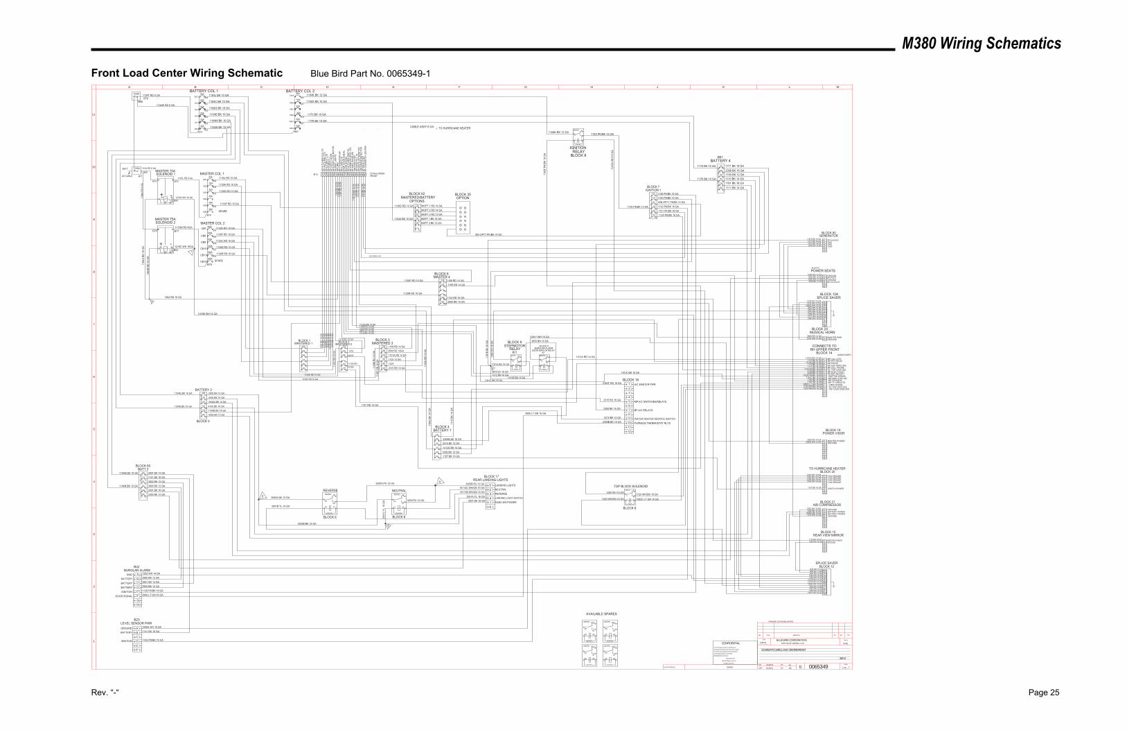
M380 Wiring Schematics
Rev. “-“ Page 25
Front Load Center Wiring Schematic Blue Bird Part No. 0065349-1
INACTIVATES NOS.
LET. WAS REVISIONS DR. APP. CCN
SCALEBLUE BIRD CORPORATIONFORT VALLEY GEORGIA, U.S.A.
CCN
DR.
APP.
BY
BY EPAGE
__OF__
1
2
3
4
5
6
7
8
9
10
11
A B C D E F G H J K L M
0065349
SCHEMATIC,WRG,LOAD CENTER,FRONT
05/28/03
05/28/03
SS
SW
12857M NONE
1 2
CONFIDENTIALThe information hereon is confidential
business information and may not be copied
or used for any purpose unless permission
is expressly granted in writing by
Blue Bird Body Company.
Copyright 2002
Blue Bird Body Company
All rights reserved
38H4
STANDARD 12V HOUSE LIGHTING
BATT 100A
7.5A
MASTERED 1
7.5A
10A
7.5A
7.5A
15A 15A
15A
7.5A
MASTERED 2
7.5A
1319 RD 16 GA
1173
RD
14
GA
1302
RD
16
GA
1309
RD
14
GA
1326
RD
16
GA
1312
E R
D 1
4 G
A13
15 R
D 1
4 G
A11
30C
RD
10
GA
1104 RD 6 GA
1130
E R
D 1
0 G
A 10A
MASTERED 3
15A
7.5A
7.5A
10A
3870 GY 16 GA
1168 RD 14 GA
1101A RD 14 GA
1103 14 GA
20A
7.5A
20A
10A
BATTERY 111
04C
BK
10 G
A
1325 RD 16 GA
1325
1319
1112A RD14 GA
1312G BK 14 GA
STEPMOTORRELAY
K1
1312 BN 16 GA
1181A BK 16 GA
3500 RD 14GA
2303F
2310 BK 12 GA2309B BK 16 GA
1104G BK 10 GA7.5A
BATTERY 2
7.5A
15A
20A
20A
7.5A
3000 BK 12 GA
1104D BK 10 GA
1312G BK 14 GA
3870 GY 16 GA
1312 BN 16 GA
4200 BK 12 GA
1104B BK 14 GA
4100 BK 16 GA
BURGLAR ALARMDOOR SWITCH RELAY
K1
1181B BK 16 GA
3400 BK 14 GA
3402A BK 12 GA
1
2
3
4
5
6
7
8
9
10
11
12
1
2
3
4
5
6
7
8
9
10
11
12
1130D RD 10 GA
6
5
4
3
2
1 7
8
9
10
11
12
1130
F R
D 1
0 G
A
MICRO 24
2523
21 22
MICRO 19
2018
16 17
1
2
3
4
5
6 12
11
10
9
8
7
MOPT 1 RD 14 GAMOPT 2 RD 14 GAMOPT 3 RD 12 GABOPT 1 BK 14 GABOPT 2 BK 12 GA
3300 BK 12 GA3001 BK 16 GA3900 BK 12 GA3902 BK 12 GA1141 BK 16 GA3901 BK 14 GA
3850 BN 16 GABLOCK 9BLOCK 9
BLOCK 16
MICRO 19
2018
16 17
MICRO 24
2523
21 22
4
2 3000A BK 12 GA
3001B YL 16 GA
3000B BK 12 GA
3001
C Y
L 16
GA
3200A PU 12 GA
3200 PU 12 GA
3200B PU 12 GA18114C WH/GN 16 GA
18113B WH/GN 16 GA
523416
BLOCK 17REAR LANDING LIGHTS
1130G RD 10 GA
1104X BK 10 GA
1104M BK 10 GA
1104N BK 10 GA
BLOCK 62MASTERED/BATTERY
BLOCK 60BATT 3
BLOCK 35OPTION
BLOCK 8 BLOCK 8
2303F RD 16 GA
2310 BK 12 GA
2309B BK 16 GA
123456789
1011
1101A RD 14 GA1115 BK 16 GA
1112A RD 14 GA1110 BK 14 GA1111 BK 14 GA
1124 PK/BK 16 GA4100 BK 16 GA4200 BK 12 GA
1102F PK/BK 16 GA1181C BK 16 GA
ABCDEFGHJK
1249 WH 16 GA1265 WH 14 GA1245 WH 14 GA1242 WH 12 GA1292 WH 14 GA
1216B WH 14 GA1216A WH 16 GA1266A WH 16 GA
1264 WH 12 GA1243 WH 12 GA
1276 WH 12 GA1278 WH 14 GA
KJHGFEDCBA
BLOCK 12A
BLOCK 12
BLOCK 14
SPLICE SAVER
SPLICE SAVER
POWER VISORBLOCK 19
123456789
2900 RD 14 GA1266G WH 14 GA
1243 WH 12 GA1242 WH 12 GA
987654321
BLOCK 20TO HURRICANE HEATER
AIR COMPRESSORBLOCK 21
123456789
1265 WH 14 GA3400 BK 14 GA
1245 WH 14 GA1246 WH 14 GA
3402A BK 12 GA1276 WH 12 GA
POWER SEATSBLOCK 18
123456
1264 WH 12 GA3300 BK 12 GA
BLOCK 24MUSICAL HORN
1278 WH 14 GA3500 RD 14 GA
B
A
123456
1123 RD 16 GA1249 WH 16 GA
REAR VIEW MIRRORBLOCK 15
LM1281Y WH 16 GA
1246 WH 14 GA
6
BLOCK 4
BLOCK 3BLOCK 2BLOCK 1
3
1130F RD 10 GA
1104
B BK
14
GA
1101A RD 14 GA
123456789101112
3908 LT GN 16 GA
1134
F R
D 1
4 G
A
1364
RD
16
GA
1151 PK/BK 16 GA
1
2
3
4
5
6 12
11
10
9
8
7
1281Y WH 16 GA
BLOCK 5
1
2
3
4
5
6
7
8
9
10
11
12
1
2
3
4
5
6 12
11
10
9
8
7
3001A YL 16 GA
REVERSE NEUTRAL
3001 BK 16 GA
GROUNDBP,PILOT
DASH SW POWER
LANDING LIGHT SWITCH
REVERSENEUTRALLANDING LIGHTS
MASTER PWRGROUND
BP,FRT RADIO
BP,BAY RECEPT
MASTER POWERGROUND
GROUNDBATTERY POWERBATTERY POWERGROUND
GROUNDMASTER POWER
A/C MASTER PWR
FURNACE THERMOSTAT RLYSWATER HEATER SERVICE SWITCH
AVAILABLE SPARES
ABCDEF
GNDBATTERYBATTERY
BATTERYIGNITION
DOOR SIGNAL
1292 WH 14 GA3900 BK 12 GA3901 BK 14 GA3902 BK 12 GA1128 PK/BK 16 GA3908 LT GN 16 GA
BURGLAR ALARM
LEVEL SENSOR PWR
IGNITION
BATTERYGROUND
FEDCBA
1266G WH 14 GA
15A
20A
20A
7.5A
CONNECTS TORH UPPER FRONT
7.5A
1142 PK/BK 16 GA
1141 BK 16 GA
1266A WH 16 GA
1 2 3 4 5 19 7 161518 6 9 10111213 8 14172021
1130F RD 10 GA
1130E RD 10 GA
1171 BK 14 GA
1110 BK 14 GA1181 BK 16 GA1111 BK 14 GA
BATTERY 4
1
2
3
4
5
6
7
8
9
10
11
12
1128 PK/BK 16 GA
MASTER 4
15A
10A
7.5A
IGNITIONRELAY
BLOCK 9
1169 RD 14 GA
1120 PK/BK 12 GA
1123 RD 16 GA2900 RD 14 GA
1216
A W
H 1
6 G
A
7
8
9
10
11
12
1130R RD 10 GA
1
2
3
4
5
6
1
2
3
4
5
6 12
11
9
8
7
BLOCK 7IGNITION 1
7.5A
7.5A
7.5A
7.5A
BLOCK 6
1130P RD 10 GA
1130K RD 10 GA
1130J RD 10 GA
30A
30A
30A
30A 1130D RD 10 GA
1130C RD 10 GA
100A
30A
30A
30A
30A
30A
BATTERY COL 1
MASTER 75ASOLENOID 1
MASTER 75ASOLENOID 2
1216C WH 16GA
1216D WH 16 GA
MASTER COL 1
MASTER COL 2
1142 PK/BK 16 GA
FAN GROUND
FAN GROUNDFAN GROUND
FAN GROUND
MP,VAL LGTS
MP,RADIOBP,AUX PWR CIRCBP,CELL PHONEIG, TOP LOCK SOL
IGNITION SIGNALBP KWIK STEP SW
1120 PK/BK 12 GA
1168
RD
14
GA
30A
30A
30A
30A
30A
30A
1364
A R
D 1
6 G
A
1364
B R
D 1
6 G
A
1150 PK/BK 16 GA7.5A
1150
PK/
BK 1
6 G
A
1364 RD 16 GA
12
7.5A
1102
F PK
/BK
16 G
A
1176 BK 10 GA
1103
RD
14
GA
1175 BK 10 GA
AUDIO/VIDEO
1176 BK 10 GA
1175 BK 10 GA
MP,
KITC
HEN
CLG
LTS
MP,
AISL
E,PN
L LT
SM
P,LR
SPO
T LT
SM
P,PO
RC
H L
TM
P,ST
EP C
OVE
RM
P,D
OO
R L
OC
K M
OTO
RM
P,M
AP L
IGH
TSM
P,C
MD
BP,T
O M
ASTE
R S
WM
P,LV
RM
LTS
STEP
DO
OR
SIG
NAL
DO
OR
SIG
NAL
MP,
KITC
HEN
VEN
T,FL
MP,
REM
OTE
SPO
T LT
SBP
,MAG
DO
OR
SW
IGN
,KW
IK S
TEP
MP,
DIN
ETTE
LTS
MP,
BAC
K-U
P M
ON
ITO
RIG
N,R
ADAR
DET
ECTO
RBP
KW
IK S
TEP
BP C
IGAR
ETTE
LIG
HTE
R
1124 PK/BK 16 GA1151 PK/BK 16 GA
1168 RD 14 GA
1181C BK 16 GA
B13 TO RH UPPERFRONT
1104T RD 6 GA 1104J BK 10 GA
1104C BK 10 GA
1104G BK 10 GA
1104D BK 10 GA
1104M BK 10 GA
1104N BK 10 GA
1130L RD 6 GA
1104
A R
D 6
GA
1130M RD 6GA
1
1130G RD 10 GA
1130P RD 10 GA
SPARE
1163 BK 12 GA
15A
1282 WH 16 GA
1104
J BK
10
GA
1115
BK
16 G
A
5
0040553
20A
2315 RD 16 GA7.5A
2315 RD 16 GA
7.5A
7.5A
1157 BK 16 GA SWITCH POWER
1157 BK 16 GA
1295 WH 12 GA
1295 WH 12 GA
3395 BK 12 GA GROUNDBP,CO-PILOT
2309 BK 16 GA
MP,A/C SWITCHES/RELAYS
BP,A/C RELAYS
2309 BK 16 GA7.5A
25A
15A
15A
3395 BK 12 GA
MP,CB RADIO1155 RD 14 GA
1155 RD 14 GA15A
CABLE ASSY 8 GA TO HURRICANE HEATERB73
B30
B31
B32
B33
B34
B35
B70
B71
B74 B75
B90
B76 B77
B91
B78
B38
B39
B40
B42
B79
B44
B45
B46
B47
B61
B22
B23
30A
30A
1130R RD 10 GA
SPARE
B43
15A
1187 RD 14 GA MP,TV CIRCUITS
1187 RD 14 GA
B37
B36
B72
30A
30A
30A
30A
30A
20A
1104W RD 6 GA
BATTERY COL 2
B96
1104K BK 12 GA
MICRO 4
53
1 2
B95
1163
BK
12 G
A11
71 B
K 14
GA
BP,ELEC TOILET
CB1
CB2
CB3
CB4
CB5
CB6
CB12
CB11
CB10
CB9
CB8
CB7
CB13
CB14
CB15
CB16
CB17
CB18
CB19
CB20
CB21
CB22
CB23
CB24
1104K BK 12 GA
10
GH
1181C BK 16 GA
1216B WH 14 GA
1104X BK 10 GAB81
B97
30A
7.5A
15A
20A
15A
20A
IGN OPT1 PK/BK 14 GA10A
IGN OPT1 PK/BK 14 GA
654321
1260 WH 14 GA
1275 WH 14 GA
1277 WH 16 GA
1181D BK 16 GA1277 WH 16 GA1275 WH 14 GA1260 WH 14 GA
1280 WH 16 GA
131415161718
TOP BLOCK SOLENOID
BLOCK 8
1280 WH 16 GA
1520 WH/GN 16 GA
1720 WH/GN 16 GA
1283C LT GN 16 GA
1283C LT GN 16 GA1720 WH/GN 16 GA1520 WH/GN 16 GA
LM
BLOCK 80GENERATOR
BP,GAUGESGNDGNDGND
OPTIONS
3 MPH SIGNALTO TOP LOCK SOLTOP LOCK DASH SW
MICRO 4
53
1 2
MICRO 87A
8730
85 86
MICRO 87A
8730
85 86
MICRO 87A
8730
85 86
MICRO 87A
8730
85 86
86 85+ -
86 85+ -
1282
WH
16
GA
2/0 CABLE
1181
D B
K 16
GA
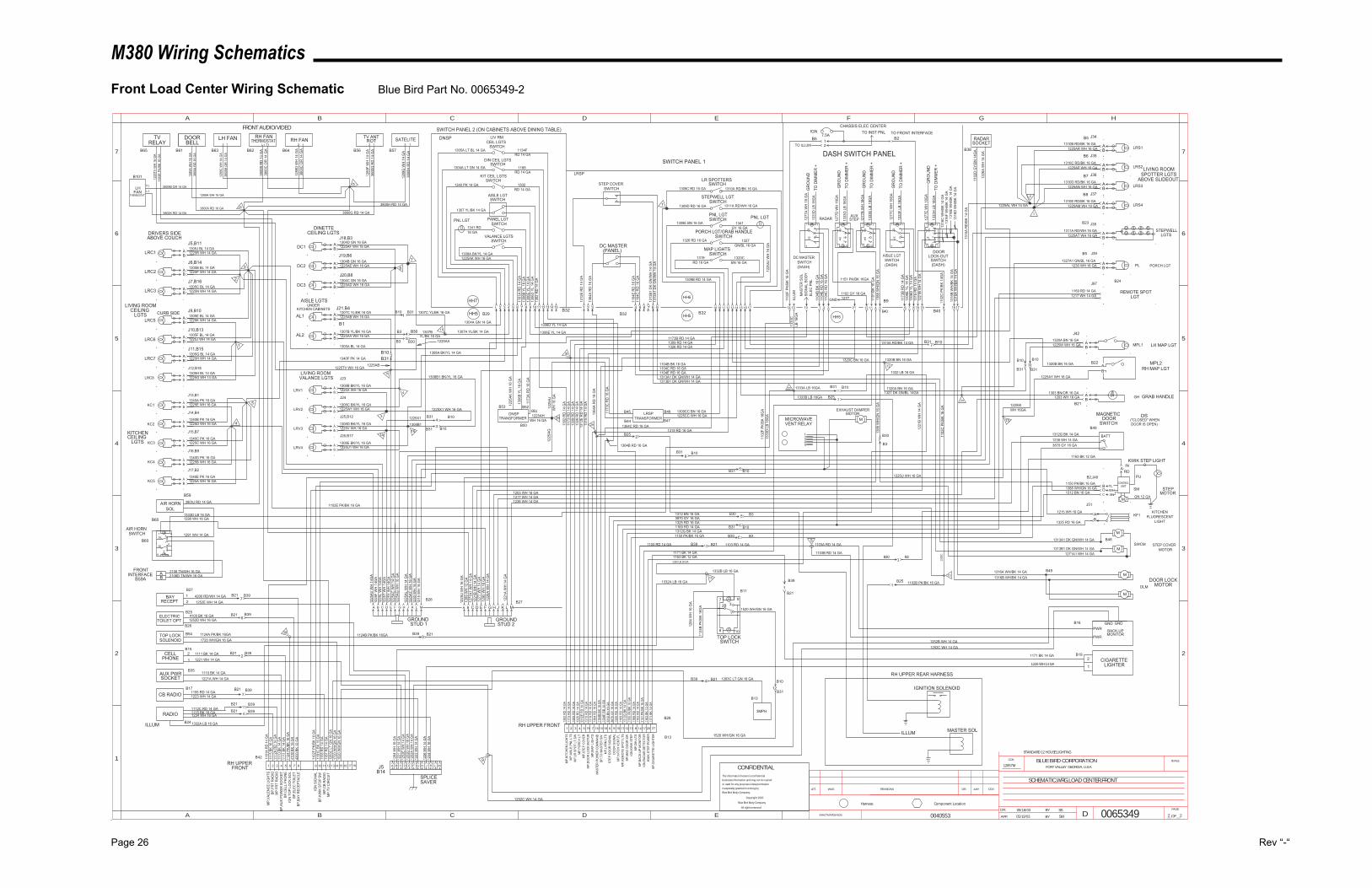
M380 Wiring Schematics
Page 26 Rev “-“
Front Load Center Wiring Schematic Blue Bird Part No. 0065349-2
1
932B
7
8 10
8 10
5B
4
61
93
2B7
INACTIVATES NOS.
LET. WAS REVISIONS DR. APP. CCN
SCALEBLUE BIRD CORPORATIONFORT VALLEY GEORGIA, U.S.A.
CCN
DR.
APP. BY
BY
DPAGE
__OF__
1
2
3
4
5
A B C D E F G H
B C D E
5
4
3
2
6 6
77
A
Component LocationHarness
SCHEMATIC,WRG,LOAD CENTER,FRONT
0065349
12857M
SS05/16/03
SW 2 2
STANDARD 12 HOUSE LIGHTING
05/19/03
CONFIDENTIALThe information hereon is confidential
business information and may not be copied
or used for any purpose unless permission
is expressly granted in writing by
Blue Bird Body Company.
Copyright 2002
Blue Bird Body Company
All rights reserved
PORCH LGT
STEPWELLLGTS
LIVING ROOMSPOTTER LGTS
LIVING ROOMCEILING
LGTS
KITCHENCEILING
LGTS
LIVING ROOMVALANCE LGTS
DINETTECEILING LGTS
AISLE LGTS
BA LH MAP LGT
AISLE LGT
(DASH)SWITCH
DC MASTER
(DASH)SWITCH
PNL LGT
SWITCH PANEL 1
MAP LIGHTSSWITCH
PNL LGTSWITCH
STEPWELL LGTSWITCH
LR SPOTTERSSWITCH
PNL LGT
LIV RM
SWITCHCEIL LGTS
AISLE LGTSWITCH
DIN CEIL LGTSSWITCH
KIT CEIL LGTSSWITCH
PANEL LGTSWITCH
VALANCE LGTSSWITCH
SWITCH PANEL 2 (ON CABINETS ABOVE DINING TABLE)
STEP COVERSWITCH
STEPMOTOR
STEP COVERMOTOR
DOOR LOCKMOTOR
CA B D E F G H J K L M
GROUNDSTUD 1
CA B D E F G H J K L M
GROUNDSTUD 2
B27
1305B BL 14 GA
1225R WH 14 GA1305J BL 14 GA
1225P WH 14 GA
1305C BL 14 GA
1305E BL 14 GA
1305F BL 14 GA
1305G BL 14 GA
1305H BL 14 GA
1225N WH 14 GA
1225K WH 14 GA
1225J WH 14 GA
1225H WH 14 GA
1225G WH 14 GA
1340A PK 16 GA1225E WH 16 GA
1340B PK 16 GA
1340C PK 16 GA
1340D PK 16 GA
1340E PK 16 GA
1225D WH 16 GA
1225C WH 16 GA
1225B WH 16 GA
1225A WH 16 GA
1308B BK/YL 16 GA1225X WH 16 GA
1308C BK/YL 16 GA1225W1 WH 16 GA
1308D BK/YL 16 GA1225V WH 16 GA
1308E BK/YL 16 GA1225U1 WH 16 GA
1340F PK 14 GA
1305A BL 14 GA
1225AA WH 16 GA1307B YL/BK 16 GA
1225AB WH 16 GA1307C YL/BK 16 GA
1304D GN 16 GA1225AF WH 16 GA
1304B GN 16 GA1225AE WH 16 GA
1304C GN 16 GA1225AD WH 16 GA
1304A GN 14 GA
1307A YL/BK 14 GA
1308A BK/YL 14 GA
1101
A R
D 1
4 G
A13
06B
YL 1
6 G
A13
06E
YL 1
4 G
A13
06D
YL
14 G
A13
02 R
D 1
4 G
A
1312
E R
D 1
4 G
A
1305A LT BL 14 GA
1304A LT GN 14 GA
1340 PK 14 GA
1307 YL/BK 14 GA
1308A BK/YL 14 GA1225AK WH 16 GA
1173B RD 14 GA1306E YL 14 GA
1306D YL 14 GA
1173
RD
14
GA
1302
RD
14
GA
1309 RD 14 GA1326 RD 14 GA
1225CC WH 16 GA
1104B BK 16 GA1104C RD 16 GA1104E RD 16 GA1313A1 DK GN/WH 14 GA1313B1 DK GN/WH 14 GA
1225
F W
H 1
4GA
1225
AV W
H 1
4GA
1225
L W
H 1
4GA
1225
T W
H 1
4GA
1225
Y W
H 1
4GA
1225
AC W
H 1
4 G
A12
25AG
WH
16
GA
1225
AL W
H 1
4 G
A12
25AT
WH
16
GA
1225
U W
H 1
6 G
A
1271
A1 W
H 1
4 G
A
1319 RD 16 GA
1310B RD/BK 16 GA1225AR WH 16 GA
1310C RD/BK 16 GA
1310D RD/BK 16 GA
1310E RD/BK 16 GA
1225AP WH 16 GA
1225AN WH 16 GA
1225AM WH 16 GA
1311A RD/WH 16 GA1225AT WH 16 GA
1327A1 GN/BL 16 GA1230 WH 16 GA
1320A BN 16 GA1225W WH 16 GA
1150 PK/BK 16 GA1388 WH/GN 16 GA
1313A1 DK GN/WH 14 GA
1271A1 WH 14 GA1313B1 DK GN/WH 14 GA
1316A WH/BK 14 GA
1320C BN 16 GA
1225U WH 16 GA
1225AL WH 14 GA
1310A RD/BK 16 GA
1311A RD/WH 16 GA
1309C RD 16 GA
1309D RD 16 GA
1309E BN 16 GA
1319RD 16 GA
1320CBN 16 GA
1309B RD 14 GA
1134FRD 14 GA
1168RD 14 GA
1302RD 14 GA
PORCH LGT/GRAB HANDLESWITCH
1326 RD 16 GA 1327GN/BL 16 GA
1309
RD
14
GA
1326
RD
14
GA
1312
E R
D 1
4 G
A13
15 R
D 1
4 G
A
DC MASTER(PANEL)
1364
A R
D 1
6 G
A
1104
E R
D 1
6 G
A11
04C
RD
16
GA
LRC1
LRC2
LRC3
LRC5
LRC6
LRC7
LRC8
KC1
KC2
KC3
KC4
KC5
DC1
AL1
LRV1
DC2
DC3
AL2
LRV2
LRV3
LRV4
1312G BK 14 GA
DOORSWITCH
1238 WH 14 GA
LRS1
LRS2
LRS3
LRS4
MPL1
SM
SWCM
DLM
1225
AJ W
H 1
6 G
A
1313
B1 D
K G
N/W
H 1
4 G
A13
13A1
DK
GN
/WH
14
GA
J5,B11
J6,B14
J7,B16
J9,B10
J10,B13
J11,B15
J12,B18
J13,B1
J14,B4
J15,B7
J16,B9
J17,B2
J23
J21,B4
J18,B3
J19,B6
J20,B8
B1
J24
J25,B12
J26,B17
B29B32
B32 B32
B2,J48
J42
J34
J35
J36
J37
J38
1306
D Y
L 14
GA
1306
E YL
14
GA
1173
B R
D 1
4 G
A
1104
C R
D 1
6 G
A11
04E
RD
16
GA
1388
WH
/GN
16
GA
1104
B BK
16
GA
1181
BK
16 G
A
3870 GY 16 GA
KITCHENFLUORESCENT
LIGHT
1215 WH 16 GA
1325 RD 16 GA
J51
KF1
1230
WH
16
GA
1341 RD16 GA
1341GY 16 GA
J39
1215
WH
16
GA
GR
OU
ND
TO D
IMM
ER +
TO D
IMM
ER +
GR
OU
ND
TO D
IMM
ER +
GR
OU
ND
DASH SWITCH PANEL
1203 WH 16 GA1303 BN/OR 16 GA
BA
1203 WH 16 GA
GH GRAB HANDLE
J97
1217 WH 14 GA1169 RD 14 GA REMOTE SPOT
LGT
1325 RD 16 GA
1217 WH 14 GA
PL
1238 WH 14 GA
IN
1163 BK 12 GA
DS("CLOSED" WHENDOOR IS OPEN)
1150 PK/BK 16 GA
DNSP
LRSP
A
BD
1306
B YL
16
GA
1225AHWH 16 GA
1225
AJW
H 1
6 G
A
1225
AK W
H 1
6 G
A
1309CC BN 16 GADNSP
TRANSFORMERLRSP
TRANSFORMER
1225
AG
1 2 3 4 5 6 7 8 9 10 11 1 2 3 4 5 6 7 8 9 10 18 11 12 13 14 15 16 17
C1312 BN 16 GA
3870 GY 16 GA
MAGNETIC
1169 RD 14 GA1312G BK 14 GA
1312 BN 16 GA
1316B WH/BK 14 GA
1315
RD
14
GA
1221
B W
H 1
4 G
A
1221
B W
H 1
4 G
A
1316
B W
H/B
K 14
GA
1316
A W
H/B
K 14
GA
TO D
IMM
ER +
GR
OU
ND
M
M
M
M
DOOR
SWITCHLOCK-OUT
(DASH)
MMICROWAVEVENT RELAY
12345
EXHAUST DAMPERMOTOR
1 2 3 4 5 19 7 16 15 18 6 9 10 11 12 13
AB
AB
AB
AB
AB
AB
AB
AB
AB
AB
AB
AB
AB
AB
AB
AB
AB
AB
AB
AB
AB
AB
AB
AB
AB
AB
AB
4
65B
8 10
97
32B
1
4
65B
8 10
97
32B
1
4
6
1
2B
5B
37 9
108
1
2B 3
7 9
108
5B 6
4
12 13 14 15
8 14 17 20 21
YLWHBN
RD
CONTROLUNIT
GN 12 GA
BATT
B24
2B25
11
B39
1103 RD 14 GA 12B39
8B30
6 16
1102
C
1102B PK/BK 16 GAB2510
MP,
LR S
POT
LT,S
W
B409
KWIK
STE
P PO
WER
MP,
KITC
H V
ENT,
FLD
OO
R S
IGN
ALST
EP D
OO
R S
IGN
ALM
P,LV
RM
LTS
MP,
STEP
CO
VER
MP,
POR
CH
LT
8
RH UPPER FRONT
MP,
KITC
HEN
LIG
HTS
121110987654321
4 512
RADARSOCKET
B9
B40
1151 PK/BK 16GA
B49
1
BACK-UPMONITOR
CIGARETTELIGHTER
1103A RD 14 GA
1103B RD 14 GA
5
B28
B13
MP,
AISL
E,PN
L LT
S
MP,
DO
OR
LO
CK
MO
TOR
MP,
MAP
LIG
HTS
MAS
TER
PO
WER
CO
MM
AND
BP,T
O M
ASTE
R S
W
MP,
REM
OTE
SPO
T LT
SBP
,MAG
DO
OR
SW
IGN
,KW
IK S
TEP
MP,
DIN
LTS
MP,
BAC
K-U
P M
ON
ITO
RIG
N,R
ADAR
DET
ECTO
R
BP,C
IGAR
ETTE
LIG
HTE
R
1101
A R
D 1
4 G
AM
P,VA
LEN
CE
LIG
HTS
6
7
2
1
3
4
5
B3 45
15
4
3
1225X1
1308B1
B31
B26
26
8B31
B3
B30 B3
B30 B31
1163 BK 12 GA
B30
B3
B23
B5
1
1171 BK 14 GA
1171 BK 14 GA
B16
B19
8 10
3
5B
2B
1
6
4
1102 GY 16 GA
GR
OU
ND
TO D
IMM
ER +
1 2 3
1302
RD
14
GA
1173
RD
14
GA
1309
RD
14
GA
1326
RD
14
GA
1312
E R
D 1
4 G
A13
15 R
D 1
4 G
A13
19 R
D 1
6 G
A13
64 R
D 1
6 G
A11
04B
BK 1
6 G
A11
34F
RD
14
GA
1312
BN
16
GA
3870
GY
16 G
A13
25 R
D 1
6 G
A11
69 R
D 1
4 G
A13
12G
BK
14 G
A11
50 P
K/BK
16
GA
1168
RD
14
GA
1103
RD
14
GA
1151
PK/
BK 1
6 G
A11
63 B
K 12
GA
1171
BK
14 G
A
1181
C B
K 16
GA
BP,K
WIK
STO
P SW
1
BAYRECEPT
TOP LOCKSOLENOID
CELLPHONE
AUX PWRSOCKET
CB RADIO
RADIO
B10
2B10
1308B1 BK/YL 16 GA
4
3
1225X1 WH 16 GA
B10
RADARAUX
STEP1
2
B5
B6
B7
B8
B109 10
7B10
1327 DK GN/BL 14GA
AB
5
6
B10
B10
1284
WH
16
GA
1221
WH
14
GA
1252
A W
H 1
4 G
A12
23 W
H 1
4 G
A
1226
WH
14
GA
1234
WH
16
GA
7
6
2
3
51112C RD 14 GA
1155 RD 14 GA
1252D WH 16 GA
4200 RD/WH 14 GA1252E WH 14 GA
B26
B27
B254100 BK 16 GA
B21
B21
B21
B39
B39
B54
1111 BK 14 GA
14
1234 WH 16 GA
1223 WH 14 GA
1221 WH 14 GA
1
21226 WH 14 GA
GND GND
1252B WH 14 GA1252C WH 14 GA
1252C WH 14 GA
1332B LB 16 GA
1332A LB 16 GA
1332 LB 16 GA
10
1284
WH
16
GA
1124
B PK
/BK
16G
A
1520 WH/GN 16 GA
3MPH
B13
12
B10
9
PWR
PWR
CA B D E F G H J K L M
B48
B22AB
13
1225AY WH 16 GA
12
1320A BN 16 GA
1320B BN 16 GA
B31
24
MPL2RH MAP LGT
1310
A R
D/B
K 14
GA
13
ILLU
M13
33C
LB 1
6GA
1102
D G
Y/BN
14G
A
1226
A W
H 1
4 G
A
B38
B21
1320B BN 16 GA
1102
C P
K/BK
14G
A
87 19 18 17
23 1333A LB 16GA
B10
1102
F PK
/BK
16G
A13
33D
LB
16G
A
B31
B25
7
B46
B47B44
B45
29
1173
A R
D 1
6 G
A
1173
C R
D 1
6 G
A
1221
A W
H 1
4 G
A
B31
B11
B21 1103 RD 14 GA
1289
WH
12
GA
1290
WH
16
GA
1226
A W
H 1
4 G
A
1187
RD
14
GA
MP,
TV C
IRC
UIT
B21
B21
1115
BK
16 G
A11
12A
RD
14
GA
1110
BK
14 G
A11
11 B
K 14
GA
1124
PK/
BK 1
6 G
A41
00 B
K 16
GA
4200
BK
12 G
A
BP,F
RT
RAD
IOM
P FR
T R
ADIO
BP,A
UX
POW
ER S
OC
KET
BP,C
ELL
PHO
NE
IGN
TO
P LO
CK
SOL
BP,E
LEC
TO
ILET
BP,B
AY R
ECEP
TAC
LE
IGN
SIG
NAL
B42
RH UPPER FRONT
MP,
CB
RAD
IO
B24
B17
B35
B39
B39
B39
1124A PK/BK 16GA1720 WH/GN 16 GA
B31
B3
B30 11
1307C YL/BK 16 GA
YL/BK 16 GA1307B
B30
B311614
B53
B50
B51B52
J5B14
TOP LOCK SWITCH
1221
B W
H 1
4 G
A
1102
C P
K/BK
16
GA
1388
WH
/GN
16
GA
1
1310A RD/BK 14 GA
6
1102
F PK
/BK
16 G
A
AIR HORNSWITCH
BA 2108 TN/WH 16 GA
2108D TN/WH 16 GA
AIR HORNSOL
1333D LB 16 GA
1291 WH 14 GA
B65
TVRELAY
DOORBELL
LH FAN RH FANTHERMOSTAT RH FAN TV ANT
ROT SATELITE
B61 B63 B62 B64 B56 B57
25
26
FRONTINTERFACE
1290 WH 16 GA
B59
3800J RD 14 GA
1289A WH 16 GA
3800A RD 16 GA
3800
C O
R 1
4 G
A
1289
D W
H 1
4 G
A
1289
F W
H 1
4 G
A
1289
G W
H 1
4 G
A
3800H RD 14 GA
3800G RD 14 GA
B31
B21
B31
1520 WH/GN 16 GA
B31B31
11
3
IGN7.5A
CHASSIS ELEC CENTER
B101
FANTHERMOSTAT
1289
C W
H 1
4 G
A
B10
1283C LT GN 16 GA
SPLICESAVER
ILLUM 1332A LB 16 GA
12
ELECTRICTOILET OPT
1221A WH 14 GA
B21 B3911
1115 BK 16 GA
1155
RD
14
GA
1252
D W
H 1
6 G
A12
52E
WH
14
GA
B60
B59A
B60
2
1
B15
1225
TV W
H 1
6 G
A11
02E
PK/B
K 16
GA
1289
A W
H 1
6 G
A38
00A
RD
16
GA
LH T1
L1
ILLUM MASTER SOL
RH UPPER REAR HARNESS
IGNITION SOLENOID
B49
PU
KWIK STEP LIGHT
B10
1110 BK 14 GA
1102E PK/BK 16 GA
B10
1332 LB 16 GA
1333B LB 16GA
2 12 1
3800
H R
D 1
4 G
A
3800
G R
D 1
4 G
A
FRONT AUDIO/VIDEO
2 1
3800
M O
R 1
4 G
A
3800K RD 14 GA
L1 T1
3800
B R
D 1
4 G
A
3800
C O
R 1
4 G
A
2 1
1225TV WH 16 GA
3800M OR 14 GA
1314 15 16 17 18
1283
C L
T G
N 1
6 G
A17
20 W
H/G
N 1
6 G
A15
20 W
H/G
N 1
6 G
A
30 B39 B2191124B PK/BK 16GA
1277
WH
14
GA
B39 4 B21
CURB SIDE
DRIVERS SIDEABOVE COUCH
KITCHEN CABINETSUNDER
1102
F PK
/BK
16 G
A
21
1364C RD 16 GA
1277GND
10
MAS
TER
SO
LSI
GN
AL B
OD
YEL
EC P
NL
1277
A W
H 1
8 G
A
12TO ILLUM
B5TO INST PNL
B2TO FRONT INTERFACE
1277
D W
H 1
8GA
1333
D L
B 18
GA
1333
G L
B 18
GA
1277
B W
H 1
8GA
1333
E LB
18G
A
1277
C W
H 1
8GA
1333
F LB
18G
A
1277
E W
H 1
8GA
1333
H L
B 18
GA
ABOVE SLIDEOUT
0040553
M
HH6
HH5
HH7
HH5HH5
1316
F W
H/B
K 14
GA
1316
D W
H/B
K 14
GA
1225WWH 16GA
1316
E W
H/B
K 14
GA
1316
C W
H/B
K 14
GA
1364B RD 16 GA
1364
A R
D 1
6 G
A
1225AA
B31
1225AB
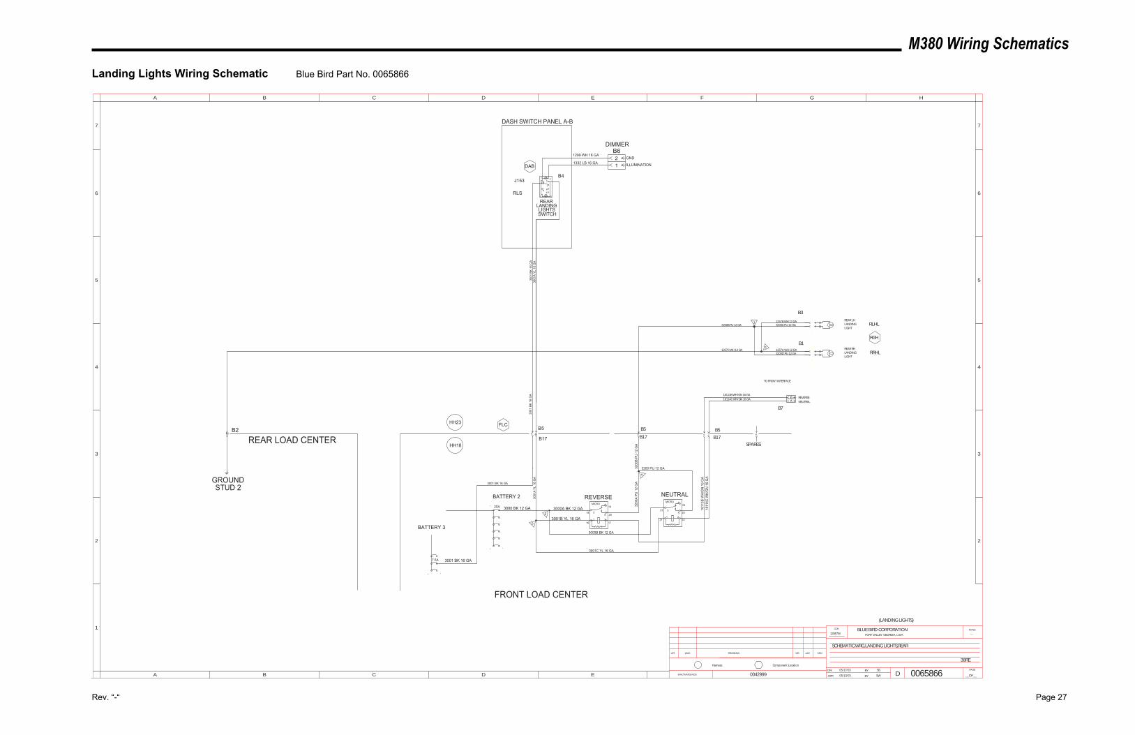
M380 Wiring Schematics
Rev. “-“ Page 27
Landing Lights Wiring Schematic Blue Bird Part No. 0065866
461
2B
5B
37 9
108
0042999 06/13/03
(LANDING LIGHTS)
12857M ---
SW
SS05/17/03
0065866
38RE
SCHEMATIC,WRG,LANDING LIGHTS,REAR
INACTIVATES NOS.
LET. WAS REVISIONS DR. APP. CCN
SCALEBLUE BIRD CORPORATIONFORT VALLEY GEORGIA, U.S.A.
CCN
DR.
APP. BY
BY
DPAGE
__OF__
1
2
3
4
5
A B C D E F G H
B C D E
5
4
3
2
6 6
77
A
Component LocationHarness
REAR
SWITCH
LANDINGLIGHTS
M
GROUNDSTUD 2
20A
BATTERY 2
1
3001
BK
16 G
A
3000 BK 12 GA
FRONT LOAD CENTER
J153
DASH SWITCH PANEL A-B
3001
BK
16 G
A30
01A
YL 1
6 G
A
REAR LHLANDINGLIGHT
REAR RHLANDINGLIGHT
3200C PU 12 GA1257B WH 12 GA
1257A WH 12 GA3200D PU 12 GA
3200B PU 12 GA
1257C WH 12 GA
REAR LOAD CENTER
DAB
RCH
FLC
RLHL
RRHL
RLS
3200 PU 12 GA
23
TO FRONT INTERFACE
16 17
18
19
20
21 22
23
24
25
4
4
5
7.5A
BATTERY 3
3001 BK 16 GA
3001 BK 16 GA
5
3001
A YL
16
GA
2
1299 WH 16 GA
1332 LB 16 GAGND
ILLUMINATION
DIMMER
B3
B1
1
2
BA
B7
B5
NEUTRAL
REVERSE
B2
B6
B4
REVERSE NEUTRAL
B5
B17
B5
B17 B176
SPARES
3001B YL 16 GA
3200
B PU
12
GA
3200
A PU
12
GA
MICRO 4
53
1 2
MICRO 4
53
1 2
12
HH23
HH18
3000A BK 12 GA
3001C YL 16 GA
3000B BK 12 GA
18114C WH/GN 16 GA
1811
3B W
H/G
N 1
6 G
A
18113B WH/GN 16 GA
1811
4C W
H/G
N 1
6 G
A
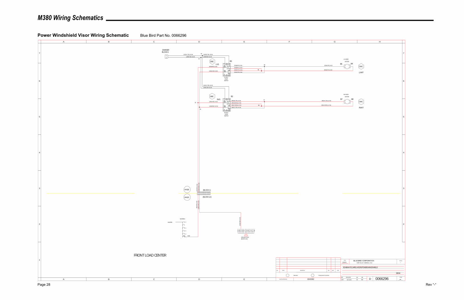
M380 Wiring Schematics
Page 28 Rev “-“
Power Windshield Visor Wiring Schematic Blue Bird Part No. 0066296
4
65B
8 10
9732B
1
4
65B
8 10
9732B
1
0043092 06/13/03
12857M ---
SW
SS05/12/03
0066296
38H4
SCHEMATIC,WRG,VISOR,POWER,WINDSHIELD
INACTIVATES NOS.
LET. WAS REVISIONS DR. APP. CCN
SCALEBLUE BIRD CORPORATIONFORT VALLEY GEORGIA, U.S.A.
CCN
DR.
APP. BY
BY
DPAGE
__OF__
1
2
3
4
5
A B C D E F G H
B C D E
5
4
3
2
6 6
77
A
Component LocationHarness
15A
MASTER 4
FRONT LOAD CENTER
2900
RD
14
GA
(BLOCK 1)
(BLOCK 12)
RH VISOR
MOTOR
RVMT
2901A DK BL 14 GA
2902A LT BL 14 GA
2900
2900
RD
14
GA
MASTER
LH W/SVISOR
SWITCH
RH W/SVISOR
SWITCH
LVS
RVS
DBC
DBC
OHC2902B LT BL 14 GA
2901B DK BL 14 GA
2901C DK BL 14 GA
2902C LT BL 14 GA
2904C PK 14 GA
2903C PU 14 GA
2903B PU 14 GA
2904B PK 14 GAOHC
2904A PK 14 GA
2903A PU 14 GA
LVMT
LH VISOR
MOTOR
2900A RD 14 GA
2900B RD 14 GA
1266A WH 14 GA
1266B WH 14 GA
GROUND STUD(BLOCK 12A)
CA B D E F G H J K L M
1266
G W
H 1
4 G
A
1332C LT BL 16 GA
1299C WH 16 GA
1332B LT BL 16 GA
1299B WH 16 GA
1332A LT BL 16 GA
1299A WH 16 GA
1266
G W
H 1
4 G
A12
66G
WH
14
GA
S1
S2
S8
S7
S6
S5
S3
S4
1 2 3 4 5 6 7 8 9
B2
B3
1
2
DIMMERBLOCK 6
B4B5
B8B7
HH28
HH19
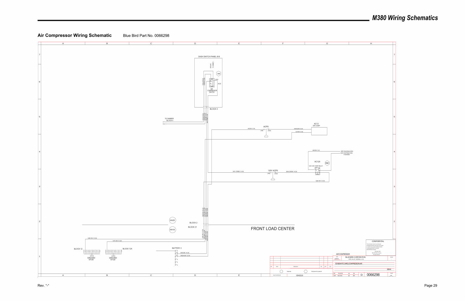
M380 Wiring Schematics
Rev. “-“ Page 29
Air Compressor Wiring Schematic Blue Bird Part No. 0066298
461
2B
5B
37 9
108
0043210 06/13/03
AIR COMPRESSOR
12857M ---
SW
SS05/12/03
0066298
38H4
SCHEMATIC,WRG,COMPRESSOR,AIR
INACTIVATES NOS.
LET. WAS REVISIONS DR. APP. CCN
SCALEBLUE BIRD CORPORATIONFORT VALLEY GEORGIA, U.S.A.
CCN
DR.
APP. BY
BY
DPAGE
__OF__
1
2
3
4
5
A B C D E F G H
B C D E
5
4
3
2
6 6
77
A
Component LocationHarness
CONFIDENTIALThe information hereon is confidential
business information and may not be copied
or used for any purpose unless permission
is expressly granted in writing by
Blue Bird Body Company.
Copyright 2002
Blue Bird Body Company
All rights reserved
AIR
SWITCHCOMPRESSOR
CA B D E F G H J K L M
GROUNDSTUD
BATTERY 2
7.5A
1
BLOCK 2
BLOCK 21
1265 WH 14 GA
3400
BK
14 G
A
FRONT LOAD CENTER
J161
GROU
ND
TO D
IMME
R +
DASH SWITCH PANEL B-B
3400
BK
14 G
A34
01 O
R/BK
14 G
A34
00 B
K 14
GA
120V AIR COMP RELAY
3401 OR/BK 14 GA
1265 WH 14 GA
DBB
RB1AC120
ACS
3400 BK 14 GA
AC12AIR COMP
1276 WH 12 GA
ACPS3403 BL/BK 12 GA
3402
A BK
12
GA
3402 BK 12 GALINE LOAD
3402
BK
12 G
A
4 2 3
1265
WH
14
GA
1276
WH
12
GA
1276 WH 12 GA
GROUNDSTUD
MLKJHGFEDBA C
1276
WH
12
GA
1265
WH
14
GA
120V ACPSLINE LOAD
3404 OR/BK 14 GA
32B79
BLOCK 3
AB
1299
WH
16 G
A13
32 LB
16 G
A
BLOCK 4TO DIMMER
1332
LB 16
GA
1299
WH
16 G
A
BLOCK 12ABLOCK 12
#06 BK 12-2SEE DIAGRAM,WRG.
120V DISTRIBUTION# 0049560
3402A BK 12 GA20A
MICRO 4
531 2
HH25
HH18
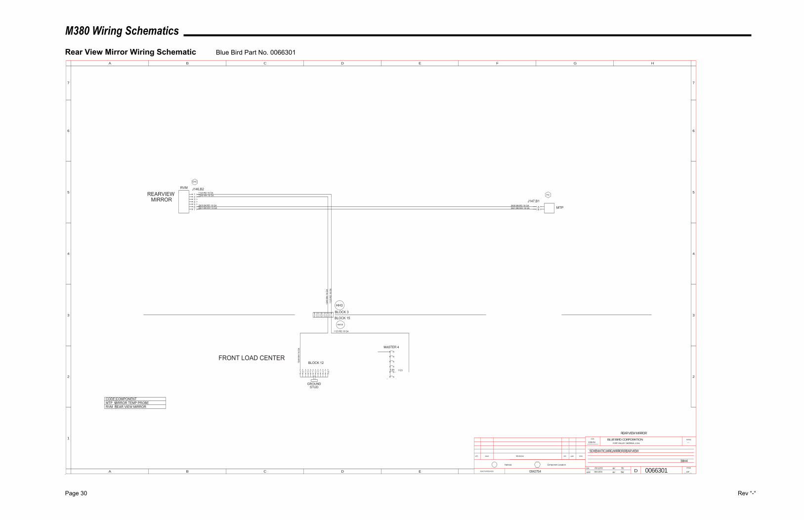
M380 Wiring Schematics
Page 30 Rev “-“
Rear View Mirror Wiring Schematic Blue Bird Part No. 0066301
0042754
REAR VIEW MIRROR
12857M ---
SW
SS05/12/03
0066301
38H4
SCHEMATIC,WRG,MIRROR,REAR VIEW
INACTIVATES NOS.
LET. WAS REVISIONS DR. APP. CCN
SCALEBLUE BIRD CORPORATIONFORT VALLEY GEORGIA, U.S.A.
CCN
DR.
APP. BY
BY
DPAGE
__OF__
1
2
3
4
5
A B C D E F G H
B C D E
5
4
3
2
6 6
77
A
Component LocationHarness
CA B D E F G H J K L M
GROUNDSTUD
1BLOCK 3
BLOCK 15
1249 WH 16 GA1123 RD 16 GA
2601 BK/WH 18 GA2600 BK/RD 18 GA
1249
WH
16
GA
RVM
MTP
J146,B2
J147,B1
7.5A
MASTER 4
1123
RD
16
GA
1123
1123 RD 16 GA
AB
12
FRONT LOAD CENTER
345 2600 BK/RD 18 GA67 2601 BK/WH 18 GA
REARVIEWMIRROR
CODE COMPONENT
RVM REAR VIEW MIRRORMTP MIRROR TEMP PROBE
OHC
FC
06/13/03
1249
WH
16
GA
2
BLOCK 12
3456
HH3
HH18
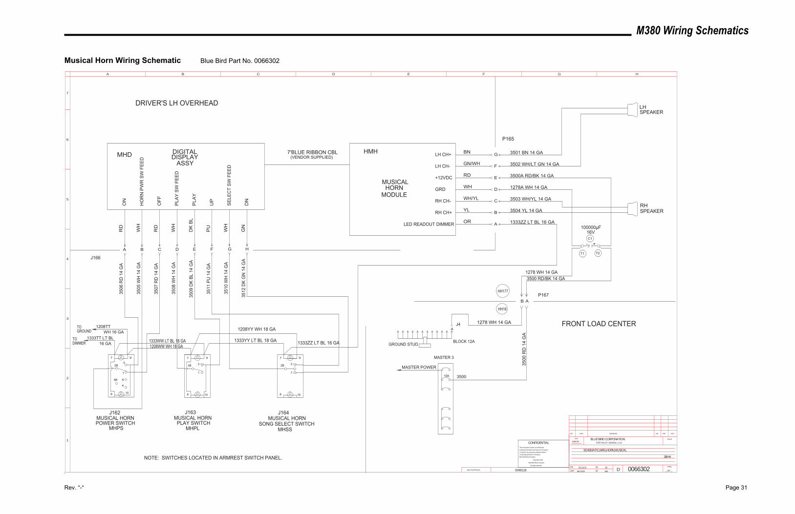
M380 Wiring Schematics
Rev. “-“ Page 31
Musical Horn Wiring Schematic Blue Bird Part No. 0066302
4
6
1
2B
5B
3
7 9
108
97
32B
1
108
97
32B
1
108
0049118 06/13/03 SW
05/12/03 SS
38H4
SCHEMATIC,WRG,HORN,MUSICAL
12857M
0066302INACTIVATES NOS.
LET. WAS REVISIONS DR. APP. CCN
SCALEBLUE BIRD CORPORATIONFORT VALLEY GEORGIA, U.S.A.
CCN
DR.
APP. BY
BY
DPAGE
__OF__
1
2
3
4
5
A B C D E F G H
6
7
CONFIDENTIALThe information hereon is confidential
business information and may not be copied
or used for any purpose unless permission
is expressly granted in writing by
Blue Bird Body Company.
Copyright 2002
Blue Bird Body Company
All rights reserved
7'BLUE RIBBON CBL(VENDOR SUPPLIED)MHD DIGITAL
DISPLAY ASSY
ON
HO
RN
PW
R S
W F
EE
D
OFF
PLA
Y S
W F
EE
D
PLA
Y
UP
SE
LEC
T S
W F
EE
D
DN
RD
WH
RD
WH
DK
BL
PU
WH
GN
BN
GN/WH
RD
WH
WH/YL
YL
OR
HA B C D E F G
D
C
B
A
G
F
E
3501 BN 14 GA
3502 WH/LT GN 14 GA
3500A RD/BK 14 GA
1278A WH 14 GA
3503 WH/YL 14 GA
3504 YL 14 GA
1333ZZ LT BL 16 GA
1333TT LT BL16 GA
WH 16 GATO GROUND
TO DIMMER
1278 WH 14 GA
3500
MASTER POWER
3500
RD
14
GA
GROUND STUD
A
ABP167
FRONT LOAD CENTER
DRIVER'S LH OVERHEAD
NOTE: SWITCHES LOCATED IN ARMREST SWITCH PANEL.
J4
MUSICALHORN
MODULE
HMH LH CH+
LH CH-
+12VDC
GRD
RH CH-
RH CH+
LED READOUT DIMMER
10A
MASTER 3
J162MUSICAL HORNPOWER SWITCH
MHPS
J163MUSICAL HORN
PLAY SWITCH MHPL
J164MUSICAL HORN
SONG SELECT SWITCH MHSS
3506
RD
14
GA
3505
WH
14
GA
3507
RD
14
GA
3508
WH
14
GA
3509
DK
BL 1
4 G
A
3511
PU
14
GA
3510
WH
14
GA
3512
DK
GN
14
GA
1333YY LT BL 18 GA
1208YY WH 18 GA
1208WW WH 18 GA1333WW LT BL 18 GA 1333ZZ LT BL 16 GA
P165
LHSPEAKER
RHSPEAKER
J166T1 T2
C1
+-
100000µF16V
1278 WH 14 GA3500 RD/BK 14 GA
BLOCK 12A
1208TT
HH177
HH18
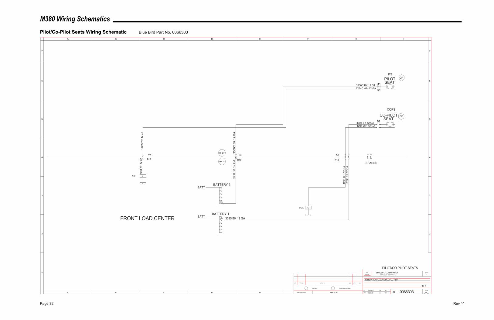
M380 Wiring Schematics
Page 32 Rev “-“
Pilot/Co-Pilot Seats Wiring Schematic Blue Bird Part No. 0066303
06/13/03
PILOT/CO-PILOT SEATS
12857M ---
SW
SS05/13/03
0066303
38H4
SCHEMATIC,WRG,SEATS,PILOT/CO-PILOT
INACTIVATES NOS.
LET. WAS REVISIONS DR. APP. CCN
SCALEBLUE BIRD CORPORATIONFORT VALLEY GEORGIA, U.S.A.
CCN
DR.
APP. BY
BY
DPAGE
__OF__
1
2
3
4
5
A B C D E F G H
B C D E
5
4
3
2
6 6
77
A
Component LocationHarness
20A
BATTERY 3
FRONT LOAD CENTER
3300
C B
K 12
GA
BATT
B3
B18
B3
PILOTSEAT
PS
COPS
CO-PILOTSEAT
3300
BK
12 G
A
1295 WH 12 GA
1264
C W
H 1
2 G
A
3300C BK 12 GA
3395 BK 12 GA
1264C WH 12 GA
CP
CP
2
12
2
1
B18
0043192
BATTBATTERY 1
20A
J
1264
WH
12
GA
B12
3 41
GB12A
1295
WH
12
GA
3395
BK
12 G
A
B3
B18
3395 BK 12 GA
5 6
SPARES
B2
B1
HH27
HH18
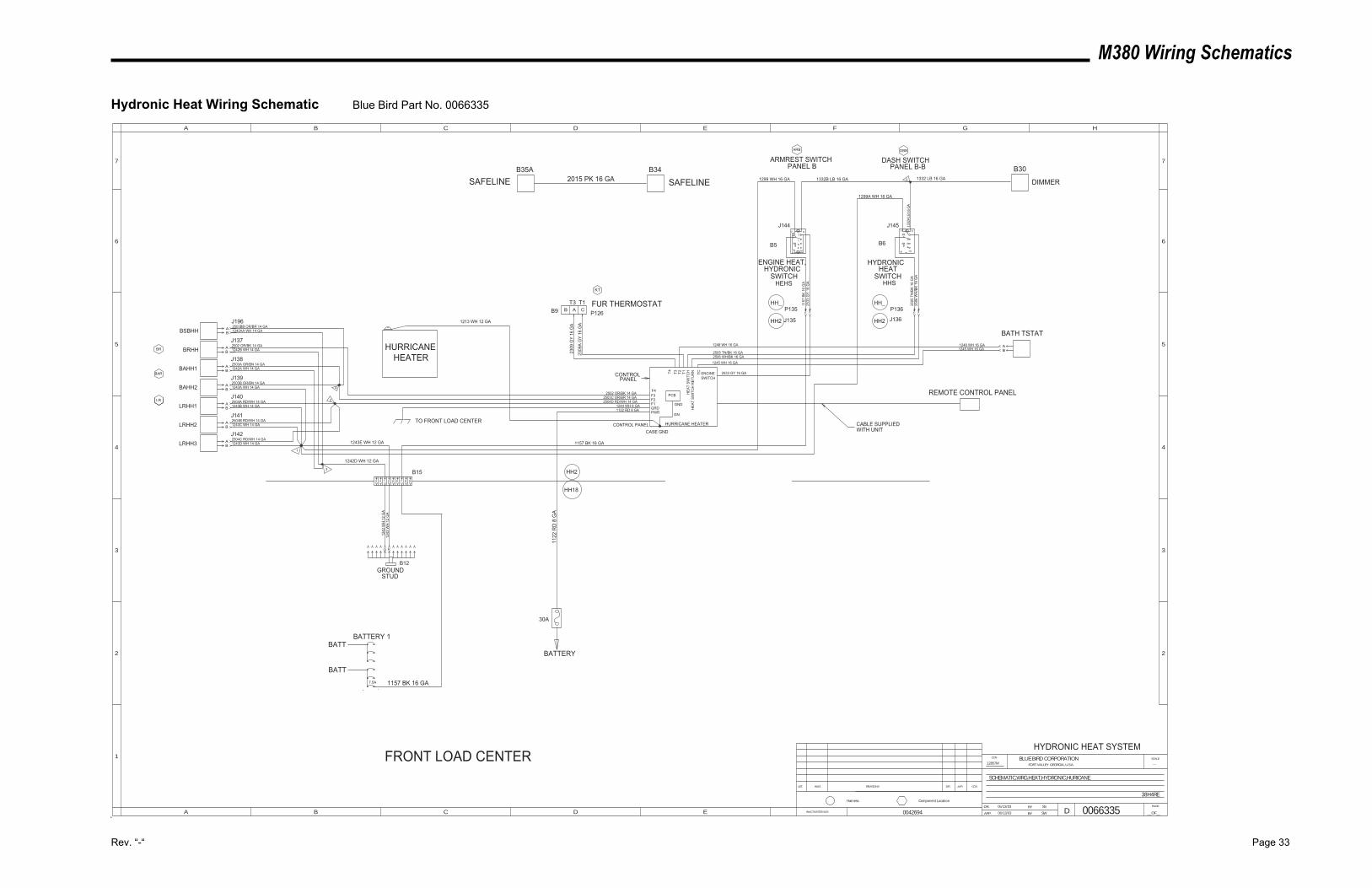
M380 Wiring Schematics
Rev. “-“ Page 33
Hydronic Heat Wiring Schematic Blue Bird Part No. 0066335
461
2B
5B
37 9
108
06/13/03
HYDRONIC HEAT SYSTEM12857M ---
SW
SS05/13/03
0066335
38H4RE
SCHEMATIC,WRG,HEAT,HYDRONIC,HURICANE
INACTIVATES NOS.
LET. WAS REVISIONS DR. APP. CCN
SCALEBLUE BIRD CORPORATIONFORT VALLEY GEORGIA, U.S.A.
CCN
DR.
APP. BY
BY
DPAGE
__OF__
1
2
3
4
5
A B C D E F G H
B C D E
5
4
3
2
6 6
77
A
Component LocationHarness
0042694
7.5A
BATTERY 1
ENGINE HEAT,HYDRONIC
SWITCH
HYDRONICHEAT
SWITCH
DASH SWITCHPANEL B-B
2503A OR/BN 14 GA
1242B WH 14 GA2502 OR/BK 14 GA
1242A WH 14 GA
2503B OR/BN 14 GA
2504A RD/WH 14 GA
2504B RD/WH 14 GA
2504C RD/WH 14 GA
1243A WH 14 GA
1243B WH 14 GA
1243C WH 14 GA
1243D WH 14 GA
BRHH
BAHH1
BAHH2
LRHH1
LRHH2
LRHH3
J137
J138
J139
J140
J141
J142
P135 P136
J135 J136
2533
GY
16 G
A
2506
WH
/BK
16 G
A
1157
BK
16 G
A
2505
TN
/BK
16 G
A
ARMREST SWITCHPANEL B
J144 J145
GROUNDSTUD
1242
WH
12
GA
1243
WH
12
GA
1122
RD
8 G
A
AB
BA
AB
BA
AB
BA
2309
A G
Y 16
GA
2309
GY
16 G
A
FUR THERMOSTATP126
2503C OR/BR 14 GA2504D RD/WH 14 GA
1244 WH 8 GA1122 RD 8 GA
2502 OR/BK 14 GA
2533 GY 16 GA
2506 WH/BK 16 GA2505 TN/BK 16 GA
HEHS HHS
FRONT LOAD CENTER
F3F2F1GRDPWR
HURRICANE HEATER
ENGINESWITCH
T3 T2 T1H
EAT
SWIT
CH
HEA
T SW
ITC
H R
ETU
RN
BR
BAR
LR
KT
ARB DBB
30A
2 3 2 3
3
1
2
4F4
1157 BK 16 GA
T4
1248 WH 16 GA
1245 WH 16 GA
BATH TSTAT
BA1248 WH 16 GA
1245 WH 16 GA
TC
REMOTE CONTROL PANEL
WITH UNIT
BSBHH BA
J1962503BB OR/BR 14 GA1242AA WH 14 GA
461
2B
5B
37 9
108
987652143
BATT
BATT
1157 BK 16 GA
BATTERY
1332B LB 16 GA
1299A WH 16 GA
1299 WH 16 GA
B5 B6
1332
A L
B 16
GA
DIMMER
B30
A CBT3 T1
B9
B34
SAFELINEB35A
SAFELINE 2015 PK 16 GA
TO FRONT LOAD CENTER
1243E WH 12 GA
1242D WH 12 GA
B15
D K
B12
5 1332 LB 16 GA
PCB
GND
HURRICANEHEATER
1213 WH 12 GA
CONTROL PANELCASE GND
GN
HH_
HH2
HH_
HH2
HH2
HH18
CABLE SUPPLIED
CONTROL PANEL
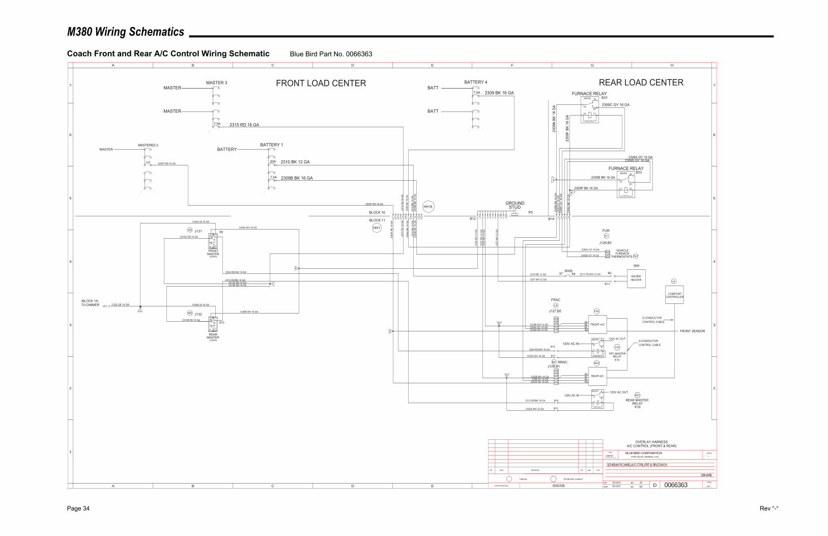
M380 Wiring Schematics
Page 34 Rev “-“
Coach Front and Rear A/C Control Wiring Schematic Blue Bird Part No. 0066363
461
2B
5B
37 9
108
461
2B
5B
37 9
108
0042436 06/13/03
A/C CONTROL (FRONT & REAR)OVERLAY HARNESS
12857M ---
SW
SS05/14/03
0066363
38H4RE
SCHEMATIC,WRG,A/C CTRL,FRT & RR,COACH
INACTIVATES NOS.
LET. WAS REVISIONS DR. APP. CCN
SCALEBLUE BIRD CORPORATIONFORT VALLEY GEORGIA, U.S.A.
CCN
DR.
APP. BY
BY
DPAGE
__OF__
1
2
3
4
5
A B C D E F G H
B C D E
5
4
3
2
6 6
77
A
Component LocationHarness
J131
FRONT
(DASH)MASTER
REAR
(DASH)MASTER
J132J127,B5
21
J126,B3
2309C GY 16 GA
K15
FRT MASTERRELAY
FRONT A/C
RDBLBLBK
REAR MASTERRELAY
K16
BKBLBLRD
REAR A/C
12
J128,B1
BLOCK 16
FRONT SENSOR
COMFORTCONTROLLER
1332B LB 16 GA
1332A LB 16 GA
VEHICLEFURNACE
FUR
GROUNDSTUD
1233B WH 14 GA2309A GY 16 GA2303B RD 16 GA
1232B WH 14 GA2309 GY 16 GA
2303E RD 16 GA
1233
WH
14
GA
1232
WH
14
GA
1237
WH
12
GA
2304 RD/WH 16 GA
2312 RD/BK 16 GA
2315A RD 16 GA
2315B RD 16 GA
RRAC
FRAC
7.5A
MASTERED 2
7.5A
20A
BATTERY 1
2303F RD 16 GA 2310 BK 12 GA
BATTERYMASTER
2315A RD 16 GA2315B RD 16 GA
2310
BK
12 G
A
2303
F R
D 1
6 G
A
2310
BK
12 G
A
2303F RD 16 GA
2310 BK 12 GA
1237 WH 12 GAWATERHEATER
2311 PU/WH 12 GA
WH
FRONT LOAD CENTER
WHS
2309D GY 16 GA
2309B BK 16 GA
2309
B BK
16
GA
2309
B BK
16
GA
1232A WH 16 GA
2312 RD/BK 16 GA
2304 RD/WH 16 GA
1233A WH 16 GA
120V AC IN120V AC OUT
120V AC IN120V AC OUT
2309
BK
16 G
A
2315
RD
16
GA
BR
LR
LR
PNT
KT
DBC
1238
WH
14
GA
DBCFAC
FAC
RAC
RAC
1238B WH 16 GA
1238A WH 16 GA
P5
1 1332 LB 14 GA(BLOCK 14)TO DIMMER
5
1 2 9 10
REAR LOAD CENTER
1 2
2309
B BK
16
GA
2309
GY
16 G
A23
09C
GY
16 G
A
3 4 5 6
2309C GY 16 GA
2309P BK 16 GA
2309E BK 16 GA
6
FURNACE RELAY
2309
J BK
16
GA
2309A GY 16 GA2309D GY 16 GA
2309
N B
K 16
GA
2309
F BK
16
GA
FURNACE RELAY
2315 RD 16 GA
MASTER 3
7.5A
MASTER
MASTER
3 4 5 6 7 8
BATT
BATT7.5A
BATTERY 4
2309 BK 16 GA
2315
RD
16
GA
2309
J BK
16
GA
4
1
3
THERMOSTATS
4
3
2
3456
B16
B15
B17
B18
6543
B7 B8 B6
B13
1
2
3
1 2 3 4 5 6 7 8 910 11 12B19B12
B9
B10
1112
BLOCK 11
MICRO 19
2018
16 17
MICRO 24
2523
21 22
B23
B23
MICRO 4
53
1 2
MICRO 4
53
1 2
6-CONDUCTORCONTROL CABLE
HH1
6-CONDUCTORCONTROL CABLE
HH18
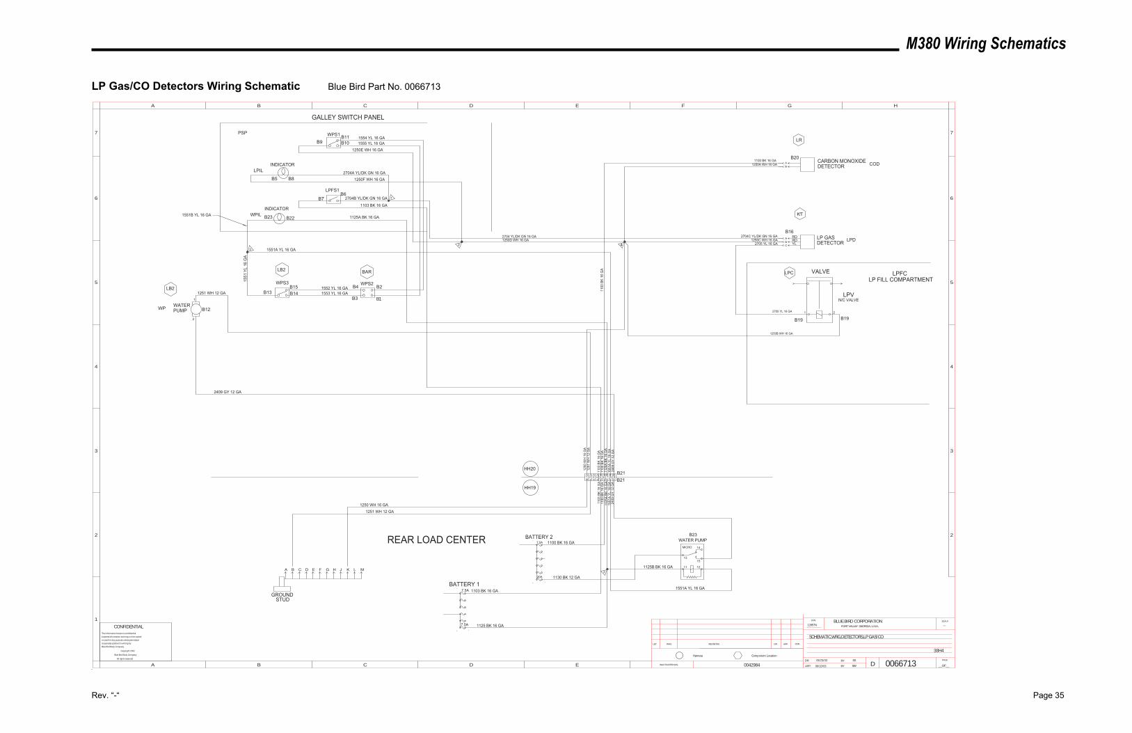
M380 Wiring Schematics
Rev. “-“ Page 35
LP Gas/CO Detectors Wiring Schematic Blue Bird Part No. 0066713
0042984
WPIL
LPIL
12857N ---
SW
SS05/23/03
0066713
38H4
SCHEMATIC,WRG,DETECTORS,LP GAS/CO
INACTIVATES NOS.
LET. WAS REVISIONS DR. APP. CCN
SCALEBLUE BIRD CORPORATIONFORT VALLEY GEORGIA, U.S.A.
CCN
DR.
APP. BY
BY
DPAGE
__OF__
1
2
3
4
5
A B C D E F G H
B C D E
5
4
3
2
6 6
77
A
Component LocationHarness
CONFIDENTIALThe information hereon is confidential
business information and may not be copied
or used for any purpose unless permission
is expressly granted in writing by
Blue Bird Body Company.
Copyright 2002
Blue Bird Body Company
All rights reserved
7.5ABATTERY 2REAR LOAD CENTER
1103
BK
16 G
A11
03 B
K 16
GA
1250
WH
16
GA
GROUNDSTUD
1100 BK 16 GA
1100
BK
16 G
A11
00 B
K 16
GA
LPD
COD
B16
1250C WH 16 GA
1100 BK 16 GA
2704C YL/DK GN 16 GA
1250A WH 16 GA
2705 YL 16 GA
1125
A BK
16
GA
1125
A BK
16
GA
LPV
VALVE
N/C VALVE
INDICATOR
WPS1
LPFS1
RDRDYL
WATERPUMPWP
GALLEY SWITCH PANEL
LP GASDETECTOR
CARBON MONOXIDEDETECTOR
LP FILL COMPARTMENT
2704B YL/DK GN 16 GA
1251 WH 12 GA
1250B WH 16 GA
2705 YL 16 GA
1103 BK 16 GA
1250F WH 16 GA2704A YL/DK GN 16 GA
1250E WH 16 GA1555 YL 16 GA1554 YL 16 GA
WPS3 WPS21552 YL 16 GA1553 YL 16 GA
LPC
KT
LR
LPFC
PSP
LB2
LB2 BAR
1
06/10/03
AB
ABC
INDICATOR
1125A BK 16 GA
315
51 Y
L 16
GA
1551A YL 16 GA
1250D WH 16 GA
B23WATER PUMP
1551A YL 16 GA
1125B BK 16 GA
1130 BK 12 GA20A
5 6 7
2409
GY
12 G
A15
51A
YL 1
6 G
A24
09 G
Y 12
GA
2409 GY 12 GA
A B C D E F G H J K L M
1 2 3 4
1100
BK
16 G
A
1250 WH 16 GA
B5 B8
B9B11B10
B7B6
B23 B22
B13B15B14
B12
1251
WH
12
GA
2
B20
B19 B19
B21B21
8 9
1551
A YL
16
GA
1251 WH 12 GA
4
B4
B3 B1
B2
2
7.5A 1125 BK 16 GA
1103 BK 16 GABATTERY 1
7.5A
1 2
1
2
MICRO 14
1513
11 12
HH19
2704 YL/DK GN 16 GA
1551B YL 16 GA
HH20
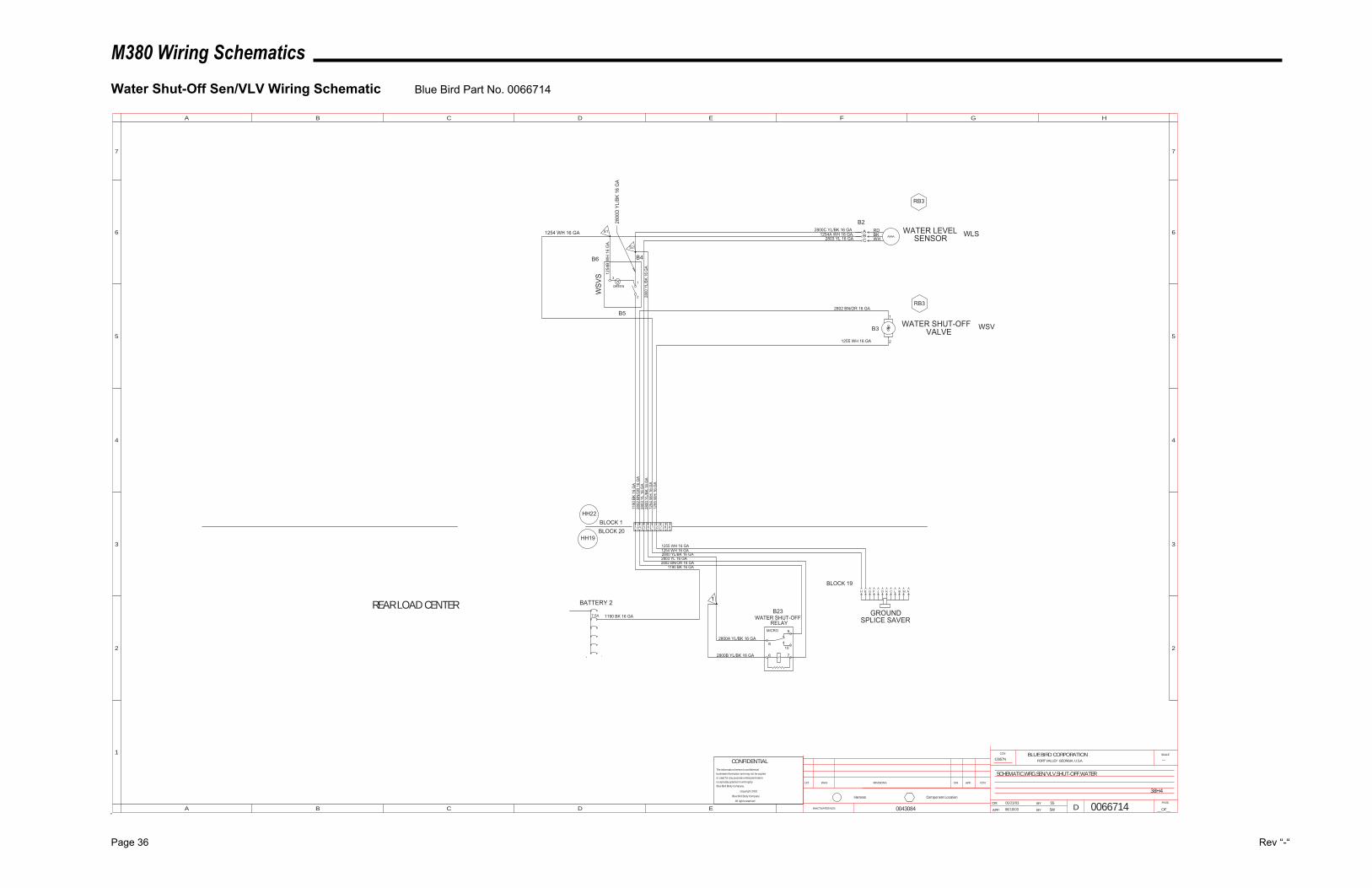
M380 Wiring Schematics
Page 36 Rev “-“
Water Shut-Off Sen/VLV Wiring Schematic Blue Bird Part No. 0066714
0043084 06/10/03
12857N ---
SW
SS05/23/03
0066714
38H4
SCHEMATIC,WRG,SEN/VLV,SHUT-OFF,WATER
INACTIVATES NOS.
LET. WAS REVISIONS DR. APP. CCN
SCALEBLUE BIRD CORPORATIONFORT VALLEY GEORGIA, U.S.A.
CCN
DR.
APP. BY
BY
DPAGE
__OF__
1
2
3
4
5
A B C D E F G H
B C D E
5
4
3
2
6 6
77
A
Component LocationHarness
CONFIDENTIALThe information hereon is confidential
business information and may not be copied
or used for any purpose unless permission
is expressly granted in writing by
Blue Bird Body Company.
Copyright 2002
Blue Bird Body Company
All rights reserved
BATTERY 2
7.5A
REAR LOAD CENTER
1190
BK
16 G
A
1254 WH 16 GA
GROUNDSPLICE SAVER1190 BK 16 GA
BLOCK 1BLOCK 20
1255 WH 16 GA
WLS1254A WH 16 GA.2800C YL/BK 16 GA
2803 YL 16 GA
RDBKWH
WATER SHUT-OFFVALVE
WSV
WATER LEVELSENSOR
2802 BN/OR 16 GA
1255 WH 16 GA
2802
BN
/OR
16
GA
2803
YL
16 G
A
2800B YL/BK 16 GA
2803 YL 16 GA2802 BN/OR 16 GA
1190 BK 16 GA
B23WATER SHUT-OFF
RELAY
RB3
RB3
ABC
WSV
S
1
2
3
GREEN
1254
B W
H 1
6 G
A.
1254 WH 16 GA S1
S2
2800 YL/BK 16 GA
2800
YL/
BK 1
6 G
A28
00 Y
L/BK
16
GA
1254
WH
16
GA
1255
WH
16
GA
BLOCK 19
1 23 4 5 6
H E G F J D K C L B M A
7 8 9
2800A YL/BK 16 GA
1
B2
1
2
B3
B6 B4
B5
MICRO 9
108
6 7
HH22
HH19
2800
D Y
L/BK
16
GA
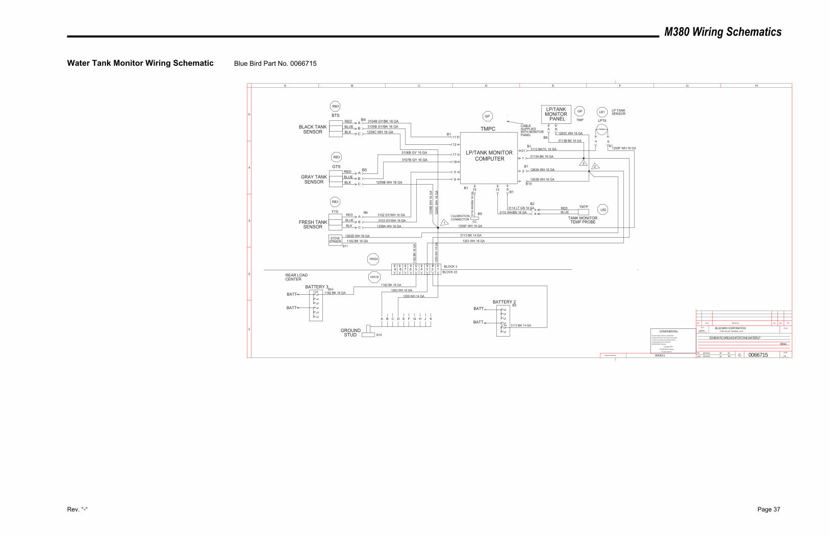
M380 Wiring Schematics
Rev. “-“ Page 37
Water Tank Monitor Wiring Schematic Blue Bird Part No. 0066715
STUDGROUND
21
1
2
11
12
17
18
5
6
15 13 9
LPTS
LP TANKSENSOR
TMTP
TANK MONITORTEMP PROBE
CALIBRATIONCONNECTOR
LP/TANK MONITORCOMPUTER
RB3
RB3
RB3
HH19
GPBTS
GTS
FTS
TMPC
FRESH TANKSENSOR
GRAY TANKSENSOR
BLACK TANKSENSOR
REDBLUEBLK
REDBLUEBLK
RED
BLUE
BLK
HH24
REDBLUE
3104B GY/BK 16 GA3105B GY/BK 16 GA1259C WH 16 GA
3106B GY 16 GA
3107B GY 16 GA
1259B WH 16 GA
3102 GY/WH 16 GA
3103 GY/WH 16 GA
1259A WH 16 GA
1263 WH 16 GA
1259F WH 16 GA
A B
1259F WH 16 GA3112 BK/YL 16 GA
3113A BK 16 GA
1263A WH 16 GA
3113 BK 14 GA
REAR LOADCENTER
3113 BK 14 GA
LB1
ABC
A
BC
A
B
C
CC
AB
LB2
1263B WH 16 GA
LP/TANK MONITOR
PANEL
3113B BK 16 GA
A B1263C WH 16 GA
GP
TMP
3 2
1259
WH
14
GA
3115 WH/BN 16 GA3114 LT GN 16 GA
BLOCK 3
BLOCK 22
B7
B8
B1
B10
B2
B1
B4
B5
B6
7.5A
A B C D E F G H J K
1263 WH 16 GA
1259 WH 14 GA
9 8 7 6 5 4
3116
WH
/BN
16
GA
1
BATTERY 2
32B1
B1
B9
B1
1259
B W
H 1
6 G
A
1259
C W
H 1
6 G
A
1
BATT
BATT
B5
B19
1182 BK 16 GAB24
BATT
BATT
BATTERY 37.5A 1182 BK 16 GA
STOVESTRIKER 1182 BK 16 GA
1182
BK
16 G
A
1263D WH 16 GA
B11
SCHEMATIC,WRG,MONITOR,TANK,WATER/LP
38H4
12857N
006671505/23/03 SS
SW06/10/030043011INACTIVATES NOS.
LET. WAS REVISIONS DR. APP. CCN
SCALEBLUE BIRD CORPORATIONFORT VALLEY GEORGIA, U.S.A.
CCN
DR.
APP. BY
BY
CPAGE
__OF__
1
2
3
4
5
A B C D E F G H
CONFIDENTIALThe information hereon is confidential
business information and may not be copied
or used for any purpose unless permission
is expressly granted in writing by
Blue Bird Body Company.
Copyright 2002
Blue Bird Body Company
All rights reserved
CABLESUPPLIEDWITH MONITORPANEL
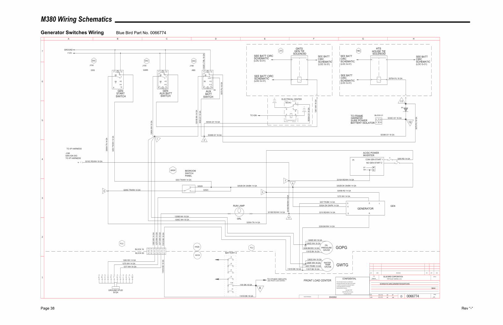
M380 Wiring Schematics
Page 38 Rev “-“
Generator Switches Wiring Blue Bird Part No. 0066774
MICRO 4
53
1 2
COM GEN START 1NO GEN START 2
GYWH
123
4
5 6
3208 BK/WH 14 GA
3207 PK/BK 14 GA
1275 WH 14 GA
3205B RD 14 GA
OILPRESSURE
GAUGE
WATERTEMP
GAUGE
GOPG
GWTG
GENERATOR3202A DK GN/PK 14 GA
1260
WH
14
GA
1277
WH
16
GA
1275
WH
14
GA
GRL
RUN LAMP
GNTSGEN TIE
SOLENOID
HTSHOUSE TIESOLENOID
SEE BATT CIRCSCHEMATIC(LOC G-31)
SEE BATT CIRCSCHEMATIC(LOC G-31)
SEE BATT CIRCSCHEMATIC(LOC G-31)
SEE BATT CIRCSCHEMATIC(LOC G-31)
SEE BATT CIRCSCHEMATIC(LOC G-31)
SEE BATT CIRCSCHEMATIC(LOC G-31)
1261
WH
16
GA
BATTERY 4
FRONT LOAD CENTER
GROUND+12V
J154
DAC DAC
J155 J156
DAC
GENSTARTSWITCH
GENAUX BATTSWITCH
AUXBATT
SWITCH
LFC HBC
AC/DC POWERINVERTER
3205 RD 14 GA
FLCHH26
HH18
BLOCK 16
BLOCK 80
FLC
3202B DK GN/BK 14 GA
BEDROOMSWITCHPANEL
BRSP
3205
A TN
14
GA
3203
TN
/WH
14
GA
1260
A W
H 1
6 G
A
1261
B W
H 1
4 G
A
5030
GY
16 G
A
3203 TN/WH 14 GA
0066774BT06/17/03
SCHEMATIC,WRG,GENERATOR,SWITCHES
38H4
12857M
SW06/12/03
3210A RD/WH 14 GA
3202B DK GN/BK 14 GA
3210 RD/WH 14 GA3210B RD/WH 14 GA
PI
1 2
4
5
GSS GABS ABS
3205A TN 14 GA
GEN
3205C TN/WH 14 GA6 3202C
3202D
7
J188GEN IGN SIGTO I/P HARNESS
TO I/P HARNESS
3210C RD/WH 18 GA
INACTIVATES NOS.
LET. WAS REVISIONS DR. APP. CCN
SCALEBLUE BIRD CORPORATIONFORT VALLEY GEORGIA, U.S.A.
CCN
DR.
APP. BY
BY
DPAGE
__OF__
1
2
3
4
5
A B C D E F G H
6
7
1
10
7
2B3
9
1
6
45B
810
7
2B3
9
1
6
45B
8
1
2B3
7 9
108
5B 6
4
3
5A
5A
3210
D R
D/W
H 1
4 G
A
5 4 3 2 1
1206B WH 16 GA
1206C WH 16 GA
1181
D B
K 16
GA
1260 WH 14 GA
1275 WH 14 GA1277 WH 16 GA
--A
--A
1181
D B
K 16
GA
1181 BK 16 GA
1181D BK 16 GA
TO OTHER CIRCUITS(SEE FRONT LOAD CENTER)
1260E WH 16 GA
1260D WH 16 GA
3208 BK/WH 14 GA
1181E BK 16 GA
1260G WH 16 GA
1260F WH 16 GA
S9
S103207 PK/BK 14 GA1181F BK 16 GA1181D BK 16 GA
5075
PU
16
GA
5030A GY 16 GA
11
12
5075
PU
16
GA5030C GY 16 GA
B
A
BLOCK 21TO FRAMEHARNESSSURE POWERBATTERY ISOLATOR
6A
5075A PU 16 GA
0043002
5030B GY 16 GA 5030B GY 16 GA
ELECTRICAL CENTER
TO IGN
1332
E LT
/BL
16 G
A
B4
5030
A G
Y 16
GA
CONFIDENTIALThe information hereon is confidential
business information and may not be copied
or used for any purpose unless permission
is expressly granted in writing by
Blue Bird Body Company.
Copyright 2002
Blue Bird Body Company
All rights reserved
6
6
CA B D E F G H J K L M
GROUND STUDB12A
--A
--A
--A
7.5A
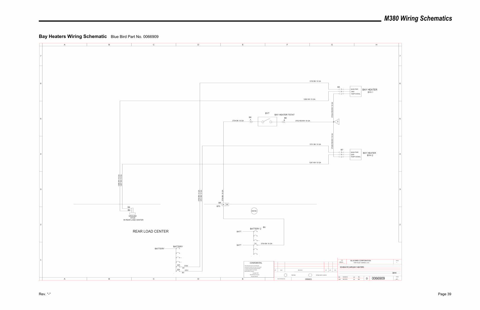
M380 Wiring Schematics
Rev. “-“ Page 39
Bay Heaters Wiring Schematic Blue Bird Part No. 0066909
1286
WH
10
GA
3700
BK
10 G
A
REAR LOAD CENTER
12857N ---
SW
SS06/02/03
0066909
38H4
SCHEMATIC,WRG,BAY HEATERS
BATTERY
30A
30A
GROUNDSTUD
3700
1287
WH
10
GA
BAY HEATERBYH 2
3701 BK 10 GA
1287 WH 10 GA
3701
BK
10 G
A
06/10/03
BYT
2
CBA
ABC
1286 WH 10 GA
3700 BK 10 GA
BYH 1BAY HEATER
3704 BK 16 GA 3702 RD/WH 16 GA
BAY HEATER TSTAT
3702
B R
D/W
H 1
6 G
A37
02A
RD
/WH
16
GA
3701
A B
0056821
B5MAIN PWRGNDTEMP SIGNAL
B6
B7MAIN PWRGNDTEMP SIGNAL
B4B2
IN REAR LOAD CENTER
BATTERY
A BB8
B70
3704
BK
16 G
A
BATT
3704 BK 16 GA
BATTERY 2
7.5ABATT
B6
B5
B1
B3
INACTIVATES NOS.
LET. WAS REVISIONS DR. APP. CCN
SCALEBLUE BIRD CORPORATIONFORT VALLEY GEORGIA, U.S.A.
CCN
DR.
APP. BY
BY
DPAGE
__OF__
1
2
3
4
5
A B C D E F G H
B C D E
5
4
3
2
6 6
77
A
Component LocationHarness
CONFIDENTIALThe information hereon is confidential
business information and may not be copied
or used for any purpose unless permission
is expressly granted in writing by
Blue Bird Body Company.
Copyright 2002
Blue Bird Body Company
All rights reserved
HH19
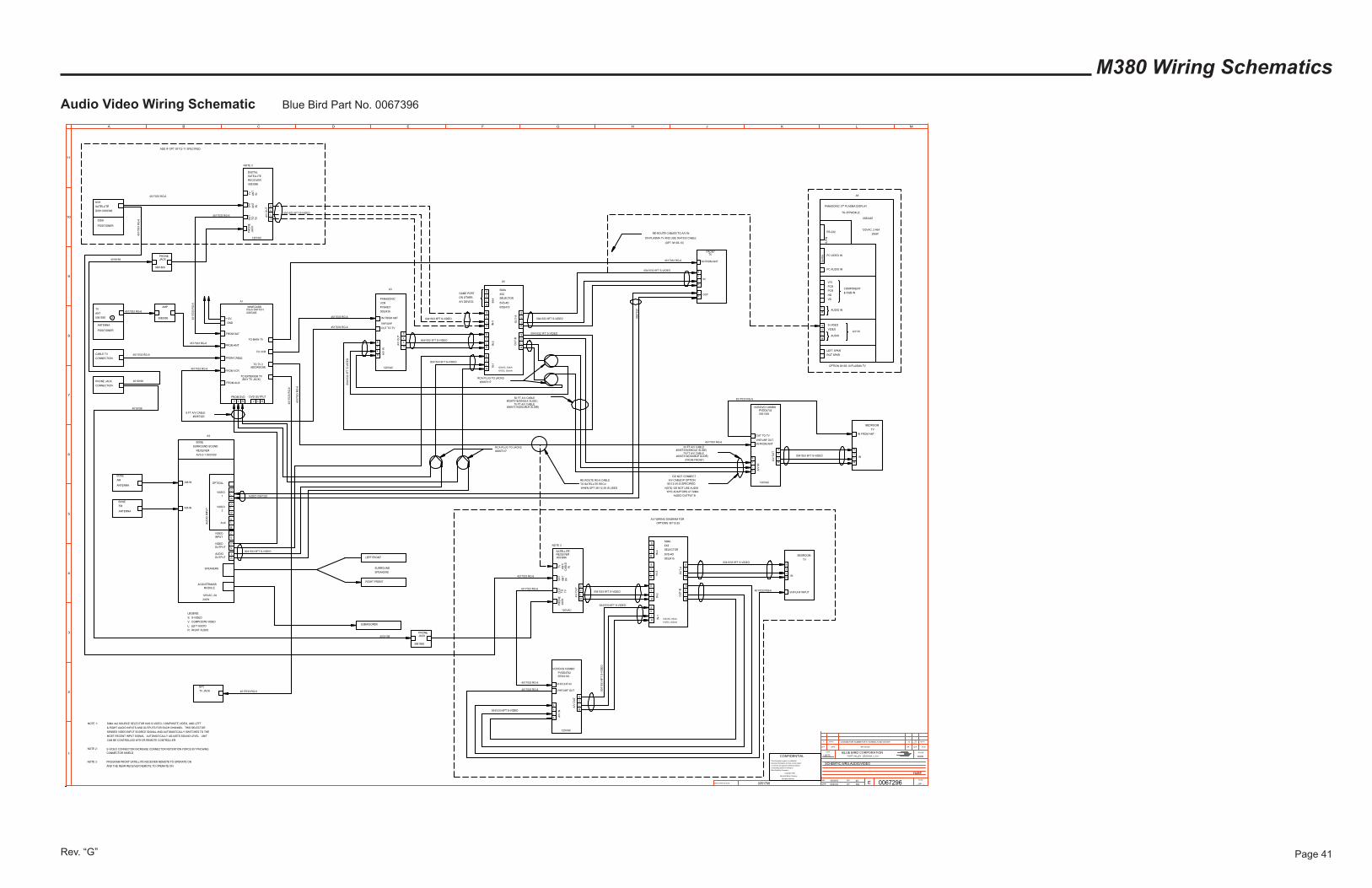
M380 Wiring Schematics
Audio Video Wiring Schematic Blue Bird Part No. 0067396
Rev. “G” Page 41
LEFT SPKR
RGT SPKR
L
RAUDIO
V
S
VIDEO
S-VIDEO
A/V IN
R
LAUDIO IN
PCR
PCB
V/G
VD
HD
COMPONENT
& RGB IN
PC AUDIO IN
PC VIDEO IN
15
-PIN
9-P
IN
RS-232
PANASONIC 37" PLASMA DISPLAY
TH-37PWD4UZ
R
S
V
L
R
L
V
S
R
R
L
V
S
S
V
L
R
S
V
L
S
V
L
R
IN-1
IN-2
IN-3
IN-4
SIMA
SVS-4D
4X2
SELECTOR
R
A/V
OU
T
S
V
L
ADD IF OPT 38112-11 SPECIFIED
R
L
V
S
A/V
IN
PANASONIC
VCR
PVS4821
(OPT 38105-10)
TV
PVDD4742
WYE ADAPTORS AT SIMA
AUDIO OUTPUT B
S
IN
PVDD4742
V
L
R
V
L
R
L
V
S
A/V
IN
DO NOT CONNECT
A/V CABLE IF OPTION
BOSE
SURROUND SOUND
RECEIVER
AM
ANTENNAAM-IN
FM-IN
ACOUSTIMASS
SUBWOOFER
LEFT FRONT
RIGHT FRONT
SURROUND
SPEAKERS
120VAC, 63mA
15VDC, 500mA
120VAC, 2A
240W
120VAC, 2.46A
295W
NOTE 1: SIMA 4x2 SOURCE SELECTOR HAS S-VIDEO, COMPOSITE VIDEO, AND LEFT
& RIGHT AUDIO INPUTS AND OUTPUTS FOR EACH CHANNEL. THIS SELECTOR
SENSES VIDEO INPUT SOURCE SIGNAL AND AUTOMATICALLY SWITCHES TO THE
BOSE
RE-ROUTE CABLES TO A/V IN
MOST RECENT INPUT SIGNAL. AUTOMATICALLY ADJUSTS SOUND LEVEL. UNIT
CAN BE CONTROLLED WITH IR REMOTE CONTROLLER.
LEGEND:
S: S-VIDEO
V: COMPOSITE VIDEO
L: LEFT AUDIO
R: RIGHT AUDIO
120VAC
L
V
ON PLASMA TV AND USE 0041533 CABLE.120VAC
DISH
POSITIONER
S
IN
R
A/V
OU
T
S
0041533 6FT S-VIDEO
A3
A5
#0067317
A4
A6
R
L
V
0052425
0052439
0052415
AUDIO 0067320
AV3-2-1 0051590
BOSE
DIGITAL
BEDROOM
TV
#0067317
SATELLITE
GAME PORT
OR OTHER
A/V DEVICE
FM
ANTENNA
RCA PLUG TO JACKS
SPEAKERS
MODULE
OPTICAL
AUDIO
OUTPUT R
L
VIDEO
OUTPUTV
S
VIDEO
INPUT
C
S
AUX
R
LD
AU
DIO
INP
UT
D
L
R
VIDEO
2
VIDEO
1
D
L
R
S-VIDEO CONNECTOR-INCREASE CONNECTOR RETENTION FORCE BY PINCHING
CONNECTOR SHIELD.
TO
SATELLITE
A/V
OU
T
R
S
DISH 0039398
KVH
TVFRONT
R
L
V
IN FROM ANT
R
L
6 FT A/V CABLE
#0067320
OPTION 38105-10 PLASMA TV
IN
OUT
OU
T-A
OU
T-B
RECEIVER
OU
T
120VAC
BEDROOM
VCR/DVD COMBO
#0067318(SINGLE SLIDE)75 FT A/V CABLE
(FROM FRONT)
38112-29 IS SPECIFIED
NOTE: DO NOT USE AUDIO
TV
R
L
V
L
V
S
A/V
IN
R
A/V
OU
T S
120VAC
VCR/DVD COMBO
R
S
V
L
R
L
V
S
R
R
L
V
S
S
V
L
R
S
V
L
S
V
L
R
IN-1
IN-2
IN-3
IN-4
SIMA
SVS-4D
4X2
SELECTOR
120VAC, 63mA
15VDC, 500mA
0052415
OU
T-A
OU
T-B
A/V WIRING DIAGRAM FOR
OPTIONS 38112-29
L
V
120VAC
TO
SATELLITE
A/V
OU
T
R
S
RECEIVER
OU
T
NOTE 2:
0053996
RCA PLUG TO JACKS
0041533 6FT S-VIDEO
0041533 6FT S-VIDEO
0041533 6FT S-VIDEO
0041533 6FT S-VIDEO
0041533 6FT S-VIDEO
00
41
53
36F
TS
-VID
EO
00
67
32
0
SA
T
AN
TIN
TV
ANT
0081595
ANTENNA
POSITIONER
CABLE TV
CONNECTION
IN FROM ANT
OUT TO TV
WINEGARDRG-6 SWITCH0067295
+12V
FROM SAT
FROM ANT
FROM CABLE
FROM VCR
FROM AUX
GND
3982956
AMP
TO MAIN TV
TO VCR
TO TV 2
TO EXTERIOR TV
OUT TO TV
IN FROM ANT
IN FROM ANT
0041532 3FT S-VIDEO
0041533 6FT S-VIDEO 0041533 6FT S-VIDEO
0041533 6FT S-VIDEO
FROM DVD DVD OUTPUT
V L R RLV
4517033 RG-6
4517033 RG-6
4517033 RG-6
4517033 RG-6
4517033 RG-6
4517033 RG-6
4517033 RG-6
0041533 6FT S-VIDEO
0041533 6FT S-VIDEO
0041532 3FT S-VIDEO
00
41
53
23
FT
S-V
IDE
O
4517033 RG-6
45
17
03
3R
G-6
45
17
03
3R
G-6
45
17
03
3R
G-6
TV JACK
BAY
4517033 RG-6
45
17
03
3R
G-6
S
4517033 RG-6
INAN
T
SA
T
TV
4517033 RG-6
VHF/UHF IN
VHF/UHF OUT
4517033 RG-6
VHF/UHF INPUT4517033 RG-6
4517033 RG-6
4517033 RG-6
0053996
RE-ROUTE RG-6 CABLE
TO SATELLITE RECV.
WHEN OPT 38112-29 IS USED.
A1
4517033 RG-6
50 FT A/V CABLE
#0067319(DOUBLE SLIDE)
50 FT A/V CABLE#0067318(SINGLE SLIDE)
75 FT A/V CABLE#0067319(DOUBLE SLIDE)
4517033 RG-6
(BEDROOM)
(BAY TV JACK)
0051338
00524142
TV
AN
TIN
TV
AN
T\
CA
BL
EIN
PH
ON
EJA
CK
PH
ON
EJA
CK
PHONE JACK
CONNECTION
VHF/UHF
VHF/UHF OUT
3881869
PHONEJACK4018198
4018198
4018198
PHONEJACK
3881869
4018198
NOTE 3
NOTE 3
NOTE 3: PROGRAM FRONT SATELLITE RECEIVER REMOTE TO OPERATE ON
AND THE REAR RECEIVER REMOTE TO OPERATE ON
A 3847431 CHANGED PART NUMBER FOR TV ANTENNA TO BE "0081595" SSSS
08/04/0413077A
INACTIVATES NOS.
LET. WAS REVISIONS DR. APP. CCN
SCALEBLUE BIRD CORPORATIONFORT VALLEY GEORGIA, U.S.A.
CCN
DR.
APP.
BY
BY EPAGE
__OF__
1
2
3
4
5
6
7
8
9
10
11
A B C D E F G H J K L M
0067296
SCHEMTIC,WRG,AUDIO/VIDEO
06/09/03
07/21/03
BT
SW
12857SNONECONFIDENTIAL
The information hereon is confidential
business information and may not be copied
or used for any purpose unless permission
is expressly granted in writing by
Blue Bird Body Company.
Copyright 2002
Blue Bird Body Company
All rights reserved
H4RE
0051798
A
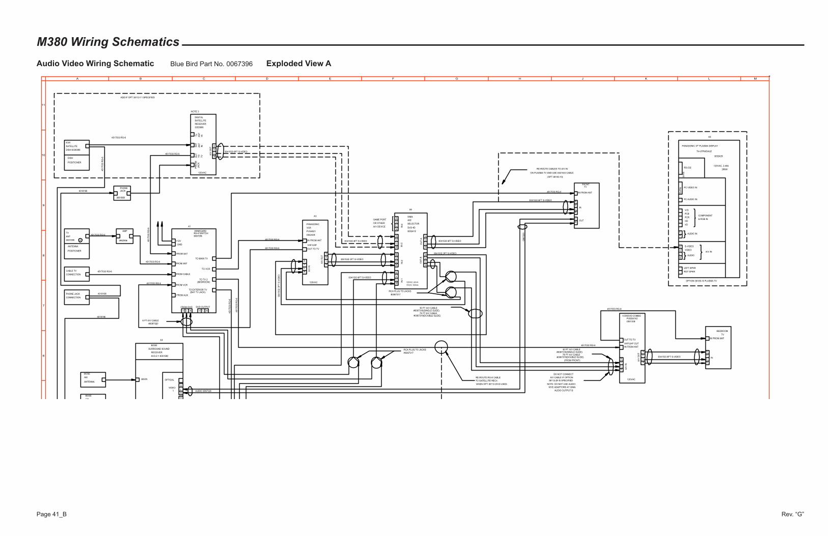
M380 Wiring SchematicsAudio Video Wiring Schematic Blue Bird Part No. 0067396 Exploded View A
Rev. “G”Page 41_B
LEFT SPKR
RGT SPKR
L
RAUDIO
V
S
VIDEO
S-VIDEO
A/V IN
R
LAUDIO IN
PCR
PCB
V/G
VD
HD
COMPONENT
& RGB IN
PC AUDIO IN
PC VIDEO IN
15
-PIN
9-P
IN
RS-232
PANASONIC 37" PLASMA DISPLAY
TH-37PWD4UZ
R
S
V
L
R
L
V
S
R
R
L
V
S
S
V
L
R
S
V
L
S
V
L
R
IN-1
IN-2
IN-3
IN-4
SIMA
SVS-4D
4X2
SELECTOR
R
A/V
OU
T
S
V
L
ADD IF OPT 38112-11 SPECIFIED
R
L
V
S
A/V
IN
PANASONIC
VCR
PVS4821
(OPT 38105-10)
TV
PVDD4742
WYE ADAPTORS AT SIMA
AUDIO OUTPUT B
V
L
R
L
V
S
A/V
IN
DO NOT CONNECT
A/V CABLE IF OPTION
BOSE
SURROUND SOUND
RECEIVER
AM
ANTENNAAM-IN
120VAC, 63mA
15VDC, 500mA
120VAC, 2.46A
295W
BOSE
RE-ROUTE CABLES TO A/V IN
120VAC
L
V
ON PLASMA TV AND USE 0041533 CABLE.120VAC
DISH
POSITIONER
S
IN
R
A/V
OU
T
S
A3
A5
#0067317
A4
A6
R
L
V
0052425
0052439
0052415
AUDIO 0067320
AV3-2-1 0051590
BOSE
DIGITAL
BEDROOM
TV
#0067317
SATELLITE
GAME PORT
OR OTHER
A/V DEVICE
FM
RCA PLUG TO JACKS
OPTICAL
DVIDEO
VIDEO
1
D
L
R
TO
SATELLITE
A/V
OU
T
R
S
DISH 0039398
KVH
TVFRONT
R
L
V
IN FROM ANT
R
L
6 FT A/V CABLE
#0067320
OPTION 38105-10 PLASMA TV
IN
OUT
OU
T-A
OU
T-B
RECEIVER
OU
T
120VAC
VCR/DVD COMBO
#0067318(SINGLE SLIDE)75 FT A/V CABLE
(FROM FRONT)
38112-29 IS SPECIFIED
NOTE: DO NOT USE AUDIO
0053996
RCA PLUG TO JACKS
0041533 6FT S-VIDEO
0067320
SA
T
AN
TIN
TV
ANT
0081595
ANTENNA
POSITIONER
CABLE TV
CONNECTION
IN FROM ANT
OUT TO TV
WINEGARDRG-6 SWITCH0067295
+12V
FROM SAT
FROM ANT
FROM CABLE
FROM VCR
FROM AUX
GND
3982956
AMP
TO MAIN TV
TO VCR
TO TV 2
TO EXTERIOR TV
OUT TO TV
IN FROM ANT
IN FROM ANT
0041532 3FT S-VIDEO
0041533 6FT S-VIDEO 0041533 6FT S-VIDEO
0041533 6FT S-VIDEO
FROM DVD DVD OUTPUT
V L R RLV
4517033 RG-6
4517033 RG-6
4517033 RG-6
4517033 RG-6
4517033 RG-6
4517033 RG-6
4517033 RG-6
0041533 6FT S-VIDEO
0041533 6FT S-VIDEO
0041532 3FT S-VIDEO
00
41
53
23
FT
S-V
IDE
O
4517033 RG-6
45
17
03
3R
G-6
45
17
03
3R
G-6
45
17
03
3R
G-6
45
17
03
3R
G-6
S
4517033 RG-6
RE-ROUTE RG-6 CABLE
TO SATELLITE RECV.
WHEN OPT 38112-29 IS USED.
A1
4517033 RG-6
50 FT A/V CABLE
#0067319(DOUBLE SLIDE)
50 FT A/V CABLE#0067318(SINGLE SLIDE)
75 FT A/V CABLE#0067319(DOUBLE SLIDE)
4517033 RG-6
(BEDROOM)
(BAY TV JACK)
0051338
TV
AN
TIN
PH
ON
EJA
CK
PHONE JACK
CONNECTION
VHF/UHF
VHF/UHF OUT
3881869
PHONEJACK4018198
4018198
4018198
NOTE 3
6
7
8
9
10
11
A B C D E F G H J K L M
A
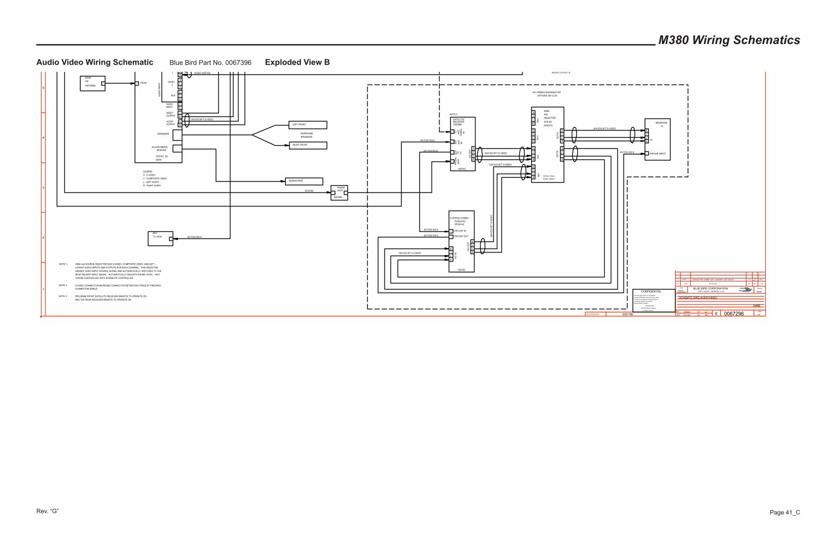
M380 Wiring Schematics
Audio Video Wiring Schematic Blue Bird Part No. 0067396 Exploded View B
Rev. “G” Page 41_C
AUDIO OUTPUT B
S
IN
PVDD4742
V
L
R
FM-IN
ACOUSTIMASS
SUBWOOFER
LEFT FRONT
RIGHT FRONT
SURROUND
SPEAKERS
120VAC, 2A
240W
NOTE 1: SIMA 4x2 SOURCE SELECTOR HAS S-VIDEO, COMPOSITE VIDEO, AND LEFT
& RIGHT AUDIO INPUTS AND OUTPUTS FOR EACH CHANNEL. THIS SELECTOR
SENSES VIDEO INPUT SOURCE SIGNAL AND AUTOMATICALLY SWITCHES TO THE
MOST RECENT INPUT SIGNAL. AUTOMATICALLY ADJUSTS SOUND LEVEL. UNIT
CAN BE CONTROLLED WITH IR REMOTE CONTROLLER.
LEGEND:
S: S-VIDEO
V: COMPOSITE VIDEO
L: LEFT AUDIO
R: RIGHT AUDIO
0041533 6FT S-VIDEO
AUDIO 0067320
BOSE
FM
ANTENNA
SPEAKERS
MODULE
AUDIO
OUTPUT R
L
VIDEO
OUTPUTV
S
VIDEO
INPUT
C
S
AUX
R
LD
AU
DIO
INP
UT
D
L
R
VIDEO
2
1L
R
S-VIDEO CONNECTOR-INCREASE CONNECTOR RETENTION FORCE BY PINCHING
CONNECTOR SHIELD.
BEDROOM
TV
R
L
V
L
V
S
A/V
IN
R
A/V
OU
T S
120VAC
VCR/DVD COMBO
R
S
V
L
R
L
V
S
R
R
L
V
S
S
V
L
R
S
V
L
S
V
L
R
IN-1
IN-2
IN-3
IN-4
SIMA
SVS-4D
4X2
SELECTOR
120VAC, 63mA
15VDC, 500mA
0052415
OU
T-A
OU
T-B
A/V WIRING DIAGRAM FOR
OPTIONS 38112-29
L
V
120VAC
TO
SATELLITE
A/V
OU
T
R
S
RECEIVER
OU
T
NOTE 2:
0041533 6FT S-VIDEO
0041533 6FT S-VIDEO
0041533 6FT S-VIDEO
0041533 6FT S-VIDEO
00
41
53
36
FT
S-V
IDE
O
TV JACK
BAY
4517033 RG-6
INAN
T
SA
T
TV
4517033 RG-6
VHF/UHF IN
VHF/UHF OUT
4517033 RG-6
VHF/UHF INPUT4517033 RG-6
4517033 RG-6
4517033 RG-6
0053996
00524142
TV
AN
T\
CA
BL
EIN
PH
ON
EJA
CK
PHONEJACK
3881869
4018198
NOTE 3
NOTE 3: PROGRAM FRONT SATELLITE RECEIVER REMOTE TO OPERATE ON
AND THE REAR RECEIVER REMOTE TO OPERATE ON
A 3847431 CHANGED PART NUMBER FOR TV ANTENNA TO BE "0081595" SSSS
08/04/0413077A
INACTIVATES NOS.
LET. WAS REVISIONS DR. APP. CCN
SCALEBLUE BIRD CORPORATIONFORT VALLEY GEORGIA, U.S.A.
CCN
DR.
APP.
BY
BY EPAGE
__OF__
1
2
3
4
5
0067296
SCHEMTIC,WRG,AUDIO/VIDEO
06/09/03
07/21/03
BT
SW
12857SNONECONFIDENTIAL
The information hereon is confidential
business information and may not be copied
or used for any purpose unless permission
is expressly granted in writing by
Blue Bird Body Company.
Copyright 2002
Blue Bird Body Company
All rights reserved
H4RE
0051798
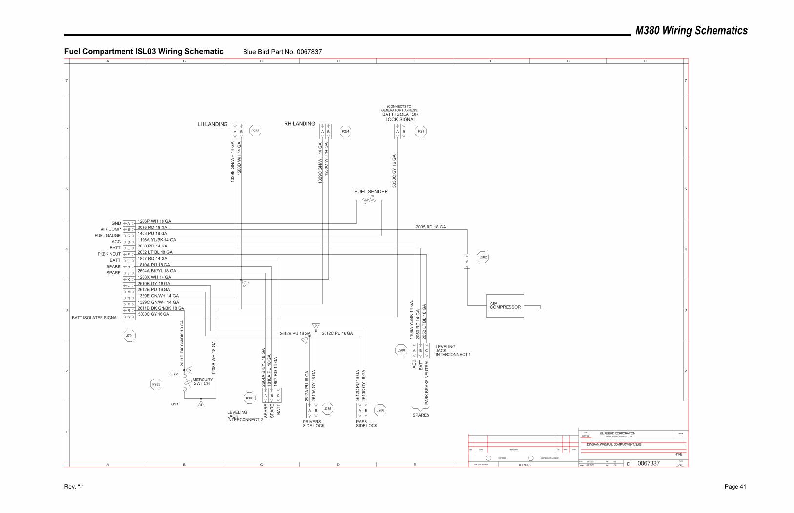
M380 Wiring Schematics
Rev. “-“ Page 41
Fuel Compartment ISL03 Wiring Schematic Blue Bird Part No. 0067837
FUEL SENDER
AIRCOMPRESSOR
1206P WH 18 GA2035 RD 18 GA .1403 PU 18 GA1106A YL/BK 14 GA.2050 RD 14 GA2052 LT BL 18 GA1807 RD 14 GA1810A PU 18 GA2604A BK/YL 18 GA
2604
A B
K/Y
L 18
GA
1810
A P
U 1
8 G
A18
07 R
D 1
4 G
A
1106
A Y
L/B
K 1
4 G
A.
2050
RD
14
GA
2052
LT
BL
18 G
A
2035 RD 18 GA .
DIAGRAM,WRG,FUEL COMPARTMENT,ISL03
H4RE
006783707/03/03 SS
CE08/19/03
12857R
LEVELINGJACKINTERCONNECT 1
LEVELINGJACKINTERCONNECT 2
GNDAIR COMP
FUEL GAUGEACC
BATTPKBK NEUT
BATTSPARESPARE
SPAR
ESP
ARE
BATT
ACC
PAR
K,BR
AKE,
NEU
TRAL
C
A
B
D
E
F
G
H
J
K
L
M
N
P
R
1208X WH 14 GA2610B GY 18 GA2612B PU 16 GA1329E GN/WH 14 GA1329C GN/WH 14 GA2611B DK GN/BK 18 GA
A B
1329
E G
N/W
H 1
4 G
A12
08D
WH
14
GA
LH LANDING
3
BA
RH LANDING
1208
C W
H 1
4 G
A13
29C
GN
/WH
14
GA
A
BA A B
2
1
2612C PU 16 GA2612B PU 16 GA
2612
A PU
16
GA
2610
A G
Y 16
GA
2610
C G
Y 16
GA
2612
C P
U 1
6 G
A1208
B W
H 1
8 G
A
PASSSIDE LOCK
DRIVERSSIDE LOCK
P283 P284
J282
J286J285
P281
J280
J79
P285
2611
B D
K G
N/B
K 18
GA
5
4
GY2
GY1
SBATT ISOLATER SIGNAL5030C GY 16 GA
P21
5030
C G
Y 1
6 G
A
BATT ISOLATOR
A B
LOCK SIGNAL
(CONNECTS TOGENERATOR HARNESS)
0039926
SPARES
INACTIVATES NOS.
LET. WAS REVISIONS DR. APP. CCN
SCALEBLUE BIRD CORPORATIONFORT VALLEY GEORGIA, U.S.A.
CCN
DR.
APP. BY
BY
DPAGE
__OF__
1
2
3
4
5
A B C D E F G H
B C D E
5
4
3
2
6 6
77
A
Component LocationHarness
A B C
A B C
MERCURYSWITCH
BATT