Embed Size (px)
Citation preview
(1,1)
北米Model "A2600BE-B" EDITED: 2020/ 9/ 1
ForewordForewordSFWAA
Congratulations on choosing a SUBARU vehicle. This Owner’sManual has all the information necessary to keep your SUBARU inexcellent condition and to properly maintain the emission controlsystem forminimizing emission pollutants.We urge you to read thismanual carefully so that you may understand your vehicle and itsoperation. For information not found in this Owner’s Manual, suchas details concerning repairs or adjustments, please contact theSUBARU dealer from whom you purchased your SUBARU or thenearest SUBARU dealer.The information, specifications and illustrations found in thismanual are those in effect at the time of printing. SUBARUCORPORATION reserves the right to change specifications anddesigns at any time without prior notice and without incurring anyobligation to make the same or similar changes on vehiclespreviously sold. This Owner’s Manual applies to all models andcovers all equipment, including factory installed options. Someexplanations, therefore may be for equipment not installed in yourvehicle.
Please leave thismanual in the vehicle at the time of resale. The nextowner will need the information found herein.
SUBARU CORPORATION, TOKYO, JAPAN
“SUBARU” and the six-star cluster design are registered trademarks of SUBARU CORPORATION.
*C Copyright 2020 SUBARU CORPORATION

(2,1)
北米Model "A2600BE-B" EDITED: 2020/ 9/ 1
(3,1)
北米Model "A2600BE-B" EDITED: 2020/ 9/ 1
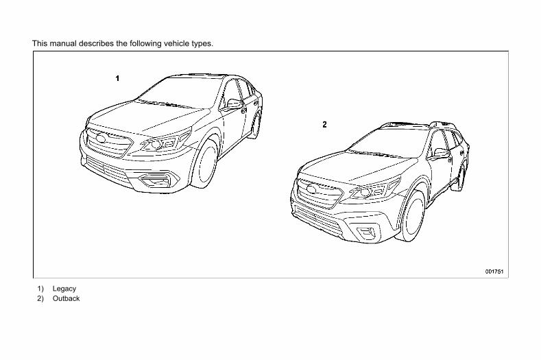
This manual describes the following vehicle types.
1) Legacy2) Outback

(2,1)
北米Model "A2600BE-B" EDITED: 2020/ 9/ 1
(1,1)
北米Model "A2600BE-B" EDITED: 2020/ 10/ 1
Table of Contents
Keys and Doors .........................................................................................................113 Chapter 2
Instruments and Controls....................................................................................... 165 Chapter 3
Climate Control ......................................................................................................... 277
Audio ........................................................................................................................... 297 Chapter 5
Interior Equipment ................................................................................................... 301 Chapter 6
Starting and Operating............................................................................................ 323 Chapter 7
Driving Tips ............................................................................................................... 417 Chapter 8
In Case of Emergency............................................................................................. 447 Chapter 9
Appearance Care ...................................................................................................... 473 Chapter 10
Maintenance and Service ....................................................................................... 481 Chapter 11
Specifications............................................................................................................ 529 Chapter 12
Consumer Information and Reporting Safety Defects .................................... 549 Chapter 13
Index............................................................................................................................ 567 Chapter 14
Chapter 4
Illustrated Index ...........................................................................................................13
Chapter 1Seat, Seatbelt and SRS Airbags ..............................................................................27
Introduction ....................................................................................................................1

(2,1)
北米Model "A2600BE-B" EDITED: 2020/ 10/ 1
(3,1)
北米Model "A2600BE-B" EDITED: 2020/ 10/ 1
sint* Warranties ........................................................... 2Warranties for U.S.A. ............................................. 2Warranties for Canada ........................................... 2Warranties except for U.S.A. and Canada ............... 2
* How to Use This Owner’s Manual ..................... 2Using Your Owner’s Manual ................................... 2Safety Warnings .................................................... 3Safety Symbol ....................................................... 4Abbreviation List ................................................... 4
* Vehicle Symbols ................................................. 5* Safety Precautions When Driving ..................... 5
Seatbelt and SRS Airbag........................................ 5Child Safety........................................................... 5Engine Exhaust Gas (Carbon Monoxide) ................ 6Drinking and Driving.............................................. 7
Drugs and Driving ................................................. 7Driving When Tired or Sleepy................................ 8Modification of Your Vehicle .................................. 8Use of Cell Phones/Texting and Driving ................. 8Driving Vehicles Equipped with NavigationSystem ............................................................... 8
Driving with Pets................................................... 8Tire Pressures....................................................... 9On-Road and Off-Road Driving .............................. 9Attaching Accessories .......................................... 9
* General Information ......................................... 10California Perchlorate Advisory ............................10Noise from under the Vehicle ...............................10Event Data Recorder ............................................10
Introduction0
Introduction
(4,1)
北米Model "A2600BE-B" EDITED: 2020/ 10/ 1
Warrantiess00aa
& Warranties for U.S.A.s00aa01
SUBARU vehicles distributed by Subaru ofAmerica, Inc. and sold at retail by anauthorized SUBARU dealer in the UnitedStates come with the following warranties:. SUBARU Limited Warranties. Federal Emission Control SystemsWarranties. California Emissions Control Sys-tems Warranties
All warranty information, including applic-ability, details of coverage and exclusions,is in the “Warranty and MaintenanceBooklet.” Read these warranties carefully.
& Warranties for Canadas00aa05
SUBARU vehicles distributed by SubaruCanada, Inc. and sold at retail by anauthorized SUBARU dealer in Canadacome with the following warranties:. SUBARU Limited Warranty. Emission Control System Warranty
All warranty information, including applic-ability, details of coverage and exclusions,is in the “Warranty and Service Booklet.”Read these warranties carefully.
& Warranties except for U.S.A.and Canada
s00aa06All warranty information, including detailsof coverage and exclusions, is in the“Warranty and Maintenance Booklet.”Read these warranties carefully.
How to Use This Owner’sManual
s00ab
& Using Your Owner’s Manuals00ab01
Before you operate your vehicle, carefullyread this manual. To protect yourself andextend the service life of your vehicle,follow the instructions in this manual.Failure to observe these instructions mayresult in serious injury and damage to yourvehicle.
This manual is composed of fourteenchapters. Each chapter begins with a brieftable of contents, so you can usually tell ata glance if that chapter contains theinformation you want.
IntroductionThis chapter informs you general informa-tion before driving.Illustrated IndexThis chapter informs you about the vehiclelayout with illustrations.Chapter 1: Seat, Seatbelt and SRSAirbagsThis chapter informs you how to use theseat and seatbelt and contains precau-tions for the SRS airbags.Chapter 2: Keys and DoorsThis chapter informs you how to operatethe keys, locks and windows.
Warranties2
(5,1)
北米Model "A2600BE-B" EDITED: 2020/ 10/ 1
Chapter 3: Instruments and ControlsThis chapter informs you about the opera-tion of instrument panel indicators and howto use the instruments and other switches.Chapter 4: Climate ControlThis chapter informs you how to operatethe climate control.Chapter 5: AudioThis chapter informs you about your audiosystem.Chapter 6: Interior EquipmentThis chapter informs you how to operateinterior equipment.Chapter 7: Starting and OperatingThis chapter informs you how to start andoperate your SUBARU.Chapter 8: Driving TipsThis chapter informs you how to drive yourSUBARU in various conditions and ex-plains some safety tips on driving.Chapter 9: In case of EmergencyThis chapter informs you what to do if youhave a problem, such as a flat tire orengine overheating.Chapter 10: Appearance CareThis chapter informs you how to keep yourSUBARU looking good.
Chapter 11: Maintenance and ServiceThis chapter informs youwhen you need totake your SUBARU to the dealer forscheduled maintenance and informs youhow to keep your SUBARU runningproperly.Chapter 12: SpecificationsThis chapter informs you about the dimen-sions and capacities of your SUBARU.Chapter 13: Consumer Information andReporting Safety DefectsThis chapter informs you about Tireinformation, Uniform tire quality gradingstandards and Reporting safety defects.Chapter 14: IndexThis is an alphabetical listing of all that’s inthis manual. You can use it to quickly findsomething you want to read.
For EyeSight system:For details about the EyeSight system,refer to the Owner’s Manual supplementfor the EyeSight system.
Depending on specifications, the vehicleshown in the illustrations may differ fromyour vehicle in terms of equipment.
& Safety Warningss00ab02
You will find a number of WARNINGs,CAUTIONs and NOTEs in this manual.These safety warnings alert you to poten-tial hazards that could result in injury to youor others.Please read these safety warnings as wellas all other portions of this manual care-fully in order to gain a better understandingof how to use your SUBARU vehicle safely.
WARNING
A WARNING indicates a situation inwhich serious injury or death couldresult if the warning is ignored.
CAUTION
A CAUTION indicates a situation inwhich injury or damage to yourvehicle, or both, could result if thecaution is ignored.
NOTEA NOTE gives information or sugges-tions how to make better use of yourvehicle.
– CONTINUED –
How to Use This Owner’s Manual 3
0
Introduction
(6,1)
北米Model "A2600BE-B" EDITED: 2020/ 10/ 1
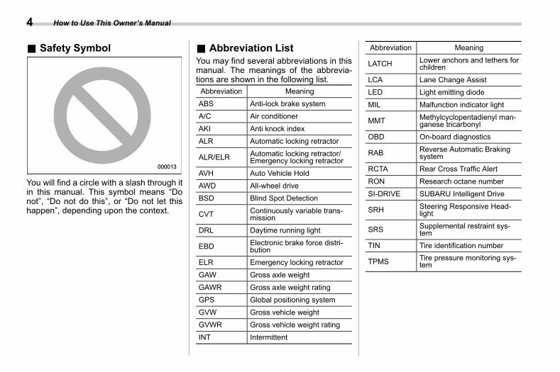
& Safety Symbols00ab03
You will find a circle with a slash through itin this manual. This symbol means “Donot”, “Do not do this”, or “Do not let thishappen”, depending upon the context.
& Abbreviation Lists00ab04
You may find several abbreviations in thismanual. The meanings of the abbrevia-tions are shown in the following list.Abbreviation Meaning
ABS Anti-lock brake systemA/C Air conditioner
AKI Anti knock indexALR Automatic locking retractor
ALR/ELR Automatic locking retractor/Emergency locking retractor
AVH Auto Vehicle Hold
AWD All-wheel driveBSD Blind Spot Detection
CVT Continuously variable trans-mission
DRL Daytime running light
EBD Electronic brake force distri-bution
ELR Emergency locking retractor
GAW Gross axle weight
GAWR Gross axle weight ratingGPS Global positioning system
GVW Gross vehicle weightGVWR Gross vehicle weight rating
INT Intermittent
Abbreviation Meaning
LATCH Lower anchors and tethers forchildren
LCA Lane Change AssistLED Light emitting diode
MIL Malfunction indicator light
MMT Methylcyclopentadienyl man-ganese tricarbonyl
OBD On-board diagnostics
RAB Reverse Automatic Brakingsystem
RCTA Rear Cross Traffic Alert
RON Research octane numberSI-DRIVE SUBARU Intelligent Drive
SRH Steering Responsive Head-light
SRS Supplemental restraint sys-tem
TIN Tire identification number
TPMS Tire pressure monitoring sys-tem
How to Use This Owner’s Manual4
(7,1)
北米Model "A2600BE-B" EDITED: 2020/ 10/ 1
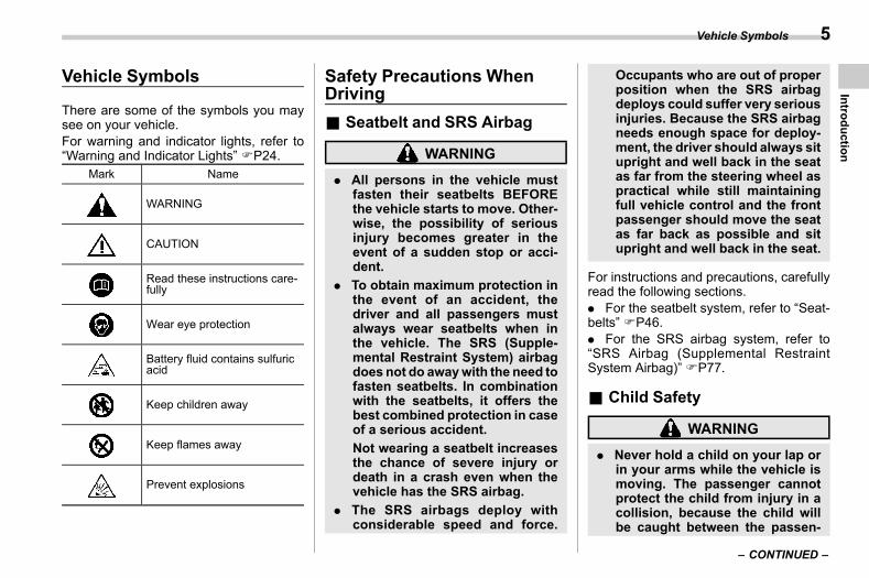
Vehicle Symbolss00ac
There are some of the symbols you maysee on your vehicle.For warning and indicator lights, refer to“Warning and Indicator Lights” FP24.
Mark Name
WARNING
CAUTION
Read these instructions care-fully
Wear eye protection
Battery fluid contains sulfuricacid
Keep children away
Keep flames away
Prevent explosions
Safety Precautions WhenDriving
s00ad
& Seatbelt and SRS Airbags00ad01
WARNING
. All persons in the vehicle mustfasten their seatbelts BEFOREthe vehicle starts to move. Other-wise, the possibility of seriousinjury becomes greater in theevent of a sudden stop or acci-dent.
. To obtain maximum protection inthe event of an accident, thedriver and all passengers mustalways wear seatbelts when inthe vehicle. The SRS (Supple-mental Restraint System) airbagdoes not do awaywith the need tofasten seatbelts. In combinationwith the seatbelts, it offers thebest combined protection in caseof a serious accident.Not wearing a seatbelt increasesthe chance of severe injury ordeath in a crash even when thevehicle has the SRS airbag.
. The SRS airbags deploy withconsiderable speed and force.
Occupants who are out of properposition when the SRS airbagdeploys could suffer very seriousinjuries. Because the SRS airbagneeds enough space for deploy-ment, the driver should always situpright and well back in the seatas far from the steering wheel aspractical while still maintainingfull vehicle control and the frontpassenger should move the seatas far back as possible and situpright and well back in the seat.
For instructions and precautions, carefullyread the following sections.. For the seatbelt system, refer to “Seat-belts” FP46.. For the SRS airbag system, refer to“SRS Airbag (Supplemental RestraintSystem Airbag)” FP77.
& Child Safetys00ad02
WARNING
. Never hold a child on your lap orin your arms while the vehicle ismoving. The passenger cannotprotect the child from injury in acollision, because the child willbe caught between the passen-
– CONTINUED –
Vehicle Symbols 5
0
Introduction
(8,1)
北米Model "A2600BE-B" EDITED: 2020/ 10/ 1
ger and objects inside the vehi-cle.
. While riding in the vehicle, infantsand small children should alwaysbe seated in the REAR seat in aninfant or child restraint systemwhich is appropriate for thechild’s age, height and weight. Ifa child is too big for a childrestraint system, the child shouldsit in the REAR seat and berestrained using the seatbelts.According to accident statistics,children are safer when properlyrestrained in the rear seatingpositions than in the front seatingpositions. Never allow a child tostand up or kneel on the seat.
. Place children in the REAR seatproperly restrained at all times ina child restraint system or in aseatbelt. The SRS airbag deployswith considerable speed andforce and can injure or even killchildren, especially if they are notrestrained or improperly re-strained. Because children arelighter and weaker than adults,their risk of being injured fromdeployment is greater.
. NEVER INSTALL A CHILD SEATIN THE FRONT SEAT. DOING SO
RISKS SERIOUS INJURY ORDEATH TO THE CHILD BY PLA-CING THE CHILD’S HEAD TOOCLOSE TO THE SRS AIRBAG.
. Always turn the child safety locksto the “LOCK” position whenchildren sit in the rear seat.Serious injury could result if achild accidentally opens the doorand falls out. Refer to “ChildSafety Locks” FP145.
. Always lock the passengers’ win-dows using the lock switch whenchildren are riding in the vehicle.Failure to follow this procedurecould result in injury to a childoperating the power window. Re-fer to “Windows” FP145.
. Never leave unattended children,adults or animals in the vehicle.They could accidentally injurethemselves or others throughinadvertent operation of the ve-hicle. Also, on hot or sunny days,temperature in a closed vehiclecould quickly become high en-ough to cause severe or possiblyfatal injuries to them.
. Help prevent children, adults oranimals from locking themselvesin the trunk. On hot or sunny
days, the temperature in the trunkcould quickly become high en-ough to cause death or seriousheat-related injuries includingbrain damage to anyone lockedinside, particularly for small chil-dren.
. When leaving the vehicle, closeall windows and lock all doors.Also make certain that the trunkis closed.
For instructions and precautions, carefullyread the following sections.. For the seatbelt system, refer to “Seat-belts” FP46.. For the child restraint system, refer to“Child Restraint Systems” FP58.. For the SRS airbag system, refer to“SRS Airbag (Supplemental RestraintSystem Airbag)” FP77.
& Engine Exhaust Gas (CarbonMonoxide)
s00ad03
WARNING
. Never inhale engine exhaust gas.Engine exhaust gas containscarbon monoxide, a colorlessand odorless gas which is dan-gerous, or even lethal, if inhaled.
Safety Precautions When Driving6
(9,1)
北米Model "A2600BE-B" EDITED: 2020/ 10/ 1
. Always properly maintain the en-gine exhaust system to preventengine exhaust gas fromenteringthe vehicle.
. Never run the engine in a closedspace, such as a garage, exceptfor the brief time needed to drivethe vehicle in or out of it.
. Avoid remaining in a parked ve-hicle for a long time while theengine is running. If that is un-avoidable, then use the ventila-tion fan to force fresh air into thevehicle.
. Always keep the front ventilatorinlet grille free from snow, leavesor other obstructions to ensurethat the ventilation system al-ways works properly.
. If at any time you suspect thatexhaust fumes are entering thevehicle, have the problemchecked and corrected as soonas possible. If you must driveunder these conditions, driveonly with all windows fully open.
. Keep the trunk lid or rear gateclosed while driving to preventexhaust gas from entering thevehicle.
& Drinking and Drivings00ad04
WARNING
Drinking and then driving is verydangerous. Alcohol in the blood-stream delays your reaction andimpairs your perception, judgmentand attentiveness. If you drive afterdrinking – even if you drink just alittle – it will increase the risk ofbeing involved in a serious or fatalaccident, injuring or killing yourself,your passengers and others. Inaddition, if you are injured in theaccident, alcohol may increase theseverity of that injury.Please don’t drink and drive.
Drunken driving is one of themost frequentcauses of accidents. Since alcohol affectsall people differently, you may have con-sumed too much alcohol to drive safelyeven if the level of alcohol in your blood isbelow the legal limit. The safest thing youcan do is never drink and drive. However ifyou have no choice but to drive, stopdrinking and sober up completely beforegetting behind the wheel.
& Drugs and Drivings00ad05
WARNING
There are some drugs (over thecounter and prescription) that candelay your reaction time and impairyour perception, judgment and at-tentiveness. If you drive after takingthem, it may increase your, yourpassengers’ and other persons’ riskof being involved in a serious or fatalaccident.
If you are taking any drugs, check withyour doctor or pharmacist or read theliterature that accompanies themedicationto determine if the drug you are taking canimpair your driving ability. Do not driveafter taking anymedications that canmakeyou drowsy or otherwise affect your abilityto safely operate a motor vehicle. If youhave a medical condition that requires youto take drugs, please consult with yourdoctor.
Never drive if you are under the influenceof any illicit mind-altering drugs. For yourown health and well-being, we urge younot to take illegal drugs in the first placeand to seek treatment if you are addictedto those drugs.
– CONTINUED –
Safety Precautions When Driving 7
0
Introduction
(10,1)
北米Model "A2600BE-B" EDITED: 2020/ 10/ 1
& Driving When Tired or Sleepys00ad06
WARNING
When you are tired or sleepy, yourreaction will be delayed and yourperception, judgment and attentive-ness will be impaired. If you drivewhen tired or sleepy, your, yourpassengers’ and other persons’chances of being involved in aserious accident may increase.
Please do not continue to drive but insteadfind a safe place to rest if you are tired orsleepy. On long trips, you should makeperiodic rest stops to refresh yourselfbefore continuing on your journey. Whenpossible, you should share the driving withothers.
& Modification of Your Vehicles00ad07
WARNING
Do not remove the genuine SUBARUnavigation and/or audio system.Doing so could cause the followingfunctions to be inoperable.. Combination meter display (color
LCD). Rear view image and help lines
. Vehicle settings
. Climate control
. Front seat heater and ventilation
. Clock
CAUTION
Your vehicle should not be modifiedother than with genuine SUBARUparts and accessories. Other typesof modifications could affect itsperformance, safety or durability,and may even violate governmentalregulations. In addition, damage orperformance problems resultingfrom modification may not be cov-ered under warranties.
& Use of Cell Phones/Textingand Driving
s00ad16
CAUTION
Do not talk on a cell phone or textwhile driving; it may distract yourattention from driving and lead to anaccident. If you use a cell phone totalk or text, first pull off the road andpark in a safe place. In some States/Provinces, it may be lawful to talk on
a phone while driving, but only if thephone is hands-free.
& Driving Vehicles Equippedwith Navigation System
s00ad09
WARNING
Do not allow the monitor to distractyour attention from driving. Also, donot operate the controls of thenavigation system while driving.The loss of attention to driving couldlead to an accident. If you wish tooperate the controls of the naviga-tion system, first take the vehicle offthe road and stop it in a safelocation.
& Driving with Petss00ad10
Unrestrained pets can interfere with yourdriving and distract your attention fromdriving. In a collision or sudden stop,unrestrained pets or cages can be thrownaround inside the vehicle and hurt you oryour passengers. Besides, the pets can behurt under these situations. It is also fortheir own safety that pets should beproperly restrained in your vehicle. Re-strain a pet with a special traveling harness
Safety Precautions When Driving8
(11,1)
北米Model "A2600BE-B" EDITED: 2020/ 10/ 1
which can be secured to the rear seat witha seatbelt or use a pet carrier which can besecured to the rear seat by routing aseatbelt through the carrier’s handle.Never restrain pets or pet carriers in thefront passenger’s seat. For further infor-mation, consult your veterinarian, localanimal protection society or pet shop.
& Tire Pressuress00ad11
Check and, if necessary, adjust the pres-sure of each tire and the spare (ifequipped) at least once a month andbefore any long journey.
Check the tire pressure when the tires arecold. Use a pressure gauge to adjust thetire pressures to the values shown on thetire placard. For detailed information, referto “Tires and Wheels” FP502.
WARNING
Driving at high speeds withexcessively low tire pressurescan cause the tires to deformseverely and to rapidly be-come hot. A sharp increase intemperature could cause treadseparation, and destruction ofthe tires. The resulting loss of
vehicle control could lead toan accident.
& On-Road and Off-Road Driv-ing
s00ad13This vehicle is classified as a utility vehicle.Utility vehicles have a significantly higherrollover rate than other types of vehicles.Your vehicle has a higher ground clear-ance and higher center of gravity, making itmore likely to roll over than ordinarypassenger cars. It also handles andmaneuvers differently from other passen-ger cars. For this reason, please readcarefully the following section and followthe instructions and precautions in order toprevent serious injury or death due to lossof control, rollover and other accidents.Refer to “Off Road Driving” FP422.
& Attaching Accessoriess00ad15
WARNING
. Do not attach any accessories,labels or stickers (other thanproperly placed inspection stick-ers) to the windshield. Suchitems may obstruct your view.
. If it is necessary to attach anaccessory (such as an electronictoll collection (ETC) device orsecurity pass) to the windshield,consult your SUBARU dealer fordetails on the proper location.
Safety Precautions When Driving 9
0
Introduction
(12,1)
北米Model "A2600BE-B" EDITED: 2020/ 10/ 1
General Informations00ak
& California Perchlorate Advi-sory
s00ak03Certain vehicle components such as air-bag modules, seatbelt pretensioners andkeyless entry transmitter batteries maycontain perchlorate material. Specialhandling may apply for service or vehicleend of life disposal. See www.dtsc.ca.gov/hazardouswaste/perchlorate.
& Noise from under the Vehicles00ak01
NOTEYou may hear a noise from under thevehicle approximately 5 to 10 hoursafter the ignition switch is turned to the“LOCK”/“OFF” position. However, thisdoes not indicate a malfunction. Thisnoise is caused by the operation of thefuel evaporation leakage checking sys-tem and the operation is normal. Thenoise will stop after approximately 15minutes.
& Event Data Recorders00ak04
This vehicle is equippedwith an event datarecorder (EDR). The main purpose of anEDR is to record, in certain crash or nearcrash-like situations, such as an air bag
deployment or hitting a road obstacle, datathat will assist in understanding how avehicle’s systems performed. The EDR isdesigned to record data related to vehicledynamics and safety systems for a shortperiod of time, typically 30 seconds or less.The EDR in this vehicle is designed torecord such data as:. How various systems in your vehiclewere operating;. Whether or not the driver and passen-ger safety belts were buckled/fastened;. How far (if at all) the driver wasdepressing the accelerator and/or brakepedal; and,. How fast the vehicle was traveling.
These data can help provide a betterunderstanding of the circumstances inwhich crashes and injuries occur. NOTE:EDR data are recorded by your vehicleonly if a non-trivial crash situation occurs;no data are recorded by the EDR undernormal driving conditions and no personaldata (e.g., name, gender, age, and crashlocation) are recorded. However, otherparties, such as law enforcement, couldcombine the EDR data with the type ofpersonally identifying data routinely ac-quired during a crash investigation.
To read data recorded by an EDR, specialequipment is required, and access to the
vehicle or the EDR is needed. In additionto the vehicle manufacturer, other parties,such as law enforcement, that have thespecial equipment, can read the informa-tion if they have access to the vehicle orthe EDR.
General Information10

(13,1)
北米Model "A2600BE-B" EDITED: 2020/ 10/ 1
— — — — — — — — — — — — — — — — — — — — — — — — — — — — — — — — — — — — — — — —
— — — — — — — — — — — — — — — — — — — — — — — — — — — — — — — — — — — — — — — —
— — — — — — — — — — — — — — — — — — — — — — — — — — — — — — — — — — — — — — — —
— — — — — — — — — — — — — — — — — — — — — — — — — — — — — — — — — — — — — — — —
— — — — — — — — — — — — — — — — — — — — — — — — — — — — — — — — — — — — — — — —
— — — — — — — — — — — — — — — — — — — — — — — — — — — — — — — — — — — — — — — —
— — — — — — — — — — — — — — — — — — — — — — — — — — — — — — — — — — — — — — — —
— — — — — — — — — — — — — — — — — — — — — — — — — — — — — — — — — — — — — — — —
— — — — — — — — — — — — — — — — — — — — — — — — — — — — — — — — — — — — — — — —
— — — — — — — — — — — — — — — — — — — — — — — — — — — — — — — — — — — — — — — —
— — — — — — — — — — — — — — — — — — — — — — — — — — — — — — — — — — — — — — — —
— — — — — — — — — — — — — — — — — — — — — — — — — — — — — — — — — — — — — — — —
— — — — — — — — — — — — — — — — — — — — — — — — — — — — — — — — — — — — — — — —

(14,1)
北米Model "A2600BE-B" EDITED: 2020/ 10/ 1
— — — — — — — — — — — — — — — — — — — — — — — — — — — — — — — — — — — — — — — —
— — — — — — — — — — — — — — — — — — — — — — — — — — — — — — — — — — — — — — — —
— — — — — — — — — — — — — — — — — — — — — — — — — — — — — — — — — — — — — — — —
— — — — — — — — — — — — — — — — — — — — — — — — — — — — — — — — — — — — — — — —
— — — — — — — — — — — — — — — — — — — — — — — — — — — — — — — — — — — — — — — —
— — — — — — — — — — — — — — — — — — — — — — — — — — — — — — — — — — — — — — — —
— — — — — — — — — — — — — — — — — — — — — — — — — — — — — — — — — — — — — — — —
— — — — — — — — — — — — — — — — — — — — — — — — — — — — — — — — — — — — — — — —
— — — — — — — — — — — — — — — — — — — — — — — — — — — — — — — — — — — — — — — —
— — — — — — — — — — — — — — — — — — — — — — — — — — — — — — — — — — — — — — — —
— — — — — — — — — — — — — — — — — — — — — — — — — — — — — — — — — — — — — — — —
— — — — — — — — — — — — — — — — — — — — — — — — — — — — — — — — — — — — — — — —
— — — — — — — — — — — — — — — — — — — — — — — — — — — — — — — — — — — — — — — —
(15,1)
北米Model "A2600BE-B" EDITED: 2020/ 10/ 1
sill* Exterior .............................................................. 14* Interior ............................................................... 16* Instrument Panel............................................... 19* Steering Wheel.................................................. 20* Light Control and Wiper Control Levers/
Switches .......................................................... 21
* Combination Meter ........................................... 22U.S.-Spec. Models ................................................22Except U.S.-Spec. Models.....................................23
* Warning and Indicator Lights.......................... 24
Illustrated Index
1
IllustratedIndex
(16,1)
北米Model "A2600BE-B" EDITED: 2020/ 10/ 1
Exteriors00ay
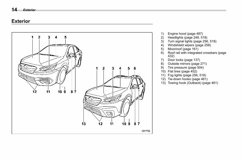
1) Engine hood (page 487)2) Headlights (page 248, 518)3) Turn signal lights (page 256, 518)4) Windshield wipers (page 258)5) Moonroof (page 161)6) Roof rail with integrated crossbars (page
432)7) Door locks (page 137)8) Outside mirrors (page 271)9) Tire pressure (page 504)10) Flat tires (page 452)11) Fog lights (page 256, 518)12) Tie-down hooks (page 461)13) Towing hook (Outback) (page 461)
Exterior14
(17,1)
北米Model "A2600BE-B" EDITED: 2020/ 10/ 1
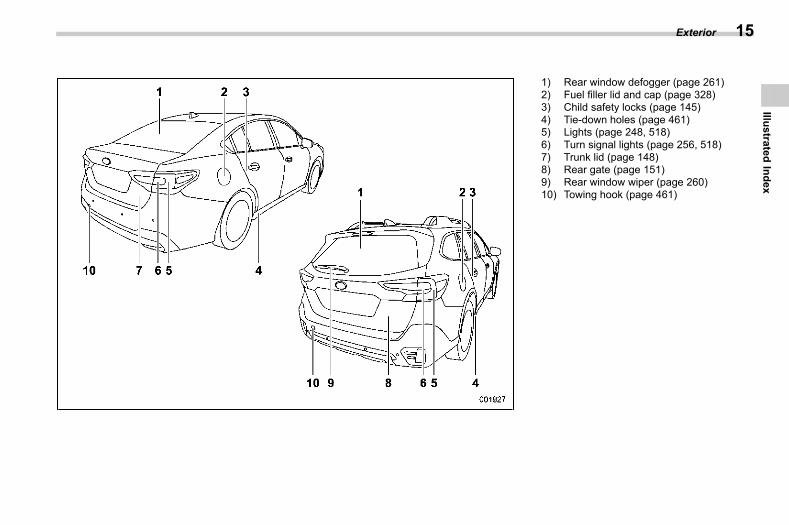
1) Rear window defogger (page 261)2) Fuel filler lid and cap (page 328)3) Child safety locks (page 145)4) Tie-down holes (page 461)5) Lights (page 248, 518)6) Turn signal lights (page 256, 518)7) Trunk lid (page 148)8) Rear gate (page 151)9) Rear window wiper (page 260)10) Towing hook (page 461)
Exterior 15
1
IllustratedIndex
(18,1)
北米Model "A2600BE-B" EDITED: 2020/ 10/ 1
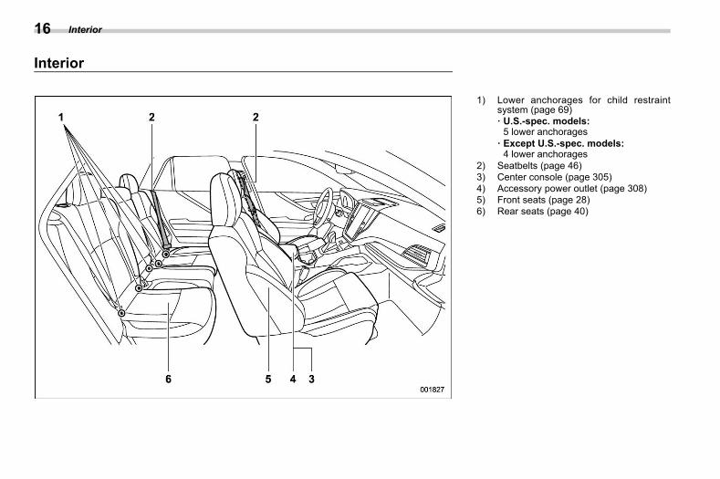
Interiors00az
1) Lower anchorages for child restraintsystem (page 69)· U.S.-spec. models:5 lower anchorages
· Except U.S.-spec. models:4 lower anchorages
2) Seatbelts (page 46)3) Center console (page 305)4) Accessory power outlet (page 308)5) Front seats (page 28)6) Rear seats (page 40)
Interior16
(19,1)
北米Model "A2600BE-B" EDITED: 2020/ 10/ 1
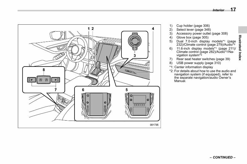
1) Cup holder (page 306)2) Select lever (page 348)3) Accessory power outlet (page 308)4) Glove box (page 305)5) Dual 7.0-inch display models*1 (page
232)/Climate control (page 279)/Audio*26) 11.6-inch display models*1 (page 211)/
Climate control (page 282)/Audio*2/Na-vigation system*2
7) Rear seat heater switches (page 39)8) USB power supply (page 310)*1: Center information display*2: For details about how to use the audio and
navigation system (if equipped), refer tothe separate navigation/audio Owner’sManual.
– CONTINUED –
Interior 17
1
IllustratedIndex
(20,1)
北米Model "A2600BE-B" EDITED: 2020/ 10/ 1
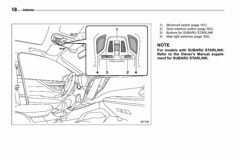
1) Moonroof switch (page 161)2) Door interlock switch (page 302)3) Buttons for SUBARU STARLINK4) Map light switches (page 302)
NOTEFor models with SUBARU STARLINK:Refer to the Owner’s Manual supple-ment for SUBARU STARLINK.
Interior18
(21,1)
北米Model "A2600BE-B" EDITED: 2020/ 10/ 1
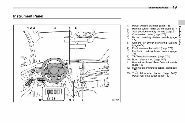
Instrument Panels00ba
1) Power window switches (page 145)2) Remote control mirror switch (page 271)3) Seat position memory buttons (page 33)4) Combination meter (page 173)5) Hazard warning flasher switch (page
172)6) Camera for Driver Monitoring System
(page 404)7) Front view monitor switch (page 377)8) Electronic parking brake switch (page
366)9) Tilt/Telescopic steering (page 274)10) Hood release knob (page 487)11) Hands-free Power Rear Gate off switch
(page 160)12) Illumination brightness control dial (page
175)13) Trunk lid opener button (page 149)/
Power rear gate button (page 152)
Instrument Panel 19
1
IllustratedIndex
(22,1)
北米Model "A2600BE-B" EDITED: 2020/ 10/ 1
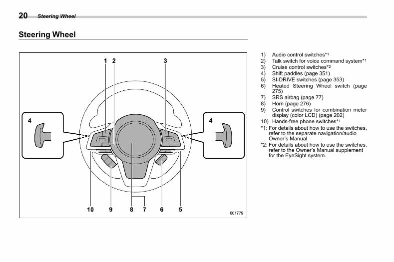
Steering Wheels00bb
1) Audio control switches*12) Talk switch for voice command system*13) Cruise control switches*24) Shift paddles (page 351)5) SI-DRIVE switches (page 353)6) Heated Steering Wheel switch (page
275)7) SRS airbag (page 77)8) Horn (page 276)9) Control switches for combination meter
display (color LCD) (page 202)10) Hands-free phone switches*1*1: For details about how to use the switches,
refer to the separate navigation/audioOwner’s Manual.
*2: For details about how to use the switches,refer to the Owner’s Manual supplementfor the EyeSight system.
Steering Wheel20
(23,1)
北米Model "A2600BE-B" EDITED: 2020/ 10/ 1
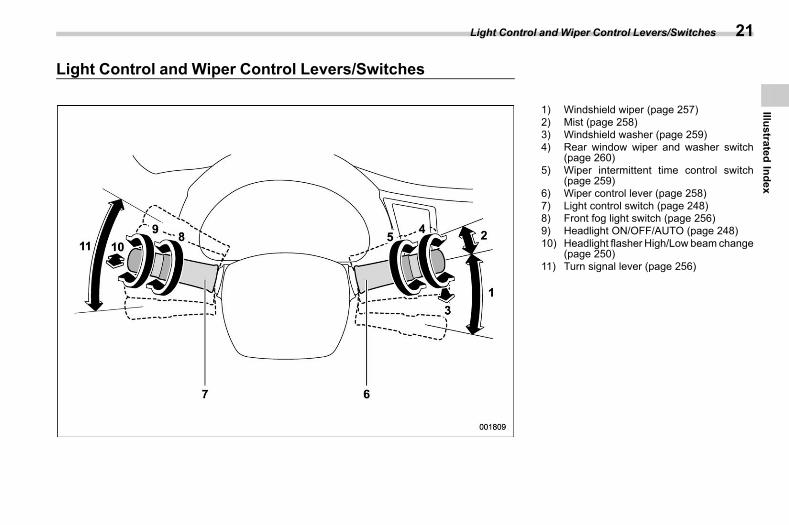
Light Control and Wiper Control Levers/Switchess00bc
1) Windshield wiper (page 257)2) Mist (page 258)3) Windshield washer (page 259)4) Rear window wiper and washer switch
(page 260)5) Wiper intermittent time control switch
(page 259)6) Wiper control lever (page 258)7) Light control switch (page 248)8) Front fog light switch (page 256)9) Headlight ON/OFF/AUTO (page 248)10) Headlight flasher High/Low beam change
(page 250)11) Turn signal lever (page 256)
Light Control and Wiper Control Levers/Switches 21
1
IllustratedIndex
(24,1)
北米Model "A2600BE-B" EDITED: 2020/ 10/ 1
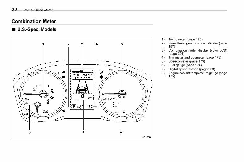
Combination Meters00bd
& U.S.-Spec. Modelss00bd01
1) Tachometer (page 173)2) Select lever/gear position indicator (page
197)3) Combination meter display (color LCD)
(page 201)4) Trip meter and odometer (page 173)5) Speedometer (page 173)6) Fuel gauge (page 174)7) Digital speed screen (page 208)8) Engine coolant temperature gauge (page
175)
Combination Meter22
(25,1)
北米Model "A2600BE-B" EDITED: 2020/ 10/ 1
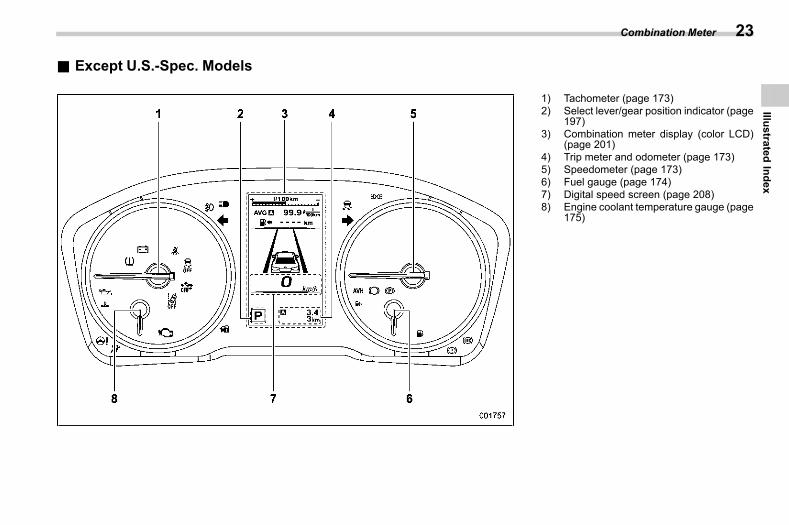
& Except U.S.-Spec. Modelss00bd02
1) Tachometer (page 173)2) Select lever/gear position indicator (page
197)3) Combination meter display (color LCD)
(page 201)4) Trip meter and odometer (page 173)5) Speedometer (page 173)6) Fuel gauge (page 174)7) Digital speed screen (page 208)8) Engine coolant temperature gauge (page
175)
Combination Meter 23
1
IllustratedIndex
(26,1)
北米Model "A2600BE-B" EDITED: 2020/ 10/ 1
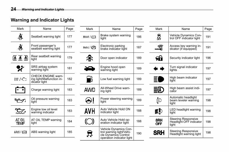
Warning and Indicator Lights s00be
Mark Name Page
Seatbelt warning light 177
Front passenger’sseatbelt warning light 177
Rear seatbelt warninglight 179
SRS airbag systemwarning light 181
CHECK ENGINE warn-ing light/Malfunction in-dicator light
182
Charge warning light 183
Oil pressure warninglight 183
Engine low oil levelwarning indicator 183
AT OIL TEMP warninglight 184
/ ABS warning light 185
Mark Name Page
/ Brake system warninglight 186
/ Electronic parkingbrake indicator light 187
Door open indicator 189
Engine hood openwarning light 189
Low fuel warning light 189
All-Wheel Drive warn-ing light 189
Power steering warninglight 189
Auto Vehicle Hold ONindicator light 188
Auto Vehicle Hold op-eration indicator light 188
Vehicle Dynamics Con-trol warning light/Vehi-cle Dynamics Controloperation indicator light
190
Mark Name Page
Vehicle Dynamics Con-trol OFF indicator light 191
Access key warning in-dicator (if equipped) 191
Security indicator light 196
Turn signal indicatorlights 197
High beam indicatorlight 197
High beam assist indi-cator 197
Automatic headlightbeam leveler warninglight
198
LED headlight warninglight 198
Steering ResponsiveHeadlight OFF indicatorlight
198
Steering ResponsiveHeadlight warning light 198
Warning and Indicator Lights24
(27,1)
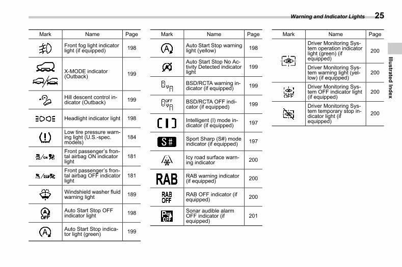
北米Model "A2600BE-B" EDITED: 2020/ 10/ 1
Mark Name Page
Front fog light indicatorlight (if equipped) 198
X-MODE indicator(Outback) 199
Hill descent control in-dicator (Outback) 199
Headlight indicator light 198
Low tire pressure warn-ing light (U.S.-spec.models)
184
Front passenger’s fron-tal airbag ON indicatorlight
181
Front passenger’s fron-tal airbag OFF indicatorlight
181
Windshield washer fluidwarning light 189
Auto Start Stop OFFindicator light 198
Auto Start Stop indica-tor light (green) 199
Mark Name Page
Auto Start Stop warninglight (yellow) 198
Auto Start Stop No Ac-tivity Detected indicatorlight
199
BSD/RCTA warning in-dicator (if equipped) 199
BSD/RCTA OFF indi-cator (if equipped) 199
Intelligent (I) mode in-dicator (if equipped) 197
Sport Sharp (S#) modeindicator (if equipped) 197
Icy road surface warn-ing indicator 200
RAB warning indicator(if equipped) 200
RAB OFF indicator (ifequipped) 200
Sonar audible alarmOFF indicator (ifequipped)
201
Mark Name PageDriver Monitoring Sys-tem operation indicatorlight (green) (ifequipped)
200
Driver Monitoring Sys-tem warning light (yel-low) (if equipped)
200
Driver Monitoring Sys-tem OFF indicator light(if equipped)
200
Driver Monitoring Sys-tem temporary stop in-dicator light (ifequipped)
200
Warning and Indicator Lights 25
1
IllustratedIndex

(28,1)
北米Model "A2600BE-B" EDITED: 2020/ 10/ 1
— — — — — — — — — — — — — — — — — — — — — — — — — — — — — — — — — — — — — — — —
— — — — — — — — — — — — — — — — — — — — — — — — — — — — — — — — — — — — — — — —
— — — — — — — — — — — — — — — — — — — — — — — — — — — — — — — — — — — — — — — —
— — — — — — — — — — — — — — — — — — — — — — — — — — — — — — — — — — — — — — — —
— — — — — — — — — — — — — — — — — — — — — — — — — — — — — — — — — — — — — — — —
— — — — — — — — — — — — — — — — — — — — — — — — — — — — — — — — — — — — — — — —
— — — — — — — — — — — — — — — — — — — — — — — — — — — — — — — — — — — — — — — —
— — — — — — — — — — — — — — — — — — — — — — — — — — — — — — — — — — — — — — — —
— — — — — — — — — — — — — — — — — — — — — — — — — — — — — — — — — — — — — — — —
— — — — — — — — — — — — — — — — — — — — — — — — — — — — — — — — — — — — — — — —
— — — — — — — — — — — — — — — — — — — — — — — — — — — — — — — — — — — — — — — —
— — — — — — — — — — — — — — — — — — — — — — — — — — — — — — — — — — — — — — — —
— — — — — — — — — — — — — — — — — — — — — — — — — — — — — — — — — — — — — — — —
(29,1)
北米Model "A2600BE-B" EDITED: 2020/ 10/ 1
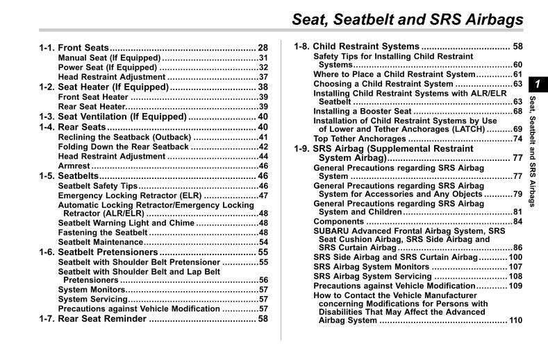
s011-1. Front Seats........................................................ 28
Manual Seat (If Equipped) .....................................31Power Seat (If Equipped) ......................................32Head Restraint Adjustment ...................................37
1-2. Seat Heater (If Equipped) ................................. 38Front Seat Heater .................................................39Rear Seat Heater...................................................39
1-3. Seat Ventilation (If Equipped) .......................... 401-4. Rear Seats......................................................... 40
Reclining the Seatback (Outback) .........................41Folding Down the Rear Seatback ..........................42Head Restraint Adjustment ...................................44Armrest ................................................................46
1-5. Seatbelts............................................................ 46Seatbelt Safety Tips..............................................46Emergency Locking Retractor (ELR) .....................47Automatic Locking Retractor/Emergency LockingRetractor (ALR/ELR) ...........................................48
Seatbelt Warning Light and Chime ........................48Fastening the Seatbelt ..........................................48Seatbelt Maintenance............................................54
1-6. Seatbelt Pretensioners ..................................... 55Seatbelt with Shoulder Belt Pretensioner ..............55Seatbelt with Shoulder Belt and Lap BeltPretensioners .....................................................56
System Monitors...................................................57System Servicing..................................................57Precautions against Vehicle Modification ..............57
1-7. Rear Seat Reminder ......................................... 58
1-8. Child Restraint Systems .................................. 58Safety Tips for Installing Child RestraintSystems.............................................................60
Where to Place a Child Restraint System..............61Choosing a Child Restraint System ......................63Installing Child Restraint Systems with ALR/ELRSeatbelt .............................................................63
Installing a Booster Seat ......................................68Installation of Child Restraint Systems by Useof Lower and Tether Anchorages (LATCH) ..........69
Top Tether Anchorages ........................................741-9. SRS Airbag (Supplemental Restraint
System Airbag)............................................... 77General Precautions regarding SRS AirbagSystem ..............................................................77
General Precautions regarding SRS AirbagSystem for Accessories and Any Objects ...........79
General Precautions regarding SRS AirbagSystem and Children..........................................81
Components ........................................................84SUBARU Advanced Frontal Airbag System, SRSSeat Cushion Airbag, SRS Side Airbag andSRS Curtain Airbag ............................................86
SRS Side Airbag and SRS Curtain Airbag ........... 100SRS Airbag System Monitors ............................. 107SRS Airbag System Servicing ............................ 108Precautions against Vehicle Modification............ 109How to Contact the Vehicle Manufacturerconcerning Modifications for Persons withDisabilities That May Affect the AdvancedAirbag System ................................................. 110
Seat, Seatbelt and SRS Airbags
1
Seat,SeatbeltandSR
SAirbags
(30,1)
北米Model "A2600BE-B" EDITED: 2020/ 10/ 1
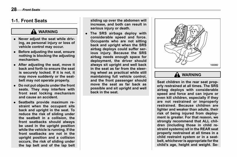
1-1. Front Seatss01aa
WARNING
. Never adjust the seat while driv-ing, as personal injury or loss ofvehicle control may occur.
. Before adjusting the seat, ensurenothing is blocking the adjustingmechanism.
. After adjusting the seat, move itback and forth to ensure the seatis securely locked. If it is not, itmay move suddenly or the seat-belt may not operate properly.
. Do not put objects under the frontseats. They may interfere withfront seat locking mechanismand cause an accident.
. Seatbelts provide maximum re-straint when the occupant sitsback and upright in the seat. Toreduce the risk of sliding underthe seatbelt in a collision, thefront seatbacks should alwaysbe used in the upright positionwhile the vehicle is running. If thefront seatbacks are not in theupright position and a collisionoccurs, the risk of sliding underthe lap belt and of the lap belt
sliding up over the abdomen willincrease, and both can result inserious injury or death.
. The SRS airbags deploy withconsiderable speed and force.Occupants who are not sittingback and upright when the SRSairbag deploys could suffer ser-ious injury. Because the SRSairbag needs enough space fordeployment, the driver shouldalways sit upright and well backin the seat as far from the steer-ing wheel as practical while stillmaintaining full vehicle control,and the front passenger shouldmove the seat as far back aspossible and sit upright and wellback in the seat.
WARNING
Seat children in the rear seat prop-erly restrained at all times. The SRSairbag deploys with considerablespeed and force and can injure oreven kill children, especially if theyare not restrained or improperlyrestrained. Because children arelighter and weaker than adults, theirrisk of being injured from deploy-ment is greater. For that reason, westrongly recommend that ALL chil-dren (including those in child re-straint systems) sit in the REAR seatproperly restrained at all times in achild restraint system or in a seat-belt, whichever is appropriate for thechild’s age, height and weight. Se-
Front Seats28
(31,1)
北米Model "A2600BE-B" EDITED: 2020/ 10/ 1
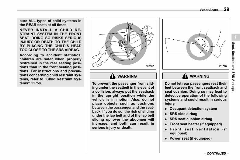
cure ALL types of child systems inthe REAR seats at all times.NEVER INSTALL A CHILD RE-STRAINT SYSTEM IN THE FRONTSEAT. DOING SO RISKS SERIOUSINJURY OR DEATH TO THE CHILDBY PLACING THE CHILD’S HEADTOO CLOSE TO THE SRS AIRBAG.According to accident statistics,children are safer when properlyrestrained in the rear seating posi-tions than in the front seating posi-tions. For instructions and precau-tions concerning child restraint sys-tems, refer to “Child Restraint Sys-tems” FP58.
WARNING
To prevent the passenger from slid-ing under the seatbelt in the event ofa collision, always put the seatbackin the upright position while thevehicle is in motion. Also, do notplace objects such as cushionsbetween the passenger and the seat-back. If you do so, the risk of slidingunder the lap belt and of the lap beltsliding up over the abdomen willincrease, and both can result inserious injury or death.
WARNING
Do not let rear passengers rest theirfeet between the front seatback andseat cushion. Doing so may lead todetective operation of the followingsystems and could result in seriousinjury.. Occupant detection system. SRS side airbag. SRS seat cushion airbag. Front seat heater (if equipped). Front seat vent i la t ion ( i f
equipped). Power seat (if equipped)
– CONTINUED –
Front Seats 29
1
Seat,SeatbeltandSR
SAirbags
(32,1)
北米Model "A2600BE-B" EDITED: 2020/ 10/ 1
WARNING
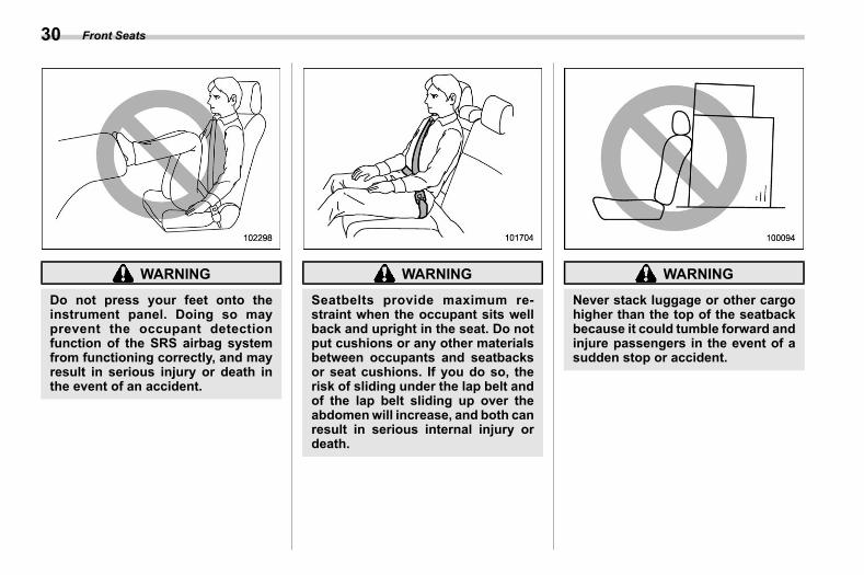
Do not press your feet onto theinstrument panel. Doing so mayprevent the occupant detectionfunction of the SRS airbag systemfrom functioning correctly, and mayresult in serious injury or death inthe event of an accident.
WARNING
Seatbelts provide maximum re-straint when the occupant sits wellback and upright in the seat. Do notput cushions or any other materialsbetween occupants and seatbacksor seat cushions. If you do so, therisk of sliding under the lap belt andof the lap belt sliding up over theabdomenwill increase, and both canresult in serious internal injury ordeath.
WARNING
Never stack luggage or other cargohigher than the top of the seatbackbecause it could tumble forward andinjure passengers in the event of asudden stop or accident.
Front Seats30
(33,1)
北米Model "A2600BE-B" EDITED: 2020/ 10/ 1
& Manual Seat (If Equipped)s01aa01
! Forward and backward adjustments01aa0101
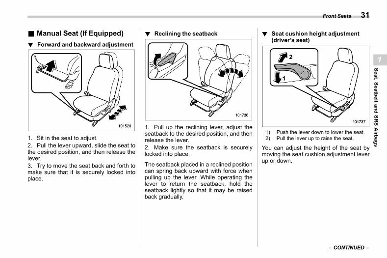
1. Sit in the seat to adjust.2. Pull the lever upward, slide the seat tothe desired position, and then release thelever.3. Try to move the seat back and forth tomake sure that it is securely locked intoplace.
! Reclining the seatbacks01aa0102
1. Pull up the reclining lever, adjust theseatback to the desired position, and thenrelease the lever.2. Make sure the seatback is securelylocked into place.
The seatback placed in a reclined positioncan spring back upward with force whenpulling up the lever. While operating thelever to return the seatback, hold theseatback lightly so that it may be raisedback gradually.
! Seat cushion height adjustment(driver’s seat)
s01aa0103
1) Push the lever down to lower the seat.2) Pull the lever up to raise the seat.
You can adjust the height of the seat bymoving the seat cushion adjustment leverup or down.
– CONTINUED –
Front Seats 31
1
Seat,SeatbeltandSR
SAirbags
(34,1)
北米Model "A2600BE-B" EDITED: 2020/ 10/ 1
& Power Seat (If Equipped)s01aa02
! Driver’s seats01aa0208
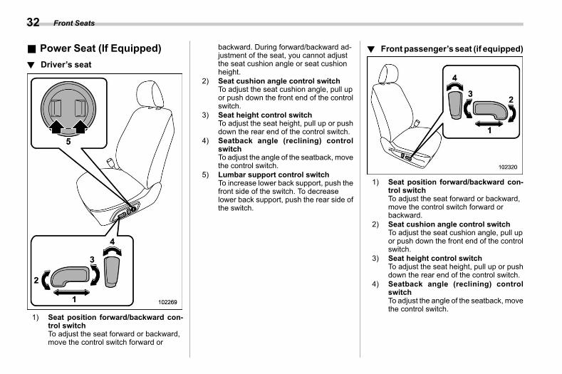
1) Seat position forward/backward con-trol switchTo adjust the seat forward or backward,move the control switch forward or
backward. During forward/backward ad-justment of the seat, you cannot adjustthe seat cushion angle or seat cushionheight.
2) Seat cushion angle control switchTo adjust the seat cushion angle, pull upor push down the front end of the controlswitch.
3) Seat height control switchTo adjust the seat height, pull up or pushdown the rear end of the control switch.
4) Seatback angle (reclining) controlswitchTo adjust the angle of the seatback, movethe control switch.
5) Lumbar support control switchTo increase lower back support, push thefront side of the switch. To decreaselower back support, push the rear side ofthe switch.
! Front passenger’s seat (if equipped)s01aa0209
1) Seat position forward/backward con-trol switchTo adjust the seat forward or backward,move the control switch forward orbackward.
2) Seat cushion angle control switchTo adjust the seat cushion angle, pull upor push down the front end of the controlswitch.
3) Seat height control switchTo adjust the seat height, pull up or pushdown the rear end of the control switch.
4) Seatback angle (reclining) controlswitchTo adjust the angle of the seatback, movethe control switch.
Front Seats32
(35,1)
北米Model "A2600BE-B" EDITED: 2020/ 10/ 1
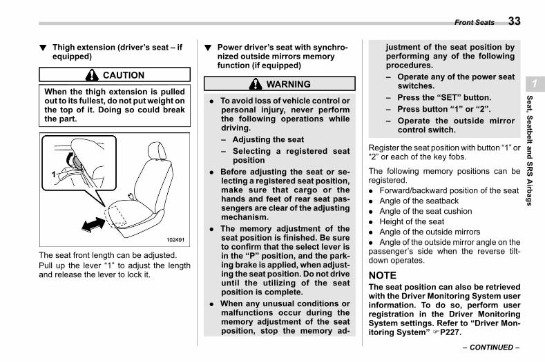
! Thigh extension (driver’s seat – ifequipped)
s01aa0210
CAUTION
When the thigh extension is pulledout to its fullest, do not putweight onthe top of it. Doing so could breakthe part.
The seat front length can be adjusted.Pull up the lever “1” to adjust the lengthand release the lever to lock it.
! Power driver’s seat with synchro-nized outside mirrors memoryfunction (if equipped)
s01aa0207
WARNING
. To avoid loss of vehicle control orpersonal injury, never performthe following operations whiledriving.– Adjusting the seat– Selecting a registered seat
position. Before adjusting the seat or se-
lecting a registered seat position,make sure that cargo or thehands and feet of rear seat pas-sengers are clear of the adjustingmechanism.
. The memory adjustment of theseat position is finished. Be sureto confirm that the select lever isin the “P” position, and the park-ing brake is applied, when adjust-ing the seat position. Do not driveuntil the utilizing of the seatposition is complete.
. When any unusual conditions ormalfunctions occur during thememory adjustment of the seatposition, stop the memory ad-
justment of the seat position byperforming any of the followingprocedures.– Operate any of the power seat
switches.– Press the “SET” button.– Press button “1” or “2”.– Operate the outside mirror
control switch.
Register the seat position with button “1” or“2” or each of the key fobs.
The following memory positions can beregistered.. Forward/backward position of the seat. Angle of the seatback. Angle of the seat cushion. Height of the seat. Angle of the outside mirrors. Angle of the outside mirror angle on thepassenger’s side when the reverse tilt-down operates.
NOTEThe seat position can also be retrievedwith the Driver Monitoring System userinformation. To do so, perform userregistration in the Driver MonitoringSystem settings. Refer to “Driver Mon-itoring System” FP227.
– CONTINUED –
Front Seats 33
1
Seat,SeatbeltandSR
SAirbags
(36,1)
北米Model "A2600BE-B" EDITED: 2020/ 10/ 1
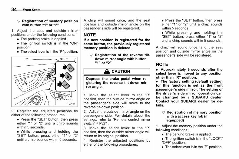
! Registration of memory positionwith button “1” or “2”
s01aa020701
1. Adjust the seat and outside mirrorpositions under the following conditions.
. The parking brake is applied.
. The ignition switch is in the “ON”position.. The select lever is in the “P” position.
2. Register the adjusted positions byeither of the following procedures.
. Press the “SET” button, then presseither “1” or “2” until a chirp soundswithin 5 seconds.. While pressing and holding the“SET” button, press either “1” or “2”until a chirp sounds within 5 seconds.
A chirp will sound once, and the seatposition and outside mirror angle on thepassenger’s side will be registered.
NOTEIf a new position is registered for thesame button, the previously registeredmemory position is deleted.
! Registration of the reverse tilt-down mirror angle with button“1” or “2”
s01aa020706
CAUTION
Depress the brake pedal when re-gistering the reverse tilt-down mir-ror angle.
1. Move the select lever to the “R”position, then the outside mirror angle onthe passenger’s side will move to thereverse tilt-down position.2. Adjust the outside mirror angle on thepassenger’s side. For details about thesettings, refer to “Remote control mirrorswitch” FP271.3. Move the select lever to the “P”position, then the outside mirror angle willreturn to its original position.4. Register the adjusted positions byeither of the following procedures.
. Press the “SET” button, then presseither “1” or “2” until a chirp soundswithin 5 seconds.. While pressing and holding the“SET” button, press either “1” or “2”until a chirp sounds within 5 seconds.
A chirp will sound once, and the seatposition and outside mirror angle on thepassenger’s side will be registered.
NOTE. Approximately 9 seconds after theselect lever is moved to any positionother than “R” position.. The factory setting (default setting)for this function is set as the frontpassenger’s side mirror. The setting ofthe driver’s side mirror operation canbe changed by a SUBARU dealer.Contact your SUBARU dealer for de-tails.
! Registration of memory positionwith a access key fob (ifequipped)
s01aa020703
1. Adjust the memory position under thefollowing conditions.
. The parking brake is applied.
. The ignition switch is in the “LOCK”/“OFF” position.. The select lever is in the “P” position.
Front Seats34
(37,1)
北米Model "A2600BE-B" EDITED: 2020/ 10/ 1
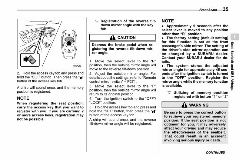
2. Hold the access key fob and press andhold the “SET” button. Then press the “ ”button of the access key fob.
A chirp will sound once, and the memoryposition is registered.
NOTEWhen registering the seat position,carry the access key that you want toregister with you. If you are carrying 2or more access keys, registration maynot be possible.
! Registration of the reverse tilt-down mirror angle with the keyfob
s01aa020707
CAUTION
Depress the brake pedal when re-gistering the reverse tilt-down mir-ror angle.
1. Move the select lever to the “R”position, then the outside mirror angle willmove to the reverse tilt-down position.2. Adjust the outside mirror angle. Fordetails about the settings, refer to “Remotecontrol mirror switch” FP271.3. Move the select lever to the “P”position, then the outside mirror angle willreturn to its original position.4. Turn the ignition switch to the “OFF”/“LOCK” position.5. Hold the access key fob and press andhold the “SET” button, then press the “ ”button of the access key fob.A chirp will sound once, and the reversetilt-down mirror angle will be registered.
NOTE. Approximately 9 seconds after theselect lever is moved to any positionother than “R” position.. The factory setting (default setting)for this function is set as the frontpassenger’s side mirror. The setting ofthe driver’s side mirror operation canbe changed by a SUBARU dealer.Contact your SUBARU dealer for de-tails.. The system stores the adjustedmirror angle for approximately 45 sec-onds after the ignition switch is turnedto the “OFF” position. Register themirror angle while the memory functionis available.
! Utilizing of memory positionregistered with button “1” or “2”
s01aa020702
WARNING
Be sure to press the correct buttonto retrieve your registered memoryposition. If the seat position is notoptimum for you, it may adverselyaffect your driving and may reducethe effectiveness of the seatbelt.That could result in an accidentinvolving serious injury or death.
– CONTINUED –
Front Seats 35
1
Seat,SeatbeltandSR
SAirbags
(38,1)
北米Model "A2600BE-B" EDITED: 2020/ 10/ 1
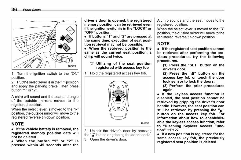
1. Turn the ignition switch to the “ON”position.2. Put the select lever is in the “P” positionand apply the parking brake. Then pressbutton “1” or “2”.
A chirp will sound and the seat and angleof the outside mirrors moves to theregistered position.When the select lever is moved to the “R”position, the outside mirror will move to theregistered reverse tilt-down position.
NOTE. If the vehicle battery is removed, theregistered memory position data willnot be deleted.. When the button “1” or “2” ispressed within 45 seconds after the
driver’s door is opened, the registeredmemory position can be retrieved evenif the ignition switch is in the “LOCK” or“OFF” position.. If buttons “1” and “2” are pressed atthe same time, execution of seat posi-tion retrieval may not be possible.. When the retrieved position is thesame as the current seat position, achirp will sound twice.
! Utilizing of the seat positionregistered with access key fob
s01aa020704
1. Hold the registered access key fob.
2. Unlock the driver’s door by pressingthe “ ” button or gripping the door handle.3. Open the driver’s door.
A chirp sounds and the seat moves to theregistered position.When the select lever is moved to the “R”position, the outside mirror will move to theregistered reverse tilt-down position.
NOTE. If the registered seat position cannotbe retrieved after performing the pre-vious procedures, try the followingprocedures.
(1) Press the “SET” button on thedriver’s door.(2) Press the “ ” button on theaccess key fob or touch the doorlock sensor to lock the doors.(3) Perform the prior proceduresagain.
. If the keyless access function isdisabled, the seat position cannot beretrieved by gripping the driver’s doorhandle. However, the seat position canstill be retrieved by pressing the “ ”button on the access key fob. Forinformation about how to enable/dis-able the keyless access function, referto “Disabling Keyless Access Func-tion” FP127.. If a new position is registered for thesame access key fob, the previouslyregistered seat position is deleted.
Front Seats36

(39,1)
北米Model "A2600BE-B" EDITED: 2020/ 10/ 1
. If you are carrying 2 or more accesskeys, seat position retrieval may not bepossible.
! Clearing the registered seat posi-tion with access key fob
s01aa020705
1. Close the driver’s door.2. While holding the access key fob andpressing the “SET” button, press the “ ”button on the access key fob.
A chirp will sound, and the registered seatposition will be cleared.
NOTEAfter deleting the seat position, wait fora few moments before registering anew seat position.
& Head Restraint Adjustments01aa04
WARNING
. Never drive the vehicle with thehead restraints removed becausethey are designed to reduce therisk of serious neck injury in theevent that the vehicle is struckfrom the rear. Also, never installthe head restraints backwards.Doing so will prevent the headrestraints from functioning asintended. Therefore, when the
head restraints are removed, allhead restraints must be rein-stalled properly to protect vehicleoccupants.
. The vehicle should not be oper-ated until the head restraints areinstalled in their proper posi-tions.
. The front seat head restraints aredesigned to be installed into thefront seats only. The rear seathead restraints are designed tobe installed into the rear seatsonly. Do not attempt to install thefront seat head restraints into therear seats, or the rear seat headrestraints into the front seats.
Both the driver’s seat and front passen-ger’s seat are equipped with head re-straints. Both head restraints are adjusta-ble in the following ways.
! Head restraint height adjustments01aa0401
1) Head restraint2) Release button
To raise:Pull the head restraint up.To lower:Push the head restraint down while press-ing the release button on the top of theseatback.To remove:While pressing the release button, pull outthe head restraint.To install:Install the head restraint into the holes thatare located on the top of the seatback untilthe head restraint locks. Press and holdthe release button to lower the headrestraint.
– CONTINUED –
Front Seats 37
1
Seat,SeatbeltandSR
SAirbags
(40,1)
北米Model "A2600BE-B" EDITED: 2020/ 10/ 1
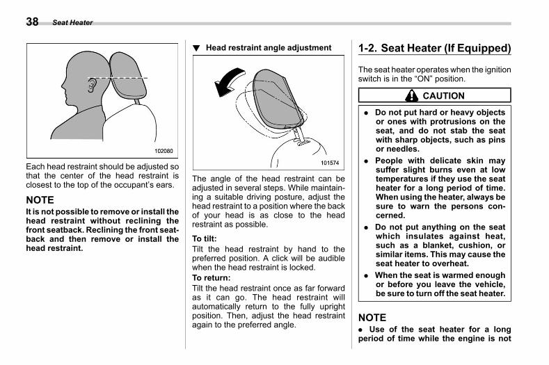
Each head restraint should be adjusted sothat the center of the head restraint isclosest to the top of the occupant’s ears.
NOTEIt is not possible to remove or install thehead restraint without reclining thefront seatback. Reclining the front seat-back and then remove or install thehead restraint.
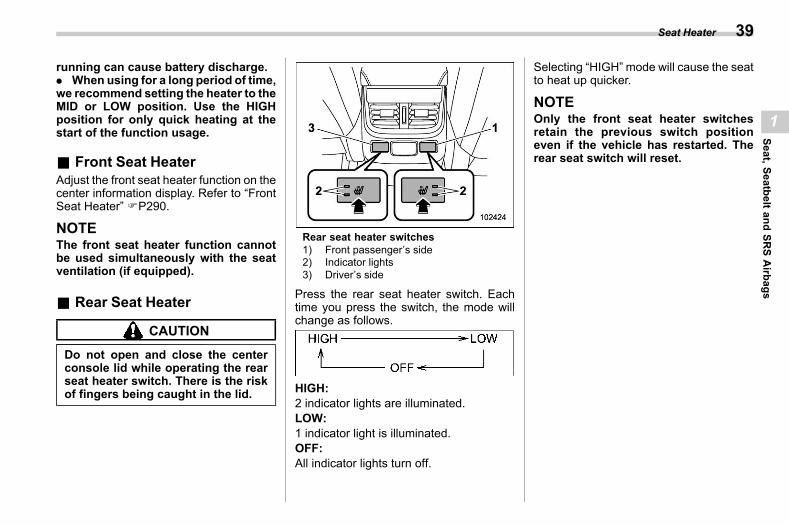
! Head restraint angle adjustments01aa0402
The angle of the head restraint can beadjusted in several steps. While maintain-ing a suitable driving posture, adjust thehead restraint to a position where the backof your head is as close to the headrestraint as possible.
To tilt:Tilt the head restraint by hand to thepreferred position. A click will be audiblewhen the head restraint is locked.To return:Tilt the head restraint once as far forwardas it can go. The head restraint willautomatically return to the fully uprightposition. Then, adjust the head restraintagain to the preferred angle.
1-2. Seat Heater (If Equipped)s01ab
The seat heater operates when the ignitionswitch is in the “ON” position.
CAUTION
. Do not put hard or heavy objectsor ones with protrusions on theseat, and do not stab the seatwith sharp objects, such as pinsor needles.
. People with delicate skin maysuffer slight burns even at lowtemperatures if they use the seatheater for a long period of time.When using the heater, always besure to warn the persons con-cerned.
. Do not put anything on the seatwhich insulates against heat,such as a blanket, cushion, orsimilar items. This may cause theseat heater to overheat.
. When the seat is warmed enoughor before you leave the vehicle,be sure to turn off the seat heater.
NOTE. Use of the seat heater for a longperiod of time while the engine is not
Seat Heater38
(41,1)
北米Model "A2600BE-B" EDITED: 2020/ 10/ 1
running can cause battery discharge.. When using for a long period of time,we recommend setting the heater to theMID or LOW position. Use the HIGHposition for only quick heating at thestart of the function usage.
& Front Seat Heaters01ab05
Adjust the front seat heater function on thecenter information display. Refer to “FrontSeat Heater” FP290.
NOTEThe front seat heater function cannotbe used simultaneously with the seatventilation (if equipped).
& Rear Seat Heaters01ab06
CAUTION
Do not open and close the centerconsole lid while operating the rearseat heater switch. There is the riskof fingers being caught in the lid.
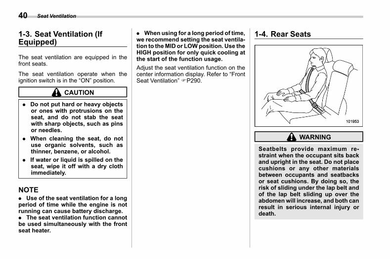
Rear seat heater switches1) Front passenger’s side2) Indicator lights3) Driver’s side
Press the rear seat heater switch. Eachtime you press the switch, the mode willchange as follows.
HIGH:2 indicator lights are illuminated.LOW:1 indicator light is illuminated.OFF:All indicator lights turn off.
Selecting “HIGH” mode will cause the seatto heat up quicker.
NOTEOnly the front seat heater switchesretain the previous switch positioneven if the vehicle has restarted. Therear seat switch will reset.
Seat Heater 39
1
Seat,SeatbeltandSR
SAirbags
(42,1)
北米Model "A2600BE-B" EDITED: 2020/ 10/ 1
1-3. Seat Ventilation (IfEquipped)
s01ar
The seat ventilation are equipped in thefront seats.
The seat ventilation operate when theignition switch is in the “ON” position.
CAUTION
. Do not put hard or heavy objectsor ones with protrusions on theseat, and do not stab the seatwith sharp objects, such as pinsor needles.
. When cleaning the seat, do notuse organic solvents, such asthinner, benzene, or alcohol.
. If water or liquid is spilled on theseat, wipe it off with a dry clothimmediately.
NOTE. Use of the seat ventilation for a longperiod of time while the engine is notrunning can cause battery discharge.. The seat ventilation function cannotbe used simultaneously with the frontseat heater.
. When using for a long period of time,we recommend setting the seat ventila-tion to theMID or LOWposition. Use theHIGH position for only quick cooling atthe start of the function usage.Adjust the seat ventilation function on thecenter information display. Refer to “FrontSeat Ventilation” FP290.
1-4. Rear Seatss01ac
WARNING
Seatbelts provide maximum re-straint when the occupant sits backand upright in the seat. Do not placecushions or any other materialsbetween occupants and seatbacksor seat cushions. By doing so, therisk of sliding under the lap belt andof the lap belt sliding up over theabdomenwill increase, and both canresult in serious internal injury ordeath.
Seat Ventilation40
(43,1)
北米Model "A2600BE-B" EDITED: 2020/ 10/ 1
WARNING
Never stack luggage or other cargohigher than the top of the seatbackas it could tumble forward and injurepassengers in the event of a suddenstop or accident.
& Reclining the Seatback(Outback)
s01ac06
WARNING
To prevent the passenger from slid-ing under the seatbelt in the event ofa collision, always put the seatbackin the upright position while thevehicle is in motion.
CAUTION
If the vehicle is equipped with acargo area cover, observe the fol-lowing precautions.. Make sure hands are not pinched
between the headrest and the
cargo area cover when rear seatis reclined.
. Move the front cover of the cargoarea cover backward so that thecover is not damaged by thereclined seatback. Refer to “Lift-ing Cargo Cover (Outback – IfEquipped)” FP314.
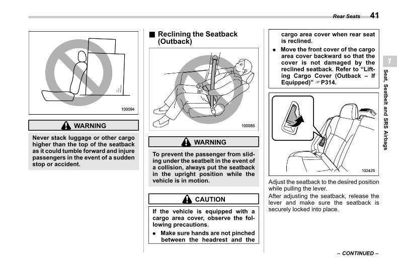
Adjust the seatback to the desired positionwhile pulling the lever.After adjusting the seatback, release thelever and make sure the seatback issecurely locked into place.
– CONTINUED –
Rear Seats 41
1
Seat,SeatbeltandSR
SAirbags
(44,1)
北米Model "A2600BE-B" EDITED: 2020/ 10/ 1
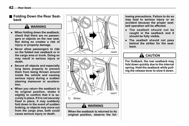
& Folding Down the Rear Seat-back
s01ac02
WARNING
. When folding down the seatback,check that there are no passen-gers or objects on the rear seat.Not doing so creates a risk ofinjury or property damage.
. Never allow passengers to rideon the folded rear seatback or inthe cargo area or trunk. Doing somay result in serious injury ordeath.
. Secure all objects and especiallylong items properly to preventthem from being thrown aroundinside the vehicle and causingserious injury during a suddensteering maneuver or accelera-tion.
. When you return the seatback toits original position, shake itslightly to confirm that it is se-curely in place. If it is not securelyfixed in place, it may suddenlyfold down in the event of suddenbraking, or objects maymove outfrom the cargo area, both couldcause serious injury or death.
1) Striker
WARNING
When the seatback is returned to itsoriginal position, observe the fol-
lowing precautions. Failure to do somay lead to serious injury or anaccident because the proper seat-belt operation will be affected.. The seatbelt should not be
caught in the seatback and itshould be fully visible.
. The seatbelt should not passbehind the striker for the seat-back.
CAUTION
For Outback, the rear seatback mayfold down quickly due to the internalspring. Hold the seatback while pull-ing the release lever to slow it down.
Rear Seats42
(45,1)
北米Model "A2600BE-B" EDITED: 2020/ 10/ 1
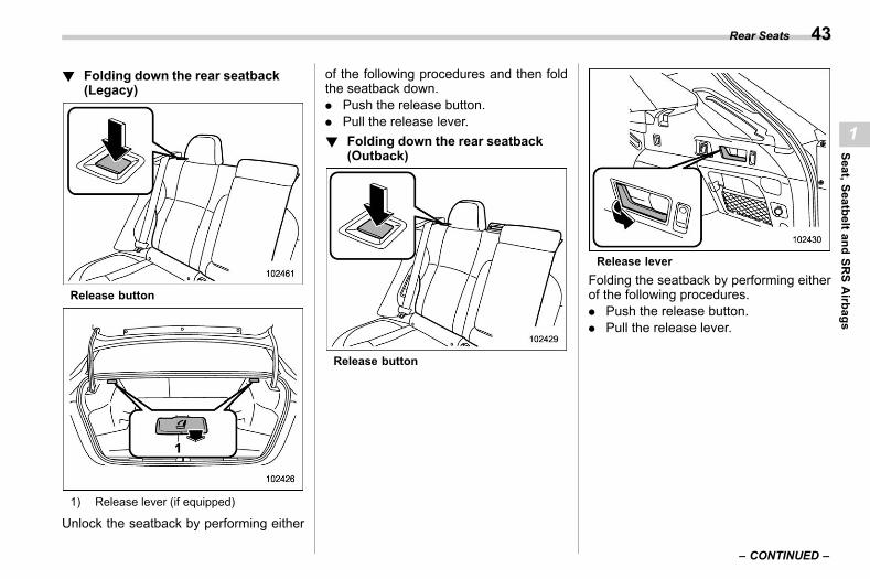
! Folding down the rear seatback(Legacy)
s01ac0201
Release button
1) Release lever (if equipped)
Unlock the seatback by performing either
of the following procedures and then foldthe seatback down.. Push the release button.. Pull the release lever.! Folding down the rear seatback
(Outback)s01ac0202
Release button
Release leverFolding the seatback by performing eitherof the following procedures.. Push the release button.. Pull the release lever.
– CONTINUED –
Rear Seats 43
1
Seat,SeatbeltandSR
SAirbags
(46,1)
北米Model "A2600BE-B" EDITED: 2020/ 10/ 1
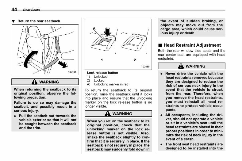
! Return the rear seatbacks01ac0204
WARNING
When returning the seatback to itsoriginal position, observe the fol-lowing precaution.Failure to do so may damage theseatbelt, and possibly result in aserious injury.. Pull the seatbelt out towards the
vehicle exterior so that it will notbe caught between the seatbackand the trim.
Lock release button1) Unlocked2) LockedA) Unlocking marker in red
To return the seatback to its originalposition, raise the seatback until it locksinto place and ensure that the unlockingmarker on the lock release button is nolonger visible.
WARNING
When you return the seatback to itsoriginal position, check that theunlocking marker on the lock re-lease button is not visible. Also,shake the seatback slightly to con-firm that it is securely in place. If theseatback is not securely in place, theseatbackmay suddenly fold down in
the event of sudden braking, orobjects may move out from thecargo area, which could cause ser-ious injury or death.
& Head Restraint Adjustments01ac03
Both the rear window side seats and therear center seat are equipped with headrestraints.
WARNING
. Never drive the vehicle with thehead restraints removed becausethey are designed to reduce therisk of serious neck injury in theevent that the vehicle is struckfrom the rear. Therefore, whenyou remove the head restraints,you must reinstall all head re-straints to protect vehicle occu-pants.
. All occupants, including the dri-ver, should not operate a vehicleor sit in a vehicle’s seat until thehead restraints are placed in theirproper positions in order to mini-mize the risk of neck injury in theevent of a crash.
. The front seat head restraints aredesigned to be installed into the
Rear Seats44
(47,1)
北米Model "A2600BE-B" EDITED: 2020/ 10/ 1
front seats only. The rear seathead restraints are designed tobe installed into the rear seatsonly. Do not attempt to install thefront seat head restraints into therear seats, or the rear seat headrestraints into the front seats.
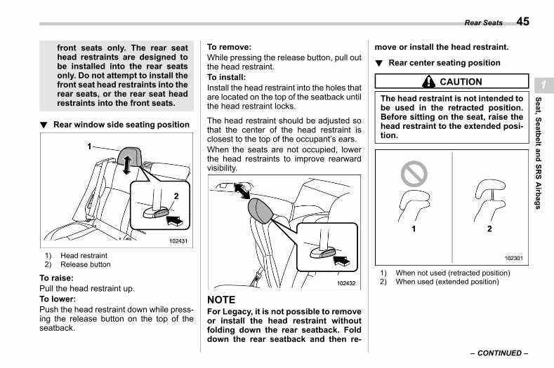
! Rear window side seating positions01ac0301
1) Head restraint2) Release button
To raise:Pull the head restraint up.To lower:Push the head restraint down while press-ing the release button on the top of theseatback.
To remove:While pressing the release button, pull outthe head restraint.To install:Install the head restraint into the holes thatare located on the top of the seatback untilthe head restraint locks.
The head restraint should be adjusted sothat the center of the head restraint isclosest to the top of the occupant’s ears.When the seats are not occupied, lowerthe head restraints to improve rearwardvisibility.
NOTEFor Legacy, it is not possible to removeor install the head restraint withoutfolding down the rear seatback. Folddown the rear seatback and then re-
move or install the head restraint.
! Rear center seating positions01ac0302
CAUTION
The head restraint is not intended tobe used in the retracted position.Before sitting on the seat, raise thehead restraint to the extended posi-tion.
1) When not used (retracted position)2) When used (extended position)
– CONTINUED –
Rear Seats 45
1
Seat,SeatbeltandSR
SAirbags
(48,1)
北米Model "A2600BE-B" EDITED: 2020/ 10/ 1
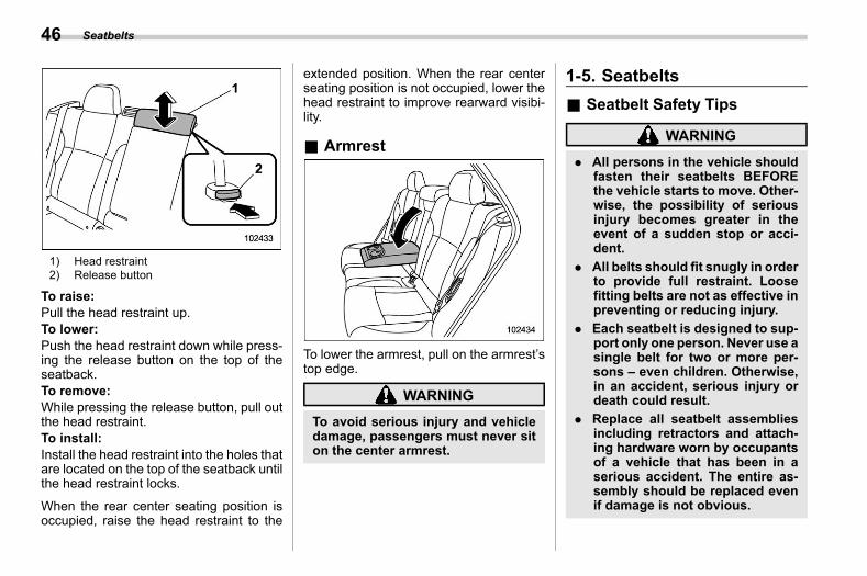
1) Head restraint2) Release button
To raise:Pull the head restraint up.To lower:Push the head restraint down while press-ing the release button on the top of theseatback.To remove:While pressing the release button, pull outthe head restraint.To install:Install the head restraint into the holes thatare located on the top of the seatback untilthe head restraint locks.
When the rear center seating position isoccupied, raise the head restraint to the
extended position. When the rear centerseating position is not occupied, lower thehead restraint to improve rearward visibi-lity.
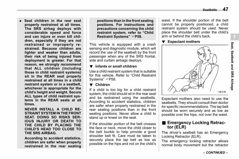
& Armrests01ac01
To lower the armrest, pull on the armrest’stop edge.
WARNING
To avoid serious injury and vehicledamage, passengers must never siton the center armrest.
1-5. Seatbeltss01ae
& Seatbelt Safety Tipss01ae01
WARNING
. All persons in the vehicle shouldfasten their seatbelts BEFOREthe vehicle starts to move. Other-wise, the possibility of seriousinjury becomes greater in theevent of a sudden stop or acci-dent.
. All belts should fit snugly in orderto provide full restraint. Loosefitting belts are not as effective inpreventing or reducing injury.
. Each seatbelt is designed to sup-port only one person. Never use asingle belt for two or more per-sons – even children. Otherwise,in an accident, serious injury ordeath could result.
. Replace all seatbelt assembliesincluding retractors and attach-ing hardware worn by occupantsof a vehicle that has been in aserious accident. The entire as-sembly should be replaced evenif damage is not obvious.
Seatbelts46
(49,1)
北米Model "A2600BE-B" EDITED: 2020/ 10/ 1
. Seat children in the rear seatproperly restrained at all times.The SRS airbag deploys withconsiderable speed and forceand can injure or even kill chil-dren, especially if they are notrestrained or improperly re-strained. Because children arelighter and weaker than adults,their risk of being injured fromdeployment is greater. For thatreason, we strongly recommendthat ALL children (includingthose in child restraint systems)sit in the REAR seat properlyrestrained at all times in a childrestraint system or in a seatbelt,whichever is appropriate for thechild’s height and weight. SecureALL types of child restraint sys-tems in the REAR seats at alltimes.NEVER INSTALL A CHILD RE-STRAINTSYSTEM INTHEFRONTSEAT. DOING SO RISKS SER-IOUS INJURY OR DEATH TOTHE CHILD BY PLACING THECHILD’S HEAD TOO CLOSE TOTHE SRS AIRBAG.According to accident statistics,children are safer when properlyrestrained in the rear seating
positions than in the front seatingpositions. For instructions andprecautions concerning the childrestraint system, refer to “ChildRestraint Systems” FP58.
This vehicle is equipped with a crashsensing and diagnostic module, which willrecord the use of the seatbelt by the frontpassenger when any of the SRS frontal,side and curtain airbags deploys.! Infants or small children
s01ae0101Use a child restraint system that is suitablefor this vehicle. Refer to “Child RestraintSystems” FP58.! Children
s01ae0102If a child is too big for a child restraintsystem, the child should sit in the rear seatand be restrained using the seatbelts.According to accident statistics, childrenare safer when properly restrained in therear seating positions than in the frontseating positions. Never allow a child tostand up or kneel on the seat.
If the shoulder portion of the belt crossesthe face or neck, move the child closer tothe belt buckle to help provide a goodshoulder belt fit. Care must be taken tosecurely place the lap belt as low aspossible on the hips and not on the child’s
waist. If the shoulder portion of the beltcannot be properly positioned, a childrestraint system should be used. Neverplace the shoulder belt under the child’sarm or behind the child’s back.! Expectant mothers
s01ae0103
Expectant mothers also need to use theseatbelts. They should consult their doctorfor specific recommendations. The lap beltshould be worn securely and as low aspossible over the hips, not over the waist.
& Emergency Locking Retrac-tor (ELR)
s01ae02The driver’s seatbelt has an EmergencyLocking Retractor (ELR).The emergency locking retractor allowsnormal body movement but the retractor
– CONTINUED –
Seatbelts 47
1
Seat,SeatbeltandSR
SAirbags
(50,1)
北米Model "A2600BE-B" EDITED: 2020/ 10/ 1
locks automatically during a sudden stop,impact or if you pull the belt very quicklyout of the retractor.
& Automatic LockingRetractor/Emergency Locking Retrac-tor (ALR/ELR)
s01ae03Each passenger’s seatbelt has an Auto-matic Locking Retractor/Emergency Lock-ing Retractor (ALR/ELR). The AutomaticLocking Retractor/Emergency LockingRetractor normally functions as an Emer-gency Locking Retractor (ELR). The ALR/ELR has an additional locking mode,“Automatic Locking Retractor (ALR)mode”, intended to secure a child restraintsystem.
The ALR mode functions as follows.When the seatbelt is once drawn outcompletely and is then retracted evenslightly, the retractor locks the seatbelt inthat position and the seatbelt cannot beextended. As the belt is rewinding, clickswill be heard which indicate the retractorfunctions as an ALR. When the seatbelt isretracted fully, the ALR mode is canceledand the ELR mode is restored.
When securing a child restraint system onthe rear seats by using a seatbelt, theseatbelt must be changed over to theAutomatic Locking Retractor (ALR) mode.
For instructions on how to install the childrestraint system using a seatbelt, refer to“Installing Child Restraint Systems withALR/ELR Seatbelt” FP63.
When the child restraint system is re-moved, make sure that the retractor isrestored to the Emergency Locking Re-tractor (ELR) mode by allowing the seat-belt to retract fully.
& Seatbelt Warning Lightand Chime s01ae04
Refer to “Seatbelt Warning Light andChime” FP177.
& Fastening the Seatbelts01ae06
WARNING
. Never use a belt that is twisted orreversed. In an accident, this canincrease the risk or severity ofinjury.
. Keep the lap belt as low aspossible on your hips. In a colli-sion, this spreads the force of thelap belt over stronger hip bonesinstead of across the weakerabdomen.
. Seatbelts provide maximum re-straint when the occupant sits
well back and upright in the seat.To reduce the risk of slidingunder the seatbelt in a collision,the front seatbacks should bealways used in the upright posi-tion while the vehicle is running.If the front seatbacks are notused in the upright position in acollision, the risk of sliding underthe lap belt and of the lap beltsliding up over the abdomen willincrease, and both can result inserious internal injury or death.
. Do not put cushions or any othermaterials between occupantsand seatbacks or seat cushions.If you do so, the risk of slidingunder the lap belt and of the lapbelt sliding up over the abdomenwill increase, and both can resultin serious internal injury or death.
Seatbelts48
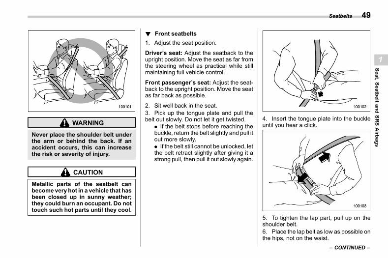
(51,1)
北米Model "A2600BE-B" EDITED: 2020/ 10/ 1
WARNING
Never place the shoulder belt underthe arm or behind the back. If anaccident occurs, this can increasethe risk or severity of injury.
CAUTION
Metallic parts of the seatbelt canbecomevery hot in a vehicle that hasbeen closed up in sunny weather;they could burn an occupant. Do nottouch such hot parts until they cool.
! Front seatbeltss01ae0601
1. Adjust the seat position:
Driver’s seat: Adjust the seatback to theupright position. Move the seat as far fromthe steering wheel as practical while stillmaintaining full vehicle control.
Front passenger’s seat: Adjust the seat-back to the upright position. Move the seatas far back as possible.
2. Sit well back in the seat.3. Pick up the tongue plate and pull thebelt out slowly. Do not let it get twisted.
. If the belt stops before reaching thebuckle, return the belt slightly and pull itout more slowly.. If the belt still cannot be unlocked, letthe belt retract slightly after giving it astrong pull, then pull it out slowly again.
4. Insert the tongue plate into the buckleuntil you hear a click.
5. To tighten the lap part, pull up on theshoulder belt.6. Place the lap belt as low as possible onthe hips, not on the waist.
– CONTINUED –
Seatbelts 49
1
Seat,SeatbeltandSR
SAirbags
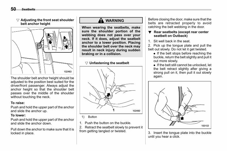
(52,1)
北米Model "A2600BE-B" EDITED: 2020/ 10/ 1
! Adjusting the front seat shoulderbelt anchor height
s01ae060101
The shoulder belt anchor height should beadjusted to the position best suited for thedriver/front passenger. Always adjust theanchor height so that the shoulder beltpasses over the middle of the shoulderwithout touching the neck.
To raise:Push and hold the upper part of the anchorand slide the anchor up.To lower:Push and hold the upper part of the anchorand slide the anchor down.
Pull down the anchor to make sure that it islocked in place.
WARNING
When wearing the seatbelts, makesure the shoulder portion of thewebbing does not pass over yourneck. If it does, adjust the seatbeltanchor to a lower position. Placingthe shoulder belt over the neck mayresult in neck injury during suddenbraking or in a collision.
! Unfastening the seatbelts01ae060102
1) Button
1. Push the button on the buckle.2. Retract the seatbelt slowly to prevent itfrom getting tangled or twisted.
Before closing the door, make sure that thebelts are retracted properly to avoidcatching the belt webbing in the door.! Rear seatbelts (except rear center
seatbelt on Outback)s01ae0602
1. Sit well back in the seat.2. Pick up the tongue plate and pull thebelt out slowly. Do not let it get twisted.
. If the belt stops before reaching thebuckle, return the belt slightly and pull itout more slowly.. If the belt still cannot be unlocked, letthe belt retract slightly after giving astrong pull on it, then pull it out slowlyagain.
3. Insert the tongue plate into the buckleuntil you hear a click.
Seatbelts50
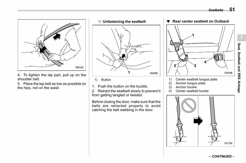
(53,1)
北米Model "A2600BE-B" EDITED: 2020/ 10/ 1
4. To tighten the lap part, pull up on theshoulder belt.5. Place the lap belt as low as possible onthe hips, not on the waist.
! Unfastening the seatbelts01ae060201
1) Button
1. Push the button on the buckle.2. Retract the seatbelt slowly to prevent itfrom getting tangled or twisted.
Before closing the door, make sure that thebelts are retracted properly to avoidcatching the belt webbing in the door.
! Rear center seatbelt on Outbacks01ae0603
1) Center seatbelt tongue plate2) Anchor tongue plate3) Anchor buckle4) Center seatbelt buckle
– CONTINUED –
Seatbelts 51
1
Seat,SeatbeltandSR
SAirbags
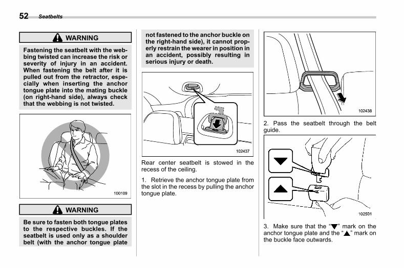
(54,1)
北米Model "A2600BE-B" EDITED: 2020/ 10/ 1
WARNING
Fastening the seatbelt with the web-bing twisted can increase the risk orseverity of injury in an accident.When fastening the belt after it ispulled out from the retractor, espe-cially when inserting the anchortongue plate into the mating buckle(on right-hand side), always checkthat the webbing is not twisted.
WARNING
Be sure to fasten both tongue platesto the respective buckles. If theseatbelt is used only as a shoulderbelt (with the anchor tongue plate
not fastened to the anchor buckle onthe right-hand side), it cannot prop-erly restrain the wearer in position inan accident, possibly resulting inserious injury or death.
Rear center seatbelt is stowed in therecess of the ceiling.
1. Retrieve the anchor tongue plate fromthe slot in the recess by pulling the anchortongue plate.
2. Pass the seatbelt through the beltguide.
3. Make sure that the “ ” mark on theanchor tongue plate and the “ ” mark onthe buckle face outwards.
Seatbelts52
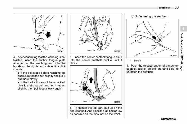
(55,1)
北米Model "A2600BE-B" EDITED: 2020/ 10/ 1
4. After confirming that the webbing is nottwisted, insert the anchor tongue plateattached at the webbing end into thebuckle on the right-hand side until a clicksounds.
. If the belt stops before reaching thebuckle, return the belt slightly and pull itout more slowly.. If the belt still cannot be unlocked,give it a strong pull and let it retractslightly, then pull it out slowly again.
5. Insert the center seatbelt tongue plateinto the center seatbelt buckle until itclicks.
6. To tighten the lap part, pull up on theshoulder belt. And place the lap belt as lowas possible on the hips, not on the waist.
! Unfastening the seatbelts01ae060301
1) Button
1. Push the release button of the centerseatbelt buckle (on the left-hand side) tounfasten the seatbelt.
– CONTINUED –
Seatbelts 53
1
Seat,SeatbeltandSR
SAirbags
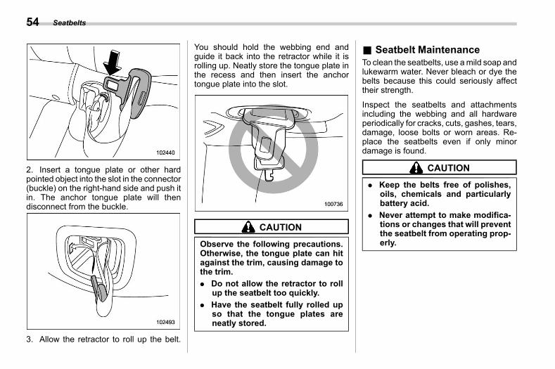
(56,1)
北米Model "A2600BE-B" EDITED: 2020/ 10/ 1
2. Insert a tongue plate or other hardpointed object into the slot in the connector(buckle) on the right-hand side and push itin. The anchor tongue plate will thendisconnect from the buckle.
3. Allow the retractor to roll up the belt.
You should hold the webbing end andguide it back into the retractor while it isrolling up. Neatly store the tongue plate inthe recess and then insert the anchortongue plate into the slot.
CAUTION
Observe the following precautions.Otherwise, the tongue plate can hitagainst the trim, causing damage tothe trim.. Do not allow the retractor to roll
up the seatbelt too quickly.. Have the seatbelt fully rolled up
so that the tongue plates areneatly stored.
& Seatbelt Maintenances01ae07
To clean the seatbelts, use amild soap andlukewarm water. Never bleach or dye thebelts because this could seriously affecttheir strength.
Inspect the seatbelts and attachmentsincluding the webbing and all hardwareperiodically for cracks, cuts, gashes, tears,damage, loose bolts or worn areas. Re-place the seatbelts even if only minordamage is found.
CAUTION
. Keep the belts free of polishes,oils, chemicals and particularlybattery acid.
. Never attempt to make modifica-tions or changes that will preventthe seatbelt from operating prop-erly.
Seatbelts54
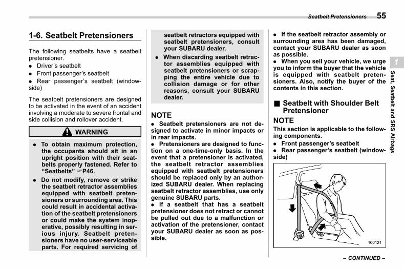
(57,1)
北米Model "A2600BE-B" EDITED: 2020/ 10/ 1
1-6. Seatbelt Pretensionerss01af
The following seatbelts have a seatbeltpretensioner.. Driver’s seatbelt. Front passenger’s seatbelt. Rear passenger’s seatbelt (window-side)
The seatbelt pretensioners are designedto be activated in the event of an accidentinvolving a moderate to severe frontal andside collision and rollover accident.
WARNING
. To obtain maximum protection,the occupants should sit in anupright position with their seat-belts properly fastened. Refer to“Seatbelts” FP46.
. Do not modify, remove or strikethe seatbelt retractor assembliesequipped with seatbelt preten-sioners or surrounding area. Thiscould result in accidental activa-tion of the seatbelt pretensionersor could make the system inop-erative, possibly resulting in ser-ious injury. Seatbelt preten-sioners have no user-serviceableparts. For required servicing of
seatbelt retractors equipped withseatbelt pretensioners, consultyour SUBARU dealer.
. When discarding seatbelt retrac-tor assemblies equipped withseatbelt pretensioners or scrap-ping the entire vehicle due tocollision damage or for otherreasons, consult your SUBARUdealer.
NOTE. Seatbelt pretensioners are not de-signed to activate in minor impacts orin rear impacts.. Pretensioners are designed to func-tion on a one-time-only basis. In theevent that a pretensioner is activated,the seatbelt retractor assembliesequipped with seatbelt pretensionersshould be replaced only by an author-ized SUBARU dealer. When replacingseatbelt retractor assemblies, use onlygenuine SUBARU parts.. If a seatbelt that has a seatbeltpretensioner does not retract or cannotbe pulled out due to a malfunction oractivation of the pretensioner, contactyour SUBARU dealer as soon as pos-sible.
. If the seatbelt retractor assembly orsurrounding area has been damaged,contact your SUBARU dealer as soonas possible.. When you sell your vehicle, we urgeyou to inform the buyer that the vehicleis equipped with seatbelt preten-sioners. Also, notify the buyer of thecontents in this section.
& Seatbelt with Shoulder BeltPretensioner
s01af01NOTEThis section is applicable to the follow-ing components.. Front passenger’s seatbelt. Rear passenger’s seatbelt (window-side)
– CONTINUED –
Seatbelt Pretensioners 55
1
Seat,SeatbeltandSR
SAirbags
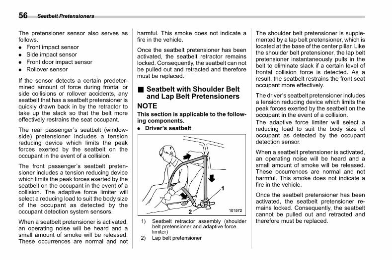
(58,1)
北米Model "A2600BE-B" EDITED: 2020/ 10/ 1
The pretensioner sensor also serves asfollows.. Front impact sensor. Side impact sensor. Front door impact sensor. Rollover sensor
If the sensor detects a certain predeter-mined amount of force during frontal orside collisions or rollover accidents, anyseatbelt that has a seatbelt pretensioner isquickly drawn back in by the retractor totake up the slack so that the belt moreeffectively restrains the seat occupant.
The rear passenger’s seatbelt (window-side) pretensioner includes a tensionreducing device which limits the peakforces exerted by the seatbelt on theoccupant in the event of a collision.
The front passenger’s seatbelt preten-sioner includes a tension reducing devicewhich limits the peak forces exerted by theseatbelt on the occupant in the event of acollision. The adaptive force limiter willselect a reducing load to suit the body sizeof the occupant as detected by theoccupant detection system sensors.
When a seatbelt pretensioner is activated,an operating noise will be heard and asmall amount of smoke will be released.These occurrences are normal and not
harmful. This smoke does not indicate afire in the vehicle.
Once the seatbelt pretensioner has beenactivated, the seatbelt retractor remainslocked. Consequently, the seatbelt can notbe pulled out and retracted and thereforemust be replaced.
& Seatbelt with Shoulder Beltand Lap Belt Pretensioners
s01af02NOTEThis section is applicable to the follow-ing components.. Driver’s seatbelt
1) Seatbelt retractor assembly (shoulderbelt pretensioner and adaptive forcelimiter)
2) Lap belt pretensioner
The shoulder belt pretensioner is supple-mented by a lap belt pretensioner, which islocated at the base of the center pillar. Likethe shoulder belt pretensioner, the lap beltpretensioner instantaneously pulls in thebelt to eliminate slack if a certain level offrontal collision force is detected. As aresult, the seatbelt restrains the front seatoccupant more effectively.
The driver’s seatbelt pretensioner includesa tension reducing device which limits thepeak forces exerted by the seatbelt on theoccupant in the event of a collision.The adaptive force limiter will select areducing load to suit the body size ofoccupant as detected by the occupantdetection sensor.
When a seatbelt pretensioner is activated,an operating noise will be heard and asmall amount of smoke will be released.These occurrences are normal and notharmful. This smoke does not indicate afire in the vehicle.
Once the seatbelt pretensioner has beenactivated, the seatbelt pretensioner re-mains locked. Consequently, the seatbeltcannot be pulled out and retracted andtherefore must be replaced.
Seatbelt Pretensioners56
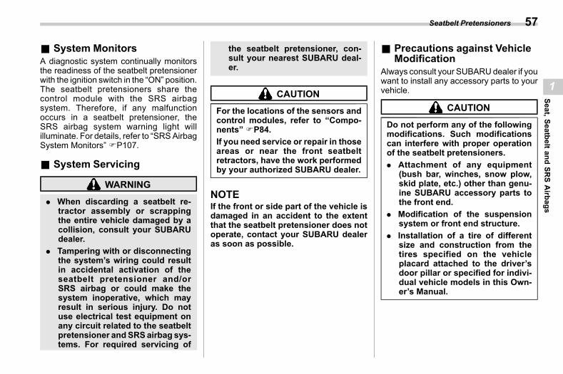
(59,1)
北米Model "A2600BE-B" EDITED: 2020/ 10/ 1
& System Monitorss01af03
A diagnostic system continually monitorsthe readiness of the seatbelt pretensionerwith the ignition switch in the “ON” position.The seatbelt pretensioners share thecontrol module with the SRS airbagsystem. Therefore, if any malfunctionoccurs in a seatbelt pretensioner, theSRS airbag system warning light willilluminate. For details, refer to “SRSAirbagSystem Monitors” FP107.
& System Servicings01af04
WARNING
. When discarding a seatbelt re-tractor assembly or scrappingthe entire vehicle damaged by acollision, consult your SUBARUdealer.
. Tampering with or disconnectingthe system’s wiring could resultin accidental activation of theseatbelt pretensioner and/orSRS airbag or could make thesystem inoperative, which mayresult in serious injury. Do notuse electrical test equipment onany circuit related to the seatbeltpretensioner andSRSairbag sys-tems. For required servicing of
the seatbelt pretensioner, con-sult your nearest SUBARU deal-er.
CAUTION
For the locations of the sensors andcontrol modules, refer to “Compo-nents” FP84.If you need service or repair in thoseareas or near the front seatbeltretractors, have the work performedby your authorized SUBARU dealer.
NOTEIf the front or side part of the vehicle isdamaged in an accident to the extentthat the seatbelt pretensioner does notoperate, contact your SUBARU dealeras soon as possible.
& Precautions against VehicleModification
s01af05Always consult your SUBARUdealer if youwant to install any accessory parts to yourvehicle.
CAUTION
Do not perform any of the followingmodifications. Such modificationscan interfere with proper operationof the seatbelt pretensioners.. Attachment of any equipment
(bush bar, winches, snow plow,skid plate, etc.) other than genu-ine SUBARU accessory parts tothe front end.
. Modification of the suspensionsystem or front end structure.
. Installation of a tire of differentsize and construction from thetires specified on the vehicleplacard attached to the driver’sdoor pillar or specified for indivi-dual vehicle models in this Own-er’s Manual.
Seatbelt Pretensioners 57
1
Seat,SeatbeltandSR
SAirbags
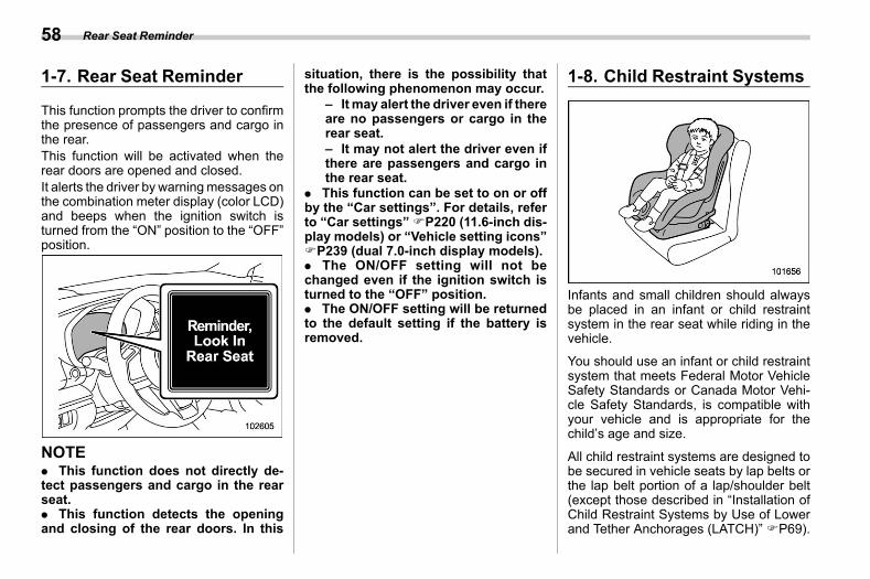
(60,1)
北米Model "A2600BE-B" EDITED: 2020/ 10/ 1
1-7. Rear Seat Reminders01at
This function prompts the driver to confirmthe presence of passengers and cargo inthe rear.This function will be activated when therear doors are opened and closed.It alerts the driver by warningmessages onthe combination meter display (color LCD)and beeps when the ignition switch isturned from the “ON” position to the “OFF”position.
NOTE. This function does not directly de-tect passengers and cargo in the rearseat.. This function detects the openingand closing of the rear doors. In this
situation, there is the possibility thatthe following phenomenon may occur.
– Itmay alert the driver even if thereare no passengers or cargo in therear seat.– It may not alert the driver even ifthere are passengers and cargo inthe rear seat.
. This function can be set to on or offby the “Car settings”. For details, referto “Car settings”FP220 (11.6-inch dis-play models) or “Vehicle setting icons”FP239 (dual 7.0-inch display models).. The ON/OFF setting will not bechanged even if the ignition switch isturned to the “OFF” position.. The ON/OFF setting will be returnedto the default setting if the battery isremoved.
1-8. Child Restraint Systemss01ag
Infants and small children should alwaysbe placed in an infant or child restraintsystem in the rear seat while riding in thevehicle.
You should use an infant or child restraintsystem that meets Federal Motor VehicleSafety Standards or Canada Motor Vehi-cle Safety Standards, is compatible withyour vehicle and is appropriate for thechild’s age and size.
All child restraint systems are designed tobe secured in vehicle seats by lap belts orthe lap belt portion of a lap/shoulder belt(except those described in “Installation ofChild Restraint Systems by Use of Lowerand Tether Anchorages (LATCH)” FP69).
Rear Seat Reminder58
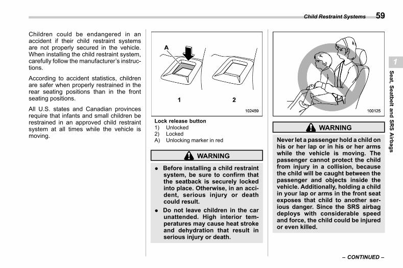
(61,1)
北米Model "A2600BE-B" EDITED: 2020/ 10/ 1
Children could be endangered in anaccident if their child restraint systemsare not properly secured in the vehicle.When installing the child restraint system,carefully follow the manufacturer’s instruc-tions.
According to accident statistics, childrenare safer when properly restrained in therear seating positions than in the frontseating positions.
All U.S. states and Canadian provincesrequire that infants and small children berestrained in an approved child restraintsystem at all times while the vehicle ismoving.
Lock release button1) Unlocked2) LockedA) Unlocking marker in red
WARNING
. Before installing a child restraintsystem, be sure to confirm thatthe seatback is securely lockedinto place. Otherwise, in an acci-dent, serious injury or deathcould result.
. Do not leave children in the carunattended. High interior tem-peratures may cause heat strokeand dehydration that result inserious injury or death.
WARNING
Never let a passenger hold a child onhis or her lap or in his or her armswhile the vehicle is moving. Thepassenger cannot protect the childfrom injury in a collision, becausethe child will be caught between thepassenger and objects inside thevehicle. Additionally, holding a childin your lap or arms in the front seatexposes that child to another ser-ious danger. Since the SRS airbagdeploys with considerable speedand force, the child could be injuredor even killed.
– CONTINUED –
Child Restraint Systems 59
1
Seat,SeatbeltandSR
SAirbags
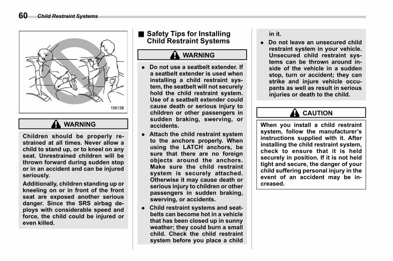
(62,1)
北米Model "A2600BE-B" EDITED: 2020/ 10/ 1
WARNING
Children should be properly re-strained at all times. Never allow achild to stand up, or to kneel on anyseat. Unrestrained children will bethrown forward during sudden stopor in an accident and can be injuredseriously.Additionally, children standing up orkneeling on or in front of the frontseat are exposed another seriousdanger. Since the SRS airbag de-ploys with considerable speed andforce, the child could be injured oreven killed.
& Safety Tips for InstallingChild Restraint Systems
s01ag16
WARNING
. Do not use a seatbelt extender. Ifa seatbelt extender is used wheninstalling a child restraint sys-tem, the seatbelt will not securelyhold the child restraint system.Use of a seatbelt extender couldcause death or serious injury tochildren or other passengers insudden braking, swerving, oraccidents.
. Attach the child restraint systemto the anchors properly. Whenusing the LATCH anchors, besure that there are no foreignobjects around the anchors.Make sure the child restraintsystem is securely attached.Otherwise it may cause death orserious injury to children or otherpassengers in sudden braking,swerving, or accidents.
. Child restraint systems and seat-belts can become hot in a vehiclethat has been closed up in sunnyweather; they could burn a smallchild. Check the child restraintsystem before you place a child
in it.. Do not leave an unsecured child
restraint system in your vehicle.Unsecured child restraint sys-tems can be thrown around in-side of the vehicle in a suddenstop, turn or accident; they canstrike and injure vehicle occu-pants as well as result in seriousinjuries or death to the child.
CAUTION
When you install a child restraintsystem, follow the manufacturer’sinstructions supplied with it. Afterinstalling the child restraint system,check to ensure that it is heldsecurely in position. If it is not heldtight and secure, the danger of yourchild suffering personal injury in theevent of an accident may be in-creased.
Child Restraint Systems60
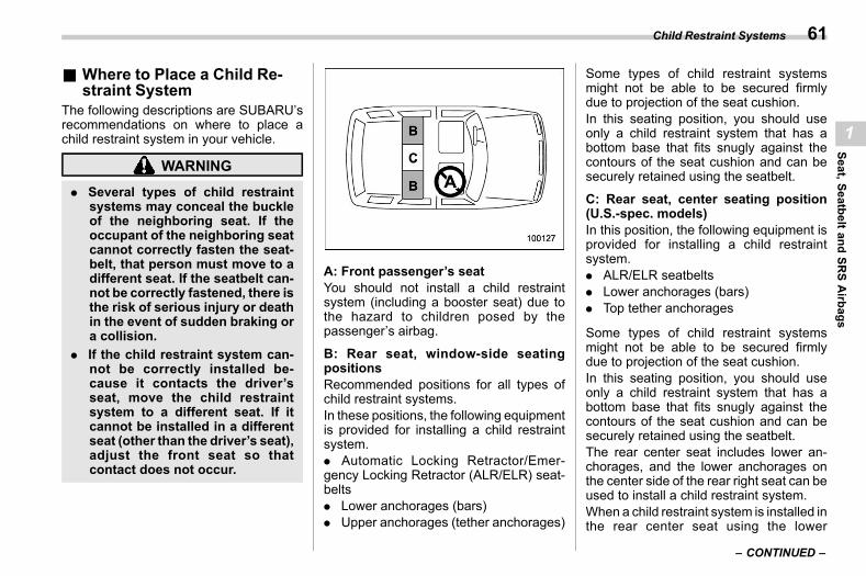
(63,1)
北米Model "A2600BE-B" EDITED: 2020/ 10/ 1
& Where to Place a Child Re-straint System
s01ag01The following descriptions are SUBARU’srecommendations on where to place achild restraint system in your vehicle.
WARNING
. Several types of child restraintsystems may conceal the buckleof the neighboring seat. If theoccupant of the neighboring seatcannot correctly fasten the seat-belt, that person must move to adifferent seat. If the seatbelt can-not be correctly fastened, there isthe risk of serious injury or deathin the event of sudden braking ora collision.
. If the child restraint system can-not be correctly installed be-cause it contacts the driver’sseat, move the child restraintsystem to a different seat. If itcannot be installed in a differentseat (other than the driver’s seat),adjust the front seat so thatcontact does not occur.
A: Front passenger’s seatYou should not install a child restraintsystem (including a booster seat) due tothe hazard to children posed by thepassenger’s airbag.
B: Rear seat, window-side seatingpositionsRecommended positions for all types ofchild restraint systems.In these positions, the following equipmentis provided for installing a child restraintsystem.. Automatic Locking Retractor/Emer-gency Locking Retractor (ALR/ELR) seat-belts. Lower anchorages (bars). Upper anchorages (tether anchorages)
Some types of child restraint systemsmight not be able to be secured firmlydue to projection of the seat cushion.In this seating position, you should useonly a child restraint system that has abottom base that fits snugly against thecontours of the seat cushion and can besecurely retained using the seatbelt.
C: Rear seat, center seating position(U.S.-spec. models)In this position, the following equipment isprovided for installing a child restraintsystem.. ALR/ELR seatbelts. Lower anchorages (bars). Top tether anchorages
Some types of child restraint systemsmight not be able to be secured firmlydue to projection of the seat cushion.In this seating position, you should useonly a child restraint system that has abottom base that fits snugly against thecontours of the seat cushion and can besecurely retained using the seatbelt.The rear center seat includes lower an-chorages, and the lower anchorages onthe center side of the rear right seat can beused to install a child restraint system.When a child restraint system is installed inthe rear center seat using the lower
– CONTINUED –
Child Restraint Systems 61
1
Seat,SeatbeltandSR
SAirbags
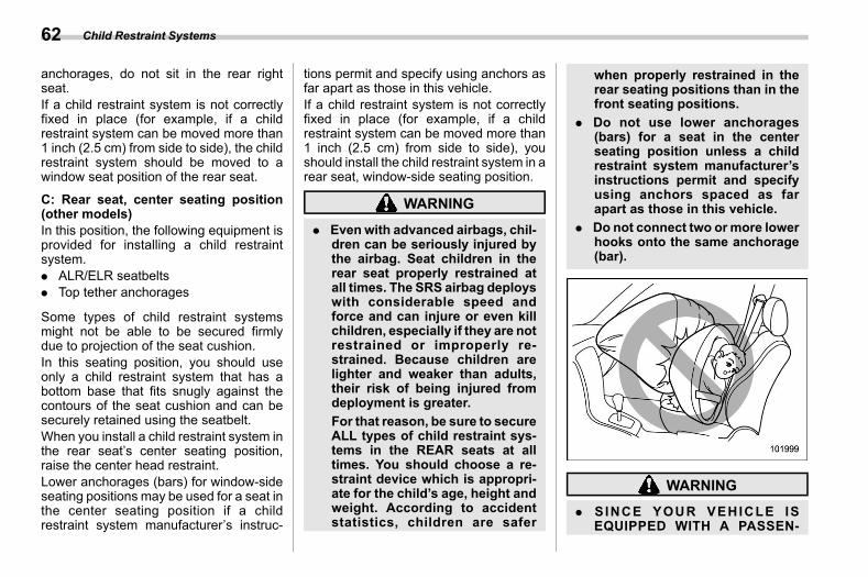
(64,1)
北米Model "A2600BE-B" EDITED: 2020/ 10/ 1
anchorages, do not sit in the rear rightseat.If a child restraint system is not correctlyfixed in place (for example, if a childrestraint system can be moved more than1 inch (2.5 cm) from side to side), the childrestraint system should be moved to awindow seat position of the rear seat.
C: Rear seat, center seating position(other models)In this position, the following equipment isprovided for installing a child restraintsystem.. ALR/ELR seatbelts. Top tether anchorages
Some types of child restraint systemsmight not be able to be secured firmlydue to projection of the seat cushion.In this seating position, you should useonly a child restraint system that has abottom base that fits snugly against thecontours of the seat cushion and can besecurely retained using the seatbelt.When you install a child restraint system inthe rear seat’s center seating position,raise the center head restraint.Lower anchorages (bars) for window-sideseating positions may be used for a seat inthe center seating position if a childrestraint system manufacturer’s instruc-
tions permit and specify using anchors asfar apart as those in this vehicle.If a child restraint system is not correctlyfixed in place (for example, if a childrestraint system can be moved more than1 inch (2.5 cm) from side to side), youshould install the child restraint system in arear seat, window-side seating position.
WARNING
. Evenwith advanced airbags, chil-dren can be seriously injured bythe airbag. Seat children in therear seat properly restrained atall times. The SRS airbag deployswith considerable speed andforce and can injure or even killchildren, especially if they are notrestrained or improperly re-strained. Because children arelighter and weaker than adults,their risk of being injured fromdeployment is greater.For that reason, be sure to secureALL types of child restraint sys-tems in the REAR seats at alltimes. You should choose a re-straint device which is appropri-ate for the child’s age, height andweight. According to accidentstatistics, children are safer
when properly restrained in therear seating positions than in thefront seating positions.
. Do not use lower anchorages(bars) for a seat in the centerseating position unless a childrestraint system manufacturer’sinstructions permit and specifyusing anchors spaced as farapart as those in this vehicle.
. Do not connect two ormore lowerhooks onto the same anchorage(bar).
WARNING
. SINCE YOUR VEHICLE ISEQUIPPED WITH A PASSEN-
Child Restraint Systems62
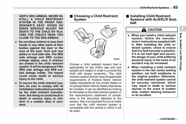
(65,1)
北米Model "A2600BE-B" EDITED: 2020/ 10/ 1
GER’S SRS AIRBAG, NEVER IN-STALL A CHILD RESTRAINTSYSTEM IN THE FRONT PAS-SENGER’S SEAT. DOING SORISKS SERIOUS INJURY ORDEATH TO THE CHILD BY PLA-CING THE CHILD’S HEAD TOOCLOSE TO THE SRS AIRBAG.
. Do not allow children to lean theirheads or any other parts of theirbodies against the door or thearea of the seat, front and rearpillars or roof side rails. The SRSside airbags and SRS curtainairbags deploy even if childrenare seated in the child restraintsystem. It will be dangerous if theSRS side airbags and SRS cur-tain airbags inflate. The impactcould cause death or seriousinjury to the child.
. To secure the child restraint sys-tem, be sure to comply with allinstallation instructions providedby the child restraint manufac-turer. Not doing so could result indeath or serious injury to chil-dren in a sudden stop or acci-dent.
& Choosing a Child RestraintSystem
s01ag02
Choose a child restraint system that isappropriate for the child’s age and size(weight and height) in order to provide thechild with proper protection. The childrestraint system should meet all applicablerequirements of Federal Motor VehicleSafety Standards for the United States orof CanadaMotor Vehicle Safety Standardsfor Canada. It can be identified by lookingfor the label on the child restraint system orthe manufacture’s statement of compli-ance in the document attached to thesystem. Also it is important for you to makesure that the child restraint system iscompatible with the vehicle in which it willbe used.
& Installing Child RestraintSystems with ALR/ELR Seat-belt
s01ag04
CAUTION
. When you install a child restraintsystem, follow the manufac-turer’s instructions supplied withit. After installing the child re-straint system, check to ensurethat it is held securely in position.If it is not held tight and secure,the danger of your child sufferingpersonal injury in the event of anaccident may be increased.
. When installing a child restraintsystem in the rear center seatingposition, set both seatbacks tothe original position. Otherwise,the child restraint system cannotbe securely restrained, whichmay result in death or seriousinjuries in the event of suddenstop, sudden steering maneuveror an accident.
– CONTINUED –
Child Restraint Systems 63
1
Seat,SeatbeltandSR
SAirbags
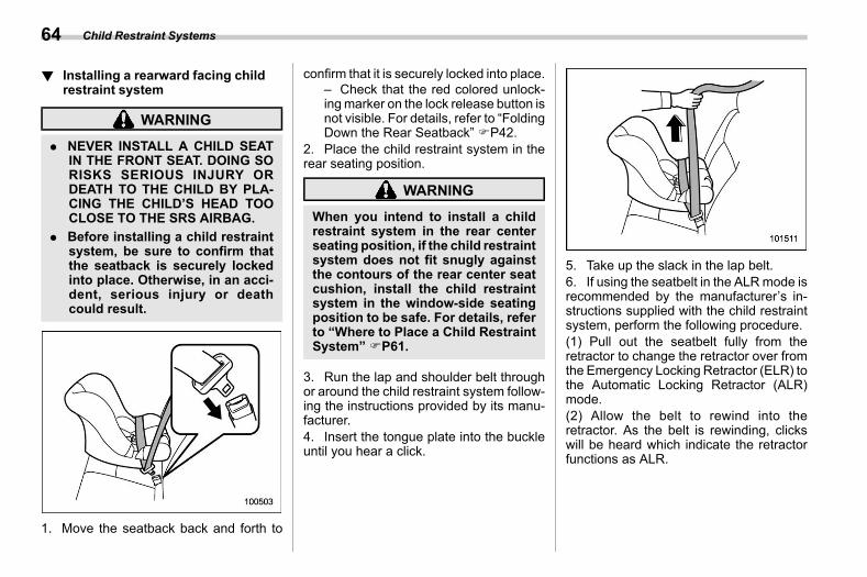
(66,1)
北米Model "A2600BE-B" EDITED: 2020/ 10/ 1
! Installing a rearward facing childrestraint system
s01ag0401
WARNING
. NEVER INSTALL A CHILD SEATIN THE FRONT SEAT. DOING SORISKS SERIOUS INJURY ORDEATH TO THE CHILD BY PLA-CING THE CHILD’S HEAD TOOCLOSE TO THE SRS AIRBAG.
. Before installing a child restraintsystem, be sure to confirm thatthe seatback is securely lockedinto place. Otherwise, in an acci-dent, serious injury or deathcould result.
1. Move the seatback back and forth to
confirm that it is securely locked into place.– Check that the red colored unlock-ingmarker on the lock release button isnot visible. For details, refer to “FoldingDown the Rear Seatback” FP42.
2. Place the child restraint system in therear seating position.
WARNING
When you intend to install a childrestraint system in the rear centerseating position, if the child restraintsystem does not fit snugly againstthe contours of the rear center seatcushion, install the child restraintsystem in the window-side seatingposition to be safe. For details, referto “Where to Place a Child RestraintSystem” FP61.
3. Run the lap and shoulder belt throughor around the child restraint system follow-ing the instructions provided by its manu-facturer.4. Insert the tongue plate into the buckleuntil you hear a click.
5. Take up the slack in the lap belt.6. If using the seatbelt in the ALRmode isrecommended by the manufacturer’s in-structions supplied with the child restraintsystem, perform the following procedure.(1) Pull out the seatbelt fully from theretractor to change the retractor over fromthe Emergency Locking Retractor (ELR) tothe Automatic Locking Retractor (ALR)mode.(2) Allow the belt to rewind into theretractor. As the belt is rewinding, clickswill be heard which indicate the retractorfunctions as ALR.
Child Restraint Systems64
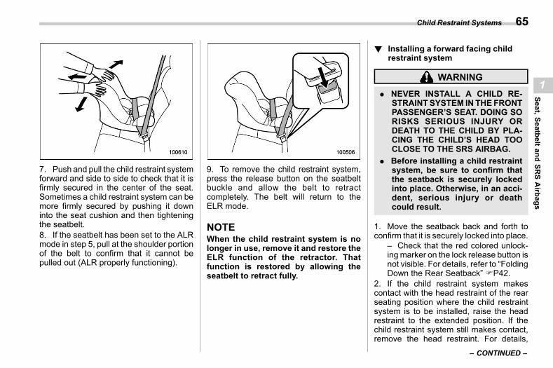
(67,1)
北米Model "A2600BE-B" EDITED: 2020/ 10/ 1
7. Push and pull the child restraint systemforward and side to side to check that it isfirmly secured in the center of the seat.Sometimes a child restraint system can bemore firmly secured by pushing it downinto the seat cushion and then tighteningthe seatbelt.8. If the seatbelt has been set to the ALRmode in step 5, pull at the shoulder portionof the belt to confirm that it cannot bepulled out (ALR properly functioning).
9. To remove the child restraint system,press the release button on the seatbeltbuckle and allow the belt to retractcompletely. The belt will return to theELR mode.
NOTEWhen the child restraint system is nolonger in use, remove it and restore theELR function of the retractor. Thatfunction is restored by allowing theseatbelt to retract fully.
! Installing a forward facing childrestraint system
s01ag0402
WARNING
. NEVER INSTALL A CHILD RE-STRAINTSYSTEM IN THEFRONTPASSENGER’S SEAT. DOING SORISKS SERIOUS INJURY ORDEATH TO THE CHILD BY PLA-CING THE CHILD’S HEAD TOOCLOSE TO THE SRS AIRBAG.
. Before installing a child restraintsystem, be sure to confirm thatthe seatback is securely lockedinto place. Otherwise, in an acci-dent, serious injury or deathcould result.
1. Move the seatback back and forth toconfirm that it is securely locked into place.
– Check that the red colored unlock-ingmarker on the lock release button isnot visible. For details, refer to “FoldingDown the Rear Seatback” FP42.
2. If the child restraint system makescontact with the head restraint of the rearseating position where the child restraintsystem is to be installed, raise the headrestraint to the extended position. If thechild restraint system still makes contact,remove the head restraint. For details,
– CONTINUED –
Child Restraint Systems 65
1
Seat,SeatbeltandSR
SAirbags
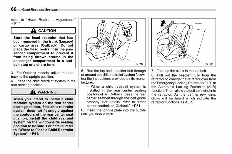
(68,1)
北米Model "A2600BE-B" EDITED: 2020/ 10/ 1
refer to “Head Restraint Adjustment”FP44.
CAUTION
Store the head restraint that hasbeen removed in the trunk (Legacy)or cargo area (Outback). Do notplace the head restraint in the pas-senger compartment to prevent itfrom being thrown around in thepassenger compartment in a sud-den stop or a sharp turn.
3. For Outback models, adjust the seat-back to the upright position.4. Place the child restraint system in therear seating position.
WARNING
When you intend to install a childrestraint system on the rear centerseating position, if the child restraintsystem does not fit snugly againstthe contours of the rear center seatcushion, install the child restraintsystem on the window-side seatingposition to be safe. For details, referto “Where to Place a Child RestraintSystem” FP61.
5. Run the lap and shoulder belt throughor around the child restraint system follow-ing the instructions provided by its manu-facturer.
– When a child restraint system isinstalled in the rear center seatingposition of an Outback, pass the rearcenter seatbelt through the belt guideproperly. For details, refer to “Rearcenter seatbelt on Outback” FP51.
6. Insert the tongue plate into the buckleuntil you hear a click.
7. Take up the slack in the lap belt.8. Pull out the seatbelt fully from theretractor to change the retractor over fromthe Emergency Locking Retractor (ELR) tothe Automatic Locking Retractor (ALR)function. Then, allow the belt to rewind intothe retractor. As the belt is rewinding,clicks will be heard which indicate theretractor functions as ALR.
Child Restraint Systems66
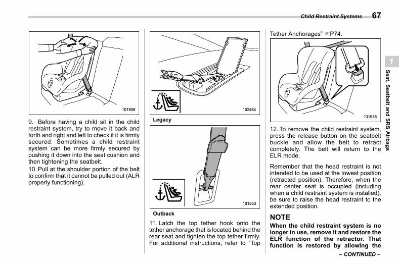
(69,1)
北米Model "A2600BE-B" EDITED: 2020/ 10/ 1
9. Before having a child sit in the childrestraint system, try to move it back andforth and right and left to check if it is firmlysecured. Sometimes a child restraintsystem can be more firmly secured bypushing it down into the seat cushion andthen tightening the seatbelt.10. Pull at the shoulder portion of the beltto confirm that it cannot be pulled out (ALRproperly functioning).
Legacy
Outback
11. Latch the top tether hook onto thetether anchorage that is located behind therear seat and tighten the top tether firmly.For additional instructions, refer to “Top
Tether Anchorages” FP74.
12. To remove the child restraint system,press the release button on the seatbeltbuckle and allow the belt to retractcompletely. The belt will return to theELR mode.
Remember that the head restraint is notintended to be used at the lowest position(retracted position). Therefore, when therear center seat is occupied (includingwhen a child restraint system is installed),be sure to raise the head restraint to theextended position.
NOTEWhen the child restraint system is nolonger in use, remove it and restore theELR function of the retractor. Thatfunction is restored by allowing the
– CONTINUED –
Child Restraint Systems 67
1
Seat,SeatbeltandSR
SAirbags
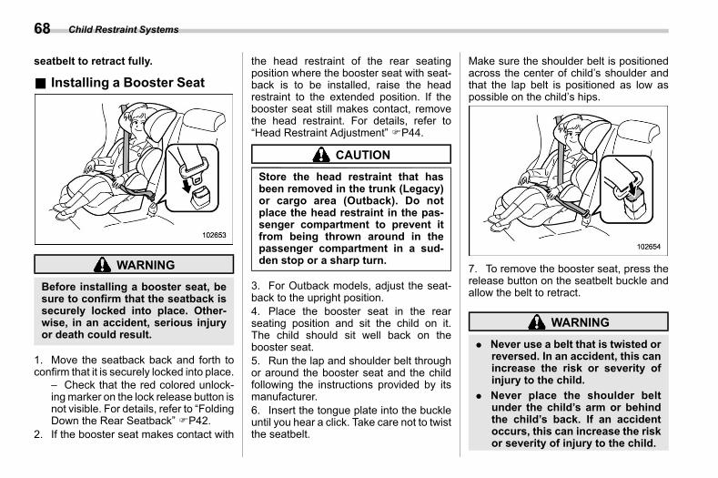
(70,1)
北米Model "A2600BE-B" EDITED: 2020/ 10/ 1
seatbelt to retract fully.
& Installing a Booster Seats01ag05
WARNING
Before installing a booster seat, besure to confirm that the seatback issecurely locked into place. Other-wise, in an accident, serious injuryor death could result.
1. Move the seatback back and forth toconfirm that it is securely locked into place.
– Check that the red colored unlock-ingmarker on the lock release button isnot visible. For details, refer to “FoldingDown the Rear Seatback” FP42.
2. If the booster seat makes contact with
the head restraint of the rear seatingposition where the booster seat with seat-back is to be installed, raise the headrestraint to the extended position. If thebooster seat still makes contact, removethe head restraint. For details, refer to“Head Restraint Adjustment” FP44.
CAUTION
Store the head restraint that hasbeen removed in the trunk (Legacy)or cargo area (Outback). Do notplace the head restraint in the pas-senger compartment to prevent itfrom being thrown around in thepassenger compartment in a sud-den stop or a sharp turn.
3. For Outback models, adjust the seat-back to the upright position.4. Place the booster seat in the rearseating position and sit the child on it.The child should sit well back on thebooster seat.5. Run the lap and shoulder belt throughor around the booster seat and the childfollowing the instructions provided by itsmanufacturer.6. Insert the tongue plate into the buckleuntil you hear a click. Take care not to twistthe seatbelt.
Make sure the shoulder belt is positionedacross the center of child’s shoulder andthat the lap belt is positioned as low aspossible on the child’s hips.
7. To remove the booster seat, press therelease button on the seatbelt buckle andallow the belt to retract.
WARNING
. Never use a belt that is twisted orreversed. In an accident, this canincrease the risk or severity ofinjury to the child.
. Never place the shoulder beltunder the child’s arm or behindthe child’s back. If an accidentoccurs, this can increase the riskor severity of injury to the child.
Child Restraint Systems68
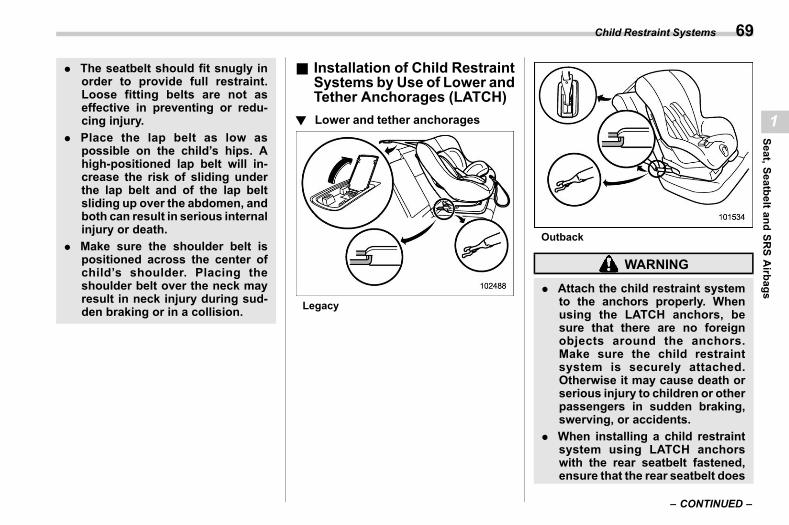
(71,1)
北米Model "A2600BE-B" EDITED: 2020/ 10/ 1
. The seatbelt should fit snugly inorder to provide full restraint.Loose fitting belts are not aseffective in preventing or redu-cing injury.
. Place the lap belt as low aspossible on the child’s hips. Ahigh-positioned lap belt will in-crease the risk of sliding underthe lap belt and of the lap beltsliding up over the abdomen, andboth can result in serious internalinjury or death.
. Make sure the shoulder belt ispositioned across the center ofchild’s shoulder. Placing theshoulder belt over the neck mayresult in neck injury during sud-den braking or in a collision.
& Installation of Child RestraintSystems by Use of Lower andTether Anchorages (LATCH)
s01ag07
! Lower and tether anchoragess01ag0701
Legacy
Outback
WARNING
. Attach the child restraint systemto the anchors properly. Whenusing the LATCH anchors, besure that there are no foreignobjects around the anchors.Make sure the child restraintsystem is securely attached.Otherwise it may cause death orserious injury to children or otherpassengers in sudden braking,swerving, or accidents.
. When installing a child restraintsystem using LATCH anchorswith the rear seatbelt fastened,ensure that the rear seatbelt does
– CONTINUED –
Child Restraint Systems 69
1
Seat,SeatbeltandSR
SAirbags
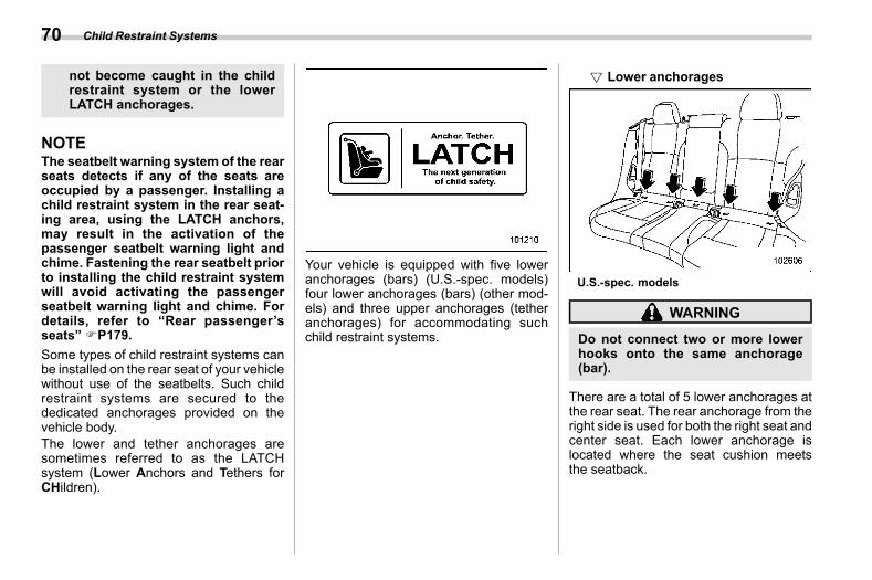
(72,1)
北米Model "A2600BE-B" EDITED: 2020/ 10/ 1
not become caught in the childrestraint system or the lowerLATCH anchorages.
NOTEThe seatbelt warning system of the rearseats detects if any of the seats areoccupied by a passenger. Installing achild restraint system in the rear seat-ing area, using the LATCH anchors,may result in the activation of thepassenger seatbelt warning light andchime. Fastening the rear seatbelt priorto installing the child restraint systemwill avoid activating the passengerseatbelt warning light and chime. Fordetails, refer to “Rear passenger’sseats” FP179.Some types of child restraint systems canbe installed on the rear seat of your vehiclewithout use of the seatbelts. Such childrestraint systems are secured to thededicated anchorages provided on thevehicle body.The lower and tether anchorages aresometimes referred to as the LATCHsystem (Lower Anchors and Tethers forCHildren).
Your vehicle is equipped with five loweranchorages (bars) (U.S.-spec. models)four lower anchorages (bars) (other mod-els) and three upper anchorages (tetheranchorages) for accommodating suchchild restraint systems.
! Lower anchoragess01ag070101
U.S.-spec. models
WARNING
Do not connect two or more lowerhooks onto the same anchorage(bar).
There are a total of 5 lower anchorages atthe rear seat. The rear anchorage from theright side is used for both the right seat andcenter seat. Each lower anchorage islocated where the seat cushion meetsthe seatback.
Child Restraint Systems70
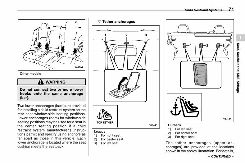
(73,1)
北米Model "A2600BE-B" EDITED: 2020/ 10/ 1
Other models
WARNING
Do not connect two or more lowerhooks onto the same anchorage(bar).
Two lower anchorages (bars) are providedfor installing a child restraint system on therear seat window-side seating positions.Lower anchorages (bars) for window-sideseating positions may be used for a seat inthe center seating position if a childrestraint system manufacturer’s instruc-tions permit and specify using anchors asfar apart as those in this vehicle. Eachlower anchorage is located where the seatcushion meets the seatback.
! Tether anchoragess01ag070102
Legacy1) For right seat2) For center seat3) For left seat
Outback1) For left seat2) For center seat3) For right seat
The tether anchorages (upper an-chorages) are provided at the locationsshown in the above illustration. For details,
– CONTINUED –
Child Restraint Systems 71
1
Seat,SeatbeltandSR
SAirbags
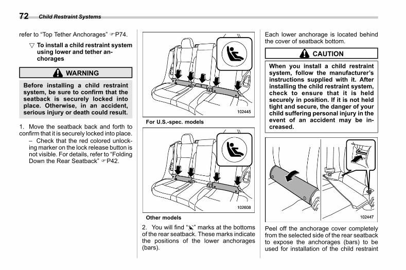
(74,1)
北米Model "A2600BE-B" EDITED: 2020/ 10/ 1
refer to “Top Tether Anchorages” FP74.
! To install a child restraint systemusing lower and tether an-chorages
s01ag070103
WARNING
Before installing a child restraintsystem, be sure to confirm that theseatback is securely locked intoplace. Otherwise, in an accident,serious injury or death could result.
1. Move the seatback back and forth toconfirm that it is securely locked into place.
– Check that the red colored unlock-ingmarker on the lock release button isnot visible. For details, refer to “FoldingDown the Rear Seatback” FP42.
For U.S.-spec. models
Other models
2. You will find “ ” marks at the bottomsof the rear seatback. Thesemarks indicatethe positions of the lower anchorages(bars).
Each lower anchorage is located behindthe cover of seatback bottom.
CAUTION
When you install a child restraintsystem, follow the manufacturer’sinstructions supplied with it. Afterinstalling the child restraint system,check to ensure that it is heldsecurely in position. If it is not heldtight and secure, the danger of yourchild suffering personal injury in theevent of an accident may be in-creased.
Peel off the anchorage cover completelyfrom the selected side of the rear seatbackto expose the anchorages (bars) to beused for installation of the child restraint
Child Restraint Systems72
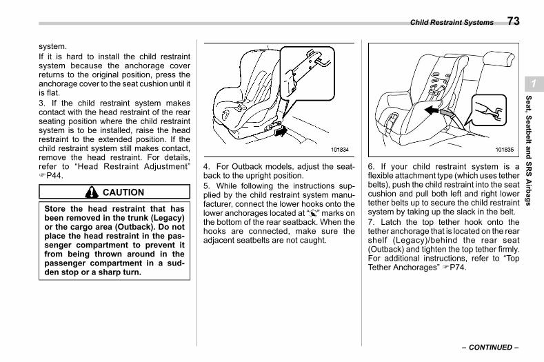
(75,1)
北米Model "A2600BE-B" EDITED: 2020/ 10/ 1
system.If it is hard to install the child restraintsystem because the anchorage coverreturns to the original position, press theanchorage cover to the seat cushion until itis flat.3. If the child restraint system makescontact with the head restraint of the rearseating position where the child restraintsystem is to be installed, raise the headrestraint to the extended position. If thechild restraint system still makes contact,remove the head restraint. For details,refer to “Head Restraint Adjustment”FP44.
CAUTION
Store the head restraint that hasbeen removed in the trunk (Legacy)or the cargo area (Outback). Do notplace the head restraint in the pas-senger compartment to prevent itfrom being thrown around in thepassenger compartment in a sud-den stop or a sharp turn.
4. For Outback models, adjust the seat-back to the upright position.5. While following the instructions sup-plied by the child restraint system manu-facturer, connect the lower hooks onto thelower anchorages located at “ ” marks onthe bottom of the rear seatback. When thehooks are connected, make sure theadjacent seatbelts are not caught.
6. If your child restraint system is aflexible attachment type (which uses tetherbelts), push the child restraint into the seatcushion and pull both left and right lowertether belts up to secure the child restraintsystem by taking up the slack in the belt.7. Latch the top tether hook onto thetether anchorage that is located on the rearshelf (Legacy)/behind the rear seat(Outback) and tighten the top tether firmly.For additional instructions, refer to “TopTether Anchorages” FP74.
– CONTINUED –
Child Restraint Systems 73
1
Seat,SeatbeltandSR
SAirbags
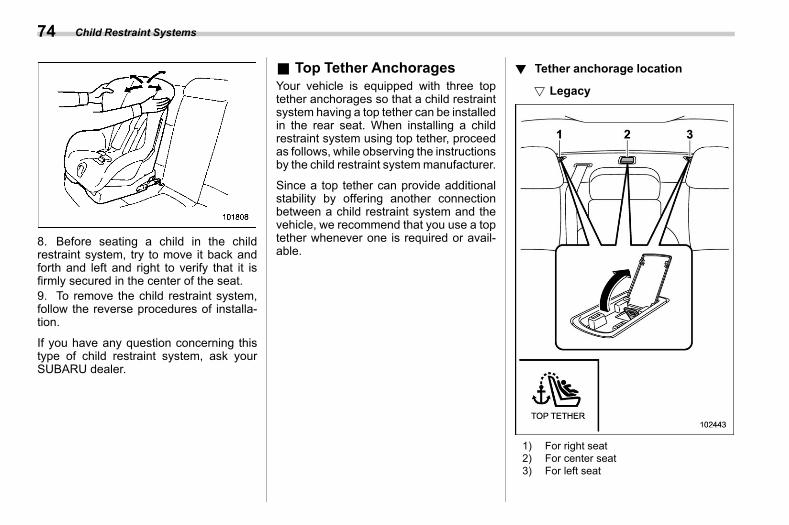
(76,1)
北米Model "A2600BE-B" EDITED: 2020/ 10/ 1
8. Before seating a child in the childrestraint system, try to move it back andforth and left and right to verify that it isfirmly secured in the center of the seat.9. To remove the child restraint system,follow the reverse procedures of installa-tion.
If you have any question concerning thistype of child restraint system, ask yourSUBARU dealer.
& Top Tether Anchoragess01ag09
Your vehicle is equipped with three toptether anchorages so that a child restraintsystem having a top tether can be installedin the rear seat. When installing a childrestraint system using top tether, proceedas follows, while observing the instructionsby the child restraint systemmanufacturer.
Since a top tether can provide additionalstability by offering another connectionbetween a child restraint system and thevehicle, we recommend that you use a toptether whenever one is required or avail-able.
! Tether anchorage locations01ag0901
! Legacys01ag090101
1) For right seat2) For center seat3) For left seat
Child Restraint Systems74
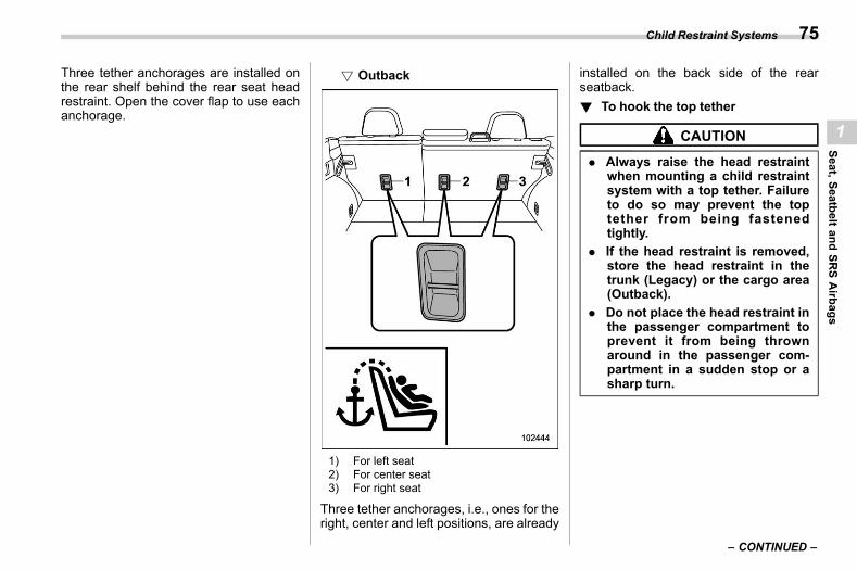
(77,1)
北米Model "A2600BE-B" EDITED: 2020/ 10/ 1
Three tether anchorages are installed onthe rear shelf behind the rear seat headrestraint. Open the cover flap to use eachanchorage.
! Outbacks01ag090102
1) For left seat2) For center seat3) For right seat
Three tether anchorages, i.e., ones for theright, center and left positions, are already
installed on the back side of the rearseatback.! To hook the top tether
s01ag0902
CAUTION
. Always raise the head restraintwhen mounting a child restraintsystem with a top tether. Failureto do so may prevent the toptether from being fastenedtightly.
. If the head restraint is removed,store the head restraint in thetrunk (Legacy) or the cargo area(Outback).
. Do not place the head restraint inthe passenger compartment toprevent it from being thrownaround in the passenger com-partment in a sudden stop or asharp turn.
– CONTINUED –
Child Restraint Systems 75
1
Seat,SeatbeltandSR
SAirbags
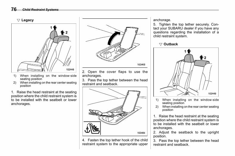
(78,1)
北米Model "A2600BE-B" EDITED: 2020/ 10/ 1
! Legacys01ag090201
1) When installing on the window-sideseating position
2) When installing on the rear center seatingposition
1. Raise the head restraint at the seatingposition where the child restraint system isto be installed with the seatbelt or loweranchorages.
2. Open the cover flaps to use theanchorages.3. Pass the top tether between the headrestraint and seatback.
4. Fasten the top tether hook of the childrestraint system to the appropriate upper
anchorage.5. Tighten the top tether securely. Con-tact your SUBARU dealer if you have anyquestions regarding the installation of achild restraint system.
! Outbacks01ag090202
1) When installing on the window-sideseating position
2) When installing on the rear center seatingposition
1. Raise the head restraint at the seatingposition where the child restraint system isto be installed with the seatbelt or loweranchorages.2. Adjust the seatback to the uprightposition.3. Pass the top tether between the headrestraint and seatback.
Child Restraint Systems76
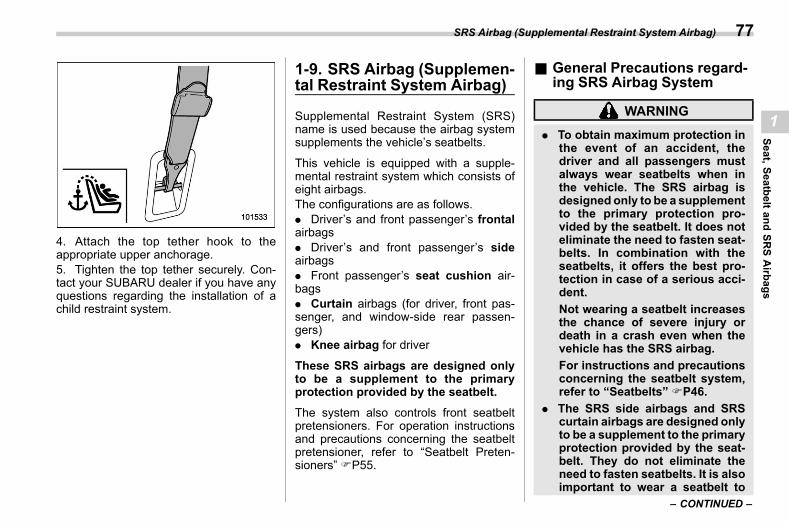
(79,1)
北米Model "A2600BE-B" EDITED: 2020/ 10/ 1
4. Attach the top tether hook to theappropriate upper anchorage.5. Tighten the top tether securely. Con-tact your SUBARU dealer if you have anyquestions regarding the installation of achild restraint system.
1-9. SRS Airbag (Supplemen-tal Restraint System Airbag)
s01ah
Supplemental Restraint System (SRS)name is used because the airbag systemsupplements the vehicle’s seatbelts.
This vehicle is equipped with a supple-mental restraint system which consists ofeight airbags.The configurations are as follows.. Driver’s and front passenger’s frontalairbags. Driver’s and front passenger’s sideairbags. Front passenger’s seat cushion air-bags. Curtain airbags (for driver, front pas-senger, and window-side rear passen-gers). Knee airbag for driver
These SRS airbags are designed onlyto be a supplement to the primaryprotection provided by the seatbelt.The system also controls front seatbeltpretensioners. For operation instructionsand precautions concerning the seatbeltpretensioner, refer to “Seatbelt Preten-sioners” FP55.
& General Precautions regard-ing SRS Airbag System
s01ah10
WARNING
. To obtain maximum protection inthe event of an accident, thedriver and all passengers mustalways wear seatbelts when inthe vehicle. The SRS airbag isdesigned only to be a supplementto the primary protection pro-vided by the seatbelt. It does noteliminate the need to fasten seat-belts. In combination with theseatbelts, it offers the best pro-tection in case of a serious acci-dent.Not wearing a seatbelt increasesthe chance of severe injury ordeath in a crash even when thevehicle has the SRS airbag.For instructions and precautionsconcerning the seatbelt system,refer to “Seatbelts” FP46.
. The SRS side airbags and SRScurtain airbags are designed onlyto be a supplement to the primaryprotection provided by the seat-belt. They do not eliminate theneed to fasten seatbelts. It is alsoimportant to wear a seatbelt to
– CONTINUED –
SRS Airbag (Supplemental Restraint System Airbag) 77
1
Seat,SeatbeltandSR
SAirbags
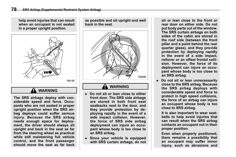
(80,1)
北米Model "A2600BE-B" EDITED: 2020/ 10/ 1
help avoid injuries that can resultwhen an occupant is not seatedin a proper upright position.
WARNING
The SRS airbags deploy with con-siderable speed and force. Occu-pants who are not seated in properupright position when the SRS air-bag deploys could suffer seriousinjury. Because the SRS airbagneeds enough space for deploy-ment, the driver should always situpright and back in the seat as farfrom the steering wheel as practicalwhile still maintaining full vehiclecontrol, and the front passengershould move the seat as far back
as possible and sit upright and wellback in the seat.
WARNING
. Do not sit or lean close to eitherfront door. The SRS side airbagsare stored in both front seatseatbacks next to the door, andthey provide protection by de-ploying rapidly in the event of aside impact collision. However,the force of SRS side airbagdeployment can injure an occu-pant whose body is too close toan SRS airbag.
. Since your vehicle is equippedwith SRS curtain airbags, do not
sit or lean close to the front orrear door on either side. Do notput body parts out of the window.The SRS curtain airbags on bothsides of the cabin are stored inthe roof side (between the frontpillar and a point behind the rearquarter glass), and they provideprotection by deploying rapidlyin the event of a side impact,rollover or an offset frontal colli-sion. However, the force of itsdeployment can injure an occu-pant whose body is too close toan SRS airbag.
. Do not sit or lean unnecessarilyclose to the SRS airbag. Becausethe SRS airbag deploys withconsiderable speed and force toprotect in high speed collisions,the force of an airbag can injurean occupant whose body is tooclose to SRS airbag.It is also important to wear seat-belts to help avoid injuries thatcan result when the SRS airbagcontacts an occupant not in theirproper position.Even when properly positioned,there remains a possibility thatan occupant may suffer minorinjury, such as abrasions and
SRS Airbag (Supplemental Restraint System Airbag)78
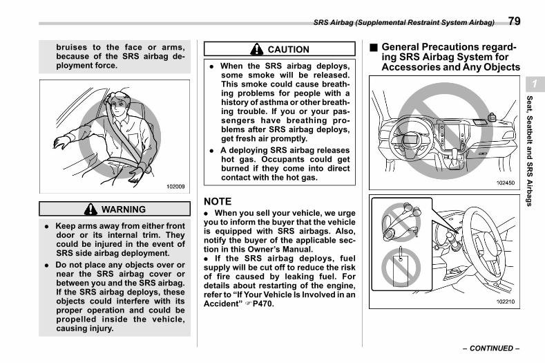
(81,1)
北米Model "A2600BE-B" EDITED: 2020/ 10/ 1
bruises to the face or arms,because of the SRS airbag de-ployment force.
WARNING
. Keep arms away from either frontdoor or its internal trim. Theycould be injured in the event ofSRS side airbag deployment.
. Do not place any objects over ornear the SRS airbag cover orbetween you and the SRS airbag.If the SRS airbag deploys, theseobjects could interfere with itsproper operation and could bepropelled inside the vehicle,causing injury.
CAUTION
. When the SRS airbag deploys,some smoke will be released.This smoke could cause breath-ing problems for people with ahistory of asthma or other breath-ing trouble. If you or your pas-sengers have breathing pro-blems after SRS airbag deploys,get fresh air promptly.
. A deploying SRS airbag releaseshot gas. Occupants could getburned if they come into directcontact with the hot gas.
NOTE. When you sell your vehicle, we urgeyou to inform the buyer that the vehicleis equipped with SRS airbags. Also,notify the buyer of the applicable sec-tion in this Owner’s Manual.. If the SRS airbag deploys, fuelsupply will be cut off to reduce the riskof fire caused by leaking fuel. Fordetails about restarting of the engine,refer to “If Your Vehicle Is Involved in anAccident” FP470.
& General Precautions regard-ing SRS Airbag System forAccessories andAnyObjects
s01ah13
– CONTINUED –
SRS Airbag (Supplemental Restraint System Airbag) 79
1
Seat,SeatbeltandSR
SAirbags
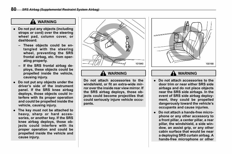
(82,1)
北米Model "A2600BE-B" EDITED: 2020/ 10/ 1
WARNING
. Do not put any objects (includingstraps or cord) over the steeringwheel pad, column cover, ordashboard.– These objects could be en-
tangled with the steeringwheel, preventing the SRSfrontal airbag, etc. from oper-ating properly.
– If the SRS frontal airbag de-ploys, these objects could bepropelled inside the vehicle,causing injury.
. Do not put any objects under thedriver’s side of the instrumentpanel. If the SRS knee airbagdeploys, those objects could in-terfere with its proper operationand could be propelled inside thevehicle, causing injury.
. The key must not be attached toheavy, sharp or hard acces-sories, or another key. If the SRSknee airbag deploys, those ob-jects could interfere with itsproper operation and could bepropelled inside the vehicle andcause injury.
WARNING
Do not attach accessories to thewindshield, or fit an extra-wide mir-ror over the inside rear viewmirror. Ifthe SRS airbag deploys, those ob-jects could become projectiles thatcould seriously injure vehicle occu-pants.
WARNING
. Do not attach accessories to thedoor trim or near either SRS sideairbags and do not place objectsnear the SRS side airbags. In theevent of SRS side airbag deploy-ment, they could be propelleddangerously toward the vehicle’soccupants and cause injuries.
. Do not attach a hands-free micro-phone or any other accessory toa front pillar, a center pillar, a rearpillar, the windshield, a side win-dow, an assist grip, or any othercabin surface that would be neara deploying SRS curtain airbag. Ahands-free microphone or other
SRS Airbag (Supplemental Restraint System Airbag)80
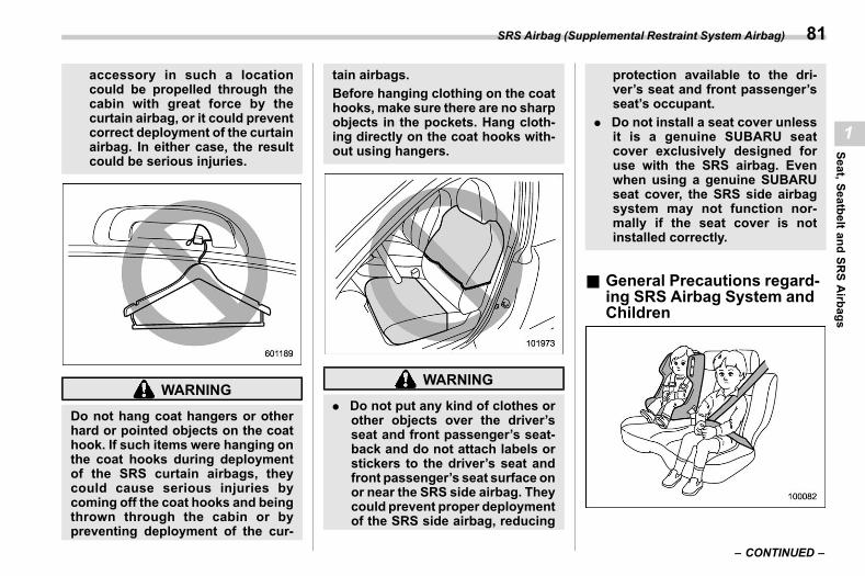
(83,1)
北米Model "A2600BE-B" EDITED: 2020/ 10/ 1
accessory in such a locationcould be propelled through thecabin with great force by thecurtain airbag, or it could preventcorrect deployment of the curtainairbag. In either case, the resultcould be serious injuries.
WARNING
Do not hang coat hangers or otherhard or pointed objects on the coathook. If such items were hanging onthe coat hooks during deploymentof the SRS curtain airbags, theycould cause serious injuries bycoming off the coat hooks and beingthrown through the cabin or bypreventing deployment of the cur-
tain airbags.Before hanging clothing on the coathooks, make sure there are no sharpobjects in the pockets. Hang cloth-ing directly on the coat hooks with-out using hangers.
WARNING
. Do not put any kind of clothes orother objects over the driver’sseat and front passenger’s seat-back and do not attach labels orstickers to the driver’s seat andfront passenger’s seat surface onor near the SRS side airbag. Theycould prevent proper deploymentof the SRS side airbag, reducing
protection available to the dri-ver’s seat and front passenger’sseat’s occupant.
. Do not install a seat cover unlessit is a genuine SUBARU seatcover exclusively designed foruse with the SRS airbag. Evenwhen using a genuine SUBARUseat cover, the SRS side airbagsystem may not function nor-mally if the seat cover is notinstalled correctly.
& General Precautions regard-ing SRS Airbag System andChildren
s01ah14
– CONTINUED –
SRS Airbag (Supplemental Restraint System Airbag) 81
1
Seat,SeatbeltandSR
SAirbags
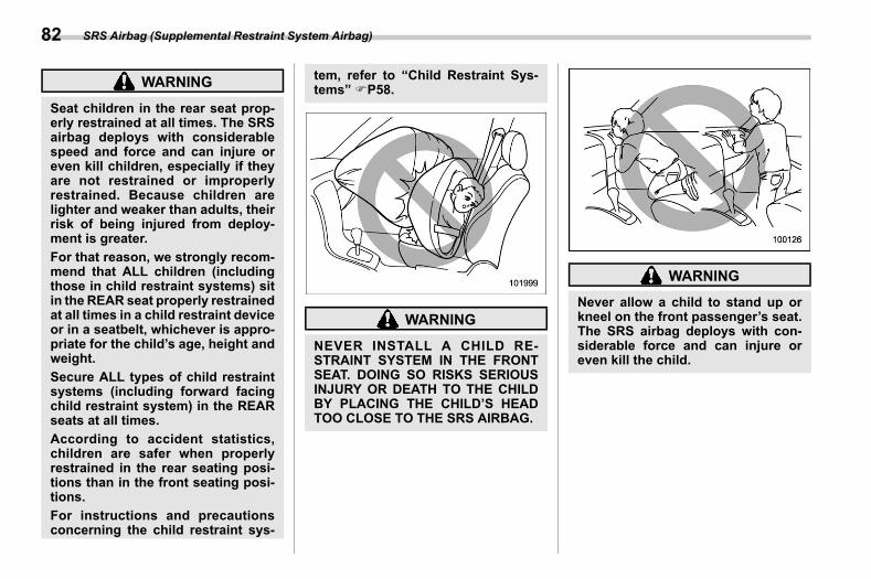
(84,1)
北米Model "A2600BE-B" EDITED: 2020/ 10/ 1
WARNING
Seat children in the rear seat prop-erly restrained at all times. The SRSairbag deploys with considerablespeed and force and can injure oreven kill children, especially if theyare not restrained or improperlyrestrained. Because children arelighter and weaker than adults, theirrisk of being injured from deploy-ment is greater.For that reason, we strongly recom-mend that ALL children (includingthose in child restraint systems) sitin the REAR seat properly restrainedat all times in a child restraint deviceor in a seatbelt, whichever is appro-priate for the child’s age, height andweight.Secure ALL types of child restraintsystems (including forward facingchild restraint system) in the REARseats at all times.According to accident statistics,children are safer when properlyrestrained in the rear seating posi-tions than in the front seating posi-tions.For instructions and precautionsconcerning the child restraint sys-
tem, refer to “Child Restraint Sys-tems” FP58.
WARNING
NEVER INSTALL A CHILD RE-STRAINT SYSTEM IN THE FRONTSEAT. DOING SO RISKS SERIOUSINJURY OR DEATH TO THE CHILDBY PLACING THE CHILD’S HEADTOO CLOSE TO THE SRS AIRBAG.
WARNING
Never allow a child to stand up orkneel on the front passenger’s seat.The SRS airbag deploys with con-siderable force and can injure oreven kill the child.
SRS Airbag (Supplemental Restraint System Airbag)82
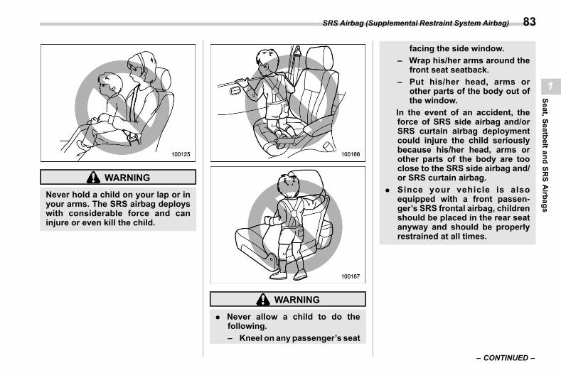
(85,1)
北米Model "A2600BE-B" EDITED: 2020/ 10/ 1
WARNING
Never hold a child on your lap or inyour arms. The SRS airbag deployswith considerable force and caninjure or even kill the child.
WARNING
. Never allow a child to do thefollowing.– Kneel on any passenger’s seat
facing the side window.– Wrap his/her arms around the
front seat seatback.– Put his/her head, arms or
other parts of the body out ofthe window.
In the event of an accident, theforce of SRS side airbag and/orSRS curtain airbag deploymentcould injure the child seriouslybecause his/her head, arms orother parts of the body are tooclose to the SRS side airbag and/or SRS curtain airbag.
. Since your vehicle is alsoequipped with a front passen-ger’s SRS frontal airbag, childrenshould be placed in the rear seatanyway and should be properlyrestrained at all times.
– CONTINUED –
SRS Airbag (Supplemental Restraint System Airbag) 83
1
Seat,SeatbeltandSR
SAirbags
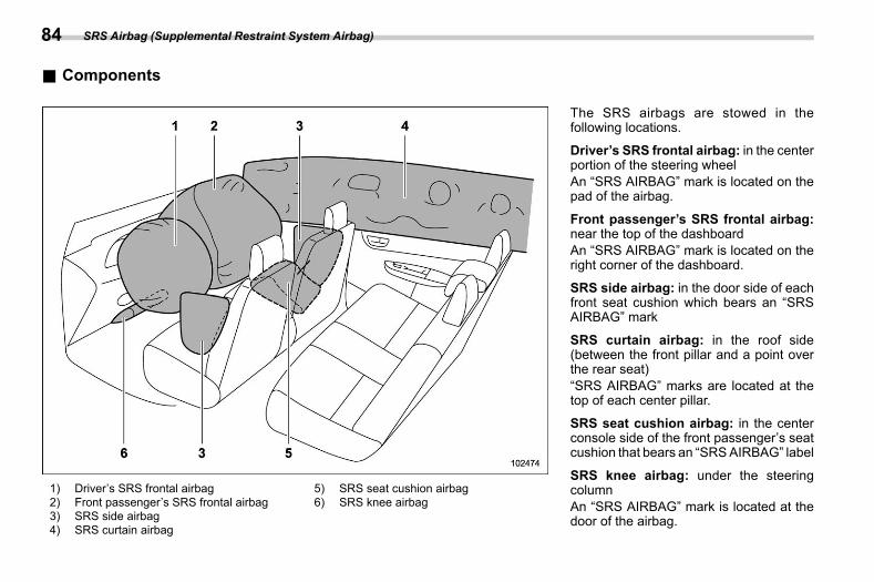
(86,1)
北米Model "A2600BE-B" EDITED: 2020/ 10/ 1
& Componentss01ah11
1) Driver’s SRS frontal airbag2) Front passenger’s SRS frontal airbag3) SRS side airbag4) SRS curtain airbag
5) SRS seat cushion airbag6) SRS knee airbag
The SRS airbags are stowed in thefollowing locations.
Driver’s SRS frontal airbag: in the centerportion of the steering wheelAn “SRS AIRBAG” mark is located on thepad of the airbag.
Front passenger’s SRS frontal airbag:near the top of the dashboardAn “SRS AIRBAG” mark is located on theright corner of the dashboard.
SRS side airbag: in the door side of eachfront seat cushion which bears an “SRSAIRBAG” mark
SRS curtain airbag: in the roof side(between the front pillar and a point overthe rear seat)“SRS AIRBAG” marks are located at thetop of each center pillar.
SRS seat cushion airbag: in the centerconsole side of the front passenger’s seatcushion that bears an “SRSAIRBAG” label
SRS knee airbag: under the steeringcolumnAn “SRS AIRBAG” mark is located at thedoor of the airbag.
SRS Airbag (Supplemental Restraint System Airbag)84
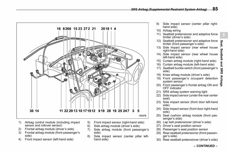
(87,1)
北米Model "A2600BE-B" EDITED: 2020/ 10/ 1
1) Airbag control module (including impactsensor and rollover sensor)
2) Frontal airbag module (driver’s side)3) Frontal airbag module (front passenger’s
side)4) Front impact sensor (left-hand side)
5) Front impact sensor (right-hand side)6) Side airbag module (driver’s side)7) Side airbag module (front passenger’s
side)8) Side impact sensor (center pillar left-
hand side)
9) Side impact sensor (center pillar right-hand side)
10) Airbag wiring11) Seatbelt pretensioner and adaptive force
limiter (driver’s side)12) Seatbelt pretensioner and adaptive force
limiter (front passenger’s side)13) Side impact sensor (rear wheel house
right-hand side)14) Side impact sensor (rear wheel house
left-hand side)15) Curtain airbag module (right-hand side)16) Curtain airbag module (left-hand side)17) Seatbelt buckle switch (front passenger’s
side)18) Knee airbag module (driver’s side)19) Front passenger’s occupant detection
system sensor20) Front passenger’s frontal airbag ON and
OFF indicator21) SRS airbag system warning light22) Side impact sensor (under the rear center
seat)23) Side impact sensor (front door left-hand
side)24) Side impact sensor (front door right-hand
side)25) Seat cushion airbag module (front pas-
senger’s side)26) Lap belt pretensioner (driver’s side)27) Driver’s seat position sensor28) Passenger’s seat position sensor29) Rear seatbelt pretensioner (front passen-
ger’s side)30) Rear seatbelt pretensioner (driver’s side)
– CONTINUED –
SRS Airbag (Supplemental Restraint System Airbag) 85
1
Seat,SeatbeltandSR
SAirbags
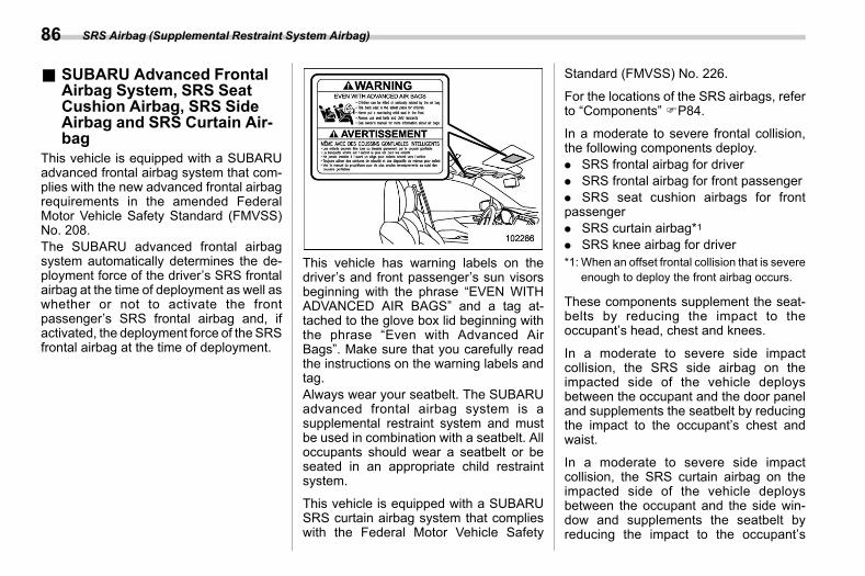
(88,1)
北米Model "A2600BE-B" EDITED: 2020/ 10/ 1
& SUBARU Advanced FrontalAirbag System, SRS SeatCushion Airbag, SRS SideAirbag and SRS Curtain Air-bag
s01ah02This vehicle is equipped with a SUBARUadvanced frontal airbag system that com-plies with the new advanced frontal airbagrequirements in the amended FederalMotor Vehicle Safety Standard (FMVSS)No. 208.The SUBARU advanced frontal airbagsystem automatically determines the de-ployment force of the driver’s SRS frontalairbag at the time of deployment as well aswhether or not to activate the frontpassenger’s SRS frontal airbag and, ifactivated, the deployment force of the SRSfrontal airbag at the time of deployment.
This vehicle has warning labels on thedriver’s and front passenger’s sun visorsbeginning with the phrase “EVEN WITHADVANCED AIR BAGS” and a tag at-tached to the glove box lid beginning withthe phrase “Even with Advanced AirBags”. Make sure that you carefully readthe instructions on the warning labels andtag.Always wear your seatbelt. The SUBARUadvanced frontal airbag system is asupplemental restraint system and mustbe used in combination with a seatbelt. Alloccupants should wear a seatbelt or beseated in an appropriate child restraintsystem.
This vehicle is equipped with a SUBARUSRS curtain airbag system that complieswith the Federal Motor Vehicle Safety
Standard (FMVSS) No. 226.
For the locations of the SRS airbags, referto “Components” FP84.
In a moderate to severe frontal collision,the following components deploy.. SRS frontal airbag for driver. SRS frontal airbag for front passenger. SRS seat cushion airbags for frontpassenger. SRS curtain airbag*1. SRS knee airbag for driver*1: When an offset frontal collision that is severe
enough to deploy the front airbag occurs.
These components supplement the seat-belts by reducing the impact to theoccupant’s head, chest and knees.
In a moderate to severe side impactcollision, the SRS side airbag on theimpacted side of the vehicle deploysbetween the occupant and the door paneland supplements the seatbelt by reducingthe impact to the occupant’s chest andwaist.
In a moderate to severe side impactcollision, the SRS curtain airbag on theimpacted side of the vehicle deploysbetween the occupant and the side win-dow and supplements the seatbelt byreducing the impact to the occupant’s
SRS Airbag (Supplemental Restraint System Airbag)86
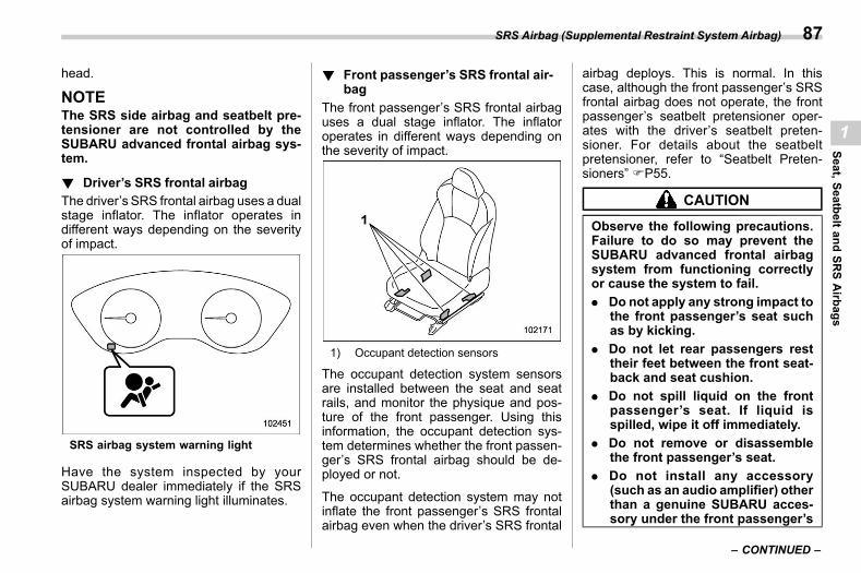
(89,1)
北米Model "A2600BE-B" EDITED: 2020/ 10/ 1
head.
NOTEThe SRS side airbag and seatbelt pre-tensioner are not controlled by theSUBARU advanced frontal airbag sys-tem.
! Driver’s SRS frontal airbags01ah0201
The driver’s SRS frontal airbag uses a dualstage inflator. The inflator operates indifferent ways depending on the severityof impact.
SRS airbag system warning light
Have the system inspected by yourSUBARU dealer immediately if the SRSairbag system warning light illuminates.
! Front passenger’s SRS frontal air-bag
s01ah0202The front passenger’s SRS frontal airbaguses a dual stage inflator. The inflatoroperates in different ways depending onthe severity of impact.
1) Occupant detection sensors
The occupant detection system sensorsare installed between the seat and seatrails, and monitor the physique and pos-ture of the front passenger. Using thisinformation, the occupant detection sys-tem determines whether the front passen-ger’s SRS frontal airbag should be de-ployed or not.
The occupant detection system may notinflate the front passenger’s SRS frontalairbag even when the driver’s SRS frontal
airbag deploys. This is normal. In thiscase, although the front passenger’s SRSfrontal airbag does not operate, the frontpassenger’s seatbelt pretensioner oper-ates with the driver’s seatbelt preten-sioner. For details about the seatbeltpretensioner, refer to “Seatbelt Preten-sioners” FP55.
CAUTION
Observe the following precautions.Failure to do so may prevent theSUBARU advanced frontal airbagsystem from functioning correctlyor cause the system to fail.. Do not apply any strong impact to
the front passenger’s seat suchas by kicking.
. Do not let rear passengers resttheir feet between the front seat-back and seat cushion.
. Do not spill liquid on the frontpassenger’s seat. If liquid isspilled, wipe it off immediately.
. Do not remove or disassemblethe front passenger’s seat.
. Do not install any accessory(such as an audio amplifier) otherthan a genuine SUBARU acces-sory under the front passenger’s
– CONTINUED –
SRS Airbag (Supplemental Restraint System Airbag) 87
1
Seat,SeatbeltandSR
SAirbags
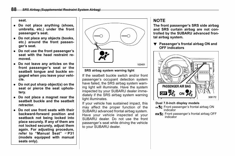
(90,1)
北米Model "A2600BE-B" EDITED: 2020/ 10/ 1
seat.. Do not place anything (shoes,
umbrella, etc.) under the frontpassenger’s seat.
. Do not place any objects (books,etc.) around the front passen-ger’s seat.
. Do not use the front passenger’sseat with the head restraint re-moved.
. Do not leave any articles on thefront passenger’s seat or theseatbelt tongue and buckle en-gaged when you leave your vehi-cle.
. Do not put sharp object(s) on theseat or pierce the seat uphols-tery.
. Do not place a magnet near theseatbelt buckle and the seatbeltretractor.
. Do not use front seats with theirbackward-forward position andseatback not being locked intoplace securely. If any of them arenot locked securely, adjust themagain. For adjusting procedure,refer to “Manual Seat” FP31(models equipped with manualseats only).
SRS airbag system warning lightIf the seatbelt buckle switch and/or frontpassenger’s occupant detection systemhave failed, the SRS airbag system warn-ing light will illuminate. Have the systeminspected by your SUBARU dealer imme-diately if the SRS airbag system warninglight illuminates.If your vehicle has sustained impact, thismay affect the proper function of theSUBARU advanced frontal airbag system.Have your vehicle inspected at yourSUBARU dealer. Do not use the frontpassenger’s seat while driving the vehicleto your SUBARU dealer.
NOTEThe front passenger’s SRS side airbagand SRS curtain airbag are not con-trolled by the SUBARU advanced fron-tal airbag system.
! Passenger’s frontal airbag ON andOFF indicators
s01ah0203
Dual 7.0-inch display models: Front passenger’s frontal airbag ONindicator: Front passenger’s frontal airbag OFFindicator
SRS Airbag (Supplemental Restraint System Airbag)88
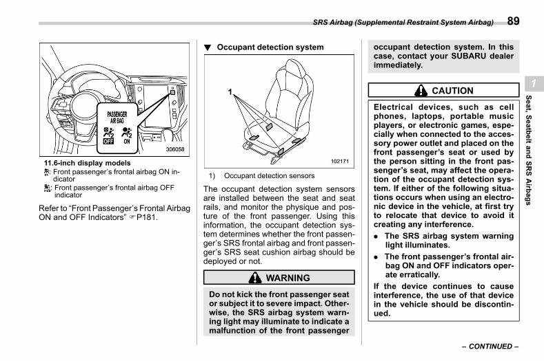
(91,1)
北米Model "A2600BE-B" EDITED: 2020/ 10/ 1
11.6-inch display models: Front passenger’s frontal airbag ON in-dicator: Front passenger’s frontal airbag OFFindicator
Refer to “Front Passenger’s Frontal AirbagON and OFF Indicators” FP181.
! Occupant detection systems01ah0209
1) Occupant detection sensors
The occupant detection system sensorsare installed between the seat and seatrails, and monitor the physique and pos-ture of the front passenger. Using thisinformation, the occupant detection sys-tem determines whether the front passen-ger’s SRS frontal airbag and front passen-ger’s SRS seat cushion airbag should bedeployed or not.
WARNING
Do not kick the front passenger seator subject it to severe impact. Other-wise, the SRS airbag system warn-ing light may illuminate to indicate amalfunction of the front passenger
occupant detection system. In thiscase, contact your SUBARU dealerimmediately.
CAUTION
Electrical devices, such as cellphones, laptops, portable musicplayers, or electronic games, espe-cially when connected to the acces-sory power outlet and placed on thefront passenger’s seat or used bythe person sitting in the front pas-senger’s seat, may affect the opera-tion of the occupant detection sys-tem. If either of the following situa-tions occurs when using an electro-nic device in the vehicle, at first tryto relocate that device to avoid itcreating any interference.. The SRS airbag system warning
light illuminates.. The front passenger’s frontal air-
bag ON and OFF indicators oper-ate erratically.
If the device continues to causeinterference, the use of that devicein the vehicle should be discontin-ued.
– CONTINUED –
SRS Airbag (Supplemental Restraint System Airbag) 89
1
Seat,SeatbeltandSR
SAirbags
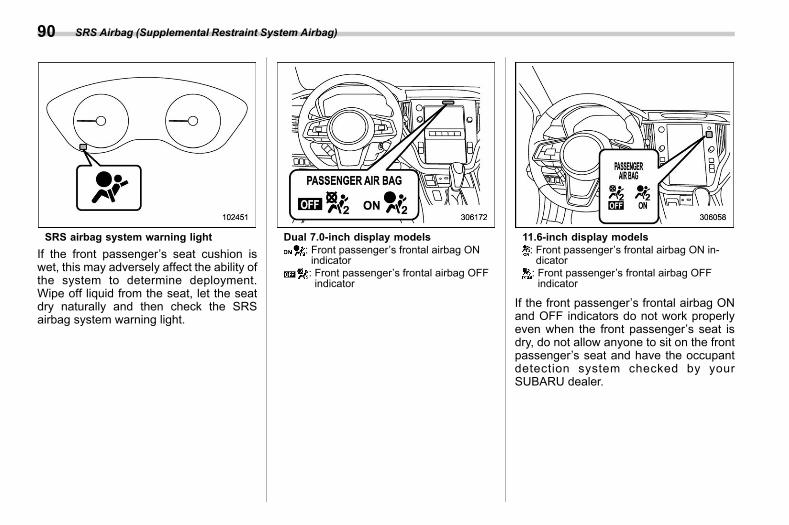
(92,1)
北米Model "A2600BE-B" EDITED: 2020/ 10/ 1
SRS airbag system warning lightIf the front passenger’s seat cushion iswet, this may adversely affect the ability ofthe system to determine deployment.Wipe off liquid from the seat, let the seatdry naturally and then check the SRSairbag system warning light.
Dual 7.0-inch display models: Front passenger’s frontal airbag ONindicator: Front passenger’s frontal airbag OFFindicator
11.6-inch display models: Front passenger’s frontal airbag ON in-dicator: Front passenger’s frontal airbag OFFindicator
If the front passenger’s frontal airbag ONand OFF indicators do not work properlyeven when the front passenger’s seat isdry, do not allow anyone to sit on the frontpassenger’s seat and have the occupantdetection system checked by yourSUBARU dealer.
SRS Airbag (Supplemental Restraint System Airbag)90
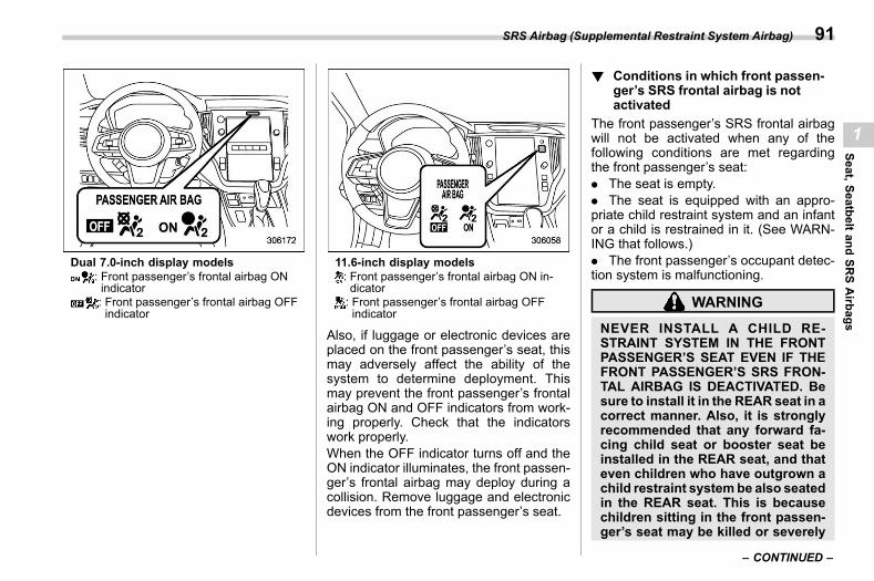
(93,1)
北米Model "A2600BE-B" EDITED: 2020/ 10/ 1
Dual 7.0-inch display models: Front passenger’s frontal airbag ONindicator: Front passenger’s frontal airbag OFFindicator
11.6-inch display models: Front passenger’s frontal airbag ON in-dicator: Front passenger’s frontal airbag OFFindicator
Also, if luggage or electronic devices areplaced on the front passenger’s seat, thismay adversely affect the ability of thesystem to determine deployment. Thismay prevent the front passenger’s frontalairbag ON and OFF indicators from work-ing properly. Check that the indicatorswork properly.When the OFF indicator turns off and theON indicator illuminates, the front passen-ger’s frontal airbag may deploy during acollision. Remove luggage and electronicdevices from the front passenger’s seat.
! Conditions in which front passen-ger’s SRS frontal airbag is notactivated
s01ah0204The front passenger’s SRS frontal airbagwill not be activated when any of thefollowing conditions are met regardingthe front passenger’s seat:. The seat is empty.. The seat is equipped with an appro-priate child restraint system and an infantor a child is restrained in it. (See WARN-ING that follows.). The front passenger’s occupant detec-tion system is malfunctioning.
WARNING
NEVER INSTALL A CHILD RE-STRAINT SYSTEM IN THE FRONTPASSENGER’S SEAT EVEN IF THEFRONT PASSENGER’S SRS FRON-TAL AIRBAG IS DEACTIVATED. Besure to install it in the REAR seat in acorrect manner. Also, it is stronglyrecommended that any forward fa-cing child seat or booster seat beinstalled in the REAR seat, and thateven children who have outgrown achild restraint systembe also seatedin the REAR seat. This is becausechildren sitting in the front passen-ger’s seat may be killed or severely
– CONTINUED –
SRS Airbag (Supplemental Restraint System Airbag) 91
1
Seat,SeatbeltandSR
SAirbags
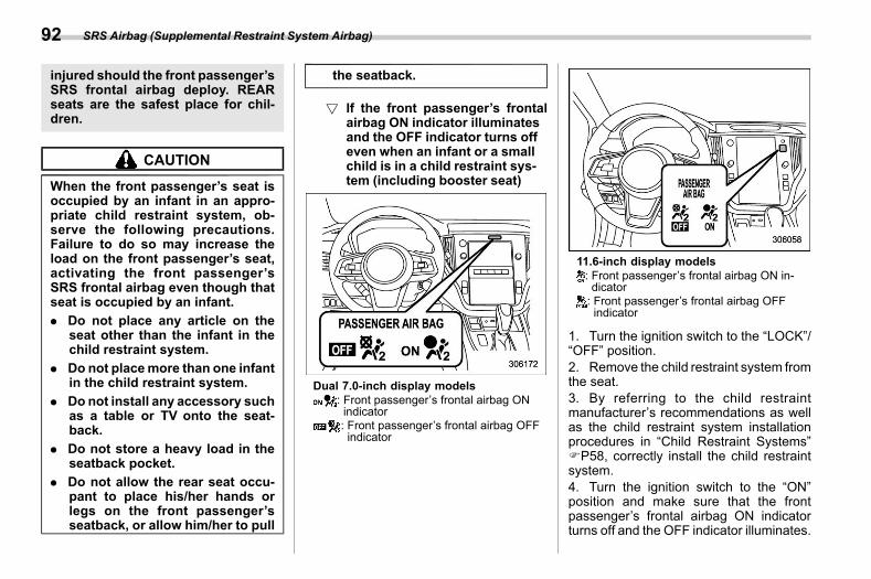
(94,1)
北米Model "A2600BE-B" EDITED: 2020/ 10/ 1
injured should the front passenger’sSRS frontal airbag deploy. REARseats are the safest place for chil-dren.
CAUTION
When the front passenger’s seat isoccupied by an infant in an appro-priate child restraint system, ob-serve the following precautions.Failure to do so may increase theload on the front passenger’s seat,activating the front passenger’sSRS frontal airbag even though thatseat is occupied by an infant.. Do not place any article on the
seat other than the infant in thechild restraint system.
. Do not placemore than one infantin the child restraint system.
. Do not install any accessory suchas a table or TV onto the seat-back.
. Do not store a heavy load in theseatback pocket.
. Do not allow the rear seat occu-pant to place his/her hands orlegs on the front passenger’sseatback, or allow him/her to pull
the seatback.
! If the front passenger’s frontalairbag ON indicator illuminatesand the OFF indicator turns offeven when an infant or a smallchild is in a child restraint sys-tem (including booster seat)
s01ah020401
Dual 7.0-inch display models: Front passenger’s frontal airbag ONindicator: Front passenger’s frontal airbag OFFindicator
11.6-inch display models: Front passenger’s frontal airbag ON in-dicator: Front passenger’s frontal airbag OFFindicator
1. Turn the ignition switch to the “LOCK”/“OFF” position.2. Remove the child restraint system fromthe seat.3. By referring to the child restraintmanufacturer’s recommendations as wellas the child restraint system installationprocedures in “Child Restraint Systems”FP58, correctly install the child restraintsystem.4. Turn the ignition switch to the “ON”position and make sure that the frontpassenger’s frontal airbag ON indicatorturns off and the OFF indicator illuminates.
SRS Airbag (Supplemental Restraint System Airbag)92
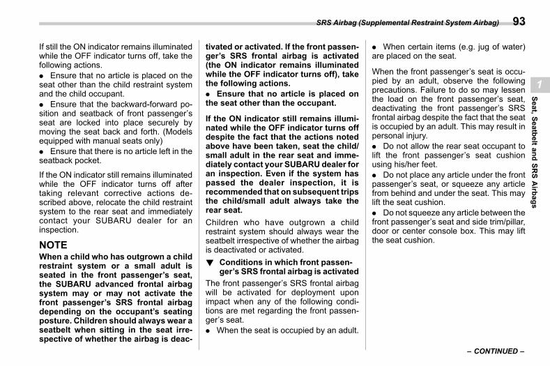
(95,1)
北米Model "A2600BE-B" EDITED: 2020/ 10/ 1
If still the ON indicator remains illuminatedwhile the OFF indicator turns off, take thefollowing actions.. Ensure that no article is placed on theseat other than the child restraint systemand the child occupant.. Ensure that the backward-forward po-sition and seatback of front passenger’sseat are locked into place securely bymoving the seat back and forth. (Modelsequipped with manual seats only). Ensure that there is no article left in theseatback pocket.
If the ON indicator still remains illuminatedwhile the OFF indicator turns off aftertaking relevant corrective actions de-scribed above, relocate the child restraintsystem to the rear seat and immediatelycontact your SUBARU dealer for aninspection.
NOTEWhen a child who has outgrown a childrestraint system or a small adult isseated in the front passenger’s seat,the SUBARU advanced frontal airbagsystem may or may not activate thefront passenger’s SRS frontal airbagdepending on the occupant’s seatingposture. Children should always wear aseatbelt when sitting in the seat irre-spective of whether the airbag is deac-
tivated or activated. If the front passen-ger’s SRS frontal airbag is activated(the ON indicator remains illuminatedwhile the OFF indicator turns off), takethe following actions.. Ensure that no article is placed onthe seat other than the occupant.
If the ON indicator still remains illumi-nated while the OFF indicator turns offdespite the fact that the actions notedabove have been taken, seat the child/small adult in the rear seat and imme-diately contact your SUBARU dealer foran inspection. Even if the system haspassed the dealer inspection, it isrecommended that on subsequent tripsthe child/small adult always take therear seat.Children who have outgrown a childrestraint system should always wear theseatbelt irrespective of whether the airbagis deactivated or activated.! Conditions in which front passen-
ger’s SRS frontal airbag is activateds01ah0205
The front passenger’s SRS frontal airbagwill be activated for deployment uponimpact when any of the following condi-tions are met regarding the front passen-ger’s seat.. When the seat is occupied by an adult.
. When certain items (e.g. jug of water)are placed on the seat.
When the front passenger’s seat is occu-pied by an adult, observe the followingprecautions. Failure to do so may lessenthe load on the front passenger’s seat,deactivating the front passenger’s SRSfrontal airbag despite the fact that the seatis occupied by an adult. This may result inpersonal injury.. Do not allow the rear seat occupant tolift the front passenger’s seat cushionusing his/her feet.. Do not place any article under the frontpassenger’s seat, or squeeze any articlefrom behind and under the seat. This maylift the seat cushion.. Do not squeeze any article between thefront passenger’s seat and side trim/pillar,door or center console box. This may liftthe seat cushion.
– CONTINUED –
SRS Airbag (Supplemental Restraint System Airbag) 93
1
Seat,SeatbeltandSR
SAirbags
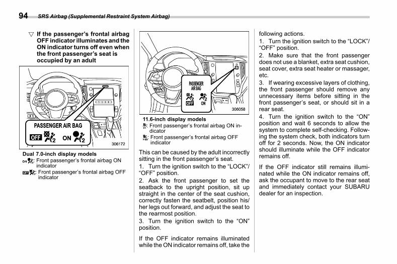
(96,1)
北米Model "A2600BE-B" EDITED: 2020/ 10/ 1
! If the passenger’s frontal airbagOFF indicator illuminates and theON indicator turns off even whenthe front passenger’s seat isoccupied by an adult
s01ah020501
Dual 7.0-inch display models: Front passenger’s frontal airbag ONindicator: Front passenger’s frontal airbag OFFindicator
11.6-inch display models: Front passenger’s frontal airbag ON in-dicator: Front passenger’s frontal airbag OFFindicator
This can be caused by the adult incorrectlysitting in the front passenger’s seat.1. Turn the ignition switch to the “LOCK”/“OFF” position.2. Ask the front passenger to set theseatback to the upright position, sit upstraight in the center of the seat cushion,correctly fasten the seatbelt, position his/her legs out forward, and adjust the seat tothe rearmost position.3. Turn the ignition switch to the “ON”position.
If the OFF indicator remains illuminatedwhile theON indicator remains off, take the
following actions.1. Turn the ignition switch to the “LOCK”/“OFF” position.2. Make sure that the front passengerdoes not use a blanket, extra seat cushion,seat cover, extra seat heater or massager,etc.3. If wearing excessive layers of clothing,the front passenger should remove anyunnecessary items before sitting in thefront passenger’s seat, or should sit in arear seat.4. Turn the ignition switch to the “ON”position and wait 6 seconds to allow thesystem to complete self-checking. Follow-ing the system check, both indicators turnoff for 2 seconds. Now, the ON indicatorshould illuminate while the OFF indicatorremains off.
If the OFF indicator still remains illumi-nated while the ON indicator remains off,ask the occupant to move to the rear seatand immediately contact your SUBARUdealer for an inspection.
SRS Airbag (Supplemental Restraint System Airbag)94
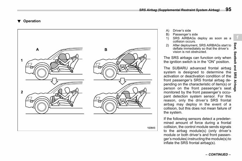
(97,1)
北米Model "A2600BE-B" EDITED: 2020/ 10/ 1
! Operations01ah0207
A) Driver’s sideB) Passenger’s side1) SRS AIRBAGs deploy as soon as a
collision occurs.2) After deployment, SRS AIRBAGs start to
deflate immediately so that the driver’svision is not obstructed.
The SRS airbags can function only whenthe ignition switch is in the “ON” position.
The SUBARU advanced frontal airbagsystem is designed to determine theactivation or deactivation condition of thefront passenger’s SRS frontal airbag de-pending on the characteristic of item(s) orperson on the front passenger’s seatmonitored by the front passenger’s occu-pant detection system sensor. For thisreason, only the driver’s SRS frontalairbag may deploy in the event of acollision, but this does not mean failure ofthe system.
If the following sensors detect a predeter-mined amount of force during a frontalcollision, the control module sends signalsto the airbag module(s) (only driver’smodule or both driver’s and front passen-ger’smodules) instructing themodule(s) toinflate the SRS frontal airbag(s).
– CONTINUED –
SRS Airbag (Supplemental Restraint System Airbag) 95
1
Seat,SeatbeltandSR
SAirbags
(98,1)
北米Model "A2600BE-B" EDITED: 2020/ 10/ 1
. The front impact sensors
. The impact sensors in the airbagcontrol module
On the driver’s side, the SRS knee airbagalso inflates with the SRS frontal airbag.
The driver’s and front passenger’s SRSfrontal airbags use dual stage inflators.The two inflators of each airbag aretriggered either sequentially or simulta-neously, depending on the severity ofimpact, in the case of the driver’s SRSfrontal airbag and depending on theseverity of impact and the characteristicof item(s) or person on the seat in the caseof the front passenger’s SRS frontal air-bag.! After deployment
s01ah0210After deployment, the SRS airbag imme-diately starts to deflate so that the driver’svision is not obstructed and the driver’sability to maintain control of the vehicle isnot impaired. The time required fromdetecting impact to the deflation of theSRS airbag after deployment is shorterthan the blink of an eye.
Both when only the driver’s SRS frontalairbag deploys and the driver’s and frontpassenger’s SRS frontal airbags deploy,the driver’s and front passenger’s seatbeltpretensioners operate at the same time.
When the SRS airbag deploys, a sudden,fairly loud inflation noise will be heard andsome smoke will be released. Theseoccurrences are a normal result of thedeployment. This smoke does not indicatea fire in the vehicle.
CAUTION
Do not touch the SRS airbag systemcomponents around the steeringwheel and dashboard with barehands right after deployment. Doingso can cause burns because thecomponents can be very hot as aresult of deployment.
! Example of the type of accidents01ah0211
The driver’s SRS frontal airbag and frontpassenger’s SRS frontal airbag are de-signed as follows.. To deploy in the event of an accidentinvolving a moderate to severe frontalcollision. To function on a one-time-only basis
The driver’s SRS frontal airbag and frontpassenger’s SRS frontal airbag are notdesigned as follows.. To deploy in most lesser frontal im-pacts*1
. To deploy in most side or rear impactsor in most rollover accidents*2*1: Because the necessary protection can be
achieved by the seatbelt alone.*2: Because deployment of only the driver’s
SRS frontal airbag or both the driver’s andfront passenger’s SRS frontal airbagswould not protect the occupant in thosesituations.
SRS airbag deployment depends on thelevel of force experienced in the passen-ger compartment during a collision. Thatlevel differs from one type of collision toanother, and it may have no bearing on thevisible damage done to the vehicle itself.
SRS Airbag (Supplemental Restraint System Airbag)96
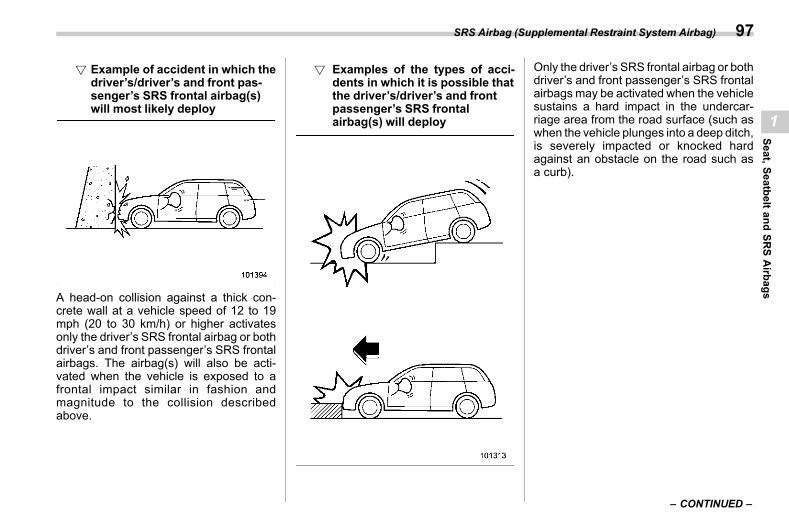
(99,1)
北米Model "A2600BE-B" EDITED: 2020/ 10/ 1
! Example of accident in which thedriver’s/driver’s and front pas-senger’s SRS frontal airbag(s)will most likely deploy
s01ah021101
A head-on collision against a thick con-crete wall at a vehicle speed of 12 to 19mph (20 to 30 km/h) or higher activatesonly the driver’s SRS frontal airbag or bothdriver’s and front passenger’s SRS frontalairbags. The airbag(s) will also be acti-vated when the vehicle is exposed to afrontal impact similar in fashion andmagnitude to the collision describedabove.
! Examples of the types of acci-dents in which it is possible thatthe driver’s/driver’s and frontpassenger’s SRS frontalairbag(s) will deploy
s01ah021102
Only the driver’s SRS frontal airbag or bothdriver’s and front passenger’s SRS frontalairbags may be activated when the vehiclesustains a hard impact in the undercar-riage area from the road surface (such aswhen the vehicle plunges into a deep ditch,is severely impacted or knocked hardagainst an obstacle on the road such asa curb).
– CONTINUED –
SRS Airbag (Supplemental Restraint System Airbag) 97
1
Seat,SeatbeltandSR
SAirbags
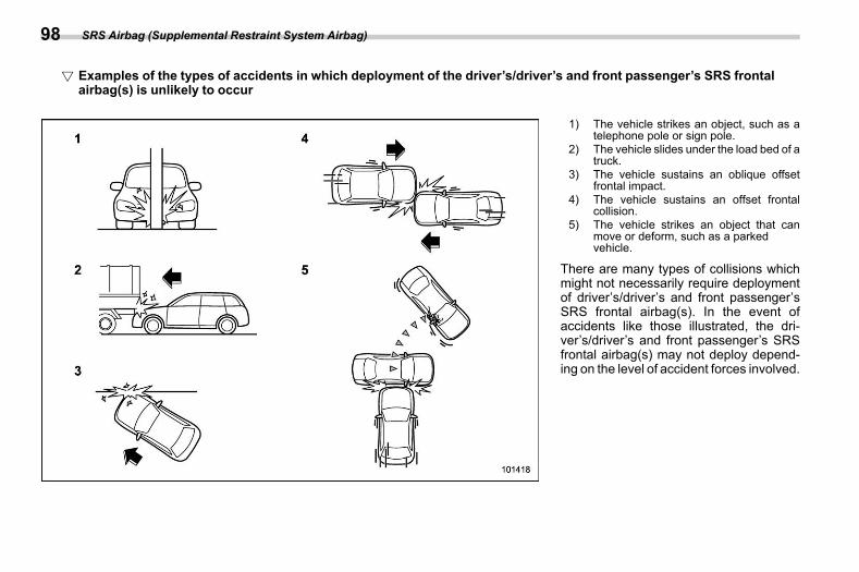
(100,1)
北米Model "A2600BE-B" EDITED: 2020/ 10/ 1
! Examples of the types of accidents in which deployment of the driver’s/driver’s and front passenger’s SRS frontalairbag(s) is unlikely to occur
S01AH021103
1) The vehicle strikes an object, such as atelephone pole or sign pole.
2) The vehicle slides under the load bed of atruck.
3) The vehicle sustains an oblique offsetfrontal impact.
4) The vehicle sustains an offset frontalcollision.
5) The vehicle strikes an object that canmove or deform, such as a parkedvehicle.
There are many types of collisions whichmight not necessarily require deploymentof driver’s/driver’s and front passenger’sSRS frontal airbag(s). In the event ofaccidents like those illustrated, the dri-ver’s/driver’s and front passenger’s SRSfrontal airbag(s) may not deploy depend-ing on the level of accident forces involved.
SRS Airbag (Supplemental Restraint System Airbag)98
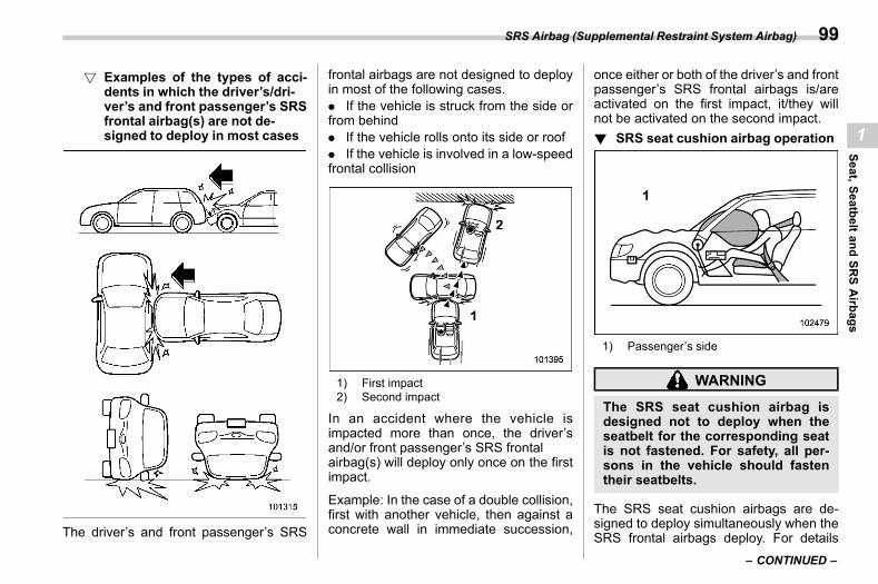
(101,1)
北米Model "A2600BE-B" EDITED: 2020/ 10/ 1
! Examples of the types of acci-dents in which the driver’s/dri-ver’s and front passenger’s SRSfrontal airbag(s) are not de-signed to deploy in most cases
s01ah021104
The driver’s and front passenger’s SRS
frontal airbags are not designed to deployin most of the following cases.. If the vehicle is struck from the side orfrom behind. If the vehicle rolls onto its side or roof. If the vehicle is involved in a low-speedfrontal collision
1) First impact2) Second impact
In an accident where the vehicle isimpacted more than once, the driver’sand/or front passenger’s SRS frontalairbag(s) will deploy only once on the firstimpact.
Example: In the case of a double collision,first with another vehicle, then against aconcrete wall in immediate succession,
once either or both of the driver’s and frontpassenger’s SRS frontal airbags is/areactivated on the first impact, it/they willnot be activated on the second impact.! SRS seat cushion airbag operation
s01ah0212
1) Passenger’s side
WARNING
The SRS seat cushion airbag isdesigned not to deploy when theseatbelt for the corresponding seatis not fastened. For safety, all per-sons in the vehicle should fastentheir seatbelts.
The SRS seat cushion airbags are de-signed to deploy simultaneously when theSRS frontal airbags deploy. For details
– CONTINUED –
SRS Airbag (Supplemental Restraint System Airbag) 99
1
Seat,SeatbeltandSR
SAirbags
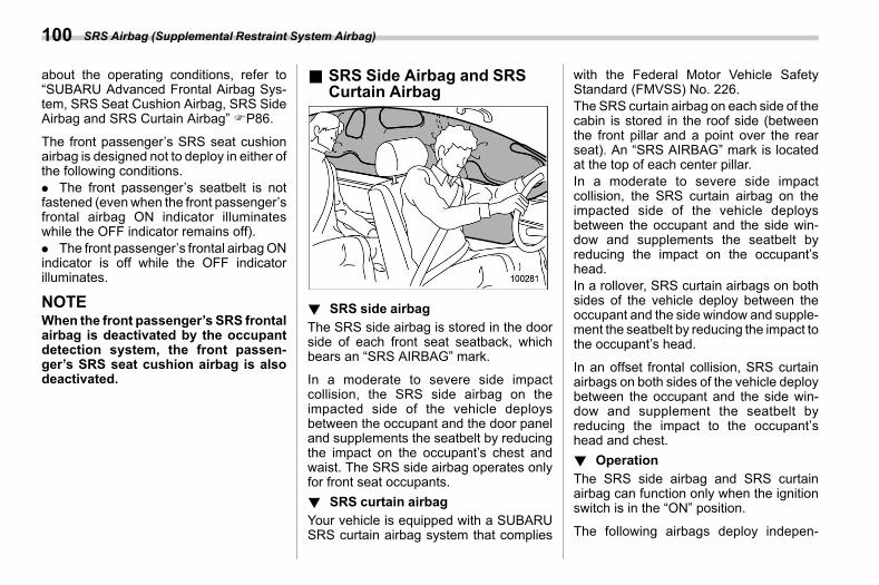
(102,1)
北米Model "A2600BE-B" EDITED: 2020/ 10/ 1
about the operating conditions, refer to“SUBARU Advanced Frontal Airbag Sys-tem, SRS Seat Cushion Airbag, SRS SideAirbag and SRS Curtain Airbag” FP86.
The front passenger’s SRS seat cushionairbag is designed not to deploy in either ofthe following conditions.. The front passenger’s seatbelt is notfastened (evenwhen the front passenger’sfrontal airbag ON indicator illuminateswhile the OFF indicator remains off).. The front passenger’s frontal airbagONindicator is off while the OFF indicatorilluminates.
NOTEWhen the front passenger’s SRS frontalairbag is deactivated by the occupantdetection system, the front passen-ger’s SRS seat cushion airbag is alsodeactivated.
& SRS Side Airbag and SRSCurtain Airbag
s01ah03
! SRS side airbags01ah0302
The SRS side airbag is stored in the doorside of each front seat seatback, whichbears an “SRS AIRBAG” mark.
In a moderate to severe side impactcollision, the SRS side airbag on theimpacted side of the vehicle deploysbetween the occupant and the door paneland supplements the seatbelt by reducingthe impact on the occupant’s chest andwaist. The SRS side airbag operates onlyfor front seat occupants.! SRS curtain airbag
s01ah0303Your vehicle is equipped with a SUBARUSRS curtain airbag system that complies
with the Federal Motor Vehicle SafetyStandard (FMVSS) No. 226.The SRS curtain airbag on each side of thecabin is stored in the roof side (betweenthe front pillar and a point over the rearseat). An “SRS AIRBAG” mark is locatedat the top of each center pillar.In a moderate to severe side impactcollision, the SRS curtain airbag on theimpacted side of the vehicle deploysbetween the occupant and the side win-dow and supplements the seatbelt byreducing the impact on the occupant’shead.In a rollover, SRS curtain airbags on bothsides of the vehicle deploy between theoccupant and the side window and supple-ment the seatbelt by reducing the impact tothe occupant’s head.
In an offset frontal collision, SRS curtainairbags on both sides of the vehicle deploybetween the occupant and the side win-dow and supplement the seatbelt byreducing the impact to the occupant’shead and chest.! Operation
s01ah0301The SRS side airbag and SRS curtainairbag can function only when the ignitionswitch is in the “ON” position.
The following airbags deploy indepen-
SRS Airbag (Supplemental Restraint System Airbag)100
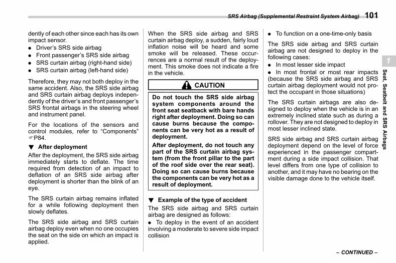
(103,1)
北米Model "A2600BE-B" EDITED: 2020/ 10/ 1
dently of each other since each has its ownimpact sensor.. Driver’s SRS side airbag. Front passenger’s SRS side airbag. SRS curtain airbag (right-hand side). SRS curtain airbag (left-hand side)
Therefore, they may not both deploy in thesame accident. Also, the SRS side airbagand SRS curtain airbag deploys indepen-dently of the driver’s and front passenger’sSRS frontal airbags in the steering wheeland instrument panel.
For the locations of the sensors andcontrol modules, refer to “Components”FP84.! After deployment
s01ah0304After the deployment, the SRS side airbagimmediately starts to deflate. The timerequired from detection of an impact todeflation of an SRS side airbag afterdeployment is shorter than the blink of aneye.
The SRS curtain airbag remains inflatedfor a while following deployment thenslowly deflates.
The SRS side airbag and SRS curtainairbag deploy even when no one occupiesthe seat on the side on which an impact isapplied.
When the SRS side airbag and SRScurtain airbag deploy, a sudden, fairly loudinflation noise will be heard and somesmoke will be released. These occur-rences are a normal result of the deploy-ment. This smoke does not indicate a firein the vehicle.
CAUTION
Do not touch the SRS side airbagsystem components around thefront seat seatback with bare handsright after deployment. Doing so cancause burns because the compo-nents can be very hot as a result ofdeployment.After deployment, do not touch anypart of the SRS curtain airbag sys-tem (from the front pillar to the partof the roof side over the rear seat).Doing so can cause burns becausethe components can be very hot as aresult of deployment.
! Example of the type of accidents01ah0305
The SRS side airbag and SRS curtainairbag are designed as follows:. To deploy in the event of an accidentinvolving amoderate to severe side impactcollision
. To function on a one-time-only basis
The SRS side airbag and SRS curtainairbag are not designed to deploy in thefollowing cases:. In most lesser side impact. In most frontal or most rear impacts(because the SRS side airbag and SRScurtain airbag deployment would not pro-tect the occupant in those situations)
The SRS curtain airbags are also de-signed to deploy when the vehicle is in anextremely inclined state such as during arollover. They are not designed to deploy inmost lesser inclined state.
SRS side airbag and SRS curtain airbagdeployment depend on the level of forceexperienced in the passenger compart-ment during a side impact collision. Thatlevel differs from one type of collision toanother, and it may have no bearing on thevisible damage done to the vehicle itself.
– CONTINUED –
SRS Airbag (Supplemental Restraint System Airbag) 101
1
Seat,SeatbeltandSR
SAirbags
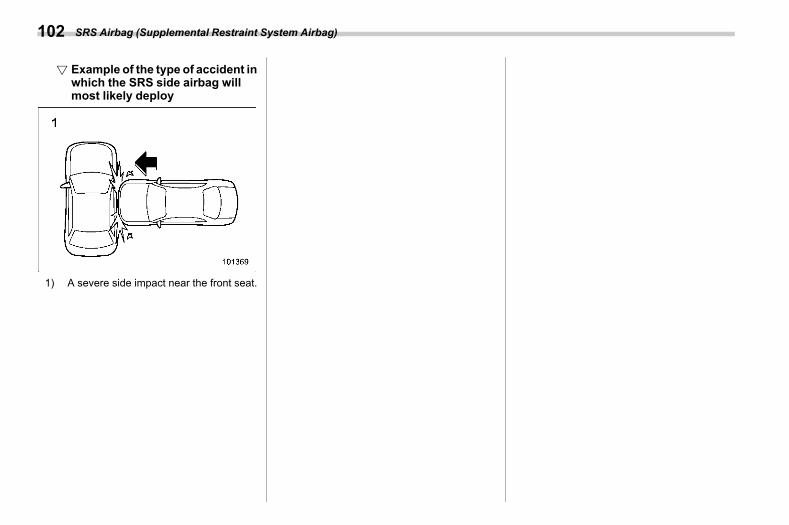
(104,1)
北米Model "A2600BE-B" EDITED: 2020/ 10/ 1
! Example of the type of accident inwhich the SRS side airbag willmost likely deploy
s01ah030501
1) A severe side impact near the front seat.
SRS Airbag (Supplemental Restraint System Airbag)102
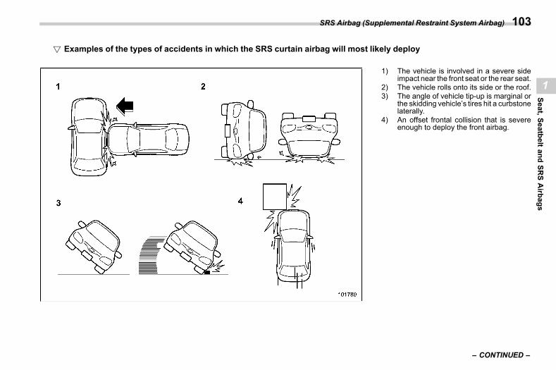
(105,1)
北米Model "A2600BE-B" EDITED: 2020/ 10/ 1
! Examples of the types of accidents in which the SRS curtain airbag will most likely deployS01AH030502
1) The vehicle is involved in a severe sideimpact near the front seat or the rear seat.
2) The vehicle rolls onto its side or the roof.3) The angle of vehicle tip-up is marginal or
the skidding vehicle’s tires hit a curbstonelaterally.
4) An offset frontal collision that is severeenough to deploy the front airbag.
– CONTINUED –
SRS Airbag (Supplemental Restraint System Airbag) 103
1
Seat,SeatbeltandSR
SAirbags
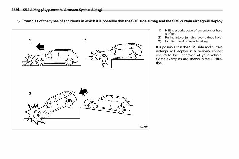
(106,1)
北米Model "A2600BE-B" EDITED: 2020/ 10/ 1
! Examples of the types of accidents in which it is possible that the SRS side airbag and the SRS curtain airbagwill deployS01AH030503
1) Hitting a curb, edge of pavement or hardsurface
2) Falling into or jumping over a deep hole3) Landing hard or vehicle falling
It is possible that the SRS side and curtainairbags will deploy if a serious impactoccurs to the underside of your vehicle.Some examples are shown in the illustra-tion.
SRS Airbag (Supplemental Restraint System Airbag)104
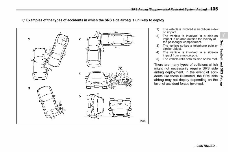
(107,1)
北米Model "A2600BE-B" EDITED: 2020/ 10/ 1
! Examples of the types of accidents in which the SRS side airbag is unlikely to deployS01AH030504
1) The vehicle is involved in an oblique side-on impact.
2) The vehicle is involved in a side-onimpact in an area outside the vicinity ofthe passenger compartment.
3) The vehicle strikes a telephone pole orsimilar object.
4) The vehicle is involved in a side-onimpact from a motorcycle.
5) The vehicle rolls onto its side or the roof.
There are many types of collisions whichmight not necessarily require SRS sideairbag deployment. In the event of acci-dents like those illustrated, the SRS sideairbag may not deploy depending on thelevel of accident forces involved.
– CONTINUED –
SRS Airbag (Supplemental Restraint System Airbag) 105
1
Seat,SeatbeltandSR
SAirbags
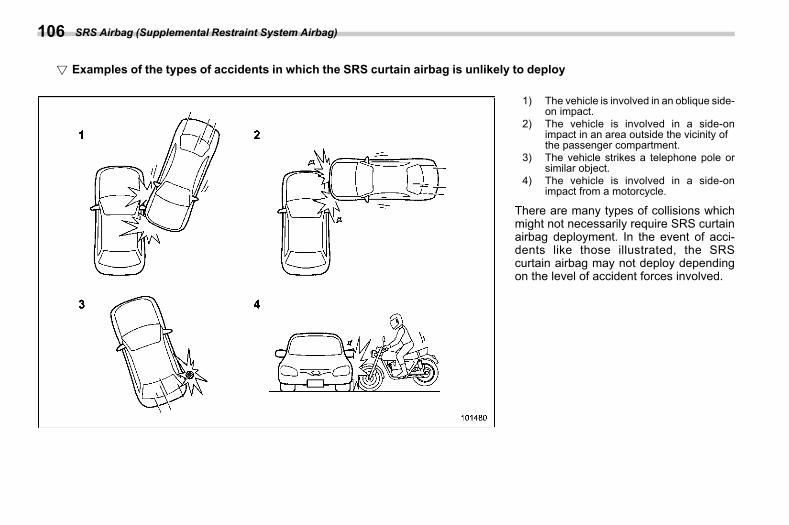
(108,1)
北米Model "A2600BE-B" EDITED: 2020/ 10/ 1
! Examples of the types of accidents in which the SRS curtain airbag is unlikely to deployS01AH030505
1) The vehicle is involved in an oblique side-on impact.
2) The vehicle is involved in a side-onimpact in an area outside the vicinity ofthe passenger compartment.
3) The vehicle strikes a telephone pole orsimilar object.
4) The vehicle is involved in a side-onimpact from a motorcycle.
There are many types of collisions whichmight not necessarily require SRS curtainairbag deployment. In the event of acci-dents like those illustrated, the SRScurtain airbag may not deploy dependingon the level of accident forces involved.
SRS Airbag (Supplemental Restraint System Airbag)106
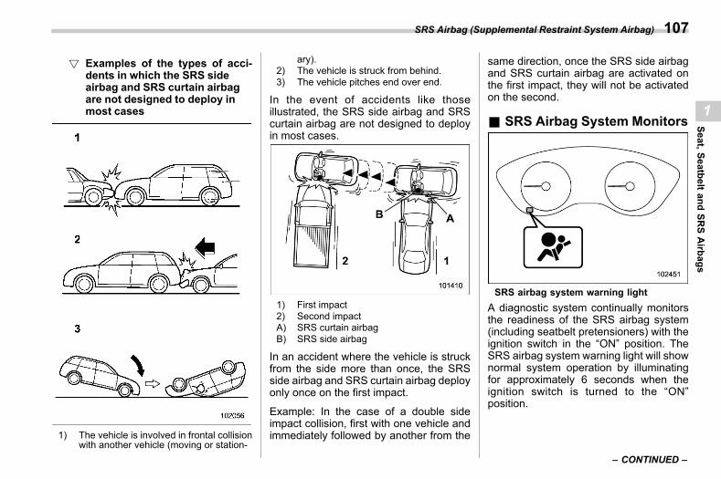
(109,1)
北米Model "A2600BE-B" EDITED: 2020/ 10/ 1
! Examples of the types of acci-dents in which the SRS sideairbag and SRS curtain airbagare not designed to deploy inmost cases
s01ah030506
1) The vehicle is involved in frontal collisionwith another vehicle (moving or station-
ary).2) The vehicle is struck from behind.3) The vehicle pitches end over end.
In the event of accidents like thoseillustrated, the SRS side airbag and SRScurtain airbag are not designed to deployin most cases.
1) First impact2) Second impactA) SRS curtain airbagB) SRS side airbag
In an accident where the vehicle is struckfrom the side more than once, the SRSside airbag and SRS curtain airbag deployonly once on the first impact.
Example: In the case of a double sideimpact collision, first with one vehicle andimmediately followed by another from the
same direction, once the SRS side airbagand SRS curtain airbag are activated onthe first impact, they will not be activatedon the second.
& SRS Airbag System Monitorss01ah04
SRS airbag system warning lightA diagnostic system continually monitorsthe readiness of the SRS airbag system(including seatbelt pretensioners) with theignition switch in the “ON” position. TheSRS airbag system warning light will shownormal system operation by illuminatingfor approximately 6 seconds when theignition switch is turned to the “ON”position.
– CONTINUED –
SRS Airbag (Supplemental Restraint System Airbag) 107
1
Seat,SeatbeltandSR
SAirbags
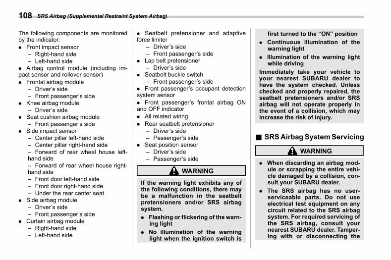
(110,1)
北米Model "A2600BE-B" EDITED: 2020/ 10/ 1
The following components are monitoredby the indicator:. Front impact sensor
– Right-hand side– Left-hand side
. Airbag control module (including im-pact sensor and rollover sensor). Frontal airbag module
– Driver’s side– Front passenger’s side
. Knee airbag module– Driver’s side
. Seat cushion airbag module– Front passenger’s side
. Side impact sensor– Center pillar left-hand side– Center pillar right-hand side– Forward of rear wheel house left-hand side– Forward of rear wheel house right-hand side– Front door left-hand side– Front door right-hand side– Under the rear center seat
. Side airbag module– Driver’s side– Front passenger’s side
. Curtain airbag module– Right-hand side– Left-hand side
. Seatbelt pretensioner and adaptiveforce limiter
– Driver’s side– Front passenger’s side
. Lap belt pretensioner– Driver’s side
. Seatbelt buckle switch– Front passenger’s side
. Front passenger’s occupant detectionsystem sensor. Front passenger’s frontal airbag ONand OFF indicator. All related wiring. Rear seatbelt pretensioner
– Driver’s side– Passenger’s side
. Seat position sensor– Driver’s side– Passenger’s side
WARNING
If the warning light exhibits any ofthe following conditions, there maybe a malfunction in the seatbeltpretensioners and/or SRS airbagsystem.. Flashing or flickering of the warn-
ing light. No illumination of the warning
light when the ignition switch is
first turned to the “ON” position. Continuous illumination of the
warning light. Illumination of the warning light
while drivingImmediately take your vehicle toyour nearest SUBARU dealer tohave the system checked. Unlesschecked and properly repaired, theseatbelt pretensioners and/or SRSairbag will not operate properly inthe event of a collision, which mayincrease the risk of injury.
& SRSAirbagSystemServicings01ah05
WARNING
. When discarding an airbag mod-ule or scrapping the entire vehi-cle damaged by a collision, con-sult your SUBARU dealer.
. The SRS airbag has no user-serviceable parts. Do not useelectrical test equipment on anycircuit related to the SRS airbagsystem. For required servicing ofthe SRS airbag, consult yournearest SUBARU dealer. Tamper-ing with or disconnecting the
SRS Airbag (Supplemental Restraint System Airbag)108
(111,1)
北米Model "A2600BE-B" EDITED: 2020/ 10/ 1
system’s wiring could result inaccidental inflation of the SRSairbag or could make the systeminoperative, which may result inserious injury.
CAUTION
If you need service or repair in areasindicated in the following list, havethe work performed by an author-ized SUBARU dealer. The SRS air-bag control module, impact sensorsand airbag modules are stored inthese areas.. Under the center of the instru-
ment panel. On both the right and left sides at
the front of the vehicle. Steering wheel and column and
nearby areas. Bottom of the steering column
and nearby areas. Top of the dashboard on front
passenger’s side and nearbyareas
. Each front seat and nearby area
. Inside each center pillar
. Inside each front door
. In each roof side (from the frontpillar to a point over the rear seat)
. Between the rear seat cushionand rear wheel house on eachside
. Under the rear center seat
In the event that the SRS airbag isdeployed, replacement of the systemshould be performed only by an author-ized SUBARU dealer. When the compo-nents of the SRS airbag system arereplaced, use only genuine SUBARUparts.
NOTEIn the following cases, contact yourSUBARU dealer as soon as possible.. The front part of the vehicle wasinvolved in an accident in which onlythe driver’s SRS frontal airbag or bothdriver’s and front passenger’s SRSfrontal airbags did not deploy.. The pad of the steering wheel, thecover over the front passenger’s SRSfrontal airbag, or either roof side (fromthe front pillar to a point over the rearseat) is scratched, cracked, or other-wise damaged.. The center pillar, front door, rearwheel house or rear sub frame, or anarea near these parts, was involved in
an accident in which the SRS sideairbag and SRS curtain airbag did notdeploy.. The fabric or leather of either frontseatback is cut, frayed, or otherwisedamaged.. The rear part of the vehicle wasinvolved in an accident in which noSRS airbag was deployed.
& Precautions against VehicleModification
s01ah06
WARNING
. To avoid accidental activation ofthe system or rendering the sys-tem inoperative, which may re-sult in serious injury, no modifi-cations should be made to anycomponents or wiring of the SRSairbag system.This includes following modifica-tions.– Installation of custom steering
wheels– Attachment of additional trim
materials to the dashboard– Installation of custom seats– Replacement of seat fabric or
leather
– CONTINUED –
SRS Airbag (Supplemental Restraint System Airbag) 109
1
Seat,SeatbeltandSR
SAirbags
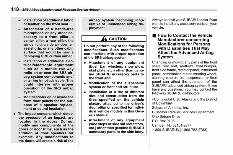
(112,1)
北米Model "A2600BE-B" EDITED: 2020/ 10/ 1
– Installation of additional fabricor leather on the front seat
– Attachment of a hands-freemicrophone or any other ac-cessory to a front pillar, acenter pillar, a rear pillar, thewindshield, a side window, anassist grip, or any other cabinsurface that would be near adeploying SRS curtain airbag.
– Installation of additional elec-trical/electronic equipmentsuch as a mobile two-wayradio on or near the SRS air-bag system components and/or wiring is not advisable. Thiscould interfere with properoperation of the SRS airbagsystem.
– Modifications on or inside thefront door panels for the pur-pose of a speaker replace-ment or sound insulation
. The impact sensors, which detectthe pressure of an impact, arelocated in the doors. Do notmodify any components of thedoors or door trims, such as theaddition of door speakers forexample. Any modifications tothe doors will create a risk of the
airbag system becoming inop-erative or unintended airbag de-ployment.
CAUTION
Do not perform any of the followingmodifications. Such modificationscan interfere with proper operationof the SRS airbag system.. Attachment of any equipment
(bush bar, winches, snow plow,skid plate, etc.) other than genu-ine SUBARU accessory parts tothe front end.
. Modification of the suspensionsystem or front end structure.
. Installation of a tire of differentsize and construction from thetires specified on the vehicleplacard attached to the driver’sdoor pillar or specified for indivi-dual vehicle models in this Own-er’s Manual.
. Attachment of any equipment(side steps or side sill protectors,etc.) other than genuine SUBARUaccessory parts to the side body.
Always consult your SUBARUdealer if youwant to install any accessory parts on yourvehicle.
& How to Contact the VehicleManufacturer concerningModifications for Personswith Disabilities That MayAffect the Advanced AirbagSystem
s01ah15Changing or moving any parts of the frontseats, rear seat, seatbelts, front bumper,front side frame, radiator panel, instrumentpanel, combination meter, steering wheel,steering column, tire, suspension or floorpanel can affect the operation of theSUBARU advanced airbag system. If youhave any questions, you may contact thefollowing SUBARU distributors.
<Continental U.S., Alaska and the Districtof Columbia>Subaru of America, Inc.Customer Retailer Services DepartmentOne Subaru DriveP.O. Box 9103Camden, NJ 08101-98771-800-SUBARU3 (1-800-782-2783)
SRS Airbag (Supplemental Restraint System Airbag)110
(113,1)
北米Model "A2600BE-B" EDITED: 2020/ 10/ 1
<Hawaii>Subaru Hawaii2850 Pukoloa Street, Ste. 101,Honolulu, HI 96819877-215-0338
<Guam>Shen’s Corporation dba Prestige Automo-biles491 East Marine Corps Drive,Dededo, Guam 96929671-633-2698
<Puerto Rico>Trebol Motors296 Marginal JF Kennedy, San Juan,Puerto Rico787-793-2828
<Canada>Subaru Canada, Inc.Consumer Support Department560 Suffolk Court, Mississauga, OntarioL5R 4J71-800-894-4212
There are currently no SUBARU distribu-tors in any other U.S. territories. If you arein such an area, please contact theSUBARU distributor or dealer from whichyou bought your vehicle.
SRS Airbag (Supplemental Restraint System Airbag) 111
1
Seat,SeatbeltandSR
SAirbags

(114,1)
北米Model "A2600BE-B" EDITED: 2020/ 10/ 1
— — — — — — — — — — — — — — — — — — — — — — — — — — — — — — — — — — — — — — — —
— — — — — — — — — — — — — — — — — — — — — — — — — — — — — — — — — — — — — — — —
— — — — — — — — — — — — — — — — — — — — — — — — — — — — — — — — — — — — — — — —
— — — — — — — — — — — — — — — — — — — — — — — — — — — — — — — — — — — — — — — —
— — — — — — — — — — — — — — — — — — — — — — — — — — — — — — — — — — — — — — — —
— — — — — — — — — — — — — — — — — — — — — — — — — — — — — — — — — — — — — — — —
— — — — — — — — — — — — — — — — — — — — — — — — — — — — — — — — — — — — — — — —
— — — — — — — — — — — — — — — — — — — — — — — — — — — — — — — — — — — — — — — —
— — — — — — — — — — — — — — — — — — — — — — — — — — — — — — — — — — — — — — — —
— — — — — — — — — — — — — — — — — — — — — — — — — — — — — — — — — — — — — — — —
— — — — — — — — — — — — — — — — — — — — — — — — — — — — — — — — — — — — — — — —
— — — — — — — — — — — — — — — — — — — — — — — — — — — — — — — — — — — — — — — —
— — — — — — — — — — — — — — — — — — — — — — — — — — — — — — — — — — — — — — — —
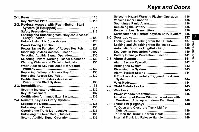
(115,1)
北米Model "A2600BE-B" EDITED: 2020/ 10/ 1
s022-1. Keys................................................................. 115
Key Number Plate............................................... 1152-2. Keyless Access with Push-Button Start
System (If Equipped) .................................... 115Safety Precautions.............................................. 116Locking and Unlocking with “Keyless Access”Entry Function..................................................120
Unlock Using PIN Code Access ..........................124Power Saving Function.......................................126Power Saving Function of Access Key Fob .........127Disabling Keyless Access Function ....................127Selecting Audible Signal Operation .....................130Selecting Hazard Warning Flasher Operation.......130Warning Chimes and Warning Indicator ..............130When Access Key Fob Does Not OperateProperly ...........................................................130
Replacing Battery of Access Key Fob .................130Replacing Access Key Fob .................................130Certification for Keyless Access withPush-Button Start System.................................130
2-3. Immobilizer...................................................... 131Security Indicator Light.......................................132Key Replacement................................................132Certification for Immobilizer System....................132
2-4. Remote Keyless Entry System ...................... 133Locking the Doors ..............................................135Unlocking the Doors ...........................................135Opening the Trunk Lid (Legacy) ..........................135Unlocking the Rear Gate (Outback) .....................135Setting Audible Signal Operation ........................135
Selecting Hazard Warning Flasher Operation ...... 136Vehicle Finder Function...................................... 136Sounding a Panic Alarm..................................... 136Replacing the Battery......................................... 136Replacing Lost Transmitters............................... 136Certification for Remote Keyless Entry System... 136
2-5. Door Locks ......................................................137Locking and Unlocking from the Outside............ 137Locking and Unlocking from the Inside .............. 139Automatic Door Locking/Unlocking .................... 140Key Lock-In Prevention Function........................ 140Battery Drainage Prevention Function ................ 141
2-6. Alarm System ..................................................141Alarm System Operation .................................... 142Arming the System ............................................ 142Disarming the System ........................................ 143Alarm System Setting......................................... 144If You Have Accidentally Triggered the AlarmSystem ............................................................ 144
Valet Mode ......................................................... 1442-7. Child Safety Locks ..........................................1452-8. Windows...........................................................145
Power Window Operation ................................... 146Initialization of Power Window (Windows withOne-Touch Auto up and down Function)........... 148
2-9. Trunk Lid (Legacy) ..........................................148To Open and Close the Trunk Lid fromOutside............................................................ 149
To Open the Trunk Lid from Inside ..................... 149Internal Trunk Lid Release Handle ...................... 149
Keys and Doors
2
Keys
andDoors
(116,1)
北米Model "A2600BE-B" EDITED: 2020/ 10/ 1
2-10. Rear Gate (Outback) ..................................... 151Manual Rear Gate ...............................................151Power Rear Gate (If Equipped) ............................152
2-11. Moonroof (If Equipped) .................................161Moonroof Switches ............................................ 161Sunshade........................................................... 162
Keys and Doors
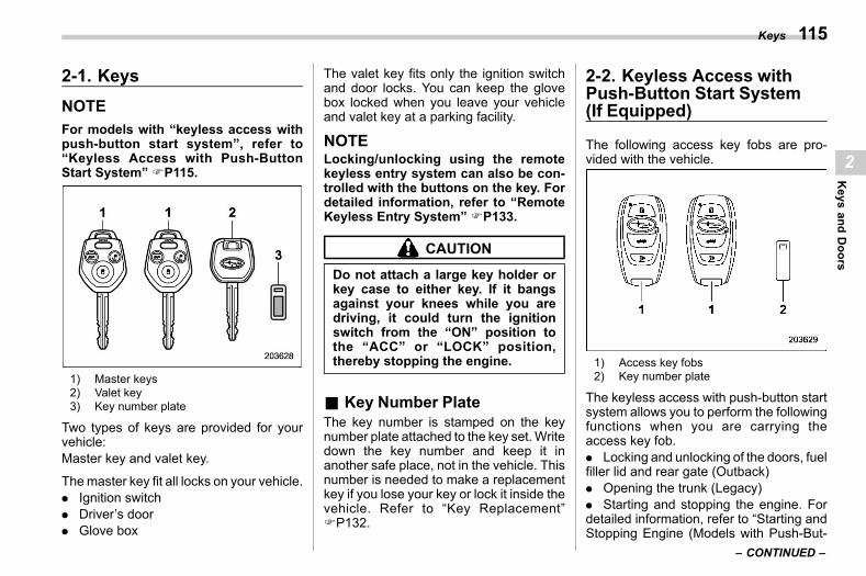
(117,1)
北米Model "A2600BE-B" EDITED: 2020/ 10/ 1
2-1. Keyss02aa
NOTEFor models with “keyless access withpush-button start system”, refer to“Keyless Access with Push-ButtonStart System” FP115.
1) Master keys2) Valet key3) Key number plate
Two types of keys are provided for yourvehicle:Master key and valet key.
Themaster key fit all locks on your vehicle.. Ignition switch. Driver’s door. Glove box
The valet key fits only the ignition switchand door locks. You can keep the glovebox locked when you leave your vehicleand valet key at a parking facility.
NOTELocking/unlocking using the remotekeyless entry system can also be con-trolled with the buttons on the key. Fordetailed information, refer to “RemoteKeyless Entry System” FP133.
CAUTION
Do not attach a large key holder orkey case to either key. If it bangsagainst your knees while you aredriving, it could turn the ignitionswitch from the “ON” position tothe “ACC” or “LOCK” position,thereby stopping the engine.
& Key Number Plates02aa01
The key number is stamped on the keynumber plate attached to the key set.Writedown the key number and keep it inanother safe place, not in the vehicle. Thisnumber is needed to make a replacementkey if you lose your key or lock it inside thevehicle. Refer to “Key Replacement”FP132.
2-2. Keyless Access withPush-Button Start System(If Equipped)
s02ap
The following access key fobs are pro-vided with the vehicle.
1) Access key fobs2) Key number plate
The keyless access with push-button startsystem allows you to perform the followingfunctions when you are carrying theaccess key fob.. Locking and unlocking of the doors, fuelfiller lid and rear gate (Outback). Opening the trunk (Legacy). Starting and stopping the engine. Fordetailed information, refer to “Starting andStopping Engine (Models with Push-But-
– CONTINUED –
Keys 115
2
Keys
andDoors
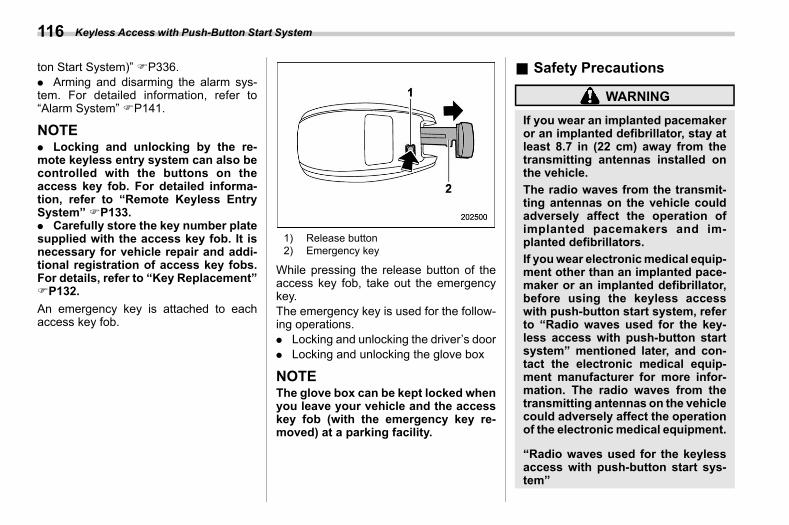
(118,1)
北米Model "A2600BE-B" EDITED: 2020/ 10/ 1
ton Start System)” FP336.. Arming and disarming the alarm sys-tem. For detailed information, refer to“Alarm System” FP141.
NOTE. Locking and unlocking by the re-mote keyless entry system can also becontrolled with the buttons on theaccess key fob. For detailed informa-tion, refer to “Remote Keyless EntrySystem” FP133.. Carefully store the key number platesupplied with the access key fob. It isnecessary for vehicle repair and addi-tional registration of access key fobs.For details, refer to “Key Replacement”FP132.An emergency key is attached to eachaccess key fob.
1) Release button2) Emergency key
While pressing the release button of theaccess key fob, take out the emergencykey.The emergency key is used for the follow-ing operations.. Locking and unlocking the driver’s door. Locking and unlocking the glove box
NOTEThe glove box can be kept locked whenyou leave your vehicle and the accesskey fob (with the emergency key re-moved) at a parking facility.
& Safety Precautionss02ap11
WARNING
If you wear an implanted pacemakeror an implanted defibrillator, stay atleast 8.7 in (22 cm) away from thetransmitting antennas installed onthe vehicle.The radio waves from the transmit-ting antennas on the vehicle couldadversely affect the operation ofimplanted pacemakers and im-planted defibrillators.If youwear electronicmedical equip-ment other than an implanted pace-maker or an implanted defibrillator,before using the keyless accesswith push-button start system, referto “Radio waves used for the key-less access with push-button startsystem” mentioned later, and con-tact the electronic medical equip-ment manufacturer for more infor-mation. The radio waves from thetransmitting antennas on the vehiclecould adversely affect the operationof the electronic medical equipment.
“Radio waves used for the keylessaccess with push-button start sys-tem”
Keyless Access with Push-Button Start System116
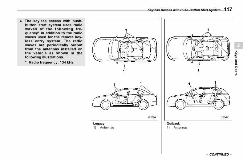
(119,1)
北米Model "A2600BE-B" EDITED: 2020/ 10/ 1
. The keyless access with push-button start system uses radiowaves of the following fre-quency* in addition to the radiowaves used for the remote key-less entry system. The radiowaves are periodically outputfrom the antennas installed onthe vehicle as shown in thefollowing illustrations.*: Radio frequency: 134 kHz
Legacy1) Antennas
Outback1) Antennas
– CONTINUED –
Keyless Access with Push-Button Start System 117
2
Keys
andDoors
(120,1)
北米Model "A2600BE-B" EDITED: 2020/ 10/ 1
CAUTION
. Never leave or store the accesskey fob inside the vehicle orwithin 6.6 ft (2 m) around thevehicle (e.g., in the garage). Theaccess key fob may be lockedinside the vehicle, or the batterymay discharge rapidly. Note thatthe push-button ignition switchmay not turn on in some casesdepending on the location of theaccess key fob.
. The access key fob containselectronic components. Observethe following precautions to pre-vent malfunctions.– It is recommended to have the
access key fob battery re-placed at an authorizedSUBARU dealer to avoid therisk of damage.
– Do not get the access key fobwet. If the access key fob getswet, wipe it off immediatelyand let it dry completely.
– Donot apply strong impacts tothe access key fob.
– Never leave the access keyfob in direct sunlight or any-where that may become hot,
such as on the dashboard. Itmay damage the battery orcause circuit malfunctions.
– Do not wash the access keyfob in an ultrasonic washer.
– Do not leave the access keyfob in humid or dusty loca-tions. Doing so may causemalfunctions.
– Keep the access key fob awayfrom magnetic sources.
– Do not leave the access keyfob near a personal computeror home electrical appliance.
– Do not leave the access keyfob near a battery charger orany electrical accessories.
– Do not apply metallic windowtint or attach metallic objectsto the windows.
– Do not fit non genuine acces-sories or parts.
. If the access key fob is dropped,the integrated emergency key in-side may become loose. Be care-ful not to lose the emergency key.
. When traveling in an airplane, donot press the button of the ac-cess key fob. If any button of theaccess key fob is pressed, radio
waves are emitted and may affectthe operation of the airplane. In abag, take measures to preventthe buttons from being pressedaccidentally.
NOTE. The operational/non-operationalsetting for the keyless access functioncan be changed. For the setting proce-dure, refer to “Disabling Keyless Ac-cess Function” FP127.. For detailed information about theoperation method for the push-buttonignition switch while the keyless ac-cess function is switched to the non-operational mode, refer to “Access KeyFob – If Access Key Fob Does NotOperate Properly” FP465.. The keyless access with push-but-ton start system uses weak radiowaves. The status of the access keyfob and environmental conditions mayinterfere with the communication be-tween the access key fob and thevehicle under the following conditions,and it may not be possible to lock orunlock the doors or start the engine.
– When operating near a facilitywhere strong radio waves are trans-mitted, such as a broadcast station
Keyless Access with Push-Button Start System118
(121,1)
北米Model "A2600BE-B" EDITED: 2020/ 10/ 1
and power transmission lines.– When products that transmitradio waves are used, such as anaccess key fob or a remote trans-mitter key of another vehicle.– When carrying the access key fobof your vehicle together with theaccess key fob or the remote trans-mitter of another vehicle.– When the access key fob isplaced near wireless communica-tion equipment such as a cellphone.– When the access key fob isplaced near a metallic object.– When metallic accessories areattached to the access key fob.– When carrying the access key fobwith an electronic appliance such asa laptop computer.– When the battery of the accesskey fob is discharged.
. The access key fob is always com-municating with the vehicle and iscontinuously using the battery.Although the life of the battery variesdepending on the operating conditions,it is approximately 1 to 2 years. If thebattery becomes fully discharged, re-place it with a new one.
. If an access key fob is lost, it isrecommended that all of the remainingaccess key fobs be reregistered. Forreregistration of an access key fob,contact a SUBARU dealer.. For a spare access key fob, contact aSUBARU dealer.. Up to 7 access key fobs can beregistered for one vehicle.. Do not leave the access key fob inthe storage spaces inside the vehicle,such as the door pocket, dashboard orinside the corner of the cargo area.Vibrations may damage the key fob orturn on the switch, possibly resulting ina lockout.. After the vehicle battery is dis-charged or replaced, initialization ofthe steering lock system may be re-quired to start the engine. In this case,perform the following procedure toinitialize the steering lock.
(1) Turn the push-button ignitionswitch to the “OFF” position. Fordetails, refer to “Switching PowerStatus” FP171.(2) Open and close the driver’sdoor.(3) Wait for approximately 10 sec-onds.
When the steering is locked, the initi-alization is completed.. Do not leave the access key fob inthe following places.
– On the instrument panel– On the floor– Inside the glove box– Inside the door trim pocket– On the rear seat– On the rear shelf (Legacy)– Inside the trunk (Legacy)– In the cargo area (Outback)
If you do, the following situationsmay occur.– The access key fob is mistakenlylocked inside the vehicle.– A false warning issues althoughno malfunction actually occurs.– No warning issues even when amalfunction occurs.
– CONTINUED –
Keyless Access with Push-Button Start System 119
2
Keys
andDoors
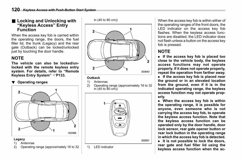
(122,1)
北米Model "A2600BE-B" EDITED: 2020/ 10/ 1
& Locking and Unlocking with“Keyless Access” EntryFunction
s02ap01When the access key fob is carried withinthe operating range, the doors, the fuelfiller lid, the trunk (Legacy) and the reargate (Outback) can be locked/unlockedjust by touching the door handle.
NOTEThe vehicle can also be locked/un-locked with the remote keyless entrysystem. For details, refer to “RemoteKeyless Entry System” FP133.
! Operating rangess02ap0101
Legacy1) Antennas2) Operating range (approximately 16 to 32
in (40 to 80 cm))
Outback1) Antennas2) Operating range (approximately 16 to 32
in (40 to 80 cm))
1) LED indicator
When the access key fob is within either ofthe operating ranges of the front doors, theLED indicator on the access key fobflashes. When the keyless access func-tions are disabled, the LED indicator doesnot flash unless a button on the access keyfob is pressed.
NOTE. If the access key fob is placed tooclose to the vehicle body, the keylessaccess functions may not operateproperly. If it does not operate properly,repeat the operation from farther away.. If the access key fob is placed nearthe ground or in an elevated locationfrom the ground, even if it is in theindicated operating range, the keylessaccess function may not operate prop-erly.. When the access key fob is withinthe operating range, it is possible foranyone, even someone who is notcarrying the access key fob, to operatethe keyless access function. Note thatthe keyless access function can beoperated only by the door handle, doorlock sensor, rear gate opener button orrear lock button in the operating rangein which the access key fob is detected.. It is not possible to lock the doors,rear gate and fuel filler lid using thekeyless access function when the ac-
Keyless Access with Push-Button Start System120
(123,1)
北米Model "A2600BE-B" EDITED: 2020/ 10/ 1
cess key fob is inside the vehicle.However, depending on the status ofthe access key fob and the environ-mental conditions, the access key fobmay be locked inside the vehicle.Before locking the vehicle, make surethat you have the access key fob.. When the battery of the access keyfob is discharged, or when operating itin a location with strong radio waves ornoise (e.g., near a radio tower, powerplant, broadcast station or an areawhere wireless equipment is used), orwhile talking on a cell phone, theoperating ranges may be reduced, orthe keyless access function may notoperate.In such a case, perform the proceduredescribed in “Locking and Unlocking”FP466.. The doors may lock or unlock whenthe car is being washed or exposed to asignificant amount of water thattouches the door handle while the keyfob is still in the operating range.
! How to lock and unlocks02ap0108
It is possible to perform the followingoperations when you are carrying theaccess key fob.. Lock and unlock the doors and the fuelfiller lid.
. Unlock the trunk lid (Legacy).
. Unlock and lock the rear gate(Outback).
NOTE. It is not possible to lock the doors,rear gate and fuel filler lid using thekeyless access function when thepush-button ignition switch is in the“ACC” or “ON” position. Refer to“Switching Power Status” FP171.. If the door handle is gripped with agloved hand, the door lock may not bereleased.. If the door lock sensor is touchedthree times or more repeatedly, thesystem will ignore the sensor opera-tion.. When performing the locking proce-dure too quickly, locking may notcomplete. After performing the lockingprocedure, it is recommended to pullthe rear door handle to confirm that thedoors have been locked.. If any of the doors (or the rear gate)are not fully closed, the following willoccur to alert you that the doors (or therear gate) are not properly closed.
– An electronic chirp sounds fivetimes.– The hazard warning flashersflash five times.
. It is possible to lock the doors evenwhen one of the doors is open. Afterperforming the locking procedure,close the opened door or rear gate tolock it.. Within 3 seconds after locking thedoors and the rear gate using thekeyless access function, it is not pos-sible to unlock doors and/or the reargate using the keyless access function.. When locking, be sure to carry theaccess key fob to prevent locking theaccess key fob in the vehicle.. The setting of the hazard warningflasher operation and the volume of theaudible signal can be changed by yourSUBARU dealer. Contact your SUBARUdealer for details. Also, for models withthe center information display, thesetting of the hazard warning flasheroperation can be changed by operatingthe center information display. For de-tails, refer to “Car settings” FP220.
– CONTINUED –
Keyless Access with Push-Button Start System 121
2
Keys
andDoors
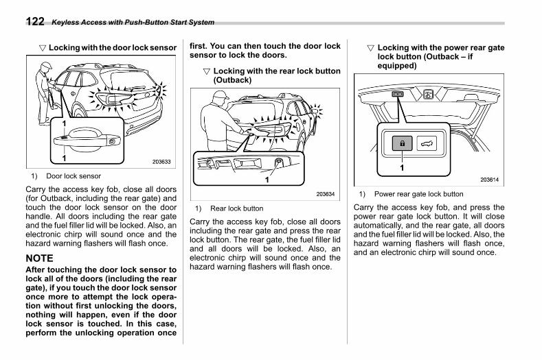
(124,1)
北米Model "A2600BE-B" EDITED: 2020/ 10/ 1
! Lockingwith thedoor locksensors02ap010801
1) Door lock sensor
Carry the access key fob, close all doors(for Outback, including the rear gate) andtouch the door lock sensor on the doorhandle. All doors including the rear gateand the fuel filler lid will be locked. Also, anelectronic chirp will sound once and thehazard warning flashers will flash once.
NOTEAfter touching the door lock sensor tolock all of the doors (including the reargate), if you touch the door lock sensoronce more to attempt the lock opera-tion without first unlocking the doors,nothing will happen, even if the doorlock sensor is touched. In this case,perform the unlocking operation once
first. You can then touch the door locksensor to lock the doors.
! Locking with the rear lock button(Outback)
s02ap010802
1) Rear lock button
Carry the access key fob, close all doorsincluding the rear gate and press the rearlock button. The rear gate, the fuel filler lidand all doors will be locked. Also, anelectronic chirp will sound once and thehazard warning flashers will flash once.
! Locking with the power rear gatelock button (Outback – ifequipped)
s02ap010803
1) Power rear gate lock button
Carry the access key fob, and press thepower rear gate lock button. It will closeautomatically, and the rear gate, all doorsand the fuel filler lid will be locked. Also, thehazard warning flashers will flash once,and an electronic chirp will sound once.
Keyless Access with Push-Button Start System122
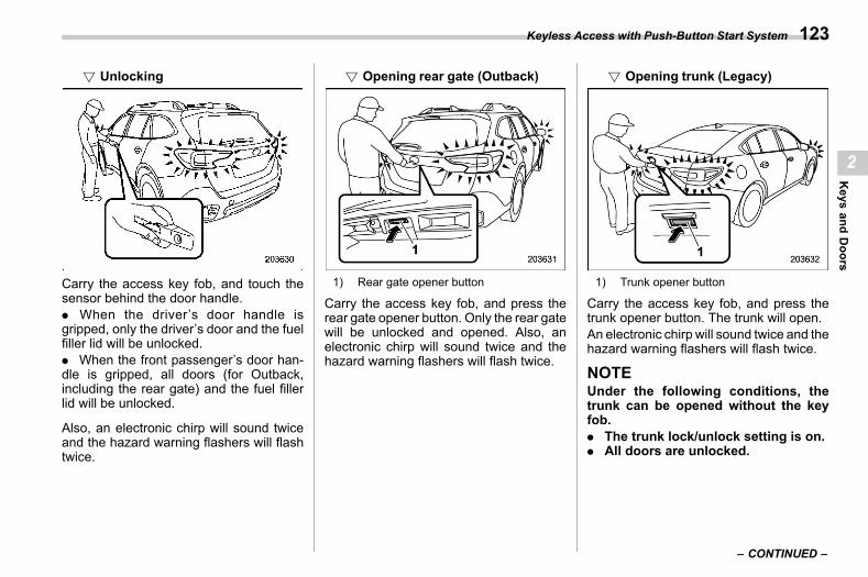
(125,1)
北米Model "A2600BE-B" EDITED: 2020/ 10/ 1
! Unlockings02ap010804
Carry the access key fob, and touch thesensor behind the door handle.. When the driver’s door handle isgripped, only the driver’s door and the fuelfiller lid will be unlocked.. When the front passenger’s door han-dle is gripped, all doors (for Outback,including the rear gate) and the fuel fillerlid will be unlocked.
Also, an electronic chirp will sound twiceand the hazard warning flashers will flashtwice.
! Opening rear gate (Outback)s02ap010805
1) Rear gate opener button
Carry the access key fob, and press therear gate opener button. Only the rear gatewill be unlocked and opened. Also, anelectronic chirp will sound twice and thehazard warning flashers will flash twice.
! Opening trunk (Legacy)s02ap010806
1) Trunk opener button
Carry the access key fob, and press thetrunk opener button. The trunk will open.An electronic chirp will sound twice and thehazard warning flashers will flash twice.
NOTEUnder the following conditions, thetrunk can be opened without the keyfob.. The trunk lock/unlock setting is on.. All doors are unlocked.
– CONTINUED –
Keyless Access with Push-Button Start System 123
2
Keys
andDoors
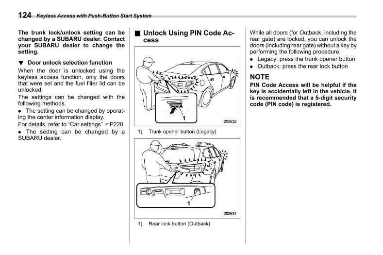
(126,1)
北米Model "A2600BE-B" EDITED: 2020/ 10/ 1
The trunk lock/unlock setting can bechanged by a SUBARU dealer. Contactyour SUBARU dealer to change thesetting.
! Door unlock selection functions02ap0105
When the door is unlocked using thekeyless access function, only the doorsthat were set and the fuel filler lid can beunlocked.The settings can be changed with thefollowing methods.. The setting can be changed by operat-ing the center information display.For details, refer to “Car settings”FP220.. The setting can be changed by aSUBARU dealer.
& Unlock Using PIN Code Ac-cess
s02ap21
1) Trunk opener button (Legacy)
1) Rear lock button (Outback)
While all doors (for Outback, including therear gate) are locked, you can unlock thedoors (including rear gate) without a key byperforming the following procedure.. Legacy: press the trunk opener button. Outback: press the rear lock button
NOTEPIN Code Access will be helpful if thekey is accidentally left in the vehicle. Itis recommended that a 5-digit securitycode (PIN code) is registered.
Keyless Access with Push-Button Start System124
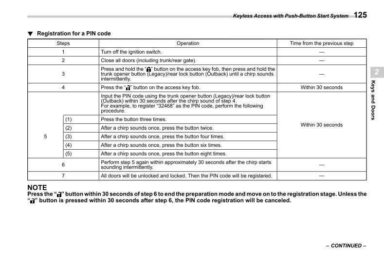
(127,1)
北米Model "A2600BE-B" EDITED: 2020/ 10/ 1
! Registration for a PIN codes02ap2102
Steps Operation Time from the previous step
1 Turn off the ignition switch. —2 Close all doors (including trunk/rear gate). —
3Press and hold the “ ” button on the access key fob, then press and hold thetrunk opener button (Legacy)/rear lock button (Outback) until a chirp soundsintermittently.
—
4 Press the “ ” button on the access key fob. Within 30 seconds
Input the PIN code using the trunk opener button (Legacy)/rear lock button(Outback) within 30 seconds after the chirp sound of step 4.For example, to register “32468” as the PIN code, perform the followingprocedure.
Within 30 seconds
5
(1) Press the button three times.
(2) After a chirp sounds once, press the button twice.(3) After a chirp sounds once, press the button four times.
(4) After a chirp sounds once, press the button six times.(5) After a chirp sounds once, press the button eight times.
6 Perform step 5 again within approximately 30 seconds after the chirp startssounding intermittently. —
7 All doors will be unlocked and locked. Then the PIN code will be registered. —
NOTEPress the “ ” buttonwithin 30 seconds of step 6 to end the preparationmode andmove on to the registration stage. Unless the“ ” button is pressed within 30 seconds after step 6, the PIN code registration will be canceled.
– CONTINUED –
Keyless Access with Push-Button Start System 125
2
Keys
andDoors
(128,1)
北米Model "A2600BE-B" EDITED: 2020/ 10/ 1
NOTE. Press the trunk opener button/rearlock button ten times to enter “0”.. Change the PIN code frequently toprotect your vehicle from theft.. If you have lent your vehicle toanother person, confirm that the PINcode has not been changed or deleted.If the PIN code has been changed ordeleted, reregister a new PIN code.. If you make an error during theregistration procedure, press the “ ”or “ ” button on the access key fob.Then, start over from the proceduredescribed in “Preparation”.. To protect your vehicle from theft,you cannot register “00000” to “99999”or “12345” as a PIN code.. Do not register your vehicle licenseplate number or simple numbers suchas “11122” or “12121” as a PIN code.Doing so will increase the risk ofvehicle theft.. When you try to register “22222”, theregistered PIN code will be deleted. Youcannot unlock the doors by PIN CodeAccess until a new code is registered.. After registering a new PIN code,make sure that you can unlock thedoors using the PIN code.. The PIN code cannot be deletedwhile the keyless access function is
disabled by operating the access keyfob.. Reregister the PIN code in the fol-lowing case.
– When you forget the PIN code– When you want to change the PINcode
! Unlockings02ap2103
Perform steps (1) to (5) of step 5 describedin “Registration”.
NOTE. You cannot unlock by PIN CodeAccess in the following cases.
– When the access key fob is withinthe operating ranges– When the ignition switch is in the“ACC” or “ON” position
. If you make an operation error dur-ing the unlocking procedure, start overwith the unlocking procedure afterwaiting for 5 seconds or longer.. To protect your vehicle from theft, abuzzer will sound if incorrect PIN codesare entered five times continuously. Ifthis occurs, you cannot unlock thedoors by PIN Code Access for 5minutes.
& Power Saving Functions02ap23
To protect the access key fob battery andthe vehicle battery, the keyless accessfunction will be disabled as follows.. When the keyless access function andthe remote keyless entry system have notbeen used:
(1) 5 days after the push-button igni-tion switch has been turned off, com-munication between the antennas andthe access key fob will be stopped.(2) 9 days after step (1), the sensors(both lock sensor and unlock sensor)on the front passenger’s door will bedisabled.
. When the access key fob has been leftin the operating range for 10 minutes orlonger while all doors are locked, thekeyless access function will be disabled.
! Recovery from power saving modes02ap2301
When one of the following operations isperformed, the keyless access functionwill be recovered.. Unlock by gripping the door handle(only when the sensors on the frontpassenger’s door are not disabled) orpressing the rear gate opener button onthe rear gate (Outback)/trunk openerbutton on the trunk lid (Legacy).
Keyless Access with Push-Button Start System126
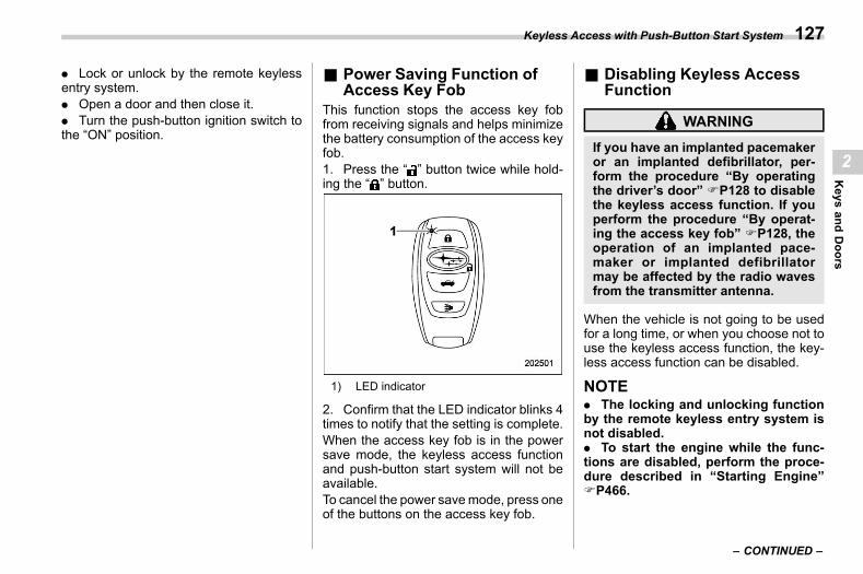
(129,1)
北米Model "A2600BE-B" EDITED: 2020/ 10/ 1
. Lock or unlock by the remote keylessentry system.. Open a door and then close it.. Turn the push-button ignition switch tothe “ON” position.
& Power Saving Function ofAccess Key Fob
s02ap26This function stops the access key fobfrom receiving signals and helps minimizethe battery consumption of the access keyfob.1. Press the “ ” button twice while hold-ing the “ ” button.
1) LED indicator
2. Confirm that the LED indicator blinks 4times to notify that the setting is complete.When the access key fob is in the powersave mode, the keyless access functionand push-button start system will not beavailable.To cancel the power savemode, press oneof the buttons on the access key fob.
& Disabling Keyless AccessFunction
s02ap07
WARNING
If you have an implanted pacemakeror an implanted defibrillator, per-form the procedure “By operatingthe driver’s door” FP128 to disablethe keyless access function. If youperform the procedure “By operat-ing the access key fob” FP128, theoperation of an implanted pace-maker or implanted defibrillatormay be affected by the radio wavesfrom the transmitter antenna.
When the vehicle is not going to be usedfor a long time, or when you choose not touse the keyless access function, the key-less access function can be disabled.
NOTE. The locking and unlocking functionby the remote keyless entry system isnot disabled.. To start the engine while the func-tions are disabled, perform the proce-dure described in “Starting Engine”FP466.
– CONTINUED –
Keyless Access with Push-Button Start System 127
2
Keys
andDoors
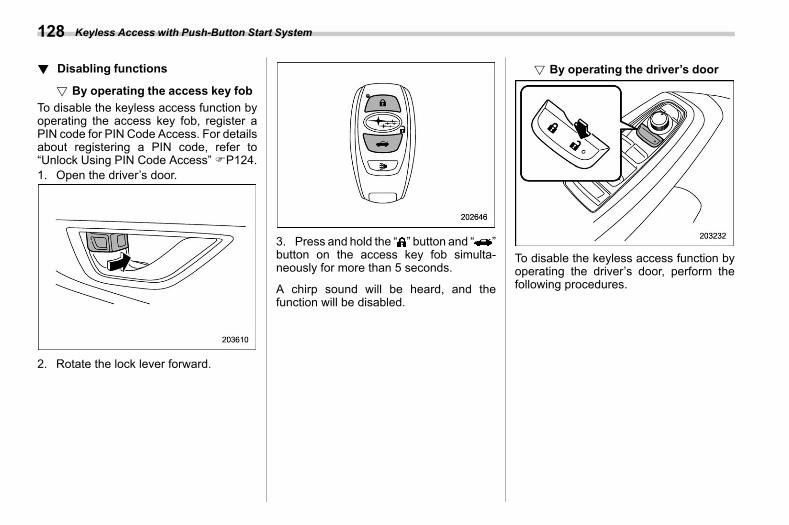
(130,1)
北米Model "A2600BE-B" EDITED: 2020/ 10/ 1
! Disabling functionss02ap0701
! By operating the access key fobs02ap070102
To disable the keyless access function byoperating the access key fob, register aPIN code for PIN Code Access. For detailsabout registering a PIN code, refer to“Unlock Using PIN Code Access”FP124.1. Open the driver’s door.
2. Rotate the lock lever forward.
3. Press and hold the “ ” button and “ ”button on the access key fob simulta-neously for more than 5 seconds.
A chirp sound will be heard, and thefunction will be disabled.
! By operating the driver’s doors02ap070101
To disable the keyless access function byoperating the driver’s door, perform thefollowing procedures.
Keyless Access with Push-Button Start System128
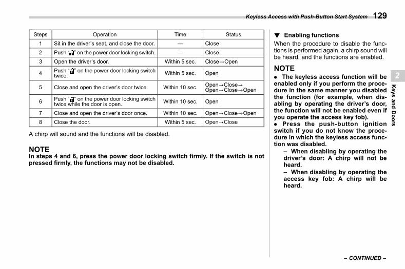
(131,1)
北米Model "A2600BE-B" EDITED: 2020/ 10/ 1
Steps Operation Time Status1 Sit in the driver’s seat, and close the door. — Close
2 Push “ ” on the power door locking switch. — Close
3 Open the driver’s door. Within 5 sec. Close?Open
4 Push “ ” on the power door locking switchtwice. Within 5 sec. Open
5 Close and open the driver’s door twice. Within 10 sec. Open?Close?Open?Close?Open
6 Push “ ” on the power door locking switchtwice while the door is open. Within 10 sec. Open
7 Close and open the driver’s door once. Within 10 sec. Open?Close?Open
8 Close the door. Within 5 sec. Open?Close
A chirp will sound and the functions will be disabled.
NOTEIn steps 4 and 6, press the power door locking switch firmly. If the switch is notpressed firmly, the functions may not be disabled.
! Enabling functionss02ap0702
When the procedure to disable the func-tions is performed again, a chirp sound willbe heard, and the functions are enabled.
NOTE. The keyless access function will beenabled only if you perform the proce-dure in the same manner you disabledthe function (for example, when dis-abling by operating the driver’s door,the function will not be enabled even ifyou operate the access key fob).. Press the push-button ignitionswitch if you do not know the proce-dure in which the keyless access func-tion was disabled.
– When disabling by operating thedriver’s door: A chirp will not beheard.– When disabling by operating theaccess key fob: A chirp will beheard.
– CONTINUED –
Keyless Access with Push-Button Start System 129
2
Keys
andDoors
(132,1)
北米Model "A2600BE-B" EDITED: 2020/ 10/ 1
& Selecting Audible Signal Op-eration
s02ap12Using an electronic chirp, the system willgive you an audible signal when the doorsare locked or unlocked. If desired, you canturn the audible signal off by operating thecenter information display. For details,refer to “Car settings” FP220.
Furthermore, the volume setting of theaudible signal can also be changed by aSUBARU dealer. Consult your SUBARUdealer for details.
& Selecting Hazard WarningFlasher Operation
s02ap18Using the hazard warning flasher, thesystem will give you a visible signal whenthe doors are locked or unlocked. Ifdesired, you can turn the hazard warningflashers off by operating the center infor-mation display. For details, refer to “Carsettings” FP220. The setting can also bechanged by a SUBARU dealer. Consultyour SUBARU dealer for details.
& WarningChimesandWarningIndicator
s02ap06The keyless access with push-button startsystem is equipped with a warning chimeand the access key warning indicator in
order to minimize improper operations andhelp protect your vehicle from theft.For details, refer to “Warning Chimes andWarning Indicator of the Keyless Accesswith Push-Button Start System” FP191.
& When Access Key Fob DoesNot Operate Properly
s02ap08Refer to “Access Key Fob – If Access KeyFob Does Not Operate Properly” FP465.
& Replacing Battery of AccessKey Fob
s02ap09Refer to “Replacing Battery of Access KeyFob” FP526.
& Replacing Access Key Fobs02ap13
Access key fobs can be replaced atSUBARU dealers. For more details, con-tact a SUBARU dealer.
& Certification for Keyless Ac-cess with Push-Button StartSystem
s02ap14. U.S.-spec. models
FCC ID: HYQ14AHKFCC ID: Y8PFJ18-2FCC ID: Y8PSSPIMB02
CAUTION
FCC WARNINGChanges or modifications not ex-pressly approved by the party re-sponsible for compliance could voidthe user’s authority to operate theequipment.
This device complies with part 15 of theFCC Rules. Operation is subject to thefollowing two conditions: (1) This devicemay not cause harmful interference, and(2) this device must accept any interfer-ence received, including interference thatmay cause undesired operation.
Keyless Access with Push-Button Start System130
(133,1)
北米Model "A2600BE-B" EDITED: 2020/ 10/ 1
. Canada-spec. models . Mexico-spec. models
IFTRLVDE1415-166114AHKDENSO
2-3. Immobilizers02ab
The immobilizer system is designed toprevent an unauthorized person fromstarting the engine. Only keys registeredwith your vehicle’s immobilizer system canbe used to operate your vehicle. If enginestart is attempted with an unregisteredaccess key fob or key, the engine will notstart. Even if the engine does start, it willstop after a few seconds. This system,however, is not a 100% anti-theft guaran-tee.
CAUTION
. Do not place the key under directsunlight or anywhere it may be-come hot.
. Do not get the key wet. If the keygets wet, wipe it dry with a clothimmediately.
. Do not modify or remove thesystem. If modified or removed,the proper operation of the sys-tem cannot be guaranteed.
NOTE. To protect your vehicle from theft,please pay close attention to the follow-ing security precautions:
– CONTINUED –
Immobilizer 131
2
Keys
andDoors
(134,1)
北米Model "A2600BE-B" EDITED: 2020/ 10/ 1
– Never leave your vehicle unat-tended with its keys inside.– Before leaving your vehicle,close all windows and the moon-roof, and lock the doors (all models)and rear gate (Outback).– Do not leave spare keys or anyrecord of your key number in thevehicle.
. The vehicle has a maintenance-freetype immobilizer system.
& Security Indicator Lights02ab02
Refer to “Security Indicator Light”FP196.
& Key Replacements02ab03
Your key number plate will be required ifyou ever need a replacement key made.Any new key must be registered for usewith your vehicle’s immobilizer systembefore it can be used. The maximumnumber of keys that can be registered foruse with one vehicle is as follows.. Four (models without “keyless accesswith push-button start system”). Seven (models with “keyless accesswith push-button start system”)
One key that has already been registeredis required in order to register a new key.
NOTEIf you lose a key, the lost key’s ID codestill remains in the memory of thevehicle’s immobilizer system. For se-curity reasons, the lost key’s ID codeshould be erased from the memory. Toerase the lost key’s ID code, all keysthat will be used are required.
For details about new key registrationand erasing the lost key’s ID code,contact your SUBARU dealer.
& Certification for ImmobilizerSystem
s02ab05. For models with “keyless accesswith push-button start system”:Refer to “Certification for Keyless Accesswith Push-Button Start System” FP130.
. For models without “keyless accesswith push-button start system”:
– U.S.-spec. models
FCC ID: Y8PFJ18-3
CAUTION
FCC WARNINGChanges or modifications not ex-pressly approved by the party re-sponsible for compliance could void
the user’s authority to operate theequipment.
This device complies with part 15 of theFCC Rules. Operation is subject to thefollowing two conditions: (1) This de-vice may not cause harmful interfer-ence, and (2) this device must acceptany interference received, includinginterference that may cause undesiredoperation.
Immobilizer132
(135,1)
北米Model "A2600BE-B" EDITED: 2020/ 10/ 1
– Canada-spec. models – Mexico-spec. models 2-4. Remote Keyless EntrySystem
s02ae
CAUTION
. Do not expose the remote trans-mitter to severe shocks, such asthose experienced as a result ofdropping or throwing.
. Do not take the remote transmit-ter apart except when replacingthe battery.
. Do not get the remote transmitterwet. If it gets wet, wipe it dry witha cloth immediately.
. When you carry the remote trans-mitter on an airplane, do notpress the button of the remotetransmitter while in the airplane.When any button of the remotetransmitter is pressed, radiowaves are sent and may affectthe operation of the airplane.When you carry the remote trans-mitter in a bag on an airplane,take measures to prevent thebuttons of the remote transmitterfrom being pressed.
– CONTINUED –
Remote Keyless Entry System 133
2
Keys
andDoors
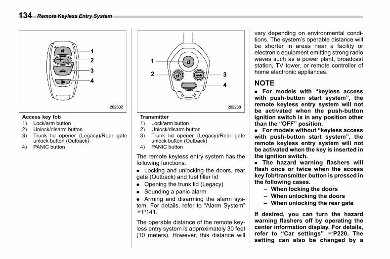
(136,1)
北米Model "A2600BE-B" EDITED: 2020/ 10/ 1
Access key fob1) Lock/arm button2) Unlock/disarm button3) Trunk lid opener (Legacy)/Rear gate
unlock button (Outback)4) PANIC button
Transmitter1) Lock/arm button2) Unlock/disarm button3) Trunk lid opener (Legacy)/Rear gate
unlock button (Outback)4) PANIC button
The remote keyless entry system has thefollowing functions.. Locking and unlocking the doors, reargate (Outback) and fuel filler lid. Opening the trunk lid (Legacy). Sounding a panic alarm. Arming and disarming the alarm sys-tem. For details, refer to “Alarm System”FP141.
The operable distance of the remote key-less entry system is approximately 30 feet(10 meters). However, this distance will
vary depending on environmental condi-tions. The system’s operable distance willbe shorter in areas near a facility orelectronic equipment emitting strong radiowaves such as a power plant, broadcaststation, TV tower, or remote controller ofhome electronic appliances.
NOTE. For models with “keyless accesswith push-button start system”, theremote keyless entry system will notbe activated when the push-buttonignition switch is in any position otherthan the “OFF” position.. For models without “keyless accesswith push-button start system”, theremote keyless entry system will notbe activated when the key is inserted inthe ignition switch.. The hazard warning flashers willflash once or twice when the accesskey fob/transmitter button is pressed inthe following cases.
– When locking the doors– When unlocking the doors– When unlocking the rear gate
If desired, you can turn the hazardwarning flashers off by operating thecenter information display. For details,refer to “Car settings” FP220. Thesetting can also be changed by a
Remote Keyless Entry System134
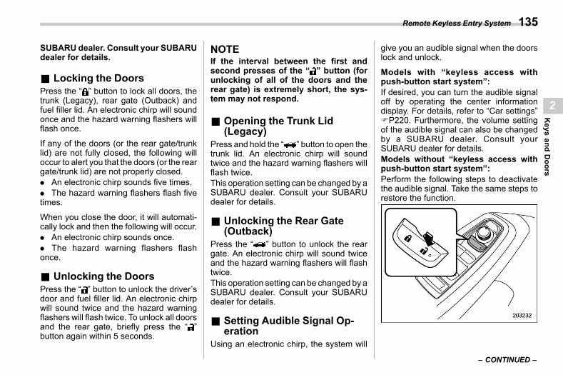
(137,1)
北米Model "A2600BE-B" EDITED: 2020/ 10/ 1
SUBARU dealer. Consult your SUBARUdealer for details.
& Locking the Doorss02ae01
Press the “ ” button to lock all doors, thetrunk (Legacy), rear gate (Outback) andfuel filler lid. An electronic chirp will soundonce and the hazard warning flashers willflash once.
If any of the doors (or the rear gate/trunklid) are not fully closed, the following willoccur to alert you that the doors (or the reargate/trunk lid) are not properly closed.. An electronic chirp sounds five times.. The hazard warning flashers flash fivetimes.
When you close the door, it will automati-cally lock and then the following will occur.. An electronic chirp sounds once.. The hazard warning flashers flashonce.
& Unlocking the Doorss02ae02
Press the “ ” button to unlock the driver’sdoor and fuel filler lid. An electronic chirpwill sound twice and the hazard warningflashers will flash twice. To unlock all doorsand the rear gate, briefly press the “ ”button again within 5 seconds.
NOTEIf the interval between the first andsecond presses of the “ ” button (forunlocking of all of the doors and therear gate) is extremely short, the sys-tem may not respond.
& Opening the Trunk Lid(Legacy)
s02ae13Press and hold the “ ” button to open thetrunk lid. An electronic chirp will soundtwice and the hazard warning flashers willflash twice.This operation setting can be changed by aSUBARU dealer. Consult your SUBARUdealer for details.
& Unlocking the Rear Gate(Outback)
s02ae03Press the “ ” button to unlock the reargate. An electronic chirp will sound twiceand the hazard warning flashers will flashtwice.This operation setting can be changed by aSUBARU dealer. Consult your SUBARUdealer for details.
& Setting Audible Signal Op-eration
s02ae07Using an electronic chirp, the system will
give you an audible signal when the doorslock and unlock.
Models with “keyless access withpush-button start system”:If desired, you can turn the audible signaloff by operating the center informationdisplay. For details, refer to “Car settings”FP220. Furthermore, the volume settingof the audible signal can also be changedby a SUBARU dealer. Consult yourSUBARU dealer for details.Models without “keyless access withpush-button start system”:Perform the following steps to deactivatethe audible signal. Take the same steps torestore the function.
– CONTINUED –
Remote Keyless Entry System 135
2
Keys
andDoors
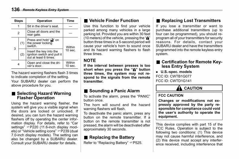
(138,1)
北米Model "A2600BE-B" EDITED: 2020/ 10/ 1
Steps Operation Time1 Sit in the driver’s seat. —
2 Close all doors and therear gate. —
3
(1)Press and hold “ ” onthe power lockingswitch. Within
10 sec.(2)
Insert the key into theignition switch and pull itout at least 6 times.
4 Open and close the dri-ver’s door.
Within10 sec.
The hazard warning flashers flash 3 timesto indicate completion of the setting.Your SUBARU dealer can perform theabove procedure for you.
& Selecting Hazard WarningFlasher Operation
s02ae26Using the hazard warning flasher, thesystem will give you a visible signal whenthe doors are locked or unlocked. Ifdesired, you can turn the hazard warningflashers off by operating the center infor-mation display. For details, refer to “Carsettings” FP220 (11.6-inch display mod-els) or “Vehicle setting icons”FP239 (dual7.0-inch display models). The setting canalso be changed by a SUBARU dealer.Consult your SUBARU dealer for details.
& Vehicle Finder Functions02ae05
Use this function to find your vehicleparked among many vehicles in a largeparking lot. Provided you are within 30 feet(10meters) of the vehicle, pressing the “ ”button three times in a 5-second period willcause your vehicle’s horn to sound onceand its hazard warning flashers to flashthree times.
NOTEIf the interval between presses is tooshort when you press the “ ” buttonthree times, the system may not re-spond to the signals from the remotetransmitter.
& Sounding a Panic Alarms02ae06
To activate the alarm, press the “PANIC”button once.The horn will sound and the hazardwarning flashers will flash.To deactivate the panic alarm, press anybutton on the remote transmitter. If abutton on the remote transmitter is notpressed, the alarmwill be deactivated afterapproximately 30 seconds.
& Replacing the Batterys02ae08
Refer to “Replacing Battery” FP525.
& Replacing Lost Transmitterss02ae09
If you lose a transmitter or want topurchase additional transmitters (up tofour can be programmed), you should re-program all of your transmitters for securityreasons. For details, contact yourSUBARU dealer and have the transmittersprogrammed into the remote keyless entrysystem.
& Certification for Remote Key-less Entry System
s02ae18. U.S.-spec. modelsFCC ID: CWTB1G077FCC ID: CWTD1G141
CAUTION
FCC CAUTIONChanges or modifications not ex-pressly approved by the party re-sponsible for compliance could voidthe user’s authority to operate theequipment.
This device complies with part 15 of theFCC Rules. Operation is subject to thefollowing two conditions: (1) This devicemay not cause harmful interference, and(2) this device must accept any interfer-ence received, including interference that
Remote Keyless Entry System136
(139,1)
北米Model "A2600BE-B" EDITED: 2020/ 10/ 1
may cause undesired operation.
. Canada-spec. models
. Mexico-spec. models
IFETEL RLVSUTB15-1814SUBARUMODEL: TB1G077
IFETEL RLVSUTD18-0302SUBARUMODEL: TD1G141
2-5. Door Lockss02ac
& Locking and Unlocking fromthe Outside
s02ac01NOTEIf you unlock the driver’s door with akey (including an emergency key) andopen the door while the alarm system isarmed, the alarm system is triggeredand the vehicle’s horn sounds. In thiscase, perform any of the followingoperations:
Models with “keyless access withpush-button start system”:. Press any button on the access keyfob (except when the access key fobbattery is discharged).. Turn the push-button ignition switchto the “ACC” position.. Carry the access key fob and per-form either of the following procedures.
– Grip the front door handle.– Press the rear gate opener but-ton.
Models without “keyless access withpush-button start system”:. Press any button on the remotetransmitter (except when the transmit-ter battery is discharged).
– CONTINUED –
Door Locks 137
2
Keys
andDoors
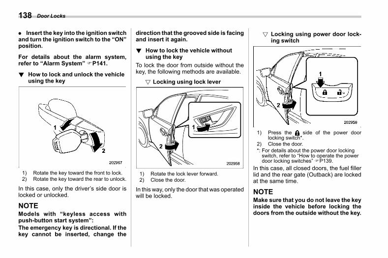
(140,1)
北米Model "A2600BE-B" EDITED: 2020/ 10/ 1
. Insert the key into the ignition switchand turn the ignition switch to the “ON”position.
For details about the alarm system,refer to “Alarm System” FP141.
! How to lock and unlock the vehicleusing the key
s02ac0101
1) Rotate the key toward the front to lock.2) Rotate the key toward the rear to unlock.
In this case, only the driver’s side door islocked or unlocked.
NOTEModels with “keyless access withpush-button start system”:The emergency key is directional. If thekey cannot be inserted, change the
direction that the grooved side is facingand insert it again.
! How to lock the vehicle withoutusing the key
s02ac0102To lock the door from outside without thekey, the following methods are available.
! Locking using lock levers02ac010201
1) Rotate the lock lever forward.2) Close the door.
In this way, only the door that was operatedwill be locked.
! Locking using power door lock-ing switch
s02ac010202
1) Press the side of the power doorlocking switch*.
2) Close the door.*: For details about the power door lockingswitch, refer to “How to operate the powerdoor locking switches” FP139.
In this case, all closed doors, the fuel fillerlid and the rear gate (Outback) are lockedat the same time.
NOTEMake sure that you do not leave the keyinside the vehicle before locking thedoors from the outside without the key.
Door Locks138
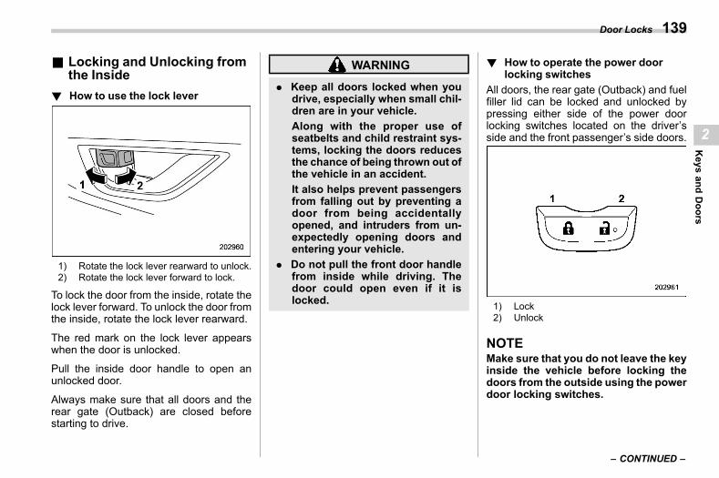
(141,1)
北米Model "A2600BE-B" EDITED: 2020/ 10/ 1
& Locking and Unlocking fromthe Inside
s02ac02
! How to use the lock levers02ac0202
1) Rotate the lock lever rearward to unlock.2) Rotate the lock lever forward to lock.
To lock the door from the inside, rotate thelock lever forward. To unlock the door fromthe inside, rotate the lock lever rearward.
The red mark on the lock lever appearswhen the door is unlocked.
Pull the inside door handle to open anunlocked door.
Always make sure that all doors and therear gate (Outback) are closed beforestarting to drive.
WARNING
. Keep all doors locked when youdrive, especially when small chil-dren are in your vehicle.Along with the proper use ofseatbelts and child restraint sys-tems, locking the doors reducesthe chance of being thrown out ofthe vehicle in an accident.It also helps prevent passengersfrom falling out by preventing adoor from being accidentallyopened, and intruders from un-expectedly opening doors andentering your vehicle.
. Do not pull the front door handlefrom inside while driving. Thedoor could open even if it islocked.
! How to operate the power doorlocking switches
s02ac0203All doors, the rear gate (Outback) and fuelfiller lid can be locked and unlocked bypressing either side of the power doorlocking switches located on the driver’sside and the front passenger’s side doors.
1) Lock2) Unlock
NOTEMake sure that you do not leave the keyinside the vehicle before locking thedoors from the outside using the powerdoor locking switches.
– CONTINUED –
Door Locks 139
2
Keys
andDoors
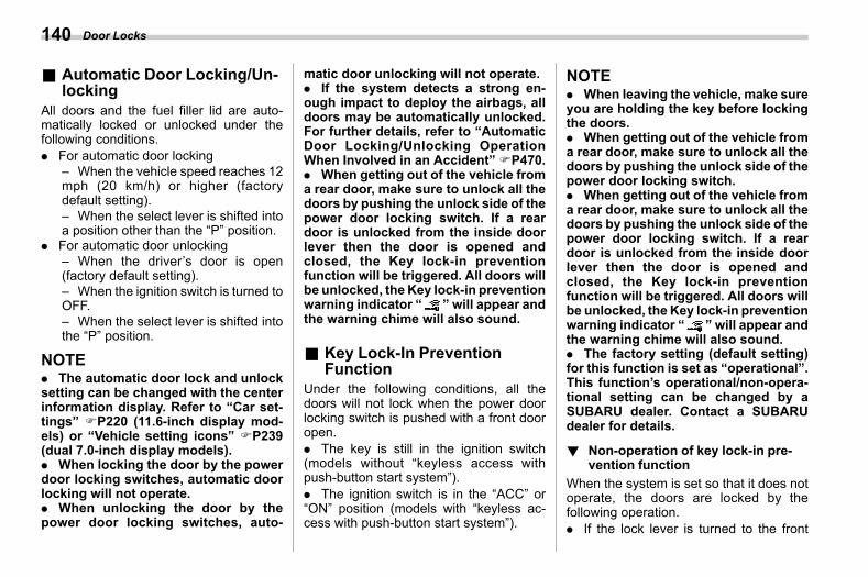
(142,1)
北米Model "A2600BE-B" EDITED: 2020/ 10/ 1
& Automatic Door Locking/Un-locking
s02ac08All doors and the fuel filler lid are auto-matically locked or unlocked under thefollowing conditions.. For automatic door locking
– When the vehicle speed reaches 12mph (20 km/h) or higher (factorydefault setting).– When the select lever is shifted intoa position other than the “P” position.
. For automatic door unlocking– When the driver’s door is open(factory default setting).– When the ignition switch is turned toOFF.– When the select lever is shifted intothe “P” position.
NOTE. The automatic door lock and unlocksetting can be changed with the centerinformation display. Refer to “Car set-tings” FP220 (11.6-inch display mod-els) or “Vehicle setting icons” FP239(dual 7.0-inch display models).. When locking the door by the powerdoor locking switches, automatic doorlocking will not operate.. When unlocking the door by thepower door locking switches, auto-
matic door unlocking will not operate.. If the system detects a strong en-ough impact to deploy the airbags, alldoors may be automatically unlocked.For further details, refer to “AutomaticDoor Locking/Unlocking OperationWhen Involved in an Accident”FP470.. When getting out of the vehicle froma rear door, make sure to unlock all thedoors by pushing the unlock side of thepower door locking switch. If a reardoor is unlocked from the inside doorlever then the door is opened andclosed, the Key lock-in preventionfunction will be triggered. All doors willbe unlocked, the Key lock-in preventionwarning indicator “ ” will appear andthe warning chime will also sound.
& Key Lock-In PreventionFunction
s02ac06Under the following conditions, all thedoors will not lock when the power doorlocking switch is pushed with a front dooropen.. The key is still in the ignition switch(models without “keyless access withpush-button start system”).. The ignition switch is in the “ACC” or“ON” position (models with “keyless ac-cess with push-button start system”).
NOTE. When leaving the vehicle, make sureyou are holding the key before lockingthe doors.. When getting out of the vehicle froma rear door, make sure to unlock all thedoors by pushing the unlock side of thepower door locking switch.. When getting out of the vehicle froma rear door, make sure to unlock all thedoors by pushing the unlock side of thepower door locking switch. If a reardoor is unlocked from the inside doorlever then the door is opened andclosed, the Key lock-in preventionfunction will be triggered. All doors willbe unlocked, the Key lock-in preventionwarning indicator “ ” will appear andthe warning chime will also sound.. The factory setting (default setting)for this function is set as “operational”.This function’s operational/non-opera-tional setting can be changed by aSUBARU dealer. Contact a SUBARUdealer for details.
! Non-operation of key lock-in pre-vention function
s02ac0602When the system is set so that it does notoperate, the doors are locked by thefollowing operation.. If the lock lever is turned to the front
Door Locks140
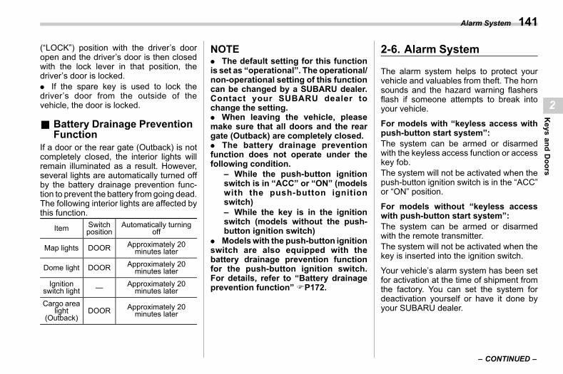
(143,1)
北米Model "A2600BE-B" EDITED: 2020/ 10/ 1
(“LOCK”) position with the driver’s dooropen and the driver’s door is then closedwith the lock lever in that position, thedriver’s door is locked.. If the spare key is used to lock thedriver’s door from the outside of thevehicle, the door is locked.
& Battery Drainage PreventionFunction
s02ac03If a door or the rear gate (Outback) is notcompletely closed, the interior lights willremain illuminated as a result. However,several lights are automatically turned offby the battery drainage prevention func-tion to prevent the battery fromgoing dead.The following interior lights are affected bythis function.
Item Switchposition
Automatically turningoff
Map lights DOOR Approximately 20minutes later
Dome light DOOR Approximately 20minutes later
Ignitionswitch light — Approximately 20
minutes later
Cargo arealight
(Outback)DOOR Approximately 20
minutes later
NOTE. The default setting for this functionis set as “operational”. The operational/non-operational setting of this functioncan be changed by a SUBARU dealer.Contact your SUBARU dealer tochange the setting.. When leaving the vehicle, pleasemake sure that all doors and the reargate (Outback) are completely closed.. The battery drainage preventionfunction does not operate under thefollowing condition.
– While the push-button ignitionswitch is in “ACC” or “ON” (modelswith the push-button ignitionswitch)– While the key is in the ignitionswitch (models without the push-button ignition switch)
. Modelswith the push-button ignitionswitch are also equipped with thebattery drainage prevention functionfor the push-button ignition switch.For details, refer to “Battery drainageprevention function” FP172.
2-6. Alarm Systems02af
The alarm system helps to protect yourvehicle and valuables from theft. The hornsounds and the hazard warning flashersflash if someone attempts to break intoyour vehicle.
For models with “keyless access withpush-button start system”:The system can be armed or disarmedwith the keyless access function or accesskey fob.The system will not be activated when thepush-button ignition switch is in the “ACC”or “ON” position.
For models without “keyless accesswith push-button start system”:The system can be armed or disarmedwith the remote transmitter.The system will not be activated when thekey is inserted into the ignition switch.
Your vehicle’s alarm system has been setfor activation at the time of shipment fromthe factory. You can set the system fordeactivation yourself or have it done byyour SUBARU dealer.
– CONTINUED –
Alarm System 141
2
Keys
andDoors
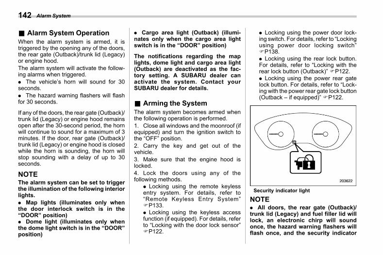
(144,1)
北米Model "A2600BE-B" EDITED: 2020/ 10/ 1
& Alarm System Operations02af01
When the alarm system is armed, it istriggered by the opening any of the doors,the rear gate (Outback)/trunk lid (Legacy)or engine hood.The alarm system will activate the follow-ing alarms when triggered.. The vehicle’s horn will sound for 30seconds.. The hazard warning flashers will flashfor 30 seconds.
If any of the doors, the rear gate (Outback)/trunk lid (Legacy) or engine hood remainsopen after the 30-second period, the hornwill continue to sound for a maximum of 3minutes. If the door, rear gate (Outback)/trunk lid (Legacy) or engine hood is closedwhile the horn is sounding, the horn willstop sounding with a delay of up to 30seconds.
NOTEThe alarm system can be set to triggerthe illumination of the following interiorlights.. Map lights (illuminates only whenthe door interlock switch is in the“DOOR” position). Dome light (illuminates only whenthe dome light switch is in the “DOOR”position)
. Cargo area light (Outback) (illumi-nates only when the cargo area lightswitch is in the “DOOR” position)
The notifications regarding the maplights, dome light and cargo area light(Outback) are deactivated as the fac-tory setting. A SUBARU dealer canactivate the system. Contact yourSUBARU dealer for details.
& Arming the Systems02af04
The alarm system becomes armed whenthe following operation is performed.1. Close all windows and the moonroof (ifequipped) and turn the ignition switch tothe “OFF” position.2. Carry the key and get out of thevehicle.3. Make sure that the engine hood islocked.4. Lock the doors using any of thefollowing methods.
. Locking using the remote keylessentry system. For details, refer to“Remote Keyless Entry System”FP133.. Locking using the keyless accessfunction (if equipped). For details, referto “Locking with the door lock sensor”FP122.
. Locking using the power door lock-ing switch. For details, refer to “Lockingusing power door locking switch”FP138.. Locking using the rear lock button.For details, refer to “Locking with therear lock button (Outback)” FP122.. Locking using the power rear gatelock button. For details, refer to “Lock-ing with the power rear gate lock button(Outback – if equipped)” FP122.
Security indicator light
NOTE. All doors, the rear gate (Outback)/trunk lid (Legacy) and fuel filler lid willlock, an electronic chirp will soundonce, the hazard warning flashers willflash once, and the security indicator
Alarm System142
(145,1)
北米Model "A2600BE-B" EDITED: 2020/ 10/ 1
light will start flashing rapidly.. If any of the doors or the rear gate(Outback)/trunk lid (Legacy) is not fullyclosed, an electronic chirp sounds fivetimes and the hazard warning flashersflash five times to alert you that thedoors (or the rear gate (Outback)/trunklid (Legacy)) are not properly closed.When you close the door, doors willautomatically lock and the system willautomatically arm in 30 seconds.5. Approximately 30 seconds later, thesystem will enter surveillance state.
When the system is in surveillance state,the security indicator light will then flashslowly (twice approximately every 2 sec-onds), indicating that the system has beenarmed for surveillance.
NOTE. The system can be armed even if thewindows and/or moonroof are open.Always make sure that they are fullyclosed before arming the system.. The 30-second standby time can beeliminated if you prefer. Have it per-formed by your SUBARU dealer.. If any of the following actions isdone during the standby period, thesystem will not switch to the surveil-lance state.
– Doors (including the rear gate(Outback)/trunk lid (Legacy)) areunlocked using the access key fob/remote transmitter.– Doors (including the rear gate(Outback)/trunk lid (Legacy)) areunlocked using the keyless accessfunction (models with “keyless ac-cess with push-button start sys-tem”).– Any door (including the rear gate(Outback) and engine hood) isopened.– The ignition switch is turned tothe “ON” position (models without“keyless access with push-buttonstart system”).– Push-button ignition switch isturned to the “ACC” position (mod-els with “keyless access with push-button start system”).
& Disarming the Systems02af05
Perform either of the following procedures.. Briefly press a button (for less than 2seconds) on the access key fob/remotetransmitter.. Carry the access key fob and performeither of the following procedures (modelswith “keyless access with push-buttonstart system”).
– Grip the front door handle.
– Press the rear gate opener button(Outback).– Press the trunk opener button(Legacy).– Unlock using the PIN code access.
The flashing of the security indicator lightwill then change slowly (once approxi-mately every 3 seconds from twice ap-proximately every 2 seconds), indicatingthat the alarm system has been disarmed.! Emergency disarming
s02af0501If you cannot disarm the system using theaccess key fob/transmitter (i.e., the trans-mitter is lost, broken or the transmitterbattery is too weak), you can disarm thesystem without using the access key fob/remote transmitter.The system can be disarmed if you turn theignition switch from the “LOCK”/“OFF”position to the “ON” position with aregistered key/access key fob.
NOTEFor models with “keyless access withpush-button start system”, if the ac-cess key fob battery is discharged,perform the procedure described in“Switching Power Status” FP466. Insuch a case, replace the battery im-mediately. Refer to “Replacing Batteryof Access Key Fob” FP526.
– CONTINUED –
Alarm System 143
2
Keys
andDoors
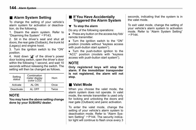
(146,1)
北米Model "A2600BE-B" EDITED: 2020/ 10/ 1
& Alarm System Settings02af11
To change the setting of your vehicle’salarm system for activation or deactiva-tion, do the following.1. Disarm the alarm system. Refer to“Disarming the System” FP143.2. Sit in the driver’s seat and shut alldoors, the rear gate (Outback), the trunk lid(Legacy) and engine hood.3. Turn the ignition switch to the “ON”position.4. Hold down “ ” of the driver’s powerdoor locking switch, open the driver’s doorwithin the following 1 second, and wait 10seconds without releasing the switch. Thesetting will then be changed as follows.
Settingstatus
Combinationmeter display(color LCD)
Horn
Activate AL ON OnceDeactivate AL OFF Twice
NOTEYoumay have the above setting changedone by your SUBARU dealer.
& If You Have AccidentallyTriggered the Alarm System
s02af03
! To stop the alarms02af0301
Do any of the following operations:. Press any button on the access key fob/remote transmitter.. Turn the ignition switch to the “ON”position (models without “keyless accesswith push-button start system”).. Turn the push-button ignition to the“ACC” position (models with “keylessaccess with push-button start system”).
NOTEOnly registered keys will stop thealarm. If the immobilizer transponderis not registered, the alarm will notstop.
& Valet Modes02af06
When you choose the valet mode, thealarm system does not operate. In valetmode, the remote transmitter is used onlyfor locking and unlocking the doors andrear gate (Outback) and panic activation.
To enter the valet mode, change thesetting of your vehicle’s alarm system todeactivation mode. Refer to “Alarm Sys-tem Setting” FP144. The security indica-tor light will continue to flash once every 3
seconds, indicating that the system is inthe valet mode.
To exit valet mode, change the setting ofyour vehicle’s alarm system to activationmode. Refer to “Alarm System Setting”FP144.
Alarm System144
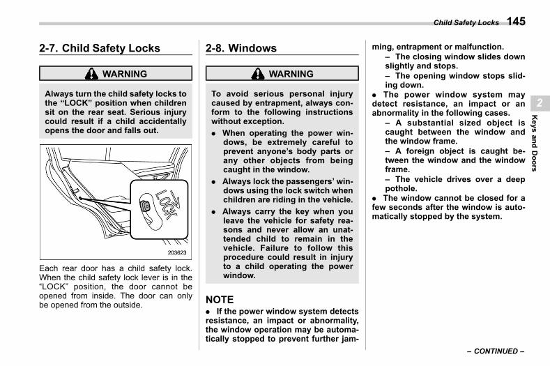
(147,1)
北米Model "A2600BE-B" EDITED: 2020/ 10/ 1
2-7. Child Safety Lockss02ag
WARNING
Always turn the child safety locks tothe “LOCK” position when childrensit on the rear seat. Serious injurycould result if a child accidentallyopens the door and falls out.
Each rear door has a child safety lock.When the child safety lock lever is in the“LOCK” position, the door cannot beopened from inside. The door can onlybe opened from the outside.
2-8. Windowss02ah
WARNING
To avoid serious personal injurycaused by entrapment, always con-form to the following instructionswithout exception.. When operating the power win-
dows, be extremely careful toprevent anyone’s body parts orany other objects from beingcaught in the window.
. Always lock the passengers’ win-dows using the lock switch whenchildren are riding in the vehicle.
. Always carry the key when youleave the vehicle for safety rea-sons and never allow an unat-tended child to remain in thevehicle. Failure to follow thisprocedure could result in injuryto a child operating the powerwindow.
NOTE. If the power window system detectsresistance, an impact or abnormality,the window operation may be automa-tically stopped to prevent further jam-
ming, entrapment or malfunction.– The closing window slides downslightly and stops.– The opening window stops slid-ing down.
. The power window system maydetect resistance, an impact or anabnormality in the following cases.
– A substantial sized object iscaught between the window andthe window frame.– A foreign object is caught be-tween the window and the windowframe.– The vehicle drives over a deeppothole.
. The window cannot be closed for afew seconds after the window is auto-matically stopped by the system.
– CONTINUED –
Child Safety Locks 145
2
Keys
andDoors
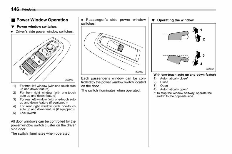
(148,1)
北米Model "A2600BE-B" EDITED: 2020/ 10/ 1
& Power Window Operations02ah07
! Power window switchess02ah0701
. Driver’s side power window switches:
1) For front left window (with one-touch autoup and down feature)
2) For front right window (with one-touchauto up and down feature)
3) For rear left window (with one-touch autoup and down feature (if equipped))
4) For rear right window (with one-touchauto up and down feature (if equipped))
5) Lock switch
All door windows can be controlled by thepower window switch cluster on the driverside door.The switch illuminates when operated.
. Passenger’s side power windowswitches:
Each passenger’s window can be con-trolled by the power window switch locatedon the door.The switch illuminates when operated.
! Operating the windows02ah0702
With one-touch auto up and down feature1) Automatically close*2) Close3) Open4) Automatically open**: To stop the window halfway, operate theswitch to the opposite side.
Windows146
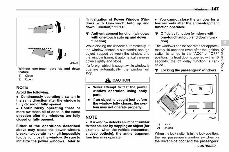
(149,1)
北米Model "A2600BE-B" EDITED: 2020/ 10/ 1
Without one-touch auto up and downfeature1) Close2) Open
NOTEAvoid the following.. Continuously operating a switch inthe same direction after the window isfully closed or fully opened.. Continuously operating three ormore switches all at once in the samedirection after the windows are fullyclosed or fully opened.
Either of the operations describedabove may cause the power windowbreaker to operatemaking it impossibleto open or close the window. Be sure toinitialize the power windows. Refer to
“Initialization of Power Window (Win-dows with One-Touch Auto up anddown Function)” FP148.
! Anti-entrapment function (windowswith one-touch auto up and downfunction)
s02ah0703While closing the window automatically, ifthe window senses a substantial enoughobject trapped between the window andthe window frame, it automatically movesdown slightly and stops.If a foreign object is caught while window isopening automatically, the window willstop.
CAUTION
. Never attempt to test the powerwindow operation using bodyparts.
. If an object is caught just beforethe window fully closes, the sys-tem may not operate properly.
NOTE. If a window detects an impact similarto that caused by trapping an object (forexample, when the vehicle encountersa deep pothole), the anti-entrapmentfunction may operate.
. You cannot close the window for afew seconds after the anti-entrapmentfunction operates.
! Off delay function (windows withone-touch auto up and down func-tion)
s02ah0705The windows can be operated for approxi-mately 40 seconds even after the ignitionswitch is turned to the “ACC” or “OFF”position. If a front door is opened within 40seconds, the off delay function is can-celed.! Locking the passengers’ windows
s02ah0704
1) Lock2) Unlock
When the lock switch is in the lock position,the rear passenger’s window switches onthe driver side door and the passengers’
– CONTINUED –
Windows 147
2
Keys
andDoors
(150,1)
北米Model "A2600BE-B" EDITED: 2020/ 10/ 1
window switches cannot be operated.When the indicator on the windowswitches does not illuminate, the windowswitch cannot be operated.
& Initialization of Power Win-dow (Windows with One-Touch Auto up and downFunction)
s02ah06If the one-touch auto up and down functionor off delay function does not operateproperly, operate each window accordingto the following procedure in order toinitialize the power window system.1. Close the door.2. Turn the ignition switch to the “ON”position.3. Open the window completely and thenpress and hold down the power windowswitch for approximately 1 second.4. Close the window completely and thenpull and hold the power window switch forapproximately 1 second.
2-9. Trunk Lid (Legacy)s02ai
WARNING
. To prevent dangerous exhaustgas from entering the vehicle,always keep the trunk lid closedwhile the engine is running.
. Check that the trunk is comple-tely closed before driving. If it isnot, it may suddenly open, whichcould lead to an accident.
. Help prevent children, adults oranimals from locking themselvesin the trunk. On hot or sunnydays, the temperature in the trunkcould quickly become high en-ough to cause death or seriousheat-related injuries includingbrain damage to anyone lockedinside, particularly for small chil-dren.
. When leaving the vehicle, closeall windows and lock all doors.Also make certain that the trunkis closed.
CAUTION
. Be extremely careful not to catchfingers or other objects whenclosing the trunk lid.
. Check carefully when openingand closing the trunk.
. Pay attention to hot engine ex-haust gas when loading and un-loading cargo, as it could possi-bly cause burns.
. Be careful opening the trunkwhen the wind is strong. Thetrunk lid could close or opensuddenly, possibly causing inju-ries.
. Make sure that the trunk is com-pletely open when using it. If it isnot, the trunk lid may suddenlydrop and cause serious injury.
. Be careful opening and closingthe trunk suddenly on a slope, astrunk ismore difficult to open andclose on a slope than on a flatarea.
. Do not install accessories otherthan genuine SUBARU parts. Ifthe trunk lid becomes too heavy,the stay may not be able to hold itopen.
Trunk Lid (Legacy)148
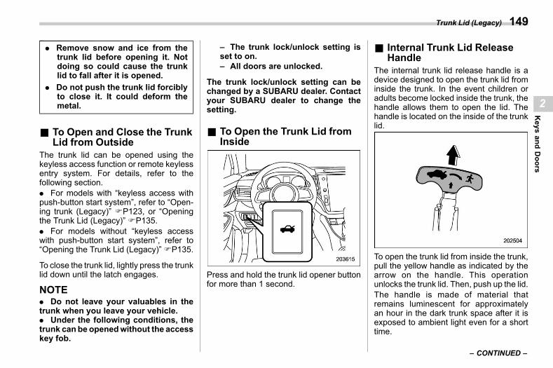
(151,1)
北米Model "A2600BE-B" EDITED: 2020/ 10/ 1
. Remove snow and ice from thetrunk lid before opening it. Notdoing so could cause the trunklid to fall after it is opened.
. Do not push the trunk lid forciblyto close it. It could deform themetal.
& To Open and Close the TrunkLid from Outside
s02ai01The trunk lid can be opened using thekeyless access function or remote keylessentry system. For details, refer to thefollowing section.. For models with “keyless access withpush-button start system”, refer to “Open-ing trunk (Legacy)” FP123, or “Openingthe Trunk Lid (Legacy)” FP135.. For models without “keyless accesswith push-button start system”, refer to“Opening the Trunk Lid (Legacy)”FP135.
To close the trunk lid, lightly press the trunklid down until the latch engages.
NOTE. Do not leave your valuables in thetrunk when you leave your vehicle.. Under the following conditions, thetrunk can be openedwithout the accesskey fob.
– The trunk lock/unlock setting isset to on.– All doors are unlocked.
The trunk lock/unlock setting can bechanged by a SUBARU dealer. Contactyour SUBARU dealer to change thesetting.
& To Open the Trunk Lid fromInside
s02ai02
Press and hold the trunk lid opener buttonfor more than 1 second.
& Internal Trunk Lid ReleaseHandle
s02ai04The internal trunk lid release handle is adevice designed to open the trunk lid frominside the trunk. In the event children oradults become locked inside the trunk, thehandle allows them to open the lid. Thehandle is located on the inside of the trunklid.
To open the trunk lid from inside the trunk,pull the yellow handle as indicated by thearrow on the handle. This operationunlocks the trunk lid. Then, push up the lid.The handle is made of material thatremains luminescent for approximatelyan hour in the dark trunk space after it isexposed to ambient light even for a shorttime.
– CONTINUED –
Trunk Lid (Legacy) 149
2
Keys
andDoors
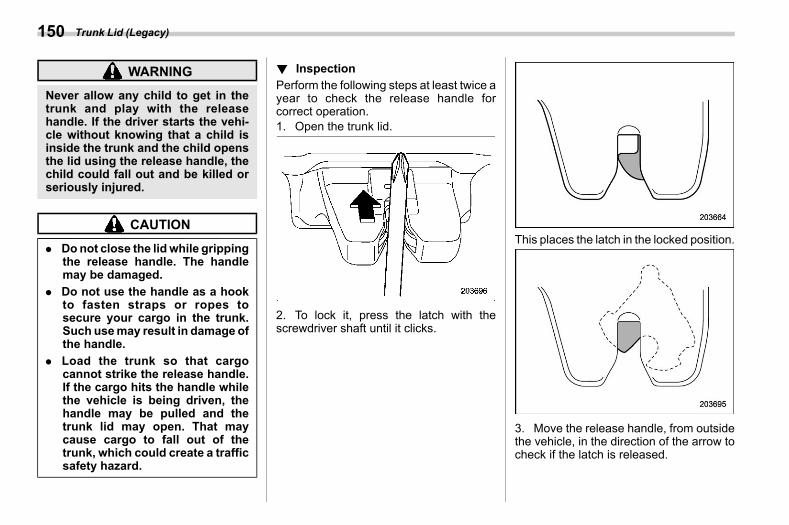
(152,1)
北米Model "A2600BE-B" EDITED: 2020/ 10/ 1
WARNING
Never allow any child to get in thetrunk and play with the releasehandle. If the driver starts the vehi-cle without knowing that a child isinside the trunk and the child opensthe lid using the release handle, thechild could fall out and be killed orseriously injured.
CAUTION
. Donot close the lidwhile grippingthe release handle. The handlemay be damaged.
. Do not use the handle as a hookto fasten straps or ropes tosecure your cargo in the trunk.Such usemay result in damage ofthe handle.
. Load the trunk so that cargocannot strike the release handle.If the cargo hits the handle whilethe vehicle is being driven, thehandle may be pulled and thetrunk lid may open. That maycause cargo to fall out of thetrunk, which could create a trafficsafety hazard.
! Inspections02ai0401
Perform the following steps at least twice ayear to check the release handle forcorrect operation.1. Open the trunk lid.
2. To lock it, press the latch with thescrewdriver shaft until it clicks.
This places the latch in the locked position.
3. Move the release handle, from outsidethe vehicle, in the direction of the arrow tocheck if the latch is released.
Trunk Lid (Legacy)150
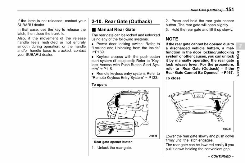
(153,1)
北米Model "A2600BE-B" EDITED: 2020/ 10/ 1
If the latch is not released, contact yourSUBARU dealer.In that case, use the key to release thelatch, then close the trunk lid.Also, if the movement of the releasehandle feels restricted or not entirelysmooth during operation, or the handleand/or handle base is cracked, contactyour SUBARU dealer.
2-10. Rear Gate (Outback)s02aj
& Manual Rear Gates02aj04
The rear gate can be locked and unlockedusing any of the following systems.. Power door locking switch: Refer to“Locking and Unlocking from the Inside”FP139.. Keyless access with the push-buttonstart system (if equipped): Refer to “Key-less Access with Push-Button Start Sys-tem” FP115.. Remote keyless entry system: Refer to“Remote Keyless Entry System” FP133.
To open:
Rear gate opener button
1. Unlock the rear gate.
2. Press and hold the rear gate openerbutton. The rear gate will open slightly.3. Hold the rear gate and lift it up slowly.
NOTEIf the rear gate cannot be opened due toa discharged vehicle battery, a mal-function in the door locking/unlockingsystemor other causes, you can unlockit by manually operating the rear gatelock release lever. For the procedure,refer to “Rear Gate (Outback) – If theRear Gate Cannot Be Opened” FP467.To close:
Lower the rear gate slowly and push downfirmly until the latch engages.The rear gate can be lowered easily if youpull it down holding the convenient grip.
– CONTINUED –
Rear Gate (Outback) 151
2
Keys
andDoors
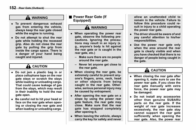
(154,1)
北米Model "A2600BE-B" EDITED: 2020/ 10/ 1
WARNING
. To prevent dangerous exhaustgas from entering the vehicle,always keep the rear gate closedwhile the engine is running.
. Do not attempt to shut the reargate while holding the recessedgrip. Also do not close the reargate by pulling the grip frominside the cargo space. There isa danger of your hand beingcaught and injured.
CAUTION
. Do not jam a plastic bag in orplace cellophane tape on the reargate stays or scratch the stayswhile loading or unloading cargo.That could cause leakage of gasfrom the stays, which may resultin their inability to hold the reargate open.
. Be careful not to hit your head orface on the rear gate when open-ing or closing the rear gate andwhen loading or unloading cargo.
& Power Rear Gate (IfEquipped)
s02aj01
WARNING
. When operating the power reargate, observe the following pre-cautions. Ignoring the precau-tions may result in an injury (e.g., anyone’s body is hit againstthe rear gate or is caught in therear gate, etc.)– Make sure there are no people
around the rear gate.– Never let anyone get close to
the rear gate.. When closing the rear gate, be
extremely careful to prevent any-one’s fingers, arms, neck, heador other objects from beingcaught in the rear gate. Other-wise, serious personal injurymaybe caused by entrapment.
. After opening the rear gate on aslope by using the power reargate feature, the rear gate mayclose. Make sure that the reargate has stopped completelyafter opening it.
. When leaving the vehicle, alwayscarry the key for safety and never
allow an unattended child toremain in the vehicle. Failure tofollow this procedure could re-sult in injury to a child operatingthe power rear gate.
. The driver should be aware of andpay careful attention to his/herresponsibilities.
. Use the power rear gate onlywhen the area around the reargate is clearly visible and whenyou have checked that there is nodanger of people being caught inthe gate.
CAUTION
. When closing the rear gate afteropening it, make sure to use thepower rear gate. If you close therear gate manually with extraforce, the power rear gate maybe damaged.
. Do not install any accessoriesother than genuine SUBARUparts on the rear gate. If theweight of rear gate increasesexcessively, the rear gate staycannot support the rear gatesufficiently when opening therear gate. Also, the power rear
Rear Gate (Outback)152
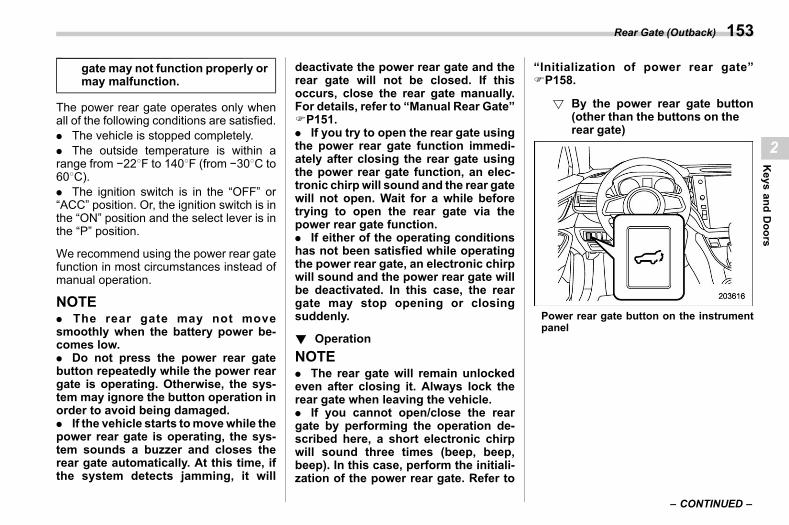
(155,1)
北米Model "A2600BE-B" EDITED: 2020/ 10/ 1
gate may not function properly ormay malfunction.
The power rear gate operates only whenall of the following conditions are satisfied.. The vehicle is stopped completely.. The outside temperature is within arange from −228F to 1408F (from −308C to608C).. The ignition switch is in the “OFF” or“ACC” position. Or, the ignition switch is inthe “ON” position and the select lever is inthe “P” position.
We recommend using the power rear gatefunction in most circumstances instead ofmanual operation.
NOTE. The rear gate may not movesmoothly when the battery power be-comes low.. Do not press the power rear gatebutton repeatedly while the power reargate is operating. Otherwise, the sys-tem may ignore the button operation inorder to avoid being damaged.. If the vehicle starts tomovewhile thepower rear gate is operating, the sys-tem sounds a buzzer and closes therear gate automatically. At this time, ifthe system detects jamming, it will
deactivate the power rear gate and therear gate will not be closed. If thisoccurs, close the rear gate manually.For details, refer to “Manual Rear Gate”FP151.. If you try to open the rear gate usingthe power rear gate function immedi-ately after closing the rear gate usingthe power rear gate function, an elec-tronic chirp will sound and the rear gatewill not open. Wait for a while beforetrying to open the rear gate via thepower rear gate function.. If either of the operating conditionshas not been satisfied while operatingthe power rear gate, an electronic chirpwill sound and the power rear gate willbe deactivated. In this case, the reargate may stop opening or closingsuddenly.
! Operations02aj0111
NOTE. The rear gate will remain unlockedeven after closing it. Always lock therear gate when leaving the vehicle.. If you cannot open/close the reargate by performing the operation de-scribed here, a short electronic chirpwill sound three times (beep, beep,beep). In this case, perform the initiali-zation of the power rear gate. Refer to
“Initialization of power rear gate”FP158.
! By the power rear gate button(other than the buttons on therear gate)
s02aj011101
Power rear gate button on the instrumentpanel
– CONTINUED –
Rear Gate (Outback) 153
2
Keys
andDoors
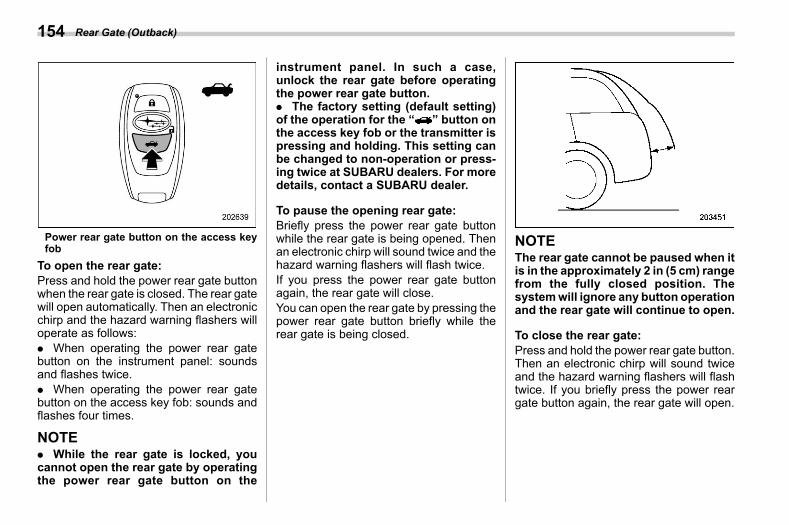
(156,1)
北米Model "A2600BE-B" EDITED: 2020/ 10/ 1
Power rear gate button on the access keyfob
To open the rear gate:Press and hold the power rear gate buttonwhen the rear gate is closed. The rear gatewill open automatically. Then an electronicchirp and the hazard warning flashers willoperate as follows:. When operating the power rear gatebutton on the instrument panel: soundsand flashes twice.. When operating the power rear gatebutton on the access key fob: sounds andflashes four times.
NOTE. While the rear gate is locked, youcannot open the rear gate by operatingthe power rear gate button on the
instrument panel. In such a case,unlock the rear gate before operatingthe power rear gate button.. The factory setting (default setting)of the operation for the “ ” button onthe access key fob or the transmitter ispressing and holding. This setting canbe changed to non-operation or press-ing twice at SUBARU dealers. For moredetails, contact a SUBARU dealer.
To pause the opening rear gate:Briefly press the power rear gate buttonwhile the rear gate is being opened. Thenan electronic chirp will sound twice and thehazard warning flashers will flash twice.If you press the power rear gate buttonagain, the rear gate will close.You can open the rear gate by pressing thepower rear gate button briefly while therear gate is being closed.
NOTEThe rear gate cannot be paused when itis in the approximately 2 in (5 cm) rangefrom the fully closed position. Thesystemwill ignore any button operationand the rear gate will continue to open.
To close the rear gate:Press and hold the power rear gate button.Then an electronic chirp will sound twiceand the hazard warning flashers will flashtwice. If you briefly press the power reargate button again, the rear gate will open.
Rear Gate (Outback)154
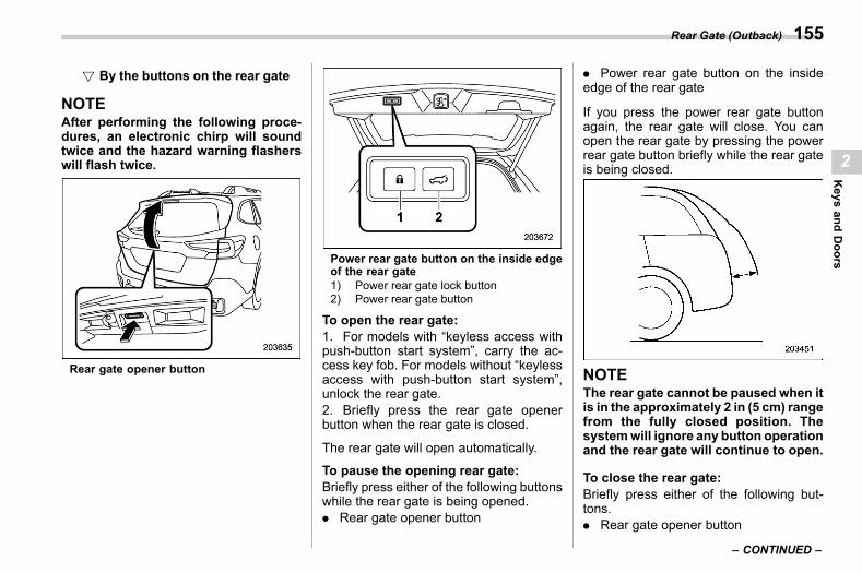
(157,1)
北米Model "A2600BE-B" EDITED: 2020/ 10/ 1
! By the buttons on the rear gates02aj011102
NOTEAfter performing the following proce-dures, an electronic chirp will soundtwice and the hazard warning flasherswill flash twice.
Rear gate opener button
Power rear gate button on the inside edgeof the rear gate1) Power rear gate lock button2) Power rear gate button
To open the rear gate:1. For models with “keyless access withpush-button start system”, carry the ac-cess key fob. For models without “keylessaccess with push-button start system”,unlock the rear gate.2. Briefly press the rear gate openerbutton when the rear gate is closed.
The rear gate will open automatically.
To pause the opening rear gate:Briefly press either of the following buttonswhile the rear gate is being opened.. Rear gate opener button
. Power rear gate button on the insideedge of the rear gate
If you press the power rear gate buttonagain, the rear gate will close. You canopen the rear gate by pressing the powerrear gate button briefly while the rear gateis being closed.
NOTEThe rear gate cannot be paused when itis in the approximately 2 in (5 cm) rangefrom the fully closed position. Thesystemwill ignore any button operationand the rear gate will continue to open.
To close the rear gate:Briefly press either of the following but-tons.. Rear gate opener button
– CONTINUED –
Rear Gate (Outback) 155
2
Keys
andDoors
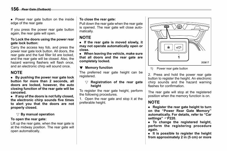
(158,1)
北米Model "A2600BE-B" EDITED: 2020/ 10/ 1
. Power rear gate button on the insideedge of the rear gate
If you press the power rear gate buttonagain, the rear gate will open.
To Lock the doors using the power reargate lock button:Carry the access key fob, and press thepower rear gate lock button. All doors, therear gate and the fuel filler lid are locked,and the rear gate will be closed. Also, thehazard warning flashers will flash once,and an electronic chirp will sound once.
NOTE. By pushing the power rear gate lockbutton for more than 2 seconds, alldoors are locked, however, the autoclosing function of the rear gate will becanceled.. If any of the doors is not fully closed,the electronic chirp sounds five timesto alert you that the doors are notproperly closed.
! By manual operations02aj011103
To open the rear gate:Lift up the rear gate, when the rear gate isat the midway position. The rear gate willopen automatically.
To close the rear gate:Pull down the rear gate when the rear gateis opened. The rear gate will close auto-matically.
NOTE. If the rear gate is moved slowly, itmay not operate automatically open orclose.. When leaving the vehicle, make surethat all doors and the rear gate arecompletely locked.
! Memory functions02aj0101
The preferred rear gate height can beregistered.
! Registration of the rear gateheight
s02aj010101
To register the rear gate height, performthe following procedures.1. Open the rear gate and stop it at thepreferable height.
1) Power rear gate button
2. Press and hold the power rear gatebutton to register the height. An electronicchirp sounds and the hazard warningflashes for confirmation.
The rear gate will stop at the registeredposition when the memory function is on.
NOTE. Register the rear gate height to turnon the “Power Rear Gate Memory”automatically. For details, refer to “Carsettings” FP220.. To change the registered height,perform the registering procedureagain.. It is possible to register the heightfrom approximately 2 in (5 cm) or more
Rear Gate (Outback)156
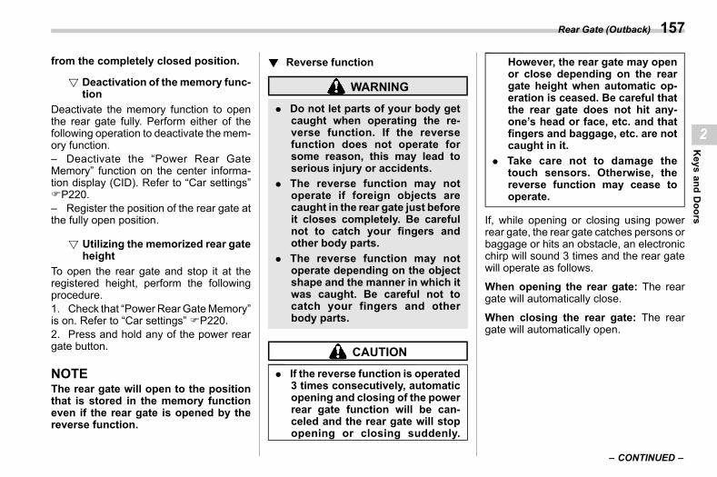
(159,1)
北米Model "A2600BE-B" EDITED: 2020/ 10/ 1
from the completely closed position.
! Deactivation of the memory func-tion
s02aj010103
Deactivate the memory function to openthe rear gate fully. Perform either of thefollowing operation to deactivate the mem-ory function.– Deactivate the “Power Rear GateMemory” function on the center informa-tion display (CID). Refer to “Car settings”FP220.– Register the position of the rear gate atthe fully open position.
! Utilizing the memorized rear gateheight
s02aj010102
To open the rear gate and stop it at theregistered height, perform the followingprocedure.1. Check that “Power RearGateMemory”is on. Refer to “Car settings” FP220.2. Press and hold any of the power reargate button.
NOTEThe rear gate will open to the positionthat is stored in the memory functioneven if the rear gate is opened by thereverse function.
! Reverse functions02aj0102
WARNING
. Do not let parts of your body getcaught when operating the re-verse function. If the reversefunction does not operate forsome reason, this may lead toserious injury or accidents.
. The reverse function may notoperate if foreign objects arecaught in the rear gate just beforeit closes completely. Be carefulnot to catch your fingers andother body parts.
. The reverse function may notoperate depending on the objectshape and the manner in which itwas caught. Be careful not tocatch your fingers and otherbody parts.
CAUTION
. If the reverse function is operated3 times consecutively, automaticopening and closing of the powerrear gate function will be can-celed and the rear gate will stopopening or closing suddenly.
However, the rear gate may openor close depending on the reargate height when automatic op-eration is ceased. Be careful thatthe rear gate does not hit any-one’s head or face, etc. and thatfingers and baggage, etc. are notcaught in it.
. Take care not to damage thetouch sensors. Otherwise, thereverse function may cease tooperate.
If, while opening or closing using powerrear gate, the rear gate catches persons orbaggage or hits an obstacle, an electronicchirp will sound 3 times and the rear gatewill operate as follows.
When opening the rear gate: The reargate will automatically close.
When closing the rear gate: The reargate will automatically open.
– CONTINUED –
Rear Gate (Outback) 157
2
Keys
andDoors
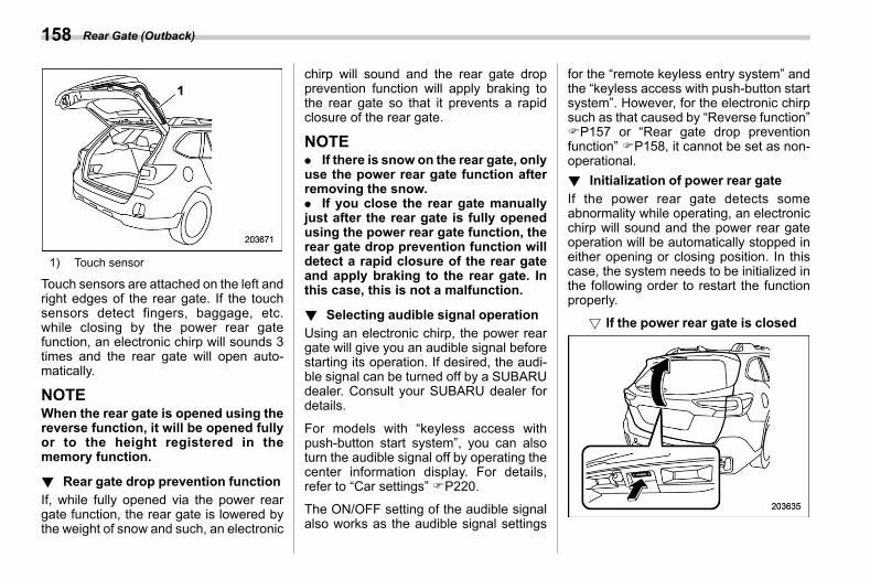
(160,1)
北米Model "A2600BE-B" EDITED: 2020/ 10/ 1
1) Touch sensor
Touch sensors are attached on the left andright edges of the rear gate. If the touchsensors detect fingers, baggage, etc.while closing by the power rear gatefunction, an electronic chirp will sounds 3times and the rear gate will open auto-matically.
NOTEWhen the rear gate is opened using thereverse function, it will be opened fullyor to the height registered in thememory function.
! Rear gate drop prevention functions02aj0104
If, while fully opened via the power reargate function, the rear gate is lowered bythe weight of snow and such, an electronic
chirp will sound and the rear gate dropprevention function will apply braking tothe rear gate so that it prevents a rapidclosure of the rear gate.
NOTE. If there is snow on the rear gate, onlyuse the power rear gate function afterremoving the snow.. If you close the rear gate manuallyjust after the rear gate is fully openedusing the power rear gate function, therear gate drop prevention function willdetect a rapid closure of the rear gateand apply braking to the rear gate. Inthis case, this is not a malfunction.
! Selecting audible signal operations02aj0109
Using an electronic chirp, the power reargate will give you an audible signal beforestarting its operation. If desired, the audi-ble signal can be turned off by a SUBARUdealer. Consult your SUBARU dealer fordetails.
For models with “keyless access withpush-button start system”, you can alsoturn the audible signal off by operating thecenter information display. For details,refer to “Car settings” FP220.
The ON/OFF setting of the audible signalalso works as the audible signal settings
for the “remote keyless entry system” andthe “keyless access with push-button startsystem”. However, for the electronic chirpsuch as that caused by “Reverse function”FP157 or “Rear gate drop preventionfunction” FP158, it cannot be set as non-operational.! Initialization of power rear gate
s02aj0112If the power rear gate detects someabnormality while operating, an electronicchirp will sound and the power rear gateoperation will be automatically stopped ineither opening or closing position. In thiscase, the system needs to be initialized inthe following order to restart the functionproperly.
! If the power rear gate is closeds02aj011201
Rear Gate (Outback)158
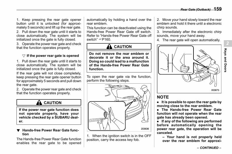
(161,1)
北米Model "A2600BE-B" EDITED: 2020/ 10/ 1
1. Keep pressing the rear gate openerbutton until it is unlocked (for approxi-mately 5 seconds) and lift up the rear gate.2. Pull down the rear gate until it starts toclose automatically. The system will beinitialized once the gate is fully closed.3. Operate the power rear gate and checkthat the function operates properly.
! If the power rear gate is openeds02aj011202
1. Pull down the rear gate until it starts toclose automatically. The system will beinitialized once the gate is fully closed.If the rear gate will not close completely,keep pressing the rear gate opener buttonfor approximately 5 seconds and pull downthe rear gate.2. Operate the power rear gate and checkthat the function operates properly.
CAUTION
If the power rear gate function doesnot operate properly, have yourvehicle checked by a SUBARU deal-er.
! Hands-free Power Rear Gate func-tion
s02aj0113The Hands-free Power Rear Gate functionenables the rear gate to be opened
automatically by holding a hand over therear emblem.This function can be deactivated using theHands-free Power Rear Gate off switch.Refer to “Hands-free Power Rear Gate offswitch” FP160.
CAUTION
Do not remove the rear emblem ordecorate it or the area around it.Doing so could lead to amalfunctionof the Hands-free Power Rear Gatefunction.
To open the rear gate via the function,perform the following steps.
1. When the ignition switch is in the OFFposition, carry the access key fob.
2. Move your hand slowly toward the rearemblem and hold it there until a electronicchirp sounds.3. Immediately after the electronic chirpsounds, move your hand away.4. The rear gate will open automatically.
NOTE. It is possible to open the rear gate bymoving close to the rear emblem.. The Hands-free Power Rear Gatefunction will not operate when the reargate has already been opened.. If any of the following are performedbefore automatically opening thepower rear gate, the operation will becanceled.
– Your hand is not properly heldover the rear emblem for approxi-
– CONTINUED –
Rear Gate (Outback) 159
2
Keys
andDoors
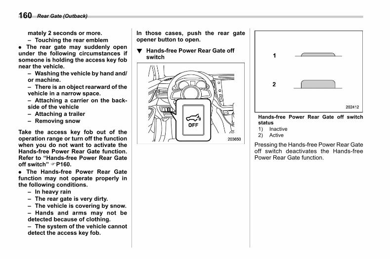
(162,1)
北米Model "A2600BE-B" EDITED: 2020/ 10/ 1
mately 2 seconds or more.– Touching the rear emblem
. The rear gate may suddenly openunder the following circumstances ifsomeone is holding the access key fobnear the vehicle.
– Washing the vehicle by hand and/or machine.– There is an object rearward of thevehicle in a narrow space.– Attaching a carrier on the back-side of the vehicle– Attaching a trailer– Removing snow
Take the access key fob out of theoperation range or turn off the functionwhen you do not want to activate theHands-free Power Rear Gate function.Refer to “Hands-free Power Rear Gateoff switch” FP160.. The Hands-free Power Rear Gatefunction may not operate properly inthe following conditions.
– In heavy rain– The rear gate is very dirty.– The vehicle is covering by snow.– Hands and arms may not bedetected because of clothing.– The system of the vehicle cannotdetect the access key fob.
In those cases, push the rear gateopener button to open.
! Hands-free Power Rear Gate offswitch
s02aj0114
Hands-free Power Rear Gate off switchstatus1) Inactive2) Active
Pressing the Hands-free Power Rear Gateoff switch deactivates the Hands-freePower Rear Gate function.
Rear Gate (Outback)160
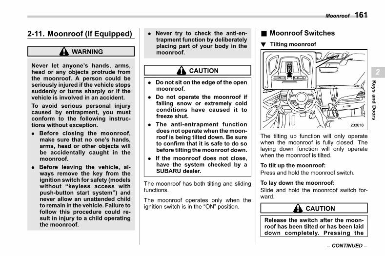
(163,1)
北米Model "A2600BE-B" EDITED: 2020/ 10/ 1
2-11. Moonroof (If Equipped)s02ak
WARNING
Never let anyone’s hands, arms,head or any objects protrude fromthe moonroof. A person could beseriously injured if the vehicle stopssuddenly or turns sharply or if thevehicle is involved in an accident.To avoid serious personal injurycaused by entrapment, you mustconform to the following instruc-tions without exception.. Before closing the moonroof,
make sure that no one’s hands,arms, head or other objects willbe accidentally caught in themoonroof.
. Before leaving the vehicle, al-ways remove the key from theignition switch for safety (modelswithout “keyless access withpush-button start system”) andnever allow an unattended childto remain in the vehicle. Failure tofollow this procedure could re-sult in injury to a child operatingthe moonroof.
. Never try to check the anti-en-trapment function by deliberatelyplacing part of your body in themoonroof.
CAUTION
. Do not sit on the edge of the openmoonroof.
. Do not operate the moonroof iffalling snow or extremely coldconditions have caused it tofreeze shut.
. The anti-entrapment functiondoes not operate when themoon-roof is being tilted down. Be sureto confirm that it is safe to do sobefore tilting themoonroof down.
. If the moonroof does not close,have the system checked by aSUBARU dealer.
The moonroof has both tilting and slidingfunctions.
The moonroof operates only when theignition switch is in the “ON” position.
& Moonroof Switchess02ak02
! Tilting moonroofs02ak0201
The tilting up function will only operatewhen the moonroof is fully closed. Thelaying down function will only operatewhen the moonroof is tilted.
To tilt up the moonroof:Press and hold the moonroof switch.
To lay down the moonroof:Slide and hold the moonroof switch for-ward.
CAUTION
Release the switch after the moon-roof has been tilted or has been laiddown completely. Pressing the
– CONTINUED –
Moonroof 161
2
Keys
andDoors
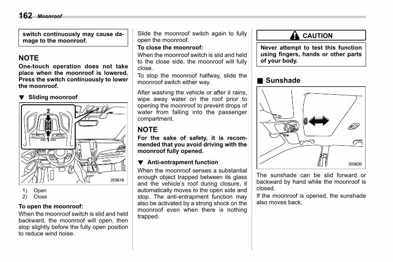
(164,1)
北米Model "A2600BE-B" EDITED: 2020/ 10/ 1
switch continuously may cause da-mage to the moonroof.
NOTEOne-touch operation does not takeplace when the moonroof is lowered.Press the switch continuously to lowerthe moonroof.
! Sliding moonroofs02ak0202
1) Open2) Close
To open the moonroof:When the moonroof switch is slid and heldbackward, the moonroof will open, thenstop slightly before the fully open positionto reduce wind noise.
Slide the moonroof switch again to fullyopen the moonroof.To close the moonroof:When the moonroof switch is slid and heldto the close side, the moonroof will fullyclose.To stop the moonroof halfway, slide themoonroof switch either way.
After washing the vehicle or after it rains,wipe away water on the roof prior toopening the moonroof to prevent drops ofwater from falling into the passengercompartment.
NOTEFor the sake of safety, it is recom-mended that you avoid driving with themoonroof fully opened.
! Anti-entrapment functions02ak0203
When the moonroof senses a substantialenough object trapped between its glassand the vehicle’s roof during closure, itautomatically moves to the open side andstop. The anti-entrapment function mayalso be activated by a strong shock on themoonroof even when there is nothingtrapped.
CAUTION
Never attempt to test this functionusing fingers, hands or other partsof your body.
& Sunshades02ak05
The sunshade can be slid forward orbackward by hand while the moonroof isclosed.If the moonroof is opened, the sunshadealso moves back.
Moonroof162

(165,1)
北米Model "A2600BE-B" EDITED: 2020/ 10/ 1
— — — — — — — — — — — — — — — — — — — — — — — — — — — — — — — — — — — — — — — —
— — — — — — — — — — — — — — — — — — — — — — — — — — — — — — — — — — — — — — — —
— — — — — — — — — — — — — — — — — — — — — — — — — — — — — — — — — — — — — — — —
— — — — — — — — — — — — — — — — — — — — — — — — — — — — — — — — — — — — — — — —
— — — — — — — — — — — — — — — — — — — — — — — — — — — — — — — — — — — — — — — —
— — — — — — — — — — — — — — — — — — — — — — — — — — — — — — — — — — — — — — — —
— — — — — — — — — — — — — — — — — — — — — — — — — — — — — — — — — — — — — — — —
— — — — — — — — — — — — — — — — — — — — — — — — — — — — — — — — — — — — — — — —
— — — — — — — — — — — — — — — — — — — — — — — — — — — — — — — — — — — — — — — —
— — — — — — — — — — — — — — — — — — — — — — — — — — — — — — — — — — — — — — — —
— — — — — — — — — — — — — — — — — — — — — — — — — — — — — — — — — — — — — — — —
— — — — — — — — — — — — — — — — — — — — — — — — — — — — — — — — — — — — — — — —
— — — — — — — — — — — — — — — — — — — — — — — — — — — — — — — — — — — — — — — —

(166,1)
北米Model "A2600BE-B" EDITED: 2020/ 10/ 1
— — — — — — — — — — — — — — — — — — — — — — — — — — — — — — — — — — — — — — — —
— — — — — — — — — — — — — — — — — — — — — — — — — — — — — — — — — — — — — — — —
— — — — — — — — — — — — — — — — — — — — — — — — — — — — — — — — — — — — — — — —
— — — — — — — — — — — — — — — — — — — — — — — — — — — — — — — — — — — — — — — —
— — — — — — — — — — — — — — — — — — — — — — — — — — — — — — — — — — — — — — — —
— — — — — — — — — — — — — — — — — — — — — — — — — — — — — — — — — — — — — — — —
— — — — — — — — — — — — — — — — — — — — — — — — — — — — — — — — — — — — — — — —
— — — — — — — — — — — — — — — — — — — — — — — — — — — — — — — — — — — — — — — —
— — — — — — — — — — — — — — — — — — — — — — — — — — — — — — — — — — — — — — — —
— — — — — — — — — — — — — — — — — — — — — — — — — — — — — — — — — — — — — — — —
— — — — — — — — — — — — — — — — — — — — — — — — — — — — — — — — — — — — — — — —
— — — — — — — — — — — — — — — — — — — — — — — — — — — — — — — — — — — — — — — —
— — — — — — — — — — — — — — — — — — — — — — — — — — — — — — — — — — — — — — — —
(167,1)
北米Model "A2600BE-B" EDITED: 2020/ 10/ 1
s033-1. Ignition Switch (Models without
Push-Button Start System) .......................... 168Key Positions .....................................................168Key Reminder Chime ..........................................169Ignition Switch Light...........................................169
3-2. Push-Button Ignition Switch (Models withPush-Button Start System) .......................... 170Safety Precautions..............................................170Operating Range for Push-Button Start System...170Switching Power Status ......................................171When Access Key Fob Does Not OperateProperly ...........................................................172
3-3. Hazard Warning Flasher................................. 1723-4. Meters and Gauges ........................................ 173
Speedometer ......................................................173Tachometer.........................................................173Odometer ...........................................................173Double Trip Meter ...............................................174Fuel Gauge.........................................................174Engine Coolant Temperature Gauge ....................175Combination Meter Settings................................175
3-5. Illumination Brightness Control .................... 175Auto Dimmer Cancel Function ............................176
3-6. Warning and Indicator Lights ........................ 177Seatbelt Warning Light and Chime ......................177SRS Airbag System Warning Light ......................181Front Passenger’s Frontal Airbag ON and OFFIndicators .........................................................181
CHECK ENGINE Warning Light/MalfunctionIndicator Light ..................................................182
Charge Warning Light .........................................183
Oil Pressure Warning Light ................................ 183Engine Low Oil Level Warning Indicator ............. 183AT OIL TEMP Warning Light ............................... 184Low Tire Pressure Warning Light (U.S.-Spec.Models)............................................................ 184
ABS Warning Light............................................. 185Brake System Warning Light .............................. 186Electronic Parking Brake Indicator Light............. 187Auto Vehicle Hold ON Indicator Light ................. 188Auto Vehicle Hold Operation Indicator Light ....... 188Low Fuel Warning Light ..................................... 189Door Open Indicator........................................... 189Engine Hood Open Warning Light ...................... 189Windshield Washer Fluid Warning Light ............. 189All-Wheel Drive Warning Light ............................ 189Power Steering Warning Light ............................ 189Vehicle Dynamics Control Warning Light/Vehicle Dynamics Control Operation IndicatorLight ................................................................ 190
Vehicle Dynamics Control OFF Indicator Light .... 191Warning Chimes and Warning Indicator of theKeyless Access with Push-Button StartSystem (If Equipped) ........................................ 191
Security Indicator Light ...................................... 196SI-DRIVE Indicator Light (If Equipped) ................ 197Select Lever/Gear Position Indicator................... 197Turn Signal Indicator Lights ............................... 197High Beam Indicator Light.................................. 197High Beam Assist Indicator ................................ 197Automatic Headlight Beam Leveler WarningLight ................................................................ 198
LED Headlight Warning Light ............................. 198
Instruments and Controls
3
Instruments
andControls
(168,1)
北米Model "A2600BE-B" EDITED: 2020/ 10/ 1
Steering Responsive Headlight OFF IndicatorLight ................................................................198
Steering Responsive Headlight Warning Light .....198Headlight Indicator Light.....................................198Front Fog Light Indicator Light (If Equipped).......198Auto Start Stop Warning Light (Yellow) ...............198Auto Start Stop OFF Indicator Light ....................198Auto Start Stop Indicator Light (Green) ...............199Auto Start Stop No Activity Detected IndicatorLight ................................................................199
X-MODE Indicator (Outback) ...............................199Hill Descent Control Indicator (Outback) .............199BSD/RCTA Warning Indicator (If Equipped)..........199BSD/RCTA OFF Indicator (If Equipped)................199Icy Road Surface Warning Indicator ....................200RAB Warning Indicator (If Equipped)...................200RAB OFF Indicator (If Equipped) .........................200Driver Monitoring System Operation IndicatorLight (Green) (If Equipped)................................200
Driver Monitoring System Warning Light(Yellow) (If Equipped)........................................200
Driver Monitoring System OFF Indicator Light(If Equipped).....................................................200
Driver Monitoring System Temporary StopIndicator Light (If Equipped)..............................200
Sonar Audible Alarm OFF Indicator(If Equipped).....................................................201
3-7. Combination Meter Display (Color LCD) ...... 201Basic Operation..................................................202Welcome Screen (Opening Animation) andGood-Bye (Ending Animation) Screen ...............202
Warning Screen ..................................................203
Meter Information Screen ................................... 203Telltale Screen ................................................... 204Basic Screens.................................................... 205Digital Speed Screen.......................................... 208
3-8. Center Information Display (CID) ...................209Features ............................................................ 209Welcome Screen ................................................ 209Good-Bye Screen ............................................... 210Interruption Screen ............................................ 210Touch Screen Operations ................................... 21011.6-Inch Display Models (If Equipped) ............... 211Dual 7.0-Inch Display Models (If Equipped) ......... 232
3-9. Clock ................................................................245Setting the Clock Manually ................................. 245Setting the Clock Automatically.......................... 246
3-10. Light Control Switch .....................................248Headlights ......................................................... 248High/Low Beam Change (Dimmer) ...................... 250Headlight Flasher ............................................... 250High Beam Assist Function ................................ 251Daytime Running Light System .......................... 254
3-11. Steering Responsive Headlight (SRH) .........2543-12. Headlight Beam Leveler................................2553-13. Front Fog Light Switch (If Equipped) ..........2563-14. Turn Signal Lever ..........................................256
One-Touch Lane Changer ................................... 2573-15. Wiper and Washer .........................................257
Windshield Wiper and Washer Switches ............. 258Rear Window Wiper and Washer Switch(Outback) ......................................................... 260
Instruments and Controls
(169,1)
北米Model "A2600BE-B" EDITED: 2020/ 10/ 1
3-16. Defogger and Deicer..................................... 2613-17. Mirrors ........................................................... 263
Inside Mirror (without Auto-Dimming Function)(If Equipped).....................................................263
Auto-Dimming Mirror/Compass with HomeLink®
(If Equipped).....................................................263
Outside Mirrors .................................................. 2713-18. Tilt/Telescopic Steering Wheel .....................2743-19. Heated Steering Wheel System
(If Equipped) ..................................................2753-20. Horn................................................................276
Instruments and Controls
3
Instruments
andControls
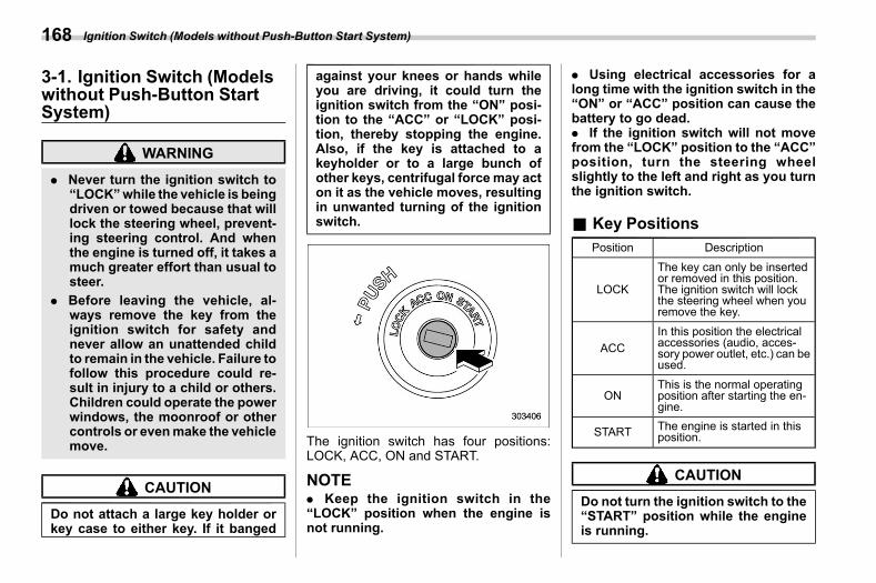
(170,1)
北米Model "A2600BE-B" EDITED: 2020/ 10/ 1
3-1. Ignition Switch (Modelswithout Push-Button StartSystem)
s03aa
WARNING
. Never turn the ignition switch to“LOCK”while the vehicle is beingdriven or towed because that willlock the steering wheel, prevent-ing steering control. And whenthe engine is turned off, it takes amuch greater effort than usual tosteer.
. Before leaving the vehicle, al-ways remove the key from theignition switch for safety andnever allow an unattended childto remain in the vehicle. Failure tofollow this procedure could re-sult in injury to a child or others.Children could operate the powerwindows, the moonroof or othercontrols or evenmake the vehiclemove.
CAUTION
Do not attach a large key holder orkey case to either key. If it banged
against your knees or hands whileyou are driving, it could turn theignition switch from the “ON” posi-tion to the “ACC” or “LOCK” posi-tion, thereby stopping the engine.Also, if the key is attached to akeyholder or to a large bunch ofother keys, centrifugal forcemay acton it as the vehicle moves, resultingin unwanted turning of the ignitionswitch.
The ignition switch has four positions:LOCK, ACC, ON and START.
NOTE. Keep the ignition switch in the“LOCK” position when the engine isnot running.
. Using electrical accessories for along time with the ignition switch in the“ON” or “ACC” position can cause thebattery to go dead.. If the ignition switch will not movefrom the “LOCK” position to the “ACC”position, turn the steering wheelslightly to the left and right as you turnthe ignition switch.
& Key Positionss03aa11
Position Description
LOCK
The key can only be insertedor removed in this position.The ignition switch will lockthe steering wheel when youremove the key.
ACCIn this position the electricalaccessories (audio, acces-sory power outlet, etc.) can beused.
ONThis is the normal operatingposition after starting the en-gine.
START The engine is started in thisposition.
CAUTION
Do not turn the ignition switch to the“START” position while the engineis running.
Ignition Switch (Models without Push-Button Start System)168
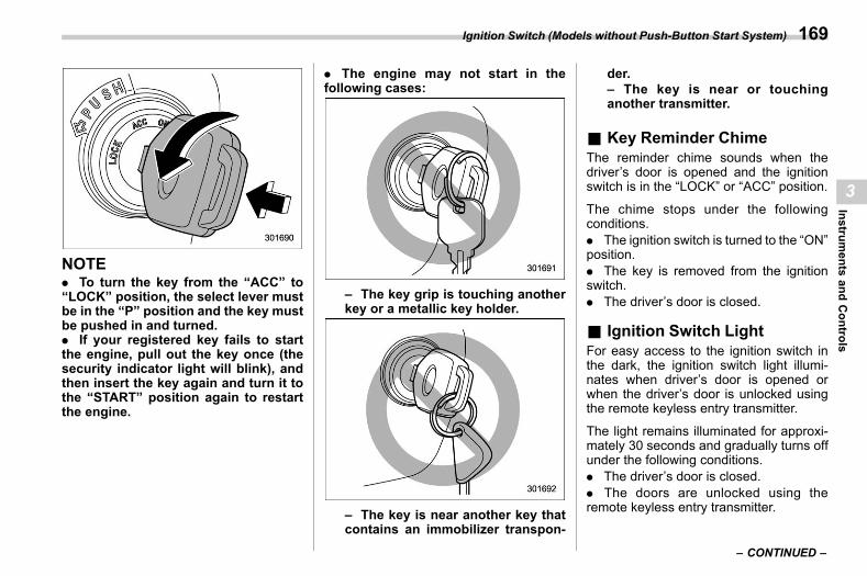
(171,1)
北米Model "A2600BE-B" EDITED: 2020/ 10/ 1
NOTE. To turn the key from the “ACC” to“LOCK” position, the select lever mustbe in the “P” position and the key mustbe pushed in and turned.. If your registered key fails to startthe engine, pull out the key once (thesecurity indicator light will blink), andthen insert the key again and turn it tothe “START” position again to restartthe engine.
. The engine may not start in thefollowing cases:
– The key grip is touching anotherkey or a metallic key holder.
– The key is near another key thatcontains an immobilizer transpon-
der.– The key is near or touchinganother transmitter.
& Key Reminder Chimes03aa05
The reminder chime sounds when thedriver’s door is opened and the ignitionswitch is in the “LOCK” or “ACC” position.
The chime stops under the followingconditions.. The ignition switch is turned to the “ON”position.. The key is removed from the ignitionswitch.. The driver’s door is closed.
& Ignition Switch Lights03aa06
For easy access to the ignition switch inthe dark, the ignition switch light illumi-nates when driver’s door is opened orwhen the driver’s door is unlocked usingthe remote keyless entry transmitter.
The light remains illuminated for approxi-mately 30 seconds and gradually turns offunder the following conditions.. The driver’s door is closed.. The doors are unlocked using theremote keyless entry transmitter.
– CONTINUED –
Ignition Switch (Models without Push-Button Start System) 169
3
Instruments
andControls
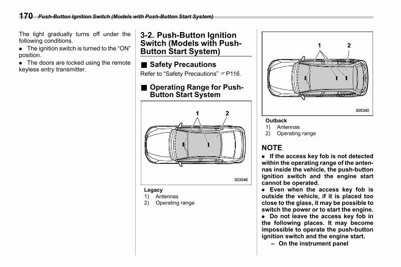
(172,1)
北米Model "A2600BE-B" EDITED: 2020/ 10/ 1
The light gradually turns off under thefollowing conditions.. The ignition switch is turned to the “ON”position.. The doors are locked using the remotekeyless entry transmitter.
3-2. Push-Button IgnitionSwitch (Models with Push-Button Start System)
s03bg
& Safety Precautionss03bg04
Refer to “Safety Precautions” FP116.
& Operating Range for Push-Button Start System
s03bg01
Legacy1) Antennas2) Operating range
Outback1) Antennas2) Operating range
NOTE. If the access key fob is not detectedwithin the operating range of the anten-nas inside the vehicle, the push-buttonignition switch and the engine startcannot be operated.. Even when the access key fob isoutside the vehicle, if it is placed tooclose to the glass, it may be possible toswitch the power or to start the engine.. Do not leave the access key fob inthe following places. It may becomeimpossible to operate the push-buttonignition switch and the engine start.
– On the instrument panel
Push-Button Ignition Switch (Models with Push-Button Start System)170
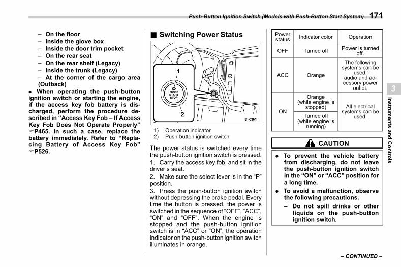
(173,1)
北米Model "A2600BE-B" EDITED: 2020/ 10/ 1
– On the floor– Inside the glove box– Inside the door trim pocket– On the rear seat– On the rear shelf (Legacy)– Inside the trunk (Legacy)– At the corner of the cargo area(Outback)
. When operating the push-buttonignition switch or starting the engine,if the access key fob battery is dis-charged, perform the procedure de-scribed in “Access Key Fob – If AccessKey Fob Does Not Operate Properly”FP465. In such a case, replace thebattery immediately. Refer to “Repla-cing Battery of Access Key Fob”FP526.
& Switching Power Statuss03bg02
1) Operation indicator2) Push-button ignition switch
The power status is switched every timethe push-button ignition switch is pressed.1. Carry the access key fob, and sit in thedriver’s seat.2. Make sure the select lever is in the “P”position.3. Press the push-button ignition switchwithout depressing the brake pedal. Everytime the button is pressed, the power isswitched in the sequence of “OFF”, “ACC”,“ON” and “OFF”. When the engine isstopped and the push-button ignitionswitch is in “ACC” or “ON”, the operationindicator on the push-button ignition switchilluminates in orange.
Powerstatus Indicator color Operation
OFF Turned off Power is turnedoff.
ACC Orange
The followingsystems can be
used:audio and ac-cessory power
outlet.
ON
Orange(while engine is
stopped) All electricalsystems can be
used.Turned off(while engine is
running)
CAUTION
. To prevent the vehicle batteryfrom discharging, do not leavethe push-button ignition switchin the “ON” or “ACC” position fora long time.
. To avoid a malfunction, observethe following precautions.– Do not spill drinks or other
liquids on the push-buttonignition switch.
– CONTINUED –
Push-Button Ignition Switch (Models with Push-Button Start System) 171
3
Instruments
andControls
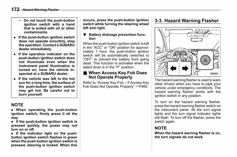
(174,1)
北米Model "A2600BE-B" EDITED: 2020/ 10/ 1
– Do not touch the push-buttonignition switch with a handthat is soiled with oil or othercontaminants.
. If the push-button ignition switchdoes not operate smoothly, stopthe operation. Contact a SUBARUdealer immediately.
. If the operation indicator on thepush-button ignition switch doesnot illuminate even when theinstrument panel illumination isturned on, have the vehicle in-spected at a SUBARU dealer.
. If the vehicle was left in the hotsun for a long time, the surface ofthe push-button ignition switchmay get hot. Be careful not toburn yourself.
NOTE. When operating the push-buttonignition switch, firmly press it all theway.. If the push-button ignition switch ispressed quickly, the power may notturn on or off.. If the indicator light on the push-button ignition switch flashes in greenwhen the push-button ignition switch ispressed, steering is locked. When this
occurs, press the push-button ignitionswitch while turning the steering wheelleft and right.
! Battery drainage prevention func-tion
s03bg0201When the push-button ignition switch is leftin the “ACC” or “ON” position for approxi-mately 1 hour, the push-button ignitionswitch will be automatically switched to“OFF” to prevent the battery from goingdead. This function is activated when theselect lever is in the “P” position.
& When Access Key Fob DoesNot Operate Properly
s03bg03Refer to “Access Key Fob – If Access KeyFob Does Not Operate Properly” FP465.
3-3. Hazard Warning Flashers03ab
The hazard warning flasher is used towarnother drivers when you have to park yourvehicle under emergency conditions. Thehazard warning flasher works with theignition switch in any position.
To turn on the hazard warning flasher,press the hazard warning flasher switch onthe instrument panel. All the turn signallights and the turn signal indicator lightswill flash. To turn off the flasher, press theswitch again.
NOTEWhen the hazard warning flasher is on,the turn signals do not work.
Hazard Warning Flasher172
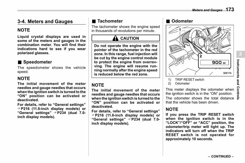
(175,1)
北米Model "A2600BE-B" EDITED: 2020/ 10/ 1
3-4. Meters and Gaugess03ad
NOTELiquid crystal displays are used insome of the meters and gauges in thecombination meter. You will find theirindications hard to see if you wearpolarized glasses.
& Speedometers03ad03
The speedometer shows the vehiclespeed.
NOTEThe initial movement of the meterneedles and gauge needles that occurswhen the ignition switch is turned to the“ON” position can be activated ordeactivated.For details, refer to “General settings”FP216 (11.6-inch display models) or“General settings” FP234 (dual 7.0-inch display models).
& Tachometers03ad06
The tachometer shows the engine speedin thousands of revolutions per minute.
CAUTION
Do not operate the engine with thepointer of the tachometer in the redzone. In this range, fuel injection willbe cut by the engine control moduleto protect the engine from overrev-ving. The engine will resume run-ning normally after the engine speedis reduced below the red zone.
NOTEThe initial movement of the meterneedles and gauge needles that occurswhen the ignition switch is turned to the“ON” position can be activated ordeactivated.For details, refer to “General settings”FP216 (11.6-inch display models) or“General settings” FP234 (dual 7.0-inch display models).
& Odometers03ad04
1) TRIP RESET switch2) Odometer
This meter displays the odometer whenthe ignition switch is in the “ON” position.The odometer shows the total distancethat the vehicle has been driven.
NOTEIf you press the TRIP RESET switchwhen the ignition switch is in the“LOCK”/“OFF” or “ACC” position, theodometer/trip meter will light up. Theindicators will turn off when the TRIPRESET switch is not operated forapproximately 10 seconds.
– CONTINUED –
Meters and Gauges 173
3
Instruments
andControls
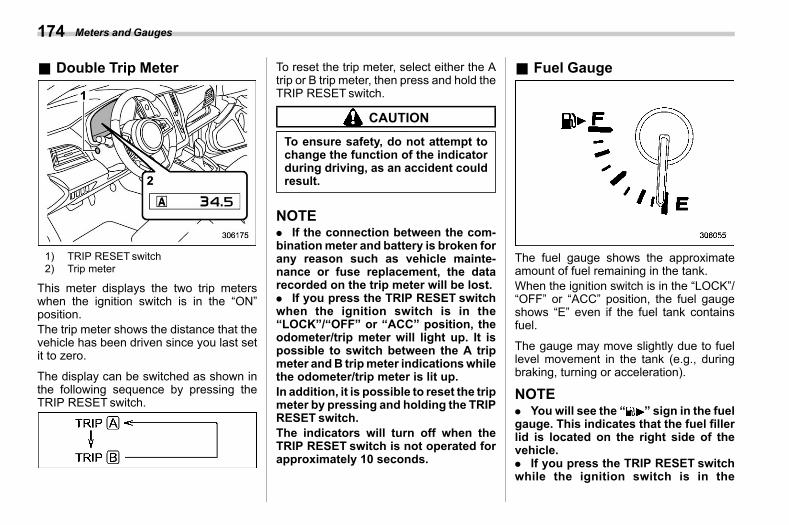
(176,1)
北米Model "A2600BE-B" EDITED: 2020/ 10/ 1
& Double Trip Meters03ad05
1) TRIP RESET switch2) Trip meter
This meter displays the two trip meterswhen the ignition switch is in the “ON”position.The trip meter shows the distance that thevehicle has been driven since you last setit to zero.
The display can be switched as shown inthe following sequence by pressing theTRIP RESET switch.
To reset the trip meter, select either the Atrip or B trip meter, then press and hold theTRIP RESET switch.
CAUTION
To ensure safety, do not attempt tochange the function of the indicatorduring driving, as an accident couldresult.
NOTE. If the connection between the com-binationmeter and battery is broken forany reason such as vehicle mainte-nance or fuse replacement, the datarecorded on the trip meter will be lost.. If you press the TRIP RESET switchwhen the ignition switch is in the“LOCK”/“OFF” or “ACC” position, theodometer/trip meter will light up. It ispossible to switch between the A tripmeter andB tripmeter indicationswhilethe odometer/trip meter is lit up.In addition, it is possible to reset the tripmeter by pressing and holding the TRIPRESET switch.The indicators will turn off when theTRIP RESET switch is not operated forapproximately 10 seconds.
& Fuel Gauges03ad07
The fuel gauge shows the approximateamount of fuel remaining in the tank.When the ignition switch is in the “LOCK”/“OFF” or “ACC” position, the fuel gaugeshows “E” even if the fuel tank containsfuel.
The gauge may move slightly due to fuellevel movement in the tank (e.g., duringbraking, turning or acceleration).
NOTE. You will see the “ ” sign in the fuelgauge. This indicates that the fuel fillerlid is located on the right side of thevehicle.. If you press the TRIP RESET switchwhile the ignition switch is in the
Meters and Gauges174
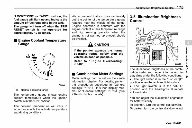
(177,1)
北米Model "A2600BE-B" EDITED: 2020/ 10/ 1
“LOCK”/“OFF” or “ACC” position, thefuel gauge will light up and indicate theamount of fuel remaining in the tank.The gauge will turn off when the TRIPRESET switch is not operated forapproximately 10 seconds.
& Engine Coolant TemperatureGauge
s03ad08
1) Normal operating range
The temperature gauge shows enginecoolant temperature when the ignitionswitch is in the “ON” position.
The coolant temperature will vary inaccordance with the outside temperatureand driving conditions.
We recommend that you drive moderatelyuntil the pointer of the temperature gaugereaches near the middle of the range.Engine operation is optimum with theengine coolant at this temperature rangeand high revving operation when theengine is not warmed up enough shouldbe avoided.
CAUTION
If the pointer exceeds the normaloperating range, safely stop thevehicle as soon as possible.Refer to “Engine Overheating”FP460.
& Combination Meter Settingss03ad16
Meter settings can be set on the centerinformation display. For details, performthe procedures described in “Generalsettings” FP216 (11.6-inch display mod-els) or “General settings” FP234 (dual7.0-inch display models).
3-5. Illumination BrightnessControl
s03aj
The illumination brightness of the combi-nation meter and center information dis-play dims under the following conditions.. The light switch is in the “ ” or “ ”position when the ambient light is dark.. The light switch is in the “AUTO”position and the headlights illuminateautomatically.
You can adjust the illumination brightnessfor better visibility.To brighten, turn the control dial upward.To darken, turn the control dial downward.
– CONTINUED –
Illumination Brightness Control 175
3
Instruments
andControls
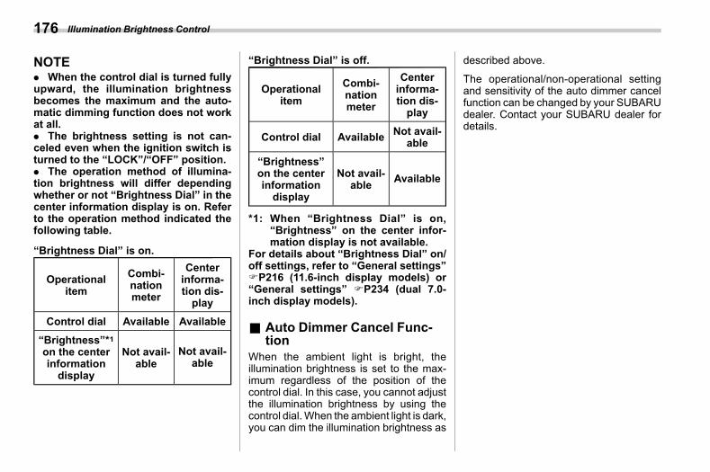
(178,1)
北米Model "A2600BE-B" EDITED: 2020/ 10/ 1
NOTE. When the control dial is turned fullyupward, the illumination brightnessbecomes the maximum and the auto-matic dimming function does not workat all.. The brightness setting is not can-celed even when the ignition switch isturned to the “LOCK”/“OFF” position.. The operation method of illumina-tion brightness will differ dependingwhether or not “Brightness Dial” in thecenter information display is on. Referto the operation method indicated thefollowing table.
“Brightness Dial” is on.
Operationalitem
Combi-nationmeter
Centerinforma-tion dis-play
Control dial Available Available“Brightness”*1on the centerinformationdisplay
Not avail-able
Not avail-able
“Brightness Dial” is off.
Operationalitem
Combi-nationmeter
Centerinforma-tion dis-play
Control dial Available Not avail-able
“Brightness”on the centerinformationdisplay
Not avail-able Available
*1: When “Brightness Dial” is on,“Brightness” on the center infor-mation display is not available.
For details about “Brightness Dial” on/off settings, refer to “General settings”FP216 (11.6-inch display models) or“General settings” FP234 (dual 7.0-inch display models).
& Auto Dimmer Cancel Func-tion
s03aj01When the ambient light is bright, theillumination brightness is set to the max-imum regardless of the position of thecontrol dial. In this case, you cannot adjustthe illumination brightness by using thecontrol dial.When the ambient light is dark,you can dim the illumination brightness as
described above.
The operational/non-operational settingand sensitivity of the auto dimmer cancelfunction can be changed by your SUBARUdealer. Contact your SUBARU dealer fordetails.
Illumination Brightness Control176
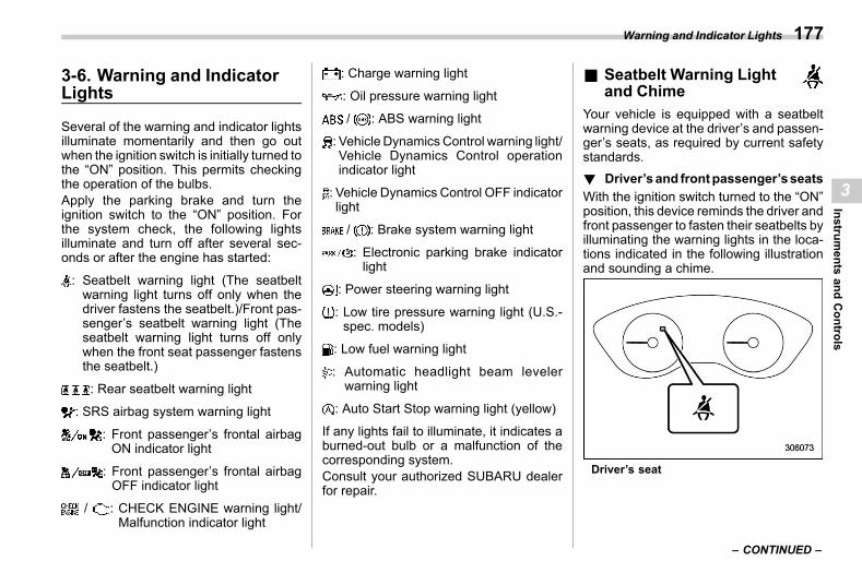
(179,1)
北米Model "A2600BE-B" EDITED: 2020/ 10/ 1
3-6. Warning and IndicatorLights
s03ae
Several of the warning and indicator lightsilluminate momentarily and then go outwhen the ignition switch is initially turned tothe “ON” position. This permits checkingthe operation of the bulbs.Apply the parking brake and turn theignition switch to the “ON” position. Forthe system check, the following lightsilluminate and turn off after several sec-onds or after the engine has started:
: Seatbelt warning light (The seatbeltwarning light turns off only when thedriver fastens the seatbelt.)/Front pas-senger’s seatbelt warning light (Theseatbelt warning light turns off onlywhen the front seat passenger fastensthe seatbelt.)
: Rear seatbelt warning light
: SRS airbag system warning light
: Front passenger’s frontal airbagON indicator light
: Front passenger’s frontal airbagOFF indicator light
/ : CHECK ENGINE warning light/Malfunction indicator light
: Charge warning light
: Oil pressure warning light
/ : ABS warning light
: Vehicle Dynamics Control warning light/Vehicle Dynamics Control operationindicator light
: Vehicle Dynamics Control OFF indicatorlight
/ : Brake system warning light
: Electronic parking brake indicatorlight
: Power steering warning light
: Low tire pressure warning light (U.S.-spec. models)
: Low fuel warning light
: Automatic headlight beam levelerwarning light
: Auto Start Stop warning light (yellow)
If any lights fail to illuminate, it indicates aburned-out bulb or a malfunction of thecorresponding system.Consult your authorized SUBARU dealerfor repair.
& Seatbelt Warning Lightand Chime s03ae01
Your vehicle is equipped with a seatbeltwarning device at the driver’s and passen-ger’s seats, as required by current safetystandards.! Driver’sand frontpassenger’sseats
s03ae0114With the ignition switch turned to the “ON”position, this device reminds the driver andfront passenger to fasten their seatbelts byilluminating the warning lights in the loca-tions indicated in the following illustrationand sounding a chime.
Driver’s seat
– CONTINUED –
Warning and Indicator Lights 177
3
Instruments
andControls
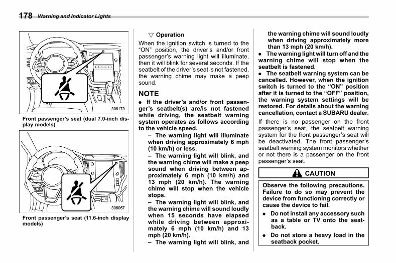
(180,1)
北米Model "A2600BE-B" EDITED: 2020/ 10/ 1
Front passenger’s seat (dual 7.0-inch dis-play models)
Front passenger’s seat (11.6-inch displaymodels)
! Operations03ae011401
When the ignition switch is turned to the“ON” position, the driver’s and/or frontpassenger’s warning light will illuminate,then it will blink for several seconds. If theseatbelt of the driver’s seat is not fastened,the warning chime may make a peepsound.
NOTE. If the driver’s and/or front passen-ger’s seatbelt(s) are/is not fastenedwhile driving, the seatbelt warningsystem operates as follows accordingto the vehicle speed.
– The warning light will illuminatewhen driving approximately 6 mph(10 km/h) or less.– The warning light will blink, andthe warning chime will make a peepsound when driving between ap-proximately 6 mph (10 km/h) and13 mph (20 km/h). The warningchime will stop when the vehiclestops.– The warning light will blink, andthe warning chime will sound loudlywhen 15 seconds have elapsedwhile driving between approxi-mately 6 mph (10 km/h) and 13mph (20 km/h).– The warning light will blink, and
the warning chime will sound loudlywhen driving approximately morethan 13 mph (20 km/h).
. Thewarning light will turn off and thewarning chime will stop when theseatbelt is fastened.. The seatbelt warning system can becancelled. However, when the ignitionswitch is turned to the “ON” positionafter it is turned to the “OFF” position,the warning system settings will berestored. For details about the warningcancellation, contact a SUBARU dealer.If there is no passenger on the frontpassenger’s seat, the seatbelt warningsystem for the front passenger’s seat willbe deactivated. The front passenger’sseatbelt warning systemmonitors whetheror not there is a passenger on the frontpassenger’s seat.
CAUTION
Observe the following precautions.Failure to do so may prevent thedevice from functioning correctly orcause the device to fail.. Do not install any accessory such
as a table or TV onto the seat-back.
. Do not store a heavy load in theseatback pocket.
Warning and Indicator Lights178
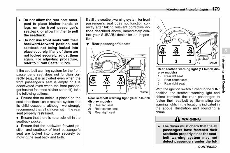
(181,1)
北米Model "A2600BE-B" EDITED: 2020/ 10/ 1
. Do not allow the rear seat occu-pant to place his/her hands orlegs on the front passenger’sseatback, or allow him/her to pullthe seatback.
. Do not use front seats with theirbackward-forward position andseatback not being locked intoplace securely. If any of them arenot locked securely, adjust themagain. For adjusting procedure,refer to “Front Seats” FP28.
If the seatbelt warning system for the frontpassenger’s seat does not function cor-rectly (e.g., it is activated even when thefront passenger’s seat is empty or it isdeactivated even when the front passen-ger has not fastened his/her seatbelt), takethe following actions.. Ensure that no article is placed on theseat other than a child restraint system andits child occupant, although we stronglyrecommend that all children sit in the rearseat properly restrained.. Ensure that there is no article left in theseatback pocket.. Ensure that the backward-forward po-sition and seatback of front passenger’sseat are locked into place securely bymoving the seat back and forth.
If still the seatbelt warning system for frontpassenger’s seat does not function cor-rectly after taking relevant corrective ac-tions described above, immediately con-tact your SUBARU dealer for an inspec-tion.! Rear passenger’s seats
s03ae0115
Rear seatbelt warning light (dual 7.0-inchdisplay models)1) Rear left seat2) Rear center seat3) Rear right seat
Rear seatbelt warning light (11.6-inch dis-play models)1) Rear left seat2) Rear center seat3) Rear right seat
With the ignition switch turned to the “ON”position, the seatbelt warning light andchime reminds the rear passenger tofasten their seatbelt by illuminating thewarning lights in the locations indicated inthe above illustration and sounding achime.
WARNING
. The driver must check that the allpassengers have fastened theirseatbelts properly since the seat-belt warning system may notdetect passengers under the fol-
– CONTINUED –
Warning and Indicator Lights 179
3
Instruments
andControls
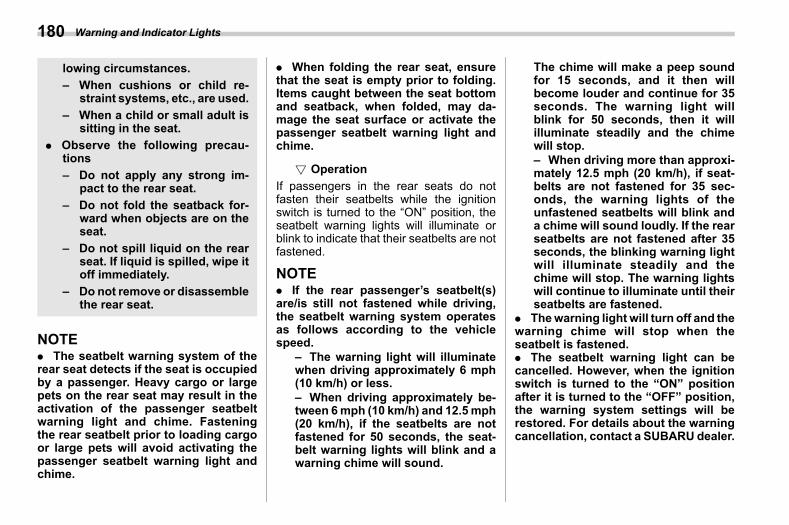
(182,1)
北米Model "A2600BE-B" EDITED: 2020/ 10/ 1
lowing circumstances.– When cushions or child re-
straint systems, etc., are used.– When a child or small adult is
sitting in the seat.. Observe the following precau-
tions– Do not apply any strong im-
pact to the rear seat.– Do not fold the seatback for-
ward when objects are on theseat.
– Do not spill liquid on the rearseat. If liquid is spilled, wipe itoff immediately.
– Do not remove or disassemblethe rear seat.
NOTE. The seatbelt warning system of therear seat detects if the seat is occupiedby a passenger. Heavy cargo or largepets on the rear seat may result in theactivation of the passenger seatbeltwarning light and chime. Fasteningthe rear seatbelt prior to loading cargoor large pets will avoid activating thepassenger seatbelt warning light andchime.
. When folding the rear seat, ensurethat the seat is empty prior to folding.Items caught between the seat bottomand seatback, when folded, may da-mage the seat surface or activate thepassenger seatbelt warning light andchime.
! Operations03ae011501
If passengers in the rear seats do notfasten their seatbelts while the ignitionswitch is turned to the “ON” position, theseatbelt warning lights will illuminate orblink to indicate that their seatbelts are notfastened.
NOTE. If the rear passenger’s seatbelt(s)are/is still not fastened while driving,the seatbelt warning system operatesas follows according to the vehiclespeed.
– The warning light will illuminatewhen driving approximately 6 mph(10 km/h) or less.– When driving approximately be-tween 6mph (10 km/h) and 12.5mph(20 km/h), if the seatbelts are notfastened for 50 seconds, the seat-belt warning lights will blink and awarning chime will sound.
The chime will make a peep soundfor 15 seconds, and it then willbecome louder and continue for 35seconds. The warning light willblink for 50 seconds, then it willilluminate steadily and the chimewill stop.– When driving more than approxi-mately 12.5 mph (20 km/h), if seat-belts are not fastened for 35 sec-onds, the warning lights of theunfastened seatbelts will blink anda chime will sound loudly. If the rearseatbelts are not fastened after 35seconds, the blinking warning lightwill illuminate steadily and thechime will stop. The warning lightswill continue to illuminate until theirseatbelts are fastened.
. Thewarning light will turn off and thewarning chime will stop when theseatbelt is fastened.. The seatbelt warning light can becancelled. However, when the ignitionswitch is turned to the “ON” positionafter it is turned to the “OFF” position,the warning system settings will berestored. For details about the warningcancellation, contact a SUBARU dealer.
Warning and Indicator Lights180
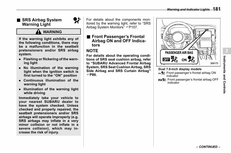
(183,1)
北米Model "A2600BE-B" EDITED: 2020/ 10/ 1
& SRS Airbag SystemWarning Light s03ae02
WARNING
If the warning light exhibits any ofthe following conditions, there maybe a malfunction in the seatbeltpretensioners and/or SRS airbagsystem.. Flashing or flickering of the warn-
ing light. No illumination of the warning
light when the ignition switch isfirst turned to the “ON” position
. Continuous illumination of thewarning light
. Illumination of the warning lightwhile driving
Immediately take your vehicle toyour nearest SUBARU dealer tohave the system checked. Unlesschecked and properly repaired, theseatbelt pretensioners and/or SRSairbags will operate improperly (e.g.SRS airbags may inflate in a veryminor collision or not inflate in asevere collision), which may in-crease the risk of injury.
For details about the components mon-itored by the warning light, refer to “SRSAirbag System Monitors” FP107.
& Front Passenger’s FrontalAirbag ON and OFF Indica-tors
s03ae03NOTEFor details about the operating condi-tions of SRS seat cushion airbag, referto “SUBARU Advanced Frontal AirbagSystem, SRSSeat CushionAirbag, SRSSide Airbag and SRS Curtain Airbag”FP86.
Dual 7.0-inch display models: Front passenger’s frontal airbag ONindicator: Front passenger’s frontal airbag OFFindicator
– CONTINUED –
Warning and Indicator Lights 181
3
Instruments
andControls
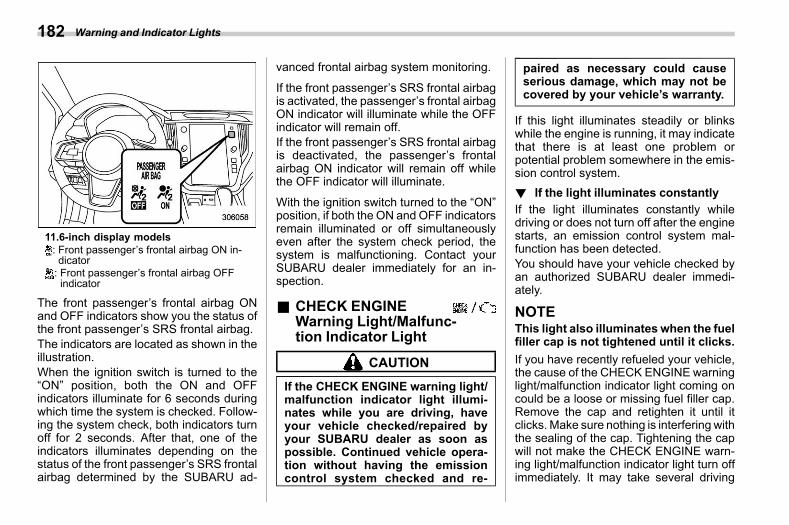
(184,1)
北米Model "A2600BE-B" EDITED: 2020/ 10/ 1
11.6-inch display models: Front passenger’s frontal airbag ON in-dicator: Front passenger’s frontal airbag OFFindicator
The front passenger’s frontal airbag ONand OFF indicators show you the status ofthe front passenger’s SRS frontal airbag.The indicators are located as shown in theillustration.When the ignition switch is turned to the“ON” position, both the ON and OFFindicators illuminate for 6 seconds duringwhich time the system is checked. Follow-ing the system check, both indicators turnoff for 2 seconds. After that, one of theindicators illuminates depending on thestatus of the front passenger’s SRS frontalairbag determined by the SUBARU ad-
vanced frontal airbag system monitoring.
If the front passenger’s SRS frontal airbagis activated, the passenger’s frontal airbagON indicator will illuminate while the OFFindicator will remain off.If the front passenger’s SRS frontal airbagis deactivated, the passenger’s frontalairbag ON indicator will remain off whilethe OFF indicator will illuminate.
With the ignition switch turned to the “ON”position, if both the ON and OFF indicatorsremain illuminated or off simultaneouslyeven after the system check period, thesystem is malfunctioning. Contact yourSUBARU dealer immediately for an in-spection.
& CHECK ENGINEWarning Light/Malfunc-tion Indicator Light s03ae04
CAUTION
If the CHECK ENGINE warning light/malfunction indicator light illumi-nates while you are driving, haveyour vehicle checked/repaired byyour SUBARU dealer as soon aspossible. Continued vehicle opera-tion without having the emissioncontrol system checked and re-
paired as necessary could causeserious damage, which may not becovered by your vehicle’s warranty.
If this light illuminates steadily or blinkswhile the engine is running, it may indicatethat there is at least one problem orpotential problem somewhere in the emis-sion control system.! If the light illuminates constantly
s03ae0401If the light illuminates constantly whiledriving or does not turn off after the enginestarts, an emission control system mal-function has been detected.You should have your vehicle checked byan authorized SUBARU dealer immedi-ately.
NOTEThis light also illuminates when the fuelfiller cap is not tightened until it clicks.If you have recently refueled your vehicle,the cause of the CHECK ENGINE warninglight/malfunction indicator light coming oncould be a loose or missing fuel filler cap.Remove the cap and retighten it until itclicks. Make sure nothing is interfering withthe sealing of the cap. Tightening the capwill not make the CHECK ENGINE warn-ing light/malfunction indicator light turn offimmediately. It may take several driving
Warning and Indicator Lights182
(185,1)
北米Model "A2600BE-B" EDITED: 2020/ 10/ 1
trips. If the light does not turn off, take yourvehicle to your authorized SUBARUdealerimmediately.! If the light is blinking
s03ae0402If the light is blinking while driving, anengine misfire condition has been de-tected which may damage the emissioncontrol system.To prevent serious damage to the emis-sion control system, you should conform tothe following instructions.. Reduce vehicle speed.. Avoid hard acceleration.. Avoid steep uphill grades.. Reduce the amount of cargo, if possi-ble.. Stop towing a trailer as soon aspossible (Outback).
The CHECK ENGINE warning light/mal-function indicator light may stop blinkingand illuminate steadily after several drivingtrips. You should have your vehiclechecked by an authorized SUBARUdealerimmediately.
& Charge Warning Light s03ae05
If this light illuminates when the engine isrunning, it may indicate that the chargingsystem is not working properly.
If the light illuminates while driving or doesnot turn off after the engine starts, stop theengine at the first safe opportunity andcheck the alternator belt. If the belt isloose, broken or if the belt is in goodcondition but the light remains illuminated,contact your nearest SUBARU dealerimmediately.
& Oil Pressure WarningLight s03ae06
CAUTION
Do not operate the engine with theoil pressure warning light on. Thismay cause serious engine damage.
If this light illuminates when the engine isrunning, it may indicate that the engine oilpressure is low and the lubricating systemis not working properly.
If the light illuminates while driving or doesnot turn off after the engine starts, stop theengine at the first safe opportunity andcontact your nearest SUBARU dealerimmediately.For details about checking the engine oillevel or adding the engine oil, refer to“Engine Oil” FP491.
& Engine Low Oil LevelWarning Indicator s03ae58
This indicator appears when the engine oillevel decreases to the lower limit.If the warning indicator appears, check theengine oil level on a level surface. Whenthe engine oil level is not within the normalrange, refill with engine oil. Refer to“Engine Oil” FP491. After adding orchanging the engine oil, warm up theengine and stop it on a level surface, thenstart the engine after a lapse of 1 minute ormore. Confirm that the warning indicatorhas turned off after the engine has started.If the warning indicator does not turn offafter refilling the engine oil, or the indicatorappears even though the engine oil level iswithin the normal range, have the vehiclechecked by a SUBARU dealer.
NOTE. The oil level will be detected by thesystem just after turning the ignitionswitch to the “OFF” position. If the oillevel is below the lower limit when theignition switch is turned to the “ON”position, the engine low oil level warn-ing indicator will turn on.. When the vehicle is parked on asteep slope, the engine low oil levelwarning indicator may not illuminateeven if the oil level is below the lower
– CONTINUED –
Warning and Indicator Lights 183
3
Instruments
andControls
(186,1)
北米Model "A2600BE-B" EDITED: 2020/ 10/ 1
limit to avoid erroneous lighting.
& AT OIL TEMP WarningLight s03ae07
If this light illuminates when the engine isrunning, it may indicate that the transmis-sion fluid temperature is too hot.If the light illuminates while driving, im-mediately stop the vehicle in a safe placeand let the engine idle until the warninglight turns off.! Transmission control system warn-
ings03ae0701
If the “AT OIL TEMP” warning light flashesafter the engine has started, it may indicatethat the transmission control system is notworking properly. Contact your nearestSUBARU dealer for service immediately.
& Low Tire PressureWarning Light (U.S.-Spec. Models) s03ae08
When the ignition switch is turned to the“ON” position, the low tire pressure warn-ing light will illuminate for approximately 2seconds to check that the tire pressuremonitoring system (TPMS) is functioningproperly. If there is no problem and all tiresare properly inflated, the light will go out.Each tire, including the spare (if provided),
should be checked monthly when cold andinflated to the inflation pressure recom-mended by the vehicle manufacturer onthe vehicle placard or tire inflation pres-sure label. (If your vehicle has tires of adifferent size than the size indicated on thevehicle placard or tire inflation pressurelabel, you should determine the proper tireinflation pressure for those tires.)
As an added safety feature, your vehiclehas been equipped with a tire pressuremonitoring system (TPMS) that illuminatesa low tire pressure telltale when one ormore of your tires is significantly under-inflated. Accordingly, when the low tirepressure telltale illuminates, you shouldstop and check your tires as soon aspossible, and inflate them to the properpressure. Driving on a significantly under-inflated tire causes the tire to overheat andcan lead to tire failure. Under-inflation alsoreduces fuel efficiency and tire tread life,and may affect the vehicle’s handling andstopping ability.Please note that the TPMS is not asubstitute for proper tire maintenance,and it is the driver’s responsibility tomaintain correct tire pressure, even ifunder-inflation has not reached the levelto trigger illumination of the TPMS low tirepressure telltale.Your vehicle has also been equipped with
a TPMS malfunction indicator to indicatewhen the system is not operating properly.The TPMS malfunction indicator is com-bined with the low tire pressure telltale.When the system detects a malfunction,the telltale will flash for approximately oneminute and then remain continuouslyilluminated. This sequence will continueupon subsequent vehicle start-ups as longas the malfunction exists. When the mal-function indicator is illuminated, the sys-temmay not be able to detect or signal lowtire pressure as intended. TPMS malfunc-tions may occur for a variety of reasons,including the installation of replacement oralternate tires or wheels on the vehicle thatprevent the TPMS from functioning prop-erly. Always check the TPMS malfunctiontelltale after replacing one or more tires orwheels on your vehicle to ensure that thereplacement or alternate tires and wheelsallow the TPMS to continue to functionproperly.Should the warning light illuminate steadilyafter blinking for approximately one min-ute, have the system inspected by yournearest SUBARU dealer as soon aspossible.
Warning and Indicator Lights184
(187,1)
北米Model "A2600BE-B" EDITED: 2020/ 10/ 1
WARNING
If this light does not illuminatebriefly after the ignition switch isturned ON or the light illuminatessteadily after blinking for approxi-mately one minute, you should haveyour Tire Pressure Monitoring Sys-tem checked at a SUBARU dealer assoon as possible.If this light illuminates while driving,never brake suddenly. Instead, per-form the following procedure. Other-wise an accident involving seriousvehicle damage and serious perso-nal injury could occur.1) Keep driving straight aheadwhile
gradually reducing speed.2) Slowly pull off the road to a safe
place.If this light still illuminates whiledriving after adjusting the tire pres-sure, a tire may have significantdamage and a fast leak that causesthe tire to lose air rapidly. If you havea flat tire, replace it with a spare tireas soon as possible.When a spare tire is mounted or awheel rim is replaced without theoriginal pressure sensor/transmitterbeing transferred, the Low tire pres-
sure warning light will illuminatesteadily after blinking for approxi-mately one minute. This indicatesthe TPMS is unable to monitor allfour road wheels. Contact yourSUBARU dealer as soon as possiblefor tire and sensor replacement and/or system resetting. If the lightilluminates steadily after blinkingfor approximately one minute,promptly contact a SUBARU dealerto have the system inspected.
CAUTION
The tire pressuremonitoring systemis NOT a substitute for manuallychecking tire pressure. The tirepressure should be checked peri-odically (at least monthly) using atire gauge. After any change to tirepressure(s), the tire pressure mon-itoring system will not re-check tireinflation pressures until the vehicleis first driven more than 20 mph (32km/h). After adjusting the tire pres-sures, increase the vehicle speed toat least 20 mph (32 km/h) to start theTPMS re-checking of the tire infla-tion pressures. If the tire pressuresare now above the severe low pres-sure threshold, the low tire pressure
warning light should turn off a fewminutes later. Therefore, be sure toinstall the specified size for the frontand rear tires.
& ABS Warning Light s03ae09
CAUTION
. If any of the following conditionsoccur, we recommend that youhave the ABS repaired at the firstavailable opportunity by yourSUBARU dealer.– The warning light does not
illuminate when the ignitionswitch is turned to the “ON”position.
– The warning light illuminateswhen the ignition switch isturned to the “ON” position,but it does not turn off evenafter starting the vehicle.
– The warning light illuminatesduring driving.
. When the warning light is on (andbrake system warning light isoff), the ABS function shutsdown; however, the conventionalbrake system continues to oper-ate normally.
– CONTINUED –
Warning and Indicator Lights 185
3
Instruments
andControls
(188,1)
北米Model "A2600BE-B" EDITED: 2020/ 10/ 1
The ABSwarning light illuminates togetherwith the brake system warning light if theEBD system malfunctions. For furtherdetails of the EBD system malfunctionwarning, refer to “Brake System WarningLight” FP186.
NOTEIf the warning light behavior is asdescribed in the following conditions,the ABS may be considered normal.. The warning light illuminates rightafter the engine is started but turns offimmediately, remaining off.. The warning light remains illumi-nated after the engine has been started,but it turns off while driving.. The warning light illuminates duringdriving, but it turns off immediately andremains off.When driving with an insufficient batteryvoltage such as when the engine is jumpstarted, the ABS warning light may illumi-nate. This is due to the low battery voltageand does not indicate a malfunction. Whenthe battery becomes fully charged, thelight will turn off.
& Brake System Warn-ing Light
s03ae10
WARNING
. Driving with the brake systemwarning light on is dangerous.This indicates your brake systemmay not be working properly. Ifthe light remains illuminated,have the brakes inspected by aSUBARU dealer immediately.
. If at all in doubt about whether thebrakes are operating properly, donot drive the vehicle. Have yourvehicle towed to the nearestSUBARU dealer for repair.
. If the brake system warning lightilluminates, the electronic park-ing brake system may be mal-functioning. Immediately stopyour vehicle in a safe location,use tire stops under the tires toprevent the vehicle from movingand contact your SUBARU deal-er. For details, refer to “Electro-nic Parking Brake” FP366.
NOTE. Even if the brake system warninglight illuminates, if the warning light
behavior is as described in the follow-ing examples, the electronic parkingbrake system is not malfunctioning.
– The warning light turns off whenthe electronic parking brake is ap-plied or released.– The warning light turns off whenthe ignition switch is turned to the“ON” position again.
. The brake system warning light mayilluminate immediately after the engineis started. However, it is not malfunc-tioning if the warning light turns offafter the electronic parking brake isreleased.. The brake system warning light mayilluminate after the electronic parkingbrake is frequently applied and re-leased. However, the electronic parkingbrake system is not malfunctioning ifthe light turns off after a short period oftime.. When the engine is started while theelectronic parking brake is applied/released, the system may judge anabnormal situation and the warninglight may illuminate. If the warning lightilluminates, turn the ignition switchonce to the “LOCK”/“OFF” positionand then restart the engine. Then,apply/release the electronic parkingbrake. If the warning light turns off,
Warning and Indicator Lights186
(189,1)
北米Model "A2600BE-B" EDITED: 2020/ 10/ 1
the system will be restored.This light has the following functions.! Brake fluid level warning
s03ae1002This light illuminates when the brake fluidlevel has dropped to near the “MIN” level ofthe brake fluid reservoir with the ignitionswitch in the “ON” position and with theparking brake fully released.
If the brake system warning light shouldilluminate while driving (with the parkingbrake fully released and with the ignitionswitch positioned in “ON”), it could be anindication of leaking of brake fluid or wornbrake pads. If this occurs, immediatelystop the vehicle at the nearest safe placeand check the brake fluid level. If the fluidlevel is below the “MIN” mark in thereservoir, do not drive the vehicle. Havethe vehicle towed to the nearest SUBARUdealer for repair.! Electronic Brake Force Distribution
(EBD) system warnings03ae1003
If the warning light remains on even thoughthe parking brake is released, the brakefluid level may be low or there could be aproblem with the EBD system. Park thevehicle in a safe place immediately andcontact a SUBARU dealer.
! Electronic parking brake systemwarning
s03ae1004The brake systemwarning light illuminateswhen the electronic parking brake systemis malfunctioning. If the warning lightilluminates, promptly park in a safe loca-tion as soon as possible and contact yourSUBARU dealer.The brake system warning light remainsilluminated when the parking brake cannotbe released even if the parking brakeswitch is pushed. For details, refer to“Electronic Parking Brake” FP366.
! Frequent operation warnings03ae100403
The brake systemwarning light illuminatesand a chirp sound will be heard if theparking brake switch is operated toofrequently. In this case, the operation ofthe parking brake switch is restricted toprotect the electronic parking brake sys-tem.
& Electronic ParkingBrake Indicator Light s03ae85
! Parking brake indicators03ae8501
The light illuminates with the parking brakeapplied while the ignition switch is in the“ACC” or “ON” position. It turns off whenthe parking brake is fully released.
! Electronic parking brake systemwarning
s03ae8502
WARNING
. When you release the electronicparking brake while the engine isrunning, the electronic parkingbrake indicator light will turn off.However, if the light still illumi-nates, stop the vehicle in a safelocation immediately and havethe system inspected by aSUBARU dealer.
. If at all in doubt about whether thebrakes are operating properly, donot drive the vehicle. Have yourvehicle towed to the nearestSUBARU dealer for repair.
. If the electronic parking brakeindicator light flashes, the elec-tronic parking brake system maybe malfunctioning. Immediatelystop your vehicle in a safe loca-tion, use tire stops under the tiresto prevent the vehicle from mov-ing and contact your SUBARUdealer. For details, refer to “Elec-tronic Parking Brake” FP366.
– CONTINUED –
Warning and Indicator Lights 187
3
Instruments
andControls
(190,1)
北米Model "A2600BE-B" EDITED: 2020/ 10/ 1
NOTE. When the ignition switch is turned tothe “LOCK”/“OFF” position with theelectronic parking brake applied, theelectronic parking brake indicator lightremains illuminated for approximately30 seconds and then turns off.. When the electronic parking brakeswitch is pulled to apply the electronicparking brake while the ignition switchis in the “LOCK”/“OFF” position, theelectronic parking brake indicator lightilluminates, remains illuminated forapproximately 30 seconds and thenturns off.. Even if the electronic parking brakeindicator light flashes, if the warninglight behavior is as described in thefollowing examples, the electronicparking brake system is not malfunc-tioning.
– The indicator light turns off whenthe electronic parking brake is re-leased.
. The electronic parking brake indica-tor light may flash immediately after theengine is started. However, it is notmalfunctioning if the indicator lightturns off after the electronic parkingbrake is released.. The electronic parking brake indica-tor light may flash after the electronic
parking brake is frequently applied andreleased. However, the electronic park-ing brake system is not malfunctioningif the light turns off after a short periodof time.The electronic parking brake indicator lightflashes when the electronic parking brakesystem is malfunctioning. If the indicatorlight flashes, promptly park in a safelocation as soon as possible and contactyour SUBARU dealer.The electronic parking brake indicator lightremains illuminated when the parkingbrake cannot be released even if theparking brake switch is pushed. For de-tails, refer to “Electronic Parking Brake”FP366.
! Parking brake apply inhibit warn-ing
s03ae850201
The electronic parking brake indicator lightflashes for 10 seconds and a chirp soundwill be heard if the parking brake switch isoperated when the parking brake cannotbe applied.
! Frequent operation warnings03ae850202
The electronic parking brake indicator lightflashes for 10 seconds and a chirp soundwill be heard if the parking brake switch isoperated too frequently. In this case, theoperation of the parking brake switch is
restricted to protect the electronic parkingbrake system.
NOTEWait until the indicator light turns off.
& Auto Vehicle Hold ONIndicator Light s03ae94
CAUTION
If the Auto Vehicle Hold ON indicatorlight does not illuminate even when“Auto Vehicle Hold (AVH)” istouched to activate the Auto VehicleHold function, the electronic parkingbrake system may be malfunction-ing.
This indicator light illuminates when theAuto Vehicle Hold is activated. For details,refer to “Auto Vehicle Hold function”FP368.
& Auto Vehicle Hold Op-eration Indicator Light s03ae95
This indicator light illuminates while thevehicle is stopped by the Auto Vehicle Holdfunction. For details, refer to “Auto VehicleHold function” FP368.
Warning and Indicator Lights188
(191,1)
北米Model "A2600BE-B" EDITED: 2020/ 10/ 1
& Low FuelWarning Light s03ae11
The low fuel warning light illuminates whenthe tank is nearly empty approximately 2.6US gal (10.0 liters, or 2.2 Imp gal). It onlyoperates when the ignition switch is in the“ON” position.
CAUTION
Promptly put fuel in the tank when-ever the low fuel warning lightilluminates. Engine misfires as aresult of an empty tank could causedamage to the engine.
& Door Open Indicator s03ae61
When any of the doors, the rear gate(Outback) or the trunk lid (Legacy) is notfully closed, the door open indicatorappears. This function is effective even ifthe ignition switch is in the “LOCK”/“OFF”or “ACC” position or the key is removedfrom the ignition switch (models without“keyless access with push-button startsystem”).The open door is indicated by the corre-sponding part of the door open indicator.
Always make sure this indicator does notappear before you start to drive.
& Engine Hood OpenWarning Light s03ae98
The warning light illuminates if the enginehood is not fully closed. This function iseffective even if the ignition switch is in the“LOCK”/“OFF” or “ACC” position, or thekey is removed from the ignition switch(models without “keyless access withpush-button start system”).
Always make sure this light is not illumi-nated before you start to drive.
& Windshield WasherFluid Warning Light s03ae42
This light appears when the fluid level inthe windshield washer fluid tank de-creases to the lower limit (approximately0.6 US qt, 0.6 liter, 0.5 Imp qt).
& All-Wheel Drive Warn-ing Light s03ae13
WARNING
Continued driving with the AWDwarning light flashing can lead topowertrain damage. If the AWDwarning light flashes, promptly park
in a safe location and then checkwhether all four tires are the samediameter and whether any of thetires has a puncture or has lost airpressure for some other reason.
NOTEIf the temporary spare tire is used, theAWDwarning lightmay flash. Use of thetemporary spare tire should thereforebe restricted to the minimum timenecessary. Replace the temporaryspare tire with a conventional tire assoon as possible.This light flashes if the vehicle is drivenwith tires of different diameters fitted on itswheels or with the air pressure excessivelylow in any of its tires.
& Power Steering Warn-ing Light s03ae53
While the engine is running, this warninglight illuminates when a malfunction hasbeen detected in the electric power steer-ing system.
CAUTION
When the power steering warninglight is illuminated, there may bemore resistance when the steering
– CONTINUED –
Warning and Indicator Lights 189
3
Instruments
andControls
(192,1)
北米Model "A2600BE-B" EDITED: 2020/ 10/ 1
wheel is operated. Drive carefully tothe nearest SUBARU dealer andhave the vehicle inspected immedi-ately.
NOTEIf the steering wheel is operated in thefollowing ways, the power steeringcontrol system may temporarily limitthe power assist in order to prevent thesystem components, such as the con-trol computer and drive motor, fromoverheating.. The steering wheel is operated fre-quently and turned sharply while thevehicle is maneuvered at extremely lowspeeds, such as while frequently turn-ing the steering wheel during parallelparking.. The steering wheel remains in thefully turned position for a long period oftime.
At this time, there will be more resis-tance when steering. However this isnot a malfunction. Normal steeringforce will be restored after the steeringwheel is not operated for a while andthe power steering control system hasan opportunity to cool down. However,if the power steering is operated in anon-standard way which causes power
assist limitation to occur too frequently,that may result in a malfunction of thepower steering control system.
& Vehicle Dynamics Con-trol Warning Light/Vehi-cle Dynamics ControlOperation IndicatorLight s03ae14
! Vehicle Dynamics Control warninglight
s03ae1401
CAUTION
The Vehicle Dynamics Control sys-tem provides its ABS controlthrough the electrical circuit of theABS. Accordingly, if the ABS isinoperative, the Vehicle DynamicsControl system becomes unable toprovide ABS control. As a result, theVehicle Dynamics Control systembecomes inoperative, causing thewarning light to illuminate. Althoughboth the Vehicle Dynamics ControlandABS are inoperative in this case,the ordinary functions of the brakesystem are still available. You will besafe while driving in this condition,but drive carefully and have yourvehicle checked at a SUBARUdealer
as soon as possible.
NOTE. If the electrical circuit of the VehicleDynamics Control system itself mal-functions, the warning light only illumi-nates. At this time, the ABS (Anti-lockBrake System) remains fully opera-tional.. The warning light illuminates whenthe electronic control system of theABS/Vehicle Dynamics Control systemmalfunctions.The Vehicle Dynamics Control system isprobably inoperative under any of thefollowing conditions. Have your vehiclechecked at a SUBARU dealer immedi-ately.. The warning light does not illuminatewhen the ignition switch is turned to the“ON” position.. The warning light illuminates while thevehicle is running.
NOTEIf the warning light behavior is asdescribed in the following examples,the Vehicle Dynamics Control systemmay be considered normal.. The warning light illuminates rightafter the engine is started but turns off
Warning and Indicator Lights190
(193,1)
北米Model "A2600BE-B" EDITED: 2020/ 10/ 1
immediately and remains off.. The warning light illuminates afterthe engine has started and turns offwhile the vehicle is subsequently beingdriven.. The warning light illuminates duringdriving, but turns off immediately andremains off.
! VehicleDynamicsControl operationindicator light
s03ae1402The indicator light flashes during activationof the skid suppression function and duringactivation of the traction control function.
NOTE. The light may remain illuminated fora short period of time after the enginehas been started, especially in coldweather. This does not indicate theexistence of a problem. The lightshould turn off as soon as the enginehas warmed up.. The indicator light illuminates whenthe engine has developed a problemand the CHECK ENGINE warning light/malfunction indicator light is on.The Vehicle Dynamics Control system isprobably malfunctioning under the follow-ing condition. Have your vehicle checkedat a SUBARU dealer as soon as possible.
. The light does not turn off even after thelapse of several minutes (the engine haswarmed up) after the engine has started.
& Vehicle Dynamics Con-trol OFF Indicator Light s03ae15
The light illuminates when “Vehicle Dy-namics Control” is selected to deactivatethe Vehicle Dynamics Control system.
The Vehicle Dynamics Control system isprobably malfunctioning under any of thefollowing conditions. Have your vehiclechecked at a SUBARU dealer immedi-ately.. The light does not illuminate while thesystem check.. The light does not turn off even after aperiod of approximately 2 seconds afterthe ignition switch has been turned to the“ON” position.
& WarningChimesandWarningIndicator of the Keyless Ac-cess with Push-Button StartSystem (If Equipped)
s03ae55
Access key warning indicatorThe keyless access with push-button startsystem is equipped with a warning chimeand the access key warning indicator inorder to minimize improper operations andhelp protect your vehicle from theft.
When the warning chime sounds and/orthe warning indicator appears, take theappropriate action.
You cannot turn the warning chimes off.However, the volume setting of the outsidewarning chime can be changed by aSUBARU dealer. Consult your SUBARU
– CONTINUED –
Warning and Indicator Lights 191
3
Instruments
andControls
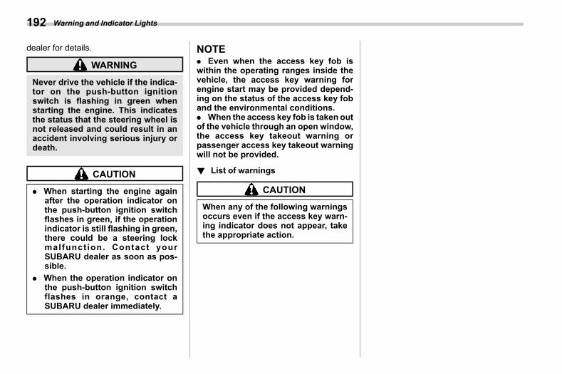
(194,1)
北米Model "A2600BE-B" EDITED: 2020/ 10/ 1
dealer for details.
WARNING
Never drive the vehicle if the indica-tor on the push-button ignitionswitch is flashing in green whenstarting the engine. This indicatesthe status that the steering wheel isnot released and could result in anaccident involving serious injury ordeath.
CAUTION
. When starting the engine againafter the operation indicator onthe push-button ignition switchflashes in green, if the operationindicator is still flashing in green,there could be a steering lockmalfunction. Contact yourSUBARU dealer as soon as pos-sible.
. When the operation indicator onthe push-button ignition switchflashes in orange, contact aSUBARU dealer immediately.
NOTE. Even when the access key fob iswithin the operating ranges inside thevehicle, the access key warning forengine start may be provided depend-ing on the status of the access key foband the environmental conditions.. When the access key fob is taken outof the vehicle through an open window,the access key takeout warning orpassenger access key takeout warningwill not be provided.
! List of warningss03ae5504
CAUTION
When any of the following warningsoccurs even if the access key warn-ing indicator does not appear, takethe appropriate action.
Warning and Indicator Lights192
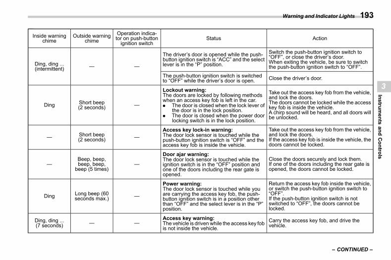
(195,1)
北米Model "A2600BE-B" EDITED: 2020/ 10/ 1
Inside warningchime
Outside warningchime
Operation indica-tor on push-buttonignition switch
Status Action
Ding, ding ...(intermittent) — —
The driver’s door is opened while the push-button ignition switch is “ACC” and the selectlever is in the “P” position.
Switch the push-button ignition switch to“OFF”, or close the driver’s door.When exiting the vehicle, be sure to switchthe push-button ignition switch to “OFF”.
The push-button ignition switch is switchedto “OFF” while the driver’s door is open. Close the driver’s door.
Ding Short beep(2 seconds) —
Lockout warning:The doors are locked by following methodswhen an access key fob is left in the car.. The door is closed when the lock lever of
the door is in the lock position.. The door is closed when the power door
locking switch is in the lock position.
Take out the access key fob from the vehicle,and lock the doors.The doors cannot be locked while the accesskey fob is inside the vehicle.A chirp sound will be heard, and all doors willbe unlocked.
— Short beep(2 seconds) —
Access key lock-in warning:The door lock sensor is touched while thepush-button ignition switch is “OFF” and theaccess key fob is inside the vehicle.
Take out the access key fob from the vehicle,and lock the doors.If the access key fob is inside the vehicle, thedoors cannot be locked.
—Beep, beep,beep, beep,beep (5 times)
—
Door ajar warning:The door lock sensor is touched while theignition switch is in the “OFF” position andone of the doors including the rear gate isopened.
Close the doors securely and lock them.If one of the doors including the rear gate isopened, the doors cannot be locked.
Ding Long beep (60seconds max.) —
Power warning:The door lock sensor is touched while youare carrying the access key fob, the push-button ignition switch is in a position otherthan “OFF” and the select lever is in the “P”position.
Return the access key fob inside the vehicle,or switch the push-button ignition switch to“OFF”.If the push-button ignition switch is notswitched to “OFF”, the doors cannot belocked.
Ding, ding ...(7 seconds) — —
Access key warning:The vehicle is drivenwhile the access key fobis not inside the vehicle.
Carry the access key fob, and drive thevehicle.
– CONTINUED –
Warning and Indicator Lights 193
3
Instruments
andControls
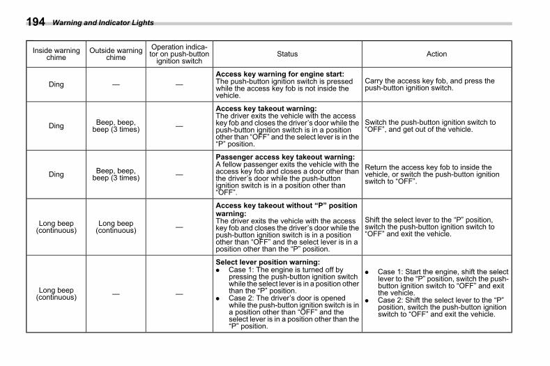
(196,1)
北米Model "A2600BE-B" EDITED: 2020/ 10/ 1
Inside warningchime
Outside warningchime
Operation indica-tor on push-buttonignition switch
Status Action
Ding — —Access key warning for engine start:The push-button ignition switch is pressedwhile the access key fob is not inside thevehicle.
Carry the access key fob, and press thepush-button ignition switch.
Ding Beep, beep,beep (3 times) —
Access key takeout warning:The driver exits the vehicle with the accesskey fob and closes the driver’s door while thepush-button ignition switch is in a positionother than “OFF” and the select lever is in the“P” position.
Switch the push-button ignition switch to“OFF”, and get out of the vehicle.
Ding Beep, beep,beep (3 times) —
Passenger access key takeout warning:A fellow passenger exits the vehicle with theaccess key fob and closes a door other thanthe driver’s door while the push-buttonignition switch is in a position other than“OFF”.
Return the access key fob to inside thevehicle, or switch the push-button ignitionswitch to “OFF”.
Long beep(continuous)
Long beep(continuous) —
Access key takeout without “P” positionwarning:The driver exits the vehicle with the accesskey fob and closes the driver’s door while thepush-button ignition switch is in a positionother than “OFF” and the select lever is in aposition other than the “P” position.
Shift the select lever to the “P” position,switch the push-button ignition switch to“OFF” and exit the vehicle.
Long beep(continuous) — —
Select lever position warning:. Case 1: The engine is turned off by
pressing the push-button ignition switchwhile the select lever is in a position otherthan the “P” position.
. Case 2: The driver’s door is openedwhile the push-button ignition switch is ina position other than “OFF” and theselect lever is in a position other than the“P” position.
. Case 1: Start the engine, shift the selectlever to the “P” position, switch the push-button ignition switch to “OFF” and exitthe vehicle.
. Case 2: Shift the select lever to the “P”position, switch the push-button ignitionswitch to “OFF” and exit the vehicle.
Warning and Indicator Lights194
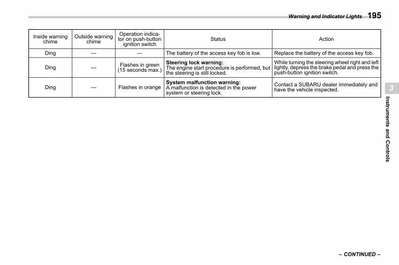
(197,1)
北米Model "A2600BE-B" EDITED: 2020/ 10/ 1
Inside warningchime
Outside warningchime
Operation indica-tor on push-buttonignition switch
Status Action
Ding — — The battery of the access key fob is low. Replace the battery of the access key fob.
Ding — Flashes in green(15 seconds max.)
Steering lock warning:The engine start procedure is performed, butthe steering is still locked.
While turning the steering wheel right and leftlightly, depress the brake pedal and press thepush-button ignition switch.
Ding — Flashes in orangeSystem malfunction warning:A malfunction is detected in the powersystem or steering lock.
Contact a SUBARU dealer immediately andhave the vehicle inspected.
– CONTINUED –
Warning and Indicator Lights 195
3
Instruments
andControls
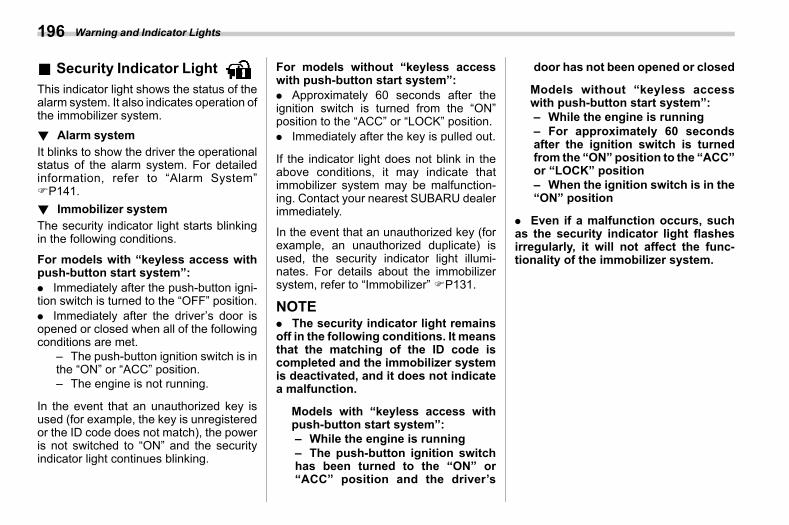
(198,1)
北米Model "A2600BE-B" EDITED: 2020/ 10/ 1
& Security Indicator Light s03ae16
This indicator light shows the status of thealarm system. It also indicates operation ofthe immobilizer system.! Alarm system
s03ae1601It blinks to show the driver the operationalstatus of the alarm system. For detailedinformation, refer to “Alarm System”FP141.! Immobilizer system
s03ae1602The security indicator light starts blinkingin the following conditions.
For models with “keyless access withpush-button start system”:. Immediately after the push-button igni-tion switch is turned to the “OFF” position.. Immediately after the driver’s door isopened or closed when all of the followingconditions are met.
– The push-button ignition switch is inthe “ON” or “ACC” position.– The engine is not running.
In the event that an unauthorized key isused (for example, the key is unregisteredor the ID code does not match), the poweris not switched to “ON” and the securityindicator light continues blinking.
For models without “keyless accesswith push-button start system”:. Approximately 60 seconds after theignition switch is turned from the “ON”position to the “ACC” or “LOCK” position.. Immediately after the key is pulled out.
If the indicator light does not blink in theabove conditions, it may indicate thatimmobilizer system may be malfunction-ing. Contact your nearest SUBARU dealerimmediately.
In the event that an unauthorized key (forexample, an unauthorized duplicate) isused, the security indicator light illumi-nates. For details about the immobilizersystem, refer to “Immobilizer” FP131.
NOTE. The security indicator light remainsoff in the following conditions. It meansthat the matching of the ID code iscompleted and the immobilizer systemis deactivated, and it does not indicatea malfunction.
Models with “keyless access withpush-button start system”:– While the engine is running– The push-button ignition switchhas been turned to the “ON” or“ACC” position and the driver’s
door has not been opened or closed
Models without “keyless accesswith push-button start system”:– While the engine is running– For approximately 60 secondsafter the ignition switch is turnedfrom the “ON” position to the “ACC”or “LOCK” position– When the ignition switch is in the“ON” position
. Even if a malfunction occurs, suchas the security indicator light flashesirregularly, it will not affect the func-tionality of the immobilizer system.
Warning and Indicator Lights196
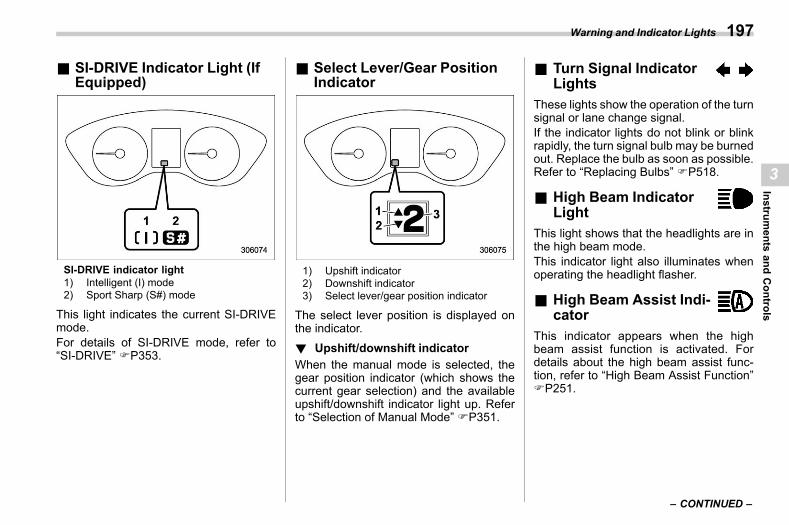
(199,1)
北米Model "A2600BE-B" EDITED: 2020/ 10/ 1
& SI-DRIVE Indicator Light (IfEquipped)
s03ae52
SI-DRIVE indicator light1) Intelligent (I) mode2) Sport Sharp (S#) mode
This light indicates the current SI-DRIVEmode.For details of SI-DRIVE mode, refer to“SI-DRIVE” FP353.
& Select Lever/Gear PositionIndicator
s03ae43
1) Upshift indicator2) Downshift indicator3) Select lever/gear position indicator
The select lever position is displayed onthe indicator.! Upshift/downshift indicator
s03ae4305When the manual mode is selected, thegear position indicator (which shows thecurrent gear selection) and the availableupshift/downshift indicator light up. Referto “Selection of Manual Mode” FP351.
& Turn Signal IndicatorLights s03ae20
These lights show the operation of the turnsignal or lane change signal.If the indicator lights do not blink or blinkrapidly, the turn signal bulb may be burnedout. Replace the bulb as soon as possible.Refer to “Replacing Bulbs” FP518.
& High Beam IndicatorLight s03ae21
This light shows that the headlights are inthe high beam mode.This indicator light also illuminates whenoperating the headlight flasher.
& High Beam Assist Indi-cator s03ae83
This indicator appears when the highbeam assist function is activated. Fordetails about the high beam assist func-tion, refer to “High Beam Assist Function”FP251.
– CONTINUED –
Warning and Indicator Lights 197
3
Instruments
andControls
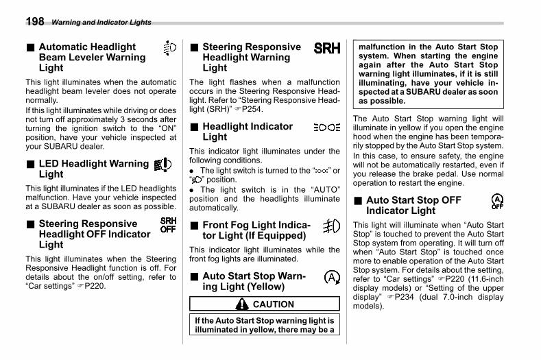
(200,1)
北米Model "A2600BE-B" EDITED: 2020/ 10/ 1
& Automatic HeadlightBeam Leveler WarningLight s03ae33
This light illuminates when the automaticheadlight beam leveler does not operatenormally.If this light illuminates while driving or doesnot turn off approximately 3 seconds afterturning the ignition switch to the “ON”position, have your vehicle inspected atyour SUBARU dealer.
& LED Headlight WarningLight s03ae76
This light illuminates if the LED headlightsmalfunction. Have your vehicle inspectedat a SUBARU dealer as soon as possible.
& Steering ResponsiveHeadlight OFF IndicatorLight s03ae89
This light illuminates when the SteeringResponsive Headlight function is off. Fordetails about the on/off setting, refer to“Car settings” FP220.
& Steering ResponsiveHeadlight WarningLight s03aeb2
The light flashes when a malfunctionoccurs in the Steering Responsive Head-light. Refer to “Steering Responsive Head-light (SRH)” FP254.
& Headlight IndicatorLight s03ae24
This indicator light illuminates under thefollowing conditions.. The light switch is turned to the “ ” or“ ” position.. The light switch is in the “AUTO”position and the headlights illuminateautomatically.
& Front Fog Light Indica-tor Light (If Equipped) s03ae25
This indicator light illuminates while thefront fog lights are illuminated.
& Auto Start Stop Warn-ing Light (Yellow) s03ae65
CAUTION
If the Auto Start Stopwarning light isilluminated in yellow, there may be a
malfunction in the Auto Start Stopsystem. When starting the engineagain after the Auto Start Stopwarning light illuminates, if it is stillilluminating, have your vehicle in-spected at a SUBARUdealer as soonas possible.
The Auto Start Stop warning light willilluminate in yellow if you open the enginehood when the engine has been tempora-rily stopped by the Auto Start Stop system.In this case, to ensure safety, the enginewill not be automatically restarted, even ifyou release the brake pedal. Use normaloperation to restart the engine.
& Auto Start Stop OFFIndicator Light s03aeb3
This light will illuminate when “Auto StartStop” is touched to prevent the Auto StartStop system from operating. It will turn offwhen “Auto Start Stop” is touched oncemore to enable operation of the Auto StartStop system. For details about the setting,refer to “Car settings” FP220 (11.6-inchdisplay models) or “Setting of the upperdisplay” FP234 (dual 7.0-inch displaymodels).
Warning and Indicator Lights198
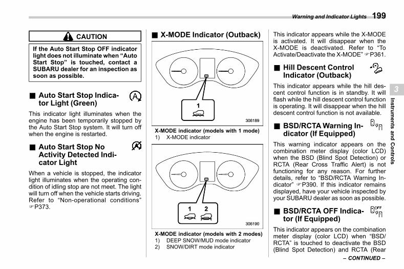
(201,1)
北米Model "A2600BE-B" EDITED: 2020/ 10/ 1
CAUTION
If the Auto Start Stop OFF indicatorlight does not illuminate when “AutoStart Stop” is touched, contact aSUBARU dealer for an inspection assoon as possible.
& Auto Start Stop Indica-tor Light (Green) s03ae66
This indicator light illuminates when theengine has been temporarily stopped bythe Auto Start Stop system. It will turn offwhen the engine is restarted.
& Auto Start Stop NoActivity Detected Indi-cator Light s03aea3
When a vehicle is stopped, the indicatorlight illuminates when the operating con-dition of idling stop are not meet. The lightwill turn off when the vehicle starts driving.Refer to “Non-operational conditions”FP373.
& X-MODE Indicator (Outback)s03ae68
X-MODE indicator (models with 1 mode)1) X-MODE indicator
X-MODE indicator (models with 2 modes)1) DEEP SNOW/MUD mode indicator2) SNOW/DIRT mode indicator
This indicator appears while the X-MODEis activated. It will disappear when theX-MODE is deactivated. Refer to “ToActivate/Deactivate the X-MODE”FP361.
& Hill Descent ControlIndicator (Outback) s03ae69
This indicator appears while the hill des-cent control function is in standby. It willflash while the hill descent control functionis operating. It will disappear when the hilldescent control function is not available.
& BSD/RCTAWarning In-dicator (If Equipped) s03ae80
This warning indicator appears on thecombination meter display (color LCD)when the BSD (Blind Spot Detection) orRCTA (Rear Cross Traffic Alert) is notfunctioning for any reason. For furtherdetails, refer to “BSD/RCTA Warning In-dicator” FP390. If this indicator remainsdisplayed, have your vehicle inspected byyour SUBARU dealer as soon as possible.
& BSD/RCTA OFF Indica-tor (If Equipped) s03ae86
This indicator appears on the combinationmeter display (color LCD) when “BSD/RCTA” is touched to deactivate the BSD(Blind Spot Detection) and RCTA (Rear
– CONTINUED –
Warning and Indicator Lights 199
3
Instruments
andControls
(202,1)
北米Model "A2600BE-B" EDITED: 2020/ 10/ 1
Cross Traffic Alert), or when the BSD/RCTA is suspended temporarily. For de-tails, refer to “BSD/RCTA OFF Indicator”FP389.
& Icy Road SurfaceWarning Indicator s03ae82
When the outside temperature is 378F(38C) or less, the icy road surface warningindicator will illuminate to inform the driverthat the road surface may be frozen.
NOTE. The outside temperature indicatorshows the temperature in the areaaround the sensor. However, the tem-perature may not be indicated correctlyor the update may be delayed in thefollowing conditions.
– While parking or driving at lowspeeds– When the outside temperaturechanges suddenly (example: whengoing in and out of an undergroundparking area or when passingthrough a tunnel)– When starting the engine afterbeing parked for a certain period oftime
. The icy road surface warning indi-cator should be treated only as a guide.Be sure to check the condition of the
road surface before driving.. Once the icy road surface warningindicator appears, it will not disappearunless the outside temperature hasincreased to 418F (58C) or higher.
& RABWarning Indi-cator (If Equipped)
s03ae91This indicator illuminates if the ReverseAutomatic Braking (RAB) systemmalfunc-tions. Refer to “Reverse Automatic Brak-ing (RAB) System” FP393.
& RAB OFF Indicator (IfEquipped) s03ae92
This indicator illuminates when the Re-verse Automatic Braking (RAB) system isturned OFF, or when the Reverse Auto-matic Braking (RAB) system is suspendedtemporarily. Refer to “Reverse AutomaticBraking (RAB) System” FP393.
& Driver Monitoring Sys-tem Operation IndicatorLight (Green) (IfEquipped) s03aea4
This indicator illuminates when the DriverMonitoring System is activated. Refer to“Driver Monitoring System operation in-dicator light (green)” FP412.
& Driver Monitoring Sys-tem Warning Light (Yel-low) (If Equipped) s03aeb6
This warning light illuminates if the DriverMonitoring System malfunctions. Haveyour vehicle inspected at a SUBARUdealer as soon as possible. Refer to“Driver Monitoring System operation in-dicator light (green)” FP412.
& Driver Monitoring Sys-tem OFF Indicator Light(If Equipped) s03aea5
This indicator illuminates when “DriverMonitoring System” is touched to deacti-vate the Driver Monitoring System. Referto “Driver Monitoring System OFF indica-tor light” FP412.
& Driver Monitoring Sys-tem Temporary Stop In-dicator Light (IfEquipped) s03aea6
This indicator illuminates when the DriverMonitoring System is temporarily stopped.Refer to “Driver Monitoring System tem-porary stop indicator light” FP412.
Warning and Indicator Lights200
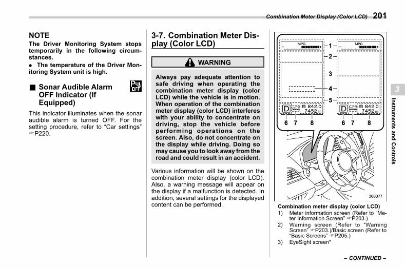
(203,1)
北米Model "A2600BE-B" EDITED: 2020/ 10/ 1
NOTEThe Driver Monitoring System stopstemporarily in the following circum-stances.. The temperature of the Driver Mon-itoring System unit is high.
& Sonar Audible AlarmOFF Indicator (IfEquipped) s03ae93
This indicator illuminates when the sonaraudible alarm is turned OFF. For thesetting procedure, refer to “Car settings”FP220.
3-7. Combination Meter Dis-play (Color LCD)
s03bn
WARNING
Always pay adequate attention tosafe driving when operating thecombination meter display (colorLCD) while the vehicle is in motion.When operation of the combinationmeter display (color LCD) interfereswith your ability to concentrate ondriving, stop the vehicle beforeperforming operations on thescreen. Also, do not concentrate onthe display while driving. Doing somay cause you to look away from theroad and could result in an accident.
Various information will be shown on thecombination meter display (color LCD).Also, a warning message will appear onthe display if a malfunction is detected. Inaddition, several settings for the displayedcontent can be performed. Combination meter display (color LCD)
1) Meter information screen (Refer to “Me-ter Information Screen” FP203.)
2) Warning screen (Refer to “WarningScreen” FP203.)/Basic screen (Refer to“Basic Screens” FP205.)
3) EyeSight screen*
– CONTINUED –
Combination Meter Display (Color LCD) 201
3
Instruments
andControls
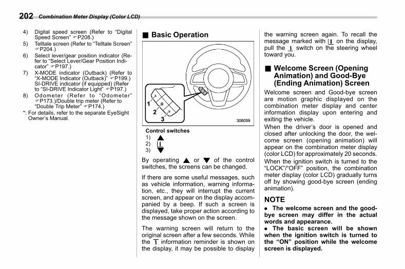
(204,1)
北米Model "A2600BE-B" EDITED: 2020/ 10/ 1
4) Digital speed screen (Refer to “DigitalSpeed Screen” FP208.)
5) Telltale screen (Refer to “Telltale Screen”FP204.)
6) Select lever/gear position indicator (Re-fer to “Select Lever/Gear Position Indi-cator” FP197.)
7) X-MODE indicator (Outback) (Refer to“X-MODE Indicator (Outback)” FP199.)SI-DRIVE indicator (if equipped) (Referto “SI-DRIVE Indicator Light” FP197.)
8) Odometer (Refer to “Odometer”FP173.)/Double trip meter (Refer to“Double Trip Meter” FP174.)
*: For details, refer to the separate EyeSightOwner’s Manual.
& Basic Operations03bn01
Control switches1)2)3)
By operating or of the controlswitches, the screens can be changed.
If there are some useful messages, suchas vehicle information, warning informa-tion, etc., they will interrupt the currentscreen, and appear on the display accom-panied by a beep. If such a screen isdisplayed, take proper action according tothe message shown on the screen.
The warning screen will return to theoriginal screen after a few seconds. Whilethe information reminder is shown onthe display, it may be possible to display
the warning screen again. To recall themessage marked with on the display,pull the switch on the steering wheeltoward you.
& Welcome Screen (OpeningAnimation) and Good-Bye(Ending Animation) Screen
s03bn08Welcome screen and Good-bye screenare motion graphic displayed on thecombination meter display and centerinformation display upon entering andexiting the vehicle.When the driver’s door is opened andclosed after unlocking the door, the wel-come screen (opening animation) willappear on the combination meter display(color LCD) for approximately 20 seconds.When the ignition switch is turned to the“LOCK”/“OFF” position, the combinationmeter display (color LCD) gradually turnsoff by showing good-bye screen (endinganimation).
NOTE. The welcome screen and the good-bye screen may differ in the actualwords and appearance.. The basic screen will be shownwhen the ignition switch is turned tothe “ON” position while the welcomescreen is displayed.
Combination Meter Display (Color LCD)202
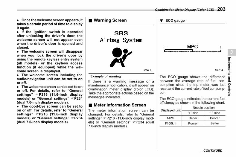
(205,1)
北米Model "A2600BE-B" EDITED: 2020/ 10/ 1
. Once thewelcome screen appears, ittakes a certain period of time to displayit again.. If the ignition switch is operatedafter unlocking the driver’s door, thewelcome screen will not appear evenwhen the driver’s door is opened andclosed.. The welcome screen will disappearwhen you lock the driver’s door byusing the remote keyless entry system(all models) or the keyless accessfunction (if equipped) while the wel-come screen is displayed.. The welcome screen including theaudio/navigation unit can be set to onor off.. Thewelcome screen can be set to onor off. For details, refer to “Generalsettings” FP216 (11.6-inch displaymodels) or “General settings” FP234(dual 7.0-inch display models).. The good-bye screen can be set toon or off. For details, refer to “Generalsettings” FP216 (11.6-inch displaymodels) or “General settings” FP234(dual 7.0-inch display models).
& Warning Screens03bn05
Example of warningIf there is a warning message or amaintenance notification, it will appear oncombination meter display (color LCD).Take the appropriate actions based on themessages indicated.
& Meter Information Screens03bn12
The meter information screen can bechanged. For details, refer to “Generalsettings” FP216 (11.6-inch display mod-els) or “General settings” FP234 (dual7.0-inch display models).
! ECO gauges03bn1201
The ECO gauge shows the differencebetween the average rate of fuel con-sumption since the trip meter was lastreset and the current rate of fuel consump-tion.
The ECO gauge indicates the current fuelefficiency as shown in the following chart.
Displayed unitNeedle position
“+” side “−” side
MPG Better Poorerl/100km Poorer Better
– CONTINUED –
Combination Meter Display (Color LCD) 203
3
Instruments
andControls
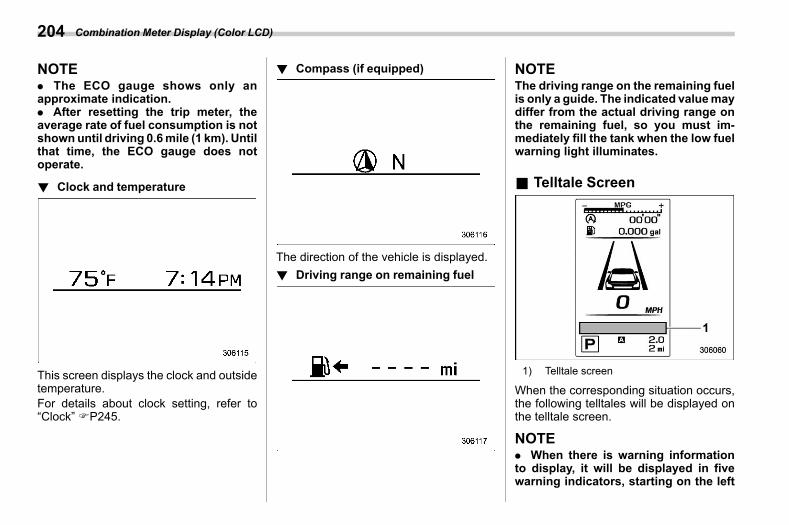
(206,1)
北米Model "A2600BE-B" EDITED: 2020/ 10/ 1
NOTE. The ECO gauge shows only anapproximate indication.. After resetting the trip meter, theaverage rate of fuel consumption is notshownuntil driving 0.6mile (1 km). Untilthat time, the ECO gauge does notoperate.
! Clock and temperatures03bn1202
This screen displays the clock and outsidetemperature.For details about clock setting, refer to“Clock” FP245.
! Compass (if equipped)s03bn1203
The direction of the vehicle is displayed.! Driving range on remaining fuel
s03bn1204
NOTEThe driving range on the remaining fuelis only a guide. The indicated valuemaydiffer from the actual driving range onthe remaining fuel, so you must im-mediately fill the tank when the low fuelwarning light illuminates.
& Telltale Screens03bn09
1) Telltale screen
When the corresponding situation occurs,the following telltales will be displayed onthe telltale screen.
NOTE. When there is warning informationto display, it will be displayed in fivewarning indicators, starting on the left
Combination Meter Display (Color LCD)204
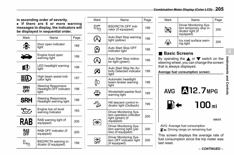
(207,1)
北米Model "A2600BE-B" EDITED: 2020/ 10/ 1
in ascending order of severity.. If there are 6 or more warningmessages to display, the indicators willbe displayed in sequential order.
Mark Name Page
Door open indicatorlight 189
Engine hood openwarning light 189
LED headlight warninglight 198
High beam assist indi-cator light 197
Steering ResponsiveHeadlight OFF indicatorlight
198
Steering ResponsiveHeadlight warning light 198
Engine low oil levelwarning lndicator 183
RAB warning light (ifequipped) 200
RAB OFF indicator (ifequipped) 200
BSD/RCTA warning in-dicator (if equipped) 199
Mark Name Page
BSD/RCTA OFF indi-cator (if equipped) 199
Auto Start Stop warninglight (yellow) 198
Auto Start Stop OFFindicator light 198
Auto Start Stop indica-tor light (green) 199
Auto Start Stop No Ac-tivity Detected indicatorlight
199
Automatic headlightbeam leveler warninglight
198
Windshield washer fluidwarning light 189
Hill descent control in-dicator light (Outback) 199
Driver Monitoring Sys-tem operation indicatorlight (green) (ifequipped)
200
Driver Monitoring Sys-tem warning light (yel-low) (if equipped)
200
Driver Monitoring Sys-tem OFF indicator light(if equipped)
200
Mark Name PageDriver Monitoring Sys-tem temporary stop in-dicator light (ifequipped)
200
Icy road surface warn-ing light 200
& Basic Screenss03bn06
By operating the or switch on thesteering wheel, you can change the screenthat is always displayed.Average fuel consumption screen:
AVG: Average fuel consumption: Driving range on remaining fuel
This screen displays the average rate offuel consumption since the trip meter waslast reset.
– CONTINUED –
Combination Meter Display (Color LCD) 205
3
Instruments
andControls
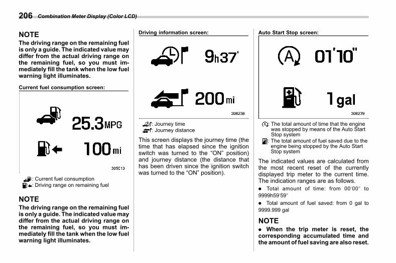
(208,1)
北米Model "A2600BE-B" EDITED: 2020/ 10/ 1
NOTEThe driving range on the remaining fuelis only a guide. The indicated valuemaydiffer from the actual driving range onthe remaining fuel, so you must im-mediately fill the tank when the low fuelwarning light illuminates.
Current fuel consumption screen:
: Current fuel consumption: Driving range on remaining fuel
NOTEThe driving range on the remaining fuelis only a guide. The indicated valuemaydiffer from the actual driving range onthe remaining fuel, so you must im-mediately fill the tank when the low fuelwarning light illuminates.
Driving information screen:
: Journey time: Journey distance
This screen displays the journey time (thetime that has elapsed since the ignitionswitch was turned to the “ON” position)and journey distance (the distance thathas been driven since the ignition switchwas turned to the “ON” position).
Auto Start Stop screen:
: The total amount of time that the enginewas stopped by means of the Auto StartStop system
: The total amount of fuel saved due to theengine being stopped by the Auto StartStop system
The indicated values are calculated fromthe most recent reset of the currentlydisplayed trip meter to the current time.The indication ranges are as follows.. Total amount of time: from 00’00@ to9999h59’59@
. Total amount of fuel saved: from 0 gal to9999.999 gal
NOTE. When the trip meter is reset, thecorresponding accumulated time andthe amount of fuel saving are also reset.
Combination Meter Display (Color LCD)206
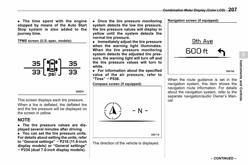
(209,1)
北米Model "A2600BE-B" EDITED: 2020/ 10/ 1
. The time spent with the enginestopped by means of the Auto StartStop system is also added to thejourney time.
TPMS screen (U.S.-spec. models):
This screen displays each tire pressure.When a tire is deflated, the deflated tireand the tire pressure will be displayed onthe screen in yellow.
NOTE. The tire pressure values are dis-played several minutes after driving.. You can set the tire pressure units.For details about setting the units, referto “General settings”FP216 (11.6-inchdisplay models) or “General settings”FP234 (dual 7.0-inch display models).
. Once the tire pressure monitoringsystem detects the low tire pressure,the tire pressure values will display inyellow until the system detects thenormal tire pressure.. Immediately adjust the tire pressurewhen the warning light illuminates.When the tire pressure monitoringsystem detects the adjusted tire pres-sure, the warning light will turn off andthe tire pressure values will turn towhite.. For information about the specifiedvalue of the air pressure, refer to“Tires” FP536.Compass screen (if equipped):
The direction of the vehicle is displayed.
Navigation screen (if equipped):
When the route guidance is set in thenavigation system, this item shows thenavigation route information. For detailsabout the navigation system, refer to theseparate navigation/audio Owner’s Man-ual.
– CONTINUED –
Combination Meter Display (Color LCD) 207
3
Instruments
andControls
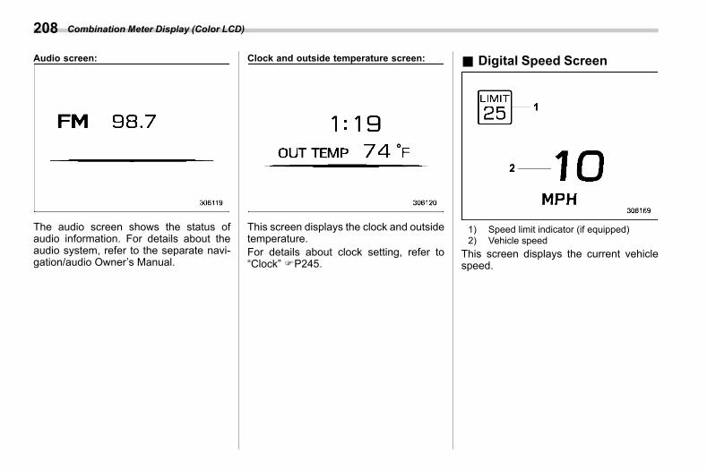
(210,1)
北米Model "A2600BE-B" EDITED: 2020/ 10/ 1
Audio screen:
The audio screen shows the status ofaudio information. For details about theaudio system, refer to the separate navi-gation/audio Owner’s Manual.
Clock and outside temperature screen:
This screen displays the clock and outsidetemperature.For details about clock setting, refer to“Clock” FP245.
& Digital Speed Screens03bn11
1) Speed limit indicator (if equipped)2) Vehicle speed
This screen displays the current vehiclespeed.
Combination Meter Display (Color LCD)208
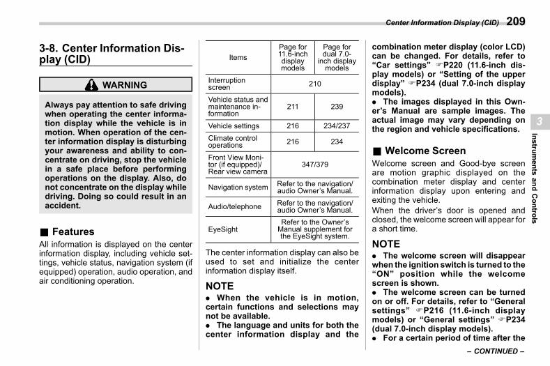
(211,1)
北米Model "A2600BE-B" EDITED: 2020/ 10/ 1
3-8. Center Information Dis-play (CID)
s03bs
WARNING
Always pay attention to safe drivingwhen operating the center informa-tion display while the vehicle is inmotion. When operation of the cen-ter information display is disturbingyour awareness and ability to con-centrate on driving, stop the vehiclein a safe place before performingoperations on the display. Also, donot concentrate on the display whiledriving. Doing so could result in anaccident.
& Featuress03bs01
All information is displayed on the centerinformation display, including vehicle set-tings, vehicle status, navigation system (ifequipped) operation, audio operation, andair conditioning operation.
ItemsPage for11.6-inchdisplaymodels
Page fordual 7.0-
inch displaymodels
Interruptionscreen 210
Vehicle status andmaintenance in-formation
211 239
Vehicle settings 216 234/237Climate controloperations 216 234
Front View Moni-tor (if equipped)/Rear view camera
347/379
Navigation system Refer to the navigation/audio Owner’s Manual.
Audio/telephone Refer to the navigation/audio Owner’s Manual.
EyeSightRefer to the Owner’sManual supplement forthe EyeSight system.
The center information display can also beused to set and initialize the centerinformation display itself.
NOTE. When the vehicle is in motion,certain functions and selections maynot be available.. The language and units for both thecenter information display and the
combination meter display (color LCD)can be changed. For details, refer to“Car settings” FP220 (11.6-inch dis-play models) or “Setting of the upperdisplay” FP234 (dual 7.0-inch displaymodels).. The images displayed in this Own-er’s Manual are sample images. Theactual image may vary depending onthe region and vehicle specifications.
& Welcome Screens03bs02
Welcome screen and Good-bye screenare motion graphic displayed on thecombination meter display and centerinformation display upon entering andexiting the vehicle.When the driver’s door is opened andclosed, the welcome screen will appear fora short time.
NOTE. The welcome screen will disappearwhen the ignition switch is turned to the“ON” position while the welcomescreen is shown.. The welcome screen can be turnedon or off. For details, refer to “Generalsettings” FP216 (11.6-inch displaymodels) or “General settings” FP234(dual 7.0-inch display models).. For a certain period of time after the
– CONTINUED –
Center Information Display (CID) 209
3
Instruments
andControls
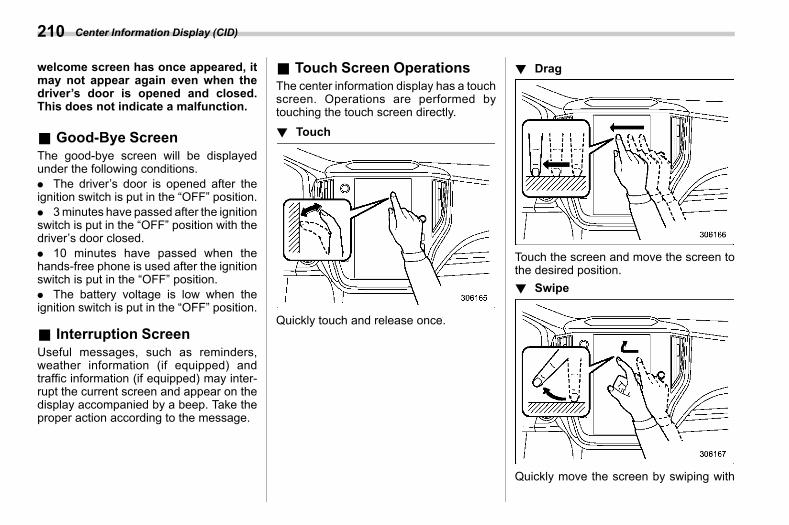
(212,1)
北米Model "A2600BE-B" EDITED: 2020/ 10/ 1
welcome screen has once appeared, itmay not appear again even when thedriver’s door is opened and closed.This does not indicate a malfunction.
& Good-Bye Screens03bs08
The good-bye screen will be displayedunder the following conditions.. The driver’s door is opened after theignition switch is put in the “OFF” position.. 3minutes have passed after the ignitionswitch is put in the “OFF” position with thedriver’s door closed.. 10 minutes have passed when thehands-free phone is used after the ignitionswitch is put in the “OFF” position.. The battery voltage is low when theignition switch is put in the “OFF” position.
& Interruption Screens03bs03
Useful messages, such as reminders,weather information (if equipped) andtraffic information (if equipped) may inter-rupt the current screen and appear on thedisplay accompanied by a beep. Take theproper action according to the message.
& Touch Screen Operationss03bs04
The center information display has a touchscreen. Operations are performed bytouching the touch screen directly.! Touch
s03bs0401
Quickly touch and release once.
! Drags03bs0402
Touch the screen and move the screen tothe desired position.! Swipe
s03bs0403
Quickly move the screen by swiping with
Center Information Display (CID)210
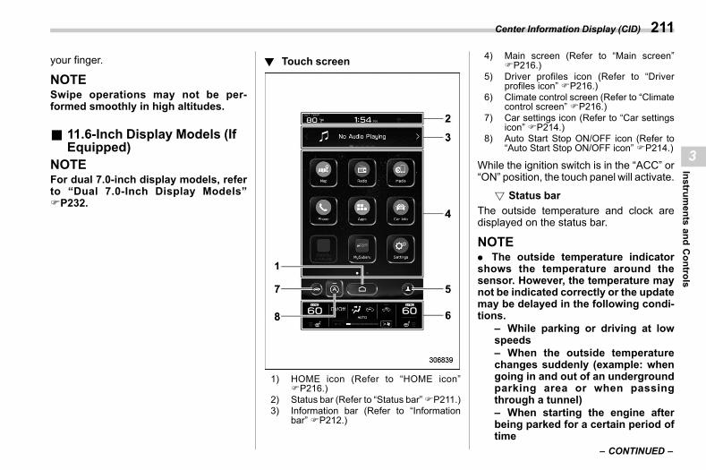
(213,1)
北米Model "A2600BE-B" EDITED: 2020/ 10/ 1
your finger.
NOTESwipe operations may not be per-formed smoothly in high altitudes.
& 11.6-Inch Display Models (IfEquipped)
s03bs05NOTEFor dual 7.0-inch display models, referto “Dual 7.0-Inch Display Models”FP232.
! Touch screens03bs0501
1) HOME icon (Refer to “HOME icon”FP216.)
2) Status bar (Refer to “Status bar”FP211.)3) Information bar (Refer to “Information
bar” FP212.)
4) Main screen (Refer to “Main screen”FP216.)
5) Driver profiles icon (Refer to “Driverprofiles icon” FP216.)
6) Climate control screen (Refer to “Climatecontrol screen” FP216.)
7) Car settings icon (Refer to “Car settingsicon” FP214.)
8) Auto Start Stop ON/OFF icon (Refer to“Auto Start Stop ON/OFF icon” FP214.)
While the ignition switch is in the “ACC” or“ON” position, the touch panel will activate.
! Status bars03bs050101
The outside temperature and clock aredisplayed on the status bar.
NOTE. The outside temperature indicatorshows the temperature around thesensor. However, the temperature maynot be indicated correctly or the updatemay be delayed in the following condi-tions.
– While parking or driving at lowspeeds– When the outside temperaturechanges suddenly (example: whengoing in and out of an undergroundparking area or when passingthrough a tunnel)– When starting the engine afterbeing parked for a certain period oftime
– CONTINUED –
Center Information Display (CID) 211
3
Instruments
andControls
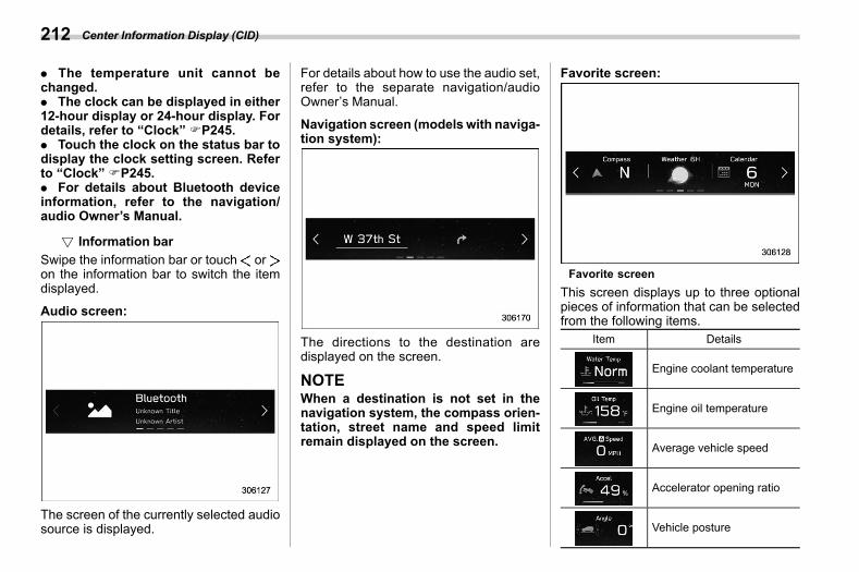
(214,1)
北米Model "A2600BE-B" EDITED: 2020/ 10/ 1
. The temperature unit cannot bechanged.. The clock can be displayed in either12-hour display or 24-hour display. Fordetails, refer to “Clock” FP245.. Touch the clock on the status bar todisplay the clock setting screen. Referto “Clock” FP245.. For details about Bluetooth deviceinformation, refer to the navigation/audio Owner’s Manual.
! Information bars03bs050102
Swipe the information bar or touch oron the information bar to switch the itemdisplayed.
Audio screen:
The screen of the currently selected audiosource is displayed.
For details about how to use the audio set,refer to the separate navigation/audioOwner’s Manual.
Navigation screen (models with naviga-tion system):
The directions to the destination aredisplayed on the screen.
NOTEWhen a destination is not set in thenavigation system, the compass orien-tation, street name and speed limitremain displayed on the screen.
Favorite screen:
Favorite screenThis screen displays up to three optionalpieces of information that can be selectedfrom the following items.
Item Details
Engine coolant temperature
Engine oil temperature
Average vehicle speed
Accelerator opening ratio
Vehicle posture
Center Information Display (CID)212
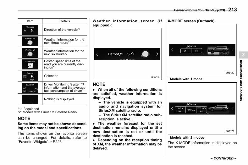
(215,1)
北米Model "A2600BE-B" EDITED: 2020/ 10/ 1
Item Details
Direction of the vehicle*1
Weather information for thenext three hours*2
Weather information for thenext six hours*2
Posted speed limit of theroad you are currently driv-ing on*1
Calendar
Driver Monitoring System*1information and the averagefuel consumption of driver
Nothing is displayed.
*1: If equipped*2: Models with SiriusXM Satellite Radio
NOTESome itemsmay not be shown depend-ing on the model and specifications.The items shown on the favorite screencan be changed. For details, refer to“Favorite Widgets” FP226.
Weather information screen (ifequipped):
NOTE. When all of the following conditionsare satisfied, weather information isdisplayed.
– The vehicle is equipped with anaudio and navigation system forSiriusXM satellite radio.– The SiriusXM satellite radio sub-scription is active.
. The weather forecast for the setdestination remains displayed until anew destination is set or until thedestination is reached.. Depending on the reception timingof XM, the weather information may bedelayed.
X-MODE screen (Outback):
Models with 1 mode
Models with 2 modesThe X-MODE information is displayed onthe screen.
– CONTINUED –
Center Information Display (CID) 213
3
Instruments
andControls
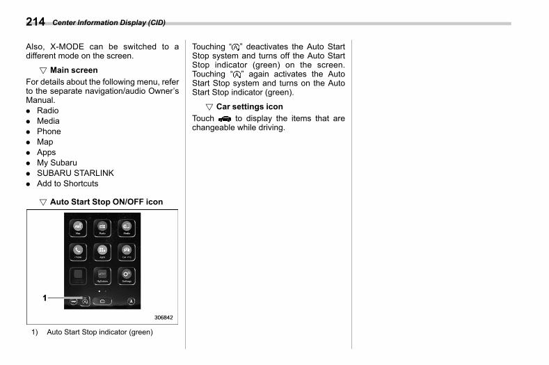
(216,1)
北米Model "A2600BE-B" EDITED: 2020/ 10/ 1
Also, X-MODE can be switched to adifferent mode on the screen.
! Main screens03bs050103
For details about the following menu, referto the separate navigation/audio Owner’sManual.. Radio. Media. Phone. Map. Apps. My Subaru. SUBARU STARLINK. Add to Shortcuts
! Auto Start Stop ON/OFF icons03bs050108
1) Auto Start Stop indicator (green)
Touching “ ” deactivates the Auto StartStop system and turns off the Auto StartStop indicator (green) on the screen.Touching “ ” again activates the AutoStart Stop system and turns on the AutoStart Stop indicator (green).
! Car settings icons03bs050104
Touch to display the items that arechangeable while driving.
Center Information Display (CID)214
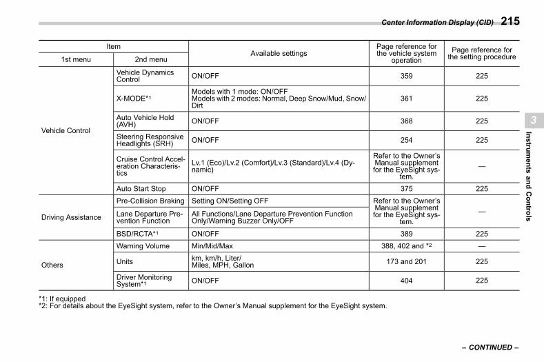
(217,1)
北米Model "A2600BE-B" EDITED: 2020/ 10/ 1
ItemAvailable settings
Page reference forthe vehicle system
operationPage reference forthe setting procedure1st menu 2nd menu
Vehicle Control
Vehicle DynamicsControl ON/OFF 359 225
X-MODE*1Models with 1 mode: ON/OFFModels with 2 modes: Normal, Deep Snow/Mud, Snow/Dirt
361 225
Auto Vehicle Hold(AVH) ON/OFF 368 225
Steering ResponsiveHeadlights (SRH) ON/OFF 254 225
Cruise Control Accel-eration Characteris-tics
Lv.1 (Eco)/Lv.2 (Comfort)/Lv.3 (Standard)/Lv.4 (Dy-namic)
Refer to the Owner’sManual supplementfor the EyeSight sys-
tem.—
Auto Start Stop ON/OFF 375 225
Driving Assistance
Pre-Collision Braking Setting ON/Setting OFF Refer to the Owner’sManual supplementfor the EyeSight sys-
tem.—Lane Departure Pre-
vention FunctionAll Functions/Lane Departure Prevention FunctionOnly/Warning Buzzer Only/OFF
BSD/RCTA*1 ON/OFF 389 225
Others
Warning Volume Min/Mid/Max 388, 402 and *2 —
Units km, km/h, Liter/Miles, MPH, Gallon 173 and 201 225
Driver MonitoringSystem*1 ON/OFF 404 225
*1: If equipped*2: For details about the EyeSight system, refer to the Owner’s Manual supplement for the EyeSight system.
– CONTINUED –
Center Information Display (CID) 215
3
Instruments
andControls
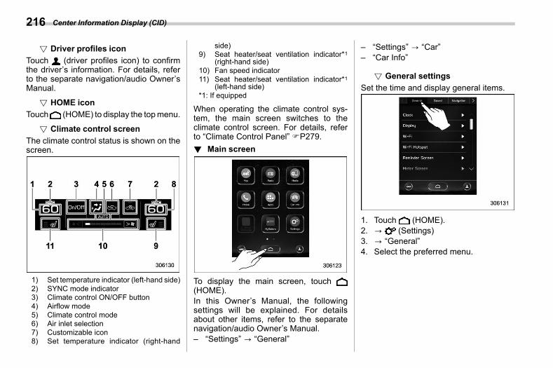
(218,1)
北米Model "A2600BE-B" EDITED: 2020/ 10/ 1
! Driver profiles icons03bs050105
Touch (driver profiles icon) to confirmthe driver’s information. For details, referto the separate navigation/audio Owner’sManual.
! HOME icons03bs050106
Touch (HOME) to display the topmenu.
! Climate control screens03bs050107
The climate control status is shown on thescreen.
1) Set temperature indicator (left-hand side)2) SYNC mode indicator3) Climate control ON/OFF button4) Airflow mode5) Climate control mode6) Air inlet selection7) Customizable icon8) Set temperature indicator (right-hand
side)9) Seat heater/seat ventilation indicator*1
(right-hand side)10) Fan speed indicator11) Seat heater/seat ventilation indicator*1
(left-hand side)*1: If equipped
When operating the climate control sys-tem, the main screen switches to theclimate control screen. For details, referto “Climate Control Panel” FP279.! Main screen
s03bs0502
To display the main screen, touch(HOME).In this Owner’s Manual, the followingsettings will be explained. For detailsabout other items, refer to the separatenavigation/audio Owner’s Manual.– “Settings” ? “General”
– “Settings” ? “Car”– “Car Info”
! General settingss03bs050201
Set the time and display general items.
1. Touch (HOME).2. ? (Settings)3. ? “General”4. Select the preferred menu.
Center Information Display (CID)216
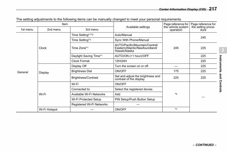
(219,1)
北米Model "A2600BE-B" EDITED: 2020/ 10/ 1
The setting adjustments to the following items can be manually changed to meet your personal requirements.Item
Available settingsPage reference forthe vehicle system
operation
Page reference forthe setting proce-
dure1st menu 2nd menu 3rd menu
General
Clock
Time Setting*1*2 Auto/Manual
245
245Time Setting*3 Sync With Phone/Manual
Time Zone*1AUTO/Pacific/Mountain/Central/Eastern/Atlantic/Newfoundland/Hawaii/Alaska
225
Daylight Saving Time*1 AUTO/ON (+1 hour)/OFF 225Clock Format 12H/24H 225
Display
Display Off Turn the screen on or off. — 225Brightness Dial ON/OFF 175 225
Brightness/Contrast Set and adjust the brightness andcontrast of the display. 225 225
Wi-Fi
Wi-Fi ON/OFF
*6—
Connected to: Select the registered devise.Available Wi-Fi Networks Add
Wi-Fi Protected Setup PIN Setup/Push Button SetupRegistered Wi-Fi Networks —
Wi-Fi Hotspot — ON/OFF *7
– CONTINUED –
Center Information Display (CID) 217
3
Instruments
andControls
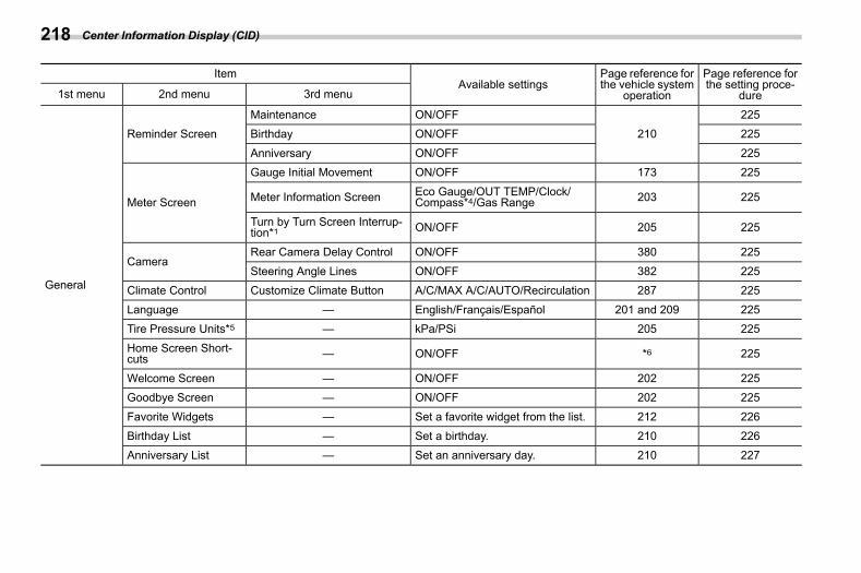
(220,1)
北米Model "A2600BE-B" EDITED: 2020/ 10/ 1
ItemAvailable settings
Page reference forthe vehicle system
operation
Page reference forthe setting proce-
dure1st menu 2nd menu 3rd menu
General
Reminder ScreenMaintenance ON/OFF
210225
Birthday ON/OFF 225
Anniversary ON/OFF 225
Meter Screen
Gauge Initial Movement ON/OFF 173 225
Meter Information Screen Eco Gauge/OUT TEMP/Clock/Compass*4/Gas Range 203 225
Turn by Turn Screen Interrup-tion*1 ON/OFF 205 225
CameraRear Camera Delay Control ON/OFF 380 225
Steering Angle Lines ON/OFF 382 225Climate Control Customize Climate Button A/C/MAX A/C/AUTO/Recirculation 287 225
Language — English/Français/Español 201 and 209 225Tire Pressure Units*5 — kPa/PSi 205 225
Home Screen Short-cuts — ON/OFF *6 225
Welcome Screen — ON/OFF 202 225Goodbye Screen — ON/OFF 202 225
Favorite Widgets — Set a favorite widget from the list. 212 226
Birthday List — Set a birthday. 210 226Anniversary List — Set an anniversary day. 210 227
Center Information Display (CID)218
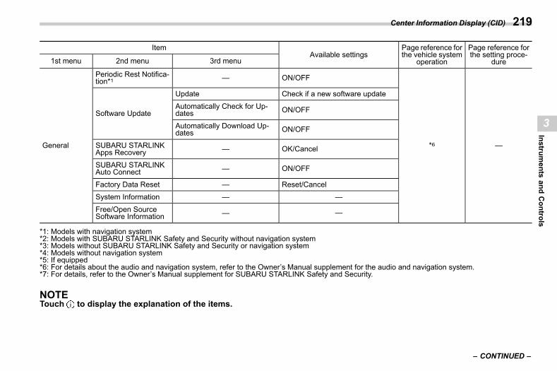
(221,1)
北米Model "A2600BE-B" EDITED: 2020/ 10/ 1
ItemAvailable settings
Page reference forthe vehicle system
operation
Page reference forthe setting proce-
dure1st menu 2nd menu 3rd menu
General
Periodic Rest Notifica-tion*1 — ON/OFF
*6 —
Software Update
Update Check if a new software updateAutomatically Check for Up-dates ON/OFF
Automatically Download Up-dates ON/OFF
SUBARU STARLINKApps Recovery — OK/Cancel
SUBARU STARLINKAuto Connect — ON/OFF
Factory Data Reset — Reset/CancelSystem Information — —
Free/Open SourceSoftware Information — —
*1: Models with navigation system*2: Models with SUBARU STARLINK Safety and Security without navigation system*3: Models without SUBARU STARLINK Safety and Security or navigation system*4: Models without navigation system*5: If equipped*6: For details about the audio and navigation system, refer to the Owner’s Manual supplement for the audio and navigation system.*7: For details, refer to the Owner’s Manual supplement for SUBARU STARLINK Safety and Security.
NOTETouch to display the explanation of the items.
– CONTINUED –
Center Information Display (CID) 219
3
Instruments
andControls
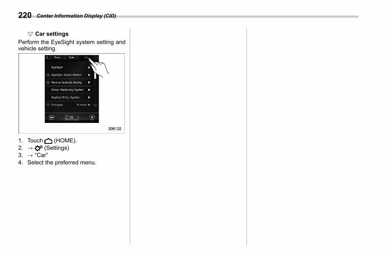
(222,1)
北米Model "A2600BE-B" EDITED: 2020/ 10/ 1
! Car settingss03bs050209
Perform the EyeSight system setting andvehicle setting.
1. Touch (HOME).2. ? (Settings)3. ? “Car”4. Select the preferred menu.
Center Information Display (CID)220
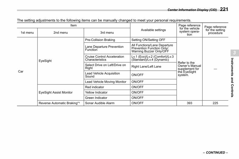
(223,1)
北米Model "A2600BE-B" EDITED: 2020/ 10/ 1
The setting adjustments to the following items can be manually changed to meet your personal requirements.Item
Available settingsPage referencefor the vehiclesystem opera-
tion
Page referencefor the settingprocedure1st menu 2nd menu 3rd menu
Car
EyeSight
Pre-Collision Braking Setting ON/Setting OFF
Refer to theOwner’s Manualsupplement forthe EyeSightsystem.
—
Lane Departure PreventionFunction
All Functions/Lane DeparturePrevention Function Only/Warning Buzzer Only/OFF
Cruise Control AccelerationCharacteristics
Lv.1 (Eco)/Lv.2 (Comfort)/Lv.3(Standard)/Lv.4 (Dynamic)
Select Drive on Left/Drive onRight Right Lane/Left Lane
Lead Vehicle AcquisitionSound ON/OFF
Lead Vehicle Moving Monitor ON/OFF
EyeSight Assist MonitorRed indicator ON/OFFYellow Indicator ON/OFF
Green Indicator ON/OFFReverse Automatic Braking*1 Sonar Audible Alarm ON/OFF 393 225
– CONTINUED –
Center Information Display (CID) 221
3
Instruments
andControls
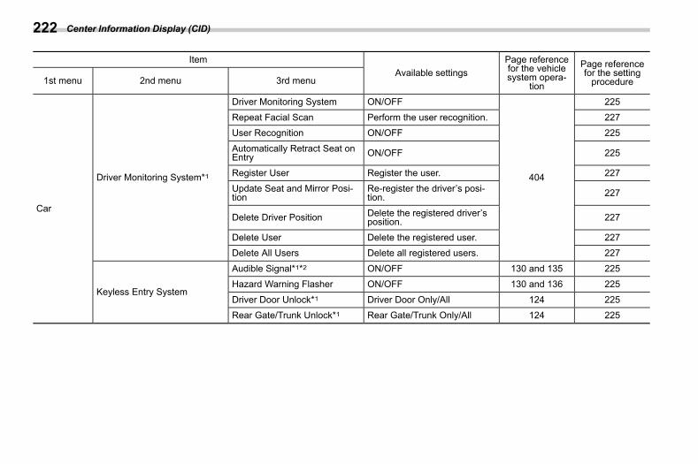
(224,1)
北米Model "A2600BE-B" EDITED: 2020/ 10/ 1
ItemAvailable settings
Page referencefor the vehiclesystem opera-
tion
Page referencefor the settingprocedure1st menu 2nd menu 3rd menu
Car
Driver Monitoring System*1
Driver Monitoring System ON/OFF
404
225
Repeat Facial Scan Perform the user recognition. 227User Recognition ON/OFF 225
Automatically Retract Seat onEntry ON/OFF 225
Register User Register the user. 227Update Seat and Mirror Posi-tion
Re-register the driver’s posi-tion. 227
Delete Driver Position Delete the registered driver’sposition. 227
Delete User Delete the registered user. 227Delete All Users Delete all registered users. 227
Keyless Entry System
Audible Signal*1*2 ON/OFF 130 and 135 225Hazard Warning Flasher ON/OFF 130 and 136 225
Driver Door Unlock*1 Driver Door Only/All 124 225Rear Gate/Trunk Unlock*1 Rear Gate/Trunk Only/All 124 225
Center Information Display (CID)222
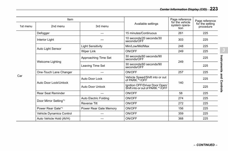
(225,1)
北米Model "A2600BE-B" EDITED: 2020/ 10/ 1
ItemAvailable settings
Page referencefor the vehiclesystem opera-
tion
Page referencefor the settingprocedure1st menu 2nd menu 3rd menu
Car
Defogger — 15 minutes/Continuous 261 225
Interior Light — 10 seconds/20 seconds/30seconds/OFF 303 225
Auto Light SensorLight Sensitivity Min/Low/Mid/Max 248 225Wiper Link ON/OFF 249 225
Welcome LightingApproaching Time Set 30 seconds/60 seconds/90
seconds/OFF249
225
Leaving Time Set 30 seconds/60 seconds/90seconds/OFF 225
One-Touch Lane Changer — ON/OFF 257 225
Auto Door Lock/UnlockAuto Door Lock Vehicle Speed/Shift into or out
of PARK.*1/OFF140
225
Auto Door Unlock Ignition OFF/Driver Door Open/Shift into or out of PARK.*1/OFF 225
Rear Seat Reminder — ON/OFF 58 225
Door Mirror Setting*1Auto Electric Folding ON/OFF 274 225
Reverse Tilt ON/OFF 272 225
Power Rear Gate*1 Power Rear Gate Memory ON/OFF 156 225Vehicle Dynamics Control — ON/OFF 359 225
Auto Vehicle Hold (AVH) — ON/OFF 368 225
– CONTINUED –
Center Information Display (CID) 223
3
Instruments
andControls
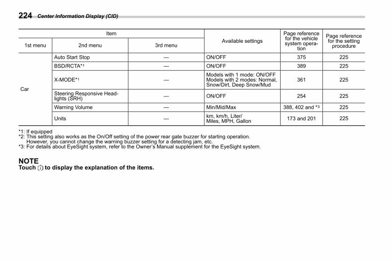
(226,1)
北米Model "A2600BE-B" EDITED: 2020/ 10/ 1
ItemAvailable settings
Page referencefor the vehiclesystem opera-
tion
Page referencefor the settingprocedure1st menu 2nd menu 3rd menu
Car
Auto Start Stop — ON/OFF 375 225
BSD/RCTA*1 — ON/OFF 389 225
X-MODE*1 —Models with 1 mode: ON/OFFModels with 2 modes: Normal,Snow/Dirt, Deep Snow/Mud
361 225
Steering Responsive Head-lights (SRH) — ON/OFF 254 225
Warning Volume — Min/Mid/Max 388, 402 and *3 225
Units — km, km/h, Liter/Miles, MPH, Gallon 173 and 201 225
*1: If equipped*2: This setting also works as the On/Off setting of the power rear gate buzzer for starting operation.
However, you cannot change the warning buzzer setting for a detecting jam, etc.*3: For details about EyeSight system, refer to the Owner’s Manual supplement for the EyeSight system.
NOTETouch to display the explanation of the items.
Center Information Display (CID)224
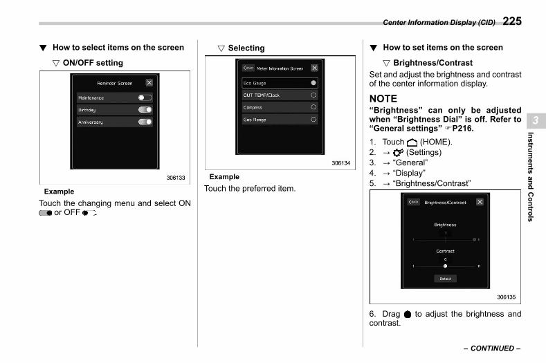
(227,1)
北米Model "A2600BE-B" EDITED: 2020/ 10/ 1
! How to select items on the screens03bs0510
! ON/OFF settings03bs051001
ExampleTouch the changing menu and select ON
or OFF .
! Selectings03bs051002
ExampleTouch the preferred item.
! How to set items on the screens03bs0511
! Brightness/Contrasts03bs051101
Set and adjust the brightness and contrastof the center information display.
NOTE“Brightness” can only be adjustedwhen “Brightness Dial” is off. Refer to“General settings” FP216.1. Touch (HOME).2. ? (Settings)3. ? “General”4. ? “Display”5. ? “Brightness/Contrast”
6. Drag to adjust the brightness andcontrast.
– CONTINUED –
Center Information Display (CID) 225
3
Instruments
andControls
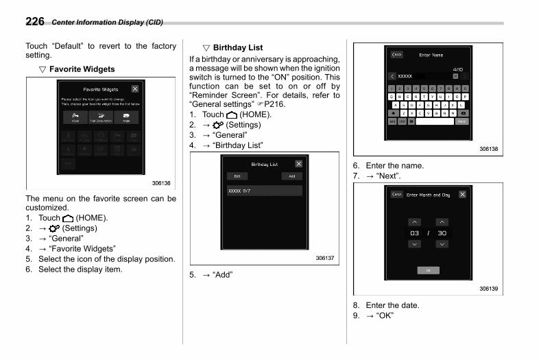
(228,1)
北米Model "A2600BE-B" EDITED: 2020/ 10/ 1
Touch “Default” to revert to the factorysetting.
! Favorite Widgetss03bs051102
The menu on the favorite screen can becustomized.1. Touch (HOME).2. ? (Settings)3. ? “General”4. ? “Favorite Widgets”5. Select the icon of the display position.6. Select the display item.
! Birthday Lists03bs051103
If a birthday or anniversary is approaching,a message will be shown when the ignitionswitch is turned to the “ON” position. Thisfunction can be set to on or off by“Reminder Screen”. For details, refer to“General settings” FP216.1. Touch (HOME).2. ? (Settings)3. ? “General”4. ? “Birthday List”
5. ? “Add”
6. Enter the name.7. ? “Next”.
8. Enter the date.9. ? “OK”
Center Information Display (CID)226
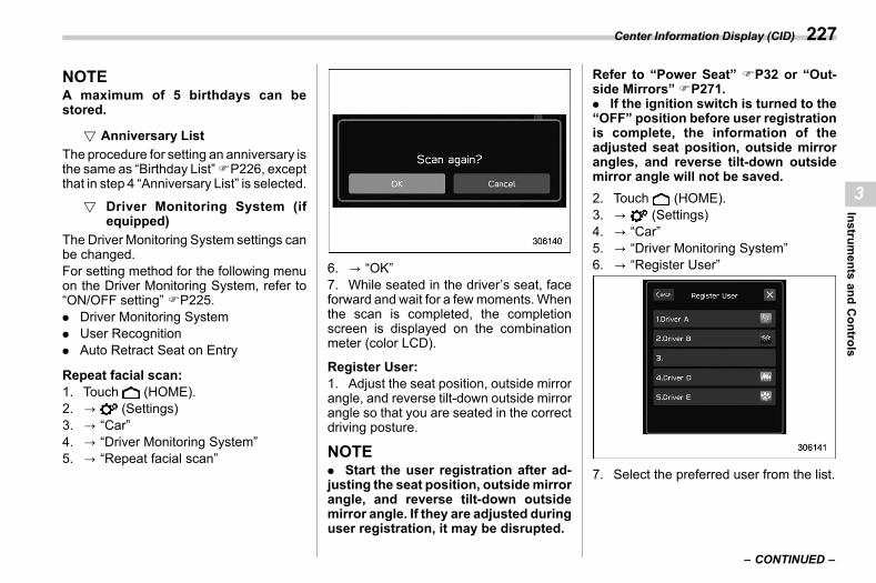
(229,1)
北米Model "A2600BE-B" EDITED: 2020/ 10/ 1
NOTEA maximum of 5 birthdays can bestored.
! Anniversary Lists03bs051104
The procedure for setting an anniversary isthe same as “Birthday List”FP226, exceptthat in step 4 “Anniversary List” is selected.
! Driver Monitoring System (ifequipped)
s03bs051105
The Driver Monitoring System settings canbe changed.For setting method for the following menuon the Driver Monitoring System, refer to“ON/OFF setting” FP225.. Driver Monitoring System. User Recognition. Auto Retract Seat on Entry
Repeat facial scan:1. Touch (HOME).2. ? (Settings)3. ? “Car”4. ? “Driver Monitoring System”5. ? “Repeat facial scan”
6. ? “OK”7. While seated in the driver’s seat, faceforward and wait for a fewmoments.Whenthe scan is completed, the completionscreen is displayed on the combinationmeter (color LCD).
Register User:1. Adjust the seat position, outside mirrorangle, and reverse tilt-down outside mirrorangle so that you are seated in the correctdriving posture.
NOTE. Start the user registration after ad-justing the seat position, outsidemirrorangle, and reverse tilt-down outsidemirror angle. If they are adjusted duringuser registration, it may be disrupted.
Refer to “Power Seat” FP32 or “Out-side Mirrors” FP271.. If the ignition switch is turned to the“OFF” position before user registrationis complete, the information of theadjusted seat position, outside mirrorangles, and reverse tilt-down outsidemirror angle will not be saved.2. Touch (HOME).3. ? (Settings)4. ? “Car”5. ? “Driver Monitoring System”6. ? “Register User”
7. Select the preferred user from the list.
– CONTINUED –
Center Information Display (CID) 227
3
Instruments
andControls
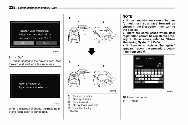
(230,1)
北米Model "A2600BE-B" EDITED: 2020/ 10/ 1
8. ? “Set”9. While seated in the driver’s seat, faceforward and wait for a few moments.
When the screen changes, the registrationof the facial scan is completed.
A) Forward directionB) Display direction1) Face forward.2) Do not lower your chin.3) Face the display.*: Display
NOTE. If user registration cannot be per-formed, turn your face forward asshown in the illustration, then turn tothe display.. There are some cases where userregistration cannot be registered prop-erly. In those cases, refer to “DriverMonitoring System” FP404.. If “Unable to register. Try again.”appears, repeat the procedure begin-ning from step 5.
10. Enter the name.11. ? “Next”
Center Information Display (CID)228
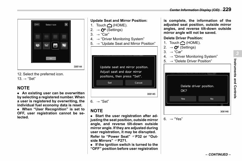
(231,1)
北米Model "A2600BE-B" EDITED: 2020/ 10/ 1
12. Select the preferred icon.13.? “Set”
NOTE. An existing user can be overwrittenby selecting a registered number.Whena user is registered by overwriting, theindividual fuel economy data is reset.. When “User Recognition” is set toOFF, user registration cannot be se-lected.
Update Seat and Mirror Position:1. Touch (HOME).2. ? (Settings)3. ? “Car”4. ? “Driver Monitoring System”5. ? “Update Seat and Mirror Position”
6. ? “Set”
NOTE. Start the user registration after ad-justing the seat position, outsidemirrorangle, and reverse tilt-down outsidemirror angle. If they are adjusted duringuser registration, it may be disrupted.Refer to “Power Seat” FP32 or “Out-side Mirrors” FP271.. If the ignition switch is turned to the“OFF” position before user registration
is complete, the information of theadjusted seat position, outside mirrorangles, and reverse tilt-down outsidemirror angle will not be saved.Delete Driver Position:1. Touch (HOME).2. ? (Settings)3. ? “Car”4. ? “Driver Monitoring System”5. ? “Delete Driver Position”
6. ? “Yes”
– CONTINUED –
Center Information Display (CID) 229
3
Instruments
andControls
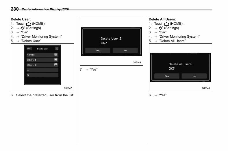
(232,1)
北米Model "A2600BE-B" EDITED: 2020/ 10/ 1
Delete User:1. Touch (HOME).2. ? (Settings)3. ? “Car”4. ? “Driver Monitoring System”5. ? “Delete User”
6. Select the preferred user from the list.
7. ? “Yes”
Delete All Users:1. Touch (HOME).2. ? (Settings)3. ? “Car”4. ? “Driver Monitoring System”5. ? “Delete All Users”
6. ? “Yes”
Center Information Display (CID)230
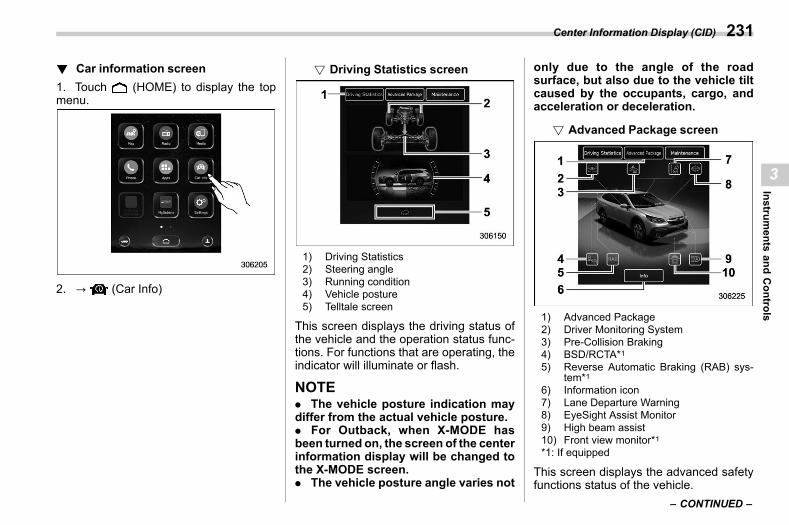
(233,1)
北米Model "A2600BE-B" EDITED: 2020/ 10/ 1
! Car information screens03bs0503
1. Touch (HOME) to display the topmenu.
2. ? (Car Info)
! Driving Statistics screens03bs050301
1) Driving Statistics2) Steering angle3) Running condition4) Vehicle posture5) Telltale screen
This screen displays the driving status ofthe vehicle and the operation status func-tions. For functions that are operating, theindicator will illuminate or flash.
NOTE. The vehicle posture indication maydiffer from the actual vehicle posture.. For Outback, when X-MODE hasbeen turned on, the screen of the centerinformation display will be changed tothe X-MODE screen.. The vehicle posture angle varies not
only due to the angle of the roadsurface, but also due to the vehicle tiltcaused by the occupants, cargo, andacceleration or deceleration.
! Advanced Package screens03bs050302
1) Advanced Package2) Driver Monitoring System3) Pre-Collision Braking4) BSD/RCTA*15) Reverse Automatic Braking (RAB) sys-
tem*16) Information icon7) Lane Departure Warning8) EyeSight Assist Monitor9) High beam assist10) Front view monitor*1*1: If equipped
This screen displays the advanced safetyfunctions status of the vehicle.
– CONTINUED –
Center Information Display (CID) 231
3
Instruments
andControls
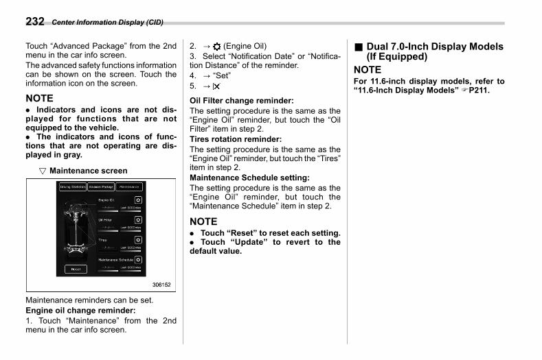
(234,1)
北米Model "A2600BE-B" EDITED: 2020/ 10/ 1
Touch “Advanced Package” from the 2ndmenu in the car info screen.The advanced safety functions informationcan be shown on the screen. Touch theinformation icon on the screen.
NOTE. Indicators and icons are not dis-played for functions that are notequipped to the vehicle.. The indicators and icons of func-tions that are not operating are dis-played in gray.
! Maintenance screens03bs050303
Maintenance reminders can be set.Engine oil change reminder:1. Touch “Maintenance” from the 2ndmenu in the car info screen.
2. ? (Engine Oil)3. Select “Notification Date” or “Notifica-tion Distance” of the reminder.4. ? “Set”5. ?
Oil Filter change reminder:The setting procedure is the same as the“Engine Oil” reminder, but touch the “OilFilter” item in step 2.Tires rotation reminder:The setting procedure is the same as the“Engine Oil” reminder, but touch the “Tires”item in step 2.Maintenance Schedule setting:The setting procedure is the same as the“Engine Oil” reminder, but touch the“Maintenance Schedule” item in step 2.
NOTE. Touch “Reset” to reset each setting.. Touch “Update” to revert to thedefault value.
& Dual 7.0-Inch Display Models(If Equipped)
s03bs06NOTEFor 11.6-inch display models, refer to“11.6-Inch Display Models” FP211.
Center Information Display (CID)232
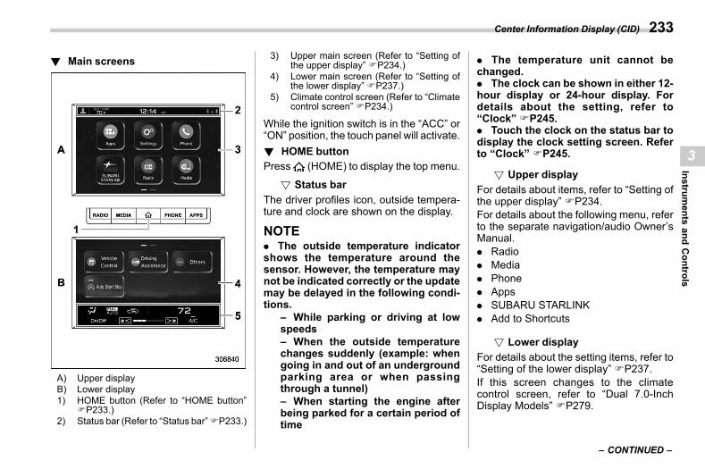
(235,1)
北米Model "A2600BE-B" EDITED: 2020/ 10/ 1
! Main screenss03bs0601
A) Upper displayB) Lower display1) HOME button (Refer to “HOME button”
FP233.)2) Status bar (Refer to “Status bar”FP233.)
3) Upper main screen (Refer to “Setting ofthe upper display” FP234.)
4) Lower main screen (Refer to “Setting ofthe lower display” FP237.)
5) Climate control screen (Refer to “Climatecontrol screen” FP234.)
While the ignition switch is in the “ACC” or“ON” position, the touch panel will activate.! HOME button
s03bs0609Press (HOME) to display the top menu.
! Status bars03bs060901
The driver profiles icon, outside tempera-ture and clock are shown on the display.
NOTE. The outside temperature indicatorshows the temperature around thesensor. However, the temperature maynot be indicated correctly or the updatemay be delayed in the following condi-tions.
– While parking or driving at lowspeeds– When the outside temperaturechanges suddenly (example: whengoing in and out of an undergroundparking area or when passingthrough a tunnel)– When starting the engine afterbeing parked for a certain period oftime
. The temperature unit cannot bechanged.. The clock can be shown in either 12-hour display or 24-hour display. Fordetails about the setting, refer to“Clock” FP245.. Touch the clock on the status bar todisplay the clock setting screen. Referto “Clock” FP245.
! Upper displays03bs060902
For details about items, refer to “Setting ofthe upper display” FP234.For details about the following menu, referto the separate navigation/audio Owner’sManual.. Radio. Media. Phone. Apps. SUBARU STARLINK. Add to Shortcuts
! Lower displays03bs060903
For details about the setting items, refer to“Setting of the lower display” FP237.If this screen changes to the climatecontrol screen, refer to “Dual 7.0-InchDisplay Models” FP279.
– CONTINUED –
Center Information Display (CID) 233
3
Instruments
andControls
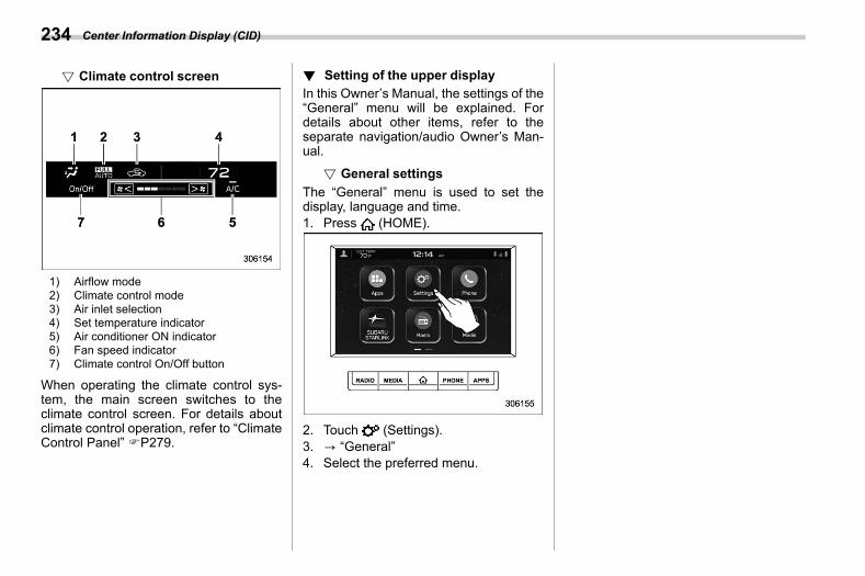
(236,1)
北米Model "A2600BE-B" EDITED: 2020/ 10/ 1
! Climate control screens03bs060904
1) Airflow mode2) Climate control mode3) Air inlet selection4) Set temperature indicator5) Air conditioner ON indicator6) Fan speed indicator7) Climate control On/Off button
When operating the climate control sys-tem, the main screen switches to theclimate control screen. For details aboutclimate control operation, refer to “ClimateControl Panel” FP279.
! Setting of the upper displays03bs0602
In this Owner’s Manual, the settings of the“General” menu will be explained. Fordetails about other items, refer to theseparate navigation/audio Owner’s Man-ual.
! General settingss03bs060204
The “General” menu is used to set thedisplay, language and time.1. Press (HOME).
2. Touch (Settings).3. ? “General”4. Select the preferred menu.
Center Information Display (CID)234
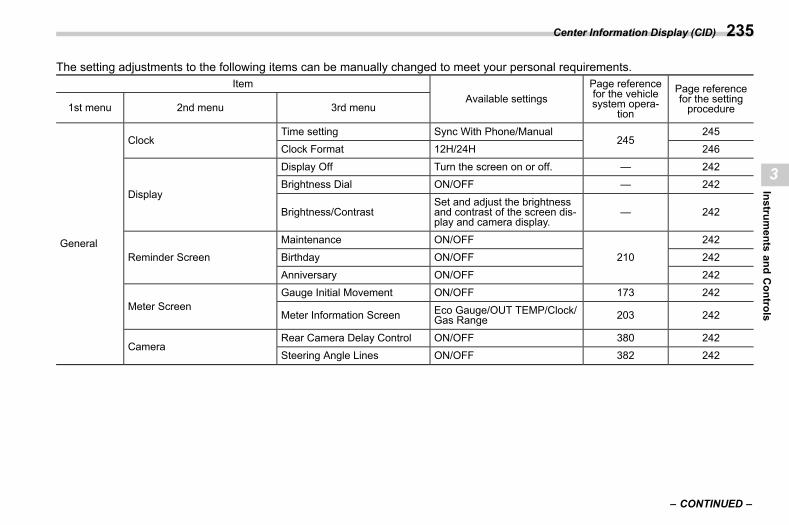
(237,1)
北米Model "A2600BE-B" EDITED: 2020/ 10/ 1
The setting adjustments to the following items can be manually changed to meet your personal requirements.Item
Available settingsPage referencefor the vehiclesystem opera-
tion
Page referencefor the settingprocedure1st menu 2nd menu 3rd menu
General
ClockTime setting Sync With Phone/Manual
245245
Clock Format 12H/24H 246
Display
Display Off Turn the screen on or off. — 242Brightness Dial ON/OFF — 242
Brightness/ContrastSet and adjust the brightnessand contrast of the screen dis-play and camera display.
— 242
Reminder Screen
Maintenance ON/OFF
210
242
Birthday ON/OFF 242
Anniversary ON/OFF 242
Meter ScreenGauge Initial Movement ON/OFF 173 242
Meter Information Screen Eco Gauge/OUT TEMP/Clock/Gas Range 203 242
CameraRear Camera Delay Control ON/OFF 380 242Steering Angle Lines ON/OFF 382 242
– CONTINUED –
Center Information Display (CID) 235
3
Instruments
andControls
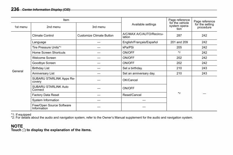
(238,1)
北米Model "A2600BE-B" EDITED: 2020/ 10/ 1
ItemAvailable settings
Page referencefor the vehiclesystem opera-
tion
Page referencefor the settingprocedure1st menu 2nd menu 3rd menu
General
Climate Control Customize Climate Button A/C/MAX A/C/AUTO/Recircu-lation 287 242
Language — English/Français/Español 201 and 209 242
Tire Pressure Units*1 — kPa/PSi 205 242Home Screen Shortcuts — ON/OFF *2 242
Welcome Screen — ON/OFF 202 242Goodbye Screen — ON/OFF 202 242
Birthday List — Set a birthday. 210 243
Anniversary List — Set an anniversary day. 210 243SUBARU STARLINK Apps Re-covery — OK/Cancel
*2 —
SUBARU STARLINK AutoConnect — ON/OFF
Factory Data Reset — Reset/Cancel
System Information — —Free/Open Source SoftwareInformation — —
*1: If equipped*2: For details about the audio and navigation system, refer to the Owner’s Manual supplement for the audio and navigation system.
NOTETouch to display the explanation of the items.
Center Information Display (CID)236
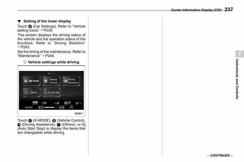
(239,1)
北米Model "A2600BE-B" EDITED: 2020/ 10/ 1
! Setting of the lower displays03bs0605
Touch (Car Settings). Refer to “Vehiclesetting icons” FP239.This screen displays the driving status ofthe vehicle and the operation status of thefunctions. Refer to “Driving Statistics”FP243.Set the timing of themaintenance. Refer to“Maintenance” FP244.
! Vehicle settings while drivings03bs060502
Touch (X-MODE), (Vehicle Control),(Driving Assistance), (Others), or
(Auto Start Stop) to display the items thatare changeable while driving.
– CONTINUED –
Center Information Display (CID) 237
3
Instruments
andControls
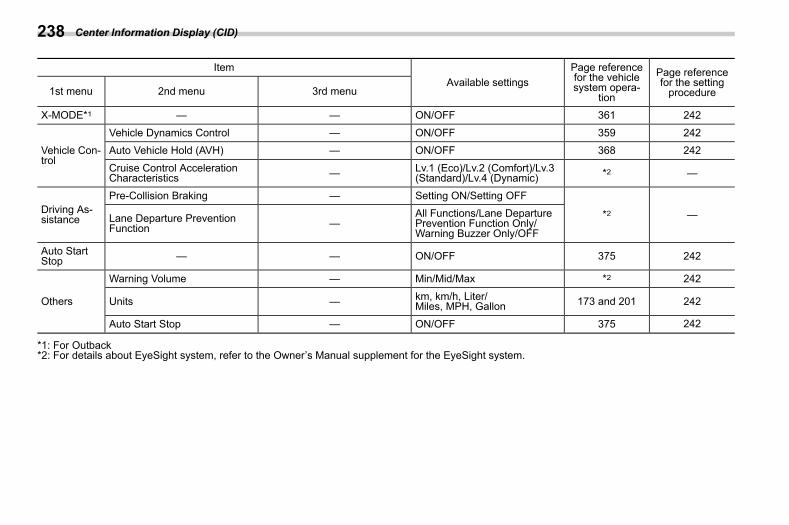
(240,1)
北米Model "A2600BE-B" EDITED: 2020/ 10/ 1
ItemAvailable settings
Page referencefor the vehiclesystem opera-
tion
Page referencefor the settingprocedure1st menu 2nd menu 3rd menu
X-MODE*1 — — ON/OFF 361 242
Vehicle Con-trol
Vehicle Dynamics Control — ON/OFF 359 242Auto Vehicle Hold (AVH) — ON/OFF 368 242
Cruise Control AccelerationCharacteristics — Lv.1 (Eco)/Lv.2 (Comfort)/Lv.3
(Standard)/Lv.4 (Dynamic) *2 —
Driving As-sistance
Pre-Collision Braking — Setting ON/Setting OFF
*2 —Lane Departure PreventionFunction —
All Functions/Lane DeparturePrevention Function Only/Warning Buzzer Only/OFF
Auto StartStop — — ON/OFF 375 242
Others
Warning Volume — Min/Mid/Max *2 242
Units — km, km/h, Liter/Miles, MPH, Gallon 173 and 201 242
Auto Start Stop — ON/OFF 375 242
*1: For Outback*2: For details about EyeSight system, refer to the Owner’s Manual supplement for the EyeSight system.
Center Information Display (CID)238
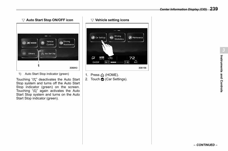
(241,1)
北米Model "A2600BE-B" EDITED: 2020/ 10/ 1
! Auto Start Stop ON/OFF icons03bs060503
1) Auto Start Stop indicator (green)
Touching “ ” deactivates the Auto StartStop system and turns off the Auto StartStop indicator (green) on the screen.Touching “ ” again activates the AutoStart Stop system and turns on the AutoStart Stop indicator (green).
! Vehicle setting iconss03bs060501
1. Press (HOME).2. Touch (Car Settings).
– CONTINUED –
Center Information Display (CID) 239
3
Instruments
andControls
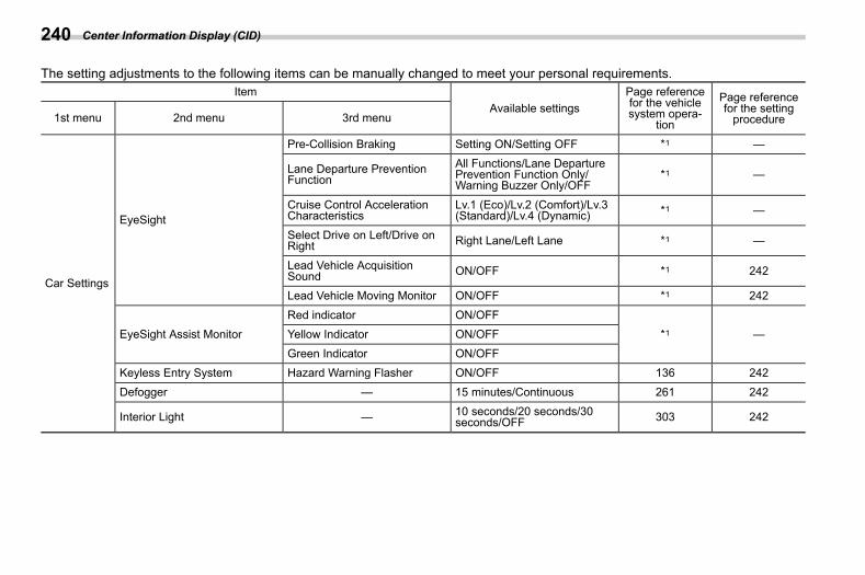
(242,1)
北米Model "A2600BE-B" EDITED: 2020/ 10/ 1
The setting adjustments to the following items can be manually changed to meet your personal requirements.Item
Available settingsPage referencefor the vehiclesystem opera-
tion
Page referencefor the settingprocedure1st menu 2nd menu 3rd menu
Car Settings
EyeSight
Pre-Collision Braking Setting ON/Setting OFF *1 —
Lane Departure PreventionFunction
All Functions/Lane DeparturePrevention Function Only/Warning Buzzer Only/OFF
*1 —
Cruise Control AccelerationCharacteristics
Lv.1 (Eco)/Lv.2 (Comfort)/Lv.3(Standard)/Lv.4 (Dynamic) *1 —
Select Drive on Left/Drive onRight Right Lane/Left Lane *1 —
Lead Vehicle AcquisitionSound ON/OFF *1 242
Lead Vehicle Moving Monitor ON/OFF *1 242
EyeSight Assist MonitorRed indicator ON/OFF
*1 —Yellow Indicator ON/OFF
Green Indicator ON/OFFKeyless Entry System Hazard Warning Flasher ON/OFF 136 242
Defogger — 15 minutes/Continuous 261 242
Interior Light — 10 seconds/20 seconds/30seconds/OFF 303 242
Center Information Display (CID)240
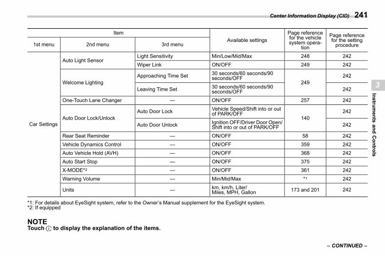
(243,1)
北米Model "A2600BE-B" EDITED: 2020/ 10/ 1
ItemAvailable settings
Page referencefor the vehiclesystem opera-
tion
Page referencefor the settingprocedure1st menu 2nd menu 3rd menu
Car Settings
Auto Light SensorLight Sensitivity Min/Low/Mid/Max 248 242
Wiper Link ON/OFF 249 242
Welcome LightingApproaching Time Set 30 seconds/60 seconds/90
seconds/OFF249
242
Leaving Time Set 30 seconds/60 seconds/90seconds/OFF 242
One-Touch Lane Changer — ON/OFF 257 242
Auto Door Lock/UnlockAuto Door Lock Vehicle Speed/Shift into or out
of PARK/OFF140
242
Auto Door Unlock Ignition OFF/Driver Door Open/Shift into or out of PARK/OFF 242
Rear Seat Reminder — ON/OFF 58 242
Vehicle Dynamics Control — ON/OFF 359 242Auto Vehicle Hold (AVH) — ON/OFF 368 242
Auto Start Stop — ON/OFF 375 242X-MODE*2 — ON/OFF 361 242
Warning Volume — Min/Mid/Max *1 242
Units — km, km/h, Liter/Miles, MPH, Gallon 173 and 201 242
*1: For details about EyeSight system, refer to the Owner’s Manual supplement for the EyeSight system.*2: If equipped
NOTETouch to display the explanation of the items.
– CONTINUED –
Center Information Display (CID) 241
3
Instruments
andControls
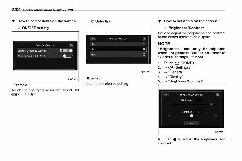
(244,1)
北米Model "A2600BE-B" EDITED: 2020/ 10/ 1
! How to select items on the screens03bs0610
! ON/OFF settings03bs061001
ExampleTouch the changing menu and select ON
or OFF .
! Selectings03bs061002
ExampleTouch the preferred setting.
! How to set items on the screens03bs0611
! Brightness/Contrasts03bs061101
Set and adjust the brightness and contrastof the center information display.
NOTE“Brightness” can only be adjustedwhen “Brightness Dial” is off. Refer to“General settings” FP234.1. Touch (HOME).2. ? (Settings)3. ? “General”4. ? “Display”5. ? “Brightness/Contrast”
6. Drag to adjust the brightness andcontrast.
Center Information Display (CID)242
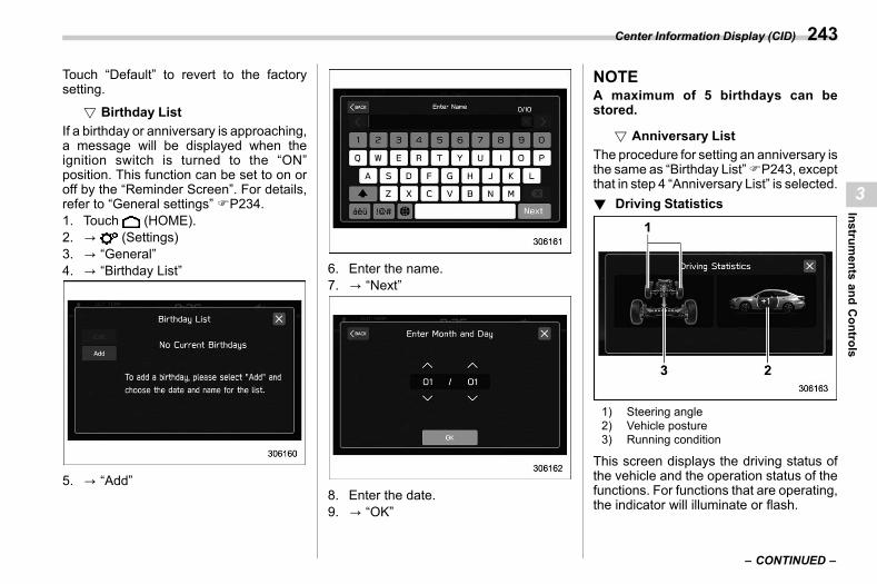
(245,1)
北米Model "A2600BE-B" EDITED: 2020/ 10/ 1
Touch “Default” to revert to the factorysetting.
! Birthday Lists03bs061102
If a birthday or anniversary is approaching,a message will be displayed when theignition switch is turned to the “ON”position. This function can be set to on oroff by the “Reminder Screen”. For details,refer to “General settings” FP234.1. Touch (HOME).2. ? (Settings)3. ? “General”4. ? “Birthday List”
5. ? “Add”
6. Enter the name.7. ? “Next”
8. Enter the date.9. ? “OK”
NOTEA maximum of 5 birthdays can bestored.
! Anniversary Lists03bs061103
The procedure for setting an anniversary isthe same as “Birthday List”FP243, exceptthat in step 4 “Anniversary List” is selected.! Driving Statistics
s03bs0603
1) Steering angle2) Vehicle posture3) Running condition
This screen displays the driving status ofthe vehicle and the operation status of thefunctions. For functions that are operating,the indicator will illuminate or flash.
– CONTINUED –
Center Information Display (CID) 243
3
Instruments
andControls
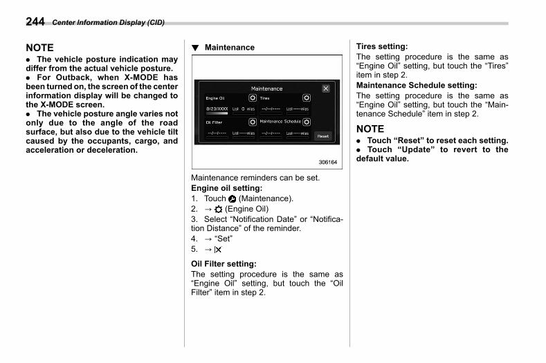
(246,1)
北米Model "A2600BE-B" EDITED: 2020/ 10/ 1
NOTE. The vehicle posture indication maydiffer from the actual vehicle posture.. For Outback, when X-MODE hasbeen turned on, the screen of the centerinformation display will be changed tothe X-MODE screen.. The vehicle posture angle varies notonly due to the angle of the roadsurface, but also due to the vehicle tiltcaused by the occupants, cargo, andacceleration or deceleration.
! Maintenances03bs0604
Maintenance reminders can be set.Engine oil setting:1. Touch (Maintenance).2. ? (Engine Oil)3. Select “Notification Date” or “Notifica-tion Distance” of the reminder.4. ? “Set”5. ?
Oil Filter setting:The setting procedure is the same as“Engine Oil” setting, but touch the “OilFilter” item in step 2.
Tires setting:The setting procedure is the same as“Engine Oil” setting, but touch the “Tires”item in step 2.Maintenance Schedule setting:The setting procedure is the same as“Engine Oil” setting, but touch the “Main-tenance Schedule” item in step 2.
NOTE. Touch “Reset” to reset each setting.. Touch “Update” to revert to thedefault value.
Center Information Display (CID)244
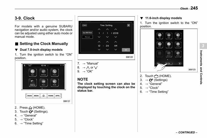
(247,1)
北米Model "A2600BE-B" EDITED: 2020/ 10/ 1
3-9. Clocks03af
For models with a genuine SUBARUnavigation and/or audio system, the clockcan be adjusted using either auto mode ormanual mode.
& Setting the Clock Manuallys03af03
! Dual 7.0-inch display modelss03af0303
1. Turn the ignition switch to the “ON”position.
2. Press (HOME).3. Touch (Settings).4. ? “General”5. ? “Clock”6. ? “Time Setting”
7. ? “Manual”8. ? or9. ? “OK”
NOTEThe clock setting screen can also bedisplayed by touching the clock on thestatus bar.
! 11.6-inch display modelss03af0304
1. Turn the ignition switch to the “ON”position.
2. Touch (HOME).3. ? (Settings)4. ? “General”5. ? “Clock”6. ? “Time Setting”
– CONTINUED –
Clock 245
3
Instruments
andControls
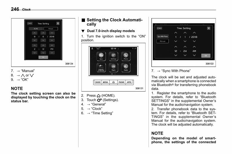
(248,1)
北米Model "A2600BE-B" EDITED: 2020/ 10/ 1
7. ? “Manual”8. ? or9. ? “OK”
NOTEThe clock setting screen can also bedisplayed by touching the clock on thestatus bar.
& Setting the Clock Automati-cally
s03af02
! Dual 7.0-inch display modelss03af0204
1. Turn the ignition switch to the “ON”position.
2. Press (HOME).3. Touch (Settings).4. ? “General”5. ? “Clock”6. ? “Time Setting”
7. ? “Sync With Phone”
The clock will be set and adjusted auto-matically when a smartphone is connectedvia Bluetooth® for transferring phonebookdata.1. Register the smartphone to the audiosystem. For details, refer to “BluetoothSETTINGS” in the supplemental Owner’sManual for the audio/navigation system.2. Transfer phonebook data to the sys-tem. For details, refer to “Bluetooth SET-TINGS” in the supplemental Owner’sManual for the audio/navigation system.The clock will be adjusted automatically.
NOTEDepending on the model of smart-phone, the settings of the connected
Clock246
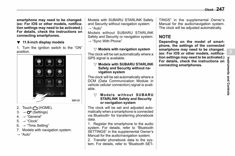
(249,1)
北米Model "A2600BE-B" EDITED: 2020/ 10/ 1
smartphone may need to be changed.(ex: For iOS or other models, notifica-tion settings may need to be activated.)For details, check the instructions onconnecting smartphones.
! 11.6-inch display modelss03af0205
1. Turn the ignition switch to the “ON”position.
2. Touch (HOME).3. ? (Settings)4. ? “General”5. ? “Clock”6. ? “Time Setting”7. Models with navigation system:? “Auto”
Models with SUBARU STARLINK Safetyand Security without navigation system:? “Auto”Models without SUBARU STARLINKSafety and Security or navigation system:? “Sync With Phone”
! Models with navigation systems03af020501
The clock will be set automatically where aGPS signal is available.
! Models with SUBARU STARLINKSafety and Security without na-vigation system
s03af020507
The clock will be set automatically where aDCM (Data Communication Module invehicle cellular connection) signal is avail-able.
! Models wi thout SUBARUSTARLINK Safety and Securityor navigation system
s03af020508
The clock will be set and adjusted auto-matically when a smartphone is connectedvia Bluetooth® for transferring phonebookdata.1. Register the smartphone to the audiosystem. For details, refer to “BluetoothSETTINGS” in the supplemental Owner’sManual for the audio/navigation system.2. Transfer phonebook data to the sys-tem. For details, refer to “Bluetooth SET-
TINGS” in the supplemental Owner’sManual for the audio/navigation system.The clock will be adjusted automatically.
NOTEDepending on the model of smart-phone, the settings of the connectedsmartphone may need to be changed.(ex: For iOS or other models, notifica-tion settings may need to be activated.)For details, check the instructions onconnecting smartphones.
Clock 247
3
Instruments
andControls
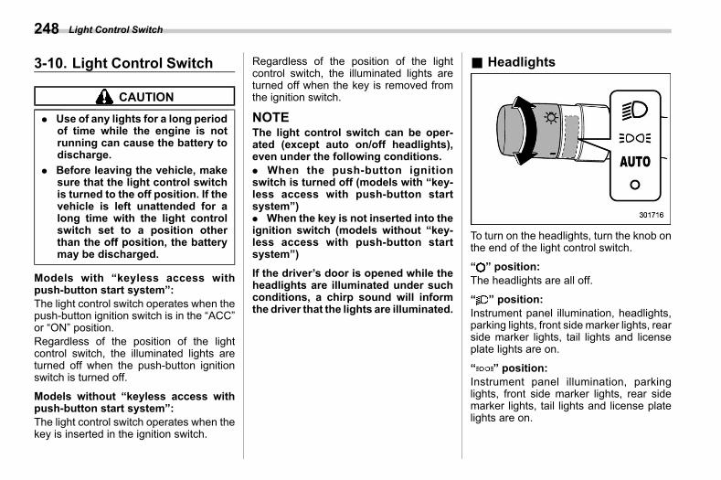
(250,1)
北米Model "A2600BE-B" EDITED: 2020/ 10/ 1
3-10. Light Control Switchs03ah
CAUTION
. Use of any lights for a long periodof time while the engine is notrunning can cause the battery todischarge.
. Before leaving the vehicle, makesure that the light control switchis turned to the off position. If thevehicle is left unattended for along time with the light controlswitch set to a position otherthan the off position, the batterymay be discharged.
Models with “keyless access withpush-button start system”:The light control switch operates when thepush-button ignition switch is in the “ACC”or “ON” position.Regardless of the position of the lightcontrol switch, the illuminated lights areturned off when the push-button ignitionswitch is turned off.
Models without “keyless access withpush-button start system”:The light control switch operates when thekey is inserted in the ignition switch.
Regardless of the position of the lightcontrol switch, the illuminated lights areturned off when the key is removed fromthe ignition switch.
NOTEThe light control switch can be oper-ated (except auto on/off headlights),even under the following conditions.. When the push-button ignitionswitch is turned off (models with “key-less access with push-button startsystem”). When the key is not inserted into theignition switch (models without “key-less access with push-button startsystem”)
If the driver’s door is opened while theheadlights are illuminated under suchconditions, a chirp sound will informthe driver that the lights are illuminated.
& Headlightss03ah01
To turn on the headlights, turn the knob onthe end of the light control switch.
“ ” position:The headlights are all off.
“ ” position:Instrument panel illumination, headlights,parking lights, front side marker lights, rearside marker lights, tail lights and licenseplate lights are on.
“ ” position:Instrument panel illumination, parkinglights, front side marker lights, rear sidemarker lights, tail lights and license platelights are on.
Light Control Switch248
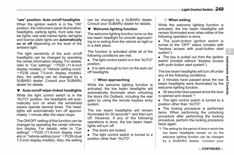
(251,1)
北米Model "A2600BE-B" EDITED: 2020/ 10/ 1
“ ” position: Auto on/off headlightsWhen the ignition switch is in the “ON”position, the instrument panel illumination,headlights, parking lights, front side mar-ker lights, rear side marker lights, tail lightsand license plate lights are automaticallyon or off depending on the level of theambient light.
The light sensitivity of the auto on/offheadlights can be changed by operatingthe center information display. For details,refer to “Car settings” FP220 (11.6-inchdisplay models) or “Vehicle setting icons”FP239 (dual 7.0-inch display models).Also, the setting can be changed by aSUBARU dealer. Consult your SUBARUdealer for details.! Auto-on/off wiper-linked headlights
s03ah0106While the light control switch is in the“AUTO” position, the headlights will auto-matically turn on when the windshieldwipers operate several times. The head-lights will automatically turn off approxi-mately 1 minute after the wiper stops.
The ON/OFF setting of this function can bechanged by operating the center informa-tion display. For details, refer to “Carsettings” FP220 (11.6-inch display mod-els) or “Vehicle setting icons”FP239 (dual7.0-inch display models). Also, the setting
can be changed by a SUBARU dealer.Consult your SUBARU dealer for details.! Welcome lighting function
s03ah0103The welcome lighting function turns on thelow beam headlight for smooth approach-ing to or exiting from the vehicle at night orin a dark place.
The function is activated while all of thefollowing conditions are met.. The light control switch is in the “AUTO”position.. It is dark enough to turn on the auto on/off headlights.
! When approachings03ah010301
While the welcome lighting function isactivated, the low beam headlights willautomatically illuminate when unlockingthe doors (for Outback, including the reargate) by using the remote keyless entrysystem.
The low beam headlights will remainilluminated for 30 seconds*1 and then turnoff. However, if any of the followingoperations is done, the low beam head-lights will turn off.. The doors are locked.. The light control switch is turned to aposition other than “AUTO”.
! When exitings03ah010302
While the welcome lighting function isactivated, the low beam headlights willremain illuminated even when either of thefollowing operation is done.. The push-button ignition switch isturned to the “OFF” status (models with“keyless access with push-button startsystem”).. The key is pulled out from the ignitionswitch (models without “keyless accesswith push-button start system”).
The low beam headlights will turn off underany of the following conditions.. 3 minutes have passed since the lowbeam headlights were illuminated by thewelcome lighting function.. 30 seconds have passed since the dooris opened and closed.*1. The light control switch is turned to aposition other than “AUTO”.. The locking procedure is performedtwice. When performing the unlockingprocedure after performing the lockingprocedure, perform the locking proceduretwice again.*1: The setting for the period of time in which the
low beam headlights remain on by thewelcome lighting function can be changedby a SUBARU dealer. Contact your
– CONTINUED –
Light Control Switch 249
3
Instruments
andControls
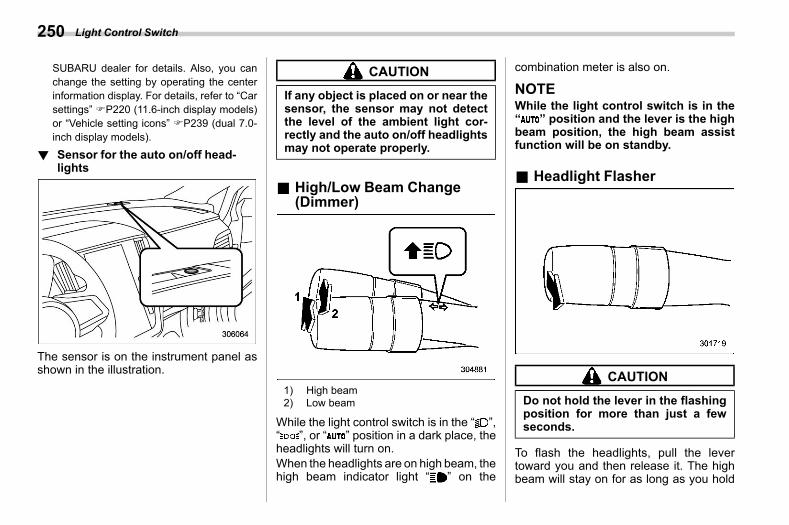
(252,1)
北米Model "A2600BE-B" EDITED: 2020/ 10/ 1
SUBARU dealer for details. Also, you canchange the setting by operating the centerinformation display. For details, refer to “Carsettings” FP220 (11.6-inch display models)or “Vehicle setting icons” FP239 (dual 7.0-inch display models).
! Sensor for the auto on/off head-lights
s03ah0101
The sensor is on the instrument panel asshown in the illustration.
CAUTION
If any object is placed on or near thesensor, the sensor may not detectthe level of the ambient light cor-rectly and the auto on/off headlightsmay not operate properly.
& High/Low Beam Change(Dimmer)
s03ah02
1) High beam2) Low beam
While the light control switch is in the “ ”,“ ”, or “ ” position in a dark place, theheadlights will turn on.When the headlights are on high beam, thehigh beam indicator light “ ” on the
combination meter is also on.
NOTEWhile the light control switch is in the“ ” position and the lever is the highbeam position, the high beam assistfunction will be on standby.
& Headlight Flashers03ah03
CAUTION
Do not hold the lever in the flashingposition for more than just a fewseconds.
To flash the headlights, pull the levertoward you and then release it. The highbeam will stay on for as long as you hold
Light Control Switch250
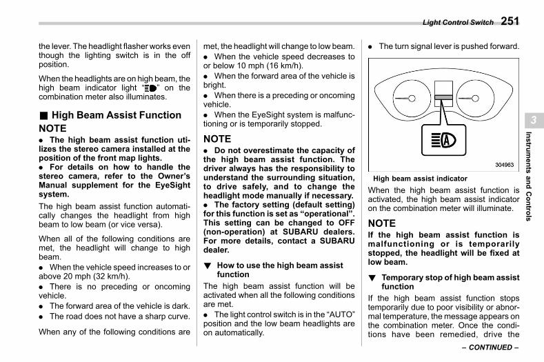
(253,1)
北米Model "A2600BE-B" EDITED: 2020/ 10/ 1
the lever. The headlight flasher works eventhough the lighting switch is in the offposition.
When the headlights are on high beam, thehigh beam indicator light “ ” on thecombination meter also illuminates.
& High Beam Assist Functions03ah07
NOTE. The high beam assist function uti-lizes the stereo camera installed at theposition of the front map lights.. For details on how to handle thestereo camera, refer to the Owner’sManual supplement for the EyeSightsystem.The high beam assist function automati-cally changes the headlight from highbeam to low beam (or vice versa).
When all of the following conditions aremet, the headlight will change to highbeam.. When the vehicle speed increases to orabove 20 mph (32 km/h).. There is no preceding or oncomingvehicle.. The forward area of the vehicle is dark.. The road does not have a sharp curve.
When any of the following conditions are
met, the headlight will change to low beam.. When the vehicle speed decreases toor below 10 mph (16 km/h).. When the forward area of the vehicle isbright.. When there is a preceding or oncomingvehicle.. When the EyeSight system is malfunc-tioning or is temporarily stopped.
NOTE. Do not overestimate the capacity ofthe high beam assist function. Thedriver always has the responsibility tounderstand the surrounding situation,to drive safely, and to change theheadlight mode manually if necessary.. The factory setting (default setting)for this function is set as “operational”.This setting can be changed to OFF(non-operation) at SUBARU dealers.For more details, contact a SUBARUdealer.
! How to use the high beam assistfunction
s03ah0701The high beam assist function will beactivated when all the following conditionsare met.. The light control switch is in the “AUTO”position and the low beam headlights areon automatically.
. The turn signal lever is pushed forward.
High beam assist indicatorWhen the high beam assist function isactivated, the high beam assist indicatoron the combination meter will illuminate.
NOTEIf the high beam assist function ismalfunctioning or is temporarilystopped, the headlight will be fixed atlow beam.
! Temporary stop of high beam assistfunction
s03ah0706If the high beam assist function stopstemporarily due to poor visibility or abnor-mal temperature, themessage appears onthe combination meter. Once the condi-tions have been remedied, drive the
– CONTINUED –
Light Control Switch 251
3
Instruments
andControls
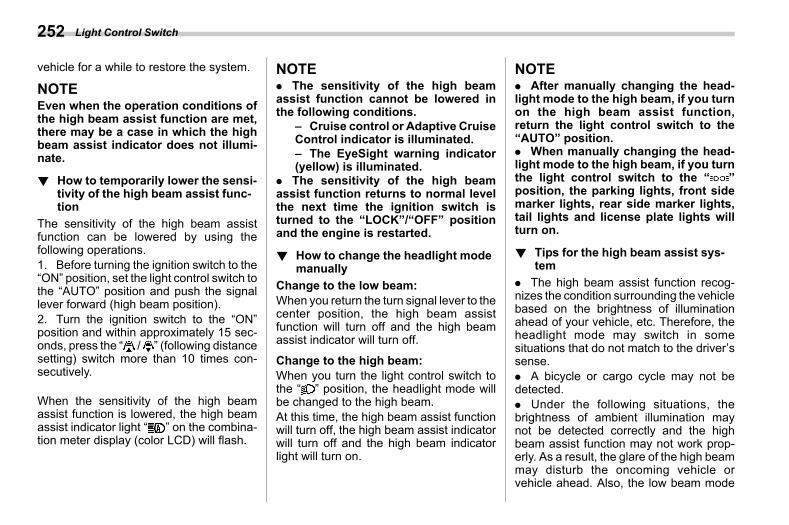
(254,1)
北米Model "A2600BE-B" EDITED: 2020/ 10/ 1
vehicle for a while to restore the system.
NOTEEven when the operation conditions ofthe high beam assist function are met,there may be a case in which the highbeam assist indicator does not illumi-nate.
! How to temporarily lower the sensi-tivity of the high beam assist func-tion
s03ah0704The sensitivity of the high beam assistfunction can be lowered by using thefollowing operations.1. Before turning the ignition switch to the“ON” position, set the light control switch tothe “AUTO” position and push the signallever forward (high beam position).2. Turn the ignition switch to the “ON”position and within approximately 15 sec-onds, press the “ / ” (following distancesetting) switch more than 10 times con-secutively.
When the sensitivity of the high beamassist function is lowered, the high beamassist indicator light “ ” on the combina-tion meter display (color LCD) will flash.
NOTE. The sensitivity of the high beamassist function cannot be lowered inthe following conditions.
– Cruise control or Adaptive CruiseControl indicator is illuminated.– The EyeSight warning indicator(yellow) is illuminated.
. The sensitivity of the high beamassist function returns to normal levelthe next time the ignition switch isturned to the “LOCK”/“OFF” positionand the engine is restarted.
! How to change the headlight modemanually
s03ah0702Change to the low beam:When you return the turn signal lever to thecenter position, the high beam assistfunction will turn off and the high beamassist indicator will turn off.
Change to the high beam:When you turn the light control switch tothe “ ” position, the headlight mode willbe changed to the high beam.At this time, the high beam assist functionwill turn off, the high beam assist indicatorwill turn off and the high beam indicatorlight will turn on.
NOTE. After manually changing the head-light mode to the high beam, if you turnon the high beam assist function,return the light control switch to the“AUTO” position.. When manually changing the head-light mode to the high beam, if you turnthe light control switch to the “ ”position, the parking lights, front sidemarker lights, rear side marker lights,tail lights and license plate lights willturn on.
! Tips for the high beam assist sys-tem
s03ah0703. The high beam assist function recog-nizes the condition surrounding the vehiclebased on the brightness of illuminationahead of your vehicle, etc. Therefore, theheadlight mode may switch in somesituations that do not match to the driver’ssense.. A bicycle or cargo cycle may not bedetected.. Under the following situations, thebrightness of ambient illumination maynot be detected correctly and the highbeam assist function may not work prop-erly. As a result, the glare of the high beammay disturb the oncoming vehicle orvehicle ahead. Also, the low beam mode
Light Control Switch252
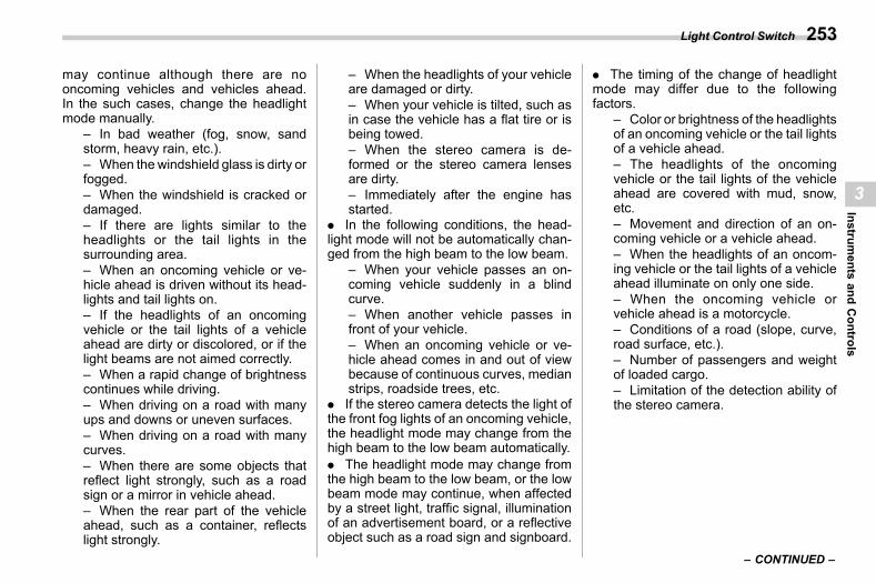
(255,1)
北米Model "A2600BE-B" EDITED: 2020/ 10/ 1
may continue although there are nooncoming vehicles and vehicles ahead.In the such cases, change the headlightmode manually.
– In bad weather (fog, snow, sandstorm, heavy rain, etc.).– When the windshield glass is dirty orfogged.– When the windshield is cracked ordamaged.– If there are lights similar to theheadlights or the tail lights in thesurrounding area.– When an oncoming vehicle or ve-hicle ahead is driven without its head-lights and tail lights on.– If the headlights of an oncomingvehicle or the tail lights of a vehicleahead are dirty or discolored, or if thelight beams are not aimed correctly.– When a rapid change of brightnesscontinues while driving.– When driving on a road with manyups and downs or uneven surfaces.– When driving on a road with manycurves.– When there are some objects thatreflect light strongly, such as a roadsign or a mirror in vehicle ahead.– When the rear part of the vehicleahead, such as a container, reflectslight strongly.
– When the headlights of your vehicleare damaged or dirty.– When your vehicle is tilted, such asin case the vehicle has a flat tire or isbeing towed.– When the stereo camera is de-formed or the stereo camera lensesare dirty.– Immediately after the engine hasstarted.
. In the following conditions, the head-light mode will not be automatically chan-ged from the high beam to the low beam.
– When your vehicle passes an on-coming vehicle suddenly in a blindcurve.– When another vehicle passes infront of your vehicle.– When an oncoming vehicle or ve-hicle ahead comes in and out of viewbecause of continuous curves, medianstrips, roadside trees, etc.
. If the stereo camera detects the light ofthe front fog lights of an oncoming vehicle,the headlight mode may change from thehigh beam to the low beam automatically.. The headlight mode may change fromthe high beam to the low beam, or the lowbeam mode may continue, when affectedby a street light, traffic signal, illuminationof an advertisement board, or a reflectiveobject such as a road sign and signboard.
. The timing of the change of headlightmode may differ due to the followingfactors.
– Color or brightness of the headlightsof an oncoming vehicle or the tail lightsof a vehicle ahead.– The headlights of the oncomingvehicle or the tail lights of the vehicleahead are covered with mud, snow,etc.– Movement and direction of an on-coming vehicle or a vehicle ahead.– When the headlights of an oncom-ing vehicle or the tail lights of a vehicleahead illuminate on only one side.– When the oncoming vehicle orvehicle ahead is a motorcycle.– Conditions of a road (slope, curve,road surface, etc.).– Number of passengers and weightof loaded cargo.– Limitation of the detection ability ofthe stereo camera.
– CONTINUED –
Light Control Switch 253
3
Instruments
andControls
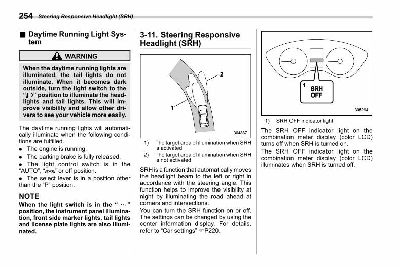
(256,1)
北米Model "A2600BE-B" EDITED: 2020/ 10/ 1
& Daytime Running Light Sys-tem
s03ah04
WARNING
When the daytime running lights areilluminated, the tail lights do notilluminate. When it becomes darkoutside, turn the light switch to the“ ” position to illuminate the head-lights and tail lights. This will im-prove visibility and allow other dri-vers to see your vehicle more easily.
The daytime running lights will automati-cally illuminate when the following condi-tions are fulfilled.. The engine is running.. The parking brake is fully released.. The light control switch is in the“AUTO”, “ ” or off position.. The select lever is in a position otherthan the “P” position.
NOTEWhen the light switch is in the “ ”position, the instrument panel illumina-tion, front side marker lights, tail lightsand license plate lights are also illumi-nated.
3-11. Steering ResponsiveHeadlight (SRH)
s03bl
1) The target area of illumination when SRHis activated
2) The target area of illumination when SRHis not activated
SRH is a function that automatically movesthe headlight beam to the left or right inaccordance with the steering angle. Thisfunction helps to improve the visibility atnight by illuminating the road ahead atcorners and intersections.You can turn the SRH function on or off.The settings can be changed by using thecenter information display. For details,refer to “Car settings” FP220.
1) SRH OFF indicator light
The SRH OFF indicator light on thecombination meter display (color LCD)turns off when SRH is turned on.The SRH OFF indicator light on thecombination meter display (color LCD)illuminates when SRH is turned off.
Steering Responsive Headlight (SRH)254
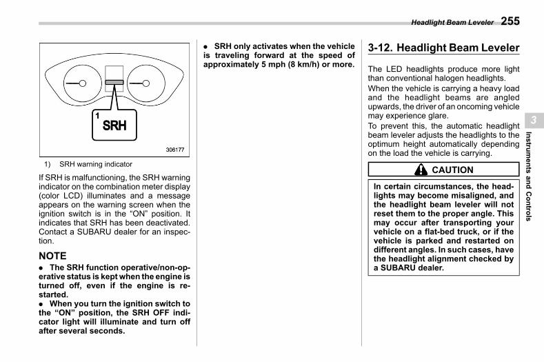
(257,1)
北米Model "A2600BE-B" EDITED: 2020/ 10/ 1
1) SRH warning indicator
If SRH is malfunctioning, the SRH warningindicator on the combination meter display(color LCD) illuminates and a messageappears on the warning screen when theignition switch is in the “ON” position. Itindicates that SRH has been deactivated.Contact a SUBARU dealer for an inspec-tion.
NOTE. The SRH function operative/non-op-erative status is keptwhen the engine isturned off, even if the engine is re-started.. When you turn the ignition switch tothe “ON” position, the SRH OFF indi-cator light will illuminate and turn offafter several seconds.
. SRH only activates when the vehicleis traveling forward at the speed ofapproximately 5 mph (8 km/h) or more.
3-12. Headlight Beam Levelers03at
The LED headlights produce more lightthan conventional halogen headlights.When the vehicle is carrying a heavy loadand the headlight beams are angledupwards, the driver of an oncoming vehiclemay experience glare.To prevent this, the automatic headlightbeam leveler adjusts the headlights to theoptimum height automatically dependingon the load the vehicle is carrying.
CAUTION
In certain circumstances, the head-lights may become misaligned, andthe headlight beam leveler will notreset them to the proper angle. Thismay occur after transporting yourvehicle on a flat-bed truck, or if thevehicle is parked and restarted ondifferent angles. In such cases, havethe headlight alignment checked bya SUBARU dealer.
Headlight Beam Leveler 255
3
Instruments
andControls
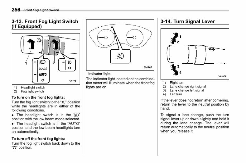
(258,1)
北米Model "A2600BE-B" EDITED: 2020/ 10/ 1
3-13. Front Fog Light Switch(If Equipped)
s03al
1) Headlight switch2) Fog light switch
To turn on the front fog lights:Turn the fog light switch to the “ ” positionwhile the headlights are in either of thefollowing conditions.. The headlight switch is in the “ ”position with the low beammode selected.. The headlight switch is in the “AUTO”position and the low beam headlights turnon automatically.
To turn off the front fog lights:Turn the fog light switch back down to the“ ” position.
Indicator lightThe indicator light located on the combina-tion meter will illuminate when the front foglights are on.
3-14. Turn Signal Levers03ai
1) Right turn2) Lane change right signal3) Lane change left signal4) Left turn
If the lever does not return after cornering,return the lever to the neutral position byhand.
To signal a lane change, push the turnsignal lever up or down slightly and hold itduring the lane change. The lever willreturn automatically to the neutral positionwhen you release it.
Front Fog Light Switch256
(259,1)
北米Model "A2600BE-B" EDITED: 2020/ 10/ 1
& One-Touch Lane Changers03ai01
To flash the turn signal and turn signalindicator light three times, push the turnsignal lever up or down slightly andimmediately release it.
NOTEThe operational/non-operationalsetting of the one-touch lane changercan be changed by a SUBARU dealer.Contact the nearest SUBARU dealer fordetails. The setting can also be chan-ged by operating the center informationdisplay. For details, refer to “Car set-tings” FP220 (11.6-inch display mod-els) or “Vehicle setting icons” FP239(dual 7.0-inch display models).
3-15. Wiper and Washers03am
WARNING
In freezing weather, do not use thewindshield washer until the wind-shield is sufficiently warmed by thedefroster.Otherwise the washer fluid canfreeze on the windshield, blockingyour view.
CAUTION
. Do not operate the washer con-tinuously for more than 10 sec-onds, or when the washer fluidtank is empty. This may causeoverheating of the washer motor.Check the washer fluid level fre-quently, such as at fuel stops.
. Do not operate the wipers whenthe windshield or rear window isdry. This may scratch the glass,damage the blade rubbers andmight cause the wiper motor tofail. Before operating the wiperon a dry windshield or rear win-dow, always use the windshieldwasher.
. In freezing weather, be sure thatthe blade rubbers are not frozento the windshield or rear windowbefore switching on the wipers.Attempting to operate the wiperwith the blade rubbers frozen tothe window glass could causenot only the blade rubbers to bedamaged but also might causethewipermotor to fail. If the bladerubbers are frozen to the windowglass, be sure to operate thedefroster, windshield wiper dei-cer (if equipped) or rear windowdefogger before turning on thewiper.
. If the wipers stop during opera-tion because of ice or some otherobstruction on the window, thismight cause the wiper motor tofail even if the wiper switch isturned off. I f this occurs,promptly stop the vehicle in asafe location, turn the ignitionswitch to the “LOCK”/“OFF” po-sition and clean thewindowglassto allow proper wiper operation.
. Use clean water if windshieldwasher fluid is unavailable. Inareas where water freezes inwinter, use SUBARU WindshieldWasher Fluid or the equivalent.
– CONTINUED –
Wiper and Washer 257
3
Instruments
andControls
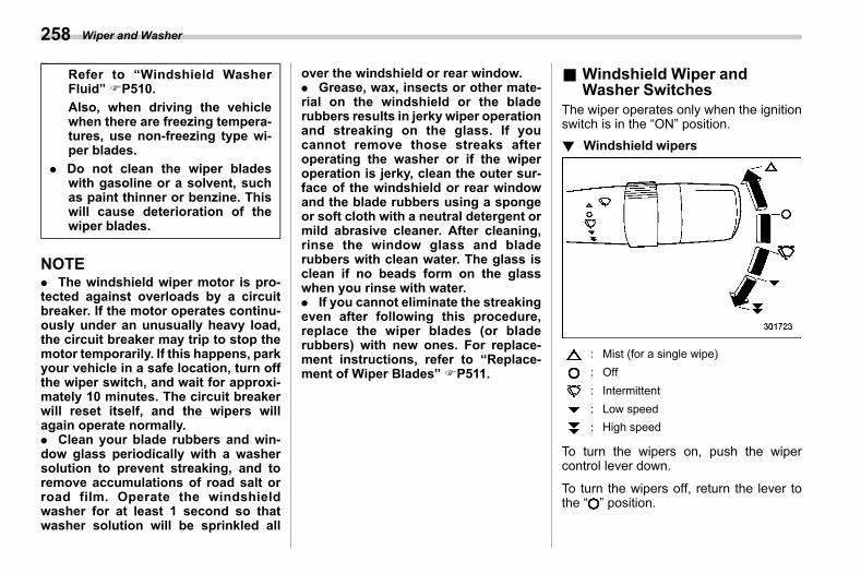
(260,1)
北米Model "A2600BE-B" EDITED: 2020/ 10/ 1
Refer to “Windshield WasherFluid” FP510.Also, when driving the vehiclewhen there are freezing tempera-tures, use non-freezing type wi-per blades.
. Do not clean the wiper bladeswith gasoline or a solvent, suchas paint thinner or benzine. Thiswill cause deterioration of thewiper blades.
NOTE. The windshield wiper motor is pro-tected against overloads by a circuitbreaker. If the motor operates continu-ously under an unusually heavy load,the circuit breaker may trip to stop themotor temporarily. If this happens, parkyour vehicle in a safe location, turn offthe wiper switch, and wait for approxi-mately 10 minutes. The circuit breakerwill reset itself, and the wipers willagain operate normally.. Clean your blade rubbers and win-dow glass periodically with a washersolution to prevent streaking, and toremove accumulations of road salt orroad film. Operate the windshieldwasher for at least 1 second so thatwasher solution will be sprinkled all
over the windshield or rear window.. Grease, wax, insects or other mate-rial on the windshield or the bladerubbers results in jerky wiper operationand streaking on the glass. If youcannot remove those streaks afteroperating the washer or if the wiperoperation is jerky, clean the outer sur-face of the windshield or rear windowand the blade rubbers using a spongeor soft cloth with a neutral detergent ormild abrasive cleaner. After cleaning,rinse the window glass and bladerubbers with clean water. The glass isclean if no beads form on the glasswhen you rinse with water.. If you cannot eliminate the streakingeven after following this procedure,replace the wiper blades (or bladerubbers) with new ones. For replace-ment instructions, refer to “Replace-ment of Wiper Blades” FP511.
& Windshield Wiper andWasher Switches
s03am01The wiper operates only when the ignitionswitch is in the “ON” position.! Windshield wipers
s03am0101
: Mist (for a single wipe): Off: Intermittent: Low speed: High speed
To turn the wipers on, push the wipercontrol lever down.
To turn the wipers off, return the lever tothe “ ” position.
Wiper and Washer258
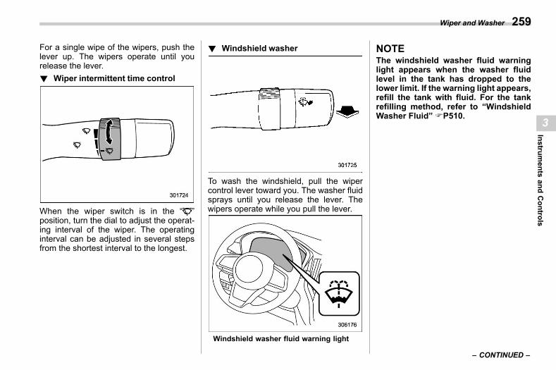
(261,1)
北米Model "A2600BE-B" EDITED: 2020/ 10/ 1
For a single wipe of the wipers, push thelever up. The wipers operate until yourelease the lever.! Wiper intermittent time control
s03am0103
When the wiper switch is in the “ ”position, turn the dial to adjust the operat-ing interval of the wiper. The operatinginterval can be adjusted in several stepsfrom the shortest interval to the longest.
! Windshield washers03am0104
To wash the windshield, pull the wipercontrol lever toward you. The washer fluidsprays until you release the lever. Thewipers operate while you pull the lever.
Windshield washer fluid warning light
NOTEThe windshield washer fluid warninglight appears when the washer fluidlevel in the tank has dropped to thelower limit. If the warning light appears,refill the tank with fluid. For the tankrefilling method, refer to “WindshieldWasher Fluid” FP510.
– CONTINUED –
Wiper and Washer 259
3
Instruments
andControls
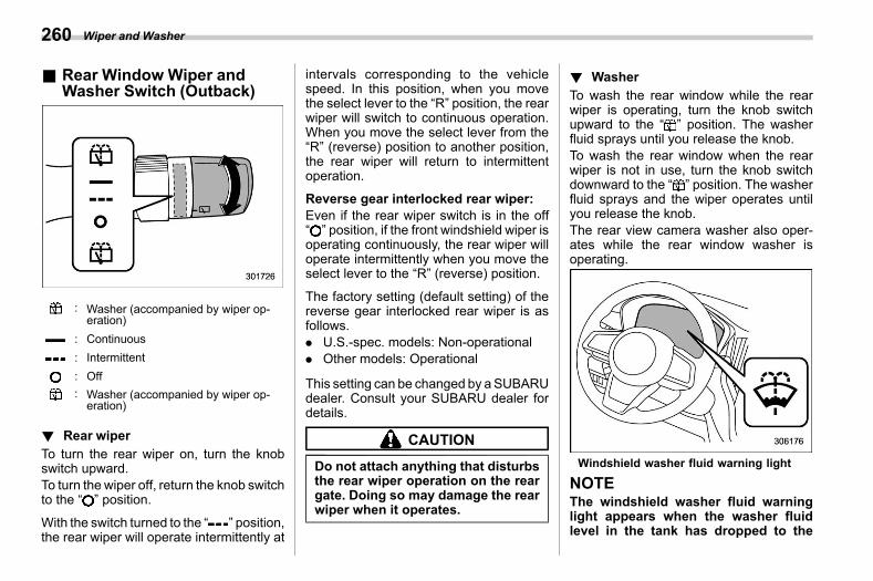
(262,1)
北米Model "A2600BE-B" EDITED: 2020/ 10/ 1
& Rear Window Wiper andWasher Switch (Outback)
s03am02
: Washer (accompanied by wiper op-eration)
: Continuous: Intermittent: Off: Washer (accompanied by wiper op-eration)
! Rear wipers03am0201
To turn the rear wiper on, turn the knobswitch upward.To turn the wiper off, return the knob switchto the “ ” position.
With the switch turned to the “ ” position,the rear wiper will operate intermittently at
intervals corresponding to the vehiclespeed. In this position, when you movethe select lever to the “R” position, the rearwiper will switch to continuous operation.When you move the select lever from the“R” (reverse) position to another position,the rear wiper will return to intermittentoperation.
Reverse gear interlocked rear wiper:Even if the rear wiper switch is in the off“ ” position, if the front windshield wiper isoperating continuously, the rear wiper willoperate intermittently when you move theselect lever to the “R” (reverse) position.
The factory setting (default setting) of thereverse gear interlocked rear wiper is asfollows.. U.S.-spec. models: Non-operational. Other models: Operational
This setting can be changed by aSUBARUdealer. Consult your SUBARU dealer fordetails.
CAUTION
Do not attach anything that disturbsthe rear wiper operation on the reargate. Doing so may damage the rearwiper when it operates.
! Washers03am0202
To wash the rear window while the rearwiper is operating, turn the knob switchupward to the “ ” position. The washerfluid sprays until you release the knob.To wash the rear window when the rearwiper is not in use, turn the knob switchdownward to the “ ” position. The washerfluid sprays and the wiper operates untilyou release the knob.The rear view camera washer also oper-ates while the rear window washer isoperating.
Windshield washer fluid warning light
NOTEThe windshield washer fluid warninglight appears when the washer fluidlevel in the tank has dropped to the
Wiper and Washer260
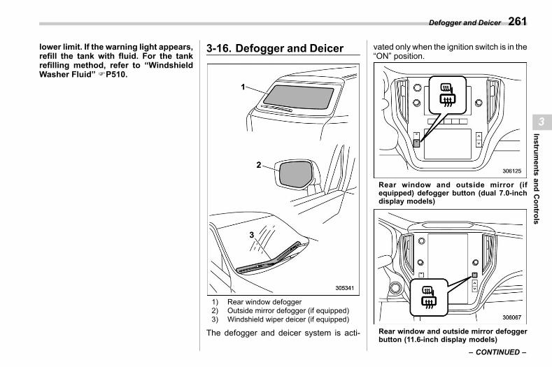
(263,1)
北米Model "A2600BE-B" EDITED: 2020/ 10/ 1
lower limit. If the warning light appears,refill the tank with fluid. For the tankrefilling method, refer to “WindshieldWasher Fluid” FP510.
3-16. Defogger and Deicers03bi
1) Rear window defogger2) Outside mirror defogger (if equipped)3) Windshield wiper deicer (if equipped)
The defogger and deicer system is acti-
vated only when the ignition switch is in the“ON” position.
Rear window and outside mirror (ifequipped) defogger button (dual 7.0-inchdisplay models)
Rear window and outside mirror defoggerbutton (11.6-inch display models)
– CONTINUED –
Defogger and Deicer 261
3
Instruments
andControls
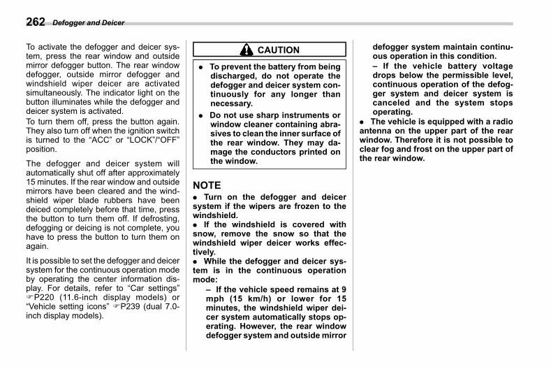
(264,1)
北米Model "A2600BE-B" EDITED: 2020/ 10/ 1
To activate the defogger and deicer sys-tem, press the rear window and outsidemirror defogger button. The rear windowdefogger, outside mirror defogger andwindshield wiper deicer are activatedsimultaneously. The indicator light on thebutton illuminates while the defogger anddeicer system is activated.To turn them off, press the button again.They also turn off when the ignition switchis turned to the “ACC” or “LOCK”/“OFF”position.
The defogger and deicer system willautomatically shut off after approximately15 minutes. If the rear window and outsidemirrors have been cleared and the wind-shield wiper blade rubbers have beendeiced completely before that time, pressthe button to turn them off. If defrosting,defogging or deicing is not complete, youhave to press the button to turn them onagain.
It is possible to set the defogger and deicersystem for the continuous operation modeby operating the center information dis-play. For details, refer to “Car settings”FP220 (11.6-inch display models) or“Vehicle setting icons” FP239 (dual 7.0-inch display models).
CAUTION
. To prevent the battery from beingdischarged, do not operate thedefogger and deicer system con-tinuously for any longer thannecessary.
. Do not use sharp instruments orwindow cleaner containing abra-sives to clean the inner surface ofthe rear window. They may da-mage the conductors printed onthe window.
NOTE. Turn on the defogger and deicersystem if the wipers are frozen to thewindshield.. If the windshield is covered withsnow, remove the snow so that thewindshield wiper deicer works effec-tively.. While the defogger and deicer sys-tem is in the continuous operationmode:
– If the vehicle speed remains at 9mph (15 km/h) or lower for 15minutes, the windshield wiper dei-cer system automatically stops op-erating. However, the rear windowdefogger system and outside mirror
defogger system maintain continu-ous operation in this condition.– If the vehicle battery voltagedrops below the permissible level,continuous operation of the defog-ger system and deicer system iscanceled and the system stopsoperating.
. The vehicle is equipped with a radioantenna on the upper part of the rearwindow. Therefore it is not possible toclear fog and frost on the upper part ofthe rear window.
Defogger and Deicer262
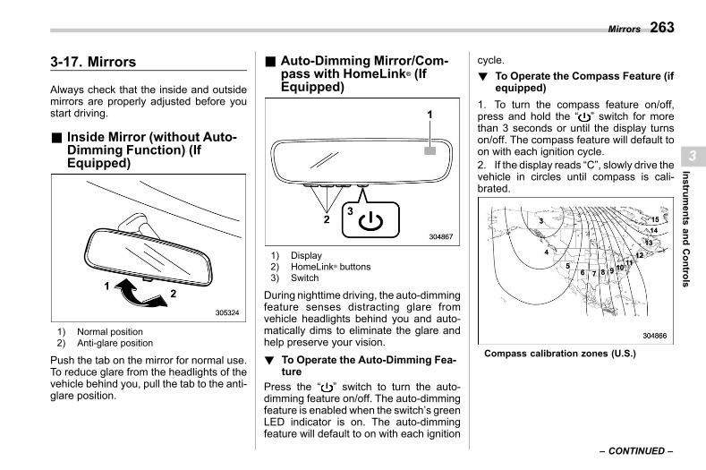
(265,1)
北米Model "A2600BE-B" EDITED: 2020/ 10/ 1
3-17. Mirrorss03ap
Always check that the inside and outsidemirrors are properly adjusted before youstart driving.
& Inside Mirror (without Auto-Dimming Function) (IfEquipped)
s03ap08
1) Normal position2) Anti-glare position
Push the tab on the mirror for normal use.To reduce glare from the headlights of thevehicle behind you, pull the tab to the anti-glare position.
& Auto-Dimming Mirror/Com-pass with HomeLink® (IfEquipped)
s03ap10
1) Display2) HomeLink® buttons3) Switch
During nighttime driving, the auto-dimmingfeature senses distracting glare fromvehicle headlights behind you and auto-matically dims to eliminate the glare andhelp preserve your vision.! To Operate the Auto-Dimming Fea-
tures03ap1001
Press the “ ” switch to turn the auto-dimming feature on/off. The auto-dimmingfeature is enabled when the switch’s greenLED indicator is on. The auto-dimmingfeature will default to on with each ignition
cycle.! To Operate the Compass Feature (if
equipped)s03ap1002
1. To turn the compass feature on/off,press and hold the “ ” switch for morethan 3 seconds or until the display turnson/off. The compass feature will default toon with each ignition cycle.2. If the display reads “C”, slowly drive thevehicle in circles until compass is cali-brated.
Compass calibration zones (U.S.)
– CONTINUED –
Mirrors 263
3
Instruments
andControls
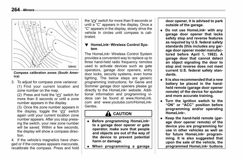
(266,1)
北米Model "A2600BE-B" EDITED: 2020/ 10/ 1
Compass calibration zones (South Amer-ica)
3. To adjust for compass zone variance:(1) Find your current location andzone number on the map.(2) Press and hold the “ ” switch formore than 6 seconds or until a zonenumber appears in the display.(3) Once the zone number appears inthe display, toggle the “ ” switchagain until your current location zonenumber appears. After you stop press-ing the switch, your new zone numberwill be saved. Within a few seconds,the display will show a compass direc-tion.
4. If the vehicle’s magnetics have chan-ged or if the compass appears inaccurate,recalibrate the compass. Press and hold
the “ ” switch for more than 9 seconds oruntil a “C” appears in the display. Once a“C” appears in the display, slowly drive thevehicle in circles until compass is cali-brated.
! HomeLink® Wireless Control Sys-tem
s03ap1003The HomeLink® Wireless Control Systemprovides a convenient way to replace up tothree hand-held radio frequency remotesused to activate devices such as gateoperators, garage door openers, entrydoor locks, security systems, even homelighting. The below steps are genericprogramming instructions; for Genie andSommer garage door openers please godirectly to the HomeLink® website. Addi-tional information and programming vi-deos can be found at www.HomeLink.com and www.youtube.com/HomeLink-Gentex.
CAUTION
. Before programming HomeLink®
to a garage door opener or gateoperator, make sure that peopleand objects are out of the way ofthe device to prevent potentialharm or damage.
. When programming a garage
door opener, it is advised to parkoutside of the garage.
. Do not use HomeLink® with anygarage door opener that lackssafety stop and reverse featuresas required by U.S. federal safetystandards (this includes any gar-age door opener model manufac-tured before April 1, 1982). Agarage door that cannot detectan object signaling the door tostop and reverse does not meetcurrent U.S. federal safety stan-dards.
. It is also recommended that a newbattery be placed in the hand-held remote (garage door openerremote) of the device for quickerand more accurate training.
. Turn the ignition switch to the“ON” or “ACC” position beforeprogramming and/or operatingHomeLink®.
. Keep the hand-held remote (gar-age door opener remote) of thedevice you are programming foruse in other vehicles as well asfor future HomeLink® program-ming. It is also suggested thatupon the sale of the vehicle, theprogrammed HomeLink® buttons
Mirrors264
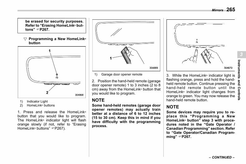
(267,1)
北米Model "A2600BE-B" EDITED: 2020/ 10/ 1
be erased for security purposes.Refer to “Erasing HomeLink® but-tons” FP267.
! Programming a New HomeLink®
buttons03ap100301
1) Indicator Light2) HomeLink® buttons
1. Press and release the HomeLink®
button that you would like to program.The HomeLink® indicator light will flashorange slowly (if not, refer to “ErasingHomeLink® buttons” FP267).
1) Garage door opener remote
2. Position the hand-held remote (garagedoor opener remote) 1 to 3 inches (2 to 8cm) away from the HomeLink® button thatyou would like to program.
NOTESome hand-held remotes (garage dooropener remotes) may actually trainbetter at a distance of 6 to 12 inches(15 to 30 cm). Keep this in mind if youhave difficulty with the programmingprocess.
3. While the HomeLink® indicator light isflashing orange, press and hold the hand-held remote button. Continue pressing thehand-held remote button until theHomeLink® indicator light changes fromorange to green. You may now release thehand-held remote button.
NOTESome devices may require you to re-place this “Programming a NewHomeLink® button” step 3 with proce-dures noted in the “Gate Operator /Canadian Programming” section. Referto “Gate Operator/Canadian Program-ming” FP267.
– CONTINUED –
Mirrors 265
3
Instruments
andControls
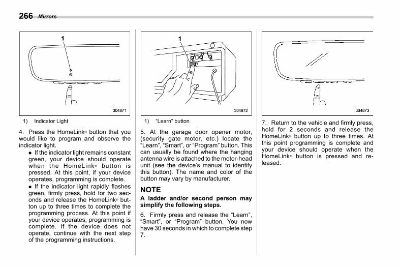
(268,1)
北米Model "A2600BE-B" EDITED: 2020/ 10/ 1
1) Indicator Light
4. Press the HomeLink® button that youwould like to program and observe theindicator light.
. If the indicator light remains constantgreen, your device should operatewhen the HomeLink® button ispressed. At this point, if your deviceoperates, programming is complete.. If the indicator light rapidly flashesgreen, firmly press, hold for two sec-onds and release the HomeLink® but-ton up to three times to complete theprogramming process. At this point ifyour device operates, programming iscomplete. If the device does notoperate, continue with the next stepof the programming instructions.
1) “Learn” button
5. At the garage door opener motor,(security gate motor, etc.) locate the“Learn”, “Smart”, or “Program” button. Thiscan usually be found where the hangingantennawire is attached to themotor-headunit (see the device’s manual to identifythis button). The name and color of thebutton may vary by manufacturer.
NOTEA ladder and/or second person maysimplify the following steps.6. Firmly press and release the “Learn”,“Smart”, or “Program” button. You nowhave 30 seconds in which to complete step7.
7. Return to the vehicle and firmly press,hold for 2 seconds and release theHomeLink® button up to three times. Atthis point programming is complete andyour device should operate when theHomeLink® button is pressed and re-leased.
Mirrors266
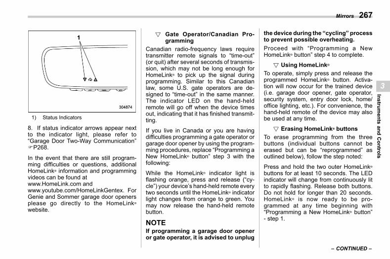
(269,1)
北米Model "A2600BE-B" EDITED: 2020/ 10/ 1
1) Status Indicators
8. If status indicator arrows appear nextto the indicator light, please refer to“Garage Door Two-Way Communication”FP268.
In the event that there are still program-ming difficulties or questions, additionalHomeLink® information and programmingvideos can be found atwww.HomeLink.com andwww.youtube.com/HomeLinkGentex. ForGenie and Sommer garage door openersplease go directly to the HomeLink®
website.
! Gate Operator/Canadian Pro-gramming
s03ap100302
Canadian radio-frequency laws requiretransmitter remote signals to “time-out”(or quit) after several seconds of transmis-sion, which may not be long enough forHomeLink® to pick up the signal duringprogramming. Similar to this Canadianlaw, some U.S. gate operators are de-signed to “time-out” in the same manner.The indicator LED on the hand-heldremote will go off when the device timesout, indicating that it has finished transmit-ting.
If you live in Canada or you are havingdifficulties programming a gate operator orgarage door opener by using the program-ming procedures, replace “Programming aNew HomeLink® button” step 3 with thefollowing:
While the HomeLink® indicator light isflashing orange, press and release (“cy-cle”) your device’s hand-held remote everytwo seconds until the HomeLink® indicatorlight changes from orange to green. Youmay now release the hand-held remotebutton.
NOTEIf programming a garage door openeror gate operator, it is advised to unplug
the device during the “cycling” processto prevent possible overheating.Proceed with “Programming a NewHomeLink® button” step 4 to complete.
! Using HomeLink®
s03ap100303
To operate, simply press and release theprogrammed HomeLink® button. Activa-tion will now occur for the trained device(i.e. garage door opener, gate operator,security system, entry door lock, home/office lighting, etc.). For convenience, thehand-held remote of the device may alsobe used at any time.
! Erasing HomeLink® buttonss03ap100304
To erase programming from the threebuttons (individual buttons cannot beerased but can be “reprogrammed” asoutlined below), follow the step noted:
Press and hold the two outer HomeLink®buttons for at least 10 seconds. The LEDindicator will change from continuously litto rapidly flashing. Release both buttons.Do not hold for longer than 20 seconds.HomeLink® is now ready to be pro-grammed at any time beginning with“Programming a New HomeLink® button”- step 1.
– CONTINUED –
Mirrors 267
3
Instruments
andControls
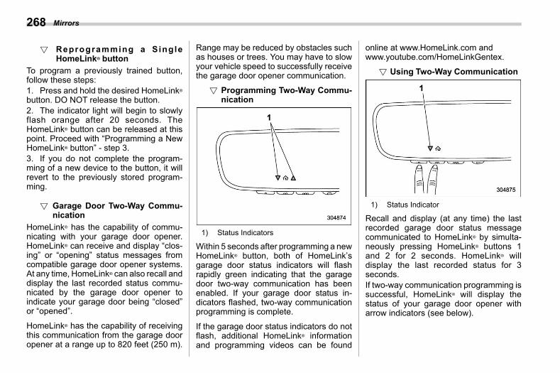
(270,1)
北米Model "A2600BE-B" EDITED: 2020/ 10/ 1
! Reprogramming a SingleHomeLink® button
s03ap100305
To program a previously trained button,follow these steps:1. Press and hold the desired HomeLink®button. DO NOT release the button.2. The indicator light will begin to slowlyflash orange after 20 seconds. TheHomeLink® button can be released at thispoint. Proceed with “Programming a NewHomeLink® button” - step 3.3. If you do not complete the program-ming of a new device to the button, it willrevert to the previously stored program-ming.
! Garage Door Two-Way Commu-nication
s03ap100306
HomeLink® has the capability of commu-nicating with your garage door opener.HomeLink® can receive and display “clos-ing” or “opening” status messages fromcompatible garage door opener systems.At any time, HomeLink® can also recall anddisplay the last recorded status commu-nicated by the garage door opener toindicate your garage door being “closed”or “opened”.
HomeLink® has the capability of receivingthis communication from the garage dooropener at a range up to 820 feet (250 m).
Range may be reduced by obstacles suchas houses or trees. You may have to slowyour vehicle speed to successfully receivethe garage door opener communication.
! Programming Two-Way Commu-nication
s03ap100307
1) Status Indicators
Within 5 seconds after programming a newHomeLink® button, both of HomeLink’sgarage door status indicators will flashrapidly green indicating that the garagedoor two-way communication has beenenabled. If your garage door status in-dicators flashed, two-way communicationprogramming is complete.
If the garage door status indicators do notflash, additional HomeLink® informationand programming videos can be found
online at www.HomeLink.com andwww.youtube.com/HomeLinkGentex.
! Using Two-Way Communications03ap100308
1) Status Indicator
Recall and display (at any time) the lastrecorded garage door status messagecommunicated to HomeLink® by simulta-neously pressing HomeLink® buttons 1and 2 for 2 seconds. HomeLink® willdisplay the last recorded status for 3seconds.If two-way communication programming issuccessful, HomeLink® will display thestatus of your garage door opener witharrow indicators (see below).
Mirrors268
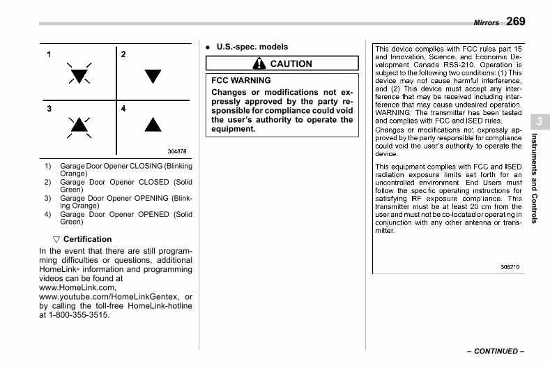
(271,1)
北米Model "A2600BE-B" EDITED: 2020/ 10/ 1
1) GarageDoor Opener CLOSING (BlinkingOrange)
2) Garage Door Opener CLOSED (SolidGreen)
3) Garage Door Opener OPENING (Blink-ing Orange)
4) Garage Door Opener OPENED (SolidGreen)
! Certifications03ap100309
In the event that there are still program-ming difficulties or questions, additionalHomeLink® information and programmingvideos can be found atwww.HomeLink.com,www.youtube.com/HomeLinkGentex, orby calling the toll-free HomeLink-hotlineat 1-800-355-3515.
. U.S.-spec. models
CAUTION
FCC WARNINGChanges or modifications not ex-pressly approved by the party re-sponsible for compliance could voidthe user’s authority to operate theequipment.
– CONTINUED –
Mirrors 269
3
Instruments
andControls
(272,1)
北米Model "A2600BE-B" EDITED: 2020/ 10/ 1
. Canada-spec. models
HomeLink® and the HomeLink® house areregistered trademarks of Gentex Corpora-tion.
WARNING
. When p r o g r amm i n g t h eHomeLink® Wireless Control Sys-tem, you may be operating agarage door opener or otherdevice. Make sure that peopleand objects are out of the way ofthe garage door or other deviceto prevent potential harm or da-mage.
. Do not use the HomeLink® Wire-less Control System with a gar-age door opener that lacks thesafety stop and reverse featureas required by applicable safetystandards. A garage door openerwhich cannot detect an object,signaling the door to stop andreverse, does not meet thesesafety standards. Using a garagedoor opener without these fea-tures increases risk of seriousinjury or death. For more infor-mation, consult the HomeLink®
website at www.homelink.com orcall 1-800-355-3515.
Mirrors270
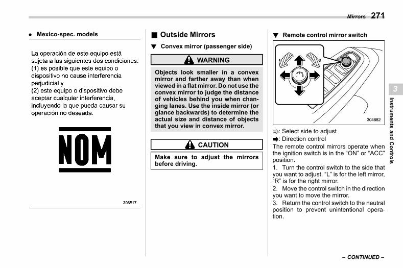
(273,1)
北米Model "A2600BE-B" EDITED: 2020/ 10/ 1
. Mexico-spec. models & Outside Mirrorss03ap03
! Convex mirror (passenger side)s03ap0301
WARNING
Objects look smaller in a convexmirror and farther away than whenviewed in a flatmirror. Do not use theconvex mirror to judge the distanceof vehicles behind you when chan-ging lanes. Use the inside mirror (orglance backwards) to determine theactual size and distance of objectsthat you view in convex mirror.
CAUTION
Make sure to adjust the mirrorsbefore driving.
! Remote control mirror switchs03ap0302
: Select side to adjust: Direction control
The remote control mirrors operate whenthe ignition switch is in the “ON” or “ACC”position.1. Turn the control switch to the side thatyou want to adjust. “L” is for the left mirror,“R” is for the right mirror.2. Move the control switch in the directionyou want to move the mirror.3. Return the control switch to the neutralposition to prevent unintentional opera-tion.
– CONTINUED –
Mirrors 271
3
Instruments
andControls
(274,1)
北米Model "A2600BE-B" EDITED: 2020/ 10/ 1
NOTE. The mirrors can also be adjustedmanually.
For models with memory function:. The outside mirror can be adjustedfor approximately 45 seconds after thefollowing conditions are met.
– The ignition switch is turned tothe “OFF” position.– The door is unlocked using theaccess key fob.
. The outside mirror angle can beregistered with button “1”, “2” or eachof the key fobs. For details, refer to“Power driver’s seat with synchronizedoutside mirrors memory function”FP33.. The outside mirror angle can also beretrieved with the Driver MonitoringSystem user information. To do so,perform user registration in the DriverMonitoring System settings. Refer to“Driver Monitoring System” FP227.
! Reverse tilt-down feature (ifequipped)
s03ap030201
When backing the vehicle up, the rightand/or left outside mirrors will turn down-ward automatically to provide better rearvisibility.1. Push the ignition switch to the ON
position.2. Move the select lever to the R (Re-verse) position.3. The outside mirror surface movesdownward.
The outside mirror surface will return to itsoriginal position when the following condi-tion are met.. Approximately 9 seconds after theselect lever is moved to any position otherthan R (Reverse).. The ignition switch is turned to the“OFF” position.. The vehicle is running.
NOTE. The reverse tilt-down mirror anglecan be registered with button “1”, “2”or each of the key fobs. For details,refer to “Power driver’s seat withsynchronized outside mirrors memoryfunction” FP33.. The reverse tilt-down mirror anglecan also be retrieved with the DriverMonitoring System user information.To do so, perform user registration inthe Driver Monitoring System settings.Refer to “Driver Monitoring System”FP227.. The operational/non-operationalsetting can be changed by operating
the center information display. For de-tails, refer to “Car settings” FP220.. The factory setting (default setting)for this function is set as the frontpassenger’s side mirror. The setting ofdriver’s side mirror operation can bechanged by a SUBARU dealer. Contactyour SUBARU dealer for details.
CAUTION
Depress the brake pedal during thereverse tilt-down mirror angle ad-justment.
To adjust the reverse tilt-down mirrorangle, adjust the outside mirror using theremote control mirror switch while thereverse tilt-down operates. For detailsabout how to adjust the outside mirrorangle, refer to “Remote control mirrorswitch” FP271.Memory function:The angle of the reverse tilt-down mirrorcan be registered. Register the positionwith button “1”, “2” or each of the accesskey fobs and retrieve the position.For details about registration or retrieval ofa position, refer to “Power driver’s seatwith synchronized outside mirrors memoryfunction” FP33.
Mirrors272
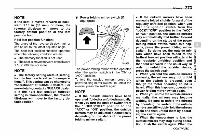
(275,1)
北米Model "A2600BE-B" EDITED: 2020/ 10/ 1
NOTEIf the seat is moved forward or back-ward 1.18 in (30 mm) or more, thereverse tilt-down will move to thefactory default position or the lastposition hold.Hold last position function:The angle of the reverse tilt-down mirrorcan be set to the latest adjusted angle.The hold last position function operateswhen the following condition are met.. The memory function is not used.. The seat is moved forward or backward1.18 in (30 mm) or more.
NOTE. The factory setting (default setting)for this function is set as “non-opera-tional”. This setting can be changed to“operational” at SUBARU dealers. Formore details, contact a SUBARU dealer.. If the hold last position functionsetting is “non-operation”, the reversetilt-down will move to the factory de-fault position.
! Power folding mirror switch (ifequipped)
s03ap0304
The power folding mirror switch operateswhen the ignition switch is in the “ON” or“ACC” position.To fold the outside mirrors, press thepower folding mirror switch. To unfold themirrors, press the switch again.
NOTE. If the outside mirrors have beenoperated (folded or unfolded)manually,when you turn the ignition switch fromthe “LOCK”/“OFF” position to the“ACC” or “ON” position, the outsidemirrors may be adjusted automaticallydepending on the status of the powerfolding mirror switch.
. If the outside mirrors have beenmanually folded slightly forward of theregularly unfolded position, when youturn the ignition switch from the“LOCK”/“OFF” position to the “ACC”or “ON” position, the outside mirrorsmay automatically fold further forwarddepending on the status of the powerfolding mirror switch. When this hap-pens, press the power folding mirrorswitch. By doing so, the outside mir-rors which have been folded to thefurthest forward position will extend tothe regularly unfolded position andthen fold rearward in the usual way. Inorder to unfold the outside mirrors,press the switch again.. When you fold the outside mirrorsmanually, the mirrors may not unfoldwhen the switch is pressed, eventhough the motor operating sound isheard. When this happens, operate thepower folding mirror switch again.. When you unfold the outsidemirrorsmanually, the mirrors may becomewobbly. Be sure to unfold the mirrorsby operating the switch. If the outsidemirrors are still wobbly, fold themirrorsagain and then unfold them by operat-ing the switch again.. When the temperature is low, theoutside mirrors may stop during opera-tion. Push the switch again. When the
– CONTINUED –
Mirrors 273
3
Instruments
andControls
(276,1)
北米Model "A2600BE-B" EDITED: 2020/ 10/ 1
outside mirrors do not work by operat-ing the switch, move the outside mir-rors several times manually. Thismakes it possible to operate them byswitch operation.. When you operate the power foldingmirror switch continuously, it may notwork. This is not amalfunction. Operateafter waiting for a short period of time.. The outside mirrors can be operated(folded or unfolded) manually for ap-proximately 45 seconds after the fol-lowing conditions are met.
– The ignition switch is turned tothe “OFF” position.– The door is unlocked using theaccess key fob.
! Power folding door mirror func-tion (if equipped)
s03ap030401
The mirrors are automatically folded whenthe power folding mirror switch is in themirror unfolding position, the ignitionswitch is turned OFF, and the doors arelocked.The mirrors are automatically unfoldedwhen the power folding mirror switch is inthe mirror unfolding position and the doorsare unlocked.
NOTE. The power folding door mirror func-tion does not operate when the powerfolding mirror switch is in the mirrorunfolding position.. The setting of the power folding doormirrors function can be changed byoperating the center information dis-play. For details, refer to “Car settings”FP220. Also, the setting can be chan-ged by your SUBARU dealer.We recommend that you contact yourSUBARU dealer for details.
3-18. Tilt/Telescopic SteeringWheel
s03bf
WARNING
. Do not adjust the steering wheeltilt/telescopic position while driv-ing. This may cause loss ofvehicle control and result in per-sonal injury.
. If the lever cannot be raised to thefixed position, adjust the steeringwheel again. It is dangerous todrive without locking the steeringwheel. This may cause loss ofvehicle control and result in per-sonal injury.
Tilt/Telescopic Steering Wheel274
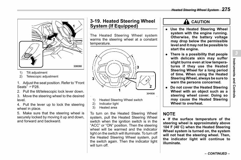
(277,1)
北米Model "A2600BE-B" EDITED: 2020/ 10/ 1
1) Tilt adjustment2) Telescopic adjustment
1. Adjust the seat position. Refer to “FrontSeats” FP28.2. Pull the tilt/telescopic lock lever down.3. Move the steering wheel to the desiredlevel.4. Pull the lever up to lock the steeringwheel in place.5. Make sure that the steering wheel issecurely locked by moving it up and down,and forward and backward.
3-19. Heated Steering WheelSystem (If Equipped)
s03bm
The Heated Steering Wheel systemwarms the steering wheel at a constanttemperature.
1) Heated Steering Wheel switch2) Indicator light3) Heated area
To turn on the Heated Steering Wheelsystem, pull the Heated Steering Wheelswitch when the ignition switch is in the“ACC” or “ON” position. Then the steeringwheel will be warmed and the indicatorlight on the switch will illuminate. To turn offthe Heated Steering Wheel system, pullthe switch again. Then the indicator lightwill turn off.
CAUTION
. Use the Heated Steering Wheelsystem with the engine running.Otherwise, the battery voltagemay drop below the permissiblelevel and itmay not be possible tostart the engine.
. There is a possibility that peoplewith delicate skin may sufferslight burns even at low tempera-tures if they use the HeatedSteering Wheel for a long periodof time. When using the HeatedSteeringWheel, always be sure towarn the persons concerned.
. Do not cover the Heated SteeringWheel with an object such as asteering wheel cover. Doing somay cause the Heated SteeringWheel to overheat.
NOTE. If the surface temperature of thesteering wheel is approximately above1048F (408C) when the Heated SteeringWheel system is turned on, the systemwill not heat the steering wheel. Then,the indicator light will continue toilluminate.
– CONTINUED –
Heated Steering Wheel System 275
3
Instruments
andControls
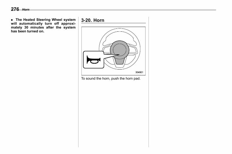
(278,1)
北米Model "A2600BE-B" EDITED: 2020/ 10/ 1
. The Heated Steering Wheel systemwill automatically turn off approxi-mately 30 minutes after the systemhas been turned on.
3-20. Horns03ar
To sound the horn, push the horn pad.
Horn276
(279,1)
北米Model "A2600BE-B" EDITED: 2020/ 10/ 1
s044-1. Ventilator Control............................................ 278
Center Ventilators ...............................................278Side Ventilators ..................................................278Rear Ventilators (If Equipped) .............................278
4-2. Climate Control Panel .................................... 279Dual 7.0-Inch Display Models ..............................27911.6-Inch Display Models ....................................282
4-3. Automatic Climate Control Operation........... 285Sensors..............................................................286
4-4. Manual Climate Control.................................. 287Airflow Mode Selection .......................................287Temperature Control ...........................................288Fan Speed Control..............................................288Air Conditioner Control.......................................289Air Inlet Selection ...............................................289To Turn Off the Climate Control System ..............289
4-5. Front Seat Heater and Ventilation(If Equipped).................................................. 290Front Seat Heater ...............................................290
Front Seat Ventilation......................................... 2904-6. Defrosting ........................................................2914-7. Operating Tips for Heater and Air
Conditioner ....................................................292Cleaning Ventilator Grille.................................... 292Efficient Cooling after Parking in DirectSunlight ........................................................... 292
Lubrication Oil Circulation in the RefrigerantCircuit.............................................................. 292
Checking Air Conditioning System beforeSummer Season............................................... 292
Cooling and Dehumidifying in High Humidityand Low Temperature Weather Condition ......... 292
Air Conditioner Compressor Shut-Off WhenEngine Is Heavily Loaded ................................. 292
Refrigerant for Your Climate Control System ...... 2934-8. Air Filtration System .......................................293
Replacing the Cabin Air Filter............................. 293
Climate Control
4
Clim
ateControl
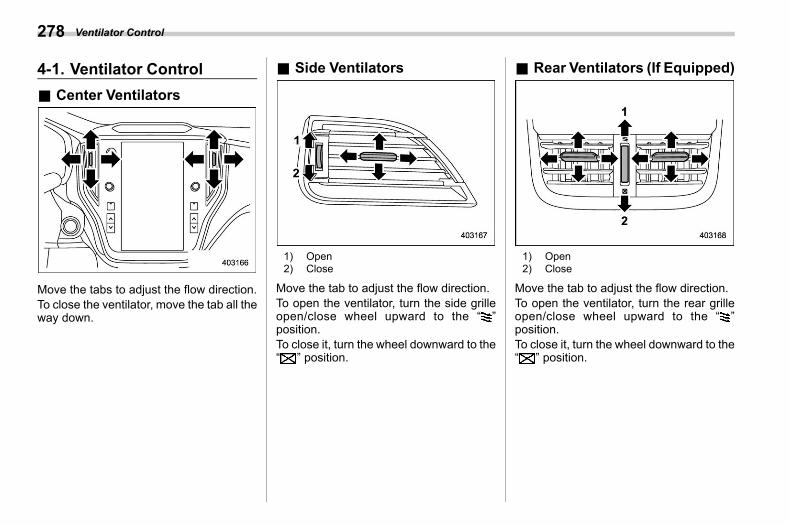
(280,1)
北米Model "A2600BE-B" EDITED: 2020/ 10/ 1
4-1. Ventilator Controls04af
& Center Ventilatorss04af01
Move the tabs to adjust the flow direction.To close the ventilator, move the tab all theway down.
& Side Ventilatorss04af02
1) Open2) Close
Move the tab to adjust the flow direction.To open the ventilator, turn the side grilleopen/close wheel upward to the “ ”position.To close it, turn the wheel downward to the“ ” position.
& Rear Ventilators (If Equipped)s04af04
1) Open2) Close
Move the tab to adjust the flow direction.To open the ventilator, turn the rear grilleopen/close wheel upward to the “ ”position.To close it, turn the wheel downward to the“ ” position.
Ventilator Control278
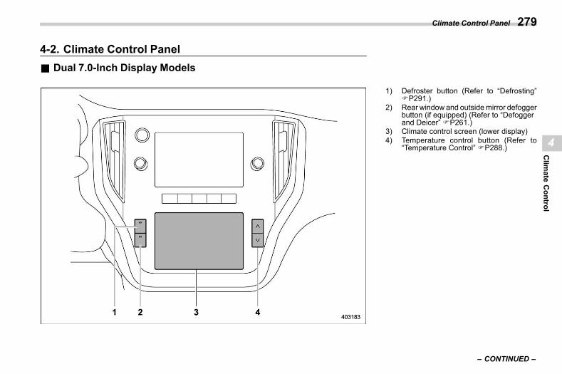
(281,1)
北米Model "A2600BE-B" EDITED: 2020/ 10/ 1
4-2. Climate Control Panels04ag
& Dual 7.0-Inch Display Modelss04ag11
1) Defroster button (Refer to “Defrosting”FP291.)
2) Rear window and outsidemirror defoggerbutton (if equipped) (Refer to “Defoggerand Deicer” FP261.)
3) Climate control screen (lower display)4) Temperature control button (Refer to
“Temperature Control” FP288.)
– CONTINUED –
Climate Control Panel 279
4
Clim
ateControl
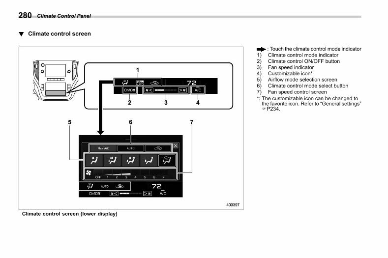
(282,1)
北米Model "A2600BE-B" EDITED: 2020/ 10/ 1
! Climate control screens04ag1101
Climate control screen (lower display)
: Touch the climate control mode indicator1) Climate control mode indicator2) Climate control ON/OFF button3) Fan speed indicator4) Customizable icon*5) Airflow mode selection screen6) Climate control mode select button7) Fan speed control screen*: The customizable icon can be changed tothe favorite icon. Refer to “General settings”FP234.
Climate Control Panel280
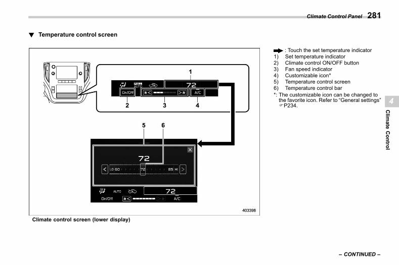
(283,1)
北米Model "A2600BE-B" EDITED: 2020/ 10/ 1
! Temperature control screens04ag1102
Climate control screen (lower display)
: Touch the set temperature indicator1) Set temperature indicator2) Climate control ON/OFF button3) Fan speed indicator4) Customizable icon*5) Temperature control screen6) Temperature control bar*: The customizable icon can be changed tothe favorite icon. Refer to “General settings”FP234.
– CONTINUED –
Climate Control Panel 281
4
Clim
ateControl
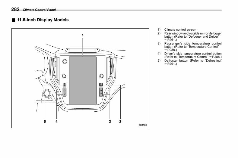
(284,1)
北米Model "A2600BE-B" EDITED: 2020/ 10/ 1
& 11.6-Inch Display Modelss04ag12
1) Climate control screen2) Rear window and outsidemirror defogger
button (Refer to “Defogger and Deicer”FP261.)
3) Passenger’s side temperature controlbutton (Refer to “Temperature Control”FP288.)
4) Driver’s side temperature control button(Refer to “Temperature Control”FP288.)
5) Defroster button (Refer to “Defrosting”FP291.)
Climate Control Panel282

(285,1)
北米Model "A2600BE-B" EDITED: 2020/ 10/ 1
! Climate control screens04ag1201
: Touch the climate control mode indicator1) Climate control ON/OFF button2) Climate control mode indicator3) Customizable icon*14) Fan speed indicator5) Airflow mode selection screen6) Climate control mode select button7) Fan speed control screen*1: The customizable icon can be changed to
the favorite icon. Refer to “General set-tings” FP216.
– CONTINUED –
Climate Control Panel 283
4
Clim
ateControl
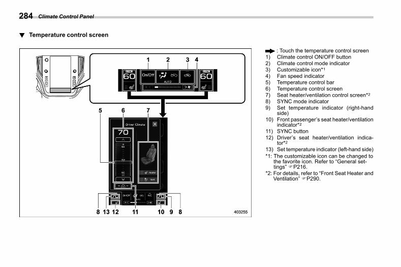
(286,1)
北米Model "A2600BE-B" EDITED: 2020/ 10/ 1
! Temperature control screens04ag1202
: Touch the temperature control screen1) Climate control ON/OFF button2) Climate control mode indicator3) Customizable icon*14) Fan speed indicator5) Temperature control bar6) Temperature control screen7) Seat heater/ventilation control screen*28) SYNC mode indicator9) Set temperature indicator (right-hand
side)10) Front passenger’s seat heater/ventilation
indicator*211) SYNC button12) Driver’s seat heater/ventilation indica-
tor*213) Set temperature indicator (left-hand side)*1: The customizable icon can be changed to
the favorite icon. Refer to “General set-tings” FP216.
*2: For details, refer to “Front Seat Heater andVentilation” FP290.
Climate Control Panel284
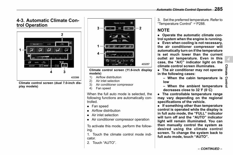
(287,1)
北米Model "A2600BE-B" EDITED: 2020/ 10/ 1
4-3. Automatic Climate Con-trol Operation
s04ai
Climate control screen (dual 7.0-inch dis-play models)
Climate control screen (11.6-inch displaymodels)1) Airflow distribution2) Air inlet selection3) Air conditioner compressor4) Fan speed
When the full auto mode is selected, thefollowing functions are automatically con-trolled.. Fan speed. Airflow distribution. Air inlet selection. Air conditioner compressor operation
To activate this mode, perform the follow-ing.1. Touch the climate control mode indi-cator.2. Touch “AUTO”.
3. Set the preferred temperature. Refer to“Temperature Control” FP288.
NOTE. Operate the automatic climate con-trol systemwhen the engine is running.. Even when cooling is not necessary,the air conditioner compressor willautomatically turn on if the temperatureis set much lower than the currentoutlet air temperature. Even in thiscase, the “A/C” indicator light on theclimate control screen illuminates.. The air conditioner may not operatein the following cases:
– When the cabin temperature islow– When the ambient temperaturedecreases close to 328F (08C)
. The controllable temperature rangemay vary depending on the regionalspecifications of the vehicle.. If something other than temperaturecontrol is operated while the display isin full auto mode, the “FULL” indicatorwill turn off and the “AUTO” indicatorlight will remain illuminated. You canthen manually control the system asdesired using the climate controlscreen. To change the system back tofull auto mode, touch “AUTO”.
– CONTINUED –
Automatic Climate Control Operation 285
4
Clim
ateControl
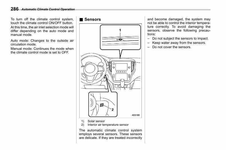
(288,1)
北米Model "A2600BE-B" EDITED: 2020/ 10/ 1
To turn off the climate control system,touch the climate control ON/OFF button.At this time, the air inlet selection mode willdiffer depending on the auto mode andmanual mode.
Auto mode: Changes to the outside aircirculation mode.Manual mode: Continues the mode whenthe climate control mode is set to OFF.
& Sensorss04ai03
1) Solar sensor2) Interior air temperature sensor
The automatic climate control systememploys several sensors. These sensorsare delicate. If they are treated incorrectly
and become damaged, the system maynot be able to control the interior tempera-ture correctly. To avoid damaging thesensors, observe the following precau-tions:– Do not subject the sensors to impact.– Keep water away from the sensors.– Do not cover the sensors.
Automatic Climate Control Operation286
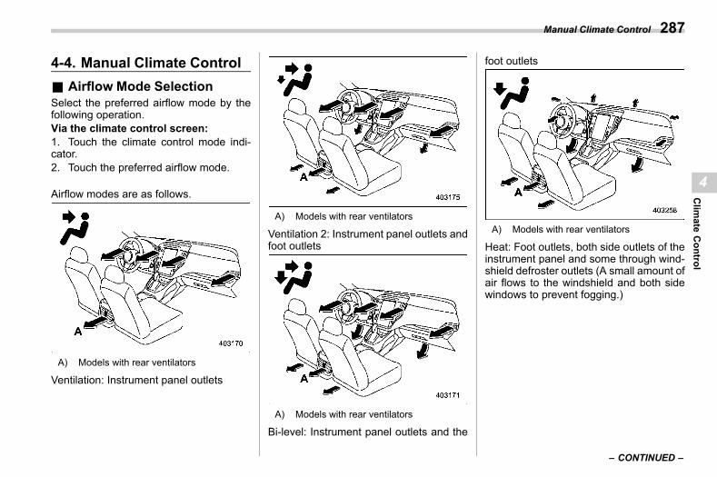
(289,1)
北米Model "A2600BE-B" EDITED: 2020/ 10/ 1
4-4. Manual Climate Controls04ab
& Airflow Mode Selections04ab04
Select the preferred airflow mode by thefollowing operation.Via the climate control screen:1. Touch the climate control mode indi-cator.2. Touch the preferred airflow mode.
Airflow modes are as follows.
A) Models with rear ventilators
Ventilation: Instrument panel outlets
A) Models with rear ventilators
Ventilation 2: Instrument panel outlets andfoot outlets
A) Models with rear ventilators
Bi-level: Instrument panel outlets and the
foot outlets
A) Models with rear ventilators
Heat: Foot outlets, both side outlets of theinstrument panel and some through wind-shield defroster outlets (A small amount ofair flows to the windshield and both sidewindows to prevent fogging.)
– CONTINUED –
Manual Climate Control 287
4
Clim
ateControl

(290,1)
北米Model "A2600BE-B" EDITED: 2020/ 10/ 1
A) Models with rear ventilators
Heat-def: Windshield defroster outlets,foot outlets and both side outlets of theinstrument panel
& Temperature Controls04ab05
Perform the following operation to regulatethe temperature of airflow from the airoutlets.Temperature control buttons:Press the temperature control button to theblue side (cool) or the red side (warm).Temperature control screen:1. Touch the set temperature indicator.2. Touch and move the temperature con-trol bar.
! Max A/C modes04ab0503
For quicker cooling, touch “MAX A/C” onthe climate control mode select button orcustomizable icon.When the Max A/C mode is on, thefollowing settings will be changed auto-matically.. The air conditioner will turn on.. The temperature will be set on thelowest.. The fan speed will be set on themaximum speed.. The air inlet will be set to the recircula-tion mode.. The airflow mode setting will be set tothe ventilation mode.
To turn off the Max A/C mode and return tothe previous setting, touch “MAX A/C”
again.! SYNC mode (11.6-inch display
models)s04ab0505
When the SYNC mode is turned on, boththe driver’s and passenger’s side tem-peratures are synchronized using thedriver’s side temperature control buttonand temperature control display.1. Touch the set temperature indicator.2. Touch “SYNC” to turn the SYNC modeon or off.
The SYNC mode indicator will turn white.Touch “SYNC” again, press the passen-ger’s side temperature control button oroperate the passenger’s side temperaturecontrol bar to cancel the SYNC mode. TheSYNCmode indicator will be grayed out. Inthis case, temperature control on thedriver’s side and passenger’s side will beseparated. The temperature will be con-trolled individually using the driver’s andpassenger’s temperature control buttonand the driver’s and passenger’s tempera-ture control bar.
& Fan Speed Controls04ab06
Select the preferred fan speed by thefollowing operation.Via the fan speed indicator:Touch or on the climate controlscreen.
Manual Climate Control288
(291,1)
北米Model "A2600BE-B" EDITED: 2020/ 10/ 1
Via the fan speed control screen:1. Touch the climate control mode indi-cator2. Touch the preferred fan speed. It isalso possible to change the fan speed bydragging.
& Air Conditioner Controls04ab07
The air conditioner operates only when theengine is running.Perform the following operation while thefan is in operation to turn on the airconditioner.. If “A/C” is displayed on the customiz-able icon, touch “A/C”. When the airconditioner is on, the “A/C” indicatorilluminates.. If a customizable icon other than “A/C”is displayed, touch the climate controlmode indicator. Then touch “A/C” on theclimate control mode select button. Whenthe air conditioner is on, “A/C” will turnblue.
To turn off the air conditioner, touch “A/C”again. The indicator light will turn off or itwill be grayed out.
NOTEFor efficient defogging or dehumidify-ing in cold weather, turn on the airconditioner. However, if the ambient
temperature decreases to approxi-mately 328F (08C), the air conditionerand dehumidification system may notwork properly.
& Air Inlet Selections04ab08
Select the air inlet by pressing the air inletselection button.
Recirculation mode: Interior air is recir-culated inside the vehicle. This mode isused for the following cases.. When driving on a dusty road. When you want cooling performance toincrease (for example, in particularly hotweather)
Perform the following operation to selectthis mode.. is displayed on the customizableicon:
(1) Touch .. is not displayed on the customiz-able icon:
(1) Touch the climate control modeindicator.(2) Touch on the climate controlmode select button.
will be displayed on the climate controlmode indicator.
Outside air circulation mode: Outsideair is drawn into the passenger compart-ment. This mode is used for the followingcases.. When the road is no longer dusty. When the interior has cooled to acomfortable temperature
Perform the same operation as the recir-culation mode to change the mode.will be displayed on the climate controlmode indicator.
WARNING
Continued operation in the recircu-lation mode may fog up the win-dows. Switch to the outside aircirculation mode as soon as theoutside dusty condition clears.
& To Turn Off the Climate Con-trol System
s04ab10To turn off the climate control system,touch the climate control ON/OFF button.
Manual Climate Control 289
4
Clim
ateControl
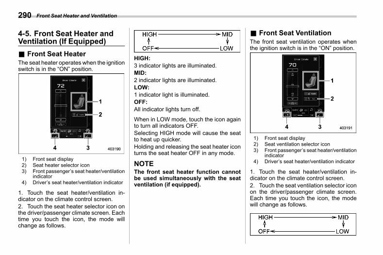
(292,1)
北米Model "A2600BE-B" EDITED: 2020/ 10/ 1
4-5. Front Seat Heater andVentilation (If Equipped)
s04al
& Front Seat Heaters04al01
The seat heater operates when the ignitionswitch is in the “ON” position.
1) Front seat display2) Seat heater selector icon3) Front passenger’s seat heater/ventilation
indicator4) Driver’s seat heater/ventilation indicator
1. Touch the seat heater/ventilation in-dicator on the climate control screen.2. Touch the seat heater selector icon onthe driver/passenger climate screen. Eachtime you touch the icon, the mode willchange as follows.
HIGH:3 indicator lights are illuminated.MID:2 indicator lights are illuminated.LOW:1 indicator light is illuminated.OFF:All indicator lights turn off.
When in LOW mode, touch the icon againto turn all indicators OFF.Selecting HIGH mode will cause the seatto heat up quicker.Holding and releasing the seat heater iconturns the seat heater OFF in any mode.
NOTEThe front seat heater function cannotbe used simultaneously with the seatventilation (if equipped).
& Front Seat Ventilations04al02
The front seat ventilation operates whenthe ignition switch is in the “ON” position.
1) Front seat display2) Seat ventilation selector icon3) Front passenger’s seat heater/ventilation
indicator4) Driver’s seat heater/ventilation indicator
1. Touch the seat heater/ventilation in-dicator on the climate control screen.2. Touch the seat ventilation selector iconon the driver/passenger climate screen.Each time you touch the icon, the modewill change as follows.
Front Seat Heater and Ventilation290
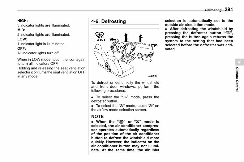
(293,1)
北米Model "A2600BE-B" EDITED: 2020/ 10/ 1
HIGH:3 indicator lights are illuminated.MID:2 indicator lights are illuminated.LOW:1 indicator light is illuminated.OFF:All indicator lights turn off.
When in LOW mode, touch the icon againto turn all indicators OFF.Holding and releasing the seat ventilationselector icon turns the seat ventilationOFFin any mode.
4-6. Defrostings04ah
To defrost or dehumidify the windshieldand front door windows, perform thefollowing procedures.
. To select the “ ” mode, press thedefroster button.. To select the “ ” mode, touch “ ” onthe airflow mode selection screen.
NOTE. When the “ ” or “ ” mode isselected, the air conditioner compres-sor operates automatically regardlessof the position of the air conditionerbutton to defrost the windshield morequickly. However, the indicator on theair conditioner button may not illumi-nate. At the same time, the air inlet
selection is automatically set to theoutside air circulation mode.. After defrosting the windshield bypressing the defroster button “ ”,pressing the button again returns thesystem to the setting that had beenselected before the defroster was acti-vated.
Defrosting 291
4
Clim
ateControl
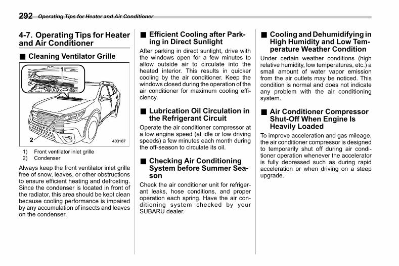
(294,1)
北米Model "A2600BE-B" EDITED: 2020/ 10/ 1
4-7. Operating Tips for Heaterand Air Conditioner
s04ad
& Cleaning Ventilator Grilles04ad01
1) Front ventilator inlet grille2) Condenser
Always keep the front ventilator inlet grillefree of snow, leaves, or other obstructionsto ensure efficient heating and defrosting.Since the condenser is located in front ofthe radiator, this area should be kept cleanbecause cooling performance is impairedby any accumulation of insects and leaveson the condenser.
& Efficient Cooling after Park-ing in Direct Sunlight
s04ad02After parking in direct sunlight, drive withthe windows open for a few minutes toallow outside air to circulate into theheated interior. This results in quickercooling by the air conditioner. Keep thewindows closed during the operation of theair conditioner for maximum cooling effi-ciency.
& Lubrication Oil Circulation inthe Refrigerant Circuit
s04ad03Operate the air conditioner compressor ata low engine speed (at idle or low drivingspeeds) a few minutes each month duringthe off-season to circulate its oil.
& Checking Air ConditioningSystem before Summer Sea-son
s04ad04Check the air conditioner unit for refriger-ant leaks, hose conditions, and properoperation each spring. Have the air con-ditioning system checked by yourSUBARU dealer.
& CoolingandDehumidifying inHigh Humidity and Low Tem-perature Weather Condition
s04ad05Under certain weather conditions (highrelative humidity, low temperatures, etc.) asmall amount of water vapor emissionfrom the air outlets may be noticed. Thiscondition is normal and does not indicateany problem with the air conditioningsystem.
& Air Conditioner CompressorShut-Off When Engine IsHeavily Loaded
s04ad06To improve acceleration and gas mileage,the air conditioner compressor is designedto temporarily shut off during air condi-tioner operation whenever the acceleratoris fully depressed such as during rapidacceleration or when driving on a steepupgrade.
Operating Tips for Heater and Air Conditioner292
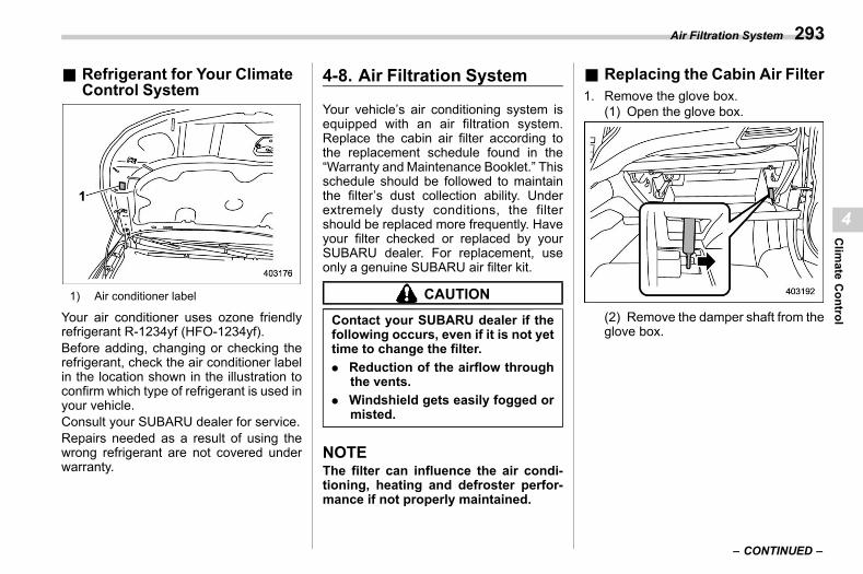
(295,1)
北米Model "A2600BE-B" EDITED: 2020/ 10/ 1
& Refrigerant for Your ClimateControl System
s04ad07
1) Air conditioner label
Your air conditioner uses ozone friendlyrefrigerant R-1234yf (HFO-1234yf).Before adding, changing or checking therefrigerant, check the air conditioner labelin the location shown in the illustration toconfirm which type of refrigerant is used inyour vehicle.Consult your SUBARU dealer for service.Repairs needed as a result of using thewrong refrigerant are not covered underwarranty.
4-8. Air Filtration Systems04ae
Your vehicle’s air conditioning system isequipped with an air filtration system.Replace the cabin air filter according tothe replacement schedule found in the“Warranty and Maintenance Booklet.” Thisschedule should be followed to maintainthe filter’s dust collection ability. Underextremely dusty conditions, the filtershould be replaced more frequently. Haveyour filter checked or replaced by yourSUBARU dealer. For replacement, useonly a genuine SUBARU air filter kit.
CAUTION
Contact your SUBARU dealer if thefollowing occurs, even if it is not yettime to change the filter.. Reduction of the airflow through
the vents.. Windshield gets easily fogged or
misted.
NOTEThe filter can influence the air condi-tioning, heating and defroster perfor-mance if not properly maintained.
& Replacing the Cabin Air Filters04ae01
1. Remove the glove box.(1) Open the glove box.
(2) Remove the damper shaft from theglove box.
– CONTINUED –
Air Filtration System 293
4
Clim
ateControl
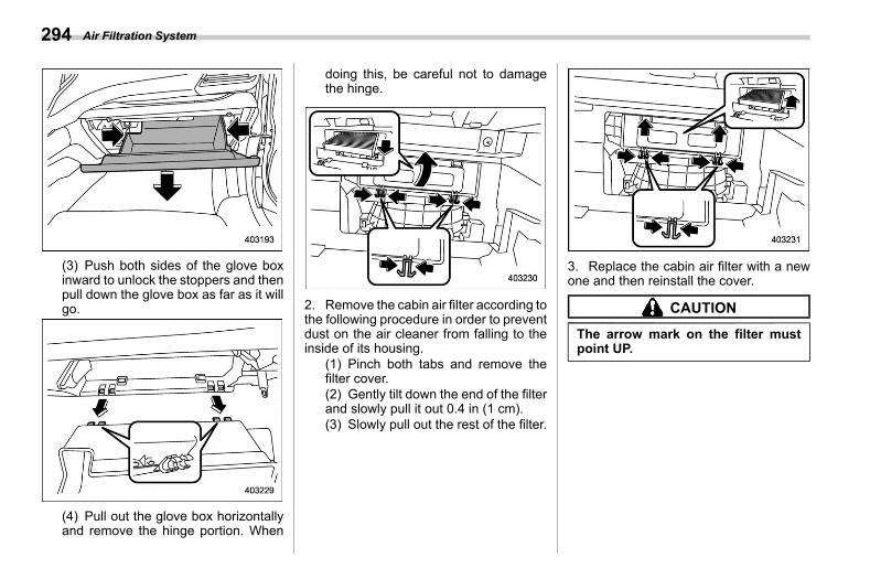
(296,1)
北米Model "A2600BE-B" EDITED: 2020/ 10/ 1
(3) Push both sides of the glove boxinward to unlock the stoppers and thenpull down the glove box as far as it willgo.
(4) Pull out the glove box horizontallyand remove the hinge portion. When
doing this, be careful not to damagethe hinge.
2. Remove the cabin air filter according tothe following procedure in order to preventdust on the air cleaner from falling to theinside of its housing.
(1) Pinch both tabs and remove thefilter cover.(2) Gently tilt down the end of the filterand slowly pull it out 0.4 in (1 cm).(3) Slowly pull out the rest of the filter.
3. Replace the cabin air filter with a newone and then reinstall the cover.
CAUTION
The arrow mark on the filter mustpoint UP.
Air Filtration System294
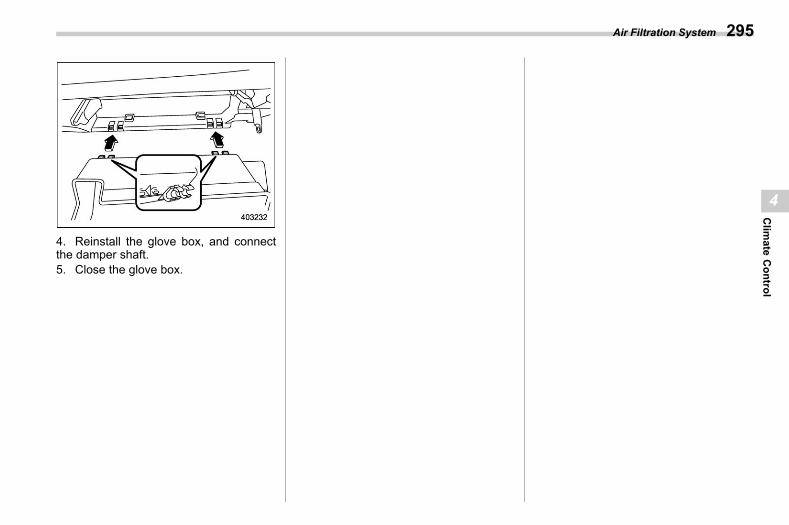
(297,1)
北米Model "A2600BE-B" EDITED: 2020/ 10/ 1
4. Reinstall the glove box, and connectthe damper shaft.5. Close the glove box.
Air Filtration System 295
4
Clim
ateControl

(298,1)
北米Model "A2600BE-B" EDITED: 2020/ 10/ 1
— — — — — — — — — — — — — — — — — — — — — — — — — — — — — — — — — — — — — — — —
— — — — — — — — — — — — — — — — — — — — — — — — — — — — — — — — — — — — — — — —
— — — — — — — — — — — — — — — — — — — — — — — — — — — — — — — — — — — — — — — —
— — — — — — — — — — — — — — — — — — — — — — — — — — — — — — — — — — — — — — — —
— — — — — — — — — — — — — — — — — — — — — — — — — — — — — — — — — — — — — — — —
— — — — — — — — — — — — — — — — — — — — — — — — — — — — — — — — — — — — — — — —
— — — — — — — — — — — — — — — — — — — — — — — — — — — — — — — — — — — — — — — —
— — — — — — — — — — — — — — — — — — — — — — — — — — — — — — — — — — — — — — — —
— — — — — — — — — — — — — — — — — — — — — — — — — — — — — — — — — — — — — — — —
— — — — — — — — — — — — — — — — — — — — — — — — — — — — — — — — — — — — — — — —
— — — — — — — — — — — — — — — — — — — — — — — — — — — — — — — — — — — — — — — —
— — — — — — — — — — — — — — — — — — — — — — — — — — — — — — — — — — — — — — — —
— — — — — — — — — — — — — — — — — — — — — — — — — — — — — — — — — — — — — — — —
(299,1)
北米Model "A2600BE-B" EDITED: 2020/ 10/ 1
s055-1. Antenna ........................................................... 298
Printed Antenna..................................................298Roof Antenna..................................................... 298
5-2. Audio Set .........................................................298
Audio
5
Audio
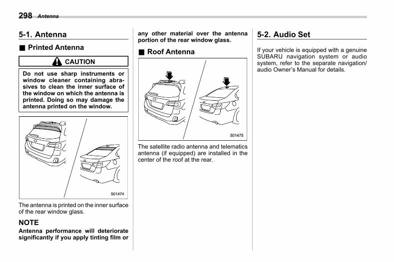
(300,1)
北米Model "A2600BE-B" EDITED: 2020/ 10/ 1
5-1. Antennas05aa
& Printed Antennas05aa01
CAUTION
Do not use sharp instruments orwindow cleaner containing abra-sives to clean the inner surface ofthe window on which the antenna isprinted. Doing so may damage theantenna printed on the window.
The antenna is printed on the inner surfaceof the rear window glass.
NOTEAntenna performance will deterioratesignificantly if you apply tinting film or
any other material over the antennaportion of the rear window glass.
& Roof Antennas05aa03
The satellite radio antenna and telematicsantenna (if equipped) are installed in thecenter of the roof at the rear.
5-2. Audio Sets05ac
If your vehicle is equipped with a genuineSUBARU navigation system or audiosystem, refer to the separate navigation/audio Owner’s Manual for details.
Antenna298

(301,1)
北米Model "A2600BE-B" EDITED: 2020/ 10/ 1
— — — — — — — — — — — — — — — — — — — — — — — — — — — — — — — — — — — — — — — —
— — — — — — — — — — — — — — — — — — — — — — — — — — — — — — — — — — — — — — — —
— — — — — — — — — — — — — — — — — — — — — — — — — — — — — — — — — — — — — — — —
— — — — — — — — — — — — — — — — — — — — — — — — — — — — — — — — — — — — — — — —
— — — — — — — — — — — — — — — — — — — — — — — — — — — — — — — — — — — — — — — —
— — — — — — — — — — — — — — — — — — — — — — — — — — — — — — — — — — — — — — — —
— — — — — — — — — — — — — — — — — — — — — — — — — — — — — — — — — — — — — — — —
— — — — — — — — — — — — — — — — — — — — — — — — — — — — — — — — — — — — — — — —
— — — — — — — — — — — — — — — — — — — — — — — — — — — — — — — — — — — — — — — —
— — — — — — — — — — — — — — — — — — — — — — — — — — — — — — — — — — — — — — — —
— — — — — — — — — — — — — — — — — — — — — — — — — — — — — — — — — — — — — — — —
— — — — — — — — — — — — — — — — — — — — — — — — — — — — — — — — — — — — — — — —
— — — — — — — — — — — — — — — — — — — — — — — — — — — — — — — — — — — — — — — —

(302,1)
北米Model "A2600BE-B" EDITED: 2020/ 10/ 1
— — — — — — — — — — — — — — — — — — — — — — — — — — — — — — — — — — — — — — — —
— — — — — — — — — — — — — — — — — — — — — — — — — — — — — — — — — — — — — — — —
— — — — — — — — — — — — — — — — — — — — — — — — — — — — — — — — — — — — — — — —
— — — — — — — — — — — — — — — — — — — — — — — — — — — — — — — — — — — — — — — —
— — — — — — — — — — — — — — — — — — — — — — — — — — — — — — — — — — — — — — — —
— — — — — — — — — — — — — — — — — — — — — — — — — — — — — — — — — — — — — — — —
— — — — — — — — — — — — — — — — — — — — — — — — — — — — — — — — — — — — — — — —
— — — — — — — — — — — — — — — — — — — — — — — — — — — — — — — — — — — — — — — —
— — — — — — — — — — — — — — — — — — — — — — — — — — — — — — — — — — — — — — — —
— — — — — — — — — — — — — — — — — — — — — — — — — — — — — — — — — — — — — — — —
— — — — — — — — — — — — — — — — — — — — — — — — — — — — — — — — — — — — — — — —
— — — — — — — — — — — — — — — — — — — — — — — — — — — — — — — — — — — — — — — —
— — — — — — — — — — — — — — — — — — — — — — — — — — — — — — — — — — — — — — — —
(303,1)
北米Model "A2600BE-B" EDITED: 2020/ 10/ 1
s066-1. Interior Light ................................................... 302
Dome Light.........................................................302Map Lights .........................................................302Cargo Area Light (Outback) ................................303OFF Delay Timer.................................................303
6-2. Sun Visors....................................................... 303Vanity Mirror with Light.......................................304
6-3. Storage Compartment .................................... 304Glove Box ..........................................................305Center Console...................................................305Overhead Console ..............................................305
6-4. Cup Holder ...................................................... 306Front Passenger’s Cup Holder ............................306Rear Passenger’s Cup Holder .............................307
6-5. Bottle Holders ................................................. 3076-6. Accessory Power Outlets .............................. 3086-7. USB Power Supply ......................................... 310
How to Use the USB Power Supply .....................310
6-8. Ashtray (Dealer Option) ..................................3116-9. Assist Grip .......................................................3126-10. Coat Hook ......................................................3126-11. Shopping Bag Hook ......................................313
Legacy............................................................... 313Outback ............................................................. 313
6-12. Floor Mat ........................................................3146-13. Lifting Cargo Cover (Outback –
If Equipped) ...................................................314To Install the Cover Housing .............................. 315Using the Cover ................................................. 315To Remove the Cover Housing ........................... 317To Stow the Cover.............................................. 318To Take Out the Stowed Cover ........................... 319
6-14. Convenient Tie-Down Hooks (Outback) ......3196-15. Adjustable Storage Net (Outback) ...............3206-16. Under-Floor Storage Compartment..............320
Interior Equipment
6
InteriorEquipm
ent
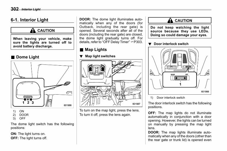
(304,1)
北米Model "A2600BE-B" EDITED: 2020/ 10/ 1
6-1. Interior Lights06aa
CAUTION
When leaving your vehicle, makesure the lights are turned off toavoid battery discharge.
& Dome Lights06aa01
1) ON2) DOOR3) OFF
The dome light switch has the followingpositions:
ON: The light turns on.OFF: The light turns off.
DOOR: The dome light illuminates auto-matically when any of the doors (forOutback, including the rear gate) isopened. Several seconds after all of thedoors (including the rear gate) are closed,the dome light gradually turns off. Fordetails, refer to “OFFDelay Timer”FP303.
& Map Lightss06aa06
! Map light switchess06aa0606
To turn on the map light, press the lens.To turn it off, press the lens again.
CAUTION
Do not keep watching the lightsource because they use LEDs.Doing so could damage your eyes.
! Door interlock switchs06aa0602
1) Door interlock switch
The door interlock switch has the followingpositions.
OFF: The map lights do not illuminateautomatically in conjunction with a dooropening. However, the lights can be turnedon manually by pressing the map lightlens.DOOR: The map lights illuminate auto-matically when any of the doors (other thanthe rear gate or trunk lid) is opened even
Interior Light302
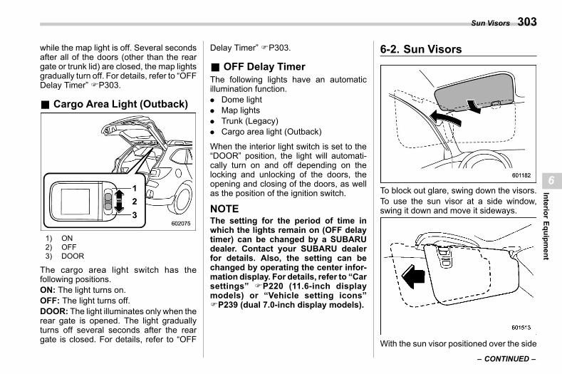
(305,1)
北米Model "A2600BE-B" EDITED: 2020/ 10/ 1
while the map light is off. Several secondsafter all of the doors (other than the reargate or trunk lid) are closed, the map lightsgradually turn off. For details, refer to “OFFDelay Timer” FP303.
& Cargo Area Light (Outback)s06aa02
1) ON2) OFF3) DOOR
The cargo area light switch has thefollowing positions.ON: The light turns on.OFF: The light turns off.DOOR: The light illuminates only when therear gate is opened. The light graduallyturns off several seconds after the reargate is closed. For details, refer to “OFF
Delay Timer” FP303.
& OFF Delay Timers06aa07
The following lights have an automaticillumination function.. Dome light. Map lights. Trunk (Legacy). Cargo area light (Outback)
When the interior light switch is set to the“DOOR” position, the light will automati-cally turn on and off depending on thelocking and unlocking of the doors, theopening and closing of the doors, as wellas the position of the ignition switch.
NOTEThe setting for the period of time inwhich the lights remain on (OFF delaytimer) can be changed by a SUBARUdealer. Contact your SUBARU dealerfor details. Also, the setting can bechanged by operating the center infor-mation display. For details, refer to “Carsettings” FP220 (11.6-inch displaymodels) or “Vehicle setting icons”FP239 (dual 7.0-inch display models).
6-2. Sun Visorss06ac
To block out glare, swing down the visors.To use the sun visor at a side window,swing it down and move it sideways.
With the sun visor positioned over the side
– CONTINUED –
Sun Visors 303
6
InteriorEquipm
ent
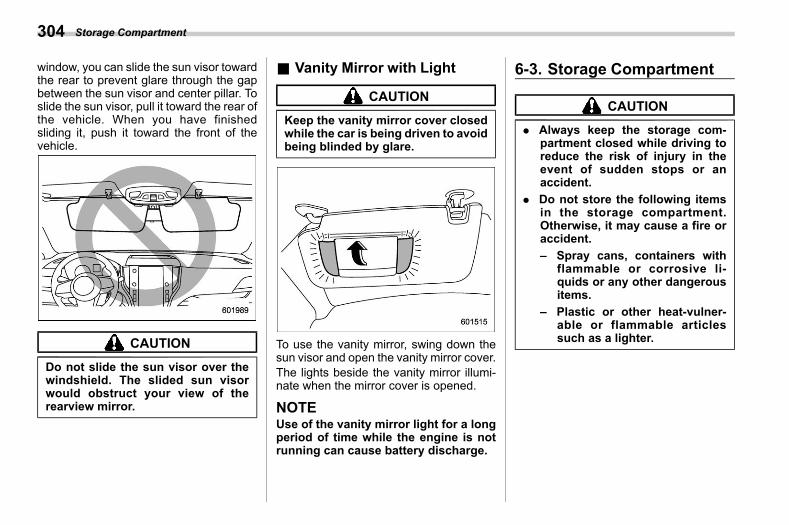
(306,1)
北米Model "A2600BE-B" EDITED: 2020/ 10/ 1
window, you can slide the sun visor towardthe rear to prevent glare through the gapbetween the sun visor and center pillar. Toslide the sun visor, pull it toward the rear ofthe vehicle. When you have finishedsliding it, push it toward the front of thevehicle.
CAUTION
Do not slide the sun visor over thewindshield. The slided sun visorwould obstruct your view of therearview mirror.
& Vanity Mirror with Lights06ac02
CAUTION
Keep the vanity mirror cover closedwhile the car is being driven to avoidbeing blinded by glare.
To use the vanity mirror, swing down thesun visor and open the vanity mirror cover.The lights beside the vanity mirror illumi-nate when the mirror cover is opened.
NOTEUse of the vanity mirror light for a longperiod of time while the engine is notrunning can cause battery discharge.
6-3. Storage Compartments06ad
CAUTION
. Always keep the storage com-partment closed while driving toreduce the risk of injury in theevent of sudden stops or anaccident.
. Do not store the following itemsin the storage compartment.Otherwise, it may cause a fire oraccident.– Spray cans, containers with
flammable or corrosive li-quids or any other dangerousitems.
– Plastic or other heat-vulner-able or flammable articlessuch as a lighter.
Storage Compartment304
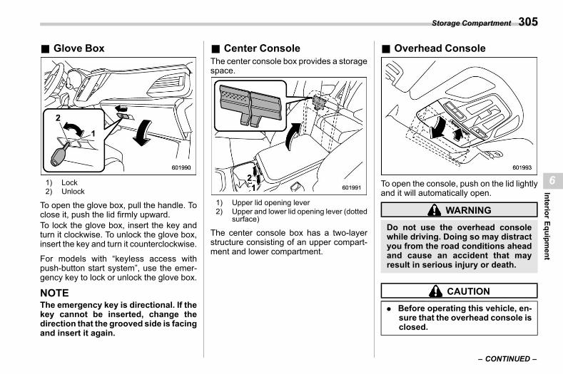
(307,1)
北米Model "A2600BE-B" EDITED: 2020/ 10/ 1
& Glove Boxs06ad01
1) Lock2) Unlock
To open the glove box, pull the handle. Toclose it, push the lid firmly upward.To lock the glove box, insert the key andturn it clockwise. To unlock the glove box,insert the key and turn it counterclockwise.
For models with “keyless access withpush-button start system”, use the emer-gency key to lock or unlock the glove box.
NOTEThe emergency key is directional. If thekey cannot be inserted, change thedirection that the grooved side is facingand insert it again.
& Center Consoles06ad02
The center console box provides a storagespace.
1) Upper lid opening lever2) Upper and lower lid opening lever (dotted
surface)
The center console box has a two-layerstructure consisting of an upper compart-ment and lower compartment.
& Overhead Consoles06ad04
To open the console, push on the lid lightlyand it will automatically open.
WARNING
Do not use the overhead consolewhile driving. Doing so may distractyou from the road conditions aheadand cause an accident that mayresult in serious injury or death.
CAUTION
. Before operating this vehicle, en-sure that the overhead console isclosed.
– CONTINUED –
Storage Compartment 305
6
InteriorEquipm
ent
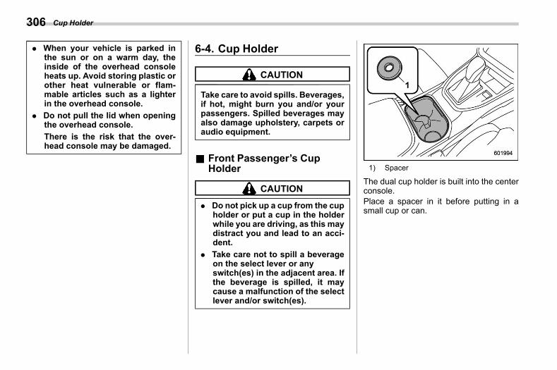
(308,1)
北米Model "A2600BE-B" EDITED: 2020/ 10/ 1
. When your vehicle is parked inthe sun or on a warm day, theinside of the overhead consoleheats up. Avoid storing plastic orother heat vulnerable or flam-mable articles such as a lighterin the overhead console.
. Do not pull the lid when openingthe overhead console.There is the risk that the over-head console may be damaged.
6-4. Cup Holders06ae
CAUTION
Take care to avoid spills. Beverages,if hot, might burn you and/or yourpassengers. Spilled beverages mayalso damage upholstery, carpets oraudio equipment.
& Front Passenger’s CupHolder
s06ae01
CAUTION
. Do not pick up a cup from the cupholder or put a cup in the holderwhile you are driving, as this maydistract you and lead to an acci-dent.
. Take care not to spill a beverageon the select lever or anyswitch(es) in the adjacent area. Ifthe beverage is spilled, it maycause a malfunction of the selectlever and/or switch(es).
1) Spacer
The dual cup holder is built into the centerconsole.Place a spacer in it before putting in asmall cup or can.
Cup Holder306
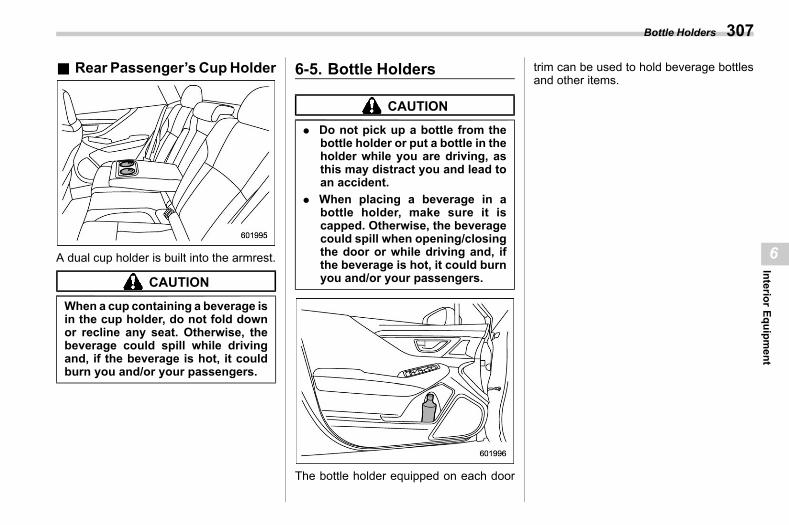
(309,1)
北米Model "A2600BE-B" EDITED: 2020/ 10/ 1
& Rear Passenger’s CupHolders06ae02
A dual cup holder is built into the armrest.
CAUTION
When a cup containing a beverage isin the cup holder, do not fold downor recline any seat. Otherwise, thebeverage could spill while drivingand, if the beverage is hot, it couldburn you and/or your passengers.
6-5. Bottle Holderss06av
CAUTION
. Do not pick up a bottle from thebottle holder or put a bottle in theholder while you are driving, asthis may distract you and lead toan accident.
. When placing a beverage in abottle holder, make sure it iscapped. Otherwise, the beveragecould spill when opening/closingthe door or while driving and, ifthe beverage is hot, it could burnyou and/or your passengers.
The bottle holder equipped on each door
trim can be used to hold beverage bottlesand other items.
Bottle Holders 307
6
InteriorEquipm
ent
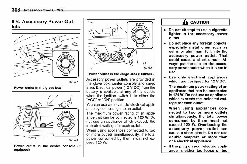
(310,1)
北米Model "A2600BE-B" EDITED: 2020/ 10/ 1
6-6. Accessory Power Out-lets
s06af
Power outlet in the glove box
Power outlet in the center console (ifequipped)
Power outlet in the cargo area (Outback)Accessory power outlets are provided inthe glove box, center console and cargoarea. Electrical power (12 V DC) from thebattery is available at any of the outletswhen the ignition switch is in either the“ACC” or “ON” position.You can use an in-vehicle electrical appli-ance by connecting it to an outlet.The maximum power rating of an appli-ance that can be connected is 120 W. Donot use an appliance which exceeds theindicated wattage for each outlet.When using appliances connected to twoor more outlets simultaneously, the totalpower consumed by them must not ex-ceed 120 W.
CAUTION
. Do not attempt to use a cigarettelighter in the accessory poweroutlet.
. Do not place any foreign objects,especially metal ones such ascoins or aluminum foil, into theaccessory power outlet. Thatcould cause a short circuit. Al-ways put the cap on the acces-sory power outlet when it is not inuse.
. Use only electrical applianceswhich are designed for 12 V DC.The maximum power rating of anappliance that can be connectedis 120W. Do not use an appliancewhich exceeds the indicated wat-tage for each outlet.When using appliances con-nected to two or more outletssimultaneously, the total powerconsumed by them must notexceed 120 W. Overloading theaccessory power outlet cancause a short circuit. Do not usedouble adapters or more thanone electrical appliance.
. If the plug on your electric appli-ance is either too loose or too
Accessory Power Outlets308
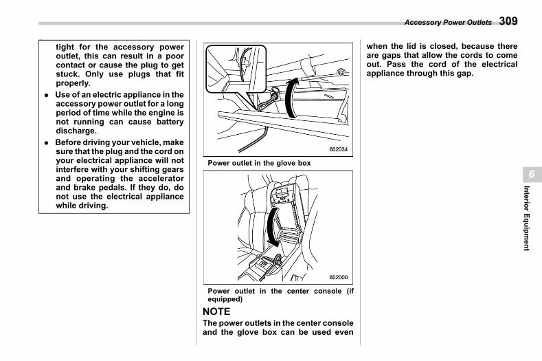
(311,1)
北米Model "A2600BE-B" EDITED: 2020/ 10/ 1
tight for the accessory poweroutlet, this can result in a poorcontact or cause the plug to getstuck. Only use plugs that fitproperly.
. Use of an electric appliance in theaccessory power outlet for a longperiod of time while the engine isnot running can cause batterydischarge.
. Before driving your vehicle, makesure that the plug and the cord onyour electrical appliance will notinterfere with your shifting gearsand operating the acceleratorand brake pedals. If they do, donot use the electrical appliancewhile driving.
Power outlet in the glove box
Power outlet in the center console (ifequipped)
NOTEThe power outlets in the center consoleand the glove box can be used even
when the lid is closed, because thereare gaps that allow the cords to comeout. Pass the cord of the electricalappliance through this gap.
Accessory Power Outlets 309
6
InteriorEquipm
ent
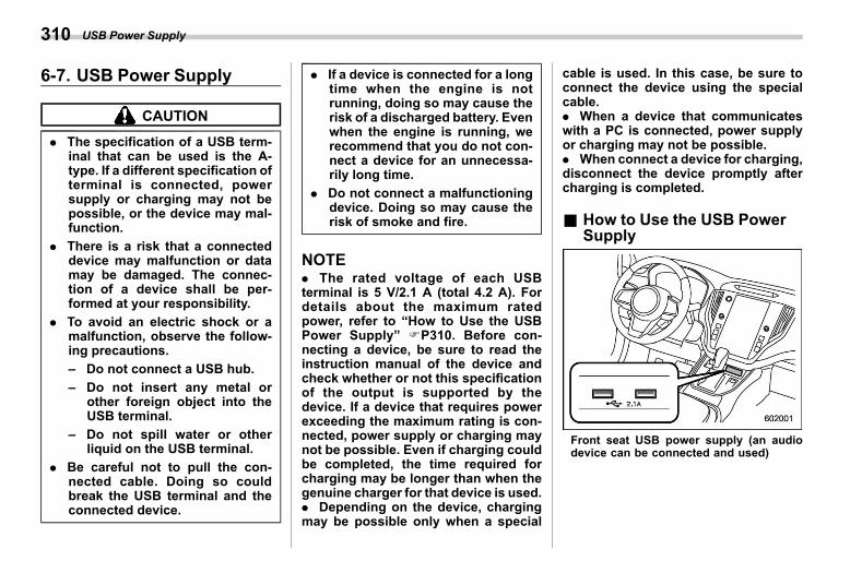
(312,1)
北米Model "A2600BE-B" EDITED: 2020/ 10/ 1
6-7. USB Power Supplys06ay
CAUTION
. The specification of a USB term-inal that can be used is the A-type. If a different specification ofterminal is connected, powersupply or charging may not bepossible, or the device may mal-function.
. There is a risk that a connecteddevice may malfunction or datamay be damaged. The connec-tion of a device shall be per-formed at your responsibility.
. To avoid an electric shock or amalfunction, observe the follow-ing precautions.– Do not connect a USB hub.– Do not insert any metal or
other foreign object into theUSB terminal.
– Do not spill water or otherliquid on the USB terminal.
. Be careful not to pull the con-nected cable. Doing so couldbreak the USB terminal and theconnected device.
. If a device is connected for a longtime when the engine is notrunning, doing so may cause therisk of a discharged battery. Evenwhen the engine is running, werecommend that you do not con-nect a device for an unnecessa-rily long time.
. Do not connect a malfunctioningdevice. Doing so may cause therisk of smoke and fire.
NOTE. The rated voltage of each USBterminal is 5 V/2.1 A (total 4.2 A). Fordetails about the maximum ratedpower, refer to “How to Use the USBPower Supply” FP310. Before con-necting a device, be sure to read theinstruction manual of the device andcheck whether or not this specificationof the output is supported by thedevice. If a device that requires powerexceeding the maximum rating is con-nected, power supply or charging maynot be possible. Even if charging couldbe completed, the time required forcharging may be longer than when thegenuine charger for that device is used.. Depending on the device, chargingmay be possible only when a special
cable is used. In this case, be sure toconnect the device using the specialcable.. When a device that communicateswith a PC is connected, power supplyor charging may not be possible.. When connect a device for charging,disconnect the device promptly aftercharging is completed.
& How to Use the USB PowerSupply
s06ay01
Front seat USB power supply (an audiodevice can be connected and used)
USB Power Supply310
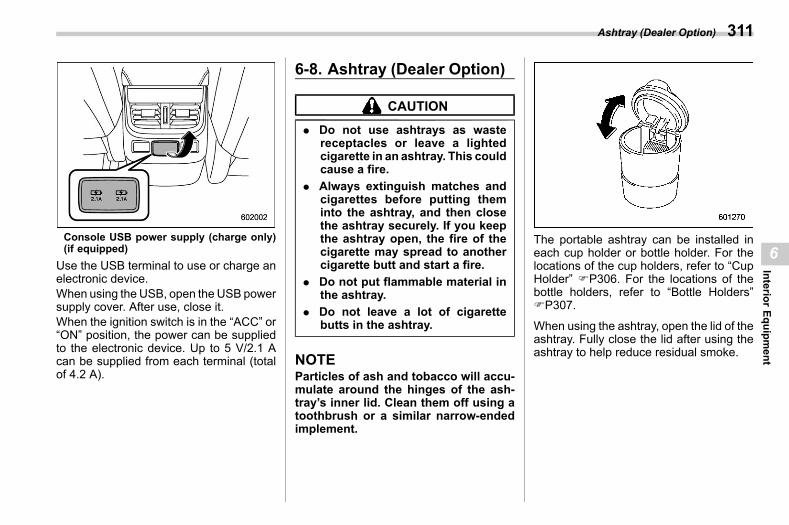
(313,1)
北米Model "A2600BE-B" EDITED: 2020/ 10/ 1
Console USB power supply (charge only)(if equipped)
Use the USB terminal to use or charge anelectronic device.When using the USB, open the USB powersupply cover. After use, close it.When the ignition switch is in the “ACC” or“ON” position, the power can be suppliedto the electronic device. Up to 5 V/2.1 Acan be supplied from each terminal (totalof 4.2 A).
6-8. Ashtray (Dealer Option)s06ag
CAUTION
. Do not use ashtrays as wastereceptacles or leave a lightedcigarette in an ashtray. This couldcause a fire.
. Always extinguish matches andcigarettes before putting theminto the ashtray, and then closethe ashtray securely. If you keepthe ashtray open, the fire of thecigarette may spread to anothercigarette butt and start a fire.
. Do not put flammable material inthe ashtray.
. Do not leave a lot of cigarettebutts in the ashtray.
NOTEParticles of ash and tobacco will accu-mulate around the hinges of the ash-tray’s inner lid. Clean them off using atoothbrush or a similar narrow-endedimplement.
The portable ashtray can be installed ineach cup holder or bottle holder. For thelocations of the cup holders, refer to “CupHolder” FP306. For the locations of thebottle holders, refer to “Bottle Holders”FP307.
When using the ashtray, open the lid of theashtray. Fully close the lid after using theashtray to help reduce residual smoke.
Ashtray (Dealer Option) 311
6
InteriorEquipm
ent
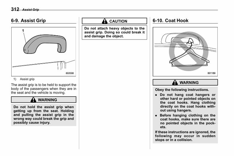
(314,1)
北米Model "A2600BE-B" EDITED: 2020/ 10/ 1
6-9. Assist Grips06bd
1) Assist grip
The assist grip is to be held to support thebody of the passengers when they are inthe seat and the vehicle is moving.
WARNING
Do not hold the assist grip whengetting up from the seat. Holdingand pulling the assist grip in thewrong way could break the grip andpossibly cause injury.
CAUTION
Do not attach heavy objects to theassist grip. Doing so could break itand damage the object.
6-10. Coat Hooks06ah
WARNING
Obey the following instructions.. Do not hang coat hangers or
other hard or pointed objects onthe coat hooks. Hang clothingdirectly on the coat hooks with-out using hangers.
. Before hanging clothing on thecoat hooks, make sure there areno pointed objects in the pock-ets.
If these instructions are ignored, thefollowing may occur in suddenstops or in a collision.
Assist Grip312
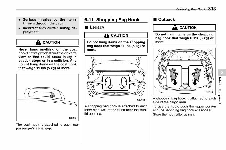
(315,1)
北米Model "A2600BE-B" EDITED: 2020/ 10/ 1
. Serious injuries by the itemsthrown through the cabin
. Incorrect SRS curtain airbag de-ployment
CAUTION
Never hang anything on the coathook that might obstruct the driver’sview or that could cause injury insudden stops or in a collision. Anddo not hang items on the coat hookthat weigh 11 lbs (5 kg) or more.
The coat hook is attached to each rearpassenger’s assist grip.
6-11. Shopping Bag Hooks06ai
& Legacys06ai01
CAUTION
Do not hang items on the shoppingbag hook that weigh 11 lbs (5 kg) ormore.
A shopping bag hook is attached to eachinner side wall of the trunk near the trunklid opening.
& Outbacks06ai02
CAUTION
Do not hang items on the shoppingbag hook that weigh 6 lbs (3 kg) ormore.
A shopping bag hook is attached to eachside of the cargo area.To use the hook, push the upper portionand the shopping bag hook will appear.Store the hook after using it.
Shopping Bag Hook 313
6
InteriorEquipm
ent
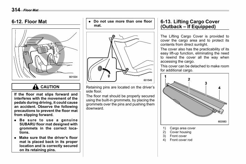
(316,1)
北米Model "A2600BE-B" EDITED: 2020/ 10/ 1
6-12. Floor Mats06aj
CAUTION
If the floor mat slips forward andinterferes with the movement of thepedals during driving, it could causean accident. Observe the followingprecautions to prevent the floor matfrom slipping forward.. Be sure to use a genuine
SUBARU floor mat designed withgrommets in the correct loca-tions.
. Make sure that the driver’s floormat is placed back in its properlocation and is correctly securedon its retaining pins.
. Do not use more than one floormat.
Retaining pins are located on the driver’sside floor.The floor mat should be properly securedusing the built-in grommets, by placing thegrommets over the pins and pushing themdownward.
6-13. Lifting Cargo Cover(Outback – If Equipped)
s06ak
The Lifting Cargo Cover is provided tocover the cargo area and to protect itscontents from direct sunlight.The cover also has the practicability of itseasy lift-up function, eliminating the needto rewind the cover all the way whenaccessing the cargo.This cover can be detached to make roomfor additional cargo.
1) Cargo area cover2) Cover housing3) Front cover4) Front cover rod
Floor Mat314
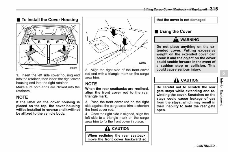
(317,1)
北米Model "A2600BE-B" EDITED: 2020/ 10/ 1
& To Install the Cover Housings06ak05
1. Insert the left side cover housing endinto the retainer, then insert the right coverhousing end into the right retainer.Make sure both ends are clicked into theretainers.
NOTEIf the label on the cover housing isplaced on the top, the cover housingwill be installed in reverse and it will notbe affixed to the vehicle body.
2. Align the right side of the front coverrod end with a triangle mark on the cargoarea trim.
NOTEWhen the rear seatbacks are reclined,align the front cover rod to the reartriangle mark.3. Push the front cover rod on the rightside against the cargo area trim to shortenthe front cover rod.4. Once the right side is aligned, align theleft side to a triangle mark on the cargoarea trim to fix the front cover in place.
CAUTION
When reclining the rear seatback,move the front cover backward so
that the cover is not damaged
& Using the Covers06ak01
WARNING
Do not place anything on the ex-tended cover. Putting excessiveweight on the extended cover canbreak it and the object on the covercould tumble forward in the event ofa sudden stop or collision. Thiscould cause serious injury.
CAUTION
Be careful not to scratch the reargate stays while extending and re-winding the cover. Scratches on thestays could cause leakage of gasfrom the stays, which may result intheir inability to hold the rear gateopen.
– CONTINUED –
Lifting Cargo Cover (Outback – If Equipped) 315
6
InteriorEquipm
ent
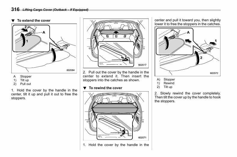
(318,1)
北米Model "A2600BE-B" EDITED: 2020/ 10/ 1
! To extend the covers06ak0101
A Stopper1) Tilt up2) Pull out
1. Hold the cover by the handle in thecenter, tilt it up and pull it out to free thestoppers.
2. Pull out the cover by the handle in thecenter to extend it. Then insert thestoppers into the catches as shown.
! To rewind the covers06ak0103
1. Hold the cover by the handle in the
center and pull it toward you, then slightlylower it to free the stoppers in the catches.
A) Stopper1) Rewind2) Tilt up
2. Slowly rewind the cover completely.Then tilt the cover up by the handle to hookthe stoppers.
Lifting Cargo Cover (Outback – If Equipped)316
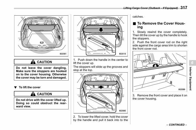
(319,1)
北米Model "A2600BE-B" EDITED: 2020/ 10/ 1
CAUTION
Do not leave the cover dangling.Make sure the stoppers are hookedon to the cover housing. Otherwisethe cover may be torn and damaged.
! To lift the covers06ak0102
CAUTION
Do not drive with the cover lifted up.Doing so could obstruct the rear-ward view.
1. Push down the handle in the center tolift the cover up.The stoppers will slide up the grooves andstop at the top.
2. To lower the lifted cover, hold the coverby the handle and pull it back into to the
catches.
& To Remove the Cover Hous-ing
s06ak021. Slowly rewind the cover completely.Then tilt the cover up by the handle to hookthe stoppers.2. Push the front cover rod on the rightside against the cargo area trim to shortenthe front cover rod.
3. Remove the front cover and place it onthe cover housing.
– CONTINUED –
Lifting Cargo Cover (Outback – If Equipped) 317
6
InteriorEquipm
ent
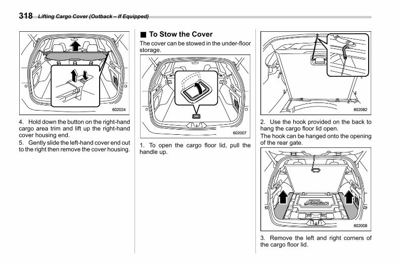
(320,1)
北米Model "A2600BE-B" EDITED: 2020/ 10/ 1
4. Hold down the button on the right-handcargo area trim and lift up the right-handcover housing end.5. Gently slide the left-hand cover end outto the right then remove the cover housing.
& To Stow the Covers06ak11
The cover can be stowed in the under-floorstorage.
1. To open the cargo floor lid, pull thehandle up.
2. Use the hook provided on the back tohang the cargo floor lid open.The hook can be hanged onto the openingof the rear gate.
3. Remove the left and right corners ofthe cargo floor lid.
Lifting Cargo Cover (Outback – If Equipped)318
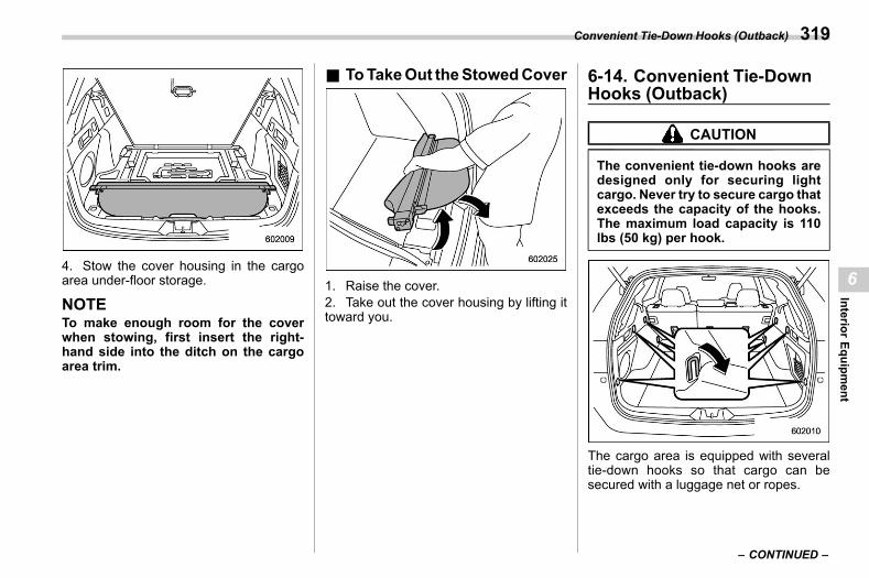
(321,1)
北米Model "A2600BE-B" EDITED: 2020/ 10/ 1
4. Stow the cover housing in the cargoarea under-floor storage.
NOTETo make enough room for the coverwhen stowing, first insert the right-hand side into the ditch on the cargoarea trim.
& ToTakeOut theStowedCovers06ak10
1. Raise the cover.2. Take out the cover housing by lifting ittoward you.
6-14. Convenient Tie-DownHooks (Outback)
s06am
CAUTION
The convenient tie-down hooks aredesigned only for securing lightcargo. Never try to secure cargo thatexceeds the capacity of the hooks.The maximum load capacity is 110lbs (50 kg) per hook.
The cargo area is equipped with severaltie-down hooks so that cargo can besecured with a luggage net or ropes.
– CONTINUED –
Convenient Tie-Down Hooks (Outback) 319
6
InteriorEquipm
ent
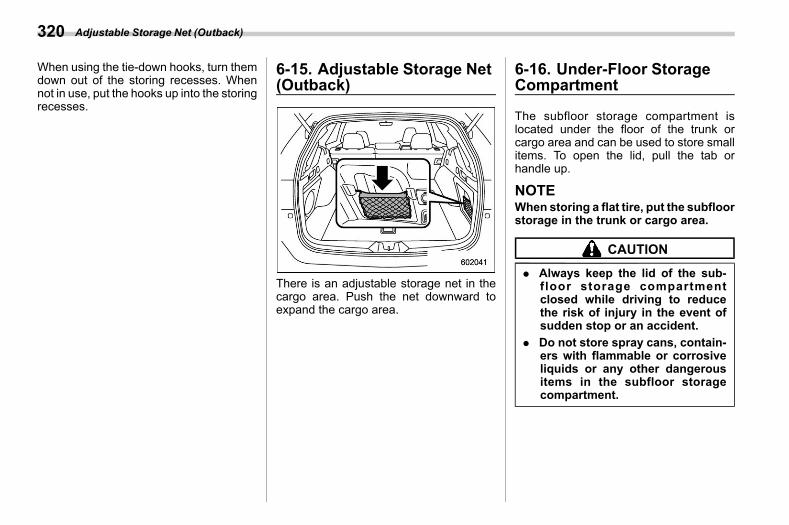
(322,1)
北米Model "A2600BE-B" EDITED: 2020/ 10/ 1
When using the tie-down hooks, turn themdown out of the storing recesses. Whennot in use, put the hooks up into the storingrecesses.
6-15. Adjustable Storage Net(Outback)
s06be
There is an adjustable storage net in thecargo area. Push the net downward toexpand the cargo area.
6-16. Under-Floor StorageCompartment
s06an
The subfloor storage compartment islocated under the floor of the trunk orcargo area and can be used to store smallitems. To open the lid, pull the tab orhandle up.
NOTEWhen storing a flat tire, put the subfloorstorage in the trunk or cargo area.
CAUTION
. Always keep the lid of the sub-floor storage compartmentclosed while driving to reducethe risk of injury in the event ofsudden stop or an accident.
. Do not store spray cans, contain-ers with flammable or corrosiveliquids or any other dangerousitems in the subfloor storagecompartment.
Adjustable Storage Net (Outback)320
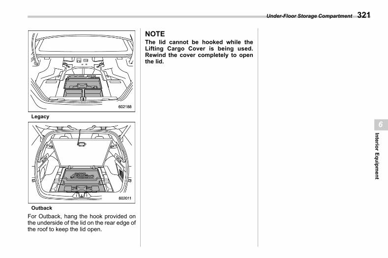
(323,1)
北米Model "A2600BE-B" EDITED: 2020/ 10/ 1
Legacy
OutbackFor Outback, hang the hook provided onthe underside of the lid on the rear edge ofthe roof to keep the lid open.
NOTEThe lid cannot be hooked while theLifting Cargo Cover is being used.Rewind the cover completely to openthe lid.
Under-Floor Storage Compartment 321
6
InteriorEquipm
ent

(324,1)
北米Model "A2600BE-B" EDITED: 2020/ 10/ 1
— — — — — — — — — — — — — — — — — — — — — — — — — — — — — — — — — — — — — — — —
— — — — — — — — — — — — — — — — — — — — — — — — — — — — — — — — — — — — — — — —
— — — — — — — — — — — — — — — — — — — — — — — — — — — — — — — — — — — — — — — —
— — — — — — — — — — — — — — — — — — — — — — — — — — — — — — — — — — — — — — — —
— — — — — — — — — — — — — — — — — — — — — — — — — — — — — — — — — — — — — — — —
— — — — — — — — — — — — — — — — — — — — — — — — — — — — — — — — — — — — — — — —
— — — — — — — — — — — — — — — — — — — — — — — — — — — — — — — — — — — — — — — —
— — — — — — — — — — — — — — — — — — — — — — — — — — — — — — — — — — — — — — — —
— — — — — — — — — — — — — — — — — — — — — — — — — — — — — — — — — — — — — — — —
— — — — — — — — — — — — — — — — — — — — — — — — — — — — — — — — — — — — — — — —
— — — — — — — — — — — — — — — — — — — — — — — — — — — — — — — — — — — — — — — —
— — — — — — — — — — — — — — — — — — — — — — — — — — — — — — — — — — — — — — — —
— — — — — — — — — — — — — — — — — — — — — — — — — — — — — — — — — — — — — — — —
(325,1)
北米Model "A2600BE-B" EDITED: 2020/ 10/ 1
s077-1. Fuel .................................................................. 326
Fuel Requirements..............................................326Fuel Filler Lid and Cap........................................328
7-2. State Emission Testing (U.S. Only) ............... 3327-3. Preparing to Drive .......................................... 3337-4. Starting and Stopping the Engine (Models
without Push-Button Ignition Switch) ......... 334General Precautions When Starting/StoppingEngine..............................................................334
Starting Engine...................................................334Stopping the Engine ...........................................335Steering Lock .....................................................336
7-5. Starting and Stopping Engine (Modelswith Push-Button Start System) .................. 336Safety Precautions..............................................336Operating Range for Push-Button Start System...336Starting Engine...................................................336Stopping Engine .................................................338When Access Key Fob Does Not OperateProperly ...........................................................338
Steering Lock .....................................................3387-6. Remote Engine Start System
(Dealer Option) .............................................. 339Remote Engine Starter Transceiver (Fob) ............339Alternate Operation Method for Models with“Keyless Access with Push-Button StartSystem” ...........................................................343
Entering the Vehicle While It Is Running viaRemote Start (Models without “Keyless Accesswith Push-Button Start System”).......................343
Entering the Vehicle While It Is Running viaRemote Start (Models with “Keyless Accesswith Push-Button Start System”) ...................... 344
Entering the Vehicle Following Remote EngineStart Shutdown ................................................ 344
Pre-heating or Pre-cooling the Interior ofthe Vehicle ....................................................... 344
Remote Transmitter Program (Remote EngineStarter Transceiver).......................................... 344
System Maintenance .......................................... 345Certification for Remote Engine Starter .............. 346
7-7. Continuously Variable Transmission .............347Continuously Variable Transmission Features..... 347Select Lever ....................................................... 348Shift Lock Function............................................ 349Selection of Manual Mode .................................. 351Driving Tips ....................................................... 352
7-8. SI-DRIVE (If Equipped)....................................353Intelligent (I) Mode ............................................. 353Sport Sharp (S#) Mode ....................................... 353SI-DRIVE Switches ............................................. 353
7-9. Power Steering ................................................3547-10. Braking...........................................................355
Braking Tips ...................................................... 355Brake System..................................................... 355Disc Brake Pad Wear Warning Indicators............ 356
7-11. ABS (Anti-Lock Brake System) ....................356ABS Self-Check.................................................. 357ABS Warning Light............................................. 357
Starting and Operating
7
Startingand
Operating
(326,1)
北米Model "A2600BE-B" EDITED: 2020/ 10/ 1
7-12. Electronic Brake Force Distribution (EBD)System........................................................... 357EBD System Malfunctions...................................357
7-13. Vehicle Dynamics Control System .............. 358Vehicle Dynamics Control System Monitor ..........359To Turn On/Off the Vehicle Dynamics ControlSystem.............................................................359
7-14. X-MODE (Outback)........................................ 360To Activate/Deactivate the X-MODE .....................361Hill Descent Control Function .............................362
7-15. Tire Pressure Monitoring System (TPMS)(U.S.-Spec. Models) ...................................... 363TPMS Screen......................................................365
7-16. Parking Your Vehicle .................................... 365Electronic Parking Brake ....................................366Parking Tips .......................................................371
7-17. Auto Start Stop System ............................... 372System Operation ...............................................372Displaying the Auto Start Stop System Status.....375System Warning .................................................375
7-18. Front View Monitor (If Equipped) ................ 376How to Access the Front View Monitor................377How to Cancel the Front View Monitor ................377Range of Image on Screen..................................377Guiding Line.......................................................378Handling of Camera ............................................378
7-19. Rear View Camera ........................................ 379How to Use the Rear View Camera......................380Viewing Range on the Screen .............................381Help Lines ..........................................................382
7-20. BSD/RCTA (If Equipped) ...............................384System Features ................................................ 384System Operation .............................................. 386BSD/RCTA Approach Indicator Light/WarningBuzzer ............................................................. 388
BSD/RCTA OFF Indicator.................................... 389BSD/RCTA Warning Indicator.............................. 390To Turn On/Off the BSD/RCTA ............................ 390Certification for the BSD/RCTA ........................... 391Handling of Radar Sensors................................. 392
7-21. Reverse Automatic Braking (RAB)System (If Equipped) ....................................393
Reverse Automatic Braking (RAB) SystemOverview.......................................................... 394
Operating Conditions ......................................... 396Object Detection Warning Function .................... 399Reverse Automatic Braking (RAB) SystemFunction Operation .......................................... 400
Canceling the Reverse Automatic Braking(RAB) System Operation .................................. 402
Reverse Automatic Braking (RAB) SystemON/OFF Setting ................................................ 402
RAB Warning Indicator....................................... 403Handling of the Sonar Sensors........................... 403
7-22. Driver Monitoring System (If Equipped) ......404User Recognition Function ................................. 408Inattentive/Drowsy Driving Warning .................... 410Driver Monitoring System Indicator/Warning ....... 411Using the Driver Monitoring System ................... 412Registering and Deleting a User ......................... 414
Starting and Operating
(327,1)
北米Model "A2600BE-B" EDITED: 2020/ 10/ 1
Registering and Deleting Driver PositionPersonalization.................................................414
Driver Monitoring System ON/OFF Settings.........414
Certification for Driver Monitoring System(U.S.-Spec. Models) .......................................... 415
Starting and Operating
7
Startingand
Operating
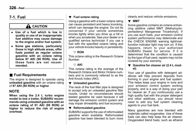
(328,1)
北米Model "A2600BE-B" EDITED: 2020/ 10/ 1
7-1. Fuels07aa
CAUTION
. Use of a fuel which is low inquality or use of an inappropriatefuel additive may cause damageto the engine and/or fuel system.
. Some gas stations, particularlythose in high altitude areas, offerfuels posted as regular octanegasoline with an octane ratingbelow 87 AKI (90 RON). Use ofthose fuels are not recom-mended.
& Fuel Requirementss07aa01
The engine is designed to operate usingunleaded gasoline with an octane ratingof 87 AKI (90 RON) or higher.
NOTEWhen using the 2.4 L turbo enginemodel to tow a trailer, SUBARU recom-mends using unleaded gasolinewith anoctane rating of 91 AKI (95 RON) orhigher to reduce the risk of engineoverheat.
! Fuel octane ratings07aa0103
Using a gasoline with a lower octane ratingcan cause persistent and heavy knocking,which can damage the engine. Do not beconcerned if your vehicle sometimesknocks lightly when you drive up a hill orwhen you accelerate. See your dealer or aqualified service technician if you use afuel with the specified octane rating andyour vehicle knocks heavily or persistently.
! RONs07aa010301
This octane rating is the Research OctaneNumber.
! AKIs07aa010302
This octane rating is the average of theResearch Octane and Motor Octane num-bers and is commonly referred to as theAnti Knock Index (AKI).! Unleaded gasoline
s07aa0104The neck of the fuel filler pipe is designedto accept only an unleaded gasoline fillernozzle. Under no circumstances shouldleaded gasoline be used because it willdamage the emission control system andmay impair driveability and fuel economy.! Reformulated gasoline
s07aa0128SUBARU supports the use of reformulatedgasoline when available. Reformulatedgasoline has been blended to burn more
cleanly and reduce vehicle emissions.! MMT
s07aa0106Some gasoline contains an octane-enhan-cing additive called MMT (Methylcyclo-pentadienyl Manganese Tricarbonyl). Ifyou use such fuels, your emission controlsystem performance may deteriorate andthe CHECK ENGINE warning light/mal-function indicator light may turn on. If thishappens, return to your authorizedSUBARU Dealer for service. If it isdetermined that the condition is causedby the type of fuel used, repairs may not becovered by your warranty.! Gasoline for cleaner air (2.4 L mod-
el)s07aa0129
Your use of gasoline with detergent ad-ditives will help prevent deposits fromforming in your engine and fuel system.This helps keep your engine in tune andyour emission control system workingproperly, and is a way of doing your partfor cleaner air. If you continuously use ahigh quality fuel with the proper detergentand other additives, you should neverneed to add any fuel system cleaningagents to your fuel tank.
Many gasolines are now blended withmaterials called oxygenates. Use of thesefuels can also help keep the air cleaner.Oxygenated blend fuels, such as ethanol
Fuel326
(329,1)
北米Model "A2600BE-B" EDITED: 2020/ 10/ 1
(ethyl or grain alcohol) may be used in yourvehicle, but should contain no more than15% ethanol for the proper operation ofyour SUBARU.
Do not use any gasoline that containsmore than 15%ethanol, including from anypump labeled E30, E50 or E85 (which areonly some examples of fuel containingmore than 15% ethanol).
In addition, some gasoline suppliers arenow producing reformulated gasolines,which are designed to reduce vehicleemissions. SUBARU approves the use ofreformulated gasoline.
If you are not sure what the fuel contains,you should ask your service station op-erators if their gasolines contain deter-gents and oxygenates and if they havebeen reformulated to reduce vehicle emis-sions.
As additional guidance, only use fuelssuited for your vehicle as explained in thefollowing description.. Fuel should be unleaded and have anoctane rating no lower than that specifiedin this manual.. Methanol (methyl or wood alcohol) issometimes mixed with unleaded gasoline.Methanol can be used in your vehicleONLY if it does not exceed 5% of the fuel
mixture AND if it is accompanied bysufficient quantities of the proper cosol-vents and corrosion inhibitors required toprevent damage to the fuel system. Do notuse fuel containing methanol EXCEPTunder these conditions.. If undesirable driveability problems areexperienced and you suspect they may befuel related, try a different brand of gaso-line before seeking service at yourSUBARU dealer.. Fuel system damage or driveabilityproblems which result from the use ofimproper fuel are not covered under theSUBARU Limited Warranty.! Gasoline for cleaner air (2.5 L mod-
el)s07aa0107
Your use of gasoline with detergent ad-ditives will help prevent deposits fromforming in your engine and fuel system.This helps keep your engine in tune andyour emission control system workingproperly, and is a way of doing your partfor cleaner air. If you continuously use ahigh quality fuel with the proper detergentand other additives, you should neverneed to add any fuel system cleaningagents to your fuel tank.
Many gasolines are now blended withmaterials called oxygenates. Use of thesefuels can also help keep the air cleaner.
Oxygenated blend fuels, such as ethanol(ethyl or grain alcohol) may be used in yourvehicle, but should contain no more than10% ethanol for the proper operation ofyour SUBARU.
Do not use any gasoline that containsmore than 10%ethanol, including from anypump labeled E15, E30, E50 or E85 (whichare only some examples of fuel containingmore than 10% ethanol).
In addition, some gasoline suppliers arenow producing reformulated gasolines,which are designed to reduce vehicleemissions. SUBARU approves the use ofreformulated gasoline.
If you are not sure what the fuel contains,you should ask your service station op-erators if their gasolines contain deter-gents and oxygenates and if they havebeen reformulated to reduce vehicle emis-sions.
As additional guidance, only use fuelssuited for your vehicle as explained in thefollowing.. Fuel should be unleaded and have anoctane rating no lower than that specifiedin this manual.. Methanol (methyl or wood alcohol) issometimes mixed with unleaded gasoline.Methanol can be used in your vehicle
– CONTINUED –
Fuel 327
7
Startingand
Operating
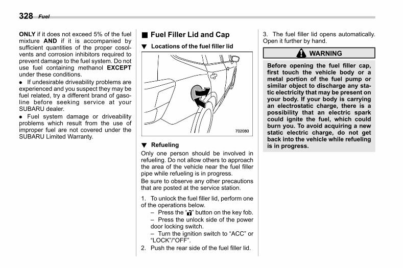
(330,1)
北米Model "A2600BE-B" EDITED: 2020/ 10/ 1
ONLY if it does not exceed 5% of the fuelmixture AND if it is accompanied bysufficient quantities of the proper cosol-vents and corrosion inhibitors required toprevent damage to the fuel system. Do notuse fuel containing methanol EXCEPTunder these conditions.. If undesirable driveability problems areexperienced and you suspect they may befuel related, try a different brand of gaso-line before seeking service at yourSUBARU dealer.. Fuel system damage or driveabilityproblems which result from the use ofimproper fuel are not covered under theSUBARU Limited Warranty.
& Fuel Filler Lid and Caps07aa02
! Locations of the fuel filler lids07aa0202
! Refuelings07aa0201
Only one person should be involved inrefueling. Do not allow others to approachthe area of the vehicle near the fuel fillerpipe while refueling is in progress.Be sure to observe any other precautionsthat are posted at the service station.
1. To unlock the fuel filler lid, perform oneof the operations below.
– Press the “ ” button on the key fob.– Press the unlock side of the powerdoor locking switch.– Turn the ignition switch to “ACC” or“LOCK”/“OFF”.
2. Push the rear side of the fuel filler lid.
3. The fuel filler lid opens automatically.Open it further by hand.
WARNING
Before opening the fuel filler cap,first touch the vehicle body or ametal portion of the fuel pump orsimilar object to discharge any sta-tic electricity that may be present onyour body. If your body is carryingan electrostatic charge, there is apossibility that an electric sparkcould ignite the fuel, which couldburn you. To avoid acquiring a newstatic electric charge, do not getback into the vehicle while refuelingis in progress.
Fuel328
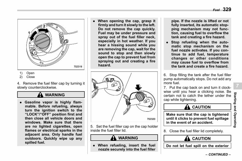
(331,1)
北米Model "A2600BE-B" EDITED: 2020/ 10/ 1
1) Open2) Close
4. Remove the fuel filler cap by turning itslowly counterclockwise.
WARNING
. Gasoline vapor is highly flam-mable. Before refueling, alwaysturn the ignition switch to the“LOCK”/“OFF” position first andthen close all vehicle doors andwindows. Make sure that thereare no lighted cigarettes, openflames or electrical sparks in theadjacent area. Only handle fueloutdoors. Quickly wipe up anyspilled fuel.
. When opening the cap, grasp itfirmly and turn it slowly to the left.Do not remove the cap quickly.Fuel may be under pressure andspray out of the fuel filler neck,especially in hot weather. If youhear a hissing sound while youare removing the cap, wait for thesound to stop and then slowlyopen the cap to prevent fuel fromspraying out and creating a firehazard.
5. Set the fuel filler cap on the cap holderinside the fuel filler lid.
WARNING
. When refueling, insert the fuelnozzle securely into the fuel filler
pipe. If the nozzle is lifted or notfully inserted, its automatic stop-ping mechanism may not func-tion, causing fuel to overflow thetank and creating a fire hazard.
. Stop refueling when the auto-matic stop mechanism on thefuel nozzle activates. If you con-tinue to add fuel, temperaturechanges or other conditionsmay cause fuel to overflow fromthe tank and create a fire hazard.
6. Stop filling the tank after the fuel fillerpump automatically stops. Do not add anymore fuel.7. Put the cap back on and turn it clock-wise until you hear a clicking noise. Becertain not to catch the tether under thecap while tightening.
CAUTION
Make sure that the cap is tighteneduntil it clicks to prevent fuel spillagein the event of an accident.
8. Close the fuel filler lid completely.
CAUTION
Do not let fuel spill on the exterior
– CONTINUED –
Fuel 329
7
Startingand
Operating
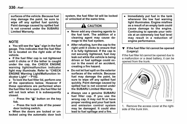
(332,1)
北米Model "A2600BE-B" EDITED: 2020/ 10/ 1
surfaces of the vehicle. Because fuelmay damage the paint, be sure towipe off any spilled fuel quickly.Paint damage caused by spilled fuelis not covered under the SUBARULimited Warranty.
NOTE. You will see the “ ” sign in the fuelgauge. This indicates that the fuel fillerlid is located on the right side of thevehicle.. If the fuel filler cap is not tighteneduntil it clicks or if the tether is caughtunder the cap, the CHECK ENGINEwarning light/malfunction indicatorlight may illuminate. Refer to “CHECKENGINE Warning Light/Malfunction In-dicator Light” FP182.. To lock the fuel filler lid, perform oneof the operations below. However ifthese operations are performed whenthe fuel filler lid is open, the fuel filler lidwill not lock when it is subsequentlyclosed.
– Press the “ ” button on the keyfob.– Press the lock side of the powerdoor locking switch.
. When the doors are locked or un-locked using the automatic door lock
system, the fuel filler lid will be lockedor unlocked at the same time.
CAUTION
. Never add any cleaning agents tothe fuel tank. The addition of acleaning agent may cause da-mage to the fuel system.
. After refueling, turn the cap to theright until it clicks to ensure thatit is fully tightened. If the cap isnot securely tightened, fuel mayleak out while the vehicle is beingdriven or fuel spillage could oc-cur in the event of an accident,creating a fire hazard.
. Do not let fuel spill on the exteriorsurfaces of the vehicle. Becausefuel may damage the paint, besure to wipe off any spilled fuelquickly. Paint damage caused byspilled fuel is not covered underthe SUBARU Limited Warranty.
. Always use a genuine SUBARUfuel filler cap. If you use thewrong cap, it may not fit or haveproper venting and your fuel tankand emission control systemmay be damaged. It could alsolead to fuel spillage and a fire.
. Immediately put fuel in the tankwhenever the low fuel warninglight illuminates. Engine misfiresas a result of an empty tank couldcause damage to the engine.Continuing to operate your vehi-cle at an extremely low fuel levelmay result in a reduction ofengine performance.
! If the fuel filler lid cannot be opened(Legacy)
s07aa0204If the fuel filler lid cannot be opened due toa malfunction or a dead battery, it can beopened from the trunk.
1. Remove the access cover at the right-side of the trunk trim.
Fuel330
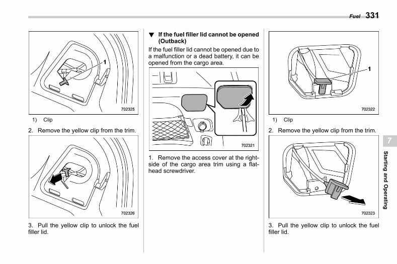
(333,1)
北米Model "A2600BE-B" EDITED: 2020/ 10/ 1
1) Clip
2. Remove the yellow clip from the trim.
3. Pull the yellow clip to unlock the fuelfiller lid.
! If the fuel filler lid cannot be opened(Outback)
s07aa0203If the fuel filler lid cannot be opened due toa malfunction or a dead battery, it can beopened from the cargo area.
1. Remove the access cover at the right-side of the cargo area trim using a flat-head screwdriver.
1) Clip
2. Remove the yellow clip from the trim.
3. Pull the yellow clip to unlock the fuelfiller lid.
Fuel 331
7
Startingand
Operating
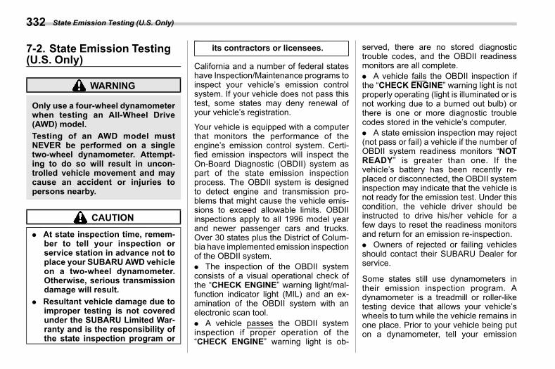
(334,1)
北米Model "A2600BE-B" EDITED: 2020/ 10/ 1
7-2. State Emission Testing(U.S. Only)
s07ab
WARNING
Only use a four-wheel dynamometerwhen testing an All-Wheel Drive(AWD) model.Testing of an AWD model mustNEVER be performed on a singletwo-wheel dynamometer. Attempt-ing to do so will result in uncon-trolled vehicle movement and maycause an accident or injuries topersons nearby.
CAUTION
. At state inspection time, remem-ber to tell your inspection orservice station in advance not toplace your SUBARU AWD vehicleon a two-wheel dynamometer.Otherwise, serious transmissiondamage will result.
. Resultant vehicle damage due toimproper testing is not coveredunder the SUBARU Limited War-ranty and is the responsibility ofthe state inspection program or
its contractors or licensees.
California and a number of federal stateshave Inspection/Maintenance programs toinspect your vehicle’s emission controlsystem. If your vehicle does not pass thistest, some states may deny renewal ofyour vehicle’s registration.
Your vehicle is equipped with a computerthat monitors the performance of theengine’s emission control system. Certi-fied emission inspectors will inspect theOn-Board Diagnostic (OBDII) system aspart of the state emission inspectionprocess. The OBDII system is designedto detect engine and transmission pro-blems that might cause the vehicle emis-sions to exceed allowable limits. OBDIIinspections apply to all 1996 model yearand newer passenger cars and trucks.Over 30 states plus the District of Colum-bia have implemented emission inspectionof the OBDII system.. The inspection of the OBDII systemconsists of a visual operational check ofthe “CHECK ENGINE” warning light/mal-function indicator light (MIL) and an ex-amination of the OBDII system with anelectronic scan tool.. A vehicle passes the OBDII systeminspection if proper operation of the“CHECK ENGINE” warning light is ob-
served, there are no stored diagnostictrouble codes, and the OBDII readinessmonitors are all complete.. A vehicle fails the OBDII inspection ifthe “CHECK ENGINE” warning light is notproperly operating (light is illuminated or isnot working due to a burned out bulb) orthere is one or more diagnostic troublecodes stored in the vehicle’s computer.. A state emission inspection may reject(not pass or fail) a vehicle if the number ofOBDII system readiness monitors “NOTREADY” is greater than one. If thevehicle’s battery has been recently re-placed or disconnected, the OBDII systeminspection may indicate that the vehicle isnot ready for the emission test. Under thiscondition, the vehicle driver should beinstructed to drive his/her vehicle for afew days to reset the readiness monitorsand return for an emission re-inspection.. Owners of rejected or failing vehiclesshould contact their SUBARU Dealer forservice.
Some states still use dynamometers intheir emission inspection program. Adynamometer is a treadmill or roller-liketesting device that allows your vehicle’swheels to turn while the vehicle remains inone place. Prior to your vehicle being puton a dynamometer, tell your emission
State Emission Testing (U.S. Only)332
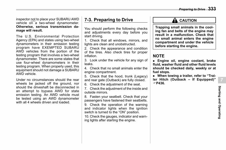
(335,1)
北米Model "A2600BE-B" EDITED: 2020/ 10/ 1
inspector not to place your SUBARU AWDvehicle on a two-wheel dynamometer.Otherwise, serious transmission da-mage will result.
The U.S. Environmental ProtectionAgency (EPA) and states using two-wheeldynamometers in their emission testingprogram have EXEMPTED SUBARUAWD vehicles from the portion of thetesting program that involves a two-wheeldynamometer. There are some states thatuse four-wheel dynamometers in theirtesting program. When properly used, thisequipment should not damage a SUBARUAWD vehicle.
Under no circumstances should the rearwheels be jacked off the ground, norshould the driveshaft be disconnected inan attempt to bypass AWD for stateemission testing. An AWD vehicle mustbe tested using an AWD dynamometerwith all 4 wheels driven and loaded.
7-3. Preparing to Drives07ac
You should perform the following checksand adjustments every day before youstart driving.1. Check that all windows, mirrors, andlights are clean and unobstructed.2. Check the appearance and conditionof the tires. Also check tires for properinflation.3. Look under the vehicle for any sign ofleaks.4. Check that no small animals enter theengine compartment.5. Check that the hood, trunk (Legacy)and rear gate (Outback) are fully closed.6. Check the adjustment of the seat.7. Check the adjustment of the inside andoutside mirrors.8. Fasten your seatbelt. Check that yourpassengers have fastened their seatbelts.9. Check the operation of the warningand indicator lights when the ignitionswitch is turned to the “ON” position.10. Check the gauges, indicator and warn-ing lights after starting the engine.
CAUTION
Trapping small animals in the cool-ing fan and belts of the engine mayresult in a malfunction. Check thatno small animal enters the enginecompartment and under the vehiclebefore starting the engine.
NOTE. Engine oil, engine coolant, brakefluid, washer fluid and other fluid levelsshould be checked daily, weekly or atfuel stops.. When towing a trailer, refer to “Trai-ler Hitch (Outback – If Equipped)”FP436.
Preparing to Drive 333
7
Startingand
Operating
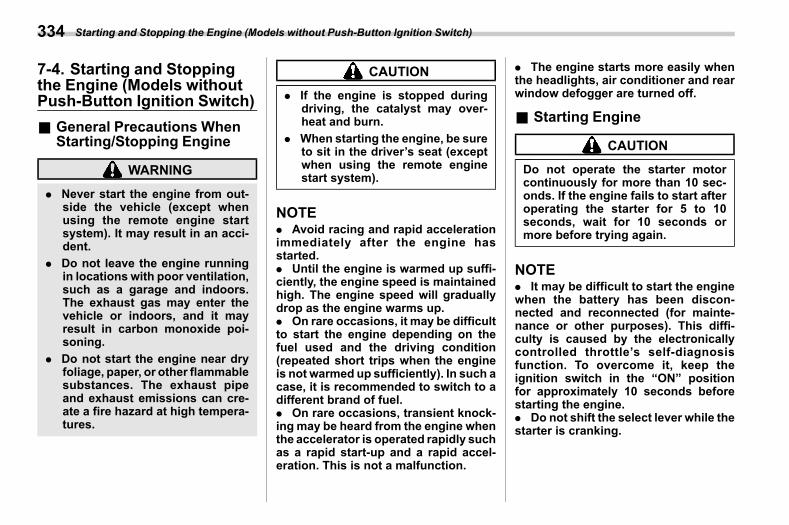
(336,1)
北米Model "A2600BE-B" EDITED: 2020/ 10/ 1
7-4. Starting and Stoppingthe Engine (Models withoutPush-Button Ignition Switch)
s07bd
& General Precautions WhenStarting/Stopping Engine
s07bd06
WARNING
. Never start the engine from out-side the vehicle (except whenusing the remote engine startsystem). It may result in an acci-dent.
. Do not leave the engine runningin locations with poor ventilation,such as a garage and indoors.The exhaust gas may enter thevehicle or indoors, and it mayresult in carbon monoxide poi-soning.
. Do not start the engine near dryfoliage, paper, or other flammablesubstances. The exhaust pipeand exhaust emissions can cre-ate a fire hazard at high tempera-tures.
CAUTION
. If the engine is stopped duringdriving, the catalyst may over-heat and burn.
. When starting the engine, be sureto sit in the driver’s seat (exceptwhen using the remote enginestart system).
NOTE. Avoid racing and rapid accelerationimmediately after the engine hasstarted.. Until the engine is warmed up suffi-ciently, the engine speed is maintainedhigh. The engine speed will graduallydrop as the engine warms up.. On rare occasions, it may be difficultto start the engine depending on thefuel used and the driving condition(repeated short trips when the engineis not warmed up sufficiently). In such acase, it is recommended to switch to adifferent brand of fuel.. On rare occasions, transient knock-ing may be heard from the engine whenthe accelerator is operated rapidly suchas a rapid start-up and a rapid accel-eration. This is not a malfunction.
. The engine starts more easily whenthe headlights, air conditioner and rearwindow defogger are turned off.
& Starting Engines07bd01
CAUTION
Do not operate the starter motorcontinuously for more than 10 sec-onds. If the engine fails to start afteroperating the starter for 5 to 10seconds, wait for 10 seconds ormore before trying again.
NOTE. It may be difficult to start the enginewhen the battery has been discon-nected and reconnected (for mainte-nance or other purposes). This diffi-culty is caused by the electronicallycontrolled throttle’s self-diagnosisfunction. To overcome it, keep theignition switch in the “ON” positionfor approximately 10 seconds beforestarting the engine.. Do not shift the select lever while thestarter is cranking.
Starting and Stopping the Engine (Models without Push-Button Ignition Switch)334
(337,1)
北米Model "A2600BE-B" EDITED: 2020/ 10/ 1
CAUTION
If you restart the engine while thevehicle is moving, shift the selectlever into the “N” position. Do notattempt to place the select lever of amoving vehicle into the “P” position.
1. Apply the parking brake.2. Turn off unnecessary lights and acces-sories.3. Shift the select lever to the “P” or “N”position (preferably “P” position). Thestarter will only operate when the selectlever is at the “P” or “N” position.4. Turn the ignition switch to the “ON”position and check the operation of thewarning and indicator lights. Refer to“Warning and Indicator Lights” FP177.5. Turn the ignition switch to the “START”position without depressing the accelera-tor pedal. Release the key immediatelyafter the engine has started.If the engine does not start, perform thefollowing procedure.
(1) Turn the ignition switch to the“LOCK” position and wait for at least10 seconds. After checking that theparking brake is applied, turn theignition switch to the “START” positionwhile depressing the accelerator pedal
slightly (approximately a quarter of thefull stroke). Release the acceleratorpedal as soon as the engine starts.(2) If this fails to start the engine, turnthe ignition switch back to the “LOCK”position and wait for at least 10seconds. Then fully depress the accel-erator pedal and turn the ignitionswitch to the “START” position. If theengine starts, quickly release the ac-celerator pedal.(3) If this fails to start the engine, turnthe ignition switch again to the “LOCK”position. After waiting for 10 secondsor longer, turn the ignition switch to the“START” position without depressingthe accelerator pedal.(4) If the engine still does not start,contact your nearest SUBARU dealerfor assistance.
6. Confirm that all warning and indicatorlights have turned off after the engine hasstarted. The fuel injection system auto-matically lowers the idle speed as theengine warms up.
While the engine is warming up,make surethat the select lever is at the “P” or “N”position and that the parking brake isapplied.
& Stopping the Engines07bd02
The ignition switch should be turned offonly when the vehicle is stopped and theengine is idling.
WARNING
Do not stop the engine when thevehicle is moving. This will causeloss of power to the power steeringand the brake booster, making steer-ing and braking more difficult. Itcould also result in accidental acti-vation of the “LOCK” position on theignition switch, causing the steeringwheel to lock.
1. Stop the vehicle completely.2. Move the select lever to the “P”position.3. Turn the ignition switch to the “LOCK/OFF” position.
The engine will stop, and the power will beswitched off.
– CONTINUED –
Starting and Stopping the Engine (Models without Push-Button Ignition Switch) 335
7
Startingand
Operating
(338,1)
北米Model "A2600BE-B" EDITED: 2020/ 10/ 1
& Steering Locks07bd07
After stopping the engine and the key isremoved from ignition switch, the steeringwheel will be locked due to the steeringlock function.When the engine is restarted, the steeringlock will be automatically released.! When the steering lock cannot be
releaseds07bd0701
When you cannot unlock the steeringwheel, perform the following steps.1. Check that the parking brake is ap-plied.2. Turn off unnecessary lights and acces-sories.3. Check that the select lever is set in the“P” position.4. Depress the brake pedal and keep itdepressed.5. Turn the ignition switch to the “ON”position while turning the steering wheelleft and right.
If you cannot unlock the steering wheel bydoing the steps, contact your nearestSUBARU dealer.
7-5. Starting and StoppingEngine (Models with Push-Button Start System)
s07be
& Safety Precautionss07be06
Refer to “Safety Precautions” FP116.
& Operating Range for Push-Button Start System
s07be01Refer to “Operating Range for Push-Button Start System” FP170.
& Starting Engines07be03
WARNING
. There are some general precau-tions when starting the engine.Carefully read the precautionsdescribed in “General Precau-tions When Starting/StoppingEngine” FP334.
. If the indicator on the push-but-ton ignition switch flashes ingreen after the engine hasstarted, never drive the vehicle.The steering is still locked, and itmay result in an accident.
CAUTION
. When the operation indicator onthe push-button ignition switch isflashing in orange, theremay be amalfunction with the vehicle.Contact a SUBARU dealer imme-diately.
. If the indicator on the push-but-ton ignition switch is flashing ingreen after the engine hasstarted, it means that the steeringis still locked. While moving thesteering wheel right and left,depress the brake pedal, andpress the push-button ignitionswitch.
. Do not continue pressing thepush-button ignition switch formore than 10 seconds. Doing socould cause a malfunction. If theengine does not start, stop press-ing the push-button ignitionswitch. Instead, press the push-button ignition switch withoutdepressing the brake pedal toswitch the power status to“OFF”.Wait 10 seconds, and thenpress the push-button ignitionswitch to start the engine.
Starting and Stopping Engine (Models with Push-Button Start System)336
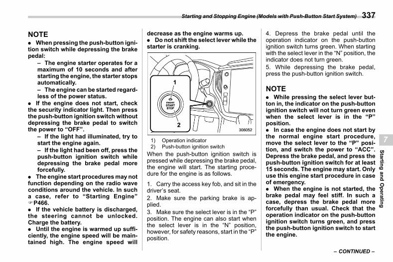
(339,1)
北米Model "A2600BE-B" EDITED: 2020/ 10/ 1
NOTE. When pressing the push-button igni-tion switch while depressing the brakepedal:
– The engine starter operates for amaximum of 10 seconds and afterstarting the engine, the starter stopsautomatically.– The engine can be started regard-less of the power status.
. If the engine does not start, checkthe security indicator light. Then pressthe push-button ignition switch withoutdepressing the brake pedal to switchthe power to “OFF”.
– If the light had illuminated, try tostart the engine again.– If the light had been off, press thepush-button ignition switch whiledepressing the brake pedal moreforcefully.
. The engine start proceduresmay notfunction depending on the radio waveconditions around the vehicle. In sucha case, refer to “Starting Engine”FP466.. If the vehicle battery is discharged,the steering cannot be unlocked.Charge the battery.. Until the engine is warmed up suffi-ciently, the engine speed will be main-tained high. The engine speed will
decrease as the engine warms up.. Do not shift the select lever while thestarter is cranking.
1) Operation indicator2) Push-button ignition switch
When the push-button ignition switch ispressed while depressing the brake pedal,the engine will start. The starting proce-dure for the engine is as follows.
1. Carry the access key fob, and sit in thedriver’s seat.2. Make sure the parking brake is ap-plied.3. Make sure the select lever is in the “P”position. The engine can also start whenthe select lever is in the “N” position,however, for safety reasons, start in the “P”position.
4. Depress the brake pedal until theoperation indicator on the push-buttonignition switch turns green. When startingwith the select lever in the “N” position, theindicator does not turn green.5. While depressing the brake pedal,press the push-button ignition switch.
NOTE. While pressing the select lever but-ton in, the indicator on the push-buttonignition switch will not turn green evenwhen the select lever is in the “P”position.. In case the engine does not start bythe normal engine start procedure,move the select lever to the “P” posi-tion, and switch the power to “ACC”.Depress the brake pedal, and press thepush-button ignition switch for at least15 seconds. The engine may start. Onlyuse this engine start procedure in caseof emergency.. When the engine is not started, thebrake pedal may feel stiff. In such acase, depress the brake pedal moreforcefully than usual. Check that theoperation indicator on the push-buttonignition switch turns green, and pressthe push-button ignition switch to startthe engine.
– CONTINUED –
Starting and Stopping Engine (Models with Push-Button Start System) 337
7
Startingand
Operating
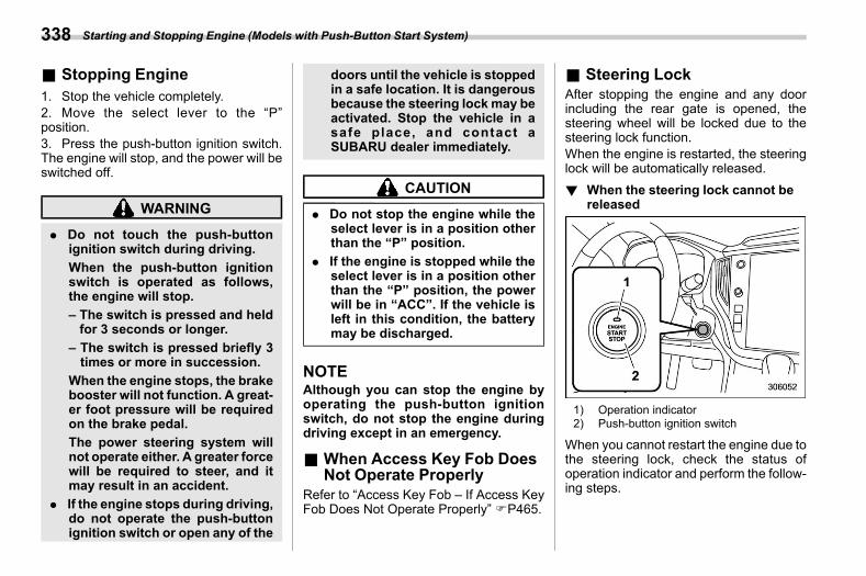
(340,1)
北米Model "A2600BE-B" EDITED: 2020/ 10/ 1
& Stopping Engines07be04
1. Stop the vehicle completely.2. Move the select lever to the “P”position.3. Press the push-button ignition switch.The engine will stop, and the power will beswitched off.
WARNING
. Do not touch the push-buttonignition switch during driving.When the push-button ignitionswitch is operated as follows,the engine will stop.– The switch is pressed and heldfor 3 seconds or longer.
– The switch is pressed briefly 3times or more in succession.
When the engine stops, the brakebooster will not function. A great-er foot pressure will be requiredon the brake pedal.The power steering system willnot operate either. A greater forcewill be required to steer, and itmay result in an accident.
. If the engine stops during driving,do not operate the push-buttonignition switch or open any of the
doors until the vehicle is stoppedin a safe location. It is dangerousbecause the steering lock may beactivated. Stop the vehicle in asafe place, and contact aSUBARU dealer immediately.
CAUTION
. Do not stop the engine while theselect lever is in a position otherthan the “P” position.
. If the engine is stopped while theselect lever is in a position otherthan the “P” position, the powerwill be in “ACC”. If the vehicle isleft in this condition, the batterymay be discharged.
NOTEAlthough you can stop the engine byoperating the push-button ignitionswitch, do not stop the engine duringdriving except in an emergency.
& When Access Key Fob DoesNot Operate Properly
s07be05Refer to “Access Key Fob – If Access KeyFob Does Not Operate Properly” FP465.
& Steering Locks07be07
After stopping the engine and any doorincluding the rear gate is opened, thesteering wheel will be locked due to thesteering lock function.When the engine is restarted, the steeringlock will be automatically released.! When the steering lock cannot be
releaseds07be0701
1) Operation indicator2) Push-button ignition switch
When you cannot restart the engine due tothe steering lock, check the status ofoperation indicator and perform the follow-ing steps.
Starting and Stopping Engine (Models with Push-Button Start System)338
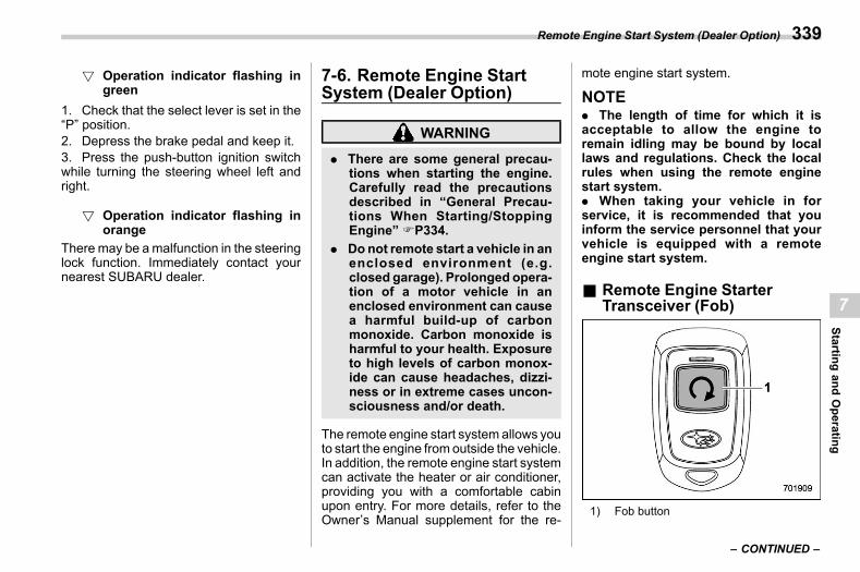
(341,1)
北米Model "A2600BE-B" EDITED: 2020/ 10/ 1
! Operation indicator flashing ingreen
s07be070101
1. Check that the select lever is set in the“P” position.2. Depress the brake pedal and keep it.3. Press the push-button ignition switchwhile turning the steering wheel left andright.
! Operation indicator flashing inorange
s07be070102
There may be amalfunction in the steeringlock function. Immediately contact yournearest SUBARU dealer.
7-6. Remote Engine StartSystem (Dealer Option)
s07az
WARNING
. There are some general precau-tions when starting the engine.Carefully read the precautionsdescribed in “General Precau-tions When Starting/StoppingEngine” FP334.
. Donot remote start a vehicle in anenclosed environment (e.g.closed garage). Prolonged opera-tion of a motor vehicle in anenclosed environment can causea harmful build-up of carbonmonoxide. Carbon monoxide isharmful to your health. Exposureto high levels of carbon monox-ide can cause headaches, dizzi-ness or in extreme cases uncon-sciousness and/or death.
The remote engine start system allows youto start the engine from outside the vehicle.In addition, the remote engine start systemcan activate the heater or air conditioner,providing you with a comfortable cabinupon entry. For more details, refer to theOwner’s Manual supplement for the re-
mote engine start system.
NOTE. The length of time for which it isacceptable to allow the engine toremain idling may be bound by locallaws and regulations. Check the localrules when using the remote enginestart system.. When taking your vehicle in forservice, it is recommended that youinform the service personnel that yourvehicle is equipped with a remoteengine start system.
& Remote Engine StarterTransceiver (Fob)
s07az21
1) Fob button
– CONTINUED –
Remote Engine Start System (Dealer Option) 339
7
Startingand
Operating
(342,1)
北米Model "A2600BE-B" EDITED: 2020/ 10/ 1
! Starting the engines07az2101
NOTEAll vehicle doors (including rear gate)and the engine hood must be closedprior to activating the remote enginestart system. Any open entry point willprevent starting or cause the engine tostop.
The remote engine start system is acti-vated by pressing the fob button on yourremote engine starter transceiver (fob)twice within 3 seconds. If the fob is withinoperating range of the system and the startrequest is received, the following willoccur.. The fob flashes and beeps once.. The horn sounds once.. The side marker lights, tail lights, andparking lights flash once.
If the fob is not within range (the user is toofar away from the vehicle), the fob willindicate two long flashes without beeping.
The system will check certain safetypreconditions before starting, and if allconditions are met, the engine will startwithin 5 seconds. After the engine starts,the following will occur.. The fob flashes and beeps twice.. The horn sounds once.
. The side marker lights, tail lights, andparking lights flash once.
While the engine is idling via the remoteengine start system, the following willoccur.. The side marker lights, tail lights, andparking lights remain illuminated.. The fob button flashes once every 3seconds.. The power windows are disabled.
If the engine turns over but does not start(or starts and stalls) the remote enginestart system will power off and thenattempt to start the engine 3 additionaltimes. The system will not attempt torestart the engine if it determines a vehiclemalfunction is preventing starting. If theengine does not start after 3 additionalattempts, the remote engine start requestwill be aborted.! Stopping the engine
s07az2102Press and hold the fob button for at least 2seconds to stop the engine. The fob willflash and beep three times, indicating theengine has stopped. If the stop request isnot received (for example, if the user is toofar away from the vehicle), the fob willcontinue to flash once every 3 seconds.The system will automatically stop theengine after 15 minutes.
! Remote start safety featuress07az2103
For safety and security reasons, theremote engine start system will preventstarting (or stop the engine if running) andsound the horn twice if any of the followingconditions is detected. In addition, the fobwill flash and beep 3 times.. The total run-time has exceeded 20minutes.. The brake pedal is depressed.. A key is in the ignition switch.. The engine hood is open.. The engine idle speed exceeds 3,500rpm.. The security alarm is triggered.. The select lever is not in the “P”position.
If the system detects any door (includingthe rear gate) open during operation, it willprevent starting or stop the engine, andsound the horn and flash side markerlights, tail lights, and parking lights 6 times.
In addition to the items above, if thevehicle’s engine management systemdetermines there is a safety risk due to avehicle-related problem, the vehicle willpower down and the horn will sound 3times.
Remote Engine Start System (Dealer Option)340
(343,1)
北米Model "A2600BE-B" EDITED: 2020/ 10/ 1
NOTE. If the alarm system is armed at thetime of remote engine starter activation(the security indicator light on thecombination meter is flashing), thealarm system will remain armedthroughout the remote start run cycle.. If the alarm system is disarmed atthe time of remote engine starter acti-vation (the security indicator light onthe combination meter is not flashing),the alarm system will remain disarmedthroughout the remote start run cycle.
! Remote start operation - fob con-firmation
s07az2104Your remote engine starter fob is abidirectional transceiver that can confirmsystem operation with several differentvisual and audible indications. The fob’sLED-backlit button and internal piezobuzzer will indicate the status of thesystem using the following the flash andbeep sequences, provided the fob is withinoperational range of the system.
– CONTINUED –
Remote Engine Start System (Dealer Option) 341
7
Startingand
Operating
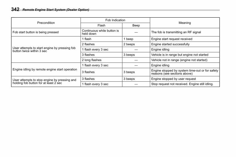
(344,1)
北米Model "A2600BE-B" EDITED: 2020/ 10/ 1
PreconditionFob Indication
MeaningFlash Beep
Fob start button is being pressed Continuous while button isheld down — The fob is transmitting an RF signal
User attempts to start engine by pressing fobbutton twice within 3 sec
1 flash 1 beep Engine start request received
2 flashes 2 beeps Engine started successfully1 flash every 3 sec — Engine idling
3 flashes 3 beeps Vehicle is in range but engine not started2 long flashes — Vehicle not in range (engine not started)
Engine idling by remote engine start operation1 flash every 3 sec — Engine idling
3 flashes 3 beeps Engine stopped by system time-out or for safetyreasons (see sections above)
User attempts to stop engine by pressing andholding fob button for at least 2 sec
3 flashes 3 beeps Engine stopped by user request1 flash every 3 sec — Stop request not received. Engine still idling.
Remote Engine Start System (Dealer Option)342
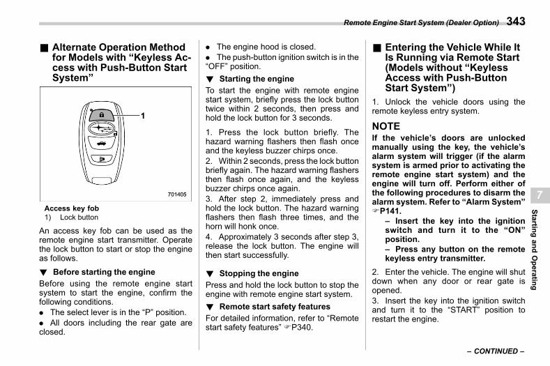
(345,1)
北米Model "A2600BE-B" EDITED: 2020/ 10/ 1
& Alternate Operation Methodfor Models with “Keyless Ac-cess with Push-Button StartSystem”
s07az22
Access key fob1) Lock button
An access key fob can be used as theremote engine start transmitter. Operatethe lock button to start or stop the engineas follows.! Before starting the engine
s07az2201Before using the remote engine startsystem to start the engine, confirm thefollowing conditions.. The select lever is in the “P” position.. All doors including the rear gate areclosed.
. The engine hood is closed.
. The push-button ignition switch is in the“OFF” position.! Starting the engine
s07az2202To start the engine with remote enginestart system, briefly press the lock buttontwice within 2 seconds, then press andhold the lock button for 3 seconds.
1. Press the lock button briefly. Thehazard warning flashers then flash onceand the keyless buzzer chirps once.2. Within 2 seconds, press the lock buttonbriefly again. The hazard warning flashersthen flash once again, and the keylessbuzzer chirps once again.3. After step 2, immediately press andhold the lock button. The hazard warningflashers then flash three times, and thehorn will honk once.4. Approximately 3 seconds after step 3,release the lock button. The engine willthen start successfully.
! Stopping the engines07az2203
Press and hold the lock button to stop theengine with remote engine start system.! Remote start safety features
s07az2204For detailed information, refer to “Remotestart safety features” FP340.
& Entering the Vehicle While ItIs Running via Remote Start(Models without “KeylessAccess with Push-ButtonStart System”)
s07az031. Unlock the vehicle doors using theremote keyless entry system.
NOTEIf the vehicle’s doors are unlockedmanually using the key, the vehicle’salarm system will trigger (if the alarmsystem is armed prior to activating theremote engine start system) and theengine will turn off. Perform either ofthe following procedures to disarm thealarm system. Refer to “Alarm System”FP141.
– Insert the key into the ignitionswitch and turn it to the “ON”position.– Press any button on the remotekeyless entry transmitter.
2. Enter the vehicle. The engine will shutdown when any door or rear gate isopened.3. Insert the key into the ignition switchand turn it to the “START” position torestart the engine.
– CONTINUED –
Remote Engine Start System (Dealer Option) 343
7
Startingand
Operating
(346,1)
北米Model "A2600BE-B" EDITED: 2020/ 10/ 1
& Entering the Vehicle While ItIs Running via Remote Start(Models with “Keyless Ac-cess with Push-Button StartSystem”)
s07az241. Unlock the vehicle doors using thekeyless access function and remote key-less entry system.
NOTEIf the vehicle’s doors are unlockedmanually using the key, the vehicle’salarm system will trigger (if the alarmsystem is armed prior to activating theremote engine start system) and theengine will turn off. Perform either ofthe following procedures to disarm thealarm system. Refer to “Alarm System”FP141.
– Turn the push-button ignitionswitch to the “ACC” or “ON” posi-tion.– Press any button on the accesskey fob.
2. Enter the vehicle. The engine willremain running provided the access keyfob is present and detected by the vehicle.3. Press the push-button ignition switchonce while depressing the brake pedalbefore driving your vehicle. The remoteengine starter transceiver (fob) will flash
and beep 3 times to indicate that theremote start system has been shut down.
& Entering the Vehicle Follow-ing Remote Engine StartShutdown
s07az10An alarm trigger may occur if the vehicle isopened by the remote keyless entrytransmitter within a few seconds immedi-ately following remote engine start shut-down.
& Pre-heating or Pre-coolingthe Interior of the Vehicle
s07az04Before exiting the vehicle, set the tem-perature controls to the desired setting andoperation. After the system starts theengine, the heater or air conditioning willactivate and heat or cool the interior toyour setting.
& Remote Transmitter Program(Remote Engine StarterTransceiver)
s07az13New transmitters can be programmed tothe remote engine start system in theevent that a transmitter is lost, stolen,damaged or additional transmitters aredesired (the system will accept up to eighttransmitters). New remote engine starttransmitters can be programmed accord-
ing to the following procedure.1. Open the driver’s door (the driver’sdoor must remain open throughout theentire process).2. Depress and hold the brake pedal.3. Turn the ignition switch to “ON” then“LOCK”/“OFF”, back to “ON” then “LOCK”/“OFF”, back to “ON” then “LOCK”/“OFF”,then back to “ON” again and leave theignition “ON” throughout the programmingprocess.4. The system will flash the side markerlights, tail lights and parking lights andhonk the horn three times, indicating thatthe system has entered the transmitterlearn mode.5. Press and release the “ ” button onthe transmitter that you want to program.6. The system will flash the side markerlights, tail lights and parking lights andhonk the horn one time, indicating that thesystem has learned the transmitter. Uponsuccessful programming, the remote startconfirmation transmitter button will flashone time.7. Repeat step 5 for any additionaltransmitters (the system will accept up toeight transmitters).8. The system will exit the transmitterlearn mode if the key is turned to the“LOCK”/“OFF” position, the door is closed
Remote Engine Start System (Dealer Option)344
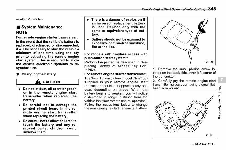
(347,1)
北米Model "A2600BE-B" EDITED: 2020/ 10/ 1
or after 2 minutes.
& System Maintenances07az09
NOTEFor remote engine starter transceiver:In the event that the vehicle’s battery isreplaced, discharged or disconnected,it will be necessary to start the vehicle aminimum of one time using the keyprior to activating the remote enginestart system. This is required to allowthe vehicle electronic systems to re-synchronize.
! Changing the batterys07az0901
CAUTION
. Do not let dust, oil or water get onor in the remote engine starttransmitter when replacing thebattery.
. Be careful not to damage theprinted circuit board in the re-mote engine start transmitterwhen replacing the battery.
. Be careful not to allow children totouch the battery and any re-moved parts; children couldswallow them.
. There is a danger of explosion ifan incorrect replacement batteryis used. Replace only with thesame or equivalent type of bat-tery.
. Battery should not be exposed toexcessive heat such as sunshine,fire or the like.
For models with “keyless access withpush-button start system”:Perform the procedure described in “Re-placing Battery of Access Key Fob”FP526.For remote engine starter transceiver:The 3-volt lithium battery (model CR-2450)supplied in your remote engine starttransmitter should last approximately oneyear, depending on usage. When thebattery begins to weaken, you will noticea decrease in range (distance from thevehicle that your remote control operates).Follow the instructions below to changethe remote engine start transmitter battery.
1. Remove the small phillips screw lo-cated on the back side lower left corner ofthe transmitter.2. Carefully pry the remote engine starttransmitter halves apart using a small flat-head screwdriver.
– CONTINUED –
Remote Engine Start System (Dealer Option) 345
7
Startingand
Operating
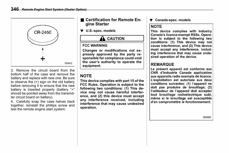
(348,1)
北米Model "A2600BE-B" EDITED: 2020/ 10/ 1
3. Remove the circuit board from thebottom half of the case and remove thebattery and replace with new one. Be sureto observe the (+) sign on the old batterybefore removing it to ensure that the newbattery is inserted properly (battery “+”should be pointed away from the transmit-ter circuit board on battery).4. Carefully snap the case halves backtogether, reinstall the phillips screw andtest the remote engine start system.
& Certification for Remote En-gine Starter
s07az23
! U.S.-spec. modelss07az2301
CAUTION
FCC WARNINGChanges or modifications not ex-pressly approved by the party re-sponsible for compliance could voidthe user’s authority to operate theequipment.
NOTEThis device complies with part 15 of theFCC Rules. Operation is subject to thefollowing two conditions: (1) This de-vice may not cause harmful interfer-ence, and (2) this device must acceptany interference received, includinginterference that may cause undesiredoperation.
! Canada-spec. modelss07az2302
Remote Engine Start System (Dealer Option)346
(349,1)
北米Model "A2600BE-B" EDITED: 2020/ 10/ 1
7-7. Continuously VariableTransmission
s07bg
WARNING
Do not shift from the “P” or “N”position into the “D” or “R” positionwhile depressing the acceleratorpedal. This may cause the vehicleto lurch forward or backward.
CAUTION
. Observe the following precau-tions. Failure to observe theseprecautions could cause damageto the transmission.– Shift into the “P” or “R” posi-
tion only after the vehicle hascompletely stopped.
– Do not shift from the “D”position into the “R” positionor vice versa until the vehiclehas completely stopped.
. Do not race the engine for morethan 5 seconds in any positionexcept the “N” or “P” positionwhen the brake is applied orwhen chocks are used in thewheels. This may cause the
transmission fluid to overheat.. Never move the vehicle rearward
by inertia with the select lever setin a forward driving position ormove the vehicle forward byinertia with the select lever setin the “R” position. Doing so mayresult in an unexpected accidentor malfunction.
. When parking the vehicle, firstsecurely apply the parking brakeand then place the select lever inthe “P” position. Do not park for along time with the select lever inany other position as doing socould result in a dead battery.
& Continuously Variable Trans-mission Features
s07bg06The continuously variable transmission iselectronically controlled and provides aninfinite number of forward speeds and 1reverse speed. It also has a manual mode.
NOTE. When the engine coolant tempera-ture is still low, the transmission willshift at higher engine speeds thanwhen the coolant temperature is suffi-ciently high in order to shorten thewarm-up time and improve driveability.
The gearshift timing will automaticallyshift to the normal timing after theengine has warmed up.. Immediately after transmission fluidis replaced, you may feel that thetransmission operation is somewhatunusual. This results from invalidationof data which the on-board computerhas collected and stored in memory toallow the transmission to shift at themost appropriate times for the currentcondition of your vehicle. Optimizedshifting will be restored as the vehiclecontinues to be driven for a while.. When driving under continuous hea-vy load conditions such as towing acamper or climbing a long, steep hill,the engine speed, vehicle speed and airconditioning system cooling perfor-mance may automatically be reduced.This is not amalfunction. This phenom-enon results from the engine controlfunction maintaining the cooling per-formance of the vehicle. The engineand vehicle speed will return to anormal speed when the engine is ableto maintain the optimum cooling per-formance after the heavy load de-creases. Driving under a heavy loadmust be performed with extreme care.Do not try to pass a vehicle in frontwhen driving on an uphill slope whiletowing.
– CONTINUED –
Continuously Variable Transmission 347
7
Startingand
Operating
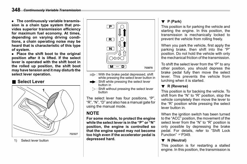
(350,1)
北米Model "A2600BE-B" EDITED: 2020/ 10/ 1
. The continuously variable transmis-sion is a chain type system that pro-vides superior transmission efficiencyfor maximum fuel economy. At times,depending on varying driving condi-tions, a chain operating noise may beheard that is characteristic of this typeof system.. Place the shift boot to the originalposition after it is lifted. If the selectlever is operated with the shift boot inthe rolled up position, the shift bootmay have tension and it may disturb theselect lever operation.
& Select Levers07bg01
1) Select lever button
: With the brake pedal depressed, shiftwhile pressing the select lever button in: Shift while pressing the select leverbutton in: Shift without pressing the select leverbutton
The select lever has four positions, “P”,“R”, “N”, “D” and also has amanual gate forusing the manual mode.
NOTEFor some models, to protect the enginewhile the select lever is in the “P” or “N”position, the engine is controlled sothat the engine speed may not becometoo high even if the accelerator pedal isdepressed hard.
! P (Park)s07bg0101
This position is for parking the vehicle andstarting the engine. In this position, thetransmission is mechanically locked toprevent the vehicle from rolling freely.
When you park the vehicle, first apply theparking brake, then shift into the “P”position. Do not hold the vehicle with onlythemechanical friction of the transmission.
To shift the select lever from the “P” to anyother position, you should depress thebrake pedal fully then move the selectlever. This prevents the vehicle fromlurching when it is started.! R (Reverse)
s07bg0102This position is for backing the vehicle. Toshift from the “N” to “R” position, stop thevehicle completely then move the lever tothe “R” position while pressing the selectlever button in.
When the ignition switch has been turnedto the “ACC” position, the movement of theselect lever from the “N” to “R” position isonly possible by depressing the brakepedal. For details, refer to “Shift LockFunction” FP349.! N (Neutral)
s07bg0103This position is for restarting a stalledengine. In this position, the transmission is
Continuously Variable Transmission348
(351,1)
北米Model "A2600BE-B" EDITED: 2020/ 10/ 1
neutral, meaning that the wheels andtransmission are not locked. Therefore,the vehicle will roll freely, even on theslightest incline unless the parking brakeor foot brake is applied.
Avoid coasting with the transmission inneutral. Engine braking has no effect inthis condition.
WARNING
Do not drive the vehicle with theselect lever in the “N” (neutral)position. Engine braking has noeffect in this condition and the riskof an accident is consequently in-creased.
! D (Drive)s07bg0104
This position is for normal driving. Thetransmission shifts automatically and con-tinuously into a suitable gear according tothe vehicle speed and the acceleration yourequire. Also, while driving up and down ahill, the transmission assists and controlsthe driving performance and engine brak-ing while corresponding to the road grade.
When more acceleration is required in “D”position, depress the accelerator pedalfully to the floor and hold that position. Thetransmission will automatically downshift.
In this case, the transmission will operatelike a conventional automatic transmis-sion. When you release the pedal, thetransmission will return to the original gearposition.
If one of the shift paddles behind thesteering wheel is operated while driving inthe “D” position, the transmission willtemporarily switch to the manual mode.In this mode, you can shift to any gearposition using the shift paddles. For detailsabout themanual mode, refer to “Selectionof Manual Mode” FP351. Once thevehicle speed stabilizes, the transmissionwill switch from the manual mode back tothe “D” position for normal driving.
! While climbing a grades07bg010401
When driving up a hill, undesired upshift isprevented from taking place when theaccelerator is released. This minimizesthe chance of subsequent downshifting toa lower gear when accelerating again. Thisprevents repeated upshifting and down-shifting resulting in a smoother operationof the vehicle.
NOTEThe transmission may downshift, de-pending on the way the acceleratorpedal is depressed to accelerate thevehicle again.
& Shift Lock Functions07bg04
The shift lock function helps prevent theimproper operation of the select lever.. The select lever cannot be operatedunless the ignition switch is turned to the“ON” position and the brake pedal isdepressed.. The select lever cannot be moved fromthe “P” position to any other position beforethe brake pedal is depressed. Depress thebrake pedal first, and then operate theselect lever.. Only the “P” position allows you to turnthe key from the “ACC” position to the“LOCK” position and remove the key fromthe ignition key cylinder (models without“keyless access with push-button startsystem”).. Only the “P” position allows you to turnthe push-button ignition switch to the“OFF” position (models with “keylessaccess with push-button start system”).. If the ignition switch is turned to the“ACC” position while the select lever is inthe “N” position, the select lever may notbe moved to the “P” position withoutdepressing the brake pedal and pressingthe select lever button.
– CONTINUED –
Continuously Variable Transmission 349
7
Startingand
Operating
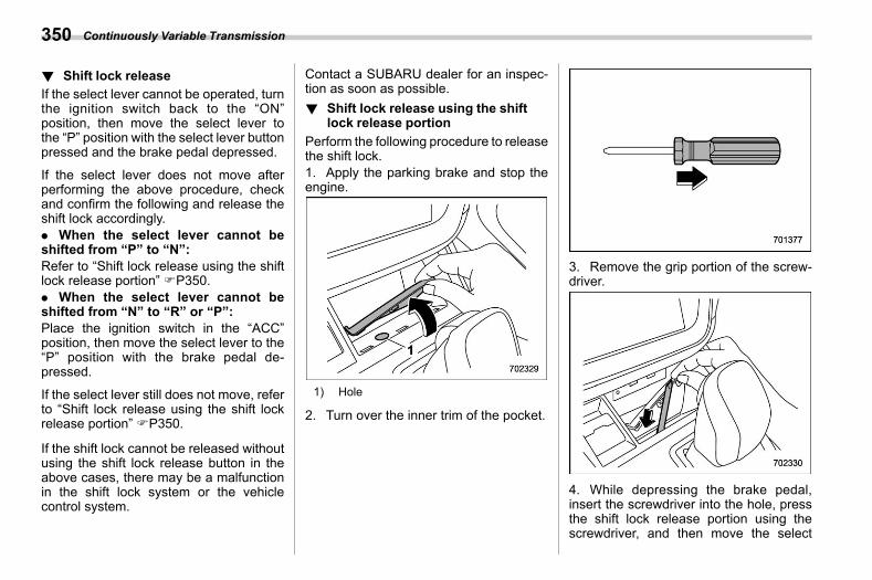
(352,1)
北米Model "A2600BE-B" EDITED: 2020/ 10/ 1
! Shift lock releases07bg0401
If the select lever cannot be operated, turnthe ignition switch back to the “ON”position, then move the select lever tothe “P” position with the select lever buttonpressed and the brake pedal depressed.
If the select lever does not move afterperforming the above procedure, checkand confirm the following and release theshift lock accordingly.. When the select lever cannot beshifted from “P” to “N”:Refer to “Shift lock release using the shiftlock release portion” FP350.. When the select lever cannot beshifted from “N” to “R” or “P”:Place the ignition switch in the “ACC”position, then move the select lever to the“P” position with the brake pedal de-pressed.
If the select lever still does not move, referto “Shift lock release using the shift lockrelease portion” FP350.
If the shift lock cannot be released withoutusing the shift lock release button in theabove cases, there may be a malfunctionin the shift lock system or the vehiclecontrol system.
Contact a SUBARU dealer for an inspec-tion as soon as possible.! Shift lock release using the shift
lock release portions07bg0402
Perform the following procedure to releasethe shift lock.1. Apply the parking brake and stop theengine.
1) Hole
2. Turn over the inner trim of the pocket.
3. Remove the grip portion of the screw-driver.
4. While depressing the brake pedal,insert the screwdriver into the hole, pressthe shift lock release portion using thescrewdriver, and then move the select
Continuously Variable Transmission350
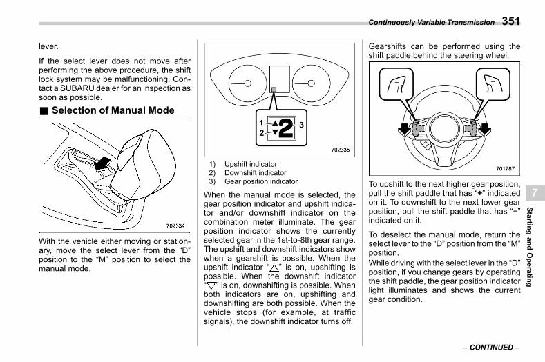
(353,1)
北米Model "A2600BE-B" EDITED: 2020/ 10/ 1
lever.
If the select lever does not move afterperforming the above procedure, the shiftlock system may be malfunctioning. Con-tact a SUBARU dealer for an inspection assoon as possible.& Selection of Manual Mode
s07bg02
With the vehicle either moving or station-ary, move the select lever from the “D”position to the “M” position to select themanual mode.
1) Upshift indicator2) Downshift indicator3) Gear position indicator
When the manual mode is selected, thegear position indicator and upshift indica-tor and/or downshift indicator on thecombination meter illuminate. The gearposition indicator shows the currentlyselected gear in the 1st-to-8th gear range.The upshift and downshift indicators showwhen a gearshift is possible. When theupshift indicator “ ” is on, upshifting ispossible. When the downshift indicator“ ” is on, downshifting is possible. Whenboth indicators are on, upshifting anddownshifting are both possible. When thevehicle stops (for example, at trafficsignals), the downshift indicator turns off.
Gearshifts can be performed using theshift paddle behind the steering wheel.
To upshift to the next higher gear position,pull the shift paddle that has “+” indicatedon it. To downshift to the next lower gearposition, pull the shift paddle that has “−”indicated on it.
To deselect the manual mode, return theselect lever to the “D” position from the “M”position.While driving with the select lever in the “D”position, if you change gears by operatingthe shift paddle, the gear position indicatorlight illuminates and shows the currentgear condition.
– CONTINUED –
Continuously Variable Transmission 351
7
Startingand
Operating
(354,1)
北米Model "A2600BE-B" EDITED: 2020/ 10/ 1
CAUTION
Donot place or hang anything on theshift paddles. Doing somay result inaccidental gear shifting.
NOTEPlease read the following points care-fully and bear them in mind when usingthe manual mode.. If you attempt to shift downwhen theengine speed is too high, i.e., when adownshift would push the tachometerneedle beyond the red zone, beeps willbe emitted to warn you that the down-shift is not possible.. If you attempt to shift up when thevehicle speed is too low, the transmis-sion will not respond.. You can perform a skip-shift (forexample, from 4th to 2nd) by operatingthe shift paddle twice in rapid succes-sion.. The transmission automatically se-lects 1st gear when the vehicle stopsmoving.. If the temperature of the transmis-sion fluid becomes too high, the “ATOILTEMP” warning light will illuminate.Immediately stop the vehicle in a safeplace and let the engine idle until the
warning light turns off.
For models with SI-DRIVE, by selectingSport Sharp (S#) mode, upshifting willnot occur automatically. According tothe road conditions, shift changemanually so that the tachometer needledoes not enter the red zone. Also, if theengine revolutions reach the specifiednumber, the fuel supply will be cut. Inthis case, perform shift up operation.
& Driving Tipss07bg05
NOTEIf the accelerator and brake pedals aredepressed at the same time, drivingtorque may be restrained. This is not amalfunction.. On a road surface where there is a riskof wheelspin (for example, a snow- orgravel-covered road), you can pull awayfrom a standstill safely and easily by firstselecting the 2nd gear of the manualmode.. Always apply the foot or parking brakewhen the vehicle is stopped in the “D” or“R” position.. Make sure to apply the parking brakewhen parking your vehicle. Do not hold thevehicle with only the transmission.
. Do not keep the vehicle in a stationaryposition on an uphill grade by using the “D”position. Use the brake instead.. The engine may, on rare occasions,knock when the vehicle rapidly acceler-ates or rapidly pulls away from a standstill.This phenomenon does not indicate amalfunction.
Continuously Variable Transmission352
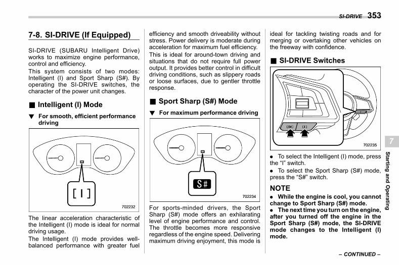
(355,1)
北米Model "A2600BE-B" EDITED: 2020/ 10/ 1
7-8. SI-DRIVE (If Equipped)s07bc
SI-DRIVE (SUBARU Intelligent Drive)works to maximize engine performance,control and efficiency.This system consists of two modes:Intelligent (I) and Sport Sharp (S#). Byoperating the SI-DRIVE switches, thecharacter of the power unit changes.
& Intelligent (I) Modes07bc02
! For smooth, efficient performancedriving
s07bc0201
The linear acceleration characteristic ofthe Intelligent (I) mode is ideal for normaldriving usage.The Intelligent (I) mode provides well-balanced performance with greater fuel
efficiency and smooth driveability withoutstress. Power delivery is moderate duringacceleration for maximum fuel efficiency.This is ideal for around-town driving andsituations that do not require full poweroutput. It provides better control in difficultdriving conditions, such as slippery roadsor loose surfaces, due to gentler throttleresponse.
& Sport Sharp (S#) Modes07bc04
! For maximum performance drivings07bc0401
For sports-minded drivers, the SportSharp (S#) mode offers an exhilaratinglevel of engine performance and control.The throttle becomes more responsiveregardless of the engine speed. Deliveringmaximum driving enjoyment, this mode is
ideal for tackling twisting roads and formerging or overtaking other vehicles onthe freeway with confidence.
& SI-DRIVE Switchess07bc01
. To select the Intelligent (I) mode, pressthe “I” switch.. To select the Sport Sharp (S#) mode,press the “S#” switch.
NOTE. While the engine is cool, you cannotchange to Sport Sharp (S#) mode.. The next time you turn on the engine,after you turned off the engine in theSport Sharp (S#) mode, the SI-DRIVEmode changes to the Intelligent (I)mode.
– CONTINUED –
SI-DRIVE 353
7
Startingand
Operating
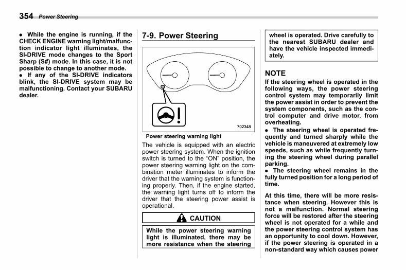
(356,1)
北米Model "A2600BE-B" EDITED: 2020/ 10/ 1
. While the engine is running, if theCHECK ENGINE warning light/malfunc-tion indicator light illuminates, theSI-DRIVE mode changes to the SportSharp (S#) mode. In this case, it is notpossible to change to another mode.. If any of the SI-DRIVE indicatorsblink, the SI-DRIVE system may bemalfunctioning. Contact your SUBARUdealer.
7-9. Power Steerings07aj
Power steering warning lightThe vehicle is equipped with an electricpower steering system. When the ignitionswitch is turned to the “ON” position, thepower steering warning light on the com-bination meter illuminates to inform thedriver that the warning system is function-ing properly. Then, if the engine started,the warning light turns off to inform thedriver that the steering power assist isoperational.
CAUTION
While the power steering warninglight is illuminated, there may bemore resistance when the steering
wheel is operated. Drive carefully tothe nearest SUBARU dealer andhave the vehicle inspected immedi-ately.
NOTEIf the steering wheel is operated in thefollowing ways, the power steeringcontrol system may temporarily limitthe power assist in order to prevent thesystem components, such as the con-trol computer and drive motor, fromoverheating.. The steering wheel is operated fre-quently and turned sharply while thevehicle is maneuvered at extremely lowspeeds, such as while frequently turn-ing the steering wheel during parallelparking.. The steering wheel remains in thefully turned position for a long period oftime.
At this time, there will be more resis-tance when steering. However this isnot a malfunction. Normal steeringforce will be restored after the steeringwheel is not operated for a while andthe power steering control system hasan opportunity to cool down. However,if the power steering is operated in anon-standard way which causes power
Power Steering354
(357,1)
北米Model "A2600BE-B" EDITED: 2020/ 10/ 1
assist limitation to occur too frequently,this may result in a malfunction of thepower steering control system.
7-10. Brakings07ak
& Braking Tipss07ak01
WARNING
Never rest your foot on the brakepedal while driving. This can causedangerous overheating of thebrakes and needless wear on thebrake pads.
! When the brakes get wets07ak0101
When driving in rain or after washing thevehicle, the brakes may get wet. As aresult, brake stopping distance will belonger. To dry the brakes, drive the vehicleat a safe speedwhile lightly depressing thebrake pedal to heat up the brakes.! Use of engine braking
s07ak0102Remember to make use of engine brakingin addition to foot braking. When descend-ing a grade, if only the foot brake is used,the brakes may start working improperlybecause of brake fluid overheating,caused by overheated brake pads. To helpprevent this, shift into a lower gear to getstronger engine braking.! Braking when a tire is punctured
s07ak0103Do not depress the brake pedal suddenlywhen a tire is punctured. This could cause
a loss of control of the vehicle. Keepdriving straight ahead while graduallyreducing speed. Then slowly pull off theroad to a safe place.
& Brake Systems07ak02
! Two separate circuitss07ak0201
Your vehicle has a dual circuit brakesystem. Each circuit works diagonallyacross the vehicle. If one circuit of thebrake system should fail, the other half ofthe system still works. If one circuit fails,the brake pedal will go down much closerto the floor than usual and you will need topress it down much harder. And a muchlonger distance will be needed to stop thevehicle.! Brake booster
s07ak0202The brake booster uses engine manifoldvacuum to assist braking force. Do not turnoff the engine while driving because thatwill turn off the brake booster, resulting inpoor braking power.The brakes will continue to work evenwhen the brake booster completely stopsfunctioning. If this happens, however, youwill have to depress the pedal much harderthan normal and the braking distance willincrease.
– CONTINUED –
Braking 355
7
Startingand
Operating
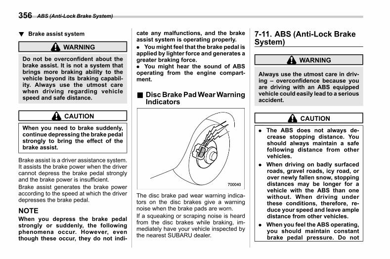
(358,1)
北米Model "A2600BE-B" EDITED: 2020/ 10/ 1
! Brake assist systems07ak0203
WARNING
Do not be overconfident about thebrake assist. It is not a system thatbrings more braking ability to thevehicle beyond its braking capabil-ity. Always use the utmost carewhen driving regarding vehiclespeed and safe distance.
CAUTION
When you need to brake suddenly,continue depressing the brake pedalstrongly to bring the effect of thebrake assist.
Brake assist is a driver assistance system.It assists the brake power when the drivercannot depress the brake pedal stronglyand the brake power is insufficient.Brake assist generates the brake poweraccording to the speed at which the driverdepresses the brake pedal.
NOTEWhen you depress the brake pedalstrongly or suddenly, the followingphenomena occur. However, eventhough these occur, they do not indi-
cate any malfunctions, and the brakeassist system is operating properly.. Youmight feel that the brake pedal isapplied by lighter force and generates agreater braking force.. You might hear the sound of ABSoperating from the engine compart-ment.
& DiscBrakePadWearWarningIndicators
s07ak03
The disc brake pad wear warning indica-tors on the disc brakes give a warningnoise when the brake pads are worn.If a squeaking or scraping noise is heardfrom the disc brakes while braking, im-mediately have your vehicle inspected bythe nearest SUBARU dealer.
7-11. ABS (Anti-Lock BrakeSystem)
s07al
WARNING
Always use the utmost care in driv-ing – overconfidence because youare driving with an ABS equippedvehicle could easily lead to a seriousaccident.
CAUTION
. The ABS does not always de-crease stopping distance. Youshould always maintain a safefollowing distance from othervehicles.
. When driving on badly surfacedroads, gravel roads, icy road, orover newly fallen snow, stoppingdistances may be longer for avehicle with the ABS than onewithout. When driving underthese conditions, therefore, re-duce your speed and leave ampledistance from other vehicles.
. When you feel the ABS operating,you should maintain constantbrake pedal pressure. Do not
ABS (Anti-Lock Brake System)356
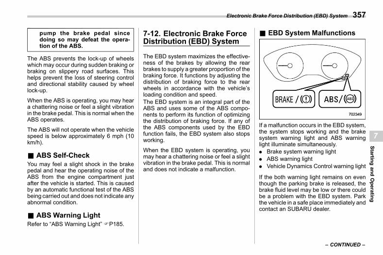
(359,1)
北米Model "A2600BE-B" EDITED: 2020/ 10/ 1
pump the brake pedal sincedoing so may defeat the opera-tion of the ABS.
The ABS prevents the lock-up of wheelswhich may occur during sudden braking orbraking on slippery road surfaces. Thishelps prevent the loss of steering controland directional stability caused by wheellock-up.
When the ABS is operating, you may heara chattering noise or feel a slight vibrationin the brake pedal. This is normal when theABS operates.
The ABS will not operate when the vehiclespeed is below approximately 6 mph (10km/h).
& ABS Self-Checks07al01
You may feel a slight shock in the brakepedal and hear the operating noise of theABS from the engine compartment justafter the vehicle is started. This is causedby an automatic functional test of the ABSbeing carried out and does not indicate anyabnormal condition.
& ABS Warning Lights07al02
Refer to “ABS Warning Light” FP185.
7-12. Electronic Brake ForceDistribution (EBD) System
s07am
The EBD system maximizes the effective-ness of the brakes by allowing the rearbrakes to supply a greater proportion of thebraking force. It functions by adjusting thedistribution of braking force to the rearwheels in accordance with the vehicle’sloading condition and speed.The EBD system is an integral part of theABS and uses some of the ABS compo-nents to perform its function of optimizingthe distribution of braking force. If any ofthe ABS components used by the EBDfunction fails, the EBD system also stopsworking.
When the EBD system is operating, youmay hear a chattering noise or feel a slightvibration in the brake pedal. This is normaland does not indicate a malfunction.
& EBD System Malfunctionss07am01
If a malfunction occurs in the EBD system,the system stops working and the brakesystem warning light and ABS warninglight illuminate simultaneously.. Brake system warning light. ABS warning light. Vehicle Dynamics Control warning light
If the both warning light remains on eventhough the parking brake is released, thebrake fluid level may be low or there couldbe a problem with the EBD system. Parkthe vehicle in a safe place immediately andcontact an SUBARU dealer.
– CONTINUED –
Electronic Brake Force Distribution (EBD) System 357
7
Startingand
Operating
(360,1)
北米Model "A2600BE-B" EDITED: 2020/ 10/ 1
WARNING
. Driving with the brake systemwarning light on is dangerous.This indicates your brake systemmay not be working properly. Ifthe light remains on, have thebrakes inspected by a SUBARUdealer immediately.
. If at all in doubt about whether thebrakes are operating properly, donot drive the vehicle. Have yourvehicle towed to the nearestSUBARU dealer for repair.
7-13. Vehicle Dynamics Con-trol System
s07an
WARNING
Always use the utmost care in driv-ing – overconfidence because youare driving with a Vehicle DynamicsControl system equipped vehiclecould easily lead to a serious acci-dent.
CAUTION
. Even if your vehicle is equippedwith Vehicle Dynamics Controlsystem, winter tires should beused when driving on snow-cov-ered or icy roads; in addition,vehicle speed should be reducedconsiderably. Simply having aVehicle Dynamics Control sys-tem does not guarantee that thevehicle will be able to avoidaccidents in any situation.
. Activation of the Vehicle Dy-namics Control system is anindication that the road beingtravelled on has a slippery sur-face; since having Vehicle Dy-
namics Control is no guaranteethat full vehicle control will bemaintained at all times and underall conditions, its activationshould be seen as a sign thatthe speed of the vehicle shouldbe reduced considerably.
. Whenever suspension compo-nents, steering components, oran axle are removed from avehicle equipped with the VehicleDynamics Control system, havean inspection of that systemperformed by an authorizedSUBARU dealer.
. The following precautions shouldbe observed in order to ensurethat the Vehicle Dynamics Con-trol system is operating properly.– All four wheels should be
fitted with tires of the samesize, type, and brand. Further-more, the amount of wearshould be the same for all fourtires.
– Keep the tire pressure at theproper level as shown on thevehicle placard attached tothe driver’s side door pillar.
– When replacing a flat tire, useonly the specified temporary
Vehicle Dynamics Control System358
(361,1)
北米Model "A2600BE-B" EDITED: 2020/ 10/ 1
spare tire. However, even withthe specified temporary sparetire, the effectiveness of theVehicle Dynamics Controlsystem will be reduced.
. If non-matching tires are used,the Vehicle Dynamics Controlsystem may not operate cor-rectly.
In the event of wheelspin and/or skiddingon a slippery road surface and/or duringcornering and/or an evasive maneuver,the Vehicle Dynamics Control systemadjusts the engine’s output and thewheels’ respective braking forces to helpmaintain traction and directional control.. Traction Control FunctionThe traction control function is designed toprevent spinning of the driving wheels onslippery road surfaces, thereby helping tomaintain traction and directional control.Activation of this function is indicated byflashing of the Vehicle Dynamics Controloperation indicator light.
. Skid Suppression FunctionThe skid suppression function is designedto help maintain directional stability bysuppressing the wheels’ tendency to slidesideways during steering operations. Acti-vation of this function is indicated by
flashing of the Vehicle Dynamics Controloperation indicator light.
NOTE. The Vehicle Dynamics Control sys-tem may be considered normal whenthe following conditions occur.
– Slight twitching of the brakepedal is felt.– The vehicle or steering wheelshakes to a small degree.– An operating noise from the en-gine compartment is heard brieflywhen starting the engine and whendriving off after starting the engine.– The brake pedal seems to joltwhen driving off after starting theengine.
. In the following circumstances, thevehicle may be less stable than it feelsto the driver. The Vehicle DynamicsControl System may therefore operate.Such operation does not indicate asystem malfunction.
– On gravel-covered or ruttedroads– On unfinished roads– When the vehicle is towing atrailer (Outback)– When the vehicle is fitted withsnow tires or winter tires
. Activation of the Vehicle DynamicsControl system will cause operation ofthe steering wheel to feel slightlydifferent compared to that for normalconditions.. It is always important to reducespeed when approaching a corner,even if the vehicle is equipped withVehicle Dynamics Control.. Always turn off the engine beforereplacing a tire as failure to do so mayrender the Vehicle Dynamics Controlsystem unable to operate correctly.
& Vehicle Dynamics ControlSystem Monitor
s07an01Refer to “Vehicle Dynamics Control Warn-ing Light/Vehicle Dynamics Control Op-eration Indicator Light” FP190 and “Vehi-cle Dynamics Control OFF Indicator Light”FP191.
& To Turn On/Off the VehicleDynamics Control System
s07an07To turn the Vehicle Dynamics Control onand off, operate the center informationdisplay. Refer to “Car settings” FP220(11.6-inch display models) or “Vehiclesetting icons” FP239 (dual 7.0-inch dis-play models).Creating an adequate driving wheel slip by
– CONTINUED –
Vehicle Dynamics Control System 359
7
Startingand
Operating
(362,1)
北米Model "A2600BE-B" EDITED: 2020/ 10/ 1
deactivating the Vehicle Dynamics Controlsystem temporarily may help to escapefrom the following situations. Turn theVehicle Dynamics Control system off whennecessary.. A standing start on a steeply slopingroad with a snowy, gravel-covered, orotherwise slippery surface. Extrication of the vehicle when itswheels are stuck in mud or deep snow
When turning off the Vehicle DynamicsControl system during engine operation,the Vehicle Dynamics Control OFF indica-tor light on the combination meter illumi-nates. The Vehicle Dynamics Controlsystem will be deactivated. When “VehicleDynamics Control” has been touchedagain to reactivate the Vehicle DynamicsControl system, the Vehicle DynamicsControl OFF indicator light turns off.You should not deactivate the VehicleDynamics Control system except underthe above-mentioned situations.
CAUTION
The Vehicle Dynamics Control sys-tem helps prevent unstable vehiclemotion such as skidding using con-trol of the brakes and engine power.Do not turn off the Vehicle DynamicsControl system unless it is abso-
lutely necessary. If you must turn offthe Vehicle Dynamics Control sys-tem, drive very carefully based onthe road surface condition.
NOTE. When “Vehicle Dynamics Control”has been touched to deactivate theVehicle Dynamics Control system, theVehicle Dynamics Control system auto-matically reactivates itself the next timethe ignition switch is turned to the“LOCK”/“OFF” position and the engineis restarted.. When “Vehicle Dynamics Control”has been touched to deactivate theVehicle Dynamics Control system, thevehicle’s running performance is com-parable with that of a vehicle that doesnot have a Vehicle Dynamics Controlsystem. Do not deactivate the VehicleDynamics Control system except whenabsolutely necessary.. Even when the Vehicle DynamicsControl system is deactivated, compo-nents of the brake control system maystill activate. When the brake controlsystem is activated, the Vehicle Dy-namics Control operation indicatorlight flashes.
7-14. X-MODE (Outback)s07bi
WARNING
. Always use the utmost care indriving – overconfidence be-cause you are driving a vehiclewith X-MODE could easily lead toa serious accident.
. Always use the utmost care indriving – overconfidence be-cause you are driving a vehiclewith hill descent control functioncould easily lead to a seriousaccident. Be especially careful,and depress the brake pedal ifnecessary when driving on ex-tremely steep downhill, frozen,muddy or sandy roads. Failureto control the vehicle’s speedmay cause a loss of control andresult in a serious accident.
CAUTION
. Even if your vehicle is equippedwith X-MODE, winter tires shouldbe used when driving on snow-covered or icy roads; in addition,vehicle speed should be reducedconsiderably. Simply having
X-MODE (Outback)360
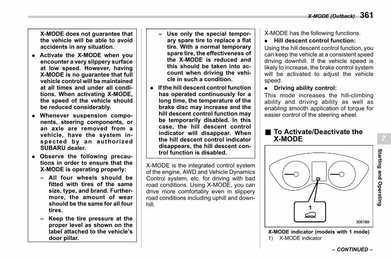
(363,1)
北米Model "A2600BE-B" EDITED: 2020/ 10/ 1
X-MODE does not guarantee thatthe vehicle will be able to avoidaccidents in any situation.
. Activate the X-MODE when youencounter a very slippery surfaceat low speed. However, havingX-MODE is no guarantee that fullvehicle control will bemaintainedat all times and under all condi-tions. When activating X-MODE,the speed of the vehicle shouldbe reduced considerably.
. Whenever suspension compo-nents, steering components, oran axle are removed from avehicle, have the system in-spected by an authorizedSUBARU dealer.
. Observe the following precau-tions in order to ensure that theX-MODE is operating properly:– All four wheels should be
fitted with tires of the samesize, type, and brand. Further-more, the amount of wearshould be the same for all fourtires.
– Keep the tire pressure at theproper level as shown on thelabel attached to the vehicle’sdoor pillar.
– Use only the special tempor-ary spare tire to replace a flattire. With a normal temporaryspare tire, the effectiveness ofthe X-MODE is reduced andthis should be taken into ac-count when driving the vehi-cle in such a condition.
. If the hill descent control functionhas operated continuously for along time, the temperature of thebrake disc may increase and thehill descent control function maybe temporarily disabled. In thiscase, the hill descent controlindicator will disappear. Whenthe hill descent control indicatordisappears, the hill descent con-trol function is disabled.
X-MODE is the integrated control systemof the engine, AWD and Vehicle DynamicsControl system, etc. for driving with badroad conditions. Using X-MODE, you candrive more comfortably even in slipperyroad conditions including uphill and down-hill.
X-MODE has the following functions.. Hill descent control function:Using the hill descent control function, youcan keep the vehicle at a consistent speeddriving downhill. If the vehicle speed islikely to increase, the brake control systemwill be activated to adjust the vehiclespeed.. Driving ability control:This mode increases the hill-climbingability and driving ability as well asenabling smooth application of torque foreasier control of the steering wheel.
& To Activate/Deactivate theX-MODE
s07bi01
X-MODE indicator (models with 1 mode)1) X-MODE indicator
– CONTINUED –
X-MODE (Outback) 361
7
Startingand
Operating
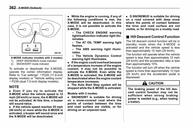
(364,1)
北米Model "A2600BE-B" EDITED: 2020/ 10/ 1
X-MODE indicator (models with 2 modes)1) DEEP SNOW/MUD mode indicator2) SNOW/DIRT mode indicator
To activate or deactivate the X-MODE,operate the center information display.Refer to “Car settings” FP220 (11.6-inchdisplay models) or “Vehicle setting icons”FP239 (dual 7.0-inch display models).
NOTE. Even if you try to activate theX-MODE when the vehicle speed is 12mph (20 km/h) ormore, the X-MODEwillnot be activated. At this time, a buzzerwill sound twice.. If the vehicle speed reaches 25 mph(40 km/h) or more while the X-MODE isactivated, a buzzer will sound once andthe X-MODE will be deactivated.
. While the engine is running, if any ofthe following conditions is met, theX-MODE will be deactivated. In thiscase, it is not possible to activate theX-MODE.
– The CHECK ENGINE warninglight/malfunction indicator light illu-minates.– The AT OIL TEMP warning lightflashes.– The ABS warning light illumi-nates.– The Vehicle Dynamics Controlwarning light illuminates.
. If the engine could overheat becauseof a temperature increase of the enginecoolant, it may not be possible toactivate the X-MODE. Even while theX-MODE is activated, the X-MODE willbe deactivatedwhen the engine coolanttemperature increases.. The Auto Start Stop system will bestopped while the X-MODE is activated.
Models with 2 modes:. SNOW/DIRT is suitable for drivingon a snow-covered road where thepoints of contact between the tiresand road surface are visible, or fordriving on an unpaved road.
. D.SNOW/MUD is suitable for drivingon a road covered with deep snowwhere the points of contact betweenthe tires and road surface are notvisible, or for driving on a muddy road.
& Hill Descent Control Functions07bi03
The hill descent control function will be instandby mode when the X-MODE isactivated and the vehicle speed is lessthan approximately 12 mph (20 km/h).The function will operate when the vehiclespeed is less than approximately 12 mph(20 km/h) and the accelerator ratio is lessthan approximately 10%.The function will turn off when the vehiclespeed is more than approximately 12 mph(20 km/h) and the accelerator pedal isdepressed.
CAUTION
The braking power of the hill des-cent control function may not besufficient when strong brakingpower is needed (e.g., when towinga trailer).
X-MODE (Outback)362
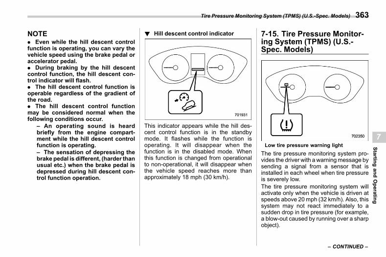
(365,1)
北米Model "A2600BE-B" EDITED: 2020/ 10/ 1
NOTE. Even while the hill descent controlfunction is operating, you can vary thevehicle speed using the brake pedal oraccelerator pedal.. During braking by the hill descentcontrol function, the hill descent con-trol indicator will flash.. The hill descent control function isoperable regardless of the gradient ofthe road.. The hill descent control functionmay be considered normal when thefollowing conditions occur.
– An operating sound is heardbriefly from the engine compart-ment while the hill descent controlfunction is operating.– The sensation of depressing thebrake pedal is different, (harder thanusual etc.) when the brake pedal isdepressed during hill descent con-trol function operation.
! Hill descent control indicators07bi0301
This indicator appears while the hill des-cent control function is in the standbymode. It flashes while the function isoperating. It will disappear when thefunction is in the disabled mode. Whenthis function is changed from operationalto non-operational, it will disappear whenthe vehicle speed reaches more thanapproximately 18 mph (30 km/h).
7-15. Tire Pressure Monitor-ing System (TPMS) (U.S.-Spec. Models)
s07ao
Low tire pressure warning lightThe tire pressure monitoring system pro-vides the driver with awarningmessage bysending a signal from a sensor that isinstalled in each wheel when tire pressureis severely low.The tire pressure monitoring system willactivate only when the vehicle is driven atspeeds above 20mph (32 km/h). Also, thissystem may not react immediately to asudden drop in tire pressure (for example,a blow-out caused by running over a sharpobject).
– CONTINUED –
Tire Pressure Monitoring System (TPMS) (U.S.-Spec. Models) 363
7
Startingand
Operating
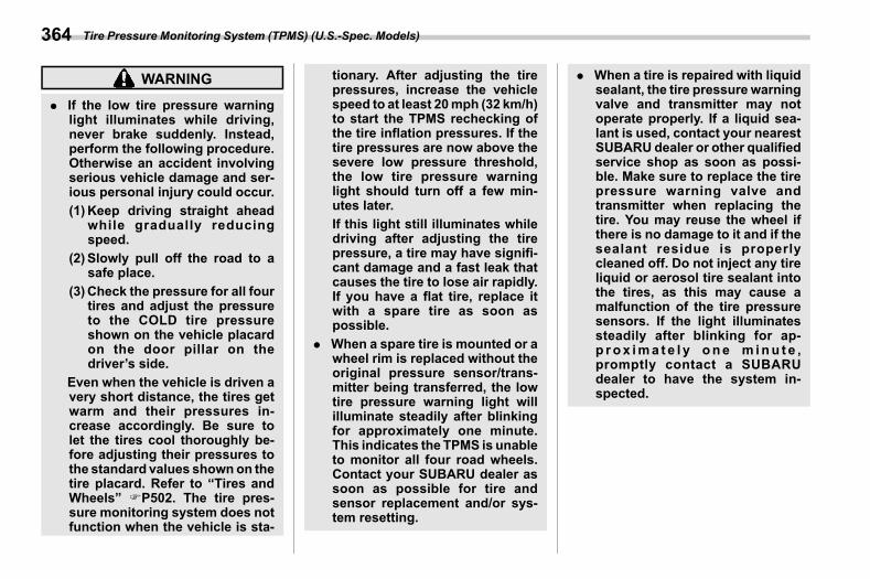
(366,1)
北米Model "A2600BE-B" EDITED: 2020/ 10/ 1
WARNING
. If the low tire pressure warninglight illuminates while driving,never brake suddenly. Instead,perform the following procedure.Otherwise an accident involvingserious vehicle damage and ser-ious personal injury could occur.(1) Keep driving straight ahead
while gradually reducingspeed.
(2) Slowly pull off the road to asafe place.
(3) Check the pressure for all fourtires and adjust the pressureto the COLD tire pressureshown on the vehicle placardon the door pillar on thedriver’s side.
Even when the vehicle is driven avery short distance, the tires getwarm and their pressures in-crease accordingly. Be sure tolet the tires cool thoroughly be-fore adjusting their pressures tothe standard values shownon thetire placard. Refer to “Tires andWheels” FP502. The tire pres-sure monitoring system does notfunction when the vehicle is sta-
tionary. After adjusting the tirepressures, increase the vehiclespeed to at least 20mph (32 km/h)to start the TPMS rechecking ofthe tire inflation pressures. If thetire pressures are now above thesevere low pressure threshold,the low tire pressure warninglight should turn off a few min-utes later.If this light still illuminates whiledriving after adjusting the tirepressure, a tire may have signifi-cant damage and a fast leak thatcauses the tire to lose air rapidly.If you have a flat tire, replace itwith a spare tire as soon aspossible.
. When a spare tire is mounted or awheel rim is replaced without theoriginal pressure sensor/trans-mitter being transferred, the lowtire pressure warning light willilluminate steadily after blinkingfor approximately one minute.This indicates the TPMS is unableto monitor all four road wheels.Contact your SUBARU dealer assoon as possible for tire andsensor replacement and/or sys-tem resetting.
. When a tire is repaired with liquidsealant, the tire pressure warningvalve and transmitter may notoperate properly. If a liquid sea-lant is used, contact your nearestSUBARU dealer or other qualifiedservice shop as soon as possi-ble. Make sure to replace the tirepressure warning valve andtransmitter when replacing thetire. You may reuse the wheel ifthere is no damage to it and if thesealant residue is properlycleaned off. Do not inject any tireliquid or aerosol tire sealant intothe tires, as this may cause amalfunction of the tire pressuresensors. If the light illuminatessteadily after blinking for ap-p rox ima t e l y one m inu t e ,promptly contact a SUBARUdealer to have the system in-spected.
Tire Pressure Monitoring System (TPMS) (U.S.-Spec. Models)364
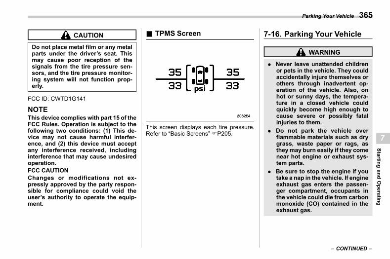
(367,1)
北米Model "A2600BE-B" EDITED: 2020/ 10/ 1
CAUTION
Do not place metal film or any metalparts under the driver’s seat. Thismay cause poor reception of thesignals from the tire pressure sen-sors, and the tire pressure monitor-ing system will not function prop-erly.
FCC ID: CWTD1G141
NOTEThis device complies with part 15 of theFCC Rules. Operation is subject to thefollowing two conditions: (1) This de-vice may not cause harmful interfer-ence, and (2) this device must acceptany interference received, includinginterference that may cause undesiredoperation.FCC CAUTIONChanges or modifications not ex-pressly approved by the party respon-sible for compliance could void theuser’s authority to operate the equip-ment.
& TPMS Screens07ao05
This screen displays each tire pressure.Refer to “Basic Screens” FP205.
7-16. Parking Your Vehicles07ap
WARNING
. Never leave unattended childrenor pets in the vehicle. They couldaccidentally injure themselves orothers through inadvertent op-eration of the vehicle. Also, onhot or sunny days, the tempera-ture in a closed vehicle couldquickly become high enough tocause severe or possibly fatalinjuries to them.
. Do not park the vehicle overflammable materials such as drygrass, waste paper or rags, asthey may burn easily if they comenear hot engine or exhaust sys-tem parts.
. Be sure to stop the engine if youtake a nap in the vehicle. If engineexhaust gas enters the passen-ger compartment, occupants inthe vehicle could die from carbonmonoxide (CO) contained in theexhaust gas.
– CONTINUED –
Parking Your Vehicle 365
7
Startingand
Operating
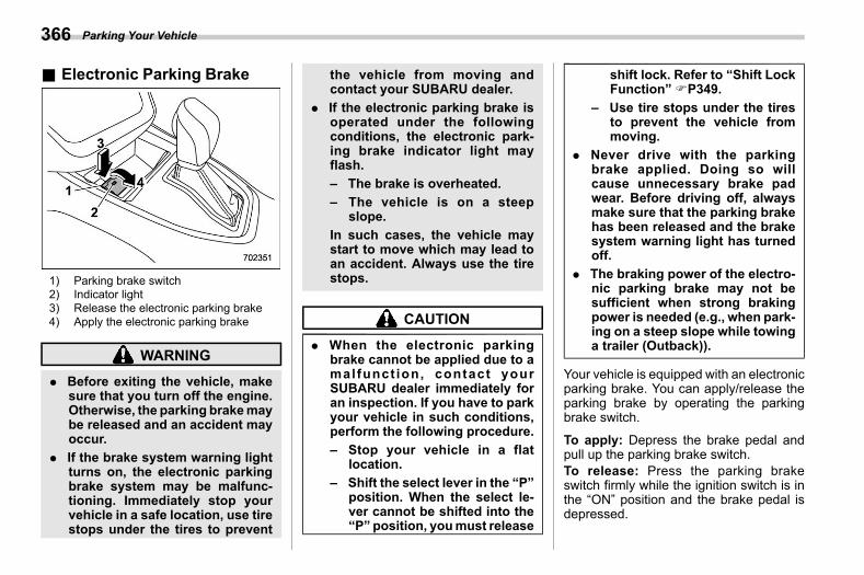
(368,1)
北米Model "A2600BE-B" EDITED: 2020/ 10/ 1
& Electronic Parking Brakes07ap03
1) Parking brake switch2) Indicator light3) Release the electronic parking brake4) Apply the electronic parking brake
WARNING
. Before exiting the vehicle, makesure that you turn off the engine.Otherwise, the parking brakemaybe released and an accident mayoccur.
. If the brake system warning lightturns on, the electronic parkingbrake system may be malfunc-tioning. Immediately stop yourvehicle in a safe location, use tirestops under the tires to prevent
the vehicle from moving andcontact your SUBARU dealer.
. If the electronic parking brake isoperated under the followingconditions, the electronic park-ing brake indicator light mayflash.– The brake is overheated.– The vehicle is on a steep
slope.In such cases, the vehicle maystart to move which may lead toan accident. Always use the tirestops.
CAUTION
. When the electronic parkingbrake cannot be applied due to amalfunct ion, contact yourSUBARU dealer immediately foran inspection. If you have to parkyour vehicle in such conditions,perform the following procedure.– Stop your vehicle in a flat
location.– Shift the select lever in the “P”
position. When the select le-ver cannot be shifted into the“P” position, youmust release
shift lock. Refer to “Shift LockFunction” FP349.
– Use tire stops under the tiresto prevent the vehicle frommoving.
. Never drive with the parkingbrake applied. Doing so willcause unnecessary brake padwear. Before driving off, alwaysmake sure that the parking brakehas been released and the brakesystem warning light has turnedoff.
. The braking power of the electro-nic parking brake may not besufficient when strong brakingpower is needed (e.g., when park-ing on a steep slope while towinga trailer (Outback)).
Your vehicle is equipped with an electronicparking brake. You can apply/release theparking brake by operating the parkingbrake switch.
To apply: Depress the brake pedal andpull up the parking brake switch.To release: Press the parking brakeswitch firmly while the ignition switch is inthe “ON” position and the brake pedal isdepressed.
Parking Your Vehicle366
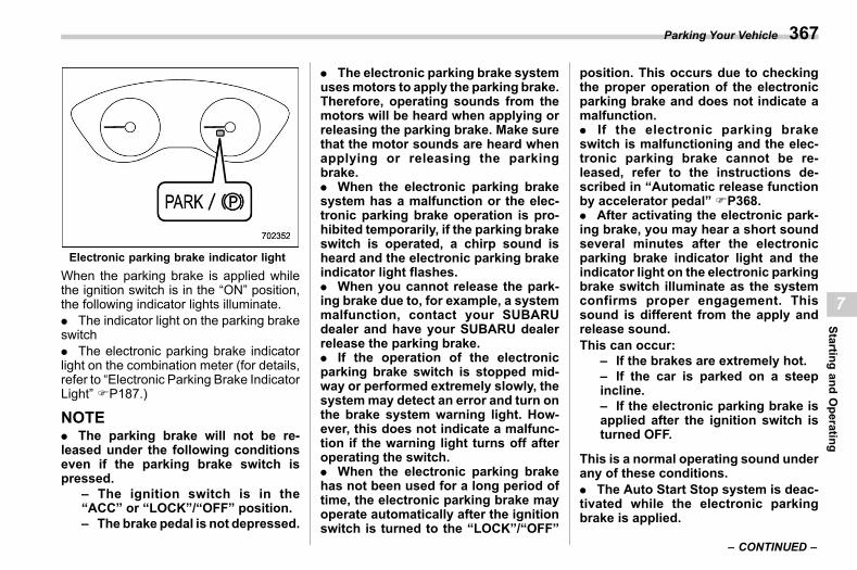
(369,1)
北米Model "A2600BE-B" EDITED: 2020/ 10/ 1
Electronic parking brake indicator lightWhen the parking brake is applied whilethe ignition switch is in the “ON” position,the following indicator lights illuminate.. The indicator light on the parking brakeswitch. The electronic parking brake indicatorlight on the combination meter (for details,refer to “Electronic Parking Brake IndicatorLight” FP187.)
NOTE. The parking brake will not be re-leased under the following conditionseven if the parking brake switch ispressed.
– The ignition switch is in the“ACC” or “LOCK”/“OFF” position.– The brake pedal is not depressed.
. The electronic parking brake systemusesmotors to apply the parking brake.Therefore, operating sounds from themotors will be heard when applying orreleasing the parking brake. Make surethat the motor sounds are heard whenapplying or releasing the parkingbrake.. When the electronic parking brakesystem has a malfunction or the elec-tronic parking brake operation is pro-hibited temporarily, if the parking brakeswitch is operated, a chirp sound isheard and the electronic parking brakeindicator light flashes.. When you cannot release the park-ing brake due to, for example, a systemmalfunction, contact your SUBARUdealer and have your SUBARU dealerrelease the parking brake.. If the operation of the electronicparking brake switch is stopped mid-way or performed extremely slowly, thesystemmay detect an error and turn onthe brake system warning light. How-ever, this does not indicate a malfunc-tion if the warning light turns off afteroperating the switch.. When the electronic parking brakehas not been used for a long period oftime, the electronic parking brake mayoperate automatically after the ignitionswitch is turned to the “LOCK”/“OFF”
position. This occurs due to checkingthe proper operation of the electronicparking brake and does not indicate amalfunction.. If the electronic parking brakeswitch is malfunctioning and the elec-tronic parking brake cannot be re-leased, refer to the instructions de-scribed in “Automatic release functionby accelerator pedal” FP368.. After activating the electronic park-ing brake, you may hear a short soundseveral minutes after the electronicparking brake indicator light and theindicator light on the electronic parkingbrake switch illuminate as the systemconfirms proper engagement. Thissound is different from the apply andrelease sound.This can occur:
– If the brakes are extremely hot.– If the car is parked on a steepincline.– If the electronic parking brake isapplied after the ignition switch isturned OFF.
This is a normal operating sound underany of these conditions.. The Auto Start Stop system is deac-tivated while the electronic parkingbrake is applied.
– CONTINUED –
Parking Your Vehicle 367
7
Startingand
Operating
(370,1)
北米Model "A2600BE-B" EDITED: 2020/ 10/ 1
. If you operate the electronic parkingbrake switch while the Auto Start Stopsystem is activated, the Auto Start Stopsystem will be deactivated. The elec-tronic parking brake will activate afterthe engine is restarted. After the elec-tronic parking brake indicator light isilluminated, release your foot from thebrake pedal.. When starting the engine or restart-ing the engine using theAuto Start Stopsystem, if you operate the electronicparking brake switch, the electronicparking brake indicator light may flashtemporarily. However, this is not amalfunction if the light turns off afterthe electronic parking brake is deacti-vated.
! Automatic release function by ac-celerator pedal
s07ap0301The electronic parking brake system hasan automatic release function. The parkingbrake will be automatically released bydepressing the accelerator pedal. How-ever, the automatic release function doesnot operate under the following conditions.. Any door (other than the trunk lid or reargate) is open.. The driver’s seatbelt is not fastened.
If the parking brake is automaticallyreleased, the electronic parking brake
indicator light and the indicator light onthe parking brake switch turn off.
NOTEEven if you have applied the parkingbrake, the parking brake will be auto-matically released when the accelera-tor pedal is depressed.
! Auto Vehicle Hold functions07ap0305
The Auto Vehicle Hold function will auto-matically keep the vehicle stopped evenafter releasing the brake pedal when thevehicle is at a complete stop, such as attraffic signals.
WARNING
. Do not use the Auto Vehicle Holdfunction on a steep hill or slip-pery road. The vehicle may moveevenwhenusing theAuto VehicleHold function, causing seriousinjury or accidents.
. Do not use the Auto Vehicle Holdfunction to park the vehicle. Thevehicle may move unexpectedly,causing serious injury or acci-dents. Make sure to shift theselect lever to the “P” positionand apply the electronic parkingbrake in the following cases.
– When you are going to parkyour vehicle.
– When passengers are gettingin or out of the vehicle.
– When you are loading or un-loading.
. When using the Auto VehicleHold function, do not release thebrake pedal before the Auto Ve-hicle Hold operation indicatorilluminates. The vehicle maymove unexpectedly, causing ser-ious injury or accidents.
. Deactivate the Auto Vehicle Holdfunction in the following cases.Otherwise, the vehicle may moveunexpectedly, causing seriousinjury or accidents.– When washing your vehicle in
an automatic car wash– When being towed
CAUTION
. When stopping on a steep slopewith the Auto Vehicle Hold func-tion turned on, the electronicparking brake may be automati-cally applied. Then the electronicparking brake indicator light will
Parking Your Vehicle368
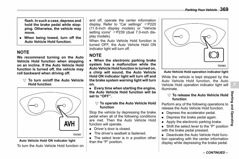
(371,1)
北米Model "A2600BE-B" EDITED: 2020/ 10/ 1
flash. In such a case, depress andhold the brake pedal while stop-ping. Otherwise, the vehicle maymove.
. When being towed, turn off theAuto Vehicle Hold function.
NOTEWe recommend turning on the AutoVehicle Hold function when stoppingon an incline. If the Auto Vehicle Holdfunction is turned off, the vehicle mayroll backward when driving off.
! To turn on/off the Auto VehicleHold function
s07ap030501
Auto Vehicle Hold ON indicator lightTo turn the Auto Vehicle Hold function on
and off, operate the center informationdisplay. Refer to “Car settings” FP220(11.6-inch display models) or “Vehiclesetting icons” FP239 (dual 7.0-inch dis-play models).When the Auto Vehicle Hold function isturned OFF, the Auto Vehicle Hold ONindicator light will turn off.
NOTE. When the electronic parking brakesystem has a malfunction while theAuto Vehicle Hold function is turned on,a chirp will sound, the Auto VehicleHold ON indicator light will turn off andthe brake system warning light will turnon.. Every time when starting the engine,the Auto Vehicle Hold function will beset to “OFF”.
! To operate the Auto Vehicle Holdfunction
s07ap030503
Stop the vehicle by depressing the brakepedal when all of the following conditionsare met. Then the Auto Vehicle Holdfunction will operate.. Driver’s door is closed.. The driver’s seatbelt is fastened.. The select lever is in a position otherthan the “P” position.
Auto Vehicle Hold operation indicator lightWhile the vehicle is kept stopped by theAuto Vehicle Hold function, the AutoVehicle Hold operation indicator light willilluminate.
! To release the Auto Vehicle Holdfunction
s07ap030504
Perform any of the following operations torelease the Auto Vehicle Hold function.. Depress the accelerator pedal.. Depress the brake pedal again.. Apply the electronic parking brake.. Shift the select lever to the “P” positionwith the brake pedal pressed.. Deactivate the Auto Vehicle Hold func-tion operating with the center informationdisplay while depressing the brake pedal.
– CONTINUED –
Parking Your Vehicle 369
7
Startingand
Operating
(372,1)
北米Model "A2600BE-B" EDITED: 2020/ 10/ 1
When the Auto Vehicle Hold function isreleased, the Auto Vehicle Hold operationindicator light will turn off.
Under any of the following conditions, theAuto Vehicle Hold function will be auto-matically released and the electronicparking brake will be automatically ap-plied.. The Auto Vehicle Hold function hasbeen in operation for 10 minutes.. The driver’s seatbelt is unfastened.. The ignition switch is turned to the“LOCK”/“OFF” position.. The vehicle is stopped on a steepslope.. The Auto Vehicle Hold function ismalfunctioning.
In such cases, the Auto Vehicle Holdoperation indicator light will turn off andthe electronic parking brake indicator lightwill illuminate.
! Tipss07ap030505
. When the electronic parking brake isautomatically applied with the vehicle keptstopped by the Auto Vehicle Hold function,release the electronic parking brake byeither of the following operations beforestarting off. Then make sure that theelectronic parking brake indicator light isoff.
– Depress the accelerator pedal withthe driver’s seatbelt fastened and withthe doors closed.– Press the electronic parking brakeswitch with the brake pedal depressed.
. Under certain conditions, including amalfunction of the Auto Vehicle Hold, awarning buzzer will sound and a warningmessage will appear on the combinationmeter display (color LCD). All warningmessages should be strictly observed.. On a steep slope, the vehicle cannot bekept stopped by the Auto Vehicle Holdfunction. In such a case, depress and holdthe brake pedal.. When stopping on a steep slope withthe Auto Vehicle Hold function activated,the electronic parking brake may automa-tically applied after stopping, then theelectronic parking brake indicator lightmay flash. In such a case, depress andhold the brake pedal while stopped.Otherwise, the vehicle may move. Whengetting out of the vehicle, stop the vehicleon a flat surface, then apply the electronicparking brake.. If the Auto Vehicle Hold ON indicatorlight does not illuminates even aftertouching “Auto Vehicle Hold (AVH)” withthe operating conditions met, the functionmay have a malfunction. Contact yourSUBARU dealer for an inspection.
. You may hear a sound while the AutoVehicle Hold function is keeping yourvehicle stopped. This is normal, and doesnot represent a malfunction.. While the vehicle is kept stopped by theAuto Vehicle Hold function, the brakepedal may feel stiff. However, this is not amalfunction.. When using the Auto Vehicle Holdfunction, depress the brake pedal firmly.Otherwise, the Auto Vehicle Hold may notoperate.! Emergency brake
s07ap0303
CAUTION
Use the emergency brake only incase of an emergency. If the emer-gency brake is excessively used, thebrake parts will wear down faster orthe brake may not work sufficientlydue to brake overheating.
NOTE. While using the emergency brake,the electronic parking brake indicatorlight and the indicator light on theparking brake switch illuminate and achirp sounds.. While using the emergency brake, asound may be heard from the engine
Parking Your Vehicle370
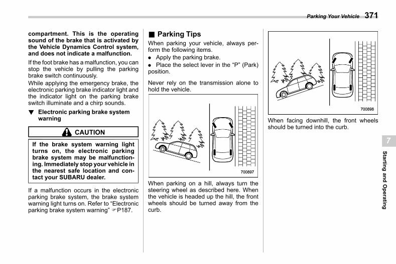
(373,1)
北米Model "A2600BE-B" EDITED: 2020/ 10/ 1
compartment. This is the operatingsound of the brake that is activated bythe Vehicle Dynamics Control system,and does not indicate a malfunction.If the foot brake has amalfunction, you canstop the vehicle by pulling the parkingbrake switch continuously.While applying the emergency brake, theelectronic parking brake indicator light andthe indicator light on the parking brakeswitch illuminate and a chirp sounds.! Electronic parking brake system
warnings07ap0304
CAUTION
If the brake system warning lightturns on, the electronic parkingbrake system may be malfunction-ing. Immediately stop your vehicle inthe nearest safe location and con-tact your SUBARU dealer.
If a malfunction occurs in the electronicparking brake system, the brake systemwarning light turns on. Refer to “Electronicparking brake system warning” FP187.
& Parking Tipss07ap02
When parking your vehicle, always per-form the following items.. Apply the parking brake.. Place the select lever in the “P” (Park)position.
Never rely on the transmission alone tohold the vehicle.
When parking on a hill, always turn thesteering wheel as described here. Whenthe vehicle is headed up the hill, the frontwheels should be turned away from thecurb.
When facing downhill, the front wheelsshould be turned into the curb.
Parking Your Vehicle 371
7
Startingand
Operating
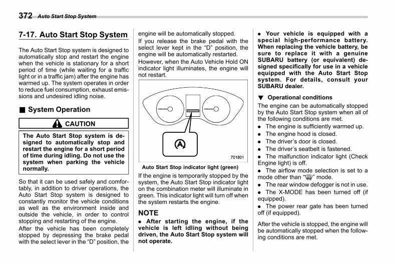
(374,1)
北米Model "A2600BE-B" EDITED: 2020/ 10/ 1
7-17. Auto Start Stop Systems07bh
The Auto Start Stop system is designed toautomatically stop and restart the enginewhen the vehicle is stationary for a shortperiod of time (while waiting for a trafficlight or in a traffic jam) after the engine haswarmed up. The system operates in orderto reduce fuel consumption, exhaust emis-sions and undesired idling noise.
& System Operations07bh01
CAUTION
The Auto Start Stop system is de-signed to automatically stop andrestart the engine for a short periodof time during idling. Do not use thesystem when parking the vehiclenormally.
So that it can be used safely and comfor-tably, in addition to driver operations, theAuto Start Stop system is designed toconstantly monitor the vehicle conditionsas well as the environment inside andoutside the vehicle, in order to controlstopping and restarting of the engine.After the vehicle has been completelystopped by depressing the brake pedalwith the select lever in the “D” position, the
engine will be automatically stopped.If you release the brake pedal with theselect lever kept in the “D” position, theengine will be automatically restarted.However, when the Auto Vehicle Hold ONindicator light illuminates, the engine willnot restart.
Auto Start Stop indicator light (green)If the engine is temporarily stopped by thesystem, the Auto Start Stop indicator lighton the combination meter will illuminate ingreen. This indicator light will turn off whenthe system restarts the engine.
NOTE. After starting the engine, if thevehicle is left idling without beingdriven, the Auto Start Stop system willnot operate.
. Your vehicle is equipped with aspecial high-performance battery.When replacing the vehicle battery, besure to replace it with a genuineSUBARU battery (or equivalent) de-signed specifically for use in a vehicleequipped with the Auto Start Stopsystem. For details, consult yourSUBARU dealer.
! Operational conditionss07bh0105
The engine can be automatically stoppedby the Auto Start Stop system when all ofthe following conditions are met.. The engine is sufficiently warmed up.. The engine hood is closed.. The driver’s door is closed.. The driver’s seatbelt is fastened.. The malfunction indicator light (CheckEngine light) is off.. The airflow mode selection is set to amode other than “ ” mode.. The rear window defogger is not in use.. The X-MODE has been turned off (ifequipped).. The power rear gate has been turnedoff (if equipped).
After the vehicle is stopped, the engine willbe automatically stopped when the follow-ing conditions are met.
Auto Start Stop System372
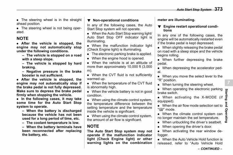
(375,1)
北米Model "A2600BE-B" EDITED: 2020/ 10/ 1
. The steering wheel is in the straightahead position.. The steering wheel is not being oper-ated.
NOTE. After the vehicle is stopped, theengine may not automatically stopunder the following conditions.
– The vehicle is stopped on a roadwith a steep slope.– The vehicle is stopped by hardbraking.– Negative pressure in the brakebooster is not sufficient.
. After the vehicle is stopped, theengine may not automatically stop ifthe brake pedal is not fully depressed.Make sure to depress the brake pedalfirmly when stopping the vehicle.. In the following cases, it may takesome time for the Auto Start Stopsystem to operate.
– When the battery is dischargedbecause the vehicle has not beenused for a long period of time, etc.– The coolant temperature is low.– When the battery terminals havebeen reconnected after replacingthe battery, etc.
! Non-operational conditionss07bh0106
In any of the following cases, the AutoStart Stop system will not operate.. When the Auto Start Stop warning light/Auto Start Stop OFF indicator light isilluminating.. When the malfunction indicator light(Check Engine light) is illuminating.. The electronic parking brake is applied.. When the engine hood is opened.. When the vehicle is at an altitude ofmore than approximately 10,000 ft (3,000m).. When the CVT fluid is not sufficientlywarmed up.. When the temperature of the CVT fluidis abnormally high.. When the vehicle battery is not in goodcondition.. When using the climate control system,the temperature difference between thesetting temperature and the temperatureinside the vehicle is significant.. When using the climate control system,the amount of air flow is significant.
NOTEThe Auto Start Stop system may notoperate if the malfunction indicatorlight (Check Engine light) or otherwarning lights on the combination
meter are illuminating.
! Engine restart operational condi-tions
s07bh0107In any one of the following cases, theengine will be automatically restarted evenif the brake pedal is kept depressed.. When slightly releasing the brake pedalon road with a steep slope and the vehiclebegins rolling.. When further depressing the brakepedal.. When depressing the accelerator ped-al.. When you move the select lever to the“R” position.. When turning the steering wheel.. When operating the electronic parkingbrake switch.. When activating the X-MODE (ifequipped).. When the air flow mode selection set to“ ” mode.. When the climate control system canno longer maintain the set temperature.. When unbuckling the driver’s seatbelt.. When opening the driver’s door.. When activating the rear window de-fogger.. When the Auto Vehicle Hold function isreleased, refer to “Auto Vehicle Hold
– CONTINUED –
Auto Start Stop System 373
7
Startingand
Operating
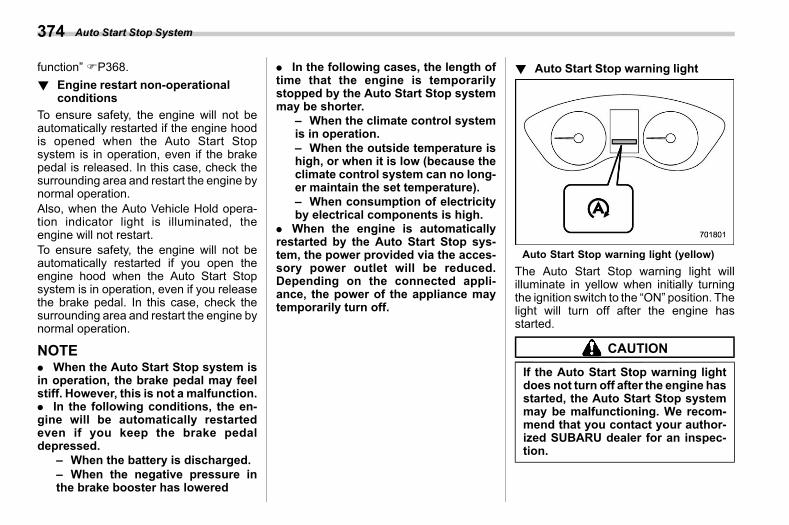
(376,1)
北米Model "A2600BE-B" EDITED: 2020/ 10/ 1
function” FP368.! Engine restart non-operational
conditionss07bh0108
To ensure safety, the engine will not beautomatically restarted if the engine hoodis opened when the Auto Start Stopsystem is in operation, even if the brakepedal is released. In this case, check thesurrounding area and restart the engine bynormal operation.Also, when the Auto Vehicle Hold opera-tion indicator light is illuminated, theengine will not restart.To ensure safety, the engine will not beautomatically restarted if you open theengine hood when the Auto Start Stopsystem is in operation, even if you releasethe brake pedal. In this case, check thesurrounding area and restart the engine bynormal operation.
NOTE. When the Auto Start Stop system isin operation, the brake pedal may feelstiff. However, this is not a malfunction.. In the following conditions, the en-gine will be automatically restartedeven if you keep the brake pedaldepressed.
– When the battery is discharged.– When the negative pressure inthe brake booster has lowered
. In the following cases, the length oftime that the engine is temporarilystopped by the Auto Start Stop systemmay be shorter.
– When the climate control systemis in operation.– When the outside temperature ishigh, or when it is low (because theclimate control system can no long-er maintain the set temperature).– When consumption of electricityby electrical components is high.
. When the engine is automaticallyrestarted by the Auto Start Stop sys-tem, the power provided via the acces-sory power outlet will be reduced.Depending on the connected appli-ance, the power of the appliance maytemporarily turn off.
! Auto Start Stop warning lights07bh0109
Auto Start Stop warning light (yellow)The Auto Start Stop warning light willilluminate in yellow when initially turningthe ignition switch to the “ON” position. Thelight will turn off after the engine hasstarted.
CAUTION
If the Auto Start Stop warning lightdoes not turn off after the engine hasstarted, the Auto Start Stop systemmay be malfunctioning. We recom-mend that you contact your author-ized SUBARU dealer for an inspec-tion.
Auto Start Stop System374
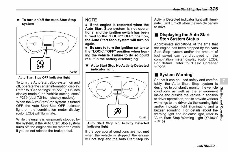
(377,1)
北米Model "A2600BE-B" EDITED: 2020/ 10/ 1
! To turn on/off the Auto Start Stopsystem
s07bh0111
Auto Start Stop OFF indicator lightTo turn the Auto Start Stop system on andoff, operate the center information display.Refer to “Car settings” FP220 (11.6-inchdisplay models) or “Vehicle setting icons”FP239 (dual 7.0-inch display models).When the Auto Start Stop system is turnedOFF, the Auto Start Stop OFF indicatorlight on the combination meter display(color LCD) will illuminate.
While the engine is temporarily stopped bythe system, if the Auto Start Stop systemturns off, the engine will be restarted evenif you do not release the brake pedal.
NOTE. If the engine is restarted when theAuto Start Stop system is not opera-tional and the ignition switch has beenturned to the “LOCK”/“OFF” position,the Auto Start Stop system will turn onagain.. Be sure to turn the ignition switch tothe “LOCK”/“OFF” position when leav-ing the vehicle. Failure to do so couldresult in the battery discharging.
! AutoStart StopNoActivityDetectedindicator light
s07bh0110
Auto Start Stop No Activity Detectedindicator light
If the operational conditions are not metwhen the vehicle is stopped, the enginewill not stop and the Auto Start Stop No
Activity Detected indicator light will illumi-nate. It will turn off when the vehicle beginsto drive.
& Displaying the Auto StartStop System Status
s07bh02Approximate indications of the time thatthe engine has been stopped by the AutoStart Stop system and/or the amount offuel saved can be displayed on thecombination meter display (color LCD).For details, refer to “Basic Screens”FP205.
& System Warnings07bh03
So that it can be used safely and comfor-tably, the Auto Start Stop system isdesigned to constantly monitor the vehicleconditions as well as the environmentinside and outside the vehicle in additionto driver operations, and to provide variouswarnings to the driver via the warning lightand/or indicator light illuminating and abuzzer sounding. For details about thewarning light and indicator light, refer to“Auto Start Stop Warning Light (Yellow)”FP198.
– CONTINUED –
Auto Start Stop System 375
7
Startingand
Operating
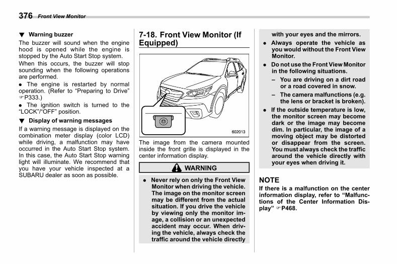
(378,1)
北米Model "A2600BE-B" EDITED: 2020/ 10/ 1
! Warning buzzers07bh0301
The buzzer will sound when the enginehood is opened while the engine isstopped by the Auto Start Stop system.When this occurs, the buzzer will stopsounding when the following operationsare performed.. The engine is restarted by normaloperation. (Refer to “Preparing to Drive”FP333.). The ignition switch is turned to the“LOCK”/“OFF” position.! Display of warning messages
s07bh0302If a warning message is displayed on thecombination meter display (color LCD)while driving, a malfunction may haveoccurred in the Auto Start Stop system.In this case, the Auto Start Stop warninglight will illuminate. We recommend thatyou have your vehicle inspected at aSUBARU dealer as soon as possible.
7-18. Front View Monitor (IfEquipped)
s07bq
The image from the camera mountedinside the front grille is displayed in thecenter information display.
WARNING
. Never rely on only the Front ViewMonitor when driving the vehicle.The image on the monitor screenmay be different from the actualsituation. If you drive the vehicleby viewing only the monitor im-age, a collision or an unexpectedaccident may occur. When driv-ing the vehicle, always check thetraffic around the vehicle directly
with your eyes and the mirrors.. Always operate the vehicle as
you would without the Front ViewMonitor.
. Donot use the Front ViewMonitorin the following situations.– You are driving on a dirt road
or a road covered in snow.– The camera malfunctions (e.g.
the lens or bracket is broken).. If the outside temperature is low,
the monitor screen may becomedark or the image may becomedim. In particular, the image of amoving object may be distortedor disappear from the screen.Youmust always check the trafficaround the vehicle directly withyour eyes when driving it.
NOTEIf there is a malfunction on the centerinformation display, refer to “Malfunc-tions of the Center Information Dis-play” FP468.
Front View Monitor376
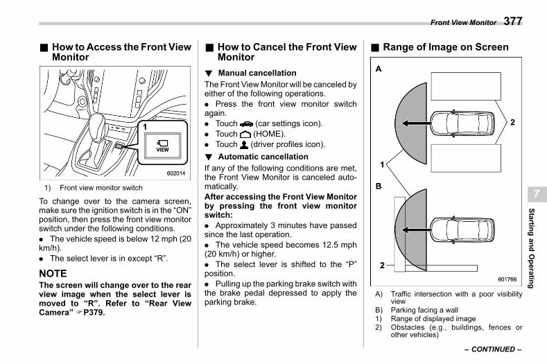
(379,1)
北米Model "A2600BE-B" EDITED: 2020/ 10/ 1
& How toAccess the Front ViewMonitor
s07bq01
1) Front view monitor switch
To change over to the camera screen,make sure the ignition switch is in the “ON”position, then press the front view monitorswitch under the following conditions.. The vehicle speed is below 12 mph (20km/h).. The select lever is in except “R”.
NOTEThe screen will change over to the rearview image when the select lever ismoved to “R”. Refer to “Rear ViewCamera” FP379.
& How to Cancel the Front ViewMonitor
s07bq02
! Manual cancellations07bq0201
The Front ViewMonitor will be canceled byeither of the following operations.. Press the front view monitor switchagain.. Touch (car settings icon).. Touch (HOME).. Touch (driver profiles icon).! Automatic cancellation
s07bq0202If any of the following conditions are met,the Front View Monitor is canceled auto-matically.After accessing the Front View Monitorby pressing the front view monitorswitch:. Approximately 3 minutes have passedsince the last operation.. The vehicle speed becomes 12.5 mph(20 km/h) or higher.. The select lever is shifted to the “P”position.. Pulling up the parking brake switch withthe brake pedal depressed to apply theparking brake.
& Range of Image on Screens07bq03
A) Traffic intersection with a poor visibilityview
B) Parking facing a wall1) Range of displayed image2) Obstacles (e.g., buildings, fences or
other vehicles)
– CONTINUED –
Front View Monitor 377
7
Startingand
Operating
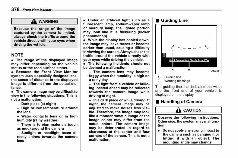
(380,1)
北米Model "A2600BE-B" EDITED: 2020/ 10/ 1
WARNING
Because the range of the imagecaptured by the camera is limited,always check the traffic around thevehicle directly with your eyes whendriving the vehicle.
NOTE. The range of the displayed imagemay differ depending on the vehiclestatus or the road surface status.. Because the Front View Monitorsystem uses a specially designed lens,the sense of distance in the displayedimage is different from the actual dis-tance.. The camera imagemay be difficult toview in the following situations. This isnot a malfunction.
– Dark place (at night)– High or low temperature aroundthe lens– Water contacts lens or in highhumidity (rainy weather)– There is foreign materials (suchas mud) around the camera– Sunlight or headlight beam di-rectly shines towards the cameralens
. Under an artificial light such as afluorescent lamp, sodium-vapor lampor mercury lamp, the lighted portionmay look like it is flickering (flickerphenomenon).. While the display has cooled down,the image may leave traces or becomedarker than usual, causing a difficultyin viewing the screen. Always check thetraffic around the vehicle directly withyour eyes while driving the vehicle.. The following incidents should notbe deemed a malfunction.
– The camera lens may becomefoggy when the humidity is high ona rainy day.– The light from a vehicle or build-ing located ahead may be reflectedtowards the camera image whiledriving at night.– In a dark place or while driving atnight, the camera image may beadjusted to make noises less visi-ble. Therefore, the image may looklike a monochromatic image or theimage colors may differ from theactual colors. The camera imagemay be deteriorated in regard tosharpness at the center and fourcorners of the screen. This is not amalfunction.
& Guiding Lines07bq04
1) Guiding line2) Warning message
The guiding line that indicates the widthand the front end of your vehicle isdisplayed on the display.
& Handling of Cameras07bq05
CAUTION
Observe the following instructions.Otherwise, the systemmaymalfunc-tion.. Do not apply any strong impact to
the camera such as banging it orhitting it with an object. Themounting angle may change.
Front View Monitor378
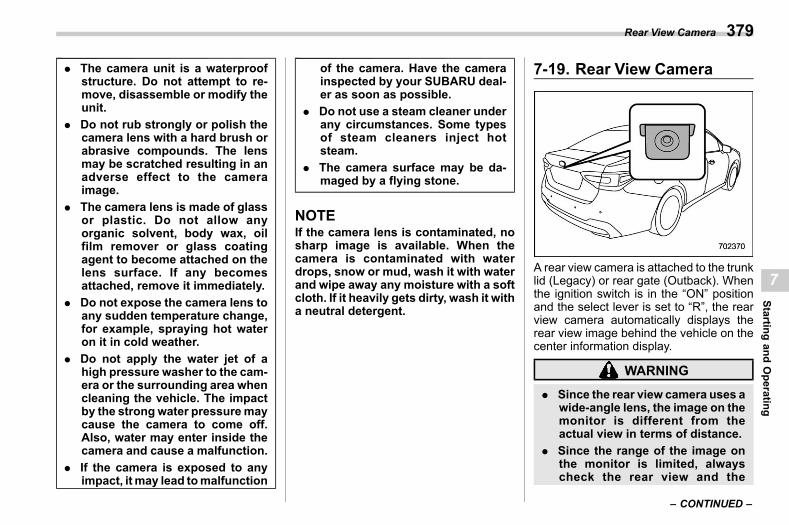
(381,1)
北米Model "A2600BE-B" EDITED: 2020/ 10/ 1
. The camera unit is a waterproofstructure. Do not attempt to re-move, disassemble or modify theunit.
. Do not rub strongly or polish thecamera lens with a hard brush orabrasive compounds. The lensmay be scratched resulting in anadverse effect to the cameraimage.
. The camera lens is made of glassor plastic. Do not allow anyorganic solvent, body wax, oilfilm remover or glass coatingagent to become attached on thelens surface. If any becomesattached, remove it immediately.
. Do not expose the camera lens toany sudden temperature change,for example, spraying hot wateron it in cold weather.
. Do not apply the water jet of ahigh pressure washer to the cam-era or the surrounding area whencleaning the vehicle. The impactby the strongwater pressuremaycause the camera to come off.Also, water may enter inside thecamera and cause a malfunction.
. If the camera is exposed to anyimpact, itmay lead tomalfunction
of the camera. Have the camerainspected by your SUBARU deal-er as soon as possible.
. Do not use a steam cleaner underany circumstances. Some typesof steam cleaners inject hotsteam.
. The camera surface may be da-maged by a flying stone.
NOTEIf the camera lens is contaminated, nosharp image is available. When thecamera is contaminated with waterdrops, snow or mud, wash it with waterand wipe away any moisture with a softcloth. If it heavily gets dirty, wash it witha neutral detergent.
7-19. Rear View Cameras07br
A rear view camera is attached to the trunklid (Legacy) or rear gate (Outback). Whenthe ignition switch is in the “ON” positionand the select lever is set to “R”, the rearview camera automatically displays therear view image behind the vehicle on thecenter information display.
WARNING
. Since the rear view camera uses awide-angle lens, the image on themonitor is different from theactual view in terms of distance.
. Since the range of the image onthe monitor is limited, alwayscheck the rear view and the
– CONTINUED –
Rear View Camera 379
7
Startingand
Operating
(382,1)
北米Model "A2600BE-B" EDITED: 2020/ 10/ 1
surrounding area with your eyesand mirrors, and move backwardat a slow speed. Moving back-ward only by checking the rearview image from the cameracould cause an accident.
. Do not disassemble or modify thecamera, switch or wiring. Ifsmoke comes out or you smell astrange odor, stop using the rearview camera immediately. Con-tact your SUBARU dealer for aninspection. Continued use mayresult in accident, fire or electricshock.
CAUTION
. When washing your vehicle witha high-pressure washer, do notallow water to touch the cameradirectly. Entry of water in thecamera lens may result in con-densation, malfunction, fire orelectric shock.
. Since the camera is a precisiondevice, do not subject it to strongimpacts. Otherwise, malfunction,fire or electric shock may occur.
. If mud or snow sticks to or isfrozen on the camera, you must
be very careful when removing it.Otherwise, damage to the cameramay cause a fire or electricshock. Pour water or lukewarmwater over the camera to removemud and ice, and wipe it with asoft, dry cloth.
. Do not put a flame close to thecamera or wiring. Otherwise, da-mage or fire may occur.
. When replacing the fuse, be sureto use a fuse with the specifiedrating. Use of a fuse with adifferent rating may result in amalfunction.
. If you use the rear view camerafor a long time while the engine isnot operated, the battery maybecome completely discharged.
NOTE. Do not wipe the camera with alcohol,benzine or paint thinner. Otherwise,discoloration may occur. To removecontamination, wipe the camera with acloth moistened with a diluted neutraldetergent. Then wipe it with a soft, drycloth.. When waxing the vehicle, be carefulnot to apply the wax to the camera. If itcomes in contact with the camera,
moisten a clean cloth with a dilutedneutral detergent to remove the wax.. The camera lens has a hard coatingto help prevent scratches. However,when washing the vehicle or cleaningthe camera lens, be careful not toscratch the camera lens. Do not use awashing brush directly on the cameralens. The image quality of the rear viewcamera may deteriorate.. Strong light shined on the cameralens may develop vertical lines aroundthe light source. This is not a malfunc-tion.. Under the fluorescent light, the dis-play may flicker. However, this is not amalfunction.. The image of the rear view cameramay be slightly different from the actualcolor of the objects.. If there is amalfunction on the centerinformation display, refer to “Malfunc-tions of the Center Information Dis-play” FP468.
& How to Use the Rear ViewCamera
s07br01When the select lever is set to “R”, the rearview camera automatically displays therear view image from the vehicle. Whenthe lever is set to other positions, theimage before setting to “R” is displayed.
Rear View Camera380
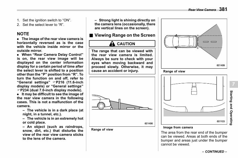
(383,1)
北米Model "A2600BE-B" EDITED: 2020/ 10/ 1
1. Set the ignition switch to “ON”.2. Set the select lever to “R”.
NOTE. The image of the rear view camera ishorizontally reversed as is the casewith the vehicle inside mirror or theoutside mirror.. When “Rear Camera Delay Control”is on, the rear view image will bedisplayed on the center informationdisplay for a certain period of time afterthe select lever is shifted to a positionother than the “P” position from “R”. Toturn the function on and off, refer to“General settings” FP216 (11.6-inchdisplay models) or “General settings”FP234 (dual 7.0-inch display models).. It may be difficult to see the image ofthe rear view camera in the followingcases. This is not a malfunction of thecamera.
– The vehicle is in a dark place (atnight, in a tunnel, etc.).– The vehicle is in an extremely hotor cold place.– An object (such as raindrops,snow, dirt, etc.) that disturbs theview of the rear view camera sticksto the lens of the camera.
– Strong light is shining directly onthe camera lens (occasionally, thereare vertical lines on the screen).
& Viewing Range on the Screens07br02
CAUTION
The range that can be viewed withthe rear view camera is limited.Always be sure to check with youreyes when moving backward andproceed slowly. Otherwise, it maycause an accident or injury.
Range of view
Range of view
Image from cameraThe area from the rear end of the bumpercan be viewed. Areas at both ends of thebumper and areas just under the bumpercannot be viewed.
– CONTINUED –
Rear View Camera 381
7
Startingand
Operating
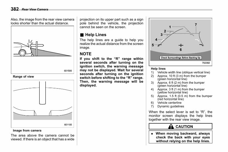
(384,1)
北米Model "A2600BE-B" EDITED: 2020/ 10/ 1
Also, the image from the rear view cameralooks shorter than the actual distance.
Range of view
Image from cameraThe area above the camera cannot beviewed. If there is an object that has a wide
projection on its upper part such as a signpole behind the vehicle, the projectioncannot be seen on the screen.
& Help Liness07br03
The help lines are a guide to help yourealize the actual distance from the screenimage.
NOTEIf you shift to the “R” range withinseveral seconds after turning on theignition switch, the warning messagemay not be displayed. Wait for severalseconds after turning on the ignitionswitch before shifting to the “R” range.Then, the warning message will bedisplayed.
Help lines1) Vehicle width line (oblique vertical line)2) Approx. 10 ft (3 m) from the bumper
(green horizontal line)3) Approx. 6 ft (2 m) from the bumper
(green horizontal line)4) Approx. 3 ft (1 m) from the bumper
(yellow horizontal line)5) Approx. 1.5 ft (0.5 m) from the bumper
(red horizontal line)6) Vehicle centerline7) Dynamic guidelines
When the select lever is set to “R”, themonitor screen displays the help linestogether with the rear view image.
CAUTION
. When moving backward, alwayscheck the back with your eyeswithout relying on the help lines.
Rear View Camera382
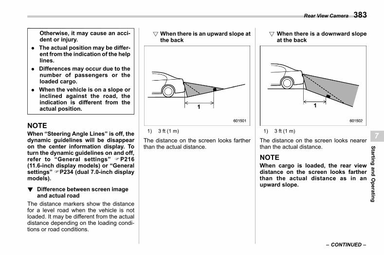
(385,1)
北米Model "A2600BE-B" EDITED: 2020/ 10/ 1
Otherwise, it may cause an acci-dent or injury.
. The actual position may be differ-ent from the indication of the helplines.
. Differences may occur due to thenumber of passengers or theloaded cargo.
. When the vehicle is on a slope orinclined against the road, theindication is different from theactual position.
NOTEWhen “Steering Angle Lines” is off, thedynamic guidelines will be disappearon the center information display. Toturn the dynamic guidelines on and off,refer to “General settings” FP216(11.6-inch display models) or “Generalsettings” FP234 (dual 7.0-inch displaymodels).
! Difference between screen imageand actual road
s07br0301The distance markers show the distancefor a level road when the vehicle is notloaded. It may be different from the actualdistance depending on the loading condi-tions or road conditions.
! When there is an upward slope atthe back
s07br030101
1) 3 ft (1 m)
The distance on the screen looks fartherthan the actual distance.
! When there is a downward slopeat the back
s07br030102
1) 3 ft (1 m)
The distance on the screen looks nearerthan the actual distance.
NOTEWhen cargo is loaded, the rear viewdistance on the screen looks fartherthan the actual distance as in anupward slope.
– CONTINUED –
Rear View Camera 383
7
Startingand
Operating
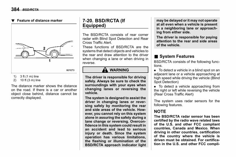
(386,1)
北米Model "A2600BE-B" EDITED: 2020/ 10/ 1
! Feature of distance markers07br0302
1) 3 ft (1 m) line2) 10 ft (3 m) line
The distance marker shows the distanceon the road. If there is a car or anotherobject close behind, distance cannot becorrectly displayed.
7-20. BSD/RCTA (IfEquipped)
s07bm
The BSD/RCTA consists of rear cornerradar with Blind Spot Detection and RearCross Traffic Alert.These functions of BSD/RCTA are thesystems that detect objects and vehicles tothe rear and draw attention to the driverwhen changing a lane or when driving inreverse.
WARNING
The driver is responsible for drivingsafely. Always be sure to check thesurroundings with your eyes whenchanging lanes or reversing thevehicle.The system is designed to assist thedriver in changing lanes or rever-sing safely by monitoring the rearand side areas of the vehicle. How-ever, you cannot rely on this systemalone in assuring the safety during alane change or reversing. Overcon-fidence in this system could result inan accident and lead to seriousinjury or death. Since the systemoperation has various limitations,the flashing or illumination of theBSD/RCTA approach indicator light
may be delayed or it may not operateat all even when a vehicle is presentin a neighboring lane or approach-ing from either side.The driver is responsible for payingattention to the rear and side areasof the vehicle.
& System Featuress07bm01
BSD/RCTA consists of the following func-tions.. To detect a vehicle in a blind spot on anadjacent lane or a vehicle approaching athigh speed while driving the vehicle (BlindSpot Detection). To detect a vehicle approaching fromthe right or left while reversing the vehicle(Rear Cross Traffic Alert)
The system uses radar sensors for thefollowing features.
NOTEThe BSD/RCTA radar sensor has beencertified by the radio wave related lawsof the U.S. and other FCC compliantcountries, Canada and Mexico. Whendriving in other countries, certificationof the country where the vehicle isdriven must be obtained. For certifica-tion in the U.S. and other FCC compli-
BSD/RCTA384
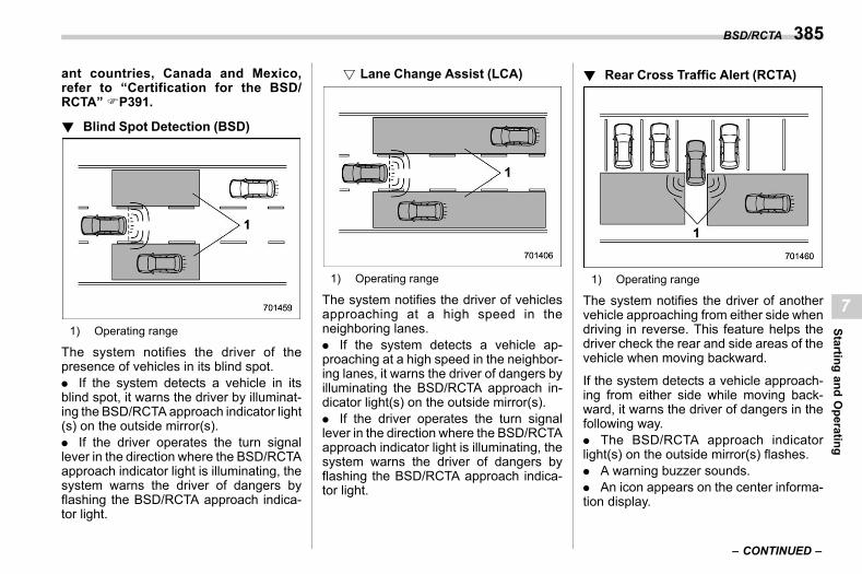
(387,1)
北米Model "A2600BE-B" EDITED: 2020/ 10/ 1
ant countries, Canada and Mexico,refer to “Certification for the BSD/RCTA” FP391.
! Blind Spot Detection (BSD)s07bm0101
1) Operating range
The system notifies the driver of thepresence of vehicles in its blind spot.. If the system detects a vehicle in itsblind spot, it warns the driver by illuminat-ing the BSD/RCTA approach indicator light(s) on the outside mirror(s).. If the driver operates the turn signallever in the direction where the BSD/RCTAapproach indicator light is illuminating, thesystem warns the driver of dangers byflashing the BSD/RCTA approach indica-tor light.
! Lane Change Assist (LCA)s07bm010101
1) Operating range
The system notifies the driver of vehiclesapproaching at a high speed in theneighboring lanes.. If the system detects a vehicle ap-proaching at a high speed in the neighbor-ing lanes, it warns the driver of dangers byilluminating the BSD/RCTA approach in-dicator light(s) on the outside mirror(s).. If the driver operates the turn signallever in the direction where the BSD/RCTAapproach indicator light is illuminating, thesystem warns the driver of dangers byflashing the BSD/RCTA approach indica-tor light.
! Rear Cross Traffic Alert (RCTA)s07bm0103
1) Operating range
The system notifies the driver of anothervehicle approaching from either side whendriving in reverse. This feature helps thedriver check the rear and side areas of thevehicle when moving backward.
If the system detects a vehicle approach-ing from either side while moving back-ward, it warns the driver of dangers in thefollowing way.. The BSD/RCTA approach indicatorlight(s) on the outside mirror(s) flashes.. A warning buzzer sounds.. An icon appears on the center informa-tion display.
– CONTINUED –
BSD/RCTA 385
7
Startingand
Operating
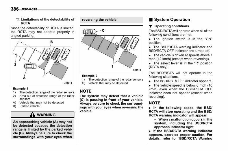
(388,1)
北米Model "A2600BE-B" EDITED: 2020/ 10/ 1
! Limitations of the detectability ofRCTA
s07bm010301
Since the detectability of RCTA is limited,the RCTA may not operate properly inangled parking.
Example 11) The detection range of the radar sensors2) Area out of detection range of the radar
sensorsA) Vehicle that may not be detectedB) Parked vehicle
WARNING
An approaching vehicle (A) may notbe detected because the detectionrange is limited by the parked vehi-cle (B). Always be sure to check thesurroundings with your eyes when
reversing the vehicle.
Example 21) The detection range of the radar sensorsC) Vehicle that may be detected
NOTEThe system may detect that a vehicle(C) is passing in front of your vehicle.Always be sure to check the surround-ings with your eyes when reversing thevehicle.
& System Operations07bm02
! Operating conditionss07bm0201
The BSD/RCTAwill operate when all of thefollowing conditions are met.. The ignition switch is in the “ON”position.. The BSD/RCTA warning indicator andBSD/RCTA OFF indicator are turned off.. The vehicle is driven at speeds above 7mph (12 km/h) (except when reversing).. The select lever is in the “R” position(RCTA only).
The BSD/RCTA will not operate in thefollowing situations.. The BSD/RCTAOFF indicator appears.. The vehicle speed is below 6 mph (10km/h) even when the BSD/RCTA OFFindicator does not appear (except whenreversing).
NOTE. In the following cases, the BSD/RCTA will stop operating and the BSD/RCTA warning indicator will appear.
– When amalfunction occurs in thesystem, including the BSD/RCTAapproach indicator light
. If the BSD/RCTA warning indicatorappears, exercise proper caution. Fordetails, refer to “BSD/RCTA Warning
BSD/RCTA386
(389,1)
北米Model "A2600BE-B" EDITED: 2020/ 10/ 1
Indicator” FP390.. In the following cases, the BSD/RCTA will temporarily stop operating(or may stop operating) and the BSD/RCTA OFF indicator will appear.
– When the radar sensor becomessignificantly misaligned (If the or-ientation of the radar sensor isshifted for any reason, readjust-ment is required. Have the sensoradjusted at a SUBARU dealer.)– When a large amount of snow orice sticks to the rear bumper sur-face around the radar sensors– When the vehicle is driven on asnow-covered road or in an envir-onment in which there are no ob-jects around (such as in a desert) fora prolonged period of time– When the temperature around theradar sensors increases exces-sively due to long driving on uphillgrades in the summer, etc.– When the temperature around theradar sensors becomes extremelylow– When the vehicle battery voltagelowers– When the vehicle voltage ex-ceeds the battery voltage rating
The BSD/RCTA will resume operationonce these conditions are corrected,and the BSD/RCTA OFF indicator willdisappear. However, if the BSD/RCTAOFF indicator appears for a prolongedperiod of time, have the system in-spected at a SUBARU dealer as soon aspossible.. The detectability of the radar sen-sors is restricted. The BSD/RCTA de-tectionmay be impaired and the systemmay not operate properly under thefollowing conditions.
– When the rear bumper around theradar sensors is distorted– When ice, snow or mud adheresto the rear bumper surface aroundthe radar sensors– When stickers, etc. are affixed onthe areas of the radar sensors onthe rear bumper– During adverse weather condi-tions such as rain, snow or fog– When driving on wet roads suchas snow-covered roads and throughpuddles
. The radar sensors may not detect ormay have difficulty detecting the fol-lowing vehicles and objects.
– Small motorcycles, bicycles, pe-destrians, stationary objects on theroad or road side, etc.
– Vehicles with body shapes thatthe radar may not reflect (vehicleswith lower body height such as atrailer with no cargo and sportscars)– Vehicles that are not approachingyour vehicle even though they are inthe detection area (either on aneighboring lane to the rear or be-side your vehicle when reversing)(The system determines the pre-sence of approaching vehiclesbased on data detected by the radarsensors.)– Vehicles traveling at significantlydifferent speeds– Vehicles driving in parallel at al-most the same speed as your vehi-cle for a prolonged time– Oncoming vehicles– Vehicles in a lane beyond theneighboring lane– Vehicles travelling at a signifi-cantly lower speed that you aretrying to overtake
. On a road with extremely narrowlanes, the system may detect vehiclesdriving in a lane next to the neighboringlane.
– CONTINUED –
BSD/RCTA 387
7
Startingand
Operating
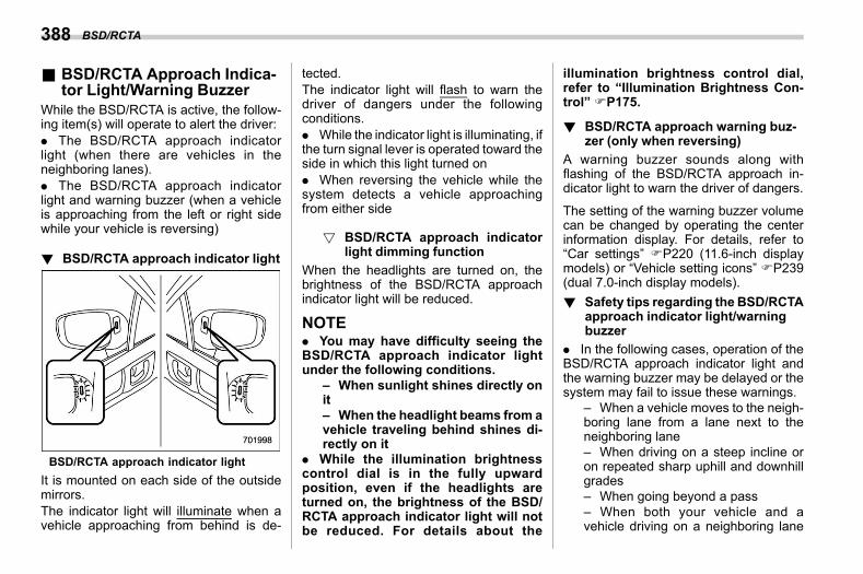
(390,1)
北米Model "A2600BE-B" EDITED: 2020/ 10/ 1
& BSD/RCTA Approach Indica-tor Light/Warning Buzzer
s07bm03While the BSD/RCTA is active, the follow-ing item(s) will operate to alert the driver:. The BSD/RCTA approach indicatorlight (when there are vehicles in theneighboring lanes).. The BSD/RCTA approach indicatorlight and warning buzzer (when a vehicleis approaching from the left or right sidewhile your vehicle is reversing)
! BSD/RCTA approach indicator lights07bm0301
BSD/RCTA approach indicator lightIt is mounted on each side of the outsidemirrors.The indicator light will illuminate when avehicle approaching from behind is de-
tected.The indicator light will flash to warn thedriver of dangers under the followingconditions.. While the indicator light is illuminating, ifthe turn signal lever is operated toward theside in which this light turned on. When reversing the vehicle while thesystem detects a vehicle approachingfrom either side
! BSD/RCTA approach indicatorlight dimming function
s07bm030101
When the headlights are turned on, thebrightness of the BSD/RCTA approachindicator light will be reduced.
NOTE. You may have difficulty seeing theBSD/RCTA approach indicator lightunder the following conditions.
– When sunlight shines directly onit– When the headlight beams from avehicle traveling behind shines di-rectly on it
. While the illumination brightnesscontrol dial is in the fully upwardposition, even if the headlights areturned on, the brightness of the BSD/RCTA approach indicator light will notbe reduced. For details about the
illumination brightness control dial,refer to “Illumination Brightness Con-trol” FP175.
! BSD/RCTA approach warning buz-zer (only when reversing)
s07bm0302A warning buzzer sounds along withflashing of the BSD/RCTA approach in-dicator light to warn the driver of dangers.
The setting of the warning buzzer volumecan be changed by operating the centerinformation display. For details, refer to“Car settings” FP220 (11.6-inch displaymodels) or “Vehicle setting icons” FP239(dual 7.0-inch display models).! Safety tips regarding the BSD/RCTA
approach indicator light/warningbuzzer
s07bm0303. In the following cases, operation of theBSD/RCTA approach indicator light andthe warning buzzer may be delayed or thesystem may fail to issue these warnings.
– When a vehicle moves to the neigh-boring lane from a lane next to theneighboring lane– When driving on a steep incline oron repeated sharp uphill and downhillgrades– When going beyond a pass– When both your vehicle and avehicle driving on a neighboring lane
BSD/RCTA388
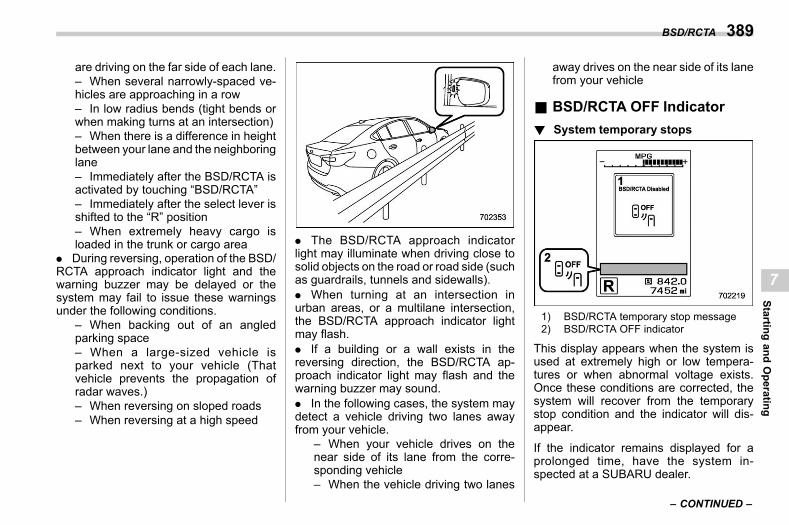
(391,1)
北米Model "A2600BE-B" EDITED: 2020/ 10/ 1
are driving on the far side of each lane.– When several narrowly-spaced ve-hicles are approaching in a row– In low radius bends (tight bends orwhen making turns at an intersection)– When there is a difference in heightbetween your lane and the neighboringlane– Immediately after the BSD/RCTA isactivated by touching “BSD/RCTA”– Immediately after the select lever isshifted to the “R” position– When extremely heavy cargo isloaded in the trunk or cargo area
. During reversing, operation of the BSD/RCTA approach indicator light and thewarning buzzer may be delayed or thesystem may fail to issue these warningsunder the following conditions.
– When backing out of an angledparking space– When a large-sized vehicle isparked next to your vehicle (Thatvehicle prevents the propagation ofradar waves.)– When reversing on sloped roads– When reversing at a high speed
. The BSD/RCTA approach indicatorlight may illuminate when driving close tosolid objects on the road or road side (suchas guardrails, tunnels and sidewalls).. When turning at an intersection inurban areas, or a multilane intersection,the BSD/RCTA approach indicator lightmay flash.. If a building or a wall exists in thereversing direction, the BSD/RCTA ap-proach indicator light may flash and thewarning buzzer may sound.. In the following cases, the system maydetect a vehicle driving two lanes awayfrom your vehicle.
– When your vehicle drives on thenear side of its lane from the corre-sponding vehicle– When the vehicle driving two lanes
away drives on the near side of its lanefrom your vehicle
& BSD/RCTA OFF Indicators07bm08
! System temporary stopss07bm0801
1) BSD/RCTA temporary stop message2) BSD/RCTA OFF indicator
This display appears when the system isused at extremely high or low tempera-tures or when abnormal voltage exists.Once these conditions are corrected, thesystem will recover from the temporarystop condition and the indicator will dis-appear.
If the indicator remains displayed for aprolonged time, have the system in-spected at a SUBARU dealer.
– CONTINUED –
BSD/RCTA 389
7
Startingand
Operating
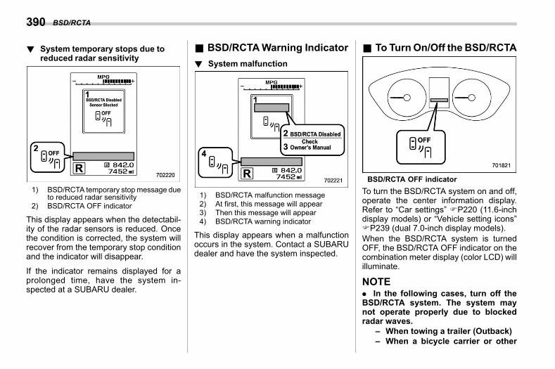
(392,1)
北米Model "A2600BE-B" EDITED: 2020/ 10/ 1
! System temporary stops due toreduced radar sensitivity
s07bm0802
1) BSD/RCTA temporary stopmessage dueto reduced radar sensitivity
2) BSD/RCTA OFF indicator
This display appears when the detectabil-ity of the radar sensors is reduced. Oncethe condition is corrected, the system willrecover from the temporary stop conditionand the indicator will disappear.
If the indicator remains displayed for aprolonged time, have the system in-spected at a SUBARU dealer.
& BSD/RCTAWarning Indicators07bm04
! System malfunctions07bm0403
1) BSD/RCTA malfunction message2) At first, this message will appear3) Then this message will appear4) BSD/RCTA warning indicator
This display appears when a malfunctionoccurs in the system. Contact a SUBARUdealer and have the system inspected.
& To TurnOn/Off the BSD/RCTAs07bm09
BSD/RCTA OFF indicatorTo turn the BSD/RCTA system on and off,operate the center information display.Refer to “Car settings” FP220 (11.6-inchdisplay models) or “Vehicle setting icons”FP239 (dual 7.0-inch display models).When the BSD/RCTA system is turnedOFF, the BSD/RCTA OFF indicator on thecombination meter display (color LCD) willilluminate.
NOTE. In the following cases, turn off theBSD/RCTA system. The system maynot operate properly due to blockedradar waves.
– When towing a trailer (Outback)– When a bicycle carrier or other
BSD/RCTA390
(393,1)
北米Model "A2600BE-B" EDITED: 2020/ 10/ 1
item is fitted to the rear of thevehicle– When using a chassis dynam-ometer or free roller device, etc.– When running the engine andmaking the wheels rotate whilelifting up the vehicle
. If the ignition switch is turned to the“LOCK”/“OFF” position, the last knownstatus of the system is maintained. Forexample, if the ignition switch is turnedto the “LOCK”/“OFF” position with theBSD/RCTA deactivated, the BSD/RCTAremains deactivated the next time theignition switch is turned to the “ON”position.
& Certification for the BSD/RCTA
s07bm06. The U.S. and other FCC compliantcountries
FCC ID: OAYSRR3A
CAUTION
FCC WARNINGChanges or modifications not ex-pressly approved by the party re-sponsible for compliance could voidthe user’s authority to operate theequipment.
This device complies with part 15 of theFCC Rules. Operation is subject to thefollowing two conditions: (1) This devicemay not cause harmful interference, and(2) this device must accept any interfer-ence received, including interference thatmay cause undesired operation.
. Canada-spec. models
– CONTINUED –
BSD/RCTA 391
7
Startingand
Operating
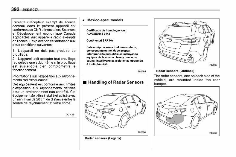
(394,1)
北米Model "A2600BE-B" EDITED: 2020/ 10/ 1
. Mexico-spec. models
& Handling of Radar Sensorss07bm07
Radar sensors (Legacy)
Radar sensors (Outback)The radar sensors, one on each side of thevehicle, are mounted inside the rearbumper.
BSD/RCTA392
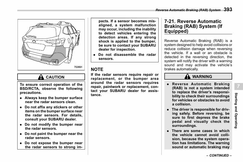
(395,1)
北米Model "A2600BE-B" EDITED: 2020/ 10/ 1
CAUTION
To ensure correct operation of theBSD/RCTA, observe the followingprecautions.. Always keep the bumper surface
near the radar sensors clean.. Do not affix any stickers or other
items on the bumper surface nearthe radar sensors. For details,consult your SUBARU dealer.
. Do not modify the bumper nearthe radar sensors.
. Do not paint the bumper near theradar sensors.
. Do not expose the bumper nearthe radar sensors to strong im-
pacts. If a sensor becomes mis-aligned, a system malfunctionmay occur, including the inabilityto detect vehicles entering thedetection areas. If any strongshock is applied to the bumper,be sure to contact your SUBARUdealer for inspection.
. Do not disassemble the radarsensors.
NOTEIf the radar sensors require repair orreplacement, or the bumper areaaround the radar sensors requiresrepair, paintwork or replacement, con-tact your SUBARU dealer for assis-tance.
7-21. Reverse AutomaticBraking (RAB) System (IfEquipped)
s07bn
Reverse Automatic Braking (RAB) is asystem designed to help avoid collisions orreduce collision damage when reversingthe vehicle. If a wall or an obstacle isdetected in the reversing direction, thesystem will notify the driver with a warningsound and may activate the vehicle’sbrakes automatically.
WARNING
. Reverse Automatic Braking(RAB) is not a system intendedto replace the driver’s responsi-bility to check their surroundingsfor vehicles or obstacles to avoida collision.
. The driver is responsible for driv-ing safely. Before reversing, besure to first depress the brakepedal and visually check thesurroundings.
. There are some cases in whichthe vehicle cannot avoid colli-sion, because the system opera-tion has limitations. The warningsound or automatic braking may
– CONTINUED –
Reverse Automatic Braking (RAB) System 393
7
Startingand
Operating
(396,1)
北米Model "A2600BE-B" EDITED: 2020/ 10/ 1
be delayed or may not operate atall even when an obstacle ispresent.
. Make sure to set the AutomaticBraking System to OFF when thevehicle is on the free roller or onthe chassis dynamometer. Other-wise, the vehicle maymove and itmay cause an accident.
. Make sure to set the AutomaticBraking System to OFF whentowing a trailer. Otherwise, thevehicle may move and it maycause an accident.
. The system is not designed todetect people (including chil-dren), animals or other movingobjects.
. Depending on the vehicle condi-tion or the surrounding environ-ment, the sonar sensor’s abilityto detect objects may becomeunstable.
NOTEThe Reverse Automatic Braking (RAB)system records and stores the follow-ing data when automatic braking oper-ates. It does not record conversations,personal information or other audio
data.. Distance from the object. Vehicle speed. Accelerator pedal operation status. Brake pedal operation status. Select lever position. Outside temperature. The sensitivity setting of the sonarsensors
SUBARU and third parties contractedby SUBARU may acquire and use therecorded data for the purpose of vehi-cle research and development.SUBARU and third parties contractedby SUBARUwill not disclose or providethe acquired data to any other thirdparty except under the following con-ditions.. The vehicle owner has given his/herconsent.. The disclosure/provision is basedon a court order or other legally en-forceable request.. Data that has been modified so thatthe user and vehicle cannot be identi-fied is provided to a research institutionfor statistical processing or similarpurposes.
& Reverse Automatic Braking(RAB) System Overview
s07bn01The Reverse Automatic Braking (RAB)system will operate the following 2 func-tions using 4 sonar sensors.. Object detection warning functionThe Reverse Automatic Braking (RAB)system detects objects rearward andwarns the driver by warning message onthe center information display and warningbeeps.. Reverse Automatic Braking (RAB)system functionThe Reverse Automatic Braking (RAB)system function detects objects rearwardand if there is a high risk of a collision, thesystem decelerates the vehicle and con-trols the braking to reduce damage.
Reverse Automatic Braking (RAB) System394
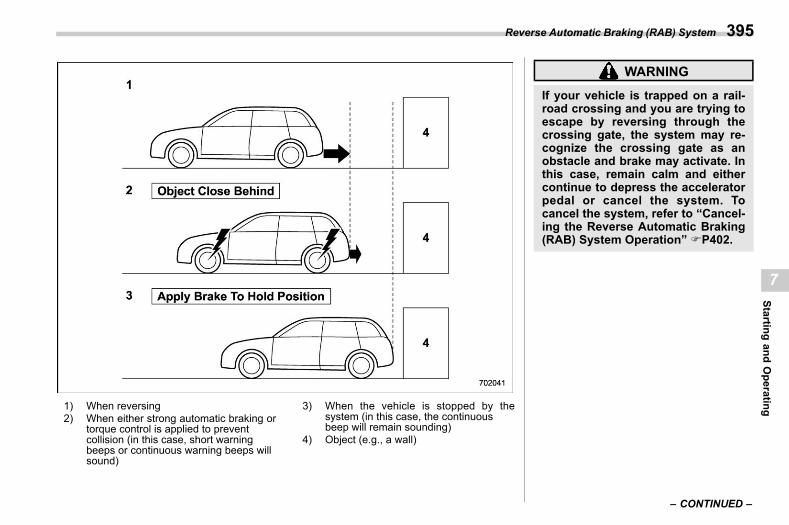
(397,1)
北米Model "A2600BE-B" EDITED: 2020/ 10/ 1
1) When reversing2) When either strong automatic braking or
torque control is applied to preventcollision (in this case, short warningbeeps or continuous warning beeps willsound)
3) When the vehicle is stopped by thesystem (in this case, the continuousbeep will remain sounding)
4) Object (e.g., a wall)
WARNING
If your vehicle is trapped on a rail-road crossing and you are trying toescape by reversing through thecrossing gate, the system may re-cognize the crossing gate as anobstacle and brake may activate. Inthis case, remain calm and eithercontinue to depress the acceleratorpedal or cancel the system. Tocancel the system, refer to “Cancel-ing the Reverse Automatic Braking(RAB) System Operation” FP402.
– CONTINUED –
Reverse Automatic Braking (RAB) System 395
7
Startingand
Operating
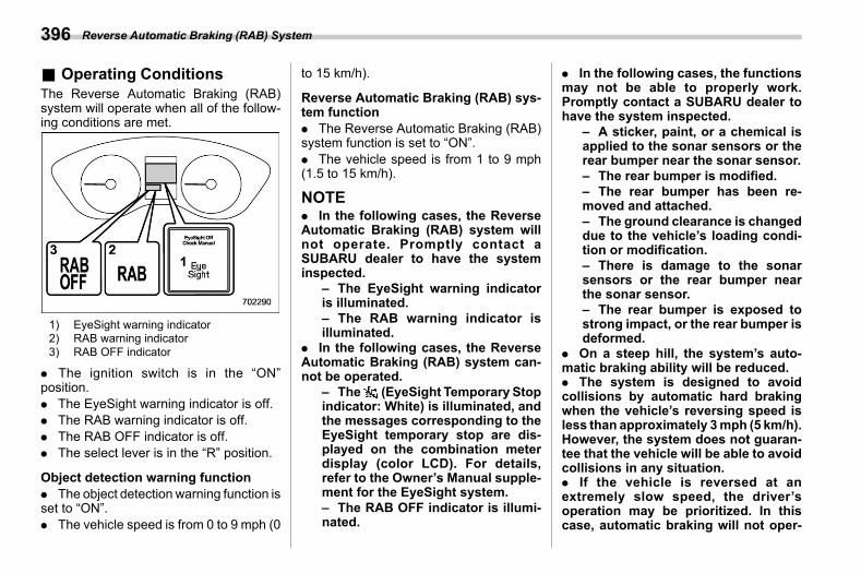
(398,1)
北米Model "A2600BE-B" EDITED: 2020/ 10/ 1
& Operating Conditionss07bn02
The Reverse Automatic Braking (RAB)system will operate when all of the follow-ing conditions are met.
1) EyeSight warning indicator2) RAB warning indicator3) RAB OFF indicator
. The ignition switch is in the “ON”position.. The EyeSight warning indicator is off.. The RAB warning indicator is off.. The RAB OFF indicator is off.. The select lever is in the “R” position.
Object detection warning function. The object detection warning function isset to “ON”.. The vehicle speed is from 0 to 9 mph (0
to 15 km/h).
Reverse Automatic Braking (RAB) sys-tem function. The Reverse Automatic Braking (RAB)system function is set to “ON”.. The vehicle speed is from 1 to 9 mph(1.5 to 15 km/h).
NOTE. In the following cases, the ReverseAutomatic Braking (RAB) system willnot operate. Promptly contact aSUBARU dealer to have the systeminspected.
– The EyeSight warning indicatoris illuminated.– The RAB warning indicator isilluminated.
. In the following cases, the ReverseAutomatic Braking (RAB) system can-not be operated.
– The (EyeSight Temporary Stopindicator: White) is illuminated, andthe messages corresponding to theEyeSight temporary stop are dis-played on the combination meterdisplay (color LCD). For details,refer to the Owner’s Manual supple-ment for the EyeSight system.– The RAB OFF indicator is illumi-nated.
. In the following cases, the functionsmay not be able to properly work.Promptly contact a SUBARU dealer tohave the system inspected.
– A sticker, paint, or a chemical isapplied to the sonar sensors or therear bumper near the sonar sensor.– The rear bumper is modified.– The rear bumper has been re-moved and attached.– The ground clearance is changeddue to the vehicle’s loading condi-tion or modification.– There is damage to the sonarsensors or the rear bumper nearthe sonar sensor.– The rear bumper is exposed tostrong impact, or the rear bumper isdeformed.
. On a steep hill, the system’s auto-matic braking ability will be reduced.. The system is designed to avoidcollisions by automatic hard brakingwhen the vehicle’s reversing speed isless than approximately 3mph (5 km/h).However, the system does not guaran-tee that the vehicle will be able to avoidcollisions in any situation.. If the vehicle is reversed at anextremely slow speed, the driver’soperation may be prioritized. In thiscase, automatic braking will not oper-
Reverse Automatic Braking (RAB) System396
(399,1)
北米Model "A2600BE-B" EDITED: 2020/ 10/ 1
ate.. The systemmaynot be able to detectand apply the brake with the followingobjects.
– Sharp or thin objects such aspoles, fences and ropes which maynot reflect the sound wave emittedfrom the sonar sensor.– Objects that are too close to therear bumper when the select lever isset to the “R” position.– Objects with a surface whichmaynot reflect the sound wave emittedfrom the sonar sensor such as achain link fence.
. Objects the system is not designedto detect and apply brake.
– Pedestrians.– Moving objects includingmovingvehicles.– Objects which absorbs soundwaves such as cloth or snow.– Objects whose surface has adiagonal angle.– Objects that are low to the groundsuch as parking blocks.– Objects that are high above theground such as objects hangingfrom above.– Objects that are out of range ofthe center of the vehicle in thehorizontal direction.
– Objects that are not in a verticaldirection.
. When reversing the vehicle, thefunctions may not be able to workproperly or may cause a system mal-function if the following conditionsexist.
High frequency sound from othersources are nearby:– Horn sound fromanother vehicle.– Engine sound from other vehi-cles.– Sound of an air brake.– Vehicle detection equipment or asonar from another vehicle.– A sound wave with a frequencysimilar to the vehicle’s system istransmitted near by.– A vehicle equipped with the samesystem is reversing toward yourreversing direction.
Weather conditions:– Extremely high or extremely lowtemperatures in which the area nearthe sonar sensor becomes too hotor too cold to operate.– The sonar sensors or the rearbumper near the sonar sensors areexposed to heavy rain or a signifi-cant amount of water.
– Fog, snow or sandstorm, etc.– Air is moving rapidly such aswhen a strong wind is blowing.
Parts attached to the rear bumpernear the sonar sensor:– Commercial electronic parts (foglight, fender pole, radio antenna) orcommercial attachment parts (trai-ler hitch, bicycle carrier, bumperguard) are attached.– Parts that emit high frequencysound, such as a horn or speaker,are attached.
Vehicle conditions:– Ice, snow or mud is adhered tothe sonar sensors or the rear bum-per near the sonar sensor.– The vehicle is significantly in-clined.– The ground clearance is signifi-cantly reduced due to the vehicle’sloading condition, etc.– When the sonar sensor is mis-aligned due to a collision or anaccident.
Surrounding environment:– A cloth banner, flag, hangingbranch or railroad crossing barsare present in the reversing direc-tion.
– CONTINUED –
Reverse Automatic Braking (RAB) System 397
7
Startingand
Operating
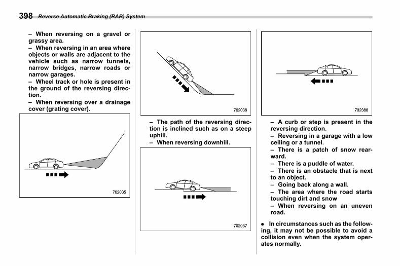
(400,1)
北米Model "A2600BE-B" EDITED: 2020/ 10/ 1
– When reversing on a gravel orgrassy area.– When reversing in an area whereobjects or walls are adjacent to thevehicle such as narrow tunnels,narrow bridges, narrow roads ornarrow garages.– Wheel track or hole is present inthe ground of the reversing direc-tion.– When reversing over a drainagecover (grating cover).
– The path of the reversing direc-tion is inclined such as on a steepuphill.– When reversing downhill.
– A curb or step is present in thereversing direction.– Reversing in a garage with a lowceiling or a tunnel.– There is a patch of snow rear-ward.– There is a puddle of water.– There is an obstacle that is nextto an object.– Going back along a wall.– The area where the road startstouching dirt and snow– When reversing on an unevenroad.
. In circumstances such as the follow-ing, it may not be possible to avoid acollision even when the system oper-ates normally.
Reverse Automatic Braking (RAB) System398
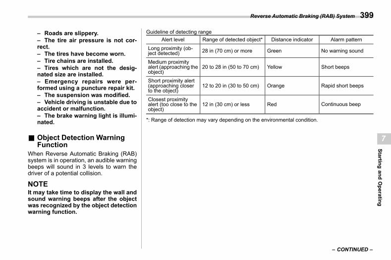
(401,1)
北米Model "A2600BE-B" EDITED: 2020/ 10/ 1
– Roads are slippery.– The tire air pressure is not cor-rect.– The tires have become worn.– Tire chains are installed.– Tires which are not the desig-nated size are installed.– Emergency repairs were per-formed using a puncture repair kit.– The suspension was modified.– Vehicle driving is unstable due toaccident or malfunction.– The brake warning light is illumi-nated.
& Object Detection WarningFunction
s07bn03When Reverse Automatic Braking (RAB)system is in operation, an audible warningbeeps will sound in 3 levels to warn thedriver of a potential collision.
NOTEIt may take time to display the wall andsound warning beeps after the objectwas recognized by the object detectionwarning function.
Guideline of detecting rangeAlert level Range of detected object* Distance indicator Alarm pattern
Long proximity (ob-ject detected) 28 in (70 cm) or more Green No warning sound
Medium proximityalert (approaching theobject)
20 to 28 in (50 to 70 cm) Yellow Short beeps
Short proximity alert(approaching closerto the object)
12 to 20 in (30 to 50 cm) Orange Rapid short beeps
Closest proximityalert (too close to theobject)
12 in (30 cm) or less Red Continuous beep
*: Range of detection may vary depending on the environmental condition.
– CONTINUED –
Reverse Automatic Braking (RAB) System 399
7
Startingand
Operating
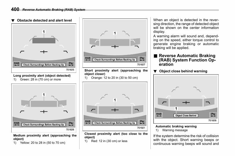
(402,1)
北米Model "A2600BE-B" EDITED: 2020/ 10/ 1
! Obstacle detected and alert levels07bn0301
Long proximity alert (object detected)1) Green: 28 in (70 cm) or more
Medium proximity alert (approaching theobject)1) Yellow: 20 to 28 in (50 to 70 cm)
Short proximity alert (approaching theobject closer)1) Orange: 12 to 20 in (30 to 50 cm)
Closest proximity alert (too close to theobject)1) Red: 12 in (30 cm) or less
When an object is detected in the rever-sing direction, the range of detected objectwill be shown on the center informationdisplay.A warning alarm will sound and, depend-ing on the speed, either torque control togenerate engine braking or automaticbraking will be applied.
& Reverse Automatic Braking(RAB) System Function Op-eration
s07bn08
! Object close behind warnings07bn0801
Automatic braking warning1) Warning message
If the system determine the risk of collisionwith the object. Short warning beeps orcontinuous warning beeps will sound and
Reverse Automatic Braking (RAB) System400
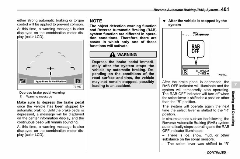
(403,1)
北米Model "A2600BE-B" EDITED: 2020/ 10/ 1
either strong automatic braking or torquecontrol will be applied to prevent collision.At this time, a warning message is alsodisplayed on the combination meter dis-play (color LCD).
Depress brake pedal warning1) Warning message
Make sure to depress the brake pedalonce the vehicle has been stopped byautomatic braking. Until the brake pedal isdepressed, a message will be displayedon the center information display and thecontinuous beep will remain sounding.At this time, a warning message is alsodisplayed on the combination meter dis-play (color LCD).
NOTEThe object detection warning functionand Reverse Automatic Braking (RAB)system function are different in opera-tion conditions. Therefore there arecases in which only one of thesefunctions will activate.
WARNING
Depress the brake pedal immedi-ately after the system stops thevehicle by automatic braking. De-pending on the conditions of theroad surface and tires, the vehiclemay not remain stopped, possiblyleading to an accident.
! After the vehicle is stopped by thesystem
s07bn0802
After the brake pedal is depressed, theRAB OFF indicator will illuminate and thesystem will temporarily stop operating.The RAB OFF indicator will turn off whenthe select lever is shifted to a position otherthan the “R” position.The system will operate again the nexttime the select lever is shifted to the “R”position.In circumstances such as the following, theReverse Automatic Braking (RAB) systemautomatically stops operating and theRABOFF indicator illuminates.– There is ice, snow, mud, or othersubstance on the sonar sensors.– The select lever was shifted to “R”
– CONTINUED –
Reverse Automatic Braking (RAB) System 401
7
Startingand
Operating
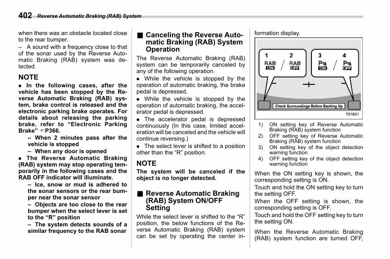
(404,1)
北米Model "A2600BE-B" EDITED: 2020/ 10/ 1
when there was an obstacle located closeto the rear bumper.– A sound with a frequency close to thatof the sonar used by the Reverse Auto-matic Braking (RAB) system was de-tected.
NOTE. In the following cases, after thevehicle has been stopped by the Re-verse Automatic Braking (RAB) sys-tem, brake control is released and theelectronic parking brake operates. Fordetails about releasing the parkingbrake, refer to “Electronic ParkingBrake” FP366.
– When 2 minutes pass after thevehicle is stopped– When any door is opened
. The Reverse Automatic Braking(RAB) system may stop operating tem-porarily in the following cases and theRAB OFF indicator will illuminate.
– Ice, snow or mud is adhered tothe sonar sensors or the rear bum-per near the sonar sensor– Objects are too close to the rearbumper when the select lever is setto the “R” position– The system detects sounds of asimilar frequency to the RAB sonar
& Canceling the Reverse Auto-matic Braking (RAB) SystemOperation
s07bn04The Reverse Automatic Braking (RAB)system can be temporarily canceled byany of the following operation.. While the vehicle is stopped by theoperation of automatic braking, the brakepedal is depressed.. While the vehicle is stopped by theoperation of automatic braking, the accel-erator pedal is depressed.. The accelerator pedal is depressedcontinuously (In this case, limited accel-eration will be canceled and the vehicle willcontinue reversing.). The select lever is shifted to a positionother than the “R” position.
NOTEThe system will be canceled if theobject is no longer detected.
& Reverse Automatic Braking(RAB) System ON/OFFSetting
s07bn05While the select lever is shifted to the “R”position, the below functions of the Re-verse Automatic Braking (RAB) systemcan be set by operating the center in-
formation display.
1) ON setting key of Reverse AutomaticBraking (RAB) system function
2) OFF setting key of Reverse AutomaticBraking (RAB) system function
3) ON setting key of the object detectionwarning function
4) OFF setting key of the object detectionwarning function
When the ON setting key is shown, thecorresponding setting is ON.Touch and hold the ON setting key to turnthe setting OFF.When the OFF setting is shown, thecorresponding setting is OFF.Touch and hold the OFF setting key to turnthe setting ON.
When the Reverse Automatic Braking(RAB) system function are turned OFF,
Reverse Automatic Braking (RAB) System402
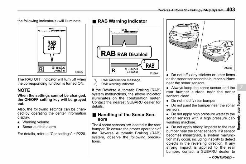
(405,1)
北米Model "A2600BE-B" EDITED: 2020/ 10/ 1
the following indicator(s) will illuminate.
The RAB OFF indicator will turn off whenthe corresponding function is turned ON.
NOTEWhen the settings cannot be changed,the ON/OFF setting key will be grayedout.Also, the following settings can be chan-ged by operating the center informationdisplay.. Warning volume. Sonar audible alarm
For details, refer to “Car settings”FP220.
& RABWarning Indicators07bn07
1) RAB malfunction message2) RAB warning indicator
If the Reverse Automatic Braking (RAB)system malfunctions, the above indicatorilluminates on the combination meter.Contact the nearest SUBARU dealer fordetails.
& Handling of the Sonar Sen-sors
s07bn06The 4 sonar sensors are located in the rearbumper. To ensure the proper operation ofthe Reverse Automatic Braking (RAB)system, observe the following precau-tions.
. Do not affix any stickers or other itemson the sonar sensor or the bumper surfacenear the sonar sensors.. Always keep the sonar sensor and therear bumper surface near the sonarsensors clean.. Do not modify rear bumper.. Do not paint the bumper near the sonarsensors.. Do not apply high pressure water to thesonar sensors with a high pressure car-washing machine.. Do not apply strong impacts to the rearbumper near the sonar sensors. If a sensorbecomes misaligned, a system malfunc-tion may occur, including inability to detectobjects in the reversing direction. If anystrong impact is applied to the rearbumper, contact a SUBARU dealer to
– CONTINUED –
Reverse Automatic Braking (RAB) System 403
7
Startingand
Operating
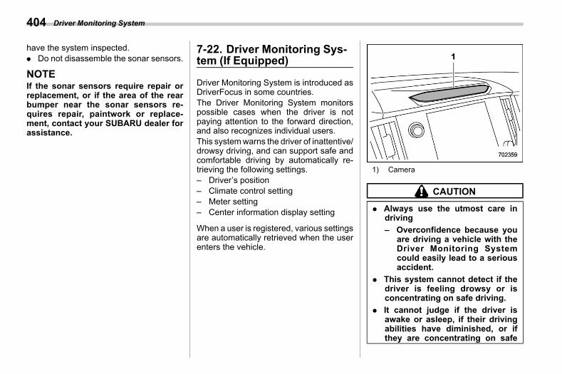
(406,1)
北米Model "A2600BE-B" EDITED: 2020/ 10/ 1
have the system inspected.. Do not disassemble the sonar sensors.
NOTEIf the sonar sensors require repair orreplacement, or if the area of the rearbumper near the sonar sensors re-quires repair, paintwork or replace-ment, contact your SUBARU dealer forassistance.
7-22. Driver Monitoring Sys-tem (If Equipped)
s07bp
Driver Monitoring System is introduced asDriverFocus in some countries.The Driver Monitoring System monitorspossible cases when the driver is notpaying attention to the forward direction,and also recognizes individual users.This systemwarns the driver of inattentive/drowsy driving, and can support safe andcomfortable driving by automatically re-trieving the following settings.– Driver’s position– Climate control setting– Meter setting– Center information display setting
When a user is registered, various settingsare automatically retrieved when the userenters the vehicle.
1) Camera
CAUTION
. Always use the utmost care indriving– Overconfidence because you
are driving a vehicle with theDriver Monitoring Systemcould easily lead to a seriousaccident.
. This system cannot detect if thedriver is feeling drowsy or isconcentrating on safe driving.
. It cannot judge if the driver isawake or asleep, if their drivingabilities have diminished, or ifthey are concentrating on safe
Driver Monitoring System404
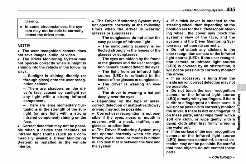
(407,1)
北米Model "A2600BE-B" EDITED: 2020/ 10/ 1
driving.. In some circumstances, the sys-
tem may not be able to correctlydetect the driver state.
NOTE. The user recognition camera doesnot save images, audio, or video.. The Driver Monitoring System maynot operate correctly when sunlight isshining into the vehicle in the followingways.
– Sunlight is shining directly (orthrough glass) onto the user recog-nition camera.– There are shadows on the dri-ver’s face caused by sunlight (orany light with a strong infraredcomponent).– There are large momentary fluc-tuations in the strength of the sun-light (or any light with a stronginfrared component) shining on theface.
. Correct detection may not be possi-ble when a device that includes aninfrared light source (such as a com-mercially available Driver MonitoringSystem) is installed in the vehicleinterior.
. The Driver Monitoring System maynot operate correctly at the followingtimes when the driver is wearingglasses or sunglasses.
– The sunglasses do not allow theeasy passage of infrared light.– The surrounding scenery is re-flected strongly in the lenses of theglasses or sunglasses.– The eyes are hidden by the frameof the glasses and the user recogni-tion camera cannot detect the eyes.– The light from an infrared lightsource (LED) is reflected in thelenses of the glasses or sunglasses.– The driver is wearing an eye-patch.– The driver is wearing a hat setdeeply over the eyes.
. Depending on the type of mask,correct detection of inattentive/drowsydriving may not be possible.. Correct user recognition is not pos-sible if the eyes, nose, or mouth iscovered with a mask, muffler, sun-glasses, or other item.. The Driver Monitoring System maynot operate correctly when the eye-brows, eyes, nose, or mouth is hiddendue to item that is between the face andthe system.
. If a thick cover is attached to thesteering wheel, then depending on theposition set for the tilt/telescopic steer-ing wheel, the cover may block thesystem’s view of the face, and thesystem and the Driver Monitoring Sys-tem may not operate correctly.. Do not attach any stickers to theuser recognition camera or the infraredlight source (LED). If the user recogni-tion camera or infrared light source(LED) is covered by an obstruction, itwill not be possible to correctlymonitorthe driver.. If an accessory is hung from theinsidemirror, correct detectionmay notbe possible.. Do not touch the user recognitioncamera or the infrared light source(LED) directly with your fingers. If thereis dirt or a fingerprint on these parts, itwill not be possible to correctlymonitorthe driver. If there is dirt or a fingerprinton these parts, either wipe them with asoft dry cloth, or wipe gently with adamp cloth after first firmly wringingthe water out.. If the surface of the user recognitioncamera or the infrared light source(LED) becomes scratched, correct de-tection may not be possible. Be carefulthat hard objects do not contact theseparts.
– CONTINUED –
Driver Monitoring System 405
7
Startingand
Operating
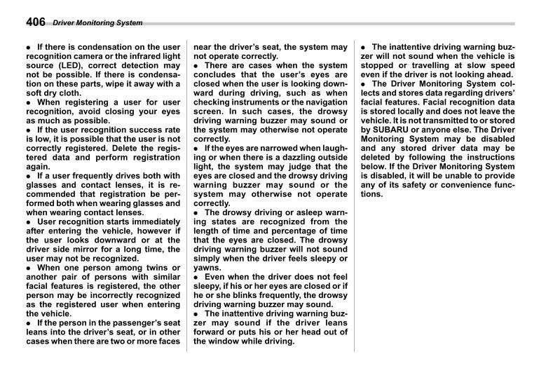
(408,1)
北米Model "A2600BE-B" EDITED: 2020/ 10/ 1
. If there is condensation on the userrecognition camera or the infrared lightsource (LED), correct detection maynot be possible. If there is condensa-tion on these parts, wipe it away with asoft dry cloth.. When registering a user for userrecognition, avoid closing your eyesas much as possible.. If the user recognition success rateis low, it is possible that the user is notcorrectly registered. Delete the regis-tered data and perform registrationagain.. If a user frequently drives both withglasses and contact lenses, it is re-commended that registration be per-formed both when wearing glasses andwhen wearing contact lenses.. User recognition starts immediatelyafter entering the vehicle, however ifthe user looks downward or at thedriver side mirror for a long time, theuser may not be recognized.. When one person among twins oranother pair of persons with similarfacial features is registered, the otherperson may be incorrectly recognizedas the registered user when enteringthe vehicle.. If the person in the passenger’s seatleans into the driver’s seat, or in othercases when there are two ormore faces
near the driver’s seat, the system maynot operate correctly.. There are cases when the systemconcludes that the user’s eyes areclosed when the user is looking down-ward during driving, such as whenchecking instruments or the navigationscreen. In such cases, the drowsydriving warning buzzer may sound orthe system may otherwise not operatecorrectly.. If the eyes are narrowedwhen laugh-ing or when there is a dazzling outsidelight, the system may judge that theeyes are closed and the drowsy drivingwarning buzzer may sound or thesystem may otherwise not operatecorrectly.. The drowsy driving or asleep warn-ing states are recognized from thelength of time and percentage of timethat the eyes are closed. The drowsydriving warning buzzer will not soundsimply when the driver feels sleepy oryawns.. Even when the driver does not feelsleepy, if his or her eyes are closed or ifhe or she blinks frequently, the drowsydriving warning buzzer may sound.. The inattentive driving warning buz-zer may sound if the driver leansforward or puts his or her head out ofthe window while driving.
. The inattentive driving warning buz-zer will not sound when the vehicle isstopped or travelling at slow speedeven if the driver is not looking ahead.. The Driver Monitoring System col-lects and stores data regarding drivers’facial features. Facial recognition datais stored locally and does not leave thevehicle. It is not transmitted to or storedby SUBARU or anyone else. The DriverMonitoring System may be disabledand any stored driver data may bedeleted by following the instructionsbelow. If the Driver Monitoring Systemis disabled, it will be unable to provideany of its safety or convenience func-tions.
Driver Monitoring System406
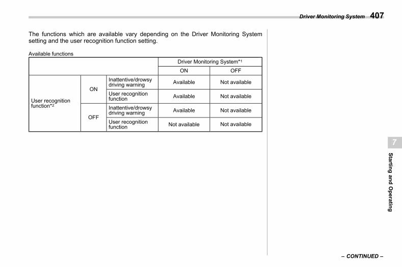
(409,1)
北米Model "A2600BE-B" EDITED: 2020/ 10/ 1
The functions which are available vary depending on the Driver Monitoring Systemsetting and the user recognition function setting.
Available functionsDriver Monitoring System*1
ON OFF
User recognitionfunction*2
ON
Inattentive/drowsydriving warning Available Not available
User recognitionfunction Available Not available
OFF
Inattentive/drowsydriving warning Available Not available
User recognitionfunction Not available Not available
– CONTINUED –
Driver Monitoring System 407
7
Startingand
Operating
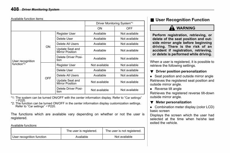
(410,1)
北米Model "A2600BE-B" EDITED: 2020/ 10/ 1
Available function itemsDriver Monitoring System*1
ON OFF
User recognitionfunction*2
ON
Register User Available Not availableDelete User Available Not available
Delete All Users Available Not available
Update Seat andMirror Position Available Not available
Delete Driver Posi-tion Available Not available
OFF
Register User Not available Not availableDelete User Available Not available
Delete All Users Available Not availableUpdate Seat andMirror Position Not available Not available
Delete Driver Posi-tion Not available Not available
*1: The system can be turned ON/OFF with the center information display. Refer to “Car settings”FP220.
*2: The function can be turned ON/OFF in the center information display customization settings.Refer to “Car settings” FP220.
The functions which are available vary depending on whether or not the user isregistered.
Available functions
The user is registered. The user is not registered.
User recognition function Available Not available
& User Recognition Functions07bp01
WARNING
Perform registration, retrieving, ordelete of the seat position and out-side mirror angle before beginningdriving. There is the risk of anaccident if registration, retrieving,or delete is performed while driving.
When a user is registered, it is possible toretrieve the following settings.! Driver position personalization
s07bp0101. Seat position and outside mirror angleRetrieves the registered seat position andoutside mirror angle.. Reverse tilt angleRetrieves the registered reverse tilt-downoutside mirror angle.! Meter personalization
s07bp0102. Combination meter display (color LCD)basic screenDisplays the screen which the user hadselected at the time when he/she lastexited the vehicle.
Driver Monitoring System408
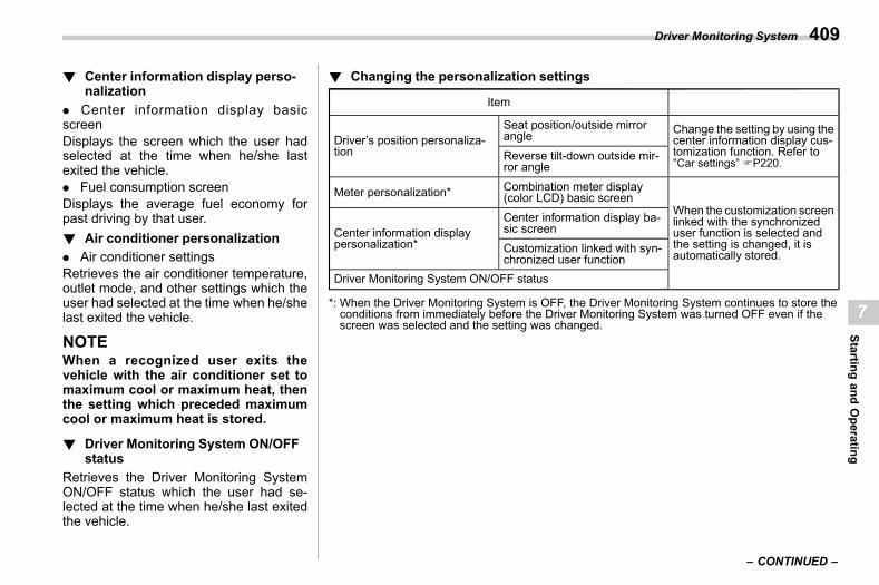
(411,1)
北米Model "A2600BE-B" EDITED: 2020/ 10/ 1
! Center information display perso-nalization
s07bp0103. Center information display basicscreenDisplays the screen which the user hadselected at the time when he/she lastexited the vehicle.. Fuel consumption screenDisplays the average fuel economy forpast driving by that user.! Air conditioner personalization
s07bp0104. Air conditioner settingsRetrieves the air conditioner temperature,outlet mode, and other settings which theuser had selected at the time when he/shelast exited the vehicle.
NOTEWhen a recognized user exits thevehicle with the air conditioner set tomaximum cool or maximum heat, thenthe setting which preceded maximumcool or maximum heat is stored.
! Driver Monitoring System ON/OFFstatus
s07bp0105Retrieves the Driver Monitoring SystemON/OFF status which the user had se-lected at the time when he/she last exitedthe vehicle.
! Changing the personalization settingss07bp0106
Item
Driver’s position personaliza-tion
Seat position/outside mirrorangle Change the setting by using the
center information display cus-tomization function. Refer to“Car settings” FP220.Reverse tilt-down outside mir-
ror angle
Meter personalization* Combination meter display(color LCD) basic screen
When the customization screenlinked with the synchronizeduser function is selected andthe setting is changed, it isautomatically stored.
Center information displaypersonalization*
Center information display ba-sic screenCustomization linked with syn-chronized user function
Driver Monitoring System ON/OFF status
*: When the Driver Monitoring System is OFF, the Driver Monitoring System continues to store theconditions from immediately before the Driver Monitoring System was turned OFF even if thescreen was selected and the setting was changed.
– CONTINUED –
Driver Monitoring System 409
7
Startingand
Operating
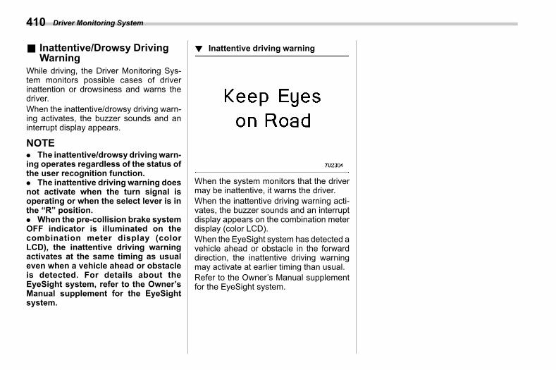
(412,1)
北米Model "A2600BE-B" EDITED: 2020/ 10/ 1
& Inattentive/Drowsy DrivingWarning
s07bp02While driving, the Driver Monitoring Sys-tem monitors possible cases of driverinattention or drowsiness and warns thedriver.When the inattentive/drowsy driving warn-ing activates, the buzzer sounds and aninterrupt display appears.
NOTE. The inattentive/drowsy drivingwarn-ing operates regardless of the status ofthe user recognition function.. The inattentive driving warning doesnot activate when the turn signal isoperating or when the select lever is inthe “R” position.. When the pre-collision brake systemOFF indicator is illuminated on thecombination meter display (colorLCD), the inattentive driving warningactivates at the same timing as usualeven when a vehicle ahead or obstacleis detected. For details about theEyeSight system, refer to the Owner’sManual supplement for the EyeSightsystem.
! Inattentive driving warnings07bp0201
When the system monitors that the drivermay be inattentive, it warns the driver.When the inattentive driving warning acti-vates, the buzzer sounds and an interruptdisplay appears on the combination meterdisplay (color LCD).When the EyeSight system has detected avehicle ahead or obstacle in the forwarddirection, the inattentive driving warningmay activate at earlier timing than usual.Refer to the Owner’s Manual supplementfor the EyeSight system.
Driver Monitoring System410
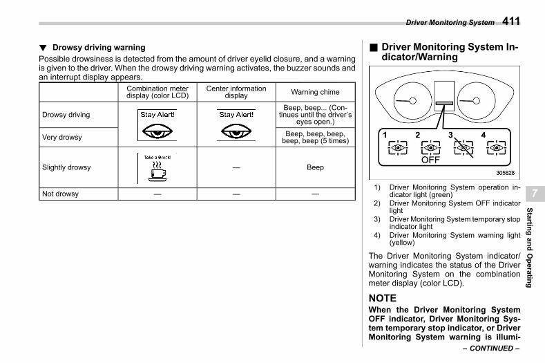
(413,1)
北米Model "A2600BE-B" EDITED: 2020/ 10/ 1
! Drowsy driving warnings07bp0202
Possible drowsiness is detected from the amount of driver eyelid closure, and a warningis given to the driver. When the drowsy driving warning activates, the buzzer sounds andan interrupt display appears.
Combination meterdisplay (color LCD)
Center informationdisplay Warning chime
Drowsy drivingBeep, beep... (Con-
tinues until the driver’seyes open.)
Very drowsy Beep, beep, beep,beep, beep (5 times)
Slightly drowsy — Beep
Not drowsy — — —
& Driver Monitoring System In-dicator/Warning
s07bp03
1) Driver Monitoring System operation in-dicator light (green)
2) Driver Monitoring System OFF indicatorlight
3) Driver Monitoring System temporary stopindicator light
4) Driver Monitoring System warning light(yellow)
The Driver Monitoring System indicator/warning indicates the status of the DriverMonitoring System on the combinationmeter display (color LCD).
NOTEWhen the Driver Monitoring SystemOFF indicator, Driver Monitoring Sys-tem temporary stop indicator, or DriverMonitoring System warning is illumi-
– CONTINUED –
Driver Monitoring System 411
7
Startingand
Operating
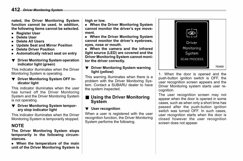
(414,1)
北米Model "A2600BE-B" EDITED: 2020/ 10/ 1
nated, the Driver Monitoring Systemfunction cannot be used. In addition,the following items cannot be selected.. Register User. Delete User. Delete All Users. Update Seat and Mirror Position. Delete Driver Position. Automatically retract seat on entry
! Driver Monitoring System operationindicator light (green)
s07bp0301This indicator illuminates when the DriverMonitoring System is operating.! Driver Monitoring System OFF in-
dicator lights07bp0302
This indicator illuminates when the userhas turned off the Driver MonitoringSystem and the Driver Monitoring Systemis not operating.! Driver Monitoring System tempor-
ary stop indicator lights07bp0303
This indicator illuminates when the DriverMonitoring System is temporarily stopped.
NOTEThe Driver Monitoring System stopstemporarily in the following circum-stances.. When the temperature of the mainunit of the Driver Monitoring System is
high or low.. When the Driver Monitoring Systemcannot monitor the driver’s eye move-ment.. When the Driver Monitoring Systemcannot monitor the driver’s eyebrows,eyes, nose or mouth.. When the camera and the infraredlight source (LED) are covered and theDriver Monitoring System cannot moni-tor the driver correctly.
! Driver Monitoring System warninglight (yellow)
s07bp0304This warning illuminates when there is aproblem with the Driver Monitoring Sys-tem. Contact a SUBARU dealer to havethe system inspected.
& Using the Driver MonitoringSystem
s07bp04
! User recognitions07bp0401
When a user is registered with the userrecognition function, the Driver MonitoringSystem performs the following.
1. When the door is opened and thepush-button ignition switch is OFF, theuser recognition screen appears and theDriver Monitoring system starts user re-cognition.The user recognition screen may notappear when the door is opened in somecases, such as when only a short time haspassed after the push-button ignitionswitch was turned OFF. In such cases,user recognition starts when the door isclosed however the user recognitionscreen does not appear.
Driver Monitoring System412
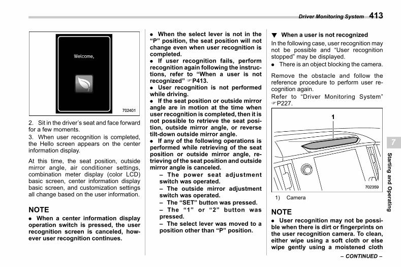
(415,1)
北米Model "A2600BE-B" EDITED: 2020/ 10/ 1
2. Sit in the driver’s seat and face forwardfor a few moments.3. When user recognition is completed,the Hello screen appears on the centerinformation display.
At this time, the seat position, outsidemirror angle, air conditioner settings,combination meter display (color LCD)basic screen, center information displaybasic screen, and customization settingsall change based on the user information.
NOTE. When a center information displayoperation switch is pressed, the userrecognition screen is canceled, how-ever user recognition continues.
. When the select lever is not in the“P” position, the seat position will notchange even when user recognition iscompleted.. If user recognition fails, performrecognition again following the instruc-tions, refer to “When a user is notrecognized” FP413.. User recognition is not performedwhile driving.. If the seat position or outside mirrorangle are in motion at the time whenuser recognition is completed, then it isnot possible to retrieve the seat posi-tion, outside mirror angle, or reversetilt-down outside mirror angle.. If any of the following operations isperformed while retrieving of the seatposition or outside mirror angle, re-trieving of the seat position and outsidemirror angle is canceled.
– The power seat adjustmentswitch was operated.– The outside mirror adjustmentswitch was operated.– The “SET” button was pressed.– The “1” or “2” button waspressed.– The select lever was moved to aposition other than “P” position.
! When a user is not recognizeds07bp0402
In the following case, user recognition maynot be possible and “User recognitionstopped” may be displayed.. There is an object blocking the camera.
Remove the obstacle and follow thereference procedure to perform user re-cognition again.Refer to “Driver Monitoring System”FP227.
1) Camera
NOTE. User recognition may not be possi-ble when there is dirt or fingerprints onthe user recognition camera. To clean,either wipe using a soft cloth or elsewipe gently using a moistened cloth
– CONTINUED –
Driver Monitoring System 413
7
Startingand
Operating
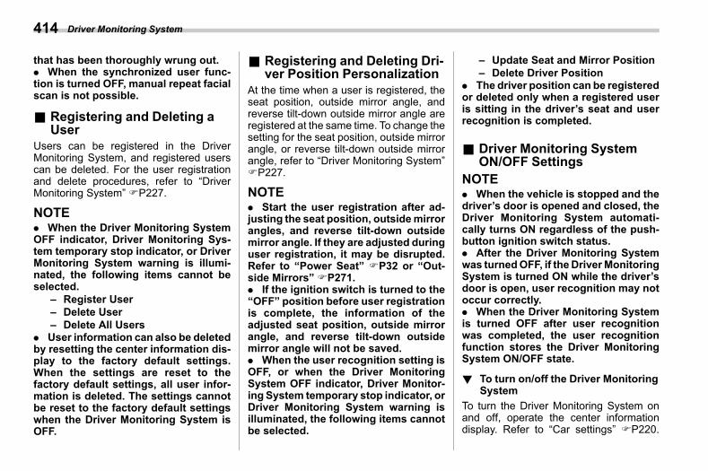
(416,1)
北米Model "A2600BE-B" EDITED: 2020/ 10/ 1
that has been thoroughly wrung out.. When the synchronized user func-tion is turned OFF, manual repeat facialscan is not possible.
& Registering and Deleting aUser
s07bp05Users can be registered in the DriverMonitoring System, and registered userscan be deleted. For the user registrationand delete procedures, refer to “DriverMonitoring System” FP227.
NOTE. When the Driver Monitoring SystemOFF indicator, Driver Monitoring Sys-tem temporary stop indicator, or DriverMonitoring System warning is illumi-nated, the following items cannot beselected.
– Register User– Delete User– Delete All Users
. User information can also be deletedby resetting the center information dis-play to the factory default settings.When the settings are reset to thefactory default settings, all user infor-mation is deleted. The settings cannotbe reset to the factory default settingswhen the Driver Monitoring System isOFF.
& Registering and Deleting Dri-ver Position Personalization
s07bp06At the time when a user is registered, theseat position, outside mirror angle, andreverse tilt-down outside mirror angle areregistered at the same time. To change thesetting for the seat position, outside mirrorangle, or reverse tilt-down outside mirrorangle, refer to “Driver Monitoring System”FP227.
NOTE. Start the user registration after ad-justing the seat position, outsidemirrorangles, and reverse tilt-down outsidemirror angle. If they are adjusted duringuser registration, it may be disrupted.Refer to “Power Seat” FP32 or “Out-side Mirrors” FP271.. If the ignition switch is turned to the“OFF” position before user registrationis complete, the information of theadjusted seat position, outside mirrorangle, and reverse tilt-down outsidemirror angle will not be saved.. When the user recognition setting isOFF, or when the Driver MonitoringSystem OFF indicator, Driver Monitor-ing System temporary stop indicator, orDriver Monitoring System warning isilluminated, the following items cannotbe selected.
– Update Seat and Mirror Position– Delete Driver Position
. The driver position can be registeredor deleted only when a registered useris sitting in the driver’s seat and userrecognition is completed.
& Driver Monitoring SystemON/OFF Settings
s07bp07NOTE. When the vehicle is stopped and thedriver’s door is opened and closed, theDriver Monitoring System automati-cally turns ON regardless of the push-button ignition switch status.. After the Driver Monitoring Systemwas turnedOFF, if theDriverMonitoringSystem is turned ON while the driver’sdoor is open, user recognition may notoccur correctly.. When the Driver Monitoring Systemis turned OFF after user recognitionwas completed, the user recognitionfunction stores the Driver MonitoringSystem ON/OFF state.
! To turn on/off the Driver MonitoringSystem
s07bp0701To turn the Driver Monitoring System onand off, operate the center informationdisplay. Refer to “Car settings” FP220.
Driver Monitoring System414
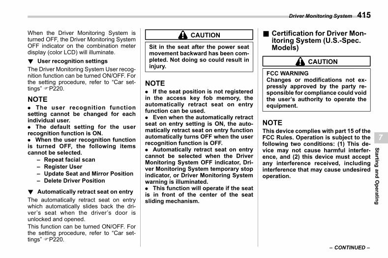
(417,1)
北米Model "A2600BE-B" EDITED: 2020/ 10/ 1
When the Driver Monitoring System isturned OFF, the Driver Monitoring SystemOFF indicator on the combination meterdisplay (color LCD) will illuminate.! User recognition settings
s07bp0702The Driver Monitoring System User recog-nition function can be turned ON/OFF. Forthe setting procedure, refer to “Car set-tings” FP220.
NOTE. The user recognition functionsetting cannot be changed for eachindividual user.. The default setting for the userrecognition function is ON.. When the user recognition functionis turned OFF, the following itemscannot be selected.
– Repeat facial scan– Register User– Update Seat and Mirror Position– Delete Driver Position
! Automatically retract seat on entrys07bp0704
The automatically retract seat on entrywhich automatically slides back the dri-ver’s seat when the driver’s door isunlocked and opened.This function can be turned ON/OFF. Forthe setting procedure, refer to “Car set-tings” FP220.
CAUTION
Sit in the seat after the power seatmovement backward has been com-pleted. Not doing so could result ininjury.
NOTE. If the seat position is not registeredin the access key fob memory, theautomatically retract seat on entryfunction can be used.. Even when the automatically retractseat on entry setting is ON, the auto-matically retract seat on entry functionautomatically turns OFF when the userrecognition function is OFF.. Automatically retract seat on entrycannot be selected when the DriverMonitoring System OFF indicator, Dri-ver Monitoring System temporary stopindicator, or Driver Monitoring Systemwarning is illuminated.. This function will operate if the seatis in front of the center of the seatsliding mechanism.
& Certification for Driver Mon-itoring System (U.S.-Spec.Models)
s07bp08
CAUTION
FCC WARNINGChanges or modifications not ex-pressly approved by the party re-sponsible for compliance could voidthe user’s authority to operate theequipment.
NOTEThis device complies with part 15 of theFCC Rules. Operation is subject to thefollowing two conditions: (1) This de-vice may not cause harmful interfer-ence, and (2) this device must acceptany interference received, includinginterference that may cause undesiredoperation.
– CONTINUED –
Driver Monitoring System 415
7
Startingand
Operating
(418,1)
北米Model "A2600BE-B" EDITED: 2020/ 10/ 1
– Canada-spec. models – Mexico-spec. models
Driver Monitoring System416
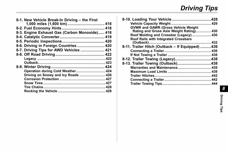
(419,1)
北米Model "A2600BE-B" EDITED: 2020/ 10/ 1
s088-1. New Vehicle Break-In Driving – the First
1,000 miles (1,600 km) .................................. 4188-2. Fuel Economy Hints ....................................... 4188-3. Engine Exhaust Gas (Carbon Monoxide)...... 4188-4. Catalytic Converter......................................... 4198-5. Periodic Inspections....................................... 4208-6. Driving in Foreign Countries ......................... 4208-7. Driving Tips for AWD Vehicles ...................... 4218-8. Off Road Driving ............................................. 422
Legacy ...............................................................422Outback..............................................................423
8-9. Winter Driving ................................................. 424Operation during Cold Weather...........................424Driving on Snowy and Icy Roads ........................426Corrosion Protection ..........................................427Snow Tires .........................................................427Tire Chains.........................................................428Rocking the Vehicle ............................................428
8-10. Loading Your Vehicle ....................................428Vehicle Capacity Weight ..................................... 429GVWR and GAWR (Gross Vehicle WeightRating and Gross Axle Weight Rating).............. 430
Roof Molding and Crossbar (Legacy).................. 430Roof Rails with Integrated Crossbars(Outback) ......................................................... 432
8-11. Trailer Hitch (Outback – If Equipped) ..........436Connecting a Trailer ........................................... 436If Not Towing a Trailer ........................................ 438
8-12. Trailer Towing (Legacy).................................4388-13. Trailer Towing (Outback)...............................438
Warranties and Maintenance............................... 439Maximum Load Limits ........................................ 439Trailer Hitches.................................................... 442Connecting a Trailer ........................................... 442Trailer Towing Tips............................................. 444
Driving Tips
8
Driving
Tips
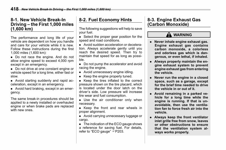
(420,1)
北米Model "A2600BE-B" EDITED: 2020/ 10/ 1
8-1. New Vehicle Break-InDriving – the First 1,000 miles(1,600 km)
s08aa
The performance and long life of yourvehicle are dependent on how you handleand care for your vehicle while it is new.Follow these instructions during the first1,000 miles (1,600 km):. Do not race the engine. And do notallow engine speed to exceed 4,000 rpmexcept in an emergency.. Do not drive at one constant engine orvehicle speed for a long time, either fast orslow.. Avoid starting suddenly and rapid ac-celeration, except in an emergency.. Avoid hard braking, except in an emer-gency.
The same break-in procedures should beapplied to a newly installed or overhauledengine or when brake pads are replacedwith new ones.
8-2. Fuel Economy Hintss08ab
The following suggestions will help to saveyour fuel.. Select the proper gear position for thespeed and road conditions.. Avoid sudden acceleration or decelera-tion. Always accelerate gently until youreach the desired speed. Then try tomaintain that speed for as long as possi-ble.. Do not pump the accelerator and avoidracing the engine.. Avoid unnecessary engine idling.. Keep the engine properly tuned.. Keep the tires inflated to the correctpressure shown on the tire placard, whichis located under the door latch on thedriver’s side. Low pressure will increasetire wear and fuel consumption.. Use the air conditioner only whennecessary.. Keep the front and rear wheels inproper alignment.. Avoid carrying unnecessary luggage orcargo.. The indication of the ECO gauge showsa reference for saving fuel. For details,refer to “ECO gauge” FP203.
8-3. Engine Exhaust Gas(Carbon Monoxide)
s08ac
WARNING
. Never inhale engine exhaust gas.Engine exhaust gas containscarbon monoxide, a colorlessand odorless gas which is dan-gerous, or even lethal, if inhaled.
. Always properly maintain the en-gine exhaust system to preventengine exhaust gas fromenteringthe vehicle.
. Never run the engine in a closedspace, such as a garage, exceptfor the brief time needed to drivethe vehicle in or out of it.
. Avoid remaining in a parked ve-hicle for a long time while theengine is running. If that is un-avoidable, then use the ventila-tion fan to force fresh air into thevehicle.
. Always keep the front ventilatorinlet grille free from snow, leavesor other obstructions to ensurethat the ventilation system al-ways works properly.
New Vehicle Break-In Driving – the First 1,000 miles (1,600 km)418
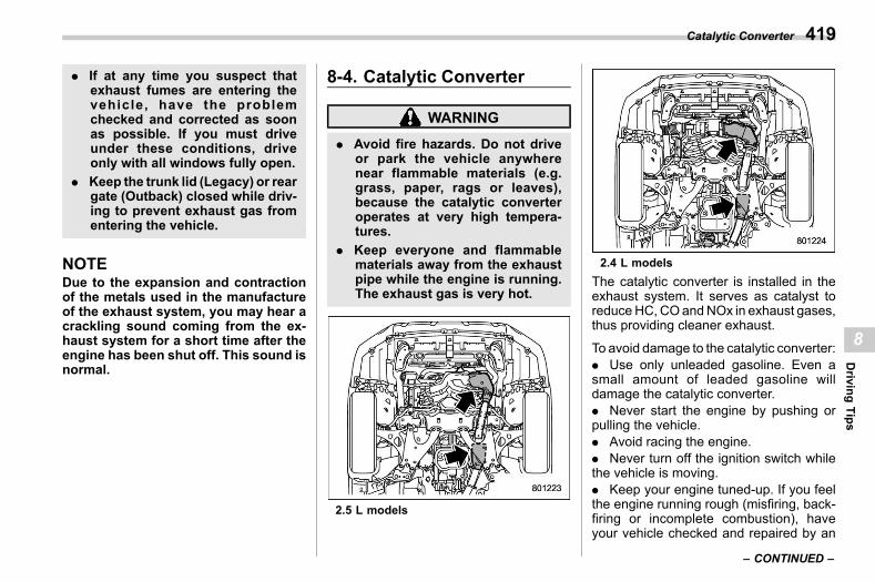
(421,1)
北米Model "A2600BE-B" EDITED: 2020/ 10/ 1
. If at any time you suspect thatexhaust fumes are entering thevehicle, have the problemchecked and corrected as soonas possible. If you must driveunder these conditions, driveonly with all windows fully open.
. Keep the trunk lid (Legacy) or reargate (Outback) closed while driv-ing to prevent exhaust gas fromentering the vehicle.
NOTEDue to the expansion and contractionof the metals used in the manufactureof the exhaust system, you may hear acrackling sound coming from the ex-haust system for a short time after theengine has been shut off. This sound isnormal.
8-4. Catalytic Converters08ad
WARNING
. Avoid fire hazards. Do not driveor park the vehicle anywherenear flammable materials (e.g.grass, paper, rags or leaves),because the catalytic converteroperates at very high tempera-tures.
. Keep everyone and flammablematerials away from the exhaustpipe while the engine is running.The exhaust gas is very hot.
2.5 L models
2.4 L modelsThe catalytic converter is installed in theexhaust system. It serves as catalyst toreduceHC, COandNOx in exhaust gases,thus providing cleaner exhaust.
To avoid damage to the catalytic converter:. Use only unleaded gasoline. Even asmall amount of leaded gasoline willdamage the catalytic converter.. Never start the engine by pushing orpulling the vehicle.. Avoid racing the engine.. Never turn off the ignition switch whilethe vehicle is moving.. Keep your engine tuned-up. If you feelthe engine running rough (misfiring, back-firing or incomplete combustion), haveyour vehicle checked and repaired by an
– CONTINUED –
Catalytic Converter 419
8
Driving
Tips
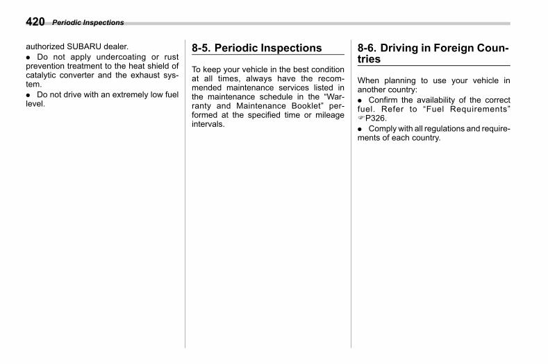
(422,1)
北米Model "A2600BE-B" EDITED: 2020/ 10/ 1
authorized SUBARU dealer.. Do not apply undercoating or rustprevention treatment to the heat shield ofcatalytic converter and the exhaust sys-tem.. Do not drive with an extremely low fuellevel.
8-5. Periodic Inspectionss08ae
To keep your vehicle in the best conditionat all times, always have the recom-mended maintenance services listed inthe maintenance schedule in the “War-ranty and Maintenance Booklet” per-formed at the specified time or mileageintervals.
8-6. Driving in Foreign Coun-tries
s08af
When planning to use your vehicle inanother country:. Confirm the availability of the correctfuel. Refer to “Fuel Requirements”FP326.. Comply with all regulations and require-ments of each country.
Periodic Inspections420
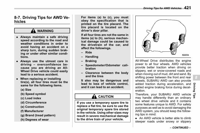
(423,1)
北米Model "A2600BE-B" EDITED: 2020/ 10/ 1
8-7. Driving Tips for AWD Ve-hicles
s08ag
WARNING
. Always maintain a safe drivingspeed according to the road andweather conditions in order toavoid having an accident on asharp turn, during sudden brak-ing or under other similar condi-tions.
. Always use the utmost care indriving – overconfidence be-cause you are driving an All-Wheel Drive vehicle could easilylead to a serious accident.
. When replacing or installingtire(s), all four tires must be thesame for the following items.(a) Size(b) Speed symbol(c) Load index(d) Circumference(e) Construction(f) Manufacturer(g) Brand (tread pattern)(h) Degrees of wear
For items (a) to (c), you mustobey the specification that isprinted on the tire placard. Thetire placard is located on thedriver’s door pillar.If all four tires are not the same initems (a) to (h), serious mechan-ical damage could be caused tothe drivetrain of the car, andaffect the followings.– Ride– Handling– Braking– Speedometer/Odometer cali-
bration– Clearance between the body
and the tiresIt also may be dangerous andlead to loss of vehicle control,and it can lead to an accident.
CAUTION
If you use a temporary spare tire toreplace a flat tire, be sure to use theoriginal temporary spare tire storedin the vehicle. Using other sizes mayresult in severe mechanical damageto the drive train of your vehicle.
All-Wheel Drive distributes the enginepower to all four wheels. AWD vehiclesprovide better traction when driving onslippery, wet or snow-covered roads andwhen moving out of mud, dirt and sand. Byshifting power between the front and rearwheels, SUBARU AWD can also provideadded traction during acceleration, andadded engine braking force during decel-eration.Therefore, your SUBARU AWD vehiclemay handle differently than an ordinarytwo wheel drive vehicle and it containssome features unique to AWD. For safetypurposes as well as to avoid damaging theAWD system, you should keep the follow-ing tips in mind:. An AWD vehicle is better able to climbsteeper roads under snowy or slippery
– CONTINUED –
Driving Tips for AWD Vehicles 421
8
Driving
Tips
(424,1)
北米Model "A2600BE-B" EDITED: 2020/ 10/ 1
conditions than a two wheel drive vehicle.There is little difference in handling, how-ever, during extremely sharp turns orsudden braking. Therefore, when drivingdown a slope or turning corners, be sure toreduce your speed and maintain an ampledistance from other vehicles.. Always check the cold tire pressurebefore starting to drive. The recommendedtire pressure is provided on the tireplacard, which is located on the door pillaron the driver’s side.. Frequent driving of an AWD vehicleunder hard-driving conditions such assteep hills or dusty roads will necessitatemore frequent replacement of the follow-ing items than that specified in the “War-ranty and Maintenance Booklet.”
– Engine oil– Brake fluid– Rear differential gear oil– Continuously variable transmissionfluid– Front differential gear oil
. There are some precautions that youmust observe when towing your vehicle.For detailed information, refer to “Towing”FP461.
8-8. Off Road Drivings08ah
WARNING
. Always maintain a safe drivingspeed according to the road andweather conditions in order toavoid having an accident on asharp turn, during sudden brak-ing or under other similar condi-tions.
. Always use the utmost care indriving – overconfidence be-cause you are driving an All-Wheel Drive vehicle could easilylead to a serious accident.
. In a rollover crash, an unbeltedperson is significantly morelikely to die than a person wear-ing a seatbelt. You the driver andall your passengers should fas-ten the seatbelts before startingto drive in order to minimize thechance of serious injury or death.
. Do not make sharp turns or quickmaneuvers unless absolutely un-avoidable. Such actions are dan-gerous as you may lose control,possibly resulting in a rolloverwhich could cause death or ser-ious injury.
. Whenever strong crosswinds arepresent, slow down sufficientlyto maintain control of your vehi-cle. Remember that your vehicle,with its higher profile and centerof gravity, is more likely to beaffected by crosswinds than or-dinary passenger cars.
& Legacys08ah03
Your AWD vehicle is neither a conven-tional off-road vehicle nor an all terrainvehicle. It is a passenger car designedprimarily for on-road use. The AWDfeature gives it some limited off-roadcapabilities in situations in which thedriving surface is relatively level, obstruc-tion-free and otherwise similar to on-roaddriving conditions. Operating it under otherthan those conditions could subject thevehicle to excessive stress which mightresult in damage not eligible for repairunder warranty. If you do take yourSUBARU off road, you should review thecommon sense precautions in the nextsection (applicable to the Outback) forgeneral guidance. But please keep in mindthat your vehicle’s off-road capabilities aremore limited than those of the Outback.Never attempt to drive through pools andpuddles, or roads flooded with water.
Off Road Driving422
(425,1)
北米Model "A2600BE-B" EDITED: 2020/ 10/ 1
Water entering the engine air intake or theexhaust pipe or water splashing ontoelectrical parts may damage your vehicleand may cause it to stall.
& Outbacks08ah02
CAUTION
Frequent driving of an AWD modelunder hard-driving conditions suchas rough roads or off roads willnecessitate more frequent replace-ment of the following items than thatspecified in the maintenance sche-dule described in the “Warranty andMaintenance Booklet.”. Engine oil. Brake fluidRemember that damage done toyour SUBARU while operating itoff-road and not using commonsense precautions such as thoselisted above is not eligible for war-ranty coverage.
Your vehicle is classified as a utilityvehicle. Utility vehicles feature a higherground clearance which enables them tobe used for wide applications including off-road driving. But please keep in mind thatyour vehicle is neither a conventional off-
road vehicle nor an all-terrain vehicle. Ahigher center of gravity in relation to thetread width as compared with ordinarypassenger cars makes vehicles of thistype more likely to roll over. In reality, utilityvehicles have a significantly higher roll-over rate than other types of vehicles. Thehigh ground clearance of this vehicle is areal advantage, giving you a better view ofthe road and allowing you to anticipateproblems earlier. However, remember thatyour utility vehicle is not designed for high-speed cornering comparable to ordinarypassenger cars and that your vehicle couldroll over if you make a sharp turn at highspeed. If you do take your SUBARU off-road, certain common sense precautionssuch as those in the following list should betaken.! Before driving
s08ah0201. Make certain that you and all of yourpassengers are wearing seatbelts.. Carry some emergency equipment,such as a towing rope or chain, a shovel,wheel blocks, first aid kit and cell phone orcitizens band radio.. Secure all cargo carried inside thevehicle and make certain that it is not piledhigher than the seatbacks. During suddenstops or jolts, unsecured cargo could bethrown around in the vehicle and cause
injury. Do not pile heavy loads on the roof.Those loads raise the vehicle’s center ofgravity and make it more prone to tip over.. Never equip your vehicle with tireslarger than those specified in this manual.! During driving
s08ah0202General precautions:. Drive carefully. Do not take unneces-sary risks by driving in dangerous areas orover rough terrain.. Slow down and employ extra caution atall times. When driving off-road, you willnot have the benefit of marked trafficlanes, banked curves, traffic signs andthe like.. Do not drive across steep slopes.Instead, drive either straight up or straightdown the slopes. A vehicle canmuchmoreeasily tip over sideways than it can endover end. Avoid driving straight up or downslopes that are too steep.. Avoid sharp turning maneuvers, espe-cially at higher speeds.. Do not grip the inside or spokes of thesteering wheel. A bad bump could jerk thewheel and injure your hands. Instead,drive with your fingers and thumbs on theoutside of the rim.. Do not drive or park over or nearflammable materials such as dry grass orfallen leaves, as they may burn easily. The
– CONTINUED –
Off Road Driving 423
8
Driving
Tips
(426,1)
北米Model "A2600BE-B" EDITED: 2020/ 10/ 1
exhaust system is very hot while theengine is running and right after the enginestops. This could create a fire hazard.
Precautions when driving under espe-cially dangerous situations:. If driving through water, such as whencrossing shallow streams:
– First, check the depth of the waterand the bottom of the stream bed forfirmness.– Next, ensure that the bed of thestream is flat.– Then, drive slowly and completelythrough the stream. The water shouldbe shallow enough that it does notreach the vehicle’s undercarriage.
. Water entering the engine air intake orthe exhaust pipe or water splashing ontoelectrical parts may damage your vehicleand may cause it to stall. Never drivethrough rushing water. Regardless of itsdepth, it can wash away the ground fromunder your tires, resulting in possible lossof traction and even vehicle rollover.. If you must rock the vehicle to free itfrom sand or mud, depress the acceleratorpedal slightly and move the select leverback and forth between “D” and “R”repeatedly. Do not race the engine. Forthe best possible traction, avoid spinningthe wheels when trying to free the vehicle.
. When the road surface is extremelyslippery, you can obtain better traction bystarting the vehicle with the transmission in2nd than 1st. Refer to “Selection of ManualMode” FP351.! After driving
s08ah0203. Always check your brakes for effective-ness immediately after driving in sand,mud or water. Do this by driving slowly andstepping on the brake pedal. Repeat thatprocess several times to dry out the brakediscs and brake pads.. After driving through tall grass, mud,rocks, sand, rivers, etc., check that there isno grass, bush, paper, rags, stones, sand,etc. adhering to or trapped on the under-body. Clear off any such matter from theunderbody. If the vehicle is used with thesematerials trapped or adhering to theunderbody, a mechanical breakdown orfire could occur.. Wash the vehicle’s underbody after off-road driving. Suspension components areparticularly prone to dirt buildup, so theyneed to be washed thoroughly.
8-9. Winter Drivings08ai
& Operation during ColdWeather
s08ai01Carry some emergency equipment, suchas a window scraper, a bag of sand, flares,a small shovel and jumper cables.
Check the battery and cables. Cold tem-peratures reduce battery capacity. Thebattery must be in good condition toprovide enough power for cold winterstarts.
It normally takes longer to start the enginein very cold weather conditions. Use anengine oil of a proper grade and viscosityfor cold weather. Using heavy summer oilwill make it harder to start the engine.
Keep the door locks from freezing bysquirting them with deicer or glycerin.
Forcing a frozen door open may damageor separate the rubber weather stripsaround the door. If the door is frozen, usehot water to melt the ice, and afterwardsthoroughly wipe the water away.
Use a windshield washer fluid that con-tains an antifreeze solution. Do not useengine antifreeze or other substitutesbecause they may damage the paint ofthe vehicle.
Winter Driving424
(427,1)
北米Model "A2600BE-B" EDITED: 2020/ 10/ 1
If you fill the windshield washer tank with afluid with a different concentration from theone used previously, purge the old fluidfrom the piping between the windshieldwasher tank and washer nozzles byoperating the washer for a certain periodof time. Otherwise, if the concentration ofthe fluid remaining in the piping is too lowfor the outside temperature, it may freezeand block the nozzles.
CAUTION
. Adjust the washer fluid concen-tration appropriately for the out-side temperature. If the concen-tration is inappropriate, sprayedwasher fluid may freeze on thewindshield and obstruct yourview, and the fluid may freeze inthe windshield washer tank.
. State or local regulations onvolatile organic compounds mayrestrict the use of methanol, acommon windshield washer anti-freeze additive. Washer fluidscontaining non-methanol anti-freeze agents should be usedonly if they provide cold weatherprotection without damagingyour vehicle’s paint, wiper bladesor washer system.
! Before driving your vehicles08ai0101
Before entering the vehicle, remove anysnow or ice from your shoes because thatcould make the pedals slippery and drivingdangerous.
While warming up the vehicle beforedriving, check that the accelerator pedal,brake pedal, and all other controls operatesmoothly.
Clear away ice and snow that has accu-mulated under the fenders to avoidmakingsteering difficult. During severe winterdriving, stop when and where it is safe todo so and check under the fendersperiodically.! Parking in cold weather
s08ai0102
WARNING
Snow can trap dangerous exhaustgases under your vehicle. Keepsnow clear of the exhaust pipe andfrom around your vehicle if you parkthe vehicle in snow with the enginerunning.
CAUTION
. Do not use the parking brakewhen parking for long periods in
cold weather since it could freezein that position.
. When the vehicle is parked insnow or when it snows, raise thewiper blades off the glass toprevent damage to them.
. Under either of the followingconditions, icing may developon the brake system, which couldcause poor braking action.– When the vehicle has been left
parked after use on roadsheavily covered with snow
– When the vehicle has been leftparked during a snowstorm
Check for snow or ice buildup onthe suspension, disc brakes andbrake hoses underneath the ve-hicle. If there is caked snow orice, remove it, being careful notto damage the disc brakes andbrake hoses and ABS harness.
When parking for long periods in coldweather, you should observe the followingtips.1. Place the select lever in the “P”position.2. Use tire stops under the tires to preventthe vehicle from moving.
– CONTINUED –
Winter Driving 425
8
Driving
Tips
(428,1)
北米Model "A2600BE-B" EDITED: 2020/ 10/ 1
! Refueling in cold weathers08ai0103
To help prevent moisture from forming inthe fuel system and the risk of its freezing,use of an antifreeze additive in the fueltank is recommended during cold weather.Use only additives that are specificallydesigned for this purpose. When an anti-freeze additive is used, its effect lastslonger if the tank is refilled whenever thefuel level reaches half empty.
If your SUBARU is not going to be used foran extended period, it is best to have thefuel tank filled to capacity.
& Driving on Snowy and IcyRoads
s08ai02
WARNING
Do not use the cruise control onslippery roads such as snowy or icyroads. This may cause loss of vehi-cle control.
CAUTION
Avoid prolonged continuous drivingin snowstorms. Snow will enter theengine’s intake system and mayhinder the airflow, which could re-sult in engine shutdown or even
breakdown.
To prevent skidding and slipping, avoidsudden braking, abrupt acceleration, high-speed driving, and sharp turning whendriving on snowy or icy roads.Always maintain ample distance betweenyour vehicle and the vehicle ahead of youto avoid the need for sudden braking.To supplement the foot brake, use theengine brake effectively to control thevehicle speed. (Shift into a lower gearwhen necessary.)Avoid shifting down abruptly. Such beha-vior can cause the wheels to lock, possiblyleading to loss of vehicle control.
An anti-lock brake system (ABS) en-hances your vehicle’s braking perfor-mance on snowy and icy roads. Forinformation about braking on slipperysurfaces, refer to “ABS (Anti-Lock BrakeSystem)” FP356 and “Vehicle DynamicsControl System” FP358.! Wiper operation when snowing
s08ai0201Before driving in cold weather, make surethe wiper blade rubbers are not frozen tothe windshield or rear window.
If the wiper blade rubbers are frozen to thewindshield or rear window, perform thefollowing procedure.
. To thaw the windshield wiper bladerubbers, use the defroster with the airflowselection in “ ” and the temperature setfor maximum warmth until the wiper bladerubbers are completely thawed. Refer to“Climate Control” FP277.. If your vehicle is equipped with a wiperdeicer, use it. It is helpful to thaw thewindshield wiper blade rubbers. Refer to“Defogger and Deicer” FP261.. To thaw the rear wiper blade rubbers,use the rear window defogger. Refer to“Defogger and Deicer” FP261.
When driving in snow, if frozen snow startsto stick on the surface of the windshielddespite wiper operation, use the defrosterwith the airflow selection in “ ” and thetemperature set for maximum warmth.After the windshield gets warmed enoughto melt the frozen snow on it, wash it awayusing the windshield washer. Refer to“Windshield washer” FP259.
Snow stuck on the wiper arm prevents thewiper from working effectively. If snow isstuck on the wiper arm, pull off the road toa safe place, then remove it. If you stop thevehicle at road side, use the hazardwarning flasher to alert other drivers. Referto “Hazard Warning Flasher” FP172.
Winter Driving426
(429,1)
北米Model "A2600BE-B" EDITED: 2020/ 10/ 1
We recommend use of non-freezing typewiper blades (winter blades) during theseasons you could have snow and freez-ing temperatures. Blades of this type givesuperior wiping performance in snowyconditions. Be sure to use blades that aresuitable for your vehicle.
CAUTION
During high-speed driving, non-freezing type wiper blades may notperform as well as standard wiperblades. If this happens, reduce thevehicle speed.
NOTEWhen the season requiring non-freez-ing type wiper blades is over, replacethem with standard wiper blades.
& Corrosion Protections08ai03
Refer to “Corrosion Protection” FP476.
& Snow Tiress08ai04
WARNING
. When replacing or installing win-ter tire(s), all four tires must bethe same for the following items.
(a) Size(b) Speed symbol(c) Load index(d) Circumference(e) Construction(f) Manufacturer(g) Brand (tread pattern)(h) Degrees of wearFor items (a) to (c), you mustobey the specification that isprinted on the tire placard. Thetire placard is located on thedriver’s door pillar.If all four tires are not the same initems (a) to (h), serious mechan-ical damage could be caused tothe drivetrain of the car, andaffect the followings.– Ride– Handling– Braking– Speedometer/Odometer cali-
bration– Clearance between the body
and the tiresIt also may be dangerous andlead to loss of vehicle control,and it can lead to an accident.
. Do not use a combination ofradial, belted bias or bias tiressince it may cause dangeroushandling characteristics and leadto an accident.
Your vehicle is equipped with “all seasontires” which are designed to provide anadequate measure of traction, handlingand braking performance in year-rounddriving. In winter, it may be possible toenhance performance through use of tiresdesigned specifically for winter drivingconditions.If you choose to install winter tires on yourvehicle, be sure to use the correct tire sizeand type. You must install four winter tiresthat are of the same size, construction,brand and load range and you shouldnever mix radial, belted bias or bias tiressince this may result in dangerous hand-ling characteristics. When you choose atire, make sure that there is enoughclearance between the tire and vehiclebody.
Remember to drive with care at all timesregardless of the type of tires on yourvehicle.
– CONTINUED –
Winter Driving 427
8
Driving
Tips
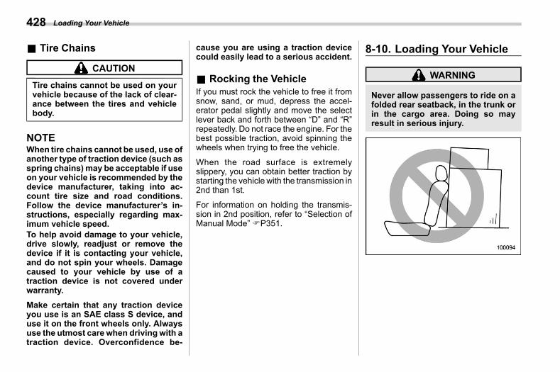
(430,1)
北米Model "A2600BE-B" EDITED: 2020/ 10/ 1
& Tire Chainss08ai05
CAUTION
Tire chains cannot be used on yourvehicle because of the lack of clear-ance between the tires and vehiclebody.
NOTEWhen tire chains cannot be used, use ofanother type of traction device (such asspring chains) may be acceptable if useon your vehicle is recommended by thedevice manufacturer, taking into ac-count tire size and road conditions.Follow the device manufacturer’s in-structions, especially regarding max-imum vehicle speed.To help avoid damage to your vehicle,drive slowly, readjust or remove thedevice if it is contacting your vehicle,and do not spin your wheels. Damagecaused to your vehicle by use of atraction device is not covered underwarranty.Make certain that any traction deviceyou use is an SAE class S device, anduse it on the front wheels only. Alwaysuse the utmost care when drivingwith atraction device. Overconfidence be-
cause you are using a traction devicecould easily lead to a serious accident.
& Rocking the Vehicles08ai06
If you must rock the vehicle to free it fromsnow, sand, or mud, depress the accel-erator pedal slightly and move the selectlever back and forth between “D” and “R”repeatedly. Do not race the engine. For thebest possible traction, avoid spinning thewheels when trying to free the vehicle.
When the road surface is extremelyslippery, you can obtain better traction bystarting the vehicle with the transmission in2nd than 1st.
For information on holding the transmis-sion in 2nd position, refer to “Selection ofManual Mode” FP351.
8-10. Loading Your Vehicles08aj
WARNING
Never allow passengers to ride on afolded rear seatback, in the trunk orin the cargo area. Doing so mayresult in serious injury.
Loading Your Vehicle428
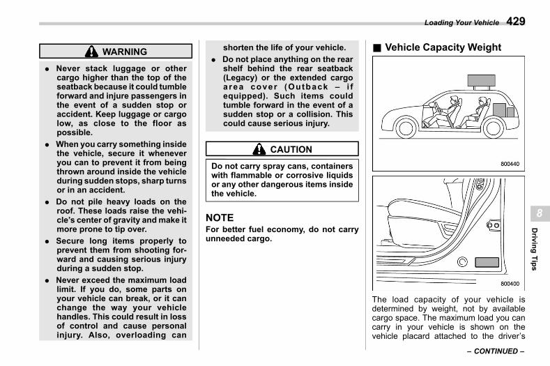
(431,1)
北米Model "A2600BE-B" EDITED: 2020/ 10/ 1
WARNING
. Never stack luggage or othercargo higher than the top of theseatback because it could tumbleforward and injure passengers inthe event of a sudden stop oraccident. Keep luggage or cargolow, as close to the floor aspossible.
. When you carry something insidethe vehicle, secure it wheneveryou can to prevent it from beingthrown around inside the vehicleduring sudden stops, sharp turnsor in an accident.
. Do not pile heavy loads on theroof. These loads raise the vehi-cle’s center of gravity andmake itmore prone to tip over.
. Secure long items properly toprevent them from shooting for-ward and causing serious injuryduring a sudden stop.
. Never exceed the maximum loadlimit. If you do, some parts onyour vehicle can break, or it canchange the way your vehiclehandles. This could result in lossof control and cause personalinjury. Also, overloading can
shorten the life of your vehicle.. Do not place anything on the rear
shelf behind the rear seatback(Legacy) or the extended cargoarea cover (Outback – i fequipped). Such items couldtumble forward in the event of asudden stop or a collision. Thiscould cause serious injury.
CAUTION
Do not carry spray cans, containerswith flammable or corrosive liquidsor any other dangerous items insidethe vehicle.
NOTEFor better fuel economy, do not carryunneeded cargo.
& Vehicle Capacity Weights08aj01
The load capacity of your vehicle isdetermined by weight, not by availablecargo space. The maximum load you cancarry in your vehicle is shown on thevehicle placard attached to the driver’s
– CONTINUED –
Loading Your Vehicle 429
8
Driving
Tips
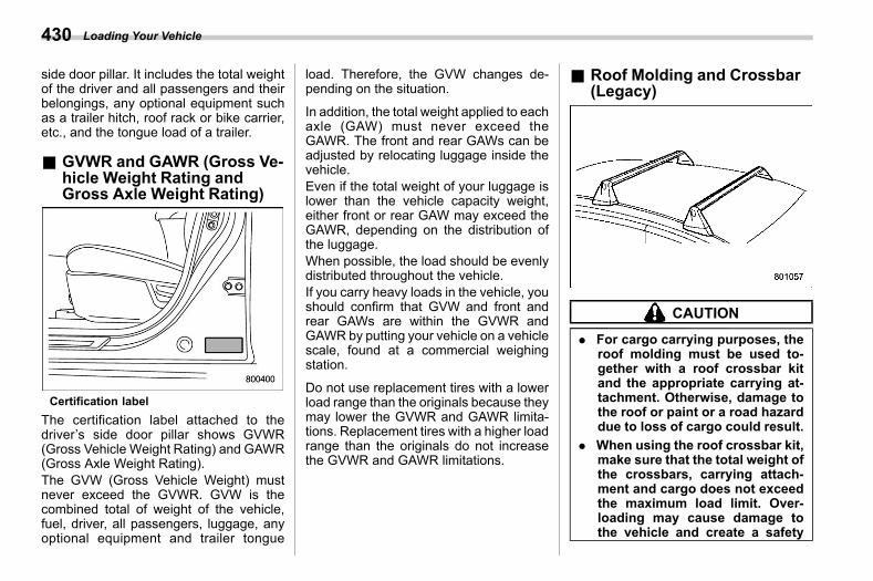
(432,1)
北米Model "A2600BE-B" EDITED: 2020/ 10/ 1
side door pillar. It includes the total weightof the driver and all passengers and theirbelongings, any optional equipment suchas a trailer hitch, roof rack or bike carrier,etc., and the tongue load of a trailer.
& GVWR and GAWR (Gross Ve-hicle Weight Rating andGross Axle Weight Rating)
s08aj02
Certification labelThe certification label attached to thedriver’s side door pillar shows GVWR(Gross Vehicle Weight Rating) and GAWR(Gross Axle Weight Rating).The GVW (Gross Vehicle Weight) mustnever exceed the GVWR. GVW is thecombined total of weight of the vehicle,fuel, driver, all passengers, luggage, anyoptional equipment and trailer tongue
load. Therefore, the GVW changes de-pending on the situation.
In addition, the total weight applied to eachaxle (GAW) must never exceed theGAWR. The front and rear GAWs can beadjusted by relocating luggage inside thevehicle.Even if the total weight of your luggage islower than the vehicle capacity weight,either front or rear GAW may exceed theGAWR, depending on the distribution ofthe luggage.When possible, the load should be evenlydistributed throughout the vehicle.If you carry heavy loads in the vehicle, youshould confirm that GVW and front andrear GAWs are within the GVWR andGAWR by putting your vehicle on a vehiclescale, found at a commercial weighingstation.
Do not use replacement tires with a lowerload range than the originals because theymay lower the GVWR and GAWR limita-tions. Replacement tires with a higher loadrange than the originals do not increasethe GVWR and GAWR limitations.
& Roof Molding and Crossbar(Legacy)
s08aj06
CAUTION
. For cargo carrying purposes, theroof molding must be used to-gether with a roof crossbar kitand the appropriate carrying at-tachment. Otherwise, damage tothe roof or paint or a road hazarddue to loss of cargo could result.
. When using the roof crossbar kit,make sure that the total weight ofthe crossbars, carrying attach-ment and cargo does not exceedthe maximum load limit. Over-loading may cause damage tothe vehicle and create a safety
Loading Your Vehicle430
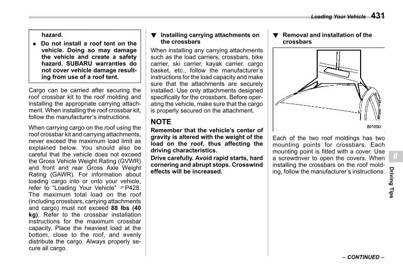
(433,1)
北米Model "A2600BE-B" EDITED: 2020/ 10/ 1
hazard.. Do not install a roof tent on the
vehicle. Doing so may damagethe vehicle and create a safetyhazard. SUBARU warranties donot cover vehicle damage result-ing from use of a roof tent.
Cargo can be carried after securing theroof crossbar kit to the roof molding andinstalling the appropriate carrying attach-ment. When installing the roof crossbar kit,follow the manufacturer’s instructions.
When carrying cargo on the roof using theroof crossbar kit and carrying attachments,never exceed the maximum load limit asexplained below. You should also becareful that the vehicle does not exceedthe Gross Vehicle Weight Rating (GVWR)and front and rear Gross Axle WeightRating (GAWR). For information aboutloading cargo into or onto your vehicle,refer to “Loading Your Vehicle” FP428.The maximum total load on the roof(including crossbars, carrying attachmentsand cargo) must not exceed 88 lbs (40kg). Refer to the crossbar installationinstructions for the maximum crossbarcapacity. Place the heaviest load at thebottom, close to the roof, and evenlydistribute the cargo. Always properly se-cure all cargo.
! Installing carrying attachments onthe crossbars
s08aj0601When installing any carrying attachmentssuch as the load carriers, crossbars, bikecarrier, ski carrier, kayak carrier, cargobasket, etc., follow the manufacturer’sinstructions for the load capacity andmakesure that the attachments are securelyinstalled. Use only attachments designedspecifically for the crossbars. Before oper-ating the vehicle, make sure that the cargois properly secured on the attachment.
NOTERemember that the vehicle’s center ofgravity is altered with the weight of theload on the roof, thus affecting thedriving characteristics.Drive carefully. Avoid rapid starts, hardcornering and abrupt stops. Crosswindeffects will be increased.
! Removal and installation of thecrossbars
s08aj0602
Each of the two roof moldings has twomounting points for crossbars. Eachmounting point is fitted with a cover. Usea screwdriver to open the covers. Wheninstalling the crossbars on the roof mold-ing, follow the manufacturer’s instructions.
– CONTINUED –
Loading Your Vehicle 431
8
Driving
Tips
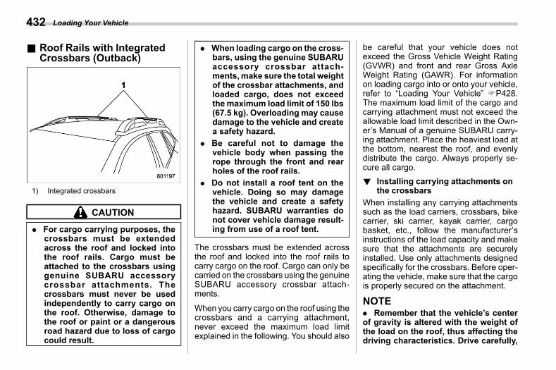
(434,1)
北米Model "A2600BE-B" EDITED: 2020/ 10/ 1
& Roof Rails with IntegratedCrossbars (Outback)
s08aj08
1) Integrated crossbars
CAUTION
. For cargo carrying purposes, thecrossbars must be extendedacross the roof and locked intothe roof rails. Cargo must beattached to the crossbars usinggenuine SUBARU accessorycrossbar attachments. Thecrossbars must never be usedindependently to carry cargo onthe roof. Otherwise, damage tothe roof or paint or a dangerousroad hazard due to loss of cargocould result.
. When loading cargo on the cross-bars, using the genuine SUBARUaccessory crossbar attach-ments,make sure the total weightof the crossbar attachments, andloaded cargo, does not exceedthemaximum load limit of 150 lbs(67.5 kg). Overloading may causedamage to the vehicle and createa safety hazard.
. Be careful not to damage thevehicle body when passing therope through the front and rearholes of the roof rails.
. Do not install a roof tent on thevehicle. Doing so may damagethe vehicle and create a safetyhazard. SUBARU warranties donot cover vehicle damage result-ing from use of a roof tent.
The crossbars must be extended acrossthe roof and locked into the roof rails tocarry cargo on the roof. Cargo can only becarried on the crossbars using the genuineSUBARU accessory crossbar attach-ments.
When you carry cargo on the roof using thecrossbars and a carrying attachment,never exceed the maximum load limitexplained in the following. You should also
be careful that your vehicle does notexceed the Gross Vehicle Weight Rating(GVWR) and front and rear Gross AxleWeight Rating (GAWR). For informationon loading cargo into or onto your vehicle,refer to “Loading Your Vehicle” FP428.The maximum load limit of the cargo andcarrying attachment must not exceed theallowable load limit described in the Own-er’s Manual of a genuine SUBARU carry-ing attachment. Place the heaviest load atthe bottom, nearest the roof, and evenlydistribute the cargo. Always properly se-cure all cargo.! Installing carrying attachments on
the crossbarss08aj0801
When installing any carrying attachmentssuch as the load carriers, crossbars, bikecarrier, ski carrier, kayak carrier, cargobasket, etc., follow the manufacturer’sinstructions of the load capacity and makesure that the attachments are securelyinstalled. Use only attachments designedspecifically for the crossbars. Before oper-ating the vehicle, make sure that the cargois properly secured on the attachment.
NOTE. Remember that the vehicle’s centerof gravity is altered with the weight ofthe load on the roof, thus affecting thedriving characteristics. Drive carefully,
Loading Your Vehicle432
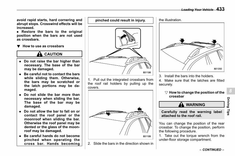
(435,1)
北米Model "A2600BE-B" EDITED: 2020/ 10/ 1
avoid rapid starts, hard cornering andabrupt stops. Crosswind effects will beincreased.. Restore the bars to the originalposition when the bars are not usedas crossbars.
! How to use as crossbarss08aj0802
CAUTION
. Do not raise the bar higher thannecessary. The base of the barmay be damaged.
. Be careful not to contact the barswhile sliding them. Otherwise,the bars may be scratched orthe latch portions may be da-maged.
. Do not slide the bar more thannecessary when sliding the bar.The base of the bar may bedamaged.
. Do not allow the bar to fall on orcontact the roof panel or themoonroof when sliding the bar.Otherwise the roof panel may bedented or the glass of the moon-roof may be damaged.
. Be careful hands do not becomepinched when operating thecross bar. Hands becoming
pinched could result in injury.
1. Pull out the integrated crossbars fromthe roof rail holders by pulling up thecovers.
2. Slide the bars in the direction shown in
the illustration.
3. Install the bars into the holders.4. Make sure that the latches are fittedsecurely.
! How to change the position of thecrossbar
s08aj080201
WARNING
Carefully read the warning labelattached to the roof rail.
You can change the position of the rearcrossbar. To change the position, performthe following procedure.1. Take out the torque wrench from theunder-floor storage compartment.
– CONTINUED –
Loading Your Vehicle 433
8
Driving
Tips
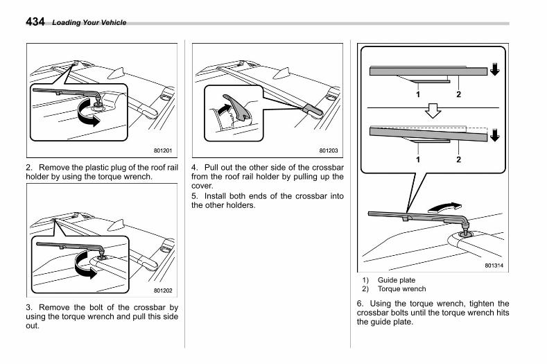
(436,1)
北米Model "A2600BE-B" EDITED: 2020/ 10/ 1
2. Remove the plastic plug of the roof railholder by using the torque wrench.
3. Remove the bolt of the crossbar byusing the torque wrench and pull this sideout.
4. Pull out the other side of the crossbarfrom the roof rail holder by pulling up thecover.5. Install both ends of the crossbar intothe other holders.
1) Guide plate2) Torque wrench
6. Using the torque wrench, tighten thecrossbar bolts until the torque wrench hitsthe guide plate.
Loading Your Vehicle434
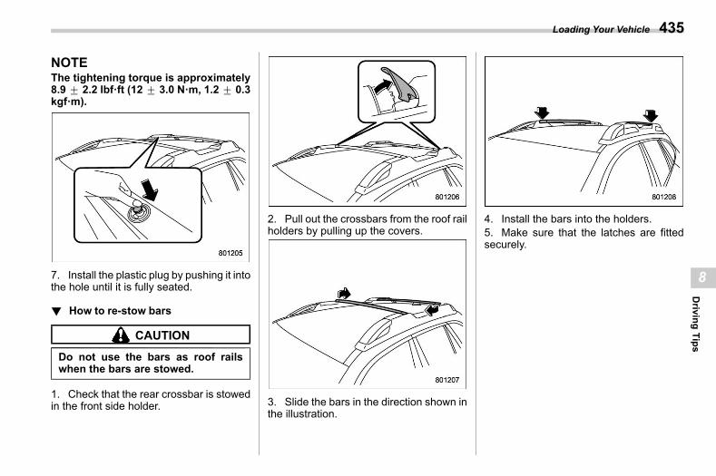
(437,1)
北米Model "A2600BE-B" EDITED: 2020/ 10/ 1
NOTEThe tightening torque is approximately8.9 + 2.2 lbf·ft (12 + 3.0 N·m, 1.2 + 0.3kgf·m).
7. Install the plastic plug by pushing it intothe hole until it is fully seated.
! How to re-stow barss08aj0803
CAUTION
Do not use the bars as roof railswhen the bars are stowed.
1. Check that the rear crossbar is stowedin the front side holder.
2. Pull out the crossbars from the roof railholders by pulling up the covers.
3. Slide the bars in the direction shown inthe illustration.
4. Install the bars into the holders.5. Make sure that the latches are fittedsecurely.
Loading Your Vehicle 435
8
Driving
Tips
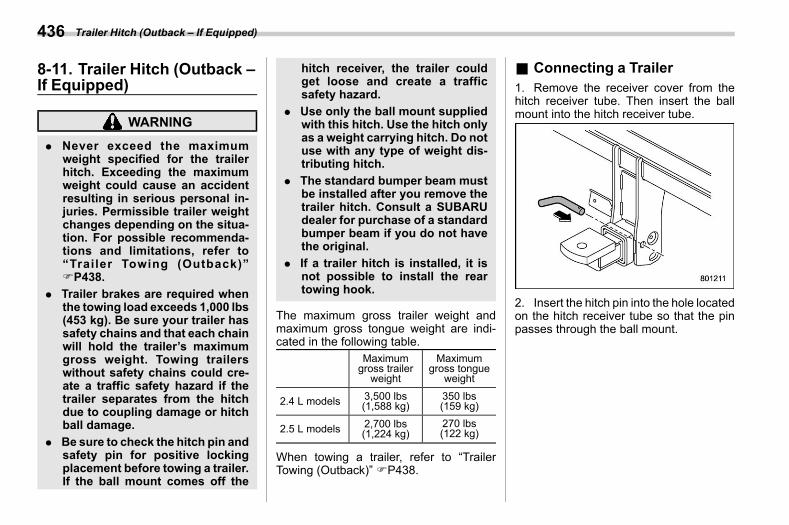
(438,1)
北米Model "A2600BE-B" EDITED: 2020/ 10/ 1
8-11. Trailer Hitch (Outback –If Equipped)
s08ak
WARNING
. Never exceed the maximumweight specified for the trailerhitch. Exceeding the maximumweight could cause an accidentresulting in serious personal in-juries. Permissible trailer weightchanges depending on the situa-tion. For possible recommenda-tions and limitations, refer to“Trailer Towing (Outback)”FP438.
. Trailer brakes are required whenthe towing load exceeds 1,000 lbs(453 kg). Be sure your trailer hassafety chains and that each chainwill hold the trailer’s maximumgross weight. Towing trailerswithout safety chains could cre-ate a traffic safety hazard if thetrailer separates from the hitchdue to coupling damage or hitchball damage.
. Be sure to check the hitch pin andsafety pin for positive lockingplacement before towing a trailer.If the ball mount comes off the
hitch receiver, the trailer couldget loose and create a trafficsafety hazard.
. Use only the ball mount suppliedwith this hitch. Use the hitch onlyas a weight carrying hitch. Do notuse with any type of weight dis-tributing hitch.
. The standard bumper beam mustbe installed after you remove thetrailer hitch. Consult a SUBARUdealer for purchase of a standardbumper beam if you do not havethe original.
. If a trailer hitch is installed, it isnot possible to install the reartowing hook.
The maximum gross trailer weight andmaximum gross tongue weight are indi-cated in the following table.
Maximumgross trailerweight
Maximumgross tongue
weight
2.4 L models 3,500 lbs(1,588 kg)
350 lbs(159 kg)
2.5 L models 2,700 lbs(1,224 kg)
270 lbs(122 kg)
When towing a trailer, refer to “TrailerTowing (Outback)” FP438.
& Connecting a Trailers08ak01
1. Remove the receiver cover from thehitch receiver tube. Then insert the ballmount into the hitch receiver tube.
2. Insert the hitch pin into the hole locatedon the hitch receiver tube so that the pinpasses through the ball mount.
Trailer Hitch (Outback – If Equipped)436
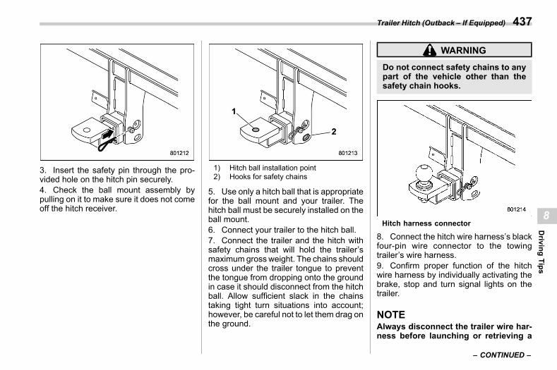
(439,1)
北米Model "A2600BE-B" EDITED: 2020/ 10/ 1
3. Insert the safety pin through the pro-vided hole on the hitch pin securely.4. Check the ball mount assembly bypulling on it to make sure it does not comeoff the hitch receiver.
1) Hitch ball installation point2) Hooks for safety chains
5. Use only a hitch ball that is appropriatefor the ball mount and your trailer. Thehitch ball must be securely installed on theball mount.6. Connect your trailer to the hitch ball.7. Connect the trailer and the hitch withsafety chains that will hold the trailer’smaximumgross weight. The chains shouldcross under the trailer tongue to preventthe tongue from dropping onto the groundin case it should disconnect from the hitchball. Allow sufficient slack in the chainstaking tight turn situations into account;however, be careful not to let them drag onthe ground.
WARNING
Do not connect safety chains to anypart of the vehicle other than thesafety chain hooks.
Hitch harness connector
8. Connect the hitch wire harness’s blackfour-pin wire connector to the towingtrailer’s wire harness.9. Confirm proper function of the hitchwire harness by individually activating thebrake, stop and turn signal lights on thetrailer.
NOTEAlways disconnect the trailer wire har-ness before launching or retrieving a
– CONTINUED –
Trailer Hitch (Outback – If Equipped) 437
8
Driving
Tips
(440,1)
北米Model "A2600BE-B" EDITED: 2020/ 10/ 1
watercraft.
& If Not Towing a Trailers08ak02
. Remove the ball mount from the hitchreceiver tube and insert the receiver coveronto the hitch receiver tube.. Place the dust cap over the four-pinconnector of the hitch wire harness toprotect against possible damage.. Occasionally lubricate terminals of thefour-pin connector using terminal grease.
8-12. Trailer Towing (Legacy)s08ar
CAUTION
Your vehicle is neither designed norintended to be used for trailer tow-ing. Therefore, never tow a trailerwith your vehicle.
SUBARU assumes no responsibility forinjuries or vehicle damage that may resultfrom trailer towing, from any trailer towingequipment or from any errors or omissionsin the instructions accompanying suchequipment. SUBARU warranties do notapply to vehicle damage or malfunctioncaused by trailer towing.
8-13. Trailer Towing(Outback)
s08al
Your vehicle is designed and intended tobe used primarily as a passenger-carryingvehicle. Towing a trailer puts additionalloads on your vehicle’s engine, drivetrain,brakes, tires and suspension and has anadverse effect on fuel economy and airconditioning system cooling performance.If you do decide to tow a trailer, your safetyand satisfaction depend upon proper useof correct equipment and cautious opera-tion of your vehicle. Drive carefully whentowing a trailer, and always consider thefollowing conditions.. Road conditions. Weather conditions. Vehicle load weight. Trailer load weight
Seek the advice of your SUBARU dealer toassist you in purchasing a hitch and othernecessary towing equipment appropriatefor your vehicle. Do not use towing equip-ment other than genuine SUBARU towingequipment. In addition, be sure to followthe instructions on correct installation anduse provided by SUBARU.
Trailer Towing (Legacy)438
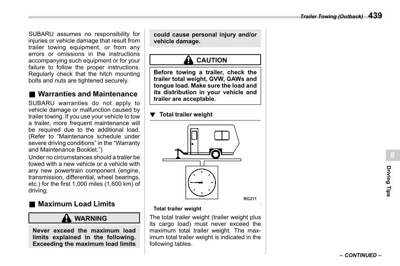
(441,1)
北米Model "A2600BE-B" EDITED: 2020/ 10/ 1
SUBARU assumes no responsibility forinjuries or vehicle damage that result fromtrailer towing equipment, or from anyerrors or omissions in the instructionsaccompanying such equipment or for yourfailure to follow the proper instructions.Regularly check that the hitch mountingbolts and nuts are tightened securely.
& Warranties and Maintenances08al01
SUBARU warranties do not apply tovehicle damage or malfunction caused bytrailer towing. If you use your vehicle to towa trailer, more frequent maintenance willbe required due to the additional load.(Refer to “Maintenance schedule undersevere driving conditions” in the “Warrantyand Maintenance Booklet.”)Under no circumstances should a trailer betowed with a new vehicle or a vehicle withany new powertrain component (engine,transmission, differential, wheel bearings,etc.) for the first 1,000 miles (1,600 km) ofdriving.
& Maximum Load Limitss08al02
WARNING
Never exceed the maximum loadlimits explained in the following.Exceeding the maximum load limits
could cause personal injury and/orvehicle damage.
CAUTION
Before towing a trailer, check thetrailer total weight, GVW, GAWs andtongue load. Make sure the load andits distribution in your vehicle andtrailer are acceptable.
! Total trailer weights08al0201
Total trailer weightThe total trailer weight (trailer weight plusits cargo load) must never exceed themaximum total trailer weight. The max-imum total trailer weight is indicated in thefollowing tables.
– CONTINUED –
Trailer Towing (Outback) 439
8
Driving
Tips
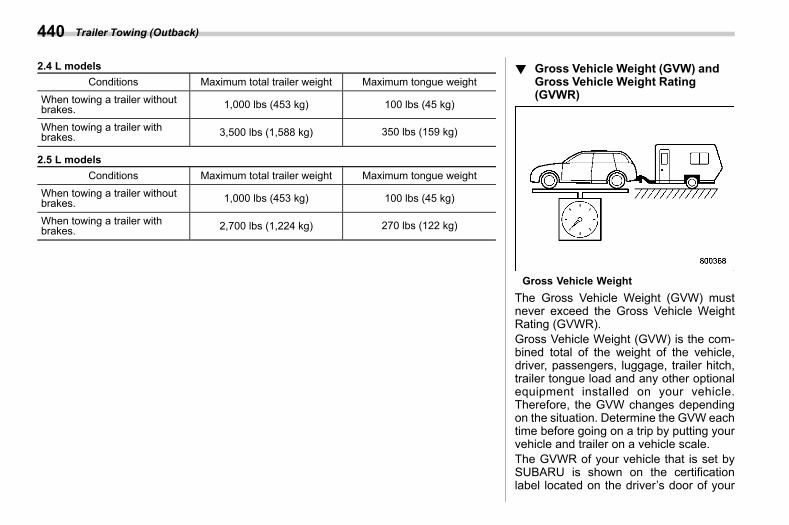
(442,1)
北米Model "A2600BE-B" EDITED: 2020/ 10/ 1
2.4 L modelsConditions Maximum total trailer weight Maximum tongue weight
When towing a trailer withoutbrakes. 1,000 lbs (453 kg) 100 lbs (45 kg)
When towing a trailer withbrakes. 3,500 lbs (1,588 kg) 350 lbs (159 kg)
2.5 L modelsConditions Maximum total trailer weight Maximum tongue weight
When towing a trailer withoutbrakes. 1,000 lbs (453 kg) 100 lbs (45 kg)
When towing a trailer withbrakes. 2,700 lbs (1,224 kg) 270 lbs (122 kg)
! Gross Vehicle Weight (GVW) andGross Vehicle Weight Rating(GVWR)
s08al0202
Gross Vehicle WeightThe Gross Vehicle Weight (GVW) mustnever exceed the Gross Vehicle WeightRating (GVWR).Gross Vehicle Weight (GVW) is the com-bined total of the weight of the vehicle,driver, passengers, luggage, trailer hitch,trailer tongue load and any other optionalequipment installed on your vehicle.Therefore, the GVW changes dependingon the situation. Determine the GVW eachtime before going on a trip by putting yourvehicle and trailer on a vehicle scale.The GVWR of your vehicle that is set bySUBARU is shown on the certificationlabel located on the driver’s door of your
Trailer Towing (Outback)440
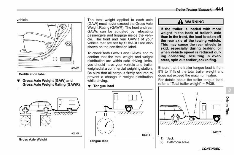
(443,1)
北米Model "A2600BE-B" EDITED: 2020/ 10/ 1
vehicle.
Certification label
! Gross Axle Weight (GAW) andGross Axle Weight Rating (GAWR)
s08al0203
Gross Axle Weight
The total weight applied to each axle(GAW) must never exceed the Gross AxleWeight Rating (GAWR). The front and rearGAWs can be adjusted by relocatingpassengers and luggage inside the vehi-cle. The front and rear GAWR of yourvehicle that are set by SUBARU are alsoshown on the certification label.
To check both GVWR and GAWR and toconfirm that the total weight and weightdistribution are within safe driving limits,you should have your vehicle and trailerweighed at a commercial weighing station.Be sure that all cargo is firmly secured toprevent a change in weight distributionwhile driving.! Tongue load
s08al0204
Tongue load
WARNING
If the trailer is loaded with moreweight in the back of trailer’s axlethan in the front, the load is taken offthe rear axle of the towing vehicle.This may cause the rear wheels toskid, especially during braking orwhen vehicle speed is reduced dur-ing cornering, resulting in over-steer, spin out and/or jackknifing.
Ensure that the trailer tongue load is from8% to 11% of the total trailer weight anddoes not exceed the maximum value.For details about the trailer tongue load,refer to “Total trailer weight” FP439.
1) Jack2) Bathroom scale
– CONTINUED –
Trailer Towing (Outback) 441
8
Driving
Tips
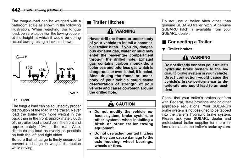
(444,1)
北米Model "A2600BE-B" EDITED: 2020/ 10/ 1
The tongue load can be weighed with abathroom scale as shown in the followingillustration. When weighing the tongueload, be sure to position the towing couplerat the height at which it would be duringactual towing, using a jack as shown.
F: Front
The tongue load can be adjusted by properdistribution of the load in the trailer. Neverload the trailer with more weight in theback than in the front; approximately 60%of the trailer load should be in the front andapproximately 40% in the rear. Also,distribute the load as evenly as possibleon both the left and right sides.Be sure that all cargo is firmly secured toprevent a change in weight distributionwhile driving.
& Trailer Hitchess08al03
WARNING
Never drill the frame or under-bodyof your vehicle to install a commer-cial trailer hitch. If you do, danger-ous exhaust gas, water or mud mayenter the passenger compartmentthrough the drilled hole. Exhaustgas contains carbon monoxide, acolorless and odorless gas which isdangerous, or even lethal, if inhaled.Also, drilling the frame or under-body of your vehicle could causedeterioration of strength of yourvehicle and cause corrosion aroundthe drilled hole.
CAUTION
. Do not modify the vehicle ex-haust system, brake system, orother systems when installing ahitch or other trailer towingequipment.
. Do not use axle-mounted hitchesas they can cause damage to theaxle housing, wheel bearings,wheels or tires.
Do not use a trailer hitch other thangenuine SUBARU trailer hitch. A genuineSUBARU hitch is available from yourSUBARU dealer.
& Connecting a Trailers08al04
! Trailer brakess08al0401
WARNING
Do not directly connect your trailer’shydraulic brake system to the hy-draulic brake system in your vehicle.Direct connection would cause thevehicle’s brake performance to de-teriorate and could lead to an acci-dent.
Check that your trailer’s brakes conformwith Federal, state/province and/or otherapplicable regulations. Your SUBARU’sbrake system is not designed to be tappedinto the trailer’s hydraulic brake system.Please ask your SUBARU dealer andprofessional trailer supplier for more in-formation about the trailer’s brake system.
Trailer Towing (Outback)442
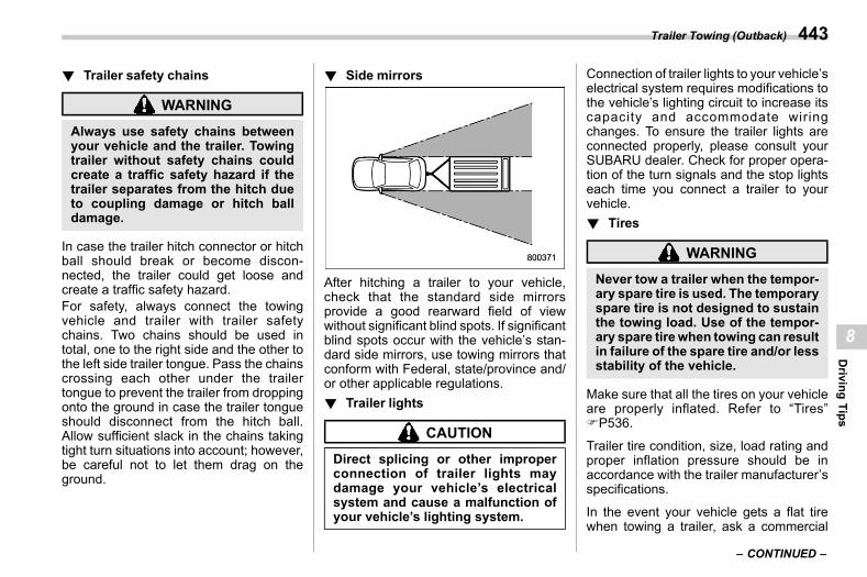
(445,1)
北米Model "A2600BE-B" EDITED: 2020/ 10/ 1
! Trailer safety chainss08al0402
WARNING
Always use safety chains betweenyour vehicle and the trailer. Towingtrailer without safety chains couldcreate a traffic safety hazard if thetrailer separates from the hitch dueto coupling damage or hitch balldamage.
In case the trailer hitch connector or hitchball should break or become discon-nected, the trailer could get loose andcreate a traffic safety hazard.For safety, always connect the towingvehicle and trailer with trailer safetychains. Two chains should be used intotal, one to the right side and the other tothe left side trailer tongue. Pass the chainscrossing each other under the trailertongue to prevent the trailer from droppingonto the ground in case the trailer tongueshould disconnect from the hitch ball.Allow sufficient slack in the chains takingtight turn situations into account; however,be careful not to let them drag on theground.
! Side mirrorss08al0403
After hitching a trailer to your vehicle,check that the standard side mirrorsprovide a good rearward field of viewwithout significant blind spots. If significantblind spots occur with the vehicle’s stan-dard side mirrors, use towing mirrors thatconform with Federal, state/province and/or other applicable regulations.! Trailer lights
s08al0404
CAUTION
Direct splicing or other improperconnection of trailer lights maydamage your vehicle’s electricalsystem and cause a malfunction ofyour vehicle’s lighting system.
Connection of trailer lights to your vehicle’selectrical system requires modifications tothe vehicle’s lighting circuit to increase itscapacity and accommodate wiringchanges. To ensure the trailer lights areconnected properly, please consult yourSUBARU dealer. Check for proper opera-tion of the turn signals and the stop lightseach time you connect a trailer to yourvehicle.! Tires
s08al0405
WARNING
Never tow a trailer when the tempor-ary spare tire is used. The temporaryspare tire is not designed to sustainthe towing load. Use of the tempor-ary spare tirewhen towing can resultin failure of the spare tire and/or lessstability of the vehicle.
Make sure that all the tires on your vehicleare properly inflated. Refer to “Tires”FP536.
Trailer tire condition, size, load rating andproper inflation pressure should be inaccordance with the trailer manufacturer’sspecifications.
In the event your vehicle gets a flat tirewhen towing a trailer, ask a commercial
– CONTINUED –
Trailer Towing (Outback) 443
8
Driving
Tips
(446,1)
北米Model "A2600BE-B" EDITED: 2020/ 10/ 1
road service representative or profes-sional to repair the flat tire.
If you carry a regular size spare tire in yourvehicle or trailer as a precaution againstgetting a flat tire, be sure that the spare tireis firmly secured.
& Trailer Towing Tipss08al05
CAUTION
. For models equipped with theBSD (Blind Spot Detection) andRCTA (Rear Cross Traffic Alert)driving support systems, whentowing a trailer, touch “BSD/RCTA” to deactivate the system.The system may not operateproperly due to the blocked radarwaves. For details about how toturn on/off the BSD/RCTA, referto “Car settings” FP220.
. For models equipped with Re-verse Automatic Braking (RAB)system, consult your SUBARUdealer for additional informationabout towing a trailer.
. Towing a trailer in high tempera-tures, or on long or steep grades,may cause the vehicle to over-heat. Refer to “Engine Overheat-
ing” FP460.. When towing a trailer, steering,
stability, stopping distance andbraking performance will be dif-ferent when compared to normaloperation. You should neverdrive at excessive speeds butalways employ extra cautionwhen towing a trailer. You shouldalso keep the following tips inmind.
. When parking on a steep slopewith a trailer attached to yourvehicle, the braking power of theelectronic parking brake may notbe sufficient since strong brakingpower is needed.
! Before starting out on a trips08al0501
. Check the towing regulations for traileror caravan vehicles that vary by state/region. Failure to comply with the proce-dures set forth will not only compromiseyour safety, but will also negate yourinsurance coverage and/or may violatethe state road and traffic acts and regula-tions.. Check that the vehicle and vehicle-to-hitchmounting are in good condition. If anyproblems are apparent, do not tow thetrailer.
. Check that the vehicle rests horizon-tally with the trailer attached. If the vehicleis tipped sharply up at the front and downat the rear, check the total trailer weight,GVW, GAWs and tongue load again, thenconfirm that the load and its distribution areacceptable.. Check that the tire pressures arecorrect.. Check that the vehicle and trailer areconnected properly. Confirm that
– The trailer tongue is connectedproperly to the hitch ball.– The trailer lights connector is con-nected properly and trailer’s stop lightsilluminate when the vehicle’s brakepedal is pressed, and that the trailer’sturn signal lights flash when the vehi-cle’s turn signal lever is operated.– The safety chains are connectedproperly.– All cargo in the trailer is securedsafely in position.– The side mirrors provide a goodrearward field of view without a sig-nificant blind spot.
. Sufficient time should be taken to learnthe “feel” of the vehicle/trailer combinationbefore starting out on a trip. In an area freeof traffic, practice turning, stopping andbacking up.
Trailer Towing (Outback)444
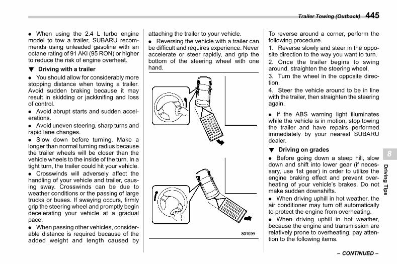
(447,1)
北米Model "A2600BE-B" EDITED: 2020/ 10/ 1
. When using the 2.4 L turbo enginemodel to tow a trailer, SUBARU recom-mends using unleaded gasoline with anoctane rating of 91 AKI (95 RON) or higherto reduce the risk of engine overheat.! Driving with a trailer
s08al0502. You should allow for considerably morestopping distance when towing a trailer.Avoid sudden braking because it mayresult in skidding or jackknifing and lossof control.. Avoid abrupt starts and sudden accel-erations.. Avoid uneven steering, sharp turns andrapid lane changes.. Slow down before turning. Make alonger than normal turning radius becausethe trailer wheels will be closer than thevehicle wheels to the inside of the turn. In atight turn, the trailer could hit your vehicle.. Crosswinds will adversely affect thehandling of your vehicle and trailer, caus-ing sway. Crosswinds can be due toweather conditions or the passing of largetrucks or buses. If swaying occurs, firmlygrip the steering wheel and promptly begindecelerating your vehicle at a gradualpace.. When passing other vehicles, consider-able distance is required because of theadded weight and length caused by
attaching the trailer to your vehicle.. Reversing the vehicle with a trailer canbe difficult and requires experience. Neveraccelerate or steer rapidly, and grip thebottom of the steering wheel with onehand.
To reverse around a corner, perform thefollowing procedure.1. Reverse slowly and steer in the oppo-site direction to the way you want to turn.2. Once the trailer begins to swingaround, straighten the steering wheel.3. Turn the wheel in the opposite direc-tion.4. Steer the vehicle around to be in linewith the trailer, then straighten the steeringagain.
. If the ABS warning light illuminateswhile the vehicle is in motion, stop towingthe trailer and have repairs performedimmediately by your nearest SUBARUdealer.! Driving on grades
s08al0503. Before going down a steep hill, slowdown and shift into lower gear (if neces-sary, use 1st gear) in order to utilize theengine braking effect and prevent over-heating of your vehicle’s brakes. Do notmake sudden downshifts.. When driving uphill in hot weather, theair conditioner may turn off automaticallyto protect the engine from overheating.. When driving uphill in hot weather,because the engine and transmission arerelatively prone to overheating, pay atten-tion to the following items.
– CONTINUED –
Trailer Towing (Outback) 445
8
Driving
Tips
(448,1)
北米Model "A2600BE-B" EDITED: 2020/ 10/ 1
– Engine coolant temperature gauge– AT OIL TEMP warning light
. If any of the following conditions occur,immediately turn off the air conditioner andstop the vehicle in the nearest safelocation. Refer to “If You Park Your Vehiclein an Emergency” FP448 and “EngineOverheating” FP460.
– Engine coolant temperature gaugeneedle approaches the OVERHEATzone. Refer to “Engine Coolant Tem-perature Gauge” FP175.– AT OIL TEMP warning light illumi-nates. Refer to “AT OILTEMPWarningLight” FP184.
. Do not use the accelerator pedal to staystationary on an uphill slope instead ofusing the parking brake or foot brake. Thatmay cause the transmission fluid to over-heat.! Parking on a grade
s08al0504Always block the wheels under bothvehicle and trailer when parking. Applythe parking brake. You should not park ona hill or slope. If parking on a hill or slopecannot be avoided, you should take thefollowing steps:
1. Apply the brakes and hold the pedaldown.2. Have someone place wheel blocks
under both the vehicle and trailer wheels.3. When the wheel blocks are in place,release the regular brakes slowly until theblocks absorb the load.4. Apply the regular brakes and thenapply the parking brake; slowly releasethe regular brakes.5. Shift into “P” and shut off the engine.
Trailer Towing (Outback)446
(449,1)
北米Model "A2600BE-B" EDITED: 2020/ 10/ 1
s099-1. If You Park Your Vehicle in an Emergency... 4489-2. Temporary Spare Tire..................................... 4489-3. Maintenance Tools.......................................... 449
Legacy ...............................................................450Outback..............................................................451
9-4. Flat Tires ......................................................... 452Changing a Flat Tire ...........................................452Tire Pressure Monitoring System (TPMS)(U.S.-Spec. Models) ..........................................456
TPMS Screen (U.S.-Spec. Models) .......................4579-5. Jump Starting ................................................. 457
How to Jump Start..............................................4589-6. Engine Overheating........................................ 460
If Steam Is Coming from the EngineCompartment....................................................460
If No Steam Is Coming from the EngineCompartment....................................................460
9-7. Towing ............................................................. 461Towing Hook and Tie-Down Hooks/Holes ............461
Using a Flat-Bed Truck....................................... 464Towing with All Wheels on the Ground ............... 464
9-8. Electronic Parking Brake – If the ElectronicParking Brake Cannot Be Released ............465
9-9. Access Key Fob – If Access Key FobDoes Not Operate Properly ..........................465
Locking and Unlocking....................................... 466Switching Power Status ..................................... 466Starting Engine .................................................. 466
9-10. Rear Gate (Outback) – If the Rear GateCannot Be Opened........................................467
9-11. Malfunctions of the Center InformationDisplay ...........................................................468
9-12. If Your Vehicle Is Involved inan Accident....................................................470
To Restart the Engine When Involved inan Accident...................................................... 470
Automatic Door Locking/Unlocking OperationWhen Involved in an Accident .......................... 470
In Case of Emergency
9
InCase
ofEmergency
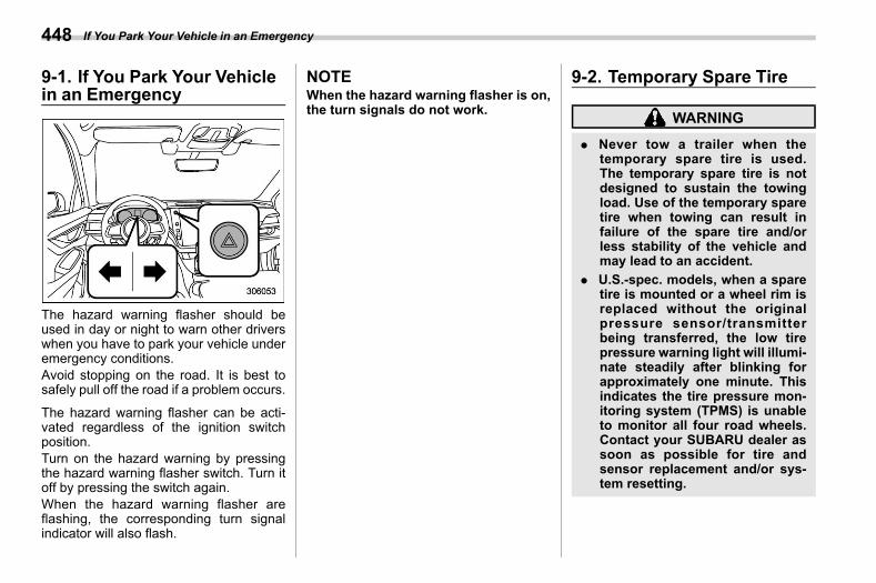
(450,1)
北米Model "A2600BE-B" EDITED: 2020/ 10/ 1
9-1. If You Park Your Vehiclein an Emergency
s09aa
The hazard warning flasher should beused in day or night to warn other driverswhen you have to park your vehicle underemergency conditions.Avoid stopping on the road. It is best tosafely pull off the road if a problem occurs.
The hazard warning flasher can be acti-vated regardless of the ignition switchposition.Turn on the hazard warning by pressingthe hazard warning flasher switch. Turn itoff by pressing the switch again.When the hazard warning flasher areflashing, the corresponding turn signalindicator will also flash.
NOTEWhen the hazard warning flasher is on,the turn signals do not work.
9-2. Temporary Spare Tires09ab
WARNING
. Never tow a trailer when thetemporary spare tire is used.The temporary spare tire is notdesigned to sustain the towingload. Use of the temporary sparetire when towing can result infailure of the spare tire and/orless stability of the vehicle andmay lead to an accident.
. U.S.-spec. models, when a sparetire is mounted or a wheel rim isreplaced without the originalpressure sensor/transmitterbeing transferred, the low tirepressure warning light will illumi-nate steadily after blinking forapproximately one minute. Thisindicates the tire pressure mon-itoring system (TPMS) is unableto monitor all four road wheels.Contact your SUBARU dealer assoon as possible for tire andsensor replacement and/or sys-tem resetting.
If You Park Your Vehicle in an Emergency448
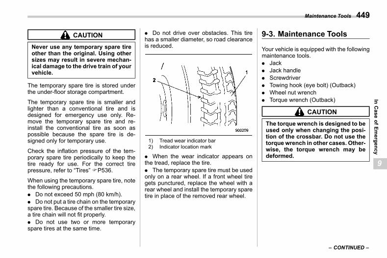
(451,1)
北米Model "A2600BE-B" EDITED: 2020/ 10/ 1
CAUTION
Never use any temporary spare tireother than the original. Using othersizes may result in severe mechan-ical damage to the drive train of yourvehicle.
The temporary spare tire is stored underthe under-floor storage compartment.
The temporary spare tire is smaller andlighter than a conventional tire and isdesigned for emergency use only. Re-move the temporary spare tire and re-install the conventional tire as soon aspossible because the spare tire is de-signed only for temporary use.
Check the inflation pressure of the tem-porary spare tire periodically to keep thetire ready for use. For the correct tirepressure, refer to “Tires” FP536.
When using the temporary spare tire, notethe following precautions.. Do not exceed 50 mph (80 km/h).. Do not put a tire chain on the temporaryspare tire. Because of the smaller tire size,a tire chain will not fit properly.. Do not use two or more temporaryspare tires at the same time.
. Do not drive over obstacles. This tirehas a smaller diameter, so road clearanceis reduced.
1) Tread wear indicator bar2) Indicator location mark
. When the wear indicator appears onthe tread, replace the tire.. The temporary spare tire must be usedonly on a rear wheel. If a front wheel tiregets punctured, replace the wheel with arear wheel and install the temporary sparetire in place of the removed rear wheel.
9-3. Maintenance Toolss09ah
Your vehicle is equipped with the followingmaintenance tools.. Jack. Jack handle. Screwdriver. Towing hook (eye bolt) (Outback). Wheel nut wrench. Torque wrench (Outback)
CAUTION
The torque wrench is designed to beused only when changing the posi-tion of the crossbar. Do not use thetorque wrench in other cases. Other-wise, the torque wrench may bedeformed.
– CONTINUED –
Maintenance Tools 449
9
InCase
ofEmergency
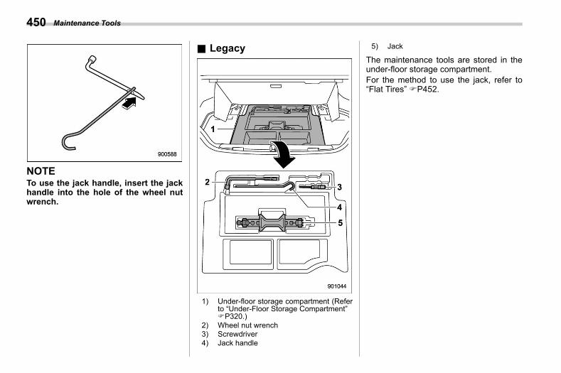
(452,1)
北米Model "A2600BE-B" EDITED: 2020/ 10/ 1
NOTETo use the jack handle, insert the jackhandle into the hole of the wheel nutwrench.
& Legacys09ah10
1) Under-floor storage compartment (Referto “Under-Floor Storage Compartment”FP320.)
2) Wheel nut wrench3) Screwdriver4) Jack handle
5) Jack
The maintenance tools are stored in theunder-floor storage compartment.For the method to use the jack, refer to“Flat Tires” FP452.
Maintenance Tools450
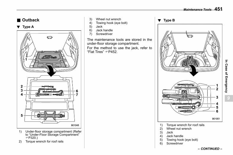
(453,1)
北米Model "A2600BE-B" EDITED: 2020/ 10/ 1
& Outbacks09ah11
! Type As09ah1103
1) Under-floor storage compartment (Referto “Under-Floor Storage Compartment”FP320.)
2) Torque wrench for roof rails
3) Wheel nut wrench4) Towing hook (eye bolt)5) Jack6) Jack handle7) Screwdriver
The maintenance tools are stored in theunder-floor storage compartment.For the method to use the jack, refer to“Flat Tires” FP452.
! Type Bs09ah1104
1) Torque wrench for roof rails2) Wheel nut wrench3) Jack4) Jack handle5) Towing hook (eye bolt)6) Screwdriver
– CONTINUED –
Maintenance Tools 451
9
InCase
ofEmergency
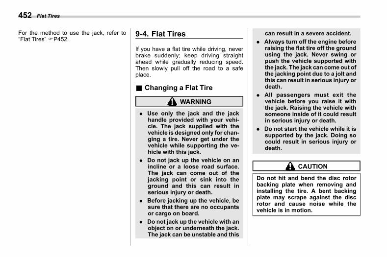
(454,1)
北米Model "A2600BE-B" EDITED: 2020/ 10/ 1
For the method to use the jack, refer to“Flat Tires” FP452.
9-4. Flat Tiress09ac
If you have a flat tire while driving, neverbrake suddenly; keep driving straightahead while gradually reducing speed.Then slowly pull off the road to a safeplace.
& Changing a Flat Tires09ac01
WARNING
. Use only the jack and the jackhandle provided with your vehi-cle. The jack supplied with thevehicle is designed only for chan-ging a tire. Never get under thevehicle while supporting the ve-hicle with this jack.
. Do not jack up the vehicle on anincline or a loose road surface.The jack can come out of thejacking point or sink into theground and this can result inserious injury or death.
. Before jacking up the vehicle, besure that there are no occupantsor cargo on board.
. Do not jack up the vehicle with anobject on or underneath the jack.The jack can be unstable and this
can result in a severe accident.. Always turn off the engine before
raising the flat tire off the groundusing the jack. Never swing orpush the vehicle supported withthe jack. The jack can come out ofthe jacking point due to a jolt andthis can result in serious injury ordeath.
. All passengers must exit thevehicle before you raise it withthe jack. Raising the vehicle withsomeone inside of it could resultin serious injury or death.
. Do not start the vehicle while it issupported by the jack. Doing socould result in serious injury ordeath.
CAUTION
Do not hit and bend the disc rotorbacking plate when removing andinstalling the tire. A bent backingplate may scrape against the discrotor and cause noise while thevehicle is in motion.
Flat Tires452
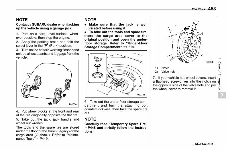
(455,1)
北米Model "A2600BE-B" EDITED: 2020/ 10/ 1
NOTEContact a SUBARUdealer when jackingup the vehicle using a garage jack.1. Park on a hard, level surface, when-ever possible, then stop the engine.2. Apply the parking brake and shift theselect lever in the “P” (Park) position.3. Turn on the hazard warning flasher andunload all occupants and luggage from thevehicle.
4. Put wheel blocks at the front and rearof the tire diagonally opposite the flat tire.5. Take out the jack, jack handle andwheel nut wrench.The tools and the spare tire are storedunder the floor of the trunk (Legacy) or thecargo area (Outback). Refer to “Mainte-nance Tools” FP449.
NOTE. Make sure that the jack is welllubricated before using it.. To take out the tools and spare tire,store the cargo area cover to theoriginal position and open the under-floor storage. Refer to “Under-FloorStorage Compartment” FP320.
6. Take out the under-floor storage com-partment and turn the attaching boltcounterclockwise, then take the spare tireout.
NOTECarefully read “Temporary Spare Tire”FP448 and strictly follow the instruc-tions.
1) Notch2) Valve hole
7. If your vehicle has wheel covers, inserta flat-head screwdriver into the notch onthe opposite side of the valve hole and prythe wheel cover to remove it.
– CONTINUED –
Flat Tires 453
9
InCase
ofEmergency
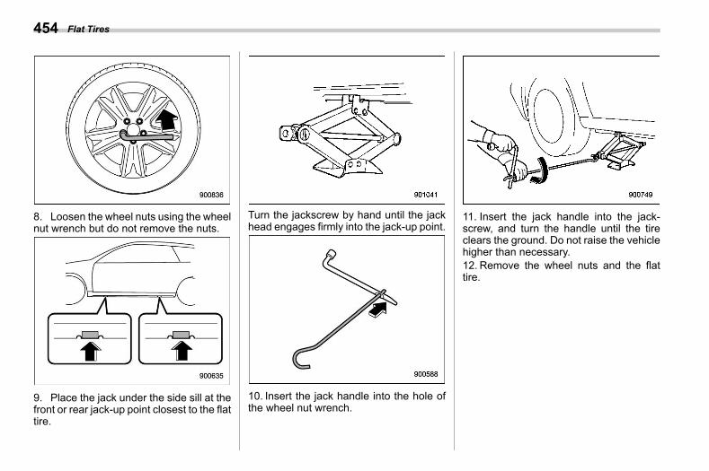
(456,1)
北米Model "A2600BE-B" EDITED: 2020/ 10/ 1
8. Loosen the wheel nuts using the wheelnut wrench but do not remove the nuts.
9. Place the jack under the side sill at thefront or rear jack-up point closest to the flattire.
Turn the jackscrew by hand until the jackhead engages firmly into the jack-up point.
10. Insert the jack handle into the hole ofthe wheel nut wrench.
11. Insert the jack handle into the jack-screw, and turn the handle until the tireclears the ground. Do not raise the vehiclehigher than necessary.12. Remove the wheel nuts and the flattire.
Flat Tires454
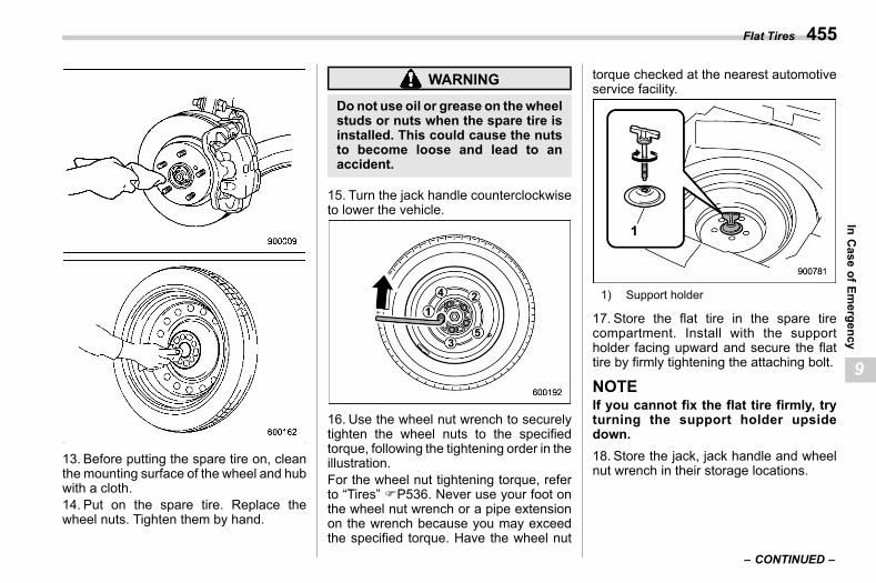
(457,1)
北米Model "A2600BE-B" EDITED: 2020/ 10/ 1
13. Before putting the spare tire on, cleanthe mounting surface of the wheel and hubwith a cloth.14. Put on the spare tire. Replace thewheel nuts. Tighten them by hand.
WARNING
Donot use oil or grease on thewheelstuds or nuts when the spare tire isinstalled. This could cause the nutsto become loose and lead to anaccident.
15. Turn the jack handle counterclockwiseto lower the vehicle.
16. Use the wheel nut wrench to securelytighten the wheel nuts to the specifiedtorque, following the tightening order in theillustration.For the wheel nut tightening torque, referto “Tires” FP536. Never use your foot onthe wheel nut wrench or a pipe extensionon the wrench because you may exceedthe specified torque. Have the wheel nut
torque checked at the nearest automotiveservice facility.
1) Support holder
17. Store the flat tire in the spare tirecompartment. Install with the supportholder facing upward and secure the flattire by firmly tightening the attaching bolt.
NOTEIf you cannot fix the flat tire firmly, tryturning the support holder upsidedown.18. Store the jack, jack handle and wheelnut wrench in their storage locations.
– CONTINUED –
Flat Tires 455
9
InCase
ofEmergency
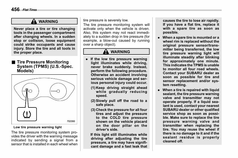
(458,1)
北米Model "A2600BE-B" EDITED: 2020/ 10/ 1
WARNING
Never place a tire or tire changingtools in the passenger compartmentafter changing wheels. In a suddenstop or collision, loose equipmentcould strike occupants and causeinjury. Store the tire and all tools inthe proper place.
& Tire Pressure MonitoringSystem (TPMS) (U.S.-Spec.Models)
s09ac02
Low tire pressure warning lightThe tire pressure monitoring system pro-vides the driver with the warning messageindicated by sending a signal from asensor that is installed in each wheel when
tire pressure is severely low.The tire pressure monitoring system willactivate only when the vehicle is driven.Also, this system may not react immedi-ately to a sudden drop in tire pressure (forexample, a blow-out caused by runningover a sharp object).
WARNING
. If the low tire pressure warninglight illuminates while driving,never brake suddenly. Instead,perform the following procedure.Otherwise an accident involvingserious vehicle damage and ser-ious personal injury could occur.(1)Keep driving straight ahead
while gradually reducingspeed.
(2) Slowly pull off the road to asafe place.
(3)Check the pressure for all fourtires and adjust the pressureto the COLD tire pressureshown on the vehicle placardon the door pillar on thedriver’s side.
If this light still illuminates whiledriving after adjusting the tirepressure, a tire may have signifi-cant damage and a fast leak that
causes the tire to lose air rapidly.If you have a flat tire, replace itwith a spare tire as soon aspossible.
. When a spare tire is mounted or awheel rim is replaced without theoriginal pressure sensor/trans-mitter being transferred, the lowtire pressure warning light willilluminate steadily after blinkingfor approximately one minute.This indicates the TPMS is unableto monitor all four road wheels.Contact your SUBARU dealer assoon as possible for tire andsensor replacement and/or sys-tem resetting.
. When a tire is repaired with liquidsealant, the tire pressure warningvalve and transmitter may notoperate properly. If a liquid sea-lant is used, contact your nearestSUBARU dealer or other qualifiedservice shop as soon as possi-ble. Make sure to replace the tirepressure warning valve andtransmitter when replacing thetire. You may reuse the wheel ifthere is no damage to it and if thesealant residue is properlycleaned off.
Flat Tires456
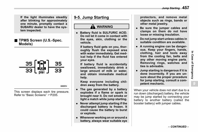
(459,1)
北米Model "A2600BE-B" EDITED: 2020/ 10/ 1
If the light illuminates steadilyafter blinking for approximatelyone minute, promptly contact aSUBARU dealer to have the sys-tem inspected.
& TPMS Screen (U.S.-Spec.Models)
s09ac05
This screen displays each tire pressure.Refer to “Basic Screens” FP205.
9-5. Jump Startings09ad
WARNING
. Battery fluid is SULFURIC ACID.Do not let it come in contact withthe eyes, skin, clothing or thevehicle.If battery fluid gets on you, thor-oughly flush the exposed areawith water immediately. Get med-ical help if the fluid has enteredyour eyes.If battery fluid is accidentallyswallowed, immediately drink alarge amount of milk or water,and obtain immediate medicalhelp.Keep everyone including chil-dren away from the battery.
. The gas generated by a batteryexplodes if a flame or spark isbrought near it. Do not smoke orlight a match while jump starting.
. Never attempt jump starting if thedischarged battery is frozen. Itcould cause the battery to burstor explode.
. Wheneverworking on or around abattery, always wear suitable eye
protectors, and remove metalobjects such as rings, bands orother metal jewelry.
. Be sure the jumper cables andclamps on them do not haveloose or missing insulation.
. Donot jump start unless cables insuitable condition are available.
. A running engine can be danger-ous. Keep your fingers, hands,clothing, hair and tools awayfrom the cooling fan, belts andany other moving engine parts.Removing rings, watches andties is advisable.
. Jump starting is dangerous if it isdone incorrectly. If you are un-sure about the proper procedurefor jump starting, consult a com-petent mechanic.
When your vehicle does not start due to arun down (discharged) battery, the vehiclemay be jump started by connecting yourbattery to another battery (called thebooster battery) with jumper cables.
– CONTINUED –
Jump Starting 457
9
InCase
ofEmergency
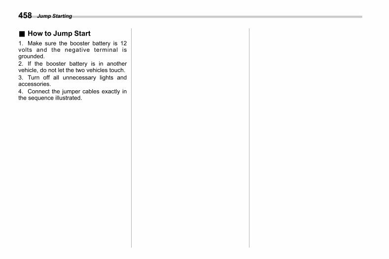
(460,1)
北米Model "A2600BE-B" EDITED: 2020/ 10/ 1
& How to Jump Starts09ad01
1. Make sure the booster battery is 12volts and the negative terminal isgrounded.2. If the booster battery is in anothervehicle, do not let the two vehicles touch.3. Turn off all unnecessary lights andaccessories.4. Connect the jumper cables exactly inthe sequence illustrated.
Jump Starting458
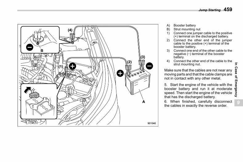
(461,1)
北米Model "A2600BE-B" EDITED: 2020/ 10/ 1
A) Booster batteryB) Strut mounting nut1) Connect one jumper cable to the positive
(+) terminal on the discharged battery.2) Connect the other end of the jumper
cable to the positive (+) terminal of thebooster battery.
3) Connect one end of the other cable to thenegative (−) terminal of the boosterbattery.
4) Connect the other end of the cable to thestrut mounting nut.
Make sure that the cables are not near anymoving parts and that the cable clamps arenot in contact with any other metal.
5. Start the engine of the vehicle with thebooster battery and run it at moderatespeed. Then start the engine of the vehiclethat has the discharged battery.6. When finished, carefully disconnectthe cables in exactly the reverse order.
Jump Starting 459
9
InCase
ofEmergency
(462,1)
北米Model "A2600BE-B" EDITED: 2020/ 10/ 1
9-6. Engine Overheatings09ae
WARNING
Never attempt to remove the radiatorcap until the engine has been shutoff and has fully cooled down. Whenthe engine is hot, the coolant isunder pressure. Removing the capwhile the engine is still hot couldrelease a spray of boiling hot cool-ant, which could burn you veryseriously.
CAUTION
If the engine overheats, the enginespeed or the vehicle speed may bereduced. Stop the vehicle in a safeplace immediately.
& If Steam Is Coming from theEngine Compartment
s09ae01Turn off the engine and get everyone awayfrom the vehicle until it cools down.
& If No Steam Is Coming fromthe Engine Compartment
s09ae02NOTEFor details about how to check thecoolant level or how to add coolant,refer to “Engine Coolant” FP495.1. Keep the engine running at idlingspeed.2. Open the hood to ventilate the enginecompartment. Refer to “Engine Hood”FP487.Confirm that the cooling fan is turning. Ifthe fan is not turning, immediately turn offthe engine and contact your authorizeddealer for repair.3. After the engine coolant temperaturehas dropped, turn off the engine.If the temperature gauge stays in theoverheated zone, turn off the engine.4. After the engine has fully cooled down,check the coolant level in the reserve tank.If the coolant level is below the “LOW”mark, add coolant up to the “FULL” mark.5. If there is no coolant in the reservetank, add coolant to the reserve tank. Thenremove the radiator cap and fill the radiatorwith coolant.
If you remove the radiator cap from a hotradiator, first wrap a thick cloth around theradiator cap, then turn the cap counter-
clockwise slowly without pressing downuntil it stops. Release the pressure fromthe radiator. After the pressure has beenfully released, remove the cap by pressingdown and turning it.
Engine Overheating460
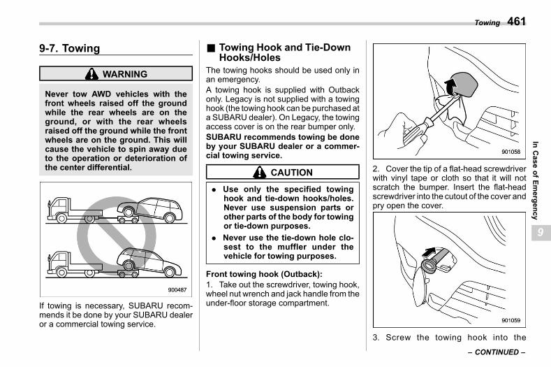
(463,1)
北米Model "A2600BE-B" EDITED: 2020/ 10/ 1
9-7. Towings09af
WARNING
Never tow AWD vehicles with thefront wheels raised off the groundwhile the rear wheels are on theground, or with the rear wheelsraised off the ground while the frontwheels are on the ground. This willcause the vehicle to spin away dueto the operation or deterioration ofthe center differential.
If towing is necessary, SUBARU recom-mends it be done by your SUBARU dealeror a commercial towing service.
& Towing Hook and Tie-DownHooks/Holes
s09af01The towing hooks should be used only inan emergency.A towing hook is supplied with Outbackonly. Legacy is not supplied with a towinghook (the towing hook can be purchased ata SUBARU dealer). On Legacy, the towingaccess cover is on the rear bumper only.SUBARU recommends towing be doneby your SUBARU dealer or a commer-cial towing service.
CAUTION
. Use only the specified towinghook and tie-down hooks/holes.Never use suspension parts orother parts of the body for towingor tie-down purposes.
. Never use the tie-down hole clo-sest to the muffler under thevehicle for towing purposes.
Front towing hook (Outback):1. Take out the screwdriver, towing hook,wheel nut wrench and jack handle from theunder-floor storage compartment.
2. Cover the tip of a flat-head screwdriverwith vinyl tape or cloth so that it will notscratch the bumper. Insert the flat-headscrewdriver into the cutout of the cover andpry open the cover.
3. Screw the towing hook into the
– CONTINUED –
Towing 461
9
InCase
ofEmergency
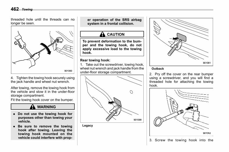
(464,1)
北米Model "A2600BE-B" EDITED: 2020/ 10/ 1
threaded hole until the threads can nolonger be seen.
4. Tighten the towing hook securely usingthe jack handle and wheel nut wrench.
After towing, remove the towing hook fromthe vehicle and stow it in the under-floorstorage compartment.Fit the towing hook cover on the bumper.
WARNING
. Do not use the towing hook forpurposes other than towing yourvehicle.
. Be sure to remove the towinghook after towing. Leaving thetowing hook mounted on thevehicle could interfere with prop-
er operation of the SRS airbagsystem in a frontal collision.
CAUTION
To prevent deformation to the bum-per and the towing hook, do notapply excessive load to the towinghook.
Rear towing hook:1. Take out the screwdriver, towing hook,wheel nut wrench and jack handle from theunder-floor storage compartment.
Legacy
Outback
2. Pry off the cover on the rear bumperusing a screwdriver, and you will find athreaded hole for attaching the towinghook.
3. Screw the towing hook into the
Towing462
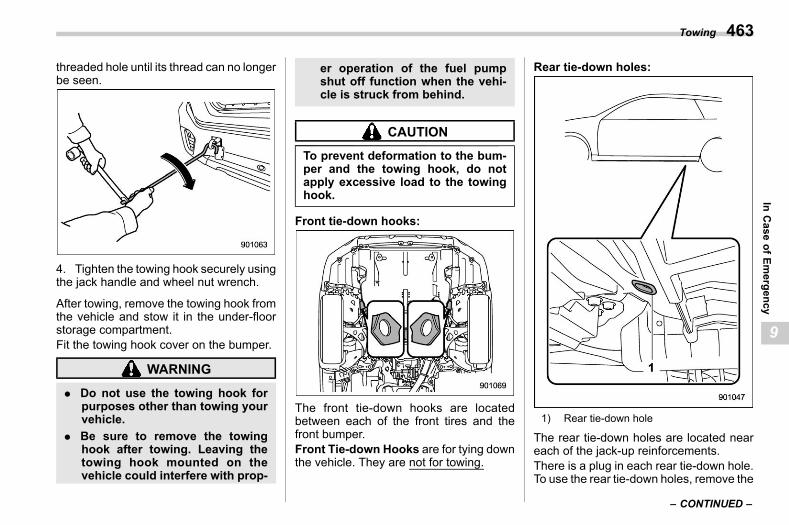
(465,1)
北米Model "A2600BE-B" EDITED: 2020/ 10/ 1
threaded hole until its thread can no longerbe seen.
4. Tighten the towing hook securely usingthe jack handle and wheel nut wrench.
After towing, remove the towing hook fromthe vehicle and stow it in the under-floorstorage compartment.Fit the towing hook cover on the bumper.
WARNING
. Do not use the towing hook forpurposes other than towing yourvehicle.
. Be sure to remove the towinghook after towing. Leaving thetowing hook mounted on thevehicle could interfere with prop-
er operation of the fuel pumpshut off function when the vehi-cle is struck from behind.
CAUTION
To prevent deformation to the bum-per and the towing hook, do notapply excessive load to the towinghook.
Front tie-down hooks:
The front tie-down hooks are locatedbetween each of the front tires and thefront bumper.Front Tie-down Hooks are for tying downthe vehicle. They are not for towing.
Rear tie-down holes:
1) Rear tie-down hole
The rear tie-down holes are located neareach of the jack-up reinforcements.There is a plug in each rear tie-down hole.To use the rear tie-down holes, remove the
– CONTINUED –
Towing 463
9
InCase
ofEmergency
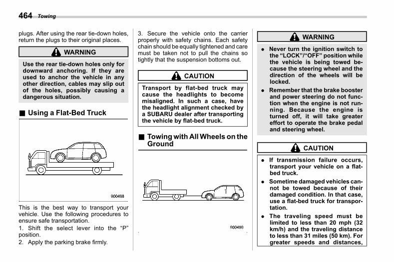
(466,1)
北米Model "A2600BE-B" EDITED: 2020/ 10/ 1
plugs. After using the rear tie-down holes,return the plugs to their original places.
WARNING
Use the rear tie-down holes only fordownward anchoring. If they areused to anchor the vehicle in anyother direction, cables may slip outof the holes, possibly causing adangerous situation.
& Using a Flat-Bed Trucks09af02
This is the best way to transport yourvehicle. Use the following procedures toensure safe transportation.1. Shift the select lever into the “P”position.2. Apply the parking brake firmly.
3. Secure the vehicle onto the carrierproperly with safety chains. Each safetychain should be equally tightened and caremust be taken not to pull the chains sotightly that the suspension bottoms out.
CAUTION
Transport by flat-bed truck maycause the headlights to becomemisaligned. In such a case, havethe headlight alignment checked bya SUBARU dealer after transportingthe vehicle by flat-bed truck.
& TowingwithAllWheels on theGround
s09af03
WARNING
. Never turn the ignition switch tothe “LOCK”/“OFF” position whilethe vehicle is being towed be-cause the steering wheel and thedirection of the wheels will belocked.
. Remember that the brake boosterand power steering do not func-tion when the engine is not run-ning. Because the engine isturned off, it will take greatereffort to operate the brake pedaland steering wheel.
CAUTION
. If transmission failure occurs,transport your vehicle on a flat-bed truck.
. Sometime damaged vehicles can-not be towed because of theirdamaged condition. In that case,use a flat-bed truck for transpor-tation.
. The traveling speed must belimited to less than 20 mph (32km/h) and the traveling distanceto less than 31 miles (50 km). Forgreater speeds and distances,
Towing464
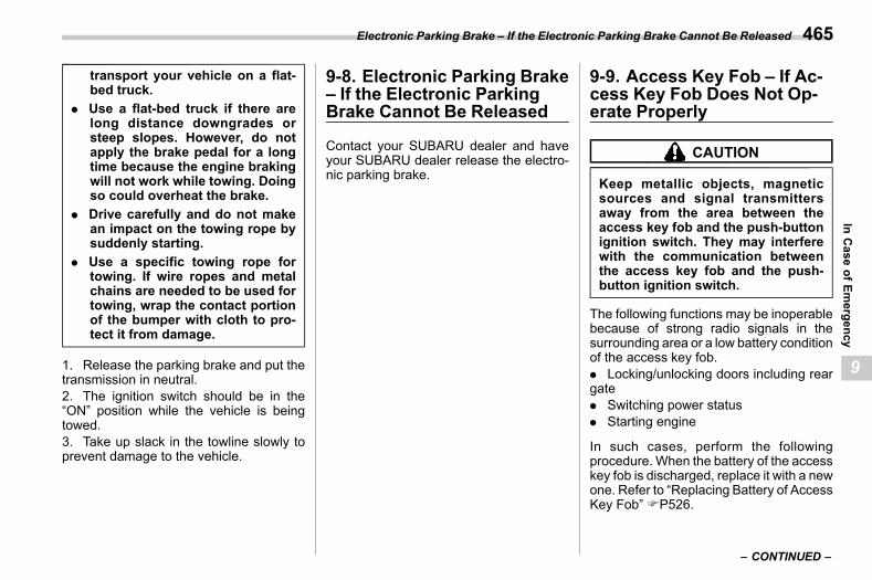
(467,1)
北米Model "A2600BE-B" EDITED: 2020/ 10/ 1
transport your vehicle on a flat-bed truck.
. Use a flat-bed truck if there arelong distance downgrades orsteep slopes. However, do notapply the brake pedal for a longtime because the engine brakingwill not work while towing. Doingso could overheat the brake.
. Drive carefully and do not makean impact on the towing rope bysuddenly starting.
. Use a specific towing rope fortowing. If wire ropes and metalchains are needed to be used fortowing, wrap the contact portionof the bumper with cloth to pro-tect it from damage.
1. Release the parking brake and put thetransmission in neutral.2. The ignition switch should be in the“ON” position while the vehicle is beingtowed.3. Take up slack in the towline slowly toprevent damage to the vehicle.
9-8. Electronic Parking Brake– If the Electronic ParkingBrake Cannot Be Released
s09an
Contact your SUBARU dealer and haveyour SUBARU dealer release the electro-nic parking brake.
9-9. Access Key Fob – If Ac-cess Key Fob Does Not Op-erate Properly
s09ap
CAUTION
Keep metallic objects, magneticsources and signal transmittersaway from the area between theaccess key fob and the push-buttonignition switch. They may interferewith the communication betweenthe access key fob and the push-button ignition switch.
The following functions may be inoperablebecause of strong radio signals in thesurrounding area or a low battery conditionof the access key fob.. Locking/unlocking doors including reargate. Switching power status. Starting engine
In such cases, perform the followingprocedure. When the battery of the accesskey fob is discharged, replace it with a newone. Refer to “Replacing Battery of AccessKey Fob” FP526.
– CONTINUED –
Electronic Parking Brake – If the Electronic Parking Brake Cannot Be Released 465
9
InCase
ofEmergency
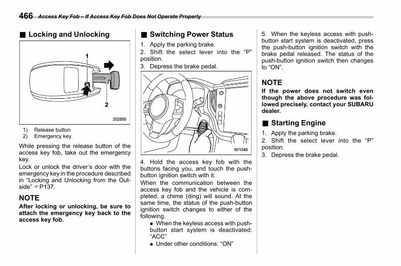
(468,1)
北米Model "A2600BE-B" EDITED: 2020/ 10/ 1
& Locking and Unlockings09ap01
1) Release button2) Emergency key
While pressing the release button of theaccess key fob, take out the emergencykey.Lock or unlock the driver’s door with theemergency key in the procedure describedin “Locking and Unlocking from the Out-side” FP137.
NOTEAfter locking or unlocking, be sure toattach the emergency key back to theaccess key fob.
& Switching Power Statuss09ap02
1. Apply the parking brake.2. Shift the select lever into the “P”position.3. Depress the brake pedal.
4. Hold the access key fob with thebuttons facing you, and touch the push-button ignition switch with it.When the communication between theaccess key fob and the vehicle is com-pleted, a chime (ding) will sound. At thesame time, the status of the push-buttonignition switch changes to either of thefollowing.
. When the keyless access with push-button start system is deactivated:“ACC”. Under other conditions: “ON”
5. When the keyless access with push-button start system is deactivated, pressthe push-button ignition switch with thebrake pedal released. The status of thepush-button ignition switch then changesto “ON”.
NOTEIf the power does not switch eventhough the above procedure was fol-lowed precisely, contact your SUBARUdealer.
& Starting Engines09ap03
1. Apply the parking brake.2. Shift the select lever into the “P”position.3. Depress the brake pedal.
Access Key Fob – If Access Key Fob Does Not Operate Properly466
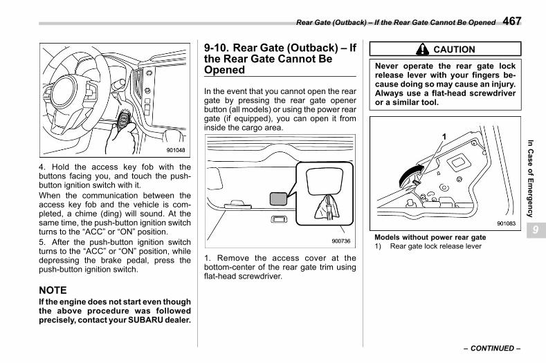
(469,1)
北米Model "A2600BE-B" EDITED: 2020/ 10/ 1
4. Hold the access key fob with thebuttons facing you, and touch the push-button ignition switch with it.When the communication between theaccess key fob and the vehicle is com-pleted, a chime (ding) will sound. At thesame time, the push-button ignition switchturns to the “ACC” or “ON” position.5. After the push-button ignition switchturns to the “ACC” or “ON” position, whiledepressing the brake pedal, press thepush-button ignition switch.
NOTEIf the engine does not start even thoughthe above procedure was followedprecisely, contact your SUBARUdealer.
9-10. Rear Gate (Outback) – Ifthe Rear Gate Cannot BeOpened
s09au
In the event that you cannot open the reargate by pressing the rear gate openerbutton (all models) or using the power reargate (if equipped), you can open it frominside the cargo area.
1. Remove the access cover at thebottom-center of the rear gate trim usingflat-head screwdriver.
CAUTION
Never operate the rear gate lockrelease lever with your fingers be-cause doing so may cause an injury.Always use a flat-head screwdriveror a similar tool.
Models without power rear gate1) Rear gate lock release lever
– CONTINUED –
Rear Gate (Outback) – If the Rear Gate Cannot Be Opened 467
9
InCase
ofEmergency
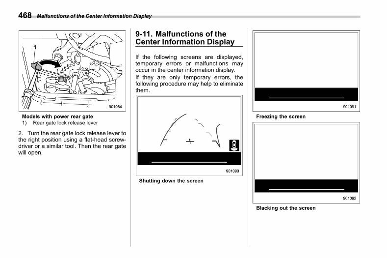
(470,1)
北米Model "A2600BE-B" EDITED: 2020/ 10/ 1
Models with power rear gate1) Rear gate lock release lever
2. Turn the rear gate lock release lever tothe right position using a flat-head screw-driver or a similar tool. Then the rear gatewill open.
9-11. Malfunctions of theCenter Information Display
s09av
If the following screens are displayed,temporary errors or malfunctions mayoccur in the center information display.If they are only temporary errors, thefollowing procedure may help to eliminatethem.
Shutting down the screen
Freezing the screen
Blacking out the screen
Malfunctions of the Center Information Display468
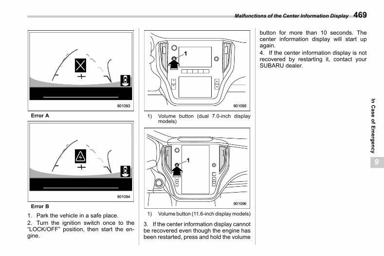
(471,1)
北米Model "A2600BE-B" EDITED: 2020/ 10/ 1
Error A
Error B
1. Park the vehicle in a safe place.2. Turn the ignition switch once to the“LOCK/OFF” position, then start the en-gine.
1) Volume button (dual 7.0-inch displaymodels)
1) Volume button (11.6-inch displaymodels)
3. If the center information display cannotbe recovered even though the engine hasbeen restarted, press and hold the volume
button for more than 10 seconds. Thecenter information display will start upagain.4. If the center information display is notrecovered by restarting it, contact yourSUBARU dealer.
Malfunctions of the Center Information Display 469
9
InCase
ofEmergency
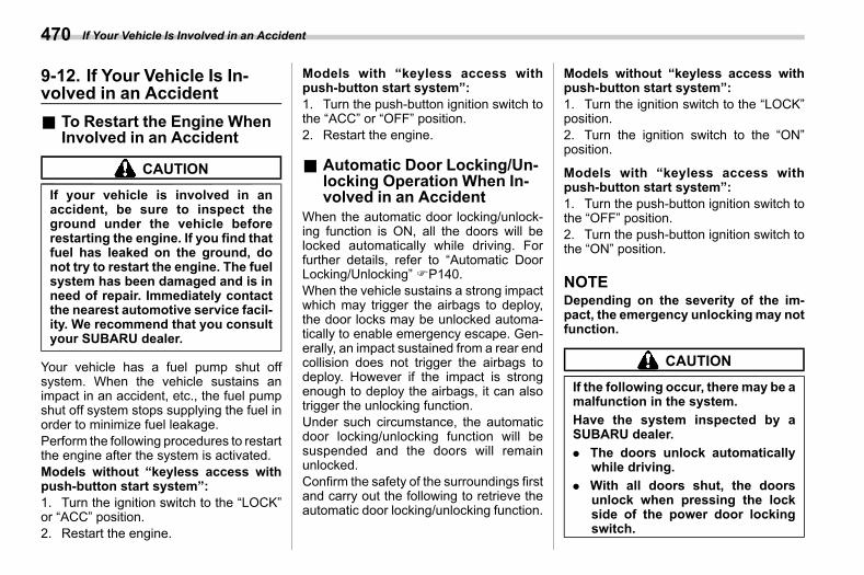
(472,1)
北米Model "A2600BE-B" EDITED: 2020/ 10/ 1
9-12. If Your Vehicle Is In-volved in an Accident
s09ar
& To Restart the Engine WhenInvolved in an Accident
s09ar02
CAUTION
If your vehicle is involved in anaccident, be sure to inspect theground under the vehicle beforerestarting the engine. If you find thatfuel has leaked on the ground, donot try to restart the engine. The fuelsystem has been damaged and is inneed of repair. Immediately contactthe nearest automotive service facil-ity. We recommend that you consultyour SUBARU dealer.
Your vehicle has a fuel pump shut offsystem. When the vehicle sustains animpact in an accident, etc., the fuel pumpshut off system stops supplying the fuel inorder to minimize fuel leakage.Perform the following procedures to restartthe engine after the system is activated.Models without “keyless access withpush-button start system”:1. Turn the ignition switch to the “LOCK”or “ACC” position.2. Restart the engine.
Models with “keyless access withpush-button start system”:1. Turn the push-button ignition switch tothe “ACC” or “OFF” position.2. Restart the engine.
& Automatic Door Locking/Un-locking Operation When In-volved in an Accident
s09ar03When the automatic door locking/unlock-ing function is ON, all the doors will belocked automatically while driving. Forfurther details, refer to “Automatic DoorLocking/Unlocking” FP140.When the vehicle sustains a strong impactwhich may trigger the airbags to deploy,the door locks may be unlocked automa-tically to enable emergency escape. Gen-erally, an impact sustained from a rear endcollision does not trigger the airbags todeploy. However if the impact is strongenough to deploy the airbags, it can alsotrigger the unlocking function.Under such circumstance, the automaticdoor locking/unlocking function will besuspended and the doors will remainunlocked.Confirm the safety of the surroundings firstand carry out the following to retrieve theautomatic door locking/unlocking function.
Models without “keyless access withpush-button start system”:1. Turn the ignition switch to the “LOCK”position.2. Turn the ignition switch to the “ON”position.
Models with “keyless access withpush-button start system”:1. Turn the push-button ignition switch tothe “OFF” position.2. Turn the push-button ignition switch tothe “ON” position.
NOTEDepending on the severity of the im-pact, the emergency unlockingmay notfunction.
CAUTION
If the following occur, theremay be amalfunction in the system.Have the system inspected by aSUBARU dealer.. The doors unlock automatically
while driving.. With all doors shut, the doors
unlock when pressing the lockside of the power door lockingswitch.
If Your Vehicle Is Involved in an Accident470
(473,1)
北米Model "A2600BE-B" EDITED: 2020/ 10/ 1
. The automatic door locking/un-locking function does not oper-ate.
If Your Vehicle Is Involved in an Accident 471
9
InCase
ofEmergency

(474,1)
北米Model "A2600BE-B" EDITED: 2020/ 10/ 1
— — — — — — — — — — — — — — — — — — — — — — — — — — — — — — — — — — — — — — — —
— — — — — — — — — — — — — — — — — — — — — — — — — — — — — — — — — — — — — — — —
— — — — — — — — — — — — — — — — — — — — — — — — — — — — — — — — — — — — — — — —
— — — — — — — — — — — — — — — — — — — — — — — — — — — — — — — — — — — — — — — —
— — — — — — — — — — — — — — — — — — — — — — — — — — — — — — — — — — — — — — — —
— — — — — — — — — — — — — — — — — — — — — — — — — — — — — — — — — — — — — — — —
— — — — — — — — — — — — — — — — — — — — — — — — — — — — — — — — — — — — — — — —
— — — — — — — — — — — — — — — — — — — — — — — — — — — — — — — — — — — — — — — —
— — — — — — — — — — — — — — — — — — — — — — — — — — — — — — — — — — — — — — — —
— — — — — — — — — — — — — — — — — — — — — — — — — — — — — — — — — — — — — — — —
— — — — — — — — — — — — — — — — — — — — — — — — — — — — — — — — — — — — — — — —
— — — — — — — — — — — — — — — — — — — — — — — — — — — — — — — — — — — — — — — —
— — — — — — — — — — — — — — — — — — — — — — — — — — — — — — — — — — — — — — — —
(475,1)
北米Model "A2600BE-B" EDITED: 2020/ 10/ 1
s1010-1. Exterior Care ................................................. 474
Washing .............................................................474Waxing and Polishing .........................................475Cleaning Alloy Wheels ........................................475
10-2. Corrosion Protection .................................... 476Most Common Causes of Corrosion....................476To Help Prevent Corrosion..................................476
10-3. Cleaning the Interior .....................................477Seat Fabric Material ........................................... 477Leather Seat Materials........................................ 477Synthetic Leather Upholstery ............................. 478Instrument Panel, Console Panel, Switches,Combination Meter, and Other PlasticSurface ............................................................ 478
Center Information Display ................................. 478
Appearance Care
10
Appearance
Care
(476,1)
北米Model "A2600BE-B" EDITED: 2020/ 10/ 1
10-1. Exterior Cares10aa
& Washings10aa01
CAUTION
. When washing the vehicle, thebrakes may get wet. As a result,the brake stopping distance willbe longer. To dry the brakes, drivethe vehicle at a safe speed whilelightly pressing the brake pedalto heat up the brakes.
. Do not wash the engine compart-ment and areas adjacent to it. Ifwater enters the engine air intakeor electrical parts, it will causeengine trouble or a malfunctionof the power steering.
. When washing inner fenders, un-derbody, bumpers and protrud-ing objects such as exhaustpipes and exhaust finishers, becareful to prevent injuries fromcontacting sharp ends.
. Do not use any organic solventswhen washing the surface of thebulb assembly cover. However, ifa detergent with organic solventsis used to wash the cover sur-face, completely rinse off thedetergent with water. Otherwise,
the cover surface may be da-maged.
. Outback: Since your vehicle isequipped with a rear wiper, auto-matic car-wash brushes couldbecome tangled around it, dama-ging the wiper arm and othercomponents. Ask the automaticcar-wash operator not to let thebrushes touch thewiper armor tofix the wiper arm on the rearwindow glass with adhesive tapebefore operating the machine.
NOTEWhen having your vehicle washed in anautomatic car wash, make sure before-hand that the car wash is of suitabletype.The best way to preserve your vehicle’sbeauty is frequent washing. Wash thevehicle at least once a month to avoidcontamination by road grime.
Wash dirt off with a wet sponge and plentyof lukewarm or cold water. Do not wash thevehicle with hot water and in direct sun-light.
Salt, chemicals, insects, tar, soot, tree sap,and bird droppings should be washed offby using a light detergent, as required. If
you use a light detergent, make certainthat it is a neutral detergent. Do not usestrong soap or chemical detergents. Allcleaning agents should be promptlyflushed from the surface and not allowedto dry there. Rinse the vehicle thoroughlywith plenty of lukewarm water. Wipe theremaining water off with a chamois or softcloth. Wear rubber gloves and use a handbrush when washing down underbody,inner fenders and suspension to effec-tively remove mud and dirt off.! Washing the underbody
s10aa0101Chemicals, salts and gravel used fordeicing road surfaces are extremely cor-rosive, accelerating the corrosion of un-derbody components, such as the exhaustsystem, fuel and brake lines, brake cables,floor pan and fenders, and suspension.Thoroughly flush the underbody and insideof the fenders with lukewarm or cold waterat frequent intervals to reduce the harmfuleffects of such agents.
Mud and sand adhering to the underbodycomponents may accelerate their corro-sion.After driving off-road or onmuddy or sandyroads, wash the mud and sand off theunderbody.Carefully flush the suspension and axleparts, as they are particularly prone tomud
Exterior Care474
(477,1)
北米Model "A2600BE-B" EDITED: 2020/ 10/ 1
and sand buildup. Do not use a sharp-edged tool to remove caked mud.
CAUTION
. Be careful not to damage brakehoses, sensor harnesses, andother parts when washing sus-pension components.
. Be careful not to flush the enginebottom for a long time. It maycause damage of some electricalparts.
! Using a warm water washers10aa0102
. Keep a good distance of 12 in (30 cm)or more between the washer nozzle andthe vehicle.. Do not wash the same area continu-ously.. If a stain will not come out easily, washby hand. Somewarmwater washers are ofthe high temperature, high pressure type,and they can damage or deform the resinparts such asmouldings, or cause water toleak into the vehicle.
& Waxing and Polishings10aa02
Always wash and dry the vehicle beforewaxing and polishing.Use a good quality polish and wax andapply them according to the manufac-turer’s instructions. Wax or polish whenthe painted surface is cool.
Be sure to polish and wax the chrome trim,as well as the painted surfaces. Loss ofwax on a painted surface leads to loss ofthe original luster and also quickens thedeterioration of the surface. It is recom-mended that a coat of wax be applied atleast once a month, or whenever thesurface no longer repels water.
If the appearance of the paint has dimin-ished to the point where the luster or tonecannot be restored, lightly polish the sur-face with a fine-grained compound. Neverpolish just the affected area, but includethe surrounding area as well. Alwayspolish in only one direction. A No. 2000grain compound is recommended. Neveruse a coarse-grained compound. Coarsergrained compounds have a smaller grain-size number and could damage the paint.After polishing with a compound, coat withwax to restore the original luster. Frequentpolishing with a compound or an incorrectpolishing technique will result in removingthe paint layer and exposing the under-
coat. When in doubt, it is always best tocontact your SUBARU dealer or an autopaint specialist.
CAUTION
Do not use any agents with organicsolvents on the surface of the bulbassembly cover. However, if a polishor wax with organic solvents isapplied to the cover surface, com-pletely wipe off the polish or wax.Otherwise, the cover surfacemay bedamaged.
NOTEBe careful not to block the windshieldwasher nozzles with wax when waxingthe vehicle.
& Cleaning Alloy Wheelss10aa04
. Promptly wipe the alloy wheels clean ofany kind of grime or agent. If dirt is left ontoo long, it may be difficult to clean off.. Do not use soap containing grit to cleanthe wheels. Be sure to use a neutralcleaning agent, and later rinse thoroughlywith water. Do not clean the wheels with astiff brush or expose them to a high-speedwashing device.
– CONTINUED –
Exterior Care 475
10
Appearance
Care
(478,1)
北米Model "A2600BE-B" EDITED: 2020/ 10/ 1
. Clean the vehicle (including the alloywheels) with water as soon as possiblewhen it has been splashed with sea water,exposed to sea breezes, or driven onroads treated with salt or other agents.
10-2. Corrosion Protections10ab
Your SUBARU has been designed andbuilt to resist corrosion. Special materialsand protective finishes have been used onmost parts of the vehicle to help maintainfine appearance, strength, and reliableoperation.
& Most Common Causes ofCorrosion
s10ab01The most common causes of corrosionare:. The accumulation of moisture retainingdirt and debris in body panel sections,cavities, and other areas.. Damage to paint and other protectivecoatings caused by gravel and stone chipsor minor accidents.
Corrosion is accelerated on the vehiclewhen:. It is exposed to road salt or dust controlchemicals, or used in coastal areas wherethere is more salt in the air, or in areaswhere there is considerable industrialpollution.. It is driven in areas of high humidity,especially when temperatures range justabove freezing.
. Dampness in certain parts of thevehicle remains for a long time, eventhough other parts of the vehicle may bedry.. High temperatures will cause corrosionto parts of the vehicle which cannot dryquickly due to lack of proper ventilation.
& To Help Prevent Corrosions10ab02
Wash the vehicle regularly to preventcorrosion of the body and suspensioncomponents. Also, wash the vehiclepromptly after driving on any of thefollowing surfaces.. Roads that have been salted to preventthem from freezing in winter. Mud, sand, or gravel. Coastal roads
After the winter has ended, it is recom-mended that the underbody be given avery thorough washing.
Before the beginning of winter, check thecondition of underbody components, suchas the exhaust system, fuel and brakelines, brake cables, suspension, steeringsystem, floor pan, and fenders. If any ofthem are found to be rusted, they shouldbe given an appropriate rust preventiontreatment or should be replaced. Contactyour SUBARU dealer to perform this kind
Corrosion Protection476
(479,1)
北米Model "A2600BE-B" EDITED: 2020/ 10/ 1
of maintenance and treatment if you needassistance.
Repair chips and scratches in the paint assoon as you find them.
Check the interior of the vehicle for waterand dirt accumulation under the floor matsbecause that could cause corrosion. Oc-casionally check under the mats to makesure the area is dry.
Keep your garage dry. Do not park yourvehicle in a damp, poorly ventilated gar-age. In such a garage, corrosion can becaused by dampness. If you wash thevehicle in the garage or put the vehicle intothe garage when wet or covered withsnow, that can cause dampness.
If your vehicle is operated in cold weatherand/or in areas where road salts and othercorrosive materials are used, the doorhinges and locks, trunk lid lock, and hoodlatch should be inspected and lubricatedperiodically.
10-3. Cleaning the Interiors10ac
Use a soft, damp cloth to clean the climatecontrol panel, audio equipment, instru-ment panel, center console, combinationmeter panel, and switches. (Do not useorganic solvents.)
& Seat Fabric Materials10ac01
Remove loose dirt, dust or debris with avacuum cleaner. If the dirt is caked on thefabric or hard to remove with a vacuumcleaner, use a soft brush then vacuum it.Wipe the fabric surface with a tightly wrungcloth and dry the seat fabric thoroughly. Ifthe fabric is still dirty, wipe using a solutionof mild soap and lukewarm water then drythoroughly.
If the stain does not come out, try acommercially available fabric cleaner.Use the cleaner on a hidden place andmake sure it does not affect the fabricadversely. Use the cleaner according to itsinstructions.
CAUTION
When cleaning the seat, do not usebenzine, paint thinner, or any similarmaterials. Doing so could damagethe surface and cause the color to
deteriorate.
& Leather Seat Materialss10ac02
The leather used by SUBARU is a highquality natural product which will retain itsdistinctive appearance and feel for manyyears with proper care.Allowing dust or road dirt to build up on thesurface can cause leather to becomebrittle and wear prematurely. To maintainits resiliency, leather should be cleanedmonthly or whenever it becomes soiled.Before cleaning leather upholstery, va-cuum it to remove dust. Use a soft andlint-free cloth dampened with lukewarmwater and mild soap, taking care not tosoak the leather or allow water to pene-trate the stitched seams. Use a gentlecircular motion while cleaning the leather -do not rub or apply extreme pressure.Wipe the leather again with another clean,slightly damp cloth to remove soap residueand dry with a soft cloth.Minor surface blemishes or difficult dirtspots may be treated with a commercialleather spray. Never use alcohol, cleaningsolvents, leather oils, varnishes orpolishes on your leather as it will dry outthe leather finish.
– CONTINUED –
Cleaning the Interior 477
10
Appearance
Care
(480,1)
北米Model "A2600BE-B" EDITED: 2020/ 10/ 1
If your SUBARU is to be parked for a longtime in bright sunlight, it is recommendedthat the seats and headrests be covered,or the windows shaded, to prevent fadingor shrinkage.You will discover that each leather seatsection will develop soft folds or wrinkles,which is characteristic of genuine leather.
& Synthetic Leather Upholsterys10ac03
The synthetic leather material used on theSUBARUmay be cleaned using mild soapor detergent and water, after first vacuum-ing or brushing away loose dirt. Allow thesoap to soak in for a few minutes and wipeoff with a clean, damp cloth. Commercialfoam-type cleaners suitable for syntheticleather materials may be used whennecessary.
CAUTION
Strong cleaning agents such assolvents, paint thinners, windowcleaner or gasoline must never beused on leather or synthetic interiormaterials. Doing so could damagethe surface and cause the color todeteriorate.
& Instrument Panel, ConsolePanel, Switches, Combina-tion Meter, and Other PlasticSurface
s10ac04Use a soft, damp cloth to clean theinstrument panel, center console, combi-nation meter panel, and switches.
CAUTION
. Do not use organic solvents suchas paint thinners or gasoline, orstrong cleaning agents that con-tain those solvents. Doing socould damage the surface andcause the color to deteriorate.
. Donot use chemical solvents thatcontain silicone on the vehicleaudio system, electrical compo-nents of the air-conditioner orany switches. If silicone adheresto these parts, it may causedamage to electrical compo-nents.
& Center Information Displays10ac11
To clean the center information display,wipe it with a silicone cloth or with a softcloth. If the display(s) is/are extremelydirty, clean it with a soft cloth moistenedwith neutral detergent then carefully wipeoff any remaining detergent.
CAUTION
. Do not spray neutral detergentdirectly onto the display(s).Doing so could damage themoni-tor’s components.
. Do not wipe the display(s) with ahard cloth. Doing so couldscratch the monitor.
. Do not use cleaning fluid thatcontains thinner, gasoline, orany other volatile substance.Such cleaning fluid could erasethe lettering on the switches onthe display(s).
Cleaning the Interior478

(481,1)
北米Model "A2600BE-B" EDITED: 2020/ 10/ 1
— — — — — — — — — — — — — — — — — — — — — — — — — — — — — — — — — — — — — — — —
— — — — — — — — — — — — — — — — — — — — — — — — — — — — — — — — — — — — — — — —
— — — — — — — — — — — — — — — — — — — — — — — — — — — — — — — — — — — — — — — —
— — — — — — — — — — — — — — — — — — — — — — — — — — — — — — — — — — — — — — — —
— — — — — — — — — — — — — — — — — — — — — — — — — — — — — — — — — — — — — — — —
— — — — — — — — — — — — — — — — — — — — — — — — — — — — — — — — — — — — — — — —
— — — — — — — — — — — — — — — — — — — — — — — — — — — — — — — — — — — — — — — —
— — — — — — — — — — — — — — — — — — — — — — — — — — — — — — — — — — — — — — — —
— — — — — — — — — — — — — — — — — — — — — — — — — — — — — — — — — — — — — — — —
— — — — — — — — — — — — — — — — — — — — — — — — — — — — — — — — — — — — — — — —
— — — — — — — — — — — — — — — — — — — — — — — — — — — — — — — — — — — — — — — —
— — — — — — — — — — — — — — — — — — — — — — — — — — — — — — — — — — — — — — — —
— — — — — — — — — — — — — — — — — — — — — — — — — — — — — — — — — — — — — — — —

(482,1)
北米Model "A2600BE-B" EDITED: 2020/ 10/ 1
— — — — — — — — — — — — — — — — — — — — — — — — — — — — — — — — — — — — — — — —
— — — — — — — — — — — — — — — — — — — — — — — — — — — — — — — — — — — — — — — —
— — — — — — — — — — — — — — — — — — — — — — — — — — — — — — — — — — — — — — — —
— — — — — — — — — — — — — — — — — — — — — — — — — — — — — — — — — — — — — — — —
— — — — — — — — — — — — — — — — — — — — — — — — — — — — — — — — — — — — — — — —
— — — — — — — — — — — — — — — — — — — — — — — — — — — — — — — — — — — — — — — —
— — — — — — — — — — — — — — — — — — — — — — — — — — — — — — — — — — — — — — — —
— — — — — — — — — — — — — — — — — — — — — — — — — — — — — — — — — — — — — — — —
— — — — — — — — — — — — — — — — — — — — — — — — — — — — — — — — — — — — — — — —
— — — — — — — — — — — — — — — — — — — — — — — — — — — — — — — — — — — — — — — —
— — — — — — — — — — — — — — — — — — — — — — — — — — — — — — — — — — — — — — — —
— — — — — — — — — — — — — — — — — — — — — — — — — — — — — — — — — — — — — — — —
— — — — — — — — — — — — — — — — — — — — — — — — — — — — — — — — — — — — — — — —
(483,1)
北米Model "A2600BE-B" EDITED: 2020/ 10/ 1
s1111-1. Maintenance Schedule ................................. 48311-2. Maintenance Precautions............................. 483
Before Checking or Servicing in the EngineCompartment....................................................484
When Checking or Servicing in the EngineCompartment....................................................485
When Checking or Servicing in the EngineCompartment While the Engine Is Running .......485
11-3. Maintenance Tips.......................................... 485Removing and Reinstalling Clips ........................485
11-4. Engine Hood.................................................. 48711-5. Engine Compartment Overview................... 489
2.5 L Models.......................................................4892.4 L Models.......................................................490
11-6. Engine Oil ...................................................... 491Engine Oil Consumption .....................................491Checking the Oil Level........................................491Changing the Oil and Oil Filter............................493Recommended Grade and Viscosity....................493Synthetic Oil.......................................................493
11-7. Cooling System............................................. 494Cooling Fan, Hose and Connections ...................494Engine Coolant...................................................495
11-8. Air Cleaner Element...................................... 496Replacing the Air Cleaner Element......................496
11-9. Spark Plugs ................................................... 498Recommended Spark Plugs ................................498
11-10. Drive Belts ................................................... 49911-11. Continuously Variable Transmission
Fluid ............................................................... 499
11-12. Front Differential Gear Oil and RearDifferential Gear Oil ......................................499
Recommended Grade and Viscosity ................... 49911-13. Brake Fluid...................................................500
Checking the Fluid Level .................................... 500Recommended Brake Fluid................................. 500
11-14. Brake Booster ..............................................50111-15. Brake Pedal ..................................................50111-16. Replacement of Brake Pad .........................50111-17. Tires and Wheels .........................................502
Types of Tires .................................................... 502Tire Pressure Monitoring System (TPMS)(U.S.-Spec. Models) .......................................... 502
Tire Inspection ................................................... 504Tire Pressures and Wear .................................... 504Wheel Balance ................................................... 506Wear Indicators.................................................. 507Rotational Direction of Tires............................... 507Tire Rotation ...................................................... 508Tire Replacement ............................................... 509Wheel Replacement............................................ 510
11-18. Alloy Wheels ................................................51011-19. Windshield Washer Fluid ............................51011-20. Replacement of Wiper Blades ....................511
Windshield Wiper Blade Assembly ..................... 512Window Wiper Blade Rubber .............................. 513Rear Window Wiper Blade Assembly(Outback) ......................................................... 514
Rear Window Wiper Blade Rubber (Outback) ...... 51411-21. Battery ..........................................................516
Maintenance and Service
11
Maintenance
andService
(484,1)
北米Model "A2600BE-B" EDITED: 2020/ 10/ 1
11-22. Fuses ........................................................... 51711-23. Installation of Accessories......................... 51811-24. Replacing Bulbs.......................................... 518
Headlights ..........................................................519Front Turn Signal Light .......................................519Rear Combination Lights ....................................519Backup Light ......................................................522Dome Light.........................................................523
Map Lights......................................................... 524Door Step Light.................................................. 524Cargo Area Light (Outback)................................ 524Trunk Light (Legacy) .......................................... 524Other Bulbs ....................................................... 525
11-25. Replacing Battery ........................................525Replacing Battery of Access Key Fob................. 526Replacing Battery of Transmitter ........................ 527
Maintenance and Service
(485,1)
北米Model "A2600BE-B" EDITED: 2020/ 10/ 1
11-1. Maintenance Schedules11aa
U.S. modelsThe scheduled maintenance items re-quired to be serviced at regular intervalsare shown in the “Warranty and Mainte-nance Booklet.” For details, read theseparate “Warranty and MaintenanceBooklet.”
Canada modelsThe scheduled maintenance items re-quired to be serviced at regular intervalsare shown in the “Warranty and ServiceBooklet.” For details, read the separate“Warranty and Service Booklet.”
Except for U.S. and Canada modelsSome items of your vehicle are required tobe serviced at scheduled intervals. Fordetails about your maintenance schedule,read the separate “Warranty and Main-tenance Booklet.”
11-2. Maintenance Precau-tions
s11ab
When maintenance and service are re-quired, it is recommended that all work bedone by an authorized SUBARU dealer.
If you performmaintenance and service byyourself, you should familiarize yourselfwith the information provided in this sec-tion on general maintenance and servicefor your SUBARU.
Incorrect or incomplete service couldcause improper or unsafe vehicle opera-tion. Any problems caused by impropermaintenance and service performed byyou are not eligible for warranty coverage.
WARNING
. Testing of an All-Wheel Drivevehicle must NEVER be per-formed on a single two-wheeldynamometer or similar appara-tus. Attempting to do so willresult in transmission damageand in uncontrolled vehiclemovement and may cause anaccident or injuries to personsnearby.
. Always select a safe area whenperforming maintenance on your
vehicle.. Always be very careful to avoid
injury when working on the vehi-cle. Remember that some of thematerials in the vehicle may behazardous if improperly used orhandled, for example, batteryacid.
. Your vehicle should only be ser-viced by persons fully competentto do so. Serious personal injurymay result to persons not experi-enced in servicing vehicles.
. Always use the proper tools andmake certain that they are wellmaintained.
. Never get under the vehicle sup-ported only by a jack. Always usesafety stands to support thevehicle.
. Never keep the engine running ina poorly ventilated area, such asa garage or other closed areas.
. Do not smoke or allow openflames around the fuel or battery.This will cause a fire.
. Because the fuel system is underpressure, replacement of the fuelfilter should be performed onlyby your SUBARU dealer.
– CONTINUED –
Maintenance Schedule 483
11
Maintenance
andService
(486,1)
北米Model "A2600BE-B" EDITED: 2020/ 10/ 1
. Wear adequate eye protection toguard against getting oil or fluidsin your eyes. If something doesget in your eyes, thoroughlywash them out with clean water.
. Do not tamper with the wiring ofthe SRS airbag system or seat-belt pretensioner system, or at-tempt to take its connectorsapart, as that may activate thesystem or it can render it inop-erative. NEVER use a circuit tes-ter for these wiring. If your SRSairbag or seatbelt pretensionerneeds service, consult your near-est SUBARU dealer.
. Check the inside of the enginecompartment to see if there areany cloths and tools left. If theyare left inside, they may be acause of malfunction and fire.
NOTESUBARU does not endorse the use ofnon-SUBARU approved flushing sys-tems and strongly advises againstperforming these services on aSUBARU vehicle. Non-SUBARU ap-proved flushing systems use chemi-cals and/or solvents which have notbeen tested or approved by SUBARU.
SUBARU warranties do not cover anypart of the vehicle which is damaged byadding or applying chemicals and/orsolvents other than those approved orrecommended by SUBARU.
& Before Checking or Servicingin the Engine Compartment
s11ab01
WARNING
. Always stop the engine and applythe parking brake to prevent thevehicle from moving.
. Always let the engine cool down.Engine parts become very hotwhen the engine is running andremain hot for some time after theengine is stopped.
. Do not spill engine oil, enginecoolant, brake fluid or any otherfluid on hot engine components.This may cause a fire.
. When the ignition switch is in the“ON” position, the cooling fanmay operate suddenly evenwhenthe engine is stopped. If yourbody or clothes come into con-tact with a rotating fan, that couldresult in serious injury. To avoidrisk of injury, perform the follow-
ing precautions.– Models with push-button start
system:Always turn the push-buttonignition switch to the “OFF”position and confirm that theoperation indicator on theswitch is turned off. Then takethe access key fob out fromthe vehicle.
– Models without push-buttonstart system:Always remove the key fromthe ignition switch.
. Before performing any servicingon a vehicle equipped with aremote engine start system tem-porarily place that system in theservice mode to prevent it fromunexpectedly starting the engine.
Maintenance Precautions484
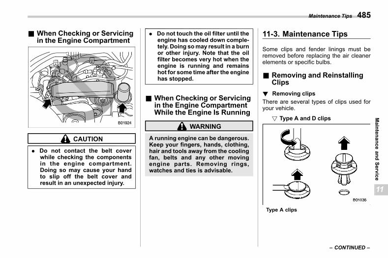
(487,1)
北米Model "A2600BE-B" EDITED: 2020/ 10/ 1
& When Checking or Servicingin the Engine Compartment
s11ab03
CAUTION
. Do not contact the belt coverwhile checking the componentsin the engine compartment.Doing so may cause your handto slip off the belt cover andresult in an unexpected injury.
. Do not touch the oil filter until theengine has cooled down comple-tely. Doing somay result in a burnor other injury. Note that the oilfilter becomes very hot when theengine is running and remainshot for some time after the enginehas stopped.
& When Checking or Servicingin the Engine CompartmentWhile the Engine Is Running
s11ab02
WARNING
A running engine can be dangerous.Keep your fingers, hands, clothing,hair and tools away from the coolingfan, belts and any other movingengine parts. Removing rings,watches and ties is advisable.
11-3. Maintenance Tipss11bi
Some clips and fender linings must beremoved before replacing the air cleanerelements or specific bulbs.
& Removing and ReinstallingClips
s11bi01
! Removing clipss11bi0101
There are several types of clips used foryour vehicle.
! Type A and D clipss11bi010107
Type A clips
– CONTINUED –
Maintenance Tips 485
11
Maintenance
andService
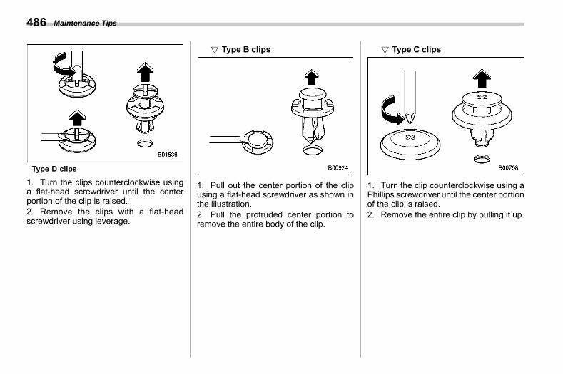
(488,1)
北米Model "A2600BE-B" EDITED: 2020/ 10/ 1
Type D clips
1. Turn the clips counterclockwise usinga flat-head screwdriver until the centerportion of the clip is raised.2. Remove the clips with a flat-headscrewdriver using leverage.
! Type B clipss11bi010102
1. Pull out the center portion of the clipusing a flat-head screwdriver as shown inthe illustration.2. Pull the protruded center portion toremove the entire body of the clip.
! Type C clipss11bi010103
1. Turn the clip counterclockwise using aPhillips screwdriver until the center portionof the clip is raised.2. Remove the entire clip by pulling it up.
Maintenance Tips486

(489,1)
北米Model "A2600BE-B" EDITED: 2020/ 10/ 1
! Reinstalling clipss11bi0102
Type A clips
Type B clips
Type C clips
Type D clipsInsert the clip without the center portionfirst and then push the center portion of theclip into the hole.
11-4. Engine Hoods11ac
CAUTION
. Be extremely careful not to catchfingers or other objects whenclosing the engine hood.
. Do not push the hood forcibly toclose it. It could deform themetal.
. Be extremely careful opening theengine hood when the wind isstrong. The engine hood couldclose suddenly, possibly causinginjuries from slamming.
. Do not install accessories otherthan genuine SUBARU parts tothe engine hood. If the enginehood becomes too heavy, thestay may not be able to supportholding it open.
. Check that the end of the hoodstay is inserted into the slot. If it isnot inserted properly, the hoodmay drop and cause injury.
– CONTINUED –
Engine Hood 487
11
Maintenance
andService
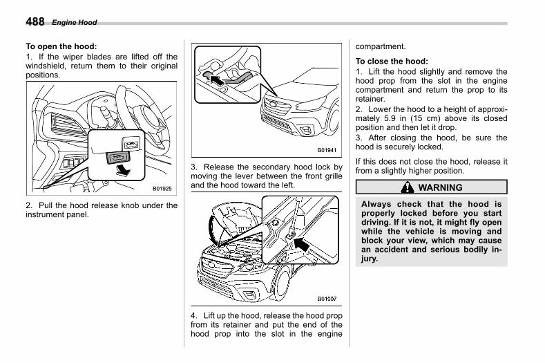
(490,1)
北米Model "A2600BE-B" EDITED: 2020/ 10/ 1
To open the hood:1. If the wiper blades are lifted off thewindshield, return them to their originalpositions.
2. Pull the hood release knob under theinstrument panel.
3. Release the secondary hood lock bymoving the lever between the front grilleand the hood toward the left.
4. Lift up the hood, release the hood propfrom its retainer and put the end of thehood prop into the slot in the engine
compartment.
To close the hood:1. Lift the hood slightly and remove thehood prop from the slot in the enginecompartment and return the prop to itsretainer.2. Lower the hood to a height of approxi-mately 5.9 in (15 cm) above its closedposition and then let it drop.3. After closing the hood, be sure thehood is securely locked.
If this does not close the hood, release itfrom a slightly higher position.
WARNING
Always check that the hood isproperly locked before you startdriving. If it is not, it might fly openwhile the vehicle is moving andblock your view, which may causean accident and serious bodily in-jury.
Engine Hood488
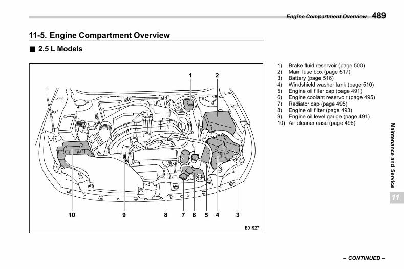
(491,1)
北米Model "A2600BE-B" EDITED: 2020/ 10/ 1
11-5. Engine Compartment Overviews11ad
& 2.5 L Modelss11ad08
1) Brake fluid reservoir (page 500)2) Main fuse box (page 517)3) Battery (page 516)4) Windshield washer tank (page 510)5) Engine oil filler cap (page 491)6) Engine coolant reservoir (page 495)7) Radiator cap (page 495)8) Engine oil filter (page 493)9) Engine oil level gauge (page 491)10) Air cleaner case (page 496)
– CONTINUED –
Engine Compartment Overview 489
11
Maintenance
andService
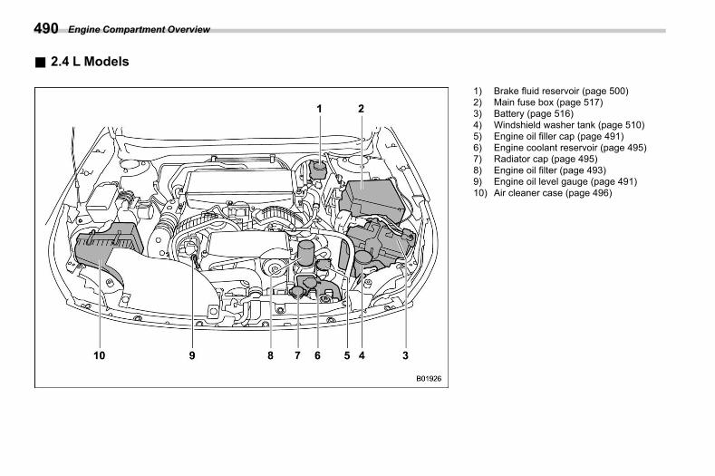
(492,1)
北米Model "A2600BE-B" EDITED: 2020/ 10/ 1
& 2.4 L Modelss11ad17
1) Brake fluid reservoir (page 500)2) Main fuse box (page 517)3) Battery (page 516)4) Windshield washer tank (page 510)5) Engine oil filler cap (page 491)6) Engine coolant reservoir (page 495)7) Radiator cap (page 495)8) Engine oil filter (page 493)9) Engine oil level gauge (page 491)10) Air cleaner case (page 496)
Engine Compartment Overview490
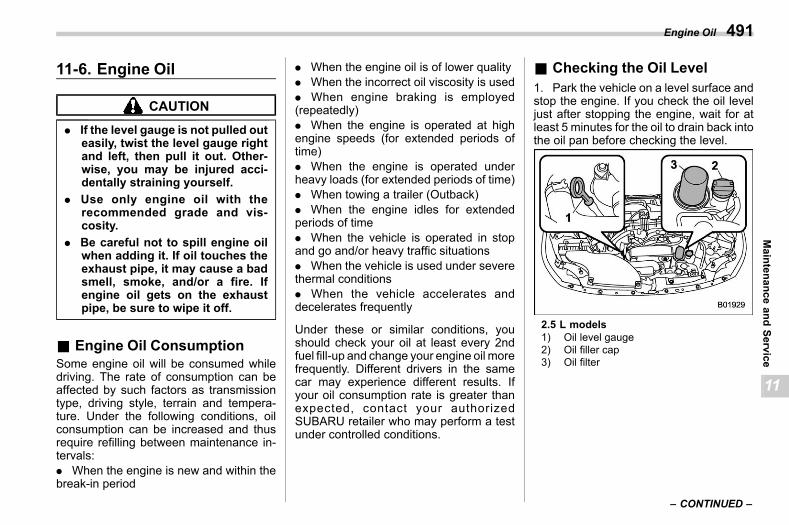
(493,1)
北米Model "A2600BE-B" EDITED: 2020/ 10/ 1
11-6. Engine Oils11ae
CAUTION
. If the level gauge is not pulled outeasily, twist the level gauge rightand left, then pull it out. Other-wise, you may be injured acci-dentally straining yourself.
. Use only engine oil with therecommended grade and vis-cosity.
. Be careful not to spill engine oilwhen adding it. If oil touches theexhaust pipe, it may cause a badsmell, smoke, and/or a fire. Ifengine oil gets on the exhaustpipe, be sure to wipe it off.
& Engine Oil Consumptions11ae07
Some engine oil will be consumed whiledriving. The rate of consumption can beaffected by such factors as transmissiontype, driving style, terrain and tempera-ture. Under the following conditions, oilconsumption can be increased and thusrequire refilling between maintenance in-tervals:. When the engine is new and within thebreak-in period
. When the engine oil is of lower quality
. When the incorrect oil viscosity is used
. When engine braking is employed(repeatedly). When the engine is operated at highengine speeds (for extended periods oftime). When the engine is operated underheavy loads (for extended periods of time). When towing a trailer (Outback). When the engine idles for extendedperiods of time. When the vehicle is operated in stopand go and/or heavy traffic situations. When the vehicle is used under severethermal conditions. When the vehicle accelerates anddecelerates frequently
Under these or similar conditions, youshould check your oil at least every 2ndfuel fill-up and change your engine oil morefrequently. Different drivers in the samecar may experience different results. Ifyour oil consumption rate is greater thanexpected, contact your authorizedSUBARU retailer who may perform a testunder controlled conditions.
& Checking the Oil Levels11ae01
1. Park the vehicle on a level surface andstop the engine. If you check the oil leveljust after stopping the engine, wait for atleast 5 minutes for the oil to drain back intothe oil pan before checking the level.
2.5 L models1) Oil level gauge2) Oil filler cap3) Oil filter
– CONTINUED –
Engine Oil 491
11
Maintenance
andService
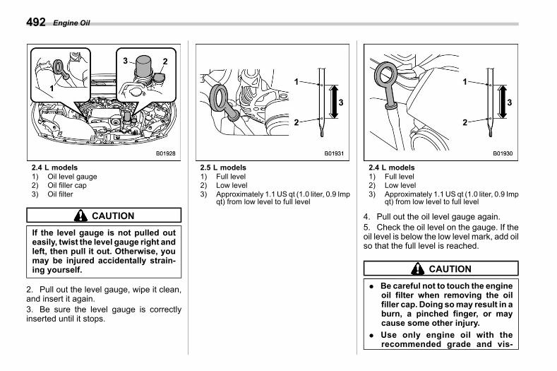
(494,1)
北米Model "A2600BE-B" EDITED: 2020/ 10/ 1
2.4 L models1) Oil level gauge2) Oil filler cap3) Oil filter
CAUTION
If the level gauge is not pulled outeasily, twist the level gauge right andleft, then pull it out. Otherwise, youmay be injured accidentally strain-ing yourself.
2. Pull out the level gauge, wipe it clean,and insert it again.3. Be sure the level gauge is correctlyinserted until it stops.
2.5 L models1) Full level2) Low level3) Approximately 1.1 US qt (1.0 liter, 0.9 Imp
qt) from low level to full level
2.4 L models1) Full level2) Low level3) Approximately 1.1 US qt (1.0 liter, 0.9 Imp
qt) from low level to full level
4. Pull out the oil level gauge again.5. Check the oil level on the gauge. If theoil level is below the low level mark, add oilso that the full level is reached.
CAUTION
. Be careful not to touch the engineoil filter when removing the oilfiller cap. Doing somay result in aburn, a pinched finger, or maycause some other injury.
. Use only engine oil with therecommended grade and vis-
Engine Oil492
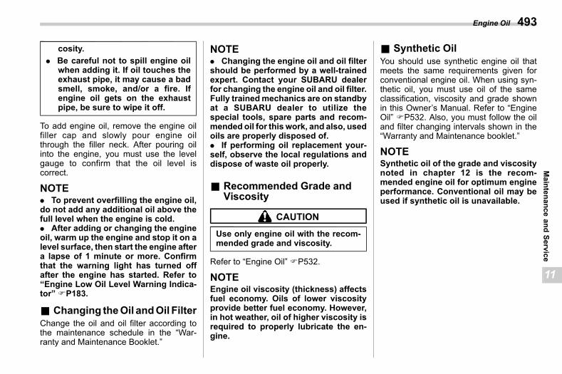
(495,1)
北米Model "A2600BE-B" EDITED: 2020/ 10/ 1
cosity.. Be careful not to spill engine oil
when adding it. If oil touches theexhaust pipe, it may cause a badsmell, smoke, and/or a fire. Ifengine oil gets on the exhaustpipe, be sure to wipe it off.
To add engine oil, remove the engine oilfiller cap and slowly pour engine oilthrough the filler neck. After pouring oilinto the engine, you must use the levelgauge to confirm that the oil level iscorrect.
NOTE. To prevent overfilling the engine oil,do not add any additional oil above thefull level when the engine is cold.. After adding or changing the engineoil, warm up the engine and stop it on alevel surface, then start the engine aftera lapse of 1 minute or more. Confirmthat the warning light has turned offafter the engine has started. Refer to“Engine Low Oil Level Warning Indica-tor” FP183.
& Changing theOil andOil Filters11ae02
Change the oil and oil filter according tothe maintenance schedule in the “War-ranty and Maintenance Booklet.”
NOTE. Changing the engine oil and oil filtershould be performed by a well-trainedexpert. Contact your SUBARU dealerfor changing the engine oil and oil filter.Fully trainedmechanics are on standbyat a SUBARU dealer to utilize thespecial tools, spare parts and recom-mended oil for this work, and also, usedoils are properly disposed of.. If performing oil replacement your-self, observe the local regulations anddispose of waste oil properly.
& Recommended Grade andViscosity
s11ae03
CAUTION
Use only engine oil with the recom-mended grade and viscosity.
Refer to “Engine Oil” FP532.
NOTEEngine oil viscosity (thickness) affectsfuel economy. Oils of lower viscosityprovide better fuel economy. However,in hot weather, oil of higher viscosity isrequired to properly lubricate the en-gine.
& Synthetic Oils11ae05
You should use synthetic engine oil thatmeets the same requirements given forconventional engine oil. When using syn-thetic oil, you must use oil of the sameclassification, viscosity and grade shownin this Owner’s Manual. Refer to “EngineOil” FP532. Also, you must follow the oiland filter changing intervals shown in the“Warranty and Maintenance booklet.”
NOTESynthetic oil of the grade and viscositynoted in chapter 12 is the recom-mended engine oil for optimum engineperformance. Conventional oil may beused if synthetic oil is unavailable.
Engine Oil 493
11
Maintenance
andService
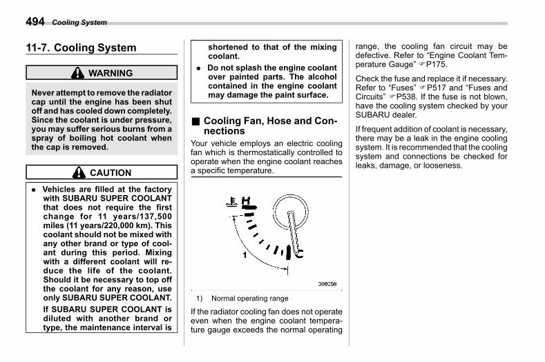
(496,1)
北米Model "A2600BE-B" EDITED: 2020/ 10/ 1
11-7. Cooling Systems11af
WARNING
Never attempt to remove the radiatorcap until the engine has been shutoff and has cooled down completely.Since the coolant is under pressure,you may suffer serious burns from aspray of boiling hot coolant whenthe cap is removed.
CAUTION
. Vehicles are filled at the factorywith SUBARU SUPER COOLANTthat does not require the firstchange for 11 years/137,500miles (11 years/220,000 km). Thiscoolant should not be mixed withany other brand or type of cool-ant during this period. Mixingwith a different coolant will re-duce the life of the coolant.Should it be necessary to top offthe coolant for any reason, useonly SUBARU SUPER COOLANT.If SUBARU SUPER COOLANT isdiluted with another brand ortype, the maintenance interval is
shortened to that of the mixingcoolant.
. Do not splash the engine coolantover painted parts. The alcoholcontained in the engine coolantmay damage the paint surface.
& Cooling Fan, Hose and Con-nections
s11af03Your vehicle employs an electric coolingfan which is thermostatically controlled tooperate when the engine coolant reachesa specific temperature.
1) Normal operating range
If the radiator cooling fan does not operateeven when the engine coolant tempera-ture gauge exceeds the normal operating
range, the cooling fan circuit may bedefective. Refer to “Engine Coolant Tem-perature Gauge” FP175.
Check the fuse and replace it if necessary.Refer to “Fuses” FP517 and “Fuses andCircuits” FP538. If the fuse is not blown,have the cooling system checked by yourSUBARU dealer.
If frequent addition of coolant is necessary,there may be a leak in the engine coolingsystem. It is recommended that the coolingsystem and connections be checked forleaks, damage, or looseness.
Cooling System494
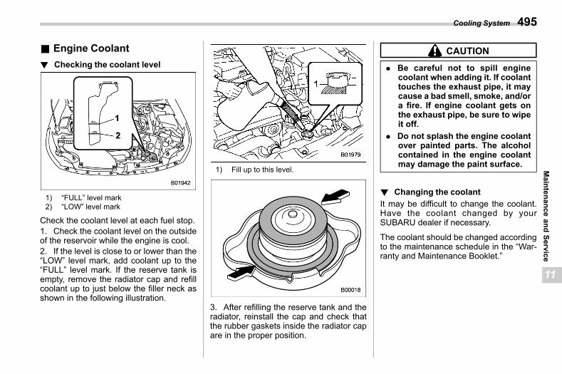
(497,1)
北米Model "A2600BE-B" EDITED: 2020/ 10/ 1
& Engine Coolants11af02
! Checking the coolant levels11af0201
1) “FULL” level mark2) “LOW” level mark
Check the coolant level at each fuel stop.1. Check the coolant level on the outsideof the reservoir while the engine is cool.2. If the level is close to or lower than the“LOW” level mark, add coolant up to the“FULL” level mark. If the reserve tank isempty, remove the radiator cap and refillcoolant up to just below the filler neck asshown in the following illustration.
1) Fill up to this level.
3. After refilling the reserve tank and theradiator, reinstall the cap and check thatthe rubber gaskets inside the radiator capare in the proper position.
CAUTION
. Be careful not to spill enginecoolant when adding it. If coolanttouches the exhaust pipe, it maycause a bad smell, smoke, and/ora fire. If engine coolant gets onthe exhaust pipe, be sure to wipeit off.
. Do not splash the engine coolantover painted parts. The alcoholcontained in the engine coolantmay damage the paint surface.
! Changing the coolants11af0202
It may be difficult to change the coolant.Have the coolant changed by yourSUBARU dealer if necessary.
The coolant should be changed accordingto the maintenance schedule in the “War-ranty and Maintenance Booklet.”
Cooling System 495
11
Maintenance
andService
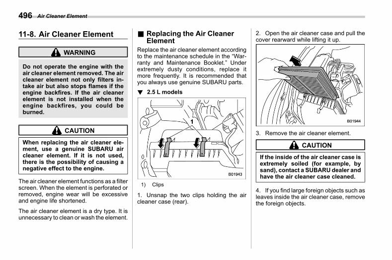
(498,1)
北米Model "A2600BE-B" EDITED: 2020/ 10/ 1
11-8. Air Cleaner Elements11ag
WARNING
Do not operate the engine with theair cleaner element removed. The aircleaner element not only filters in-take air but also stops flames if theengine backfires. If the air cleanerelement is not installed when theengine backfires, you could beburned.
CAUTION
When replacing the air cleaner ele-ment, use a genuine SUBARU aircleaner element. If it is not used,there is the possibility of causing anegative effect to the engine.
The air cleaner element functions as a filterscreen. When the element is perforated orremoved, engine wear will be excessiveand engine life shortened.
The air cleaner element is a dry type. It isunnecessary to clean or wash the element.
& Replacing the Air CleanerElement
s11ag01Replace the air cleaner element accordingto the maintenance schedule in the “War-ranty and Maintenance Booklet.” Underextremely dusty conditions, replace itmore frequently. It is recommended thatyou always use genuine SUBARU parts.! 2.5 L models
s11ag0111
1) Clips
1. Unsnap the two clips holding the aircleaner case (rear).
2. Open the air cleaner case and pull thecover rearward while lifting it up.
3. Remove the air cleaner element.
CAUTION
If the inside of the air cleaner case isextremely soiled (for example, bysand), contact a SUBARUdealer andhave the air cleaner case cleaned.
4. If you find large foreign objects such asleaves inside the air cleaner case, removethe foreign objects.
Air Cleaner Element496
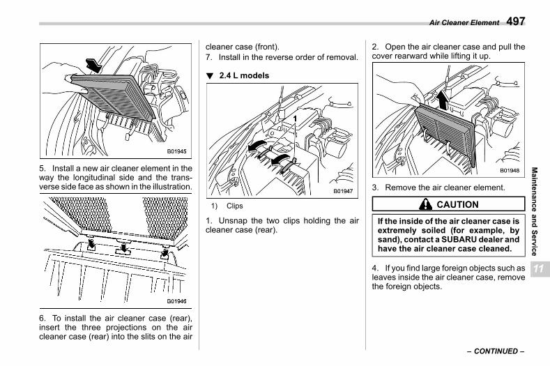
(499,1)
北米Model "A2600BE-B" EDITED: 2020/ 10/ 1
5. Install a new air cleaner element in theway the longitudinal side and the trans-verse side face as shown in the illustration.
6. To install the air cleaner case (rear),insert the three projections on the aircleaner case (rear) into the slits on the air
cleaner case (front).7. Install in the reverse order of removal.
! 2.4 L modelss11ag0112
1) Clips
1. Unsnap the two clips holding the aircleaner case (rear).
2. Open the air cleaner case and pull thecover rearward while lifting it up.
3. Remove the air cleaner element.
CAUTION
If the inside of the air cleaner case isextremely soiled (for example, bysand), contact a SUBARUdealer andhave the air cleaner case cleaned.
4. If you find large foreign objects such asleaves inside the air cleaner case, removethe foreign objects.
– CONTINUED –
Air Cleaner Element 497
11
Maintenance
andService
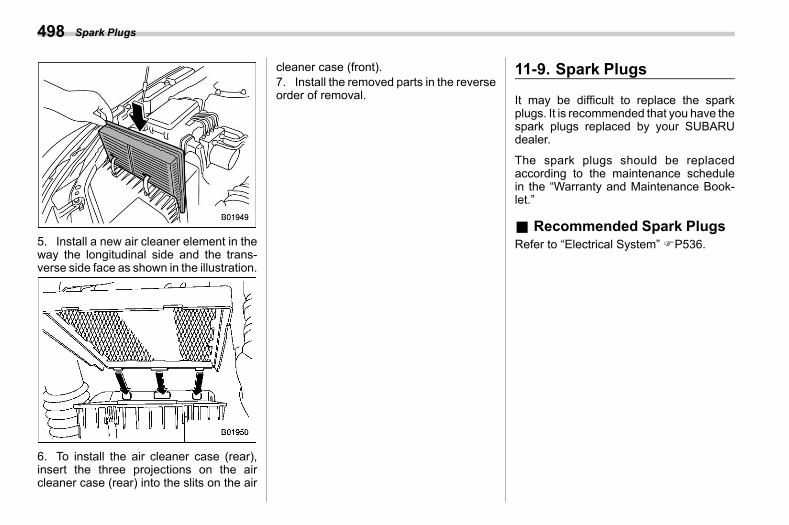
(500,1)
北米Model "A2600BE-B" EDITED: 2020/ 10/ 1
5. Install a new air cleaner element in theway the longitudinal side and the trans-verse side face as shown in the illustration.
6. To install the air cleaner case (rear),insert the three projections on the aircleaner case (rear) into the slits on the air
cleaner case (front).7. Install the removed parts in the reverseorder of removal.
11-9. Spark Plugss11ah
It may be difficult to replace the sparkplugs. It is recommended that you have thespark plugs replaced by your SUBARUdealer.
The spark plugs should be replacedaccording to the maintenance schedulein the “Warranty and Maintenance Book-let.”
& Recommended Spark Plugss11ah01
Refer to “Electrical System” FP536.
Spark Plugs498
(501,1)
北米Model "A2600BE-B" EDITED: 2020/ 10/ 1
11-10. Drive Beltss11ai
It is unnecessary to check the deflection ofthe drive belt periodically because yourengine is equipped with an automatic belttension adjuster. However, replacement ofthe belt should be done according to themaintenance schedule in the “Warrantyand Maintenance Booklet.” Consult yourSUBARU dealer for replacement.If the belt is loose, cracked or worn,contact your SUBARU dealer.
11-11. Continuously VariableTransmission Fluid
s11ay
There is no fluid level gauge. It is un-necessary to check the continuously vari-able transmission fluid level. However, ifnecessary, consult your SUBARU dealerfor inspection.
11-12. Front Differential GearOil and Rear Differential GearOil
s11bl
It is not necessary to check the gear oillevel. Check that there are no cracks,damage or leakage. However, the oilinspection should be performed accordingto the maintenance schedule in the “War-ranty and Maintenance Booklet.” Consultyour SUBARU dealer for details.
& Recommended Grade andViscosity
s11bl01Each oil manufacturer has its own baseoils and additives. Never use differentbrands together. For details, refer to “FrontDifferential and Rear Differential Gear Oil”FP534.
CAUTION
Using a differential gear oil otherthan the specified oil may cause adecline in vehicle performance.
Drive Belts 499
11
Maintenance
andService
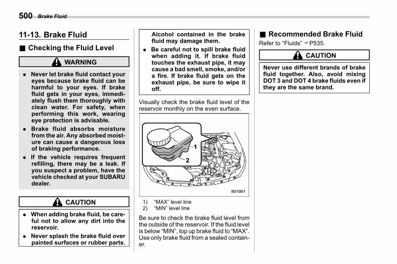
(502,1)
北米Model "A2600BE-B" EDITED: 2020/ 10/ 1
11-13. Brake Fluids11ao
& Checking the Fluid Levels11ao01
WARNING
. Never let brake fluid contact youreyes because brake fluid can beharmful to your eyes. If brakefluid gets in your eyes, immedi-ately flush them thoroughly withclean water. For safety, whenperforming this work, wearingeye protection is advisable.
. Brake fluid absorbs moisturefrom the air. Any absorbedmoist-ure can cause a dangerous lossof braking performance.
. If the vehicle requires frequentrefilling, there may be a leak. Ifyou suspect a problem, have thevehicle checked at your SUBARUdealer.
CAUTION
. When adding brake fluid, be care-ful not to allow any dirt into thereservoir.
. Never splash the brake fluid overpainted surfaces or rubber parts.
Alcohol contained in the brakefluid may damage them.
. Be careful not to spill brake fluidwhen adding it. If brake fluidtouches the exhaust pipe, it maycause a bad smell, smoke, and/ora fire. If brake fluid gets on theexhaust pipe, be sure to wipe itoff.
Visually check the brake fluid level of thereservoir monthly on the even surface.
1) “MAX” level line2) “MIN” level line
Be sure to check the brake fluid level fromthe outside of the reservoir. If the fluid levelis below “MIN”, top up brake fluid to “MAX”.Use only brake fluid from a sealed contain-er.
& Recommended Brake Fluids11ao02
Refer to “Fluids” FP535.
CAUTION
Never use different brands of brakefluid together. Also, avoid mixingDOT 3 and DOT 4 brake fluids even ifthey are the same brand.
Brake Fluid500
(503,1)
北米Model "A2600BE-B" EDITED: 2020/ 10/ 1
11-14. Brake Boosters11aq
The brake booster utilizes the vacuumproduced by the enginemanifold to reducethe force required to depress the brakepedal.The vacuum in the brake booster may beinsufficient if the brake pedal is depressedwhen the engine is stopped or after thevehicle has been parked for a long periodof time. It such cases, it is necessary todepress the brake pedal using greaterforce than usual.
11-15. Brake Pedals11ar
Check the brake pedal free play andreserve distance according to the main-tenance schedule in the “Warranty andMaintenance Booklet”.
11-16. Replacement of BrakePad
s11at
CAUTION
. If you continue to drive despitethe scraping noise from the audi-ble brake pad wear indicator, itwill result in the need for costlybrake rotor repair or replace-ment.
. It is recommended that you dis-connect the vehicle battery be-fore replacing the brake pad.However, it is dangerous to dis-connect the vehicle battery. Werecommend that you have yourSUBARUdealer replace the brakepad.
– CONTINUED –
Brake Booster 501
11
Maintenance
andService
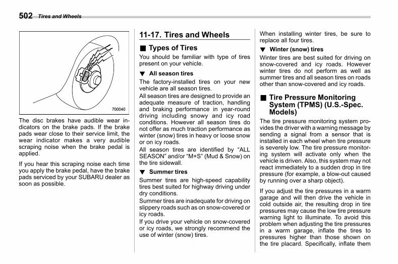
(504,1)
北米Model "A2600BE-B" EDITED: 2020/ 10/ 1
The disc brakes have audible wear in-dicators on the brake pads. If the brakepads wear close to their service limit, thewear indicator makes a very audiblescraping noise when the brake pedal isapplied.
If you hear this scraping noise each timeyou apply the brake pedal, have the brakepads serviced by your SUBARU dealer assoon as possible.
11-17. Tires and Wheelss11av
& Types of Tiress11av01
You should be familiar with type of tirespresent on your vehicle.! All season tires
s11av0101The factory-installed tires on your newvehicle are all season tires.All season tires are designed to provide anadequate measure of traction, handlingand braking performance in year-rounddriving including snowy and icy roadconditions. However all season tires donot offer as much traction performance aswinter (snow) tires in heavy or loose snowor on icy roads.All season tires are identified by “ALLSEASON” and/or “M+S” (Mud & Snow) onthe tire sidewall.! Summer tires
s11av0102Summer tires are high-speed capabilitytires best suited for highway driving underdry conditions.Summer tires are inadequate for driving onslippery roads such as on snow-covered oricy roads.If you drive your vehicle on snow-coveredor icy roads, we strongly recommend theuse of winter (snow) tires.
When installing winter tires, be sure toreplace all four tires.! Winter (snow) tires
s11av0103Winter tires are best suited for driving onsnow-covered and icy roads. Howeverwinter tires do not perform as well assummer tires and all season tires on roadsother than snow-covered and icy roads.
& Tire Pressure MonitoringSystem (TPMS) (U.S.-Spec.Models)
s11av02The tire pressure monitoring system pro-vides the driver with awarningmessage bysending a signal from a sensor that isinstalled in each wheel when tire pressureis severely low. The tire pressure monitor-ing system will activate only when thevehicle is driven. Also, this systemmay notreact immediately to a sudden drop in tirepressure (for example, a blow-out causedby running over a sharp object).
If you adjust the tire pressures in a warmgarage and will then drive the vehicle incold outside air, the resulting drop in tirepressures may cause the low tire pressurewarning light to illuminate. To avoid thisproblem when adjusting the tire pressuresin a warm garage, inflate the tires topressures higher than those shown onthe tire placard. Specifically, inflate them
Tires and Wheels502
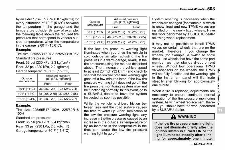
(505,1)
北米Model "A2600BE-B" EDITED: 2020/ 10/ 1
by an extra 1 psi (6.9 kPa, 0.07 kgf/cm2) forevery difference of 108F (5.68C) betweenthe temperature in the garage and thetemperature outside. By way of example,the following table shows the required tirepressures that correspond to various out-side temperatures when the temperaturein the garage is 608F (15.68C).Example:Tire size: 225/55R17 97V, 225/50R18 95VStandard tire pressures:Front: 33 psi (230 kPa, 2.3 kgf/cm2)Rear: 32 psi (220 kPa, 2.2 kgf/cm2)Garage temperature: 608F (15.68C)
Outsidetemperature
Adjusted pressure[psi (kPa, kgf/cm2)]
Front Rear
308F (−18C) 36 (250, 2.5) 35 (240, 2.4)108F (−128C) 38 (265, 2.65) 37 (255, 2.55)
−108F (−238C) 41 (280, 2.8) 39 (270, 2.7)
Example:Tire size: 225/65R17 102H, 225/60R18100HStandard tire pressures:Front: 35 psi (240 kPa, 2.4 kgf/cm2)Rear: 33 psi (230 kPa, 2.3 kgf/cm2)Garage temperature: 608F (15.68C)
Outsidetemperature
Adjusted pressure[psi (kPa, kgf/cm2)]
Front Rear
308F (−18C) 38 (260, 2.65) 36 (250, 2.5)108F (−128C) 40 (275, 2.8) 38 (265, 2.65)
−108F (−238C) 42 (290, 2.95) 41 (280, 2.8)
If the low tire pressure warning lightilluminates when you drive the vehicle incold outside air after adjusting the tirepressures in a warm garage, re-adjust thetire pressures using the method describedabove. Then, increase the vehicle speedto at least 20 mph (32 km/h) and check tosee that the low tire pressure warning lightgoes off a few minutes later. If the low tirepressure warning light does not go off, thetire pressure monitoring system may notbe functioning normally. In this event, go toa SUBARU dealer to have the systeminspected as soon as possible.
While the vehicle is driven, friction be-tween tires and the road surface causesthe tires to warm up. After illumination ofthe low tire pressure warning light, anyincrease in the tire pressures caused by anincrease in the outside air temperature orby an increase in the temperature in thetires can cause the low tire pressurewarning light to go off.
System resetting is necessary when thewheels are changed (for example, a switchto snow tires) and new TPMS valves areinstalled on the newly fitted wheels. Havethis work performed by a SUBARU dealerfollowing wheel replacement.
It may not be possible to install TPMSvalves on certain wheels that are on themarket. Therefore, if you change thewheels (for example, a switch to snowtires), use wheels that have the same partnumber as the standard-equipmentwheels. Without four operational TPMSvalve/sensors on the wheels, the TPMSwill not fully function and the warning lightin the instrument panel will illuminatesteadily after blinking for approximatelyone minute.
When a tire is replaced, adjustments arenecessary to ensure continued normaloperation of the tire pressure monitoringsystem. As with wheel replacement, there-fore, you should have the work performedby a SUBARU dealer.
WARNING
If the low tire pressure warning lightdoes not illuminate briefly after theignition switch is turned ON or thelight illuminates steadily after blink-ing for approximately one minute,
– CONTINUED –
Tires and Wheels 503
11
Maintenance
andService
(506,1)
北米Model "A2600BE-B" EDITED: 2020/ 10/ 1
you should have your Tire PressureMonitoring System checked at aSUBARU dealer as soon as possi-ble.If this light illuminates while driving,never brake suddenly. Instead, per-form the following procedure. Other-wise an accident involving seriousvehicle damage and serious perso-nal injury could occur.1) Keep driving straight aheadwhile
gradually reducing speed.2) Slowly pull off the road to a safe
place.If this light still illuminates whiledriving after adjusting the tire pres-sure, a tire may have significantdamage and a fast leak that causesthe tire to lose air rapidly. If you havea flat tire, replace it with a spare tireas soon as possible.When a spare tire is mounted or awheel rim is replaced without theoriginal pressure sensor/transmitterbeing transferred, the low tire pres-sure warning light will illuminatesteadily after blinking for approxi-mately one minute. This indicatesthe TPMS is unable to monitor allfour road wheels. Contact yourSUBARU dealer as soon as possible
for tire and sensor replacement and/or system resetting. If the lightilluminates steadily after blinkingfor approximately one minute,promptly contact a SUBARU dealerto have the system inspected.
& Tire Inspections11av03
Check on a daily basis that the tiresare free from serious damage,nails, and stones. At the same time,check the tires for abnormal wear.Contact your SUBARU dealer im-mediately if you find any problem.NOTE. When the wheels and tiresstrike curbs or are subjected toharsh treatment as when thevehicle is driven on a roughsurface, they can suffer damagethat cannot be seen with thenaked eye. This type of damagedoes not become evident untiltime has passed. Try not to driveover curbs, potholes or on otherrough surfaces. If doing so isunavoidable, keep the vehicle’s
speed down to a walking pace orless, and approach the curbs assquarely as possible. Also, makesure the tires are not pressedagainst the curb when you parkthe vehicle.. If you feel unusual vibrationwhile driving or find it difficult tosteer the vehicle in a straight line,one of the tires and/or wheelsmay be damaged. Drive slowly tothe nearest authorized SUBARUdealer and have the vehicle in-spected.
& Tire Pressures and Wears11av04
Maintaining the correct tire pres-sures helps to maximize the tires’service lives and is essential forgood running performance. Checkand, if necessary, adjust the pres-sure of each tire and the spare (ifequipped) at least once a monthand before any long journey.
Tires and Wheels504
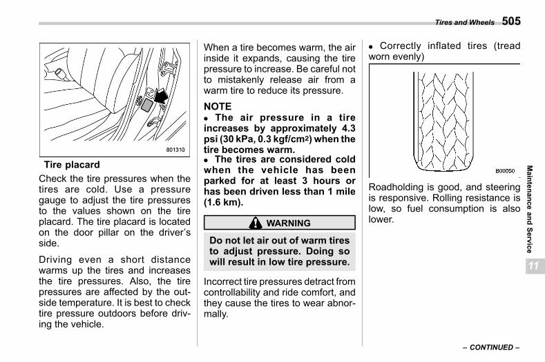
(507,1)
北米Model "A2600BE-B" EDITED: 2020/ 10/ 1
Tire placardCheck the tire pressures when thetires are cold. Use a pressuregauge to adjust the tire pressuresto the values shown on the tireplacard. The tire placard is locatedon the door pillar on the driver’sside.
Driving even a short distancewarms up the tires and increasesthe tire pressures. Also, the tirepressures are affected by the out-side temperature. It is best to checktire pressure outdoors before driv-ing the vehicle.
When a tire becomes warm, the airinside it expands, causing the tirepressure to increase. Be careful notto mistakenly release air from awarm tire to reduce its pressure.NOTE. The air pressure in a tireincreases by approximately 4.3psi (30 kPa, 0.3 kgf/cm2) when thetire becomes warm.. The tires are considered coldwhen the vehicle has beenparked for at least 3 hours orhas been driven less than 1 mile(1.6 km).
WARNING
Do not let air out of warm tiresto adjust pressure. Doing sowill result in low tire pressure.
Incorrect tire pressures detract fromcontrollability and ride comfort, andthey cause the tires to wear abnor-mally.
. Correctly inflated tires (treadworn evenly)
Roadholding is good, and steeringis responsive. Rolling resistance islow, so fuel consumption is alsolower.
– CONTINUED –
Tires and Wheels 505
11
Maintenance
andService
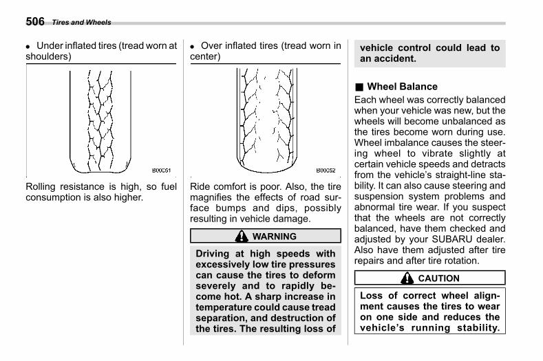
(508,1)
北米Model "A2600BE-B" EDITED: 2020/ 10/ 1
. Under inflated tires (tread worn atshoulders)
Rolling resistance is high, so fuelconsumption is also higher.
. Over inflated tires (tread worn incenter)
Ride comfort is poor. Also, the tiremagnifies the effects of road sur-face bumps and dips, possiblyresulting in vehicle damage.
WARNING
Driving at high speeds withexcessively low tire pressurescan cause the tires to deformseverely and to rapidly be-come hot. A sharp increase intemperature could cause treadseparation, and destruction ofthe tires. The resulting loss of
vehicle control could lead toan accident.
& Wheel Balances11av05
Each wheel was correctly balancedwhen your vehicle was new, but thewheels will become unbalanced asthe tires become worn during use.Wheel imbalance causes the steer-ing wheel to vibrate slightly atcertain vehicle speeds and detractsfrom the vehicle’s straight-line sta-bility. It can also cause steering andsuspension system problems andabnormal tire wear. If you suspectthat the wheels are not correctlybalanced, have them checked andadjusted by your SUBARU dealer.Also have them adjusted after tirerepairs and after tire rotation.
CAUTION
Loss of correct wheel align-ment causes the tires to wearon one side and reduces thevehicle’s running stability.
Tires and Wheels506
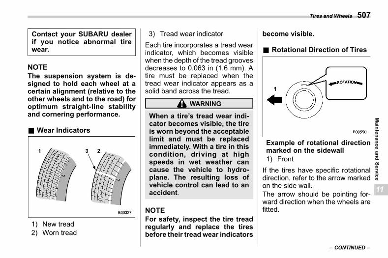
(509,1)
北米Model "A2600BE-B" EDITED: 2020/ 10/ 1
Contact your SUBARU dealerif you notice abnormal tirewear.
NOTEThe suspension system is de-signed to hold each wheel at acertain alignment (relative to theother wheels and to the road) foroptimum straight-line stabilityand cornering performance.
& Wear Indicatorss11av06
1) New tread2) Worn tread
3) Tread wear indicatorEach tire incorporates a tread wearindicator, which becomes visiblewhen the depth of the tread groovesdecreases to 0.063 in (1.6 mm). Atire must be replaced when thetread wear indicator appears as asolid band across the tread.
WARNING
When a tire’s tread wear indi-cator becomes visible, the tireis worn beyond the acceptablelimit and must be replacedimmediately. With a tire in thiscondition, driving at highspeeds in wet weather cancause the vehicle to hydro-plane. The resulting loss ofvehicle control can lead to anaccident.
NOTEFor safety, inspect the tire treadregularly and replace the tiresbefore their treadwear indicators
become visible.
& Rotational Direction of Tiress11av11
Example of rotational directionmarked on the sidewall1) FrontIf the tires have specific rotationaldirection, refer to the arrow markedon the side wall.The arrow should be pointing for-ward direction when the wheels arefitted.
– CONTINUED –
Tires and Wheels 507
11
Maintenance
andService
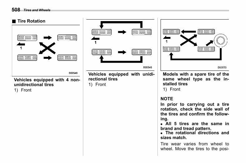
(510,1)
北米Model "A2600BE-B" EDITED: 2020/ 10/ 1
& Tire Rotations11av07
Vehicles equipped with 4 non-unidirectional tires1) Front
Vehicles equipped with unidi-rectional tires1) Front
Models with a spare tire of thesame wheel type as the in-stalled tires1) Front
NOTEIn prior to carrying out a tirerotation, check the side wall ofthe tires and confirm the follow-ing.. All 5 tires are the same inbrand and tread pattern.. The rotational directions andsizes match.Tire wear varies from wheel towheel. Move the tires to the posi-
Tires and Wheels508
(511,1)
北米Model "A2600BE-B" EDITED: 2020/ 10/ 1
tions shown in the illustration eachtime they are rotated. For the tirerotation schedule, refer to the “War-ranty and Maintenance Booklet.”Replace any damaged or unevenlyworn tire at the time of rotation. Aftertire rotation, adjust the tire pres-sures andmake sure thewheel nutsare correctly tightened.
After driving approximately 600miles (1,000 km), check the wheelnuts again and retighten any nutthat has become loose.
& Tire Replacements11av08
The wheels and tires are important andintegral parts of your vehicle’s design; theycannot be changed arbitrarily. The tiresfitted as standard equipment are optimallymatched to the characteristics of thevehicle and were selected to give the bestpossible combination of running perfor-mance, ride comfort, and service life. It isessential for every tire to have a size andconstruction matching those shown on thetire placard and to have a speed symboland load index matching those shown onthe tire placard.
Using tires of a non-specified size detractsfrom controllability, ride comfort, brakingperformance, speedometer accuracy andodometer accuracy. It also creates incor-rect body-to-tire clearances and inappro-priately changes the vehicle’s groundclearance.
All four tires must be the same in terms ofmanufacturer, brand (tread pattern), con-struction, and size. You are advised toreplace the tires with new ones that areidentical to those fitted as standard equip-ment.
For safe vehicle operation, SUBARUrecommends replacing all four tires at thesame time.
WARNING
. When replacing or installingtire(s), all four tires must be thesame for the following items.(a) Size(b) Speed symbol(c) Load index(d) Circumference(e) Construction(f) Manufacturer(g) Brand (tread pattern)
(h) Degrees of wearFor items (a) to (c), you mustobey the specification that isprinted on the tire placard. Thetire placard is located on thedriver’s door pillar.If all four tires are not the same initems (a) to (h), serious mechan-ical damage could be caused tothe drivetrain of the car, andaffect the followings.– Ride– Handling– Braking– Speedometer/Odometer cali-
bration– Clearance between the body
and the tiresIt also may be dangerous andlead to loss of vehicle control,and it can lead to an accident.
. Use only radial tires. Do not useradial tires together with beltedbias tires and/or bias-ply tires.Doing so can dangerously re-duce controllability, resulting inan accident.
– CONTINUED –
Tires and Wheels 509
11
Maintenance
andService
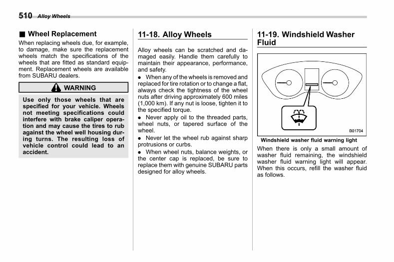
(512,1)
北米Model "A2600BE-B" EDITED: 2020/ 10/ 1
& Wheel Replacements11av09
When replacing wheels due, for example,to damage, make sure the replacementwheels match the specifications of thewheels that are fitted as standard equip-ment. Replacement wheels are availablefrom SUBARU dealers.
WARNING
Use only those wheels that arespecified for your vehicle. Wheelsnot meeting specifications couldinterfere with brake caliper opera-tion and may cause the tires to rubagainst the wheel well housing dur-ing turns. The resulting loss ofvehicle control could lead to anaccident.
11-18. Alloy Wheelss11bm
Alloy wheels can be scratched and da-maged easily. Handle them carefully tomaintain their appearance, performance,and safety.. When any of the wheels is removed andreplaced for tire rotation or to change a flat,always check the tightness of the wheelnuts after driving approximately 600 miles(1,000 km). If any nut is loose, tighten it tothe specified torque.. Never apply oil to the threaded parts,wheel nuts, or tapered surface of thewheel.. Never let the wheel rub against sharpprotrusions or curbs.. When wheel nuts, balance weights, orthe center cap is replaced, be sure toreplace them with genuine SUBARU partsdesigned for alloy wheels.
11-19. Windshield WasherFluid
s11ax
Windshield washer fluid warning lightWhen there is only a small amount ofwasher fluid remaining, the windshieldwasher fluid warning light will appear.When this occurs, refill the washer fluidas follows.
Alloy Wheels510
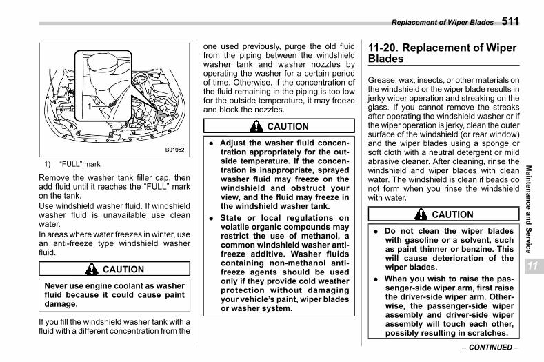
(513,1)
北米Model "A2600BE-B" EDITED: 2020/ 10/ 1
1) “FULL” mark
Remove the washer tank filler cap, thenadd fluid until it reaches the “FULL” markon the tank.Use windshield washer fluid. If windshieldwasher fluid is unavailable use cleanwater.In areas where water freezes in winter, usean anti-freeze type windshield washerfluid.
CAUTION
Never use engine coolant as washerfluid because it could cause paintdamage.
If you fill the windshield washer tank with afluid with a different concentration from the
one used previously, purge the old fluidfrom the piping between the windshieldwasher tank and washer nozzles byoperating the washer for a certain periodof time. Otherwise, if the concentration ofthe fluid remaining in the piping is too lowfor the outside temperature, it may freezeand block the nozzles.
CAUTION
. Adjust the washer fluid concen-tration appropriately for the out-side temperature. If the concen-tration is inappropriate, sprayedwasher fluid may freeze on thewindshield and obstruct yourview, and the fluid may freeze inthe windshield washer tank.
. State or local regulations onvolatile organic compounds mayrestrict the use of methanol, acommon windshield washer anti-freeze additive. Washer fluidscontaining non-methanol anti-freeze agents should be usedonly if they provide cold weatherprotection without damagingyour vehicle’s paint, wiper bladesor washer system.
11-20. Replacement of WiperBlades
s11az
Grease, wax, insects, or othermaterials onthe windshield or the wiper blade results injerky wiper operation and streaking on theglass. If you cannot remove the streaksafter operating the windshield washer or ifthe wiper operation is jerky, clean the outersurface of the windshield (or rear window)and the wiper blades using a sponge orsoft cloth with a neutral detergent or mildabrasive cleaner. After cleaning, rinse thewindshield and wiper blades with cleanwater. The windshield is clean if beads donot form when you rinse the windshieldwith water.
CAUTION
. Do not clean the wiper bladeswith gasoline or a solvent, suchas paint thinner or benzine. Thiswill cause deterioration of thewiper blades.
. When you wish to raise the pas-senger-side wiper arm, first raisethe driver-side wiper arm. Other-wise, the passenger-side wiperassembly and driver-side wiperassembly will touch each other,possibly resulting in scratches.
– CONTINUED –
Replacement of Wiper Blades 511
11
Maintenance
andService
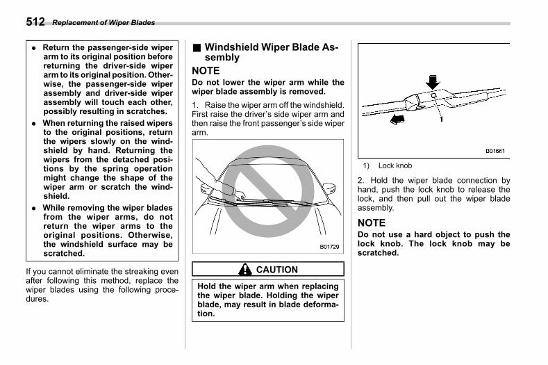
(514,1)
北米Model "A2600BE-B" EDITED: 2020/ 10/ 1
. Return the passenger-side wiperarm to its original position beforereturning the driver-side wiperarm to its original position.Other-wise, the passenger-side wiperassembly and driver-side wiperassembly will touch each other,possibly resulting in scratches.
. When returning the raised wipersto the original positions, returnthe wipers slowly on the wind-shield by hand. Returning thewipers from the detached posi-tions by the spring operationmight change the shape of thewiper arm or scratch the wind-shield.
. While removing the wiper bladesfrom the wiper arms, do notreturn the wiper arms to theoriginal positions. Otherwise,the windshield surface may bescratched.
If you cannot eliminate the streaking evenafter following this method, replace thewiper blades using the following proce-dures.
& Windshield Wiper Blade As-sembly
s11az01NOTEDo not lower the wiper arm while thewiper blade assembly is removed.1. Raise the wiper arm off the windshield.First raise the driver’s side wiper arm andthen raise the front passenger’s side wiperarm.
CAUTION
Hold the wiper arm when replacingthe wiper blade. Holding the wiperblade, may result in blade deforma-tion.
1) Lock knob
2. Hold the wiper blade connection byhand, push the lock knob to release thelock, and then pull out the wiper bladeassembly.
NOTEDo not use a hard object to push thelock knob. The lock knob may bescratched.
Replacement of Wiper Blades512
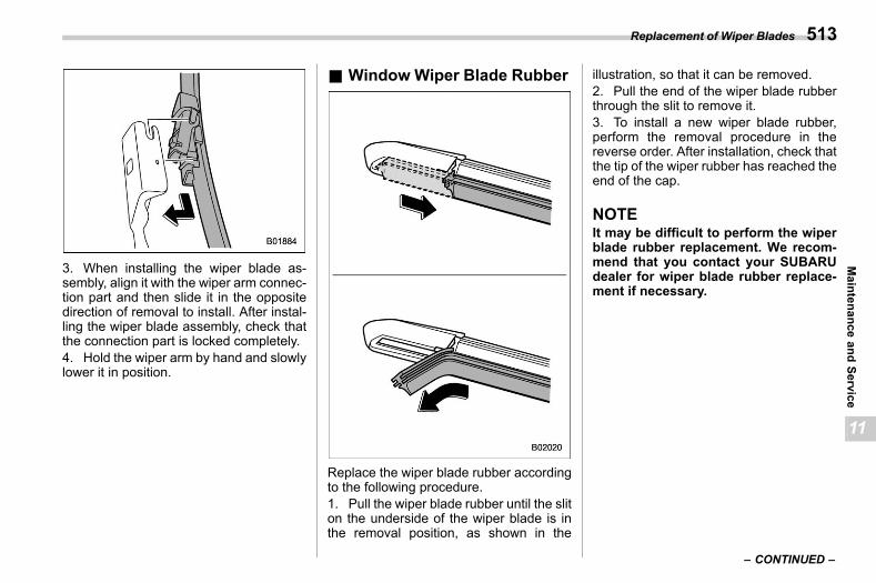
(515,1)
北米Model "A2600BE-B" EDITED: 2020/ 10/ 1
3. When installing the wiper blade as-sembly, align it with the wiper arm connec-tion part and then slide it in the oppositedirection of removal to install. After instal-ling the wiper blade assembly, check thatthe connection part is locked completely.4. Hold the wiper arm by hand and slowlylower it in position.
& Window Wiper Blade Rubbers11az05
Replace the wiper blade rubber accordingto the following procedure.1. Pull the wiper blade rubber until the sliton the underside of the wiper blade is inthe removal position, as shown in the
illustration, so that it can be removed.2. Pull the end of the wiper blade rubberthrough the slit to remove it.3. To install a new wiper blade rubber,perform the removal procedure in thereverse order. After installation, check thatthe tip of the wiper rubber has reached theend of the cap.
NOTEIt may be difficult to perform the wiperblade rubber replacement. We recom-mend that you contact your SUBARUdealer for wiper blade rubber replace-ment if necessary.
– CONTINUED –
Replacement of Wiper Blades 513
11
Maintenance
andService
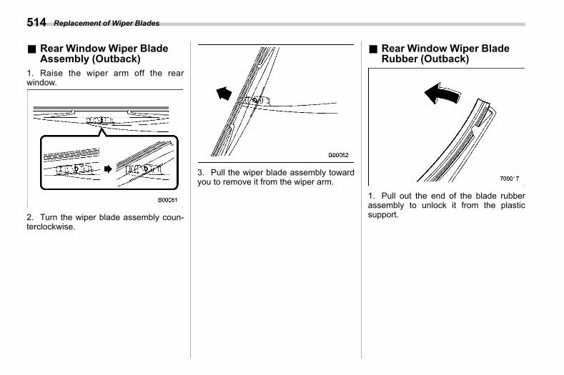
(516,1)
北米Model "A2600BE-B" EDITED: 2020/ 10/ 1
& Rear Window Wiper BladeAssembly (Outback)
s11az031. Raise the wiper arm off the rearwindow.
2. Turn the wiper blade assembly coun-terclockwise.
3. Pull the wiper blade assembly towardyou to remove it from the wiper arm.
& Rear Window Wiper BladeRubber (Outback)
s11az04
1. Pull out the end of the blade rubberassembly to unlock it from the plasticsupport.
Replacement of Wiper Blades514
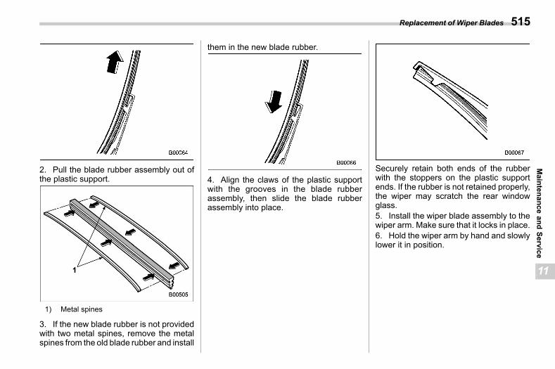
(517,1)
北米Model "A2600BE-B" EDITED: 2020/ 10/ 1
2. Pull the blade rubber assembly out ofthe plastic support.
1) Metal spines
3. If the new blade rubber is not providedwith two metal spines, remove the metalspines from the old blade rubber and install
them in the new blade rubber.
4. Align the claws of the plastic supportwith the grooves in the blade rubberassembly, then slide the blade rubberassembly into place.
Securely retain both ends of the rubberwith the stoppers on the plastic supportends. If the rubber is not retained properly,the wiper may scratch the rear windowglass.5. Install the wiper blade assembly to thewiper arm. Make sure that it locks in place.6. Hold the wiper arm by hand and slowlylower it in position.
Replacement of Wiper Blades 515
11
Maintenance
andService
(518,1)
北米Model "A2600BE-B" EDITED: 2020/ 10/ 1
11-21. Batterys11ba
WARNING
. Before beginning work on or nearany battery, be sure to extinguishall cigarettes, matches, and light-ers. Never expose a battery to anopen flame or electric sparks.Batteries give off a gas which ishighly flammable and explosive.
. For safety, in case an explosiondoes occur, wear eye protectionor shield your eyeswhenworkingnear any battery. Never lean overa battery.
. Do not let battery fluid contacteyes, skin, fabrics, or paint be-cause battery fluid is a corrosiveacid. If battery fluid gets on yourskin or in your eyes, immediatelyflush the area with water thor-oughly. Seek medical help imme-diately if acid has entered theeyes.If battery fluid is accidentallyswallowed, immediately drink alarge amount of milk or water,and seek medical attention im-mediately.
. To lessen the risk of sparks,remove rings, metal watchbands,and other metal jewelry. Neverallow metal tools to contact thepositive battery terminal and any-thing connected to it WHILE youare at the same time in contactwith any other metallic portion ofthe vehicle because a short cir-cuit will result.
. Keep everyone including childrenaway from the battery.
. Charge the battery in a well-ventilated area.
. Battery posts, terminals, and re-lated accessories contain leadand lead compounds, chemicalsknown to the State of Californiato cause cancer and reproductiveharm. Batteries also containother chemicals known to theState of California to cause can-cer. Wash hands after handling.
CAUTION
Never use more than 10 ampereswhen charging the battery becauseit will shorten battery life.
It is unnecessary to periodically check thebattery fluid level or periodically refill withdistilled water.
Battery516
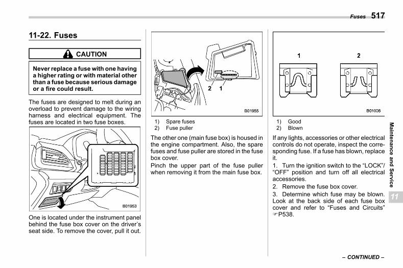
(519,1)
北米Model "A2600BE-B" EDITED: 2020/ 10/ 1
11-22. Fusess11bb
CAUTION
Never replace a fusewith one havinga higher rating or with material otherthan a fuse because serious damageor a fire could result.
The fuses are designed to melt during anoverload to prevent damage to the wiringharness and electrical equipment. Thefuses are located in two fuse boxes.
One is located under the instrument panelbehind the fuse box cover on the driver’sseat side. To remove the cover, pull it out.
1) Spare fuses2) Fuse puller
The other one (main fuse box) is housed inthe engine compartment. Also, the sparefuses and fuse puller are stored in the fusebox cover.Pinch the upper part of the fuse pullerwhen removing it from the main fuse box.
1) Good2) Blown
If any lights, accessories or other electricalcontrols do not operate, inspect the corre-sponding fuse. If a fuse has blown, replaceit.1. Turn the ignition switch to the “LOCK”/“OFF” position and turn off all electricalaccessories.2. Remove the fuse box cover.3. Determine which fuse may be blown.Look at the back side of each fuse boxcover and refer to “Fuses and Circuits”FP538.
– CONTINUED –
Fuses 517
11
Maintenance
andService
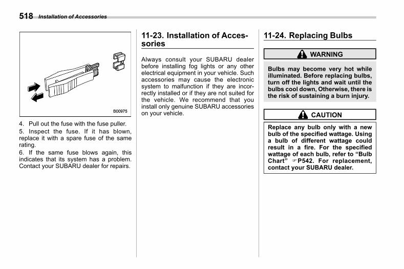
(520,1)
北米Model "A2600BE-B" EDITED: 2020/ 10/ 1
4. Pull out the fuse with the fuse puller.5. Inspect the fuse. If it has blown,replace it with a spare fuse of the samerating.6. If the same fuse blows again, thisindicates that its system has a problem.Contact your SUBARU dealer for repairs.
11-23. Installation of Acces-sories
s11bd
Always consult your SUBARU dealerbefore installing fog lights or any otherelectrical equipment in your vehicle. Suchaccessories may cause the electronicsystem to malfunction if they are incor-rectly installed or if they are not suited forthe vehicle. We recommend that youinstall only genuine SUBARU accessorieson your vehicle.
11-24. Replacing Bulbss11be
WARNING
Bulbs may become very hot whileilluminated. Before replacing bulbs,turn off the lights and wait until thebulbs cool down, Otherwise, there isthe risk of sustaining a burn injury.
CAUTION
Replace any bulb only with a newbulb of the specified wattage. Usinga bulb of different wattage couldresult in a fire. For the specifiedwattage of each bulb, refer to “BulbChart” FP542. For replacement,contact your SUBARU dealer.
Installation of Accessories518
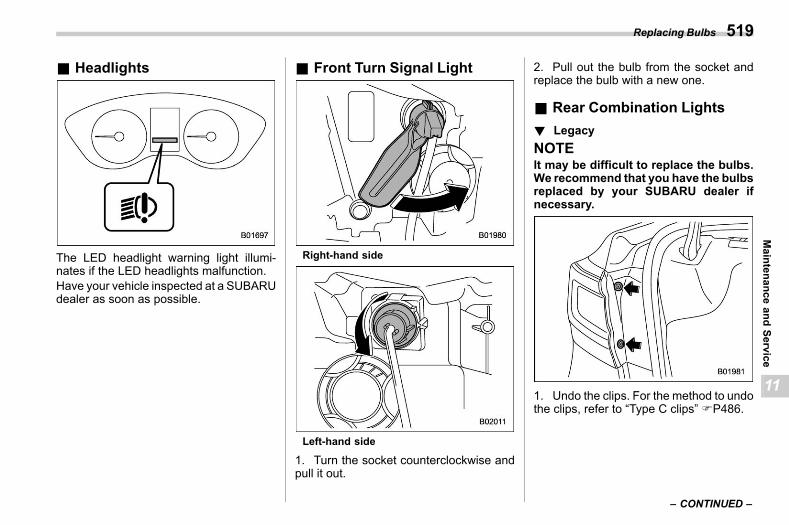
(521,1)
北米Model "A2600BE-B" EDITED: 2020/ 10/ 1
& Headlightss11be18
The LED headlight warning light illumi-nates if the LED headlights malfunction.Have your vehicle inspected at a SUBARUdealer as soon as possible.
& Front Turn Signal Lights11be03
Right-hand side
Left-hand side
1. Turn the socket counterclockwise andpull it out.
2. Pull out the bulb from the socket andreplace the bulb with a new one.
& Rear Combination Lightss11be05
! Legacys11be0501
NOTEIt may be difficult to replace the bulbs.We recommend that you have the bulbsreplaced by your SUBARU dealer ifnecessary.
1. Undo the clips. For the method to undothe clips, refer to “Type C clips” FP486.
– CONTINUED –
Replacing Bulbs 519
11
Maintenance
andService
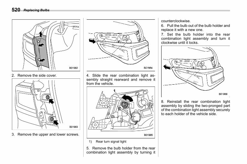
(522,1)
北米Model "A2600BE-B" EDITED: 2020/ 10/ 1
2. Remove the side cover.
3. Remove the upper and lower screws.
4. Slide the rear combination light as-sembly straight rearward and remove itfrom the vehicle.
1) Rear turn signal light
5. Remove the bulb holder from the rearcombination light assembly by turning it
counterclockwise.6. Pull the bulb out of the bulb holder andreplace it with a new one.7. Set the bulb holder into the rearcombination light assembly and turn itclockwise until it locks.
8. Reinstall the rear combination lightassembly by sliding the two-pronged partof the combination light assembly securelyto each holder of the vehicle side.
Replacing Bulbs520
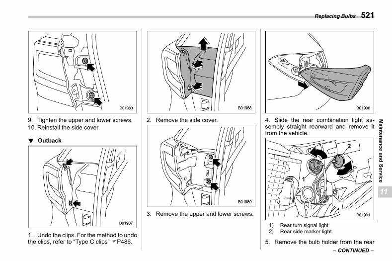
(523,1)
北米Model "A2600BE-B" EDITED: 2020/ 10/ 1
9. Tighten the upper and lower screws.10. Reinstall the side cover.
! Outbacks11be0502
1. Undo the clips. For the method to undothe clips, refer to “Type C clips” FP486.
2. Remove the side cover.
3. Remove the upper and lower screws.
4. Slide the rear combination light as-sembly straight rearward and remove itfrom the vehicle.
1) Rear turn signal light2) Rear side marker light
5. Remove the bulb holder from the rear– CONTINUED –
Replacing Bulbs 521
11
Maintenance
andService
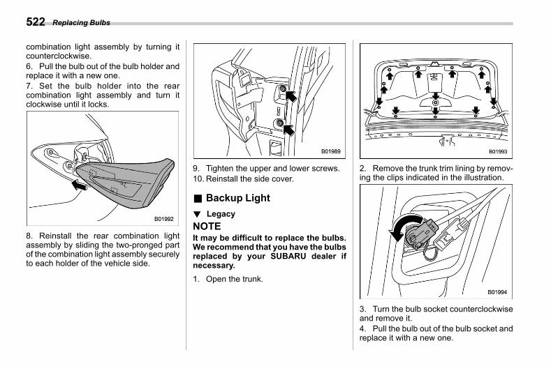
(524,1)
北米Model "A2600BE-B" EDITED: 2020/ 10/ 1
combination light assembly by turning itcounterclockwise.6. Pull the bulb out of the bulb holder andreplace it with a new one.7. Set the bulb holder into the rearcombination light assembly and turn itclockwise until it locks.
8. Reinstall the rear combination lightassembly by sliding the two-pronged partof the combination light assembly securelyto each holder of the vehicle side.
9. Tighten the upper and lower screws.10. Reinstall the side cover.
& Backup Lights11be06
! Legacys11be0601
NOTEIt may be difficult to replace the bulbs.We recommend that you have the bulbsreplaced by your SUBARU dealer ifnecessary.1. Open the trunk.
2. Remove the trunk trim lining by remov-ing the clips indicated in the illustration.
3. Turn the bulb socket counterclockwiseand remove it.4. Pull the bulb out of the bulb socket andreplace it with a new one.
Replacing Bulbs522
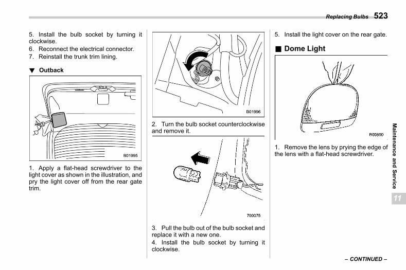
(525,1)
北米Model "A2600BE-B" EDITED: 2020/ 10/ 1
5. Install the bulb socket by turning itclockwise.6. Reconnect the electrical connector.7. Reinstall the trunk trim lining.
! Outbacks11be0602
1. Apply a flat-head screwdriver to thelight cover as shown in the illustration, andpry the light cover off from the rear gatetrim.
2. Turn the bulb socket counterclockwiseand remove it.
3. Pull the bulb out of the bulb socket andreplace it with a new one.4. Install the bulb socket by turning itclockwise.
5. Install the light cover on the rear gate.
& Dome Lights11be08
1. Remove the lens by prying the edge ofthe lens with a flat-head screwdriver.
– CONTINUED –
Replacing Bulbs 523
11
Maintenance
andService
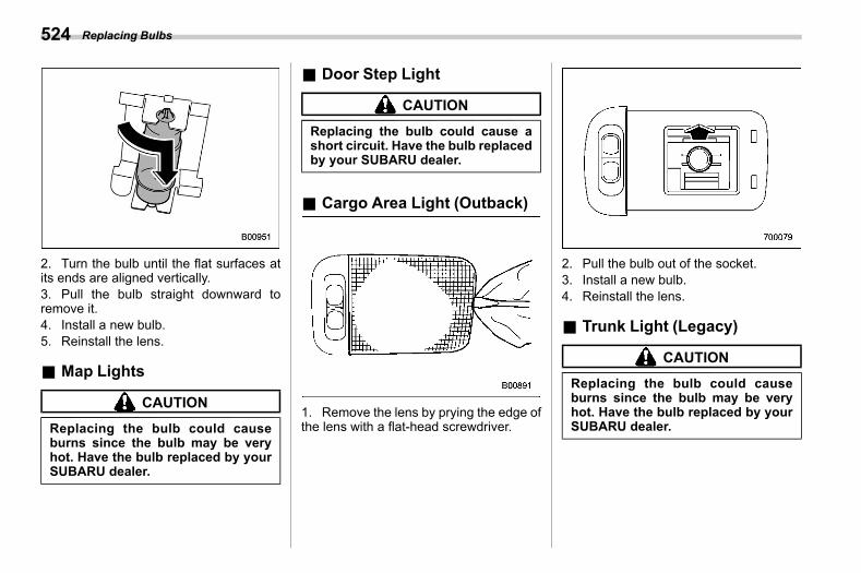
(526,1)
北米Model "A2600BE-B" EDITED: 2020/ 10/ 1
2. Turn the bulb until the flat surfaces atits ends are aligned vertically.3. Pull the bulb straight downward toremove it.4. Install a new bulb.5. Reinstall the lens.
& Map Lightss11be09
CAUTION
Replacing the bulb could causeburns since the bulb may be veryhot. Have the bulb replaced by yourSUBARU dealer.
& Door Step Lights11be10
CAUTION
Replacing the bulb could cause ashort circuit. Have the bulb replacedby your SUBARU dealer.
& Cargo Area Light (Outback)s11be11
1. Remove the lens by prying the edge ofthe lens with a flat-head screwdriver.
2. Pull the bulb out of the socket.3. Install a new bulb.4. Reinstall the lens.
& Trunk Light (Legacy)s11be12
CAUTION
Replacing the bulb could causeburns since the bulb may be veryhot. Have the bulb replaced by yourSUBARU dealer.
Replacing Bulbs524
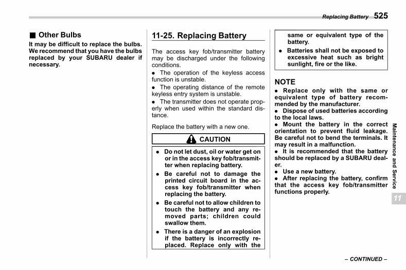
(527,1)
北米Model "A2600BE-B" EDITED: 2020/ 10/ 1
& Other Bulbss11be29
It may be difficult to replace the bulbs.We recommend that you have the bulbsreplaced by your SUBARU dealer ifnecessary.
11-25. Replacing Batterys11bk
The access key fob/transmitter batterymay be discharged under the followingconditions.. The operation of the keyless accessfunction is unstable.. The operating distance of the remotekeyless entry system is unstable.. The transmitter does not operate prop-erly when used within the standard dis-tance.
Replace the battery with a new one.
CAUTION
. Do not let dust, oil or water get onor in the access key fob/transmit-ter when replacing battery.
. Be careful not to damage theprinted circuit board in the ac-cess key fob/transmitter whenreplacing the battery.
. Be careful not to allow children totouch the battery and any re-moved parts; children couldswallow them.
. There is a danger of an explosionif the battery is incorrectly re-placed. Replace only with the
same or equivalent type of thebattery.
. Batteries shall not be exposed toexcessive heat such as brightsunlight, fire or the like.
NOTE. Replace only with the same orequivalent type of battery recom-mended by the manufacturer.. Dispose of used batteries accordingto the local laws.. Mount the battery in the correctorientation to prevent fluid leakage.Be careful not to bend the terminals. Itmay result in a malfunction.. It is recommended that the batteryshould be replaced by a SUBARU deal-er.. Use a new battery.. After replacing the battery, confirmthat the access key fob/transmitterfunctions properly.
– CONTINUED –
Replacing Battery 525
11
Maintenance
andService
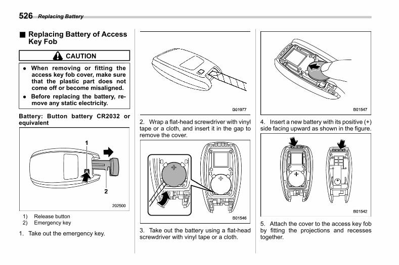
(528,1)
北米Model "A2600BE-B" EDITED: 2020/ 10/ 1
& Replacing Battery of AccessKey Fob
s11bk01
CAUTION
. When removing or fitting theaccess key fob cover, make surethat the plastic part does notcome off or become misaligned.
. Before replacing the battery, re-move any static electricity.
Battery: Button battery CR2032 orequivalent
1) Release button2) Emergency key
1. Take out the emergency key.
2. Wrap a flat-head screwdriver with vinyltape or a cloth, and insert it in the gap toremove the cover.
3. Take out the battery using a flat-headscrewdriver with vinyl tape or a cloth.
4. Insert a new battery with its positive (+)side facing upward as shown in the figure.
5. Attach the cover to the access key fobby fitting the projections and recessestogether.
Replacing Battery526
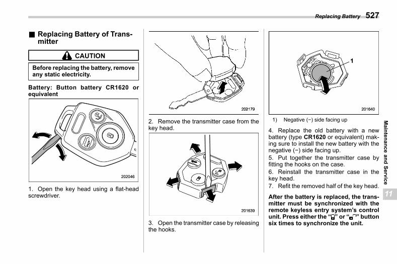
(529,1)
北米Model "A2600BE-B" EDITED: 2020/ 10/ 1
& Replacing Battery of Trans-mitter
s11bk02
CAUTION
Before replacing the battery, removeany static electricity.
Battery: Button battery CR1620 orequivalent
1. Open the key head using a flat-headscrewdriver.
2. Remove the transmitter case from thekey head.
3. Open the transmitter case by releasingthe hooks.
1) Negative (−) side facing up
4. Replace the old battery with a newbattery (type CR1620 or equivalent) mak-ing sure to install the new battery with thenegative (−) side facing up.5. Put together the transmitter case byfitting the hooks on the case.6. Reinstall the transmitter case in thekey head.7. Refit the removed half of the key head.
After the battery is replaced, the trans-mitter must be synchronized with theremote keyless entry system’s controlunit. Press either the “ ” or “ ” buttonsix times to synchronize the unit.
Replacing Battery 527
11
Maintenance
andService

(530,1)
北米Model "A2600BE-B" EDITED: 2020/ 10/ 1
— — — — — — — — — — — — — — — — — — — — — — — — — — — — — — — — — — — — — — — —
— — — — — — — — — — — — — — — — — — — — — — — — — — — — — — — — — — — — — — — —
— — — — — — — — — — — — — — — — — — — — — — — — — — — — — — — — — — — — — — — —
— — — — — — — — — — — — — — — — — — — — — — — — — — — — — — — — — — — — — — — —
— — — — — — — — — — — — — — — — — — — — — — — — — — — — — — — — — — — — — — — —
— — — — — — — — — — — — — — — — — — — — — — — — — — — — — — — — — — — — — — — —
— — — — — — — — — — — — — — — — — — — — — — — — — — — — — — — — — — — — — — — —
— — — — — — — — — — — — — — — — — — — — — — — — — — — — — — — — — — — — — — — —
— — — — — — — — — — — — — — — — — — — — — — — — — — — — — — — — — — — — — — — —
— — — — — — — — — — — — — — — — — — — — — — — — — — — — — — — — — — — — — — — —
— — — — — — — — — — — — — — — — — — — — — — — — — — — — — — — — — — — — — — — —
— — — — — — — — — — — — — — — — — — — — — — — — — — — — — — — — — — — — — — — —
— — — — — — — — — — — — — — — — — — — — — — — — — — — — — — — — — — — — — — — —
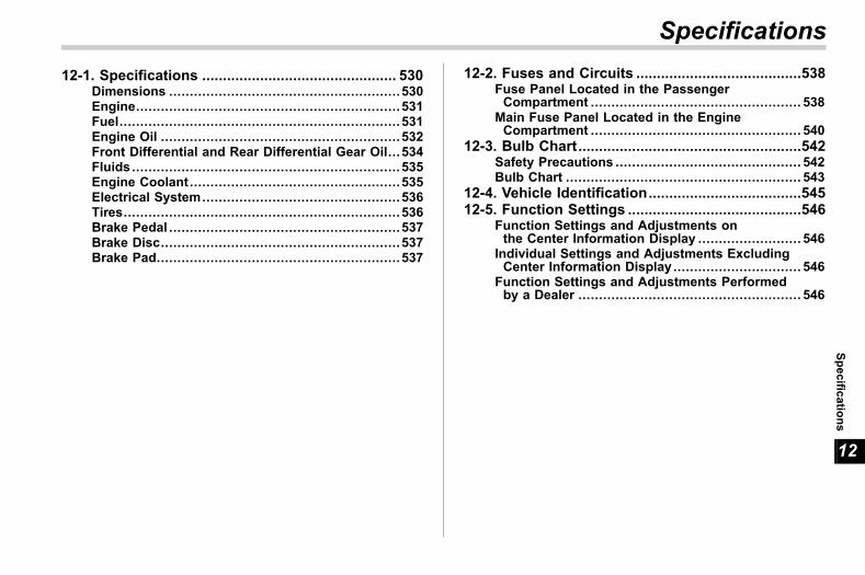
(531,1)
北米Model "A2600BE-B" EDITED: 2020/ 10/ 1
s1212-1. Specifications ............................................... 530
Dimensions ........................................................530Engine................................................................531Fuel....................................................................531Engine Oil ..........................................................532Front Differential and Rear Differential Gear Oil...534Fluids .................................................................535Engine Coolant...................................................535Electrical System................................................536Tires...................................................................536Brake Pedal ........................................................537Brake Disc..........................................................537Brake Pad...........................................................537
12-2. Fuses and Circuits ........................................538Fuse Panel Located in the PassengerCompartment ................................................... 538
Main Fuse Panel Located in the EngineCompartment ................................................... 540
12-3. Bulb Chart......................................................542Safety Precautions ............................................. 542Bulb Chart ......................................................... 543
12-4. Vehicle Identification.....................................54512-5. Function Settings ..........................................546
Function Settings and Adjustments onthe Center Information Display ......................... 546
Individual Settings and Adjustments ExcludingCenter Information Display ............................... 546
Function Settings and Adjustments Performedby a Dealer ...................................................... 546
Specifications
12
Specifications
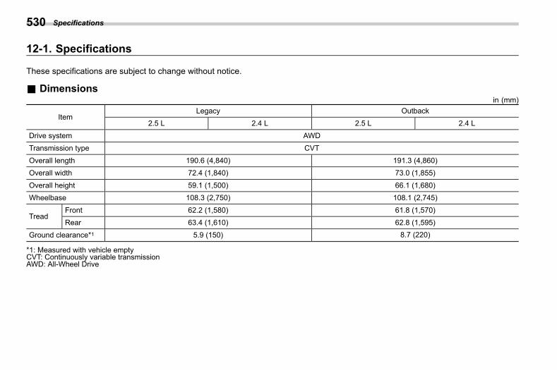
(532,1)
北米Model "A2600BE-B" EDITED: 2020/ 10/ 1
12-1. Specifications s12aa
These specifications are subject to change without notice.
& Dimensionss12aa01 in (mm)
ItemLegacy Outback
2.5 L 2.4 L 2.5 L 2.4 LDrive system AWD
Transmission type CVT
Overall length 190.6 (4,840) 191.3 (4,860)Overall width 72.4 (1,840) 73.0 (1,855)
Overall height 59.1 (1,500) 66.1 (1,680)Wheelbase 108.3 (2,750) 108.1 (2,745)
TreadFront 62.2 (1,580) 61.8 (1,570)Rear 63.4 (1,610) 62.8 (1,595)
Ground clearance*1 5.9 (150) 8.7 (220)
*1: Measured with vehicle emptyCVT: Continuously variable transmissionAWD: All-Wheel Drive
Specifications530
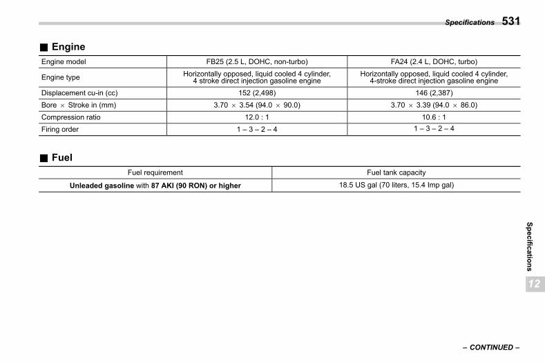
(533,1)
北米Model "A2600BE-B" EDITED: 2020/ 10/ 1
& Engines12aa02
Engine model FB25 (2.5 L, DOHC, non-turbo) FA24 (2.4 L, DOHC, turbo)
Engine type Horizontally opposed, liquid cooled 4 cylinder,4 stroke direct injection gasoline engine
Horizontally opposed, liquid cooled 4 cylinder,4-stroke direct injection gasoline engine
Displacement cu-in (cc) 152 (2,498) 146 (2,387)Bore 6 Stroke in (mm) 3.70 6 3.54 (94.0 6 90.0) 3.70 6 3.39 (94.0 6 86.0)
Compression ratio 12.0 : 1 10.6 : 1Firing order 1 – 3 – 2 – 4 1 – 3 – 2 – 4
& Fuels12aa08
Fuel requirement Fuel tank capacity
Unleaded gasoline with 87 AKI (90 RON) or higher 18.5 US gal (70 liters, 15.4 Imp gal)
– CONTINUED –
Specifications 531
12
Specifications
(534,1)
北米Model "A2600BE-B" EDITED: 2020/ 10/ 1
& Engine Oils12aa12
For the checking, adding and replacing procedure or other details, refer to “Engine Oil” FP491.
NOTEThe procedure for changing the engine oil and oil filter should be performed by a properly-trained expert. It is recommendedthat you have this service performed by your SUBARU dealer.
! Approved engine oils12aa1201
Always use the SUBARU approved engine oil. For further details, please contact your SUBARU dealer. If the approved engine oil isunavailable, use the alternative engine oil described on the next page.! Alternative engine oil
s12aa1202If the SUBARU approved oil is unavailable, the following alternative oil can be used.
NOTE. Each quantity indicated is only a guideline. The necessary quantity for replacement may differ slightly depending on thetemperature and other factors.. In choosing an oil, you want the proper quality and viscosity, as well as one that will enhance fuel economy. Oils of lowerviscosity provide better fuel economy. However, in hot weather, oil of higher viscosity is required to properly lubricate theengine. The following table lists the recommended viscosities and applicable temperatures.. When adding oil, different brands may be used together as long as they are the same API classification and SAE viscosityas those recommended by SUBARU.
Specifications532
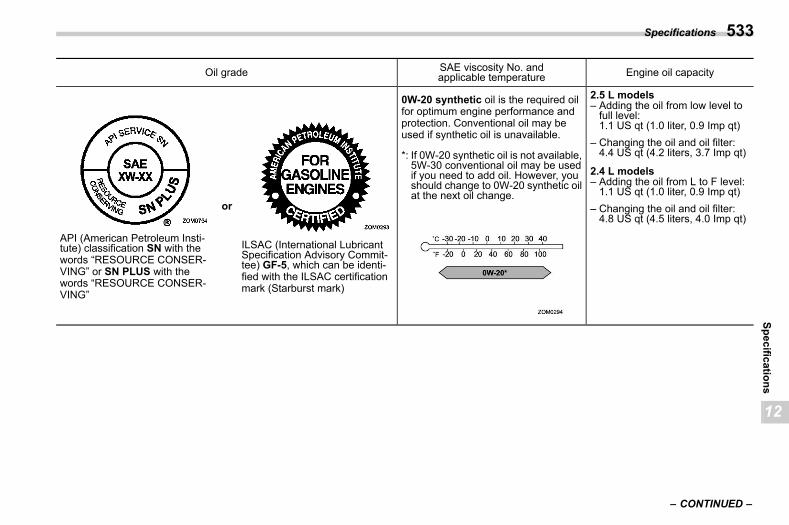
(535,1)
北米Model "A2600BE-B" EDITED: 2020/ 10/ 1
Oil grade SAE viscosity No. andapplicable temperature Engine oil capacity
API (American Petroleum Insti-tute) classification SN with thewords “RESOURCE CONSER-VING” or SN PLUS with thewords “RESOURCE CONSER-VING”
or
ILSAC (International LubricantSpecification Advisory Commit-tee) GF-5, which can be identi-fied with the ILSAC certificationmark (Starburst mark)
0W-20 synthetic oil is the required oilfor optimum engine performance andprotection. Conventional oil may beused if synthetic oil is unavailable.
*: If 0W-20 synthetic oil is not available,5W-30 conventional oil may be usedif you need to add oil. However, youshould change to 0W-20 synthetic oilat the next oil change.
2.5 L models– Adding the oil from low level tofull level:1.1 US qt (1.0 liter, 0.9 Imp qt)
– Changing the oil and oil filter:4.4 US qt (4.2 liters, 3.7 Imp qt)
2.4 L models– Adding the oil from L to F level:1.1 US qt (1.0 liter, 0.9 Imp qt)
– Changing the oil and oil filter:4.8 US qt (4.5 liters, 4.0 Imp qt)
– CONTINUED –
Specifications 533
12
Specifications
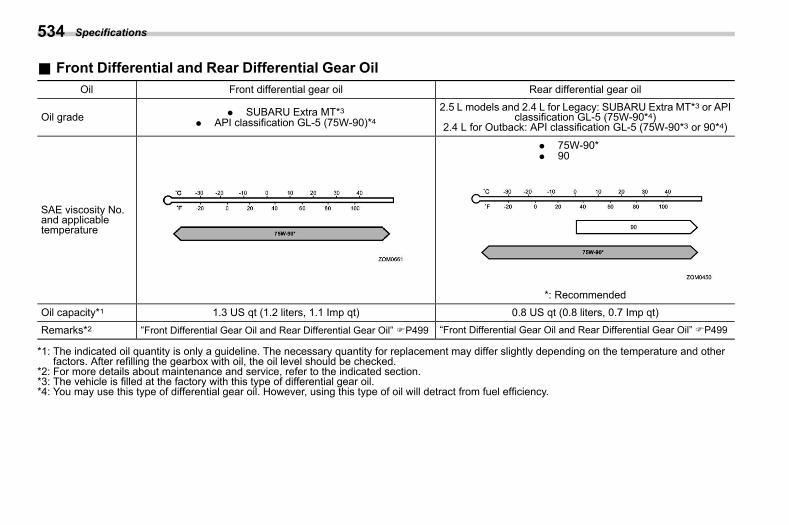
(536,1)
北米Model "A2600BE-B" EDITED: 2020/ 10/ 1
& Front Differential and Rear Differential Gear Oils12aa13
Oil Front differential gear oil Rear differential gear oil
Oil grade . SUBARU Extra MT*3. API classification GL-5 (75W-90)*4
2.5 L models and 2.4 L for Legacy: SUBARU Extra MT*3 or APIclassification GL-5 (75W-90*4)
2.4 L for Outback: API classification GL-5 (75W-90*3 or 90*4)
SAE viscosity No.and applicabletemperature
. 75W-90*
. 90
*: RecommendedOil capacity*1 1.3 US qt (1.2 liters, 1.1 Imp qt) 0.8 US qt (0.8 liters, 0.7 Imp qt)
Remarks*2 “Front Differential Gear Oil and Rear Differential Gear Oil” FP499 “Front Differential Gear Oil and Rear Differential Gear Oil” FP499
*1: The indicated oil quantity is only a guideline. The necessary quantity for replacement may differ slightly depending on the temperature and otherfactors. After refilling the gearbox with oil, the oil level should be checked.
*2: For more details about maintenance and service, refer to the indicated section.*3: The vehicle is filled at the factory with this type of differential gear oil.*4: You may use this type of differential gear oil. However, using this type of oil will detract from fuel efficiency.
Specifications534
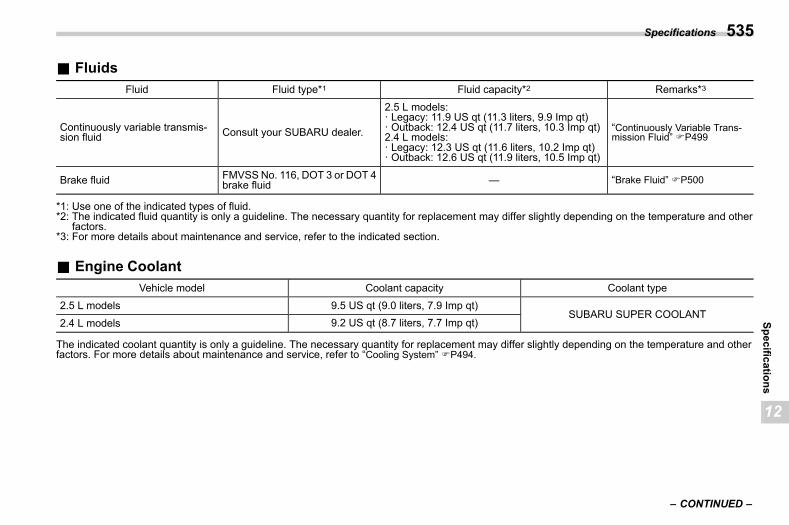
(537,1)
北米Model "A2600BE-B" EDITED: 2020/ 10/ 1
& Fluidss12aa10
Fluid Fluid type*1 Fluid capacity*2 Remarks*3
Continuously variable transmis-sion fluid Consult your SUBARU dealer.
2.5 L models:· Legacy: 11.9 US qt (11.3 liters, 9.9 Imp qt)· Outback: 12.4 US qt (11.7 liters, 10.3 Imp qt)2.4 L models:· Legacy: 12.3 US qt (11.6 liters, 10.2 Imp qt)· Outback: 12.6 US qt (11.9 liters, 10.5 Imp qt)
“Continuously Variable Trans-mission Fluid” FP499
Brake fluid FMVSSNo. 116, DOT 3 or DOT 4brake fluid — “Brake Fluid” FP500
*1: Use one of the indicated types of fluid.*2: The indicated fluid quantity is only a guideline. The necessary quantity for replacement may differ slightly depending on the temperature and other
factors.*3: For more details about maintenance and service, refer to the indicated section.
& Engine Coolants12aa11
Vehicle model Coolant capacity Coolant type2.5 L models 9.5 US qt (9.0 liters, 7.9 Imp qt)
SUBARU SUPER COOLANT2.4 L models 9.2 US qt (8.7 liters, 7.7 Imp qt)
The indicated coolant quantity is only a guideline. The necessary quantity for replacement may differ slightly depending on the temperature and otherfactors. For more details about maintenance and service, refer to “Cooling System” FP494.
– CONTINUED –
Specifications 535
12
Specifications
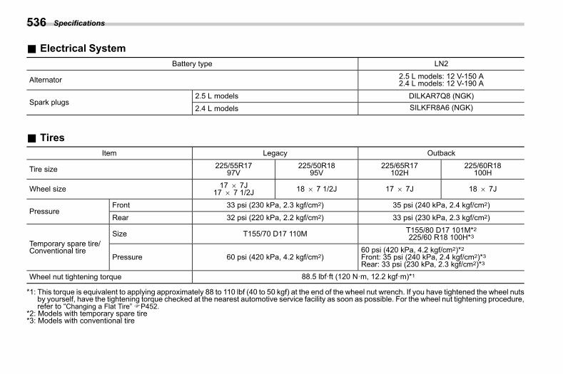
(538,1)
北米Model "A2600BE-B" EDITED: 2020/ 10/ 1
& Electrical Systems12aa03
Battery type LN2
Alternator 2.5 L models: 12 V-150 A2.4 L models: 12 V-190 A
Spark plugs2.5 L models DILKAR7Q8 (NGK)2.4 L models SILKFR8A6 (NGK)
& Tiress12aa05
Item Legacy Outback
Tire size 225/55R1797V
225/50R1895V
225/65R17102H
225/60R18100H
Wheel size 17 6 7J17 6 7 1/2J 18 6 7 1/2J 17 6 7J 18 6 7J
PressureFront 33 psi (230 kPa, 2.3 kgf/cm2) 35 psi (240 kPa, 2.4 kgf/cm2)
Rear 32 psi (220 kPa, 2.2 kgf/cm2) 33 psi (230 kPa, 2.3 kgf/cm2)
Temporary spare tire/Conventional tire
Size T155/70 D17 110M T155/80 D17 101M*2225/60 R18 100H*3
Pressure 60 psi (420 kPa, 4.2 kgf/cm2)60 psi (420 kPa, 4.2 kgf/cm2)*2Front: 35 psi (240 kPa, 2.4 kgf/cm2)*3Rear: 33 psi (230 kPa, 2.3 kgf/cm2)*3
Wheel nut tightening torque 88.5 lbf·ft (120 N·m, 12.2 kgf·m)*1
*1: This torque is equivalent to applying approximately 88 to 110 lbf (40 to 50 kgf) at the end of the wheel nut wrench. If you have tightened the wheel nutsby yourself, have the tightening torque checked at the nearest automotive service facility as soon as possible. For the wheel nut tightening procedure,refer to “Changing a Flat Tire” FP452.
*2: Models with temporary spare tire*3: Models with conventional tire
Specifications536
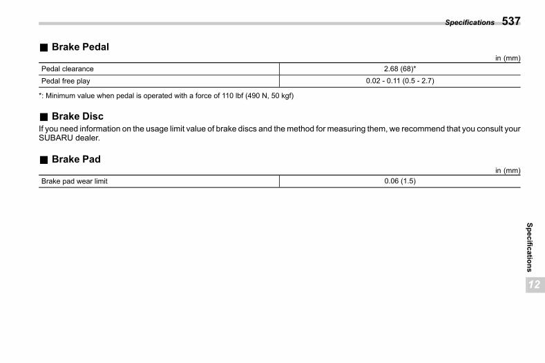
(539,1)
北米Model "A2600BE-B" EDITED: 2020/ 10/ 1
& Brake Pedals12aa27 in (mm)
Pedal clearance 2.68 (68)*Pedal free play 0.02 - 0.11 (0.5 - 2.7)
*: Minimum value when pedal is operated with a force of 110 lbf (490 N, 50 kgf)
& Brake Discs12aa18
If you need information on the usage limit value of brake discs and themethod for measuring them, we recommend that you consult yourSUBARU dealer.
& Brake Pads12aa28 in (mm)
Brake pad wear limit 0.06 (1.5)
Specifications 537
12
Specifications
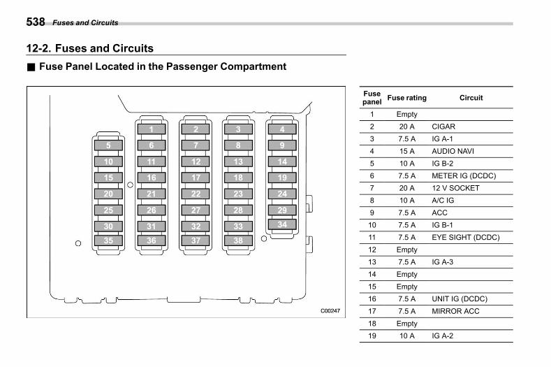
(540,1)
北米Model "A2600BE-B" EDITED: 2020/ 10/ 1
12-2. Fuses and Circuitss12ab
& Fuse Panel Located in the Passenger Compartments12ab01
Fusepanel Fuse rating Circuit
1 Empty
2 20 A CIGAR3 7.5 A IG A-1
4 15 A AUDIO NAVI5 10 A IG B-2
6 7.5 A METER IG (DCDC)7 20 A 12 V SOCKET
8 10 A A/C IG
9 7.5 A ACC10 7.5 A IG B-1
11 7.5 A EYE SIGHT (DCDC)12 Empty
13 7.5 A IG A-314 Empty
15 Empty16 7.5 A UNIT IG (DCDC)
17 7.5 A MIRROR ACC
18 Empty19 10 A IG A-2
Fuses and Circuits538
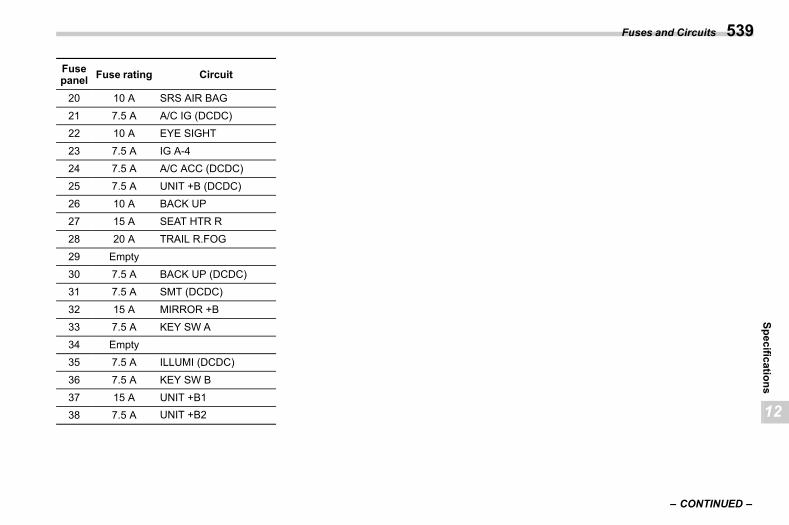
(541,1)
北米Model "A2600BE-B" EDITED: 2020/ 10/ 1
Fusepanel Fuse rating Circuit
20 10 A SRS AIR BAG
21 7.5 A A/C IG (DCDC)22 10 A EYE SIGHT
23 7.5 A IG A-424 7.5 A A/C ACC (DCDC)
25 7.5 A UNIT +B (DCDC)26 10 A BACK UP
27 15 A SEAT HTR R
28 20 A TRAIL R.FOG29 Empty
30 7.5 A BACK UP (DCDC)31 7.5 A SMT (DCDC)
32 15 A MIRROR +B33 7.5 A KEY SW A
34 Empty35 7.5 A ILLUMI (DCDC)
36 7.5 A KEY SW B
37 15 A UNIT +B138 7.5 A UNIT +B2
– CONTINUED –
Fuses and Circuits 539
12
Specifications
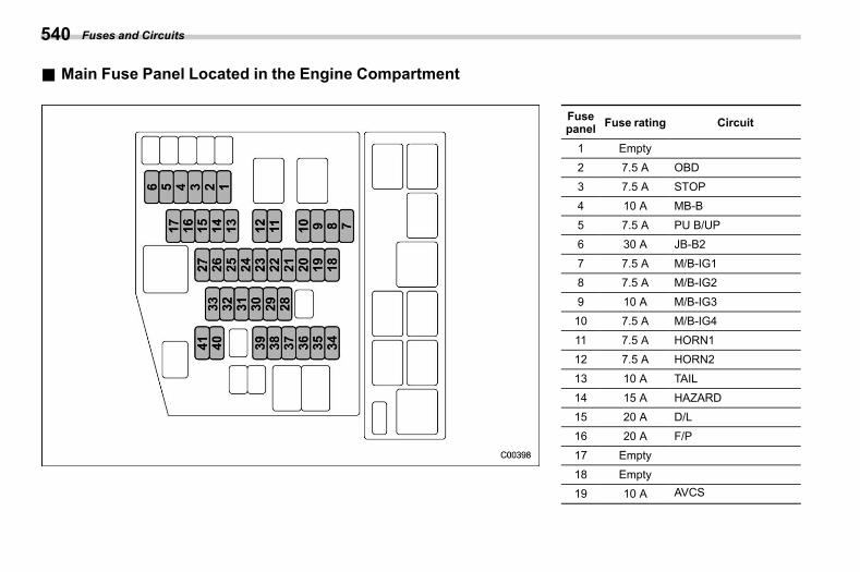
(542,1)
北米Model "A2600BE-B" EDITED: 2020/ 10/ 1
& Main Fuse Panel Located in the Engine Compartments12ab02
Fusepanel Fuse rating Circuit
1 Empty
2 7.5 A OBD3 7.5 A STOP
4 10 A MB-B
5 7.5 A PU B/UP6 30 A JB-B2
7 7.5 A M/B-IG18 7.5 A M/B-IG2
9 10 A M/B-IG310 7.5 A M/B-IG4
11 7.5 A HORN112 7.5 A HORN2
13 10 A TAIL
14 15 A HAZARD15 20 A D/L
16 20 A F/P17 Empty
18 Empty19 10 A AVCS
Fuses and Circuits540
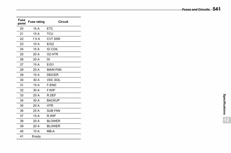
(543,1)
北米Model "A2600BE-B" EDITED: 2020/ 10/ 1
Fusepanel Fuse rating Circuit
20 15 A ETC
21 15 A TCU22 7.5 A CVT SSR
23 10 A E/G224 15 A IG COIL
25 20 A O2 HTR26 20 A DI
27 15 A E/G1
28 25 A MAIN FAN29 15 A DEICER
30 30 A VDC SOL31 15 A F-END
32 30 A F.WIP33 25 A R.DEF
34 30 A BACKUP35 20 A HTR
36 25 A SUB FAN
37 15 A R.WIP38 20 A BLOWER
39 20 A BLOWER40 10 A MB-A
41 Empty
Fuses and Circuits 541
12
Specifications
(544,1)
北米Model "A2600BE-B" EDITED: 2020/ 10/ 1
12-3. Bulb Charts12ac
& Safety Precautionss12ac03
WARNING
Bulbs may become very hot whileilluminated. Before replacing bulbs,turn off the lights and wait until thebulbs cool down. Otherwise, there isa risk of sustaining a burn injury.
CAUTION
Replace any bulb only with a newbulb of the specified wattage. Usinga bulb of different wattage couldresult in a fire.
Bulb Chart542
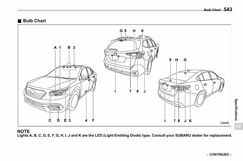
(545,1)
北米Model "A2600BE-B" EDITED: 2020/ 10/ 1
& Bulb Charts12ac04
NOTELights A, B, C, D, E, F, G, H, I, J and K are the LED (Light Emitting Diode) type. Consult your SUBARU dealer for replacement.
– CONTINUED –
Bulb Chart 543
12
Specifications
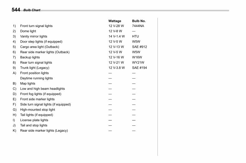
(546,1)
北米Model "A2600BE-B" EDITED: 2020/ 10/ 1
Wattage Bulb No.1) Front turn signal lights 12 V-28 W 7444NA2) Dome light 12 V-8 W —3) Vanity mirror lights 14 V-1.4 W HTU4) Door step lights (if equipped) 12 V-5 W W5W5) Cargo area light (Outback) 12 V-13 W SAE #9126) Rear side marker lights (Outback) 12 V-5 W W5W7) Backup lights 12 V-16 W W16W8) Rear turn signal lights 12 V-21 W WY21W9) Trunk light (Legacy) 12 V-3.8 W SAE #194A) Front position lights — —
Daytime running lights — —B) Map lights — —C) Low and high beam headlights — —D) Front fog lights (if equipped) — —E) Front side marker lights — —F) Side turn signal lights (if equipped) — —G) High-mounted stop light — —H) Tail lights (if equipped) — —I) License plate lights — —J) Tail and stop lights — —K) Rear side marker lights (Legacy) — —
Bulb Chart544
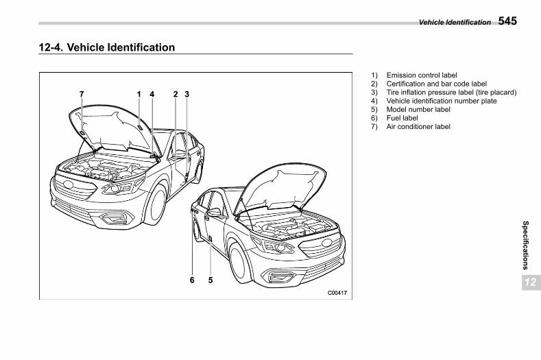
(547,1)
北米Model "A2600BE-B" EDITED: 2020/ 10/ 1
12-4. Vehicle Identifications12ad
1) Emission control label2) Certification and bar code label3) Tire inflation pressure label (tire placard)4) Vehicle identification number plate5) Model number label6) Fuel label7) Air conditioner label
Vehicle Identification 545
12
Specifications
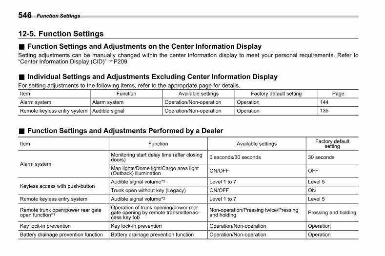
(548,1)
北米Model "A2600BE-B" EDITED: 2020/ 10/ 1
12-5. Function Settings s12ag
& Function Settings and Adjustments on the Center Information Displays12ag01
Setting adjustments can be manually changed within the center information display to meet your personal requirements. Refer to“Center Information Display (CID)” FP209.
& Individual Settings and Adjustments Excluding Center Information Displays12ag02
For setting adjustments to the following items, refer to the appropriate page for details.Item Function Available settings Factory default setting Page
Alarm system Alarm system Operation/Non-operation Operation 144Remote keyless entry system Audible signal Operation/Non-operation Operation 135
& Function Settings and Adjustments Performed by a Dealers12ag03
Item Function Available settings Factory defaultsetting
Alarm system
Monitoring start delay time (after closingdoors) 0 seconds/30 seconds 30 seconds
Map lights/Dome light/Cargo area light(Outback) illumination ON/OFF OFF
Keyless access with push-buttonAudible signal volume*2 Level 1 to 7 Level 5Trunk open without key (Legacy) ON/OFF ON
Remote keyless entry system Audible signal volume*2 Level 1 to 7 Level 5
Remote trunk open/power rear gateopen function*1
Operation of trunk opening/power reargate opening by remote transmitter/ac-cess key fob
Non-operation/Pressing twice/Pressingand holding Pressing and holding
Key lock-in prevention Key lock-in prevention Operation/Non-operation Operation
Battery drainage prevention function Battery drainage prevention function Operation/Non-operation Operation
Function Settings546
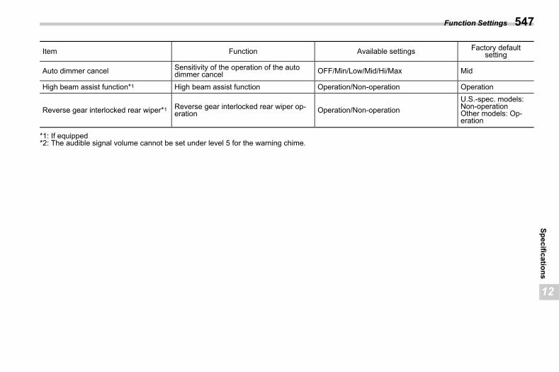
(549,1)
北米Model "A2600BE-B" EDITED: 2020/ 10/ 1
Item Function Available settings Factory defaultsetting
Auto dimmer cancel Sensitivity of the operation of the autodimmer cancel OFF/Min/Low/Mid/Hi/Max Mid
High beam assist function*1 High beam assist function Operation/Non-operation Operation
Reverse gear interlocked rear wiper*1 Reverse gear interlocked rear wiper op-eration Operation/Non-operation
U.S.-spec. models:Non-operationOther models: Op-eration
*1: If equipped*2: The audible signal volume cannot be set under level 5 for the warning chime.
Function Settings 547
12
Specifications

(550,1)
北米Model "A2600BE-B" EDITED: 2020/ 10/ 1
— — — — — — — — — — — — — — — — — — — — — — — — — — — — — — — — — — — — — — — —
— — — — — — — — — — — — — — — — — — — — — — — — — — — — — — — — — — — — — — — —
— — — — — — — — — — — — — — — — — — — — — — — — — — — — — — — — — — — — — — — —
— — — — — — — — — — — — — — — — — — — — — — — — — — — — — — — — — — — — — — — —
— — — — — — — — — — — — — — — — — — — — — — — — — — — — — — — — — — — — — — — —
— — — — — — — — — — — — — — — — — — — — — — — — — — — — — — — — — — — — — — — —
— — — — — — — — — — — — — — — — — — — — — — — — — — — — — — — — — — — — — — — —
— — — — — — — — — — — — — — — — — — — — — — — — — — — — — — — — — — — — — — — —
— — — — — — — — — — — — — — — — — — — — — — — — — — — — — — — — — — — — — — — —
— — — — — — — — — — — — — — — — — — — — — — — — — — — — — — — — — — — — — — — —
— — — — — — — — — — — — — — — — — — — — — — — — — — — — — — — — — — — — — — — —
— — — — — — — — — — — — — — — — — — — — — — — — — — — — — — — — — — — — — — — —
— — — — — — — — — — — — — — — — — — — — — — — — — — — — — — — — — — — — — — — —
(551,1)
北米Model "A2600BE-B" EDITED: 2020/ 10/ 1
s1313-1. For U.S.A. ...................................................... 55013-2. Tire Information ............................................ 550
Tire Labeling ......................................................550Recommended Tire Inflation Pressure.................552Glossary of Tire Terminology ..............................553Tire Care – Maintenance and Safety Practices .....557Vehicle Load Limit – How to Determine ...............558Determining Compatibility of Tire and VehicleLoad Capacities................................................561
Adverse Safety Consequences of Overloadingon Handling and Stopping and on Tires ............561
Steps for Determining Correct Load Limit........... 56213-3. Uniform Tire Quality Grading Standards.....562
TREADWEAR ..................................................... 563TRACTION AA, A, B, C ....................................... 563TEMPERATURE A, B, C ...................................... 563
13-4. Reporting Safety Defects (USA)...................56413-5. How to Contact Transport Canada in
Order to Report a Safety ConcernRelating to the Vehicle (Canada) .................564
Consumer Information and Reporting Safety Defects
13
Consum
erInform
ationand
Reporting
SafetyDefects
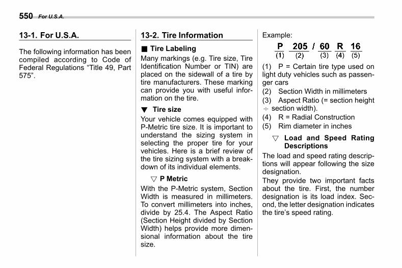
(552,1)
北米Model "A2600BE-B" EDITED: 2020/ 10/ 1
13-1. For U.S.A.s13aa
The following information has beencompiled according to Code ofFederal Regulations “Title 49, Part575”.
13-2. Tire Informations13ab
& Tire Labelings13ab01
Many markings (e.g. Tire size, TireIdentification Number or TIN) areplaced on the sidewall of a tire bytire manufacturers. These markingcan provide you with useful infor-mation on the tire.! Tire size
s13ab0101Your vehicle comes equipped withP-Metric tire size. It is important tounderstand the sizing system inselecting the proper tire for yourvehicles. Here is a brief review ofthe tire sizing system with a break-down of its individual elements.
! P Metrics13ab010101
With the P-Metric system, SectionWidth is measured in millimeters.To convert millimeters into inches,divide by 25.4. The Aspect Ratio(Section Height divided by SectionWidth) helps provide more dimen-sional information about the tiresize.
Example:
(1) P = Certain tire type used onlight duty vehicles such as passen-ger cars(2) Section Width in millimeters(3) Aspect Ratio (= section height7 section width).(4) R = Radial Construction(5) Rim diameter in inches
! Load and Speed RatingDescriptions
s13ab010102
The load and speed rating descrip-tions will appear following the sizedesignation.They provide two important factsabout the tire. First, the numberdesignation is its load index. Sec-ond, the letter designation indicatesthe tire’s speed rating.
For U.S.A.550
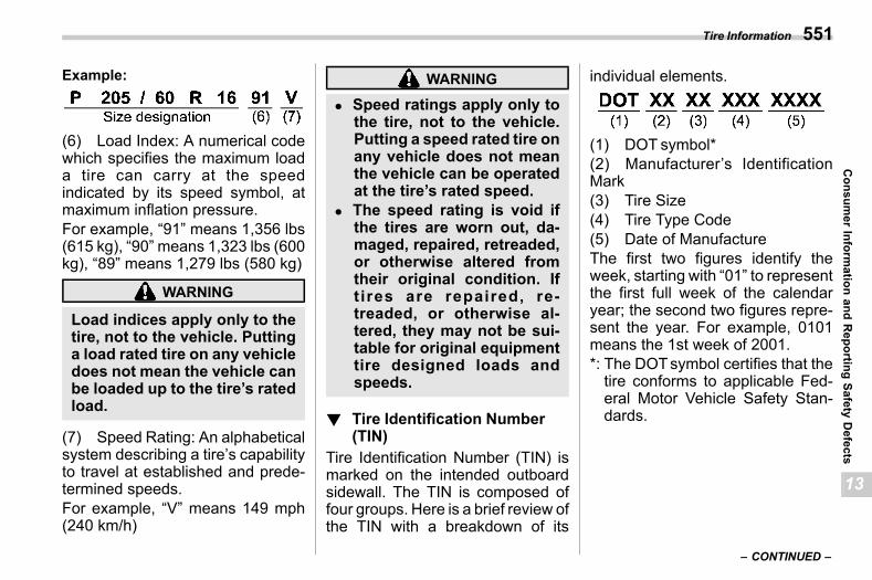
(553,1)
北米Model "A2600BE-B" EDITED: 2020/ 10/ 1
Example:
(6) Load Index: A numerical codewhich specifies the maximum loada tire can carry at the speedindicated by its speed symbol, atmaximum inflation pressure.For example, “91” means 1,356 lbs(615 kg), “90” means 1,323 lbs (600kg), “89” means 1,279 lbs (580 kg)
WARNING
Load indices apply only to thetire, not to the vehicle. Puttinga load rated tire on any vehicledoes not mean the vehicle canbe loaded up to the tire’s ratedload.
(7) Speed Rating: An alphabeticalsystem describing a tire’s capabilityto travel at established and prede-termined speeds.For example, “V” means 149 mph(240 km/h)
WARNING
. Speed ratings apply only tothe tire, not to the vehicle.Putting a speed rated tire onany vehicle does not meanthe vehicle can be operatedat the tire’s rated speed.
. The speed rating is void ifthe tires are worn out, da-maged, repaired, retreaded,or otherwise altered fromtheir original condition. Ift ires are repaired, re-treaded, or otherwise al-tered, they may not be sui-table for original equipmenttire designed loads andspeeds.
! Tire Identification Number(TIN)
s13ab0102Tire Identification Number (TIN) ismarked on the intended outboardsidewall. The TIN is composed offour groups. Here is a brief review ofthe TIN with a breakdown of its
individual elements.
(1) DOT symbol*(2) Manufacturer’s IdentificationMark(3) Tire Size(4) Tire Type Code(5) Date of ManufactureThe first two figures identify theweek, starting with “01” to representthe first full week of the calendaryear; the second two figures repre-sent the year. For example, 0101means the 1st week of 2001.*: The DOTsymbol certifies that thetire conforms to applicable Fed-eral Motor Vehicle Safety Stan-dards.
– CONTINUED –
Tire Information 551
13
Consum
erInform
ationand
Reporting
SafetyDefects
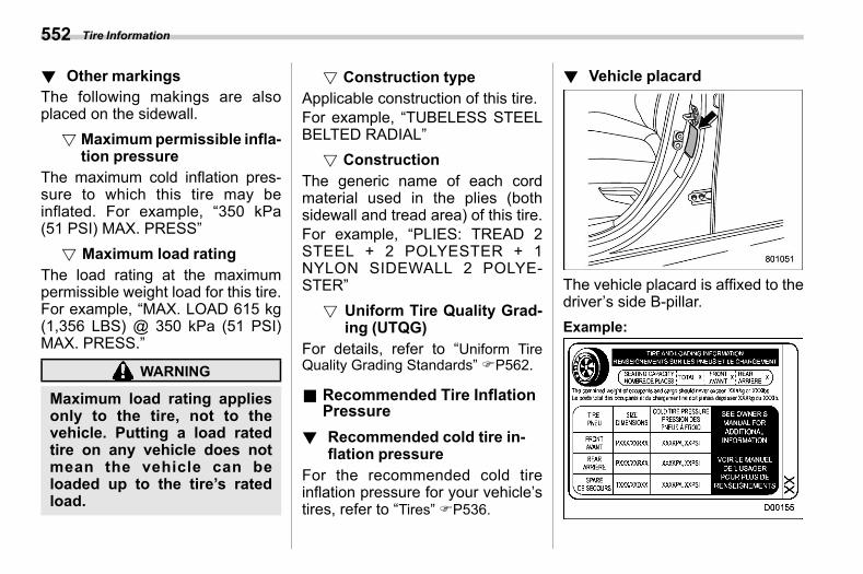
(554,1)
北米Model "A2600BE-B" EDITED: 2020/ 10/ 1
! Other markingss13ab0103
The following makings are alsoplaced on the sidewall.
! Maximumpermissible infla-tion pressure
s13ab010301
The maximum cold inflation pres-sure to which this tire may beinflated. For example, “350 kPa(51 PSI) MAX. PRESS”
! Maximum load ratings13ab010302
The load rating at the maximumpermissible weight load for this tire.For example, “MAX. LOAD 615 kg(1,356 LBS) @ 350 kPa (51 PSI)MAX. PRESS.”
WARNING
Maximum load rating appliesonly to the tire, not to thevehicle. Putting a load ratedtire on any vehicle does notmean the vehicle can beloaded up to the tire’s ratedload.
! Construction types13ab010303
Applicable construction of this tire.For example, “TUBELESS STEELBELTED RADIAL”
! Constructions13ab010304
The generic name of each cordmaterial used in the plies (bothsidewall and tread area) of this tire.For example, “PLIES: TREAD 2STEEL + 2 POLYESTER + 1NYLON SIDEWALL 2 POLYE-STER”
! Uniform Tire Quality Grad-ing (UTQG)
s13ab010305
For details, refer to “Uniform TireQuality Grading Standards” FP562.
& Recommended Tire InflationPressure
s13ab02
! Recommended cold tire in-flation pressure
s13ab0201For the recommended cold tireinflation pressure for your vehicle’stires, refer to “Tires” FP536.
! Vehicle placards13ab0202
The vehicle placard is affixed to thedriver’s side B-pillar.Example:
Tire Information552
(555,1)
北米Model "A2600BE-B" EDITED: 2020/ 10/ 1
The vehicle placard shows originaltire size, recommended cold tireinflation pressure on each tire atmaximum loaded vehicle weight,seating capacity and loading infor-mation.! Adverse safety conse-
quences of under-inflations13ab0203
Driving at high speeds with exces-sively low tire pressures can causethe tires to flex severely and torapidly become hot. A sharp in-crease in temperature could causetread separation, and failure of thetire(s). Possible resulting loss ofvehicle control could lead to anaccident.! Measuring and adjusting air
pressure to achieve properinflation
s13ab0204Check and, if necessary, adjust thepressure of each tire (including thespare) at least once a month andbefore any long journey. Check thetire pressures when the tires arecold. Use a pressure gauge to
adjust the tire pressures to thespecific values. Driving even a shortdistance warms up the tires andincreases the tire pressures. Also,the tire pressures are affected bythe outside temperature. It is best tocheck tire pressure outdoors beforedriving the vehicle. When a tirebecomes warm, the air inside itexpands, causing the tire pressureto increase. Be careful not to mis-takenly release air from a warm tireto reduce its pressure.
& Glossary of Tire Terminologys13ab03
. Accessory weightThe combined weight (in excess ofthose standard items which may bereplaced) of automatic transmis-sion, power steering, power brakes,power windows, power seats, radio,and heater, to the extent that theseitems are available as factory-in-stalled equipment (whether in-stalled or not).. BeadThe part of the tire that is made of
steel wires, wrapped or reinforcedby ply cords and that is shaped to fitthe rim.. Bead separationA breakdown of the bond betweencomponents in the bead.. Bias ply tireA pneumatic tire in which the plycords that extend to the beads arelaid at alternate angles substantiallyless than 90 degrees to the center-line of the tread.. CarcassThe tire structure, except tread andsidewall rubber which, when in-flated, bears the load.. ChunkingThe breaking away of pieces of thetread or sidewall.. Cold tire pressureThe pressure in a tire that has beendriven less than 1 mile or has beenstanding for three hours or more.. CordThe strands forming the plies in thetire.
– CONTINUED –
Tire Information 553
13
Consum
erInform
ationand
Reporting
SafetyDefects
(556,1)
北米Model "A2600BE-B" EDITED: 2020/ 10/ 1
. Cord separationThe parting of cords from adjacentrubber compounds.. CrackingAny parting within the tread, side-wall, or inner liner of the tireextending to cord material.. Curb weightThe weight of a motor vehicle withstandard equipment including themaximum capacity of fuel, oil andcoolant, and if so equipped, airconditioning and additional weightoptional engine.. Extra load tireA tire designed to operate at higherloads and higher inflation pressurethan the corresponding standardtire.. GrooveThe space between two adjacenttread ribs.. InnerlinerThe layer(s) forming the inside sur-face of a tubeless tire that containsthe inflating medium within the tire.
. Innerliner separationThe parting of the innerliner fromcord material in the carcass.. Intended outboard sidewall
(1) The sidewall that contains awhitewall, bears white letteringor bears manufacturer, brand,and/or model name molding thatis higher or deeper than thesame molding on the other side-wall of the tire, or(2) The outward facing sidewallof an asymmetrical tire that has aparticular side that must alwaysface outward when mounting ona vehicle.
. Light truck (LT) tireA tire designated by its manufac-turer as primarily intended for useon lightweight trucks or multipur-pose passenger vehicles.. Load ratingThe maximum load that a tire israted to carry for a given inflationpressure.. Maximum inflation pressureThe maximum cold inflation pres-
sure to which a tire may be inflated.. Maximum load ratingThe load rating for a tire at themaximum permissible inflationpressure for that tire.. Maximum loaded vehicle weightThe sum of:
(a) Curb weight(b) Accessory weight(c) Vehicle capacity weight(d) Production options weight
. Maximum permissible inflationpressureThe maximum cold inflation pres-sure to which a tire may be inflated.. Measuring rimThe rim on which a tire is fitted forphysical dimension requirements.. Normal occupant weight150 lbs (68 kg) times the number ofoccupants specified in the secondcolumn of Table 1 that is appendedto the end of this section.. Occupant distributionDistribution of occupants in a vehi-cle as specified in the third columnof Table 1 that is appended to the
Tire Information554
(557,1)
北米Model "A2600BE-B" EDITED: 2020/ 10/ 1
end of this section.. Open spliceAny parting at any junction of tread,sidewall, or innerliner that extendsto cord material.. Outer diameterThe overall diameter of an inflatednew tire.. Overall widthThe linear distance between theexteriors of the sidewalls of aninflated tire, including elevationsdue to labeling, decorations, orprotective bands or ribs.. Passenger car tireA tire intended for use on passen-ger cars, multipurpose passengervehicles, and trucks, that have agross vehicle weight rating (GVWR)of 10,000 lbs (4,535 kg) or less.. PlyA layer of rubber-coated parallelcords.. Ply separationA parting of rubber compoundbetween adjacent plies.
. Pneumatic tireA mechanical device made of rub-ber, chemicals, fabric and steel orother mater ia ls , that , whenmounted on an automotive wheel,provides the traction and containsthe gas or fluid that sustains theload.. Production options weightThe combined weight of thoseinstalled regular production optionsweighing over 5.1 lbs (2.3 kg) inexcess of those standard itemswhich they replace, not previouslyconsidered in curb weight or acces-sory weight, including heavy dutybrakes, ride levelers, roof rack,heavy duty battery, and special trim.. Radial ply tireA pneumatic tire in which the plycords that extend to the beads arelaid at substantially 90 degrees tothe centerline of the tread.. Recommended inflation pres-sureThe cold inflation pressure recom-mended by a vehicle manufacturer.
. Reinforced tireA tire designed to operate at higherloads and at higher inflation pres-sures than the corresponding stan-dard tire.. RimA metal support for a tire or a tireand tube assembly upon which thetire beads are seated.. Rim diameterNominal diameter of the bead seat.. Rim size designationRim diameter and width.. Rim type designationThe industry of manufacturer’s des-ignation for a rim by style or code.. Rim widthNominal distance between rimflanges.. Section widthThe linear distance between theexteriors of the sidewalls of aninflated tire, excluding elevationsdue to labeling, decoration, or pro-tective bands.
– CONTINUED –
Tire Information 555
13
Consum
erInform
ationand
Reporting
SafetyDefects
(558,1)
北米Model "A2600BE-B" EDITED: 2020/ 10/ 1
. SidewallThat portion of a tire between thetread and bead.. Sidewall separationThe parting of the rubber compoundfrom the cord material in the side-wall.. Snow tireA tire that attains a traction indexequal to or greater than 110, com-pared to the ASTM E1136-93 Stan-dard Reference Test Tire, whenusing the snow traction test asdescribed in ASTM F-1805-00,Standard Test Method for SingleWheel Driving Traction in a StraightLine on Snow-and Ice-CoveredSurfaces, and that is marked withan Alpine Symbol “ ” on at leastone sidewall.. Test rimThe rim on which a tire is fitted fortesting, and it may be any rim listedas appropriate for use with that tire.. TreadThat portion of a tire that comes intocontact with the road.
. Tread ribA tread section running circumfer-entially around a tire.. Tread separationPulling away of the tread from thetire carcass.. Treadwear indicators (TWI)The projections within the principalgrooves designed to give a visualindication of the degrees of wear ofthe tread.. Vehicle capacity weightThe rated cargo and luggage loadplus 150 lbs (68 kg) times thevehicle’s designated seating capa-city.. Vehiclemaximum load on the tireLoad on an individual tire that isdetermined by distributing to eachaxle its share of the maximumloaded vehicle weight and dividingby two.. Vehicle normal load on the tireLoad on an individual tire that isdetermined by distributing to eachaxle its share of the curb weight,accessory weight, and normal oc-
cupant weight (distributed in accor-dance with Table 1 that is appendedto the end of this section) anddividing by 2.. Wheel-holding fixtureThe fixture used to hold the wheeland tire assembly securely duringtesting.
Tire Information556
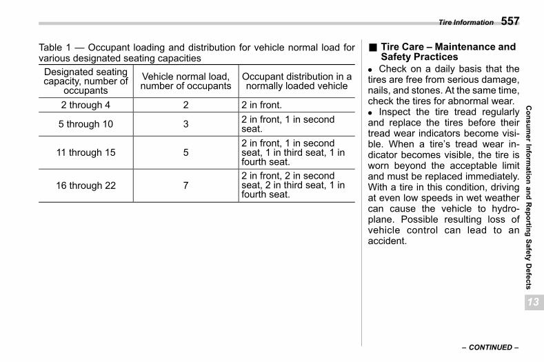
(559,1)
北米Model "A2600BE-B" EDITED: 2020/ 10/ 1
Table 1 — Occupant loading and distribution for vehicle normal load forvarious designated seating capacitiesDesignated seatingcapacity, number of
occupantsVehicle normal load,number of occupants
Occupant distribution in anormally loaded vehicle
2 through 4 2 2 in front.
5 through 10 3 2 in front, 1 in secondseat.
11 through 15 52 in front, 1 in secondseat, 1 in third seat, 1 infourth seat.
16 through 22 72 in front, 2 in secondseat, 2 in third seat, 1 infourth seat.
& Tire Care – Maintenance andSafety Practices
s13ab04. Check on a daily basis that thetires are free from serious damage,nails, and stones. At the same time,check the tires for abnormal wear.. Inspect the tire tread regularlyand replace the tires before theirtread wear indicators become visi-ble. When a tire’s tread wear in-dicator becomes visible, the tire isworn beyond the acceptable limitand must be replaced immediately.With a tire in this condition, drivingat even low speeds in wet weathercan cause the vehicle to hydro-plane. Possible resulting loss ofvehicle control can lead to anaccident.
– CONTINUED –
Tire Information 557
13
Consum
erInform
ationand
Reporting
SafetyDefects
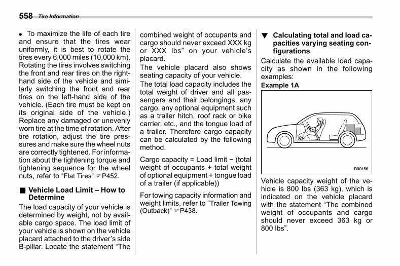
(560,1)
北米Model "A2600BE-B" EDITED: 2020/ 10/ 1
. To maximize the life of each tireand ensure that the tires wearuniformly, it is best to rotate thetires every 6,000miles (10,000 km).Rotating the tires involves switchingthe front and rear tires on the right-hand side of the vehicle and simi-larly switching the front and reartires on the left-hand side of thevehicle. (Each tire must be kept onits original side of the vehicle.)Replace any damaged or unevenlyworn tire at the time of rotation. Aftertire rotation, adjust the tire pres-sures andmake sure thewheel nutsare correctly tightened. For informa-tion about the tightening torque andtightening sequence for the wheelnuts, refer to “Flat Tires” FP452.
& Vehicle Load Limit – How toDetermine
s13ab05The load capacity of your vehicle isdetermined by weight, not by avail-able cargo space. The load limit ofyour vehicle is shown on the vehicleplacard attached to the driver’s sideB-pillar. Locate the statement “The
combined weight of occupants andcargo should never exceed XXX kgor XXX lbs” on your vehicle’splacard.The vehicle placard also showsseating capacity of your vehicle.The total load capacity includes thetotal weight of driver and all pas-sengers and their belongings, anycargo, any optional equipment suchas a trailer hitch, roof rack or bikecarrier, etc., and the tongue load ofa trailer. Therefore cargo capacitycan be calculated by the followingmethod.
Cargo capacity = Load limit − (totalweight of occupants + total weightof optional equipment + tongue loadof a trailer (if applicable))
For towing capacity information andweight limits, refer to “Trailer Towing(Outback)” FP438.
! Calculating total and load ca-pacities varying seating con-figurations
s13ab0501Calculate the available load capa-city as shown in the followingexamples:Example 1A
Vehicle capacity weight of the ve-hicle is 800 lbs (363 kg), which isindicated on the vehicle placardwith the statement “The combinedweight of occupants and cargoshould never exceed 363 kg or800 lbs”.
Tire Information558
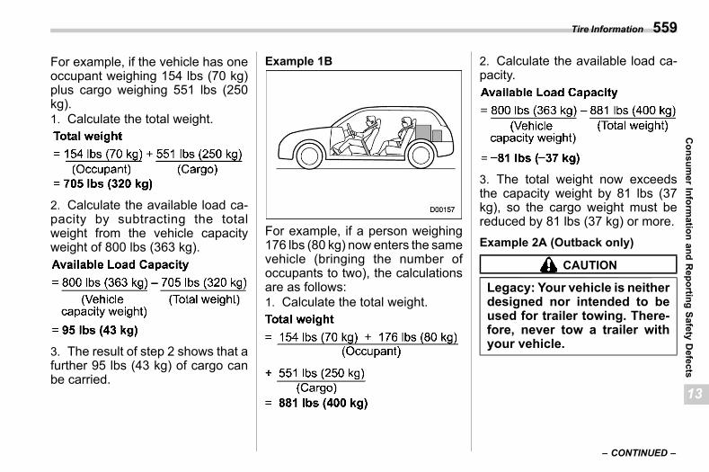
(561,1)
北米Model "A2600BE-B" EDITED: 2020/ 10/ 1
For example, if the vehicle has oneoccupant weighing 154 lbs (70 kg)plus cargo weighing 551 lbs (250kg).1. Calculate the total weight.
2. Calculate the available load ca-pacity by subtracting the totalweight from the vehicle capacityweight of 800 lbs (363 kg).
3. The result of step 2 shows that afurther 95 lbs (43 kg) of cargo canbe carried.
Example 1B
For example, if a person weighing176 lbs (80 kg) now enters the samevehicle (bringing the number ofoccupants to two), the calculationsare as follows:1. Calculate the total weight.
2. Calculate the available load ca-pacity.
3. The total weight now exceedsthe capacity weight by 81 lbs (37kg), so the cargo weight must bereduced by 81 lbs (37 kg) or more.Example 2A (Outback only)
CAUTION
Legacy: Your vehicle is neitherdesigned nor intended to beused for trailer towing. There-fore, never tow a trailer withyour vehicle.
– CONTINUED –
Tire Information 559
13
Consum
erInform
ationand
Reporting
SafetyDefects
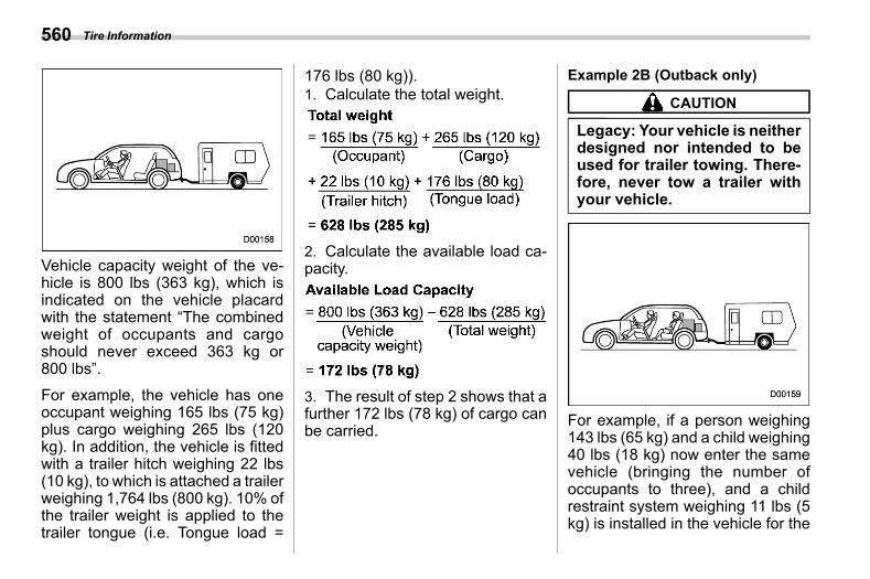
(562,1)
北米Model "A2600BE-B" EDITED: 2020/ 10/ 1
Vehicle capacity weight of the ve-hicle is 800 lbs (363 kg), which isindicated on the vehicle placardwith the statement “The combinedweight of occupants and cargoshould never exceed 363 kg or800 lbs”.
For example, the vehicle has oneoccupant weighing 165 lbs (75 kg)plus cargo weighing 265 lbs (120kg). In addition, the vehicle is fittedwith a trailer hitch weighing 22 lbs(10 kg), to which is attached a trailerweighing 1,764 lbs (800 kg). 10% ofthe trailer weight is applied to thetrailer tongue (i.e. Tongue load =
176 lbs (80 kg)).1. Calculate the total weight.
2. Calculate the available load ca-pacity.
3. The result of step 2 shows that afurther 172 lbs (78 kg) of cargo canbe carried.
Example 2B (Outback only)
CAUTION
Legacy: Your vehicle is neitherdesigned nor intended to beused for trailer towing. There-fore, never tow a trailer withyour vehicle.
For example, if a person weighing143 lbs (65 kg) and a child weighing40 lbs (18 kg) now enter the samevehicle (bringing the number ofoccupants to three), and a childrestraint system weighing 11 lbs (5kg) is installed in the vehicle for the
Tire Information560
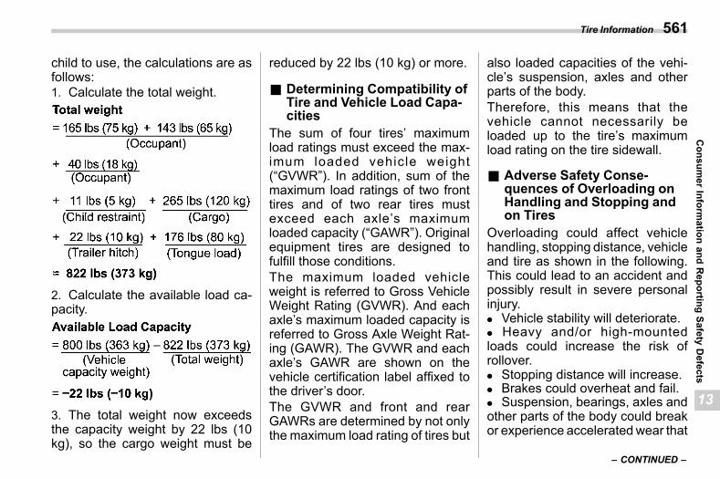
(563,1)
北米Model "A2600BE-B" EDITED: 2020/ 10/ 1
child to use, the calculations are asfollows:1. Calculate the total weight.
2. Calculate the available load ca-pacity.
3. The total weight now exceedsthe capacity weight by 22 lbs (10kg), so the cargo weight must be
reduced by 22 lbs (10 kg) or more.
& Determining Compatibility ofTire and Vehicle Load Capa-cities
s13ab06The sum of four tires’ maximumload ratings must exceed the max-imum loaded vehicle weight(“GVWR”). In addition, sum of themaximum load ratings of two fronttires and of two rear tires mustexceed each axle’s maximumloaded capacity (“GAWR”). Originalequipment tires are designed tofulfill those conditions.The maximum loaded vehicleweight is referred to Gross VehicleWeight Rating (GVWR). And eachaxle’s maximum loaded capacity isreferred to Gross Axle Weight Rat-ing (GAWR). The GVWR and eachaxle’s GAWR are shown on thevehicle certification label affixed tothe driver’s door.The GVWR and front and rearGAWRs are determined by not onlythe maximum load rating of tires but
also loaded capacities of the vehi-cle’s suspension, axles and otherparts of the body.Therefore, this means that thevehicle cannot necessarily beloaded up to the tire’s maximumload rating on the tire sidewall.
& Adverse Safety Conse-quences of Overloading onHandling and Stopping andon Tires
s13ab07Overloading could affect vehiclehandling, stopping distance, vehicleand tire as shown in the following.This could lead to an accident andpossibly result in severe personalinjury.. Vehicle stability will deteriorate.. Heavy and/or high-mountedloads could increase the risk ofrollover.. Stopping distance will increase.. Brakes could overheat and fail.. Suspension, bearings, axles andother parts of the body could breakor experience acceleratedwear that
– CONTINUED –
Tire Information 561
13
Consum
erInform
ationand
Reporting
SafetyDefects
(564,1)
北米Model "A2600BE-B" EDITED: 2020/ 10/ 1
will shorten vehicle life.. Tires could fail.. Tread separation could occur.. Tire could separate from its rim.
& Steps for Determining Cor-rect Load Limit
s13ab08
1. Locate the statement “The com-bined weight of occupants andcargo should never exceed XXXkg or XXX lbs.” on your vehicle’splacard.2. Determine the combined weightof the driver and passengers thatwill be riding in your vehicle.3. Subtract the combined weight ofthe driver and passengers fromXXX kg or XXX lbs.4. The resulting figure equals theavailable amount of cargo andluggage load capacity. For exam-ple, if the “XXX” amount equals1,400 lbs (635 kg) and there will befive 150 lbs (68 kg) passengers inyour vehicle, the amount of avail-able cargo and luggage load capa-city is 650 lbs (1,400 − 750 (5 6
150) = 650 lbs).5. Determine the combined weightof luggage and cargo being loadedon the vehicle. That weight may notsafely exceed the available cargoand luggage load capacity calcu-lated in Step 4.6. If your vehicle will be towing atrailer, load from your trailer will betransferred to your vehicle. Consultthis manual to determine how thisreduces the available cargo andluggage load capacity of your ve-hicle.
13-3. Uniform Tire QualityGrading Standards
s13ac
This information indicates the rela-tive performance of passenger cartires in the area of treadwear,traction, and temperature resis-tance. This is to aid the consumerin making an informed choice in thepurchase of tires.Quality grades can be found whereapplicable on the tire sidewall be-tween tread shoulder andmaximumsection width. For example:TREADWEAR 200 TRACTION AATEMPERATURE A
The quality grades apply to newpneumatic tires for use on passen-ger cars. However, they do notapply to deep tread, winter typesnow tires, space-saver or tempor-ary use spare tires, tires withnominal rim diameters of 12 inchesor less, or to some limited produc-tion tires.
Uniform Tire Quality Grading Standards562
(565,1)
北米Model "A2600BE-B" EDITED: 2020/ 10/ 1
All passenger car tires must con-form to Federal Safety Require-ments in addition to these grades.
& TREADWEARs13ac02
The treadwear grade is a compara-tive rating based on the wear rate ofthe tire when tested under con-trolled conditions on a specifiedgovernment test course.For example, a tire graded 150would wear one and one-half (1-1/2) times as well on the govern-ment course as a tire graded 100.The relative performance of tiresdepends upon the actual conditionsof their use, however, and maydepart significantly from the normdue to variations in driving habits,service practices and differences inroad characteristics and climate.
& TRACTION AA, A, B, Cs13ac03
The traction grades, from highest tolowest, are AA, A, B and C. Thosegrades represent the tire’s ability tostop on wet pavement as measured
under controlled conditions on spe-cified government test surfaces ofasphalt and concrete. A tire markedC may have poor traction perfor-mance.
WARNING
The traction grade assigned tothis tire is based on straight-ahead braking traction tests,and does not include accelera-tion, cornering, hydroplaning,or peak traction characteris-tics.
& TEMPERATURE A, B, Cs13ac04
The temperature grades are A (thehighest), B, and C, representing thetire’s resistance to the generation ofheat and its ability to dissipate heatwhen tested under controlled con-ditions on a specified indoor labora-tory test wheel. Sustained hightemperature can cause the materialof the tire to degenerate and reducetire life, and excessive temperature
can lead to sudden tire failure. Thegrade C corresponds to a level ofperformance which all passengercar tires must meet under theFederal Motor Vehicle Safety Stan-dard No. 109. Grades B and Arepresent higher levels of perfor-mance on the laboratory test wheelthan the minimum required by law.
WARNING
The temperature grade for thistire is established for a tire thatis properly inflated and notoverloaded. Excessive speed,underinflation, or excessiveloading, either separately orin combination, can causeheat buildup and possible tirefailure.
Uniform Tire Quality Grading Standards 563
13
Consum
erInform
ationand
Reporting
SafetyDefects
(566,1)
北米Model "A2600BE-B" EDITED: 2020/ 10/ 1
13-4. Reporting Safety De-fects (USA)
s13ah
If you believe that your vehicle has adefect which could cause a crash orcould cause injury or death, youshould immediately inform the Na-tional Highway Traffic Safety Ad-ministration (NHTSA) in addition tonotifying Subaru of America, Inc.If NHTSA receives similar com-plaints, it may open an investiga-tion, and if it finds that a safetydefect exists in a group of vehicles,it may order a recall and remedycampaign. However, NHTSA can-not become involved in individualproblems between you, your dealer,or Subaru of America, Inc. Tocontact NHTSA, you may call theVehicle Safety Hotline toll-free at 1-888-327-4236 (TTY: 1-800-424-9153); go to http://www.safercar.gov; or write to: Administrator,NHTSA, 1200 New Jersey Avenue,SE,West Building, Washington, DC20590. You can also obtain other
information about motor vehiclesafety from http://www.safercar.gov.
13-5. How to Contact Trans-port Canada in Order to Re-port a Safety ConcernRelating to the Vehicle(Canada)
s13cf
Reporting Safety Defects (USA)564
(567,1)
北米Model "A2600BE-B" EDITED: 2020/ 10/ 1
— — — — — — — — — — — — — — — — — — — — — — — — — — — — — — — — — — — — — — — —
— — — — — — — — — — — — — — — — — — — — — — — — — — — — — — — — — — — — — — — —
— — — — — — — — — — — — — — — — — — — — — — — — — — — — — — — — — — — — — — — —
— — — — — — — — — — — — — — — — — — — — — — — — — — — — — — — — — — — — — — — —
— — — — — — — — — — — — — — — — — — — — — — — — — — — — — — — — — — — — — — — —
— — — — — — — — — — — — — — — — — — — — — — — — — — — — — — — — — — — — — — — —
— — — — — — — — — — — — — — — — — — — — — — — — — — — — — — — — — — — — — — — —
— — — — — — — — — — — — — — — — — — — — — — — — — — — — — — — — — — — — — — — —
— — — — — — — — — — — — — — — — — — — — — — — — — — — — — — — — — — — — — — — —
— — — — — — — — — — — — — — — — — — — — — — — — — — — — — — — — — — — — — — — —
— — — — — — — — — — — — — — — — — — — — — — — — — — — — — — — — — — — — — — — —
— — — — — — — — — — — — — — — — — — — — — — — — — — — — — — — — — — — — — — — —
— — — — — — — — — — — — — — — — — — — — — — — — — — — — — — — — — — — — — — — —

(568,1)
北米Model "A2600BE-B" EDITED: 2020/ 10/ 1
— — — — — — — — — — — — — — — — — — — — — — — — — — — — — — — — — — — — — — — —
— — — — — — — — — — — — — — — — — — — — — — — — — — — — — — — — — — — — — — — —
— — — — — — — — — — — — — — — — — — — — — — — — — — — — — — — — — — — — — — — —
— — — — — — — — — — — — — — — — — — — — — — — — — — — — — — — — — — — — — — — —
— — — — — — — — — — — — — — — — — — — — — — — — — — — — — — — — — — — — — — — —
— — — — — — — — — — — — — — — — — — — — — — — — — — — — — — — — — — — — — — — —
— — — — — — — — — — — — — — — — — — — — — — — — — — — — — — — — — — — — — — — —
— — — — — — — — — — — — — — — — — — — — — — — — — — — — — — — — — — — — — — — —
— — — — — — — — — — — — — — — — — — — — — — — — — — — — — — — — — — — — — — — —
— — — — — — — — — — — — — — — — — — — — — — — — — — — — — — — — — — — — — — — —
— — — — — — — — — — — — — — — — — — — — — — — — — — — — — — — — — — — — — — — —
— — — — — — — — — — — — — — — — — — — — — — — — — — — — — — — — — — — — — — — —
— — — — — — — — — — — — — — — — — — — — — — — — — — — — — — — — — — — — — — — —
(569,1)
北米Model "A2600BE-B" EDITED: 2020/ 10/ 1
s14
Index
14
Index
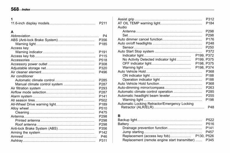
(570,1)
北米Model "A2600BE-B" EDITED: 2020/ 10/ 1
111.6-inch display models.......................................... P211
AAbbreviation .............................................................. P4ABS (Anti-lock Brake System) ................................. P356
Warning light ..................................................... P185Access key
Warning indicator............................................... P191Access key fob ....................................................... P115Accessories .......................................................... P518Accessory power outlet .......................................... P308Adjustable storage net............................................ P320Air cleaner element ................................................ P496Air conditioner
Automatic climate control .................................... P285Manual climate control system ............................ P287
Air filtration system ................................................ P293Airflow mode selection............................................ P287Alarm system ........................................................ P141All season tires...................................................... P502All-Wheel Drive warning light................................... P189Alloy wheel ........................................................... P510
Cleaning ........................................................... P475Antenna................................................................ P298
Printed antenna ................................................. P298Roof antenna .................................................... P298
Anti-lock Brake System (ABS) ................................. P356Arming the system ................................................. P142Armrest .................................................................. P46Ashtray.................................................................. P311
Assist grip ............................................................. P312AT OIL TEMP warning light...................................... P184Audio
Antenna ............................................................ P298Set ................................................................... P298
Auto dimmer cancel function.................................... P176Auto on/off headlights ............................................. P248
Sensor.............................................................. P250Auto Start Stop system ........................................... P372
Indicator light ........................................... P199, P372No Activity Detected indicator light ............. P199, P375OFF indicator light.................................... P198, P375Warning light ........................................... P198, P374
Auto Vehicle Hold................................................... P368ON indicator light ............................................... P188Operation indicator light ...................................... P188
Auto Vehicle Hold function....................................... P368Auto-dimming mirror/compass.................................. P263Automatic climate control operation .......................... P285Automatic headlight beam leveler ............................. P255
Warning light ..................................................... P198Automatic Locking Retractor/Emergency LockingRetractor (ALR/ELR).............................................. P48
BBackup light........................................................... P522Battery .................................................................. P516
Drainage prevention function ............................... P141Jump starting..................................................... P457Replacement (access key fob)................... P130, P526Replacement (remote engine start transmitter) ...... P345
Index568
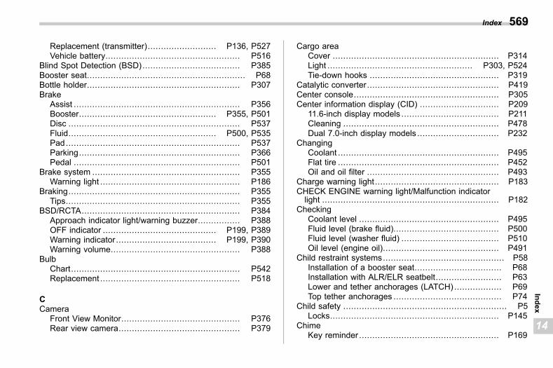
(571,1)
北米Model "A2600BE-B" EDITED: 2020/ 10/ 1
Replacement (transmitter).......................... P136, P527Vehicle battery................................................... P516
Blind Spot Detection (BSD)..................................... P385Booster seat............................................................ P68Bottle holder.......................................................... P307Brake
Assist ............................................................... P356Booster.................................................... P355, P501Disc ................................................................. P537Fluid........................................................ P500, P535Pad.................................................................. P537Parking............................................................. P366Pedal ............................................................... P501
Brake system ........................................................ P355Warning light ..................................................... P186
Braking................................................................. P355Tips.................................................................. P355
BSD/RCTA............................................................ P384Approach indicator light/warning buzzer................ P388OFF indicator ........................................... P199, P389Warning indicator...................................... P199, P390Warning volume................................................. P388
BulbChart................................................................ P542Replacement ..................................................... P518
CCamera
Front View Monitor............................................. P376Rear view camera.............................................. P379
Cargo areaCover ............................................................... P314Light ....................................................... P303, P524Tie-down hooks ................................................. P319
Catalytic converter.................................................. P419Center console....................................................... P305Center information display (CID) .............................. P209
11.6-inch display models ..................................... P211Cleaning ........................................................... P478Dual 7.0-inch display models ............................... P232
ChangingCoolant ............................................................. P495Flat tire ............................................................. P452Oil and oil filter .................................................. P493
Charge warning light............................................... P183CHECK ENGINE warning light/Malfunction indicatorlight ................................................................... P182
CheckingCoolant level ..................................................... P495Fluid level (brake fluid)........................................ P500Fluid level (washer fluid) ..................................... P510Oil level (engine oil)............................................ P491
Child restraint systems.............................................. P58Installation of a booster seat................................. P68Installation with ALR/ELR seatbelt......................... P63Lower and tether anchorages (LATCH) .................. P69Top tether anchorages ......................................... P74
Child safety .............................................................. P5Locks................................................................ P145
ChimeKey reminder ..................................................... P169
Index 569
14
Index
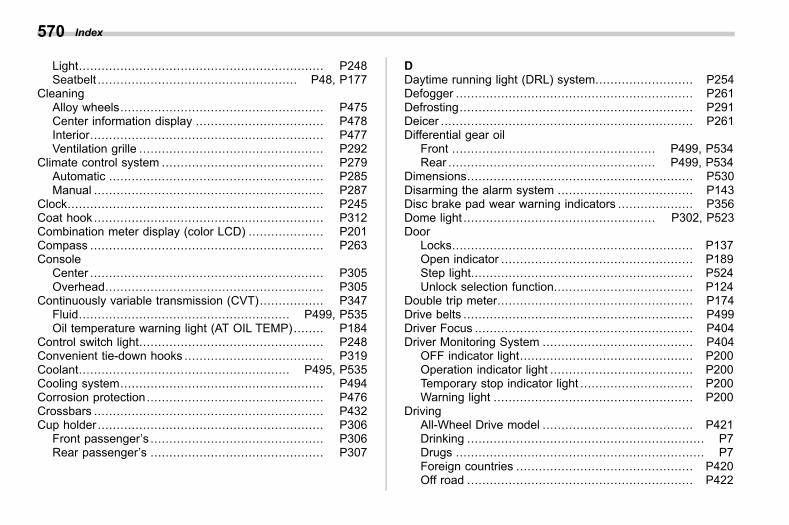
(572,1)
北米Model "A2600BE-B" EDITED: 2020/ 10/ 1
Light................................................................. P248Seatbelt ..................................................... P48, P177
CleaningAlloy wheels...................................................... P475Center information display .................................. P478Interior.............................................................. P477Ventilation grille ................................................. P292
Climate control system ........................................... P279Automatic ......................................................... P285Manual ............................................................. P287
Clock.................................................................... P245Coat hook ............................................................. P312Combination meter display (color LCD) .................... P201Compass .............................................................. P263Console
Center .............................................................. P305Overhead.......................................................... P305
Continuously variable transmission (CVT)................. P347Fluid........................................................ P499, P535Oil temperature warning light (AT OIL TEMP)........ P184
Control switch light................................................. P248Convenient tie-down hooks ..................................... P319Coolant........................................................ P495, P535Cooling system...................................................... P494Corrosion protection............................................... P476Crossbars ............................................................. P432Cup holder ............................................................ P306
Front passenger’s .............................................. P306Rear passenger’s .............................................. P307
DDaytime running light (DRL) system.......................... P254Defogger ............................................................... P261Defrosting.............................................................. P291Deicer ................................................................... P261Differential gear oil
Front ...................................................... P499, P534Rear ....................................................... P499, P534
Dimensions............................................................ P530Disarming the alarm system .................................... P143Disc brake pad wear warning indicators .................... P356Dome light ................................................... P302, P523Door
Locks................................................................ P137Open indicator ................................................... P189Step light........................................................... P524Unlock selection function..................................... P124
Double trip meter.................................................... P174Drive belts ............................................................. P499Driver Focus .......................................................... P404Driver Monitoring System ........................................ P404
OFF indicator light.............................................. P200Operation indicator light ...................................... P200Temporary stop indicator light .............................. P200Warning light ..................................................... P200
DrivingAll-Wheel Drive model ........................................ P421Drinking ............................................................... P7Drugs .................................................................. P7Foreign countries ............................................... P420Off road ............................................................ P422
Index570
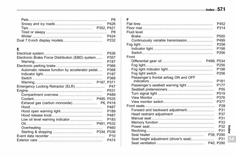
(573,1)
北米Model "A2600BE-B" EDITED: 2020/ 10/ 1
Pets ..................................................................... P8Snowy and icy roads.......................................... P426Tips......................................................... P352, P421Tired or sleepy ...................................................... P8Winter .............................................................. P424
Dual 7.0-inch display models................................... P232
EElectrical system.................................................... P536Electronic Brake Force Distribution (EBD) system...... P357
Warning............................................................ P187Electronic parking brake ......................................... P366
Automatic release function by accelerator pedal .... P368Indicator light..................................................... P187Switch .............................................................. P366Warning................................................... P187, P371
Emergency Locking Retractor (ELR) .......................... P47Engine.................................................................. P531
Compartment overview....................................... P489Coolant.................................................... P495, P535Exhaust gas (carbon monoxide) ..................... P6, P418Hood ................................................................ P487Hood open warning light ..................................... P189Hood release knob............................................. P487Low oil level warning indicator............................. P183Oil........................................................... P491, P532Overheating ...................................................... P460Starting & stopping ................................... P334, P336
Event data recorder ................................................. P10Exterior care ......................................................... P474
FFlat tires ................................................................ P452Floor mat............................................................... P314Fluid level
Brake................................................................ P500Continuously variable transmission....................... P499
Fog light ................................................................ P256Indicator light ..................................................... P198Switch............................................................... P256
FrontDifferential gear oil ................................... P499, P534Fog light............................................................ P256Fog light indicator light........................................ P198Fog light switch.................................................. P256Passenger’s frontal airbag ON and OFFindicators ........................................................ P181
Passenger’s seatbelt warning light ....................... P177Seatbelt pretensioners ......................................... P55Turn signal light ................................................. P519View Monitor ..................................................... P376View monitor switch............................................ P377
Front seats .............................................................. P28Forward and backward adjustment........................ P31Head restraint adjustment .................................... P37Manual seat ....................................................... P31Memory function ................................................. P33Power seat ......................................................... P32Reclining............................................................ P31Seat heater ............................................... P39, P290Seat height adjustment (driver's seat) .................... P31Seat ventilation .......................................... P40, P290
Index 571
14
Index
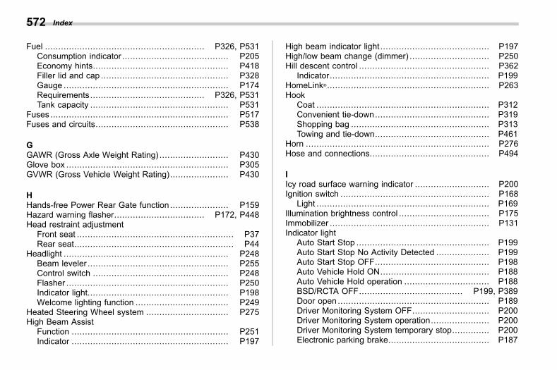
(574,1)
北米Model "A2600BE-B" EDITED: 2020/ 10/ 1
Fuel ............................................................ P326, P531Consumption indicator ........................................ P205Economy hints................................................... P418Filler lid and cap ................................................ P328Gauge .............................................................. P174Requirements........................................... P326, P531Tank capacity .................................................... P531
Fuses ................................................................... P517Fuses and circuits.................................................. P538
GGAWR (Gross Axle Weight Rating) .......................... P430Glove box ............................................................. P305GVWR (Gross Vehicle Weight Rating)...................... P430
HHands-free Power Rear Gate function ...................... P159Hazard warning flasher.................................. P172, P448Head restraint adjustment
Front seat ........................................................... P37Rear seat............................................................ P44
Headlight .............................................................. P248Beam leveler ..................................................... P255Control switch ................................................... P248Flasher ............................................................. P250Indicator light..................................................... P198Welcome lighting function ................................... P249
Heated Steering Wheel system ............................... P275High Beam Assist
Function ........................................................... P251Indicator ........................................................... P197
High beam indicator light ......................................... P197High/low beam change (dimmer) .............................. P250Hill descent control ................................................. P362
Indicator............................................................ P199HomeLink®............................................................. P263Hook
Coat ................................................................. P312Convenient tie-down........................................... P319Shopping bag .................................................... P313Towing and tie-down........................................... P461
Horn ..................................................................... P276Hose and connections............................................. P494
IIcy road surface warning indicator ............................ P200Ignition switch ........................................................ P168
Light ................................................................. P169Illumination brightness control .................................. P175Immobilizer ............................................................ P131Indicator light
Auto Start Stop .................................................. P199Auto Start Stop No Activity Detected .................... P199Auto Start Stop OFF........................................... P198Auto Vehicle Hold ON......................................... P188Auto Vehicle Hold operation ................................ P188BSD/RCTA OFF....................................... P199, P389Door open ......................................................... P189Driver Monitoring System OFF............................. P200Driver Monitoring System operation...................... P200Driver Monitoring System temporary stop.............. P200Electronic parking brake...................................... P187
Index572
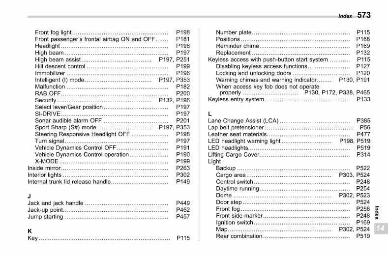
(575,1)
北米Model "A2600BE-B" EDITED: 2020/ 10/ 1
Front fog light .................................................... P198Front passenger’s frontal airbag ON and OFF....... P181Headlight .......................................................... P198High beam ........................................................ P197High beam assist ...................................... P197, P251Hill descent control ............................................ P199Immobilizer ....................................................... P196Intelligent (I) mode .................................... P197, P353Malfunction ....................................................... P182RAB OFF.......................................................... P200Security ................................................... P132, P196Select lever/Gear position ................................... P197SI-DRIVE.......................................................... P197Sonar audible alarm OFF ................................... P201Sport Sharp (S#) mode ............................. P197, P353Steering Responsive Headlight OFF .................... P198Turn signal........................................................ P197Vehicle Dynamics Control OFF............................ P191Vehicle Dynamics Control operation..................... P190X-MODE........................................................... P199
Inside mirror.......................................................... P263Interior lights ......................................................... P302Internal trunk lid release handle............................... P149
JJack and jack handle ............................................. P449Jack-up point......................................................... P452Jump starting ........................................................ P457
KKey ....................................................................... P115
Number plate..................................................... P115Positions ........................................................... P168Reminder chime................................................. P169Replacement ..................................................... P132
Keyless access with push-button start system ........... P115Disabling keyless access functions....................... P127Locking and unlocking doors ............................... P120Warning chimes and warning indicator........ P130, P191When access key fob does not operateproperly .............................. P130, P172, P338, P465
Keyless entry system .............................................. P133
LLane Change Assist (LCA) ...................................... P385Lap belt pretensioner ................................................ P56Leather seat materials............................................. P477LED headlight warning light ........................... P198, P519LED headlights....................................................... P519Lifting Cargo Cover................................................. P314Light
Backup ............................................................. P522Cargo area.............................................. P303, P524Control switch.................................................... P248Daytime running................................................. P254Dome ..................................................... P302, P523Door step .......................................................... P524Front fog ........................................................... P256Front side marker............................................... P248Ignition switch.................................................... P169Map........................................................ P302, P524Rear combination ............................................... P519
Index 573
14
Index
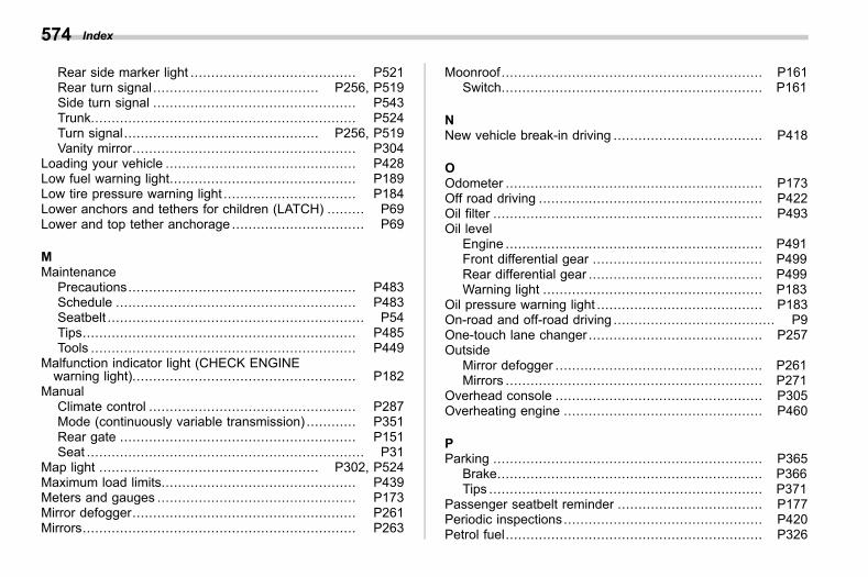
(576,1)
北米Model "A2600BE-B" EDITED: 2020/ 10/ 1
Rear side marker light ........................................ P521Rear turn signal ........................................ P256, P519Side turn signal ................................................. P543Trunk................................................................ P524Turn signal............................................... P256, P519Vanity mirror...................................................... P304
Loading your vehicle .............................................. P428Low fuel warning light............................................. P189Low tire pressure warning light ................................ P184Lower anchors and tethers for children (LATCH) ......... P69Lower and top tether anchorage ................................ P69
MMaintenance
Precautions....................................................... P483Schedule .......................................................... P483Seatbelt .............................................................. P54Tips.................................................................. P485Tools ................................................................ P449
Malfunction indicator light (CHECK ENGINEwarning light)...................................................... P182
ManualClimate control .................................................. P287Mode (continuously variable transmission) ............ P351Rear gate ......................................................... P151Seat ................................................................... P31
Map light ..................................................... P302, P524Maximum load limits............................................... P439Meters and gauges ................................................ P173Mirror defogger...................................................... P261Mirrors.................................................................. P263
Moonroof............................................................... P161Switch............................................................... P161
NNew vehicle break-in driving .................................... P418
OOdometer .............................................................. P173Off road driving ...................................................... P422Oil filter ................................................................. P493Oil level
Engine .............................................................. P491Front differential gear ......................................... P499Rear differential gear .......................................... P499Warning light ..................................................... P183
Oil pressure warning light ........................................ P183On-road and off-road driving ....................................... P9One-touch lane changer .......................................... P257Outside
Mirror defogger .................................................. P261Mirrors .............................................................. P271
Overhead console .................................................. P305Overheating engine ................................................ P460
PParking ................................................................. P365
Brake................................................................ P366Tips .................................................................. P371
Passenger seatbelt reminder ................................... P177Periodic inspections................................................ P420Petrol fuel.............................................................. P326
Index574
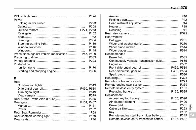
(577,1)
北米Model "A2600BE-B" EDITED: 2020/ 10/ 1
PIN code Access ................................................... P124Power
Folding mirror switch .......................................... P273Outlets ............................................................. P308Outside mirrors......................................... P271, P273Rear gate ......................................................... P152Seat ................................................................... P32Steering............................................................ P354Steering warning light......................................... P189Window switches ............................................... P146Windows........................................................... P145
Precautions against vehicle modification............ P57, P109Preparing to drive .................................................. P333Printed antenna ..................................................... P298Push-button
Ignition switch ................................................... P170Starting and stopping engine............................... P336
RRear
Combination lights ............................................. P519Differential gear oil .................................... P499, P534Turn signal light ................................................. P519View camera ..................................................... P379
Rear Cross Traffic Alert (RCTA)............................... P385Rear gate .................................................... P151, P467
Manual ............................................................. P151Power............................................................... P152
Rear Seat Reminder ................................................ P58Rear seatbelt warning light...................................... P179Rear seats .............................................................. P40
Armrest.............................................................. P46Folding down...................................................... P42Head restraint adjustment .................................... P44Heater ............................................................... P39Reclining............................................................ P41
Rear view camera .................................................. P379Rear window
Defogger ........................................................... P261Wiper and washer switch .................................... P260Wiper blade rubber............................................. P514Wiper blades ..................................................... P514
RecommendedBrake fluid......................................................... P535Continuously variable transmission fluid................ P535Engine oil .......................................................... P532Front differential gear oil ........................... P499, P534Rear differential gear oil ............................ P499, P534Spark plugs ....................................................... P536
Refueling............................................................... P328Remote control mirror switch ................................... P271Remote engine start system .................................... P339Remote keyless entry system .................................. P133
Replacing battery ..................................... P136, P525Replacement
Access key fob battery.............................. P130, P526Air cleaner element ............................................ P496Brake pad ......................................................... P501Cabin air filter .................................................... P293Key .................................................................. P132Remote engine start transmitter battery ................ P345Remote keyless entry transmitter battery .... P136, P527
Index 575
14
Index
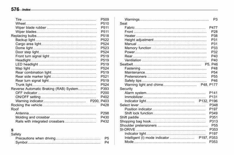
(578,1)
北米Model "A2600BE-B" EDITED: 2020/ 10/ 1
Tire .................................................................. P509Wheel............................................................... P510Wiper blade rubber ............................................. P511Wiper blades...................................................... P511
Replacing bulbs..................................................... P518Backup light ...................................................... P522Cargo area light................................................. P524Dome light ........................................................ P523Door step light................................................... P524Front turn signal light ......................................... P519Headlight .......................................................... P519LED headlight ................................................... P519Map light .......................................................... P524Rear combination light........................................ P519Rear side marker light ........................................ P521Rear turn signal light .......................................... P519Trunk light......................................................... P524
Reverse Automatic Braking (RAB) System................ P393OFF indicator .................................................... P200ON/OFF setting ................................................. P402Warning indicator...................................... P200, P403
Rocking the vehicle................................................ P428Roof
Antenna............................................................ P298Molding and crossbar ......................................... P430Rails with integrated crossbars ............................ P432
SSafety
Precautions when driving........................................ P5Symbol ................................................................. P4
Warnings.............................................................. P3Seat
Fabric ............................................................... P477Front ................................................................. P28Heater ............................................................... P38Height adjustment ............................................... P31Manual .............................................................. P31Memory function ................................................. P33Power ................................................................ P32Rear .................................................................. P40Ventilation .......................................................... P40
Seatbelt............................................................. P5, P46Fastening ........................................................... P48Maintenance....................................................... P54Pretensioners ..................................................... P55Safety tips .......................................................... P46Warning light and chime.............................. P48, P177
SecurityAlarm system..................................................... P141Immobilizer........................................................ P131Indicator light ........................................... P132, P196
Select lever ........................................................... P348Position indicator................................................ P197Shift lock function............................................... P349
Shift paddle ........................................................... P351Shopping bag hook................................................. P313Shoulder pretensioners ............................................. P55SI-DRIVE .............................................................. P353
Indicator light ..................................................... P197Intelligent (I) mode indicator ...................... P197, P353Mode ................................................................ P353
Index576
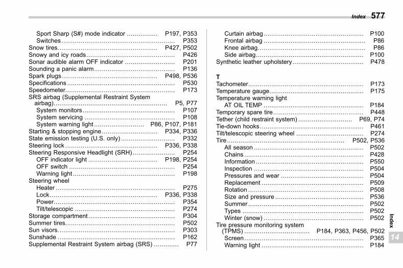
(579,1)
北米Model "A2600BE-B" EDITED: 2020/ 10/ 1
Sport Sharp (S#) mode indicator ................ P197, P353Switches........................................................... P353
Snow tires.................................................... P427, P502Snowy and icy roads.............................................. P426Sonar audible alarm OFF indicator .......................... P201Sounding a panic alarm.......................................... P136Spark plugs.................................................. P498, P536Specifications ........................................................ P530Speedometer......................................................... P173SRS airbag (Supplemental Restraint Systemairbag)........................................................... P5, P77System monitors................................................ P107System servicing ............................................... P108System warning light .......................... P86, P107, P181
Starting & stopping engine............................. P334, P336State emission testing (U.S. only) ............................ P332Steering lock ................................................ P336, P338Steering Responsive Headlight (SRH) ...................... P254
OFF indicator light .................................... P198, P254OFF switch ....................................................... P254Warning light ..................................................... P198
Steering wheelHeater .............................................................. P275Lock........................................................ P336, P338Power............................................................... P354Tilt/telescopic .................................................... P274
Storage compartment ............................................. P304Summer tires......................................................... P502Sun visors............................................................. P303Sunshade ............................................................. P162Supplemental Restraint System airbag (SRS) ............. P77
Curtain airbag.................................................... P100Frontal airbag ..................................................... P86Knee airbag........................................................ P86Side airbag........................................................ P100
Synthetic leather upholstery..................................... P478
TTachometer............................................................ P173Temperature gauge................................................. P175Temperature warning light
AT OIL TEMP .................................................... P184Temporary spare tire............................................... P448Tether (child restraint system) ............................ P69, P74Tie-down hooks...................................................... P461Tilt/telescopic steering wheel ................................... P274Tire............................................................. P502, P536
All season ......................................................... P502Chains .............................................................. P428Information ........................................................ P550Inspection ......................................................... P504Pressures and wear ........................................... P504Replacement ..................................................... P509Rotation ............................................................ P508Size and pressure .............................................. P536Summer ............................................................ P502Types ............................................................... P502Winter (snow) .................................................... P502
Tire pressure monitoring system(TPMS) .................................. P184, P363, P456, P502Screen.............................................................. P365Warning light ..................................................... P184
Index 577
14
Index
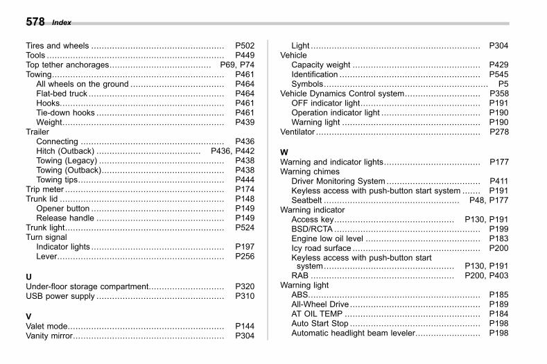
(580,1)
北米Model "A2600BE-B" EDITED: 2020/ 10/ 1
Tires and wheels ................................................... P502Tools .................................................................... P449Top tether anchorages....................................... P69, P74Towing.................................................................. P461
All wheels on the ground .................................... P464Flat-bed truck .................................................... P464Hooks............................................................... P461Tie-down hooks ................................................. P461Weight.............................................................. P439
TrailerConnecting ....................................................... P436Hitch (Outback) ........................................ P436, P442Towing (Legacy) ................................................ P438Towing (Outback)............................................... P438Towing tips........................................................ P444
Trip meter ............................................................. P174Trunk lid ............................................................... P148
Opener button ................................................... P149Release handle ................................................. P149
Trunk light............................................................. P524Turn signal
Indicator lights ................................................... P197Lever................................................................ P256
UUnder-floor storage compartment............................. P320USB power supply ................................................. P310
VValet mode............................................................ P144Vanity mirror.......................................................... P304
Light ................................................................. P304Vehicle
Capacity weight ................................................. P429Identification ...................................................... P545Symbols............................................................... P5
Vehicle Dynamics Control system............................. P358OFF indicator light.............................................. P191Operation indicator light ...................................... P190Warning light ..................................................... P190
Ventilator ............................................................... P278
WWarning and indicator lights..................................... P177Warning chimes
Driver Monitoring System .................................... P411Keyless access with push-button start system ....... P191Seatbelt .................................................... P48, P177
Warning indicatorAccess key.............................................. P130, P191BSD/RCTA ........................................................ P199Engine low oil level ............................................ P183Icy road surface ................................................. P200Keyless access with push-button startsystem.................................................. P130, P191
RAB ....................................................... P200, P403Warning light
ABS.................................................................. P185All-Wheel Drive .................................................. P189AT OIL TEMP .................................................... P184Auto Start Stop .................................................. P198Automatic headlight beam leveler......................... P198
Index578
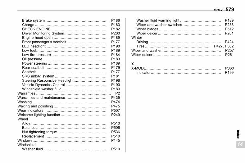
(581,1)
北米Model "A2600BE-B" EDITED: 2020/ 10/ 1
Brake system .................................................... P186Charge ............................................................. P183CHECK ENGINE ............................................... P182Driver Monitoring System.................................... P200Engine hood open ............................................. P189Front passenger’s seatbelt .................................. P177LED headlight ................................................... P198Low fuel............................................................ P189Low tire pressure ............................................... P184Oil pressure ...................................................... P183Power steering .................................................. P189Rear seatbelt..................................................... P179Seatbelt ............................................................ P177SRS airbag system ............................................ P181Steering Responsive Headlight............................ P198Vehicle Dynamics Control ................................... P190Windshield washer fluid ...................................... P189
Warranties ................................................................ P2Warranties and maintenance................................... P439Washing ............................................................... P474Waxing and polishing ............................................. P475Wear indicators ..................................................... P507Welcome lighting function ....................................... P249Wheel
Alloy................................................................. P510Balance ............................................................ P506Nut tightening torque.......................................... P536Replacement ..................................................... P510
Windows............................................................... P145Windshield
Washer fluid...................................................... P510
Washer fluid warning light ................................... P189Wiper and washer switches................................. P258Wiper blades ..................................................... P512Wiper deicer ...................................................... P261
WinterDriving .............................................................. P424Tires ....................................................... P427, P502
Wiper and washer .................................................. P257Wiper deicer .......................................................... P261
XX-MODE................................................................ P360
Indicator............................................................ P199
Index 579
14
Index

(2,1)
Model "ALL_MODEL_MEMO" EDITED: 2017/ 11/ 6Left Page
— — — — — — — — — — — — — — — — — — — — — — — — — — — — — — — — — — — — — — — —
— — — — — — — — — — — — — — — — — — — — — — — — — — — — — — — — — — — — — — — —
— — — — — — — — — — — — — — — — — — — — — — — — — — — — — — — — — — — — — — — —
— — — — — — — — — — — — — — — — — — — — — — — — — — — — — — — — — — — — — — — —
— — — — — — — — — — — — — — — — — — — — — — — — — — — — — — — — — — — — — — — —
— — — — — — — — — — — — — — — — — — — — — — — — — — — — — — — — — — — — — — — —
— — — — — — — — — — — — — — — — — — — — — — — — — — — — — — — — — — — — — — — —
— — — — — — — — — — — — — — — — — — — — — — — — — — — — — — — — — — — — — — — —
— — — — — — — — — — — — — — — — — — — — — — — — — — — — — — — — — — — — — — — —
— — — — — — — — — — — — — — — — — — — — — — — — — — — — — — — — — — — — — — — —
— — — — — — — — — — — — — — — — — — — — — — — — — — — — — — — — — — — — — — — —
— — — — — — — — — — — — — — — — — — — — — — — — — — — — — — — — — — — — — — — —
— — — — — — — — — — — — — — — — — — — — — — — — — — — — — — — — — — — — — — — —

(1,1)
Model "ALL_MODEL_MEMO" EDITED: 2017/ 11/ 6Right Page
— — — — — — — — — — — — — — — — — — — — — — — — — — — — — — — — — — — — — — — —
— — — — — — — — — — — — — — — — — — — — — — — — — — — — — — — — — — — — — — — —
— — — — — — — — — — — — — — — — — — — — — — — — — — — — — — — — — — — — — — — —
— — — — — — — — — — — — — — — — — — — — — — — — — — — — — — — — — — — — — — — —
— — — — — — — — — — — — — — — — — — — — — — — — — — — — — — — — — — — — — — — —
— — — — — — — — — — — — — — — — — — — — — — — — — — — — — — — — — — — — — — — —
— — — — — — — — — — — — — — — — — — — — — — — — — — — — — — — — — — — — — — — —
— — — — — — — — — — — — — — — — — — — — — — — — — — — — — — — — — — — — — — — —
— — — — — — — — — — — — — — — — — — — — — — — — — — — — — — — — — — — — — — — —
— — — — — — — — — — — — — — — — — — — — — — — — — — — — — — — — — — — — — — — —
— — — — — — — — — — — — — — — — — — — — — — — — — — — — — — — — — — — — — — — —
— — — — — — — — — — — — — — — — — — — — — — — — — — — — — — — — — — — — — — — —
— — — — — — — — — — — — — — — — — — — — — — — — — — — — — — — — — — — — — — — —
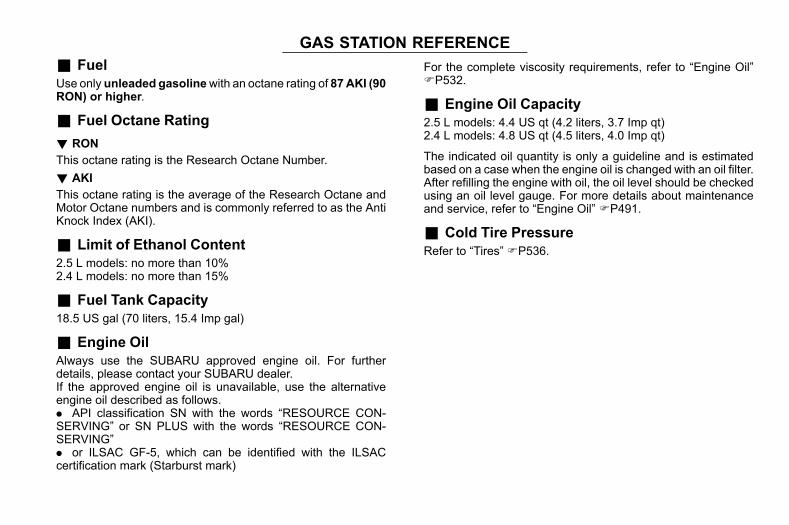
(2,1)
北米Model "A2600BE-B" EDITED: 2020/ 9/ 16
GAS STATION REFERENCES99AA
& FuelS99AA01
Use only unleaded gasolinewith an octane rating of 87AKI (90RON) or higher.
& Fuel Octane RatingS99AA02
! RONS99AA0201
This octane rating is the Research Octane Number.! AKI
S99AA0202This octane rating is the average of the Research Octane andMotor Octane numbers and is commonly referred to as the AntiKnock Index (AKI).
& Limit of Ethanol ContentS99AA09
2.5 L models: no more than 10%2.4 L models: no more than 15%
& Fuel Tank CapacityS99AA03
18.5 US gal (70 liters, 15.4 Imp gal)
& Engine OilS99AA04
Always use the SUBARU approved engine oil. For furtherdetails, please contact your SUBARU dealer.If the approved engine oil is unavailable, use the alternativeengine oil described as follows.. API classification SN with the words “RESOURCE CON-SERVING” or SN PLUS with the words “RESOURCE CON-SERVING”. or ILSAC GF-5, which can be identified with the ILSACcertification mark (Starburst mark)
For the complete viscosity requirements, refer to “Engine Oil”FP532.
& Engine Oil CapacityS99AA05
2.5 L models: 4.4 US qt (4.2 liters, 3.7 Imp qt)2.4 L models: 4.8 US qt (4.5 liters, 4.0 Imp qt)
The indicated oil quantity is only a guideline and is estimatedbased on a case when the engine oil is changed with an oil filter.After refilling the engine with oil, the oil level should be checkedusing an oil level gauge. For more details about maintenanceand service, refer to “Engine Oil” FP491.
& Cold Tire PressureS99AA06
Refer to “Tires” FP536.


