Embed Size (px)
Citation preview
OOWWNNEERR''SS MMAANNUUAALLOOppeerraattiioonnMMaaiinntteennaanncceeSSppeecciiffiiccaattiioonnss
All information in this Owner's Manual is current at the time of pub-lication. However, HYUNDAI reserves the right to make changes atany time so that our policy of continual product improvement may becarried out.
This manual applies to all HYUNDAI models and includes descrip-tions and explanations of optional as well as standard equipment.As a result, you may find material in this manual that does not applyto your specific vehicle.
F2
Your HYUNDAI should not be modified in any way.Such modifications may adversely affect the per-formance, safety or durability of your HYUNDAIand may, in addition, violate conditions of the limit-ed warranties covering the vehicle. Certain modifi-cations may also be in violation of regulationsestablished by the U.S. Department ofTransportation and other federal or state agencies.
Your vehicle is equipped with electronic fuel injec-tion and other electronic components. It is possiblefor an improperly installed/adjusted two-way radioor cellular telephone to adversely affect electronicsystems. For this reason, we recommend that youcarefully follow the radio manufacturer's instruc-tions or consult your HYUNDAI dealer for precau-tionary measures or special instructions if youchoose to install one of these devices.
CAUTION: MODIFICATIONS TOYOUR HYUNDAI
TWO-WAY RADIO OR CELLULARTELEPHONE INSTALLATION
This manual includes information titled as DAN-GER, WARNING, CAUTION and NOTICE.These titles indicate the following:
SAFETY AND VEHICLE DAMAGEWARNING
DANGER indicates a hazardous situationwhich, if not avoided, will result in death orserious injury.
DANGER
WARNING indicates a hazardous situationwhich, if not avoided, could result in deathor serious injury.
CAUTION indicates a hazardous situationwhich, if not avoided, could result in minor ormoderate injury.
CAUTION
NOTICE indicates a situation which, if notavoided, could result in vehicle damage.
NOTICE
WARNING

F3
Your Hyundai vehicle may be equipped with technologies and services that use information collected, generated, recorded or stored by the vehicle. Hyundai has created a Vehicle Owner Privacy Policy to explainhow these technologies and services collect use and share this information.
You may read our Vehicle Owner Privacy Policy on the Hyundaiusa.com website at:https://www.hyundaiusa.com/owner-privacy-policy.aspxIf you would like to receive a hard copy of our Vehicle Owner Privacy Policy, please contact our CustomerConnect Center at:
Hyundai Customer CareP.O. Box 20850Fountain Valley, CA [email protected]
Hyundai's Customer Connect Center representatives are available Monday through Friday, between the hours of 5:00 AM and 7:00 PM PST and Saturday and Sunday between 6:30 AM and 3:00 PMPST (English).For Customer Connect Center assistance in Spanish or Korean, representatives are available Mondaythrough Friday between 6:30 AM and 3:00 PM PST.
HYUNDAI VEHICLE OWNER PRIVACY POLICY
F4
INTRODUCTION
Congratulations, and thank you for choosing HYUNDAI. We are pleased to welcome you to the growing number of dis-cerning people who drive HYUNDAIs. We are very proud of the advanced engineering and high-quality construction ofeach HYUNDAI we build.Your Owner's Manual will introduce you to the features and operation of your new HYUNDAI. To become familiar withyour new HYUNDAI, so that you can fully enjoy it, read this Owner's Manual carefully before driving your new vehicle.This manual contains important safety information and instructions intended to familiarize you with your vehicle's con-trols and safety features so you can safely operate your vehicle.This manual also contains information on maintenance designed to enhance safe operation of the vehicle. It is recom-mended that all service and maintenance on your car be performed by an authorized HYUNDAI dealer. HYUNDAI deal-ers are prepared to provide high-quality service, maintenance and any other assistance that may be required.This Owner's Manual should be considered a permanent part of your vehicle, and should be kept in the vehicle so youcan refer to it at any time. The manual should stay with the vehicle if you sell it to provide the next owner with impor-tant operating, safety and maintenance information.
HYUNDAI MOTOR AMERICA
Copyright 2020 HYUNDAI Motor America. All rights reserved. No part of this publication may be reproduced, storedin any retrieval system or transmitted in any form or by any means without the prior written permission of HYUNDAIMotor America.
Severe engine and transmission damage may result from the use of poor quality fuels and lubricants thatdo not meet HYUNDAI specifications. You must always use high quality fuels and lubricants that meet thespecifications listed on Page 8-7 in the Vehicle Specifications section of the Owner's Manual.
CAUTION
F5
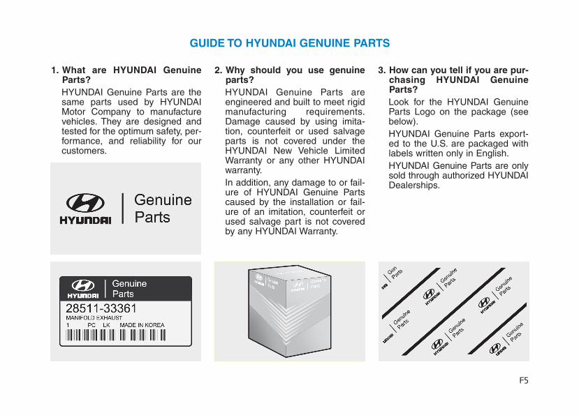
1. What are HYUNDAI GenuineParts?HYUNDAI Genuine Parts are thesame parts used by HYUNDAIMotor Company to manufacturevehicles. They are designed andtested for the optimum safety, per-formance, and reliability for ourcustomers.
2. Why should you use genuineparts?HYUNDAI Genuine Parts areengineered and built to meet rigidmanufacturing requirements.Damage caused by using imita-tion, counterfeit or used salvageparts is not covered under theHYUNDAI New Vehicle LimitedWarranty or any other HYUNDAIwarranty.In addition, any damage to or fail-ure of HYUNDAI Genuine Partscaused by the installation or fail-ure of an imitation, counterfeit orused salvage part is not coveredby any HYUNDAI Warranty.
3. How can you tell if you are pur-chasing HYUNDAI GenuineParts? Look for the HYUNDAI GenuineParts Logo on the package (seebelow).HYUNDAI Genuine Parts export-ed to the U.S. are packaged withlabels written only in English.HYUNDAI Genuine Parts are onlysold through authorized HYUNDAIDealerships.
GUIDE TO HYUNDAI GENUINE PARTS

F6
Introduction
We want to help you get the greatestpossible driving pleasure from yourvehicle. Your Owner's Manual canassist you in many ways. To gain anoverview of the contents of yourOwner's Manual, use the Table ofContents in the front of the manual.The first page of each Chapterincludes a detailed Table of Contentsof the topics in that Chapter.To quickly locate information aboutyour vehicle, use the Index in theback of the manual. It is an alphabet-ical list of what is in this manual andthe page number where it can befound.For your convenience, we haveincorporated tabs on the right-handpage edges. These tabs are codedwith the Chapter titles to assist youwith navigating through the manual.
Your safety, and the safety of others,is very important. This Owner'sManual provides you with many safe-ty precautions and operating proce-dures. This information alerts you topotential hazards that may hurt youor others, as well as damage to yourvehicle.Safety messages found on vehiclelabels and in this manual describethese hazards and what to do toavoid or reduce the risks.Warnings and instructions containedin this manual are for your safety.Failure to follow safety warnings andinstructions can lead to serious injuryor death.
Throughout this manual DANGER,WARNING, CAUTION, NOTICE andthe SAFETY ALERT SYMBOL willbe used.
This is the safety alert sym-bol. It is used to alert you topotential physical injury haz-ards. Obey all safety mes-sages that follow this symbolto avoid possible injury ordeath. The safety alert sym-bol precedes the signal wordsDANGER, WARNING andCAUTION.
HHOOWW TTOO UUSSEE TTHHIISS MMAANNUUAALL
DANGER indicates a hazardoussituation which, if not avoided,will result in death or seriousinjury.
DANGER
WARNING indicates a hazardoussituation which, if not avoided,could result in death or seriousinjury.
WARNING
SSAAFFEETTYY MMEESSSSAAGGEESS
F7
Introduction
FFUUEELL RREEQQUUIIRREEMMEENNTTSS
NOTICE indicates a situationwhich, if not avoided, could resultin vehicle damage.
Your new vehicle is designed toobtain maximum performance withUNLEADED FUEL, as well as mini-mize exhaust emissions and sparkplug fouling.
Your new vehicle is designed to useonly unleaded fuel having an octanenumber ((R+M)/2) of 87 (ResearchOctane Number 91) or higher. (Do notuse methanol blended fuels)
To prevent damage to the engineand engine components, neveradd any fuel system cleaningagents to the fuel tank other thanwhat has been specified.Consult an authorized HYUNDAIdealer for additional information.
Gasoline containing alcohol ormethanolGasohol, a mixture of gasoline andethanol (also known as grain alco-hol) are being marketed along with orinstead of leaded or unleaded gaso-line. For example, "E15" is a gasoholcomprised of 15% ethanol and 85%gasoline.Do not use gasohol containing morethan 15% ethanol, and do not usegasoline or gasohol containing anymethanol. Either of these fuels maycause drivability problems and dam-age to the fuel system, engine con-trol system and emission control sys-tem.Discontinue using gasohol of anykind if drivability problems occur.
NOTICE
NOTICE
CAUTION indicates a hazardoussituation which, if not avoided,could result in minor or moder-ate injury.
CAUTION
• Do not "top off" after the noz-zle automatically shuts offwhen refueling.
• Always check that the fuel capis installed securely to pre-vent fuel spillage in the eventof an accident.
WARNING
F8
Introduction
"E85" fuel is an alternative fuel com-prised of 85 percent ethanol and 15percent gasoline, and is manufac-tured exclusively for use in FlexibleFuel Vehicles. "E85" is not compati-ble with your vehicle. Use of "E85"may result in poor engine perform-ance and damage to your vehicle'sengine and fuel system. HYUNDAIrecommends that customers do notuse fuel with an ethanol contentexceeding 15 percent.
To prevent damage to your vehicle’sengine and fuel system:• Never use gasohol which con-
tains methanol.• Never use gasohol containing
more than 15% ethanol.• Never use leaded fuel or leaded
gasohol.• Never use "E85" fuel.Your New Vehicle LimitedWarranty does not cover damageto the fuel system or any perform-ance problems caused by the useof "E85" fuel.
Using Fuel Additives (exceptDetergent Fuel Additives)Using fuel additives such as:- Silicone fuel additive- Ferrocene (iron-based) fuel additive- Other metallic-based fuel additivesmay result in cylinder misfire, pooracceleration, engine stalling, dam-age to the catalyst, or abnormal cor-rosion, and may cause damage tothe engine resulting in a reduction inthe overall life of the powertrain.- The Malfunction Indicator Lamp
(MIL) may illuminate.
Damage to the fuel system or per-formance problem caused by theuse of these fuels or fuel additivesmay not be covered by your NewVehicle Limited Warranty.
Gasoline containing MMTSome gasoline contains harmfulmanganese-based fuel additivessuch as MMT (MethylcyclopentadienylManganese Tricarbonyl).HYUNDAI does not recommend theuse of gasoline containing MMT.This type of fuel can reduce vehicleperformance and affect your emis-sion control system.The malfunction indicator lamp onthe cluster may come on.
Detergent Fuel AdditivesHYUNDAI recommends that you usegood quality gasolines treated withdetergent additives such as TOP TIERDetergent Gasoline, which help pre-vent deposit formation in the engine.These gasolines will help the enginerun cleaner and enhance performanceof the Emission Control System. Formore information on TOP TIERDetergent Gasoline, please go to thewebsite (www.toptiergas.com).
NOTICE
NOTICE
F9
Introduction
For customers who do not use TOPTier Detergent Gasoline regularly,and have problems starting or theengine does not run smoothly, deter-gent-based fuel additives that youcan purchase separately may beadded to the gasoline. If TOP TIERDetergent Gasoline is not available,one bottle of additive added to thefuel tank according to the mainte-nance schedule is recommended(refer to the Maintenance Schedulein chapter 7).Additives are available from yourauthorized HYUNDAI dealer alongwith information on how to use them.Do not mix other additives.
Operation in foreign countriesIf you are going to drive your vehiclein another country, be sure to:• Observe all regulations regarding
registration and insurance.• Determine that acceptable fuel is
available.
• This vehicle should not be modi-fied. Modification of your vehiclecould affect its performance, safetyor durability and may even violategovernmental safety and emis-sions regulations.In addition, damage or perform-ance problems resulting from anymodification may not be coveredunder warranty.
• If you use unauthorized electronicdevices, it may cause the vehicle tooperate abnormally, wire damage,battery discharge and fire. For yoursafety, do not use unauthorizedelectronic devices.
By following a few simple precautionsfor the first 600 miles (1,000 km) youmay add to the performance, econo-my and life of your vehicle.• Do not race the engine.• While driving, keep your engine
speed (rpm, or revolutions perminute) between 2,000 rpm and4,000 rpm.
• Do not maintain a single speed forlong periods of time, either fast orslow.Varying engine speed is need-ed to properly break-in the engine.
• Avoid hard stops, except in emer-gencies, to allow the brakes to seatproperly.
VVEEHHIICCLLEE BBRREEAAKK--IINN PPRROOCCEESSSSVVEEHHIICCLLEE MMOODDIIFFIICCAATTIIOONNSS
F10
Introduction
This vehicle is equipped with anevent data recorder (EDR). Themain purpose of an EDR is torecord, in certain crash or nearcrash-like situations, such as anair bag deployment or hitting aroad obstacle, data that will assistin understanding how a vehicle’ssystems performed. The EDR isdesigned to record data related tovehicle dynamics and safety sys-tems for a short period of time,typically 30 seconds or less. TheEDR in this vehicle is designed torecord such data as:• How various systems in your
vehicle were operating;• Whether or not the driver and
passenger safety belts werebuckled/fastened;
• How far (if at all) the driver wasdepressing the acceleratorand/or brake pedal; and,
• How fast the vehicle was travel-ing.
These data can help provide a bet-ter understanding of the circum-stances in which crashes andinjuries occur. NOTE: EDR dataare recorded by your vehicle onlyif a non-trivial crash situationoccurs; no data are recorded bythe EDR under normal drivingconditions and no personal data(e.g., name, gender, age, andcrash location) are recorded.However, other parties, such aslaw enforcement, could combinethe EDR data with the type of per-sonally identifying data routinelyacquired during a crash investiga-tion.To read data recorded by an EDR,special equipment is required, andaccess to the vehicle or the EDR isneeded. In addition to the vehiclemanufacturer, other parties, suchas law enforcement, that have thespecial equipment, can read theinformation if they have access tothe vehicle or the EDR.
VVEEHHIICCLLEE DDAATTAA CCOOLLLLEECCTTIIOONN AANNDD EEVVEENNTT DDAATTAA RREECCOORRDDEERRSS
CALIFORNIA PROPOSITION 65WARNING
Items contained in motor vehi-cles or emitted from them areknown to the State of Californiato cause cancer and birthdefects or reproductive harm.These include:• Gasoline and its vapors• Engine exhaust• Used engine oil• Interior passenger compart-
ment components and materi-als
• Component parts which aresubject to heat and wear
In addition, battery posts, termi-nals and related accessoriescontain lead, lead compoundsand other chemicals known tothe State of California to causecancer and reproductive harm.For more information go tohttps://www.p65warnings.ca.gov/passenger-vehicle
WARNING
1
2
3
4
5
6
7
8
I
Your Vehicle at a Glance
Safety System of Your Vehicle
Convenient Features of Your Vehicle
Multimedia System
Driving Your Vehicle
What to Do in an Emergency
Maintenance
Specifications, Consumer Information and Reporting Safety Defects
Index
TABLE OF CONTENTS
Your vehicle at a glance
1
Your vehicle at a glance
Exterior Overview..................................................1-2Interior Overview ...................................................1-4Instrument Panel Overview ..................................1-5Engine Compartment .............................................1-6
1
1-2
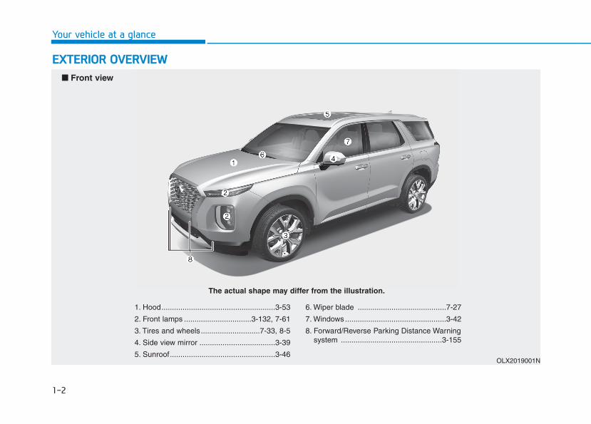
EEXXTTEERRIIOORR OOVVEERRVVIIEEWW
Your vehicle at a glance
1. Hood......................................................3-53
2. Front lamps ................................3-132, 7-61
3. Tires and wheels............................7-33, 8-5
4. Side view mirror ....................................3-39
5. Sunroof..................................................3-46
6. Wiper blade ..........................................7-27
7. Windows ................................................3-42
8. Forward/Reverse Parking Distance Warningsystem ................................................3-155
OLX2019001N
■■ Front view
The actual shape may differ from the illustration.
1-3
Your vehicle at a glance
1
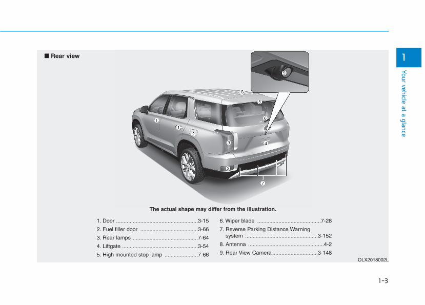
1. Door ......................................................3-15
2. Fuel filler door ......................................3-66
3. Rear lamps............................................7-64
4. Liftgate ..................................................3-54
5. High mounted stop lamp ......................7-66
6. Wiper blade ..........................................7-28
7. Reverse Parking Distance Warning system ................................................3-152
8. Antenna ..................................................4-2
9. Rear View Camera ..............................3-148OLX2018002L
■■ Rear view
The actual shape may differ from the illustration.
1-4
Your vehicle at a glance
IINNTTEERRIIOORR OOVVEERRVVIIEEWW
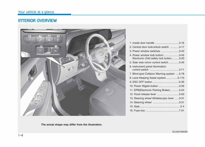
1. Inside door handle ................................3-16
2. Central door lock/unlock switch ............3-17
3. Power window switches ........................3-43
4. Power window lock button/ ....................3-45Electronic child safety lock button..........3-20
5. Side view mirror control switch ..............3-40
6. Instrument panel illumination control switch ........................................3-71
7. Blind-spot Collision Warning system ....5-78
8. Lane Keeping Assist system................5-110
9. ESC OFF button ....................................5-35
10. Power liftgate button ............................3-56
11. EPB(Electronic Parking Brake) ............5-24
12. Hood release lever ..............................3-53
13. Steering wheel tilt/telescopic lever ......3-31
14. Steering wheel ....................................3-31
15. Seat........................................................2-4
16. Fuse box ..............................................7-51
OLX2019003N
The actual shape may differ from the illustration.

IINNSSTTRRUUMMEENNTT PPAANNEELL OOVVEERRVVIIEEWW ((II))
The actual shape may differ from the illustration.
1-5
Your vehicle at a glance
1
OLX2019004N
1. Instrument cluster......................................3-69 2. Driver's front air bag..................................2-59 3. Key ignition switch/......................................5-7
Engine Start/Stop button ..........................5-10 4. Hazard warning flasher switch ....................6-2 5. Audio/Video/Navigation System ..................4-4 6. Manual climate control system/ ..............3-159
Automatic climate control system............3-171 7. Automatic transmission shift button ..........5-15 8. Auto Hold ..................................................5-29 9. Drive mode knob ......................................5-55 10. DBC button..............................................5-39 11. Forward/Reverse Parking Distance
Warning button ......................................3-156 12. Idle stop and go (ISG) OFF button ........5-51 13. Surround view monitor ..........................3-149 14. Air ventilation seat ..................................2-27 15. Seat warmer............................................2-26 16. Heated steering wheel ............................3-3217. Air ventilation seat (2nd row) ....................2-27 18. Seat warmer (2nd row) ............................2-26 19. Climate control system (rear)................3-164 20. Power outlet ..........................................3-197 21. AC inverter ............................................3-198 22. Passenger's front air bag ........................2-59 23. Glove box ..............................................3-192 24. Light control/Turn signals ......................3-13225. Wiper/Washer........................................3-14426. Steering wheel audio controls ..................4-327. Smart Cruise Controls ..........................5-129 28. Wireless cellular phone charging
system ..................................................3-201
1-6
Your vehicle at a glance
EENNGGIINNEE CCOOMMPPAARRTTMMEENNTT
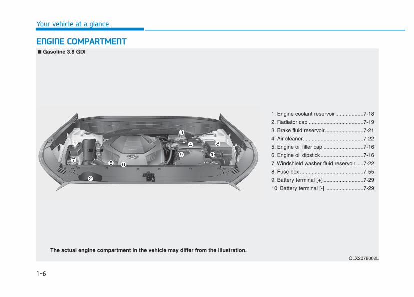
1. Engine coolant reservoir ...................7-18
2. Radiator cap .....................................7-19
3. Brake fluid reservoir..........................7-21
4. Air cleaner.........................................7-22
5. Engine oil filler cap ...........................7-16
6. Engine oil dipstick .............................7-16
7. Windshield washer fluid reservoir .....7-22
8. Fuse box ...........................................7-55
9. Battery terminal [+] ...........................7-29
10. Battery terminal [-] .........................7-29
OLX2078002L
The actual engine compartment in the vehicle may differ from the illustration.
■■ Gasoline 3.8 GDI
Safety system of your vehicle
Important Safety Precautions..............................2-2Always Wear Your Seat Belt ..........................................2-2Restrain All Children .........................................................2-2Air Bag Hazards.................................................................2-2Driver Distraction ..............................................................2-2Control Your Speed...........................................................2-3Keep Your Vehicle in Safe Condition............................2-3
Seats ........................................................................2-4Safety Precautions ...........................................................2-5Front Seats .........................................................................2-6Rear Seats.........................................................................2-13Head Restraints ...............................................................2-21Seat Warmers and Air Ventilation Seats...................2-26
Seat Belts ..............................................................2-29Seat Belt Safety Precautions.......................................2-29Seat Belt Warning Light ................................................2-30Seat Belt Restraint System...........................................2-33Additional Seat Belt Safety Precautions...................2-41Care of Seat Belt.............................................................2-44
Child Restraint System (CRS).............................2-45Children Always in the Rear.........................................2-45Selecting a Child Restraint System (CRS) .................2-47Installing a Child Restraint System (CRS)..................2-49
Air Bag - Advanced Supplemental RestraintSystem ...................................................................2-57
Where Are the Air Bags?..............................................2-59How Does the Air Bag System Operate?..................2-63What to Expect After an Air Bag Inflates................2-67Occupant Classification System (OCS).......................2-68Why Didn't My Air Bag Go Off in a Collision? ........2-73SRS Care............................................................................2-78Additional Safety Precautions .....................................2-79Air Bag Warning Label...................................................2-79
This chapter provides you with important information about how to protect yourself and your passengers.It explains how to properly use your seats and seat belts, and how your air bags work.Additionally, this chapter explains how to properly restrain infants and children in your vehicle.
2
2-2
You will find many safety precautionsand recommendations throughoutthis section, and throughout thismanual. The safety precautions inthis section are among the mostimportant.
Always Wear Your Seat Belt A seat belt is your best protection inall types of accidents. Air bags aredesigned to supplement seat belts,not replace them. So even thoughyour vehicle is equipped with airbags, ALWAYS make sure you andyour passengers wear your seatbelts, and wear them properly.
Restrain All Children All children under age 13 should ridein your vehicle properly restrained ina rear seat, not the front seat. Infantsand small children should berestrained in an appropriate childrestraint. Larger children should usea booster seat with the lap/shoulderbelt until they can use the seat beltproperly without a booster seat.
Air Bag Hazards While air bags can save lives, theycan also cause serious or fatalinjuries to occupants who sit tooclose to them, or who are not prop-erly restrained. Infants, young chil-dren, and shorter adults are at thegreatest risk of being injured by aninflating air bag. Follow all instruc-tions and warnings in this manual.
Driver Distraction Driver distraction presents a seriousand potentially deadly danger, espe-cially for inexperienced drivers.Safety should be the first concernwhen behind the wheel and driversneed to be aware of the wide array ofpotential distractions, such asdrowsiness, reaching for objects,eating, personal grooming, otherpassengers, and using cellularphones.Drivers can become distracted whenthey take their eyes and attention offthe road or their hands off the wheelto focus on activities other than driv-ing. To reduce your risk of distractionor getting into an accident:• ALWAYS set up your mobile
devices (i.e., MP3 players,phones, navigation units, etc.)when your vehicle is parked orsafely stopped.
IIMMPPOORRTTAANNTT SSAAFFEETTYY PPRREECCAAUUTTIIOONNSS
Safety system of your vehicle
2-3
Safety system of your vehicle
• ONLY use your mobile devicewhen allowed by laws and whenconditions permit safe use.NEVER text or email while driving.Most states have laws prohibitingdrivers from texting. Some statesand cities also prohibit driversfrom using handheld phones.
• NEVER let the use of a mobiledevice distract you from driving.You have a responsibility to yourpassengers and others on theroad to always drive safely, withyour hands on the wheel as wellas your eyes and attention on theroad.
Control Your Speed Excessive speed is a major factor incrash injuries and deaths. Generally,the higher the speed, the greater therisk, but serious injuries can alsooccur at lower speeds. Never drivefaster than is safe for current condi-tions, regardless of the maximumspeed posted.
Keep Your Vehicle in SafeCondition Having a tire blowout or a mechani-cal failure can be extremely haz-ardous. To reduce the possibility ofsuch problems, check your tire pres-sures and condition frequently, andperform all regularly scheduledmaintenance.
2
2-4
Safety system of your vehicle
SSEEAATTSS
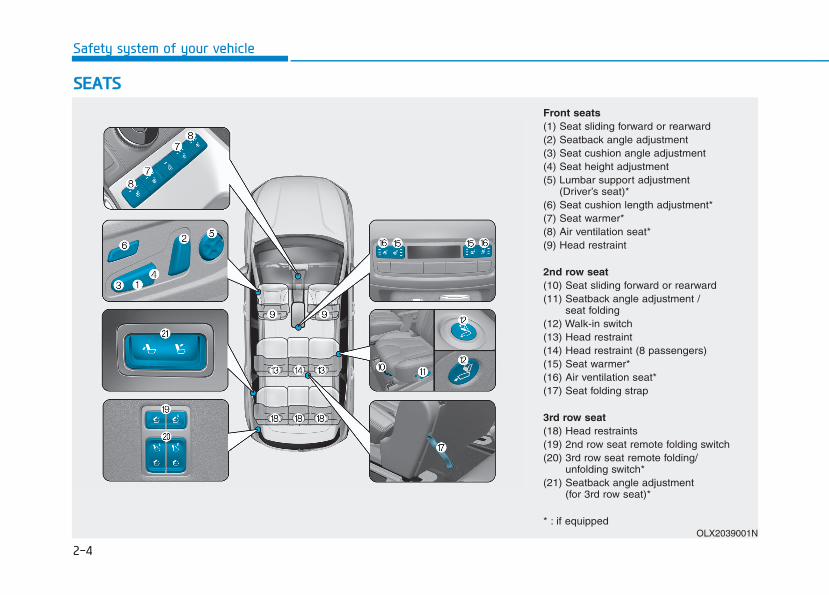
Front seats(1) Seat sliding forward or rearward (2) Seatback angle adjustment(3) Seat cushion angle adjustment(4) Seat height adjustment(5) Lumbar support adjustment
(Driver’s seat)* (6) Seat cushion length adjustment*(7) Seat warmer* (8) Air ventilation seat* (9) Head restraint
2nd row seat(10) Seat sliding forward or rearward (11) Seatback angle adjustment /
seat folding(12) Walk-in switch (13) Head restraint (14) Head restraint (8 passengers) (15) Seat warmer*(16) Air ventilation seat*(17) Seat folding strap
3rd row seat(18) Head restraints(19) 2nd row seat remote folding switch(20) 3rd row seat remote folding/
unfolding switch*(21) Seatback angle adjustment
(for 3rd row seat)*
* : if equippedOLX2039001N
Safety system of your vehicle
2
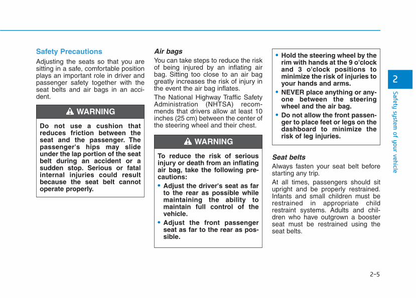
Safety PrecautionsAdjusting the seats so that you aresitting in a safe, comfortable positionplays an important role in driver andpassenger safety together with theseat belts and air bags in an acci-dent.
Air bags You can take steps to reduce the riskof being injured by an inflating airbag. Sitting too close to an air baggreatly increases the risk of injury inthe event the air bag inflates.The National Highway Traffic SafetyAdministration (NHTSA) recom-mends that drivers allow at least 10inches (25 cm) between the center ofthe steering wheel and their chest.
Seat beltsAlways fasten your seat belt beforestarting any trip.At all times, passengers should situpright and be properly restrained.Infants and small children must berestrained in appropriate childrestraint systems. Adults and chil-dren who have outgrown a boosterseat must be restrained using theseat belts.
Do not use a cushion thatreduces friction between theseat and the passenger. Thepassenger's hips may slideunder the lap portion of the seatbelt during an accident or asudden stop. Serious or fatalinternal injuries could resultbecause the seat belt cannotoperate properly.
WARNING
To reduce the risk of seriousinjury or death from an inflatingair bag, take the following pre-cautions:• Adjust the driver's seat as far
to the rear as possible whilemaintaining the ability tomaintain full control of thevehicle.
• Adjust the front passengerseat as far to the rear as pos-sible.
• Hold the steering wheel by therim with hands at the 9 o'clockand 3 o'clock positions tominimize the risk of injuries toyour hands and arms.
• NEVER place anything or any-one between the steeringwheel and the air bag.
• Do not allow the front passen-ger to place feet or legs on thedashboard to minimize therisk of leg injuries.
WARNING
2-5
2-6
Safety system of your vehicle
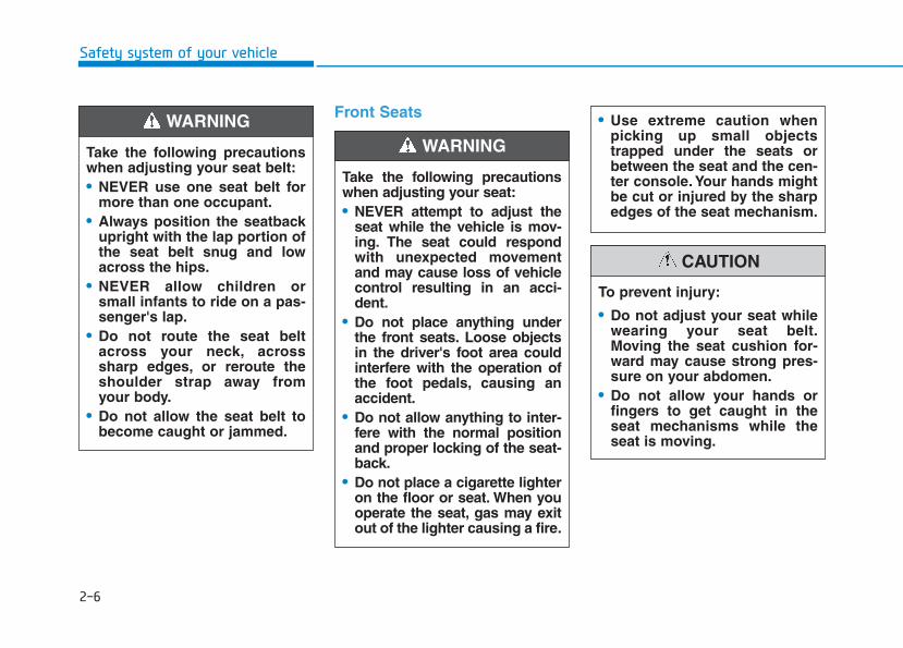
Front Seats
Take the following precautionswhen adjusting your seat:• NEVER attempt to adjust the
seat while the vehicle is mov-ing. The seat could respondwith unexpected movementand may cause loss of vehiclecontrol resulting in an acci-dent.
• Do not place anything underthe front seats. Loose objectsin the driver's foot area couldinterfere with the operation ofthe foot pedals, causing anaccident.
• Do not allow anything to inter-fere with the normal positionand proper locking of the seat-back.
• Do not place a cigarette lighteron the floor or seat. When youoperate the seat, gas may exitout of the lighter causing a fire.
WARNING
To prevent injury:
• Do not adjust your seat whilewearing your seat belt.Moving the seat cushion for-ward may cause strong pres-sure on your abdomen.
• Do not allow your hands orfingers to get caught in theseat mechanisms while theseat is moving.
CAUTION
• Use extreme caution whenpicking up small objectstrapped under the seats orbetween the seat and the cen-ter console. Your hands mightbe cut or injured by the sharpedges of the seat mechanism.
Take the following precautionswhen adjusting your seat belt:• NEVER use one seat belt for
more than one occupant.• Always position the seatback
upright with the lap portion ofthe seat belt snug and lowacross the hips.
• NEVER allow children orsmall infants to ride on a pas-senger's lap.
• Do not route the seat beltacross your neck, acrosssharp edges, or reroute theshoulder strap away fromyour body.
• Do not allow the seat belt tobecome caught or jammed.
WARNING

2-7
Safety system of your vehicle
2
Manual adjustment (if equipped)The front seat can be adjusted byusing the levers located on the out-side of the seat cushion. Before driv-ing, adjust the seat to the properposition so that you can easily con-trol the steering wheel, foot pedalsand controls on the instrumentpanel.
Forward and rearward adjustment
To move the seat forward or rearward:1. Pull up the seat slide adjustment
lever and hold it.2. Slide the seat to the position you
desire.3. Release the lever and make sure
the seat is locked in place. Moveforward and rearward without usingthe lever. If the seat moves, it is notlocked properly.
Seatback angle
To recline the seatback:1. Lean forward slightly and lift up
the seatback lever.2. Carefully lean back on the seat
and adjust the seatback to theposition you desire.
3. Release the lever and make surethe seatback is locked in place.(The lever MUST return to its orig-inal position for the seatback tolock.)
OLX2038070 OLX2038072
2-8
Safety system of your vehicle
Reclining seatback Sitting in a reclined position whenthe vehicle is in motion can be dan-gerous. Even when buckled up, theprotection of your restraint system(seat belts and air bags) is greatlyreduced by reclining your seatback.
Seat belts must be snug against yourhips and chest to work properly.When the seatback is reclined, theshoulder belt cannot do its jobbecause it will not be snug againstyour chest. Instead, it will be in frontof you. During an accident, you couldbe thrown into the seat belt, causingneck or other injuries.The more the seatback is reclined,the greater chance the passenger'ships will slide under the lap belt orthe passenger's neck will strike theshoulder belt.
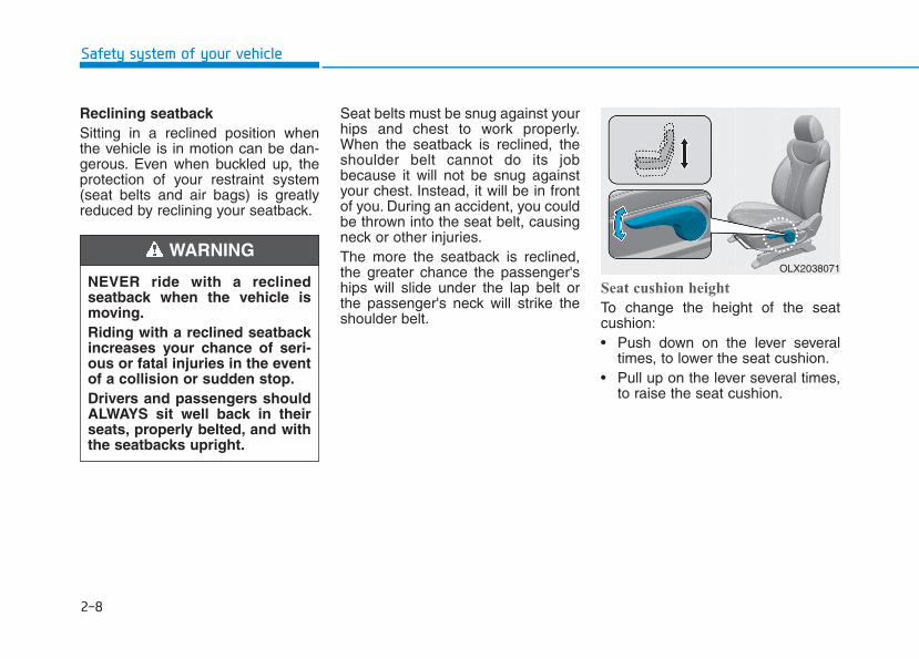
Seat cushion height
To change the height of the seatcushion:• Push down on the lever several
times, to lower the seat cushion.• Pull up on the lever several times,
to raise the seat cushion.
OLX2038071NEVER ride with a reclinedseatback when the vehicle ismoving.Riding with a reclined seatbackincreases your chance of seri-ous or fatal injuries in the eventof a collision or sudden stop.Drivers and passengers shouldALWAYS sit well back in theirseats, properly belted, and withthe seatbacks upright.
WARNING

2-9
Safety system of your vehicle
2
Power adjustment (if equipped)The front seat can be adjusted byusing the control switches located onthe outside of the seat cushion. Beforedriving, adjust the seat to the properposition so that you can easily controlthe steering wheel, foot pedals andcontrols on the instrument panel.
To prevent damage to the seats:• Always stop adjusting the seats
when the seat has moved as farforward or rearward as possible.
• Do not adjust the seats forlonger than necessary when thevehicle is turned off. This mayresult in unnecessary batterydrain.
• Do not operate two or moreseats at the same time.This mayresult in an electrical malfunc-tion.
Forward and rearward adjustment
To move the seat forward or rearward:1. Push the control switch forward or
rearward.2. Release the switch once the seat
reaches the desired position.
NOTICE
NEVER allow children in thevehicle unattended. The powerseats are operable when thevehicle is turned off.
WARNING OLX2038003
2-10
Safety system of your vehicle
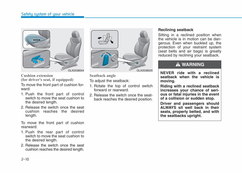
Cushion extension (for driver's seat, if equipped)
To move the front part of cushion for-ward:1. Push the front part of control
switch to move the seat cushion tothe desired length.
2. Release the switch once the seatcushion reaches the desiredlength.
To move the front part of cushionrearward:1. Push the rear part of control
switch to move the seat cushion tothe desired length.
2. Release the switch once the seatcushion reaches the desired length.
Seatback angle
To adjust the seatback:1. Rotate the top of control switch
forward or rearward.2. Release the switch once the seat-
back reaches the desired position.
Reclining seatback Sitting in a reclined position whenthe vehicle is in motion can be dan-gerous. Even when buckled up, theprotection of your restraint system(seat belts and air bags) is greatlyreduced by reclining your seatback.
OLX2038004 OLX2038005NEVER ride with a reclinedseatback when the vehicle ismoving.Riding with a reclined seatbackincreases your chance of seri-ous or fatal injuries in the eventof a collision or sudden stop.Driver and passengers shouldALWAYS sit well back in theirseats, properly belted, and withthe seatbacks upright.
WARNING
2-11
Safety system of your vehicle
2
Seat belts must be snug against yourhips and chest to work properly.When the seatback is reclined, theshoulder belt cannot do its jobbecause it will not be snug againstyour chest. Instead, it will be in frontof you. During an accident, you couldbe thrown into the seat belt, causingneck or other injuries.The more the seatback is reclined,the greater chance the passenger’ships will slide under the lap belt orthe passenger's neck will strike theshoulder belt.
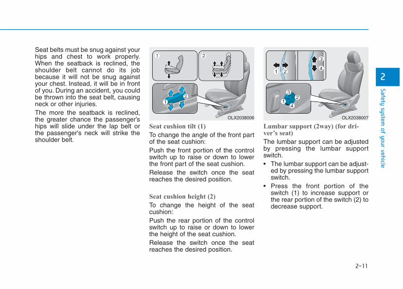
Seat cushion tilt (1)
To change the angle of the front partof the seat cushion:Push the front portion of the controlswitch up to raise or down to lowerthe front part of the seat cushion.Release the switch once the seatreaches the desired position.
Seat cushion height (2)
To change the height of the seatcushion:Push the rear portion of the controlswitch up to raise or down to lowerthe height of the seat cushion.Release the switch once the seatreaches the desired position.
Lumbar support (2way) (for dri-ver’s seat)
The lumbar support can be adjustedby pressing the lumbar supportswitch.• The lumbar support can be adjust-
ed by pressing the lumbar supportswitch.
• Press the front portion of theswitch (1) to increase support orthe rear portion of the switch (2) todecrease support.
OLX2038006 OLX2038007
2-12
Safety system of your vehicle
Lumbar support (4way) (for dri-ver’s seat) (if equipped)
The lumbar support can be adjustedby pressing the lumbar supportswitch.• Press the front portion of the
switch (1) to increase support orthe rear portion of the switch (2) todecrease support.
• To move the support position up ordown, press switch (3) or (4).
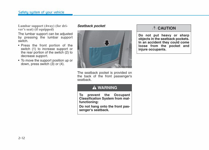
Seatback pocket
The seatback pocket is provided onthe back of the front passenger'sseatback.
To prevent the OccupantClassification System from mal-functioning:Do not hang onto the front pas-senger's seatback.
WARNING
OLX2038013
Do not put heavy or sharpobjects in the seatback pockets.In an accident they could comeloose from the pocket andinjure occupants.
CAUTION
2-13
Safety system of your vehicle
2
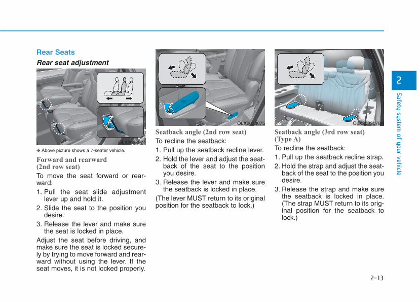
Rear Seats Rear seat adjustment
❈ Above picture shows a 7-seater vehicle.
Forward and rearward (2nd row seat)
To move the seat forward or rear-ward:1. Pull the seat slide adjustment
lever up and hold it.2. Slide the seat to the position you
desire.3. Release the lever and make sure
the seat is locked in place.Adjust the seat before driving, andmake sure the seat is locked secure-ly by trying to move forward and rear-ward without using the lever. If theseat moves, it is not locked properly.
Seatback angle (2nd row seat)
To recline the seatback:1. Pull up the seatback recline lever.2. Hold the lever and adjust the seat-
back of the seat to the positionyou desire.
3. Release the lever and make surethe seatback is locked in place.
(The lever MUST return to its originalposition for the seatback to lock.)
Seatback angle (3rd row seat) (Type A)
To recline the seatback:1. Pull up the seatback recline strap.2. Hold the strap and adjust the seat-
back of the seat to the position youdesire.
3. Release the strap and make surethe seatback is locked in place.(The strap MUST return to its orig-inal position for the seatback tolock.)
OLX2038074
OLX2038075 OLX2039078N
2-14
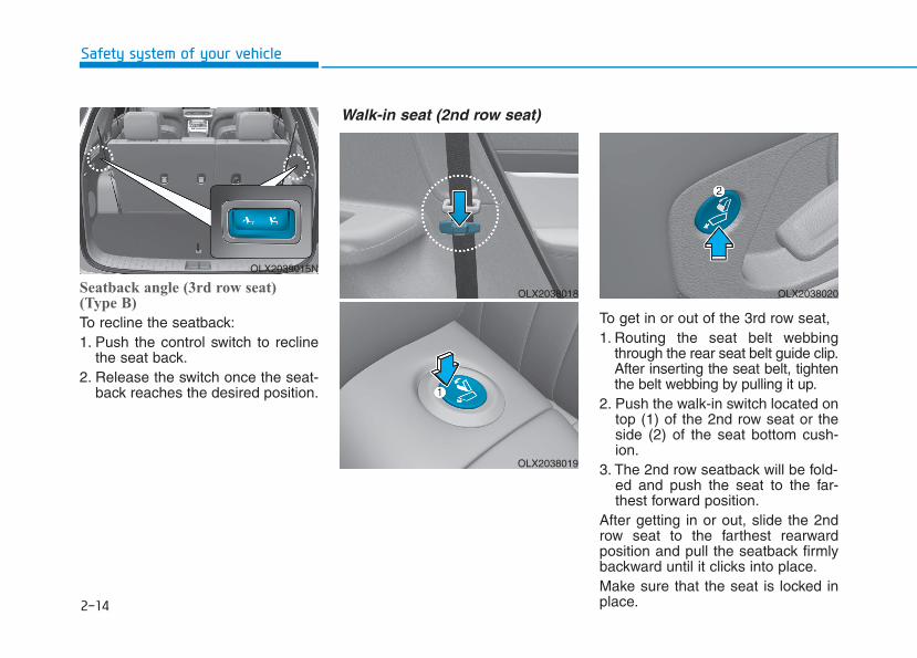
Seatback angle (3rd row seat)(Type B)
To recline the seatback:1. Push the control switch to recline
the seat back.2. Release the switch once the seat-
back reaches the desired position.
To get in or out of the 3rd row seat,1. Routing the seat belt webbing
through the rear seat belt guide clip.After inserting the seat belt, tightenthe belt webbing by pulling it up.
2. Push the walk-in switch located ontop (1) of the 2nd row seat or theside (2) of the seat bottom cush-ion.
3. The 2nd row seatback will be fold-ed and push the seat to the far-thest forward position.
After getting in or out, slide the 2ndrow seat to the farthest rearwardposition and pull the seatback firmlybackward until it clicks into place.Make sure that the seat is locked inplace.
Safety system of your vehicle
OLX2039015N
OLX2038018
OLX2038019
OLX2038020
Walk-in seat (2nd row seat)
2-15
Safety system of your vehicle
Folding the rear seat The rear seatbacks can be folded tofacilitate carrying long items or toincrease the luggage capacity of thevehicle. 2
• Never allow passengers to siton top of the folded downseatback while the vehicle ismoving. This is not a properseating position and no seatbelts are available for use.This could result in seriousinjury or death in case of anaccident or sudden stop.
• Objects carried on the foldeddown seatback should notextend higher than the top ofthe front seatbacks. Thiscould allow cargo to slide for-ward and cause injury or dam-age during sudden stops.
WARNING
Never attempt to adjust whilethe vehicle is moving or the 2ndrow seat is occupied as the seatmay suddenly move and causethe passenger on the seat to beinjured.
WARNING
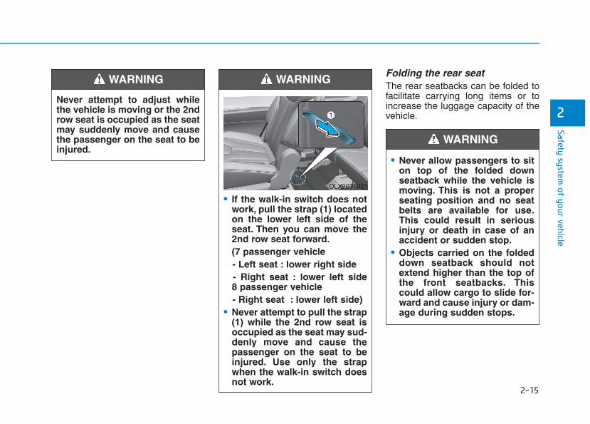
• If the walk-in switch does notwork, pull the strap (1) locatedon the lower left side of theseat. Then you can move the2nd row seat forward.(7 passenger vehicle - Left seat : lower right side- Right seat : lower left side8 passenger vehicle- Right seat : lower left side)
• Never attempt to pull the strap(1) while the 2nd row seat isoccupied as the seat may sud-denly move and cause thepassenger on the seat to beinjured. Use only the strapwhen the walk-in switch doesnot work.
WARNING
OLX2038021
2-16
Safety system of your vehicle
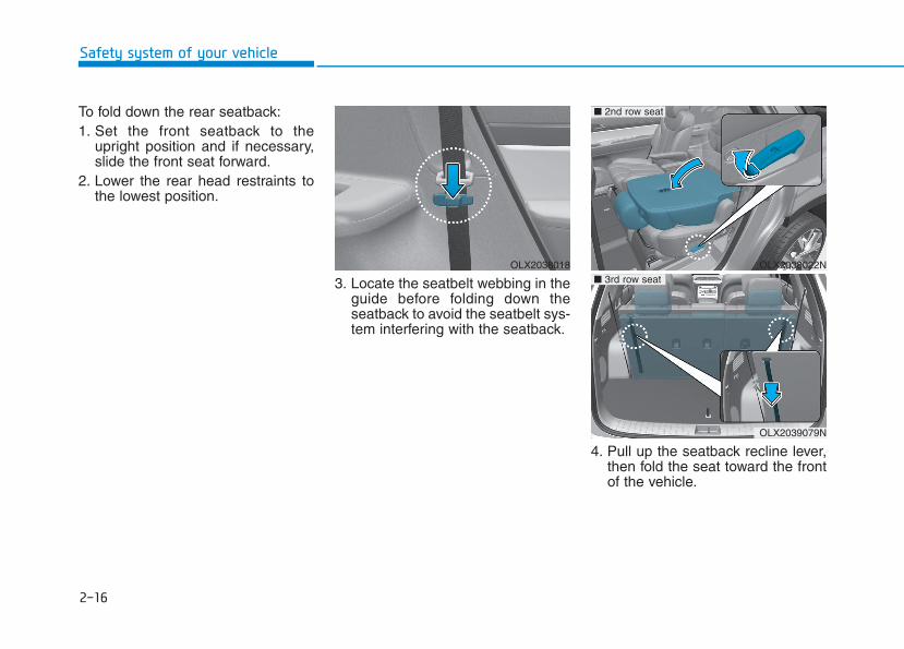
To fold down the rear seatback:1. Set the front seatback to the
upright position and if necessary,slide the front seat forward.
2. Lower the rear head restraints tothe lowest position.
3. Locate the seatbelt webbing in theguide before folding down theseatback to avoid the seatbelt sys-tem interfering with the seatback.
4. Pull up the seatback recline lever,then fold the seat toward the frontof the vehicle.
OLX2038018 OLX2038022N
■ 2nd row seat
OLX2039079N
■ 3rd row seat
2-17
Safety system of your vehicle
2
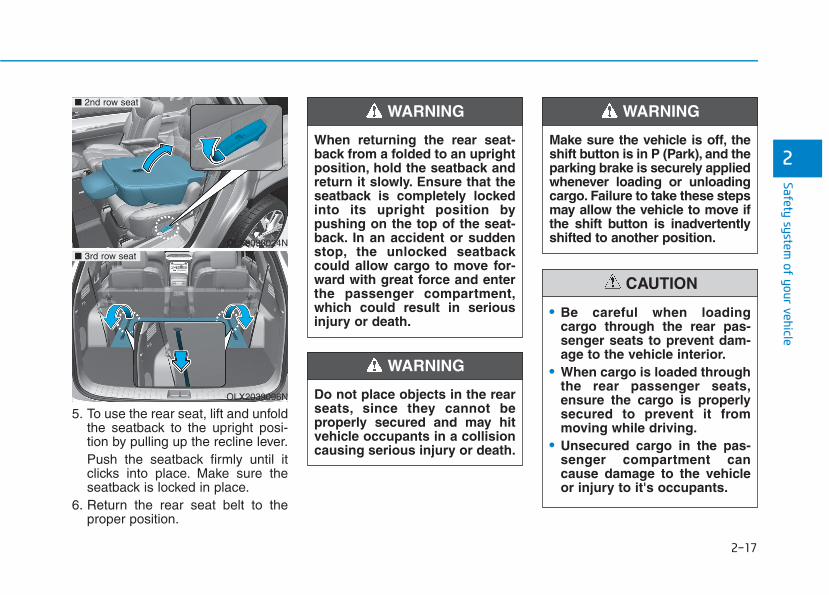
5. To use the rear seat, lift and unfoldthe seatback to the upright posi-tion by pulling up the recline lever.Push the seatback firmly until itclicks into place. Make sure theseatback is locked in place.
6. Return the rear seat belt to theproper position.
Do not place objects in the rearseats, since they cannot beproperly secured and may hitvehicle occupants in a collisioncausing serious injury or death.
WARNING
When returning the rear seat-back from a folded to an uprightposition, hold the seatback andreturn it slowly. Ensure that theseatback is completely lockedinto its upright position bypushing on the top of the seat-back. In an accident or suddenstop, the unlocked seatbackcould allow cargo to move for-ward with great force and enterthe passenger compartment,which could result in seriousinjury or death.
WARNING
OLX2039024N
■ 2nd row seat
OLX2039096N
■ 3rd row seat
Make sure the vehicle is off, theshift button is in P (Park), and theparking brake is securely appliedwhenever loading or unloadingcargo. Failure to take these stepsmay allow the vehicle to move ifthe shift button is inadvertentlyshifted to another position.
WARNING
• Be careful when loadingcargo through the rear pas-senger seats to prevent dam-age to the vehicle interior.
• When cargo is loaded throughthe rear passenger seats,ensure the cargo is properlysecured to prevent it frommoving while driving.
• Unsecured cargo in the pas-senger compartment cancause damage to the vehicleor injury to it's occupants.
CAUTION
2-18
Safety system of your vehicle
2nd row seat folding (from outside)
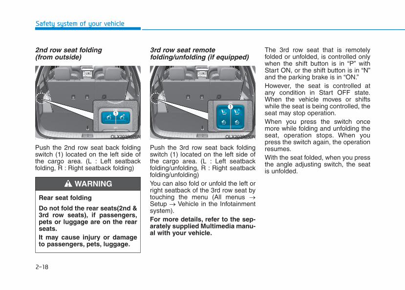
Push the 2nd row seat back foldingswitch (1) located on the left side ofthe cargo area. (L : Left seatbackfolding, R : Right seatback folding)
3rd row seat remotefolding/unfolding (if equipped)
Push the 3rd row seat back foldingswitch (1) located on the left side ofthe cargo area. (L : Left seatbackfolding/unfolding, R : Right seatbackfolding/unfolding)You can also fold or unfold the left orright seatback of the 3rd row seat bytouching the menu (All menus →Setup → Vehicle in the Infotainmentsystem).For more details, refer to the sep-arately supplied Multimedia manu-al with your vehicle.
The 3rd row seat that is remotelyfolded or unfolded, is controlled onlywhen the shift button is in “P” withStart ON, or the shift button is in “N”and the parking brake is in “ON.”However, the seat is controlled atany condition in Start OFF state.When the vehicle moves or shiftswhile the seat is being controlled, theseat may stop operation.When you press the switch oncemore while folding and unfolding theseat, operation stops. When youpress the switch again, the operationresumes.With the seat folded, when you pressthe angle adjusting switch, the seatis unfolded.
OLX2039026N OLX2039030N
Rear seat folding
Do not fold the rear seats(2nd &3rd row seats), if passengers,pets or luggage are on the rearseats.It may cause injury or damageto passengers, pets, luggage.
WARNING
2-19
Safety system of your vehicle
2
Detection of object caughtWhile folding or unfolding the 3rd rowseat, when a consistent force isdetected, the seat returns to its orig-inal position or stops operation.However, this function may not workwhen the detected resistance isbelow a specific level or the seat isalmost folded or unfolded. When astrong impact is applied to the seat,the object detection function may beactivated even if no obstacle is pres-ent.When any object caught is detectedmultiple times while operating theseat once, folding and unfolding arerepeated consecutively and then theoperation may stop. In this case,check that any object is caught andthen operate the switch again tocheck for abnormality.When the object detection isenabled, the angle of the seat backmay be changed. When you operatethe seat once by pressing the foldingbutton, the angle of the seat back isreset.
Do not place any part of yourbody or anything in the operat-ing area to intentionally checkthe detection of any objectcaught.For safety, when folding orunfolding the 3rd row seat,make sure that there is no partof body or object. To preventdamage to the seatbelt, insert itinto its holder and store it in theretractor inside a seat.When the child restraint system(CRS) is installed on the 3rd rowseat, remove the CRS and thenoperate the seat.When there is any object on thecushion of the 3rd row seat,remove it and then operate theseat.To avoid interference with afront seat, keep the backrest ofthe front seat straight and moveit forward for smooth operation.
WARNING
Without starting the engine, the3rd row seat can be folded orunfolded. When this is attempt-ed more than 10 times, the bat-tery may discharge premature-ly.Do not apply excessive force tothe 3rd row seat while in opera-tion. It may damage the seat.When you operate the seat over5 times with no rest, the electricmotor may be overloaded. Inthis case, the seat changes tooverheat prevention mode.Then you cannot operate theseat by pressing the switch.Leave the seat for over 1 minutefor later operation.
CAUTION
2-20
Armrest (2nd row, 8 passengersvehicle)
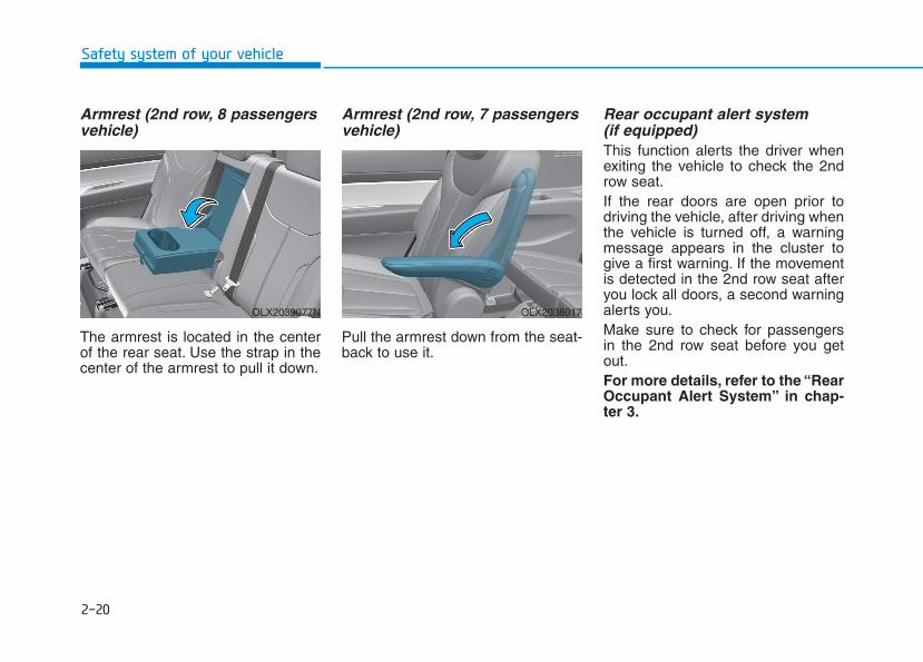
The armrest is located in the centerof the rear seat. Use the strap in thecenter of the armrest to pull it down.
Armrest (2nd row, 7 passengersvehicle)
Pull the armrest down from the seat-back to use it.
Rear occupant alert system (if equipped)This function alerts the driver whenexiting the vehicle to check the 2ndrow seat.If the rear doors are open prior todriving the vehicle, after driving whenthe vehicle is turned off, a warningmessage appears in the cluster togive a first warning. If the movementis detected in the 2nd row seat afteryou lock all doors, a second warningalerts you.Make sure to check for passengersin the 2nd row seat before you getout.For more details, refer to the “RearOccupant Alert System” in chap-ter 3.
Safety system of your vehicle
OLX2039077N OLX2038017
2-21
Safety system of your vehicle
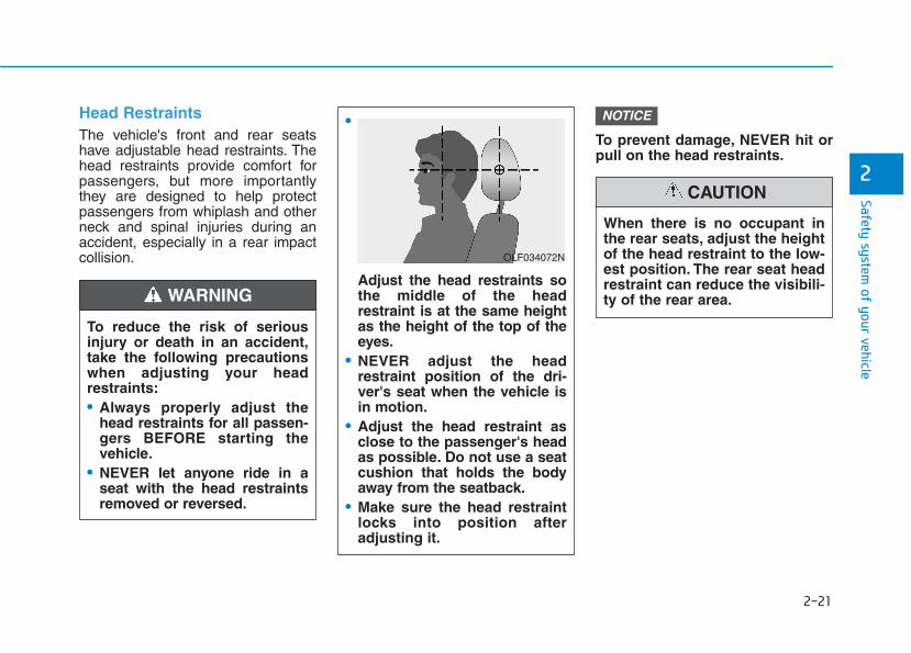
Head RestraintsThe vehicle's front and rear seatshave adjustable head restraints. Thehead restraints provide comfort forpassengers, but more importantlythey are designed to help protectpassengers from whiplash and otherneck and spinal injuries during anaccident, especially in a rear impactcollision.
To prevent damage, NEVER hit orpull on the head restraints.
NOTICE
2
To reduce the risk of seriousinjury or death in an accident,take the following precautionswhen adjusting your headrestraints:• Always properly adjust the
head restraints for all passen-gers BEFORE starting thevehicle.
• NEVER let anyone ride in aseat with the head restraintsremoved or reversed.
•
Adjust the head restraints sothe middle of the headrestraint is at the same heightas the height of the top of theeyes.
• NEVER adjust the headrestraint position of the dri-ver's seat when the vehicle isin motion.
• Adjust the head restraint asclose to the passenger's headas possible. Do not use a seatcushion that holds the bodyaway from the seatback.
• Make sure the head restraintlocks into position afteradjusting it.
WARNING
OLF034072N
When there is no occupant inthe rear seats, adjust the heightof the head restraint to the low-est position. The rear seat headrestraint can reduce the visibili-ty of the rear area.
CAUTION

2-22
Safety system of your vehicle
Front seat head restraints
The vehicle's front and passenger'sseats are equipped with adjustablehead restraints for the passengerssafety and comfort.
Adjusting the height up and down
To raise the head restraint:1. Pull it up to the desired position
(1).
To lower the head restraint:1. Push and hold the release button
(2) on the head restraint support.2. Lower the head restraint to the
desired position (3).
If you recline the seatback towardsthe front with the head restraintand seat cushion raised, the headrestraint may come in contact withthe sunvisor or other parts of thevehicle.
NOTICEOLX2038097L
OLX2038010 OLF034015
2-23
Safety system of your vehicle
2
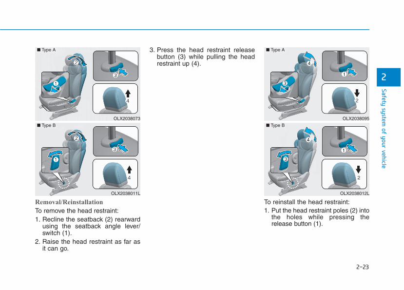
Removal/Reinstallation
To remove the head restraint:1. Recline the seatback (2) rearward
using the seatback angle lever/switch (1).
2. Raise the head restraint as far asit can go.
3. Press the head restraint releasebutton (3) while pulling the headrestraint up (4).
To reinstall the head restraint:1. Put the head restraint poles (2) into
the holes while pressing therelease button (1).
OLX2038073
OLX2038011L
■ Type A
■ Type B
OLX2038095
OLX2038012L
■ Type A
■ Type B
2-24
Safety system of your vehicle
2. Adjust the head restraint to theappropriate height.
3. Adjust the seatback (4) forwardusing the seatback angle lever/switch (3).
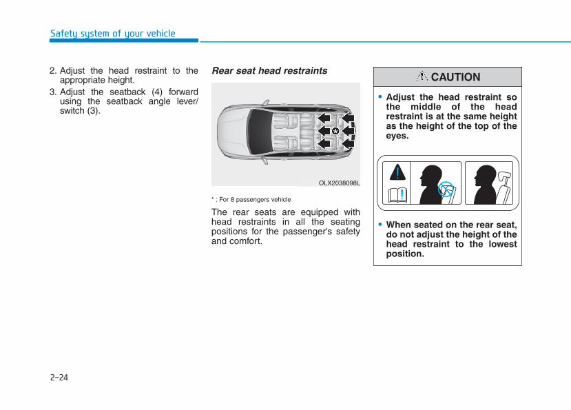
Rear seat head restraints
* : For 8 passengers vehicle
The rear seats are equipped withhead restraints in all the seatingpositions for the passenger's safetyand comfort.
OLX2038098L
• Adjust the head restraint sothe middle of the headrestraint is at the same heightas the height of the top of theeyes.
• When seated on the rear seat,do not adjust the height of thehead restraint to the lowestposition.
CAUTION
2-25
Safety system of your vehicle
2
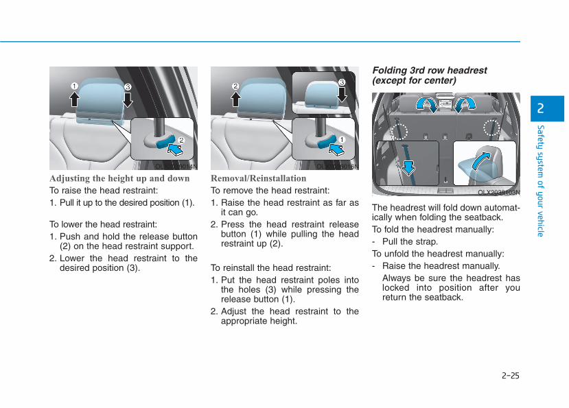
Adjusting the height up and down
To raise the head restraint:1. Pull it up to the desired position (1).
To lower the head restraint:1. Push and hold the release button
(2) on the head restraint support.2. Lower the head restraint to the
desired position (3).
Removal/Reinstallation
To remove the head restraint:1. Raise the head restraint as far as
it can go.2. Press the head restraint release
button (1) while pulling the headrestraint up (2).
To reinstall the head restraint:1. Put the head restraint poles into
the holes (3) while pressing therelease button (1).
2. Adjust the head restraint to theappropriate height.
Folding 3rd row headrest(except for center)
The headrest will fold down automat-ically when folding the seatback.To fold the headrest manually:- Pull the strap.To unfold the headrest manually:- Raise the headrest manually.
Always be sure the headrest haslocked into position after youreturn the seatback.
OLX2039016NOLX2039014N
OLX2039103N
2-26
Safety system of your vehicle
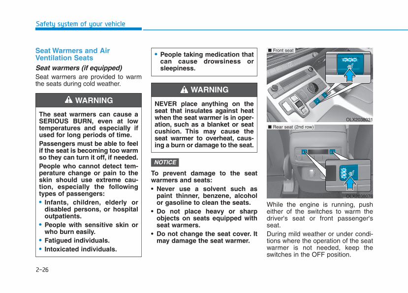
Seat Warmers and AirVentilation SeatsSeat warmers (if equipped)Seat warmers are provided to warmthe seats during cold weather.
To prevent damage to the seatwarmers and seats:• Never use a solvent such as
paint thinner, benzene, alcoholor gasoline to clean the seats.
• Do not place heavy or sharpobjects on seats equipped withseat warmers.
• Do not change the seat cover. Itmay damage the seat warmer.
While the engine is running, pusheither of the switches to warm thedriver's seat or front passenger'sseat.During mild weather or under condi-tions where the operation of the seatwarmer is not needed, keep theswitches in the OFF position.
NOTICE
OLX2038031
■ Front seat
OLX2038076
■ Rear seat (2nd row)
• People taking medication thatcan cause drowsiness orsleepiness.
NEVER place anything on theseat that insulates against heatwhen the seat warmer is in oper-ation, such as a blanket or seatcushion. This may cause theseat warmer to overheat, caus-ing a burn or damage to the seat.
WARNING
The seat warmers can cause aSERIOUS BURN, even at lowtemperatures and especially ifused for long periods of time.Passengers must be able to feelif the seat is becoming too warmso they can turn it off, if needed.People who cannot detect tem-perature change or pain to theskin should use extreme cau-tion, especially the followingtypes of passengers:• Infants, children, elderly or
disabled persons, or hospitaloutpatients.
• People with sensitive skin orwho burn easily.
• Fatigued individuals.• Intoxicated individuals.
WARNING

2-27
Safety system of your vehicle
2
• Each time you push the switch, thetemperature setting of the seatchanged as shown below:
• When pressing the switch formore than 1.5 seconds with theseat warmer operating, the seatwarmer will turn OFF.
• The seat warmer defaults to theOFF position whenever the vehi-cle is turned on.
Information With the seat warmer switch in theON position, the heating system in theseat turns off or on automaticallydepending on the seat temperature.
Front air ventilation seat(if equipped)
The air ventilation seats are providedto cool the front seats by blowing airthrough small vent holes on the sur-face of the seat cushions and seat-backs.
When the operation of the air ventila-tion seat is not needed, keep theswitches in the OFF position.While the engine is running, push theswitch to cool the driver's seat or thefront passenger's seat.• Each time you push the switch,
the airflow changes as follows:
• When pressing the switch formore than 1.5 seconds with the airventilation seat operating, theoperation will turn OFF.i
OFF HIGH ( )
LOW ( ) MIDDLE ( )
→
→
→
→
OFF HIGH ( )
LOW ( ) MIDDLE ( )
→
→
→
→
OLX2038028
■ Front seat
OLX2038029
■ Rear seat (2nd row)
2-28
Safety system of your vehicle
• The air ventilation seat defaults tothe OFF position whenever thevehicle is turned on.
Information • If the outside temperature is under
approximately 33°F (2°C), the airventilation seat may not operate.
• Use the air ventilation seat when theclimate control system is on. Usingthe air ventilation seat for prolongedperiods of time with the climate con-trol system off could cause the cli-mate control seat performance to bereduced.
To prevent damage to the air ven-tilation seat:• Use the air ventilation seat ONLY
when the climate control systemis on. Using the air ventilationseat for prolonged periods oftime with the climate controlsystem off could cause the airventilation seat to malfunction.
• Never use a solvent such aspaint thinner, benzene, alcoholor gasoline to clean the seats.
• Avoid spilling liquids on the sur-face of the front seats and seat-backs; this may cause the airvent holes to become blockedand not work properly.
• Do not place materials such asplastic bags or newspapersunder the seats. They may blockthe air intake causing the airvents to not work properly.
• Do not change the seat covers. Itmay damage the air ventilationseat.
• If the air vents do not operate,restart the vehicle. If there is nochange, have the vehicleinspected by an authorizedHYUNDAI dealer.
NOTICE
i

2-29
Safety system of your vehicle
2
This section describes how to use theseat belts properly. It also describessome of the things to avoid whenusing seat belts.
Seat Belt Safety PrecautionsAlways fasten your seat belt andmake sure all passengers have fas-tened their seat belts before startingany trip. Air bags are designed tosupplement the seat belt as an addi-tional safety device, but they are not asubstitute. Most states require alloccupants of a vehicle to wear seatbelts.
SSEEAATT BBEELLTTSS
Seat belts must be used by ALLpassengers whenever the vehi-cle is moving.Take the followingprecautions when adjusting andwearing seat belts:• ALWAYS properly restrain
children under age 13 in therear seats.
WARNING
• NEVER allow children to ridein the front passenger seat. Ifa child age 13 or older must beseated in the front seat, movethe seat as far back as possi-ble and properly restrain themin the seat.
• NEVER allow an infant or childto be carried on an occupant’slap.
• NEVER ride with the seatbackreclined when the vehicle ismoving.
• Do not allow children to sharea seat or seat belt.
• Do not wear the shoulder beltunder your arm or behind yourback.
• Always wear both the shoul-der portion and lap portion ofthe lap/shoulder belt.
• Do not use the seat belt if it istwisted. A twisted seat beltwill not protect you properlyin an accident.
• Do not use a seat belt if thewebbing or hardware is dam-aged.
• Do not latch the seat belt intothe buckles of other seats.
• NEVER unfasten the seat beltwhile driving. This may causeloss of vehicle control result-ing in an accident.
• Make sure there is nothing inthe buckle interfering with theseat belt latch mechanism.This may prevent the seat beltfrom fastening securely.
• No modifications or additionsshould be made by the userwhich will either prevent theseat belt adjusting devicesfrom operating to removeslack, or prevent the seat beltassembly from being adjustedto remove slack.
2-30
Safety system of your vehicle
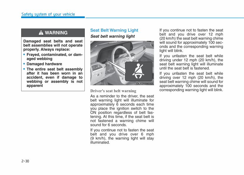
Seat Belt Warning LightSeat belt warning light
Driver's seat belt warning
As a reminder to the driver, the seatbelt warning light will illuminate forapproximately 6 seconds each timeyou place the ignition switch to theON position regardless of belt fas-tening. At this time, if the seat belt isnot fastened a warning chime willsound for 6 seconds.If you continue not to fasten the seatbelt and you drive over 6 mph (9 km/h), the warning light will stayilluminated.
If you continue not to fasten the seatbelt and you drive over 12 mph (20 km/h) the seat belt warning chimewill sound for approximately 100 sec-onds and the corresponding warninglight will blink.If you unfasten the seat belt whiledriving under 12 mph (20 km/h), theseat belt warning light will illuminateuntil the seat belt is fastened.If you unfasten the seat belt whiledriving over 12 mph (20 km/h), theseat belt warning chime will sound forapproximately 100 seconds and thecorresponding warning light will blink.
Damaged seat belts and seatbelt assemblies will not operateproperly. Always replace:• Frayed, contaminated, or dam-
aged webbing• Damaged hardware• The entire seat belt assembly
after it has been worn in anaccident, even if damage towebbing or assembly is notapparent
WARNING
OLX2039032L
2-31
Safety system of your vehicle
2
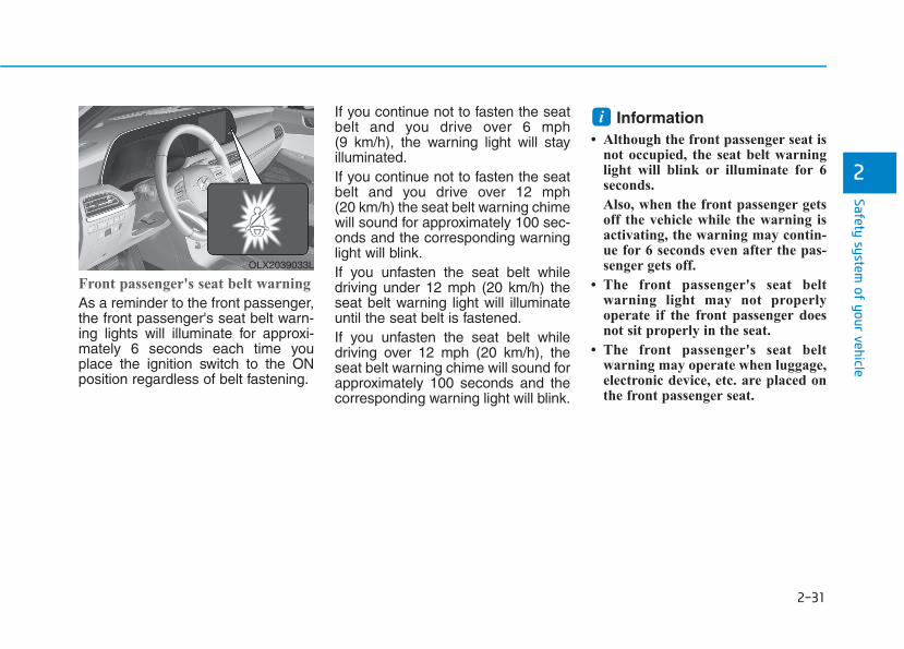
Front passenger's seat belt warning
As a reminder to the front passenger,the front passenger's seat belt warn-ing lights will illuminate for approxi-mately 6 seconds each time youplace the ignition switch to the ONposition regardless of belt fastening.
If you continue not to fasten the seatbelt and you drive over 6 mph (9 km/h), the warning light will stayilluminated.If you continue not to fasten the seatbelt and you drive over 12 mph (20 km/h) the seat belt warning chimewill sound for approximately 100 sec-onds and the corresponding warninglight will blink.If you unfasten the seat belt whiledriving under 12 mph (20 km/h) theseat belt warning light will illuminateuntil the seat belt is fastened.If you unfasten the seat belt whiledriving over 12 mph (20 km/h), theseat belt warning chime will sound forapproximately 100 seconds and thecorresponding warning light will blink.
Information • Although the front passenger seat is
not occupied, the seat belt warninglight will blink or illuminate for 6seconds.
Also, when the front passenger getsoff the vehicle while the warning isactivating, the warning may contin-ue for 6 seconds even after the pas-senger gets off.
• The front passenger's seat beltwarning light may not properlyoperate if the front passenger doesnot sit properly in the seat.
• The front passenger's seat beltwarning may operate when luggage,electronic device, etc. are placed onthe front passenger seat.
i
OLX2039033L
2-32
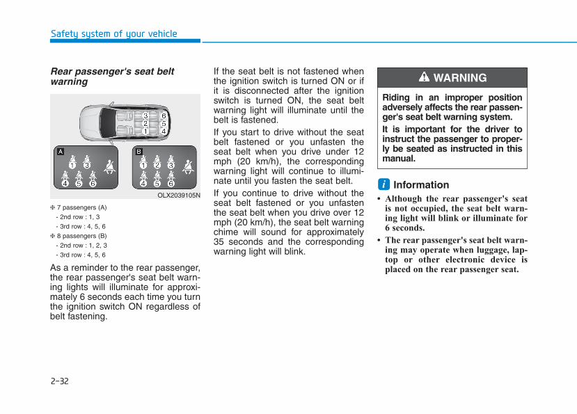
Rear passenger's seat beltwarning
❈ 7 passengers (A)
- 2nd row : 1, 3
- 3rd row : 4, 5, 6
❈ 8 passengers (B)
- 2nd row : 1, 2, 3
- 3rd row : 4, 5, 6
As a reminder to the rear passenger,the rear passenger's seat belt warn-ing lights will illuminate for approxi-mately 6 seconds each time you turnthe ignition switch ON regardless ofbelt fastening.
If the seat belt is not fastened whenthe ignition switch is turned ON or ifit is disconnected after the ignitionswitch is turned ON, the seat beltwarning light will illuminate until thebelt is fastened.If you start to drive without the seatbelt fastened or you unfasten theseat belt when you drive under 12mph (20 km/h), the correspondingwarning light will continue to illumi-nate until you fasten the seat belt.If you continue to drive without theseat belt fastened or you unfastenthe seat belt when you drive over 12mph (20 km/h), the seat belt warningchime will sound for approximately35 seconds and the correspondingwarning light will blink.
Information • Although the rear passenger's seat
is not occupied, the seat belt warn-ing light will blink or illuminate for6 seconds.
• The rear passenger's seat belt warn-ing may operate when luggage, lap-top or other electronic device isplaced on the rear passenger seat.
i
Safety system of your vehicle
OLX2039105N
Riding in an improper positionadversely affects the rear passen-ger's seat belt warning system.It is important for the driver toinstruct the passenger to proper-ly be seated as instructed in thismanual.
WARNING
2-33
Safety system of your vehicle
2
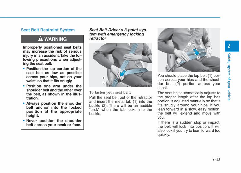
Seat Belt Restraint System Seat Belt-Driver's 3-point sys-tem with emergency lockingretractor
To fasten your seat belt:
Pull the seat belt out of the retractorand insert the metal tab (1) into thebuckle (2). There will be an audible"click" when the tab locks into thebuckle.
You should place the lap belt (1) por-tion across your hips and the shoul-der belt (2) portion across yourchest.The seat belt automatically adjusts tothe proper length after the lap beltportion is adjusted manually so that itfits snugly around your hips. If youlean forward in a slow, easy motion,the belt will extend and move withyou.If there is a sudden stop or impact,the belt will lock into position. It willalso lock if you try to lean forward tooquickly.
OHSS038101
Improperly positioned seat beltsmay increase the risk of seriousinjury in an accident.Take the fol-lowing precautions when adjust-ing the seat belt:• Position the lap portion of the
seat belt as low as possibleacross your hips, not on yourwaist, so that it fits snugly.
• Position one arm under theshoulder belt and the other overthe belt, as shown in the illus-tration.
• Always position the shoulderbelt anchor into the lockedposition at the appropriateheight.
• Never position the shoulderbelt across your neck or face.
WARNING
OHSS038102L

2-34
Safety system of your vehicle
If you are not able to smoothly pullenough of the seat belt out fromthe retractor, firmly pull the seatbelt out and release it. Afterrelease, you will be able to pull thebelt out smoothly.
Height adjustment
You can adjust the height of theshoulder belt anchor to one of thethree different positions for maximumcomfort and safety.The shoulder portion should beadjusted so it lies across your chestand midway over your shoulder near-est the door, not over your neck.
To adjust the height of the seat beltanchor, lower or raise the heightadjuster into an appropriate position.To raise the height adjuster, pull it up(1). To lower it, push it down (3) whilepressing the height adjuster button(2).Release the button to lock theanchor into position. Try sliding theheight adjuster to make sure that ithas locked into position.
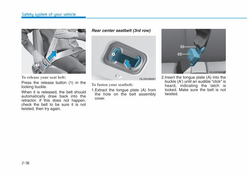
To release your seat belt:
Press the release button (1) in thelocking buckle.When it is released, the belt shouldautomatically draw back into theretractor. If this does not happen,check the belt to be sure it is nottwisted, then try again.
NOTICE
OLX2038102L OHSS038103
2-35
Safety system of your vehicle
2
Rear Seat Belt – Passenger's 3-point system with convertiblelocking retractorThis type of seat belt combines thefeatures of both an emergency lockingretractor seat belt and an automaticlocking retractor seat belt. Convertibleretractor type seat belts are installed inthe rear seat positions to help accom-modate the installation of childrestraint systems. Although a convert-ible retractor is also installed in thefront passenger seat position, NEVERplace any infant/child restraint systemin the front seat of the vehicle.
To fasten your seat belt:
Pull the seat belt out of the retractorand insert the metal tab into the buck-le. There will be an audible "click"when the tab locks into the buckle.When not securing a child restraint,the seat belt operates in the same wayas the driver's seat belt (EmergencyLocking Retractor Type). It automati-cally adjusts to the proper length onlyafter the lap belt portion of the seatbelt is adjusted manually so that it fitssnugly across your hips.When the seat belt is fully extendedfrom the retractor to allow the installa-tion of a child restraint system, theseat belt operation changes to allowthe belt to retract, but not to extend(Automatic Locking Retractor Type).Refer to the "Using a Child RestraintSystem" section in this chapter.
Although the seat belt retractorprovides the same level of protec-tion for seated passengers ineither emergency or automaticlocking modes, the emergencylocking mode allows seated pas-sengers to move freely in theirseat while keeping some tensionon the belt. During a collision orsudden stop, the retractor auto-matically locks the belt to helprestrain your body.To deactivate the automatic lock-ing mode, unbuckle the seat beltand allow the belt to fully retract.
NOTICE
2-36
Safety system of your vehicle
To release your seat belt:
Press the release button (1) in thelocking buckle.When it is released, the belt shouldautomatically draw back into theretractor. If this does not happen,check the belt to be sure it is nottwisted, then try again.
Rear center seatbelt (3rd row)
To fasten your seatbelt:
1.Extract the tongue plate (A) fromthe hole on the belt assemblycover.
2.Insert the tongue plate (A) into thebuckle (A’) until an audible “click" isheard, indicating the latch islocked. Make sure the belt is nottwisted.
OHSS038103
OLX2038081
OLX2038082
2-37
Safety system of your vehicle
2
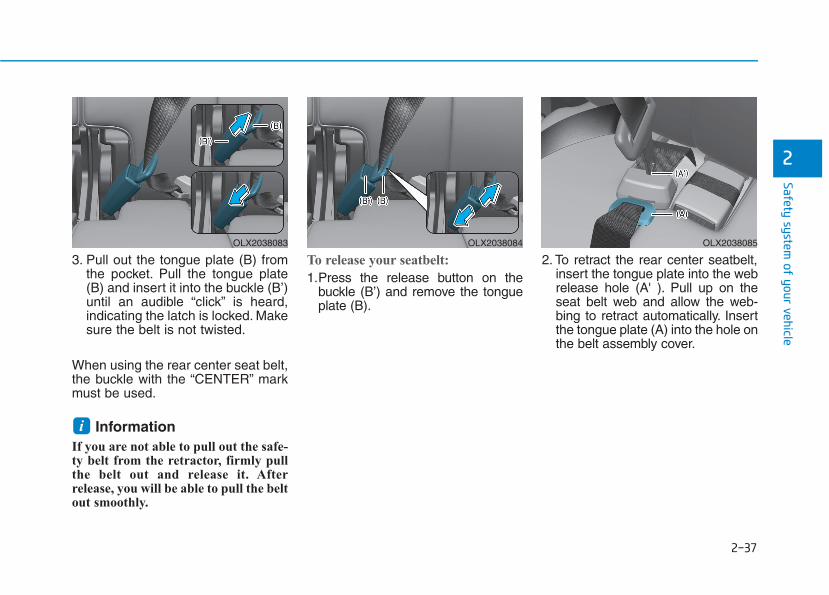
3. Pull out the tongue plate (B) fromthe pocket. Pull the tongue plate(B) and insert it into the buckle (B’)until an audible “click” is heard,indicating the latch is locked. Makesure the belt is not twisted.
When using the rear center seat belt,the buckle with the “CENTER” markmust be used.
Information If you are not able to pull out the safe-ty belt from the retractor, firmly pullthe belt out and release it. Afterrelease, you will be able to pull the beltout smoothly.
To release your seatbelt:
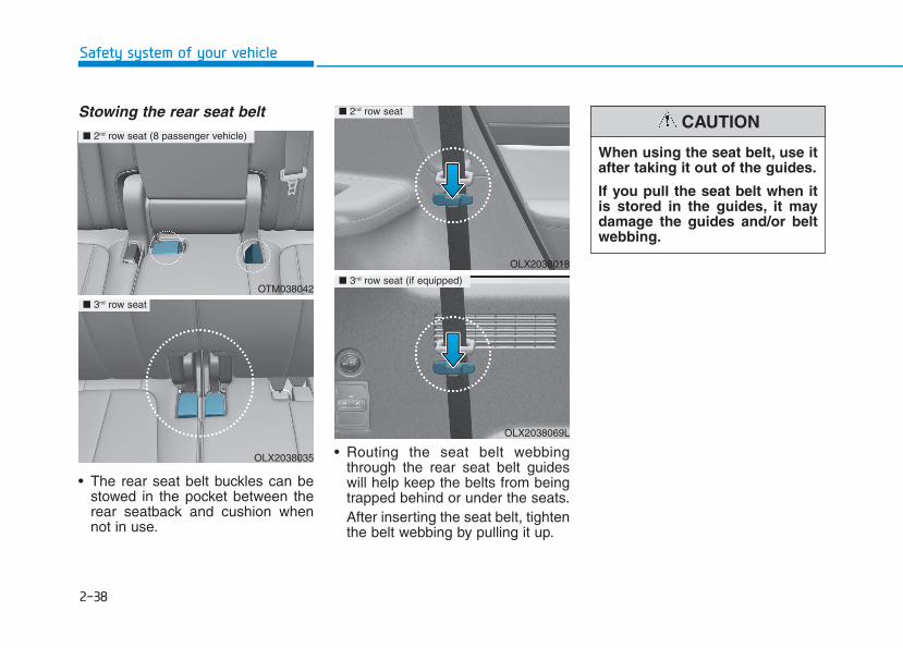
1.Press the release button on thebuckle (B’) and remove the tongueplate (B).
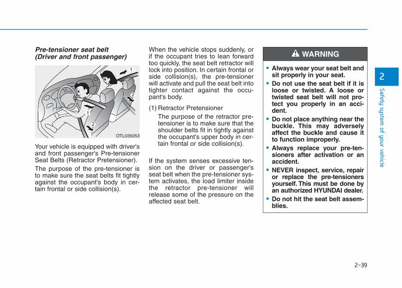
2. To retract the rear center seatbelt,insert the tongue plate into the webrelease hole (A' ). Pull up on theseat belt web and allow the web-bing to retract automatically. Insertthe tongue plate (A) into the hole onthe belt assembly cover.
i
OLX2038083 OLX2038084 OLX2038085
2-38
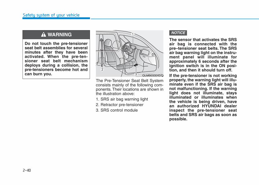
Stowing the rear seat belt
• The rear seat belt buckles can bestowed in the pocket between therear seatback and cushion whennot in use.
• Routing the seat belt webbingthrough the rear seat belt guideswill help keep the belts from beingtrapped behind or under the seats.After inserting the seat belt, tightenthe belt webbing by pulling it up.
Safety system of your vehicle
OLX2038018
OLX2038069L
■ 2nd row seat
■ 3nd row seat (if equipped)OTM038042
OLX2038035
■ 2nd row seat (8 passenger vehicle)
■ 3nd row seat
When using the seat belt, use itafter taking it out of the guides.
If you pull the seat belt when itis stored in the guides, it maydamage the guides and/or beltwebbing.
CAUTION
2-39
Safety system of your vehicle
Pre-tensioner seat belt (Driver and front passenger)
Your vehicle is equipped with driver'sand front passenger's Pre-tensionerSeat Belts (Retractor Pretensioner).The purpose of the pre-tensioner isto make sure the seat belts fit tightlyagainst the occupant's body in cer-tain frontal or side collision(s).
When the vehicle stops suddenly, orif the occupant tries to lean forwardtoo quickly, the seat belt retractor willlock into position. In certain frontal orside collision(s), the pre-tensionerwill activate and pull the seat belt intotighter contact against the occu-pant's body.
(1) Retractor Pretensioner The purpose of the retractor pre-tensioner is to make sure that theshoulder belts fit in tightly againstthe occupant's upper body in cer-tain frontal or side collision(s).
If the system senses excessive ten-sion on the driver or passenger'sseat belt when the pre-tensioner sys-tem activates, the load limiter insidethe retractor pre-tensioner willrelease some of the pressure on theaffected seat belt.
2• Always wear your seat belt and
sit properly in your seat.• Do not use the seat belt if it is
loose or twisted. A loose ortwisted seat belt will not pro-tect you properly in an acci-dent.
• Do not place anything near thebuckle. This may adverselyaffect the buckle and cause itto function improperly.
• Always replace your pre-ten-sioners after activation or anaccident.
• NEVER inspect, service, repairor replace the pre-tensionersyourself. This must be done byan authorized HYUNDAI dealer.
• Do not hit the seat belt assem-blies.
WARNING
OTL035053
2-40
Safety system of your vehicle
The Pre-Tensioner Seat Belt Systemconsists mainly of the following com-ponents. Their locations are shown inthe illustration above:1. SRS air bag warning light2. Retractor pre-tensioner3. SRS control module
The sensor that activates the SRSair bag is connected with thepre–tensioner seat belts. The SRSair bag warning light on the instru-ment panel will illuminate forapproximately 6 seconds after theignition switch is in the ON posi-tion, and then it should turn off.If the pre-tensioner is not workingproperly, the warning light will illu-minate even if the SRS air bag isnot malfunctioning. If the warninglight does not illuminate, staysilluminated or illuminates whenthe vehicle is being driven, havean authorized HYUNDAI dealerinspect the pre-tensioner seatbelts and SRS air bags as soon aspossible.
NOTICE
OLMB033040/Q
Do not touch the pre-tensionerseat belt assemblies for severalminutes after they have beenactivated. When the pre-ten-sioner seat belt mechanismdeploys during a collision, thepre-tensioners become hot andcan burn you.
WARNING
2-41
Safety system of your vehicle
2
• Both the driver's and front pas-senger's pre-tensioner seatbelts may be activated in certainfrontal or side collisions orrollovers.
• When the pre-tensioner seatbelts are activated, a loud noisemay be heard and fine dust,which may appear to be smoke,may be visible in the passengercompartment. These are normaloperating conditions and are nothazardous.
• Although it is non-toxic, the finedust may cause skin irritationand should not be inhaled forprolonged periods. Wash allexposed skin areas thoroughlyafter an accident in which thepre-tensioner seat belts wereactivated.
Additional Seat Belt SafetyPrecautionsSeat belt use during pregnancy The seat belt should always be usedduring pregnancy. The best way toprotect your unborn child is to protectyourself by always wearing the seatbelt.Pregnant women should always weara lap-shoulder seat belt. Place theshoulder belt across your chest, rout-ed between your breasts and awayfrom your neck. Place the lap belt lineso that it fits snugly and as low as pos-sible across the hips, not across theabdomen.
NOTICE
• A pregnant woman or apatient is more vulnerable toany imapcts on the abdomenduring an abrupt stop or acci-dent. If you are in an accidentwhile pregnant, we recom-mend you consult your doc-tor.
• To reduce the risk of seriousinjury or death to an unbornchild during an accident,pregnant women shouldNEVER place the lap portionof the seat belt above or overthe area of the abdomenwhere the unborn child islocated.
WARNING
2-42
Safety system of your vehicle
Seat belt use and children Infant and small children
All 50 states have child restraint lawswhich require children to travel inapproved child restraint devices,including booster seats. The age atwhich seat belts can be used insteadof child restraints differs amongstates, so you should be aware of thespecific requirements in your state,and where you are travelling. Infantand child restraints must be properlyplaced and installed in a rear seat.For more information refer to the"Child Restraint Systems" section inthis chapter.
Small children are best protectedfrom injury in an accident when prop-erly restrained in the rear seat by achild restraint system that meets therequirements of the Federal MotorVehicle Safety Standards. Beforebuying any child restraint system,make sure that it has a label certify-ing that it meets Federal MotorVehicle Safety Standard FMVSS 213.The restraint must be appropriate foryour child’s height and weight. Checkthe label on the child restraint for thisinformation. Refer to the "ChildRestraint Systems" section in thischapter.
ALWAYS properly restrain infantsand small children in a childrestraint appropriate for thechild's height and weight.To reduce the risk of seriousinjury or death to a child andother passengers, NEVER hold achild in your lap or arms whenthe vehicle is moving.The violentforces created during an acci-dent will tear the child from yourarms and throw the child againstthe interior of the vehicle.
WARNING
2-43
Safety system of your vehicle
2
Larger children
Children under age 13 and who aretoo large for a booster seat mustalways occupy the rear seat and usethe available lap/shoulder belts. Aseat belt should lie across the upperthighs and be snug across the shoul-der and chest to restrain the childsafely. Check belt fit periodically.Children are afforded the most safe-ty in the event of an accident whenthey are restrained by a properrestraint system and/or seat belts inthe rear seat. Always have theLATCH system inspected by yourauthorized HYUNDAI dealer after anaccident. An accident can damagethe LATCH system and may notproperly secure the child restraint.If a larger child over age 13 must beseated in the front seat, the childmust be securely restrained by theavailable lap/shoulder belt and theseat should be placed in the rear-most position.
If the shoulder belt portion slightlytouches the child's neck or face, tryplacing the child closer to the centerof the vehicle. If the shoulder belt stilltouches their face or neck they needto be returned to an appropriatebooster seat in the rear seat.
Transporting an injured personA seat belt should be used when aninjured person is being transported.Consult a physician for specific rec-ommendations.
One person per belt Two people (including children) shouldnever attempt to use a single seat belt.This could increase the severity ofinjuries in case of an accident.
Do not lie down Sitting in a reclined position whenthe vehicle is in motion can be dan-gerous. Even when buckled up, theprotections of your restraint system(seat belts and air bags) is greatlyreduced by reclining your seatback.To reduce the chance of injuries in theevent of an accident and to achievethe maximum effectiveness of therestraint system, all passengersshould be sitting up and the front andrear seats should be in an uprightposition when the car is moving.A seat belt cannot provide properprotection if the person is lying downin the rear seat or if the front or rearseats are in a reclined position.
• Always make sure childrenare wearing their seat beltsand that they are properlyadjusted before driving.
• NEVER allow the shoulderbelt to contact the child’sneck or face.
• Do not allow more than onechild to use a single seat belt.
WARNING
2-44
Safety system of your vehicle
Care of Seat Belts Seat belt systems should never bedisassembled or modified. In addi-tion, care should be taken to assurethat seat belts and belt hardware arenot damaged by seat hinges, doorsor other abuse.
Periodic inspectionAll seat belts should be inspectedperiodically for wear or damage ofany kind. Any damaged parts shouldbe replaced as soon as possible byan authorized HYUNDAI dealer.
Keep belts clean and dry Seat belts should be kept clean anddry. If belts become dirty, they can becleaned by using a mild soap solu-tion and warm water. Bleach, dye,strong detergents or abrasivesshould not be used because theymay damage and weaken the fabric.
When to replace seat belts The entire seat belt assembly orassemblies should be replaced if thevehicle has been involved in an acci-dent. This should be done even if nodamage is visible. Additional ques-tions concerning seat belt operationshould be directed to an authorizedHYUNDAI dealer.
• NEVER ride with a reclinedseatback when the vehicle ismoving.
• Riding with a reclined seatbackincreases your chance of seri-ous or fatal injuries in the eventof a collision or sudden stop.
• Drivers and passengers shouldalways sit well back in theirseats, properly belted, and withthe seatbacks upright.
WARNING
2-45
Safety system of your vehicle
2
Children Always in the Rear Children under age 13 must alwaysride in the rear seats and mustalways be properly restrained to min-imize the risk of injury in an accident,sudden stop or sudden maneuver.According to accident statistics, chil-dren are safer when properlyrestrained in the rear seats than inthe front seat. Even with air bags,children can be seriously injuredor killed. Children too large for achild restraint must use the seat beltsprovided.All 50 states have child restraint lawswhich require children to travel inapproved child restraint devices. Thelaws governing the age or height/weight restrictions at which seatbelts can be used instead of childrestraints differs among states, soyou should be aware of the specificrequirements in your state, andwhere you are travelling.
Child restraint systems must be prop-erly placed and installed in the rearseat. You must use a commerciallyavailable child restraint system thatmeets the requirements of the FederalMotor Vehicle Safety Standards(FMVSS 213).Child restraint systems are generallydesigned to be secured in a vehicleseat by lap belt portion of alap/shoulder belt, or by a LATCH sys-tem in the rear seats of the vehicle.
CCHHIILLDD RREESSTTRRAAIINNTT SSYYSSTTEEMM ((CCRRSS))
Always properly restrain chil-dren in the rear seats of thevehicle.Children of all ages are saferwhen restrained in the rear seat.A child riding in the front pas-senger seat can be forcefullystruck by an inflating air bagresulting in SERIOUS INJURYor DEATH.
WARNING
2-46
Safety system of your vehicle
Child restraint system (CRS) Infants and younger children must berestrained in an appropriate rear-fac-ing or forward-facing CRS that hasfirst been properly secured to therear seat of the vehicle. Read andcomply with the instructions forinstallation and use provided by themanufacturer of the child restraint.
• Always properly restrain yourchild in the child restraint.
• If the vehicle head restraintprevents proper installation ofa child seat (as described inthe child restraint systemmanual), the head restraint ofthe respective seating posi-tion shall be readjusted orentirely removed.
• Do not use an infant carrier ora child safety seat that"hooks" over a seatback, itmay not provide adequateprotection in an accident.
• After an accident, have aHYUNDAI dealer check thechild restraint system, seatbelts, lower anchors andupper tether anchors.
An improperly secured childrestraint can increase the riskof SERIOUS INJURY or DEATHin an accident. Always take thefollowing precautions whenusing a child restraint system:• NEVER install a child or infant
restraint in the front passen-ger's seat.
• Always properly secure thechild restraint to a rear seat ofthe vehicle.
• Always follow the childrestraint system manufactur-er's instructions for installa-tion and use.
WARNING
• Be especially careful wheninstalling a child restraint onthe center seating position inthe second row as it is narrow-er than the outboard positions.A wide child restraint installedon the center seat may coverthe safety belt buckles for theother seating positions. Do notallow someone to ride in aseating position where thesafety belt buckle is covered bya child restraint.
• A child restraint in the centerseating position may also con-tact or push up against thesafety belt buckles, which candamage the buckles and makethem unusable or unsafe.Always check that the childrestraint does not contact anyof the safety belt buckles.Check the placement of thechild restraint regularly tomake sure that it has not shift-ed and come into contact withany of the safety belt buckles.
WARNING

2-47
Safety system of your vehicle
2
Selecting a Child RestraintSystem (CRS) When selecting a CRS for your child,always:• Make sure the CRS has a label
certifying that it meets applicableFederal Motor Vehicle SafetyStandards (FMVSS 213).
• Select a child restraint based onyour child's height and weight. Therequired label or the instructionsfor use typically provide this infor-mation.
• Select a child restraint that fits thevehicle seating position where itwill be used.
• Read and comply with the warn-ings and instructions for installa-tion and use provided with thechild restraint system.
Child restraint system types There are three main types of childrestraint systems: rearward-facingseats, forward-facing seats, andbooster seats. They are classifiedaccording to the child's age, heightand weight.
Rearward-facing child seats
A rearward-facing child seat providesrestraint with the seating surfaceagainst the back of the child. The har-ness system holds the child in place,and in an accident, acts to keep thechild positioned in the seat andreduce the stress to the neck andspinal cord.All children under age one mustalways ride in a rearward-facing infantchild restraint.Convertible and 3-in-1 child seats typ-ically have higher height and weightlimits for the rearward-facing position,allowing you to keep your child rear-ward-facing for a longer period oftime.
NEVER install a child or infantrestraint in the front passen-ger's seat.Placing a rearward-facing childrestraint in the front seat canresult in SERIOUS INJURY orDEATH if the child restraint isstruck by an inflating air bag.
WARNING OLX2039036N
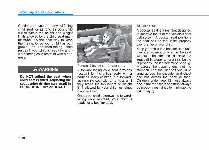
2-48
Safety system of your vehicle
Continue to use a rearward-facingchild seat for as long as your childwill fit within the height and weightlimits allowed by the child seat man-ufacturer. It's the best way to keepthem safe. Once your child has out-grown the rearward-facing childrestraint, your child is ready for a for-ward-facing child restraint with a har-ness.
Forward-facing child restraints
A forward-facing child seat providesrestraint for the child's body with aharness. Keep children in a forward-facing child seat with a harness untilthey reach the top height or weightlimit allowed by your child restraint’smanufacturer.Once your child outgrows the forward-facing child restraint, your child isready for a booster seat.
Booster seats
A booster seat is a restraint designedto improve the fit of the vehicle's seatbelt system. A booster seat positionsthe seat belt so that it fits properlyover the lap of your child.Keep your child in a booster seat untilthey are big enough to sit in the seatwithout a booster and still have theseat belt fit properly. For a seat belt tofit properly, the lap belt must lie snug-ly across the upper thighs, not thestomach. The shoulder belt should liesnug across the shoulder and chestand not across the neck or face.Children under age 13 must alwaysride in the rear seats and must alwaysbe properly restrained to minimize therisk of injury.
OLX2039002N
Do NOT adjust the seat whenchild seat is fitted. Adjusting theseat during driving can result inSERIOUS INJURY or DEATH.
WARNING
2-49
Safety system of your vehicle
2
Installing a Child RestraintSystem (CRS)
After selecting a proper child seat foryour child, check to make sure it fitsproperly in your vehicle. Follow theinstructions provided by the manu-facturer when installing the childseat. Note these general steps wheninstalling the seat to your vehicle:• Properly secure the child
restraint to the vehicle. All childrestraints must be secured to thevehicle with the lap part of alap/shoulder belt or with theLATCH system. If using thelap/shoulder belt for your childrestraint, the convertible lockingretractor should be pulled all theway out to engage the "automaticlocking" mode. (See page 2-54.)
• Make sure the child restraint isfirmly secured. After installing achild restraint to the vehicle, pushand pull the seat forward-and-back and side-to-side to verify thatit is securely attached to the seat.A child restraint secured with aseat belt should be installed asfirmly as possible. However, someside-to-side movement can beexpected.
• Secure the child in the childrestraint. Make sure the child isproperly strapped in the childrestraint according to the manu-facturer instructions.
Before installing your childrestraint system always:• Read and follow the instruc-
tions provided by the manu-facturer of the child restraint.
• Read and follow the instruc-tions regarding child restraintsystems in this manual.
Failure to follow all warningsand instructions could increasethe risk of the SERIOUS INJURYor DEATH if an accident occurs.
WARNING
If the vehicle head restraint pre-vents proper installation of achild seat (as described in thechild seat system manual, thehead restraint of the respectiveseating position shall be read-justed or entirely removed.
WARNING
A child restraint in a closedvehicle can become very hot.Toprevent burns, check the seat-ing surface and buckles beforeplacing your child in the childrestraint.
CAUTION
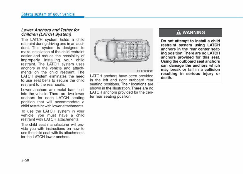
2-50
Safety system of your vehicle
Lower Anchors and Tether forChildren (LATCH System)The LATCH system holds a childrestraint during driving and in an acci-dent. This system is designed tomake installation of the child restrainteasier and reduce the possibility ofimproperly installing your childrestraint. The LATCH system usesanchors in the vehicle and attach-ments on the child restraint. TheLATCH system eliminates the needto use seat belts to secure the childrestraint to the rear seats.Lower anchors are metal bars builtinto the vehicle. There are two loweranchors for each LATCH seatingposition that will accommodate achild restraint with lower attachments.To use the LATCH system in yourvehicle, you must have a childrestraint with LATCH attachments.The child seat manufacturer will pro-vide you with instructions on how touse the child seat with its attachmentsfor the LATCH lower anchors.
LATCH anchors have been providedin the left and right outboard rearseating positions. Their locations areshown in the illustration. There are noLATCH anchors provided for the cen-ter rear seating position.
OLX2038039
Do not attempt to install a childrestraint system using LATCHanchors in the rear center seat-ing position.There are no LATCHanchors provided for this seat.Using the outboard seat anchorscan damage the anchors whichmay break or fail in a collisionresulting in serious injury ordeath.
WARNING
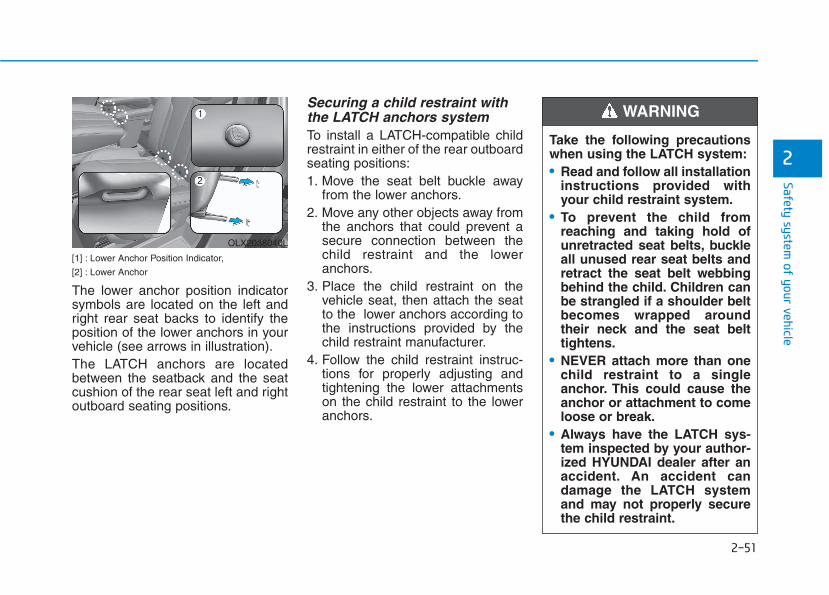
2-51
Safety system of your vehicle
2
[1] : Lower Anchor Position Indicator,
[2] : Lower Anchor
The lower anchor position indicatorsymbols are located on the left andright rear seat backs to identify theposition of the lower anchors in yourvehicle (see arrows in illustration).The LATCH anchors are locatedbetween the seatback and the seatcushion of the rear seat left and rightoutboard seating positions.
Securing a child restraint withthe LATCH anchors systemTo install a LATCH-compatible childrestraint in either of the rear outboardseating positions:1. Move the seat belt buckle away
from the lower anchors.2. Move any other objects away from
the anchors that could prevent asecure connection between thechild restraint and the loweranchors.
3. Place the child restraint on thevehicle seat, then attach the seatto the lower anchors according tothe instructions provided by thechild restraint manufacturer.
4. Follow the child restraint instruc-tions for properly adjusting andtightening the lower attachmentson the child restraint to the loweranchors.
OLX2038040L
Take the following precautionswhen using the LATCH system:• Read and follow all installation
instructions provided withyour child restraint system.
• To prevent the child fromreaching and taking hold ofunretracted seat belts, buckleall unused rear seat belts andretract the seat belt webbingbehind the child. Children canbe strangled if a shoulder beltbecomes wrapped aroundtheir neck and the seat belttightens.
• NEVER attach more than onechild restraint to a singleanchor. This could cause theanchor or attachment to comeloose or break.
• Always have the LATCH sys-tem inspected by your author-ized HYUNDAI dealer after anaccident. An accident candamage the LATCH systemand may not properly securethe child restraint.
WARNING

2-52
Safety system of your vehicle
The recommended weight for theLATCH system is under 65 lb (30kg).How to determine an appropriatechild restraint weight:Child weight + Child restraintweight < 65 lb (30kg)
Securing a child restraint seatwith "Tether Anchor" system
First secure the child restraint withthe LATCH lower anchors or the seatbelt. If the child restraint manufactur-er recommends that the top tetherstrap be attached, attach and tightenthe top tether strap to the top tetherstrap anchor.
Child restraint hook holders arelocated on the rear of the seatbacks.
NOTICE
OLX2039087N
■ 2nd row passenger seat
OLX2039101N
■ 3rd row passenger seat
Take the following precautionswhen installing the tether strap:• Read and follow all installation
instructions provided withyour child restraint system.
• NEVER attach more than onechild restraint to a single teth-er anchor. This could causethe anchor or attachment tocome loose or break.
• Do not attach the tether strapto anything other than the cor-rect tether anchor. It may notwork properly if attached tosomething else.
• Do not use the tether anchorsfor adult seat belts or harness-es, or for attaching other itemsor equipment to the vehicle.
WARNING

2-53
Safety system of your vehicle
2
To install the tether anchor:1. Route the child restraint tether
strap over the child restraint seat-back. Route the tether strap underthe head restraint and betweenthe head restraint posts, or routethe tether strap over the top of thevehicle seatback. Make sure thestrap is not twisted.
2. Connect the tether strap hook tothe tether anchor, then tighten thetether strap according to the childseat manufacturer's instructions tofirmly secure the child restraint tothe seat.
3. Check that the child restraint issecurely attached to the seat bypushing and pulling the seat for-ward-and-back and side-to-side.
Securing a child restraint withlap/shoulder beltWhen not using the LATCH system,all child restraints must be secured toa vehicle rear seat with the lap partof a lap/shoulder belt.
Automatic locking mode
Since all passenger seat belts movefreely under normal conditions andonly lock under extreme or emer-gency conditions (emergency lockingmode), you must manually pull theseat belt all the way out to shift theretractor to the "Automatic Locking"mode to secure a child restraint.The "Automatic Locking" mode willhelp prevent the normal movementof the child in the vehicle from caus-ing the seat belt to loosen and com-promise the child restraint system. Tosecure a child restraint system, usethe following procedure.
ALWAYS place a rear-facingchild restraint in the rear seat ofthe vehicle.Placing a rear-facing childrestraint in the front seat canresult in serious injury or deathif the child restraint is struck byan inflating air bag.
WARNING
OLX2039038N OLMB033044

2-54
Safety system of your vehicle
To install a child restraint system onthe rear seats, do the following:1. Place the child restraint system on
a rear seat and route the lap/ shoul-der belt around or through the childrestraint, following the restraintmanufacturer's instructions.Be sure the seat belt webbing is nottwisted.
When using the rear center seatbelt, you should also refer to the"Rear Seat Belt – Passenger's 3-point system" section in thischapter.
2. Fasten the lap/shoulder belt latchinto the buckle. Listen for the dis-tinct "click" sound.
InformationPosition the release button so that it iseasy to access in case of an emergency.
3. Pull the shoulder portion of the seatbelt all the way out. When theshoulder portion of the seat belt isfully extended, it will shift the retrac-tor to the "Automatic Locking" (childrestraint) mode.
i
NOTICE OLMB033045 OLMB033097

2-55
Safety system of your vehicle
2
4. Slowly allow the shoulder portionof the seat belt to retract and listenfor an audible "clicking" or "ratch-eting" sound. This indicates thatthe retractor is in the "AutomaticLocking" mode. If no distinctsound is heard, repeat steps 3and 4.
5. Remove as much slack from thebelt as possible by pushing downon the child restraint system whilefeeding the shoulder belt back intothe retractor.
6. Push and pull on the child restraintsystem to confirm that the seatbelt is holding it firmly in place. If itis not, release the seat belt andrepeat steps 2 through 6.
7. Double check that the retractor isin the "Automatic Locking" modeby attempting to pull more of theseat belt out of the retractor. If youcannot, the retractor is in the"Automatic Locking" mode.
If your CRS manufacturer instructs orrecommends you to use a tetheranchor with the lap/shoulder belt,refer to the previous pages for moreinformation.
When the seat belt is allowed toretract to its fully stowed position,the retractor will automaticallyswitch from the "AutomaticLocking" mode to the emergencylock mode for normal adult usage.
NOTICE
OLMB033098
If the retractor is not in the"Automatic Locking" mode, thechild restraint can move whenyour vehicle turns or stops sud-denly. A child can be seriouslyinjured or killed if the childrestraint is not properly anchoredin the car, including manuallypulling the seat belt all the wayout to shift the rectractor to the"Automatic Locking" mode.
WARNING
2-56
To remove the child restraint, pressthe release button on the buckle andthen pull the lap/shoulder belt out ofthe restraint and allow the seat beltto retract fully.
Safety system of your vehicle
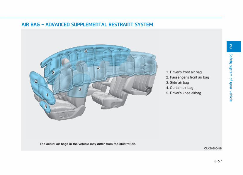
2-57
Safety system of your vehicle
2
AAIIRR BBAAGG -- AADDVVAANNCCEEDD SSUUPPPPLLEEMMEENNTTAALL RREESSTTRRAAIINNTT SSYYSSTTEEMM
OLX2039041N
The actual air bags in the vehicle may differ from the illustration.
1. Driver's front air bag
2. Passenger's front air bag
3. Side air bag
4. Curtain air bag
5. Driver’s knee airbag

2-58
Safety system of your vehicle
This vehicle is equipped with anAdvanced Supplemental Air BagSystem for the driver's seat and frontpassenger's seats.The front air bags are designed tosupplement the three-point seatbelts. For these air bags to provideprotection, the seat belts must beworn at all times when driving.You can be severely injured or killedin an accident if you are not wearinga seat belt. Air bags are designed tosupplement seat belts, but do notreplace them. Also, air bags are notdesigned to deploy in every collision.In some accidents, the seat belts arethe only restraint protecting you.
AIR BAG SAFETY PRECAUTIONS
ALWAYS use seat belts and child restraints - every trip, every time,everyone! Even with air bags, you can be seriously injured or killed ina collision if you are improperly belted or not wearing your seat beltwhen the air bag inflates.NEVER place a child in any child restraint or booster seat in the frontpassenger seat. An inflating air bag could forcefully strike the infantor child causing serious or fatal injuries.ABC - Always Buckle Children under age 13 in the back seat. It is thesafest place for children of any age to ride. If a child age 13 or oldermust be seated in the front seat, he or she must be properly beltedand the seat should be moved as far back as possible.All occupants should sit upright with the seatback in an upright posi-tion, centered on the seat cushion with their seat belt on, legs com-fortably extended and their feet on the floor until the vehicle is parkedand is turned off. If an occupant is out of position during an accident,the rapidly deploying air bag may forcefully contact the occupantcausing serious or fatal injuries.You and your passengers should never sit or lean unnecessarilyclose to the air bags or lean against the door or center console.Move your seat as far back as possible from front air bags, while stillmaintaining control of the vehicle. The U.S. National Highway TrafficSafety Administration (NHTSA) recommends that drivers allow atleast 10 inches (25 cm) between the center of the steering wheel andthe chest.
WARNING

2-59
Safety system of your vehicle
2
Where Are the Air Bags? Driver's and passenger's frontair bags Your vehicle is equipped with aAdvanced Supplemental RestraintSystem (SRS) and lap/shoulder beltsat both the driver and passengerseating positions.The SRS consists of air bags whichare located in the center of the steer-ing wheel, and the passenger's sidefront panel pad above the glove box.The air bags are labeled with the let-ters "AIR BAG" embossed on thepad covers.
The purpose of the SRS is to providethe vehicle's driver and front passen-gers with additional protection thanthat offered by the seat belt systemalone.The advanced SRS offers the abilityto control the air bag inflation withintwo levels. A first stage level is pro-vided for moderate-severity impacts.A second stage level is provided formore severe impacts.According to the impact severity, theSRS Control Module (SRSCM) con-trols the air bag inflation. Failure toproperly wear seat belts canincrease the risk or severity of injuryin an accident.
OLX2038045OLX2038044
■ Passenger’s front air bag■ Driver’s front air bag
OLX2039043N
■ Driver’s knee air bag
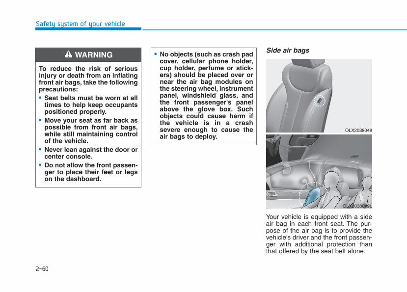
2-60
Safety system of your vehicle
Side air bags
Your vehicle is equipped with a sideair bag in each front seat. The pur-pose of the air bag is to provide thevehicle's driver and the front passen-ger with additional protection thanthat offered by the seat belt alone.
OLX2038048
OLX2038049L
• No objects (such as crash padcover, cellular phone holder,cup holder, perfume or stick-ers) should be placed over ornear the air bag modules onthe steering wheel, instrumentpanel, windshield glass, andthe front passenger's panelabove the glove box. Suchobjects could cause harm ifthe vehicle is in a crashsevere enough to cause theair bags to deploy.
To reduce the risk of seriousinjury or death from an inflatingfront air bags, take the followingprecautions:• Seat belts must be worn at all
times to help keep occupantspositioned properly.
• Move your seat as far back aspossible from front air bags,while still maintaining controlof the vehicle.
• Never lean against the door orcenter console.
• Do not allow the front passen-ger to place their feet or legson the dashboard.
WARNING
2-61
Safety system of your vehicle
2
The side air bags are designed todeploy during certain side impactcollisions, depending on the crashseverity.The side and curtain air bags onboth sides of the vehicle may deployif a rollover or possible rollover isdetected.The side air bags are not designed todeploy in all side impact or rolloversituations.
• Do not allow passengers tolean their heads or bodiesonto doors, put their arms onthe doors, stretch their armsout of the window, or placeobjects between the doorsand seats.
• Hold the steering wheel at the9 o'clock and 3 o'clock posi-tions, to minimize the risk ofinjuries to your hands andarms.
• Do not use any accessoryseat covers.This could reduceor prevent the effectivenessof the system.
• Do not place any objects overthe air bag or between the airbag and yourself. Also, do notattach any objects around thearea the air bag inflates suchas the door, side door glass,front and rear pillar.
• Do not place any objectsbetween the door and theseat. They may become dan-gerous projectiles if the sideair bag inflates.
• Do not install any accessorieson the side or near the side airbags.
• Do not put any objectsbetween the side airbag labeland seat cushion. It couldcause harm if the vehicle is ina crash severe enough tocause the air bags to deploy.
• Do not cause impact to thedoors when the ignitionswitch button is in the ONposition as this may cause theside air bags to inflate.
• If the seat or seat cover isdamaged, have the vehiclechecked and repaired by anauthorized HYUNDAI dealer.
To reduce the risk of seriousinjury or death from an inflatingside air bag, take the followingprecautions:• Seat belts must be worn at all
times to help keep occupantspositioned properly.
WARNING
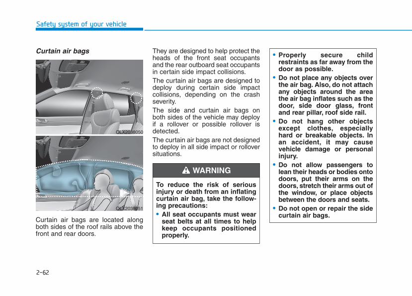
2-62
Safety system of your vehicle
Curtain air bags
Curtain air bags are located alongboth sides of the roof rails above thefront and rear doors.
They are designed to help protect theheads of the front seat occupantsand the rear outboard seat occupantsin certain side impact collisions.The curtain air bags are designed todeploy during certain side impactcollisions, depending on the crashseverity.The side and curtain air bags onboth sides of the vehicle may deployif a rollover or possible rollover isdetected.The curtain air bags are not designedto deploy in all side impact or rolloversituations.
To reduce the risk of seriousinjury or death from an inflatingcurtain air bag, take the follow-ing precautions:• All seat occupants must wear
seat belts at all times to helpkeep occupants positionedproperly.
• Properly secure childrestraints as far away from thedoor as possible.
• Do not place any objects overthe air bag. Also, do not attachany objects around the areathe air bag inflates such as thedoor, side door glass, frontand rear pillar, roof side rail.
• Do not hang other objectsexcept clothes, especiallyhard or breakable objects. Inan accident, it may causevehicle damage or personalinjury.
• Do not allow passengers tolean their heads or bodies ontodoors, put their arms on thedoors, stretch their arms out ofthe window, or place objectsbetween the doors and seats.
• Do not open or repair the sidecurtain air bags.
WARNING
OLX2038050
OLX2038051
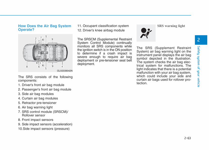
2-63
Safety system of your vehicle
2
How Does the Air Bag SystemOperate?
The SRS consists of the followingcomponents:1. Driver's front air bag module2. Passenger's front air bag module3. Side air bag modules4. Curtain air bag modules5. Retractor pre-tensioner6. Air bag warning light7. SRS control module (SRSCM)/
Rollover sensor8. Front impact sensors9. Side impact sensors (acceleration)10.Side impact sensors (pressure)
11. Occupant classification system12. Driver’s knee airbag module
The SRSCM (Supplemental RestraintSystem Control Module) continuallymonitors all SRS components whilethe ignition switch is in the ON positionto determine if a crash impact issevere enough to require air bagdeployment or pre-tensioner seat beltdeployment.
SRS warning light
The SRS (Supplement RestraintSystem) air bag warning light on theinstrument panel displays the air bagsymbol depicted in the illustration.The system checks the air bag elec-trical system for malfunctions. Thelight indicates that there is a potentialmalfunction with your air bag system,which could include your side andcurtain air bags used for rollover pro-tection.
OLX2039042N
2-64
Safety system of your vehicle
During a frontal collision, sensors willdetect the vehicle's deceleration. Ifthe rate of deceleration is highenough, the control unit will inflatethe front air bags.The front air bags help protect thedriver and front passenger byresponding to frontal impacts inwhich seat belts alone cannot pro-vide adequate restraint. When need-ed, the side air bags help provideprotection in the event of a sideimpact or rollover.• Air bags are activated (able to
inflate if necessary) only when theignition switch is in the ON posi-tion.
• Air bags inflate in the event of cer-tain frontal or side collisions tohelp protect the occupants fromserious physical injury.
• Generally, air bags are designedto inflate based upon the severityof a collision, its direction, etc.These two factors determinewhether the sensors produce anelectronic deployment/inflationsignal.
• The front air bags will completelyinflate and deflate in an instant. It isvirtually impossible for you to seethe air bags inflate during an acci-dent. It is much more likely that youwill simply see the deflated airbags hanging out of their storagecompartments after the collision.
• In addition to inflating in certainside collisions, vehicles equippedwith a rollover sensor, side andcurtain air bags will inflate if thesensing system detects a rollover.When a rollover is detected, sideand curtain air bags will remaininflated longer to help provide pro-tection from ejection, especiallywhen used in conjunction with theseat belts.
• To help provide protection, the airbags must inflate rapidly. Thespeed of air bag inflation is a con-sequence of extremely short timein which to inflate the air bagbetween the occupant and thevehicle structures before the occu-pant impacts those structures. Thisspeed of inflation reduces the riskof serious or life-threateninginjuries and is thus a necessarypart of air bag design.
If your SRS malfunctions, the airbag may not inflate properly dur-ing an accident increasing therisk of serious injury or death.If any of the following condi-tions occur, your SRS is mal-functioning:• The light does not turn on for
approximately six secondswhen the Engine Start/Stopbutton is in the ON position.
• The light stays on after illumi-nating for approximately sixseconds.
• The light comes on while thevehicle is in motion.
• The light blinks when theengine is running.
Have an authorized HYUNDAIdealer inspect the SRS as soonas possible if any of these con-ditions occur.
WARNING
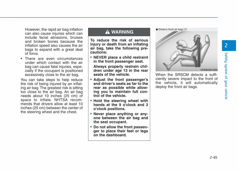
2-65
Safety system of your vehicle
2
However, the rapid air bag inflationcan also cause injuries which caninclude facial abrasions, bruisesand broken bones because theinflation speed also causes the airbags to expand with a great dealof force.
• There are even circumstancesunder which contact with the airbag can cause fatal injuries, espe-cially if the occupant is positionedexcessively close to the air bag.
You can take steps to help reducethe risk of being injured by an inflat-ing air bag. The greatest risk is sittingtoo close to the air bag. An air bagneeds about 10 inches (25 cm) ofspace to inflate. NHTSA recom-mends that drivers allow at least 10inches (25 cm) between the center ofthe steering wheel and the chest.
When the SRSCM detects a suffi-ciently severe impact to the front ofthe vehicle, it will automaticallydeploy the front air bags.
To reduce the risk of seriousinjury or death from an inflatingair bag, take the following pre-cautions:• NEVER place a child restraint
in the front passenger seat.Always properly restrain chil-dren under age 13 in the rearseats of the vehicle.
• Adjust the front passenger’sand driver's seats as far to therear as possible while allow-ing you to maintain full con-trol of the vehicle.
• Hold the steering wheel withhands at the 9 o'clock and 3o'clock positions.
• Never place anything or any-one between the air bag andthe seat occupant.
• Do not allow the front passen-ger to place their feet or legson the dashboard.
WARNING
OHM039102N
■ Driver's front air bag (1)
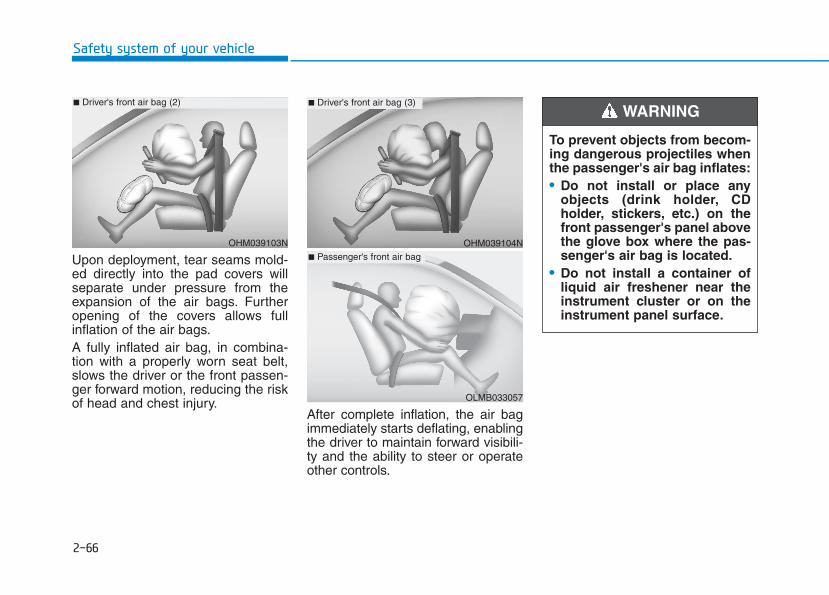
2-66
Safety system of your vehicle
Upon deployment, tear seams mold-ed directly into the pad covers willseparate under pressure from theexpansion of the air bags. Furtheropening of the covers allows fullinflation of the air bags.A fully inflated air bag, in combina-tion with a properly worn seat belt,slows the driver or the front passen-ger forward motion, reducing the riskof head and chest injury.
After complete inflation, the air bagimmediately starts deflating, enablingthe driver to maintain forward visibili-ty and the ability to steer or operateother controls.
OHM039103N
■ Driver's front air bag (2)
To prevent objects from becom-ing dangerous projectiles whenthe passenger's air bag inflates:• Do not install or place any
objects (drink holder, CDholder, stickers, etc.) on thefront passenger's panel abovethe glove box where the pas-senger's air bag is located.
• Do not install a container ofliquid air freshener near theinstrument cluster or on theinstrument panel surface.
WARNING
OHM039104N
■ Driver's front air bag (3)
OLMB033057
■ Passenger's front air bag
2-67
Safety system of your vehicle
2
What to Expect After an AirBag Inflates After a frontal or side air bag inflates,it will deflate very quickly. Air baginflation will not prevent the driverfrom seeing out of the windshield orbeing able to steer. Curtain air bagsmay remain partially inflated forsome time after they deploy.
Noise and smoke from inflatingair bag When the air bags inflate, they makea loud noise and may producesmoke and powder in the air inside ofthe vehicle. This is normal and is aresult of the ignition of the air baginflator. After the air bag inflates, youmay feel substantial discomfort inbreathing because of the contact ofyour chest with both the seat belt andthe air bag, as well as from breathingthe smoke and powder. The powdermay aggravate asthma for somepeople. If you experience breathingproblems after an air bag deploy-ment, seek medical attention imme-diately.Though the smoke and powder arenontoxic, they may cause irritation tothe skin, eyes, nose, throat, etc. Ifthis is the case, wash and rinse withcold water immediately and seekmedical attention if the symptomspersist.
• Always wash exposed skinareas thoroughly with coldwater and mild soap.
• Always have an authorizedHYUNDAI dealer replace theair bag immediately afterdeployment. Air bags aredesigned to be used onlyonce.
After an air bag inflates, takethe following precautions:• Open your windows and doors
as soon as possible afterimpact to reduce prolongedexposure to the smoke andpowder released by the inflat-ing air bag.
• Do not touch the air bag stor-age area's internal compo-nents immediately after an airbag has inflated. The partsthat come into contact with aninflating air bag may be veryhot.
WARNING
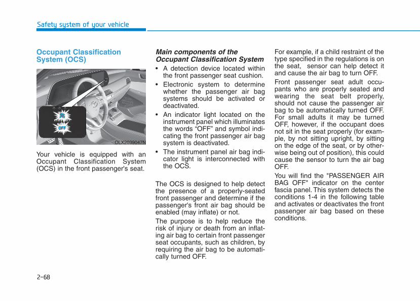
2-68
Safety system of your vehicle
Occupant ClassificationSystem (OCS)
Your vehicle is equipped with anOccupant Classification System(OCS) in the front passenger's seat.
Main components of theOccupant Classification System • A detection device located within
the front passenger seat cushion.• Electronic system to determine
whether the passenger air bagsystems should be activated ordeactivated.
• An indicator light located on theinstrument panel which illuminatesthe words “OFF” and symbol indi-cating the front passenger air bagsystem is deactivated.
• The instrument panel air bag indi-cator light is interconnected withthe OCS.
The OCS is designed to help detectthe presence of a properly-seatedfront passenger and determine if thepassenger's front air bag should beenabled (may inflate) or not.The purpose is to help reduce therisk of injury or death from an inflat-ing air bag to certain front passengerseat occupants, such as children, byrequiring the air bag to be automati-cally turned OFF.
For example, if a child restraint of thetype specified in the regulations is onthe seat, sensor can help detect itand cause the air bag to turn OFF.Front passenger seat adult occu-pants who are properly seated andwearing the seat belt properly,should not cause the passenger airbag to be automatically turned OFF.For small adults it may be turnedOFF, however, if the occupant doesnot sit in the seat properly (for exam-ple, by not sitting upright, by sittingon the edge of the seat, or by other-wise being out of position), this couldcause the sensor to turn the air bagOFF.You will find the "PASSENGER AIRBAG OFF" indicator on the centerfascia panel. This system detects theconditions 1-4 in the following tableand activates or deactivates the frontpassenger air bag based on theseconditions.
OLX2039047N
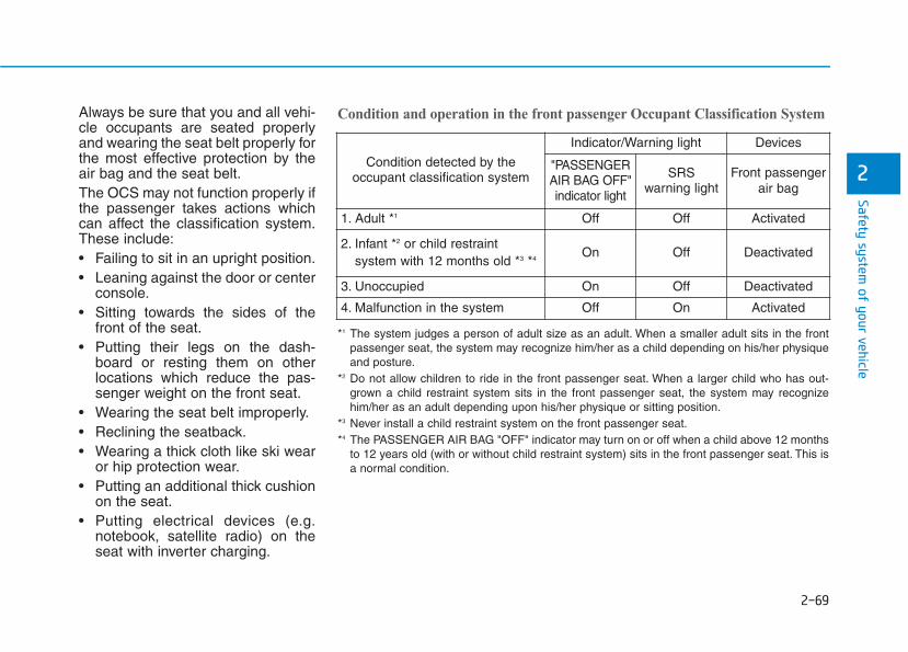
2-69
Safety system of your vehicle
2
Always be sure that you and all vehi-cle occupants are seated properlyand wearing the seat belt properly forthe most effective protection by theair bag and the seat belt.The OCS may not function properly ifthe passenger takes actions whichcan affect the classification system.These include:• Failing to sit in an upright position.• Leaning against the door or center
console.• Sitting towards the sides of the
front of the seat.• Putting their legs on the dash-
board or resting them on otherlocations which reduce the pas-senger weight on the front seat.
• Wearing the seat belt improperly.• Reclining the seatback.• Wearing a thick cloth like ski wear
or hip protection wear.• Putting an additional thick cushion
on the seat.• Putting electrical devices (e.g.
notebook, satellite radio) on theseat with inverter charging.
Condition and operation in the front passenger Occupant Classification System
Condition detected by theoccupant classification system
Indicator/Warning light Devices
"PASSENGERAIR BAG OFF"indicator light
SRSwarning light
Front passengerair bag
1. Adult *1 Off Off Activated
2. Infant *2 or child restraint system with 12 months old *3 *4
On Off Deactivated
3. Unoccupied On Off Deactivated
4. Malfunction in the system Off On Activated
*1 The system judges a person of adult size as an adult. When a smaller adult sits in the frontpassenger seat, the system may recognize him/her as a child depending on his/her physiqueand posture.
*2 Do not allow children to ride in the front passenger seat. When a larger child who has out-grown a child restraint system sits in the front passenger seat, the system may recognizehim/her as an adult depending upon his/her physique or sitting position.
*3 Never install a child restraint system on the front passenger seat.*4 The PASSENGER AIR BAG "OFF" indicator may turn on or off when a child above 12 months
to 12 years old (with or without child restraint system) sits in the front passenger seat. This isa normal condition.
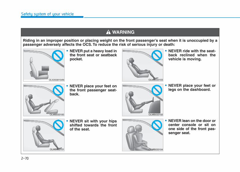
2-70
Safety system of your vehicle
Riding in an improper position or placing weight on the front passenger’s seat when it is unoccupied by apassenger adversely affects the OCS. To reduce the risk of serious injury or death:
WARNING
OLX2039104N
OLMB033100
OLMB033101
OLMB033103
OLMB033102
OLMB033104
• NEVER put a heavy load inthe front seat or seatbackpocket.
• NEVER place your feet onthe front passenger seat-back.
• NEVER sit with your hipsshifted towards the frontof the seat.
• NEVER ride with the seat-back reclined when thevehicle is moving.
• NEVER place your feet orlegs on the dashboard.
• NEVER lean on the door orcenter console or sit onone side of the front pas-senger seat.

2-71
Safety system of your vehicle
2
ODH035900K
ODH035901K
OTM038054
OTM038055
• Do not sit on the passen-ger seat wearing heavilypadded clothes such asski wear and hip protector.
• Do not use car seataccessories such as thickblankets and cushionswhich cover up the carseat surface.
• Do not place electronicdevices such as laptops,DVD player, or conductivematerials such as waterbottles on the passengerseat.
• Do not use electronicdevices such as laptopsand satellite radios whichuse inverter chargers.
• If large quantity of liquidhas been spilled on thepassenger seat, the airbag warning light mayilluminate or malfunction.Therefore, make sure theseat has been completelydried before driving thevehicle.
• Do not place sharp objects on the front passenger seat.These may damage the occupant detection sys-tem, if they puncture the seat cushion.
• Do not place any items under the front passenger seat.• When changing or replacing the seat or seat cover, use original items only. The OCS has been devel-
oped based on using original HYUNDAI car seats only. Altering or changing the authentic parts mayresult in system malfunction and increase risk of injury when in collision. Any of the above could inter-fere with the proper operation of the OCS sensor thereby increasing the risk of an injury in an accident.
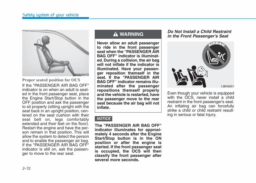
2-72
Safety system of your vehicle
Proper seated position for OCS
If the "PASSENGER AIR BAG OFF"indicator is on when an adult is seat-ed in the front passenger seat, placethe Engine Start/Stop button in theOFF position and ask the passengerto sit properly (sitting upright with theseat back in an upright position, cen-tered on the seat cushion with theirseat belt on, legs comfortablyextended and their feet on the floor).Restart the engine and have the per-son remain in that position. This willallow the system to detect the personand to enable the passenger air bag.If the "PASSENGER AIR BAG OFF"indicator is still on, ask the passen-ger to move to the rear seat.
The "PASSENGER AIR BAG OFF"indicator illuminates for approxi-mately 4 seconds after the EngineStart/Stop button is in the ONposition or after the engine isstarted. If the front passenger seatis occupied, the OCS will thenclassify the front passenger afterseveral more seconds.
Do Not Install a Child Restraintin the Front Passenger's Seat
Even though your vehicle is equippedwith the OCS, never install a childrestraint in the front passenger's seat.An inflating air bag can forcefullystrike a child or child restraint result-ing in serious or fatal injury.
NOTICE
B990A01O
Never allow an adult passengerto ride in the front passengerseat when the "PASSENGER AIRBAG OFF" indicator is illuminat-ed. During a collision, the air bagwill not inflate if the indicator isilluminated. Have your passen-ger reposition themself in theseat. If the "PASSENGER AIRBAG OFF" indicator remains illu-minated after the passengerrepositions themself properlyand the vehicle is restarted, havethe passenger move to the rearseat because the air bag will notinflate.
WARNING
1JBH3051
2-73
Safety system of your vehicle
2
Why Didn't My Air Bag Go Offin a Collision? Air bags are not designed to inflate inevery collision. There are certaintypes of accidents in which the air bagwould not be expected to provideadditional protection. These includerear impacts, second or third colli-sions in multiple impact accidents, aswell as low speed impacts. Damageto the vehicle indicates a collisionenergy absorption, and is not an indi-cator of whether or not an air bagshould have inflated.
Air bag collision sensors
• NEVER place a rear-facing orfront-facing child restraint inthe front passenger's seat ofthe vehicle.
• An inflating frontal air bagcould forcefully strike a childresulting in serious injury ordeath.
• Always properly restrain chil-dren in an appropriate childrestraint in the rear seat of thevehicle.
WARNING
To reduce the risk of an air bagdeploying unexpectedly andcausing serious injury or death:• Do not hit or allow any objects
to impact the locations where airbags or sensors are installed.
WARNING
• Do not perform maintenanceon or around the air bag sen-sors. If the location or angle ofthe sensors is altered, the airbags may deploy when theyshould not or may not deploywhen they should.
• Do not install bumper guardsor replace the bumper with anon-genuine HYUNDAI parts.This may adversely affect thecollision and air bag deploy-ment performance.
• Place the ignition switch inthe LOCK/OFF or ACC posi-tion when the vehicle is beingtowed to prevent inadvertentair bag deployment.
• Have all air bag repairs conduct-ed by an authorized HYUNDAIdealer.

2-74
Safety system of your vehicle
1. SRS control module/Rollover sensor
2. Front impact sensor
3. Side pressure sensor
4. Side impact sensor
5. Side impact sensor
OLX2039052N/OLX2038053N/OLX2039054N/OLX2038055N/OLX2038056/OLX2038057

2-75
Safety system of your vehicle
2
Air bag inflation conditions
Front air bags
Front air bags and the driver's kneeair bag are designed to inflate in afrontal collision depending on the theseverity of impact of the front colli-sion.
Side and curtain air bags
Side and curtain air bags aredesigned to inflate when an impact isdetected by side collision sensorsdepending on the severity of impactresulting from a side impact collision.
Although the driver's and front pas-senger's air bags are designed toinflate only in frontal collisions, theyalso may inflate in other types of col-lisions if the front impact sensorsdetect a sufficient impact. Side andcurtain air bags are designed toinflate only in side impact collisionsor rollover situations, but they mayinflate in other collisions if the sideimpact sensors detect a sufficientimpact.If the vehicle chassis is impacted bybumps or objects on unimprovedroads, the air bags may deploy. Drivecarefully on unimproved roads or onsurfaces not designed for vehicletraffic to prevent unintended air bagdeployment.
OLX2038058
OLX2038060
OLX2038059L

2-76
Safety system of your vehicle
Air bag non-inflation conditions
In certain low-speed collisions the airbags may not deploy. The air bagsare designed not to deploy in suchcases because they may not providebenefits beyond the protection of theseat belts.
Front air bags are not designed toinflate in rear collisions, becauseoccupants are moved backward bythe force of the impact. In this case,inflated air bags would not provideany additional benefit.
Front air bags may not inflate in sideimpact collisions, because occupantsmove in the direction of the collision,and thus in side impacts, front air bagdeployment would not provide addi-tional occupant protection.However, side and curtain air bagsmay inflate depending on the severi-ty of impact.
OLX2038061
OLX2038062 OLX2038063
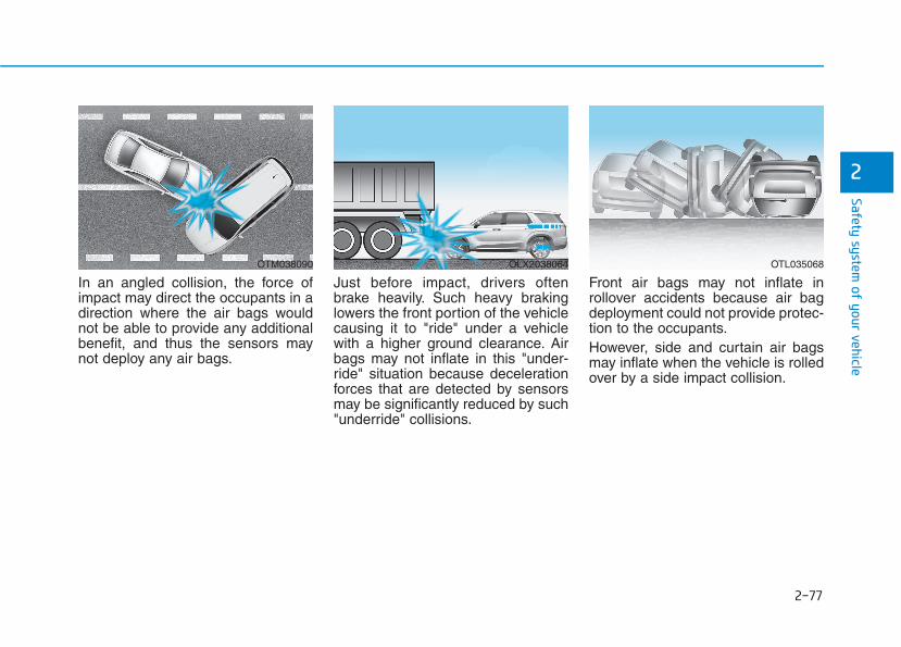
2-77
Safety system of your vehicle
2
In an angled collision, the force ofimpact may direct the occupants in adirection where the air bags wouldnot be able to provide any additionalbenefit, and thus the sensors maynot deploy any air bags.
Just before impact, drivers oftenbrake heavily. Such heavy brakinglowers the front portion of the vehiclecausing it to "ride" under a vehiclewith a higher ground clearance. Airbags may not inflate in this "under-ride" situation because decelerationforces that are detected by sensorsmay be significantly reduced by such"underride" collisions.
Front air bags may not inflate inrollover accidents because air bagdeployment could not provide protec-tion to the occupants.However, side and curtain air bagsmay inflate when the vehicle is rolledover by a side impact collision.
OTM038090 OLX2038064 OTL035068
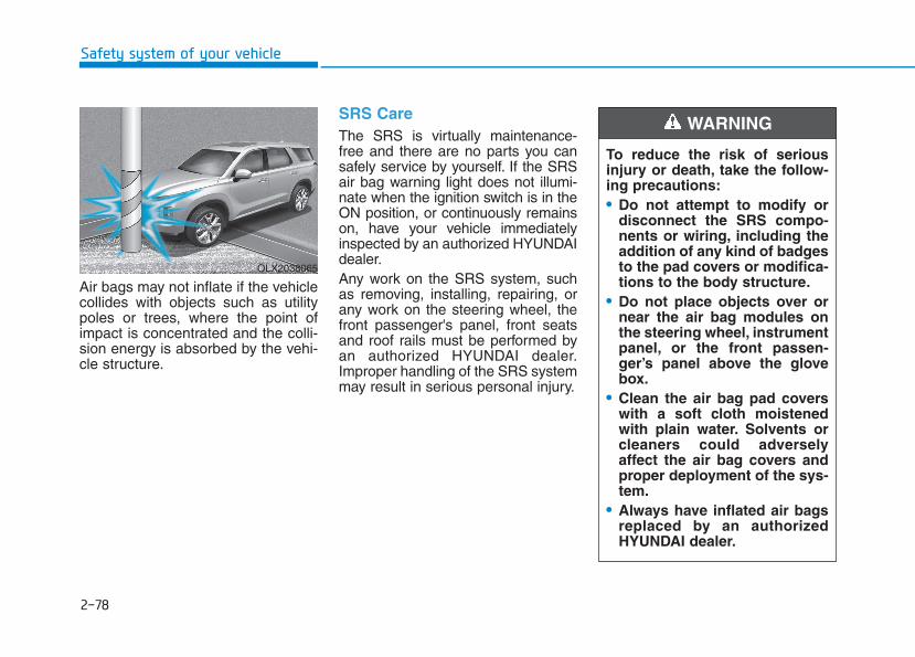
2-78
Safety system of your vehicle
Air bags may not inflate if the vehiclecollides with objects such as utilitypoles or trees, where the point ofimpact is concentrated and the colli-sion energy is absorbed by the vehi-cle structure.
SRS Care The SRS is virtually maintenance-free and there are no parts you cansafely service by yourself. If the SRSair bag warning light does not illumi-nate when the ignition switch is in theON position, or continuously remainson, have your vehicle immediatelyinspected by an authorized HYUNDAIdealer.Any work on the SRS system, suchas removing, installing, repairing, orany work on the steering wheel, thefront passenger's panel, front seatsand roof rails must be performed byan authorized HYUNDAI dealer.Improper handling of the SRS systemmay result in serious personal injury.
To reduce the risk of seriousinjury or death, take the follow-ing precautions:• Do not attempt to modify or
disconnect the SRS compo-nents or wiring, including theaddition of any kind of badgesto the pad covers or modifica-tions to the body structure.
• Do not place objects over ornear the air bag modules onthe steering wheel, instrumentpanel, or the front passen-ger’s panel above the glovebox.
• Clean the air bag pad coverswith a soft cloth moistenedwith plain water. Solvents orcleaners could adverselyaffect the air bag covers andproper deployment of the sys-tem.
• Always have inflated air bagsreplaced by an authorizedHYUNDAI dealer.
WARNING
OLX2038065

2-79
Safety system of your vehicle
2
Additional Safety Precautions Passengers should not move outof or change seats while the vehi-cle is moving. A passenger who isnot wearing a seat belt during acrash or emergency stop can bethrown against the inside of the vehi-cle, against other occupants, or beejected from the vehicle.Do not use any accessories onseat belts. Devices claiming toimprove occupant comfort or reposi-tion the seat belt can reduce the pro-tection provided by the seat belt andincrease the chance of serious injuryin a crash.
Do not modify the front seats.Modification of the front seats couldinterfere with the operation of thesupplemental restraint system sens-ing components or side air bags.Do not place items under the frontseats. Placing items under the frontseats could interfere with the opera-tion of the supplemental restraintsystem sensing components andwiring harnesses.Do not cause impact to the doors.Impact to the doors when the EngineStart/Stop button is in the ON posi-tion may cause the air bags to inflate.Modifications to accommodatedisabilities. If you require modifica-tion to your vehicle to accommodatea disability, contact the HYUNDAICustomer Connect Center at 800-633-5151.
Adding equipment to or modify-ing your air bag equipped vehicleIf you modify your vehicle by chang-ing your vehicle's frame, bumper sys-tem, front end or side sheet metal orride height, this may affect the opera-tion of your vehicle's air bag system.
Air Bag Warning Labels
Air bag warning labels, required bythe U.S. National Highway TrafficSafety Administration (NHTSA), areattached to alert the driver and pas-sengers of potential risks of the airbag system. Be sure to read all of theinformation about the air bags thatare installed on your vehicle in thisOwners Manual.
• If components of the air bagsystem must be discarded, or ifthe vehicle must be scrapped,certain safety precautionsmust be observed. Consult anauthorized HYUNDAI dealer forthe necessary information.Failure to follow these precau-tions could increase the risk ofpersonal injury.
OLX2038068L
Convenient features of your vehicle
Accessing your vehicle .........................................3-4Remote Key.........................................................................3-4Smart Key............................................................................3-8Immobilizer System.........................................................3-14
Door locks.............................................................3-15Operating Door Locks from Outside the Vehicle....3-15Operating Door Locks from Inside the Vehicle .......3-16Automatic Door Lock and Unlock Features .............3-19Child-Protector Rear Door Locks...............................3-20Electronic Child Safety Lock System .........................3-20Safe Exit Assist (SEA) System.....................................3-21Rear Occupant Alert (ROA) System ...........................3-23
Theft-alarm system.............................................3-26Driver position memory system.........................3-27
Storing Positions into Memory....................................3-27Recalling Positions from Memory...............................3-28Resetting the Driver's Seat Memory System...........3-28Easy Access Function ....................................................3-29
Steering wheel......................................................3-30Electric Power Steering (EPS) .....................................3-30Tilt Steering / Telescopic Steering .............................3-31Horn....................................................................................3-31Heated Steering Wheel..................................................3-32
Mirrors...................................................................3-33Inside Rearview Mirror ..................................................3-33Side View Mirrors ...........................................................3-39Reverse Parking Aid Function......................................3-41
Windows ................................................................3-42Power Windows...............................................................3-43
Sunroof..................................................................3-46Sunroof..............................................................................3-46Dual wide sunroof...........................................................3-46Sunshade...........................................................................3-47Sunroof Opening and Closing ......................................3-48Sliding the Sunroof.........................................................3-48Tilting the Sunroof (Front) ...........................................3-49Resetting the Sunroof ...................................................3-50Resetting the rear sunshade........................................3-51Sunroof Open Warning..................................................3-52
Exterior features .................................................3-53Hood ...................................................................................3-53Non-Powered Liftgate...................................................3-54Power Liftgate .................................................................3-56Smart Liftgate ..................................................................3-62Fuel Filler Door................................................................3-66
3

Instrument cluster................................................3-69Instrument Cluster Control............................................3-71Gauges and Meters ........................................................3-71Transmission Shift Indicator.........................................3-76Warning and Indicator Lights.......................................3-76LCD Display Messages...................................................3-90
LCD Display (Cluster type A and type B).........3-96LCD Display Control ........................................................3-96LCD Display Modes.........................................................3-97
TRIP Computer (Cluster type A and type B) ..3-110LCD Display (Cluster type C)............................3-114
LCD Display Control......................................................3-114View Modes....................................................................3-115
Option Menu (Cluster type C)..........................3-119Head up display (HUD)......................................3-130Lighting................................................................3-132
Exterior Lights ...............................................................3-132Interior Lights ................................................................3-139Welcome System...........................................................3-142
Wipers and washers ..........................................3-144Front Windshield Wipers.............................................3-144Front Windshield Washers..........................................3-146Rear Window Wiper and Washer..............................3-147
Driver Assist System .........................................3-148Rear View Monitor .......................................................3-148Surround View Monitoring .........................................3-149Blind-spot View Monitor system..............................3-150Reverse Parking Distance Warning System ...........3-152Forward/Reverse Parking Distance WarningSystem .............................................................................3-155
Manual climate control system........................3-159Heating and Air Conditioning.....................................3-160Rear climate control.....................................................3-164System Operation .........................................................3-167System Maintenance....................................................3-169
Automatic climate control system...................3-171Automatic Temperature Control Mode....................3-172Manual Temperature Control Mode.........................3-173Rear climate control.....................................................3-179System Operation .........................................................3-182System Maintenance....................................................3-184
3
Convenient features of your vehicle
Windshield defrosting and defogging ............3-186Auto Defogging System (Additional Feature withAutomatic Temperature Control System)................3-188Rear Window Defroster ..............................................3-190
Climate control additional features.................3-191Cluster ionizer................................................................3-191Automatic Ventilation...................................................3-191Sunroof Inside Air Recirculation ...............................3-191
Storage compartment........................................3-192Center Console Storage ..............................................3-192Glove Box........................................................................3-192Luggage Tray .................................................................3-193
Interior features.................................................3-194Cup Holder ......................................................................3-194Conversation mirror......................................................3-196Sunvisor...........................................................................3-196Power Outlet ..................................................................3-197AC Inverter......................................................................3-198USB Charger...................................................................3-200
Wireless Cellular Phone Charging System..............3-201Clock.................................................................................3-203Coat Hook .......................................................................3-203Floor Mat Anchor(s).....................................................3-204Luggage Net Holder .....................................................3-205Cargo Security Screen.................................................3-205Side Curtain ....................................................................3-207
Exterior features ...............................................3-209Roof Side Rails .............................................................3-209
3
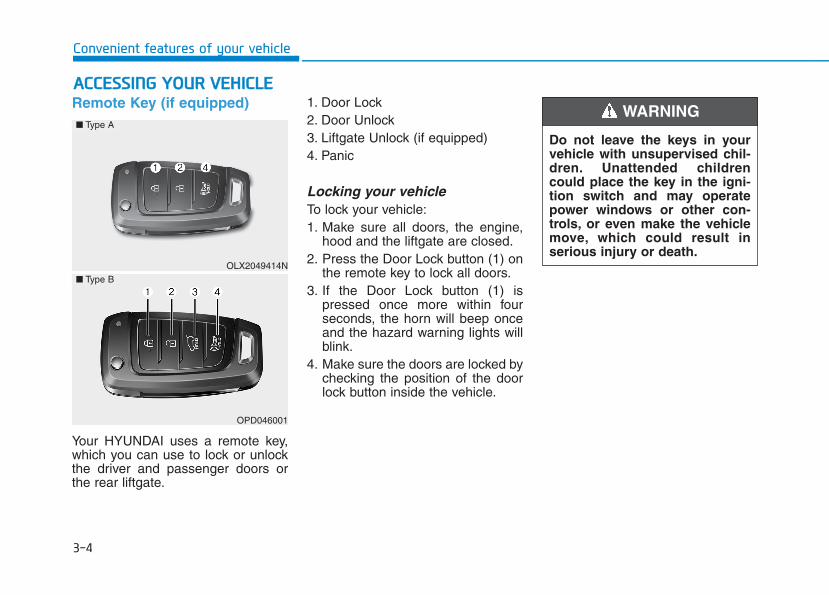
3-4
Convenient features of your vehicle
Remote Key (if equipped)
Your HYUNDAI uses a remote key,which you can use to lock or unlockthe driver and passenger doors orthe rear liftgate.
1. Door Lock 2. Door Unlock3. Liftgate Unlock (if equipped)4. Panic
Locking your vehicleTo lock your vehicle:1. Make sure all doors, the engine,
hood and the liftgate are closed.2. Press the Door Lock button (1) on
the remote key to lock all doors.3. If the Door Lock button (1) is
pressed once more within fourseconds, the horn will beep onceand the hazard warning lights willblink.
4. Make sure the doors are locked bychecking the position of the doorlock button inside the vehicle.
AACCCCEESSSSIINNGG YYOOUURR VVEEHHIICCLLEE
Do not leave the keys in yourvehicle with unsupervised chil-dren. Unattended childrencould place the key in the igni-tion switch and may operatepower windows or other con-trols, or even make the vehiclemove, which could result inserious injury or death.
WARNING
OLX2049414N
■ Type A
■ Type B
OPD046001
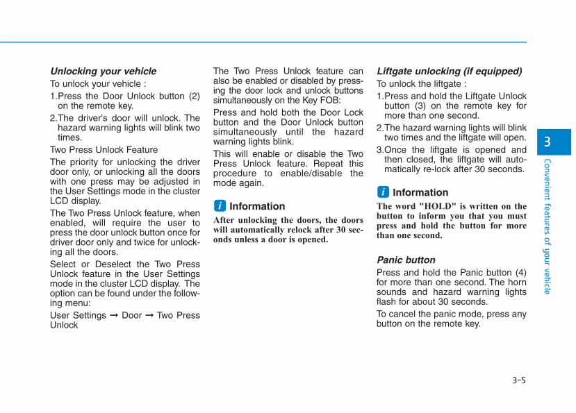
3-5
Convenient features of your vehicle
3
Unlocking your vehicleTo unlock your vehicle :1.Press the Door Unlock button (2)
on the remote key.2.The driver's door will unlock. The
hazard warning lights will blink twotimes.
Two Press Unlock FeatureThe priority for unlocking the driverdoor only, or unlocking all the doorswith one press may be adjusted inthe User Settings mode in the clusterLCD display.The Two Press Unlock feature, whenenabled, will require the user topress the door unlock button once fordriver door only and twice for unlock-ing all the doors.Select or Deselect the Two PressUnlock feature in the User Settingsmode in the cluster LCD display. Theoption can be found under the follow-ing menu:User Settings ➞ Door ➞ Two PressUnlock
The Two Press Unlock feature canalso be enabled or disabled by press-ing the door lock and unlock buttonssimultaneously on the Key FOB:Press and hold both the Door Lockbutton and the Door Unlock buttonsimultaneously until the hazardwarning lights blink.This will enable or disable the TwoPress Unlock feature. Repeat thisprocedure to enable/disable themode again.
Information After unlocking the doors, the doorswill automatically relock after 30 sec-onds unless a door is opened.
Liftgate unlocking (if equipped)To unlock the liftgate :1.Press and hold the Liftgate Unlock
button (3) on the remote key formore than one second.
2.The hazard warning lights will blinktwo times and the liftgate will open.
3.Once the liftgate is opened andthen closed, the liftgate will auto-matically re-lock after 30 seconds.
Information The word "HOLD" is written on thebutton to inform you that you mustpress and hold the button for morethan one second.
Panic buttonPress and hold the Panic button (4)for more than one second. The hornsounds and hazard warning lightsflash for about 30 seconds.To cancel the panic mode, press anybutton on the remote key.
ii
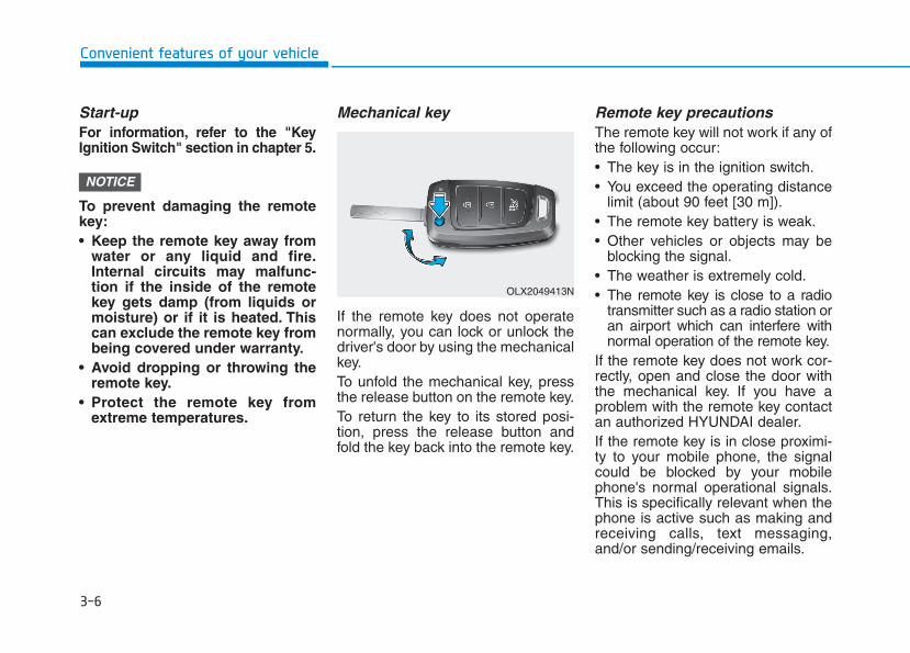
3-6
Convenient features of your vehicle
Start-up For information, refer to the "KeyIgnition Switch" section in chapter 5.
To prevent damaging the remotekey:• Keep the remote key away from
water or any liquid and fire.Internal circuits may malfunc-tion if the inside of the remotekey gets damp (from liquids ormoisture) or if it is heated. Thiscan exclude the remote key frombeing covered under warranty.
• Avoid dropping or throwing theremote key.
• Protect the remote key fromextreme temperatures.
Mechanical key
If the remote key does not operatenormally, you can lock or unlock thedriver's door by using the mechanicalkey.To unfold the mechanical key, pressthe release button on the remote key.To return the key to its stored posi-tion, press the release button andfold the key back into the remote key.
Remote key precautionsThe remote key will not work if any ofthe following occur:• The key is in the ignition switch.• You exceed the operating distance
limit (about 90 feet [30 m]).• The remote key battery is weak.• Other vehicles or objects may be
blocking the signal.• The weather is extremely cold.• The remote key is close to a radio
transmitter such as a radio station oran airport which can interfere withnormal operation of the remote key.
If the remote key does not work cor-rectly, open and close the door withthe mechanical key. If you have aproblem with the remote key contactan authorized HYUNDAI dealer.If the remote key is in close proximi-ty to your mobile phone, the signalcould be blocked by your mobilephone's normal operational signals.This is specifically relevant when thephone is active such as making andreceiving calls, text messaging,and/or sending/receiving emails.
NOTICE
OLX2049413N

3-7
Convenient features of your vehicle
3
When possible, avoid placing theremote key and your mobile phone inthe same location such as a pants orjacket pocket in order to avoid inter-ference between the two devices.
InformationThis device complies with Part 15 ofthe FCC rules.
Operation is subject to the followingthree conditions:
1.This device may not cause harmfulinterference.
2.This device must accept any inter-ference received, including interfer-ence that may cause undesired oper-ation.
3.Changes or modifications notexpressly approved by the partyresponsible for compliance couldvoid the user's authority to operatethe device.
Keep the remote key away fromelectromagnetic materials thatblock electromagnetic waves tothe key surface.
Battery replacement
If the remote key is not working prop-erly, try replacing the battery with anew one.Battery Type: CR2032
To replace the battery:1.Insert a slim tool into the slot and
gently pry open the cover.2.Using a screw driver, remove the
battery cover.3.Remove the old battery and insert
the new battery. Make sure the bat-tery position is correct.
4.Reinstall the battery cover and keycover in the reverse order ofremoval.
If you suspect your remote key mighthave sustained some damage, oryou feel your remote key is not work-ing correctly contact an authorizedHYUNDAI dealer.
InformationAn inappropriately disposedbattery can be harmful to theenvironment and human health.Dispose of the battery accordingto your local law(s) or regula-tions.
i
NOTICE
i
OPD046002
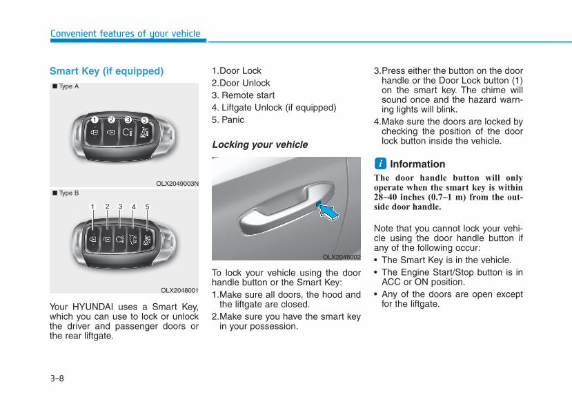
3-8
Convenient features of your vehicle
Smart Key (if equipped)
Your HYUNDAI uses a Smart Key,which you can use to lock or unlockthe driver and passenger doors orthe rear liftgate.
1.Door Lock 2.Door Unlock3. Remote start4. Liftgate Unlock (if equipped)5. Panic
Locking your vehicle
To lock your vehicle using the doorhandle button or the Smart Key:1.Make sure all doors, the hood and
the liftgate are closed.2.Make sure you have the smart key
in your possession.
3.Press either the button on the doorhandle or the Door Lock button (1)on the smart key. The chime willsound once and the hazard warn-ing lights will blink.
4.Make sure the doors are locked bychecking the position of the doorlock button inside the vehicle.
InformationThe door handle button will onlyoperate when the smart key is within28~40 inches (0.7~1 m) from the out-side door handle.
Note that you cannot lock your vehi-cle using the door handle button ifany of the following occur:• The Smart Key is in the vehicle.• The Engine Start/Stop button is in
ACC or ON position.• Any of the doors are open except
for the liftgate.
i
OLX2049003N
■ Type A
■ Type B
OLX2048001
OLX2048002

3-9
Convenient features of your vehicle
3
Unlocking your vehicle
To unlock your vehicle:1.Make sure you have the smart key
in your possession.2.Press either the button on the door
handle or the Door Unlock button(2) on the smart key. The driver'sdoor will unlock and the hazardwarning lights will blink two times.
Two Press Unlock FeatureThe priority for unlocking the driverdoor only, or unlocking all the doorswith one press may be adjusted inthe User Settings mode in the clusterLCD display.
The Two Press Unlock feature, whenenabled, will require the user topress the door unlock button once fordriver door only and twice for unlock-ing all the doors.Select or Deselect the Two PressUnlock feature in the User Settingsmode in the cluster LCD display. Theoption can be found under the follow-ing menu:User Settings ➞ Door ➞ Two PressUnlockThe Two Press Unlock feature canalso be enabled or disabled bypressing the door lock and unlockbuttons simultaneously on the KeyFOB:Press and hold both the Door Lockbutton and the Door Unlock buttonsimultaneously until the hazardwarning lights blink.This will enable or disable the TwoPress Unlock feature. Repeat thisprocedure to enable/disable themode again.
Do not leave the Smart Key inyour vehicle with unsupervisedchildren. Unattended childrencould press the Engine Start/Stop button and may operatepower windows or other con-trols, or even make the vehiclemove, which could result inserious injury or death.
WARNING
OLX2048002
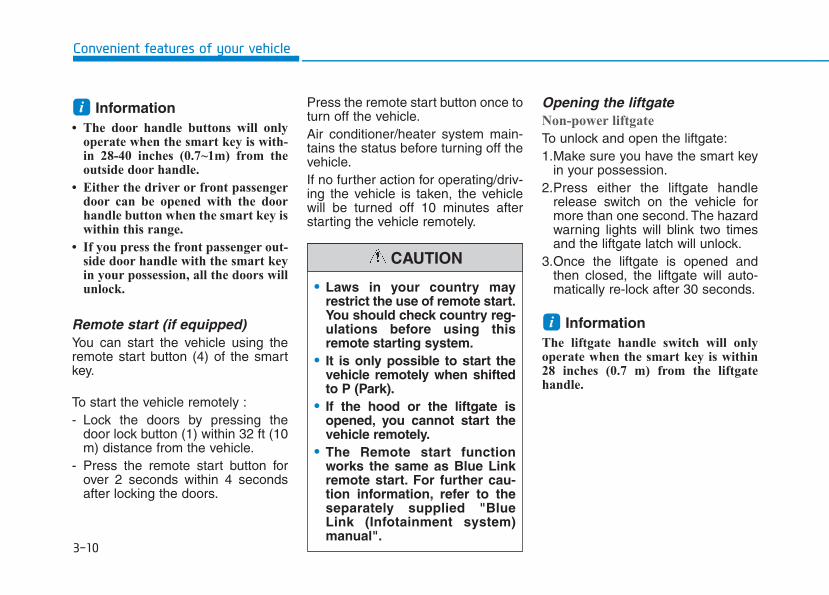
3-10
Convenient features of your vehicle
Information• The door handle buttons will only
operate when the smart key is with-in 28-40 inches (0.7~1m) from theoutside door handle.
• Either the driver or front passengerdoor can be opened with the doorhandle button when the smart key iswithin this range.
• If you press the front passenger out-side door handle with the smart keyin your possession, all the doors willunlock.
Remote start (if equipped)You can start the vehicle using theremote start button (4) of the smartkey.
To start the vehicle remotely :- Lock the doors by pressing the
door lock button (1) within 32 ft (10m) distance from the vehicle.
- Press the remote start button forover 2 seconds within 4 secondsafter locking the doors.
Press the remote start button once toturn off the vehicle.Air conditioner/heater system main-tains the status before turning off thevehicle.If no further action for operating/driv-ing the vehicle is taken, the vehiclewill be turned off 10 minutes afterstarting the vehicle remotely.
Opening the liftgateNon-power liftgate
To unlock and open the liftgate:1.Make sure you have the smart key
in your possession.2.Press either the liftgate handle
release switch on the vehicle formore than one second. The hazardwarning lights will blink two timesand the liftgate latch will unlock.
3.Once the liftgate is opened andthen closed, the liftgate will auto-matically re-lock after 30 seconds.
InformationThe liftgate handle switch will onlyoperate when the smart key is within28 inches (0.7 m) from the liftgatehandle.
i
i
• Laws in your country mayrestrict the use of remote start.You should check country reg-ulations before using thisremote starting system.
• It is only possible to start thevehicle remotely when shiftedto P (Park).
• If the hood or the liftgate isopened, you cannot start thevehicle remotely.
• The Remote start functionworks the same as Blue Linkremote start. For further cau-tion information, refer to theseparately supplied "BlueLink (Infotainment system)manual".
CAUTION
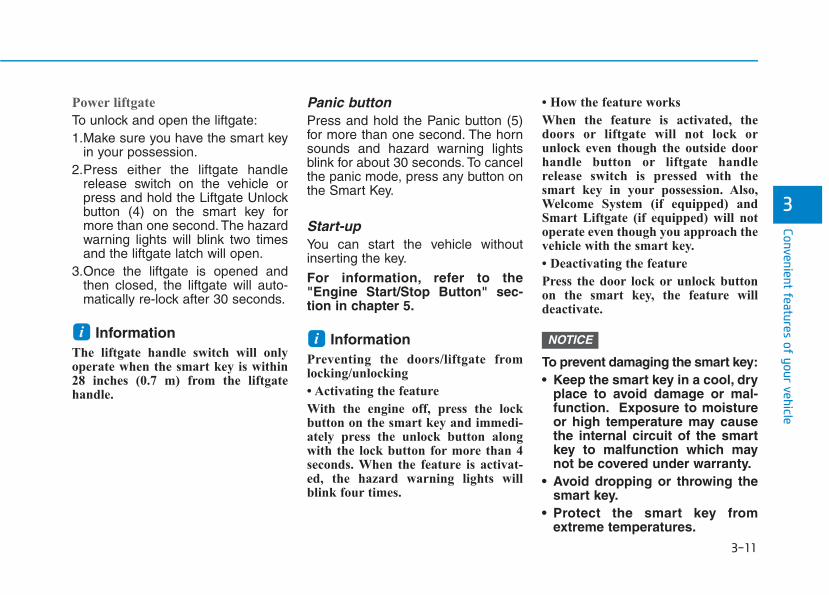
3-11
Convenient features of your vehicle
3
Power liftgate
To unlock and open the liftgate:1.Make sure you have the smart key
in your possession.2.Press either the liftgate handle
release switch on the vehicle orpress and hold the Liftgate Unlockbutton (4) on the smart key formore than one second. The hazardwarning lights will blink two timesand the liftgate latch will open.
3.Once the liftgate is opened andthen closed, the liftgate will auto-matically re-lock after 30 seconds.
InformationThe liftgate handle switch will onlyoperate when the smart key is within28 inches (0.7 m) from the liftgatehandle.
Panic buttonPress and hold the Panic button (5)for more than one second. The hornsounds and hazard warning lightsblink for about 30 seconds. To cancelthe panic mode, press any button onthe Smart Key.
Start-upYou can start the vehicle withoutinserting the key.
For information, refer to the"Engine Start/Stop Button" sec-tion in chapter 5.
InformationPreventing the doors/liftgate fromlocking/unlocking
• Activating the feature
With the engine off, press the lockbutton on the smart key and immedi-ately press the unlock button alongwith the lock button for more than 4seconds. When the feature is activat-ed, the hazard warning lights willblink four times.
• How the feature works
When the feature is activated, thedoors or liftgate will not lock orunlock even though the outside doorhandle button or liftgate handlerelease switch is pressed with thesmart key in your possession. Also,Welcome System (if equipped) andSmart Liftgate (if equipped) will notoperate even though you approach thevehicle with the smart key.
• Deactivating the feature
Press the door lock or unlock buttonon the smart key, the feature willdeactivate.
To prevent damaging the smart key:• Keep the smart key in a cool, dry
place to avoid damage or mal-function. Exposure to moistureor high temperature may causethe internal circuit of the smartkey to malfunction which maynot be covered under warranty.
• Avoid dropping or throwing thesmart key.
• Protect the smart key fromextreme temperatures.
NOTICEii
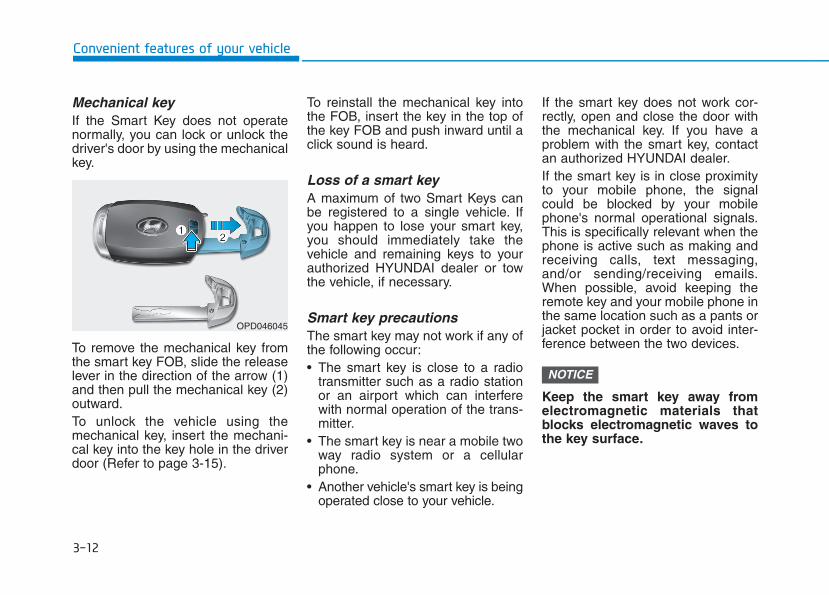
3-12
Convenient features of your vehicle
Mechanical key If the Smart Key does not operatenormally, you can lock or unlock thedriver's door by using the mechanicalkey.
To remove the mechanical key fromthe smart key FOB, slide the releaselever in the direction of the arrow (1)and then pull the mechanical key (2)outward.To unlock the vehicle using themechanical key, insert the mechani-cal key into the key hole in the driverdoor (Refer to page 3-15).
To reinstall the mechanical key intothe FOB, insert the key in the top ofthe key FOB and push inward until aclick sound is heard.
Loss of a smart key A maximum of two Smart Keys canbe registered to a single vehicle. Ifyou happen to lose your smart key,you should immediately take thevehicle and remaining keys to yourauthorized HYUNDAI dealer or towthe vehicle, if necessary.
Smart key precautionsThe smart key may not work if any ofthe following occur:• The smart key is close to a radio
transmitter such as a radio stationor an airport which can interferewith normal operation of the trans-mitter.
• The smart key is near a mobile twoway radio system or a cellularphone.
• Another vehicle's smart key is beingoperated close to your vehicle.
If the smart key does not work cor-rectly, open and close the door withthe mechanical key. If you have aproblem with the smart key, contactan authorized HYUNDAI dealer.If the smart key is in close proximityto your mobile phone, the signalcould be blocked by your mobilephone's normal operational signals.This is specifically relevant when thephone is active such as making andreceiving calls, text messaging,and/or sending/receiving emails.When possible, avoid keeping theremote key and your mobile phone inthe same location such as a pants orjacket pocket in order to avoid inter-ference between the two devices.
Keep the smart key away fromelectromagnetic materials thatblocks electromagnetic waves tothe key surface.
NOTICE
OPD046045
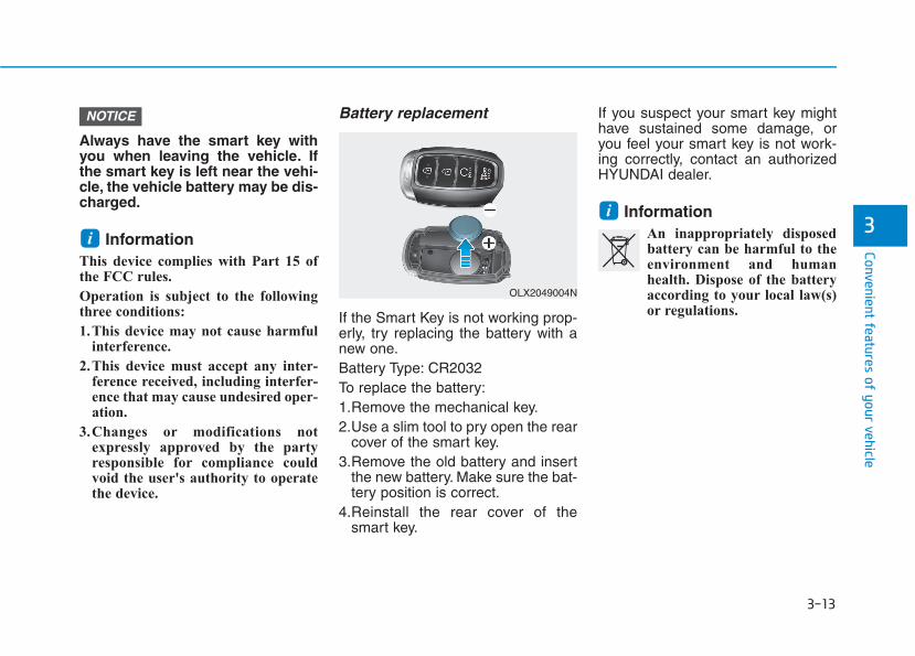
3-13
Convenient features of your vehicle
3
Always have the smart key withyou when leaving the vehicle. Ifthe smart key is left near the vehi-cle, the vehicle battery may be dis-charged.
InformationThis device complies with Part 15 ofthe FCC rules.
Operation is subject to the followingthree conditions:
1.This device may not cause harmfulinterference.
2.This device must accept any inter-ference received, including interfer-ence that may cause undesired oper-ation.
3.Changes or modifications notexpressly approved by the partyresponsible for compliance couldvoid the user's authority to operatethe device.
Battery replacement
If the Smart Key is not working prop-erly, try replacing the battery with anew one.Battery Type: CR2032To replace the battery:1.Remove the mechanical key.2.Use a slim tool to pry open the rear
cover of the smart key.3.Remove the old battery and insert
the new battery. Make sure the bat-tery position is correct.
4.Reinstall the rear cover of thesmart key.
If you suspect your smart key mighthave sustained some damage, oryou feel your smart key is not work-ing correctly, contact an authorizedHYUNDAI dealer.
InformationAn inappropriately disposedbattery can be harmful to theenvironment and humanhealth. Dispose of the batteryaccording to your local law(s)or regulations.
ii
NOTICE
OLX2049004N
3-14
Immobilizer System (if equipped)The immobilizer system protectsyour vehicle from theft. If an improp-erly coded key (or other device) isused, the engine's fuel system is dis-abled.When the ignition switch is placed inthe ON position, the immobilizer sys-tem indicator should come on briefly,then go off. If the indicator starts toblink, the system does not recognizethe coding of the key.Turn the ignition switch to theLOCK/OFF position, then turn theignition switch to the ON positionagain.In some circumstances, the vehiclemay not recognize your remote keyor smart key if another remote key orsmart key device is nearby or a metalobject such as a key chain is causinginterference with the remote key orsmart key.If this occurs, your vehicle may notstart. Remove any metal objects oradditional keys near the remote keyor smart key before attempting tostart the vehicle again.
If the system repeatedly does notrecognize the coding of the key, it isrecommended that you contact yourHYUNDAI dealer.Do not attempt to alter this system oradd other devices to it. Electricalproblems could result that may makeyour vehicle inoperable.
The transponder in your key is animportant part of the immobilizersystem. It is designed to giveyears of trouble-free service, how-ever you should avoid exposure tomoisture, static electricity andrough handling. Immobilizer sys-tem malfunction could occur.
InformationThis device complies with Part 15 ofthe FCC rules.
Operation is subject to the followingthree conditions:
1.This device may not cause harmfulinterference.
2.This device must accept any inter-ference received, including interfer-ence that may cause undesired oper-ation.
3.Changes or modifications notexpressly approved by the partyresponsible for compliance couldvoid the user’s authority to operatethe device.
i
NOTICE
Convenient features of your vehicle
In order to prevent theft of yourvehicle, do not leave spare keysanywhere in your vehicle. Yourimmobilizer password is a cus-tomer unique password andshould be kept confidential.
WARNING

3-15
Convenient features of your vehicle
Operating Door Locks fromOutside the Vehicle Mechanical key
[A] : Unlock, [B] : Lock
First, pull the outside door handle (1)and push the hook (2) located insideof outside door handle by using themechanical key. And remove thecover (3) and lower the cover down-ward not to be damaged.
Be careful not to damage thecover while removing it or mis-place it after removing it.
After removing the cover, turn thekey toward the front of the vehicle tounlock and toward the rear of thevehicle to lock.If you lock the driver's door with amechanical key, the driver's door willlock. If you unlock the driver's doorwith a mechanical key, you can openand close the driver's door only.Once the doors are unlocked, theymay be opened by pulling the doorhandle. When closing the door, pushthe door by hand. Make sure thatdoors are closed securely.
Remote key
To lock the doors, press the DoorLock button (1) on the remote key.Press the Door Unlock button (2) onthe remote key, the driver's door willunlock. If you press the Door Unlockbutton on the remote key again with-in four seconds, then all the doorswill unlock.Once the doors are unlocked, theymay be opened by pulling the doorhandle. When closing the door, pushthe door by hand. Make sure thatdoors are closed securely.
NOTICE
DDOOOORR LLOOCCKKSS
3
OLX2049415N
OLX2048005
OLX2049052L
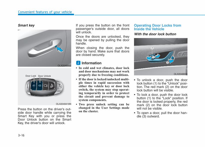
3-16
Convenient features of your vehicle
Smart key
Press the button on the driver's out-side door handle while carrying theSmart Key with you or press theDoor Unlock button on the SmartKey, the driver's door will unlock.
If you press the button on the frontpassenger's outside door, all doorswill unlock.Once the doors are unlocked, theymay be opened by pulling the doorhandle.When closing the door, push thedoor by hand. Make sure that doorsare closed securely.
Information• In cold and wet climates, door lock
and door mechanisms may not workproperly due to freezing conditions.
• If the door is locked/unlocked multi-ple times in rapid succession witheither the vehicle key or door lockswitch, the system may stop operat-ing temporarily in order to protectthe circuit and prevent damage tosystem components.
• Two press unlock setting can bechanged in the User Settings modeon the cluster.
Operating Door Locks fromInside the Vehicle With the door lock button
• To unlock a door, push the doorlock button (1) to the "Unlock" posi-tion. The red mark (2) on the doorlock button will be visible.
• To lock a door, push the door lockbutton (1) to the "Lock" position. Ifthe door is locked properly, the redmark (2) on the door lock buttonwill not be visible.
• To open a door, pull the door han-dle (3) outward.
i
OLX2049416N
Door Lock Door UnlockOLX2048006
OLX2048002
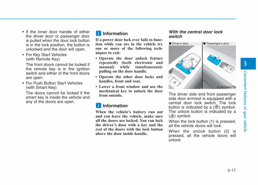
3-17
Convenient features of your vehicle
3
• If the inner door handle of eitherthe driver door or passenger dooris pulled when the door lock buttonis in the lock position, the button isunlocked and the door will open.
• For Key Start Vehicles (with Remote Key)The front doors cannot be locked ifthe remote key is in the ignitionswitch and either of the front doorsare open.
• For Push Button Start Vehicles(with Smart Key)The doors cannot be locked if thesmart key is inside the vehicle andany of the doors are open.
InformationIf a power door lock ever fails to func-tion while you are in the vehicle tryone or more of the following tech-niques to exit:
• Operate the door unlock featurerepeatedly (both electronic andmanual) while simultaneouslypulling on the door handle.
• Operate the other door locks andhandles, front and rear.
• Lower a front window and use themechanical key to unlock the doorfrom outside.
InformationWhen the vehicle’s battery run outand you leave the vehicle, make sureall the doors are locked. You can lockthe driver’s door with a key and therest of the doors with the lock buttonabove the door inside handle.
With the central door lockswitch
The driver side and front passengerside door armrest is equipped with acentral door lock switch. The lockbutton is indicated by a ( ) symbol.The unlock button is indicated by a( ) symbol.When the lock button (1) is pressed,all the vehicle doors will lock.When the unlock button (2) ispressed, all the vehicle doors willunlock.
i
i
■ Driver's door ■ Passenger's door
OLX2049417N
3-18
Convenient features of your vehicle
• For Key Start Vehicles (with Remote Key)If the key is in the ignition switchand any door is opened, the doorswill not lock even though the lockbutton (2) is pressed.
• For Push Button Start Vehicles(with Smart Key)If the smart key is in the vehicleand any door is open, the doorswill not lock even though the lockbutton (2) is pressed.
• The doors should always befully closed and locked whilethe vehicle is in motion. If thedoors are unlocked, the risk ofbeing thrown from the vehiclein a crash is increased.
• Do not pull the inner doorhandle of the driver's or pas-senger's door while the vehi-cle is moving.
WARNING
Do not leave children or animalsunattended in your vehicle. Anenclosed vehicle can becomeextremely hot, causing death orserious injury to unattendedchildren or animals who cannotescape the vehicle. Childrenmight operate features of thevehicle that could injure them,or they could encounter otherharm, possibly from someonegaining entry to the vehicle.
WARNING
Always secure your vehicle.
Leaving your vehicle unlockedincreases the potential risk toyou or others from someonehiding in your vehicle.To secure your vehicle, whiledepressing the brake, press theP (Park) button, engage theparking brake, and place theignition switch in the LOCK/OFFposition, close all windows,lock all doors, and always takethe key with you.
WARNING

3-19
Convenient features of your vehicle
3
Automatic Door Lock andUnlock FeaturesYour vehicle is equipped with fea-tures that will automatically lock orunlock your vehicle based on set-tings you select in the cluster LCDdisplay.
Auto LOCK - Enable on SpeedWhen this feature is set in the clusterLCD display, all the doors will belocked automatically when the vehi-cle exceeds 9 mph (15 kph).
Auto LOCK - Enable on ShiftWhen this feature is set in the clusterLCD display, all the doors will belocked automatically when the vehi-cle is shifted out of P (Park) while theengine is running.
Auto UNLOCK - On shift to PWhen this feature is set in the LCDcluster display, all the doors will beunlocked automatically when thevehicle is shifted back into P (Park).
Auto UNLOCK - On key out (if equipped with remote key)When this feature is set in the LCDcluster display, all the doors will beunlocked automatically when theignition key is removed from the keyignition switch.
Auto UNLOCK - Vehicle Off (if equipped with smart key)When this feature is set in the LCDcluster display, all the doors will beunlocked automatically when thevehicle is off.
For more information on thesefeatures, refer to the LCD Displaysection later in this chapter.
Additional Unlock SafetyFeature - Air Bag DeploymentAs an additional safety feature, alldoors will be automatically unlockedwhen an impact causes the air bagsto deploy.
Opening a door when somethingis approaching may cause dam-age or injury. Be careful whenopening doors and watch forvehicles, motorcycles, bicyclesor pedestrians approaching thevehicle in the path of the door.
CAUTION
If you stay in the vehicle for along time while the weather isvery hot or cold, there are risksof injuries or danger to life. Donot lock the vehicle from theoutside when someone is in thevehicle.
WARNING
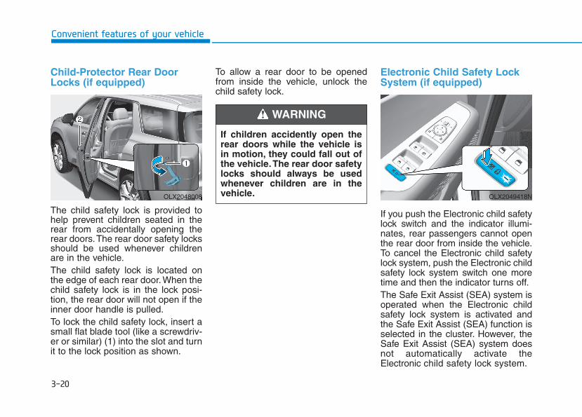
3-20
Convenient features of your vehicle
Child-Protector Rear DoorLocks (if equipped)
The child safety lock is provided tohelp prevent children seated in therear from accidentally opening therear doors.The rear door safety locksshould be used whenever childrenare in the vehicle.The child safety lock is located onthe edge of each rear door. When thechild safety lock is in the lock posi-tion, the rear door will not open if theinner door handle is pulled.To lock the child safety lock, insert asmall flat blade tool (like a screwdriv-er or similar) (1) into the slot and turnit to the lock position as shown.
To allow a rear door to be openedfrom inside the vehicle, unlock thechild safety lock.
Electronic Child Safety Lock System (if equipped)
If you push the Electronic child safetylock switch and the indicator illumi-nates, rear passengers cannot openthe rear door from inside the vehicle.To cancel the Electronic child safetylock system, push the Electronic childsafety lock system switch one moretime and then the indicator turns off.The Safe Exit Assist (SEA) system isoperated when the Electronic childsafety lock system is activated andthe Safe Exit Assist (SEA) function isselected in the cluster. However, theSafe Exit Assist (SEA) system doesnot automatically activate theElectronic child safety lock system.
OLX2048008 OLX2049418N
If children accidently open therear doors while the vehicle isin motion, they could fall out ofthe vehicle.The rear door safetylocks should always be usedwhenever children are in thevehicle.
WARNING
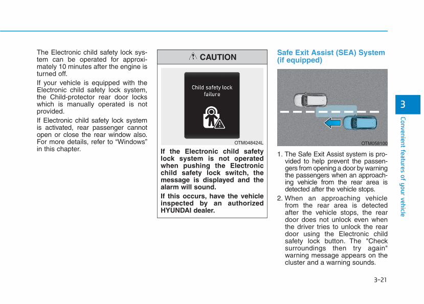
3-21
Convenient features of your vehicle
3
The Electronic child safety lock sys-tem can be operated for approxi-mately 10 minutes after the engine isturned off.If your vehicle is equipped with theElectronic child safety lock system,the Child-protector rear door lockswhich is manually operated is notprovided.If Electronic child safety lock systemis activated, rear passenger cannotopen or close the rear window also.For more details, refer to “Windows”in this chapter.
Safe Exit Assist (SEA) System(if equipped)
1. The Safe Exit Assist system is pro-vided to help prevent the passen-gers from opening a door by warningthe passengers when an approach-ing vehicle from the rear area isdetected after the vehicle stops.
2. When an approaching vehiclefrom the rear area is detectedafter the vehicle stops, the reardoor does not unlock even whenthe driver tries to unlock the reardoor using the Electronic childsafety lock button. The "Checksurroundings then try again"warning message appears on thecluster and a warning sounds.
If the Electronic child safetylock system is not operatedwhen pushing the Electronicchild safety lock switch, themessage is displayed and thealarm will sound.If this occurs, have the vehicleinspected by an authorizedHYUNDAI dealer.
CAUTION
OTM048424L OTM058100
3-22
Convenient features of your vehicle
However if you press the switchwithin 10 seconds after the warn-ing message appears (the indica-tor on the switch will turn off), thesystem judges that the driverunlocked the door acknowledgingthe rear status and releasedregardless of the rear status.
3. When an approaching vehiclefrom the rear is detected themoment the door is opened, the"Watch for traffic" warning mes-sage appears on the cluster and awarning sounds.
• The above 2 and 3 functions areactivated when you select 'DriverAssistance → Blind-Spot Safety →Safe Exit Assistance (SEA)' fromthe User Settings mode in the clus-ter LCD display.
• The Electronic child safety locksystem will operate for approxi-mately 10 minutes after the ignitionkey is removed or turned to theLOCK (or OFF) position. Afterabout 10 minutes, the indicator onthe switch turns off and you cannotdeactivate the Electronic childsafety lock system. To deactivatethe Electronic child safety lock sys-tem, press the Electronic child safe-ty lock switch again with the ignitionswitch in the ON position or afterstarting the engine.
• When the power is supplied againafter removing the battery or bat-tery discharge while the child safe-ty lock is in the lock position, pressthe child safety lock switch onceagain to match the state of the indi-cator on the child safety lock switchand actual status of the Electronicchild safety lock system.
• If the airbag is activated while thechild safety lock switch is ON (theindicator on the switch illuminates)it automatically switches OFF andthe rear door is unlocked.
• The Safe Exit Assist (SEA)system may not operate nor-mally if there is any vehicle orobstacle at the rear area ofyour vehicle.
• The Safe Exit Assist (SEA)system may not operate nor-mally when a vehicle is com-ing rapidly two lanes overfrom your vehicle or a vehicleis approaching at a fast speedfrom the rear in the lane nextto your vehicle.
• The Safe Exit Assist (SEA)system may be activated laterthan normal or may not oper-ate normally if a vehicle isapproaching fast from the rearof your vehicle.
CAUTION
3-23
Convenient features of your vehicle
3
Rear Occupant Alert (ROA)System (if equipped)The Rear Occupant Alert (ROA) sys-tem is provided to help prevent exit-ing the vehicle with the rear passen-ger left in the vehicle.
• 1st alert- When you open the front door
after opening and closing the reardoor and turning off the engine,the "Check rear seats" warningmessage appears on the cluster.
• You can activate or deactivate theRear Occupant Alert (ROA) sys-tem from the User Settings modein the cluster LCD display. Theoption can be found under the fol-lowing menu:User Settings → Convenience →Rear Occupant Alert
• 2nd alert (if equipped)- After the 1st alert the 2nd alert
operates when any movement isdetected in the vehicle after thedriver's door is closed and all thedoors are locked. The horn willactivate for about 25 seconds. Ifthe system continues to detect amovement the alert operates upto 8 times.
- Unlock the door with the remotekey or smart key to stop the alert.
- The system detects movement inthe vehicle for 24 hours after thedoor is locked.
- The 2nd alert is activated onlyafter the prior activation of the 1stalert.
• The Safe Exit Assist (SEA)system will not operate ifthere is a malfunction with theBlind-Spot Collision Warning(BCW) system as follows:- When the BCW warning
message appearsWhen the BCW sensor or thesensor surrounding is pol-luted or covered
- When the BCW does notwarn or warns wrongly
For more details, refer to cau-tions and limitations in "Blind-Spot Collision Warning (BCW)"in chapter 5.
• The system does not detectevery obstacle approachingthe vehicle exit.
• The driver and passenger areresponsible for any obstacleswhile exiting the vehicle.Always check the surroundingbefore you exit the vehicle.
WARNING
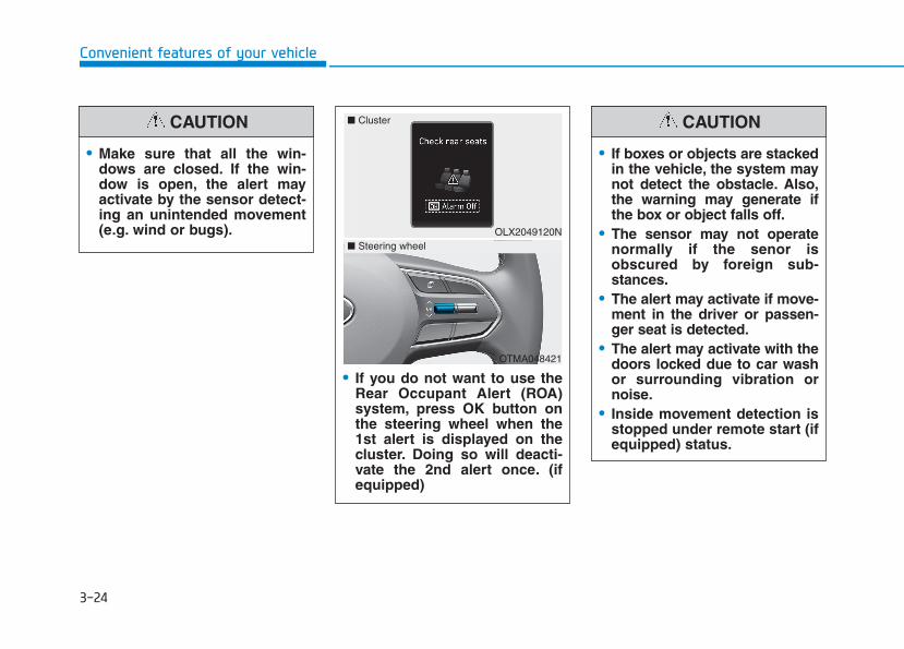
3-24
Convenient features of your vehicle
• If you do not want to use theRear Occupant Alert (ROA)system, press OK button onthe steering wheel when the1st alert is displayed on thecluster. Doing so will deacti-vate the 2nd alert once. (ifequipped)
OLX2049120N
■ Cluster
OTMA048421
■ Steering wheel
• If boxes or objects are stackedin the vehicle, the system maynot detect the obstacle. Also,the warning may generate ifthe box or object falls off.
• The sensor may not operatenormally if the senor isobscured by foreign sub-stances.
• The alert may activate if move-ment in the driver or passen-ger seat is detected.
• The alert may activate with thedoors locked due to car washor surrounding vibration ornoise.
• Inside movement detection isstopped under remote start (ifequipped) status.
CAUTION
• Make sure that all the win-dows are closed. If the win-dow is open, the alert mayactivate by the sensor detect-ing an unintended movement(e.g. wind or bugs).
CAUTION

3-25
Convenient features of your vehicle
3
• Even if your vehicle isequipped with the RearOccupant Alert (ROA) system,always make sure you checkthe rear seat before you getoff the vehicle.The alert may not operate if:- The movement does not
continue for a certain periodof time or the movement issmall.
- The rear passenger is cov-ered with an obstacle suchas a blanket.
- Also, always be cautious ofthe passenger’s safety asthe detection function and2nd alert may not operateaccording to the surround-ing environment and certainconditions.
- If a child sits on a vehicleseat without a child restraintsystem.
WARNING
3-26
Convenient features of your vehicle
This system helps to protect your vehi-cle and valuables. The horn willsound and the hazard warning lightswill blink continuously if any of thefollowing occur:- A door is opened without using the
remote key or smart key.- The liftgate is opened without
using the remote key or smart key.- The engine hood is opened.The alarm continues for 30 seconds(repeats 2 times unless the system isdisarmed), then the system resets.To turn off the alarm, unlock thedoors with the remote key or smartkey.The Theft Alarm System automati-cally sets 30 seconds after you lockthe doors and the liftgate. For thesystem to activate, you must lock thedoors and the liftgate from outsidethe vehicle with the remote key orsmart key or by pressing the buttonon the outside of the door handlewith the smart key in your posses-sion.The hazard warning lights will blinkand the chime will sound once toindicate the system is armed.
Once the security system is set,opening any door, the liftgate, or thehood without using the remote key orsmart key will cause the alarm toactivate.The Theft Alarm System will not set ifthe hood, the liftgate, or any door isnot fully closed. If the system will notset, check the hood, the liftgate, orthe doors are fully closed.Do not attempt to alter this system oradd other devices to it.
Information• Do not lock the doors until all pas-
sengers have left the vehicle. If theremaining passenger leaves thevehicle when the system is armed,the alarm will be activated.
• If the vehicle is not disarmed with theremote key or smart key, open thedoors by using the mechanical keyand place the ignition switch in theON position (for remote key) or startthe engine (for smart key) by direct-ly pressing the ignition switch withthe smart key.
• If the system is disarmed by unlock-ing the vehicle, but neither a door orthe liftgate is opened within 30 sec-onds, the doors will relock and thesystem will rearm automatically.
iTTHHEEFFTT--AALLAARRMM SSYYSSTTEEMM
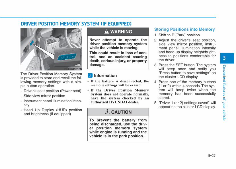
3-27
Convenient features of your vehicle
3
The Driver Position Memory Systemis provided to store and recall the fol-lowing memory settings with a sim-ple button operation.- Driver's seat position (Power seat)- Side view mirror position- Instrument panel illumination inten-
sity- Head Up Display (HUD) position
and brightness (if equipped)
Information• If the battery is disconnected, the
memory settings will be erased.
• If the Driver Position MemorySystem does not operate normally,have the system checked by anauthorized HYUNDAI dealer.
Storing Positions into Memory 1. Shift to P (Park) position.2. Adjust the driver's seat position,
side view mirror position, instru-ment panel illumination intensityand head-up display height/bright-ness to positions comfortable forthe driver.
3. Press the SET button. The systemwill beep once and notify you"Press button to save settings" onthe cluster LCD display.
4. Press one of the memory buttons(1 or 2) within 4 seconds. The sys-tem will beep twice when thememory has been successfullystored.
5. "Driver 1 (or 2) settings saved" willappear on the cluster LCD display.
i
DDRRIIVVEERR PPOOSSIITTIIOONN MMEEMMOORRYY SSYYSSTTEEMM ((IIFF EEQQUUIIPPPPEEDD))
OLX2049012N
Never attempt to operate thedriver position memory systemwhile the vehicle is moving.This could result in loss of con-trol, and an accident causingdeath, serious injury, or propertydamage.
WARNING
To prevent the battery frombeing discharged, use the driv-er position memory systemwhile engine is running and thevehicle is in the park position.
CAUTION
3-28
Convenient features of your vehicle
Recalling Positions fromMemory1. Shift to P (Park) while the ignition
switch is in the ON position.2. Press the desired memory button
(1 or 2). The system will beeponce, and then the driver's seatposition, side view mirror position,instrument panel illuminationintensity and head-up displayheight/brightness will automatical-ly adjust to the stored positions.
3. "Driver 1 (or 2) settings applied"will appear on the cluster LCD dis-play.
Information• While recalling the "1" memory
position, pressing the SET or 1 but-ton temporarily stops the adjust-ment of the recalled memory posi-tion. Pressing the 2 button recallsthe "2" memory position.
• While recalling the "2" memoryposition, pressing the SET or 2 but-ton temporarily stops the adjust-ment of the recalled memory posi-tion. Pressing the 1 button recallsthe "1" memory position.
• While recalling the stored positions,pressing one of the control buttonsfor the driver's seat, side view mir-ror, instrument panel illuminationor head-up display will cause themovement of that component to stopand move in the direction that thecontrol button is pressed.
Resetting the Driver's SeatMemory SystemTake the following procedures to resetthe driver's seat memory system,when it does not operate properly.
To reset the driver's seat memo-ry system 1. Place the ignition switch to the ON
position, shift to P (Park), andopen the driver's door.
2. Operate the control switch to setthe driver's seat and seatback tothe foremost position.
3. Simultaneously press the SETbutton and push forward the seatmovement switch over 2 seconds.
While resetting the driver's seatmemory system 1. It starts with the notification sound.2. The driver's seat and seatback is
adjusted to the rearward positionwith the notification sound.
3. The driver's seat and seatback isre-adjusted to the default position(central position) with the notifica-tion sound.
However, in the following cases, theresetting procedure and the notifica-tion sound may stop.- The memory button is pressed.- The control switch is operated.- The driving speed exceeds 2 mph
(3 km/h).- The driver's door is closed.
i
3-29
Convenient features of your vehicle
3
• Reattempt to do the resettingprocedure again, when theresetting procedure incomplete-ly stops or the notificationsound do not stop.
• Make sure that there is no obsta-cle around the driver's seat inadvance of resetting the driver'sseat memory system.
Easy Access FunctionThe system will move the driver'sseat automatically as follows:• With remote key- It will move the driver's seat rear-
ward and downward when the igni-tion key is removed.
- It will move the driver's seat for-ward and upward when the ignitionkey is inserted.
• With smart key- It will move the driver's seat rear-
ward and downward when theEngine Start/Stop button ispressed to the OFF position.
- It will move the driver's seat forwardand upward when the EngineStart/Stop button is pressed to theACC or START position.
You can activate or deactivate theEasy Access Function from the UserSettings mode in the cluster LCD dis-play.'Convenience → Seat Slide EasyAccess → Off/Normal/Extended'.'Convenience → Seat Height EasyAccess'.
❈ "Seat (upward/downward) EasyAccess" function may not operatebelow the specific seat height forpreventing injury of the passenger.
For more details, refer to "LCDDisplay" in this chapter.
NOTICE
Driver should be cautious whenusing this function to assure noinjury to passenger or child inthe back seat. In case of emer-gency the driver has to stopmovement of front seat (wheneasy access feature is activat-ed) by pressing SET button orany of the driver seat controlswitches.
CAUTION
• If the reset is failed, initializethe system once again.
• Initialize the system aftercleaning the obstacles sur-rounding of seat.
• After completing the initializa-tion, adjust the driver positionmemory system again.
CAUTION
3-30
Convenient features of your vehicle
SSTTEEEERRIINNGG WWHHEEEELLElectric Power Steering (EPS)The system assists you with steeringthe vehicle. If the vehicle is turned offor if the power steering systembecomes inoperative, you may stillsteer the vehicle, but it will requireincreased steering effort.Should you notice any change in theeffort required to steer during normalvehicle operation, have the systemchecked by an authorized HYUNDAIdealer.
• If the Electric Power SteeringSystem does not operate nor-mally, the warning light ( ) willilluminate on the instrumentcluster. You may steer the vehi-cle, but it will require increasedsteering efforts. Take your vehi-cle to an authorized HYUNDAIdealer and have the systemchecked as soon as possible.
• When abnormality is detected inthe electric power steering sys-tem, the steering assist functionwill stop. At this time, the warn-ing light turns on or blinks onthe cluster. The steering wheelmay become difficult to controlor operate. Have your vehiclechecked immediately, after mov-ing the vehicle to a safe zone.
InformationThe following symptoms may occurduring normal vehicle operation:
• The steering effort may be highimmediately after placing the igni-tion switch in the ON position.
This happens as the system per-forms the EPS system diagnostics.When the diagnostics are complet-ed, the steering wheel effort willreturn to its normal condition.
• When the battery voltage is low, youmight have to put more sterringeffrot. However, it is a temporaryconditions so that it will return tonormal condition after charging thebattery.
• A click noise may be heard from theEPS relay after the ignition switch isin the ON or LOCK/OFF position.
• Motor noise may be heard when thevehicle is at a stop or at a low driv-ing speed.
• When you operate the steeringwheel in low temperatures, abnor-mal noise may occur. If the temper-ature rises, the noise will disappear.This is a normal condition.
• When an error is detected from theEPS, the steering effort assist func-tion will not be activated.
Instrument cluster warning lightsmay be on or the steering effort maybe high. If these symptoms occur,drive the vehicle to a safe area assoon as it is safe to do so. Have thesystem checked by an authorizedHYUNDAI dealer as soon as possi-ble.
i
NOTICE
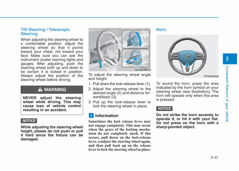
3-31
Convenient features of your vehicle
3
Tilt Steering / TelescopicSteeringWhen adjusting the steering wheel toa comfortable position, adjust thesteering wheel so that it pointstoward your chest, not toward yourface. Make sure you can see theinstrument cluster warning lights andgauges. After adjusting, push thesteering wheel both up and down tobe certain it is locked in position.Always adjust the position of thesteering wheel before driving.
While adjusting the steering wheelheight, please do not push or pullit hard since the fixture can bedamaged.
To adjust the steering wheel angleand height:1. Pull down the lock-release lever (1).2. Adjust the steering wheel to the
desired angle (2) and distance for-ward/back (3).
3. Pull up the lock-release lever tolock the steering wheel in place.
InformationSometimes the lock release lever maynot engage completely. This may occurwhen the gears of the locking mecha-nism do not completely mesh. If thisoccurs, pull down on the lock-releaselever, readjust the steering wheel again,and then pull back up on the releaselever to lock the steering wheel in place.
Horn
To sound the horn, press the areaindicated by the horn symbol on yoursteering wheel (see illustration). Thehorn will operate only when this areais pressed.
Do not strike the horn severely tooperate it, or hit it with your fist.Do not press on the horn with asharp-pointed object.
NOTICE
iNOTICE
OTM048408
OLX2048013
NEVER adjust the steeringwheel while driving. This maycause loss of vehicle controlresulting in an accident.
WARNING
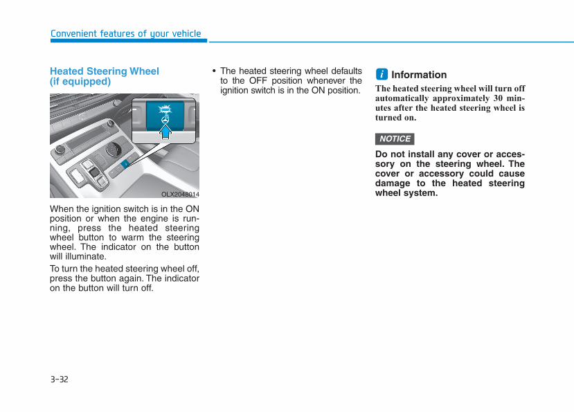
3-32
Convenient features of your vehicle
Heated Steering Wheel (if equipped)
When the ignition switch is in the ONposition or when the engine is run-ning, press the heated steeringwheel button to warm the steeringwheel. The indicator on the buttonwill illuminate.To turn the heated steering wheel off,press the button again. The indicatoron the button will turn off.
• The heated steering wheel defaultsto the OFF position whenever theignition switch is in the ON position.
Information The heated steering wheel will turn offautomatically approximately 30 min-utes after the heated steering wheel isturned on.
Do not install any cover or acces-sory on the steering wheel. Thecover or accessory could causedamage to the heated steeringwheel system.
NOTICE
i
OLX2048014

3-33
Convenient features of your vehicle
3
MMIIRRRROORRSSInside Rearview MirrorBefore driving your vehicle, check tosee that your inside rearview mirroris properly positioned. Adjust therearview mirror so that the viewthrough the rear window is properlycentered.
When cleaning the mirror, use apaper towel or similar materialdampened with glass cleaner. Donot spray glass cleaner directly onthe mirror as this may cause theliquid cleaner to enter the mirrorhousing.
Day/night rearview mirror (if equipped)
[A]: Day, [B]: Night
Make this adjustment before youstart driving and while the day/nightlever is in the day position.Pull the day/night lever towards youto reduce glare from the headlightsof the vehicles behind you duringnight driving.Remember that you lose somerearview clarity in the night position.
NOTICE
NEVER adjust the mirror whiledriving. This may cause loss ofvehicle control resulting in anaccident.
WARNING
Make sure your line of sight isnot obstructed. Do not placeobjects in the rear seat, cargoarea, or behind the rear head-rests which could interfere withyour vision through the rearwindow.
WARNING
To prevent serious injury duringan accident or deployment ofthe air bag, do not modify therearview mirror and do notinstall a wide mirror.
WARNING
OLX2048015L
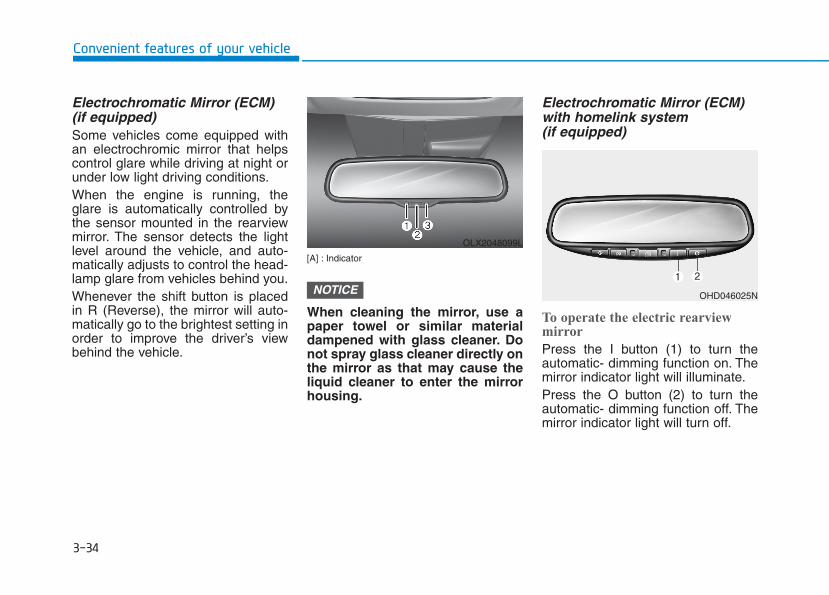
3-34
Convenient features of your vehicle
Electrochromatic Mirror (ECM)(if equipped)Some vehicles come equipped withan electrochromic mirror that helpscontrol glare while driving at night orunder low light driving conditions.When the engine is running, theglare is automatically controlled bythe sensor mounted in the rearviewmirror. The sensor detects the lightlevel around the vehicle, and auto-matically adjusts to control the head-lamp glare from vehicles behind you.Whenever the shift button is placedin R (Reverse), the mirror will auto-matically go to the brightest setting inorder to improve the driver’s viewbehind the vehicle.
[A] : Indicator
When cleaning the mirror, use apaper towel or similar materialdampened with glass cleaner. Donot spray glass cleaner directly onthe mirror as that may cause theliquid cleaner to enter the mirrorhousing.
Electrochromatic Mirror (ECM)with homelink system (if equipped)
To operate the electric rearviewmirror
Press the I button (1) to turn theautomatic- dimming function on. Themirror indicator light will illuminate.Press the O button (2) to turn theautomatic- dimming function off. Themirror indicator light will turn off.
NOTICE
OLX2048099L
OHD046025N

3-35
Convenient features of your vehicle
HomeLink® Wireless Control System
Your new mirror comes with an inte-grated HomeLink UniversalTransceiver, which allows you to pro-gram the mirror to activate yourgarage door(s), estate gate, homelighting, etc. The mirror actuallylearns the codes from your variousexisting transmitters.
Retain the original transmitter forfuture programming procedures (i.e.,new vehicle purchase). It is also sug-gested that upon the sale of the vehi-cle, the programmed HomeLink but-tons be erased for security purposes(follow step 1 in the "Programming"portion of this text).
Programming
Your vehicle may require the ignitionswitch to be turned to the ACC posi-tion for programming and/or operationof HomeLink. It is also recommendedthat a new battery be replaced in thehand-held transmitter of the devicebeing programmed to HomeLink forquicker training and accurate trans-mission of the radio-frequency.Follow these steps to train yourHomeLink mirror:
3
OHD046305N
Glare detection sensorIndicator light
Homelink buttons
• When programming theHomeLink® Wireless ControlSystem, you may be operatinga garage door or gate operator.Make sure that people andobjects are out of the way ofthe moving door or gate to pre-vent potential harm or damage.
• Do not use HomeLink withany garage door opener thatlacks the safety stop andreverse feature as required byU.S. federal safety standards.(This includes any garagedoor opener model manufac-tured before April 1, 1982.) Agarage door opener whichcannot detect an object, sig-naling the door to stop andreverse, does not meet cur-rent U.S. federal safety stan-dards. Using a garage dooropener without these featuresincreases risk of seriousinjury or death. For moredetails, call 1-800-355-3515 oron the internet at www.home-link.com.
WARNING

3-36
1. When programming the buttons forthe first time, press and hold theleft and center buttons ( , )simultaneously for approximately20 seconds until the indicator lightbegins to flash. (This procedureerases the factory-set defaultcodes. Do not perform this step toprogram additional hand-heldtransmitters.)
For non rolling code garage dooropeners, follow steps 2 - 3.For rolling code garage dooropeners, follow steps 2 - 6.For Canadian Programming,please follow the CanadianProgramming section.For help with determining whetheryour garage is non-rolling code orrolling code, please refer to thegarage door openers owner'smanual or contact HomeLink cus-tomer service at 1-800-355-3515.
2. Press and hold the button on theHomeLink system you wish to trainand the button on the transmitterwhile the transmitter is approxi-mately 1 to 3 inches away from themirror. Do not release the buttonsuntil step 3 has been completed.
3. The HomeLink indicator light willflash, first slowly and then rapidly.When the indicator light flashesrapidly, both buttons may bereleased. (The rapid flashing lightindicates successful programmingof the new frequency signal.)
NOTICE
Convenient features of your vehicle
OHD046307N
Flashing
1-3inc
hes
TransmitterOHD046306N
Flashing
3-37
Convenient features of your vehicle
Some gate operators and garagedoor openers may require you toreplace step #3 with the "cycling"procedure noted in the "CanadianProgramming" section of this doc-ument.
Rolling code programmingTo train a garage door opener (orother rolling code equipped devices)with the rolling code feature, followthese instructions after completingthe "Programming" portion of thistext. (A second person may make thefollowing training procedures quicker& easier.)4. Locate the "learn" or "smart" but-
ton on the device's motor headunit. Exact location and color ofthe button may vary by productbrand. If there is difficulty locatingthe "learn" or "smart" button, refer-ence the device's owner's manualor contact HomeLink at 1-800-355-3515 or on the internet atwww.homelink.com.
5. Press and release the "learn" or"smart" button on the device’smotor head unit. You have 30 sec-onds to complete step number 6.
6. Return to the vehicle and firmlypress and release the pro-grammed HomeLink button up tothree times. The rolling codeequipped device should now rec-ognize the HomeLink signal andactivate when the HomeLink but-ton is pressed. The remaining twobuttons may now be programmedif this has not previously beendone. Refer to the "Programming"portion of this text.
Operating HomeLink To operate, simply press the pro-grammed HomeLink button.Activation will now occur for thetrained product (garage door, securi-ty system, entry door lock, estategate, or home or office lighting). Forconvenience, the hand-held trans-mitter of the device may also be usedat any time. The HomeLink WirelessControls System (once programmed)or the original hand-held transmittermay be used to activate the device(e.g. garage door, entry door lock,etc.). In the event that there are stillprogramming difficulties, contactHomeLink at 1-800-355-3515 or onthe internet at www.homelink.com.
NOTICE
3

3-38
Erasing programmed HomeLink but-tonsTo erase the three programmed but-tons (individual buttons cannot beerased):• Press and hold the left and center
buttons simultaneously, until theindicator light begins to flash(approximately 20 seconds).Release both buttons. Do not holdfor longer than 30 seconds.
HomeLink is now in the train (orlearning) mode and can be pro-grammed at any time.
Gate operator & Canadian program-mingDuring programming, your handheldtransmitter may automatically stoptransmitting. Continue to press theIntegrated HomeLink® WirelessControl System button (note steps 2through 3 in the Programming por-tion of this document) while youpress and re-press ("cycle") yourhandheld transmitter every two sec-onds until the frequency signal hasbeen learned. The indicator light willflash slowly and then rapidly afterseveral seconds upon successfultraining.FCC ID: NZLZTVHL3IC: 4112A-ZTVHL3
InformationThis device complies with Part 15 ofthe FCC Rules.
Operation is subject to the followingthree conditions:
1. This device may not cause harmfulinterference.
2. This device must accept any inter-ference received, including interfer-ence that may cause undesiredoperation.
3. The transceiver has been tested andcomplies with FCC and IndustryCanada rules. Changes or modifica-tions not expressly approved by theparty responsible for compliancecould void the user's authority tooperate the device.
i
Convenient features of your vehicle
OHD046306N
Flashing
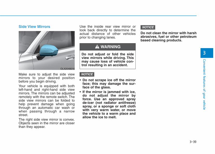
3-39
Convenient features of your vehicle
3
Side View Mirrors
Make sure to adjust the side viewmirrors to your desired positionbefore you begin driving.Your vehicle is equipped with bothleft-hand and right-hand side viewmirrors. The mirrors can be adjustedremotely with the remote switch. Theside view mirrors can be folded tohelp prevent damage when goingthrough an automatic car wash orwhen passing through a narrowstreet.The right side view mirror is convex.Objects seen in the mirror are closerthan they appear.
Use the inside rear view mirror orlook back directly to determine theactual distance of other vehiclesprior to changing lanes.
• Do not scrape ice off the mirrorface; this may damage the sur-face of the glass.
• If the mirror is jammed with ice,do not adjust the mirror byforce. Use an approved sprayde-icer (not radiator antifreeze)spray, or a sponge or soft clothwith very warm water, or movethe vehicle to a warm place andallow the ice to melt.
Do not clean the mirror with harshabrasives, fuel or other petroleumbased cleaning products.
NOTICE
NOTICE
OLX2048016
Do not adjust or fold the sideview mirrors while driving. Thismay cause loss of vehicle con-trol resulting in an accident.
WARNING
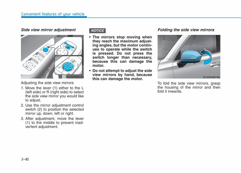
3-40
Convenient features of your vehicle
Side view mirror adjustment
Adjusting the side view mirrors1. Move the lever (1) either to the L
(left side) or R (right side) to selectthe side view mirror you would liketo adjust.
2. Use the mirror adjustment controlswitch (2) to position the selectedmirror up, down, left or right.
3. After adjustment, move the lever(1) to the middle to prevent inad-vertent adjustment.
• The mirrors stop moving whenthey reach the maximum adjust-ing angles, but the motor contin-ues to operate while the switchis pressed. Do not press theswitch longer than necessary,because this can damage themotor.
• Do not attempt to adjust the sideview mirrors by hand, becausethis can damage the motor.
Folding the side view mirrors
To fold the side view mirrors, graspthe housing of the mirror and thenfold it inwards.
NOTICE
OLX2048016LOLX2049017N
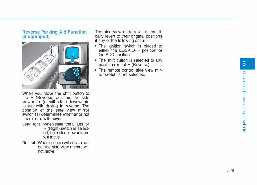
3-41
Convenient features of your vehicle
3
Reverse Parking Aid Function(if equipped)
When you move the shift button tothe R (Reverse) position, the sideview mirror(s) will rotate downwardsto aid with driving in reverse. Theposition of the side view mirrorswitch (1) determines whether or notthe mirrors will move:Left/Right : When either the L (Left) or
R (Right) switch is select-ed, both side view mirrorswill move.
Neutral : When neither switch is select-ed, the side view mirrors willnot move.
The side view mirrors will automati-cally revert to their original positionsif any of the following occur:• The ignition switch is placed to
either the LOCK/OFF position orthe ACC position.
• The shift button is selected to anyposition except R (Reverse).
• The remote control side view mir-ror switch is not selected.
OLX2049019N

3-42
(1) Driver's door power windowswitch
(2) Front passenger's door powerwindow switch
(3) Rear door (left) power windowswitch
(4) Rear door (right) power windowswitch
(5) Window opening and closing(6) Automatic power window(7) Power window lock switch
WWIINNDDOOWWSS
Convenient features of your vehicle
OLX2049020N
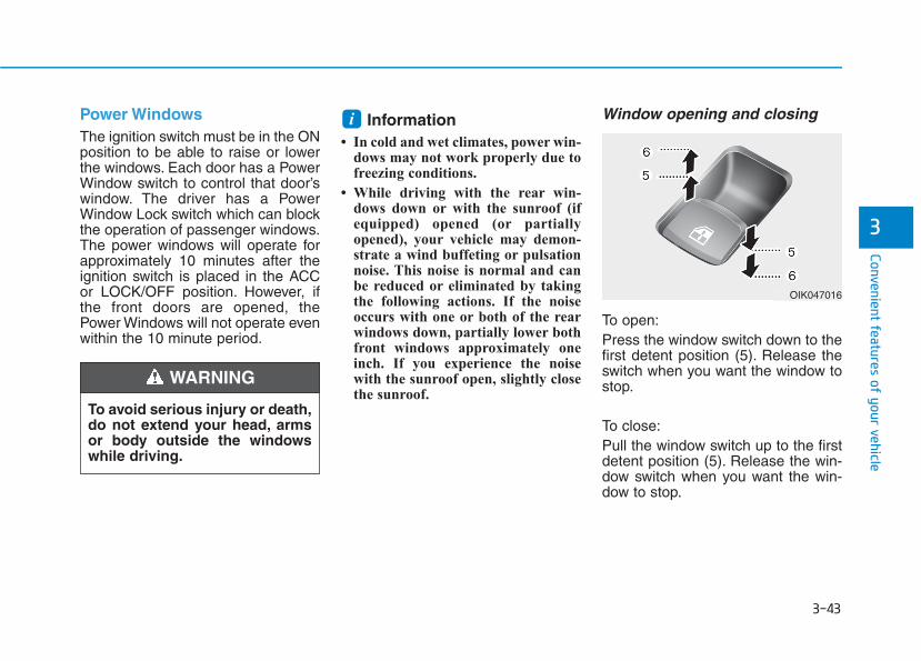
3-43
Convenient features of your vehicle
3
Power WindowsThe ignition switch must be in the ONposition to be able to raise or lowerthe windows. Each door has a PowerWindow switch to control that door’swindow. The driver has a PowerWindow Lock switch which can blockthe operation of passenger windows.The power windows will operate forapproximately 10 minutes after theignition switch is placed in the ACCor LOCK/OFF position. However, ifthe front doors are opened, thePower Windows will not operate evenwithin the 10 minute period.
Information • In cold and wet climates, power win-
dows may not work properly due tofreezing conditions.
• While driving with the rear win-dows down or with the sunroof (ifequipped) opened (or partiallyopened), your vehicle may demon-strate a wind buffeting or pulsationnoise. This noise is normal and canbe reduced or eliminated by takingthe following actions. If the noiseoccurs with one or both of the rearwindows down, partially lower bothfront windows approximately oneinch. If you experience the noisewith the sunroof open, slightly closethe sunroof.
Window opening and closing
To open:Press the window switch down to thefirst detent position (5). Release theswitch when you want the window tostop.
To close:Pull the window switch up to the firstdetent position (5). Release the win-dow switch when you want the win-dow to stop.
i
To avoid serious injury or death,do not extend your head, armsor body outside the windowswhile driving.
WARNING
OIK047016
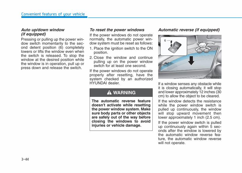
3-44
Convenient features of your vehicle
Auto up/down window (if equipped) Pressing or pulling up the power win-dow switch momentarily to the sec-ond detent position (6) completelylowers or lifts the window even whenthe switch is released. To stop thewindow at the desired position whilethe window is in operation, pull up orpress down and release the switch.
To reset the power windowsIf the power windows do not operatenormally, the automatic power win-dow system must be reset as follows:1. Place the ignition switch to the ON
position.2. Close the window and continue
pulling up on the power windowswitch for at least one second.
If the power windows do not operateproperly after resetting, have thesystem checked by an authorizedHYUNDAI dealer.
Automatic reverse (if equipped)
If a window senses any obstacle whileit is closing automatically, it will stopand lower approximately 12 inches (30cm) to allow the object to be cleared.If the window detects the resistancewhile the power window switch ispulled up continuously, the windowwill stop upward movement thenlower approximately 1 inch (2.5 cm).If the power window switch is pulledup continuously again within 5 sec-onds after the window is lowered bythe automatic window reverse fea-ture, the automatic window reversewill not operate.
The automatic reverse featuredoesn't activate while resettingthe power window system. Makesure body parts or other objectsare safely out of the way beforeclosing the windows to avoidinjuries or vehicle damage.
WARNING
OTM048021
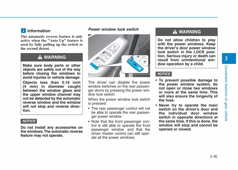
3-45
Convenient features of your vehicle
3
Information The automatic reverse feature is onlyactive when the "Auto Up" feature isused by fully pulling up the switch tothe second detent.
Do not install any accessories onthe windows.The automatic reversefeature may not operate.
Power window lock switch
The driver can disable the powerwindow switches on the rear passen-ger doors by pressing the power win-dow lock switch.When the power window lock switchis pressed:• The rear passenger control will not
be able to operate the rear passen-ger power window
• Note that the front passenger con-trol is still able to operate the frontpassenger window, and that thedriver master control can still oper-ate all the power windows.
• To prevent possible damage tothe power window system, donot open or close two windowsor more at the same time. Thiswill also ensure the longevity ofthe fuse.
• Never try to operate the mainswitch on the driver's door andthe individual door windowswitch in opposite directions atthe same time. If this is done, thewindow will stop and cannot beopened or closed.
NOTICE
NOTICE
i
Do not allow children to playwith the power windows. Keepthe driver's door power windowlock switch in the LOCK posi-tion. Serious injury or death canresult from unintentional win-dow operation by a child.
WARNING
Make sure body parts or otherobjects are safely out of the waybefore closing the windows toavoid injuries or vehicle damage.Objects less than 0.16 inch (4 mm) in diameter caughtbetween the window glass andthe upper window channel maynot be detected by the automaticreverse window and the windowwill not stop and reverse direc-tion.
WARNING
OLX2049023N
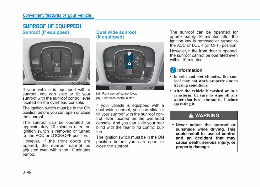
3-46
Sunroof (if equipped)
If your vehicle is equipped with asunroof, you can slide or tilt yoursunroof with the sunroof control leverlocated on the overhead console.The ignition switch must be in the ONposition before you can open or closethe sunroof.The sunroof can be operated forapproximately 10 minutes after theignition switch is removed or turnedto the ACC or LOCK/OFF position.However, if the front doors areopened, the sunroof cannot beadjusted even within the 10 minutesperiod.
Dual wide sunroof(if equipped)
[A] : Front sunroof control lever,
[B] : Rear blind control button
If your vehicle is equipped with adual wide sunroof, you can slide ortilt your sunroof with the sunroof con-trol lever located on the overheadconsole. And you can slide your rearblind with the rear blind control but-ton.The ignition switch must be in the ONposition before you can open orclose the sunroof.
The sunroof can be operated forapproximately 10 minutes after theignition key is removed or turned tothe ACC or LOCK (or OFF) position.However, if the front door is opened,the sunroof cannot be operated evenwithin 10 minutes.
Information • In cold and wet climates, the sun-
roof may not work properly due tofreezing conditions.
• After the vehicle is washed or in arainstorm, be sure to wipe off anywater that is on the sunroof beforeoperating it.
i
SSUUNNRROOOOFF ((IIFF EEQQUUIIPPPPEEDD))
Convenient features of your vehicle
• Never adjust the sunroof orsunshade while driving. Thiscould result in loss of controland an accident that maycause death, serious injury, orproperty damage.
WARNING
OLX2048025L
OLX2049409L

3-47
Convenient features of your vehicle
3
• Do not continue to move the sun-roof control lever after the sun-roof is fully opened, closed, ortilted. Damage to the motor orsystem components could occur.
• Make sure the sunroof is closedfully when leaving your vehicle.If the sunroof is left open, rain orsnow may wet the interior of thevehicle. Also, leaving the sunroofopen when the vehicle is unat-tended may invite theft.
Sunshade
Front• To open the sunshade, pull the
sunroof sunshade backward.• To close the sunshade, pull the
sunroof sunshade forward.
NOTICE• Make sure heads, hands, armsor any other body parts orobjects are out of the waybefore operating the sunroof.
• Do not extend your head, armsor body outside the sunroofwhile driving, to avoid seriousinjury.
• Do not leave the engine run-ning and the key in your vehi-cle with unsupervised children.Unattended children couldoperate the sunroof, whichcould result in serious injury.
• The sunroof is made of glass,subject to break in case of anaccident. Passengers withoutthe appropriate protection (e.g.seat belt, CRS, etc.) on mayproject out through the brokenglass and may be seriouslyinjured or even result in death.
• Do not sit on the top of thevehicle. It may cause injury orvehicle damage.
OLX2048026L
■ Front
■ Rear (if equipped)
OLX2048027

3-48
Convenient features of your vehicle
Rear (if equipped)• To open the rear blind, push the
rear blind OPEN button.• To close the rear blind, push the
rear blind CLOSE button.
Information Activating the control lever to the firstdetent requires only a very light touch.
Sunroof Opening and Closing
To open:Press the sunroof control lever back-ward to the first detent position.Release the switch when you wantthe sunroof to stop.To close:Press the sunroof control lever forwardto the first detent position. Release theswitch when you want the sunroof tostop.
Sliding the SunroofPressing the sunroof control leverbackward or forward momentarily tothe second detent position complete-ly opens or closes the sunroof evenwhen the switch is released. To stopthe sunroof at the desired positionwhile the sunroof is in operation,press the sunroof control lever back-ward or forward and release theswitch.
i
OLX2048028

3-49
Convenient features of your vehicle
3
Tilting the Sunroof (Front)
Tilt the sunroof open:Push the sunroof control leverupward until the sunroof moves tothe desired position.
To close the sunroof:Push the sunroof control lever forwarduntil the sunroof closes.
Automatic reverse (if equipped)
If the sunroof senses any to anobstacle while it is closing automati-cally, it will reverse direction thenstop to allow the object to be cleared.
Small objects that can getcaught between the sunroofglass and the front glass chan-nel may not be detected by theautomatic reverse system. Inthis case, the sunroof glass willnot detect the object and willnot reverse direction.
WARNING
OLX2048029 OLFC044035CN
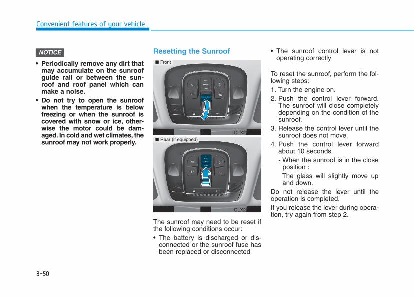
3-50
Convenient features of your vehicle
• Periodically remove any dirt thatmay accumulate on the sunroofguide rail or between the sun-roof and roof panel which canmake a noise.
• Do not try to open the sunroofwhen the temperature is belowfreezing or when the sunroof iscovered with snow or ice, other-wise the motor could be dam-aged. In cold and wet climates, thesunroof may not work properly.
Resetting the Sunroof
The sunroof may need to be reset ifthe following conditions occur:• The battery is discharged or dis-
connected or the sunroof fuse hasbeen replaced or disconnected
• The sunroof control lever is notoperating correctly
To reset the sunroof, perform the fol-lowing steps:1. Turn the engine on.2. Push the control lever forward.
The sunroof will close completelydepending on the condition of thesunroof.
3. Release the control lever until thesunroof does not move.
4. Push the control lever forwardabout 10 seconds.- When the sunroof is in the close
position :The glass will slightly move upand down.
Do not release the lever until theoperation is completed.If you release the lever during opera-tion, try again from step 2.
NOTICE
OLX2048032
■ Front
■ Rear (if equipped)
OLX2048098
3-51
Convenient features of your vehicle
5. Within 3 seconds, push the controllever forward until the sunroofoperates as follows:Slide Open → Slide Close.
Do not release the lever until theoperation is completed.If you release the lever during opera-tion, try again from step 2.6. Release the sunroof control lever
after all operation has completed.The sunroof system has beenreset.
Information If you do not reset the sunroof, it maynot work properly.
Resetting the rear sunshade(if equipped)The rear sunshade may need to bereset if the following conditionsoccur:- Battery is discharged or discon-
nected or the related fuse has beenreplaced or disconnected
- The rear sunshade does not nor-mally operate
To reset the rear sunshade, performthe following steps:1. Turn the engine on.2. Push the rear sunshade CLOSE
button. The rear sunshade willclose completely.
3. Push the rear sunshade CLOSEbutton about 10 seconds.
The rear sunshade will slightly move.Do not release the CLOSE buttonuntil the operation is completed.If you release the CLOSE button, tryagain from step 2.4. Within 3 seconds, push the
CLOSE button until the rear sun-shade operates as follows :Open → Close
Do not release the CLOSE buttonuntil the operation is completed.If you release the CLOSE button dur-ing operation, try again from step 2.5. Release the CLOSE button after
all operation has completed.The rear sunshade system has beenreset.
i
3
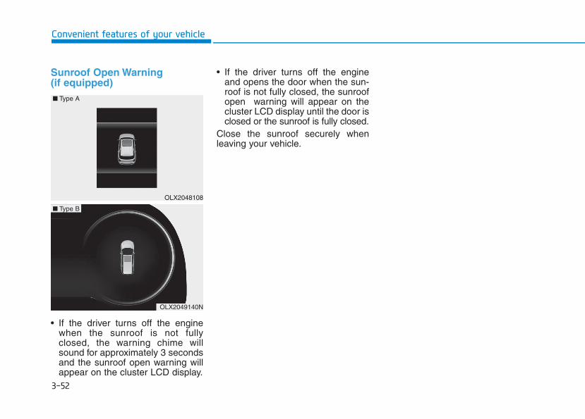
3-52
Sunroof Open Warning(if equipped)
• If the driver turns off the enginewhen the sunroof is not fullyclosed, the warning chime willsound for approximately 3 secondsand the sunroof open warning willappear on the cluster LCD display.
• If the driver turns off the engineand opens the door when the sun-roof is not fully closed, the sunroofopen warning will appear on thecluster LCD display until the door isclosed or the sunroof is fully closed.
Close the sunroof securely whenleaving your vehicle.
Convenient features of your vehicle
OLX2048108
■ Type A
OLX2049140N
■ Type B
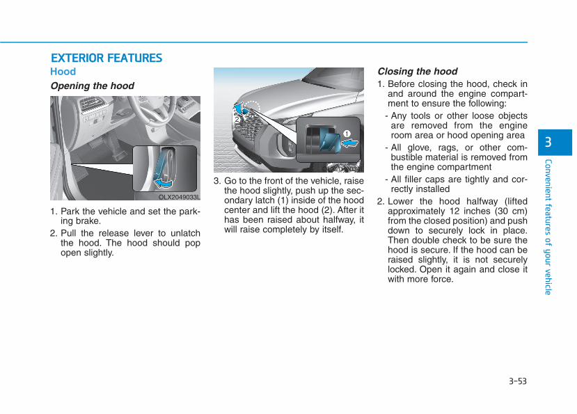
3-53
Convenient features of your vehicle
3
HoodOpening the hood
1. Park the vehicle and set the park-ing brake.
2. Pull the release lever to unlatchthe hood. The hood should popopen slightly.
3. Go to the front of the vehicle, raisethe hood slightly, push up the sec-ondary latch (1) inside of the hoodcenter and lift the hood (2). After ithas been raised about halfway, itwill raise completely by itself.
Closing the hood1. Before closing the hood, check in
and around the engine compart-ment to ensure the following:
- Any tools or other loose objectsare removed from the engineroom area or hood opening area
- All glove, rags, or other com-bustible material is removed fromthe engine compartment
- All filler caps are tightly and cor-rectly installed
2. Lower the hood halfway (liftedapproximately 12 inches (30 cm)from the closed position) and pushdown to securely lock in place.Then double check to be sure thehood is secure. If the hood can beraised slightly, it is not securelylocked. Open it again and close itwith more force.
EEXXTTEERRIIOORR FFEEAATTUURREESS
OLX2049033L
OLX2048034L
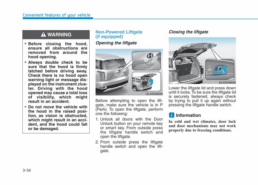
3-54
Convenient features of your vehicle
Non-Powered Liftgate (if equipped)Opening the liftgate
Before attempting to open the lift-gate, make sure the vehicle is in P(Park). To open the liftgate, performone the following:1. Unlock all doors with the Door
Unlock button on your remote keyor smart key. From outside pressthe liftgate handle switch andopen the liftgate.
2. From outside press the liftgatehandle switch and open the lift-gate.
Closing the liftgate
Lower the liftgate lid and press downuntil it locks. To be sure the liftgate lidis securely fastened, always checkby trying to pull it up again withoutpressing the liftgate handle switch.
Information In cold and wet climates, door lockand door mechanisms may not workproperly due to freezing conditions.
i
• Before closing the hood,ensure all obstructions areremoved from around thehood opening.
• Always double check to besure that the hood is firmlylatched before driving away.Check there is no hood openwarning light or message dis-played on the instrument clus-ter. Driving with the hoodopened may cause a total lossof visibility, which mightresult in an accident.
• Do not move the vehicle withthe hood in the raised posi-tion, as vision is obstructed,which might result in an acci-dent, and the hood could fallor be damaged.
WARNING
OLX2048035
OLX2048036
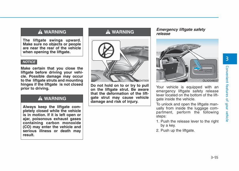
3-55
Convenient features of your vehicle
3Make certain that you close theliftgate before driving your vehi-cle. Possible damage may occurto the liftgate struts and mountinghinges if the liftgate is not closedprior to driving.
Emergency liftgate safetyrelease
Your vehicle is equipped with anemergency liftgate safety releaselever located on the bottom of the lift-gate inside the vehicle.To unlock and open the liftgate man-ually from inside the luggage com-partment, perform the followingsteps:1. Push the release lever to the right
by a key.2. Push up the liftgate.
NOTICE
OLX2048037
The liftgate swings upward.Make sure no objects or peopleare near the rear of the vehiclewhen opening the liftgate.
WARNING
Do not hold on to or try to pullon the liftgate strut. Be awarethat the deformation of the lift-gate strut may cause vehicledamage and risk of injury.
WARNING
OHYK047009
Always keep the liftgate com-pletely closed while the vehicleis in motion. If it is left open orajar, poisonous exhaust gasescontaining carbon monoxide(CO) may enter the vehicle andserious illness or death mayresult.
WARNING
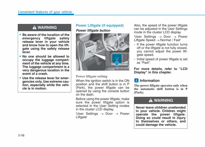
3-56
Convenient features of your vehicle
Power Liftgate (if equipped)Power liftgate button
Power liftgate setting
When the ignition switch is in the ONposition and the shift button is in P(Park), the power liftgate can beopened by using the console buttonon the dash.Before using the power liftgate, makesure the power liftgate option isselected in the User Setting modesin the cluster LCD display.'User Settings → Door → PowerLiftgate'
Also, the speed of the power liftgatecan be adjusted in the User Settingsmode in the cluster LCD display.'User Settings → Door → PowerLiftgate Speed → Normal / Fast'- If the power liftgate function turns
off or the liftgate is not fully closed,you cannot adjust the power lift-gate speed.
- Initial speed of power liftgate is setas "Fast".
For more details, refer to "LCDDisplay" in this chapter.
Information The power liftgate operates only whenthe automatic shift button is in P(Park).
i
• Be aware of the location of theemergency liftgate safetyrelease lever in your vehicleand know how to open the lift-gate using the safety releaselever.
• No one should be allowed tooccupy the luggage compart-ment of the vehicle at any time.The luggage compartment is avery dangerous location in theevent of a crash.
• Use the release lever for emer-gencies only. Use extreme cau-tion, especially while the vehi-cle is in motion.
WARNING
OLX2049040L
Never leave children unattendedin your vehicle. Children mightoperate the power liftgate.Doing so could result in injuryto themselves or others, andcould damage the vehicle.
WARNING
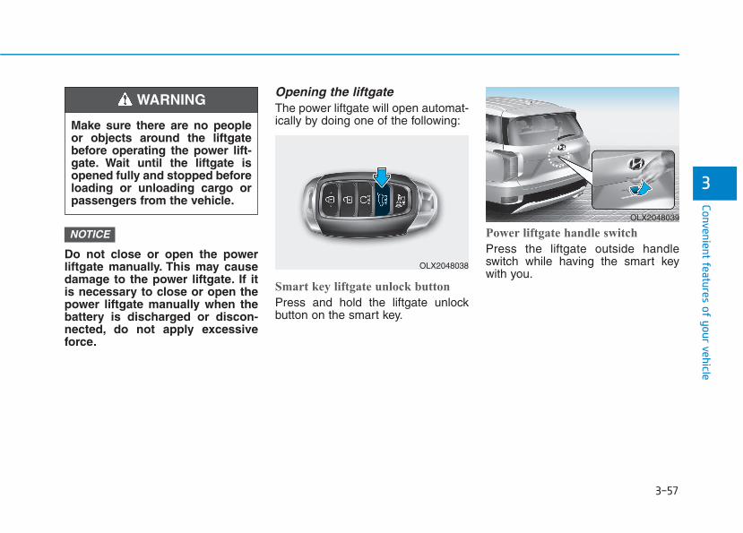
3-57
Convenient features of your vehicle
3
Do not close or open the powerliftgate manually. This may causedamage to the power liftgate. If itis necessary to close or open thepower liftgate manually when thebattery is discharged or discon-nected, do not apply excessiveforce.
Opening the liftgateThe power liftgate will open automat-ically by doing one of the following:
Smart key liftgate unlock button
Press and hold the liftgate unlockbutton on the smart key.
Power liftgate handle switch
Press the liftgate outside handleswitch while having the smart keywith you.
NOTICE
Make sure there are no peopleor objects around the liftgatebefore operating the power lift-gate. Wait until the liftgate isopened fully and stopped beforeloading or unloading cargo orpassengers from the vehicle.
WARNING
OLX2048038
OLX2048039

3-58
Convenient features of your vehicle
Power liftgate button
Press the power liftgate button forapproximately one second.
In order to suddenly stop the move-ment of the liftgate while it is operat-ing, quickly press the power liftgatebutton.
Closing the liftgateThe power liftgate will close automat-ically by doing one of the following:
Smart key liftgate unlock button
Press and hold the liftgate unlockbutton on the smart key when the lift-gate is opened. The liftgate will closeand lock automatically.
Power liftgate inner button
Press the power liftgate inner buttonfor approximately 1 second. The lift-gate will close and lock automatically.
OLX2049040L
OLX2048038
OLX2048041
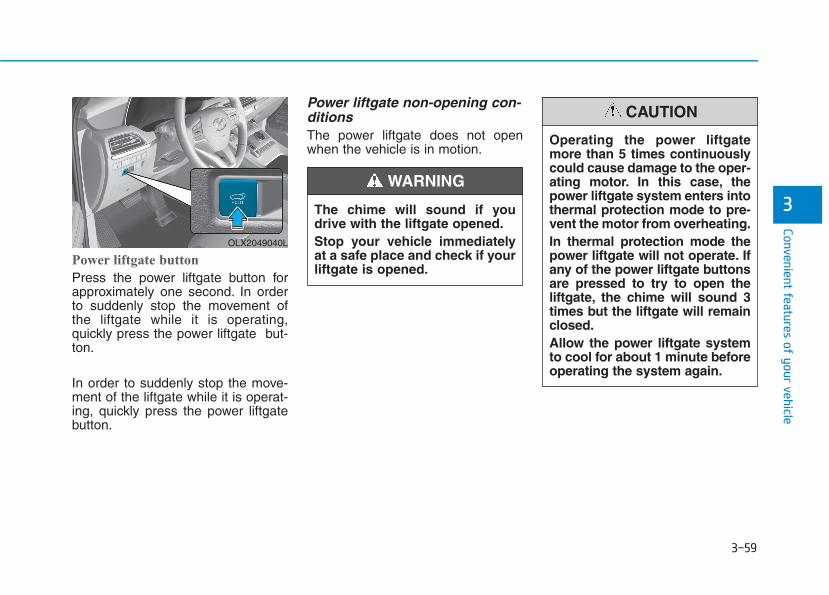
3-59
Convenient features of your vehicle
3The chime will sound if youdrive with the liftgate opened.Stop your vehicle immediatelyat a safe place and check if yourliftgate is opened.
WARNING
Power liftgate button
Press the power liftgate button forapproximately one second. In orderto suddenly stop the movement ofthe liftgate while it is operating,quickly press the power liftgate but-ton.
In order to suddenly stop the move-ment of the liftgate while it is operat-ing, quickly press the power liftgatebutton.
Power liftgate non-opening con-ditionsThe power liftgate does not openwhen the vehicle is in motion.
OLX2049040L
Operating the power liftgatemore than 5 times continuouslycould cause damage to the oper-ating motor. In this case, thepower liftgate system enters intothermal protection mode to pre-vent the motor from overheating.In thermal protection mode thepower liftgate will not operate. Ifany of the power liftgate buttonsare pressed to try to open theliftgate, the chime will sound 3times but the liftgate will remainclosed.Allow the power liftgate systemto cool for about 1 minute beforeoperating the system again.
CAUTION
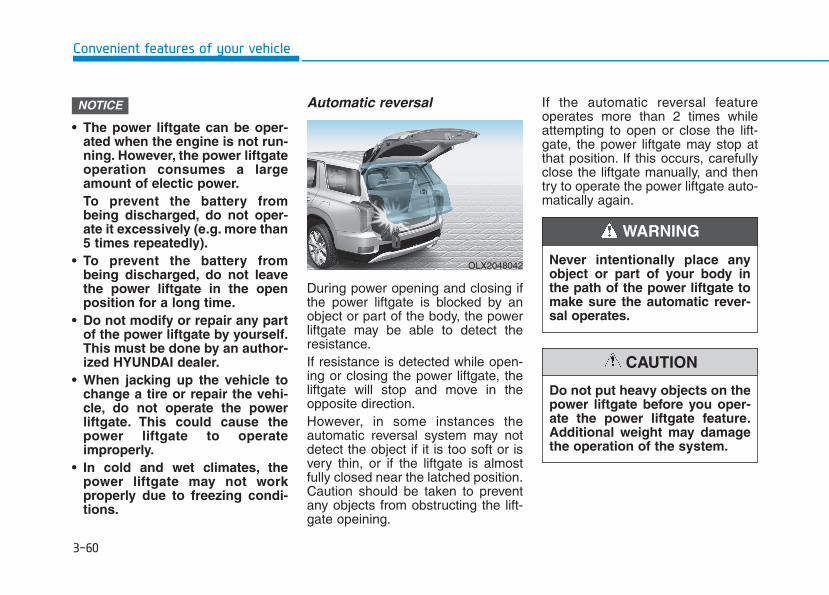
3-60
Convenient features of your vehicle
• The power liftgate can be oper-ated when the engine is not run-ning. However, the power liftgateoperation consumes a largeamount of electic power.To prevent the battery frombeing discharged, do not oper-ate it excessively (e.g. more than5 times repeatedly).
• To prevent the battery frombeing discharged, do not leavethe power liftgate in the openposition for a long time.
• Do not modify or repair any partof the power liftgate by yourself.This must be done by an author-ized HYUNDAI dealer.
• When jacking up the vehicle tochange a tire or repair the vehi-cle, do not operate the powerliftgate. This could cause thepower liftgate to operateimproperly.
• In cold and wet climates, thepower liftgate may not workproperly due to freezing condi-tions.
Automatic reversal
During power opening and closing ifthe power liftgate is blocked by anobject or part of the body, the powerliftgate may be able to detect theresistance.If resistance is detected while open-ing or closing the power liftgate, theliftgate will stop and move in theopposite direction.However, in some instances theautomatic reversal system may notdetect the object if it is too soft or isvery thin, or if the liftgate is almostfully closed near the latched position.Caution should be taken to preventany objects from obstructing the lift-gate opeining.
If the automatic reversal featureoperates more than 2 times whileattempting to open or close the lift-gate, the power liftgate may stop atthat position. If this occurs, carefullyclose the liftgate manually, and thentry to operate the power liftgate auto-matically again.
NOTICE
OLX2048042 Never intentionally place anyobject or part of your body inthe path of the power liftgate tomake sure the automatic rever-sal operates.
WARNING
Do not put heavy objects on thepower liftgate before you oper-ate the power liftgate feature.Additional weight may damagethe operation of the system.
CAUTION
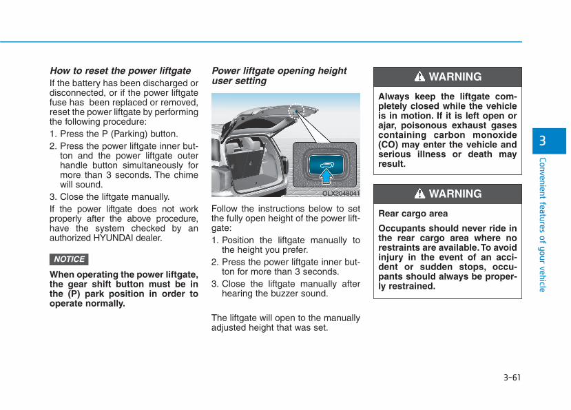
3-61
Convenient features of your vehicle
3
How to reset the power liftgateIf the battery has been discharged ordisconnected, or if the power liftgatefuse has been replaced or removed,reset the power liftgate by performingthe following procedure:1. Press the P (Parking) button.2. Press the power liftgate inner but-
ton and the power liftgate outerhandle button simultaneously formore than 3 seconds. The chimewill sound.
3. Close the liftgate manually.If the power liftgate does not workproperly after the above procedure,have the system checked by anauthorized HYUNDAI dealer.
When operating the power liftgate,the gear shift button must be inthe (P) park position in order tooperate normally.
Power liftgate opening heightuser setting
Follow the instructions below to setthe fully open height of the power lift-gate:1. Position the liftgate manually to
the height you prefer.2. Press the power liftgate inner but-
ton for more than 3 seconds.3. Close the liftgate manually after
hearing the buzzer sound.
The liftgate will open to the manuallyadjusted height that was set.
NOTICE
Always keep the liftgate com-pletely closed while the vehicleis in motion. If it is left open orajar, poisonous exhaust gasescontaining carbon monoxide(CO) may enter the vehicle andserious illness or death mayresult.
WARNING
Rear cargo area
Occupants should never ride inthe rear cargo area where norestraints are available.To avoidinjury in the event of an acci-dent or sudden stops, occu-pants should always be proper-ly restrained.
WARNING OLX2048041
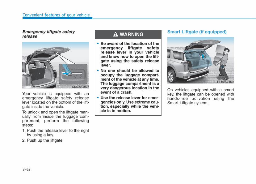
3-62
Convenient features of your vehicle
Emergency liftgate safetyrelease
Your vehicle is equipped with anemergency liftgate safety releaselever located on the bottom of the lift-gate inside the vehicle.To unlock and open the liftgate man-ually from inside the luggage com-partment, perform the followingsteps:1. Push the release lever to the right
by using a key.2. Push up the liftgate.
Smart Liftgate (if equipped)
On vehicles equipped with a smartkey, the liftgate can be opened withhands-free activation using theSmart Liftgate system.
• Be aware of the location of theemergency liftgate safetyrelease lever in your vehicleand know how to open the lift-gate using the safety releaselever.
• No one should be allowed tooccupy the luggage compart-ment of the vehicle at any time.The luggage compartment is avery dangerous location in theevent of a crash.
• Use the release lever for emer-gencies only. Use extreme cau-tion, especially while the vehi-cle is in motion.
WARNING
OLX2048037
OLX2048043

3-63
Convenient features of your vehicle
3
How to use the Smart LiftgateThe hands-free smart liftgate systemcan be opened automatically whenthe following conditions are met:• The Smart Liftgate option is
enabled in the User Settings in thecluster LCD display
• The Smart Liftgate is activated andready 15 seconds after all thedoors are closed and locked
• The Smart Liftgate will open whenthe smart key is detected in thearea behind the vehicle for 3 sec-onds
InformationThe Smart Liftgate will NOT operatewhen:
• Any door is open, or all doors areclosed but not locked
• The smart key is detected within 15seconds from when the doors wereclosed and locked
• For vehicles equipped with illumi-nated exterior front door handles, ifthe smart key is detected within 15seconds from when the doors wereclosed and locked or if the smart keyis within 60 inches (1.5 m) from thefront door handles
• The smart key is in the vehicle.
1. SettingTo activate the Smart Liftgate, go toUser Settings mode and selectSmart Liftgate in the cluster LCD dis-play.
For more details, refer to "LCDDisplay" in this chapter.
2. Detect and AlertThe Smart Liftgate detecting areaextends approximately 20-40 in (50-100 cm) behind the vehicle. If youare positioned in the detecting areaand are carrying the smart key, thehazard warning lights will blink andthe chime will sound to alert you thatthe smart liftgate will open.
InformationDo not approach the detecting area ifyou do not want the liftgate to open. Ifyou have unintentionally entered thedetecting area and the hazard warn-ing lights and chime starts to operate,move away from the area behind thevehicle with the smart key. The lift-gate will remain closed.
i
i
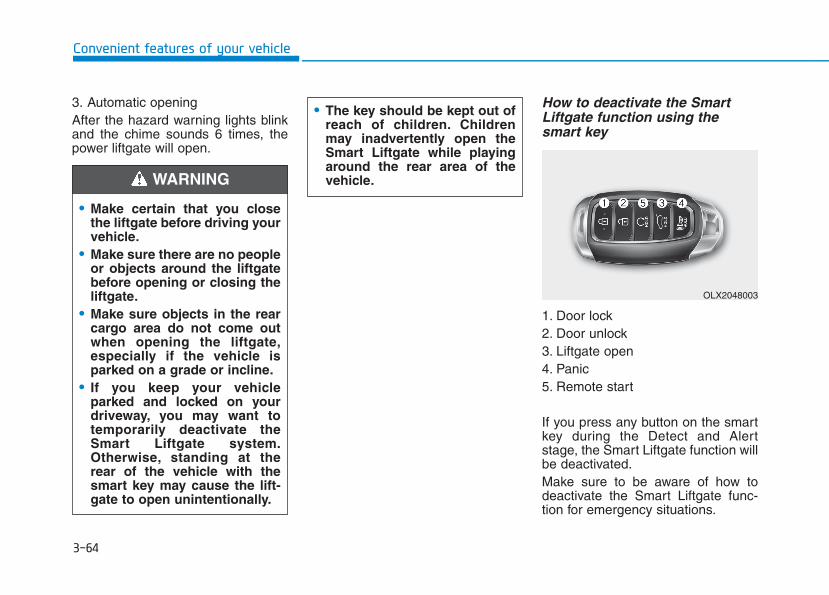
3-64
Convenient features of your vehicle
3. Automatic openingAfter the hazard warning lights blinkand the chime sounds 6 times, thepower liftgate will open.
How to deactivate the SmartLiftgate function using thesmart key
1. Door lock2. Door unlock3. Liftgate open4. Panic5. Remote start
If you press any button on the smartkey during the Detect and Alertstage, the Smart Liftgate function willbe deactivated.Make sure to be aware of how todeactivate the Smart Liftgate func-tion for emergency situations.
• Make certain that you closethe liftgate before driving yourvehicle.
• Make sure there are no peopleor objects around the liftgatebefore opening or closing theliftgate.
• Make sure objects in the rearcargo area do not come outwhen opening the liftgate,especially if the vehicle isparked on a grade or incline.
• If you keep your vehicleparked and locked on yourdriveway, you may want totemporarily deactivate theSmart Liftgate system.Otherwise, standing at therear of the vehicle with thesmart key may cause the lift-gate to open unintentionally.
WARNING
• The key should be kept out ofreach of children. Childrenmay inadvertently open theSmart Liftgate while playingaround the rear area of thevehicle.
OLX2048003
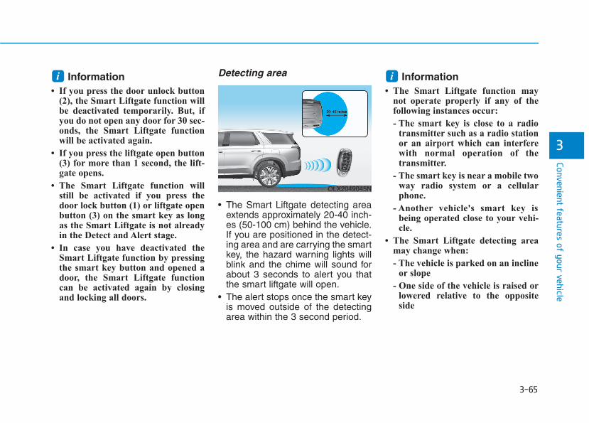
3-65
Convenient features of your vehicle
3
Information• If you press the door unlock button
(2), the Smart Liftgate function willbe deactivated temporarily. But, ifyou do not open any door for 30 sec-onds, the Smart Liftgate functionwill be activated again.
• If you press the liftgate open button(3) for more than 1 second, the lift-gate opens.
• The Smart Liftgate function willstill be activated if you press thedoor lock button (1) or liftgate openbutton (3) on the smart key as longas the Smart Liftgate is not alreadyin the Detect and Alert stage.
• In case you have deactivated theSmart Liftgate function by pressingthe smart key button and opened adoor, the Smart Liftgate functioncan be activated again by closingand locking all doors.
Detecting area
• The Smart Liftgate detecting areaextends approximately 20-40 inch-es (50-100 cm) behind the vehicle.If you are positioned in the detect-ing area and are carrying the smartkey, the hazard warning lights willblink and the chime will sound forabout 3 seconds to alert you thatthe smart liftgate will open.
• The alert stops once the smart keyis moved outside of the detectingarea within the 3 second period.
Information• The Smart Liftgate function may
not operate properly if any of thefollowing instances occur:
- The smart key is close to a radiotransmitter such as a radio stationor an airport which can interferewith normal operation of thetransmitter.
- The smart key is near a mobile twoway radio system or a cellularphone.
- Another vehicle's smart key isbeing operated close to your vehi-cle.
• The Smart Liftgate detecting areamay change when:
- The vehicle is parked on an inclineor slope
- One side of the vehicle is raised orlowered relative to the oppositeside
ii
OLX2049045N
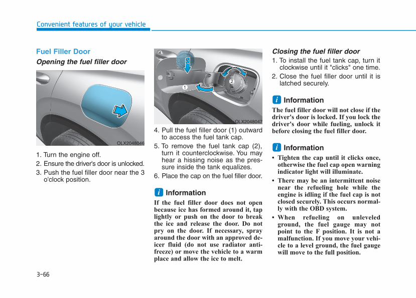
3-66
Convenient features of your vehicle
Fuel Filler DoorOpening the fuel filler door
1. Turn the engine off.2. Ensure the driver's door is unlocked.3. Push the fuel filler door near the 3
o'clock position.
4. Pull the fuel filler door (1) outwardto access the fuel tank cap.
5. To remove the fuel tank cap (2),turn it counterclockwise. You mayhear a hissing noise as the pres-sure inside the tank equalizes.
6. Place the cap on the fuel filler door.
Information If the fuel filler door does not openbecause ice has formed around it, taplightly or push on the door to breakthe ice and release the door. Do notpry on the door. If necessary, sprayaround the door with an approved de-icer fluid (do not use radiator anti-freeze) or move the vehicle to a warmplace and allow the ice to melt.
Closing the fuel filler door1. To install the fuel tank cap, turn it
clockwise until it "clicks" one time.2. Close the fuel filler door until it is
latched securely.
Information The fuel filler door will not close if thedriver's door is locked. If you lock thedriver's door while fueling, unlock itbefore closing the fuel filler door.
Information • Tighten the cap until it clicks once,
otherwise the fuel cap open warningindicator light will illuminate.
• There may be an intermittent noisenear the refueling hole while theengine is idling if the fuel cap is notclosed securely. This occurs normal-ly with the OBD system.
• When refueling on unleveledground, the fuel gauge may notpoint to the F position. It is not amalfunction. If you move your vehi-cle to a level ground, the fuel gaugewill move to the full position.
i
i
i
OLX2048046
OLX2048047
3-67
Convenient features of your vehicle
3
• Do not get back into a vehicleonce you have begun refuel-ing. You can generate a build-up of static electricity bytouching, rubbing or slidingagainst any item or fabriccapable of producing staticelectricity. Static electricitydischarge can ignite fuelvapors causing a fire. If youmust re-enter the vehicle, youshould once again eliminatepotentially dangerous staticelectricity discharge by touch-ing a metal part of the vehicle,away from the fuel filler neck,nozzle or other gasolinesource, with your bare hand.
• When using an approvedportable fuel container, besure to place the container onthe ground prior to refueling.Static electricity dischargefrom the container can ignitefuel vapors causing a fire.
Once refueling has begun,contact between your barehand and the vehicle shouldbe maintained until the fillingis complete.
• Use only approved portableplastic fuel containers designedto carry and store gasoline.
• When refueling, always movethe shift button to the P (Park)position, set the parkingbrake, and place the ignitionswitch to the LOCK/OFF posi-tion. Sparks produced byelectrical components relatedto the engine can ignite fuelvapors causing a fire.
• Do not use matches or alighter and do not smoke orleave a lit cigarette in yourvehicle while at a gas station,especially during refueling.
Gasoline is highly flammableand explosive. Failure to followthese guidelines may result inSERIOUS INJURY or DEATH:• Read and follow all warnings
posted at the gas station.• Before refueling, note the
location of the EmergencyGasoline Shut-Off, if available,at the gas station.
• Before touching the fuel noz-zle, you should eliminate thepotential build-up of staticelectricity by touching a metalpart of the vehicle, a safe dis-tance away from the fuel fillerneck, nozzle, or other gassource, with your bare hand.
• Do not use cellular phoneswhile refueling. Electric cur-rent and/or electronic interfer-ence from cellular phones canpotentially ignite fuel vaporsand cause a fire.
WARNING
3-68
Convenient features of your vehicle
Information Make sure to refuel your vehicleaccording to the "Fuel Requirements"suggested in the Introduction chapter.
• Do not spill fuel on the exteriorsurfaces of the vehicle. Any typeof fuel spilled on painted sur-faces may damage the paint.
• If the fuel filler cap requiresreplacement, use only a genuineHYUNDAI cap or the equivalentspecified for your vehicle. Anincorrect fuel filler cap canresult in a serious malfunctionof the fuel system or emissioncontrol system.
NOTICE
i• Do not over-fill or top-off yourvehicle tank, which can causegasoline spillage.
• If a fire breaks out during refu-eling, leave the vicinity of thevehicle, and immediately con-tact the manager of the gasstation and then contact thelocal fire department. Followany safety instructions theyprovide.
• If pressurized fuel sprays out,it can cover your clothes orskin and thus subject you tothe risk of fire and burns.Always remove the fuel capcarefully and slowly. If the capis venting fuel or if you hear ahissing sound, wait until thecondition stops before com-pletely removing the cap.
• Always check that the fuel capis installed securely to pre-vent fuel spillage in the eventof an accident.
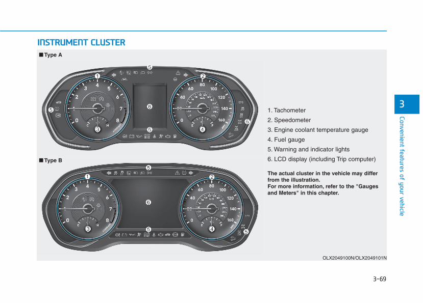
3-69
Convenient features of your vehicle
3
IINNSSTTRRUUMMEENNTT CCLLUUSSTTEERR
1. Tachometer
2. Speedometer
3. Engine coolant temperature gauge
4. Fuel gauge
5. Warning and indicator lights
6. LCD display (including Trip computer)
OLX2049100N/OLX2049101N
■■ Type A
■■ Type B
The actual cluster in the vehicle may differfrom the illustration.For more information, refer to the "Gaugesand Meters" in this chapter.
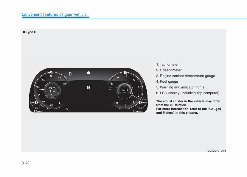
3-70
Convenient features of your vehicle
1. Tachometer
2. Speedometer
3. Engine coolant temperature gauge
4. Fuel gauge
5. Warning and indicator lights
6. LCD display (including Trip computer)
OLX2049126N
■■ Type C
The actual cluster in the vehicle may differfrom the illustration.For more information, refer to the "Gaugesand Meters" in this chapter.
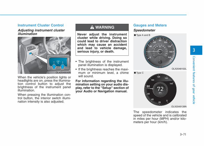
3-71
Convenient features of your vehicle
3
Instrument Cluster ControlAdjusting instrument clusterillumination
When the vehicle's position lights orheadlights are on, press the illumina-tion control button to adjust thebrightness of the instrument panelillumination.When pressing the illumination con-trol button, the interior switch illumi-nation intensity is also adjusted.
• The brightness of the instrumentpanel illumination is displayed.
• If the brightness reaches the maxi-mum or minimum level, a chimewill sound.
For information regarding the illu-mination setting on your audio dis-play, refer to the "Setup" section ofyour Audio or Navigation manual.
Gauges and MetersSpeedometer
The speedometer indicates thespeed of the vehicle and is calibratedin miles per hour (MPH) and/or kilo-meters per hour (km/h).
Never adjust the instrumentcluster while driving. Doing socould lead to driver distractionwhich may cause an accidentand lead to vehicle damage,serious injury, or death.
WARNING
OLX2049049N
OLX2049139N
OLX2048102L
■ Type A and B
■ Type C

3-72
Convenient features of your vehicle
Tachometer
The tachometer indicates theapproximate number of engine revo-lutions per minute (rpm).
Do not operate the engine withinthe tachometer's RED ZONE. Thismay cause severe engine damage.
Engine coolant temperaturegauge
This gauge indicates the tempera-ture of the engine coolant when theignition switch is in the ON position.
NOTICE
OLX2049138N
OLX2048105
■ Type A and B
■ Type C
OLX2049127N
OLX2048106
■ Type A and B
■ Type C

3-73
Convenient features of your vehicle
3
If the gauge pointer movesbeyond the normal range areatoward the "H" position, it indi-cates overheating that may dam-age the engine.Do not continue driving with anoverheated engine. If your vehicleoverheats, refer to "If the EngineOverheats" in chapter 6.
Fuel gauge
This gauge indicates the approxi-mate amount of fuel remaining in thefuel tank.
Information • The fuel tank capacity is given in
chapter 8.
• The fuel gauge is supplemented by alow fuel warning light, which willilluminate when the fuel tank isnearly empty.
• On inclines or curves, the fuel gaugepointer may fluctuate or the low fuelwarning light may come on earlierthan usual due to the movement offuel in the tank.
iNOTICE
Never remove the radiator cap orengine coolant reservoir capwhen the engine is hot. Theengine coolant is under pressureand could severely burn. Waituntil the engine is cool beforeadding coolant to the reservoir.
WARNING
OLX2049128N
OLX2048107
■ Type A and B
■ Type C
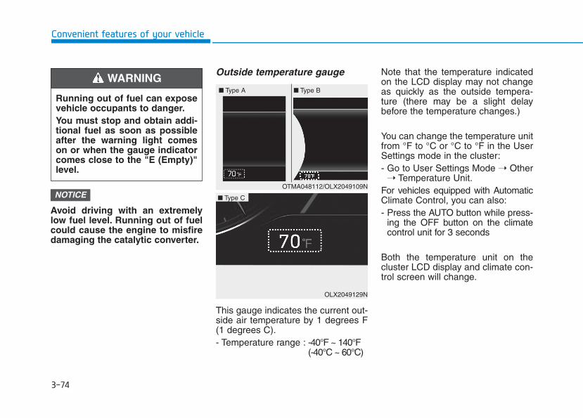
3-74
Convenient features of your vehicle
Avoid driving with an extremelylow fuel level. Running out of fuelcould cause the engine to misfiredamaging the catalytic converter.
Outside temperature gauge
This gauge indicates the current out-side air temperature by 1 degrees F(1 degrees C).- Temperature range : -40°F ~ 140°F
(-40°C ~ 60°C)
Note that the temperature indicatedon the LCD display may not changeas quickly as the outside tempera-ture (there may be a slight delaybefore the temperature changes.)
You can change the temperature unitfrom °F to °C or °C to °F in the UserSettings mode in the cluster:- Go to User Settings Mode ➝ Other
➝ Temperature Unit.For vehicles equipped with AutomaticClimate Control, you can also:- Press the AUTO button while press-
ing the OFF button on the climatecontrol unit for 3 seconds
Both the temperature unit on thecluster LCD display and climate con-trol screen will change.
NOTICE
Running out of fuel can exposevehicle occupants to danger.You must stop and obtain addi-tional fuel as soon as possibleafter the warning light comeson or when the gauge indicatorcomes close to the "E (Empty)"level.
WARNING
OTMA048112/OLX2049109N
■ Type A ■ Type B
OLX2049129N
■ Type C
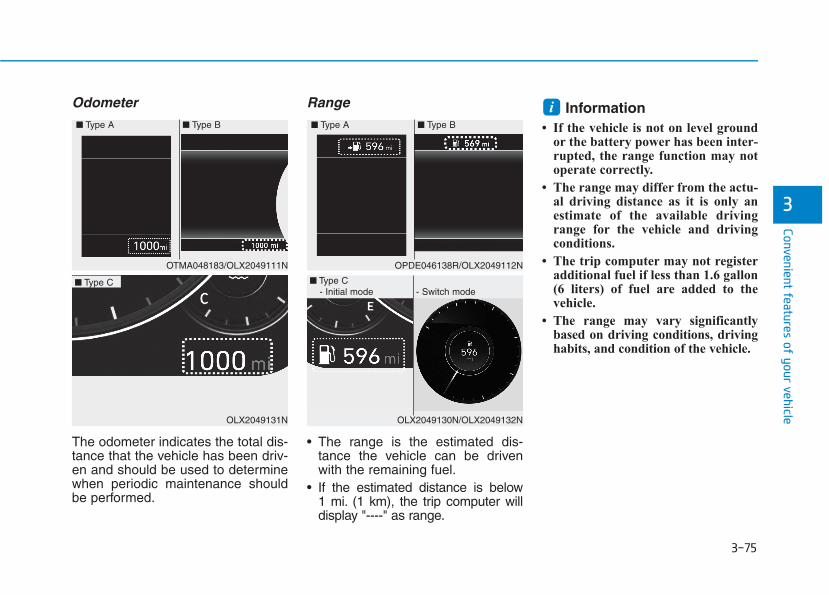
3-75
Convenient features of your vehicle
3
Odometer
The odometer indicates the total dis-tance that the vehicle has been driv-en and should be used to determinewhen periodic maintenance shouldbe performed.
Range
• The range is the estimated dis-tance the vehicle can be drivenwith the remaining fuel.
• If the estimated distance is below1 mi. (1 km), the trip computer willdisplay "----" as range.
Information • If the vehicle is not on level ground
or the battery power has been inter-rupted, the range function may notoperate correctly.
• The range may differ from the actu-al driving distance as it is only anestimate of the available drivingrange for the vehicle and drivingconditions.
• The trip computer may not registeradditional fuel if less than 1.6 gallon(6 liters) of fuel are added to thevehicle.
• The range may vary significantlybased on driving conditions, drivinghabits, and condition of the vehicle.
i
OTMA048183/OLX2049111N
■ Type A ■ Type B
OPDE046138R/OLX2049112N
■ Type A ■ Type B
OLX2049131N
■ Type C
OLX2049130N/OLX2049132N
■ Type C - Initial mode - Switch mode
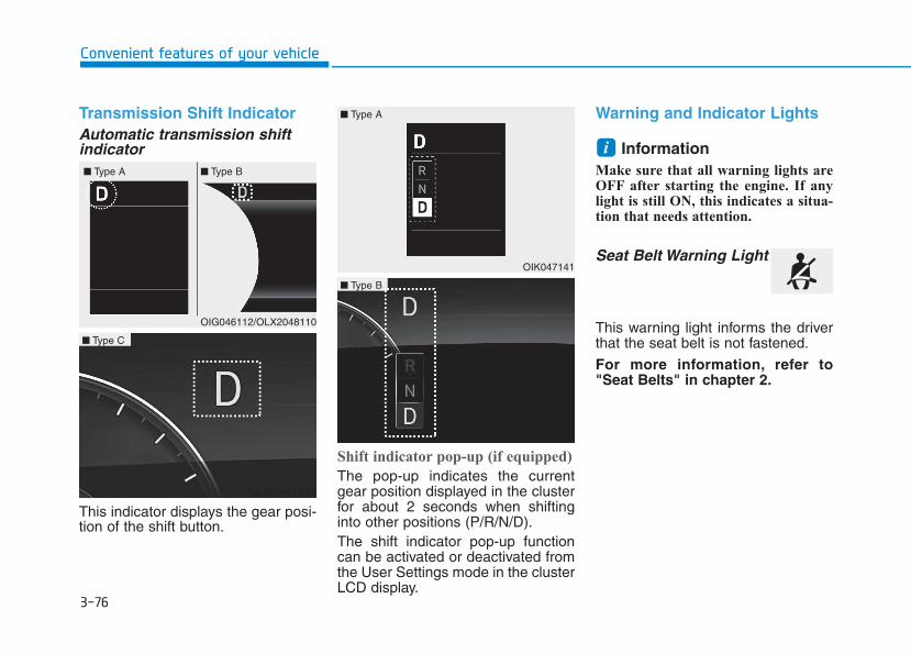
3-76
Convenient features of your vehicle
Transmission Shift IndicatorAutomatic transmission shiftindicator
This indicator displays the gear posi-tion of the shift button.
Shift indicator pop-up (if equipped)
The pop-up indicates the currentgear position displayed in the clusterfor about 2 seconds when shiftinginto other positions (P/R/N/D).The shift indicator pop-up functioncan be activated or deactivated fromthe User Settings mode in the clusterLCD display.
Warning and Indicator Lights
Information Make sure that all warning lights areOFF after starting the engine. If anylight is still ON, this indicates a situa-tion that needs attention.
Seat Belt Warning Light
This warning light informs the driverthat the seat belt is not fastened.
For more information, refer to"Seat Belts" in chapter 2.
i
OIG046112/OLX2048110
■ Type A ■ Type B
OIK047141
OLX2049133N
■ Type C
OLX2049134N
■ Type B
■ Type A
3-77
Convenient features of your vehicle
3
Air Bag Warning Light
This warning light illuminates:
• When you set the ignition switch orthe Engine Start/Stop button to theON position.- The air bag warning light illumi-
nates for about 6 seconds andthen turns off when all checkshave been performed
• The air bag warning light willremain illuminated if there is a mal-function with the Safety RestraintSystem (SRS) air bag operation.If this occurs, have the vehicleinspected by an authorizedHYUNDAI dealer.
Parking Brake & BrakeFluid Warning Light
This warning light illuminates:
• When you set the ignition switch orthe Engine Start/Stop button to theON position.- The parking brake light illumi-
nates for about 3 seconds andwill then turn off once the parkingbrake is released.
• Whenever the parking brake isapplied.
• Whenever the brake fluid level inthe reservoir is low.- If the warning light illuminates
with the parking brake released, itindicates the brake fluid level inthe reservoir is low.
If the brake fluid level in the reser-voir is low:
1. Drive carefully to the nearest safelocation and stop your vehicle.
2. With the engine stopped, check thebrake fluid level immediately andadd fluid as required (For moredetails, refer to "Brake Fluid" inchapter 7). After adding brakefluid, check all brake componentsfor fluid leaks. If a brake fluid leak isfound, or if the warning lightremains on, or if the brakes do notoperate properly, do not drive thevehicle. Have the vehicle inspectedby an authorized HYUNDAI dealer.
Dual-diagonal braking system
Your vehicle is equipped with dual-diagonal braking system.This meansyou still have braking on two wheelseven if one of the dual systemsshould fail.With only one of the dual systemsworking, more than normal pedaltravel and greater pedal pressure isrequired to stop the vehicle.

3-78
Convenient features of your vehicle
Also, the vehicle will not stop in asshort a distance with only a portionof the brake system working.If the brakes fail while you are driv-ing, shift to a lower gear for addition-al engine braking and stop the vehi-cle as soon as it is safe to do so.
Anti-lock Brake System(ABS) Warning Light
This warning light illuminates:
• When you set the ignition switch orthe Engine Start/Stop button to theON position.- The ABS warning light illuminates
for about 3 seconds and thenturns off.
• Whenever there is a malfunctionwith the ABS.Note that the hydraulic brakingsystem will still be operational evenif there is a malfunction with theABS.
Electronic Brake ForceDistribution (EBD) System Warning Light
These two warning lights illuminateat the same time while driving:
• When the ABS and regular brakesystem may not work normally.If this occurs, have the vehicleinspected by an authorizedHYUNDAI dealer.
Parking Brake & Brake FluidWarning Light
Driving the vehicle with a warn-ing light ON is dangerous. If theParking Brake & Brake FluidWarning Light illuminates withthe parking brake released, itindicates that the brake fluidlevel is low.If this occurs, have the vehicleinspected by an authorizedHYUNDAI dealer.
WARNING
3-79
Convenient features of your vehicle
3
Information - ElectronicBrake Force Distribution(EBD) System Warning Light
When the ABS Warning Light is on orboth ABS and Parking Brake & BrakeFluid Warning Lights are on, thespeedometer, odometer, or tripmetermay not work. Also, the EPS WarningLight may illuminate and the steeringeffort may increase or decrease.
If this occurs, have the vehicle inspect-ed by an authorized HYUNDAI deal-er as soon as possible.
Electric Power Steering(EPS) Warning Light
This warning light illuminates:
• When the ignition is moved to ON,the warning light illuminates forabout 3 seconds and turns offautomatically if no problem.
• When the warning light illuminateswhile driving, it indicates that thereis a problem with the electric powersteering system. In this case, havethe vehicle inspected by an author-ized HYUNDAI dealer.
i
Electronic Brake ForceDistribution (EBD) SystemWarning Light
When both ABS and ParkingBrake & Brake Fluid WarningLights are on, the brake systemwill not work normally and youmay experience an unexpectedand dangerous situation duringsudden braking.If this occurs, avoid high speeddriving and abrupt braking.Have the vehicle inspected byan authorized HYUNDAI dealeras soon as possible.
WARNING
3-80
Convenient features of your vehicle
Malfunction IndicatorLamp (MIL)
This indicator light illuminates:
• When you set the ignition switch orthe Engine Start/Stop button to theON position.- The malfunction indicator light
illuminates for about 3 secondsand then goes off.
• Whenever there is a malfunctionwith either the emission controlsystem or the engine or the vehiclepowertrain.If this occurs, have the vehicleinspected by an authorizedHYUNDAI dealer.
Driving with the MalfunctionIndicator Lamp (MIL) on maycause damage to the emissioncontrol system which could affectdrivability and/or fuel economy.
If the Malfunction Indicator Lamp(MIL) illuminates, potential catalyt-ic converter damage is possiblewhich could result in loss ofengine power.If this occurs, have the vehicleinspected by an authorizedHYUNDAI dealer as soon as possi-ble.
Electronic ParkingBrake (EPB) WarningLight
This warning light illuminates:
• When you set the ignition switch orthe Engine Start/Stop button to theON position.- It illuminates for approximately 3
seconds and then goes off.• When there is a malfunction with
the EPB.If this occurs, have the vehicleinspected by an authorizedHYUNDAI dealer.
Information The Electronic Parking Brake (EPB)Warning Light may illuminate whenthe Electronic Stability control (ESC)Indicator Light comes on to indicatethat the ESC is not working properly(This does not indicate malfunction ofthe EPB).
i
NOTICE
NOTICE
EPB

3-81
Convenient features of your vehicle
3
Charging SystemWarning Light
When this warning light illuminateswhile the engine is running, the bat-tery is not being charged. Immediatelyturn OFF all electrical accessories.Try not to use electrically operatedcontrols, such as the power windows.Keep the engine running.Have the vehicle inspected by anauthorized HYUNDAI dealer as soonas possible.
Engine Oil PressureWarning Light
This warning light illuminates:
• When the engine oil pressure is low.
If the engine oil pressure is low:
1. Drive carefully to the nearest safelocation and stop your vehicle.
2. Turn the engine off and check theengine oil level (For more details,refer to "Engine Oil" in chapter 7).If the level is low, add oil as required.If the warning light remains onafter adding oil or if oil is not avail-able, have the vehicle inspectedby an authorized HYUNDAI dealeras soon as possible.
• If the engine does not stopimmediately after the Engine OilPressure Warning Light is illumi-nated, severe damage couldresult.
• If the warning light stays onwhile the engine is running, itindicates that there may be seri-ous engine damage or malfunc-tion. In this case:1. Stop the vehicle as soon as it
is safe to do so.2. Turn off the engine and check
the oil level. If the oil level islow, fill the engine oil to theproper level.
3. Start the engine again. If thewarning light stays on afterthe engine is started, turn theengine off immediately. If thisoccurs, have the vehicleinspected by an authorizedHYUNDAI dealer.
NOTICE

3-82
Convenient features of your vehicle
Low Fuel LevelWarning Light
This warning light illuminates:
• When the fuel tank is nearly empty.Add fuel as soon as possible.
Driving with the Low Fuel Levelwarning light on or with the fuellevel below "E" can cause theengine to misfire and damage thecatalytic converter.
Washer Fluid WarningLight
This warning light illuminates:
• When the washer fluid level in thereservoir is nearly empty.If washer fluid warning light illumi-nates, refill the washer fluid reser-voir in the engine room when pos-sible.
Master Warning Light
This warning light illuminates:
• When there is a malfunction inoperation in any of the followingsystems:- LED headlamp malfunction
(if equipped)- Forward Collision-Avoidance
Assist system malfunction(if equipped)
- Forward Collision-AvoidanceAssist radar blocked (if equipped)
- Blind-Spot Collision Warningsystem malfunction (if equipped)
- Blind-Spot Collision Warningradar blocked (if equipped)
- Smart Cruise Control with Stop& Go malfunction (if equipped)
- Smart Cruise Control with Stop& Go radar blocked (if equipped)
- Lamp malfunction- High Beam Assist malfunction
(if equipped)- Tire Pressure Monitoring System
(TPMS) malfunctionTo identify the details of the warn-ing, look at the LCD display.
NOTICE
3-83
Convenient features of your vehicle
3
Low Tire PressureWarning Light
This warning light illuminates:
• When you set the ignition switch orthe Engine Start/Stop button to theON position.- It illuminates for approximately 3
seconds and then goes off.• When one or more of your tires are
significantly underinflated. (Thelocation of the underinflated tiresare displayed on the LCD display.)
For more details, refer to "TirePressure Monitoring System(TPMS)" in chapter 6.
This warning light remains ONafter blinking for approximately 60seconds, or repeatedly blinks ONand OFF in 3 second intervals:
• When there is a malfunction withthe TPMS.If this occurs, have the vehicleinspected by an authorizedHYUNDAI dealer as soon as possi-ble.
For more details, refer to "TirePressure Monitoring System(TPMS)" in chapter 6.
All Wheel Drive (AWD)Warning Light (if equipped)
This warning light illuminates:
• When you set the ignition switch orthe Engine Start/Stop button to theON position.- The All Wheel Drive warning light
illuminates for about 3 secondsand then goes off.
• Whenever there is a malfunctionwith the AWD system.If this occurs, have your vehicleinspected by an authorizedHYUNDAI dealer.Safe Stopping
• The TPMS cannot alert you tosevere and sudden tire dam-age caused by external fac-tors.
• If you notice any vehicle insta-bility, immediately take yourfoot off the accelerator pedal,apply the brakes graduallywith light force, and slowlymove to a safe position off theroad.
WARNING

3-84
Convenient features of your vehicle
Forward Collision-Avoidance Assist (FCA)System Warning Light
This warning light illuminates:
• When you set the ignition switch orthe Engine Start/Stop button to theON position.- It illuminates for approximately 3
seconds and then goes off.• When there is a malfunction with
the FCA.If this occurs, have the vehicle inspect-ed by an authorized HYUNDAI dealer.
For more details, refer to "ForwardCollision-Avoidance Assist (FCA)system" in chapter 5.
Lane Keeping Assist(LKA) System IndicatorLight
This indicator light illuminates:
• [Green] When the system operat-ing conditions are satisfied.
• [White] The system operating con-ditions are not satisfied.
• [Yellow] When there is a malfunc-tion with the lane keeping assistsystem.If this occurs, have your vehicleinspected by an authorizedHYUNDAI dealer.
For more details, refer to "LaneKeeping Assist (LKA) system" inchapter 5.
LED Headlight WarningLight (if equipped)
This warning light illuminates:
• When you set the ignition switch orthe Engine Start/Stop button to theON position.
• When there is a malfunction withthe LED headlight.If this occurs, have the vehicleinspected by an authorizedHYUNDAI dealer.
This warning light blinks:
When there is a malfunction with aLED headlight related part.If this occurs, have the vehicleinspected by an authorized HYUNDAIdealer.
Continuous driving with the LEDHeadlight Warning Light on orblinking can reduce LED headlightlife.
NOTICE

3-85
Convenient features of your vehicle
3
Icy Road Warning Light(if equipped)
This warning light is to warn the driverthe road may be icy.When the temperature on the out-side temperature gauge is approxi-mately below 40°F (4°C), the IcyRoad Warning Light and OutsideTemperature Gauge blinks and thenilluminates. Also, the warning chimesounds 1 time.You can activate or deactivate IcyRoad Warning function from the UserSettings mode in the cluster LCD dis-play.
Information If the icy road warning light appearswhile driving, you should drive moreattentively and safely refraining fromover-speeding, rapid acceleration, sud-den braking or sharp turning, etc.
AUTO STOP IndicatorLight
This indicator light illuminates:
• When the engine enters the IdleStop mode of the ISG (Idle Stop andGo) system.
This indicator light blinks:
• When the automatic starting occurs,the AUTO STOP indicator on thecluster will blink for 5 seconds.
For more details, refer to the "ISG(Idle Stop and Go) system" inchapter 5.
Information When the engine automatically startsby the ISG system, some warninglights (ABS, ESC, ESC OFF, EPS orParking brake warning light) mayturn on for a few seconds.
This happens because of low batteryvoltage. It does not mean the systemhas malfunctioned.
Electronic StabilityControl (ESC) IndicatorLight
This indicator light illuminates:
• When you set the ignition switch orthe Engine Start/Stop button to theON position.- The Electronic Stability Control
indicator light illuminates forabout 3 seconds and then goesoff.
• Whenever there is a malfunctionwith the ESC system.If this occurs, have the vehicleinspected by an authorizedHYUNDAI dealer.
This indicator light blinks:
• While the ESC is operating.
For more details, refer to"Electronic Stability Control(ESC)" in chapter 5.
ii
3-86
Convenient features of your vehicle
Electronic StabilityControl (ESC) OFFIndicator Light
This indicator light illuminates:
• When you set the ignition switch orthe Engine Start/Stop button to theON position.- It illuminates for approximately
3 seconds and then goes off.• When you deactivate the ESC sys-
tem by pressing the ESC OFF but-ton.
For more details, refer to"Electronic Stability Control(ESC)" in chapter 5.
Immobilizer IndicatorLight (without smartkey)(if equipped)
This indicator light illuminates:
• When the vehicle detects theimmobilizer in the key with the igni-tion switch in the ON position.- At this time, you can start the
engine.- The indicator light goes off after
starting the engine.This indicator light blinks:
• When there is a malfunction withthe immobilizer system.
If this occurs, have the vehicle inspect-ed by an authorized HYUNDAI dealer.
Immobilizer IndicatorLight (with smart key(if equipped)
This indicator light illuminates forup to 30 seconds:
• When the vehicle detects thesmart key in the vehicle with theEngine Start/Stop button in theACC or ON position.- Once the smart key is detected,
you can start the engine.- The indicator light goes off after
starting the engine.
This indicator light blinks for a fewseconds:
• When the smart key is not in thevehicle.- If the smart key is not detected,
you cannot start the engine.
3-87
Convenient features of your vehicle
3
This indicator light illuminates for2 seconds and goes off:
• If the smart key is in the vehicleand the Engine Start/Stop button isON, but the vehicle cannot detectthe smart key.If this occurs, have the vehicleinspected by an authorizedHYUNDAI dealer.
This indicator light blinks:
• When there is a malfunction withthe immobilizer system.If this occurs, have the vehicleinspected by an authorizedHYUNDAI dealer.
Turn Signal IndicatorLight
This indicator light blinks:
• When you operate the turn signalindicator stalk.
If any of the following occur, there maybe a malfunction with the turn signalsystem.- The turn signal indicator light illumi-
nates but does not blink- The turn signal indicator light blinks
rapidly- The turn signal indicator light does
not illuminate at allIf any of these conditions occur, haveyour vehicle inspected by an author-ized HYUNDAI dealer.
High Beam IndicatorLight
This indicator light illuminates:
• When the headlights are on and inthe high beam position
• When the turn signal lever is pulledinto the Flash-to-Pass position.
Light ON IndicatorLight
This indicator light illuminates:
• When the tail lights or headlightsare on.

3-88
Convenient features of your vehicle
High Beam Assist(HBA) indicator light(if equipped)
This indicator light illuminates :
• When the high-beam is on with thelight switch in the AUTO light posi-tion.
• If your vehicle detects oncoming orpreceding vehicles, the High BeamAssist (HBA) system will switch thehigh beam to low beam automati-cally.
For more details, refer to "HighBeam Assist (HBA) system" in thischapter.
AUTO HOLD IndicatorLight
This indicator light illuminates:
• [White] When you activate the AutoHold system by pressing the AUTOHOLD button.
• [Green] When you stop the vehiclecompletely by depressing thebrake pedal with the Auto Holdsystem activated.
• [Yellow] When there is a malfunc-tion with the Auto Hold system.If this occurs, have your vehicleinspected by an authorizedHYUNDAI dealer.
For more details, refer to "AutoHold" in chapter 5.
Cruise Indicator Light
This indicator light illuminates:
• When the cruise control system isenabled.
For more details, refer to "CruiseControl System" in chapter 5.
SPORT Mode IndicatorLight (if equipped)
This indicator light illuminates:
• When you select "SPORT" modeas drive mode.
For more details, refer to "DriveMode Integrated Control System"in chapter 5.
AUTOHOLD

3-89
Convenient features of your vehicle
3
SMART Mode IndicatorLight (if equipped)
This indicator light illuminates:
• When you select ''SMART" modeas drive mode.
For more details, refer to "DriveMode Integrated Control System''in chapter 5.
All Wheel Drive LOCKIndicator Light (if equipped)
This indicator light illuminates:
• When you set the ignition switch orthe Engine Start/Stop button to theON position.- The AWD LOCK indicator light
illuminates for about 3 secondsand then goes off.
• When you select AWD Lock modeby pressing the AWD LOCK but-ton.- The AWD LOCK mode is to trans-
fer a portion of the drive torque tothe rear wheels for increasedtraction on wet pavement, snowcovered roads or when driving offroad.
Downhill Brake Control(DBC) Indicator Light(if equipped)
This indicator light illuminates:
• When you set the ignition switch orthe Engine Start/Stop button to theON position.- The Downhill Brake Control
Indicator Light illuminates for about3 seconds and then goes off.
• When you activate the system bypressing the DBC button.
This indicator light blinks:
• When the DBC is operating.
This indicator light illuminates yel-low:
• When there is a malfunction withthe DBC system.
If this occurs, have your vehicleinspected by an authorizedHYUNDAI dealer.
For more details, refer to"Downhill Brake Control (DBC)System" in chapter 5.
AWD Lock Mode
Do not use the AWD lock modeon dry paved roads. Doing socan cause abnormal noise orvibration, and may damage theAWD system.
CAUTION
3-90
Convenient features of your vehicle
LCD Display MessagesShift to P or N to start engine(for smart key system)This warning message is displayed ifyou try to start the engine with theshift button not in the P (Park) or N(Neutral) position.
InformationYou can start the engine with the shiftbutton in the N (Neutral) position.But, for your safety, we recommendthat you start the engine with the shiftbutton in the P (Park) position.
Low key battery (for smart key system)This warning message is displayed ifthe battery of the smart key is dis-charged while changing the EngineStart/Stop button to the OFF position.
Press brake pedal to startengine (for smart key system)This warning message is displayed ifthe Engine Start/Stop buttonchanges to the ACC position twiceby pressing the button repeatedlywithout depressing the brake pedal.You can start the vehicle by depress-ing the brake pedal and then press-ing the Engine Start/Stop button.
Key not in vehicle(for smart key system)This warning message is displayed ifthe smart key is not in the vehiclewhen you press the Engine Start/Stop button.When attempting to start the vehicle,always have the smart key with you.
Key not detected (for smart key system)This warning message is displayed ifthe smart key is not detected when youpress the Engine Start/Stop button.
Press START button again(for smart key system)This message is displayed if youwere unable to start the vehicle whenthe Engine Start/Stop button waspressed.If this occurs, attempt to start theengine by pressing the Engine Start/Stop button again.If the warning message appearseach time you press the EngineStart/Stop button, have your vehicleinspected by an authorizedHYUNDAI dealer.
i
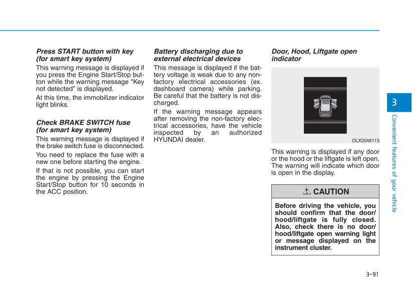
3-91
Convenient features of your vehicle
3
Press START button with key(for smart key system)This warning message is displayed ifyou press the Engine Start/Stop but-ton while the warning message "Keynot detected" is displayed.At this time, the immobilizer indicatorlight blinks.
Check BRAKE SWITCH fuse (for smart key system)This warning message is displayed ifthe brake switch fuse is disconnected.You need to replace the fuse with anew one before starting the engine.If that is not possible, you can startthe engine by pressing the EngineStart/Stop button for 10 seconds inthe ACC position.
Battery discharging due toexternal electrical devicesThis message is displayed if the bat-tery voltage is weak due to any non-factory electrical accessories (ex.dashboard camera) while parking.Be careful that the battery is not dis-charged.If the warning message appearsafter removing the non-factory elec-trical accessories, have the vehicleinspected by an authorizedHYUNDAI dealer.
Door, Hood, Liftgate open indicator
This warning is displayed if any dooror the hood or the liftgate is left open.The warning will indicate which dooris open in the display.
Before driving the vehicle, youshould confirm that the door/hood/liftgate is fully closed.Also, check there is no door/hood/liftgate open warning lightor message displayed on theinstrument cluster.
CAUTION
OLX2048113
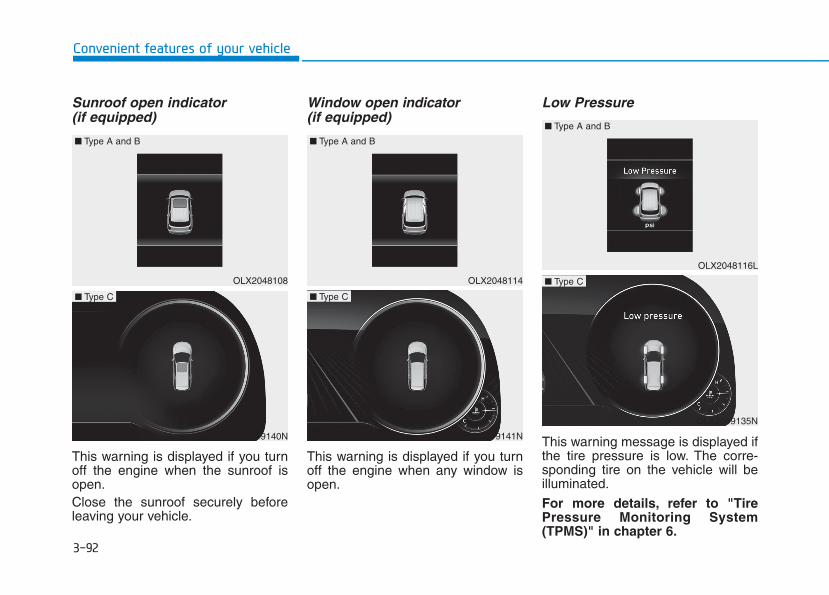
3-92
Convenient features of your vehicle
Sunroof open indicator (if equipped)
This warning is displayed if you turnoff the engine when the sunroof isopen.Close the sunroof securely beforeleaving your vehicle.
Window open indicator(if equipped)
This warning is displayed if you turnoff the engine when any window isopen.
Low Pressure
This warning message is displayed ifthe tire pressure is low. The corre-sponding tire on the vehicle will beilluminated.
For more details, refer to "TirePressure Monitoring System(TPMS)" in chapter 6.
OLX2048108
■ Type A and B
OLX2049140N
■ Type C
OLX2049141N
■ Type C
OLX2049135N
■ Type COLX2048114
OLX2048116L
■ Type A and B
■ Type A and B
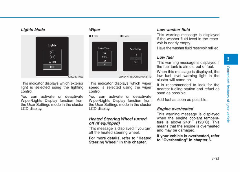
3-93
Convenient features of your vehicle
3
Lights Mode
This indicator displays which exteriorlight is selected using the lightingcontrol.You can activate or deactivateWiper/Lights Display function fromthe User Settings mode in the clusterLCD display.
Wiper
This indicator displays which wiperspeed is selected using the wipercontrol.You can activate or deactivateWiper/Lights Display function fromthe User Settings mode in the clusterLCD display.
Heated Steering Wheel turnedoff (if equipped)This message is displayed if you turnoff the heated steering wheel.
For more details, refer to "HeatedSteering Wheel" in this chapter.
Low washer fluid This warning message is displayedif the washer fluid level in the reser-voir is nearly empty.Have the washer fluid reservoir refilled.
Low fuelThis warning message is displayed ifthe fuel tank is almost out of fuel.When this message is displayed, thelow fuel level warning light in thecluster will come on.It is recommended to look for thenearest fueling station and refuel assoon as possible.
Add fuel as soon as possible.
Engine overheatedThis warning message is displayedwhen the engine coolant tempera-ture is above 248°F (120°C). Thismeans that the engine is overheatedand may be damaged.
If your vehicle is overheated, referto "Overheating" in chapter 6.
■ Rear■ Front
OIK047146L/OTMA048119OIK047145L

3-94
Convenient features of your vehicle
Check headlight (if equipped)This warning message is displayed ifthe headlights are not operatingproperly. A headlight bulb may needto be replaced.
InformationMake sure to replace the burned outbulb with a new one of the samewattage rating.
Check turn signal (if equipped)This warning message is displayed ifthe turn signal lamps are not operat-ing properly. A lamp may need to bereplaced.
InformationMake sure to replace the burned outbulb with a new one of the same wattagerating.
Check High Beam Assist (HBA)system (if equipped)This warning message is displayed ifthere is a problem with the High BeamAssist (HBA) system. Have the vehi-cle inspected by an authorizedHYUNDAI dealer.
For more details, refer to "HighBeam Assist (HBA) system" inchapter 3.
Check headlight LED (if equipped)This warning message is displayed ifthere is a problem with the LEDheadlight. Have the vehicle inspectedby an authorized HYUNDAI dealer.
Check Forward Collision-Avoidance Assist system(if equipped)This warning message is displayed ifthere is a problem with the ForwardCollision-Avoidance Assist (FCA)system. Have the vehicle inspectedby an authorized HYUNDAI dealer.
For more details, refer to "ForwardCollision-Avoidance Assist (FCA)system" in chapter 5.
Check Blind-Spot CollisionWarning (BCW) system (if equipped)This warning message is displayed ifthere is a problem with the Blind-Spot Collision Warning system. Havethe vehicle inspected by an author-ized HYUNDAI dealer.
For more details, refer to "Blind-Spot Collision Warning (BCW)/Blind-Spot Collision-AvoidanceAssist (BCA)" or "Rear Cross-Traffic Collision Warning (RCCW)/Rear Cross-Traffic Collision-Avoidance Assist (RCCA)"System in chapter 5.
i
i

3-95
Convenient features of your vehicle
3
Check Smart Cruise ControlSystem (if equipped)This warning message is displayed ifthere is a problem with the SmartCruise Control system. Have thevehicle inspected by an authorizedHYUNDAI dealer.
For more details, refer to "SmartCruise Control with Stop & Go" inchapter 5.
Check Driver Attention Warning(DAW) system (if equipped)This warning message is displayed ifthere is a problem with the DriverAttention Warning (DAW). Have thevehicle inspected by an authorizedHYUNDAI dealer.
For more details, refer to "DriverAttention Warning (DAW)" in chap-ter 5.
Check Lane Keeping Assist(LKA) system (if equipped)This warning message is displayed ifthere is a problem with the CheckLane Keeping Assist (LKA) system.Have the vehicle inspected by anauthorized HYUNDAI dealer.
For more details, refer to "CheckLane Keeping Assist (LKA) sys-tem" in chapter 5.
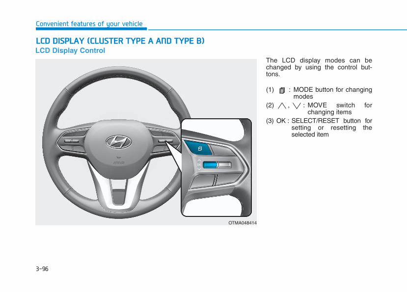
3-96
Convenient features of your vehicle
LLCCDD DDIISSPPLLAAYY ((CCLLUUSSTTEERR TTYYPPEE AA AANNDD TTYYPPEE BB))LCD Display Control
The LCD display modes can bechanged by using the control but-tons.
(1) : MODE button for changingmodes
(2) , : MOVE switch forchanging items
(3) OK : SELECT/RESET button forsetting or resetting theselected item
OTMA048414
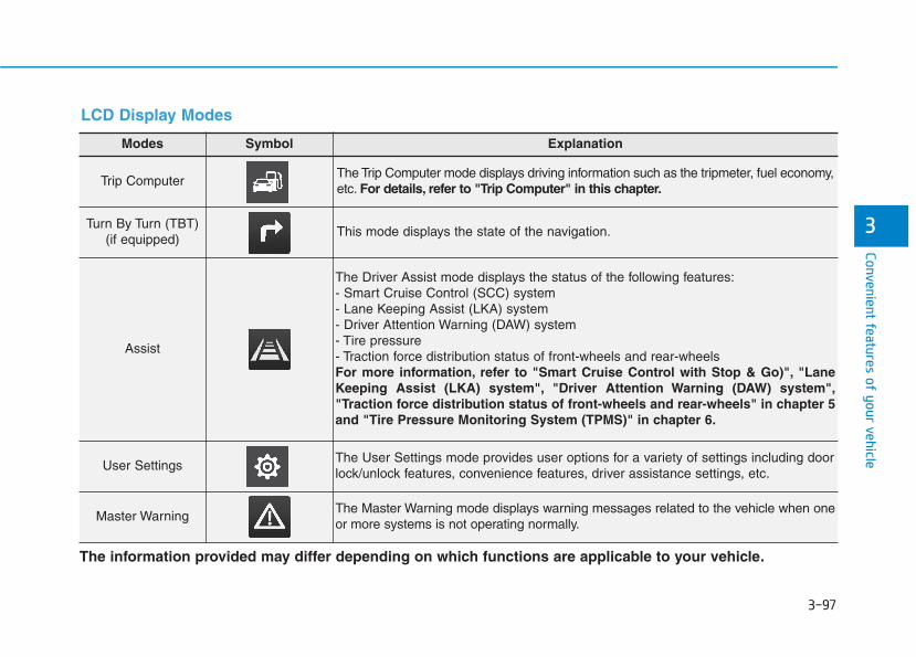
3-97
Convenient features of your vehicle
3
Modes Symbol Explanation
Trip Computer The Trip Computer mode displays driving information such as the tripmeter, fuel economy,etc. For details, refer to "Trip Computer" in this chapter.
Turn By Turn (TBT) (if equipped)
This mode displays the state of the navigation.
Assist
The Driver Assist mode displays the status of the following features:- Smart Cruise Control (SCC) system - Lane Keeping Assist (LKA) system- Driver Attention Warning (DAW) system- Tire pressure- Traction force distribution status of front-wheels and rear-wheelsFor more information, refer to "Smart Cruise Control with Stop & Go)", "LaneKeeping Assist (LKA) system", "Driver Attention Warning (DAW) system","Traction force distribution status of front-wheels and rear-wheels" in chapter 5and "Tire Pressure Monitoring System (TPMS)" in chapter 6.
User SettingsThe User Settings mode provides user options for a variety of settings including doorlock/unlock features, convenience features, driver assistance settings, etc.
Master WarningThe Master Warning mode displays warning messages related to the vehicle when oneor more systems is not operating normally.
The information provided may differ depending on which functions are applicable to your vehicle.
LCD Display Modes

3-98
Convenient features of your vehicle
Trip computer mode
The trip computer mode displaysinformation related to vehicle drivingparameters including fuel economy,tripmeter information and vehiclespeed.
For more details, refer to "TripComputer" in this chapter.
Turn By Turn (TBT) mode
This mode displays the state of thenavigation.
Assist mode
SCC/LKA/DAW
This mode displays the state of theSmart Cruise Control (SCC), LaneKeeping Assist (LKA) and DriverAttention Warning (DAW).
For more details, refer to eachsystem information in chapter 5.
OIK047124N OIK047147N OLX2049119N

3-99
Convenient features of your vehicle
3
Tire Pressure
This mode displays information relat-ed to Tire Pressure.
For more details, refer to "TirePressure Monitoring System(TPMS)" in chapter 6.
Driving force distribution (AWD)
This mode displays information relat-ed to AWD driving force.
For more details, refer to the "AllWheel Drive" in the chapter 5.
Master warning modeThis warning light informs the driverthe following situations.- LED headlamp malfunction
(if equipped)- Forward Collision-Avoidance
Assist system malfunction (if equipped)
- Forward Collision-AvoidanceAssist radar blocked (if equipped)
- Blind-Spot Collision Warning system malfunction (if equipped)
- Blind-Spot Collision Warning radarblocked (if equipped)
- Smart Cruise Control with Stop &Go malfunction (if equipped)
- Smart Cruise Control with Stop &Go radar blocked (if equipped)
- Lamp malfunction- High Beam Assist malfunction
(if equipped)- Tire Pressure Monitoring System
(TPMS) malfunction
OLX2048120L OLX2048121
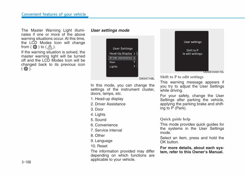
3-100
Convenient features of your vehicle
The Master Warning Light illumi-nates if one or more of the abovewarning situations occur. At this time,the LCD Modes Icon will changefrom ( ) to ( ).If the warning situation is solved, themaster warning light will be turnedoff and the LCD Modes Icon will bechanged back to its previous icon ( ).
User settings mode
In this mode, you can change thesettings of the instrument cluster,doors, lamps, etc.1. Head-up display2. Driver Assistance3. Door4. Lights5. Sound6. Convenience7. Service interval8. Other9. Language10. ResetThe information provided may differdepending on which functions areapplicable to your vehicle.
Shift to P to edit settings
This warning message appears ifyou try to adjust the User Settingswhile driving.For your safety, change the UserSettings after parking the vehicle,applying the parking brake and shift-ing to P (Park).
Quick guide help
This mode provides quick guides forthe systems in the User Settingsmode.Select an item, press and hold theOK button.
For more details, about each sys-tem, refer to this Owner's Manual.
OIK047148L
OOSEV048172L

3-101
Convenient features of your vehicle
3
Items Explanation
Enable Head-Up Display To activate or deactivate the Head-up display function.
Display Height To adjust the height of the image displayed
Rotation To adjust the angle of the image displayed.
Brightness To adjust the brightness of the image displayed.
Content Selection
To select the content to be displayed.
- Turn by Turn
- Traffic Information
- Cruise control
- Lane keeping assist
- Blind-spot Collision Warning
Speed SizeTo select the speedometer size displayed.- Large/Medium/Small
Speed ColorTo select the speedometer color displayed.- White/Orange/Green
1. Head-Up Display
For more information, refer to "Head-Up Display" in this chapter.
❈ The information provided may differ depending on which functions are applicable to your vehicle.

3-102
Convenient features of your vehicle
Items Explanation
SCC Reaction
• Fast / Normal / Slow To adjust the sensitivity of the Smart Cruise Control system.
For more details, refer to ''Smart Cruise Control with Stop & Go'' in chapter 5.
Driving assist
• Leading vehicle departure alertTo activate or deactivate the Leading vehicle departure alert.
For more details, refer to the "Leading vehicle departure alert" in chapter 5.
• Lane Following AssistTo activate or deactivate the Lane Following Assist (LFA) system.
For more details, refer to the "Lane Following Assist (LFA) System" in chapter 5.
• Highway Driving AssistTo activate or deactivate the Highway Driving Assist (HDA) system.
For more details, refer to the "Highway Driving Assist (HDA) System" in chapter 5.
Warning Timing• Normal / Later To select when to provide a warning for all driver assistance.
Warning Volume• High / Medium / Low To adjust the warning sound volume of all driver assistance.
Driver Attention WarningTo activate or deactivate the Driver Attention Warning (DAW).
For more information, refer to the "Driver Attention Warning (DAW)" in chapter 5.
2. Driver Assistance

3-103
Convenient features of your vehicle
3
Items Explanation
Forward Safety
• Active Assist: If selected, the system controls the vehicle and provides a warning when a colli-sion is detected.
• Warning Only: If selected, the system provides a warning when a collision is detected.• Off: Deactivates the system.
For more details, refer to the "Forward Collision-Avoidance Assist system" in chapter 5.
Lane Safety
To adjust the Lane Keeping Assist (LKA) function.- Lane Keeping Assist - Lane Departure Warning- Off
For more details, refer to the "Lane Keeping Assist (LKA) system" in chapter 5.
Blind-Spot Safety
• Blind-Spot View To activate or deactivate the Blind-Spot View.
For more details, refer to the "Blind-Spot View" in this chapter.
• SEA(Safe Exit Assistance) To activate or deactivate the Safe Exit Assistance.
For more details, refer to the "Safe Exit Assistance" in chapter 5.
• Active assist
• Warning only
• Off
For more details, refer to "Blind-spot Collision-Avoidance Assist (BCA)" in chapter 5.
❈ The information provided may differ depending on which functions are applicable to your vehicle.
2. Driver Assistance
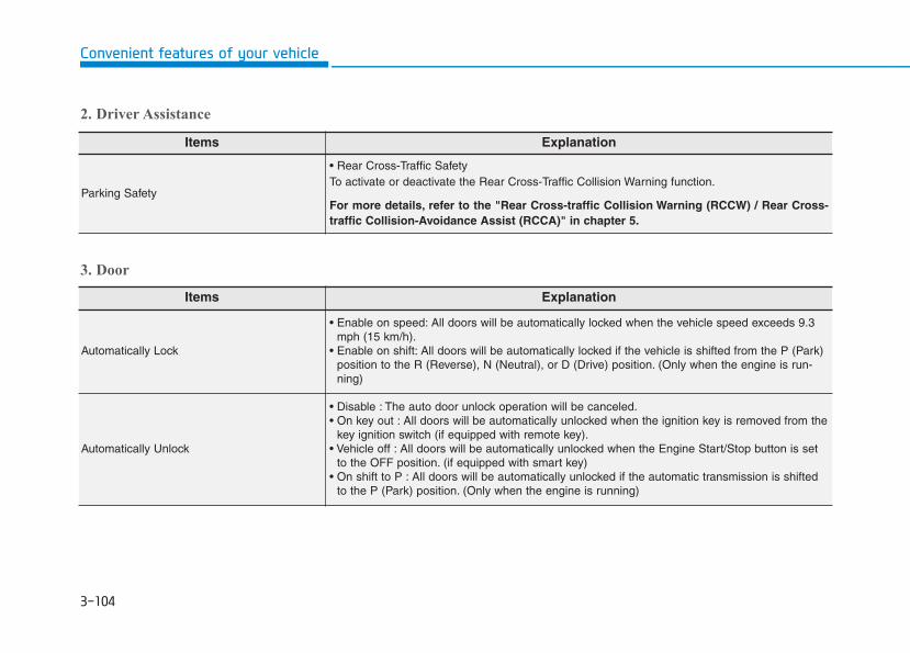
3-104
Convenient features of your vehicle
Items Explanation
Automatically Lock
• Enable on speed: All doors will be automatically locked when the vehicle speed exceeds 9.3mph (15 km/h).
• Enable on shift: All doors will be automatically locked if the vehicle is shifted from the P (Park)position to the R (Reverse), N (Neutral), or D (Drive) position. (Only when the engine is run-ning)
Automatically Unlock
• Disable : The auto door unlock operation will be canceled.• On key out : All doors will be automatically unlocked when the ignition key is removed from the
key ignition switch (if equipped with remote key).• Vehicle off : All doors will be automatically unlocked when the Engine Start/Stop button is set
to the OFF position. (if equipped with smart key)• On shift to P : All doors will be automatically unlocked if the automatic transmission is shifted
to the P (Park) position. (Only when the engine is running)
3. Door
Items Explanation
Parking Safety
• Rear Cross-Traffic SafetyTo activate or deactivate the Rear Cross-Traffic Collision Warning function.
For more details, refer to the "Rear Cross-traffic Collision Warning (RCCW) / Rear Cross-traffic Collision-Avoidance Assist (RCCA)" in chapter 5.
2. Driver Assistance
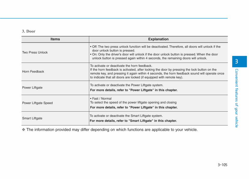
3-105
Convenient features of your vehicle
3
Items Explanation
Two Press Unlock
• Off: The two press unlock function will be deactivated. Therefore, all doors will unlock if thedoor unlock button is pressed.
• On: Only the driver's door will unlock if the door unlock button is pressed. When the doorunlock button is pressed again within 4 seconds, the remaining doors will unlock.
Horn Feedback
To activate or deactivate the horn feedback.If the horn feedback is activated, after locking the door by pressing the lock button on theremote key, and pressing it again within 4 seconds, the horn feedback sound will operate onceto indicate that all doors are locked (if equipped with remote key).
Power LiftgateTo activate or deactivate the Power Liftgate system.
For more details, refer to "Power Liftgate" in this chapter.
Power Liftgate Speed• Fast / Normal To select the speed of the power liftgate opening and closing
For more details, refer to "Power Liftgate" in this chapter.
Smart LiftgateTo activate or deactivate the Smart Liftgate system.
For more details, refer to "Smart Liftgate" in this chapter.
❈ The information provided may differ depending on which functions are applicable to your vehicle.
3. Door
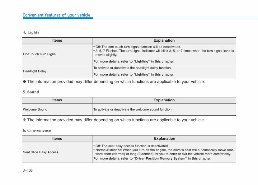
3-106
Convenient features of your vehicle
Items Explanation
One Touch Turn Signal
• Off: The one touch turn signal function will be deactivated.• 3, 5, 7 Flashes: The turn signal indicator will blink 3, 5, or 7 times when the turn signal lever is
moved slightly.
For more details, refer to "Lighting" in this chapter.
Headlight DelayTo activate or deactivate the headlight delay function.
For more details, refer to "Lighting" in this chapter.
4. Lights
6. Convenience
❈ The information provided may differ depending on which functions are applicable to your vehicle.
5. Sound
Items Explanation
Welcome Sound To activate or deactivate the welcome sound function.
❈ The information provided may differ depending on which functions are applicable to your vehicle.
Items Explanation
Seat Slide Easy Access
• Off: The seat easy access function is deactivated.• Normal/Extended: When you turn off the engine, the driver's seat will automatically move rear-
ward short (Normal) or long (Extended) for you to enter or exit the vehicle more comfortably.For more details, refer to "Driver Position Memory System" in this chapter.
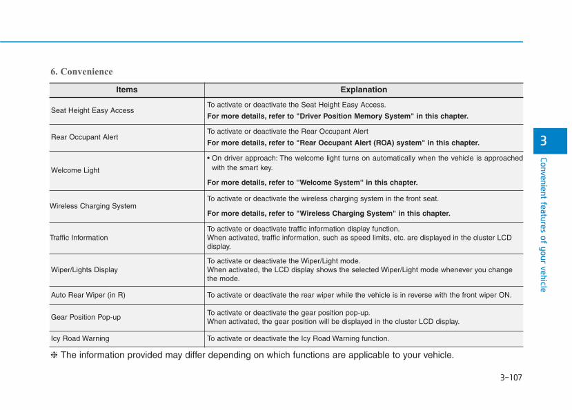
3-107
Convenient features of your vehicle
3
Items Explanation
Seat Height Easy AccessTo activate or deactivate the Seat Height Easy Access.
For more details, refer to "Driver Position Memory System" in this chapter.
Rear Occupant AlertTo activate or deactivate the Rear Occupant Alert
For more details, refer to "Rear Occupant Alert (ROA) system" in this chapter.
Welcome Light
• On driver approach: The welcome light turns on automatically when the vehicle is approachedwith the smart key.
For more details, refer to ''Welcome System'' in this chapter.
Wireless Charging SystemTo activate or deactivate the wireless charging system in the front seat.
For more details, refer to "Wireless Charging System" in this chapter.
Traffic InformationTo activate or deactivate traffic information display function.When activated, traffic information, such as speed limits, etc. are displayed in the cluster LCDdisplay.
Wiper/Lights DisplayTo activate or deactivate the Wiper/Light mode.When activated, the LCD display shows the selected Wiper/Light mode whenever you changethe mode.
Auto Rear Wiper (in R) To activate or deactivate the rear wiper while the vehicle is in reverse with the front wiper ON.
Gear Position Pop-upTo activate or deactivate the gear position pop-up.When activated, the gear position will be displayed in the cluster LCD display.
Icy Road Warning To activate or deactivate the Icy Road Warning function.
6. Convenience
❈ The information provided may differ depending on which functions are applicable to your vehicle.

3-108
Convenient features of your vehicle
7. Service interval
Information To use the service interval menu, consult an authorized HYUNDAI dealer.
If the service interval is activated and the time and distance is adjusted, messages are displayed in the followingsituations each time the vehicle is turned on.- Service in: Displayed to inform the driver the remaining mileage and days to service.- Service required: Displayed when the mileage and days to service has been reached or passed.
Information If any of the following conditions occur, the mileage and number of days to service may be incorrect.
- The battery cable is disconnected.
- The fuse switch is turned off.
- The battery is discharged.
i
i
Items Explanation
Service Interval To activate or deactivate the service interval function.
Adjust Interval If the service interval menu is activated, you may adjust the time and distance.
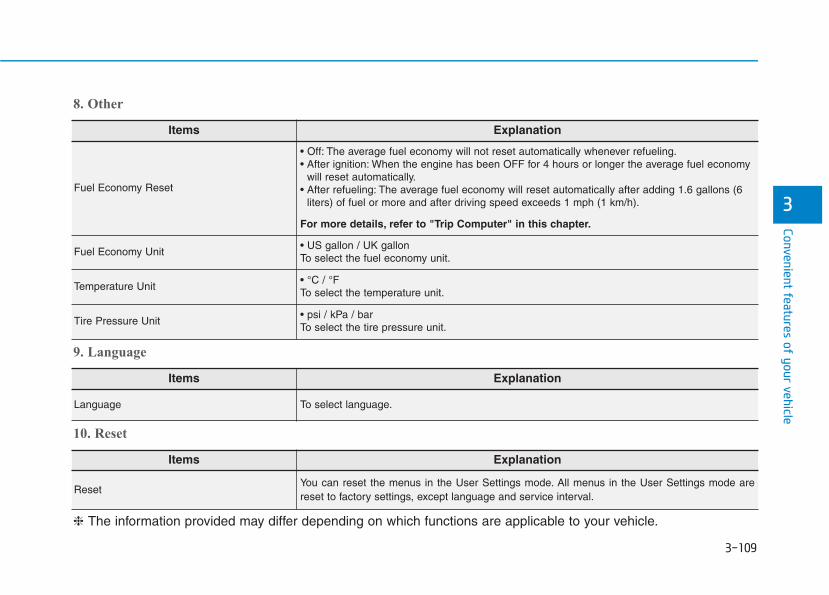
3-109
Convenient features of your vehicle
3
Items Explanation
Fuel Economy Reset
• Off: The average fuel economy will not reset automatically whenever refueling.• After ignition: When the engine has been OFF for 4 hours or longer the average fuel economy
will reset automatically.• After refueling: The average fuel economy will reset automatically after adding 1.6 gallons (6
liters) of fuel or more and after driving speed exceeds 1 mph (1 km/h).
For more details, refer to "Trip Computer" in this chapter.
Fuel Economy Unit• US gallon / UK gallonTo select the fuel economy unit.
Temperature Unit• °C / °FTo select the temperature unit.
Tire Pressure Unit• psi / kPa / barTo select the tire pressure unit.
8. Other
Items Explanation
Language To select language.
9. Language
Items Explanation
ResetYou can reset the menus in the User Settings mode. All menus in the User Settings mode arereset to factory settings, except language and service interval.
10. Reset
❈ The information provided may differ depending on which functions are applicable to your vehicle.

3-110
Convenient features of your vehicle
The trip computer is a microcomput-er-controlled driver information sys-tem that displays information relatedto driving.
Information Some driving information stored in thetrip computer (for example AverageVehicle Speed) resets if the battery isdisconnected.
Trip modes
To change the trip mode, toggle the" , " switch on the steeringwheel.
i
TTRRIIPP CCOOMMPPUUTTEERR ((CCLLUUSSTTEERR TTYYPPEE AA AANNDD TTYYPPEE BB))
OTMA048414• Tripmeter • Fuel Economy• Timer
Accumulated Info
• Tripmeter • Fuel Economy• Timer
Drive Info
• Average Fuel Economy• Instant Fuel Economy
Fuel Economy
Digital Speedometer
Auto Stop (if equipped)
Smart Shift
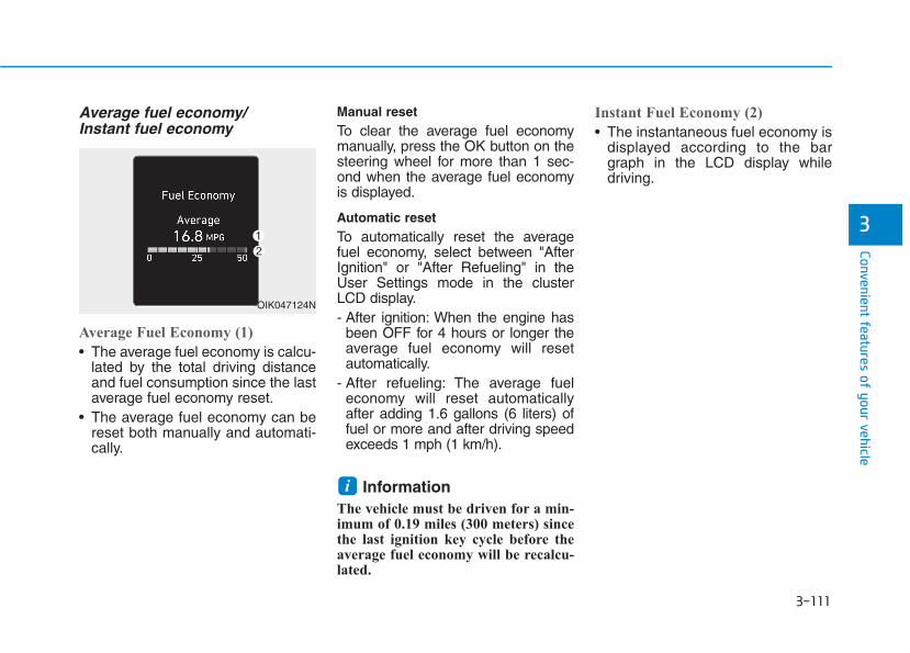
3-111
Convenient features of your vehicle
3
Average fuel economy/Instant fuel economy
Average Fuel Economy (1)
• The average fuel economy is calcu-lated by the total driving distanceand fuel consumption since the lastaverage fuel economy reset.
• The average fuel economy can bereset both manually and automati-cally.
Manual resetTo clear the average fuel economymanually, press the OK button on thesteering wheel for more than 1 sec-ond when the average fuel economyis displayed.
Automatic resetTo automatically reset the averagefuel economy, select between "AfterIgnition" or "After Refueling" in theUser Settings mode in the clusterLCD display.- After ignition: When the engine has
been OFF for 4 hours or longer theaverage fuel economy will resetautomatically.
- After refueling: The average fueleconomy will reset automaticallyafter adding 1.6 gallons (6 liters) offuel or more and after driving speedexceeds 1 mph (1 km/h).
Information The vehicle must be driven for a min-imum of 0.19 miles (300 meters) sincethe last ignition key cycle before theaverage fuel economy will be recalcu-lated.
Instant Fuel Economy (2)
• The instantaneous fuel economy isdisplayed according to the bargraph in the LCD display whiledriving.
i
OIK047124N
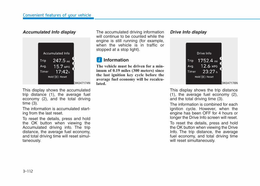
3-112
Convenient features of your vehicle
Accumulated Info display
This display shows the accumulatedtrip distance (1), the average fueleconomy (2), and the total drivingtime (3).The information is accumulated start-ing from the last reset.To reset the details, press and holdthe OK button when viewing theAccumulated driving info. The tripdistance, the average fuel economy,and total driving time will reset simul-taneously.
The accumulated driving informationwill continue to be counted while theengine is still running (for example,when the vehicle is in traffic orstopped at a stop light).
Information The vehicle must be driven for a min-imum of 0.19 miles (300 meters) sincethe last ignition key cycle before theaverage fuel economy will be recalcu-lated.
Drive Info display
This display shows the trip distance(1), the average fuel economy (2),and the total driving time (3).The information is combined for eachignition cycle. However, when theengine has been OFF for 4 hours orlonger the Drive Info screen will reset.To reset the details, press and holdthe OK button when viewing the DriveInfo. The trip distance, the averagefuel economy, and total driving timewill reset simultaneously.
i
OIK047174N OIK047176N
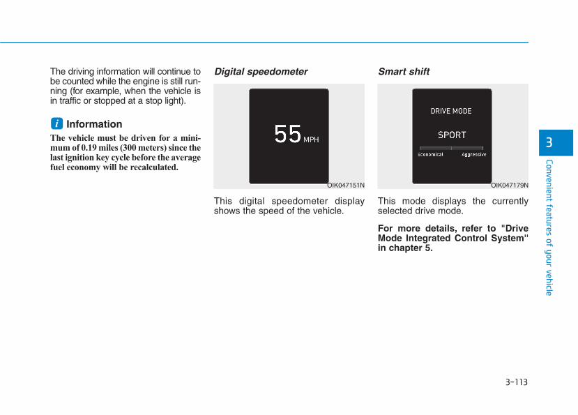
3-113
Convenient features of your vehicle
3
The driving information will continue tobe counted while the engine is still run-ning (for example, when the vehicle isin traffic or stopped at a stop light).
Information The vehicle must be driven for a mini-mum of 0.19 miles (300 meters) since thelast ignition key cycle before the averagefuel economy will be recalculated.
Digital speedometer
This digital speedometer displayshows the speed of the vehicle.
Smart shift
This mode displays the currentlyselected drive mode.
For more details, refer to "DriveMode Integrated Control System''in chapter 5.
i
OIK047151N OIK047179N
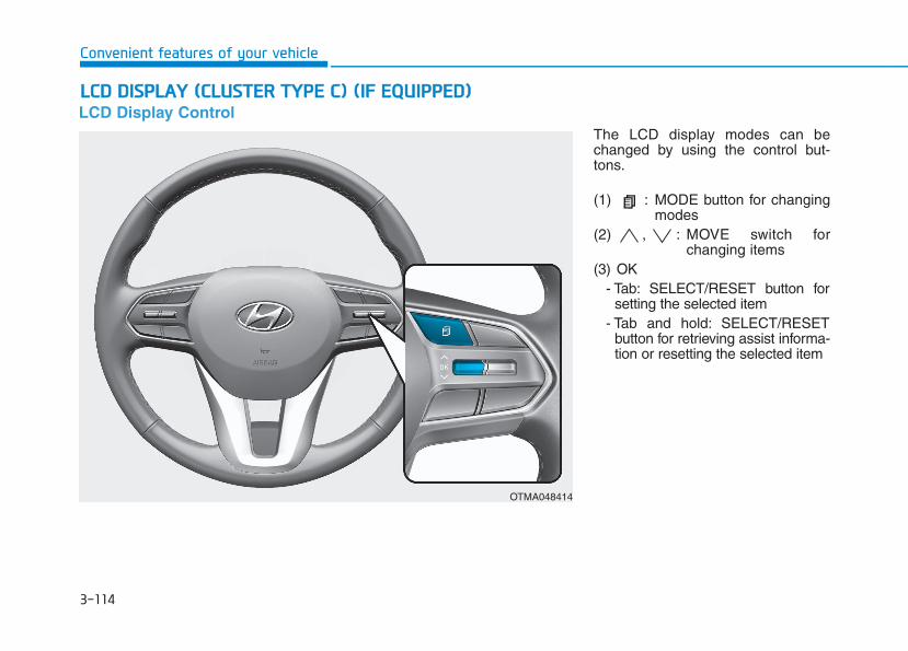
3-114
Convenient features of your vehicle
LCD Display ControlThe LCD display modes can bechanged by using the control but-tons.
(1) : MODE button for changingmodes
(2) , : MOVE switch forchanging items
(3) OK- Tab: SELECT/RESET button for
setting the selected item- Tab and hold: SELECT/RESET
button for retrieving assist informa-tion or resetting the selected item
LLCCDD DDIISSPPLLAAYY ((CCLLUUSSTTEERR TTYYPPEE CC)) ((IIFF EEQQUUIIPPPPEEDD))
OTMA048414
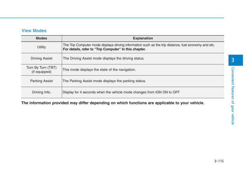
3-115
Convenient features of your vehicle
3
Modes Explanation
UtilityThe Trip Computer mode displays driving information such as the trip distance, fuel economy and etc.For details, refer to "Trip Computer" In this chapter.
Driving Assist The Driving Assist mode displays the driving status.
Turn By Turn (TBT)(if equipped)
This mode displays the state of the navigation.
Parking Assist The Parking Assist mode displays the parking status.
Driving Info. Display for 4 seconds when the vehicle mode changes from IGN ON to OFF
The information provided may differ depending on which functions are applicable to your vehicle.
View Modes
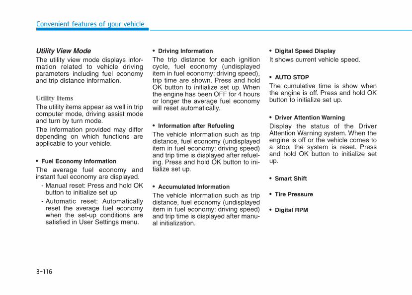
3-116
Convenient features of your vehicle
Utility View ModeThe utility view mode displays infor-mation related to vehicle drivingparameters including fuel economyand trip distance information.
Utility Items
The utility items appear as well in tripcomputer mode, driving assist modeand turn by turn mode.The information provided may differdepending on which functions areapplicable to your vehicle.
• Fuel Economy InformationThe average fuel economy andinstant fuel economy are displayed.
- Manual reset: Press and hold OKbutton to initialize set up
- Automatic reset: Automaticallyreset the average fuel economywhen the set-up conditions aresatisfied in User Settings menu.
• Driving InformationThe trip distance for each ignitioncycle, fuel economy (undisplayeditem in fuel economy: driving speed),trip time are shown. Press and holdOK button to initialize set up. Whenthe engine has been OFF for 4 hoursor longer the average fuel economywill reset automatically.
• Information after RefuelingThe vehicle information such as tripdistance, fuel economy (undisplayeditem in fuel economy: driving speed)and trip time is displayed after refuel-ing. Press and hold OK button to ini-tialize set up.
• Accumulated InformationThe vehicle information such as tripdistance, fuel economy (undisplayeditem in fuel economy: driving speed)and trip time is displayed after manu-al initialization.
• Digital Speed DisplayIt shows current vehicle speed.
• AUTO STOPThe cumulative time is show whenthe engine is off. Press and hold OKbutton to initialize set up.
• Driver Attention WarningDisplay the status of the DriverAttention Warning system. When theengine is off or the vehicle comes toa stop, the system is reset. Pressand hold OK button to initialize setup.
• Smart Shift
• Tire Pressure
• Digital RPM

3-117
Convenient features of your vehicle
3
Driving Assist View Mode
SCC/LKA/HAD/FCA
This mode displays the state of theSmart Cruise Control (SCC) andLane Keeping Assist (LKA).For more details, refer to systeminformation in chapter 5.
TBT (Turn By Turn) Mode
It shows the information by inter-working with the navigation.
Parking Assist View Mode
It displays the information related tothe parking assist system move-ment.
OLX2059118N OLX2059119N OLX2049145N

3-118
Convenient features of your vehicle
Other Information Display
Driving information summary (1)
The current operation conditions ofthe Cruise Control mode, SmartCruise Control and high speed driv-ing assist modes. It does not showsuch information while driving assistmode is working.
Driving information summary (2)
• It shows the weather and fine dustconcentration. (If equipped)
• While interworking with the naviga-tion, it displays the distance to thedestinations or stops, the time todestinations or stops and the esti-mated time of arrival.
• Assist messages appear while setup.
OLX2059120N
OLX2059121N
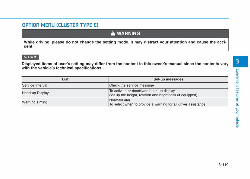
3-119
Convenient features of your vehicle
Displayed items of user's setting may differ from the content in this owner's manual since the contents varywith the vehicle’s technical specifications.
NOTICE
OOPPTTIIOONN MMEENNUU ((CCLLUUSSTTEERR TTYYPPEE CC))
3
While driving, please do not change the setting mode. It may distract your attention and cause the acci-dent.
WARNING
List Set-up messages
Service Interval Check the service message
Head-up DisplayTo activate or deactivate head-up displaySet up the height, rotation and brightness (if equipped)
Warning TimingNormal/Later To select when to provide a warning for all driver assistance
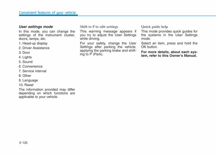
3-120
User settings modeIn this mode, you can change thesettings of the instrument cluster,doors, lamps, etc.1. Head-up display2. Driver Assistance3. Door4. Lights5. Sound6. Convenience7. Service interval8. Other9. Language10. ResetThe information provided may differdepending on which functions areapplicable to your vehicle.
Shift to P to edit settings
This warning message appears ifyou try to adjust the User Settingswhile driving.For your safety, change the UserSettings after parking the vehicle,applying the parking brake and shift-ing to P (Park).
Quick guide help
This mode provides quick guides forthe systems in the User Settingsmode.Select an item, press and hold theOK button.
For more details, about each sys-tem, refer to this Owner's Manual.
Convenient features of your vehicle
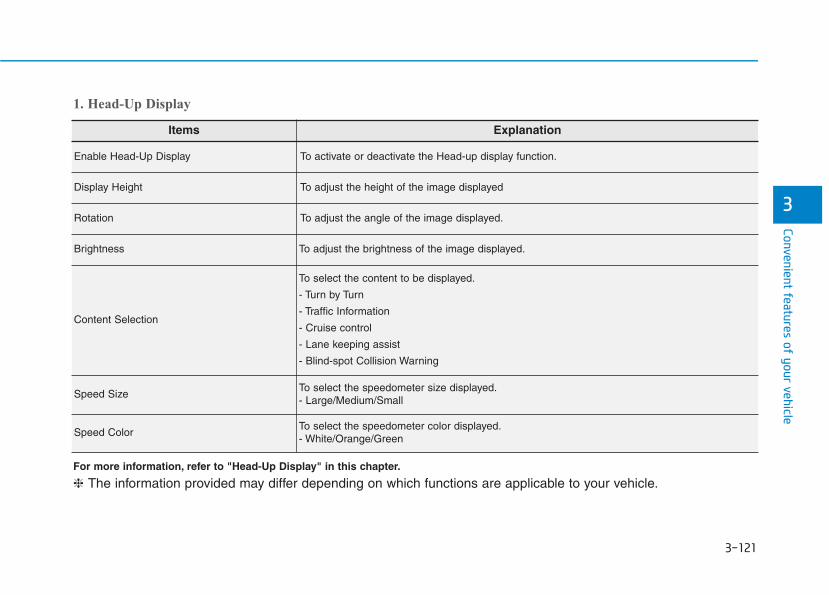
3-121
Convenient features of your vehicle
3
Items Explanation
Enable Head-Up Display To activate or deactivate the Head-up display function.
Display Height To adjust the height of the image displayed
Rotation To adjust the angle of the image displayed.
Brightness To adjust the brightness of the image displayed.
Content Selection
To select the content to be displayed.
- Turn by Turn
- Traffic Information
- Cruise control
- Lane keeping assist
- Blind-spot Collision Warning
Speed SizeTo select the speedometer size displayed.- Large/Medium/Small
Speed ColorTo select the speedometer color displayed.- White/Orange/Green
1. Head-Up Display
For more information, refer to "Head-Up Display" in this chapter.
❈ The information provided may differ depending on which functions are applicable to your vehicle.
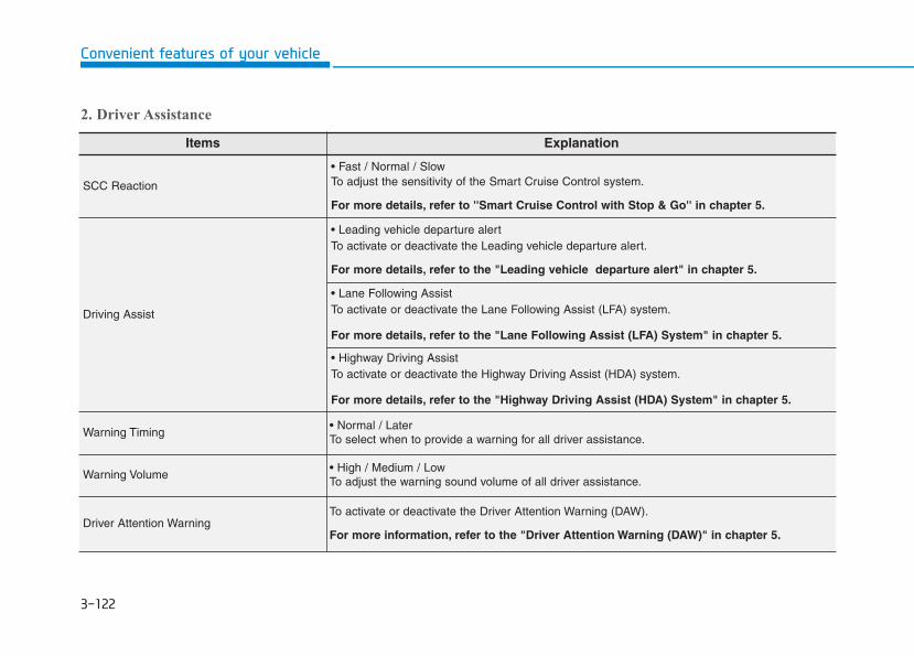
3-122
Convenient features of your vehicle
Items Explanation
SCC Reaction
• Fast / Normal / Slow To adjust the sensitivity of the Smart Cruise Control system.
For more details, refer to ''Smart Cruise Control with Stop & Go'' in chapter 5.
Driving Assist
• Leading vehicle departure alertTo activate or deactivate the Leading vehicle departure alert.
For more details, refer to the "Leading vehicle departure alert" in chapter 5.
• Lane Following AssistTo activate or deactivate the Lane Following Assist (LFA) system.
For more details, refer to the "Lane Following Assist (LFA) System" in chapter 5.
• Highway Driving AssistTo activate or deactivate the Highway Driving Assist (HDA) system.
For more details, refer to the "Highway Driving Assist (HDA) System" in chapter 5.
Warning Timing• Normal / Later To select when to provide a warning for all driver assistance.
Warning Volume• High / Medium / Low To adjust the warning sound volume of all driver assistance.
Driver Attention WarningTo activate or deactivate the Driver Attention Warning (DAW).
For more information, refer to the "Driver Attention Warning (DAW)" in chapter 5.
2. Driver Assistance
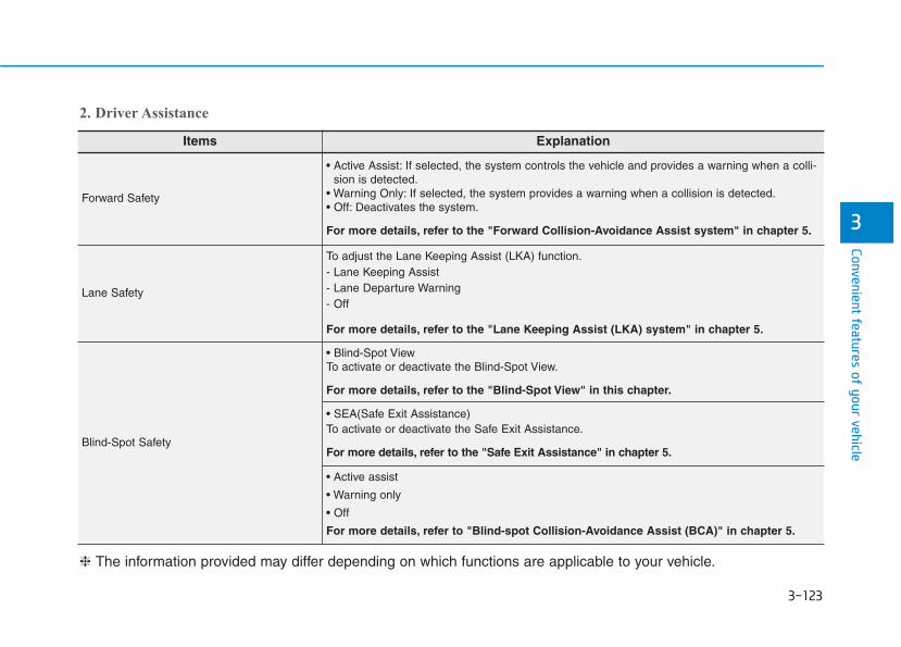
3-123
Convenient features of your vehicle
3
Items Explanation
Forward Safety
• Active Assist: If selected, the system controls the vehicle and provides a warning when a colli-sion is detected.
• Warning Only: If selected, the system provides a warning when a collision is detected.• Off: Deactivates the system.
For more details, refer to the "Forward Collision-Avoidance Assist system" in chapter 5.
Lane Safety
To adjust the Lane Keeping Assist (LKA) function.- Lane Keeping Assist - Lane Departure Warning- Off
For more details, refer to the "Lane Keeping Assist (LKA) system" in chapter 5.
Blind-Spot Safety
• Blind-Spot View To activate or deactivate the Blind-Spot View.
For more details, refer to the "Blind-Spot View" in this chapter.
• SEA(Safe Exit Assistance) To activate or deactivate the Safe Exit Assistance.
For more details, refer to the "Safe Exit Assistance" in chapter 5.
• Active assist
• Warning only
• Off
For more details, refer to "Blind-spot Collision-Avoidance Assist (BCA)" in chapter 5.
❈ The information provided may differ depending on which functions are applicable to your vehicle.
2. Driver Assistance

3-124
Convenient features of your vehicle
Items Explanation
Automatically Lock
• Enable on speed: All doors will be automatically locked when the vehicle speed exceeds 9.3mph (15 km/h).
• Enable on shift: All doors will be automatically locked if the vehicle is shifted from the P (Park)position to the R (Reverse), N (Neutral), or D (Drive) position. (Only when the engine is run-ning)
Automatically Unlock
• Disable : The auto door unlock operation will be canceled.• On key out : All doors will be automatically unlocked when the ignition key is removed from the
key ignition switch (if equipped with remote key).• Vehicle off : All doors will be automatically unlocked when the Engine Start/Stop button is set
to the OFF position. (if equipped with smart key)• On shift to P : All doors will be automatically unlocked if the automatic transmission is shifted
to the P (Park) position. (Only when the engine is running)
3. Door
Items Explanation
Parking Safety
• Rear Cross-Traffic SafetyTo activate or deactivate the Rear Cross-Traffic Collision Warning function.
For more details, refer to the "Rear Cross-traffic Collision Warning (RCCW) / Rear Cross-traffic Collision-Avoidance Assist (RCCA)" in chapter 5.
2. Driver Assistance
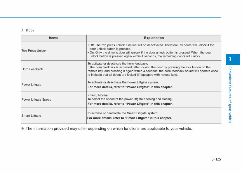
3-125
Convenient features of your vehicle
3
Items Explanation
Two Press Unlock
• Off: The two press unlock function will be deactivated. Therefore, all doors will unlock if thedoor unlock button is pressed.
• On: Only the driver's door will unlock if the door unlock button is pressed. When the doorunlock button is pressed again within 4 seconds, the remaining doors will unlock.
Horn Feedback
To activate or deactivate the horn feedback.If the horn feedback is activated, after locking the door by pressing the lock button on theremote key, and pressing it again within 4 seconds, the horn feedback sound will operate onceto indicate that all doors are locked (if equipped with remote key).
Power LiftgateTo activate or deactivate the Power Liftgate system.
For more details, refer to "Power Liftgate" in this chapter.
Power Liftgate Speed• Fast / Normal To select the speed of the power liftgate opening and closing
For more details, refer to "Power Liftgate" in this chapter.
Smart LiftgateTo activate or deactivate the Smart Liftgate system.
For more details, refer to "Smart Liftgate" in this chapter.
❈ The information provided may differ depending on which functions are applicable to your vehicle.
3. Door

3-126
Convenient features of your vehicle
Items Explanation
One Touch Turn Signal
• Off: The one touch turn signal function will be deactivated.• 3, 5, 7 Flashes: The turn signal indicator will blink 3, 5, or 7 times when the turn signal lever is
moved slightly.
For more details, refer to "Lighting" in this chapter.
Headlight DelayTo activate or deactivate the headlight delay function.
For more details, refer to "Lighting" in this chapter.
4. Lights
6. Convenience
❈ The information provided may differ depending on which functions are applicable to your vehicle.
5. Sound
Items Explanation
Welcome Sound To activate or deactivate the welcome sound function.
❈ The information provided may differ depending on which functions are applicable to your vehicle.
Items Explanation
Seat Slide Easy Access
• Off: The seat easy access function is deactivated.• Normal/Extended: When you turn off the engine, the driver's seat will automatically move rear-
ward short (Normal) or long (Extended) for you to enter or exit the vehicle more comfortably.For more details, refer to "Driver Position Memory System" in this chapter.

3-127
Convenient features of your vehicle
3
Items Explanation
Seat Height Easy AccessTo activate or deactivate the Seat Height Easy Access.
For more details, refer to "Driver Position Memory System" in this chapter.
Rear Occupant AlertTo activate or deactivate the Rear Occupant Alert
For more details, refer to "Rear Occupant Alert (ROA) system" in this chapter.
Welcome Light
• On driver approach: The welcome light turns on automatically when the vehicle is approachedwith the smart key.
For more details, refer to ''Welcome System'' in this chapter.
Wireless Charging SystemTo activate or deactivate the wireless charging system in the front seat.
For more details, refer to "Wireless Charging System" in this chapter.
Traffic InformationTo activate or deactivate traffic information display function.When activated, traffic information, such as speed limits, etc. are displayed in the cluster LCDdisplay.
Wiper/Lights DisplayTo activate or deactivate the Wiper/Light mode.When activated, the LCD display shows the selected Wiper/Light mode whenever you changethe mode.
Auto Rear Wiper (in R) To activate or deactivate the rear wiper while the vehicle is in reverse with the front wiper ON.
Gear Position Pop-upTo activate or deactivate the gear position pop-up.When activated, the gear position will be displayed in the cluster LCD display.
Icy Road Warning To activate or deactivate the Icy Road Warning function.
6. Convenience
❈ The information provided may differ depending on which functions are applicable to your vehicle.
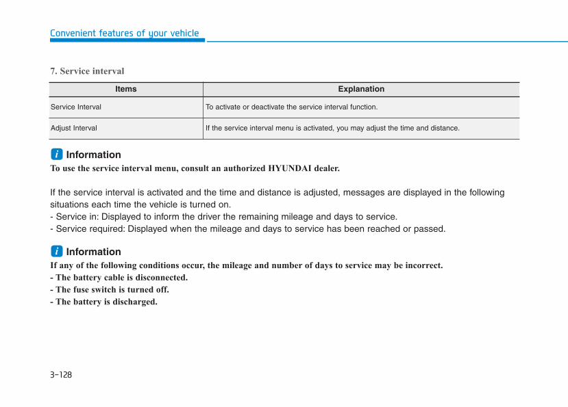
3-128
Convenient features of your vehicle
7. Service interval
Information To use the service interval menu, consult an authorized HYUNDAI dealer.
If the service interval is activated and the time and distance is adjusted, messages are displayed in the followingsituations each time the vehicle is turned on.- Service in: Displayed to inform the driver the remaining mileage and days to service.- Service required: Displayed when the mileage and days to service has been reached or passed.
Information If any of the following conditions occur, the mileage and number of days to service may be incorrect.
- The battery cable is disconnected.
- The fuse switch is turned off.
- The battery is discharged.
i
i
Items Explanation
Service Interval To activate or deactivate the service interval function.
Adjust Interval If the service interval menu is activated, you may adjust the time and distance.

3-129
Convenient features of your vehicle
3
Items Explanation
Fuel Economy Reset
• Off: The average fuel economy will not reset automatically whenever refueling.• After ignition: When the engine has been OFF for 4 hours or longer the average fuel economy
will reset automatically.• After refueling: The average fuel economy will reset automatically after adding 1.6 gallons (6
liters) of fuel or more and after driving speed exceeds 1 mph (1 km/h).
For more details, refer to "Trip Computer" in this chapter.
Fuel Economy Unit• US gallon / UK gallonTo select the fuel economy unit.
Temperature Unit• °C / °FTo select the temperature unit.
Tire Pressure Unit• psi / kPa / barTo select the tire pressure unit.
8. Other
Items Explanation
Language To select language.
9. Language
Items Explanation
ResetYou can reset the menus in the User Settings mode. All menus in the User Settings mode arereset to factory settings, except language and service interval.
10. Reset
❈ The information provided may differ depending on which functions are applicable to your vehicle.

3-130
Convenient features of your vehicle
The Head-Up Display is an optionalfeature that allows the driver to viewinformation projected onto a trans-parent screen while still keeping youreyes safely on the road ahead whiledriving.
Precautions while using thehead up displayIt may sometimes be difficult to readinformation on the head up display inthe following situations.- The driver is improperly positioned
in the driver's seat.- The driver wears polarizing-filter
sunglasses.- An object is located above the
head up display cover.- The vehicle is driven on a wet road.- Any improper lighting accessory is
installed inside the vehicle, or thereis incoming light from outside ofthe vehicle.
- The driver wears glasses.- The driver wears contact lenses.When it is difficult to read the headup display information, adjust thehead up display angle or the head updisplay brightness level in the UserSettings mode. For more details,refer to "LCD Display" in this chapter.
When replacing the front wind-shield glass of the vehicleequipped with the head up dis-play, replace it with a windshieldglass designed for the head updisplay operation. Otherwise,duplicated images may be dis-played on the windshield glass.
NOTICE
HHEEAADD UUPP DDIISSPPLLAAYY ((HHUUDD)) ((IIFF EEQQUUIIPPPPEEDD))
OLX2049051N
• Do not tint the front wind-shield glass or add othertypes of metallic coating.Otherwise, the head up dis-play image may be invisible.
• Do not place any accessorieson the crash pad or attach anyobjects on the windshieldglass.
• The Blind-spot CollisionWarning (BCW) system warn-ings on the head up displayare supplemental. Do not sole-ly depend on them to changelanes. Always take a lookaround before changing lanes.
WARNING

3-131
Convenient features of your vehicle
3
Head-up display ON/OFF
To activate the head up display,select 'Head-UP Display' on the UserSettings mode on the instrumentcluster LCD display.If you do not select 'Head-UpDisplay', the head up display will bedeactivated.
Head-up display information
1. Turn By Turn (TBT) navigation infor-mation (if equipped)
2. Speed limit signs (if equipped)3. Speedometer4. Cruise setting speed (if equipped)5. Smart Cruise Control (SCC) infor-
mation (if equipped)6. Lane Keeping Assist (LKA) sys-
tem information (if equipped)7. Blind-spot Collision Warning (BCW)
system information (if equipped)8. Warning lights (Low fuel, etc.)9. Audio/Video information
InformationIf you select the Turn By Turn (TBT)navigation information as HUD con-tents, the Turn By Turn (TBT) naviga-tion information will not be displayedin the instrument cluster LCD display.
Head-up display settingOn the LCD display, you can changethe head up display settings as fol-lows.• Enable Head-up display• Display Height• Rotation• Brightness• Content Selection• Speed Size• Speed Color
For more details, refer to "LCDDisplay" in this chapter.
i
OLX2049419NOIK047152N
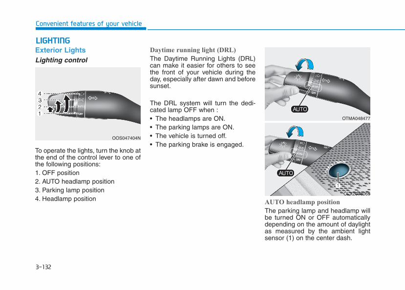
3-132
Convenient features of your vehicle
LLIIGGHHTTIINNGGExterior LightsLighting control
To operate the lights, turn the knob atthe end of the control lever to one ofthe following positions:1. OFF position2. AUTO headlamp position3. Parking lamp position4. Headlamp position
Daytime running light (DRL)
The Daytime Running Lights (DRL)can make it easier for others to seethe front of your vehicle during theday, especially after dawn and beforesunset.
The DRL system will turn the dedi-cated lamp OFF when :• The headlamps are ON.• The parking lamps are ON.• The vehicle is turned off.• The parking brake is engaged.
AUTO headlamp position
The parking lamp and headlamp willbe turned ON or OFF automaticallydepending on the amount of daylightas measured by the ambient lightsensor (1) on the center dash.
OOS047404N
OTMA048477
OLX2048065
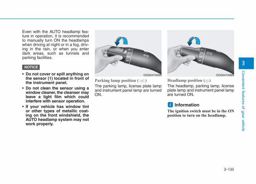
3-133
Convenient features of your vehicle
3
Even with the AUTO headlamp fea-ture in operation, it is recommendedto manually turn ON the headlampswhen driving at night or in a fog, driv-ing in the rain, or when you enterdark areas, such as tunnels andparking facilities.
• Do not cover or spill anything onthe sensor (1) located in front ofthe instrument panel.
• Do not clean the sensor using awindow cleaner, the cleanser mayleave a light film which couldinterfere with sensor operation.
• If your vehicle has window tintor other types of metallic coat-ing on the front windshield, theAUTO headlamp system may notwork properly.
Parking lamp position ( )
The parking lamp, license plate lampand instrument panel lamp are turnedON.
Headlamp position ( )
The headlamp, parking lamp, licenseplate lamp and instrument panel lampare turned ON.
Information The ignition switch must be in the ONposition to turn on the headlamp.
i
NOTICE
OOS047405N OOS047406N
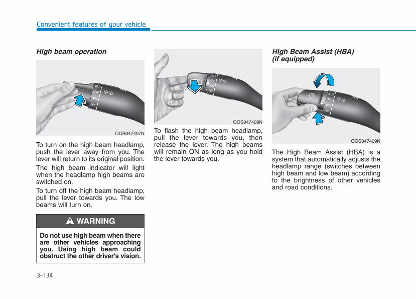
3-134
Convenient features of your vehicle
High beam operation
To turn on the high beam headlamp,push the lever away from you. Thelever will return to its original position.The high beam indicator will lightwhen the headlamp high beams areswitched on.To turn off the high beam headlamp,pull the lever towards you. The lowbeams will turn on.
To flash the high beam headlamp,pull the lever towards you, thenrelease the lever. The high beamswill remain ON as long as you holdthe lever towards you.
High Beam Assist (HBA) (if equipped)
The High Beam Assist (HBA) is asystem that automatically adjusts theheadlamp range (switches betweenhigh beam and low beam) accordingto the brightness of other vehiclesand road conditions.
Do not use high beam when thereare other vehicles approachingyou. Using high beam couldobstruct the other driver's vision.
WARNING
OOS047407N
OOS047408N
OOS047409N
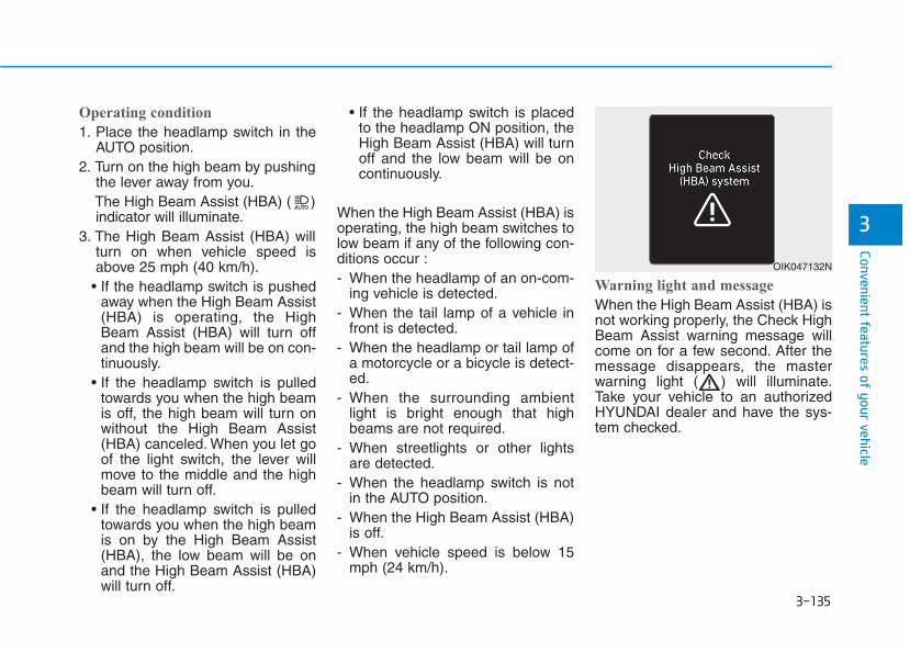
3-135
Convenient features of your vehicle
3
Operating condition
1. Place the headlamp switch in theAUTO position.
2. Turn on the high beam by pushingthe lever away from you.The High Beam Assist (HBA) ( )indicator will illuminate.
3. The High Beam Assist (HBA) willturn on when vehicle speed isabove 25 mph (40 km/h).
• If the headlamp switch is pushedaway when the High Beam Assist(HBA) is operating, the HighBeam Assist (HBA) will turn offand the high beam will be on con-tinuously.
• If the headlamp switch is pulledtowards you when the high beamis off, the high beam will turn onwithout the High Beam Assist(HBA) canceled. When you let goof the light switch, the lever willmove to the middle and the highbeam will turn off.
• If the headlamp switch is pulledtowards you when the high beamis on by the High Beam Assist(HBA), the low beam will be onand the High Beam Assist (HBA)will turn off.
• If the headlamp switch is placedto the headlamp ON position, theHigh Beam Assist (HBA) will turnoff and the low beam will be oncontinuously.
When the High Beam Assist (HBA) isoperating, the high beam switches tolow beam if any of the following con-ditions occur :- When the headlamp of an on-com-
ing vehicle is detected.- When the tail lamp of a vehicle in
front is detected.- When the headlamp or tail lamp of
a motorcycle or a bicycle is detect-ed.
- When the surrounding ambientlight is bright enough that highbeams are not required.
- When streetlights or other lightsare detected.
- When the headlamp switch is notin the AUTO position.
- When the High Beam Assist (HBA)is off.
- When vehicle speed is below 15mph (24 km/h).
Warning light and message
When the High Beam Assist (HBA) isnot working properly, the Check HighBeam Assist warning message willcome on for a few second. After themessage disappears, the masterwarning light ( ) will illuminate.Take your vehicle to an authorizedHYUNDAI dealer and have the sys-tem checked.
OIK047132N
3-136
Convenient features of your vehicle
The system may not operate nor-mally if any of the following con-ditions should occur:1) When the illumination from
an on-coming vehicle or avehicle in front is dim. Suchexamples may include:
• When the headlamps of an on-coming vehicle or the taillamps of a vehicle in front iscovered with dust, snow, orwater.
• When the headlamps on an on-coming vehicle are OFF, but thefog lamps are ON.
2) When the High Beam Assistcamera is adversely affectedby an external condition.Such examples may include:
• When the vehicle's head-lamps have been damaged ornot repaired properly.
• When the vehicle headlampsare not aimed properly.
• When the vehicle is driven ona narrow curved road or roughroad.
• When the vehicle is driven onan uphill road or downhillroad.
• When only part of the vehicle infront is visible on a crossroador curved road.
• When there is a traffic light,reflecting sign, flashing sign ormirror.
• When the road conditions arebad such as being wet or cov-ered with snow.
• When a vehicle suddenlyappears from a curve.
• When the vehicle is tilted froma flat tire or being towed.
• When the Lane Keeping Assist(LKA) system warning lightilluminates.
• When the light from the on-coming or front vehicle is notdetected because of exhaustfume, smoke, fog, snow, etc.
• When the front window is cov-ered with foreign matters suchas ice, dust, fog, or is damaged.
3) When the forward visibility ispoor. Such examples mayinclude:
• When the headlamps of an on-coming vehicle or a vehicle infront is not detected due topoor outside visibility (smog,smoke, dust, fog, heavy rain,snow, etc.).
• When the windshield visibilityis poor.
WARNING
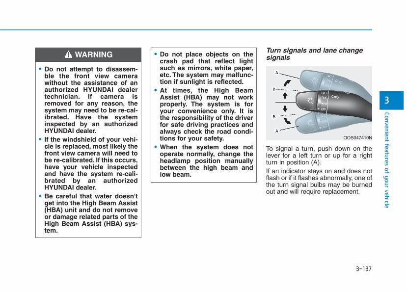
3-137
Convenient features of your vehicle
3
Turn signals and lane changesignals
To signal a turn, push down on thelever for a left turn or up for a rightturn in position (A).If an indicator stays on and does notflash or if it flashes abnormally, one ofthe turn signal bulbs may be burnedout and will require replacement.
OOS047410N
• Do not attempt to disassem-ble the front view camerawithout the assistance of anauthorized HYUNDAI dealertechnician. If camera isremoved for any reason, thesystem may need to be re-cal-ibrated. Have the systeminspected by an authorizedHYUNDAI dealer.
• If the windshield of your vehi-cle is replaced, most likely thefront view camera will need tobe re-calibrated. If this occurs,have your vehicle inspectedand have the system re-cali-brated by an authorizedHYUNDAI dealer.
• Be careful that water doesn'tget into the High Beam Assist(HBA) unit and do not removeor damage related parts of theHigh Beam Assist (HBA) sys-tem.
• Do not place objects on thecrash pad that reflect lightsuch as mirrors, white paper,etc. The system may malfunc-tion if sunlight is reflected.
• At times, the High BeamAssist (HBA) may not workproperly. The system is foryour convenience only. It isthe responsibility of the driverfor safe driving practices andalways check the road condi-tions for your safety.
• When the system does notoperate normally, change theheadlamp position manuallybetween the high beam andlow beam.
WARNING
3-138
Convenient features of your vehicle
One-touch turn signal function
To activate the One Touch TurnSignal function, push the turn signallever up or down to position (B) andthen release it.The lane change signals will blink 3,5 or 7 times.You can activate or deactivate theOne Touch Turn Signal function orchoose the number of blinks (3, 5, or7) from the User Settings mode inthe LCD display.
For more details, refer to the "LCDDisplay" section in this chapter.
Battery saver functionThe purpose of this feature is to helpprevent the battery from being dis-charged. The system automaticallyturns off the parking lamp when thedriver turns the vehicle off and opensthe driver-side door.With this feature, the parking lampswill turn off automatically if the driverparks on the side of road at night.If necessary, to keep the lamps onwhen the vehicle is turned off, performthe following:1) Open the driver-side door.2) Turn the parking lamps OFF and
ON again using the headlampswitch on the steering column.
Headlamp delay functionIf the key is removed from the ignitionswitch or placed in the ACC positionor the LOCK/OFF position with theheadlamps ON, the headlamps(and/or parking lamps) remain on forabout 5 minutes. However, if the dri-ver's door is opened and closed, theheadlights are turned off after 15seconds. Also, with the engine off ifthe driver's door is opened andclosed, the headlamps (and/or park-ing lamps) are turned off after 15seconds.The headlamps (and/or parkinglamps) can be turned off by pressingthe lock button on the remote key orsmart key twice or turning the head-lamp switch to the OFF or AUTOposition.You can activate or deactivate theHeadlamp Delay function from theUser Settings mode in the LCD dis-play.
For more details, refer to the "LCDDisplay" section in this chapter.
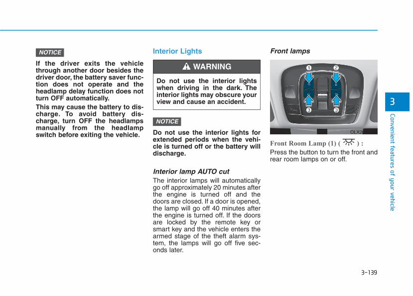
3-139
Convenient features of your vehicle
3
If the driver exits the vehiclethrough another door besides thedriver door, the battery saver func-tion does not operate and theheadlamp delay function does notturn OFF automatically.This may cause the battery to dis-charge. To avoid battery dis-charge, turn OFF the headlampsmanually from the headlampswitch before exiting the vehicle.
Interior Lights
Do not use the interior lights forextended periods when the vehi-cle is turned off or the battery willdischarge.
Interior lamp AUTO cutThe interior lamps will automaticallygo off approximately 20 minutes afterthe engine is turned off and thedoors are closed. If a door is opened,the lamp will go off 40 minutes afterthe engine is turned off. If the doorsare locked by the remote key orsmart key and the vehicle enters thearmed stage of the theft alarm sys-tem, the lamps will go off five sec-onds later.
Front lamps
Front Room Lamp (1) ( ) :
Press the button to turn the front andrear room lamps on or off.
NOTICE
NOTICE
Do not use the interior lightswhen driving in the dark. Theinterior lights may obscure yourview and cause an accident.
WARNING
OLX2048066
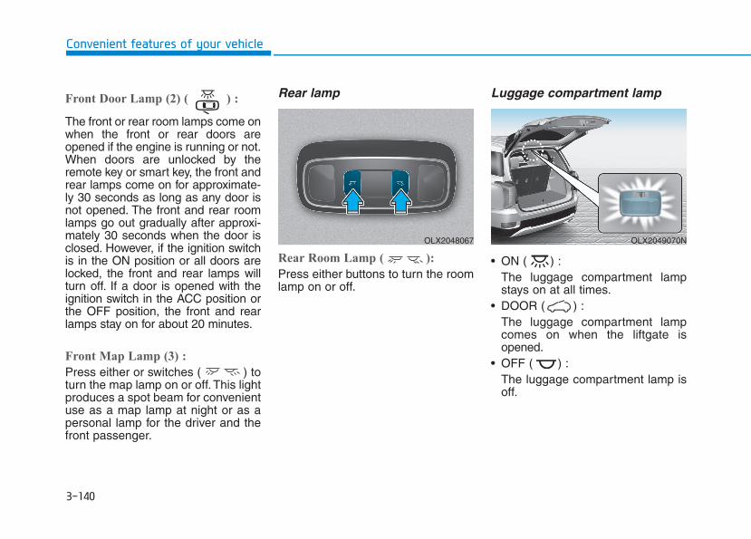
3-140
Convenient features of your vehicle
Front Door Lamp (2) ( ) :
The front or rear room lamps come onwhen the front or rear doors areopened if the engine is running or not.When doors are unlocked by theremote key or smart key, the front andrear lamps come on for approximate-ly 30 seconds as long as any door isnot opened. The front and rear roomlamps go out gradually after approxi-mately 30 seconds when the door isclosed. However, if the ignition switchis in the ON position or all doors arelocked, the front and rear lamps willturn off. If a door is opened with theignition switch in the ACC position orthe OFF position, the front and rearlamps stay on for about 20 minutes.
Front Map Lamp (3) :
Press either or switches ( ) toturn the map lamp on or off. This lightproduces a spot beam for convenientuse as a map lamp at night or as apersonal lamp for the driver and thefront passenger.
Rear lamp
Rear Room Lamp ( ):
Press either buttons to turn the roomlamp on or off.
Luggage compartment lamp
• ON ( ) :The luggage compartment lampstays on at all times.
• DOOR ( ) :The luggage compartment lampcomes on when the liftgate isopened.
• OFF ( ) :The luggage compartment lamp isoff.
OLX2048067 OLX2049070N
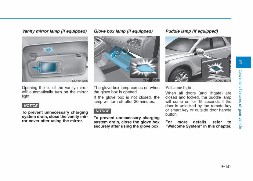
3-141
Convenient features of your vehicle
3
Vanity mirror lamp (if equipped)
Opening the lid of the vanity mirrorwill automatically turn on the mirrorlight.
To prevent unnecessary chargingsystem drain, close the vanity mir-ror cover after using the mirror.
Glove box lamp (if equipped)
The glove box lamp comes on whenthe glove box is opened.If the glove box is not closed, thelamp will turn off after 20 minutes.
To prevent unnecessary chargingsystem drain, close the glove boxsecurely after using the glove box.
Puddle lamp (if equipped)
Welcome light
When all doors (and liftgate) areclosed and locked, the puddle lampwill come on for 15 seconds if thedoor is unlocked by the remote keyor smart key or outside door handlebutton.
For more details, refer to"Welcome System" in this chapter.
NOTICENOTICE
ODH043356 OLX2048068 OLX2048071

3-142
Convenient features of your vehicle
Escort light
When the vehicle is turned OFF andthe driver's door is opened, the pud-dle lamp will come on for 30 sec-onds. If the driver's door is closedwithin the 30 seconds, the puddlelamp will turn off after 15 seconds. Ifthe driver's door is closed andlocked, the puddle lamp will turn offimmediately.The Puddle Lamp Escort Light willturn on only the first time the driver'sdoor is opened after the engine isturned off.
Welcome System (if equipped)Welcome light
Puddle lamp (if equipped) and doorhandle lamp (if equipped)
When all the doors (and liftgate) areclosed and locked, the puddle lampand door handle lamp will come onfor about 15 seconds if any of thebelow is performed.• When the door unlock button is
pressed on the remote key orsmart key.
• When the button of the outsidedoor handle is pressed with thesmart key in possession.
• If 'Convenience → Welcome Light→ On driver approach' is selectedin the User Settings mode in thecluster LCD display, the lamps willturn on when the vehicle isapproached with the smart key inpossession.
Headlamp and parking lamp
When the headlamp (lamp switch inthe headlamp or AUTO position) is onand all doors (and liftgate) are lockedand closed, the parking lamp andheadlamp will come on for 15 secondswhen the door unlock button ispressed on the remote key or smartkey.At this time, if you press the door lockor unlock button, the parking lamp andheadlamp will turn off immediately.
OLX2048064
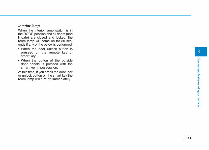
3-143
Convenient features of your vehicle
3
Interior lampWhen the interior lamp switch is inthe DOOR position and all doors (andliftgate) are closed and locked, theroom lamp will come on for 30 sec-onds if any of the below is performed.• When the door unlock button is
pressed on the remote key orsmart key.
• When the button of the outsidedoor handle is pressed with thesmart key in possession.
At this time, if you press the door lockor unlock button on the smart key theroom lamp will turn off immediately.
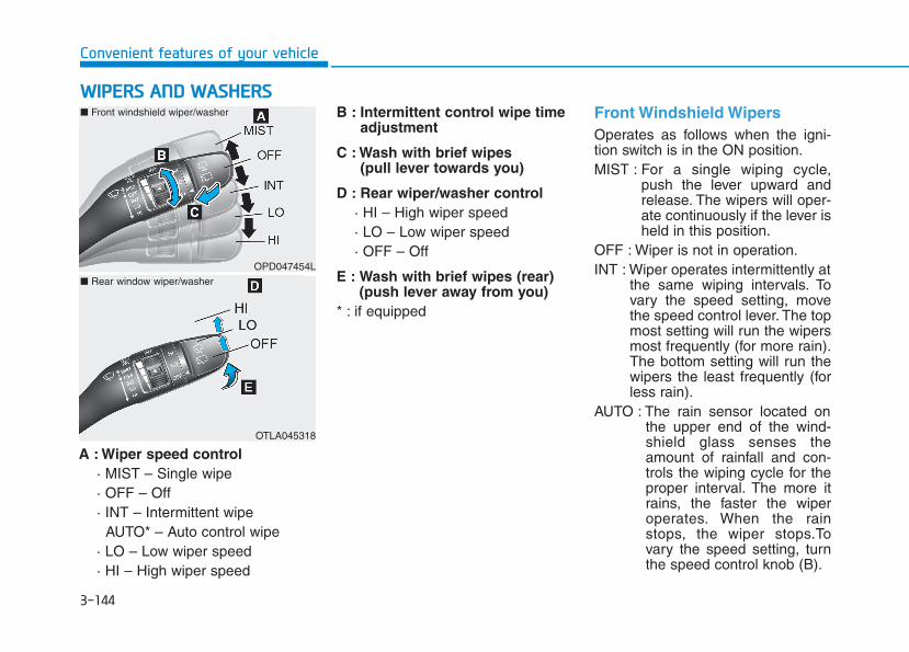
3-144
Convenient features of your vehicle
A : Wiper speed control· MIST – Single wipe· OFF – Off· INT – Intermittent wipe
AUTO* – Auto control wipe· LO – Low wiper speed· HI – High wiper speed
B : Intermittent control wipe timeadjustment
C : Wash with brief wipes(pull lever towards you)
D : Rear wiper/washer control· HI – High wiper speed· LO – Low wiper speed· OFF – Off
E : Wash with brief wipes (rear)(push lever away from you)
* : if equipped
Front Windshield Wipers Operates as follows when the igni-tion switch is in the ON position.MIST : For a single wiping cycle,
push the lever upward andrelease. The wipers will oper-ate continuously if the lever isheld in this position.
OFF : Wiper is not in operation.INT : Wiper operates intermittently at
the same wiping intervals. Tovary the speed setting, movethe speed control lever. The topmost setting will run the wipersmost frequently (for more rain).The bottom setting will run thewipers the least frequently (forless rain).
AUTO : The rain sensor located onthe upper end of the wind-shield glass senses theamount of rainfall and con-trols the wiping cycle for theproper interval. The more itrains, the faster the wiperoperates. When the rainstops, the wiper stops.Tovary the speed setting, turnthe speed control knob (B).
WWIIPPEERRSS AANNDD WWAASSHHEERRSS
OPD047454L
OTLA045318
■ Front windshield wiper/washer
■ Rear window wiper/washer
3-145
Convenient features of your vehicle
3
LO : The wiper runs at a lower speed.HI : The wiper runs at a higher speed.
Information If there is heavy accumulation of snowor ice on the windshield, defrost thewindshield for about 10 minutes, oruntil the snow and/or ice is removedbefore using the windshield wipers toensure proper operation.
If you do not remove the snow and/orice before using the wiper and washer,it may damage the wiper and washersystem.
AUTO (Automatic) control (if equipped)The rain sensor located on the upperend of the windshield glass sensesthe amount of rainfall and controlsthe wiping cycle for the proper inter-val.The wiper operation time will beautomatically controlled depends onrainfall.When the rain stops, the wiper stops.To vary the sensitivity setting, turnthe sensitivity control knob (1).If the wiper switch is set in AUTOmode when the ignition switch is inthe ON position, the wiper will oper-ate once to perform a self-check ofthe system. Set the wiper to OFFposition when the wiper is not in use.
iTo avoid personal injury fromthe windshield wipers, when theengine is running and the wind-shield wiper switch is placed inthe AUTO mode:• Do not touch the upper end of
the windshield glass facingthe rain sensor.
• Do not wipe the upper end ofthe windshield glass with adamp or wet cloth.
• Do not put pressure on thewindshield glass.
WARNING

3-146
Convenient features of your vehicle
• When washing the vehicle, setthe wiper switch in the OFF posi-tion to stop the auto wiper oper-ation. The wiper may operateand be damaged if the switch isset in the AUTO mode whilewashing the vehicle.
• Do not remove the sensor coverlocated on the upper end of thepassenger side windshieldglass. Damage to system partscould occur and may not be cov-ered by your vehicle warranty.
• Because of using a photo sen-sor, temporary malfunctioncould occur according to sud-den ambient light change madeby stone and dust while driving.
Front Windshield Washers
In the OFF position, pull the levergently toward you to spray washerfluid on the windshield and to run thewipers 1-3 cycles. The spray andwiper operation will continue untilyou release the lever. If the washerdoes not work, you may need to addwasher fluid to the washer fluidreservoir.
NOTICE
When the outside temperatureis below freezing, ALWAYSwarm the windshield using thedefroster to help prevent thewasher fluid from freezing onthe windshield and obscuringyour vision which could resultin an accident and seriousinjury or death.
WARNING
OTLE045164
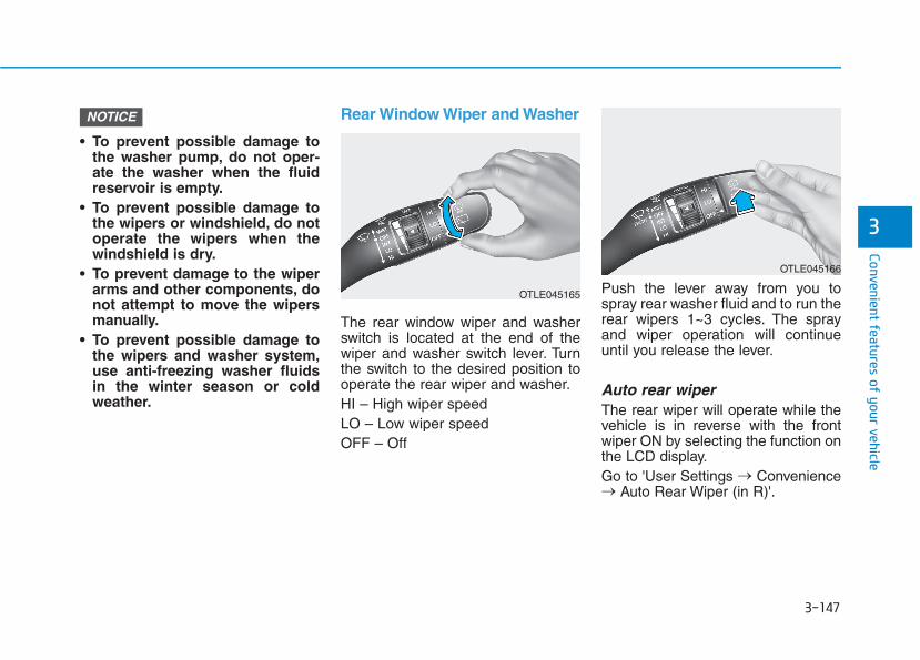
3-147
Convenient features of your vehicle
3
• To prevent possible damage tothe washer pump, do not oper-ate the washer when the fluidreservoir is empty.
• To prevent possible damage tothe wipers or windshield, do notoperate the wipers when thewindshield is dry.
• To prevent damage to the wiperarms and other components, donot attempt to move the wipersmanually.
• To prevent possible damage tothe wipers and washer system,use anti-freezing washer fluidsin the winter season or coldweather.
Rear Window Wiper and Washer
The rear window wiper and washerswitch is located at the end of thewiper and washer switch lever. Turnthe switch to the desired position tooperate the rear wiper and washer.HI – High wiper speedLO – Low wiper speed OFF – Off
Push the lever away from you tospray rear washer fluid and to run therear wipers 1~3 cycles. The sprayand wiper operation will continueuntil you release the lever.
Auto rear wiperThe rear wiper will operate while thevehicle is in reverse with the frontwiper ON by selecting the function onthe LCD display.Go to 'User Settings → Convenience→ Auto Rear Wiper (in R)'.
NOTICE
OTLE045166
OTLE045165

3-148
Convenient features of your vehicle
Rear View Monitor (if equipped)
The Rear View Monitor will activatewhen the engine is running and theshift button is in the R (Reverse)position.
This is a supplemental system thathelps provide a view of the areabehind the vehicle through the info-tainment system screen while thevehicle is in the R (Reverse) position.
Always keep the camera lensclean. The camera may not worknormally if the lens is coveredwith dirt, water or snow.
NOTICE
DDRRIIVVEERR AASSSSIISSTT SSYYSSTTEEMM
The Rear View Monitor is not asafety device. It only serves toassist the driver in identifyingobjects directly behind the mid-dle of the vehicle. The cameradoes NOT cover the completearea behind the vehicle.
WARNING
• Never rely solely on the Rearview monitor when backing-up.
• ALWAYS look around yourvehicle to make sure there areno objects or obstacles beforemoving the vehicle in anydirection to prevent a collision.
• Always pay close attentionwhen the vehicle is drivenclose to objects, particularlypedestrians, and especiallychildren.
WARNING
OLX2048056
OLX2048057L
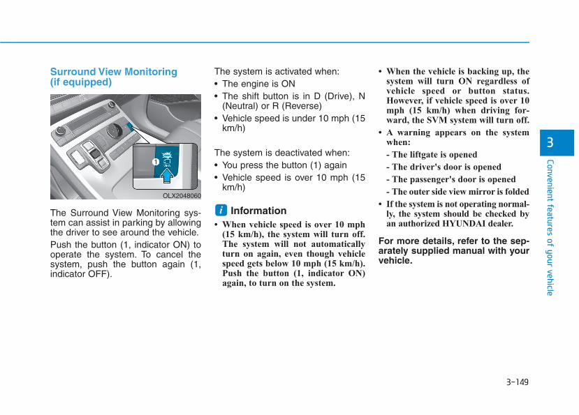
3-149
Convenient features of your vehicle
3
Surround View Monitoring(if equipped)
The Surround View Monitoring sys-tem can assist in parking by allowingthe driver to see around the vehicle.Push the button (1, indicator ON) tooperate the system. To cancel thesystem, push the button again (1,indicator OFF).
The system is activated when:• The engine is ON• The shift button is in D (Drive), N
(Neutral) or R (Reverse)• Vehicle speed is under 10 mph (15
km/h)
The system is deactivated when:• You press the button (1) again• Vehicle speed is over 10 mph (15
km/h)
Information • When vehicle speed is over 10 mph
(15 km/h), the system will turn off.The system will not automaticallyturn on again, even though vehiclespeed gets below 10 mph (15 km/h).Push the button (1, indicator ON)again, to turn on the system.
• When the vehicle is backing up, thesystem will turn ON regardless ofvehicle speed or button status.However, if vehicle speed is over 10mph (15 km/h) when driving for-ward, the SVM system will turn off.
• A warning appears on the systemwhen:
- The liftgate is opened
- The driver's door is opened
- The passenger's door is opened
- The outer side view mirror is folded
• If the system is not operating normal-ly, the system should be checked byan authorized HYUNDAI dealer.
For more details, refer to the sep-arately supplied manual with yourvehicle.
iOLX2048060

3-150
Convenient features of your vehicle
Always keep the camera lensclean. The camera may not worknormally if the lens is coveredwith foreign material.
Blind-spot View Monitor sys-tem (if equipped)
BVM (Blind-spot View Monitor) sys-tem displays the driver-side or pas-senger-side rear areas in the clusterwhen the system is activated.To turn on BVM system: Under condi-tion BVM system is enabled in thesettings1. The ignition switch is turned to the
ON position.2. The turn signal is activated
NOTICE
(1) Front camera(2) Left/Right cam-
era(3) Rear camera
Surround View Monitor systemonly serves to assist the driverin parking. ALWAYS lookaround your vehicle to makesure there are no objects orobstacles before moving thevehicle.
CAUTION
ODH047435
OLX2049062N
■ Type B
OLX2049136N
■ Type C - Driver-side
OLX2049144N
■ Type C - Passenger-side
3-151
Convenient features of your vehicle
3
To turn off BVM system1. The ignition switch is turned to the
OFF position.2. The turn signal is deactivated3. A warning screen pops up and
takes priority over the Blind-SpotView Monitor system.
System settingWith the engine ON, the Blind-spotView Monitor system turns on andgets ready to be activated when the'User Settings → Driver Assistance→ Blind-Spot Safety → Blind-SpotView' is selected on the cluster. Thesystem stops operation when the set-ting is deactivated.
• Like all assistance systems,BVM system has limitations.Over-reliance on the systemmay result in a collision.
• Always look around your vehi-cle to make sure there are noobjects or obstacles beforemoving the vehicle in anydirection to prevent a colli-sion.
• Objects are closer than theyappear. Failure to visuallyconfirm that is safe to changethe lane before doing so mayresult in crash and seriousinjury or death.
• Always keep the camera lensclean. The camera may notwork normally if the lens iscovered with foreign material.
CAUTION
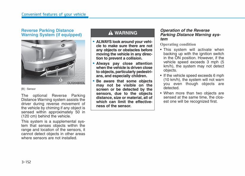
3-152
Reverse Parking DistanceWarning System (if equipped)
[B] : Sensor
The optional Reverse ParkingDistance Warning system assists thedriver during reverse movement ofthe vehicle by chiming if any object issensed within approximately 50 in(120 cm) behind the vehicle.This system is a supplemental sys-tem that senses objects within therange and location of the sensors, itcannot detect objects in other areaswhere sensors are not installed.
Operation of the ReverseParking Distance Warning sys-temOperating condition
• This system will activate whenbacking up with the ignition switchin the ON position. However, if thevehicle speed exceeds 3 mph (5km/h), the system may not detectobjects.
• If the vehicle speed exceeds 6 mph(10 km/h), the system will not warnyou even though objects aredetected.
• When more than two objects aresensed at the same time, the clos-est one will be recognized first.
Convenient features of your vehicle
• ALWAYS look around your vehi-cle to make sure there are notany objects or obstacles beforemoving the vehicle in any direc-tion to prevent a collision.
• Always pay close attentionwhen the vehicle is driven closeto objects, particularly pedestri-ans, and especially children.
• Be aware that some objectsmay not be visible on thescreen or be detected by thesensors, due to the objectsdistance, size or material, all ofwhich can limit the effective-ness of the sensor.
WARNING
OLX2048053L
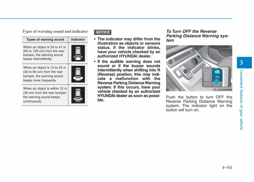
3-153
Convenient features of your vehicle
3
Types of warning sound and indicator
• The indicator may differ from theillustration as objects or sensorsstatus. If the indicator blinks,have your vehicle checked by anauthorized HYUNDAI dealer.
• If the audible warning does notsound or if the buzzer soundsintermittently when shifting into R(Reverse) position, this may indi-cate a malfunction with theReverse Parking Distance Warningsystem. If this occurs, have yourvehicle checked by an authorizedHYUNDAI dealer as soon as possi-ble.
To Turn OFF the ReverseParking Distance Warning sys-tem
Push the button to turn OFF theReverse Parking Distance Warningsystem. The indicator light on thebutton will turn on.
NOTICE
Types of warning sound Indicator
When an object is 24 to 47 in(60 to 120 cm) from the rearbumper, the warning soundbeeps intermittently.
When an object is 12 to 24 in(30 to 60 cm) from the rearbumper, the warning soundbeeps more frequently.
When an object is within 12 in(30 cm) from the rear bumper,the warning sound beepscontinuously.
OLX2049096N
3-154
Convenient features of your vehicle
Conditions Where the ReverseParking Distance Warning sys-tem May Not OperateThe Reverse Parking DistanceWarning system may not operatenormally when any of the followingoccur:
• The sensor is covered with dirt ordebris such as snow or ice, or thesensor cover is blocked.
The Reverse Parking DistanceWarning system may experience amalfunction when the followingoccurs:
• Driving on uneven road surfacessuch as unpaved roads, gravel,bumps, or gradient.
• Objects generating excessivenoise such as vehicle horns, loudmotorcycle engines, or truck airbrakes can interfere with the sen-sor.
• Heavy rain or water spray is pres-ent.
• Wireless transmitters or mobilephones are present near the sen-sor.
• The sensor is covered with snow.• Any non-factory equipment or
accessories have been installed, orif the vehicle bumper height or sen-sor installation has been modified.
Detecting range may decrease when:
• Outside air temperature is extreme-ly hot or cold.
• Undetectable objects smaller than40 inches (1 m) and narrower than6 inches (14 cm) in diameter.
The following objects may not berecognized by the sensor:
• Sharp or slim objects such asropes, chains or small poles.
• Objects, which tend to absorb sen-sor frequency such as clothes,spongy material or snow.
Reverse Parking DistanceWarning system Precautions• The Reverse Parking Distance
Warning system may not operateconsistently in some circum-stances depending on the speed ofthe vehicle and the shapes of theobjects detected.
• The Reverse Parking DistanceWarning system may malfunction ifthe vehicle bumper height or sen-sor installation has been modifiedor damaged. Any non-factoryinstalled equipment or accessoriesmay also interfere with the sensorperformance.
• The sensor may not recognizeobjects less than 12 in. (30 cm)from the sensor, or it may sense anincorrect distance. Use caution.
• When the sensor is blocked withsnow, dirt, debris, or ice, the rearparking assist system may be inop-erative until the snow or ice melts,or the debris is removed. Use asoft cloth to wipe debris away fromthe sensor.
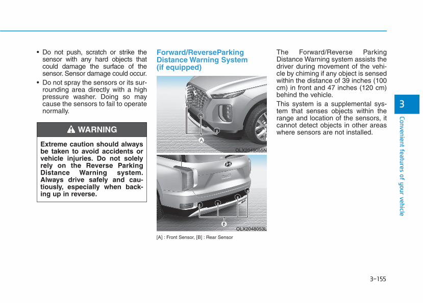
3-155
Convenient features of your vehicle
3
• Do not push, scratch or strike thesensor with any hard objects thatcould damage the surface of thesensor. Sensor damage could occur.
• Do not spray the sensors or its sur-rounding area directly with a highpressure washer. Doing so maycause the sensors to fail to operatenormally.
Forward/ReverseParkingDistance Warning System (if equipped)
[A] : Front Sensor, [B] : Rear Sensor
The Forward/Reverse ParkingDistance Warning system assists thedriver during movement of the vehi-cle by chiming if any object is sensedwithin the distance of 39 inches (100cm) in front and 47 inches (120 cm)behind the vehicle.This system is a supplemental sys-tem that senses objects within therange and location of the sensors, itcannot detect objects in other areaswhere sensors are not installed.
OLX2049055N
OLX2048053L
Extreme caution should alwaysbe taken to avoid accidents orvehicle injuries. Do not solelyrely on the Reverse ParkingDistance Warning system.Always drive safely and cau-tiously, especially when back-ing up in reverse.
WARNING

3-156
Operation of theForward/Reverse ParkingDistance Warning System
Operating condition
• This system will activate when theParking Distance Warning systembutton is pressed with the enginerunning.
• Sensing distance when backing upis approximately 47 in (120 cm)when you are driving less than 6 mph (10 km/h).
• Sensing distance when moving for-ward is approximately 39 in (100cm) when you are driving less than6 mph (10 km/h).
• When more than two objects aresensed at the same time, the clos-est one will be recognized first.
• If you push R (Reverse) positionbutton on shift button with theengine running and the ParkingDistance Warning system off, thesystem will operate automatically.
Convenient features of your vehicle
• ALWAYS look around yourvehicle to make sure there areno objects or obstaclesbefore moving the vehicle inany direction to prevent a col-lision.
• Always pay close attentionwhen the vehicle is drivenclose to objects, particularlypedestrians, and especiallychildren.
• Be aware that some objectsmay not be visible on thescreen or be detected by thesensors, due to the objectsdistance, size or material, allof which can limit the effec-tiveness of the sensor.
WARNING
OLX2049096N
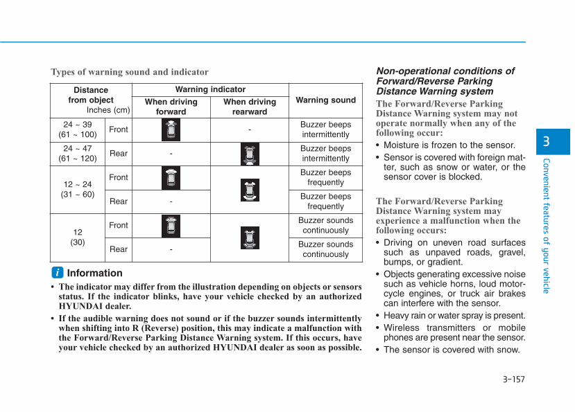
3-157
Convenient features of your vehicle
Non-operational conditions ofForward/Reverse ParkingDistance Warning systemThe Forward/Reverse ParkingDistance Warning system may notoperate normally when any of thefollowing occur:
• Moisture is frozen to the sensor.• Sensor is covered with foreign mat-
ter, such as snow or water, or thesensor cover is blocked.
The Forward/Reverse ParkingDistance Warning system mayexperience a malfunction when thefollowing occurs:
• Driving on uneven road surfacessuch as unpaved roads, gravel,bumps, or gradient.
• Objects generating excessive noisesuch as vehicle horns, loud motor-cycle engines, or truck air brakescan interfere with the sensor.
• Heavy rain or water spray is present.• Wireless transmitters or mobile
phones are present near the sensor.• The sensor is covered with snow.
3
Distance from object
Inches (cm)
Warning indicatorWarning soundWhen driving
forwardWhen driving
rearward
24 ~ 39 (61 ~ 100)
Front -Buzzer beeps intermittently
24 ~ 47(61 ~ 120)
Rear -Buzzer beeps intermittently
12 ~ 24(31 ~ 60)
FrontBuzzer beeps
frequently
Rear -Buzzer beeps
frequently
12 (30)
FrontBuzzer sounds continuously
Rear -Buzzer sounds continuously
Types of warning sound and indicator
Information • The indicator may differ from the illustration depending on objects or sensors
status. If the indicator blinks, have your vehicle checked by an authorizedHYUNDAI dealer.
• If the audible warning does not sound or if the buzzer sounds intermittentlywhen shifting into R (Reverse) position, this may indicate a malfunction withthe Forward/Reverse Parking Distance Warning system. If this occurs, haveyour vehicle checked by an authorized HYUNDAI dealer as soon as possible.
i
3-158
• Any non-factory equipment oraccessories have been installed, orif the vehicle bumper height or sen-sor installation has been modified.
Detecting range may decrease when:
• Outside air temperature isextremely hot or cold.
• Undetectable objects smaller than40 inches (1 m) and narrower than6 inches (14 cm) in diameter.
The following objects may not berecognized by the sensor:
• Sharp or slim objects such asropes, chains or small poles.
• Objects, which tend to absorb sen-sor frequency such as clothes,spongy material or snow.
Forward/Reverse ParkingDistance Warning system pre-cautions• The Forward/Reverse Parking
Distance Warning system may notoperate consistently in some cir-cumstances depending on thespeed of the vehicle and theshapes of the objects detected.
• The Forward/Reverse ParkingDistance Warning system may mal-function if the vehicle bumperheight or sensor installation hasbeen modified or damaged. Anynon-factory installed equipment oraccessories may also interfere withthe sensor performance.
• The sensor may not recognizeobjects less than 15 inches. (40cm) from the sensor, or it maysense an incorrect distance. Usecaution.
• When the sensor is blocked withsnow, dirt, debris, or ice, the sys-tem may be inoperative until thesnow or ice melts, or the debris isremoved. Use a soft cloth to wipedebris away from the sensor.
• Do not push, scratch or strike thesensor with any hard objects thatcould damage the surface of thesensor. Sensor damage could occur.
• Do not spray the sensors or its sur-rounding area directly with a highpressure washer. Doing so maycause the sensors to fail to operatenormally.
Convenient features of your vehicle
Your new vehicle warranty doesnot cover any accidents or dam-age to the vehicle or injuries toits occupants related to aForward/Reverse ParkingDistance Warning system.Always drive safely and cau-tiously.
WARNING
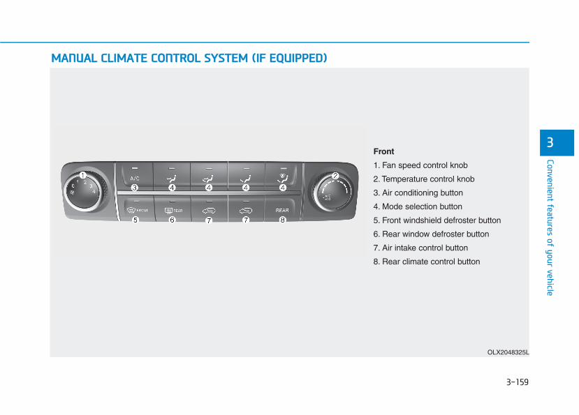
3-159
Convenient features of your vehicle
3
MMAANNUUAALL CCLLIIMMAATTEE CCOONNTTRROOLL SSYYSSTTEEMM ((IIFF EEQQUUIIPPPPEEDD))
OLX2048325L
Front
1. Fan speed control knob
2. Temperature control knob
3. Air conditioning button
4. Mode selection button
5. Front windshield defroster button
6. Rear window defroster button
7. Air intake control button
8. Rear climate control button

3-160
Convenient features of your vehicle
Heating and Air Conditioning1. Start the engine.2. Set the mode to the desired position.
To improve the effectiveness of heat-ing and cooling, select the modeaccording to the following:- Heating:- Cooling:
3. Set the temperature control to thedesired position.
4. Set the air intake control to Freshmode or Recirculation mode posi-tion.
5. Set the fan speed control to thedesired speed.
6. If air conditioning is desired, turn theair conditioning system on.
When starting the vehicle in coldweather a more efficient way to heatthe passenger compartment is to dothe following.- Turn off or lower the blower, right
after starting the engine.- Engine temperature is still low and
the air flow from the heater is stillcold.
- After a few minutes of engine warmup, turn on or set the fan to a higherlevel and adjust the temperature set-ting to hot.
Mode selection
The mode selection button controls the direction of the air flow through theventilation system. Air can be directed to the floor, dashboard outlets, orwindshield. Five symbols are used to represent Face, Bi-Level, Floor, Floor-Defrost and Defrost air position.
OLX2049410N
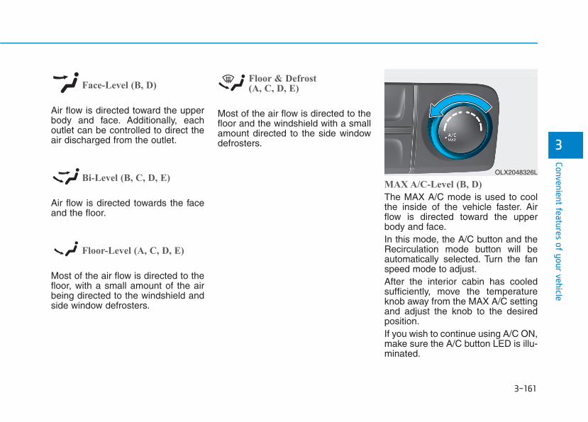
3-161
Convenient features of your vehicle
3
Face-Level (B, D)
Air flow is directed toward the upperbody and face. Additionally, eachoutlet can be controlled to direct theair discharged from the outlet.
Bi-Level (B, C, D, E)
Air flow is directed towards the faceand the floor.
Floor-Level (A, C, D, E)
Most of the air flow is directed to thefloor, with a small amount of the airbeing directed to the windshield andside window defrosters.
Floor & Defrost (A, C, D, E)
Most of the air flow is directed to thefloor and the windshield with a smallamount directed to the side windowdefrosters.
MAX A/C-Level (B, D)
The MAX A/C mode is used to coolthe inside of the vehicle faster. Airflow is directed toward the upperbody and face.In this mode, the A/C button and theRecirculation mode button will beautomatically selected. Turn the fanspeed mode to adjust.After the interior cabin has cooledsufficiently, move the temperatureknob away from the MAX A/C settingand adjust the knob to the desiredposition.If you wish to continue using A/C ON,make sure the A/C button LED is illu-minated.
OLX2048326L
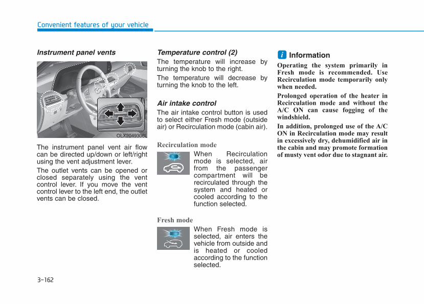
3-162
Convenient features of your vehicle
Instrument panel vents
The instrument panel vent air flowcan be directed up/down or left/rightusing the vent adjustment lever.The outlet vents can be opened orclosed separately using the ventcontrol lever. If you move the ventcontrol lever to the left end, the outletvents can be closed.
Temperature control (2)The temperature will increase byturning the knob to the right.The temperature will decrease byturning the knob to the left.
Air intake controlThe air intake control button is usedto select either Fresh mode (outsideair) or Recirculation mode (cabin air).
Recirculation mode
When Recirculationmode is selected, airfrom the passengercompartment will berecirculated through thesystem and heated orcooled according to thefunction selected.
Fresh mode
When Fresh mode isselected, air enters thevehicle from outside andis heated or cooledaccording to the functionselected.
Information Operating the system primarily inFresh mode is recommended. UseRecirculation mode temporarily onlywhen needed.
Prolonged operation of the heater inRecirculation mode and without theA/C ON can cause fogging of thewindshield.
In addition, prolonged use of the A/CON in Recirculation mode may resultin excessively dry, dehumidified air inthe cabin and may promote formationof musty vent odor due to stagnant air.
i
OLX2049306L

3-163
Convenient features of your vehicle
3
Fan speed control (1)Turn the knob to the right to increasethe fan speed and airflow. Turn theknob to the left to decrease fanspeed and airflow.Setting the fan speed control knob tothe "0" position turns off the fan.
Operating the fan speed when theignition switch is in the ON posi-tion could cause the battery todischarge. Operate the fan speedwhen the engine is running.
Air conditioning (3)Push the A/C button to turn the sys-tem on (indicator light will illuminate)and off.
Rear climate control button
If you press the rear climate controlbutton, rear passengers can controlthe rear climate system.
NOTICE
• Continued use of the climatecontrol system operation inRecirculation mode for a pro-longed period of time maycause drowsiness to theoccupants in the cabin. Thismay lead to loss of vehiclecontrol which may lead to anaccident.
• Continued use of the climatecontrol system operation inRecirculation mode with theA/C OFF may allow humidityto increase inside the cabin.This may cause condensationto accumulate on the wind-shield and obscure visibility.
• Do not sleep in your vehicle orremain parked in your vehiclewith the windows up andeither the heater or the airconditioning ON for pro-longed periods of time. Doingso may increase the levels ofcarbon dioxide in the cabinwhich may lead to seriousinjury or death.
WARNING
OLX2048327L
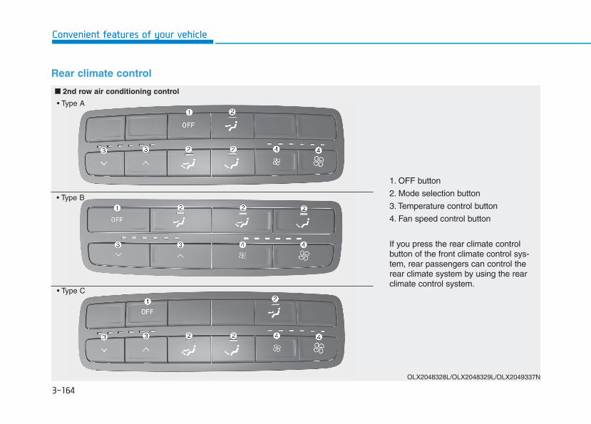
3-164
Convenient features of your vehicle
Rear climate control
OLX2048328L/OLX2048329L/OLX2049337N
1. OFF button
2. Mode selection button
3. Temperature control button
4. Fan speed control button
If you press the rear climate controlbutton of the front climate control sys-tem, rear passengers can control therear climate system by using the rearclimate control system.
■■ 2nd row air conditioning control
• Type A
• Type B
• Type C
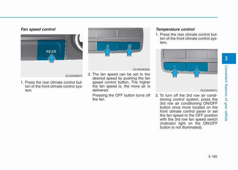
3-165
Convenient features of your vehicle
3
Fan speed control
1. Press the rear climate control but-ton of the front climate control sys-tem.
2. The fan speed can be set to thedesired speed by pushing the fanspeed control button. The higherthe fan speed is, the more air isdelivered.Pressing the OFF button turns offthe fan.
Temperature control1. Press the rear climate control but-
ton of the front climate control sys-tem.
2. To turn off the 3rd row air condi-tioning control system, press the3rd row air conditioning ON/OFFbutton once more located on thefront climate control panel or setthe fan speed to the OFF positionwith the 3rd row fan speed switch(indicator light on the ON/OFFbutton is not illuminated).
OLX2048327L
OLX2048330L
OLX2048331L

3-166
Convenient features of your vehicle
OFF mode
Push the OFF button to turn the rearclimate control system off.
Mode selection
You can select the direction of the airflow through the ventilation system.You can adjust the front climate con-trol system for heating or cooling topassengers on 2nd row seats. Theair flow is directed from the floor.
: Air flow is directed towardthe upper body from therear headliner.
: Air flow is directed towardthe upper body and thefloor.
: Air flow is directed towardthe floor.
OLX2048332L OLX2048313

3-167
Convenient features of your vehicle
3
Rear vents on the headlinerThe rear passengers can adjust thedirection of air flow from the rearvents on the headliner.If you operate the rear climate con-trol with rear vents closed, a noisemay sound. When operating the rearclimate control, open two or morerear vents.
System OperationCooling / Ventilation1. Select the Face Level mode.2. Set the air intake control to fresh
mode.3. Set the temperature control to the
desired position.4. Set the fan speed control to the
desired speed.
Heating1. Select the Floor Level mode.2. Set the air intake control to fresh
mode.3. Set the temperature control to the
desired position.4. Set the fan speed control to the
desired speed.5. If desired, turn the air conditioning
ON with the temperature controlknob set to heat in order to dehu-midify the air before it enters intothe cabin.
If the windshield fogs up, select theFloor & Defrost mode or pressthe Front Defrost mode.
OLX2048314
NoDiffusionlever (A)
Direction thumbwheel (B)
Description
1Open
( ) CloseThe air is delivered widely toward the sur-roundings of rear passengers.However, the fan speed may be decreased.
2Open
( ) Open The air is delivered widely toward the rearpassengers and surrounding of rear pas-sengers.
3
Close
( ) Open The air is only delivered toward the rear passengers.
3-168
Convenient features of your vehicle
Operation Tips
• To keep dust or unpleasant fumesfrom entering the vehicle throughthe ventilation system, temporarilyset the air intake control to recircu-lation mode. Return the control tofresh mode when the unpleasantair outside has diminished.This willhelp keep the driver alert and com-fortable.
• To help prevent the inside of thewindshield from fogging, set the airintake control to fresh mode andfan speed to the desired position,turn on the air conditioning system,and adjust the temperature controlto the desired temperature.
Air conditioning Your HYUNDAI vehicle air condition-ing system is filled with R-134arefrigerant.1. Start the engine.2. Press the air conditioning button.3. Select the Face Level mode.
4. Set the air intake control toRecirculation mode temporarily toallow the cabin to cool quickly.When the desired temperature inthe cabin is reached, change theair intake control back to Freshmode.
5. Adjust the fan speed control andtemperature control to maintainmaximum comfort.
When maximum cooling is desired,set the temperature control to theMAX A/C position, then set the fanspeed control to the highest setting.
When using the air conditioningsystem, monitor the engine tem-perature gauge closely while driv-ing up hills or in heavy traffic whenoutside temperatures are high. Airconditioning system operationwhen climbing a steep grade or inhigh outside ambient tempera-tures can cause engine overheat-ing.Continue to use the fan, but turnthe air conditioning system off ifthe engine temperature gaugeindicates engine overheating.
Air conditioning system operation tips
• If the vehicle has been parked indirect sunlight during hot weather,open the windows for a short timeto let the hot air inside the vehicleescape.
• After sufficient cooling has beenachieved, switch back from recircu-lation mode to fresh mode.
• To help reduce moisture inside ofthe windows on rainy or humiddays, decrease the humidity insidethe vehicle by operating the air con-ditioning system with the windowsand sunroof closed.
• Use the air conditioning systemevery month only for a few minutesto ensure maximum system per-formance.
• If you operate air conditioner exces-sively, the difference between thetemperature of the outside air andthat of the windshield could causethe outer surface of the windshieldto fog up, causing loss of visibility.In this case, set the mode selectionknob or button to the positionand fan speed control to the lowerspeed.
NOTICE

3-169
Convenient features of your vehicle
3
System MaintenanceCabin air filter
[A] : Outside air, [B] : Recirculated air[C] : Climate control air filter, [D] : Blower[E] : Evaporator core, [F] : Heater core
The cabin air filter is installed behindthe glove box. It filters the dust orother pollutants that enter the vehiclethrough the heating and air condi-tioning system.
Have the cabin air filter replaced byan authorized HYUNDAI dealeraccording to the maintenance sched-ule. If the vehicle is being driven insevere conditions such as dusty orrough roads and/or if transportingpets or occupants smoke inside thevehicle, then more frequent cabin airfilter inspections and changes arerequired.If the air flow rate suddenly decreas-es, the system should be checked atan authorized HYUNDAI dealer.
Checking the amount of air con-ditioner refrigerant and com-pressor lubricantWhen the amount of refrigerant islow, the performance of the air con-ditioning is reduced. Overfilling alsoreduces the performance of the airconditioning system.Therefore, if abnormal operation isfound, have the system inspected byan authorized HYUNDAI dealer.
It is important that the correcttype and amount of oil and refrig-erant is used. Otherwise, damageto the compressor and abnormalsystem operation may occur. Toprevent damage, the air condition-ing system in your vehicle shouldonly be serviced by trained andcertified technicians.
NOTICEOIK047401L
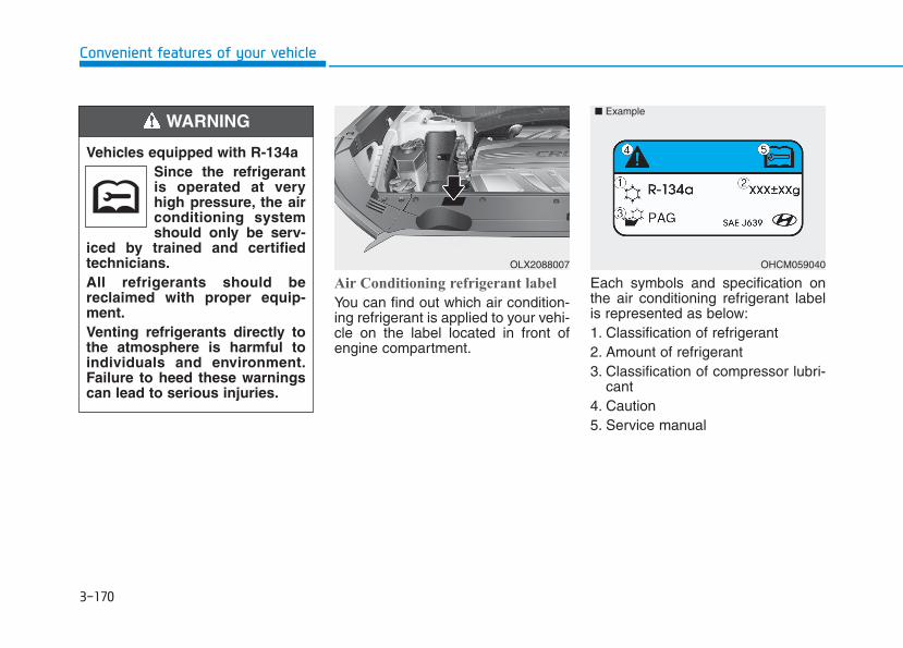
3-170
Convenient features of your vehicle
Air Conditioning refrigerant label
You can find out which air condition-ing refrigerant is applied to your vehi-cle on the label located in front ofengine compartment.
Each symbols and specification onthe air conditioning refrigerant labelis represented as below:1. Classification of refrigerant2. Amount of refrigerant3. Classification of compressor lubri-
cant4. Caution5. Service manual
Vehicles equipped with R-134aSince the refrigerantis operated at veryhigh pressure, the airconditioning systemshould only be serv-
iced by trained and certifiedtechnicians.All refrigerants should bereclaimed with proper equip-ment.Venting refrigerants directly tothe atmosphere is harmful toindividuals and environment.Failure to heed these warningscan lead to serious injuries.
WARNING
OHCM059040
■ Example
OLX2088007
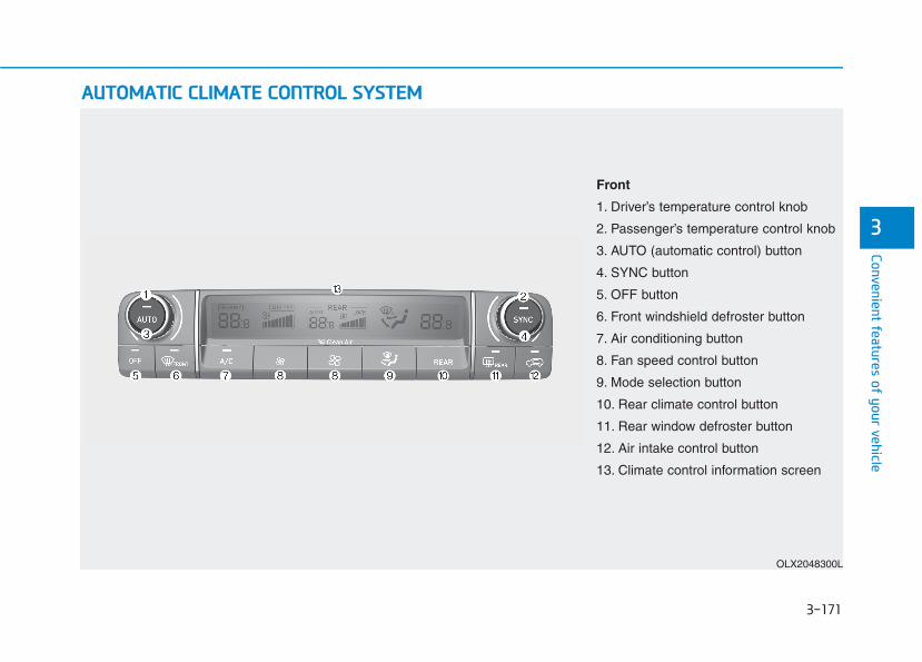
3-171
Convenient features of your vehicle
3
AAUUTTOOMMAATTIICC CCLLIIMMAATTEE CCOONNTTRROOLL SSYYSSTTEEMM
OLX2048300L
Front
1. Driver’s temperature control knob
2. Passenger’s temperature control knob
3. AUTO (automatic control) button
4. SYNC button
5. OFF button
6. Front windshield defroster button
7. Air conditioning button
8. Fan speed control button
9. Mode selection button
10. Rear climate control button
11. Rear window defroster button
12. Air intake control button
13. Climate control information screen
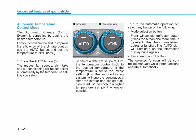
3-172
Convenient features of your vehicle
Automatic TemperatureControl ModeThe Automatic Climate ControlSystem is controlled by setting thedesired temperature.For your convenience and to improvethe efficiency of the climate control,use the AUTO button and set thetemperature to 72°F (22°C).
1. Press the AUTO button (3).The modes, fan speeds, air intakeand air-conditioning will be controlledautomatically by the temperature set-ting you select.
2. To select a different set point, turnthe temperature control knob tothe desired temperature. If thetemperature is set to the lowestsetting (Lo), the air conditioningsystem will operate continuously.After the interior has cooled suffi-ciently, adjust the knob to a highertemperature set point wheneverpossible.
To turn the automatic operation off,select any button of the following:- Mode selection button- Front windshield defroster button
(Press the button one more time todeselect the front windshielddefroster function. The 'AUTO' signwill illuminate on the informationdisplay once again.)
- Fan speed control buttonThe selected function will be con-trolled manually while other functionsoperate automatically.
OLX2048301
■ Driver side ■ Passenger side
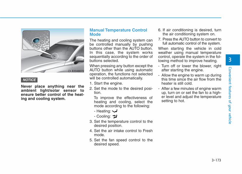
3-173
Convenient features of your vehicle
3
Never place anything near theambient light/solar sensor toensure better control of the heat-ing and cooling system.
Manual Temperature ControlModeThe heating and cooling system canbe controlled manually by pushingbuttons other than the AUTO button.In this case, the system workssequentially according to the order ofbuttons selected.When pressing any button except theAUTO button while using automaticoperation, the functions not selectedwill be controlled automatically.1. Start the engine.2. Set the mode to the desired posi-
tion.To improve the effectiveness ofheating and cooling, select themode according to the following:- Heating:- Cooling:
3. Set the temperature control to thedesired position.
4. Set the air intake control to Freshmode.
5. Set the fan speed control to thedesired speed.
6. If air conditioning is desired, turnthe air conditioning system on.
7. Press the AUTO button to convert tofull automatic control of the system.
When starting the vehicle in coldweather using manual temperaturecontrol, operate the system in the fol-lowing method to improve heating.- Turn off or lower the blower, right
after starting the engine.- Allow the engine to warm up during
this time since the air flow from theheater is still cold.
- After a few minutes of engine warmup, turn on or set the fan to a high-er level and adjust the temperaturesetting to hot.
NOTICE
OLX2048072

3-174
Convenient features of your vehicle
Mode selection (9) The air flow outlet direction is cycledas follows:
Face-Level (B, D)
Air flow is directed toward the upperbody and face. Additionally, eachoutlet can be controlled to direct theair discharged from the outlet.
Bi-Level (B, C, D, E)
Air flow is directed towards the faceand the floor.
OLX2048304
The mode selection button controls the direction of the air flow through theventilation system.

3-175
Convenient features of your vehicle
3
Floor & Defrost (A, C, D, E)
Most of the air flow is directed to thefloor and the windshield with a smallamount directed to the side windowdefrosters.
Floor-Level (A, C, D, E)
Most of the air flow is directed to thefloor, with a small amount of the airbeing directed to the windshield andside window defrosters.
Defrost-Level (6) (A, D)
Most of the air flow is directed to thewindshield with a small amount of airdirected to the side window defrosters.
Instrument panel vents
The instrument panel vent air flowcan be directed up/down or left/rightusing the vent adjustment lever.The outlet vents can be opened orclosed separately using the ventcontrol lever. If you move the ventcontrol lever to the left end, the outletvents can be closed.
Temperature control
Turn the knob to the right to increasethe temperature. Turn the knob to theleft to decrease temperature.The temperature will increase ordecrease by 1°F/0.5°C for each incre-mental location. When set to the low-est temperature setting, the air condi-tioning will operate continuously.
OLX2049306L OLX2048301
■ Driver side ■ Passenger side
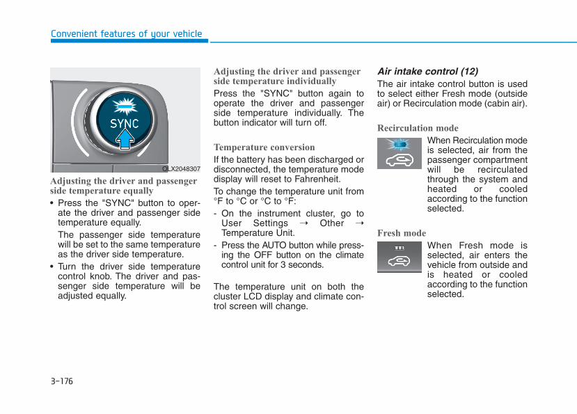
3-176
Convenient features of your vehicle
Adjusting the driver and passengerside temperature equally
• Press the "SYNC" button to oper-ate the driver and passenger sidetemperature equally.The passenger side temperaturewill be set to the same temperatureas the driver side temperature.
• Turn the driver side temperaturecontrol knob. The driver and pas-senger side temperature will beadjusted equally.
Adjusting the driver and passengerside temperature individually
Press the "SYNC" button again tooperate the driver and passengerside temperature individually. Thebutton indicator will turn off.
Temperature conversion
If the battery has been discharged ordisconnected, the temperature modedisplay will reset to Fahrenheit.To change the temperature unit from°F to °C or °C to °F:- On the instrument cluster, go to
User Settings ➝ Other ➝Temperature Unit.
- Press the AUTO button while press-ing the OFF button on the climatecontrol unit for 3 seconds.
The temperature unit on both thecluster LCD display and climate con-trol screen will change.
Air intake control (12)The air intake control button is usedto select either Fresh mode (outsideair) or Recirculation mode (cabin air).
Recirculation mode
When Recirculation modeis selected, air from thepassenger compartmentwill be recirculatedthrough the system andheated or cooledaccording to the functionselected.
Fresh mode
When Fresh mode isselected, air enters thevehicle from outside andis heated or cooledaccording to the functionselected.
OLX2048307
3-177
Convenient features of your vehicle
3
Information Operating the system primarily inFresh mode is recommended. UseRecirculation mode temporarily onlywhen needed.
Prolonged operation of the heater inRecirculation mode and without theA/C ON can cause fogging of the wind-shield.
In addition, prolonged use of the A/CON in Recirculation mode may result inexcessively dry, dehumidified air in thecabin and may promote formation ofmusty vent odor due to stagnant air.
Fan speed control (8)The fan speed can be set as desiredby pushing the fan speed control but-ton.More air is delivered with higher fanspeeds.Pressing the OFF button turns off thefan.
Information For better sound quality, fan speedmay automatically slow down for acouple of minutes when you activatevoice recognition or hands free.
Operating the fan when the igni-tion switch is in the ON positioncould cause the battery to dis-charge. Operate the fan when theengine is running.
NOTICE
i
i
• Continued use of the climatecontrol system operation inRecirculation mode for a pro-longed period of time maycause drowsiness to theoccupants in the cabin. Thismay lead to loss of vehiclecontrol which may lead to anaccident.
• Continued use of the climatecontrol system operation inRecirculation mode with theA/C OFF may allow humidityto increase inside the cabin.This may cause condensationto accumulate on the wind-shield and obscure visibility.
• Do not sleep in your vehicle orremain parked in your vehiclewith the windows up andeither the heater or the airconditioning ON for pro-longed periods of time. Doingso may increase the levels ofcarbon dioxide in the cabinwhich may lead to seriousinjury or death.
WARNING
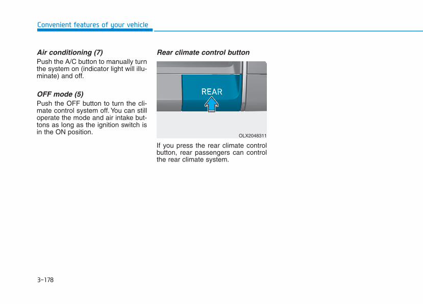
3-178
Convenient features of your vehicle
Air conditioning (7)Push the A/C button to manually turnthe system on (indicator light will illu-minate) and off.
OFF mode (5)Push the OFF button to turn the cli-mate control system off. You can stilloperate the mode and air intake but-tons as long as the ignition switch isin the ON position.
Rear climate control button
If you press the rear climate controlbutton, rear passengers can controlthe rear climate system.
OLX2048311

3-179
Convenient features of your vehicle
3
Rear climate control
1. AUTO button
2. Temperature control button
3. Mode selection button
4. Fan speed control button
5. OFF button
6. Climate control information screen
■■ 2nd row air conditioning control
If you press the rear climate control button of the front climate control system, rear passengers can control therear climate system by using the rear climate control system.
❈ When you want to use the rear climate control (heating and air conditioning)
1. Press the air conditioning button of the front climate control.2. Adjust the rear climate control (temperature, air direction and fan speed).3. Check that "Lock Control" is not selected in the infotainment system. If "Lock Control" is selected, the rear
climate control is not adjusted in the rear climate control panel.
OLX2048318
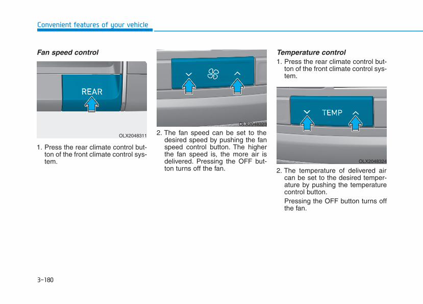
3-180
Convenient features of your vehicle
Fan speed control
1. Press the rear climate control but-ton of the front climate control sys-tem.
2. The fan speed can be set to thedesired speed by pushing the fanspeed control button. The higherthe fan speed is, the more air isdelivered. Pressing the OFF but-ton turns off the fan.
Temperature control1. Press the rear climate control but-
ton of the front climate control sys-tem.
2. The temperature of delivered aircan be set to the desired temper-ature by pushing the temperaturecontrol button.Pressing the OFF button turns offthe fan.
OLX2048311
OLX2048323
OLX2048324
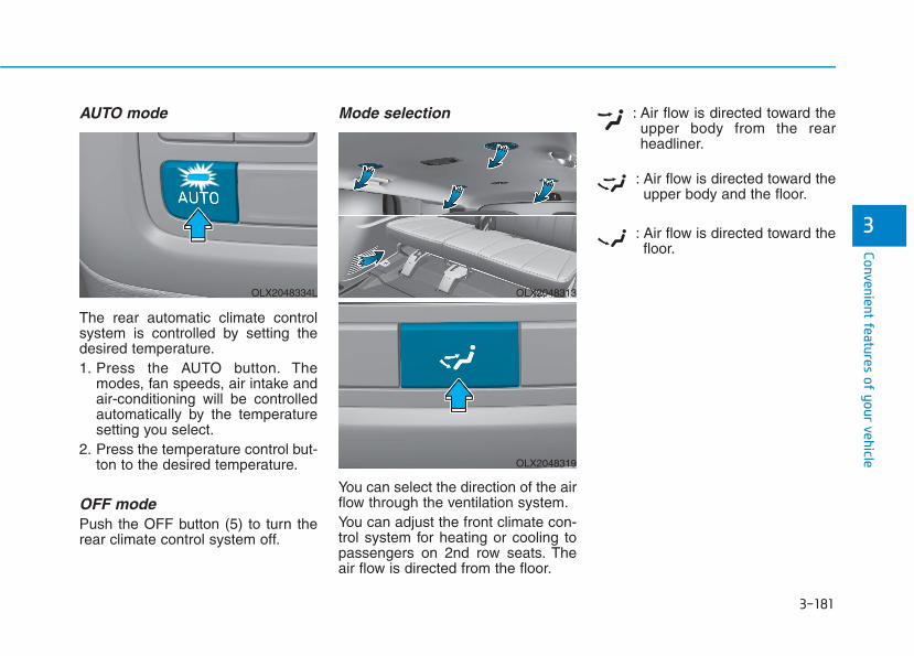
3-181
Convenient features of your vehicle
3
AUTO mode
The rear automatic climate controlsystem is controlled by setting thedesired temperature.1. Press the AUTO button. The
modes, fan speeds, air intake andair-conditioning will be controlledautomatically by the temperaturesetting you select.
2. Press the temperature control but-ton to the desired temperature.
OFF modePush the OFF button (5) to turn therear climate control system off.
Mode selection
You can select the direction of the airflow through the ventilation system.You can adjust the front climate con-trol system for heating or cooling topassengers on 2nd row seats. Theair flow is directed from the floor.
: Air flow is directed toward theupper body from the rearheadliner.
: Air flow is directed toward theupper body and the floor.
: Air flow is directed toward thefloor.
OLX2048313
OLX2048319
OLX2048334L
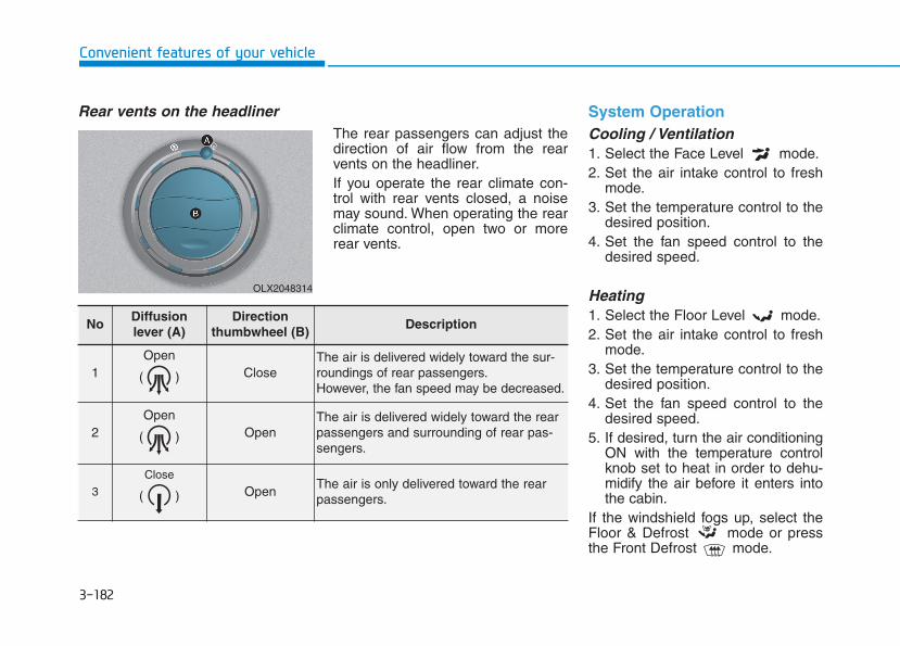
3-182
Convenient features of your vehicle
Rear vents on the headlinerThe rear passengers can adjust thedirection of air flow from the rearvents on the headliner.If you operate the rear climate con-trol with rear vents closed, a noisemay sound. When operating the rearclimate control, open two or morerear vents.
System OperationCooling / Ventilation1. Select the Face Level mode.2. Set the air intake control to fresh
mode.3. Set the temperature control to the
desired position.4. Set the fan speed control to the
desired speed.
Heating1. Select the Floor Level mode.2. Set the air intake control to fresh
mode.3. Set the temperature control to the
desired position.4. Set the fan speed control to the
desired speed.5. If desired, turn the air conditioning
ON with the temperature controlknob set to heat in order to dehu-midify the air before it enters intothe cabin.
If the windshield fogs up, select theFloor & Defrost mode or pressthe Front Defrost mode.
OLX2048314
NoDiffusionlever (A)
Direction thumbwheel (B)
Description
1Open
( ) CloseThe air is delivered widely toward the sur-roundings of rear passengers.However, the fan speed may be decreased.
2Open
( ) Open The air is delivered widely toward the rearpassengers and surrounding of rear pas-sengers.
3
Close
( ) Open The air is only delivered toward the rear passengers.
3-183
Convenient features of your vehicle
3
Operation Tips
• To keep dust or unpleasant fumesfrom entering the car through theventilation system, temporarily setthe air intake control to the recircu-lation mode. Return the control tothe to fresh mode when theunpleasant air outside has dimin-ished. This will help keep the driveralert and comfortable.
• To help prevent the inside of thewindshield from fogging, set the airintake control to fresh mode andthe fan speed to the desired posi-tion, turn on the air conditioningsystem, and adjust the temperaturecontrol to the desired temperature.
Air conditioning Your HYUNDAI vehicle air condition-ing system is filled with R-134arefrigerant.1. Start the engine.2. Press the air conditioning button.3. Select the Face Level mode.
4. Set the air intake control toRecirculation mode temporarily toallow the cabin to cool quickly.When the desired temperature inthe cabin is reached, change theair intake control back to Freshmode.
5. Adjust the fan speed control andtemperature control to maintainmaximum comfort.
When maximum cooling is desired,set the temperature control to theMAX A/C position, then set the fanspeed control to the highest setting.
When using the air conditioningsystem, monitor the engine tem-perature gauge closely while driv-ing up hills or in heavy trafficwhen outside temperatures. Airconditioning system operationwhen climbing a steep grade or inhigh outside ambient tempera-tures can cause engine overheat-ing. Continue to use the fan, butturn the air conditioning systemoff if the engine temperaturegauge indicates engine overheat-ing.
Air conditioning system operationtips
• If the vehicle has been parked indirect sunlight during hot weather,open the windows for a short timeto let the hot air inside the vehicleescape.
• After sufficient cooling has beenachieved, switch back from recircu-lation mode to fresh mode.
• To help reduce moisture inside ofthe windows on rainy or humiddays, decrease the humidity insidethe vehicle by operating the airconditioning system with the win-dows and sunroof closed.
• Use the air conditioning systemevery month only for a few minutesto ensure maximum system per-formance.
• If you operate air conditionerexcessively, the difference betweenthe temperature of the outside airand that of the windshield couldcause the outer surface of thewindshield to fog up, causing lossof visibility. In this case, set themode selection knob or button tothe position and fan speedcontrol to the lower speed.
NOTICE
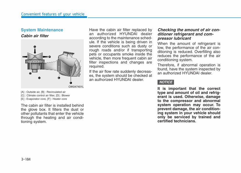
3-184
Convenient features of your vehicle
System MaintenanceCabin air filter
[A] : Outside air, [B] : Recirculated air[C] : Climate control air filter, [D] : Blower[E] : Evaporator core, [F] : Heater core
The cabin air filter is installed behindthe glove box. It filters the dust orother pollutants that enter the vehiclethrough the heating and air condi-tioning system.
Have the cabin air filter replaced byan authorized HYUNDAI dealeraccording to the maintenance sched-ule. If the vehicle is being driven insevere conditions such as dusty orrough roads and/or if transportingpets or occupants smoke inside thevehicle, then more frequent cabin airfilter inspections and changes arerequired.If the air flow rate suddenly decreas-es, the system should be checked atan authorized HYUNDAI dealer.
Checking the amount of air con-ditioner refrigerant and com-pressor lubricantWhen the amount of refrigerant islow, the performance of the air con-ditioning is reduced. Overfilling alsoreduces the performance of the airconditioning system.Therefore, if abnormal operation isfound, have the system inspected byan authorized HYUNDAI dealer.
It is important that the correcttype and amount of oil and refrig-erant is used. Otherwise, damageto the compressor and abnormalsystem operation may occur. Toprevent damage, the air condition-ing system in your vehicle shouldonly be serviced by trained andcertified technicians.
NOTICEOIK047401L
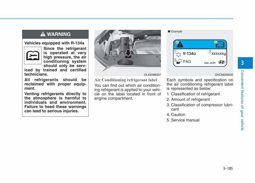
3-185
Convenient features of your vehicle
3
Air Conditioning refrigerant label
You can find out which air condition-ing refrigerant is applied to your vehi-cle on the label located in front ofengine compartment.
Each symbols and specification onthe air conditioning refrigerant labelis represented as below:1. Classification of refrigerant2. Amount of refrigerant3. Classification of compressor lubri-
cant4. Caution5. Service manual
Vehicles equipped with R-134aSince the refrigerantis operated at veryhigh pressure, the airconditioning systemshould only be serv-
iced by trained and certifiedtechnicians.All refrigerants should bereclaimed with proper equip-ment.Venting refrigerants directly tothe atmosphere is harmful toindividuals and environment.Failure to heed these warningscan lead to serious injuries.
WARNING
OHCM059040
■ Example
OLX2088007
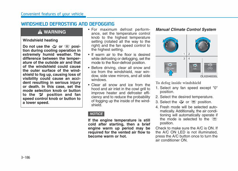
3-186
Convenient features of your vehicle
• For maximum defrost perform-ance, set the temperature controlknob to the highest temperaturesetting (rotated all the way to theright) and the fan speed control tothe highest setting.
• If warm air to the floor is desiredwhile defrosting or defogging, set themode to the floor-defrost position.
• Before driving, clear all snow andice from the windshield, rear win-dow, side view mirrors, and all sidewindows.
• Clear all snow and ice from thehood and air inlet in the cowl grill toimprove heater and defroster effi-ciency and to reduce the probabilityof fogging up the inside of the wind-shield.
If the engine temperature is stillcold after starting, then a briefengine warm up period may berequired for the vented air flow tobecome warm or hot.
Manual Climate Control System
To defog inside windshield
1. Select any fan speed except "0"position.
2. Select the desired temperature.3. Select the or position.4. Fresh mode will be selected auto-
matically. Additionally, the air condi-tioning will automatically operate ifthe mode is selected to the position.
Check to make sure the A/C is ON. Ifthe A/C ON LED is not illuminated,press the A/C button once to turn theair conditioner ON.
NOTICE
WWIINNDDSSHHIIEELLDD DDEEFFRROOSSTTIINNGG AANNDD DDEEFFOOGGGGIINNGG
Windshield heating
Do not use the or posi-tion during cooling operation inextremely humid weather. Thedifference between the temper-ature of the outside air and thatof the windshield could causethe outer surface of the wind-shield to fog up, causing loss ofvisibility could cause an acci-dent resulting in serious injuryor death. In this case, set themode selection knob or buttonto the position and fanspeed control knob or button toa lower speed.
WARNING
OLX2048335L
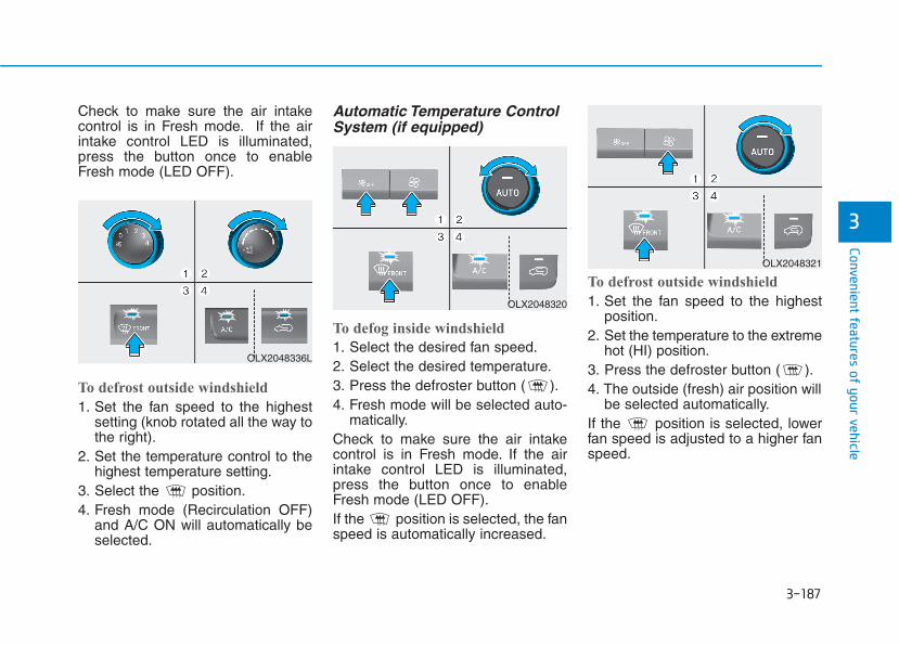
3-187
Convenient features of your vehicle
3
Check to make sure the air intakecontrol is in Fresh mode. If the airintake control LED is illuminated,press the button once to enableFresh mode (LED OFF).
To defrost outside windshield
1. Set the fan speed to the highestsetting (knob rotated all the way tothe right).
2. Set the temperature control to thehighest temperature setting.
3. Select the position.4. Fresh mode (Recirculation OFF)
and A/C ON will automatically beselected.
Automatic Temperature ControlSystem (if equipped)
To defog inside windshield
1. Select the desired fan speed.2. Select the desired temperature.3. Press the defroster button ( ).4. Fresh mode will be selected auto-
matically.Check to make sure the air intakecontrol is in Fresh mode. If the airintake control LED is illuminated,press the button once to enableFresh mode (LED OFF).If the position is selected, the fanspeed is automatically increased.
To defrost outside windshield
1. Set the fan speed to the highestposition.
2. Set the temperature to the extremehot (HI) position.
3. Press the defroster button ( ).4. The outside (fresh) air position will
be selected automatically.If the position is selected, lowerfan speed is adjusted to a higher fanspeed.
OLX2048336L
OLX2048320
OLX2048321
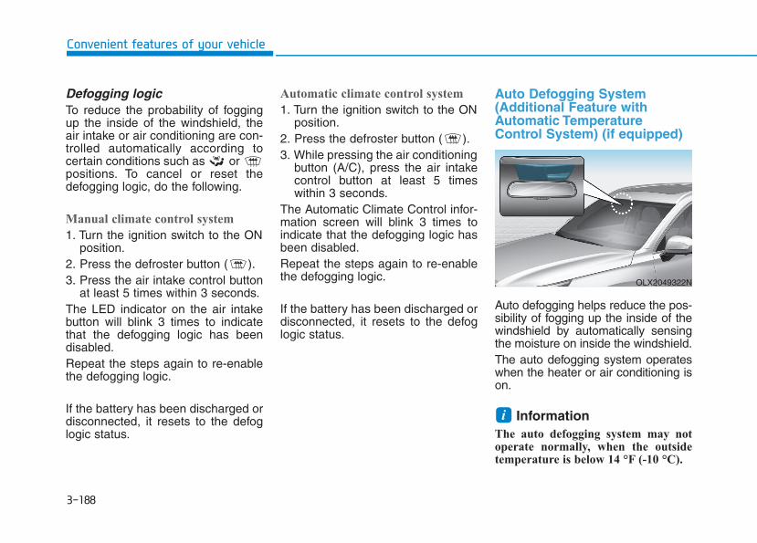
3-188
Convenient features of your vehicle
Defogging logicTo reduce the probability of foggingup the inside of the windshield, theair intake or air conditioning are con-trolled automatically according tocertain conditions such as or positions. To cancel or reset thedefogging logic, do the following.
Manual climate control system
1. Turn the ignition switch to the ONposition.
2. Press the defroster button ( ).3. Press the air intake control button
at least 5 times within 3 seconds.The LED indicator on the air intakebutton will blink 3 times to indicatethat the defogging logic has beendisabled.Repeat the steps again to re-enablethe defogging logic.
If the battery has been discharged ordisconnected, it resets to the defoglogic status.
Automatic climate control system
1. Turn the ignition switch to the ONposition.
2. Press the defroster button ( ).3. While pressing the air conditioning
button (A/C), press the air intakecontrol button at least 5 timeswithin 3 seconds.
The Automatic Climate Control infor-mation screen will blink 3 times toindicate that the defogging logic hasbeen disabled.Repeat the steps again to re-enablethe defogging logic.
If the battery has been discharged ordisconnected, it resets to the defoglogic status.
Auto Defogging System (Additional Feature withAutomatic TemperatureControl System) (if equipped)
Auto defogging helps reduce the pos-sibility of fogging up the inside of thewindshield by automatically sensingthe moisture on inside the windshield.The auto defogging system operateswhen the heater or air conditioning ison.
Information The auto defogging system may notoperate normally, when the outsidetemperature is below 14 °F (-10 °C).
i
OLX2049322N
3-189
Convenient features of your vehicle
3
When the Auto DefoggingSystem operates, the indi-cator will illuminate.
If a high amount of humidity isdetected in the vehicle, the AutoDefogging System will be enabled.The following steps will be performedautomatically:Step 1) The A/C button will turn ON.Step 2) The air intake control will
change to Fresh mode.Step 3) The mode will be changed to
defrost to direct airflow to thewindshield.
Step 4) The fan speed will be set toMAX.
If the air conditioning is off or recircu-lated air position is manually select-ed while Auto Defogging System isON, the Auto Defogging SystemIndicator will blink 3 times to signalthat the manual operation has beencanceled.
To cancel or reset the Auto Defogging System
Press the front windshield defrosterbutton for 3 seconds when the igni-tion switch is in the ON position.When the Auto Defogging System iscanceled, the ADS OFF symbol willblink 3 times and ADS OFF will bedisplayed on the climate controlinformation screen.When the Auto Defogging System isreset, the ADS OFF symbol will blink6 times without a signal.
Information • When the air conditioning is turned
on by Auto defogging system, if youtry to turn off the air conditioning, theindicator will blink 3 times and the airconditioning will not be turned off.
• To maintain the effectiveness andefficiency of the Auto DefoggingSystem, do not select Recirculationmode while the system is operating.
• When the Auto Defogging System isoperating, the fan speed adjustmentbutton, the temperature adjustmentknob, and the air intake control but-ton are all disabled.
Do not remove the sensor coverlocated on the upper end of thewindshield glass.Damage to system parts couldoccur and may not be covered byyour vehicle warranty.
NOTICE
i
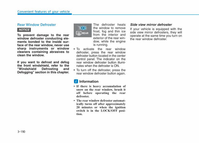
3-190
Convenient features of your vehicle
Rear Window Defroster
To prevent damage to the rearwindow defroster conducting ele-ments bonded to the inside sur-face of the rear window, never usesharp instruments or windowcleaners containing abrasives toclean the window.
If you want to defrost and defogthe front windshield, refer to the"Windshield Defrosting andDefogging" section in this chapter.
The defroster heatsthe window to removefrost, fog and thin icefrom the interior andexterior of the rear win-dow, while the engineis running.
• To activate the rear windowdefroster, press the rear windowdefroster button located in the centercontrol panel. The indicator on therear window defroster button illumi-nates when the defroster is ON.
• To turn off the defroster, press therear window defroster button again.
Information • If there is heavy accumulation of
snow on the rear window, brush itoff before operating the reardefroster.
• The rear window defroster automat-ically turns off after approximately20 minutes or when the ignitionswitch is in the LOCK/OFF posi-tion.
Side view mirror defrosterIf your vehicle is equipped with theside view mirror defrosters, they willoperate at the same time you turn onthe rear window defroster.
i
NOTICE
3-191
Convenient features of your vehicle
3
Cluster ionizer (if equipped)When the ignition switch is in the ONposition, the clean air function turnson automatically.Also, the clean air function turns offautomatically, when the ignitionswitch is in the OFF position.
Automatic Ventilation (if equipped)When the ignition switch is in the ONposition or when the engine is run-ning and temperature is below 59°F(15°C) with the recirculation modeselected more than three to five min-utes, the air intake position will auto-matically change to fresh mode.
To cancel or reset the AutomaticVentilation
When the air conditioning system ison, select Face Level mode andpress the recirculation mode buttonfive times within three seconds whilepressing A/C button.When the Automatic Ventilation fea-ture is enabled, the recirculation but-ton LED indicator will blink 6 times.When the Automatic Ventilation fea-ture is disabled, the recirculation but-ton LED indicator will blink 3 times.
Sunroof Inside AirRecirculation (if equipped)When the sunroof is opened, outside(fresh) air will be automaticallyselected. At this time, if you press theair intake control button, recirculatedair position will be selected but willchange back to outside (fresh) airafter 3 minutes. When the sunroof isclosed, the air intake position willreturn to the original position thatwas selected.
CCLLIIMMAATTEE CCOONNTTRROOLL AADDDDIITTIIOONNAALL FFEEAATTUURREESS
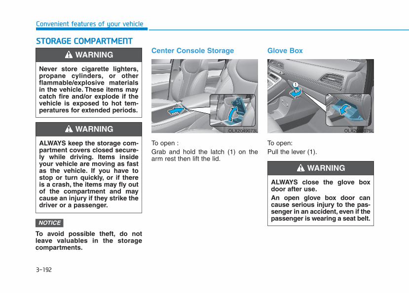
3-192
Convenient features of your vehicle
SSTTOORRAAGGEE CCOOMMPPAARRTTMMEENNTT
To avoid possible theft, do notleave valuables in the storagecompartments.
Center Console Storage
To open :Grab and hold the latch (1) on thearm rest then lift the lid.
Glove Box
To open:Pull the lever (1).
NOTICE
Never store cigarette lighters,propane cylinders, or otherflammable/explosive materialsin the vehicle. These items maycatch fire and/or explode if thevehicle is exposed to hot tem-peratures for extended periods.
WARNING
ALWAYS keep the storage com-partment covers closed secure-ly while driving. Items insideyour vehicle are moving as fastas the vehicle. If you have tostop or turn quickly, or if thereis a crash, the items may fly outof the compartment and maycause an injury if they strike thedriver or a passenger.
WARNING
ALWAYS close the glove boxdoor after use.An open glove box door cancause serious injury to the pas-senger in an accident, even if thepassenger is wearing a seat belt.
WARNING
OLX2049073L OLX2048075L

3-193
Convenient features of your vehicle
3
Luggage Tray (if equipped)
You can place a first aid kit, a reflec-tor triangle (front tray), tools, etc. inthe box for easy access.• Grasp the handle on the top of the
cover and lift it.
OLX2048076

3-194
Convenient features of your vehicle
Cup HolderFront
Cups or small beverages cups maybe placed in the cup holders.
Push the button and the coveropens. Push the buttons and the cupsupporter protrudes from the frontconsole. Push in the cup supportersecurely after use.
Rear (2nd row, 3rd row)
Cups or small beverages cups maybe placed in the cup holders.
IINNTTEERRIIOORR FFEEAATTUURREESS
OLX2048077
OLX2048078
Do not place thin objects (coin,card etc.) on the cover. Thesemay fall into the inside when thecover is operated.
CAUTION
OLX2048079
■ Rear (2nd row)
OLX2048080
■ Rear (3rd row)
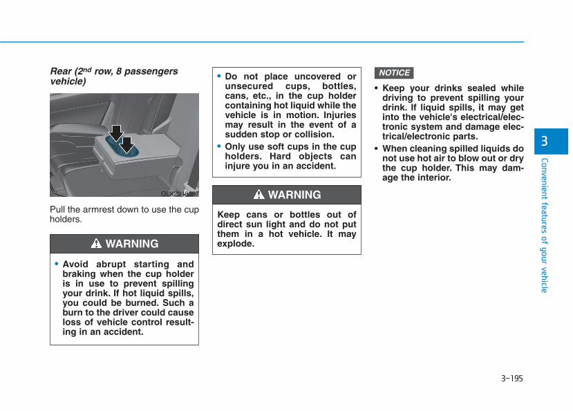
3-195
Convenient features of your vehicle
3
Rear (2nd row, 8 passengersvehicle)
Pull the armrest down to use the cupholders.
• Keep your drinks sealed whiledriving to prevent spilling yourdrink. If liquid spills, it may getinto the vehicle's electrical/elec-tronic system and damage elec-trical/electronic parts.
• When cleaning spilled liquids donot use hot air to blow out or drythe cup holder. This may dam-age the interior.
NOTICE
Keep cans or bottles out ofdirect sun light and do not putthem in a hot vehicle. It mayexplode.
WARNING
• Do not place uncovered orunsecured cups, bottles,cans, etc., in the cup holdercontaining hot liquid while thevehicle is in motion. Injuriesmay result in the event of asudden stop or collision.
• Only use soft cups in the cupholders. Hard objects caninjure you in an accident.
• Avoid abrupt starting andbraking when the cup holderis in use to prevent spillingyour drink. If hot liquid spills,you could be burned. Such aburn to the driver could causeloss of vehicle control result-ing in an accident.
WARNING
OLX2048097
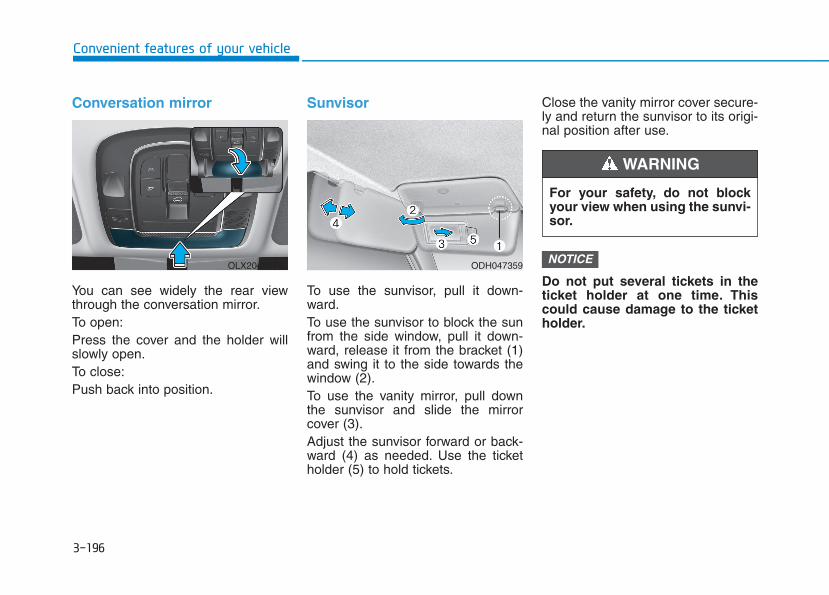
3-196
Convenient features of your vehicle
Conversation mirror
You can see widely the rear viewthrough the conversation mirror.To open:Press the cover and the holder willslowly open.To close:Push back into position.
Sunvisor
To use the sunvisor, pull it down-ward.To use the sunvisor to block the sunfrom the side window, pull it down-ward, release it from the bracket (1)and swing it to the side towards thewindow (2).To use the vanity mirror, pull downthe sunvisor and slide the mirrorcover (3).Adjust the sunvisor forward or back-ward (4) as needed. Use the ticketholder (5) to hold tickets.
Close the vanity mirror cover secure-ly and return the sunvisor to its origi-nal position after use.
Do not put several tickets in theticket holder at one time. Thiscould cause damage to the ticketholder.
NOTICE
For your safety, do not blockyour view when using the sunvi-sor.
WARNING
ODH047359OLX2048074L
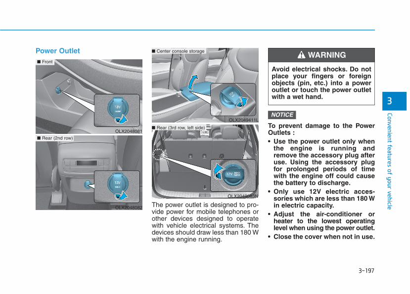
3-197
Convenient features of your vehicle
3
Power Outlet
The power outlet is designed to pro-vide power for mobile telephones orother devices designed to operatewith vehicle electrical systems. Thedevices should draw less than 180 Wwith the engine running.
To prevent damage to the PowerOutlets :• Use the power outlet only when
the engine is running andremove the accessory plug afteruse. Using the accessory plugfor prolonged periods of timewith the engine off could causethe battery to discharge.
• Only use 12V electric acces-sories which are less than 180 Win electric capacity.
• Adjust the air-conditioner orheater to the lowest operatinglevel when using the power outlet.
• Close the cover when not in use.
NOTICEOLX2049411L
Avoid electrical shocks. Do notplace your fingers or foreignobjects (pin, etc.) into a poweroutlet or touch the power outletwith a wet hand.
WARNING
OLX2048081
■ Front
OLX2048082
■ Rear (2nd row)
OLX2049083N
■ Center console storage
■ Rear (3rd row, left side)

3-198
Convenient features of your vehicle
• Some electronic devices cancause electronic interferencewhen plugged into a vehicle'spower outlet.These devices maycause excessive audio staticand malfunctions in other elec-tronic systems or devices usedin your vehicle.
• Push the plug in as far as it willgo. If good contact is not made,the plug may overheat and thefuse may open.
• Plug in battery equipped electri-cal/electronic devices withreverse current protection. Thecurrent from the battery mayflow into the vehicle's electri-cal/electronic system and causesystem malfunction.
AC Inverter (if equipped)
The AC inverter supplies 115V/150Welectric power to operate electricaccessories or equipments.
Information • Rated voltage : AC 115V
• Maximum electric power : 150W
• In order to avoid an electrical sys-tem failure, electric shock, etc., besure to read owner's manual beforeuse.
• Be sure to close the cover except thetime of use.
iOLX2049088N OUMA046410
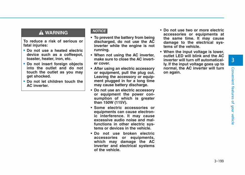
3-199
Convenient features of your vehicle
3
• To prevent the battery from beingdischarged, do not use the ACinverter while the engine is notrunning.
• When not using the AC inverter,make sure to close the AC invert-er cover.
• After using an electric accessoryor equipment, pull the plug out.Leaving the accessory or equip-ment plugged in for a long timemay cause battery discharge.
• Do not use an electric accessoryor equipment the power con-sumption of which is greaterthan 150W (115V).
• Some electric accessories orequipments can cause electron-ic interference. It may causeexcessive audio noise and mal-functions in other electric sys-tems or devices in the vehicle.
• Do not use broken electricaccessories or equipments,which may damage the ACinverter and electrical systemsof the vehicle.
• Do not use two or more electricaccessories or equipments atthe same time. It may causedamage to the electrical sys-tems of the vehicle.
• When the input voltage is lower,outlet LED will blink and the ACinverter will turn off automatical-ly. If the input voltage goes up tonormal, the AC inverter will turnon again.
NOTICE
To reduce a risk of serious orfatal injuries:• Do not use a heated electric
device such as a coffeepot,toaster, heater, iron, etc.
• Do not insert foreign objectsinto the outlet and do nottouch the outlet as you mayget shocked.
• Do not let children touch theAC inverter.
WARNING
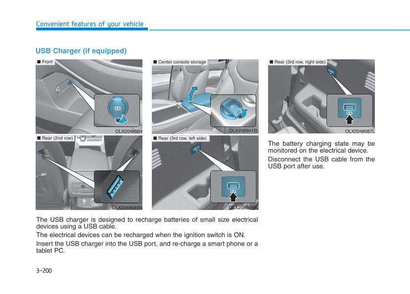
3-200
Convenient features of your vehicle
USB Charger (if equipped)
The battery charging state may bemonitored on the electrical device.Disconnect the USB cable from theUSB port after use.
OLX2048084
■ Front
OLX2049085N
■ Rear (2nd row)
The USB charger is designed to recharge batteries of small size electricaldevices using a USB cable.The electrical devices can be recharged when the ignition switch is ON.Insert the USB charger into the USB port, and re-charge a smart phone or atablet PC.
OLX2048086L
■ Rear (3rd row, left side)
■ Center console storage
OLX2048087L
■ Rear (3rd row, right side)
OLX2049412L
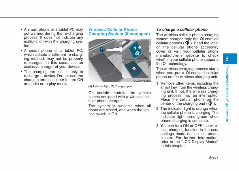
3-201
Convenient features of your vehicle
3
• A smart phone or a tablet PC mayget warmer during the re-chargingprocess. It does not indicate anymalfunction with the charging sys-tem.
• A smart phone or a tablet PC,which adopts a different re-charg-ing method, may not be properlyre-charged. In this case, use anexclusive charger of your device.
• The charging terminal is only torecharge a device. Do not use thecharging terminal either to turn ONan audio or to play media.
Wireless Cellular PhoneCharging System (if equipped)
[A]: Indicator light, [B]: Charging pad
On certain models, the vehiclecomes equipped with a wireless cel-lular phone charger.The system is available when alldoors are closed, and when the igni-tion switch is ON.
To charge a cellular phone The wireless cellular phone chargingsystem charges only the Qi-enabledcellular phones ( ). Read the labelon the cellular phone accessorycover or visit your cellular phonemanufacturer's website to checkwhether your cellular phone supportsthe Qi technology.The wireless charging process startswhen you put a Qi-enabled cellularphone on the wireless charging unit.
1. Remove other items, including thesmart key, from the wireless charg-ing unit. If not, the wireless charg-ing process may be interrupted.Place the cellular phone on thecenter of the charging pad ( ).
2. The indicator light is orange whenthe cellular phone is charging. Theindicator light turns green whenphone charging is complete.
3. You can turn ON or OFF the wire-less charging function in the usersettings mode on the instrumentcluster. For further information,refer to the "LCD Display Modes"in this chapter.
OLX2048089L
3-202
Convenient features of your vehicle
If your cellular phone is not charging:- Slightly change the position of the
cellular phone on the chargingpad.
- Make sure the indicator light isorange.
The indicator light will blink orange for10 seconds if there is a malfunction inthe wireless charging system.In this case, temporarily stop thecharging process, and re-attempt tocharge your cellular phone again.The system warns you with a mes-sage on the LCD display if the cellularphone is still on the wireless chargingunit after the engine is turned OFFand the front door is opened.
Information For some manufacturers' cellularphones, the system may not warn youeven though the cellular phone is lefton the wireless charging unit. This isdue to the particular characteristic ofthe cellular phone and not a malfunc-tion of the wireless charging.
• The wireless cellular phonecharging system may not sup-port certain cellular phones,which are not verified for the Qispecification ( ).
• When placing your cellularphone on the charging mat,position the phone in the middleof the mat for optimal chargingperformance. If your cell phoneis off to the side, the chargingrate may be less and in somecases the cell phone may experi-ence higher heat conduction.
• In some cases, the wirelesscharging may stop temporarilywhen the Remote Key or SmartKey is used, either when startingthe vehicle or locking/unlockingthe doors, etc.
• When charging certain cellularphones, the charging indicatormay not change to green whenthe cell phone is fully charged.
• The wireless charging processmay temporarily stop, when tem-perature abnormally increasesinside the wireless cellular phonecharging system. Stop the charg-ing cellular phone and wait untiltemperature falls to a certain level.
• The wireless charging processmay temporarily stop when thereis any metallic item, such as acoin, between the wireless cellularphone charging system and thecellular phone.
• When charging some cellularphones with a self-protection fea-ture, the wireless charging speedmay decrease and the wirelesscharging may stop.
• If the cellular phone has a thickcover, the wireless charging maynot be possible.
• If the cell phone is not completelycontacting the charging pad, wire-less charging may not operateproperly.
• Some magnetic items like creditcards, phone cards or rail ticketsmay be damaged if left with thecellular phone during the chargingprocess.
NOTICE
i
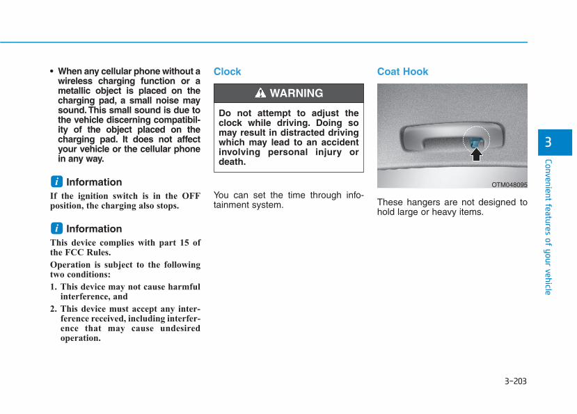
3-203
Convenient features of your vehicle
3
• When any cellular phone without awireless charging function or ametallic object is placed on thecharging pad, a small noise maysound. This small sound is due tothe vehicle discerning compatibil-ity of the object placed on thecharging pad. It does not affectyour vehicle or the cellular phonein any way.
Information If the ignition switch is in the OFFposition, the charging also stops.
Information This device complies with part 15 ofthe FCC Rules.
Operation is subject to the followingtwo conditions:
1. This device may not cause harmfulinterference, and
2. This device must accept any inter-ference received, including interfer-ence that may cause undesiredoperation.
Clock
You can set the time through info-tainment system.
Coat Hook
These hangers are not designed tohold large or heavy items.
i
i OTM048095
Do not attempt to adjust theclock while driving. Doing somay result in distracted drivingwhich may lead to an accidentinvolving personal injury ordeath.
WARNING
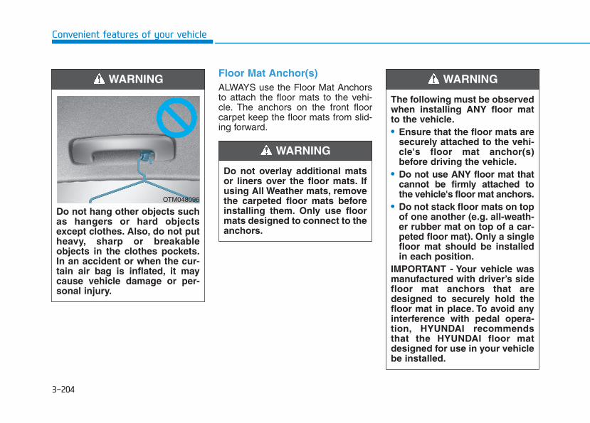
3-204
Convenient features of your vehicle
Floor Mat Anchor(s)ALWAYS use the Floor Mat Anchorsto attach the floor mats to the vehi-cle. The anchors on the front floorcarpet keep the floor mats from slid-ing forward.
Do not hang other objects suchas hangers or hard objectsexcept clothes. Also, do not putheavy, sharp or breakableobjects in the clothes pockets.In an accident or when the cur-tain air bag is inflated, it maycause vehicle damage or per-sonal injury.
WARNING
OTM048096
Do not overlay additional matsor liners over the floor mats. Ifusing All Weather mats, removethe carpeted floor mats beforeinstalling them. Only use floormats designed to connect to theanchors.
WARNING
The following must be observedwhen installing ANY floor matto the vehicle.• Ensure that the floor mats are
securely attached to the vehi-cle's floor mat anchor(s)before driving the vehicle.
• Do not use ANY floor mat thatcannot be firmly attached tothe vehicle's floor mat anchors.
• Do not stack floor mats on topof one another (e.g. all-weath-er rubber mat on top of a car-peted floor mat). Only a singlefloor mat should be installedin each position.
IMPORTANT - Your vehicle wasmanufactured with driver’s sidefloor mat anchors that aredesigned to securely hold thefloor mat in place. To avoid anyinterference with pedal opera-tion, HYUNDAI recommendsthat the HYUNDAI floor matdesigned for use in your vehiclebe installed.
WARNING
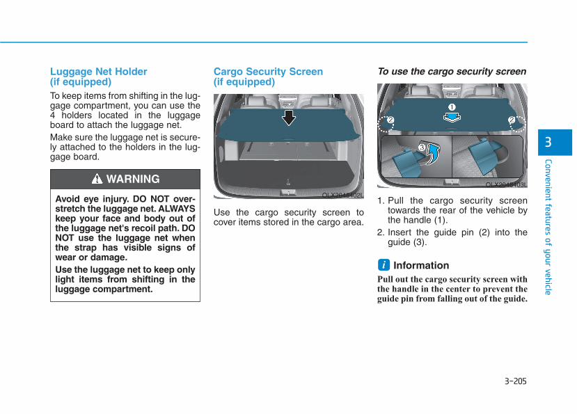
3-205
Convenient features of your vehicle
3
Luggage Net Holder (if equipped)To keep items from shifting in the lug-gage compartment, you can use the4 holders located in the luggageboard to attach the luggage net.Make sure the luggage net is secure-ly attached to the holders in the lug-gage board.
Cargo Security Screen (if equipped)
Use the cargo security screen tocover items stored in the cargo area.
To use the cargo security screen
1. Pull the cargo security screentowards the rear of the vehicle bythe handle (1).
2. Insert the guide pin (2) into theguide (3).
Information Pull out the cargo security screen withthe handle in the center to prevent theguide pin from falling out of the guide.
i
OLX2048403L
OLX2048402LAvoid eye injury. DO NOT over-stretch the luggage net. ALWAYSkeep your face and body out ofthe luggage net's recoil path. DONOT use the luggage net whenthe strap has visible signs ofwear or damage.Use the luggage net to keep onlylight items from shifting in theluggage compartment.
WARNING
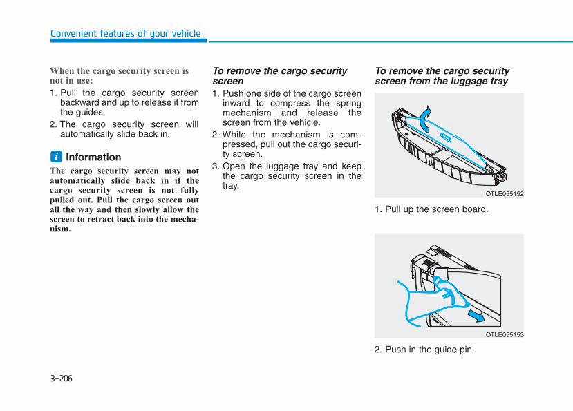
3-206
Convenient features of your vehicle
When the cargo security screen isnot in use:
1. Pull the cargo security screenbackward and up to release it fromthe guides.
2. The cargo security screen willautomatically slide back in.
Information The cargo security screen may notautomatically slide back in if thecargo security screen is not fullypulled out. Pull the cargo screen outall the way and then slowly allow thescreen to retract back into the mecha-nism.
To remove the cargo securityscreen1. Push one side of the cargo screen
inward to compress the springmechanism and release thescreen from the vehicle.
2. While the mechanism is com-pressed, pull out the cargo securi-ty screen.
3. Open the luggage tray and keepthe cargo security screen in thetray.
To remove the cargo securityscreen from the luggage tray
1. Pull up the screen board.
2. Push in the guide pin.
i
OTLE055152
OTLE055153
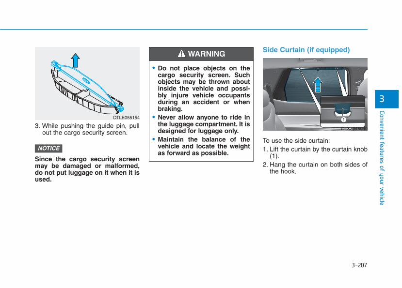
3-207
Convenient features of your vehicle
3
3. While pushing the guide pin, pullout the cargo security screen.
Since the cargo security screenmay be damaged or malformed,do not put luggage on it when it isused.
Side Curtain (if equipped)
To use the side curtain:1. Lift the curtain by the curtain knob
(1).2. Hang the curtain on both sides of
the hook.
NOTICE
• Do not place objects on thecargo security screen. Suchobjects may be thrown aboutinside the vehicle and possi-bly injure vehicle occupantsduring an accident or whenbraking.
• Never allow anyone to ride inthe luggage compartment. It isdesigned for luggage only.
• Maintain the balance of thevehicle and locate the weightas forward as possible.
WARNING
OLX2048090
OTLE055154
3-208
Convenient features of your vehicle
• Always hang both sides of thecurtain on the hook. Thiscould cause damage to theside curtain if only one side ofthe curtain is hooked.
• Do not let any foreign materialget in between the vehicle andside curtain. The side curtainmay not be lifted up.
• Do not hang other objectsexcept the side curtain.
• When using the side curtainand turning it back into place,pulling the curtain or applyingforce may cause damage tothe side curtain. When lower-ing the curtain, be sure toplace the curtain knob down-ward in that state and slowlyreturn it to the position.
CAUTION

3-209
Convenient features of your vehicle
3
Roof Side Rails (if equipped)
If your vehicle comes equipped withroof side rails, then roof rack cross-bars can be installed on top of yourvehicle.The roof rack crossbars are anaccessory and are available at yourlocal HYUNDAI dealer.
If the vehicle is equipped with asunroof, be sure not to positioncargo onto the roof rack in such away that it could interfere withsunroof operation.
• When carrying cargo on the roofrack, take the necessary precau-tions to make sure the cargodoes not damage the roof of thevehicle.
• When carrying large objects onthe roof rack, make sure they donot exceed the overall rooflength or width.
NOTICE
NOTICE
EEXXTTEERRIIOORR FFEEAATTUURREESS
• The following specification isthe maximum weight that canbe loaded onto the roof rack.Distribute the load as evenlyas possible onto the roof rackand secure the load firmly.Loading cargo or luggage inexcess of the specified weightlimit on the roof rack maydamage your vehicle.
• The vehicle center of gravity willbe higher when items areloaded onto the roof rack.Avoid sudden starts, braking,sharp turns, abrupt maneuversor high speeds that may resultin loss of vehicle control orrollover resulting in an accident.
• Always drive slowly and turncorners carefully when carry-ing items on the roof rack.Severe wind updrafts, causedby passing vehicles or naturalcauses, can cause suddenupward pressure on itemsloaded on the roof rack. Thisis especially true when carry-ing large, flat items such aswood panels or mattresses.This could cause the items tofall off the roof rack and causedamage to your vehicle orothers around you.
• To prevent damage or loss ofcargo while driving, check fre-quently before or while drivingto make sure the items on theroof rack are securely fastened.
WARNING
ROOF 220 lbs. (100kg)RACK EVENLY DISTRIBUTED
OLX2048091
Multimedia System
Infotainment System..............................................4-2USB Port ..............................................................................4-2Antenna ...............................................................................4-2Steering Wheel Audio Controls......................................4-3Bluetooth® Wireless Technology ..................................4-4Audio (Display Audio) / Video /Navigation System (AVN).................................................4-4
4
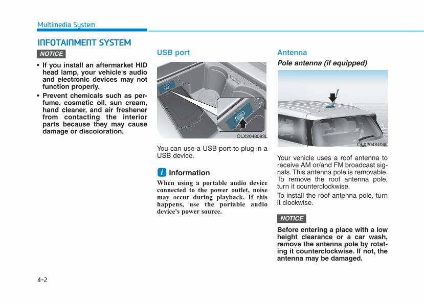
4-2
Multimedia System
• If you install an aftermarket HIDhead lamp, your vehicle's audioand electronic devices may notfunction properly.
• Prevent chemicals such as per-fume, cosmetic oil, sun cream,hand cleaner, and air freshenerfrom contacting the interiorparts because they may causedamage or discoloration.
USB port
You can use a USB port to plug in aUSB device.
Information When using a portable audio deviceconnected to the power outlet, noisemay occur during playback. If thishappens, use the portable audiodevice's power source.
AntennaPole antenna (if equipped)
Your vehicle uses a roof antenna toreceive AM or/and FM broadcast sig-nals. This antenna pole is removable.To remove the roof antenna pole,turn it counterclockwise.To install the roof antenna pole, turnit clockwise.
Before entering a place with a lowheight clearance or a car wash,remove the antenna pole by rotat-ing it counterclockwise. If not, theantenna may be damaged.
NOTICE
i
NOTICE
IINNFFOOTTAAIINNMMEENNTT SSYYSSTTEEMM
OLX2048404L
OLX2048093L
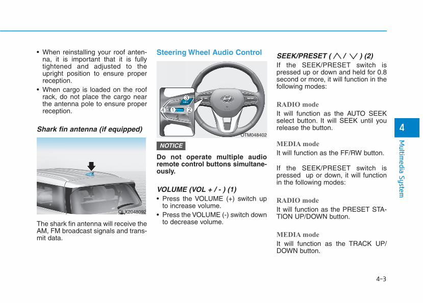
• When reinstalling your roof anten-na, it is important that it is fullytightened and adjusted to theupright position to ensure properreception.
• When cargo is loaded on the roofrack, do not place the cargo nearthe antenna pole to ensure properreception.
Shark fin antenna (if equipped)
The shark fin antenna will receive theAM, FM broadcast signals and trans-mit data.
Steering Wheel Audio Control
Do not operate multiple audioremote control buttons simultane-ously.
VOLUME (VOL + / - ) (1)• Press the VOLUME (+) switch up
to increase volume.• Press the VOLUME (-) switch down
to decrease volume.
SEEK/PRESET ( / ) (2)If the SEEK/PRESET switch ispressed up or down and held for 0.8second or more, it will function in thefollowing modes:
RADIO mode
It will function as the AUTO SEEKselect button. It will SEEK until yourelease the button.
MEDIA mode
It will function as the FF/RW button.
If the SEEK/PRESET switch ispressed up or down, it will functionin the following modes:
RADIO mode
It will function as the PRESET STA-TION UP/DOWN button.
MEDIA mode
It will function as the TRACK UP/DOWN button.
NOTICE
4-3
Multim
edia System
4
OLX2048092
OTM048402
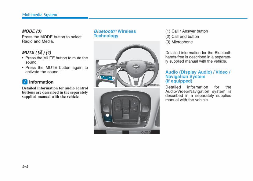
4-4
Multimedia System
MODE (3)Press the MODE button to selectRadio and Media.
MUTE ( ) (4) • Press the MUTE button to mute the
sound.• Press the MUTE button again to
activate the sound.
Information Detailed information for audio controlbuttons are described in the separatelysupplied manual with the vehicle.
Bluetooth® WirelessTechnology
(1) Call / Answer button(2) Call end button(3) Microphone
Detailed information for the Bluetoothhands-free is described in a separate-ly supplied manual with the vehicle.
Audio (Display Audio) / Video /Navigation System(if equipped)Detailed information for theAudio/Video/Navigation system isdescribed in a separately suppliedmanual with the vehicle.
iOTM048404
OLX2049094L
Driving your vehicle
5
Before Driving ........................................................5-5Before Entering the Vehicle ...........................................5-5Before Starting ..................................................................5-5
Ignition Switch........................................................5-7Key Ignition Switch ...........................................................5-7Engine Start/Stop Button .............................................5-10
Automatic Transmission ......................................5-15Automatic transmission operation ..............................5-15Parking...............................................................................5-18LCD display message......................................................5-19Good driving practices ...................................................5-20Paddle Shifter (Manual Shift Mode) ..........................5-22
Braking system.....................................................5-23Power Brakes...................................................................5-23Disc Brakes Wear Indicator ..........................................5-24Electronic Parking Brake (EPB)...................................5-24Auto Hold ..........................................................................5-29Anti-lock Brake System (ABS) ....................................5-33Electronic Stability Control (ESC)................................5-35Vehicle Stability Management (VSM).........................5-38Hill-Start Assist Control (HAC) ....................................5-39Downhill Brake Control (DBC) ......................................5-39Trailer Stability Assist (TSA).........................................5-42Good Braking Practices.................................................5-42
All Wheel Drive (AWD) ........................................5-43AWD Operation ................................................................5-44LCD display message......................................................5-47Emergency Precautions.................................................5-48
ISG (Idle Stop and Go) system...........................5-50To Activate the ISG System ..........................................5-50To Deactivate the ISG System......................................5-53ISG System Malfunction................................................5-53Battery Sensor Deactivation ........................................5-54
Drive Mode Integrated Control system (2WD).....................................................................5-55
Drive Mode .......................................................................5-55Drive Mode Integrated Control system (AWD) ....................................................................5-59
Drive Mode .......................................................................5-59Forward Collision-Avoidance Assist (FCA) system....................................................................5-63
System Setting and Operation.....................................5-63FCA Warning Message and Brake Control ...............5-66FCA Sensor (Front Radar/Front Camera).................5-68System Malfunction .......................................................5-70Limitations of the System.............................................5-72

5
Blind-Spot Collision Warning/Blind-Spot Collision-Avoidance Assist .............5-78
System Description .........................................................5-78System Setting and Operation.....................................5-79Warning and System Control .......................................5-82Detecting Sensor (Camera and Radar) ......................5-84Limitations of the System.............................................5-87
Declaration of conformity .................................5-92The radio frequency components (Rear Corner Radar) complies: ....................................5-92
Rear Cross-Traffic Collision Warning (RCCW)/Rear Cross-Traffic Collision-Avoidance Assist(RCCA) ...................................................................5-93
System Description .........................................................5-93System Setting and Operation.....................................5-94Warning and System Control .......................................5-96Detecting Sensor.............................................................5-99Limitations of the System...........................................5-100
Lane Following Assist (LFA) system...............5-104LFA Setting and Operation .........................................5-105Warning Message .........................................................5-106Limitations of the System...........................................5-108
Lane Keeping Assist (LKA) system .................5-110LKA System Operation.................................................5-111Warning Light and Message ......................................5-113Limitations of the System...........................................5-115LKA System Function Change ...................................5-117
Driver Attention Warning (DAW) system .......5-118System Setting and Operation...................................5-118Resetting the System...................................................5-119System Standby.............................................................5-120System Malfunction .....................................................5-120
Highway Driving Assist (HDA) system............5-122System Setting and Operation...................................5-122Warning Message .........................................................5-125
Smart Cruise Control With Stop & Go System...........................................................5-129
Smart Cruise Control Switch ......................................5-130Adjusting the Sensitivity of Smart Cruise Control .............................................................................5-130To Convert to Cruise Control Mode .........................5-131Smart Cruise Control Speed .......................................5-132Smart Cruise Control Vehicle-to-Vehicle Distance...........................................................................5-136Sensor to Detect Distance to the Vehicle Ahead ................................................................5-139Limitations of the System...........................................5-141
Leading Vehicle Departure Alert .....................5-147System Setting and Operation...................................5-147
Special Driving Conditions ................................5-149Hazardous Driving Conditions....................................5-149Rocking the Vehicle......................................................5-149Smooth Cornering.........................................................5-150Driving at Night .............................................................5-150Driving in the Rain ........................................................5-150Driving in Flooded Areas.............................................5-151Highway Driving ............................................................5-151Reducing the Risk of a Rollover ...............................5-152
Winter Driving ....................................................5-153Snow or Icy Conditions................................................5-153Winter Precautions.......................................................5-155
Trailer Towing.....................................................5-157If you decide to pull a trailer.....................................5-157Trailer towing equipment ............................................5-159Driving with a trailer ....................................................5-160Maintenance when trailer towing ...........................5-163
Vehicle Load Limit..............................................5-165Tire Loading Information Label .................................5-166
5

5-4
Driving your vehicle
Carbon monoxide (CO) gas is toxic. Breathing CO can cause unconsciousness and death.Engine exhaust contains carbon monoxide which cannot be seen or smelled.
Do not inhale engine exhaust.If at any time you smell engine exhaust inside the vehicle, open the windows immediately. Exposure to CO can causeunconsciousness and death by asphyxiation.
Be sure the exhaust system does not leak.The exhaust system should be checked whenever the vehicle is raised to change the oil or for any other purpose. Ifyou hear a change in the sound of the exhaust or if you drive over something that strikes the underneath side of thevehicle, have the exhaust system checked as soon as possible by an authorized HYUNDAI dealer.
Do not run the engine in an enclosed area.Letting the engine idle in your garage, even with the garage door open, is a hazardous practice. Run the engine onlylong enough to start the engine and to move the vehicle out of the garage.
Avoid idling the engine for prolonged periods with people inside the vehicle.If it is necessary to idle the engine for a prolonged period with people inside the vehicle, be sure to do so only in anopen area with the air intake set at "Fresh" and fan control set to high so fresh air is drawn into the interior.
Keep the air intakes clear.To assure proper operation of the ventilation system, keep the ventilation air intakes located in front of the windshieldclear of snow, ice, leaves, or other obstructions.
If you must drive with the liftgate open:Close all windows.Open instrument panel air vents.Set the air intake control at "Fresh", the air flow control at "Floor" or "Face", and the fan control set to high.
WARNING
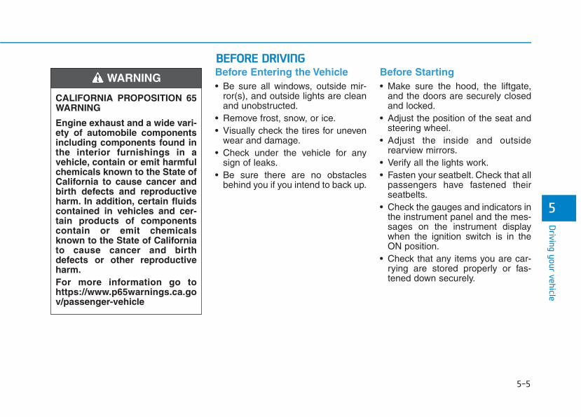
5-5
Driving your vehicle
5
Before Entering the Vehicle• Be sure all windows, outside mir-
ror(s), and outside lights are cleanand unobstructed.
• Remove frost, snow, or ice.• Visually check the tires for uneven
wear and damage.• Check under the vehicle for any
sign of leaks.• Be sure there are no obstacles
behind you if you intend to back up.
Before Starting• Make sure the hood, the liftgate,
and the doors are securely closedand locked.
• Adjust the position of the seat andsteering wheel.
• Adjust the inside and outsiderearview mirrors.
• Verify all the lights work.• Fasten your seatbelt. Check that all
passengers have fastened theirseatbelts.
• Check the gauges and indicators inthe instrument panel and the mes-sages on the instrument displaywhen the ignition switch is in theON position.
• Check that any items you are car-rying are stored properly or fas-tened down securely.
CALIFORNIA PROPOSITION 65WARNING
Engine exhaust and a wide vari-ety of automobile componentsincluding components found inthe interior furnishings in avehicle, contain or emit harmfulchemicals known to the State ofCalifornia to cause cancer andbirth defects and reproductiveharm. In addition, certain fluidscontained in vehicles and cer-tain products of componentscontain or emit chemicalsknown to the State of Californiato cause cancer and birthdefects or other reproductiveharm.For more information go tohttps://www.p65warnings.ca.gov/passenger-vehicle
WARNING
BBEEFFOORREE DDRRIIVVIINNGG

5-6
Driving your vehicle
NEVER drink or take drugs anddrive.Drinking or taking drugs and driv-ing is dangerous and may resultin an accident and SERIOUSINJURY or DEATH.Drunk driving is the numberone contributor to the highwaydeath toll each year. Even asmall amount of alcohol willaffect your reflexes, percep-tions and judgment. Just onedrink can reduce your ability torespond to changing conditionsand emergencies and your reac-tion time gets worse with eachadditional drink.Driving while under the influ-ence of drugs is as dangerousor more dangerous than drivingunder the influence of alcohol.
WARNING You are much more likely to havea serious accident if you drink ortake drugs and drive. If you aredrinking or taking drugs, don'tdrive. Do not ride with a driverwho has been drinking or takingdrugs. Choose a designated driv-er or call a taxi.
To reduce the risk of SERIOUSINJURY or DEATH, take the fol-lowing precautions:• ALWAYS wear your seat belt.
All passengers must be prop-erly belted whenever the vehi-cle is moving. For more infor-mation, refer to "Seat Belts" inchapter 2.
• Always drive defensively.Assume other drivers or pedes-trians may be careless andmake mistakes.
• Stay focused on the task ofdriving. Driver distraction cancause accidents.
• Leave plenty of space betweenyou and the vehicle in front ofyou.
WARNING
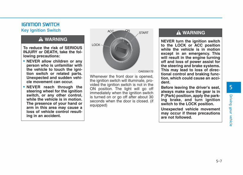
5-7
Driving your vehicle
5
Key Ignition Switch
Whenever the front door is opened,the ignition switch will illuminate, pro-vided the ignition switch is not in theON position. The light will go offimmediately when the ignition switchis turned on or go off after about 30seconds when the door is closed. (ifequipped)
IIGGNNIITTIIOONN SSWWIITTCCHH
To reduce the risk of SERIOUSINJURY or DEATH, take the fol-lowing precautions:• NEVER allow children or any
person who is unfamiliar withthe vehicle to touch the igni-tion switch or related parts.Unexpected and sudden vehi-cle movement can occur.
• NEVER reach through thesteering wheel for the ignitionswitch, or any other control,while the vehicle is in motion.The presence of your hand orarm in this area may cause aloss of vehicle control result-ing in an accident.
WARNING NEVER turn the ignition switchto the LOCK or ACC positionwhile the vehicle is in motionexcept in an emergency. Thiswill result in the engine turningoff and loss of power assist forthe steering and brake systems.This may lead to loss of direc-tional control and braking func-tion, which could cause an acci-dent.Before leaving the driver's seat,always make sure the gear is inP (Park) position, apply the park-ing brake, and turn ignitionswitch to the LOCK position.Unexpected vehicle movementmay occur if these precautionsare not followed.
WARNING
OAE056172
LOCK
ACC ONSTART
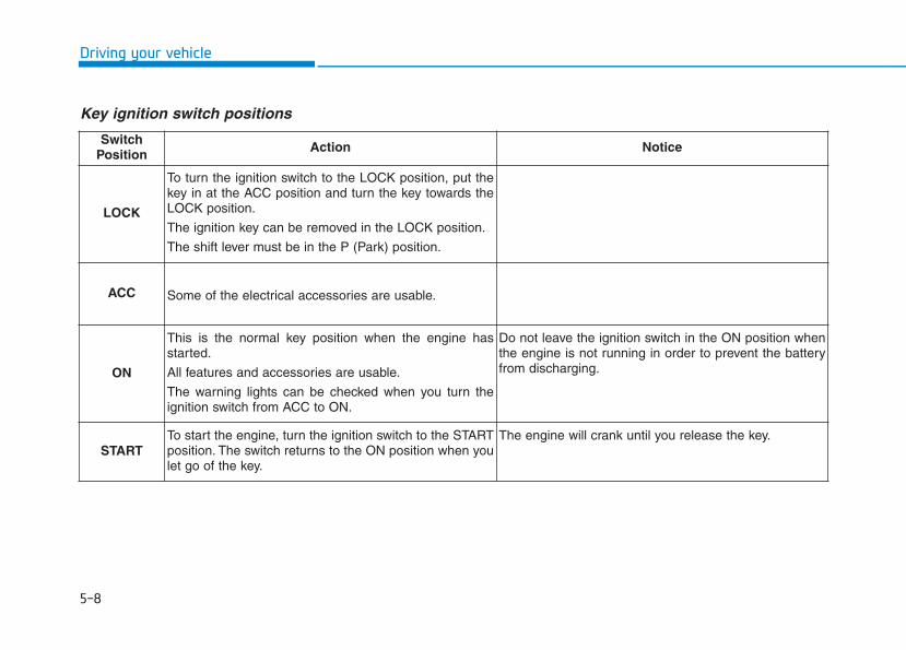
5-8
Driving your vehicle
Key ignition switch positions
SwitchPosition Action Notice
LOCK
To turn the ignition switch to the LOCK position, put thekey in at the ACC position and turn the key towards theLOCK position.
The ignition key can be removed in the LOCK position.
The shift lever must be in the P (Park) position.
ACC Some of the electrical accessories are usable.
ON
This is the normal key position when the engine hasstarted.
All features and accessories are usable.
The warning lights can be checked when you turn theignition switch from ACC to ON.
Do not leave the ignition switch in the ON position whenthe engine is not running in order to prevent the batteryfrom discharging.
STARTTo start the engine, turn the ignition switch to the STARTposition. The switch returns to the ON position when youlet go of the key.
The engine will crank until you release the key.
5-9
Driving your vehicle
5
Starting the engine 1. Make sure the parking brake isapplied.
2. Make sure the gear is in P (Park).3. Depress the brake pedal.4. Turn the ignition switch to the
START position. Hold the key(maximum of 10 seconds) until theengine starts and release it.
Information• It is best to maintain a moderate
engine speed until the vehicle enginecomes up to normal operating tem-perature. Avoid harsh or abruptacceleration or deceleration whilethe engine is still cold.
• Whether the engine is cold or warm,always start the vehicle with yourfoot on the brake pedal. Do notdepress the accelerator while start-ing the vehicle. Do not rev theengine while warming it up.
To prevent damage to the vehicle:• Do not hold the ignition key in
the START position for morethan 10 seconds. Wait 5 to 10seconds before trying again.
• Do not push or tow your vehicleto start the engine.
Turning off the engine1. Stop the vehicle and depress the
brake pedal fully.2. Shift the gear to P (Park).3. Turn the ignition switch to the off
position and apply the parkingbrake.
NOTICE
i
Always wear appropriate shoeswhen operating your vehicle.Unsuitable shoes, such as highheels, ski boots, sandals, flip-flops, etc., may interfere withyour ability to use the brake andaccelerator pedals.
WARNING
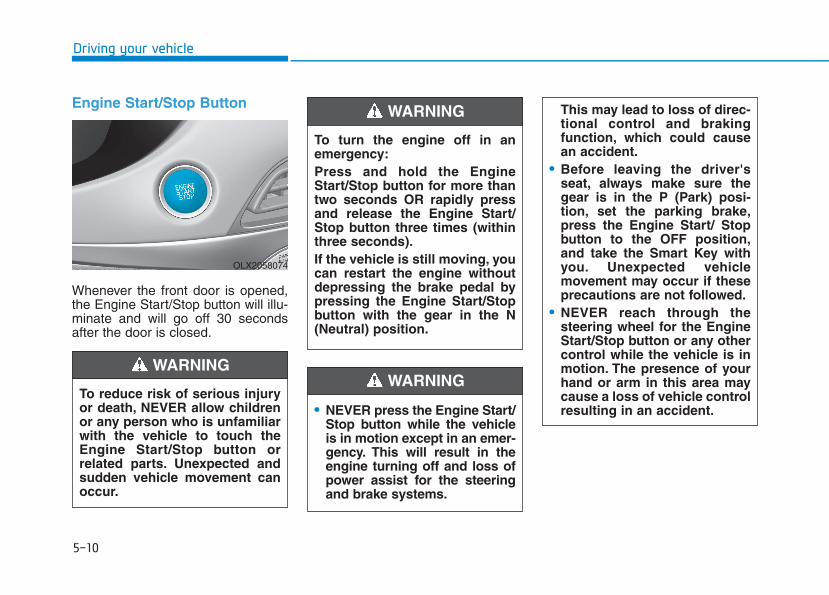
5-10
Driving your vehicle
Engine Start/Stop Button
Whenever the front door is opened,the Engine Start/Stop button will illu-minate and will go off 30 secondsafter the door is closed.
• NEVER press the Engine Start/Stop button while the vehicleis in motion except in an emer-gency. This will result in theengine turning off and loss ofpower assist for the steeringand brake systems.
WARNING
To turn the engine off in anemergency:Press and hold the EngineStart/Stop button for more thantwo seconds OR rapidly pressand release the Engine Start/Stop button three times (withinthree seconds).If the vehicle is still moving, youcan restart the engine withoutdepressing the brake pedal bypressing the Engine Start/Stopbutton with the gear in the N(Neutral) position.
This may lead to loss of direc-tional control and brakingfunction, which could causean accident.
• Before leaving the driver'sseat, always make sure thegear is in the P (Park) posi-tion, set the parking brake,press the Engine Start/ Stopbutton to the OFF position,and take the Smart Key withyou. Unexpected vehiclemovement may occur if theseprecautions are not followed.
• NEVER reach through thesteering wheel for the EngineStart/Stop button or any othercontrol while the vehicle is inmotion. The presence of yourhand or arm in this area maycause a loss of vehicle controlresulting in an accident.
WARNING
To reduce risk of serious injuryor death, NEVER allow childrenor any person who is unfamiliarwith the vehicle to touch theEngine Start/Stop button orrelated parts. Unexpected andsudden vehicle movement canoccur.
WARNING
OLX2058074

5-11
Driving your vehicle
5
Engine Start/Stop button positions
Button Position Action Notice
OFF
To turn off the engine, press the EngineStart/Stop button with the gear in P (Park).When you press the Engine Start/Stop but-ton without the gear in P (Park), the EngineStart/Stop button does not turn to the OFFposition, but turns to the ACC position.
ACC
Press the Engine Start/Stop button when thebutton is in the OFF position without depress-ing the brake pedal.Some of the electrical accessories areusable.
If you leave the Engine Start/Stop button in theACC position with the gear in P (Park) for morethan one hour, the battery power will turn offautomatically to prevent the battery from dis-charging.
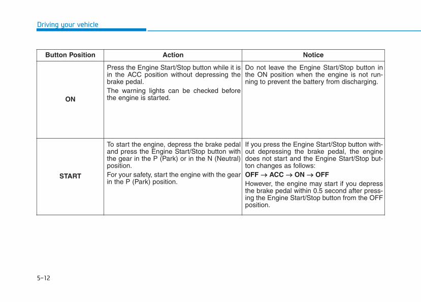
5-12
Driving your vehicle
Button Position Action Notice
ON
Press the Engine Start/Stop button while it isin the ACC position without depressing thebrake pedal.The warning lights can be checked beforethe engine is started.
Do not leave the Engine Start/Stop button inthe ON position when the engine is not run-ning to prevent the battery from discharging.
START
To start the engine, depress the brake pedaland press the Engine Start/Stop button withthe gear in the P (Park) or in the N (Neutral)position.For your safety, start the engine with the gearin the P (Park) position.
If you press the Engine Start/Stop button with-out depressing the brake pedal, the enginedoes not start and the Engine Start/Stop but-ton changes as follows:OFF →→ ACC →→ ON →→ OFFHowever, the engine may start if you depressthe brake pedal within 0.5 second after press-ing the Engine Start/Stop button from the OFFposition.
5-13
Driving your vehicle
5
Starting the engine Information• The engine will start by pressing the
Engine Start/Stop button, only whenthe smart key is in the vehicle.
• Even if the smart key is in the vehi-cle, if it is far away from the driver,the engine may not start.
• When the Engine Start/Stop buttonis in the ACC or ON position, if anydoor is open, the system checks forthe smart key. If the smart key is notin the vehicle, the " " indicatorwill blink and the warning "Key notin vehicle" will come on and if alldoors are closed, the chime will alsosound for about 5 seconds. Keep thesmart key in the vehicle when usingthe ACC position or if the vehicleengine is ON.
1. Always carry the smart key withyou.
2. Make sure the parking brake isapplied.
3. Make sure the gear is in P (Park).4. Depress the brake pedal.5. Press the Engine Start/Stop but-
ton.
Information• Do not wait for the engine to warm
up while the vehicle remains station-ary. Start driving at moderateengine speeds. (Aggressive accelerat-ing and decelerating should beavoided.)
• Always start the vehicle with yourfoot on the brake pedal. Do notdepress the accelerator while start-ing the vehicle. Do not rev theengine while warming it up.
i
i
• Always wear appropriate shoeswhen operating your vehicle.Unsuitable shoes, such ashigh heels, ski boots, sandals,flip-flops, etc., may interferewith your ability to use thebrake and accelerator pedals.
• Do not start the vehicle with theaccelerator pedal depressed.The vehicle can move and leadto an accident.
• Wait until the engine rpm isnormal. The vehicle may sud-denly move if the brake pedalis released when the rpm ishigh.
WARNING
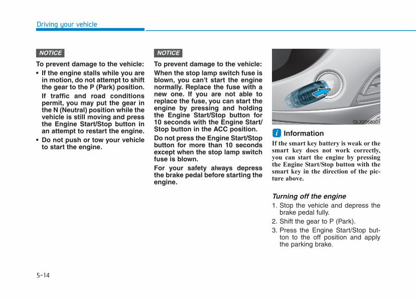
5-14
Driving your vehicle
To prevent damage to the vehicle:• If the engine stalls while you are
in motion, do not attempt to shiftthe gear to the P (Park) position.If traffic and road conditionspermit, you may put the gear inthe N (Neutral) position while thevehicle is still moving and pressthe Engine Start/Stop button inan attempt to restart the engine.
• Do not push or tow your vehicleto start the engine.
To prevent damage to the vehicle:When the stop lamp switch fuse isblown, you can't start the enginenormally. Replace the fuse with anew one. If you are not able toreplace the fuse, you can start theengine by pressing and holdingthe Engine Start/Stop button for10 seconds with the Engine Start/Stop button in the ACC position.Do not press the Engine Start/Stopbutton for more than 10 secondsexcept when the stop lamp switchfuse is blown.For your safety always depressthe brake pedal before starting theengine.
InformationIf the smart key battery is weak or thesmart key does not work correctly,you can start the engine by pressingthe Engine Start/Stop button with thesmart key in the direction of the pic-ture above.
Turning off the engine1. Stop the vehicle and depress the
brake pedal fully.2. Shift the gear to P (Park).3. Press the Engine Start/Stop but-
ton to the off position and applythe parking brake.
i
NOTICENOTICE
OLX2058001
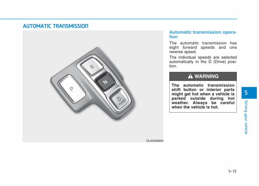
5-15
Driving your vehicle
5
Automatic transmission opera-tion The automatic transmission haseight forward speeds and onereverse speed.The individual speeds are selectedautomatically in the D (Drive) posi-tion.
AAUUTTOOMMAATTIICC TTRRAANNSSMMIISSSSIIOONN
OLX2058003
The automatic transmissionshift button or interior partsmight get hot when a vehicle isparked outside during hotweather. Always be carefulwhen the vehicle is hot.
WARNING

Driving your vehicle
Transmission rangesThe indicator in the instrument clusterdisplays the gear position when theignition switch is in the ON position.
P (Park)
Always come to a complete stopbefore shifting into P (Park).To shift from P (Park), you mustdepress firmly on the brake pedaland make sure your foot is off theaccelerator pedal.The gear must be in P (Park) beforeturning the engine off.
R (Reverse)
Use this position to drive the vehiclebackward.
Always come to a complete stopbefore shifting into or out of R(Reverse); you may damage thetransmission if you shift into R(Reverse) while the vehicle is inmotion.
When the vehicle is stopped in R(Reverse) position, if you open thedriver's door with the seat belt unfas-tened, the gear is shifted to P (Park)position automatically.However when the vehicle moves inR (Reverse) position, if you open thedriver's door with the seat belt unfas-tened, the gear may be not shifted toP (Park) position automatically forprotecting the automatic transmis-sion.
NOTICE
To reduce the risk of seriousinjury or death:• ALWAYS check the surround-
ing areas near your vehicle forpeople, especially children,before shifting a vehicle intoD (Drive) or R (Reverse).
• Before leaving the driver’sseat, always make sure thegear is in the P (Park) posi-tion, then set the parkingbrake, and place the ignitionswitch in the LOCK/OFF posi-tion. Unexpected and suddenvehicle movement can occurif these precautions are notfollowed.
• Do not use the engine brake(shifting from a high gear tolower gear) rapidly on slip-pery roads. The vehicle mayslip causing an accident.
WARNING
• Shifting into P (Park) while thevehicle is in motion maycause you to lose control ofthe vehicle.
• After the vehicle has stopped,always make sure the gear isin P (Park), apply the parkingbrake, and turn the engineoff.
• Do not use the P (Park) posi-tion in place of the parkingbrake.
WARNING
5-16
5-17
Driving your vehicle
5
N (Neutral)
The wheels and transmission are notengaged.Use N (Neutral) if you need to restarta stalled engine, or if it is necessaryto stop with the engine ON. Shift intoP (Park) if you need to leave yourvehicle for any reason.Always depress the brake pedalwhen you are shifting from N(Neutral) to another gear.
D (Drive)
This is the normal driving position.The transmission will automaticallyshift through a 8-gear sequence, pro-viding the best fuel economy andpower.To start the vehicle forward, push theD (Drive) button by depressing thebrake pedal with the engine ON.Then depress the accelerator pedalsmoothly.For extra power when passing anoth-er vehicle or driving uphill, depressthe accelerator fully. The transmis-sion will automatically downshift tothe next lower gear (or gears, asappropriate).When the vehicle is stopped in D(Drive) position, if you open the dri-ver's door with the seat belt unfas-tened, the gear is shifted to P (Park)position automatically.However when the vehicle moves inD (Drive) position, if you open the dri-ver's door with the seat belt unfas-tened, the gear may not shift to P(Park) position automatically to pro-tect the automatic transmission.
Shift-lock system For your safety, the automatic trans-mission has a shift-lock systemwhich prevents shifting the gearfrom P (Park) or N (Neutral) to R(Reverse) or D (Drive) unless thebrake pedal is depressed.To shift the gear from P (Park) or N(Neutral) to R (Reverse) or D (Drive):1. Depress and hold the brake pedal.2. Start the engine or place the igni-
tion switch in the ON position.3. Depress the brake pedal and push
the R (Reverse) or D (Drive) but-ton.Do not shift into gear unless
your foot is firmly on the brakepedal. Shifting into gear whenthe engine is running at highspeed can cause the vehicle tomove very rapidly. You couldlose control of the vehicle andhit people or objects.
WARNING
5-18
Driving your vehicle
When the battery is discharged:You cannot shift the gear when thebattery is discharged.In emergencies, do the following tomove the shift button to N (Neutral)on a level ground.1. Connect the battery cables from
another vehicle or from a anotherbattery to the jump-starting termi-nals inside the engine compart-ment.For more information refer to"Jump Starting" in chapter 6.
2. Release the parking brake withthe Engine Start/Stop button in theON position.
3. Shift the gear to the N(Neutral)position. Refer to the "Stay inNeutral when vehicle is Off" in thischapter.
ParkingAlways come to a complete stop andcontinue to depress the brake pedal.Press the P button, apply the parkingbrake, and place the ignition switchin the LOCK/OFF position. Take theKey with you when exiting the vehi-cle.• The gear is shifted to P (Park)
position automatically for safetyunder the following conditions.- When the driver unfastens the
seat belt and opens the driver’sdoor.
- When the engine is turned off withthe gear shifted to R (Reverse), D(Drive) or N (Neutral).
When you stay in the vehiclewith the engine running, becareful not to depress the accel-erator pedal for a long period oftime. The engine or exhaustsystem may overheat and starta fire.The exhaust gas and theexhaust system are very hot.Keep away from the exhaustsystem components.Do not stop or park over flam-mable materials, such as drygrass, paper or leaves. Theymay ignite and cause a fire.
WARNING
5-19
Driving your vehicle
5
LCD display messageShifting conditions not metThe warning message appears onthe LCD display, when engine RPMis too high, or when driving speed istoo fast to shift the gear.We recommend you decrease theengine speed or slow down beforeshifting the gear.
Press brake pedal to changegearThe warning message appears onthe LCD display, when the brakepedal is not depressed while shiftingthe gear.We recommend you to depress thebrake pedal and then shift the gear.
Shift to P after stoppingThe warning message appears onthe LCD display, when the gear isshifted to P (Park) while the vehicleis moving.Stop the vehicle before shifting to P(Park).
PARK engagedThe warning message appears onthe LCD display, when the gear isshifted to P (Park) while the vehicleis moving.Stop the vehicle before shifting to P(Park).
Press and hold OK button tostay in Neutral when vehicle isOffThe warning message appears onthe LCD display, when pushing theN(Neutral) button. If you want to stayN(Neutral) after turning off theengine, press and hold the “OK” but-ton on the steering wheel more than1 second.
Vehicle will stay in (N). Changegear to cancelThe warning message appears onthe LCD display, when pushing the"OK" button on the steering wheelafter the message ("Press and holdOK button to stay in Neutral whenvehicle is Off") appears on the clus-ter LCD display. The gear stays inN(Neutral) position after turning offthe engine.
NEUTRAL engagedThe message appears on the LCDdisplay, when the N (Neutral) posi-tion is engaged.
Gear already selectedThe message appears on the LCDdisplay, when pushing the currentshift button again.

5-20
Driving your vehicle
Shift button held downThe warning message appears onthe LCD display, when the shift but-ton is pressed continuously or theshift button does not properly oper-ate. Clean the surroundings of gearshift button.If this message appears again, werecommend you to have the vehicleinspected by an authorizedHYUNDAI dealer.
Shifter system malfunctionThe warning message appears onthe LCD display, when the transmis-sion or the shift button does not prop-erly operate in the P (Park) position.In this case, we recommend you toimmediately have the vehicleinspected by an authorizedHYUNDAI dealer.
Check shift controlsThe warning message appears onthe LCD display, when there is a mal-function with transmission shift but-ton.In this case, we recommend you toimmediately have the vehicleinspected by an authorizedHYUNDAI dealer.
Good driving practices • Never shift the gear from P (Park)
or N (Neutral) to any other positionwith the accelerator pedaldepressed.
• Never shift the gear into P (Park)when the vehicle is in motion.Be sure the vehicle is completelystopped before you attempt to shiftinto R (Reverse) or D (Drive).
• Do not shift the gear to N (Neutral)when driving. Doing so may resultin an accident because of a loss ofengine braking and the transmis-sion could be damaged.
• Driving uphill or downhill, alwaysshift to D (Drive) when driving for-ward or to R (Reverse) when driv-ing backwards, and check the gearposition indicated on the clusterbefore driving. If you drive in theopposite direction of the selectedgear, the engine will turn off and aserious accident might be occurreddue to the degraded brake per-formance.
5-21
Driving your vehicle
5
• Do not drive with your foot restingon the brake pedal. Even light, butconsistent pedal pressure canresult in the brakes overheating,brake wear and possibly evenbrake failure.
• When driving in sports mode, slowdown before shifting to a lowergear. Otherwise, the lower gearmay not be engaged if the enginerpms are outside of the allowablerange.
• Always apply the parking brakewhen leaving the vehicle. Do notdepend on placing the transmis-sion in P (Park) to keep the vehiclefrom moving.
• Exercise extreme caution whendriving on a slippery surface. Beespecially careful when braking,accelerating or shifting gears. On aslippery surface, an abrupt changein vehicle speed can cause thedrive wheels to lose traction andmay cause loss of vehicle controlresulting in an accident
• Optimum vehicle performance andeconomy is obtained by smoothlydepressing and releasing theaccelerator.
• In the event your vehicleleaves the roadway, do notsteer sharply. Instead, slowdown before pulling back intothe travel lanes.
• HYUNDAI recommends youfollow all posted speed limits.
To reduce the risk of SERIOUSINJURY or DEATH:• ALWAYS wear your seatbelt.
In a collision, an unbeltedoccupant is significantly morelikely to be seriously injuredor killed than a properly belt-ed occupant.
• Avoid high speeds when cor-nering or turning.
• Do not make quick steeringwheel movements, such assharp lane changes or fast,sharp turns.
• The risk of rollover is greatlyincreased if you lose controlof your vehicle at highwayspeeds.
• Loss of control often occurs iftwo or more wheels drop offthe roadway and the driverover steers to reenter theroadway.
WARNING
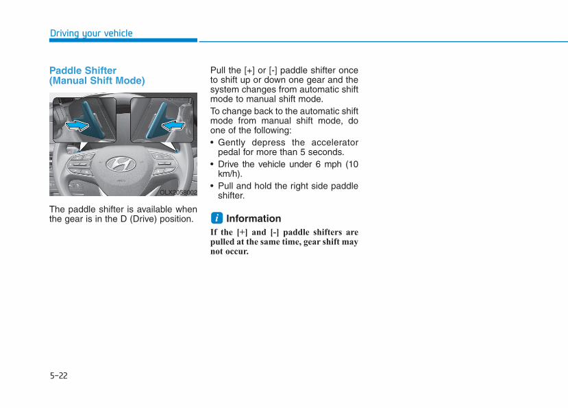
5-22
Driving your vehicle
Paddle Shifter (Manual Shift Mode)
The paddle shifter is available whenthe gear is in the D (Drive) position.
Pull the [+] or [-] paddle shifter onceto shift up or down one gear and thesystem changes from automatic shiftmode to manual shift mode.To change back to the automatic shiftmode from manual shift mode, doone of the following:• Gently depress the accelerator
pedal for more than 5 seconds.• Drive the vehicle under 6 mph (10
km/h).• Pull and hold the right side paddle
shifter.
Information If the [+] and [-] paddle shifters arepulled at the same time, gear shift maynot occur.
i
OLX2058002
5-23
Driving your vehicle
5
Power BrakesYour vehicle has power-assistedbrakes that adjust automaticallythrough normal usage.If the engine is not running or isturned off while driving, the powerassist for the brakes will not work.You can still stop your vehicle byapplying greater force to the brakepedal than typical. The stopping dis-tance, however, will be longer thanwith power brakes.When the engine is not running, thereserve brake power is partiallydepleted each time the brake pedalis applied. Do not pump the brakepedal when the power assist hasbeen interrupted.
BBRRAAKKIINNGG SSYYSSTTEEMM
Take the following precautions:• Do not drive with your foot
resting on the brake pedal.This will create abnormal highbrake temperatures, exces-sive brake lining and padwear, and increased stoppingdistances.
• When descending down along or steep hill, use the pad-dle shifter and manuallydownshift to a lower gear inorder to control your speedwithout using the brake pedalexcessively. Applying thebrakes continuously willcause the brakes to overheatand could result in a tempo-rary loss of braking perform-ance.
• Wet brakes may impair thevehicle's ability to safely slowdown; the vehicle may alsopull to one side when thebrakes are applied. Applyingthe brakes lightly will indicatewhether they have beenaffected in this way. Alwaystest your brakes in this fash-ion after driving through deepwater. To dry the brakes, light-ly tap the brake pedal to heatup the brakes while maintain-ing a safe forward speed untilbrake performance returns tonormal. Avoid driving at highspeeds until the brakes func-tion correctly.
WARNING

5-24
Driving your vehicle
Disc Brakes Wear IndicatorWhen your brake pads are worn andnew pads are required, you will heara high pitched warning sound fromyour front or rear brakes. You mayhear this sound come and go or itmay occur whenever you depressthe brake pedal.Note that some driving conditions orclimates may cause a brake squealwhen you first apply (or lightly apply)the brakes. This is normal and doesnot indicate a problem with yourbrakes.
To avoid costly brake repairs, donot continue to drive with wornbrake pads.
InformationAlways replace brake pads as com-plete front or rear axle sets.
Electronic Parking Brake(EPB)Applying the parking brake
To apply the EPB (Electronic Parking Brake):
1. Depress the brake pedal.2. Pull up the EPB switch.Make sure the Parking BrakeWarning Light comes on.i
NOTICE
To reduce the risk of SERIOUSINJURY or DEATH, do not oper-ate the EPB while the vehicle ismoving except in an emergencysituation. It could damage thebrake system and lead to anaccident.
WARNING
OLX2058082

5-25
Driving your vehicle
5
Releasing the parking brake
To release the EPB (ElectronicParking Brake):
• Place the ignition switch in the ONposition.
• Depress and hold the brake pedal.• Press the EPB switch.Make sure the Parking BrakeWarning Light goes off.
To release EPB (Electronic ParkingBrake) automatically:
1. Ensure seat belts are fastenedand the doors, hood and liftgateare closed.
2. With the engine running, depressthe brake pedal and shift out of P(Park) to R (Reverse) or D (Drive).
3. Depress the accelerator pedal.Make sure the parking brake warninglight goes off.
Information • For your safety, you can engage the
EPB even though the ignition switchis in the OFF position, but you can-not release it.
• For your safety, depress the brakepedal and release the parking brakemanually with the EPB switch whenyou drive downhill or when backingup the vehicle.
• If the parking brake warninglight is still on even though theEPB has been released, have thesystem checked by an author-ized HYUNDAI dealer.
• Do not drive your vehicle withthe EPB applied. It may causeexcessive brake pad and brakerotor wear.
EPB (Electronic Parking Brake)may be automatically appliedwhen:
• Requested by other systems• The driver turns the engine off
while Auto Hold is operating.
NOTICE
i
OLX2059083L
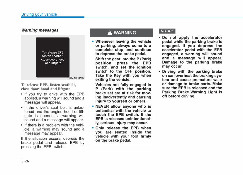
5-26
Driving your vehicle
Warning messages
To release EPB, fasten seatbelt,close door, hood and liftgate
• If you try to drive with the EPBapplied, a warning will sound and amessage will appear.
• If the driver's seat belt is unfas-tened and the engine hood or lift-gate is opened, a warning willsound and a message will appear.
• If there is a problem with the vehi-cle, a warning may sound and amessage may appear.
If the situation occurs, depress thebrake pedal and release EPB bypressing the EPB switch.
• Do not apply the acceleratorpedal while the parking brake isengaged. If you depress theaccelerator pedal with the EPBengaged, a warning will soundand a message will appear.Damage to the parking brakemay occur.
• Driving with the parking brakeon can overheat the braking sys-tem and cause premature wearor damage to brake parts. Makesure the EPB is released and theParking Brake Warning Light isoff before driving.
NOTICE
• Whenever leaving the vehicleor parking, always come to acomplete stop and continueto depress the brake pedal.Shift the gear into the P (Park)position, press the EPBswitch, and set the ignitionswitch to the OFF position.Take the Key with you whenexiting the vehicle.Vehicles not fully engaged inP (Park) with the parkingbrake set are at risk for mov-ing inadvertently and causinginjury to yourself or others.
• NEVER allow anyone who isunfamiliar with the vehicle totouch the EPB switch. If theEPB is released unintentional-ly, serious injury may occur.
• Only release the EPB whenyou are seated inside thevehicle with your foot firmlyon the brake pedal.
WARNING
OTMA058132
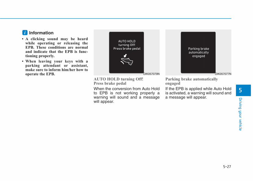
5-27
Driving your vehicle
5
Information • A clicking sound may be heard
while operating or releasing theEPB. These conditions are normaland indicate that the EPB is func-tioning properly.
• When leaving your keys with aparking attendant or assistant,make sure to inform him/her how tooperate the EPB.
AUTO HOLD turning Off!Press brake pedal
When the conversion from Auto Holdto EPB is not working properly awarning will sound and a messagewill appear.
Parking brake automaticallyengaged
If the EPB is applied while Auto Holdis activated, a warning will sound anda message will appear.
i
OIK057079N OIK057077N
5-28
Driving your vehicle
EPB malfunction indicator
This warning light illuminates if theignition switch is set to the ON posi-tion and goes off in approximately 3seconds if the system is operatingnormally.If the EPB malfunction indicatorremains on, comes on while driving,or does not come on when the igni-tion switch is changed to the ONposition, this indicates that the EPBmay have malfunctioned.If this occurs, have the systemchecked by an authorized HYUNDAIdealer.
The EPB malfunction indicator mayilluminate when the ESC indicatorcomes on to indicate that the ESC isnot working properly, but it does notindicate a malfunction of the EPB.
• If the EPB warning light is stillon, have the system checked byan authorized HYUNDAI dealer.
• If the parking brake warninglight does not illuminate orblinks even though the EPBswitch was pulled up, the EPBmay not be applied.
• If the parking brake warninglight blinks when the EPB warn-ing light is on, press the switch,and then pull it up. Repeat thisone more time. If the EPB warn-ing does not go off, have thesystem checked by an author-ized HYUNDAI dealer.
Parking brake warning lightCheck the ParkingBrake Warning Lightby placing the ignitionswitch to the ON posi-tion (do not start theengine).
This light will be illuminated when theparking brake is applied with the igni-tion switch in the START or ON posi-tion.Before driving, be sure the parkingbrake is released and the BrakeWarning Light is OFF.If the Parking Brake Warning Lightremains on after the parking brake isreleased while engine is running,there may be a malfunction in thebrake system. Immediate attention isnecessary.If at all possible, cease driving thevehicle immediately. If that is not pos-sible, use extreme caution whileoperating the vehicle and only con-tinue to drive the vehicle until youcan reach a safe location.
NOTICE
OLX2058075
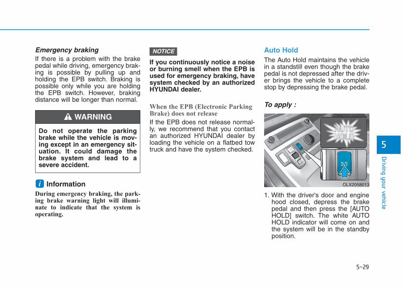
5-29
Driving your vehicle
5
Emergency brakingIf there is a problem with the brakepedal while driving, emergency brak-ing is possible by pulling up andholding the EPB switch. Braking ispossible only while you are holdingthe EPB switch. However, brakingdistance will be longer than normal.
Information During emergency braking, the park-ing brake warning light will illumi-nate to indicate that the system isoperating.
If you continuously notice a noiseor burning smell when the EPB isused for emergency braking, havesystem checked by an authorizedHYUNDAI dealer.
When the EPB (Electronic ParkingBrake) does not release
If the EPB does not release normal-ly, we recommend that you contactan authorized HYUNDAI dealer byloading the vehicle on a flatbed towtruck and have the system checked.
Auto HoldThe Auto Hold maintains the vehiclein a standstill even though the brakepedal is not depressed after the driv-er brings the vehicle to a completestop by depressing the brake pedal.
To apply :
1. With the driver's door and enginehood closed, depress the brakepedal and then press the [AUTOHOLD] switch. The white AUTOHOLD indicator will come on andthe system will be in the standbyposition.
NOTICE
i
Do not operate the parkingbrake while the vehicle is mov-ing except in an emergency sit-uation. It could damage thebrake system and lead to asevere accident.
WARNING
OLX2058013
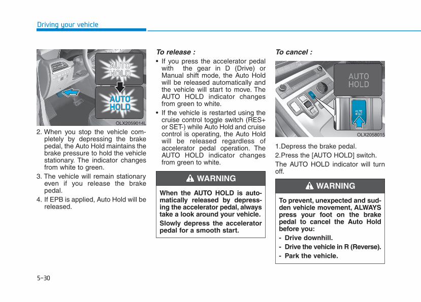
5-30
Driving your vehicle
2. When you stop the vehicle com-pletely by depressing the brakepedal, the Auto Hold maintains thebrake pressure to hold the vehiclestationary. The indicator changesfrom white to green.
3. The vehicle will remain stationaryeven if you release the brakepedal.
4. If EPB is applied, Auto Hold will bereleased.
To release :• If you press the accelerator pedal
with the gear in D (Drive) orManual shift mode, the Auto Holdwill be released automatically andthe vehicle will start to move. TheAUTO HOLD indicator changesfrom green to white.
• If the vehicle is restarted using thecruise control toggle switch (RES+or SET-) while Auto Hold and cruisecontrol is operating, the Auto Holdwill be released regardless ofaccelerator pedal operation. TheAUTO HOLD indicator changesfrom green to white.
To cancel :
1.Depress the brake pedal.2.Press the [AUTO HOLD] switch.The AUTO HOLD indicator will turnoff.
When the AUTO HOLD is auto-matically released by depress-ing the accelerator pedal, alwaystake a look around your vehicle.Slowly depress the acceleratorpedal for a smooth start.
WARNING
OLX2059014L
To prevent, unexpected and sud-den vehicle movement, ALWAYSpress your foot on the brakepedal to cancel the Auto Holdbefore you:- Drive downhill.- Drive the vehicle in R (Reverse).- Park the vehicle.
WARNING
OLX2058015

5-31
Driving your vehicle
5
Information • The Auto Hold does not operate
when:
- The driver's door is opened
- The engine hood is opened
- The gear is in P (Park) or R(Reverse)
- The EPB is applied
• For your safety, the Auto Hold auto-matically switches to EPB when:
- The driver's door is opened withthe gear in D (Drive) or N(Neutral)
- The engine hood is opened with thegear in D (Drive) or N (Neutral)
- The vehicle stops for more than 10minutes
- The vehicle stands on a steep slope
- The vehicle moves several times
In these cases, the parking brakewarning light comes on, the AUTOHOLD indicator changes fromgreen to white, and a warning soundand a message will appear to informyou that EPB has been automatical-ly engaged. Before driving off again,press foot brake pedal, check thesurrounding area near your vehicleand release parking brake manuallywith the EPB switch.
• While operating Auto Hold, you mayhear mechanical noise. However, it isnormal operating noise.
If the AUTO HOLD indicatorchanges to yellow, the Auto Holdis not working properly. Contactan authorized HYUNDAI dealer.
If there is a malfunction with thedriver's door or engine hood opendetection system, the Auto Holdmay not work properly.Contact an authorized HYUNDAIdealer.
NOTICE
NOTICE
i
• Depress the accelerator pedalslowly when you start thevehicle.
• For your safety, cancel theAuto Hold when you drivedownhill, back up the vehicleor park the vehicle.
WARNING
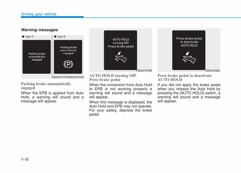
5-32
Driving your vehicle
Warning messages
Parking brake automaticallyengaged
When the EPB is applied from AutoHold, a warning will sound and amessage will appear.
AUTO HOLD turning Off!Press brake pedal
When the conversion from Auto Holdto EPB is not working properly awarning will sound and a messagewill appear.When this message is displayed, theAuto Hold and EPB may not operate.For your safety, depress the brakepedal.
Press brake pedal to deactivateAUTO HOLD
If you did not apply the brake pedalwhen you release the Auto Hold bypressing the [AUTO HOLD] switch, awarning will sound and a messagewill appear.
OIK057077N/OIK057075N
■ Type A ■ Type B
OIK057079N OIK057080L
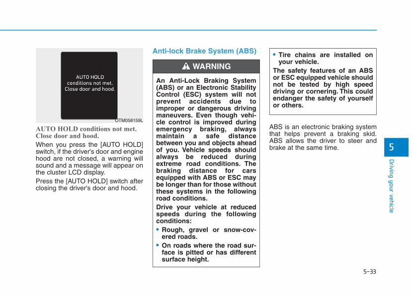
5-33
Driving your vehicle
5
AUTO HOLD conditions not met.Close door and hood.
When you press the [AUTO HOLD]switch, if the driver's door and enginehood are not closed, a warning willsound and a message will appear onthe cluster LCD display.Press the [AUTO HOLD] switch afterclosing the driver's door and hood.
Anti-lock Brake System (ABS)
ABS is an electronic braking systemthat helps prevent a braking skid.ABS allows the driver to steer andbrake at the same time.
An Anti-Lock Braking System(ABS) or an Electronic StabilityControl (ESC) system will notprevent accidents due toimproper or dangerous drivingmaneuvers. Even though vehi-cle control is improved duringemergency braking, alwaysmaintain a safe distancebetween you and objects aheadof you. Vehicle speeds shouldalways be reduced duringextreme road conditions. Thebraking distance for carsequipped with ABS or ESC maybe longer than for those withoutthese systems in the followingroad conditions.Drive your vehicle at reducedspeeds during the followingconditions:• Rough, gravel or snow-cov-
ered roads.• On roads where the road sur-
face is pitted or has differentsurface height.
WARNING
OTM058159L
• Tire chains are installed onyour vehicle.
The safety features of an ABSor ESC equipped vehicle shouldnot be tested by high speeddriving or cornering. This couldendanger the safety of yourselfor others.
5-34
Driving your vehicle
Using ABSTo obtain the maximum benefit fromyour ABS in an emergency situation,do not attempt to modulate yourbrake pressure and do not try topump your brakes. Depress yourbrake pedal as hard as possible.When you apply your brakes underconditions which may lock thewheels, you may hear sounds fromthe brakes, or feel a correspondingsensation in the brake pedal. This isnormal and it means your ABS isactive.ABS does not reduce the time or dis-tance it takes to stop the vehicle.Always maintain a safe distance fromthe vehicle in front of you.ABS will not prevent a skid thatresults from sudden changes indirection, such as trying to take acorner too fast or making a suddenlane change. Always drive at a safespeed for the road and weather con-ditions.
ABS cannot prevent a loss of stabili-ty. Always steer moderately whenbraking hard. Severe or sharp steer-ing wheel movement can still causeyour vehicle to veer into oncomingtraffic or off the road.
On loose or uneven road surfaces,operation of the anti-lock brake sys-tem may result in a longer stoppingdistance than for vehicles equippedwith a conventional brake system.The ABS warning light ( ) will stayon for several seconds after the igni-tion switch is in the ON position.During that time, the ABS will gothrough self-diagnosis and the lightwill go off if everything is normal. Ifthe light stays on, you may have aproblem with your ABS. Contact anauthorized HYUNDAI dealer as soonas possible
If the ABS warning light ( ) ison and stays on, you may havea problem with the ABS. Yourpower brakes will work normal-ly. To reduce the risk of seriousinjury or death, contact yourHYUNDAI dealer as soon aspossible.
WARNING
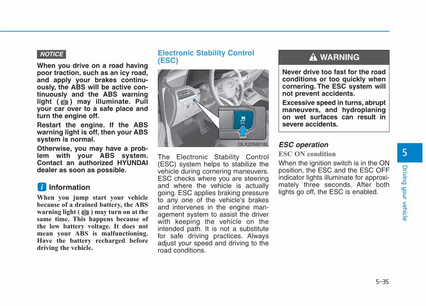
5-35
Driving your vehicle
5
When you drive on a road havingpoor traction, such as an icy road,and apply your brakes continu-ously, the ABS will be active con-tinuously and the ABS warninglight ( ) may illuminate. Pullyour car over to a safe place andturn the engine off.Restart the engine. If the ABSwarning light is off, then your ABSsystem is normal.Otherwise, you may have a prob-lem with your ABS system.Contact an authorized HYUNDAIdealer as soon as possible.
InformationWhen you jump start your vehiclebecause of a drained battery, the ABSwarning light ( ) may turn on at thesame time. This happens because ofthe low battery voltage. It does notmean your ABS is malfunctioning.Have the battery recharged beforedriving the vehicle.
Electronic Stability Control(ESC)
The Electronic Stability Control(ESC) system helps to stabilize thevehicle during cornering maneuvers.ESC checks where you are steeringand where the vehicle is actuallygoing. ESC applies braking pressureto any one of the vehicle's brakesand intervenes in the engine man-agement system to assist the driverwith keeping the vehicle on theintended path. It is not a substitutefor safe driving practices. Alwaysadjust your speed and driving to theroad conditions.
ESC operation ESC ON condition
When the ignition switch is in the ONposition, the ESC and the ESC OFFindicator lights illuminate for approxi-mately three seconds. After bothlights go off, the ESC is enabled.
i
NOTICE
OLX2059016L
Never drive too fast for the roadconditions or too quickly whencornering. The ESC system willnot prevent accidents.Excessive speed in turns, abruptmaneuvers, and hydroplaningon wet surfaces can result insevere accidents.
WARNING

5-36
Driving your vehicle
When operating
When the ESC is in opera-tion, the ESC indicator lightblinks:
• When you apply your brakes underconditions which may lock thewheels, you may hear sounds fromthe brakes, or feel a correspondingsensation in the brake pedal. Thisis normal and it means your ESC isactive.
• When the ESC activates, theengine may not respond to theaccelerator as it does under rou-tine conditions.
• If the Cruise Control was in usewhen the ESC activates, the CruiseControl automatically disengages.The Cruise Control can be reen-gaged when the road conditionsallow. See "Cruise Control System"later in this chapter. (if equipped)
• When moving out of the mud ordriving on a slippery road, theengine RPM (revolutions perminute) may not increase even ifyou press the accelerator pedaldeeply. This is to maintain the sta-bility and traction of the vehicle anddoes not indicate a problem.
ESC OFF condition
To cancel ESC operation :
• State 1Press the ESC OFF button briefly.The ESC OFF indicator light andmessage "Traction Control disabled"will illuminate. In this state, the trac-tion control function of ESC (enginemanagement) is disabled, but thebrake control function of ESC (brak-ing management) still operates.
• State 2Press and hold the ESC OFF buttoncontinuously for more than 3 sec-onds. The ESC OFF indicator lightand message "Traction and StabilityControl disabled" illuminates and awarning chime sounds. In this state,both the traction control function ofESC (engine management) and thebrake control function of ESC (brak-ing management) are disabled.If the ignition switch is placed to theLOCK/OFF position when ESC is off,ESC remains off. Upon restarting theengine, the ESC will automatically turnon again.
Indicator lights
When the ignition switch is placed tothe ON position, the ESC indicatorlight illuminates, then goes off if theESC system is operating normally.The ESC indicator light blinks when-ever the ESC is operating.If ESC indicator light stays on, yourvehicle may have a malfunction withthe ESC system. When this warninglight illuminates have your vehiclechecked by an authorized HYUNDAIdealer as soon as possible.The ESC OFF indicator light comeson when the ESC is turned off.
■ ESC indicator light (blinks)
■ ESC OFF indicator light (comes on)

5-37
Driving your vehicle
5Driving with wheels and tires withdifferent sizes may cause the ESCsystem to malfunction. Beforereplacing tires, make sure all fourtires and wheels are the samesize. Never drive the vehicle withdifferent sized wheels and tiresinstalled.
ESC OFF usageWhen Driving
The ESC OFF mode should only beused briefly to help free the vehicle ifstuck in snow or mud by temporarilystopping operation of the ESC tomaintain wheel torque.To turn ESC off while driving, pressthe ESC OFF button while driving ona flat road surface.
To prevent damage to the trans-mission:• Do not allow wheel(s) of one
axle to spin excessively whilethe ESC, ABS, and parking brakewarning lights are displayed.The repairs would not be cov-ered by the vehicle warranty.Reduce engine power and donot spin the wheel(s) excessive-ly while these lights are dis-played.
• When operating the vehicle on adynamometer, make sure theESC is turned off (ESC OFF lightilluminated).
InformationTurning the ESC off does not affect ABSor standard brake system operation.
i
NOTICENOTICE
When the ESC is blinking, thisindicates the ESC is active:Drive slowly and NEVER attemptto accelerate. NEVER turn theESC off while the ESC indicatorlight is blinking or you may losecontrol of the vehicle resulting inan accident.
WARNING
5-38
Driving your vehicle
Vehicle Stability Management(VSM)The Vehicle Stability Management(VSM) is a function of the ElectronicStability Control (ESC) system. Ithelps ensure the vehicle stays stablewhen accelerating or braking sud-denly on wet, slippery and roughroads where traction over the fourtires can suddenly become uneven. VSM operation
VSM ON condition
The VSM operates when:• The Electronic Stability Control
(ESC) is on.• Vehicle speed is approximately
above 13 mph (22 km/h) on curveroads.
• Vehicle speed is approximatelyabove 6 mph (10 km/h) when thevehicle is braking on a two surfaceroad.
✱The two surface road is made ofsurfaces which have different fric-tion forces.
When operating
When you apply your brakes underconditions which may activate theESC, you may hear sounds from thebrakes, or feel a corresponding sen-sation in the brake pedal. This is nor-mal and it means your VSM is active.
InformationThe VSM does not operate when:
• Driving on a banked road such asgradient or incline.
• Driving rearward.
• ESC OFF indicator light is on.
• EPS (Electric Power Steering) warn-ing light ( ) is on or blinks.
i
• Never drive too fast for theroad conditions.The VSM sys-tem will not prevent acci-dents. Excessive speed in badweather, slippery and unevenroads can result in severeaccidents.
Take the following precautionswhen using the Vehicle StabilityManagement (VSM):• ALWAYS check the speed and
the distance to the vehicleahead. The VSM is not a sub-stitute for safe driving prac-tices.
WARNING
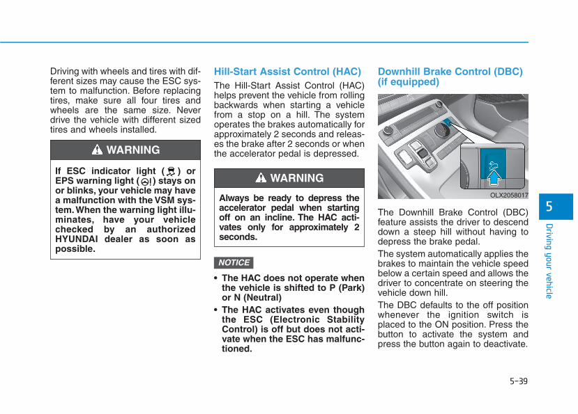
5-39
Driving your vehicle
5
Driving with wheels and tires with dif-ferent sizes may cause the ESC sys-tem to malfunction. Before replacingtires, make sure all four tires andwheels are the same size. Neverdrive the vehicle with different sizedtires and wheels installed.
Hill-Start Assist Control (HAC)The Hill-Start Assist Control (HAC)helps prevent the vehicle from rollingbackwards when starting a vehiclefrom a stop on a hill. The systemoperates the brakes automatically forapproximately 2 seconds and releas-es the brake after 2 seconds or whenthe accelerator pedal is depressed.
• The HAC does not operate whenthe vehicle is shifted to P (Park)or N (Neutral)
• The HAC activates even thoughthe ESC (Electronic StabilityControl) is off but does not acti-vate when the ESC has malfunc-tioned.
Downhill Brake Control (DBC)(if equipped)
The Downhill Brake Control (DBC)feature assists the driver to descenddown a steep hill without having todepress the brake pedal.The system automatically applies thebrakes to maintain the vehicle speedbelow a certain speed and allows thedriver to concentrate on steering thevehicle down hill.The DBC defaults to the off positionwhenever the ignition switch isplaced to the ON position. Press thebutton to activate the system andpress the button again to deactivate.
NOTICE
Always be ready to depress theaccelerator pedal when startingoff on an incline. The HAC acti-vates only for approximately 2seconds.
WARNING OLX2058017
If ESC indicator light ( ) orEPS warning light ( ) stays onor blinks, your vehicle may havea malfunction with the VSM sys-tem.When the warning light illu-minates, have your vehiclechecked by an authorizedHYUNDAI dealer as soon aspossible.
WARNING
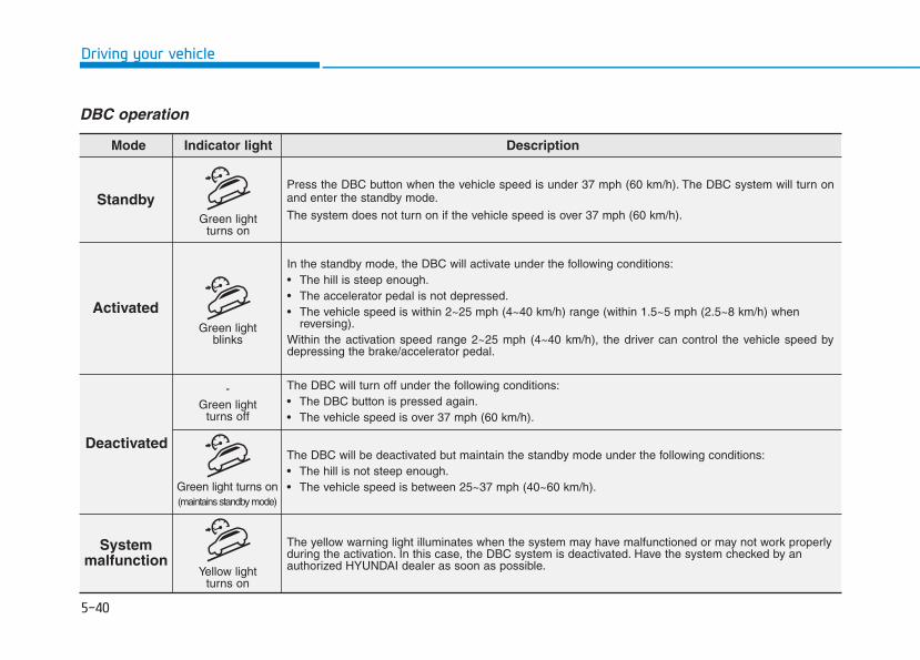
5-40
Driving your vehicle
DBC operation
StandbyPress the DBC button when the vehicle speed is under 37 mph (60 km/h). The DBC system will turn onand enter the standby mode.
The system does not turn on if the vehicle speed is over 37 mph (60 km/h).
In the standby mode, the DBC will activate under the following conditions:• The hill is steep enough.• The accelerator pedal is not depressed.• The vehicle speed is within 2~25 mph (4~40 km/h) range (within 1.5~5 mph (2.5~8 km/h) when
reversing).Within the activation speed range 2~25 mph (4~40 km/h), the driver can control the vehicle speed bydepressing the brake/accelerator pedal.
The DBC will turn off under the following conditions:• The DBC button is pressed again.• The vehicle speed is over 37 mph (60 km/h).
The yellow warning light illuminates when the system may have malfunctioned or may not work properlyduring the activation. In this case, the DBC system is deactivated. Have the system checked by anauthorized HYUNDAI dealer as soon as possible.
The DBC will be deactivated but maintain the standby mode under the following conditions:• The hill is not steep enough.• The vehicle speed is between 25~37 mph (40~60 km/h).
Activated
Deactivated
System malfunction
Mode Indicator light Description
Green lightblinks
-Green light
turns off
Green light turns on(maintains standby mode)
Yellow lightturns on
Green lightturns on
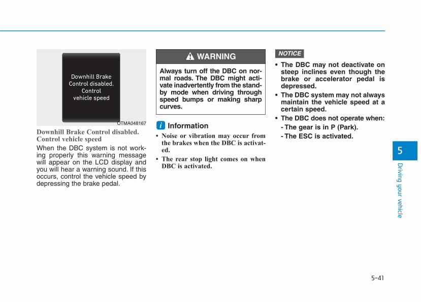
5-41
Driving your vehicle
5
Downhill Brake Control disabled.Control vehicle speed
When the DBC system is not work-ing properly this warning messagewill appear on the LCD display andyou will hear a warning sound. If thisoccurs, control the vehicle speed bydepressing the brake pedal.
Information• Noise or vibration may occur from
the brakes when the DBC is activat-ed.
• The rear stop light comes on whenDBC is activated.
• The DBC may not deactivate onsteep inclines even though thebrake or accelerator pedal isdepressed.
• The DBC system may not alwaysmaintain the vehicle speed at acertain speed.
• The DBC does not operate when:- The gear is in P (Park).- The ESC is activated.
NOTICE
i
Always turn off the DBC on nor-mal roads. The DBC might acti-vate inadvertently from the stand-by mode when driving throughspeed bumps or making sharpcurves.
WARNING
OTMA048167
5-42
Driving your vehicle
Trailer Stability Assist (TSA)Trailer Stability Assist system helpsstabilize the vehicle and trailer whenthe trailer sways or oscillates. Thereare various reasons making the vehi-cle sway and oscillate.
Factors of swaying are such as:- High speed - Strong crosswinds- Improper overloading- Sudden controlling of steering
wheel- Uneven road
Trailer Stability Assist system contin-uously analyzes the vehicle and trail-er instability. When the TrailerStability Assist system detects somesway, the brakes are applied auto-matically to stabilize the vehicle onthe front wheel. However, if it is notenough to stabilize, the brakes areapplied on all wheels automaticallyand engine power is properlyreduced. When the vehicle is stablefrom swaying, trailer stability assistsystem does not operate.
Good Braking Practices
Wet brakes can be dangerous! Thebrakes may get wet if the vehicle isdriven through standing water or if itis washed. Your vehicle will not stopas quickly if the brakes are wet. Wetbrakes may cause the vehicle to pullto one side.
To dry the brakes, apply the brakeslightly until the braking action returnsto normal, taking care to keep thevehicle under control at all times. Ifthe braking action does not return tonormal, stop as soon as it is safe todo so and call an authorizedHYUNDAI dealer for assistance.DO NOT drive with your foot restingon the brake pedal. Even light, butconstant pedal pressure can result inthe brakes overheating, brake wear,and possibly even brake failure.If a tire goes flat while you are driv-ing, apply the brakes gently andkeep the vehicle pointed straightahead while you slow down. Whenyou are moving slowly enough for itto be safe to do so, pull off the roadand stop in a safe location.Keep your foot firmly on the brakepedal when the vehicle is stopped toprevent the vehicle from rolling for-ward.
Whenever leaving the vehicle orparking, always come to a com-plete stop and continue todepress the brake pedal. Shiftthe gear to P (Park), then applythe parking brake, and place theignition switch in the LOCK/OFFposition.Vehicles parked with the park-ing brake not applied or notfully engaged may roll inadver-tently and may cause injury tothe driver and others. ALWAYSapply the parking brake beforeexiting the vehicle.
WARNING

5-43
Driving your vehicle
5
The All Wheel Drive (AWD) systemdelivers engine torque to both thefront and rear wheels for extra trac-tion. AWD is useful when maximumtraction is required on slippery,muddy, wet, or snow-covered roads.Occasional off-road use such asestablished unpaved roads and trailsare OK. It is always important thatthe driver carefully reduces thespeed to a level that does not exceedthe safe operating speed for thoseconditions.
• Do not drive in water if the levelis higher than the bottom of thevehicle.
• Check your brake conditiononce you are out of mud orwater. Depress the brake pedalseveral times as you move slow-ly until you feel normal brakingreturn.
• Shorten your scheduled mainte-nance interval if you drive in off-road conditions such as sand,mud or water (see "MaintenanceUnder Severe Usage Conditions"in chapter 7).
• Always wash your vehicle thor-oughly after off road use, espe-cially the bottom of the vehicle.
• Be sure to equip the vehicle withfour tires of the same size andtype.
• Make sure that a full time AWDvehicle is towed by a flat bedtow truck.
NOTICE
AALLLL WWHHEEEELL DDRRIIVVEE ((AAWWDD)) ((IIFF EEQQUUIIPPPPEEDD))
To reduce the risk of SERIOUSINJURY or DEATH:• Do not drive in conditions that
exceed the vehicles intendeddesign such as challengingoff-road conditions.
• Avoid high speeds when cor-nering or turning.
• Do not make quick steeringwheel movements, such assharp lane changes or fast,sharp turns.
• The risk of a rollover is great-ly increased if you lose con-trol of your vehicle at highwayspeeds.
• Loss of control often occurs iftwo or more wheels drop offthe roadway and the driverover steers to reenter theroadway.
• In the event your vehicleleaves the roadway, do notsteer sharply. Instead, slowdown before pulling back intothe travel lanes.
WARNING
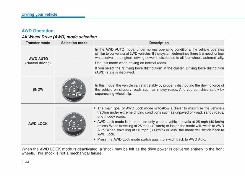
5-44
Driving your vehicle
Transfer mode Selection mode Description
AWD AUTO(Normal driving)
-
In the AWD AUTO mode, under normal operating conditions, the vehicle operatessimilar to conventional 2WD vehicles. If the system determines there is a need for fourwheel drive, the engine's driving power is distributed to all four wheels automatically.
Use this mode when driving on normal roads.
If you select the "Driving force distribution" in the cluster, Driving force distribution(AWD) state is displayed.
SNOWIn this mode, the vehicle can start stably by properly distributing the driving force ofthe vehicle on slippery roads such as snowy roads. And you can drive safely bysuppressing wheel slip.
AWD LOCK
• The main goal of AWD Lock mode is toallow a driver to maximize the vehicle'straction under extreme driving conditions such as unpaved off-road, sandy roads,and muddy roads.
• AWD Lock mode is in operation only when a vehicle travels at 25 mph (40 km/h)or less. When travelling at 25 mph (40 km/h) or faster, the mode will switch to AWDAuto. When travelling at 20 mph (30 km/h) or less, the mode will switch back toAWD Lock.
• Press the AWD Lock mode switch again to switch back to AWD Auto.
AWD OperationAll Wheel Drive (AWD) mode selection
When the AWD LOCK mode is deactivated, a shock may be felt as the drive power is delivered entirely to the frontwheels. This shock is not a mechanical failure.

5-45
Driving your vehicle
5
For safe AWD operationBefore driving
• Make sure all passengers arewearing seat belts.
• Sit upright and closer to the steer-ing wheel than usual. Adjust thesteering wheel to a position com-fortable for you to drive.
Driving on snow-covered or icyroads
• Start off slowly by applying theaccelerator pedal gently.
• Use snow tires or tire chains.• Keep sufficient distance between
your vehicle and the vehicle in frontof you.
• Apply engine braking during decel-eration by using the paddle shifterand manually selecting a lower gear.
• Avoid speeding, rapid acceleration,sudden brake applications, andsharp turns to prevent skids.
Driving in sand or mud
• Maintain slow and constant speed.• Use tire chains driving in mud if
necessary.• Keep sufficient distance between
your vehicle and the vehicle in frontof you.
• Reduce vehicle speed and alwayscheck the road condition.
• Avoid speeding, rapid acceleration,sudden brake applications, andsharp turns to prevent gettingstuck.
When the vehicle is stuck insnow, sand or mud, place a non-slip material under the drivewheels to provide traction ORSlowly spin the wheels in for-ward and reverse directionswhich causes a rocking motionthat may free the vehicle.However, avoid running theengine continuously at highrpm, doing so may damage theAWD system.
CAUTION
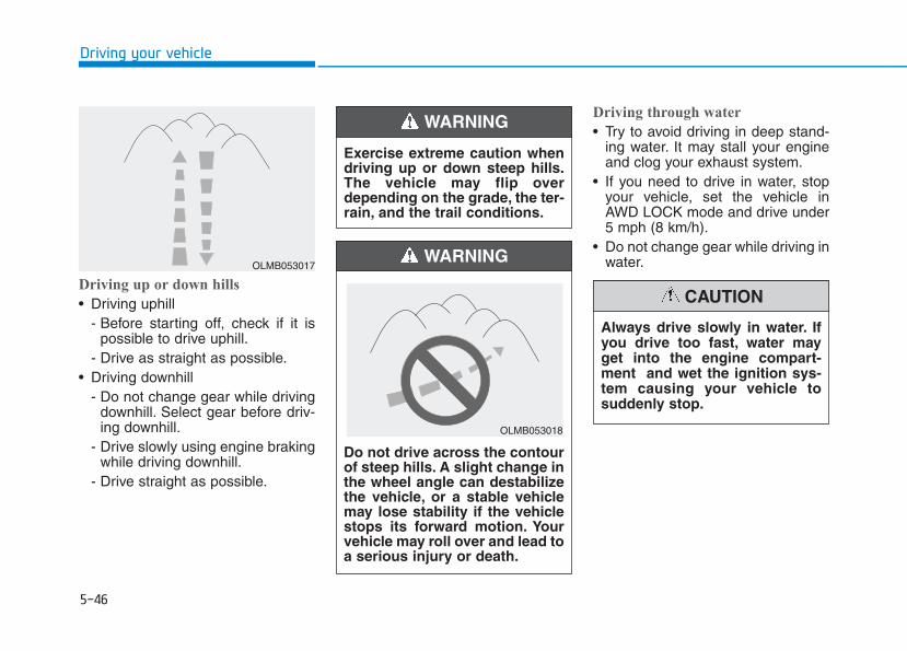
5-46
Driving your vehicle
Driving up or down hills
• Driving uphill - Before starting off, check if it is
possible to drive uphill.- Drive as straight as possible.
• Driving downhill - Do not change gear while driving
downhill. Select gear before driv-ing downhill.
- Drive slowly using engine brakingwhile driving downhill.
- Drive straight as possible.
Driving through water
• Try to avoid driving in deep stand-ing water. It may stall your engineand clog your exhaust system.
• If you need to drive in water, stopyour vehicle, set the vehicle inAWD LOCK mode and drive under5 mph (8 km/h).
• Do not change gear while driving inwater.
Exercise extreme caution whendriving up or down steep hills.The vehicle may flip overdepending on the grade, the ter-rain, and the trail conditions.
WARNING
Do not drive across the contourof steep hills. A slight change inthe wheel angle can destabilizethe vehicle, or a stable vehiclemay lose stability if the vehiclestops its forward motion. Yourvehicle may roll over and lead toa serious injury or death.
WARNING
Always drive slowly in water. Ifyou drive too fast, water mayget into the engine compart-ment and wet the ignition sys-tem causing your vehicle tosuddenly stop.
CAUTION
OLMB053018
OLMB053017

5-47
Driving your vehicle
5
Additional driving conditions
• Become familiar with the off-roadconditions before driving.
• Always pay attention when drivingoff-road and avoid dangerousareas.
• Drive slowly when driving in heavywind.
• Reduce vehicle speed when cor-nering. The center of gravity ofAWD vehicles is higher than con-ventional 2WD vehicles, makingthem more likely to roll over whenyou rapidly turn corners.
• Always hold the steering wheelfirmly when you are driving off-road.
LCD display messageTransmission hot! Park withengine On
• Under certain conditions, such asrepeated stop-and-go launches onsteep grades, sudden take off oracceleration, or other harsh drivingconditions (mud or sand road), thetransmission temperatures willincrease excessively. Finally thetransmission could be overheated.
Do not grab the inside of thesteering wheel when you aredriving off-road. You may hurtyour arm by a sudden steeringmaneuver or from steering wheelrebound due to an impact withobjects on the ground.You couldlose control of the steering wheelwhich may lead to serious injuryor death.
WARNING
OJS058137L/OJS058138L
5-48
Driving your vehicle
• If the vehicle continues to be drivenand the automatic transmissiontemperatures reach the maximumtemperature limit, the "Transmissionhot! Park with engine On" warningwill be displayed. When this occursthe automatic transmission is dis-abled until the automatic transmis-sion cools to normal temperatures.
• The warning will display a time towait for the transmission to cool.
• If this occurs, pull over to a safelocation, stop the vehicle with theengine running, apply the brakesand shift the vehicle to P (Park),and allow the transmission to cool.
• When the message "Transmissioncooled down. Resume driving"appears you can continue to driveyour vehicle.
• When possible, drive the vehiclesmoothly.
Emergency PrecautionsTiresDo not use a tire and wheel packagewith a different size and type fromthe one originally installed on yourvehicle. It can affect the safety andperformance of your vehicle, whichcould lead to steering failure orrollover causing serious injury.When replacing the tires, be sure toequip all four tires with the tire andwheel of the same size, type, tread,brand and load-carrying capacity. Ifyou equip your vehicle with anytire/wheel combination not recom-mended by HYUNDAI for off-roaddriving, you should not use thesetires for highway driving.
Towing AWD vehicles must be towed with awheel lift and dollies or flatbed equip-ment with all the wheels off theground. For more details, refer to"Towing" in chapter 6.
Dynamometer testingA full-time AWD vehicle must be test-ed on a special four wheel chassisdynamometer.
Never start or run the enginewhile a full-time AWD vehicle israised on a jack.The vehicle canslip or roll off of a jack causingserious injury or death to you orthose nearby.
WARNING
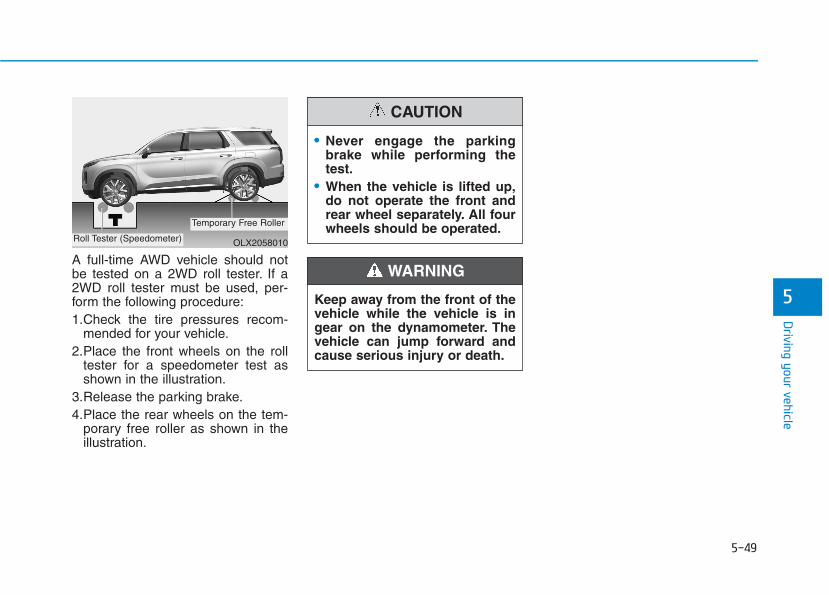
5-49
Driving your vehicle
5
A full-time AWD vehicle should notbe tested on a 2WD roll tester. If a2WD roll tester must be used, per-form the following procedure:1.Check the tire pressures recom-
mended for your vehicle.2.Place the front wheels on the roll
tester for a speedometer test asshown in the illustration.
3.Release the parking brake.4.Place the rear wheels on the tem-
porary free roller as shown in theillustration.
• Never engage the parkingbrake while performing thetest.
• When the vehicle is lifted up,do not operate the front andrear wheel separately. All fourwheels should be operated.
CAUTION
Keep away from the front of thevehicle while the vehicle is ingear on the dynamometer. Thevehicle can jump forward andcause serious injury or death.
WARNING
OLX2058010Roll Tester (Speedometer)
Temporary Free Roller

5-50
Driving your vehicle
The Idle Stop and Go (ISG) systemautomatically and temporarily shutsdown the engine when the vehicle isstopped and idling to improve fuelefficiency and reduce exhaust gasemissions. (i.e. red stop light, stopsign, and traffic jam).The engine is automatically startedupon satisfying the starting condi-tions.The ISG system is always active,when the engine is running.
Information When the engine is automaticallystarted by the ISG system, some warn-ing lights (i.e. ABS, ESC, ESC OFF,EPS, and parking brake warninglight) may illuminate for a few sec-onds due to the low battery voltage.However, it does not indicate a mal-function with the ISG system.
To Activate the ISG SystemPrerequisite for activation The ISG system operates in the fol-lowing situations.• The driver's seatbelt is fastened• The driver's door and hood are
closed• The brake vacuum pressure is
adequate• The battery sensor is activated and
the battery is sufficiently charged• Outside temperature is not too low
or too high• The vehicle is driven over a con-
stant speed and stops• The climate control system satis-
fies the conditions• The vehicle is sufficiently warmed
up• The incline is gradual• The steering wheel is turned less
than 180 degrees and then thevehicle stops
Information The ISG system isnot activated, whenthe prerequisites toactivate the ISG sys-tem are unsatisfied.In this case, the ISG
OFF button indicator illuminates,and the auto stop indicator ( )illuminates in yellow on the instru-ment cluster.
• When the above indicator remainsilluminated on the instrument clus-ter, we recommend that you havethe IGS system checked by anauthorized HYUNDAI dealer.
i
i
IISSGG ((IIDDLLEE SSTTOOPP AANNDD GGOO)) SSYYSSTTEEMM ((IIFF EEQQUUIIPPPPEEDD))
•
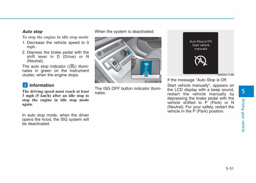
5-51
Driving your vehicle
5
Auto stopTo stop the engine in idle stop mode
1. Decrease the vehicle speed to 0mph.
2. Depress the brake pedal with theshift lever in D (Drive) or N(Neutral).
The auto stop indicator ( ) illumi-nates in green on the instrumentcluster, when the engine stops.
Information The driving speed must reach at least3 mph (5 km/h) after an idle stop tostop the engine in idle stop modeagain.
In auto stop mode, when the driveropens the hood, the ISG system willbe deactivated.
When the system is deactivated:
The ISG OFF button indicator illumi-nates.
If the message "Auto Stop is Off.Start vehicle manually", appears onthe LCD display with a beep sound,restart the vehicle manually bydepressing the brake pedal with thevehicle shifted to P (Park) or N(Neutral). For your safety, restart thevehicle in the P (Park) position.
iOLX2058018
OIK057173N
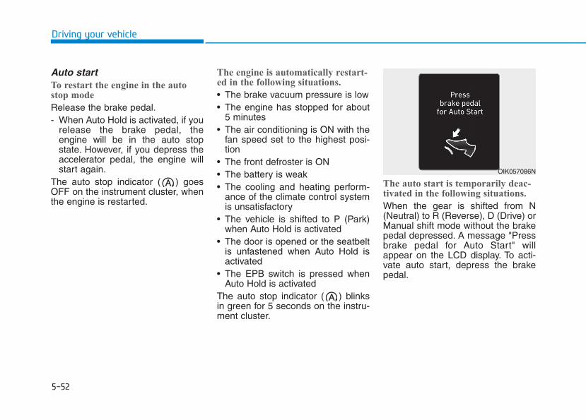
5-52
Driving your vehicle
Auto startTo restart the engine in the autostop mode
Release the brake pedal.- When Auto Hold is activated, if you
release the brake pedal, theengine will be in the auto stopstate. However, if you depress theaccelerator pedal, the engine willstart again.
The auto stop indicator ( ) goesOFF on the instrument cluster, whenthe engine is restarted.
The engine is automatically restart-ed in the following situations.
• The brake vacuum pressure is low• The engine has stopped for about
5 minutes• The air conditioning is ON with the
fan speed set to the highest posi-tion
• The front defroster is ON• The battery is weak• The cooling and heating perform-
ance of the climate control systemis unsatisfactory
• The vehicle is shifted to P (Park)when Auto Hold is activated
• The door is opened or the seatbeltis unfastened when Auto Hold isactivated
• The EPB switch is pressed whenAuto Hold is activated
The auto stop indicator ( ) blinksin green for 5 seconds on the instru-ment cluster.
The auto start is temporarily deac-tivated in the following situations.
When the gear is shifted from N(Neutral) to R (Reverse), D (Drive) orManual shift mode without the brakepedal depressed. A message "Pressbrake pedal for Auto Start" willappear on the LCD display. To acti-vate auto start, depress the brakepedal.
OIK057086N
5-53
Driving your vehicle
5
To Deactivate the ISG System • Press the ISG OFF button to deac-
tivate the ISG system. Then, theISG OFF button indicator illumi-nates.
• Press the ISG OFF button again toreactivate the ISG system. Then,the ISG OFF button indicator turnsOFF.
ISG System MalfunctionThe ISG system may not operate:
When there is a malfunction with theISG sensors or the ISG system.
The followings occur, when there isa malfunction with the ISG system:
• The auto stop indicator ( ) willblink in yellow on the instrumentcluster.
• The light on the ISG OFF buttonwill illuminate.
Information • When you cannot turn OFF the ISG
OFF button indicator by pressing theISG OFF button, or when the mal-function with the ISG system per-sists, contact an authorizedHYUNDAI dealer.
• You can turn off the ISG OFF but-ton indicator by driving over 50mph (80 km/h) for up to 2 hourswith the fan speed below the 2ndposition. If the ISG OFF buttonindicator remains ON, contact anauthorized HYUNDAI dealer.
i
When the engine is in auto stopmode, the engine may restart.Before leaving the vehicle orchecking the engine compart-ment, stop the engine placingthe ignition switch to theLOCK/OFF position or removethe ignition key.
WARNING
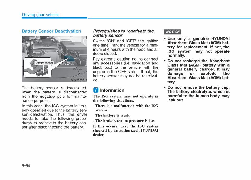
5-54
Driving your vehicle
Battery Sensor Deactivation
The battery sensor is deactivated,when the battery is disconnectedfrom the negative pole for mainte-nance purpose.In this case, the ISG system is limit-edly operated due to the battery sen-sor deactivation. Thus, the driverneeds to take the following proce-dures to reactivate the battery sen-sor after disconnecting the battery.
Prerequisites to reactivate thebattery sensorSwitch "ON" and "OFF" the ignitionone time. Park the vehicle for a mini-mum of 4 hours with the hood and alldoors closed.Pay extreme caution not to connectany accessories (i.e. navigation andblack box) to the vehicle with theengine in the OFF status. If not, thebattery sensor may not be reactivat-ed.
Information The ISG system may not operate inthe following situations.
- There is a malfunction with the ISGsystem.
- The battery is weak.
- The brake vacuum pressure is low.
If this occurs, have the ISG systemchecked by an authorized HYUNDAIdealer.
• Use only a genuine HYUNDAIAbsorbent Glass Mat (AGM) bat-tery for replacement. If not, theISG system may not operatenormally.
• Do not recharge the AbsorbentGlass Mat (AGM) battery with ageneral battery charger. It maydamage or explode theAbsorbent Glass Mat (AGM) bat-tery.
• Do not remove the battery cap.The battery electrolyte, which isharmful to the human body, mayleak out.
NOTICE
i
OLX2058019
Battery sensor
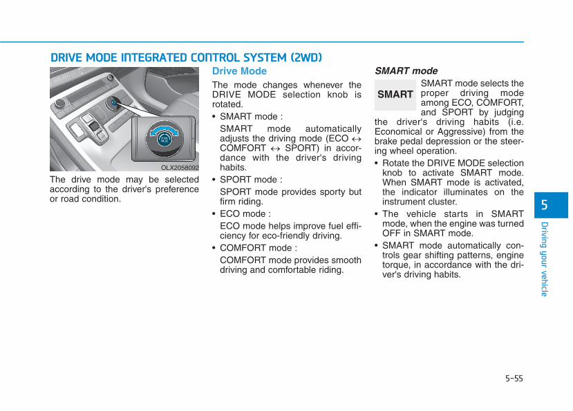
5-55
Driving your vehicle
5
The drive mode may be selectedaccording to the driver's preferenceor road condition.
Drive ModeThe mode changes whenever theDRIVE MODE selection knob isrotated.• SMART mode :
SMART mode automaticallyadjusts the driving mode (ECO ↔COMFORT ↔ SPORT) in accor-dance with the driver's drivinghabits.
• SPORT mode :SPORT mode provides sporty butfirm riding.
• ECO mode :ECO mode helps improve fuel effi-ciency for eco-friendly driving.
• COMFORT mode :COMFORT mode provides smoothdriving and comfortable riding.
SMART mode SMART mode selects theproper driving modeamong ECO, COMFORT,and SPORT by judging
the driver's driving habits (i.e.Economical or Aggressive) from thebrake pedal depression or the steer-ing wheel operation.• Rotate the DRIVE MODE selection
knob to activate SMART mode.When SMART mode is activated,the indicator illuminates on theinstrument cluster.
• The vehicle starts in SMARTmode, when the engine was turnedOFF in SMART mode.
• SMART mode automatically con-trols gear shifting patterns, enginetorque, in accordance with the dri-ver's driving habits.
DDRRIIVVEE MMOODDEE IINNTTEEGGRRAATTEEDD CCOONNTTRROOLL SSYYSSTTEEMM ((22WWDD))
OLX2058092
SMART
5-56
Driving your vehicle
Information • When you mildly drive the vehicle
in SMART mode, the driving modechanges to ECO mode to improvefuel efficiency. However, the actualfuel efficiency may differ in accor-dance with your driving situations(i.e. upward/downward slope, vehi-cle deceleration/acceleration).
• When you dynamically drive thevehicle in SMART mode by abrupt-ly decelerating or sharply turningthe driving mode changes to SPORTmode. However, it may adverselyaffect fuel economy.
Various driving situations, whichyou may encounter in SMARTmode
• The driving mode automaticallychanges to ECO mode after a cer-tain period of time, when you gen-tly depress the accelerator pedal(Your driving is categorized to beeconomical.).
• The driving mode automaticallychanges from SMART ECO modeto SMART COMFORT mode aftera certain period of time, when yousharply or repetitively depress theaccelerator pedal.
• The driving mode automaticallychanges to SMART COMFORTmode with the same driving pat-terns, when the vehicle starts todrive on an upward slope of a cer-tain angle. The driving mode auto-matically returns to SMART ECOmode, when the vehicle enters aleveled road.
• The driving mode automaticallychanges to SMART SPORT, whenyou abruptly accelerate the vehicleor repetitively operate the steeringwheel (Your driving is categorizedto be aggressive.). In this mode,your vehicle drives in a lower gearfor abrupt accelerating/decelerat-ing and increases the engine brakeperformance.
• You may still sense the enginebraking performance, even whenyou release the accelerator pedalin SMART SPORT mode. It isbecause your vehicle remains inlower gear over a certain period oftime for next acceleration. Thus, itis a normal driving situation, notindicating any malfunction.
• The driving mode automaticallychanges to SMART SPORT modeonly in harsh driving situations. Inmost of the normal driving situa-tions, the driving mode sets to beeither in SMART ECO mode or inSMART COMFORT mode.
i

5-57
Driving your vehicle
5
Limitation of SMART mode
The SMART mode may be limited infollowing situations. (The OFF indica-tor illuminates in those situations.) • The driver uses the paddle shifter
(manual shift mode) :It deactivates SMART mode. Thevehicle drives, as the driver manu-ally changes gear with the paddleshifter.
• The cruise control is activated :The cruise control system maydeactivate the SMART mode whenthe vehicle is controlled by the setspeed of the smart cruise controlsystem. (SMART mode is notdeactivated just by activating thecruise control system.)
• The transmission oil temperature iseither extremely low or extremelyhigh :The SMART mode can be active inmost of the normal driving situa-tions. However, an extremely high/low transmission oil temperaturemay temporarily deactivate theSMART mode, because the trans-mission condition is out of normaloperation condition.
SPORTSPORT mode managesthe driving dynamics byautomatically adjustingthe steering effort, and
the engine and transmission controllogic for enhanced driver perform-ance.• When SPORT mode is selected by
rotating the DRIVE MODE selec-tion knob, the SPORT indicator willilluminate.
• Whenever the engine is restarted,the drive mode will revert back toCOMFORT mode. If SPORT modeis desired, re-select SPORT mode.
• When SPORT mode is activated:- The engine rpm will tend to
remain a little higher for a brieftime even after releasing theaccelerator. This is typical whenthe SPORT mode is activated.
- Upshifts are delayed when accel-erating
Information In SPORT mode, the fuel efficiencymay decrease.
ECO modeWhen the drive mode isset to ECO mode, theengine and transmissioncontrol logic are changedto maximize fuel efficien-cy.
• When ECO mode is selected byrotating the DRIVE MODE selec-tion knob, the ECO indicator willilluminate.
• The vehicle starts in ECO mode,when the engine was turned OFFin ECO mode.
Information Fuel efficiency depends on the driver'sdriving habit and road condition.
i
i
SPORT ECO

5-58
Driving your vehicle
When ECO mode is activated:
• The acceleration response may beslightly reduced if the acceleratorpedal is depressed moderately.
• The air conditioner performancemay be limited.
• The shift pattern of the automatictransmission may change.
• The engine noise may be louder atsome automatic transmissionshifts as down-shift requires press-ing down more on the accelerator.
The above situations are normalconditions when ECO mode is acti-vated to help improve fuel efficiency.
Limitation of ECO mode operation:
If the following conditions occur whileECO mode is operating, the systemoperation is limited even thoughthere is no change in the ECO indi-cator.
• When the coolant temperature islow:The system will be limited untilengine performance becomes nor-mal.
• When driving up a hill:The system will be limited to gainpower when driving uphill becauseengine torque is restricted.
• When driving the vehicle in manualshift mode using the paddle shifter.The system will be limited accord-ing to the shift location.

5-59
Driving your vehicle
5
The drive mode may be selectedaccording to the driver's preferenceor road condition.
Drive ModeThe mode changes whenever theDRIVE MODE selection knob isrotated.
• SMART mode :SMART mode automaticallyadjusts the driving mode (ECO ↔COMFORT ↔ SPORT) in accor-dance with the driver's drivinghabits.
DDRRIIVVEE MMOODDEE IINNTTEEGGRRAATTEEDD CCOONNTTRROOLL SSYYSSTTEEMM ((AAWWDD))
OLX2059021N
OLX2059025N/OLX2059024N
OLX2059023N/OLX2059022N
■ Type A
OLX2059112N/OLX2059111N
OLX2059110N/OLX2059124N
■ Type B
5-60
Driving your vehicle
• SPORT mode :SPORT mode provides sporty butfirm riding.
• ECO mode :ECO mode helps improve fuel effi-ciency for eco-friendly driving.
• COMFORT mode :COMFORT mode provides smoothdriving and comfortable riding.
SMART mode SMART mode selects theproper driving modeamong ECO, COMFORT,and SPORT by judging
the driver's driving habits (i.e.Economical or Aggressive) from thebrake pedal depression or the steer-ing wheel operation.• Rotate the DRIVE/TERRAIN mode
selection knob to activate SMARTmode. When SMART mode is acti-vated, the indicator illuminates onthe instrument cluster.
• The vehicle starts in SMARTmode, when the engine was turnedOFF in SMART mode.
• SMART mode automatically con-trols gear shifting patterns, enginetorque, in accordance with the dri-ver's driving habits.
• SMART mode automatically con-trols the vehicle driving, such asgear shifting patterns, enginetorque, riding quality (if equippedwith the electronic suspension sys-tem), and power distribution (ifequipped with the All-Wheel Drive(AWD) system), in accordance withthe driver's driving habits.
Information • When you mildly drive the vehicle
in SMART mode, the driving modechanges to ECO mode to improvefuel efficiency. However, the actualfuel efficiency may differ in accor-dance with your driving situations(i.e. upward/downward slope, vehi-cle deceleration/acceleration).
• When you dynamically drive thevehicle in SMART mode by abrupt-ly decelerating or sharply turningthe driving mode changes to SPORTmode. However, it may adverselyaffect fuel economy.
Various driving situations, whichyou may encounter in SMARTmode
• The driving mode automaticallychanges to ECO mode after a cer-tain period of time, when you gen-tly depress the accelerator pedal(Your driving is categorized to beeconomical.).
• The driving mode automaticallychanges from SMART ECO modeto SMART COMFORT mode aftera certain period of time, when yousharply or repetitively depress theaccelerator pedal.
• The driving mode automaticallychanges to SMART COMFORTmode with the same driving pat-terns, when the vehicle starts todrive on an upward slope of a cer-tain angle. The driving mode auto-matically returns to SMART ECOmode, when the vehicle enters aleveled road.
iSMART
5-61
Driving your vehicle
5
• The driving mode automaticallychanges to SMART SPORT, whenyou abruptly accelerate the vehicleor repetitively operate the steeringwheel (Your driving is categorizedto be aggressive.). In this mode,your vehicle drives in a lower gearfor abrupt accelerating/decelerat-ing and increases the engine brakeperformance.
• You may still sense the enginebraking performance, even whenyou release the accelerator pedalin SMART SPORT mode. It isbecause your vehicle remains inlower gear over a certain period oftime for next acceleration. Thus, itis a normal driving situation, notindicating any malfunction.
• The driving mode automaticallychanges to SMART SPORT modeonly in harsh driving situations. Inmost of the normal driving situa-tions, the driving mode sets to beeither in SMART ECO mode or inSMART COMFORT mode.
Limitation of SMART mode
The SMART mode may be limited infollowing situations. (The OFF indica-tor illuminates in those situations.) • The driver uses the paddle shifter
(manual shift mode) :It deactivates SMART mode. Thevehicle drives, as the driver manu-ally changes gear with the paddleshifter.
• The cruise control is activated :The cruise control system maydeactivate the SMART mode whenthe vehicle is controlled by the setspeed of the smart cruise controlsystem. (SMART mode is notdeactivated just by activating thecruise control system.)
• The transmission oil temperature iseither extremely low or extremelyhigh :The SMART mode can be active inmost of the normal driving situa-tions. However, an extremely high/low transmission oil temperaturemay temporarily deactivate theSMART mode, because the trans-mission condition is out of normaloperation condition.
SPORTSPORT mode managesthe driving dynamics byautomatically adjustingthe steering effort, and
the engine and transmission controllogic for enhanced driver perform-ance.• When SPORT mode is selected by
rotating the DRIVE/TERRAINmode selection knob, the SPORTindicator will illuminate.
• Whenever the engine is restarted,the drive mode will revert back toCOMFORT mode. If SPORT modeis desired, re-select SPORT mode.
• When SPORT mode is activated:- The engine rpm will tend to
remain a little higher for a brieftime even after releasing theaccelerator. This is typical whenthe SPORT mode is activated.
- Upshifts are delayed when accel-erating
Information In SPORT mode, the fuel efficiencymay decrease.
i
SPORT
5-62
Driving your vehicle
ECO modeWhen the drive mode isset to ECO mode, theengine and transmissioncontrol logic are changedto maximize fuel efficien-cy.
• When ECO mode is selected byrotating the DRIVE mode selectionknob, the ECO indicator will illumi-nate.
• The vehicle starts in ECO mode,when the engine was turned OFFin ECO mode.
Information Fuel efficiency depends on the driver'sdriving habit and road condition.
When ECO mode is activated:
• The acceleration response may beslightly reduced if the acceleratorpedal is depressed moderately.
• The air conditioner performancemay be limited.
• The shift pattern of the automatictransmission may change.
• The engine noise may be louder atsome automatic transmissionshifts as down-shift requires press-ing down more on the accelerator.
The above situations are normalconditions when ECO mode is acti-vated to help improve fuel efficiency.
Limitation of ECO mode operation:
If the following conditions occur whileECO mode is operating, the systemoperation is limited even thoughthere is no change in the ECO indi-cator.
• When the coolant temperature islow:The system will be limited untilengine performance becomes nor-mal.
• When driving up a hill:The system will be limited to gainpower when driving uphill becauseengine torque is restricted.
• When driving the vehicle in manualshift mode using the paddle shifter.The system will be limited accord-ing to the shift location.
i
ECO
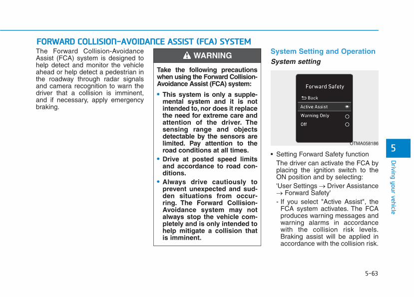
5-63
Driving your vehicle
5
The Forward Collision-AvoidanceAssist (FCA) system is designed tohelp detect and monitor the vehicleahead or help detect a pedestrian inthe roadway through radar signalsand camera recognition to warn thedriver that a collision is imminent,and if necessary, apply emergencybraking.
System Setting and OperationSystem setting
• Setting Forward Safety functionThe driver can activate the FCA byplacing the ignition switch to theON position and by selecting:'User Settings → Driver Assistance→ Forward Safety'- If you select "Active Assist", the
FCA system activates. The FCAproduces warning messages andwarning alarms in accordancewith the collision risk levels.Braking assist will be applied inaccordance with the collision risk.
FFOORRWWAARRDD CCOOLLLLIISSIIOONN--AAVVOOIIDDAANNCCEE AASSSSIISSTT ((FFCCAA)) SSYYSSTTEEMM
Take the following precautionswhen using the Forward Collision-Avoidance Assist (FCA) system:
• This system is only a supple-mental system and it is notintended to, nor does it replacethe need for extreme care andattention of the driver. Thesensing range and objectsdetectable by the sensors arelimited. Pay attention to theroad conditions at all times.
• Drive at posted speed limitsand accordance to road con-ditions.
• Always drive cautiously toprevent unexpected and sud-den situations from occur-ring. The Forward Collision-Avoidance system may notalways stop the vehicle com-pletely and is only intended tohelp mitigate a collision thatis imminent.
WARNING
OTMA058186
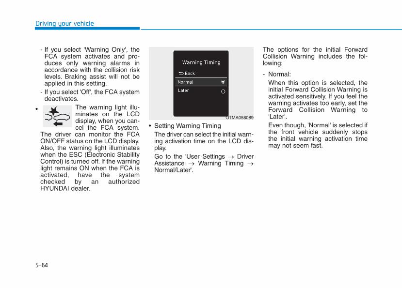
5-64
Driving your vehicle
- If you select 'Warning Only', theFCA system activates and pro-duces only warning alarms inaccordance with the collision risklevels. Braking assist will not beapplied in this setting.
- If you select 'Off', the FCA systemdeactivates.
The warning light illu-minates on the LCDdisplay, when you can-cel the FCA system.
The driver can monitor the FCAON/OFF status on the LCD display.Also, the warning light illuminateswhen the ESC (Electronic StabilityControl) is turned off. If the warninglight remains ON when the FCA isactivated, have the systemchecked by an authorizedHYUNDAI dealer.
• Setting Warning TimingThe driver can select the initial warn-ing activation time on the LCD dis-play.Go to the 'User Settings → DriverAssistance → Warning Timing →Normal/Later'.
The options for the initial ForwardCollision Warning includes the fol-lowing:
- Normal:When this option is selected, theinitial Forward Collision Warning isactivated sensitively. If you feel thewarning activates too early, set theForward Collision Warning to'Later'.Even though, 'Normal' is selected ifthe front vehicle suddenly stopsthe initial warning activation timemay not seem fast.
•OTMA058089
5-65
Driving your vehicle
5
- Later:When this option is selected, theinitial Forward Collision Warning isactivated later than normal. Thissetting reduces the amount of dis-tance between the vehicle, pedes-trian ahead before the initial warn-ing occurs.Select 'Later' when traffic is lightand when driving speed is slow.
Information If you change the warning timing, thewarning time of other systems maychange. Always be aware beforechanging the warning timing.
Prerequisite for activationThe FCA system is on and readywhen 'Active Assist' or 'WarningOnly' under Forward Safety is select-ed in the LCD display and when thefollowing prerequisites are satisfied:- ESC (Electronic Stability Control)
is on.- Vehicle speed is over 5 mph (8
km/h ) (The FCA is only activatedwithin a certain speed range.).
- The system detects a pedestrianor a vehicle in front, which may col-lide with your vehicle. However,FCA may not be activated or mayonly sound a warning alarmdepending on the driving or vehicleconditions.
i
• To avoid driver distractions,do not attempt to set or can-cel the FCA while driving thevehicle. Always completelystop the vehicle at a safeplace before setting or cancel-ing the system.
• FCA automatically activatesupon placing the ignitionswitch to the ON position. Thedriver can deactivate FCA bycanceling the system settingin the cluster LCD display.
• FCA automatically deacti-vates upon canceling ESC.When ESC is canceled, FCAcannot be activated in thecluster LCD display. In this sit-uation, the FCA warning lightwill illuminate which is nor-mal.
WARNING
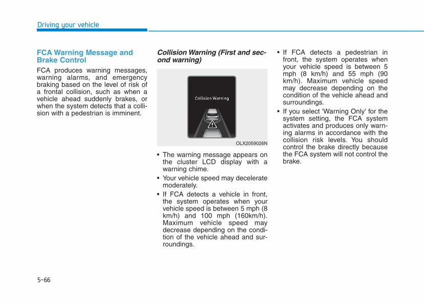
5-66
Driving your vehicle
FCA Warning Message andBrake ControlFCA produces warning messages,warning alarms, and emergencybraking based on the level of risk ofa frontal collision, such as when avehicle ahead suddenly brakes, orwhen the system detects that a colli-sion with a pedestrian is imminent.
Collision Warning (First and sec-ond warning)
• The warning message appears onthe cluster LCD display with awarning chime.
• Your vehicle speed may deceleratemoderately.
• If FCA detects a vehicle in front,the system operates when yourvehicle speed is between 5 mph (8km/h) and 100 mph (160km/h).Maximum vehicle speed maydecrease depending on the condi-tion of the vehicle ahead and sur-roundings.
• If FCA detects a pedestrian infront, the system operates whenyour vehicle speed is between 5mph (8 km/h) and 55 mph (90km/h). Maximum vehicle speedmay decrease depending on thecondition of the vehicle ahead andsurroundings.
• If you select 'Warning Only' for thesystem setting, the FCA systemactivates and produces only warn-ing alarms in accordance with thecollision risk levels. You shouldcontrol the brake directly becausethe FCA system will not control thebrake.
OLX2059026N
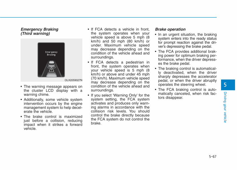
5-67
Driving your vehicle
5
Emergency Braking(Third warning)
• The warning message appears onthe cluster LCD display with awarning chime.
• Additionally, some vehicle systemintervention occurs by the enginemanagement system to help decel-erate the vehicle.
• The brake control is maximizedjust before a collision, reducingimpact when it strikes a forwardvehicle.
• If FCA detects a vehicle in front,the system operates when yourvehicle speed is above 5 mph (8km/h) and 50 mph (80 km/h) orunder. Maximum vehicle speedmay decrease depending on thecondition of the vehicle ahead andsurroundings.
• If FCA detects a pedestrian infront, the system operates whenyour vehicle speed is 5 mph (8km/h) or above and under 45 mph(70 km/h). Maximum vehicle speedmay decrease depending on thecondition of the vehicle ahead andsurroundings.
• If you select 'Warning Only' for thesystem setting, the FCA systemactivates and produces only warn-ing alarms in accordance with thecollision risk levels. You shouldcontrol the brake directly becausethe FCA system do not control thebrake.
Brake operation• In an urgent situation, the braking
system enters into the ready statusfor prompt reaction against the dri-ver’s depressing the brake pedal.
• The FCA provides additional brak-ing power for optimum braking per-formance, when the driver depress-es the brake pedal.
• The braking control is automatical-ly deactivated, when the driversharply depresses the acceleratorpedal, or when the driver abruptlyoperates the steering wheel.
• The FCA braking control is auto-matically canceled, when risk fac-tors disappear.
OLX2059027N
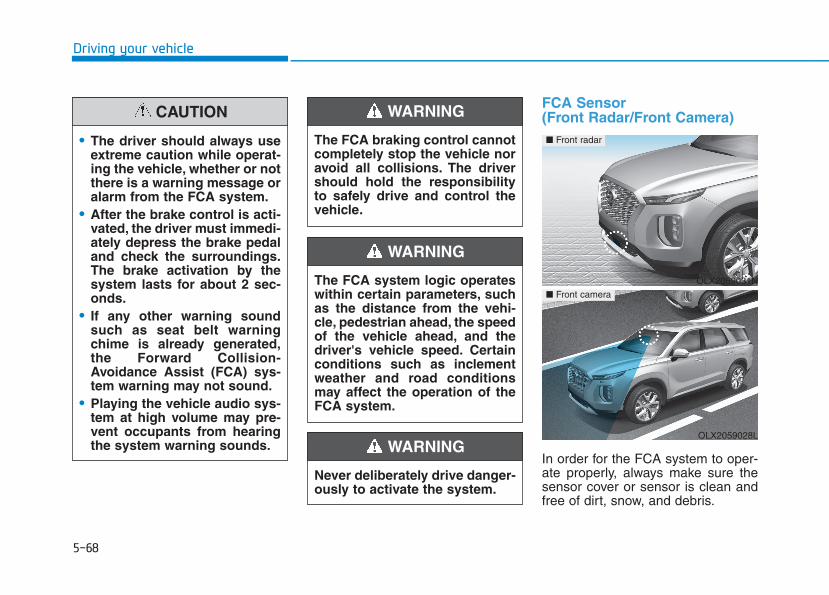
5-68
Driving your vehicle
FCA Sensor (Front Radar/Front Camera)
In order for the FCA system to oper-ate properly, always make sure thesensor cover or sensor is clean andfree of dirt, snow, and debris.
• The driver should always useextreme caution while operat-ing the vehicle, whether or notthere is a warning message oralarm from the FCA system.
• After the brake control is acti-vated, the driver must immedi-ately depress the brake pedaland check the surroundings.The brake activation by thesystem lasts for about 2 sec-onds.
• If any other warning soundsuch as seat belt warningchime is already generated,the Forward Collision-Avoidance Assist (FCA) sys-tem warning may not sound.
• Playing the vehicle audio sys-tem at high volume may pre-vent occupants from hearingthe system warning sounds.
CAUTION
The FCA system logic operateswithin certain parameters, suchas the distance from the vehi-cle, pedestrian ahead, the speedof the vehicle ahead, and thedriver's vehicle speed. Certainconditions such as inclementweather and road conditionsmay affect the operation of theFCA system.
WARNING
The FCA braking control cannotcompletely stop the vehicle noravoid all collisions. The drivershould hold the responsibilityto safely drive and control thevehicle.
WARNING
Never deliberately drive danger-ously to activate the system.
WARNING
OLX2059031N
■ Front radar
OLX2059028L
■ Front camera
5-69
Driving your vehicle
5
Dirt, snow, or foreign substances onthe sensor cover or sensor mayadversely affect the sensing perform-ance of the sensor.
• Do not apply license plate frameor foreign objects such as abumper sticker or a bumperguard near the sensor. Doing somay adversely affect the sens-ing performance of the radar.
• Always keep the sensor andcover clean and free of dirt anddebris.
• Use only a soft cloth to wash thevehicle. Do not spray pressur-ized water directly on the sensoror sensor cover.
• Be careful not to apply unneces-sary force on the sensor or sen-sor cover. If the sensor isforcibly moved out of properalignment, the FCA system maynot operate correctly. In thiscase, a warning message maynot be displayed. Have the vehi-cle inspected by an authorizedHYUNDAI dealer.
• If the front bumper becomesdamaged in the area around thesensor, the FCA system may notoperate properly. Have the vehi-cle inspected by an authorizedHYUNDAI dealer.
• Use only genuine HYUNDAIparts to repair or replace a dam-aged sensor or sensor cover. Donot apply paint to the sensorcover.
• NEVER install any accessoriesor stickers on the front wind-shield, or tint the front wind-shield.
• NEVER place any reflectiveobjects (i.e. white paper, mirror)over the crash pad. Any lightreflection may prevent the sys-tem from functioning properly.
• Pay extreme caution to keep thecamera dry.
• NEVER disassemble the cameraassembly, or apply any impacton the camera assembly.
• If the sensor is forcibly movedout of proper alignment, the FCAsystem may not operate correct-ly. In this case, a warning mes-sage may not be displayed. Havethe vehicle inspected by anauthorized HYUNDAI dealer.
InformationHave the system checked by anauthorized HYUNDAI dealer when:
• The windshield glass is replaced.
• The radar sensor or cover gets dam-aged or replaced.
i
NOTICE
NOTICE

5-70
Driving your vehicle
Warning message and warninglight
Forward Collision-Avoidance Assist(FCA) system disabled. Radar blocked
When the sensor cover is coveredwith dirt, snow, or debris, the FCAsystem operation may not be able todetect other vehicles. If this occurs, awarning message will appear on theLCD display.The system will operate normallywhen such dirt, snow or debris isremoved.FCA may not properly operate in anarea (e.g. open terrain) where anyobjects or vehicles are not detectedafter turning on the engine.
System Malfunction
Check Forward Collision-Avoidance Assist system
• When FCA is not working properly,the FCA warning light ( ) will illu-minate and the warning messagewill appear for a few seconds. Afterthe message disappears, the mas-ter warning light ( ) will illumi-nate. In this case, have the vehicleinspected by an authorizedHYUNDAI dealer.
• The FCA warning message mayappear along with the illuminationof the ESC (Electronic StabilityControl) warning light.
The FCA system may not acti-vate according to road condi-tions, inclement weather, driv-ing conditions or traffic condi-tions.
WARNING
OIK057090L
OIK057091L
5-71
Driving your vehicle
5
Both FCA warning light and warn-ing message will disappear oncethe ESC warning light issue isresolved.
• The FCA system may not acti-vate if the driver applies thebrake pedal to avoid collision.
• The brake control may beinsufficient, possibly causinga collision, if a vehicle in frontabruptly stops. Always payextreme caution.
• The FCA system may not acti-vate according to the roadconditions, inclement weath-er, driving conditions or trafficconditions.
• Occupants may get injured, ifthe vehicle abruptly stops bythe activated FCA system. Payextreme caution.
• The FCA system operatesonly to detect vehicles, pedes-trian in front of the vehicle.
• FCA is only a supplementalsystem for the driver's con-venience. It is the driver'sresponsibility to control thevehicle operation. Do notsolely depend on the FCAsystem. Rather, maintain asafe braking distance, and, ifnecessary, depress the brakepedal to reduce the drivingspeed or to stop the vehicle.
• In certain instances andunder certain driving condi-tions, the FCA system mayactivate prematurely. This ini-tial warning message appearson the LCD display with awarning chime.
WARNING
Also due to sensing limita-tions, in certain situations, thefront radar sensor or camerarecognition system may notdetect the vehicle, pedestrianahead. The FCA system maynot activate and the warningmessage may not be dis-played.
• If there is a malfunction withthe FCA system, the ForwardCollision avoidance assistsystem is not applied eventhough the braking system isoperating normally.
• If the vehicle in front stopssuddenly, you may have lesscontrol of the brake system.Therefore, always keep a safedistance between your vehicleand the vehicle in front of you.
• The FCA system may activateduring braking and the vehi-cle may stop suddenly shift-ing loose objects toward thepassengers. Always keeploose objects secured.
5-72
Driving your vehicle
Limitations of the SystemThe Forward Collision AvoidanceAssist (FCA) system is designed tomonitor the vehicle ahead or apedestrian on the roadway throughradar signals and camera recogni-tion to warn the driver that a collisionis imminent, and if necessary, applyemergency braking.In certain situations, the radar sen-sor or the camera may not be able todetect the vehicle, pedestrian ahead.In these cases, the FCA system maynot operate normally.The driver mustpay careful attention in the followingsituations where the FCA operationmay be limited.
In these cases, you must main-tain a safe braking distance,and if necessary, depress thebrake pedal to reduce the driv-ing speed in order to maintain asafe distance or to stop thevehicle.
• The FCA system operatesonly to help detect vehicles orpedestrians in front of thevehicle.
• The FCA system does notoperate when the vehicle is inreverse.
• The FCA system is notdesigned to detect otherobjects on the road such asanimals.
• The FCA system does notdetect vehicles in the oppo-site lane.
• The FCA system does notdetect cross traffic vehiclesthat are approaching.
• The FCA system cannotdetect the cross traffic cyclistthat are approaching.
• The FCA system cannotdetect vehicles that arestopped vertically to yourvehicle at a intersection ordead end street.
WARNING

5-73
Driving your vehicle
5
Detecting vehiclesThe sensor may be limited when:• The system may not operate for 15
seconds after the engine is startedor the camera is initialized
• The radar sensor or camera is cov-ered with a foreign object or debris
• The camera lens is contaminateddue to tinted, filmed or coatedwindshield, damaged glass, orstuck of foreign matter (sticker,bug, etc.) on the glass
• Inclement weather such as heavyrain or snow obscures the field ofview of the radar sensor or camera
• There is interference by electro-magnetic waves
• There is severe irregular reflectionfrom the radar sensor
• The radar/camera sensor recogni-tion is limited
• The vehicle in front is too small tobe detected (for example a motor-cycle or a bicycle, etc.)
• The vehicle in front is an oversizevehicle or trailer that is too big tobe detected by the camera recog-nition system (for example a tractortrailer, etc.)
• The camera's field of view is notwell illuminated (either too dark ortoo much reflection or too muchbacklight that obscures the field ofview)
• The vehicle in front does not havetheir rear lights properly turned ONor their rear lights are locatedunusually
• The outside brightness changessuddenly, for example when enter-ing or exiting a tunnel
• Light coming from a street light oran oncoming vehicle is reflected ona wet road surface such as a pud-dle in the road
• The field of view in front is obstruct-ed by sun glare
• The windshield glass is fogged up;a clear view of the road is obstruct-ed
• The vehicle in front is driving errati-cally
• The vehicle is on unpaved oruneven rough surfaces, or roadwith sudden gradient changes
• The vehicle is driven near areascontaining metal substances as aconstruction zone, railroad, etc.
• The vehicle drives inside a building,such as a basement parking lot
• The camera does not recognizethe entire vehicle in front
• The camera is damaged• The brightness outside is too low
such as when the headlamps arenot on at night or the vehicle isgoing through a tunnel
• The shadow is on the road by amedian strip, trees, etc.
• The vehicle drives through a toll-gate.
• The rear part of the vehicle in frontis not normally visible (the vehicleturns in other direction or the vehi-cle is overturned.)
• The adverse road conditions causeexcessive vehicle vibrations whiledriving

5-74
Driving your vehicle
• The sensor recognition changessuddenly when passing over aspeed bump
• The vehicle in front is moving verti-cally to the driving direction
• The vehicle in front is stopped ver-tically
• The vehicle in front is drivingtowards your vehicle or reversing
• You are on a roundabout and thevehicle in front circles • Driving on a curve
The performance of the FCA sys-tem may be limited when drivingon a curved road.In certain instances on a curvedroad, the FCA system may activateprematurely.Also, in certain instances the frontradar sensor or camera recognitionsystem may not detect the vehicletraveling on a curved road.In these cases, the driver mustmaintain a safe braking distance,and if necessary, depress thebrake pedal to reduce your drivingspeed in order to maintain a safedistance.
The FCA system may recognize avehicle in the next lane when driv-ing on a curved road.In this case, the system mayunnecessarily alarm the driver andapply the brake.Always pay attention to road anddriving conditions, while driving. Ifnecessary, depress the brakepedal to reduce your driving speedin order to maintain a safe dis-tance.Also, when necessary depress theaccelerator pedal to prevent thesystem from unnecessarily decel-erating your vehicle.
OTM058117 OTM058073
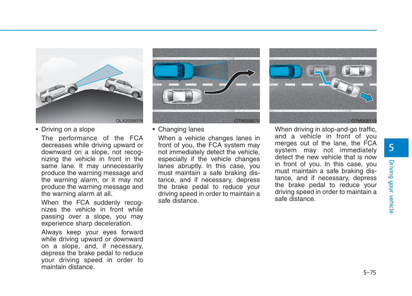
5-75
Driving your vehicle
5
• Driving on a slopeThe performance of the FCAdecreases while driving upward ordownward on a slope, not recog-nizing the vehicle in front in thesame lane. It may unnecessarilyproduce the warning message andthe warning alarm, or it may notproduce the warning message andthe warning alarm at all.When the FCA suddenly recog-nizes the vehicle in front whilepassing over a slope, you mayexperience sharp deceleration.Always keep your eyes forwardwhile driving upward or downwardon a slope, and, if necessary,depress the brake pedal to reduceyour driving speed in order tomaintain distance.
• Changing lanesWhen a vehicle changes lanes infront of you, the FCA system maynot immediately detect the vehicle,especially if the vehicle changeslanes abruptly. In this case, youmust maintain a safe braking dis-tance, and if necessary, depressthe brake pedal to reduce yourdriving speed in order to maintain asafe distance.
When driving in stop-and-go traffic,and a vehicle in front of youmerges out of the lane, the FCAsystem may not immediatelydetect the new vehicle that is nowin front of you. In this case, youmust maintain a safe braking dis-tance, and if necessary, depressthe brake pedal to reduce yourdriving speed in order to maintain asafe distance.
OLX2058076 OTM058074 OTM058119
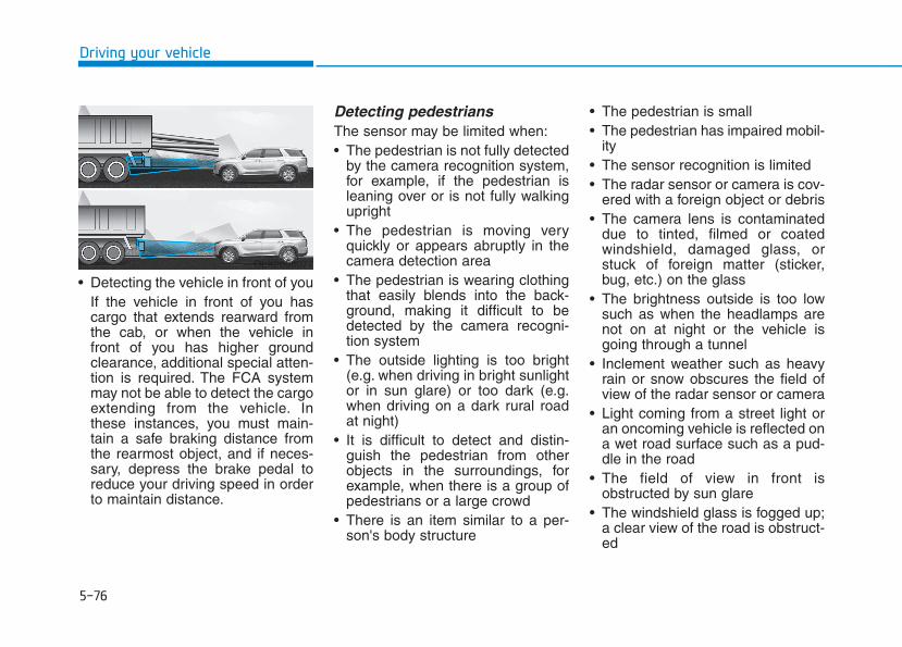
5-76
Driving your vehicle
• Detecting the vehicle in front of youIf the vehicle in front of you hascargo that extends rearward fromthe cab, or when the vehicle infront of you has higher groundclearance, additional special atten-tion is required. The FCA systemmay not be able to detect the cargoextending from the vehicle. Inthese instances, you must main-tain a safe braking distance fromthe rearmost object, and if neces-sary, depress the brake pedal toreduce your driving speed in orderto maintain distance.
Detecting pedestriansThe sensor may be limited when:• The pedestrian is not fully detected
by the camera recognition system,for example, if the pedestrian isleaning over or is not fully walkingupright
• The pedestrian is moving veryquickly or appears abruptly in thecamera detection area
• The pedestrian is wearing clothingthat easily blends into the back-ground, making it difficult to bedetected by the camera recogni-tion system
• The outside lighting is too bright(e.g. when driving in bright sunlightor in sun glare) or too dark (e.g.when driving on a dark rural roadat night)
• It is difficult to detect and distin-guish the pedestrian from otherobjects in the surroundings, forexample, when there is a group ofpedestrians or a large crowd
• There is an item similar to a per-son's body structure
• The pedestrian is small• The pedestrian has impaired mobil-
ity• The sensor recognition is limited• The radar sensor or camera is cov-
ered with a foreign object or debris• The camera lens is contaminated
due to tinted, filmed or coatedwindshield, damaged glass, orstuck of foreign matter (sticker,bug, etc.) on the glass
• The brightness outside is too lowsuch as when the headlamps arenot on at night or the vehicle isgoing through a tunnel
• Inclement weather such as heavyrain or snow obscures the field ofview of the radar sensor or camera
• Light coming from a street light oran oncoming vehicle is reflected ona wet road surface such as a pud-dle in the road
• The field of view in front isobstructed by sun glare
• The windshield glass is fogged up;a clear view of the road is obstruct-ed
OLX2058077
5-77
Driving your vehicle
5
• The adverse road conditions causeexcessive vehicle vibrations whiledriving
• The sensor recognition changessuddenly when passing over aspeed bump
• You are on a roundabout• When the pedestrian suddenly
interrupts in front of the vehicle• When there is any other electro-
magnetic interference• When the construction area, rail or
other metal object is near thecyclist
Information In some instances, the FCA systemmay be canceled when subjected toelectromagnetic interference.
InformationThis device complies with Part 15 ofthe FCC rules.
Operation is subject to the followingtwo conditions:
1. This device may not cause harmfulinterference.
2. This device must accept any inter-ference received, including interfer-ence that may cause undesiredoperation.
i
i
• Do not use the ForwardCollision Avoidance Assist(FCA) system when towing avehicle. Application of theFCA system while towing mayadversely affect the safety ofyour vehicle or the towingvehicle.
• Use extreme caution when thevehicle in front of you hascargo that extends rearwardfrom the cab, or when thevehicle in front of you hashigher ground clearance.
• The FCA system is designedto help detect and monitor thevehicle ahead to help detect apedestrian in the roadwaythrough radar signals andcamera recognition. It is notdesigned to detect bicycles,motorcycles, or smallerwheeled objects such as lug-gage bags, shopping carts, orstrollers.
WARNING • Never try to test the operationof the FCA system. Doing somay cause severe injury ordeath.
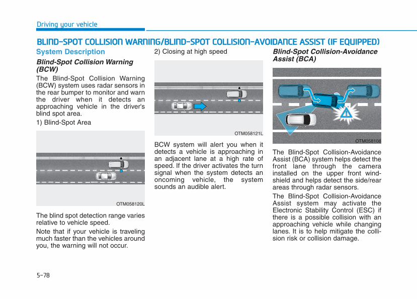
5-78
Driving your vehicle
System DescriptionBlind-Spot Collision Warning(BCW)The Blind-Spot Collision Warning(BCW) system uses radar sensors inthe rear bumper to monitor and warnthe driver when it detects anapproaching vehicle in the driver'sblind spot area.1) Blind-Spot Area
The blind spot detection range variesrelative to vehicle speed.Note that if your vehicle is travelingmuch faster than the vehicles aroundyou, the warning will not occur.
2) Closing at high speed
BCW system will alert you when itdetects a vehicle is approaching inan adjacent lane at a high rate ofspeed. If the driver activates the turnsignal when the system detects anoncoming vehicle, the systemsounds an audible alert.
Blind-Spot Collision-AvoidanceAssist (BCA)
The Blind-Spot Collision-AvoidanceAssist (BCA) system helps detect thefront lane through the camerainstalled on the upper front wind-shield and helps detect the side/rearareas through radar sensors.The Blind-Spot Collision-AvoidanceAssist system may activate theElectronic Stability Control (ESC) ifthere is a possible collision with anapproaching vehicle while changinglanes. It is to help mitigate the colli-sion risk or collision damage.
BBLLIINNDD--SSPPOOTT CCOOLLLLIISSIIOONN WWAARRNNIINNGG//BBLLIINNDD--SSPPOOTT CCOOLLLLIISSIIOONN--AAVVOOIIDDAANNCCEE AASSSSIISSTT ((IIFF EEQQUUIIPPPPEEDD))
OTM058120L
OTM058121L
OTM058108
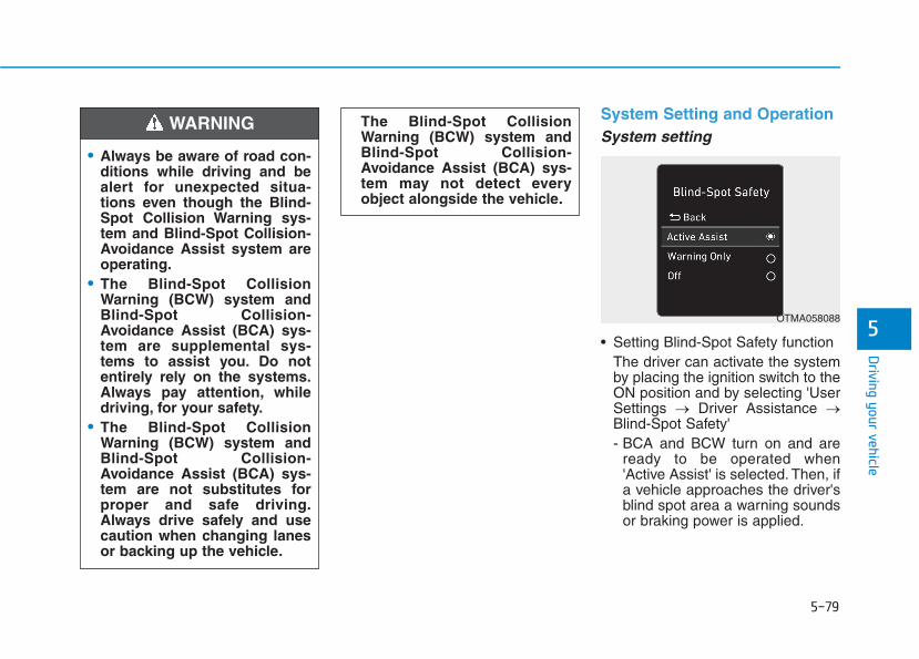
5-79
Driving your vehicle
5
System Setting and OperationSystem setting
• Setting Blind-Spot Safety functionThe driver can activate the systemby placing the ignition switch to theON position and by selecting 'UserSettings → Driver Assistance →Blind-Spot Safety' - BCA and BCW turn on and are
ready to be operated when'Active Assist' is selected. Then, ifa vehicle approaches the driver'sblind spot area a warning soundsor braking power is applied.
The Blind-Spot CollisionWarning (BCW) system andBlind-Spot Collision-Avoidance Assist (BCA) sys-tem may not detect everyobject alongside the vehicle.
• Always be aware of road con-ditions while driving and bealert for unexpected situa-tions even though the Blind-Spot Collision Warning sys-tem and Blind-Spot Collision-Avoidance Assist system areoperating.
• The Blind-Spot CollisionWarning (BCW) system andBlind-Spot Collision-Avoidance Assist (BCA) sys-tem are supplemental sys-tems to assist you. Do notentirely rely on the systems.Always pay attention, whiledriving, for your safety.
• The Blind-Spot CollisionWarning (BCW) system andBlind-Spot Collision-Avoidance Assist (BCA) sys-tem are not substitutes forproper and safe driving.Always drive safely and usecaution when changing lanesor backing up the vehicle.
WARNING
OTMA058088
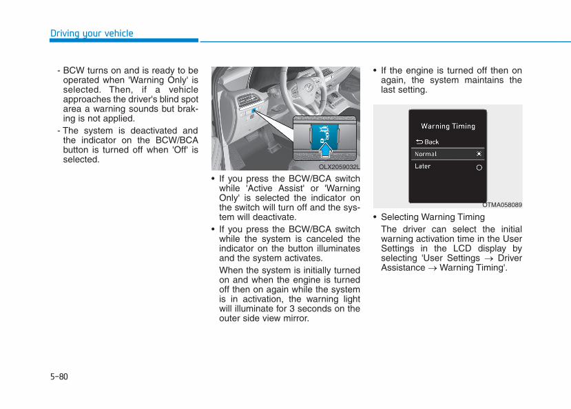
5-80
Driving your vehicle
- BCW turns on and is ready to beoperated when 'Warning Only' isselected. Then, if a vehicleapproaches the driver's blind spotarea a warning sounds but brak-ing is not applied.
- The system is deactivated andthe indicator on the BCW/BCAbutton is turned off when 'Off' isselected.
• If you press the BCW/BCA switchwhile 'Active Assist' or 'WarningOnly' is selected the indicator onthe switch will turn off and the sys-tem will deactivate.
• If you press the BCW/BCA switchwhile the system is canceled theindicator on the button illuminatesand the system activates.When the system is initially turnedon and when the engine is turnedoff then on again while the systemis in activation, the warning lightwill illuminate for 3 seconds on theouter side view mirror.
• If the engine is turned off then onagain, the system maintains thelast setting.
• Selecting Warning TimingThe driver can select the initialwarning activation time in the UserSettings in the LCD display byselecting 'User Settings → DriverAssistance → Warning Timing'.
OLX2059032L
OTMA058089

5-81
Driving your vehicle
5
• The options for the initial Blind-Spot Collision Warning includesthe following:- Normal:
When this option is selected, theinitial Blind-Spot CollisionWarning is activated normally. Ifthis setting feels sensitive,change the option to 'Later'.The warning activation time mayfeel late if a vehicle at the side orrear abruptly accelerates.
- Later:Select this warning activationtime when the traffic is light andyou are driving at low speeds.
InformationIf you change the warning timing, thewarning time of other systems maychange. Always be aware beforechanging the warning timing.
• Setting Warning VolumeThe driver can select the warningvolume of Blind-Spot CollisionWarning in the User Settings in theLCD display by selecting 'UserSettings → Driver Assistance →Warning Volume → High/Medium/Low/Off' .
For more details, refer to "LCDDisplay" in chapter 3.
InformationIf you change the warning volume, thewarning volume of other systems maychange. Always be aware beforechanging the warning volume.
Operating ConditionsThe system enters the ready status,when 'Active Assist' or 'WarningOnly' is selected and the followingconditions are satisfied:• Active Assist1) The Blind-Spot Collision-Avoidance
Assist system will operate When:- Vehicle speed is between 40
mph and 110 mph (60 km/h and180 km/h).
- The system detects both of thelane lines.
- An approaching vehicle isdetected next to or behind yourvehicle.
2) The Blind-Spot Collision Warningsystem will operate When:
The vehicle speed is aboveapproximately 20 mph (30 km/h).
• Warning Only1) The Blind-Spot Collision Warning
system will activate When:- The vehicle speed is approxi-
mately 20 mph (30 km/h).- The Blind-Spot Collision-
Avoidance Assist system is notactivated when "Warning Only" isselected for the system setting.
i
i
OLX2059127N
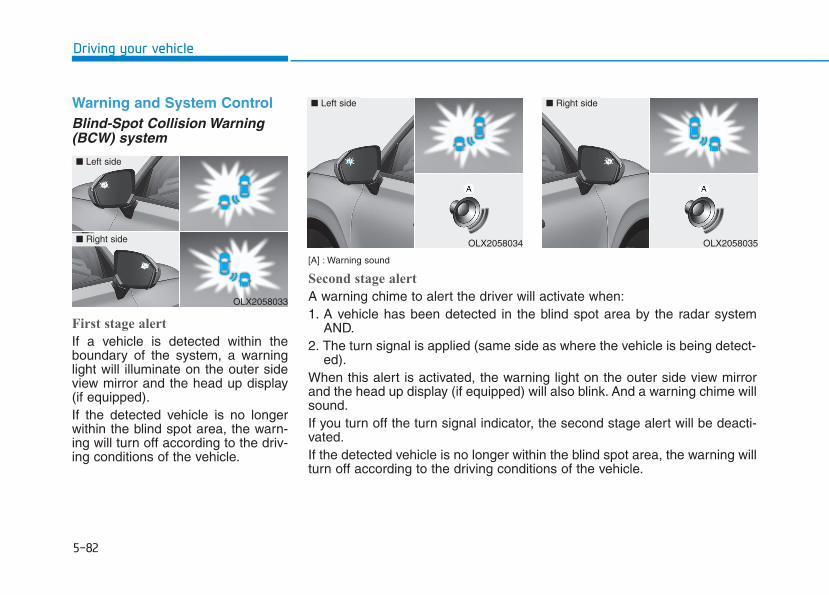
5-82
Driving your vehicle
Warning and System ControlBlind-Spot Collision Warning(BCW) system
First stage alert
If a vehicle is detected within theboundary of the system, a warninglight will illuminate on the outer sideview mirror and the head up display(if equipped).If the detected vehicle is no longerwithin the blind spot area, the warn-ing will turn off according to the driv-ing conditions of the vehicle.
[A] : Warning sound
Second stage alert
A warning chime to alert the driver will activate when:1. A vehicle has been detected in the blind spot area by the radar system
AND.2. The turn signal is applied (same side as where the vehicle is being detect-
ed).When this alert is activated, the warning light on the outer side view mirrorand the head up display (if equipped) will also blink. And a warning chime willsound.If you turn off the turn signal indicator, the second stage alert will be deacti-vated.If the detected vehicle is no longer within the blind spot area, the warning willturn off according to the driving conditions of the vehicle.
OLX2058033
■ Left side
■ Right side OLX2058034
■ Left side
OLX2058035
■ Right side
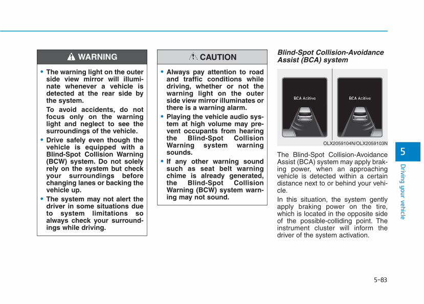
5-83
Driving your vehicle
5
Blind-Spot Collision-AvoidanceAssist (BCA) system
The Blind-Spot Collision-AvoidanceAssist (BCA) system may apply brak-ing power, when an approachingvehicle is detected within a certaindistance next to or behind your vehi-cle.In this situation, the system gentlyapply braking power on the tire,which is located in the opposite sideof the possible-colliding point. Theinstrument cluster will inform thedriver of the system activation.
• The warning light on the outerside view mirror will illumi-nate whenever a vehicle isdetected at the rear side bythe system.To avoid accidents, do notfocus only on the warninglight and neglect to see thesurroundings of the vehicle.
• Drive safely even though thevehicle is equipped with aBlind-Spot Collision Warning(BCW) system. Do not solelyrely on the system but checkyour surroundings beforechanging lanes or backing thevehicle up.
• The system may not alert thedriver in some situations dueto system limitations soalways check your surround-ings while driving.
WARNING
• Always pay attention to roadand traffic conditions whiledriving, whether or not thewarning light on the outerside view mirror illuminates orthere is a warning alarm.
• Playing the vehicle audio sys-tem at high volume may pre-vent occupants from hearingthe Blind-Spot CollisionWarning system warningsounds.
• If any other warning soundsuch as seat belt warningchime is already generated,the Blind-Spot CollisionWarning (BCW) system warn-ing may not sound.
CAUTION
OLX2059104N/OLX2059103N
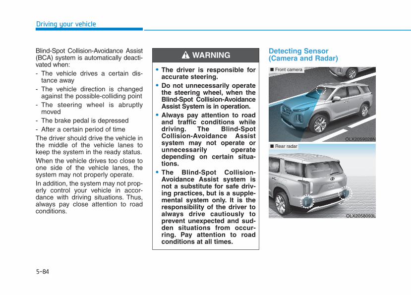
5-84
Driving your vehicle
Blind-Spot Collision-Avoidance Assist(BCA) system is automatically deacti-vated when:- The vehicle drives a certain dis-
tance away- The vehicle direction is changed
against the possible-colliding point- The steering wheel is abruptly
moved- The brake pedal is depressed- After a certain period of timeThe driver should drive the vehicle inthe middle of the vehicle lanes tokeep the system in the ready status.When the vehicle drives too close toone side of the vehicle lanes, thesystem may not properly operate.In addition, the system may not prop-erly control your vehicle in accor-dance with driving situations. Thus,always pay close attention to roadconditions.
Detecting Sensor (Camera and Radar)
• The driver is responsible foraccurate steering.
• Do not unnecessarily operatethe steering wheel, when theBlind-Spot Collision-AvoidanceAssist System is in operation.
• Always pay attention to roadand traffic conditions whiledriving. The Blind-SpotCollision-Avoidance Assistsystem may not operate orunnecessarily operatedepending on certain situa-tions.
• The Blind-Spot Collision-Avoidance Assist system isnot a substitute for safe driv-ing practices, but is a supple-mental system only. It is theresponsibility of the driver toalways drive cautiously toprevent unexpected and sud-den situations from occur-ring. Pay attention to roadconditions at all times.
WARNING
OLX2059028N
■ Front camera
OLX2058093L
■ Rear radar
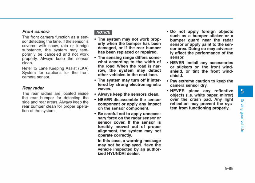
5-85
Driving your vehicle
5
Front cameraThe front camera function as a sen-sor detecting the lane. If the sensor iscovered with snow, rain or foreignsubstance, the system may tem-porarily be canceled and not workproperly. Always keep the sensorclean.Refer to Lane Keeping Assist (LKA)System for cautions for the frontcamera sensor.
Rear radarThe rear radars are located insidethe rear bumper for detecting theside and rear areas. Always keep therear bumper clean for proper opera-tion of the system.
• The system may not work prop-erly when the bumper has beendamaged, or if the rear bumperhas been replaced or repaired.
• The sensing range differs some-what according to the width ofthe road. When the road is nar-row, the system may detectother vehicles in the next lane.
• The system may turn off if inter-fered by strong electromagneticwaves.
• Always keep the sensors clean.• NEVER disassemble the sensor
component or apply any impacton the sensor component.
• Be careful not to apply unneces-sary force on the radar sensor orsensor cover. If the sensor isforcibly moved out of properalignment, the system may notoperate correctly.In this case, a warning messagemay not be displayed. Have thevehicle inspected by an author-ized HYUNDAI dealer.
• Do not apply foreign objectssuch as a bumper sticker or abumper guard near the radarsensor or apply paint to the sen-sor area. Doing so may adverse-ly affect the performance of thesensor.
• NEVER install any accessoriesor stickers on the front wind-shield, or tint the front wind-shield.
• Pay extreme caution to keep thecamera sensor dry.
• NEVER place any reflectiveobjects (i.e. white paper, mirror)over the crash pad. Any lightreflection may prevent the sys-tem from functioning properly.
NOTICE

5-86
Driving your vehicle
Warning message
Blind-Spot Collision Warning(BCW) system disabled. Radar blocked
This warning message may appearWhen:- One or both of the sensors on the
rear bumper is blocked by dirt orsnow or a foreign object.
- Driving in rural areas where thesensor does not detect anothervehicle for an extended period oftime.
- When there is inclement weathersuch as heavy snow or rain.
If any of these conditions occur, thelight on the BCW/BCA switch and thesystem will turn off automatically.
When the BCW canceled warningmessage is displayed in the cluster,check to make sure that the rearbumper is free from any dirt or snowin the areas where the sensor islocated. Remove any dirt, snow, orforeign material that could interferewith the radar sensors.
After any dirt or debris is removed,the system should operate normallyafter about 10 minutes of driving thevehicle.If the system still does not operatenormally have your vehicle inspectedby an authorized HYUNDAI dealer.
InformationTurn off the BCW, BCA and RCCWsystem when a trailer or carrier isinstalled.
- Press the BCW/BCA switch (theindicator on the switch will turn off)
- Deactivate the RCCW system bydeselecting
'User Settings →→ Driver Assistance→→ Parking Safety →→ Rear Cross-Traffic Collision Warning' (ifequipped)
i
OIK057092L

5-87
Driving your vehicle
5
Check Blind-Spot CollisionWarning (BCW) system
If there is a problem with the BCWsystem, a warning message willappear and the light on the switchwill turn off. The system will turn offautomatically. BCA will not operatealso if the BCW system turns off dueto malfunction. Have your vehicleinspected by an authorized HYUNDAIdealer.
Check Blind-Spot Collision-Avoidance Assist (BCA) system
If there is a problem with the BCAsystem, a warning message willappear. The system will turn off auto-matically. BCW will still operate evenif the BCA system turns off due tomalfunction. Have your vehicleinspected by an authorized HYUNDAIdealer to use BCA system.
Limitations of the SystemThe driver must be cautious in thebelow situations because the systemmay not detect other vehicles orobjects in certain circumstances:• When a trailer or carrier is
installed.• The vehicle driven in inclement
weather such as heavy rain orsnow.
• The sensor is polluted with rain,snow, mud, etc.
• The rear bumper where the sensoris located is covered with a foreignobject such as a bumper sticker, abumper guard, a bike rack, etc.
• The rear bumper is damaged, orthe sensor is out of the originaldefault position.
• The vehicle height gets lower orhigher due to heavy loading in aluggage compartment, abnormaltire pressure, etc.
• When the temperature of the rearbumper is high.
• When the sensors are blocked byother vehicles, walls or parking-lotpillars.
OTM058151L OLX2049137N

5-88
Driving your vehicle
• The vehicle is driven on a curvedroad.
• The vehicle is driven through a toll-gate.
• The road pavement (or the periph-eral ground) abnormally containsmetallic components (i.e. possiblydue to subway construction).
• There is a fixed object near thevehicle, such as a guardrail.
• While going down or up a steeproad where the height of the lane isdifferent.
• Driving on a narrow road wheretrees or grass or overgrown.
• Driving in rural areas where thesensor does not detect anothervehicle or structure for an extendedperiod of time.
• Driving on a wet road.• Driving on a road where the
guardrail or wall is in double struc-ture.
• A big vehicle is near such as a busor truck.
• When the other vehicle approach-es very close.
• When the other vehicle passes at avery fast speed.
• While changing lanes.• If the vehicle has started at the
same time as the vehicle next toyou and has accelerated.
• When the vehicle in the next lanemoves two lanes away from youOR when the vehicle two lanesaway moves to the next lane fromyou.
• A motorcycle or bicycle is near.• A flat trailer is near.• If there are small objects in the
detecting area such as a shoppingcart or a baby stroller.
• If there is a low height vehicle suchas a sports car.
• The brake pedal is depressed.• ESC (Electronic Stability Control)
is activated.• ESC (Electronic Stability Control)
malfunctions.• The tire pressure is low or a tire is
damaged.• The brake is reworked.
• The vehicle abruptly changes driv-ing direction.
• The vehicle makes sharp lanechanges.
• The vehicle sharply stops.• Temperature is extremely low
around the vehicle.• The vehicle severely vibrates while
driving over an uneven//bumpyroad, or concrete patch.
• The vehicle drives on a slipperysurface due to snow, water puddle,or ice.
• The Lane Keeping Assist (LKA)does not operate normally.For more details refer to "LaneKeeping Assist (LKA) system" inthis chapter.
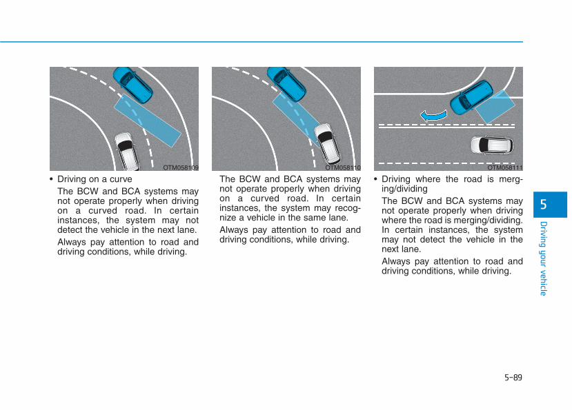
5-89
Driving your vehicle
5
• Driving on a curveThe BCW and BCA systems maynot operate properly when drivingon a curved road. In certaininstances, the system may notdetect the vehicle in the next lane.Always pay attention to road anddriving conditions, while driving.
The BCW and BCA systems maynot operate properly when drivingon a curved road. In certaininstances, the system may recog-nize a vehicle in the same lane.Always pay attention to road anddriving conditions, while driving.
• Driving where the road is merg-ing/dividingThe BCW and BCA systems maynot operate properly when drivingwhere the road is merging/dividing.In certain instances, the systemmay not detect the vehicle in thenext lane.Always pay attention to road anddriving conditions, while driving.
OTM058109 OTM058110 OTM058111
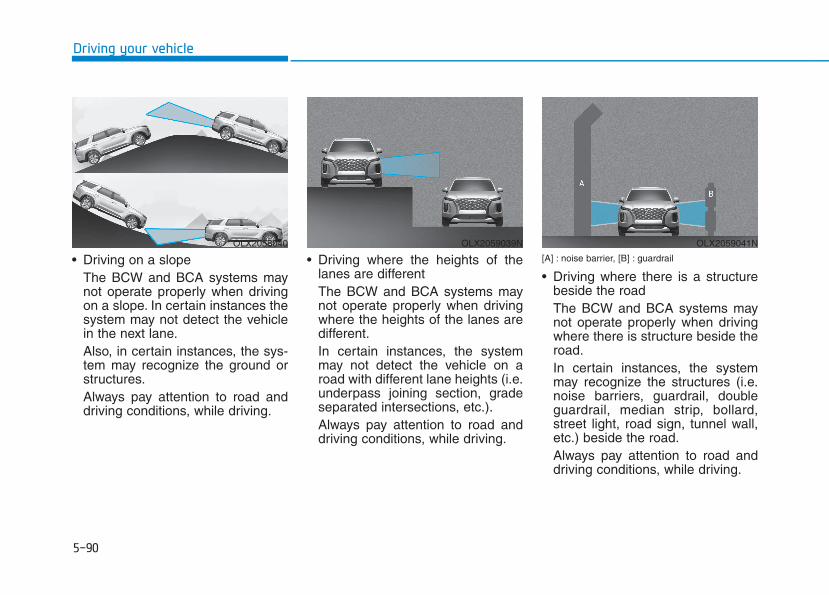
5-90
Driving your vehicle
• Driving on a slopeThe BCW and BCA systems maynot operate properly when drivingon a slope. In certain instances thesystem may not detect the vehiclein the next lane.Also, in certain instances, the sys-tem may recognize the ground orstructures.Always pay attention to road anddriving conditions, while driving.
• Driving where the heights of thelanes are differentThe BCW and BCA systems maynot operate properly when drivingwhere the heights of the lanes aredifferent.In certain instances, the systemmay not detect the vehicle on aroad with different lane heights (i.e.underpass joining section, gradeseparated intersections, etc.).Always pay attention to road anddriving conditions, while driving.
[A] : noise barrier, [B] : guardrail
• Driving where there is a structurebeside the roadThe BCW and BCA systems maynot operate properly when drivingwhere there is structure beside theroad.In certain instances, the systemmay recognize the structures (i.e.noise barriers, guardrail, doubleguardrail, median strip, bollard,street light, road sign, tunnel wall,etc.) beside the road.Always pay attention to road anddriving conditions, while driving.
OLX2058040 OLX2059039N OLX2059041N
5-91
Driving your vehicle
5
InformationThis device complies with Part 15 ofthe FCC rules.
Operation is subject to the followingtwo conditions:
1. This device may not cause harmfulinterference.
2. This device must accept any inter-ference received, including interfer-ence that may cause undesiredoperation.
i
5-92
The radio frequency compo-nents (Rear Corner Radar)complies: (if equipped)
DDEECCLLAARRAATTIIOONN OOFF CCOONNFFOORRMMIITTYY ((IIFF EEQQUUIIPPPPEEDD))
Driving your vehicle
OANATEL002
OANATEL003

5-93
Driving your vehicle
5
System DescriptionRear Cross-Traffic CollisionWarning (RCCW) system
The Rear Cross-Traffic CollisionWarning (RCCW) system uses radarsensors to monitor the approachingcross traffic from the left and rightside of the vehicle when your vehicleis in reverse.The blind spot detection range variesrelative to the approaching vehiclespeed.
Rear Cross-Traffic Collision-Avoidance Assist (RCCA) systemThe Rear Cross-Traffic Collision-Avoidance Assist (RCCA) systemmonitors approaching cross trafficfrom the left and right side of thevehicle when your vehicle is inreverse.The Rear Cross-Traffic Collision-Avoidance Assist (RCCA) systemmay activate the Electronic StabilityControl (ESC) in accordance with apossible collision with an approach-ing vehicle. It is to lower the possiblecollision risk or mitigate the possiblecollision damage.
RREEAARR CCRROOSSSS--TTRRAAFFFFIICC CCOOLLLLIISSIIOONN WWAARRNNIINNGG ((RRCCCCWW)) // RREEAARR CCRROOSSSS--TTRRAAFFFFIICC CCOOLLLLIISSIIOONN--AAVVOOIIDDAANNCCEE AASSSSIISSTT ((RRCCCCAA))
OTM058092
• Always be aware of road andtraffic conditions while driv-ing and be alert for unexpect-ed situations even though theRear Cross-Traffic CollisionWarning system and RearCross-Traffic Collision-Avoidance Assist system areoperating.
• The Rear Cross-TrafficCollision Warning system andRear Cross-Traffic Collision-Avoidance Assist system aresupplemental systems toassist you. Do not entirely relyon the systems. Always payattention, while driving, foryour safety.
• The Rear Cross-TrafficCollision Warning system andRear Cross-Traffic Collision-Avoidance Assist system arenot substitutes for proper andsafe driving. Always drivesafely and use caution whenbacking up the vehicle.
WARNING
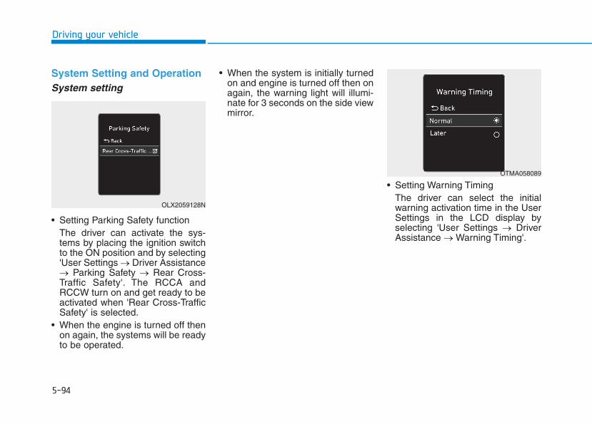
5-94
Driving your vehicle
System Setting and OperationSystem setting
• Setting Parking Safety functionThe driver can activate the sys-tems by placing the ignition switchto the ON position and by selecting'User Settings → Driver Assistance→ Parking Safety → Rear Cross-Traffic Safety'. The RCCA andRCCW turn on and get ready to beactivated when 'Rear Cross-TrafficSafety' is selected.
• When the engine is turned off thenon again, the systems will be readyto be operated.
• When the system is initially turnedon and engine is turned off then onagain, the warning light will illumi-nate for 3 seconds on the side viewmirror.
• Setting Warning TimingThe driver can select the initialwarning activation time in the UserSettings in the LCD display byselecting 'User Settings → DriverAssistance → Warning Timing'.
OLX2059128N
OTMA058089
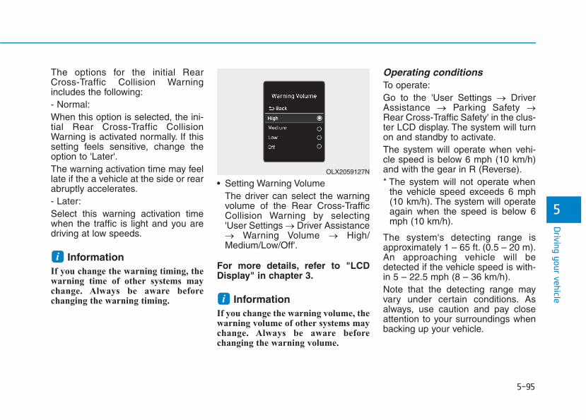
5-95
Driving your vehicle
5
The options for the initial RearCross-Traffic Collision Warningincludes the following:- Normal:When this option is selected, the ini-tial Rear Cross-Traffic CollisionWarning is activated normally. If thissetting feels sensitive, change theoption to 'Later'.The warning activation time may feellate if the a vehicle at the side or rearabruptly accelerates.- Later:Select this warning activation timewhen the traffic is light and you aredriving at low speeds.
InformationIf you change the warning timing, thewarning time of other systems maychange. Always be aware beforechanging the warning timing.
• Setting Warning VolumeThe driver can select the warningvolume of the Rear Cross-TrafficCollision Warning by selecting'User Settings → Driver Assistance→ Warning Volume → High/Medium/Low/Off'.
For more details, refer to "LCDDisplay" in chapter 3.
InformationIf you change the warning volume, thewarning volume of other systems maychange. Always be aware beforechanging the warning volume.
Operating conditionsTo operate:Go to the 'User Settings → DriverAssistance → Parking Safety →Rear Cross-Traffic Safety' in the clus-ter LCD display. The system will turnon and standby to activate.The system will operate when vehi-cle speed is below 6 mph (10 km/h)and with the gear in R (Reverse).* The system will not operate when
the vehicle speed exceeds 6 mph(10 km/h). The system will operateagain when the speed is below 6mph (10 km/h).
The system's detecting range isapproximately 1 – 65 ft. (0.5 – 20 m).An approaching vehicle will bedetected if the vehicle speed is with-in 5 – 22.5 mph (8 – 36 km/h).Note that the detecting range mayvary under certain conditions. Asalways, use caution and pay closeattention to your surroundings whenbacking up your vehicle.
i
i
OLX2059127N

5-96
Driving your vehicle
If the vehicle detected by the sensorsapproaches from the rear left/rightside of your vehicle, the warningchime will sound, the warning lighton the outer side view mirror willblink and a warning will appear onthe LCD display. If the rear view mon-itor system is in activation, a warningwill also appear on the infotainmentsystem screen.
The warning will stop when:- the detected vehicle moves out of
the sensing area or - when the vehicle is right behind
your vehicle or- when the vehicle is not approach-
ing your vehicle or- when the other vehicle slows
down.
OLX2059042N
■ Left
OLX2058044L
Warning and System ControlRear Cross-Traffic Collision Warning (RCCW) system
■ Left
OLX2059043N
■ Right
OLX2058045L
■ Right
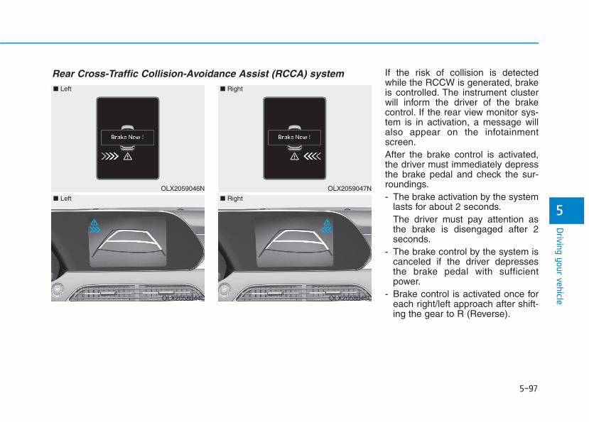
5-97
Driving your vehicle
5
If the risk of collision is detectedwhile the RCCW is generated, brakeis controlled. The instrument clusterwill inform the driver of the brakecontrol. If the rear view monitor sys-tem is in activation, a message willalso appear on the infotainmentscreen.After the brake control is activated,the driver must immediately depressthe brake pedal and check the sur-roundings.- The brake activation by the system
lasts for about 2 seconds.The driver must pay attention asthe brake is disengaged after 2seconds.
- The brake control by the system iscanceled if the driver depressesthe brake pedal with sufficientpower.
- Brake control is activated once foreach right/left approach after shift-ing the gear to R (Reverse).
Rear Cross-Traffic Collision-Avoidance Assist (RCCA) system
OLX2059046N
■ Left
OLX2058044L
■ Left
OLX2059047N
■ Right
OLX2058045L
■ Right

5-98
Driving your vehicle
The brake control may not operateproperly according to the status ofthe ESC (Electronic StabilityControl). The same warning mes-sage is displayed on the instrumentcluster when :- the ESC (Electronic Stability
Control) warning light is on.- the ESC (Electronic Stability
Control) is engaged in a differentfunction.
• Always pay attention to roadand traffic conditions whiledriving, whether or not thewarning light on the outerside view mirror illuminates orthere is a warning alarm.
• Playing the vehicle audio sys-tem at high volume may pre-vent occupants from hearingthe system's warning sounds.
• If any other warning soundsuch as seat belt warningchime is already generated,the Rear Cross-Traffic CollisionWarning system warning maynot sound.
• Drive safely even though thevehicle is equipped with aRear Cross-Traffic CollisionWarning system and RearCross-Traffic Collision-AvoidanceAssist system. Do not solelyrely on the system but checkyour surrounding when back-ing the vehicle up.
• The driver is responsible foraccurate brake control.
• Always pay extreme cautionwhile driving. The Rear Cross-Traffic Collision Warning sys-tem and Rear Cross-TrafficCollision-Avoidance Assistsystem may not operate prop-erly or unnecessarily operatedepending on traffic and driv-ing conditions.
• The Rear Cross-TrafficCollision-Avoidance Assistsystem is not a substitute forsafe driving practices, but aconvenience function only. Itis the responsibility of thedriver to always drive cau-tiously to prevent unexpectedand sudden situations fromoccurring. Pay attention to theroad conditions at all times.
WARNING
• When the operation conditionof the Rear Cross-TrafficCollision Warning system issatisfied, the warning willoccur every time a vehicleapproaches the side or rearof your stopped (0 mph vehi-cle speed) vehicle.
• The system's warning maynot operate properly if the leftor right of your vehicle's rearbumper is blocked by a vehi-cle or obstacle.
CAUTION
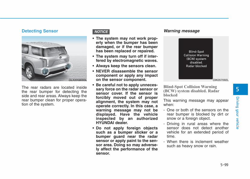
5-99
Driving your vehicle
5
Detecting Sensor
The rear radars are located insidethe rear bumper for detecting theside and rear areas. Always keep therear bumper clean for proper opera-tion of the system.
• The system may not work prop-erly when the bumper has beendamaged, or if the rear bumperhas been replaced or repaired.
• The system may turn off if inter-fered by electromagnetic waves.
• Always keep the sensors clean.• NEVER disassemble the sensor
component or apply any impacton the sensor component.
• Be careful not to apply unneces-sary force on the radar sensor orsensor cover. If the sensor isforcibly moved out of properalignment, the system may notoperate correctly. In this case, awarning message may not bedisplayed. Have the vehicleinspected by an authorizedHYUNDAI dealer.
• Do not apply foreign objectssuch as a bumper sticker or abumper guard near the radarsensor or apply paint to the sen-sor area. Doing so may adverse-ly affect the performance of thesensor.
Warning message
Blind-Spot Collision Warning(BCW) system disabled. Radarblocked
This warning message may appearwhen:- One or both of the sensors on the
rear bumper is blocked by dirt orsnow or a foreign object.
- Driving in rural areas where thesensor does not detect anothervehicle for an extended period oftime.
- When there is inclement weathersuch as heavy snow or rain.
NOTICE
OLX2058093L OIK057092L
5-100
Driving your vehicle
If any of these conditions occur, thelight on the BCW/BCA switch and thesystem will turn off automatically.When the BCW canceled warningmessage is displayed in the cluster,check to make sure that the rearbumper is free from any dirt or snowin the areas where the sensor islocated. Remove any dirt, snow, orforeign material that could interferewith the radar sensors.After any dirt or debris is removed,the system should operate normallyafter about 10 minutes of driving thevehicle.If the system still does not operatenormally have your vehicle inspectedby an authorized HYUNDAI dealer.
InformationTurn off the BCW and RCCW systemwhen a trailer or carrier is installed.
- Press the BCW/BCA switch (theindicator on the switch will turn off)
- Deactivate the RCCW system bydeselecting 'User Settings →→ DriverAssistance →→ Parking Safety →→Rear Cross-Traffic Collision Warning'
Check Blind-Spot CollisionWarning (BCW) system
If there is a problem with the BCWsystem, a warning message willappear and the light on the switchwill turn off. The system will turn offautomatically. RCCW and RCCA willnot operate also if the BCW systemturns off due to malfunction. Haveyour vehicle inspected by an author-ized HYUNDAI dealer.
Limitations of the SystemThe driver must be cautious in thebelow situations because the systemmay not detect other vehicles orobjects in certain circumstances:• When a trailer or carrier is
installed.• The vehicle drives in inclement
weather such as heavy rain or snow.• The sensor is polluted with rain,
snow, mud, etc.• The rear bumper where the sensor
is located is covered with a foreignobject such as a bumper sticker, abumper guard, a bike rack, etc.
• The rear bumper is damaged, orthe sensor is out of the originaldefault position.
• The vehicle height gets lower orhigher due to heavy loading in atrunk, abnormal tire pressure, etc.
• When the temperature of the rearbumper is high.
• When the sensors are blocked byother vehicles, walls or parking-lotpillars.
• The vehicle drives on a curved road.
i
OTM058151L
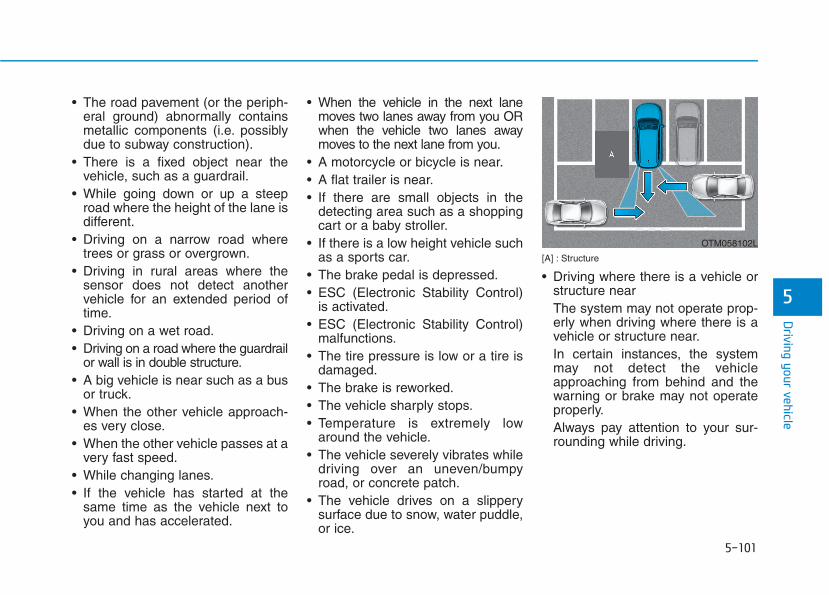
5-101
Driving your vehicle
5
• The road pavement (or the periph-eral ground) abnormally containsmetallic components (i.e. possiblydue to subway construction).
• There is a fixed object near thevehicle, such as a guardrail.
• While going down or up a steeproad where the height of the lane isdifferent.
• Driving on a narrow road wheretrees or grass or overgrown.
• Driving in rural areas where thesensor does not detect anothervehicle for an extended period oftime.
• Driving on a wet road.• Driving on a road where the guardrail
or wall is in double structure.• A big vehicle is near such as a bus
or truck.• When the other vehicle approach-
es very close.• When the other vehicle passes at a
very fast speed.• While changing lanes.• If the vehicle has started at the
same time as the vehicle next toyou and has accelerated.
• When the vehicle in the next lanemoves two lanes away from you ORwhen the vehicle two lanes awaymoves to the next lane from you.
• A motorcycle or bicycle is near.• A flat trailer is near.• If there are small objects in the
detecting area such as a shoppingcart or a baby stroller.
• If there is a low height vehicle suchas a sports car.
• The brake pedal is depressed.• ESC (Electronic Stability Control)
is activated.• ESC (Electronic Stability Control)
malfunctions.• The tire pressure is low or a tire is
damaged.• The brake is reworked.• The vehicle sharply stops.• Temperature is extremely low
around the vehicle.• The vehicle severely vibrates while
driving over an uneven/bumpyroad, or concrete patch.
• The vehicle drives on a slipperysurface due to snow, water puddle,or ice.
[A] : Structure
• Driving where there is a vehicle orstructure nearThe system may not operate prop-erly when driving where there is avehicle or structure near.In certain instances, the systemmay not detect the vehicleapproaching from behind and thewarning or brake may not operateproperly.Always pay attention to your sur-rounding while driving.
OTM058102L
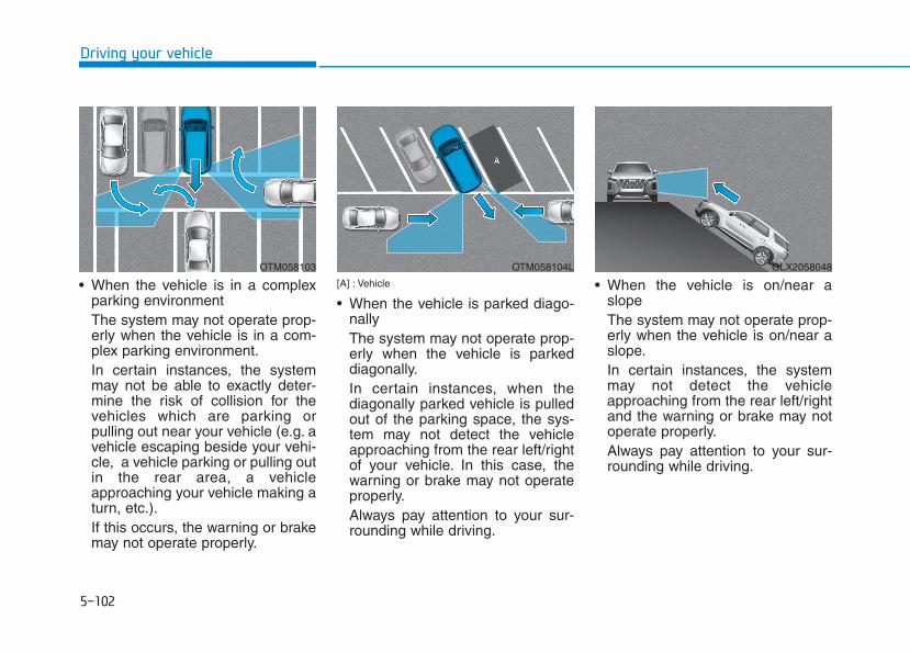
5-102
Driving your vehicle
• When the vehicle is in a complexparking environment The system may not operate prop-erly when the vehicle is in a com-plex parking environment.In certain instances, the systemmay not be able to exactly deter-mine the risk of collision for thevehicles which are parking orpulling out near your vehicle (e.g. avehicle escaping beside your vehi-cle, a vehicle parking or pulling outin the rear area, a vehicleapproaching your vehicle making aturn, etc.).If this occurs, the warning or brakemay not operate properly.
[A] : Vehicle
• When the vehicle is parked diago-nallyThe system may not operate prop-erly when the vehicle is parkeddiagonally.In certain instances, when thediagonally parked vehicle is pulledout of the parking space, the sys-tem may not detect the vehicleapproaching from the rear left/rightof your vehicle. In this case, thewarning or brake may not operateproperly.Always pay attention to your sur-rounding while driving.
• When the vehicle is on/near aslopeThe system may not operate prop-erly when the vehicle is on/near aslope.In certain instances, the systemmay not detect the vehicleapproaching from the rear left/rightand the warning or brake may notoperate properly.Always pay attention to your sur-rounding while driving.
OTM058103 OTM058104L OLX2058048
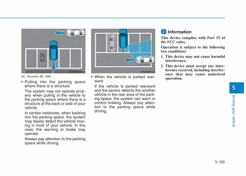
5-103
Driving your vehicle
5
[A] : Structure, [B] : Wall
• Pulling into the parking spacewhere there is a structure The system may not operate prop-erly when pulling in the vehicle tothe parking space where there is astructure at the back or side of yourvehicle.In certain instances, when backinginto the parking space, the systemmay falsely detect the vehicle mov-ing in front of your vehicle. In thiscase, the warning or brake mayoperate.Always pay attention to the parkingspace while driving.
• When the vehicle is parked rear-ward If the vehicle is parked rearwardand the sensor detects the anothervehicle in the rear area of the park-ing space, the system can warn orcontrol braking. Always pay atten-tion to the parking space whiledriving.
InformationThis device complies with Part 15 ofthe FCC rules.
Operation is subject to the followingtwo conditions:
1. This device may not cause harmfulinterference.
2. This device must accept any inter-ference received, including interfer-ence that may cause undesiredoperation.
i
OTM058106L OTM058107
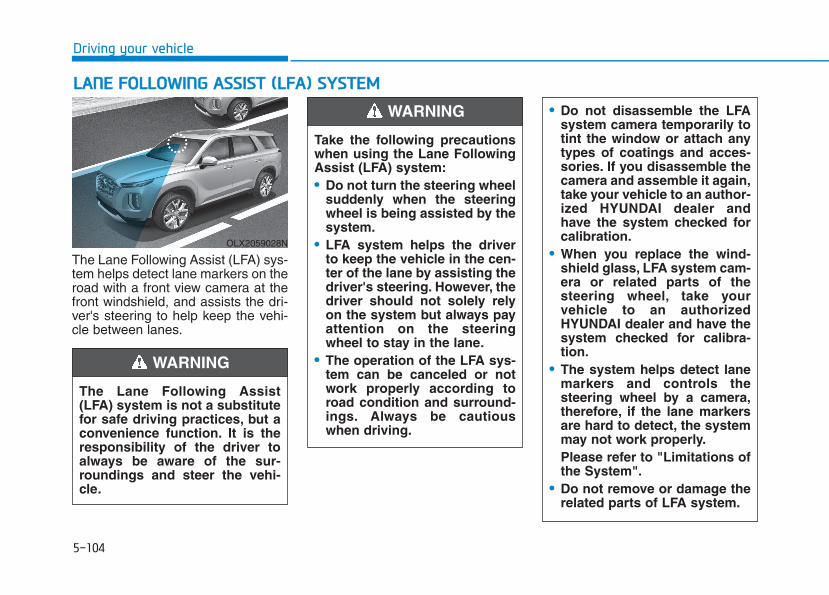
5-104
Driving your vehicle
The Lane Following Assist (LFA) sys-tem helps detect lane markers on theroad with a front view camera at thefront windshield, and assists the dri-ver's steering to help keep the vehi-cle between lanes.
LLAANNEE FFOOLLLLOOWWIINNGG AASSSSIISSTT ((LLFFAA)) SSYYSSTTEEMM
OLX2059028N
The Lane Following Assist(LFA) system is not a substitutefor safe driving practices, but aconvenience function. It is theresponsibility of the driver toalways be aware of the sur-roundings and steer the vehi-cle.
WARNING
Take the following precautionswhen using the Lane FollowingAssist (LFA) system:• Do not turn the steering wheel
suddenly when the steeringwheel is being assisted by thesystem.
• LFA system helps the driverto keep the vehicle in the cen-ter of the lane by assisting thedriver's steering. However, thedriver should not solely relyon the system but always payattention on the steeringwheel to stay in the lane.
• The operation of the LFA sys-tem can be canceled or notwork properly according toroad condition and surround-ings. Always be cautiouswhen driving.
• Do not disassemble the LFAsystem camera temporarily totint the window or attach anytypes of coatings and acces-sories. If you disassemble thecamera and assemble it again,take your vehicle to an author-ized HYUNDAI dealer andhave the system checked forcalibration.
• When you replace the wind-shield glass, LFA system cam-era or related parts of thesteering wheel, take yourvehicle to an authorizedHYUNDAI dealer and have thesystem checked for calibra-tion.
• The system helps detect lanemarkers and controls thesteering wheel by a camera,therefore, if the lane markersare hard to detect, the systemmay not work properly.Please refer to "Limitations ofthe System".
• Do not remove or damage therelated parts of LFA system.
WARNING

5-105
Driving your vehicle
5
LFA Setting and OperationSystem setting• With the ignition switch in the ON
position, the Lane Following Assistcan be activated by selecting 'Usersettings → Driver Assistance →Driving Assist → Lane FollowingAssist' in the cluster LCD display.Deselect the setting to turn off thesystem.
• If the engine is turned off then onagain, the system maintains thelast setting.
Operating conditionsSelect 'Lane Following Assist' fromthe Settings menu in the cluster LCDdisplay and satisfy the following con-ditions for the system to operate.- The Smart Cruise Control is oper-
ating- Vehicle speed is lower than 95
mph (153 km/h)
When the system is activated, theindicator ( ) on the cluster will illu-minate. The color of the indicator willchange depending on the conditionof the LFA system.- Green : Steering assist mode is
ON.- White : Steering assist mode is
OFF.
• You may not hear a warningsound of LFA system if theaudio volume is high.
• Do not place objects on thedashboard that reflects lightsuch as mirrors, white paper,etc. This may prevent the LFAsystem from functioningproperly.
• Always have your hands onthe steering wheel while theLFA system is activated.
• The steering wheel is not con-tinuously controlled so if thevehicle speed is at a higherrate when leaving a lane thevehicle may not be controlledby the system. The drivermust always follow the speedlimit when using the system.
• If you attach objects to thesteering wheel, the systemmay not assist steering or thehands off alarm may not workproperly.
• When you tow a trailer, makesure that you turn off the LFAsystem.
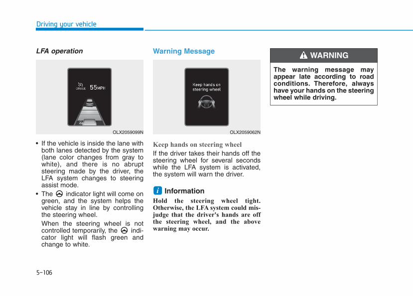
5-106
Driving your vehicle
LFA operation
• If the vehicle is inside the lane withboth lanes detected by the system(lane color changes from gray towhite), and there is no abruptsteering made by the driver, theLFA system changes to steeringassist mode.
• The indicator light will come ongreen, and the system helps thevehicle stay in line by controllingthe steering wheel.When the steering wheel is notcontrolled temporarily, the indi-cator light will flash green andchange to white.
Warning Message
Keep hands on steering wheel
If the driver takes their hands off thesteering wheel for several secondswhile the LFA system is activated,the system will warn the driver.
Information Hold the steering wheel tight.Otherwise, the LFA system could mis-judge that the driver's hands are offthe steering wheel, and the abovewarning may occur.
i
OLX2059099N OLX2059062N
The warning message mayappear late according to roadconditions. Therefore, alwayshave your hands on the steeringwheel while driving.
WARNING
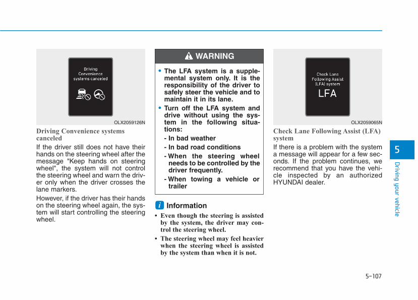
5-107
Driving your vehicle
5
Driving Convenience systems canceled
If the driver still does not have theirhands on the steering wheel after themessage "Keep hands on steeringwheel", the system will not controlthe steering wheel and warn the driv-er only when the driver crosses thelane markers.However, if the driver has their handson the steering wheel again, the sys-tem will start controlling the steeringwheel.
Information • Even though the steering is assisted
by the system, the driver may con-trol the steering wheel.
• The steering wheel may feel heavierwhen the steering wheel is assistedby the system than when it is not.
Check Lane Following Assist (LFA)system
If there is a problem with the systema message will appear for a few sec-onds. If the problem continues, werecommend that you have the vehi-cle inspected by an authorizedHYUNDAI dealer.
i
OLX2059126N OLX2059065N
• The LFA system is a supple-mental system only. It is theresponsibility of the driver tosafely steer the vehicle and tomaintain it in its lane.
• Turn off the LFA system anddrive without using the sys-tem in the following situa-tions:- In bad weather- In bad road conditions- When the steering wheel
needs to be controlled by thedriver frequently.
- When towing a vehicle ortrailer
WARNING

5-108
Driving your vehicle
The LFA system will not be in theENABLED state and/or the steeringwheel will not be assisted when:
• The turn signal is turned on beforechanging a lane. If you changelanes without the turn signal on,the steering wheel might be con-trolled.
• The vehicle is not driven in the mid-dle of the lane when the system isturned on or right after changing alane.
• ESC (Electronic Stability Control) orVSM (Vehicle Stability Management)is activated.
• The vehicle is driven on a sharpcurve.
• Vehicle speed is over 95 mph (153km/h).
• The vehicle makes sharp lanechanges.
• The vehicle brakes suddenly.• Only one lane marker is detected.
• The lane is very wide or narrow.• There are more than two lane
markers on the road (e.g. construc-tion area).
• Radius of a curve is too small.• The vehicle is driven on a steep
incline.• The steering wheel is turned sud-
denly.• The system may not operate for 15
seconds after the engine is startedor the camera is initialized.
Limitations of the SystemThe LFA system may operate prema-turely even if the vehicle does notdepart from the intended lane, OR,the LFA system may not assist yoursteering or warn you if the vehicleleaves the intended lane under thefollowing circumstances:
When the lane and road condi-tions are poor• It is difficult to distinguish the lane
marking from the road surface orthe lane marking is faded or notclearly marked.
• It is difficult to distinguish the colorof the lane marker from the road.
• There are markings on the roadsurface that look like a lane markerthat is inadvertently being detectedby the camera.
• The lane marker is indistinct ordamaged.
• The lane marker is merged ordivided. (e.g. tollgate)
• The lane number increases ordecreases or the lane marker arecrossing complicatedly.

5-109
Driving your vehicle
5
• There are more than two lanemarkers on the road in front of you.
• The lane marker is very thick orthin.
• The lane is very wide or narrow.• The lane marker ahead is not visi-
ble due to rain, snow, water on theroad, damaged or stained roadsurface, or other factors.
• The shadow is on the lane markerby a median strip, trees, guardrail,noise barriers, etc.
• The lane markers are complicatedor a structure substitutes for thelines such as a construction area.
• There are crosswalk signs or othersymbols on the road.
• The lane marker in a tunnel isstained with oil, etc.
• The lane suddenly disappearssuch as at the intersection.
When external condition is inter-vened• The brightness outside changes
suddenly such as when entering orexiting a tunnel, or when passingunder a bridge.
• The brightness outside is too lowsuch as when the headlamps arenot on at night or the vehicle isgoing through a tunnel.
• There is a boundary structure inthe roadway such as a concretebarrier, guardrail and reflector postthat is inadvertently being detectedby the camera.
• When light coming from a streetlight or an oncoming vehicle isreflected on a wet road surfacesuch as a puddle in the road.
• The field of view in front isobstructed by sun glare.
• There is not enough distancebetween you and the vehicle infront to be able to detect the lanemarker or the vehicle ahead is driv-ing on the lane marker.
• Driving on a steep grade, over ahill, or when driving on a curvedroad.
• The adverse road conditions causeexcessive vehicle vibrations whiledriving.
• The surrounding of the inside rearview mirror temperature is highdue to direct sunlight, etc.
• The sensor recognition changessuddenly when passing over aspeed bump or driving on a steepup/down or right/left grade
When front visibility is poor• The windshield or the camera lens
is covered with dirt or debris.• The windshield glass is fogged up;
a clear view of the road is obstruct-ed.
• Placing objects on the dashboard,etc.
• The sensor cannot detect the lanebecause of fog, heavy rain or snow.
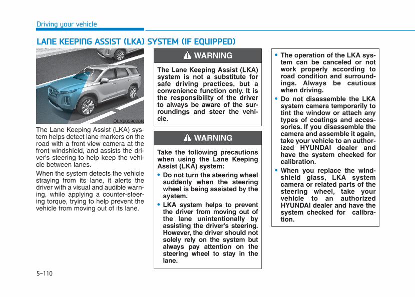
5-110
Driving your vehicle
The Lane Keeping Assist (LKA) sys-tem helps detect lane markers on theroad with a front view camera at thefront windshield, and assists the dri-ver's steering to help keep the vehi-cle between lanes.When the system detects the vehiclestraying from its lane, it alerts thedriver with a visual and audible warn-ing, while applying a counter-steer-ing torque, trying to help prevent thevehicle from moving out of its lane.
LLAANNEE KKEEEEPPIINNGG AASSSSIISSTT ((LLKKAA)) SSYYSSTTEEMM ((IIFF EEQQUUIIPPPPEEDD))
OLX2059028N
The Lane Keeping Assist (LKA)system is not a substitute forsafe driving practices, but aconvenience function only. It isthe responsibility of the driverto always be aware of the sur-roundings and steer the vehi-cle.
WARNING
Take the following precautionswhen using the Lane KeepingAssist (LKA) system:• Do not turn the steering wheel
suddenly when the steeringwheel is being assisted by thesystem.
• LKA system helps to preventthe driver from moving out ofthe lane unintentionally byassisting the driver's steering.However, the driver should notsolely rely on the system butalways pay attention on thesteering wheel to stay in thelane.
WARNING
• The operation of the LKA sys-tem can be canceled or notwork properly according toroad condition and surround-ings. Always be cautiouswhen driving.
• Do not disassemble the LKAsystem camera temporarily totint the window or attach anytypes of coatings and acces-sories. If you disassemble thecamera and assemble it again,take your vehicle to an author-ized HYUNDAI dealer andhave the system checked forcalibration.
• When you replace the wind-shield glass, LKA systemcamera or related parts of thesteering wheel, take yourvehicle to an authorizedHYUNDAI dealer and have thesystem checked for calibra-tion.
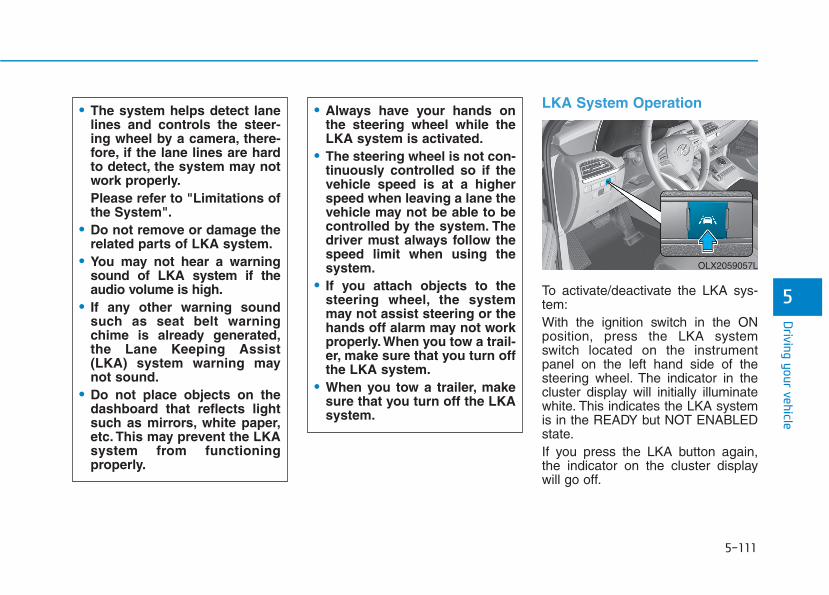
5-111
Driving your vehicle
5
LKA System Operation
To activate/deactivate the LKA sys-tem:With the ignition switch in the ONposition, press the LKA systemswitch located on the instrumentpanel on the left hand side of thesteering wheel. The indicator in thecluster display will initially illuminatewhite. This indicates the LKA systemis in the READY but NOT ENABLEDstate.If you press the LKA button again,the indicator on the cluster displaywill go off.
• The system helps detect lanelines and controls the steer-ing wheel by a camera, there-fore, if the lane lines are hardto detect, the system may notwork properly.Please refer to "Limitations ofthe System".
• Do not remove or damage therelated parts of LKA system.
• You may not hear a warningsound of LKA system if theaudio volume is high.
• If any other warning soundsuch as seat belt warningchime is already generated,the Lane Keeping Assist(LKA) system warning maynot sound.
• Do not place objects on thedashboard that reflects lightsuch as mirrors, white paper,etc. This may prevent the LKAsystem from functioningproperly.
• Always have your hands onthe steering wheel while theLKA system is activated.
• The steering wheel is not con-tinuously controlled so if thevehicle speed is at a higherspeed when leaving a lane thevehicle may not be able to becontrolled by the system. Thedriver must always follow thespeed limit when using thesystem.
• If you attach objects to thesteering wheel, the systemmay not assist steering or thehands off alarm may not workproperly. When you tow a trail-er, make sure that you turn offthe LKA system.
• When you tow a trailer, makesure that you turn off the LKAsystem.
OLX2059057L
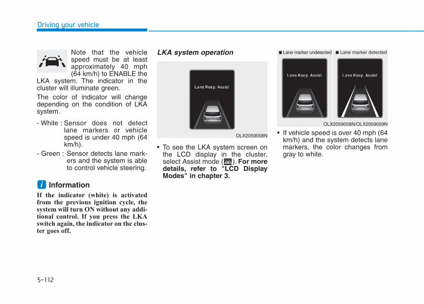
5-112
Driving your vehicle
Note that the vehiclespeed must be at leastapproximately 40 mph(64 km/h) to ENABLE the
LKA system. The indicator in thecluster will illuminate green.The color of indicator will changedepending on the condition of LKAsystem.
- White : Sensor does not detectlane markers or vehiclespeed is under 40 mph (64km/h).
- Green : Sensor detects lane mark-ers and the system is ableto control vehicle steering.
Information If the indicator (white) is activatedfrom the previous ignition cycle, thesystem will turn ON without any addi-tional control. If you press the LKAswitch again, the indicator on the clus-ter goes off.
LKA system operation
• To see the LKA system screen onthe LCD display in the cluster,select Assist mode ( ). For moredetails, refer to "LCD DisplayModes" in chapter 3.
• If vehicle speed is over 40 mph (64km/h) and the system detects lanemarkers, the color changes fromgray to white.
i
OLX2059058N
■ Lane marker undetected ■ Lane marker detected
OLX2059058N/OLX2059059N
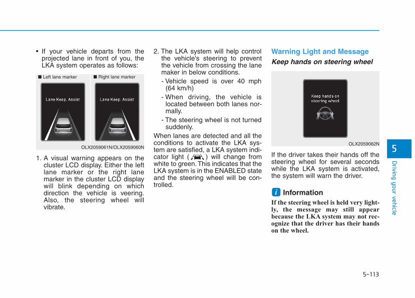
5-113
Driving your vehicle
5
• If your vehicle departs from theprojected lane in front of you, theLKA system operates as follows:
1. A visual warning appears on thecluster LCD display. Either the leftlane marker or the right lanemarker in the cluster LCD displaywill blink depending on whichdirection the vehicle is veering.Also, the steering wheel willvibrate.
2. The LKA system will help controlthe vehicle's steering to preventthe vehicle from crossing the lanemaker in below conditions.- Vehicle speed is over 40 mph
(64 km/h)- When driving, the vehicle is
located between both lanes nor-mally.
- The steering wheel is not turnedsuddenly.
When lanes are detected and all theconditions to activate the LKA sys-tem are satisfied, a LKA system indi-cator light ( ) will change fromwhite to green.This indicates that theLKA system is in the ENABLED stateand the steering wheel will be con-trolled.
Warning Light and MessageKeep hands on steering wheel
If the driver takes their hands off thesteering wheel for several secondswhile the LKA system is activated,the system will warn the driver.
Information If the steering wheel is held very light-ly, the message may still appearbecause the LKA system may not rec-ognize that the driver has their handson the wheel.
i
■ Left lane marker ■ Right lane marker
OLX2059061N/OLX2059060NOLX2059062N
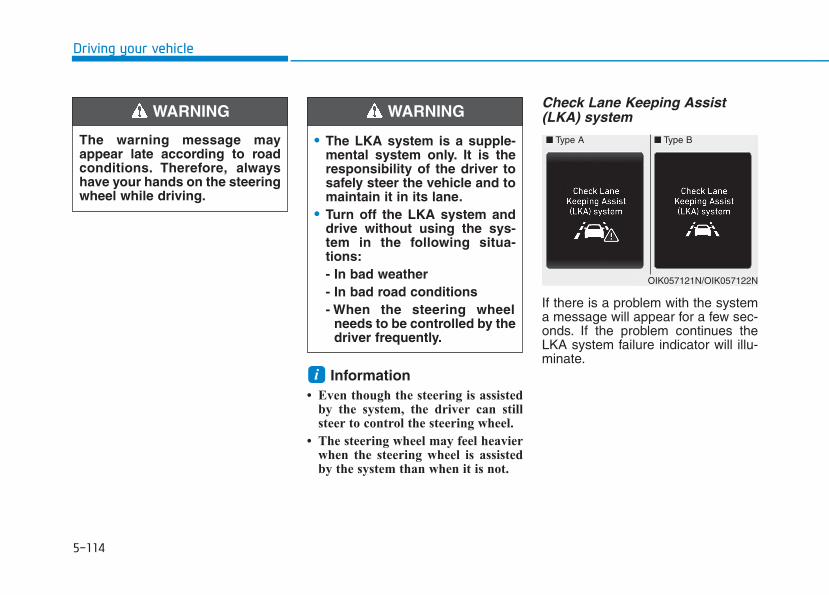
5-114
Driving your vehicle
Information• Even though the steering is assisted
by the system, the driver can stillsteer to control the steering wheel.
• The steering wheel may feel heavierwhen the steering wheel is assistedby the system than when it is not.
Check Lane Keeping Assist(LKA) system
If there is a problem with the systema message will appear for a few sec-onds. If the problem continues theLKA system failure indicator will illu-minate.
i
The warning message mayappear late according to roadconditions. Therefore, alwayshave your hands on the steeringwheel while driving.
WARNING
• The LKA system is a supple-mental system only. It is theresponsibility of the driver tosafely steer the vehicle and tomaintain it in its lane.
• Turn off the LKA system anddrive without using the sys-tem in the following situa-tions:- In bad weather- In bad road conditions- When the steering wheel
needs to be controlled by thedriver frequently.
WARNING
■ Type A ■ Type B
OIK057121N/OIK057122N
5-115
Driving your vehicle
5
LKA system indicatorThe LKA system indica-tor (yellow) will illuminateif the LKA system is notworking properly. Haveyour vehicle checked by anauthorized HYUNDAI deal-er.
When there is a problem with thesystem do one of the following:
• Turn the system on after turningthe engine off and on again.
• Check if the ignition switch is in theON position.
• Check if the system is affected bythe weather. (ex: fog, heavy rain,etc.)
• Check if there is foreign matter onthe camera lens.
If the problem is not solved, haveyour vehicle checked by an author-ized HYUNDAI dealer.
The LKA system will not be in theENABLED state and/or the steeringwheel will not be assisted when:
• The turn signal is turned on beforechanging a lane. If you changelanes without the turn signal on, thesteering wheel might be controlled.
• The vehicle is not driven in the mid-dle of the lane when the system isturned on or right after changing alane.
• ESC (Electronic Stability Control) orVSM (Vehicle Stability Management)is activated.
• The vehicle is driven on a sharpcurve.
• Vehicle speed is below 35 mph (56 km/h) and over 110 mph (177km/h).
• The vehicle makes sharp lanechanges.
• The vehicle brakes suddenly.• The lane is very wide or narrow.• There are more than two lane lines
on the road. (e.g. construction area)• Radius of a curve is too small.
• The vehicle is driven on a steepincline.
• The steering wheel is turned sud-denly.
• The system may not operate for 15seconds after the engine is startedor the camera is initialized.
Limitations of the SystemThe LKA system may operate pre-maturely even if the vehicle does notdepart from the intended lane, OR,the LKA system may not warn you ifthe vehicle leaves the intended laneunder the following circumstances:
When the lane and road condi-tions are poor• It is difficult to distinguish the lane
marker from the road because thelane marker is covered with dust orsand.
• It is difficult to distinguish the colorof the lane marker from the road.
• There are markings on the roadsurface that look like a lane markerthat is inadvertently being detectedby the camera.
5-116
Driving your vehicle
• The lane marker is indistinct ordamaged.
• The lane marker is merged ordivided (e.g. tollgate).
• The lane number increases ordecreases or the lane marker arecrossing complicatedly.
• There are more than two lanemarkers on the road in front of you.
• The lane marker is very thick orthin.
• The lane is very wide or narrow.• The lane marker ahead is not visible
due to rain, snow, water on theroad, damaged or stained road sur-face, or other factors.
• The shadow is on the lane markerby a median strip, trees, guardrail,noise barriers, etc.
• The lane markers are complicatedor a structure substitutes for thelines such as a construction area.
• There are crosswalk signs or othersymbols on the road.
• The lane marker in a tunnel isstained with oil, etc.
• The lane suddenly disappearssuch as at the intersection.
When external condition is inter-vened• The brightness outside changes
suddenly such as when entering orexiting a tunnel, or when passingunder a bridge.
• The brightness outside is too lowsuch as when the headlamps arenot on at night or the vehicle isgoing through a tunnel.
• There is a boundary structure inthe roadway such as a concretebarrier, guardrail and reflector postthat is inadvertently being detectedby the camera.
• When light coming from a streetlight or an oncoming vehicle isreflected on a wet road surfacesuch as a puddle in the road.
• The field of view in front isobstructed by sun glare.
• There is not enough distancebetween you and the vehicle infront to be able to detect the lanemarker or the vehicle ahead is driv-ing on the lane marker.
• Driving on a steep grade, over ahill, or when driving on a curvedroad.
• The adverse road conditions causeexcessive vehicle vibrations whiledriving.
• The surrounding of the inside rearview mirror temperature is highdue to direct sunlight, etc.
When front visibility is poor• The windshield or the camera lens
is blocked with dirt or debris.• The windshield glass is fogged up;
a clear view of the road is obstruct-ed.
• Placing objects on the dashboard,etc.
• The sensor cannot detect the lanebecause of fog, heavy rain or snow.
5-117
Driving your vehicle
5
LKA System Function Change The driver can change LKA to LaneDeparture Warning from the LCDdisplay. Go to the 'User Settings →Driver Assistance → Lane Safety →Lane Keeping Assist (LKA)/LaneDeparture Warning (LDW)/Off'.The system is automatically set toLane Keeping Assist(LKA) if a func-tion is not selected.- Lane Keeping Assist
Lane Keeping Assist guides thedriver to help keep the vehicle with-in the lanes. It rarely controls thesteering wheel, when the vehicledrives well inside the lanes.However, it starts to control thesteering wheel, when the vehicle isabout to deviate out of the lane.
- Lane Departure WarningLane Departure Warning alerts thedriver with a visual warning and awarning alarm when the systemdetects the vehicle departing thelane. The steering wheel will not becontrolled.
- OffIf you select 'off', the LKA system isdeactivated.
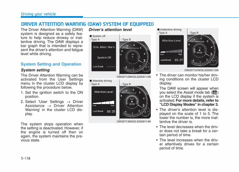
5-118
Driving your vehicle
DDRRIIVVEERR AATTTTEENNTTIIOONN WWAARRNNIINNGG ((DDAAWW)) SSYYSSTTEEMM ((IIFF EEQQUUIIPPPPEEDD))The Driver Attention Warning (DAW)system is designed as a safety fea-ture to help reduce drowsy or inat-tentive driving. The DAW displays abar graph that is intended to repre-sent the driver's attention and fatiguelevel while driving.
System Setting and OperationSystem settingThe Driver Attention Warning can beactivated from the User Settingsmenu in the cluster LCD display byfollowing the procedure below.1. Set the ignition switch to the ON
position.2. Select 'User Settings → Driver
Assistance → Driver AttentionWarning' in the cluster LCD dis-play.
The system stops operation whenthe setting is deactivated. However, ifthe engine is turned off then onagain, the system maintains the pre-vious state.
Driver's attention level
• The driver can monitor his/her driv-ing conditions on the cluster LCDdisplay.The DAW screen will appear whenyou select the Assist mode tab ( )on the LCD display if the system isactivated. For more details, refer to"LCD Display Modes" in chapter 3.
• The driver's attention level is dis-played on the scale of 1 to 5. Thelower the number is, the more inat-tentive the driver is.
• The level decreases when the driv-er does not take a break for a cer-tain period of time.
• The level increases when the driv-er attentively drives for a certainperiod of time.
■ System off - Type A - Type B
■ Attentive driving
OIK057129N/OLX2059113N
- Type A - Type B
OIK057130N/OLX2059114N
- Type A - Type B
OIK057131N/OLX2059115N
■ Inattentive driving

5-119
Driving your vehicle
5
• When the driver turns on the sys-tem while driving, it displays 'LastBreak time' and level.
Take a break
• The "Consider taking a break“message appears on the clusterLCD display and a warning soundsto suggest that the driver take abreak, when the driver’s attentionlevel is below 1.
• The Driver Attention Warning(DAW) system will not suggest abreak, when the total driving timeis shorter than 10 minutes.
Resetting the System • The last break time is set to 00:00
and the driver's attention level isset to 5 (very attentive) when thedriver resets the Driver AttentionWarning (DAW) system.
• The Driver Attention Warning(DAW) system resets in the follow-ing situations.- The engine is turned OFF.- The driver unfastens the seat
belt and then opens the driver'sdoor.
- The vehicle is stopped for morethan 10 minutes.
• The Driver Attention Warning(DAW) system operates again,when the driver restarts driving.
OIK057132L
If any other warning soundsuch as seat belt warning chimeis already generated, the DriverAttention Warning (DAW) sys-tem warning may not sound.
CAUTION
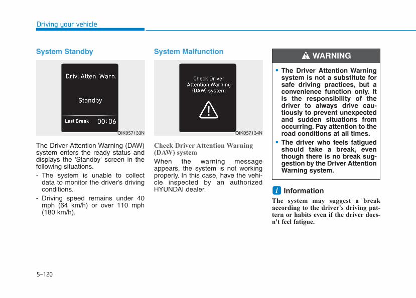
5-120
Driving your vehicle
System Standby
The Driver Attention Warning (DAW)system enters the ready status anddisplays the 'Standby' screen in thefollowing situations.- The system is unable to collect
data to monitor the driver's drivingconditions.
- Driving speed remains under 40mph (64 km/h) or over 110 mph(180 km/h).
System Malfunction
Check Driver Attention Warning(DAW) system
When the warning messageappears, the system is not workingproperly. In this case, have the vehi-cle inspected by an authorizedHYUNDAI dealer. Information
The system may suggest a breakaccording to the driver's driving pat-tern or habits even if the driver does-n't feel fatigue.
i
OIK057133N
• The Driver Attention Warningsystem is not a substitute forsafe driving practices, but aconvenience function only. Itis the responsibility of thedriver to always drive cau-tiously to prevent unexpectedand sudden situations fromoccurring. Pay attention to theroad conditions at all times.
• The driver who feels fatiguedshould take a break, eventhough there is no break sug-gestion by the Driver AttentionWarning system.
WARNING
OIK057134N
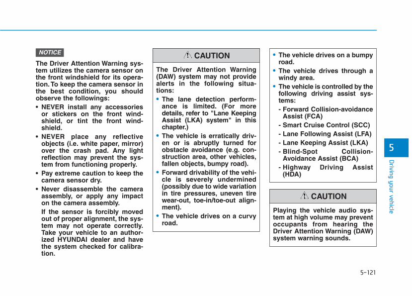
5-121
Driving your vehicle
5
The Driver Attention Warning sys-tem utilizes the camera sensor onthe front windshield for its opera-tion. To keep the camera sensor inthe best condition, you shouldobserve the followings:• NEVER install any accessories
or stickers on the front wind-shield, or tint the front wind-shield.
• NEVER place any reflectiveobjects (i.e. white paper, mirror)over the crash pad. Any lightreflection may prevent the sys-tem from functioning properly.
• Pay extreme caution to keep thecamera sensor dry.
• Never disassemble the cameraassembly, or apply any impacton the camera assembly.If the sensor is forcibly movedout of proper alignment, the sys-tem may not operate correctly.Take your vehicle to an author-ized HYUNDAI dealer and havethe system checked for calibra-tion.
NOTICE
The Driver Attention Warning(DAW) system may not providealerts in the following situa-tions:• The lane detection perform-
ance is limited. (For moredetails, refer to "Lane KeepingAssist (LKA) system" in thischapter.)
• The vehicle is erratically driv-en or is abruptly turned forobstacle avoidance (e.g. con-struction area, other vehicles,fallen objects, bumpy road).
• Forward drivability of the vehi-cle is severely undermined(possibly due to wide variationin tire pressures, uneven tirewear-out, toe-in/toe-out align-ment).
• The vehicle drives on a curvyroad.
• The vehicle drives on a bumpyroad.
• The vehicle drives through awindy area.
• The vehicle is controlled by thefollowing driving assist sys-tems:- Forward Collision-avoidance
Assist (FCA)- Smart Cruise Control (SCC) - Lane Following Assist (LFA)- Lane Keeping Assist (LKA)- Blind-Spot Collision-
Avoidance Assist (BCA)- Highway Driving Assist
(HDA)
CAUTION
Playing the vehicle audio sys-tem at high volume may preventoccupants from hearing theDriver Attention Warning (DAW)system warning sounds.
CAUTION

5-122
Driving your vehicle
The Highway Driving Assist (HDA)system helps keep the vehiclebetween lanes, maintain a distancewith the vehicle ahead, and automat-ically adjusts the vehicle speed to thespeed limit while driving on the high-way.
Information• The Highway Driving Assist (HDA)
system is available only on con-trolled access road of certain high-ways.
❈❈ Controlled access road indicatesroads with limited entrances andexits that allow uninterruptedhigh speed traffic flow. Only pas-senger cars and motorcycles areallowed on controlled accessroads.
• Additional highways may beexpanded by navigation updates.
System Setting and OperationSystem setting• With the Engine Start/Stop button
in the ON or START position, theHighway Driving Assist can be acti-vated by selecting 'All menus →Setup → Vehicle → DriverAssistance → Highway DrivingAssist' from the Settings menu inthe infotainment system screen.Deselect the setting to turn off thesystem.
• If the engine is turned off then onagain, the system maintains thelast setting.
iHHIIGGHHWWAAYY DDRRIIVVIINNGG AASSSSIISSTT ((HHDDAA)) SSYYSSTTEEMM ((IIFF EEQQUUIIPPPPEEDD))
• The Highway Driving Assist(HDA) system is not a substi-tute for safe driving practices,but a convenience function. Itis the responsibility of thedriver to always be aware ofthe surroundings and drivesafely.
• The Highway Driving Assist(HDA) system relies entirelyon the road information pro-vided by the navigation sys-tem. It is the responsibility ofthe driver to follow traffic lawsand avoid accidents.
• For your safety, please readthe owner's manual beforeusing the system.
WARNING
Available highway
(Controlled access road)
USA Interstate Highway
CanadaSelect Provincial and
Territorial Highways

5-123
Driving your vehicle
5
Operating conditionsSelect 'Highway Driving Assist' fromthe Settings menu in the infotain-ment system screen and satisfy thefollowing conditions for the system tooperate.• Driving on the highway main line• Smart Cruise Control is operating
- If the Smart Cruise Control is inthe READY state the HighwayDriving Assist will be in theREADY state. The indi-cator on the cluster will illuminatewhite.
• Vehicle speed is under 95 mph(153 km/h)
If all the mentioned conditions aresatisfied, the system is ENABLEDand the indicator on thecluster will illuminate green.
Steering wheel control
Steering control
If the vehicle detects both lane mark-ers (lane color white), the indica-tor light will change from white togreen. This indicates that the steer-ing wheel is being controlled.
Temporary deactivation
The indicator light changes fromgreen to white when the steeringwheel control is temporarily deacti-vated. Even if the steering wheel isnot controlled, the distance betweenthe vehicle ahead will be maintained.
OLX2059116N
OLX2059117N
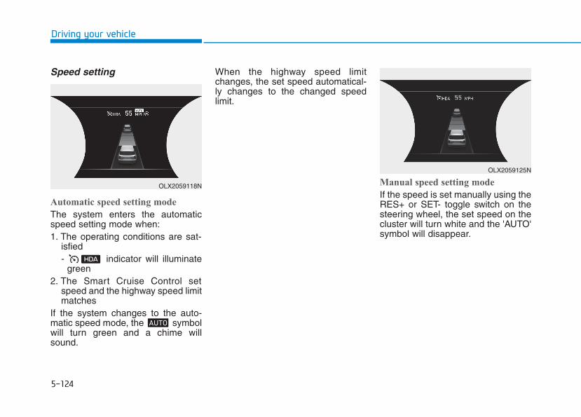
5-124
Driving your vehicle
Speed setting
Automatic speed setting mode
The system enters the automaticspeed setting mode when:1. The operating conditions are sat-
isfied- indicator will illuminate
green2. The Smart Cruise Control set
speed and the highway speed limitmatches
If the system changes to the auto-matic speed mode, the symbolwill turn green and a chime willsound.
When the highway speed limitchanges, the set speed automatical-ly changes to the changed speedlimit.
Manual speed setting mode
If the speed is set manually using theRES+ or SET- toggle switch on thesteering wheel, the set speed on thecluster will turn white and the 'AUTO'symbol will disappear.
OLX2059125N
OLX2059118N
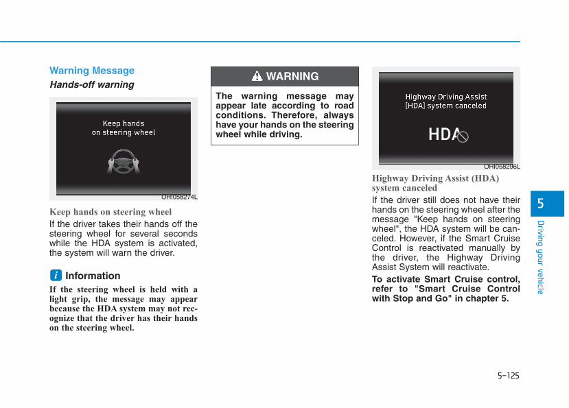
5-125
Driving your vehicle
5
Warning MessageHands-off warning
Keep hands on steering wheel
If the driver takes their hands off thesteering wheel for several secondswhile the HDA system is activated,the system will warn the driver.
Information If the steering wheel is held with alight grip, the message may appearbecause the HDA system may not rec-ognize that the driver has their handson the steering wheel.
Highway Driving Assist (HDA) system canceled
If the driver still does not have theirhands on the steering wheel after themessage "Keep hands on steeringwheel", the HDA system will be can-celed. However, if the Smart CruiseControl is reactivated manually bythe driver, the Highway DrivingAssist System will reactivate.To activate Smart Cruise control,refer to "Smart Cruise Controlwith Stop and Go" in chapter 5.
i
The warning message mayappear late according to roadconditions. Therefore, alwayshave your hands on the steeringwheel while driving.
WARNING
OHI058296L
OHI058274L
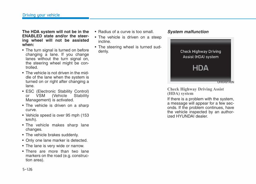
5-126
Driving your vehicle
The HDA system will not be in theENABLED state and/or the steer-ing wheel will not be assistedwhen:• The turn signal is turned on before
changing a lane. If you changelanes without the turn signal on,the steering wheel might be con-trolled.
• The vehicle is not driven in the mid-dle of the lane when the system isturned on or right after changing alane.
• ESC (Electronic Stability Control)or VSM (Vehicle StabilityManagement) is activated.
• The vehicle is driven on a sharpcurve.
• Vehicle speed is over 95 mph (153km/h).
• The vehicle makes sharp lanechanges.
• The vehicle brakes suddenly.• Only one lane marker is detected.• The lane is very wide or narrow.• There are more than two lane
markers on the road (e.g. construc-tion area).
• Radius of a curve is too small.• The vehicle is driven on a steep
incline.• The steering wheel is turned sud-
denly.
System malfunction
Check Highway Driving Assist(HDA) system
If there is a problem with the system,a message will appear for a few sec-onds. If the problem continues, havethe vehicle inspected by an author-ized HYUNDAI dealer.
OHI049140N
5-127
Driving your vehicle
5
Information • Highway Driving Assist is limited in
other countries.
• Highway Driving Assist only oper-ates based on the speed limits of thehighway but it does not work withthe speed cameras.
• The time gap could occur betweenthe navigation speed warning andsystem operation.
• The system is not designed to workon highways other than mentionedas a controlled access road. The sys-tem automatically cancels when youleave the highway.
• If there is a problem with HighwayDriving Assist, the system cannot beactivated in the infotainment systemscreen.
• If your vehicle is 1640 ft. (500 m)ahead and behind of an open toll-gate, the system is automaticallycanceled. Also, it is converted toSmart Cruise Control automaticallywith a pop-up message on the navi-gation.
• In the automatic speed settingmode, the vehicle automaticallyaccelerates or decelerates when thehighway speed limit changes.
• If your vehicle speed exceeds 95mph (153 km/h), Highway DrivingAssist is automatically canceled.Also, it is converted to Smart CruiseControl automatically with a pop-up message on the navigation.
• If you enter a rest area on the high-way or a IC/JC (intersection/junc-tion) without a destination set, thesystem is canceled later than whenthe vehicle actually leaves the high-way.
i
The Highway Driving Assistsystem may not function prop-erly in the following situations:• The navigation is not working
properly.• The navigation is not updated.• The real-time GPS or map
information provided haserrors.
• The navigation is overloadedby performing functions suchas route search, video play-back, voice recognition, etc.are performing simultaneous-ly.
• GPS signals are blocked inareas such as a tunnel.
• The driver goes off course orthe route to the destination ischanged or canceled by reset-ting the navigation.
• The vehicle enters a servicestation or rest area
• Android Auto or Car Play isoperating.
CAUTION
5-128
Driving your vehicle
Information • For information's on vehicle to vehi-
cle distance control and the frontradar, refer to "Smart CruiseControl (Stop & Go)" in this chap-ter.
• For information's on steering con-trol and distance control and thefront camera, refer to "LaneFollowing Assist (LFA)" in thischapter.
InformationThis device complies with Part 15 ofthe FCC rules.
Operation is subject to the followingthree conditions:
1. This device may not cause harmfulinterference, and
2. This device must accept any inter-ference received, including interfer-ence that may cause undesiredoperation.
3. Changes or modifications notexpressly approved by the partyresponsible for compliance couldvoid the user's authority to operatethe device.
InformationRadio frequency radiation exposureinformation:
This equipment complies with FCCradiation exposure limits set forth foran uncontrolled environment.
This equipment should be installedand operated with minimum distanceof 8 in. (20 cm) between the radiator(antenna) and your body.
This transmitter must not be co-locat-ed or operating in conjunction withany other antenna or transmitter.
ii
i
• The navigation cannot detectthe current vehicle position(ex: elevated roads includingoverpass adjacent to generalroads or nearby roads exist ina parallel way).
• The navigation is being updat-ed while driving.
• The navigation is being resetwhile driving.
• The road is slippery due tobad weather such as rain orsnow.
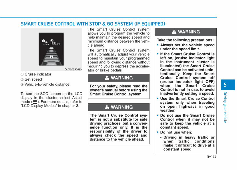
5-129
Driving your vehicle
5
➀ Cruise indicator➁ Set speed➂ Vehicle-to-vehicle distance
To see the SCC screen on the LCDdisplay in the cluster, select Assistmode ( ). For more details, refer to"LCD Display Modes" in chapter 3.
The Smart Cruise Control systemallows you to program the vehicle tohelp maintain the desired speed andminimum distance between the vehi-cle ahead.The Smart Cruise Control systemwill automatically adjust your vehiclespeed to maintain your programmedspeed and following distance withoutrequiring you to depress the acceler-ator or brake pedals.
SSMMAARRTT CCRRUUIISSEE CCOONNTTRROOLL WWIITTHH SSTTOOPP && GGOO SSYYSSTTEEMM ((IIFF EEQQUUIIPPPPEEDD))
For your safety, please read theowner's manual before using theSmart Cruise Control system.
WARNING
The Smart Cruise Control sys-tem is not a substitute for safedriving practices, but a conven-ience function only. It is theresponsibility of the driver toalways check the speed anddistance to the vehicle ahead.
WARNING
OLX2059049N
Take the following precautions :• Always set the vehicle speed
under the speed limit.• If the Smart Cruise Control is
left on, (cruise indicator lightin the instrument cluster isilluminated) the Smart CruiseControl can be activated unin-tentionally. Keep the SmartCruise Control system off(cruise indicator light OFF)when the Smart CruiseControl is not in use, to avoidinadvertently setting a speed.
• Use the Smart Cruise Controlsystem only when travelingon open highways in goodweather.
• Do not use the Smart CruiseControl when it may not besafe to keep the vehicle at aconstant speed.
• Do not use when:- Driving in heavy traffic or
when traffic conditionsmake it difficult to drive at aconstant speed
WARNING

5-130
Driving your vehicle
Smart Cruise Control Switch
CRUISE: Turns cruise control sys-tem on or off.
RES+: Resumes or increases cruisecontrol speed.
SET-: Sets or decreases cruise con-trol speed.
: Sets vehicle-to-vehicle distance.CANCEL: Cancels cruise control
operation.
Adjusting the Sensitivity ofSmart Cruise Control
The sensitivity of vehicle speedwhen following the front vehicle tomaintain the set distance can beadjusted. Go to the 'User Settings →Driver Assistance → SCC Reaction→ Fast/Normal/Slow' on the LCDdisplay. You may select one of thethree stages you prefer.• Fast:
Vehicle speed following the frontvehicle to maintain the set distanceis faster than normal speed.
- Driving on rainy, icy, orsnow-covered roads
- Driving on a steep downhillor uphill
- Driving in windy areas- Driving in parking lots- Driving near crash barriers- Driving on a sharp curve- Driving with limited view
(possibly due to bad weath-er, such as fog, snow, rain orsandstorm)
- The vehicle's sensing abilitydecreases due to vehiclemodification, resulting in alevel difference of the vehi-cle's front and rear
• Unexpected situations maylead to possible accidents.Pay attention continuously toroad conditions and drivingeven when the smart cruisecontrol system is being oper-ated.
OTM058149L
OIK057097N
5-131
Driving your vehicle
5
• Normal:Vehicle speed following the frontvehicle to maintain the set distanceis normal.
• Slow:Vehicle speed following the frontvehicle to maintain the set distanceis slower than normal speed.
InformationThe last selected speed sensitivity ofthe smart cruise control is remained inthe system.
To Convert to Cruise ControlModeThe driver may choose to switch touse the conventional Cruise Controlmode (speed only control function)by following these steps:1. Push the CRUISE button on the
steering wheel to turn the systemon. The cruise ( ) indi-cator will illuminate.
2. Push and hold the Vehicle-to-Vehicle Distance button for morethan 2 seconds.
3. Choose between "Smart CruiseControl" and "Cruise Control".
When the system is canceled usingthe CRUISE button or the CRUISEbutton is used after the engine isturned on, the Smart Cruise Controlmode will turn on.
i
When using the conventionalCruise Control mode, you mustmanually adjust the distance toother vehicles by depressingthe brake pedal. The systemdoes not automatically adjustthe distance to vehicles in frontof you.
WARNING

5-132
Driving your vehicle
Smart Cruise Control SpeedTo set Smart Cruise Controlspeed
1. Push the CRUISE button on thesteering wheel to turn the systemon. The cruise indicator will illumi-nate.
2. Accelerate to the desired speed.The Smart Cruise Control speedcan be set as follows:• 5 – 100 mph (10 - 160 km/h) :
when there is no vehicle in front• 0 – 100 mph (0 - 160 km/h) :
when there is a vehicle in front
3. Push the toggle switch down(SET-). The Set Speed andVehicle-to-Vehicle Distance on theLCD display will illuminate.
4. Release the accelerator pedal.The desired speed will automati-cally be maintained.
If there is a vehicle in front of you, thespeed may decrease to maintain thedistance to the vehicle ahead.On a steep grade, the vehicle mayslow down or speed up slightly whilegoing uphill or downhill.
Information• Vehicle speed may decrease on an
upward slope and increase on adownward slope.
• When you are setting the cruise con-trol speed, with a vehicle in frontand your vehicle speed is between 0~ 20 mph (0 ~ 30 km/h ), the speedwill set to 20 mph (30 km/h).
i
OTM058037
OTM058038

5-133
Driving your vehicle
5
To increase Smart CruiseControl set speed
Follow either of these procedures:• Push the toggle switch up (RES+),
and release it immediately. Thecruising speed will increase by 1 mph (1 km/h) each time youmove the toggle switch up in thismanner.
• Push the toggle switch up (RES+),and hold it. Your vehicle set speedwill increase by 5 mph (10 km/h).Release the toggle switch at thespeed you want.You can set the speed to 100 mph(160 km/h).
To decrease the Smart CruiseControl set speed
Follow either of these procedures:• Push the toggle switch down
(SET-), and release it immediately.The cruising speed will decreaseby 1 mph (1 km/h) each time youmove the toggle switch down inthis manner.
• Push the toggle switch down(SET-), and hold it. Your vehicle setspeed will decrease by 5 mph (10km/h). Release the toggle switchat the speed you want.
• You can set the speed to 20 mph(30 km/h).
Check the traffic and drivingconditions before using the tog-gle switch. Driving speed maysharply increase, when youpush up and hold the toggleswitch.
CAUTION
OTM058039 OTM058038

5-134
Driving your vehicle
To temporarily accelerate withthe Smart Cruise Control onIf you want to speed up temporarilywhen the Smart Cruise Control is on,depress the accelerator pedal.Increased speed will not interferewith Smart Cruise Control operationor change the set speed.To return to the set speed, take yourfoot off the accelerator pedal.If you push the toggle switch down(SET-) at increased speed, the cruis-ing speed will be set again corre-sponding to the pedal position.
Smart Cruise Control set speedwill be temporarily canceledwhen:
Canceled manually• Depressing the brake pedal.• Pushing the CANCEL button locat-
ed on the steering wheel.The Smart Cruise Control turns offtemporarily when the Set Speed andVehicle-to-Vehicle Distance indicatoron the cluster LCD display turns off.The cruise indicator is illuminatedcontinuously.
Canceled automatically• The driver's door is opened.• The vehicle is shifted to N (Neutral),
R (Reverse) or P (Park).• The EPB (Electronic Parking Brake)
is applied.• The vehicle speed is over 110 mph
(170 km/h).• The vehicle stops on a steep incline.• The ESC (Electronic Stability
Control), TCS (Traction ControlSystem) or ABS is operating.
• The ESC is turned off.• The sensor or the cover is dirty or
blocked with foreign matter.• The vehicle is stopped for a certain
period of time.• The vehicle stops and goes repeat-
edly for a long period of time.• The accelerator pedal is continu-
ously depressed for a long periodof time.
• The engine stops or the engineperformance is abnormal.
• Engine rpm is in the red zone.
Be careful when acceleratingtemporarily, because the speedis not controlled automaticallyat this time even if there is avehicle in front of you.
CAUTION
OTM058040
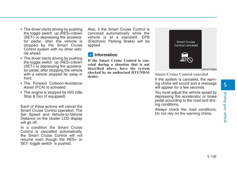
5-135
Driving your vehicle
5
• The driver starts driving by pushingthe toggle switch up (RES+)/down(SET-) or depressing the accelera-tor pedal, after the vehicle isstopped by the Smart CruiseControl system with no other vehi-cle ahead.
• The driver starts driving by pushingthe toggle switch up (RES+)/down(SET-) or depressing the accelera-tor pedal, after stopping the vehiclewith a vehicle stopped far away infront.
• The Forward Collision-AvoidanceAssist (FCA) is activated.
• The engine is stopped by ISG (IdleStop & Go) (if equipped).
Each of these actions will cancel theSmart Cruise Control operation. TheSet Speed and Vehicle-to-VehicleDistance on the cluster LCD displaywill go off.In a condition the Smart CruiseControl is cancelled automatically,the Smart Cruise Control will notresume even though the RES+ orSET- toggle switch is pushed.
Also, if the Smart Cruise Control iscanceled automatically while thevehicle is at a standstill, EPB(Electronic Parking Brake) will beapplied.
InformationIf the Smart Cruise Control is can-celed during a situation that is notdescribed above, have the systemchecked by an authorized HYUNDAIdealer.
Smart Cruise Control canceled
If the system is canceled, the warn-ing chime will sound and a messagewill appear for a few seconds.You must adjust the vehicle speed bydepressing the accelerator or brakepedal according to the road and driv-ing conditions.Always check the road conditions.Do not rely on the warning chime.
i
OIK057096N
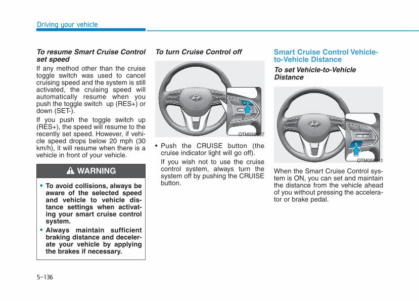
5-136
Driving your vehicle
To resume Smart Cruise Controlset speedIf any method other than the cruisetoggle switch was used to cancelcruising speed and the system is stillactivated, the cruising speed willautomatically resume when youpush the toggle switch up (RES+) ordown (SET-).If you push the toggle switch up(RES+), the speed will resume to therecently set speed. However, if vehi-cle speed drops below 20 mph (30km/h), it will resume when there is avehicle in front of your vehicle.
To turn Cruise Control off
• Push the CRUISE button (thecruise indicator light will go off).If you wish not to use the cruisecontrol system, always turn thesystem off by pushing the CRUISEbutton.
Smart Cruise Control Vehicle-to-Vehicle DistanceTo set Vehicle-to-VehicleDistance
When the Smart Cruise Control sys-tem is ON, you can set and maintainthe distance from the vehicle aheadof you without pressing the accelera-tor or brake pedal.
• To avoid collisions, always beaware of the selected speedand vehicle to vehicle dis-tance settings when activat-ing your smart cruise controlsystem.
• Always maintain sufficientbraking distance and deceler-ate your vehicle by applyingthe brakes if necessary.
WARNING
OTM058037
OTM058041
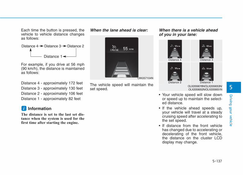
5-137
Driving your vehicle
5
Each time the button is pressed, thevehicle to vehicle distance changesas follows:
For example, if you drive at 56 mph(90 km/h), the distance is maintainedas follows:
Distance 4 - approximately 172 feetDistance 3 - approximately 130 feetDistance 2 - approximately 106 feetDistance 1 - approximately 82 feet
InformationThe distance is set to the last set dis-tance when the system is used for thefirst time after starting the engine.
When the lane ahead is clear:
The vehicle speed will maintain theset speed.
When there is a vehicle aheadof you in your lane:
• Your vehicle speed will slow downor speed up to maintain the select-ed distance.
• If the vehicle ahead speeds up,your vehicle will travel at a steadycruising speed after accelerating tothe set speed.
• If distance from the front vehiclehas changed due to accelerating ordecelerating of the front vehicle,the distance on the cluster LCDdisplay may change.
i
OIK057104N
Distance 4 Distance 3 Distance 2
Distance 1 Distance 4 Distance 3
Distance 1Distance 2OLX2059078N/OLX2059053N/OLX2059052N/OLX2059051N
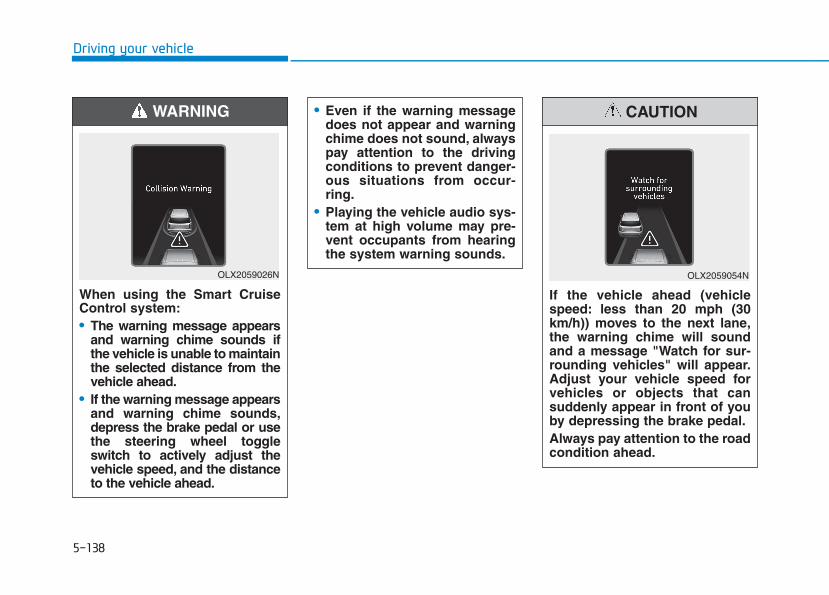
5-138
Driving your vehicle
When using the Smart CruiseControl system:• The warning message appears
and warning chime sounds ifthe vehicle is unable to maintainthe selected distance from thevehicle ahead.
• If the warning message appearsand warning chime sounds,depress the brake pedal or usethe steering wheel toggleswitch to actively adjust thevehicle speed, and the distanceto the vehicle ahead.
WARNING
OLX2059026N
• Even if the warning messagedoes not appear and warningchime does not sound, alwayspay attention to the drivingconditions to prevent danger-ous situations from occur-ring.
• Playing the vehicle audio sys-tem at high volume may pre-vent occupants from hearingthe system warning sounds.
If the vehicle ahead (vehiclespeed: less than 20 mph (30km/h)) moves to the next lane,the warning chime will soundand a message "Watch for sur-rounding vehicles" will appear.Adjust your vehicle speed forvehicles or objects that cansuddenly appear in front of youby depressing the brake pedal.Always pay attention to the roadcondition ahead.
CAUTION
OLX2059054N
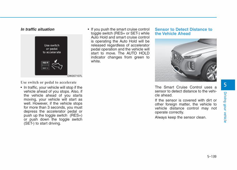
5-139
Driving your vehicle
5
In traffic situation
Use switch or pedal to accelerate
• In traffic, your vehicle will stop if thevehicle ahead of you stops. Also, ifthe vehicle ahead of you startsmoving, your vehicle will start aswell. However, if the vehicle stopsfor more than 3 seconds, you mustdepress the accelerator pedal orpush up the toggle switch (RES+)or push down the toggle switch(SET-) to start driving.
• If you push the smart cruise controltoggle switch (RES+ or SET-) whileAuto Hold and smart cruise controlis operating the Auto Hold will bereleased regardless of acceleratorpedal operation and the vehicle willstart to move. The AUTO HOLDindicator changes from green towhite.
Sensor to Detect Distance tothe Vehicle Ahead
The Smart Cruise Control uses asensor to detect distance to the vehi-cle ahead.If the sensor is covered with dirt orother foreign matter, the vehicle tovehicle distance control may notoperate correctly.Always keep the sensor clean.
OIK057107L
OLX2059031N
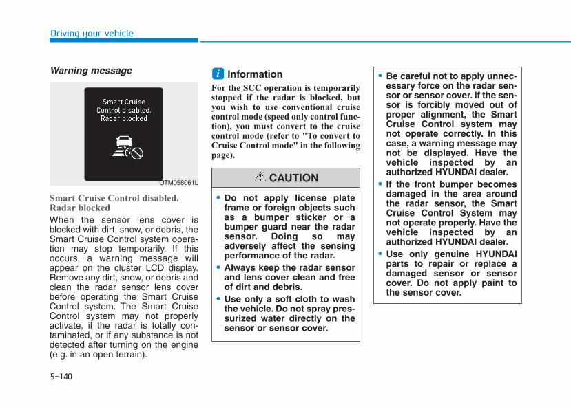
5-140
Driving your vehicle
Warning message
Smart Cruise Control disabled.Radar blocked
When the sensor lens cover isblocked with dirt, snow, or debris, theSmart Cruise Control system opera-tion may stop temporarily. If thisoccurs, a warning message willappear on the cluster LCD display.Remove any dirt, snow, or debris andclean the radar sensor lens coverbefore operating the Smart CruiseControl system. The Smart CruiseControl system may not properlyactivate, if the radar is totally con-taminated, or if any substance is notdetected after turning on the engine(e.g. in an open terrain).
InformationFor the SCC operation is temporarilystopped if the radar is blocked, butyou wish to use conventional cruisecontrol mode (speed only control func-tion), you must convert to the cruisecontrol mode (refer to "To convert toCruise Control mode" in the followingpage).
i
OTM058061L
• Do not apply license plateframe or foreign objects suchas a bumper sticker or abumper guard near the radarsensor. Doing so mayadversely affect the sensingperformance of the radar.
• Always keep the radar sensorand lens cover clean and freeof dirt and debris.
• Use only a soft cloth to washthe vehicle. Do not spray pres-surized water directly on thesensor or sensor cover.
CAUTION
• Be careful not to apply unnec-essary force on the radar sen-sor or sensor cover. If the sen-sor is forcibly moved out ofproper alignment, the SmartCruise Control system maynot operate correctly. In thiscase, a warning message maynot be displayed. Have thevehicle inspected by anauthorized HYUNDAI dealer.
• If the front bumper becomesdamaged in the area aroundthe radar sensor, the SmartCruise Control System maynot operate properly. Have thevehicle inspected by anauthorized HYUNDAI dealer.
• Use only genuine HYUNDAIparts to repair or replace adamaged sensor or sensorcover. Do not apply paint tothe sensor cover.
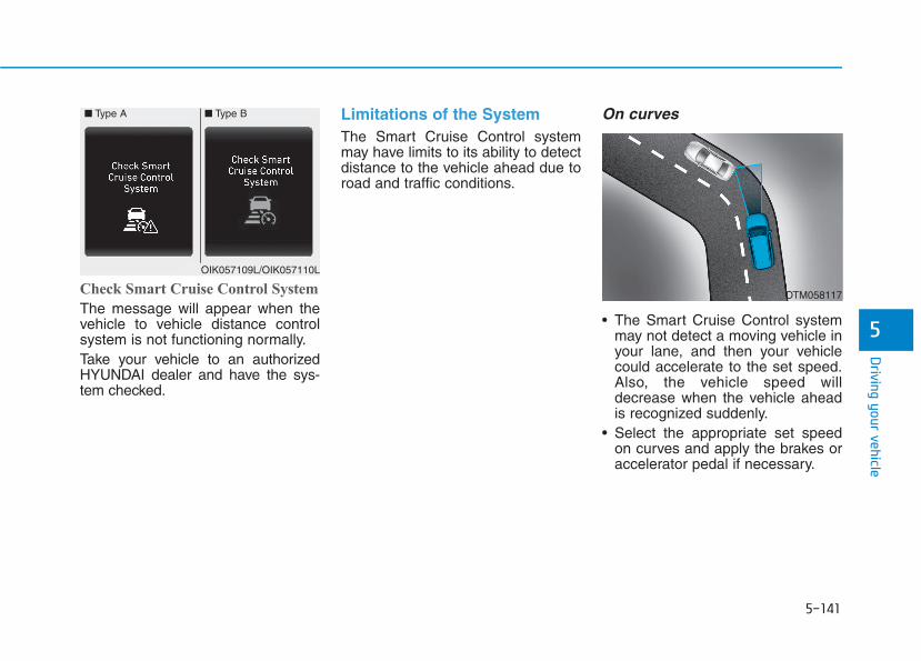
5-141
Driving your vehicle
5
Check Smart Cruise Control System
The message will appear when thevehicle to vehicle distance controlsystem is not functioning normally.Take your vehicle to an authorizedHYUNDAI dealer and have the sys-tem checked.
Limitations of the SystemThe Smart Cruise Control systemmay have limits to its ability to detectdistance to the vehicle ahead due toroad and traffic conditions.
On curves
• The Smart Cruise Control systemmay not detect a moving vehicle inyour lane, and then your vehiclecould accelerate to the set speed.Also, the vehicle speed willdecrease when the vehicle aheadis recognized suddenly.
• Select the appropriate set speedon curves and apply the brakes oraccelerator pedal if necessary.
■ Type A ■ Type B
OIK057109L/OIK057110L
OTM058117
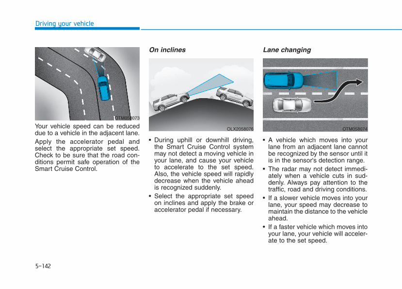
5-142
Driving your vehicle
Your vehicle speed can be reduceddue to a vehicle in the adjacent lane.Apply the accelerator pedal andselect the appropriate set speed.Check to be sure that the road con-ditions permit safe operation of theSmart Cruise Control.
On inclines
• During uphill or downhill driving,the Smart Cruise Control systemmay not detect a moving vehicle inyour lane, and cause your vehicleto accelerate to the set speed.Also, the vehicle speed will rapidlydecrease when the vehicle aheadis recognized suddenly.
• Select the appropriate set speedon inclines and apply the brake oraccelerator pedal if necessary.
Lane changing
• A vehicle which moves into yourlane from an adjacent lane cannotbe recognized by the sensor until itis in the sensor's detection range.
• The radar may not detect immedi-ately when a vehicle cuts in sud-denly. Always pay attention to thetraffic, road and driving conditions.
• If a slower vehicle moves into yourlane, your speed may decrease tomaintain the distance to the vehicleahead.
• If a faster vehicle which moves intoyour lane, your vehicle will acceler-ate to the set speed.
OTM058073
OLX2058076 OTM058074

5-143
Driving your vehicle
5
Detecting vehicles
Some vehicles in your lane cannotbe recognized by the sensor:- Narrow vehicles such as motorcy-
cles or bicycles- Vehicles offset to one side- Slow-moving vehicles or sudden-
decelerating vehicles - Stopped vehicles- Vehicles with small rear profile
such as trailers with no loads
A vehicle ahead cannot be recog-nized correctly by the sensor if any offollowing occurs:- When the vehicle is pointing
upwards due to overloading in theluggage compartment
- While the steering wheel is operat-ing
- When driving to one side of thelane
- When driving on narrow lanes oron curves
Apply the brake or accelerator pedalif necessary.
• Your vehicle may accelerate whena vehicle ahead of you disappears.
• When you are warned that thevehicle ahead of you is not detect-ed, drive with caution.
OTM058128
OTM058129
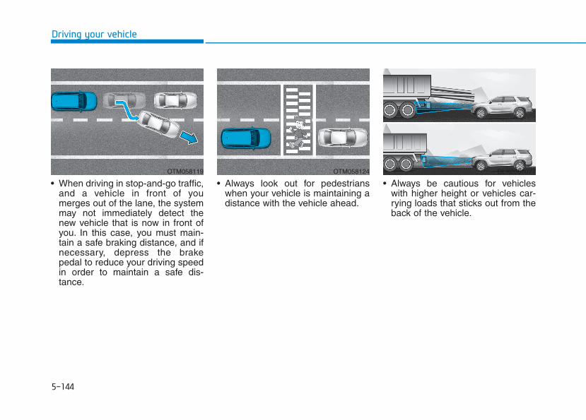
5-144
Driving your vehicle
• When driving in stop-and-go traffic,and a vehicle in front of youmerges out of the lane, the systemmay not immediately detect thenew vehicle that is now in front ofyou. In this case, you must main-tain a safe braking distance, and ifnecessary, depress the brakepedal to reduce your driving speedin order to maintain a safe dis-tance.
• Always look out for pedestrianswhen your vehicle is maintaining adistance with the vehicle ahead.
• Always be cautious for vehicleswith higher height or vehicles car-rying loads that sticks out from theback of the vehicle.
OTM058119 OTM058124 OLX2058077
5-145
Driving your vehicle
5
InformationThe Smart Cruise Control systemmay not operate temporarily due to:
• Electrical interference
• A modified suspension
• Differences of tire abrasion or tirepressure
• Installing different type of tires
i
• Vehicles moving in front ofyou with a frequent lanechange may cause a delay inthe system's reaction or maycause the system to react to avehicle actually in an adjacentlane. Always drive cautiouslyto prevent unexpected andsudden situations from occur-ring.
• Always be aware of the select-ed speed and vehicle to vehi-cle distance. The drivershould not solely rely on thesystem but always pay atten-tion to driving conditions andcontrol your vehicle speed.
• The Smart Cruise Control sys-tem may not recognize com-plex driving situations soalways pay attention to driv-ing conditions and controlyour vehicle speed.
• The Smart Cruise Control sys-tem may recognize a pedestri-an, bicycle, motorcycle, etc. asa vehicle. Always, look aheadcautiously to prevent unex-pected and sudden situationsfrom occurring.
When using the Smart CruiseControl take the following pre-cautions:• If an emergency stop is nec-
essary, you must apply thebrakes. The smart cruise con-trol system cannot guaranteethe stop for every emergencysituation.
• Keep a safe distance accord-ing to road conditions andvehicle speed. If the vehicle tovehicle distance is too closeduring a high-speed driving, aserious collision may result.
• Always maintain sufficientbraking distance and deceler-ate your vehicle by applyingthe brakes if necessary.
• The Smart Cruise Control sys-tem cannot recognize astopped vehicle, pedestrians oran oncoming vehicle. Alwayslook ahead cautiously to pre-vent unexpected and suddensituations from occurring.
WARNING
5-146
Driving your vehicle
InformationThis device complies with Part 15 ofthe FCC rules.
Operation is subject to the followingthree conditions:
1. This device may not cause harmfulinterference, and
2. This device must accept any inter-ference received, including interfer-ence that may cause undesiredoperation.
3. Changes or modifications notexpressly approved by the partyresponsible for compliance couldvoid the user's authority to operatethe device.
InformationRadio frequency radiation exposureinformation:
This equipment complies with FCCradiation exposure limits set forth foran uncontrolled environment.
This equipment should be installedand operated with minimum distanceof 8 in. (20 cm) between the radiator(antenna) and your body.
This transmitter must not be co-locat-ed or operating in conjunction withany other antenna or transmitter.
ii
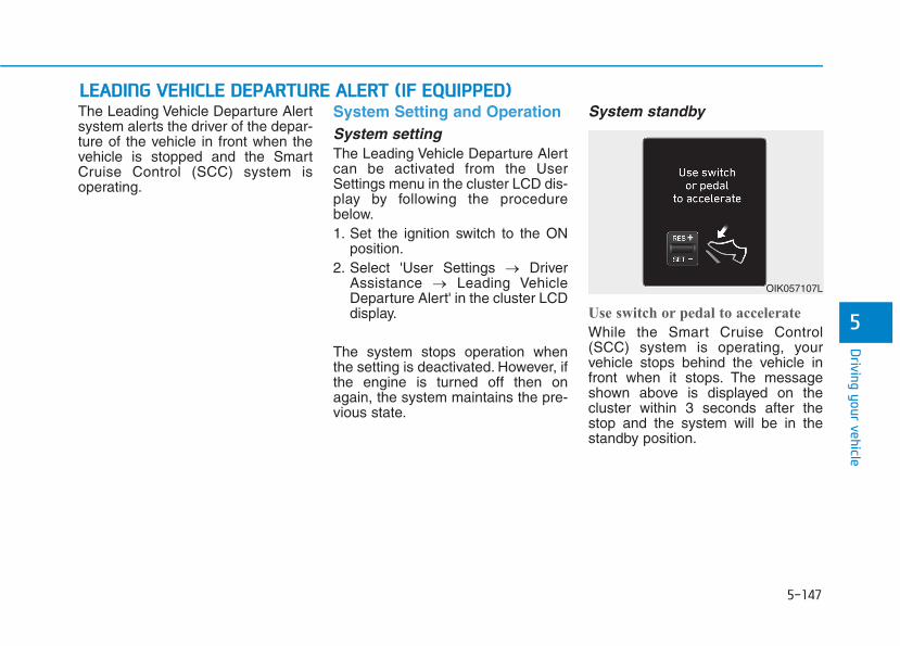
5-147
Driving your vehicle
5
The Leading Vehicle Departure Alertsystem alerts the driver of the depar-ture of the vehicle in front when thevehicle is stopped and the SmartCruise Control (SCC) system isoperating.
System Setting and OperationSystem settingThe Leading Vehicle Departure Alertcan be activated from the UserSettings menu in the cluster LCD dis-play by following the procedurebelow.1. Set the ignition switch to the ON
position.2. Select 'User Settings → Driver
Assistance → Leading VehicleDeparture Alert' in the cluster LCDdisplay.
The system stops operation whenthe setting is deactivated. However, ifthe engine is turned off then onagain, the system maintains the pre-vious state.
System standby
Use switch or pedal to accelerate
While the Smart Cruise Control(SCC) system is operating, yourvehicle stops behind the vehicle infront when it stops. The messageshown above is displayed on thecluster within 3 seconds after thestop and the system will be in thestandby position.
LLEEAADDIINNGG VVEEHHIICCLLEE DDEEPPAARRTTUURREE AALLEERRTT ((IIFF EEQQUUIIPPPPEEDD))
OIK057107L
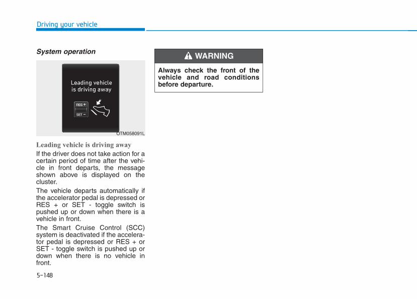
5-148
Driving your vehicle
System operation
Leading vehicle is driving away
If the driver does not take action for acertain period of time after the vehi-cle in front departs, the messageshown above is displayed on thecluster.The vehicle departs automatically ifthe accelerator pedal is depressed orRES + or SET - toggle switch ispushed up or down when there is avehicle in front.The Smart Cruise Control (SCC)system is deactivated if the accelera-tor pedal is depressed or RES + orSET - toggle switch is pushed up ordown when there is no vehicle infront.
OTM058091L
Always check the front of thevehicle and road conditionsbefore departure.
WARNING
5-149
Driving your vehicle
5
Hazardous Driving ConditionsWhen hazardous driving elementsare encountered such as water,snow, ice, mud and sand, take thebelow suggestions:• Drive cautiously and keep a longer
braking distance.• Avoid abrupt braking or steering.• When your vehicle is stuck in snow,
mud, or sand, use second gear.Accelerate slowly to avoid unnec-essary wheel spin.
• Put sand, rock salt, tire chains orother non-slip materials under thewheels to provide additional trac-tion while the vehicle becomesstuck in ice, snow, or mud.
Rocking the VehicleIf it is necessary to rock the vehicleto free it from snow, sand, or mud,first turn the steering wheel right andleft to clear the area around yourfront wheels. Then, shift back andforth between R (Reverse) and a for-ward gear.Try to avoid spinning the wheels, anddo not race the engine.To prevent transmission wear, waituntil the wheels stop spinning beforeshifting gears. Release the accelera-tor pedal while shifting, and presslightly on the accelerator pedal whilethe transmission is in gear. Slowlyspinning the wheels in forward andreverse directions causes a rockingmotion that may free the vehicle.
SSPPEECCIIAALL DDRRIIVVIINNGG CCOONNDDIITTIIOONNSS
Downshifting with an automatictransmission while driving onslippery surfaces can cause anaccident. The sudden change intire speed could cause the tiresto skid. Be careful when down-shifting on slippery surfaces.
WARNING
If the vehicle is stuck andexcessive wheel spin occurs,the temperature in the tires canincrease very quickly. If the tiresbecome damaged, a tire blowout or tire explosion can occur.This condition is dangerous -you and others may be injured.Do not attempt this procedure ifpeople or objects are anywherenear the vehicle.If you attempt to free the vehicle,the vehicle can overheat quickly,possibly causing an enginecompartment fire or other dam-age. Try to avoid spinning thewheels as much as possible toprevent overheating of either thetires or the engine. DO NOTallow the vehicle to spin thewheels above 35 mph (56 km/h).
WARNING
5-150
Driving your vehicle
Information The ESC system must be turned OFFbefore rocking the vehicle.
If you are still stuck after rockingthe vehicle a few times, have thevehicle pulled out by a tow vehicleto avoid engine overheating, pos-sible damage to the transmission,and tire damage. See "Towing" inchapter 6.
Smooth CorneringAvoid braking or gear changing incorners, especially when roads arewet. Ideally, corners should alwaysbe taken under gentle acceleration.
Driving at NightNight driving presents more hazardsthan driving in the daylight. Here aresome important tips to remember:• Slow down and keep more dis-
tance between you and other vehi-cles, as it may be more difficult tosee at night, especially in areaswhere there may not be any streetlights.
• Adjust your mirrors to reduce theglare from other driver's head-lamps.
• Keep your headlamps clean andproperly aimed. Dirty or improperlyaimed headlamps will make itmuch more difficult to see at night.
• Avoid staring directly at the head-lamps of oncoming vehicles. Youcould be temporarily blinded, and itwill take several seconds for youreyes to readjust to the darkness.
Driving in the RainRain and wet roads can make drivingdangerous. Here are a few things toconsider when driving in the rain oron slick pavement:• Slow down and allow extra follow-
ing distance. A heavy rainfallmakes it harder to see and increas-es the distance needed to stopyour vehicle.
• Turn OFF your Cruise Control.• Replace your windshield wiper
blades when they show signs ofstreaking or missing areas on thewindshield.
• Tires should be properly main-tained with at least 2/32nds of aninch of tread depth. If your tires donot have enough tread, making aquick stop on wet pavement cancause a skid and possibly lead toan accident. See "Tire replace-ment" in chapter 7.
• Turn on your headlamps to make iteasier for others to see you.
NOTICE
i
5-151
Driving your vehicle
5
• Driving too fast through large pud-dles can affect your brakes. If youmust go through puddles, try todrive through them slowly.
• If you believe your brakes may bewet, apply them lightly while driv-ing until normal braking operationreturns.
Hydroplaning If the road is wet enough and you aregoing fast enough, your vehicle mayhave little or no contact with the roadsurface and actually ride on thewater. The best advice is SLOWDOWN when the road is wet.
The risk of hydroplaning increas-es as the depth of tire treaddecreases, refer to "Tire replace-ment " in chapter 7.
Driving in Flooded AreasAvoid driving through flooded areasunless you are sure the water is nohigher than the bottom of the wheelhub. Drive through any water slowly.Allow adequate stopping distancebecause brake performance may bereduced.After driving through water, dry thebrakes by gently applying them sev-eral times while the vehicle is movingslowly.
Highway DrivingTiresAdjust the tire inflation, as specified.Under-inflation may overheat ordamage the tires.Do not install worn-out or damagedtires, which may reduce traction oradversely affect vehicle handling.This could lead to sudden tire failurethat may cause loss of vehicle con-trol resulting in an accident.
Information Never over-inflate your tires above themaximum inflation pressure, as speci-fied on your tires.
Fuel, engine coolant and engineoilDriving at higher speeds on the high-way consumes more fuel and is lessefficient than driving at a slower,more moderate speed. Maintain amoderate speed in order to conservefuel when driving on the highway.Be sure to check both the enginecoolant level and the engine oilbefore driving.
Drive beltA loose or damaged drive belt mayoverheat the engine.
i
5-152
Driving your vehicle
Utility vehicles have a signifi-cantly higher rollover rate thanother types of vehicles. To pre-vent rollovers or loss of control:• Take corners at slower speeds
than you would with a passen-ger vehicle.
• Avoid sharp turns and abruptmaneuvers.
• Do not modify your vehicle inany way that you would raisethe center of gravity.
• Keep tires properly inflated.• Do not carry heavy cargo on
the roof.
WARNING Reducing the Risk of aRollover Your multi-purpose passenger vehi-cle is defined as a Sports UtilityVehicle (SUV). SUV's have higherground clearance and a narrowertrack to make them capable of per-forming in a wide variety of off-roadapplications. The specific designcharacteristics give them a highercenter of gravity than ordinary vehi-cles making them more likely to rollover if you make abrupt turns. Utilityvehicles have a significantly higherrollover rate than other types of vehi-cles. Due to this risk, driver and pas-sengers are strongly recommendedto buckle their seat belts. In a rollovercrash, an unbelted person is signifi-cantly more likely to die than a per-son wearing a seat belt.There are steps that a driver canmake to reduce the risk of a rollover.If at all possible, avoid sharp turns orabrupt maneuvers, do not load yourvehicle with heavy cargo on the roof,and never modify your vehicle in anyway.
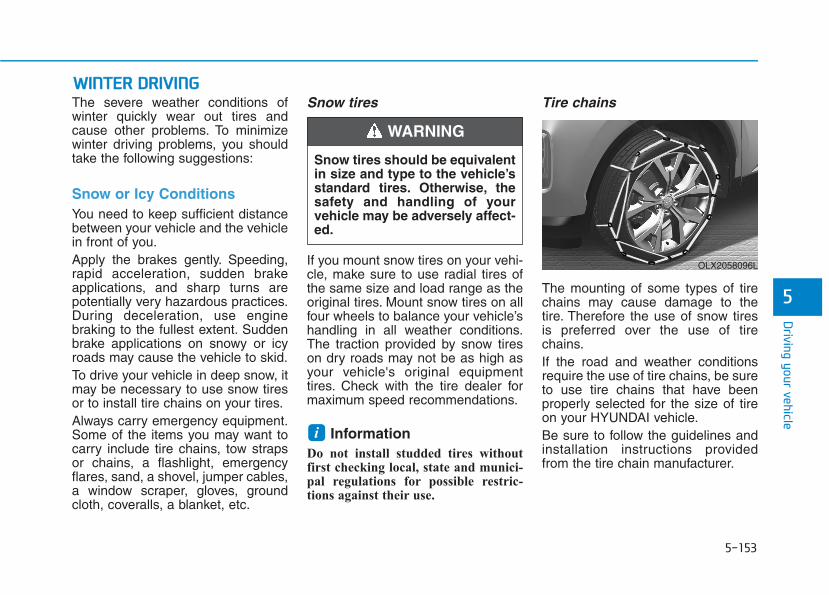
5-153
Driving your vehicle
5
WWIINNTTEERR DDRRIIVVIINNGGThe severe weather conditions ofwinter quickly wear out tires andcause other problems. To minimizewinter driving problems, you shouldtake the following suggestions:
Snow or Icy ConditionsYou need to keep sufficient distancebetween your vehicle and the vehiclein front of you.Apply the brakes gently. Speeding,rapid acceleration, sudden brakeapplications, and sharp turns arepotentially very hazardous practices.During deceleration, use enginebraking to the fullest extent. Suddenbrake applications on snowy or icyroads may cause the vehicle to skid.To drive your vehicle in deep snow, itmay be necessary to use snow tiresor to install tire chains on your tires.Always carry emergency equipment.Some of the items you may want tocarry include tire chains, tow strapsor chains, a flashlight, emergencyflares, sand, a shovel, jumper cables,a window scraper, gloves, groundcloth, coveralls, a blanket, etc.
Snow tires
If you mount snow tires on your vehi-cle, make sure to use radial tires ofthe same size and load range as theoriginal tires. Mount snow tires on allfour wheels to balance your vehicle’shandling in all weather conditions.The traction provided by snow tireson dry roads may not be as high asyour vehicle's original equipmenttires. Check with the tire dealer formaximum speed recommendations.
Information Do not install studded tires withoutfirst checking local, state and munici-pal regulations for possible restric-tions against their use.
Tire chains
The mounting of some types of tirechains may cause damage to thetire. Therefore the use of snow tiresis preferred over the use of tirechains.If the road and weather conditionsrequire the use of tire chains, be sureto use tire chains that have beenproperly selected for the size of tireon your HYUNDAI vehicle.Be sure to follow the guidelines andinstallation instructions providedfrom the tire chain manufacturer.
i
Snow tires should be equivalentin size and type to the vehicle’sstandard tires. Otherwise, thesafety and handling of yourvehicle may be adversely affect-ed.
WARNING
OLX2058096L
5-154
Driving your vehicle
Damage to your vehicle caused byimproper tire chain use is not cov-ered by your vehicle manufacturer’swarranty.
Information • Install tire chains on both left and
right front tires. It should be notedthat installing tire chains on thetires will provide a greater drivingforce, but will not prevent sideskids.
• Do not install studded tires withoutfirst checking local, state andmunicipal regulations for possiblerestrictions against their use.
Chain installation
When installing tire chains, follow themanufacturer’s instructions andmount them as tightly possible. Driveslowly (less than 20 mph (30 km/h))with chains installed. If you hear thechains contacting the body or chas-sis, stop and tighten them. If they stillmake contact, slow down until thenoise stops. Remove the tire chainsas soon as you begin driving oncleared roads.When mounting snow chains, parkthe vehicle on level ground awayfrom traffic. Turn on the vehicleHazard Warning Flasher and place atriangular emergency warning devicebehind the vehicle (if available).Always place the vehicle in P (Park),apply the parking brake and turn offthe engine before installing snowchains.
i
The use of tire chains mayadversely affect vehicle han-dling:• Drive less than 20 mph
(30 km/h) or the chain manu-facturer's recommended speedlimit, whichever is lower.
• Drive carefully and avoidbumps, holes, sharp turns,and other road hazards, whichmay cause the vehicle tobounce.
• Avoid sharp turns or lockedwheel braking.
WARNING
5-155
Driving your vehicle
5
- When using tire chains:• Wrong size chains or improperly
installed chains can damageyour vehicle's brake lines, sus-pension, body and wheels.
• Use SAE "S" class or wirechains.
• If you hear noise caused bychains contacting the body,retighten the chain to preventcontact with the vehicle body.
• To prevent body damage,retighten the chains after driving0.3~0.6 miles (0.5~1.0 km).
• Do not use tire chains on vehi-cles equipped with aluminumwheels. If unavoidable, use awire type chain.
• Use wire chains less than 0.59inch (15 mm) wide to preventdamage to the chain’s connec-tion.
Winter PrecautionsUse high quality ethylene glycolcoolantYour vehicle is delivered with highquality ethylene glycol coolant in thecooling system. It is the only type ofcoolant that should be used becauseit helps prevent corrosion in the cool-ing system, lubricates the waterpump and prevents freezing. Be sureto replace or replenish your coolantin accordance with the maintenanceschedule in chapter 7. Before winter,have your coolant tested to assurethat its freezing point is sufficient forthe temperatures anticipated duringthe winter.
Change to "winter weight" oil ifnecessaryIn some climates it is recommendedthat a lower viscosity "winter weight"oil be used during cold weather. Seechapter 8 for recommendations. Ifyou aren't sure what weight oil youshould use, consult an authorizedHYUNDAI dealer.
Check battery and cablesWinter puts additional burdens onthe battery system. Visually inspectthe battery and cables as describedin chapter 7. The level of charge inyour battery can be checked by anauthorized HYUNDAI dealer or aservice station.
NOTICE
5-156
Driving your vehicle
Check spark plugs and ignitionsystemInspect your spark plugs asdescribed in chapter 7 and replacethem if necessary. Also check allignition wiring and components to besure they are not cracked, worn ordamaged in any way.
Use approved window washeranti-freeze in systemTo keep the water in the windowwasher system from freezing, add anapproved window washer anti-freezesolution in accordance with instruc-tions on the container. Window wash-er anti-freeze is available from anauthorized HYUNDAI dealer andmost auto parts outlets. Do not useengine coolant or other types of anti-freeze as these may damage thepaint finish.
Do not let your parking brakefreezeUnder some conditions your parkingbrake can freeze in the engagedposition.This is most likely to happenwhen there is an accumulation ofsnow or ice around or near the rearbrakes or if the brakes are wet. Ifthere is a risk the parking brake mayfreeze, apply it only temporarily whileyou put the gear in P and block therear wheels so the car cannot roll.Then release the parking brake.
Do not let ice and snow accu-mulate underneathUnder some conditions, snow andice can build up under the fendersand interfere with the steering. Whendriving in severe winter conditionswhere this may happen, you shouldperiodically check underneath thecar to be sure the movement of thefront wheels and the steering com-ponents is not obstructed.
Don't place foreign objects ormaterials in the engine com-partmentPlacement of foreign object or mate-rials which prevent cooling of theengine, in the engine compartment,may cause a failure or combustion.The manufacturer is not responsiblefor the damage caused by suchplacement.
To keep locks from freezingTo keep the locks from freezing,squirt an approved de-icer fluid orglycerine into the key opening. If alock is covered with ice, squirt it withan approved de-icing fluid to removethe ice. If the lock is frozen internally,you may be able to thaw it out byusing a heated key. Handle the heat-ed key with care to avoid injury.
5-157
Driving your vehicle
5
If you are considering to tow with yourvehicle, you should first check withyour state's Department of MotorVehicles to determine legal require-ments. Since laws vary from state tostate the requirements for towingtrailers, vehicles, or other types ofvehicles or apparatus may differ. Askan authorized HYUNDAI dealer forfurther details before towing.Remember that trailering is differentthan just driving your vehicle by itself.Trailering means changes in han-dling, durability, and fuel economy.Successful, safe trailering requirescorrect equipment, and it has to beused properly. Damage to your vehi-cle caused by improper trailer towingis not covered by your vehicle manu-facturer’s warranty.This section contains many time-tested, important trailering tips andsafety rules. Many of these areimportant for your safety and that ofyour passengers. Please read thissection carefully before you pull atrailer.
If you decide to pull a trailerHere are some important points ifyou decide to pull a trailer:• Consider using a sway control. You
can ask a trailer hitch dealer aboutsway control.
• Do not do any towing with yourvehicle during its first 1,200 miles(2,000 km) in order to allow theengine to properly break in. Failureto heed this caution may result inserious engine or transmissiondamage.
• When towing a trailer, be sure toconsult an authorized HYUNDAIdealer for further information onadditional requirements such as atowing kit, etc.
• Always drive your vehicle at a mod-erate speed (less than 60 mph(100 km/h)) or posted towingspeed limit.
• On a long uphill grade, do notexceed 45 mph (70 km/h) or theposted towing speed limit,whichever is lower.
• Carefully observe the weight andload limits provided in the followingpages.
TTRRAAIILLEERR TTOOWWIINNGG
Take the following precautions:• If you don't use the correct
towing equipment, or if youdrive improperly while towing,you can lose control of thevehicle when pulling a trailer.For example, if the trailer istoo heavy, the braking per-formance may be reduced.You and your passengerscould be seriously or fatallyinjured. Pull a trailer only ifyou have followed all thesteps in this section.
• Before towing, make sure thetotal trailer weight, GCW(Gross Combination Weight),GVW (Gross Vehicle Weight),GAW (Gross Axle Weight ) andtrailer tongue load are all with-in the limits.
• When you tow a trailer, makesure to turn off the Idle Stopand Go system.
WARNING
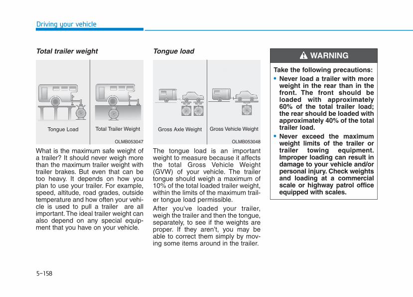
5-158
Driving your vehicle
Total trailer weight
What is the maximum safe weight ofa trailer? It should never weigh morethan the maximum trailer weight withtrailer brakes. But even that can betoo heavy. It depends on how youplan to use your trailer. For example,speed, altitude, road grades, outsidetemperature and how often your vehi-cle is used to pull a trailer are allimportant.The ideal trailer weight canalso depend on any special equip-ment that you have on your vehicle.
Tongue load
The tongue load is an importantweight to measure because it affectsthe total Gross Vehicle Weight(GVW) of your vehicle. The trailertongue should weigh a maximum of10% of the total loaded trailer weight,within the limits of the maximum trail-er tongue load permissible.After you've loaded your trailer,weigh the trailer and then the tongue,separately, to see if the weights areproper. If they aren’t, you may beable to correct them simply by mov-ing some items around in the trailer.
OLMB053047
Tongue Load Total Trailer Weight
OLMB053048
Gross Axle Weight Gross Vehicle Weight
Take the following precautions:• Never load a trailer with more
weight in the rear than in thefront. The front should beloaded with approximately60% of the total trailer load;the rear should be loaded withapproximately 40% of the totaltrailer load.
• Never exceed the maximumweight limits of the trailer ortrailer towing equipment.Improper loading can result indamage to your vehicle and/orpersonal injury. Check weightsand loading at a commercialscale or highway patrol officeequipped with scales.
WARNING

5-159
Driving your vehicle
5
lbs (kg)
Trailer towing equipmentHitches It's important to have the correcthitch equipment. Crosswinds, largetrucks going by, and rough roads area few reasons why you'll need theright hitch. Here are some rules tofollow:• The bumpers on your vehicle are
not intended for hitches. Do notattach rental hitches or otherbumper-type hitches to them. Useonly a frame-mounted hitch thatdoes not attach to the bumper.
• A HYUNDAI trailer hitch accessoryis available at an authorizedHYUNDAI dealer.
Item 7 seater 8 seater
Maximum trailerweight
Without brake system 1,653 (750) 1,653 (750)
With brake system 5,000 (2,267) 5,000 (2,267)
Maximum permissible static vertical load on thecoupling device
500 (227) 500 (227)
Reference weight and distance when towing a trailer
5-160
Driving your vehicle
Safety chainsYou should always attach chainsbetween your vehicle and your trail-er. Cross the safety chains under thetongue of the trailer so that thetongue will not drop to the road if itbecomes separated from the hitch.Instructions about safety chains maybe provided by the hitch manufactur-er or trailer manufacturer. Follow themanufacturer's recommendation forattaching safety chains. Always leavejust enough slack so you can turnwith your trailer. And, never allowsafety chains to drag on the ground.
Trailer brakesIf your trailer is equipped with a brak-ing system, make sure it conforms tofederal and/or local regulations andthat it is properly installed and oper-ating correctly.If your trailer weighs more than themaximum trailer weight without trail-er brakes loaded, then it needs itsown brakes and they must be ade-quate. Be sure to read and follow theinstructions for the trailer brakes soyou’ll be able to install, adjust andmaintain them properly. Do not tapinto your vehicle's brake system.Trailer brakes must be applied sepa-rately from your vehicle's brake sys-tem.
Driving with a trailerTowing a trailer requires a certainamount of experience. Before settingout for the open road, you must getto know your trailer. Acquaint your-self with the feel of handling andbraking with the added weight of thetrailer. And always keep in mind thatthe vehicle you are driving is nowlonger and not nearly as responsiveas your vehicle is by itself.Before you start, check the trailerhitch and platform, safety chains,electrical connector(s), lights, tiresand brakes.During your trip, occasionally checkto be sure that the load is secure,and that the lights and trailer brakesare still working.
Do not use a trailer with its ownbrakes unless you are absolute-ly certain that you have properlyset up the brake system. Use anexperienced, competent trailershop for this work.
WARNING
5-161
Driving your vehicle
5
DistanceStay at least twice as far behind thevehicle ahead as you would whendriving your vehicle without a trailer.This can help you avoid situationsthat require heavy braking and sud-den turns.
PassingYou will need more passing distanceup ahead when you’re towing a trail-er. And, because of the increasedvehicle length, you’ll need to gomuch farther beyond the passedvehicle before you can return to yourlane.
Backing upHold the bottom of the steeringwheel with one hand. Then, to movethe trailer to the left, move your handto the left. To move the trailer to theright, move your hand to the right.Always back up slowly and, if possi-ble, have someone guide you.
Making turnsWhen you're turning with a trailer,make wider turns than normal. Dothis so your trailer won't strike softshoulders, curbs, road signs, trees, orother objects. Avoid jerky or suddenmaneuvers. Signal well in advance.
Turn signalsWhen you tow a trailer, your vehiclehas to have a different turn signalflasher and extra wiring. The greenarrows on your instrument panel willflash whenever you signal a turn orlane change. Properly connected,the trailer lights will also flash to alertother drivers you're about to turn,change lanes, or stop.When towing a trailer, the greenarrows on your instrument panel willflash for turns even if the bulbs on thetrailer are burned out. Thus, you maythink drivers behind you are seeingyour signals when, in fact, they arenot. It's important to check periodical-ly to be sure the trailer bulbs are stillworking. You must also check thelights every time you disconnect andthen reconnect the wires.
Do not connect a trailer lightingsystem directly to your vehi-cle's lighting system. Use anapproved trailer wiring harness.Failure to do so could result indamage to the vehicle electricalsystem and/or personal injury.Consult an authorized HYUNDAIdealer for assistance.
WARNING
5-162
Driving your vehicle
Driving on hillsReduce speed and shift to a lowergear before you start down a long orsteep downgrade. If you don't shiftdown, you might have to use yourbrakes so much that they would getoverheated and may not operate effi-ciently.On a long uphill grade, shift downand reduce your speed to around 45mph (70 km/h) to reduce the possi-bility of engine and transmissionoverheating.If your trailer weighs more than themaximum trailer weight without trailerbrakes, you should drive in D (Drive)when towing a trailer. Operating yourvehicle in D (Drive) when towing atrailer will minimize heat build-up andextend the life of your transmission.
To prevent engine and/or trans-mission overheating:• When towing a trailer on steep
grades (in excess of 6%) payclose attention to the enginecoolant temperature gauge toensure the engine does notoverheat. If the needle of thecoolant temperature gaugemoves towards "H" (HOT), pullover and stop as soon as it issafe to do so, and allow theengine to idle until it coolsdown.You may proceed once theengine has cooled sufficiently.
• When towing a trailer, your vehi-cle speed may be much slowerthan the general flow of traffic,especially when climbing anuphill grade. Use the right handlane when towing a trailer on anuphill grade. Choose your vehi-cle speed according to the max-imum posted speed limit forvehicles with trailers, the steep-ness of the grade, and your trail-er weight.
Parking on hillsGenerally, if you have a trailer attachedto your vehicle, you should not parkyour vehicle on a hill.
However, if you ever have to park yourtrailer on a hill, here's how to do it:1. Pull the vehicle into the parking
area.Turn the steering wheel in thedirection of the curb (right if head-ed down hill, left if headed up hill).
2. Shift the vehicle to P (Park).3. Set the parking brake and shut off
the vehicle.4. Place wheel chocks under the
trailer wheels on the down hill sideof the wheels.
NOTICE
5-163
Driving your vehicle
5
5. Start the vehicle, apply the brakes,shift to neutral, release the park-ing brake and slowly release thebrakes until the trailer chocksabsorb the load.
6. Reapply the brakes and parkingbrakes.
7. Move the shift lever to P (Park).8. Shut off the vehicle and release
the vehicle brakes but leave theparking brake set.
Driving the vehicle after it hasbeen parked on a hill1. With the gear shift lever in P
(Park), apply the brakes and holdthe brake pedal down while per-forming the following:• Start your engine;• Shift into gear; and• Release the parking brake.
2. Slowly remove your foot from thebrake pedal.
3. Drive slowly until the trailer is clearof the chocks.
4. Stop and have someone pick upand store the chocks.
Maintenance when trailer tow-ing Your vehicle will need service moreoften when you regularly pull a trail-er. Important items to pay particularattention to include engine oil, auto-matic transmission fluid, axle lubri-cant and cooling system fluid. Brakecondition is another important item tofrequently check. If you're trailering,it’s a good idea to review these itemsbefore you start your trip. Don't forgetto also maintain your trailer andhitch. Follow the maintenance sched-ule that accompanied your trailer andcheck it periodically. Preferably,inspect the vehicle and trailer at thestart of each day's driving. Inspectthe hitch mounting to make sure thehitch is properly secured to the vehi-cle. Inspect the trailer electricalwiring to make sure brake lights, turnsignal lights, running lights, and haz-ard lights are working properly.
• Do not get out of the vehiclewithout the parking brakefirmly set. If you have left theengine running, the vehiclecan move suddenly. You andothers could be seriously orfatally injured.
• Do not apply the acceleratorpedal to hold the vehicle onan uphill.
WARNING
5-164
Driving your vehicle
To prevent vehicle damage:• Due to higher load during trailer
usage, overheating might occuron hot days or during uphill driv-ing. If the coolant gauge indi-cates over-heating, switch offthe air conditioner and stop thevehicle in a safe area to cooldown the engine.
• When towing check the automat-ic transmission fluid more fre-quently.
NOTICE
5-165
Driving your vehicle
5
Two labels on your driver's door sillshow how much weight your vehiclewas designed to carry: the Tire andLoading Information Label and theCertification Label.Before loading your vehicle, familiar-ize yourself with the following termsfor determining your vehicle's weightratings, from the vehicle's specifica-tions and the Certification Label:
Base Curb WeightThis is the weight of the vehicleincluding a full tank of fuel and allstandard equipment. It does notinclude passengers, cargo, or option-al equipment.
Vehicle Curb WeightThis is the weight of your new vehiclewhen you picked it up from your deal-er plus any aftermarket equipment.
Cargo WeightThis figure includes all weight addedto the Base Curb Weight, includingcargo and optional equipment.
GAW (Gross Axle Weight)This is the total weight placed oneach axle (front and rear) - includingvehicle curb weight and all payload.
GAWR (Gross Axle Weight Rating)This is the maximum allowableweight that can be carried by a singleaxle (front or rear). These numbersare shown on the Certification Label.The total load on each axle mustnever exceed its GAWR.
GVW (Gross Vehicle Weight)This is the Base Curb Weight plusactual Cargo Weight plus passen-gers.
GVWR (Gross Vehicle WeightRating)This is the maximum allowableweight of the fully loaded vehicle(including all options, equipment,passengers and cargo). The GVWRis shown on the Certification Labellocated on the driver’s door sill.
VVEEHHIICCLLEE LLOOAADD LLIIMMIITT
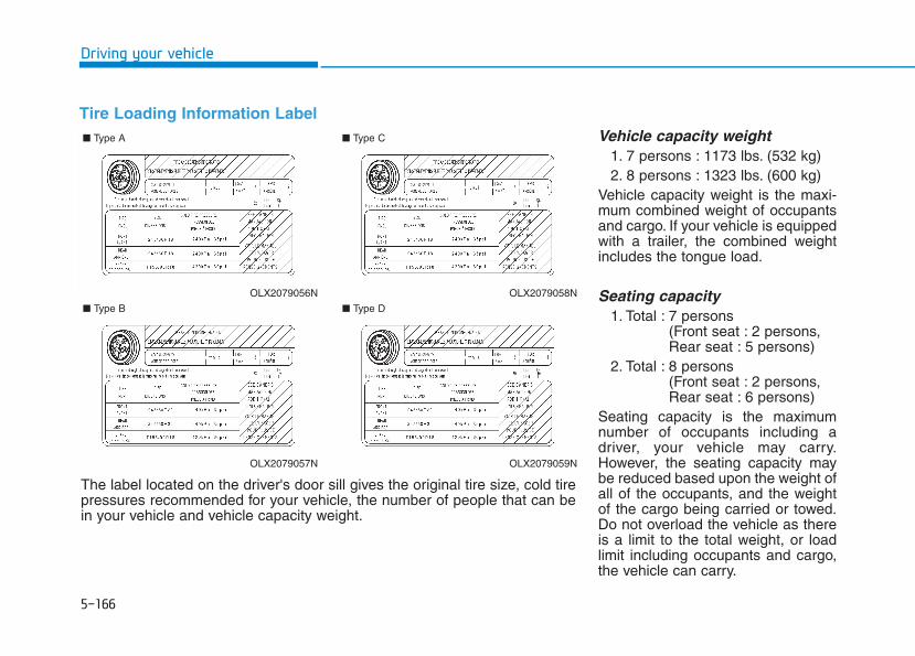
5-166
Driving your vehicle
Tire Loading Information LabelVehicle capacity weight
1. 7 persons : 1173 lbs. (532 kg)2. 8 persons : 1323 lbs. (600 kg)
Vehicle capacity weight is the maxi-mum combined weight of occupantsand cargo. If your vehicle is equippedwith a trailer, the combined weightincludes the tongue load.
Seating capacity1. Total : 7 persons
(Front seat : 2 persons,Rear seat : 5 persons)
2. Total : 8 persons (Front seat : 2 persons,Rear seat : 6 persons)
Seating capacity is the maximumnumber of occupants including adriver, your vehicle may carry.However, the seating capacity maybe reduced based upon the weight ofall of the occupants, and the weightof the cargo being carried or towed.Do not overload the vehicle as thereis a limit to the total weight, or loadlimit including occupants and cargo,the vehicle can carry.
OLX2079056N
■ Type A
OLX2079057N
■ Type B
OLX2079058N
■ Type C
OLX2079059N
■ Type D
The label located on the driver's door sill gives the original tire size, cold tirepressures recommended for your vehicle, the number of people that can bein your vehicle and vehicle capacity weight.
5-167
Driving your vehicle
5
Cargo capacityThe cargo capacity of your vehiclewill increase or decrease dependingon the weight and the number ofoccupants and the tongue load, ifyour vehicle is equipped with a trailer.
Steps for determining correctload limit1. Locate the statement "The com-
bined weight of occupants andcargo should never exceed XXXkg or XXX lbs." on your vehicle'splacard.
2. Determine the combined weight ofthe driver and passengers that willbe riding in your vehicle.
3. Subtract the combined weight ofthe driver and passengers fromXXX kg or XXX lbs.
4. The resulting figure equals theavailable amount of cargo and lug-gage load capacity. For example, ifthe "XXX" amount equals 1400lbs. and there will be five 150 lb.passengers in your vehicle, theamount of available cargo and lug-gage load capacity is 650 lbs.(1400 - 750 (5 x 150) = 650 lbs.)
5. Determine the combined weight ofluggage and cargo being loadedon the vehicle. That weight maynot safely exceed the availablecargo and luggage load capacitycalculated in Step 4.
6. If your vehicle will be towing a trail-er, load from your trailer will betransferred to your vehicle.Consult this manual to determinehow this reduces the availablecargo and luggage load capacityof your vehicle.
Do not overload the vehicle asthere is a limit to the totalweight, or load limit, includingoccupants and cargo, the vehi-cle can carry. Overloading canshorten the life of the vehicle. Ifthe GVWR or the GAWR isexceeded, parts on the vehiclecan break, and it can changethe handling of your vehicle.These could cause you to losecontrol and result in an acci-dent.
WARNING
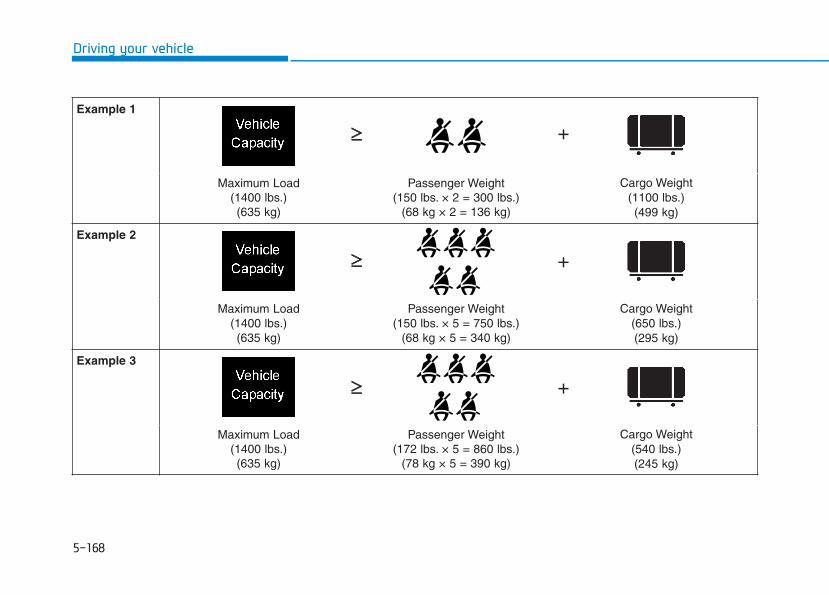
5-168
Driving your vehicle
Example 1
Maximum Load(1400 lbs.)(635 kg)
Passenger Weight(150 lbs. × 2 = 300 lbs.)
(68 kg × 2 = 136 kg)
Cargo Weight(1100 lbs.)(499 kg)
Example 2
Maximum Load(1400 lbs.)(635 kg)
Passenger Weight(150 lbs. × 5 = 750 lbs.)
(68 kg × 5 = 340 kg)
Cargo Weight(650 lbs.)(295 kg)
Example 3
Maximum Load(1400 lbs.)(635 kg)
Passenger Weight(172 lbs. × 5 = 860 lbs.)
(78 kg × 5 = 390 kg)
Cargo Weight(540 lbs.)(245 kg)
+≥≥
≥≥
≥≥
+
+

5-169
Driving your vehicle
5
Certification label
The certification label is located onthe driver’s door sill at the center pil-lar and shows the maximum allow-able weight of the fully loaded vehi-cle. This is called the GVWR (GrossVehicle Weight Rating). The GVWRincludes the weight of the vehicle, alloccupants, fuel and cargo.This label also tells you the maxi-mum weight that can be supportedby the front and rear axles, calledGross Axle Weight Rating (GAWR).
The total weight of the vehicle,including all occupants, accessories,cargo, and trailer tongue load mustnot exceed the Gross Vehicle WeightRating (GVWR) or the Gross AxleWeight Rating (GAWR). To find outthe actual loads on your front andrear axles, you need to go to a weighstation and weigh your vehicle. Besure to spread out your load equallyon both sides of the centerline.
OBH059070
Overloading
• Never exceed the GVWR foryour vehicle, the GAWR foreither the front or rear axleand vehicle capacity weight.Exceeding these ratings canaffect your vehicle’s handlingand braking ability, and causean accident.
• Do not overload your vehicle.Overloading your vehicle cancause heat buildup in yourvehicle’s tires and possibletire failure, increased stop-ping distances and poor vehi-cle handling-all of which mayresult in a crash.
WARNING
Overloading your vehicle maycause damage. Repairs would notbe covered by your warranty. Donot overload your vehicle.
NOTICE
If you carry items inside yourvehicle (e.g., suitcases, tools,packages, or anything else),they are moving as fast as thevehicle. If you have to stop orturn quickly, or if there is acrash, the items will keep goingand can cause an injury if theystrike the driver or a passenger.• Put items in the cargo area of
your vehicle. Try to spread theweight evenly.
• Do not stack items, like suit-cases, inside the vehicleabove the tops of the seats.
• Do not leave an unsecuredchild restraint in your vehicle.
• When you carry somethinginside the vehicle, secure it.
WARNING
Driving your vehicle
5-170
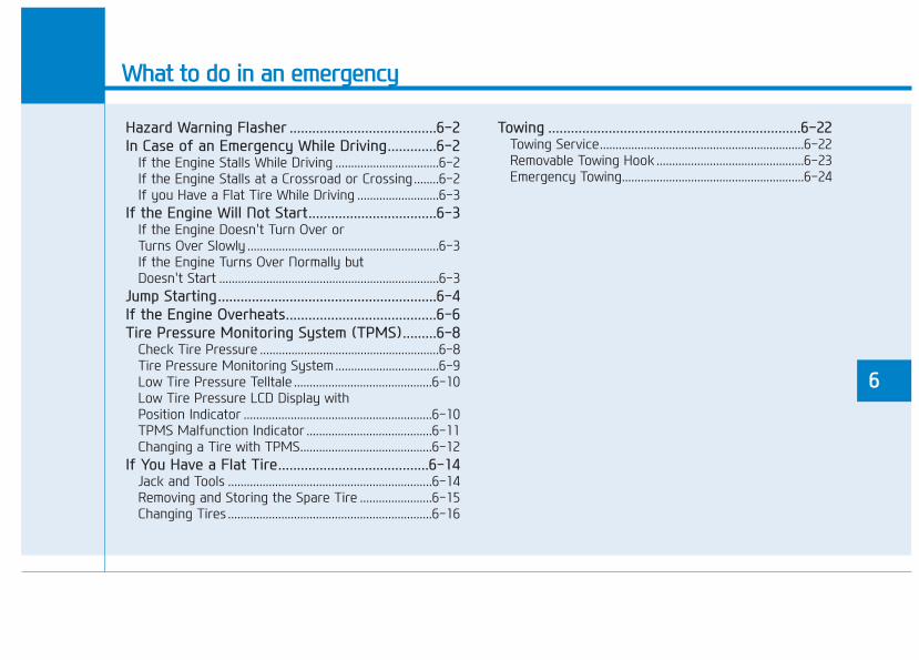
What to do in an emergency
6
Hazard Warning Flasher .......................................6-2In Case of an Emergency While Driving.............6-2
If the Engine Stalls While Driving .................................6-2If the Engine Stalls at a Crossroad or Crossing........6-2If you Have a Flat Tire While Driving ..........................6-3
If the Engine Will Not Start..................................6-3If the Engine Doesn't Turn Over or Turns Over Slowly .............................................................6-3If the Engine Turns Over Normally but Doesn't Start ......................................................................6-3
Jump Starting..........................................................6-4If the Engine Overheats........................................6-6Tire Pressure Monitoring System (TPMS).........6-8
Check Tire Pressure .........................................................6-8Tire Pressure Monitoring System.................................6-9Low Tire Pressure Telltale ............................................6-10Low Tire Pressure LCD Display with Position Indicator ............................................................6-10TPMS Malfunction Indicator ........................................6-11Changing a Tire with TPMS..........................................6-12
If You Have a Flat Tire........................................6-14Jack and Tools .................................................................6-14Removing and Storing the Spare Tire .......................6-15Changing Tires .................................................................6-16
Towing ...................................................................6-22Towing Service.................................................................6-22Removable Towing Hook ...............................................6-23Emergency Towing..........................................................6-24

6-2
The hazard warning flasher servesas a warning to other drivers to exer-cise extreme caution when approach-ing, overtaking, or passing your vehi-cle.It should be used whenever emer-gency repairs are being made orwhen the vehicle is stopped near theedge of a roadway.
To turn the hazard warning flasheron or off, press the hazard warningflasher button. The button is locatedin the center fascia panel. Both theleft and right turn signal lights willflash simultaneously.• The hazard warning flasher oper-
ates whether your vehicle is run-ning or not.
• The turn signals do not work whenthe hazard flasher is on.
If the Engine Stalls WhileDriving• Reduce your speed gradually,
keeping a straight line. Move cau-tiously off the road to a safe place.
• Turn on your hazard warning flash-er.
• Try to start the engine again. Ifyour vehicle will not start, contactan authorized HYUNDAI dealer orseek other qualified assistance.
If the Engine Stalls at aCrossroad or Crossing If the engine stalls at a crossroads orcrossing, if safe to do so, move theshift button to the N (Neutral) posi-tion and then push the vehicle to asafe location.
HHAAZZAARRDD WWAARRNNIINNGG FFLLAASSHHEERR
What to do in an emergency
IINN CCAASSEE OOFF AANN EEMMEERRGGEENNCCYYWWHHIILLEE DDRRIIVVIINNGG
OLX2068001
6-3
What to do in an em
ergency
If you Have a Flat Tire WhileDrivingIf a tire goes flat while you are driving:• Take your foot off the accelerator
pedal and let the vehicle slow downwhile driving straight ahead. Do notapply the brakes immediately orattempt to pull off the road as thismay cause loss of vehicle controlresulting in an accident. When thevehicle has slowed to such a speedthat it is safe to do so, brake care-fully and pull off the road. Drive offthe road as far as possible andpark on firm, level ground. If youare on a divided highway, do notpark in the median area betweenthe two traffic lanes.
• When the vehicle is stopped, pressthe hazard warning flasher button,move the shift button into P (Park),and apply the parking brake, andplace the ignition switch in the OFFposition.
• Have all passengers get out of thevehicle. Be sure they all get out onthe side of the vehicle that is awayfrom traffic.
• When changing a flat tire, followthe instructions provided later inthis chapter.
If the Engine Doesn't TurnOver or Turns Over Slowly • Be sure the shift button is in N
(Neutral) or P (Park). The enginestarts only when the shift button isin N (Neutral) or P (Park).
• Check the battery connections tobe sure they are clean and tight.
• Turn on the interior light. If the lightdims or goes out when you oper-ate the starter, the battery isdrained.
Do not push or pull the vehicle tostart it. This could cause damage toyour vehicle. See instructions for"Jump Starting" provided in thischapter.
If the Engine Turns OverNormally but Doesn't Start Check the fuel level and add fuel ifnecessary.If the engine still does not start, haveyour vehicle checked by an author-ized HYUNDAI dealer.
6
IIFF TTHHEE EENNGGIINNEE WWIILLLL NNOOTT SSTTAARRTT
Push or pull starting the vehiclemay cause the catalytic con-verter to overload which canlead to damage to the emissioncontrol system.
CAUTION

6-4
What to do in an emergency
Jump starting can be dangerous ifdone incorrectly. Follow the jumpstarting procedure in this section toavoid serious injury or damage toyour vehicle. If in doubt about how toproperly jump start your vehicle, westrongly recommend that you have aservice technician or towing servicedo it for you.
JJUUMMPP SSTTAARRTTIINNGG
To prevent SERIOUS INJURY orDEATH to you or bystanders,always follow these precautionswhen working near or handlingthe battery:
Always read and followinstructions carefullywhen handling a battery.Wear eye protectiondesigned to protect theeyes from acid splashes.Keep all flames, sparks,or smoking materialsaway from the battery.Hydrogen is alwayspresent in battery cells,is highly combustible,and may explode if ignit-ed.Keep batteries out ofreach of children.
WARNING Batteries contain sulfu-ric acid which is highlycorrosive. Do not allowacid to contact youreyes, skin or clothing.
If acid gets into your eyes, flushyour eyes with clean water for atleast 15 minutes and get imme-diate medical attention. If acidgets on your skin, thoroughlywash the area. If you feel pain ora burning sensation, get med-ical attention immediately.• When lifting a plastic-cased
battery, excessive pressureon the case may cause batteryacid to leak. Lift with a batterycarrier or with your hands onopposite corners.
• Do not attempt to jump startyour vehicle if your battery isfrozen.
• NEVER attempt to rechargethe battery when the vehicle'sbattery cables are connectedto the battery.
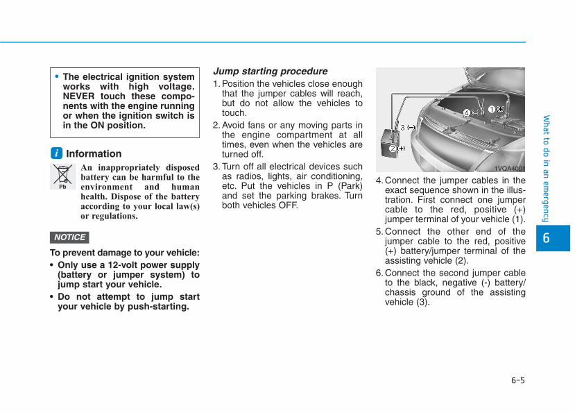
6-5
What to do in an em
ergency
6
InformationAn inappropriately disposedbattery can be harmful to theenvironment and humanhealth. Dispose of the batteryaccording to your local law(s)or regulations.
To prevent damage to your vehicle:• Only use a 12-volt power supply
(battery or jumper system) tojump start your vehicle.
• Do not attempt to jump startyour vehicle by push-starting.
Jump starting procedure 1. Position the vehicles close enough
that the jumper cables will reach,but do not allow the vehicles totouch.
2. Avoid fans or any moving parts inthe engine compartment at alltimes, even when the vehicles areturned off.
3. Turn off all electrical devices suchas radios, lights, air conditioning,etc. Put the vehicles in P (Park)and set the parking brakes. Turnboth vehicles OFF.
4. Connect the jumper cables in theexact sequence shown in the illus-tration. First connect one jumpercable to the red, positive (+)jumper terminal of your vehicle (1).
5. Connect the other end of thejumper cable to the red, positive(+) battery/jumper terminal of theassisting vehicle (2).
6. Connect the second jumper cableto the black, negative (-) battery/chassis ground of the assistingvehicle (3).
NOTICE
i
Pb
• The electrical ignition systemworks with high voltage.NEVER touch these compo-nents with the engine runningor when the ignition switch isin the ON position.
1VQA4001

6-6
What to do in an emergency
7. Connect the other end of the sec-ond jumper cable to the black,negative (-) chassis ground of yourvehicle (4).Do not allow the jumper cables tocontact anything except the cor-rect battery or jumper terminals orthe correct ground. Do not leanover the battery when making con-nections.
8. Start the engine of the assistingvehicle and let it run at approxi-mately 2,000 rpm for a few min-utes. Then start your vehicle.
9. Operate your vehicle for at least 30minutes of driving or at least 60minutes of engine running at idlebefore shutting off the engine.Without sufficient time to chargethe battery, another no-start willoccur.You can also visit your near-est dealer to request the batterybe charged and tested.
If your vehicle will not start after afew attempts, it probably requiresservicing. In this event please seekqualified assistance. If the cause ofyour battery discharging is notapparent, have your vehicle checkedby an authorized HYUNDAI dealer.
Disconnect the jumper cables in theexact reverse order you connectedthem:1. Disconnect the jumper cable from
the black, negative (-) chassisground of your vehicle (4).
2. Disconnect the other end of thejumper cable from the black, neg-ative (-) battery/chassis ground ofthe assisting vehicle (3).
3. Disconnect the second jumpercable from the red, positive (+)battery/jumper terminal of theassisting vehicle (2).
4. Disconnect the other end of thejumper cable from the red, posi-tive (+) jumper terminal of yourvehicle (1).
If your temperature gage indicatesoverheating, you experience a lossof power, or hear loud pinging orknocking, the engine may be over-heating. If this happens, you should:1. Pull off the road and stop as soon
as it is safe to do so.2. Put the vehicle in P (Park) and set
the parking brake. If the air condi-tioning is ON, turn it OFF.
3. If engine coolant is running outunder the vehicle or steam is com-ing out from the hood, stop theengine. Do not open the hood untilthe coolant has stopped running orthe steaming has stopped. If thereis no visible loss of engine coolantand no steam, leave the enginerunning and check to be sure theengine cooling fan is operating. Ifthe fan is not running, turn theengine off.
IIFF TTHHEE EENNGGIINNEE OOVVEERRHHEEAATTSS
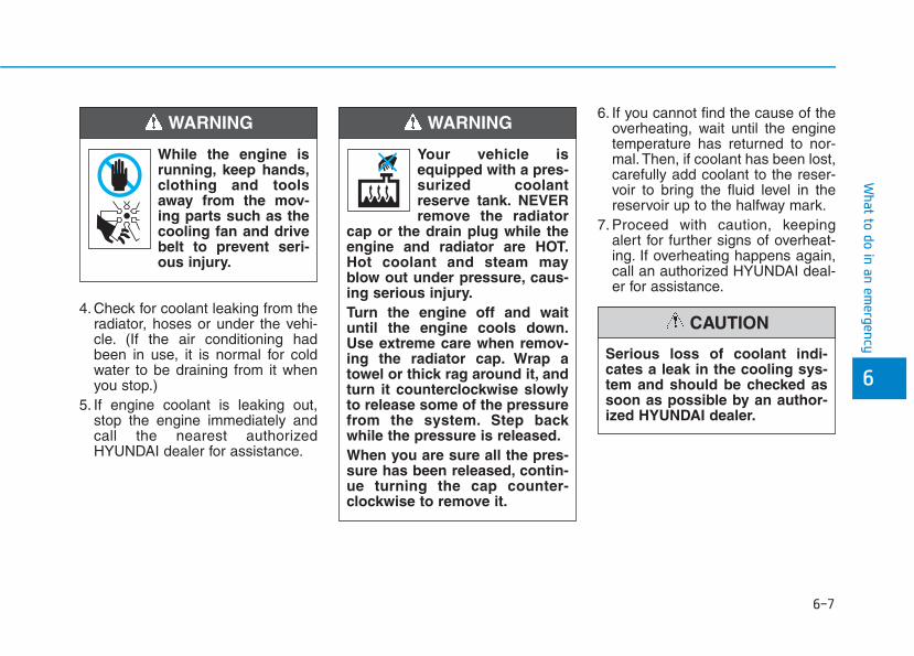
6-7
What to do in an em
ergency
6
4. Check for coolant leaking from theradiator, hoses or under the vehi-cle. (If the air conditioning hadbeen in use, it is normal for coldwater to be draining from it whenyou stop.)
5. If engine coolant is leaking out,stop the engine immediately andcall the nearest authorizedHYUNDAI dealer for assistance.
6. If you cannot find the cause of theoverheating, wait until the enginetemperature has returned to nor-mal. Then, if coolant has been lost,carefully add coolant to the reser-voir to bring the fluid level in thereservoir up to the halfway mark.
7. Proceed with caution, keepingalert for further signs of overheat-ing. If overheating happens again,call an authorized HYUNDAI deal-er for assistance.
While the engine isrunning, keep hands,clothing and toolsaway from the mov-ing parts such as thecooling fan and drivebelt to prevent seri-ous injury.
WARNING
Serious loss of coolant indi-cates a leak in the cooling sys-tem and should be checked assoon as possible by an author-ized HYUNDAI dealer.
CAUTION
Your vehicle isequipped with a pres-surized coolantreserve tank. NEVERremove the radiator
cap or the drain plug while theengine and radiator are HOT.Hot coolant and steam mayblow out under pressure, caus-ing serious injury.Turn the engine off and waituntil the engine cools down.Use extreme care when remov-ing the radiator cap. Wrap atowel or thick rag around it, andturn it counterclockwise slowlyto release some of the pressurefrom the system. Step backwhile the pressure is released.When you are sure all the pres-sure has been released, contin-ue turning the cap counter-clockwise to remove it.
WARNING
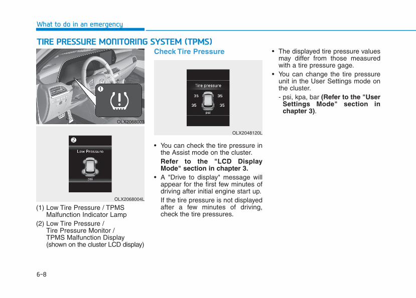
6-8
What to do in an emergency
(1) Low Tire Pressure / TPMSMalfunction Indicator Lamp
(2) Low Tire Pressure / Tire Pressure Monitor / TPMS Malfunction Display(shown on the cluster LCD display)
Check Tire Pressure
• You can check the tire pressure inthe Assist mode on the cluster.Refer to the "LCD DisplayMode" section in chapter 3.
• A "Drive to display" message willappear for the first few minutes ofdriving after initial engine start up.If the tire pressure is not displayedafter a few minutes of driving,check the tire pressures.
• The displayed tire pressure valuesmay differ from those measuredwith a tire pressure gage.
• You can change the tire pressureunit in the User Settings mode onthe cluster.- psi, kpa, bar (Refer to the "User
Settings Mode" section inchapter 3).
TTIIRREE PPRREESSSSUURREE MMOONNIITTOORRIINNGG SSYYSSTTEEMM ((TTPPMMSS))
OLX2068003
OLX2068004L
OLX2048120L

6-9
What to do in an em
ergency
6
Tire Pressure MonitoringSystem
Each tire, including the spare (if pro-vided), should be checked monthlywhen cold and inflated to the inflationpressure recommended by the vehi-cle manufacturer on the vehicle plac-ard or tire inflation pressure label. (Ifyour vehicle has tires of a differentsize than the size indicated on thevehicle placard or tire inflation pres-sure label, you should determine theproper tire inflation pressure forthose tires.)
As an added safety feature, yourvehicle has been equipped with a tirepressure monitoring system (TPMS)that illuminates a low tire pressuretelltale when one or more of yourtires is significantly under-inflated.Accordingly, when the low tire pres-sure telltale illuminates, you shouldstop and check your tires as soon aspossible, and inflate them to theproper pressure. Driving on a signifi-cantly under-inflated tire causes thetire to overheat and can lead to tirefailure.Under-inflation also reduces fuel effi-ciency and tire tread life, and mayaffect the vehicle’s handling andstopping ability.Please note that the TPMS is not asubstitute for proper tire mainte-nance, and it is the driver's responsi-bility to maintain correct tire pres-sure, even if under-inflation has notreached the level to trigger illumina-tion of the TPMS low tire pressuretelltale.
Your vehicle has also been equippedwith a TPMS malfunction indicator toindicate when the system is notoperating properly. The TPMS mal-function indicator is combined withthe low tire pressure telltale. Whenthe system detects a malfunction,the telltale will flash for approximate-ly one minute and then remain con-tinuously illuminated. This sequencewill continue upon subsequent vehi-cle start-ups as long as the malfunc-tion exists.When the malfunction indicator isilluminated, the system may not beable to detect or signal low tire pres-sure as intended. TPMS malfunc-tions may occur for a variety of rea-sons, including the installation ofreplacement or alternate tires orwheels on the vehicle that preventthe TPMS from functioning properly.Always check the TPMS malfunctiontelltale after replacing one or moretires or wheels on your vehicle toensure that the replacement or alter-nate tires and wheels allow the TPMSto continue to function properly.
Over-inflation or under-inflationcan reduce tire life, adverselyaffect vehicle handling, andlead to sudden tire failure thatmay cause loss of vehicle con-trol resulting in an accident.
WARNING
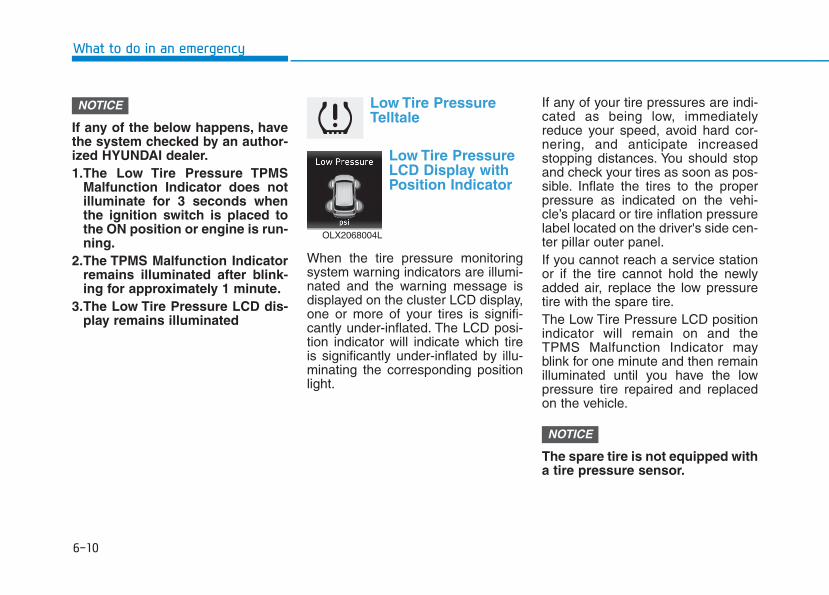
6-10
What to do in an emergency
If any of the below happens, havethe system checked by an author-ized HYUNDAI dealer.1.The Low Tire Pressure TPMS
Malfunction Indicator does notilluminate for 3 seconds whenthe ignition switch is placed tothe ON position or engine is run-ning.
2.The TPMS Malfunction Indicatorremains illuminated after blink-ing for approximately 1 minute.
3.The Low Tire Pressure LCD dis-play remains illuminated
Low Tire PressureTelltale
Low Tire PressureLCD Display withPosition Indicator
When the tire pressure monitoringsystem warning indicators are illumi-nated and the warning message isdisplayed on the cluster LCD display,one or more of your tires is signifi-cantly under-inflated. The LCD posi-tion indicator will indicate which tireis significantly under-inflated by illu-minating the corresponding positionlight.
If any of your tire pressures are indi-cated as being low, immediatelyreduce your speed, avoid hard cor-nering, and anticipate increasedstopping distances. You should stopand check your tires as soon as pos-sible. Inflate the tires to the properpressure as indicated on the vehi-cle’s placard or tire inflation pressurelabel located on the driver's side cen-ter pillar outer panel.If you cannot reach a service stationor if the tire cannot hold the newlyadded air, replace the low pressuretire with the spare tire.The Low Tire Pressure LCD positionindicator will remain on and theTPMS Malfunction Indicator mayblink for one minute and then remainilluminated until you have the lowpressure tire repaired and replacedon the vehicle.
The spare tire is not equipped witha tire pressure sensor.
NOTICE
NOTICE
OLX2068004L
6-11
What to do in an em
ergency
6
TPMS MalfunctionIndicator
The TPMS Malfunction Indicator willilluminate after it blinks for approxi-mately one minute when there is aproblem with the Tire PressureMonitoring System.Have the system checked by anauthorized HYUNDAI dealer as soonas possible.
If there is a malfunction with theTPMS, the individual tire pres-sures in the cluster LCD displaywill not be available. Have the sys-tem checked by an authorizedHYUNDAI dealer as soon as possi-ble.
NOTICE
In winter or cold weather, theLow Tire Pressure Telltale maybe illuminated if the tire pres-sure was adjusted to the recom-mended tire inflation pressurein warm weather. It does notmean your TPMS is malfunc-tioning because the decreasedtemperature leads to a propor-tional lowering of tire pressure.When you drive your vehiclefrom a warm area to a cold areaor from a cold area to a warmarea, or the outside temperatureis greatly higher or lower, youshould check the tire inflationpressure and adjust the tires tothe recommended tire inflationpressure.
CAUTION
Low pressure damage
Significantly low tire pressuremakes the vehicle unstable andcan contribute to loss of vehiclecontrol and increased brakingdistances.Continued driving on low pres-sure tires can cause the tires tooverheat and fail.
WARNING
6-12
What to do in an emergency
The TPMS Malfunction Indicatormay illuminate after blinking forone minute if the vehicle is nearelectric power supply cables orradio transmitters such as policestations, government and publicoffices, broadcasting stations,military installations, airports,transmitting towers, etc.Additionally, the TPMS MalfunctionIndicator may illuminate if snowchains are used or electronicdevices such as computers, charg-ers, remote starters, navigation,etc. This may interfere with normaloperation of the TPMS.
Changing a Tire with TPMSIf you have a flat tire, the Low TirePressure and LCD position indicatorwill come on. Have the flat tirerepaired by an authorized HYUNDAIdealer as soon as possible orreplace the flat tire with the sparetire.
The spare tire does not come with atire pressure monitoring sensor.When the low pressure tire or the flattire is replaced with the spare tire,the Low Tire Pressure LCD positionindicator will remain on. Also, theTPMS Malfunction Indicator will illu-minate after blinking for one minute ifthe vehicle is driven at speed above15.5 mph (25 km/h) for approximate-ly 20 minutes.
Once the original tire equipped witha tire pressure monitoring sensor isreinflated to the recommended pres-sure and reinstalled on the vehicle,the Low Tire Pressure LCD positionindicator and TPMS MalfunctionIndicator will go off within a few min-utes of driving.If the indicators do not disappearafter a few minutes, please visit anauthorized HYUNDAI dealer.Each wheel is equipped with a tirepressure sensor mounted inside thetire behind the valve stem (except forthe spare tire). You must use TPMSspecific wheels. It is recommendedthat you always have your tires serv-iced by an authorized HYUNDAIdealer.
NOTICE
Never use a puncture-repairingagent not approved by HYUNDAIdealer to repair and/or inflate alow pressure tire. Tire sealantnot approved by HYUNDAI deal-er may damage the tire pressuresensor.
CAUTION
6-13
What to do in an em
ergency
6
You may not be able identify a tirewith low pressure by simply lookingat it. Always use a good quality tirepressure gauge to measure the tire'sinflation pressure. Please note that atire that is hot (from being driven) willhave a higher pressure measure-ment than a tire that is cold.A cold tire means the vehicle hasbeen sitting for 3 hours and driven forless than 1 mile (1.6 km) in that 3hour period.Allow the tire to cool before measur-ing the inflation pressure. Always besure the tire is cold before inflating tothe recommended pressure.
InformationThis device complies with Part 15 ofthe FCC rules.
Operation is subject to the followingthree conditions:
1.This device may not cause harmfulinterference.
2.This device must accept any inter-ference received, including interfer-ence that may cause undesired oper-ation.
3.Changes or modifications notexpressly approved by the partyresponsible for compliance couldvoid the user's authority to operatethe equipment.
i
• The TPMS cannot alert you tosevere and sudden tire dam-age caused by external fac-tors such as nails or roaddebris.
• If you feel any vehicle instabil-ity, immediately take your footoff the accelerator, apply thebrakes gradually with lightforce, and slowly move to asafe position off the road.
WARNING
Tampering with, modifying, ordisabling the Tire PressureMonitoring System (TPMS)components may interfere withthe system's ability to warn thedriver of low tire pressure con-ditions and/or TPMS malfunc-tions. Tampering with, modify-ing, or disabling the TirePressure Monitoring System(TPMS) components may voidthe warranty for that portion ofthe vehicle.
WARNING
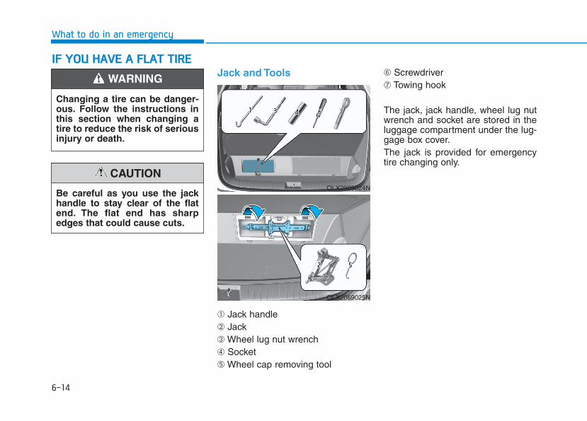
6-14
What to do in an emergency
Jack and Tools
➀ Jack handle➁ Jack➂ Wheel lug nut wrench➃ Socket➄ Wheel cap removing tool
➅ Screwdriver➆ Towing hook
The jack, jack handle, wheel lug nutwrench and socket are stored in theluggage compartment under the lug-gage box cover.The jack is provided for emergencytire changing only.
IIFF YYOOUU HHAAVVEE AA FFLLAATT TTIIRREE
Changing a tire can be danger-ous. Follow the instructions inthis section when changing atire to reduce the risk of seriousinjury or death.
WARNING
Be careful as you use the jackhandle to stay clear of the flatend. The flat end has sharpedges that could cause cuts.
CAUTIONOLX2069024N
OLX2069025N
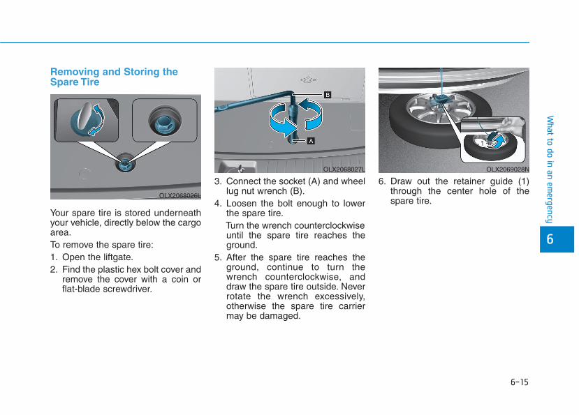
6-15
What to do in an em
ergency
Removing and Storing theSpare Tire
Your spare tire is stored underneathyour vehicle, directly below the cargoarea.To remove the spare tire:1. Open the liftgate.2. Find the plastic hex bolt cover and
remove the cover with a coin orflat-blade screwdriver.
3. Connect the socket (A) and wheellug nut wrench (B).
4. Loosen the bolt enough to lowerthe spare tire.Turn the wrench counterclockwiseuntil the spare tire reaches theground.
5. After the spare tire reaches theground, continue to turn thewrench counterclockwise, anddraw the spare tire outside. Neverrotate the wrench excessively,otherwise the spare tire carriermay be damaged.
6. Draw out the retainer guide (1)through the center hole of thespare tire.
6
OLX2068026L
OLX2068027L OLX2069028N
6-16
What to do in an emergency
To store the spare tire:1. Lay the tire on the ground with the
valve stem facing up.2. Place the wheel under the vehicle
and install the retainer guide andchain through the wheel center.
3. Turn the wrench clockwise until itclicks.
Changing Tires
Follow these steps to change yourvehicle's tire:1. Park on a level, firm surface.2. Move the shift button into P
(Park), apply the parking brake,and place the ignition switch in theOFF position.
3. Press the hazard warning flasherbutton.
4. Remove the wheel lug nutwrench, jack, jack handle, wheelcap remover (big cap only) andspare tire from the vehicle.
5. Block both the front and rear ofthe tire diagonally opposite of thetire you are changing.
A vehicle can slip or roll off of ajack causing serious injury ordeath to you or those nearby.Take the following safety pre-cautions:• Never place any portion of
your body under a vehicle thatis supported by a jack.
• NEVER attempt to change atire in the lane of traffic.ALWAYS move the vehiclecompletely off the road onlevel, firm ground away fromtraffic before trying to changea tire. If you cannot find a level,firm place off the road, call atowing service for assistance.
• Be sure to use the jack pro-vided with the vehicle.
• ALWAYS place the jack on thedesignated jacking positionson the vehicle and NEVER onthe bumpers or any other partof the vehicle for jacking sup-port.
• Do not start or run the enginewhile the vehicle is on thejack.
• Do not allow anyone to remainin the vehicle while it is on thejack.
• Keep children away from theroad and the vehicle.
WARNING
Ensure the spare tire retainerguide is properly aligned withthe center of the spare tire toprevent the spare tire from "rat-tling".Otherwise, it may cause thespare tire to fall off the carrierand lead to an accident.
CAUTION
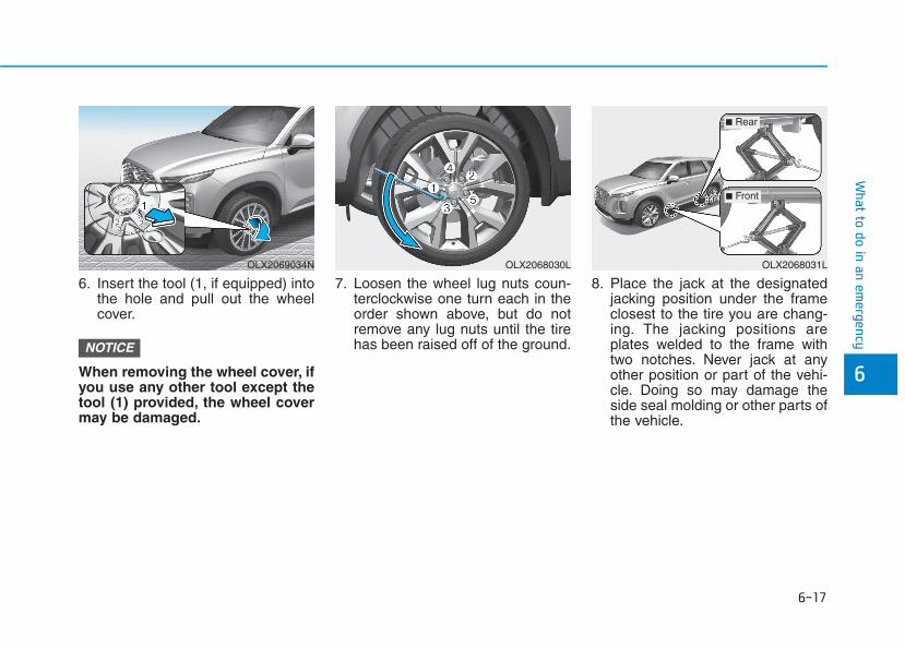
6-17
What to do in an em
ergency
6
6. Insert the tool (1, if equipped) intothe hole and pull out the wheelcover.
When removing the wheel cover, ifyou use any other tool except thetool (1) provided, the wheel covermay be damaged.
7. Loosen the wheel lug nuts coun-terclockwise one turn each in theorder shown above, but do notremove any lug nuts until the tirehas been raised off of the ground.
8. Place the jack at the designatedjacking position under the frameclosest to the tire you are chang-ing. The jacking positions areplates welded to the frame withtwo notches. Never jack at anyother position or part of the vehi-cle. Doing so may damage theside seal molding or other parts ofthe vehicle.
NOTICE
OLX2068030LOLX2069034N OLX2068031L
■ Front
■ Rear
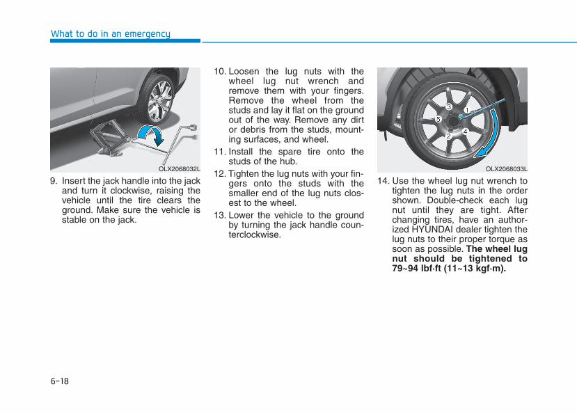
6-18
What to do in an emergency
9. Insert the jack handle into the jackand turn it clockwise, raising thevehicle until the tire clears theground. Make sure the vehicle isstable on the jack.
10. Loosen the lug nuts with thewheel lug nut wrench andremove them with your fingers.Remove the wheel from thestuds and lay it flat on the groundout of the way. Remove any dirtor debris from the studs, mount-ing surfaces, and wheel.
11. Install the spare tire onto thestuds of the hub.
12. Tighten the lug nuts with your fin-gers onto the studs with thesmaller end of the lug nuts clos-est to the wheel.
13. Lower the vehicle to the groundby turning the jack handle coun-terclockwise.
14. Use the wheel lug nut wrench totighten the lug nuts in the ordershown. Double-check each lugnut until they are tight. Afterchanging tires, have an author-ized HYUNDAI dealer tighten thelug nuts to their proper torque assoon as possible. The wheel lugnut should be tightened to79~94 lbf·ft (11~13 kgf·m).
OLX2068033LOLX2068032L
6-19
What to do in an em
ergency
6
If you have a tire gauge, check thetire pressure (see "Tires andWheels" in chapter 8 for tire pressureinstructions.). If the pressure is loweror higher than recommended, driveslowly to the nearest service stationand adjust it to the recommendedpressure. Always reinstall the valvecap after checking or adjusting tirepressure. If the cap is not replaced,air may leak from the tire. If you losea valve cap, buy another and install itas soon as possible. After changingtires, secure the flat tire and returnthe jack and tools to their proper stor-age locations. If it is hard to securethe flat tire, put the flat tire in the lug-gage compartment.
• Check the tire pressure as soonas possible after installing aspare tire. Adjust it to the rec-ommended pressure.
• Check and tighten the wheel lugnuts after driving over 30 mile(50 km) if tires are replaced.Recheck the tire wheel lug nutsafter driving over 600 mile (1,000km).
If any of the equipment such as thejack, lug nuts, studs, or other equip-ment is damaged or in poor condi-tion, do not attempt to change thetire and call for assistance.
Use of compact spare tiresCompact spare tires are designed foremergency use only. Drive carefullyon the compact spare tire andalways follow the safety precautions.
NOTICE
Your vehicle has metric threadson the studs and lug nuts. Makecertain during tire changing thatthe same nuts that wereremoved are reinstalled. If youhave to replace your lug nutsmake sure they have metricthreads to avoid damaging thestuds and ensure the wheel isproperly secured to the hub.Consult an authorized HYUNDAIdealer for assistance.
CAUTION
To prevent compact spare tirefailure and loss of control pos-sibly resulting in an accident:• Use the compact spare tire
only in an emergency.• NEVER operate your vehicle
over 50 mph (80 km/h).• Do not exceed the vehicle's
maximum load rating or theload carrying capacity shownon the sidewall of the com-pact spare tire.
• Do not use the compact sparetire continuously. Repair orreplace the original tire assoon as possible to avoid fail-ure of the compact spare tire.
WARNING

6-20
What to do in an emergency
When driving with the compact sparetire mounted to your vehicle:• Check the tire pressure after
installing the compact spare tire.The compact spare tire should beinflated to 60 psi (420 kPa).
• Do not take this vehicle through anautomatic car wash while the com-pact spare tire is installed.
• Do not use the compact spare tireon any other vehicle because thistire has been designed especiallyfor your vehicle.
• The compact spare tire’s tread life isshorter than a regular tire. Inspectyour compact spare tire regularlyand replace worn compact sparetires with the same size and design,mounted on the same wheel.
• Do not use more than one com-pact spare tire at a time.
• Do not tow a trailer while the com-pact spare tire is installed.
When the original tire and wheelare repaired and reinstalled on thevehicle, the lug nut torque must beset correctly. The correct lug nuttightening torque is 79~94 lbf·ft(11~13 kgf·m).
NOTICE
To prevent damaging the com-pact spare tire and your vehicle:• Drive slowly enough for the
road conditions to avoid allhazards, such as a potholesor debris.
• Avoid driving over obstacles.The compact spare tire diame-ter is smaller than the diame-ter of a conventional tire andreduces the ground clearanceapproximately 1 inch (25 mm).
• Do not use tire chains on thecompact spare tire. Becauseof the smaller size, a tire chainwill not fit properly.
• Do not use the compact sparetire on any other wheels, norshould standard tires, snowtires, wheel covers or trimrings be used with the com-pact spare wheel.
CAUTION
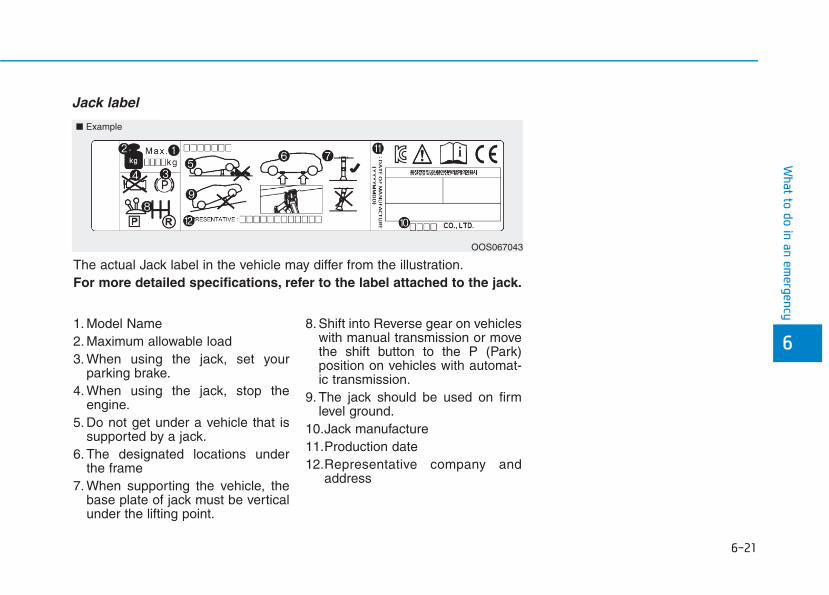
6-21
What to do in an em
ergency
Jack label
6
The actual Jack label in the vehicle may differ from the illustration.For more detailed specifications, refer to the label attached to the jack.
1. Model Name2. Maximum allowable load3. When using the jack, set your
parking brake.4. When using the jack, stop the
engine.5. Do not get under a vehicle that is
supported by a jack.6. The designated locations under
the frame7. When supporting the vehicle, the
base plate of jack must be verticalunder the lifting point.
8. Shift into Reverse gear on vehicleswith manual transmission or movethe shift button to the P (Park)position on vehicles with automat-ic transmission.
9. The jack should be used on firmlevel ground.
10.Jack manufacture11.Production date12.Representative company and
address
■ Example
OOS067043
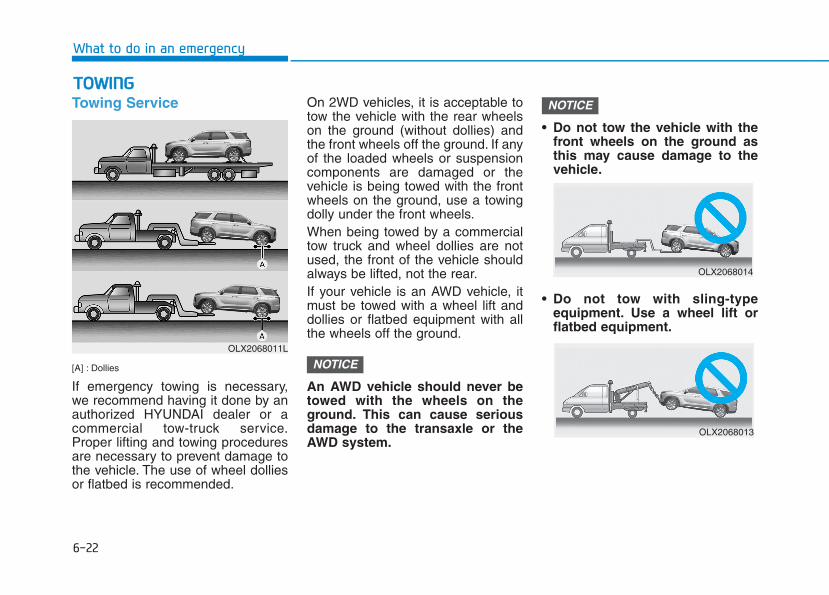
6-22
What to do in an emergency
Towing Service
[A] : Dollies
If emergency towing is necessary,we recommend having it done by anauthorized HYUNDAI dealer or acommercial tow-truck service.Proper lifting and towing proceduresare necessary to prevent damage tothe vehicle. The use of wheel dolliesor flatbed is recommended.
On 2WD vehicles, it is acceptable totow the vehicle with the rear wheelson the ground (without dollies) andthe front wheels off the ground. If anyof the loaded wheels or suspensioncomponents are damaged or thevehicle is being towed with the frontwheels on the ground, use a towingdolly under the front wheels.When being towed by a commercialtow truck and wheel dollies are notused, the front of the vehicle shouldalways be lifted, not the rear.If your vehicle is an AWD vehicle, itmust be towed with a wheel lift anddollies or flatbed equipment with allthe wheels off the ground.
An AWD vehicle should never betowed with the wheels on theground. This can cause seriousdamage to the transaxle or theAWD system.
• Do not tow the vehicle with thefront wheels on the ground asthis may cause damage to thevehicle.
• Do not tow with sling-typeequipment. Use a wheel lift orflatbed equipment.
NOTICE
NOTICE
TTOOWWIINNGG
OLX2068011L
OLX2068014
OLX2068013
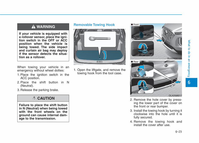
6-23
What to do in an em
ergency
6
When towing your vehicle in anemergency without wheel dollies:1. Place the ignition switch in the
ACC position.2. Place the shift button in N
(Neutral).3. Release the parking brake.
Removable Towing Hook
1. Open the liftgate, and remove thetowing hook from the tool case.
2. Remove the hole cover by press-ing the lower part of the cover onthe front or rear bumper.
3. Install the towing hook by turning itclockwise into the hole until it isfully secured.
4. Remove the towing hook andinstall the cover after use.
OLX2069016N
■ Front
OLX2068017
If your vehicle is equipped witha rollover sensor, place the igni-tion switch in the OFF or ACCposition when the vehicle isbeing towed. The side impactand curtain air bag may deployif the sensor detects the situa-tion as a rollover.
WARNING
Failure to place the shift buttonin N (Neutral) when being towedwith the front wheels on theground can cause internal dam-age to the transmission.
CAUTION
OLX2068015■ Rear

6-24
What to do in an emergency
Emergency Towing
If towing is necessary, we recom-mend you have it done by an author-ized HYUNDAI dealer or a commer-cial tow truck service.
If towing service is not available in anemergency, your vehicle may betemporarily towed using a cable orchain secured to the emergency tow-ing hook at the front (or rear) of thevehicle.Use extreme caution when towingthe vehicle with a cable or chain. Adriver must be in the vehicle to steerit and operate the brakes.Towing in this manner may be doneonly on hard-surfaced roads for ashort distance and at low speeds.Also, the wheels, axles, power train,steering and brakes must all be ingood condition.
Always follow these emergency tow-ing precautions:• While depressing the brake pedal
shift to the N (Neutral) position andturn the vehicle off. The POWERbutton will be in the ACC position.
• Release the parking brake.• Depress the brake pedal with more
force than normal since you willhave reduced braking perform-ance.
• More steering effort will berequired because the power steer-ing system will be disabled.
• Use a vehicle heavier than yourown to tow your vehicle.
• The drivers of both vehicles shouldcommunicate with each other fre-quently.
• Before emergency towing, checkthat the hook is not broken or dam-aged.
• Fasten the towing cable or chainsecurely to the hook.
• Do not jerk the hook. Apply steadyand even force.
OLX2069018N
OLX2068019
The driver must be in the vehi-cle for steering and brakingoperations when the vehicle isbeing towed. Passengers otherthan the driver must not be inthe vehicle.
CAUTION

6-25
What to do in an em
ergency
6
• Use a towing cable or chain lessthan 16 feet (5 m) long. Attach awhite or red cloth (about 12 inch(30 cm) wide) in the middle of thecable or chain for easy visibility.
• Drive carefully so the towing cableor chain remains tight during tow-ing.
• Before towing, check the reductiongear for fluid leaks under your vehi-cle. If the reduction gear is leaking,flatbed equipment or a towing dollymust be used.
Accelerate or decelerate the vehi-cle in a slow and gradual mannerwhile maintaining tension on thetow rope or chain to start or drivethe vehicle, otherwise tow hooksand the vehicle may be damaged.
To avoid damage to your vehicleand vehicle components whentowing:• Always pull straight ahead when
using the towing hooks. Do notpull from the side or at a verticalangle.
• Do not use the towing hooks topull a vehicle out of mud, sandor other conditions from whichthe vehicle cannot be driven outunder its own power.
• Limit the vehicle speed to 10 mph (15 km/h) and drive lessthan 1 mile (1.5 km) when towingto avoid serious damage to thereduction gear.
NOTICE
NOTICE
OFE068022

7
Maintenance
7
Maintenance
Engine compartment .............................................7-3Maintenance services ...........................................7-4
Owner's Responsibility.....................................................7-4Owner Maintenance Precautions..................................7-4
Owner maintenance...............................................7-5Owner Maintenance Schedule .......................................7-6
Scheduled maintenance services.........................7-7Normal Maintenance Schedule (3.8 GDI) ....................7-8Maintenance Under Severe Usage Conditions (3.8 GDI) .............................................................................7-11
Explanation of scheduled maintenance items.7-13Engine oil ..............................................................7-16
Checking the Engine Oil Level .....................................7-16Checking the Engine Oil and Filter.............................7-17
Engine coolant......................................................7-18Checking the Engine Coolant Level............................7-18Changing Engine Coolant ..............................................7-20
Brake fluid ............................................................7-21Checking the Brake Fluid Level...................................7-21
Washer fluid .........................................................7-22Checking the Washer Fluid Level................................7-22
Air cleaner ............................................................7-22Filter Replacement..........................................................7-22
Climate control air filter .....................................7-24Filter Inspection...............................................................7-24
Wiper blades .........................................................7-26Blade Inspection ..............................................................7-26Blade Replacement .........................................................7-26
Battery...................................................................7-29For Best Battery Service ..............................................7-30Battery Recharging ........................................................7-31Reset Features.................................................................7-32
Tires and wheels ..................................................7-33Tire Care............................................................................7-33Recommended Cold Tire Inflation Pressures...........7-34Check Tire Inflation Pressure ......................................7-35Tire Rotation.....................................................................7-35Wheel Alignment and Tire Balance ............................7-36Tire Replacement ...........................................................7-37Wheel Replacement ........................................................7-38Tire Traction .....................................................................7-38Tire Maintenance ............................................................7-39Tire Sidewall Labeling ....................................................7-39Tire Terminology and Definitions................................7-43All Season Tires...............................................................7-46Snow Tires ........................................................................7-46Radial-Ply Tires ...............................................................7-46
7

7
Fuses......................................................................7-48Instrument Panel Fuse Replacement..........................7-49Engine Compartment Panel Fuse Replacement.......7-50Fuse/Relay Panel Description......................................7-51
Light bulbs.............................................................7-61Headlamp, Parking lamp, Daytime Running Light, Turn signal lamp and Side marker ..............................7-61Side Repeater Lamp Replacement ..............................7-64Rear combination lamp light replacement ................7-64High Mounted Stop Lamp Bulb Replacement ..........7-66License Plate Light Bulb Replacement .....................7-66Interior Light Bulb Replacement .................................7-67
Appearance care..................................................7-69Exterior Care ....................................................................7-69Interior Care .....................................................................7-74
Emission control system .....................................7-77Crankcase Emission Control System ..........................7-77Evaporative Emission Control System Including Onboard Refueling Vapor Recovery (ORVR)............7-77Exhaust Emission Control System ..............................7-78
California perchlorate notice .............................7-81

EENNGGIINNEE CCOOMMPPAARRTTMMEENNTT
OLX2078002L
■■ 3.8 GDI
1. Engine coolant reservoir
2. Radiator cap
3. Brake fluid reservoir
4. Air cleaner
5. Engine oil dipstick
6. Engine oil filler cap
7. Windshield washer fluid reservoir
8. Fuse box
9. Battery terminal [+]
10. Battery terminal [-]
The actual engine compartment in thevehicle may differ from the illustration.
The actual engine compartment in the vehicle may differ from the illustration.
Maintenance
7
7-3

MMAAIINNTTEENNAANNCCEE SSEERRVVIICCEESSYou should exercise the utmost careto prevent damage to your vehicleand injury to yourself whenever per-forming any maintenance or inspec-tion procedures.We recommend you have your vehi-cle maintained and repaired by anauthorized HYUNDAI dealer. Anauthorized HYUNDAI dealer meetsHYUNDAI's high service qualitystandards and receives technicalsupport from HYUNDAI in order toprovide you with a high level of serv-ice satisfaction.
Owner's ResponsibilityMaintenance service and recordretention are the owner's responsibil-ity.You should retain documents thatshow proper maintenance has beenperformed on your vehicle in accor-dance with the scheduled mainte-nance service charts shown on thefollowing pages. You need this infor-mation to establish your compliancewith the servicing and maintenancerequirements of your vehicle war-ranties.
Detailed warranty information is pro-vided in your Owner's Handbook &Warranty Information booklet.Repairs and adjustments required asa result of improper maintenance ora lack of required maintenance arenot covered.
Owner MaintenancePrecautionsInadequate, incomplete or insuffi-cient servicing may result in opera-tional problems with your vehicle thatcould lead to vehicle damage, anaccident, or personal injury. Thischapter provides instructions only forthe maintenance items that are easyto perform. Several procedures canbe done only by an authorizedHYUNDAI dealer with special tools.Your vehicle should not be modifiedin any way. Such modifications mayadversely affect the performance,safety or durability of your vehicleand may, in addition, violate condi-tions of the limited warranties cover-ing the vehicle.
Certain modifications may also be inviolation of regulations establishedby the U.S. Department ofTransportation and other federal orstate agencies.
Improper owner maintenance dur-ing the warranty period may affectwarranty coverage. For details,read the separate Owner'sHandbook & Warranty Informationbooklet provided with the vehicle.If you're unsure about any serviceor maintenance procedure, have itdone by an authorized HYUNDAIdealer.
NOTICE
Maintenance
7-4
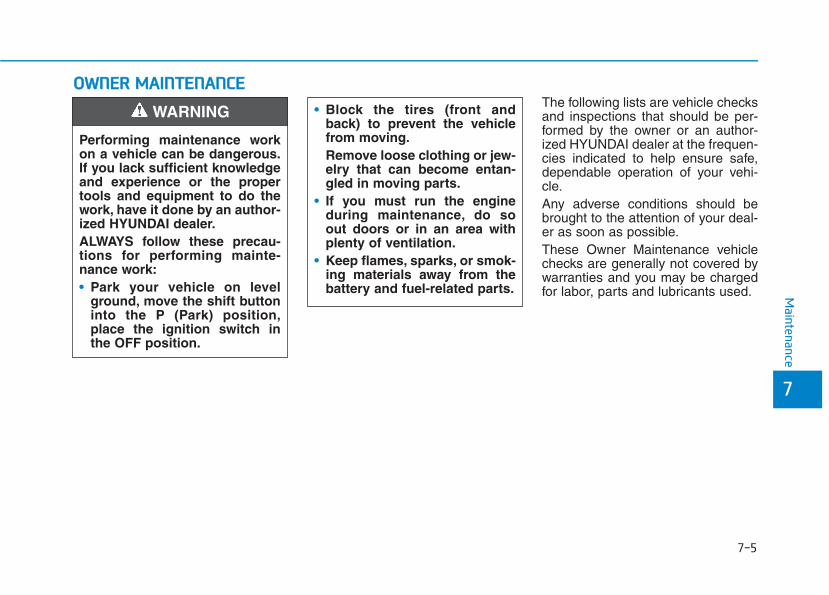
OOWWNNEERR MMAAIINNTTEENNAANNCCEEThe following lists are vehicle checksand inspections that should be per-formed by the owner or an author-ized HYUNDAI dealer at the frequen-cies indicated to help ensure safe,dependable operation of your vehi-cle.Any adverse conditions should bebrought to the attention of your deal-er as soon as possible.These Owner Maintenance vehiclechecks are generally not covered bywarranties and you may be chargedfor labor, parts and lubricants used.
Performing maintenance workon a vehicle can be dangerous.If you lack sufficient knowledgeand experience or the propertools and equipment to do thework, have it done by an author-ized HYUNDAI dealer.ALWAYS follow these precau-tions for performing mainte-nance work:• Park your vehicle on level
ground, move the shift buttoninto the P (Park) position,place the ignition switch inthe OFF position.
WARNING • Block the tires (front andback) to prevent the vehiclefrom moving.Remove loose clothing or jew-elry that can become entan-gled in moving parts.
• If you must run the engineduring maintenance, do soout doors or in an area withplenty of ventilation.
• Keep flames, sparks, or smok-ing materials away from thebattery and fuel-related parts. M
aintenance
7
7-5

Owner Maintenance ScheduleWhen you stop for fuel:• Check the engine oil level.• Check the coolant level in the
engine coolant reservoir.• Check the windshield washer fluid
level.• Check the tire for low or under-
inflated tires.
While operating your vehicle:• Note any changes in the sound of
the exhaust or any smell ofexhaust fumes in the vehicle.
• Check for vibrations in the steeringwheel. Notice if there is anyincreased steering effort or loose-ness in the steering wheel, orchange in its straight-ahead posi-tion.
• Notice if your vehicle constantlyturns slightly or "pulls" to one sidewhen traveling on smooth, levelroad.
• When stopping, listen and checkfor unusual sounds, pulling to oneside, increased brake pedal travelor "hard-to-push" brake pedal.
• If any slipping or changes in theoperation of your transmissionoccurs, check the transmissionfluid level.
• Check the automatic transmissionP (Park) function.
• Check the parking brake.• Check for fluid leaks under your
vehicle (water dripping from the airconditioning system during or afteruse is normal).
At least monthly:• Check coolant level in the engine
coolant reservoir.• Check the operation of all exterior
lights, including the brake lights,turn signals and hazard warningflashers.
• Check the inflation pressures of alltires including the spare for tiresthat are worn, show uneven wear,or are damaged.
• Check for loose wheel lug nuts.
At least twice a year:(i.e., every Spring and Autumn)• Check radiator, heater and air con-
ditioning hoses for leaks or dam-age.
• Check windshield washer sprayand wiper operation. Clean wiperblades with a clean cloth damp-ened with washer a fluid.
Be careful when checking yourengine coolant level when theengine is hot. This may result incoolant being blown out of theopening and cause seriousburns and other injuries.
WARNING
Maintenance
7-6

• Check headlamp alignment.• Check muffler, exhaust pipes,
shields and clamps.• Check seat belts for wear and
function.
At least once a year:• Clean body and door drain holes.• Lubricate door hinges and hood
hinges.• Lubricate door and hood locks and
latches.• Lubricate door rubber weather
strips.• Lubricate door checker.• Check the air conditioning system.• Inspect and lubricate automatic
transmission linkage and controls.• Clean the battery and terminals.• Check the brake fluid level.
Follow Normal MaintenanceSchedule if the vehicle is usuallyoperated where none of the followingconditions apply. If any of the follow-ing conditions apply, you must followthe Maintenance Under SevereUsage Conditions.• Repeatedly driving short distances
of less than 5 miles (8 km) in nor-mal temperature or less than 10miles (16 km) in freezing tempera-ture
• Extensive engine idling or lowspeed driving for long distances
• Driving on rough, dusty, muddy,unpaved, graveled or salt- spreadroads
• Driving in areas using salt or othercorrosive materials or in very coldweather
• Driving in heavy dust conditions• Driving in heavy traffic area
• Driving on uphill, downhill, ormountain road
• Towing a trailer, or using a camper,or roof rack
• Driving as a patrol car, taxi, othercommercial use or vehicle towing
• Driving over 106 mph (170 km/h)• Frequently driving in stop-and-go
conditionsFor additional information or assis-tance see your authorized HYUNDAIdealer.
SSCCHHEEDDUULLEEDD MMAAIINNTTEENNAANNCCEESSEERRVVIICCEESS
Maintenance
7
7-7

Maintenance
7-8
Normal Maintenance Schedule (3.8 GDI)
I : Inspect and if necessary, adjust, correct, clean or replace.R : Replace or change.*1 : The drive belt should be replaced when cracks occur or tension is reduced.*2 : If TOP TIER Detergent Gasoline is not available, one bottle of additive is recommended. Additives are available from your
authorized HYUNDAI dealer along with information on how to use them. Do not mix other additives.*3 : Inspect for excessive valve noise and/or engine vibration and adjust if necessary. Have an authorized authorized HYUNDAI
dealer perform the operation.
Number of months or driving distance, whichever comes firstMonths 12 24 36 48 60 72 84 96 108 120 132 144 156 168 180Miles×1,000 7.5 15 22.5 30 37.5 45 52.5 60 67.5 75 82.5 90 97.5 105 112.5Km×1,000 12 24 36 48 60 72 84 96 108 120 132 144 156 168 180
Drive belts *1 At first, inspect at 60,000 miles (96,000 km) or 72 months,after that, inspect every 15,000 miles (24,000 km) or 24 months
Engine oil and engine oil filter R R R R R R R R R R R R R R R
Fuel additives *2 Add every 7,500 miles (12,000 km) or 12 months
Air cleaner filter I I R I I R I I R I I R I I R
Spark plugs Replace every 97,500 miles (156,000 km)
Valve clearance *3 Inspect every 60,000 miles (96,000 km) or 72 months
Rotate tires Rotate every 7,500 miles (12,000 km)
MAINTENANCEINTERVALS
MAINTENANCEITEM
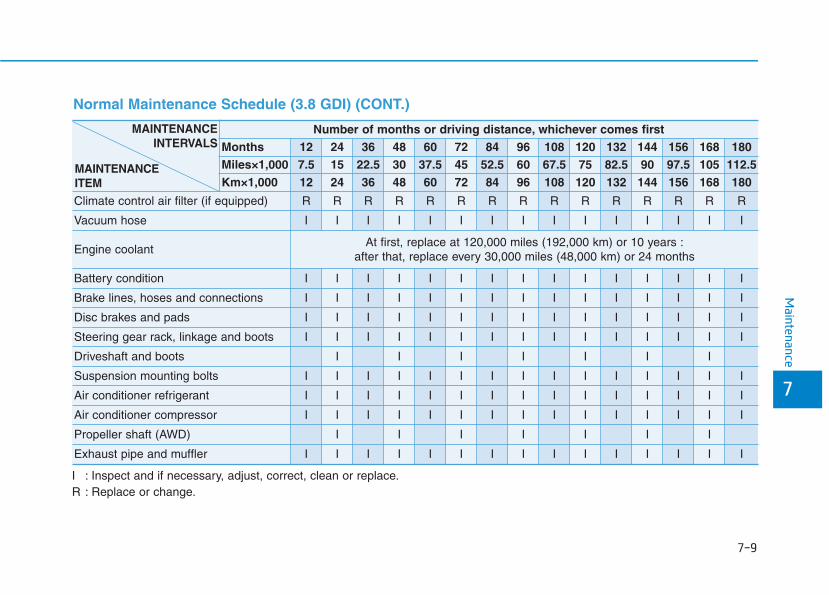
Maintenance
7
7-9
I : Inspect and if necessary, adjust, correct, clean or replace.R : Replace or change.
Number of months or driving distance, whichever comes firstMonths 12 24 36 48 60 72 84 96 108 120 132 144 156 168 180Miles×1,000 7.5 15 22.5 30 37.5 45 52.5 60 67.5 75 82.5 90 97.5 105 112.5Km×1,000 12 24 36 48 60 72 84 96 108 120 132 144 156 168 180
Climate control air filter (if equipped) R R R R R R R R R R R R R R R
Vacuum hose I I I I I I I I I I I I I I I
Engine coolantAt first, replace at 120,000 miles (192,000 km) or 10 years :
after that, replace every 30,000 miles (48,000 km) or 24 months
Battery condition I I I I I I I I I I I I I I I
Brake lines, hoses and connections I I I I I I I I I I I I I I I
Disc brakes and pads I I I I I I I I I I I I I I I
Steering gear rack, linkage and boots I I I I I I I I I I I I I I I
Driveshaft and boots I I I I I I I
Suspension mounting bolts I I I I I I I I I I I I I I I
Air conditioner refrigerant I I I I I I I I I I I I I I I
Air conditioner compressor I I I I I I I I I I I I I I I
Propeller shaft (AWD) I I I I I I I
Exhaust pipe and muffler I I I I I I I I I I I I I I I
MAINTENANCEINTERVALS
MAINTENANCEITEM
Normal Maintenance Schedule (3.8 GDI) (CONT.)
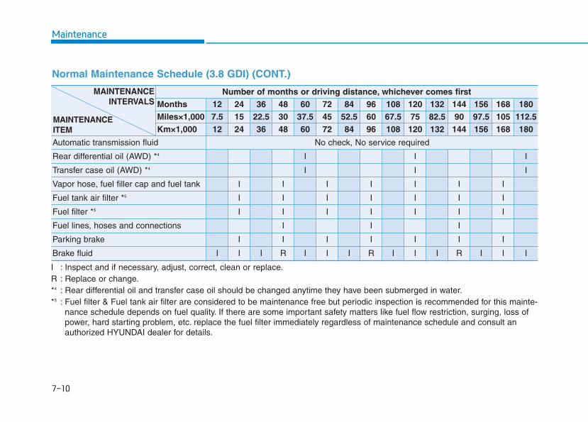
Maintenance
7-10
I : Inspect and if necessary, adjust, correct, clean or replace.R : Replace or change.*4 : Rear differential oil and transfer case oil should be changed anytime they have been submerged in water.*5 : Fuel filter & Fuel tank air filter are considered to be maintenance free but periodic inspection is recommended for this mainte-
nance schedule depends on fuel quality. If there are some important safety matters like fuel flow restriction, surging, loss ofpower, hard starting problem, etc. replace the fuel filter immediately regardless of maintenance schedule and consult anauthorized HYUNDAI dealer for details.
Number of months or driving distance, whichever comes firstMonths 12 24 36 48 60 72 84 96 108 120 132 144 156 168 180Miles×1,000 7.5 15 22.5 30 37.5 45 52.5 60 67.5 75 82.5 90 97.5 105 112.5Km×1,000 12 24 36 48 60 72 84 96 108 120 132 144 156 168 180
Automatic transmission fluid No check, No service required
Rear differential oil (AWD) *4 I I I
Transfer case oil (AWD) *4 I I I
Vapor hose, fuel filler cap and fuel tank I I I I I I I
Fuel tank air filter *5 I I I I I I I
Fuel filter *5 I I I I I I I
Fuel lines, hoses and connections I I I
Parking brake I I I I I I I
Brake fluid I I I R I I I R I I I R I I I
MAINTENANCEINTERVALS
MAINTENANCEITEM
Normal Maintenance Schedule (3.8 GDI) (CONT.)
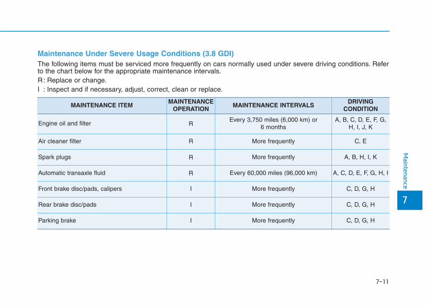
Maintenance
7
7-11
Maintenance Under Severe Usage Conditions (3.8 GDI)The following items must be serviced more frequently on cars normally used under severe driving conditions. Referto the chart below for the appropriate maintenance intervals.R : Replace or change.I : Inspect and if necessary, adjust, correct, clean or replace.
MAINTENANCE ITEMMAINTENANCE
OPERATIONMAINTENANCE INTERVALS
DRIVING CONDITION
Engine oil and filter REvery 3,750 miles (6,000 km) or
6 monthsA, B, C, D, E, F, G,
H, I, J, K
Air cleaner filter R More frequently C, E
Spark plugs R More frequently A, B, H, I, K
Automatic transaxle fluid R Every 60,000 miles (96,000 km) A, C, D, E, F, G, H, I
Front brake disc/pads, calipers I More frequently C, D, G, H
Rear brake disc/pads I More frequently C, D, G, H
Parking brake I More frequently C, D, G, H

Maintenance
7-12
Severe driving conditionsA-Repeatedly driving short distance of less than 5 miles (8 km)
in normal temperature or less than 10 miles (16 km) in freez-ing temperature
B-Extensive engine idling or low speed driving for long dis-tances
C-Driving on rough, dusty, muddy, unpaved, graveled or salt-spread roads
D-Driving in areas using salt or other corrosive materials or invery cold weather
E-Driving in heavy dust condition
F - Driving in heavy traffic area
G- Driving on uphill, downhill, or mountain road repeatedly
H- Towing a Trailer, or using a camper, or roof rack
I -Driving as a patrol car, taxi, other commercial use or vehicletowing
J - Driving over 106 mph (170 km/h)
K- Frequently driving in stop-and-go conditions
MAINTENANCE ITEMMAINTENANCE
OPERATIONMAINTENANCE INTERVALS
DRIVING CONDITION
Steering gear box, linkage & boots/Lower arm ball joint, upper arm ball joint
I More frequently C, D, E, F, G, H, I
Drive shafts and boots IEvery 3,750 miles (6,000 km) or
6 monthsC, D, E, F, G, H, I, J
Rear differential oil R Every 75,000 miles (120,000 km) C, G, H, I, J
Transfer case oil (AWD) R Every 75,000 miles (120,000 km) C, G, H, I, J
Climate control air filter (for evaporator and blower unit) R More frequently C, E
Propeller shaft IEvery 7,500 miles (12,000 km) or
6 monthsC, E
7-13
7
Maintenance
EEXXPPLLAANNAATTIIOONN OOFF SSCCHHEEDDUULLEEDD MMAAIINNTTEENNAANNCCEE IITTEEMMSSEngine Oil and FilterThe engine oil and filter should bechanged at the intervals specified inthe maintenance schedule. If thevehicle is being driven in severe con-ditions, more frequent oil and filterchanges are required.
Drive BeltsInspect all drive belts for evidence ofcuts, cracks, excessive wear or oilsaturation and replace if necessary.Drive belts should be checked peri-odically for proper tension andadjusted as necessary.
Fuel FilterA clogged-up fuel filter may limit thevehicle driving speed, damage theemission system, and cause thehard starting. When a considerableamount of foreign substances areaccumulated in the fuel tank, the fuelfilter should be replaced.Upon installing a new fuel filter, oper-ate the engine for several minutes,and check the connections for anyleakages. Fuel filters should beinstalled by an authorized HYUNDAIdealer.
Fuel Lines, Fuel Hoses andConnections Check the fuel lines, fuel hoses andconnections for leakage and dam-age. Have an authorized HYUNDAIdealer replace any damaged or leak-ing parts immediately.
Vapor Hose and Fuel FillerCapThe vapor hose and fuel filler capshould be inspected at those inter-vals specified in the maintenanceschedule. Make sure a new vaporhose or fuel filler cap is correctlyreplaced.
Vacuum Crankcase VentilationHosesInspect the surface of hoses for evi-dence of heat and/or mechanicaldamage. Hard and brittle rubber,cracking, tears, cuts, abrasions, andexcessive swelling indicate deterio-ration. Particular attention should bepaid to examine those hose surfacesnearest to high heat sources, suchas the exhaust manifold.Inspect the hose routing to ensurethat the hoses do not come in con-tact with any heat source, sharpedges or moving component whichmight cause heat damage ormechanical wear. Inspect all hoseconnections, such as clamps andcouplings, to make sure they aresecure, and that no leaks are pres-ent. Hoses should be replacedimmediately if there is any evidenceof deterioration or damage.
7-14
Maintenance
Air Cleaner FilterA genuine HYUNDAI air cleaner filteris recommended when the filter isreplaced.
Spark Plugs Make sure to install new spark plugsof the correct heat range.
Cooling SystemCheck cooling system components,such as radiator, coolant reservoir,hoses and connections for leakageand damage. Replace any damagedparts.
Engine Coolant The coolant should be changed atthe intervals specified in the mainte-nance schedule.
Automatic Transmission FluidAutomatic transmission fluid shouldnot be checked under normal usageconditions. But in severe conditions,the fluid should be changed at anauthorized HYUNDAI dealer inaccordance to the scheduled mainte-nance at the beginning of this chap-ter.
InformationAutomatic transmission fluid color isred when new.
As the vehicle is driven, the automatictransmission fluid will begin to lookdarker. This is a normal condition andyou should not judge the need toreplace the fluid based upon thechanged color.
The use of a non-specified fluidcould result in transmission mal-function and failure. Use only thespecified automatic transmissionfluid (refer to "RecommendedLubricants and Capacities" inchapter 8).
NOTICE
i
7-15
7
Maintenance
Brake Hoses and LinesVisually check for proper installation,chafing, cracks, deterioration andany leakage. Replace any deteriorat-ed or damaged parts immediately.
Brake Fluid Check the brake fluid level in thebrake fluid reservoir. The level shouldbe between the MIN and the MAXmarks on the side of the reservoir.Use only hydraulic brake fluid con-forming to DOT 3 or DOT 4 specifi-cation.
Parking BrakeInspect the parking brake system.
Brake Discs, Pads, Calipersand RotorsCheck the pads for excessive wear,discs for run out and wear, andcalipers for fluid leakage.
Exhaust Pipe and Muffler Visually inspect the exhaust pipes,muffler and hangers for cracks, dete-rioration, or damage. Start theengine and listen carefully for anyexhaust gas leakage. Tighten con-nections or replace parts as neces-sary.
Suspension Mounting Bolts Check the suspension connectionsfor looseness or damage. Retightento the specified torque.
Steering Gear Box, Linkage &Boots/Lower Arm Ball JointWith the vehicle stopped and theengine off, check for excessive free-play in the steering wheel. Check thelinkage for bends or damage. Checkthe dust boots and ball joints fordeterioration, cracks, or damage.Replace any damaged parts.
Drive Shafts and BootsCheck the drive shafts, boots andclamps for cracks, deterioration, ordamage. Replace any damagedparts and, if necessary, repack thegrease.
Air Conditioning Refrigerant Check the air conditioning lines andconnections for leakage and dam-age.

7-16
Maintenance
EENNGGIINNEE OOIILLChecking the Engine Oil Level 1. Follow all of the oil manufacturer's
precautions.2. Be sure the vehicle is on the level
ground in P (Park) with the park-ing brake set. If possible, block thewheels.
3. Turn the engine on and allow theengine to reach normal operatingtemperature.
4. Turn the engine off and wait aboutfive minutes for the oil to return tothe oil pan.
5. Pull the dipstick out, wipe it clean,and re-insert it fully.
6. Pull the dipstick out again andcheck the level. The level shouldbe between F and L.
7. If it is near or at L, add enough oilto bring the level to F.
Use only the specified engine oil.(refer to "Recommended Lubricantsand Capacities" in chapter 8).
OLX2079005N OLX2078006
7-17
7
Maintenance
To prevent damage to yourengine:• Do not overfill with engine oil.
Add oil in small quantities andrecheck level to ensure engineis not overfilled.
• Do not spill engine oil whenadding or changing engine oil.Use a funnel to help prevent oilfrom being spilled on enginecomponents. Wipe off spilled oilimmediately.
Checking the Engine Oil andFilter
Have engine oil and filter changed byan authorized HYUNDAI dealeraccording to the MaintenanceSchedule at the beginning of thischapter.
NOTICE
CALIFORNIA PROPOSITION 65WARNING
Engine oil contains chemicalsknown to the State of Californiato cause cancer, birth defectsand reproductive harm. Usedengine oil may cause irritationor cancer of the skin if left incontact with the skin for pro-longed periods of time. Alwaysprotect your skin by washingyour hands thoroughly withsoap and warm water as soonas possible after handling usedoil.For more information go tohttps://www.p65warnings.ca.gov/passenger-vehicle
WARNING
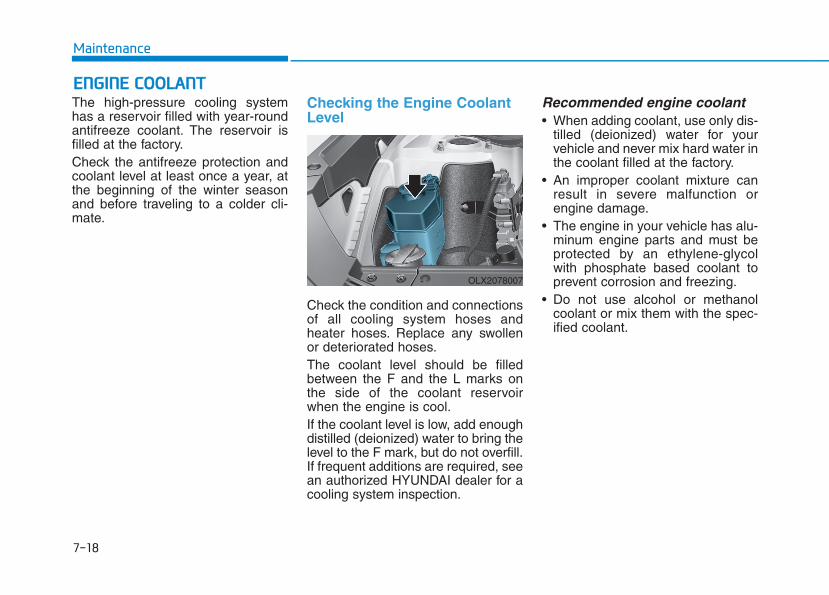
7-18
Maintenance
EENNGGIINNEE CCOOOOLLAANNTTThe high-pressure cooling systemhas a reservoir filled with year-roundantifreeze coolant. The reservoir isfilled at the factory.Check the antifreeze protection andcoolant level at least once a year, atthe beginning of the winter seasonand before traveling to a colder cli-mate.
Checking the Engine CoolantLevel
Check the condition and connectionsof all cooling system hoses andheater hoses. Replace any swollenor deteriorated hoses.The coolant level should be filledbetween the F and the L marks onthe side of the coolant reservoirwhen the engine is cool.If the coolant level is low, add enoughdistilled (deionized) water to bring thelevel to the F mark, but do not overfill.If frequent additions are required, seean authorized HYUNDAI dealer for acooling system inspection.
Recommended engine coolant • When adding coolant, use only dis-
tilled (deionized) water for yourvehicle and never mix hard water inthe coolant filled at the factory.
• An improper coolant mixture canresult in severe malfunction orengine damage.
• The engine in your vehicle has alu-minum engine parts and must beprotected by an ethylene-glycolwith phosphate based coolant toprevent corrosion and freezing.
• Do not use alcohol or methanolcoolant or mix them with the spec-ified coolant.
OLX2078007
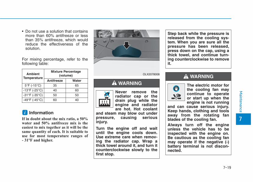
7-19
7
Maintenance
• Do not use a solution that containsmore than 60% antifreeze or lessthan 35% antifreeze, which wouldreduce the effectiveness of thesolution.
For mixing percentage, refer to thefollowing table:
InformationIf in doubt about the mix ratio, a 50%water and 50% antifreeze mix is theeasiest to mix together as it will be thesame quantity of each. It is suitable touse for most temperature ranges of - 31°F and higher.
i
The electric motor forthe cooling fan maycontinue to operateor start up when theengine is not running
and can cause serious injury.Keep hands, clothing and toolsaway from the rotating fanblades of the cooling fan.Always turn off the engineunless the vehicle has to beinspected with the engine on.Be cautious as the cooling fanmay operate if the negative (-)battery terminal is not discon-nected.
WARNING Ambient
Temperature
Mixture Percentage (volume)
Antifreeze Water5°F (-15°C) 35 65
-13°F (-25°C) 40 60
-31°F (-35°C) 50 50
-49°F (-45°C) 60 40
Never remove theradiator cap or thedrain plug while theengine and radiatorare hot. Hot coolant
and steam may blow out underpressure, causing seriousinjury.
Turn the engine off and waituntil the engine cools down.Use extreme care when remov-ing the radiator cap. Wrap athick towel around it, and turn itcounterclockwise slowly to thefirst stop.
WARNING
Step back while the pressure isreleased from the cooling sys-tem. When you are sure all thepressure has been released,press down on the cap, using athick towel, and continue turn-ing counterclockwise to removeit.
OLX2078008
7-20
Maintenance
Changing Engine Coolant Have coolant changed by an author-ized HYUNDAI dealer according tothe Maintenance Schedule at thebeginning of this chapter.
To prevent damage to engineparts, put a thick towel around theradiator cap before refilling thecoolant to prevent the coolantfrom overflowing into engineparts, such as the alternator.
NOTICE
Do not use engine coolant orantifreeze in the washer fluidreservoir.Engine coolant can severelyobscure visibility when sprayedon the windshield and maycause loss of vehicle controlresulting in an accident.Engine coolant may also causedamage to paint and body trim.
WARNING

7-21
7
Maintenance
BBRRAAKKEE FFLLUUIIDDChecking the Brake FluidLevel
Check the fluid level in the reservoirperiodically. The fluid level should bebetween MAX and MIN marks on theside of the reservoir.Before removing the reservoir capand adding brake fluid, clean thearea around the reservoir cap thor-oughly to prevent brake fluid contam-ination.
If the level is low, add the specifiedbrake fluid to the MAX level.The levelwill fall with accumulated mileage.This is a normal condition associatedwith the wear of the brake linings. Ifthe fluid level is excessively low, havethe brake system checked by anauthorized HYUNDAI dealer.
• Do not allow brake fluid to con-tact the vehicle's body paint, aspaint damage will result.
• Brake fluid, which has beenexposed to open air for anextended time should NEVER beused as its quality cannot beguaranteed. It should be dis-posed of properly.
• Do not use the incorrect brakefluid. A few drops of mineralbased oil, such as engine oil, inyour brake system can damagebrake system parts.
Information Use only the specified brake fluid(refer to "Recommended Lubricantsand Capacities" in chapter 8).
i
NOTICE
If the brake system requires fre-quent additions of fluid thiscould indicate a leak in thebrake system. Have the vehicleinspected by an authorizedHYUNDAI dealer.
WARNING
Do not allow brake fluid to comein contact with your eyes. Ifbrake fluid comes in contactwith your eyes, flush your eyeswith clean water for at least 15minutes and get immediatemedical attention.
WARNING
OLX2078009
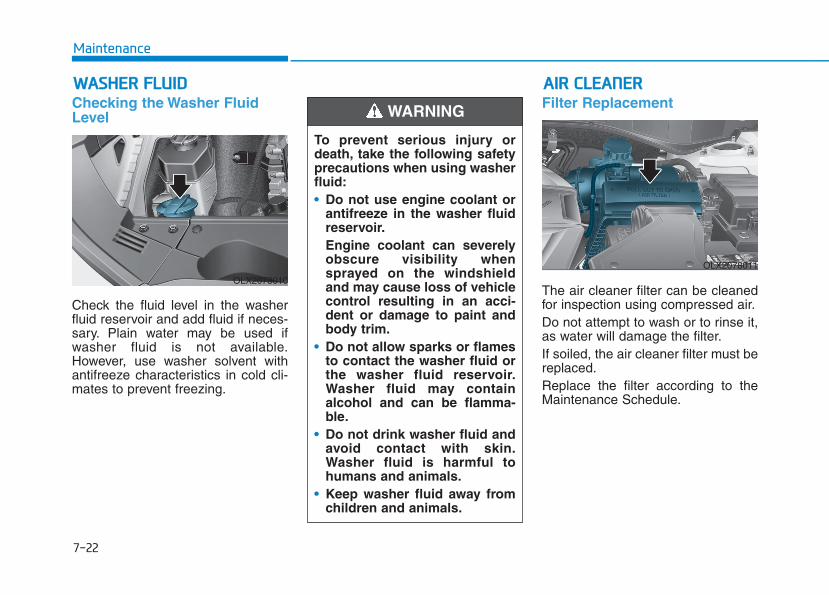
7-22
Maintenance
WWAASSHHEERR FFLLUUIIDDChecking the Washer FluidLevel
Check the fluid level in the washerfluid reservoir and add fluid if neces-sary. Plain water may be used ifwasher fluid is not available.However, use washer solvent withantifreeze characteristics in cold cli-mates to prevent freezing.
Filter Replacement
The air cleaner filter can be cleanedfor inspection using compressed air.Do not attempt to wash or to rinse it,as water will damage the filter.If soiled, the air cleaner filter must bereplaced.Replace the filter according to theMaintenance Schedule.
AAIIRR CCLLEEAANNEERR
To prevent serious injury ordeath, take the following safetyprecautions when using washerfluid:• Do not use engine coolant or
antifreeze in the washer fluidreservoir.Engine coolant can severelyobscure visibility whensprayed on the windshieldand may cause loss of vehiclecontrol resulting in an acci-dent or damage to paint andbody trim.
• Do not allow sparks or flamesto contact the washer fluid orthe washer fluid reservoir.Washer fluid may containalcohol and can be flamma-ble.
• Do not drink washer fluid andavoid contact with skin.Washer fluid is harmful tohumans and animals.
• Keep washer fluid away fromchildren and animals.
WARNING
OLX2078010
OLX2078011

7-23
7
Maintenance
1. Pull down the air cleaner filtercover (1).
2. Pull down the lever (2) to theUNLOCK position.
3. Replace the air cleaner filter.4. Reassemble the air cleaner cover
in the reverse order.5. Check that the cover is firmly
installed.
OLX2078012 OLX2078013 OLX2078014

7-24
Maintenance
Information If the vehicle is operated in extremelydusty or sandy areas, replace the aircleaner filter more often than theusual recommended intervals (refer to"Maintenance Under Severe UsageConditions" in this chapter).
• Do not drive with the air cleanerfilter removed. This will result inexcessive engine wear.
• When removing the air cleanerfilter, be careful that dust or dirtdoes not enter the air intake, ordamage may result.
• Use HYUNDAI genuine parts.Use of non-genuine parts coulddamage the air flow sensor.
Filter InspectionThe climate control air filter shouldbe replaced according to theMaintenance Schedule. If the vehicleis operated in severely air-pollutedcities or on dusty rough roads for along period and/or if transportingpets or occupants smoke inside thevehicle, then it should be inspectedmore frequently and replaced soon-er. Replace the climate control air fil-ter by following the procedure belowand be careful to avoid damagingother components.
1. With the glove box open, removethe stoppers on both sides toallow the glove box to hang freelyon the hinges.
NOTICE
iCCLLIIMMAATTEE CCOONNTTRROOLL AAIIRR FFIILLTTEERR
OLX2078017
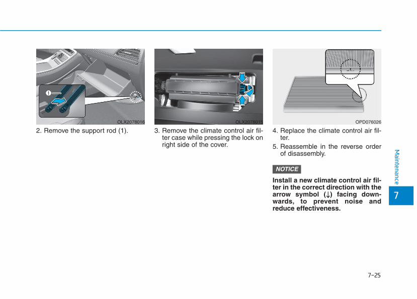
7-25
7
Maintenance
2. Remove the support rod (1). 3. Remove the climate control air fil-ter case while pressing the lock onright side of the cover.
4. Replace the climate control air fil-ter.
5. Reassemble in the reverse orderof disassembly.
Install a new climate control air fil-ter in the correct direction with thearrow symbol (↓↓) facing down-wards, to prevent noise andreduce effectiveness.
NOTICE
OLX2078016 OLX2078015 OPD076026
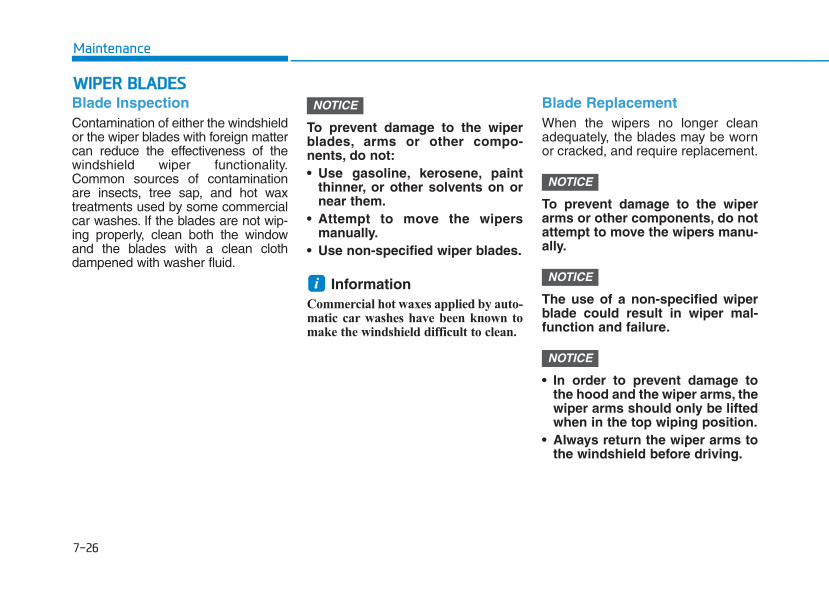
7-26
Maintenance
WWIIPPEERR BBLLAADDEESSBlade InspectionContamination of either the windshieldor the wiper blades with foreign mattercan reduce the effectiveness of thewindshield wiper functionality.Common sources of contaminationare insects, tree sap, and hot waxtreatments used by some commercialcar washes. If the blades are not wip-ing properly, clean both the windowand the blades with a clean clothdampened with washer fluid.
To prevent damage to the wiperblades, arms or other compo-nents, do not:• Use gasoline, kerosene, paint
thinner, or other solvents on ornear them.
• Attempt to move the wipersmanually.
• Use non-specified wiper blades.
Information Commercial hot waxes applied by auto-matic car washes have been known tomake the windshield difficult to clean.
Blade ReplacementWhen the wipers no longer cleanadequately, the blades may be wornor cracked, and require replacement.
To prevent damage to the wiperarms or other components, do notattempt to move the wipers manu-ally.
The use of a non-specified wiperblade could result in wiper mal-function and failure.
• In order to prevent damage tothe hood and the wiper arms, thewiper arms should only be liftedwhen in the top wiping position.
• Always return the wiper arms tothe windshield before driving.
NOTICE
NOTICE
NOTICE
i
NOTICE
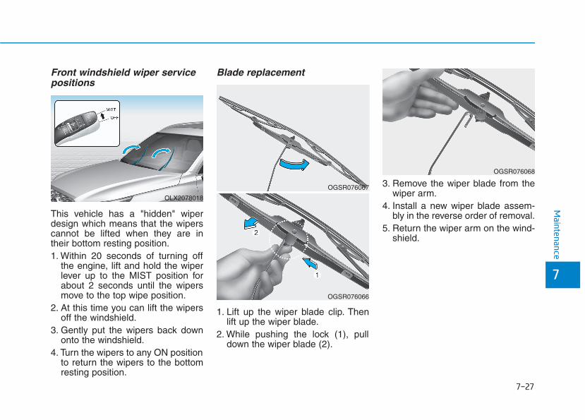
7-27
7
Maintenance
Front windshield wiper servicepositions
This vehicle has a "hidden" wiperdesign which means that the wiperscannot be lifted when they are intheir bottom resting position.1. Within 20 seconds of turning off
the engine, lift and hold the wiperlever up to the MIST position forabout 2 seconds until the wipersmove to the top wipe position.
2. At this time you can lift the wipersoff the windshield.
3. Gently put the wipers back downonto the windshield.
4. Turn the wipers to any ON positionto return the wipers to the bottomresting position.
Blade replacement
1. Lift up the wiper blade clip. Thenlift up the wiper blade.
2. While pushing the lock (1), pulldown the wiper blade (2).
3. Remove the wiper blade from thewiper arm.
4. Install a new wiper blade assem-bly in the reverse order of removal.
5. Return the wiper arm on the wind-shield.
OLX2078018
OGSR076067
OGSR076066
OGSR076068
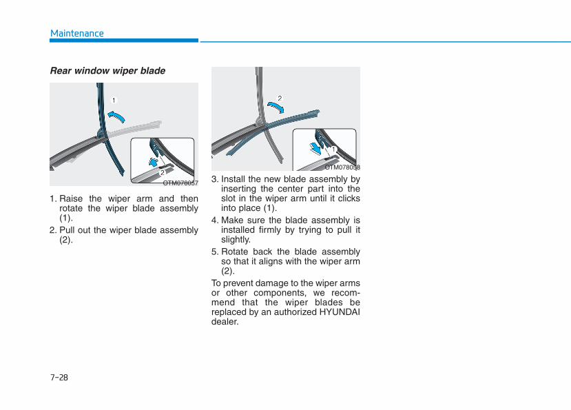
7-28
Maintenance
Rear window wiper blade
1. Raise the wiper arm and thenrotate the wiper blade assembly(1).
2. Pull out the wiper blade assembly(2).
3. Install the new blade assembly byinserting the center part into theslot in the wiper arm until it clicksinto place (1).
4. Make sure the blade assembly isinstalled firmly by trying to pull itslightly.
5. Rotate back the blade assemblyso that it aligns with the wiper arm(2).
To prevent damage to the wiper armsor other components, we recom-mend that the wiper blades bereplaced by an authorized HYUNDAIdealer.
OTM078057
OTM078058
BBAATTTTEERRYY
7-29
7
Maintenance
To prevent SERIOUS INJURY orDEATH to you or bystanders,always follow these precautionswhen working near or handlingthe battery:
Always read and followinstructions carefullywhen handling a battery.Wear eye protectiondesigned to protect theeyes from acid splashes.Keep all flames, sparks,or smoking materialsaway from the battery.Hydrogen is always pres-ent in battery cells, ishighly combustible, andmay explode if ignited.Keep batteries out ofreach of children.
WARNING Batteries contain sulfu-ric acid which is highlycorrosive. Do not allowacid to contact youreyes, skin or clothing.
If acid gets into your eyes, flushyour eyes with clean water for atleast 15 minutes and get imme-diate medical attention. If acidgets on your skin, thoroughlywash the area. If you feel pain ora burning sensation, get med-ical attention immediately.• When lifting a plastic-cased
battery, excessive pressureon the case may cause batteryacid to leak. Lift with a batterycarrier or with your hands onopposite corners.
• Do not attempt to jump startyour vehicle if your battery isfrozen.
• NEVER attempt to rechargethe battery when the vehicle’sbattery cables are connectedto the battery.
• The electrical ignition systemworks with high voltage.NEVER touch these compo-nents with the engine runningor when the ignition switch isin the ON position.
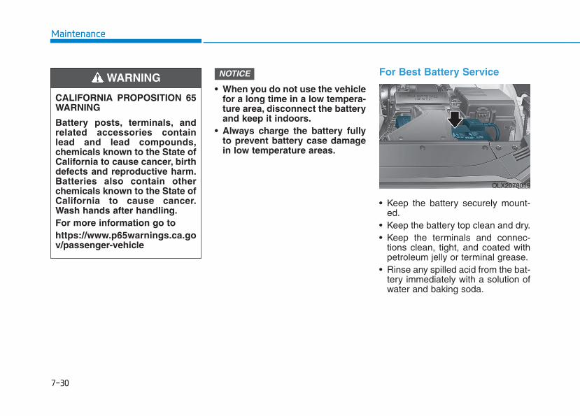
• When you do not use the vehiclefor a long time in a low tempera-ture area, disconnect the batteryand keep it indoors.
• Always charge the battery fullyto prevent battery case damagein low temperature areas.
For Best Battery Service
• Keep the battery securely mount-ed.
• Keep the battery top clean and dry.• Keep the terminals and connec-
tions clean, tight, and coated withpetroleum jelly or terminal grease.
• Rinse any spilled acid from the bat-tery immediately with a solution ofwater and baking soda.
NOTICE
7-30
Maintenance
CALIFORNIA PROPOSITION 65WARNING
Battery posts, terminals, andrelated accessories containlead and lead compounds,chemicals known to the State ofCalifornia to cause cancer, birthdefects and reproductive harm.Batteries also contain otherchemicals known to the State ofCalifornia to cause cancer.Wash hands after handling.For more information go tohttps://www.p65warnings.ca.gov/passenger-vehicle
WARNING
OLX2078019
7-31
7
Maintenance
Battery Recharging
AGM battery • Absorbent Glass Matt (AGM)
batteries are maintenance-freeand we recommend that theAGM battery be serviced by anauthorized retailer of HYUNDAIdealer. For charging your AGMbattery, use only fully automaticbattery chargers that are spe-cially developed for AGM batter-ies.
• When replacing the AGM bat-tery, we recommend that youuse parts for replacement froman authorized retailer ofHYUNDAI dealer.
• Do not open or remove the capon top of the battery. This maycause leaks of internal elec-trolyte that could result insevere injury.
NOTICE
Always follow these instruc-tions when recharging yourvehicle's battery to avoid therisk of SERIOUS INJURY orDEATH from explosions or acidburns:• Before performing mainte-
nance or recharging the bat-tery, turn off all accessoriesand place the ignition switchto the LOCK/OFF position.
• Keep all flames, sparks, orsmoking materials away fromthe battery.
• Always work outdoors or in anarea with plenty of ventilation.
• Wear eye protection whenchecking the battery duringcharging.
• The battery must be removedfrom the vehicle and placed ina well ventilated area.
WARNING
• Watch the battery duringcharging, and stop or reducethe charging rate if the batterycells begin boiling violently.
• The negative battery cablemust be removed first andinstalled last when the batteryis disconnected. Disconnectthe battery charger in the fol-lowing order:(1)Turn off the battery charger
main switch.(2)Unhook the negative clamp
from the negative batteryterminal.
(3)Unhook the positive clampfrom the positive batteryterminal.
• Always use a genuineHYUNDAI approved batterywhen you replace the battery.

7-32
Maintenance
By jump starting After a jump start from a good bat-tery, drive the vehicle for at least 30minutes or operate at idle for at least60 minutes before it is shutoff.Alternatively you may visit a dealerfor charge and battery test.The vehicle may not restart if youshut it off before the battery had achance to adequately recharge. See"Jump Starting" in chapter 6 for moreinformation on jump starting proce-dures.
Information An inappropriately disposedbattery can be harmful tothe environment and humanhealth. Dispose of the bat-tery according to your locallaw(s) or regulations.
Reset FeaturesThe following items may need to bereset after the battery has been dis-charged or the battery has been dis-connected. See chapter 3 or 4 for:• Power Windows• Driver Position Memory System• Trip Computer• Climate Control System• Clock• Audio System• Sunroof
i
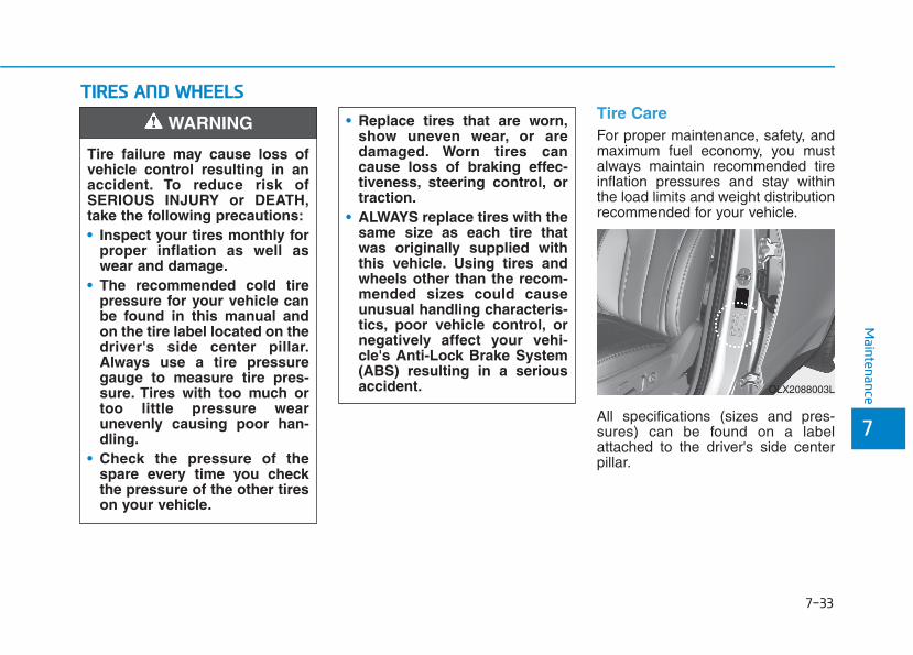
7-33
7
Maintenance
TTIIRREESS AANNDD WWHHEEEELLSS Tire CareFor proper maintenance, safety, andmaximum fuel economy, you mustalways maintain recommended tireinflation pressures and stay withinthe load limits and weight distributionrecommended for your vehicle.
All specifications (sizes and pres-sures) can be found on a labelattached to the driver's side centerpillar.
• Replace tires that are worn,show uneven wear, or aredamaged. Worn tires cancause loss of braking effec-tiveness, steering control, ortraction.
• ALWAYS replace tires with thesame size as each tire thatwas originally supplied withthis vehicle. Using tires andwheels other than the recom-mended sizes could causeunusual handling characteris-tics, poor vehicle control, ornegatively affect your vehi-cle's Anti-Lock Brake System(ABS) resulting in a seriousaccident.
Tire failure may cause loss ofvehicle control resulting in anaccident. To reduce risk ofSERIOUS INJURY or DEATH,take the following precautions:• Inspect your tires monthly for
proper inflation as well aswear and damage.
• The recommended cold tirepressure for your vehicle canbe found in this manual andon the tire label located on thedriver's side center pillar.Always use a tire pressuregauge to measure tire pres-sure. Tires with too much ortoo little pressure wearunevenly causing poor han-dling.
• Check the pressure of thespare every time you checkthe pressure of the other tireson your vehicle.
WARNING
OLX2088003L
7-34
Maintenance
Recommended Cold TireInflation Pressures All tire pressures (including thespare) should be checked when thetires are cold. "Cold tires" means thevehicle has not been driven for atleast three hours or has been drivenfor less than one mile (1.6 km).Warm tires normally exceed recom-mended cold tire pressures by 4 to 6psi (28 to 41 kPa). Do not release airfrom warm tires to adjust the pres-sure or the tires will be under-inflat-ed. For recommended inflation pres-sure, refer to "Tire and Wheels" inchapter 8.
Recommended pressures mustbe maintained for the best ride,vehicle handling, and minimumtire wear.Over-inflation or under-inflationcan reduce tire life, adverselyaffect vehicle handling, andlead to sudden tire failure thatcould result in loss of vehiclecontrol resulting in an accident.Severe under-inflation can leadto severe heat build-up, causingblowouts, tread separation andother tire failures that can resultin the loss of vehicle controlresulting in an accident. Thisrisk is much higher on hot daysand when driving for long peri-ods at high speeds.
WARNING
• Under-inflation results inexcessive wear, poor handlingand reduced fuel economy.Wheel deformation is alsopossible. Keep your tire pres-sures at the proper levels. If atire frequently needs refilling,have it checked by an author-ized HYUNDAI dealer.
• Over-inflation produces aharsh ride, excessive wear atthe center of the tire tread,and a greater possibility ofdamage from road hazards.
CAUTION

7-35
7
Maintenance
Check Tire Inflation PressureCheck your tires, including the sparetire, once a month or more.
How to checkUse a good quality tire pressuregauge to check tire pressure. Youcan not tell if your tires are properlyinflated simply by looking at them.Radial tires may look properly inflat-ed when they are under-inflated.Remove the valve cap from the tirevalve stem. Press the tire gauge firm-ly onto the valve to get a pressuremeasurement. If the cold tire inflationpressure matches the recommendedpressure on the tire label located onthe driver's side center pillar or in thismanual. No further adjustment isnecessary. If the pressure is low, addair until you reach the recommendedpressure. Make sure to put the valvecaps back on the valve stems.Without the valve cap, dirt or mois-ture could get into the valve core andcause air leakage. If a valve cap ismissing, install a new one as soon aspossible.
If you overfill the tire, release air bypushing on the metal stem in thecenter of the tire valve. Recheck thetire pressure with the tire gauge. Besure to put the valve caps back onthe valve stems. Without the valvecap, dirt or moisture could get intothe valve core and cause air leakage.If a valve cap is missing, install a newone as soon as possible.A cold tire means the vehicle hasbeen sitting for 3 hours and driven forless than 1 mile (1.6 km) in that 3hour period.Allow the tire to cool before measur-ing the inflation pressure. Always besure the tire is cold before inflating tothe recommended pressure.
Tire RotationTo equalize tread wear, HYUNDAIrecommends that the tires be rotatedaccording to the maintenance sched-ule or sooner if irregular wear devel-ops.During rotation, check the tires forcorrect balance.When rotating tires, check for unevenwear and damage. Abnormal wear isusually caused by incorrect tire pres-sure, improper wheel alignment, out-of-balance wheels, severe braking orsevere cornering. Look for bumps orbulges in the tread or side of the tire.Replace the tire if you find any ofthese conditions. Replace the tire iffabric or cord is visible. After rotation,be sure to bring the front and rear tirepressures to specification and checklug nut tightness (proper torque is79~94 lbf·ft [11~13 kgf·m]).
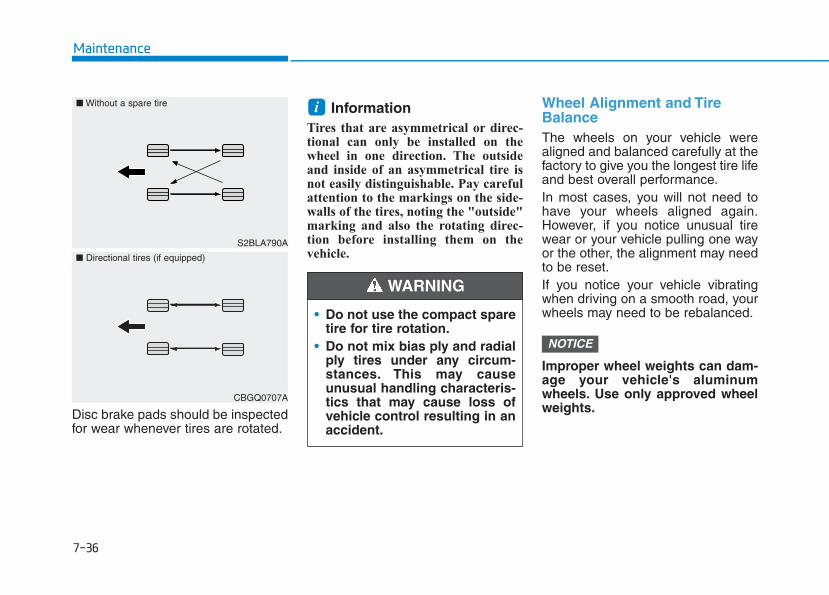
7-36
Maintenance
Disc brake pads should be inspectedfor wear whenever tires are rotated.
Information Tires that are asymmetrical or direc-tional can only be installed on thewheel in one direction. The outsideand inside of an asymmetrical tire isnot easily distinguishable. Pay carefulattention to the markings on the side-walls of the tires, noting the "outside"marking and also the rotating direc-tion before installing them on thevehicle.
Wheel Alignment and TireBalanceThe wheels on your vehicle werealigned and balanced carefully at thefactory to give you the longest tire lifeand best overall performance.In most cases, you will not need tohave your wheels aligned again.However, if you notice unusual tirewear or your vehicle pulling one wayor the other, the alignment may needto be reset.If you notice your vehicle vibratingwhen driving on a smooth road, yourwheels may need to be rebalanced.
Improper wheel weights can dam-age your vehicle's aluminumwheels. Use only approved wheelweights.
NOTICE
i
• Do not use the compact sparetire for tire rotation.
• Do not mix bias ply and radialply tires under any circum-stances. This may causeunusual handling characteris-tics that may cause loss ofvehicle control resulting in anaccident.
WARNING
S2BLA790A
■ Without a spare tire
CBGQ0707A
■ Directional tires (if equipped)
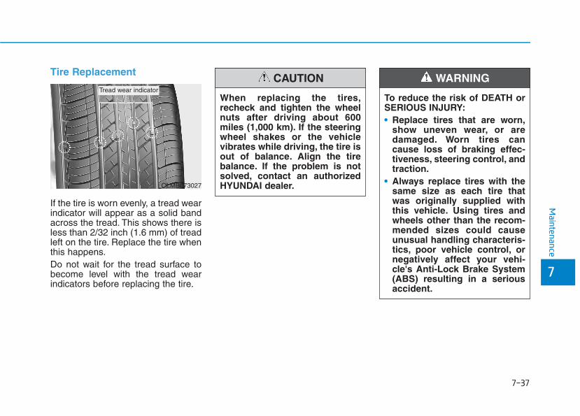
7-37
7
Maintenance
Tire Replacement
If the tire is worn evenly, a tread wearindicator will appear as a solid bandacross the tread. This shows there isless than 2/32 inch (1.6 mm) of treadleft on the tire. Replace the tire whenthis happens.Do not wait for the tread surface tobecome level with the tread wearindicators before replacing the tire.
To reduce the risk of DEATH orSERIOUS INJURY:• Replace tires that are worn,
show uneven wear, or aredamaged. Worn tires cancause loss of braking effec-tiveness, steering control, andtraction.
• Always replace tires with thesame size as each tire thatwas originally supplied withthis vehicle. Using tires andwheels other than the recom-mended sizes could causeunusual handling characteris-tics, poor vehicle control, ornegatively affect your vehi-cle's Anti-Lock Brake System(ABS) resulting in a seriousaccident.
WARNING
When replacing the tires,recheck and tighten the wheelnuts after driving about 600miles (1,000 km). If the steeringwheel shakes or the vehiclevibrates while driving, the tire isout of balance. Align the tirebalance. If the problem is notsolved, contact an authorizedHYUNDAI dealer.
CAUTION
OLMB073027
Tread wear indicator
7-38
Maintenance
Compact spare tire replacementA compact spare tire has a shortertread life than a regular size tire.Replace it when you can see thetread wear indicator bars on the tire.The replacement compact spare tireshould be the same size and designtire as the one provided with yournew vehicle and should be mountedon the same compact spare tirewheel. The compact spare tire is notdesigned to be mounted on a regularsize wheel, and the compact sparetire wheel is not designed for mount-ing a regular size tire.
Wheel ReplacementWhen replacing the metal wheels forany reason, make sure the newwheels are equivalent to the originalfactory units in diameter, rim widthand offset.
Tire Traction Tire traction can be reduced if youdrive on worn tires, tires that areimproperly inflated or on slipperyroad surfaces. Tires should bereplaced when the tread depth is atleast 2/32 inch (1.6 mm). To reducethe possibility of losing control, slowdown whenever there is rain, snow orice on the road.
The original tire should berepaired or replaced as soon aspossible to avoid failure of thespare and loss of vehicle con-trol resulting in an accident.Thecompact spare tire is for emer-gency use only. Do not operateyour vehicle over 50 mph (80km/h) when using the compactspare tire.
WARNING
• Tires degrade over time, evenwhen they are not being used.Regardless of the remainingtread, HYUNDAI recommendsthat tires be replaced after six(6) years of normal service.
• When replacing tires (orwheels), it is recommended toreplace the two front or tworear tires (or wheels) as a pair.Replacing just one tire canseriously affect your vehicle'shandling. If only replacing onepair of tires, it is recommend-ed to install the pair of newtires on the rear axle.
• Heat caused by hot climatesor frequent high loading con-ditions can accelerate theaging process. Failure to fol-low this warning may causesudden tire failure, whichcould lead to a loss of vehiclecontrol resulting in an acci-dent.
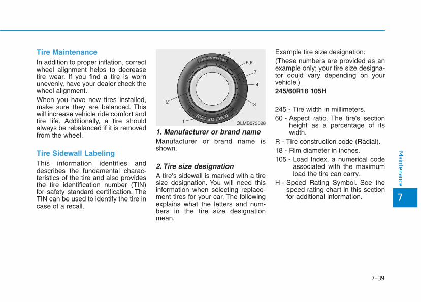
7-39
7
Maintenance
Tire MaintenanceIn addition to proper inflation, correctwheel alignment helps to decreasetire wear. If you find a tire is wornunevenly, have your dealer check thewheel alignment.When you have new tires installed,make sure they are balanced. Thiswill increase vehicle ride comfort andtire life. Additionally, a tire shouldalways be rebalanced if it is removedfrom the wheel.
Tire Sidewall LabelingThis information identifies anddescribes the fundamental charac-teristics of the tire and also providesthe tire identification number (TIN)for safety standard certification. TheTIN can be used to identify the tire incase of a recall.
1. Manufacturer or brand name Manufacturer or brand name isshown.
2. Tire size designation A tire's sidewall is marked with a tiresize designation. You will need thisinformation when selecting replace-ment tires for your car. The followingexplains what the letters and num-bers in the tire size designationmean.
Example tire size designation:(These numbers are provided as anexample only; your tire size designa-tor could vary depending on yourvehicle.)245/60R18 105H
245 - Tire width in millimeters.60 - Aspect ratio. The tire's section
height as a percentage of itswidth.
R - Tire construction code (Radial).18 - Rim diameter in inches.105 - Load Index, a numerical code
associated with the maximumload the tire can carry.
H - Speed Rating Symbol. See thespeed rating chart in this sectionfor additional information.
OLMB073028
1
1
2 3
4
5,6
7
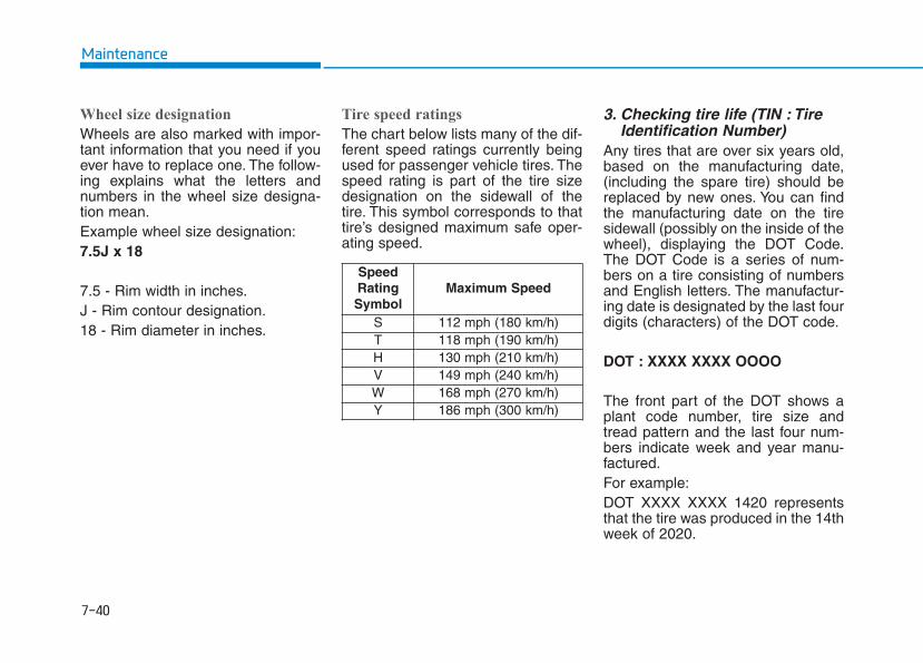
7-40
Maintenance
Wheel size designation
Wheels are also marked with impor-tant information that you need if youever have to replace one. The follow-ing explains what the letters andnumbers in the wheel size designa-tion mean.Example wheel size designation:7.5J x 18
7.5 - Rim width in inches.J - Rim contour designation.18 - Rim diameter in inches.
Tire speed ratings
The chart below lists many of the dif-ferent speed ratings currently beingused for passenger vehicle tires. Thespeed rating is part of the tire sizedesignation on the sidewall of thetire. This symbol corresponds to thattire’s designed maximum safe oper-ating speed.
3. Checking tire life (TIN : TireIdentification Number)
Any tires that are over six years old,based on the manufacturing date,(including the spare tire) should bereplaced by new ones. You can findthe manufacturing date on the tiresidewall (possibly on the inside of thewheel), displaying the DOT Code.The DOT Code is a series of num-bers on a tire consisting of numbersand English letters. The manufactur-ing date is designated by the last fourdigits (characters) of the DOT code.
DOT : XXXX XXXX OOOO
The front part of the DOT shows aplant code number, tire size andtread pattern and the last four num-bers indicate week and year manu-factured.For example:DOT XXXX XXXX 1420 representsthat the tire was produced in the 14thweek of 2020.
SpeedRatingSymbol
Maximum Speed
S 112 mph (180 km/h)T 118 mph (190 km/h)H 130 mph (210 km/h)V 149 mph (240 km/h)W 168 mph (270 km/h)Y 186 mph (300 km/h)
7-41
7
Maintenance
4. Tire ply composition andmaterial
The number of layers or plies of rub-ber-coated fabric in the tire. Tiremanufacturers also must indicate thematerials in the tire, which includesteel, nylon, polyester, and others.The letter "R" means radial ply con-struction; the letter "D" means diago-nal or bias ply construction; and theletter "B" means belted-bias ply con-struction.
5. Maximum permissible infla-tion pressure
This number is the greatest amountof air pressure that should be put inthe tire. Do not exceed the maximumpermissible inflation pressure. Referto the Tire and Loading Informationlabel for recommended inflationpressure.
6. Maximum load ratingThis number indicates the maximumload in kilograms and pounds thatcan be carried by the tire. Whenreplacing the tires on the vehicle,always use a tire that has the sameload rating as the factory installedtire.
7. Uniform tire quality gradingQuality grades can be found whereapplicable on the tire sidewallbetween tread shoulder and maxi-mum section width.For example:TREAD WEAR 200TRACTION AATEMPERATURE A
Tread wear
The tread wear grade is a compara-tive rating based on the wear rate ofthe tire when tested under controlledconditions on a specified govern-ment test course. For example, a tiregraded 150 would wear one-and-a-half times (1½) as well on the gov-ernment course as a tire graded 100.The relative performance of tiresdepends upon the actual conditionsof their use, however, and maydepart significantly from the normdue to variations in driving habits,service practices and differences inroad characteristics and climate.These grades are molded on thesidewalls of passenger vehicle tires.The tires available as standard oroptional equipment on your vehiclemay vary with respect to grade.
7-42
Maintenance
Traction - AA, A, B & C
The traction grades, from highest tolowest, are AA, A, B and C. Thosegrades represent the tire's ability tostop on wet pavement as measuredunder controlled conditions on spec-ified government test surfaces ofasphalt and concrete. A tire markedC may have poor traction perform-ance.
Temperature - A, B & C
The temperature grades are A (thehighest), B and C representing thetire’s resistance to the generation ofheat and its ability to dissipate heatwhen tested under controlled condi-tions on a specified indoor laboratorytest wheel.Sustained high temperature cancause the material of the tire todegenerate and reduce tire life, andexcessive temperature can lead tosudden tire failure. Grade Cresponds to a level of performancewhich all passenger car tires mustmeet under the Federal MotorVehicle Safety Standard No. 109.Grades B and A represent higherlevels of performance on the labora-tory test wheel than the minimumrequired by law.
The temperature grade for thistire is established for a tire thatis properly inflated and notoverloaded. Excessive speed,under-inflation, over-inflation,or excessive loading, eitherseparately or in combination,can cause heat build-up andpossible sudden tire failure.This may cause loss of vehiclecontrol resulting in an accident.
WARNING
The traction grade assigned tothis tire is based on straight-ahead braking traction tests,and does not include accelera-tion, cornering, hydroplaning,or peak traction characteristics.
WARNING
7-43
7
Maintenance
Tire Terminology andDefinitions Air Pressure The amount of air inside the tirepressing outward on the tire. Airpressure is expressed in pounds persquare inch (psi) or kilopascal (kPa).
Accessory WeightThis means the combined weight ofoptional accessories. Some exam-ples of optional accessories areautomatic transmission, powerseats, and air conditioning.
Aspect RatioThe relationship of a tire's height toits width.
BeltA rubber coated layer of cords that islocated between the plies and thetread. Cords may be made from steelor other reinforcing materials.
BeadThe tire bead contains steel wireswrapped by steel cords that hold thetire onto the rim.
Bias Ply Tire A pneumatic tire in which the pliesare laid at alternate angles less than90 degrees to the centerline of thetread.
Cold Tire PressureThe amount of air pressure in a tire,measured in pounds per square inch(psi) or kilopascals (kPa) before a tirehas built up heat from driving.
Curb WeightThis means the weight of a motorvehicle with standard and optionalequipment including the maximumcapacity of fuel, oil and coolant, butwithout passengers and cargo.
DOT MarkingsA code molded into the sidewall of atire signifying that the tire is in com-pliance with the U.S. Department ofTransportation motor vehicle safetystandards. The DOT code includesthe Tire Identification Number (TIN),an alphanumeric designator whichcan also identify the tire manufactur-er, production plant, brand and dateof production.
GVWRGross Vehicle Weight Rating
GAWR FRTGross Axle Weight Rating for theFront Axle.
GAWR RRGross Axle Weight Rating for theRear axle.
7-44
Maintenance
Intended Outboard SidewallThe side of an asymmetrical tire, thatmust always face outward whenmounted on a vehicle.
Kilopascal (kPa)The metric unit for air pressure.
Light truck(LT) tireA tire designated by its manufactureras primarily intended for use on light-weight trucks or multipurpose pas-senger vehicles.
Load ratingsThe maximum load that a tire is ratedto carry for a given inflation pressure.
Load IndexAn assigned number ranging from 1to 279 that corresponds to the loadcarrying capacity of a tire.
Maximum Inflation PressureThe maximum air pressure to whicha cold tire may be inflated. The max-imum air pressure is molded onto thesidewall.
Maximum Load RatingThe load rating for a tire at the maxi-mum permissible inflation pressurefor that tire.
Maximum Loaded VehicleWeightThe sum of curb weight; accessoryweight; vehicle capacity weight; andproduction options weight.
Normal Occupant WeightThe number of occupants a vehicleis designed to seat multiplied by 150pounds (68 kg).
Occupant DistributionDesignated seating positions.
Outward Facing SidewallAn asymmetrical tire has a particularside that faces outward when mount-ed on a vehicle. The outward facingsidewall bears white lettering orbears manufacturer, brand, and/ormodel name molding that is higher ordeeper than the same moldings onthe inner facing sidewall.
Passenger (P-Metric) tireA tire used on passenger cars andsome light duty trucks and multipur-pose vehicles.
Ply A layer of rubber-coated parallelcords.

7-45
7
Maintenance
Pneumatic tireA mechanical device made of rubber,chemicals, fabric and steel or othermaterials, that, when mounted on anautomotive wheel provides the trac-tion and contains the gas or fluid thatsustains the load.
Pneumatic options weightThe combined weight of installedregular production options weighingover 5 lb. (2.3 kg) in excess of thestandard items which they replace,not previously considered in curbweight or accessory weight, includ-ing heavy duty breaks, ride levelers,roof rack, heavy duty battery, andspecial trim.
Recommended InflationPressureVehicle manufacturer's recommend-ed tire inflation pressure as shownon the tire placard.
Radial Ply TireA pneumatic tire in which the plycords that extend to the beads arelaid at 90 degrees to the centerline ofthe tread.
RimA metal support for a tire and uponwhich the tire beads are seated.
SidewallThe portion of a tire between thetread and the bead.
Speed RatingAn alphanumeric code assigned to atire indicating the maximum speed atwhich a tire can operate.
TractionThe friction between the tire and theroad surface. The amount of grip pro-vided.
TreadThe portion of a tire that comes intocontact with the road.
Treadwear IndicatorsNarrow bands, sometimes called"wear bars", that show across thetread of a tire when only 1/16 inch oftread remains.
UTQGSUniform Tire Quality GradingStandards is a tire information sys-tem that provides consumers withratings for a tire's traction, tempera-ture and treadwear. Ratings aredetermined by tire manufacturersusing government testing proce-dures. The ratings are molded intothe sidewall of the tire.
7-46
Maintenance
Vehicle Capacity WeightThe number of designated seatingpositions multiplied by 150 lbs. (68kg) plus the rated cargo and luggageload.
Vehicle Maximum Load on theTireLoad on an individual tire due to curband accessory weight plus maximumoccupant and cargo weight.
Vehicle Normal Load on the TireLoad on an individual tire that isdetermined by distributing to eachaxle its share of the curb weight,accessory weight, and normal occu-pant weight and dividing by 2.
Vehicle PlacardA label permanently attached to avehicle showing the original equip-ment tire size and recommendedinflation pressure.
All Season TiresHYUNDAI specifies all season tireson some models to provide goodperformance for use all year round,including snowy road conditions. Allseason tires are identified by ALLSEASON and/or M+S (Mud andSnow) on the tire sidewall. Snow tireshave better snow traction than allseason tires and may be moreappropriate in some areas.
Snow TiresIf you equip your car with snow tires,they should be the same size andhave the same load capacity as theoriginal tires. Snow tires should beinstalled on all four wheels; other-wise, poor handling may result. Snowtires should carry 4 psi (28 kPa)more air pressure than the pressurerecommended for the standard tireson the tire label on the driver’s side ofthe center pillar, or up to the maxi-mum pressure shown on the tiresidewall, whichever is less. Do notdrive faster than 75 mph (120 km/h)when your vehicle is equipped withsnow tires.
Radial-Ply TiresRadial-ply tires provide improvedtread life, road hazard resistance andsmoother high speed ride. The radi-al-ply tires used on this vehicle are ofbelted construction, and are selectedto complement the ride and handlingcharacteristics of your vehicle.Radial-ply tires have the same loadcarrying capacity, as bias-ply or biasbelted tires of the same size, and usethe same recommended inflationpressure. Mixing of radial-ply tireswith bias-ply or bias belted tires isnot recommended. Any combina-tions of radial-ply and bias-ply or biasbelted tires when used on the samevehicle will seriously deterioratevehicle handling. The best rule to fol-low is: Identical pairs of radial-plytires should always be used as a setfor the front tires and a set for therear tires.

7-47
7
Maintenance
Longer wearing tires can be moresusceptible to irregular tread wear. Itis very important to follow the tirerotation interval in this chapter toachieve the tread life potential ofthese tires. Cuts and punctures inradial-ply tires are repairable only inthe tread area, because of sidewallflexing. Consult your tire dealer forradial-ply tire repairs.
• When driving on a rough roador off road, drive cautiouslybecause tires and wheels maybe damaged. And after driv-ing, inspect tires and wheels.
• When passing over a pothole,speed bump, manhole, orcurb stone, drive slowly sothat the tires and wheels arenot damaged.
• If the tire is subjected to asevere impact, have the tireand wheel inspected by anauthorized HYUNDAI dealer.
• It is not easy to recognize tiredamage with your own eyes.But if there is the slightest hintof tire damage, have the tirechecked or replaced becausethe tire damage may cause airleakage from the tire.
• If the tire is damaged by driv-ing on a rough road, off road,pothole, manhole, or curbstone, it will not be covered bythe warranty.
CAUTION
Do not mix bias ply and radialply tires under any circum-stances.This may cause unusu-al handling characteristics thatmay cause loss of vehicle con-trol resulting in an accident.
WARNING
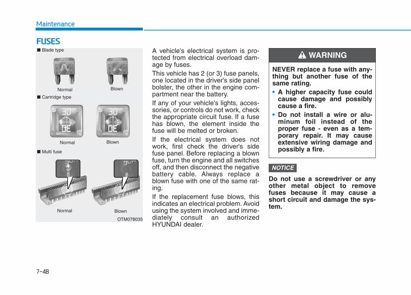
7-48
Maintenance
FFUUSSEESSA vehicle's electrical system is pro-tected from electrical overload dam-age by fuses.This vehicle has 2 (or 3) fuse panels,one located in the driver's side panelbolster, the other in the engine com-partment near the battery.If any of your vehicle's lights, acces-sories, or controls do not work, checkthe appropriate circuit fuse. If a fusehas blown, the element inside thefuse will be melted or broken.If the electrical system does notwork, first check the driver's sidefuse panel. Before replacing a blownfuse, turn the engine and all switchesoff, and then disconnect the negativebattery cable. Always replace ablown fuse with one of the same rat-ing.If the replacement fuse blows, thisindicates an electrical problem. Avoidusing the system involved and imme-diately consult an authorizedHYUNDAI dealer.
Do not use a screwdriver or anyother metal object to removefuses because it may cause ashort circuit and damage the sys-tem.
NOTICE
NEVER replace a fuse with any-thing but another fuse of thesame rating.• A higher capacity fuse could
cause damage and possiblycause a fire.
• Do not install a wire or alu-minum foil instead of theproper fuse - even as a tem-porary repair. It may causeextensive wiring damage andpossibly a fire.
WARNING ■ Blade type
Normal
■ Cartridge type
Blown
Normal Blown
■ Multi fuse
Normal Blown
OTM078035
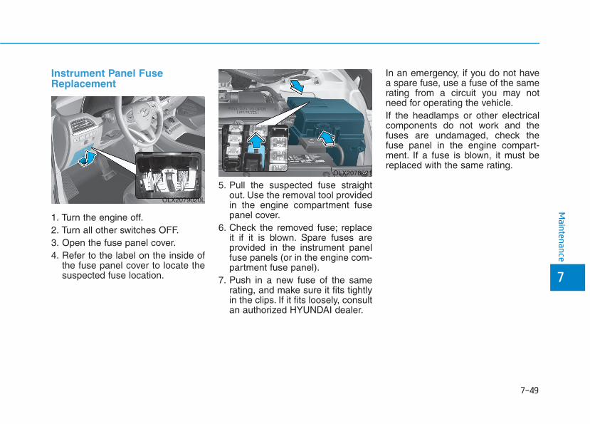
7-49
7
Maintenance
Instrument Panel FuseReplacement
1. Turn the engine off.2. Turn all other switches OFF.3. Open the fuse panel cover.4. Refer to the label on the inside of
the fuse panel cover to locate thesuspected fuse location.
5. Pull the suspected fuse straightout. Use the removal tool providedin the engine compartment fusepanel cover.
6. Check the removed fuse; replaceit if it is blown. Spare fuses areprovided in the instrument panelfuse panels (or in the engine com-partment fuse panel).
7. Push in a new fuse of the samerating, and make sure it fits tightlyin the clips. If it fits loosely, consultan authorized HYUNDAI dealer.
In an emergency, if you do not havea spare fuse, use a fuse of the samerating from a circuit you may notneed for operating the vehicle.If the headlamps or other electricalcomponents do not work and thefuses are undamaged, check thefuse panel in the engine compart-ment. If a fuse is blown, it must bereplaced with the same rating.
OLX2079020L
OLX2078021
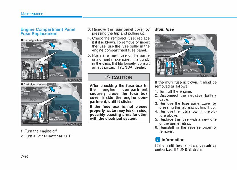
7-50
Maintenance
Engine Compartment PanelFuse Replacement
1. Turn the engine off.2. Turn all other switches OFF.
3. Remove the fuse panel cover bypressing the tap and pulling up.
4. Check the removed fuse; replaceit if it is blown. To remove or insertthe fuse, use the fuse puller in theengine compartment fuse panel.
5. Push in a new fuse of the samerating, and make sure it fits tightlyin the clips. If it fits loosely, consultan authorized HYUNDAI dealer.
Multi fuse
If the multi fuse is blown, it must beremoved as follows:1. Turn off the engine.2. Disconnect the negative battery
cable.3. Remove the fuse panel cover by
pressing the tab and pulling it up.4. Remove the nuts shown in the pic-
ture above.5. Replace the fuse with a new one
of the same rating.6. Reinstall in the reverse order of
removal.
Information If the multi fuse is blown, consult anauthorized HYUNDAI dealer.
i
After checking the fuse box inthe engine compartmentsecurely close the fuse boxcover inside the engine com-partment, until it clicks.If the fuse box is not closedproperly, water may leak in side,possibly causing a malfunctionwith the electrical system.
CAUTIONOLX2078024
■ Blade type fuse
OLX2078025
■ Cartridge type fuse
OLX2078023
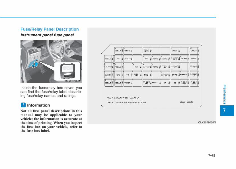
7-51
7
Maintenance
Fuse/Relay Panel DescriptionInstrument panel fuse panel
Inside the fuse/relay box cover, youcan find the fuse/relay label describ-ing fuse/relay names and ratings.
Information Not all fuse panel descriptions in thismanual may be applicable to yourvehicle; the information is accurate atthe time of printing. When you inspectthe fuse box on your vehicle, refer tothe fuse box label.
i
OLX2079054N
OLX2079027L

7-52
Maintenance
Fuse Name Fuse Rating Protected Component
MODULE 4 7.5A Data Link Connector, Stop Lamp Switch, Driver Door Module
AIR BAG 1 15A SRS Control Module, Passenger Occupant Detection Sensor
BRAKESWITCH
7.5A IBU, Stop Lamp Switch
MODULE 9 15AFront A/C Control Module, Low DC-DC Converter (Audio), Power Tail Gate Unit, Driver IMS Control Module,Head-up Display, Driver Door Module, Driver/Passenger Power Outside Mirror, Security Indicator, Rain Sensor,Rear Occupant Alert (ROA) Sensor, 3RD Seat Folding Control Module
MODULE 10 10ABlind-Spot Collision Warning Unit LH/RH, Front Console Switch, Rear A/C Control Module, Electro ChromicMirror, Data Link Connector, Front Wireless Charger
AIR BAG IND 10A Seat Belt Indicator, Instrument Cluster
IBU 1 7.5A IBU
MODULE 2 7.5A1ST Seat Warmer Control Module, 1ST Air Ventilation Seat Control Module, 2ND Air Ventilation Seat LH/RHControl Module, 2ND Seat LH/RH Warmer Control Module, 3RD Seat Folding Control Module, AC InverterOutlet, Inverter Unit, Surround View Monitor Unit
MODULE 8 7.5ADriver/Passenger Smart Key Outside Handle, Driver/Passenger Outside Mirror, Key Solenoid, Center FasciaKeyboard (Hazard Switch)
S/HEATERFRT
20A 1ST Air Ventilation Control Module, 1ST Seat Warmer Control Module
AIR BAG 2 15A SRS Control Module
E-SHIFTER 2 10A Electronic ATM Shift Lever Switch (SBW), SCU
Instrument panel fuse panel
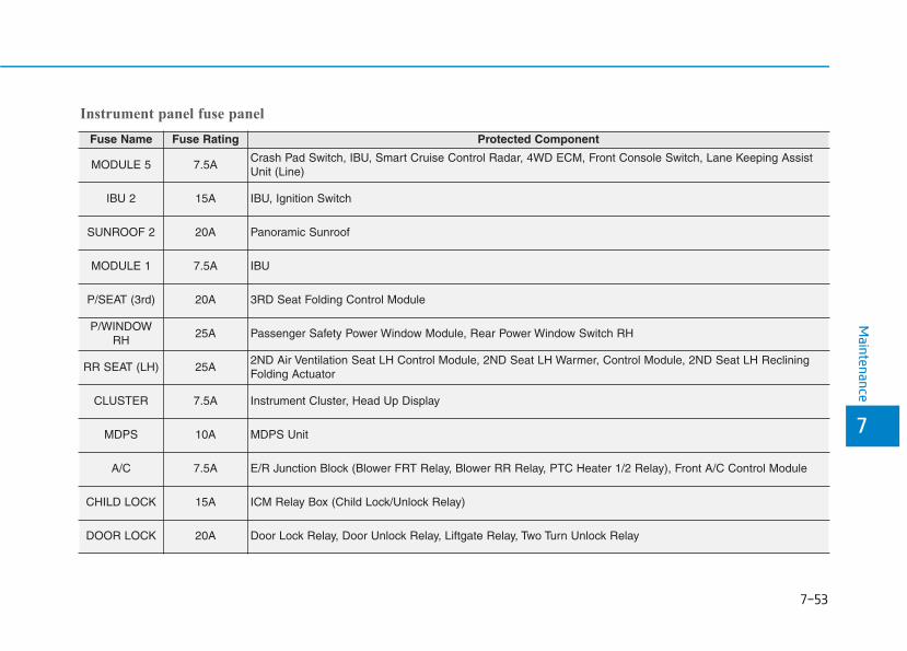
7-53
7
Maintenance
Fuse Name Fuse Rating Protected Component
MODULE 5 7.5ACrash Pad Switch, IBU, Smart Cruise Control Radar, 4WD ECM, Front Console Switch, Lane Keeping AssistUnit (Line)
IBU 2 15A IBU, Ignition Switch
SUNROOF 2 20A Panoramic Sunroof
MODULE 1 7.5A IBU
P/SEAT (3rd) 20A 3RD Seat Folding Control Module
P/WINDOWRH
25A Passenger Safety Power Window Module, Rear Power Window Switch RH
RR SEAT (LH) 25A2ND Air Ventilation Seat LH Control Module, 2ND Seat LH Warmer, Control Module, 2ND Seat LH RecliningFolding Actuator
CLUSTER 7.5A Instrument Cluster, Head Up Display
MDPS 10A MDPS Unit
A/C 7.5A E/R Junction Block (Blower FRT Relay, Blower RR Relay, PTC Heater 1/2 Relay), Front A/C Control Module
CHILD LOCK 15A ICM Relay Box (Child Lock/Unlock Relay)
DOOR LOCK 20A Door Lock Relay, Door Unlock Relay, Liftgate Relay, Two Turn Unlock Relay
Instrument panel fuse panel
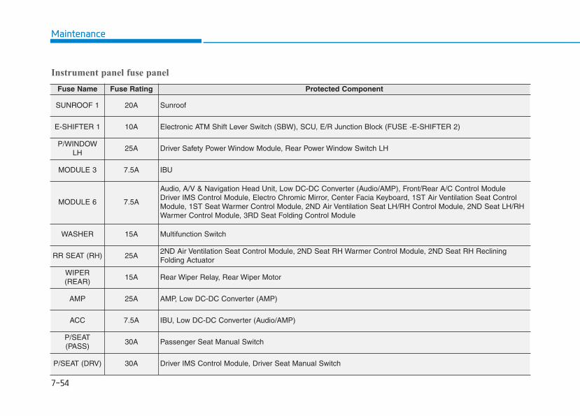
7-54
Maintenance
Fuse Name Fuse Rating Protected Component
SUNROOF 1 20A Sunroof
E-SHIFTER 1 10A Electronic ATM Shift Lever Switch (SBW), SCU, E/R Junction Block (FUSE -E-SHIFTER 2)
P/WINDOWLH
25A Driver Safety Power Window Module, Rear Power Window Switch LH
MODULE 3 7.5A IBU
MODULE 6 7.5A
Audio, A/V & Navigation Head Unit, Low DC-DC Converter (Audio/AMP), Front/Rear A/C Control ModuleDriver IMS Control Module, Electro Chromic Mirror, Center Facia Keyboard, 1ST Air Ventilation Seat ControlModule, 1ST Seat Warmer Control Module, 2ND Air Ventilation Seat LH/RH Control Module, 2ND Seat LH/RHWarmer Control Module, 3RD Seat Folding Control Module
WASHER 15A Multifunction Switch
RR SEAT (RH) 25A2ND Air Ventilation Seat Control Module, 2ND Seat RH Warmer Control Module, 2ND Seat RH RecliningFolding Actuator
WIPER(REAR)
15A Rear Wiper Relay, Rear Wiper Motor
AMP 25A AMP, Low DC-DC Converter (AMP)
ACC 7.5A IBU, Low DC-DC Converter (Audio/AMP)
P/SEAT(PASS)
30A Passenger Seat Manual Switch
P/SEAT (DRV) 30A Driver IMS Control Module, Driver Seat Manual Switch
Instrument panel fuse panel
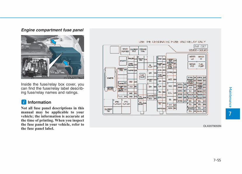
7-55
7
Maintenance
Engine compartment fuse panel
Inside the fuse/relay box cover, youcan find the fuse/relay label describ-ing fuse/relay names and ratings.
Information Not all fuse panel descriptions in thismanual may be applicable to yourvehicle; the information is accurate atthe time of printing. When you inspectthe fuse panel in your vehicle, refer tothe fuse panel label.
i
OLX2078022
OLX2079055N

7-56
Maintenance
Engine compartment fuse panel
Fuse Name Fuse Rating Protected Component
MULTI FUSE(10P)
MDPS 80A MDPS Unit
COOLING FAN 1 80A Cooling Fan Relay (600W)
EPB 60A ESC Module
B+4 50AICU Junction Block (Fuse - MODULE 8, S/HEATER FRT, P/WINDOW RH, AMP, SUN-ROOF)
B+3 50AICU Junction Block (Fuse - P/WINDOW LH, RR SEAT (LH), P/SEAT (DRV), P/SEAT(PASS))
B+2 50A ICU Junction Block (IPS 8/IPS 10/IPS 11/IPS 12/IPS 13/IPS 14/IPS 15)
REAR HEATED 40A Rear Heated Relay
ESC 1 40A ESC Module
BLOWER 40A Blower Relay
ESC 2 40A ESC Module
MULTI FUSE(2P)
PTC HEATER 1 50A PTC Heater 1 Relay
PTC HEATER 2 50A PTC Heater 2 Relay
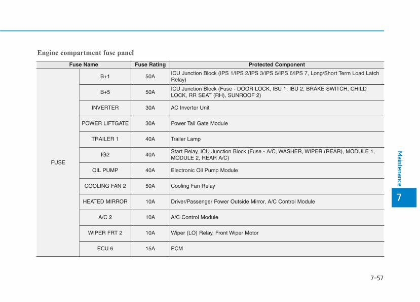
7-57
7
Maintenance
Engine compartment fuse panel
Fuse Name Fuse Rating Protected Component
FUSE
B+1 50AICU Junction Block (IPS 1/IPS 2/IPS 3/IPS 5/IPS 6/IPS 7, Long/Short Term Load LatchRelay)
B+5 50AICU Junction Block (Fuse - DOOR LOCK, IBU 1, IBU 2, BRAKE SWITCH, CHILDLOCK, RR SEAT (RH), SUNROOF 2)
INVERTER 30A AC Inverter Unit
POWER LIFTGATE 30A Power Tail Gate Module
TRAILER 1 40A Trailer Lamp
IG2 40AStart Relay, ICU Junction Block (Fuse - A/C, WASHER, WIPER (REAR), MODULE 1,MODULE 2, REAR A/C)
OIL PUMP 40A Electronic Oil Pump Module
COOLING FAN 2 50A Cooling Fan Relay
HEATED MIRROR 10A Driver/Passenger Power Outside Mirror, A/C Control Module
A/C 2 10A A/C Control Module
WIPER FRT 2 10A Wiper (LO) Relay, Front Wiper Motor
ECU 6 15A PCM
Maintenance
7

7-58
Maintenance
Engine compartment fuse panel
Fuse Name Fuse Rating Protected Component
FUSE
AMS 10A Battery Sensor
E-SHIFTER 1 20A Electronic Transmission
4WD 20A AWD ECM
E-SHIFTER2 10A Electronic Transmission
BLOWER 2 10A A/C Control Module
BLOWER 1 40A Rear Blower Relay
TCU 1 15A Transmission Range Switch
PCB Block
SENSOR 6 15A Glow Relay Unit
ECU 3 10A ESC Module
ICU 10A ICU Junction Block
SENSOR 5 10A Oxygen Sensor Up #1/#2
IGN COIL 20A Ignition Coil #1/#2/#3/#4/#5/#6

7-59
7
Maintenance
Engine compartment fuse panel
Fuse Name Fuse Rating Protected Component
PCB Block
SENSOR 1 10A Fuel Pump Relay
A/C 1 10A [2.4 GDI] A/CON Relay
WIPER FRT 1 30A Wiper Main Relay
TCU 2 10A TCM, SBW Controller
ECU 3 20A PCM
B/ALARM HORN 15A Burglar Alarm Horn Relay
HORN 15A Horn Relay
FUEL PUMP 20A Fuel Pump Relay
ECU 1 20A PCM
SENSOR 2 10AA/C Comp Relay, Variable Intake Solenoid Valve, Oil Pump Solenoid Valve, OxygenSensor Down, Oil Control Valve, Electronic Thermostat Heater, Purge Control SolenoidValve
ECU 2 20A PCM
POWER OUTLET 1 20A Rear Power Outlet 1
Maintenance
7
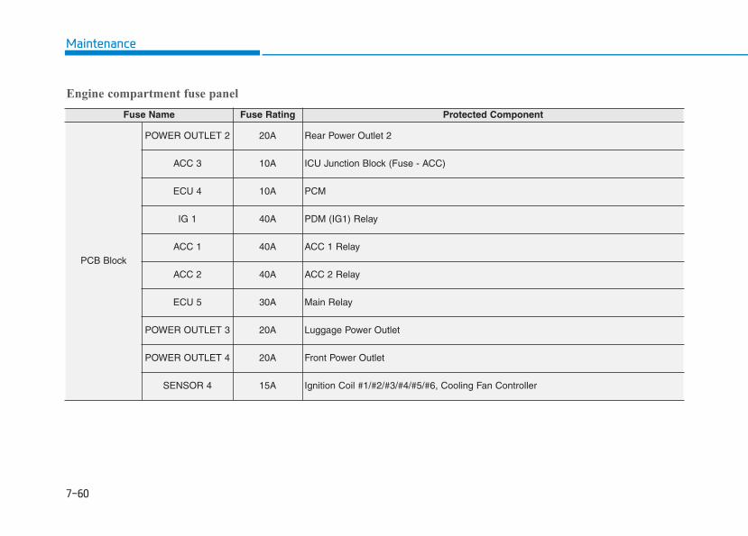
7-60
Maintenance
Engine compartment fuse panel
Fuse Name Fuse Rating Protected Component
PCB Block
POWER OUTLET 2 20A Rear Power Outlet 2
ACC 3 10A ICU Junction Block (Fuse - ACC)
ECU 4 10A PCM
IG 1 40A PDM (IG1) Relay
ACC 1 40A ACC 1 Relay
ACC 2 40A ACC 2 Relay
ECU 5 30A Main Relay
POWER OUTLET 3 20A Luggage Power Outlet
POWER OUTLET 4 20A Front Power Outlet
SENSOR 4 15A Ignition Coil #1/#2/#3/#4/#5/#6, Cooling Fan Controller
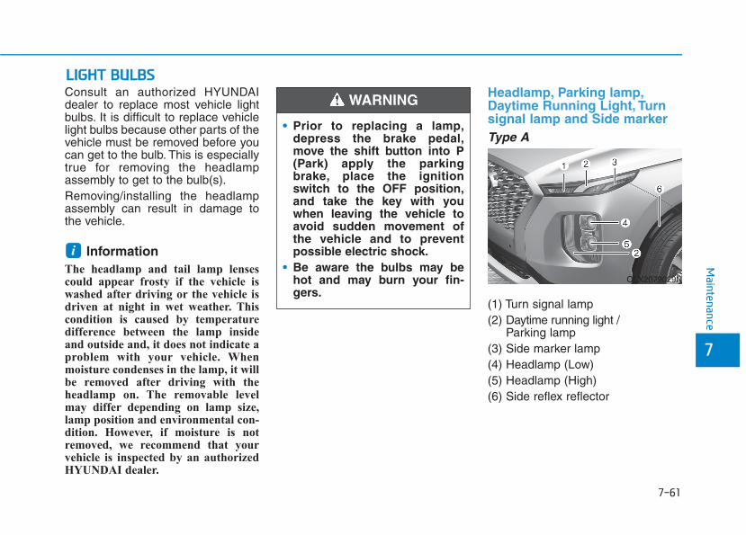
7-61
7
Maintenance
LLIIGGHHTT BBUULLBBSSConsult an authorized HYUNDAIdealer to replace most vehicle lightbulbs. It is difficult to replace vehiclelight bulbs because other parts of thevehicle must be removed before youcan get to the bulb. This is especiallytrue for removing the headlampassembly to get to the bulb(s).Removing/installing the headlampassembly can result in damage tothe vehicle.
Information The headlamp and tail lamp lensescould appear frosty if the vehicle iswashed after driving or the vehicle isdriven at night in wet weather. Thiscondition is caused by temperaturedifference between the lamp insideand outside and, it does not indicate aproblem with your vehicle. Whenmoisture condenses in the lamp, it willbe removed after driving with theheadlamp on. The removable levelmay differ depending on lamp size,lamp position and environmental con-dition. However, if moisture is notremoved, we recommend that yourvehicle is inspected by an authorizedHYUNDAI dealer.
Headlamp, Parking lamp,Daytime Running Light, Turnsignal lamp and Side markerType A
(1) Turn signal lamp(2) Daytime running light /
Parking lamp(3) Side marker lamp(4) Headlamp (Low)(5) Headlamp (High)(6) Side reflex reflector
i
• Prior to replacing a lamp,depress the brake pedal,move the shift button into P(Park) apply the parkingbrake, place the ignitionswitch to the OFF position,and take the key with youwhen leaving the vehicle toavoid sudden movement ofthe vehicle and to preventpossible electric shock.
• Be aware the bulbs may behot and may burn your fin-gers.
WARNING
OLX2079029N
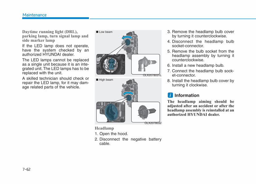
7-62
Maintenance
Daytime running light (DRL),parking lamp, turn signal lamp andside marker lamp
If the LED lamp does not operate,have the system checked by anauthorized HYUNDAI dealer.The LED lamps cannot be replacedas a single unit because it is an inte-grated unit. The LED lamps has to bereplaced with the unit.A skilled technician should check orrepair the LED lamp, for it may dam-age related parts of the vehicle.
Headlamp
1. Open the hood.2. Disconnect the negative battery
cable.
3. Remove the headlamp bulb coverby turning it counterclockwise.
4. Disconnect the headlamp bulbsocket-connector.
5. Remove the bulb socket from theheadlamp assembly by turning itcounterclockwise.
6. Install a new headlamp bulb.7. Connect the headlamp bulb sock-
et-connector.8. Install the headlamp bulb cover by
turning it clockwise.
Information The headlamp aiming should beadjusted after an accident or after theheadlamp assembly is reinstalled at anauthorized HYUNDAI dealer.
i
OLX2078031L
■ Low beam
OLX2078032
■ High beam
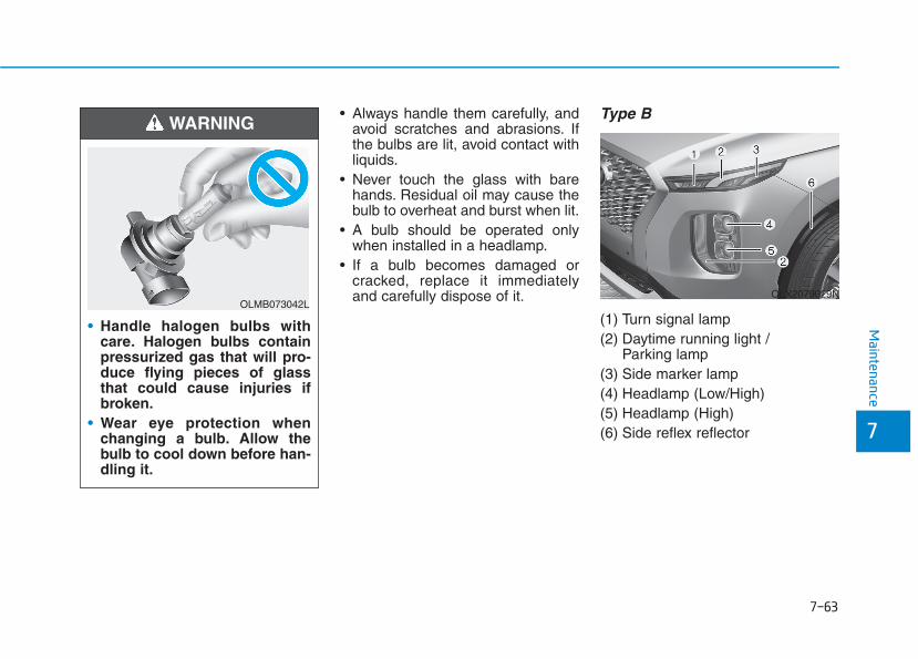
7-63
7
Maintenance
• Always handle them carefully, andavoid scratches and abrasions. Ifthe bulbs are lit, avoid contact withliquids.
• Never touch the glass with barehands. Residual oil may cause thebulb to overheat and burst when lit.
• A bulb should be operated onlywhen installed in a headlamp.
• If a bulb becomes damaged orcracked, replace it immediatelyand carefully dispose of it.
Type B
(1) Turn signal lamp(2) Daytime running light /
Parking lamp(3) Side marker lamp(4) Headlamp (Low/High)(5) Headlamp (High)(6) Side reflex reflector
• Handle halogen bulbs withcare. Halogen bulbs containpressurized gas that will pro-duce flying pieces of glassthat could cause injuries ifbroken.
• Wear eye protection whenchanging a bulb. Allow thebulb to cool down before han-dling it.
WARNING
OLMB073042LOLX2079029N
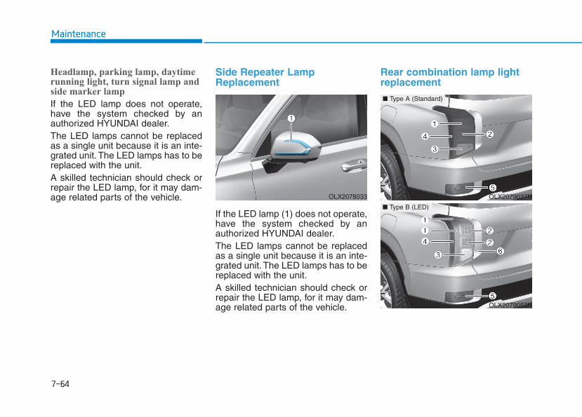
7-64
Maintenance
Headlamp, parking lamp, daytimerunning light, turn signal lamp andside marker lamp
If the LED lamp does not operate,have the system checked by anauthorized HYUNDAI dealer.The LED lamps cannot be replacedas a single unit because it is an inte-grated unit. The LED lamps has to bereplaced with the unit.A skilled technician should check orrepair the LED lamp, for it may dam-age related parts of the vehicle.
Side Repeater LampReplacement
If the LED lamp (1) does not operate,have the system checked by anauthorized HYUNDAI dealer.The LED lamps cannot be replacedas a single unit because it is an inte-grated unit. The LED lamps has to bereplaced with the unit.A skilled technician should check orrepair the LED lamp, for it may dam-age related parts of the vehicle.
Rear combination lamp lightreplacement
OLX2078033 OLX2079037N
■ Type A (Standard)
OLX2079053N
■ Type B (LED)

7-65
7
Maintenance
■■ Type A
(1) Tail lamp(2) Tail/Stop lamp(3) Turn signal lamp(4) Side marker lamp(5) Backup lamp
■■ Type B
(1) Tail lamp, Side marker(2) Stop lamp(3) Turn signal lamp(4) Side marker lamp(5) Backup lamp(6) Garnish lamp
Stop/Tail lamp and turn signal lamp(Type A)
1. Turn off the engine.2. Open the liftgate.3. Loosen the lamp assembly retain-
ing screws with a cross-tip screw-driver.
4. Remove the rear combinationlamp assembly from the body ofthe vehicle.
5. Remove the socket from theassembly by turning the socketcounterclockwise until the tabs onthe socket align with the slots onthe assembly.
6. Remove the bulb from the socketby pressing it in and rotating itcounterclockwise until the tabs onthe bulb align with the slots in thesocket. Pull the bulb out of thesocket.
7. Insert a new bulb by inserting itinto the socket and rotating it untilit locks into place.
8. Install the socket into the assem-bly by aligning the tabs on thesocket with the slots in the assem-bly. Push the socket into theassembly and turn the socketclockwise.
9. Reinstall the lamp assembly to thebody of the vehicle.
OLX2078035 OLX2078036
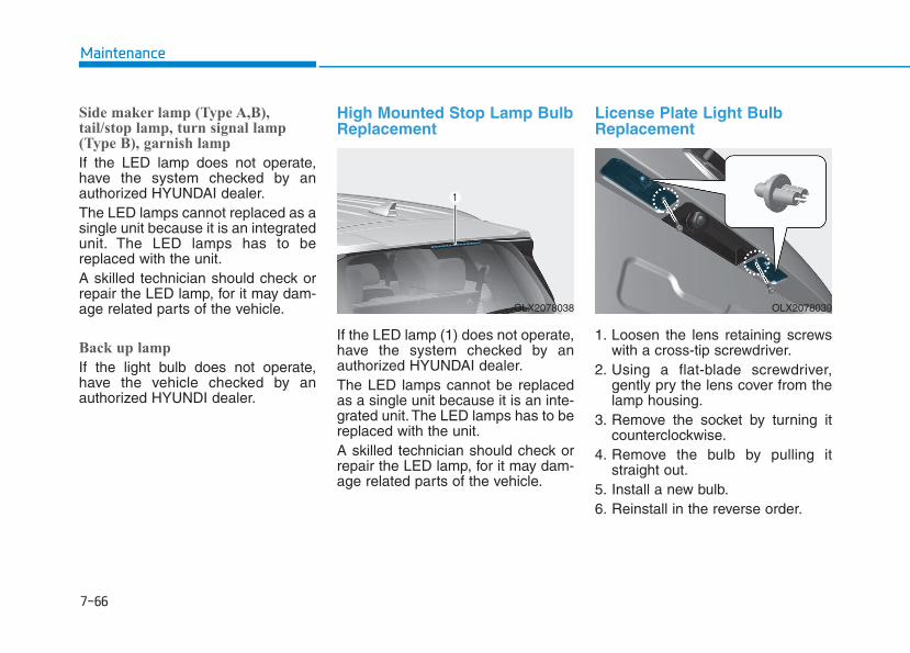
7-66
Maintenance
Side maker lamp (Type A,B),tail/stop lamp, turn signal lamp(Type B), garnish lamp
If the LED lamp does not operate,have the system checked by anauthorized HYUNDAI dealer.The LED lamps cannot replaced as asingle unit because it is an integratedunit. The LED lamps has to bereplaced with the unit.A skilled technician should check orrepair the LED lamp, for it may dam-age related parts of the vehicle.
Back up lamp
If the light bulb does not operate,have the vehicle checked by anauthorized HYUNDI dealer.
High Mounted Stop Lamp BulbReplacement
If the LED lamp (1) does not operate,have the system checked by anauthorized HYUNDAI dealer.The LED lamps cannot be replacedas a single unit because it is an inte-grated unit. The LED lamps has to bereplaced with the unit.A skilled technician should check orrepair the LED lamp, for it may dam-age related parts of the vehicle.
License Plate Light BulbReplacement
1. Loosen the lens retaining screwswith a cross-tip screwdriver.
2. Using a flat-blade screwdriver,gently pry the lens cover from thelamp housing.
3. Remove the socket by turning itcounterclockwise.
4. Remove the bulb by pulling itstraight out.
5. Install a new bulb.6. Reinstall in the reverse order.
OLX2078038 OLX2078039
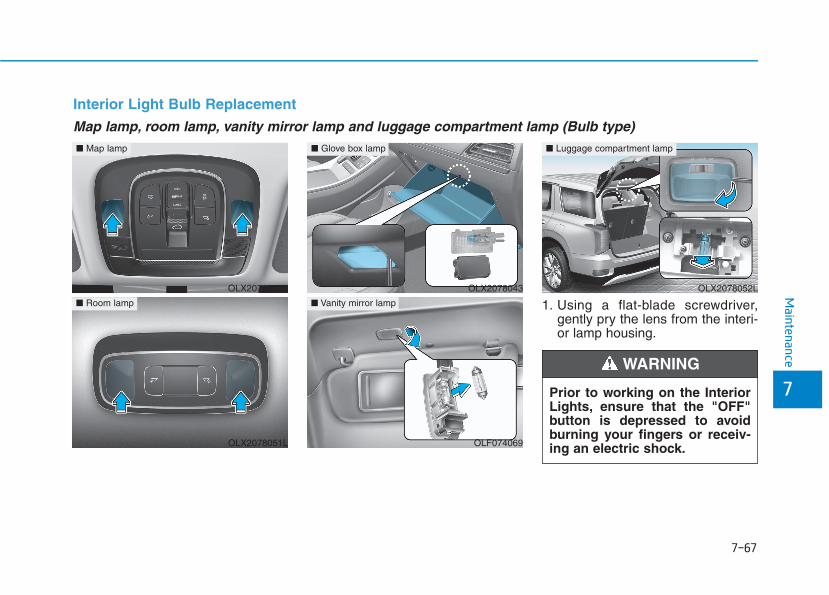
7-67
7
Maintenance
1. Using a flat-blade screwdriver,gently pry the lens from the interi-or lamp housing.
Map lamp, room lamp, vanity mirror lamp and luggage compartment lamp (Bulb type)
Interior Light Bulb Replacement
Prior to working on the InteriorLights, ensure that the "OFF"button is depressed to avoidburning your fingers or receiv-ing an electric shock.
WARNING
OLX2078050L
■ Map lamp
OLX2078051L
■ Room lamp
OLX2078052L
■ Luggage compartment lamp
OLX2078043
■ Glove box lamp
OLF074069
■ Vanity mirror lamp

7-68
Maintenance
2. Remove the bulb by pulling itstraight out.
3. Install a new bulb in the socket.4. Align the lens tabs with the interi-
or lamp housing notches and snapthe lens into place.
Use care not to dirty or damagelens, lens tab, and plastic hous-ings.
If the LED lamp (1) does not operate,have the system checked by anauthorized HYUNDAI dealer.The LED lamps cannot be replacedas a single unit because it is an inte-grated unit. The LED lamps has to bereplaced with the unit.A skilled technician should check orrepair the LED lamp, for it may dam-age related parts of the vehicle
NOTICE
Map lamp / Room lamp / Luggage compartment lamp (LED Type)
OLX2078040
■ Map lamp
OLX2078041
■ Room lamp
OLX2078042
■ Luggage compartment lamp

7-69
7
Maintenance
AAPPPPEEAARRAANNCCEE CCAARREEExterior CareExterior general caution It is very important to follow the labeldirections when using any chemicalcleaner or polish. Read all warningand caution statements that appearon the label.
Protecting your vehicle's finishWashing
To help protect your vehicle’s finishfrom rust and deterioration, wash itthoroughly and frequently at leastonce a month with lukewarm or coldwater.If you use your vehicle for off-roaddriving, you should wash it after eachoff-road trip. Pay special attention tothe removal of any accumulation ofsalt, dirt, mud, and other foreignmaterials. Make sure the drain holesin the lower edges of the doors androcker panels are kept clear andclean.
Insects, tar, tree sap, bird droppings,industrial pollution and similardeposits can damage your vehicle’sfinish if not removed immediately.Even prompt washing with plainwater may not completely remove allthese deposits. A mild soap, safe foruse on painted surfaces, should beused.After washing, rinse the vehicle thor-oughly with lukewarm or cold water.Do not allow soap to dry on the fin-ish.
• Do not use strong soap, chemi-cal detergents or hot water, anddo not wash the vehicle in directsunlight or when the body of thevehicle is warm.
• Be careful when washing theside windows of your vehicle.Especially, with high-pressurewater, water may leak throughthe windows and wet the interi-or.
• To prevent damage to the plasticparts, do not clean with chemi-cal solvents or strong deter-gents.
NOTICE
After washing the vehicle, testthe brakes while driving slowlyto see if they have been affectedby water before getting on theroad. If braking performance isimpaired, dry the brakes byapplying them lightly whilemaintaining a slow forwardspeed.
WARNING
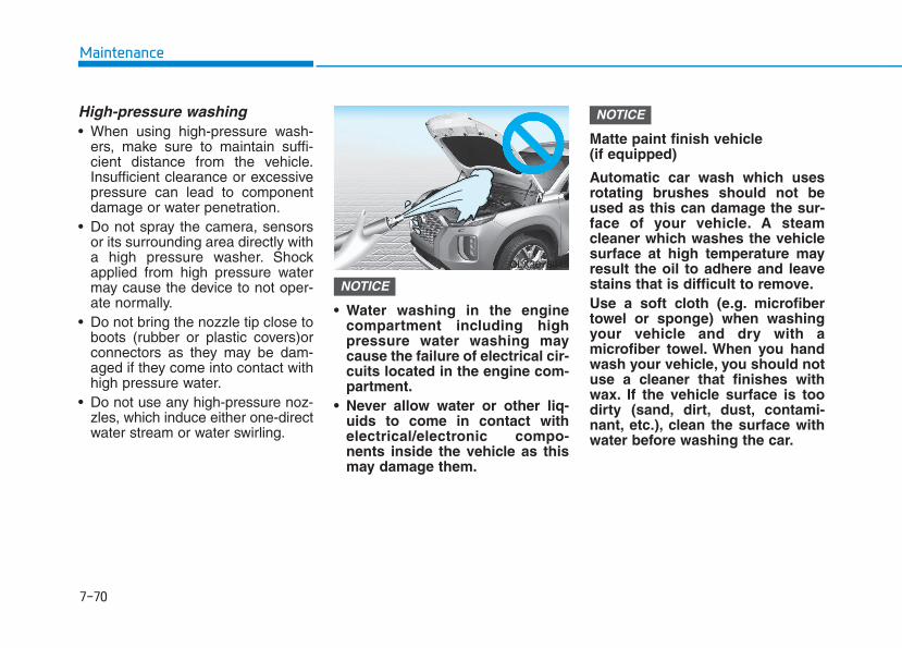
7-70
Maintenance
High-pressure washing• When using high-pressure wash-
ers, make sure to maintain suffi-cient distance from the vehicle.Insufficient clearance or excessivepressure can lead to componentdamage or water penetration.
• Do not spray the camera, sensorsor its surrounding area directly witha high pressure washer. Shockapplied from high pressure watermay cause the device to not oper-ate normally.
• Do not bring the nozzle tip close toboots (rubber or plastic covers)orconnectors as they may be dam-aged if they come into contact withhigh pressure water.
• Do not use any high-pressure noz-zles, which induce either one-directwater stream or water swirling.
• Water washing in the enginecompartment including highpressure water washing maycause the failure of electrical cir-cuits located in the engine com-partment.
• Never allow water or other liq-uids to come in contact withelectrical/electronic compo-nents inside the vehicle as thismay damage them.
Matte paint finish vehicle (if equipped)
Automatic car wash which usesrotating brushes should not beused as this can damage the sur-face of your vehicle. A steamcleaner which washes the vehiclesurface at high temperature mayresult the oil to adhere and leavestains that is difficult to remove.Use a soft cloth (e.g. microfibertowel or sponge) when washingyour vehicle and dry with amicrofiber towel. When you handwash your vehicle, you should notuse a cleaner that finishes withwax. If the vehicle surface is toodirty (sand, dirt, dust, contami-nant, etc.), clean the surface withwater before washing the car.
NOTICE
NOTICE
OLX2078045

7-71
7
Maintenance
Waxing
A good coat of wax provides a barri-er between your paint and environ-mental contamination.Keeping a good coat of wax on yourvehicle will help protect it.Wax the vehicle when water will nolonger bead on the paint.Always wash and dry the vehiclebefore waxing. Use a good qualityliquid or paste wax, and follow themanufacturer’s instructions. Wax allmetal trim to protect it and to main-tain its luster.Removing oil, tar, and similar materi-als with a spot remover will usuallystrip the wax from the finish. Be sureto re-wax these areas even if the restof the vehicle does not yet need wax-ing.
• Wiping dust or dirt off the bodywith a dry cloth will scratch thefinish.
• Do not use steel wool, abrasivecleaners, or strong detergentscontaining highly alkaline orcaustic agents on chrome-plat-ed or anodized aluminum parts.This may result in damage to theprotective coating and causediscoloration or paint deteriora-tion.
Matte paint finish vehicle (if equipped)
Do not use any polish protectorsuch as a detergent, an abrasiveand a polish. In case wax isapplied, remove the wax immedi-ately using a silicon remover andif any tar or tar contaminant is onthe surface use a tar remover toclean. However, be careful not toapply too much pressure on thepainted area.
Repairing your vehicle's finishDeep scratches or stone chips in thepainted surface must be repairedpromptly. Exposed metal will quicklyrust and may develop into a majorrepair expense.
If your vehicle is damaged andrequires any metal repair orreplacement, be sure the bodyshop applies anti-corrosion mate-rials to the parts repaired orreplaced.
Matte paint finish vehicle (if equipped)
In case of matte paint finish vehi-cles, it is impossible to modifyonly the damaged area and repairof the whole part is necessary. Ifthe vehicle is damaged and paint-ing is required, we recommendthat you have your vehicle main-tained and repaired by an author-ized HYUNDAI dealer. Takeextreme care, as it is difficult torestore the quality after the repair.
NOTICE
NOTICE
NOTICE
NOTICE
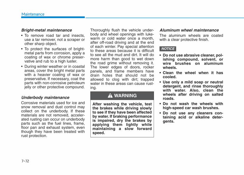
7-72
Maintenance
Bright-metal maintenance• To remove road tar and insects,
use a tar remover, not a scraper orother sharp object.
• To protect the surfaces of bright-metal parts from corrosion, apply acoating of wax or chrome preser-vative and rub to a high luster.
• During winter weather or in coastalareas, cover the bright metal partswith a heavier coating of wax orpreservative. If necessary, coat theparts with non-corrosive petroleumjelly or other protective compound.
Underbody maintenanceCorrosive materials used for ice andsnow removal and dust control maycollect on the underbody. If thesematerials are not removed, acceler-ated rusting can occur on underbodyparts such as the fuel lines, frame,floor pan and exhaust system, eventhough they have been treated withrust protection.
Thoroughly flush the vehicle under-body and wheel openings with luke-warm or cold water once a month,after off-road driving and at the endof each winter. Pay special attentionto these areas because it is difficultto see all the mud and dirt. It will domore harm than good to wet downthe road grime without removing it.The lower edges of doors, rockerpanels, and frame members havedrain holes that should not beallowed to clog with dirt; trappedwater in these areas can cause rust-ing.
Aluminum wheel maintenance The aluminum wheels are coatedwith a clear protective finish.
• Do not use abrasive cleaner, pol-ishing compound, solvent, orwire brushes on aluminumwheels.
• Clean the wheel when it hascooled.
• Use only a mild soap or neutraldetergent, and rinse thoroughlywith water. Also, clean thewheels after driving on saltedroads.
• Do not wash the wheels withhigh-speed car wash brushes.
• Do not use any cleaners con-taining acid or alkaline deter-gents.
NOTICE
After washing the vehicle, testthe brakes while driving slowlyto see if they have been affectedby water. If braking performanceis impaired, dry the brakes byapplying them lightly whilemaintaining a slow forwardspeed.
WARNING
7-73
7
Maintenance
Corrosion protectionProtecting your vehicle from corro-sion
By using the most advanced designand construction practices to combatcorrosion, HYUNDAI produces vehi-cles of the highest quality. However,this is only part of the job. To achievethe long-term corrosion resistanceyour vehicle can deliver, the owner’scooperation and assistance is alsorequired.
Common causes of corrosion
The most common causes of corro-sion on your vehicle are:• Road salt, dirt and moisture that is
allowed to accumulate underneaththe vehicle.
• Removal of paint or protectivecoatings by stones, gravel, abra-sion or minor scrapes and dentswhich leave unprotected metalexposed to corrosion.
High-corrosion areas
If you live in an area where your vehi-cle is regularly exposed to corrosivematerials, corrosion protection isparticularly important. Some of thecommon causes of accelerated cor-rosion are road salts, dust controlchemicals, ocean air and industrialpollution.
Moisture breeds corrosion
Moisture creates the conditions inwhich corrosion is most likely tooccur. For example, corrosion isaccelerated by high humidity, partic-ularly when temperatures are justabove freezing. In such conditions,the corrosive material is kept in con-tact with the car surfaces by moisturethat is slow to evaporate.Mud is particularly corrosivebecause it is slow to dry and holdsmoisture in contact with the vehicle.Although the mud appears to be dry,it can still retain the moisture andpromote corrosion.
High temperatures can also acceler-ate corrosion of parts that are notproperly ventilated so the moisturecan be dispersed. For all these rea-sons, it is particularly important tokeep your vehicle clean and free ofmud or accumulations of other mate-rials. This applies not only to the vis-ible surfaces but particularly to theunderside of the vehicle.
To help prevent corrosion
Keep your vehicle cleanThe best way to prevent corrosion isto keep your vehicle clean and freeof corrosive materials. Attention tothe underside of the vehicle is partic-ularly important.
• If you live in a high-corrosion area— where road salts are used, nearthe ocean, areas with industrialpollution, acid rain, etc.—, youshould take extra care to preventcorrosion. In winter, hose off theunderside of your vehicle at leastonce a month and be sure to cleanthe underside thoroughly whenwinter is over.

7-74
Maintenance
• When cleaning underneath thevehicle, pay particular attention tothe components under the fendersand other areas that are hiddenfrom view. Do a thorough job; justdampening the accumulated mudrather than washing it away willaccelerate corrosion rather thanprevent it. Water under high pres-sure and steam are particularlyeffective in removing accumulatedmud and corrosive materials.
• When cleaning lower door panels,rocker panels and frame members,be sure that drain holes are keptopen so that moisture can escapeand not be trapped inside to accel-erate corrosion.
Keep your garage dryDon't park your vehicle in a damp,poorly ventilated garage. This cre-ates a favorable environment for cor-rosion. This is particularly true if youwash your vehicle in the garage ordrive it into the garage when it is stillwet or covered with snow, ice ormud. Even a heated garage can con-tribute to corrosion unless it is wellventilated so moisture is dispersed.
Keep paint and trim in good conditionScratches or chips in the finishshould be covered with "touch-up"paint as soon as possible to reducethe possibility of corrosion. If baremetal is showing through, the atten-tion of a qualified body and paintshop is recommended.Bird droppings are highly corrosiveand may damage painted surfaces injust a few hours. Always remove birddroppings as soon as possible.
Interior CareInterior general precautions Prevent caustic solutions such asperfume and cosmetic oil, from con-tacting the interior parts becausethey may cause damage or discol-oration. If they do contact the interiorparts, wipe them off immediately.See the instructions for the properway to clean vinyl.
• Never allow water or other liq-uids to come in contact withelectrical/electronic compo-nents inside the vehicle as thismay damage them.
• When cleaning leather products(steering wheel, seats etc.), useneutral detergents or low alco-hol content solutions. If you usehigh alcohol content solutionsor acid/alkaline detergents, thecolor of the leather may fade orthe surface may get stripped off.
NOTICE
7-75
7
Maintenance
Cleaning the upholstery andinterior trim Vinyl (if equipped)
Remove dust and loose dirt fromvinyl with a whisk broom or vacuumcleaner. Clean vinyl surfaces with avinyl cleaner.
Fabric (if equipped)
Remove dust and loose dirt from fab-ric with a whisk broom or vacuumcleaner. Clean with a mild soap solu-tion recommended for upholstery orcarpets. Remove fresh spots imme-diately with a fabric spot cleaner. Iffresh spots do not receive immediateattention, the fabric can be stainedand its color can be affected. Also, itsfire-resistant properties can bereduced if the material is not proper-ly maintained.
Using anything but recommendedcleaners and procedures mayaffect the fabric's appearance andfire-resistant properties.
Leather (if equipped)
• Features of seat leather- Leather is made from the outer
skin of an animal, which goesthrough a special process to beavailable for use. Since it is a nat-ural product, each part differs inthickness or density.Wrinkles may appear as a naturalresult of stretching and shrinkingdepending on the temperatureand humidity.
- The seat is made of stretchablefabric to improve comfort.
- The parts contacting the body arecurved and the side supportingarea is high which provides driv-ing comfort and stability.
- Wrinkles may appear naturallyfrom usage. It is not a fault of theproducts.
NOTICE
• Wrinkles or abrasions whichappear naturally from usageare not covered by warranty.
• Belts with metallic acces-sories, zippers or keys insidethe back pocket may damagethe seat fabric.
• Make sure not to wet the seat.It may change the nature ofnatural leather.
• Jeans or clothes which couldbleach may contaminate thesurface of the seat coveringfabric.
CAUTION
7-76
Maintenance
• Caring for the leather seats- Vacuum the seat periodically to
remove dust and sand on theseat. It will prevent abrasion ordamage of the leather and main-tain its quality.
- Wipe the natural leather seatcover often with dry or soft cloth.
- Use of proper leather protectormay prevent abrasion of thecover and helps maintain thecolor. Be sure to read the instruc-tions and consult a specialistwhen using leather coating orprotective agent.
- Light colored (beige, creambeige) leather is easily contami-nated and the stain is noticeable.Clean the seats frequently.
- Avoid wiping with wet cloth. It maycause the surface to crack.
• Cleaning the leather seats- Remove all contaminations
instantly. Refer to instructionsbelow for removal of each con-taminant.
- Cosmetic products (sunscreen,foundation, etc.)Apply cleansing cream on a clothand wipe the contaminated spot.Wipe off the cream with a wetcloth and remove water with a drycloth.
- Beverages (coffee, soft drink,etc.)Apply a small amount of neutraldetergent and wipe until contami-nations do not smear.
- OilRemove oil instantly withabsorbable cloth and wipe withstain remover used only for natu-ral leather.
- Chewing gumHarden the gum with ice andremove gradually.
Cleaning the seat belt webbing Clean the belt webbing with any mildsoap solution recommended forcleaning upholstery or carpet. Followthe instructions provided with thesoap. Do not bleach or re-dye thewebbing because this may weakenthe seat belt.
Cleaning the interior windowglass If the interior glass surfaces of thevehicle become fogged (that is, cov-ered with an oily, greasy or waxyfilm), they should be cleaned withglass cleaner. Follow the directionson the glass cleaner container.
Do not scrape or scratch theinside of the rear window. Thismay result in damage to the rearwindow defroster grid.
NOTICE

7-77
7
Maintenance
The emission control system of yourvehicle is covered by a written limitedwarranty. Please see the warrantyinformation contained in the Owner’sHandbook & Warranty Informationbooklet in your vehicle.Your vehicle is equipped with anemission control system to meet allapplicable emission regulations.There are three emission controlsystems, as follows.
(1) Crankcase emission control sys-tem
(2) Evaporative emission control sys-tem
(3) Exhaust emission control system
In order to ensure the proper func-tion of the emission control systems,it is recommended that you haveyour vehicle inspected and main-tained by an authorized HYUNDAIdealer in accordance with the main-tenance schedule in this manual.
For the Inspection andMaintenance Test (with ElectronicStability Control (ESC) system)• To prevent the vehicle from mis-
firing during dynamometer test-ing, turn the Electronic StabilityControl (ESC) system off bypressing the ESC switch (ESCOFF light illuminated).
• After dynamometer testing iscompleted, turn the ESC systemback on by pressing the ESCswitch again.
1. Crankcase Emission ControlSystem
The positive crankcase ventilationsystem is employed to prevent airpollution caused by blow-by gasesbeing emitted from the crankcase.This system supplies fresh filtered airto the crankcase through the airintake hose. Inside the crankcase,the fresh air mixes with blow-bygases, which then pass through thePCV valve into the induction system.
2. Evaporative Emission ControlSystem Including OnboardRefueling Vapor Recovery(ORVR)
The Evaporative Emission ControlSystem is designed to prevent fuelvapors from escaping into the atmos-phere. The ORVR system isdesigned to allow the vapors fromthe fuel tank to be loaded into a can-ister while refueling at the gas sta-tion, preventing the escape of fuelvapors into the atmosphere.
NOTICE
EEMMIISSSSIIOONN CCOONNTTRROOLL SSYYSSTTEEMM
7-78
Maintenance
CanisterFuel vapors generated inside the fueltank are absorbed and stored in theonboard canister. When the engine isrunning, the fuel vapors absorbed inthe canister are drawn into the surgetank through the purge control sole-noid valve.
Purge Control Solenoid Valve(PCSV)The purge control solenoid valve iscontrolled by the Engine ControlModule (ECM); when the enginecoolant temperature is low duringidling, the PCSV closes so that evap-orated fuel is not taken into theengine. After the engine warms-upduring ordinary driving, the PCSVopens to introduce evaporated fuel tothe engine.
3. Exhaust Emission Control System
The Exhaust Emission ControlSystem is a highly effective systemwhich controls exhaust emissionswhile maintaining good vehicle per-formance.When the engine starts or fails tostart, excessive attempts to restartthe engine may cause damage to theemission system.
Engine exhaust (carbon monox-ide) precautions • Carbon monoxide can be present
with other exhaust fumes. If yousmell exhaust fumes of any kind inyour vehicle, drive with all the win-dows fully open. Have your vehiclechecked and repaired immediately.
Engine exhaust gases containcarbon monoxide (CO). Thoughcolorless and odorless, it isdangerous and could be lethal ifinhaled. Follow the instructionson this page to avoid CO poi-soning.
WARNING
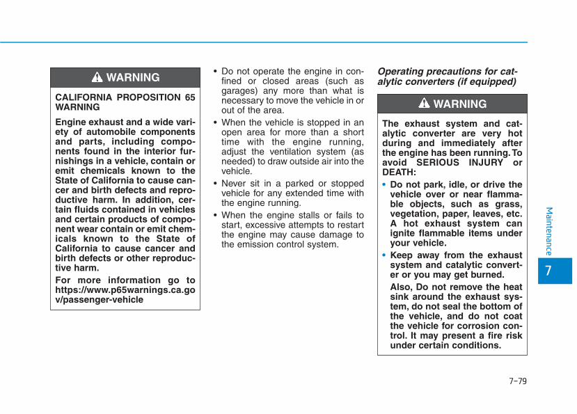
7-79
7
Maintenance
• Do not operate the engine in con-fined or closed areas (such asgarages) any more than what isnecessary to move the vehicle in orout of the area.
• When the vehicle is stopped in anopen area for more than a shorttime with the engine running,adjust the ventilation system (asneeded) to draw outside air into thevehicle.
• Never sit in a parked or stoppedvehicle for any extended time withthe engine running.
• When the engine stalls or fails tostart, excessive attempts to restartthe engine may cause damage tothe emission control system.
Operating precautions for cat-alytic converters (if equipped)
The exhaust system and cat-alytic converter are very hotduring and immediately afterthe engine has been running.Toavoid SERIOUS INJURY orDEATH:• Do not park, idle, or drive the
vehicle over or near flamma-ble objects, such as grass,vegetation, paper, leaves, etc.A hot exhaust system canignite flammable items underyour vehicle.
• Keep away from the exhaustsystem and catalytic convert-er or you may get burned.Also, Do not remove the heatsink around the exhaust sys-tem, do not seal the bottom ofthe vehicle, and do not coatthe vehicle for corrosion con-trol. It may present a fire riskunder certain conditions.
WARNING CALIFORNIA PROPOSITION 65WARNING
Engine exhaust and a wide vari-ety of automobile componentsand parts, including compo-nents found in the interior fur-nishings in a vehicle, contain oremit chemicals known to theState of California to cause can-cer and birth defects and repro-ductive harm. In addition, cer-tain fluids contained in vehiclesand certain products of compo-nent wear contain or emit chem-icals known to the State ofCalifornia to cause cancer andbirth defects or other reproduc-tive harm.For more information go tohttps://www.p65warnings.ca.gov/passenger-vehicle
WARNING

7-80
Maintenance
Your vehicle is equipped with a cat-alytic converter emission controldevice. To prevent damage to thecatalytic converter and to your vehi-cle, take the following precautions:• Use only UNLEADED FUEL for
gasoline engines.• Do not operate the vehicle when
there are signs of engine malfunc-tion, such as misfire or a noticeableloss of performance.
• Do not misuse or abuse theengine. Examples of misuse arecoasting with the engine off anddescending steep grades in gearwith the engine off.
• Do not operate the engine at highidle speed for extended periods (5minutes or more).
• Do not modify or tamper with anypart of the engine or emission con-trol system. All inspections andadjustments must be made by anauthorized HYUNDAI dealer.
• Avoid driving with extremely lowfuel level. If you run out of gasoline,it could cause the engine to misfireand result in excessive loading ofthe catalytic converter.

7-81
7
Maintenance
CCAALLIIFFOORRNNIIAA PPEERRCCHHLLOORRAATTEE NNOOTTIICCEEPerchlorate Material-special handling may apply, See: www.dtsc.ca.gov/hazardouswaste/perchlorate.
Notice to California Vehicle Dismantlers:Perchlorate containing materials, such as air bag inflators, seatbelt pretensioners and keyless remote entry batteries,must be disposed of according to Title 22 California Code of Regulations Section 67384.10 (a).
888
Specifications & Consum
er information
8
Specifications, Consumer information and Reporting safety defects
8
Dimensions ..............................................................8-2Engine......................................................................8-2Bulb Wattage ..........................................................8-3Tires and Wheels ...................................................8-5Volume and Weight................................................8-6Air Conditioning System........................................8-6Recommended Lubricants and Capacities..........8-7
Recommended SAE Viscosity Number .........................8-9Vehicle Identification Number (VIN) .................8-10Vehicle Ccertification Label................................8-10Tire Specification and Pressure Label .............8-11Engine Number .....................................................8-11Consumer Information.........................................8-12Reporting Safety Defects ...................................8-13
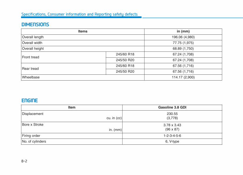
8-2
Specifications, Consumer information and Reporting safety defects
DDIIMMEENNSSIIOONNSS
EENNGGIINNEE
Items in (mm)
Overall length 196.06 (4,980)
Overall width 77.75 (1,975)
Overall height 68.89 (1,750)
Front tread245/60 R18 67.24 (1,708)
245/50 R20 67.24 (1,708)
Rear tread245/60 R18 67.56 (1,716)
245/50 R20 67.56 (1,716)
Wheelbase 114.17 (2,900)
Item Gasoline 3.8 GDI
Displacementcu. in (cc)
230.55(3,778)
Bore x Stroke
in. (mm)3.78 x 3.43 (96 x 87)
Firing order 1-2-3-4-5-6
No. of cylinders 6, V-type
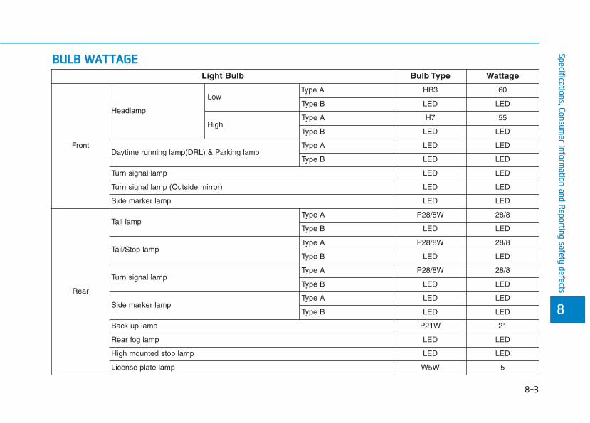
BBUULLBB WWAATTTTAAGGEE
88
Specifications, Consumer inform
ation and Reporting safety defects
Light Bulb Bulb Type Wattage
Front
Headlamp
LowType A HB3 60
Type B LED LED
HighType A H7 55
Type B LED LED
Daytime running lamp(DRL) & Parking lampType A LED LED
Type B LED LED
Turn signal lamp LED LED
Turn signal lamp (Outside mirror) LED LED
Side marker lamp LED LED
Rear
Tail lampType A P28/8W 28/8
Type B LED LED
Tail/Stop lampType A P28/8W 28/8
Type B LED LED
Turn signal lampType A P28/8W 28/8
Type B LED LED
Side marker lampType A LED LED
Type B LED LED
Back up lamp P21W 21
Rear fog lamp LED LED
High mounted stop lamp LED LED
License plate lamp W5W 5
8-3
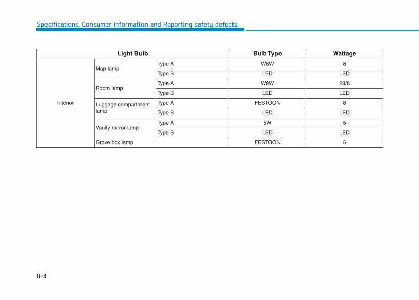
8-4
Specifications, Consumer information and Reporting safety defects
Light Bulb Bulb Type Wattage
Interior
Map lampType A W8W 8
Type B LED LED
Room lampType A W8W 28/8
Type B LED LED
Luggage compartmentlamp
Type A FESTOON 8
Type B LED LED
Vanity mirror lampType A 5W 5
Type B LED LED
Grove box lamp FESTOON 5
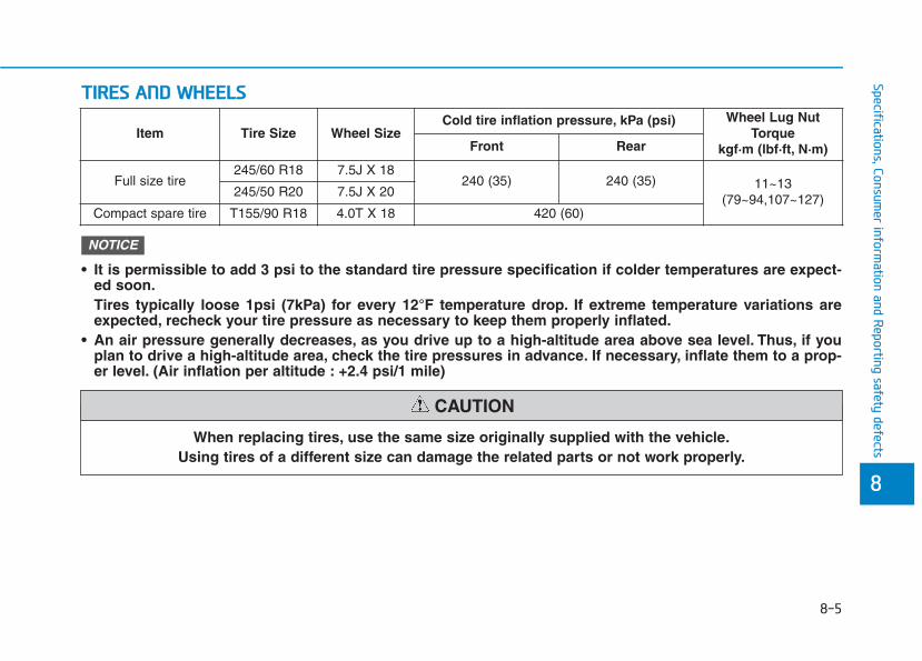
TTIIRREESS AANNDD WWHHEEEELLSS
8-5
88
Specifications, Consumer inform
ation and Reporting safety defects
• It is permissible to add 3 psi to the standard tire pressure specification if colder temperatures are expect-ed soon.Tires typically loose 1psi (7kPa) for every 12°F temperature drop. If extreme temperature variations areexpected, recheck your tire pressure as necessary to keep them properly inflated.
• An air pressure generally decreases, as you drive up to a high-altitude area above sea level. Thus, if youplan to drive a high-altitude area, check the tire pressures in advance. If necessary, inflate them to a prop-er level. (Air inflation per altitude : +2.4 psi/1 mile)
NOTICE
Item Tire Size Wheel SizeCold tire inflation pressure, kPa (psi) Wheel Lug Nut
Torque kgf·m (lbf·ft, N·m)Front Rear
Full size tire245/60 R18 7.5J X 18
240 (35) 240 (35) 11~13(79~94,107~127)
245/50 R20 7.5J X 20
Compact spare tire T155/90 R18 4.0T X 18 420 (60)
When replacing tires, use the same size originally supplied with the vehicle.Using tires of a different size can damage the related parts or not work properly.
CAUTION
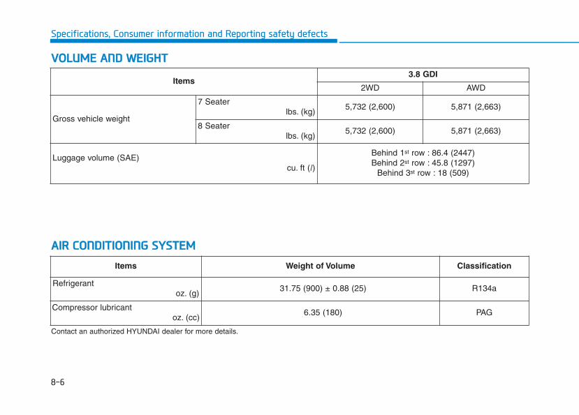
8-6
Specifications, Consumer information and Reporting safety defects
VVOOLLUUMMEE AANNDD WWEEIIGGHHTT
AAIIRR CCOONNDDIITTIIOONNIINNGG SSYYSSTTEEMM
Contact an authorized HYUNDAI dealer for more details.
Items3.8 GDI
2WD AWD
Gross vehicle weight
7 Seaterlbs. (kg)
5,732 (2,600) 5,871 (2,663)
8 Seaterlbs. (kg)
5,732 (2,600) 5,871 (2,663)
Luggage volume (SAE)cu. ft (l)
Behind 1st row : 86.4 (2447)Behind 2st row : 45.8 (1297)
Behind 3st row : 18 (509)
Items Weight of Volume Classification
Refrigerant oz. (g)
31.75 (900) ± 0.88 (25) R134a
Compressor lubricantoz. (cc)
6.35 (180) PAG
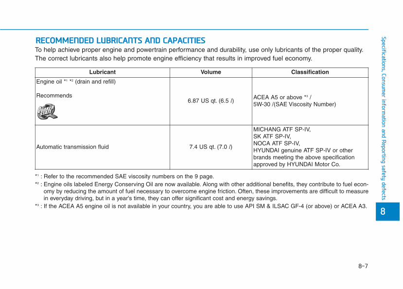
8-7
88
Specifications, Consumer inform
ation and Reporting safety defects
To help achieve proper engine and powertrain performance and durability, use only lubricants of the proper quality.The correct lubricants also help promote engine efficiency that results in improved fuel economy.
RREECCOOMMMMEENNDDEEDD LLUUBBRRIICCAANNTTSS AANNDD CCAAPPAACCIITTIIEESS
Lubricant Volume Classification
Engine oil *1 *2 (drain and refill)
Recommends6.87 US qt. (6.5 l) ACEA A5 or above *3 /
5W-30 /(SAE Viscosity Number)
Automatic transmission fluid 7.4 US qt. (7.0 l)
MICHANG ATF SP-IV,SK ATF SP-IV,NOCA ATF SP-IV,HYUNDAI genuine ATF SP-IV or otherbrands meeting the above specificationapproved by HYUNDAI Motor Co.
*1 : Refer to the recommended SAE viscosity numbers on the 9 page.*2 : Engine oils labeled Energy Conserving Oil are now available. Along with other additional benefits, they contribute to fuel econ-
omy by reducing the amount of fuel necessary to overcome engine friction. Often, these improvements are difficult to measurein everyday driving, but in a year's time, they can offer significant cost and energy savings.
*3 : If the ACEA A5 engine oil is not available in your country, you are able to use API SM & ILSAC GF-4 (or above) or ACEA A3.
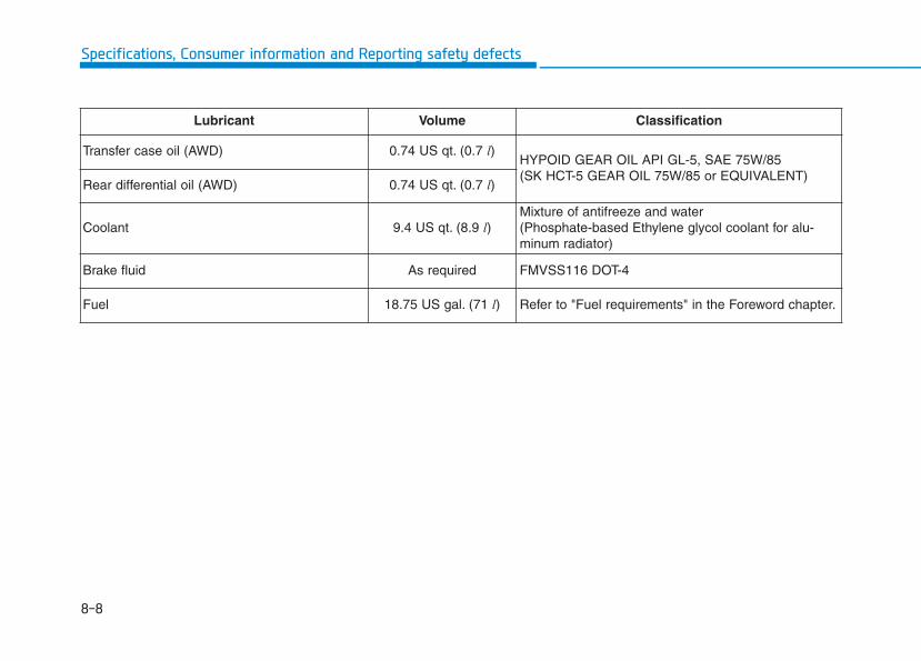
8-8
Specifications, Consumer information and Reporting safety defects
Lubricant Volume Classification
Transfer case oil (AWD) 0.74 US qt. (0.7 l)HYPOID GEAR OIL API GL-5, SAE 75W/85 (SK HCT-5 GEAR OIL 75W/85 or EQUIVALENT)
Rear differential oil (AWD) 0.74 US qt. (0.7 l)
Coolant 9.4 US qt. (8.9 l)Mixture of antifreeze and water(Phosphate-based Ethylene glycol coolant for alu-minum radiator)
Brake fluid As required FMVSS116 DOT-4
Fuel 18.75 US gal. (71 l) Refer to "Fuel requirements" in the Foreword chapter.
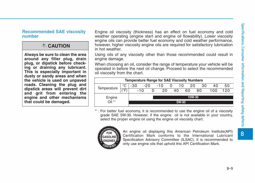
8-9
88
Specifications, Consumer inform
ation and Reporting safety defects
Recommended SAE viscositynumber
Always be sure to clean the areaaround any filler plug, drainplug, or dipstick before check-ing or draining any lubricant.This is especially important industy or sandy areas and whenthe vehicle is used on unpavedroads. Cleaning the plug anddipstick areas will prevent dirtand grit from entering theengine and other mechanismsthat could be damaged.
CAUTION
*1 : For better fuel economy, it is recommended to use the engine oil of a viscositygrade SAE 5W-30. However, if the engine oil is not available in your country,select the proper engine oil using the engine oil viscosity chart.
An engine oil displaying this American Petroleum Institute(API)Certification Mark conforms to the International LubricantSpecification Advisory Committee (ILSAC). It is recommended toonly use engine oils that uphold this API Certification Mark.
Engine oil viscosity (thickness) has an effect on fuel economy and coldweather operating (engine start and engine oil flowability). Lower viscosityengine oils can provide better fuel economy and cold weather performance,however, higher viscosity engine oils are required for satisfactory lubricationin hot weather.Using oils of any viscosity other than those recommended could result inengine damage.When choosing an oil, consider the range of temperature your vehicle will beoperated in before the next oil change. Proceed to select the recommendedoil viscosity from the chart.
Temperature Range for SAE Viscosity Numbers
Temperature -30 -20 -10 0 10 20 30 40 50
-10 0 20 40 60 80 100 120
Engine Oil *1
°C(°F)
10W-30
5W-30
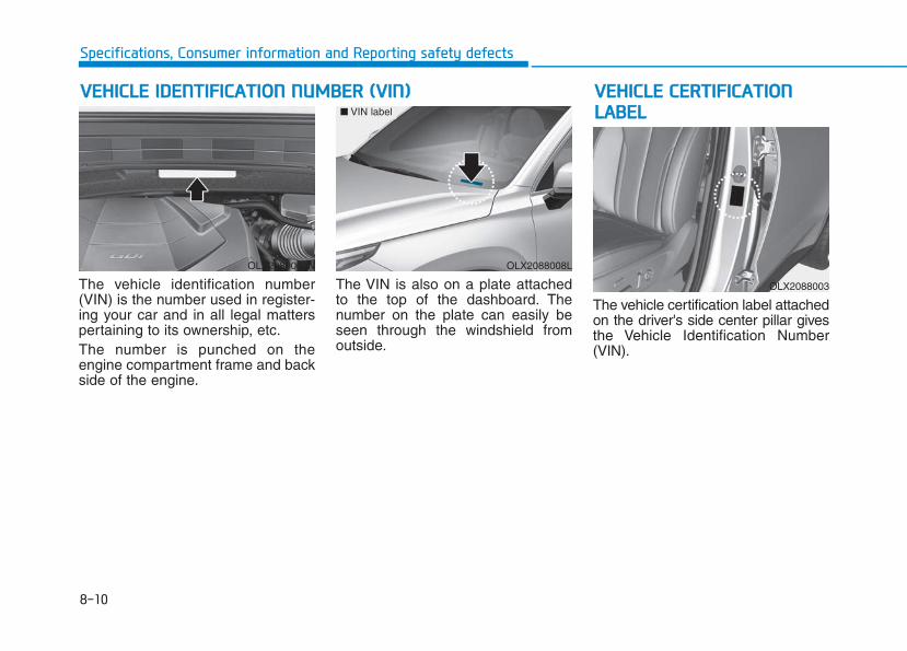
8-10
Specifications, Consumer information and Reporting safety defects
The vehicle identification number(VIN) is the number used in register-ing your car and in all legal matterspertaining to its ownership, etc.The number is punched on theengine compartment frame and backside of the engine.
The VIN is also on a plate attachedto the top of the dashboard. Thenumber on the plate can easily beseen through the windshield fromoutside.
The vehicle certification label attachedon the driver's side center pillar givesthe Vehicle Identification Number(VIN).
VVEEHHIICCLLEE IIDDEENNTTIIFFIICCAATTIIOONN NNUUMMBBEERR ((VVIINN)) VVEEHHIICCLLEE CCEERRTTIIFFIICCAATTIIOONNLLAABBEELL
OLX2089002N OLX2088008L
■ VIN label
OLX2088003
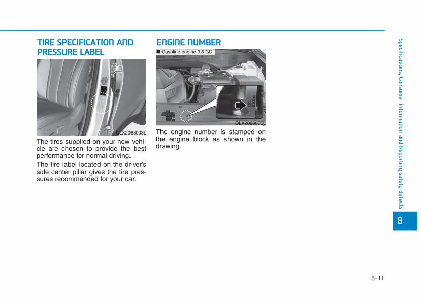
8-11
88
Specifications, Consumer inform
ation and Reporting safety defects
The tires supplied on your new vehi-cle are chosen to provide the bestperformance for normal driving.The tire label located on the driver’sside center pillar gives the tire pres-sures recommended for your car.
The engine number is stamped onthe engine block as shown in thedrawing.
EENNGGIINNEE NNUUMMBBEERRTTIIRREE SSPPEECCIIFFIICCAATTIIOONN AANNDDPPRREESSSSUURREE LLAABBEELL
OLX2088003L
OLX2088006L
■ Gasoline engine 3.8 GDI
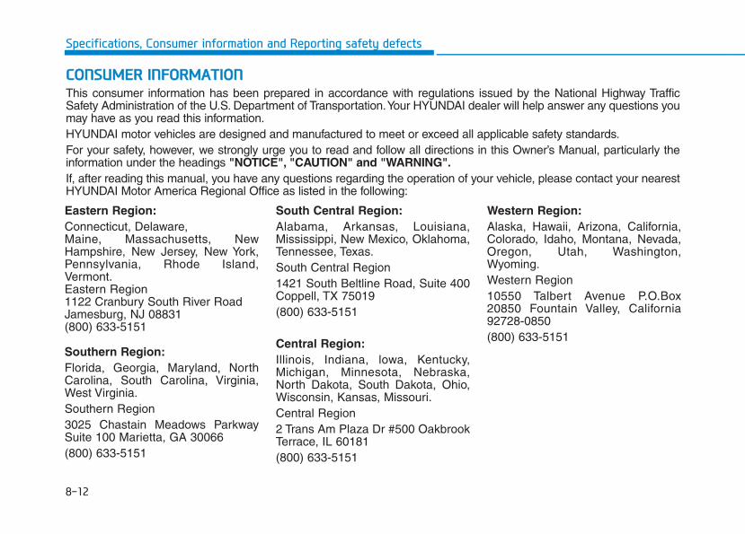
8-12
Specifications, Consumer information and Reporting safety defects
Eastern Region:Connecticut, Delaware,Maine, Massachusetts, NewHampshire, New Jersey, New York,Pennsylvania, Rhode Island,Vermont.Eastern Region1122 Cranbury South River RoadJamesburg, NJ 08831(800) 633-5151
Southern Region:Florida, Georgia, Maryland, NorthCarolina, South Carolina, Virginia,West Virginia.Southern Region 3025 Chastain Meadows ParkwaySuite 100 Marietta, GA 30066(800) 633-5151
South Central Region:Alabama, Arkansas, Louisiana,Mississippi, New Mexico, Oklahoma,Tennessee, Texas.South Central Region1421 South Beltline Road, Suite 400Coppell, TX 75019(800) 633-5151
Central Region:Illinois, Indiana, lowa, Kentucky,Michigan, Minnesota, Nebraska,North Dakota, South Dakota, Ohio,Wisconsin, Kansas, Missouri.Central Region2 Trans Am Plaza Dr #500 OakbrookTerrace, IL 60181(800) 633-5151
Western Region:Alaska, Hawaii, Arizona, California,Colorado, Idaho, Montana, Nevada,Oregon, Utah, Washington,Wyoming.Western Region10550 Talbert Avenue P.O.Box20850 Fountain Valley, California92728-0850(800) 633-5151
CCOONNSSUUMMEERR IINNFFOORRMMAATTIIOONNThis consumer information has been prepared in accordance with regulations issued by the National Highway TrafficSafety Administration of the U.S. Department of Transportation.Your HYUNDAI dealer will help answer any questions youmay have as you read this information.HYUNDAI motor vehicles are designed and manufactured to meet or exceed all applicable safety standards.For your safety, however, we strongly urge you to read and follow all directions in this Owner’s Manual, particularly theinformation under the headings "NOTICE", "CAUTION" and "WARNING".If, after reading this manual, you have any questions regarding the operation of your vehicle, please contact your nearestHYUNDAI Motor America Regional Office as listed in the following:
8-13
88
Specifications, Consumer inform
ation and Reporting safety defects
If you believe that your vehicle has a defect which could cause a crash or could cause injury or death, you shouldimmediately inform the National Highway Traffic Safety Administration (NHTSA) in addition to notifying HYUNDAIMOTOR AMERICA.
To contact NHTSA, you may call the Vehicle Safety Hotline toll-free at 1-888- 327-4236 (TTY: 1-800-424-9153);go to http://www.safercar.gov;download the SaferCar mobile application;or write to: Administrator, NHTSA
1200 New Jersey Ave, SE,West Building Washington, D.C. 20590.
You can also obtain other information about motor vehicle safety from http://www.safercar.gov.
If NHTSA receives similar complaints, it may open an investigation, and if it finds that a safety defect exists in a groupof vehicles, it may order a recall and remedy campaign. However, NHTSA cannot become involved in individual prob-lems between you, your dealer, or HYUNDAI MOTOR AMERICA.
RREEPPOORRTTIINNGG SSAAFFEETTYY DDEEFFEECCTTSS

I
Index
I

I-2
AC inverter ...................................................................3-198
Air bag warning labels....................................................2-79
Air bags...........................................................................2-57
Additional safety precautions.....................................2-79
Air bag collision sensors ............................................2-73
Air bag inflation conditions .......................................2-75
Air bag non-inflation conditions ................................2-76
Air bag warning labels ...............................................2-79
Curtain air bags ..........................................................2-62
Do not install a child restraint on the front passenger seat..........................................................2-72
Driver's air bag ...........................................................2-59
Driver's knee air bag ..................................................2-59
How does the air bags system operate? .....................2-63
Occupant classification system (OCS).......................2-68
Passenger's front air bag.............................................2-59
Side air bags ...............................................................2-60
SRS Care ....................................................................2-78
SRS components and functions..................................2-63
SRS warning light ......................................................2-63
What to expect after an air bag inflates .....................2-67
Why didn't my air bag go off in a collision ...............2-73
Air cleaner filter replacement .........................................7-22
Air conditioning refrigerant label .................................3-185
Air conditioning system specification ..............................8-6
All Wheel Drive (AWD).................................................5-43
Antenna .............................................................................4-2
Anti-lock Brake System (ABS) ......................................5-33
Appearance care..............................................................7-69
Exterior care ...............................................................7-69
Interior care ................................................................7-74
Armrest ...........................................................................2-20
Audio/Video/Navigation system.......................................4-4
Auto defogging system .................................................3-188
Auto headlamp position................................................3-132
Automatic climate control system ................................3-171
Air conditioning .......................................................3-178
Air intake control .....................................................3-176
Automatic heating and air conditioning...................3-172
Fan speed control .....................................................3-177
Manual heating and air conditioning .......................3-173
Mode selection .........................................................3-174
OFF mode.................................................................3-178
Rear climate control button......................................3-178
System maintenance.................................................3-184
Temperature control .................................................3-175
Automatic transmission ..................................................5-15
Good driving practices ...............................................5-20
Paddle shifter..............................................................5-22
Parking........................................................................5-18
Shift lock system ........................................................5-17
Automatic ventilation ...................................................3-191
Index
A
I-3
Battery.............................................................................7-29
Battery recharging ......................................................7-31
Battery saver function...................................................3-138
Before driving ...................................................................5-5
Blind-Spot Collision Warning (BCW) system ...............5-78
Blind-Spot Collision-Avoidance Assist (BCA) system..5-78
Blind-spot view monitor system...................................3-150
Bluetooth® Wireless Technology ......................................4-4
Brake fluid ......................................................................7-21
Brake system...................................................................5-23
Anti-lock Brake System (ABS)..................................5-33
Auto hold....................................................................5-29
Disc brakes wear indicator .........................................5-24
Downhill Brake Control (DBC).................................5-39
Electronic Parking Brake (EPB) ................................5-24
Electronic Stability Control (ESC).............................5-35
Good braking practices ..............................................5-42
Hill-start Assist Control (HAC) .................................5-39
Power brakes ..............................................................5-23
Trailer Stability Assist (TSA).....................................5-42
Vehicle Stability Management (VSM) .......................5-38
Bulb replacement ............................................................7-61
Daytime running light (DRL) ...........................7-61, 7-63
Front parking lamp ...........................................7-61, 7-63
Front turn signal lamp.......................................7-61, 7-63
Headlamp ..........................................................7-61, 7-63
High mounted stop lamp ............................................7-66
Interior light................................................................7-67
License plate light ......................................................7-66
Rear combination light bulb.......................................7-64
Side marker lamp..............................................7-61, 7-63
Side repeater lamp......................................................7-64
Bulb wattage .....................................................................8-3
Capacities (Lubricants) .....................................................8-7
Care
Exterior care ...............................................................7-69
Interior care ................................................................7-74
Tire care......................................................................7-33
Cargo security screen....................................................3-205
Center console storage..................................................3-192
Central door lock/unlock switch.....................................3-17
Certification label ...........................................................8-10
Check tire inflation pressure...........................................7-35
I
Index
B
C
I-4
Child restraint system (CRS)..........................................2-46
Booster seats...............................................................2-48
Forward-facing child restraints ..................................2-48
Installing a child restraint system (CRS) ...................2-49
Lower anchors and tether for children (LATCH system) .....................................................2-50
Securing a child restraint seat with "Tether Anchor" system......................................................................2-52
Securing a child restraint with lap/shoulder belt .......2-53
Securing a child restraint with the LATCH anchors system......................................................................2-51
Selecting a child restraint system (CRS) ...................2-47
Child-protector rear door lock ........................................3-20
Climate control air filter .................................................7-24
Clock .............................................................................3-203
Cluster ionizer...............................................................3-191
Coat hanger ...................................................................3-203
Crankcase emission control system................................7-77
Cup holder.....................................................................3-194
Curtain air bags...............................................................2-62
Day/night rearview mirror ..............................................3-33
Daytime running light (DRL) .......................................3-132
Declaration of conformity .............................................5-92
Defroster .......................................................................3-190
Rear window defroster .............................................3-190
Dimensions .......................................................................8-2
Door locks.......................................................................3-15
Auto door lock/unlock features..................................3-19
Central door lock/unlock switch ................................3-17
Child-protector rear door lock....................................3-20
Electronic child safety lock system............................3-20
Downhill Brake Control (DBC) .....................................5-39
Drive Mode............................................................5-55, 5-59
Drive mode integrated control system
Drive Mode ................................................................5-55
Drive mode integrated control system (AWD)
Drive Mode ................................................................5-59
Driver Attention Warning (DAW) system ....................5-118
Driver position memory system .....................................3-27
Easy access function ..................................................3-29
Recalling positions from memory..............................3-28
Resetting the driver's seat memory system ................3-28
Storing positions into memory ...................................3-27
Driver's air bag................................................................2-59
Driver's knee air bag .......................................................2-59
Driving at night.............................................................5-150
Driving in flooded areas ...............................................5-151
Driving in the rain.........................................................5-150
Index
D
I-5
Electric power steering (EPS).........................................3-30
Electrochromatic mirror (ECM) .....................................3-34
Electronic child safety lock system ................................3-20
Electronic Parking Brake (EPB).....................................5-24
Electronic Stability Control (ESC) .................................5-35
Emergency towing ..........................................................6-24
Emission control system .................................................7-77
Crankcase emission control system ...........................7-77
Evaporative emission control System ........................7-77
Exhaust emission control system ...............................7-78
Engine compartment..................................................1-6, 7-3
Engine compartment panel fuse replacement.................7-50
Engine coolant ................................................................7-18
Engine coolant temperature gauge .................................3-72
Engine number ................................................................8-11
Engine oil ........................................................................7-16
Engine specification..........................................................8-2
Engine Start/Stop button .................................................5-10
Evaporative emission control System.............................7-77
Exhaust emission control system....................................7-78
Explanation of scheduled maintenance items.................7-13
Exterior care....................................................................7-69
Exterior features............................................................3-209
Roof side rails ..........................................................3-209
Exterior overview .............................................................1-2
Front view ....................................................................1-2
Rear view......................................................................1-3
Flat tire ............................................................................6-14
Changing a tire ...........................................................6-16
Floor mat anchor(s).......................................................3-204
Fluid
Brake fluid..................................................................7-21
Washer fluid ...............................................................7-22
Forward Collision-Avoidance Assist (FCA) system ......5-63
Forward/Reverse Parking distance warning system.....3-155
Front air ventilation seat .................................................2-27
Front seat head restraints ................................................2-22
Front seats .........................................................................2-6
Manual adjustment .......................................................2-7
Power adjustment .........................................................2-9
Reclining seatback ..............................................2-8, 2-10
Seatback pocket..........................................................2-12
Front windshield washers .............................................3-146
Front windshield wipers ...............................................3-144
Fuel filler door ................................................................3-66
Fuel gauge.......................................................................3-73
Fuel requirements
Fuel additives ................................................................F8
Unleaded........................................................................F7
I
Index
E
F
I-6
Fuses ...............................................................................7-48
Engine compartment panel fuse replacement ............7-50
Fuse/relay panel description.......................................7-51
Instrument panel fuse replacement.............................7-49
Multi fuse ...................................................................7-50
Gauges and meters ..........................................................3-71
Glove box......................................................................3-192
Grove box lamp ............................................................3-141
Hazard warning flasher.....................................................6-2
Hazardous driving conditions .......................................5-149
Head Restraints ...............................................................2-21
Front seat head restraints............................................2-22
Rear seat head restraints.............................................2-24
Head up display ............................................................3-130
Headlamp delay function..............................................3-138
Headlamp position ........................................................3-133
Heated steering wheel.....................................................3-32
High Beam Assist (HBA) .............................................3-134
High beam operation.....................................................3-134
Highway driving ...........................................................5-151
Highway Driving Assist (HDA) system .......................5-122
Hill-start Assist Control (HAC)......................................5-39
Hood................................................................................3-53
Horn ................................................................................3-31
How to use this manual .....................................................F6
Idle Stop and Go (ISG) System ......................................5-50
If the engine doesn't turn over or turns over slowly.........6-3
If the engine overheats......................................................6-6
If the engine stalls at a crossroad or crossing...................6-2
If the engine stalls while driving ......................................6-2
If the engine turns over normally but doesn't start...........6-3
If the engine will not start.................................................6-3
If you have a flat tire while driving..................................6-3
Immobilizer system.........................................................3-14
Important safety precautions.............................................2-2
Air Bag Hazards ...........................................................2-2
Always Wear Your Seat Belt ........................................2-2
Control Your Speed ......................................................2-3
Driver Distraction.........................................................2-2
Keep Your Vehicle in Safe Condition ..........................2-3
Restrain All Children....................................................2-2
In case of emergency while driving..................................6-2
Index
I
G
H
I-7
Infotainment system..........................................................4-2
Antenna ........................................................................4-2
Audio/Video/Navigation system ..................................4-4
Bluetooth® Wireless Technology..................................4-4
Steering wheel audio controls ......................................4-3
USB port.......................................................................4-2
Inside rearview mirror ....................................................3-33
Instrument cluster ...........................................................3-69
Assist mode ................................................................3-98
Adjusting instrument cluster illumination..................3-69
Gauges and meters .....................................................3-71
LCD display control ...................................................3-96
LCD display messages ...............................................3-90
LCD display modes....................................................3-97
Option menu .............................................................3-119
Transmission shift indicator .......................................3-76
Trip computer mode .................................................3-110
User settings mode ...................................................3-100
Warning and indicator lights ......................................3-76
Instrument panel fuse replacement .................................7-49
Instrument panel overview ...............................................1-5
Interior care.....................................................................7-74
Interior features
AC inverter ...............................................................3-198
Cargo security screen ...............................................3-205
Clock ........................................................................3-203
Coat hanger ..............................................................3-203
Conversation mirror .................................................3-196
Cup holder ................................................................3-194
Floor mat anchor(s) ..................................................3-204
Luggage net (holder) ................................................3-205
Power outlet..............................................................3-197
Side curtain...............................................................3-207
Sunvisor....................................................................3-196
USB charger .............................................................3-200
Wireless cellular phone charging system.................3-201
Interior lamp AUTO cut................................................3-139
Interior lights.................................................................3-139
Front lamps...............................................................3-139
Grove box lamp........................................................3-141
Interior lamp AUTO cut ...........................................3-139
Luggage compartment lamp.....................................3-140
Puddle lamp..............................................................3-141
Rear lamps................................................................3-140
Vanity mirror lamp ...................................................3-141
Interior overview...............................................................1-4
Jump starting.....................................................................6-4
Key ignition switch...........................................................5-7
I
Index
J
K
I-8
Label
Tire sidewall labeling .................................................7-39
Tire specification and pressure label ..........................8-11
Vehicle certification label...........................................8-10
Lane change signals ......................................................3-137
Lane Following Assist (LFA) system ...........................5-104
Lane Keeping Assist (LKA) system .............................5-110
LCD display
Assist mode ................................................................3-98
Driving assist view mode .........................................3-117
LCD display modes....................................................3-97
Master warning mode.................................................3-99
Other information display ........................................3-118
Parking assist view mode .........................................3-117
Trip computer mode ...................................................3-98
Turn By Turn (TBT) mode.......................................3-117
User settings mode ...................................................3-100
Utility view mode.....................................................3-116
View modes ..............................................................3-115
LCD display messages
Battery discharging due to external electrical devices.....................................................................3-91
Check Blind-Spot Collision Warning system ............3-94
Check BRAKE SWITCH fuse ...................................3-91
Check Driver Attention Warning (DAW) system ......3-95
Check Forward Collision-Avoidance Assist system ..3-94
Check headlight..........................................................3-94
Check headlight LED.................................................3-94
Check High Beam Assist (HBA) system ...................3-94
Check Lane Keeping Assist (LKA) system ...............3-95
Check Smart Cruise Control system ..........................3-95
Door, Hood, Trunk open indicator .............................3-91
Engine has overheated................................................3-93
Heated steering wheel turned off ...............................3-93
Key not detected.........................................................3-90
Key not in vehicle ......................................................3-90
Lights mode................................................................3-93
Low fuel .....................................................................3-93
Low key battery..........................................................3-90
Low pressure ..............................................................3-92
Low washer fluid........................................................3-93
Press brake pedal to start engine................................3-90
Press START button again .........................................3-90
Press START button with key ....................................3-91
Shift to P or N to start engine ....................................3-90
Sunroof open indicator ...............................................3-92
Window open indicator ..............................................3-92
Wiper mode ................................................................3-93
Index
L
I-9
LCD display modes ........................................................3-97
Leading Vehicle Departure Alert system ......................5-147
Liftgate............................................................................3-54
Emergency liftgate safety release...............................3-62
How to reset the power liftgate..................................3-61
Power liftgate .............................................................3-56
Power liftgate opening height user setting.................3-61
Smart liftgate ..............................................................3-62
Light bulbs ......................................................................7-61
Lighting.........................................................................3-132
Auto headlamp position ...........................................3-132
Battery saver function ..............................................3-138
Daytime running light (DRL) ..................................3-132
Headlamp delay function .........................................3-138
Headlamp position....................................................3-133
High Beam Assist (HBA).........................................3-134
High beam operation ................................................3-134
Lane change signals .................................................3-137
Parking lamp position ..............................................3-133
Turn signals ..............................................................3-137
Lubricants and capacities..................................................8-7
Luggage compartment lamp .........................................3-140
Luggage net (holder).....................................................3-205
Luggage tray .................................................................3-193
Maintenance
Explanation of scheduled maintenance items ............7-13
Maintenance services ...................................................7-4
Maintenance under severe usage conditions (3.8 GDI) .................................................................7-11
Normal maintenance schedule (3.8 GDI) ....................7-8
Owner maintenance......................................................7-5
Scheduled maintenance services ..................................7-7
Tire maintenance ........................................................7-39
Maintenance services ........................................................7-4
Manual climate control system.....................................3-159
Air conditioning .......................................................3-163
Air intake control .....................................................3-162
Fan speed control .....................................................3-163
Heating and air conditioning....................................3-160
Mode selection .........................................................3-160
Rear climate control .................................................3-164
Rear climate control button......................................3-163
System maintenance.................................................3-169
Temperature control .................................................3-162
Mechanical key........................................................3-6, 3-12
I
Index
M

I-10
Mirrors ............................................................................3-33
Day/night rearview mirror..........................................3-33
Electrochromatic mirror (ECM).................................3-34
Folding/Unfolding the outside rearview mirror .........3-40
Inside rearview mirror................................................3-33
Reverse parking aid function .....................................3-41
Side view mirror.........................................................3-39
Side view mirror adjustment ......................................3-40
Multi fuse........................................................................7-50
Occupant classification system (OCS) ...........................2-68
Odometer.........................................................................3-75
Outside temperature ........................................................3-74
Owner maintenance ..........................................................7-5
Paddle shifter ..................................................................5-22
Parking lamp position ...................................................3-133
Passenger's front air bag .................................................2-59
Power brakes...................................................................5-23
Power outlet ..................................................................3-197
Power window lock switch.............................................3-45
Puddle lamp ..................................................................3-141
Range ..............................................................................3-75
Rear Cross-Traffic Collision Warning (RCCW) system ..........................................................................5-93
Rear Cross-Traffic Collision-Avoidance Assist (RCCA) system ..........................................................................5-93
Rear occupant alert system....................................2-20, 3-23
Rear seat head restraints .................................................2-24
Rear seats ........................................................................2-13
2nd row seat folding (from outside)............................2-18
3rd row seat remote folding/unfolding........................2-18
Armrest (2nd row, 7 passengers vehicle) ....................2-20
Armrest (2nd row, 8 passengers vehicle) ....................2-20
Folding the rear seat ...................................................2-15
Rear occupant alert system ...............................2-20, 3-23
Rear seat adjustment ..................................................2-13
Walk-in seat (2nd row seat).........................................2-14
Rear view monitor ........................................................3-148
Rear window wiper and washer ...................................3-147
Recommended cold tire inflation pressures ...................7-34
Recommended lubricants and capacities ..........................8-7
Reducing the risk of a rollover .....................................5-152
Index
R
P
O
I-11
Remote key .......................................................................3-4
Battery replacement......................................................3-7
Liftgate unlocking ........................................................3-5
Locking.........................................................................3-4
Mechanical key ............................................................3-6
Start-up .........................................................................3-6
Unlocking .....................................................................3-5
Removable towing hook .................................................6-23
Replacement light bulb ...................................................7-61
Reverse Parking Distance Warning system ..................3-152
Turn OFF the Reverse parking distance warning system....................................................................3-153
Rocking the vehicle ......................................................5-149
Rotation (Tire) ................................................................7-35
Safe exit assist (SEA) system .........................................3-21
Safety messages .................................................................F6
Scheduled maintenance services.......................................7-7
Seat Belts ........................................................................2-29
Do not lie down..........................................................2-43
Keep belts clean and dry ............................................2-44
One person per belt ....................................................2-43
Periodic inspection .....................................................2-44
Pre-tensioner seat belt ................................................2-39
Rear center seatbelt (3rd row).....................................2-36
Rear passenger's seat belt warning.............................2-32
Seat Belt Restraint System.........................................2-33
Seat Belt Safety Precautions ......................................2-29
Seat belt use and children...........................................2-42
Seat belt use during pregnancy ..................................2-41
Seat Belt Warning Light .............................................2-30
Stowing the rear seat belt ...........................................2-38
Transporting an injured person ..................................2-43
When to replace seat belts..........................................2-44
Seat Warmers ..................................................................2-25
Seats ..................................................................................2-4
Front air ventilation seat ............................................2-27
Front Seats....................................................................2-6
Head Restraints ..........................................................2-21
Rear Seats ...................................................................2-13
Safety Precautions ........................................................2-5
Seat Warmers..............................................................2-25
Side air bags....................................................................2-60
Side curtain ...................................................................3-207
Side view mirror .............................................................3-39
Smart Cruise Control system........................................5-129
Smart key ..........................................................................3-8
Battery replacement....................................................3-13
Locking.........................................................................3-8
Mechanical key ..........................................................3-12
Opening the liftgate ....................................................3-11
Panic button ................................................................3-11
Remote start................................................................3-10
Start-up .......................................................................3-11
Unlocking .....................................................................3-9
I
Index
S

I-12
Smart liftgate...................................................................3-62
Smooth cornering..........................................................5-150
Snow tires .....................................................................5-153
Spare tire
Use of compact spare tires .........................................6-19
Special driving conditions
Driving at night ........................................................5-150
Driving in flooded areas...........................................5-151
Driving in the rain ....................................................5-150
Hazardous driving conditions ..................................5-149
Highway driving.......................................................5-151
Reducing the risk of a rollover.................................5-152
Rocking the vehicle..................................................5-149
Smooth cornering .....................................................5-150
Speedometer....................................................................3-71
Steering wheel
Electric power steering (EPS) ....................................3-30
Heated steering wheel ................................................3-32
Horn............................................................................3-31
Tilt steering/telescopic steering..................................3-31
Steering wheel audio controls...........................................4-3
Storage compartment ....................................................3-192
Center console storage .............................................3-192
Glove box .................................................................3-192
Luggage tray.............................................................3-193
Sunroof............................................................................3-46
Dual wide sunroof ......................................................3-46
Resetting the sunroof..................................................3-50
Sliding the sunroof .....................................................3-48
Sunroof open warning ................................................3-52
Sunroof opening and closing......................................3-48
Sunshade.....................................................................3-47
Tilting the sunroof ......................................................3-49
Sunroof inside air recirculation ....................................3-191
Sunshade .........................................................................3-47
Resetting the rear sunshade........................................3-51
Sunvisor ........................................................................3-196
Surround view monitoring............................................3-149
Tachometer......................................................................3-72
Theft-alarm system .........................................................3-26
Tire pressure monitoring system (TPMS) ........................6-8
Tire rotation ....................................................................7-35
Tire specification and pressure label ..............................8-11
Tires and wheels ......................................................7-33, 8-5
Check tire inflation pressure ......................................7-35
Recommended cold tire inflation pressures ...............7-34
Tire care......................................................................7-33
Tire maintenance ........................................................7-39
Tire replacement.........................................................7-37
Tire rotation ................................................................7-35
Tire sidewall labeling .................................................7-39
Index
T
I-13
Tire traction ................................................................7-38
Use of compact spare tires .........................................6-19
Wheel alignment and tire balance..............................7-36
Wheel replacement .....................................................7-38
Towing ............................................................................6-22
Trailer Stability Assist (TSA) .........................................5-42
Trailer towing................................................................5-157
Trip computer................................................................3-110
Accumulated Info display ........................................3-112
Average fuel economy..............................................3-111
Digital speedometer..................................................3-113
Driving Info display .................................................3-112
Instant fuel economy ................................................3-111
Smart shift ................................................................3-113
Turn signals...................................................................3-137
USB charger..................................................................3-200
USB port ...........................................................................4-2
Use of compact spare tires..............................................6-19
User settings mode........................................................3-100
Vanity mirror lamp........................................................3-141
Vehicle break-in process ....................................................F9
Vehicle certification label ...............................................8-10
Vehicle identification number (VIN) ..............................8-10
Vehicle load limit ..........................................................5-165
Vehicle modification ..........................................................F9
Vehicle Stability Management (VSM)............................5-38
Vehicle weight and luggage volume.................................8-6
View modes...................................................................3-115
Warning and indicator lights...........................................3-76
Air bag warning light .................................................3-77
All Wheel Drive (AWD) warning light......................3-83
All wheel drive lock indicator light ...........................3-89
Anti-lock Brake System (ABS) warning light ...........3-78
Auto hold ON indicator light .....................................3-88
Auto stop indicator light ............................................3-85
Charging system warning light .................................3-81
Cruise indicator light..................................................3-88
Downhill Brake Control (DBC) indicator light .........3-89
Electric Power Steering (EPS) warning light.............3-79
Electronic brake force warning light..........................3-78
Electronic Parking Brake (EPB) warning light..........3-80
Electronic stability control (ESC) indicator light ......3-85
I
Index
U
V
W
I-14
Electronic stability control (ESC) OFF indicator light .........................................................................3-86
Engine oil pressure warning light .............................3-81
Forward Collision-Avoidance Assist (FCA) system warning light ...........................................................3-84
High Beam Assist (HBA) indicator light ...................3-88
High beam indicator light ..........................................3-87
Icy road warning light ................................................3-85
Immobilizer indicator light ........................................3-86
Lane Keeping Assist (LKA) system indicator light...3-84
LED headlight warning light......................................3-84
Light ON indicator light.............................................3-87
Low fuel level warning light......................................3-82
Low tire pressure warning light .................................3-83
Malfunction Indicator lamp (MIL).............................3-80
Master warning light ..................................................3-82
Parking brake & brake fluid warning light ................3-77
Seat belt warning light ...............................................3-76
SMART mode indicator light.....................................3-89
Turn signal indicator light ..........................................3-87
Washer fluid ....................................................................7-22
Welcome system ...........................................................3-142
Headlamp and parking lamp ....................................3-142
Interior lamp.............................................................3-143
Puddle lamp and door handle lamp..........................3-142
Wheel alignment and tire balance ..................................7-36
Wheel replacement .........................................................7-38
Windows .........................................................................3-42
Auto up/down window...............................................3-44
Automatic reversal .....................................................3-44
Power window lock switch ........................................3-45
Power windows ..........................................................3-43
Resetting the windows ...............................................3-44
Windshield defrosting and defogging...........................3-186
Winter driving ...............................................................5-153
Snow tires .................................................................5-153
Tire chains ................................................................5-153
Winter Precautions........................................................5-155
Wiper blades replacement...............................................7-26
Wipers and washers ......................................................3-144
Front windshield washers.........................................3-146
Front windshield wipers ...........................................3-144
Rear window wiper and washer ...............................3-147
Wireless cellular phone charging system......................3-201
Index


