Embed Size (px)
Citation preview
SECOND EDITION 22_DT_OM_EN_USC
©2021 FCA US LLC. All Rights Reserved. Tous droits réservés. Ram is a registered trademark of FCA US LLC. Ram est une marque déposée de FCA US LLC. App Store is a registered trademark of Apple Inc. Google Play Store is a registered trademark of Google.
2022 RAM 1500OWNER’S MANUAL
20
22
RA
M 1
50
0
Whether it is providing information about specific product features, taking a tour through your vehicle’s heritage, knowing what steps to take following an accident or scheduling your next appointment, we know you will find the app an important extension of your Ram vehicle. Simply download the app, select your make and model and enjoy the ride. To get this app, go directly to the App Store® or Google Play® Store and enter the search keyword “ram toolbox” (U.S. residents only).
DOWNLOAD THE MOST UP-TO-DATE OWNER’S MANUAL, RADIO AND WARRANTY BOOKS
OWNERS.MOPAR.CA
CANADA
MOPAR.COM/OM
U.S.
The driver’s primary responsibility is the safe operation of the vehicle. Driving while distracted can result in loss of vehicle control, resulting in an accident and personal injury. FCA US LLC strongly recommends that the driver use extreme caution when using any device or feature that may take their attention off the road. Use of any electrical devices, such as cellular telephones, computers, portable radios, vehicle navigation or other devices, by the driver while the vehicle is moving is dangerous and could lead to a serious accident. Texting while driving is also dangerous and should never be done while the vehicle is moving. If you find yourself unable to devote your full attention to vehicle operation, pull off the road to a safe location and stop your vehicle. Some states or provinces prohibit the use of cellular telephones or texting while driving. It is always the driver’s responsibility to comply with all local laws.
This Owner’s Manual has been prepared to help you get acquainted with your new Ram brand vehicle and to provide a convenient reference for common questions.
Not all features shown in this manual may apply to your vehicle. For additional information on accessories to help personalize your vehicle, visit mopar.com/om (U.S.), owners.mopar.ca (Canada) or your local Ram brand dealer.
DRIVING AND ALCOHOLDrunk driving is one of the most frequent causes of accidents. Your driving ability can be seriously impaired with blood alcohol levels far below the legal minimum. If you are drinking, don’t drive. Ride with a designated non-drinking driver, call a cab, a friend or use public transportation.
WARNINGDriving after drinking can lead to an accident. Your perceptions are less sharp, your reflexes are slower and your judgment is impaired when you have been drinking. Never drink and then drive.
WARNING: Operating, servicing and maintaining a passenger vehicle or off-highway motor vehicle can expose you to chemicals including engine exhaust, carbon monoxide, phthalates, and lead, which are known to the State of California to cause cancer and birth defects or other reproductive harm. To minimize exposure, avoid breathing exhaust, do not idle the engine except as necessary, service your vehicle in a well-ventilated area and wear gloves or wash your hands frequently when servicing your vehicle. For more information go to www.P65Warnings.ca.gov/passenger-vehicle.
This Owner’s Manual illustrates and describes the operation of features and equipment that are either standard or optional on this vehicle. This manual may also include a description of features and equipment that are no longer available or were not ordered on this vehicle. Please disregard any features and equipment described in this manual that are not on this vehicle. FCA US LLC reserves the right to make changes in design and specifications, and/or make additions to or improvements to its products without imposing any obligation upon itself to install them on products previously manufactured.
With respect to any vehicles sold in Canada, the name FCA US LLC shall be deemed to be deleted and the name FCA Canada Inc. used in substitution therefore.
This Owner’s Manual is intended to familiarize you with the important features of your vehicle. Your most up-to-date Owner’s Manual, Navigation/Uconnect manuals and Warranty Booklet can be found by visiting the website on the back cover.
U.S. Residents: If you are the first registered retail owner of your vehicle, you may obtain a complimentary printed copy of the Warranty Booklet by calling 1-866-726-4636 or by contacting your dealer. Replacement kits can be purchased by visiting www.techauthority.com.
Canadian Residents: If you are the first registered retail owner of your vehicle, you may obtain a complimentary printed copy of the Warranty Booklet or purchase a replacement kit by calling 1-800-387-1143 or by contacting your dealer.
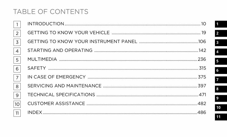
TABLE OF CONTENTS
1
2
3
4
5
6
7
8
9
10
11
1 INTRODUCTION............................................................................................................................ 10
2 GETTING TO KNOW YOUR VEHICLE ................................................................................. 19
3 GETTING TO KNOW YOUR INSTRUMENT PANEL ......................................................106
4 STARTING AND OPERATING ............................................................................................... 142
5 MULTIMEDIA ..............................................................................................................................236
6 SAFETY ......................................................................................................................................... 315
7 IN CASE OF EMERGENCY .................................................................................................... 375
8 SERVICING AND MAINTENANCE ...................................................................................... 397
9 TECHNICAL SPECIFICATIONS .............................................................................................471
10 CUSTOMER ASSISTANCE .....................................................................................................482
11 INDEX.............................................................................................................................................486
22_DT_OM_EN_USC_t.book Page 1
2
INTRODUCTION
SYMBOLS KEY........................................................ 11VAN CONVERSIONS/CAMPERS .......................... 11CONSUMER INFORMATION — TRUCK-CAMPER LOADING................................................................. 11VEHICLE MODIFICATIONS/ALTERATIONS ......... 13SYMBOL GLOSSARY.............................................. 13
GETTING TO KNOW YOUR VEHICLEKEYS ....................................................................... 19
Key Fob .............................................................19SENTRY KEY ........................................................... 23IGNITION SWITCH ................................................. 23
Keyless Enter ‘n Go™ Ignition .........................23REMOTE START — IF EQUIPPED (GASOLINE) .... 24
How To Use Remote Start................................25To Exit Remote Start Mode..............................26Remote Start Front Defrost Activation — If Equipped........................................................26Remote Start Comfort Systems — If Equipped........................................................26Remote Start Windshield Wiper De–Icer Activation — If Equipped ..................................27Remote Start Abort Message ..........................27
REMOTE START — IF EQUIPPED (DIESEL) .........27How To Use Remote Start................................27
VEHICLE SECURITY SYSTEM — IF EQUIPPED .....28To Arm The System ..........................................28To Disarm The System .....................................28Rearming Of The System .................................29Security System Manual Override...................29
DOORS ....................................................................29Manual Door Locks ..........................................29Power Door Locks — If Equipped ....................30Power Side Steps — If Equipped .....................30Keyless Enter ‘n Go™ — Passive Entry ...........30Automatic Unlock Doors On Exit —If Equipped........................................................32Automatic Door Locks — If Equipped ..............33Child-Protection Door Lock System — Rear Doors........................................................33
STEERING WHEEL ..................................................34Tilt/Telescoping Steering Column...................34Heated Steering Wheel — If Equipped ............34
DRIVER MEMORY SETTINGS — IF EQUIPPED.....35Programming The Memory Feature ................35Linking And Unlinking The Key Fob To Memory .............................................................35Memory Position Recall ...................................36
SEATS ..................................................................... 36Manual Adjustment(Front Seats) — If Equipped.............................36Manual Adjustment (Rear Seats)....................38Power Adjustment (Front Seats) —If Equipped .......................................................39Heated Seats — If Equipped ...........................40Ventilated Seats — If Equipped .......................41Plastic Grocery Bag Retainers ........................42Head Restraints ...............................................42
UCONNECT VOICE RECOGNITION — IF EQUIPPED .......................................................... 44
Introducing Voice Recognition ........................44Basic Voice Commands ...................................44Get Started .......................................................44Additional Information .....................................45
DRIVER ADJUSTABLE PEDALS — IF EQUIPPED........................................................... 45MIRRORS................................................................ 46
Inside Rearview Mirror.....................................46Illuminated Vanity Mirror .................................47Outside Mirrors ................................................48Outside Automatic Dimming Mirrors — If Equipped .......................................................48Power Mirrors ...................................................48Power Folding Outside Mirrors ForStandard And Trailer Tow — If Equipped ........49Trailer Towing Mirrors — If Equipped .............50Heated Mirrors — If Equipped .........................50Tilt Side Mirrors In Reverse — If Equipped .....50
22_DT_OM_EN_USC_t.book Page 2
3
UNIVERSAL GARAGE DOOR OPENER (HOMELINK®) — IF EQUIPPED ............................ 50
Before You Begin Programming HomeLink®.......................................................51Erasing All The HomeLink® Channels ............51Identifying Whether You Have A RollingCode Or Non-Rolling Code Device ...................51Programming HomeLink® To A GarageDoor Opener .....................................................51Programming HomeLink® To A Miscellaneous Device ......................................52Reprogramming A Single HomeLink® Button ...............................................................53Canadian/Gate Operator Programming .........53Security .............................................................54Troubleshooting Tips........................................54
EXTERIOR LIGHTS ................................................. 54Headlight Switch...............................................54Multifunction Lever .........................................55Daytime Running Lights (DRLs).......................55High/Low Beam Switch....................................56Automatic High Beam Headlamp Control —If Equipped .......................................................56Flash-To-Pass....................................................56Automatic Headlights — If Equipped ..............56Parking Lights And Panel Lights......................56Automatic Headlights With Wipers..................57
Headlight Delay ................................................57Lights-On Reminder .........................................57Fog Lights — If Equipped .................................57Turn Signals......................................................58Lane Change Assist — If Equipped..................58Cargo Lights/Trailer Spotter Lights/Trailer Hitch Light With Bed Lights —If Equipped........................................................58Battery Saver ....................................................59
INTERIOR LIGHTS...................................................59Courtesy Lights.................................................59Illuminated Entry .............................................61
WINDSHIELD WIPERS AND WASHERS...............61Windshield Wiper Operation............................61Rain Sensing Wipers — If Equipped ................62
CLIMATE CONTROLS .............................................63Automatic Climate Control DescriptionsAnd Functions ..................................................63Manual Climate Control Descriptions And Functions ..................................................66Automatic Temperature Control (ATC) —If Equipped........................................................68Climate Voice Recognition — If Equipped .......69Operating Tips .................................................69
INTERIOR STORAGE AND EQUIPMENT ...............70Storage..............................................................70USB/AUX Control .............................................75Electrical Power Outlets ..................................77Power Inverter — If Equipped .........................78Wireless Charging Pad — If Equipped .............79
WINDOWS ............................................................. 80Power Windows ................................................80Automatic Window Features ...........................80Reset Auto-Up ..................................................81Window Lockout Switch...................................81Power Sliding Rear Window — If Equipped ....81Manual Sliding Rear Window —If Equipped ...82Wind Buffeting .................................................82
POWER SUNROOF — IF EQUIPPED ..................... 82Single Pane Power Sunroof — If Equipped .....82Dual Pane Power Sunroof — If Equipped........84
HOOD .................................................................... 86To Open The Hood............................................86To Close The Hood ...........................................86
TAILGATE ................................................................ 86Opening.............................................................86Closing ..............................................................87Locking Tailgate ...............................................87Multifunction Tailgate — If Equipped ..............87Tailgate Removal .............................................88Bed Step — If Equipped ...................................90
PICKUP BOX ........................................................... 92Bed Rail Tie-Down System — If Equipped.......93
RAMBOX — IF EQUIPPED...................................... 94Locking And Unlocking RamBox......................95RamBox Cargo Storage Bins ...........................95RamBox Safety Warning ..................................97Bed Divider — If Equipped ...............................97
22_DT_OM_EN_USC_t.book Page 3
4
TRI-FOLD TONNEAU COVER — IF EQUIPPED ..... 99Tonneau Cover Components ...........................99Tri-Fold Tonneau Cover Folding For Driving Or Removal........................................ 100Tri-Fold Tonneau Cover Installation ............. 103Tri-Fold Tonneau Cover Cleaning ................. 105
GETTING TO KNOW YOUR INSTRUMENT PANELBASE / MIDLINE INSTRUMENT CLUSTER — GASOLINE .............................................................106
Base / Midline Instrument ClusterDescriptions — Gasoline ............................... 107
PREMIUM INSTRUMENT CLUSTER — GASOLINE .............................................................108
Premium Instrument Cluster Descriptions — Gasoline ............................... 109
BASE / MIDLINE INSTRUMENT CLUSTER — DIESEL...................................................................110
Base / Midline Instrument ClusterDescriptions — Diesel.................................... 111
PREMIUM INSTRUMENT CLUSTER — DIESEL...................................................................113
Premium Instrument Cluster Descriptions — Diesel ................................... 114
INSTRUMENT CLUSTER DISPLAY...................... 115Instrument Cluster Display Location and Controls.......................................................... 115Oil Life Reset ................................................. 116Display Menu Items ...................................... 117Head Up Display (HUD) — If Equipped ........ 124Diesel Particulate Filter (DPF) Messages .... 125Displays.......................................................... 126Diesel Exhaust Fluid (DEF) WarningMessages....................................................... 127Diesel Exhaust Fluid (DEF) Fault Warning Messages....................................................... 127Battery Saver On/Battery Saver ModeMessage — Electrical Load ReductionActions — If Equipped.................................... 128
WARNING LIGHTS AND MESSAGES................. 129Red Warning Lights....................................... 130Yellow Warning Lights ................................... 133Yellow Indicator Lights .................................. 136Green Indicator Lights .................................. 138White Indicator Lights ................................... 139Blue Indicator Lights ..................................... 140
ONBOARD DIAGNOSTIC SYSTEM — OBD II...... 140Onboard Diagnostic System (OBD II) Cybersecurity ................................... 140
EMISSIONS INSPECTION ANDMAINTENANCE PROGRAMS ............................ 141
STARTING AND OPERATINGSTARTING THE ENGINE ......................................142
Automatic Transmission ............................... 143Tip Start Feature .......................................... 143Keyless Enter ‘n Go™ — Ignition .................. 143Normal Starting Using ENGINESTART/STOP Button — Gasoline Engine...... 143AutoPark ........................................................ 144If Engine Fails To Start ................................. 145Normal Starting Using ENGINE START/STOP Button — Diesel Engine .......... 146Cold Weather Operation(Below –22°F Or −30°C) ............................ 147After Starting ................................................. 147Starting Fluids — Diesel Engine Only ........... 147
NORMAL OPERATION — DIESEL ENGINE .........147Cold Weather Precautions............................ 148Engine Idling .................................................. 149Stopping The Engine..................................... 149
ENGINE BLOCK HEATER — IF EQUIPPED..........150ENGINE BREAK-IN RECOMMENDATIONS — GASOLINE ENGINE .............................................151ENGINE BREAK-IN RECOMMENDATIONS — DIESEL ENGINE....................................................151PARKING BRAKE ...............................................151
Electric Park Brake (EPB) ........................... 151
22_DT_OM_EN_USC_t.book Page 4
5
AUTOMATIC TRANSMISSION ............................154Ignition Park Interlock................................... 155Brake/Transmission Shift Interlock (BTSI) System .......................................................... 1558-Speed Automatic Transmission ............... 156
FOUR-WHEEL DRIVE OPERATION —IF EQUIPPED ........................................................161
Four-Position Electronically ShiftedTransfer Case — If Equipped ........................ 161Five-Position Electronically Shifted Transfer Case — If Equipped ....................................... 163
ACTIVE-LEVEL FOUR CORNER AIR SUSPENSION SYSTEM — IF EQUIPPED.............165
Description..................................................... 165Air Suspension Modes .................................. 167Instrument Cluster Display Messages ......... 168Operation ....................................................... 168
ACTIVE-LEVEL FOUR CORNER AIR SUSPENSION SYSTEM (OFF-ROAD GROUP) — IF EQUIPPED.........................................................169
Description..................................................... 169Air Suspension Modes .................................. 171Instrument Cluster Display Messages ......... 172Operation ....................................................... 172
AXLE LOCK SYSTEM — IF EQUIPPED ................173
LIMITED-SLIP DIFFERENTIAL —IF EQUIPPED ....................................................... 174POWER STEERING ............................................. 174
Electric Power Steering ................................ 174FUEL SAVER TECHNOLOGY 5.7L ENGINES ONLY — IF EQUIPPED......................... 174STOP/START SYSTEM — IF EQUIPPED............. 175
Autostop Mode .............................................. 175Possible Reasons The Engine Does Not Autostop......................................................... 175To Start The Engine While In AutostopMode .............................................................. 176To Manually Turn Off The Stop/StartSystem ........................................................... 176To Manually Turn On The Stop/StartSystem ........................................................... 177System Malfunction ...................................... 177
CRUISE CONTROL SYSTEMS — IF EQUIPPED ....................................................... 177
Cruise Control................................................ 177Adaptive Cruise Control (ACC) ...................... 179
PARKSENSE FRONT/REAR PARK ASSIST SYSTEM — IF EQUIPPED .................................... 188
ParkSense Sensors....................................... 189ParkSense Warning Display ......................... 189ParkSense Display ........................................ 189
Enabling And Disabling Front And/Or Rear ParkSense ............................................ 192Service The ParkSense Park Assist System ........................................................... 192Cleaning The ParkSense System ................. 193ParkSense System Usage Precautions........ 193
PARKSENSE ACTIVE PARK ASSISTSYSTEM — IF EQUIPPED .....................................194
Enabling And Disabling The ParkSense Active Park Assist System............................. 194Parallel/Perpendicular Parking Space Assistance Operation.................................... 195
LANESENSE — IF EQUIPPED ..............................198LaneSense Operation ................................... 198Turning LaneSense On Or Off....................... 198LaneSense Warning Message...................... 198Changing LaneSense Status ........................ 200
PARKVIEW REAR BACK UP CAMERA ..............201SURROUND VIEW CAMERA SYSTEM — IF EQUIPPED ........................................................202
Forward Facing Camera With Tire Lines — If Equipped .................................................... 205
TRAILER CAMERAS — IF EQUIPPED .................206Trailer Surround View Camera System —If Equipped .................................................... 206AUX Camera — If Equipped........................... 208
22_DT_OM_EN_USC_t.book Page 5
6
REFUELING THE VEHICLE — GASOLINEENGINE .................................................................209REFUELING THE VEHICLE — DIESELENGINE .................................................................210
Avoid Using Contaminated Fuel ................... 211Bulk Fuel Storage — Diesel Fuel................... 211Diesel Exhaust Fluid...................................... 211Diesel Exhaust Fluid Storage........................ 211Adding Diesel Exhaust Fluid ......................... 212
VEHICLE LOADING ............................................213Gross Vehicle Weight Rating (GVWR) .......... 213Payload .......................................................... 214Gross Axle Weight Rating (GAWR)................ 214Tire Size.......................................................... 214Rim Size ......................................................... 214Inflation Pressure .......................................... 214Curb Weight ................................................... 214Loading .......................................................... 214
TRAILER TOWING ..............................................214Common Towing Definitions......................... 215Trailer Hitch Type and Maximum TrailerWeight ............................................................ 218
Trailer Towing Weights(Maximum Trailer Weight Ratings) .............. 218Trailer And Tongue Weight ........................... 219Trailer Reverse Steering Control .................. 219Towing Requirements .................................. 221Towing Tips ................................................... 227
SNOWPLOW......................................................... 228Before Plowing............................................... 228Snowplow Prep Package Model Availability...................................................... 228Over The Road Operation With Snowplow Attached......................................................... 229Operating Tips ............................................... 229General Maintenance ................................... 229
RECREATIONAL TOWING(BEHIND MOTORHOME) .................................... 230
Towing This Vehicle Behind Another Vehicle ........................................................... 230Recreational Towing — Two-Wheel DriveModels ........................................................... 231Recreational Towing — Four-Wheel DriveModels ........................................................... 231
DRIVING TIPS....................................................... 233Driving On Slippery Surfaces ....................... 233Driving Through Water .................................. 233Off-Road Driving Tips ................................... 235
MULTIMEDIAUCONNECT SYSTEMS..........................................236CYBERSECURITY..................................................236UCONNECT SETTINGS ........................................237
Customer Programmable Features ............ 237UCONNECT INTRODUCTION................................262
System Overview .......................................... 262Safety And General Information .................. 263
UCONNECT MODES .............................................264Steering Wheel Audio Controls .................... 264Radio Mode .................................................. 265Media Mode ................................................. 273Phone Mode ................................................. 275
CONNECTED VEHICLE SERVICES —IF EQUIPPED ........................................................285
Is My Vehicle Connected? ............................ 285Introduction To Connected Vehicle Services ........................................................ 285Getting Started With Connected Vehicle Services ........................................................ 287Using SiriusXM Guardian™ .......................... 288Manage My SiriusXM Guardian™Account .......................................................... 300
22_DT_OM_EN_USC_t.book Page 6
7
CONNECTED SERVICES FAQS ...........................300Connected Services SOS FAQs — If Equipped .................................................... 300Connected Services Remote DoorLock/Unlock FAQs ........................................ 301Connected Services RoadsideAssistance FAQs ........................................... 301Connected Services Send & Go FAQs — If Equipped .................................................... 301Connected Services Vehicle Finder FAQs ... 302Connected Services Stolen VehicleAssistance FAQs — If Equipped ................... 302Connected Services Remote VehicleStart FAQs ..................................................... 302Connected Services Remote Horn & Lights FAQs .................................................... 303Connected Services Account FAQs —If Equipped..................................................... 303Data Collection & Privacy.............................. 305
RADIO OPERATION AND MOBILE PHONES......305Regulatory And Safety Information .............. 306
PERFORMANCE PAGES — IF EQUIPPED...........306Timers ............................................................ 307Gauges ........................................................... 307G-Force........................................................... 308Dynamometer (Dyno)/Engine....................... 308Vehicle Dynamics .......................................... 309
OFF-ROAD PAGES — IF EQUIPPED ................... 309Off-Road Pages Status Bar .......................... 310Vehicle Dynamics ......................................... 311Accessory Gauge........................................... 312Pitch & Roll .................................................... 313Suspension.................................................... 314Forward Facing Camera................................ 314
SAFETYSAFETY FEATURES.............................................. 315
Anti-Lock Brake System (ABS) ..................... 315Electronic Brake Control (EBC) System ....... 316
AUXILIARY DRIVING SYSTEMS.......................... 322Blind Spot Monitoring (BSM) — If Equipped .................................................... 322Forward Collision Warning (FCW) WithMitigation — If Equipped ............................... 329Tire Pressure Monitoring System(TPMS)............................................................ 332
OCCUPANT RESTRAINT SYSTEMS ................... 338Occupant Restraint Systems Features ....... 338Important Safety Precautions ...................... 338Seat Belt Systems ........................................ 339Supplemental Restraint Systems (SRS) ...... 345Child Restraints............................................. 358
SAFETY TIPS ........................................................372Transporting Passengers.............................. 372Transporting Pets ....................................... 372Safety Checks You Should Make InsideThe Vehicle ................................................... 372Periodic Safety Checks You Should Make Outside The Vehicle............................ 373Exhaust Gas................................................... 374Carbon Monoxide Warnings ........................ 374
IN CASE OF EMERGENCYHAZARD WARNING FLASHERS ........................375ASSIST AND SOS SYSTEM — IF EQUIPPED ......376JACKING AND TIRE CHANGING ........................379
Preparations For Jacking .............................. 379Jack Location................................................. 380Removal Of Jack And Tools .......................... 380Removing The Spare Tire ............................. 381Jacking Instructions ...................................... 383To Stow The Flat Or Spare ........................... 386Reinstalling The Jack And Tools................... 387
JUMP STARTING .................................................388Preparations For Jump Start ........................ 388Jump Starting Procedure .............................. 389
REFUELING IN EMERGENCY – IF EQUIPPED ........................................................390
22_DT_OM_EN_USC_t.book Page 7
8
IF YOUR ENGINE OVERHEATS ...........................391MANUAL PARK RELEASE ...................................392FREEING A STUCK VEHICLE ..............................393TOWING A DISABLED VEHICLE .........................394
Two-Wheel Drive Models............................... 395Four-Wheel Drive Models.............................. 395Emergency Tow Hooks — If Equipped .......... 396
ENHANCED ACCIDENT RESPONSE SYSTEM (EARS) ..................................................................396EVENT DATA RECORDER (EDR).........................396
SERVICING AND MAINTENANCESCHEDULED SERVICING — GASOLINEENGINE .................................................................397
Maintenance Plan ......................................... 398SCHEDULED SERVICING — DIESEL ENGINE ....402
Maintenance Plan — Diesel Fuel Up To B5 Biodiesel ....................................................... 403Additional Maintenance — B6 To B20Biodiesel ........................................................ 406
ENGINE COMPARTMENT .................................. 4073.6L Engine With Stop/Start ....................... 4075.7L Engine Without Stop/Start................... 4085.7L Engine With Stop/Start ........................ 4093.0L Diesel Engine ........................................ 410Checking Oil Level ......................................... 411Adding Washer Fluid .................................... 411Maintenance-Free Battery ........................... 411Pressure Washing ......................................... 412
VEHICLE MAINTENANCE..................................... 412Engine Oil — Gas Engine .............................. 412Engine Oil Filter ............................................ 413Engine Air Cleaner Filter .............................. 413Draining Fuel/Water Separator Filter —Diesel Engine ................................................ 416Underbody Mounted Fuel FilterReplacement — Diesel Engine...................... 417Priming If The Engine Has Run OutOf Fuel — Diesel Engine ................................ 417Intervention Regeneration Strategy — Message Process Flow (Diesel Engine) ....... 418Diesel Exhaust Fluid...................................... 418Air Conditioner Maintenance ....................... 418Accessory Drive Belt Inspection ................... 421
Body Lubrication .......................................... 422Windshield Wiper Blades ............................. 422Exhaust System ............................................ 423Cooling System ............................................. 424Charge Air Cooler — Inter-Cooler(Diesel Engine) .............................................. 428Brake System ............................................... 428Automatic Transmission .............................. 429Rear Axle And 4x4 Front Driving Axle Fluid Level .................................................... 430Transfer Case ............................................... 430Fuses.............................................................. 430Bulb Replacement ....................................... 442
TIRES.....................................................................448Tire Safety Information ................................ 448Tires — General Information ........................ 455Tire Types....................................................... 459Spare Tires — If Equipped ............................ 459Wheel And Wheel Trim Care ........................ 461Snow Traction Devices ................................. 463Tire Rotation Recommendations ................ 465
DEPARTMENT OF TRANSPORTATIONUNIFORM TIRE QUALITY GRADES ....................465
Treadwear...................................................... 465Traction Grades............................................. 466Temperature Grades..................................... 466
22_DT_OM_EN_USC_t.book Page 8
9
STORING THE VEHICLE ....................................466BODYWORK..........................................................466
Protection From Atmospheric Agents ......... 466Body And Underbody Maintenance.............. 467Preserving The Bodywork ............................. 467
INTERIORS ...........................................................469Seats And Fabric Parts.................................. 469Plastic And Coated Parts .............................. 470Leather Surfaces........................................... 470Glass Surfaces .............................................. 470
TECHNICAL SPECIFICATIONSVEHICLE IDENTIFICATION NUMBER (VIN).........471BRAKE SYSTEM ..................................................471WHEEL AND TIRE TORQUE SPECIFICATIONS .................................................471
Torque Specifications .................................. 471
FUEL REQUIREMENTS — GASOLINE ENGINE ................................................................ 472
3.6L Engine .................................................. 4725.7L Engine ................................................... 472Reformulated Gasoline ................................ 472Materials Added To Fuel .............................. 473Gasoline/Oxygenate Blends ........................ 473Do Not Use E-85 In Non-Flex Fuel Vehicles.......................................................... 473CNG And LP Fuel System Modifications ...... 473Methylcyclopentadienyl ManganeseTricarbonyl (MMT) In Gasoline...................... 474Fuel System Cautions ................................... 474
FUEL REQUIREMENTS – DIESEL ENGINE ........ 474Diesel Fuel Specifications ............................ 475Biodiesel Fuel Requirements ....................... 475
FLUID CAPACITIES ............................................. 477ENGINE FLUIDS AND LUBRICANTS .................. 478CHASSIS FLUIDS AND LUBRICANTS ............... 481
CUSTOMER ASSISTANCESUGGESTIONS FOR OBTAINING SERVICE FOR YOUR VEHICLE ............................................482
Prepare For The Appointment ...................... 482Prepare A List ................................................ 482Be Reasonable With Requests..................... 482
IF YOU NEED ASSISTANCE ................................482FCA US LLC Customer Center....................... 482FCA Canada Inc. Customer Center .............. 482Mexico............................................................ 483Puerto Rico And US Virgin Islands ............... 483Customer Assistance For The HearingOr Speech Impaired(TDD/TTY) ...................................................... 483Service Contract ........................................... 483
WARRANTY INFORMATION................................483MOPAR® PARTS .................................................484REPORTING SAFETY DEFECTS ..........................484
In The 50 United States And Washington, D.C............................................ 484In Canada ...................................................... 484
PUBLICATION ORDER FORMS ..........................485GENERAL INFORMATION....................................485
22_DT_OM_EN_USC_t.book Page 9
10
INTRODUCTIONDear Customer,
Congratulations on the purchase of your new Ram vehicle. Be assured that it represents precision workmanship, distinctive styling, and high quality.This is a specialized utility vehicle. It can go places and perform tasks that are not intended for conventional passenger vehicles. It handles and maneuvers differently from many passenger vehicles both on-road and off-road, so take time to become familiar with your vehicle. If equipped, the two-wheel drive version of this vehicle was designed for on-road use only. It is not intended for off-road driving or use in other severe conditions suited for a four-wheel drive vehicle. Before you start to drive this vehicle, read the Owner’s Manual. Be sure you are familiar with all vehicle controls, particularly those used for braking, steering, transmission, and transfer case shifting. Learn how your vehicle handles on different road surfaces. Your driving skills will improve with experience. When driving off-road, or working the vehicle, don’t overload the vehicle or expect the vehicle to overcome the natural laws of physics. Always observe federal, state, provincial and local laws wherever you drive. As with other vehicles of this type, failure to operate this vehicle correctly may result in loss of control or a collision Ú page 233.This Owner's Manual has been prepared with the assistance of service and engineering specialists to acquaint you with the operation and maintenance of your vehicle. It is supplemented by customer-oriented documents. Within this information, you will find a description of the services that FCA US LLC offers to its customers as well as the details of the terms and conditions for maintaining its validity. Please take the time to read all of these publications carefully before driving your vehicle for the first time. Following the instructions, recommendations, tips, and important warnings in this manual will help ensure safe and enjoyable operation of your vehicle.This Owner's Manual describes all versions of this vehicle. Options and equipment dedicated to specific markets or versions are not expressly indicated in the text. Therefore, you should only consider the information that is related to the trim level, engine, and version that you have purchased. Any content introduced throughout the Owner's Information, which may or may not be applicable to your vehicle, will be identified with the wording “If Equipped”. All data contained in this publication are intended to help you use your vehicle in the best possible way. FCA US LLC aims at a constant improvement of the vehicles produced. For this reason, it reserves the right to make changes to the model described for technical and/or commercial reasons. For further information, contact an authorized dealer.When it comes to service, remember that authorized dealers know your Ram vehicle best, have factory-trained technicians, genuine Mopar® parts, and care about your satisfaction.
22_DT_OM_EN_USC_t.book Page 10
11
SYMBOLS KEY
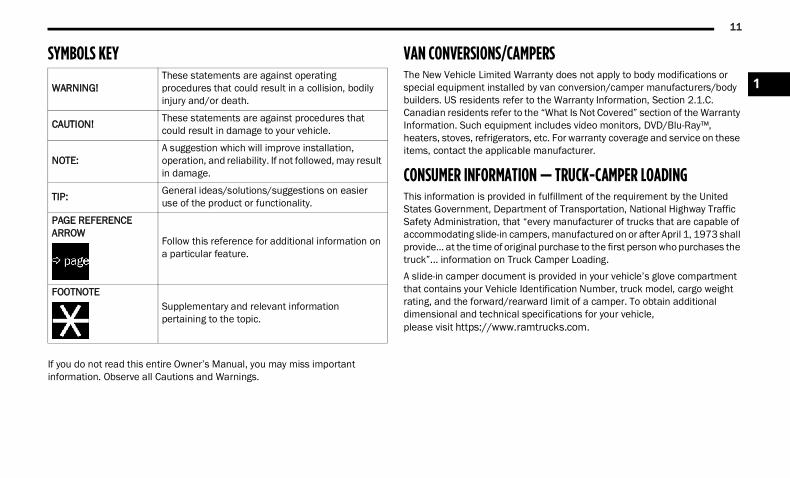
If you do not read this entire Owner’s Manual, you may miss important information. Observe all Cautions and Warnings.
VAN CONVERSIONS/CAMPERS The New Vehicle Limited Warranty does not apply to body modifications or special equipment installed by van conversion/camper manufacturers/body builders. US residents refer to the Warranty Information, Section 2.1.C. Canadian residents refer to the “What Is Not Covered” section of the Warranty Information. Such equipment includes video monitors, DVD/Blu-Ray™, heaters, stoves, refrigerators, etc. For warranty coverage and service on these items, contact the applicable manufacturer.
CONSUMER INFORMATION — TRUCK-CAMPER LOADINGThis information is provided in fulfillment of the requirement by the United States Government, Department of Transportation, National Highway Traffic Safety Administration, that “every manufacturer of trucks that are capable of accommodating slide-in campers, manufactured on or after April 1, 1973 shall provide... at the time of original purchase to the first person who purchases the truck”... information on Truck Camper Loading.A slide-in camper document is provided in your vehicle’s glove compartment that contains your Vehicle Identification Number, truck model, cargo weight rating, and the forward/rearward limit of a camper. To obtain additional dimensional and technical specifications for your vehicle,please visit https://www.ramtrucks.com.
WARNING!These statements are against operating procedures that could result in a collision, bodily injury and/or death.
CAUTION! These statements are against procedures that could result in damage to your vehicle.
NOTE:A suggestion which will improve installation, operation, and reliability. If not followed, may result in damage.
TIP: General ideas/solutions/suggestions on easier use of the product or functionality.
PAGE REFERENCE ARROW
Follow this reference for additional information on a particular feature.
FOOTNOTESupplementary and relevant information pertaining to the topic.
1
22_DT_OM_EN_USC_t.book Page 11
12
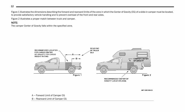
Figure 1 illustrates the dimensions describing the forward and rearward limits of the zone in which the Center of Gravity (CG) of a slide-in camper must be located, to provide satisfactory vehicle handling and to prevent overload of the front and rear axles.Figure 2 illustrates a proper match between truck and camper.NOTE:The camper Center of Gravity falls within the specified zone.
A — Forward Limit of Camper CGB — Rearward Limit of Camper CG
22_DT_OM_EN_USC_t.book Page 12
13
When the truck is used to carry a slide-in camper, the total cargo load of the truck consists of the manufacturer’s camper weight figure, the weight of installed additional camper equipment not included in the manufacturer’s camper weight figure, the weight of camper cargo, and the weight of passengers in the camper. The total cargo load should not exceed the truck’s cargo weight rating and the camper’s CG should fall within the truck’s recommended CG zone when installed.Secure loose items to prevent weight shifts that could affect the balance of your vehicle. When the truck camper is loaded, drive to a scale and weigh the front and rear wheels separately, to determine axle loads. Individual axle loads should not exceed either of the Gross Axle Weight Ratings (GAWR). The total of the axle loads should not exceed the Gross Vehicle Weight Rating (GVWR). If weight ratings are exceeded, move or remove items to get the total weight below the ratings.
NOTE:These ratings are also provided on the vehicle certification label located on the driver’s side B-pillar. See Ú page 213 for more information.For any additional instructions, please contact your conversion/camper manufacturer or an authorized dealer.
VEHICLE MODIFICATIONS/ALTERATIONS
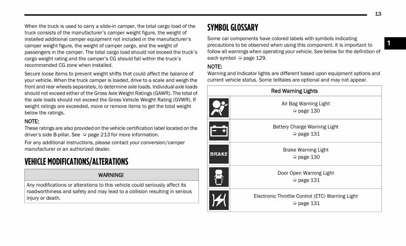
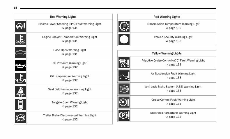
SYMBOL GLOSSARYSome car components have colored labels with symbols indicating precautions to be observed when using this component. It is important to follow all warnings when operating your vehicle. See below for the definition of each symbol Ú page 129.NOTE:Warning and Indicator lights are different based upon equipment options and current vehicle status. Some telltales are optional and may not appear.
WARNING!
Any modifications or alterations to this vehicle could seriously affect its roadworthiness and safety and may lead to a collision resulting in serious injury or death.
Red Warning Lights
Air Bag Warning Light Ú page 130
Battery Charge Warning Light Ú page 131
Brake Warning Light Ú page 130
Door Open Warning Light Ú page 131
Electronic Throttle Control (ETC) Warning Light Ú page 131
1
22_DT_OM_EN_USC_t.book Page 13
14
Electric Power Steering (EPS) Fault Warning Light Ú page 131
Engine Coolant Temperature Warning Light Ú page 131
Hood Open Warning Light Ú page 131
Oil Pressure Warning Light Ú page 132
Oil Temperature Warning Light Ú page 132
Seat Belt Reminder Warning Light Ú page 132
Tailgate Open Warning Light Ú page 132
Trailer Brake Disconnected Warning Light Ú page 132
Red Warning Lights
Transmission Temperature Warning Light Ú page 132
Vehicle Security Warning Light Ú page 133
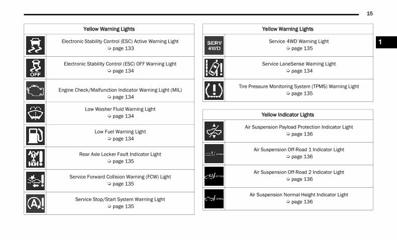
Yellow Warning Lights
Adaptive Cruise Control (ACC) Fault Warning Light Ú page 133
Air Suspension Fault Warning Light Ú page 133
Anti-Lock Brake System (ABS) Warning Light Ú page 133
Cruise Control Fault Warning Light Ú page 135
Electronic Park Brake Warning Light Ú page 133
Red Warning Lights
22_DT_OM_EN_USC_t.book Page 14
15
Electronic Stability Control (ESC) Active Warning Light Ú page 133
Electronic Stability Control (ESC) OFF Warning Light Ú page 134
Engine Check/Malfunction Indicator Warning Light (MIL)
Ú page 134
Low Washer Fluid Warning Light Ú page 134
Low Fuel Warning Light Ú page 134
Rear Axle Locker Fault Indicator Light Ú page 135
Service Forward Collision Warning (FCW) Light Ú page 135
Service Stop/Start System Warning Light Ú page 135
Yellow Warning Lights
Service 4WD Warning Light Ú page 135
Service LaneSense Warning Light Ú page 134
Tire Pressure Monitoring System (TPMS) Warning Light Ú page 135
Yellow Indicator Lights
Air Suspension Payload Protection Indicator Light Ú page 136
Air Suspension Off-Road 1 Indicator Light Ú page 136
Air Suspension Off-Road 2 Indicator Light Ú page 136
Air Suspension Normal Height Indicator Light Ú page 136
Yellow Warning Lights
1
22_DT_OM_EN_USC_t.book Page 15
16
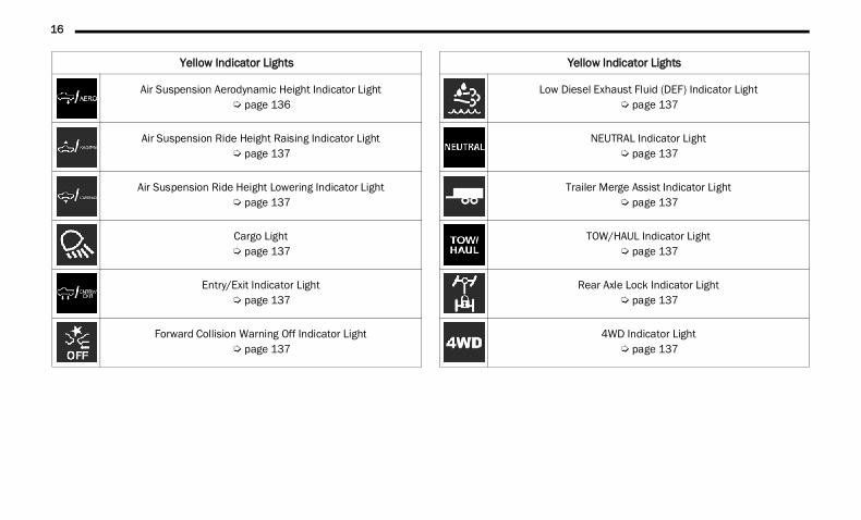
Air Suspension Aerodynamic Height Indicator Light Ú page 136
Air Suspension Ride Height Raising Indicator Light Ú page 137
Air Suspension Ride Height Lowering Indicator Light Ú page 137
Cargo Light Ú page 137
Entry/Exit Indicator Light Ú page 137
Forward Collision Warning Off Indicator Light Ú page 137
Yellow Indicator Lights
Low Diesel Exhaust Fluid (DEF) Indicator Light Ú page 137
NEUTRAL Indicator Light Ú page 137
Trailer Merge Assist Indicator Light Ú page 137
TOW/HAUL Indicator Light Ú page 137
Rear Axle Lock Indicator Light Ú page 137
4WD Indicator Light Ú page 137
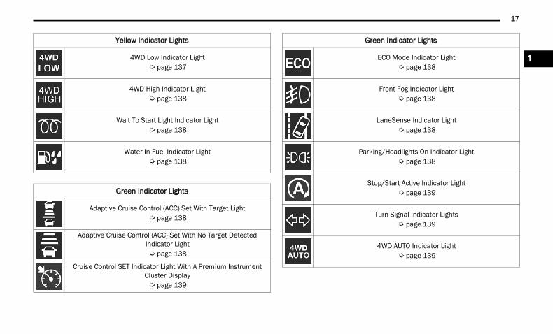
Yellow Indicator Lights
22_DT_OM_EN_USC_t.book Page 16
17
4WD Low Indicator Light Ú page 137
4WD High Indicator Light Ú page 138
Wait To Start Light Indicator Light Ú page 138
Water In Fuel Indicator Light Ú page 138
Green Indicator Lights
Adaptive Cruise Control (ACC) Set With Target Light Ú page 138
Adaptive Cruise Control (ACC) Set With No Target Detected Indicator Light Ú page 138
Cruise Control SET Indicator Light With A Premium Instrument Cluster Display Ú page 139
Yellow Indicator Lights
ECO Mode Indicator Light Ú page 138
Front Fog Indicator Light Ú page 138
LaneSense Indicator Light Ú page 138
Parking/Headlights On Indicator Light Ú page 138
Stop/Start Active Indicator Light Ú page 139
Turn Signal Indicator Lights Ú page 139
4WD AUTO Indicator Light Ú page 139
Green Indicator Lights
1
22_DT_OM_EN_USC_t.book Page 17
18
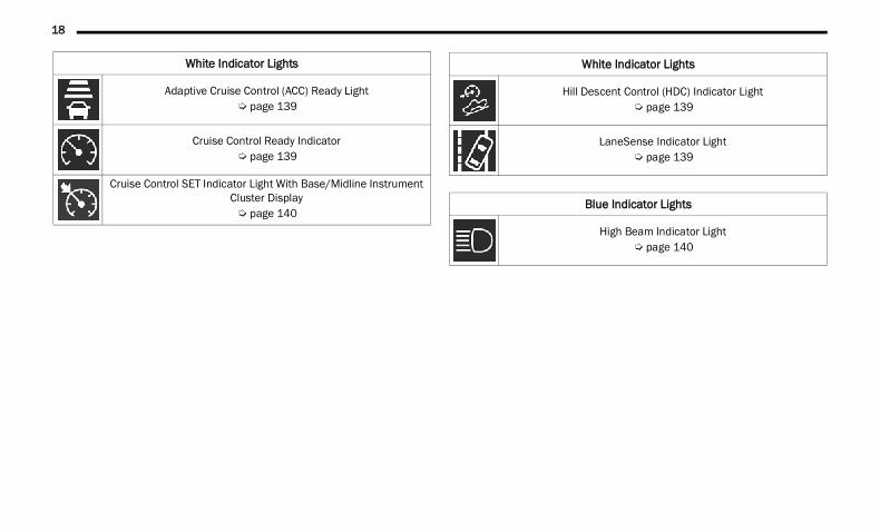
White Indicator Lights
Adaptive Cruise Control (ACC) Ready Light Ú page 139
Cruise Control Ready Indicator Ú page 139
Cruise Control SET Indicator Light With Base/Midline Instrument Cluster Display Ú page 140
Hill Descent Control (HDC) Indicator Light Ú page 139
LaneSense Indicator Light Ú page 139
Blue Indicator Lights
High Beam Indicator Light Ú page 140
White Indicator Lights
22_DT_OM_EN_USC_t.book Page 18
19
GETTING TO KNOW YOUR VEHICLE
KEYS KEY FOB
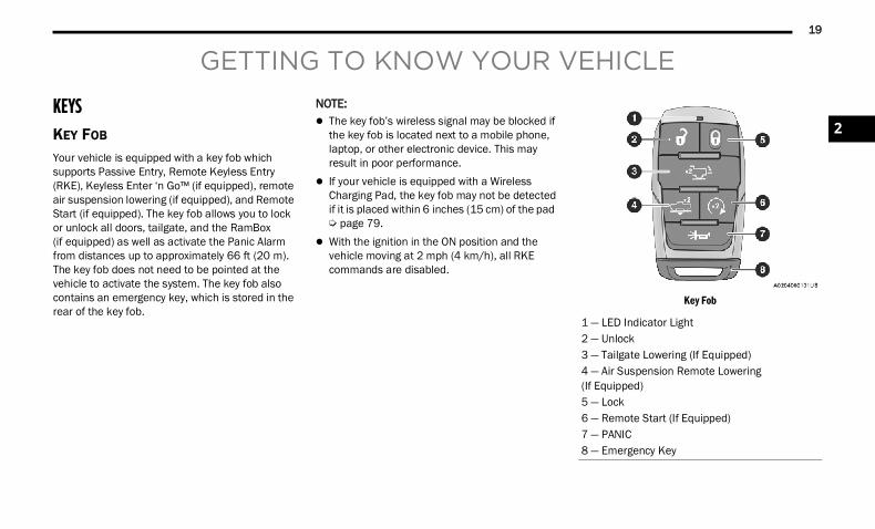
Your vehicle is equipped with a key fob which supports Passive Entry, Remote Keyless Entry (RKE), Keyless Enter ‘n Go™ (if equipped), remote air suspension lowering (if equipped), and Remote Start (if equipped). The key fob allows you to lock or unlock all doors, tailgate, and the RamBox (if equipped) as well as activate the Panic Alarm from distances up to approximately 66 ft (20 m). The key fob does not need to be pointed at the vehicle to activate the system. The key fob also contains an emergency key, which is stored in the rear of the key fob.
NOTE: The key fob’s wireless signal may be blocked if
the key fob is located next to a mobile phone, laptop, or other electronic device. This may result in poor performance.
If your vehicle is equipped with a Wireless Charging Pad, the key fob may not be detected if it is placed within 6 inches (15 cm) of the pad Ú page 79.
With the ignition in the ON position and the vehicle moving at 2 mph (4 km/h), all RKE commands are disabled.
Key Fob
1 — LED Indicator Light2 — Unlock3 — Tailgate Lowering (If Equipped)4 — Air Suspension Remote Lowering(If Equipped)5 — Lock6 — Remote Start (If Equipped)7 — PANIC8 — Emergency Key
2
22_DT_OM_EN_USC_t.book Page 19
20 GETTING TO KNOW YOUR VEHICLE
In case the ignition switch does not change with the push of a button, the key fob may have a low or fully depleted battery. A low key fob battery can be verified by referring to the instrument cluster display, which will display directions to follow.NOTE:A low key fob battery condition may be indicated by a message in the instrument cluster display, or by the LED light on the key fob. If the LED key fob light no longer illuminates from key fob button pushes, then the key fob battery requires replacement Ú page 485.To Lock/Unlock The Doors And TailgatePush and release the unlock button on the key fob once to unlock the driver’s door, or, twice within five seconds to unlock all doors, the tailgate and the RamBox (if equipped). To lock all the doors and the tailgate, push the lock button once.When the doors are unlocked, the turn signals will flash and the illuminated entry system will be activated. When the doors are locked, the turn signals will flash and the horn will chirp.All doors can be programmed to unlock on the first push of the unlock button. The horn chirp when the lock button is pushed can be programmed on/off within Uconnect Settings Ú page 237.
Key Left Vehicle FeatureIf a valid key fob is no longer detected inside the vehicle while the vehicle’s ignition system is in the ON/RUN or START position, the message “Key Left Vehicle” will be shown in the instrument cluster display along with an interior chime. An exterior audible and visual alert will also be activated to warn the driver.The vehicle’s horn will rapidly chirp three times along with a single flash of the vehicle’s exterior lights.
NOTE: The doors have to be open and then closed in
order for the vehicle to check for the presence of a key fob; the Key Left Vehicle feature will not activate until all of the doors are closed.
These alerts will not be activated in situations where the vehicle’s engine is left running with the key fob inside.
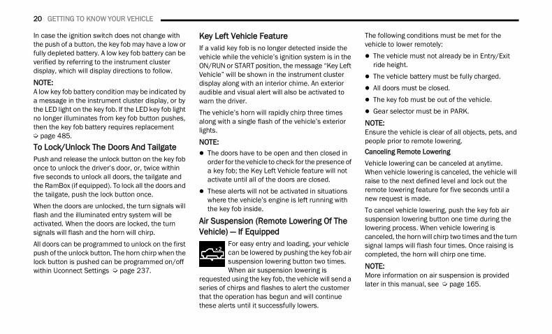
Air Suspension (Remote Lowering Of The Vehicle) — If Equipped
For easy entry and loading, your vehicle can be lowered by pushing the key fob air suspension lowering button two times. When air suspension lowering is
requested using the key fob, the vehicle will send a series of chirps and flashes to alert the customer that the operation has begun and will continue these alerts until it successfully lowers.
The following conditions must be met for the vehicle to lower remotely: The vehicle must not already be in Entry/Exit
ride height. The vehicle battery must be fully charged. All doors must be closed. The key fob must be out of the vehicle. Gear selector must be in PARK.NOTE:Ensure the vehicle is clear of all objects, pets, and people prior to remote lowering.Canceling Remote LoweringVehicle lowering can be canceled at anytime. When vehicle lowering is canceled, the vehicle will raise to the next defined level and lock out the remote lowering feature for five seconds until a new request is made.To cancel vehicle lowering, push the key fob air suspension lowering button one time during the lowering process. When vehicle lowering is canceled, the horn will chirp two times and the turn signal lamps will flash four times. Once raising is completed, the horn will chirp one time.
NOTE:More information on air suspension is provided later in this manual, see Ú page 165.
22_DT_OM_EN_USC_t.book Page 20
GETTING TO KNOW YOUR VEHICLE 21
Replacing The Battery In The Key Fob The replacement battery model is one CR2450 battery.NOTE: Customers are recommended to use a battery
obtained from Mopar®. Aftermarket coin battery dimensions may not meet the original OEM coin battery dimensions.
Perchlorate Material — special handling may apply. See www.dtsc.ca.gov/hazard-ouswaste/perchlorate for further information.
Do not touch the battery terminals that are on the back housing or the printed circuit board.
Do not replace the coin battery if the LED on the key fob above the top row buttons blinks when a button is pressed. The coin battery should last a minimum of three years with normal vehicle usage.
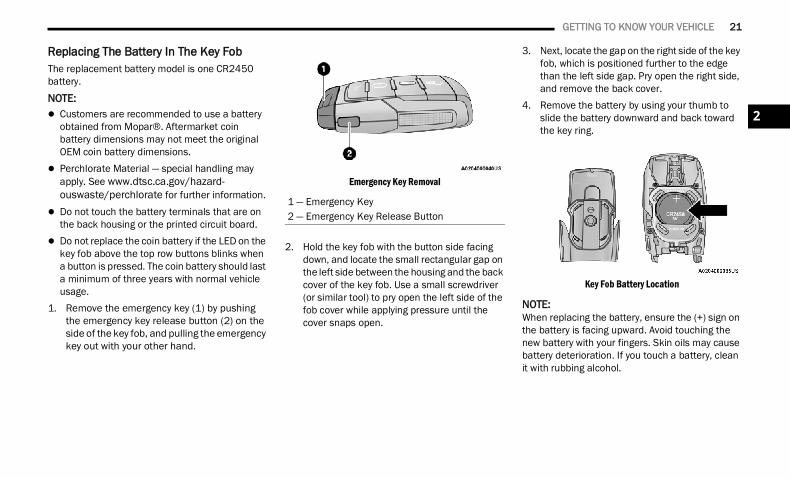
1. Remove the emergency key (1) by pushing the emergency key release button (2) on the side of the key fob, and pulling the emergency key out with your other hand.
Emergency Key Removal
2. Hold the key fob with the button side facing down, and locate the small rectangular gap on the left side between the housing and the back cover of the key fob. Use a small screwdriver (or similar tool) to pry open the left side of the fob cover while applying pressure until the cover snaps open.
3. Next, locate the gap on the right side of the key fob, which is positioned further to the edge than the left side gap. Pry open the right side, and remove the back cover.
4. Remove the battery by using your thumb to slide the battery downward and back toward the key ring.
Key Fob Battery Location
NOTE:When replacing the battery, ensure the (+) sign on the battery is facing upward. Avoid touching the new battery with your fingers. Skin oils may cause battery deterioration. If you touch a battery, clean it with rubbing alcohol.
1 — Emergency Key2 — Emergency Key Release Button
2
22_DT_OM_EN_USC_t.book Page 21
22 GETTING TO KNOW YOUR VEHICLE
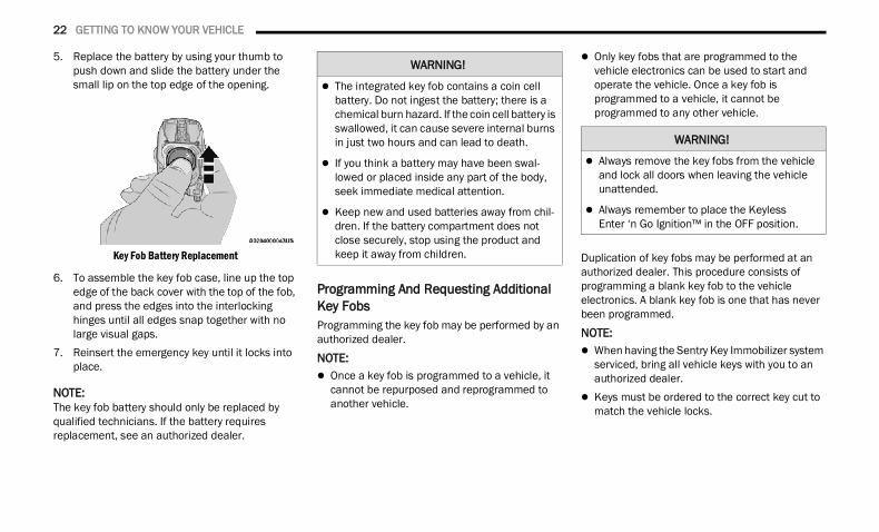
5. Replace the battery by using your thumb to push down and slide the battery under the small lip on the top edge of the opening.
Key Fob Battery Replacement
6. To assemble the key fob case, line up the top edge of the back cover with the top of the fob, and press the edges into the interlocking hinges until all edges snap together with no large visual gaps.
7. Reinsert the emergency key until it locks into place.
NOTE:The key fob battery should only be replaced by qualified technicians. If the battery requires replacement, see an authorized dealer.
Programming And Requesting Additional Key Fobs Programming the key fob may be performed by an authorized dealer.NOTE: Once a key fob is programmed to a vehicle, it
cannot be repurposed and reprogrammed to another vehicle.
Only key fobs that are programmed to the vehicle electronics can be used to start and operate the vehicle. Once a key fob is programmed to a vehicle, it cannot be programmed to any other vehicle.
Duplication of key fobs may be performed at an authorized dealer. This procedure consists of programming a blank key fob to the vehicle electronics. A blank key fob is one that has never been programmed.
NOTE: When having the Sentry Key Immobilizer system
serviced, bring all vehicle keys with you to an authorized dealer.
Keys must be ordered to the correct key cut to match the vehicle locks.
WARNING!
The integrated key fob contains a coin cell battery. Do not ingest the battery; there is a chemical burn hazard. If the coin cell battery is swallowed, it can cause severe internal burns in just two hours and can lead to death.
If you think a battery may have been swal-lowed or placed inside any part of the body, seek immediate medical attention.
Keep new and used batteries away from chil-dren. If the battery compartment does not close securely, stop using the product and keep it away from children.
WARNING!
Always remove the key fobs from the vehicle and lock all doors when leaving the vehicle unattended.
Always remember to place the Keyless Enter ‘n Go Ignition™ in the OFF position.
22_DT_OM_EN_USC_t.book Page 22
GETTING TO KNOW YOUR VEHICLE 23
SENTRY KEYThe Sentry Key Immobilizer system prevents unauthorized vehicle operation by disabling the engine. The system does not need to be armed or activated. Operation is automatic, regardless of whether the vehicle is locked or unlocked.The system uses a key fob, keyless push button ignition and a Radio Frequency (RF) receiver to prevent unauthorized vehicle operation. Therefore, only key fobs that are programmed to the vehicle can be used to start and operate the vehicle. The system cannot reprogram a key fob obtained from another vehicle.After placing the ignition in the ON/RUN position, the Vehicle Security Light will turn on for three seconds for a bulb check. If the light remains on after the bulb check, it indicates that there is a problem with the electronics. In addition, if the light begins to flash after the bulb check, it indicates that someone attempted to start the engine with an invalid key fob. In the event that a valid key fob is used to start the engine but there is an issue with the vehicle electronics, the engine will start and shut off after two seconds.
If the Vehicle Security Light turns on during normal vehicle operation (vehicle running for longer than 10 seconds), it indicates that there is a fault in the electronics. Should this occur, have the vehicle serviced as soon as possible by an authorized dealer.
All of the key fobs provided with your new vehicle have been programmed to the vehicle electronics Ú page 485.
IGNITION SWITCH KEYLESS ENTER ‘N GO™ IGNITION
This feature allows the driver to operate the ignition switch with the push of a button as long as the key fob is in the passenger compartment.The START/STOP ignition button has several operating modes that are labeled and will illuminate when in position. These modes are OFF, ACC, ON/RUN, and START.
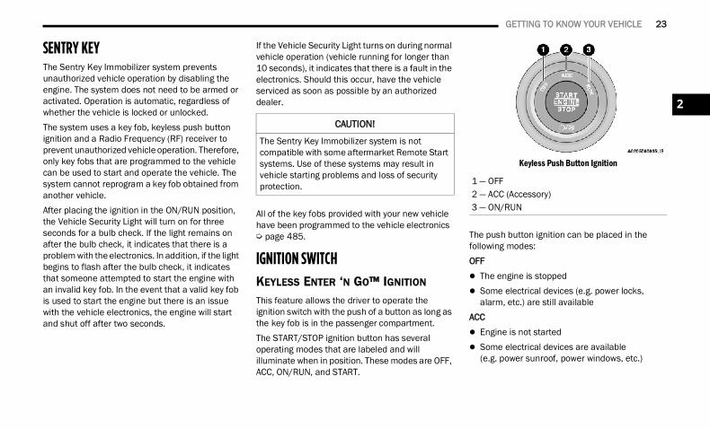
Keyless Push Button Ignition
The push button ignition can be placed in the following modes:OFF The engine is stopped Some electrical devices (e.g. power locks,
alarm, etc.) are still availableACC Engine is not started Some electrical devices are available
(e.g. power sunroof, power windows, etc.)
CAUTION!
The Sentry Key Immobilizer system is not compatible with some aftermarket Remote Start systems. Use of these systems may result in vehicle starting problems and loss of security protection. 1 — OFF
2 — ACC (Accessory)3 — ON/RUN
2
22_DT_OM_EN_USC_t.book Page 23
24 GETTING TO KNOW YOUR VEHICLE
ON/RUN Driving position All electrical devices are available (e.g. climate
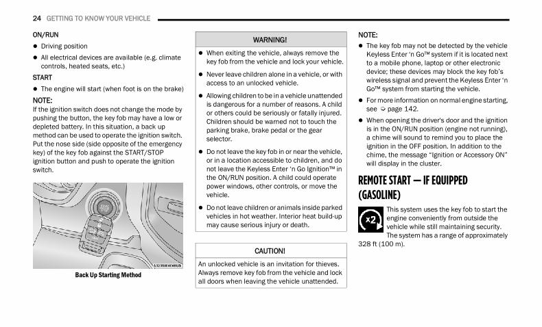
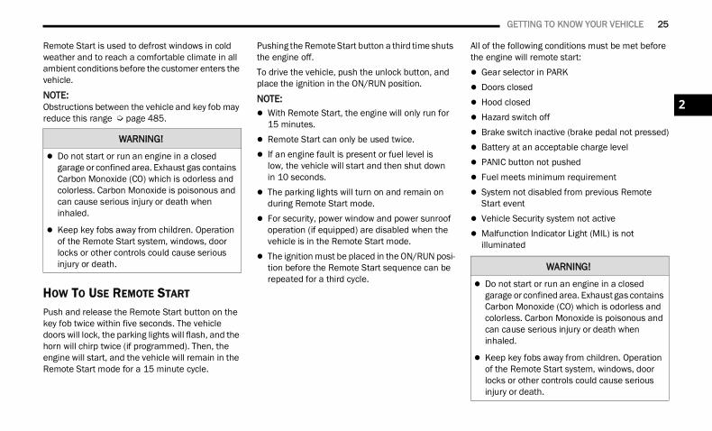
controls, heated seats, etc.)START The engine will start (when foot is on the brake)NOTE:If the ignition switch does not change the mode by pushing the button, the key fob may have a low or depleted battery. In this situation, a back up method can be used to operate the ignition switch. Put the nose side (side opposite of the emergency key) of the key fob against the START/STOP ignition button and push to operate the ignition switch.
Back Up Starting Method
NOTE: The key fob may not be detected by the vehicle
Keyless Enter ‘n Go™ system if it is located next to a mobile phone, laptop or other electronic device; these devices may block the key fob’s wireless signal and prevent the Keyless Enter ‘n Go™ system from starting the vehicle.
For more information on normal engine starting, see Ú page 142.
When opening the driver's door and the ignition is in the ON/RUN position (engine not running), a chime will sound to remind you to place the ignition in the OFF position. In addition to the chime, the message “Ignition or Accessory ON” will display in the cluster.
REMOTE START — IF EQUIPPED (GASOLINE)
This system uses the key fob to start the engine conveniently from outside the vehicle while still maintaining security. The system has a range of approximately
328 ft (100 m).
WARNING!
When exiting the vehicle, always remove the key fob from the vehicle and lock your vehicle.
Never leave children alone in a vehicle, or with access to an unlocked vehicle.
Allowing children to be in a vehicle unattended is dangerous for a number of reasons. A child or others could be seriously or fatally injured. Children should be warned not to touch the parking brake, brake pedal or the gear selector.
Do not leave the key fob in or near the vehicle, or in a location accessible to children, and do not leave the Keyless Enter ‘n Go Ignition™ in the ON/RUN position. A child could operate power windows, other controls, or move the vehicle.
Do not leave children or animals inside parked vehicles in hot weather. Interior heat build-up may cause serious injury or death.
CAUTION!
An unlocked vehicle is an invitation for thieves. Always remove key fob from the vehicle and lock all doors when leaving the vehicle unattended.
22_DT_OM_EN_USC_t.book Page 24
GETTING TO KNOW YOUR VEHICLE 25
Remote Start is used to defrost windows in cold weather and to reach a comfortable climate in all ambient conditions before the customer enters the vehicle.NOTE:Obstructions between the vehicle and key fob may reduce this range Ú page 485.
HOW TO USE REMOTE START
Push and release the Remote Start button on the key fob twice within five seconds. The vehicle doors will lock, the parking lights will flash, and the horn will chirp twice (if programmed). Then, the engine will start, and the vehicle will remain in the Remote Start mode for a 15 minute cycle.
Pushing the Remote Start button a third time shuts the engine off.To drive the vehicle, push the unlock button, and place the ignition in the ON/RUN position.
NOTE: With Remote Start, the engine will only run for
15 minutes. Remote Start can only be used twice. If an engine fault is present or fuel level is
low, the vehicle will start and then shut downin 10 seconds.
The parking lights will turn on and remain on during Remote Start mode.
For security, power window and power sunroof operation (if equipped) are disabled when the vehicle is in the Remote Start mode.
The ignition must be placed in the ON/RUN posi-tion before the Remote Start sequence can be repeated for a third cycle.
All of the following conditions must be met before the engine will remote start: Gear selector in PARK Doors closed Hood closed Hazard switch off Brake switch inactive (brake pedal not pressed) Battery at an acceptable charge level PANIC button not pushed Fuel meets minimum requirement System not disabled from previous Remote
Start event Vehicle Security system not active Malfunction Indicator Light (MIL) is not
illuminated
WARNING!
Do not start or run an engine in a closed garage or confined area. Exhaust gas contains Carbon Monoxide (CO) which is odorless and colorless. Carbon Monoxide is poisonous and can cause serious injury or death when inhaled.
Keep key fobs away from children. Operation of the Remote Start system, windows, door locks or other controls could cause serious injury or death. WARNING!
Do not start or run an engine in a closed garage or confined area. Exhaust gas contains Carbon Monoxide (CO) which is odorless and colorless. Carbon Monoxide is poisonous and can cause serious injury or death when inhaled.
Keep key fobs away from children. Operation of the Remote Start system, windows, door locks or other controls could cause serious injury or death.
2
22_DT_OM_EN_USC_t.book Page 25
26 GETTING TO KNOW YOUR VEHICLE
TO EXIT REMOTE START MODE
To drive the vehicle after a Remote Start, unlock the doors using the key fob or Passive Entry and disarm the Vehicle Security system (if equipped). Then, prior to the end of the 15 minute cycle, press the brake pedal and push and release the START/STOP ignition button.The Remote Start system will turn the engine off if the Remote Start button on the key fob is pushed again, or if the engine is allowed to run for the entire 15 minute cycle. Once the ignition is placed in the ON/RUN position, the climate controls will resume the previously set operations (temperature, blower control, etc.).
NOTE: To avoid unintentional shutdowns, the system
will disable for two seconds after receiving a valid Remote Start request.
For vehicles equipped with the Keyless Enter ‘n Go™ — Passive Entry feature, the message “Remote Start Active — Push Start Button” will display in the instrument cluster display until you push the START/STOP ignition button.
REMOTE START FRONT DEFROST ACTIVATION — IF EQUIPPED
When Remote Start is active, and the outside ambient temperature is 40°F (4.5°C) or below, the system will automatically activate front defrost for 15 minutes or less. The time is dependent on the ambient temperature. Once the timer expires, the system will automatically adjust the settings depending on ambient conditions. See “Remote Start Comfort Systems — If Equipped” in the next section for detailed operation.
REMOTE START COMFORT SYSTEMS — IF EQUIPPED
When Remote Start is activated, the front and rear defrost will automatically turn on in cold weather. The heated steering wheel and driver heated seat feature will turn on if programmed in the comfort menu screen within Uconnect Settings Ú page 237. In warm weather, the driver vented seat feature will automatically turn on when the Remote Start is activated and is programmed in the comfort menu screen. The vehicle will adjust the climate control settings depending on the outside ambient temperature.
Automatic Temperature Control (ATC) —If EquippedThe climate controls automatically adjust to an optimal temperature and mode, dependent on the outside ambient temperature. When the ignition is placed in the ON/RUN position, the climate controls will resume their previous settings.Manual Temperature Control (MTC) — If Equipped In ambient temperatures of 40°F (4.5°C) or
below, the climate settings will default to maximum heat, with fresh air entering the cabin. If the front defrost timer expires, the vehicle will enter Mix Mode.
In ambient temperatures from 40°F (4.5°C) to 78°F (26°C), the climate settings will be based on the last settings selected by the driver.
In ambient temperatures of 78°F (26°C) or above, the climate settings will default toMAX A/C, Bi-Level mode, with Recirculation on.
For more information on ATC, MTC, and climate control settings, see Ú page 63.NOTE:These features will stay on through the duration of Remote Start, or until the ignition is placed in the ON/RUN position. The climate control settings will change, and exit the automatic defaults, if manually adjusted by the driver while the vehicle is in Remote Start mode. This includes turning the climate controls off using the OFF button.
22_DT_OM_EN_USC_t.book Page 26
GETTING TO KNOW YOUR VEHICLE 27
REMOTE START WINDSHIELD WIPER DE–ICER ACTIVATION — IF EQUIPPED
When Remote Start is active and the outside ambient temperature is less than 33°F (0.6°C), the Windshield Wiper De-Icer will activate. Exiting Remote Start will resume its previous operation. If the Windshield Wiper De-Icer was active, the timer and operation will continue.
REMOTE START ABORT MESSAGE
The following messages will display in the instrument cluster display if the vehicle fails to remote start, or exits Remote Start prematurely: Remote Start Cancelled — Door Open Remote Start Cancelled — Hood Open Remote Start Cancelled — Fuel Low Remote Start Cancelled — Too Cold Remote Start Cancelled — Time Expired Remote Start Disabled — Start Vehicle to ResetThe message will stay active until the ignition is placed in the ON/RUN position.
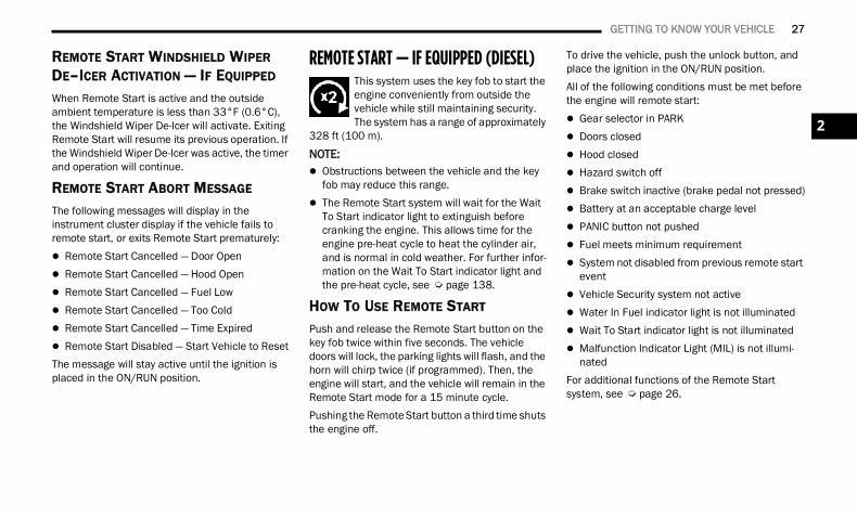
REMOTE START — IF EQUIPPED (DIESEL) This system uses the key fob to start the engine conveniently from outside the vehicle while still maintaining security. The system has a range of approximately
328 ft (100 m).NOTE: Obstructions between the vehicle and the key
fob may reduce this range. The Remote Start system will wait for the Wait
To Start indicator light to extinguish before cranking the engine. This allows time for the engine pre-heat cycle to heat the cylinder air, and is normal in cold weather. For further infor-mation on the Wait To Start indicator light and the pre-heat cycle, see Ú page 138.
HOW TO USE REMOTE START
Push and release the Remote Start button on the key fob twice within five seconds. The vehicle doors will lock, the parking lights will flash, and the horn will chirp twice (if programmed). Then, the engine will start, and the vehicle will remain in the Remote Start mode for a 15 minute cycle.Pushing the Remote Start button a third time shuts the engine off.
To drive the vehicle, push the unlock button, and place the ignition in the ON/RUN position.All of the following conditions must be met before the engine will remote start: Gear selector in PARK Doors closed Hood closed Hazard switch off Brake switch inactive (brake pedal not pressed) Battery at an acceptable charge level PANIC button not pushed Fuel meets minimum requirement System not disabled from previous remote start
event Vehicle Security system not active Water In Fuel indicator light is not illuminated Wait To Start indicator light is not illuminated Malfunction Indicator Light (MIL) is not illumi-
natedFor additional functions of the Remote Start system, see Ú page 26.
2
22_DT_OM_EN_USC_t.book Page 27
28 GETTING TO KNOW YOUR VEHICLE
VEHICLE SECURITY SYSTEM — IF EQUIPPED The Vehicle Security system monitors the vehicle doors, hood, tailgate, and the Keyless Enter ‘n Go™ Ignition for unauthorized operation. While the Vehicle Security system is armed, interior switches for door locks and tailgate release are disabled. If something triggers the alarm, the Vehicle Security system will provide the following audible and visible signals: The horn will pulse. The turn signals will flash. The Vehicle Security Light, located in the upper
right corner of the instrument cluster display, will flash.
TO ARM THE SYSTEM
Follow these steps to arm the Vehicle Security system:1. Make sure the vehicle’s ignition is placed in
the OFF position. For vehicles equipped with Keyless Entry,
make sure the vehicle’s keyless ignition system is OFF.
2. Perform one of the following methods to lock the vehicle: Push the lock button on the interior power
door lock switch with the driver and/or passenger door open.
Push the lock button on the exterior Passive Entry door handle with a valid key fob avail-able in the same exterior zone Ú page 30.
Push the lock button on the key fob.3. If any doors are open, close them.
TO DISARM THE SYSTEM
The Vehicle Security system can be disarmed using any of the following methods: Push the unlock button on the key fob. Grab the Passive Entry door handle to unlock
the door Ú page 30. Cycle the ignition out of the OFF position to
disarm the system.
NOTE: The driver's door key cylinder cannot arm or
disarm the Vehicle Security system. Use of the door key cylinder when the system is armed will sound the alarm when the door is opened.
The Vehicle Security system remains armed when the power tailgate (if equipped) is opened using the tailgate button on the key fob.
If Passive Entry (if equipped) is used to unlock the tailgate, the Vehicle Security system is disarmed and the rest of the vehicle doors will remain locked unless all doors are set to unlock on first press within Uconnect Settings.
When the Vehicle Security system is armed, the interior power door lock switches will not unlock the doors.
The Vehicle Security system is designed to protect your vehicle. However, you can create conditions where the system will give you a false alarm. If one of the previously described arming sequences has occurred, the Vehicle Security system will arm regardless of whether you are in the vehicle or not. If you remain in the vehicle and open a door, the alarm will sound. If this occurs, disarm the Vehicle Security system.
WARNING!
Do not start or run an engine in a closed garage or confined area. Exhaust gas contains Carbon Monoxide (CO) which is odorless and colorless. Carbon Monoxide is poisonous and can cause serious injury or death when inhaled.
Keep key fobs away from children. Operation of the Remote Start system, windows, door locks or other controls could cause serious injury or death.
22_DT_OM_EN_USC_t.book Page 28
GETTING TO KNOW YOUR VEHICLE 29
If the Vehicle Security system is armed and the battery becomes disconnected, the Vehicle Security system will remain armed when the battery is reconnected; the exterior lights will flash, and the horn will sound. If this occurs, disarm the Vehicle Security system.
REARMING OF THE SYSTEM
If something triggers the alarm and no action is taken to disarm it, the Vehicle Security system will turn the horn off after a 29 second cycle (with five seconds between cycles and up to eight cycles if the trigger remains active) and then rearm itself.
SECURITY SYSTEM MANUAL OVERRIDE
The Vehicle Security system will not arm if you lock the doors using the manual door lock.
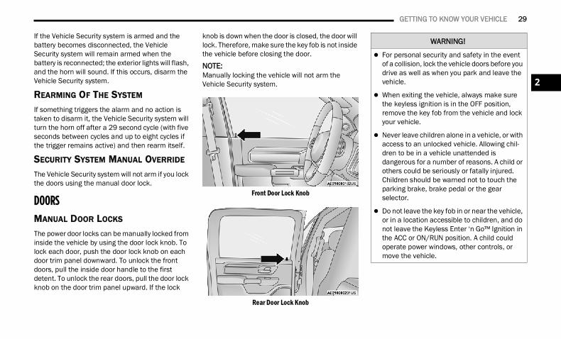
DOORS MANUAL DOOR LOCKS
The power door locks can be manually locked from inside the vehicle by using the door lock knob. To lock each door, push the door lock knob on each door trim panel downward. To unlock the front doors, pull the inside door handle to the first detent. To unlock the rear doors, pull the door lock knob on the door trim panel upward. If the lock
knob is down when the door is closed, the door will lock. Therefore, make sure the key fob is not inside the vehicle before closing the door.
NOTE:Manually locking the vehicle will not arm the Vehicle Security system.
Front Door Lock Knob
Rear Door Lock Knob
WARNING!
For personal security and safety in the event of a collision, lock the vehicle doors before you drive as well as when you park and leave the vehicle.
When exiting the vehicle, always make sure the keyless ignition is in the OFF position, remove the key fob from the vehicle and lock your vehicle.
Never leave children alone in a vehicle, or with access to an unlocked vehicle. Allowing chil-dren to be in a vehicle unattended is dangerous for a number of reasons. A child or others could be seriously or fatally injured. Children should be warned not to touch the parking brake, brake pedal or the gear selector.
Do not leave the key fob in or near the vehicle, or in a location accessible to children, and do not leave the Keyless Enter ‘n Go™ Ignition in the ACC or ON/RUN position. A child could operate power windows, other controls, or move the vehicle.
2
22_DT_OM_EN_USC_t.book Page 29
30 GETTING TO KNOW YOUR VEHICLE
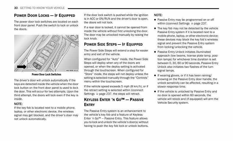
POWER DOOR LOCKS — IF EQUIPPED The power door lock switches are located on each front door panel. Push the switch to lock or unlock the doors.
Power Door Lock Switches
The driver’s door will unlock automatically if the keys are detected inside the vehicle when the door lock button on the front door panel is used to lock the door. This will occur for two attempts. Upon the third attempt, the doors will lock even if the key is inside.
NOTE:If the key fob is located next to a mobile phone, laptop, or other electronic device, the wireless signal may get blocked, and the driver’s door may not unlock automatically.
If the door lock switch is pushed while the ignition is in ACC or ON/RUN and the driver's door is open, the doors will not lock.If a rear door is locked, it cannot be opened from inside the vehicle without first unlocking the door. The door may be unlocked manually by raising the lock knob.
POWER SIDE STEPS — IF EQUIPPED The Power Side Steps will extend a step for easier entry and exit of the vehicle.When configured for “Auto” mode, the Power Side Steps will deploy when any of the doors are opened, or when the deploy setting is activated through the touchscreen. When configured for “Store” mode, the steps will not deploy unless the setting is selected manually through the “Controls” menu within the touchscreen.If the vehicle speed exceeds 5 mph (8 km/h), or if the retract setting is selected within Uconnect Settings Ú page 237, the steps will retract.
KEYLESS ENTER ‘N GO™ — PASSIVE ENTRY The Passive Entry system is an enhancement to the vehicle’s key fob and a feature of KeylessEnter ‘n Go™ — Passive Entry. This feature allows you to lock and unlock the vehicle’s door(s) without having to push the key fob lock or unlock buttons.
NOTE: Passive Entry may be programmed on or off
within Uconnect Settings Ú page 237. The key fob may not be detected by the vehicle
Passive Entry system if it is located next to a mobile phone, laptop, or other electronic device; these devices may block the key fob’s wireless signal and prevent the Passive Entry system from locking/unlocking the vehicle.
Passive Entry Unlock initiates illuminated approach (low beams, license plate lamp, posi-tion lamps) for whichever time duration is set between 0, 30, 60 or 90 seconds. Passive Entry Unlock also initiates two flashes of the turn signal lamps.
If wearing gloves, or if it has been raining/snowing on the Passive Entry door handle, the unlock sensitivity can be affected, resulting in a slower response time.
If the vehicle is unlocked by Passive Entry and no door is opened within 60 seconds, the vehicle will relock and (if equipped) will arm the Vehicle Security system.
22_DT_OM_EN_USC_t.book Page 30
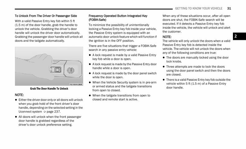
GETTING TO KNOW YOUR VEHICLE 31
To Unlock From The Driver Or Passenger SideWith a valid Passive Entry key fob within 5 ft (1.5 m) of the door handle, grab the handle to unlock the vehicle. Grabbing the driver’s door handle will unlock the driver door automatically. Grabbing the passenger door handle will unlock all doors and the tailgate automatically.
Grab The Door Handle To Unlock
NOTE: Either the driver door only or all doors will unlock
when you grab hold of the front driver’s door handle, depending on the selected setting in the Uconnect system Ú page 237.
All doors will unlock when the front passenger door handle is grabbed regardless of the driver’s door unlock preference setting.
Frequency Operated Button Integrated Key (FOBIK-Safe)To minimize the possibility of unintentionally locking a Passive Entry key fob inside your vehicle, the Passive Entry system is equipped with an automatic door unlock feature which will function if the ignition is in the OFF position.There are five situations that trigger a FOBIK-Safe search in any passive entry vehicle: A lock request is made by a valid Passive Entry
key fob while a door is open. A lock request is made by the Passive Entry door
handle while a door is open. A lock request is made by the door panel switch
while the door is open. When the Vehicle Security system is in pre-arm
or armed status and the tailgate transitions from open to closed.
When the tailgate transitions from open to closed and remote start is active.
When any of these situations occur, after all open doors are shut, the FOBIK-Safe search will be executed. If it detects a Passive Entry key fob inside the vehicle, the vehicle will unlock and alert the customer.
NOTE:The vehicle will only unlock the doors when a valid Passive Entry key fob is detected inside the vehicle. The vehicle will not unlock the doors when any of the following conditions are true: The doors are manually locked using the door
lock knobs. Three attempts are made to lock the doors
using the door panel switch and then the doors are closed.
There is a valid Passive Entry key fob outside the vehicle within 5 ft (1.5 m) of a Passive Entry door handle.
2
22_DT_OM_EN_USC_t.book Page 31
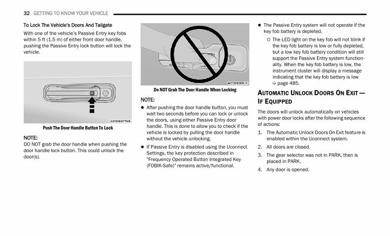
32 GETTING TO KNOW YOUR VEHICLE
To Lock The Vehicle’s Doors And TailgateWith one of the vehicle’s Passive Entry key fobs within 5 ft (1.5 m) of either front door handle, pushing the Passive Entry lock button will lock the vehicle.
Push The Door Handle Button To Lock
NOTE:DO NOT grab the door handle when pushing the door handle lock button. This could unlock the door(s).
Do NOT Grab The Door Handle When Locking
NOTE: After pushing the door handle button, you must
wait two seconds before you can lock or unlock the doors, using either Passive Entry door handle. This is done to allow you to check if the vehicle is locked by pulling the door handle without the vehicle unlocking.
If Passive Entry is disabled using the Uconnect Settings, the key protection described in "Frequency Operated Button Integrated Key (FOBIK-Safe)" remains active/functional.
The Passive Entry system will not operate if the key fob battery is depleted. The LED light on the key fob will not blink if
the key fob battery is low or fully depleted, but a low key fob battery condition will still support the Passive Entry system function-ality. When the key fob battery is low, the instrument cluster will display a message indicating that the key fob battery is low Ú page 485.
AUTOMATIC UNLOCK DOORS ON EXIT — IF EQUIPPED
The doors will unlock automatically on vehicles with power door locks after the following sequence of actions:1. The Automatic Unlock Doors On Exit feature is
enabled within the Uconnect system.2. All doors are closed.3. The gear selector was not in PARK, then is
placed in PARK.4. Any door is opened.
22_DT_OM_EN_USC_t.book Page 32
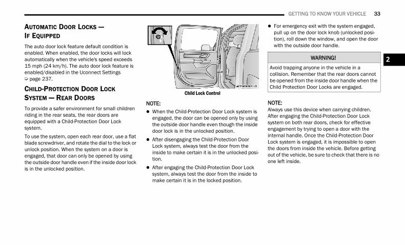
GETTING TO KNOW YOUR VEHICLE 33
AUTOMATIC DOOR LOCKS —IF EQUIPPED The auto door lock feature default condition is enabled. When enabled, the door locks will lock automatically when the vehicle's speed exceeds 15 mph (24 km/h). The auto door lock feature is enabled/disabled in the Uconnect Settings Ú page 237.
CHILD-PROTECTION DOOR LOCK SYSTEM — REAR DOORS
To provide a safer environment for small children riding in the rear seats, the rear doors are equipped with a Child-Protection Door Lock system.To use the system, open each rear door, use a flat blade screwdriver, and rotate the dial to the lock or unlock position. When the system on a door is engaged, that door can only be opened by using the outside door handle even if the inside door lock is in the unlocked position.
Child Lock Control
NOTE: When the Child-Protection Door Lock system is
engaged, the door can be opened only by using the outside door handle even though the inside door lock is in the unlocked position.
After disengaging the Child-Protection Door Lock system, always test the door from the inside to make certain it is in the unlocked posi-tion.
After engaging the Child-Protection Door Lock system, always test the door from the inside to make certain it is in the locked position.
For emergency exit with the system engaged, pull up on the door lock knob (unlocked posi-tion), roll down the window, and open the door with the outside door handle.
NOTE:Always use this device when carrying children. After engaging the Child-Protection Door Lock system on both rear doors, check for effective engagement by trying to open a door with the internal handle. Once the Child-Protection Door Lock system is engaged, it is impossible to open the doors from inside the vehicle. Before getting out of the vehicle, be sure to check that there is no one left inside.
WARNING!
Avoid trapping anyone in the vehicle in a collision. Remember that the rear doors cannot be opened from the inside door handle when the Child Protection Door Locks are engaged.
2
22_DT_OM_EN_USC_t.book Page 33
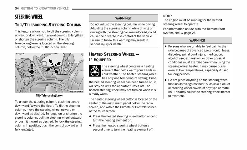
34 GETTING TO KNOW YOUR VEHICLE
STEERING WHEEL TILT/TELESCOPING STEERING COLUMN This feature allows you to tilt the steering column upward or downward. It also allows you to lengthen or shorten the steering column. The tilt/telescoping lever is located on the steering column, below the multifunction lever.
Tilt/Telescoping Lever
To unlock the steering column, push the control downward (toward the floor). To tilt the steering column, move the steering wheel upward or downward as desired. To lengthen or shorten the steering column, pull the steering wheel outward or push it inward as desired. To lock the steering column in position, push the control upward until fully engaged.
HEATED STEERING WHEEL — IF EQUIPPED
The steering wheel contains a heating element that helps warm your hands in cold weather. The heated steering wheel has only one temperature setting. Once
the heated steering wheel has been turned on, it will stay on until the operator turns it off. The heated steering wheel may not turn on when it is already warm.The heated steering wheel button is located on the center of the instrument panel below the radio screen, and within the Climate or Controls screen of the touchscreen. Press the heated steering wheel button once to
turn the heating element on. Press the heated steering wheel button a
second time to turn the heating element off.
NOTE:The engine must be running for the heated steering wheel to operate.For information on use with the Remote Start system, see Ú page 26.
WARNING!
Do not adjust the steering column while driving. Adjusting the steering column while driving or driving with the steering column unlocked, could cause the driver to lose control of the vehicle. Failure to follow this warning may result in serious injury or death.
WARNING!
Persons who are unable to feel pain to the skin because of advanced age, chronic illness, diabetes, spinal cord injury, medication, alcohol use, exhaustion, or other physical conditions must exercise care when using the steering wheel heater. It may cause burns even at low temperatures, especially if used for long periods.
Do not place anything on the steering wheel that insulates against heat, such as a blanket or steering wheel covers of any type or mate-rial. This may cause the steering wheel heater to overheat.
22_DT_OM_EN_USC_t.book Page 34
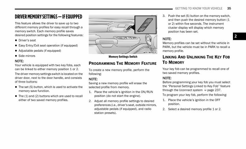
GETTING TO KNOW YOUR VEHICLE 35
DRIVER MEMORY SETTINGS — IF EQUIPPED This feature allows the driver to save up to two different memory profiles for easy recall through a memory switch. Each memory profile saves desired position settings for the following features: Driver’s seat Easy Entry/Exit seat operation (if equipped) Adjustable pedals (if equipped) Side mirrorsNOTE:Your vehicle is equipped with two key fobs, each can be linked to either memory position 1 or 2.The driver memory settings switch is located on the driver door, next to the door handle, and consists of three buttons: The set (S) button, which is used to activate the
memory save function. The (1) and (2) buttons which are used to recall
either of two saved memory profiles.
Memory Settings Switch
PROGRAMMING THE MEMORY FEATURE
To create a new memory profile, perform the following:NOTE:Saving a new memory profile will erase the selected profile from memory.1. Place the vehicle’s ignition in the ON/RUN
position (do not start the engine).2. Adjust all memory profile settings to desired
preferences (i.e., driver’s seat, outside mirrors, adjustable pedals (if equipped), and radio station presets).
3. Push the set (S) button on the memory switch, and then push the desired memory button (1 or 2) within five seconds. The instrument cluster display will display which memory position has been set.
NOTE:Memory profiles can be set without the vehicle in PARK, but the vehicle must be in PARK to recall a memory profile.
LINKING AND UNLINKING THE KEY FOB TO MEMORY
Your key fob can be programmed to recall one of two saved memory profiles.NOTE:Before programming your key fob you must select the “Personal Settings Linked to Key Fob” feature through the Uconnect system Ú page 237.To program your key fob, perform the following:1. Place the vehicle’s ignition in the OFF
position.2. Select a desired memory profile 1 or 2.
2
22_DT_OM_EN_USC_t.book Page 35
36 GETTING TO KNOW YOUR VEHICLE
3. Once the profile has been recalled, push and release the set (S) button on the memory switch.
4. Push and release button (1) or (2) accordingly. “Memory Profile Set” (1 or 2) will display in the instrument cluster.
5. Push and release the lock button on the key fob within 10 seconds.
NOTE:Your key fob can be unlinked from your memory settings by pushing the set (S) button, followedby pushing the unlock button on the key fob within 10 seconds.
MEMORY POSITION RECALL
NOTE:If a recall is attempted when the vehicle is not in PARK, a message will display in the instrument cluster display.To recall the memory settings for driver one or two, push the desired memory button number (1 or 2) or the unlock button on the key fob linked to the desired memory position.
A recall can be canceled by pushing any of the memory buttons (S, 1, or 2) during a recall. When a recall is canceled, the driver seat will stop moving. A delay of one second will occur before another recall can be selected.
SEATS Seats are a part of the Occupant Restraint system of the vehicle.
MANUAL ADJUSTMENT(FRONT SEATS) — IF EQUIPPED
WARNING!
It is dangerous to ride in a cargo area, inside or outside of a vehicle. In a collision, people riding in these areas are more likely to be seri-ously injured or killed.
Do not allow people to ride in any area of your vehicle that is not equipped with seats and seat belts. In a collision, people riding in these areas are more likely to be seriously injured or killed.
Be sure everyone in your vehicle is in a seat and using a seat belt properly.
WARNING!
Adjusting a seat while the vehicle is moving is dangerous. The sudden movement of the seat could cause you to lose control. The seat belt might not be adjusted properly and you could be injured. Adjust the seat only while the vehicle is parked.
Do not ride with the seatback reclined so that the shoulder belt is no longer resting against your chest. In a collision you could slide under the seat belt and be seriously or even fatally injured. Use the recliner only when the vehicle is parked.
22_DT_OM_EN_USC_t.book Page 36
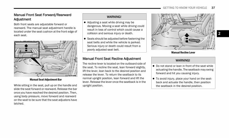
GETTING TO KNOW YOUR VEHICLE 37
Manual Front Seat Forward/Rearward AdjustmentBoth front seats are adjustable forward or rearward. The manual seat adjustment handle is located under the seat cushion at the front edge of each seat.
Manual Seat Adjustment Bar
While sitting in the seat, pull up on the handle and slide the seat forward or rearward. Release the bar once you have reached the desired position. Then, using body pressure, move forward and rearward on the seat to be sure that the seat adjusters have latched.
Manual Front Seat Recline AdjustmentThe recline lever is located on the outboard side of the seat. To recline the seat, lean forward slightly, lift the lever, lean back to the desired position and release the lever. To return the seatback to its normal upright position, lean forward and lift the lever. Release the lever once the seatback is in the upright position.
Manual Recline Lever
WARNING!
Adjusting a seat while driving may be dangerous. Moving a seat while driving could result in loss of control which could cause a collision and serious injury or death.
Seats should be adjusted before fastening the seat belts and while the vehicle is parked. Serious injury or death could result from a poorly adjusted seat belt.
WARNING!
Do not stand or lean in front of the seat while actuating the handle. The seatback may swing forward and hit you causing injury.
To avoid injury, place your hand on the seat-back and actuate the handle, then position the seatback in the desired position.
2
22_DT_OM_EN_USC_t.book Page 37
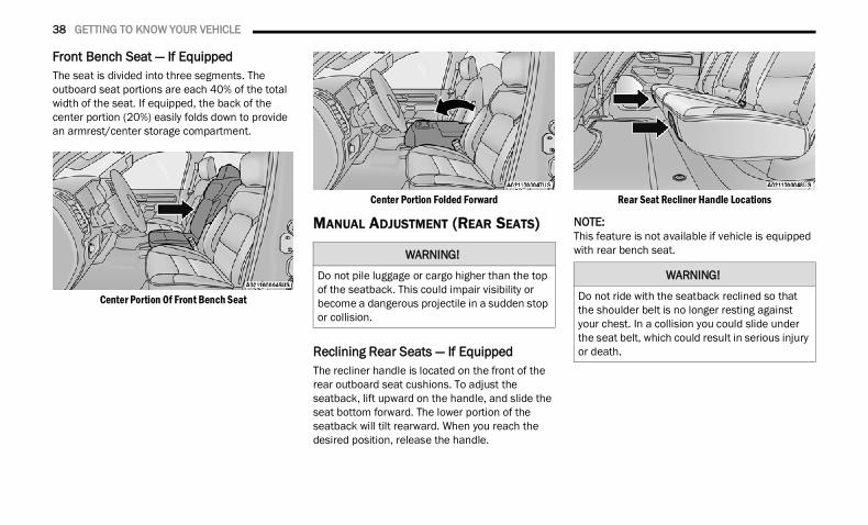
38 GETTING TO KNOW YOUR VEHICLE
Front Bench Seat — If Equipped The seat is divided into three segments. The outboard seat portions are each 40% of the total width of the seat. If equipped, the back of the center portion (20%) easily folds down to provide an armrest/center storage compartment.
Center Portion Of Front Bench Seat
Center Portion Folded Forward
MANUAL ADJUSTMENT (REAR SEATS)
Reclining Rear Seats — If EquippedThe recliner handle is located on the front of the rear outboard seat cushions. To adjust the seatback, lift upward on the handle, and slide the seat bottom forward. The lower portion of the seatback will tilt rearward. When you reach the desired position, release the handle.
Rear Seat Recliner Handle Locations
NOTE:This feature is not available if vehicle is equipped with rear bench seat.WARNING!
Do not pile luggage or cargo higher than the top of the seatback. This could impair visibility or become a dangerous projectile in a sudden stop or collision.
WARNING!
Do not ride with the seatback reclined so that the shoulder belt is no longer resting against your chest. In a collision you could slide under the seat belt, which could result in serious injury or death.
22_DT_OM_EN_USC_t.book Page 38
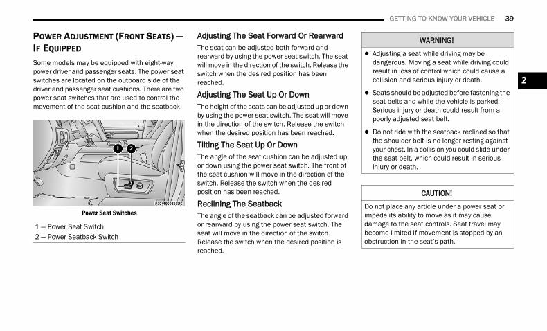
GETTING TO KNOW YOUR VEHICLE 39
POWER ADJUSTMENT (FRONT SEATS) — IF EQUIPPED
Some models may be equipped with eight-way power driver and passenger seats. The power seat switches are located on the outboard side of the driver and passenger seat cushions. There are two power seat switches that are used to control the movement of the seat cushion and the seatback.
Power Seat Switches
Adjusting The Seat Forward Or RearwardThe seat can be adjusted both forward and rearward by using the power seat switch. The seat will move in the direction of the switch. Release the switch when the desired position has been reached.
Adjusting The Seat Up Or Down The height of the seats can be adjusted up or down by using the power seat switch. The seat will move in the direction of the switch. Release the switch when the desired position has been reached.
Tilting The Seat Up Or Down The angle of the seat cushion can be adjusted up or down using the power seat switch. The front of the seat cushion will move in the direction of the switch. Release the switch when the desired position has been reached.
Reclining The Seatback The angle of the seatback can be adjusted forward or rearward by using the power seat switch. The seat will move in the direction of the switch. Release the switch when the desired position is reached.
1 — Power Seat Switch2 — Power Seatback Switch
WARNING!
Adjusting a seat while driving may be dangerous. Moving a seat while driving could result in loss of control which could cause a collision and serious injury or death.
Seats should be adjusted before fastening the seat belts and while the vehicle is parked. Serious injury or death could result from a poorly adjusted seat belt.
Do not ride with the seatback reclined so that the shoulder belt is no longer resting against your chest. In a collision you could slide under the seat belt, which could result in serious injury or death.
CAUTION!
Do not place any article under a power seat or impede its ability to move as it may cause damage to the seat controls. Seat travel may become limited if movement is stopped by an obstruction in the seat’s path.
2
22_DT_OM_EN_USC_t.book Page 39
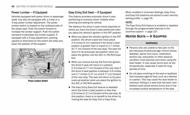
40 GETTING TO KNOW YOUR VEHICLE
Power Lumbar — If EquippedVehicles equipped with power driver or passenger seats may also be equipped with a 2-way or a 4-way power lumbar adjustment. The power lumbar switch is located on the outboard side of the power seat. Push the switch forward to increase the lumbar support. Push the switch rearward to decrease the lumbar support. If equipped with a 4-way adjustment, pushing upward or downward on the switch will raise and lower the position of the support.
Power Lumbar Switch
Easy Entry/Exit Seat — If EquippedThis feature provides automatic driver’s seat positioning to enhance driver mobility when entering and exiting the vehicle.The distance the driver’s seat moves depends on where you have the driver’s seat positioned when you place the vehicle’s ignition in the OFF position. When you place the vehicle’s ignition in the OFF
position, the driver’s seat will move about 2.4 inches (6 cm) rearward if the driver’s seat position is greater than or equal to 2.7 inches (6.77 cm) forward of the rear stop. The seat will return to its previously set position when you place the ignition into the ACC or ON/RUN posi-tion.
When you remove the key fob from the ignition, the driver’s seat will move to a position 0.3 inches (0.77 cm) forward of the rear stop if the driver’s seat position is between 0.9 inches and 2.7 inches (2.27 cm and 6.77 cm) forward of the rear stop. The seat will return to its previ-ously set position when you place the ignition to the ACC or ON/RUN position.
The Easy Entry/Easy Exit feature is disabled when the driver’s seat position is less than 0.9 inches (2.27 cm) forward of the rear stop. At this position, there is no benefit to the driver by moving the seat for Easy Exit or Easy Entry.
When enabled in Uconnect Settings, Easy Entry and Easy Exit positions are stored in each memory setting profile Ú page 35.
NOTE:The Easy Entry/Exit feature is enabled or disabled through the programmable features in the Uconnect system Ú page 237.
HEATED SEATS — IF EQUIPPED
WARNING!
Persons who are unable to feel pain to the skin because of advanced age, chronic illness, diabetes, spinal cord injury, medication, alcohol use, exhaustion or other physical condition must exercise care when using the seat heater. It may cause burns even at low temperatures, especially if used for long periods of time.
Do not place anything on the seat or seatback that insulates against heat, such as a blanket or cushion. This may cause the seat heater to overheat. Sitting in a seat that has been over-heated could cause serious burns due to the increased surface temperature of the seat.
22_DT_OM_EN_USC_t.book Page 40
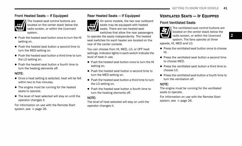
GETTING TO KNOW YOUR VEHICLE 41
Front Heated Seats — If EquippedThe heated seat control buttons are located on the center stack below the radio screen, or within the Uconnect system.
Push the heated seat button once to turn the HI setting on.
Push the heated seat button a second time to turn the MED setting on.
Push the heated seat button a third time to turn the LO setting on.
Push the heated seat button a fourth time to turn the heating elements off.
NOTE: Once a heat setting is selected, heat will be felt
within two to five minutes. The engine must be running for the heated
seats to operate. The level of heat selected will stay on until the
operator changes it.For information on use with the Remote Start system, see Ú page 26.
Rear Heated Seats — If EquippedOn some models, the two rear outboard seats may be equipped with heated seats. There are two heated seat switches that allow the rear passengers
to operate the seats independently. The heated seat switches for each heater are located on the rear of the center console.You can choose from HI, MED, LO, or OFF heat settings. Indicator lights in each switch indicate the level of heat in use. Push the heated seat button once to turn the HI
setting on. Push the heated seat button a second time to
turn the MED setting on. Push the heated seat button a third time to turn
the LO setting on. Push the heated seat button a fourth time to
turn the heating elements off.NOTE:The level of heat selected will stay on until the operator changes it.
VENTILATED SEATS — IF EQUIPPED
Front Ventilated SeatsThe ventilated seat control buttons are located on the center stack below the radio screen, or within the Uconnect system. The fans operate at three
speeds, HI, MED and LO. Press the ventilated seat button once to choose
HI. Press the ventilated seat button a second time
to choose MED. Press the ventilated seat button a third time to
choose LO. Press the ventilated seat button a fourth time to
turn the ventilation off.NOTE:The engine must be running for the ventilated seats to operate.For information on use with the Remote Start system, see Ú page 26.
2
22_DT_OM_EN_USC_t.book Page 41
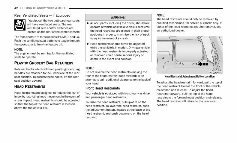
42 GETTING TO KNOW YOUR VEHICLE
Rear Ventilated Seats — If EquippedIf equipped, the two outboard rear seats will have ventilated seats. The rear ventilated seat control switches are located on the rear of the center console.
The fans operate at three speeds: HI, MED, and LO. Push the ventilated seat buttons to toggle through the speeds, or to turn the feature off.
NOTE:The engine must be running for the ventilated seats to operate.
PLASTIC GROCERY BAG RETAINERS Retainer hooks which will hold plastic grocery bag handles are attached to the underside of the rear seat cushion. To access these hooks, lift the rear seat cushion upward.
HEAD RESTRAINTS Head restraints are designed to reduce the risk of injury by restricting head movement in the event of a rear impact. Head restraints should be adjusted so that the top of the head restraint is located above the top of your ear.
NOTE:Do not reverse the head restraints (making the rear of the head restraint face forward) in an attempt to gain additional clearance to the back of your head.Front Head RestraintsYour vehicle is equipped with front four-way driver and passenger head restraints.To raise the head restraint, pull upward on the head restraint. To lower the head restraint, push the adjustment button, located at the base of the head restraint, and push downward on the head restraint.
NOTE:The head restraints should only be removed by qualified technicians, for service purposes only. If either of the head restraints require removal, see an authorized dealer.
Head Restraint Adjustment Button Location
To adjust the head restraint forward, pull the top of the head restraint toward the front of the vehicle as desired and release. To adjust the head restraint rearward, pull the top of the head restraint to the forward most position and release. The head restraint will return to the rear most position.
WARNING!
All occupants, including the driver, should not operate a vehicle or sit in a vehicle’s seat until the head restraints are placed in their proper positions in order to minimize the risk of neck injury in the event of a crash.
Head restraints should never be adjusted while the vehicle is in motion. Driving a vehicle with the head restraints improperly adjusted or removed could cause serious injury or death in the event of a collision.
22_DT_OM_EN_USC_t.book Page 42
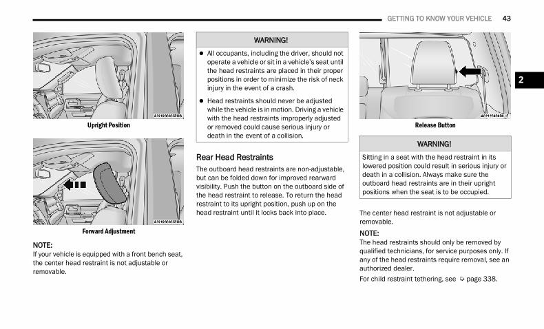
GETTING TO KNOW YOUR VEHICLE 43
Upright Position
Forward Adjustment
NOTE:If your vehicle is equipped with a front bench seat, the center head restraint is not adjustable or removable.
Rear Head RestraintsThe outboard head restraints are non-adjustable, but can be folded down for improved rearward visibility. Push the button on the outboard side of the head restraint to release. To return the head restraint to its upright position, push up on the head restraint until it locks back into place.
Release Button
The center head restraint is not adjustable or removable.
NOTE:The head restraints should only be removed by qualified technicians, for service purposes only. If any of the head restraints require removal, see an authorized dealer.For child restraint tethering, see Ú page 338.
WARNING!
All occupants, including the driver, should not operate a vehicle or sit in a vehicle’s seat until the head restraints are placed in their proper positions in order to minimize the risk of neck injury in the event of a crash.
Head restraints should never be adjusted while the vehicle is in motion. Driving a vehicle with the head restraints improperly adjusted or removed could cause serious injury or death in the event of a collision.
WARNING!
Sitting in a seat with the head restraint in its lowered position could result in serious injury or death in a collision. Always make sure the outboard head restraints are in their upright positions when the seat is to be occupied.
2
22_DT_OM_EN_USC_t.book Page 43
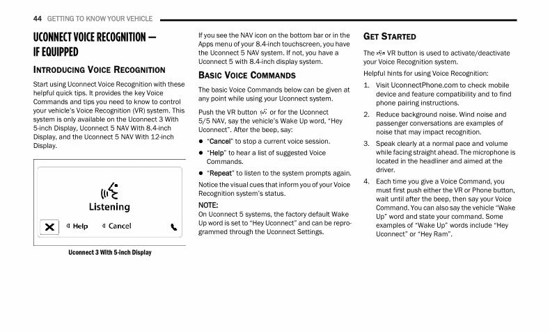
44 GETTING TO KNOW YOUR VEHICLE
UCONNECT VOICE RECOGNITION — IF EQUIPPED INTRODUCING VOICE RECOGNITION
Start using Uconnect Voice Recognition with these helpful quick tips. It provides the key Voice Commands and tips you need to know to control your vehicle’s Voice Recognition (VR) system. This system is only available on the Uconnect 3 With 5-inch Display, Uconnect 5 NAV With 8.4-inch Display, and the Uconnect 5 NAV With 12-inch Display.
Uconnect 3 With 5-inch Display
If you see the NAV icon on the bottom bar or in the Apps menu of your 8.4-inch touchscreen, you have the Uconnect 5 NAV system. If not, you have a Uconnect 5 with 8.4-inch display system.
BASIC VOICE COMMANDS
The basic Voice Commands below can be given at any point while using your Uconnect system.
Push the VR button or for the Uconnect 5/5 NAV, say the vehicle’s Wake Up word, “Hey Uconnect”. After the beep, say: “Cancel” to stop a current voice session. “Help” to hear a list of suggested Voice
Commands. “Repeat” to listen to the system prompts again.Notice the visual cues that inform you of your Voice Recognition system’s status.NOTE:On Uconnect 5 systems, the factory default Wake Up word is set to “Hey Uconnect” and can be repro-grammed through the Uconnect Settings.
GET STARTED
The VR button is used to activate/deactivate your Voice Recognition system.Helpful hints for using Voice Recognition:1. Visit UconnectPhone.com to check mobile
device and feature compatibility and to find phone pairing instructions.
2. Reduce background noise. Wind noise and passenger conversations are examples of noise that may impact recognition.
3. Speak clearly at a normal pace and volume while facing straight ahead. The microphone is located in the headliner and aimed at the driver.
4. Each time you give a Voice Command, you must first push either the VR or Phone button, wait until after the beep, then say your Voice Command. You can also say the vehicle “Wake Up” word and state your command. Some examples of “Wake Up” words include “Hey Uconnect” or “Hey Ram”.
22_DT_OM_EN_USC_t.book Page 44
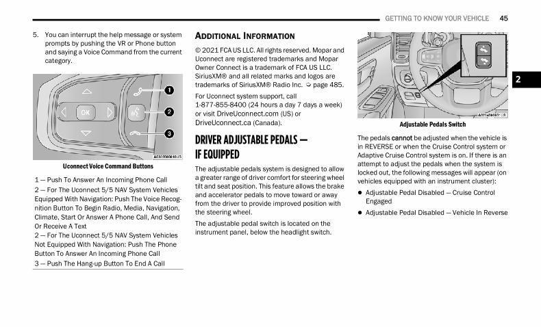
GETTING TO KNOW YOUR VEHICLE 45
5. You can interrupt the help message or system prompts by pushing the VR or Phone button and saying a Voice Command from the current category.
Uconnect Voice Command Buttons
ADDITIONAL INFORMATION
© 2021 FCA US LLC. All rights reserved. Mopar and Uconnect are registered trademarks and Mopar Owner Connect is a trademark of FCA US LLC. SiriusXM® and all related marks and logos are trademarks of SiriusXM® Radio Inc. Ú page 485.For Uconnect system support, call 1-877-855-8400 (24 hours a day 7 days a week) or visit DriveUconnect.com (US) or DriveUconnect.ca (Canada).
DRIVER ADJUSTABLE PEDALS — IF EQUIPPED The adjustable pedals system is designed to allow a greater range of driver comfort for steering wheel tilt and seat position. This feature allows the brake and accelerator pedals to move toward or away from the driver to provide improved position with the steering wheel.The adjustable pedal switch is located on the instrument panel, below the headlight switch.
Adjustable Pedals Switch
The pedals cannot be adjusted when the vehicle is in REVERSE or when the Cruise Control system or Adaptive Cruise Control system is on. If there is an attempt to adjust the pedals when the system is locked out, the following messages will appear (on vehicles equipped with an instrument cluster): Adjustable Pedal Disabled — Cruise Control
Engaged Adjustable Pedal Disabled — Vehicle In Reverse
1 — Push To Answer An Incoming Phone Call2 — For The Uconnect 5/5 NAV System Vehicles Equipped With Navigation: Push The Voice Recog-nition Button To Begin Radio, Media, Navigation, Climate, Start Or Answer A Phone Call, And Send Or Receive A Text2 — For The Uconnect 5/5 NAV System Vehicles Not Equipped With Navigation: Push The Phone Button To Answer An Incoming Phone Call3 — Push The Hang-up Button To End A Call
2
22_DT_OM_EN_USC_t.book Page 45
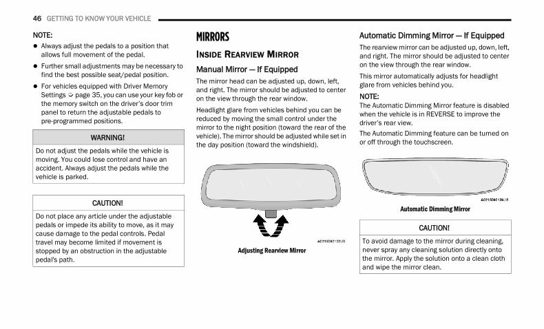
46 GETTING TO KNOW YOUR VEHICLE
NOTE: Always adjust the pedals to a position that
allows full movement of the pedal. Further small adjustments may be necessary to
find the best possible seat/pedal position. For vehicles equipped with Driver Memory
Settings Ú page 35, you can use your key fob or the memory switch on the driver’s door trim panel to return the adjustable pedals to pre-programmed positions.
MIRRORS INSIDE REARVIEW MIRROR
Manual Mirror — If EquippedThe mirror head can be adjusted up, down, left, and right. The mirror should be adjusted to center on the view through the rear window.Headlight glare from vehicles behind you can be reduced by moving the small control under the mirror to the night position (toward the rear of the vehicle). The mirror should be adjusted while set in the day position (toward the windshield).
Adjusting Rearview Mirror
Automatic Dimming Mirror — If Equipped The rearview mirror can be adjusted up, down, left, and right. The mirror should be adjusted to center on the view through the rear window.This mirror automatically adjusts for headlight glare from vehicles behind you.NOTE:The Automatic Dimming Mirror feature is disabled when the vehicle is in REVERSE to improve the driver’s rear view.The Automatic Dimming feature can be turned on or off through the touchscreen.
Automatic Dimming Mirror
WARNING!
Do not adjust the pedals while the vehicle is moving. You could lose control and have an accident. Always adjust the pedals while the vehicle is parked.
CAUTION!
Do not place any article under the adjustable pedals or impede its ability to move, as it may cause damage to the pedal controls. Pedal travel may become limited if movement is stopped by an obstruction in the adjustable pedal's path.
CAUTION!
To avoid damage to the mirror during cleaning, never spray any cleaning solution directly onto the mirror. Apply the solution onto a clean cloth and wipe the mirror clean.
22_DT_OM_EN_USC_t.book Page 46
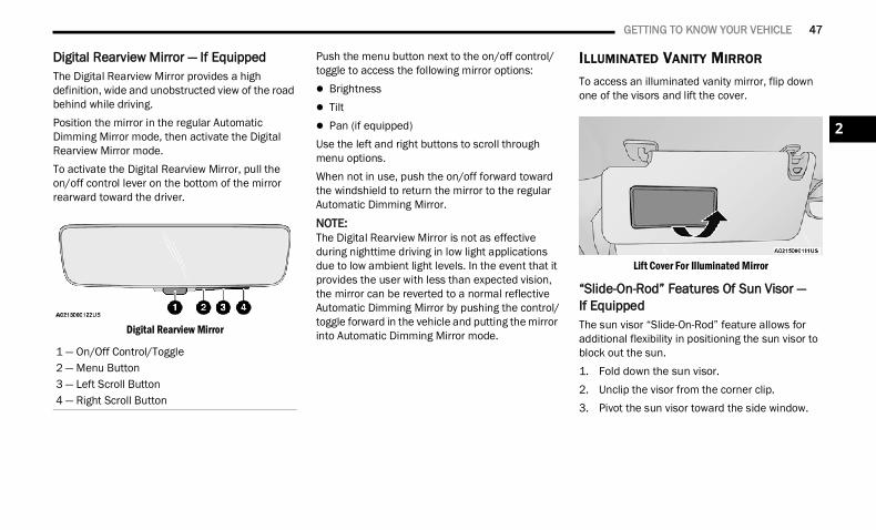
GETTING TO KNOW YOUR VEHICLE 47
Digital Rearview Mirror — If EquippedThe Digital Rearview Mirror provides a high definition, wide and unobstructed view of the road behind while driving.Position the mirror in the regular Automatic Dimming Mirror mode, then activate the Digital Rearview Mirror mode.To activate the Digital Rearview Mirror, pull the on/off control lever on the bottom of the mirror rearward toward the driver.
Digital Rearview Mirror
Push the menu button next to the on/off control/toggle to access the following mirror options: Brightness Tilt Pan (if equipped)Use the left and right buttons to scroll through menu options.When not in use, push the on/off forward toward the windshield to return the mirror to the regular Automatic Dimming Mirror.
NOTE:The Digital Rearview Mirror is not as effective during nighttime driving in low light applications due to low ambient light levels. In the event that it provides the user with less than expected vision, the mirror can be reverted to a normal reflective Automatic Dimming Mirror by pushing the control/toggle forward in the vehicle and putting the mirror into Automatic Dimming Mirror mode.
ILLUMINATED VANITY MIRROR
To access an illuminated vanity mirror, flip down one of the visors and lift the cover.
Lift Cover For Illuminated Mirror
“Slide-On-Rod” Features Of Sun Visor — If EquippedThe sun visor “Slide-On-Rod” feature allows for additional flexibility in positioning the sun visor to block out the sun.1. Fold down the sun visor.2. Unclip the visor from the corner clip.3. Pivot the sun visor toward the side window.
1 — On/Off Control/Toggle2 — Menu Button3 — Left Scroll Button4 — Right Scroll Button
2
22_DT_OM_EN_USC_t.book Page 47
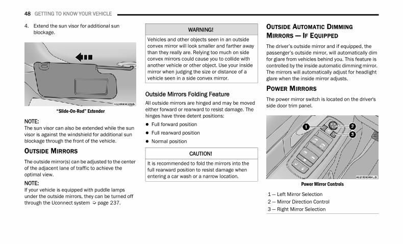
48 GETTING TO KNOW YOUR VEHICLE
4. Extend the sun visor for additional sun blockage.
“Slide-On-Rod” Extender
NOTE:The sun visor can also be extended while the sun visor is against the windshield for additional sun blockage through the front of the vehicle.
OUTSIDE MIRRORS The outside mirror(s) can be adjusted to the center of the adjacent lane of traffic to achieve the optimal view.NOTE:If your vehicle is equipped with puddle lamps under the outside mirrors, they can be turned off through the Uconnect system Ú page 237.
Outside Mirrors Folding FeatureAll outside mirrors are hinged and may be moved either forward or rearward to resist damage. The hinges have three detent positions: Full forward position Full rearward position Normal position
OUTSIDE AUTOMATIC DIMMING MIRRORS — IF EQUIPPED
The driver’s outside mirror and if equipped, the passenger’s outside mirror, will automatically dim for glare from vehicles behind you. This feature is controlled by the inside automatic dimming mirror. The mirrors will automatically adjust for headlight glare when the inside mirror adjusts.
POWER MIRRORS
The power mirror switch is located on the driver's side door trim panel.
Power Mirror Controls
WARNING!
Vehicles and other objects seen in an outside convex mirror will look smaller and farther away than they really are. Relying too much on side convex mirrors could cause you to collide with another vehicle or other object. Use your inside mirror when judging the size or distance of a vehicle seen in a side convex mirror.
CAUTION!
It is recommended to fold the mirrors into the full rearward position to resist damage when entering a car wash or a narrow location.
1 — Left Mirror Selection2 — Mirror Direction Control3 — Right Mirror Selection
22_DT_OM_EN_USC_t.book Page 48
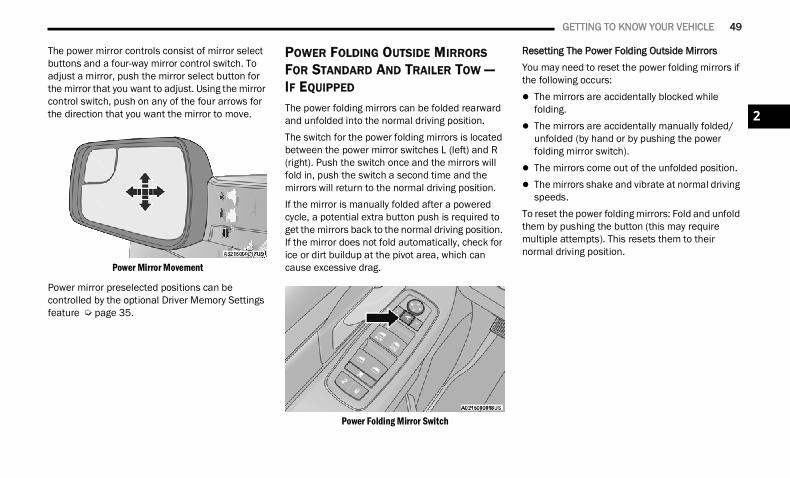
GETTING TO KNOW YOUR VEHICLE 49
The power mirror controls consist of mirror select buttons and a four-way mirror control switch. To adjust a mirror, push the mirror select button for the mirror that you want to adjust. Using the mirror control switch, push on any of the four arrows for the direction that you want the mirror to move.
Power Mirror Movement
Power mirror preselected positions can be controlled by the optional Driver Memory Settings feature Ú page 35.
POWER FOLDING OUTSIDE MIRRORS FOR STANDARD AND TRAILER TOW — IF EQUIPPED
The power folding mirrors can be folded rearward and unfolded into the normal driving position.The switch for the power folding mirrors is located between the power mirror switches L (left) and R (right). Push the switch once and the mirrors will fold in, push the switch a second time and the mirrors will return to the normal driving position.If the mirror is manually folded after a powered cycle, a potential extra button push is required to get the mirrors back to the normal driving position. If the mirror does not fold automatically, check for ice or dirt buildup at the pivot area, which can cause excessive drag.
Power Folding Mirror Switch
Resetting The Power Folding Outside MirrorsYou may need to reset the power folding mirrors if the following occurs: The mirrors are accidentally blocked while
folding. The mirrors are accidentally manually folded/
unfolded (by hand or by pushing the power folding mirror switch).
The mirrors come out of the unfolded position. The mirrors shake and vibrate at normal driving
speeds.To reset the power folding mirrors: Fold and unfold them by pushing the button (this may require multiple attempts). This resets them to their normal driving position.
2
22_DT_OM_EN_USC_t.book Page 49
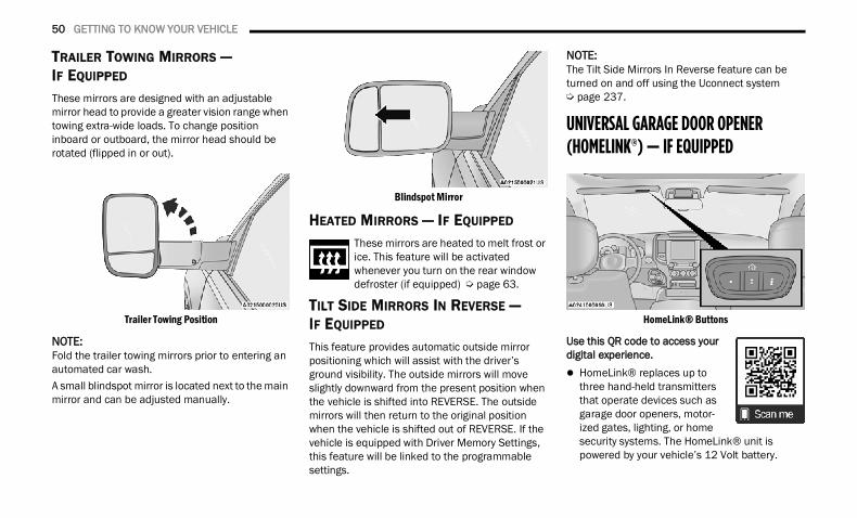
50 GETTING TO KNOW YOUR VEHICLE
TRAILER TOWING MIRRORS — IF EQUIPPED These mirrors are designed with an adjustable mirror head to provide a greater vision range when towing extra-wide loads. To change position inboard or outboard, the mirror head should be rotated (flipped in or out).
Trailer Towing Position
NOTE:Fold the trailer towing mirrors prior to entering an automated car wash.A small blindspot mirror is located next to the main mirror and can be adjusted manually.
Blindspot Mirror
HEATED MIRRORS — IF EQUIPPED These mirrors are heated to melt frost or ice. This feature will be activated whenever you turn on the rear window defroster (if equipped) Ú page 63.
TILT SIDE MIRRORS IN REVERSE — IF EQUIPPED
This feature provides automatic outside mirror positioning which will assist with the driver’s ground visibility. The outside mirrors will move slightly downward from the present position when the vehicle is shifted into REVERSE. The outside mirrors will then return to the original position when the vehicle is shifted out of REVERSE. If the vehicle is equipped with Driver Memory Settings, this feature will be linked to the programmable settings.
NOTE:The Tilt Side Mirrors In Reverse feature can be turned on and off using the Uconnect system Ú page 237.
UNIVERSAL GARAGE DOOR OPENER (HOMELINK®) — IF EQUIPPED
HomeLink® Buttons
Use this QR code to access your digital experience. HomeLink® replaces up to
three hand-held transmitters that operate devices such as garage door openers, motor-ized gates, lighting, or home security systems. The HomeLink® unit is powered by your vehicle’s 12 Volt battery.
22_DT_OM_EN_USC_t.book Page 50
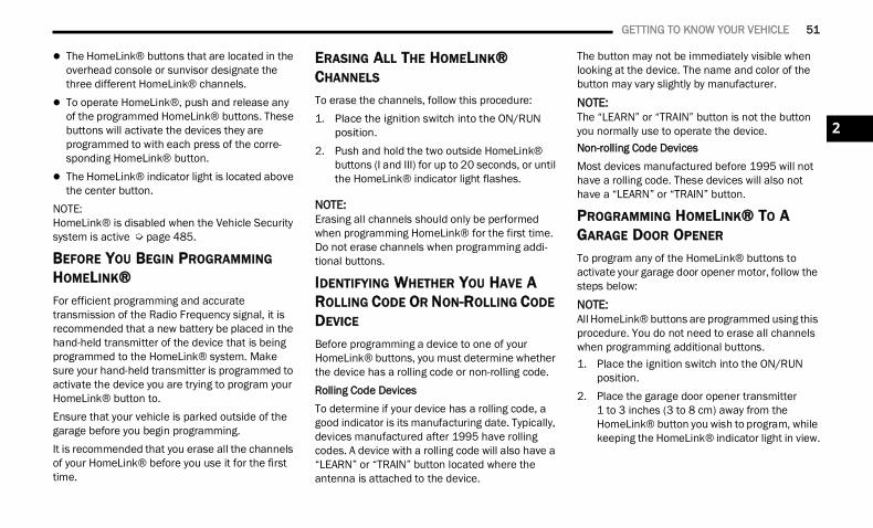
GETTING TO KNOW YOUR VEHICLE 51
The HomeLink® buttons that are located in the overhead console or sunvisor designate the three different HomeLink® channels.
To operate HomeLink®, push and release any of the programmed HomeLink® buttons. These buttons will activate the devices they are programmed to with each press of the corre-sponding HomeLink® button.
The HomeLink® indicator light is located above the center button.
NOTE:HomeLink® is disabled when the Vehicle Security system is active Ú page 485.
BEFORE YOU BEGIN PROGRAMMING HOMELINK®For efficient programming and accurate transmission of the Radio Frequency signal, it is recommended that a new battery be placed in the hand-held transmitter of the device that is being programmed to the HomeLink® system. Make sure your hand-held transmitter is programmed to activate the device you are trying to program your HomeLink® button to.Ensure that your vehicle is parked outside of the garage before you begin programming.It is recommended that you erase all the channels of your HomeLink® before you use it for the first time.
ERASING ALL THE HOMELINK® CHANNELS
To erase the channels, follow this procedure:1. Place the ignition switch into the ON/RUN
position.2. Push and hold the two outside HomeLink®
buttons (I and III) for up to 20 seconds, or until the HomeLink® indicator light flashes.
NOTE:Erasing all channels should only be performed when programming HomeLink® for the first time. Do not erase channels when programming addi-tional buttons.
IDENTIFYING WHETHER YOU HAVE A ROLLING CODE OR NON-ROLLING CODE DEVICE
Before programming a device to one of your HomeLink® buttons, you must determine whether the device has a rolling code or non-rolling code.Rolling Code DevicesTo determine if your device has a rolling code, a good indicator is its manufacturing date. Typically, devices manufactured after 1995 have rolling codes. A device with a rolling code will also have a “LEARN” or “TRAIN” button located where the antenna is attached to the device.
The button may not be immediately visible when looking at the device. The name and color of the button may vary slightly by manufacturer.
NOTE:The “LEARN” or “TRAIN” button is not the button you normally use to operate the device.Non-rolling Code DevicesMost devices manufactured before 1995 will not have a rolling code. These devices will also not have a “LEARN” or “TRAIN” button.
PROGRAMMING HOMELINK® TO A GARAGE DOOR OPENER
To program any of the HomeLink® buttons to activate your garage door opener motor, follow the steps below:NOTE:All HomeLink® buttons are programmed using this procedure. You do not need to erase all channels when programming additional buttons.1. Place the ignition switch into the ON/RUN
position.2. Place the garage door opener transmitter
1 to 3 inches (3 to 8 cm) away from the HomeLink® button you wish to program, while keeping the HomeLink® indicator light in view.
2
22_DT_OM_EN_USC_t.book Page 51
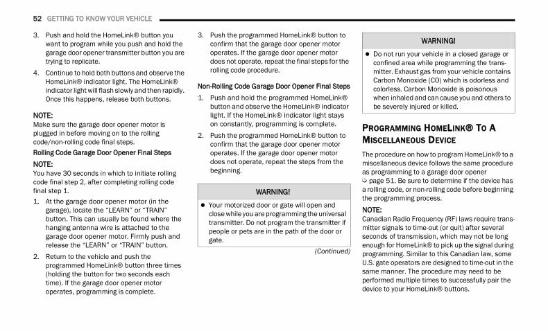
52 GETTING TO KNOW YOUR VEHICLE
(Continued)
3. Push and hold the HomeLink® button you want to program while you push and hold the garage door opener transmitter button you are trying to replicate.
4. Continue to hold both buttons and observe the HomeLink® indicator light. The HomeLink® indicator light will flash slowly and then rapidly. Once this happens, release both buttons.
NOTE:Make sure the garage door opener motor is plugged in before moving on to the rolling code/non-rolling code final steps.Rolling Code Garage Door Opener Final StepsNOTE:You have 30 seconds in which to initiate rolling code final step 2, after completing rolling code final step 1.1. At the garage door opener motor (in the
garage), locate the “LEARN” or “TRAIN” button. This can usually be found where the hanging antenna wire is attached to the garage door opener motor. Firmly push and release the “LEARN” or “TRAIN” button.
2. Return to the vehicle and push the programmed HomeLink® button three times (holding the button for two seconds each time). If the garage door opener motor operates, programming is complete.
3. Push the programmed HomeLink® button to confirm that the garage door opener motor operates. If the garage door opener motor does not operate, repeat the final steps for the rolling code procedure.
Non-Rolling Code Garage Door Opener Final Steps1. Push and hold the programmed HomeLink®
button and observe the HomeLink® indicator light. If the HomeLink® indicator light stays on constantly, programming is complete.
2. Push the programmed HomeLink® button to confirm that the garage door opener motor operates. If the garage door opener motor does not operate, repeat the steps from the beginning.
PROGRAMMING HOMELINK® TO A MISCELLANEOUS DEVICE
The procedure on how to program HomeLink® to a miscellaneous device follows the same procedure as programming to a garage door opener Ú page 51. Be sure to determine if the device has a rolling code, or non-rolling code before beginning the programming process.
NOTE:Canadian Radio Frequency (RF) laws require trans-mitter signals to time-out (or quit) after several seconds of transmission, which may not be long enough for HomeLink® to pick up the signal during programming. Similar to this Canadian law, some U.S. gate operators are designed to time-out in the same manner. The procedure may need to be performed multiple times to successfully pair the device to your HomeLink® buttons.
WARNING!
Your motorized door or gate will open and close while you are programming the universal transmitter. Do not program the transmitter if people or pets are in the path of the door or gate.
Do not run your vehicle in a closed garage or confined area while programming the trans-mitter. Exhaust gas from your vehicle contains Carbon Monoxide (CO) which is odorless and colorless. Carbon Monoxide is poisonous when inhaled and can cause you and others to be severely injured or killed.
WARNING!
22_DT_OM_EN_USC_t.book Page 52
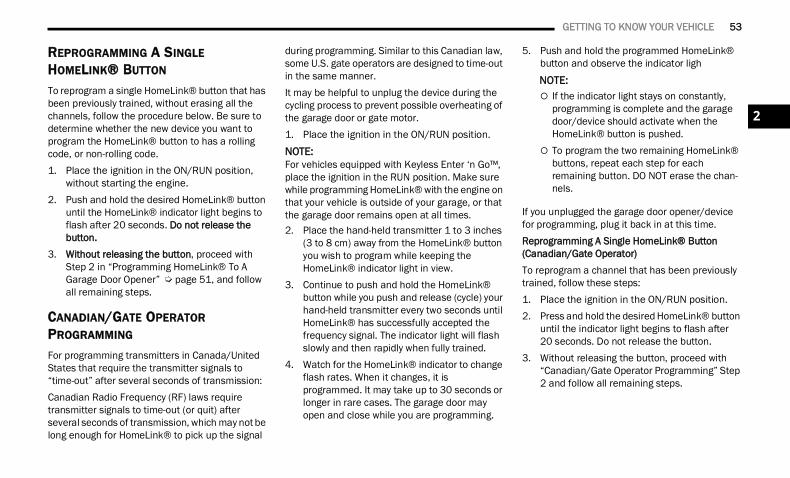
GETTING TO KNOW YOUR VEHICLE 53
REPROGRAMMING A SINGLE HOMELINK® BUTTON
To reprogram a single HomeLink® button that has been previously trained, without erasing all the channels, follow the procedure below. Be sure to determine whether the new device you want to program the HomeLink® button to has a rolling code, or non-rolling code.1. Place the ignition in the ON/RUN position,
without starting the engine.2. Push and hold the desired HomeLink® button
until the HomeLink® indicator light begins to flash after 20 seconds. Do not release the button.
3. Without releasing the button, proceed with Step 2 in “Programming HomeLink® To A Garage Door Opener” Ú page 51, and follow all remaining steps.
CANADIAN/GATE OPERATOR PROGRAMMING
For programming transmitters in Canada/United States that require the transmitter signals to “time-out” after several seconds of transmission:Canadian Radio Frequency (RF) laws require transmitter signals to time-out (or quit) after several seconds of transmission, which may not be long enough for HomeLink® to pick up the signal
during programming. Similar to this Canadian law, some U.S. gate operators are designed to time-out in the same manner.It may be helpful to unplug the device during the cycling process to prevent possible overheating of the garage door or gate motor.1. Place the ignition in the ON/RUN position.
NOTE:For vehicles equipped with Keyless Enter ‘n Go™, place the ignition in the RUN position. Make sure while programming HomeLink® with the engine on that your vehicle is outside of your garage, or that the garage door remains open at all times.2. Place the hand-held transmitter 1 to 3 inches
(3 to 8 cm) away from the HomeLink® button you wish to program while keeping the HomeLink® indicator light in view.
3. Continue to push and hold the HomeLink® button while you push and release (cycle) your hand-held transmitter every two seconds until HomeLink® has successfully accepted the frequency signal. The indicator light will flash slowly and then rapidly when fully trained.
4. Watch for the HomeLink® indicator to change flash rates. When it changes, it is programmed. It may take up to 30 seconds or longer in rare cases. The garage door may open and close while you are programming.
5. Push and hold the programmed HomeLink® button and observe the indicator ligh
NOTE: If the indicator light stays on constantly,
programming is complete and the garage door/device should activate when the HomeLink® button is pushed.
To program the two remaining HomeLink® buttons, repeat each step for each remaining button. DO NOT erase the chan-nels.
If you unplugged the garage door opener/device for programming, plug it back in at this time.Reprogramming A Single HomeLink® Button (Canadian/Gate Operator)To reprogram a channel that has been previously trained, follow these steps:1. Place the ignition in the ON/RUN position.2. Press and hold the desired HomeLink® button
until the indicator light begins to flash after 20 seconds. Do not release the button.
3. Without releasing the button, proceed with “Canadian/Gate Operator Programming” Step 2 and follow all remaining steps.
2
22_DT_OM_EN_USC_t.book Page 53
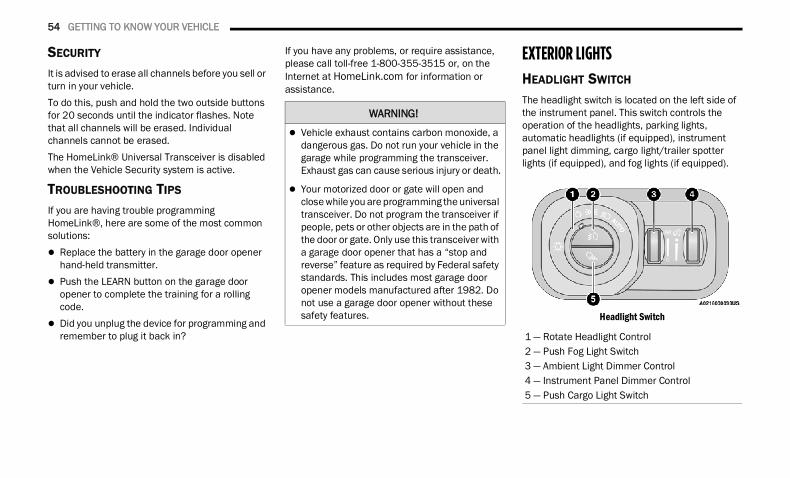
54 GETTING TO KNOW YOUR VEHICLE
SECURITY
It is advised to erase all channels before you sell or turn in your vehicle.To do this, push and hold the two outside buttons for 20 seconds until the indicator flashes. Note that all channels will be erased. Individual channels cannot be erased.The HomeLink® Universal Transceiver is disabled when the Vehicle Security system is active.
TROUBLESHOOTING TIPS
If you are having trouble programming HomeLink®, here are some of the most common solutions: Replace the battery in the garage door opener
hand-held transmitter. Push the LEARN button on the garage door
opener to complete the training for a rolling code.
Did you unplug the device for programming and remember to plug it back in?
If you have any problems, or require assistance, please call toll-free 1-800-355-3515 or, on the Internet at HomeLink.com for information or assistance.
EXTERIOR LIGHTS HEADLIGHT SWITCH The headlight switch is located on the left side of the instrument panel. This switch controls the operation of the headlights, parking lights, automatic headlights (if equipped), instrument panel light dimming, cargo light/trailer spotter lights (if equipped), and fog lights (if equipped).
Headlight Switch
WARNING!
Vehicle exhaust contains carbon monoxide, a dangerous gas. Do not run your vehicle in the garage while programming the transceiver. Exhaust gas can cause serious injury or death.
Your motorized door or gate will open and close while you are programming the universal transceiver. Do not program the transceiver if people, pets or other objects are in the path of the door or gate. Only use this transceiver with a garage door opener that has a “stop and reverse” feature as required by Federal safety standards. This includes most garage door opener models manufactured after 1982. Do not use a garage door opener without these safety features.
1 — Rotate Headlight Control2 — Push Fog Light Switch3 — Ambient Light Dimmer Control4 — Instrument Panel Dimmer Control5 — Push Cargo Light Switch
22_DT_OM_EN_USC_t.book Page 54
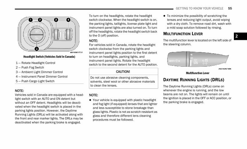
GETTING TO KNOW YOUR VEHICLE 55
Headlight Switch (Vehicles Sold In Canada)
NOTE:Vehicles sold in Canada are equipped with a head-light switch with an AUTO and ON detent but without an OFF detent. Headlights will be deacti-vated when the headlight switch is placed in the parking lights position. However, the Daytime Running Lights (DRLs) will be activated along with the front and rear marker lights. The DRLs may be deactivated when the parking brake is engaged.
To turn on the headlights, rotate the headlight switch clockwise. When the headlight switch is on, the parking lights, taillights, license plate light and instrument panel lights are also turned on. To turn off the headlights, rotate the headlight switch back to the O (off) position.
NOTE:For vehicles sold in Canada, rotate the headlight switch clockwise from the parking lights and instrument panel lights position to the first detent to turn on headlights, parking lights, and instrument panel lights. Rotate the headlight switch to the second detent for the AUTO position.
NOTE: Your vehicle is equipped with plastic headlight
and fog light (if equipped) lenses that are lighter and less susceptible to stone breakage than glass lights. Plastic is not as scratch resistant as glass and therefore different lens cleaning procedures must be followed.
To minimize the possibility of scratching the lenses and reducing light output, avoid wiping with a dry cloth. To remove road dirt, wash with a mild soap solution followed by rinsing.
MULTIFUNCTION LEVER The multifunction lever is located on the left side of the steering column.
Multifunction Lever
DAYTIME RUNNING LIGHTS (DRLS) The Daytime Running Lights (DRLs) come on whenever the engine is running, and the low beams are not on. The lights will remain on until the ignition is placed in the OFF or ACC position, or the parking brake is engaged.
1 — Rotate Headlight Control2 — Push Fog Switch3 — Ambient Light Dimmer Control4 — Instrument Panel Dimmer Control5 — Push Cargo Light Switch
CAUTION!
Do not use abrasive cleaning components, solvents, steel wool or other abrasive materials to clean the lenses.
2
22_DT_OM_EN_USC_t.book Page 55
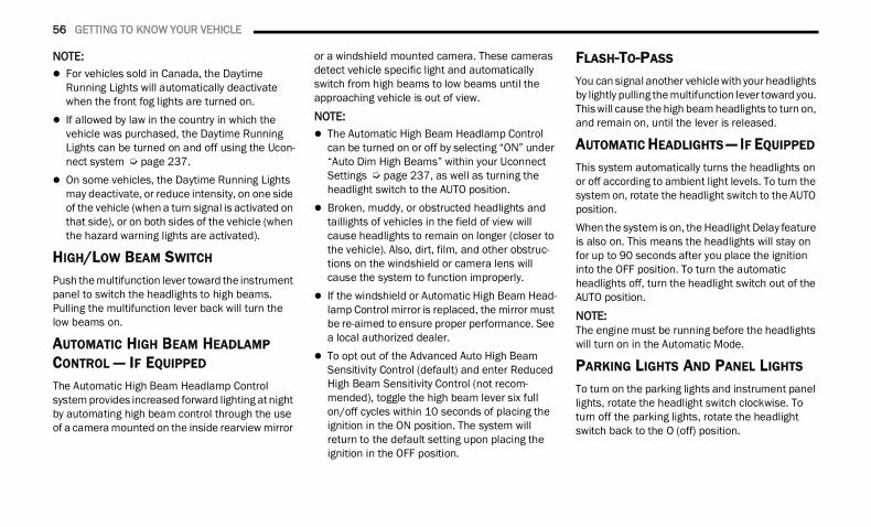
56 GETTING TO KNOW YOUR VEHICLE
NOTE: For vehicles sold in Canada, the Daytime
Running Lights will automatically deactivate when the front fog lights are turned on.
If allowed by law in the country in which the vehicle was purchased, the Daytime Running Lights can be turned on and off using the Ucon-nect system Ú page 237.
On some vehicles, the Daytime Running Lights may deactivate, or reduce intensity, on one side of the vehicle (when a turn signal is activated on that side), or on both sides of the vehicle (when the hazard warning lights are activated).
HIGH/LOW BEAM SWITCH Push the multifunction lever toward the instrument panel to switch the headlights to high beams. Pulling the multifunction lever back will turn the low beams on.
AUTOMATIC HIGH BEAM HEADLAMP CONTROL — IF EQUIPPED The Automatic High Beam Headlamp Control system provides increased forward lighting at night by automating high beam control through the use of a camera mounted on the inside rearview mirror
or a windshield mounted camera. These cameras detect vehicle specific light and automatically switch from high beams to low beams until the approaching vehicle is out of view.
NOTE: The Automatic High Beam Headlamp Control
can be turned on or off by selecting “ON” under “Auto Dim High Beams” within your Uconnect Settings Ú page 237, as well as turning the headlight switch to the AUTO position.
Broken, muddy, or obstructed headlights and taillights of vehicles in the field of view will cause headlights to remain on longer (closer to the vehicle). Also, dirt, film, and other obstruc-tions on the windshield or camera lens will cause the system to function improperly.
If the windshield or Automatic High Beam Head-lamp Control mirror is replaced, the mirror must be re-aimed to ensure proper performance. See a local authorized dealer.
To opt out of the Advanced Auto High Beam Sensitivity Control (default) and enter Reduced High Beam Sensitivity Control (not recom-mended), toggle the high beam lever six full on/off cycles within 10 seconds of placing the ignition in the ON position. The system will return to the default setting upon placing the ignition in the OFF position.
FLASH-TO-PASS You can signal another vehicle with your headlights by lightly pulling the multifunction lever toward you. This will cause the high beam headlights to turn on, and remain on, until the lever is released.
AUTOMATIC HEADLIGHTS — IF EQUIPPED This system automatically turns the headlights on or off according to ambient light levels. To turn the system on, rotate the headlight switch to the AUTO position.When the system is on, the Headlight Delay feature is also on. This means the headlights will stay on for up to 90 seconds after you place the ignition into the OFF position. To turn the automatic headlights off, turn the headlight switch out of the AUTO position.
NOTE:The engine must be running before the headlights will turn on in the Automatic Mode.
PARKING LIGHTS AND PANEL LIGHTS
To turn on the parking lights and instrument panel lights, rotate the headlight switch clockwise. To turn off the parking lights, rotate the headlight switch back to the O (off) position.
22_DT_OM_EN_USC_t.book Page 56
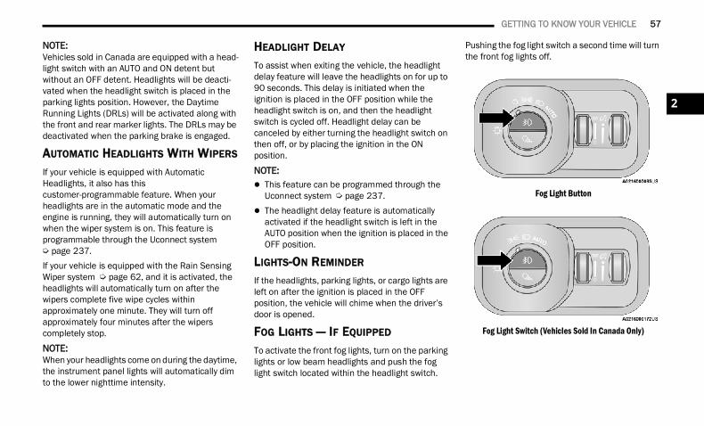
GETTING TO KNOW YOUR VEHICLE 57
NOTE:Vehicles sold in Canada are equipped with a head-light switch with an AUTO and ON detent but without an OFF detent. Headlights will be deacti-vated when the headlight switch is placed in the parking lights position. However, the Daytime Running Lights (DRLs) will be activated along with the front and rear marker lights. The DRLs may be deactivated when the parking brake is engaged.
AUTOMATIC HEADLIGHTS WITH WIPERS
If your vehicle is equipped with Automatic Headlights, it also has this customer-programmable feature. When your headlights are in the automatic mode and the engine is running, they will automatically turn on when the wiper system is on. This feature is programmable through the Uconnect system Ú page 237.If your vehicle is equipped with the Rain Sensing Wiper system Ú page 62, and it is activated, the headlights will automatically turn on after the wipers complete five wipe cycles within approximately one minute. They will turn off approximately four minutes after the wipers completely stop.
NOTE:When your headlights come on during the daytime, the instrument panel lights will automatically dim to the lower nighttime intensity.
HEADLIGHT DELAY
To assist when exiting the vehicle, the headlight delay feature will leave the headlights on for up to 90 seconds. This delay is initiated when the ignition is placed in the OFF position while the headlight switch is on, and then the headlight switch is cycled off. Headlight delay can be canceled by either turning the headlight switch on then off, or by placing the ignition in the ON position.
NOTE: This feature can be programmed through the
Uconnect system Ú page 237. The headlight delay feature is automatically
activated if the headlight switch is left in the AUTO position when the ignition is placed in the OFF position.
LIGHTS-ON REMINDER
If the headlights, parking lights, or cargo lights are left on after the ignition is placed in the OFF position, the vehicle will chime when the driver’s door is opened.
FOG LIGHTS — IF EQUIPPED To activate the front fog lights, turn on the parking lights or low beam headlights and push the fog light switch located within the headlight switch.
Pushing the fog light switch a second time will turn the front fog lights off.
Fog Light Button
Fog Light Switch (Vehicles Sold In Canada Only)
2
22_DT_OM_EN_USC_t.book Page 57
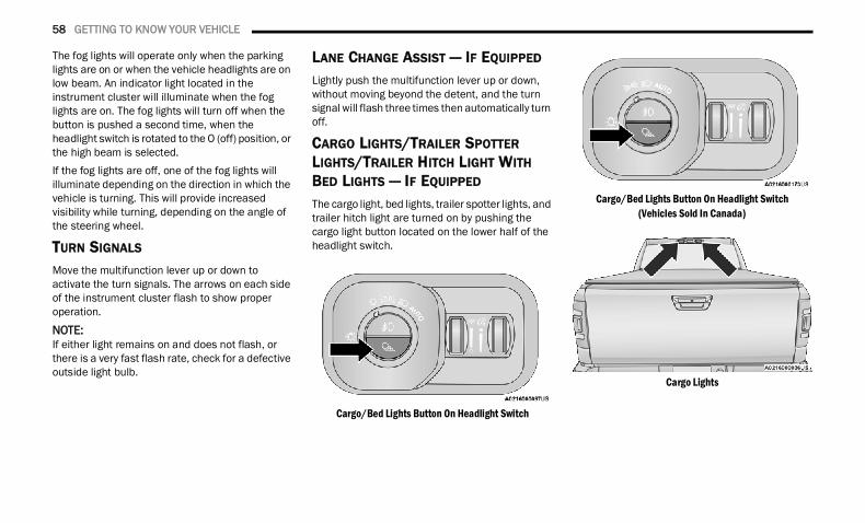
58 GETTING TO KNOW YOUR VEHICLE
The fog lights will operate only when the parking lights are on or when the vehicle headlights are on low beam. An indicator light located in the instrument cluster will illuminate when the fog lights are on. The fog lights will turn off when the button is pushed a second time, when the headlight switch is rotated to the O (off) position, or the high beam is selected.If the fog lights are off, one of the fog lights will illuminate depending on the direction in which the vehicle is turning. This will provide increased visibility while turning, depending on the angle of the steering wheel.
TURN SIGNALS Move the multifunction lever up or down to activate the turn signals. The arrows on each side of the instrument cluster flash to show proper operation.NOTE:If either light remains on and does not flash, or there is a very fast flash rate, check for a defective outside light bulb.
LANE CHANGE ASSIST — IF EQUIPPED
Lightly push the multifunction lever up or down, without moving beyond the detent, and the turn signal will flash three times then automatically turn off.
CARGO LIGHTS/TRAILER SPOTTER LIGHTS/TRAILER HITCH LIGHT WITH BED LIGHTS — IF EQUIPPED
The cargo light, bed lights, trailer spotter lights, and trailer hitch light are turned on by pushing the cargo light button located on the lower half of the headlight switch.
Cargo/Bed Lights Button On Headlight Switch
Cargo/Bed Lights Button On Headlight Switch(Vehicles Sold In Canada)
Cargo Lights
22_DT_OM_EN_USC_t.book Page 58
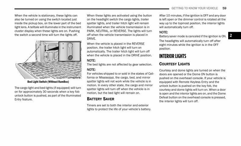
GETTING TO KNOW YOUR VEHICLE 59
When the vehicle is stationary, these lights can also be turned on using the switch located just inside the pickup box, on the lower part of the bed light lens. A telltale will illuminate in the instrument cluster display when these lights are on. Pushing the switch a second time will turn the lights off.
Bed Light Switch (Without RamBox)
The cargo light and bed lights (if equipped) will turn on for approximately 30 seconds when a key fob unlock button is pushed, as part of the Illuminated Entry feature.
When these lights are activated using the button on the headlight switch the cargo lights, trailer spotter lights, and trailer hitch light will remain illuminated when the vehicle transmission is in PARK, NEUTRAL, or REVERSE. The lights will turn off when the vehicle transmission is placed in DRIVE.When the vehicle is placed in the REVERSE position, the trailer hitch light will turn on automatically. The trailer hitch light will turn off when the vehicle is placed in the DRIVE position.
NOTE:The bed lights are not affected by gear selection.NOTE:For vehicles shipped to or sold in the states of Cali-fornia or Mississippi, the cargo, bed, and mirror spotter lights will not work while the vehicle is in motion. In every other state, the cargo and mirror spotter lights will turn off when the vehicle is in motion, but the bed light will remain on.
BATTERY SAVER
Timers are set to both the interior and exterior lights to protect the life of your vehicle’s battery.
After 10 minutes, if the ignition is OFF and any door is left open or the dimmer control is rotated all the way up to the topmost position, the interior lights will automatically turn off.NOTE:Battery saver mode is canceled if the ignition is ON.The headlights will automatically turn off after eight minutes while the ignition is in the OFF position.
INTERIOR LIGHTS COURTESY LIGHTS
Courtesy and dome lights are turned on when the doors are opened or the Dome ON button is pushed on the overhead console. If your vehicle is equipped with Remote Keyless Entry and the unlock button is pushed on the key fob, the courtesy and dome lights will turn on. When a door is open and the interior lights are on, and the Dome Defeat button on the overhead console is pressed, the interior lights will turn off.
2
22_DT_OM_EN_USC_t.book Page 59
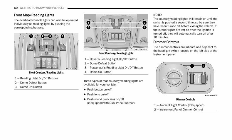
60 GETTING TO KNOW YOUR VEHICLE
Front Map/Reading LightsThe overhead console lights can also be operated individually as reading lights by pushing the corresponding buttons.
Front Courtesy/Reading Lights
Front Courtesy/Reading Lights
Three types of rear courtesy/reading lights are available for your vehicle. Push button on/off Push lens on/off Push round puck lens on/off
(if equipped with Dual Pane Sunroof)
NOTE:The courtesy/reading lights will remain on until the switch is pushed a second time, so be sure they have been turned off before exiting the vehicle. If the interior lights are left on after the ignition is turned off, they will automatically turn off after 10 minutes.Dimmer ControlsThe dimmer controls are inboard and adjacent to the headlight switch located on the left side of the instrument panel.
Dimmer Controls
1 — Reading Light On/Off Buttons2 — Dome Defeat Button3 — Dome ON Button
1 — Driver’s Reading Light On/Off Button2 — Dome Defeat Button3 — Passenger’s Reading Light On/Off Button4 — Dome On Button
1 — Ambient Light Control (If Equipped)2 — Instrument Panel Dimmer Control
22_DT_OM_EN_USC_t.book Page 60
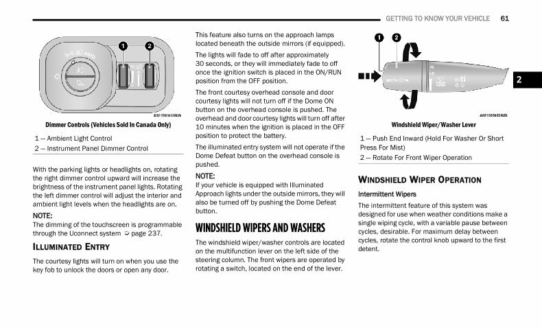
GETTING TO KNOW YOUR VEHICLE 61
Dimmer Controls (Vehicles Sold In Canada Only)
With the parking lights or headlights on, rotating the right dimmer control upward will increase the brightness of the instrument panel lights. Rotating the left dimmer control will adjust the interior and ambient light levels when the headlights are on.NOTE:The dimming of the touchscreen is programmable through the Uconnect system Ú page 237.
ILLUMINATED ENTRY The courtesy lights will turn on when you use the key fob to unlock the doors or open any door.
This feature also turns on the approach lamps located beneath the outside mirrors (if equipped).The lights will fade to off after approximately 30 seconds, or they will immediately fade to off once the ignition switch is placed in the ON/RUN position from the OFF position.The front courtesy overhead console and door courtesy lights will not turn off if the Dome ON button on the overhead console is pushed. The overhead and door courtesy lights will turn off after 10 minutes when the ignition is placed in the OFF position to protect the battery.The illuminated entry system will not operate if the Dome Defeat button on the overhead console is pushed.
NOTE:If your vehicle is equipped with Illuminated Approach lights under the outside mirrors, they will also be turned off by pushing the Dome Defeat button.
WINDSHIELD WIPERS AND WASHERS The windshield wiper/washer controls are located on the multifunction lever on the left side of the steering column. The front wipers are operated by rotating a switch, located on the end of the lever.
Windshield Wiper/Washer Lever
WINDSHIELD WIPER OPERATION
Intermittent WipersThe intermittent feature of this system was designed for use when weather conditions make a single wiping cycle, with a variable pause between cycles, desirable. For maximum delay between cycles, rotate the control knob upward to the first detent.
1 — Ambient Light Control2 — Instrument Panel Dimmer Control
1 — Push End Inward (Hold For Washer Or Short Press For Mist)2 — Rotate For Front Wiper Operation
2
22_DT_OM_EN_USC_t.book Page 61
62 GETTING TO KNOW YOUR VEHICLE
The delay interval decreases as you rotate the knob until it enters the low continual speed position. The delay can be regulated from a maximum of about 18 seconds between cycles, to a cycle every one second. The delay intervals will double in duration when the vehicle speed is 10 mph (16 km/h) or less.Windshield WashersTo use the windshield washer, push the washer knob, located on the end of the multifunction lever, inward and hold. Washer fluid will be sprayed and the wiper will operate for two to three cycles after the washer knob is released.If the washer knob pushed while in the delay range, the wiper will operate for several seconds after the washer knob is released. It will then resume the intermittent interval previously selected. If the washer knob is pushed while in the off position, the wiper will turn on and cycle approximately three times after the wash knob is released.To prevent freeze-up of your windshield washer system in cold weather, select a solution or mixture that meets or exceeds the temperature range of your climate. This rating information can be found on most washer fluid containers.
MistWhen a single wipe to clear off road mist or spray from a passing vehicle is needed, push the washer knob, located on the end of the multifunction lever, inward briefly and release. The wipers will cycle one time and automatically shut off.
NOTE:The mist feature does not activate the washer pump; therefore, no washer fluid will be sprayed on the windshield. The wash function must be used in order to spray the windshield with washer fluid.For information on wiper care and replacement, see Ú page 422.
RAIN SENSING WIPERS — IF EQUIPPED This feature senses rain or snowfall on the windshield and automatically activates the wipers. Rotate the end of the multifunction lever to one of four detent positions to activate this feature.
The sensitivity of the system can be adjusted with the multifunction lever. Wiper delay position one is the least sensitive, and wiper delay detent position four is the most sensitive.Wiper delay position three should be used for normal rain conditions.Positions one and two can be used if the driver desires less wiper sensitivity. Position four can be used if the driver desires more sensitivity. Place the wiper switch in the O (off) position when not using the system.
NOTE: The Rain Sensing feature will not operate when
the wiper switch is in the low or high-speed position.
The Rain Sensing feature may not function prop-erly when ice, or dried salt water is present on the windshield.
Use of Rain-X or products containing wax or sili-cone may reduce Rain Sensing performance.
The Rain Sensing feature can be turned on and off using the Uconnect system Ú page 237.
WARNING!
Sudden loss of visibility through the windshield could lead to a collision. You might not see other vehicles or other obstacles. To avoid sudden icing of the windshield during freezing weather, warm the windshield with the defroster before and during windshield washer use.
22_DT_OM_EN_USC_t.book Page 62
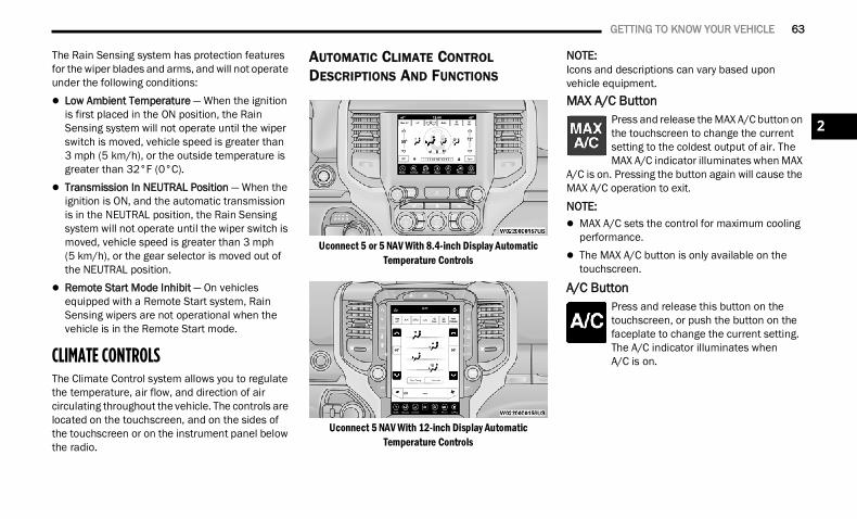
GETTING TO KNOW YOUR VEHICLE 63
The Rain Sensing system has protection features for the wiper blades and arms, and will not operate under the following conditions: Low Ambient Temperature — When the ignition
is first placed in the ON position, the Rain Sensing system will not operate until the wiper switch is moved, vehicle speed is greater than 3 mph (5 km/h), or the outside temperature is greater than 32°F (0°C).
Transmission In NEUTRAL Position — When the ignition is ON, and the automatic transmission is in the NEUTRAL position, the Rain Sensing system will not operate until the wiper switch is moved, vehicle speed is greater than 3 mph (5 km/h), or the gear selector is moved out of the NEUTRAL position.
Remote Start Mode Inhibit — On vehicles equipped with a Remote Start system, Rain Sensing wipers are not operational when the vehicle is in the Remote Start mode.
CLIMATE CONTROLS The Climate Control system allows you to regulate the temperature, air flow, and direction of air circulating throughout the vehicle. The controls are located on the touchscreen, and on the sides of the touchscreen or on the instrument panel below the radio.
AUTOMATIC CLIMATE CONTROL DESCRIPTIONS AND FUNCTIONS
Uconnect 5 or 5 NAV With 8.4-inch Display Automatic Temperature Controls
Uconnect 5 NAV With 12-inch Display AutomaticTemperature Controls
NOTE:Icons and descriptions can vary based upon vehicle equipment.MAX A/C Button
Press and release the MAX A/C button on the touchscreen to change the current setting to the coldest output of air. The MAX A/C indicator illuminates when MAX
A/C is on. Pressing the button again will cause the MAX A/C operation to exit.
NOTE: MAX A/C sets the control for maximum cooling
performance. The MAX A/C button is only available on the
touchscreen.
A/C ButtonPress and release this button on the touchscreen, or push the button on the faceplate to change the current setting. The A/C indicator illuminates whenA/C is on.
2
22_DT_OM_EN_USC_t.book Page 63
64 GETTING TO KNOW YOUR VEHICLE
Recirculation ButtonPress and release this button on the touchscreen, or push the button on the faceplate, to change the system between Recirculation mode and outside air
mode. The Recirculation indicator and the A/C indicator illuminate when the Recirculation button is pressed. Recirculation can be used when outside conditions, such as smoke, odors, dust, or high humidity are present. Recirculation can be used in all modes. Recirculation may be unavailable (button on the touchscreen greyed out) if conditions exist that could create fogging on the inside of the windshield. The A/C can be deselected manually without disturbing the mode control selection. Continuous use of the Recirculation mode may make the inside air stuffy and window fogging may occur. Extended use of this mode is not recommended. Recirculation mode may automatically adjust to optimize customer experience for warming, cooling, dehumidification, etc.In cold weather, use of Recirculation mode may lead to excessive window fogging. The recirculation feature may be unavailable if conditions exist that could create fogging on the inside of the windshield.
Auto ButtonSet your desired temperature and press AUTO. AUTO will achieve and maintain your desired temperature by automatically adjusting the blower speed
and air distribution. Air Conditioning (A/C) may be active during AUTO operation to improve performance. AUTO mode is highly recommended for efficiency.You can turn AUTO on in one of two ways: Press and release this button on the touch-
screen. Push the button on the faceplate.Toggling this function will cause the system to switch between manual mode and automatic mode Ú page 68.
Front Defrost ButtonPress and release the Front Defrost button on the touchscreen, or push and release the button on the faceplate, to change the current airflow setting to
Defrost mode. The Front Defrost indicator illuminates when Front Defrost is on. Air comes from the windshield and side window demist outlets. When the defrost button is selected, the blower level may increase. Use Defrost mode with maximum temperature settings for best windshield and side window defrosting and defogging. When toggling the front defrost mode
button, the climate system will return to the previous setting.
Rear Defrost ButtonPress and release the Rear Defrost button on the touchscreen, or push and release the button on the faceplate, to turn on the rear window defroster and the
heated outside mirrors (if equipped). The Rear Defrost indicator illuminates when the rear window defroster is on. The rear window defroster automatically turns off after 10 minutes.
CAUTION!
Failure to follow these cautions can cause damage to the heating elements:
Use care when washing the inside of the rear window. Do not use abrasive window cleaners on the interior surface of the window. Use a soft cloth and a mild washing solution, wiping parallel to the heating elements. Labels can be peeled off after soaking with warm water.
Do not use scrapers, sharp instruments, or abrasive window cleaners on the interior surface of the window.
Keep all objects a safe distance from the window.
22_DT_OM_EN_USC_t.book Page 64
GETTING TO KNOW YOUR VEHICLE 65
Driver And Passenger Temperature Up And Down ButtonsThese buttons provide the driver and passenger with independent temperature control.
Push the red button (or rotate knob if equipped) on the faceplate, press the red button on the touchscreen, or press and slide the temperature bar towards the
red arrow button on the touchscreen for warmer temperature settings.
Push the blue button (or rotate knob if equipped) on the faceplate, press the blue button on the touchscreen, or press and slide the temperature bar towards
the blue arrow button on the touchscreen for cooler temperature settings.
NOTE: The numbers within the temperature display will
only appear if the system is equipped with an automatic climate control system.
Up and down buttons are only available on vehi-cles equipped with a 12-inch display.
SYNC ButtonPress the SYNC button on the touchscreen to toggle the SYNC feature on/off. The SYNC indicator illuminates when SYNC is on. SYNC synchronizes the
passenger temperature setting with the driver temperature setting. Changing the passenger’s temperature setting while in SYNC will automatically exit this feature.
NOTE:The SYNC button is only available on the touch-screen.Blower Control
Blower Control regulates the amount of air forced through the climate control system. There are seven blower speeds available. Adjusting the blower will cause
automatic mode to switch to manual operation. The speeds can be selected using either the blower control knob on the faceplate or the buttons on the touchscreen.FaceplateThe blower speed increases as you turn the blower control knob clockwise from the lowest blower setting. The blower speed decreases as you turn the blower control knob counterclockwise.
TouchscreenUse the small blower icon to reduce the blower setting and the large blower icon to increase the blower setting. Blower can also be selected by pressing the blower bar area between the icons.
Mode ControlSelect Mode by pressing one of the Mode buttons on the touchscreen, or pushing the Mode button on the faceplate, to change the airflow distribution mode.
The airflow distribution mode can be adjusted so air comes from the instrument panel outlets, floor outlets, defrost outlets, and demist outlets.
Panel ModeAir comes from the outlets in the instrument panel. Each of these outlets can be individually adjusted to direct the flow of air. The air vanes of the center
outlets and outboard outlets can be moved up and down or side to side to regulate airflow direction. There is a shut-off wheel located below the air vanes to shut off or adjust the amount of airflow from these outlets.
2
22_DT_OM_EN_USC_t.book Page 65
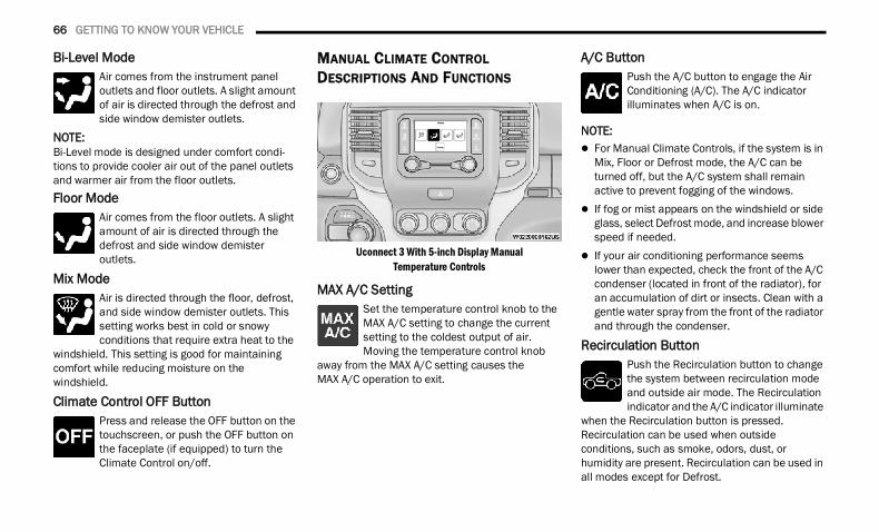
66 GETTING TO KNOW YOUR VEHICLE
Bi-Level ModeAir comes from the instrument panel outlets and floor outlets. A slight amount of air is directed through the defrost and side window demister outlets.
NOTE:Bi-Level mode is designed under comfort condi-tions to provide cooler air out of the panel outlets and warmer air from the floor outlets.Floor Mode
Air comes from the floor outlets. A slight amount of air is directed through the defrost and side window demister outlets.
Mix ModeAir is directed through the floor, defrost, and side window demister outlets. This setting works best in cold or snowy conditions that require extra heat to the
windshield. This setting is good for maintaining comfort while reducing moisture on the windshield.
Climate Control OFF ButtonPress and release the OFF button on the touchscreen, or push the OFF button on the faceplate (if equipped) to turn the Climate Control on/off.
MANUAL CLIMATE CONTROL DESCRIPTIONS AND FUNCTIONS
Uconnect 3 With 5-inch Display Manual Temperature Controls
MAX A/C SettingSet the temperature control knob to the MAX A/C setting to change the current setting to the coldest output of air. Moving the temperature control knob
away from the MAX A/C setting causes the MAX A/C operation to exit.
A/C ButtonPush the A/C button to engage the Air Conditioning (A/C). The A/C indicator illuminates when A/C is on.
NOTE: For Manual Climate Controls, if the system is in
Mix, Floor or Defrost mode, the A/C can be turned off, but the A/C system shall remain active to prevent fogging of the windows.
If fog or mist appears on the windshield or side glass, select Defrost mode, and increase blower speed if needed.
If your air conditioning performance seems lower than expected, check the front of the A/C condenser (located in front of the radiator), for an accumulation of dirt or insects. Clean with a gentle water spray from the front of the radiator and through the condenser.
Recirculation ButtonPush the Recirculation button to change the system between recirculation mode and outside air mode. The Recirculation indicator and the A/C indicator illuminate
when the Recirculation button is pressed. Recirculation can be used when outside conditions, such as smoke, odors, dust, or humidity are present. Recirculation can be used in all modes except for Defrost.
22_DT_OM_EN_USC_t.book Page 66
GETTING TO KNOW YOUR VEHICLE 67
Recirculation may be unavailable if conditions exist that could create fogging on the inside of the windshield. The A/C can be deselected manually without disturbing the mode control selection. Continuous use of the Recirculation mode may make the inside air stuffy and window fogging may occur. Extended use of this mode is not recommended.On systems with Manual Climate Controls, the Recirculation mode is not allowed in Defrost mode to improve window cleaning operation. Recirculation is disabled automatically if this mode is selected. Attempting to use Recirculation while in this mode causes the LED in the control button to blink and then turn off.
Front Defrost SettingTurn the mode control knob to the Front Defrost mode setting. Air comes from the windshield and side window demist outlets. When the defrost button is
selected, the blower level may increase. Use Defrost mode with maximum temperature settings for best windshield and side window defrosting and defogging.
Rear Defrost ButtonPush and release the Rear Defrost Control button to turn on the rear window defroster and the heated outside mirrors (if equipped). The Rear Defrost indicator
illuminates when the rear window defroster is on. The rear window defroster automatically turns off after 10 minutes.
Temperature ControlTemperature Control regulates the temperature of the air forced through the climate system.
The temperature increases as you turn the temperature control knob clockwise.
The temperature decreases as you turn the temperature control knob counterclockwise.
Blower ControlBlower Control regulates the amount of air forced through the climate control system. There are seven blower speeds available. The blower speed increases as
you turn the blower control knob clockwise from the lowest blower setting. The blower speed decreases as you turn the blower control knob counterclockwise.
Mode ControlTurn the mode control knob or press the mode control button (if equipped) to adjust airflow distribution. The airflow distribution mode can be adjusted so air
comes from the instrument panel outlets, floor outlets, defrost outlets and demist outlets.
CAUTION!
Failure to follow these cautions can cause damage to the heating elements:
Use care when washing the inside of the rear window. Do not use abrasive window cleaners on the interior surface of the window. Use a soft cloth and a mild washing solution, wiping parallel to the heating elements. Labels can be peeled off after soaking with warm water.
Do not use scrapers, sharp instruments, or abrasive window cleaners on the interior surface of the window.
Keep all objects a safe distance from the window.
2
22_DT_OM_EN_USC_t.book Page 67
68 GETTING TO KNOW YOUR VEHICLE
Panel ModeAir comes from the outlets in the instrument panel. Each of these outlets can be individually adjusted to direct the flow of air. The air vanes of the center
outlets and outboard outlets can be moved up and down or side to side to regulate airflow direction. There is a shut-off wheel located below the air vanes to shut off or adjust the amount of airflow from these outlets.
Bi-Level ModeAir comes from the instrument panel outlets and floor outlets. A slight amount of air is directed through the defrost and side window demister outlets.
NOTE:Bi-Level mode is designed under comfort condi-tions to provide cooler air out of the panel outlets and warmer air from the floor outlets.Floor Mode
Air comes from the floor outlets. A slight amount of air is directed through the defrost and side window demister outlets.
Mix ModeAir is directed through the floor, defrost, and side window demister outlets. This setting works best in cold or snowy conditions that require extra heat to the
windshield. This setting is good for maintaining comfort while reducing moisture on the windshield.
AUTOMATIC TEMPERATURE CONTROL (ATC) — IF EQUIPPED Automatic Operation1. Push the AUTO button on the faceplate, or the
AUTO button on the touchscreen on the Automatic Temperature Control (ATC) Panel.
2. Next, adjust the temperature that you would like the system to maintain by adjusting the driver and passenger temperature control buttons. Once the desired temperature is displayed, the system will achieve and automatically maintain that temperature.
3. When the system is set up for your comfort level, it is not necessary to change the settings. You will experience the greatest efficiency by simply allowing the system to function automatically.
NOTE: It is not necessary to move the temperature
settings for cold or hot vehicles. The system automatically adjusts the temperature, mode, and blower speed to provide comfort as quickly as possible.
The temperature can be displayed in US or Metric units by selecting the US/Metric customer-programmable feature within Ucon-nect Settings Ú page 237.
To provide you with maximum comfort in the Automatic mode during cold start-ups, the blower fan will remain on low until the engine warms up. The blower will increase in speed and transition into Auto mode.
Manual Operation OverrideThis system offers a full complement of manual override features. The AUTO symbol in the front ATC display will be turned off when the system is being used in the manual mode.
22_DT_OM_EN_USC_t.book Page 68
GETTING TO KNOW YOUR VEHICLE 69
CLIMATE VOICE RECOGNITION — IF EQUIPPED
Adjust vehicle temperatures hands-free and keep everyone comfortable while you keep moving ahead.Push the VR button on the steering wheel. After the beep, say one of the following commands: “Set driver temperature to 70 degrees” “Set passenger temperature to 70 degrees”Did you know: Voice Command for Climate may only be used to adjust the interior temperature of your vehicle. Voice Command will not work to adjust the heated seats or steering wheel if equipped.
OPERATING TIPS Refer to the chart at the end of this section for suggested control settings for various weather conditions.
Summer OperationThe engine cooling system must be protected with a high-quality antifreeze coolant to provide proper corrosion protection and to protect against engine overheating. OAT coolant (conforming to MS.90032) is recommended.
Winter OperationTo ensure the best possible heater and defroster performance, make sure the engine cooling system is functioning properly and the proper amount, type, and concentration of coolant is used. Use of the Air Recirculation mode during Winter months is not recommended, because it may cause window fogging.
Vacation/Storage For information on maintaining the Climate Control system when the vehicle is being stored for an extended period of time, see Ú page 466.
Window Fogging Vehicle windows tend to fog on the inside in mild, rainy, and/or humid weather. To clear the windows, select Defrost or Mix mode and increase the front blower speed. Do not use the Recirculation mode without A/C for long periods, as fogging may occur.
Outside Air IntakeMake sure the air intake, located directly in front of the windshield, is free of obstructions, such as leaves. Leaves collected in the air intake may reduce airflow, and if they enter the air distribution box, they could plug the water drains. In Winter months, make sure the air intake is clear of ice, slush, and snow.
Cabin Air Filter The Climate Control system filters out dust and pollen from the air. Contact an authorized dealer to service your cabin air filter, and to have it replaced when needed.
Stop/Start System — If EquippedWhile in an Autostop, the Climate Control system may automatically adjust airflow to maintain cabin comfort. Customer settings will be maintained upon return to an engine running condition.
2
22_DT_OM_EN_USC_t.book Page 69
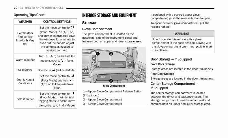
70 GETTING TO KNOW YOUR VEHICLE
Operating Tips Chart INTERIOR STORAGE AND EQUIPMENTSTORAGE
Glove CompartmentThe glove compartment is located on the passenger side of the instrument panel and features both an upper and lower storage area.
Glove Compartment
If equipped with a covered upper glove compartment, push the release button to open.To open the lower glove compartment, pull the release handle.
Door Storage — If EquippedFront Door StorageStorage areas are located in the door trim panels.Rear Door StorageStorage areas are located in the door trim panels.
Center Storage Compartment — If Equipped The center storage compartment is located between the driver and passenger seats. The storage compartment provides an armrest and contains both an upper and lower storage area.
WEATHER CONTROL SETTINGS
Hot Weather And Vehicle
Interior Is Very Hot
Set the mode control to (Panel Mode), (A/C) on,
and blower on high. Roll down the windows for a minute to flush out the hot air. Adjust the controls as needed to
achieve comfort.
Warm WeatherTurn (A/C) on and set the
mode control to (Panel Mode).
Cool Sunny Operate in (Bi-Level Mode).
Cool & Humid Conditions
Set the mode control to (Floor Mode) and turn (A/C) on to keep windows
clear.
Cold Weather
Set the mode control to (Floor Mode). If windshield
fogging starts to occur, move the control to (Mix Mode).
1 — Upper Glove Compartment Release Button(If Equipped)2 — Upper Glove Compartment3 — Lower Glove Compartment
WARNING!
Do not operate this vehicle with a glove compartment in the open position. Driving with the glove compartment open may result in injury in a collision.
22_DT_OM_EN_USC_t.book Page 70
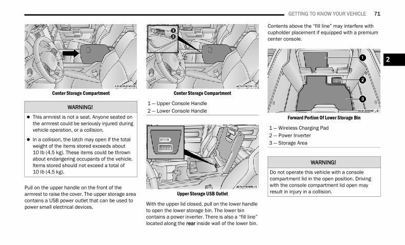
GETTING TO KNOW YOUR VEHICLE 71
Center Storage Compartment
Pull on the upper handle on the front of the armrest to raise the cover. The upper storage area contains a USB power outlet that can be used to power small electrical devices.
Center Storage Compartment
Upper Storage USB Outlet
With the upper lid closed, pull on the lower handle to open the lower storage bin. The lower bin contains a power inverter. There is also a “fill line” located along the rear inside wall of the lower bin.
Contents above the “fill line” may interfere with cupholder placement if equipped with a premium center console.
Forward Portion Of Lower Storage Bin
WARNING!
This armrest is not a seat. Anyone seated on the armrest could be seriously injured during vehicle operation, or a collision.
In a collision, the latch may open if the total weight of the items stored exceeds about 10 lb (4.5 kg). These items could be thrown about endangering occupants of the vehicle. Items stored should not exceed a total of 10 lb (4.5 kg).
1 — Upper Console Handle2 — Lower Console Handle
1 — Wireless Charging Pad2 — Power Inverter3 — Storage Area
WARNING!
Do not operate this vehicle with a console compartment lid in the open position. Driving with the console compartment lid open may result in injury in a collision.
2
22_DT_OM_EN_USC_t.book Page 71
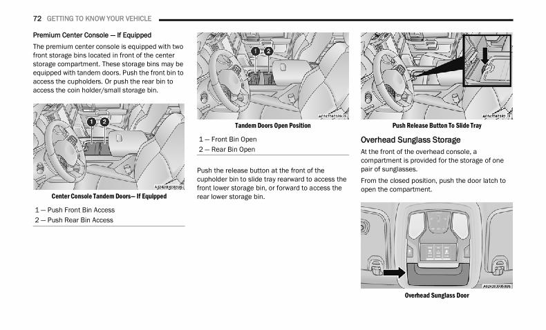
72 GETTING TO KNOW YOUR VEHICLE
Premium Center Console — If EquippedThe premium center console is equipped with two front storage bins located in front of the center storage compartment. These storage bins may be equipped with tandem doors. Push the front bin to access the cupholders. Or push the rear bin to access the coin holder/small storage bin.
Center Console Tandem Doors— If Equipped
Tandem Doors Open Position
Push the release button at the front of the cupholder bin to slide tray rearward to access the front lower storage bin, or forward to access the rear lower storage bin.
Push Release Button To Slide Tray
Overhead Sunglass StorageAt the front of the overhead console, a compartment is provided for the storage of one pair of sunglasses.From the closed position, push the door latch to open the compartment.
Overhead Sunglass Door
1 — Push Front Bin Access2 — Push Rear Bin Access
1 — Front Bin Open2 — Rear Bin Open
22_DT_OM_EN_USC_t.book Page 72
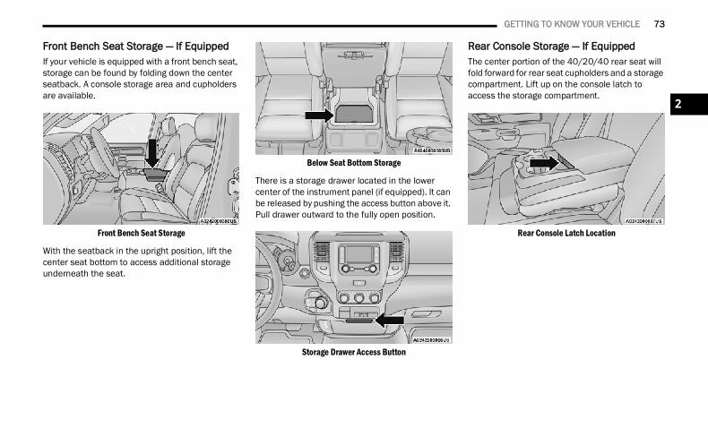
GETTING TO KNOW YOUR VEHICLE 73
Front Bench Seat Storage — If EquippedIf your vehicle is equipped with a front bench seat, storage can be found by folding down the center seatback. A console storage area and cupholders are available.
Front Bench Seat Storage
With the seatback in the upright position, lift the center seat bottom to access additional storage underneath the seat.
Below Seat Bottom Storage
There is a storage drawer located in the lower center of the instrument panel (if equipped). It can be released by pushing the access button above it. Pull drawer outward to the fully open position.
Storage Drawer Access Button
Rear Console Storage — If EquippedThe center portion of the 40/20/40 rear seat will fold forward for rear seat cupholders and a storage compartment. Lift up on the console latch to access the storage compartment.
Rear Console Latch Location
2
22_DT_OM_EN_USC_t.book Page 73
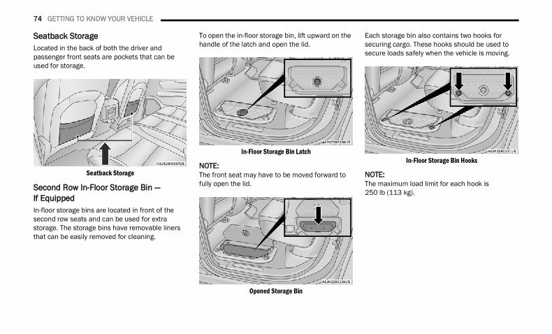
74 GETTING TO KNOW YOUR VEHICLE
Seatback StorageLocated in the back of both the driver and passenger front seats are pockets that can be used for storage.
Seatback Storage
Second Row In-Floor Storage Bin — If EquippedIn-floor storage bins are located in front of the second row seats and can be used for extra storage. The storage bins have removable liners that can be easily removed for cleaning.
To open the in-floor storage bin, lift upward on the handle of the latch and open the lid.
In-Floor Storage Bin Latch
NOTE:The front seat may have to be moved forward to fully open the lid.
Opened Storage Bin
Each storage bin also contains two hooks for securing cargo. These hooks should be used to secure loads safely when the vehicle is moving.
In-Floor Storage Bin Hooks
NOTE:The maximum load limit for each hook is 250 lb (113 kg).
22_DT_OM_EN_USC_t.book Page 74
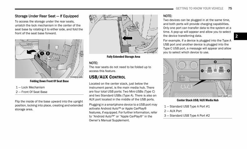
GETTING TO KNOW YOUR VEHICLE 75
Storage Under Rear Seat — If EquippedTo access the storage under the rear seats, unlatch the lock mechanism in the center of the seat base by rotating it to either side, and fold the front of the seat base forward.
Folding Down Front Of Seat Base
Flip the inside of the base upward into the upright position, locking into place, creating and extended storage area.
Fully Extended Storage Area
NOTE:The rear seats do not need to be folded up to access this feature.
USB/AUX CONTROL Located on the center stack, just below the instrument panel, is the main media hub. There are four total USB ports: Two Mini-USBs (Type C) and two Standard USBs (Type A). There is also an AUX port located in the middle of the USB ports.Plugging in a smartphone device to a USB port may activate Android Auto™ or Apple CarPlay® features, if equipped. For further information, refer to “Android Auto™” or “Apple CarPlay®” in the Owner’s Manual Supplement.
NOTE:Two devices can be plugged in at the same time, and both ports will provide charging capabilities. Only one port can transfer data to the system at a time. A pop-up will appear and allow you to select the device transferring data.For example, if a device is plugged into the Type A USB port and another device is plugged into the Type C USB port, a message will appear and allow you to select which device to use.
Center Stack USB/AUX Media Hub
1 — Lock Mechanism2 — Front Of Seat Base
1 — Standard USB Type A Port #12 — AUX Port3 — Standard USB Type A Port #2
2
22_DT_OM_EN_USC_t.book Page 75
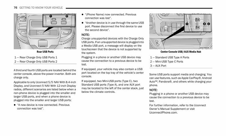
76 GETTING TO KNOW YOUR VEHICLE
Rear USB Ports
A third and fourth USB ports are located behind the center console, above the power inverter. Both are charge only.Applicable to only Uconnect 5/5 NAV With 8.4-inch Display, and Uconnect 5 NAV With 12-inch Display radios, different scenarios are listed below when a non-phone device is plugged into the smaller and larger USB ports, and when a phone device is plugged into the smaller and larger USB ports: “A new device is now connected. Previous
connection was lost”.
“(Phone Name) now connected. Previous connection was lost”.
“Another device is in use through the same USB port. Please disconnect the first device to use the second device”.
NOTE:Charge unsupported devices with the Charge Only USB ports. If an unsupported device is plugged into a Media USB port, a message will display on the touchscreen that the device is not supported by the system.Plugging in a phone or another USB device may cause the connection to a previous device to be lost.If equipped, your vehicle may also contain a USB port located on the top tray of the vehicle’s center console.If equipped, two Mini-USB ports (Type C), two Standard USB ports (Type A), and one AUX port may be located to the left of the center stack, just below the climate controls.
Center Console USB/AUX Media Hub
Some USB ports support media and charging. You can use features, such as Apple CarPlay®, Android Auto™, Pandora®, and others while charging your phone.
NOTE:Plugging in a phone or another USB device may cause the connection to a previous device to be lost.For further information, refer to the Uconnect Owner’s Manual Supplement or visit UconnectPhone.com.
1 — Rear Charge Only USB Ports 12 — Rear Charge Only USB Ports 2
1 — Standard USB Type A Ports2 — Mini-USB Type C Ports3 — AUX Port
22_DT_OM_EN_USC_t.book Page 76
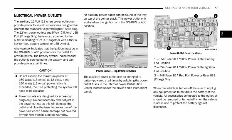
GETTING TO KNOW YOUR VEHICLE 77
ELECTRICAL POWER OUTLETS The auxiliary 12 Volt (13 Amp) power outlet can provide power for in-cab accessories designed for use with the standard “cigarette lighter” style plug. The 12 Volt power outlets and 5 Volt (2.5 Amp) USB Port (Charge Only) have a cap attached to the outlet indicating “12V DC”, together with either a key symbol, battery symbol, or USB symbol.A key symbol indicates that the ignition must be in the ON/RUN or ACC positions for the outlet to provide power. The battery symbol indicates that the outlet is connected to the battery, and can provide power at all times.
An auxiliary power outlet can be found in the tray on top of the center stack. This power outlet only works when the ignition is in the ON/RUN or ACC position.
Power Outlet — Top Of Center Stack
The auxiliary power outlet can be changed to battery powered at all times by switching the power outlet fuses in the Internal Power Distribution Center located under the driver’s side instrument panel.
Power Outlet Fuse Locations
When the vehicle is turned off, be sure to unplug any equipment as to not drain the battery of the vehicle. All accessories connected to the outlet(s) should be removed or turned off when the vehicle is not in use to protect the battery against discharge.
CAUTION!
Do not exceed the maximum power of 160 Watts (13 Amps) at 12 Volts. If the 160 Watts (13 Amps) power rating is exceeded, the fuse protecting the system will need to be replaced.
Power outlets are designed for accessory plugs only. Do not insert any other object in the power outlets as this will damage the outlet and blow the fuse. Improper use of the power outlet can cause damage not covered by your New Vehicle Limited Warranty.
1 — F54 Fuse 20 A Yellow Power Outlet Battery Fed Position2 — F54 Fuse 20 A Yellow Power Outlet Ignition Fed Position3 — F48 Fuse 10 A Red Port Power or Rear USB (Charge Only)
2
22_DT_OM_EN_USC_t.book Page 77
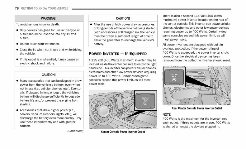
78 GETTING TO KNOW YOUR VEHICLE
(Continued)
POWER INVERTER — IF EQUIPPED A 115 Volt (400 Watts maximum) inverter may be located inside the center console towards the right hand side. This inverter can power cellular phones, electronics and other low power devices requiring power up to 400 Watts. Certain video game consoles exceed this power limit, as will most power tools.
Center Console Power Inverter Outlet
There is also a second 115 Volt (400 Watts maximum) power inverter located on the rear of the center console. This inverter can power cellular phones, electronics and other low power devices requiring power up to 400 Watts. Certain video game consoles exceed this power limit, as will most power tools.All power inverters are designed with built-in overload protection. If the power rating of 400 Watts is exceeded, the power inverter shuts down. Once the electrical device has been removed from the outlet the inverter should reset.
Rear Center Console Power Inverter Outlet
NOTE:400 Watts is the maximum for the inverter, not each outlet. If three outlets are in use, 400 Watts is shared amongst the devices plugged in.
WARNING!
To avoid serious injury or death:
Only devices designed for use in this type of outlet should be inserted into any 12 Volt outlet.
Do not touch with wet hands.
Close the lid when not in use and while driving the vehicle.
If this outlet is mishandled, it may cause an electric shock and failure.
CAUTION!
Many accessories that can be plugged in draw power from the vehicle's battery, even when not in use (i.e., cellular phones, etc.). Eventu-ally, if plugged in long enough, the vehicle's battery will discharge sufficiently to degrade battery life and/or prevent the engine from starting.
Accessories that draw higher power (i.e., coolers, vacuum cleaners, lights, etc.), will discharge the battery even more quickly. Only use these intermittently and with greater caution.
After the use of high power draw accessories, or long periods of the vehicle not being started (with accessories still plugged in), the vehicle must be driven a sufficient length of time to allow the generator to recharge the vehicle's battery.
CAUTION!
22_DT_OM_EN_USC_t.book Page 78
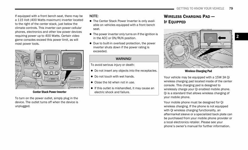
GETTING TO KNOW YOUR VEHICLE 79
If equipped with a front bench seat, there may be a 115 Volt (400 Watts maximum) inverter located to the right of the center stack, just below the climate controls. This inverter can power cellular phones, electronics and other low power devices requiring power up to 400 Watts. Certain video game consoles exceed this power limit, as will most power tools.
Center Stack Power Inverter
To turn on the power outlet, simply plug in the device. The outlet turns off when the device is unplugged.
NOTE: The Center Stack Power Inverter is only avail-
able on vehicles equipped with a front bench seat.
The power inverter only turns on if the ignition is in the ACC or ON/RUN position.
Due to built-in overload protection, the power inverter shuts down if the power rating is exceeded.
WIRELESS CHARGING PAD — IF EQUIPPED
Wireless Charging Pad
Your vehicle may be equipped with a 15W 3A Qi wireless charging pad located inside of the center console. This charging pad is designed to wirelessly charge your Qi enabled mobile phone. Qi is a standard that allows wireless charging of your mobile phone.Your mobile phone must be designed for Qi wireless charging. If the phone is not equipped with Qi wireless charging functionality, an aftermarket sleeve or a specialized back plate can be purchased from your mobile phone provider or a local electronics retailer. Please see your phone’s owner’s manual for further information.
WARNING!
To avoid serious injury or death:
Do not insert any objects into the receptacles.
Do not touch with wet hands.
Close the lid when not in use.
If this outlet is mishandled, it may cause an electric shock and failure.
2
22_DT_OM_EN_USC_t.book Page 79
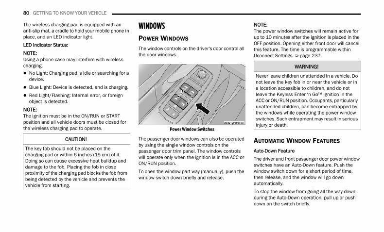
80 GETTING TO KNOW YOUR VEHICLE
The wireless charging pad is equipped with an anti-slip mat, a cradle to hold your mobile phone in place, and an LED indicator light.LED Indicator Status:NOTE:Using a phone case may interfere with wireless charging. No Light: Charging pad is idle or searching for a
device. Blue Light: Device is detected, and is charging. Red Light/Flashing: Internal error, or foreign
object is detected.NOTE:The ignition must be in the ON/RUN or START position and all vehicle doors must be closed for the wireless charging pad to operate.
WINDOWS POWER WINDOWS
The window controls on the driver's door control all the door windows.
Power Window Switches
The passenger door windows can also be operated by using the single window controls on the passenger door trim panel. The window controls will operate only when the ignition is in the ACC or ON/RUN position.To open the window part way (manually), push the window switch down briefly and release.
NOTE:The power window switches will remain active for up to 10 minutes after the ignition is placed in the OFF position. Opening either front door will cancel this feature. The time is programmable within Uconnect Settings Ú page 237.
AUTOMATIC WINDOW FEATURES
Auto-Down FeatureThe driver and front passenger door power window switches have an Auto-Down feature. Push the window switch down for a short period of time, then release, and the window will go down automatically.To stop the window from going all the way down during the Auto-Down operation, pull up or push down on the switch briefly.
CAUTION!
The key fob should not be placed on the charging pad or within 6 inches (15 cm) of it. Doing so can cause excessive heat buildup and damage to the fob. Placing the fob in close proximity of the charging pad blocks the fob from being detected by the vehicle and prevents the vehicle from starting.
WARNING!
Never leave children unattended in a vehicle. Do not leave the key fob in or near the vehicle or in a location accessible to children, and do not leave the Keyless Enter ‘n Go™ Ignition in the ACC or ON/RUN position. Occupants, particularly unattended children, can become entrapped by the windows while operating the power window switches. Such entrapment may result in serious injury or death.
22_DT_OM_EN_USC_t.book Page 80
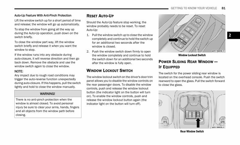
GETTING TO KNOW YOUR VEHICLE 81
Auto-Up Feature With Anti-Pinch ProtectionLift the window switch up for a short period of time and release; the window will go up automatically.To stop the window from going all the way up during the Auto-Up operation, push down on the switch briefly.To close the window part way, lift the window switch briefly and release it when you want the window to stop.If the window runs into any obstacle during auto-closure, it will reverse direction and then go back down. Remove the obstacle and use the window switch again to close the window.
NOTE:Any impact due to rough road conditions may trigger the auto-reverse function unexpectedly during auto-closure. If this happens, pull the switch lightly and hold to close the window manually.
RESET AUTO-UP Should the Auto-Up feature stop working, the window probably needs to be reset. To reset Auto-Up:1. Pull the window switch up to close the window
completely and continue to hold the switch up for an additional two seconds after the window is closed.
2. Push the window switch down firmly to open the window completely and continue to hold the switch down for an additional two seconds after the window is fully open.
WINDOW LOCKOUT SWITCH
The window lockout switch on the driver's door trim panel allows you to disable the window controls on the rear passenger doors. To disable the window controls, push and release the window lockout button (the indicator light on the button will turn on). To enable the window controls, push and release the window lockout button again (the indicator light on the button will turn off).
Window Lockout Switch
POWER SLIDING REAR WINDOW — IF EQUIPPED The switch for the power sliding rear window is located on the overhead console. Push the switch rearward to open the glass. Pull the switch forward to close the glass.
Rear Window Switch
WARNING!
There is no anti-pinch protection when the window is almost closed. To avoid personal injury be sure to clear your arms, hands, fingers and all objects from the window path before closing.
2
22_DT_OM_EN_USC_t.book Page 81
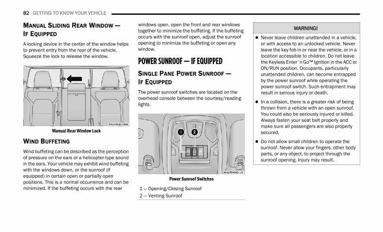
82 GETTING TO KNOW YOUR VEHICLE
MANUAL SLIDING REAR WINDOW —IF EQUIPPED
A locking device in the center of the window helps to prevent entry from the rear of the vehicle. Squeeze the lock to release the window.
Manual Rear Window Lock
WIND BUFFETING Wind buffeting can be described as the perception of pressure on the ears or a helicopter-type sound in the ears. Your vehicle may exhibit wind buffeting with the windows down, or the sunroof (if equipped) in certain open or partially open positions. This is a normal occurrence and can be minimized. If the buffeting occurs with the rear
windows open, open the front and rear windows together to minimize the buffeting. If the buffeting occurs with the sunroof open, adjust the sunroof opening to minimize the buffeting or open any window.
POWER SUNROOF — IF EQUIPPED SINGLE PANE POWER SUNROOF — IF EQUIPPED
The power sunroof switches are located on the overhead console between the courtesy/reading lights.
Power Sunroof Switches
1 — Opening/Closing Sunroof2 — Venting Sunroof
WARNING!
Never leave children unattended in a vehicle, or with access to an unlocked vehicle. Never leave the key fob in or near the vehicle, or in a location accessible to children. Do not leave the Keyless Enter ‘n Go™ Ignition in the ACC or ON/RUN position. Occupants, particularly unattended children, can become entrapped by the power sunroof while operating the power sunroof switch. Such entrapment may result in serious injury or death.
In a collision, there is a greater risk of being thrown from a vehicle with an open sunroof. You could also be seriously injured or killed. Always fasten your seat belt properly and make sure all passengers are also properly secured.
Do not allow small children to operate the sunroof. Never allow your fingers, other body parts, or any object, to project through the sunroof opening. Injury may result.
22_DT_OM_EN_USC_t.book Page 82
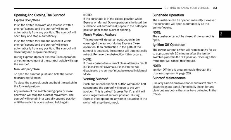
GETTING TO KNOW YOUR VEHICLE 83
Opening And Closing The SunroofExpress Open/ClosePush the switch rearward and release it within one-half second and the sunroof will open automatically from any position. The sunroof will open fully and stop automatically.Push the switch forward and release it within one-half second and the sunroof will close automatically from any position. The sunroof will close fully and stop automatically.During Express Open or Express Close operation, any other movement of the sunroof switch will stop the sunroof.Manual Open/CloseTo open the sunroof, push and hold the switch rearward to full open.To close the sunroof, push and hold the switch in the forward position.Any release of the switch during open or close operation will stop the sunroof movement. The sunroof will remain in a partially opened position until the switch is operated and held again.
NOTE:If the sunshade is in the closed position when Express or Manual Open operation is initiated the sunshade will automatically open to the half open position prior to the sunroof opening.Pinch Protect FeatureThis feature will detect an obstruction in the opening of the sunroof during Express Close operation. If an obstruction in the path of the sunroof is detected, the sunroof will automatically retract. Remove the obstruction if this occurs.NOTE:If three consecutive sunroof close attempts result in Pinch Protect reversals, Pinch Protect will disable and the sunroof must be closed in Manual Mode.Venting SunroofPush and release the Vent button within one half second and the sunroof will open to the vent position. This is called “Express Vent”, and it will occur regardless of sunroof position. During Express Vent operation, any other actuation of the switch will stop the sunroof.
Sunshade OperationThe sunshade can be opened manually. However, the sunshade will open automatically as the sunroof opens.NOTE:The sunshade cannot be closed if the sunroof is open.Ignition Off OperationThe power sunroof switch will remain active for up to approximately 10 minutes after the ignition switch is placed in the OFF position. Opening either front door will cancel this feature.NOTE:Ignition Off time is programmable through the Uconnect system Ú page 237.Sunroof MaintenanceUse only a non-abrasive cleaner and a soft cloth to clean the glass panel. Periodically check for and clear out any debris that may have collected in the tracks.
2
22_DT_OM_EN_USC_t.book Page 83
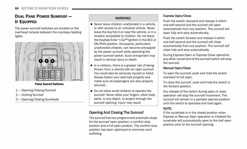
84 GETTING TO KNOW YOUR VEHICLE
DUAL PANE POWER SUNROOF — IF EQUIPPED The power sunroof switches are located on the overhead console between the courtesy/reading lights.
Power Sunroof Switches
Opening And Closing The SunroofThe sunroof has two programmed automatic stops for the sunroof open position; a comfort stop position and a full open position. The comfort stop position has been optimized to minimize wind buffeting.
Express Open/ClosePush the switch rearward and release it within one-half second and the sunroof will open automatically from any position. The sunroof will open fully and stop automatically.Push the switch forward and release it within one-half second and the sunroof will close automatically from any position. The sunroof will close fully and stop automatically.During Express Open or Express Close operation, any other movement of the sunroof switch will stop the sunroof.Manual Open/CloseTo open the sunroof, push and hold the switch rearward to full open.To close the sunroof, push and hold the switch in the forward position.Any release of the switch during open or close operation will stop the sunroof movement. The sunroof will remain in a partially opened position until the switch is operated and held again.
NOTE:If the sunshade is in the closed position when Express or Manual Open operation is initiated the sunshade will automatically open to the half open position prior to the sunroof opening.
1 — Opening/Closing Sunroof2 — Venting Sunroof3 — Opening/Closing Sunshade
WARNING!
Never leave children unattended in a vehicle, or with access to an unlocked vehicle. Never leave the key fob in or near the vehicle, or in a location accessible to children. Do not leave the Keyless Enter ‘n Go™ Ignition in the ACC or ON/RUN position. Occupants, particularly unattended children, can become entrapped by the power sunroof while operating the power sunroof switch. Such entrapment may result in serious injury or death.
In a collision, there is a greater risk of being thrown from a vehicle with an open sunroof. You could also be seriously injured or killed. Always fasten your seat belt properly and make sure all passengers are also properly secured.
Do not allow small children to operate the sunroof. Never allow your fingers, other body parts, or any object, to project through the sunroof opening. Injury may result.
22_DT_OM_EN_USC_t.book Page 84
GETTING TO KNOW YOUR VEHICLE 85
Opening And Closing The Power SunshadeThe sunshade has two programmed positions: half open and full open positions. When operating the sunshade from the closed position, the sunshade will always stop at the half open position regardless of express or manual open operation. The switch must be actuated again to continue on to full open position.If the sunroof is open or vented, the sunshade cannot be closed beyond the half open position. Pushing the sunshade close switch when the sunroof is open/vented and the sunshade is at half open position will first automatically close the sunroof prior to the sunshade closing.Express Open/ClosePush the sunshade switch rearward and release it within one-half second, the sunshade will open to the half open position and stop automatically. Push and release the switch again from the half open position and the sunshade will open to the full open position and stop automatically.Push the sunshade switch forward and release it within one-half second and the sunshade will close automatically.During Express Open or Express Close operation, any other actuation of the sunroof switches will stop the sunshade in a partially open position.
Manual Open/ClosePush and hold the sunshade switch rearward, the sunshade will open to the half open position and stop automatically. Push and hold the sunshade switch again and the sunshade will open to the full open position.Push and hold the switch forward and the sunshade will close and stop at full closed position.Releasing the switch while the sunshade is in motion will stop the sunshade in a partially open position.
Pinch Protect FeatureThis feature will detect an obstruction in the opening of the sunroof during Express Close operation. If an obstruction in the path of the sunroof is detected, the sunroof will automatically retract. Remove the obstruction if this occurs.NOTE:If three consecutive sunroof close attempts result in Pinch Protect reversals, Pinch Protect will disable and the sunroof must be closed in Manual Mode.
Venting SunroofPush and release the Vent button within one half second and the sunroof will open to the vent position. This is called “Express Vent” and it will occur regardless of sunroof position. During Express Vent operation, any movement of the switch will stop the sunroof.
NOTE:If the sunshade was not already open, it will auto-matically open prior to the roof opening to the vent position.Ignition Off OperationThe power sunroof switch will remain active for up to approximately 10 minutes after the ignition switch is placed in the OFF position. Opening either front door will cancel this feature.NOTE:Ignition Off time is programmable through the Uconnect system Ú page 237.Sunroof MaintenanceUse only a non-abrasive cleaner and a soft cloth to clean the glass panel. Periodically check for and clear out any debris that may have collected in the tracks.
2
22_DT_OM_EN_USC_t.book Page 85
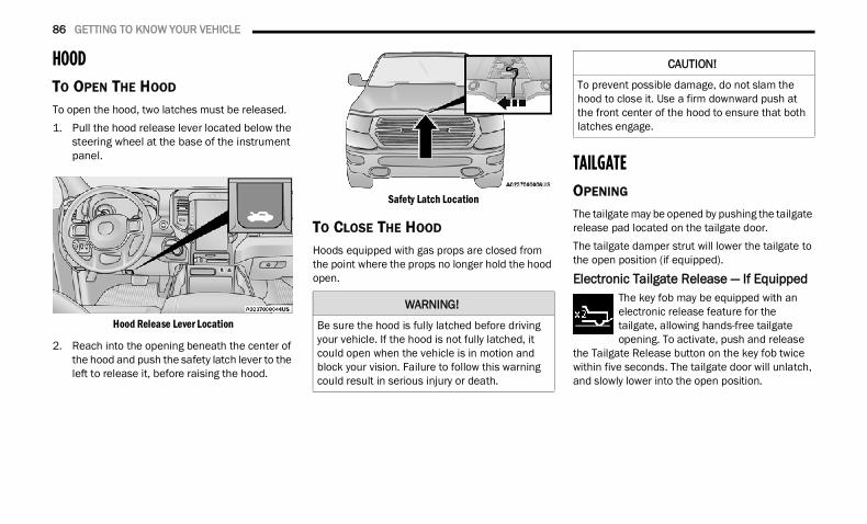
86 GETTING TO KNOW YOUR VEHICLE
HOOD TO OPEN THE HOOD
To open the hood, two latches must be released.1. Pull the hood release lever located below the
steering wheel at the base of the instrument panel.
Hood Release Lever Location
2. Reach into the opening beneath the center of the hood and push the safety latch lever to the left to release it, before raising the hood.
Safety Latch Location
TO CLOSE THE HOOD
Hoods equipped with gas props are closed from the point where the props no longer hold the hood open.
TAILGATEOPENING
The tailgate may be opened by pushing the tailgate release pad located on the tailgate door.The tailgate damper strut will lower the tailgate to the open position (if equipped).
Electronic Tailgate Release — If Equipped The key fob may be equipped with an electronic release feature for the tailgate, allowing hands-free tailgate opening. To activate, push and release
the Tailgate Release button on the key fob twice within five seconds. The tailgate door will unlatch, and slowly lower into the open position.
WARNING!
Be sure the hood is fully latched before driving your vehicle. If the hood is not fully latched, it could open when the vehicle is in motion and block your vision. Failure to follow this warning could result in serious injury or death.
CAUTION!
To prevent possible damage, do not slam the hood to close it. Use a firm downward push at the front center of the hood to ensure that both latches engage.
22_DT_OM_EN_USC_t.book Page 86
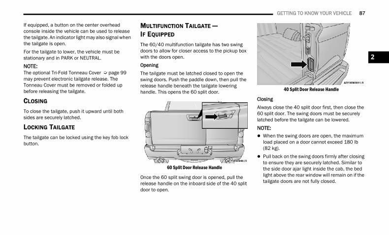
GETTING TO KNOW YOUR VEHICLE 87
If equipped, a button on the center overhead console inside the vehicle can be used to release the tailgate. An indicator light may also signal when the tailgate is open.For the tailgate to lower, the vehicle must be stationary and in PARK or NEUTRAL.
NOTE:The optional Tri-Fold Tonneau Cover Ú page 99 may prevent electronic tailgate release. The Tonneau Cover must be removed or folded up before releasing the tailgate.
CLOSING
To close the tailgate, push it upward until both sides are securely latched.
LOCKING TAILGATE
The tailgate can be locked using the key fob lock button.
MULTIFUNCTION TAILGATE —IF EQUIPPED The 60/40 multifunction tailgate has two swing doors to allow for closer access to the pickup box with the doors open.OpeningThe tailgate must be latched closed to open the swing doors. Push the paddle down, then pull the release handle beneath the tailgate lowering handle. This opens the 60 split door.
60 Split Door Release Handle
Once the 60 split swing door is opened, pull the release handle on the inboard side of the 40 split door to open.
40 Split Door Release Handle
ClosingAlways close the 40 split door first, then close the 60 split door. The swing doors must be securely latched before the tailgate can be lowered.
NOTE: When the swing doors are open, the maximum
load placed on a door cannot exceed 180 lb(82 kg).
Pull back on the swing doors firmly after closing to ensure they are securely latched. Similar to the side door ajar light inside the cab, the bed light above the rear window will remain on if the tailgate doors are not fully closed.
2
22_DT_OM_EN_USC_t.book Page 87
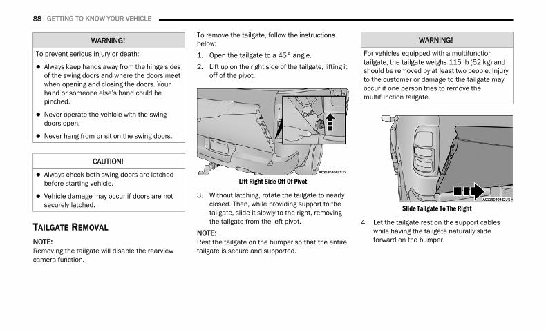
88 GETTING TO KNOW YOUR VEHICLE
TAILGATE REMOVAL NOTE:Removing the tailgate will disable the rearview camera function.
To remove the tailgate, follow the instructions below:1. Open the tailgate to a 45° angle.2. Lift up on the right side of the tailgate, lifting it
off of the pivot.
Lift Right Side Off Of Pivot
3. Without latching, rotate the tailgate to nearly closed. Then, while providing support to the tailgate, slide it slowly to the right, removing the tailgate from the left pivot.
NOTE:Rest the tailgate on the bumper so that the entire tailgate is secure and supported.
Slide Tailgate To The Right
4. Let the tailgate rest on the support cables while having the tailgate naturally slide forward on the bumper.
WARNING!
To prevent serious injury or death:
Always keep hands away from the hinge sides of the swing doors and where the doors meet when opening and closing the doors. Your hand or someone else’s hand could be pinched.
Never operate the vehicle with the swing doors open.
Never hang from or sit on the swing doors.
CAUTION!
Always check both swing doors are latched before starting vehicle.
Vehicle damage may occur if doors are not securely latched.
WARNING!
For vehicles equipped with a multifunction tailgate, the tailgate weighs 115 lb (52 kg) and should be removed by at least two people. Injury to the customer or damage to the tailgate may occur if one person tries to remove the multifunction tailgate.
22_DT_OM_EN_USC_t.book Page 88
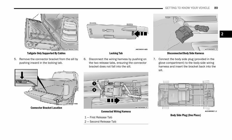
GETTING TO KNOW YOUR VEHICLE 89
Tailgate Only Supported By Cables
5. Remove the connector bracket from the sill by pushing inward in the locking tab.
Connector Bracket Location
Locking Tab
6. Disconnect the wiring harness by pushing on the two release tabs, ensuring the connector bracket does not fall into the sill.
Connected Wiring Harness
Disconnected Body Side Harness
7. Connect the body side plug (provided in the glove compartment) to the body side wiring harness and insert the bracket back into the sill.
Body Side Plug (One Piece)1 — First Release Tab2 — Second Release Tab
2
22_DT_OM_EN_USC_t.book Page 89
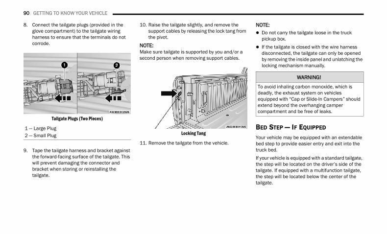
90 GETTING TO KNOW YOUR VEHICLE
8. Connect the tailgate plugs (provided in the glove compartment) to the tailgate wiring harness to ensure that the terminals do not corrode.
Tailgate Plugs (Two Pieces)
9. Tape the tailgate harness and bracket against the forward-facing surface of the tailgate. This will prevent damaging the connector and bracket when storing or reinstalling the tailgate.
10. Raise the tailgate slightly, and remove the support cables by releasing the lock tang from the pivot.
NOTE:Make sure tailgate is supported by you and/or a second person when removing support cables.
Locking Tang
11. Remove the tailgate from the vehicle.
NOTE: Do not carry the tailgate loose in the truck
pickup box. If the tailgate is closed with the wire harness
disconnected, the tailgate can only be opened by removing the inside panel and unlatching the locking mechanism manually.
BED STEP — IF EQUIPPED
Your vehicle may be equipped with an extendable bed step to provide easier entry and exit into the truck bed.If your vehicle is equipped with a standard tailgate, the step will be located on the driver’s side of the tailgate. If equipped with a multifunction tailgate, the step will be located below the center of the tailgate.
1 — Large Plug2 — Small Plug
WARNING!
To avoid inhaling carbon monoxide, which is deadly, the exhaust system on vehicles equipped with “Cap or Slide-In Campers” should extend beyond the overhanging camper compartment and be free of leaks.
22_DT_OM_EN_USC_t.book Page 90
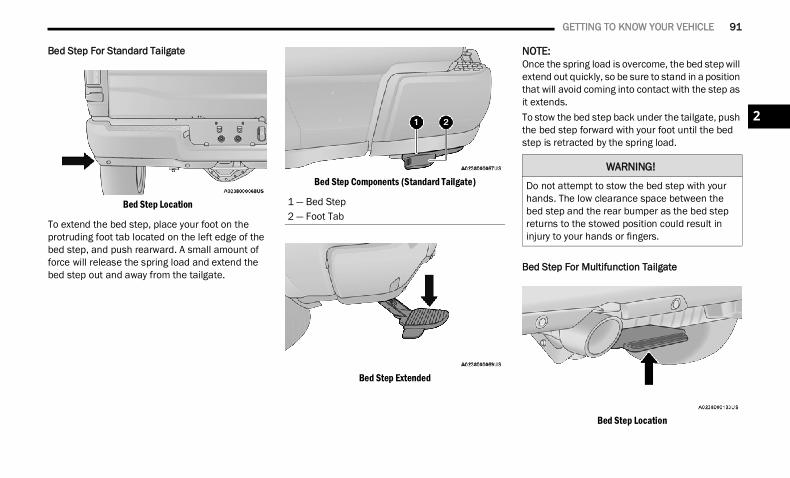
GETTING TO KNOW YOUR VEHICLE 91
Bed Step For Standard Tailgate
Bed Step Location
To extend the bed step, place your foot on the protruding foot tab located on the left edge of the bed step, and push rearward. A small amount of force will release the spring load and extend the bed step out and away from the tailgate.
Bed Step Components (Standard Tailgate)
Bed Step Extended
NOTE:Once the spring load is overcome, the bed step will extend out quickly, so be sure to stand in a position that will avoid coming into contact with the step as it extends.To stow the bed step back under the tailgate, push the bed step forward with your foot until the bed step is retracted by the spring load.
Bed Step For Multifunction Tailgate
Bed Step Location
1 — Bed Step2 — Foot Tab
WARNING!
Do not attempt to stow the bed step with your hands. The low clearance space between the bed step and the rear bumper as the bed step returns to the stowed position could result in injury to your hands or fingers.
2
22_DT_OM_EN_USC_t.book Page 91
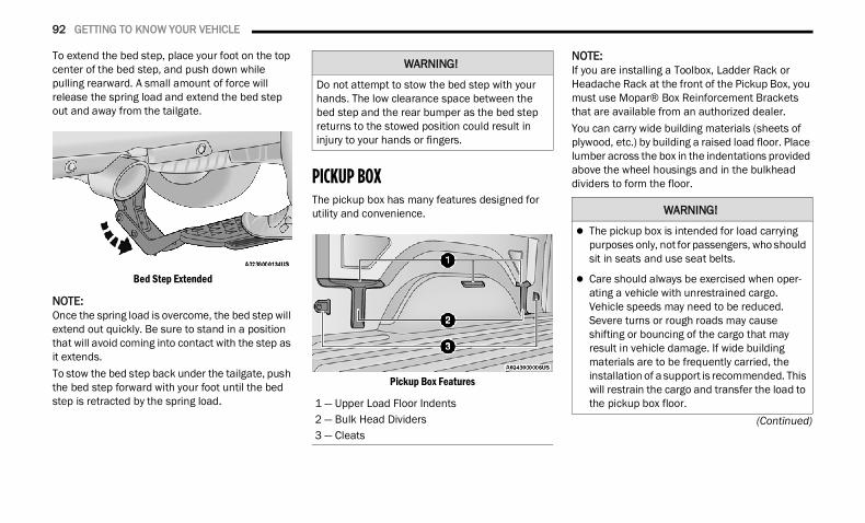
92 GETTING TO KNOW YOUR VEHICLE
(Continued)
To extend the bed step, place your foot on the top center of the bed step, and push down while pulling rearward. A small amount of force will release the spring load and extend the bed step out and away from the tailgate.
Bed Step Extended
NOTE:Once the spring load is overcome, the bed step will extend out quickly. Be sure to stand in a position that will avoid coming into contact with the step as it extends.To stow the bed step back under the tailgate, push the bed step forward with your foot until the bed step is retracted by the spring load.
PICKUP BOX The pickup box has many features designed for utility and convenience.
Pickup Box Features
NOTE:If you are installing a Toolbox, Ladder Rack or Headache Rack at the front of the Pickup Box, you must use Mopar® Box Reinforcement Brackets that are available from an authorized dealer.You can carry wide building materials (sheets of plywood, etc.) by building a raised load floor. Place lumber across the box in the indentations provided above the wheel housings and in the bulkhead dividers to form the floor.
WARNING!
Do not attempt to stow the bed step with your hands. The low clearance space between the bed step and the rear bumper as the bed step returns to the stowed position could result in injury to your hands or fingers.
1 — Upper Load Floor Indents2 — Bulk Head Dividers3 — Cleats
WARNING!
The pickup box is intended for load carrying purposes only, not for passengers, who should sit in seats and use seat belts.
Care should always be exercised when oper-ating a vehicle with unrestrained cargo. Vehicle speeds may need to be reduced. Severe turns or rough roads may cause shifting or bouncing of the cargo that may result in vehicle damage. If wide building materials are to be frequently carried, the installation of a support is recommended. This will restrain the cargo and transfer the load to the pickup box floor.
22_DT_OM_EN_USC_t.book Page 92
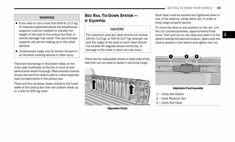
GETTING TO KNOW YOUR VEHICLE 93
There are stampings in the sheet metal on the inner side bulkheads of the box in front of and behind both wheel housings. Place wooden boards across the box from side to side to create separate load compartments in the pickup box.There are four tie-down cleats bolted to the lower sides of the pickup box that can sustain loads up to 1,000 lb (450 kg) total.
BED RAIL TIE-DOWN SYSTEM —IF EQUIPPED
There are two adjustable cleats on each side of the bed that can be used to assist in securing cargo.
Adjustable Cleats
Each cleat must be located and tightened down in one of the detents, along either rail, in order to keep cargo properly secure.To move the cleat to any position on the rail, turn the nut counterclockwise, approximately three turns. Then pull out on the cleat and slide it to the detent nearest the desired location. Make sure the cleat is seated in the detent and tighten the nut.
Adjustable Cleat Assembly
If you wish to carry more than 600 lb (272 kg) of material suspended above the wheelhouse, supports must be installed to transfer the weight of the load to the pickup box floor or vehicle damage may result. The use of proper supports will permit loading up to the rated payload.
Unrestrained cargo may be thrown forward in an accident causing serious or fatal injury.
WARNING!
CAUTION!
The maximum load per cleat should not exceed 250 lb (113 kg), or 500 lb (227 kg) total per rail, and the angle of the load on each cleat should not exceed 45 degrees above horizontal, or damage to the cleat or cleat rail may occur.
1 — Utility Rail Detent2 — Cleat Retainer Nut3 — Utility Rail Cleat
2
22_DT_OM_EN_USC_t.book Page 93
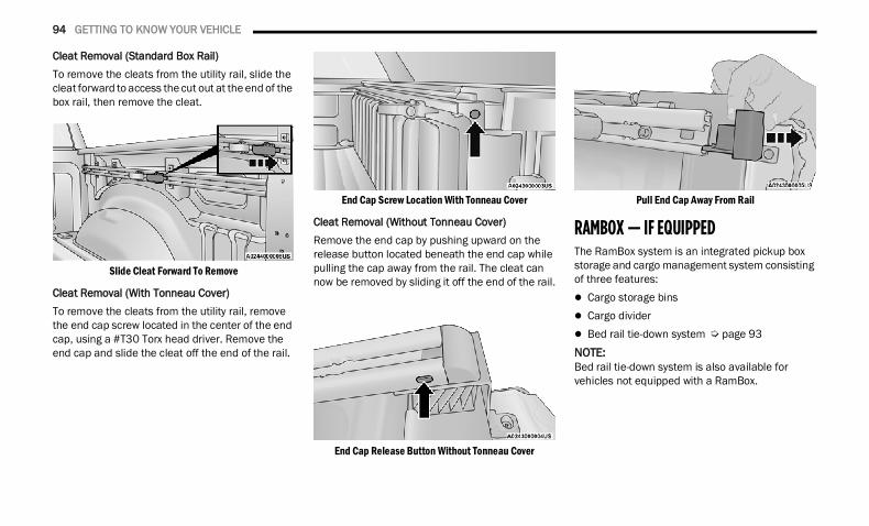
94 GETTING TO KNOW YOUR VEHICLE
Cleat Removal (Standard Box Rail)To remove the cleats from the utility rail, slide the cleat forward to access the cut out at the end of the box rail, then remove the cleat.
Slide Cleat Forward To Remove
Cleat Removal (With Tonneau Cover)To remove the cleats from the utility rail, remove the end cap screw located in the center of the end cap, using a #T30 Torx head driver. Remove the end cap and slide the cleat off the end of the rail.
End Cap Screw Location With Tonneau Cover
Cleat Removal (Without Tonneau Cover)Remove the end cap by pushing upward on the release button located beneath the end cap while pulling the cap away from the rail. The cleat can now be removed by sliding it off the end of the rail.
End Cap Release Button Without Tonneau Cover
Pull End Cap Away From Rail
RAMBOX — IF EQUIPPED The RamBox system is an integrated pickup box storage and cargo management system consisting of three features: Cargo storage bins Cargo divider Bed rail tie-down system Ú page 93NOTE:Bed rail tie-down system is also available for vehicles not equipped with a RamBox.
22_DT_OM_EN_USC_t.book Page 94
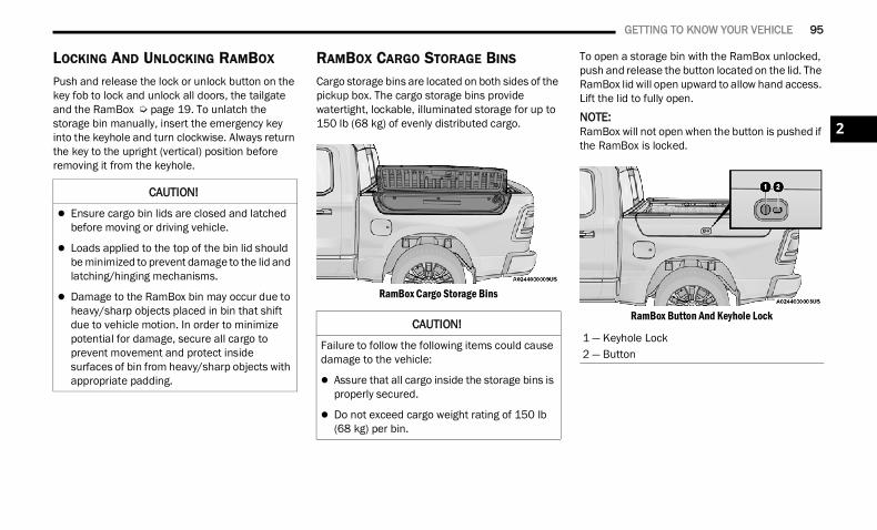
GETTING TO KNOW YOUR VEHICLE 95
LOCKING AND UNLOCKING RAMBOX
Push and release the lock or unlock button on the key fob to lock and unlock all doors, the tailgate and the RamBox Ú page 19. To unlatch the storage bin manually, insert the emergency key into the keyhole and turn clockwise. Always return the key to the upright (vertical) position before removing it from the keyhole.
RAMBOX CARGO STORAGE BINS
Cargo storage bins are located on both sides of the pickup box. The cargo storage bins provide watertight, lockable, illuminated storage for up to 150 lb (68 kg) of evenly distributed cargo.
RamBox Cargo Storage Bins
To open a storage bin with the RamBox unlocked, push and release the button located on the lid. The RamBox lid will open upward to allow hand access. Lift the lid to fully open.
NOTE:RamBox will not open when the button is pushed if the RamBox is locked.
RamBox Button And Keyhole Lock
CAUTION!
Ensure cargo bin lids are closed and latched before moving or driving vehicle.
Loads applied to the top of the bin lid should be minimized to prevent damage to the lid and latching/hinging mechanisms.
Damage to the RamBox bin may occur due to heavy/sharp objects placed in bin that shift due to vehicle motion. In order to minimize potential for damage, secure all cargo to prevent movement and protect inside surfaces of bin from heavy/sharp objects with appropriate padding.
CAUTION!
Failure to follow the following items could cause damage to the vehicle:
Assure that all cargo inside the storage bins is properly secured.
Do not exceed cargo weight rating of 150 lb (68 kg) per bin.
1 — Keyhole Lock2 — Button
2
22_DT_OM_EN_USC_t.book Page 95
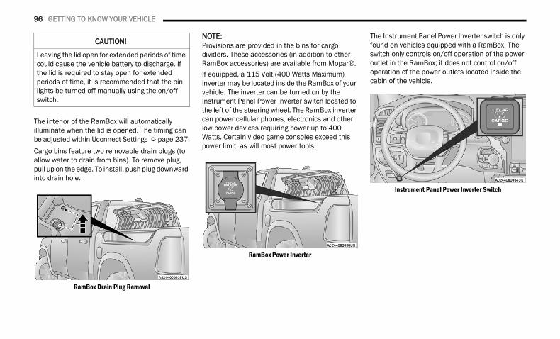
96 GETTING TO KNOW YOUR VEHICLE
The interior of the RamBox will automatically illuminate when the lid is opened. The timing can be adjusted within Uconnect Settings Ú page 237.Cargo bins feature two removable drain plugs (to allow water to drain from bins). To remove plug, pull up on the edge. To install, push plug downward into drain hole.
RamBox Drain Plug Removal
NOTE:Provisions are provided in the bins for cargo dividers. These accessories (in addition to other RamBox accessories) are available from Mopar®.If equipped, a 115 Volt (400 Watts Maximum) inverter may be located inside the RamBox of your vehicle. The inverter can be turned on by the Instrument Panel Power Inverter switch located to the left of the steering wheel. The RamBox inverter can power cellular phones, electronics and other low power devices requiring power up to 400 Watts. Certain video game consoles exceed this power limit, as will most power tools.
RamBox Power Inverter
The Instrument Panel Power Inverter switch is only found on vehicles equipped with a RamBox. The switch only controls on/off operation of the power outlet in the RamBox; it does not control on/off operation of the power outlets located inside the cabin of the vehicle.
Instrument Panel Power Inverter Switch
CAUTION!
Leaving the lid open for extended periods of time could cause the vehicle battery to discharge. If the lid is required to stay open for extended periods of time, it is recommended that the bin lights be turned off manually using the on/off switch.
22_DT_OM_EN_USC_t.book Page 96
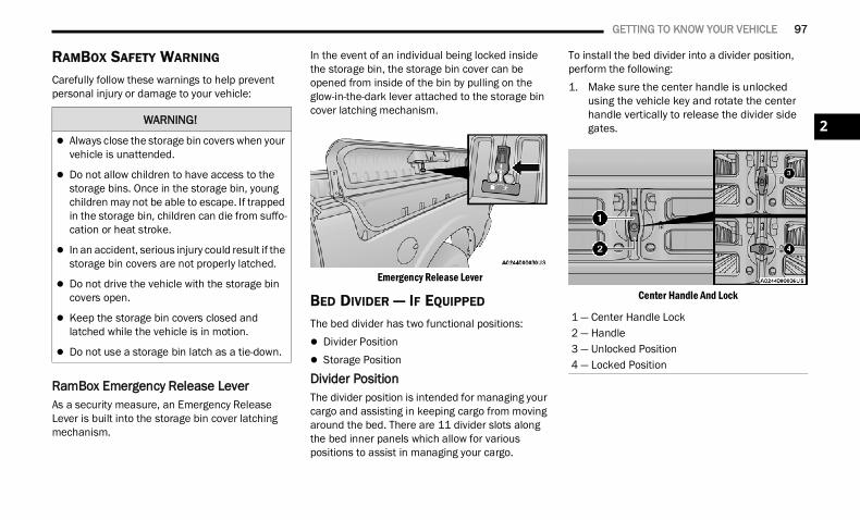
GETTING TO KNOW YOUR VEHICLE 97
RAMBOX SAFETY WARNING
Carefully follow these warnings to help prevent personal injury or damage to your vehicle:
RamBox Emergency Release LeverAs a security measure, an Emergency Release Lever is built into the storage bin cover latching mechanism.
In the event of an individual being locked inside the storage bin, the storage bin cover can be opened from inside of the bin by pulling on the glow-in-the-dark lever attached to the storage bin cover latching mechanism.
Emergency Release Lever
BED DIVIDER — IF EQUIPPED
The bed divider has two functional positions: Divider Position Storage Position
Divider PositionThe divider position is intended for managing your cargo and assisting in keeping cargo from moving around the bed. There are 11 divider slots along the bed inner panels which allow for various positions to assist in managing your cargo.
To install the bed divider into a divider position, perform the following:1. Make sure the center handle is unlocked
using the vehicle key and rotate the center handle vertically to release the divider side gates.
Center Handle And Lock
WARNING!
Always close the storage bin covers when your vehicle is unattended.
Do not allow children to have access to the storage bins. Once in the storage bin, young children may not be able to escape. If trapped in the storage bin, children can die from suffo-cation or heat stroke.
In an accident, serious injury could result if the storage bin covers are not properly latched.
Do not drive the vehicle with the storage bin covers open.
Keep the storage bin covers closed and latched while the vehicle is in motion.
Do not use a storage bin latch as a tie-down.
1 — Center Handle Lock2 — Handle3 — Unlocked Position4 — Locked Position
2
22_DT_OM_EN_USC_t.book Page 97
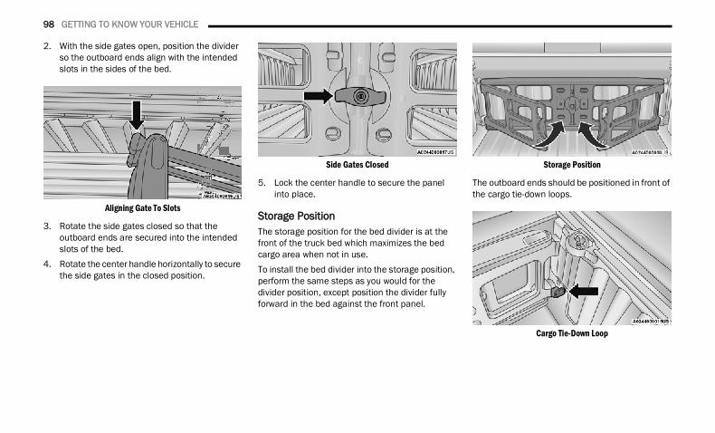
98 GETTING TO KNOW YOUR VEHICLE
2. With the side gates open, position the divider so the outboard ends align with the intended slots in the sides of the bed.
Aligning Gate To Slots
3. Rotate the side gates closed so that the outboard ends are secured into the intended slots of the bed.
4. Rotate the center handle horizontally to secure the side gates in the closed position.
Side Gates Closed
5. Lock the center handle to secure the panel into place.
Storage PositionThe storage position for the bed divider is at the front of the truck bed which maximizes the bed cargo area when not in use.To install the bed divider into the storage position, perform the same steps as you would for the divider position, except position the divider fully forward in the bed against the front panel.
Storage Position
The outboard ends should be positioned in front of the cargo tie-down loops.
Cargo Tie-Down Loop
22_DT_OM_EN_USC_t.book Page 98
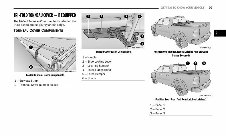
GETTING TO KNOW YOUR VEHICLE 99
TRI-FOLD TONNEAU COVER — IF EQUIPPED The Tri-Fold Tonneau Cover can be installed on the truck bed to protect your gear and cargo.
TONNEAU COVER COMPONENTS
Folded Tonneau Cover Components
Tonneau Cover Latch Components Position One (Front Latches Latched And StowageStraps Secured)
Position Two (Front And Rear Latches Latched)
1 – Stowage Strap2 – Tonneau Cover Bumper Folded
1 — Handle2 — Slide Locking Lever3 — Locating Bumper4 — Truck Flange Bead5 — Latch Bumper6 — J Hook
1 — Panel 12 — Panel 23 — Panel 3
2
22_DT_OM_EN_USC_t.book Page 99
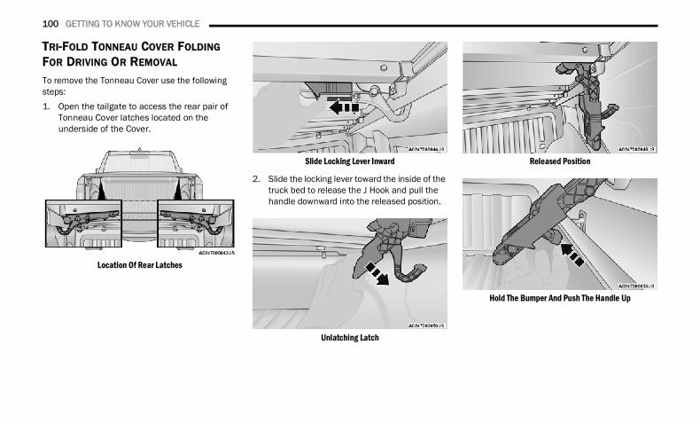
100 GETTING TO KNOW YOUR VEHICLE
TRI-FOLD TONNEAU COVER FOLDING FOR DRIVING OR REMOVAL
To remove the Tonneau Cover use the following steps:1. Open the tailgate to access the rear pair of
Tonneau Cover latches located on the underside of the Cover.
Location Of Rear Latches
Slide Locking Lever Inward
2. Slide the locking lever toward the inside of the truck bed to release the J Hook and pull the handle downward into the released position.
Unlatching Latch
Released Position
Hold The Bumper And Push The Handle Up
22_DT_OM_EN_USC_t.book Page 100
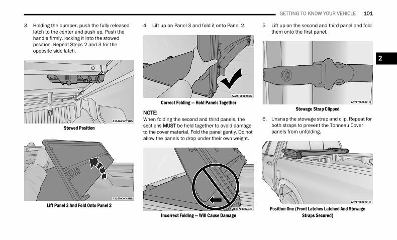
GETTING TO KNOW YOUR VEHICLE 101
3. Holding the bumper, push the fully released latch to the center and push up. Push the handle firmly, locking it into the stowed position. Repeat Steps 2 and 3 for the opposite side latch.
Stowed Position
Lift Panel 3 And Fold Onto Panel 2
4. Lift up on Panel 3 and fold it onto Panel 2.
Correct Folding — Hold Panels Together
NOTE:When folding the second and third panels, the sections MUST be held together to avoid damage to the cover material. Fold the panel gently. Do not allow the panels to drop under their own weight.
Incorrect Folding — Will Cause Damage
5. Lift up on the second and third panel and fold them onto the first panel.
Stowage Strap Clipped
6. Unsnap the stowage strap and clip. Repeat for both straps to prevent the Tonneau Cover panels from unfolding.
Position One (Front Latches Latched And StowageStraps Secured)
2
22_DT_OM_EN_USC_t.book Page 101
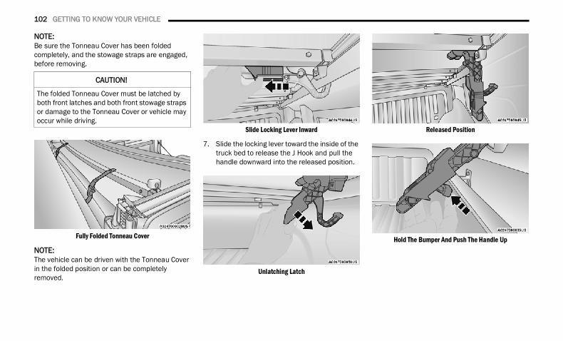
102 GETTING TO KNOW YOUR VEHICLE
NOTE:Be sure the Tonneau Cover has been folded completely, and the stowage straps are engaged, before removing.
Fully Folded Tonneau Cover
NOTE:The vehicle can be driven with the Tonneau Cover in the folded position or can be completely removed.
Slide Locking Lever Inward
7. Slide the locking lever toward the inside of the truck bed to release the J Hook and pull the handle downward into the released position.
Unlatching Latch
Released Position
Hold The Bumper And Push The Handle Up
CAUTION!
The folded Tonneau Cover must be latched by both front latches and both front stowage straps or damage to the Tonneau Cover or vehicle may occur while driving.
22_DT_OM_EN_USC_t.book Page 102
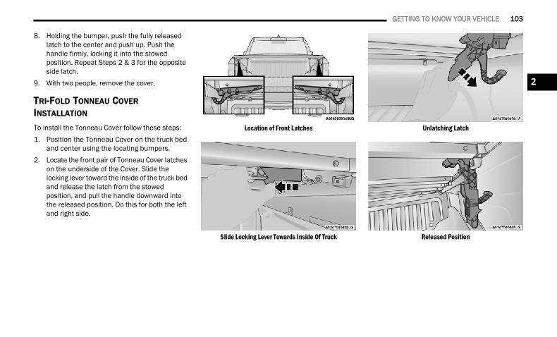
GETTING TO KNOW YOUR VEHICLE 103
8. Holding the bumper, push the fully released latch to the center and push up. Push the handle firmly, locking it into the stowed position. Repeat Steps 2 & 3 for the opposite side latch.
9. With two people, remove the cover.
TRI-FOLD TONNEAU COVER INSTALLATION
To install the Tonneau Cover follow these steps:1. Position the Tonneau Cover on the truck bed
and center using the locating bumpers.2. Locate the front pair of Tonneau Cover latches
on the underside of the Cover. Slide the locking lever toward the inside of the truck bed and release the latch from the stowed position, and pull the handle downward into the released position. Do this for both the left and right side.
Location of Front Latches
Slide Locking Lever Towards Inside Of Truck
Unlatching Latch
Released Position
2
22_DT_OM_EN_USC_t.book Page 103
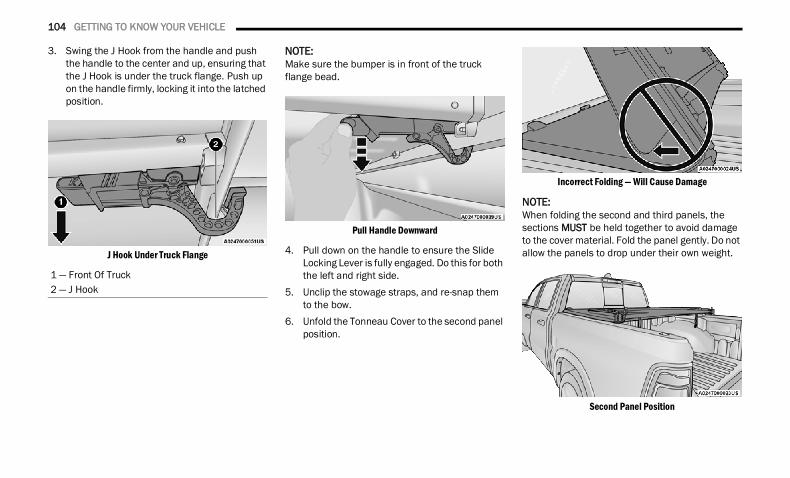
104 GETTING TO KNOW YOUR VEHICLE
3. Swing the J Hook from the handle and push the handle to the center and up, ensuring that the J Hook is under the truck flange. Push up on the handle firmly, locking it into the latched position.
J Hook Under Truck Flange
NOTE:Make sure the bumper is in front of the truck flange bead.
Pull Handle Downward
4. Pull down on the handle to ensure the Slide Locking Lever is fully engaged. Do this for both the left and right side.
5. Unclip the stowage straps, and re-snap them to the bow.
6. Unfold the Tonneau Cover to the second panel position.
Incorrect Folding — Will Cause Damage
NOTE:When folding the second and third panels, the sections MUST be held together to avoid damage to the cover material. Fold the panel gently. Do not allow the panels to drop under their own weight.
Second Panel Position
1 — Front Of Truck2 — J Hook
22_DT_OM_EN_USC_t.book Page 104
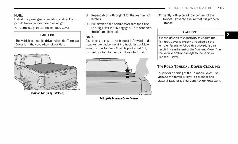
GETTING TO KNOW YOUR VEHICLE 105
NOTE:Unfold the panel gently, and do not allow the panels to drop under their own weight.7. Completely unfold the Tonneau Cover.
Position Two (Fully Unfolded)
8. Repeat steps 2 through 3 for the rear pair of latches.
9. Pull down on the handle to ensure the Slide Locking Lever is fully engaged. Do this for both the left and right side.
NOTE:Also check to ensure the bumper is forward of the bead on the underside of the truck flange. Make sure that the Tonneau Cover is positioned fully forward, so that the bumper clears the bead.
Pull Up On Tonneau Cover Corners
10. Gently pull up on all four corners of the Tonneau Cover to ensure that it is properly latched.
TRI-FOLD TONNEAU COVER CLEANING
For proper cleaning of the Tonneau Cover, use Mopar® Whitewall & Vinyl Top Cleaner and Mopar® Leather & Vinyl Conditioner/Protectant.
CAUTION!
The vehicle cannot be driven when the Tonneau Cover is in the second panel position.
CAUTION!
It is the driver’s responsibility to ensure the Tonneau Cover is properly installed on the vehicle. Failure to follow this procedure can result in detachment of the Tonneau Cover from the vehicle and/or damage to the vehicle/Tonneau Cover.
2
22_DT_OM_EN_USC_t.book Page 105
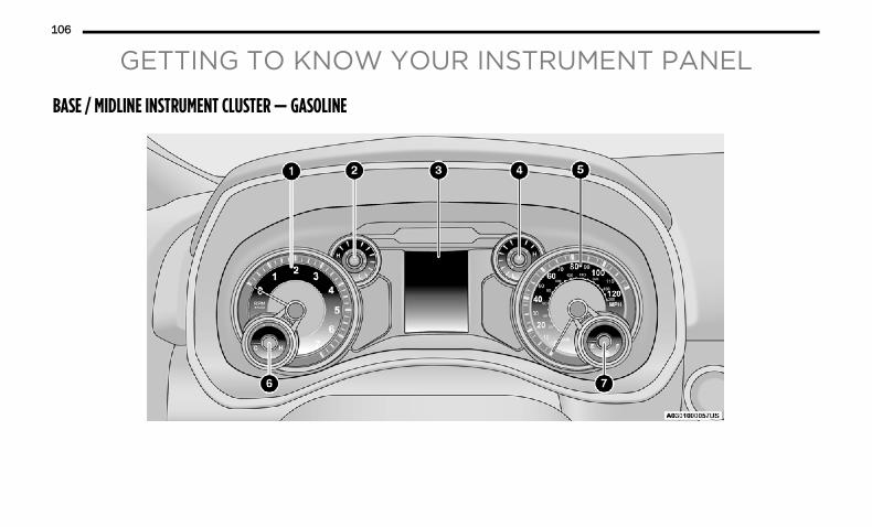
106
GETTING TO KNOW YOUR INSTRUMENT PANEL
BASE / MIDLINE INSTRUMENT CLUSTER — GASOLINE
22_DT_OM_EN_USC_t.book Page 106
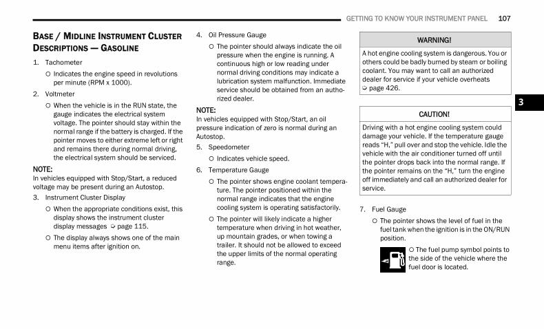
GETTING TO KNOW YOUR INSTRUMENT PANEL 107
BASE / MIDLINE INSTRUMENT CLUSTER DESCRIPTIONS — GASOLINE
1. Tachometer Indicates the engine speed in revolutions
per minute (RPM x 1000).2. Voltmeter
When the vehicle is in the RUN state, the gauge indicates the electrical system voltage. The pointer should stay within the normal range if the battery is charged. If the pointer moves to either extreme left or right and remains there during normal driving, the electrical system should be serviced.
NOTE:In vehicles equipped with Stop/Start, a reduced voltage may be present during an Autostop.3. Instrument Cluster Display
When the appropriate conditions exist, this display shows the instrument cluster display messages Ú page 115.
The display always shows one of the main menu items after ignition on.
4. Oil Pressure Gauge The pointer should always indicate the oil
pressure when the engine is running. A continuous high or low reading under normal driving conditions may indicate a lubrication system malfunction. Immediate service should be obtained from an autho-rized dealer.
NOTE:In vehicles equipped with Stop/Start, an oil pressure indication of zero is normal during an Autostop.5. Speedometer
Indicates vehicle speed.6. Temperature Gauge
The pointer shows engine coolant tempera-ture. The pointer positioned within the normal range indicates that the engine cooling system is operating satisfactorily.
The pointer will likely indicate a higher temperature when driving in hot weather, up mountain grades, or when towing a trailer. It should not be allowed to exceed the upper limits of the normal operating range.
7. Fuel Gauge The pointer shows the level of fuel in the
fuel tank when the ignition is in the ON/RUN position.
The fuel pump symbol points to the side of the vehicle where the fuel door is located.
WARNING!
A hot engine cooling system is dangerous. You or others could be badly burned by steam or boiling coolant. You may want to call an authorized dealer for service if your vehicle overheats Ú page 426.
CAUTION!
Driving with a hot engine cooling system could damage your vehicle. If the temperature gauge reads “H,” pull over and stop the vehicle. Idle the vehicle with the air conditioner turned off until the pointer drops back into the normal range. If the pointer remains on the “H,” turn the engine off immediately and call an authorized dealer for service.
3
22_DT_OM_EN_USC_t.book Page 107
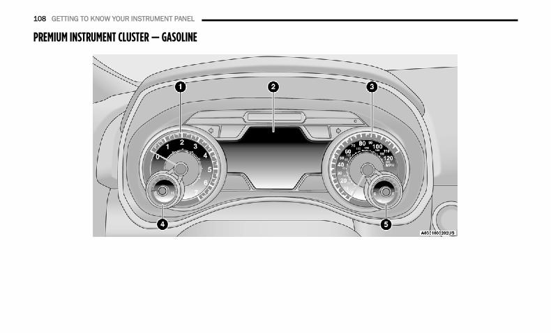
108 GETTING TO KNOW YOUR INSTRUMENT PANEL
PREMIUM INSTRUMENT CLUSTER — GASOLINE
22_DT_OM_EN_USC_t.book Page 108
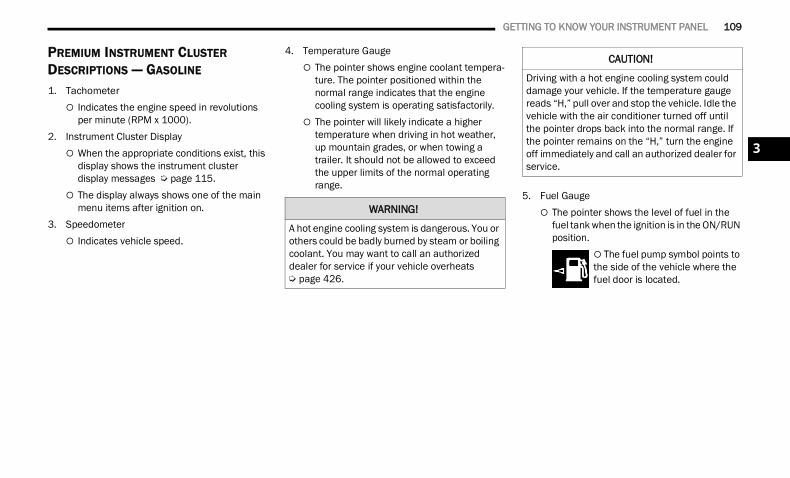
GETTING TO KNOW YOUR INSTRUMENT PANEL 109
PREMIUM INSTRUMENT CLUSTER DESCRIPTIONS — GASOLINE
1. Tachometer Indicates the engine speed in revolutions
per minute (RPM x 1000).2. Instrument Cluster Display
When the appropriate conditions exist, this display shows the instrument cluster display messages Ú page 115.
The display always shows one of the main menu items after ignition on.
3. Speedometer Indicates vehicle speed.
4. Temperature Gauge The pointer shows engine coolant tempera-
ture. The pointer positioned within the normal range indicates that the engine cooling system is operating satisfactorily.
The pointer will likely indicate a higher temperature when driving in hot weather, up mountain grades, or when towing a trailer. It should not be allowed to exceed the upper limits of the normal operating range.
5. Fuel Gauge The pointer shows the level of fuel in the
fuel tank when the ignition is in the ON/RUN position.
The fuel pump symbol points to the side of the vehicle where the fuel door is located.
WARNING!
A hot engine cooling system is dangerous. You or others could be badly burned by steam or boiling coolant. You may want to call an authorized dealer for service if your vehicle overheats Ú page 426.
CAUTION!
Driving with a hot engine cooling system could damage your vehicle. If the temperature gauge reads “H,” pull over and stop the vehicle. Idle the vehicle with the air conditioner turned off until the pointer drops back into the normal range. If the pointer remains on the “H,” turn the engine off immediately and call an authorized dealer for service.
3
22_DT_OM_EN_USC_t.book Page 109
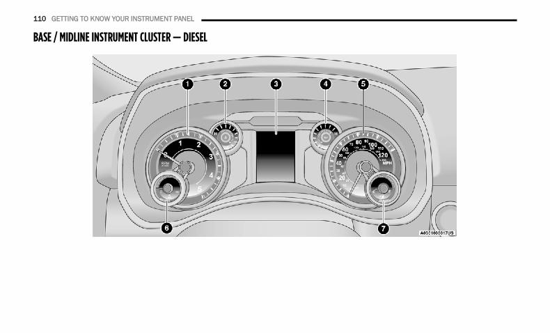
110 GETTING TO KNOW YOUR INSTRUMENT PANEL
BASE / MIDLINE INSTRUMENT CLUSTER — DIESEL
22_DT_OM_EN_USC_t.book Page 110
GETTING TO KNOW YOUR INSTRUMENT PANEL 111
BASE / MIDLINE INSTRUMENT CLUSTER DESCRIPTIONS — DIESEL 1. Tachometer
Indicates the engine speed in revolutions per minute (RPM x 1000).
2. Engine Coolant Temperature This gauge shows the engine coolant
temperature. The gauge pointer will likely show higher temperatures when driving in hot weather, up mountain grades, or in heavy stop and go traffic. If the red Warning Light turns on while driving, safely bring the vehicle to a stop, and turn off the engine. DO NOT operate the vehicle until the cause is corrected.
3. Instrument Cluster Display When the appropriate conditions exist, this
display shows the instrument cluster display messages Ú page 115.
The display always shows one of the main menu items after ignition on.
4. Oil Pressure Gauge The pointer should always indicate some oil
pressure when the engine is running. A continuous high or low reading under normal driving conditions may indicate a lubrication system malfunction. Immediate service should be obtained from an autho-rized dealer.
5. Speedometer Indicates vehicle speed.
WARNING!
A hot engine cooling system is dangerous. You or others could be badly burned by steam or boiling coolant. You may want to call an authorized dealer for service if your vehicle overheats Ú page 426.
WARNING!
Driving with a hot engine cooling system could damage your vehicle. If the temperature gauge reads “H” pull over and stop the vehicle. Idle the vehicle with the air conditioner turned off until the pointer drops back into the normal range. If the pointer remains on the “H”, turn the engine off immediately and call an authorized dealer for service.
3
22_DT_OM_EN_USC_t.book Page 111
112 GETTING TO KNOW YOUR INSTRUMENT PANEL
6. Diesel Exhaust Fluid (DEF) Gauge The DEF Gauge displays the actual level of
Diesel Exhaust Fluid in the DEF tank. DEF is required to maintain normal vehicle opera-tion and emissions compliance. If some-thing is wrong with the gauge, a DEF Warning Message or Malfunction Indicator Light (MIL) will be displayed Ú page 127.
NOTE:• The gauge may take up to five seconds to
update after adding a gallon or more of Diesel Exhaust Fluid to the DEF tank. If you have a fault related to the DEF system, the gauge may not update to the new level. See an authorized dealer for service.
• The DEF gauge may also not immediately update after a refill if the temperature of the DEF fluid is below 12°F (-11°C). The DEF line heater will possibly warm up the DEF fluid and allow the gauge to update after a period of run time. Under very cold condi-tions, it is possible that the gauge may not reflect the new fill level for several drives.
• Outside temperature can affect DEF consumption. In cold conditions, 12°F (-11°C) and below, the DEF gauge needle can stay on a fixed position and may not move for extended periods of time. This is a normal function of the system.
7. Fuel Gauge The gauge shows the level of fuel in the
fuel tank when the ignition switch is in the ON/RUN position.
The fuel pump symbol points to the side of the vehicle where the fuel door is located.
22_DT_OM_EN_USC_t.book Page 112
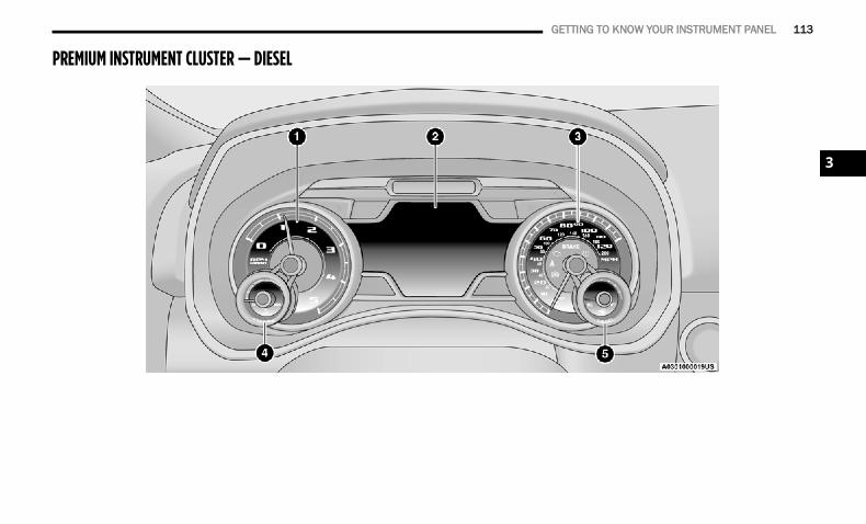
GETTING TO KNOW YOUR INSTRUMENT PANEL 113
PREMIUM INSTRUMENT CLUSTER — DIESEL
3
22_DT_OM_EN_USC_t.book Page 113
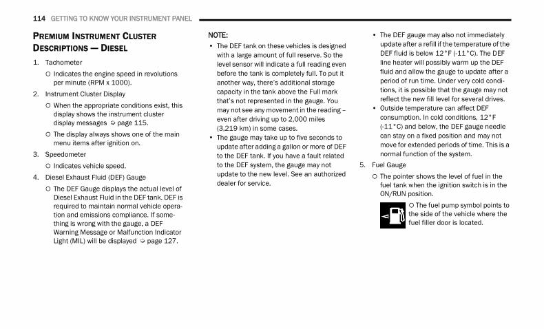
114 GETTING TO KNOW YOUR INSTRUMENT PANEL
PREMIUM INSTRUMENT CLUSTER DESCRIPTIONS — DIESEL 1. Tachometer
Indicates the engine speed in revolutions per minute (RPM x 1000).
2. Instrument Cluster Display When the appropriate conditions exist, this
display shows the instrument cluster display messages Ú page 115.
The display always shows one of the main menu items after ignition on.
3. Speedometer Indicates vehicle speed.
4. Diesel Exhaust Fluid (DEF) Gauge The DEF Gauge displays the actual level of
Diesel Exhaust Fluid in the DEF tank. DEF is required to maintain normal vehicle opera-tion and emissions compliance. If some-thing is wrong with the gauge, a DEF Warning Message or Malfunction Indicator Light (MIL) will be displayed Ú page 127.
NOTE:• The DEF tank on these vehicles is designed
with a large amount of full reserve. So the level sensor will indicate a full reading even before the tank is completely full. To put it another way, there’s additional storage capacity in the tank above the Full mark that’s not represented in the gauge. You may not see any movement in the reading – even after driving up to 2,000 miles(3,219 km) in some cases.
• The gauge may take up to five seconds to update after adding a gallon or more of DEF to the DEF tank. If you have a fault related to the DEF system, the gauge may not update to the new level. See an authorized dealer for service.
• The DEF gauge may also not immediately update after a refill if the temperature of the DEF fluid is below 12°F (-11°C). The DEF line heater will possibly warm up the DEF fluid and allow the gauge to update after a period of run time. Under very cold condi-tions, it is possible that the gauge may not reflect the new fill level for several drives.
• Outside temperature can affect DEF consumption. In cold conditions, 12°F (-11°C) and below, the DEF gauge needle can stay on a fixed position and may not move for extended periods of time. This is a normal function of the system.
5. Fuel Gauge The pointer shows the level of fuel in the
fuel tank when the ignition switch is in the ON/RUN position.
The fuel pump symbol points to the side of the vehicle where the fuel filler door is located.
22_DT_OM_EN_USC_t.book Page 114
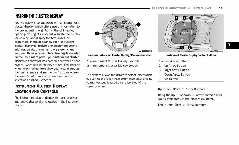
GETTING TO KNOW YOUR INSTRUMENT PANEL 115
INSTRUMENT CLUSTER DISPLAYYour vehicle will be equipped with an instrument cluster display, which offers useful information to the driver. With the ignition in the OFF mode, opening/closing of a door will activate the display for viewing, and display the total miles, or kilometers, in the odometer. Your instrument cluster display is designed to display important information about your vehicle’s systems and features. Using a driver interactive display located on the instrument panel, your instrument cluster display can show you how systems are working and give you warnings when they are not. The steering wheel mounted controls allow you to scroll through the main menus and submenus. You can access the specific information you want and make selections and adjustments.
INSTRUMENT CLUSTER DISPLAY LOCATION AND CONTROLS
The instrument cluster display features a driver interactive display that is located in the instrument cluster.
Premium Instrument Cluster Display/Controls Location
The system allows the driver to select information by pushing the following instrument cluster display control buttons located on the left side of the steering wheel.
Instrument Cluster Display Control Buttons
Up And Down Arrow Buttons:
Using the up or down arrow button allows you to cycle through the Main Menu Items.
Left And Right Arrow Buttons:
1 — Instrument Cluster Display Controls2 — Instrument Cluster Display Screen
1 — Left Arrow Button2 — Up Arrow Button3 — Right Arrow Button4 — Down Arrow Button5 — OK Button
3
22_DT_OM_EN_USC_t.book Page 115
116 GETTING TO KNOW YOUR INSTRUMENT PANEL
Using the left or right arrow button allows you to cycle through the submenu items of the Main menu item.NOTE:
Holding the up / down or left / right arrow buttons will loop the user through the currently selected menu or options presented on the screen.
Main menu and submenus wrap for continuous scrolling.
Upon returning to a main menu, the last submenu screen viewed within that main menu will be displayed.
OK Button:For Digital Speedometer: Pushing the OK button changes units
(mph or km/h).
For Screen Setup: OK button allows user to enter menu and
submenus.
Within each submenu layer, the up and down arrow buttons will allow the user to select the item of interest.
Pushing the OK button makes the selection and a confirmation screen will appear (returning the user to the first page of the submenu).
Pushing the left arrow button will exit each submenu layer and return to the main menu.
OIL LIFE RESET
Your vehicle is equipped with an engine oil change indicator system. The “Oil Change Required” message will display in the instrument cluster display for five seconds after a single chime has sounded, to indicate the next scheduled oil change interval. The engine oil change indicator system is duty cycle based, which means the engine oil change interval may fluctuate, dependent upon your personal driving style.
Unless reset, this message will continue to display each time you place the ignition in the ON/RUN position. To turn off the message temporarily, push and release the OK or arrow buttons. To reset the oil change indicator system (after performing the scheduled maintenance), refer to the following procedure:1. Without pressing the brake pedal, push the
ENGINE START/STOP button and place the ignition in the ON/RUN position (do not start the engine).
2. Push and release the down arrow button to scroll downward through the main menu to “Vehicle Info.”
3. Push and release the right arrow button to access the ”Oil Life” screen.
22_DT_OM_EN_USC_t.book Page 116
GETTING TO KNOW YOUR INSTRUMENT PANEL 117
4. Push and hold the OK button to reset oil life. If conditions are met, the gauge and numeric display will update to show 100%. If conditions are not met a pop-up message of “To reset oil life engine must be off with ignition in run” will be displayed (for five seconds), and the user will remain at the Oil Life screen.
5. Push and release the up or down arrow button to exit the submenu screen.
NOTE:If the indicator message illuminates when you start the vehicle, the oil change indicator system did not reset. If necessary, repeat this procedure.
DISPLAY MENU ITEMS
Push and release the up or down arrow button until the desired selectable menu icon is highlighted in the instrument cluster display.
SpeedometerPush and release the up or down arrow button until the speedometer menu item is highlighted in the instrument cluster display. Push and release the OK button to cycle the display between mph and km/h.
Vehicle InfoPush and release the up or down arrow button until the Vehicle Info menu icon is displayed in the instrument cluster display. Push and release the left or right arrow button to scroll through the information submenus and push and release the OK button to select or reset the resettable submenus. Tire Pressure Monitor System Air Suspension — If Equipped Coolant Temperature — If Equipped Trans Temperature (Automatic only) Oil Temperature Oil Pressure — If Equipped Oil Life Battery Voltage — If Equipped Gauge Summary — If Equipped
Coolant Temp Trans Temp Oil Temp Oil Pressure
Engine Hours
Off Road – If EquippedPush and release the up or down arrow button until the Off Road menu icon is displayed in the instrument cluster display. Push and release the left or right arrow button to scroll through the information submenus. Drivetrain
Front Wheel Angle: displays the graphical and numerical value of calculated average front wheel angle from the steering wheel orientation.
Transfer Case Lock Status: displays “Lock” graphic only during 4WD High, 4WD High Part Time, 4WD Low status.
Axle Lock And Sway Bar Status (If Equipped): displays front and rear or rear only axle locker graphic, and sway bar connection graphic with text message (connected or disconnected).
Pitch And Roll Displays the pitch and roll of the vehicle in
the graphic with the angle number on the screen.
3
22_DT_OM_EN_USC_t.book Page 117
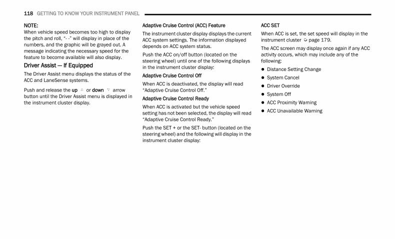
118 GETTING TO KNOW YOUR INSTRUMENT PANEL
NOTE:When vehicle speed becomes too high to display the pitch and roll, “- -” will display in place of the numbers, and the graphic will be grayed out. A message indicating the necessary speed for the feature to become available will also display.Driver Assist — If EquippedThe Driver Assist menu displays the status of the ACC and LaneSense systems.
Push and release the up or down arrow button until the Driver Assist menu is displayed in the instrument cluster display.
Adaptive Cruise Control (ACC) FeatureThe instrument cluster display displays the current ACC system settings. The information displayed depends on ACC system status.Push the ACC on/off button (located on the steering wheel) until one of the following displays in the instrument cluster display:Adaptive Cruise Control OffWhen ACC is deactivated, the display will read “Adaptive Cruise Control Off.”Adaptive Cruise Control ReadyWhen ACC is activated but the vehicle speed setting has not been selected, the display will read “Adaptive Cruise Control Ready.”Push the SET + or the SET- button (located on the steering wheel) and the following will display in the instrument cluster display:
ACC SETWhen ACC is set, the set speed will display in the instrument cluster Ú page 179.The ACC screen may display once again if any ACC activity occurs, which may include any of the following: Distance Setting Change System Cancel Driver Override System Off ACC Proximity Warning ACC Unavailable Warning
22_DT_OM_EN_USC_t.book Page 118
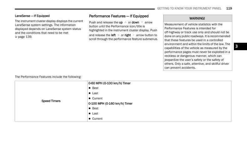
GETTING TO KNOW YOUR INSTRUMENT PANEL 119
LaneSense — If EquippedThe instrument cluster display displays the current LaneSense system settings. The information displayed depends on LaneSense system status and the conditions that need to be met Ú page 139.
Performance Features — If EquippedPush and release the up or down arrow button until the Performance icon/title is highlighted in the instrument cluster display. Push and release the left or right arrow button to scroll through the performance feature submenus.
The Performance Features include the following:
WARNING!
Measurement of vehicle statistics with the Performance Features is intended for off-highway or track use only and should not be done on any public roadways. It is recommended that these features be used in a controlled environment and within the limits of the law. The capabilities of the vehicle as measured by the performance pages must never be exploited in a reckless or dangerous manner, which can jeopardize the user’s safety or the safety of others. Only a safe, attentive, and skillful driver can prevent accidents.
Speed Timers
0-60 MPH (0-100 km/h) Timer Best Last Current0-100 MPH (0-160 km/h) Timer Best Last Current
3
22_DT_OM_EN_USC_t.book Page 119
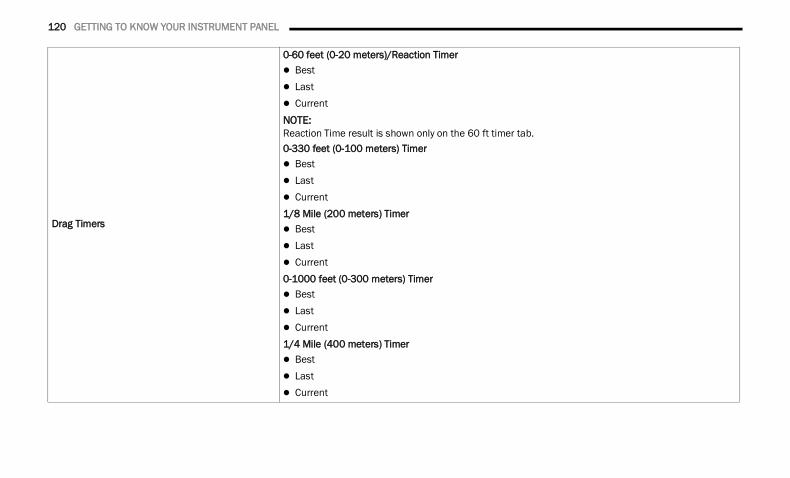
120 GETTING TO KNOW YOUR INSTRUMENT PANEL
Drag Timers
0-60 feet (0-20 meters)/Reaction Timer Best Last CurrentNOTE:Reaction Time result is shown only on the 60 ft timer tab.0-330 feet (0-100 meters) Timer Best Last Current1/8 Mile (200 meters) Timer Best Last Current0-1000 feet (0-300 meters) Timer Best Last Current1/4 Mile (400 meters) Timer Best Last Current
22_DT_OM_EN_USC_t.book Page 120
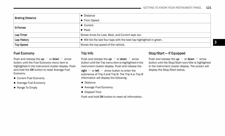
GETTING TO KNOW YOUR INSTRUMENT PANEL 121
Fuel EconomyPush and release the up or down arrow button until the Fuel Economy menu item is highlighted in the instrument cluster display. Push and hold the OK button to reset Average Fuel Economy. Current Fuel Economy Average Fuel Economy Range To Empty
Trip InfoPush and release the up or down arrow button until the Trip menu item is highlighted in the instrument cluster display. Push and release the right or left arrow button to enter the submenus of Trip A and Trip B. The Trip A or Trip B information will display the following: Distance Average Fuel Economy Elapsed TimePush and hold OK button to reset all information.
Stop/Start — If EquippedPush and release the up or down arrow button until the Stop/Start icon/title is highlighted in the instrument cluster display. The screen will display the Stop/Start status.
Braking Distance Distance From Speed
G-Forces Current Peak
Lap Timer Shows times for Last, Best, and Current laps ran.
Lap History Will list the last four laps with the best lap highlighted in green.
Top Speed Shows the top speed of the vehicle.3
22_DT_OM_EN_USC_t.book Page 121
122 GETTING TO KNOW YOUR INSTRUMENT PANEL
Trailer Tow — If EquippedPush and release the up or down arrow button until the Trailer Tow menu item is highlighted in the instrument cluster display. Push and release the right or left arrow button to cycle through the following trailer tow information: Trip (trailer specific) Distance: Push and hold
the OK button to reset the distance. Integrated Trailer Brake Module (ITBM):
Braking Output Trailer Type ITBM Gain
Trailer Light Check: Push and hold the OK button to begin the Trailer Light Test sequence Ú page 225.
Trailer Tire Pressure Monitoring: The Instrument Cluster Display will display the Trailer Tire Pres-sure for a connected trailer with sensors that match the active trailer profile. When a low tire is present, the low tire value will be displayed in red, and the affected low tire will have a red glow. “Trailer Tire Low“ will be displayed on the center bottom of the Instrument Cluster Display screen.
AudioPush and release the up or down arrow button until the Audio Menu icon/title is highlighted in the instrument cluster display. This menu will display the audio source information, including the Song name, Artist name, and audio source with an accompanying graphic.Phone Call StatusWhen a call is incoming, a Phone Call Status pop-up will display on the screen. The pop-up will remain until the phone is answered or ignored.
NOTE:The call status will temporarily replace the previous media source information displayed on the screen. When the pop-up is no longer displayed, the display will return to the last used screen.Stored MessagesPush and release the up or down arrow button until the Messages Menu item is highlighted. This feature shows the number of stored warning messages. Push and release the right or left arrow button to cycle through stored messages.
Settings Head Up Display (HUD) – If EquippedNOTE:The HUD feature Settings are available at any vehicle speed Ú page 124.Screen Setup Driver Selectable Items
Push and release the up or down arrow button until the Settings Menu Icon/Title is highlighted in the instrument cluster display. Push and release the OK button to enter the submenus and follow the prompts on the screen as needed. The Settings feature allows you to change what information is displayed in the instrument cluster as well as the location that information is displayed.
NOTE:The Settings feature is only available when the vehicle speed is less than 5 mph.
22_DT_OM_EN_USC_t.book Page 122
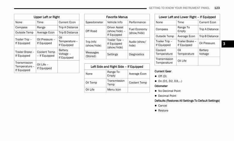
GETTING TO KNOW YOUR INSTRUMENT PANEL 123
Current Gear Off (D) On (D1, D2, D3,...)Odometer No Decimal Point Decimal PointDefaults (Restores All Settings To Default Settings) Cancel Restore
Upper Left or RightNone Time Current Econ
Compass Range Trip A Distance
Outside Temp Average Econ Trip B Distance
Trailer Trip – If Equipped
Oil Pressure – If Equipped
Oil Temperature – If Equipped
Trailer Brake – If Equipped
Coolant Temp – If Equipped
Battery Voltage –If Equipped
Transmission Temperature – If Equipped
Oil Life –If Equipped
Favorite MenusSpeedometer Vehicle Info Performance
Off RoadDriver Assist (show/hide) – If Equipped
Fuel Economy (show/hide)
Trip Info (show/hide)
Trailer Tow – If Equipped (show/hide)
Audio (show/hide)
Messages (Stored) Settings Diagnostics
Left Side and Right Side – If Equipped
None Range To Empty Average Econ
Oil Temp Transmission Temp Coolant Temp
Oil Life Menu Icon
Lower Left and Lower Right – If EquippedNone Time Current Econ
Compass Range To Empty Trip A Distance
Outside Temp Average Econ Trip B Distance
Trailer Trip –If Equipped
Trailer Brake – If Equipped Oil Pressure
Coolant Temperature
Oil Temperature
Battery Voltage
Transmission Temperature Oil Life
3
22_DT_OM_EN_USC_t.book Page 123
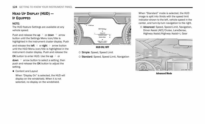
124 GETTING TO KNOW YOUR INSTRUMENT PANEL
HEAD UP DISPLAY (HUD) — IF EQUIPPED NOTE:The HUD feature Settings are available at any vehicle speed.
Push and release the up or down arrow button until the Settings Menu icon/title is highlighted in the instrument cluster display. Push and release the left or right arrow button until the HUD Menu icon/title is highlighted in the instrument cluster display. Push and release the OK button to enter HUD. Use the up or down arrow button to select a setting, then push and release the OK button to adjust the setting. Content and Layout
When “Display On” is selected, the HUD will display on the windshield. When it is not selected, no display on the windshield.
HUD ON/OFF
Simple: Speed, Speed Limit Standard: Speed, Speed Limit, Navigation
When “Standard” mode is selected, the HUD image is split into thirds with the speed limit indicator shown to the left, vehicle speed in the center, and turn-by-turn navigation to the right. Advanced: Speed, Speed Limit, Navigation,
Driver Assist (ACC/Cruise, LaneSense, Highway Assist/Highway Assist+), Gear
Advanced Mode
22_DT_OM_EN_USC_t.book Page 124
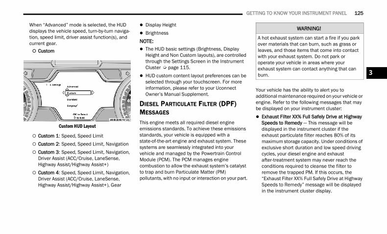
GETTING TO KNOW YOUR INSTRUMENT PANEL 125
When “Advanced” mode is selected, the HUD displays the vehicle speed, turn-by-turn naviga-tion, speed limit, driver assist function(s), and current gear. Custom
Custom HUD Layout
Custom 1: Speed, Speed Limit Custom 2: Speed, Speed Limit, Navigation Custom 3: Speed, Speed Limit, Navigation,
Driver Assist (ACC/Cruise, LaneSense, Highway Assist/Highway Assist+)
Custom 4: Speed, Speed Limit, Navigation, Driver Assist (ACC/Cruise, LaneSense, Highway Assist/Highway Assist+), Gear
Display Height BrightnessNOTE: The HUD basic settings (Brightness, Display
Height and Non Custom layouts), are controlled through the Settings Screen in the Instrument Cluster Ú page 115.
HUD custom content layout preferences can be selected through your touchscreen. For more information, please refer to your Uconnect Owner’s Manual Supplement.
DIESEL PARTICULATE FILTER (DPF) MESSAGES This engine meets all required diesel engine emissions standards. To achieve these emissions standards, your vehicle is equipped with a state-of-the-art engine and exhaust system. These systems are seamlessly integrated into your vehicle and managed by the Powertrain Control Module (PCM). The PCM manages engine combustion to allow the exhaust system’s catalyst to trap and burn Particulate Matter (PM) pollutants, with no input or interaction on your part.
Your vehicle has the ability to alert you to additional maintenance required on your vehicle or engine. Refer to the following messages that may be displayed on your instrument cluster: Exhaust Filter XX% Full Safely Drive at Highway
Speeds to Remedy — This message will be displayed in the instrument cluster if the exhaust particulate filter reaches 80% of its maximum storage capacity. Under conditions of exclusive short duration and low speed driving cycles, your diesel engine and exhaust after-treatment system may never reach the conditions required to cleanse the filter to remove the trapped PM. If this occurs, the “Exhaust Filter XX% Full Safely Drive at Highway Speeds to Remedy” message will be displayed in the instrument cluster display.
WARNING!
A hot exhaust system can start a fire if you park over materials that can burn, such as grass or leaves, and those items that come into contact with your exhaust system. Do not park or operate your vehicle in areas where your exhaust system can contact anything that can burn. 3
22_DT_OM_EN_USC_t.book Page 125
126 GETTING TO KNOW YOUR INSTRUMENT PANEL
If this message is displayed, you will hear one chime to assist in alerting you of this condition. By simply driving your vehicle at highway speeds for up to 20 minutes, you can remedy the condi-tion in the particulate filter system and allow your diesel engine and exhaust after-treatment system to cleanse the filter to remove the trapped PM and restore the system to normal operating condition.
Exhaust System — Regeneration In Process Exhaust Filter XX% Full — This message indi-cates that the DPF is self-cleaning. Maintain your current driving condition until regeneration is completed.
Exhaust System — Regeneration Completed — This message indicates that the DPF self-cleaning is completed. If this message is displayed, you will hear one chime to assist in alerting you of this condition.
Exhaust Service Required — See Dealer Now — This messages indicates regeneration has been disabled due to a system malfunction. At this point the engine Powertrain Control Module (PCM) will register a fault code, the instrument panel will display a MIL light.
Exhaust Filter Full — Power Reduced See Dealer — This message indicates the PCM has derated the engine to limit the likelihood of permanent damage to the after-treatment system. If this condition is not corrected and a dealer service is not performed, extensive exhaust after-treatment damage can occur. To correct this condition it will be necessary to have your vehicle serviced by an authorized dealer.
NOTE:Failing to follow the oil change indicator, changing your oil and resetting the oil change indicator by 0 miles remaining will prevent the diesel exhaust filter from performing it's cleaning routine. This will shortly result in a Malfunction Indicator Light (MIL) and reduced engine power. Only an authorized dealer will be able to correct this condition.
DISPLAYS
When the appropriate conditions exist, the instrument cluster display displays the following messages: System Setup Unavailable – Vehicle Not in Park System Setup Unavailable – Vehicle in Motion Exhaust Filter Full Safely Drive at Highway
Speeds To Remedy Exhaust Filter XX% Full – Power Reduced See
Dealer Exhaust Service Required – See Dealer Now Exhaust System – Filter XX% Full Service
Required See Dealer Exhaust System – Regeneration In Process
Exhaust Filter XX% Full Exhaust System – Regeneration Completed Engine Will Not Restart in XXXX mi DEF Low
Refill Soon Engine Will Not Restart in XXXX mi Refill DEF Engine Will Not Restart Refill DEF Service DEF System See Dealer Incorrect DEF Detected See Dealer Engine Will Not Restart in XXX mi Service DEF
See Dealer Engine Will Not Restart Service DEF System See
Dealer
CAUTION!
See an authorized dealer, as damage to the exhaust system could occur soon with continued operation.
CAUTION!
See an authorized dealer, as damage to the exhaust system could occur soon with continued operation.
22_DT_OM_EN_USC_t.book Page 126
GETTING TO KNOW YOUR INSTRUMENT PANEL 127
DIESEL EXHAUST FLUID (DEF) WARNING MESSAGES
Your vehicle will begin displaying warning messages when the DEF level reaches a driving range of approximately 500 miles (800 km). If the following warning message sequence is ignored, your vehicle may not restart unless DEF is added with in the displayed mileage shown in the cluster message. Engine Will Not Restart in XXXX mi DEF Low
Refill Soon — This message will display when DEF driving range is less than 500 miles, DEF fluid top off is required within the displayed mileage. The message will be displayed in the cluster during vehicle start up with the current allowed mileage and accompanied by a single chime. The remaining mileage can be pulled up anytime in the “Messages” list within the instru-ment cluster display.
Engine Will Not Restart in XXXX mi RefillDEF — This message will display when DEF driving range is less than 200 miles. It is also displayed at 150 miles and 100 miles. DEF fluid top off is required within the displayed mileage. The message will be displayed in the instrument cluster display during vehicle start up with an updated distance mileage, and it will be accom-panied by a single chime. Starting at 100 miles, remaining range will be continuously displayed
while operating the vehicle. Chimes will also accompany the 75, 50 and 25 mile remaining distances. The DEF Low telltale will be on contin-uously until DEF fluid is topped off.
Engine Will Not Restart Refill DEF — This message will display when the DEF driving range is less than one mile, DEF fluid top off is required or the engine will not restart. The message will be displayed in the instrument cluster display during vehicle start up, and it will be accompanied by a single chime. The DEF Low telltale will be illuminated continuously until DEF fluid tank is filled with a minimum of two gallons of DEF.
DIESEL EXHAUST FLUID (DEF) FAULT WARNING MESSAGES
There are different messages which are displayed if the vehicle detects that the DEF system has been filled with a fluid other than DEF, has experienced component failures, or when tampering has been detected.When the DEF system needs to be serviced the following warnings will display: Service DEF System See Dealer — This message
will display when the fault is initially detected and each time the vehicle is started. The message will be accompanied by a single chime and the Malfunction Indicator Light. We recom-mend you drive to the nearest authorized dealer
and have your vehicle serviced immediately. If not corrected in 50 miles, vehicle will enter the “Engine Will not restart in XXX mi Service DEF See dealer” warning stage and message.
Incorrect DEF Detected See Dealer — This message will display if the DEF system has detected the incorrect fluid has been introduced to the DEF tank. The message will be accompa-nied by a single chime. We recommend you drive to your nearest authorized dealer and have your vehicle serviced immediately. If not corrected in 30 miles, vehicle will enter the “Engine Will not restart in XXX mi Service DEF See dealer” warning stage and message.
Engine Will Not Restart in XXX mi Service DEF See Dealer — This message is first displayed if the fault detected is not serviced after 50 miles of operation. It is also displayed at 150 miles, 125 miles and 100 miles. System service is required within the displayed mileage. The message will be displayed during vehicle start up with an updated distance mileage, and it will be accompanied by a single chime. Starting at 100 miles, remaining range will be continuously displayed while operating the vehicle. Chimes will also accompany the 75, 50 and 25 mile remaining distances. We recommend you drive to the nearest authorized dealer and have your vehicle serviced immediately.
3
22_DT_OM_EN_USC_t.book Page 127
128 GETTING TO KNOW YOUR INSTRUMENT PANEL
Engine Will Not Restart Service DEF System See Dealer — This message will display if DEF system issue detected is not serviced during the allowed period. Your engine will not restart unless your vehicle is serviced by an authorized dealer. This message will be displayed when under 1 mile until engine will not start and each time the vehicle is started, and will be continu-ously displayed. The message will be accompa-nied by a single chime. Your Malfunction Indicator Light will be continuously illumined. We highly recommend you drive to the nearest authorized dealer if the message appears while engine is running.
Engine Will Not Start Service DEF System See Dealer — This message will display when the fault detected is not serviced after the Engine will not restart Service DEF System See Dealer message is displayed on the next subsequent restart. Your engine will not start unless your vehicle is serviced by an authorized dealer. The message will be accompanied by a single chime. Your Malfunction Indicator Light will be continuously illuminated. If the message appears and you can not start the engine, we recommend having your vehicle towed to the nearest authorized dealer immediately.
BATTERY SAVER ON/BATTERY SAVER MODE MESSAGE — ELECTRICAL LOAD REDUCTION ACTIONS — IF EQUIPPED This vehicle is equipped with an Intelligent Battery Sensor (IBS) to perform additional monitoring of the electrical system and status of the vehicle battery.In cases when the IBS detects charging system failure, or the vehicle battery conditions are deteriorating, electrical load reduction actions will take place to extend the driving time and distance of the vehicle. This is done by reducing power to or turning off non-essential electrical loads.Load reduction is only active when the engine is running. It will display a message if there is a risk of battery depletion to the point where the vehicle may stall due to lack of electrical supply, or will not restart after the current drive cycle.When load reduction is activated, the message “Battery Saver On Some Systems May Have Reduced Power” will appear in the instrument cluster.
These messages indicate the vehicle battery has a low state of charge and continues to lose electrical charge at a rate that the charging system cannot sustain.
NOTE: The charging system is independent from load
reduction. The charging system performs a diag-nostic on the charging system continuously.
If the Battery Charge Warning Light is on it may indicate a problem with the charging system Ú page 131.
The electrical loads that may be switched off(if equipped), and vehicle functions which can be affected by load reduction: Heated Seats / Vented Seats / Heated Wheel Rear Defroster And Heated Mirrors HVAC System 115 Volts AC Power Inverter System Audio and Telematics System
22_DT_OM_EN_USC_t.book Page 128
GETTING TO KNOW YOUR INSTRUMENT PANEL 129
Loss of the battery charge may indicate one or more of the following conditions: The charging system cannot deliver enough
electrical power to the vehicle system because the electrical loads are larger than the capability of charging system. The charging system is still functioning properly.
Turning on all possible vehicle electrical loads (e.g. HVAC to max settings, exterior and interior lights, overloaded power outlets +12 Volts, 115 Volts AC, USB ports) during certain driving condi-tions (city driving, towing, frequent stopping).
Installing options like additional lights, upfitter electrical accessories, audio systems, alarms and similar devices.
Unusual driving cycles (short trips separated by long parking periods).
The vehicle was parked for an extended period of time (weeks, months).
The battery was recently replaced and was not charged completely.
The battery was discharged by an electrical load left on when the vehicle was parked.
The battery was used for an extended period with the engine not running to supply radio, lights, chargers, +12 Volt portable appliances like vacuum cleaners, game consoles and similar devices.
What to do when an electrical load reduction action message is present (“Battery Saver On” or “Battery Saver Mode”)During a trip: Reduce power to unnecessary loads if possible:
Turn off redundant lights (interior or exte-rior).
Check what may be plugged in to power outlets +12 Volts, 115 Volts AC, USB ports.
Check HVAC settings (blower, temperature). Check the audio settings (volume).
After a trip: Check if any aftermarket equipment was
installed (additional lights, upfitter electrical accessories, audio systems, alarms) and review specifications if any (load and Ignition Off Draw currents).
Evaluate the latest driving cycles (distance, driving time and parking time).
The vehicle should have service performed if the message is still present during consecutive trips and the evaluation of the vehicle and driving pattern did not help to identify the cause.
WARNING LIGHTS AND MESSAGESThe warning/indicator lights will illuminate in the instrument panel together with a dedicated message and/or acoustic signal when applicable. These indications are indicative and precautionary and as such must not be considered as exhaustive and/or alternative to the information contained in the Owner’s Manual, which you are advised to read carefully in all cases. Always refer to the information in this chapter in the event of a failure indication. All active telltales will display first if applicable. The system check menu may appear different based upon equipment options and current vehicle status. Some telltales are optional and may not appear.
3
22_DT_OM_EN_USC_t.book Page 129
130 GETTING TO KNOW YOUR INSTRUMENT PANEL
RED WARNING LIGHTS
Air Bag Warning Light This warning light will illuminate to indicate a fault with the air bag, and will turn on for four to eight seconds as a bulb check when the ignition is placed in the
ON/RUN or ACC/ON/RUN position. This light will illuminate with a single chime when a fault with the air bag has been detected, it will stay on until the fault is cleared. If the light is either not on during startup, stays on, or turns on while driving, have the system inspected at an authorized dealer as soon as possible.
Brake Warning Light This warning light monitors various brake functions, including brake fluid level and parking brake application. If the brake light turns on it may indicate that the
parking brake is applied, that the brake fluid level is low, or that there is a problem with the Anti-Lock Brake System reservoir.If the light remains on when the parking brake has been disengaged, and the fluid level is at the full mark on the master cylinder reservoir, it indicates a possible brake hydraulic system malfunction or that a problem with the Brake Booster has been detected by the Anti-Lock Brake System (ABS) / Electronic Stability Control (ESC) system. In this case, the light will remain on until the condition has
been corrected. If the problem is related to the brake booster, the ABS pump will run when applying the brake, and a brake pedal pulsation may be felt during each stop.The dual brake system provides a reserve braking capacity in the event of a failure to a portion of the hydraulic system. A leak in either half of the dual brake system is indicated by the Brake Warning Light, which will turn on when the brake fluid level in the master cylinder has dropped below a specified level.The light will remain on until the cause is corrected.
NOTE:The light may flash momentarily during sharp cornering maneuvers, which change fluid level conditions. The vehicle should have service performed, and the brake fluid level checked.If brake failure is indicated, immediate repair is necessary.
Vehicles equipped with the Anti-Lock Brake System (ABS) are also equipped with Electronic Brake Force Distribution (EBD). In the event of an EBD failure, the Brake Warning Light will turn on along with the ABS Light. Immediate repair to the ABS system is required.Operation of the Brake Warning Light can be checked by turning the ignition switch from the OFF position to the ON/RUN position. The light should illuminate for approximately two seconds. The light should then turn off unless the parking brake is applied or a brake fault is detected. If the light does not illuminate, have the light inspected by an authorized dealer.The light also will turn on when the parking brake is applied with the ignition switch in the ON/RUN position.
NOTE:This light shows only that the parking brake is applied. It does not show the degree of brake appli-cation.WARNING!
Driving a vehicle with the red brake light on is dangerous. Part of the brake system may have failed. It will take longer to stop the vehicle. You could have a collision. Have the vehicle checked immediately.
22_DT_OM_EN_USC_t.book Page 130
GETTING TO KNOW YOUR INSTRUMENT PANEL 131
Battery Charge Warning Light This warning light will illuminate when the battery is not charging properly. If it stays on while the engine is running, there may be a malfunction with the charging
system. Contact an authorized dealer as soon as possible.This indicates a possible problem with the electrical system or a related component.
Door Open Warning LightThis indicator will illuminate when a door is ajar/open and not fully closed.
NOTE:If the vehicle is moving there will also be a single chime.Electronic Throttle Control (ETC) Warning Light
This warning light will illuminate to indicate a problem with the ETC system. If a problem is detected while the vehicle is running, the light will either stay on or
flash depending on the nature of the problem. Cycle the ignition when the vehicle is safely and completely stopped and the transmission is placed in the PARK position. The light should turn off. If
the light remains on with the vehicle running, your vehicle will usually be drivable; however, see an authorized dealer for service as soon as possible.
NOTE:This light may turn on if the accelerator and brake pedals are pressed at the same time.If the light continues to flash when the vehicle is running, immediate service is required and you may experience reduced performance, an elevated/rough idle, or engine stall and your vehicle may require towing. The light will come on when the ignition is placed in the ON/RUN or ACC/ON/RUN position and remain on briefly as a bulb check. If the light does not come on during starting, have the system checked by an authorized dealer.
Electric Power Steering (EPS) Fault Warning Light
This warning light will turn on when there's a fault with the EPS system Ú page 174.
Engine Coolant TemperatureWarning Light
This warning light warns of an overheated engine condition. If the engine coolant temperature is too high, this indicator will illuminate and a single
chime will sound. If the temperature reaches the upper limit, a continuous chime will sound for four minutes or until the engine is able to cool, whichever comes first.If the light turns on while driving, safely pull over and stop the vehicle. If the Air Conditioning (A/C) system is on, turn it off. Also, shift the transmission into NEUTRAL (N) and idle the vehicle. If the temperature reading does not return to normal, turn the engine off immediately and call for service Ú page 391.
Hood Open Warning Light This warning light will illuminate when the hood is ajar/open and not fully closed.
NOTE:If the vehicle is moving, there will also be a single chime.
WARNING!
Continued operation with reduced assist could pose a safety risk to yourself and others. Service should be obtained as soon as possible.
3
22_DT_OM_EN_USC_t.book Page 131
132 GETTING TO KNOW YOUR INSTRUMENT PANEL
Oil Pressure Warning Light This warning light will illuminate, and a chime will sound, to indicate low engine oil pressure. If the light and chime turn on while driving, safely stop the vehicle and
turn off the engine as soon as possible. After the vehicle is safely stopped, restart the engine and monitor the Oil Pressure Warning Light. If the Oil Pressure Warning Light is still illuminated, turn the engine OFF and contact an authorized dealer for further assistance. Do not operate the vehicle until the cause is corrected. If the lamp is no longer illuminated, the engine can be operated but it is recommended to take the vehicle to an authorized dealer as soon as possible.Do not operate the vehicle until the cause is corrected. This light does not indicate how much oil is in the engine. The engine oil level must be checked under the hood.
Oil Temperature Warning Light This warning light will illuminate to indicate the engine oil temperature is high. If the light turns on while driving, stop the vehicle and shut off the engine
as soon as possible. Wait for oil temperature to return to normal levels.
Seat Belt Reminder Warning Light This warning light indicates when the driver or passenger seat belt is unbuckled. When the ignition is first placed in the ON/RUN or ACC/ON/RUN
position and if the driver’s seat belt is unbuckled, a chime will sound and the light will turn on. When driving, if the driver or front passenger seat belt remains unbuckled, the Seat Belt Reminder Light will flash or remain on continuously and a chime will sound Ú page 338.
Tailgate Open Warning Light This warning light will illuminate when the tailgate is open.
NOTE:If the vehicle is moving, there will also be a single chime.Trailer Brake Disconnected Warning Light
This warning light will illuminate when the Trailer Brake has been disconnected.
Transmission Temperature WarningLight — If Equipped
This warning light will illuminate to warn of a high transmission fluid temperature. This may occur with strenuous usage such as trailer towing. If this light turns
on, stop the vehicle and run the engine at idle or slightly faster, with the transmission in PARK or NEUTRAL, until the light turns off. Once the light turns off, you may continue to drive normally.
WARNING!
If you continue operating the vehicle when the Transmission Temperature Warning Light is illuminated you could cause the fluid to boil over, come in contact with hot engine or exhaust components and cause a fire.
CAUTION!
Continuous driving with the Transmission Temperature Warning Light illuminated will eventually cause severe transmission damage or transmission failure.
22_DT_OM_EN_USC_t.book Page 132
GETTING TO KNOW YOUR INSTRUMENT PANEL 133
Vehicle Security Warning Light — If Equipped
This light will flash at a fast rate for approximately 15 seconds when the vehicle security system is arming, and then will flash slowly until the vehicle is disarmed.
YELLOW WARNING LIGHTS
Adaptive Cruise Control (ACC) Fault Warning Light — If Equipped
This warning light will illuminate to indicate a fault in the ACC system. Contact an authorized dealer for service Ú page 179.
Air Suspension Fault Warning Light — If Equipped
This light will illuminate when a fault is detected with the air suspension system.
Anti-Lock Brake System (ABS) Warning Light
This warning light monitors the ABS. The light will turn on when the ignition is placed in the ON/RUN or ACC/ON/RUN position and may stay on for as long as
four seconds.If the ABS light remains on or turns on while driving, then the Anti-Lock portion of the brake system is not functioning and service is required as soon as possible. However, the conventional brake system will continue to operate normally, assuming the Brake Warning Light is not also on.If the ABS light does not turn on when the ignition is placed in the ON/RUN or ACC/ON/RUN position, have the brake system inspected by an authorized dealer.
Electronic Park Brake Warning Light This warning light will illuminate to indicate the Electronic Park Brake is not functioning properly and service is required. Contact an authorized dealer.
Electronic Stability Control (ESC) Active Warning Light — If Equipped
This warning light will indicate when the ESC system is Active. The ESC Indicator Light in the instrument cluster will come on when the ignition is placed in the
ON/RUN or ACC/ON/RUN position, and when ESC is activated. It should go out with the engine running. If the ESC Indicator Light comes on continuously with the engine running, a malfunction has been detected in the ESC system. If this warning light remains on after several ignition cycles, and the vehicle has been driven several miles (kilometers) at speeds greater than 30 mph (48 km/h), see an authorized dealer as soon as possible to have the problem diagnosed and corrected. The ESC OFF Indicator Light and the ESC Indi-
cator Light come on momentarily each time the ignition is placed in the ON/RUN or ACC/ON/RUN position.
The ESC system will make buzzing or clicking sounds when it is active. This is normal; the sounds will stop when ESC becomes inactive.
This light will come on when the vehicle is in an ESC event.
3
22_DT_OM_EN_USC_t.book Page 133
134 GETTING TO KNOW YOUR INSTRUMENT PANEL
Electronic Stability Control (ESC) OFF Warning Light — If Equipped
This warning light indicates the ESC is off.Each time the ignition is turned to ON/RUN or ACC/ON/RUN, the ESC
system will be on, even if it was turned off previously.
Service LaneSense Warning Light — If Equipped
This warning light will illuminate when the LaneSense system is not operating and requires service. Please contact an authorized dealer.
Low Washer Fluid Warning Light —If Equipped
This warning light will illuminate when the windshield washer fluid is low.
Low Fuel Warning Light When the fuel level is less than a ¼ tank, and the Distance to Empty is less than 50 miles, this light will turn on and remain on until fuel is added.
A single warning chime will sound with Low Fuel Warning.
Engine Check/Malfunction Indicator Warning Light (MIL)
The MIL is a part of an Onboard Diagnostic System called OBD II that monitors engine and automatic transmission control systems. This
warning light will illuminate when the ignition is in the ON/RUN position before engine start. If the bulb does not come on when turning the ignition switch from OFF to ON/RUN, have the condition checked promptly.Certain conditions, such as a loose or missing gas cap, poor quality fuel, etc., may illuminate the light after engine start. The vehicle should be serviced if the light stays on through several typical driving styles. In most situations, the vehicle will drive normally and will not require towing.When the engine is running, the MIL may flash to alert serious conditions that could lead to immediate loss of power or severe catalytic converter damage. The vehicle should be serviced by an authorized dealer as soon as possible if this occurs.
WARNING!
A malfunctioning catalytic converter, as referenced above, can reach higher temperatures than in normal operating conditions. This can cause a fire if you drive slowly or park over flammable substances such as dry plants, wood, cardboard, etc. This could result in death or serious injury to the driver, occupants or others.
CAUTION!
Prolonged driving with the Malfunction Indicator Light (MIL) on could cause damage to the vehicle control system. It also could affect fuel economy and driveability. If the MIL is flashing, severe catalytic converter damage and power loss will soon occur. Immediate service is required.
22_DT_OM_EN_USC_t.book Page 134
GETTING TO KNOW YOUR INSTRUMENT PANEL 135
Rear Axle Locker Fault Indicator Light — If Equipped
This warning light will illuminate to indicate when a rear axle locker fault has been detected.
Service Forward Collision Warning (FCW) Light — If Equipped
This warning light will illuminate to indicate a fault in the FCW System. Contact an authorized dealer for service Ú page 329.
Service Stop/Start System Warning Light — If Equipped
This warning light will illuminate when the Stop/Start system is not functioning properly and service is required. Contact an authorized dealer for service.
Service 4WD Warning Light — If EquippedThis warning light will illuminate to signal a fault with the 4WD system. If the light stays on or comes on during driving, it means that the 4WD system is not
functioning properly and that service is required. We recommend you drive to the nearest service center and have the vehicle serviced immediately.
Cruise Control Fault Warning LightThis warning light will illuminate to indicate the Cruise Control System is not functioning properly and service is required. Contact an authorized dealer.
Tire Pressure Monitoring System (TPMS) Warning Light
The warning light switches on and a message is displayed to indicate that the tire pressure is lower than the recommended value and/or that slow
pressure loss is occurring. In these cases, optimal tire duration and fuel consumption may not be guaranteed.Should one or more tires be in the condition mentioned above, the display will show the indications corresponding to each tire.
Each tire, including the spare (if provided), should be checked monthly when cold and inflated to the inflation pressure recommended by the vehicle manufacturer on the vehicle placard or tire inflation pressure label. If your vehicle has tires of a different size than the size indicated on the vehicle placard or tire inflation pressure label, you should determine the proper tire inflation pressure for those tires.As an added safety feature, your vehicle has been equipped with a Tire Pressure Monitoring System (TPMS) that illuminates a low tire pressure telltale when one or more of your tires is significantly underinflated. Accordingly, when the low tire pressure telltale illuminates, you should stop and check your tires as soon as possible, and inflate them to the proper pressure. Driving on a significantly underinflated tire causes the tire to overheat and can lead to tire failure. Underinflation also reduces fuel efficiency and tire tread life, and may affect the vehicle’s handling and stopping ability.
CAUTION!
Do not continue driving with one or more flat tires as handling may be compromised. Stop the vehicle, avoiding sharp braking and steering. If a tire puncture occurs, repair immediately using the dedicated tire repair kit and contact an authorized dealer as soon as possible.
3
22_DT_OM_EN_USC_t.book Page 135
136 GETTING TO KNOW YOUR INSTRUMENT PANEL
Please note that the TPMS is not a substitute for proper tire maintenance, and it is the driver’s responsibility to maintain correct tire pressure, even if underinflation has not reached the level to trigger illumination of the TPMS low tire pressure telltale.Your vehicle has also been equipped with a TPMS malfunction indicator to indicate when the system is not operating properly. The TPMS malfunction indicator is combined with the low tire pressure telltale. When the system detects a malfunction, the telltale will flash for approximately one minute and then remain continuously illuminated. This sequence will continue upon subsequent vehicle start-ups as long as the malfunction exists. When the malfunction indicator is illuminated, the system may not be able to detect or signal low tire pressure as intended. TPMS malfunctions may occur for a variety of reasons, including the installation of replacement or alternate tires or wheels on the vehicle that prevent the TPMS from functioning properly. Always check the TPMS malfunction telltale after replacing one or more tires or wheels on your vehicle to ensure that the replacement or alternate tires and wheels allow the TPMS to continue to function properly.
YELLOW INDICATOR LIGHTS
Air Suspension Payload Protection Indicator Light — If Equipped
This indicator light will illuminate to indicate that the maximum payload may have been exceeded or load leveling cannot be achieved at its current ride
height. Protection Mode will automatically be selected to “protect” the air suspension system, air suspension adjustment is limited due to payload.
Air Suspension Off-Road 1 Indicator Light — If Equipped
This light will illuminate when the air suspension system is set to the Off-Road 1 setting Ú page 165.
Air Suspension Off-Road 2 Indicator Light — If Equipped
This light will illuminate when the air suspension system is set to the Off-Road 2 setting Ú page 165.
Air Suspension Normal Height Indicator Light— If Equipped
This light will illuminate when the air suspension system is set to the Normal setting Ú page 165.
Air Suspension Aerodynamic Height Indicator Light— If Equipped
This light will illuminate when the air suspension system is set to the Aerodynamic setting.
CAUTION!
The TPMS has been optimized for the original equipment tires and wheels. TPMS pressures and warning have been established for the tire size equipped on your vehicle. Undesirable system operation or sensor damage may result when using replacement equipment that is not of the same size, type, and/or style. Aftermarket wheels can cause sensor damage. Using aftermarket tire sealants may cause the Tire Pressure Monitoring System (TPMS) sensor to become inoperable. After using an aftermarket tire sealant it is recommended that you take your vehicle to an authorized dealer to have your sensor function checked.
22_DT_OM_EN_USC_t.book Page 136
GETTING TO KNOW YOUR INSTRUMENT PANEL 137
Air Suspension Ride Height Raising Indicator Light— If Equipped
This light will blink and alert the driver that the vehicle is changing to a higher ride height.
Air Suspension Ride Height Lowering Indicator Light— If Equipped
This light will blink and alert the driver that the vehicle is changing to a lower ride height.
Cargo Light — If Equipped This indicator light will illuminate when the cargo light is activated by pushing the cargo light button on the headlight switch.
Forward Collision Warning Off Indicator Light — If Equipped
This indicator light illuminates to indicate that Forward Collision Warning is off.
Low Diesel Exhaust Fluid (DEF) Indicator Light — If Equipped
The Low DEF Indicator will illuminate if the vehicle is low on Diesel Exhaust Fluid (DEF) Ú page 211.
NEUTRAL Indicator Light — If EquippedThis light alerts the driver that the 4WD power transfer case is in the NEUTRAL mode and the front and rear driveshafts are disengaged from the powertrain.
Rear Axle Lock Indicator LightThis light indicates when the rear axle lock has been activated.
Entry/Exit Indicator Light— If EquippedThis light will illuminate when the vehicle is automatically lowered from ride height position downward for easy entry and exit of the vehicle Ú page 165.
TOW/HAUL Indicator Light This indicator light will illuminate when TOW/HAUL mode is selected.
Trailer Merge Assist Indicator Light — If Equipped
This indicator light will illuminate to indicate when Trailer Merge Assist has been activated Ú page 322.
4WD Indicator Light — If Equipped This light alerts the driver that the vehicle is in the four-wheel drive mode, and the front and rear driveshafts are mechanically locked together forcing the
front and rear wheels to rotate at the same speed.
4WD Low Indicator Light — If Equipped This light alerts the driver that the vehicle is in the 4WD Low mode. The front and rear driveshafts are mechanically locked together forcing the front and rear
wheels to rotate at the same speed. Low range provides a greater gear reduction ratio to provide increased torque at the wheels Ú page 161.
3
22_DT_OM_EN_USC_t.book Page 137
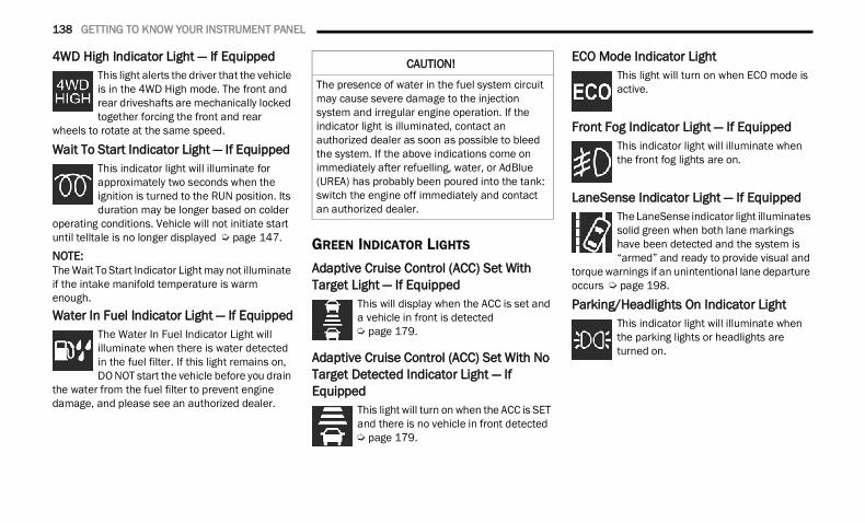
138 GETTING TO KNOW YOUR INSTRUMENT PANEL
4WD High Indicator Light — If Equipped This light alerts the driver that the vehicle is in the 4WD High mode. The front and rear driveshafts are mechanically locked together forcing the front and rear
wheels to rotate at the same speed.
Wait To Start Indicator Light — If Equipped This indicator light will illuminate for approximately two seconds when the ignition is turned to the RUN position. Its duration may be longer based on colder
operating conditions. Vehicle will not initiate start until telltale is no longer displayed Ú page 147.
NOTE:The Wait To Start Indicator Light may not illuminate if the intake manifold temperature is warm enough.Water In Fuel Indicator Light — If Equipped
The Water In Fuel Indicator Light will illuminate when there is water detected in the fuel filter. If this light remains on, DO NOT start the vehicle before you drain
the water from the fuel filter to prevent engine damage, and please see an authorized dealer.
GREEN INDICATOR LIGHTS
Adaptive Cruise Control (ACC) Set With Target Light — If Equipped
This will display when the ACC is set and a vehicle in front is detected Ú page 179.
Adaptive Cruise Control (ACC) Set With No Target Detected Indicator Light — If Equipped
This light will turn on when the ACC is SET and there is no vehicle in front detected Ú page 179.
ECO Mode Indicator LightThis light will turn on when ECO mode is active.
Front Fog Indicator Light — If EquippedThis indicator light will illuminate when the front fog lights are on.
LaneSense Indicator Light — If EquippedThe LaneSense indicator light illuminates solid green when both lane markings have been detected and the system is “armed” and ready to provide visual and
torque warnings if an unintentional lane departure occurs Ú page 198.
Parking/Headlights On Indicator Light This indicator light will illuminate when the parking lights or headlights are turned on.
CAUTION!
The presence of water in the fuel system circuit may cause severe damage to the injection system and irregular engine operation. If the indicator light is illuminated, contact an authorized dealer as soon as possible to bleed the system. If the above indications come on immediately after refuelling, water, or AdBlue (UREA) has probably been poured into the tank: switch the engine off immediately and contact an authorized dealer.
22_DT_OM_EN_USC_t.book Page 138
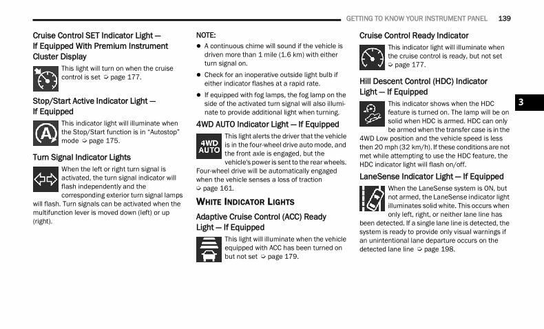
GETTING TO KNOW YOUR INSTRUMENT PANEL 139
Cruise Control SET Indicator Light — If Equipped With Premium Instrument Cluster Display
This light will turn on when the cruise control is set Ú page 177.
Stop/Start Active Indicator Light —If Equipped
This indicator light will illuminate when the Stop/Start function is in “Autostop” mode Ú page 175.
Turn Signal Indicator Lights When the left or right turn signal is activated, the turn signal indicator will flash independently and the corresponding exterior turn signal lamps
will flash. Turn signals can be activated when the multifunction lever is moved down (left) or up (right).
NOTE: A continuous chime will sound if the vehicle is
driven more than 1 mile (1.6 km) with either turn signal on.
Check for an inoperative outside light bulb if either indicator flashes at a rapid rate.
If equipped with fog lamps, the fog lamp on the side of the activated turn signal will also illumi-nate to provide additional light when turning.
4WD AUTO Indicator Light — If Equipped This light alerts the driver that the vehicle is in the four-wheel drive auto mode, and the front axle is engaged, but the vehicle's power is sent to the rear wheels.
Four-wheel drive will be automatically engaged when the vehicle senses a loss of traction Ú page 161.
WHITE INDICATOR LIGHTS
Adaptive Cruise Control (ACC) ReadyLight — If Equipped
This light will illuminate when the vehicle equipped with ACC has been turned on but not set Ú page 179.
Cruise Control Ready Indicator This indicator light will illuminate when the cruise control is ready, but not set Ú page 177.
Hill Descent Control (HDC) IndicatorLight — If Equipped
This indicator shows when the HDC feature is turned on. The lamp will be on solid when HDC is armed. HDC can only be armed when the transfer case is in the
4WD Low position and the vehicle speed is less then 20 mph (32 km/h). If these conditions are not met while attempting to use the HDC feature, the HDC indicator light will flash on/off.
LaneSense Indicator Light — If Equipped When the LaneSense system is ON, but not armed, the LaneSense indicator light illuminates solid white. This occurs when only left, right, or neither lane line has
been detected. If a single lane line is detected, the system is ready to provide only visual warnings if an unintentional lane departure occurs on the detected lane line Ú page 198.
3
22_DT_OM_EN_USC_t.book Page 139
140 GETTING TO KNOW YOUR INSTRUMENT PANEL
Cruise Control SET Indicator Light — If Equipped With Base/Midline Instrument Cluster Display
This light will turn on when the cruise control is set Ú page 177.
BLUE INDICATOR LIGHTS
High Beam Indicator LightThis indicator light will illuminate to indicate that the high beam headlights are on. With the low beams activated, push the multifunction lever forward
(toward the front of the vehicle) to turn on the high beams. Pull the multifunction lever rearward (toward the rear of the vehicle) to turn off the high beams. If the high beams are off, pull the lever toward you for a temporary high beam on, “flash to pass” scenario.
ONBOARD DIAGNOSTIC SYSTEM — OBD II Your vehicle is equipped with a sophisticated Onboard Diagnostic system called OBD II. This system monitors the performance of the emissions, engine, and transmission control systems. When these systems are operating properly, your vehicle will provide excellent performance and fuel economy, as well as engine emissions well within current government regulations.If any of these systems require service, the OBD II system will turn on the Malfunction Indicator Light (MIL). It will also store diagnostic codes and other information to assist your service technician in making repairs. Although your vehicle will usually be drivable and not need towing, see an authorized dealer for service as soon as possible.
ONBOARD DIAGNOSTIC SYSTEM (OBD II) CYBERSECURITY
Your vehicle is required to have OBD II and a connection port to allow access to information related to the performance of your emissions controls. Authorized service technicians may need to access this information to assist with the diagnosis and service of your vehicle and emissions system Ú page 236.
CAUTION!
Prolonged driving with the MIL on could cause further damage to the emission control system. It could also affect fuel economy and driveability. The vehicle must be serviced before any emissions tests can be performed.
If the MIL is flashing while the vehicle is running, severe catalytic converter damage and power loss will soon occur. Immediate service is required.
WARNING!
ONLY an authorized service technician should connect equipment to the OBD II connection port in order to read the VIN, diagnose, or service your vehicle.
If unauthorized equipment is connected to the OBD II connection port, such as a driver-behavior tracking device, it may:
Be possible that vehicle systems, including safety related systems, could be impaired or a loss of vehicle control could occur that may result in an accident involving serious injury or death.
Access, or allow others to access, infor-mation stored in your vehicle systems, including personal information.
22_DT_OM_EN_USC_t.book Page 140
GETTING TO KNOW YOUR INSTRUMENT PANEL 141
EMISSIONS INSPECTION AND MAINTENANCE PROGRAMS In some localities, it may be a legal requirement to pass an inspection of your vehicle's emissions control system. Failure to pass could prevent vehicle registration.
For states that require an Inspection and Maintenance (I/M), this check verifies the Malfunction Indicator Light (MIL) is functioning and is not on when the
engine is running, and that the OBD II system is ready for testing.Normally, the OBD II system will be ready. TheOBD II system may not be ready if your vehicle was recently serviced, recently had a depleted battery or a battery replacement. If the OBD II system should be determined not ready for the I/M test, your vehicle may fail the test.
Your vehicle has a simple ignition actuated test, which you can use prior to going to the test station. To check if your vehicle's OBD II system is ready, you must do the following:1. Cycle the ignition switch to the ON position,
but do not crank or start the engine.
NOTE:If you crank or start the engine, you will have to start this test over.2. As soon as you cycle the ignition switch to the
ON position, you will see the Malfunction Indicator Light (MIL) symbol come on as part of a normal bulb check.
3. Approximately 15 seconds later, one of two things will happen: The MIL will flash for about 10 seconds and
then return to being fully illuminated until you turn OFF the ignition or start the engine. This means that your vehicle's OBD II system is not ready and you should not proceed to the I/M station.
The MIL will not flash at all and will remain fully illuminated until you place the ignition in the off position or start the engine. This means that your vehicle's OBD II system is ready and you can proceed to the I/M station.
If your OBD II system is not ready, you should see an authorized dealer or repair facility. If your vehicle was recently serviced or had a battery failure or replacement, you may need to do nothing more than drive your vehicle as you normally would in order for your OBD II system to update. A recheck with the above test routine may then indicate that the system is now ready.Regardless of whether your vehicle's OBD II system is ready or not, if the MIL is illuminated during normal vehicle operation you should have your vehicle serviced before going to the I/M station. The I/M station can fail your vehicle because the MIL is on with the engine running.
3
22_DT_OM_EN_USC_t.book Page 141
142
(Continued)
(Continued)
STARTING AND OPERATING
STARTING THE ENGINE GASOLINE ENGINEBefore starting your vehicle, adjust your seat, adjust both inside and outside mirrors, and fasten your seat belt.The starter should not be operated for more than 10-second intervals. Waiting at least 10 to 15 seconds between such intervals will protect the starter from overheating.
DIESEL ENGINEBefore starting your vehicle, adjust your seat, both inside and outside mirrors, and fasten your seat belts.The starter is allowed to crank for up to 25-second intervals. Waiting at least two minutes between such intervals will protect the starter from overheating.
WARNING!
When leaving the vehicle, always make sure the keyless ignition node is in the OFF posi-tion, remove the key fob from the vehicle and lock the vehicle.
Never leave children alone in a vehicle, or with access to an unlocked vehicle. Allowing chil-dren to be in a vehicle unattended is dangerous for a number of reasons. A child or others could be seriously or fatally injured. Children should be warned not to touch the parking brake, brake pedal or the gear selector.
Do not leave the key fob in or near the vehicle, or in a location accessible to children, and do not leave the ignition of a vehicle equipped with Keyless Enter ‘n Go™ in the ACC or ON/RUN position. A child could operate power windows, other controls, or move the vehicle.
Do not leave children or animals inside parked vehicles in hot weather. Interior heat buildup may cause serious injury or death.
WARNING! WARNING!
Before exiting a vehicle, always come to a complete stop, then shift the automatic trans-mission into PARK and apply the parking brake.
Always make sure the ENGINE START/STOP button is in the OFF position, key fob is removed from the vehicle and vehicle is locked.
Never leave children alone in a vehicle, or with access to an unlocked vehicle. Leaving chil-dren in a vehicle unattended is dangerous for a number of reasons. A child or others could be seriously or fatally injured. Children should be warned not to touch the parking brake, brake pedal or the gear selector.
22_DT_OM_EN_USC_t.book Page 142
STARTING AND OPERATING 143
NOTE:Engine start-up in very low ambient temperature could result in evident white smoke. This condition will disappear as the engine warms up.
AUTOMATIC TRANSMISSION
Start the engine with the transmission in PARK position. Apply the brake before shifting into any driving range.NOTE: This vehicle is equipped with a transmission
shift interlocking system. The brake pedal must be pressed to shift out of PARK.
If equipped with an 8-speed transmission, starting the vehicle in NEUTRAL is not possible unless the Manual Park Release has been acti-vated Ú page 392.
TIP START FEATURE Do not press the accelerator. Cycle the ignition switch briefly to the START position and release it. The starter motor will continue to run and will automatically disengage when the engine is running.
KEYLESS ENTER ‘N GO™ — IGNITION
This feature allows the driver to operate the ignition switch with the push of a button, as long as the Remote Start/Keyless Enter ‘n Go™ key fob is in the passenger compartment.
NORMAL STARTING USING ENGINE START/STOP BUTTON — GASOLINE ENGINE To Turn On The Engine Using The ENGINE START/STOP Button1. The transmission must be in PARK.2. Press and hold the brake pedal while pushing
the ENGINE START/STOP button once.3. The system starts the vehicle. If the vehicle
fails to start, the starter will disengage automatically after 10 seconds.
4. If you wish to stop the cranking of the engine prior to the engine starting, push the button again.
To Turn Off The Engine Using The ENGINE START/STOP Button1. Place the gear selector in PARK, then push
and release the ENGINE START/STOP button. The ignition will return to the OFF position.
2. If the gear selector is not in PARK, the ENGINE START/STOP button must be held for two seconds or three short pushes in a row with the vehicle speed above 5 mph (8 km/h) before the engine will shut off. The ignition will remain in the ACC position until the gear selector is in PARK and the button is pushed twice to the OFF position.
Do not leave the key fob in or near the vehicle, or in a location accessible to children, and do not leave the ignition of a vehicle equipped with Keyless Enter ‘n Go™ in the ACC or ON/RUN position. A child could operate power windows, other controls, or move the vehicle.
Do not leave children or animals inside parked vehicles in hot weather. Interior heat buildup may cause serious injury or death.
CAUTION!
The engine is allowed to crank as long as 25 seconds. If the engine fails to start during this period, please wait at least two minutes for the starter to cool before repeating start procedure.
If the Water in Fuel Indicator Light remains on, DO NOT START engine before you drain the water from the fuel filter to avoid engine damage Ú page 416.
WARNING!
4
22_DT_OM_EN_USC_t.book Page 143
144 STARTING AND OPERATING
3. If the gear selector is not in PARK and the ENGINE START/STOP button is pushed once with the vehicle speed above 5 mph (8 km/h), the instrument cluster will display a “Vehicle Not In Park” message and the engine will remain running. Never leave a vehicle out of the PARK position, or it could roll.
NOTE:If the gear selector is not in PARK, and the ENGINE START/STOP button is pushed once with the vehicle speed below 5 mph (8 km/h), the engine will shut off and the ignition will remain in the ACC position. If vehicle speed drops below 1.2 mph (1.9 km/h), the vehicle may AutoPark Ú page 144.ENGINE START/STOP Button Functions — With Driver’s Foot OFF The Brake Pedal (In PARK Or NEUTRAL Position)The ENGINE START/STOP button operates similar to an ignition switch. It has three positions: OFF, ACC, and ON/RUN. To change the ignition positions without starting the vehicle and use the accessories, follow these directions:1. Start with the ignition in the OFF position.2. Push the ENGINE START/STOP button once to
place the ignition to the ACC position.3. Push the ENGINE START/STOP button a
second time to place the ignition to the ON/RUN position.
4. Push the ENGINE START/STOP button a third time to return the ignition to the OFF position.
AUTOPARK
AutoPark is a supplemental feature to assist in placing the vehicle in PARK should the situations on the following pages occur. It is a back-up system and should not be relied upon as the primary method by which the driver shifts the vehicle into PARK.The conditions under which AutoPark will engage are outlined on the following pages.
If the vehicle is not in PARK and the driver turns off the engine, the vehicle may AutoPark.AutoPark will engage when all of these conditions are met: Vehicle is equipped with a rotary shifter and an
8-speed transmission Vehicle is not in PARK Vehicle speed is 1.2 mph (1.9 km/h) or less Ignition is switched from ON/RUN to ACCNOTE:For Keyless Enter ‘n Go™ equipped vehicles, the engine will turn off and the ignition switch will change to ACC position. After 30 minutes the ignition switches to OFF automatically, unless the driver turns the ignition switch OFF.If the vehicle is not in PARK and the driver exits the vehicle with the engine running, the vehicle may AutoPark.AutoPark will engage when all of these conditions are met: Vehicle is equipped with a rotary shifter and an
8-speed transmission Vehicle is not in PARK Vehicle speed is 1.2 mph (1.9 km/h) or less Driver’s seat belt is unbuckled Driver’s door is ajar Brake pedal is not pressed
WARNING!
Driver inattention could lead to failure to place the vehicle in PARK. ALWAYS DO A VISUAL CHECK that your vehicle is in PARK by verifying that a solid (not blinking) “P” is indicated in the instrument cluster display and near the gear selector. If the “P” indicator is blinking, your vehicle is not in PARK. As an added precaution, always apply the parking brake when exiting the vehicle.
AutoPark is a supplemental feature. It is not designed to replace the need to shift your vehicle into PARK. It is a back up system and should not be relied upon as the primary method by which the driver shifts the vehicle into PARK.
22_DT_OM_EN_USC_t.book Page 144
STARTING AND OPERATING 145
The message “AutoPark Engaged Shift to P then Shift to Gear” will display in the instrument cluster.NOTE:In some cases the ParkSense graphic will be displayed in the instrument cluster, causing the “AutoPark Engaged Shift to P then Shift to Gear” message to not be seen. In these cases, the gear selector must be returned to “P” to select desired gear.If the driver shifts into PARK while moving, the vehicle may AutoPark.AutoPark will engage ONLY when vehicle speed is 1.2 mph (1.9 km/h) or less.The message “Vehicle Speed is Too High to Shift to P” will be displayed in the instrument cluster if vehicle speed is above 1.2 mph (1.9 km/h).
4WD LOW — If EquippedAutoPark will be disabled when operating the vehicle in 4WD LOW.The message “AutoPark Disabled” will be displayed in the instrument cluster.Additional customer warnings will be given when all of these conditions are met: Vehicle is not in PARK Driver’s door is ajar Vehicle is in 4WD LOWThe message “AutoPark Not Engaged” will be displayed in the instrument cluster. A warning chime will continue until you shift the vehicle into PARK or the driver’s door is closed.ALWAYS DO A VISUAL CHECK that your vehicle is in PARK by looking for the "P" in the instrument cluster display and near the gear selector. As an added precaution, always apply the parking brake when exiting the vehicle.
IF ENGINE FAILS TO START If the engine fails to start after you have followed the “Normal Starting” procedure, it may be flooded. Push the accelerator pedal all the way to the floor and hold it there while the engine is cranking. This should clear any excess fuel in case the engine is flooded.
The starter motor will engage automatically, run for 10 seconds, and then disengage. Once this occurs, release the accelerator pedal and the brake pedal, wait 10 to 15 seconds, then repeat the “Normal Starting” procedure.
WARNING!
If vehicle speed is above 1.2 mph (1.9 km/h), the transmission will default to NEUTRAL until the vehicle speed drops below 1.2 mph (1.9 km/h). A vehicle left in the NEUTRAL position can roll. As an added precaution, always apply the parking brake when exiting the vehicle.
WARNING!
Never pour fuel or other flammable liquid into the throttle body air inlet opening in an attempt to start the vehicle. This could result in flash fire causing serious personal injury.
Do not attempt to push or tow your vehicle to get it started. Vehicles equipped with an auto-matic transmission cannot be started this way. Unburned fuel could enter the catalytic converter and once the engine has started, ignite and damage the converter and vehicle.
If the vehicle has a discharged battery, booster cables may be used to obtain a start from a booster battery or the battery in another vehicle. This type of start can be dangerous if done improperly Ú page 388.
CAUTION!
To prevent damage to the starter, do not crank the engine for more than 10 seconds at a time. Wait 10 to 15 seconds before trying again.
4
22_DT_OM_EN_USC_t.book Page 145
146 STARTING AND OPERATING
If the engine has been flooded, it may start to run, but not have enough power to continue running when the ignition button/key is released. If this occurs, continue cranking with the accelerator pedal pushed all the way to the floor. Release the accelerator pedal and the ignition button/key once the engine is running smoothly.If the engine shows no sign of starting after a 10 second period of engine cranking with the accelerator pedal held to the floor, wait 10 to15 seconds, then repeat the “Normal Starting” procedure.
NORMAL STARTING USING ENGINE START/STOP BUTTON — DIESEL ENGINE Observe the instrument panel telltales when starting the engine.NOTE:Normal starting of either a cold or a warm engine is obtained without pumping or pressing the accel-erator pedal.To Turn On The Engine Using The ENGINE START/STOP Button1. The transmission must be in PARK (P).2. Press and hold the brake pedal while pushing
the ENGINE START/STOP button once.
NOTE:A delay of the start, up to five seconds is possible under very cold conditions. The Wait to Start telltale will be illuminated during the pre-heat process. When the engine Wait To Start light goes off the engine will automatically crank.
3. The system starts the vehicle. If the vehicle fails to start, the starter will disengage automatically after 25 seconds.
4. If you wish to stop the cranking of the engine prior to the engine starting, push the button again.
NOTE:Normal starting of either a cold or a warm engine is obtained without pumping or pressing the accel-erator pedal.
To Turn Off The Engine Using The ENGINE START/STOP Button1. Place the gear selector in PARK, then push
and release the ENGINE START/STOP button. The ignition will return to the OFF position.
2. If the gear selector is not in PARK, the ENGINE START/STOP button must be held for two seconds or three short pushes in a row with the vehicle speed above 5 mph (8 km/h) before the engine will shut off. The ignition will remain in the ACC position until the gear selector is in PARK and the button is pushed twice to the OFF position.
3. If the gear selector is not in PARK and the ENGINE START/STOP button is pushed once with the vehicle speed above 5 mph (8 km/h), the instrument cluster will display a “Vehicle Not In Park” message and the engine will remain running. Never leave a vehicle out of the PARK position, or it could roll.
NOTE:If the gear selector is not in PARK, and the ENGINE START/STOP button is pushed once with the vehicle speed below 5 mph (8 km/h), the engine will shut off and the ignition will remain in the ACC position. If vehicle speed drops below 1.2 mph (1.9 km/h), the vehicle may AutoPark Ú page 144.
CAUTION!
If the Water in Fuel Indicator Light remains on, DO NOT START the engine before you drain the water from the fuel filter to avoid engine damage Ú page 416.
22_DT_OM_EN_USC_t.book Page 146
STARTING AND OPERATING 147
(Continued)
ENGINE START/STOP Button Functions — With Driver’s Foot OFF The Brake Pedal (In PARK Or NEUTRAL Position)The ENGINE START/STOP button operates similar to an ignition switch. It has three positions: OFF, ACC, and ON/RUN. To change the ignition modes without starting the vehicle and use the accessories, follow these directions:1. Start with the ignition in the OFF position.2. Push the ENGINE START/STOP button once to
place the ignition to the ACC position.3. Push the ENGINE START/STOP button a
second time to place the ignition to the ON/RUN position.
4. Push the ENGINE START/STOP button a third time to return the ignition to the OFF position.
COLD WEATHER OPERATION(BELOW –22°F OR −30°C) To ensure reliable starting at these temperatures, use of an externally powered electric engine block heater (available from an authorized dealer) is recommended.
AFTER STARTING
The idle speed is controlled automatically, and it will decrease as the engine warms up.
STARTING FLUIDS — DIESEL ENGINE ONLY
The engine is equipped with a glow plug preheating system. If the instructions in this manual are followed, the engine should start in all conditions and no type of starting fluid should be used. NORMAL OPERATION — DIESEL ENGINE
Observe the following when the diesel engine is operating. All message center lights are off. Malfunction Indicator Light (MIL) is off. Engine Oil Pressure telltale is not illuminated. Voltmeter operation:The voltmeter may show a gauge fluctuation at various engine temperatures. This is caused by the glow plug heating system. The number of cycles and the length of the cycling operation is controlled by the engine control module. Glow plug heater operation can run for several minutes, once the heater operation is complete the voltmeter needle will stabilize.
WARNING!
Do not leave children or animals inside parked vehicles in hot weather. Interior heat build up may cause serious injury or death.
When leaving the vehicle, always make sure the wireless ignition node is in the OFF posi-tion, remove the key fob from the vehicle and lock the vehicle.
Never leave children alone in a vehicle, or with access to an unlocked vehicle. Allowing chil-dren to be in a vehicle unattended is dangerous for a number of reasons. A child or others could be seriously or fatally injured. Children should be warned not to touch the parking brake, brake pedal or the gear selector.
Do not leave the key fob in or near the vehicle, or in a location accessible to children, and do not leave the ignition of a vehicle equipped with Keyless Enter ‘n Go™ in the ACC or ON/RUN position. A child could operate power windows, other controls, or move the vehicle.
WARNING!
4
22_DT_OM_EN_USC_t.book Page 147
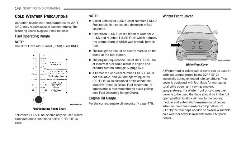
148 STARTING AND OPERATING
COLD WEATHER PRECAUTIONS
Operation in ambient temperature below 32°F (0°C) may require special considerations. The following charts suggest these options:
Fuel Operating RangeNOTE:Use Ultra Low Sulfur Diesel (ULSD) Fuels ONLY.
Fuel Operating Range Chart
*Number 1 ULSD Fuel should only be used where extended arctic conditions below (0°F/-18°C) exist.
NOTE: Use of Climatized ULSD Fuel or Number 1 ULSD
Fuel results in a noticeable decrease in fuel economy.
Climatized ULSD Fuel is a blend of Number 2 ULSD and Number 1 ULSD Fuels which reduces the temperature at which wax crystals form in fuel.
The fuel grade should be clearly marked on the pump at the fuel station.
The engine requires the use of ULSD Fuel. Use of incorrect fuel could result in engine and exhaust system damage Ú page 474.
If Climatized or diesel Number 1 ULSD Fuel is not available, and you are operating below (20°F/-6°C), in sustained arctic conditions, Mopar® Premium Diesel Fuel Treatment (or equivalent) is recommended to avoid gelling (see Fuel Operating Range Chart).
Engine Oil UsageFor the correct engine oil viscosity Ú page 478.
Winter Front Cover
Winter Front Cover
A Winter front or cold weather cover can be used in ambient temperatures below 32°F (0°C), especially during extended idle conditions. This cover is equipped with four flaps for managing total grille opening in varying ambient temperatures. If a Winter front or cold weather cover is to be used the flaps should be in the full open position to allow air flow to the cooling module and automatic transmission oil cooler. When ambient temperatures drop below 0°F (-17°C) the four flaps need to be closed. A suitable cold weather cover is available from a Mopar® dealer.
22_DT_OM_EN_USC_t.book Page 148
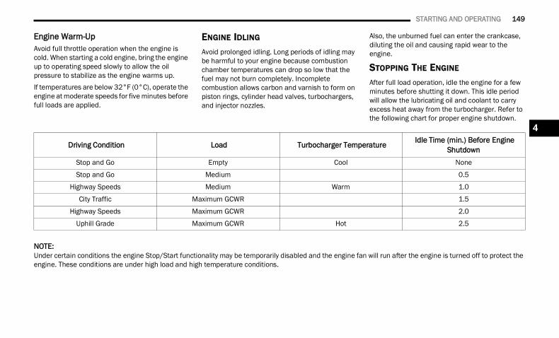
STARTING AND OPERATING 149
Engine Warm-UpAvoid full throttle operation when the engine is cold. When starting a cold engine, bring the engine up to operating speed slowly to allow the oil pressure to stabilize as the engine warms up.If temperatures are below 32°F (0°C), operate the engine at moderate speeds for five minutes before full loads are applied.
ENGINE IDLING
Avoid prolonged idling. Long periods of idling may be harmful to your engine because combustion chamber temperatures can drop so low that the fuel may not burn completely. Incomplete combustion allows carbon and varnish to form on piston rings, cylinder head valves, turbochargers, and injector nozzles.
Also, the unburned fuel can enter the crankcase, diluting the oil and causing rapid wear to the engine.
STOPPING THE ENGINE
After full load operation, idle the engine for a few minutes before shutting it down. This idle period will allow the lubricating oil and coolant to carry excess heat away from the turbocharger. Refer to the following chart for proper engine shutdown.
NOTE:Under certain conditions the engine Stop/Start functionality may be temporarily disabled and the engine fan will run after the engine is turned off to protect the engine. These conditions are under high load and high temperature conditions.
Driving Condition Load Turbocharger Temperature Idle Time (min.) Before Engine Shutdown
Stop and Go Empty Cool None
Stop and Go Medium 0.5
Highway Speeds Medium Warm 1.0
City Traffic Maximum GCWR 1.5
Highway Speeds Maximum GCWR 2.0
Uphill Grade Maximum GCWR Hot 2.5
4
22_DT_OM_EN_USC_t.book Page 149
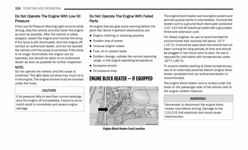
150 STARTING AND OPERATING
Do Not Operate The Engine With Low Oil PressureIf the Low Oil Pressure Warning Light turns on while driving, stop the vehicle and shut down the engine as soon as possible. After the vehicle is safely stopped, restart the engine and monitor the lamp. If the lamp is still illuminated, shut the engine off, contact an authorized dealer, and do not operate the vehicle until the cause is corrected. If the lamp is no longer illuminated, the engine can be operated, but should be taken to an authorized dealer as soon as possible for further inspection.
NOTE:Do not operate the vehicle until the cause is corrected. This light does not show how much oil is in the engine. The engine oil level must be checked under the hood.
Do Not Operate The Engine With Failed PartsAll engine failures give some warning before the parts fail. Some important observations are: Engine misfiring or vibrating severely Sudden loss of power Unusual engine noises Fuel, oil or coolant leaks Sudden change, outside the normal operating
range, in the engine operating temperature Excessive smoke Oil pressure drop
ENGINE BLOCK HEATER — IF EQUIPPED
Engine Block Heater Cord Location
The engine block heater warms engine coolant and permits quicker starts in cold weather. Connect the heater cord to a ground-fault interrupter protected 110–115 Volt AC electrical outlet with a grounded, three-wire extension cord.For diesel engines, its use is recommended for environments that routinely fall below -10°F (-23°C). It should be used when the vehicle has not been running for long periods of time and should be plugged in two hours prior to start. Its use is required for cold starts with temperatures under -20°F (-28°C).To ensure reliable starting at these temperatures, use of an externally powered electric engine block heater (available from an authorized dealer) is recommended.The engine block heater cord is routed under the hood on the passenger side of the vehicle next to the engine coolant reservoir.CAUTION!
If oil pressure falls to less than normal readings, shut the engine off immediately. Failure to do so could result in immediate and severe engine damage.
WARNING!
Remember to disconnect the engine block heater cord before driving. Damage to the 110-115 Volt electrical cord could cause electrocution.
22_DT_OM_EN_USC_t.book Page 150
STARTING AND OPERATING 151
ENGINE BREAK-IN RECOMMENDATIONS — GASOLINE ENGINE A long break-in period is not required for the engine and drivetrain (transmission and axle) in your vehicle.Drive moderately during the first 300 miles (500 km). After the initial 60 miles (100 km), speeds up to 50 or 55 mph (80 or 90 km/h) are desirable.While cruising, brief full-throttle acceleration within the limits of local traffic laws contributes to a good break-in. Wide-open throttle acceleration in low gear can be detrimental and should be avoided.The engine oil installed in the engine at the factory is a high-quality energy conserving type lubricant. Oil changes should be consistent with anticipated climate conditions under which vehicle operations will occur. For the recommended viscosity and quality grades Ú page 478.
NOTE:A new engine may consume some oil during its first few thousand miles (kilometers) of operation. This should be considered a normal part of the break-in and not interpreted as a problem. Please check your oil level with the engine oil indicator often during the break-in period. Add oil as required.
ENGINE BREAK-IN RECOMMENDATIONS — DIESEL ENGINEThe diesel engine does not require a break-in period due to its construction. Normal operation is allowed, providing the following recommendations are followed: Warm up the engine before placing it under
load. Do not operate the engine at idle for prolonged
periods. Observe vehicle oil pressure and temperature
indicators. Check the coolant and oil levels frequently. Vary throttle position at highway speeds when
carrying or towing significant weight.NOTE:Light duty operation such as light trailer towing or no load operation will extend the time before the engine is at full efficiency. Reduced fuel economy and power may be seen at this time.
The engine oil installed in the engine at the factory is a high-quality energy conserving type lubricant. Oil changes should be consistent with anticipated climate conditions under which vehicle operations will occur. For the recommended viscosity and quality grades Ú page 478.
NOTE:NON-DETERGENT OR STRAIGHT MINERAL OILS MUST NEVER BE USED.
PARKING BRAKE ELECTRIC PARK BRAKE (EPB) Your vehicle is equipped with an EPB that offers simple operation, and some additional features that make the parking brake more convenient and useful.The parking brake is primarily intended to prevent the vehicle from rolling while parked. Before leaving the vehicle, make sure that the parking brake is applied. Also, be certain to leave the transmission in PARK.You can engage the parking brake in two ways: Manually, by applying the parking brake switch. Automatically, by enabling the Auto Park Brake
feature in the Customer Programmable Features section of the Uconnect settings.
CAUTION!
Never use Non-Detergent Oil or Straight Mineral Oil in the engine or damage may result.
4
22_DT_OM_EN_USC_t.book Page 151
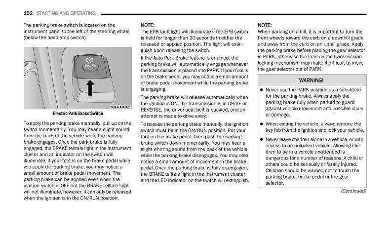
152 STARTING AND OPERATING
(Continued)
The parking brake switch is located on the instrument panel to the left of the steering wheel (below the headlamp switch).
Electric Park Brake Switch
To apply the parking brake manually, pull up on the switch momentarily. You may hear a slight sound from the back of the vehicle while the parking brake engages. Once the park brake is fully engaged, the BRAKE telltale light in the instrument cluster and an indicator on the switch will illuminate. If your foot is on the brake pedal while you apply the parking brake, you may notice a small amount of brake pedal movement. The parking brake can be applied even when the ignition switch is OFF but the BRAKE telltale light will not illuminate, however, it can only be released when the ignition is in the ON/RUN position.
NOTE:The EPB fault light will illuminate if the EPB switch is held for longer than 20 seconds in either the released or applied position. The light will extin-guish upon releasing the switch.If the Auto Park Brake feature is enabled, the parking brake will automatically engage whenever the transmission is placed into PARK. If your foot is on the brake pedal, you may notice a small amount of brake pedal movement while the parking brake is engaging.The parking brake will release automatically when the ignition is ON, the transmission is in DRIVE or REVERSE, the driver seat belt is buckled, and an attempt is made to drive away.To release the parking brake manually, the ignition switch must be in the ON/RUN position. Put your foot on the brake pedal, then push the parking brake switch down momentarily. You may hear a slight whirring sound from the back of the vehicle while the parking brake disengages. You may also notice a small amount of movement in the brake pedal. Once the parking brake is fully disengaged, the BRAKE telltale light in the instrument cluster and the LED indicator on the switch will extinguish.
NOTE:When parking on a hill, it is important to turn the front wheels toward the curb on a downhill grade and away from the curb on an uphill grade. Apply the parking brake before placing the gear selector in PARK, otherwise the load on the transmission locking mechanism may make it difficult to move the gear selector out of PARK.
WARNING!
Never use the PARK position as a substitute for the parking brake. Always apply the parking brake fully when parked to guard against vehicle movement and possible injury or damage.
When exiting the vehicle, always remove the key fob from the ignition and lock your vehicle.
Never leave children alone in a vehicle, or with access to an unlocked vehicle. Allowing chil-dren to be in a vehicle unattended is dangerous for a number of reasons. A child or others could be seriously or fatally injured. Children should be warned not to touch the parking brake, brake pedal or the gear selector.
22_DT_OM_EN_USC_t.book Page 152
STARTING AND OPERATING 153
If exceptional circumstances should make it necessary to engage the parking brake while the vehicle is in motion, maintain upward pressure on the EPB switch for as long as engagement is desired. The BRAKE telltale light will illuminate, and a continuous chime will sound. The rear stop lamps will also be illuminated automatically while the vehicle remains in motion.To disengage the parking brake while the vehicle is in motion, release the switch. If the vehicle is brought to a complete stop using the parking brake, when the vehicle reaches approximately 3 mph, (5 km/h) the parking brake will remain engaged.
In the unlikely event of a malfunction of the EPB system, a yellow EPB fault light will illuminate. This may be accompanied by the BRAKE telltale light flashing. In this event, urgent service of the EPB system is required. Do not rely on the parking brake to hold the vehicle stationary.
Auto Park BrakeThe Electric Park Brake (EPB) can be programmed to be applied automatically whenever the vehicle is at a standstill and the automatic transmission is placed in PARK. Auto Park Brake is enabled and disabled by customer selection through the Customer Programmable Features section of the Uconnect Settings Ú page 252.Any single Auto Park Brake application can be bypassed by pushing the EPB switch to the release position while the transmission is placed in PARK.
SafeHoldSafeHold is a safety feature of the Electric Park Brake (EPB) system that will engage the parking brake automatically if the vehicle is left unsecured while the ignition is in ON/RUN.The parking brake will automatically engage if all of the following conditions are met: The vehicle is at a standstill. There is no attempt to press the brake pedal
and accelerator pedal. The seat belt is unbuckled. The driver door is open.
Do not leave the key fob in or near the vehicle, or in a location accessible to children, and do not leave a vehicle equipped with Keyless Enter ‘n Go™ in the ACC or ON/RUN position. A child could operate power windows, other controls, or move the vehicle.
Be sure the parking brake is fully disengaged before driving; failure to do so can lead to brake failure and a collision.
Always fully apply the parking brake when leaving your vehicle, or it may roll and cause damage or injury. Also be certain to leave the transmission in PARK. Failure to do so may allow the vehicle to roll and cause damage or injury.
CAUTION!
If the Brake System Warning Light remains on with the parking brake released, a brake system malfunction is indicated. Have the brake system serviced by an authorized dealer immediately.
WARNING!
WARNING!
Driving the vehicle with the parking brake engaged, or repeated use of the parking brake to slow the vehicle, may cause serious damage to the brake system. Be sure the parking brake is fully disengaged before driving; failure to do so can lead to brake failure and a collision.
4
22_DT_OM_EN_USC_t.book Page 153
154 STARTING AND OPERATING
(Continued)
SafeHold can be temporarily bypassed by pushing the EPB switch while the driver door is open. Once manually bypassed, SafeHold will be enabled again once the vehicle reaches 12 mph (20 km/h) or the ignition is turned to the OFF position and back to ON again.
Brake Service ModeWe recommend having your brakes serviced by an authorized dealer. You should only make repairs for which you have the knowledge and the right equipment. You should only enter Brake Service Mode during brake service.When servicing your rear brakes, it may be necessary for you or your technician to push the rear piston into the rear caliper bore. With the Electric Park Brake (EPB) system, this can only be done after retracting the EPB actuator. Fortunately, actuator retraction can be done easily by entering the Brake Service Mode through the Uconnect Settings in your vehicle. This menu-based system will guide you through the steps necessary to retract the EPB actuator in order to perform rear brake service.
Service Mode has requirements that must be met in order to be activated: The vehicle must be at a standstill. The parking brake must be unapplied. The transmission must be in PARK or NEUTRAL.While in Service Mode, the EPB fault lamp will flash continuously while the ignition is in ON/RUN.When brake service work is complete, the following steps must be followed to reset the park brake system to normal operation: Ensure the vehicle is at a standstill. Press the brake pedal with moderate force. Apply the EPB Switch.
AUTOMATIC TRANSMISSION You must press and hold the brake pedal while shifting out of PARK.
WARNING!
You can be badly injured working on or around a motor vehicle. Do only that service work for which you have the knowledge and the right equipment. If you have any doubt about your ability to perform a service job, take your vehicle to a competent mechanic.
WARNING!
Never use the PARK position as a substitute for the parking brake. Always apply the parking brake fully when exiting the vehicle to guard against vehicle movement and possible injury or damage.
Your vehicle could move and injure you and others if it is not in PARK. Check by trying to move the transmission gear selector out of PARK with the brake pedal released. Make sure the transmission is in PARK before exiting the vehicle.
The transmission may not engage PARK if the vehicle is moving. Always bring the vehicle to a complete stop before shifting to PARK, and verify that the transmission gear position indi-cator solidly indicates PARK (P) without blinking. Ensure that the vehicle is completely stopped, and the PARK position is properly indicated, before exiting the vehicle.
22_DT_OM_EN_USC_t.book Page 154
STARTING AND OPERATING 155
(Continued)
IGNITION PARK INTERLOCK
This vehicle is equipped with an Ignition Park Interlock which requires the transmission to be in PARK before the ignition can be turned to the OFF position. This helps the driver avoid inadvertently leaving the vehicle without placing the transmission in PARK. This system also locks the transmission in PARK whenever the ignition is in the OFF position.
NOTE:The transmission is NOT locked in PARK when the ignition is in the ACC position (even though the engine will be off). Ensure that the transmission is in PARK, and the ignition is OFF (not in ACC position) before exiting the vehicle.
BRAKE/TRANSMISSION SHIFT INTERLOCK (BTSI) SYSTEM This vehicle is equipped with a BTSI system that holds the transmission gear selector in PARK unless the brakes are applied. To shift the transmission out of PARK, the engine must be running and the brake pedal must be pressed.The brake pedal must also be pressed to shift from NEUTRAL into DRIVE or REVERSE when the vehicle is stopped or moving at low speeds.
It is dangerous to shift out of PARK or NEUTRAL if the engine speed is higher than idle speed. If your foot is not firmly pressing the brake pedal, the vehicle could accelerate quickly forward or in reverse. You could lose control of the vehicle and hit someone or something. Only shift into gear when the engine is idling normally and your foot is firmly pressing the brake pedal.
Unintended movement of a vehicle could injure those in or near the vehicle. As with all vehicles, you should never exit a vehicle while the engine is running. Before exiting a vehicle, always come to a complete stop, then apply the parking brake, shift the transmission into PARK, and turn the ignition OFF. When the ignition is in the OFF position, the transmis-sion is locked in PARK, securing the vehicle against unwanted movement.
When exiting the vehicle, always make sure the ignition is in the OFF position, remove the key fob from the vehicle, and lock the vehicle.
WARNING!
Never leave children alone in a vehicle, or with access to an unlocked vehicle. Allowing chil-dren to be in a vehicle unattended is dangerous for a number of reasons. A child or others could be seriously or fatally injured. Children should be warned not to touch the parking brake, brake pedal or the transmis-sion gear selector.
Do not leave the key fob in or near the vehicle (or in a location accessible to children), and do not leave the ignition in the ACC or ON/RUN position. A child could operate power windows, other controls, or move the vehicle.
CAUTION!
Shift into or out of PARK or REVERSE only after the vehicle has come to a complete stop.
Do not shift between PARK, REVERSE, NEUTRAL, or DRIVE when the engine is above idle speed.
Before shifting into any gear, make sure your foot is firmly pressing the brake pedal.
WARNING!
4
22_DT_OM_EN_USC_t.book Page 155
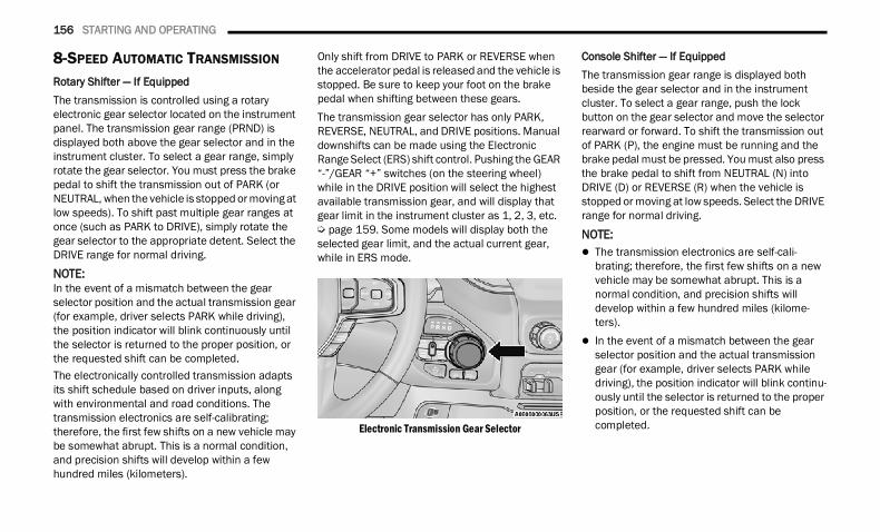
156 STARTING AND OPERATING
8-SPEED AUTOMATIC TRANSMISSION Rotary Shifter — If EquippedThe transmission is controlled using a rotary electronic gear selector located on the instrument panel. The transmission gear range (PRND) is displayed both above the gear selector and in the instrument cluster. To select a gear range, simply rotate the gear selector. You must press the brake pedal to shift the transmission out of PARK (or NEUTRAL, when the vehicle is stopped or moving at low speeds). To shift past multiple gear ranges at once (such as PARK to DRIVE), simply rotate the gear selector to the appropriate detent. Select the DRIVE range for normal driving.
NOTE:In the event of a mismatch between the gear selector position and the actual transmission gear (for example, driver selects PARK while driving), the position indicator will blink continuously until the selector is returned to the proper position, or the requested shift can be completed.The electronically controlled transmission adapts its shift schedule based on driver inputs, along with environmental and road conditions. The transmission electronics are self-calibrating; therefore, the first few shifts on a new vehicle may be somewhat abrupt. This is a normal condition, and precision shifts will develop within a few hundred miles (kilometers).
Only shift from DRIVE to PARK or REVERSE when the accelerator pedal is released and the vehicle is stopped. Be sure to keep your foot on the brake pedal when shifting between these gears.The transmission gear selector has only PARK, REVERSE, NEUTRAL, and DRIVE positions. Manual downshifts can be made using the Electronic Range Select (ERS) shift control. Pushing the GEAR “-”/GEAR “+” switches (on the steering wheel) while in the DRIVE position will select the highest available transmission gear, and will display that gear limit in the instrument cluster as 1, 2, 3, etc. Ú page 159. Some models will display both the selected gear limit, and the actual current gear, while in ERS mode.
Electronic Transmission Gear Selector
Console Shifter — If EquippedThe transmission gear range is displayed both beside the gear selector and in the instrument cluster. To select a gear range, push the lock button on the gear selector and move the selector rearward or forward. To shift the transmission out of PARK (P), the engine must be running and the brake pedal must be pressed. You must also press the brake pedal to shift from NEUTRAL (N) into DRIVE (D) or REVERSE (R) when the vehicle is stopped or moving at low speeds. Select the DRIVE range for normal driving.
NOTE: The transmission electronics are self-cali-
brating; therefore, the first few shifts on a new vehicle may be somewhat abrupt. This is a normal condition, and precision shifts will develop within a few hundred miles (kilome-ters).
In the event of a mismatch between the gear selector position and the actual transmission gear (for example, driver selects PARK while driving), the position indicator will blink continu-ously until the selector is returned to the proper position, or the requested shift can be completed.
22_DT_OM_EN_USC_t.book Page 156
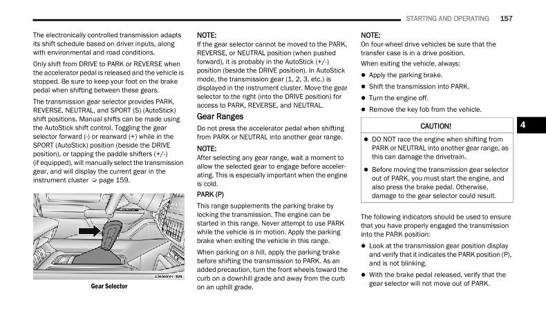
STARTING AND OPERATING 157
The electronically controlled transmission adapts its shift schedule based on driver inputs, along with environmental and road conditions.Only shift from DRIVE to PARK or REVERSE when the accelerator pedal is released and the vehicle is stopped. Be sure to keep your foot on the brake pedal when shifting between these gears.The transmission gear selector provides PARK, REVERSE, NEUTRAL, and SPORT (S) (AutoStick) shift positions. Manual shifts can be made using the AutoStick shift control. Toggling the gear selector forward (-) or rearward (+) while in the SPORT (AutoStick) position (beside the DRIVE position), or tapping the paddle shifters (+/-) (if equipped), will manually select the transmission gear, and will display the current gear in the instrument cluster Ú page 159.
Gear Selector
NOTE:If the gear selector cannot be moved to the PARK, REVERSE, or NEUTRAL position (when pushed forward), it is probably in the AutoStick (+/-) position (beside the DRIVE position). In AutoStick mode, the transmission gear (1, 2, 3, etc.) is displayed in the instrument cluster. Move the gear selector to the right (into the DRIVE position) for access to PARK, REVERSE, and NEUTRAL.Gear RangesDo not press the accelerator pedal when shifting from PARK or NEUTRAL into another gear range.NOTE:After selecting any gear range, wait a moment to allow the selected gear to engage before acceler-ating. This is especially important when the engine is cold.PARK (P)This range supplements the parking brake by locking the transmission. The engine can be started in this range. Never attempt to use PARK while the vehicle is in motion. Apply the parking brake when exiting the vehicle in this range.When parking on a hill, apply the parking brake before shifting the transmission to PARK. As an added precaution, turn the front wheels toward the curb on a downhill grade and away from the curb on an uphill grade.
NOTE:On four-wheel drive vehicles be sure that the transfer case is in a drive position.When exiting the vehicle, always: Apply the parking brake. Shift the transmission into PARK. Turn the engine off. Remove the key fob from the vehicle.
The following indicators should be used to ensure that you have properly engaged the transmission into the PARK position: Look at the transmission gear position display
and verify that it indicates the PARK position (P), and is not blinking.
With the brake pedal released, verify that the gear selector will not move out of PARK.
CAUTION!
DO NOT race the engine when shifting from PARK or NEUTRAL into another gear range, as this can damage the drivetrain.
Before moving the transmission gear selector out of PARK, you must start the engine, and also press the brake pedal. Otherwise, damage to the gear selector could result.
4
22_DT_OM_EN_USC_t.book Page 157
158 STARTING AND OPERATING
REVERSE (R)This range is for moving the vehicle backward. Shift into REVERSE only after the vehicle has come to a complete stop.NEUTRAL (N)Use this range when the vehicle is standing for prolonged periods with the engine running. Apply the parking brake and shift the transmission into PARK if you must exit the vehicle.
DRIVE (D)This range should be used for most city and highway driving. It provides the smoothest upshifts and downshifts, and the best fuel economy. The transmission automatically upshifts through all forward gears.When frequent transmission shifting occurs (such as when operating the vehicle under heavy loading conditions, in hilly terrain, traveling into strong head winds, or while towing a heavy trailer), select TOW/HAUL mode or use the Electronic Range Select (ERS) shift control to select a lower gear range Ú page 159. Under these conditions, using a lower gear range will improve performance and extend transmission life by reducing excessive shifting and heat buildup.During extremely cold temperatures (-22°F [-30°C] or below), transmission operation may be modified depending on engine and transmission temperature as well as vehicle speed. Normal operation will resume once the transmission temperature has risen to a suitable level.
Transmission Limp Home Mode Transmission function is monitored electronically for abnormal conditions. If a condition is detected that could result in transmission damage, Transmission Limp Home Mode is activated. In this mode, the transmission may operate only in
certain gears, or may not shift at all. Vehicle performance may be severely degraded and the engine may stall. In some situations, the transmission may not re-engage if the engine is turned off and restarted. The Malfunction Indicator Light (MIL) may be illuminated. A message in the instrument cluster will inform the driver of the more serious conditions, and indicate what actions may be necessary.In the event of a momentary problem, the transmission can be reset to regain all forward gears by performing the following steps:
NOTE:In cases where the instrument cluster message indicates the transmission may not re-engage after engine shutdown, perform this procedure only in a desired location (preferably, at an authorized dealer).1. Stop the vehicle.2. Shift the transmission into PARK, if possible. If
not, shift the transmission to NEUTRAL.3. Push and hold the ignition switch until the
engine turns off.4. Wait approximately 30 seconds.5. Restart the engine.6. Shift into the desired gear range. If the
problem is no longer detected, the transmission will return to normal operation.
WARNING!
Do not coast in NEUTRAL and never turn off the ignition to coast down a hill. These are unsafe practices that limit your response to changing traffic or road conditions. You might lose control of the vehicle and have a collision.
CAUTION!
Towing the vehicle, coasting, or driving for any other reason with the transmission in NEUTRAL can cause severe transmission damage.
For Recreational Towing Ú page 231.
For Towing A Disabled Vehicle Ú page 394.
22_DT_OM_EN_USC_t.book Page 158
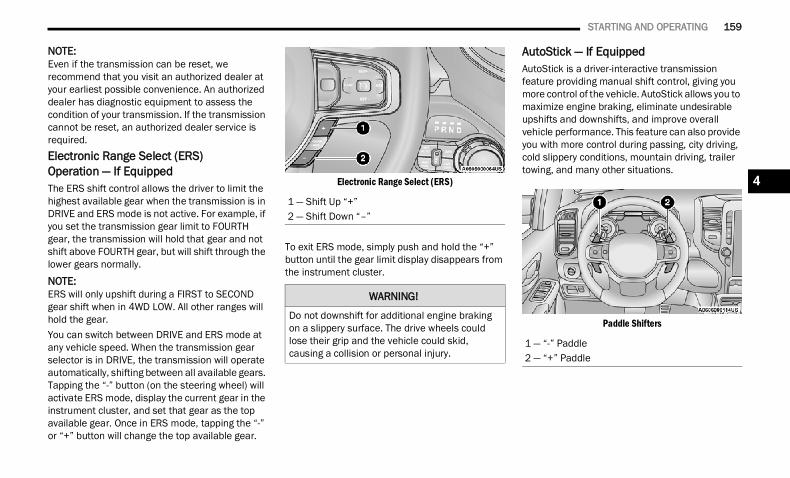
STARTING AND OPERATING 159
NOTE:Even if the transmission can be reset, we recommend that you visit an authorized dealer at your earliest possible convenience. An authorized dealer has diagnostic equipment to assess the condition of your transmission. If the transmission cannot be reset, an authorized dealer service is required.Electronic Range Select (ERS) Operation — If EquippedThe ERS shift control allows the driver to limit the highest available gear when the transmission is in DRIVE and ERS mode is not active. For example, if you set the transmission gear limit to FOURTH gear, the transmission will hold that gear and not shift above FOURTH gear, but will shift through the lower gears normally.
NOTE:ERS will only upshift during a FIRST to SECOND gear shift when in 4WD LOW. All other ranges will hold the gear.You can switch between DRIVE and ERS mode at any vehicle speed. When the transmission gear selector is in DRIVE, the transmission will operate automatically, shifting between all available gears. Tapping the “-” button (on the steering wheel) will activate ERS mode, display the current gear in the instrument cluster, and set that gear as the top available gear. Once in ERS mode, tapping the “-” or “+” button will change the top available gear.
Electronic Range Select (ERS)
To exit ERS mode, simply push and hold the “+” button until the gear limit display disappears from the instrument cluster.
AutoStick — If EquippedAutoStick is a driver-interactive transmission feature providing manual shift control, giving you more control of the vehicle. AutoStick allows you to maximize engine braking, eliminate undesirable upshifts and downshifts, and improve overall vehicle performance. This feature can also provide you with more control during passing, city driving, cold slippery conditions, mountain driving, trailer towing, and many other situations.
Paddle Shifters
1 — Shift Up “+”2 — Shift Down “–”
WARNING!
Do not downshift for additional engine braking on a slippery surface. The drive wheels could lose their grip and the vehicle could skid, causing a collision or personal injury.
1 — “-” Paddle2 — “+” Paddle
4
22_DT_OM_EN_USC_t.book Page 159
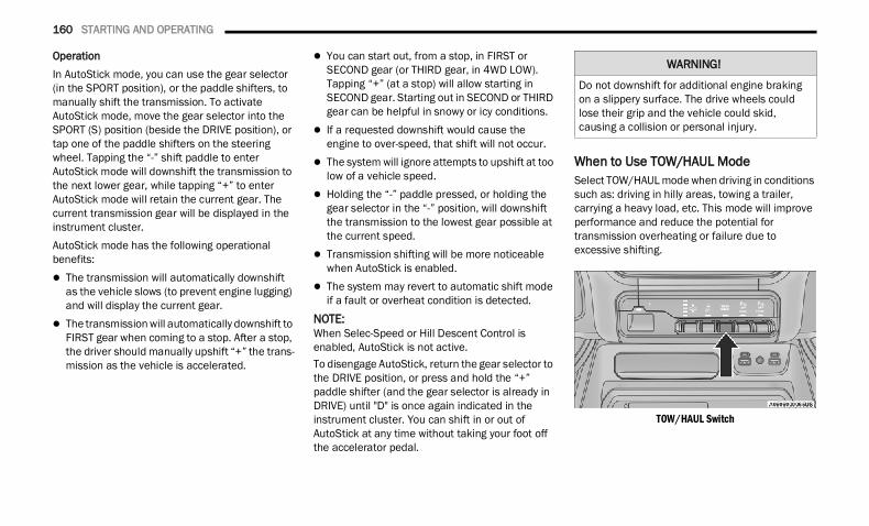
160 STARTING AND OPERATING
OperationIn AutoStick mode, you can use the gear selector (in the SPORT position), or the paddle shifters, to manually shift the transmission. To activate AutoStick mode, move the gear selector into the SPORT (S) position (beside the DRIVE position), or tap one of the paddle shifters on the steering wheel. Tapping the “-” shift paddle to enter AutoStick mode will downshift the transmission to the next lower gear, while tapping “+” to enter AutoStick mode will retain the current gear. The current transmission gear will be displayed in the instrument cluster.AutoStick mode has the following operational benefits: The transmission will automatically downshift
as the vehicle slows (to prevent engine lugging) and will display the current gear.
The transmission will automatically downshift to FIRST gear when coming to a stop. After a stop, the driver should manually upshift “+” the trans-mission as the vehicle is accelerated.
You can start out, from a stop, in FIRST or SECOND gear (or THIRD gear, in 4WD LOW). Tapping “+” (at a stop) will allow starting in SECOND gear. Starting out in SECOND or THIRD gear can be helpful in snowy or icy conditions.
If a requested downshift would cause the engine to over-speed, that shift will not occur.
The system will ignore attempts to upshift at too low of a vehicle speed.
Holding the “-” paddle pressed, or holding the gear selector in the “-” position, will downshift the transmission to the lowest gear possible at the current speed.
Transmission shifting will be more noticeable when AutoStick is enabled.
The system may revert to automatic shift mode if a fault or overheat condition is detected.
NOTE:When Selec-Speed or Hill Descent Control is enabled, AutoStick is not active.To disengage AutoStick, return the gear selector to the DRIVE position, or press and hold the “+” paddle shifter (and the gear selector is already in DRIVE) until "D" is once again indicated in the instrument cluster. You can shift in or out of AutoStick at any time without taking your foot off the accelerator pedal.
When to Use TOW/HAUL ModeSelect TOW/HAUL mode when driving in conditions such as: driving in hilly areas, towing a trailer, carrying a heavy load, etc. This mode will improve performance and reduce the potential for transmission overheating or failure due to excessive shifting.
TOW/HAUL Switch
WARNING!
Do not downshift for additional engine braking on a slippery surface. The drive wheels could lose their grip and the vehicle could skid, causing a collision or personal injury.
22_DT_OM_EN_USC_t.book Page 160
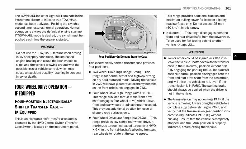
STARTING AND OPERATING 161
The TOW/HAUL Indicator Light will illuminate in the instrument cluster to indicate that TOW/HAUL mode has been activated. Pushing the switch a second time restores normal operation. Normal operation is always the default at engine start-up. If TOW/HAUL mode is desired, the switch must be pushed each time the engine is started.
FOUR-WHEEL DRIVE OPERATION —IF EQUIPPED FOUR-POSITION ELECTRONICALLY SHIFTED TRANSFER CASE — IF EQUIPPED This is an electronic shift transfer case and is operated by the 4WD Control Switch (Transfer Case Switch), located on the instrument panel.
Four-Position/On-Demand Transfer Case
This electronically shifted transfer case provides four positions: Two-Wheel Drive High Range (2WD) — This
range is for normal street and highway driving on dry hard surfaced roads. Driving the vehicle in 2WD will have greater fuel economy benefits as the front axle is not engaged in 2WD.
Four-Wheel Drive High Range (4WD HIGH) — This range provides torque to the front drive-shaft (engages four-wheel drive) which allows front and rear wheels to spin at the same speed. This provides additional traction for loose or slippery road surfaces only.
Four-Wheel Drive Low Range (4WD LOW) — This range provides low speed four-wheel drive. It maximizes torque (increased torque over 4WD HIGH) to the front driveshaft; allowing front and rear wheels to rotate at the same speed.
This range provides additional traction and maximum pulling power for loose or slippery road surfaces only. Do not exceed 25 mph (40 km/h) in this range.
N (Neutral) — This range disengages both the front and rear driveshafts from the powertrain. To be used for flat towing behind another vehicle Ú page 231.
WARNING!
Do not use the TOW/HAUL feature when driving in icy or slippery conditions. The increased engine braking can cause the rear wheels to slide, and the vehicle to swing around with the possible loss of vehicle control, which may cause an accident possibly resulting in personal injury or death.
WARNING!
You or others could be injured or killed if you leave the vehicle unattended with the transfer case in the N (Neutral) position without first fully engaging the parking brake. The transfer case N (Neutral) position disengages both the front and rear drive shaft from the powertrain, and will allow the vehicle to roll, even if the transmission is in PARK. The parking brake should always be applied when the driver is not in the vehicle.
The transmission may not engage PARK if the vehicle is moving. Always bring the vehicle to a complete stop before shifting to PARK, and verify that the transmission gear position indi-cator solidly indicates PARK (P) without blinking. Ensure that the vehicle is completely stopped, and the PARK position is properly indicated, before exiting the vehicle.
4
22_DT_OM_EN_USC_t.book Page 161
162 STARTING AND OPERATING
NOTE: The 4WD HIGH and 4WD LOW positions are
designed for loose, slippery road surfaces only. Driving in the 4WD HIGH and 4WD LOW posi-tions on dry, hard surfaced roads may cause increased tire wear and damage to the driveline components.
The transfer case N (Neutral) button is located in the center of the 4WD Control Switch and is pushed by using a ballpoint pen or similar object. The transfer case N (Neutral) position is to be used for recreational towing only Ú page 231.
Transfer Case Position Indicator LightsThe Transfer Case Position Indicator Lights (4WD HIGH and 4WD LOW) are located in the instrument cluster and indicate the current and desired transfer case selection. When you select a different transfer case position, the indicator lights will do the following:1. The current position indicator light will turn
off.2. The selected position indicator light will flash
until the transfer case completes the shift.3. When the shift is complete, the indicator light
for the selected position will stop flashing and remain on.
If the transfer case does not shift into the desired position, one or more of the following events may occur:1. The indicator light for the current position will
remain on.2. The newly selected position indicator light will
continue to flash.3. If the transfer case will not shift, a message
will appear on the cluster stating the 4WD shift has canceled.
NOTE:Before retrying a selection, make certain that all the necessary requirements for selecting a new transfer case position have been met. To retry the selection, push the current position, wait five seconds, and retry selection.The SERV 4WD Warning Light monitors the electronic shift four-wheel drive system. If this light remains on after engine start-up or illuminates during driving, it means that the four-wheel drive system is not functioning properly and that service is required.
NOTE:Do not attempt to make a shift while only the front or rear wheels are spinning. This could cause damage to driveline components.When operating your vehicle in 4WD LOW, the engine speed is approximately three times that of the 2WD or 4WD HIGH positions at a given road speed. Take care not to overspeed the engine and do not exceed 25 mph (40 km/h).Proper operation of four-wheel drive vehicles depends on tires of equal size, type and circumference on each wheel. Any difference in tire size can cause damage to the drivetrain.Because four-wheel drive provides improved traction, there is a tendency to exceed safe turning and stopping speeds. Do not go faster than road conditions permit.
WARNING!
Always engage the parking brake when powering down the vehicle if the SERV 4WD Warning Light is illuminated. Not engaging the parking brake may allow the vehicle to roll which may cause personal injury or death.
22_DT_OM_EN_USC_t.book Page 162
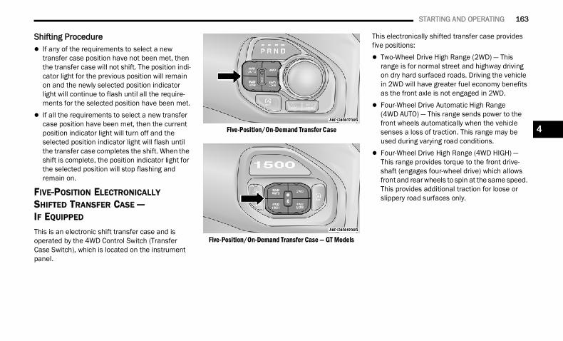
STARTING AND OPERATING 163
Shifting Procedure If any of the requirements to select a new
transfer case position have not been met, then the transfer case will not shift. The position indi-cator light for the previous position will remain on and the newly selected position indicator light will continue to flash until all the require-ments for the selected position have been met.
If all the requirements to select a new transfer case position have been met, then the current position indicator light will turn off and the selected position indicator light will flash until the transfer case completes the shift. When the shift is complete, the position indicator light for the selected position will stop flashing and remain on.
FIVE-POSITION ELECTRONICALLY SHIFTED TRANSFER CASE — IF EQUIPPED This is an electronic shift transfer case and is operated by the 4WD Control Switch (Transfer Case Switch), which is located on the instrument panel.
Five-Position/On-Demand Transfer Case
Five-Position/On-Demand Transfer Case — GT Models
This electronically shifted transfer case provides five positions: Two-Wheel Drive High Range (2WD) — This
range is for normal street and highway driving on dry hard surfaced roads. Driving the vehicle in 2WD will have greater fuel economy benefits as the front axle is not engaged in 2WD.
Four-Wheel Drive Automatic High Range(4WD AUTO) — This range sends power to the front wheels automatically when the vehicle senses a loss of traction. This range may be used during varying road conditions.
Four-Wheel Drive High Range (4WD HIGH) — This range provides torque to the front drive-shaft (engages four-wheel drive) which allows front and rear wheels to spin at the same speed. This provides additional traction for loose or slippery road surfaces only.
4
22_DT_OM_EN_USC_t.book Page 163
164 STARTING AND OPERATING
(Continued)
Four-Wheel Drive Low Range (4WD LOW) — This range provides low speed four-wheel drive. It maximizes torque (increased torque over 4WD HIGH) to the front driveshaft; allowing front and rear wheels to rotate at the same speed. This range provides additional traction and maximum pulling power for loose or slippery road surfaces only. Do not exceed 25 mph (40 km/h) in this range.
N (Neutral) — This range disengages both the front and rear driveshafts from the powertrain. To be used for flat towing behind another vehicle Ú page 231.
NOTE: The 4WD HIGH and 4WD LOW positions are
designed for loose, slippery road surfaces only. Driving in the 4WD HIGH and 4WD LOW posi-tions on dry hard surfaced roads may cause increased tire wear and damage to the driveline components.
The transfer case N (Neutral) button is located in the center of the 4WD Control Switch and is pushed by using a ballpoint pen or similar object. The transfer case N (Neutral) position is to be used for recreational towing only Ú page 231.
Transfer Case Position Indicator LightsThe Transfer Case Position Indicator Lights(4WD HIGH, 4WD LOW, and 4WD AUTO) are located in the instrument cluster and indicate the current and desired transfer case selection. When you select a different transfer case position, the indicator lights will do the following:1. The current position indicator light will turn
off.2. The selected position indicator light will flash
until the transfer case completes the shift.3. When the shift is complete, the indicator light
for the selected position will stop flashing and remain on.
If the transfer case does not shift into the desired position, one or more of the following events may occur:1. The indicator light for the current position will
remain on.2. The newly selected position indicator light will
continue to flash.3. If the transfer case will not shift, there will be a
cluster message stating the 4WD shift has canceled.
WARNING!
You or others could be injured or killed if you leave the vehicle unattended with the transfer case in the N (Neutral) position without first fully engaging the parking brake. The transfer case N (Neutral) position disengages both the front and rear drive shaft from the powertrain, and will allow the vehicle to roll, even if the transmission is in PARK. The parking brake should always be applied when the driver is not in the vehicle.
The transmission may not engage PARK if the vehicle is moving. Always bring the vehicle to a complete stop before shifting to PARK, and verify that the transmission gear position indi-cator solidly indicates PARK (P) without blinking. Ensure that the vehicle is completely stopped, and the PARK position is properly indicated, before exiting the vehicle.
WARNING!
22_DT_OM_EN_USC_t.book Page 164
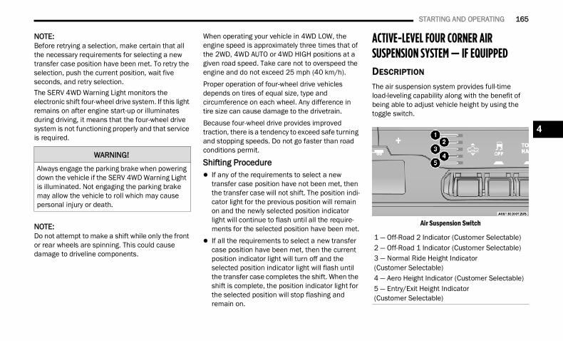
STARTING AND OPERATING 165
NOTE:Before retrying a selection, make certain that all the necessary requirements for selecting a new transfer case position have been met. To retry the selection, push the current position, wait five seconds, and retry selection.The SERV 4WD Warning Light monitors the electronic shift four-wheel drive system. If this light remains on after engine start-up or illuminates during driving, it means that the four-wheel drive system is not functioning properly and that service is required.
NOTE:Do not attempt to make a shift while only the front or rear wheels are spinning. This could cause damage to driveline components.
When operating your vehicle in 4WD LOW, the engine speed is approximately three times that of the 2WD, 4WD AUTO or 4WD HIGH positions at a given road speed. Take care not to overspeed the engine and do not exceed 25 mph (40 km/h).Proper operation of four-wheel drive vehicles depends on tires of equal size, type and circumference on each wheel. Any difference in tire size can cause damage to the drivetrain.Because four-wheel drive provides improved traction, there is a tendency to exceed safe turning and stopping speeds. Do not go faster than road conditions permit.
Shifting Procedure If any of the requirements to select a new
transfer case position have not been met, then the transfer case will not shift. The position indi-cator light for the previous position will remain on and the newly selected position indicator light will continue to flash until all the require-ments for the selected position have been met.
If all the requirements to select a new transfer case position have been met, then the current position indicator light will turn off and the selected position indicator light will flash until the transfer case completes the shift. When the shift is complete, the position indicator light for the selected position will stop flashing and remain on.
ACTIVE-LEVEL FOUR CORNER AIR SUSPENSION SYSTEM — IF EQUIPPED DESCRIPTION
The air suspension system provides full-time load-leveling capability along with the benefit of being able to adjust vehicle height by using the toggle switch.
Air Suspension Switch
WARNING!
Always engage the parking brake when powering down the vehicle if the SERV 4WD Warning Light is illuminated. Not engaging the parking brake may allow the vehicle to roll which may cause personal injury or death.
1 — Off-Road 2 Indicator (Customer Selectable)2 — Off-Road 1 Indicator (Customer Selectable)3 — Normal Ride Height Indicator (Customer Selectable)4 — Aero Height Indicator (Customer Selectable)5 — Entry/Exit Height Indicator(Customer Selectable)
4
22_DT_OM_EN_USC_t.book Page 165
166 STARTING AND OPERATING
Off-Road 2 (OR2) (Raises the vehicle approxi-mately 2 inches [51 mm]) – This position is intended for off-road use only where maximum ground clearance is required. To enter OR2, push the height selector switch up twice from the NRH position or once from the OR1 position while vehicle speed is below 20 mph (32 km/h). While in OR2, if the vehicle speed exceeds 25 mph (40 km/h) the vehicle height will be automatically lowered to OR1. Off-Road 2 may not be available due to vehicle payload, an instrument cluster message will be displayed when this occurs Ú page 115.
Off-Road 1 (OR1) (Raises the vehicle approxi-mately 1 inch [26 mm]) – This position should be the primary position for all off-road driving until Off-Road 2 (OR2) is needed. A smoother and more comfortable ride will result. To enter OR1, push the height selector switch up once from the NRH position while the vehicle speed is below 35 mph (56 km/h). When in the OR1 position, if the vehicle speed remains between 40 mph (64 km/h) and 50 mph (80 km/h) for
greater than 20 seconds or if the vehicle speed exceeds 50 mph (80 km/h), the vehicle will be automatically lowered to NRH. Off-Road 1 may not be available due to vehicle payload, an instrument cluster message will be displayed when this occurs Ú page 115.
Normal Ride Height (NRH) – This is the standard position of the suspension and is meant for normal driving.
Aero Height (Lowers the vehicle approximately 0.6 inch [15 mm]) – This position provides improved aerodynamics by lowering the vehicle. The vehicle will automatically enter Automatic Aero Mode when the vehicle speed remains between 62 mph (100 km/h) and 66 mph (106 km/h) for greater than 20 seconds or if the vehicle speed exceeds 66 mph (106 km/h). The vehicle will return to NRH from Aero Mode if the vehicle speed remains between 30 mph (48 km/h) and 35 mph (56 km/h) for greater than 20 seconds or if the vehicle speed falls below 30 mph (48 km/h).
NOTE: Automatic Aero mode will be disabled if a
trailer is detected to prevent shifting loads. Speed thresholds for raising/lowering the
vehicle automatically at higher speeds only apply if Automatic Aero Mode is enabled in your Uconnect Radio settings.
To enter Aero Height manually push the height selector switch down once from NRH at any vehicle speed. To return to NRH push the height selector switch up once while vehicle speed is less than 56 mph (90 km/h).
NOTE:Automatic Aero Mode may be disabled through vehicle settings in the instrument cluster display Ú page 115 or through your Uconnect Radio(if equipped) Ú page 237. Entry/Exit Height (Lowers the vehicle approxi-
mately 2 inches [51 mm]) – This position lowers the vehicle for easier passenger entry and exit as well as lowering the vehicle for easier loading and unloading of cargo. To enter Entry/Exit Mode, push the height selector switch down once from the NRH while the vehicle speed is below 33 mph (53 km/h). Once the vehicle speed goes below 15 mph (24 km/h) the vehicle height will begin to lower. If the vehicle speed remains between 15 mph (24 km/h) and 25 mph (40 km/h) for greater than 60 seconds, or the vehicle speed exceeds 25 mph (40 km/h) the Entry/Exit change will be canceled. To return to Normal Height Mode, push the height selector switch up once while in Entry/Exit or drive the vehicle over 15 mph (24 km/h).
CAUTION!
If the vehicle is in Off-Road 1 or Off-Road 2 setting, be aware of your surroundings, you may not have the clearance required for certain areas and vehicle damage may occur.
22_DT_OM_EN_USC_t.book Page 166
STARTING AND OPERATING 167
NOTE:Entry/Exit Height may be achieved using the Remote Lowering feature on your key fob for easier entry/loading Ú page 19.
The system requires that the ignition be in theON/RUN position or the engine running for all user requested changes. When lowering the vehicle, all of the doors must be closed. If a door is opened at any time while the vehicle is lowering, the change will not be completed until the open door(s) is closed.This system uses a lifting and lowering pattern which keeps the headlights from incorrectly shining into oncoming traffic. When raising the vehicle, the rear of the vehicle will move up first and then the front. When lowering the vehicle, the front will move down first and then the rear.After the engine is turned off, it may be noticed that the air suspension system operates briefly; this is normal. The system is correcting the position of the vehicle to ensure a proper appearance.
To assist with changing a spare tire, the air suspension system has a feature which allows the automatic leveling to be disabled Ú page 115.
NOTE: Default Ride Height:
Select Aero Height or Normal Ride Height as the default for all vehicle speeds and oper-ation. This is the selected height that the suspension will level for speed changes (e.g. raising from Entry/Exit Height at speed, lowering from Off-Road Height at speed, etc.).
Default ride height can be changed by manually adjusting the Air Suspension switch to Normal Ride Height or Aero Ride Height and staying in the selected height for 2.5 seconds. It will be stored as the default ride height and the height will be main-tained until a new default ride height is selected.
If equipped with a touchscreen radio, all enabling/disabling of air suspension features must be done through the radio Ú page 237.
AIR SUSPENSION MODES
The air suspension system has multiple modes to protect the system in unique situations. The engine should be running to change between Air Suspension Modes.Automatic Aero ModeTo improve aerodynamics, the air suspension system has a feature which will put the vehicle into Aero Height automatically at higher speeds Ú page 115.Automatic Aero Mode may be disabled through vehicle settings in the Uconnect Radio (if equipped) Ú page 237.Tire Jack ModeTo assist with changing a tire, the air suspension system has a feature which allows the automatic leveling to be disabled Ú page 237.Transport ModeFor towing your vehicle with four wheels off the road, the air suspension system has a feature which will put the vehicle into Entry/Exit height and disable the automatic load leveling system Ú page 237.
CAUTION!
When in Entry/Exit Height, be aware of your surroundings, you may not have the clearance required for certain areas and vehicle damage may occur.
WARNING!
The air suspension system uses a high pressure volume of air to operate the system. To avoid personal injury or damage to the system, see an authorized dealer for service.
4
22_DT_OM_EN_USC_t.book Page 167
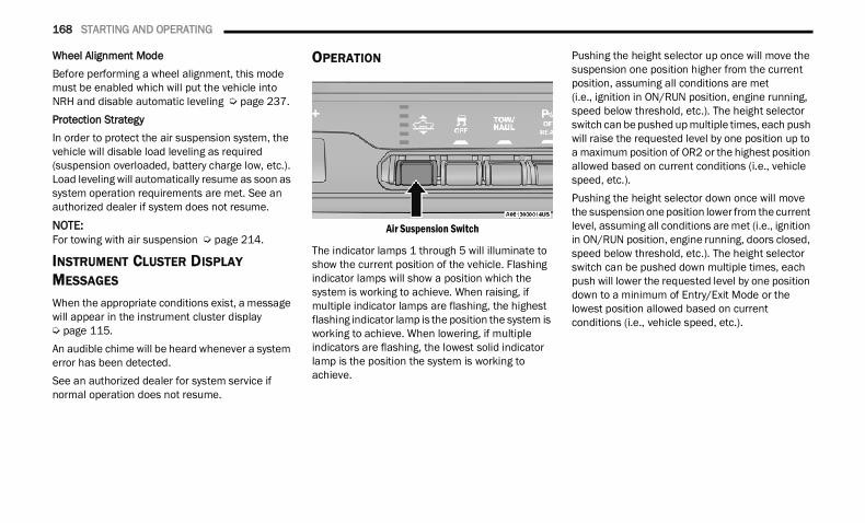
168 STARTING AND OPERATING
Wheel Alignment ModeBefore performing a wheel alignment, this mode must be enabled which will put the vehicle into NRH and disable automatic leveling Ú page 237.Protection StrategyIn order to protect the air suspension system, the vehicle will disable load leveling as required (suspension overloaded, battery charge low, etc.). Load leveling will automatically resume as soon as system operation requirements are met. See an authorized dealer if system does not resume.
NOTE:For towing with air suspension Ú page 214.
INSTRUMENT CLUSTER DISPLAY MESSAGES
When the appropriate conditions exist, a message will appear in the instrument cluster display Ú page 115.An audible chime will be heard whenever a system error has been detected.See an authorized dealer for system service if normal operation does not resume.
OPERATION
Air Suspension Switch
The indicator lamps 1 through 5 will illuminate to show the current position of the vehicle. Flashing indicator lamps will show a position which the system is working to achieve. When raising, if multiple indicator lamps are flashing, the highest flashing indicator lamp is the position the system is working to achieve. When lowering, if multiple indicators are flashing, the lowest solid indicator lamp is the position the system is working to achieve.
Pushing the height selector up once will move the suspension one position higher from the current position, assuming all conditions are met(i.e., ignition in ON/RUN position, engine running, speed below threshold, etc.). The height selector switch can be pushed up multiple times, each push will raise the requested level by one position up to a maximum position of OR2 or the highest position allowed based on current conditions (i.e., vehicle speed, etc.).Pushing the height selector down once will move the suspension one position lower from the current level, assuming all conditions are met (i.e., ignition in ON/RUN position, engine running, doors closed, speed below threshold, etc.). The height selector switch can be pushed down multiple times, each push will lower the requested level by one position down to a minimum of Entry/Exit Mode or the lowest position allowed based on current conditions (i.e., vehicle speed, etc.).
22_DT_OM_EN_USC_t.book Page 168
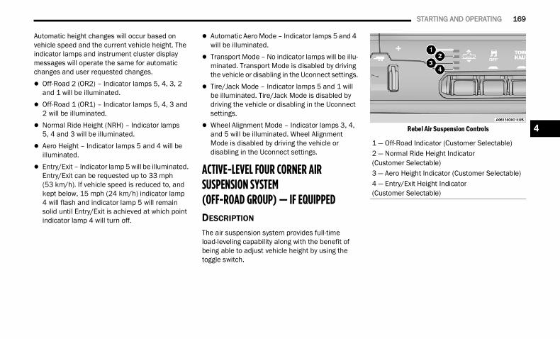
STARTING AND OPERATING 169
Automatic height changes will occur based on vehicle speed and the current vehicle height. The indicator lamps and instrument cluster display messages will operate the same for automatic changes and user requested changes. Off-Road 2 (OR2) – Indicator lamps 5, 4, 3, 2
and 1 will be illuminated. Off-Road 1 (OR1) – Indicator lamps 5, 4, 3 and
2 will be illuminated. Normal Ride Height (NRH) – Indicator lamps
5, 4 and 3 will be illuminated. Aero Height – Indicator lamps 5 and 4 will be
illuminated. Entry/Exit – Indicator lamp 5 will be illuminated.
Entry/Exit can be requested up to 33 mph (53 km/h). If vehicle speed is reduced to, and kept below, 15 mph (24 km/h) indicator lamp4 will flash and indicator lamp 5 will remain solid until Entry/Exit is achieved at which point indicator lamp 4 will turn off.
Automatic Aero Mode – Indicator lamps 5 and 4 will be illuminated.
Transport Mode – No indicator lamps will be illu-minated. Transport Mode is disabled by driving the vehicle or disabling in the Uconnect settings.
Tire/Jack Mode – Indicator lamps 5 and 1 will be illuminated. Tire/Jack Mode is disabled by driving the vehicle or disabling in the Uconnect settings.
Wheel Alignment Mode – Indicator lamps 3, 4, and 5 will be illuminated. Wheel Alignment Mode is disabled by driving the vehicle or disabling in the Uconnect settings.
ACTIVE-LEVEL FOUR CORNER AIR SUSPENSION SYSTEM (OFF-ROAD GROUP) — IF EQUIPPED DESCRIPTION
The air suspension system provides full-time load-leveling capability along with the benefit of being able to adjust vehicle height by using the toggle switch.
Rebel Air Suspension Controls
1 — Off-Road Indicator (Customer Selectable)2 — Normal Ride Height Indicator (Customer Selectable)3 — Aero Height Indicator (Customer Selectable)4 — Entry/Exit Height Indicator (Customer Selectable)
4
22_DT_OM_EN_USC_t.book Page 169
170 STARTING AND OPERATING
Off-Road (OR) (Raises the vehicle approximately 1 inch [26 mm]) – This position is intended for off-roading use only where maximum ground clearance is required. To enter OR, push the height selector switch up once from the NRH position while vehicle speed is below 20 mph (32 km/h). While in OR, if the vehicle speed exceeds 25 mph (40 km/h) the vehicle height will be automatically lowered to NRH. Off-Road may not be available due to vehicle payload, an instrument cluster display message will be shown when this occurs Ú page 115.
Normal Ride Height (NRH) – This is the standard position of the suspension and is meant for normal driving.
Aero Height (Lowers the vehicle approximately 0.6 inches [15 mm]) – This position provides improved aerodynamics by lowering the vehicle. The vehicle will automatically enter Automatic Aero Mode when the vehicle speed remains between 62 mph (100 km/h) and 66 mph (106 km/h) for greater than 20 seconds or if the vehicle speed exceeds 66 mph (106 km/h). The vehicle will return to NRH from Aero Mode if the vehicle speed remains between 30 mph (48 km/h) and 35 mph (56 km/h) for greater than 20 seconds or if the vehicle speed falls below 30 mph (48 km/h).
NOTE: Automatic Aero mode will be disabled if a
trailer is detected to prevent shifting loads. Speed thresholds for raising or lowering the
vehicle only apply if Automatic Aero Mode is enabled through vehicle settings on your Uconnect Radio.
To enter Aero Height manually push the height selector switch down once from NRH at any vehicle speed. To return to NRH push the height selector switch up once while vehicle speed is less than 56 mph(90 km/h).
Automatic Aero Mode may be disabled through vehicle settings on your Uconnect Radio.
Entry/Exit Height (Lowers the vehicle approxi-mately 3 inches [73 mm]) – This position lowers the vehicle for easier passenger entry and exit as well as lowering the vehicle for easier loading and unloading of cargo. To enter Entry/Exit Mode, push the height selector switch down twice from the NRH while the vehicle speed is below 33 mph (53 km/h). Once the vehicle speed goes below 15 mph (24 km/h) the vehicle height will begin to lower. If the vehicle speed remains between 15 mph (24 km/h) and 25 mph (40 km/h) for greater than 60 seconds, or the vehicle speed exceeds 25 mph (40 km/h) the Entry/Exit change will be canceled. To return to Normal Height Mode, push the height selector switch up twice while in Entry/Exit or drive the vehicle over 15 mph (24 km/h). Entry/Exit Height may not be available due to vehicle payload, an instrument cluster display message will be shown when this occurs Ú page 115.
CAUTION!
If the vehicle is in Off-Road setting, be aware of your surroundings, you may not have the clearance required for certain areas and vehicle damage may occur.
CAUTION!
When in Entry/Exit Height, be aware of your surroundings, you may not have the clearance required for certain areas and vehicle damage may occur.
22_DT_OM_EN_USC_t.book Page 170
STARTING AND OPERATING 171
The system requires that the ignition be in the ON/RUN position or the engine running for all user requested changes. When lowering the vehicle, all of the doors must be closed. If a door is opened at any time while the vehicle is lowering, the change will not be completed until the open door(s) is closed.This system uses a lifting and lowering pattern which keeps the headlights from incorrectly shining into oncoming traffic. When raising the vehicle, the rear of the vehicle will move up first and then the front. When lowering the vehicle, the front will move down first and then the rear.After the engine is turned off, it may be noticed that the air suspension system operates briefly; this is normal. The system is correcting the position of the vehicle to ensure a proper appearance.To assist with changing a spare tire, the air suspension system has a feature which allows the automatic leveling to be disabled Ú page 237.
NOTE: Default Ride Height:
Select Aero Height or Normal Ride Height as the default for all vehicle speeds and oper-ation. This is the selected height that the suspension will level for speed changes (e.g. raising from Entry/Exit Height at speed, lowering from Off-Road Height at speed, etc.).
Default ride height can be changed by manually adjusting the Air Suspension switch to Normal Ride Height or Aero Ride Height and staying in the selected height for 2.5 seconds. It will be stored as the default ride height and the height will be main-tained until a new default ride height is selected.
If equipped with a touchscreen radio, all enabling/disabling of air suspension features must be done through the radio Ú page 237.
AIR SUSPENSION MODES
The air suspension system has multiple modes to protect the system in unique situations:Automatic Aero ModeTo improve aerodynamics, the air suspension system has a feature which will put the vehicle into Aero height automatically at higher speeds Ú page 115.
Tire Jack ModeTo assist with changing a tire, the air suspension system has a feature which allows the automatic leveling to be disabled Ú page 237.Transport ModeFor towing your vehicle with four wheels off the road, the air suspension system has a feature which will put the vehicle into Entry/Exit height and disable the automatic load leveling system Ú page 237.Wheel Alignment ModeBefore performing a wheel alignment, this mode must be enabled which moves the vehicle to normal ride height and disables the automatic leveling Ú page 237.Protection StrategyIn order to protect the air suspension system, the vehicle will disable load leveling as required (suspension overloaded, battery charge low, etc.). Load leveling will automatically resume as soon as system operation requirements are met. See an authorized dealer if system does not resume.
NOTE:For towing with air suspension Ú page 214.
WARNING!
The air suspension system uses a high pressure volume of air to operate the system. To avoid personal injury or damage to the system, see an authorized dealer for service.
4
22_DT_OM_EN_USC_t.book Page 171
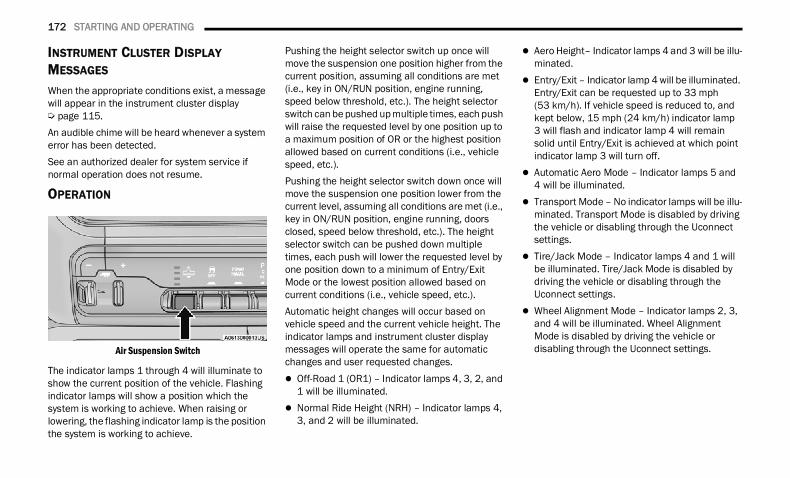
172 STARTING AND OPERATING
INSTRUMENT CLUSTER DISPLAY MESSAGES
When the appropriate conditions exist, a message will appear in the instrument cluster display Ú page 115.An audible chime will be heard whenever a system error has been detected.See an authorized dealer for system service if normal operation does not resume.
OPERATION
Air Suspension Switch
The indicator lamps 1 through 4 will illuminate to show the current position of the vehicle. Flashing indicator lamps will show a position which the system is working to achieve. When raising or lowering, the flashing indicator lamp is the position the system is working to achieve.
Pushing the height selector switch up once will move the suspension one position higher from the current position, assuming all conditions are met (i.e., key in ON/RUN position, engine running, speed below threshold, etc.). The height selector switch can be pushed up multiple times, each push will raise the requested level by one position up to a maximum position of OR or the highest position allowed based on current conditions (i.e., vehicle speed, etc.).Pushing the height selector switch down once will move the suspension one position lower from the current level, assuming all conditions are met (i.e., key in ON/RUN position, engine running, doors closed, speed below threshold, etc.). The height selector switch can be pushed down multiple times, each push will lower the requested level by one position down to a minimum of Entry/Exit Mode or the lowest position allowed based on current conditions (i.e., vehicle speed, etc.).Automatic height changes will occur based on vehicle speed and the current vehicle height. The indicator lamps and instrument cluster display messages will operate the same for automatic changes and user requested changes. Off-Road 1 (OR1) – Indicator lamps 4, 3, 2, and
1 will be illuminated. Normal Ride Height (NRH) – Indicator lamps 4,
3, and 2 will be illuminated.
Aero Height– Indicator lamps 4 and 3 will be illu-minated.
Entry/Exit – Indicator lamp 4 will be illuminated. Entry/Exit can be requested up to 33 mph (53 km/h). If vehicle speed is reduced to, and kept below, 15 mph (24 km/h) indicator lamp3 will flash and indicator lamp 4 will remain solid until Entry/Exit is achieved at which point indicator lamp 3 will turn off.
Automatic Aero Mode – Indicator lamps 5 and 4 will be illuminated.
Transport Mode – No indicator lamps will be illu-minated. Transport Mode is disabled by driving the vehicle or disabling through the Uconnect settings.
Tire/Jack Mode – Indicator lamps 4 and 1 will be illuminated. Tire/Jack Mode is disabled by driving the vehicle or disabling through the Uconnect settings.
Wheel Alignment Mode – Indicator lamps 2, 3, and 4 will be illuminated. Wheel Alignment Mode is disabled by driving the vehicle or disabling through the Uconnect settings.
22_DT_OM_EN_USC_t.book Page 172
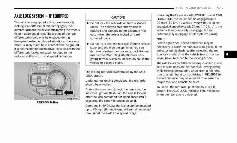
STARTING AND OPERATING 173
AXLE LOCK SYSTEM — IF EQUIPPEDThis vehicle is equipped with an electronically locking rear differential. When engaged, this differential locks the axle shafts forcing the wheels to spin at an equal rate. The locking of the rear differential should only be engaged during low-speed, extreme off-road situations where one wheel is likely to not be in contact with the ground. It is not recommended to drive the vehicle with the differentials locked on pavement due to the reduced ability to turn and speed limitations.
AXLE LOCK Button
The locking rear axle is controlled by the AXLE LOCK button.Under normal driving conditions, the rear axle should be unlocked.During the command to lock the rear axle, the indicator light will flash until the axle is locked. After the lock command has been successfully executed, the light will remain on solid.Operating in 4WD LOW the locker can be engaged up to 40 mph (64 km/h) and will remain engaged throughout the 4WD LOW speed range.
Operating the locker in 2WD, 4WD AUTO, and 4WD LOCK/HIGH, the locker can be engaged up to 20 mph (32 km/h). While driving with the locker engaged, if speed exceeds 25 mph (40 km/h), the locker will automatically disengage, but will automatically re-engage at 20 mph (32 km/h).
NOTE:Left to right wheel speed difference may be necessary to allow the rear axle to fully lock. If the indicator light is flashing after selecting the rear axle lock mode, drive the vehicle in a turn or on loose gravel to expedite the locking action. The axle locker could become torque locked due to side to side loads on the rear axle. Driving slowly while turning the steering wheel from a left hand turn to a right hand turn or driving in REVERSE for a short distance may be required to release the torque lock and unlock the axles.To unlock the rear axle, push the AXLE LOCK button. The AXLE LOCK indicator light will go out when the rear axle is unlocked.
CAUTION!
Do not lock the rear axle on hard surfaced roads. The ability to steer the vehicle is reduced and damage to the drivetrain may occur when the axle is locked on hard surfaced roads.
Do not try to lock the rear axle if the vehicle is stuck and the tires are spinning. You can damage drivetrain components. Lock the rear axle before attempting situations or navi-gating terrain, which could possibly cause the vehicle to become stuck.
4
22_DT_OM_EN_USC_t.book Page 173
174 STARTING AND OPERATING
LIMITED-SLIP DIFFERENTIAL —IF EQUIPPED The limited-slip differential provides additional traction on snow, ice, mud, sand and gravel, particularly when there is a difference between the traction characteristics of the surface under the right and left rear wheels. During normal driving and cornering, the limited-slip unit performs similarly to a conventional differential. On slippery surfaces, however, the differential delivers more of the driving effort to the rear wheel having the better traction.The limited-slip differential is especially helpful during slippery driving conditions. With both rear wheels on a slippery surface, a slight application of the accelerator will supply maximum traction. When starting with only one rear wheel on an excessively slippery surface, slight momentary application of the parking brake may be necessary to gain maximum traction.
Care should be taken to avoid sudden accelerations when both rear wheels are on a slippery surface. This could cause both rear wheels to spin, and allow the vehicle to slide sideways on the crowned surface of a road or in a turn.
POWER STEERING ELECTRIC POWER STEERING The electric power steering system will provide increased vehicle response and ease of maneuverability. The power steering system adapts to different driving conditions.If the steering icon is flashing, it indicates that the vehicle needs to be taken to the dealer for service. It is likely the vehicle has lost power steering assistance.If the steering icon is displayed and the “POWER STEERING SYSTEM OVER TEMP” message is displayed on the instrument cluster screen, this indicates an over temperature condition in the power steering system. Once driving conditions are safe, pull over and let the vehicle idle for a few moments until the icon and message turn off Ú page 115.
If the steering icon is displayed and the “SERVICE POWER STEERING – ASSIST OFF” message is displayed on the instrument cluster screen, this indicates the vehicle needs to be taken to the dealer for service Ú page 115.
NOTE: Even if the power steering assistance is no
longer operational, it is still possible to steer the vehicle. Under these conditions there will be a substantial increase in steering effort, espe-cially at low speeds and during parking maneu-vers.
If the condition persists, see an authorized dealer for service.
FUEL SAVER TECHNOLOGY 5.7L ENGINES ONLY — IF EQUIPPEDThis feature offers improved fuel economy by shutting off four of the engine's eight cylinders during light load and cruise conditions. The system is automatic with no driver inputs or additional driving skills required.NOTE:This system may take some time to return to full functionality after a battery disconnect.
WARNING!
When servicing vehicles equipped with a limited-slip or locking differential, never run the engine with one rear wheel off the ground as the vehicle may drive through the rear wheel remaining on the ground and result in unintended movement.
22_DT_OM_EN_USC_t.book Page 174

STARTING AND OPERATING 175
STOP/START SYSTEM — IF EQUIPPEDThe Stop/Start function, included with eTorque equipped vehicles, is developed to save fuel and reduce emissions. The system will stop the engine automatically as the vehicle decelerates at low speeds if the required conditions are met. Releasing the brake pedal or shifting out of DRIVE will automatically restart the engine.Vehicles equipped with eTorque contain a heavy-duty motor generator and an additional hybrid electric battery to store energy from vehicle deceleration used to expand engine off energy storage and for engine startup after a stop, as well as providing engine torque assist when conditions are met to enable this.
AUTOSTOP MODE
The Stop/Start feature is enabled after every normal customer engine start. It will remain in STOP/START NOT READY until you drive forward with a vehicle speed greater than 2 mph (3 km/h). At that time, the system will go into STOP/START READY and if all other conditions are met, the system may go into STOP/START AUTOSTOP ACTIVE Autostop mode.
To Activate The Autostop Mode, The Following Must Occur:1. The system must be in STOP/START READY
state. A STOP/START READY message will be displayed in the instrument cluster within the Stop/Start section Ú page 115.
2. The vehicle must be decelerating and likely coming to a complete stop.
3. The transmission gear selector must be in DRIVE and the brake pedal pressed.
The engine will shut down, the tachometer will move to the zero position and the stop/start telltale will illuminate indicating you are in an Autostop. While in an Autostop, the Climate Controls system may automatically adjust airflow to maintain cabin comfort. Customer settings will be maintained upon return to an engine running condition.
POSSIBLE REASONS THE ENGINE DOES NOT AUTOSTOP
Prior to engine shut down, the system will check many safety and comfort conditions to see if they are fulfilled. In following situations, the engine will not Autostop: Driver’s seat belt is not buckled Driver’s door is not closed The vehicle is on a steep grade
Cabin heating or cooling is in process and an acceptable cabin temperature has not been achieved
HVAC is set to full defrost mode at a high blower speed
Engine has not reached normal operating temperature
Engine or exhaust temperature is too high The battery is charging The transmission is not in DRIVE Hood is open Transfer case is in 4WD LOW TOW/HAUL mode is selected Accelerator pedal input Excessive 12 Volt loads Brake application is adequate to obtain and
maintain a stopIt may be possible to operate the vehicle several consecutive times in extreme conditions and not meet all criteria to enable an Autostop state.
4
22_DT_OM_EN_USC_t.book Page 175
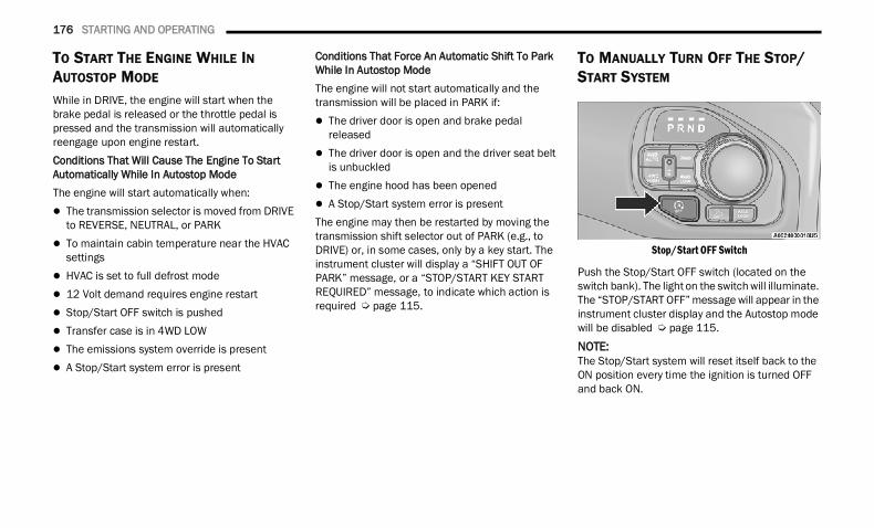
176 STARTING AND OPERATING
TO START THE ENGINE WHILE IN AUTOSTOP MODE
While in DRIVE, the engine will start when the brake pedal is released or the throttle pedal is pressed and the transmission will automatically reengage upon engine restart.Conditions That Will Cause The Engine To Start Automatically While In Autostop ModeThe engine will start automatically when: The transmission selector is moved from DRIVE
to REVERSE, NEUTRAL, or PARK To maintain cabin temperature near the HVAC
settings HVAC is set to full defrost mode 12 Volt demand requires engine restart Stop/Start OFF switch is pushed Transfer case is in 4WD LOW The emissions system override is present A Stop/Start system error is present
Conditions That Force An Automatic Shift To Park While In Autostop ModeThe engine will not start automatically and the transmission will be placed in PARK if: The driver door is open and brake pedal
released The driver door is open and the driver seat belt
is unbuckled The engine hood has been opened A Stop/Start system error is presentThe engine may then be restarted by moving the transmission shift selector out of PARK (e.g., to DRIVE) or, in some cases, only by a key start. The instrument cluster will display a “SHIFT OUT OF PARK” message, or a “STOP/START KEY START REQUIRED” message, to indicate which action is required Ú page 115.
TO MANUALLY TURN OFF THE STOP/START SYSTEM
Stop/Start OFF Switch
Push the Stop/Start OFF switch (located on the switch bank). The light on the switch will illuminate. The “STOP/START OFF” message will appear in the instrument cluster display and the Autostop mode will be disabled Ú page 115.NOTE:The Stop/Start system will reset itself back to the ON position every time the ignition is turned OFF and back ON.
22_DT_OM_EN_USC_t.book Page 176
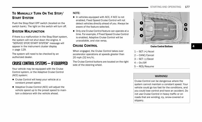
STARTING AND OPERATING 177
TO MANUALLY TURN ON THE STOP/START SYSTEM
Push the Stop/Start OFF switch (located on the switch bank). The light on the switch will turn off.
SYSTEM MALFUNCTION
If there is a malfunction in the Stop/Start system, the system will not shut down the engine. A “SERVICE STOP/START SYSTEM” message will appear in the instrument cluster display Ú page 129.The system will need to be checked by an authorized dealer.
CRUISE CONTROL SYSTEMS — IF EQUIPPED Your vehicle may be equipped with the Cruise Control system, or the Adaptive Cruise Control (ACC) system: Cruise Control will keep your vehicle at a
constant preset speed. Adaptive Cruise Control (ACC) will adjust the
vehicle speed up to the preset speed to main-tain a distance with the vehicle ahead.
NOTE: In vehicles equipped with ACC, if ACC is not
enabled, Fixed Speed Cruise Control will not detect vehicles directly ahead of you. Always be aware of the feature selected.
Only one Cruise Control feature can operate at a time. For example, if Fixed Speed Cruise Control is enabled, Adaptive Cruise Control will be unavailable, and vice versa.
CRUISE CONTROL
When engaged, the Cruise Control takes over accelerator operations at speeds greater than 20 mph (32 km/h).The Cruise Control buttons are located on the right side of the steering wheel.
Cruise Control Buttons
1 — SET (+)/Accel2 — CANC/Cancel3 — SET (-)/Decel4 — On/Off5 — RES/Resume
WARNING!
Cruise Control can be dangerous where the system cannot maintain a constant speed. Your vehicle could go too fast for the conditions, and you could lose control and have an accident. Do not use Cruise Control in heavy traffic or on roads that are winding, icy, snow-covered or slippery.
4
22_DT_OM_EN_USC_t.book Page 177
178 STARTING AND OPERATING
To ActivatePush the on/off button to activate the Cruise Control. The cruise indicator light in the instrument cluster display will illuminate. To turn the system off, push the on/off button a second time. The cruise indicator light will turn off. The system should be turned off when not in use.
To Set A Desired SpeedTurn the Cruise Control on.When the vehicle has reached the desired speed, push the SET (+) or SET (-) button and release. Release the accelerator and the vehicle will operate at the selected speed.NOTE:The vehicle should be traveling at a steady speed and on level ground before pushing the SET (+) or SET (-) button.
To Vary The Speed SettingTo Increase Or Decrease The Set SpeedAfter setting a speed, you can increase the set speed by pushing the SET (+) button, or decrease speed by pushing the SET (-) button.U.S. Speed (mph) Pushing the SET (+), or SET (-) button once will
result in a 1 mph speed adjustment. Each subsequent tap of the button results in an adjustment of 1 mph.
If the button is continually pushed, the set speed will continue to adjust in 5 mph incre-ments until the button is released. The new set speed is reflected in the instrument cluster display.
Metric Speed (km/h) Pushing the SET (+), or SET (-) button once will
result in a 1 km/h speed adjustment. Each subsequent tap of the button results in an adjustment of 1 km/h.
If the button is continually pushed, the set speed will continue to adjust in 10 km/h incre-ments until the button is released. The new set speed is reflected in the instrument cluster display.
NOTE:When you override and push the SET (+) or SET (-) button, the new set speed will be the current speed of the vehicle.To Accelerate For PassingWhile the Cruise Control is set, press the accelerator to pass as you would normally. When the pedal is released, the vehicle will return to the set speed.
USING CRUISE CONTROL ON HILLSThe transmission may downshift on hills to maintain the vehicle set speed.The Cruise Control system maintains speed up and down hills. A slight speed change on moderate hills is normal. On steep hills, a greater speed loss or gain may occur so it may be preferable to drive without Cruise Control.
WARNING!
Leaving the Cruise Control system on when not in use is dangerous. You could accidentally set the system or cause it to go faster than you want. You could lose control and have an accident. Always ensure the system is off when you are not using it.
WARNING!
Cruise Control can be dangerous where the system cannot maintain a constant speed. Your vehicle could go too fast for the conditions, and you could lose control and have an accident. Do not use Cruise Control in heavy traffic or on roads that are winding, icy, snow-covered or slippery.
22_DT_OM_EN_USC_t.book Page 178
STARTING AND OPERATING 179
(Continued)
To Resume Speed To resume a previously set speed, push the RES button and release. Resume can be used at any speed above 20 mph (32 km/h).
To Deactivate A tap on the brake pedal, pushing the CANC (cancel) button, or normal brake pressure while slowing the vehicle will deactivate the Cruise Control system without erasing the set speed from memory.The following conditions will also deactivate the Cruise Control system without erasing the set speed from memory: Vehicle parking brake is applied Stability event occurs Gear selector is moved out of DRIVE Engine overspeed occursPushing the on/off button or placing the ignition in the OFF position, erases the set speed from memory.
ADAPTIVE CRUISE CONTROL (ACC) Adaptive Cruise Control (ACC) increases the driving convenience provided by Cruise Control while traveling on highways and major roadways. However, it is not a safety system and not designed to prevent collisions. The Cruise Control function performs differently Ú page 177.ACC will allow you to keep Cruise Control engaged in light to moderate traffic conditions without the constant need to reset your speed. ACC utilizes a radar sensor and a forward facing camera designed to detect a vehicle directly ahead of you to maintain a set speed.
NOTE: If the ACC sensor detects a vehicle ahead, ACC
will apply limited braking or acceleration (not to exceed the original set speed) automatically to maintain a preset following distance, while matching the speed of the vehicle ahead.
Any chassis/suspension or tire size modifica-tions to the vehicle will affect the performance of the Adaptive Cruise Control and Forward Colli-sion Warning system.
Fixed Speed Cruise Control (ACC not enabled) will not detect vehicles directly ahead of you. Always be aware of the feature selected Ú page 485.
WARNING!
Adaptive Cruise Control (ACC) is a conve-nience system. It is not a substitute for active driver involvement. It is always the driver’s responsibility to be attentive of road, traffic, and weather conditions, vehicle speed, distance to the vehicle ahead; and, most importantly, brake operation to ensure safe operation of the vehicle under all road condi-tions. Your complete attention is always required while driving to maintain safe control of your vehicle. Failure to follow these warn-ings can result in a collision and death or serious personal injury.
The ACC system:
Does not react to pedestrians, oncoming vehicles, and stationary objects (e.g., a stopped vehicle in a traffic jam or a disabled vehicle).
Cannot take street, traffic, and weather conditions into account, and may be limited upon adverse sight distance condi-tions.
4
22_DT_OM_EN_USC_t.book Page 179
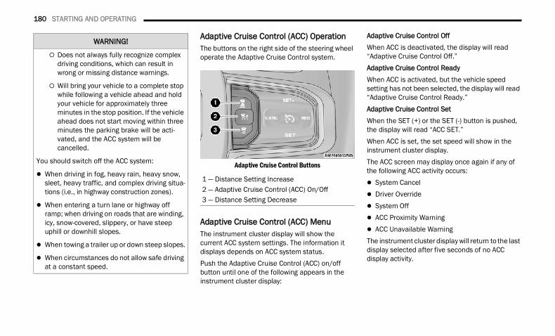
180 STARTING AND OPERATING
Adaptive Cruise Control (ACC) OperationThe buttons on the right side of the steering wheel operate the Adaptive Cruise Control system.
Adaptive Cruise Control Buttons
Adaptive Cruise Control (ACC) MenuThe instrument cluster display will show the current ACC system settings. The information it displays depends on ACC system status.Push the Adaptive Cruise Control (ACC) on/off button until one of the following appears in the instrument cluster display:
Adaptive Cruise Control OffWhen ACC is deactivated, the display will read “Adaptive Cruise Control Off.”Adaptive Cruise Control ReadyWhen ACC is activated, but the vehicle speed setting has not been selected, the display will read “Adaptive Cruise Control Ready.”Adaptive Cruise Control SetWhen the SET (+) or the SET (-) button is pushed, the display will read “ACC SET.”When ACC is set, the set speed will show in the instrument cluster display.The ACC screen may display once again if any of the following ACC activity occurs: System Cancel Driver Override System Off ACC Proximity Warning ACC Unavailable WarningThe instrument cluster display will return to the last display selected after five seconds of no ACC display activity.
Does not always fully recognize complex driving conditions, which can result in wrong or missing distance warnings.
Will bring your vehicle to a complete stop while following a vehicle ahead and hold your vehicle for approximately three minutes in the stop position. If the vehicle ahead does not start moving within three minutes the parking brake will be acti-vated, and the ACC system will be cancelled.
You should switch off the ACC system:
When driving in fog, heavy rain, heavy snow, sleet, heavy traffic, and complex driving situa-tions (i.e., in highway construction zones).
When entering a turn lane or highway off ramp; when driving on roads that are winding, icy, snow-covered, slippery, or have steep uphill or downhill slopes.
When towing a trailer up or down steep slopes.
When circumstances do not allow safe driving at a constant speed.
WARNING!
1 — Distance Setting Increase2 — Adaptive Cruise Control (ACC) On/Off3 — Distance Setting Decrease
22_DT_OM_EN_USC_t.book Page 180
STARTING AND OPERATING 181
Activating Adaptive Cruise Control (ACC)The minimum set speed for the ACC system is 20 mph (32 km/h).When the system is turned on and in the ready state, the instrument cluster display will read“ACC Ready.”When the system is off, the instrument cluster display will read “Adaptive Cruise Control (ACC) Off.”
NOTE:You cannot engage ACC under the following condi-tions: When in 4WD Low When the brakes are applied When the parking brake is applied When the automatic transmission is in PARK,
REVERSE or NEUTRAL When the vehicle speed is below the minimum
speed range When the brakes are overheated When the driver’s door is open at low speeds When the driver’s seat belt is unbuckled at low
speeds When there is a stationary vehicle in front of
your vehicle in close proximity When Electronic Stability Control (ESC) Full Off
mode is active
To Activate/DeactivatePush and release the Adaptive Cruise Control (ACC) on/off button. The ACC menu in the instrument cluster displays “ACC Ready.”To turn the system off, push and release the Adaptive Cruise Control (ACC) on/off button again. At this time, the system will turn off and the instrument cluster display will show “Adaptive Cruise Control (ACC) Off.”
To Set A Desired ACC SpeedWhen the vehicle reaches the speed desired, push the SET (+) button or the SET (-) button and release. The instrument cluster display will show the set speed.
NOTE:Fixed Speed Cruise Control can be used without ACC enabled. To change between the different modes, push the ACC on/off button which turns the ACC and the Fixed Speed Cruise Control off. Pushing the Fixed Speed Cruise Control on/off button will result in turning on (changing to) Fixed Speed Cruise Control mode.
If ACC is set when the vehicle speed is below 20 mph (32 km/h), the set speed will default to 20 mph (32 km/h).
NOTE:Fixed Speed Cruise Control cannot be set below 20 mph (32 km/h).If either system is set when the vehicle speed is above 20 mph (32 km/h), the set speed shall be the current speed of the vehicle.
WARNING!
Leaving the Adaptive Cruise Control (ACC) system on when not in use is dangerous. You could accidentally set the system or cause it to go faster than you want. You could lose control and have a collision. Always leave the system off when you are not using it.
WARNING!
In the Fixed Speed Cruise Control mode, the system will not react to vehicles ahead. In addition, the proximity warning does not activate and no alarm will sound even if you are too close to the vehicle ahead since neither the presence of the vehicle ahead nor the vehicle-to-vehicle distance is detected. Be sure to maintain a safe distance between your vehicle and the vehicle ahead. Always be aware which mode is selected.
4
22_DT_OM_EN_USC_t.book Page 181
182 STARTING AND OPERATING
NOTE: Keeping your foot on the accelerator pedal can
cause the vehicle to continue to accelerate beyond the set speed. If this occurs, the message “ACC DRIVER OVERRIDE” will display in the instrument cluster display.
If you continue to accelerate beyond the set speed while ACC is enabled, the system will not control the distance between your vehicle and the vehicle ahead. The vehicle speed will only be determined by the position of the accelerator pedal.
To CancelThe following conditions cancel the ACC or Fixed Speed Cruise Control systems: The brake pedal is applied The CANC (cancel) button is pushed The Anti-Lock Brake System (ABS) activates The trailer brake is applied manually (if
equipped) The gear selector is removed from the DRIVE
position The Electronic Stability Control/Traction Control
System (ESC/TCS) activates The vehicle parking brake is applied The Trailer Sway Control (TSC) activates
The driver switches ESC to Full Off mode The braking temperature exceeds normal range
(overheated)The following conditions will only cancel the ACC system: Driver seat belt is unbuckled at low speeds Driver door is opened at low speeds
To Turn OffThe system will turn off and clear the set speed in memory if: The Adaptive Cruise Control (ACC) on/off button
is pushed The Fixed Speed Cruise Control on/off button is
pushed The ignition is placed in the OFF position 4WD Low is engaged
To ResumeIf there is a set speed in memory, push the RES (resume) button and then remove your foot from the accelerator pedal. The instrument cluster display will show the last set speed.Resume can be used at any speed above 20 mph (32 km/h) when only Fixed Speed Cruise Control is being used.Resume can be used at any speed above 0 mph (0 km/h) when ACC is active.
NOTE: If your vehicle is at a standstill for longer than
two seconds, then the driver will either have to push the RES (resume) button, or apply the accelerator pedal to reengage the Adaptive Cruise Control (ACC) to the existing set speed.
ACC cannot be resumed if there is a stationary vehicle in front of your vehicle in close proximity.
To Vary The Speed SettingTo Increase Or Decrease The Set SpeedAfter setting a speed, you can increase the set speed by pushing the SET (+) button, or decrease speed by pushing the SET (-) button.
WARNING!
The Resume function should only be used if traffic and road conditions permit. Resuming a set speed that is too high or too low for prevailing traffic and road conditions could cause the vehicle to accelerate or decelerate too sharply for safe operation. Failure to follow these warnings can result in a collision and death or serious personal injury.
22_DT_OM_EN_USC_t.book Page 182
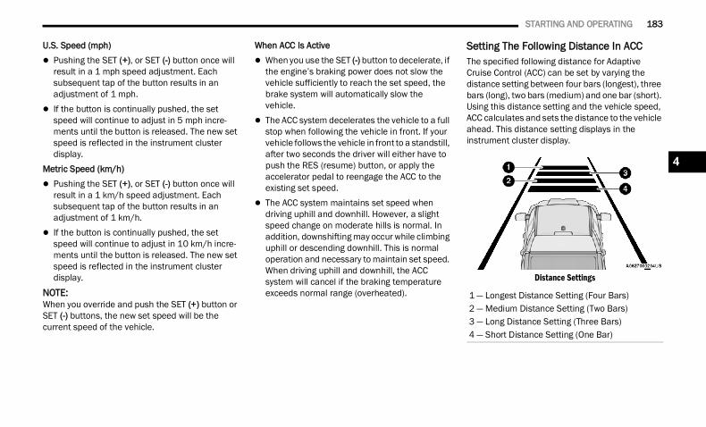
STARTING AND OPERATING 183
U.S. Speed (mph) Pushing the SET (+), or SET (-) button once will
result in a 1 mph speed adjustment. Each subsequent tap of the button results in an adjustment of 1 mph.
If the button is continually pushed, the set speed will continue to adjust in 5 mph incre-ments until the button is released. The new set speed is reflected in the instrument cluster display.
Metric Speed (km/h) Pushing the SET (+), or SET (-) button once will
result in a 1 km/h speed adjustment. Each subsequent tap of the button results in an adjustment of 1 km/h.
If the button is continually pushed, the set speed will continue to adjust in 10 km/h incre-ments until the button is released. The new set speed is reflected in the instrument cluster display.
NOTE:When you override and push the SET (+) button or SET (-) buttons, the new set speed will be the current speed of the vehicle.
When ACC Is Active When you use the SET (-) button to decelerate, if
the engine’s braking power does not slow the vehicle sufficiently to reach the set speed, the brake system will automatically slow the vehicle.
The ACC system decelerates the vehicle to a full stop when following the vehicle in front. If your vehicle follows the vehicle in front to a standstill, after two seconds the driver will either have to push the RES (resume) button, or apply the accelerator pedal to reengage the ACC to the existing set speed.
The ACC system maintains set speed when driving uphill and downhill. However, a slight speed change on moderate hills is normal. In addition, downshifting may occur while climbing uphill or descending downhill. This is normal operation and necessary to maintain set speed. When driving uphill and downhill, the ACC system will cancel if the braking temperature exceeds normal range (overheated).
Setting The Following Distance In ACCThe specified following distance for Adaptive Cruise Control (ACC) can be set by varying the distance setting between four bars (longest), three bars (long), two bars (medium) and one bar (short). Using this distance setting and the vehicle speed, ACC calculates and sets the distance to the vehicle ahead. This distance setting displays in the instrument cluster display.
Distance Settings
1 — Longest Distance Setting (Four Bars)2 — Medium Distance Setting (Two Bars)3 — Long Distance Setting (Three Bars)4 — Short Distance Setting (One Bar)
4
22_DT_OM_EN_USC_t.book Page 183
184 STARTING AND OPERATING
To increase the distance setting, push the Distance Increase button and release. Each time the button is pushed, the distance setting increases by one bar (longer).To decrease the distance setting, push the Distance Decrease button and release. Each time the button is pushed, the distance setting decreases by one bar (shorter).If there is no vehicle ahead, the vehicle will maintain the set speed. If a slower moving vehicle is detected in the same lane, the instrument cluster displays the ACC Set With Target Detected Indicator Light, and the system adjusts vehicle speed automatically to maintain the distance setting, regardless of the set speed.The vehicle will then maintain the set distance until: The vehicle ahead accelerates to a speed above
the set speed. The vehicle ahead moves out of your lane or
view of the sensor. The distance setting is changed. The system disengages.The maximum braking applied by ACC is limited; however, the driver can always apply the brakes manually, if necessary.
NOTE:The brake lights will illuminate whenever the ACC system applies the brakes.A Proximity Warning will alert the driver if ACC predicts that its maximum braking level is not sufficient to maintain the set distance. If this occurs, a visual alert “BRAKE!” will flash in the instrument cluster display and a chime will sound while ACC continues to apply its maximum braking capacity.
NOTE:The “BRAKE!” screen in the instrument cluster display is a warning for the driver to take action and does not mean that the Forward Collision Warning system is applying the brakes autono-mously.Overtake AidWhen driving with Adaptive Cruise Control (ACC) engaged, and following a vehicle, the system will provide an additional acceleration up to the ACC set speed to assist in passing the vehicle. This additional acceleration is triggered when the driver utilizes the left turn signal and will only be active when passing on the left hand side.
ACC Operation At StopIn the event that the ACC system brings your vehicle to a standstill while following the vehicle in front, if the vehicle in front starts moving within two
seconds of your vehicle coming to a standstill, your vehicle will resume motion without the need for any driver action.If the vehicle in front does not start moving within two seconds of your vehicle coming to a standstill, the driver will either have to push the RES (resume) button, or apply the accelerator pedal to reengage the ACC to the existing set speed.
NOTE:After the ACC system holds your vehicle at a stand-still for approximately three consecutive minutes, the parking brake will be activated, and the ACC system will be canceled.While ACC is holding your vehicle at a standstill, if the driver seat belt is unbuckled or the driver door is opened, the parking brake will be activated, and the ACC system will be canceled.
WARNING!
When the ACC system is resumed, the driver must ensure that there are no pedestrians, vehicles or objects in the path of the vehicle. Failure to follow these warnings can result in a collision and death or serious personal injury.
22_DT_OM_EN_USC_t.book Page 184
STARTING AND OPERATING 185
Display Warnings And Maintenance
“WIPE FRONT RADAR SENSOR IN FRONT OF VEHICLE” WARNINGThe “ACC/FCW Unavailable Wipe Front Radar Sensor” warning will display and a chime will sound when conditions temporarily limit system performance.This most often occurs at times of poor visibility, such as in snow or heavy rain. The ACC system may also become temporarily blinded due to obstructions, such as mud, dirt or ice. In these cases, the instrument cluster display will display “ACC/FCW Unavailable Wipe Front Radar Sensor” and the system will deactivate.The “ACC/FCW Unavailable Wipe Front Radar Sensor” message can sometimes be displayed while driving in highly reflective areas (i.e. ice and snow, or tunnels with reflective tiles). The ACC system will recover after the vehicle has left these areas. Under rare conditions, when the radar is not tracking any vehicles or objects in its path this warning may temporarily occur.
NOTE:If the “ACC/FCW Unavailable Wipe Front Radar Sensor” warning is active, Fixed Speed Cruise Control is still available.
If weather conditions are not a factor, the driver should examine the sensor. It may require cleaning or removal of an obstruction. The sensor is located in the camera in the center of the windshield, on the forward side of the rearview mirror.To keep the ACC system operating properly, it is important to note the following maintenance items: Always keep the sensor clean. Carefully clear
the windshield. Do not remove any screws from the sensor.
Doing so could cause an ACC system malfunc-tion or failure and require a sensor realignment.
Do not attach or install any accessories near the sensor, including transparent material. Doing so could cause an ACC system failure or malfunc-tion.
When the condition that deactivated the system is no longer present, the system will return to the “Adaptive Cruise Control Off” state and will resume function by simply reactivating it.
NOTE: If the “ACC/FCW Unavailable Wipe Front Radar
Sensor” message occurs frequently (e.g. more than once on every trip) without any snow, rain, mud, or other obstruction, have the radar sensor realigned at an authorized dealer.
Installing a snowplow, front-end protector, an aftermarket grille or modifying the grille is not recommended. Doing so may block the sensor and inhibit ACC/FCW operation.
“CLEAN FRONT WINDSHIELD” WARNINGThe “ACC/FCW Limited Functionality Clean Front Windshield” warning will display and a chime will sound when conditions temporarily limit system performance. This most often occurs at times of poor visibility, such as in snow or heavy rain and fog. The ACC system may also become temporarily blinded due to obstructions, such as mud, dirt, or ice on windshield, driving directly into the sun and fog on the inside of glass. In these cases, the instrument cluster display will show “ACC/FCW Limited Functionality Clean Front Windshield” and the system will have degraded performance.This message can sometimes be displayed while driving in adverse weather conditions. The ACC/FCW system will recover after the vehicle has left these areas. Under rare conditions, when the camera is not tracking any vehicles or objects in its path this warning may temporarily occur.If weather conditions are not a factor, the driver should examine the windshield and the camera located on the back side of the inside rear view mirror. They may require cleaning or removal of an obstruction.
4
22_DT_OM_EN_USC_t.book Page 185
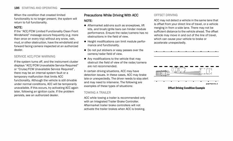
186 STARTING AND OPERATING
When the condition that created limited functionality is no longer present, the system will return to full functionality.NOTE:If the “ACC/FCW Limited Functionality Clean Front Windshield” message occurs frequently (e.g. more than once on every trip) without any snow, rain, mud, or other obstruction, have the windshield and forward facing camera inspected at an authorized dealer.
SERVICE ACC/FCW WARNINGIf the system turns off, and the instrument cluster displays “ACC/FCW Unavailable Service Required” or “Cruise/FCW Unavailable Service Required”, there may be an internal system fault or a temporary malfunction that limits ACC functionality. Although the vehicle is still drivable under normal conditions, ACC will be temporarily unavailable. If this occurs, try activating ACC again later, following an ignition cycle. If the problem persists, see an authorized dealer.
Precautions While Driving With ACCNOTE: Aftermarket add-ons such as snowplows, lift
kits, and brush/grille bars can hinder module performance. Ensure the radar/camera has no obstructions in the field of view.
Height modifications can limit module perfor-mance and functionality.
Do not put stickers or easy passes over the camera/radar field of view.
Any modifications to the vehicle that may obstruct the field of view of the radar/camera are not recommended.
In certain driving situations, ACC may have detection issues. In these cases, ACC may brake late or unexpectedly. The driver needs to stay alert and may need to intervene. The following are examples of these types of situations:
TOWING A TRAILERACC while towing a trailer is recommended only with an Integrated Trailer Brake Controller. Aftermarket trailer brake controllers will not activate the trailer brakes when ACC is braking.
OFFSET DRIVINGACC may not detect a vehicle in the same lane that is offset from your direct line of travel, or a vehicle merging in from a side lane. There may not be sufficient distance to the vehicle ahead. The offset vehicle may move in and out of the line of travel, which can cause your vehicle to brake or accelerate unexpectedly.
Offset Driving Condition Example
22_DT_OM_EN_USC_t.book Page 186
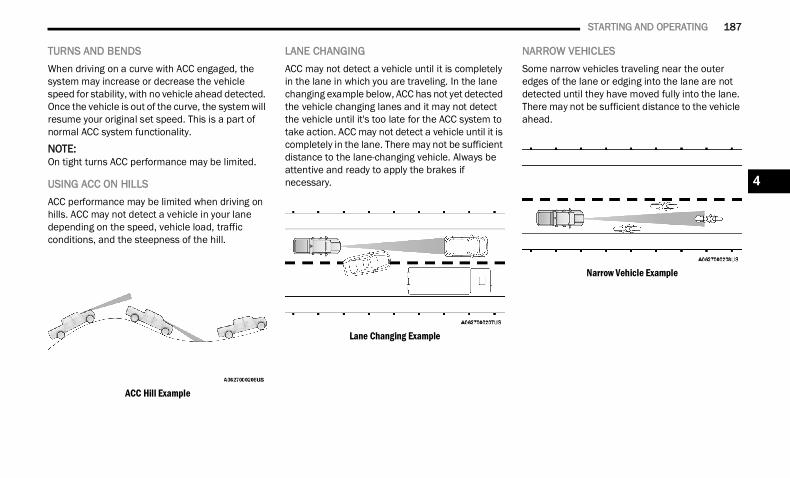
STARTING AND OPERATING 187
TURNS AND BENDSWhen driving on a curve with ACC engaged, the system may increase or decrease the vehicle speed for stability, with no vehicle ahead detected. Once the vehicle is out of the curve, the system will resume your original set speed. This is a part of normal ACC system functionality.
NOTE:On tight turns ACC performance may be limited.
USING ACC ON HILLSACC performance may be limited when driving on hills. ACC may not detect a vehicle in your lane depending on the speed, vehicle load, traffic conditions, and the steepness of the hill.
ACC Hill Example
LANE CHANGINGACC may not detect a vehicle until it is completely in the lane in which you are traveling. In the lane changing example below, ACC has not yet detected the vehicle changing lanes and it may not detect the vehicle until it's too late for the ACC system to take action. ACC may not detect a vehicle until it is completely in the lane. There may not be sufficient distance to the lane-changing vehicle. Always be attentive and ready to apply the brakes if necessary.
Lane Changing Example
NARROW VEHICLESSome narrow vehicles traveling near the outer edges of the lane or edging into the lane are not detected until they have moved fully into the lane. There may not be sufficient distance to the vehicle ahead.
Narrow Vehicle Example
4
22_DT_OM_EN_USC_t.book Page 187
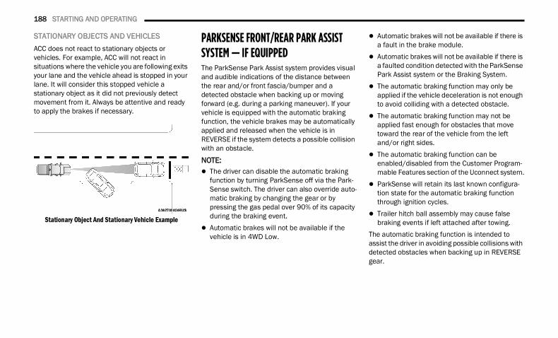
188 STARTING AND OPERATING
STATIONARY OBJECTS AND VEHICLESACC does not react to stationary objects or vehicles. For example, ACC will not react in situations where the vehicle you are following exits your lane and the vehicle ahead is stopped in your lane. It will consider this stopped vehicle a stationary object as it did not previously detect movement from it. Always be attentive and ready to apply the brakes if necessary.
Stationary Object And Stationary Vehicle Example
PARKSENSE FRONT/REAR PARK ASSIST SYSTEM — IF EQUIPPED The ParkSense Park Assist system provides visual and audible indications of the distance between the rear and/or front fascia/bumper and a detected obstacle when backing up or moving forward (e.g. during a parking maneuver). If your vehicle is equipped with the automatic braking function, the vehicle brakes may be automatically applied and released when the vehicle is in REVERSE if the system detects a possible collision with an obstacle.
NOTE: The driver can disable the automatic braking
function by turning ParkSense off via the Park-Sense switch. The driver can also override auto-matic braking by changing the gear or by pressing the gas pedal over 90% of its capacity during the braking event.
Automatic brakes will not be available if the vehicle is in 4WD Low.
Automatic brakes will not be available if there is a fault in the brake module.
Automatic brakes will not be available if there is a faulted condition detected with the ParkSense Park Assist system or the Braking System.
The automatic braking function may only be applied if the vehicle deceleration is not enough to avoid colliding with a detected obstacle.
The automatic braking function may not be applied fast enough for obstacles that move toward the rear of the vehicle from the left and/or right sides.
The automatic braking function can be enabled/disabled from the Customer Program-mable Features section of the Uconnect system.
ParkSense will retain its last known configura-tion state for the automatic braking function through ignition cycles.
Trailer hitch ball assembly may cause false braking events if left attached after towing.
The automatic braking function is intended to assist the driver in avoiding possible collisions with detected obstacles when backing up in REVERSE gear.
22_DT_OM_EN_USC_t.book Page 188
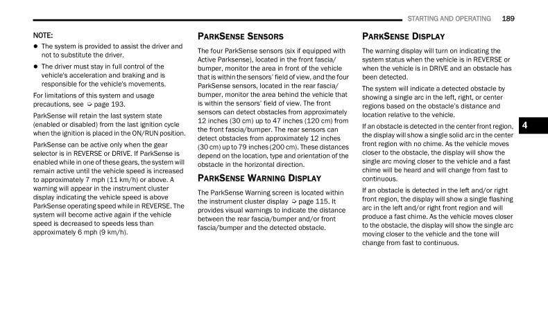
STARTING AND OPERATING 189
NOTE: The system is provided to assist the driver and
not to substitute the driver. The driver must stay in full control of the
vehicle's acceleration and braking and is responsible for the vehicle's movements.
For limitations of this system and usage precautions, see Ú page 193.ParkSense will retain the last system state (enabled or disabled) from the last ignition cycle when the ignition is placed in the ON/RUN position.ParkSense can be active only when the gear selector is in REVERSE or DRIVE. If ParkSense is enabled while in one of these gears, the system will remain active until the vehicle speed is increased to approximately 7 mph (11 km/h) or above. A warning will appear in the instrument cluster display indicating the vehicle speed is above ParkSense operating speed while in REVERSE. The system will become active again if the vehicle speed is decreased to speeds less than approximately 6 mph (9 km/h).
PARKSENSE SENSORS
The four ParkSense sensors (six if equipped with Active Parksense), located in the front fascia/bumper, monitor the area in front of the vehicle that is within the sensors’ field of view, and the four ParkSense sensors, located in the rear fascia/bumper, monitor the area behind the vehicle that is within the sensors’ field of view. The front sensors can detect obstacles from approximately 12 inches (30 cm) up to 47 inches (120 cm) from the front fascia/bumper. The rear sensors can detect obstacles from approximately 12 inches (30 cm) up to 79 inches (200 cm). These distances depend on the location, type and orientation of the obstacle in the horizontal direction.
PARKSENSE WARNING DISPLAY
The ParkSense Warning screen is located within the instrument cluster display Ú page 115. It provides visual warnings to indicate the distance between the rear fascia/bumper and/or front fascia/bumper and the detected obstacle.
PARKSENSE DISPLAY
The warning display will turn on indicating the system status when the vehicle is in REVERSE or when the vehicle is in DRIVE and an obstacle has been detected.The system will indicate a detected obstacle by showing a single arc in the left, right, or center regions based on the obstacle’s distance and location relative to the vehicle.If an obstacle is detected in the center front region, the display will show a single solid arc in the center front region with no chime. As the vehicle moves closer to the obstacle, the display will show the single arc moving closer to the vehicle and a fast chime will be heard and will change from fast to continuous.If an obstacle is detected in the left and/or right front region, the display will show a single flashing arc in the left and/or right front region and will produce a fast chime. As the vehicle moves closer to the obstacle, the display will show the single arc moving closer to the vehicle and the tone will change from fast to continuous.
4
22_DT_OM_EN_USC_t.book Page 189
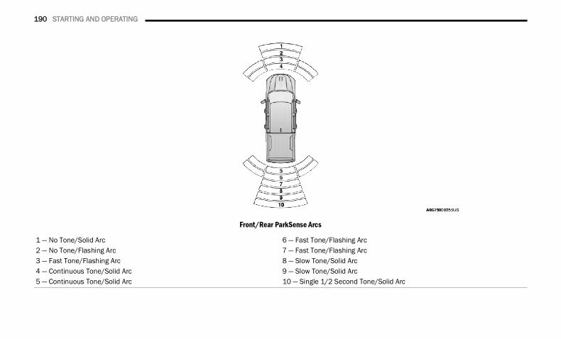
190 STARTING AND OPERATING
Front/Rear ParkSense Arcs
1 — No Tone/Solid Arc 6 — Fast Tone/Flashing Arc2 — No Tone/Flashing Arc 7 — Fast Tone/Flashing Arc3 — Fast Tone/Flashing Arc 8 — Slow Tone/Solid Arc4 — Continuous Tone/Solid Arc 9 — Slow Tone/Solid Arc5 — Continuous Tone/Solid Arc 10 — Single 1/2 Second Tone/Solid Arc
22_DT_OM_EN_USC_t.book Page 190
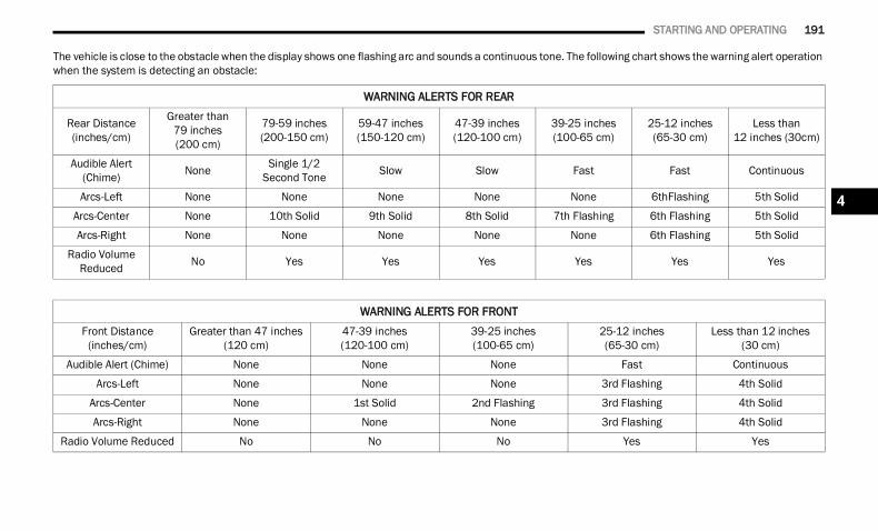
STARTING AND OPERATING 191
The vehicle is close to the obstacle when the display shows one flashing arc and sounds a continuous tone. The following chart shows the warning alert operation when the system is detecting an obstacle:
WARNING ALERTS FOR REAR
Rear Distance (inches/cm)
Greater than 79 inches(200 cm)
79-59 inches (200-150 cm)
59-47 inches (150-120 cm)
47-39 inches (120-100 cm)
39-25 inches (100-65 cm)
25-12 inches (65-30 cm)
Less than 12 inches (30cm)
Audible Alert (Chime) None Single 1/2
Second Tone Slow Slow Fast Fast Continuous
Arcs-Left None None None None None 6thFlashing 5th Solid
Arcs-Center None 10th Solid 9th Solid 8th Solid 7th Flashing 6th Flashing 5th Solid
Arcs-Right None None None None None 6th Flashing 5th Solid
Radio Volume Reduced No Yes Yes Yes Yes Yes Yes
WARNING ALERTS FOR FRONTFront Distance
(inches/cm)Greater than 47 inches
(120 cm)47-39 inches(120-100 cm)
39-25 inches(100-65 cm)
25-12 inches(65-30 cm)
Less than 12 inches(30 cm)
Audible Alert (Chime) None None None Fast Continuous
Arcs-Left None None None 3rd Flashing 4th Solid
Arcs-Center None 1st Solid 2nd Flashing 3rd Flashing 4th Solid
Arcs-Right None None None 3rd Flashing 4th Solid
Radio Volume Reduced No No No Yes Yes
4
22_DT_OM_EN_USC_t.book Page 191
192 STARTING AND OPERATING
NOTE:ParkSense will reduce the volume of the radio, if on, when the system is sounding an audio tone.Front Park Assist Audible AlertsParkSense will turn off the Front Park Assist audible alert (chime) after approximately three seconds when an obstacle has been detected, the vehicle is stationary, and brake pedal is applied.Adjustable Chime Volume SettingsThe Front and Rear chime volume settings are programmable through the Uconnect system Ú page 237.
ENABLING AND DISABLING FRONT AND/OR REAR PARKSENSE
Front ParkSense can be enabled and disabled with the Front ParkSense switch.
Rear ParkSense can be enabled and disabled with the Rear ParkSense switch.When the Front or Rear ParkSense switch is pushed to disable the system, the instrument cluster display Ú page 115 will show a vehicle graphic of the Front or Rear ParkSense on/off state for two seconds.
When the gear selector is moved to REVERSE and the Front or Rear system is disabled, the instrument cluster display will show a vehicle graphic with “OFF” on the corresponding side. This vehicle graphic will be displayed for as long as the vehicle is in REVERSE.
NOTE:Arc alerts from the enabled ParkSense system, will interrupt the five second messages, and the instrument cluster display will show the vehicle graphic with the corresponding arcs and “OFF” message.The Front or Rear ParkSense switch LED will be on when Front or Rear ParkSense is disabled or requires service. The Front or Rear ParkSense switch LED will be off when the Front or Rear system is enabled. If the Front or Rear ParkSense switch is pushed, and the system requires service, the Front or Rear ParkSense switch LED will blink momentarily, and then the LED will be on.
SERVICE THE PARKSENSE PARK ASSIST SYSTEM
During vehicle start up, when the ParkSense System has detected a faulted condition, the instrument cluster will actuate a single chime, once per ignition cycle, and it will display the "PARKSENSE UNAVAILABLE WIPE REAR SENSORS", "PARKSENSE UNAVAILABLE WIPE FRONT SENSORS", or the "PARKSENSE
UNAVAILABLE SERVICE REQUIRED" message for five seconds. When the gear selector is moved to REVERSE and the system has detected a faulted condition, the instrument cluster display will display a "WIPE OFF" message on the corresponding blocked system while the vehicle is in REVERSE. The system will continue to provide arc alerts for the side that is functioning properly.If "PARKSENSE UNAVAILABLE WIPE REAR SENSORS" or "PARKSENSE UNAVAILABLE WIPE FRONT SENSORS" appears in the instrument cluster display make sure the outer surface and the underside of the rear fascia/bumper and/or front fascia/bumper is clean and clear of snow, ice, mud, dirt or other obstruction and then cycle the ignition. If the message continues to appear see an authorized dealer.
NOTE:Water from a car wash or road slush in freezing weather may also cause sensors to become blocked.If the "PARKSENSE UNAVAILABLE SERVICE REQUIRED" message appears in the instrument cluster display, see your authorized dealer.
22_DT_OM_EN_USC_t.book Page 192
STARTING AND OPERATING 193
CLEANING THE PARKSENSE SYSTEM
Clean the ParkSense sensors with water, car wash soap and a soft cloth. Do not use rough or hard cloths. Do not scratch or poke the sensors.
PARKSENSE SYSTEM USAGE PRECAUTIONS
NOTE: Ensure that the front and rear fascias/bumpers
are free of snow, ice, mud, dirt and debris to keep the ParkSense system operating properly.
Jackhammers, large trucks, and othervibrations could affect the performance of ParkSense.
When you turn Front or Rear ParkSense off, the instrument cluster display will show a vehicle graphic of the Front or Rear ParkSense on/off state for two seconds. Furthermore, once you turn Front or Rear ParkSense off, it remains off until you turn it on again, even if you cycle the ignition.
When you move the gear selector to the REVERSE position and Front or Rear ParkSense is turned off, the instrument cluster display will show a vehicle graphic with "OFF" in the corre-sponding side. This vehicle graphic will be displayed for as long as the vehicle is in REVERSE.
ParkSense, when on, will reduce the volume of the radio when it is sounding a tone.
Clean the ParkSense sensors regularly, taking care not to scratch or damage them. The sensors must not be covered with ice, snow, slush, mud, dirt or debris. Failure to do so can result in the system not working properly. The ParkSense system might not detect an obstacle behind or in front of the fascia/bumper, or it could provide a false indication that an obstacle is behind or in front of the fascia/bumper.
Use the ParkSense switch to turn the ParkSense system off if obstacles such as bicycle carriers, trailer hitches, etc. are placed near the rear fascia/bumper. Failure to do so can result in the system misinterpreting a close obstacle as a sensor problem, causing the “PARKSENSE UNAVAILABLE SERVICE REQUIRED” message to be appear in the instrument cluster display.
ParkSense should be disabled when the tailgate is in the lowered or open position. A lowered tail-gate could provide a false indication that an obstacle is behind the vehicle and could also cause a false braking event.
The Rear ParkSense system will automatically disable when the system detects that a trailer with trailer brakes has been connected to the Integrated Trailer Brake Module.
The Front ParkSense system will automatically disable if a snow plow has been connected to the vehicle.
WARNING!
Drivers must be careful when backing up even when using ParkSense. Always check carefully behind your vehicle, look behind you, and be sure to check for pedestrians, animals, other vehicles, obstructions, and blind spots before backing up. You are responsible for safety and must continue to pay attention to your surroundings. Failure to do so can result in serious injury or death.
Before using ParkSense, it is strongly recom-mended that the ball mount and hitch ball assembly be disconnected from the vehicle when the vehicle is not used for towing. Failure to do so can result in injury or damage to vehicles or obstacles because the hitch ball will be much closer to the obstacle than the rear fascia/bumper when the vehicle sounds the continuous tone. Also, the sensors could detect the ball mount and hitch ball assembly, depending on its size and shape, and give a false indication that an obstacle is behind the vehicle, and could cause false braking.
4
22_DT_OM_EN_USC_t.book Page 193
194 STARTING AND OPERATING
PARKSENSE ACTIVE PARK ASSISTSYSTEM — IF EQUIPPEDThe ParkSense Active Park Assist system is intended to assist the driver during parallel and perpendicular parking maneuvers by identifying a proper parking space, providing audible/visual instructions through the instrument cluster display, and controlling the steering wheel. The ParkSense Active Park Assist system is defined as “semi-automatic” since the driver maintains control of the accelerator, gear selector and brakes. Depending on the driver's parking
maneuver selection, the ParkSense Active Park Assist system is capable of maneuvering a vehicle into a parallel or a perpendicular parking space on either side (i.e., driver side or passenger side).
NOTE: The driver is always responsible for controlling
the vehicle, responsible for any surrounding objects, and must intervene as required.
The system is provided to assist the driver and not to substitute the driver.
During a semi-automatic maneuver, if the driver touches the steering wheel after being instructed to remove their hands from the steering wheel, the system will cancel, and the driver will be required to manually complete the parking maneuver.
The system may not work in all conditions (e.g. environmental conditions such as heavy rain, snow, etc., or if searching for a parking space that has surfaces that will absorb the ultrasonic sensor waves).
New vehicles from the dealership must have at least 30 miles (48 km) accumulated before the ParkSense Active Park Assist system is fully cali-brated and performs accurately. This is due to the system’s dynamic vehicle calibration to improve the performance of the feature.
The driver must control the vehicle’s brakes. The automatic emergency braking feature is NOT intended to substitute for the driver during REVERSE maneuvers.
ENABLING AND DISABLING THE PARKSENSE ACTIVE PARK ASSIST SYSTEM
The ParkSense Active Park Assist system can be enabled and disabled with the ParkSense Active Park Assist switch, located on the switch panel below the
Uconnect display.NOTE:If your vehicle is equipped with a 12-inch Uconnect display, the ParkSense Active Park Assist switch is located above the display.To enable or disable the ParkSense Active Park Assist system, push the ParkSense Active Park Assist switch once (LED turns on). Pushing the switch a second time will disable the system(LED turns off).The ParkSense Active Park Assist system will turn off automatically for any of the following conditions: Parking maneuver is completed. Vehicle speed is greater than 18 mph
(30 km/h) when searching for a parking space.
CAUTION!
ParkSense is only a parking aid and it is unable to recognize every obstacle, including small obstacles. Parking curbs might be temporarily detected or not detected at all. Obstacles located above or below the sensors will not be detected when they are in close proximity.
The vehicle must be driven slowly when using ParkSense in order to be able to stop in time when an obstacle is detected. It is recom-mended that the driver looks over his/her shoulder when using ParkSense.
22_DT_OM_EN_USC_t.book Page 194
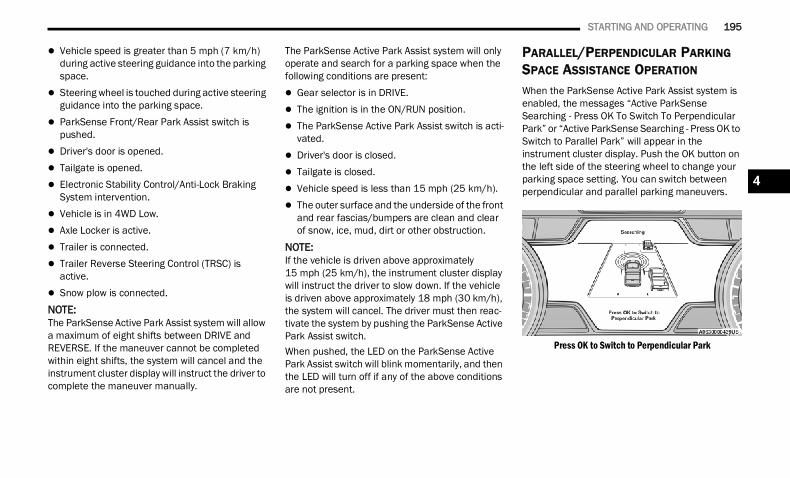
STARTING AND OPERATING 195
Vehicle speed is greater than 5 mph (7 km/h) during active steering guidance into the parking space.
Steering wheel is touched during active steering guidance into the parking space.
ParkSense Front/Rear Park Assist switch is pushed.
Driver's door is opened. Tailgate is opened. Electronic Stability Control/Anti-Lock Braking
System intervention. Vehicle is in 4WD Low. Axle Locker is active. Trailer is connected. Trailer Reverse Steering Control (TRSC) is
active. Snow plow is connected.NOTE:The ParkSense Active Park Assist system will allow a maximum of eight shifts between DRIVE and REVERSE. If the maneuver cannot be completed within eight shifts, the system will cancel and the instrument cluster display will instruct the driver to complete the maneuver manually.
The ParkSense Active Park Assist system will only operate and search for a parking space when the following conditions are present: Gear selector is in DRIVE. The ignition is in the ON/RUN position. The ParkSense Active Park Assist switch is acti-
vated. Driver's door is closed. Tailgate is closed. Vehicle speed is less than 15 mph (25 km/h). The outer surface and the underside of the front
and rear fascias/bumpers are clean and clear of snow, ice, mud, dirt or other obstruction.
NOTE:If the vehicle is driven above approximately 15 mph (25 km/h), the instrument cluster display will instruct the driver to slow down. If the vehicle is driven above approximately 18 mph (30 km/h), the system will cancel. The driver must then reac-tivate the system by pushing the ParkSense Active Park Assist switch.When pushed, the LED on the ParkSense Active Park Assist switch will blink momentarily, and then the LED will turn off if any of the above conditions are not present.
PARALLEL/PERPENDICULAR PARKING SPACE ASSISTANCE OPERATION
When the ParkSense Active Park Assist system is enabled, the messages “Active ParkSense Searching - Press OK To Switch To Perpendicular Park” or “Active ParkSense Searching - Press OK to Switch to Parallel Park” will appear in the instrument cluster display. Push the OK button on the left side of the steering wheel to change your parking space setting. You can switch between perpendicular and parallel parking maneuvers.
Press OK to Switch to Perpendicular Park
4
22_DT_OM_EN_USC_t.book Page 195
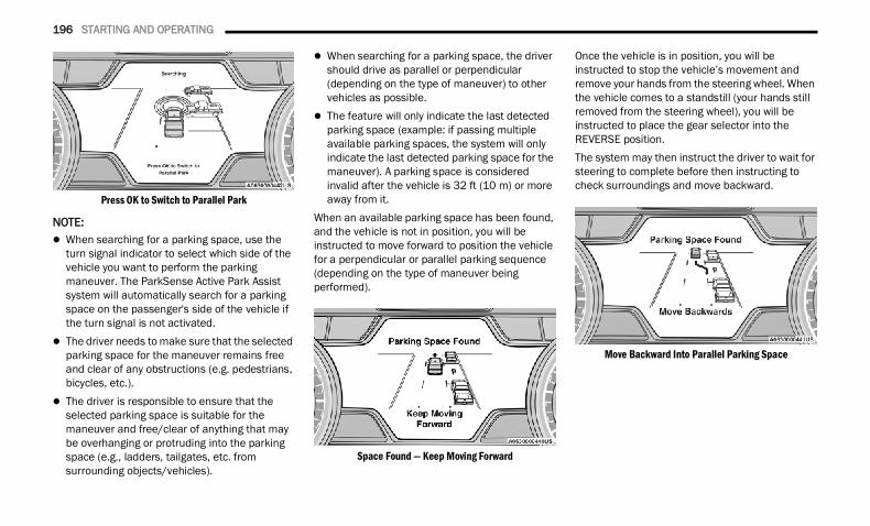
196 STARTING AND OPERATING
Press OK to Switch to Parallel Park
NOTE: When searching for a parking space, use the
turn signal indicator to select which side of the vehicle you want to perform the parking maneuver. The ParkSense Active Park Assist system will automatically search for a parking space on the passenger's side of the vehicle if the turn signal is not activated.
The driver needs to make sure that the selected parking space for the maneuver remains free and clear of any obstructions (e.g. pedestrians, bicycles, etc.).
The driver is responsible to ensure that the selected parking space is suitable for the maneuver and free/clear of anything that may be overhanging or protruding into the parking space (e.g., ladders, tailgates, etc. from surrounding objects/vehicles).
When searching for a parking space, the driver should drive as parallel or perpendicular (depending on the type of maneuver) to other vehicles as possible.
The feature will only indicate the last detected parking space (example: if passing multiple available parking spaces, the system will only indicate the last detected parking space for the maneuver). A parking space is considered invalid after the vehicle is 32 ft (10 m) or more away from it.
When an available parking space has been found, and the vehicle is not in position, you will be instructed to move forward to position the vehicle for a perpendicular or parallel parking sequence (depending on the type of maneuver being performed).
Space Found — Keep Moving Forward
Once the vehicle is in position, you will be instructed to stop the vehicle’s movement and remove your hands from the steering wheel. When the vehicle comes to a standstill (your hands still removed from the steering wheel), you will be instructed to place the gear selector into the REVERSE position.The system may then instruct the driver to wait for steering to complete before then instructing to check surroundings and move backward.
Move Backward Into Parallel Parking Space
22_DT_OM_EN_USC_t.book Page 196
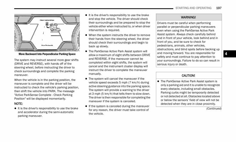
STARTING AND OPERATING 197
(Continued)
Move Backward Into Perpendicular Parking Space
The system may instruct several more gear shifts (DRIVE and REVERSE), with hands off of the steering wheel, before instructing the driver to check surroundings and complete the parking maneuver.When the vehicle is in the parking position, the maneuver is complete and the driver will be instructed to check the vehicle's parking position, then shift the vehicle into PARK. The message "Active ParkSense Complete - Check Parking Position" will be displayed momentarily.
NOTE: It is the driver's responsibility to use the brake
and accelerator during the semi-automatic parking maneuver.
It is the driver's responsibility to use the brake and stop the vehicle. The driver should check their surroundings and be prepared to stop the vehicle either when instructed to, or when driver intervention is required.
When the system instructs the driver to remove their hands from the steering wheel, the driver should check their surroundings and begin to back up slowly.
The ParkSense Active Park Assist system will allow a maximum of eight shifts between DRIVE and REVERSE. If the maneuver cannot be completed within eight shifts, the system will cancel and the instrument cluster display will instruct the driver to complete the maneuver manually.
The system will cancel the maneuver if the vehicle speed exceeds 5 mph (7 km/h) during active steering guidance into the parking space. The system will provide a warning to the driver at 3 mph (5 km/h) that tells them to slow down. The driver is then responsible for completing the maneuver if the system is canceled.
If the system is canceled during the maneuver for any reason, the driver must take control of the vehicle.
WARNING!
Drivers must be careful when performing parallel or perpendicular parking maneuvers even when using the ParkSense Active Park Assist system. Always check carefully behind and in front of your vehicle, look behind and in front of you, and be sure to check for pedestrians, animals, other vehicles, obstructions, and blind spots before backing up and moving forward. You are responsible for safety and must continue to pay attention to your surroundings. Failure to do so can result in serious injury or death.
CAUTION!
The ParkSense Active Park Assist system is only a parking aid and it is unable to recognize every obstacle, including small obstacles. Parking curbs might be temporarily detected or not detected at all. Obstacles located above or below the sensors’ field of view will not be detected when they are in close proximity.
4
22_DT_OM_EN_USC_t.book Page 197
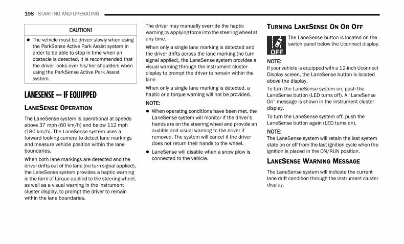
198 STARTING AND OPERATING
LANESENSE — IF EQUIPPED LANESENSE OPERATION
The LaneSense system is operational at speeds above 37 mph (60 km/h) and below 112 mph (180 km/h). The LaneSense system uses a forward looking camera to detect lane markings and measure vehicle position within the lane boundaries.When both lane markings are detected and the driver drifts out of the lane (no turn signal applied), the LaneSense system provides a haptic warning in the form of torque applied to the steering wheel, as well as a visual warning in the instrument cluster display, to prompt the driver to remain within the lane boundaries.
The driver may manually override the haptic warning by applying force into the steering wheel at any time.When only a single lane marking is detected and the driver drifts across the lane marking (no turn signal applied), the LaneSense system provides a visual warning through the instrument cluster display to prompt the driver to remain within the lane.When only a single lane marking is detected, a haptic or a torque warning will not be provided.
NOTE: When operating conditions have been met, the
LaneSense system will monitor if the driver’s hands are on the steering wheel and provide an audible and visual warning to the driver if removed. The system will cancel if the driver does not return their hands to the wheel.
LaneSense will disable when a snow plow is connected to the vehicle.
TURNING LANESENSE ON OR OFF
The LaneSense button is located on the switch panel below the Uconnect display.
NOTE:If your vehicle is equipped with a 12-inch Uconnect Display screen, the LaneSense button is located above the display.To turn the LaneSense system on, push the LaneSense button (LED turns off). A “LaneSense On” message is shown in the instrument cluster display.To turn the LaneSense system off, push the LaneSense button again (LED turns on).
NOTE:The LaneSense system will retain the last system state on or off from the last ignition cycle when the ignition is placed in the ON/RUN position.
LANESENSE WARNING MESSAGE
The LaneSense system will indicate the current lane drift condition through the instrument cluster display.
The vehicle must be driven slowly when using the ParkSense Active Park Assist system in order to be able to stop in time when an obstacle is detected. It is recommended that the driver looks over his/her shoulders when using the ParkSense Active Park Assist system.
CAUTION!
22_DT_OM_EN_USC_t.book Page 198
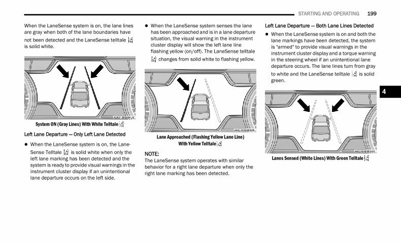
STARTING AND OPERATING 199
When the LaneSense system is on, the lane lines are gray when both of the lane boundaries have not been detected and the LaneSense telltale is solid white.
System ON (Gray Lines) With White Telltale
Left Lane Departure — Only Left Lane Detected
When the LaneSense system is on, the Lane-Sense Telltale is solid white when only the left lane marking has been detected and the system is ready to provide visual warnings in the instrument cluster display if an unintentional lane departure occurs on the left side.
When the LaneSense system senses the lane has been approached and is in a lane departure situation, the visual warning in the instrument cluster display will show the left lane line flashing yellow (on/off). The LaneSense telltale
changes from solid white to flashing yellow.
Lane Approached (Flashing Yellow Lane Line) With Yellow Telltale
NOTE:The LaneSense system operates with similar behavior for a right lane departure when only the right lane marking has been detected.
Left Lane Departure — Both Lane Lines Detected When the LaneSense system is on and both the
lane markings have been detected, the system is "armed" to provide visual warnings in the instrument cluster display and a torque warning in the steering wheel if an unintentional lane departure occurs. The lane lines turn from gray to white and the LaneSense telltale is solid green.
Lanes Sensed (White Lines) With Green Telltale
4
22_DT_OM_EN_USC_t.book Page 199
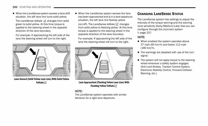
200 STARTING AND OPERATING
When the LaneSense system senses a lane drift situation, the left lane line turns solid yellow. The LaneSense telltale changes from solid green to solid yellow. At this time torque is applied to the steering wheel in the opposite direction of the lane boundary.For example: If approaching the left side of the lane the steering wheel will turn to the right.
Lane Sensed (Solid Yellow Lane Line) With Solid Yellow Telltale
When the LaneSense system senses the lane has been approached and is in a lane departure situation, the left lane line flashes yellow (on/off). The LaneSense telltale changes from solid yellow to flashing yellow. At this time torque is applied to the steering wheel in the opposite direction of the lane boundary.For example: If approaching the left side of the lane the steering wheel will turn to the right.
Lane Approached (Flashing Yellow Lane Line) With Flashing Yellow Telltale
NOTE:The LaneSense system operates with similar behavior for a right lane departure.
CHANGING LANESENSE STATUS
The LaneSense system has settings to adjust the intensity of the torque warning and the warning zone sensitivity (Early/Medium/Late) that you can configure through the Uconnect system Ú page 237.NOTE: When enabled the system operates above
37 mph (60 km/h) and below 112 mph (180 km/h).
The warnings are disabled with use of the turn signal.
The system will not apply torque to the steering wheel whenever a safety system engages (Anti-Lock Brakes, Traction Control System, Electronic Stability Control, Forward Collision Warning, etc.).
22_DT_OM_EN_USC_t.book Page 200
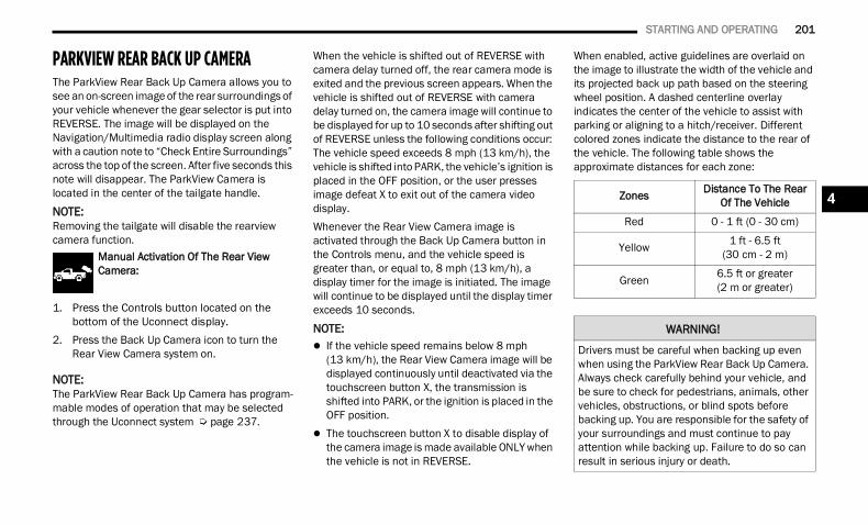
STARTING AND OPERATING 201
PARKVIEW REAR BACK UP CAMERA The ParkView Rear Back Up Camera allows you to see an on-screen image of the rear surroundings of your vehicle whenever the gear selector is put into REVERSE. The image will be displayed on the Navigation/Multimedia radio display screen along with a caution note to “Check Entire Surroundings” across the top of the screen. After five seconds this note will disappear. The ParkView Camera is located in the center of the tailgate handle.
NOTE:Removing the tailgate will disable the rearview camera function.
Manual Activation Of The Rear View Camera:
1. Press the Controls button located on the bottom of the Uconnect display.
2. Press the Back Up Camera icon to turn the Rear View Camera system on.
NOTE:The ParkView Rear Back Up Camera has program-mable modes of operation that may be selected through the Uconnect system Ú page 237.
When the vehicle is shifted out of REVERSE with camera delay turned off, the rear camera mode is exited and the previous screen appears. When the vehicle is shifted out of REVERSE with camera delay turned on, the camera image will continue to be displayed for up to 10 seconds after shifting out of REVERSE unless the following conditions occur: The vehicle speed exceeds 8 mph (13 km/h), the vehicle is shifted into PARK, the vehicle’s ignition is placed in the OFF position, or the user presses image defeat X to exit out of the camera video display.Whenever the Rear View Camera image is activated through the Back Up Camera button in the Controls menu, and the vehicle speed is greater than, or equal to, 8 mph (13 km/h), a display timer for the image is initiated. The image will continue to be displayed until the display timer exceeds 10 seconds.
NOTE: If the vehicle speed remains below 8 mph
(13 km/h), the Rear View Camera image will be displayed continuously until deactivated via the touchscreen button X, the transmission is shifted into PARK, or the ignition is placed in the OFF position.
The touchscreen button X to disable display of the camera image is made available ONLY when the vehicle is not in REVERSE.
When enabled, active guidelines are overlaid on the image to illustrate the width of the vehicle and its projected back up path based on the steering wheel position. A dashed centerline overlay indicates the center of the vehicle to assist with parking or aligning to a hitch/receiver. Different colored zones indicate the distance to the rear of the vehicle. The following table shows the approximate distances for each zone:
Zones Distance To The Rear Of The Vehicle
Red 0 - 1 ft (0 - 30 cm)
Yellow 1 ft - 6.5 ft (30 cm - 2 m)
Green 6.5 ft or greater(2 m or greater)
WARNING!
Drivers must be careful when backing up even when using the ParkView Rear Back Up Camera. Always check carefully behind your vehicle, and be sure to check for pedestrians, animals, other vehicles, obstructions, or blind spots before backing up. You are responsible for the safety of your surroundings and must continue to pay attention while backing up. Failure to do so can result in serious injury or death.
4
22_DT_OM_EN_USC_t.book Page 201
202 STARTING AND OPERATING
NOTE:If snow, ice, mud, or any foreign substance builds up on the camera lens, clean the lens, rinse with water, and dry with a soft cloth. Do not cover the lens.Zoom ViewWhen the Rear View Camera image is being displayed, and the vehicle speed is below 8 mph (13 km/h) while in any gear, Zoom View is available. By pressing the “magnifying glass” icon in the upper left of the display screen, the image will zoom in to four times the standard view. Pressing the icon a second time will return the view to the standard Back Up Camera display.
When Zoom View is selected while the vehicle is in REVERSE, then shifted to DRIVE, the camera delay view will display the standard Back Up Camera view. If the vehicle is then returned to REVERSE gear from DRIVE, the Zoom View selection will automatically resume.
NOTE:The Zoom View button and AUX button (if equipped) will not be available when the vehicle is shifted into REVERSE and the Trailer Reverse Steering Control (TRSC) feature (if equipped) is activated.Shifting to NEUTRAL from any gear will maintain the selected view (Zoom or Standard) as long as the vehicle is below 8 mph (13 km/h).If the vehicle is in PARK, Zoom View is available until the gear selector is placed in DRIVE or REVERSE and speeds are at or above 8 mph (13 km/h).
NOTE: If the vehicle is in DRIVE, NEUTRAL, or REVERSE,
and speed is greater than or equal to 8 mph (13 km/h), Zoom View is unavailable and the icon will appear grey.
While in Zoom View, the guidelines will not be visible.
For information on Auxiliary Cameras (if equipped), see Ú page 208.
SURROUND VIEW CAMERA SYSTEM — IF EQUIPPED The Surround View Camera system allows you to see an on-screen image of the surroundings and the Top View of your vehicle. This occurs whenever the gear selector is in REVERSE or when enabled through the Uconnect system. The Top View of the vehicle will also show if any doors are open. The image will be displayed on the touchscreen along with a caution note “Check Entire Surroundings”. After five seconds, this note will disappear. The Surround View Camera system is comprised of four cameras located in the front grille, rear tailgate and side mirrors.
NOTE: Removing the tailgate will disable the rearview
camera function. The Surround View Camera system has
programmable settings that may be selected through the Uconnect system Ú page 237.
Press this button on the touchscreen to enter the Surround View Camera menu in the Uconnect system.
CAUTION!
To avoid vehicle damage, ParkView should only be used as a parking aid. The ParkView camera is unable to view every obstacle or object in your drive path.
To avoid vehicle damage, the vehicle must be driven slowly when using ParkView to be able to stop in time when an obstacle is seen. It is recommended that the driver look frequently over his/her shoulder when using ParkView.
22_DT_OM_EN_USC_t.book Page 202
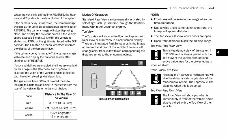
STARTING AND OPERATING 203
When the vehicle is shifted into REVERSE, the Rear View and Top View is the default view of the system.If the camera delay is turned on, the camera image will display for up to 10 seconds after shifting out of REVERSE. The camera image will stop displaying, close, and display the previous screen if the vehicle speed exceeds 8 mph (13 km/h), the vehicle is shifted into PARK, or the ignition is placed in the OFF position. The X button on the touchscreen disables the display of the camera image.If the camera delay is turned off, the camera image will close and display the previous screen after shifting out of REVERSE.If active guidelines are enabled, the lines are overlaid on the image in the Rear View and Top View to illustrate the width of the vehicle and its projected path based on steering wheel position.The guidelines have different colored zones to indicate the distance an object in the view is from the rear of the vehicle. Refer to the chart below:
Modes Of OperationStandard Rear View can be manually activated by selecting “Back Up Camera” through the Controls menu within the Uconnect system.Top ViewThe Top View will show in the Uconnect system with Rear View or Front View in a split screen display. There are integrated ParkSense arcs in the image at the front and rear of the vehicle. The arcs will change color from yellow to red corresponding the distance zones to the oncoming object.
Surround View Camera View
NOTE: Front tires will be seen in the image when the
tires are turned. Due to wide angle cameras in the mirrors, the
image will appear distorted. The Top View will show which doors are open. Open front doors will block the outside image.Top View Plus Rear View
This is the default view of the system in REVERSE and is always paired with the Top View of the vehicle with optional active guidelines for the projected path
when enabled.Rear Cross Path View
Pressing the Rear Cross Path soft key will give the driver a wider angle view of the rear camera system. The Top View will be disabled when this is selected.
Top View Plus Front ViewThe Front View will show you what is immediately in front of the vehicle and is always paired with the Top View of the vehicle.
Zone Distance To The Rear Of The Vehicle
Red 0 - 1 ft (0 - 30 cm)
Yellow 1 ft - 6.5 ft (30 cm - 2 m)
Green 6.5 ft or greater(2 m or greater)
4
22_DT_OM_EN_USC_t.book Page 203
204 STARTING AND OPERATING
Front Cross Path ViewPressing the Front Cross Path soft key will give the driver a wider angle view of the front camera system. The Top View will be disabled when this is selected.
Backup Camera ViewPressing the Back Up Camera soft key will provide a full screen rear view with the ability to access a Zoom View.
NOTE: If the Backup Camera was selected through the
Surround View Camera menu, exiting out of screen display will return to the Surround View menu. If the Backup Camera was manually acti-vated through the Controls menu of the Ucon-nect system, exiting out of the display screen will return to the Controls menu.
When the Trailer Reverse Steering Control (TRSC) feature (if equipped) is activated, the following buttons on the touchscreen will be unavailable: Backup Camera Front Facing Camera with Tire Lines All Surround View Camera Views
Zoom ViewWhen the Rear View Camera image is being displayed, and the vehicle speed is below 8 mph (13 km/h), Zoom View is available. By pressing the “magnifying glass” icon in the upper left of the display screen, the image will zoom in two times the standard view. Pressing the icon a second time will return the view to the standard Back Up Camera display.When Zoom View is selected while the vehicle is in REVERSE, then shifted to DRIVE, the camera delay view will display the standard Back Up Camera view. If the vehicle is then returned to REVERSE gear from DRIVE, the Zoom View selection will automatically resume.Shifting to NEUTRAL from any gear will maintain the selected view (Zoom or Standard) as long as the vehicle is below 8 mph (13 km/h).If the vehicle is in PARK, Zoom View is available until the gear selector is placed in DRIVE or REVERSE and speeds are at or above 8 mph (13 km/h).
NOTE: If the vehicle is in DRIVE, NEUTRAL, or REVERSE,
and speed is greater than or equal to 8 mph (13 km/h), Zoom View is unavailable and the icon will appear grey.
While in Zoom View, the guidelines will not be visible.
DeactivationThe system is deactivated in the following conditions if it was activated automatically: When the vehicle is shifted out of REVERSE with
camera delay turned on, the camera image will continue to be displayed for up to 10 seconds after shifting out of REVERSE unless the vehicle speed exceeds 8 mph (13 km/h), the vehicle is shifted into PARK or the ignition is placed in the OFF position. There is a touchscreen button X to disable the display of the camera image.
When the vehicle is shifted out of REVERSE with camera delay turned off, the Surround View Camera mode is exited and the last known screen appears again.
The system is deactivated in the following conditions if it was activated manually from the Uconnect controls menu via Surround View button or Back Up Camera button: The X button on the display is pressed Vehicle is shifted into PARK Ignition is placed in the OFF position Vehicle speed is over 8 mph (13 km/h) for
10 seconds
22_DT_OM_EN_USC_t.book Page 204
STARTING AND OPERATING 205
NOTE:If the Surround View Camera is activated manually, and the vehicle is shifted into REVERSE, deacti-vation methods for automatic activation are assumed.The camera delay system is turned off manually through the Uconnect settings menu Ú page 237.
NOTE: If snow, ice, mud, or any foreign substance
builds up on the camera lenses, clean the lenses, rinse with water, and dry with a soft cloth. Do not cover the lenses.
If a malfunction with the system has occurred, see an authorized dealer. For information on Auxiliary Cameras (if equipped),
see Ú page 208.
FORWARD FACING CAMERA WITH TIRE LINES — IF EQUIPPED
The Forward Facing Camera displays a front view image of the road ahead, along with tire lines to guide the driver when driving on narrow roads. Tire lines can be activated/deactivated through the Uconnect Settings.
ActivationThe Forward Facing Camera can be activated in the following ways: Pressing the Forward Facing Camera button in
the Controls screen or Apps menu Pressing the Forward Facing Camera button
located in the upper left corner of the Back Up camera display
Once activated, the camera image will remain on as long as the vehicle speed is below 8 mph (13 km/h).DeactivationThe Forward Facing Camera is deactivated in the following conditions: The vehicle exceeds 8 mph (13 km/h), except
when vehicle is in 4WD Low. The X button on the display is pressed. The vehicle is shifted into PARK. The ignition is placed in the OFF position.NOTE:If the vehicle is in 4WD Low, the Forward Facing Camera image will be displayed until the X button is pressed or the ignition is placed in the OFF position.
WARNING!
Drivers must be careful when backing up even when using the Surround View Camera. Always check carefully behind your vehicle, and be sure to check for pedestrians, animals, other vehicles, obstructions, or blind spots before backing up. You are responsible for the safety of your surroundings and must continue to pay attention while backing up. Failure to do so can result in serious injury or death.
CAUTION!
To avoid vehicle damage, Surround View should only be used as a parking aid. The Surround View camera is unable to view every obstacle or object in your drive path.
To avoid vehicle damage, the vehicle must be driven slowly when using Surround View to be able to stop in time when an obstacle is seen. It is recommended that the driver look frequently over his/her shoulder when using Surround View.
4
22_DT_OM_EN_USC_t.book Page 205
206 STARTING AND OPERATING
TRAILER CAMERAS — IF EQUIPPED TRAILER SURROUND VIEW CAMERA SYSTEM — IF EQUIPPED
The Trailer Surround View Camera system allows you to see an on-screen image of the surroundings and the Top View of a trailer using four mountable cameras. This occurs whenever the More Cams soft button is selected, or when enabled through the Uconnect system. The image will be displayed on the Uconnect display along with a caution note “Check Entire Surroundings”. After five seconds, this note will disappear.
NOTE: Trailer Surround View Camera kit is only avail-
able for vehicles equipped with the Surround View Camera system.
The Trailer Surround View Camera system has programmable settings that may be selected through the Uconnect system Ú page 237.
Set UpThe Trailer Surround View Camera system includes an installation kit with a Trailer Surround View Module and four Trailer Surround View Cameras that must be installed on your trailer prior to connecting to your vehicle. See the installation instructions included with the Trailer Surround View installation kit for more information.
Once the Trailer Surround View Module and cameras are installed and the trailer is connected to the vehicle via the 12-way connector, the settings Trailer Surround Camera settings can be accessed. The Trailer Surround Camera settings can be accessed through Uconnect Settings by pressing the Trailer soft button in the Trailer Settings or the Camera Settings. The system requires input of the trailer dimensions prior to use of the system.
NOTE: If a trailer is connected but the trailer dimen-
sions have not been entered in the Trailer Surround settings page, the system will default to the settings page.
If a trailer is not connected and any soft button is selected, a message will appear: “Connect Trailer Equipped With Trailer Surround View System”.
Inputting Trailer ValuesFor the Trailer Surround View Camera system to function, all fields must be entered. When a value is needed the screen will display “Required”.
When the Trailer Type soft button is selectedtwo options are available: Conventional or Gooseneck/5th Wheel.ActivationThe Trailer Surround Camera can be activated through the Uconnect system when the vehicle is in PARK, NEUTRAL, OR DRIVE.When the vehicle is shifted into REVERSE, Surround View Camera showing the Top View and Backup Camera is the default view of the system. Press the More Cams soft button and press the Trailer tab to access the Trailer Cameras. Press Trailer Surround Camera soft button to access Top View and Rear View of the trailer.
Setting Description
Trailer Length Input the total length of the trailer
Trailer Width Input the total width of the trailer
Camera Height Input the height of the mounted camera
Trailer Type Choose the trailer type from menu
22_DT_OM_EN_USC_t.book Page 206
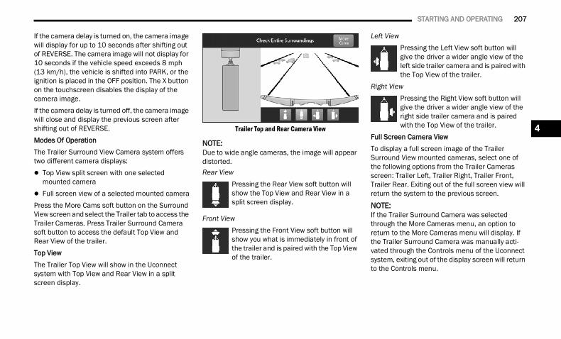
STARTING AND OPERATING 207
If the camera delay is turned on, the camera image will display for up to 10 seconds after shifting out of REVERSE. The camera image will not display for 10 seconds if the vehicle speed exceeds 8 mph (13 km/h), the vehicle is shifted into PARK, or the ignition is placed in the OFF position. The X button on the touchscreen disables the display of the camera image.If the camera delay is turned off, the camera image will close and display the previous screen after shifting out of REVERSE.Modes Of OperationThe Trailer Surround View Camera system offers two different camera displays: Top View split screen with one selected
mounted camera Full screen view of a selected mounted cameraPress the More Cams soft button on the Surround View screen and select the Trailer tab to access the Trailer Cameras. Press Trailer Surround Camera soft button to access the default Top View and Rear View of the trailer.Top ViewThe Trailer Top View will show in the Uconnect system with Top View and Rear View in a split screen display.
Trailer Top and Rear Camera View
NOTE:Due to wide angle cameras, the image will appear distorted.Rear View
Pressing the Rear View soft button will show the Top View and Rear View in a split screen display.
Front ViewPressing the Front View soft button will show you what is immediately in front of the trailer and is paired with the Top View of the trailer.
Left ViewPressing the Left View soft button will give the driver a wider angle view of the left side trailer camera and is paired with the Top View of the trailer.
Right ViewPressing the Right View soft button will give the driver a wider angle view of the right side trailer camera and is paired with the Top View of the trailer.
Full Screen Camera ViewTo display a full screen image of the Trailer Surround View mounted cameras, select one of the following options from the Trailer Cameras screen: Trailer Left, Trailer Right, Trailer Front, Trailer Rear. Exiting out of the full screen view will return the system to the previous screen.
NOTE:If the Trailer Surround Camera was selected through the More Cameras menu, an option to return to the More Cameras menu will display. If the Trailer Surround Camera was manually acti-vated through the Controls menu of the Uconnect system, exiting out of the display screen will return to the Controls menu.
4
22_DT_OM_EN_USC_t.book Page 207
208 STARTING AND OPERATING
DeactivationThe system is deactivated in the following conditions if it was activated automatically: When the vehicle is shifted out of REVERSE with
camera delay turned on, the camera image will continue to be displayed for up to 10 seconds, unless the vehicle speed exceeds 8 mph (13 km/h), the vehicle is shifted into PARK or the ignition is placed in the OFF position. There is a touchscreen button X to disable the display of the camera image.
When the vehicle is shifted out of REVERSE with camera delay turned off, the Trailer Surround View Camera mode is exited and the last known screen appears again.
The system is deactivated in the following conditions if it was activated manually from the Uconnect controls menu via the Trailer Surround Camera soft button: The X button on the display is pressed Vehicle is shifted into PARK Ignition is placed in the OFF position Vehicle speed is over 8 mph (13 km/h) for
10 seconds
NOTE:If the Trailer Surround Camera is activated manually, and the vehicle is shifted into REVERSE, deactivation methods for automatic activation are assumed.The camera delay system is turned off manually through the Uconnect system Ú page 237.
NOTE: If snow, ice, mud, or any foreign substance
builds up on the camera lenses, clean the lenses, rinse with water, and dry with a soft cloth. Do not cover the lenses.
If a malfunction with the system has occurred, see an authorized dealer.
AUX CAMERA — IF EQUIPPED
Your vehicle may be equipped with one or two AUX Cameras, which display rearview and side view images from the trailer on the touchscreen.NOTE:Two Aux Cameras are only available on vehicles with NAV equipped radios if the vehicle is not equipped with a Center High Mounted Stop Lamp (CHMSL) and Surround View Camera system.
WARNING!
Drivers must be careful when backing up even when using the Trailer Surround View Camera. Always check carefully behind your vehicle, and be sure to check for pedestrians, animals, other vehicles, obstructions, or blind spots before backing up. You are responsible for the safety of your surroundings and must continue to pay attention while backing up. Failure to do so can result in serious injury or death.
CAUTION!
To avoid vehicle damage, Trailer Surround View should only be used as a parking aid. The Trailer Surround View Camera is unable to view every obstacle or object in your drive path.
To avoid vehicle damage, the vehicle must be driven slowly when using Trailer Surround View to be able to stop in time when an obstacle is seen. It is recommended that the driver look frequently over his/her shoulder when using Trailer Surround View.
22_DT_OM_EN_USC_t.book Page 208
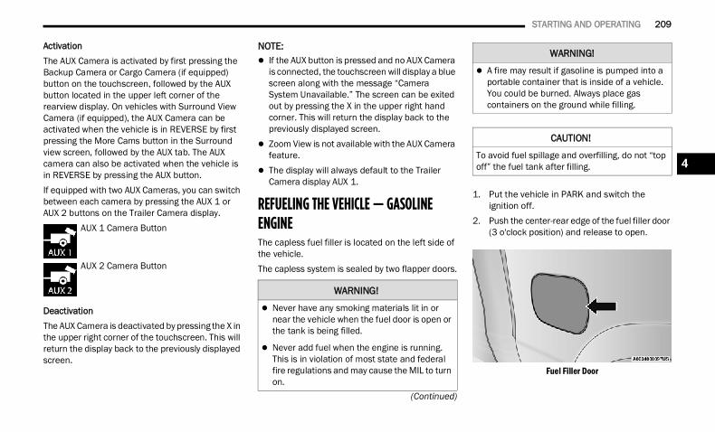
STARTING AND OPERATING 209
(Continued)
ActivationThe AUX Camera is activated by first pressing the Backup Camera or Cargo Camera (if equipped) button on the touchscreen, followed by the AUX button located in the upper left corner of the rearview display. On vehicles with Surround View Camera (if equipped), the AUX Camera can be activated when the vehicle is in REVERSE by first pressing the More Cams button in the Surround view screen, followed by the AUX tab. The AUX camera can also be activated when the vehicle is in REVERSE by pressing the AUX button.If equipped with two AUX Cameras, you can switch between each camera by pressing the AUX 1 or AUX 2 buttons on the Trailer Camera display.
AUX 1 Camera Button
AUX 2 Camera Button
DeactivationThe AUX Camera is deactivated by pressing the X in the upper right corner of the touchscreen. This will return the display back to the previously displayed screen.
NOTE: If the AUX button is pressed and no AUX Camera
is connected, the touchscreen will display a blue screen along with the message “Camera System Unavailable.” The screen can be exited out by pressing the X in the upper right hand corner. This will return the display back to the previously displayed screen.
Zoom View is not available with the AUX Camera feature.
The display will always default to the Trailer Camera display AUX 1.
REFUELING THE VEHICLE — GASOLINE ENGINE The capless fuel filler is located on the left side of the vehicle.The capless system is sealed by two flapper doors.
1. Put the vehicle in PARK and switch the ignition off.
2. Push the center-rear edge of the fuel filler door (3 o'clock position) and release to open.
Fuel Filler Door
WARNING!
Never have any smoking materials lit in or near the vehicle when the fuel door is open or the tank is being filled.
Never add fuel when the engine is running. This is in violation of most state and federal fire regulations and may cause the MIL to turn on.
A fire may result if gasoline is pumped into a portable container that is inside of a vehicle. You could be burned. Always place gas containers on the ground while filling.
CAUTION!
To avoid fuel spillage and overfilling, do not “top off” the fuel tank after filling.
WARNING!
4
22_DT_OM_EN_USC_t.book Page 209
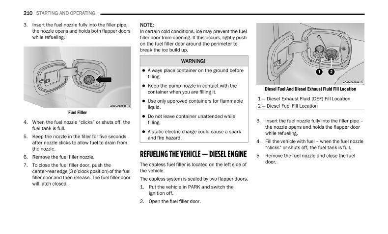
210 STARTING AND OPERATING
3. Insert the fuel nozzle fully into the filler pipe, the nozzle opens and holds both flapper doors while refueling.
Fuel Filler
4. When the fuel nozzle “clicks” or shuts off, the fuel tank is full.
5. Keep the nozzle in the filler for five seconds after nozzle clicks to allow fuel to drain from the nozzle.
6. Remove the fuel filler nozzle.7. To close the fuel filler door, push the
center-rear edge (3 o’clock position) of the fuel filler door and then release. The fuel filler door will latch closed.
NOTE:In certain cold conditions, ice may prevent the fuel filler door from opening. If this occurs, lightly push on the fuel filler door around the perimeter to break the ice build up.
REFUELING THE VEHICLE — DIESEL ENGINE The capless fuel filler is located on the left side of the vehicle.The capless system is sealed by two flapper doors.1. Put the vehicle in PARK and switch the
ignition off.2. Open the fuel filler door.
Diesel Fuel And Diesel Exhaust Fluid Fill Location
3. Insert the fuel nozzle fully into the filler pipe – the nozzle opens and holds the flapper door while refueling.
4. Fill the vehicle with fuel – when the fuel nozzle “clicks” or shuts off, the fuel tank is full.
5. Remove the fuel nozzle and close the fuel door.
WARNING!
Always place container on the ground before filling.
Keep the pump nozzle in contact with the container when you are filling it.
Use only approved containers for flammable liquid.
Do not leave container unattended while filling.
A static electric charge could cause a spark and fire hazard.
1 — Diesel Exhaust Fluid (DEF) Fill Location2 — Diesel Fuel Fill Location
22_DT_OM_EN_USC_t.book Page 210
STARTING AND OPERATING 211
AVOID USING CONTAMINATED FUEL
Fuel that is contaminated by water or dirt can cause severe damage to the engine fuel system. Proper maintenance of the engine fuel filter and fuel tank is essential Ú page 412.
BULK FUEL STORAGE — DIESEL FUEL
If you store quantities of fuel, good maintenance of the stored fuel is also essential. Fuel contaminated with water will promote the growth of “microbes.” These microbes form “slime” that will clog the fuel filtration system and lines. Drain condensation from the supply tank and change the line filter on a regular basis.
NOTE:When a diesel engine is allowed to run out of fuel, air is pulled into the fuel system.If the vehicle will not start Ú page 417.
DIESEL EXHAUST FLUID
Your vehicle is equipped with a Selective Catalytic Reduction (SCR) system to meet diesel emissions standards required by the Environmental Protection Agency.
The purpose of the SCR system is to reduce levels of oxides of nitrogen (NOx) emitted from engines that are harmful to our health and the environment to a near-zero level. A small quantity of Diesel Exhaust Fluid (DEF) is injected into the exhaust upstream of a catalyst where, when vaporized, converts smog-forming NOx into harmless nitrogen (N2) and water vapor (H2O), two natural components of the air we breathe.
DIESEL EXHAUST FLUID STORAGE
Diesel Exhaust Fluid (DEF) is considered a very stable product with a long shelf life. If DEF is kept in temperatures between 10° and 90°F (-12° and 32°C), it will last a minimum of one year.DEF may freeze at temperatures at or below 12°F (-11°C). The system has been designed to operate in this environment.
NOTE:When working with DEF, it is important to know that: Any containers or parts that come into contact
with DEF must be DEF compatible (plastic or stainless steel). Copper, brass, aluminum, iron or non-stainless steel should be avoided as they are subject to corrosion by DEF.
If DEF is spilled, it should be wiped up completely.
WARNING!
Never have any smoking materials lit in or near the vehicle when the fuel door is open or the tank is being filled.
Never add fuel when the engine is running. This is in violation of most state and federal fire regulations and may cause the Malfunc-tion Indicator Light (MIL) to turn on.
A fire may result if fuel is pumped into a portable container that is inside of a vehicle. You could be burned. Always place fuel containers on the ground while filling.
CAUTION!
To avoid fuel spillage and overfilling, do not “top off” the fuel tank after filling.
WARNING!
Do not open the high pressure fuel system with the engine running. Engine operation causes high fuel pressure. High pressure fuel spray can cause serious injury or death.
4
22_DT_OM_EN_USC_t.book Page 211
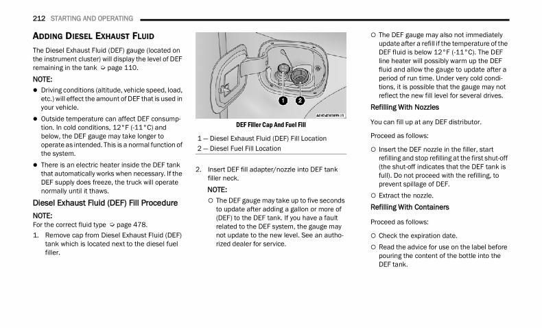
212 STARTING AND OPERATING
ADDING DIESEL EXHAUST FLUID
The Diesel Exhaust Fluid (DEF) gauge (located on the instrument cluster) will display the level of DEF remaining in the tank Ú page 110.NOTE: Driving conditions (altitude, vehicle speed, load,
etc.) will effect the amount of DEF that is used in your vehicle.
Outside temperature can affect DEF consump-tion. In cold conditions, 12°F (-11°C) and below, the DEF gauge may take longer to operate as intended. This is a normal function of the system.
There is an electric heater inside the DEF tank that automatically works when necessary. If the DEF supply does freeze, the truck will operate normally until it thaws.
Diesel Exhaust Fluid (DEF) Fill ProcedureNOTE:For the correct fluid type Ú page 478.1. Remove cap from Diesel Exhaust Fluid (DEF)
tank which is located next to the diesel fuel filler.
DEF Filler Cap And Fuel Fill
2. Insert DEF fill adapter/nozzle into DEF tank filler neck.NOTE: The DEF gauge may take up to five seconds
to update after adding a gallon or more of (DEF) to the DEF tank. If you have a fault related to the DEF system, the gauge may not update to the new level. See an autho-rized dealer for service.
The DEF gauge may also not immediately update after a refill if the temperature of the DEF fluid is below 12°F (-11°C). The DEF line heater will possibly warm up the DEF fluid and allow the gauge to update after a period of run time. Under very cold condi-tions, it is possible that the gauge may not reflect the new fill level for several drives.
Refilling With Nozzles
You can fill up at any DEF distributor.
Proceed as follows:
Insert the DEF nozzle in the filler, start refilling and stop refilling at the first shut-off (the shut-off indicates that the DEF tank is full). Do not proceed with the refilling, to prevent spillage of DEF.
Extract the nozzle.Refilling With Containers
Proceed as follows:
Check the expiration date. Read the advice for use on the label before
pouring the content of the bottle into the DEF tank.
1 — Diesel Exhaust Fluid (DEF) Fill Location2 — Diesel Fuel Fill Location
22_DT_OM_EN_USC_t.book Page 212
STARTING AND OPERATING 213
(Continued)
If systems which cannot be screwed in(e.g. tanks) are used for refilling, after the indication appears on the instrument panel display Ú page 115 fill the DEF tank with no more than 2 gallons (8 liters).
If containers which can be screwed to the filler are used, the reservoir is full when the DEF level in the container stops pouring out. Do not proceed further.
3. Stop filling the DEF tank immediately when any of the following happen: DEF stops flowing from the fill bottle into the DEF tank, DEF splashes out the filler neck, or a DEF pump nozzle automatically shuts off.
4. Reinstall cap onto DEF tank.
Filling The Def Tank In Cold ClimatesYour vehicle is equipped with an automatic DEF heating system. This allows the DEF injection system to operate properly at temperatures below 12°F (-11°C). If your vehicle is not in operation for an extended period of time with temperatures below 12°F (-11°C), the DEF in the tank may freeze. Do not overfill the DEF tank. If the tank is overfilled and freezes, it could be damaged.Extra care should be taken when filling with portable containers to avoid overfilling. Keep an eye on the DEF gauge in your instrument cluster. You may safely add a maximum of 2 gallons (7.6 Liters) when your DEF gauge is reading at the half mark.
VEHICLE LOADING GROSS VEHICLE WEIGHT RATING (GVWR) The GVWR is the total permissible weight of your vehicle including driver, passengers, vehicle, options and cargo. The label also specifies maximum capacities of front and rear Gross Axle Weight Rating (GAWR). Total load must be limited so GVWR and front and rear GAWR are not exceeded.
CAUTION!
To avoid DEF spillage, and possible damage to the DEF tank from overfilling, do not “top off” the DEF tank after filling.
DO NOT OVERFILL. DEF will freeze below 12ºF (-11ºC). The DEF system is designed to work in temperatures below the DEF freezing point, however, if the tank is overfilled and freezes, the system could be damaged.
When DEF is spilled, clean the area immedi-ately with water and use an absorbent mate-rial to soak up the spills on the ground.
Do not attempt to start your engine if DEF is accidentally added to the diesel fuel tank as it can result in severe damage to your engine, including but not limited to failure of the fuel pump and injectors.
Never add anything other than DEF to the tank – especially any form of hydrocarbon such as diesel fuel, fuel system additives, gasoline, or any other petroleum-based product. Even a very small amount of these, less than 100 parts per million or less than 1 oz. per 78 gallons (295 liters) will contaminate the entire DEF system and will require replace-ment. If owners use a container, funnel or nozzle when refilling the tank, it should either be new or one that has only been used for adding DEF. Mopar® provides an attachable nozzle with its DEF for this purpose.
CAUTION!
4
22_DT_OM_EN_USC_t.book Page 213
214 STARTING AND OPERATING
PAYLOAD
The payload of a vehicle is defined as the allowable load weight a truck can carry, including the weight of the driver, all passengers, options and cargo.
GROSS AXLE WEIGHT RATING (GAWR)The GAWR is the maximum permissible load on the front and rear axles. The load must be distributed in the cargo area so that the GAWR of each axle is not exceeded.Each axle GAWR is determined by the components in the system with the lowest load carrying capacity (axle, springs, tires or wheels). Heavier axles or suspension components sometimes specified by purchasers for increased durability does not necessarily increase the vehicle's GVWR.
TIRE SIZE
The tire size on the Vehicle Certification Label represents the actual tire size on your vehicle. Replacement tires must be equal to the load capacity of this tire size.
RIM SIZE
This is the rim size that is appropriate for the tire size listed.
INFLATION PRESSURE
This is the cold tire inflation pressure for your vehicle for all loading conditions up to full Gross Axle Weight Rating (GAWR).
CURB WEIGHT
The curb weight of a vehicle is defined as the total weight of the vehicle with all fluids, including vehicle fuel, at full capacity conditions, and with no occupants or cargo loaded into the vehicle. The front and rear curb weight values are determined by weighing your vehicle on a commercial scale before any occupants or cargo are added.
LOADING
The actual total weight and the weight of the front and rear of your vehicle at the ground can best be determined by weighing it when it is loaded and ready for operation.The entire vehicle should first be weighed on a commercial scale to insure that the Gross Vehicle Weight Rating (GVWR) has not been exceeded. The weight on the front and rear of the vehicle should then be determined separately to be sure that the load is properly distributed over the front and rear axle. Weighing the vehicle may show that the Gross Axle Weight Rating (GAWR) of either the front or rear axles has been exceeded but the total load is within the specified GVWR. If so, weight must be shifted from front to rear or rear to front as
appropriate until the specified weight limitations are met. Store the heavier items down low and be sure that the weight is distributed equally. Stow all loose items securely before driving.Improper weight distributions can have an adverse effect on the way your vehicle steers and handles and the way the brakes operate.
TRAILER TOWING In this section you will find safety tips and information on limits to the type of towing you can reasonably do with your vehicle. Before towing a trailer, carefully review this information to tow your load as efficiently and safely as possible.To maintain the New Vehicle Limited Warranty coverage, follow the requirements and recommendations in this manual concerning vehicles used for trailer towing.
CAUTION!
Do not load your vehicle any heavier than the GVWR or the maximum front and rear GAWR. If you do, parts on your vehicle can break, or it can change the way your vehicle handles. This could cause you to lose control. Also, overloading can shorten the life of your vehicle.
22_DT_OM_EN_USC_t.book Page 214
STARTING AND OPERATING 215
COMMON TOWING DEFINITIONS
The following trailer towing related definitions will assist you in understanding the following information:
Gross Vehicle Weight Rating (GVWR) The GVWR is the total allowable weight of your vehicle. This includes driver, passengers, cargo and tongue weight. The total load must be limited so that you do not exceed the GVWR Ú page 213.
Gross Trailer Weight (GTW)The GTW is the weight of the trailer plus the weight of all cargo, consumables and equipment (permanent or temporary) loaded in or on the trailer in its “loaded and ready for operation” condition.The recommended way to measure GTW is to put your fully loaded trailer on a vehicle scale. The entire weight of the trailer must be supported by the scale.
Gross Combination Weight Rating (GCWR)The GCWR is the total allowable weight of your vehicle and trailer when weighed in combination.
Gross Axle Weight Rating (GAWR) The GAWR is the maximum capacity of the front and rear axles. Distribute the load over the front and rear axles evenly. Make sure that you do not exceed either front or rear GAWR Ú page 213.
Tongue Weight (TW)The TW is the downward force exerted on the hitch ball by the trailer. You must consider this as part of the load on your vehicle.
Trailer Frontal AreaThe frontal area is the maximum height multiplied by the maximum width of the front of a trailer.
Trailer Sway Control (TSC)The TSC can be a mechanical telescoping link that can be installed between the hitch receiver and the trailer tongue that typically provides adjustable friction associated with the telescoping motion to dampen any unwanted trailer swaying motions while traveling.The electronic TSC (If equipped) recognizes a swaying trailer and automatically applies individual wheel brakes and/or reduces engine power to attempt to eliminate the trailer sway.
Weight-Carrying HitchA weight-carrying hitch supports the trailer tongue weight, just as if it were luggage located at a hitch ball or some other connecting point of the vehicle. These kinds of hitches are commonly used to tow small and medium sized trailers.
WARNING!
If the gross trailer weight is 5,000 lb (2,267 kg) or more, it is recommended to use a weight-distributing hitch to ensure stable handling of your vehicle. If you use a standard weight-carrying hitch, you could lose control of your vehicle and cause a collision.
WARNING!
It is important that you do not exceed the maximum front or rear GAWR. A dangerous driving condition can result if either rating is exceeded. You could lose control of the vehicle and have a collision.
4
22_DT_OM_EN_USC_t.book Page 215
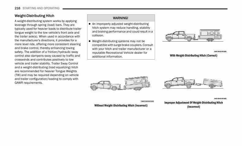
216 STARTING AND OPERATING
Weight-Distributing HitchA weight-distributing system works by applying leverage through spring (load) bars. They are typically used for heavier loads to distribute trailer tongue weight to the tow vehicle's front axle and the trailer axle(s). When used in accordance with the manufacturer's directions, it provides for a more level ride, offering more consistent steering and brake control, thereby enhancing towing safety. The addition of a friction/hydraulic sway control also dampens sway caused by traffic and crosswinds and contributes positively to tow vehicle and trailer stability. Trailer Sway Control and a weight-distributing (load equalizing) hitch are recommended for heavier Tongue Weights (TW) and may be required depending on vehicle and trailer configuration/loading to comply with GAWR requirements.
Without Weight-Distributing Hitch (Incorrect)
With Weight-Distributing Hitch (Correct)
Improper Adjustment Of Weight-Distributing Hitch (Incorrect)
WARNING!
An improperly adjusted weight-distributing hitch system may reduce handling, stability and braking performance and could result in a collision.
Weight-distributing systems may not be compatible with surge brake couplers. Consult with your hitch and trailer manufacturer or a reputable Recreational Vehicle dealer for additional information.
22_DT_OM_EN_USC_t.book Page 216
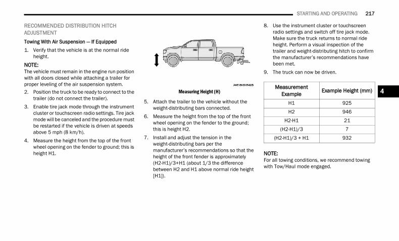
STARTING AND OPERATING 217
RECOMMENDED DISTRIBUTION HITCH ADJUSTMENTTowing With Air Suspension — If Equipped1. Verify that the vehicle is at the normal ride
height.NOTE:The vehicle must remain in the engine run position with all doors closed while attaching a trailer for proper leveling of the air suspension system.2. Position the truck to be ready to connect to the
trailer (do not connect the trailer).3. Enable tire jack mode through the instrument
cluster or touchscreen radio settings. Tire jack mode will be canceled and the procedure must be restarted if the vehicle is driven at speeds above 5 mph (8 km/h).
4. Measure the height from the top of the front wheel opening on the fender to ground; this is height H1.
Measuring Height (H)
5. Attach the trailer to the vehicle without the weight-distributing bars connected.
6. Measure the height from the top of the front wheel opening on the fender to the ground; this is height H2.
7. Install and adjust the tension in the weight-distributing bars per the manufacturer’s recommendations so that the height of the front fender is approximately (H2-H1)/3+H1 (about 1/3 the difference between H2 and H1 above normal ride height [H1]).
8. Use the instrument cluster or touchscreen radio settings and switch off tire jack mode. Make sure the truck returns to normal ride height. Perform a visual inspection of the trailer and weight-distributing hitch to confirm the manufacturer’s recommendations have been met.
9. The truck can now be driven.
NOTE:For all towing conditions, we recommend towing with Tow/Haul mode engaged.
Measurement Example Example Height (mm)
H1 925
H2 946
H2-H1 21
(H2-H1)/3 7
(H2-H1)/3 + H1 932
4
22_DT_OM_EN_USC_t.book Page 217
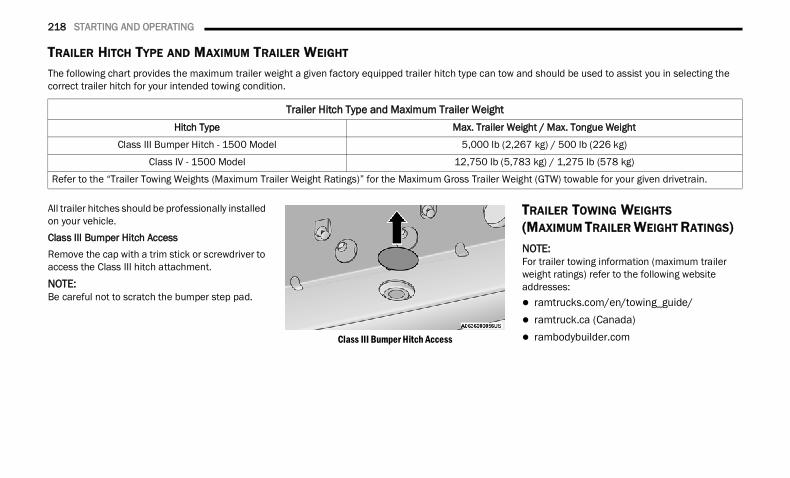
218 STARTING AND OPERATING
TRAILER HITCH TYPE AND MAXIMUM TRAILER WEIGHT
The following chart provides the maximum trailer weight a given factory equipped trailer hitch type can tow and should be used to assist you in selecting the correct trailer hitch for your intended towing condition.
All trailer hitches should be professionally installed on your vehicle.Class III Bumper Hitch AccessRemove the cap with a trim stick or screwdriver to access the Class III hitch attachment.
NOTE:Be careful not to scratch the bumper step pad.
Class III Bumper Hitch Access
TRAILER TOWING WEIGHTS(MAXIMUM TRAILER WEIGHT RATINGS) NOTE:For trailer towing information (maximum trailer weight ratings) refer to the following website addresses: ramtrucks.com/en/towing_guide/ ramtruck.ca (Canada) rambodybuilder.com
Trailer Hitch Type and Maximum Trailer WeightHitch Type Max. Trailer Weight / Max. Tongue Weight
Class III Bumper Hitch - 1500 Model 5,000 lb (2,267 kg) / 500 lb (226 kg)
Class IV - 1500 Model 12,750 lb (5,783 kg) / 1,275 lb (578 kg)
Refer to the “Trailer Towing Weights (Maximum Trailer Weight Ratings)” for the Maximum Gross Trailer Weight (GTW) towable for your given drivetrain.
22_DT_OM_EN_USC_t.book Page 218
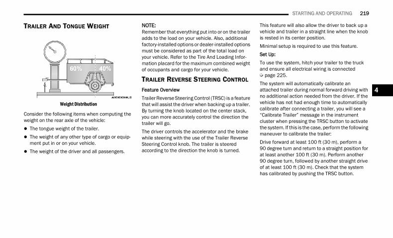
STARTING AND OPERATING 219
TRAILER AND TONGUE WEIGHT
Weight Distribution
Consider the following items when computing the weight on the rear axle of the vehicle: The tongue weight of the trailer. The weight of any other type of cargo or equip-
ment put in or on your vehicle. The weight of the driver and all passengers.
NOTE:Remember that everything put into or on the trailer adds to the load on your vehicle. Also, additional factory-installed options or dealer-installed options must be considered as part of the total load on your vehicle. Refer to the Tire And Loading Infor-mation placard for the maximum combined weight of occupants and cargo for your vehicle.
TRAILER REVERSE STEERING CONTROL
Feature OverviewTrailer Reverse Steering Control (TRSC) is a feature that will assist the driver when backing up a trailer. By turning the knob located on the center stack, you can more accurately control the direction the trailer will go.The driver controls the accelerator and the brake while steering with the use of the Trailer Reverse Steering Control knob. The trailer is steered according to the direction the knob is turned.
This feature will also allow the driver to back up a vehicle and trailer in a straight line when the knob is rested in its center position.Minimal setup is required to use this feature.Set Up:To use the system, hitch your trailer to the truck and ensure all electrical wiring is connected Ú page 225.The system will automatically calibrate an attached trailer during normal forward driving with no additional action needed from the driver. If the vehicle has not had enough time to automatically calibrate after connecting a trailer, you will see a “Calibrate Trailer” message in the instrument cluster when pressing the TRSC button to activate the system. If this is the case, perform the following maneuver to calibrate the trailer:Drive forward at least 100 ft (30 m), perform a90 degree turn and return to a straight position for at least another 100 ft (30 m). Perform another 90 degree turn, followed by another straight drive of at least 100 ft (30 m). Check that the system has calibrated by pushing the TRSC button.
4
22_DT_OM_EN_USC_t.book Page 219
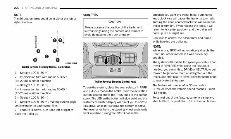
220 STARTING AND OPERATING
NOTE:The 90 degree turns could be in either the left or right direction.
Trailer Reverse Steering Control Calibration
Using TRSC
Trailer Reverse Steering Control Knob
To use the system, place the gear selector in PARK and put your foot on the brake. Push the activation button located above the TRSC knob in the center stack. The LED on the button will glow solid and the instrument cluster display will direct you to shift to REVERSE. Once in REVERSE the system is active. Remove hands from the steering wheel and slowly back up while turning the TRSC knob in the
direction you want the trailer to go. Turning the knob clockwise will cause the trailer to turn right. Turning the knob counterclockwise will cause the trailer to turn left. If you release the knob, it will return to its center position, and the trailer will back up in a straight line.Continue to control the accelerator and brake while backing the trailer up.
NOTE:While active, TRSC will automatically disable the Rear Park Assist system if it was previously enabled.The system will limit the top speed your vehicle can travel in REVERSE while using the feature. If needed, you can shift to DRIVE or NEUTRAL to pull forward to get more room or straighten out the trailer, and shift back to REVERSE without the need to reactivate the feature.The feature will cancel after 30 seconds inDRIVE or when the vehicle speed reaches 8 mph (12 km/h).To cancel out of the feature, come to a stop and shift to PARK, or push the TRSC activation button.
1 — Straight 100 ft (30 m)2 — Intersection turn with radius 50-65 ft (15-20 m) in either direction3 — Straight 100 ft (30 m)4 — Intersection turn with radius 50-65 ft (15-20 m) in either direction5 — Straight 100 ft (30 m)6 — Straight 100 ft (30 m), making sure to align vehicle/trailer to path center line7 — Feature is active, turn knob left or right to back the trailer up
CAUTION!
Always observe the position of the trailer and surroundings using the camera and mirrors to avoid damage to the truck or trailer.
22_DT_OM_EN_USC_t.book Page 220
STARTING AND OPERATING 221
Instrument Cluster Messages:
“Calibrate Trailer ” will display when a trailer is not calibrated and the vehicle is at a standstill while the button is pushed.
“Calibrating Trailer” will display when the trailer is not calibrated and the vehicle is moving while the button is pushed.
“To Activate Trailer Steering Shift To P” will display when the trailer is calibrated success-fully, the TRSC activation button is pushed and the vehicle is not in PARK.
“Trailer Steering Ready, Shift To Reverse” will display when the button is pushed, trailer is cali-brated and the vehicle is in PARK.
“Trailer Steering Active” will display after the driver shifts to REVERSE and indicates the feature is active.
“Trailer Steering Unavailable” will display if there is a fault in the system preventing activa-tion, the driver’s door is open, the driver’s seat belt is unbuckled, or the tailgate is open.
Other reasons the feature may cancel: The driver overrides steering by placing hands
on the steering wheel. Trailer tracking is lost.
If the trailer angle becomes excessive, the brakes apply bringing the vehicle to a stop and then applying the parking brake.
Trailer steering button is pushed while active. Vehicle speed goes over 8 mph (12 km/h). Driver door is open and seat belt is unbuckled. Transmission shifted to PARK.Trailer MemoryThe trailer steering system will automatically retain the calibration of the previous five trailers connected, so recalibration will not be necessary when hooking up. The next time the vehicle is started, place the vehicle in DRIVE and drive a short distance. The TRSC system can then be activated.
NOTE:Trailers may look different during day and night conditions. In such cases, the trailer may need to recalibrate.Some trailers (such as boat trailers) will need to recalibrate while loaded and unloaded.NOTE: The system may not detect a trailer in low light
conditions. In sunny conditions, the perfor-mance may be degraded as shadows pass over the trailer.
The driver is always responsible for safe opera-tion of truck and trailer.
The driver is always in control of the truck as well as the trailer and is responsible for controlling the throttle and brakes.
The system may not function when the camera lens is blocked, blurred (covered with water, snow, ice, dirt, etc) and will not work unless the tailgate is upright and fully latched.
TOWING REQUIREMENTS To promote proper break-in of your new vehicle drivetrain components, the following guidelines are recommended.
Perform the maintenance listed in the Scheduled Servicing section for the proper maintenance intervals Ú page 397. When towing a trailer, never exceed the GAWR or GCWR ratings.
CAUTION!
Do not tow a trailer at all during the first 500 miles (805 km) the new vehicle is driven. The engine, axle or other parts could be damaged.
Then, during the first 500 miles (805 km) that a trailer is towed, do not drive over 50 mph (80 km/h) and do not make starts at full throttle. This helps the engine and other parts of the vehicle wear in at the heavier loads.
4
22_DT_OM_EN_USC_t.book Page 221
222 STARTING AND OPERATING
(Continued)
Towing Requirements — Tires Do not attempt to tow a trailer while using a
compact spare tire. Do not drive more than 50 mph (80 km/h) when
towing while using a full size spare tire. Proper tire inflation pressures are essential to
the safe and satisfactory operation of your vehicle.
Check the trailer tires for proper tire inflation pressures before trailer usage.
Check for signs of tire wear or visible tire damage before towing a trailer.
Replacing tires with a higher load carrying capacity will not increase the vehicle's GVWR and GAWR limits.
For further information Ú page 448.
WARNING!
Make certain that the load is secured in the trailer and will not shift during travel. When trailering cargo that is not fully secured, dynamic load shifts can occur that may be difficult for the driver to control. You could lose control of your vehicle and have a collision.
When hauling cargo or towing a trailer, do not overload your vehicle or trailer. Overloading can cause a loss of control, poor performance or damage to brakes, axle, engine, transmis-sion, steering, suspension, chassis structure or tires.
Safety chains must always be used between your vehicle and trailer. Always connect the chains to the hook retainers of the vehicle hitch. Cross the chains under the trailer tongue and allow enough slack for turning corners.
Vehicles with trailers should not be parked on a grade. When parking, apply the parking brake on the tow vehicle. Put the tow vehicle transmission in PARK. For four-wheel drive vehicles, make sure the transfer case is not in NEUTRAL. Always, block or "chock" the trailer wheels.
GCWR must not be exceeded.
Total weight must be distributed between the tow vehicle and the trailer such that the following four ratings are not exceeded:
GVWR
GTW
GAWR
Tongue weight rating for the trailer hitch utilized.
WARNING!
22_DT_OM_EN_USC_t.book Page 222
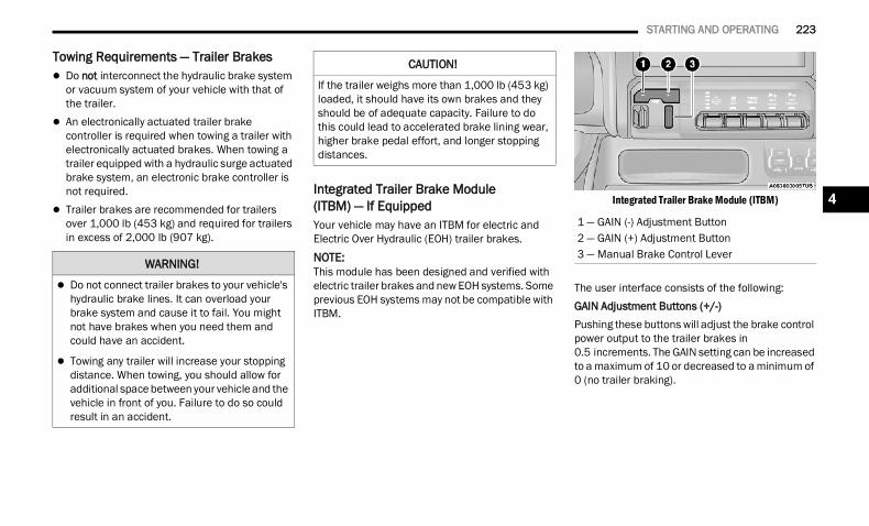
STARTING AND OPERATING 223
Towing Requirements — Trailer Brakes Do not interconnect the hydraulic brake system
or vacuum system of your vehicle with that of the trailer.
An electronically actuated trailer brake controller is required when towing a trailer with electronically actuated brakes. When towing a trailer equipped with a hydraulic surge actuated brake system, an electronic brake controller is not required.
Trailer brakes are recommended for trailers over 1,000 lb (453 kg) and required for trailers in excess of 2,000 lb (907 kg).
Integrated Trailer Brake Module (ITBM) — If Equipped Your vehicle may have an ITBM for electric and Electric Over Hydraulic (EOH) trailer brakes.NOTE:This module has been designed and verified with electric trailer brakes and new EOH systems. Some previous EOH systems may not be compatible with ITBM.
Integrated Trailer Brake Module (ITBM)
The user interface consists of the following:GAIN Adjustment Buttons (+/-)Pushing these buttons will adjust the brake control power output to the trailer brakes in 0.5 increments. The GAIN setting can be increased to a maximum of 10 or decreased to a minimum of 0 (no trailer braking).
WARNING!
Do not connect trailer brakes to your vehicle's hydraulic brake lines. It can overload your brake system and cause it to fail. You might not have brakes when you need them and could have an accident.
Towing any trailer will increase your stopping distance. When towing, you should allow for additional space between your vehicle and the vehicle in front of you. Failure to do so could result in an accident.
CAUTION!
If the trailer weighs more than 1,000 lb (453 kg) loaded, it should have its own brakes and they should be of adequate capacity. Failure to do this could lead to accelerated brake lining wear, higher brake pedal effort, and longer stopping distances.
1 — GAIN (-) Adjustment Button2 — GAIN (+) Adjustment Button3 — Manual Brake Control Lever
4
22_DT_OM_EN_USC_t.book Page 223
224 STARTING AND OPERATING
GAINThe GAIN setting is used to set the trailer brake control for the specific towing condition and should be changed as towing conditions change. Changes to towing conditions include trailer load, vehicle load, road conditions and weather.Manual Brake Control LeverSlide the manual brake control lever to the left to activate power to the trailer's electric brakes independent of the tow vehicle's brakes. If the manual brake control lever is activated while the brake is also applied, the greater of the two inputs determines the power sent to the trailer brakes.The trailer and the vehicle’s stop lamps will come on when braking normally with the vehicle brake pedal. Only the trailer stop lamps will come on when the manual brake control lever is applied.Trailer Brake Status Indicator LightThis light indicates the trailer electrical connection status.If no electrical connection is detected after the ignition is turned on, pushing the GAIN adjustment button or sliding the manual brake control lever will display the GAIN setting for 10 seconds and the Trailer Brake Status Indicator Light will not be displayed.
If a fault is detected in the trailer wiring or the Integrated Trailer Brake Module (ITBM), the Trailer Brake Status Indicator Light will flash.Adjusting GAIN
NOTE:This should only be performed in a traffic free envi-ronment at speeds of approximately 20–25 mph (30–40 km/h).1. Make sure the trailer brakes are in good
working condition, functioning normally and properly adjusted. See your trailer dealer if necessary.
2. Hook up the trailer and make the electrical connections according to the trailer manufacturer's instructions.
3. When a trailer is plugged in with electric or EOH brakes, the trailer connected message should appear in the instrument cluster display (if the connection is not recognized by the ITBM, braking functions will not be available), the GAIN setting will illuminate and the correct type of trailer must be selected from the instrument cluster display options.
4. Push the UP or DOWN button on the steering wheel until “TRAILER TOW” appears on the screen.
5. Push the RIGHT arrow on the steering wheel to enter “TRAILER TOW”.
6. Push the UP or DOWN buttons until the Trailer Brake Type appears on the screen.
7. Push the RIGHT arrow and then push the UP or DOWN buttons until the proper Trailer Brake Type appears on the screen.
8. In a traffic-free environment, tow the trailer on a dry, level surface at a speed of 20–25 mph (30–40 km/h) and squeeze the manual brake control lever completely.
9. If the trailer wheels lockup (indicated by squealing tires), reduce the GAIN setting; if the trailer wheels turn freely, increase the GAIN setting.
Repeat steps 8 and 9 until the GAIN setting isat a point just below trailer wheel lockup. If towing a heavier trailer, trailer wheel lockup maynot be attainable even with the maximum GAIN setting of 10.
22_DT_OM_EN_USC_t.book Page 224
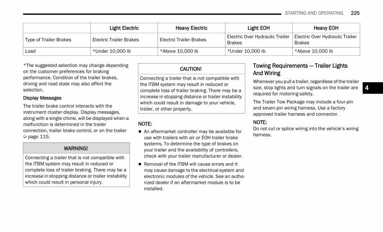
STARTING AND OPERATING 225
*The suggested selection may change depending on the customer preferences for braking performance. Condition of the trailer brakes, driving and road state may also affect the selection.Display MessagesThe trailer brake control interacts with the instrument cluster display. Display messages, along with a single chime, will be displayed when a malfunction is determined in the trailer connection, trailer brake control, or on the trailer Ú page 115.
NOTE: An aftermarket controller may be available for
use with trailers with air or EOH trailer brake systems. To determine the type of brakes on your trailer and the availability of controllers, check with your trailer manufacturer or dealer.
Removal of the ITBM will cause errors and it may cause damage to the electrical system and electronic modules of the vehicle. See an autho-rized dealer if an aftermarket module is to be installed.
Towing Requirements — Trailer LightsAnd WiringWhenever you pull a trailer, regardless of the trailer size, stop lights and turn signals on the trailer are required for motoring safety.The Trailer Tow Package may include a four-pin and seven-pin wiring harness. Use a factory approved trailer harness and connector.
NOTE:Do not cut or splice wiring into the vehicle’s wiring harness.
Light Electric Heavy Electric Light EOH Heavy EOH
Type of Trailer Brakes Electric Trailer Brakes Electric Trailer Brakes Electric Over Hydraulic Trailer Brakes
Electric Over Hydraulic Trailer Brakes
Load *Under 10,000 lb *Above 10,000 lb *Under 10,000 lb *Above 10,000 lb
WARNING!
Connecting a trailer that is not compatible with the ITBM system may result in reduced or complete loss of trailer braking. There may be a increase in stopping distance or trailer instability which could result in personal injury.
CAUTION!
Connecting a trailer that is not compatible with the ITBM system may result in reduced or complete loss of trailer braking. There may be a increase in stopping distance or trailer instability which could result in damage to your vehicle, trailer, or other property.
4
22_DT_OM_EN_USC_t.book Page 225
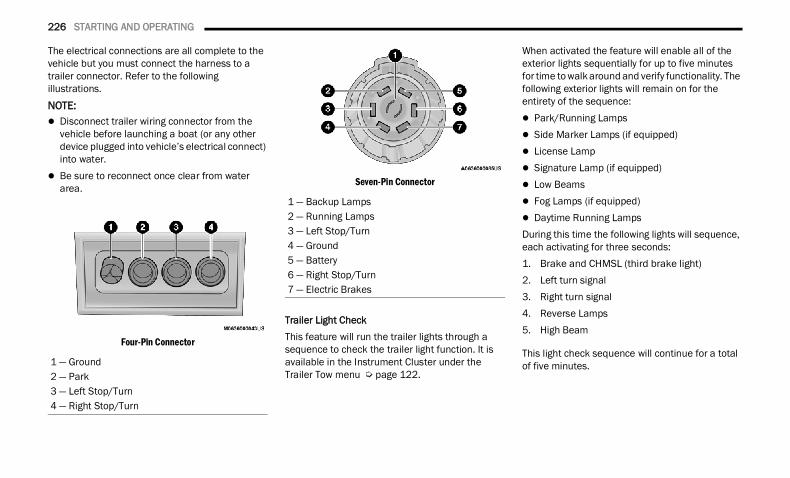
226 STARTING AND OPERATING
The electrical connections are all complete to the vehicle but you must connect the harness to a trailer connector. Refer to the following illustrations.NOTE: Disconnect trailer wiring connector from the
vehicle before launching a boat (or any other device plugged into vehicle’s electrical connect) into water.
Be sure to reconnect once clear from water area.
Four-Pin Connector
Seven-Pin Connector
Trailer Light CheckThis feature will run the trailer lights through a sequence to check the trailer light function. It is available in the Instrument Cluster under the Trailer Tow menu Ú page 122.
When activated the feature will enable all of the exterior lights sequentially for up to five minutes for time to walk around and verify functionality. The following exterior lights will remain on for the entirety of the sequence: Park/Running Lamps Side Marker Lamps (if equipped) License Lamp Signature Lamp (if equipped) Low Beams Fog Lamps (if equipped) Daytime Running LampsDuring this time the following lights will sequence, each activating for three seconds:1. Brake and CHMSL (third brake light)2. Left turn signal3. Right turn signal4. Reverse Lamps5. High Beam
This light check sequence will continue for a total of five minutes.1 — Ground
2 — Park3 — Left Stop/Turn4 — Right Stop/Turn
1 — Backup Lamps2 — Running Lamps3 — Left Stop/Turn4 — Ground5 — Battery6 — Right Stop/Turn7 — Electric Brakes
22_DT_OM_EN_USC_t.book Page 226
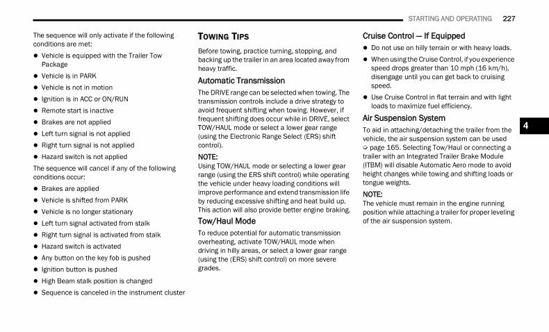
STARTING AND OPERATING 227
The sequence will only activate if the following conditions are met: Vehicle is equipped with the Trailer Tow
Package Vehicle is in PARK Vehicle is not in motion Ignition is in ACC or ON/RUN Remote start is inactive Brakes are not applied Left turn signal is not applied Right turn signal is not applied Hazard switch is not appliedThe sequence will cancel if any of the following conditions occur: Brakes are applied Vehicle is shifted from PARK Vehicle is no longer stationary Left turn signal activated from stalk Right turn signal is activated from stalk Hazard switch is activated Any button on the key fob is pushed Ignition button is pushed High Beam stalk position is changed Sequence is canceled in the instrument cluster
TOWING TIPS Before towing, practice turning, stopping, and backing up the trailer in an area located away from heavy traffic.
Automatic TransmissionThe DRIVE range can be selected when towing. The transmission controls include a drive strategy to avoid frequent shifting when towing. However, if frequent shifting does occur while in DRIVE, select TOW/HAUL mode or select a lower gear range (using the Electronic Range Select (ERS) shift control).
NOTE:Using TOW/HAUL mode or selecting a lower gear range (using the ERS shift control) while operating the vehicle under heavy loading conditions will improve performance and extend transmission life by reducing excessive shifting and heat build up. This action will also provide better engine braking.Tow/Haul ModeTo reduce potential for automatic transmission overheating, activate TOW/HAUL mode when driving in hilly areas, or select a lower gear range (using the (ERS) shift control) on more severe grades.
Cruise Control — If Equipped Do not use on hilly terrain or with heavy loads. When using the Cruise Control, if you experience
speed drops greater than 10 mph (16 km/h), disengage until you can get back to cruising speed.
Use Cruise Control in flat terrain and with light loads to maximize fuel efficiency.
Air Suspension SystemTo aid in attaching/detaching the trailer from the vehicle, the air suspension system can be used Ú page 165. Selecting Tow/Haul or connecting a trailer with an Integrated Trailer Brake Module (ITBM) will disable Automatic Aero mode to avoid height changes while towing and shifting loads or tongue weights.
NOTE:The vehicle must remain in the engine running position while attaching a trailer for proper leveling of the air suspension system.
4
22_DT_OM_EN_USC_t.book Page 227
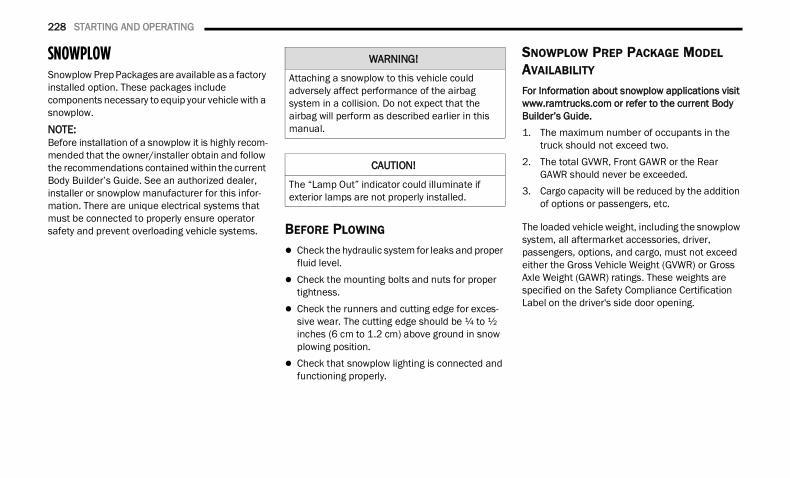
228 STARTING AND OPERATING
SNOWPLOWSnowplow Prep Packages are available as a factory installed option. These packages include components necessary to equip your vehicle with a snowplow.NOTE:Before installation of a snowplow it is highly recom-mended that the owner/installer obtain and follow the recommendations contained within the current Body Builder’s Guide. See an authorized dealer, installer or snowplow manufacturer for this infor-mation. There are unique electrical systems that must be connected to properly ensure operator safety and prevent overloading vehicle systems. BEFORE PLOWING
Check the hydraulic system for leaks and proper fluid level.
Check the mounting bolts and nuts for proper tightness.
Check the runners and cutting edge for exces-sive wear. The cutting edge should be ¼ to ½ inches (6 cm to 1.2 cm) above ground in snow plowing position.
Check that snowplow lighting is connected and functioning properly.
SNOWPLOW PREP PACKAGE MODEL AVAILABILITY
For Information about snowplow applications visit www.ramtrucks.com or refer to the current Body Builder’s Guide.1. The maximum number of occupants in the
truck should not exceed two.2. The total GVWR, Front GAWR or the Rear
GAWR should never be exceeded.3. Cargo capacity will be reduced by the addition
of options or passengers, etc.
The loaded vehicle weight, including the snowplow system, all aftermarket accessories, driver, passengers, options, and cargo, must not exceed either the Gross Vehicle Weight (GVWR) or Gross Axle Weight (GAWR) ratings. These weights are specified on the Safety Compliance Certification Label on the driver's side door opening.
WARNING!
Attaching a snowplow to this vehicle could adversely affect performance of the airbag system in a collision. Do not expect that the airbag will perform as described earlier in this manual.
CAUTION!
The “Lamp Out” indicator could illuminate if exterior lamps are not properly installed.
22_DT_OM_EN_USC_t.book Page 228
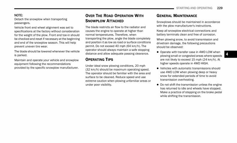
STARTING AND OPERATING 229
NOTE:Detach the snowplow when transporting passengers.Vehicle front end wheel alignment was set to specifications at the factory without consideration for the weight of the plow. Front end toe-in should be checked and reset if necessary at the beginning and end of the snowplow season. This will help prevent uneven tire wear.The blade should be lowered whenever the vehicle is parked.Maintain and operate your vehicle and snowplow equipment following the recommendations provided by the specific snowplow manufacturer.
OVER THE ROAD OPERATION WITH SNOWPLOW ATTACHED
The blade restricts air flow to the radiator and causes the engine to operate at higher than normal temperatures. Therefore, when transporting the plow, angle the blade completely and position it as low as road or surface conditions permit. Do not exceed 40 mph (64 km/h). The operator should always maintain a safe stopping distance and allow adequate passing clearance.
OPERATING TIPS
Under ideal snow plowing conditions, 20 mph (32 km/h) should be maximum operating speed. The operator should be familiar with the area and surface to be cleaned. Reduce speed and use extreme caution when plowing unfamiliar areas or under poor visibility.
GENERAL MAINTENANCE
Snowplows should be maintained in accordance with the plow manufacturer's instructions.Keep all snowplow electrical connections and battery terminals clean and free of corrosion.When plowing snow, to avoid transmission and drivetrain damage, the following precautions should be observed: Operate with transfer case in 4WD LOW when
plowing small or congested areas where speeds are not likely to exceed 15 mph (24 km/h). At higher speeds operate in 4WD HIGH.
Vehicles with automatic transmissions should use 4WD LOW when plowing deep or heavy snow for extended periods of time to avoid transmission overheating.
Do not shift the transmission unless the engine has returned to idle and wheels have stopped. Make a practice of stepping on the brake pedal while shifting the transmission.
4
22_DT_OM_EN_USC_t.book Page 229
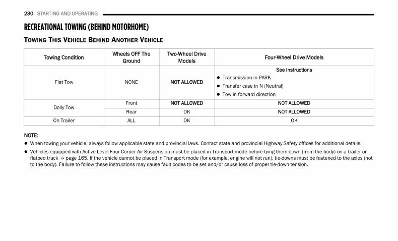
230 STARTING AND OPERATING
RECREATIONAL TOWING (BEHIND MOTORHOME) TOWING THIS VEHICLE BEHIND ANOTHER VEHICLE
NOTE: When towing your vehicle, always follow applicable state and provincial laws. Contact state and provincial Highway Safety offices for additional details. Vehicles equipped with Active-Level Four Corner Air Suspension must be placed in Transport mode before tying them down (from the body) on a trailer or
flatbed truck Ú page 165. If the vehicle cannot be placed in Transport mode (for example, engine will not run), tie-downs must be fastened to the axles (not to the body). Failure to follow these instructions may cause fault codes to be set and/or cause loss of proper tie-down tension.
Towing Condition Wheels OFF The Ground
Two-Wheel Drive Models Four-Wheel Drive Models
Flat Tow NONE NOT ALLOWED
See Instructions Transmission in PARK Transfer case in N (Neutral) Tow in forward direction
Dolly TowFront NOT ALLOWED NOT ALLOWED
Rear OK NOT ALLOWED
On Trailer ALL OK OK
22_DT_OM_EN_USC_t.book Page 230
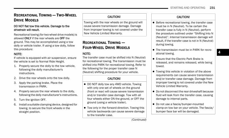
STARTING AND OPERATING 231
(Continued)
RECREATIONAL TOWING — TWO-WHEEL DRIVE MODELS
DO NOT flat tow this vehicle. Damage to the drivetrain will result.Recreational towing (for two-wheel drive models) is allowed ONLY if the rear wheels are OFF the ground. This may be accomplished using a tow dolly or vehicle trailer. If using a tow dolly, follow this procedure:
NOTE:If vehicle is equipped with air suspension, ensure the vehicle is set to Normal Ride Height.1. Properly secure the dolly to the tow vehicle,
following the dolly manufacturer's instructions.
2. Drive the rear wheels onto the tow dolly.3. Apply the parking brake. Place the
transmission in PARK.4. Properly secure the rear wheels to the dolly,
following the dolly manufacturer's instructions.5. Turn the ignition OFF.6. Install a suitable clamping device, designed for
towing, to secure the front wheels in the straight position.
RECREATIONAL TOWING — FOUR-WHEEL DRIVE MODELS
NOTE:The transfer case must be shifted into N (Neutral) for recreational towing. The transmission must be shifted into PARK for recreational towing. Refer to the following for the proper transfer case N (Neutral) shifting procedure for your vehicle.
CAUTION!
Towing with the rear wheels on the ground will cause severe transmission damage. Damage from improper towing is not covered under the New Vehicle Limited Warranty.
CAUTION!
DO NOT dolly tow any 4WD vehicle. Towing with only one set of wheels on the ground (front or rear) will cause severe transmission and/or transfer case damage. Tow with all four wheels either ON the ground, or OFF the ground (using a vehicle trailer).
Tow only in the forward direction. Towing this vehicle backwards can cause severe damage to the transfer case.
Before recreational towing, the transfer case must be in N (Neutral). To be certain the transfer case is fully in N (Neutral), perform the procedure outlined under “Shifting Into N (Neutral)”. Internal transmission damage will result, if the transfer case is not in N (Neutral) during towing.
The transmission must be in PARK for recre-ational towing.
Ensure that the Electric Park Brake is released, and remains released, while being towed.
Towing this vehicle in violation of the above requirements can cause severe transmission and/or transfer case damage. Damage from improper towing is not covered under the New Vehicle Limited Warranty.
Do not disconnect the rear driveshaft because fluid will leak from the transfer case, causing damage to internal parts.
Do not use a fascia/bumper-mounted clamp-on tow bar on your vehicle. The fascia/bumper face bar will be damaged.
CAUTION!
4
22_DT_OM_EN_USC_t.book Page 231
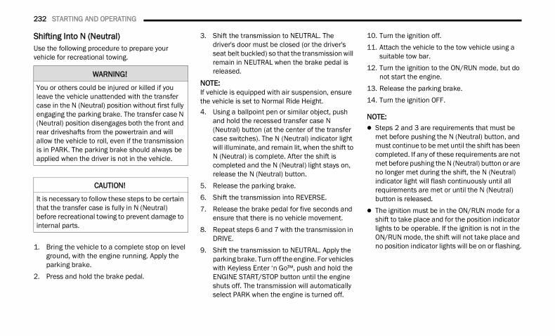
232 STARTING AND OPERATING
Shifting Into N (Neutral) Use the following procedure to prepare your vehicle for recreational towing.
1. Bring the vehicle to a complete stop on level ground, with the engine running. Apply the parking brake.
2. Press and hold the brake pedal.
3. Shift the transmission to NEUTRAL. The driver's door must be closed (or the driver's seat belt buckled) so that the transmission will remain in NEUTRAL when the brake pedal is released.
NOTE:If vehicle is equipped with air suspension, ensure the vehicle is set to Normal Ride Height.4. Using a ballpoint pen or similar object, push
and hold the recessed transfer case N (Neutral) button (at the center of the transfer case switches). The N (Neutral) indicator light will illuminate, and remain lit, when the shift to N (Neutral) is complete. After the shift is completed and the N (Neutral) light stays on, release the N (Neutral) button.
5. Release the parking brake.6. Shift the transmission into REVERSE.7. Release the brake pedal for five seconds and
ensure that there is no vehicle movement.8. Repeat steps 6 and 7 with the transmission in
DRIVE.9. Shift the transmission to NEUTRAL. Apply the
parking brake. Turn off the engine. For vehicles with Keyless Enter ‘n Go™, push and hold the ENGINE START/STOP button until the engine shuts off. The transmission will automatically select PARK when the engine is turned off.
10. Turn the ignition off.11. Attach the vehicle to the tow vehicle using a
suitable tow bar.12. Turn the ignition to the ON/RUN mode, but do
not start the engine.13. Release the parking brake.14. Turn the ignition OFF.
NOTE: Steps 2 and 3 are requirements that must be
met before pushing the N (Neutral) button, and must continue to be met until the shift has been completed. If any of these requirements are not met before pushing the N (Neutral) button or are no longer met during the shift, the N (Neutral) indicator light will flash continuously until all requirements are met or until the N (Neutral) button is released.
The ignition must be in the ON/RUN mode for a shift to take place and for the position indicator lights to be operable. If the ignition is not in the ON/RUN mode, the shift will not take place and no position indicator lights will be on or flashing.
WARNING!
You or others could be injured or killed if you leave the vehicle unattended with the transfer case in the N (Neutral) position without first fully engaging the parking brake. The transfer case N (Neutral) position disengages both the front and rear driveshafts from the powertrain and will allow the vehicle to roll, even if the transmission is in PARK. The parking brake should always be applied when the driver is not in the vehicle.
CAUTION!
It is necessary to follow these steps to be certain that the transfer case is fully in N (Neutral) before recreational towing to prevent damage to internal parts.
22_DT_OM_EN_USC_t.book Page 232
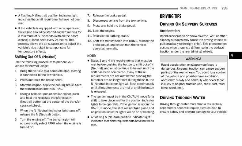
STARTING AND OPERATING 233
A flashing N (Neutral) position indicator light indicates that shift requirements have not been met.
If the vehicle is equipped with air suspension, the engine should be started and left running for a minimum of 60 seconds (with all the doors closed) at least once every 24 hours. This process allows the air suspension to adjust the vehicle’s ride height to compensate for temperature effects.
Shifting Out Of N (Neutral) Use the following procedure to prepare your vehicle for normal usage:1. Bring the vehicle to a complete stop, leaving
it connected to the tow vehicle.2. Press and hold the brake pedal.3. Start the engine. Apply the parking brake. Shift
the transmission into NEUTRAL.4. Using a ballpoint pen or similar object, push
and hold the recessed transfer case N (Neutral) button (at the center of the transfer case switches).
5. When the N (Neutral) indicator light turns off, release the N (Neutral) button.
6. Turn the engine off. The transmission will automatically select PARK when the engine is turned off.
7. Release the brake pedal.8. Disconnect vehicle from the tow vehicle.9. Press and hold the brake pedal.10. Start the engine.11. Release the parking brake.12. Shift the transmission into DRIVE, release the
brake pedal, and check that the vehicle operates normally.
NOTE: Steps 3 and 4 are requirements that must be
met before pushing the button to shift out of N (Neutral), and must continue to be met until the shift has been completed. If any of these requirements are not met before pushing the button or are no longer met during the shift, the N (Neutral) indicator light will flash continuously until all requirements are met or until the button is released.
The ignition must be in the ON/RUN mode for a shift to take place and for the position indicator lights to be operable. If the ignition is not in the ON/RUN mode, the shift will not take place and no position indicator lights will be on or flashing.
A flashing N (Neutral) position indicator light indicates that shift requirements have not been met.
DRIVING TIPSDRIVING ON SLIPPERY SURFACES AccelerationRapid acceleration on snow covered, wet, or other slippery surfaces may cause the driving wheels to pull erratically to the right or left. This phenomenon occurs when there is a difference in the surface traction under the rear (driving) wheels.
DRIVING THROUGH WATER Driving through water more than a few inches/centimeters deep will require extra caution to ensure safety and prevent damage to your vehicle.
WARNING!
Rapid acceleration on slippery surfaces is dangerous. Unequal traction can cause sudden pulling of the rear wheels. You could lose control of the vehicle and possibly have a collision. Accelerate slowly and carefully whenever there is likely to be poor traction (ice, snow, wet, mud, loose sand, etc.).
4
22_DT_OM_EN_USC_t.book Page 233
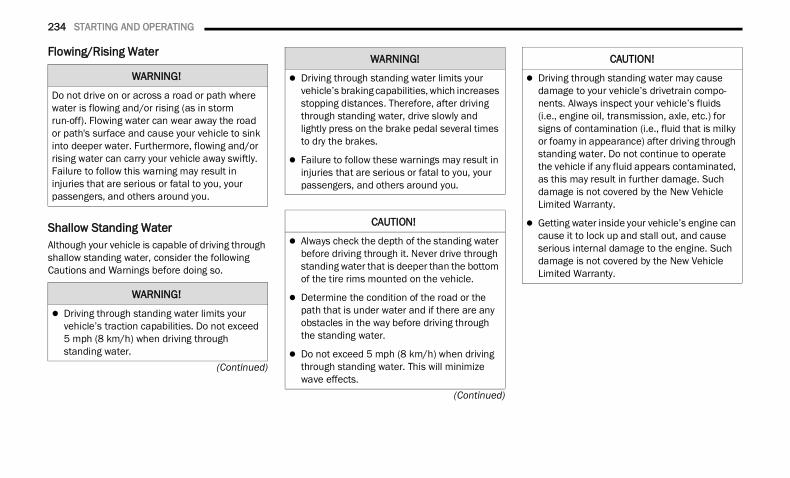
234 STARTING AND OPERATING
(Continued)
(Continued)
Flowing/Rising Water
Shallow Standing WaterAlthough your vehicle is capable of driving through shallow standing water, consider the following Cautions and Warnings before doing so.
WARNING!
Do not drive on or across a road or path where water is flowing and/or rising (as in storm run-off). Flowing water can wear away the road or path's surface and cause your vehicle to sink into deeper water. Furthermore, flowing and/or rising water can carry your vehicle away swiftly. Failure to follow this warning may result in injuries that are serious or fatal to you, your passengers, and others around you.
WARNING!
Driving through standing water limits your vehicle’s traction capabilities. Do not exceed 5 mph (8 km/h) when driving through standing water.
Driving through standing water limits your vehicle’s braking capabilities, which increases stopping distances. Therefore, after driving through standing water, drive slowly and lightly press on the brake pedal several times to dry the brakes.
Failure to follow these warnings may result in injuries that are serious or fatal to you, your passengers, and others around you.
CAUTION!
Always check the depth of the standing water before driving through it. Never drive through standing water that is deeper than the bottom of the tire rims mounted on the vehicle.
Determine the condition of the road or the path that is under water and if there are any obstacles in the way before driving through the standing water.
Do not exceed 5 mph (8 km/h) when driving through standing water. This will minimize wave effects.
WARNING!
Driving through standing water may cause damage to your vehicle’s drivetrain compo-nents. Always inspect your vehicle’s fluids (i.e., engine oil, transmission, axle, etc.) for signs of contamination (i.e., fluid that is milky or foamy in appearance) after driving through standing water. Do not continue to operate the vehicle if any fluid appears contaminated, as this may result in further damage. Such damage is not covered by the New Vehicle Limited Warranty.
Getting water inside your vehicle’s engine can cause it to lock up and stall out, and cause serious internal damage to the engine. Such damage is not covered by the New Vehicle Limited Warranty.
CAUTION!
22_DT_OM_EN_USC_t.book Page 234
STARTING AND OPERATING 235
OFF-ROAD DRIVING TIPS Care should be taken when attempting to climb steep hills or driving diagonally across a hill or slope. If natural obstacles force you to travel diagonally up or down a hill, choose a mild angle and keep as little side tilt as possible. Keep the vehicle moving and make turns slowly and cautiously.If you must back down a hill, back straight down using REVERSE gear. Never back down in NEUTRAL or diagonally across the hill.When driving over sand, mud, and other soft terrain, shift to low gear and drive steadily. Apply the accelerator slowly to avoid spinning the wheels.Do not reduce the tire pressures for this type of driving.
After Driving Off-RoadOff-road operation puts more stress on your vehicle than does most on-road driving. After going off-road, it is always a good idea to check for damage. That way you can get any problems taken care of right away and have your vehicle ready when you need it. Completely inspect the underbody of your
vehicle. Check tires, body structure, steering, suspension, and exhaust system for damage.
Inspect the radiator for mud and debris and clean as required.
Check threaded fasteners for looseness, partic-ularly on the chassis, drivetrain components, steering, and suspension. Retighten them, if required, and torque to the values specified in the Service Manual.
Check for accumulations of plants or brush. These things could be a fire hazard. They might hide damage to fuel lines, brake hoses, axle pinion seals, and propeller shafts.
After extended operation in mud, sand, water, or similar dirty conditions, have the radiator, fan, brake rotors, wheels, brake linings, and axle yokes inspected and cleaned as soon as possible.
If you experience unusual vibration after driving in mud, slush or similar conditions, check the wheels for impacted material. Impacted mate-rial can cause a wheel imbalance and freeing the wheels of it will correct the situation.
WARNING!
Abrasive material in any part of the brakes may cause excessive wear or unpredictable braking. You might not have full braking power when you need it to prevent a collision. If you have been operating your vehicle in dirty conditions, get your brakes checked and cleaned as necessary.
4
22_DT_OM_EN_USC_t.book Page 235
236
MULTIMEDIA
UCONNECT SYSTEMS For detailed information about your Uconnect3 With 5-inch Display Ú page 262.For detailed information about your Uconnect5/5 NAV With 8.4-inch Display system or your Uconnect 5 NAV With 12-inch Display system, refer to your Uconnect Owner’s Manual Supplement.
NOTE:Uconnect screen images are for illustration purposes only and may not reflect exact software for your vehicle.
CYBERSECURITY Your vehicle may be a connected vehicle and may be equipped with both wired and wireless networks. These networks allow your vehicle to send and receive information. This information allows systems and features in your vehicle to function properly.
Your vehicle may be equipped with certain security features to reduce the risk of unauthorized and unlawful access to vehicle systems and wireless communications. Vehicle software technology continues to evolve over time and FCA US LLC, working with its suppliers, evaluates and takes appropriate steps as needed.The risk of unauthorized and unlawful access to your vehicle systems may still exist, even if the most recent version of vehicle software (such as Uconnect software) is installed.
NOTE: To help further improve user experience,
features, stability, etc., and minimize the poten-tial risk of a security breach, vehicle owners should: Routinely check www.driveuconnect.com
(US Residents) or www.driveuconnect.ca (Canadian Residents) to learn about avail-able Uconnect software updates.
Only connect and use trusted media devices (e.g. personal mobile phones, USBs, CDs).WARNING!
ONLY insert trusted devices/components into your vehicle. Media of unknown origin could possibly contain malicious software, and if installed in your vehicle, it may increase the possibility for vehicle systems to be breached.
As always, if you experience unusual vehicle behavior, take your vehicle to your nearest authorized dealer immediately.
22_DT_OM_EN_USC_t.book Page 236
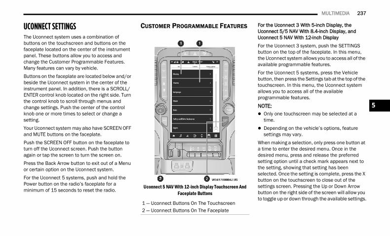
MULTIMEDIA 237
UCONNECT SETTINGS The Uconnect system uses a combination of buttons on the touchscreen and buttons on the faceplate located on the center of the instrument panel. These buttons allow you to access and change the Customer Programmable Features. Many features can vary by vehicle.Buttons on the faceplate are located below and/or beside the Uconnect system in the center of the instrument panel. In addition, there is a SCROLL/ENTER control knob located on the right side. Turn the control knob to scroll through menus and change settings. Push the center of the control knob one or more times to select or change a setting.Your Uconnect system may also have SCREEN OFF and MUTE buttons on the faceplate.Push the SCREEN OFF button on the faceplate to turn off the Uconnect screen. Push the button again or tap the screen to turn the screen on.Press the Back Arrow button to exit out of a Menu or certain option on the Uconnect system.For the Uconnect 5 systems, push and hold the Power button on the radio’s faceplate for a minimum of 15 seconds to reset the radio.
CUSTOMER PROGRAMMABLE FEATURES
Uconnect 5 NAV With 12-inch Display Touchscreen And Faceplate Buttons
For the Uconnect 3 With 5-inch Display, the Uconnect 5/5 NAV With 8.4-inch Display, and Uconnect 5 NAV With 12-inch DisplayFor the Uconnect 3 system, push the SETTINGS button on the top of the faceplate. In this menu, the Uconnect system allows you to access all of the available programmable features.For the Uconnect 5 systems, press the Vehicle button, then press the Settings tab at the top of the touchscreen. In this menu, the Uconnect system allows you to access all of the available programmable features.
NOTE: Only one touchscreen may be selected at a
time. Depending on the vehicle’s options, feature
settings may vary.When making a selection, only press one button at a time to enter the desired menu. Once in the desired menu, press and release the preferred setting option until a check mark appears next to the setting, showing that setting has been selected. Once the setting is complete, press the X button on the touchscreen to close out of the settings screen. Pressing the Up or Down Arrow button on the right side of the screen will allow you to toggle up or down through the available settings.
1 — Uconnect Buttons On The Touchscreen2 — Uconnect Buttons On The Faceplate
5
22_DT_OM_EN_USC_t.book Page 237
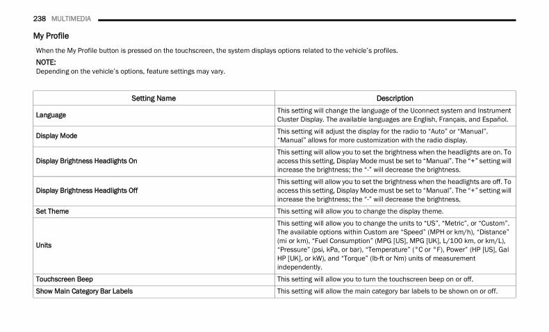
238 MULTIMEDIA
My Profile
When the My Profile button is pressed on the touchscreen, the system displays options related to the vehicle’s profiles.NOTE:Depending on the vehicle’s options, feature settings may vary.
Setting Name Description
Language This setting will change the language of the Uconnect system and Instrument Cluster Display. The available languages are English, Français, and Español.
Display Mode This setting will adjust the display for the radio to “Auto” or “Manual”. “Manual” allows for more customization with the radio display.
Display Brightness Headlights OnThis setting will allow you to set the brightness when the headlights are on. To access this setting, Display Mode must be set to “Manual”. The “+” setting will increase the brightness; the “-” will decrease the brightness.
Display Brightness Headlights OffThis setting will allow you to set the brightness when the headlights are off. To access this setting, Display Mode must be set to “Manual”. The “+” setting will increase the brightness; the “-” will decrease the brightness.
Set Theme This setting will allow you to change the display theme.
Units
This setting will allow you to change the units to “US”, “Metric”, or “Custom”. The available options within Custom are “Speed” (MPH or km/h), “Distance” (mi or km), “Fuel Consumption” (MPG [US], MPG [UK], L/100 km, or km/L), “Pressure” (psi, kPa, or bar), “Temperature” (°C or °F), Power” (HP [US], Gal HP [UK], or kW), and “Torque” (lb-ft or Nm) units of measurement independently.
Touchscreen Beep This setting will allow you to turn the touchscreen beep on or off.
Show Main Category Bar Labels This setting will allow the main category bar labels to be shown on or off.
22_DT_OM_EN_USC_t.book Page 238
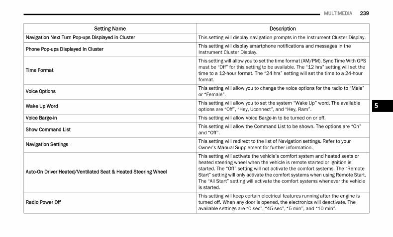
MULTIMEDIA 239
Navigation Next Turn Pop-ups Displayed in Cluster This setting will display navigation prompts in the Instrument Cluster Display.
Phone Pop-ups Displayed In Cluster This setting will display smartphone notifications and messages in the Instrument Cluster Display.
Time Format
This setting will allow you to set the time format (AM/PM). Sync Time With GPS must be “Off” for this setting to be available. The “12 hrs” setting will set the time to a 12-hour format. The “24 hrs” setting will set the time to a 24-hour format.
Voice Options This setting will allow you to change the voice options for the radio to “Male” or “Female”.
Wake Up Word This setting will allow you to set the system “Wake Up” word. The available options are “Off”, “Hey, Uconnect”, and “Hey, Ram”.
Voice Barge-in This setting will allow Voice Barge-in to be turned on or off.
Show Command List This setting will allow the Command List to be shown. The options are “On” and “Off”.
Navigation Settings This setting will redirect to the list of Navigation settings. Refer to your Owner’s Manual Supplement for further information.
Auto-On Driver Heated/Ventilated Seat & Heated Steering Wheel
This setting will activate the vehicle’s comfort system and heated seats or heated steering wheel when the vehicle is remote started or ignition is started. The “Off” setting will not activate the comfort systems. The “Remote Start” setting will only activate the comfort systems when using Remote Start. The “All Start” setting will activate the comfort systems whenever the vehicle is started.
Radio Power OffThis setting will keep certain electrical features running after the engine is turned off. When any door is opened, the electronics will deactivate. The available settings are “0 sec”, “45 sec”, “5 min”, and “10 min”.
Setting Name Description
5
22_DT_OM_EN_USC_t.book Page 239
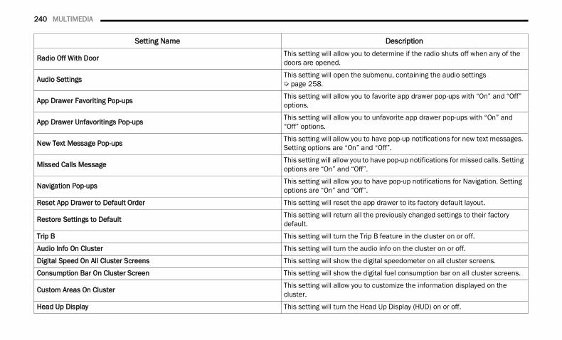
240 MULTIMEDIA
Radio Off With Door This setting will allow you to determine if the radio shuts off when any of the doors are opened.
Audio Settings This setting will open the submenu, containing the audio settings Ú page 258.
App Drawer Favoriting Pop-ups This setting will allow you to favorite app drawer pop-ups with “On” and “Off” options.
App Drawer Unfavoritings Pop-ups This setting will allow you to unfavorite app drawer pop-ups with “On” and “Off” options.
New Text Message Pop-ups This setting will allow you to have pop-up notifications for new text messages. Setting options are “On” and “Off”.
Missed Calls Message This setting will allow you to have pop-up notifications for missed calls. Setting options are “On” and “Off”.
Navigation Pop-ups This setting will allow you to have pop-up notifications for Navigation. Setting options are “On” and “Off”.
Reset App Drawer to Default Order This setting will reset the app drawer to its factory default layout.
Restore Settings to Default This setting will return all the previously changed settings to their factory default.
Trip B This setting will turn the Trip B feature in the cluster on or off.
Audio Info On Cluster This setting will turn the audio info on the cluster on or off.
Digital Speed On All Cluster Screens This setting will show the digital speedometer on all cluster screens.
Consumption Bar On Cluster Screen This setting will show the digital fuel consumption bar on all cluster screens.
Custom Areas On Cluster This setting will allow you to customize the information displayed on the cluster.
Head Up Display This setting will turn the Head Up Display (HUD) on or off.
Setting Name Description
22_DT_OM_EN_USC_t.book Page 240
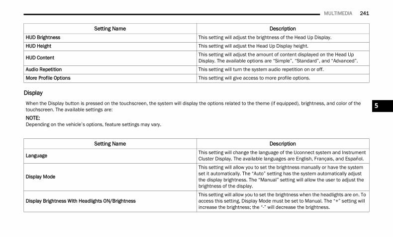
MULTIMEDIA 241
Display
HUD Brightness This setting will adjust the brightness of the Head Up Display.
HUD Height This setting will adjust the Head Up Display height.
HUD Content This setting will adjust the amount of content displayed on the Head Up Display. The available options are “Simple”, “Standard”, and “Advanced”.
Audio Repetition This setting will turn the system audio repetition on or off.
More Profile Options This setting will give access to more profile options.
Setting Name Description
When the Display button is pressed on the touchscreen, the system will display the options related to the theme (if equipped), brightness, and color of the touchscreen. The available settings are:NOTE:Depending on the vehicle’s options, feature settings may vary.
Setting Name Description
Language This setting will change the language of the Uconnect system and Instrument Cluster Display. The available languages are English, Français, and Español.
Display Mode
This setting will allow you to set the brightness manually or have the system set it automatically. The “Auto” setting has the system automatically adjust the display brightness. The “Manual” setting will allow the user to adjust the brightness of the display.
Display Brightness With Headlights ON/BrightnessThis setting will allow you to set the brightness when the headlights are on. To access this setting, Display Mode must be set to Manual. The “+” setting will increase the brightness; the “-” will decrease the brightness.
5
22_DT_OM_EN_USC_t.book Page 241
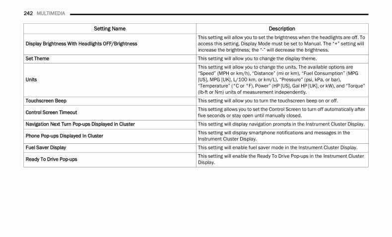
242 MULTIMEDIA
Display Brightness With Headlights OFF/BrightnessThis setting will allow you to set the brightness when the headlights are off. To access this setting, Display Mode must be set to Manual. The “+” setting will increase the brightness; the “-” will decrease the brightness.
Set Theme This setting will allow you to change the display theme.
Units
This setting will allow you to change the units. The available options are “Speed” (MPH or km/h), “Distance” (mi or km), “Fuel Consumption” (MPG [US], MPG [UK], L/100 km, or km/L), “Pressure” (psi, kPa, or bar), “Temperature” (°C or °F), Power” (HP [US], Gal HP [UK], or kW), and “Torque” (lb-ft or Nm) units of measurement independently.
Touchscreen Beep This setting will allow you to turn the touchscreen beep on or off.
Control Screen Timeout This setting allows you to set the Control Screen to turn off automatically after five seconds or stay open until manually closed.
Navigation Next Turn Pop-ups Displayed in Cluster This setting will display navigation prompts in the Instrument Cluster Display.
Phone Pop-ups Displayed In Cluster This setting will display smartphone notifications and messages in the Instrument Cluster Display.
Fuel Saver Display This setting will enable fuel saver mode in the Instrument Cluster Display.
Ready To Drive Pop-ups This setting will enable the Ready To Drive Pop-ups in the Instrument Cluster Display.
Setting Name Description
22_DT_OM_EN_USC_t.book Page 242
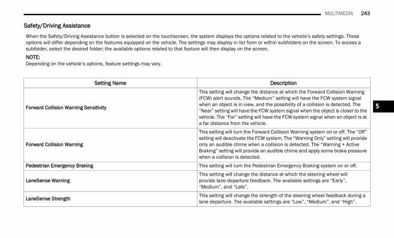
MULTIMEDIA 243
Safety/Driving Assistance
When the Safety/Driving Assistance button is selected on the touchscreen, the system displays the options related to the vehicle’s safety settings. These options will differ depending on the features equipped on the vehicle. The settings may display in list form or within subfolders on the screen. To access a subfolder, select the desired folder; the available options related to that feature will then display on the screen.NOTE:Depending on the vehicle’s options, feature settings may vary.
Setting Name Description
Forward Collision Warning Sensitivity
This setting will change the distance at which the Forward Collision Warning (FCW) alert sounds. The “Medium” setting will have the FCW system signal when an object is in view, and the possibility of a collision is detected. The “Near” setting will have the FCW system signal when the object is closer to the vehicle. The “Far” setting will have the FCW system signal when an object is at a far distance from the vehicle.
Forward Collision Warning
This setting will turn the Forward Collision Warning system on or off. The “Off” setting will deactivate the FCW system. The “Warning Only” setting will provide only an audible chime when a collision is detected. The “Warning + Active Braking” setting will provide an audible chime and apply some brake pressure when a collision is detected.
Pedestrian Emergency Braking This setting will turn the Pedestrian Emergency Braking system on or off.
LaneSense WarningThis setting will change the distance at which the steering wheel will provide lane departure feedback. The available settings are “Early”, “Medium”, and “Late”.
LaneSense Strength This setting will change the strength of the steering wheel feedback during a lane departure. The available settings are “Low”, “Medium”, and “High”.
5
22_DT_OM_EN_USC_t.book Page 243
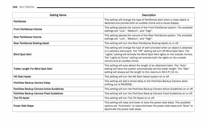
244 MULTIMEDIA
ParkSense This setting will change the type of ParkSense alert when a close object is detected and provide both an audible chime and a visual display.
Front ParkSense Volume This setting adjusts the volume of the Front ParkSense system. The available settings are “Low”, “Medium”, and “High”.
Rear ParkSense Volume This setting adjusts the volume of the Rear ParkSense system. The available settings are “Low”, “Medium”, and “High”.
Rear ParkSense Braking Assist This setting will turn the Rear ParkSense Braking Assist on or off.
Blind Spot Alert
This setting will change the type of alert provided when an object is detected in a vehicle’s blind spot. The “Off” setting will turn off Blind Spot Alert. The “Lights” setting will activate the Blind Spot Alert lights on the outside mirrors. The “Lights & Chime” setting will activate both the lights on the outside mirrors and an audible chime.
Trailer Length For Blind Spot AlertThis setting will auto detect the length of an attached trailer. The “Auto” setting will have the system automatically set the trailer length. The “Max” setting will always set the length to the maximum 39.5 ft (12 m).
Hill Start Assist This setting will turn the Hill Start Assist system on or off.
ParkView Backup Camera Delay This setting will add a timed delay to the ParkView Backup Camera when shifting out of REVERSE.
ParkView Backup Camera Active Guidelines This setting will turn the ParkView Backup Camera Active Guidelines on or off.
ParkView Backup Camera Fixed Guidelines This setting will turn the ParkView Backup Camera Fixed Guidelines on or off.
Tire Fill Assist This setting will turn Tire Fill Assist on or off.
Power Side StepsThis setting will raise and lower or stow the power side steps. The available options are “Automatic” to raise and lower the power side steps and “Stow” to deactivate the power side steps.
Setting Name Description
22_DT_OM_EN_USC_t.book Page 244
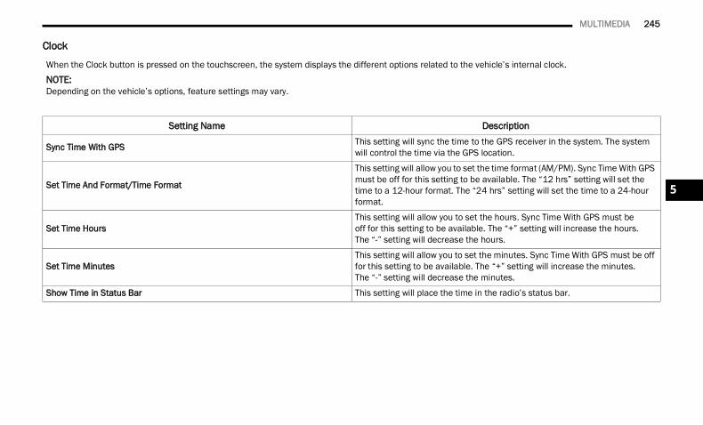
MULTIMEDIA 245
Clock
When the Clock button is pressed on the touchscreen, the system displays the different options related to the vehicle’s internal clock.NOTE:Depending on the vehicle’s options, feature settings may vary.
Setting Name Description
Sync Time With GPS This setting will sync the time to the GPS receiver in the system. The system will control the time via the GPS location.
Set Time And Format/Time Format
This setting will allow you to set the time format (AM/PM). Sync Time With GPS must be off for this setting to be available. The “12 hrs” setting will set the time to a 12-hour format. The “24 hrs” setting will set the time to a 24-hour format.
Set Time HoursThis setting will allow you to set the hours. Sync Time With GPS must be off for this setting to be available. The “+” setting will increase the hours. The “-” setting will decrease the hours.
Set Time MinutesThis setting will allow you to set the minutes. Sync Time With GPS must be off for this setting to be available. The “+” setting will increase the minutes. The “-” setting will decrease the minutes.
Show Time in Status Bar This setting will place the time in the radio’s status bar.
5
22_DT_OM_EN_USC_t.book Page 245
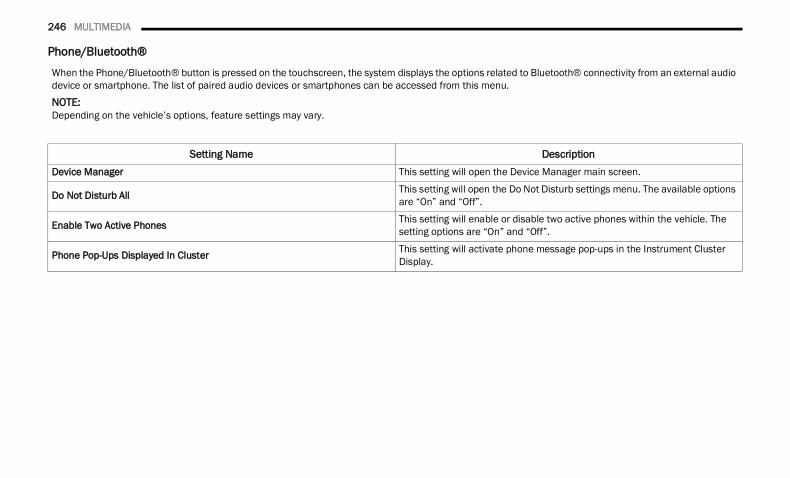
246 MULTIMEDIA
Phone/Bluetooth®
When the Phone/Bluetooth® button is pressed on the touchscreen, the system displays the options related to Bluetooth® connectivity from an external audio device or smartphone. The list of paired audio devices or smartphones can be accessed from this menu.NOTE:Depending on the vehicle’s options, feature settings may vary.
Setting Name DescriptionDevice Manager This setting will open the Device Manager main screen.
Do Not Disturb All This setting will open the Do Not Disturb settings menu. The available options are “On” and “Off”.
Enable Two Active Phones This setting will enable or disable two active phones within the vehicle. The setting options are “On” and “Off”.
Phone Pop-Ups Displayed In Cluster This setting will activate phone message pop-ups in the Instrument Cluster Display.
22_DT_OM_EN_USC_t.book Page 246
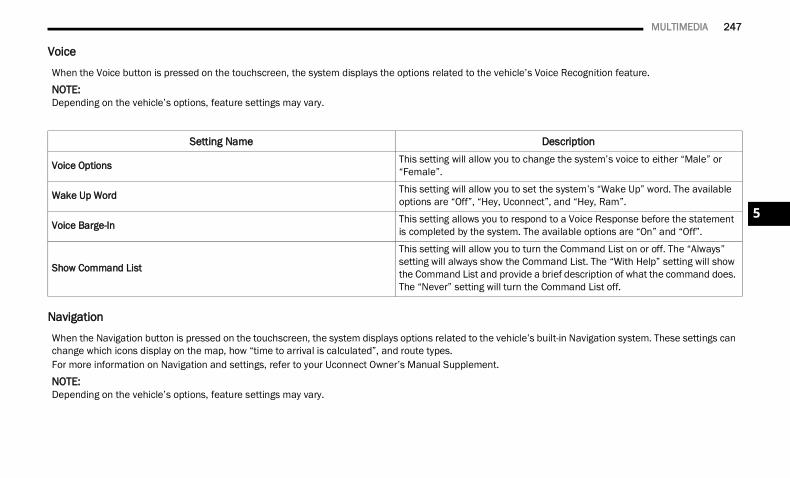
MULTIMEDIA 247
Voice
Navigation
When the Voice button is pressed on the touchscreen, the system displays the options related to the vehicle’s Voice Recognition feature.NOTE:Depending on the vehicle’s options, feature settings may vary.
Setting Name Description
Voice Options This setting will allow you to change the system’s voice to either “Male” or “Female”.
Wake Up Word This setting will allow you to set the system’s “Wake Up” word. The available options are “Off”, “Hey, Uconnect”, and “Hey, Ram”.
Voice Barge-In This setting allows you to respond to a Voice Response before the statement is completed by the system. The available options are “On” and “Off”.
Show Command List
This setting will allow you to turn the Command List on or off. The “Always” setting will always show the Command List. The “With Help” setting will show the Command List and provide a brief description of what the command does. The “Never” setting will turn the Command List off.
When the Navigation button is pressed on the touchscreen, the system displays options related to the vehicle’s built-in Navigation system. These settings can change which icons display on the map, how “time to arrival is calculated”, and route types.For more information on Navigation and settings, refer to your Uconnect Owner’s Manual Supplement.NOTE:Depending on the vehicle’s options, feature settings may vary.
5
22_DT_OM_EN_USC_t.book Page 247
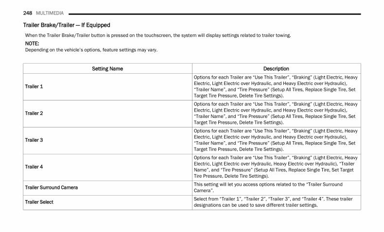
248 MULTIMEDIA
Trailer Brake/Trailer — If Equipped
When the Trailer Brake/Trailer button is pressed on the touchscreen, the system will display settings related to trailer towing.NOTE:Depending on the vehicle’s options, feature settings may vary.
Setting Name Description
Trailer 1
Options for each Trailer are “Use This Trailer”, “Braking” (Light Electric, Heavy Electric, Light Electric over Hydraulic, and Heavy Electric over Hydraulic), “Trailer Name”, and “Tire Pressure” (Setup All Tires, Replace Single Tire, Set Target Tire Pressure, Delete Tire Settings).
Trailer 2
Options for each Trailer are “Use This Trailer”, “Braking” (Light Electric, Heavy Electric, Light Electric over Hydraulic, and Heavy Electric over Hydraulic), “Trailer Name”, and “Tire Pressure” (Setup All Tires, Replace Single Tire, Set Target Tire Pressure, Delete Tire Settings).
Trailer 3
Options for each Trailer are “Use This Trailer”, “Braking” (Light Electric, Heavy Electric, Light Electric over Hydraulic, and Heavy Electric over Hydraulic), “Trailer Name”, and “Tire Pressure” (Setup All Tires, Replace Single Tire, Set Target Tire Pressure, Delete Tire Settings).
Trailer 4
Options for each Trailer are “Use This Trailer”, “Braking” (Light Electric, Heavy Electric, Light Electric over Hydraulic, Heavy Electric over Hydraulic), “Trailer Name”, and “Tire Pressure” (Setup All Tires, Replace Single Tire, Set Target Tire Pressure, Delete Tire Settings).
Trailer Surround Camera This setting will let you access options related to the “Trailer Surround Camera”.
Trailer Select Select from “Trailer 1”, “Trailer 2”, “Trailer 3”, and “Trailer 4”. These trailer designations can be used to save different trailer settings.
22_DT_OM_EN_USC_t.book Page 248
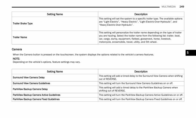
MULTIMEDIA 249
Camera
Trailer Brake Type
This setting will set the system to a specific trailer type. The available options are “Light Electric”, “Heavy Electric”, “Light Electric-Over-Hydraulic”, and “Heavy Electric-Over-Hydraulic”.
Trailer Name
This setting will personalize the trailer name depending on the type of trailer you are hauling. Select the trailer name from the following list: trailer, boat, car, cargo, dump, equipment, flatbed, gooseneck, horse, livestock, motorcycle, snowmobile, travel, utility, and 5th wheel.
Setting Name Description
When the Camera button is pressed on the touchscreen, the system displays the options related to the vehicle’s camera features.NOTE:Depending on the vehicle’s options, feature settings may vary.
Setting Name Description
Surround View Camera Delay This setting will add a timed delay to the Surround View Camera when shifting out of REVERSE.
Surround View Camera Guidelines This setting will turn the Surround View Camera Guidelines on or off.
ParkView Backup Camera Delay This setting will add a timed delay to the ParkView Backup Camera when shifting out of REVERSE.
ParkView Backup Camera Active Guidelines This setting will turn the ParkView Backup Camera Active Guidelines on or off.
ParkView Backup Camera Fixed Guidelines This setting will turn the ParkView Backup Camera Fixed Guidelines on or off.
5
22_DT_OM_EN_USC_t.book Page 249
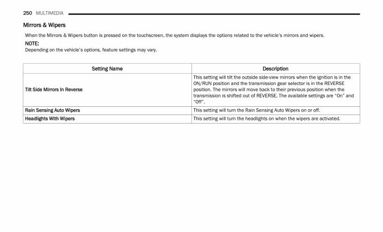
250 MULTIMEDIA
Mirrors & Wipers
When the Mirrors & Wipers button is pressed on the touchscreen, the system displays the options related to the vehicle’s mirrors and wipers.NOTE:Depending on the vehicle’s options, feature settings may vary.
Setting Name Description
Tilt Side Mirrors In Reverse
This setting will tilt the outside side-view mirrors when the ignition is in the ON/RUN position and the transmission gear selector is in the REVERSE position. The mirrors will move back to their previous position when the transmission is shifted out of REVERSE. The available settings are “On” and “Off”.
Rain Sensing Auto Wipers This setting will turn the Rain Sensing Auto Wipers on or off.
Headlights With Wipers This setting will turn the headlights on when the wipers are activated.
22_DT_OM_EN_USC_t.book Page 250
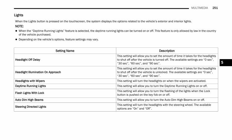
MULTIMEDIA 251
Lights
When the Lights button is pressed on the touchscreen, the system displays the options related to the vehicle’s exterior and interior lights.NOTE: When the “Daytime Running Lights” feature is selected, the daytime running lights can be turned on or off. This feature is only allowed by law in the country
of the vehicle purchased. Depending on the vehicle’s options, feature settings may vary.
Setting Name Description
Headlight Off DelayThis setting will allow you to set the amount of time it takes for the headlights to shut off after the vehicle is turned off. The available settings are “0 sec”, “30 sec”, “60 sec”, and “90 sec”.
Headlight Illumination On ApproachThis setting will allow you to set the amount of time it takes for the headlights to shut off after the vehicle is unlocked. The available settings are “0 sec”, “30 sec”, “60 sec”, and “90 sec”.
Headlights with Wipers This setting will turn the headlights on when the wipers are activated.
Daytime Running Lights This setting will allow you to turn the Daytime Running Lights on or off.
Flash Lights With Lock This setting will allow you to turn the flashing of the lights when the Lock button is pushed on the key fob on or off.
Auto Dim High Beams This setting will allow you to turn the Auto Dim High Beams on or off.
Steering Directed Lights This setting will turn the headlights with the steering wheel. The available options are “On” and “Off”.
5
22_DT_OM_EN_USC_t.book Page 251
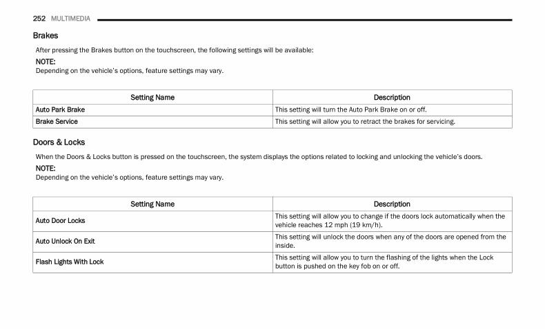
252 MULTIMEDIA
Brakes
Doors & Locks
After pressing the Brakes button on the touchscreen, the following settings will be available:NOTE:Depending on the vehicle’s options, feature settings may vary.
Setting Name DescriptionAuto Park Brake This setting will turn the Auto Park Brake on or off.
Brake Service This setting will allow you to retract the brakes for servicing.
When the Doors & Locks button is pressed on the touchscreen, the system displays the options related to locking and unlocking the vehicle’s doors.NOTE:Depending on the vehicle’s options, feature settings may vary.
Setting Name Description
Auto Door Locks This setting will allow you to change if the doors lock automatically when the vehicle reaches 12 mph (19 km/h).
Auto Unlock On Exit This setting will unlock the doors when any of the doors are opened from the inside.
Flash Lights With Lock This setting will allow you to turn the flashing of the lights when the Lock button is pushed on the key fob on or off.
22_DT_OM_EN_USC_t.book Page 252
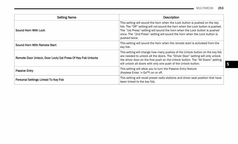
MULTIMEDIA 253
Sound Horn With Lock
This setting will sound the horn when the Lock button is pushed on the key fob. The “Off” setting will not sound the horn when the Lock button is pushed. The “1st Press” setting will sound the horn when the Lock button is pushed once. The “2nd Press” setting will sound the horn when the Lock button is pushed twice.
Sound Horn With Remote Start This setting will sound the horn when the remote start is activated from the key fob.
Remote Door Unlock, Door Lock/1st Press Of Key Fob Unlocks
This setting will change how many pushes of the Unlock button on the key fob are needed to unlock all the doors. The “Driver Door” setting will only unlock the driver door on the first push on the Unlock button. The “All Doors” setting will unlock all doors with only one push of the Unlock button.
Passive Entry This setting will allow you to turn the Passive Entry feature(Keyless Enter ‘n Go™) on or off.
Personal Settings Linked To Key Fob This setting will recall preset radio stations and driver seat position that have been linked to the key fob.
Setting Name Description
5
22_DT_OM_EN_USC_t.book Page 253
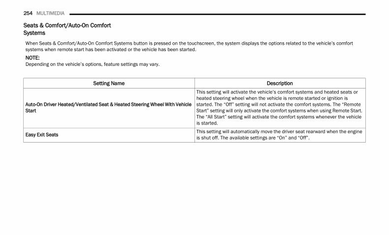
254 MULTIMEDIA
Seats & Comfort/Auto-On Comfort Systems
When Seats & Comfort/Auto-On Comfort Systems button is pressed on the touchscreen, the system displays the options related to the vehicle’s comfort systems when remote start has been activated or the vehicle has been started.NOTE:Depending on the vehicle’s options, feature settings may vary.
Setting Name Description
Auto-On Driver Heated/Ventilated Seat & Heated Steering Wheel With Vehicle Start
This setting will activate the vehicle’s comfort systems and heated seats or heated steering wheel when the vehicle is remote started or ignition is started. The “Off” setting will not activate the comfort systems. The “Remote Start” setting will only activate the comfort systems when using Remote Start. The “All Start” setting will activate the comfort systems whenever the vehicle is started.
Easy Exit Seats This setting will automatically move the driver seat rearward when the engine is shut off. The available settings are “On” and “Off”.
22_DT_OM_EN_USC_t.book Page 254
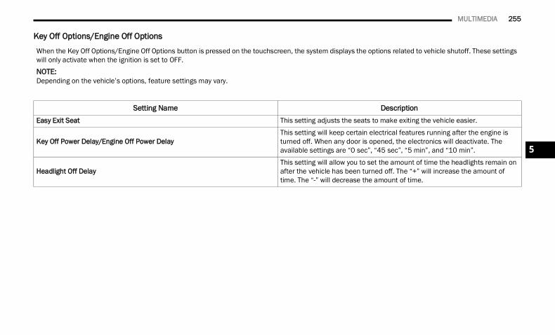
MULTIMEDIA 255
Key Off Options/Engine Off Options
When the Key Off Options/Engine Off Options button is pressed on the touchscreen, the system displays the options related to vehicle shutoff. These settings will only activate when the ignition is set to OFF.NOTE:Depending on the vehicle’s options, feature settings may vary.
Setting Name DescriptionEasy Exit Seat This setting adjusts the seats to make exiting the vehicle easier.
Key Off Power Delay/Engine Off Power DelayThis setting will keep certain electrical features running after the engine is turned off. When any door is opened, the electronics will deactivate. The available settings are “0 sec”, “45 sec”, “5 min”, and “10 min”.
Headlight Off DelayThis setting will allow you to set the amount of time the headlights remain on after the vehicle has been turned off. The “+” will increase the amount of time. The “-” will decrease the amount of time.
5
22_DT_OM_EN_USC_t.book Page 255
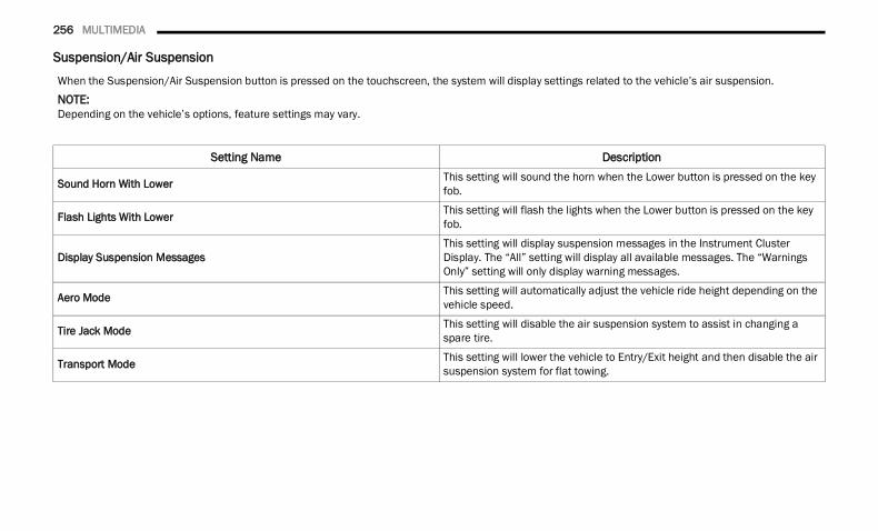
256 MULTIMEDIA
Suspension/Air Suspension
When the Suspension/Air Suspension button is pressed on the touchscreen, the system will display settings related to the vehicle’s air suspension.NOTE:Depending on the vehicle’s options, feature settings may vary.
Setting Name Description
Sound Horn With Lower This setting will sound the horn when the Lower button is pressed on the key fob.
Flash Lights With Lower This setting will flash the lights when the Lower button is pressed on the key fob.
Display Suspension MessagesThis setting will display suspension messages in the Instrument Cluster Display. The “All” setting will display all available messages. The “Warnings Only” setting will only display warning messages.
Aero Mode This setting will automatically adjust the vehicle ride height depending on the vehicle speed.
Tire Jack Mode This setting will disable the air suspension system to assist in changing a spare tire.
Transport Mode This setting will lower the vehicle to Entry/Exit height and then disable the air suspension system for flat towing.
22_DT_OM_EN_USC_t.book Page 256
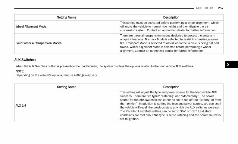
MULTIMEDIA 257
AUX Switches
Wheel Alignment ModeThis setting must be activated before performing a wheel alignment, which will move the vehicle to normal ride height and then disable the air suspension system. Contact an authorized dealer for further information.
Four Corner Air Suspension Modes
There are three air suspension modes designed to protect the system in unique situations. Tire Jack Mode is selected to assist in changing a spare tire. Transport Mode is selected to assist when the vehicle is being flat bed towed. Wheel Alignment Mode is selected before performing a wheel alignment. Contact an authorized dealer for further information.
Setting Name Description
When the AUX Switches button is pressed on the touchscreen, the system displays the options related to the four vehicle AUX switches.NOTE:Depending on the vehicle’s options, feature settings may vary.
Setting Name Description
AUX 1-4
This setting will adjust the type and power source for the four vehicle AUX switches. There are two types: “Latching” and “Momentary”. The power source for the AUX switches can either be set to run off the “Battery” or from the “Ignition”. In addition to setting the type and power source, you can set if the vehicle will recall the previous state at which the AUX switches were set. The Recalled Last State setting can be set to “On” or “Off”. Last state conditions are met only if the type is set to Latching and the power source is set to Ignition.
5
22_DT_OM_EN_USC_t.book Page 257
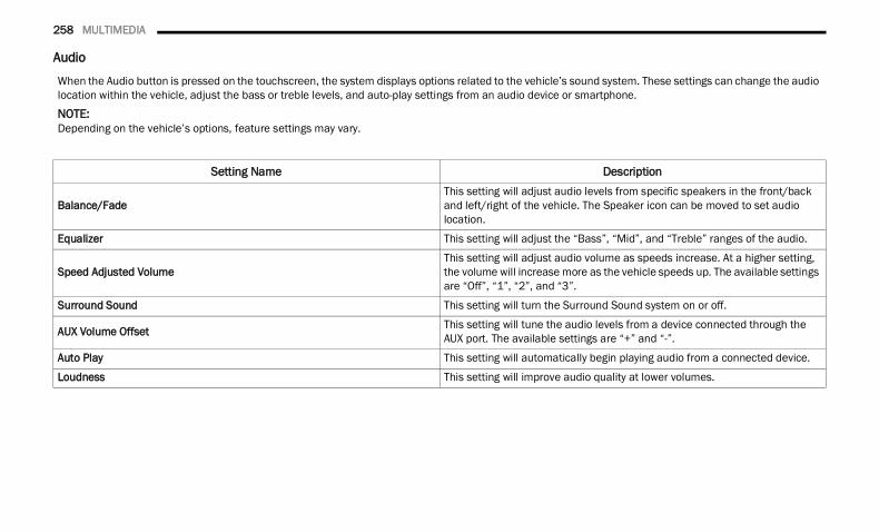
258 MULTIMEDIA
Audio
When the Audio button is pressed on the touchscreen, the system displays options related to the vehicle’s sound system. These settings can change the audio location within the vehicle, adjust the bass or treble levels, and auto-play settings from an audio device or smartphone.NOTE:Depending on the vehicle’s options, feature settings may vary.
Setting Name Description
Balance/FadeThis setting will adjust audio levels from specific speakers in the front/back and left/right of the vehicle. The Speaker icon can be moved to set audio location.
Equalizer This setting will adjust the “Bass”, “Mid”, and “Treble” ranges of the audio.
Speed Adjusted VolumeThis setting will adjust audio volume as speeds increase. At a higher setting, the volume will increase more as the vehicle speeds up. The available settings are “Off”, “1”, “2”, and “3”.
Surround Sound This setting will turn the Surround Sound system on or off.
AUX Volume Offset This setting will tune the audio levels from a device connected through the AUX port. The available settings are “+” and “-”.
Auto Play This setting will automatically begin playing audio from a connected device.
Loudness This setting will improve audio quality at lower volumes.
22_DT_OM_EN_USC_t.book Page 258
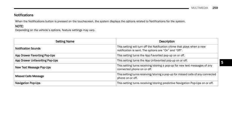
MULTIMEDIA 259
Notifications
When the Notifications button is pressed on the touchscreen, the system displays the options related to Notifications for the system.NOTE:Depending on the vehicle’s options, feature settings may vary.
Setting Name Description
Notification Sounds This setting will turn off the Notification chime that plays when a new notification is sent. The options are “On” and “Off”.
App Drawer Favoriting Pop-Ups This setting turns the App Favorited pop-up on or off.
App Drawer Unfavoriting Pop-Ups This setting turns the App Unfavorited pop-up on or off.
New Text Message Pop-Ups This setting turns receiving/storing a pop-up for new text messages of any connected phone on or off.
Missed Calls Message This setting turns receiving/storing a pop-up for missed calls of any connected phone on or off.
Navigation Pop-Ups This setting turns receiving/storing predictive Navigation Pop-Ups on or off.
5
22_DT_OM_EN_USC_t.book Page 259
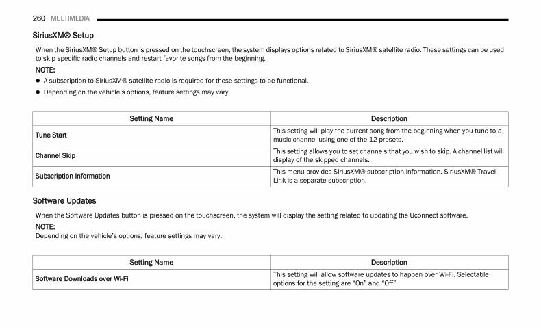
260 MULTIMEDIA
SiriusXM® Setup
Software Updates
When the SiriusXM® Setup button is pressed on the touchscreen, the system displays options related to SiriusXM® satellite radio. These settings can be used to skip specific radio channels and restart favorite songs from the beginning.NOTE: A subscription to SiriusXM® satellite radio is required for these settings to be functional. Depending on the vehicle’s options, feature settings may vary.
Setting Name Description
Tune Start This setting will play the current song from the beginning when you tune to a music channel using one of the 12 presets.
Channel Skip This setting allows you to set channels that you wish to skip. A channel list will display of the skipped channels.
Subscription Information This menu provides SiriusXM® subscription information. SiriusXM® Travel Link is a separate subscription.
When the Software Updates button is pressed on the touchscreen, the system will display the setting related to updating the Uconnect software.NOTE:Depending on the vehicle’s options, feature settings may vary.
Setting Name Description
Software Downloads over Wi-Fi This setting will allow software updates to happen over Wi-Fi. Selectable options for the setting are “On” and “Off”.
22_DT_OM_EN_USC_t.book Page 260
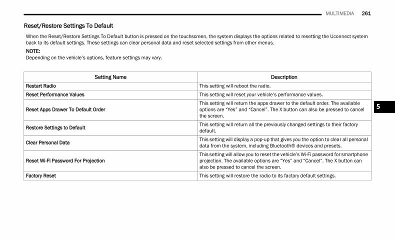
MULTIMEDIA 261
Reset/Restore Settings To Default
When the Reset/Restore Settings To Default button is pressed on the touchscreen, the system displays the options related to resetting the Uconnect system back to its default settings. These settings can clear personal data and reset selected settings from other menus.NOTE:Depending on the vehicle’s options, feature settings may vary.
Setting Name DescriptionRestart Radio This setting will reboot the radio.
Reset Performance Values This setting will reset your vehicle’s performance values.
Reset Apps Drawer To Default OrderThis setting will return the apps drawer to the default order. The available options are “Yes” and “Cancel”. The X button can also be pressed to cancel the screen.
Restore Settings to Default This setting will return all the previously changed settings to their factory default.
Clear Personal Data This setting will display a pop-up that gives you the option to clear all personal data from the system, including Bluetooth® devices and presets.
Reset Wi-Fi Password For ProjectionThis setting will allow you to reset the vehicle’s Wi-Fi password for smartphone projection. The available options are “Yes” and “Cancel”. The X button can also be pressed to cancel the screen.
Factory Reset This setting will restore the radio to its factory default settings.
5
22_DT_OM_EN_USC_t.book Page 261
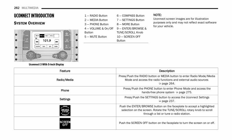
262 MULTIMEDIA
UCONNECT INTRODUCTIONSYSTEM OVERVIEW
Uconnect 3 With 5-inch Display
NOTE:Uconnect screen images are for illustration purposes only and may not reflect exact software for your vehicle.
1 — RADIO Button 6 — COMPASS Button2 — MEDIA Button 7 — SETTINGS Button3 — PHONE Button 8 — MORE Button4 — VOLUME & On/Off Button
9 — ENTER/BROWSE & TUNE/SCROLL Knob
5 — MUTE Button 10 — SCREEN OFFButton
Feature Description
Radio/MediaPress/Push the RADIO button or MEDIA button to enter Radio Mode/Media
Mode and access the radio functions and external audio sources Ú page 264.
Phone Press/Push the PHONE button to enter Phone Mode and access the hands-free phone system Ú page 275.
Settings Press/Push the SETTINGS button to access the Uconnect Settings Ú page 237.
Push the ENTER/BROWSE button on the faceplate to accept a highlighted selection on the screen. Rotate the TUNE/SCROLL rotary knob to scroll
through a list or tune a radio station.
Push the SCREEN OFF button on the faceplate to turn the screen on or off.
22_DT_OM_EN_USC_t.book Page 262
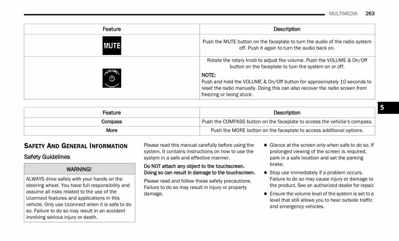
MULTIMEDIA 263
SAFETY AND GENERAL INFORMATION Safety Guidelines
Please read this manual carefully before using the system. It contains instructions on how to use the system in a safe and effective manner.Do NOT attach any object to the touchscreen. Doing so can result in damage to the touchscreen.Please read and follow these safety precautions. Failure to do so may result in injury or property damage.
Glance at the screen only when safe to do so. If prolonged viewing of the screen is required, park in a safe location and set the parking brake.
Stop use immediately if a problem occurs. Failure to do so may cause injury or damage to the product. See an authorized dealer for repair.
Ensure the volume level of the system is set to a level that still allows you to hear outside traffic and emergency vehicles.
Push the MUTE button on the faceplate to turn the audio of the radio system off. Push it again to turn the audio back on.
Rotate the rotary knob to adjust the volume. Push the VOLUME & On/Off button on the faceplate to turn the system on or off.
NOTE:Push and hold the VOLUME & On/Off button for approximately 10 seconds to reset the radio manually. Doing this can also recover the radio screen from freezing or being stuck.
Feature DescriptionCompass Push the COMPASS button on the faceplate to access the vehicle’s compass.
More Push the MORE button on the faceplate to access additional options.
Feature Description
WARNING!
ALWAYS drive safely with your hands on the steering wheel. You have full responsibility and assume all risks related to the use of the Uconnect features and applications in this vehicle. Only use Uconnect when it is safe to do so. Failure to do so may result in an accident involving serious injury or death.
5
22_DT_OM_EN_USC_t.book Page 263
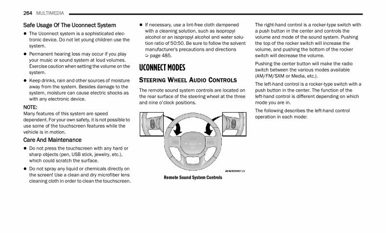
264 MULTIMEDIA
Safe Usage Of The Uconnect System The Uconnect system is a sophisticated elec-
tronic device. Do not let young children use the system.
Permanent hearing loss may occur if you play your music or sound system at loud volumes. Exercise caution when setting the volume on the system.
Keep drinks, rain and other sources of moisture away from the system. Besides damage to the system, moisture can cause electric shocks as with any electronic device.
NOTE:Many features of this system are speed dependent. For your own safety, it is not possible to use some of the touchscreen features while the vehicle is in motion.Care And Maintenance Do not press the touchscreen with any hard or
sharp objects (pen, USB stick, jewelry, etc.), which could scratch the surface.
Do not spray any liquid or chemicals directly on the screen! Use a clean and dry microfiber lens cleaning cloth in order to clean the touchscreen.
If necessary, use a lint-free cloth dampened with a cleaning solution, such as isopropyl alcohol or an isopropyl alcohol and water solu-tion ratio of 50:50. Be sure to follow the solvent manufacturer's precautions and directions Ú page 485.
UCONNECT MODESSTEERING WHEEL AUDIO CONTROLS The remote sound system controls are located on the rear surface of the steering wheel at the three and nine o’clock positions.
Remote Sound System Controls
The right-hand control is a rocker-type switch with a push button in the center and controls the volume and mode of the sound system. Pushing the top of the rocker switch will increase the volume, and pushing the bottom of the rocker switch will decrease the volume.Pushing the center button will make the radio switch between the various modes available(AM/FM/SXM or Media, etc.).The left-hand control is a rocker-type switch with a push button in the center. The function of the left-hand control is different depending on which mode you are in.The following describes the left-hand control operation in each mode:
22_DT_OM_EN_USC_t.book Page 264
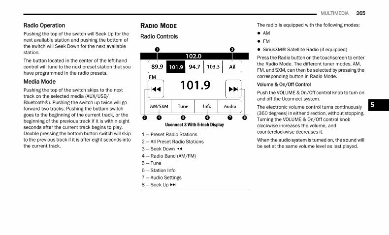
MULTIMEDIA 265
Radio OperationPushing the top of the switch will Seek Up for the next available station and pushing the bottom of the switch will Seek Down for the next available station.The button located in the center of the left-hand control will tune to the next preset station that you have programmed in the radio presets.
Media ModePushing the top of the switch skips to the next track on the selected media (AUX/USB/Bluetooth®). Pushing the switch up twice will go forward two tracks. Pushing the bottom switch goes to the beginning of the current track, or the beginning of the previous track if it is within eight seconds after the current track begins to play. Double pressing the bottom button switch will skip to the previous track if it is after eight seconds into the current track.
RADIO MODE Radio Controls
Uconnect 3 With 5-inch Display
The radio is equipped with the following modes: AM FM SiriusXM® Satellite Radio (if equipped)Press the Radio button on the touchscreen to enter the Radio Mode. The different tuner modes, AM, FM, and SXM, can then be selected by pressing the corresponding button in Radio Mode.Volume & On/Off ControlPush the VOLUME & On/Off control knob to turn on and off the Uconnect system.The electronic volume control turns continuously (360 degrees) in either direction, without stopping. Turning the VOLUME & On/Off control knob clockwise increases the volume, and counterclockwise decreases it.When the audio system is turned on, the sound will be set at the same volume level as last played.
1 — Preset Radio Stations2 — All Preset Radio Stations3 — Seek Down 4 — Radio Band (AM/FM)5 — Tune6 — Station Info7 — Audio Settings8 — Seek Up
5
22_DT_OM_EN_USC_t.book Page 265
266 MULTIMEDIA
Mute ButtonPush the MUTE button to mute or unmute the system.Tune/Scroll ControlTurn the rotary TUNE/SCROLL control knob clockwise to increase or counterclockwise to decrease the radio station frequency. Push the ENTER/BROWSE button to choose a selection.SeekThe Seek Up and Down functions are activated by pressing the double arrow buttons on the touchscreen to the right and left of the radio station display or by pushing the left steering wheel audio control button up or down.
Seek Up and Seek Down
Press and release the Seek Up or SeekDown button to tune the radio to the next available station or channel. During a Seek Up/Down function, if the radio reaches the starting station after passing through the entire band two times, the radio will stop at the station where it began.
Fast Seek Up and Fast Seek Down Press and hold, and then release the SeekUp or Seek Down button to advance the radio through the available stations or channels at a faster rate. The radio stops at the next available station or channel when the button on the touchscreen is released.
NOTE:Pressing and holding either the Seek Up or Seek Down button will scan the different frequency bands at a slower rate.Info — If EquippedPress the Info button to display information related to the currently playing song and radio station.Direct TunePress the Tune button located at the bottom of the radio screen to directly tune to a desired radio station or channel.Press the available number button on the touchscreen to begin selecting a desired station. Once a number has been entered, any numbers that are no longer possible (stations that cannot be reached) will become deactivated/grayed out.
UndoYou can backspace an entry by pressing the Back button on the touchscreen.GOOnce the last digit of a station has been entered, press “Ok”. The Direct Tune screen will close, and the system will automatically tune to that station.
RADIO VOICE COMMANDSUse your voice to quickly get to the AM, FM, or SiriusXM® Satellite Radio stations you would like to hear. (Subscription or included SiriusXM® Satellite Radio trial required.)
Push the VR button on the steering wheel and wait for the beep to say a command. See an example below: “Tune to ninety-five-point-five FM” “Tune to Satellite Channel Hits 1”Did You Know: At any time, if you are not sure of what to say or want to learn a Voice Command, push the VR button and say “Help”. The system provides you with a list of commands.
22_DT_OM_EN_USC_t.book Page 266
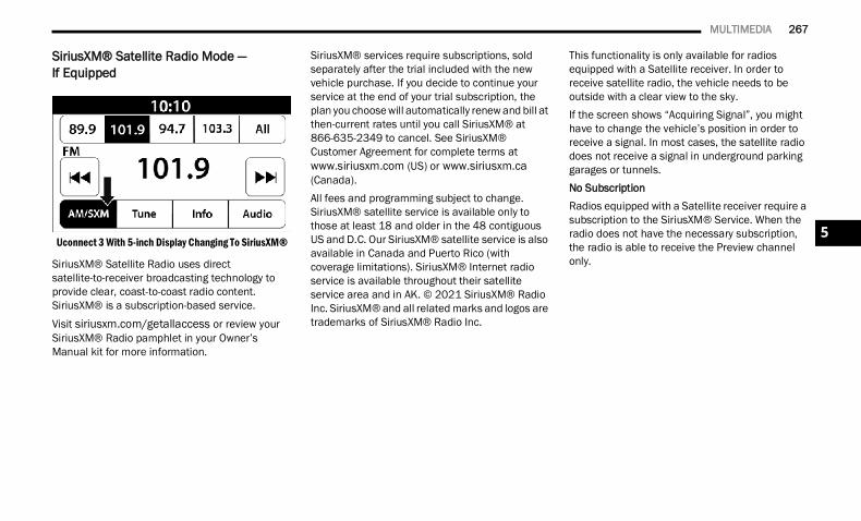
MULTIMEDIA 267
SiriusXM® Satellite Radio Mode —If Equipped
Uconnect 3 With 5-inch Display Changing To SiriusXM®
SiriusXM® Satellite Radio uses direct satellite-to-receiver broadcasting technology to provide clear, coast-to-coast radio content. SiriusXM® is a subscription-based service.Visit siriusxm.com/getallaccess or review your SiriusXM® Radio pamphlet in your Owner’s Manual kit for more information.
SiriusXM® services require subscriptions, sold separately after the trial included with the new vehicle purchase. If you decide to continue your service at the end of your trial subscription, the plan you choose will automatically renew and bill at then-current rates until you call SiriusXM® at 866-635-2349 to cancel. See SiriusXM® Customer Agreement for complete terms at www.siriusxm.com (US) or www.siriusxm.ca (Canada).All fees and programming subject to change. SiriusXM® satellite service is available only to those at least 18 and older in the 48 contiguous US and D.C. Our SiriusXM® satellite service is also available in Canada and Puerto Rico (with coverage limitations). SiriusXM® Internet radio service is available throughout their satellite service area and in AK. © 2021 SiriusXM® Radio Inc. SiriusXM® and all related marks and logos are trademarks of SiriusXM® Radio Inc.
This functionality is only available for radios equipped with a Satellite receiver. In order to receive satellite radio, the vehicle needs to be outside with a clear view to the sky.If the screen shows “Acquiring Signal”, you might have to change the vehicle’s position in order to receive a signal. In most cases, the satellite radio does not receive a signal in underground parking garages or tunnels.No SubscriptionRadios equipped with a Satellite receiver require a subscription to the SiriusXM® Service. When the radio does not have the necessary subscription, the radio is able to receive the Preview channel only.
5
22_DT_OM_EN_USC_t.book Page 267
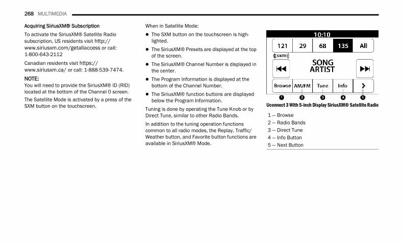
268 MULTIMEDIA
Acquiring SiriusXM® SubscriptionTo activate the SiriusXM® Satellite Radio subscription, US residents visit http://www.siriusxm.com/getallaccess or call: 1-800-643-2112Canadian residents visit https://www.siriusxm.ca/ or call: 1-888-539-7474.
NOTE:You will need to provide the SiriusXM® ID (RID) located at the bottom of the Channel 0 screen.The Satellite Mode is activated by a press of the SXM button on the touchscreen.
When in Satellite Mode: The SXM button on the touchscreen is high-
lighted. The SiriusXM® Presets are displayed at the top
of the screen. The SiriusXM® Channel Number is displayed in
the center. The Program Information is displayed at the
bottom of the Channel Number. The SiriusXM® function buttons are displayed
below the Program Information.Tuning is done by operating the Tune Knob or by Direct Tune, similar to other Radio Bands.In addition to the tuning operation functions common to all radio modes, the Replay, Traffic/Weather button, and Favorite button functions are available in SiriusXM® Mode.
Uconnect 3 With 5-inch Display SiriusXM® Satellite Radio
1 — Browse2 — Radio Bands3 — Direct Tune4 — Info Button5 — Next Button
22_DT_OM_EN_USC_t.book Page 268
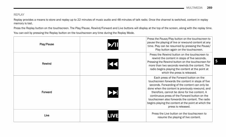
MULTIMEDIA 269
REPLAY Replay provides a means to store and replay up to 22 minutes of music audio and 48 minutes of talk radio. Once the channel is switched, content in replay memory is lost.Press the Replay button on the touchscreen. The Play/Pause, Rewind/Forward and Live buttons will display at the top of the screen, along with the replay time.You can exit by pressing the Replay button on the touchscreen any time during the Replay Mode.
Play/Pause
Press the Pause/Play button on the touchscreen to pause the playing of live or rewound content at any time. Play can be resumed by pressing the Pause/
Play button again on the touchscreen.
Rewind
Press the Rewind button on the touchscreen to rewind the content in steps of five seconds.
Pressing the Rewind button on the touchscreen for more than two seconds rewinds the content. The radio begins playing the content at the point at
which the press is released.
Forward
Each press of the Forward button on the touchscreen forwards the content in steps of five seconds. Forwarding of the content can only be
done when the content is previously rewound, and therefore, cannot be done for live content. A
continuous press of the Forward button on the touchscreen also forwards the content. The radio
begins playing the content at the point at which the press is released.
Live Press the Live button on the touchscreen to resume the playing of live content.
5
22_DT_OM_EN_USC_t.book Page 269
270 MULTIMEDIA
FAVORITES Press the Favorites button on the touchscreen to activate the favorites menu, which will time out within 20 seconds in absence of user interaction.You can exit the Favorites Menu by a press of the X button.The Favorites feature enables you to set a favorite artist or song that is currently playing. The radio then uses this information to alert you when either the favorite artist or song is being played at any time by any of the SiriusXM® Channels.The maximum number of favorites that can be stored in the Radio is 50.Favorite Artist: While the song is playing, to set a favorite artist, press the Favorites button on the touchscreen and then the Favorite Artist button on the touchscreen.Favorite Song: While the song is playing, to set a favorite song, press the Favorites button on the touchscreen and then the Favorite Song button on the touchscreen.
BROWSE IN SXM Press the Browse button on the touchscreen to edit Presets, Favorites, Game Zone, and Jump settings, along with providing the SiriusXM® Channel List.
This Screen contains many submenus. You can exit submenus to return to a parent menu by pressing the Back arrow.AllPress the All button on the Browse Screen. When pressing the All button, the following categories become available: Channel List: Press the Channel List to display
all the SiriusXM® Channel Numbers. You can scroll the Channel List by pressing the Up and Down arrows, located on the right side of the screen. Scrolling can also be done by operating the TUNE/SCROLL knob.
Genre List: Press the Genre button on the touch-screen to display a list of Genres. You can select any desired Genre by pressing the Genre List. The radio tunes to a channel with the content in the selected Genre.
FavoritesPress the Favorites button on the Browse screen.The Favorites menu provides a means to edit the Favorites list and to configure the Alert Settings, along with providing a list of Channels currently airing any of the items in the Favorites list.You can scroll the Favorites list by pressing the Up and Down arrows located at the right side of the screen. Scrolling can also be done by operating the TUNE/SCROLL knob as well.
Remove FavoritesPress the Remove Favorites tab at the top of the screen. Press the Delete All button on the touchscreen to delete all of the Favorites or press the Trash Can icon next to the Favorite to be deleted.Alert SettingsPress the Alert Settings tab at the top of the Favorites screen. The Alert Settings menu allows you to choose from a visual alert or audible and visual alert when one of your favorites is airing on any of the SiriusXM® channels.Game ZonePress the Game Zone button, located at the left of the Browse screen. This feature provides you with the ability to select teams, edit the selection, and set alerts.On-AirPress the On-Air tab at the top of the screen. The On-Air list provides a list of Channels currently airing any of the items in the Selections list, and pressing any of the items in the list tunes the radio to that channel.
22_DT_OM_EN_USC_t.book Page 270
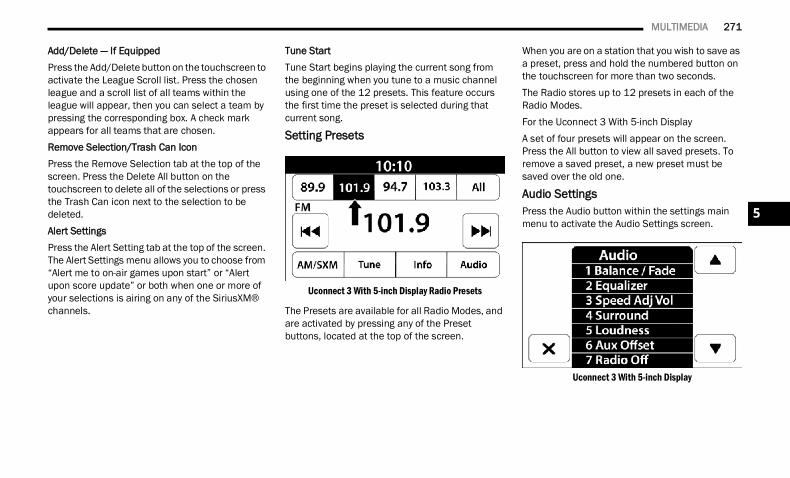
MULTIMEDIA 271
Add/Delete — If EquippedPress the Add/Delete button on the touchscreen to activate the League Scroll list. Press the chosen league and a scroll list of all teams within the league will appear, then you can select a team by pressing the corresponding box. A check mark appears for all teams that are chosen.Remove Selection/Trash Can IconPress the Remove Selection tab at the top of the screen. Press the Delete All button on the touchscreen to delete all of the selections or press the Trash Can icon next to the selection to be deleted.Alert SettingsPress the Alert Setting tab at the top of the screen. The Alert Settings menu allows you to choose from “Alert me to on-air games upon start” or “Alert upon score update” or both when one or more of your selections is airing on any of the SiriusXM® channels.
Tune StartTune Start begins playing the current song from the beginning when you tune to a music channel using one of the 12 presets. This feature occurs the first time the preset is selected during that current song.
Setting Presets
Uconnect 3 With 5-inch Display Radio Presets
The Presets are available for all Radio Modes, and are activated by pressing any of the Preset buttons, located at the top of the screen.
When you are on a station that you wish to save as a preset, press and hold the numbered button on the touchscreen for more than two seconds.The Radio stores up to 12 presets in each of the Radio Modes.For the Uconnect 3 With 5-inch DisplayA set of four presets will appear on the screen. Press the All button to view all saved presets. To remove a saved preset, a new preset must be saved over the old one.
Audio Settings Press the Audio button within the settings main menu to activate the Audio Settings screen.
Uconnect 3 With 5-inch Display
5
22_DT_OM_EN_USC_t.book Page 271
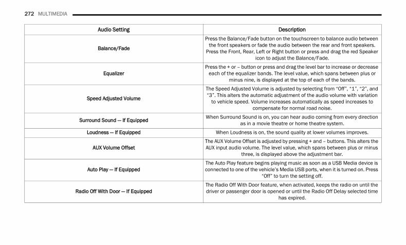
272 MULTIMEDIA
Audio Setting Description
Balance/Fade
Press the Balance/Fade button on the touchscreen to balance audio between the front speakers or fade the audio between the rear and front speakers.
Press the Front, Rear, Left or Right button or press and drag the red Speaker icon to adjust the Balance/Fade.
EqualizerPress the + or – button or press and drag the level bar to increase or decrease
each of the equalizer bands. The level value, which spans between plus or minus nine, is displayed at the top of each of the bands.
Speed Adjusted Volume
The Speed Adjusted Volume is adjusted by selecting from “Off”, “1”, “2”, and “3”. This alters the automatic adjustment of the audio volume with variation
to vehicle speed. Volume increases automatically as speed increases to compensate for normal road noise.
Surround Sound — If Equipped When Surround Sound is on, you can hear audio coming from every direction as in a movie theatre or home theatre system.
Loudness — If Equipped When Loudness is on, the sound quality at lower volumes improves.
AUX Volume OffsetThe AUX Volume Offset is adjusted by pressing + and – buttons. This alters the AUX input audio volume. The level value, which spans between plus or minus
three, is displayed above the adjustment bar.
Auto Play — If EquippedThe Auto Play feature begins playing music as soon as a USB Media device is connected to one of the vehicle’s Media USB ports, when it is turned on. Press
“Off” to turn the setting off.
Radio Off With Door — If EquippedThe Radio Off With Door feature, when activated, keeps the radio on until the driver or passenger door is opened or until the Radio Off Delay selected time
has expired.
22_DT_OM_EN_USC_t.book Page 272
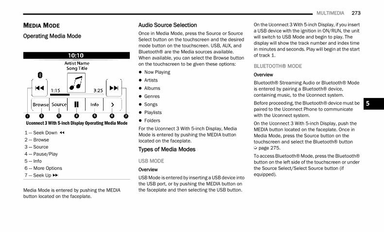
MULTIMEDIA 273
MEDIA MODE Operating Media Mode
Uconnect 3 With 5-inch Display Operating Media Mode
Media Mode is entered by pushing the MEDIA button located on the faceplate.
Audio Source SelectionOnce in Media Mode, press the Source or Source Select button on the touchscreen and the desired mode button on the touchscreen. USB, AUX, and Bluetooth® are the Media sources available. When available, you can select the Browse button on the touchscreen to be given these options: Now Playing Artists Albums Genres Songs Playlists FoldersFor the Uconnect 3 With 5-inch Display, Media Mode is entered by pushing the MEDIA button located on the faceplate.
Types of Media Modes
USB MODEOverviewUSB Mode is entered by inserting a USB device into the USB port, or by pushing the MEDIA button on the faceplate and then selecting the USB button.
On the Uconnect 3 With 5-inch Display, if you insert a USB device with the ignition in ON/RUN, the unit will switch to USB Mode and begin to play. The display will show the track number and index time in minutes and seconds. Play will begin at the start of track 1.
BLUETOOTH® MODEOverviewBluetooth® Streaming Audio or Bluetooth® Mode is entered by pairing a Bluetooth® device, containing music, to the Uconnect system.Before proceeding, the Bluetooth® device must be paired to the Uconnect Phone to communicate with the Uconnect system.On the Uconnect 3 With 5-inch Display, push the MEDIA button located on the faceplate. Once in Media Mode, press the Source button on the touchscreen and select the Bluetooth® button Ú page 275.To access Bluetooth® Mode, press the Bluetooth® button on the left side of the touchscreen or under the Source Select/Select Source button (if equipped).
1 — Seek Down 2 — Browse3 — Source4 — Pause/Play5 — Info6 — More Options7 — Seek Up
5
22_DT_OM_EN_USC_t.book Page 273
274 MULTIMEDIA
AUX MODEOverviewAuxiliary Mode (AUX) is entered by inserting an AUX device using a cable with a 3.5 mm audio jack into the AUX port, or by pushing the MEDIA button on the faceplate, selecting the Source button and then the AUX button.To insert an Auxiliary device, gently insert the Auxiliary device cable into the AUX port. If you insert an Auxiliary device with the ignition and the radio on, the unit will switch to AUX Mode and begin to play.Controlling The Auxiliary DeviceThe control of the Auxiliary device (e.g., selecting playlists, play, fast forward, etc.) cannot be provided by the radio; use the device controls instead. Adjust the volume with the Volume button, Volume/Mute rotary knob, or the On/Off rotary knob, or with the volume of the attached device.
NOTE:The radio unit is acting as the amplifier for audio output from the Auxiliary device. Therefore, if the volume control on the Auxiliary device is set too low, there will be insufficient audio signal for the radio unit to play the music on the device.
Seek Up /Seek Down In USB Mode, press the Seek Up button on the touchscreen for the next selection on the USB device. Press and release the Seek Down button on the touchscreen to return to the beginning of the current selection, or to return to the beginning of the previous selection if the USB device is within the first three seconds of the current selection.In Bluetooth® Mode, press and release the Seek Up button on the touchscreen for the next selection on the Bluetooth® device. Press and release the Seek Down button on the touchscreen to return to the beginning of the current selection, or return to the beginning of the previous selection if the Bluetooth® device is within the first second of the current selection.BrowseIn USB Mode, press the Browse button on the touchscreen to display the browse window. In USB Mode, the left side of the browse window displays a list of ways you can browse through the contents of the USB device. If supported by the device, you can browse by Folder, Artist, Playlist, Album, Song, etc. Press the desired button on the touchscreen on the left side of the screen. The center of the browse window shows items and their sub-functions, which can be scrolled through by pressing the Up and Down buttons to the right. The TUNE/SCROLL knob can also be used to scroll.
On the Uconnect 3 With 5-inch Display, rotate the BROWSE button on the faceplate or press the Browse button on the touchscreen to scroll through and select a desired track on the device. Press the Exit button on the touchscreen if you wish to cancel the Browse function.Media ModeIn USB Mode, press the Media button on the touchscreen to select the desired audio source: USB.In Bluetooth® Mode, press the Media button on the touchscreen to select the desired audio source: Bluetooth®.In AUX Mode, press the Media button on the touchscreen to select the desired audio source: AUX.RepeatIn USB Mode, press the Repeat button on the touchscreen to toggle the repeat functionality. The Repeat button on the touchscreen is highlighted when active. The Radio will continue to play the current track, repeatedly, as long as the repeat is active. Press the Repeat button again to enter Repeat All. The radio will continue to play all the current tracks, repeatedly, as long as the repeat function is active. To cancel Repeat, press the Repeat button a third time.
22_DT_OM_EN_USC_t.book Page 274
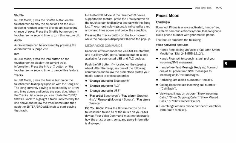
MULTIMEDIA 275
ShuffleIn USB Mode, press the Shuffle button on the touchscreen to play the selections on the USB device in random order to provide an interesting change of pace. Press the Shuffle button on the touchscreen a second time to turn this feature off.AudioAudio settings can be accessed by pressing the Audio button Ú page 265.InfoIn USB Mode, press the Info button on the touchscreen to display the current track information. Press the Info or X button on the touchscreen a second time to cancel this feature.TracksIn USB Mode, press the Tracks button on the touchscreen to display a pop-up with the Song List. The song currently playing is indicated by an arrow and lines above and below the song title. When in the Tracks List screen you can rotate the TUNE/SCROLL knob to highlight a track (indicated by the line above and below the track name) and then push the ENTER/BROWSE knob to start playing that track.
In Bluetooth® Mode, if the Bluetooth® device supports this feature, press the Tracks button on the touchscreen to display a pop-up with the Song List. The currently playing song is indicated by a red arrow and lines above and below the song title.Pressing the Tracks button on the touchscreen while the pop-up is displayed will close the pop-up.
MEDIA VOICE COMMANDSUconnect offers connections via USB, Bluetooth®, and auxiliary (AUX) ports. Voice operation is only available for connected USB and AUX devices.
Push the VR button located on the steering wheel. After the beep, say one of the following commands and follow the prompts to switch your media source or choose an artist: “Change source to Bluetooth®” “Change source to AUX” “Change source to USB” “Play artist Beethoven”; “Play album Greatest
Hits”; “Play song Moonlight Sonata”; “Play genre Classical”
Did You Know: Press the Browse button on the touchscreen to see all of the music on your USB device. Your Voice Command must match exactly how the artist, album, song, and genre information is displayed.
PHONE MODE OverviewUconnect Phone is a voice-activated, hands-free, in-vehicle communications system. It allows you to dial a phone number with your mobile phone.The feature supports the following:Voice Activated Features Hands-Free dialing via Voice (“Call John Smith
Mobile” or “Dial 248-555-1212”). Hands-Free text-to-speech listening of your
incoming SMS messages. Hands-Free Text Message Replying: Forward
one of 18 predefined SMS messages to incoming calls/text messages.
Redialing last dialed numbers (“Redial”). Calling Back the last incoming call number
(“Call Back”). Viewing call logs on screen (“Show Incoming
Calls,” “Show Outgoing Calls,” “Show Missed Calls,” or “Show Recent Calls”).
Searching Contacts phone number (“Search for John Smith Mobile”).
5
22_DT_OM_EN_USC_t.book Page 275
276 MULTIMEDIA
Screen Activated Features Dialing via Keypad using touchscreen. Viewing and Calling contacts from Phonebooks
displayed on the touchscreen. Setting Favorite Contact phone numbers so they
are easily accessible on the Main Phone screen. Viewing and Calling contacts from Recent Call
logs. Reviewing your recent Incoming SMS
Messages. Pairing up to 10 phones/audio devices for easy
access to connect to them quickly.NOTE:Your phone must be capable of SMS messaging via Bluetooth® for messaging features to work properly.Your mobile phone’s audio is transmitted through your vehicle’s audio system; the system will automatically mute your radio when using the Uconnect Phone.For Uconnect customer support:
US visit UconnectPhone.com or call 877-855-8400
Canada visit UconnectPhone.com or call 800-465-2001 (English) or (French) call 800-387-9983
Uconnect Phone allows you to transfer calls between the system and your mobile phone as you enter or exit your vehicle and enables you to mute the system's microphone for private conversation.
The Phone feature is driven through your Bluetooth® “Hands-Free Profile” mobile phone. Uconnect features Bluetooth® technology — the global standard that enables different electronic devices to connect to each other without wires or a docking station. Ensure you phone is turned on with Bluetooth® active and has been paired to the Uconnect system. Up to 10 mobile phones or audio devices are allowed to be linked to the system. Only one linked (or paired) mobile phone and one audio device can be used with the system at a time.
Phone ButtonThe Phone button on your steering wheel is used to get into the Phone Mode and make calls, show recent, incoming or outgoing calls, view phonebook, etc.
When you push the button you will hear a BEEP. The BEEP is your signal to give a command.Voice Command Button
The Voice Command button on your steering wheel is only used for “barge in” and when you are already in a call or want to make another call.
The button on your steering wheel is also used to access the Voice Commands for the Uconnect Voice Command features if your vehicle is equipped.
Phone Operation
OPERATIONVoice commands can be used to operate the Uconnect Phone and to navigate its menu structure. Voice commands are required after most Uconnect Phone prompts. There are two general methods for how Voice Command works:1. Say compound commands like “Call John
Smith mobile”.2. Say the individual commands and allow the
system to guide you to complete the task.
WARNING!
ALWAYS drive safely with your hands on the steering wheel. You have full responsibility and assume all risks related to the use of the Uconnect features and applications in this vehicle. Only use Uconnect when it is safe to do so. Failure to do so may result in an accident involving serious injury or death.
22_DT_OM_EN_USC_t.book Page 276
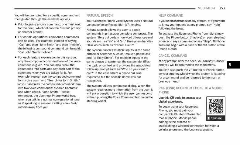
MULTIMEDIA 277
You will be prompted for a specific command and then guided through the available options. Prior to giving a voice command, one must wait
for the beep, which follows the “Listen” prompt or another prompt.
For certain operations, compound commands can be used. For example, instead of saying “Call” and then “John Smith” and then “mobile”, the following compound command can be said: “Call John Smith mobile.”
For each feature explanation in this section, only the compound command form of the voice command is given. You can also break the commands into parts and say each part of the command when you are asked for it. For example, you can use the compound command form voice command “Search for John Smith,” or you can break the compound command form into two voice commands: “Search Contacts” and when asked, “John Smith.” Please remember, the Uconnect Phone works best when you talk in a normal conversational tone, as if speaking to someone sitting a few feet/meters away from you.
NATURAL SPEECHYour Uconnect Phone Voice system uses a Natural Language Voice Recognition (VR) engine.Natural speech allows the user to speak commands in phrases or complete sentences. The system filters out certain non-word utterances and sounds such as “ah” and “eh.” The system handles fill-in words such as “I would like to”.The system handles multiple inputs in the same phrase or sentence such as “make a phone call” and “to Kelly Smith”. For multiple inputs in the same phrase or sentence, the system identifies the topic or context and provides the associated follow-up prompt such as “Who do you want to call?” in the case where a phone call was requested but the specific name was not recognized.The system utilizes continuous dialog. When the system requires more information from the user, it will ask a question to which the user can respond without pushing the Voice Command button on the steering wheel.
HELP COMMANDIf you need assistance at any prompt, or if you want to know your options at any prompt, say “Help” following the beep.To activate the Uconnect Phone from idle, simply push the Phone button (if active) on your steering wheel and say a command or say “Help”. All Phone sessions begin with a push of the VR button or the Phone button.
CANCEL COMMANDAt any prompt, after the beep, you can say “Cancel” and you will be returned to the main menu.You can also push the VR button or Phone button on your steering wheel when the system is listening for a command and be returned to the main or previous menu.
PAIR (LINK) UCONNECT PHONE TO A MOBILE PHONEUse this QR code to access your digital experience.To begin using your Uconnect Phone, you must pair your compatible Bluetooth®-enabled mobile phone. Mobile phone pairing is the process of establishing a wireless connection between a cellular phone and the Uconnect system.
5
22_DT_OM_EN_USC_t.book Page 277
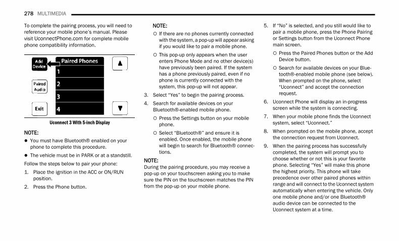
278 MULTIMEDIA
To complete the pairing process, you will need to reference your mobile phone’s manual. Please visit UconnectPhone.com for complete mobile phone compatibility information.
Uconnect 3 With 5-inch Display
NOTE: You must have Bluetooth® enabled on your
phone to complete this procedure. The vehicle must be in PARK or at a standstill.Follow the steps below to pair your phone:1. Place the ignition in the ACC or ON/RUN
position.2. Press the Phone button.
NOTE: If there are no phones currently connected
with the system, a pop-up will appear asking if you would like to pair a mobile phone.
This pop-up only appears when the user enters Phone Mode and no other device(s) have previously been paired. If the system has a phone previously paired, even if no phone is currently connected with the system, this pop-up will not appear.
3. Select “Yes” to begin the pairing process.4. Search for available devices on your
Bluetooth®-enabled mobile phone. Press the Settings button on your mobile
phone. Select “Bluetooth®” and ensure it is
enabled. Once enabled, the mobile phone will begin to search for Bluetooth® connec-tions.
NOTE:During the pairing procedure, you may receive a pop-up on your touchscreen asking you to make sure the PIN on the touchscreen matches the PIN from the pop-up on your mobile phone.
5. If “No” is selected, and you still would like to pair a mobile phone, press the Phone Pairing or Settings button from the Uconnect Phone main screen. Press the Paired Phones button or the Add
Device button. Search for available devices on your Blue-
tooth®-enabled mobile phone (see below). When prompted on the phone, select “Uconnect” and accept the connection request.
6. Uconnect Phone will display an in-progress screen while the system is connecting.
7. When your mobile phone finds the Uconnect system, select “Uconnect.”
8. When prompted on the mobile phone, accept the connection request from Uconnect.
9. When the pairing process has successfully completed, the system will prompt you to choose whether or not this is your favorite phone. Selecting “Yes” will make this phone the highest priority. This phone will take precedence over other paired phones within range and will connect to the Uconnect system automatically when entering the vehicle. Only one mobile phone and/or one Bluetooth® audio device can be connected to the Uconnect system at a time.
22_DT_OM_EN_USC_t.book Page 278
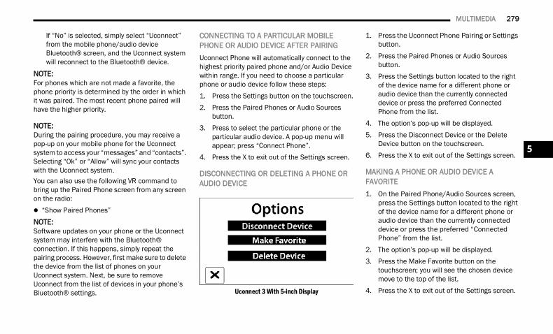
MULTIMEDIA 279
If “No” is selected, simply select “Uconnect” from the mobile phone/audio device Bluetooth® screen, and the Uconnect system will reconnect to the Bluetooth® device.
NOTE:For phones which are not made a favorite, the phone priority is determined by the order in which it was paired. The most recent phone paired will have the higher priority.
NOTE:During the pairing procedure, you may receive a pop-up on your mobile phone for the Uconnect system to access your “messages” and “contacts”. Selecting “Ok” or “Allow” will sync your contacts with the Uconnect system.You can also use the following VR command to bring up the Paired Phone screen from any screen on the radio: “Show Paired Phones”NOTE:Software updates on your phone or the Uconnect system may interfere with the Bluetooth® connection. If this happens, simply repeat the pairing process. However, first make sure to delete the device from the list of phones on your Uconnect system. Next, be sure to remove Uconnect from the list of devices in your phone’s Bluetooth® settings.
CONNECTING TO A PARTICULAR MOBILE PHONE OR AUDIO DEVICE AFTER PAIRINGUconnect Phone will automatically connect to the highest priority paired phone and/or Audio Device within range. If you need to choose a particular phone or audio device follow these steps: 1. Press the Settings button on the touchscreen.2. Press the Paired Phones or Audio Sources
button.3. Press to select the particular phone or the
particular audio device. A pop-up menu will appear; press “Connect Phone”.
4. Press the X to exit out of the Settings screen.
DISCONNECTING OR DELETING A PHONE OR AUDIO DEVICE
Uconnect 3 With 5-inch Display
1. Press the Uconnect Phone Pairing or Settings button.
2. Press the Paired Phones or Audio Sources button.
3. Press the Settings button located to the right of the device name for a different phone or audio device than the currently connected device or press the preferred Connected Phone from the list.
4. The option’s pop-up will be displayed.5. Press the Disconnect Device or the Delete
Device button on the touchscreen.6. Press the X to exit out of the Settings screen.
MAKING A PHONE OR AUDIO DEVICE A FAVORITE1. On the Paired Phone/Audio Sources screen,
press the Settings button located to the right of the device name for a different phone or audio device than the currently connected device or press the preferred “Connected Phone” from the list.
2. The option’s pop-up will be displayed.3. Press the Make Favorite button on the
touchscreen; you will see the chosen device move to the top of the list.
4. Press the X to exit out of the Settings screen.
5
22_DT_OM_EN_USC_t.book Page 279
280 MULTIMEDIA
PHONEBOOK DOWNLOAD (AUTOMATIC PHONEBOOK TRANSFER FROM MOBILE PHONE) — IF EQUIPPEDIf supported by your phone, Uconnect Phone has the ability to download contact names and number entries from the mobile phone’s phonebook. Specific Bluetooth® Phones with Phonebook Access Profile may support this feature. Your mobile phone may receive a pop-up asking for permission for the Uconnect system to access your messages and contacts. Selecting “Ok” or “Allow” will sync your contacts with the Uconnect system.See the Uconnect website, UconnectPhone.com, for supported phones. To call a name from a downloaded mobile
phonebook, Ú page 284. Automatic download and update of a phone-
book, if supported, begins as soon as the Blue-tooth® wireless phone connection is made to the Uconnect Phone, for example, after you start the vehicle.
A maximum of 5,000 contact names with four numbers per contact will be downloaded and updated every time a phone is connected to the Uconnect Phone.
Depending on the maximum number of entries downloaded, there may be a short delay before the latest downloaded names can be used. Until then, if available, the previously downloaded phonebook is available for use.
Only the phonebook of the currently connected mobile phone is accessible.
This downloaded phonebook cannot be edited or deleted on the Uconnect Phone. These can only be edited on the mobile phone. The changes are transferred and updated to Ucon-nect Phone on the next phone connection.
MANAGING YOUR FAVORITES — IF EQUIPPEDThere are two ways you can add an entry to your favorites:1. After loading the mobile phonebook, press
the Favorites button on the touchscreen, and then press one of the +Add Favorite Contact buttons that appears on the list.
2. After loading the mobile phonebook, select “Contacts” from the Phone main screen, and then select the appropriate number. Press the Down Arrow button or the Settings Gear button next to the selected number to display the option’s pop-up. In the pop-up, select “Add to Favorites”.
NOTE:If the Favorites list is full, you will be asked to remove an existing favorite.
TO REMOVE A FAVORITE — IF EQUIPPED1. To remove a Favorite, select “Favorites” from
the Phone main screen.2. Next, select the Down Arrow icon or the
Settings Gear icon next to the contact you want to remove from your favorites. This will bring up the options for that Favorite contact.
3. Deselect the Star icon to delete the Favorite.
Phone Call FeaturesThe following features can be accessed through the Uconnect Phone if the feature(s) are available and supported by Bluetooth® on your mobile service plan. For example, if your mobile service plan provides three-way calling, this feature can be accessed through the Uconnect Phone. Check with your mobile service provider for the features that you have.Listed below are the phone options with Uconnect: Redial Dial by pressing in the number Voice Commands (Dial by Saying a Name, Call
by Saying a Phonebook Name, Redial or Call Back)
22_DT_OM_EN_USC_t.book Page 280
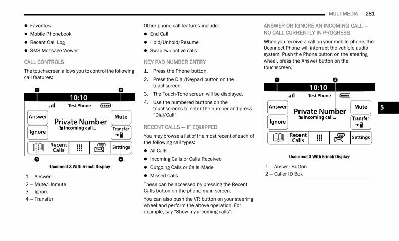
MULTIMEDIA 281
Favorites Mobile Phonebook Recent Call Log SMS Message Viewer
CALL CONTROLSThe touchscreen allows you to control the following call features:
Uconnect 3 With 5-inch Display
Other phone call features include: End Call Hold/Unhold/Resume Swap two active calls
KEY PAD NUMBER ENTRY1. Press the Phone button.2. Press the Dial/Keypad button on the
touchscreen.3. The Touch-Tone screen will be displayed.4. Use the numbered buttons on the
touchscreens to enter the number and press “Dial/Call”.
RECENT CALLS — IF EQUIPPEDYou may browse a list of the most recent of each of the following call types: All Calls Incoming Calls or Calls Received Outgoing Calls or Calls Made Missed CallsThese can be accessed by pressing the Recent Calls button on the phone main screen.You can also push the VR button on your steering wheel and perform the above operation. For example, say “Show my incoming calls”.
ANSWER OR IGNORE AN INCOMING CALL — NO CALL CURRENTLY IN PROGRESSWhen you receive a call on your mobile phone, the Uconnect Phone will interrupt the vehicle audio system. Push the Phone button on the steering wheel, press the Answer button on the touchscreen.
Uconnect 3 With 5-inch Display
1 — Answer2 — Mute/Unmute3 — Ignore4 — Transfer
1 — Answer Button2 — Caller ID Box
5
22_DT_OM_EN_USC_t.book Page 281
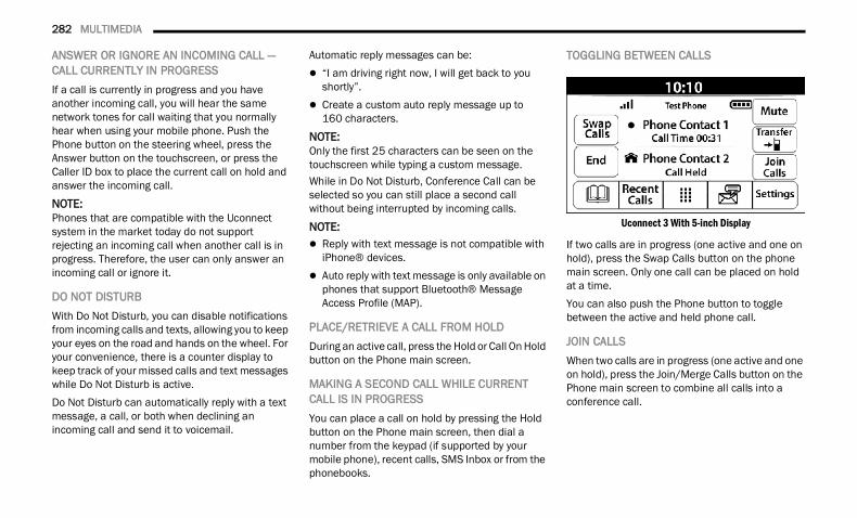
282 MULTIMEDIA
ANSWER OR IGNORE AN INCOMING CALL — CALL CURRENTLY IN PROGRESSIf a call is currently in progress and you have another incoming call, you will hear the same network tones for call waiting that you normally hear when using your mobile phone. Push the Phone button on the steering wheel, press the Answer button on the touchscreen, or press the Caller ID box to place the current call on hold and answer the incoming call.
NOTE:Phones that are compatible with the Uconnect system in the market today do not support rejecting an incoming call when another call is in progress. Therefore, the user can only answer an incoming call or ignore it.
DO NOT DISTURB With Do Not Disturb, you can disable notifications from incoming calls and texts, allowing you to keep your eyes on the road and hands on the wheel. For your convenience, there is a counter display to keep track of your missed calls and text messages while Do Not Disturb is active.Do Not Disturb can automatically reply with a text message, a call, or both when declining an incoming call and send it to voicemail.
Automatic reply messages can be: “I am driving right now, I will get back to you
shortly”. Create a custom auto reply message up to
160 characters.NOTE:Only the first 25 characters can be seen on the touchscreen while typing a custom message.While in Do Not Disturb, Conference Call can be selected so you can still place a second call without being interrupted by incoming calls.NOTE: Reply with text message is not compatible with
iPhone® devices. Auto reply with text message is only available on
phones that support Bluetooth® Message Access Profile (MAP).
PLACE/RETRIEVE A CALL FROM HOLDDuring an active call, press the Hold or Call On Hold button on the Phone main screen.
MAKING A SECOND CALL WHILE CURRENT CALL IS IN PROGRESSYou can place a call on hold by pressing the Hold button on the Phone main screen, then dial a number from the keypad (if supported by your mobile phone), recent calls, SMS Inbox or from the phonebooks.
TOGGLING BETWEEN CALLS
Uconnect 3 With 5-inch Display
If two calls are in progress (one active and one on hold), press the Swap Calls button on the phone main screen. Only one call can be placed on hold at a time.You can also push the Phone button to toggle between the active and held phone call.
JOIN CALLSWhen two calls are in progress (one active and one on hold), press the Join/Merge Calls button on the Phone main screen to combine all calls into a conference call.
22_DT_OM_EN_USC_t.book Page 282
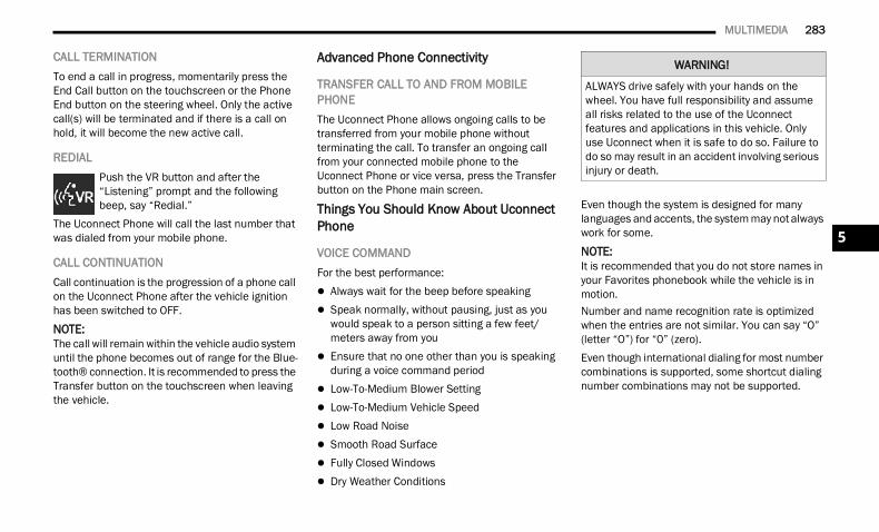
MULTIMEDIA 283
CALL TERMINATIONTo end a call in progress, momentarily press the End Call button on the touchscreen or the Phone End button on the steering wheel. Only the active call(s) will be terminated and if there is a call on hold, it will become the new active call.
REDIALPush the VR button and after the “Listening” prompt and the following beep, say “Redial.”
The Uconnect Phone will call the last number that was dialed from your mobile phone.
CALL CONTINUATIONCall continuation is the progression of a phone call on the Uconnect Phone after the vehicle ignition has been switched to OFF.NOTE:The call will remain within the vehicle audio system until the phone becomes out of range for the Blue-tooth® connection. It is recommended to press the Transfer button on the touchscreen when leaving the vehicle.
Advanced Phone Connectivity
TRANSFER CALL TO AND FROM MOBILE PHONEThe Uconnect Phone allows ongoing calls to be transferred from your mobile phone without terminating the call. To transfer an ongoing call from your connected mobile phone to the Uconnect Phone or vice versa, press the Transfer button on the Phone main screen.
Things You Should Know About Uconnect Phone
VOICE COMMANDFor the best performance: Always wait for the beep before speaking Speak normally, without pausing, just as you
would speak to a person sitting a few feet/meters away from you
Ensure that no one other than you is speaking during a voice command period
Low-To-Medium Blower Setting Low-To-Medium Vehicle Speed Low Road Noise Smooth Road Surface Fully Closed Windows Dry Weather Conditions
Even though the system is designed for many languages and accents, the system may not always work for some.NOTE:It is recommended that you do not store names in your Favorites phonebook while the vehicle is in motion.Number and name recognition rate is optimized when the entries are not similar. You can say “O” (letter “O”) for “0” (zero).Even though international dialing for most number combinations is supported, some shortcut dialing number combinations may not be supported.
WARNING!
ALWAYS drive safely with your hands on the wheel. You have full responsibility and assume all risks related to the use of the Uconnect features and applications in this vehicle. Only use Uconnect when it is safe to do so. Failure to do so may result in an accident involving serious injury or death.
5
22_DT_OM_EN_USC_t.book Page 283
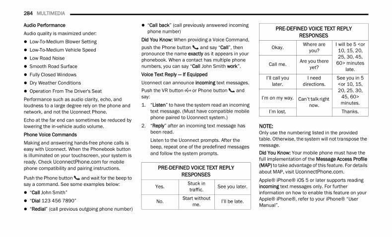
284 MULTIMEDIA
Audio PerformanceAudio quality is maximized under: Low-To-Medium Blower Setting Low-To-Medium Vehicle Speed Low Road Noise Smooth Road Surface Fully Closed Windows Dry Weather Conditions Operation From The Driver's SeatPerformance such as audio clarity, echo, and loudness to a large degree rely on the phone and network, and not the Uconnect Phone.Echo at the far end can sometimes be reduced by lowering the in-vehicle audio volume.Phone Voice CommandsMaking and answering hands-free phone calls is easy with Uconnect. When the Phonebook button is illuminated on your touchscreen, your system is ready. Check UconnectPhone.com for mobile phone compatibility and pairing instructions.
Push the Phone button and wait for the beep to say a command. See some examples below: “Call John Smith” “Dial 123 456 7890” “Redial” (call previous outgoing phone number)
“Call back” (call previously answered incoming phone number)
Did You Know: When providing a Voice Command, push the Phone button and say “Call”, then pronounce the name exactly as it appears in your phonebook. When a contact has multiple phone numbers, you can say “Call John Smith work”.Voice Text Reply — If EquippedUconnect can announce incoming text messages. Push the VR button or Phone button and say:1. “Listen” to have the system read an incoming
text message. (Must have compatible mobile phone paired to Uconnect system.)
2. “Reply” after an incoming text message has been read.Listen to the Uconnect prompts. After the beep, repeat one of the predefined messages and follow the system prompts.
NOTE:Only use the numbering listed in the provided table. Otherwise, the system will not transpose the message.Did You Know: Your mobile phone must have the full implementation of the Message Access Profile (MAP) to take advantage of this feature. For details about MAP, visit UconnectPhone.com.Apple® iPhone® iOS 5 or later supports reading incoming text messages only. For further information on how to enable this feature on your Apple® iPhone®, refer to your iPhone® “User Manual”.
PRE-DEFINED VOICE TEXT REPLY RESPONSES
Yes. Stuck in traffic. See you later.
No. Start without me. I’ll be late.
Okay. Where are you?
I will be 5 <or 10, 15, 20, 25, 30, 45,
60> minutes late.
Call me. Are you there yet?
I’ll call you later.
I need directions.
See you in 5 <or 10, 15, 20, 25, 30,
45, 60> minutes.
I’m on my way. Can’t talk right now.
I’m lost. Thanks.
PRE-DEFINED VOICE TEXT REPLY RESPONSES
22_DT_OM_EN_USC_t.book Page 284
MULTIMEDIA 285
Did You Know: Voice Text Reply is not compatible with iPhone®, but if your vehicle is equipped with Siri® Eyes Free, you can use your voice to send a text message.Siri® Eyes Free — If EquippedWhen used with your Apple® iPhone® connected to your vehicle via Bluetooth®, Siri lets you use your voice to send text messages, select media, place phone calls and much more. Siri uses your natural language to understand what you mean and responds back to confirm your requests. The system is designed to keep your eyes on the road and your hands on the wheel by letting Siri help you perform useful tasks.To enable Siri, push and hold, then release the Uconnect Voice Recognition (VR) button on the steering wheel. After you hear a double beep, you can ask Siri to play podcasts and music, get directions, read text messages, and many other useful requests.
BLUETOOTH® COMMUNICATION LINKMobile phones may lose connection to the Uconnect Phone. When this happens, the connection can generally be re-established by restarting the mobile phone. Your mobile phone is recommended to remain in Bluetooth® ON mode.
POWER-UPAfter switching the ignition key from OFF to either the ON/RUN or ACC position, or after a language change, you must wait at least 15 seconds prior to using the system Ú page 485.
CONNECTED VEHICLE SERVICES —IF EQUIPPED IS MY VEHICLE CONNECTED?If equipped, vehicles with an ASSIST and an SOS button are connected vehicles. These buttons will be located on either the rearview mirror or overhead console, depending on the vehicle. If these buttons are present in your vehicle, you have a connected radio and can take advantage of the many connected vehicle features.For further information about the ASSIST and SOS buttons Ú page 376.
INTRODUCTION TO CONNECTED VEHICLE SERVICES One of the many benefits of your vehicle’s Uconnect system is that you can now take advantage of SiriusXM Guardian™ connected services. To unlock the full potential of SiriusXM Guardian™ in your vehicle, you first need to activate SiriusXM Guardian™ connected services.
NOTE:SiriusXM Guardian™ involves the collection, trans-mission and use of data from your vehicle Ú page 305.SiriusXM Guardian™ Contact InformationSiriusXM Guardian™/Care US residents visit: https://www.driveucon-
nect.com/sirius-xm-guardian.html or call 1-844-796-4827
Canadian residents visit: https://www.driveu-connect.ca/en/sirius-xm-guardian or call 1-877-324-9091
WARNING!
ALWAYS obey traffic laws and pay attention to the road. ALWAYS drive safely with your hands on the steering wheel. You have full responsibility and assume all risks related to the use of the features and applications in this vehicle. Only use the features and applications when it is safe to do so. Failure to comply may result in an accident involving serious injury or death.
5
22_DT_OM_EN_USC_t.book Page 285
286 MULTIMEDIA
What Is SiriusXM Guardian™?SiriusXM Guardian™ uses an embedded device in the Uconnect system installed in your vehicle, which receives GPS signals and communicates with the SiriusXM Guardian™ Customer Care center via wireless and landline communications networks. Depending on the type of device in your vehicle, some SiriusXM Guardian™ connected services require an operable LTE (voice/data) or 3G or 4G (data) network compatible with your device. SiriusXM Guardian™ is available only on equipped vehicles purchased within the continental United States, Alaska, Hawaii, Puerto Rico and Canada.
NOTE: Certain SiriusXM Guardian™ connected
services are dependent upon an operative telematics device, a cellular connection, naviga-tion map data, and GPS satellite signal recep-tion, which can limit the ability to reach the response center or reach emergency support.
Not all features of SiriusXM Guardian™ are available everywhere at all times, particularly in remote or enclosed areas.
Other factors outside the control of SiriusXM Guardian™ that may limit or prevent service delivery are hills, structures, buildings, tunnels, weather, damage to the electrical system or other important parts of your vehicle, network congestion, civil disturbances, actions of third parties or the government, Internet failure, and/or the physical location of your vehicle, such as in an underground parking structure or under a bridge.
Not all SiriusXM Guardian™ features are available for all models.SiriusXM Guardian™ provides: The ability to remotely lock/unlock and remote
start your vehicle from virtually anywhere by using the Mobile App or your computer.
If equipped — Send & Go capability with the Mobile App. Use the Mobile App to easily search, map and send your locations directly to your Uconnect Navigation.
The ability to locate your vehicle, when you forget where you parked, using the Vehicle Finder function of the Mobile App.
Before you drive, familiarize yourself with the easy-to-use Uconnect system and SiriusXM Guardian™ connected services.
The ASSIST and SOS Call Buttons On Your Rearview Mirror Or Overhead ConsoleIf equipped, the ASSIST Button is used for contacting Roadside Assistance, Vehicle Care, Uconnect Care, and SiriusXM Guardian™ Customer Care. The SOS Call button connects you directly to SiriusXM Guardian™ Customer Care for assistance in an emergency.
Activation — If EquippedTo unlock the full potential of SiriusXM Guardian™ in your vehicle, you must activate your SiriusXM Guardian™ connected services.1. Press the Apps icon on the bottom of your
in-vehicle touchscreen.2. Select the Activate Services icon from your list
of apps.3. For customers in the United States, select
“Customer Care” to speak with a SiriusXM Guardian™ Customer Care agent who will activate services in your vehicle, or select “Enter Email” to activate on the web.For customers in Canada, enter your email ad-dress to activate services in your vehicle.
22_DT_OM_EN_USC_t.book Page 286
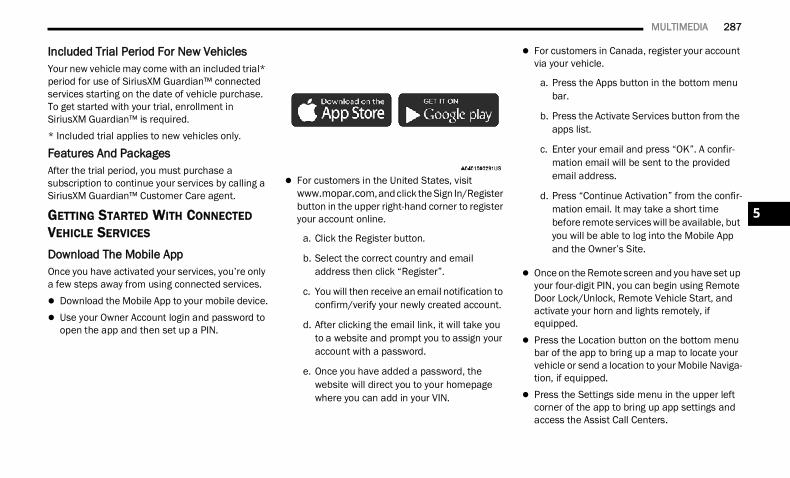
MULTIMEDIA 287
Included Trial Period For New VehiclesYour new vehicle may come with an included trial* period for use of SiriusXM Guardian™ connected services starting on the date of vehicle purchase. To get started with your trial, enrollment in SiriusXM Guardian™ is required.* Included trial applies to new vehicles only.
Features And PackagesAfter the trial period, you must purchase a subscription to continue your services by calling a SiriusXM Guardian™ Customer Care agent.
GETTING STARTED WITH CONNECTED VEHICLE SERVICES Download The Mobile AppOnce you have activated your services, you’re only a few steps away from using connected services. Download the Mobile App to your mobile device. Use your Owner Account login and password to
open the app and then set up a PIN.
For customers in the United States, visit www.mopar.com, and click the Sign In/Register button in the upper right-hand corner to register your account online.
a. Click the Register button.
b. Select the correct country and email address then click “Register”.
c. You will then receive an email notification to confirm/verify your newly created account.
d. After clicking the email link, it will take you to a website and prompt you to assign your account with a password.
e. Once you have added a password, the website will direct you to your homepage where you can add in your VIN.
For customers in Canada, register your account via your vehicle.
a. Press the Apps button in the bottom menu bar.
b. Press the Activate Services button from the apps list.
c. Enter your email and press “OK”. A confir-mation email will be sent to the provided email address.
d. Press “Continue Activation” from the confir-mation email. It may take a short time before remote services will be available, but you will be able to log into the Mobile App and the Owner’s Site.
Once on the Remote screen and you have set up your four-digit PIN, you can begin using Remote Door Lock/Unlock, Remote Vehicle Start, and activate your horn and lights remotely, if equipped.
Press the Location button on the bottom menu bar of the app to bring up a map to locate your vehicle or send a location to your Mobile Naviga-tion, if equipped.
Press the Settings side menu in the upper left corner of the app to bring up app settings and access the Assist Call Centers.
5
22_DT_OM_EN_USC_t.book Page 287
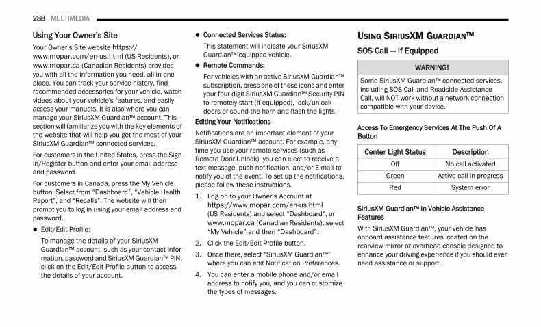
288 MULTIMEDIA
Using Your Owner’s SiteYour Owner’s Site website https://www.mopar.com/en-us.html (US Residents), or www.mopar.ca (Canadian Residents) provides you with all the information you need, all in one place. You can track your service history, find recommended accessories for your vehicle, watch videos about your vehicle's features, and easily access your manuals. It is also where you can manage your SiriusXM Guardian™ account. This section will familiarize you with the key elements of the website that will help you get the most of your SiriusXM Guardian™ connected services.For customers in the United States, press the Sign In/Register button and enter your email address and password.For customers in Canada, press the My Vehicle button. Select from “Dashboard”, “Vehicle Health Report”, and “Recalls”. The website will then prompt you to log in using your email address and password. Edit/Edit Profile:
To manage the details of your SiriusXM Guardian™ account, such as your contact infor-mation, password and SiriusXM Guardian™ PIN, click on the Edit/Edit Profile button to access the details of your account.
Connected Services Status:This statement will indicate your SiriusXM Guardian™-equipped vehicle.
Remote Commands:For vehicles with an active SiriusXM Guardian™ subscription, press one of these icons and enter your four-digit SiriusXM Guardian™ Security PIN to remotely start (if equipped), lock/unlock doors or sound the horn and flash the lights.
Editing Your NotificationsNotifications are an important element of your SiriusXM Guardian™ account. For example, any time you use your remote services (such as Remote Door Unlock), you can elect to receive a text message, push notification, and/or E-mail to notify you of the event. To set up the notifications, please follow these instructions.1. Log on to your Owner’s Account at
https://www.mopar.com/en-us.html (US Residents) and select “Dashboard”, or www.mopar.ca (Canadian Residents), select “My Vehicle” and then “Dashboard”.
2. Click the Edit/Edit Profile button.3. Once there, select “SiriusXM Guardian™”
where you can edit Notification Preferences.4. You can enter a mobile phone and/or email
address to notify you, and you can customize the types of messages.
USING SIRIUSXM GUARDIAN™ SOS Call — If Equipped
Access To Emergency Services At The Push Of A Button
SiriusXM Guardian™ In-Vehicle Assistance FeaturesWith SiriusXM Guardian™, your vehicle has onboard assistance features located on the rearview mirror or overhead console designed to enhance your driving experience if you should ever need assistance or support.
WARNING!
Some SiriusXM Guardian™ connected services, including SOS Call and Roadside Assistance Call, will NOT work without a network connection compatible with your device.
Center Light Status DescriptionOff No call activated
Green Active call in progress
Red System error
22_DT_OM_EN_USC_t.book Page 288
MULTIMEDIA 289
DescriptionSOS Call offers a convenient way to get in contact with a SiriusXM Guardian™ Customer Care agent in the event of an emergency. When the connection between the vehicle and the live agent is made, your vehicle will automatically transmit location information. In the event of a minor collision, medical or any other emergency, press the SOS button to be connected to a call center agent who can send emergency assistance to your vehicle’s location.
NOTE:Certain SiriusXM Guardian™ connected services are dependent on an operational Uconnect system, cellular network availability that is compatible with the device in your vehicle, and GPS network availability. Not all features of SiriusXM Guardian™ are available everywhere at all times, particularly in remote or enclosed areas.How It Works 1. Push the SOS Call button; the indicator light
will turn green indicating a call has been placed.
NOTE: In case the SOS Call button is accidentally
pushed, there is a 10-second delay before the SOS call is placed. The system will verbally alert you that a call is about to be made. To cancel the SOS Call connection, push the SOS Call button on the rearview mirror or overhead console or press the Cancel button on the touchscreen within10 seconds.
During an SOS Call, the Bluetooth®-paired phone is disconnected so incoming or outgoing calls will go through your mobile device versus the hands-free system which is not available due to the SOS Call.
2. Once a connection between the vehicle and a SiriusXM Guardian™ Customer Care agent is made, the agent will stay on the line with you.
NOTE:Calls between the vehicle occupants and the SiriusXM Guardian™ Customer Care center may be recorded or monitored for quality assurance purposes. Through your enrollment in and use of the SiriusXM Guardian™ connected services, you consent to being recorded.
SOS Call System LimitationsVehicles that have been purchased in the US and that travel into Mexico and Canada may have limited services. In particular, responses to SOS calls or other emergency services may be unavailable or very limited. Vehicles purchased outside the United States and Canada are unable to receive SiriusXM Guardian™ connected services.If the SOS Call system detects a malfunction, any of the following may occur at the time the malfunction is detected: The light will continuously be illuminated red. The screen will display the following message
“Vehicle phone requires service. Please contact your dealer.”
An in-vehicle audio message will state “Vehicle phone requires service. Please contact your dealer.”
5
22_DT_OM_EN_USC_t.book Page 289
290 MULTIMEDIA
(Continued)
(Continued)
Even if the SOS Call system is fully functional, factors beyond FCA US LLC’s control may prevent or stop SOS Call system operation. These include, but are not limited to, the following factors: The ignition key is in OFF position. The vehicle’s electrical systems are not intact. The vehicle battery loses power or becomes
disconnected during a vehicle crash. The SOS Call system software and/or hardware
is damaged during a vehicle crash. LTE (voice/data) or 3G or 4G (data) coverage
and/or GPS signals are unavailable or obstructed.
Network congestion. Weather conditions. Buildings, structures, geographic terrain, or
tunnels.If your vehicle loses battery power for any reason (including during or after an accident), the SOS Call system, among other vehicle systems, will not operate.
Requirements This feature is available only on vehicles sold in
the US or Canada. Vehicle must be properly equipped with the Siri-
usXM Guardian™ connected services. Vehicle must be registered with SiriusXM Guardian™ and have an active subscription that includes the applicable feature.
Vehicle must have an operable LTE (voice/data) or 3G or 4G (data) network connection compat-ible with your device.
Vehicle must be powered in the ON/RUN or ACC (Accessory) position with a properly functioning electrical system.
WARNING!
Never place anything on or near the vehicle’s LTE (voice/data) or 3G or 4G (data) and GPS antennas. You could prevent LTE (voice/data) or 4G (data) and GPS signal reception, which can prevent your vehicle from placing an emergency call.
Do not add any aftermarket electrical equip-ment to the vehicle’s electrical system. This may prevent your vehicle from sending a signal to initiate an emergency call. To avoid interference that can cause the SOS Call system to fail, never add aftermarket equip-ment (e.g., two-way mobile radio, CB radio, data recorder, etc.) to your vehicle’s electrical system or modify the antennas on your vehicle. IF YOUR VEHICLE LOSES POWER FOR ANY REASON (INCLUDING DURING OR AFTER AN ACCIDENT), NEITHER THE MOBILE APPS NOR THE SIRIUSXM GUARDIAN™ CONNECTED SERVICES WILL OPERATE.
The Occupant Restraint Controller (ORC) turns on the Air Bag Warning Light on the instru-ment panel if a malfunction in any part of the air bag system is detected. If the Air Bag Warning Light is illuminated, the air bag system may not be working properly and the SOS Call system may not be able to send a signal to the SiriusXM Guardian™ Customer Care center. If the Air Bag Warning Light is illu-minated, have an authorized dealer service your vehicle immediately.
WARNING!
22_DT_OM_EN_USC_t.book Page 290
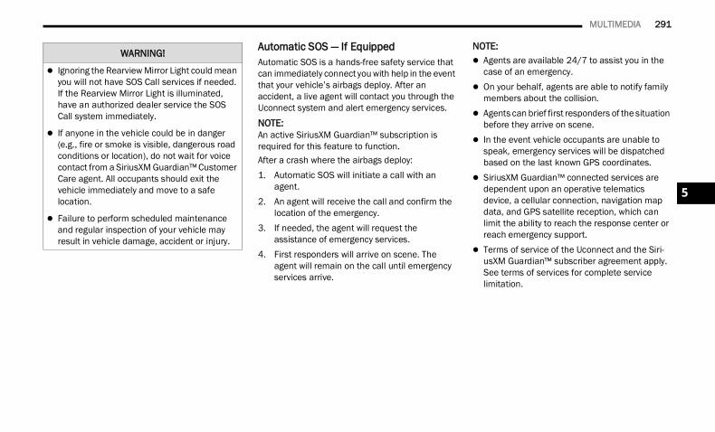
MULTIMEDIA 291
Automatic SOS — If EquippedAutomatic SOS is a hands-free safety service that can immediately connect you with help in the event that your vehicle’s airbags deploy. After an accident, a live agent will contact you through the Uconnect system and alert emergency services.NOTE:An active SiriusXM Guardian™ subscription is required for this feature to function.After a crash where the airbags deploy:1. Automatic SOS will initiate a call with an
agent.2. An agent will receive the call and confirm the
location of the emergency.3. If needed, the agent will request the
assistance of emergency services.4. First responders will arrive on scene. The
agent will remain on the call until emergency services arrive.
NOTE: Agents are available 24/7 to assist you in the
case of an emergency. On your behalf, agents are able to notify family
members about the collision. Agents can brief first responders of the situation
before they arrive on scene. In the event vehicle occupants are unable to
speak, emergency services will be dispatched based on the last known GPS coordinates.
SiriusXM Guardian™ connected services are dependent upon an operative telematics device, a cellular connection, navigation map data, and GPS satellite reception, which can limit the ability to reach the response center or reach emergency support.
Terms of service of the Uconnect and the Siri-usXM Guardian™ subscriber agreement apply. See terms of services for complete service limitation.
Ignoring the Rearview Mirror Light could mean you will not have SOS Call services if needed. If the Rearview Mirror Light is illuminated, have an authorized dealer service the SOS Call system immediately.
If anyone in the vehicle could be in danger (e.g., fire or smoke is visible, dangerous road conditions or location), do not wait for voice contact from a SiriusXM Guardian™ Customer Care agent. All occupants should exit the vehicle immediately and move to a safelocation.
Failure to perform scheduled maintenance and regular inspection of your vehicle may result in vehicle damage, accident or injury.
WARNING!
5
22_DT_OM_EN_USC_t.book Page 291
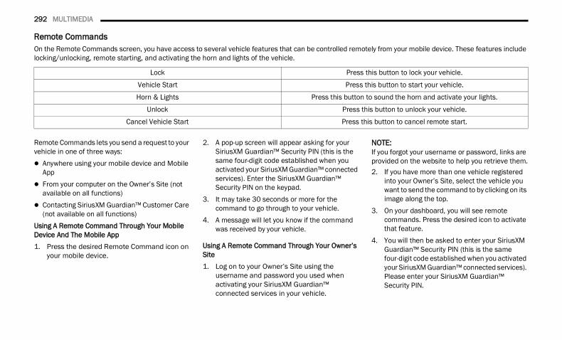
292 MULTIMEDIA
Remote CommandsOn the Remote Commands screen, you have access to several vehicle features that can be controlled remotely from your mobile device. These features include locking/unlocking, remote starting, and activating the horn and lights of the vehicle.
Remote Commands lets you send a request to your vehicle in one of three ways: Anywhere using your mobile device and Mobile
App From your computer on the Owner’s Site (not
available on all functions) Contacting SiriusXM Guardian™ Customer Care
(not available on all functions)Using A Remote Command Through Your Mobile Device And The Mobile App1. Press the desired Remote Command icon on
your mobile device.
2. A pop-up screen will appear asking for your SiriusXM Guardian™ Security PIN (this is the same four-digit code established when you activated your SiriusXM Guardian™ connected services). Enter the SiriusXM Guardian™ Security PIN on the keypad.
3. It may take 30 seconds or more for the command to go through to your vehicle.
4. A message will let you know if the command was received by your vehicle.
Using A Remote Command Through Your Owner’s Site 1. Log on to your Owner’s Site using the
username and password you used when activating your SiriusXM Guardian™ connected services in your vehicle.
NOTE:If you forgot your username or password, links are provided on the website to help you retrieve them.2. If you have more than one vehicle registered
into your Owner’s Site, select the vehicle you want to send the command to by clicking on its image along the top.
3. On your dashboard, you will see remote commands. Press the desired icon to activate that feature.
4. You will then be asked to enter your SiriusXM Guardian™ Security PIN (this is the same four-digit code established when you activated your SiriusXM Guardian™ connected services). Please enter your SiriusXM Guardian™ Security PIN.
Lock Press this button to lock your vehicle.
Vehicle Start Press this button to start your vehicle.
Horn & Lights Press this button to sound the horn and activate your lights.
Unlock Press this button to unlock your vehicle.
Cancel Vehicle Start Press this button to cancel remote start.
22_DT_OM_EN_USC_t.book Page 292
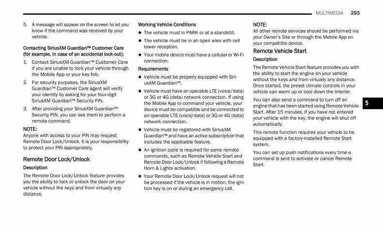
MULTIMEDIA 293
5. A message will appear on the screen to let you know if the command was received by your vehicle.
Contacting SiriusXM Guardian™ Customer Care (for example, in case of an accidental lock-out): 1. Contact SiriusXM Guardian™ Customer Care
if you are unable to lock your vehicle through the Mobile App or your key fob.
2. For security purposes, the SiriusXM Guardian™ Customer Care agent will verify your identity by asking for your four-digit SiriusXM Guardian™ Security PIN.
3. After providing your SiriusXM Guardian™ Security PIN, you can ask them to perform a remote command.
NOTE:Anyone with access to your PIN may request Remote Door Lock/Unlock. It is your responsibility to protect your PIN appropriately.
Remote Door Lock/Unlock DescriptionThe Remote Door Lock/Unlock feature provides you the ability to lock or unlock the door on your vehicle without the keys and from virtually any distance.
Working Vehicle Conditions The vehicle must in PARK or at a standstill. The vehicle must be in an open area with cell
tower reception. Your mobile device must have a cellular or Wi-Fi
connection.Requirements Vehicle must be properly equipped with Siri-
usXM Guardian™. Vehicle must have an operable LTE (voice/data)
or 3G or 4G (data) network connection. If using the Mobile App to command your vehicle, your device must be compatible and be connected to an operable LTE (voice/data) or 3G or 4G (data) network connection.
Vehicle must be registered with SiriusXM Guardian™ and have an active subscription that includes the applicable feature.
An ignition cycle is required for some remote commands, such as Remote Vehicle Start and Remote Door Lock/Unlock if following a Remote Horn & Lights activation.
Your Remote Door Lock/Unlock request will not be processed if the vehicle is in motion, the igni-tion key is on or during an emergency call.
NOTE:All other remote services should be performed via your Owner’s Site or through the Mobile App on your compatible device.Remote Vehicle Start DescriptionThe Remote Vehicle Start feature provides you with the ability to start the engine on your vehicle without the keys and from virtually any distance. Once started, the preset climate controls in your vehicle can warm up or cool down the interior.You can also send a command to turn off an engine that has been started using Remote Vehicle Start. After 15 minutes, if you have not entered your vehicle with the key, the engine will shut off automatically.This remote function requires your vehicle to be equipped with a factory-installed Remote Start system.You can set up push notifications every time a command is sent to activate or cancel Remote Start.
5
22_DT_OM_EN_USC_t.book Page 293
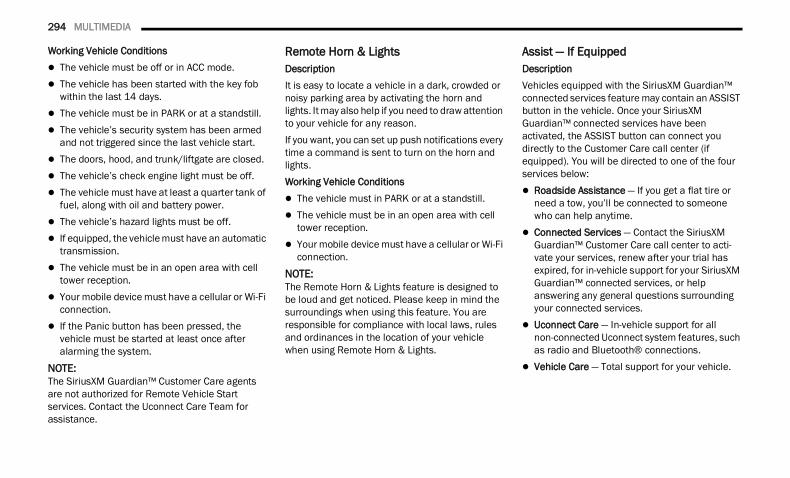
294 MULTIMEDIA
Working Vehicle Conditions The vehicle must be off or in ACC mode. The vehicle has been started with the key fob
within the last 14 days. The vehicle must be in PARK or at a standstill. The vehicle’s security system has been armed
and not triggered since the last vehicle start. The doors, hood, and trunk/liftgate are closed. The vehicle’s check engine light must be off. The vehicle must have at least a quarter tank of
fuel, along with oil and battery power. The vehicle’s hazard lights must be off. If equipped, the vehicle must have an automatic
transmission. The vehicle must be in an open area with cell
tower reception. Your mobile device must have a cellular or Wi-Fi
connection. If the Panic button has been pressed, the
vehicle must be started at least once after alarming the system.
NOTE:The SiriusXM Guardian™ Customer Care agents are not authorized for Remote Vehicle Start services. Contact the Uconnect Care Team for assistance.
Remote Horn & Lights DescriptionIt is easy to locate a vehicle in a dark, crowded or noisy parking area by activating the horn and lights. It may also help if you need to draw attention to your vehicle for any reason.If you want, you can set up push notifications every time a command is sent to turn on the horn and lights.Working Vehicle Conditions The vehicle must in PARK or at a standstill. The vehicle must be in an open area with cell
tower reception. Your mobile device must have a cellular or Wi-Fi
connection.NOTE:The Remote Horn & Lights feature is designed to be loud and get noticed. Please keep in mind the surroundings when using this feature. You are responsible for compliance with local laws, rules and ordinances in the location of your vehicle when using Remote Horn & Lights.
Assist — If EquippedDescriptionVehicles equipped with the SiriusXM Guardian™ connected services feature may contain an ASSIST button in the vehicle. Once your SiriusXM Guardian™ connected services have been activated, the ASSIST button can connect you directly to the Customer Care call center (if equipped). You will be directed to one of the four services below: Roadside Assistance — If you get a flat tire or
need a tow, you’ll be connected to someone who can help anytime.
Connected Services — Contact the SiriusXM Guardian™ Customer Care call center to acti-vate your services, renew after your trial has expired, for in-vehicle support for your SiriusXM Guardian™ connected services, or help answering any general questions surrounding your connected services.
Uconnect Care — In-vehicle support for all non-connected Uconnect system features, such as radio and Bluetooth® connections.
Vehicle Care — Total support for your vehicle.
22_DT_OM_EN_USC_t.book Page 294
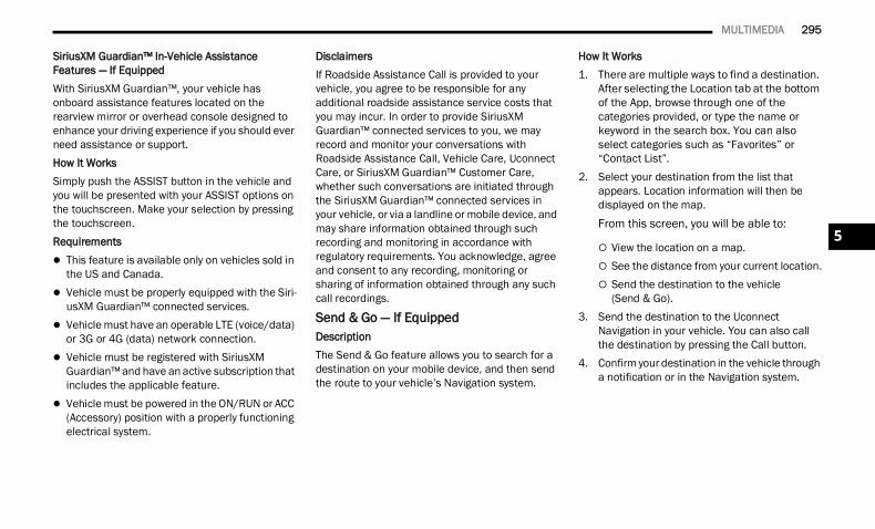
MULTIMEDIA 295
SiriusXM Guardian™ In-Vehicle Assistance Features — If EquippedWith SiriusXM Guardian™, your vehicle has onboard assistance features located on the rearview mirror or overhead console designed to enhance your driving experience if you should ever need assistance or support.How It WorksSimply push the ASSIST button in the vehicle and you will be presented with your ASSIST options on the touchscreen. Make your selection by pressing the touchscreen.Requirements This feature is available only on vehicles sold in
the US and Canada. Vehicle must be properly equipped with the Siri-
usXM Guardian™ connected services. Vehicle must have an operable LTE (voice/data)
or 3G or 4G (data) network connection. Vehicle must be registered with SiriusXM
Guardian™ and have an active subscription that includes the applicable feature.
Vehicle must be powered in the ON/RUN or ACC (Accessory) position with a properly functioning electrical system.
DisclaimersIf Roadside Assistance Call is provided to your vehicle, you agree to be responsible for any additional roadside assistance service costs that you may incur. In order to provide SiriusXM Guardian™ connected services to you, we may record and monitor your conversations with Roadside Assistance Call, Vehicle Care, Uconnect Care, or SiriusXM Guardian™ Customer Care, whether such conversations are initiated through the SiriusXM Guardian™ connected services in your vehicle, or via a landline or mobile device, and may share information obtained through such recording and monitoring in accordance with regulatory requirements. You acknowledge, agree and consent to any recording, monitoring or sharing of information obtained through any such call recordings.
Send & Go — If Equipped DescriptionThe Send & Go feature allows you to search for a destination on your mobile device, and then send the route to your vehicle’s Navigation system.
How It Works1. There are multiple ways to find a destination.
After selecting the Location tab at the bottom of the App, browse through one of the categories provided, or type the name or keyword in the search box. You can also select categories such as “Favorites” or “Contact List”.
2. Select your destination from the list that appears. Location information will then be displayed on the map.
From this screen, you will be able to:
View the location on a map. See the distance from your current location. Send the destination to the vehicle
(Send & Go).3. Send the destination to the Uconnect
Navigation in your vehicle. You can also call the destination by pressing the Call button.
4. Confirm your destination in the vehicle through a notification or in the Navigation system.
5
22_DT_OM_EN_USC_t.book Page 295
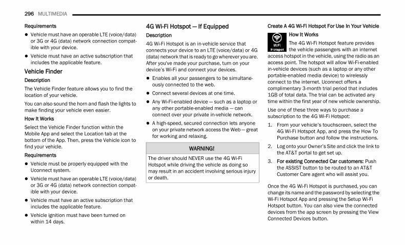
296 MULTIMEDIA
Requirements Vehicle must have an operable LTE (voice/data)
or 3G or 4G (data) network connection compat-ible with your device.
Vehicle must have an active subscription that includes the applicable feature.
Vehicle Finder DescriptionThe Vehicle Finder feature allows you to find the location of your vehicle.You can also sound the horn and flash the lights to make finding your vehicle even easier.How It WorksSelect the Vehicle Finder function within the Mobile App and select the Location tab at the bottom of the App. Then, press the Vehicle icon to find your vehicle.Requirements Vehicle must be properly equipped with the
Uconnect system. Vehicle must have an operable LTE (voice/data)
or 3G or 4G (data) network connection compat-ible with your device.
Vehicle must have an active subscription that includes the applicable feature.
Vehicle ignition must have been turned on within 14 days.
4G Wi-Fi Hotspot — If Equipped Description4G Wi-Fi Hotspot is an in-vehicle service that connects your device to an LTE (voice/data) or 4G (data) network that is ready to go wherever you are. After you've made your purchase, turn on your device’s Wi-Fi and connect your devices. Enables all your passengers to be simultane-
ously connected to the web. Connect several devices at one time. Any Wi-Fi-enabled device — such as a laptop or
any other portable-enabled media — can connect over your private in-vehicle network.
A high-speed, secured connection lets anyone on your private network access the Web — great for working and relaxing.
Create A 4G Wi-Fi Hotspot For Use In Your VehicleHow It WorksThe 4G Wi-Fi Hotspot feature provides the vehicle passengers with an internet
access hotspot in the vehicle, using the radio as an access point. The hotspot will allow Wi-Fi-enabled in-vehicle devices (such as a laptop or any other portable-enabled media device) to wirelessly connect to the internet. Uconnect offers a complimentary 3-month trial period that includes 1GB of total data. The trial can be activated any time within the first year of new vehicle ownership.Use one of these three ways to purchase a subscription to the 4G Wi-Fi Hotspot:1. From your vehicle’s touchscreen, select the
4G Wi-Fi Hotspot App, and press the How To Purchase button and follow the instructions.
2. Log onto your Owner’s Site and click the link to the AT&T portal to get set up.
3. For existing Connected Car customers: Push the ASSIST button to be routed to an AT&T Customer Care agent who will assist you.
Once the 4G Wi-Fi Hotspot is purchased, you can change its name and the password by selecting the Wi-Fi Hotspot App and pressing the Setup Wi-Fi Hotspot button. You can also view the connected devices from the app screen by pressing the View Connected Devices button.
WARNING!
The driver should NEVER use the 4G Wi-Fi Hotspot while driving the vehicle as doing so may result in an accident involving serious injury or death.
22_DT_OM_EN_USC_t.book Page 296
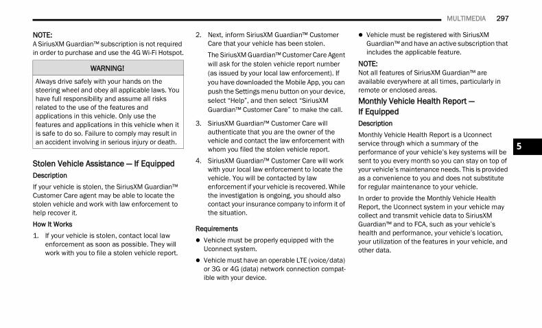
MULTIMEDIA 297
NOTE:A SiriusXM Guardian™ subscription is not required in order to purchase and use the 4G Wi-Fi Hotspot.
Stolen Vehicle Assistance — If EquippedDescriptionIf your vehicle is stolen, the SiriusXM Guardian™ Customer Care agent may be able to locate the stolen vehicle and work with law enforcement to help recover it.How It Works 1. If your vehicle is stolen, contact local law
enforcement as soon as possible. They will work with you to file a stolen vehicle report.
2. Next, inform SiriusXM Guardian™ Customer Care that your vehicle has been stolen.The SiriusXM Guardian™ Customer Care Agent will ask for the stolen vehicle report number (as issued by your local law enforcement). If you have downloaded the Mobile App, you can push the Settings menu button on your device, select “Help”, and then select “SiriusXM Guardian™ Customer Care” to make the call.
3. SiriusXM Guardian™ Customer Care will authenticate that you are the owner of the vehicle and contact the law enforcement with whom you filed the stolen vehicle report.
4. SiriusXM Guardian™ Customer Care will work with your local law enforcement to locate the vehicle. You will be contacted by law enforcement if your vehicle is recovered. While the investigation is ongoing, you should also contact your insurance company to inform it of the situation.
Requirements Vehicle must be properly equipped with the
Uconnect system. Vehicle must have an operable LTE (voice/data)
or 3G or 4G (data) network connection compat-ible with your device.
Vehicle must be registered with SiriusXM Guardian™ and have an active subscription that includes the applicable feature.
NOTE:Not all features of SiriusXM Guardian™ are available everywhere at all times, particularly in remote or enclosed areas.Monthly Vehicle Health Report — If EquippedDescriptionMonthly Vehicle Health Report is a Uconnect service through which a summary of the performance of your vehicle’s key systems will be sent to you every month so you can stay on top of your vehicle’s maintenance needs. This is provided as a convenience to you and does not substitute for regular maintenance to your vehicle.In order to provide the Monthly Vehicle Health Report, the Uconnect system in your vehicle may collect and transmit vehicle data to SiriusXM Guardian™ and to FCA, such as your vehicle’s health and performance, your vehicle’s location, your utilization of the features in your vehicle, and other data.
WARNING!
Always drive safely with your hands on the steering wheel and obey all applicable laws. You have full responsibility and assume all risks related to the use of the features and applications in this vehicle. Only use the features and applications in this vehicle when it is safe to do so. Failure to comply may result in an accident involving in serious injury or death. 5
22_DT_OM_EN_USC_t.book Page 297
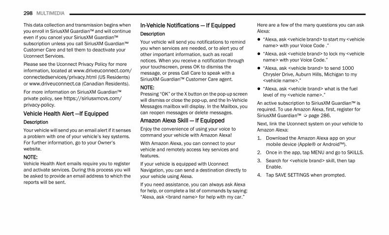
298 MULTIMEDIA
This data collection and transmission begins when you enroll in SiriusXM Guardian™ and will continue even if you cancel your SiriusXM Guardian™ subscription unless you call SiriusXM Guardian™ Customer Care and tell them to deactivate your Uconnect Services.Please see the Uconnect Privacy Policy for more information, located at www.driveuconnect.com/connectedservices/privacy.html (US Residents) or www.driveuconnect.ca (Canadian Residents).For more information on SiriusXM Guardian™ private policy, see https://siriusxmcvs.com/privacy-policy.
Vehicle Health Alert —If EquippedDescriptionYour vehicle will send you an email alert if it senses a problem with one of your vehicle’s key systems. For further information, go to your Owner’s website.NOTE:Vehicle Health Alert emails require you to register and activate services. During this process you will be asked to provide an email address to which the reports will be sent.
In-Vehicle Notifications — If Equipped DescriptionYour vehicle will send you notifications to remind you when services are needed, or to alert you of other important information, such as recall notices. When you receive a notification through your touchscreen, press OK to dismiss the message, or press Call Care to speak with a SiriusXM Guardian™ Customer Care agent.
NOTE:Pressing “OK” or the X button on the pop-up screen will dismiss or close the pop-up, and the In-Vehicle Messages mailbox will display. In the Mailbox, you can reopen messages or delete messages.Amazon Alexa Skill — If EquippedEnjoy the convenience of using your voice to command your vehicle with Amazon Alexa!With Amazon Alexa, you can connect to your vehicle and remotely access key services and features.If your vehicle is equipped with Uconnect Navigation, you can send a destination directly to your vehicle using Alexa.If you need assistance, you can always ask Alexa for help, or complete a list of commands by saying: “Alexa, ask <brand name> for help with my car.”
Here are a few of the many questions you can ask Alexa: “Alexa, ask <vehicle brand> to start my <vehicle
name> with your Voice Code .” “Alexa, ask <vehicle brand> to lock my <vehicle
name> with your Voice Code.” “Alexa, ask <vehicle brand> to send 1000
Chrysler Drive, Auburn Hills, Michigan to my <vehicle name>.”
“Alexa, ask <vehicle brand> what is the fuel level of my <vehicle name>.”
An active subscription to SiriusXM Guardian™ is required. To use Amazon Alexa, first, register for SiriusXM Guardian™ Ú page 286.Next, link the Uconnect system on your vehicle to Amazon Alexa:1. Download the Amazon Alexa app on your
mobile device (Apple® or Android™).2. Once in the app, tap MENU and go to SKILLS.3. Search for <vehicle brand> skill, then tap
Enable.4. Tap SAVE SETTINGS when prompted.
22_DT_OM_EN_USC_t.book Page 298
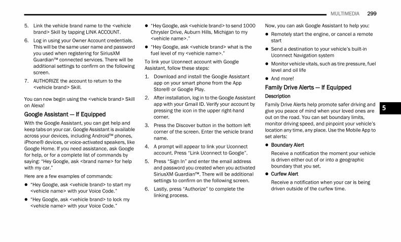
MULTIMEDIA 299
5. Link the vehicle brand name to the <vehicle brand> Skill by tapping LINK ACCOUNT.
6. Log in using your Owner Account credentials. This will be the same user name and password you used when registering for SiriusXM Guardian™ connected services. There will be additional settings to confirm on the following screen.
7. AUTHORIZE the account to return to the <vehicle brand> Skill.
You can now begin using the <vehicle brand> Skill on Alexa!
Google Assistant — If EquippedWith the Google Assistant, you can get help and keep tabs on your car. Google Assistant is available across your devices, including Android™ phones, iPhone® devices, or voice-activated speakers, like Google Home. If you need assistance, ask Google for help, or for a complete list of commands by saying: “Hey Google, ask <brand name> for help with my car.”Here are a few examples of commands: “Hey Google, ask <vehicle brand> to start my
<vehicle name> with your Voice Code.” “Hey Google, ask <vehicle brand> to lock my
<vehicle name> with your Voice Code.”
“Hey Google, ask <vehicle brand> to send 1000 Chrysler Drive, Auburn Hills, Michigan to my <vehicle name>.”
“Hey Google, ask <vehicle brand> what is the fuel level of my <vehicle name>.”
To link your Uconnect account with Google Assistant, follow these steps:1. Download and install the Google Assistant
app on your smart phone from the App Store® or Google Play.
2. After installation, log in to the Google Assistant app with your Gmail ID. Verify your account by pressing the icon in the upper right-hand corner.
3. Press the Discover button in the bottom left corner of the screen. Enter the vehicle brand name.
4. A prompt will appear to link your Uconnect account. Press “Link Uconnect to Google”.
5. Press “Sign In” and enter the email address and password you created when you activated SiriusXM Guardian™. There will be additional settings to confirm on the following screen.
6. Lastly, press “Authorize” to complete the linking process.
Now, you can ask Google Assistant to help you: Remotely start the engine, or cancel a remote
start Send a destination to your vehicle’s built-in
Uconnect Navigation system Monitor vehicle vitals, such as tire pressure, fuel
level and oil life And more!
Family Drive Alerts — If Equipped DescriptionFamily Drive Alerts help promote safer driving and give you peace of mind when your loved ones are out on the road. You can set boundary limits, monitor driving speed, and pinpoint your vehicle’s location any time, any place. Use the Mobile App to set alerts: Boundary Alert
Receive a notification the moment your vehicle is driven either out of or into a geographic boundary that you set.
Curfew AlertReceive a notification when your car is being driven outside of the curfew time.
5
22_DT_OM_EN_USC_t.book Page 299
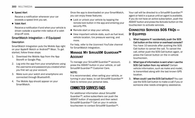
300 MULTIMEDIA
Speed AlertReceive a notification whenever your car exceeds a speed limit you set.
Valet AlertReceive a notification if and when your vehicle is driven outside a quarter-mile radius of a valet drop-off zone.
SmartWatch Integration — If Equipped DescriptionSmartWatch Integration puts the Mobile App right on your Apple® Watch or Android™ Wear. To get started, follow these steps:1. Download the Mobile App from the App
Store® or Google Play.2. Log onto the app from your smartphone using
the username and password you created when you first set up your account.
3. Make sure your watch and smartphone are connected through Bluetooth®.
4. The Mobile App should appear on your SmartWatch.
Once the app is downloaded on your SmartWatch, you can enjoy these features: Lock or unlock your vehicle by tapping the
remote lock button in the app and entering your security PIN.
Remote start or stop your vehicle. View important vehicle stats, such as fuel level,
vehicle location, tire pressure warning, and more.
For help, refer to the Uconnect YouTube channel for SmartWatch Integration.
MANAGE MY SIRIUSXM GUARDIAN™ ACCOUNT
To manage your SiriusXM Guardian™ account, press the ASSIST button in your vehicle, or call SiriusXM Guardian™ Customer Care.NOTE:It is recommended, when selling your vehicle, or turning in your lease, to call SiriusXM Guardian™ Care to remove your personal data.
CONNECTED SERVICES FAQS For additional information about SiriusXM Guardian™, active subscribers can push the ASSIST button (if equipped) and then select SiriusXM Guardian™ Call on your in-vehicle touchscreen to contact SiriusXM Guardian™.
Your call will be directed to a SiriusXM Guardian™ agent or held in a queue until an agent is available. If you do not have an active subscription, push the ASSIST button and press the Activate button on the touchscreen to activate services.
CONNECTED SERVICES SOS FAQS — IF EQUIPPED 1. What happens if I accidentally push the SOS
Call button on the mirror or overhead console? You have 10 seconds after pushing the SOS Call button to cancel the call. To cancel the call, either push the SOS Call button again, or press the Cancel button on the in-vehicle touchscreen.
2. What type of information is sent when I use the SOS Call button from my vehicle? Certain vehicle information, such as make and model, is transmitted along with the last known GPS location.
3. When could I use the SOS Call button? You can use the SOS Call button to make a call if you or someone else needs emergency assistance.
22_DT_OM_EN_USC_t.book Page 300
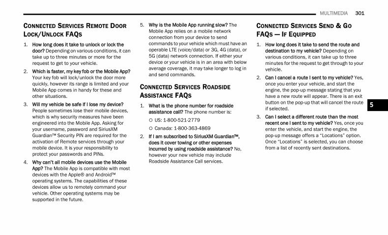
MULTIMEDIA 301
CONNECTED SERVICES REMOTE DOOR LOCK/UNLOCK FAQS 1. How long does it take to unlock or lock the
door? Depending on various conditions, it can take up to three minutes or more for the request to get to your vehicle.
2. Which is faster, my key fob or the Mobile App? Your key fob will lock/unlock the door more quickly, however its range is limited and your Mobile App comes in handy for these and other situations.
3. Will my vehicle be safe if I lose my device? People sometimes lose their mobile devices, which is why security measures have been engineered into the Mobile App. Asking for your username, password and SiriusXM Guardian™ Security PIN are required for the activation of Remote services through your mobile device. It is your responsibility to protect your passwords and PINs.
4. Why can’t all mobile devices use the Mobile App? The Mobile App is compatible with most devices with the Apple® and Android™ operating systems. The capabilities of these devices allow us to remotely command your vehicle. Other operating systems may be supported in the future.
5. Why is the Mobile App running slow? The Mobile App relies on a mobile network connection from your device to send commands to your vehicle which must have an operable LTE (voice/data) or 3G, 4G (data), or 5G (data) network connection. If either your device or your vehicle is in an area with below average coverage, it may take longer to log in and send commands.
CONNECTED SERVICES ROADSIDE ASSISTANCE FAQS 1. What is the phone number for roadside
assistance call? The phone number is: US: 1-800-521-2779 Canada: 1-800-363-4869
2. If I am subscribed to SiriusXM Guardian™, does it cover towing or other expenses incurred by using roadside assistance? No, however your new vehicle may include Roadside Assistance Call services.
CONNECTED SERVICES SEND & GO FAQS — IF EQUIPPED 1. How long does it take to send the route and
destination to my vehicle? Depending on various conditions, it can take up to three minutes for the request to get through to your vehicle.
2. Can I cancel a route I sent to my vehicle? Yes, once you enter your vehicle, and start the engine, the pop-up message stating that you have a new route will appear. There is an exit button on the pop-up that will cancel the route if selected.
3. Can I select a different route than the most recent one I sent to my vehicle? Yes, once you enter the vehicle, and start the engine, the pop-up message offers a “Locations” option. Once “Locations” is selected, you can choose from a list of recently sent destinations.
5
22_DT_OM_EN_USC_t.book Page 301
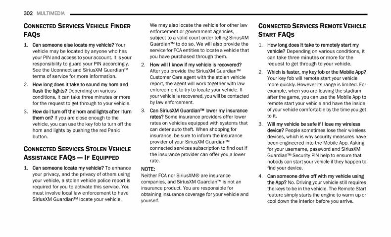
302 MULTIMEDIA
CONNECTED SERVICES VEHICLE FINDER FAQS 1. Can someone else locate my vehicle? Your
vehicle may be located by anyone who has your PIN and access to your account. It is your responsibility to guard your PIN accordingly. See the Uconnect and SiriusXM Guardian™ terms of service for more information.
2. How long does it take to sound my horn and flash the lights? Depending on various conditions, it can take three minutes or more for the request to get through to your vehicle.
3. How do I turn off the horn and lights after I turn them on? If you are close enough to the vehicle, you can use the key fob to turn off the horn and lights by pushing the red Panic button.
CONNECTED SERVICES STOLEN VEHICLE ASSISTANCE FAQS — IF EQUIPPED 1. Can someone locate my vehicle? To enhance
your privacy, and the privacy of others using your vehicle, a stolen vehicle police report is required for you to activate this service. You must involve local law enforcement to have SiriusXM Guardian™ locate your vehicle.
We may also locate the vehicle for other law enforcement or government agencies, subject to a valid court order telling SiriusXM Guardian™ to do so. We will also provide the service for FCA entities to locate a vehicle that you have purchased through them.
2. How will I know if my vehicle is recovered? After you provide the SiriusXM Guardian™ Customer Care agent with the stolen vehicle report, the agent will work together with law enforcement to try to locate your vehicle. If your vehicle is recovered, you will be contacted by law enforcement.
3. Can SiriusXM Guardian™ lower my insurance rates? Some insurance providers offer lower rates on vehicles equipped with systems that can deter auto theft. When shopping for insurance, be sure to inform the insurance provider of your SiriusXM Guardian™ connected services subscription to find out if the insurance provider can offer you a lower rate.
NOTE:Neither FCA nor SiriusXM® are insurance companies, and SiriusXM Guardian™ is not an insurance product. You are responsible for obtaining insurance coverage for your vehicle and yourself.
CONNECTED SERVICES REMOTE VEHICLE START FAQS 1. How long does it take to remotely start my
vehicle? Depending on various conditions, it can take three minutes or more for the request to get through to your vehicle.
2. Which is faster, my key fob or the Mobile App? Your key fob will remote start your vehicle more quickly. However its range is limited. For example, when you are leaving the stadium after the game, you can use the Mobile App to remote start your vehicle and have the inside of your vehicle comfortable by the time you get to it.
3. Will my vehicle be safe if I lose my wireless device? People sometimes lose their wireless devices, which is why security measures have been engineered into the Mobile App. Asking for your username, password and SiriusXM Guardian™ Security PIN help to ensure that nobody can start your vehicle if they happen to find your device.
4. Can someone drive off with my vehicle using the App? No. Driving your vehicle still requires the keys to be in the vehicle. The Remote Start feature simply starts the engine to warm up or cool down the interior before you arrive.
22_DT_OM_EN_USC_t.book Page 302
MULTIMEDIA 303
5. Can I stop a vehicle that is being driven with the cancel Remote Vehicle Start command? No. If the vehicle is in motion, the cancel Remote Vehicle Start button will not stop the vehicle.
6. Why can’t all mobile devices use the Mobile App? The Mobile App has been designed to work on most devices with the Apple® and Android™ operating systems. The capabilities of these devices allow us to remotely command your vehicle. Other operating systems may be supported in the future.
CONNECTED SERVICES REMOTE HORN & LIGHTS FAQS
1. How long does it take to sound my horn and flash the lights? Depending on various conditions, it can take three minutes or more for the request to get through to your vehicle.
2. Which is faster, my key fob or the Mobile App? Your key fob will sound the horn and flash the lights quicker; however, its range is limited.
3. How do I turn off the horn and lights after I turn them on? If you are close enough to the vehicle, you can use the key fob to turn off the horn and lights by pressing the red Panic button. Otherwise, Remote Horn & Lights will continue for a maximum of three minutes.
4. Why can’t all mobile devices use the Mobile App? The Mobile App has been designed to work on most devices with the Apple® and Android™ operating systems. The capabilities of these devices allow us to remotely command your vehicle. Other operating systems may be supported in the future.
CONNECTED SERVICES ACCOUNT FAQS — IF EQUIPPED
1. How do I register for my SiriusXM Guardian™ account? There are three ways that you can register your SiriusXM Guardian™ Account: Push the ASSIST button. A call will be placed
to an agent who can assist in registering your new account.
Press the Activate Services icon in the Apps menu. Select the button to speak with an agent, who can assist in registering your new account.
Press the Activate Services icon in the Apps menu. Enter your email on the touchscreen and then follow the prompts from the provided email. You will receive an email with an activation link that will be good for 72 hours. Once you click the activation link, you will be prompted to fill out your informa-tion and accept Terms and Conditions. Then, you will be directed to the SiriusXM Guardian™ home page to complete your profile and demo the remote services.
2. Why do I need an email address? Without an email address, customers cannot register for SiriusXM Guardian™. Customers need to register so they can subscribe to receive additional services and create a SiriusXM Guardian™ Security PIN for remote command requests.
3. How do I create a SiriusXM Guardian™ security PIN? Set up your SiriusXM Guardian™ Security PIN during the registration process. The SiriusXM Guardian™ Security PIN will be required to authenticate you when accessing your account via SiriusXM Guardian™ Call or performing any remote services, such as Remote Door Lock/Unlock, Remote Horn & Lights, or Remote Vehicle Start.
5
22_DT_OM_EN_USC_t.book Page 303
304 MULTIMEDIA
4. What if I forgot my SiriusXM Guardian™ security PIN? If you’ve already activated services and forgot your SiriusXM Guardian™ Security PIN, you can reset the PIN by selecting Edit Profile on your Owner’s Site.
5. How do I update my SiriusXM Guardian™ payment account address? Your SiriusXM Guardian™ Payment Account address can be updated online, or by calling SiriusXM Guardian™ Customer Care from ASSIST in your vehicle. To update online: login to your Owner’s Site, and select Edit Profile > SiriusXM Guardian™ Payment Account.
6. How do I update my SiriusXM Guardian™ profile? Your name, home address, phone number, email address and SiriusXM Guardian™ Security PIN can be updated online on your Owner’s Site. Log in to your Owner’s Site then select Edit Profile to edit your personal information. Make your edits and click Save.
7. Can I try features or packages before I buy them? Your new vehicle purchase may have come with an included trial period for certain Apps and services.
8. Can I access every App and service while driving? No, some applications and services are not available while driving. For your own safety, it is not possible to use some of the touchscreen features while the vehicle is in motion (e.g. key pad).
9. What happens when my subscription comes up for renewal? If you have added a credit card to your account information, your subscription will be automatically renewed for a term length in accordance with the service plan that you have selected at the then current subscription rate and on every renewal date thereafter, unless you cancel your subscription by calling SiriusXM Guardian™ Care. If you have not added a credit card to your account, SiriusXM Guardian™ will send you an email or letter in advance of your expiration date to remind you that your subscription is ending soon.
10. How do I manage my SiriusXM Guardian™ notification preferences? Contact SiriusXM Guardian™ Customer Care, or go to your Owner’s Site and then update your preferences on the SiriusXM Guardian™ customer web portal.
11. How do I purchase a subscription? Contact SiriusXM Guardian™ Customer Care by pushing the ASSIST button on your rearview mirror or overhead console.
12. How do I update my credit card information? Login to your Owner’s Site, and select Edit Profile, then select SiriusXM Guardian™ Payment Account.
13. How do I find out how much longer I have on my subscription? Contact SiriusXM Guardian™ Customer Care.You also can visit your Owner’s Site and choose a subscription to view its expiration date. When your subscription is about to ex-pire, you will receive an email or letter of notifi-cation.
14. Can I get a refund if I have not used the entire subscription? Prorated refunds are provided from the date of cancellation for annual plans or longer. Please see the Uconnect and SiriusXM Guardian™ Terms & Conditions for refunds related to billing plans of other lengths and other circumstances.
15. Can I cancel a subscription before it expires? Yes. If you have an annual subscription, your subscription will be canceled the day you cancel. If you have a monthly subscription, your subscription will be canceled on the last day of the month in which you choose to cancel.
22_DT_OM_EN_USC_t.book Page 304
MULTIMEDIA 305
16. What should I do if I want to sell my vehicle? Before your vehicle is sold to a new owner, you’ll want to remove your account information. This process removes all personal information, returns the Uconnect system to its original factory settings, removes all SiriusXM Guardian™ connected services and account information. To remove your account information from the Uconnect system, contact SiriusXM Guardian™ Customer Care.
17. What if I forgot to remove my account information before I returned my lease vehicle or sold it? Contact SiriusXM Guardian™ Customer Care.
18. What will happen if an operable LTE (voice/data), 4G (data), or 5G (data) network connection compatible with my device is temporarily unavailable? The SOS Call and ASSIST buttons will NOT function if you are not connected to an operable LTE (voice/data) or 3G, 4G (data), 5G (data) network. Services that required your smartphone only direct calls to Roadside Assistance Call may be functioning if you have an operable network.
DATA COLLECTION & PRIVACY
The Uconnect system collects and transmits data which may include information about your vehicle, your vehicle’s health and performance, your vehicle’s location, your utilization of the features in your vehicle, and other data. The collection, use and sharing of this information is required to provide the SiriusXM Guardian™ connected services and is further described by the Uconnect Privacy Policy, which can be found at www.driveuconnect.com/connectedservices/privacy.html (US Residents) or www.driveuconnect.ca (Canadian Residents). This information may be collected by SiriusXM® Connected Vehicle Services Inc. and shared with FCA US LLC for the purposes stated in the Uconnect Privacy Policy. Vehicle health and diagnostic information including location data may be used by Uconnect to provide a Vehicle Health Report to you.
Even if you cancel your SiriusXM Guardian™ subscription, this vehicle diagnostic health information, including location data, may still be transmitted from your vehicle and you may still have a Vehicle Health Report sent to you.Use of any of the Connected Services including SiriusXM Guardian™ is deemed to be your consent to the collection, use and disclosure of this information in accordance with the Uconnect Privacy Policy. If you do not want this information to be collected, used, or shared, you must cancel your Uconnect services in their entirety by contacting us as referenced in the Uconnect Privacy Policy.
RADIO OPERATION AND MOBILE PHONES Under certain conditions, the mobile phone being on in your vehicle can cause erratic or noisy performance from your radio. This condition may be lessened or eliminated by repositioning the mobile phone within the vehicle. This condition is not harmful to the radio. If your radio performance does not satisfactorily improve from repositioning the mobile phone, it is recommended that the volume be turned down or off during mobile phone operation when not using the Uconnect system.
5
22_DT_OM_EN_USC_t.book Page 305
306 MULTIMEDIA
REGULATORY AND SAFETY INFORMATION
US/CANADAExposure to Radio Frequency RadiationThe radiated output power of the internal wireless radio is far below the FCC and IC radio frequency exposure limits. Nevertheless, the wireless radio will be used in such a manner that the radio is 8 in (20 cm) or further from the human body.The internal wireless radio operates within guidelines found in radio frequency safety standards and recommendations, which reflect the consensus of the scientific community.The radio manufacturer believes the internal wireless radio is safe for use by consumers. The level of energy emitted is far less than the electromagnetic energy emitted by wireless devices such as mobile phones. However, the use of wireless radios may be restricted in some situations or environments, such as aboard airplanes. If you are unsure of restrictions, you are encouraged to ask for authorization before turning on the wireless radio Ú page 485.
PERFORMANCE PAGES — IF EQUIPPEDPerformance Pages is an application that provides a display for performance indicators that will help you gain familiarity with the capabilities of your vehicle in real time.To access the Performance Pages, press the Vehicle button on the touchscreen. Then, press the Performance tab. Press the desired button on the touchscreen to access that specific Performance Page.
The Performance Pages include the following: Timers Gauges G-Force Dyno/Engine Vehicle DynamicsSnapshotThe Snapshot feature allows you to take a screenshot of any page. The information can be saved onto a USB device.To take a snapshot, make sure a USB device is plugged into the vehicle. Next, press the Snapshot icon located in the lower left corner of the touchscreen.The file will be saved to the USB drive. At the time a snapshot is taken, the bottom bar of the touchscreen will be replaced with the historical data from the vehicle present at the time the snapshot icon was pressed. The following information will display: Date Vehicle Identification Number (VIN) Longitude And Latitude Coordinates Outside Temperature Odometer
WARNING!
Measurement of vehicle statistics with the Performance Pages is intended for off-highway or off-road use only and should not be done on any public roadways. It is recommended that these features be used in a controlled environment and within the limits of the law. The capabilities of the vehicle as measured by the Performance Pages must never be exploited in a reckless or dangerous manner, which can jeopardize the user’s safety or the safety of others. Only a safe, attentive, and skillful driver can prevent accidents.
22_DT_OM_EN_USC_t.book Page 306
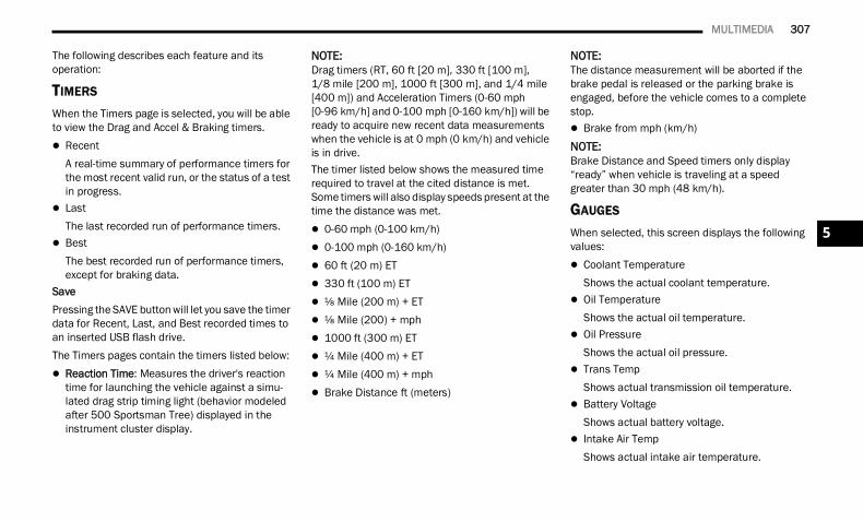
MULTIMEDIA 307
The following describes each feature and its operation:
TIMERS
When the Timers page is selected, you will be able to view the Drag and Accel & Braking timers. Recent
A real-time summary of performance timers for the most recent valid run, or the status of a test in progress.
LastThe last recorded run of performance timers.
BestThe best recorded run of performance timers, except for braking data.
SavePressing the SAVE button will let you save the timer data for Recent, Last, and Best recorded times to an inserted USB flash drive.The Timers pages contain the timers listed below: Reaction Time: Measures the driver's reaction
time for launching the vehicle against a simu-lated drag strip timing light (behavior modeled after 500 Sportsman Tree) displayed in the instrument cluster display.
NOTE:Drag timers (RT, 60 ft [20 m], 330 ft [100 m], 1/8 mile [200 m], 1000 ft [300 m], and 1/4 mile [400 m]) and Acceleration Timers (0-60 mph [0-96 km/h] and 0-100 mph [0-160 km/h]) will be ready to acquire new recent data measurements when the vehicle is at 0 mph (0 km/h) and vehicle is in drive.The timer listed below shows the measured time required to travel at the cited distance is met. Some timers will also display speeds present at the time the distance was met. 0-60 mph (0-100 km/h) 0-100 mph (0-160 km/h) 60 ft (20 m) ET 330 ft (100 m) ET ⅛ Mile (200 m) + ET ⅛ Mile (200) + mph 1000 ft (300 m) ET ¼ Mile (400 m) + ET ¼ Mile (400 m) + mph Brake Distance ft (meters)
NOTE:The distance measurement will be aborted if the brake pedal is released or the parking brake is engaged, before the vehicle comes to a complete stop. Brake from mph (km/h)NOTE:Brake Distance and Speed timers only display “ready” when vehicle is traveling at a speed greater than 30 mph (48 km/h).
GAUGES
When selected, this screen displays the following values: Coolant Temperature
Shows the actual coolant temperature. Oil Temperature
Shows the actual oil temperature. Oil Pressure
Shows the actual oil pressure. Trans Temp
Shows actual transmission oil temperature. Battery Voltage
Shows actual battery voltage. Intake Air Temp
Shows actual intake air temperature.
5
22_DT_OM_EN_USC_t.book Page 307
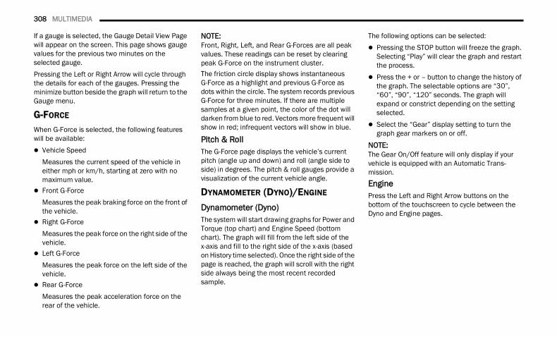
308 MULTIMEDIA
If a gauge is selected, the Gauge Detail View Page will appear on the screen. This page shows gauge values for the previous two minutes on the selected gauge.Pressing the Left or Right Arrow will cycle through the details for each of the gauges. Pressing the minimize button beside the graph will return to the Gauge menu.
G-FORCE
When G-Force is selected, the following features will be available: Vehicle Speed
Measures the current speed of the vehicle in either mph or km/h, starting at zero with no maximum value.
Front G-ForceMeasures the peak braking force on the front of the vehicle.
Right G-ForceMeasures the peak force on the right side of the vehicle.
Left G-ForceMeasures the peak force on the left side of the vehicle.
Rear G-ForceMeasures the peak acceleration force on the rear of the vehicle.
NOTE:Front, Right, Left, and Rear G-Forces are all peak values. These readings can be reset by clearing peak G-Force on the instrument cluster.The friction circle display shows instantaneous G-Force as a highlight and previous G-Force as dots within the circle. The system records previous G-Force for three minutes. If there are multiple samples at a given point, the color of the dot will darken from blue to red. Vectors more frequent will show in red; infrequent vectors will show in blue.
Pitch & RollThe G-Force page displays the vehicle’s current pitch (angle up and down) and roll (angle side to side) in degrees. The pitch & roll gauges provide a visualization of the current vehicle angle.
DYNAMOMETER (DYNO)/ENGINE
Dynamometer (Dyno)The system will start drawing graphs for Power and Torque (top chart) and Engine Speed (bottom chart). The graph will fill from the left side of the x-axis and fill to the right side of the x-axis (based on History time selected). Once the right side of the page is reached, the graph will scroll with the right side always being the most recent recorded sample.
The following options can be selected: Pressing the STOP button will freeze the graph.
Selecting “Play” will clear the graph and restart the process.
Press the + or – button to change the history of the graph. The selectable options are “30”, “60”, “90”, “120” seconds. The graph will expand or constrict depending on the setting selected.
Select the “Gear” display setting to turn the graph gear markers on or off.
NOTE:The Gear On/Off feature will only display if your vehicle is equipped with an Automatic Trans-mission.EnginePress the Left and Right Arrow buttons on the bottom of the touchscreen to cycle between the Dyno and Engine pages.
22_DT_OM_EN_USC_t.book Page 308
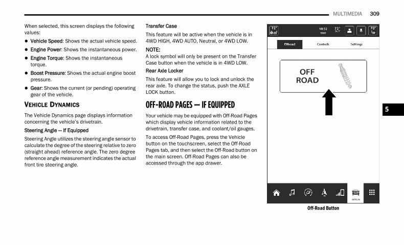
MULTIMEDIA 309
When selected, this screen displays the following values: Vehicle Speed: Shows the actual vehicle speed. Engine Power: Shows the instantaneous power. Engine Torque: Shows the instantaneous
torque. Boost Pressure: Shows the actual engine boost
pressure. Gear: Shows the current (or pending) operating
gear of the vehicle.
VEHICLE DYNAMICS
The Vehicle Dynamics page displays information concerning the vehicle’s drivetrain.Steering Angle — If EquippedSteering Angle utilizes the steering angle sensor to calculate the degree of the steering relative to zero (straight ahead) reference angle. The zero degree reference angle measurement indicates the actual front tire steering angle.
Transfer CaseThis feature will be active when the vehicle is in 4WD HIGH, 4WD AUTO, Neutral, or 4WD LOW.
NOTE:A lock symbol will only be present on the Transfer Case button when the vehicle is in 4WD LOW.Rear Axle LockerThis feature will allow you to lock and unlock the rear axle. To change the status, push the AXLE LOCK button.
OFF-ROAD PAGES — IF EQUIPPED Your vehicle may be equipped with Off-Road Pages which display vehicle information related to the drivetrain, transfer case, and coolant/oil gauges.To access Off-Road Pages, press the Vehicle button on the touchscreen, select the Off-Road Pages tab, and then select the Off-Road button on the main screen. Off-Road Pages can also be accessed through the app drawer.
Off-Road Button
5
22_DT_OM_EN_USC_t.book Page 309
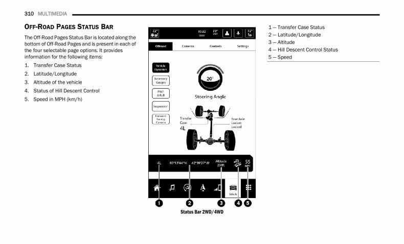
310 MULTIMEDIA
OFF-ROAD PAGES STATUS BAR The Off-Road Pages Status Bar is located along the bottom of Off-Road Pages and is present in each of the four selectable page options. It provides information for the following items:1. Transfer Case Status2. Latitude/Longitude3. Altitude of the vehicle4. Status of Hill Descent Control5. Speed in MPH (km/h)
Status Bar 2WD/4WD
1 — Transfer Case Status2 — Latitude/Longitude3 — Altitude4 — Hill Descent Control Status5 — Speed
22_DT_OM_EN_USC_t.book Page 310
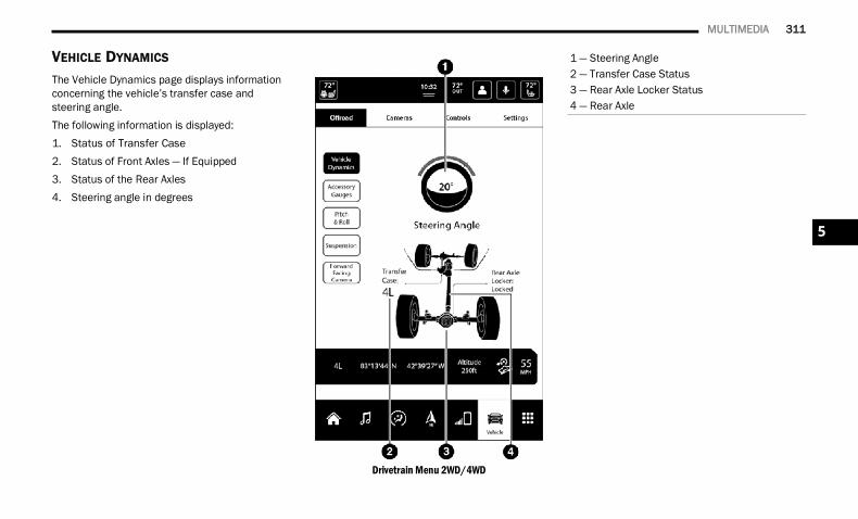
MULTIMEDIA 311
VEHICLE DYNAMICS The Vehicle Dynamics page displays information concerning the vehicle’s transfer case and steering angle.The following information is displayed:1. Status of Transfer Case2. Status of Front Axles — If Equipped3. Status of the Rear Axles4. Steering angle in degrees
Drivetrain Menu 2WD/4WD
1 — Steering Angle2 — Transfer Case Status3 — Rear Axle Locker Status4 — Rear Axle
5
22_DT_OM_EN_USC_t.book Page 311
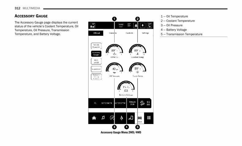
312 MULTIMEDIA
ACCESSORY GAUGE
The Accessory Gauge page displays the current status of the vehicle’s Coolant Temperature, Oil Temperature, Oil Pressure, Transmission Temperature, and Battery Voltage.
Accessory Gauge Menu 2WD/4WD
1 — Oil Temperature2 — Coolant Temperature3 — Oil Pressure4 — Battery Voltage5 — Transmission Temperature
22_DT_OM_EN_USC_t.book Page 312
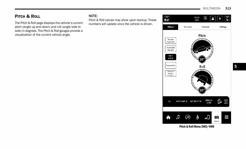
MULTIMEDIA 313
PITCH & ROLL
The Pitch & Roll page displays the vehicle’s current pitch (angle up and down) and roll (angle side to side) in degrees. The Pitch & Roll gauges provide a visualization of the current vehicle angle.
NOTE:Pitch & Roll values may show upon startup. These numbers will update once the vehicle is driven.
Pitch & Roll Menu 2WD/4WD
5
22_DT_OM_EN_USC_t.book Page 313
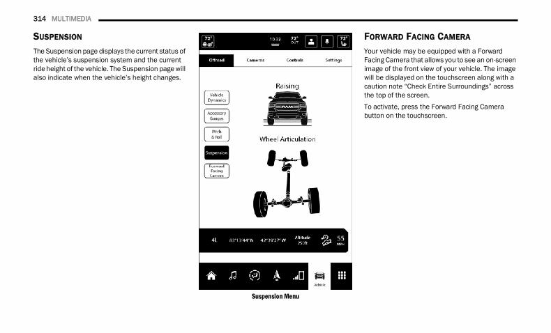
314 MULTIMEDIA
SUSPENSION
The Suspension page displays the current status of the vehicle’s suspension system and the current ride height of the vehicle. The Suspension page will also indicate when the vehicle’s height changes.
Suspension Menu
FORWARD FACING CAMERA
Your vehicle may be equipped with a Forward Facing Camera that allows you to see an on-screen image of the front view of your vehicle. The image will be displayed on the touchscreen along with a caution note “Check Entire Surroundings” across the top of the screen.To activate, press the Forward Facing Camera button on the touchscreen.
22_DT_OM_EN_USC_t.book Page 314
315
(Continued)
SAFETY
SAFETY FEATURESANTI-LOCK BRAKE SYSTEM (ABS) The ABS provides increased vehicle stability and brake performance under most braking conditions. The system automatically prevents wheel lock and enhances vehicle control during braking.The ABS performs a self-check cycle to ensure that the ABS is working properly each time the vehicle is started and driven. During this self-check, you may hear a slight clicking sound as well as some related motor noises.The ABS is activated during braking when the system detects one or more wheels are beginning to lock. Road conditions such as ice, snow, gravel, bumps, railroad tracks, loose debris, or panic stops may increase the likelihood of ABS activation(s).You also may experience the following normal characteristics when the ABS activates: ABS motor noise or clicking sounds (you may
continue to hear for a short time after the stop) Brake pedal pulsations A slight drop of the brake pedal at the end of the
stop
The ABS is designed to function with the Original Equipment Manufacturer (OEM) tires. Modification may result in degraded ABS performance.
Anti-Lock Brake System (ABS) Warning LightThe yellow ABS Warning Light will turn on when the ignition is placed in the ON/RUN mode and may stay on for as long as four seconds.If the ABS Warning Light remains on or comes on while driving, it indicates that the anti-lock portion of the brake system is not functioning and that service is required. However, the conventional brake system will continue to operate normally if the ABS Warning Light is on.
WARNING!
The ABS contains sophisticated electronic equipment that may be susceptible to interfer-ence caused by improperly installed or high output radio transmitting equipment. This interference can cause possible loss of anti-lock braking capability. Installation of such equipment should be performed by qual-ified professionals.
Pumping of the Anti-Lock Brakes will diminish their effectiveness and may lead to a collision. Pumping makes the stopping distance longer. Just press firmly on your brake pedal when you need to slow down or stop.
The ABS cannot prevent the natural laws of physics from acting on the vehicle, nor can it increase braking or steering efficiency beyond that afforded by the condition of the vehicle brakes and tires or the traction afforded.
The ABS cannot prevent collisions, including those resulting from excessive speed in turns, following another vehicle too closely, or hydro-planing.
The capabilities of an ABS equipped vehicle must never be exploited in a reckless or dangerous manner that could jeopardize the user’s safety or the safety of others.
WARNING!
6
22_DT_OM_EN_USC_t.book Page 315
316 SAFETY
If the ABS Warning Light is on, the brake system should be serviced as soon as possible to restore the benefits of anti-lock brakes. If the ABS Warning Light does not come on when the ignition is placed in the ON/RUN mode, have the light repaired as soon as possible.
ELECTRONIC BRAKE CONTROL (EBC) SYSTEM Your vehicle is equipped with an advanced Electronic Brake Control (EBC) system. This system includes Anti-Lock Brake System (ABS), Brake Assist System (BAS), Electronic Brake Force Distribution (EBD), Electronic Roll Mitigation (ERM), Electronic Stability Control (ESC), Hill Start Assist (HSA), and Traction Control System (TCS). These systems work together to enhance both vehicle stability and control in various driving conditions.Your vehicle may also be equipped with Trailer Sway Control (TSC) and Hill Descent Control (HDC).
Brake Assist System (BAS) The BAS is designed to optimize the vehicle’s braking capability during emergency braking maneuvers. The system detects an emergency braking situation by sensing the rate and amount of brake application, and then applies optimum pressure to the brakes. This can help reduce braking distances. The BAS complements the Anti-Lock Brake System (ABS). Applying the brakes very quickly results in the best BAS assistance. To receive the benefit of the system, you must apply continuous braking pressure during the stopping sequence (do not “pump” the brakes). Do not reduce brake pedal pressure unless braking is no longer desired. Once the brake pedal is released, the BAS is deactivated.
Brake System Warning LightThe red Brake System Warning Light will turn on when the ignition is placed in the ON/RUN mode and may stay on for as long as four seconds.If the Brake System Warning Light remains on or comes on while driving, it indicates that the brake system is not functioning properly and that immediate service is required. If the Brake System Warning Light does not come on when the ignition is placed in the ON/RUN mode, have the light repaired as soon as possible.
Electronic Brake Force Distribution (EBD)EBD manages the distribution of the braking torque between the front and rear axles by limiting braking pressure to the rear axle. This is done to prevent overslip of the rear wheels to avoid vehicle instability, and to prevent the rear axle from entering the Anti-Lock Brake System (ABS) before the front axle.
WARNING!
The Brake Assist System (BAS) cannot prevent the natural laws of physics from acting on the vehicle, nor can it increase the traction afforded by prevailing road conditions. BAS cannot prevent collisions, including those resulting from excessive speed in turns, driving on very slippery surfaces, or hydroplaning. The capabilities of a BAS-equipped vehicle must never be exploited in a reckless or dangerous manner, which could jeopardize the user's safety or the safety of others.
22_DT_OM_EN_USC_t.book Page 316
SAFETY 317
(Continued)
Electronic Roll Mitigation (ERM) The ERM system anticipates the potential for wheel lift by monitoring the driver’s steering wheel input and the speed of the vehicle. When ERM determines that the rate of change of the steering wheel angle and vehicle’s speed are sufficient to potentially cause wheel lift, it then applies the appropriate brake and may also reduce engine power to lessen the chance that wheel lift will occur. ERM can only reduce the chance of wheel lift occurring during severe or evasive driving maneuvers; it cannot prevent wheel lift due to other factors, such as road conditions, leaving the roadway, striking objects or other vehicles.
Electronic Stability Control (ESC) ESC enhances directional control and stability of the vehicle under various driving conditions. ESC corrects for oversteering or understeering of the vehicle by applying the brake of the appropriate wheel(s) to counteract the above conditions. Engine power may also be reduced to help the vehicle maintain the desired path. Oversteer — when the vehicle is turning more
than appropriate for the steering wheel position. Understeer — when the vehicle is turning less
than appropriate for the steering wheel position.ESC uses sensors in the vehicle to determine the vehicle path intended by the driver and compares it to the actual path of the vehicle. When the actual path does not match the intended path, ESC applies the brake of the appropriate wheel to assist in counteracting the oversteer or understeer condition.The ESC Activation/Malfunction Indicator Light located in the instrument cluster will start to flash as soon as the ESC system becomes active. The ESC Activation/Malfunction Indicator Light also flashes when the TCS is active. If the ESC Activation/Malfunction Indicator Light begins to flash during acceleration, ease up on the accelerator and apply as little throttle as possible. Be sure to adapt your speed and driving to the prevailing road conditions.
WARNING!
Many factors, such as vehicle loading, road conditions and driving conditions, influence the chance that wheel lift or rollover may occur. ERM cannot prevent all wheel lift or rollovers, especially those that involve leaving the roadway or striking objects or other vehicles. The capabilities of an ERM-equipped vehicle must never be exploited in a reckless or dangerous manner which could jeopardize the user's safety or the safety of others.
WARNING!
Electronic Stability Control (ESC) cannot prevent the natural laws of physics from acting on the vehicle, nor can it increase the traction afforded by prevailing road condi-tions. ESC cannot prevent accidents, including those resulting from excessive speed in turns, driving on very slippery surfaces, or hydro-planing. ESC also cannot prevent accidents resulting from loss of vehicle control due to inappropriate driver input for the conditions. Only a safe, attentive, and skillful driver can prevent accidents. The capabilities of an ESC equipped vehicle must never be exploited in a reckless or dangerous manner which could jeopardize the user’s safety or the safety of others.
6
22_DT_OM_EN_USC_t.book Page 317
318 SAFETY
ESC Operating ModesDepending upon model and mode of operation, the ESC system may have multiple operating modes.ESC OnThis is the normal operating mode for the ESC. Whenever the vehicle is started, the ESC system will be in this mode. This mode should be used for most driving conditions. Alternate ESC modes should only be used for specific reasons as noted in the following paragraphs.
Partial OffThis mode may be useful if the vehicle becomes stuck. This mode may modify TCS and ESC thresholds for activation, which allows for more wheel spin than normally allowed.To enter the “Partial Off” mode, momentarily push the ESC OFF button and the ESC OFF Indicator Light will illuminate. To turn the ESC on again, momentarily push the ESC OFF button and the ESC OFF Indicator Light will turn off.
NOTE:For vehicles with multiple partial ESC modes, the push and release of the button will toggle the ESC modes. Multiple attempts may be required to return to “ESC On”.
Full Off — If EquippedThis mode is intended for off-highway or off-road use only and should not be used on any public roadways. In this mode, TCS and ESC features are turned off. To enter the “Full Off” mode, push and hold the ESC OFF button for five seconds while the vehicle is stopped with the engine running. After five seconds, a chime will sound, the ESC OFF Indicator Light will illuminate, and the “ESC OFF” message will display in the instrument cluster. To turn ESC on again, momentarily push the ESC OFF button.
NOTE:System may switch from ESC “Full Off” to “Partial Off” mode when vehicle exceeds a predetermined speed. When the vehicle speed slows below the predetermined speed the system will return to ESC “Full Off”.ESC modes may also be affected by drive modes(if equipped).
Vehicle modifications, or failure to properly maintain your vehicle, may change the handling characteristics of your vehicle, and may negatively affect the performance of the ESC system. Changes to the steering system, suspension, braking system, tire type and size or wheel size may adversely affect ESC perfor-mance. Improperly inflated and unevenly worn tires may also degrade ESC performance. Any vehicle modification or poor vehicle mainte-nance that reduces the effectiveness of the ESC system can increase the risk of loss of vehicle control, vehicle rollover, personal injury and death.
WARNING!
WARNING!
When in “Partial Off” mode, the TCS function-ality of ESC (except for the limited slip feature described in the TCS section) has been disabled and the ESC OFF Indicator Light will be illuminated. When in “Partial Off” mode, the engine power reduction feature of TCS is disabled, and the enhanced vehicle stability offered by the ESC system is reduced.
Trailer Sway Control (TSC) is disabled when the ESC system is in the “Partial Off” mode.
22_DT_OM_EN_USC_t.book Page 318
SAFETY 319
ESC Activation/Malfunction Indicator Light And ESC OFF Indicator Light
The ESC Activation/Malfunction Indicator Light in the instrument cluster will come on when the ignition is placed in the ON/RUN mode. It should go out with the
engine running. If the ESC Activation/Malfunction Indicator Light comes on continuously with the engine running, a malfunction has been detected in the ESC system. If this light remains on after several ignition cycles, and the vehicle has been driven several miles (kilometers) at speeds greater than 30 mph (48 km/h), see an authorized dealer as soon as possible to have the problem diagnosed and corrected.The ESC Activation/Malfunction Indicator Light starts to flash as soon as the tires lose traction and the ESC system becomes active. The ESC Activation/Malfunction Indicator Light also flashes when TCS is active. If the ESC Activation/Malfunction Indicator Light begins to flash during acceleration, ease up on the accelerator and apply as little throttle as possible. Be sure to adapt your speed and driving to the prevailing road conditions.
The ESC OFF Indicator Light indicates that the Electronic Stability Control (ESC) is in a reduced mode.
NOTE: The ESC Activation/Malfunction Indicator Light
and the ESC OFF Indicator Light come on momentarily each time the ignition is placed in the ON/RUN mode.
Each time the ignition is placed in the ON/RUN mode, the ESC system will be on even if it was turned off previously.
The ESC system will make buzzing or clicking sounds when it is active. This is normal; the sounds will stop when ESC becomes inactive following the maneuver that caused the ESC activation.
Hill Descent Control (HDC) — If Equipped HDC is intended for low speed off-road driving while in 4WD Low. HDC maintains vehicle speed while descending hills during various driving situations. HDC controls vehicle speed by actively controlling the brakes.HDC Has Three States:1. Off (feature is not enabled and will not
activate).2. Enabled (feature is enabled and ready but
activation conditions are not met, or driver is actively overriding with brake or throttle application).
3. Active (feature is enabled and actively controlling vehicle speed).
WARNING!
In the ESC “Full Off” mode, the engine torque reduction and stability features are disabled. Therefore, enhanced vehicle stability offered by the ESC system is unavailable. In an emer-gency evasive maneuver, the ESC system will not engage to assist in maintaining stability. ESC “Full Off” mode is intended for off-highway or off-road use only.
The Electronic Stability Control (ESC) cannot prevent the natural laws of physics from acting on the vehicle, nor can it increase the traction afforded by prevailing road condi-tions. ESC cannot prevent all accidents, including those resulting from excessive speed in turns, driving on very slippery surfaces, or hydroplaning. ESC also cannot prevent collisions.
6
22_DT_OM_EN_USC_t.book Page 319
320 SAFETY
Enabling HDCHDC is enabled by pushing the HDC switch, but the following conditions must also be met to enable HDC: The driveline is in 4WD Low. The vehicle speed is below 5 mph (8 km/h). The parking brake is released. The driver door is closed.Activating HDCOnce HDC is enabled it will activate automatically if driven down a grade of sufficient magnitude. The set speed for HDC is selectable by the driver, and can be adjusted by using the gear shift +/-. The following summarizes the HDC set speeds:HDC Target Set Speeds P = No set speed. HDC may be enabled but will
not activate. R = 0.6 mph (1 km/h) N = 1.2 mph (2 km/h) D = 0.6 mph (1 km/h) 1st = 0.6 mph (1 km/h) 2nd = 1.2 mph (2 km/h) 3rd = 1.8 mph (3 km/h) 4th = 2.5 mph (4 km/h) 5th = 3.1 mph (5 km/h)
6th = 3.7 mph (6 km/h) 7th = 4.3 mph (7 km/h) 8th = 5.0 mph (8 km/h) 9th = 5.6 mph (9 km/h) – If EquippedNOTE:During HDC the +/- shifter input is used for HDC target speed selection, but will not affect the gear chosen by the transmission. When actively controlling HDC the transmission will shift appro-priately for the driver-selected set speed and corre-sponding driving conditions.Driver OverrideThe driver may override HDC activation with throttle or brake application at any time.Deactivating HDCHDC will be deactivated but remain available if any of the following conditions occur: The driver overrides HDC set speed with throttle
or brake application. The vehicle speed exceeds 20 mph (32 km/h)
but remains below 40 mph (64 km/h). The vehicle is on a downhill grade of insufficient
magnitude, is on level ground, or is on an uphill grade.
The vehicle is shifted to PARK.
Disabling HDCHDC will be deactivated and disabled if any of the following conditions occur: The driver pushes the HDC switch. The driveline is shifted out of the 4WD Low. The parking brake is applied. The driver door opens. The vehicle is driven greater than 20 mph
(32 km/h) for greater than 70 seconds. The vehicle is driven greater than 40 mph
(64 km/h) (HDC exits immediately). HDC detects excessive brake temperature.Feedback To The DriverThe instrument cluster has an HDC icon and the HDC switch has an LED icon, which offers feedback to the driver about the state HDC is in. The cluster icon and switch lamp will illuminate
and remain on solid when HDC is enabled or activated. This is the normal operating condition for HDC.
The cluster icon and switch lamp will flash for several seconds, then extinguish when the driver pushes the HDC switch but enable condi-tions are not met.
22_DT_OM_EN_USC_t.book Page 320
SAFETY 321
The cluster icon and switch lamp will flash for several seconds, then extinguish when HDC disables due to excess speed.
The cluster icon and switch lamp will flash when HDC deactivates due to overheated brakes. The flashing will stop and HDC will activate again once the brakes have cooled sufficiently.
Hill Start Assist (HSA) HSA is designed to mitigate roll back from a complete stop while on an incline. If the driver releases the brake while stopped on an incline, HSA will continue to hold the brake pressure for a short period. If the driver does not apply the throttle before this time expires, the system will release brake pressure and the vehicle will roll down the hill as normal.The following conditions must be met in order for HSA to activate: The feature must be enabled. The vehicle must be stopped.
The parking brake must be off. The driver door must be closed. The vehicle must be on a sufficient grade. The gear selection must match vehicle uphill
direction (i.e., vehicle facing uphill is in forward gear; vehicle backing uphill is in REVERSE gear).
HSA will work in REVERSE gear and all forward gears. The system will not activate if the trans-mission is in PARK or NEUTRAL.
Disabling And Enabling HSAThis feature can be turned on or turned off. To change the current setting, proceed as follows:If disabling HSA using Uconnect Settings Ú page 237.
Towing With HSAHSA will also provide assistance to mitigate roll back while towing a trailer.WARNING!
HDC is only intended to assist the driver in controlling vehicle speed when descending hills. The driver must remain attentive to the driving conditions and is responsible for maintaining a safe vehicle speed.
WARNING!
There may be situations where the Hill Start Assist (HSA) will not activate and slight rolling may occur, such as on minor hills or with a loaded vehicle, or while pulling a trailer. HSA is not a substitute for active driving involvement. It is always the driver’s responsibility to be attentive to distance to other vehicles, people, and objects, and most importantly brake operation to ensure safe operation of the vehicle under all road conditions. Your complete attention is always required while driving to maintain safe control of your vehicle. Failure to follow these warnings can result in a collision or serious personal injury.
WARNING!
If you use a trailer brake controller with your trailer, the trailer brakes may be activated and deactivated with the brake switch. If so, there may not be enough brake pressure to hold both the vehicle and the trailer on a hill when the brake pedal is released. In order to avoid rolling down an incline while resuming accel-eration, manually activate the trailer brake or apply more vehicle brake pressure prior to releasing the brake pedal.
HSA is not a parking brake. Always apply the parking brake fully when exiting your vehicle. Also, be certain to place the transmission in PARK.
Failure to follow these warnings can result in a collision or serious personal injury.
6
22_DT_OM_EN_USC_t.book Page 321
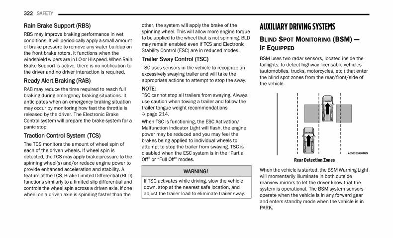
322 SAFETY
Rain Brake Support (RBS)RBS may improve braking performance in wet conditions. It will periodically apply a small amount of brake pressure to remove any water buildup on the front brake rotors. It functions when the windshield wipers are in LO or HI speed. When Rain Brake Support is active, there is no notification to the driver and no driver interaction is required.
Ready Alert Braking (RAB)RAB may reduce the time required to reach full braking during emergency braking situations. It anticipates when an emergency braking situation may occur by monitoring how fast the throttle is released by the driver. The Electronic Brake Control system will prepare the brake system for a panic stop.
Traction Control System (TCS) The TCS monitors the amount of wheel spin of each of the driven wheels. If wheel spin is detected, the TCS may apply brake pressure to the spinning wheel(s) and/or reduce engine power to provide enhanced acceleration and stability. A feature of the TCS, Brake Limited Differential (BLD) functions similarly to a limited slip differential and controls the wheel spin across a driven axle. If one wheel on a driven axle is spinning faster than the
other, the system will apply the brake of the spinning wheel. This will allow more engine torque to be applied to the wheel that is not spinning. BLD may remain enabled even if TCS and Electronic Stability Control (ESC) are in reduced modes.
Trailer Sway Control (TSC) TSC uses sensors in the vehicle to recognize an excessively swaying trailer and will take the appropriate actions to attempt to stop the sway.NOTE:TSC cannot stop all trailers from swaying. Always use caution when towing a trailer and follow the trailer tongue weight recommendations Ú page 214.When TSC is functioning, the ESC Activation/Malfunction Indicator Light will flash, the engine power may be reduced and you may feel the brakes being applied to individual wheels to attempt to stop the trailer from swaying. TSC is disabled when the ESC system is in the “Partial Off” or “Full Off” modes.
AUXILIARY DRIVING SYSTEMSBLIND SPOT MONITORING (BSM) — IF EQUIPPED BSM uses two radar sensors, located inside the taillights, to detect highway licensable vehicles (automobiles, trucks, motorcycles, etc.) that enter the blind spot zones from the rear/front/side of the vehicle.
Rear Detection Zones
When the vehicle is started, the BSM Warning Light will momentarily illuminate in both outside rearview mirrors to let the driver know that the system is operational. The BSM system sensors operate when the vehicle is in any forward gear and enters standby mode when the vehicle is in PARK.
WARNING!
If TSC activates while driving, slow the vehicle down, stop at the nearest safe location, and adjust the trailer load to eliminate trailer sway.
22_DT_OM_EN_USC_t.book Page 322
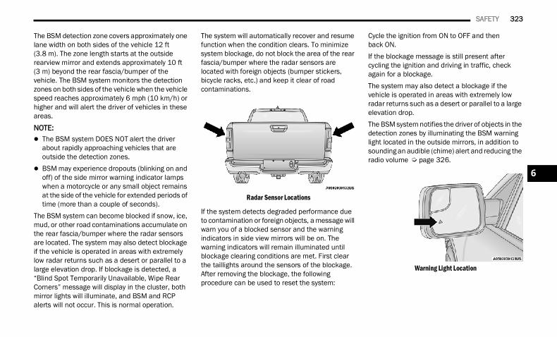
SAFETY 323
The BSM detection zone covers approximately one lane width on both sides of the vehicle 12 ft (3.8 m). The zone length starts at the outside rearview mirror and extends approximately 10 ft (3 m) beyond the rear fascia/bumper of the vehicle. The BSM system monitors the detection zones on both sides of the vehicle when the vehicle speed reaches approximately 6 mph (10 km/h) or higher and will alert the driver of vehicles in these areas.
NOTE: The BSM system DOES NOT alert the driver
about rapidly approaching vehicles that are outside the detection zones.
BSM may experience dropouts (blinking on and off) of the side mirror warning indicator lamps when a motorcycle or any small object remains at the side of the vehicle for extended periods of time (more than a couple of seconds).
The BSM system can become blocked if snow, ice, mud, or other road contaminations accumulate on the rear fascia/bumper where the radar sensors are located. The system may also detect blockage if the vehicle is operated in areas with extremely low radar returns such as a desert or parallel to a large elevation drop. If blockage is detected, a “Blind Spot Temporarily Unavailable, Wipe Rear Corners” message will display in the cluster, both mirror lights will illuminate, and BSM and RCP alerts will not occur. This is normal operation.
The system will automatically recover and resume function when the condition clears. To minimize system blockage, do not block the area of the rear fascia/bumper where the radar sensors are located with foreign objects (bumper stickers, bicycle racks, etc.) and keep it clear of road contaminations.
Radar Sensor Locations
If the system detects degraded performance due to contamination or foreign objects, a message will warn you of a blocked sensor and the warning indicators in side view mirrors will be on. The warning indicators will remain illuminated until blockage clearing conditions are met. First clear the taillights around the sensors of the blockage. After removing the blockage, the following procedure can be used to reset the system:
Cycle the ignition from ON to OFF and thenback ON.If the blockage message is still present after cycling the ignition and driving in traffic, check again for a blockage.The system may also detect a blockage if the vehicle is operated in areas with extremely low radar returns such as a desert or parallel to a large elevation drop.The BSM system notifies the driver of objects in the detection zones by illuminating the BSM warning light located in the outside mirrors, in addition to sounding an audible (chime) alert and reducing the radio volume Ú page 326.
Warning Light Location
6
22_DT_OM_EN_USC_t.book Page 323
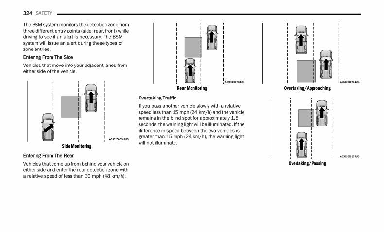
324 SAFETY
The BSM system monitors the detection zone from three different entry points (side, rear, front) while driving to see if an alert is necessary. The BSM system will issue an alert during these types of zone entries.Entering From The SideVehicles that move into your adjacent lanes from either side of the vehicle.
Side Monitoring
Entering From The RearVehicles that come up from behind your vehicle on either side and enter the rear detection zone with a relative speed of less than 30 mph (48 km/h).
Rear Monitoring
Overtaking TrafficIf you pass another vehicle slowly with a relative speed less than 15 mph (24 km/h) and the vehicle remains in the blind spot for approximately 1.5 seconds, the warning light will be illuminated. If the difference in speed between the two vehicles is greater than 15 mph (24 km/h), the warning light will not illuminate.
Overtaking/Approaching
Overtaking/Passing
22_DT_OM_EN_USC_t.book Page 324
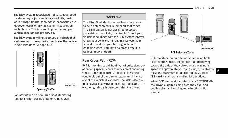
SAFETY 325
The BSM system is designed not to issue an alert on stationary objects such as guardrails, posts, walls, foliage, berms, snow banks, car washes, etc. However, occasionally the system may alert on such objects. This is normal operation and your vehicle does not require service.The BSM system will not alert you of objects that are traveling in the opposite direction of the vehicle in adjacent lanes Ú page 485.
Opposing Traffic
For information on how Blind Spot Monitoring functions when pulling a trailer Ú page 326.
Rear Cross Path (RCP) RCP is intended to aid the driver when backing out of parking spaces where their vision of oncoming vehicles may be blocked. Proceed slowly and cautiously out of the parking space until the rear end of the vehicle is exposed. The RCP system will then have a clear view of the cross traffic, and if an oncoming vehicle is detected, alert the driver.
RCP Detection Zones
RCP monitors the rear detection zones on both sides of the vehicle, for objects that are moving toward the side of the vehicle with a minimum speed of approximately 3 mph (5 km/h), to objects moving a maximum of approximately 20 mph (32 km/h), such as in parking lot situations.When RCP is on and the vehicle is in REVERSE (R), the driver is alerted using both the visual and audible alarms, including reducing the radio volume.
WARNING!
The Blind Spot Monitoring system is only an aid to help detect objects in the blind spot zones. The BSM system is not designed to detect pedestrians, bicyclists, or animals. Even if your vehicle is equipped with the BSM system, always check your vehicle’s mirrors, glance over your shoulder, and use your turn signal before changing lanes. Failure to do so can result in serious injury or death.
6
22_DT_OM_EN_USC_t.book Page 325
326 SAFETY
NOTE:In a parking lot situation, oncoming vehicles can be blocked by vehicles parked on either side. If the sensors are blocked by other structures or vehicles, the system will not be able to alert the driver.
Blind Spot ModesBlind Spot has three selectable modes of operation that are available in the Uconnect system.
Blind Spot Alert Lights OnlyWhen operating in Blind Spot Alert mode, the BSM system will provide a visual alert in the appropriate side view mirror based on a detected object. However, when the system is operating in Rear Cross Path (RCP) mode, the system will respond with both visual and audible alerts when a detected object is present. Whenever an audible alert is requested, the radio is muted.Blind Spot Alert Lights/ChimeWhen operating in Blind Spot Alert Lights/Chime mode, the BSM system will provide a visual alert in the appropriate side view mirror based on a detected object. If the turn signal is then activated, and it corresponds to an alert present on that side of the vehicle, an audible chime will also be sounded. Whenever a turn signal and detected object are present on the same side at the same time, both the visual and audible alerts will be issued. In addition to the audible alert the radio (if on) will also be muted.
NOTE:Whenever an audible alert is requested by the BSM system, the radio is also muted.
When the system is in RCP, the system shall respond with both visual and audible alerts when a detected object is present. Whenever an audible alert is requested, the radio is also muted. Turn/hazard signal status is ignored; the RCP state always requests the chime.Blind Spot Alert OffWhen the BSM system is turned off there will be no visual or audible alerts from either the BSM, RCP, or Trailer Merge Assist systems.
NOTE:The BSM system will store the current operating mode when the vehicle is shut off. Each time the vehicle is started the previously stored mode will be recalled and used.Trailer Merge Assist — If EquippedTrailer Merge Assist is a function of the Blind Spot Monitoring (BSM) system that extends the blind spot zone to work while pulling a trailer.NOTE:When Trailer Merge Assist is activated, Rear Cross Path is disabled.
WARNING!
Rear Cross Path Detection (RCP) is not a backup aid system. It is intended to be used to help a driver detect an oncoming vehicle in a parking lot situation. Drivers must be careful when backing up, even when using RCP. Always check carefully behind your vehicle, look behind you, and be sure to check for pedestrians, animals, other vehicles, obstructions, and blind spots before backing up. Failure to do so can result in serious injury or death.
22_DT_OM_EN_USC_t.book Page 326
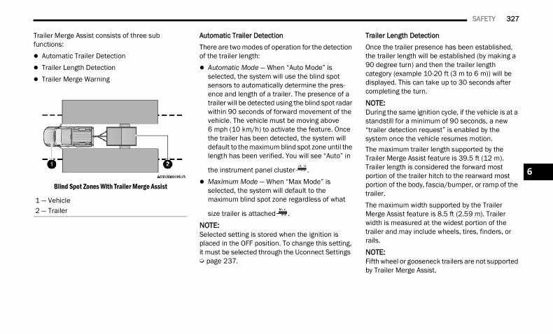
SAFETY 327
Trailer Merge Assist consists of three sub functions: Automatic Trailer Detection Trailer Length Detection Trailer Merge Warning
Blind Spot Zones With Trailer Merge Assist
Automatic Trailer DetectionThere are two modes of operation for the detection of the trailer length: Automatic Mode — When “Auto Mode” is
selected, the system will use the blind spot sensors to automatically determine the pres-ence and length of a trailer. The presence of a trailer will be detected using the blind spot radar within 90 seconds of forward movement of the vehicle. The vehicle must be moving above 6 mph (10 km/h) to activate the feature. Once the trailer has been detected, the system will default to the maximum blind spot zone until the length has been verified. You will see “Auto” in
the instrument panel cluster . Maximum Mode — When “Max Mode” is
selected, the system will default to the maximum blind spot zone regardless of what
size trailer is attached .NOTE:Selected setting is stored when the ignition is placed in the OFF position. To change this setting, it must be selected through the Uconnect Settings Ú page 237.
Trailer Length DetectionOnce the trailer presence has been established, the trailer length will be established (by making a 90 degree turn) and then the trailer length category (example 10-20 ft (3 m to 6 m)) will be displayed. This can take up to 30 seconds after completing the turn.
NOTE:During the same ignition cycle, if the vehicle is at a standstill for a minimum of 90 seconds, a new “trailer detection request” is enabled by the system once the vehicle resumes motion.The maximum trailer length supported by the Trailer Merge Assist feature is 39.5 ft (12 m). Trailer length is considered the forward most portion of the trailer hitch to the rearward most portion of the body, fascia/bumper, or ramp of the trailer.The maximum width supported by the Trailer Merge Assist feature is 8.5 ft (2.59 m). Trailer width is measured at the widest portion of the trailer and may include wheels, tires, finders, or rails.
NOTE:Fifth wheel or gooseneck trailers are not supported by Trailer Merge Assist.
1 — Vehicle2 — Trailer
6
22_DT_OM_EN_USC_t.book Page 327
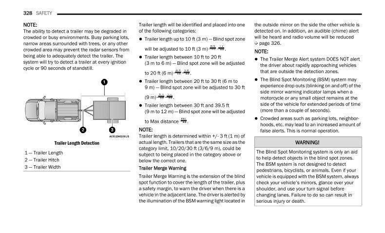
328 SAFETY
NOTE:The ability to detect a trailer may be degraded in crowded or busy environments. Busy parking lots, narrow areas surrounded with trees, or any other crowded area may prevent the radar sensors from being able to adequately detect the trailer. The system will try to detect a trailer at every ignition cycle or 90 seconds of standstill.
Trailer Length Detection
Trailer length will be identified and placed into one of the following categories: Trailer length up to 10 ft (3 m) — Blind spot zone
will be adjusted to 10 ft (3 m) . Trailer length between 10 ft to 20 ft
(3 m to 6 m) — Blind spot zone will be adjusted
to 20 ft (6 m) . Trailer length between 20 ft to 30 ft (6 m to
9 m) — Blind spot zone will be adjusted to 30 ft
(9 m) . Trailer length between 30 ft and 39.5 ft
(9 m to 12 m) — Blind spot zone will be adjusted
to Max distance .NOTE:Trailer length is determined within +/- 3 ft (1 m) of actual length. Trailers that are the same size as the category limit, 10/20/30 ft (3/6/9 m), could be subject to being placed in the category above or below the correct one.Trailer Merge WarningTrailer Merge Warning is the extension of the blind spot function to cover the length of the trailer, plus a safety margin, to warn the driver when there is a vehicle in the adjacent lane. The driver is alerted by the illumination of the BSM warning light located in
the outside mirror on the side the other vehicle is detected on. In addition, an audible (chime) alert will be heard and radio volume will be reduced Ú page 326.
NOTE: The Trailer Merge Alert system DOES NOT alert
the driver about rapidly approaching vehicles that are outside the detection zones.
The Blind Spot Monitoring (BSM) system may experience drop outs (blinking on and off) of the side mirror warning indicator lamps when a motorcycle or any small object remains at the side of the vehicle for extended periods of time (more than a couple of seconds).
Crowded areas such as parking lots, neighbor-hoods, etc. may lead to an increased amount of false alerts. This is normal operation.
1 — Trailer Length2 — Trailer Hitch3 — Trailer Width
WARNING!
The Blind Spot Monitoring system is only an aid to help detect objects in the blind spot zones. The BSM system is not designed to detect pedestrians, bicyclists, or animals. Even if your vehicle is equipped with the BSM system, always check your vehicle’s mirrors, glance over your shoulder, and use your turn signal before changing lanes. Failure to do so can result in serious injury or death.
22_DT_OM_EN_USC_t.book Page 328
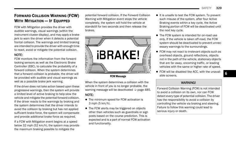
SAFETY 329
FORWARD COLLISION WARNING (FCW) WITH MITIGATION — IF EQUIPPED
FCW with Mitigation provides the driver with audible warnings, visual warnings (within the instrument cluster display), and may apply a brake jerk to warn the driver when it detects a potential frontal collision. The warnings and limited braking are intended to provide the driver with enough time to react, avoid or mitigate the potential collision.
NOTE:FCW monitors the information from the forward looking sensors as well as the Electronic Brake Controller (EBC), to calculate the probability of a forward collision. When the system determines that a forward collision is probable, the driver will be provided with audible and visual warnings as well as a possible brake jerk warning. If the driver does not take action based upon these progressive warnings, then the system will provide a limited level of active braking to help slow the vehicle and mitigate the potential forward collision. If the driver reacts to the warnings by braking and the system determines that the driver intends to avoid the collision by braking but has not applied sufficient brake force, the system will compensate and provide additional brake force as required.If a FCW with Mitigation event begins at a speed below 32 mph (52 km/h), the system may provide the maximum braking possible to mitigate the
potential forward collision. If the Forward Collision Warning with Mitigation event stops the vehicle completely, the system will hold the vehicle at standstill for two seconds and then release the brakes.
FCW Message
When the system determines a collision with the vehicle in front of you is no longer probable, the warning message will be deactivated Ú page 485.
NOTE: The minimum speed for FCW activation is
3 mph (5 km/h). The FCW alerts may be triggered on objects
other than vehicles such as guardrails or sign posts based on the course prediction. This is expected and is a part of normal FCW activation and functionality.
It is unsafe to test the FCW system. To prevent such misuse of the system, after four Active Braking events within a key cycle, the Active Braking portion of FCW will be deactivated until the next key cycle.
The FCW system is intended for on-road use only. If the vehicle is taken off-road, the FCW system should be deactivated to prevent unnec-essary warnings to the surroundings.
FCW may not react to irrelevant objects such as overhead objects, ground reflections, objects not in the path of the vehicle, stationary objects that are far away, oncoming traffic, or leading vehicles with the same or higher rate of speed.
FCW will be disabled like ACC, with the unavail-able screens.
WARNING!
Forward Collision Warning (FCW) is not intended to avoid a collision on its own, nor can FCW detect every type of potential collision. The driver has the responsibility to avoid a collision by controlling the vehicle via braking and steering. Failure to follow this warning could lead to serious injury or death.
6
22_DT_OM_EN_USC_t.book Page 329
330 SAFETY
Turning FCW On Or OffThe FCW button is located in the Uconnect display in the control settings Ú page 237. To turn the FCW system on, press the forward
collision button once. To turn the FCW system off, press the forward
collision button once.NOTE: When the FCW is “on”, this allows the system to
warn the driver of a possible collision with the vehicle in front.
When the FCW is “off”, this prevents the system from warning the driver of a possible collision with the vehicle in front. If the FCW is set to “off”, “FCW OFF” will be displayed in the instrument cluster display.
When FCW status is set to “Only Warning”, this prevents the system from providing limited active braking, or additional brake support if the driver is not braking adequately in the event of a potential frontal collision.
When FCW status is set to “Warning and Braking”, this allows the system to warn the driver of a possible collision with the vehicle in front using audible/visual warnings and it applies autonomous braking.
The FCW system state is defaulted to “Full On” from one ignition cycle to the next. If the system is turned off, it will reset to “Full On” when the vehicle is restarted.
FCW Braking Status And SensitivityThe FCW Sensitivity and Active Braking status are programmable through the Uconnect system Ú page 237. Far
When the sensitivity of FCW is set to the “Far” setting and the system status is “Only Warning”, this allows the system to warn the driver of a possible more distant collision with the vehicle in front using audible/visual warnings.
More cautious drivers that do not mind frequent warnings may prefer this setting.
Medium When the sensitivity of FCW is set to the
“Medium” setting and the system status is “Only Warning”, this allows the system to warn the driver of a possible collision with the vehicle in front using audible/visual warnings.
Near When the sensitivity of FCW is set to the
“Near” setting and the system status is “Only Warning”, this allows the system to warn the driver of a possible closer collision with the vehicle in front using audible/visual warnings.
This setting provides less reaction time than the “Far” and “Medium” settings, which allows for a more dynamic driving experi-ence.
More dynamic or aggressive drivers that want to avoid frequent warnings may prefer this setting.
22_DT_OM_EN_USC_t.book Page 330
SAFETY 331
FCW Limited WarningIf the instrument cluster displays “ACC/FCW Limited Functionality” or “ACC/FCW Limited Functionality Clean Front Windshield” momentarily, there may be a condition that limits FCW functionality. Although the vehicle is still driveable under normal conditions, the active braking may not be fully available. Once the condition that limited the system performance is no longer present, the system will return to its full performance state. If the problem persists, see an authorized dealer.
Service FCW WarningIf the system turns off, and the instrument cluster displays: ACC/FCW Unavailable Service Required Cruise/FCW Unavailable Service RequiredThis indicates there is an internal system fault. Although the vehicle is still drivable under normal conditions, have the system checked by an authorized dealer.
Pedestrian Emergency Braking (PEB) — If Equipped PEB is a subsystem of the FCW system that provides the driver with audible and visual warnings in the instrument cluster display, and may apply automatic braking when it detects a potential frontal collision with a pedestrian.If a PEB event begins at a speed below 37 mph (60 km/h), the system may provide braking to mitigate the potential collision with a pedestrian. If the PEB event stops the vehicle completely, the system will hold the vehicle at a standstill for two seconds and then release the brakes. When the system determines a collision with the pedestrian in front of you is no longer probable, the warning message will be deactivated.The minimum speed for PEB activation is 3 mph (5 km/h).
Turning PEB On Or Off
NOTE:The default status of PEB is “On.” This allows the system to warn you of a possible frontal collision with the pedestrian.The PEB button is located in the Uconnect display in the controls settings Ú page 237.To turn the PEB system off, push the Pedestrian Emergency Braking button once.To turn the PEB system back on, push the Pedestrian Emergency Braking button again.Changing the PEB status to “Off” deactivates the system, so no warning or active braking will be available in case of a possible frontal collision with the pedestrian.
NOTE:The PEB system will retain the last setting selected by the driver after ignition shut down.
WARNING!
Pedestrian Emergency Braking (PEB) is not intended to avoid a collision on its own, nor can PEB detect every type of potential collision with a pedestrian. The driver has the responsibility to avoid a collision by controlling the vehicle via braking and steering. Failure to follow this warning could lead to serious injury or death.
6
22_DT_OM_EN_USC_t.book Page 331
332 SAFETY
(Continued)
TIRE PRESSURE MONITORING SYSTEM (TPMS) TPMS will warn the driver of a low tire pressure based on the vehicle recommended cold placard pressure.NOTE:The TPMS Warning Light will illuminate in the instrument cluster and a chime will sound when tire pressure is low in one or more of the four active road tires. In addition, the instrument cluster will display a graphic showing the pressure values of each tire with the low tire pressure values in a different color, or the Uconnect radio will display a TPMS message; when this occurs you must increase the tire pressure to the recommended cold placard pressure in order for the TPMS Warning Light to turn off.The tire pressure will vary with temperature by about 1 psi (7 kPa) for every 12°F (6.5°C). This means that when the outside temperature decreases, the tire pressure will decrease. Tire pressure should always be set based on cold inflation tire pressure. This is defined as the tire pressure after the vehicle has not been driven for at least three hours, or driven less than 1 mile (1.6 km) after a three hour period. The cold tire
inflation pressure must not exceed the maximum inflation pressure molded into the tire sidewall. The tire pressure will also increase as the vehicle is driven — this is normal and there should be no adjustment for this increased pressure.See Ú page 448 on how to properly inflate the vehicle’s tires.The TPMS will warn the driver of a low tire pressure if the tire pressure falls below the low-pressure warning limit for any reason, including low temperature effects and natural pressure loss through the tire Ú page 485.The TPMS will continue to warn the driver of low tire pressure as long as the condition exists, and will not turn off until the tire pressure is at or above the recommended cold placard pressure. Once the low TPMS Warning Light illuminates, increase the tire pressure to the recommended cold placard pressure in order for the TPMS Warning Light to turn off. The system will automatically update and the TPMS Warning Light will turn off once the system receives the updated tire pressures. The vehicle may need to be driven for up to 20 minutes above 15 mph (24 km/h) in order for the TPMS to receive this information.
NOTE:When filling warm tires, the tire pressure may need to be increased up to an additional 4 psi (28 kPa) above the recommended cold placard pressure in order to turn the TPMS Warning Light off.
For example, your vehicle may have a recommended cold (parked for more than three hours) placard pressure of 30 psi (207 kPa). If the ambient temperature is 68°F (20°C) and the measured tire pressure is 27 psi (186 kPa), a temperature drop to 20°F (-7°C) will decrease the tire pressure to approximately 23 psi (158 kPa). This tire pressure is sufficiently low enough to turn on the TPMS Warning Light. Driving the vehicle may cause the tire pressure to rise to approximately 27 psi (186 kPa), but the TPMS Warning Light will still be on. In this situation, the TPMS Warning Light will turn off only after the tires are inflated to the vehicle’s recommended cold placard pressure value.
CAUTION!
The TPMS has been optimized for the original equipment tires and wheels. TPMS pressures and warning have been established for the tire size equipped on your vehicle. Undesirable system operation or sensor damage may result when using replacement equipment that is not of the same size, type, and/or style. Aftermarket wheels can cause sensor damage.
22_DT_OM_EN_USC_t.book Page 332
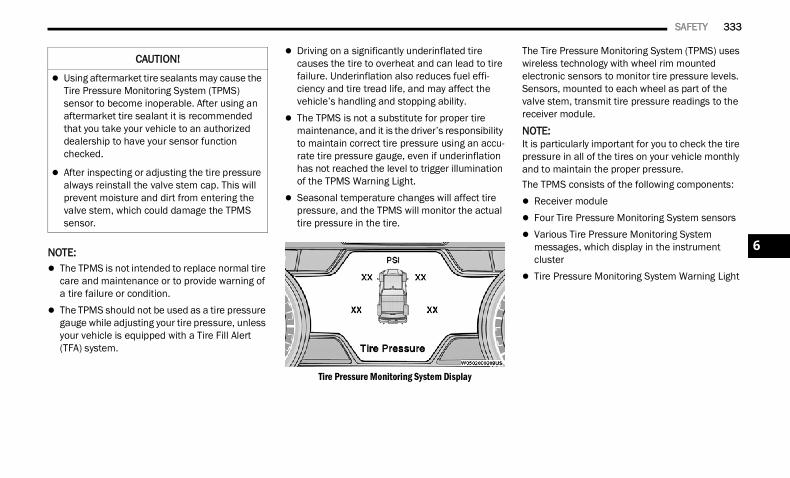
SAFETY 333
NOTE: The TPMS is not intended to replace normal tire
care and maintenance or to provide warning of a tire failure or condition.
The TPMS should not be used as a tire pressure gauge while adjusting your tire pressure, unless your vehicle is equipped with a Tire Fill Alert (TFA) system.
Driving on a significantly underinflated tire causes the tire to overheat and can lead to tire failure. Underinflation also reduces fuel effi-ciency and tire tread life, and may affect the vehicle’s handling and stopping ability.
The TPMS is not a substitute for proper tire maintenance, and it is the driver’s responsibility to maintain correct tire pressure using an accu-rate tire pressure gauge, even if underinflation has not reached the level to trigger illumination of the TPMS Warning Light.
Seasonal temperature changes will affect tire pressure, and the TPMS will monitor the actual tire pressure in the tire.
Tire Pressure Monitoring System Display
The Tire Pressure Monitoring System (TPMS) uses wireless technology with wheel rim mounted electronic sensors to monitor tire pressure levels. Sensors, mounted to each wheel as part of the valve stem, transmit tire pressure readings to the receiver module.
NOTE:It is particularly important for you to check the tire pressure in all of the tires on your vehicle monthly and to maintain the proper pressure.The TPMS consists of the following components: Receiver module Four Tire Pressure Monitoring System sensors Various Tire Pressure Monitoring System
messages, which display in the instrument cluster
Tire Pressure Monitoring System Warning Light
Using aftermarket tire sealants may cause the Tire Pressure Monitoring System (TPMS) sensor to become inoperable. After using an aftermarket tire sealant it is recommended that you take your vehicle to an authorized dealership to have your sensor function checked.
After inspecting or adjusting the tire pressure always reinstall the valve stem cap. This will prevent moisture and dirt from entering the valve stem, which could damage the TPMS sensor.
CAUTION!
6
22_DT_OM_EN_USC_t.book Page 333
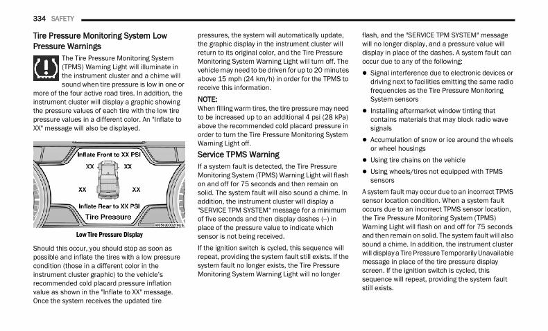
334 SAFETY
Tire Pressure Monitoring System Low Pressure Warnings
The Tire Pressure Monitoring System (TPMS) Warning Light will illuminate in the instrument cluster and a chime will sound when tire pressure is low in one or
more of the four active road tires. In addition, the instrument cluster will display a graphic showing the pressure values of each tire with the low tire pressure values in a different color. An "Inflate to XX" message will also be displayed.
Low Tire Pressure Display
Should this occur, you should stop as soon as possible and inflate the tires with a low pressure condition (those in a different color in the instrument cluster graphic) to the vehicle’s recommended cold placard pressure inflation value as shown in the "Inflate to XX" message. Once the system receives the updated tire
pressures, the system will automatically update, the graphic display in the instrument cluster will return to its original color, and the Tire Pressure Monitoring System Warning Light will turn off. The vehicle may need to be driven for up to 20 minutes above 15 mph (24 km/h) in order for the TPMS to receive this information.
NOTE:When filling warm tires, the tire pressure may need to be increased up to an additional 4 psi (28 kPa) above the recommended cold placard pressure in order to turn the Tire Pressure Monitoring System Warning Light off.Service TPMS WarningIf a system fault is detected, the Tire Pressure Monitoring System (TPMS) Warning Light will flash on and off for 75 seconds and then remain on solid. The system fault will also sound a chime. In addition, the instrument cluster will display a "SERVICE TPM SYSTEM" message for a minimum of five seconds and then display dashes (--) in place of the pressure value to indicate which sensor is not being received.If the ignition switch is cycled, this sequence will repeat, providing the system fault still exists. If the system fault no longer exists, the Tire Pressure Monitoring System Warning Light will no longer
flash, and the "SERVICE TPM SYSTEM" message will no longer display, and a pressure value will display in place of the dashes. A system fault can occur due to any of the following: Signal interference due to electronic devices or
driving next to facilities emitting the same radio frequencies as the Tire Pressure Monitoring System sensors
Installing aftermarket window tinting that contains materials that may block radio wave signals
Accumulation of snow or ice around the wheels or wheel housings
Using tire chains on the vehicle Using wheels/tires not equipped with TPMS
sensorsA system fault may occur due to an incorrect TPMS sensor location condition. When a system fault occurs due to an incorrect TPMS sensor location, the Tire Pressure Monitoring System (TPMS) Warning Light will flash on and off for 75 seconds and then remain on solid. The system fault will also sound a chime. In addition, the instrument cluster will display a Tire Pressure Temporarily Unavailable message in place of the tire pressure display screen. If the ignition switch is cycled, this sequence will repeat, providing the system fault still exists.
22_DT_OM_EN_USC_t.book Page 334
SAFETY 335
If the system fault no longer exists, the “Tire Pressure Monitoring System Warning Light” will no longer flash and the tire pressure display screen will be displayed showing the tire pressure values the correct locations.Vehicles With Non-Matching Full Size Spare Or Compact Spare The non-matching full size spare or compact
spare tire does not have a TPMS sensor. There-fore, the TPMS will not monitor the pressure in the non-matching full size spare or compact spare tire.
If you install the non-matching full size spare or compact spare tire in place of a road tire that has a pressure below the low-pressure warning limit, upon the next ignition switch cycle, the Tire Pressure Monitoring System (TPMS) Warning Light and a “LOW TIRE” message will remain on and a chime will sound. In addition, the graphic in the instrument cluster will still display a pres-sure value in a different color and an “Inflate to XX” message.
After driving the vehicle for up to 20 minutes above 15 mph (24 km/h), the Tire Pressure Monitoring System (TPMS) Warning Light will flash on and off for 75 seconds and then remain on solid. In addition, the instrument cluster will display a "SERVICE TPM SYSTEM" message for a minimum of five seconds and then display dashes (--) in place of the pressure value.
For each subsequent ignition switch cycle, a chime will sound, the Tire Pressure Monitoring System (TPMS) Warning Light will flash on and off for 75 seconds and then remain on solid, and the instrument cluster will display a "SERVICE TPM SYSTEM" message for a minimum of five seconds and then display dashes (--) in place of the pressure value.
Once you repair or replace the original road tire and reinstall it on the vehicle in place of the non-matching full size spare or compact spare, the TPMS will update automatically. In addition, the Tire Pressure Monitoring System (TPMS) Warning Light will turn off and the graphic in the instrument cluster will display a new pressure value instead of dashes (--), as long as no tire pressure is below the low-pressure warning limit in any of the four active road tires. The vehicle may need to be driven for up to 20 minutes above 15 mph (24 km/h) in order for the TPMS to receive this information.
Tire Fill AlertThis feature notifies the user when the placard tire pressure is attained while inflating or deflating the tire.You may choose to disable or enable the Tire Fill Alert feature through use of the Uconnect Settings in the radio.
NOTE: Only one tire can be filled at a time when using
the Tire Fill Alert system. The Tire Fill Alert feature cannot be entered if an
existing TPMS fault is set to “active” or if the system is in deactivation mode (if equipped).
The system will be activated when a positive increase in tire pressure is detected by the TPMS while inflating the tire. The ignition must be in the RUN mode, with the transmission in PARK.
NOTE:It is not required to have the engine running to enter Tire Fill Alert mode.The hazard lamps will come on to confirm the vehicle is in Tire Fill Alert mode.
6
22_DT_OM_EN_USC_t.book Page 335
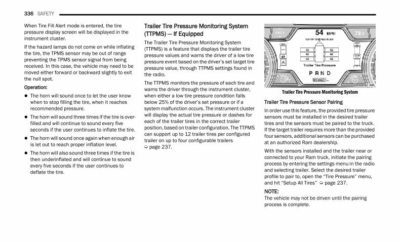
336 SAFETY
When Tire Fill Alert mode is entered, the tire pressure display screen will be displayed in the instrument cluster.If the hazard lamps do not come on while inflating the tire, the TPMS sensor may be out of range preventing the TPMS sensor signal from being received. In this case, the vehicle may need to be moved either forward or backward slightly to exit the null spot.Operation: The horn will sound once to let the user know
when to stop filling the tire, when it reaches recommended pressure.
The horn will sound three times if the tire is over-filled and will continue to sound every five seconds if the user continues to inflate the tire.
The horn will sound once again when enough air is let out to reach proper inflation level.
The horn will also sound three times if the tire is then underinflated and will continue to sound every five seconds if the user continues to deflate the tire.
Trailer Tire Pressure Monitoring System (TTPMS) — If EquippedThe Trailer Tire Pressure Monitoring System (TTPMS) is a feature that displays the trailer tire pressure values and warns the driver of a low tire pressure event based on the driver’s set target tire pressure value, through TTPMS settings found in the radio.The TTPMS monitors the pressure of each tire and warns the driver through the instrument cluster, when either a low tire pressure condition falls below 25% of the driver’s set pressure or if a system malfunction occurs. The instrument cluster will display the actual tire pressure or dashes for each of the trailer tires in the correct trailer position, based on trailer configuration. The TTPMS can support up to 12 trailer tires per configured trailer on up to four configurable trailers Ú page 237.
Trailer Tire Pressure Monitoring System
Trailer Tire Pressure Sensor PairingIn order use this feature, the provided tire pressure sensors must be installed in the desired trailer tires and the sensors must be paired to the truck. If the target trailer requires more than the provided four sensors, additional sensors can be purchased at an authorized Ram dealership.With the sensors installed and the trailer near or connected to your Ram truck, initiate the pairing process by entering the settings menu in the radio and selecting trailer. Select the desired trailer profile to pair to, open the “Tire Pressure” menu, and hit “Setup All Tires” Ú page 237.
NOTE:The vehicle may not be driven until the pairing process is complete.
22_DT_OM_EN_USC_t.book Page 336
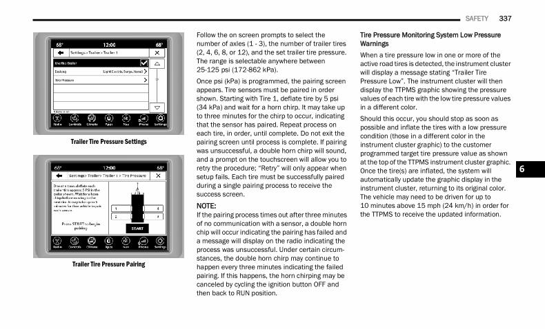
SAFETY 337
Trailer Tire Pressure Settings
Trailer Tire Pressure Pairing
Follow the on screen prompts to select thenumber of axles (1 - 3), the number of trailer tires (2, 4, 6, 8, or 12), and the set trailer tire pressure. The range is selectable anywhere between 25-125 psi (172-862 kPa).Once psi (kPa) is programmed, the pairing screen appears. Tire sensors must be paired in order shown. Starting with Tire 1, deflate tire by 5 psi(34 kPa) and wait for a horn chirp. It may take up to three minutes for the chirp to occur, indicating that the sensor has paired. Repeat process on each tire, in order, until complete. Do not exit the pairing screen until process is complete. If pairing was unsuccessful, a double horn chirp will sound, and a prompt on the touchscreen will allow you to retry the procedure; “Retry” will only appear when setup fails. Each tire must be successfully paired during a single pairing process to receive the success screen.
NOTE:If the pairing process times out after three minutes of no communication with a sensor, a double horn chip will occur indicating the pairing has failed and a message will display on the radio indicating the process was unsuccessful. Under certain circum-stances, the double horn chirp may continue to happen every three minutes indicating the failed pairing. If this happens, the horn chirping may be canceled by cycling the ignition button OFF and then back to RUN position.
Tire Pressure Monitoring System Low Pressure WarningsWhen a tire pressure low in one or more of the active road tires is detected, the instrument cluster will display a message stating “Trailer Tire Pressure Low”. The instrument cluster will then display the TTPMS graphic showing the pressure values of each tire with the low tire pressure values in a different color.Should this occur, you should stop as soon as possible and inflate the tires with a low pressure condition (those in a different color in the instrument cluster graphic) to the customer programmed target tire pressure value as shown at the top of the TTPMS instrument cluster graphic. Once the tire(s) are inflated, the system will automatically update the graphic display in the instrument cluster, returning to its original color. The vehicle may need to be driven for up to 10 minutes above 15 mph (24 km/h) in order for the TTPMS to receive the updated information.
6
22_DT_OM_EN_USC_t.book Page 337
338 SAFETY
Service TTPMS WarningIf a system fault is detected, the instrument cluster will display a “Trailer Tire Pressure System Service Required” message for a minimum of five seconds.Once the system fault is corrected the "Trailer Tire Pressure System Service Required" message will no longer be displayed. The vehicle may need to be driven for up to 10 minutes above 15 mph (24 km/h) in order for the TTPMS to receive the trailer tire pressure information.Trailer Tire Pressure System Not ConfiguredA “Trailer Tire Pressure System Not Configured” message will be displayed in the instrument cluster on the TTPMS instrument cluster graphic when a trailer number is selected that has not had trailer tire pressure sensors paired. To correct this condition, see Ú page 237.Trailer Sensors Detected Do Not Match Active TrailerThe “Trailer Sensors Detected Do Not Match Active Trailer” message will be displayed in the instrument cluster when the trailer sensors being received by the TTPMS module do not match the trailer sensors paired to the current trailer number selected. This message will be displayed when the sensors being received completely match the sensors paired to another trailer number configured in the TTPMS module.
To correct this condition, the correct trailer number must be selected in the radio Ú page 237.
OCCUPANT RESTRAINT SYSTEMS Some of the most important safety features in your vehicle are the restraint systems:
OCCUPANT RESTRAINT SYSTEMS FEATURES Seat Belt Systems Supplemental Restraint Systems (SRS) Air Bags Child RestraintsSome of the safety features described in this section may be standard equipment on some models, or may be optional equipment on others. If you are not sure, ask an authorized dealer.
IMPORTANT SAFETY PRECAUTIONS
Please pay close attention to the information in this section. It tells you how to use your restraint system properly, to keep you and your passengers as safe as possible.
Here are some simple steps you can take to minimize the risk of harm from a deploying air bag:1. Children 12 years old and under should
always ride buckled up in the rear seat of a vehicle with a rear seat.
2. A child who is not big enough to wear the vehicle seat belt properly must be secured in the appropriate child restraint or belt-positioning booster seat in a rear seating position Ú page 358.
3. If a child from 2 to 12 years old (not in a rear-facing child restraint) must ride in the front passenger seat, move the seat as far back as possible and use the proper child restraint Ú page 358.
4. Never allow children to slide the shoulder belt behind them or under their arm.
5. You should read the instructions provided with your child restraint to make sure that you are using it properly.
6. All occupants should always wear their lap and shoulder belts properly.
22_DT_OM_EN_USC_t.book Page 338
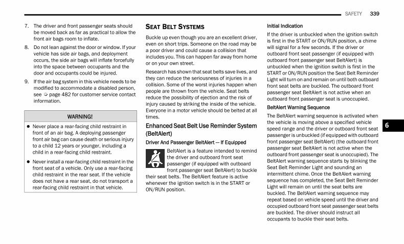
SAFETY 339
7. The driver and front passenger seats should be moved back as far as practical to allow the front air bags room to inflate.
8. Do not lean against the door or window. If your vehicle has side air bags, and deployment occurs, the side air bags will inflate forcefully into the space between occupants and the door and occupants could be injured.
9. If the air bag system in this vehicle needs to be modified to accommodate a disabled person, see Ú page 482 for customer service contact information.
SEAT BELT SYSTEMS Buckle up even though you are an excellent driver, even on short trips. Someone on the road may be a poor driver and could cause a collision that includes you. This can happen far away from home or on your own street.Research has shown that seat belts save lives, and they can reduce the seriousness of injuries in a collision. Some of the worst injuries happen when people are thrown from the vehicle. Seat belts reduce the possibility of ejection and the risk of injury caused by striking the inside of the vehicle. Everyone in a motor vehicle should be belted at all times.
Enhanced Seat Belt Use Reminder System (BeltAlert) Driver And Passenger BeltAlert — If Equipped
BeltAlert is a feature intended to remind the driver and outboard front seat passenger (if equipped with outboard front passenger seat BeltAlert) to buckle
their seat belts. The BeltAlert feature is active whenever the ignition switch is in the START or ON/RUN position.
Initial IndicationIf the driver is unbuckled when the ignition switch is first in the START or ON/RUN position, a chime will signal for a few seconds. If the driver or outboard front seat passenger (if equipped with outboard front passenger seat BeltAlert) is unbuckled when the ignition switch is first in the START or ON/RUN position the Seat Belt Reminder Light will turn on and remain on until both outboard front seat belts are buckled. The outboard front passenger seat BeltAlert is not active when an outboard front passenger seat is unoccupied.BeltAlert Warning SequenceThe BeltAlert warning sequence is activated when the vehicle is moving above a specified vehicle speed range and the driver or outboard front seat passenger is unbuckled (if equipped with outboard front passenger seat BeltAlert) (the outboard front passenger seat BeltAlert is not active when the outboard front passenger seat is unoccupied). The BeltAlert warning sequence starts by blinking the Seat Belt Reminder Light and sounding an intermittent chime. Once the BeltAlert warning sequence has completed, the Seat Belt Reminder Light will remain on until the seat belts are buckled. The BeltAlert warning sequence may repeat based on vehicle speed until the driver and occupied outboard front seat passenger seat belts are buckled. The driver should instruct all occupants to buckle their seat belts.
WARNING!
Never place a rear-facing child restraint in front of an air bag. A deploying passenger front air bag can cause death or serious injury to a child 12 years or younger, including a child in a rear-facing child restraint.
Never install a rear-facing child restraint in the front seat of a vehicle. Only use a rear-facing child restraint in the rear seat. If the vehicle does not have a rear seat, do not transport a rear-facing child restraint in that vehicle.
6
22_DT_OM_EN_USC_t.book Page 339
340 SAFETY
(Continued)
Change Of StatusIf the driver or outboard front seat passenger (if equipped with outboard front passenger seat BeltAlert) unbuckles their seat belt while the vehicle is traveling, the BeltAlert warning sequence will begin until the seat belts are buckled again.The outboard front passenger seat BeltAlert is not active when the outboard front passenger seat is unoccupied. BeltAlert may be triggered when an animal or other items are placed on the outboard front passenger seat or when the seat is folded flat (if equipped). It is recommended that pets be restrained in the rear seat (if equipped) in pet harnesses or pet carriers that are secured by seat belts, and cargo is properly stowed.BeltAlert can be activated or deactivated by an authorized dealer. FCA US LLC does not recommend deactivating BeltAlert.
NOTE:If BeltAlert has been deactivated and the driver or outboard front seat passenger (if equipped with outboard front passenger seat BeltAlert) is unbuckled the Seat Belt Reminder Light will turn on and remain on until the driver and outboard front seat passenger seat belts are buckled.
Lap/Shoulder Belts All seating positions in your vehicle are equipped with lap/shoulder belts.The seat belt webbing retractor will lock only during very sudden stops or collisions. This feature allows the shoulder part of the seat belt to move freely with you under normal conditions. However, in a collision the seat belt will lock and reduce your risk of striking the inside of the vehicle or being thrown out of the vehicle.
WARNING!
Relying on the air bags alone could lead to more severe injuries in a collision. The air bags work with your seat belt to restrain you properly. In some collisions, the air bags won’t deploy at all. Always wear your seat belt even though you have air bags.
In a collision, you and your passengers can suffer much greater injuries if you are not prop-erly buckled up. You can strike the interior of your vehicle or other passengers, or you can be thrown out of the vehicle. Always be sure you and others in your vehicle are buckled up properly.
It is dangerous to ride in a cargo area, inside or outside of a vehicle. In a collision, people riding in these areas are more likely to be seriously injured or killed.
Do not allow people to ride in any area of your vehicle that is not equipped with seats and seat belts.
Be sure everyone in your vehicle is in a seat and using a seat belt properly. Occupants, including the driver, should always wear their seat belts whether or not an air bag is also provided at their seating position to minimize the risk of severe injury or death in the event of a crash.
Wearing your seat belt incorrectly could make your injuries in a collision much worse. You might suffer internal injuries, or you could even slide out of the seat belt. Follow these instruc-tions to wear your seat belt safely and to keep your passengers safe, too.
Two people should never be belted into a single seat belt. People belted together can crash into one another in a collision, hurting one another badly. Never use a lap/shoulder belt or a lap belt for more than one person, no matter what their size.
WARNING!
22_DT_OM_EN_USC_t.book Page 340
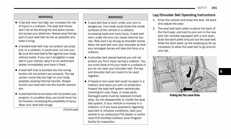
SAFETY 341
(Continued)
Lap/Shoulder Belt Operating Instructions 1. Enter the vehicle and close the door. Sit back
and adjust the seat.2. The seat belt latch plate is above the back of
the front seat, and next to your arm in the rear seat (for vehicles equipped with a rear seat). Grab the latch plate and pull out the seat belt. Slide the latch plate up the webbing as far as necessary to allow the seat belt to go around your lap.
Pulling Out The Latch Plate
WARNING!
A lap belt worn too high can increase the risk of injury in a collision. The seat belt forces won’t be at the strong hip and pelvic bones, but across your abdomen. Always wear the lap part of your seat belt as low as possible and keep it snug.
A twisted seat belt may not protect you prop-erly. In a collision, it could even cut into you. Be sure the seat belt is flat against your body, without twists. If you can’t straighten a seat belt in your vehicle, take it to an authorized dealer immediately and have it fixed.
A seat belt that is buckled into the wrong buckle will not protect you properly. The lap portion could ride too high on your body, possibly causing internal injuries. Always buckle your seat belt into the buckle nearest you.
A seat belt that is too loose will not protect you properly. In a sudden stop, you could move too far forward, increasing the possibility of injury. Wear your seat belt snugly.
A seat belt that is worn under your arm is dangerous. Your body could strike the inside surfaces of the vehicle in a collision, increasing head and neck injury. A seat belt worn under the arm can cause internal inju-ries. Ribs aren’t as strong as shoulder bones. Wear the seat belt over your shoulder so that your strongest bones will take the force in a collision.
A shoulder belt placed behind you will not protect you from injury during a collision. You are more likely to hit your head in a collision if you do not wear your shoulder belt. The lap and shoulder belt are meant to be used together.
A frayed or torn seat belt could rip apart in a collision and leave you with no protection. Inspect the seat belt system periodically, checking for cuts, frays, or loose parts. Damaged parts must be replaced immedi-ately. Do not disassemble or modify the seat belt system. If your vehicle is involved in a collision, or if you have questions regarding seat belt or retractor conditions, take your vehicle to an authorized FCA dealer or autho-rized FCA Certified Collision Care Program facility for inspection.
WARNING!
6
22_DT_OM_EN_USC_t.book Page 341
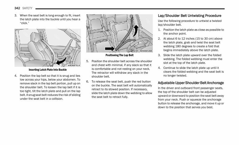
342 SAFETY
3. When the seat belt is long enough to fit, insert the latch plate into the buckle until you hear a “click.”
Inserting Latch Plate Into Buckle
4. Position the lap belt so that it is snug and lies low across your hips, below your abdomen. To remove slack in the lap belt portion, pull up on the shoulder belt. To loosen the lap belt if it is too tight, tilt the latch plate and pull on the lap belt. A snug seat belt reduces the risk of sliding under the seat belt in a collision.
Positioning The Lap Belt
5. Position the shoulder belt across the shoulder and chest with minimal, if any slack so that it is comfortable and not resting on your neck. The retractor will withdraw any slack in the shoulder belt.
6. To release the seat belt, push the red button on the buckle. The seat belt will automatically retract to its stowed position. If necessary, slide the latch plate down the webbing to allow the seat belt to retract fully.
Lap/Shoulder Belt Untwisting Procedure Use the following procedure to untwist a twisted lap/shoulder belt.1. Position the latch plate as close as possible to
the anchor point.2. At about 6 to 12 inches (15 to 30 cm) above
the latch plate, grab and twist the seat belt webbing 180 degrees to create a fold that begins immediately above the latch plate.
3. Slide the latch plate upward over the folded webbing. The folded webbing must enter the slot at the top of the latch plate.
4. Continue to slide the latch plate up until it clears the folded webbing and the seat belt is no longer twisted.
Adjustable Upper Shoulder Belt Anchorage In the driver and outboard front passenger seats, the top of the shoulder belt can be adjusted upward or downward to position the seat belt away from your neck. Push or squeeze the anchorage button to release the anchorage, and move it up or down to the position that serves you best.
22_DT_OM_EN_USC_t.book Page 342
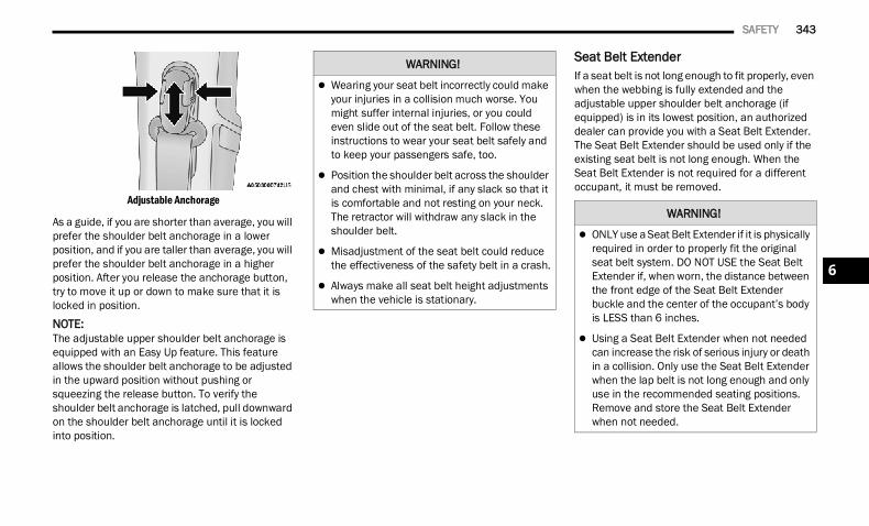
SAFETY 343
Adjustable Anchorage
As a guide, if you are shorter than average, you will prefer the shoulder belt anchorage in a lower position, and if you are taller than average, you will prefer the shoulder belt anchorage in a higher position. After you release the anchorage button, try to move it up or down to make sure that it is locked in position.
NOTE:The adjustable upper shoulder belt anchorage is equipped with an Easy Up feature. This feature allows the shoulder belt anchorage to be adjusted in the upward position without pushing or squeezing the release button. To verify the shoulder belt anchorage is latched, pull downward on the shoulder belt anchorage until it is locked into position.
Seat Belt Extender If a seat belt is not long enough to fit properly, even when the webbing is fully extended and the adjustable upper shoulder belt anchorage (if equipped) is in its lowest position, an authorized dealer can provide you with a Seat Belt Extender. The Seat Belt Extender should be used only if the existing seat belt is not long enough. When the Seat Belt Extender is not required for a different occupant, it must be removed.
WARNING!
Wearing your seat belt incorrectly could make your injuries in a collision much worse. You might suffer internal injuries, or you could even slide out of the seat belt. Follow these instructions to wear your seat belt safely and to keep your passengers safe, too.
Position the shoulder belt across the shoulder and chest with minimal, if any slack so that it is comfortable and not resting on your neck. The retractor will withdraw any slack in the shoulder belt.
Misadjustment of the seat belt could reduce the effectiveness of the safety belt in a crash.
Always make all seat belt height adjustments when the vehicle is stationary.
WARNING!
ONLY use a Seat Belt Extender if it is physically required in order to properly fit the original seat belt system. DO NOT USE the Seat Belt Extender if, when worn, the distance between the front edge of the Seat Belt Extender buckle and the center of the occupant’s body is LESS than 6 inches.
Using a Seat Belt Extender when not needed can increase the risk of serious injury or death in a collision. Only use the Seat Belt Extender when the lap belt is not long enough and only use in the recommended seating positions. Remove and store the Seat Belt Extender when not needed.
6
22_DT_OM_EN_USC_t.book Page 343
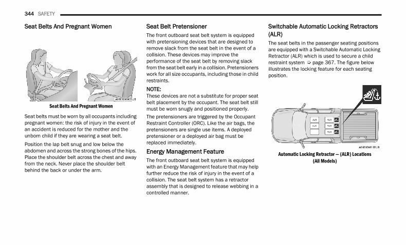
344 SAFETY
Seat Belts And Pregnant Women
Seat Belts And Pregnant Women
Seat belts must be worn by all occupants including pregnant women: the risk of injury in the event of an accident is reduced for the mother and the unborn child if they are wearing a seat belt.Position the lap belt snug and low below the abdomen and across the strong bones of the hips. Place the shoulder belt across the chest and away from the neck. Never place the shoulder belt behind the back or under the arm.
Seat Belt Pretensioner The front outboard seat belt system is equipped with pretensioning devices that are designed to remove slack from the seat belt in the event of a collision. These devices may improve the performance of the seat belt by removing slack from the seat belt early in a collision. Pretensioners work for all size occupants, including those in child restraints.
NOTE:These devices are not a substitute for proper seat belt placement by the occupant. The seat belt still must be worn snugly and positioned properly.The pretensioners are triggered by the Occupant Restraint Controller (ORC). Like the air bags, the pretensioners are single use items. A deployed pretensioner or a deployed air bag must be replaced immediately.
Energy Management Feature The front outboard seat belt system is equipped with an Energy Management feature that may help further reduce the risk of injury in the event of a collision. The seat belt system has a retractor assembly that is designed to release webbing in a controlled manner.
Switchable Automatic Locking Retractors (ALR)The seat belts in the passenger seating positions are equipped with a Switchable Automatic Locking Retractor (ALR) which is used to secure a child restraint system Ú page 367. The figure below illustrates the locking feature for each seating position.
Automatic Locking Retractor — (ALR) Locations(All Models)
22_DT_OM_EN_USC_t.book Page 344
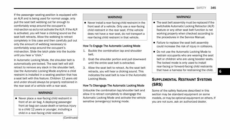
SAFETY 345
(Continued)
If the passenger seating position is equipped with an ALR and is being used for normal usage, only pull the seat belt webbing out far enough to comfortably wrap around the occupant’s mid-section so as to not activate the ALR. If the ALR is activated, you will hear a clicking sound as the seat belt retracts. Allow the webbing to retract completely in this case and then carefully pull out only the amount of webbing necessary to comfortably wrap around the occupant’s mid-section. Slide the latch plate into the buckle until you hear a "click."In Automatic Locking Mode, the shoulder belt is automatically pre-locked. The seat belt will still retract to remove any slack in the shoulder belt. Use the Automatic Locking Mode anytime a child restraint is installed in a seating position that has a seat belt with this feature. Children 12 years old and under should always be properly restrained in the rear seat of a vehicle with a rear seat.
How To Engage The Automatic Locking Mode1. Buckle the combination lap and shoulder
belt.2. Grab the shoulder portion and pull downward
until the entire seat belt is extracted.3. Allow the seat belt to retract. As the seat belt
retracts, you will hear a clicking sound. This indicates the seat belt is now in the Automatic Locking Mode.
How To Disengage The Automatic Locking ModeUnbuckle the combination lap/shoulder belt and allow it to retract completely to disengage the Automatic Locking Mode and activate the vehicle sensitive (emergency) locking mode.
SUPPLEMENTAL RESTRAINT SYSTEMS (SRS)Some of the safety features described in this section may be standard equipment on some models, or may be optional equipment on others. If you are not sure, ask an authorized dealer.
WARNING!
Never place a rear-facing child restraint in front of an air bag. A deploying passenger front air bag can cause death or serious injury to a child 12 years or younger, including a child in a rear-facing child restraint.
Never install a rear-facing child restraint in the front seat of a vehicle. Only use a rear-facing child restraint in the rear seat. If the vehicle does not have a rear seat, do not transport a rear-facing child restraint in that vehicle.
WARNING! WARNING!
The seat belt assembly must be replaced if the switchable Automatic Locking Retractor (ALR) feature or any other seat belt function is not working properly when checked according to the procedures in the Service Manual.
Failure to replace the seat belt assembly could increase the risk of injury in collisions.
Do not use the Automatic Locking Mode to restrain occupants who are wearing the seat belt or children who are using booster seats. The locked mode is only used to install rear-facing or forward-facing child restraints that have a harness for restraining the child. 6
22_DT_OM_EN_USC_t.book Page 345
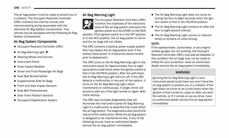
346 SAFETY
The air bag system must be ready to protect you in a collision. The Occupant Restraint Controller (ORC) monitors the internal circuits and interconnecting wiring associated with the electrical Air Bag System Components. Your vehicle may be equipped with the following Air Bag System Components:
Air Bag System Components Occupant Restraint Controller (ORC)
Air Bag Warning Light Steering Wheel and Column Instrument Panel Knee Impact Bolsters Driver and Front Passenger Air Bags Seat Belt Buckle Switch Supplemental Side Air Bags Front and Side Impact Sensors Seat Belt Pretensioners Seat Track Position Sensors Occupant Classification System
Air Bag Warning Light The Occupant Restraint Controller (ORC) monitors the readiness of the electronic parts of the air bag system whenever the ignition switch is in the START or ON/RUN
position. If the ignition switch is in the OFF position or in the ACC position, the air bag system is not on and the air bags will not inflate.The ORC contains a backup power supply system that may deploy the air bag system even if the battery loses power or it becomes disconnected prior to deployment.The ORC turns on the Air Bag Warning Light in the instrument panel for approximately four to eight seconds for a self-check when the ignition switch is first in the ON/RUN position. After the self-check, the Air Bag Warning Light will turn off. If the ORC detects a malfunction in any part of the system, it turns on the Air Bag Warning Light, either momentarily or continuously. A single chime will sound to alert you if the light comes on again after initial startup.The ORC also includes diagnostics that will illuminate the instrument panel Air Bag Warning Light if a malfunction is detected that could affect the air bag system. The diagnostics also record the nature of the malfunction. While the air bag system is designed to be maintenance free, if any of the following occurs, have an authorized dealer service the air bag system immediately.
The Air Bag Warning Light does not come on during the four to eight seconds when the igni-tion switch is first in the ON/RUN position.
The Air Bag Warning Light remains on after the four to eight-second interval.
The Air Bag Warning Light comes on intermit-tently or remains on while driving.
NOTE:If the speedometer, tachometer, or any engine related gauges are not working, the Occupant Restraint Controller (ORC) may also be disabled. In this condition the air bags may not be ready to inflate for your protection. Have an authorized dealer service the air bag system immediately.
WARNING!
Ignoring the Air Bag Warning Light in your instrument panel could mean you won’t have the air bag system to protect you in a collision. If the light does not come on as a bulb check when the ignition is first turned on, stays on after you start the vehicle, or if it comes on as you drive, have an authorized dealer service the air bag system immediately.
22_DT_OM_EN_USC_t.book Page 346
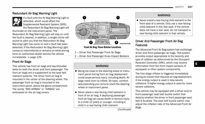
SAFETY 347
(Continued)
Redundant Air Bag Warning Light If a fault with the Air Bag Warning Light is detected, which could affect the Supplemental Restraint System (SRS), the Redundant Air Bag Warning Light will
illuminate on the instrument panel. The Redundant Air Bag Warning Light will stay on until the fault is cleared. In addition, a single chime will sound to alert you that the Redundant Air Bag Warning Light has come on and a fault has been detected. If the Redundant Air Bag Warning Light comes on intermittently or remains on while driving have an authorized dealer service the vehicle immediately Ú page 129.
Front Air BagsThis vehicle has front air bags and lap/shoulder belts for both the driver and front passenger. The front air bags are a supplement to the seat belt restraint systems. The driver front air bag is mounted in the center of the steering wheel. The passenger front air bag is mounted in the instrument panel, above the glove compartment. The words “SRS AIRBAG” or “AIRBAG” are embossed on the air bag covers.
Front Air Bag/Knee Bolster Locations
Driver And Passenger Front Air Bag FeaturesThe Advanced Front Air Bag system has multistage driver and front passenger air bags. This system provides output appropriate to the severity and type of collision as determined by the Occupant Restraint Controller (ORC), which may receive information from the front impact sensors (if equipped) or other system components.The first stage inflator is triggered immediately during an impact that requires air bag deployment. A low energy output is used in less severe collisions. A higher energy output is used for more severe collisions.This vehicle may be equipped with a driver and/or front passenger seat belt buckle switch that detects whether the driver or front passenger seat belt is buckled. The seat belt buckle switch may adjust the inflation rate of the Advanced Front Air Bags.
1 — Driver And Passenger Front Air Bags2 — Driver And Passenger Knee Impact Bolsters
WARNING!
Being too close to the steering wheel or instru-ment panel during front air bag deployment could cause serious injury, including death. Air bags need room to inflate. Sit back, comfort-ably extending your arms to reach the steering wheel or instrument panel.
Never place a rear-facing child restraint in front of an air bag. A deploying passenger front air bag can cause death or serious injury to a child 12 years or younger, including a child in a rear-facing child restraint.
Never install a rear-facing child restraint in the front seat of a vehicle. Only use a rear-facing child restraint in the rear seat. If the vehicle does not have a rear seat, do not transport a rear-facing child restraint in that vehicle.
WARNING!
6
22_DT_OM_EN_USC_t.book Page 347
348 SAFETY
This vehicle may be equipped with driver and/or front passenger seat track position sensors that may adjust the inflation rate of the Advanced Front Air Bags based upon seat position.This vehicle is equipped with a right front passenger Occupant Classification System (“OCS”) that is designed to provide Passenger Advanced Front Air Bag output appropriate to the occupant’s seated weight input, as determined by the OCS.
Front Air Bag Operation Front Air Bags are designed to provide additional protection by supplementing the seat belts. Front air bags are not expected to reduce the risk of injury in rear, side, or rollover collisions. The front air bags will not deploy in all frontal collisions, including some that may produce substantial vehicle damage — for example, some pole collisions, truck underrides, and angle offset collisions.On the other hand, depending on the type and location of impact, front air bags may deploy in crashes with little vehicle front-end damage but that produce a severe initial deceleration.Because air bag sensors measure vehicle deceleration over time, vehicle speed and damage by themselves are not good indicators of whether or not an air bag should have deployed.Seat belts are necessary for your protection in all collisions, and also are needed to help keep you in position, away from an inflating air bag.When the Occupant Restraint Controller (ORC) detects a collision requiring the front air bags, it signals the inflator units. A large quantity of non-toxic gas is generated to inflate the front air bags.
The steering wheel hub trim cover and the upper passenger side of the instrument panel separate and fold out of the way as the air bags inflate to their full size. The front air bags fully inflate in less time than it takes to blink your eyes. The front air bags then quickly deflate while helping to restrain the driver and front passenger.
Occupant Classification System (OCS) — Front Passenger Seat The Occupant Classification System (OCS) is part of a Federally regulated safety system for this vehicle. It is designed to provide Passenger Advanced Front Air Bag output appropriate to the occupant’s seated weight, as determined by the OCS.The Occupant Classification System (OCS) consists of the following: Occupant Restraint Controller (ORC) Occupant Classification Module (OCM) and
Sensor located in the front passenger seat
Air Bag Warning Light
WARNING!
No objects should be placed over or near the air bag on the instrument panel or steering wheel because any such objects could cause harm if the vehicle is in a collision severe enough to cause the air bag to inflate.
Do not put anything on or around the air bag covers or attempt to open them manually. You may damage the air bags and you could be injured because the air bags may no longer be functional. The protective covers for the air bag cushions are designed to open only when the air bags are inflating.
Relying on the air bags alone could lead to more severe injuries in a collision. The air bags work with your seat belt to restrain you properly. In some collisions, air bags won’t deploy at all. Always wear your seat belts even though you have air bags.
22_DT_OM_EN_USC_t.book Page 348
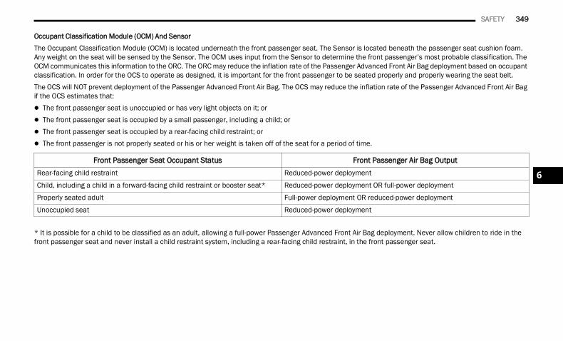
SAFETY 349
Occupant Classification Module (OCM) And SensorThe Occupant Classification Module (OCM) is located underneath the front passenger seat. The Sensor is located beneath the passenger seat cushion foam. Any weight on the seat will be sensed by the Sensor. The OCM uses input from the Sensor to determine the front passenger’s most probable classification. The OCM communicates this information to the ORC. The ORC may reduce the inflation rate of the Passenger Advanced Front Air Bag deployment based on occupant classification. In order for the OCS to operate as designed, it is important for the front passenger to be seated properly and properly wearing the seat belt.The OCS will NOT prevent deployment of the Passenger Advanced Front Air Bag. The OCS may reduce the inflation rate of the Passenger Advanced Front Air Bag if the OCS estimates that: The front passenger seat is unoccupied or has very light objects on it; or The front passenger seat is occupied by a small passenger, including a child; or The front passenger seat is occupied by a rear-facing child restraint; or The front passenger is not properly seated or his or her weight is taken off of the seat for a period of time.
* It is possible for a child to be classified as an adult, allowing a full-power Passenger Advanced Front Air Bag deployment. Never allow children to ride in the front passenger seat and never install a child restraint system, including a rear-facing child restraint, in the front passenger seat.
Front Passenger Seat Occupant Status Front Passenger Air Bag OutputRear-facing child restraint Reduced-power deployment
Child, including a child in a forward-facing child restraint or booster seat* Reduced-power deployment OR full-power deployment
Properly seated adult Full-power deployment OR reduced-power deployment
Unoccupied seat Reduced-power deployment
6
22_DT_OM_EN_USC_t.book Page 349
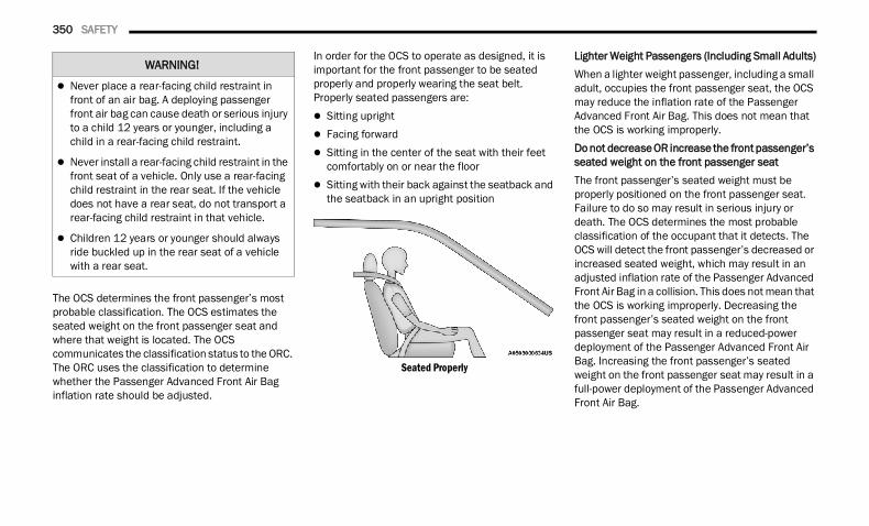
350 SAFETY
The OCS determines the front passenger’s most probable classification. The OCS estimates the seated weight on the front passenger seat and where that weight is located. The OCS communicates the classification status to the ORC. The ORC uses the classification to determine whether the Passenger Advanced Front Air Bag inflation rate should be adjusted.
In order for the OCS to operate as designed, it is important for the front passenger to be seated properly and properly wearing the seat belt. Properly seated passengers are: Sitting upright Facing forward Sitting in the center of the seat with their feet
comfortably on or near the floor Sitting with their back against the seatback and
the seatback in an upright position
Seated Properly
Lighter Weight Passengers (Including Small Adults)When a lighter weight passenger, including a small adult, occupies the front passenger seat, the OCS may reduce the inflation rate of the Passenger Advanced Front Air Bag. This does not mean that the OCS is working improperly.Do not decrease OR increase the front passenger’s seated weight on the front passenger seatThe front passenger’s seated weight must be properly positioned on the front passenger seat. Failure to do so may result in serious injury or death. The OCS determines the most probable classification of the occupant that it detects. The OCS will detect the front passenger’s decreased or increased seated weight, which may result in an adjusted inflation rate of the Passenger Advanced Front Air Bag in a collision. This does not mean that the OCS is working improperly. Decreasing the front passenger’s seated weight on the front passenger seat may result in a reduced-power deployment of the Passenger Advanced Front Air Bag. Increasing the front passenger’s seated weight on the front passenger seat may result in a full-power deployment of the Passenger Advanced Front Air Bag.
WARNING!
Never place a rear-facing child restraint in front of an air bag. A deploying passenger front air bag can cause death or serious injury to a child 12 years or younger, including a child in a rear-facing child restraint.
Never install a rear-facing child restraint in the front seat of a vehicle. Only use a rear-facing child restraint in the rear seat. If the vehicle does not have a rear seat, do not transport a rear-facing child restraint in that vehicle.
Children 12 years or younger should always ride buckled up in the rear seat of a vehicle with a rear seat.
22_DT_OM_EN_USC_t.book Page 350
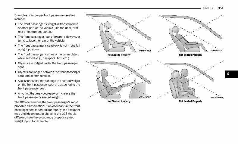
SAFETY 351
Examples of improper front passenger seating include: The front passenger’s weight is transferred to
another part of the vehicle (like the door, arm rest or instrument panel).
The front passenger leans forward, sideways, or turns to face the rear of the vehicle.
The front passenger’s seatback is not in the full upright position.
The front passenger carries or holds an object while seated (e.g., backpack, box, etc.).
Objects are lodged under the front passenger seat.
Objects are lodged between the front passenger seat and center console.
Accessories that may change the seated weight on the front passenger seat are attached to the front passenger seat.
Anything that may decrease or increase the front passenger’s seated weight.
The OCS determines the front passenger’s most probable classification. If an occupant in the front passenger seat is seated improperly, the occupant may provide an output signal to the OCS that is different from the occupant’s properly seated weight input, for example:
Not Seated Properly
Not Seated Properly
Not Seated Properly
Not Seated Properly
6
22_DT_OM_EN_USC_t.book Page 351
352 SAFETY
The Air Bag Warning Light in the instrument panel will turn on whenever the OCS is unable to classify the front passenger seat status. A malfunction in the OCS may affect the operation of the air bag system.
If the Air Bag Warning Light does not come on, or stays on after you start the vehicle, or it comes on as you drive, take the vehicle to an authorized dealer for service immediately.The passenger seat assembly contains critical OCS components that may affect the Passenger Advanced Front Air Bag inflation. In order for the OCS to properly classify the seated weight of a front seat passenger, the OCS components must function as designed. Do not make any modifications to the front passenger seat components, assembly, or to the seat cover. If the seat, trim cover, or cushion needs service for any reason, take the vehicle to an authorized dealer. Only FCA US LLC approved seat accessories may be used.The following requirements must be strictly followed: Do not modify the front passenger seat
assembly or components in any way.
Do not use prior or future model year seat covers or cushions not designated by FCA US LLC for the specific model being repaired. Always use the correct seat cover and cushion specified for the vehicle.
Do not replace the seat cover or cushion with an aftermarket seat cover or cushion.
Do not add a secondary seat cover or mat. At no time should any Supplemental Restraint
System (SRS) component or SRS related component or fastener be modified or replaced with any part except those which are approved by FCA US LLC.
WARNING!
If a child restraint system, child, small teen-ager or adult in the front passenger seat is seated improperly, the occupant may provide an output signal to the OCS that is different from the occupant’s properly seated weight input. This may result in serious injury or death in a collision.
Always wear your seat belt and sit properly, with the seatback in an upright position, your back against the seatback, sitting upright, facing forward, in the center of the seat, with your feet comfortably on or near the floor.
Do not carry or hold any objects (e.g., back-packs, boxes, etc.) while seated in the front passenger seat. Holding an object may provide an output signal to the OCS that is different than the occupant’s properly seated weight input, which may result in serious injury or death in a collision.
Placing an object on the floor under the front passenger seat may prevent the OCS from working properly, which may result in serious injury or death in a collision. Do not place any objects on the floor under the front passenger seat.
WARNING!
Unapproved modifications or service proce-dures to the passenger seat assembly, its related components, seat cover or cushion may inadvertently change the air bag deploy-ment in case of a frontal collision. This could result in death or serious injury to the front passenger if the vehicle is involved in a colli-sion. A modified vehicle may not comply with required Federal Motor Vehicle Safety Stan-dards (FMVSS) and/or Canadian Motor Vehicle Safety Standards (CMVSS).
If it is necessary to modify the air bag system for persons with disabilities, contact an autho-rized dealer.
22_DT_OM_EN_USC_t.book Page 352
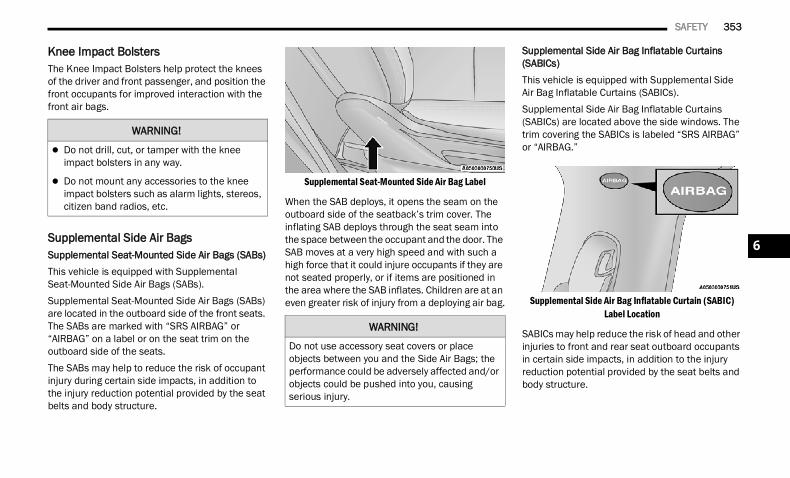
SAFETY 353
Knee Impact Bolsters The Knee Impact Bolsters help protect the knees of the driver and front passenger, and position the front occupants for improved interaction with the front air bags.
Supplemental Side Air BagsSupplemental Seat-Mounted Side Air Bags (SABs)This vehicle is equipped with Supplemental Seat-Mounted Side Air Bags (SABs).Supplemental Seat-Mounted Side Air Bags (SABs) are located in the outboard side of the front seats. The SABs are marked with “SRS AIRBAG” or “AIRBAG” on a label or on the seat trim on the outboard side of the seats.The SABs may help to reduce the risk of occupant injury during certain side impacts, in addition to the injury reduction potential provided by the seat belts and body structure.
Supplemental Seat-Mounted Side Air Bag Label
When the SAB deploys, it opens the seam on the outboard side of the seatback’s trim cover. The inflating SAB deploys through the seat seam into the space between the occupant and the door. The SAB moves at a very high speed and with such a high force that it could injure occupants if they are not seated properly, or if items are positioned in the area where the SAB inflates. Children are at an even greater risk of injury from a deploying air bag.
Supplemental Side Air Bag Inflatable Curtains (SABICs)This vehicle is equipped with Supplemental Side Air Bag Inflatable Curtains (SABICs).Supplemental Side Air Bag Inflatable Curtains (SABICs) are located above the side windows. The trim covering the SABICs is labeled “SRS AIRBAG” or “AIRBAG.”
Supplemental Side Air Bag Inflatable Curtain (SABIC) Label Location
SABICs may help reduce the risk of head and other injuries to front and rear seat outboard occupants in certain side impacts, in addition to the injury reduction potential provided by the seat belts and body structure.
WARNING!
Do not drill, cut, or tamper with the knee impact bolsters in any way.
Do not mount any accessories to the knee impact bolsters such as alarm lights, stereos, citizen band radios, etc.
WARNING!
Do not use accessory seat covers or place objects between you and the Side Air Bags; the performance could be adversely affected and/or objects could be pushed into you, causing serious injury.
6
22_DT_OM_EN_USC_t.book Page 353
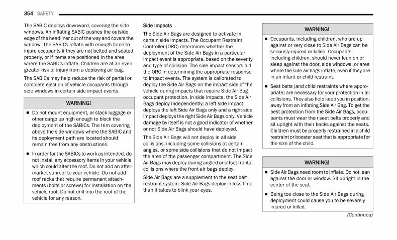
354 SAFETY
(Continued)
The SABIC deploys downward, covering the side windows. An inflating SABIC pushes the outside edge of the headliner out of the way and covers the window. The SABICs inflate with enough force to injure occupants if they are not belted and seated properly, or if items are positioned in the area where the SABICs inflate. Children are at an even greater risk of injury from a deploying air bag.The SABICs may help reduce the risk of partial or complete ejection of vehicle occupants through side windows in certain side impact events.
Side ImpactsThe Side Air Bags are designed to activate in certain side impacts. The Occupant Restraint Controller (ORC) determines whether the deployment of the Side Air Bags in a particular impact event is appropriate, based on the severity and type of collision. The side impact sensors aid the ORC in determining the appropriate response to impact events. The system is calibrated to deploy the Side Air Bags on the impact side of the vehicle during impacts that require Side Air Bag occupant protection. In side impacts, the Side Air Bags deploy independently; a left side impact deploys the left Side Air Bags only and a right-side impact deploys the right Side Air Bags only. Vehicle damage by itself is not a good indicator of whether or not Side Air Bags should have deployed.The Side Air Bags will not deploy in all side collisions, including some collisions at certain angles, or some side collisions that do not impact the area of the passenger compartment. The Side Air Bags may deploy during angled or offset frontal collisions where the front air bags deploy.Side Air Bags are a supplement to the seat belt restraint system. Side Air Bags deploy in less time than it takes to blink your eyes.
WARNING!
Do not mount equipment, or stack luggage or other cargo up high enough to block the deployment of the SABICs. The trim covering above the side windows where the SABIC and its deployment path are located should remain free from any obstructions.
In order for the SABICs to work as intended, do not install any accessory items in your vehicle which could alter the roof. Do not add an after-market sunroof to your vehicle. Do not add roof racks that require permanent attach-ments (bolts or screws) for installation on the vehicle roof. Do not drill into the roof of the vehicle for any reason.
WARNING!
Occupants, including children, who are up against or very close to Side Air Bags can be seriously injured or killed. Occupants, including children, should never lean on or sleep against the door, side windows, or area where the side air bags inflate, even if they are in an infant or child restraint.
Seat belts (and child restraints where appro-priate) are necessary for your protection in all collisions. They also help keep you in position, away from an inflating Side Air Bag. To get the best protection from the Side Air Bags, occu-pants must wear their seat belts properly and sit upright with their backs against the seats. Children must be properly restrained in a child restraint or booster seat that is appropriate for the size of the child.
WARNING!
Side Air Bags need room to inflate. Do not lean against the door or window. Sit upright in the center of the seat.
Being too close to the Side Air Bags during deployment could cause you to be severely injured or killed.
22_DT_OM_EN_USC_t.book Page 354
SAFETY 355
NOTE:Air bag covers may not be obvious in the interior trim, but they will open during air bag deployment.Rollover EventsSide Air Bags and seat belt pretensioners are designed to activate in certain rollover events. The Occupant Restraint Controller (ORC) determines whether deployment in a particular rollover event is appropriate, based on the severity and type of collision. Vehicle damage by itself is not a good indicator of whether or not Side Air Bags and seat belt pretensioners should have deployed.The Side Air Bags and seat belt pretensioners will not deploy in all rollover events. The rollover sensing system determines if a rollover event may be in progress and whether deployment is appropriate. In the event the vehicle experiences a rollover or near rollover event, and deployment is appropriate, the rollover sensing system will deploy the side air bags and seat belt pretensioners on both sides of the vehicle.
The SABICs may help reduce the risk of partial or complete ejection of vehicle occupants through side windows in certain rollover or side impact events.
Air Bag System ComponentsNOTE:The Occupant Restraint Controller (ORC) monitors the internal circuits and interconnecting wiring associated with electrical Air Bag System Compo-nents listed below: Occupant Restraint Controller (ORC)
Air Bag Warning Light Steering Wheel and Column Instrument Panel Knee Impact Bolsters Driver and Front Passenger Air Bags Seat Belt Buckle Switch Supplemental Side Air Bags Front and Side Impact Sensors Seat Belt Pretensioners Seat Track Position Sensors Occupant Classification System
If A Deployment Occurs The front air bags are designed to deflate immediately after deployment.NOTE:Front and/or side air bags will not deploy in all colli-sions. This does not mean something is wrong with the air bag system.If you do have a collision which deploys the air bags, any or all of the following may occur: The air bag material may sometimes cause
abrasions and/or skin reddening to the occu-pants as the air bags deploy and unfold. The abrasions are similar to friction rope burns or those you might get sliding along a carpet or gymnasium floor. They are not caused by contact with chemicals. They are not permanent and normally heal quickly. However, if you haven’t healed significantly within a few days, or if you have any blistering, see your doctor imme-diately.
Relying on the Side Air Bags alone could lead to more severe injuries in a collision. The Side Air Bags work with your seat belt to restrain you properly. In some collisions, Side Air Bags won’t deploy at all. Always wear your seat belt even though you have Side Air Bags.
WARNING!
6
22_DT_OM_EN_USC_t.book Page 355
356 SAFETY
As the air bags deflate, you may see some smoke-like particles. The particles are a normal by-product of the process that generates the non-toxic gas used for air bag inflation. These airborne particles may irritate the skin, eyes, nose, or throat. If you have skin or eye irritation, rinse the area with cool water. For nose or throat irritation, move to fresh air. If the irritation continues, see your doctor. If these particles settle on your clothing, follow the garment manufacturer’s instructions for cleaning.
Do not drive your vehicle after the air bags have deployed. If you are involved in another collision, the air bags will not be in place to protect you.
NOTE: Air bag covers may not be obvious in the interior
trim, but they will open during air bag deploy-ment.
After any collision, the vehicle should be taken to an authorized dealer immediately.
Enhanced Accident Response System In the event of an impact, if the communication network remains intact, and the power remains intact, depending on the nature of the event, the Occupant Restraint Controller (ORC) will determine whether to have the Enhanced Accident Response System perform the following functions: Cut off fuel to the engine (if equipped) Cut off battery power to the electric motor (if
equipped) Flash hazard lights as long as the battery has
power Turn on the interior lights, which remain on as
long as the battery has power or for 15 minutes from the intervention of the Enhanced Accident Response System
Unlock the power door locksYour vehicle may also be designed to perform any of these other functions in response to the Enhanced Accident Response System: Turn off the Fuel Filter Heater, Turn off the HVAC
Blower Motor, Close the HVAC Circulation Door
Cut off battery power to the: Engine Electric Motor (if equipped) Electric power steering Brake booster Electric park brake Automatic transmission gear selector Horn Front wiper Headlamp washer pump (if equipped)
NOTE:After an accident, remember to cycle the ignition to the STOP (OFF/LOCK) position and remove the key from the ignition switch to avoid draining the battery. Carefully check the vehicle for fuel leaks in the engine compartment and on the ground near the engine compartment and fuel tank before resetting the system and starting the engine. If there are no fuel leaks or damage to the vehicle electrical devices (e.g. headlights) after an accident, reset the system by following the procedure described below. If you have any doubt, contact an authorized dealer.
WARNING!
Deployed air bags and seat belt pretensioners cannot protect you in another collision. Have the air bags, seat belt pretensioners, and the seat belt retractor assemblies replaced by an authorized dealer immediately. Also, have the Occupant Restraint Controller System serviced as well.
22_DT_OM_EN_USC_t.book Page 356
SAFETY 357
(Continued)
Enhanced Accident Response System Reset ProcedureIn order to reset the Enhanced Accident Response System functions after an event, the ignition switch must be changed from ignition START or ON/RUN to ignition OFF. Carefully check the vehicle for fuel leaks in the engine compartment and on the ground near the engine compartment and fuel tank before resetting the system and starting the engine. After an accident, if the vehicle will not start after performing the reset procedure, the vehicle must be towed to an authorized dealer to be inspected and to have the Enhanced Accident Response System reset.
Maintaining Your Air Bag System
Event Data Recorder (EDR)This vehicle is equipped with an event data recorder (EDR). The main purpose of an EDR is to record, in certain crash or near crash-like situations, such as an air bag deployment or hitting a road obstacle, data that will assist in understanding how a vehicle’s systems performed. The EDR is designed to record data related to vehicle dynamics and safety systems for a short period of time, typically 30 seconds or less. The EDR in this vehicle is designed to record such data as: How various systems in your vehicle were
operating; Whether or not the driver and passenger safety
belts were buckled/fastened; How far (if at all) the driver was depressing the
accelerator and/or brake pedal; and, How fast the vehicle was traveling.These data can help provide a better understanding of the circumstances in which crashes and injuries occur.
WARNING!
Modifications to any part of the air bag system could cause it to fail when you need it. You could be injured if the air bag system is not there to protect you. Do not modify the compo-nents or wiring, including adding any kind of badges or stickers to the steering wheel hub trim cover or the upper passenger side of the instrument panel. Do not modify the front fascia/bumper, vehicle body structure, or add aftermarket side steps or running boards.
It is dangerous to try to repair any part of the air bag system yourself. Be sure to tell anyone who works on your vehicle that it has an air bag system.
Do not attempt to modify any part of your air bag system. The air bag may inflate acciden-tally or may not function properly if modifica-tions are made. Take your vehicle to an authorized dealer for any air bag system service. If your seat, including your trim cover and cushion, needs to be serviced in any way (including removal or loosening/tightening of seat attachment bolts), take the vehicle to an authorized dealer. Only manufacturer approved seat accessories may be used. If it is necessary to modify the air bag system for persons with disabilities, contact an autho-rized dealer.
WARNING!
6
22_DT_OM_EN_USC_t.book Page 357
358 SAFETY
NOTE:EDR data are recorded by your vehicle only if a non-trivial crash situation occurs; no data are recorded by the EDR under normal driving condi-tions and no personal data (e.g., name, gender, age, and crash location) are recorded. However, other parties, such as law enforcement, could combine the EDR data with the type of personally identifying data routinely acquired during a crash investigation.To read data recorded by an EDR, special equipment is required, and access to the vehicle or the EDR is needed. In addition to the vehicle manufacturer, other parties, such as law enforcement, that have the special equipment, can read the information if they have access to the vehicle or the EDR.
CHILD RESTRAINTS Everyone in your vehicle needs to be buckled up at all times, including babies and children. Every state in the United States, and every Canadian province, requires that small children ride in proper restraint systems. This is the law, and you can be prosecuted for ignoring it.Children 12 years or younger should ride properly buckled up in a rear seat, if available. According to crash statistics, children are safer when properly restrained in the rear seats rather than in the front.
There are different sizes and types of restraints for children from newborn size to the child almost large enough for an adult safety belt. Always check the child seat Owner’s Manual to make sure you have the correct seat for your child. Carefully read and follow all the instructions and warnings in the child restraint Owner’s Manual and on all the labels attached to the child restraint.Before buying any restraint system, make sure that it has a label certifying that it meets all applicable Safety Standards. You should also make sure that you can install it in the vehicle where you will use it.
NOTE: For additional information, refer to http://
www.nhtsa.gov/parents-and-caregivers or call: 1–888–327–4236
Canadian residents should refer to Transport Canada’s website for additional information: https://www.tc.gc.ca/en/services/road/child-car-seat-safety.html
WARNING!
In a collision, an unrestrained child can become a projectile inside the vehicle. The force required to hold even an infant on your lap could become so great that you could not hold the child, no matter how strong you are. The child and others could be badly injured or killed. Any child riding in your vehicle should be in a proper restraint for the child’s size.
22_DT_OM_EN_USC_t.book Page 358
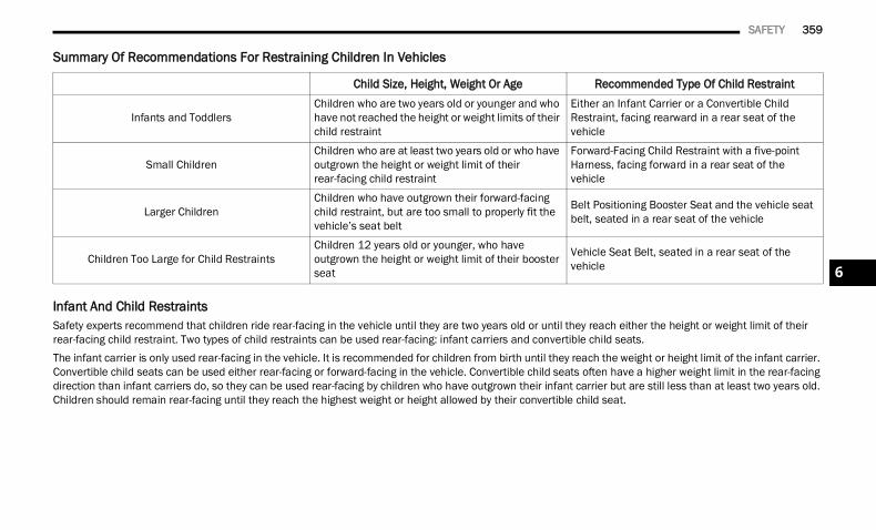
SAFETY 359
Summary Of Recommendations For Restraining Children In Vehicles
Infant And Child Restraints Safety experts recommend that children ride rear-facing in the vehicle until they are two years old or until they reach either the height or weight limit of their rear-facing child restraint. Two types of child restraints can be used rear-facing: infant carriers and convertible child seats.The infant carrier is only used rear-facing in the vehicle. It is recommended for children from birth until they reach the weight or height limit of the infant carrier. Convertible child seats can be used either rear-facing or forward-facing in the vehicle. Convertible child seats often have a higher weight limit in the rear-facing direction than infant carriers do, so they can be used rear-facing by children who have outgrown their infant carrier but are still less than at least two years old. Children should remain rear-facing until they reach the highest weight or height allowed by their convertible child seat.
Child Size, Height, Weight Or Age Recommended Type Of Child Restraint
Infants and ToddlersChildren who are two years old or younger and who have not reached the height or weight limits of their child restraint
Either an Infant Carrier or a Convertible Child Restraint, facing rearward in a rear seat of the vehicle
Small ChildrenChildren who are at least two years old or who have outgrown the height or weight limit of their rear-facing child restraint
Forward-Facing Child Restraint with a five-point Harness, facing forward in a rear seat of the vehicle
Larger ChildrenChildren who have outgrown their forward-facing child restraint, but are too small to properly fit the vehicle’s seat belt
Belt Positioning Booster Seat and the vehicle seat belt, seated in a rear seat of the vehicle
Children Too Large for Child RestraintsChildren 12 years old or younger, who have outgrown the height or weight limit of their booster seat
Vehicle Seat Belt, seated in a rear seat of the vehicle 6
22_DT_OM_EN_USC_t.book Page 359
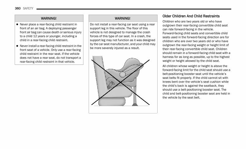
360 SAFETY
Older Children And Child Restraints Children who are two years old or who have outgrown their rear-facing convertible child seat can ride forward-facing in the vehicle. Forward-facing child seats and convertible child seats used in the forward-facing direction are for children who are over two years old or who have outgrown the rear-facing weight or height limit of their rear-facing convertible child seat. Children should remain in a forward-facing child seat with a harness for as long as possible, up to the highest weight or height allowed by the child seat.All children whose weight or height is above the forward-facing limit for the child seat should use a belt-positioning booster seat until the vehicle’s seat belts fit properly. If the child cannot sit with knees bent over the vehicle’s seat cushion while the child’s back is against the seatback, they should use a belt-positioning booster seat. The child and belt-positioning booster seat are held in the vehicle by the seat belt.
WARNING!
Never place a rear-facing child restraint in front of an air bag. A deploying passenger front air bag can cause death or serious injury to a child 12 years or younger, including a child in a rear-facing child restraint.
Never install a rear-facing child restraint in the front seat of a vehicle. Only use a rear-facing child restraint in the rear seat. If the vehicle does not have a rear seat, do not transport a rear-facing child restraint in that vehicle.
WARNING!
Do not install a rear-facing car seat using a rear support leg in this vehicle. The floor of this vehicle is not designed to manage the crash forces of this type of car seat. In a crash, the support leg may not function as it was designed by the car seat manufacturer, and your child may be more severely injured as a result.
22_DT_OM_EN_USC_t.book Page 360
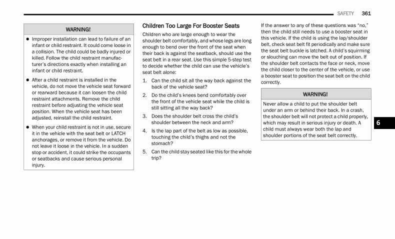
SAFETY 361
Children Too Large For Booster Seats Children who are large enough to wear the shoulder belt comfortably, and whose legs are long enough to bend over the front of the seat when their back is against the seatback, should use the seat belt in a rear seat. Use this simple 5-step test to decide whether the child can use the vehicle’s seat belt alone:1. Can the child sit all the way back against the
back of the vehicle seat?2. Do the child’s knees bend comfortably over
the front of the vehicle seat while the child is still sitting all the way back?
3. Does the shoulder belt cross the child’s shoulder between the neck and arm?
4. Is the lap part of the belt as low as possible, touching the child’s thighs and not the stomach?
5. Can the child stay seated like this for the whole trip?
If the answer to any of these questions was “no,” then the child still needs to use a booster seat in this vehicle. If the child is using the lap/shoulder belt, check seat belt fit periodically and make sure the seat belt buckle is latched. A child’s squirming or slouching can move the belt out of position. If the shoulder belt contacts the face or neck, move the child closer to the center of the vehicle, or use a booster seat to position the seat belt on the child correctly.
WARNING!
Improper installation can lead to failure of an infant or child restraint. It could come loose in a collision. The child could be badly injured or killed. Follow the child restraint manufac-turer’s directions exactly when installing an infant or child restraint.
After a child restraint is installed in the vehicle, do not move the vehicle seat forward or rearward because it can loosen the child restraint attachments. Remove the child restraint before adjusting the vehicle seat position. When the vehicle seat has been adjusted, reinstall the child restraint.
When your child restraint is not in use, secure it in the vehicle with the seat belt or LATCH anchorages, or remove it from the vehicle. Do not leave it loose in the vehicle. In a sudden stop or accident, it could strike the occupants or seatbacks and cause serious personal injury.
WARNING!
Never allow a child to put the shoulder belt under an arm or behind their back. In a crash, the shoulder belt will not protect a child properly, which may result in serious injury or death. A child must always wear both the lap and shoulder portions of the seat belt correctly.
6
22_DT_OM_EN_USC_t.book Page 361
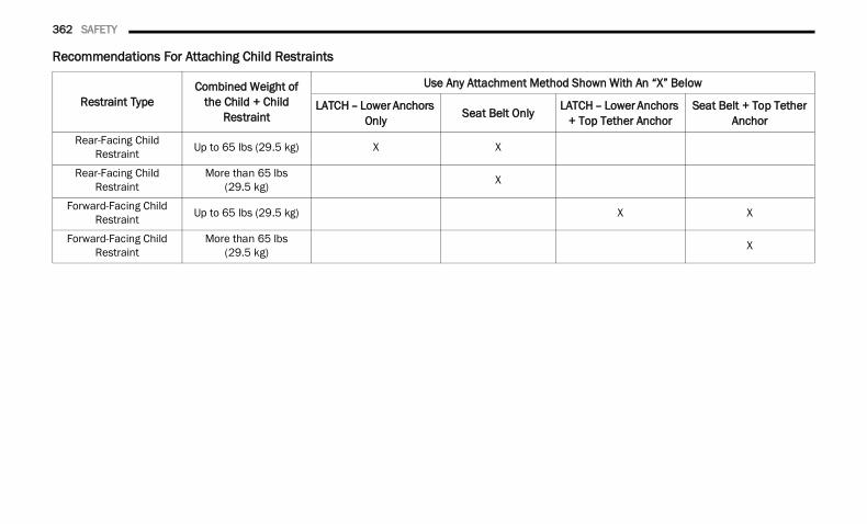
362 SAFETY
Recommendations For Attaching Child Restraints
Restraint TypeCombined Weight of
the Child + Child Restraint
Use Any Attachment Method Shown With An “X” Below
LATCH – Lower Anchors Only Seat Belt Only LATCH – Lower Anchors
+ Top Tether AnchorSeat Belt + Top Tether
AnchorRear-Facing Child
Restraint Up to 65 lbs (29.5 kg) X X
Rear-Facing Child Restraint
More than 65 lbs (29.5 kg) X
Forward-Facing Child Restraint Up to 65 lbs (29.5 kg) X X
Forward-Facing Child Restraint
More than 65 lbs(29.5 kg) X
22_DT_OM_EN_USC_t.book Page 362
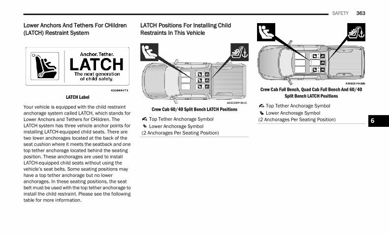
SAFETY 363
Lower Anchors And Tethers For CHildren (LATCH) Restraint System
LATCH Label
Your vehicle is equipped with the child restraint anchorage system called LATCH, which stands for Lower Anchors and Tethers for CHildren. The LATCH system has three vehicle anchor points for installing LATCH-equipped child seats. There are two lower anchorages located at the back of the seat cushion where it meets the seatback and one top tether anchorage located behind the seating position. These anchorages are used to install LATCH-equipped child seats without using the vehicle’s seat belts. Some seating positions may have a top tether anchorage but no lower anchorages. In these seating positions, the seat belt must be used with the top tether anchorage to install the child restraint. Please see the following table for more information.
LATCH Positions For Installing Child Restraints In This Vehicle
Crew Cab 60/40 Split Bench LATCH Positions
Crew Cab Full Bench, Quad Cab Full Bench And 60/40 Split Bench LATCH Positions
Top Tether Anchorage Symbol Lower Anchorage Symbol
(2 Anchorages Per Seating Position)
Top Tether Anchorage Symbol Lower Anchorage Symbol
(2 Anchorages Per Seating Position) 6
22_DT_OM_EN_USC_t.book Page 363
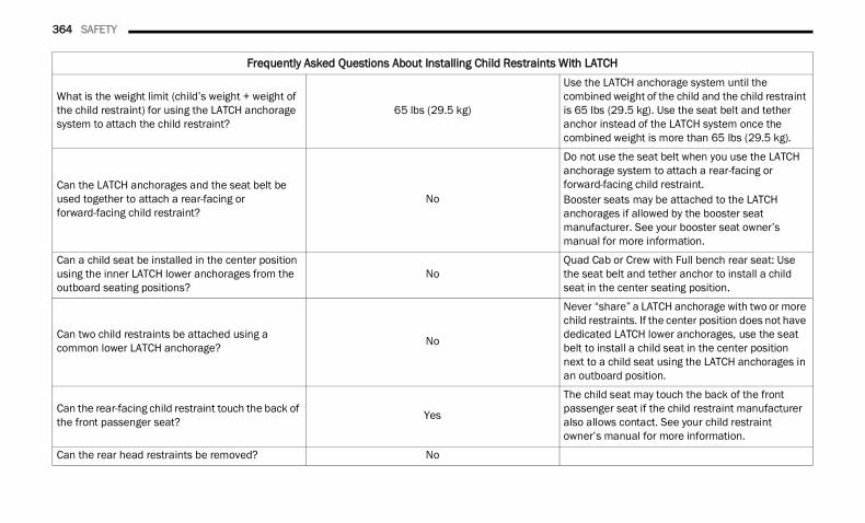
364 SAFETY
Frequently Asked Questions About Installing Child Restraints With LATCH
What is the weight limit (child’s weight + weight of the child restraint) for using the LATCH anchorage system to attach the child restraint?
65 lbs (29.5 kg)
Use the LATCH anchorage system until the combined weight of the child and the child restraint is 65 lbs (29.5 kg). Use the seat belt and tether anchor instead of the LATCH system once the combined weight is more than 65 lbs (29.5 kg).
Can the LATCH anchorages and the seat belt be used together to attach a rear-facing or forward-facing child restraint?
No
Do not use the seat belt when you use the LATCH anchorage system to attach a rear-facing or forward-facing child restraint.Booster seats may be attached to the LATCH anchorages if allowed by the booster seat manufacturer. See your booster seat owner’s manual for more information.
Can a child seat be installed in the center position using the inner LATCH lower anchorages from the outboard seating positions?
NoQuad Cab or Crew with Full bench rear seat: Use the seat belt and tether anchor to install a child seat in the center seating position.
Can two child restraints be attached using a common lower LATCH anchorage? No
Never “share” a LATCH anchorage with two or more child restraints. If the center position does not have dedicated LATCH lower anchorages, use the seat belt to install a child seat in the center position next to a child seat using the LATCH anchorages in an outboard position.
Can the rear-facing child restraint touch the back of the front passenger seat? Yes
The child seat may touch the back of the front passenger seat if the child restraint manufacturer also allows contact. See your child restraint owner’s manual for more information.
Can the rear head restraints be removed? No
22_DT_OM_EN_USC_t.book Page 364
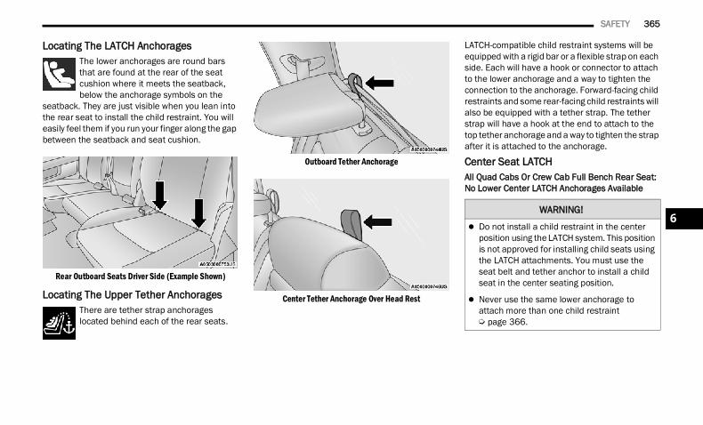
SAFETY 365
Locating The LATCH Anchorages The lower anchorages are round bars that are found at the rear of the seat cushion where it meets the seatback, below the anchorage symbols on the
seatback. They are just visible when you lean into the rear seat to install the child restraint. You will easily feel them if you run your finger along the gap between the seatback and seat cushion.
Rear Outboard Seats Driver Side (Example Shown)
Locating The Upper Tether AnchoragesThere are tether strap anchorages located behind each of the rear seats.
Outboard Tether Anchorage
Center Tether Anchorage Over Head Rest
LATCH-compatible child restraint systems will be equipped with a rigid bar or a flexible strap on each side. Each will have a hook or connector to attach to the lower anchorage and a way to tighten the connection to the anchorage. Forward-facing child restraints and some rear-facing child restraints will also be equipped with a tether strap. The tether strap will have a hook at the end to attach to the top tether anchorage and a way to tighten the strap after it is attached to the anchorage.
Center Seat LATCHAll Quad Cabs Or Crew Cab Full Bench Rear Seat: No Lower Center LATCH Anchorages Available
WARNING!
Do not install a child restraint in the center position using the LATCH system. This position is not approved for installing child seats using the LATCH attachments. You must use the seat belt and tether anchor to install a child seat in the center seating position.
Never use the same lower anchorage to attach more than one child restraint Ú page 366.
6
22_DT_OM_EN_USC_t.book Page 365
366 SAFETY
Crew Cab Split Bench Rear Seat: Center LATCH Anchorages AvailableIf a child restraint installed in the center position blocks the seat belt webbing or buckle for the outboard position, do not use that outboard position. If a child seat in the center position blocks the outboard LATCH anchors or seat belt, do not install a child seat in that outboard position.
Always follow the directions of the child restraint manufacturer when installing your child restraint. Not all child restraint systems will be installed as described here.
To Install A LATCH-Compatible Child RestraintIf the selected seating position has a Switchable Automatic Locking Retractor (ALR) seat belt, stow the seat belt, following the instructions below. See Ú page 367 to check what type of seat belt each seating position has.
1. Loosen the adjusters on the lower straps and on the tether strap of the child seat so that you can more easily attach the hooks or connectors to the vehicle anchorages.
2. Place the child seat between the lower anchorages for that seating position. If the second row seat can be reclined, you may recline the seat and/or raise the head restraint (if adjustable) to get a better fit. If the rear seat can be moved forward and rearward in the vehicle, you may wish to move it to its rear-most position to make room for the child seat. You may also move the front seat forward to allow more room for the child seat.
3. Attach the lower hooks or connectors of the child restraint to the lower anchorages in the selected seating position.
4. If the child restraint has a tether strap, connect it to the top tether anchorage. See Ú page 369 for directions to attach a tether anchor.
5. Tighten all of the straps as you push the child restraint rearward and downward into the seat. Remove slack in the straps according to the child restraint manufacturer’s instructions.
6. Test that the child restraint is installed tightly by pulling back and forth on the child seat at the belt path. It should not move more than 1 inch (25.4 mm) in any direction.
How To Stow An Unused Switchable-ALR (ALR) Seat Belt:When using the LATCH attaching system to install a child restraint, stow all ALR seat belts that are not being used by other occupants or being used to secure child restraints. An unused belt could injure a child if they play with it and accidentally lock the seat belt retractor. Before installing a child restraint using the LATCH system, buckle the seat belt behind the child restraint and out of the child’s reach. If the buckled seat belt interferes with the child restraint installation, instead of buckling it behind the child restraint, route the seat belt through the child restraint belt path and then buckle it. Do not lock the seat belt. Remind all children in the vehicle that the seat belts are not toys and that they should not play with them.
WARNING!
Never use the same lower anchorage to attach more than one child restraint Ú page 366.
22_DT_OM_EN_USC_t.book Page 366
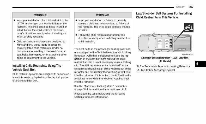
SAFETY 367
Installing Child Restraints Using The Vehicle Seat BeltChild restraint systems are designed to be secured in vehicle seats by lap belts or the lap belt portion of a lap/shoulder belt.
The seat belts in the passenger seating positions are equipped with a Switchable Automatic Locking Retractor (ALR) that is designed to keep the lap portion of the seat belt tight around the child restraint so that it is not necessary to use a locking clip. The ALR retractor can be “switched” into a locked mode by pulling all of the webbing out of the retractor and then letting the webbing retract back into the retractor. If it is locked, the ALR will make a clicking noise while the webbing is pulled back into the retractor.See the “Automatic Locking Mode” description Ú page 344 for additional information on ALR.Please see the table below and the following sections for more information.
Lap/Shoulder Belt Systems For Installing Child Restraints In This Vehicle
Automatic Locking Retractor — (ALR) Locations(All Models)
WARNING!
Improper installation of a child restraint to the LATCH anchorages can lead to failure of the restraint. The child could be badly injured or killed. Follow the child restraint manufac-turer’s directions exactly when installing an infant or child restraint.
Child restraint anchorages are designed to withstand only those loads imposed by correctly-fitted child restraints. Under no circumstances are they to be used for adult seat belts, harnesses, or for attaching other items or equipment to the vehicle.
WARNING!
Improper installation or failure to properly secure a child restraint can lead to failure of the restraint. The child could be badly injured or killed.
Follow the child restraint manufacturer’s directions exactly when installing an infant or child restraint.
ALR — Switchable Automatic Locking Retractor Top Tether Anchorage Symbol
6
22_DT_OM_EN_USC_t.book Page 367
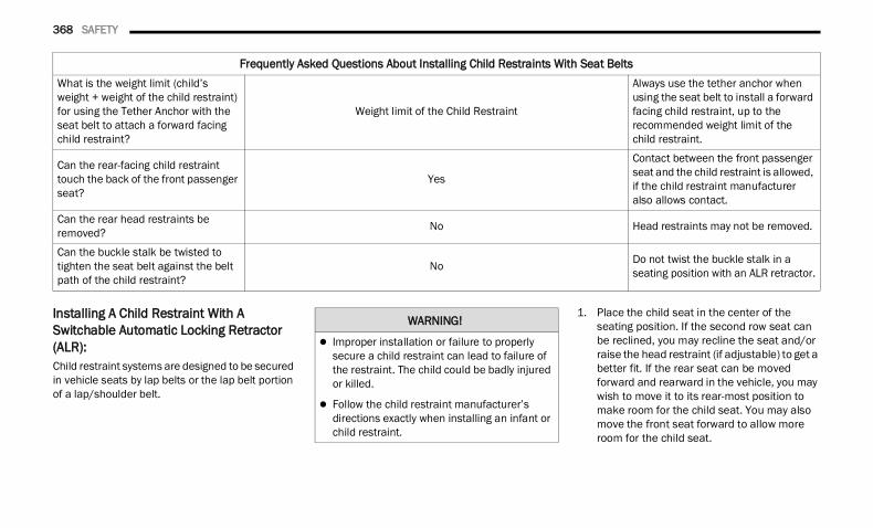
368 SAFETY
Installing A Child Restraint With A Switchable Automatic Locking Retractor (ALR): Child restraint systems are designed to be secured in vehicle seats by lap belts or the lap belt portion of a lap/shoulder belt.
1. Place the child seat in the center of the seating position. If the second row seat can be reclined, you may recline the seat and/or raise the head restraint (if adjustable) to get a better fit. If the rear seat can be moved forward and rearward in the vehicle, you may wish to move it to its rear-most position to make room for the child seat. You may also move the front seat forward to allow more room for the child seat.
Frequently Asked Questions About Installing Child Restraints With Seat BeltsWhat is the weight limit (child’s weight + weight of the child restraint) for using the Tether Anchor with the seat belt to attach a forward facing child restraint?
Weight limit of the Child Restraint
Always use the tether anchor when using the seat belt to install a forward facing child restraint, up to the recommended weight limit of the child restraint.
Can the rear-facing child restraint touch the back of the front passenger seat?
Yes
Contact between the front passenger seat and the child restraint is allowed, if the child restraint manufacturer also allows contact.
Can the rear head restraints be removed? No Head restraints may not be removed.
Can the buckle stalk be twisted to tighten the seat belt against the belt path of the child restraint?
No Do not twist the buckle stalk in a seating position with an ALR retractor.
WARNING!
Improper installation or failure to properly secure a child restraint can lead to failure of the restraint. The child could be badly injured or killed.
Follow the child restraint manufacturer’s directions exactly when installing an infant or child restraint.
22_DT_OM_EN_USC_t.book Page 368
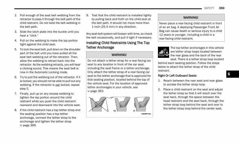
SAFETY 369
2. Pull enough of the seat belt webbing from the retractor to pass it through the belt path of the child restraint. Do not twist the belt webbing in the belt path.
3. Slide the latch plate into the buckle until you hear a “click.”
4. Pull on the webbing to make the lap portion tight against the child seat.
5. To lock the seat belt, pull down on the shoulder part of the belt until you have pulled all the seat belt webbing out of the retractor. Then, allow the webbing to retract back into the retractor. As the webbing retracts, you will hear a clicking sound. This means the seat belt is now in the Automatic Locking mode.
6. Try to pull the webbing out of the retractor. If it is locked, you should not be able to pull out any webbing. If the retractor is not locked, repeat step 5.
7. Finally, pull up on any excess webbing to tighten the lap portion around the child restraint while you push the child restraint rearward and downward into the vehicle seat.
8. If the child restraint has a top tether strap and the seating position has a top tether anchorage, connect the tether strap to the anchorage and tighten the tether strap Ú page 369.
9. Test that the child restraint is installed tightly by pulling back and forth on the child seat at the belt path. It should not move more than 1 inch (25.4 mm) in any direction.
Any seat belt system will loosen with time, so check the belt occasionally, and pull it tight if necessary.
Installing Child Restraints Using The Top Tether Anchorage The top tether anchorages in this vehicle
are tether strap loops located between the rear glass and the back of the rear seat. There is a tether strap loop located
behind each seating position. Follow the steps below to attach the tether strap of the child restraint.Right Or Left Outboard Seats:1. Reach between the rear seat and rear glass
to access the tether strap loop.2. Place a child restraint on the seat and adjust
the tether strap so that it will reach over the seat back, through the space between the head restraint and the seat back, through the tether strap loop behind the seat and over to the tether strap loop behind the center seat.
WARNING!
Do not attach a tether strap for a rear-facing car seat to any location in front of the car seat, including the seat frame or a tether anchorage. Only attach the tether strap of a rear-facing car seat to the tether anchorage that is approved for that seating position, located behind the top of the vehicle seat. For the location of approved tether anchorages in your vehicle, see Ú page 363.
WARNING!
Never place a rear-facing child restraint in front of an air bag. A deploying Passenger Front Air Bag can cause death or serious injury to a child 12 years or younger, including a child in a rear-facing child restraint.
6
22_DT_OM_EN_USC_t.book Page 369
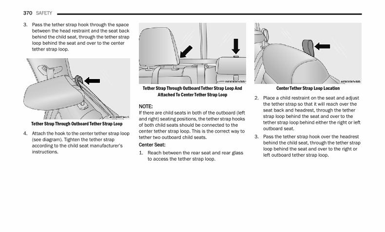
370 SAFETY
3. Pass the tether strap hook through the space between the head restraint and the seat back behind the child seat, through the tether strap loop behind the seat and over to the center tether strap loop.
Tether Strap Through Outboard Tether Strap Loop
4. Attach the hook to the center tether strap loop (see diagram). Tighten the tether strap according to the child seat manufacturer’s instructions.
Tether Strap Through Outboard Tether Strap Loop And Attached To Center Tether Strap Loop
NOTE:If there are child seats in both of the outboard (left and right) seating positions, the tether strap hooks of both child seats should be connected to the center tether strap loop. This is the correct way to tether two outboard child seats.Center Seat:1. Reach between the rear seat and rear glass
to access the tether strap loop.
Center Tether Strap Loop Location
2. Place a child restraint on the seat and adjust the tether strap so that it will reach over the seat back and headrest, through the tether strap loop behind the seat and over to the tether strap loop behind either the right or left outboard seat.
3. Pass the tether strap hook over the headrest behind the child seat, through the tether strap loop behind the seat and over to the right or left outboard tether strap loop.
22_DT_OM_EN_USC_t.book Page 370
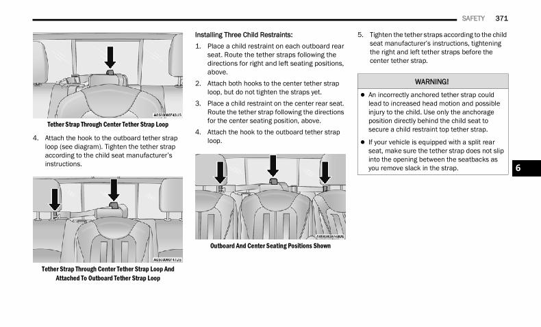
SAFETY 371
Tether Strap Through Center Tether Strap Loop
4. Attach the hook to the outboard tether strap loop (see diagram). Tighten the tether strap according to the child seat manufacturer’s instructions.
Tether Strap Through Center Tether Strap Loop And Attached To Outboard Tether Strap Loop
Installing Three Child Restraints:1. Place a child restraint on each outboard rear
seat. Route the tether straps following the directions for right and left seating positions, above.
2. Attach both hooks to the center tether strap loop, but do not tighten the straps yet.
3. Place a child restraint on the center rear seat. Route the tether strap following the directions for the center seating position, above.
4. Attach the hook to the outboard tether strap loop.
Outboard And Center Seating Positions Shown
5. Tighten the tether straps according to the child seat manufacturer’s instructions, tightening the right and left tether straps before the center tether strap.
WARNING!
An incorrectly anchored tether strap could lead to increased head motion and possible injury to the child. Use only the anchorage position directly behind the child seat to secure a child restraint top tether strap.
If your vehicle is equipped with a split rear seat, make sure the tether strap does not slip into the opening between the seatbacks as you remove slack in the strap. 6
22_DT_OM_EN_USC_t.book Page 371
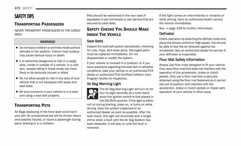
372 SAFETY
SAFETY TIPS TRANSPORTING PASSENGERS
NEVER TRANSPORT PASSENGERS IN THE CARGO AREA.
TRANSPORTING PETS Air Bags deploying in the front seat could harm your pet. An unrestrained pet will be thrown about and possibly injured, or injure a passenger during panic braking or in a collision.
Pets should be restrained in the rear seat (if equipped) in pet harnesses or pet carriers that are secured by seat belts.
SAFETY CHECKS YOU SHOULD MAKE INSIDE THE VEHICLE Seat Belts Inspect the seat belt system periodically, checking for cuts, frays, and loose parts. Damaged parts must be replaced immediately. Do not disassemble or modify the system.If your vehicle is involved in a collision, or if you have questions regarding the seat belt or retractor conditions, take your vehicle to an authorized FCA dealer or authorized FCA Certified Collision Care Program facility for inspection.
Air Bag Warning Light The Air Bag Warning Light will turn on for four to eight seconds as a bulb check when the ignition switch is first placed in the ON/RUN position. If the light is either
not on during starting, stays on, or turns on while driving, have the system inspected at an authorized dealer as soon as possible. After the bulb check, this light will illuminate with a single chime when a fault with the Air Bag System has been detected. It will stay on until the fault is removed.
If the light comes on intermittently or remains on while driving, have an authorized dealer service the vehicle immediately.See Ú page 338 for further information.
Defroster Check operation by selecting the defrost mode and place the blower control on high speed. You should be able to feel the air directed against the windshield. See an authorized dealer for service if your defroster is inoperable.
Floor Mat Safety InformationAlways use floor mats designed to fit your vehicle. Only use a floor mat that does not interfere with the operation of the accelerator, brake or clutch pedals. Only use a floor mat that is securely attached using the floor mat fasteners so it cannot slip out of position and interfere with the accelerator, brake or clutch pedals or impair safe operation of your vehicle in other ways.
WARNING!
Do not leave children or animals inside parked vehicles in hot weather. Interior heat buildup may cause serious injury or death.
It is extremely dangerous to ride in a cargo area, inside or outside of a vehicle. In a colli-sion, people riding in these areas are more likely to be seriously injured or killed.
Do not allow people to ride in any area of your vehicle that is not equipped with seats and seat belts.
Be sure everyone in your vehicle is in a seat and using a seat belt properly.
22_DT_OM_EN_USC_t.book Page 372
SAFETY 373
(Continued)(Continued)
PERIODIC SAFETY CHECKS YOU SHOULD MAKE OUTSIDE THE VEHICLE
Tires Examine tires for excessive tread wear and uneven wear patterns. Check for stones, nails, glass, or other objects lodged in the tread or sidewall. Inspect the tread for cuts and cracks. Inspect sidewalls for cuts, cracks, and bulges. Check the lug nut/bolt torque for tightness. Check the tires (including spare) for proper cold inflation pressure.
WARNING!
An improperly attached, damaged, folded, or stacked floor mat, or damaged floor mat fasteners may cause your floor mat to interfere with the accelerator, brake, or clutch pedals and cause a loss of vehicle control. To prevent SERIOUS INJURY or DEATH:
ALWAYS securely attach your floor mat using the floor mat fasteners. DO NOT install your floor mat upside down or turn your floor mat over.
Lightly pull to confirm mat is secured using the floor mat fasteners on a regular basis.
ALWAYS REMOVE THE EXISTING FLOOR MAT FROM THE VEHICLE before installing any other floor mat. NEVER install or stack an additional
floor mat on top of an existing floor mat.
ONLY install floor mats designed to fit your vehicle. NEVER install a floor mat that cannot be properly attached and secured to your vehicle. If a floor mat needs to be replaced, only use a FCA approved floor mat for the specific make, model, and year of your vehicle.
ONLY use the driver’s side floor mat on the driver’s side floor area. To check for interfer-ence, with the vehicle properly parked with the engine off, fully depress the accelerator, the brake, and the clutch pedal (if present) to check for interference. If your floor mat inter-feres with the operation of any pedal, or is not secure to the floor, remove the floor mat from the vehicle and place the floor mat in your trunk.
ONLY use the passenger’s side floor mat on the passenger’s side floor area.
ALWAYS make sure objects cannot fall or slide into the driver’s side floor area when the vehicle is moving. Objects can become trapped under accelerator, brake, or clutch pedals and could cause a loss of vehicle control.
NEVER place any objects under the floor mat (e.g., towels, keys, etc.). These objects could change the position of the floor mat and may cause interference with the accelerator, brake, or clutch pedals.
WARNING!
If the vehicle carpet has been removed and re-installed, always properly attach carpet to the floor and check the floor mat fasteners are secure to the vehicle carpet. Fully depress each pedal to check for interference with the accelerator, brake, or clutch pedals then re-install the floor mats.
It is recommended to only use mild soap and water to clean your floor mats. After cleaning, always check your floor mat has been properly installed and is secured to your vehicle using the floor mat fasteners by lightly pulling mat.
WARNING!
6
22_DT_OM_EN_USC_t.book Page 373
374 SAFETY
(Continued)
Lights Have someone observe the operation of brake lights and exterior lights while you work the controls. Check turn signal and high beam indicator lights on the instrument panel.
Door Latches Check for proper closing, latching, and locking.
Fluid Leaks Check area under the vehicle after overnight parking for fuel, coolant, oil, or other fluid leaks. Also, if gasoline fumes are detected or if fuel or brake fluid leaks are suspected, the cause should be located and corrected immediately.
EXHAUST GAS
The best protection against carbon monoxide entry into the vehicle body is a properly maintained engine exhaust system.Whenever a change is noticed in the sound of the exhaust system, when exhaust fumes can be detected inside the vehicle, or when the underside or rear of the vehicle is damaged, have an authorized dealer inspect the complete exhaust system and adjacent body areas for broken, damaged, deteriorated, or mispositioned parts. Open seams or loose connections could permit exhaust fumes to seep into the passenger compartment. In addition, inspect the exhaust system each time the vehicle is raised for lubrication or oil change. Replace as required.
CARBON MONOXIDE WARNINGS
WARNING!
Exhaust gases can injure or kill. They contain carbon monoxide (CO), which is colorless and odorless. Breathing it can make you unconscious and can eventually poison you. To avoid breathing (CO), follow these safety tips:
Do not run the engine in a closed garage or in confined areas any longer than needed to move your vehicle in or out of the area.
If you are required to drive with the trunk/lift-gate/rear doors open, make sure that all windows are closed and the climate control BLOWER switch is set at high speed. DO NOT use the recirculation mode.
If it is necessary to sit in a parked vehicle with the engine running, adjust your heating or cooling controls to force outside air into the vehicle. Set the blower at high speed.
WARNING!
WARNING!
Carbon monoxide (CO) in exhaust gases is deadly. Follow the precautions below to prevent carbon monoxide poisoning:
Do not inhale exhaust gases. They contain carbon monoxide, a colorless and odorless gas, which can kill. Never run the engine in a closed area, such as a garage, and never sit in a parked vehicle with the engine running for an extended period. If the vehicle is stopped in an open area with the engine running for more than a short period, adjust the ventilation system to force fresh, outside air into the vehicle.
Guard against carbon monoxide with proper maintenance. Have the exhaust system inspected every time the vehicle is raised. Have any abnormal conditions repaired promptly. Until repaired, drive with all side windows fully open.
22_DT_OM_EN_USC_t.book Page 374
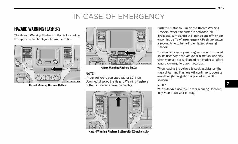
375
IN CASE OF EMERGENCY
HAZARD WARNING FLASHERS The Hazard Warning Flashers button is located on the upper switch bank just below the radio.
Hazard Warning Flashers Button
Hazard Warning Flashers Button
NOTE:If your vehicle is equipped with a 12–inch Uconnect display, the Hazard Warning Flashers button is located above the display.
Hazard Warning Flashers Button with 12-inch display
Push the button to turn on the Hazard Warning Flashers. When the button is activated, all directional turn signals will flash on and off to warn oncoming traffic of an emergency. Push the button a second time to turn off the Hazard Warning Flashers.This is an emergency warning system and it should not be used when the vehicle is in motion. Use only when your vehicle is disabled or signaling a safety hazard warning for other motorists.When leaving the vehicle to seek assistance, the Hazard Warning Flashers will continue to operate even though the ignition is placed in the OFF position.
NOTE:With extended use the Hazard Warning Flashers may wear down your battery.
7
22_DT_OM_EN_USC_t.book Page 375
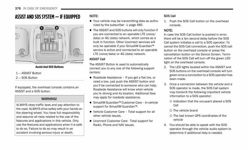
376 IN CASE OF EMERGENCY
ASSIST AND SOS SYSTEM — IF EQUIPPED
Assist And SOS Buttons
If equipped, the overhead console contains an ASSIST and a SOS button.
NOTE: Your vehicle may be transmitting data as autho-
rized by the subscriber Ú page 485. The ASSIST and SOS buttons will only function if
you are connected to an operable LTE (voice/data) or 4G (data) network, which comes as a built in function. Other Uconnect services will only be operable if your SiriusXM Guardian™ service is active and connected to an operable LTE (voice/data) or 4G (data) network.
ASSIST CallThe ASSIST Button is used to automatically connect you to any one of the following support centers: Roadside Assistance – If you get a flat tire, or
need a tow, just push the ASSIST button and you’ll be connected to someone who can help. Roadside Assistance will know what vehicle you’re driving and its location. Additional fees may apply for roadside assistance.
SiriusXM Guardian™ Customer Care – In-vehicle support for SiriusXM Guardian™.
Vehicle Customer Care – Total support for all other vehicle issues.
Uconnect Customer Care - Total support for Radio, Phone and NAV issues.
SOS Call1. Push the SOS Call button on the overhead
console.NOTE:In case the SOS Call button is pushed in error, there will be a ten second delay before the SOS Call system initiates a call to a SOS operator. To cancel the SOS Call connection, push the SOS call button on the overhead console or press the cancellation button on the Device Screen. Termi-nation of the SOS Call will turn off the green LED light on the overhead console.2. The LED lights located within the ASSIST and
SOS buttons on the overhead console will turn green once a connection to a SOS operator has been made.
3. Once a connection between the vehicle and a SOS operator is made, the SOS Call system may transmit the following important vehicle information to a SOS operator: Indication that the occupant placed a SOS
Call The vehicle brand The last known GPS coordinates of the
vehicle4. You should be able to speak with the SOS
operator through the vehicle audio system to determine if additional help is needed.
1 — ASSIST Button2 — SOS Button
WARNING!
ALWAYS obey traffic laws and pay attention to the road. ALWAYS drive safely with your hands on the steering wheel. You have full responsibility and assume all risks related to the use of the features and applications in this vehicle. Only use the features and applications when it is safe to do so. Failure to do so may result in an accident involving serious injury or death.
22_DT_OM_EN_USC_t.book Page 376
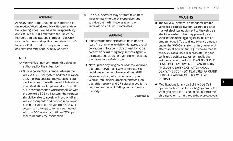
IN CASE OF EMERGENCY 377
(Continued)
NOTE: Your vehicle may be transmitting data as
authorized by the subscriber. Once a connection is made between the
vehicle’s SOS Call system and the SOS oper-ator, the SOS operator may be able to open a voice connection with the vehicle to deter-mine if additional help is needed. Once the SOS operator opens a voice connection with the vehicle’s SOS Call system, the operator should be able to speak with you or other vehicle occupants and hear sounds occur-ring in the vehicle. The vehicle’s SOS Call system will attempt to remain connected with the SOS operator until the SOS oper-ator terminates the connection.
5. The SOS operator may attempt to contact appropriate emergency responders and provide them with important vehicle information and GPS coordinates.
WARNING!
ALWAYS obey traffic laws and pay attention to the road. ALWAYS drive safely with your hands on the steering wheel. You have full responsibility and assume all risks related to the use of the features and applications in this vehicle. Only use the features and applications when it is safe to do so. Failure to do so may result in an accident involving serious injury or death.
WARNING!
If anyone in the vehicle could be in danger (e.g., fire or smoke is visible, dangerous road conditions or location), do not wait for voice contact from an Emergency Services Agent. All occupants should exit the vehicle immediately and move to a safe location.
Never place anything on or near the vehicle’s operable network and GPS antennas. You could prevent operable network and GPS signal reception, which can prevent your vehicle from placing an emergency call. An operable network and GPS signal reception is required for the SOS Call system to function properly.
The SOS Call system is embedded into the vehicle’s electrical system. Do not add after-market electrical equipment to the vehicle’s electrical system. This may prevent your vehicle from sending a signal to initiate an emergency call. To avoid interference that can cause the SOS Call system to fail, never add aftermarket equipment (e.g., two-way mobile radio, CB radio, data recorder, etc.) to your vehicle’s electrical system or modify the antennas on your vehicle. IF YOUR VEHICLE LOSES BATTERY POWER FOR ANY REASON (INCLUDING DURING OR AFTER AN ACCI-DENT), THE UCONNECT FEATURES, APPS AND SERVICES, AMONG OTHERS, WILL NOT OPERATE.
Modifications to any part of the SOS Call system could cause the air bag system to fail when you need it. You could be injured if the air bag system is not there to help protect you.
WARNING!
7
22_DT_OM_EN_USC_t.book Page 377
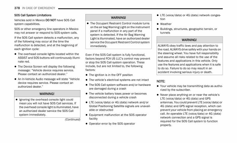
378 IN CASE OF EMERGENCY
(Continued)
SOS Call System LimitationsVehicles sold in Mexico DO NOT have SOS Call system capabilities.SOS or other emergency line operators in Mexico may not answer or respond to SOS system calls.If the SOS Call system detects a malfunction, any of the following may occur at the time the malfunction is detected, and at the beginning of each ignition cycle: The overhead console lights located within the
ASSIST and SOS buttons will continuously illumi-nate red.
The Device Screen will display the following message: “Vehicle device requires service. Please contact an authorized dealer.”
An In-Vehicle Audio message will state “Vehicle device requires service. Please contact an authorized dealer.”
Even if the SOS Call system is fully functional, factors beyond FCA US LLC’s control may prevent or stop the SOS Call system operation. These include, but are not limited to, the following factors: The ignition is in the OFF position The vehicle’s electrical systems are not intact The SOS Call system software and/or hardware
are damaged during a crash The vehicle battery loses power or becomes
disconnected during a vehicle crash LTE (voice/data) or 4G (data) network and/or
Global Positioning Satellite signals are unavail-able or obstructed
Equipment malfunction at the SOS operator facility
Operator error by the SOS operator
LTE (voice/data) or 4G (data) network conges-tion
Weather Buildings, structures, geographic terrain, or
tunnels
NOTE: Your vehicle may be transmitting data as autho-
rized by the subscriber. Never place anything on or near the vehicle’s
LTE (voice/data) or 4G (data) and GPS antennas. You could prevent LTE (voice/data) or 4G (data) and GPS signal reception, which can prevent your vehicle from placing an emergency call. An operable LTE (voice/data) or 4G (data) network connection and a GPS signal is required for the SOS Call system to function properly.
WARNING!
Ignoring the overhead console light could mean you will not have SOS Call services. If the overhead console light is illuminated, have an authorized dealer service the SOS Call system immediately.
The Occupant Restraint Control module turns on the air bag Warning Light on the instrument panel if a malfunction in any part of the system is detected. If the Air Bag Warning Light is illuminated, have an authorized dealer service the Occupant Restraint Control system immediately.
WARNING!
WARNING!
ALWAYS obey traffic laws and pay attention to the road. ALWAYS drive safely with your hands on the steering wheel. You have full responsibility and assume all risks related to the use of the features and applications in this vehicle. Only use the features and applications when it is safe to do so. Failure to do so may result in an accident involving serious injury or death.
22_DT_OM_EN_USC_t.book Page 378
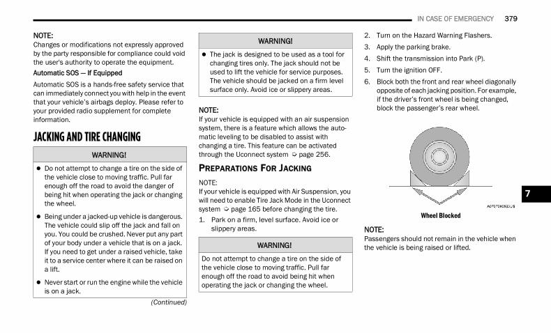
IN CASE OF EMERGENCY 379
(Continued)
NOTE:Changes or modifications not expressly approved by the party responsible for compliance could void the user's authority to operate the equipment.Automatic SOS — If EquippedAutomatic SOS is a hands-free safety service that can immediately connect you with help in the event that your vehicle’s airbags deploy. Please refer to your provided radio supplement for complete information.
JACKING AND TIRE CHANGING
NOTE:If your vehicle is equipped with an air suspension system, there is a feature which allows the auto-matic leveling to be disabled to assist with changing a tire. This feature can be activated through the Uconnect system Ú page 256.
PREPARATIONS FOR JACKING
NOTE:If your vehicle is equipped with Air Suspension, you will need to enable Tire Jack Mode in the Uconnect system Ú page 165 before changing the tire.1. Park on a firm, level surface. Avoid ice or
slippery areas.
2. Turn on the Hazard Warning Flashers.3. Apply the parking brake.4. Shift the transmission into Park (P).5. Turn the ignition OFF.6. Block both the front and rear wheel diagonally
opposite of each jacking position. For example, if the driver’s front wheel is being changed, block the passenger’s rear wheel.
Wheel Blocked
NOTE:Passengers should not remain in the vehicle when the vehicle is being raised or lifted.
WARNING!
Do not attempt to change a tire on the side of the vehicle close to moving traffic. Pull far enough off the road to avoid the danger of being hit when operating the jack or changing the wheel.
Being under a jacked-up vehicle is dangerous. The vehicle could slip off the jack and fall on you. You could be crushed. Never put any part of your body under a vehicle that is on a jack. If you need to get under a raised vehicle, take it to a service center where it can be raised on a lift.
Never start or run the engine while the vehicle is on a jack.
The jack is designed to be used as a tool for changing tires only. The jack should not be used to lift the vehicle for service purposes. The vehicle should be jacked on a firm level surface only. Avoid ice or slippery areas.
WARNING!
Do not attempt to change a tire on the side of the vehicle close to moving traffic. Pull far enough off the road to avoid being hit when operating the jack or changing the wheel.
WARNING!
7
22_DT_OM_EN_USC_t.book Page 379
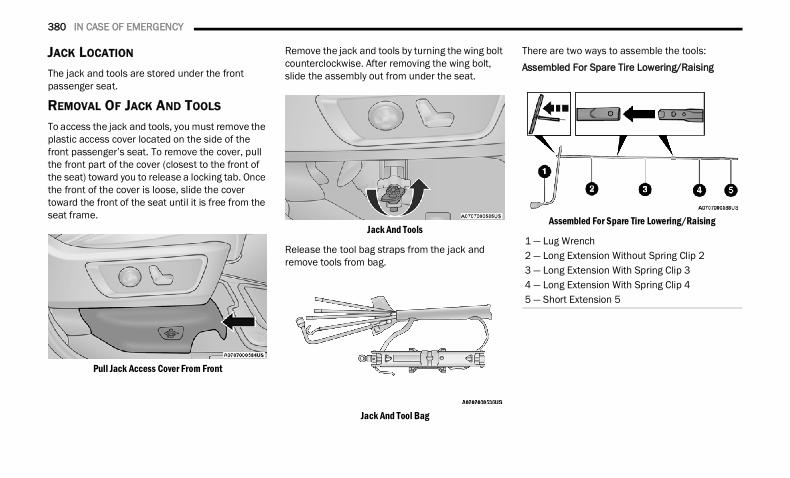
380 IN CASE OF EMERGENCY
JACK LOCATION
The jack and tools are stored under the front passenger seat.
REMOVAL OF JACK AND TOOLS
To access the jack and tools, you must remove the plastic access cover located on the side of the front passenger’s seat. To remove the cover, pull the front part of the cover (closest to the front of the seat) toward you to release a locking tab. Once the front of the cover is loose, slide the cover toward the front of the seat until it is free from the seat frame.
Pull Jack Access Cover From Front
Remove the jack and tools by turning the wing bolt counterclockwise. After removing the wing bolt, slide the assembly out from under the seat.
Jack And Tools
Release the tool bag straps from the jack and remove tools from bag.
Jack And Tool Bag
There are two ways to assemble the tools:Assembled For Spare Tire Lowering/Raising
Assembled For Spare Tire Lowering/Raising
1 — Lug Wrench2 — Long Extension Without Spring Clip 23 — Long Extension With Spring Clip 34 — Long Extension With Spring Clip 45 — Short Extension 5
22_DT_OM_EN_USC_t.book Page 380
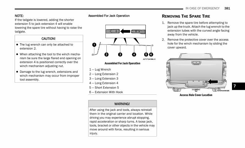
IN CASE OF EMERGENCY 381
NOTE:If the tailgate is lowered, adding the shorter extension 5 to jack extension 4 will enable lowering the spare tire without having to raise the tailgate.
Assembled For Jack Operation
Assembled For Jack Operation
REMOVING THE SPARE TIRE
1. Remove the spare tire before attempting to jack up the truck. Attach the lug wrench to the extension tubes with the curved angle facing away from the vehicle.
2. Remove the protective cover over the access hole for the winch mechanism by sliding the cover upward.
Access Hole Cover Location
CAUTION!
The lug wrench can only be attached to extension 2.
When attaching the tool to the winch mecha-nism be sure the large flared end opening on extension 4 is positioned correctly over the winch mechanism adjusting nut.
Damage to the lug wrench, extensions and winch mechanism may occur from improper tool assembly.
1 — Lug Wrench2 — Long Extension 23 — Long Extension 34 — Long Extension 45 — Short Extension 56 — Extension With Hook
WARNING!
After using the jack and tools, always reinstall them in the original carrier and location. While driving you may experience abrupt stopping, rapid acceleration or sharp turns. A loose jack, tools, bracket or other objects in the vehicle may move around with force, resulting in serious injury.
7
22_DT_OM_EN_USC_t.book Page 381
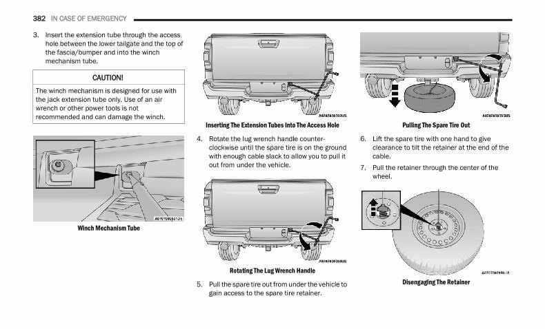
382 IN CASE OF EMERGENCY
3. Insert the extension tube through the access hole between the lower tailgate and the top of the fascia/bumper and into the winch mechanism tube.
Winch Mechanism Tube
Inserting The Extension Tubes Into The Access Hole
4. Rotate the lug wrench handle counter-clockwise until the spare tire is on the ground with enough cable slack to allow you to pull it out from under the vehicle.
Rotating The Lug Wrench Handle
5. Pull the spare tire out from under the vehicle to gain access to the spare tire retainer.
Pulling The Spare Tire Out
6. Lift the spare tire with one hand to give clearance to tilt the retainer at the end of the cable.
7. Pull the retainer through the center of the wheel.
Disengaging The Retainer
CAUTION!
The winch mechanism is designed for use with the jack extension tube only. Use of an air wrench or other power tools is not recommended and can damage the winch.
22_DT_OM_EN_USC_t.book Page 382
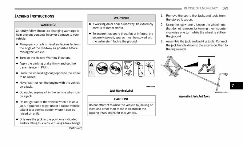
IN CASE OF EMERGENCY 383
(Continued)
JACKING INSTRUCTIONS
Jack Warning Label
1. Remove the spare tire, jack, and tools from the stored location.
2. Using the lug wrench, loosen the wheel nuts (but do not remove), by turning them counter-clockwise one turn while the wheel is still on the ground.
3. Assemble the jack and jacking tools. Connect the jack handle driver to the extension, then to the lug wrench.
Assembled Jack And Tools
WARNING!
Carefully follow these tire changing warnings to help prevent personal injury or damage to your vehicle:
Always park on a firm, level surface as far from the edge of the roadway as possible before raising the vehicle.
Turn on the Hazard Warning Flashers.
Apply the parking brake firmly and set the transmission in PARK.
Block the wheel diagonally opposite the wheel to be raised.
Never start or run the engine with the vehicle on a jack.
Do not let anyone sit in the vehicle when it is on a jack.
Do not get under the vehicle when it is on a jack. If you need to get under a raised vehicle, take it to a service center where it can be raised on a lift.
Only use the jack in the positions indicated and for lifting this vehicle during a tire change.
If working on or near a roadway, be extremely careful of motor traffic.
To assure that spare tires, flat or inflated, are securely stowed, spares must be stowed with the valve stem facing the ground.
CAUTION!
Do not attempt to raise the vehicle by jacking on locations other than those indicated in the Jacking Instructions for this vehicle.
WARNING!
7
22_DT_OM_EN_USC_t.book Page 383
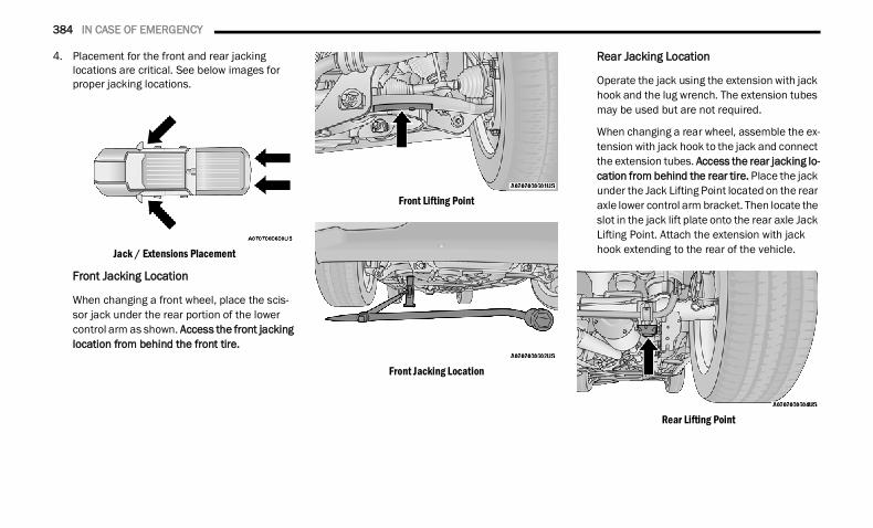
384 IN CASE OF EMERGENCY
4. Placement for the front and rear jacking locations are critical. See below images for proper jacking locations.
Jack / Extensions Placement
Front Jacking Location
When changing a front wheel, place the scis-sor jack under the rear portion of the lower control arm as shown. Access the front jacking location from behind the front tire.
Front Lifting Point
Front Jacking Location
Rear Jacking Location
Operate the jack using the extension with jack hook and the lug wrench. The extension tubes may be used but are not required.
When changing a rear wheel, assemble the ex-tension with jack hook to the jack and connect the extension tubes. Access the rear jacking lo-cation from behind the rear tire. Place the jack under the Jack Lifting Point located on the rear axle lower control arm bracket. Then locate the slot in the jack lift plate onto the rear axle Jack Lifting Point. Attach the extension with jack hook extending to the rear of the vehicle.
Rear Lifting Point
22_DT_OM_EN_USC_t.book Page 384
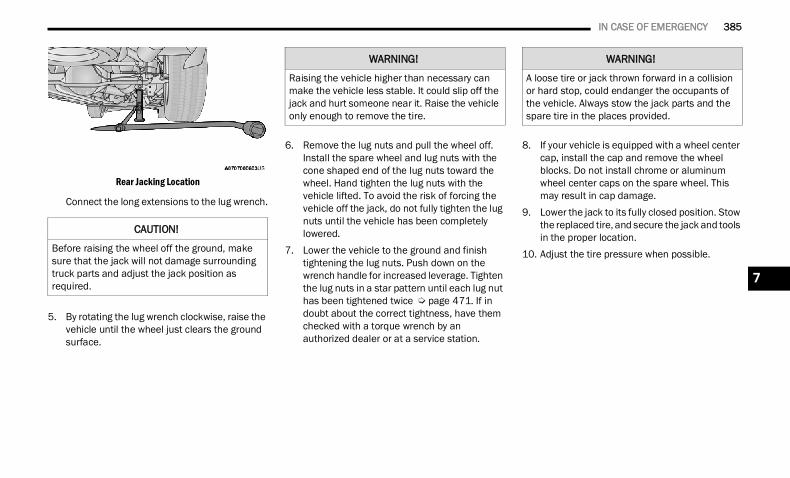
IN CASE OF EMERGENCY 385
Rear Jacking Location
Connect the long extensions to the lug wrench.
5. By rotating the lug wrench clockwise, raise the vehicle until the wheel just clears the ground surface.
6. Remove the lug nuts and pull the wheel off. Install the spare wheel and lug nuts with the cone shaped end of the lug nuts toward the wheel. Hand tighten the lug nuts with the vehicle lifted. To avoid the risk of forcing the vehicle off the jack, do not fully tighten the lug nuts until the vehicle has been completely lowered.
7. Lower the vehicle to the ground and finish tightening the lug nuts. Push down on the wrench handle for increased leverage. Tighten the lug nuts in a star pattern until each lug nut has been tightened twice Ú page 471. If in doubt about the correct tightness, have them checked with a torque wrench by an authorized dealer or at a service station.
8. If your vehicle is equipped with a wheel center cap, install the cap and remove the wheel blocks. Do not install chrome or aluminum wheel center caps on the spare wheel. This may result in cap damage.
9. Lower the jack to its fully closed position. Stow the replaced tire, and secure the jack and tools in the proper location.
10. Adjust the tire pressure when possible.
CAUTION!
Before raising the wheel off the ground, make sure that the jack will not damage surrounding truck parts and adjust the jack position as required.
WARNING!
Raising the vehicle higher than necessary can make the vehicle less stable. It could slip off the jack and hurt someone near it. Raise the vehicle only enough to remove the tire.
WARNING!
A loose tire or jack thrown forward in a collision or hard stop, could endanger the occupants of the vehicle. Always stow the jack parts and the spare tire in the places provided.
7
22_DT_OM_EN_USC_t.book Page 385
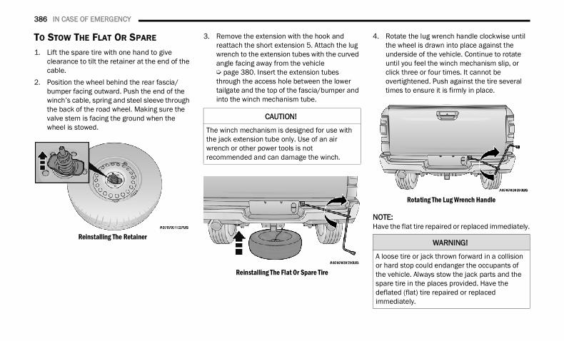
386 IN CASE OF EMERGENCY
TO STOW THE FLAT OR SPARE 1. Lift the spare tire with one hand to give
clearance to tilt the retainer at the end of the cable.
2. Position the wheel behind the rear fascia/bumper facing outward. Push the end of the winch’s cable, spring and steel sleeve through the back of the road wheel. Making sure the valve stem is facing the ground when the wheel is stowed.
Reinstalling The Retainer
3. Remove the extension with the hook and reattach the short extension 5. Attach the lug wrench to the extension tubes with the curved angle facing away from the vehicle Ú page 380. Insert the extension tubes through the access hole between the lower tailgate and the top of the fascia/bumper and into the winch mechanism tube.
Reinstalling The Flat Or Spare Tire
4. Rotate the lug wrench handle clockwise until the wheel is drawn into place against the underside of the vehicle. Continue to rotate until you feel the winch mechanism slip, or click three or four times. It cannot be overtightened. Push against the tire several times to ensure it is firmly in place.
Rotating The Lug Wrench Handle
NOTE:Have the flat tire repaired or replaced immediately.
CAUTION!
The winch mechanism is designed for use with the jack extension tube only. Use of an air wrench or other power tools is not recommended and can damage the winch.
WARNING!
A loose tire or jack thrown forward in a collision or hard stop could endanger the occupants of the vehicle. Always stow the jack parts and the spare tire in the places provided. Have the deflated (flat) tire repaired or replaced immediately.
22_DT_OM_EN_USC_t.book Page 386
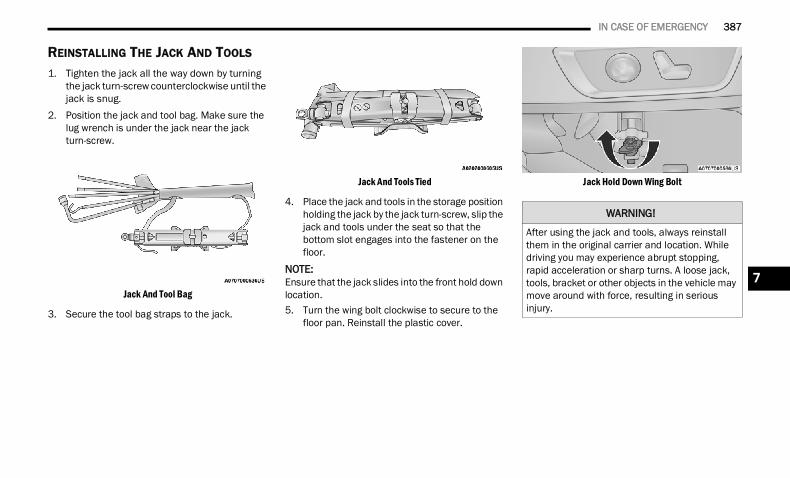
IN CASE OF EMERGENCY 387
REINSTALLING THE JACK AND TOOLS
1. Tighten the jack all the way down by turning the jack turn-screw counterclockwise until the jack is snug.
2. Position the jack and tool bag. Make sure the lug wrench is under the jack near the jack turn-screw.
Jack And Tool Bag
3. Secure the tool bag straps to the jack.
Jack And Tools Tied
4. Place the jack and tools in the storage position holding the jack by the jack turn-screw, slip the jack and tools under the seat so that the bottom slot engages into the fastener on the floor.
NOTE:Ensure that the jack slides into the front hold down location.5. Turn the wing bolt clockwise to secure to the
floor pan. Reinstall the plastic cover.
Jack Hold Down Wing Bolt
WARNING!
After using the jack and tools, always reinstall them in the original carrier and location. While driving you may experience abrupt stopping, rapid acceleration or sharp turns. A loose jack, tools, bracket or other objects in the vehicle may move around with force, resulting in serious injury.
7
22_DT_OM_EN_USC_t.book Page 387
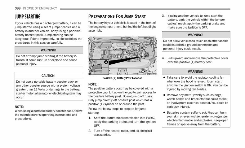
388 IN CASE OF EMERGENCY
JUMP STARTING If your vehicle has a discharged battery, it can be jump started using a set of jumper cables and a battery in another vehicle, or by using a portable battery booster pack. Jump starting can be dangerous if done improperly, so please follow the procedures in this section carefully.
NOTE:When using a portable battery booster pack, follow the manufacturer's operating instructions and precautions.
PREPARATIONS FOR JUMP START
The battery in your vehicle is located in the front of the engine compartment, behind the left headlight assembly.
Positive (+) Battery Post Location
NOTE:The positive battery post may be covered with a protective cap. Lift up on the cap to gain access to the positive battery post. Do not jump off fuses. Only jump directly off positive post which has a positive (+) symbol on or around the post.Follow the below steps to prepare for jump starting:1. Shift the automatic transmission into PARK,
apply the parking brake and turn the ignition OFF.
2. Turn off the heater, radio, and all electrical accessories.
3. If using another vehicle to jump start the battery, park the vehicle within the jumper cables’ reach, apply the parking brake and make sure the ignition is OFF.
4. Pull upward and remove the protective cover over the positive (+) battery post.
WARNING!
Do not attempt jump starting if the battery is frozen. It could rupture or explode and cause personal injury.
CAUTION!
Do not use a portable battery booster pack or any other booster source with a system voltage greater than 12 Volts or damage to the battery, starter motor, alternator or electrical system may occur.
WARNING!
Do not allow vehicles to touch each other as this could establish a ground connection and personal injury could result.
WARNING!
Take care to avoid the radiator cooling fan whenever the hood is raised. It can start anytime the ignition switch is ON. You can be injured by moving fan blades.
Remove any metal jewelry such as rings, watch bands and bracelets that could make an inadvertent electrical contact. You could be seriously injured.
Batteries contain sulfuric acid that can burn your skin or eyes and generate hydrogen gas which is flammable and explosive. Keep open flames or sparks away from the battery.
22_DT_OM_EN_USC_t.book Page 388
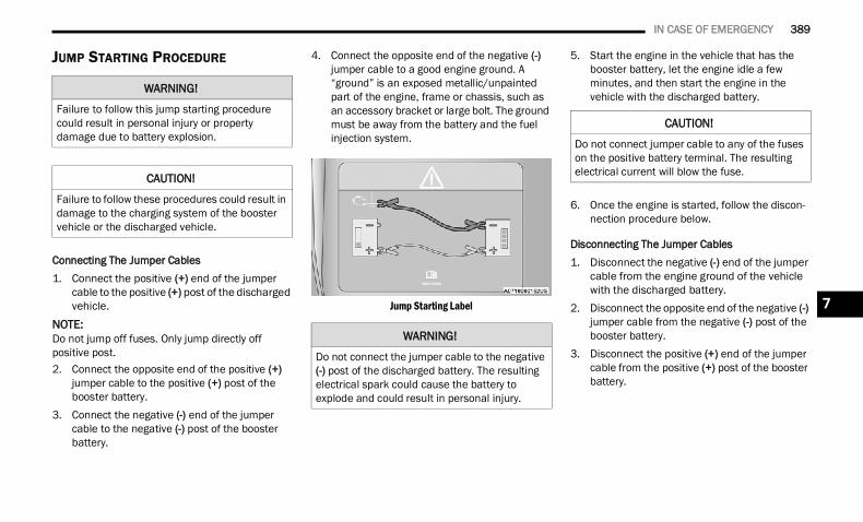
IN CASE OF EMERGENCY 389
JUMP STARTING PROCEDURE
Connecting The Jumper Cables1. Connect the positive (+) end of the jumper
cable to the positive (+) post of the discharged vehicle.
NOTE:Do not jump off fuses. Only jump directly off positive post.2. Connect the opposite end of the positive (+)
jumper cable to the positive (+) post of the booster battery.
3. Connect the negative (-) end of the jumper cable to the negative (-) post of the booster battery.
4. Connect the opposite end of the negative (-) jumper cable to a good engine ground. A “ground” is an exposed metallic/unpainted part of the engine, frame or chassis, such as an accessory bracket or large bolt. The ground must be away from the battery and the fuel injection system.
Jump Starting Label
5. Start the engine in the vehicle that has the booster battery, let the engine idle a few minutes, and then start the engine in the vehicle with the discharged battery.
6. Once the engine is started, follow the discon-nection procedure below.
Disconnecting The Jumper Cables1. Disconnect the negative (-) end of the jumper
cable from the engine ground of the vehicle with the discharged battery.
2. Disconnect the opposite end of the negative (-) jumper cable from the negative (-) post of the booster battery.
3. Disconnect the positive (+) end of the jumper cable from the positive (+) post of the booster battery.
WARNING!
Failure to follow this jump starting procedure could result in personal injury or property damage due to battery explosion.
CAUTION!
Failure to follow these procedures could result in damage to the charging system of the booster vehicle or the discharged vehicle.
WARNING!
Do not connect the jumper cable to the negative (-) post of the discharged battery. The resulting electrical spark could cause the battery to explode and could result in personal injury.
CAUTION!
Do not connect jumper cable to any of the fuses on the positive battery terminal. The resulting electrical current will blow the fuse.
7
22_DT_OM_EN_USC_t.book Page 389
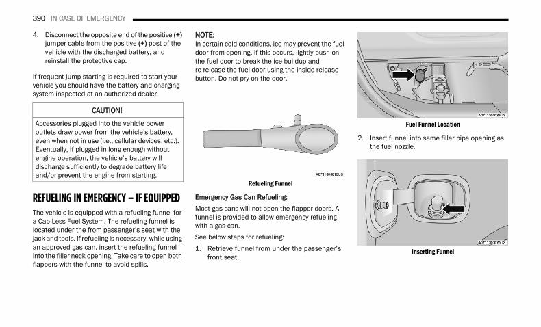
390 IN CASE OF EMERGENCY
4. Disconnect the opposite end of the positive (+) jumper cable from the positive (+) post of the vehicle with the discharged battery, and reinstall the protective cap.
If frequent jump starting is required to start your vehicle you should have the battery and charging system inspected at an authorized dealer.
REFUELING IN EMERGENCY – IF EQUIPPED The vehicle is equipped with a refueling funnel for a Cap-Less Fuel System. The refueling funnel is located under the from passenger’s seat with the jack and tools. If refueling is necessary, while using an approved gas can, insert the refueling funnel into the filler neck opening. Take care to open both flappers with the funnel to avoid spills.
NOTE:In certain cold conditions, ice may prevent the fuel door from opening. If this occurs, lightly push on the fuel door to break the ice buildup and re-release the fuel door using the inside release button. Do not pry on the door.
Refueling Funnel
Emergency Gas Can Refueling:Most gas cans will not open the flapper doors. A funnel is provided to allow emergency refueling with a gas can.See below steps for refueling:1. Retrieve funnel from under the passenger’s
front seat.
Fuel Funnel Location
2. Insert funnel into same filler pipe opening as the fuel nozzle.
Inserting Funnel
CAUTION!
Accessories plugged into the vehicle power outlets draw power from the vehicle’s battery, even when not in use (i.e., cellular devices, etc.). Eventually, if plugged in long enough without engine operation, the vehicle’s battery will discharge sufficiently to degrade battery life and/or prevent the engine from starting.
22_DT_OM_EN_USC_t.book Page 390
IN CASE OF EMERGENCY 391
3. Ensure funnel is inserted fully to hold flapper doors open.
4. Pour fuel into funnel opening.
5. Remove funnel from filler pipe, clean off prior to putting back in the spare tire storage area.
IF YOUR ENGINE OVERHEATS If the vehicle is overheating, it will need to be serviced by an authorized dealer.In any of the following situations, you can reduce the potential for overheating by taking the appropriate action. On the highways — slow down. In city traffic — while stopped, place the trans-
mission in NEUTRAL (N), but do not increase the engine idle speed while preventing vehicle motion with the brakes.
NOTE:There are steps that you can take to slow down an impending overheat condition: If your Air Conditioner (A/C) is on, turn it off. The
A/C system adds heat to the engine cooling system and turning the A/C off can help remove this heat.
You can also turn the temperature control to maximum heat, the mode control to floor and the blower control to high. This allows the heater core to act as a supplement to the radiator and aids in removing heat from the engine cooling system.
CAUTION!
To avoid fuel spillage and overfilling, do not “top off” the fuel tank after filling.
WARNING!
Never have any smoking materials lit in or near the vehicle when the fuel door is open or the tank is being filled.
Never add fuel when the engine is running. This is in violation of most state and federal fire regulations and may cause the Malfunc-tion Indicator Light to turn on.
A fire may result if fuel is pumped into a portable container that is inside of a vehicle. You could be burned. Always place fuel containers on the ground while filling.
WARNING!
You or others can be badly burned by hot engine coolant (antifreeze) or steam from your radiator. If you see or hear steam coming from under the hood, do not open the hood until the radiator has had time to cool. Never try to open a cooling system pressure cap when the radiator or coolant bottle is hot.
CAUTION!
Driving with a hot cooling system could damage your vehicle. If the temperature gauge reads HOT (H), pull over and stop the vehicle. Idle the vehicle with the air conditioner turned off until the pointer drops back into the normal range. If the pointer remains on HOT (H), and you hear continuous chimes, turn the engine off immediately and call for service.
7
22_DT_OM_EN_USC_t.book Page 391
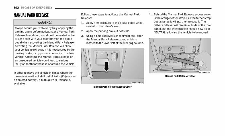
392 IN CASE OF EMERGENCY
MANUAL PARK RELEASE
In order to move the vehicle in cases where the transmission will not shift out of PARK (P) (such as a depleted battery), a Manual Park Release is available.
Follow these steps to activate the Manual Park Release:1. Apply firm pressure to the brake pedal while
seated in the driver’s seat.2. Apply the parking brake if possible.3. Using a small screwdriver or similar tool, open
the Manual Park Release cover, which is located to the lower left of the steering column.
Manual Park Release Access Cover
4. Behind the Manual Park Release access cover is the orange tether strap. Pull the tether strap out as far as it will go, then release it. The tether and lever will remain outside of the trim panel and the transmission should now be in NEUTRAL, allowing the vehicle to be moved.
Manual Park Release Tether
WARNING!
Always secure your vehicle by fully applying the parking brake before activating the Manual Park Release. In addition, you should be seated in the driver’s seat with your foot firmly on the brake pedal when activating the Manual Park Release. Activating the Manual Park Release will allow your vehicle to roll away if it is not secured by the parking brake, or by proper connection to a tow vehicle. Activating the Manual Park Release on an unsecured vehicle could lead to serious injury or death for those in or around the vehicle.
22_DT_OM_EN_USC_t.book Page 392
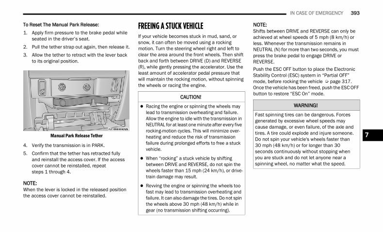
IN CASE OF EMERGENCY 393
To Reset The Manual Park Release:1. Apply firm pressure to the brake pedal while
seated in the driver’s seat.2. Pull the tether strap out again, then release it.3. Allow the tether to retract with the lever back
to its original position.
Manual Park Release Tether
4. Verify the transmission is in PARK.5. Confirm that the tether has retracted fully
and reinstall the access cover. If the access cover cannot be reinstalled, repeat steps 1 through 4.
NOTE:When the lever is locked in the released position the access cover cannot be reinstalled.
FREEING A STUCK VEHICLE If your vehicle becomes stuck in mud, sand, or snow, it can often be moved using a rocking motion. Turn the steering wheel right and left to clear the area around the front wheels. Then shift back and forth between DRIVE (D) and REVERSE (R), while gently pressing the accelerator. Use the least amount of accelerator pedal pressure that will maintain the rocking motion, without spinning the wheels or racing the engine.
NOTE:Shifts between DRIVE and REVERSE can only be achieved at wheel speeds of 5 mph (8 km/h) or less. Whenever the transmission remains in NEUTRAL (N) for more than two seconds, you must press the brake pedal to engage DRIVE or REVERSE.Push the ESC OFF button to place the Electronic Stability Control (ESC) system in “Partial OFF” mode, before rocking the vehicle Ú page 317. Once the vehicle has been freed, push the ESC OFF button to restore “ESC On” mode.CAUTION!
Racing the engine or spinning the wheels may lead to transmission overheating and failure. Allow the engine to idle with the transmission in NEUTRAL for at least one minute after every five rocking-motion cycles. This will minimize over-heating and reduce the risk of transmission failure during prolonged efforts to free a stuck vehicle.
When “rocking” a stuck vehicle by shifting between DRIVE and REVERSE, do not spin the wheels faster than 15 mph (24 km/h), or drive-train damage may result.
Revving the engine or spinning the wheels too fast may lead to transmission overheating and failure. It can also damage the tires. Do not spin the wheels above 30 mph (48 km/h) while in gear (no transmission shifting occurring).
WARNING!
Fast spinning tires can be dangerous. Forces generated by excessive wheel speeds may cause damage, or even failure, of the axle and tires. A tire could explode and injure someone. Do not spin your vehicle's wheels faster than 30 mph (48 km/h) or for longer than 30 seconds continuously without stopping when you are stuck and do not let anyone near a spinning wheel, no matter what the speed.
7
22_DT_OM_EN_USC_t.book Page 393
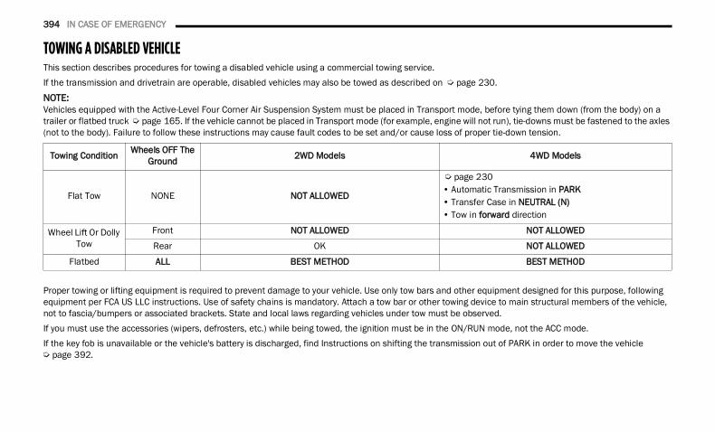
394 IN CASE OF EMERGENCY
TOWING A DISABLED VEHICLE This section describes procedures for towing a disabled vehicle using a commercial towing service.If the transmission and drivetrain are operable, disabled vehicles may also be towed as described on Ú page 230.NOTE:Vehicles equipped with the Active-Level Four Corner Air Suspension System must be placed in Transport mode, before tying them down (from the body) on a trailer or flatbed truck Ú page 165. If the vehicle cannot be placed in Transport mode (for example, engine will not run), tie-downs must be fastened to the axles (not to the body). Failure to follow these instructions may cause fault codes to be set and/or cause loss of proper tie-down tension.
Proper towing or lifting equipment is required to prevent damage to your vehicle. Use only tow bars and other equipment designed for this purpose, following equipment per FCA US LLC instructions. Use of safety chains is mandatory. Attach a tow bar or other towing device to main structural members of the vehicle, not to fascia/bumpers or associated brackets. State and local laws regarding vehicles under tow must be observed.If you must use the accessories (wipers, defrosters, etc.) while being towed, the ignition must be in the ON/RUN mode, not the ACC mode.If the key fob is unavailable or the vehicle's battery is discharged, find Instructions on shifting the transmission out of PARK in order to move the vehicle Ú page 392.
Towing Condition Wheels OFF The Ground 2WD Models 4WD Models
Flat Tow NONE NOT ALLOWED
Ú page 230 • Automatic Transmission in PARK • Transfer Case in NEUTRAL (N) • Tow in forward direction
Wheel Lift Or Dolly Tow
Front NOT ALLOWED NOT ALLOWED
Rear OK NOT ALLOWED
Flatbed ALL BEST METHOD BEST METHOD
22_DT_OM_EN_USC_t.book Page 394
IN CASE OF EMERGENCY 395
TWO-WHEEL DRIVE MODELS
FCA US LLC recommends towing your vehicle with all four wheels OFF the ground using a flatbed.If flatbed equipment is not available, and the transmission is operable, the vehicle may be towed (with front wheels on the ground) under the following conditions: The transmission must be in NEUTRAL (N).
Instructions on shifting the transmission to NEUTRAL (N) when the engine is OFF Ú page 392.
The towing speed must not exceed 30 mph (48 km/h).
The towing distance must not exceed 30 miles (48 km).
If the transmission is not operable, or the vehicle must be towed faster than 30 mph (48 km/h) and farther than 30 miles (48 km), tow with the rear wheels OFF the ground. An acceptable method to tow the vehicle on a flatbed are as follows: Using a suitable steering wheel stabilizer to hold
the front wheels in the straight position with the rear wheels raised and the front wheels ON the ground.
FOUR-WHEEL DRIVE MODELS
FCA US LLC recommends towing with all wheels OFF the ground.
CAUTION!
Do not use sling type equipment when towing. Vehicle damage may occur.
When securing the vehicle to a flatbed truck, do not attach to front or rear suspension components. Damage to your vehicle may result from improper towing.
CAUTION!
Towing this vehicle in violation of the above requirements can cause severe transmission damage. Damage from improper towing is not covered under the New Vehicle Limited Warranty.
CAUTION!
Front or rear wheel lifts must not be used (if the remaining wheels are on the ground). Internal damage to the transmission or transfer case will occur if a front or rear wheel lift is used when towing.
Towing this vehicle in violation of the above requirements can cause severe transmission and/or transfer case damage. Damage from improper towing is not covered under the New Vehicle Limited Warranty.
7
22_DT_OM_EN_USC_t.book Page 395
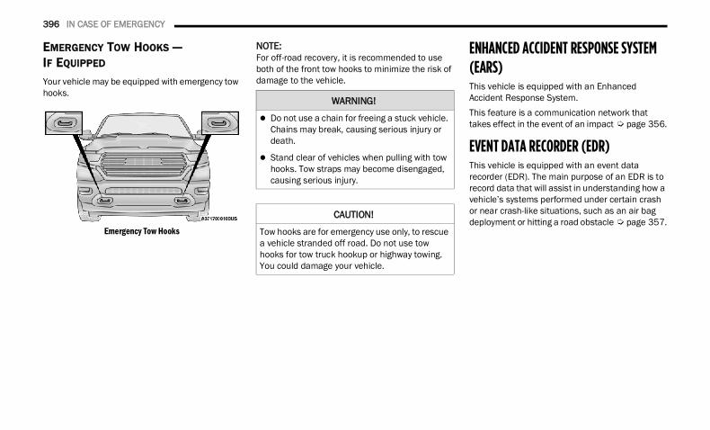
396 IN CASE OF EMERGENCY
EMERGENCY TOW HOOKS — IF EQUIPPED
Your vehicle may be equipped with emergency tow hooks.
Emergency Tow Hooks
NOTE:For off-road recovery, it is recommended to use both of the front tow hooks to minimize the risk of damage to the vehicle.
ENHANCED ACCIDENT RESPONSE SYSTEM (EARS) This vehicle is equipped with an Enhanced Accident Response System.This feature is a communication network that takes effect in the event of an impact Ú page 356.
EVENT DATA RECORDER (EDR)This vehicle is equipped with an event data recorder (EDR). The main purpose of an EDR is to record data that will assist in understanding how a vehicle’s systems performed under certain crash or near crash-like situations, such as an air bag deployment or hitting a road obstacle Ú page 357.
WARNING!
Do not use a chain for freeing a stuck vehicle. Chains may break, causing serious injury or death.
Stand clear of vehicles when pulling with tow hooks. Tow straps may become disengaged, causing serious injury.
CAUTION!
Tow hooks are for emergency use only, to rescue a vehicle stranded off road. Do not use tow hooks for tow truck hookup or highway towing. You could damage your vehicle.
22_DT_OM_EN_USC_t.book Page 396
397
SERVICING AND MAINTENANCE
SCHEDULED SERVICING — GASOLINE ENGINE Your vehicle is equipped with an automatic oil change indicator system. The oil change indicator system will remind you that it is time to take your vehicle in for scheduled maintenance.Based on engine operation conditions, the oil change indicator message will illuminate. This means that service is required for your vehicle. Operating conditions such as frequent short-trips, trailer tow, and extremely hot or cold ambient temperatures will influence when the “Oil Change Required” message is displayed. Have your vehicle serviced as soon as possible, within the next 500 miles (805 km).
An authorized dealer will reset the oil change indicator message after completing the scheduled oil change. If a scheduled oil change is performed by someone other than an authorized dealer, the message can be reset by referring to the steps described under Instrument Cluster Display Ú page 115.
NOTE:Under no circumstances should oil change intervals exceed 10,000 miles (16,000 km), 12 months or 350 hours of engine run time, whichever comes first. The 350 hours of engine run or idle time is generally only a concern for fleet customers.
Once A Month Or Before A Long Trip: Check engine oil level. Check windshield washer fluid level. Check tire pressure and look for unusual wear
or damage. Rotate tires at the first sign of irreg-ular wear, even if it occurs before the oil indi-cator system turns on.
Check the fluid levels of the coolant reservoir, brake master cylinder, and fill as needed.
Check function of all interior and exterior lights.
8
22_DT_OM_EN_USC_t.book Page 397
398 SERVICING AND MAINTENANCE
MAINTENANCE PLAN
Refer to the Maintenance Plan for required maintenance. More frequent maintenance may be needed in severe conditions, such as dusty areas and very short trip driving. In some extreme conditions, additional maintenance not specified in the maintenance schedule may be required.
NOTE:Using white lithium grease, lubricate the door hinge roller pivot joints twice a year to prevent premature wear.
At Every Oil Change Interval As Indicated By Oil Change Indicator System: Change the oil and filter.
Rotate the tires at the first sign of irregular wear, even if it occurs before the oil indicator system turns on.
Inspect the battery and clean and tighten terminals as required.
Inspect the CV/Universal joints.
Inspect the brake pads, shoes, rotors, drums, and hoses.
Inspect the engine cooling system protection and hoses.
Inspect the exhaust system.
Inspect the engine air cleaner if using in dusty or off-road conditions, replace the engine air cleaner, as necessary.
Inspect and replace the Evaporative System Fresh Air Filter as necessary; replacement may be more frequent if vehicle is operated in extreme dusty condi-tions.
22_DT_OM_EN_USC_t.book Page 398
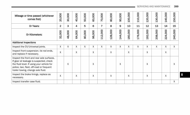
SERVICING AND MAINTENANCE 399
Mileage or time passed (whichever comes first) 20
,000
30,0
00
40,0
00
50,0
00
60,0
00
70,0
00
80,0
00
90,0
00
100,
000
110,
000
120,
000
130,
000
140,
000
150,
000
Or Years: 2 3 4 5 6 7 8 9 10 11 12 13 14 15
Or Kilometers:
32,0
00
48,0
00
64,0
00
80,0
00
96,0
00
112,
000
128,
000
144,
000
160,
000
176,
000
192,
000
208,
000
224,
000
240,
000
Additional Inspections
Inspect the CV/Universal joints. X X X X X X X X X X X X X X
Inspect front suspension, tie rod ends, and replace if necessary. X X X X X X X
Inspect the front and rear axle surfaces. If gear oil leakage is suspected, check the fluid level. If using your vehicle for police, taxi, fleet, off-road or frequent trailer towing, change axle fluid.
X X X X X
Inspect the brake linings, replace as necessary. X X X X X X X
Inspect transfer case fluid. X
8
22_DT_OM_EN_USC_t.book Page 399
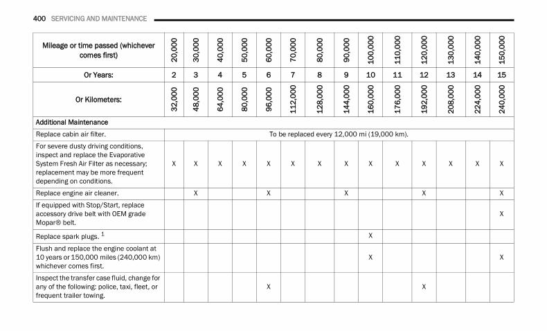
400 SERVICING AND MAINTENANCE
Additional Maintenance
Replace cabin air filter. To be replaced every 12,000 mi (19,000 km).
For severe dusty driving conditions, inspect and replace the Evaporative System Fresh Air Filter as necessary; replacement may be more frequent depending on conditions.
X X X X X X X X X X X X X X
Replace engine air cleaner. X X X X X
If equipped with Stop/Start, replace accessory drive belt with OEM grade Mopar® belt.
X
Replace spark plugs. 1 X
Flush and replace the engine coolant at 10 years or 150,000 miles (240,000 km) whichever comes first.
X X
Inspect the transfer case fluid, change for any of the following: police, taxi, fleet, or frequent trailer towing.
X X
Mileage or time passed (whichever comes first) 20
,000
30,0
00
40,0
00
50,0
00
60,0
00
70,0
00
80,0
00
90,0
00
100,
000
110,
000
120,
000
130,
000
140,
000
150,
000
Or Years: 2 3 4 5 6 7 8 9 10 11 12 13 14 15
Or Kilometers:
32,0
00
48,0
00
64,0
00
80,0
00
96,0
00
112,
000
128,
000
144,
000
160,
000
176,
000
192,
000
208,
000
224,
000
240,
000
22_DT_OM_EN_USC_t.book Page 400
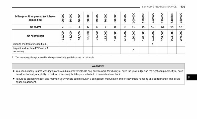
SERVICING AND MAINTENANCE 401
Change the transfer case fluid. X
Inspect and replace PCV valve if necessary. X
1. The spark plug change interval is mileage-based only; yearly intervals do not apply.
Mileage or time passed (whichever comes first) 20
,000
30,0
00
40,0
00
50,0
00
60,0
00
70,0
00
80,0
00
90,0
00
100,
000
110,
000
120,
000
130,
000
140,
000
150,
000
Or Years: 2 3 4 5 6 7 8 9 10 11 12 13 14 15
Or Kilometers:
32,0
00
48,0
00
64,0
00
80,0
00
96,0
00
112,
000
128,
000
144,
000
160,
000
176,
000
192,
000
208,
000
224,
000
240,
000
WARNING!
You can be badly injured working on or around a motor vehicle. Do only service work for which you have the knowledge and the right equipment. If you have any doubt about your ability to perform a service job, take your vehicle to a competent mechanic.
Failure to properly inspect and maintain your vehicle could result in a component malfunction and effect vehicle handling and performance. This could cause an accident.
8
22_DT_OM_EN_USC_t.book Page 401
402 SERVICING AND MAINTENANCE
SCHEDULED SERVICING — DIESEL ENGINE Your vehicle is equipped with an automatic oil change indicator system. The oil change indicator system will remind you that it is time to take your vehicle in for scheduled maintenance.Based on engine operation conditions, the oil change indicator message will illuminate. This means that service is required for your vehicle. Operating conditions such as frequent short-trips, trailer tow, extremely hot or cold ambient temperatures will influence when the “Oil Change Required” message is displayed. Have your vehicle serviced as soon as possible, within the next 500 miles (805 km).
An authorized dealer will reset the oil change indicator message after completing the scheduled oil change. If a scheduled oil change is performed by someone other than an authorized dealer, the message can be reset by referring to the steps described under Instrument Cluster Display Ú page 115.
NOTE:Under no circumstances should oil change intervals exceed 10,000 miles (16,000 km) or 12 months, whichever comes first.
Once A Month Or Before A Long Trip: Check engine oil level. Check windshield washer fluid level. Check the tire inflation pressures and look for
unusual wear or damage. Check the fluid levels of the coolant reservoir,
brake master cylinder, and power steering, and fill as needed.
Check function of all interior and exterior lights.
22_DT_OM_EN_USC_t.book Page 402
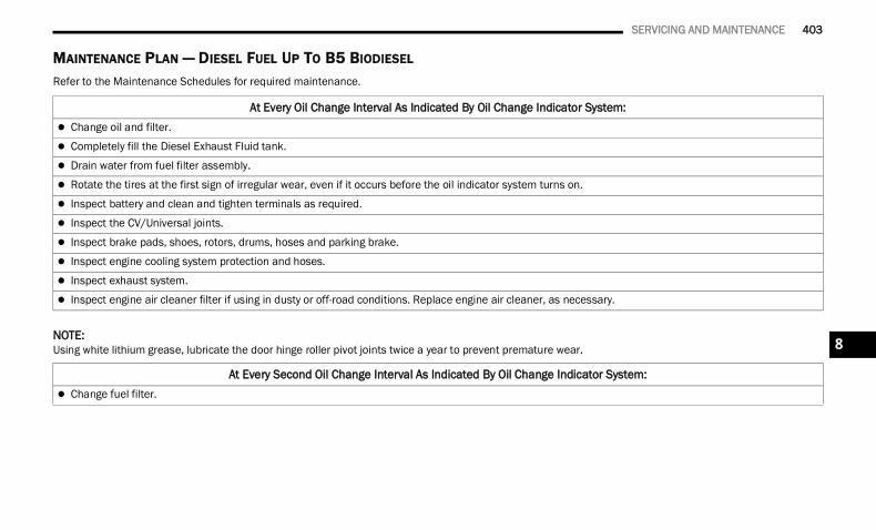
SERVICING AND MAINTENANCE 403
MAINTENANCE PLAN — DIESEL FUEL UP TO B5 BIODIESEL Refer to the Maintenance Schedules for required maintenance.
NOTE:Using white lithium grease, lubricate the door hinge roller pivot joints twice a year to prevent premature wear.
At Every Oil Change Interval As Indicated By Oil Change Indicator System: Change oil and filter.
Completely fill the Diesel Exhaust Fluid tank.
Drain water from fuel filter assembly.
Rotate the tires at the first sign of irregular wear, even if it occurs before the oil indicator system turns on.
Inspect battery and clean and tighten terminals as required.
Inspect the CV/Universal joints.
Inspect brake pads, shoes, rotors, drums, hoses and parking brake.
Inspect engine cooling system protection and hoses.
Inspect exhaust system.
Inspect engine air cleaner filter if using in dusty or off-road conditions. Replace engine air cleaner, as necessary.
At Every Second Oil Change Interval As Indicated By Oil Change Indicator System: Change fuel filter.
8
22_DT_OM_EN_USC_t.book Page 403
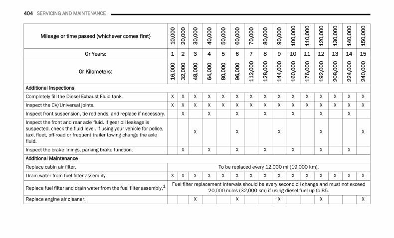
404 SERVICING AND MAINTENANCE
Mileage or time passed (whichever comes first)
10,0
00
20,0
00
30,0
00
40,0
00
50,0
00
60,0
00
70,0
00
80,0
00
90,0
00
100,
000
110,
000
120,
000
130,
000
140,
000
150,
000
Or Years: 1 2 3 4 5 6 7 8 9 10 11 12 13 14 15
Or Kilometers:
16,0
00
32,0
00
48,0
00
64,0
00
80,0
00
96,0
00
112,
000
128,
000
144,
000
160,
000
176,
000
192,
000
208,
000
224,
000
240,
000
Additional Inspections
Completely fill the Diesel Exhaust Fluid tank. X X X X X X X X X X X X X X X
Inspect the CV/Universal joints. X X X X X X X X X X X X X X X
Inspect front suspension, tie rod ends, and replace if necessary. X X X X X X X
Inspect the front and rear axle fluid. If gear oil leakage is suspected, check the fluid level. If using your vehicle for police, taxi, fleet, off-road or frequent trailer towing change the axle fluid.
X X X X X
Inspect the brake linings, parking brake function. X X X X X X X
Additional Maintenance
Replace cabin air filter. To be replaced every 12,000 mi (19,000 km).
Drain water from fuel filter assembly. X X X X X X X X X X X X X X X
Replace fuel filter and drain water from the fuel filter assembly.1Fuel filter replacement intervals should be every second oil change and must not exceed
20,000 miles (32,000 km) if using diesel fuel up to B5.
Replace engine air cleaner. X X X X X
22_DT_OM_EN_USC_t.book Page 404
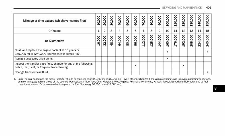
SERVICING AND MAINTENANCE 405
Flush and replace the engine coolant at 10 years or 150,000 miles (240,000 km) whichever comes first. X X
Replace accessory drive belt(s). X
Inspect the transfer case fluid, change for any of the following: police, taxi, fleet, or frequent trailer towing. X X
Change transfer case fluid. X
1. Under normal conditions the diesel fuel filter should be replaced every 20,000 miles (32,000 km) (every other oil change). If the vehicle is being used in severe operating conditions, or in certain geographical areas of the country (Pennsylvania, New York, Ohio, Maryland, West Virginia, Arkansas, Oklahoma, Kansas, Iowa, Missouri and Nebraska) due to fuel cleanliness issues, it’s recommended to replace the fuel filter every 10,000 miles (16,000 km).
Mileage or time passed (whichever comes first)
10,0
00
20,0
00
30,0
00
40,0
00
50,0
00
60,0
00
70,0
00
80,0
00
90,0
00
100,
000
110,
000
120,
000
130,
000
140,
000
150,
000
Or Years: 1 2 3 4 5 6 7 8 9 10 11 12 13 14 15
Or Kilometers:
16,0
00
32,0
00
48,0
00
64,0
00
80,0
00
96,0
00
112,
000
128,
000
144,
000
160,
000
176,
000
192,
000
208,
000
224,
000
240,
000
8
22_DT_OM_EN_USC_t.book Page 405
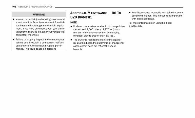
406 SERVICING AND MAINTENANCE
ADDITIONAL MAINTENANCE — B6 TO B20 BIODIESEL
NOTE: Under no circumstances should oil change inter-
vals exceed 8,000 miles (12,875 km) or six months, whichever comes first when using biodiesel blends greater than 5% (B5).
The owner is required to monitor mileage for B6-B20 biodiesel, the automatic oil change indi-cator system does not reflect the use of biofuels.
Fuel filter change interval is maintained at every second oil change. This is especially important with biodiesel usage.
For more information on using biodiesel Ú page 475.
WARNING!
You can be badly injured working on or around a motor vehicle. Do only service work for which you have the knowledge and the right equip-ment. If you have any doubt about your ability to perform a service job, take your vehicle to a competent mechanic.
Failure to properly inspect and maintain your vehicle could result in a component malfunc-tion and effect vehicle handling and perfor-mance. This could cause an accident.
22_DT_OM_EN_USC_t.book Page 406
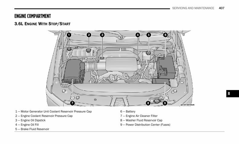
SERVICING AND MAINTENANCE 407
ENGINE COMPARTMENT 3.6L ENGINE WITH STOP/START
1 — Motor Generator Unit Coolant Reservoir Pressure Cap 6 — Battery2 — Engine Coolant Reservoir Pressure Cap 7 — Engine Air Cleaner Filter3 — Engine Oil Dipstick 8 — Washer Fluid Reservoir Cap4 — Engine Oil Fill 9 — Power Distribution Center (Fuses)5 — Brake Fluid Reservoir
8
22_DT_OM_EN_USC_t.book Page 407
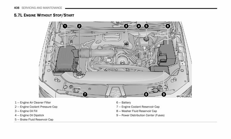
408 SERVICING AND MAINTENANCE
5.7L ENGINE WITHOUT STOP/START
1 — Engine Air Cleaner Filter 6 — Battery2 — Engine Coolant Pressure Cap 7 — Engine Coolant Reservoir Cap3 — Engine Oil Fill 8 — Washer Fluid Reservoir Cap4 — Engine Oil Dipstick 9 — Power Distribution Center (Fuses)5 — Brake Fluid Reservoir Cap
22_DT_OM_EN_USC_t.book Page 408
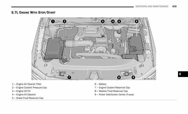
SERVICING AND MAINTENANCE 409
5.7L ENGINE WITH STOP/START
1 — Engine Air Cleaner Filter 6 — Battery2 — Engine Coolant Pressure Cap 7 — Engine Coolant Reservoir Cap3 — Engine Oil Fill 8 — Washer Fluid Reservoir Cap4 — Engine Oil Dipstick 9 — Power Distribution Center (Fuses)5 — Brake Fluid Reservoir Cap
8
22_DT_OM_EN_USC_t.book Page 409
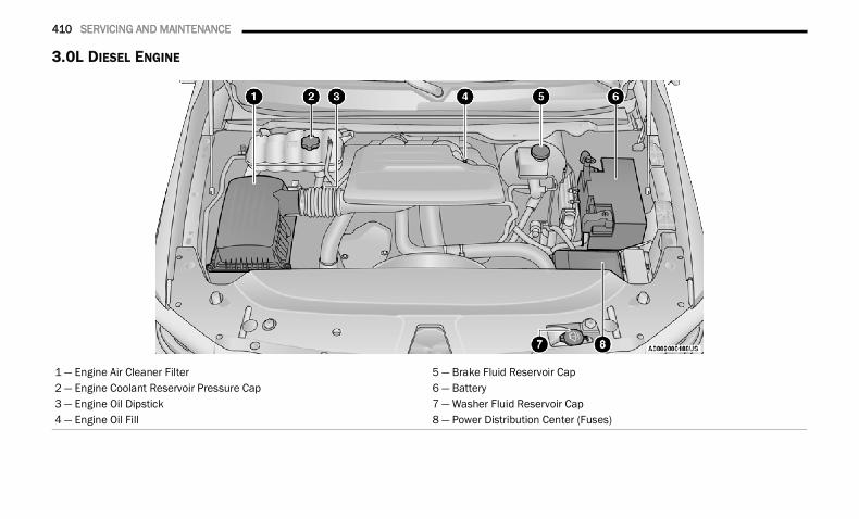
410 SERVICING AND MAINTENANCE
3.0L DIESEL ENGINE
1 — Engine Air Cleaner Filter 5 — Brake Fluid Reservoir Cap2 — Engine Coolant Reservoir Pressure Cap 6 — Battery3 — Engine Oil Dipstick 7 — Washer Fluid Reservoir Cap4 — Engine Oil Fill 8 — Power Distribution Center (Fuses)
22_DT_OM_EN_USC_t.book Page 410
SERVICING AND MAINTENANCE 411
(Continued)
CHECKING OIL LEVEL
To ensure proper engine lubrication, the engine oil must be maintained at the correct level. Check the oil level at regular intervals, such as every fuel stop. The best time to check the engine oil level is about five minutes after a fully warmed up engine is shut off.Checking the oil while the vehicle is on level ground will improve the accuracy of the oil level readings.There are four possible dipstick types: Crosshatched zone. Crosshatched zone marked SAFE. Crosshatched zone marked with MIN at the low
end of the range and MAX at the high end of the range.
Crosshatched zone marked with dimples at the MIN and the MAX ends of the range.
NOTE:Always maintain the oil level within the crosshatch markings on the dipstick.Adding 1 quart (1.0 liter) of oil when the reading is at the low end of the dipstick range will raise the oil level to the high end of the range marking.
ADDING WASHER FLUID The fluid reservoir is located under the hood and should be checked for fluid level at regular intervals. Fill the reservoir with windshield washer solvent only (not radiator antifreeze). When refilling the washer fluid reservoir, take some washer fluid and apply it to a cloth or towel and wipe the wiper blades clean. This will help blade performance.To prevent freeze-up of your windshield washer system in cold weather, select a solution or mixture that meets or exceeds the temperature range of your climate. This rating information can be found on most washer fluid containers.
After the engine has warmed up, operate the defroster for a few minutes to reduce the possibility of smearing or freezing the fluid on the cold windshield. Windshield washer solution used with water as directed on the container, aids cleaning action, reduces the freezing point to avoid line clogging, and is not harmful to paint or trim.
MAINTENANCE-FREE BATTERY Your vehicle is equipped with a maintenance-free battery. You will never have to add water, and periodic maintenance is not required.
CAUTION!
Overfilling or underfilling the crankcase will cause oil aeration or loss of oil pressure. This could damage your engine.
WARNING!
Commercially available windshield washer solvents are flammable. They could ignite and burn you. Care must be exercised when filling or working around the washer solution.
WARNING!
Battery fluid is a corrosive acid solution and can burn or even blind you. Do not allow battery fluid to contact your eyes, skin, or clothing. Do not lean over a battery when attaching clamps. If acid splashes in eyes or on skin, flush the area immediately with large amounts of water Ú page 388.
Battery gas is flammable and explosive. Keep flame or sparks away from the battery. Do not use a booster battery or any other booster source with an output greater than 12 Volts. Do not allow cable clamps to touch each other.
8
22_DT_OM_EN_USC_t.book Page 411
412 SERVICING AND MAINTENANCE
PRESSURE WASHING
Cleaning the engine compartment with a high pressure washer is not recommended.
VEHICLE MAINTENANCE An authorized dealer has the qualified service personnel, special tools, and equipment to perform all service operations in an expert manner. Service Manuals are available which include detailed service information for your vehicle. Refer to these Service Manuals before attempting any procedure yourself.
NOTE:Intentional tampering with emissions control systems may void your warranty and could result in civil penalties being assessed against you.
ENGINE OIL — GAS ENGINE Engine Oil Selection — Gasoline Engine Use only the manufacturer's recommended fluids Ú page 478.NOTE:Hemi engines (5.7L) at times can tick right after startup and then quiet down after approximately 30 seconds. This is normal and will not harm the engine. This characteristic can be caused by short drive cycles. For example, if the vehicle is started then shut off after driving a short distance. Upon restarting, you may experience a ticking sound. Other causes could be if the vehicle is unused for an extended period of time, incorrect oil, extended oil changes or extended idling. If the engine continues to tick or if the Malfunction Indicator Light (MIL) comes on, see the nearest authorized dealer.Engine Oil Selection — Diesel EngineUse only the manufacturer's recommended fluids Ú page 478.
Battery posts, terminals, and related accesso-ries contain lead and lead compounds. Wash hands after handling.
CAUTION!
It is essential when replacing the cables on the battery that the positive cable is attached to the positive post and the negative cable is attached to the negative post. Battery posts are marked positive (+) and negative (-) and are identified on the battery case. Cable clamps should be tight on the terminal posts and free of corrosion.
If a “fast charger” is used while the battery is in the vehicle, disconnect both vehicle battery cables before connecting the charger to the battery. Do not use a “fast charger” to provide starting voltage.
WARNING! CAUTION!
Precautions have been taken to safeguard all parts and connections however, the pressures generated by these machines is such that complete protection against water ingress cannot be guaranteed.
WARNING!
You can be badly injured working on or around a motor vehicle. Only do service work for which you have the knowledge and the proper equipment. If you have any doubt about your ability to perform a service job, take your vehicle to a competent mechanic.
22_DT_OM_EN_USC_t.book Page 412
SERVICING AND MAINTENANCE 413
American Petroleum Institute (API) Approved Engine OilThese symbols mean that the oil has been certified by the API. The manufacturer only recommends API trademark oils.
The API Starburst trademark certifies 0W-20, 0W-30 and 5W-30 engine oils.
The API Donut trademark certifies 0W-40 and 5W-40 engine oil.
Synthetic Engine Oils Your engine was designed for synthetic engine oils, only use synthetic API approved engine oils.Synthetic engine oils which do not have both the correct API trademark and the correct SAE viscosity grade numbers should not be used.
Materials Added To Engine Oil The manufacturer strongly recommends against the addition of any additives (other than leak detection dyes) to the engine oil. Engine oil is an engineered product and its performance may be impaired by supplemental additives.
Disposing Of Used Engine Oil And Oil Filters Care should be taken in disposing of used engine oil and oil filters from your vehicle. Used oil and oil filters, indiscriminately discarded, can present a problem to the environment. Contact an authorized dealer, service station or governmental agency for advice on how and where used oil and oil filters can be safely discarded in your area.
ENGINE OIL FILTER The engine oil filter should be replaced with a new filter at every engine oil change.Engine Oil Filter SelectionA full-flow type disposable oil filter should be used for replacement. The quality of replacement filters varies considerably. Only high quality Mopar® certified filters should be used.
ENGINE AIR CLEANER FILTER For the proper maintenance intervals Ú page 398.
Engine Air Cleaner Filter SelectionThe quality of replacement filters varies considerably. Only high quality Mopar® certified filters should be used.
CAUTION!
Do not use chemical flushes in your engine oil as the chemicals can damage your engine. Such damage is not covered by the New Vehicle Limited Warranty.
WARNING!
The air induction system (air cleaner, hoses, etc.) can provide a measure of protection in the case of engine backfire. Do not remove the air induction system (air cleaner, hoses, etc.) unless such removal is necessary for repair or maintenance. Make sure that no one is near the engine compartment before starting the vehicle with the air induction system (air cleaner, hoses, etc.) removed. Failure to do so can result in serious personal injury.
8
22_DT_OM_EN_USC_t.book Page 413
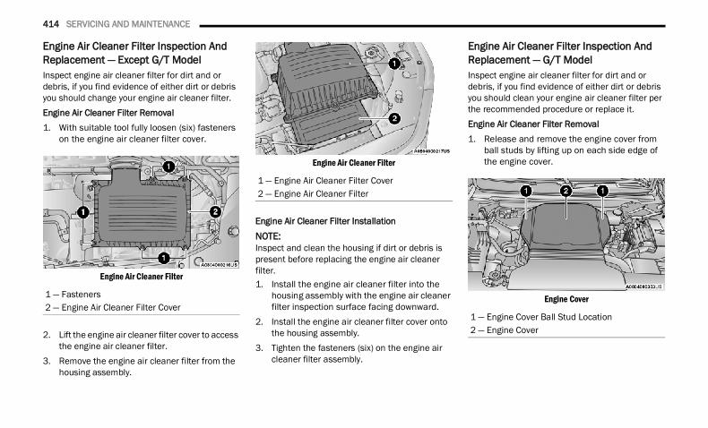
414 SERVICING AND MAINTENANCE
Engine Air Cleaner Filter Inspection And Replacement — Except G/T ModelInspect engine air cleaner filter for dirt and or debris, if you find evidence of either dirt or debris you should change your engine air cleaner filter.Engine Air Cleaner Filter Removal1. With suitable tool fully loosen (six) fasteners
on the engine air cleaner filter cover.
Engine Air Cleaner Filter
2. Lift the engine air cleaner filter cover to access the engine air cleaner filter.
3. Remove the engine air cleaner filter from the housing assembly.
Engine Air Cleaner Filter
Engine Air Cleaner Filter Installation
NOTE:Inspect and clean the housing if dirt or debris is present before replacing the engine air cleaner filter.1. Install the engine air cleaner filter into the
housing assembly with the engine air cleaner filter inspection surface facing downward.
2. Install the engine air cleaner filter cover onto the housing assembly.
3. Tighten the fasteners (six) on the engine air cleaner filter assembly.
Engine Air Cleaner Filter Inspection And Replacement — G/T ModelInspect engine air cleaner filter for dirt and or debris, if you find evidence of either dirt or debris you should clean your engine air cleaner filter per the recommended procedure or replace it.Engine Air Cleaner Filter Removal 1. Release and remove the engine cover from
ball studs by lifting up on each side edge of the engine cover.
Engine Cover1 — Fasteners2 — Engine Air Cleaner Filter Cover
1 — Engine Air Cleaner Filter Cover2 — Engine Air Cleaner Filter
1 — Engine Cover Ball Stud Location2 — Engine Cover
22_DT_OM_EN_USC_t.book Page 414
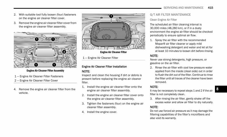
SERVICING AND MAINTENANCE 415
2. With suitable tool fully loosen (four) fasteners on the engine air cleaner filter cover.
3. Remove the engine air cleaner filter cover from the engine air cleaner filter assembly.
Engine Air Cleaner Filter Assembly
4. Remove the engine air cleaner filter from the vehicle.
Engine Air Cleaner Filter
Engine Air Cleaner Filter InstallationNOTE:Inspect and clean the housing if dirt or debris is present before replacing the engine air cleaner filter.1. Install the engine air cleaner filter onto the
engine air cleaner filter assembly.2. Install the engine air cleaner filter cover onto
the engine air cleaner filter assembly.3. Tighten the fasteners (four) on the engine air
cleaner filter assembly.4. Install the engine cover.
G/T AIR FILTER MAINTENANCEClean Engine Air FilterThe scheduled air filter cleaning interval is 30,000 miles (48,280 km), or if in a dusty environment the engine air filter should be checked periodically to ensure optimal air flow.1. Spray the air filter with the recommended
Mopar® air filter cleaner or apply mild dishwashing detergent and water and let sit for at least 10 minutes to loosen dirt before rinsing.
NOTE:Never use strong detergents, high pressure, or gasoline on the air filter.2. Rinse the air filter with cool low-pressure water
applied from the inside (clean side) out in order to flush the dirt out of the filter. Continue to rinse the filter until all traces of the cleaner have been removed.
NOTE:It may be necessary to repeat steps 1 and 2 if the air filter is not completely clean.3. After rinsing the air filter, gently shake off the
excess water and allow air filter to dry naturally.NOTE:Do not use forced air pressure as it may damage the filtering capabilities of the filter’s microfibers and also void its warranty.
1 — Engine Air Cleaner Filter Fasteners2 — Engine Air Cleaner Filter Cover
1 — Engine Air Cleaner Filter
8
22_DT_OM_EN_USC_t.book Page 415
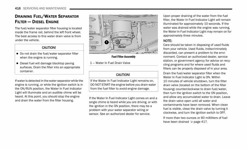
416 SERVICING AND MAINTENANCE
DRAINING FUEL/WATER SEPARATOR FILTER — DIESEL ENGINE The fuel/water separator filter housing is located inside the frame rail, behind the left front wheel. The best access to this water drain valve is from under the vehicle.
If water is detected in the water separator while the engine is running, or while the ignition switch is in the ON/RUN position, the Water In Fuel Indicator Light will illuminate and an audible chime will be heard. At this point, you should stop the engine and drain the water from the filter housing.
Fuel Filter Assembly
If the Water In Fuel Indicator Light comes on and a single chime is heard while you are driving, or with the ignition in the ON position, there may be a problem with your water separator wiring or sensor. See an authorized dealer for service.
Upon proper draining of the water from the fuel filter, the Water In Fuel Indicator Light will remain illuminated for approximately 10 seconds. If the water was drained while the engine was running, the Water In Fuel Indicator Light may remain on for approximately three minutes.
NOTE:Care should be taken in disposing of used fluids from your vehicle. Used fluids, indiscriminately discarded, can present a problem to the envi-ronment. Contact an authorized dealer, service station, or government agency for advice on recy-cling programs and for where used fluids and filters can be properly disposed of in your area.Drain the fuel/water separator filter when the Water In Fuel Indicator Light is ON. Within 10 minutes of vehicle shutdown, turn the filter drain valve (located on the bottom of the filter housing) counterclockwise to drain fuel/water, then turn the ignition switch to the ON position, and allow any accumulated water to drain. Leave the drain valve open until all water and contaminants have been removed. When clean fuel is visible, close the drain valve by turning it clockwise, and turn the ignition switch to OFF.If more than two ounces or 60 milliliters of fuel have been drained Ú page 417.
CAUTION!
Do not drain the fuel/water separator filter when the engine is running.
Diesel fuel will damage blacktop paving surfaces. Drain the filter into an appropriate container.
1 — Water In Fuel Drain Valve
CAUTION!
If the Water In Fuel Indicator Light remains on, DO NOT START the engine before you drain water from the fuel filter to avoid engine damage.
22_DT_OM_EN_USC_t.book Page 416
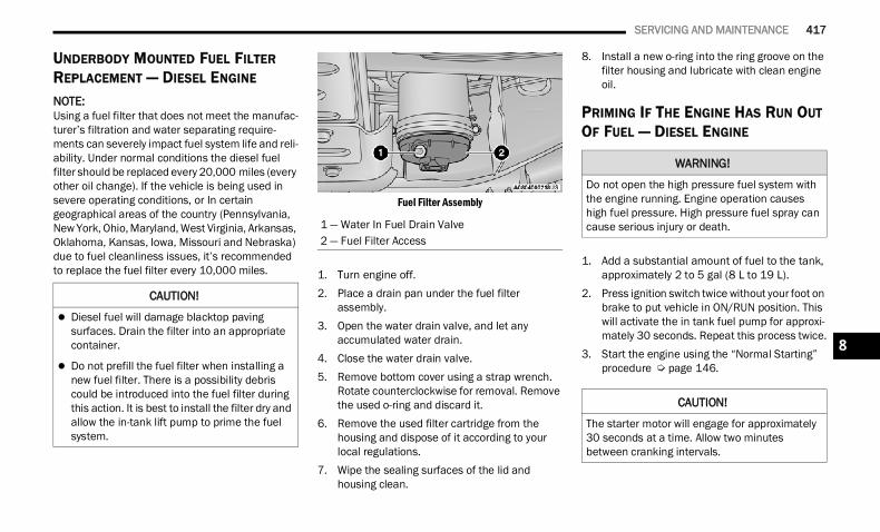
SERVICING AND MAINTENANCE 417
UNDERBODY MOUNTED FUEL FILTER REPLACEMENT — DIESEL ENGINE
NOTE:Using a fuel filter that does not meet the manufac-turer’s filtration and water separating require-ments can severely impact fuel system life and reli-ability. Under normal conditions the diesel fuel filter should be replaced every 20,000 miles (every other oil change). If the vehicle is being used in severe operating conditions, or In certain geographical areas of the country (Pennsylvania, New York, Ohio, Maryland, West Virginia, Arkansas, Oklahoma, Kansas, Iowa, Missouri and Nebraska) due to fuel cleanliness issues, it’s recommended to replace the fuel filter every 10,000 miles.
Fuel Filter Assembly
1. Turn engine off.2. Place a drain pan under the fuel filter
assembly.3. Open the water drain valve, and let any
accumulated water drain.4. Close the water drain valve.5. Remove bottom cover using a strap wrench.
Rotate counterclockwise for removal. Remove the used o-ring and discard it.
6. Remove the used filter cartridge from the housing and dispose of it according to your local regulations.
7. Wipe the sealing surfaces of the lid and housing clean.
8. Install a new o-ring into the ring groove on the filter housing and lubricate with clean engine oil.
PRIMING IF THE ENGINE HAS RUN OUT OF FUEL — DIESEL ENGINE
1. Add a substantial amount of fuel to the tank, approximately 2 to 5 gal (8 L to 19 L).
2. Press ignition switch twice without your foot on brake to put vehicle in ON/RUN position. This will activate the in tank fuel pump for approxi-mately 30 seconds. Repeat this process twice.
3. Start the engine using the “Normal Starting” procedure Ú page 146.
CAUTION!
Diesel fuel will damage blacktop paving surfaces. Drain the filter into an appropriate container.
Do not prefill the fuel filter when installing a new fuel filter. There is a possibility debris could be introduced into the fuel filter during this action. It is best to install the filter dry and allow the in-tank lift pump to prime the fuel system.
1 — Water In Fuel Drain Valve2 — Fuel Filter Access
WARNING!
Do not open the high pressure fuel system with the engine running. Engine operation causes high fuel pressure. High pressure fuel spray can cause serious injury or death.
CAUTION!
The starter motor will engage for approximately 30 seconds at a time. Allow two minutes between cranking intervals.
8
22_DT_OM_EN_USC_t.book Page 417
418 SERVICING AND MAINTENANCE
NOTE:The engine may run rough until the air is forced from all the fuel lines.
NOTE: Use of biodiesel mixture in excess of 20% can
negatively impact the fuel filter's ability to sepa-rate water from the fuel, resulting in high pres-sure fuel system corrosion or damage.
In addition, commercially available fuel addi-tives are not necessary for the proper operation of your diesel engine.
For extreme cold conditions, "Mopar® Premium Diesel Fuel Treatment" is recommended to assist with cold starting.
INTERVENTION REGENERATION STRATEGY — MESSAGE PROCESS FLOW (DIESEL ENGINE)This engine meets all required diesel engine emissions standards. To achieve these emissions standards, your vehicle is equipped with a state-of-the-art engine and exhaust system. These systems are seamlessly integrated into your vehicle and managed by the Powertrain Control Module (PCM). The PCM manages engine combustion to allow the exhaust system’s catalyst to trap and burn Particulate Matter (PM) pollutants, with no input or interaction on your part.Additionally, your vehicle has the ability to alert you to additional maintenance required on your vehicle or engine Ú page 115.
DIESEL EXHAUST FLUID
Diesel Exhaust Fluid (DEF) sometimes known simply by the name of its active component, UREA—is a key component of Selective Catalytic Reduction (SCR) systems, which help diesel vehicles meet stringent emission regulations. DEF is a liquid reducing agent that reacts with engine exhaust in the presence of a catalyst to convert smog-forming Nitrogen Oxides (NOx) into harmless nitrogen and water vapor.Refer to Engine Fluids And Lubricants Ú page 478 for further information.
AIR CONDITIONER MAINTENANCE For best possible performance, your air conditioner should be checked and serviced by an authorized dealer at the start of each warm season. This service should include cleaning of the condenser fins and a performance test. Drive belt tension should also be checked at this time.
WARNING!
Do not use alcohol or gasoline as a fuel blending agent. They can be unstable under certain conditions and be hazardous or explosive when mixed with diesel fuel.
CAUTION!
Due to lack of lubricants in alcohol or gasoline, the use of these fuels can cause damage to the fuel system.
WARNING!
A hot exhaust system can start a fire if you park over materials that can burn, such as grass or leaves, and those items that come into contact with your exhaust system. Do not park or operate your vehicle in areas where your exhaust system can contact anything that can burn.
22_DT_OM_EN_USC_t.book Page 418
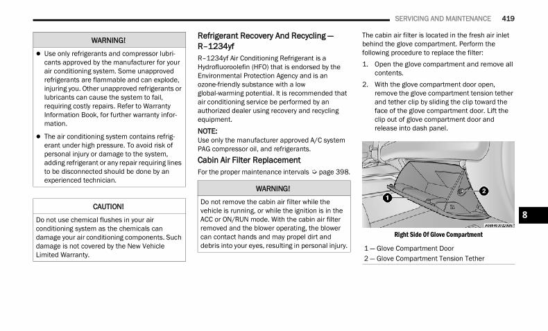
SERVICING AND MAINTENANCE 419
Refrigerant Recovery And Recycling — R–1234yf R–1234yf Air Conditioning Refrigerant is a Hydrofluoroolefin (HFO) that is endorsed by the Environmental Protection Agency and is an ozone-friendly substance with a low global-warming potential. It is recommended that air conditioning service be performed by an authorized dealer using recovery and recycling equipment.
NOTE:Use only the manufacturer approved A/C system PAG compressor oil, and refrigerants.Cabin Air Filter Replacement For the proper maintenance intervals Ú page 398.
The cabin air filter is located in the fresh air inlet behind the glove compartment. Perform the following procedure to replace the filter:1. Open the glove compartment and remove all
contents.2. With the glove compartment door open,
remove the glove compartment tension tether and tether clip by sliding the clip toward the face of the glove compartment door. Lift the clip out of glove compartment door and release into dash panel.
Right Side Of Glove Compartment
WARNING!
Use only refrigerants and compressor lubri-cants approved by the manufacturer for your air conditioning system. Some unapproved refrigerants are flammable and can explode, injuring you. Other unapproved refrigerants or lubricants can cause the system to fail, requiring costly repairs. Refer to Warranty Information Book, for further warranty infor-mation.
The air conditioning system contains refrig-erant under high pressure. To avoid risk of personal injury or damage to the system, adding refrigerant or any repair requiring lines to be disconnected should be done by an experienced technician.
CAUTION!
Do not use chemical flushes in your air conditioning system as the chemicals can damage your air conditioning components. Such damage is not covered by the New Vehicle Limited Warranty.
WARNING!
Do not remove the cabin air filter while the vehicle is running, or while the ignition is in the ACC or ON/RUN mode. With the cabin air filter removed and the blower operating, the blower can contact hands and may propel dirt and debris into your eyes, resulting in personal injury. 1 — Glove Compartment Door
2 — Glove Compartment Tension Tether
8
22_DT_OM_EN_USC_t.book Page 419
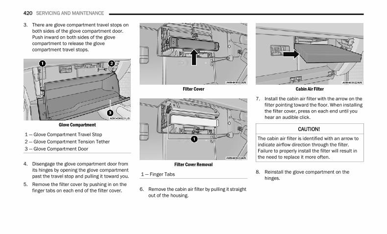
420 SERVICING AND MAINTENANCE
3. There are glove compartment travel stops on both sides of the glove compartment door. Push inward on both sides of the glove compartment to release the glove compartment travel stops.
Glove Compartment
4. Disengage the glove compartment door from its hinges by opening the glove compartment past the travel stop and pulling it toward you.
5. Remove the filter cover by pushing in on the finger tabs on each end of the filter cover.
Filter Cover
Filter Cover Removal
6. Remove the cabin air filter by pulling it straight out of the housing.
Cabin Air Filter
7. Install the cabin air filter with the arrow on the filter pointing toward the floor. When installing the filter cover, press on each end until you hear an audible click.
8. Reinstall the glove compartment on the hinges.
1 — Glove Compartment Travel Stop2 — Glove Compartment Tension Tether3 — Glove Compartment Door
1 — Finger Tabs
CAUTION!
The cabin air filter is identified with an arrow to indicate airflow direction through the filter. Failure to properly install the filter will result in the need to replace it more often.
22_DT_OM_EN_USC_t.book Page 420
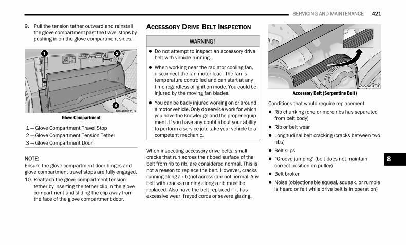
SERVICING AND MAINTENANCE 421
9. Pull the tension tether outward and reinstall the glove compartment past the travel stops by pushing in on the glove compartment sides.
Glove Compartment
NOTE:Ensure the glove compartment door hinges and glove compartment travel stops are fully engaged.10. Reattach the glove compartment tension
tether by inserting the tether clip in the glove compartment and sliding the clip away from the face of the glove compartment door.
ACCESSORY DRIVE BELT INSPECTION
When inspecting accessory drive belts, small cracks that run across the ribbed surface of the belt from rib to rib, are considered normal. This is not a reason to replace the belt. However, cracks running along a rib (not across) are not normal. Any belt with cracks running along a rib must be replaced. Also have the belt replaced if it has excessive wear, frayed cords or severe glazing.
Accessory Belt (Serpentine Belt)
Conditions that would require replacement: Rib chunking (one or more ribs has separated
from belt body) Rib or belt wear Longitudinal belt cracking (cracks between two
ribs) Belt slips “Groove jumping" (belt does not maintain
correct position on pulley) Belt broken Noise (objectionable squeal, squeak, or rumble
is heard or felt while drive belt is in operation)
1 — Glove Compartment Travel Stop2 — Glove Compartment Tension Tether3 — Glove Compartment Door
WARNING!
Do not attempt to inspect an accessory drive belt with vehicle running.
When working near the radiator cooling fan, disconnect the fan motor lead. The fan is temperature controlled and can start at any time regardless of ignition mode. You could be injured by the moving fan blades.
You can be badly injured working on or around a motor vehicle. Only do service work for which you have the knowledge and the proper equip-ment. If you have any doubt about your ability to perform a service job, take your vehicle to a competent mechanic.
8
22_DT_OM_EN_USC_t.book Page 421
422 SERVICING AND MAINTENANCE
NOTE:Identify and correct problem before new belt is installed.NOTE:If your vehicle is equipped with a Stop/Start, belt must be replaced with an OEM grade Mopar® belt.Some conditions can be caused by a faulty component such as a belt pulley. Belt pulleys should be carefully inspected for damage and proper alignment.Belt replacement on some models requires the use of special tools, we recommend having your vehicle serviced at an authorized dealer.
BODY LUBRICATION Locks and all body pivot points, including such items as seat tracks, door hinge pivot points and rollers, liftgate, tailgate, decklid, sliding doors and hood hinges, should be lubricated periodically. Use a lithium-based grease, such as Mopar® Spray White Lube to assure quiet, easy operation and to protect against rust and wear. Prior to the application of any lubricant, the parts concerned should be wiped clean to remove dust and grit; after lubricating excess oil and grease should be removed. Particular attention should also be given to hood latching components to ensure proper function. When performing other underhood services, the hood latch release mechanism, and safety catch should be cleaned and lubricated.
The external lock cylinders should be lubricated twice a year, preferably in the Autumn and Spring. Apply a small amount of a high quality lubricant, such as Mopar® Lock Cylinder Lubricant directly into the lock cylinder.
WINDSHIELD WIPER BLADES Clean the rubber edges of the wiper blades and the windshield periodically with a sponge or soft cloth and a mild nonabrasive cleaner. This will remove accumulations of salt or road film.Operation of the wipers on dry glass for long periods may cause deterioration of the wiper blades. Always use washer fluid when using the wipers to remove salt or dirt from a dry windshield.Avoid using the wiper blades to remove frost or ice from the windshield. Keep the blade rubber out of contact with petroleum products such as engine oil, gasoline, etc.
NOTE:Life expectancy of wiper blades varies depending on geographical area and frequency of use. If chat-tering, marks, water lines or wet spots are present, clean the wiper blades or replace as necessary.
The wiper blades and wiper arms should be inspected periodically, not just when wiper performance problems are experienced. This inspection should include the following points: Wear or uneven edges Foreign material Hardening or cracking Deformation or fatigueIf a wiper blade or wiper arm is damaged, replace the affected wiper arm or blade with a new unit. Do not attempt to repair a wiper arm or blade that is damaged.
Wiper Blade Removal/Installation
1. Lift the wiper arm to raise the wiper blade off of the glass, until the wiper arm is in the full up position.
CAUTION!
Do not allow the wiper arm to spring back against the glass without the wiper blade in place or the glass may be damaged.
22_DT_OM_EN_USC_t.book Page 422
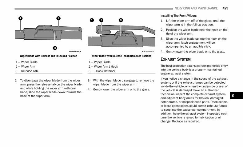
SERVICING AND MAINTENANCE 423
Wiper Blade With Release Tab In Locked Position
2. To disengage the wiper blade from the wiper arm, press the release tab on the wiper blade and while holding the wiper arm with one hand, slide the wiper blade down towards the base of the wiper arm.
Wiper Blade With Release Tab In Unlocked Position
3. With the wiper blade disengaged, remove the wiper blade from the wiper arm.
4. Gently lower the wiper arm onto the glass.
Installing The Front Wipers1. Lift the wiper arm off of the glass, until the
wiper arm is in the full up position.2. Position the wiper blade near the hook on the
tip of the wiper arm.3. Slide the wiper blade up into the hook on the
wiper arm, latch engagement will be accompanied by an audible click.
4. Gently lower the wiper blade onto the glass.
EXHAUST SYSTEM The best protection against carbon monoxide entry into the vehicle body is a properly maintained engine exhaust system.If you notice a change in the sound of the exhaust system; or if the exhaust fumes can be detected inside the vehicle; or when the underside or rear of the vehicle is damaged; have an authorized technician inspect the complete exhaust system and adjacent body areas for broken, damaged, deteriorated, or mispositioned parts. Open seams or loose connections could permit exhaust fumes to seep into the passenger compartment. In addition, have the exhaust system inspected each time the vehicle is raised for lubrication or oil change. Replace as required.
1 — Wiper Blade2 — Wiper Arm3 — Release Tab
1 — Wiper Blade2 — Wiper Arm J Hook3 — J Hook Retainer
8
22_DT_OM_EN_USC_t.book Page 423
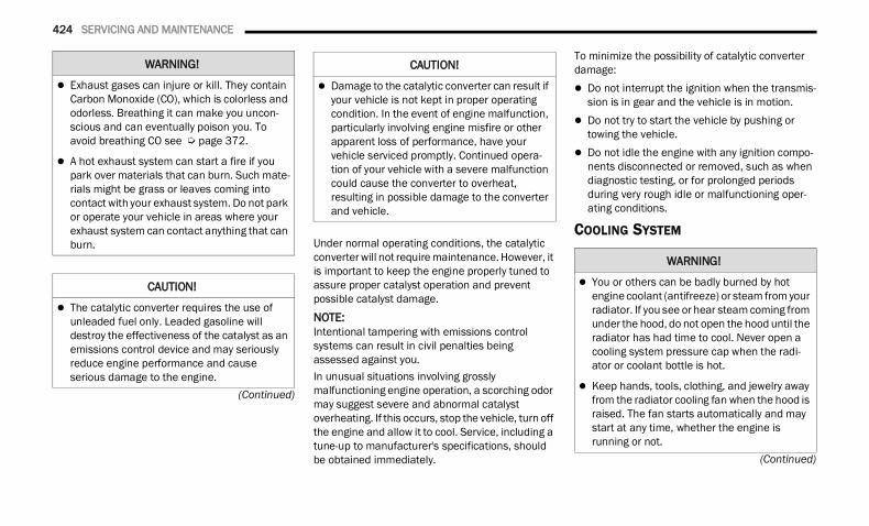
424 SERVICING AND MAINTENANCE
(Continued)
(Continued)
Under normal operating conditions, the catalytic converter will not require maintenance. However, it is important to keep the engine properly tuned to assure proper catalyst operation and prevent possible catalyst damage.NOTE:Intentional tampering with emissions control systems can result in civil penalties being assessed against you.In unusual situations involving grossly malfunctioning engine operation, a scorching odor may suggest severe and abnormal catalyst overheating. If this occurs, stop the vehicle, turn off the engine and allow it to cool. Service, including a tune-up to manufacturer's specifications, should be obtained immediately.
To minimize the possibility of catalytic converter damage: Do not interrupt the ignition when the transmis-
sion is in gear and the vehicle is in motion. Do not try to start the vehicle by pushing or
towing the vehicle. Do not idle the engine with any ignition compo-
nents disconnected or removed, such as when diagnostic testing, or for prolonged periods during very rough idle or malfunctioning oper-ating conditions.
COOLING SYSTEM
WARNING!
Exhaust gases can injure or kill. They contain Carbon Monoxide (CO), which is colorless and odorless. Breathing it can make you uncon-scious and can eventually poison you. To avoid breathing CO see Ú page 372.
A hot exhaust system can start a fire if you park over materials that can burn. Such mate-rials might be grass or leaves coming into contact with your exhaust system. Do not park or operate your vehicle in areas where your exhaust system can contact anything that can burn.
CAUTION!
The catalytic converter requires the use of unleaded fuel only. Leaded gasoline will destroy the effectiveness of the catalyst as an emissions control device and may seriously reduce engine performance and cause serious damage to the engine.
Damage to the catalytic converter can result if your vehicle is not kept in proper operating condition. In the event of engine malfunction, particularly involving engine misfire or other apparent loss of performance, have your vehicle serviced promptly. Continued opera-tion of your vehicle with a severe malfunction could cause the converter to overheat, resulting in possible damage to the converter and vehicle.
CAUTION!
WARNING!
You or others can be badly burned by hot engine coolant (antifreeze) or steam from your radiator. If you see or hear steam coming from under the hood, do not open the hood until the radiator has had time to cool. Never open a cooling system pressure cap when the radi-ator or coolant bottle is hot.
Keep hands, tools, clothing, and jewelry away from the radiator cooling fan when the hood is raised. The fan starts automatically and may start at any time, whether the engine is running or not.
22_DT_OM_EN_USC_t.book Page 424
SERVICING AND MAINTENANCE 425
Engine Coolant Checks Check the engine coolant (antifreeze) protection every 12 months (before the onset of freezing weather, where applicable). If the engine coolant is dirty or rusty in appearance, the system should be drained, flushed and refilled with fresh coolant. Check the front of the A/C condenser (if equipped) or radiator for any accumulation of bugs, leaves, etc. If dirty, clean by gently spraying water from a garden hose vertically down the face of the A/C condenser (if equipped) or the back of the radiator core.Check the engine cooling system hoses for brittle rubber, cracking, tears, cuts and tightness of the connection at the coolant recovery bottle and radiator. Inspect the entire system for leaks.DO NOT REMOVE THE COOLANT PRESSURE CAP WHEN THE COOLING SYSTEM IS HOT.
Cooling System — Drain, Flush And Refill NOTE:Some vehicles require special tools to add coolant properly. Failure to fill these systems properly could lead to severe internal engine damage. If any coolant is needed to be added to the system please contact an authorized dealer.If the engine coolant (antifreeze) is dirty or contains visible sediment, have an authorized dealer clean and flush with OAT coolant (conforming to MS.90032).For the proper maintenance intervals Ú page 398.
Selection Of Coolant For further information Ú page 478.NOTE: Mixing of engine coolant (antifreeze) other than
specified Organic Additive Technology (OAT) engine coolant, may result in engine damage and may decrease corrosion protection. OAT engine coolant is different and should not be mixed with Hybrid Organic Additive Technology (HOAT) engine coolant or any “globally compat-ible” coolant. If a non-OAT engine coolant is introduced into the cooling system in an emer-gency, the cooling system will need to be drained, flushed, and refilled with fresh OAT coolant (conforming to MS.90032), by an autho-rized dealer as soon as possible.
Do not use water alone or alcohol-based engine coolant products. Do not use additional rust inhibitors or anti-rust products, as they may not be compatible with the radiator engine coolant and may plug the radiator.
This vehicle has not been designed for use with propylene glycol-based engine coolant. Use of propylene glycol-based engine coolant is not recommended.
Some vehicles require special tools to add coolant properly. Failure to fill these systems properly could lead to severe internal engine damage. If any coolant is needed to be added to the system please contact an authorized dealer.
Adding Coolant Your vehicle has been built with an improved engine coolant (OAT coolant conforming to MS.90032) that allows extended maintenance intervals. This engine coolant (antifreeze) can be used up to 10 years or 150,000 miles (240,000 km) before replacement. To prevent reducing this extended maintenance period, it is important that you use the same engine coolant (OAT coolant conforming to MS.90032) throughout the life of your vehicle.
When working near the radiator cooling fan, disconnect the fan motor lead or turn the igni-tion to the OFF mode. The fan is temperature controlled and can start at any time the igni-tion is in the ON mode.
WARNING!
8
22_DT_OM_EN_USC_t.book Page 425
426 SERVICING AND MAINTENANCE
Please review these recommendations for using Organic Additive Technology (OAT) engine coolant that meets the requirements of the manufacturer Material Standard MS.90032. When adding engine coolant: We recommend using Mopar® Antifreeze/
Coolant 10 Year/150,000 Mile (240,000 km) Formula OAT that meets the requirements of the manufacturer Material Standard MS.90032.
Mix a minimum solution of 50% OAT engine coolant that meets the requirements of the manufacturer Material Standard MS.90032 and distilled water. Use higher concentrations (not to exceed 70%) if temperatures below −34°F (−37°C) are anticipated. Please contact an authorized dealer for assistance.
Use only high purity water such as distilled or deionized water when mixing the water/engine coolant solution. The use of lower quality water will reduce the amount of corrosion protection in the engine cooling system.
NOTE: It is the owner's responsibility to maintain the
proper level of protection against freezing according to the temperatures occurring in the area where the vehicle is operated.
Some vehicles require special tools to add coolant properly. Failure to fill these systems properly could lead to severe internal engine damage. If any coolant is needed to be added to the system, please contact an authorized dealer.
Mixing engine coolant types is not recom-mended and can result in cooling system damage. If HOAT and OAT coolant are mixed in an emergency, have an authorized dealer drain, flush, and refill with OAT coolant (conforming to MS.90032) as soon as possible.
Cooling System Pressure Cap The cap must be fully tightened to prevent loss of engine coolant (antifreeze), and to ensure that engine coolant will return to the radiator from the coolant expansion bottle/recovery tank (if equipped).The cap should be inspected and cleaned if there is any accumulation of foreign material on the sealing surfaces.
Disposal Of Used Coolant Used ethylene glycol-based coolant (antifreeze) is a regulated substance requiring proper disposal. Check with your local authorities to determine the disposal rules for your community. To prevent ingestion by animals or children, do not store ethylene glycol-based coolant in open containers or allow it to remain in puddles on the ground, clean up any ground spills immediately. If ingested, seek emergency assistance immediately.
WARNING!
Do not open hot engine cooling system. Never add engine coolant (antifreeze) when the engine is overheated. Do not loosen or remove the cap to cool an overheated engine. Heat causes pressure to build up in the cooling system. To prevent scalding or injury, do not remove the pressure cap while the system is hot or under pressure.
Do not use a pressure cap other than the one specified for your vehicle. Personal injury or engine damage may result.
22_DT_OM_EN_USC_t.book Page 426
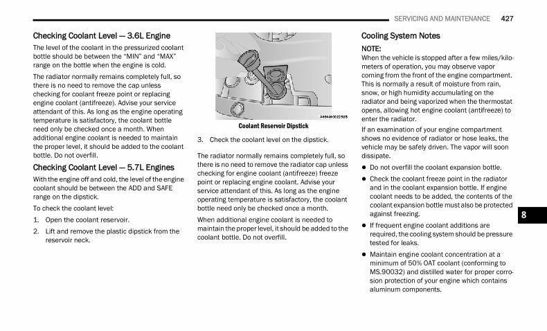
SERVICING AND MAINTENANCE 427
Checking Coolant Level — 3.6L Engine The level of the coolant in the pressurized coolant bottle should be between the “MIN” and “MAX” range on the bottle when the engine is cold.The radiator normally remains completely full, so there is no need to remove the cap unless checking for coolant freeze point or replacing engine coolant (antifreeze). Advise your service attendant of this. As long as the engine operating temperature is satisfactory, the coolant bottle need only be checked once a month. When additional engine coolant is needed to maintain the proper level, it should be added to the coolant bottle. Do not overfill.
Checking Coolant Level — 5.7L EnginesWith the engine off and cold, the level of the engine coolant should be between the ADD and SAFE range on the dipstick.To check the coolant level:1. Open the coolant reservoir.2. Lift and remove the plastic dipstick from the
reservoir neck.
Coolant Reservoir Dipstick
3. Check the coolant level on the dipstick.
The radiator normally remains completely full, so there is no need to remove the radiator cap unless checking for engine coolant (antifreeze) freeze point or replacing engine coolant. Advise your service attendant of this. As long as the engine operating temperature is satisfactory, the coolant bottle need only be checked once a month.When additional engine coolant is needed to maintain the proper level, it should be added to the coolant bottle. Do not overfill.
Cooling System NotesNOTE:When the vehicle is stopped after a few miles/kilo-meters of operation, you may observe vapor coming from the front of the engine compartment. This is normally a result of moisture from rain, snow, or high humidity accumulating on the radiator and being vaporized when the thermostat opens, allowing hot engine coolant (antifreeze) to enter the radiator.If an examination of your engine compartment shows no evidence of radiator or hose leaks, the vehicle may be safely driven. The vapor will soon dissipate. Do not overfill the coolant expansion bottle. Check the coolant freeze point in the radiator
and in the coolant expansion bottle. If engine coolant needs to be added, the contents of the coolant expansion bottle must also be protected against freezing.
If frequent engine coolant additions are required, the cooling system should be pressure tested for leaks.
Maintain engine coolant concentration at a minimum of 50% OAT coolant (conforming to MS.90032) and distilled water for proper corro-sion protection of your engine which contains aluminum components.
8
22_DT_OM_EN_USC_t.book Page 427
428 SERVICING AND MAINTENANCE
(Continued)
Make sure that the coolant expansion bottle overflow hoses are not kinked or obstructed.
Keep the front of the radiator clean. If your vehicle is equipped with air conditioning, keep the front of the condenser clean.
Do not change the thermostat for Summer or Winter operation. If replacement is ever neces-sary, install ONLY the correct type thermostat. Other designs may result in unsatisfactory engine cooling performance, poor gas mileage, and increased emissions.
CHARGE AIR COOLER — INTER-COOLER (DIESEL ENGINE)The charge air cooler is positioned in front of the radiator and the air conditioner condenser. Air enters the engine through the air cleaner and passes through the turbocharger, where it is pressurized. This pressurized air rapidly reaches high temperature. The air is then directed through a hose to the charge air cooler and through another hose to the intake manifold of the engine. This cooling process enables more efficient burning of fuel resulting in fewer emissions.To guarantee optimum performance of the system, keep the surfaces of the charge air cooler, condenser and radiator clean and free of debris. Periodically check the hoses leading to and from
the charge air cooler for cracks or loose clamps resulting in loss of pressure and reduced engine performance.
BRAKE SYSTEM In order to ensure brake system performance, all brake system components should be inspected periodically Ú page 398.
Fluid Level Check — Brake Master Cylinder The fluid level of the brake master cylinder should be checked whenever the vehicle is serviced, or immediately if the Brake System Warning Light is on. If necessary, add fluid to bring level within the designated marks on the side of the reservoir of the brake master cylinder. Be sure to clean the top of the master cylinder area before removing cap. With disc brakes, fluid level can be expected to fall as the brake pads wear. Brake fluid level should be
checked when pads are replaced. If the brake fluid is abnormally low, check the system for leaks Ú page 481.
WARNING!
Riding the brakes can lead to brake failure and possibly a collision. Driving with your foot resting or riding on the brake pedal can result in abnormally high brake temperatures, excessive lining wear, and possible brake damage. You would not have your full braking capacity in an emergency.
WARNING!
Use only manufacturer's recommended brake fluid Ú page 481. Using the wrong type of brake fluid can severely damage your brake system and/or impair its performance. The proper type of brake fluid for your vehicle is also identified on the original factory installed hydraulic master cylinder reservoir.
To avoid contamination from foreign matter or moisture, use only new brake fluid or fluid that has been in a tightly closed container. Keep the master cylinder reservoir cap secured at all times. Brake fluid in an open container absorbs moisture from the air resulting in a lower boiling point. This may cause it to boil unexpectedly during hard or prolonged braking, resulting in sudden brake failure. This could result in a collision.
Overfilling the brake fluid reservoir can result in spilling brake fluid on hot engine parts, causing the brake fluid to catch fire. Brake fluid can also damage painted and vinyl surfaces, care should be taken to avoid its contact with these surfaces.
22_DT_OM_EN_USC_t.book Page 428
SERVICING AND MAINTENANCE 429
AUTOMATIC TRANSMISSION Special Additives The manufacturer strongly recommends against using any special additives in the transmission. Automatic Transmission Fluid (ATF) is an engineered product and its performance may be impaired by supplemental additives. Therefore, do not add any fluid additives to the transmission. Avoid using transmission sealers as they may adversely affect seals.
Fluid Level Check The fluid level is preset at the factory and does not require adjustment under normal operating conditions. Routine fluid level checks are not required, therefore the transmission has no dipstick. An authorized dealer can check your transmission fluid level using special service tools.If you notice fluid leakage or transmission malfunction, visit an authorized dealer immediately to have the transmission fluid level checked. Operating the vehicle with an improper fluid level can cause severe transmission damage.
Fluid And Filter Changes Under normal operating conditions, the fluid installed at the factory will provide satisfactory lubrication for the life of the vehicle.
Routine fluid and filter changes are not required. However, change the fluid and filter if the fluid becomes contaminated (with water, etc.), or if the transmission is disassembled for any reason.
Selection Of Lubricant It is important to use the proper transmission fluid to ensure optimum transmission performance and life. Use only the manufacturer recommended transmission fluid Ú page 481. It is important to maintain the transmission fluid at the correct level using the recommended fluid. No chemical flushes should be used in any transmission; only the approved lubricant should be used.
Do not allow petroleum based fluid to contam-inate the brake fluid. Brake seal components could be damaged, causing partial or complete brake failure. This could result in a collision.
CAUTION!
Do not use chemical flushes in your transmission as the chemicals can damage your transmission components. Such damage is not covered by the New Vehicle Limited Warranty.
WARNING!
CAUTION!
If a transmission fluid leak occurs, visit an authorized dealer immediately. Severe transmission damage may occur. An authorized dealer has the proper tools to adjust the fluid level accurately.
CAUTION!
Using a transmission fluid other than the manufacturer’s recommended fluid may cause deterioration in transmission shift quality and/or torque converter shudder Ú page 481.
8
22_DT_OM_EN_USC_t.book Page 429
430 SERVICING AND MAINTENANCE
(Continued)
REAR AXLE AND 4X4 FRONT DRIVING AXLE FLUID LEVEL For normal service, periodic fluid level checks are not required. When the vehicle is serviced for other reasons the exterior surfaces of the axle assembly should be inspected. If gear oil leakage is suspected inspect the fluid level Ú page 481. This inspection should be made with the vehicle in a level position.The fluid level should be even with the bottom of the fill hole (within 1/4 in (6.4 mm) of edge of hole) for the front axle and rear axle.
Drain And RefillFor the proper maintenance intervals Ú page 398.
Lubricant SelectionFor further information Ú page 481.NOTE:The presence of water in the gear lubricant will result in corrosion and possible failure of differ-ential components. Operation of the vehicle in water, as may be encountered in some off-highway types of service, will require draining and refilling the axle to avoid damage.
Limited-Slip Differentials Rear axles equipped with a Limited Slip Differential require that 5 oz. (148 ml) Mopar® Limited Slip Additive be added to the gear lubricant Ú page 481. The Mopar® Limited Slip Additive should be added to the gear lubricant whenever a fluid change is made to an axle equipped with a Limited Slip Differential.
NOTE:When refilling a limited slip differential axle which requires a friction modification additive, the additive should be added before the gear lubricant to ensure proper additive fill.
TRANSFER CASE Fluid Level CheckThis fluid level can be checked by removing the filler plug. The fluid level should be to the bottom edge of the filler plug hole (or within 1/8 inch of the bottom) with the vehicle in a level position.
Drain And RefillFor the proper maintenance intervals Ú page 398.
Selection Of LubricantUse only the manufacturer recommended fluid Ú page 481.
FUSES
General Information
WARNING!
When replacing a blown fuse, always use an appropriate replacement fuse with the same amp rating as the original fuse. Never replace a fuse with another fuse of higher amp rating. The use of a fuse with a rating other than indicated may result in a dangerous electrical system overload. If a properly rated fuse continues to blow, it indicates a problem in the circuit that must be corrected. Never replace a blown fuse with metal wires or any other material. Do not place a fuse inside a circuit breaker cavity or vice versa. Failure to use proper fuses may result in serious personal injury, fire and/or property damage.
Before replacing a fuse, make sure that the igni-tion is off and that all the other services are switched off and/or disengaged.
22_DT_OM_EN_USC_t.book Page 430
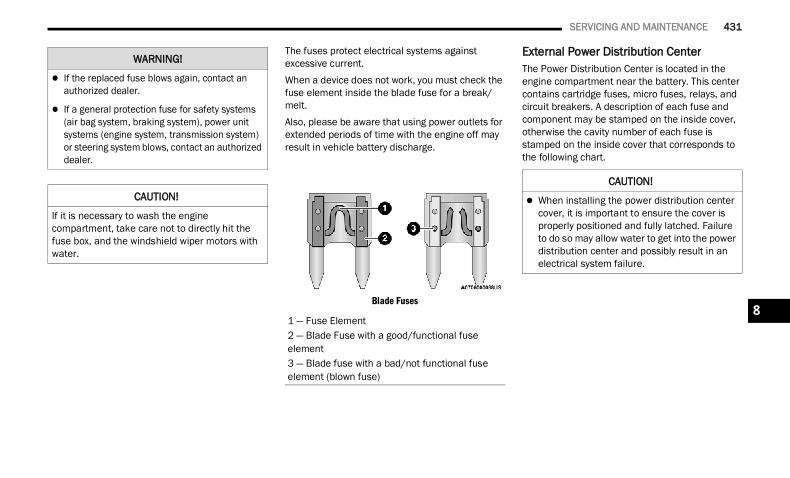
SERVICING AND MAINTENANCE 431
The fuses protect electrical systems against excessive current.When a device does not work, you must check the fuse element inside the blade fuse for a break/melt.Also, please be aware that using power outlets for extended periods of time with the engine off may result in vehicle battery discharge.
Blade Fuses
External Power Distribution Center The Power Distribution Center is located in the engine compartment near the battery. This center contains cartridge fuses, micro fuses, relays, and circuit breakers. A description of each fuse and component may be stamped on the inside cover, otherwise the cavity number of each fuse is stamped on the inside cover that corresponds to the following chart.
If the replaced fuse blows again, contact an authorized dealer.
If a general protection fuse for safety systems (air bag system, braking system), power unit systems (engine system, transmission system) or steering system blows, contact an authorized dealer.
CAUTION!
If it is necessary to wash the engine compartment, take care not to directly hit the fuse box, and the windshield wiper motors with water.
WARNING!
1 — Fuse Element2 — Blade Fuse with a good/functional fuseelement3 — Blade fuse with a bad/not functional fuseelement (blown fuse)
CAUTION!
When installing the power distribution center cover, it is important to ensure the cover is properly positioned and fully latched. Failure to do so may allow water to get into the power distribution center and possibly result in an electrical system failure.
8
22_DT_OM_EN_USC_t.book Page 431
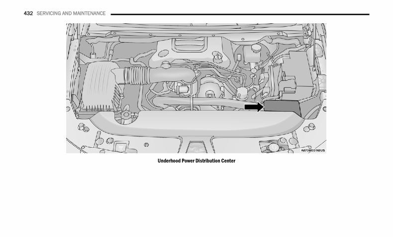
432 SERVICING AND MAINTENANCE
Underhood Power Distribution Center
22_DT_OM_EN_USC_t.book Page 432
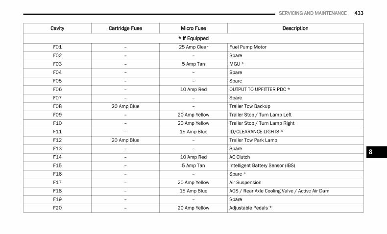
SERVICING AND MAINTENANCE 433
Cavity Cartridge Fuse Micro Fuse Description
* If EquippedF01 – 25 Amp Clear Fuel Pump Motor
F02 – – Spare
F03 – 5 Amp Tan MGU *
F04 – – Spare
F05 – – Spare
F06 – 10 Amp Red OUTPUT TO UPFITTER PDC *
F07 – – Spare
F08 20 Amp Blue – Trailer Tow Backup
F09 – 20 Amp Yellow Trailer Stop / Turn Lamp Left
F10 – 20 Amp Yellow Trailer Stop / Turn Lamp Right
F11 – 15 Amp Blue ID/CLEARANCE LIGHTS *
F12 20 Amp Blue – Trailer Tow Park Lamp
F13 – – Spare
F14 – 10 Amp Red AC Clutch
F15 – 5 Amp Tan Intelligent Battery Sensor (IBS)
F16 – – Spare *
F17 – 20 Amp Yellow Air Suspension
F18 – 15 Amp Blue AGS / Rear Axle Cooling Valve / Active Air Dam
F19 – – Spare
F20 – 20 Amp Yellow Adjustable Pedals *
8
22_DT_OM_EN_USC_t.book Page 433
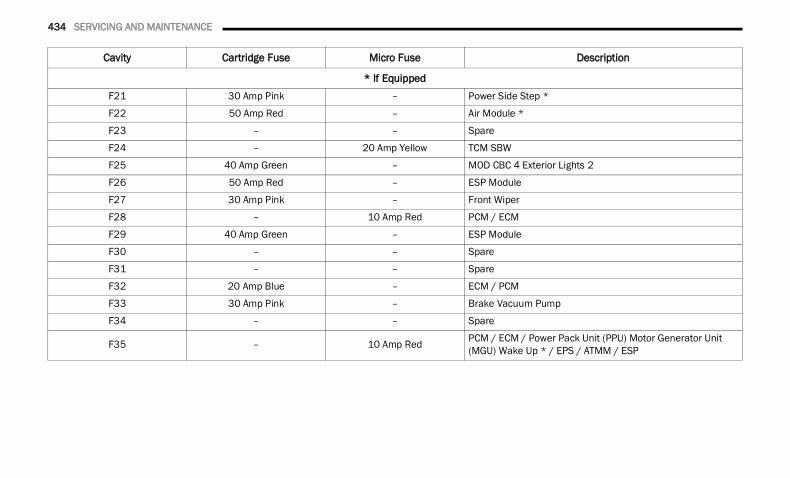
434 SERVICING AND MAINTENANCE
F21 30 Amp Pink – Power Side Step *
F22 50 Amp Red – Air Module *
F23 – – Spare
F24 – 20 Amp Yellow TCM SBW
F25 40 Amp Green – MOD CBC 4 Exterior Lights 2
F26 50 Amp Red – ESP Module
F27 30 Amp Pink – Front Wiper
F28 – 10 Amp Red PCM / ECM
F29 40 Amp Green – ESP Module
F30 – – Spare
F31 – – Spare
F32 20 Amp Blue – ECM / PCM
F33 30 Amp Pink – Brake Vacuum Pump
F34 – – Spare
F35 – 10 Amp Red PCM / ECM / Power Pack Unit (PPU) Motor Generator Unit (MGU) Wake Up * / EPS / ATMM / ESP
Cavity Cartridge Fuse Micro Fuse Description
* If Equipped
22_DT_OM_EN_USC_t.book Page 434
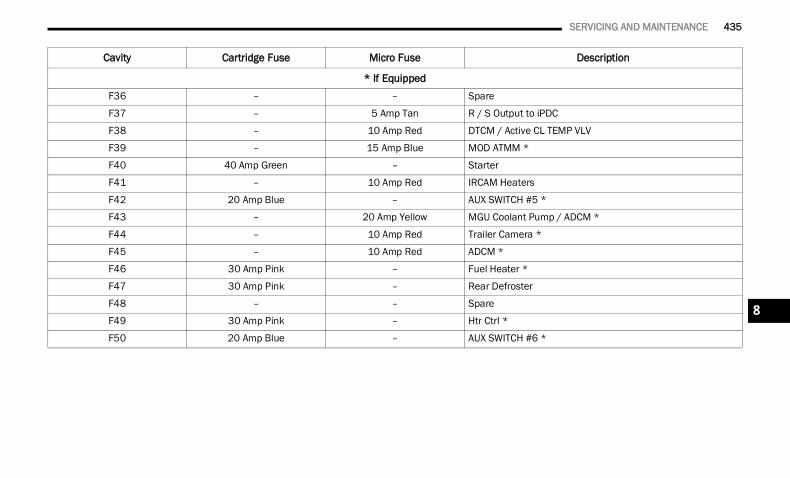
SERVICING AND MAINTENANCE 435
F36 – – Spare
F37 – 5 Amp Tan R / S Output to iPDC
F38 – 10 Amp Red DTCM / Active CL TEMP VLV
F39 – 15 Amp Blue MOD ATMM *
F40 40 Amp Green – Starter
F41 – 10 Amp Red IRCAM Heaters
F42 20 Amp Blue – AUX SWITCH #5 *
F43 – 20 Amp Yellow MGU Coolant Pump / ADCM *
F44 – 10 Amp Red Trailer Camera *
F45 – 10 Amp Red ADCM *
F46 30 Amp Pink – Fuel Heater *
F47 30 Amp Pink – Rear Defroster
F48 – – Spare
F49 30 Amp Pink – Htr Ctrl *
F50 20 Amp Blue – AUX SWITCH #6 *
Cavity Cartridge Fuse Micro Fuse Description
* If Equipped
8
22_DT_OM_EN_USC_t.book Page 435
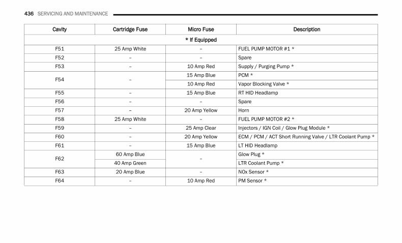
436 SERVICING AND MAINTENANCE
F51 25 Amp White – FUEL PUMP MOTOR #1 *
F52 – – Spare
F53 – 10 Amp Red Supply / Purging Pump *
F54 –15 Amp Blue PCM *
10 Amp Red Vapor Blocking Valve *
F55 – 15 Amp Blue RT HID Headlamp
F56 – – Spare
F57 – 20 Amp Yellow Horn
F58 25 Amp White – FUEL PUMP MOTOR #2 *
F59 – 25 Amp Clear Injectors / IGN Coil / Glow Plug Module *
F60 – 20 Amp Yellow ECM / PCM / ACT Short Running Valve / LTR Coolant Pump *
F61 – 15 Amp Blue LT HID Headlamp
F6260 Amp Blue
–Glow Plug *
40 Amp Green LTR Coolant Pump *
F63 20 Amp Blue – NOx Sensor *
F64 – 10 Amp Red PM Sensor *
Cavity Cartridge Fuse Micro Fuse Description
* If Equipped
22_DT_OM_EN_USC_t.book Page 436
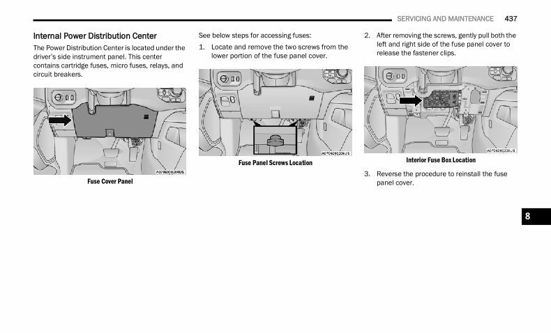
SERVICING AND MAINTENANCE 437
Internal Power Distribution Center The Power Distribution Center is located under the driver’s side instrument panel. This center contains cartridge fuses, micro fuses, relays, and circuit breakers.
Fuse Cover Panel
See below steps for accessing fuses:1. Locate and remove the two screws from the
lower portion of the fuse panel cover.
Fuse Panel Screws Location
2. After removing the screws, gently pull both the left and right side of the fuse panel cover to release the fastener clips.
Interior Fuse Box Location
3. Reverse the procedure to reinstall the fuse panel cover.
8
22_DT_OM_EN_USC_t.book Page 437
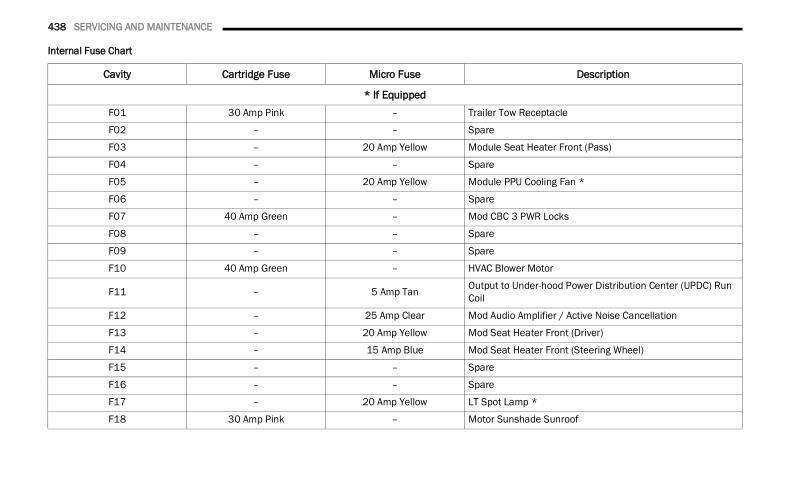
438 SERVICING AND MAINTENANCE
Internal Fuse Chart
Cavity Cartridge Fuse Micro Fuse Description
* If EquippedF01 30 Amp Pink – Trailer Tow Receptacle
F02 – – Spare
F03 – 20 Amp Yellow Module Seat Heater Front (Pass)
F04 – – Spare
F05 – 20 Amp Yellow Module PPU Cooling Fan *
F06 – – Spare
F07 40 Amp Green – Mod CBC 3 PWR Locks
F08 – – Spare
F09 – – Spare
F10 40 Amp Green – HVAC Blower Motor
F11 – 5 Amp Tan Output to Under-hood Power Distribution Center (UPDC) Run Coil
F12 – 25 Amp Clear Mod Audio Amplifier / Active Noise Cancellation
F13 – 20 Amp Yellow Mod Seat Heater Front (Driver)
F14 – 15 Amp Blue Mod Seat Heater Front (Steering Wheel)
F15 – – Spare
F16 – – Spare
F17 – 20 Amp Yellow LT Spot Lamp *
F18 30 Amp Pink – Motor Sunshade Sunroof
22_DT_OM_EN_USC_t.book Page 438
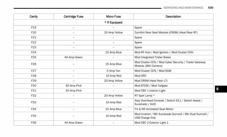
SERVICING AND MAINTENANCE 439
F19 – – Spare
F20 – 20 Amp Yellow Comfort Rear Seat Module (CRSM) (Heat Rear RT)
F21 – – Spare
F22 – – Spare
F23 – – Spare
F24 – 15 Amp Blue Mod RF Hub / Mod Ignition / Mod Cluster CNN
F25 40 Amp Green – Mod Integrated Trailer Brake
F26 – 15 Amp Blue Mod Cluster CCN / Mod Cyber Security / Trailer Gateway Module (360 Camera)
F27 – 5 Amp Tan Mod Cluster CCN / Mod SGW
F28 – 10 Amp Red Mod ORC
F29 – 20 Amp Yellow Mod CRSM (Heat Rear LT)
F30 30 Amp Pink – Mod DTCM / Mod Tailgate
F31 30 Amp Pink – Mod CBC 1 Interior Light
F32 – 20 Amp Yellow RT Spot Lamp *
F33 – 10 Amp Red Assy Overhead Console / Switch 911 / Switch Assist / Sunshade / HUD
F34 – 15 Amp Blue Frt & RR Ventilated Seat Motor
F35 – 10 Amp Red Mod Inverter / Mtr Sunshade Sunroof / Mtr Dual Sunroof / USB Charge Only
F36 40 Amp Green – Mod CBC 2 Exterior Light 1
Cavity Cartridge Fuse Micro Fuse Description
* If Equipped
8
22_DT_OM_EN_USC_t.book Page 439
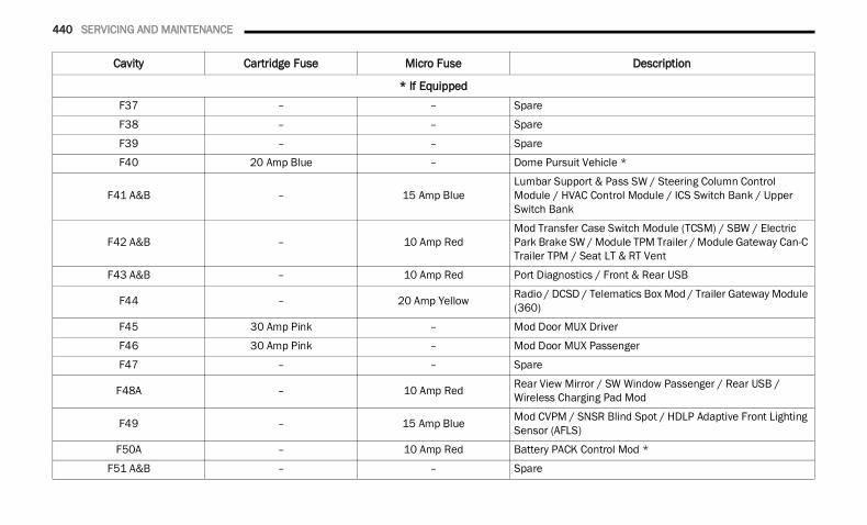
440 SERVICING AND MAINTENANCE
F37 – – Spare
F38 – – Spare
F39 – – Spare
F40 20 Amp Blue – Dome Pursuit Vehicle *
F41 A&B – 15 Amp BlueLumbar Support & Pass SW / Steering Column Control Module / HVAC Control Module / ICS Switch Bank / Upper Switch Bank
F42 A&B – 10 Amp RedMod Transfer Case Switch Module (TCSM) / SBW / Electric Park Brake SW / Module TPM Trailer / Module Gateway Can-C Trailer TPM / Seat LT & RT Vent
F43 A&B – 10 Amp Red Port Diagnostics / Front & Rear USB
F44 – 20 Amp Yellow Radio / DCSD / Telematics Box Mod / Trailer Gateway Module (360)
F45 30 Amp Pink – Mod Door MUX Driver
F46 30 Amp Pink – Mod Door MUX Passenger
F47 – – Spare
F48A – 10 Amp Red Rear View Mirror / SW Window Passenger / Rear USB / Wireless Charging Pad Mod
F49 – 15 Amp Blue Mod CVPM / SNSR Blind Spot / HDLP Adaptive Front Lighting Sensor (AFLS)
F50A – 10 Amp Red Battery PACK Control Mod *
F51 A&B – – Spare
Cavity Cartridge Fuse Micro Fuse Description
* If Equipped
22_DT_OM_EN_USC_t.book Page 440
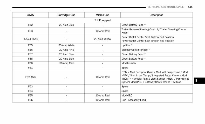
SERVICING AND MAINTENANCE 441
F52 20 Amp Blue – Direct Battery Feed *
F53 – 10 Amp Red Trailer Reverse Steering Control / Trailer Steering Control Knob
F54A & F54B – 20 Amp YellowPower Outlet Center Seat Battery Fed PositionPower Outlet Center Seat Ignition Fed Position
F55 25 Amp White – Upfitter *
F56 30 Amp Pink – Mod Network Interface *
F57 20 Amp Blue – Direct Battery Feed *
F58 20 Amp Blue – Direct Battery Feed *
F60 50 Amp Red – Mod Inverter
F61 – – Spare
F62 A&B – 10 Amp Red
ITBM / Mod Occupant Class / Mod IAIR Suspension / Mod HVAC / Snsr In car Temp / Integrated Radar Camera Mod (IRCM) / Humidity Rain & Light Sensor (HRLS) / Parktronics System Mod (PTS) / Gateway Can-C Trailer TPM Mod
F63 – – Spare
F64 – – Spare
F65 – 10 Amp Red Mod ORC
F66 – 10 Amp Red Run - Accessory Feed
Cavity Cartridge Fuse Micro Fuse Description
* If Equipped
8
22_DT_OM_EN_USC_t.book Page 441
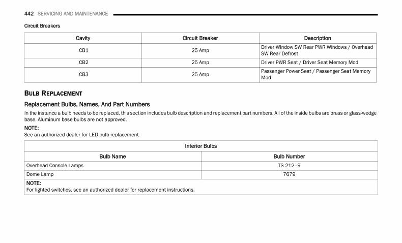
442 SERVICING AND MAINTENANCE
Circuit Breakers
BULB REPLACEMENT Replacement Bulbs, Names, And Part Numbers In the instance a bulb needs to be replaced, this section includes bulb description and replacement part numbers. All of the inside bulbs are brass or glass-wedge base. Aluminum base bulbs are not approved.NOTE:See an authorized dealer for LED bulb replacement.
Cavity Circuit Breaker Description
CB1 25 Amp Driver Window SW Rear PWR Windows / Overhead SW Rear Defrost
CB2 25 Amp Driver PWR Seat / Driver Seat Memory Mod
CB3 25 Amp Passenger Power Seat / Passenger Seat Memory Mod
Interior Bulbs
Bulb Name Bulb NumberOverhead Console Lamps TS 212–9
Dome Lamp 7679
NOTE:For lighted switches, see an authorized dealer for replacement instructions.
22_DT_OM_EN_USC_t.book Page 442
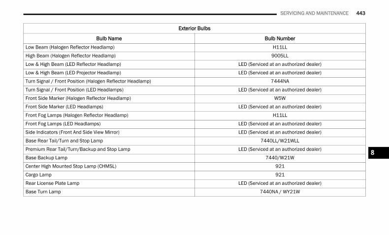
SERVICING AND MAINTENANCE 443
Exterior Bulbs
Bulb Name Bulb NumberLow Beam (Halogen Reflector Headlamp) H11LL
High Beam (Halogen Reflector Headlamp) 9005LL
Low & High Beam (LED Reflector Headlamp) LED (Serviced at an authorized dealer)
Low & High Beam (LED Projector Headlamp) LED (Serviced at an authorized dealer)
Turn Signal / Front Position (Halogen Reflector Headlamp) 7444NA
Turn Signal / Front Position (LED Headlamps) LED (Serviced at an authorized dealer)
Front Side Marker (Halogen Reflector Headlamp) W5W
Front Side Marker (LED Headlamps) LED (Serviced at an authorized dealer)
Front Fog Lamps (Halogen Reflector Headlamp) H11LL
Front Fog Lamps (LED Headlamps) LED (Serviced at an authorized dealer)
Side Indicators (Front And Side View Mirror) LED (Serviced at an authorized dealer)
Base Rear Tail/Turn and Stop Lamp 7440LL/W21WLL
Premium Rear Tail/Turn/Backup and Stop Lamp LED (Serviced at an authorized dealer)
Base Backup Lamp 7440/W21W
Center High Mounted Stop Lamp (CHMSL) 921
Cargo Lamp 921
Rear License Plate Lamp LED (Serviced at an authorized dealer)
Base Turn Lamp 7440NA / WY21W
8
22_DT_OM_EN_USC_t.book Page 443
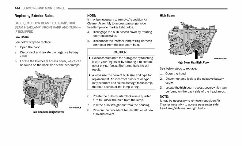
444 SERVICING AND MAINTENANCE
Replacing Exterior Bulbs
BASE QUAD: LOW BEAM HEADLAMP, HIGH BEAM HEADLAMP, FRONT PARK AND TURN — IF EQUIPPED Low BeamSee below steps to replace:1. Open the hood.2. Disconnect and isolate the negative battery
cable.3. Locate the low beam access cover, which can
be found on the back side of the headlamps.
Low Beam Headlight Cover
NOTE:It may be necessary to remove/reposition Air Cleaner Assembly to access passenger side headlamp/side marker light bulbs.4. Disengage the bulb access cover by rotating
counterclockwise.5. Disconnect the internal lamp wiring harness
connector from the low beam bulb.
6. Rotate the bulb counterclockwise a quarter turn to unlock the bulb from the lamp.
7. Pull the bulb straight out from the housing.8. Reverse the procedure for installation of new
bulb and covers.
High Beam
High Beam Headlight Cover
See below steps to replace:1. Open the hood.2. Disconnect and isolate the negative battery
cable.3. Locate the high beam access cover, which can
be found on the back side of the headlamps.
NOTE:It may be necessary to remove/reposition Air Cleaner Assembly to access passenger side headlamp/side marker light bulbs.
CAUTION!
Do not contaminate the bulb glass by touching it with your fingers or by allowing it to contact other oily surfaces. Shortened bulb life will result.
Always use the correct bulb size and type for replacement. An incorrect bulb size or type may overheat and cause damage to the lamp, the bulb socket, or the lamp wiring.
22_DT_OM_EN_USC_t.book Page 444
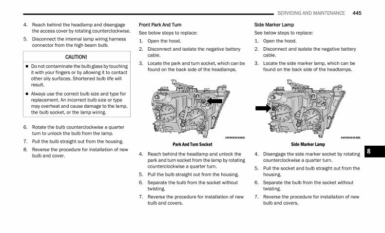
SERVICING AND MAINTENANCE 445
4. Reach behind the headlamp and disengage the access cover by rotating counterclockwise.
5. Disconnect the internal lamp wiring harness connector from the high beam bulb.
6. Rotate the bulb counterclockwise a quarter turn to unlock the bulb from the lamp.
7. Pull the bulb straight out from the housing.8. Reverse the procedure for installation of new
bulb and cover.
Front Park And TurnSee below steps to replace:1. Open the hood.2. Disconnect and isolate the negative battery
cable.3. Locate the park and turn socket, which can be
found on the back side of the headlamps.
Park And Turn Socket
4. Reach behind the headlamp and unlock the park and turn socket from the lamp by rotating counterclockwise a quarter turn.
5. Pull the bulb straight out from the housing.6. Separate the bulb from the socket without
twisting.7. Reverse the procedure for installation of new
bulb and covers.
Side Marker LampSee below steps to replace:1. Open the hood.2. Disconnect and isolate the negative battery
cable.3. Locate the side marker lamp, which can be
found on the back side of the headlamps.
Side Marker Lamp
4. Disengage the side marker socket by rotating counterclockwise a quarter turn.
5. Pull the socket and bulb straight out from the housing.
6. Separate the bulb from the socket without twisting.
7. Reverse the procedure for installation of new bulb and covers.
CAUTION!
Do not contaminate the bulb glass by touching it with your fingers or by allowing it to contact other oily surfaces. Shortened bulb life will result.
Always use the correct bulb size and type for replacement. An incorrect bulb size or type may overheat and cause damage to the lamp, the bulb socket, or the lamp wiring.
8
22_DT_OM_EN_USC_t.book Page 445
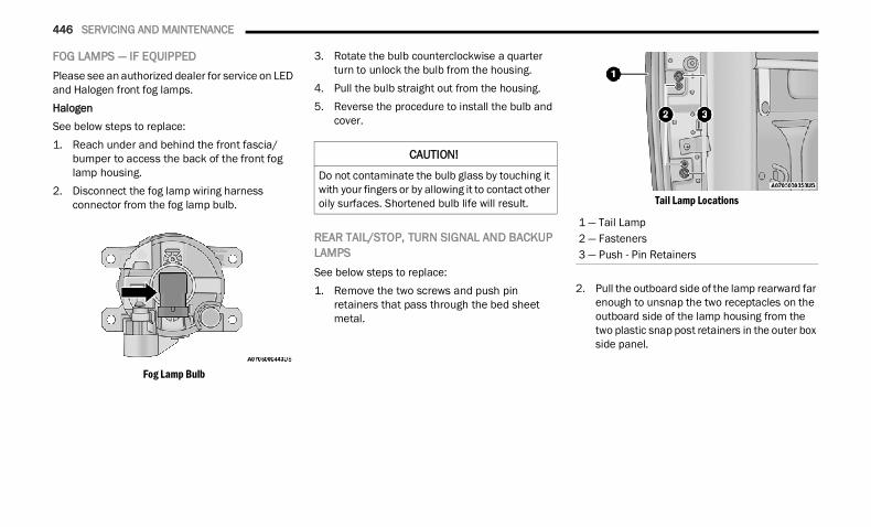
446 SERVICING AND MAINTENANCE
FOG LAMPS — IF EQUIPPED Please see an authorized dealer for service on LED and Halogen front fog lamps.HalogenSee below steps to replace:1. Reach under and behind the front fascia/
bumper to access the back of the front fog lamp housing.
2. Disconnect the fog lamp wiring harness connector from the fog lamp bulb.
Fog Lamp Bulb
3. Rotate the bulb counterclockwise a quarter turn to unlock the bulb from the housing.
4. Pull the bulb straight out from the housing.5. Reverse the procedure to install the bulb and
cover.
REAR TAIL/STOP, TURN SIGNAL AND BACKUP LAMPS See below steps to replace:1. Remove the two screws and push pin
retainers that pass through the bed sheet metal.
Tail Lamp Locations
2. Pull the outboard side of the lamp rearward far enough to unsnap the two receptacles on the outboard side of the lamp housing from the two plastic snap post retainers in the outer box side panel.
CAUTION!
Do not contaminate the bulb glass by touching it with your fingers or by allowing it to contact other oily surfaces. Shortened bulb life will result.
1 — Tail Lamp2 — Fasteners3 — Push - Pin Retainers
22_DT_OM_EN_USC_t.book Page 446
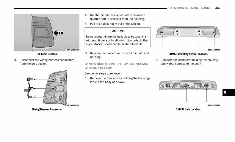
SERVICING AND MAINTENANCE 447
Tail Lamp Removal
3. Disconnect the wiring harness connectors from the bulb socket.
Wiring Harness Connector
4. Rotate the bulb socket counterclockwise a quarter turn to unlock it from the housing.
5. Pull the bulb straight out of the socket.
6. Reverse the procedure to install the bulb and housing.
CENTER HIGH MOUNTED STOP LAMP (CHMSL) WITH CARGO LAMP See below steps to replace:1. Remove the four screws holding the housing/
lens to the body as shown.
CHMSL Mounting Screw Locations
2. Separate the connector holding the housing and wiring harness to the body.
CHMSL Bulb Location
CAUTION!
Do not contaminate the bulb glass by touching it with your fingers or by allowing it to contact other oily surfaces. Shortened bulb life will result.
8
22_DT_OM_EN_USC_t.book Page 447
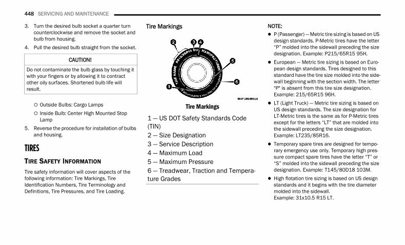
448 SERVICING AND MAINTENANCE
3. Turn the desired bulb socket a quarter turn counterclockwise and remove the socket and bulb from housing.
4. Pull the desired bulb straight from the socket.
Outside Bulbs: Cargo Lamps Inside Bulb: Center High Mounted Stop
Lamp5. Reverse the procedure for installation of bulbs
and housing.
TIRESTIRE SAFETY INFORMATION Tire safety information will cover aspects of the following information: Tire Markings, Tire Identification Numbers, Tire Terminology and Definitions, Tire Pressures, and Tire Loading.
Tire Markings
Tire Markings
NOTE: P (Passenger) — Metric tire sizing is based on US
design standards. P-Metric tires have the letter “P” molded into the sidewall preceding the size designation. Example: P215/65R15 95H.
European — Metric tire sizing is based on Euro-pean design standards. Tires designed to this standard have the tire size molded into the side-wall beginning with the section width. The letter "P" is absent from this tire size designation. Example: 215/65R15 96H.
LT (Light Truck) — Metric tire sizing is based on US design standards. The size designation for LT-Metric tires is the same as for P-Metric tires except for the letters “LT” that are molded into the sidewall preceding the size designation. Example: LT235/85R16.
Temporary spare tires are designed for tempo-rary emergency use only. Temporary high pres-sure compact spare tires have the letter “T” or “S” molded into the sidewall preceding the size designation. Example: T145/80D18 103M.
High flotation tire sizing is based on US design standards and it begins with the tire diameter molded into the sidewall. Example: 31x10.5 R15 LT.
CAUTION!
Do not contaminate the bulb glass by touching it with your fingers or by allowing it to contract other oily surfaces. Shortened bulb life will result.
1 — US DOT Safety Standards Code (TIN)2 — Size Designation3 — Service Description4 — Maximum Load5 — Maximum Pressure6 — Treadwear, Traction and Tempera-ture Grades
22_DT_OM_EN_USC_t.book Page 448
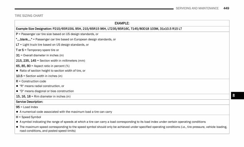
SERVICING AND MAINTENANCE 449
TIRE SIZING CHART
EXAMPLE:Example Size Designation: P215/65R15XL 95H, 215/65R15 96H, LT235/85R16C, T145/80D18 103M, 31x10.5 R15 LT
P = Passenger car tire size based on US design standards, or
"....blank...." = Passenger car tire based on European design standards, or
LT = Light truck tire based on US design standards, or
T or S = Temporary spare tire or
31 = Overall diameter in inches (in)
215, 235, 145 = Section width in millimeters (mm)
65, 85, 80 = Aspect ratio in percent (%) Ratio of section height to section width of tire, or
10.5 = Section width in inches (in)
R = Construction code "R" means radial construction, or "D" means diagonal or bias construction
15, 16, 18 = Rim diameter in inches (in)
Service Description:
95 = Load Index A numerical code associated with the maximum load a tire can carry
H = Speed Symbol A symbol indicating the range of speeds at which a tire can carry a load corresponding to its load index under certain operating conditions The maximum speed corresponding to the speed symbol should only be achieved under specified operating conditions (i.e., tire pressure, vehicle loading,
road conditions, and posted speed limits)
8
22_DT_OM_EN_USC_t.book Page 449
450 SERVICING AND MAINTENANCE
Tire Identification Number (TIN)The Tire Identification Number (TIN) may be found on one or both sides of the tire; however, the date code may only be on one side. Tires with white sidewalls will have the full TIN, including the date code, located on the white sidewall side of the tire. Look for the TIN on the outboard side of black sidewall tires as mounted on the vehicle. If the TIN is not found on the outboard side, then you will find it on the inboard side of the tire.
Load Identification:Absence of the following load identification symbols on the sidewall of the tire indicates a Standard Load (SL) tire: XL = Extra load (or reinforced) tire, or LL = Light load tire or C, D, E, F, G = Load range associated with the maximum load a tire can carry at a specified pressure
Maximum Load – Maximum load indicates the maximum load this tire is designed to carry
Maximum Pressure – Maximum pressure indicates the maximum permissible cold tire inflation pressure for this tire
EXAMPLE:
EXAMPLE:DOT MA L9 ABCD 0301
DOT = Department of Transportation This symbol certifies that the tire is in compliance with the US Department of Transportation tire safety standards and is approved for highway use
MA = Code representing the tire manufacturing location (two digits)
L9 = Code representing the tire size (two digits)
ABCD = Code used by the tire manufacturer (one to four digits)
03 = Number representing the week in which the tire was manufactured (two digits) 03 means the 3rd week
22_DT_OM_EN_USC_t.book Page 450
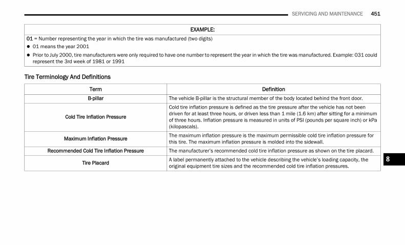
SERVICING AND MAINTENANCE 451
Tire Terminology And Definitions
01 = Number representing the year in which the tire was manufactured (two digits) 01 means the year 2001 Prior to July 2000, tire manufacturers were only required to have one number to represent the year in which the tire was manufactured. Example: 031 could
represent the 3rd week of 1981 or 1991
Term DefinitionB-pillar The vehicle B-pillar is the structural member of the body located behind the front door.
Cold Tire Inflation Pressure
Cold tire inflation pressure is defined as the tire pressure after the vehicle has not been driven for at least three hours, or driven less than 1 mile (1.6 km) after sitting for a minimum of three hours. Inflation pressure is measured in units of PSI (pounds per square inch) or kPa (kilopascals).
Maximum Inflation Pressure The maximum inflation pressure is the maximum permissible cold tire inflation pressure for this tire. The maximum inflation pressure is molded into the sidewall.
Recommended Cold Tire Inflation Pressure The manufacturer’s recommended cold tire inflation pressure as shown on the tire placard.
Tire Placard A label permanently attached to the vehicle describing the vehicle’s loading capacity, the original equipment tire sizes and the recommended cold tire inflation pressures.
EXAMPLE:
8
22_DT_OM_EN_USC_t.book Page 451
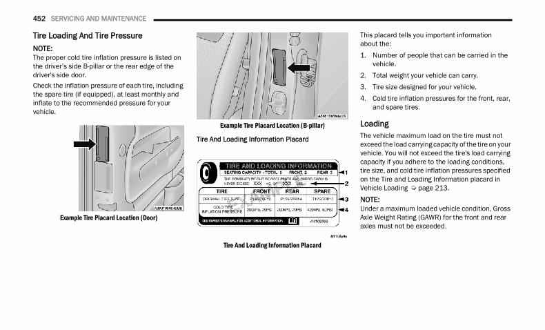
452 SERVICING AND MAINTENANCE
Tire Loading And Tire Pressure NOTE:The proper cold tire inflation pressure is listed on the driver’s side B-pillar or the rear edge of the driver's side door.Check the inflation pressure of each tire, including the spare tire (if equipped), at least monthly and inflate to the recommended pressure for your vehicle.
Example Tire Placard Location (Door)
Example Tire Placard Location (B-pillar)
Tire And Loading Information Placard
Tire And Loading Information Placard
This placard tells you important informationabout the:1. Number of people that can be carried in the
vehicle.2. Total weight your vehicle can carry.3. Tire size designed for your vehicle.4. Cold tire inflation pressures for the front, rear,
and spare tires.
Loading The vehicle maximum load on the tire must not exceed the load carrying capacity of the tire on your vehicle. You will not exceed the tire's load carrying capacity if you adhere to the loading conditions, tire size, and cold tire inflation pressures specified on the Tire and Loading Information placard in Vehicle Loading Ú page 213.
NOTE:Under a maximum loaded vehicle condition, Gross Axle Weight Rating (GAWR) for the front and rear axles must not be exceeded.
22_DT_OM_EN_USC_t.book Page 452
SERVICING AND MAINTENANCE 453
For further information on GAWR, vehicle loading, and trailer towing Ú page 213.To determine the maximum loading conditions of your vehicle, locate the statement “The combined weight of occupants and cargo should never exceed XXX kg or XXX lbs” on the Tire and Loading Information placard. The combined weight of occupants, cargo/luggage and trailer tongue weight (if applicable) should never exceed the weight referenced here.
Steps For Determining Correct Load Limit—(1) Locate the statement “The combined weight of occupants and cargo should never exceed XXX kg or XXX lbs.” on your vehicle's placard.(2) Determine the combined weight of the driver and passengers that will be riding in your vehicle.
(3) Subtract the combined weight of the driver and passengers from XXX kg or XXX lbs.(4) The resulting figure equals the available amount of cargo and luggage load capacity. For example, if “XXX” amount equals 1400 lbs. and there will be five 150 lb passengers in your vehicle, the amount of available cargo and luggage load capacity is 650 lbs. (1400-750 (5x150) = 650 lbs.)(5) Determine the combined weight of luggage and cargo being loaded on the vehicle. That weight may not safely exceed the available cargo and luggage load capacity calculated in Step 4.(6) If your vehicle will be towing a trailer, load from your trailer will be transferred to your vehicle. Consult this manual to determine how this reduces the available cargo and luggage load capacity of your vehicle.
Metric Example For Load LimitFor example, if “XXX” amount equals 635 kg and there will be five 68 kg passengers in your vehicle, the amount of available cargo and luggage load capacity is 295 kg (635-340 (5x68) = 295 kg) as shown in step 4.
NOTE: If your vehicle will be towing a trailer, load from
your trailer will be transferred to your vehicle. The following table shows examples on how to calculate total load, cargo/luggage, and towing capacities of your vehicle with varying seating configurations and number and size of occu-pants. This table is for illustration purposes only and may not be accurate for the seating and load carry capacity of your vehicle.
For the following example, the combined weight of occupants and cargo should never exceed 865 lbs (392 kg).
8
22_DT_OM_EN_USC_t.book Page 453
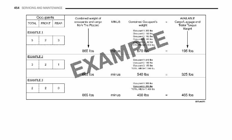
454 SERVICING AND MAINTENANCE
22_DT_OM_EN_USC_t.book Page 454
SERVICING AND MAINTENANCE 455
TIRES — GENERAL INFORMATION Tire Pressure Proper tire inflation pressure is essential to the safe and satisfactory operation of your vehicle. Four primary areas are affected by improper tire pressure: Safety Fuel Economy Tread Wear Ride Comfort and Vehicle Stability
Safety Both underinflation and overinflation affect the stability of the vehicle and can produce a feeling of sluggish response or over responsiveness in the steering.NOTE: Unequal tire pressures from side to side may
cause erratic and unpredictable steering response.
Unequal tire pressure from side to side may cause the vehicle to drift left or right.
Fuel EconomyUnderinflated tires will increase tire rolling resistance resulting in higher fuel consumption.Tread WearImproper cold tire inflation pressures can cause abnormal wear patterns and reduced tread life, resulting in the need for earlier tire replacement.Ride Comfort And Vehicle StabilityProper tire inflation contributes to a comfortable ride. Overinflation produces a jarring and uncomfortable ride.
WARNING!
Overloading of your tires is dangerous. Overloading can cause tire failure, affect vehicle handling, and increase your stopping distance. Use tires of the recommended load capacity for your vehicle. Never overload them.
WARNING!
Improperly inflated tires are dangerous and can cause collisions.
Underinflation increases tire flexing and can result in overheating and tire failure.
Overinflation reduces a tire's ability to cushion shock. Objects on the road and chuckholes can cause damage that result in tire failure.
Overinflated or underinflated tires can affect vehicle handling and can fail suddenly, resulting in loss of vehicle control.
Unequal tire pressures can cause steering problems. You could lose control of your vehicle.
Unequal tire pressures from one side of the vehicle to the other can cause the vehicle to drift to the right or left.
Always drive with each tire inflated to the recommended cold tire inflation pressure.
8
22_DT_OM_EN_USC_t.book Page 455
456 SERVICING AND MAINTENANCE
Tire Inflation Pressures The proper cold tire inflation pressure is listed on the driver's side B-pillar or rear edge of the driver's side door.At least once a month: Check and adjust tire pressure with a good
quality pocket-type pressure gauge. Do not make a visual judgment when determining proper inflation. Tires may look properly inflated even when they are underinflated.
Inspect tires for signs of tire wear or visible damage.
Inflation pressures specified on the placard are always “cold tire inflation pressure”. Cold tire inflation pressure is defined as the tire pressure after the vehicle has not been driven for at least three hours, or driven less than 1 mile (1.6 km) after sitting for a minimum of three hours. The cold tire inflation pressure must not exceed the maximum inflation pressure molded into the tire sidewall.
Check tire pressures more often if subject to a wide range of outdoor temperatures, as tire pressures vary with temperature changes.Tire pressures change by approximately 1 psi(7 kPa) per 12°F (7°C) of air temperature change. Keep this in mind when checking tire pressure inside a garage, especially in the Winter.Example: If garage temperature = 68°F (20°C) and the outside temperature = 32°F (0°C) then the cold tire inflation pressure should be increased by 3 psi (21 kPa), which equals 1 psi (7 kPa) for every 12°F (7°C) for this outside temperature condition.Tire pressure may increase from 2 to 6 psi (13 to 40 kPa) during operation. DO NOT reduce this normal pressure build up or your tire pressure will be too low.
Tire Pressures For High Speed Operation The manufacturer advocates driving at safe speeds and within posted speed limits. Where speed limits or conditions are such that the vehicle can be driven at high speeds, maintaining correct tire inflation pressure is very important. Increased tire pressure and reduced vehicle loading may be required for high-speed vehicle operation. Refer to an authorized tire dealer or original equipment vehicle dealer for recommended safe operating speeds, loading and cold tire inflation pressures.
Radial Ply Tires
Tire RepairIf your tire becomes damaged, it may be repaired if it meets the following criteria: The tire has not been driven on when flat The damage is only on the tread section of your
tire (sidewall damage is not repairable) The puncture is no greater than a ¼ of an inch
(6 mm)
CAUTION!
After inspecting or adjusting the tire pressure, always reinstall the valve stem cap. This will prevent moisture and dirt from entering the valve stem, which could damage the valve stem.
WARNING!
High speed driving with your vehicle under maximum load is dangerous. The added strain on your tires could cause them to fail. You could have a serious collision. Do not drive a vehicle loaded to the maximum capacity at continuous speeds above 75 mph (120 km/h).
WARNING!
Combining radial ply tires with other types of tires on your vehicle will cause your vehicle to handle poorly. The instability could cause a collision. Always use radial ply tires in sets of four. Never combine them with other types of tires.
22_DT_OM_EN_USC_t.book Page 456
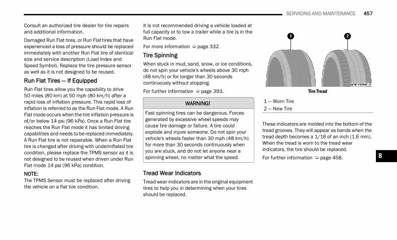
SERVICING AND MAINTENANCE 457
Consult an authorized tire dealer for tire repairs and additional information.Damaged Run Flat tires, or Run Flat tires that have experienced a loss of pressure should be replaced immediately with another Run Flat tire of identical size and service description (Load Index and Speed Symbol). Replace the tire pressure sensor as well as it is not designed to be reused.
Run Flat Tires — If EquippedRun Flat tires allow you the capability to drive 50 miles (80 km) at 50 mph (80 km/h) after a rapid loss of inflation pressure. This rapid loss of inflation is referred to as the Run Flat mode. A Run Flat mode occurs when the tire inflation pressure is of/or below 14 psi (96 kPa). Once a Run Flat tire reaches the Run Flat mode it has limited driving capabilities and needs to be replaced immediately. A Run Flat tire is not repairable. When a Run Flat tire is changed after driving with underinflated tire condition, please replace the TPMS sensor as it is not designed to be reused when driven under Run Flat mode 14 psi (96 kPa) condition.
NOTE:The TPMS Sensor must be replaced after driving the vehicle on a flat tire condition.
It is not recommended driving a vehicle loaded at full capacity or to tow a trailer while a tire is in the Run Flat mode.For more information Ú page 332.
Tire Spinning When stuck in mud, sand, snow, or ice conditions, do not spin your vehicle's wheels above 30 mph (48 km/h) or for longer than 30 seconds continuously without stopping.For further information Ú page 393.
Tread Wear Indicators Tread wear indicators are in the original equipment tires to help you in determining when your tires should be replaced.
Tire Tread
These indicators are molded into the bottom of the tread grooves. They will appear as bands when the tread depth becomes a 1/16 of an inch (1.6 mm). When the tread is worn to the tread wear indicators, the tire should be replaced.For further information Ú page 458.
WARNING!
Fast spinning tires can be dangerous. Forces generated by excessive wheel speeds may cause tire damage or failure. A tire could explode and injure someone. Do not spin your vehicle's wheels faster than 30 mph (48 km/h) for more than 30 seconds continuously when you are stuck, and do not let anyone near a spinning wheel, no matter what the speed.
1 — Worn Tire2 — New Tire
8
22_DT_OM_EN_USC_t.book Page 457
458 SERVICING AND MAINTENANCE
Life Of Tire The service life of a tire is dependent upon varying factors including, but not limited to: Driving style Tire pressure - Improper cold tire inflation pres-
sures can cause uneven wear patterns to develop across the tire tread. These abnormal wear patterns will reduce tread life, resulting in the need for earlier tire replacement
Distance driven Performance tires, tires with a speed rating of V
or higher, and Summer tires typically have a reduced tread life. Rotation of these tires per the vehicle scheduled maintenance is highly recommended
NOTE:Wheel Valve Stem must be replaced as well when installing new tires due to wear and tear in existing tires.
Keep dismounted tires in a cool, dry place with as little exposure to light as possible. Protect tires from contact with oil, grease, and gasoline.
Replacement Tires The tires on your new vehicle provide a balance of many characteristics. They should be inspected regularly for wear and correct cold tire inflation pressures. The manufacturer strongly recommends that you use tires equivalent to the originals in size, quality and performance when replacement is needed Ú page 457. Refer to the Tire and Loading Information placard or the Vehicle Certification Label for the size designation of your tire. The Load Index and Speed Symbol for your tire will be found on the original equipment tire sidewall.For more information relating to the Load Index and Speed Symbol of a tire Ú page 449.It is recommended to replace the two front tires or two rear tires as a pair. Replacing just one tire can seriously affect your vehicle’s handling. If you ever replace a wheel, make sure that the wheel’s specifications match those of the original wheels.It is recommended you contact an authorized tire dealer or original equipment dealer with any questions you may have on tire specifications or capability. Failure to use equivalent replacement tires may adversely affect the safety, handling, and ride of your vehicle.
WARNING!
Tires and the spare tire should be replaced after six years, regardless of the remaining tread. Failure to follow this warning can result in sudden tire failure. You could lose control and have a collision resulting in serious injury or death.
WARNING!
Do not use a tire, wheel size, load rating, or speed rating other than that specified for your vehicle. Some combinations of unapproved tires and wheels may change suspension dimensions and performance characteristics, resulting in changes to steering, handling, and braking of your vehicle. This can cause unpre-dictable handling and stress to steering and suspension components. You could lose control and have a collision resulting in serious injury or death. Use only the tire and wheel sizes with load ratings approved for your vehicle.
Never use a tire with a smaller load index or capacity, other than what was originally equipped on your vehicle. Using a tire with a smaller load index could result in tire over-loading and failure. You could lose control and have a collision.
Failure to equip your vehicle with tires having adequate speed capability can result in sudden tire failure and loss of vehicle control.
22_DT_OM_EN_USC_t.book Page 458
SERVICING AND MAINTENANCE 459
TIRE TYPES
All Season Tires — If EquippedAll Season tires provide traction for all seasons (Spring, Summer, Autumn, and Winter). Traction levels may vary between different all season tires. All season tires can be identified by the M+S, M&S, M/S or MS designation on the tire sidewall. Use all season tires only in sets of four; failure to do so may adversely affect the safety and handling of your vehicle.
Summer Or Three Season Tires — If EquippedSummer tires provide traction in both wet and dry conditions, and are not intended to be driven in snow or on ice. If your vehicle is equipped with Summer tires, be aware these tires are not designed for Winter or cold driving conditions. Install Winter tires on your vehicle when ambient temperatures are less than 40°F (5°C) or if roads are covered with ice or snow. For more information, contact an authorized dealer.
Summer tires do not contain the all season designation or mountain/snowflake symbol on the tire sidewall. Use Summer tires only in sets of four; failure to do so may adversely affect the safety and handling of your vehicle.
Snow Tires Some areas of the country require the use of snow tires during the Winter. Snow tires can be identified by a “mountain/snowflake” symbol on the tire sidewall.
If you need snow tires, select tires equivalent in size and type to the original equipment tires. Use snow tires only in sets of four; failure to do so may
adversely affect the safety and handling of your vehicle.Snow tires generally have lower speed ratings than what was originally equipped with your vehicle and should not be operated at sustained speeds over 75 mph (120 km/h). For speeds above 75 mph (120 km/h) refer to original equipment or an
authorized tire dealer for recommended safe operating speeds, loading and cold tire inflation pressures.While studded tires improve performance on ice, skid and traction capability on wet or dry surfaces may be poorer than that of non-studded tires. Some states prohibit studded tires; therefore, local laws should be checked before using these tire types.
SPARE TIRES — IF EQUIPPED NOTE:For vehicles equipped with Tire Service Kit instead of a spare tire, please refer to “Tire Service Kit” in “In Case Of Emergency” for further information.
For restrictions when towing with a spare tire designated for temporary emergency use Ú page 222.
CAUTION!
Replacing original tires with tires of a different size may result in false speedometer and odometer readings.
WARNING!
Do not use Summer tires in snow/ice conditions. You could lose vehicle control, resulting in severe injury or death. Driving too fast for conditions also creates the possibility of loss of vehicle control.
CAUTION!
Because of the reduced ground clearance, do not take your vehicle through an automatic car wash with a compact or limited use temporary spare installed. Damage to the vehicle may result.
8
22_DT_OM_EN_USC_t.book Page 459
460 SERVICING AND MAINTENANCE
Spare Tire Matching Original Equipped Tire And Wheel — If Equipped Your vehicle may be equipped with a spare tire and wheel equivalent in look and function to the original equipment tire and wheel found on the front or rear axle of your vehicle. This spare tire may be used in the tire rotation for your vehicle. If your vehicle has this option, refer to an authorized tire dealer for the recommended tire rotation pattern.
Compact Spare Tire — If Equipped The compact spare is for temporary emergency use only. You can identify if your vehicle is equipped with a compact spare by looking at the spare tire description on the Tire and Loading Information Placard located on the driver’s side door opening or on the sidewall of the tire. Compact spare tire descriptions begin with the letter “T” or “S” preceding the size designation. Example: T145/80D18 103M.T, S = Temporary Spare Tire
Since this tire has limited tread life, the original equipment tire should be repaired (or replaced) and reinstalled on your vehicle at the first opportunity.Do not install a wheel cover or attempt to mount a conventional tire on the compact spare wheel, since the wheel is designed specifically for the compact spare tire. Do not install more than one compact spare tire and wheel on the vehicle at any given time.
Collapsible Spare Tire — If EquippedThe collapsible spare is for temporary emergency use only. You can identify if your vehicle is equipped with a collapsible spare by looking at the spare tire description on the Tire and Loading Information Placard located on the driver’s side door opening or on the sidewall of the tire.Collapsible spare tire description example: 165/80-17 101P.Since this tire has limited tread life, the original equipment tire should be repaired (or replaced) and reinstalled on your vehicle at the first opportunity.Inflate collapsible tire only after the wheel is properly installed to the vehicle. Inflate the collapsible tire using the electric air pump before lowering the vehicle.Do not install a wheel cover or attempt to mount a conventional tire on the collapsible spare wheel, since the wheel is designed specifically for the collapsible spare tire.
WARNING!
Compact and collapsible spares are for temporary emergency use only. With these spares, do not drive more than 50 mph (80 km/h). Temporary use spares have limited tread life. When the tread is worn to the tread wear indicators, the temporary use spare tire needs to be replaced. Be sure to follow the warnings, which apply to your spare. Failure to do so could result in spare tire failure and loss of vehicle control.
22_DT_OM_EN_USC_t.book Page 460
SERVICING AND MAINTENANCE 461
Full Size Spare — If Equipped The full size spare is for temporary emergency use only. This tire may look like the originally equipped tire on the front or rear axle of your vehicle, but it is not. This spare tire may have limited tread life. When the tread is worn to the tread wear indicators, the temporary use full size spare tire needs to be replaced. Since it is not the same as your original equipment tire, replace (or repair) the original equipment tire and reinstall on the vehicle at the first opportunity.
Limited Use Spare — If Equipped The limited use spare tire is for temporary emergency use only. This tire is identified by a label located on the limited use spare wheel. This label contains the driving limitations for this spare. This tire may look like the original equipped tire on the front or rear axle of your vehicle, but it is not. Installation of this limited use spare tire affects vehicle handling. Since it is not the same as your original equipment tire, replace (or repair) the original equipment tire and reinstall on the vehicle at the first opportunity.
WHEEL AND WHEEL TRIM CARE All wheels and wheel trim, especially aluminum and chrome plated wheels, should be cleaned regularly using mild (neutral Ph) soap and water to maintain their luster and to prevent corrosion. Wash wheels with the same soap solution recommended for the body of the vehicle and remember to always wash when the surfaces are not hot to the touch.Your wheels are susceptible to deterioration caused by salt, sodium chloride, magnesium chloride, calcium chloride, etc., and other road chemicals used to melt ice or control dust on dirt roads. Use a soft cloth or sponge and mild soap to wipe away promptly. Do not use harsh chemicals or a stiff brush. They can damage the wheel’s protective coating that helps keep them from corroding and tarnishing.
WARNING!
Compact and Collapsible spares are for temporary emergency use only. With these spares, do not drive more than 50 mph(80 km/h). Temporary use spares have limited tread life. When the tread is worn to the tread wear indicators, the temporary use spare tire needs to be replaced. Be sure to follow the warnings, which apply to your spare. Failure to do so could result in spare tire failure and loss of vehicle control.
WARNING!
Limited use spares are for emergency use only. Installation of this limited use spare tire affects vehicle handling. With this tire, do not drive more than the speed listed on the limited use spare wheel. Keep inflated to the cold tire inflation pressures listed on your Tire and Loading Information Placard located on the driver’s side B-pillar or the rear edge of the driver’s side door. Replace (or repair) the original equipment tire at the first opportunity and reinstall it on your vehicle. Failure to do so could result in loss of vehicle control.
8
22_DT_OM_EN_USC_t.book Page 461
462 SERVICING AND MAINTENANCE
When cleaning extremely dirty wheels including excessive brake dust, care must be taken in the selection of tire and wheel cleaning chemicals and equipment to prevent damage to the wheels. Mopar® Wheel Treatment or Mopar® Chrome Cleaner or their equivalent is recommended or select a non-abrasive, non-acidic cleaner for aluminum or chrome wheels.
NOTE:If you intend parking or storing your vehicle for an extended period after cleaning the wheels with wheel cleaner, drive your vehicle and apply the brakes to remove the water droplets from the brake components. This activity will remove the red rust on the brake rotors and prevent vehicle vibration when braking.
Dark Vapor Chrome, Black Satin Chrome, or Low Gloss Clear Coat WheelsCAUTION!
Avoid products or automatic car washes that use acidic solutions or strong alkaline additives or harsh brushes. Many aftermarket wheel cleaners and automatic car washes may damage the wheel's protective finish. Such damage is not covered by the New Vehicle Limited Warranty. Only car wash soap, Mopar® Wheel Cleaner or equivalent is recommended.
CAUTION!
Do not use scouring pads, steel wool, a bristle brush, metal polishes or oven cleaner. These products may damage the wheel's protective finish. Such damage is not covered by the New Vehicle Limited Warranty. Only car wash soap, Mopar® Wheel Cleaner or equivalent is recommended.
CAUTION!
If your vehicle is equipped with these specialty wheels, DO NOT USE wheel cleaners, abrasives, or polishing compounds. They will permanently damage this finish and such damage is not covered by the New Vehicle Limited Warranty. HAND WASH ONLY USING MILD SOAP AND WATER WITH A SOFT CLOTH. Used on a regular basis; this is all that is required to maintain this finish.
22_DT_OM_EN_USC_t.book Page 462
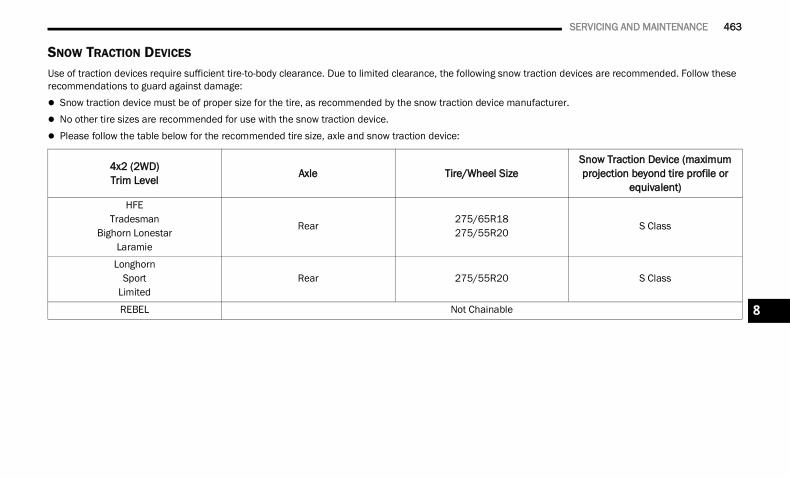
SERVICING AND MAINTENANCE 463
SNOW TRACTION DEVICES Use of traction devices require sufficient tire-to-body clearance. Due to limited clearance, the following snow traction devices are recommended. Follow these recommendations to guard against damage: Snow traction device must be of proper size for the tire, as recommended by the snow traction device manufacturer. No other tire sizes are recommended for use with the snow traction device. Please follow the table below for the recommended tire size, axle and snow traction device:
4x2 (2WD)Trim Level Axle Tire/Wheel Size
Snow Traction Device (maximum projection beyond tire profile or
equivalent)HFE
TradesmanBighorn Lonestar
Laramie
Rear275/65R18275/55R20
S Class
LonghornSport
LimitedRear 275/55R20 S Class
REBEL Not Chainable 8
22_DT_OM_EN_USC_t.book Page 463
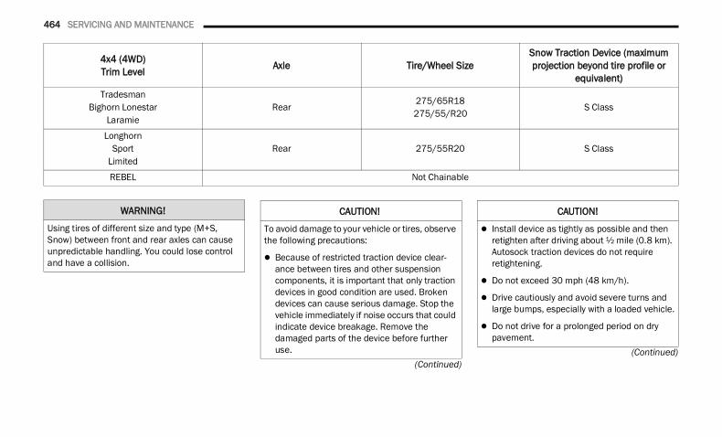
464 SERVICING AND MAINTENANCE
(Continued)(Continued)
4x4 (4WD)Trim Level Axle Tire/Wheel Size
Snow Traction Device (maximum projection beyond tire profile or
equivalent)Tradesman
Bighorn LonestarLaramie
Rear275/65R18275/55/R20
S Class
LonghornSport
LimitedRear 275/55R20 S Class
REBEL Not Chainable
WARNING!
Using tires of different size and type (M+S, Snow) between front and rear axles can cause unpredictable handling. You could lose control and have a collision.
CAUTION!
To avoid damage to your vehicle or tires, observe the following precautions:
Because of restricted traction device clear-ance between tires and other suspension components, it is important that only traction devices in good condition are used. Broken devices can cause serious damage. Stop the vehicle immediately if noise occurs that could indicate device breakage. Remove the damaged parts of the device before further use.
Install device as tightly as possible and then retighten after driving about ½ mile (0.8 km). Autosock traction devices do not require retightening.
Do not exceed 30 mph (48 km/h).
Drive cautiously and avoid severe turns and large bumps, especially with a loaded vehicle.
Do not drive for a prolonged period on dry pavement.
CAUTION!
22_DT_OM_EN_USC_t.book Page 464
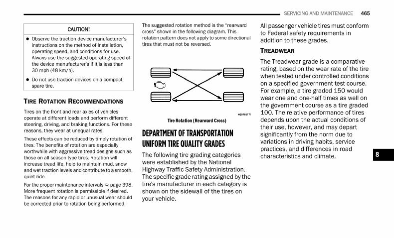
SERVICING AND MAINTENANCE 465
TIRE ROTATION RECOMMENDATIONS Tires on the front and rear axles of vehicles operate at different loads and perform different steering, driving, and braking functions. For these reasons, they wear at unequal rates.These effects can be reduced by timely rotation of tires. The benefits of rotation are especially worthwhile with aggressive tread designs such as those on all season type tires. Rotation will increase tread life, help to maintain mud, snow and wet traction levels and contribute to a smooth, quiet ride.For the proper maintenance intervals Ú page 398. More frequent rotation is permissible if desired. The reasons for any rapid or unusual wear should be corrected prior to rotation being performed.
The suggested rotation method is the “rearward cross” shown in the following diagram. This rotation pattern does not apply to some directional tires that must not be reversed.
Tire Rotation (Rearward Cross)
DEPARTMENT OF TRANSPORTATION UNIFORM TIRE QUALITY GRADES The following tire grading categories were established by the National Highway Traffic Safety Administration. The specific grade rating assigned by the tire's manufacturer in each category is shown on the sidewall of the tires on your vehicle.
All passenger vehicle tires must conform to Federal safety requirements in addition to these grades.TREADWEAR
The Treadwear grade is a comparative rating, based on the wear rate of the tire when tested under controlled conditions on a specified government test course. For example, a tire graded 150 would wear one and one-half times as well on the government course as a tire graded 100. The relative performance of tires depends upon the actual conditions of their use, however, and may depart significantly from the norm due to variations in driving habits, service practices, and differences in road characteristics and climate.
Observe the traction device manufacturer’s instructions on the method of installation, operating speed, and conditions for use. Always use the suggested operating speed of the device manufacturer’s if it is less than 30 mph (48 km/h).
Do not use traction devices on a compact spare tire.
CAUTION!
8
22_DT_OM_EN_USC_t.book Page 465
466 SERVICING AND MAINTENANCE
TRACTION GRADES
The Traction grades, from highest to lowest, are AA, A, B, and C. These grades represent the tire's ability to stop on wet pavement, as measured under controlled conditions on specified government test surfaces of asphalt and concrete. A tire marked C may have poor traction performance.
TEMPERATURE GRADES
The Temperature grades are A (the highest), B, and C, representing the tire's resistance to the generation of heat and its ability to dissipate heat, when tested under controlled conditions on a specified indoor laboratory test wheel.
Sustained high temperature can cause the material of the tire to degenerate and reduce tire life, and excessive temperature can lead to sudden tire failure. The grade C corresponds to a level of performance, which all passenger vehicle tires must meet under the Federal Motor Vehicle Safety Standard No. 109. Grades B and A represent higher levels of performance on the laboratory test wheel, than the minimum required by law.
STORING THE VEHICLE If you are storing your vehicle for more than three weeks, we recommend that you take the following steps to minimize the drain on your vehicle's battery: Disconnect the negative cable from battery. Any time you store your vehicle or keep it out of
service (i.e., vacation) for two weeks or more, run the air conditioning system at idle for about five minutes in the fresh air and high blower setting. This will ensure adequate system lubri-cation to minimize the possibility of compressor damage when the system is started again.
BODYWORKPROTECTION FROM ATMOSPHERIC AGENTS Vehicle body care requirements vary according to geographic locations and usage. Chemicals that make roads passable in snow and ice and those that are sprayed on trees and road surfaces during other seasons are highly corrosive to the metal in your vehicle. Outside parking, which exposes your vehicle to airborne contaminants, road surfaces on which the vehicle is operated, extreme hot or cold weather and other extreme conditions will have an adverse effect on paint, metal trim, and underbody protection.
WARNING!
The traction grade assigned to this tire is based on straight-ahead braking traction tests, and does not include acceleration, cornering, hydroplaning, or peak traction characteristics.
WARNING!
The temperature grade for this tire is established for a tire that is properly inflated and not overloaded. Excessive speed, underinflation, or excessive loading, either separately or in combination, can cause heat buildup and possible tire failure.
22_DT_OM_EN_USC_t.book Page 466
SERVICING AND MAINTENANCE 467
The following maintenance recommendations will enable you to obtain maximum benefit from the corrosion resistance built into your vehicle.
What Causes Corrosion?Corrosion is the result of deterioration or removal of paint and protective coatings from your vehicle.The most common causes are: Road salt, dirt and moisture accumulation. Stone and gravel impact. Insects, tree sap and tar. Salt in the air near seacoast localities. Atmospheric fallout/industrial pollutants.
BODY AND UNDERBODY MAINTENANCE
Cleaning Headlights Your vehicle is equipped with plastic headlights and fog lights that are lighter and less susceptible to stone breakage than glass headlights.Plastic is not as scratch resistant as glass and therefore different lens cleaning procedures must be followed.To minimize the possibility of scratching the lenses and reducing light output, avoid wiping with a dry cloth. To remove road dirt, wash with a mild soap solution followed by rinsing.
Do not use abrasive cleaning components, solvents, steel wool or other aggressive material to clean the lenses.
Tri-Fold Soft Tonneau Cover Care For cleaning and protecting the vinyl Tri-Fold Tonneau cover, use Mopar® Whitewall & Vinyl Top Cleaner and Mopar® Leather and Vinyl Conditioner/Protectant.
PRESERVING THE BODYWORK
Washing Wash your vehicle regularly. Always wash your
vehicle in the shade using Mopar® Car Wash, or a mild car wash soap, and rinse the panels completely with water.
If insects, tar, or other similar deposits have accumulated on your vehicle, use Mopar® Super Kleen Bug and Tar Remover to remove.
Use a high quality cleaner wax, such as Mopar® Cleaner Wax to remove road film, stains and to protect your paint finish. Use precautions to not scratch the paint.
Avoid using abrasive compounds and power buffing that may diminish the gloss or thin out the paint finish.
Fascia/Bumper CareThe customer is responsible to clean and maintain the chrome components of the vehicle. Wash away road debris and salt using an automotive soap. Fascia/bumpers should be cleaned regularly using mild (neutral Ph) soap and water to maintain their luster and to prevent corrosion.Your fascia/bumpers are susceptible to deterioration caused by salt, sodium chloride, magnesium chloride, calcium chloride, etc., and other road chemicals used to melt ice or control dust on dirt roads. Do not use harsh chemicals or a stiff brush. They can stain or damage the protective coating that helps keep them from corroding and tarnishing.
CAUTION!
Do not use abrasive or strong cleaning mate-rials such as steel wool or scouring powder that will scratch metal and painted surfaces.
Use of power washers exceeding 1,200 psi(8,274 kPa) can result in damage or removal of paint and decals.
8
22_DT_OM_EN_USC_t.book Page 467
468 SERVICING AND MAINTENANCE
Special Care If you drive on salted or dusty roads or if you
drive near the ocean, hose off the undercarriage at least once a month.
It is important that the drain holes in the lower edges of the doors, rocker panels, and trunk be kept clear and open.
If you detect any stone chips or scratches in the paint, touch them up immediately.
If your vehicle is damaged due to a collision or similar cause that destroys the paint and protec-tive coating, have your vehicle repaired as soon as possible.
If you carry special cargo such as chemicals, fertilizers, de-icer salt, etc., be sure that such materials are well packaged and sealed.
If a lot of driving is done on gravel roads, consider mud or stone shields behind each wheel.
Use Mopar® Touch Up Paint on scratches as soon as possible. An authorized dealer has touch up paint to match the color of your vehicle.
Spray-On Bedliner – If EquippedDuring ownership, the shine and luster of the Spray-On Bedliner can fade from oxidation, road dirt, heavy-duty hauling and hard water stains. Weathering and UV exposure will lead to fading.To help maintain the appearance of your Spray-On Bedliner, the manufacturer recommends you periodically rinse all loose dirt from your truck bed and clean your truck at least twice per year using the Mopar® Spray-On Bedliner Conditioner available at a local authorized dealer.
To Help Maintain The Appearance Of Your Spray-On Bedliner, Follow The Steps Below: 1. Rinse your truck bed out with water to remove
any loose dirt and debris.2. Mix a mild soap or detergent with water. Then
apply solution with a soft cloth or brush.3. Rinse bedliner with water.4. Once dry, apply a small amount of Mopar®
Spray-On Bedliner Conditioner to a moist towel or sponge and wipe over the entire surface of the truck bedliner.
Spray-On Bedliners are chemically-resistant to many different types of chemicals (including gasoline, oil, hydraulic fluids) for short periods of time. If a spill occurs on your Spray-On Bedliner, rinse the truck out as soon as possible to avoid permanent damage.
CAUTION!
Do not use scouring pads, steel wool, a bristle brush, metal polishes, or oven cleaner. These products may damage the bumper’s protec-tive finish. Such damage is not covered by the New Vehicle Limited Warranty. Only car wash soap, Mopar® Chrome Cleaner, or equivalent is recommended.
Avoid products or automatic car washes that use acidic solutions, strong alkaline additives, or harsh brushes. Many aftermarket cleaners and automatic car washes may damage the bumper’s protective finish. Such damage is not covered by the New Vehicle Limited Warranty. Only car wash soap, Mopar® Chrome Cleaner, or equivalent is recom-mended.
WARNING!
Do not use silicon-based protection products to clean your bedliner. Silicon-based products can become slippery and may result in personal injury.
22_DT_OM_EN_USC_t.book Page 468
SERVICING AND MAINTENANCE 469
Repairing The Spray-On BedlinerWhile extremely tough, it is possible to damage a Spray-On Bedliner. One common condition is when loading a heavy pallet and dragging that pallet across the floor of the bed. If a nail or sharp point is exposed under the weight of the pallet a scratch or tear is possible. While not covered by your new vehicle warranty, a cosmetic fix to cover the metal exposed by the scratch is required. To repair a tear or gouge, follow the directions provided in the Mopar® Quick Repair Kit.
INTERIORS SEATS AND FABRIC PARTS
Use Mopar® Total Clean to clean fabric upholstery and carpeting.
Stain Repel Fabric Cleaning Procedure — If EquippedStain Repel seats may be cleaned in the following manner: Remove as much of the stain as possible by
blotting with a clean, dry towel. Blot any remaining stain with a clean, damp
towel. For tough stains, apply Mopar® Total Clean, or
a mild soap solution to a clean, damp cloth and remove stain. Use a fresh, damp towel to remove soap residue.
For grease stains, apply Mopar® Multi-Purpose Cleaner to a clean, damp cloth and remove stain. Use a fresh, damp towel to remove soap residue.
Do not use any harsh solvents or any other form of protectants on Stain Repel products.
Seat Belt Maintenance Do not bleach, dye or clean the belts with chemical solvents or abrasive cleaners. This will weaken the fabric.
If the belts need cleaning, use a mild soap solution or lukewarm water. Do not remove the belts from the vehicle to wash them. Dry with a soft cloth.Sun damage can also weaken the fabric. Replace the belts if they appear frayed or worn or if the buckles do not work properly.
NOTE:If the belts retract slowly, inspect the upper turning loop for soiling. If soiling is present, clean with a wet soft cloth until all residue is removed.
WARNING!
Do not use volatile solvents for cleaning purposes. Many are potentially flammable, and if used in closed areas they may cause respiratory harm.
WARNING!
A frayed or torn seat belt could rip apart in a collision and leave you with no protection. Inspect the seat belt system periodically, checking for cuts, frays, or loose parts. Damaged parts must be replaced immediately. Do not disassemble or modify the seat belt system. If your vehicle is involved in a collision, or if you have questions regarding seat belt or retractor conditions, take your vehicle to an authorized FCA dealer or authorized FCA Certified Collision Care Program facility for inspection.
8
22_DT_OM_EN_USC_t.book Page 469
470 SERVICING AND MAINTENANCE
PLASTIC AND COATED PARTS
Use Mopar® Total Clean to clean vinyl upholstery.
Cleaning Plastic Instrument Cluster Lenses The lenses in front of the instruments in this vehicle are molded in clear plastic. When cleaning the lenses, care must be taken to avoid scratching the plastic.Clean with a wet soft cloth. A mild soap solution may be used, but do not use high alcohol content or abrasive cleaners. If soap is used, wipe clean with a clean damp cloth. Dry with a soft cloth.
LEATHER SURFACES
Mopar® Total Clean is specifically recommended for leather upholstery.Your leather upholstery can be best preserved by regular cleaning with a damp soft cloth. Small particles of dirt can act as an abrasive and damage the leather upholstery and should be removed promptly with a damp cloth. Stubborn soils can be removed easily with a soft cloth and Mopar® Total Clean. Care should be taken to avoid soaking your leather upholstery with any liquid. Please do not use polishes, oils, cleaning fluids, solvents, detergents, or ammonia-based cleaners to clean your leather upholstery.
NOTE:If equipped with light colored leather, it tends to show any foreign material, dirt, and fabric dye transfer more so than darker colors. The leather is designed for easy cleaning, and the manufacturer recommends Mopar® Total Clean leather cleaner applied on a cloth to clean the leather seats as needed.
GLASS SURFACES All glass surfaces should be cleaned on a regular basis with Mopar® Glass Cleaner, or any commercial household-type glass cleaner. Never use an abrasive type cleaner. Use caution when cleaning the inside rear window equipped with electric defrosters or windows equipped with radio antennas. Do not use scrapers or other sharp instruments that may scratch the elements.When cleaning the rear view mirror, spray cleaner on the towel or cloth that you are using. Do not spray cleaner directly on the mirror.
CAUTION!
Direct contact of air fresheners, insect repel-lents, suntan lotions, or hand sanitizers to the plastic, painted, or decorated surfaces of the interior may cause permanent damage. Wipe away immediately.
Damage caused by these type of products may not be covered by your New Vehicle Limited Warranty.
CAUTION!
Do not use Alcohol and Alcohol-based and/or Ketone based cleaning products to clean leather upholstery, as damage to the upholstery may result.
22_DT_OM_EN_USC_t.book Page 470
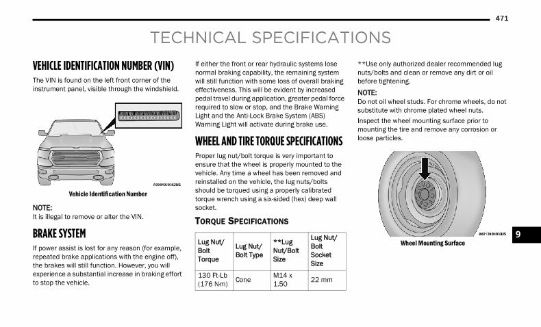
471
TECHNICAL SPECIFICATIONS
VEHICLE IDENTIFICATION NUMBER (VIN)The VIN is found on the left front corner of the instrument panel, visible through the windshield.
Vehicle Identification Number
NOTE:It is illegal to remove or alter the VIN.
BRAKE SYSTEM If power assist is lost for any reason (for example, repeated brake applications with the engine off), the brakes will still function. However, you will experience a substantial increase in braking effort to stop the vehicle.
If either the front or rear hydraulic systems lose normal braking capability, the remaining system will still function with some loss of overall braking effectiveness. This will be evident by increased pedal travel during application, greater pedal force required to slow or stop, and the Brake Warning Light and the Anti-Lock Brake System (ABS) Warning Light will activate during brake use.
WHEEL AND TIRE TORQUE SPECIFICATIONS Proper lug nut/bolt torque is very important to ensure that the wheel is properly mounted to the vehicle. Any time a wheel has been removed and reinstalled on the vehicle, the lug nuts/bolts should be torqued using a properly calibrated torque wrench using a six-sided (hex) deep wall socket.
TORQUE SPECIFICATIONS
**Use only authorized dealer recommended lug nuts/bolts and clean or remove any dirt or oil before tightening.NOTE:Do not oil wheel studs. For chrome wheels, do not substitute with chrome plated wheel nuts.Inspect the wheel mounting surface prior to mounting the tire and remove any corrosion or loose particles.
Wheel Mounting SurfaceLug Nut/Bolt Torque
Lug Nut/Bolt Type
**Lug Nut/Bolt Size
Lug Nut/Bolt Socket Size
130 Ft-Lb (176 N·m) Cone M14 x
1.50 22 mm
9
22_DT_OM_EN_USC_t.book Page 471
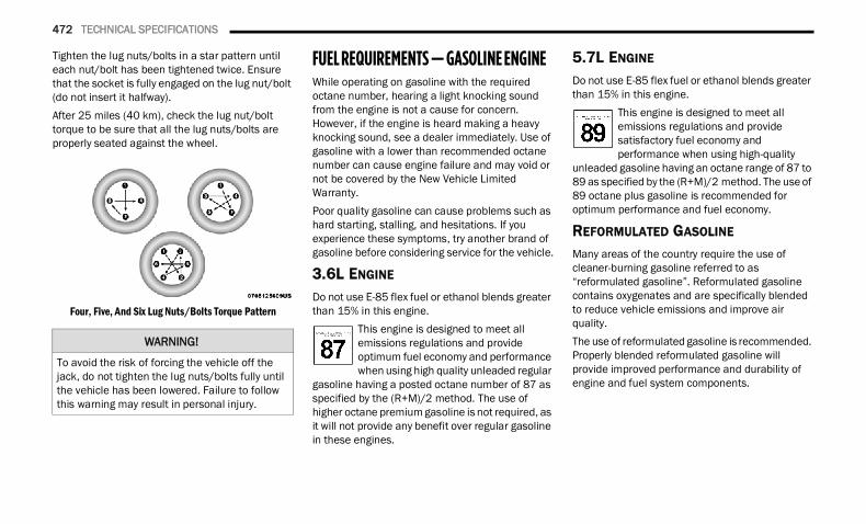
472 TECHNICAL SPECIFICATIONS
Tighten the lug nuts/bolts in a star pattern until each nut/bolt has been tightened twice. Ensure that the socket is fully engaged on the lug nut/bolt (do not insert it halfway).After 25 miles (40 km), check the lug nut/bolt torque to be sure that all the lug nuts/bolts are properly seated against the wheel.
Four, Five, And Six Lug Nuts/Bolts Torque Pattern
FUEL REQUIREMENTS — GASOLINE ENGINE While operating on gasoline with the required octane number, hearing a light knocking sound from the engine is not a cause for concern. However, if the engine is heard making a heavy knocking sound, see a dealer immediately. Use of gasoline with a lower than recommended octane number can cause engine failure and may void or not be covered by the New Vehicle Limited Warranty.Poor quality gasoline can cause problems such as hard starting, stalling, and hesitations. If you experience these symptoms, try another brand of gasoline before considering service for the vehicle.
3.6L ENGINE Do not use E-85 flex fuel or ethanol blends greater than 15% in this engine.
This engine is designed to meet all emissions regulations and provide optimum fuel economy and performance when using high quality unleaded regular
gasoline having a posted octane number of 87 as specified by the (R+M)/2 method. The use of higher octane premium gasoline is not required, as it will not provide any benefit over regular gasoline in these engines.
5.7L ENGINE
Do not use E-85 flex fuel or ethanol blends greater than 15% in this engine.
This engine is designed to meet all emissions regulations and provide satisfactory fuel economy and performance when using high-quality
unleaded gasoline having an octane range of 87 to 89 as specified by the (R+M)/2 method. The use of 89 octane plus gasoline is recommended for optimum performance and fuel economy.
REFORMULATED GASOLINE Many areas of the country require the use of cleaner-burning gasoline referred to as “reformulated gasoline”. Reformulated gasoline contains oxygenates and are specifically blended to reduce vehicle emissions and improve air quality.The use of reformulated gasoline is recommended. Properly blended reformulated gasoline will provide improved performance and durability of engine and fuel system components.
WARNING!
To avoid the risk of forcing the vehicle off the jack, do not tighten the lug nuts/bolts fully until the vehicle has been lowered. Failure to follow this warning may result in personal injury.
22_DT_OM_EN_USC_t.book Page 472
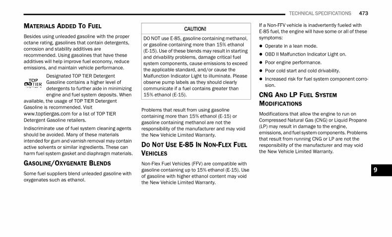
TECHNICAL SPECIFICATIONS 473
MATERIALS ADDED TO FUEL Besides using unleaded gasoline with the proper octane rating, gasolines that contain detergents, corrosion and stability additives are recommended. Using gasolines that have these additives will help improve fuel economy, reduce emissions, and maintain vehicle performance.
Designated TOP TIER Detergent Gasoline contains a higher level of detergents to further aide in minimizing engine and fuel system deposits. When
available, the usage of TOP TIER Detergent Gasoline is recommended. Visit www.toptiergas.com for a list of TOP TIER Detergent Gasoline retailers.Indiscriminate use of fuel system cleaning agents should be avoided. Many of these materials intended for gum and varnish removal may contain active solvents or similar ingredients. These can harm fuel system gasket and diaphragm materials.
GASOLINE/OXYGENATE BLENDS Some fuel suppliers blend unleaded gasoline with oxygenates such as ethanol.
Problems that result from using gasoline containing more than 15% ethanol (E-15) or gasoline containing methanol are not the responsibility of the manufacturer and may void the New Vehicle Limited Warranty.
DO NOT USE E-85 IN NON-FLEX FUEL VEHICLES
Non-Flex Fuel Vehicles (FFV) are compatible with gasoline containing up to 15% ethanol (E-15). Use of gasoline with higher ethanol content may void the New Vehicle Limited Warranty.
If a Non-FFV vehicle is inadvertently fueled with E-85 fuel, the engine will have some or all of these symptoms: Operate in a lean mode. OBD II Malfunction Indicator Light on. Poor engine performance. Poor cold start and cold drivability. Increased risk for fuel system component corro-
sion.
CNG AND LP FUEL SYSTEM MODIFICATIONS
Modifications that allow the engine to run on Compressed Natural Gas (CNG) or Liquid Propane (LP) may result in damage to the engine, emissions, and fuel system components. Problems that result from running CNG or LP are not the responsibility of the manufacturer and may void the New Vehicle Limited Warranty.
CAUTION!
DO NOT use E-85, gasoline containing methanol, or gasoline containing more than 15% ethanol (E-15). Use of these blends may result in starting and drivability problems, damage critical fuel system components, cause emissions to exceed the applicable standard, and/or cause the Malfunction Indicator Light to illuminate. Please observe pump labels as they should clearly communicate if a fuel contains greater than 15% ethanol (E-15).
9
22_DT_OM_EN_USC_t.book Page 473
474 TECHNICAL SPECIFICATIONS
(Continued)
METHYLCYCLOPENTADIENYL MANGANESE TRICARBONYL (MMT) IN GASOLINE
MMT is a manganese-containing metallic additive that is blended into some gasoline to increase octane. Gasoline blended with MMT provides no performance advantage beyond gasoline of the same octane number without MMT. Gasoline blended with MMT reduces spark plug life and reduces emissions system performance in some vehicles. The manufacturer recommends that gasoline without MMT be used in your vehicle. The MMT content of gasoline may not be indicated on the gasoline pump; therefore, you should ask the gasoline retailer whether the gasoline contains MMT. MMT is prohibited in Federal and California reformulated gasoline.
FUEL SYSTEM CAUTIONSNOTE:Intentional tampering with the emissions control system can result in civil penalties being assessed against you.
FUEL REQUIREMENTS – DIESEL ENGINE Federal law requires that you must fuel this vehicle with Ultra Low Sulfur Highway Diesel fuel (15 ppm Sulfur maximum) and prohibits the use of Low Sulfur Highway Diesel fuel (500 ppm Sulfur maximum) to avoid damage to the emissions control system.Use good quality diesel fuel from a reputable supplier in your vehicle. For most year-round service, No. 2 diesel fuel meeting ASTM (formerly known as the American Society for Testing and Materials) specification D-975 Grade S15 will provide good performance. If the vehicle is exposed to extreme cold (below 20°F or -7°C), or is required to operate at colder-than-normal conditions for prolonged periods, use Climatized Number 2 diesel fuel or dilute the Number 2 diesel fuel with 50% Number 1 diesel fuel. This will provide better protection from fuel gelling or wax-plugging of the fuel filters.
CAUTION!
Follow these guidelines to maintain your vehicle’s performance:
The use of leaded gasoline is prohibited by Federal law. Using leaded gasoline can impair engine performance and damage the emis-sions control system.
An out-of-tune engine or certain fuel or ignition malfunctions can cause the catalytic converter to overheat. If you notice a pungent burning odor or some light smoke, your engine may be out of tune or malfunctioning and may require immediate service. Contact an autho-rized dealer for service assistance.
The use of fuel additives, which are now being sold as octane enhancers, is not recom-mended. Most of these products contain high concentrations of methanol. Fuel system damage or vehicle performance problems resulting from the use of such fuels or addi-tives is not the responsibility of the manufac-turer and may void or not be covered under the New Vehicle Limited Warranty.
CAUTION!
WARNING!
Do not use alcohol or gasoline as a fuel blending agent. They can be unstable under certain conditions and hazardous or explosive when mixed with diesel fuel.
22_DT_OM_EN_USC_t.book Page 474
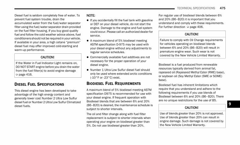
TECHNICAL SPECIFICATIONS 475
Diesel fuel is seldom completely free of water. To prevent fuel system trouble, drain the accumulated water from the fuel/water separator filter using the fuel/water separator drain provided on the fuel filter housing. If you buy good quality fuel and follow the cold weather advice above, fuel conditioners should not be required in your vehicle. If available in your area, a high cetane “premium” diesel fuel may offer improved cold-starting and warm-up performance.
DIESEL FUEL SPECIFICATIONS
This diesel engine has been developed to take advantage of the high energy content and generally lower cost Number 2 Ultra Low Sulfur diesel fuel or Number 2 Ultra Low Sulfur Climatized diesel fuels.
NOTE: If you accidentally fill the fuel tank with gasoline
or DEF on your diesel vehicle, do not start the engine. Damage to the engine and fuel system could occur. Please call an authorized dealer for service.
A maximum blend of 5% biodiesel meeting ASTM specification D-975 may be used with your diesel engine without any adjustments to regular service schedules.
Commercially available fuel additives are not necessary for the proper operation of your diesel engine.
Number 1 Ultra Low Sulfur diesel fuel should only be used where extended arctic conditions (-10°F or -23°C) exist.
BIODIESEL FUEL REQUIREMENTS
A maximum blend of 5% biodiesel meeting ASTM specification D975 is recommended for use with your diesel engine. If frequent operation with Biodiesel blends that are between 6% and 20% (B6–B20) is desired, the maintenance schedule is subject to shorter intervals.The oil and filter change along with fuel filter replacement is subject to shorter intervals when operating your engine on biodiesel greater than 5%. Do not use biodiesel greater than 20%.
For regular use of biodiesel blends between 6% and 20% (B6–B20) it is important that you understand and comply with these requirements. For further direction Ú page 406.
Biodiesel is a fuel produced from renewable resources typically derived from animal fat, rapeseed oil (Rapeseed Methyl Ester (RME) base), or soybean oil (Soy Methyl Ester (SME or SOME) base).Biodiesel fuel has inherent limitations which require that you understand and adhere to the following requirements if you use blends of Biodiesel between 6% and 20% (B6–B20). There are no unique restrictions for the use of B5.
CAUTION!
If the Water in Fuel Indicator Light remains on, DO NOT START engine before you drain the water from the fuel filter(s) to avoid engine damage Ú page 416.
CAUTION!
Failure to comply with Oil Change requirements for vehicles operating on biodiesel blends between 6% and 20% (B6–B20) will result in premature engine wear. Such wear is not covered by the New Vehicle Limited Warranty.
CAUTION!
Use of blends greater than 20% is not approved. Use of blends greater than 20% can result in engine damage. Such damage is not covered by the New Vehicle Limited Warranty.
9
22_DT_OM_EN_USC_t.book Page 475
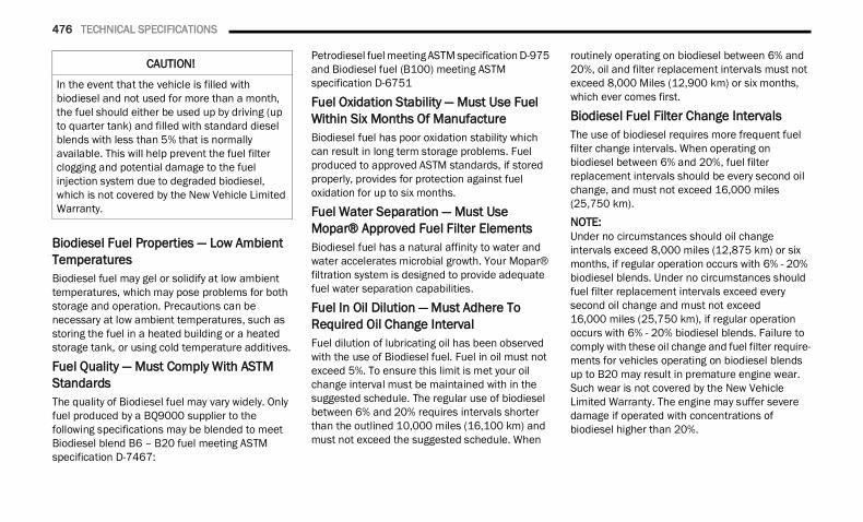
476 TECHNICAL SPECIFICATIONS
Biodiesel Fuel Properties — Low Ambient TemperaturesBiodiesel fuel may gel or solidify at low ambient temperatures, which may pose problems for both storage and operation. Precautions can be necessary at low ambient temperatures, such as storing the fuel in a heated building or a heated storage tank, or using cold temperature additives.
Fuel Quality — Must Comply With ASTM StandardsThe quality of Biodiesel fuel may vary widely. Only fuel produced by a BQ9000 supplier to the following specifications may be blended to meet Biodiesel blend B6 – B20 fuel meeting ASTM specification D-7467:
Petrodiesel fuel meeting ASTM specification D-975 and Biodiesel fuel (B100) meeting ASTM specification D-6751
Fuel Oxidation Stability — Must Use Fuel Within Six Months Of ManufactureBiodiesel fuel has poor oxidation stability which can result in long term storage problems. Fuel produced to approved ASTM standards, if stored properly, provides for protection against fuel oxidation for up to six months.
Fuel Water Separation — Must Use Mopar® Approved Fuel Filter ElementsBiodiesel fuel has a natural affinity to water and water accelerates microbial growth. Your Mopar® filtration system is designed to provide adequate fuel water separation capabilities.
Fuel In Oil Dilution — Must Adhere To Required Oil Change IntervalFuel dilution of lubricating oil has been observed with the use of Biodiesel fuel. Fuel in oil must not exceed 5%. To ensure this limit is met your oil change interval must be maintained with in the suggested schedule. The regular use of biodiesel between 6% and 20% requires intervals shorter than the outlined 10,000 miles (16,100 km) and must not exceed the suggested schedule. When
routinely operating on biodiesel between 6% and 20%, oil and filter replacement intervals must not exceed 8,000 Miles (12,900 km) or six months, which ever comes first.
Biodiesel Fuel Filter Change IntervalsThe use of biodiesel requires more frequent fuel filter change intervals. When operating on biodiesel between 6% and 20%, fuel filter replacement intervals should be every second oil change, and must not exceed 16,000 miles (25,750 km).
NOTE:Under no circumstances should oil change intervals exceed 8,000 miles (12,875 km) or six months, if regular operation occurs with 6% - 20% biodiesel blends. Under no circumstances should fuel filter replacement intervals exceed every second oil change and must not exceed 16,000 miles (25,750 km), if regular operation occurs with 6% - 20% biodiesel blends. Failure to comply with these oil change and fuel filter require-ments for vehicles operating on biodiesel blends up to B20 may result in premature engine wear. Such wear is not covered by the New Vehicle Limited Warranty. The engine may suffer severe damage if operated with concentrations of biodiesel higher than 20%.
CAUTION!
In the event that the vehicle is filled with biodiesel and not used for more than a month, the fuel should either be used up by driving (up to quarter tank) and filled with standard diesel blends with less than 5% that is normally available. This will help prevent the fuel filter clogging and potential damage to the fuel injection system due to degraded biodiesel, which is not covered by the New Vehicle Limited Warranty.
22_DT_OM_EN_USC_t.book Page 476
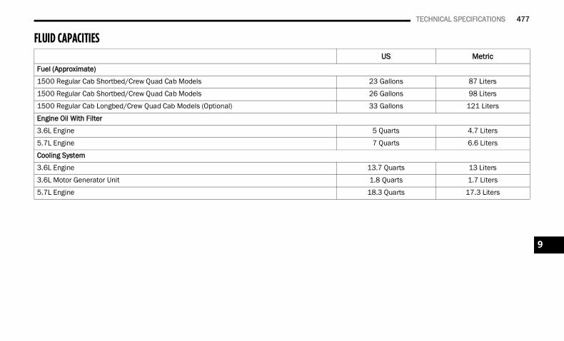
TECHNICAL SPECIFICATIONS 477
FLUID CAPACITIES US Metric
Fuel (Approximate)
1500 Regular Cab Shortbed/Crew Quad Cab Models 23 Gallons 87 Liters
1500 Regular Cab Shortbed/Crew Quad Cab Models 26 Gallons 98 Liters
1500 Regular Cab Longbed/Crew Quad Cab Models (Optional) 33 Gallons 121 Liters
Engine Oil With Filter
3.6L Engine 5 Quarts 4.7 Liters
5.7L Engine 7 Quarts 6.6 Liters
Cooling System
3.6L Engine 13.7 Quarts 13 Liters
3.6L Motor Generator Unit 1.8 Quarts 1.7 Liters
5.7L Engine 18.3 Quarts 17.3 Liters
9
22_DT_OM_EN_USC_t.book Page 477
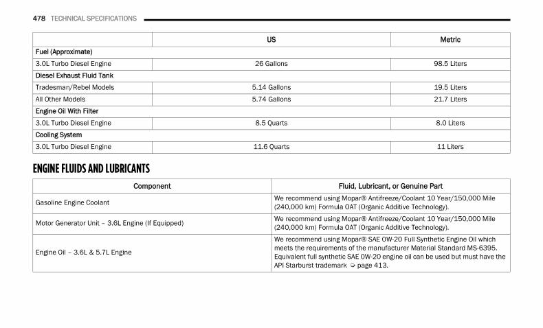
478 TECHNICAL SPECIFICATIONS
ENGINE FLUIDS AND LUBRICANTS
US MetricFuel (Approximate)
3.0L Turbo Diesel Engine 26 Gallons 98.5 Liters
Diesel Exhaust Fluid Tank
Tradesman/Rebel Models 5.14 Gallons 19.5 Liters
All Other Models 5.74 Gallons 21.7 Liters
Engine Oil With Filter
3.0L Turbo Diesel Engine 8.5 Quarts 8.0 Liters
Cooling System
3.0L Turbo Diesel Engine 11.6 Quarts 11 Liters
Component Fluid, Lubricant, or Genuine Part
Gasoline Engine Coolant We recommend using Mopar® Antifreeze/Coolant 10 Year/150,000 Mile (240,000 km) Formula OAT (Organic Additive Technology).
Motor Generator Unit – 3.6L Engine (If Equipped) We recommend using Mopar® Antifreeze/Coolant 10 Year/150,000 Mile (240,000 km) Formula OAT (Organic Additive Technology).
Engine Oil – 3.6L & 5.7L Engine
We recommend using Mopar® SAE 0W-20 Full Synthetic Engine Oil which meets the requirements of the manufacturer Material Standard MS-6395. Equivalent full synthetic SAE 0W-20 engine oil can be used but must have the API Starburst trademark Ú page 413.
22_DT_OM_EN_USC_t.book Page 478
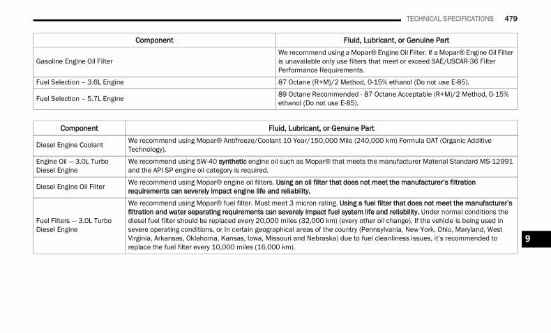
TECHNICAL SPECIFICATIONS 479
Gasoline Engine Oil FilterWe recommend using a Mopar® Engine Oil Filter. If a Mopar® Engine Oil Filter is unavailable only use filters that meet or exceed SAE/USCAR-36 Filter Performance Requirements.
Fuel Selection – 3.6L Engine 87 Octane (R+M)/2 Method, 0-15% ethanol (Do not use E-85).
Fuel Selection – 5.7L Engine 89 Octane Recommended - 87 Octane Acceptable (R+M)/2 Method, 0-15% ethanol (Do not use E-85).
Component Fluid, Lubricant, or Genuine Part
Diesel Engine Coolant We recommend using Mopar® Antifreeze/Coolant 10 Year/150,000 Mile (240,000 km) Formula OAT (Organic Additive Technology).
Engine Oil — 3.0L Turbo Diesel Engine
We recommend using 5W-40 synthetic engine oil such as Mopar® that meets the manufacturer Material Standard MS-12991 and the API SP engine oil category is required.
Diesel Engine Oil Filter We recommend using Mopar® engine oil filters. Using an oil filter that does not meet the manufacturer’s filtration requirements can severely impact engine life and reliability.
Fuel Filters — 3.0L Turbo Diesel Engine
We recommend using Mopar® fuel filter. Must meet 3 micron rating. Using a fuel filter that does not meet the manufacturer’s filtration and water separating requirements can severely impact fuel system life and reliability. Under normal conditions the diesel fuel filter should be replaced every 20,000 miles (32,000 km) (every other oil change). If the vehicle is being used in severe operating conditions, or In certain geographical areas of the country (Pennsylvania, New York, Ohio, Maryland, West Virginia, Arkansas, Oklahoma, Kansas, Iowa, Missouri and Nebraska) due to fuel cleanliness issues, it’s recommended to replace the fuel filter every 10,000 miles (16,000 km).
Component Fluid, Lubricant, or Genuine Part
9
22_DT_OM_EN_USC_t.book Page 479
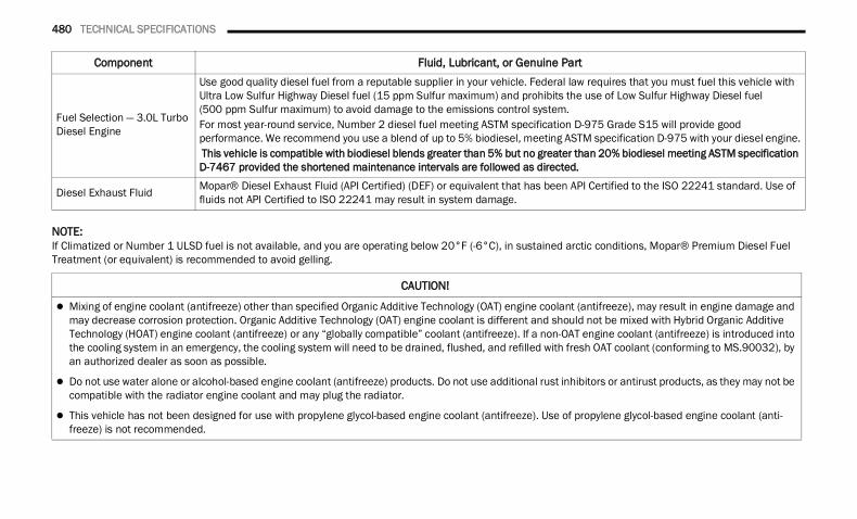
480 TECHNICAL SPECIFICATIONS
NOTE:If Climatized or Number 1 ULSD fuel is not available, and you are operating below 20°F (-6°C), in sustained arctic conditions, Mopar® Premium Diesel Fuel Treatment (or equivalent) is recommended to avoid gelling.
Fuel Selection — 3.0L Turbo Diesel Engine
Use good quality diesel fuel from a reputable supplier in your vehicle. Federal law requires that you must fuel this vehicle with Ultra Low Sulfur Highway Diesel fuel (15 ppm Sulfur maximum) and prohibits the use of Low Sulfur Highway Diesel fuel(500 ppm Sulfur maximum) to avoid damage to the emissions control system.For most year-round service, Number 2 diesel fuel meeting ASTM specification D-975 Grade S15 will provide good performance. We recommend you use a blend of up to 5% biodiesel, meeting ASTM specification D-975 with your diesel engine. This vehicle is compatible with biodiesel blends greater than 5% but no greater than 20% biodiesel meeting ASTM specification D-7467 provided the shortened maintenance intervals are followed as directed.
Diesel Exhaust Fluid Mopar® Diesel Exhaust Fluid (API Certified) (DEF) or equivalent that has been API Certified to the ISO 22241 standard. Use of fluids not API Certified to ISO 22241 may result in system damage.
Component Fluid, Lubricant, or Genuine Part
CAUTION!
Mixing of engine coolant (antifreeze) other than specified Organic Additive Technology (OAT) engine coolant (antifreeze), may result in engine damage and may decrease corrosion protection. Organic Additive Technology (OAT) engine coolant is different and should not be mixed with Hybrid Organic Additive Technology (HOAT) engine coolant (antifreeze) or any “globally compatible” coolant (antifreeze). If a non-OAT engine coolant (antifreeze) is introduced into the cooling system in an emergency, the cooling system will need to be drained, flushed, and refilled with fresh OAT coolant (conforming to MS.90032), by an authorized dealer as soon as possible.
Do not use water alone or alcohol-based engine coolant (antifreeze) products. Do not use additional rust inhibitors or antirust products, as they may not be compatible with the radiator engine coolant and may plug the radiator.
This vehicle has not been designed for use with propylene glycol-based engine coolant (antifreeze). Use of propylene glycol-based engine coolant (anti-freeze) is not recommended.
22_DT_OM_EN_USC_t.book Page 480
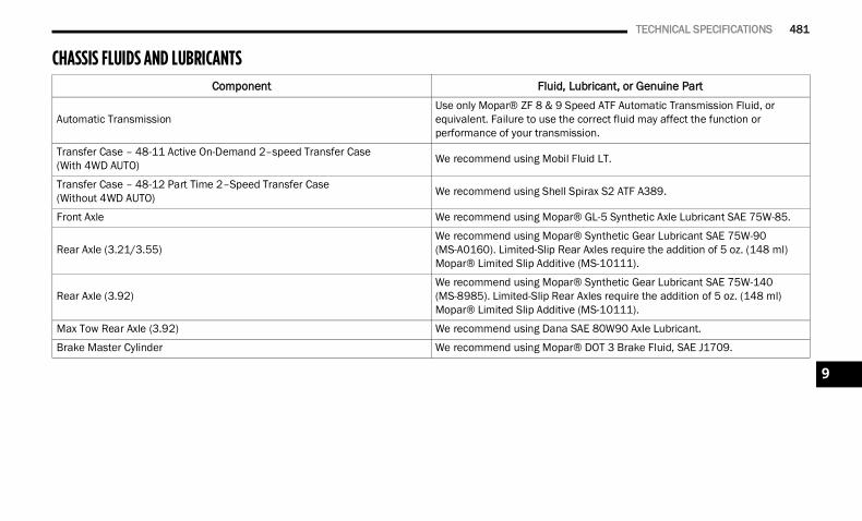
TECHNICAL SPECIFICATIONS 481
CHASSIS FLUIDS AND LUBRICANTS Component Fluid, Lubricant, or Genuine Part
Automatic TransmissionUse only Mopar® ZF 8 & 9 Speed ATF Automatic Transmission Fluid, or equivalent. Failure to use the correct fluid may affect the function or performance of your transmission.
Transfer Case – 48-11 Active On-Demand 2–speed Transfer Case(With 4WD AUTO) We recommend using Mobil Fluid LT.
Transfer Case – 48-12 Part Time 2–Speed Transfer Case(Without 4WD AUTO) We recommend using Shell Spirax S2 ATF A389.
Front Axle We recommend using Mopar® GL-5 Synthetic Axle Lubricant SAE 75W-85.
Rear Axle (3.21/3.55)We recommend using Mopar® Synthetic Gear Lubricant SAE 75W-90 (MS-A0160). Limited-Slip Rear Axles require the addition of 5 oz. (148 ml) Mopar® Limited Slip Additive (MS-10111).
Rear Axle (3.92)We recommend using Mopar® Synthetic Gear Lubricant SAE 75W-140 (MS-8985). Limited-Slip Rear Axles require the addition of 5 oz. (148 ml) Mopar® Limited Slip Additive (MS-10111).
Max Tow Rear Axle (3.92) We recommend using Dana SAE 80W90 Axle Lubricant.
Brake Master Cylinder We recommend using Mopar® DOT 3 Brake Fluid, SAE J1709.
9
22_DT_OM_EN_USC_t.book Page 481
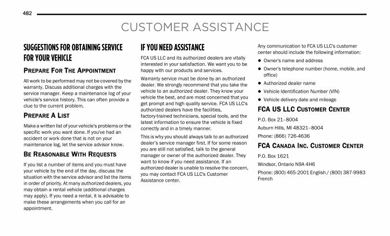
482
CUSTOMER ASSISTANCE
SUGGESTIONS FOR OBTAINING SERVICE FOR YOUR VEHICLE PREPARE FOR THE APPOINTMENT
All work to be performed may not be covered by the warranty. Discuss additional charges with the service manager. Keep a maintenance log of your vehicle's service history. This can often provide a clue to the current problem.
PREPARE A LIST
Make a written list of your vehicle's problems or the specific work you want done. If you've had an accident or work done that is not on your maintenance log, let the service advisor know.
BE REASONABLE WITH REQUESTS
If you list a number of items and you must have your vehicle by the end of the day, discuss the situation with the service advisor and list the items in order of priority. At many authorized dealers, you may obtain a rental vehicle (additional charges may apply). If you need a rental, it is advisable to make these arrangements when you call for an appointment.
IF YOU NEED ASSISTANCE FCA US LLC and its authorized dealers are vitally interested in your satisfaction. We want you to be happy with our products and services.Warranty service must be done by an authorized dealer. We strongly recommend that you take the vehicle to an authorized dealer. They know your vehicle the best, and are most concerned that you get prompt and high quality service. FCA US LLC's authorized dealers have the facilities, factory-trained technicians, special tools, and the latest information to ensure the vehicle is fixed correctly and in a timely manner.This is why you should always talk to an authorized dealer’s service manager first. If for some reason you are still not satisfied, talk to the general manager or owner of the authorized dealer. They want to know if you need assistance. If an authorized dealer is unable to resolve the concern, you may contact FCA US LLC's Customer Assistance center.
Any communication to FCA US LLC's customer center should include the following information: Owner's name and address Owner's telephone number (home, mobile, and
office) Authorized dealer name Vehicle Identification Number (VIN) Vehicle delivery date and mileage
FCA US LLC CUSTOMER CENTER
P.O. Box 21–8004Auburn Hills, MI 48321–8004Phone: (866) 726-4636
FCA CANADA INC. CUSTOMER CENTER
P.O. Box 1621Windsor, Ontario N9A 4H6Phone: (800) 465-2001 English / (800) 387-9983 French
22_DT_OM_EN_USC_t.book Page 482
CUSTOMER ASSISTANCE 483
MEXICO
Av. Prolongacion Paseo de la Reforma, 1240Sante Fe C.P. 05109Mexico, D.F.In Mexico City: 800-505-1300Outside Mexico City: +(52) 55 50817568
PUERTO RICO AND US VIRGIN ISLANDS
FCA Caribbean LLCP.O. Box 191857San Juan 00919-1857Phone: (866) 726-4636Fax: (787) 782-3345
CUSTOMER ASSISTANCE FOR THE HEARING OR SPEECH IMPAIRED(TDD/TTY)To assist customers who have hearing difficulties, FCA US LLC has installed special TDD (Telecommu-nication Devices for the Deaf) equipment at its customer center. Any hearing or speech impaired customer, who has access to a TDD or a conventional teletypewriter (TTY) in the United States, can communicate with FCA US LLC by dialing 1-800-380-2479.
Canadian residents with hearing difficulties that require assistance can use the special needs relay service offered by Bell Canada. For TTY teletypewriter users, dial 711 and for Voice callers, dial 1-800-855-0511 to connect with a Bell Relay Service operator.
SERVICE CONTRACT You may have purchased a service contract for a vehicle to help protect you from the high cost of unexpected repairs after FCA US LLC's New Vehicle Limited Warranty expires. The Mopar® Vehicle Protection plans are the ONLY vehicle extended protection plans authorized, endorsed and backed by FCA US LLC to provide additional protection beyond your vehicle’s warranty. If you purchased a Mopar® Vehicle Protection Plan, you will receive Plan Provisions and an Owner Identification Card in the mail within three weeks of the vehicle delivery date. If you have any questions about the service contract, call FCA US LLC's Service Contract National Customer Hotline at 1-800-521-9922 (Canadian residents, call (800) 465-2001 English / (800) 387-9983 French).FCA US LLC is not responsible for any service contract you may have purchased from another manufacturer. If you require service after FCA US LLC’s New Vehicle Limited Warranty expires, please refer to the contract documents, and contact the person listed in those documents.
We appreciate that you have made a major investment when you purchased the vehicle. An authorized dealer has also made a major investment in facilities, tools, and training to ensure that you are absolutely delighted with the ownership experience.
WARRANTY INFORMATIONSee the Warranty Information for the terms and provisions of FCA US LLC warranties applicable to this vehicle and market. Refer to www.mopar.com/om for further information.
WARNING!
Engine exhaust (internal combustion engines only), some of its constituents, and certain vehicle components contain, or emit, chemicals known to the State of California to cause cancer and birth defects, or other reproductive harm. In addition, certain fluids contained in vehicles and certain products of component wear contain, or emit, chemicals known to the State of California to cause cancer and birth defects, or other reproductive harm.
10
22_DT_OM_EN_USC_t.book Page 483
484 CUSTOMER ASSISTANCE
See the Warranty Information for the terms and provisions of FCA Canada Inc. warranties applicable to this vehicle and market. Refer to www.owners.mopar.ca/en for further information.For French, refer to www.owners.mopar.ca/fr for further information.Use this QR code to access your digital experience.
MOPAR® PARTSMopar® original equipment parts & accessories and factory filled fluids are available from an authorized dealer. They are recommended for your vehicle to keep it operating at its best and maintain its original condition.
REPORTING SAFETY DEFECTS IN THE 50 UNITED STATES AND WASHINGTON, D.C.If you believe that your vehicle has a defect that could cause a crash or cause injury or death, you should immediately inform the National Highway Traffic Safety Administration (NHTSA) in addition to notifying FCA US LLC.If NHTSA receives similar complaints, it may open an investigation, and if it finds that a safety defect exists in a group of vehicles, it may order a recall and remedy campaign. However, NHTSA cannot become involved in individual problems between you, an authorized dealer or FCA US LLC.
To contact NHTSA, you may call the Vehicle Safety Hotline toll free at 1-888-327-4236 (TTY: 1-800-424-9153); or go to http://www.safercar.gov; or write to: Administrator, NHTSA, 1200 New Jersey Avenue, SE., West Building, Washington, D.C. 20590. You can also obtain other information about motor vehicle safety from http://www.safercar.gov.IN CANADA
If you believe that your vehicle has a safety defect, you should contact the Customer Service Department immediately. Canadian customers who wish to report a safety defect to the Canadian government should contact Transport Canada, Motor Vehicle Defect Investigations and Recalls at 1-800-333-0510 or go to wwwapps.tc.gc.ca/Saf-Sec-Sur/7/PCDB-BDPP.
22_DT_OM_EN_USC_t.book Page 484
CUSTOMER ASSISTANCE 485
PUBLICATION ORDER FORMS To order the following manuals, you may use either the website or the phone numbers listed below.Service Manuals These comprehensive Service Manuals provide a complete working knowledge of the vehicle, system, and/or components and is written in straightforward language with illustrations, diagrams, and charts.Diagnostic Procedure ManualsDiagnostic Procedure Manuals are filled with diagrams, charts and detailed illustrations. These manuals make it easy to find and fix problems on computer-controlled vehicle systems and features. They show exactly how to find and correct problems, using step-by-step troubleshooting and drivability procedures, proven diagnostic tests and a complete list of all tools and equipment.To order a hard copy of your Service or Diagnostic Procedure manuals, visit:
www.techauthority.com (US and Canada).Owner's ManualsThese Owner's Manuals have been prepared with the assistance of service and engineering specialists to acquaint you with specific FCA vehicles.
To access your Owner's Information online, visit www.mopar.com/om (US) or www.owners.mopar.ca (Canada).OrCall Tech Authority toll free at: 1-800-890-4038 (US)Owner's Manuals, Radio Manuals and Warranty Information Books can be ordered through Archway at: 1-800-387-1143 (Canada)
GENERAL INFORMATIONThe following regulatory statement applies to all Radio Frequency (RF) devices equipped in this vehicle:This device complies with Part 15 of the FCC Rules and with Innovation, Science and Economic Development Canada license-exempt RSS standard(s). Operation is subject to the following two conditions:1. This device may not cause harmful
interference, and2. This device must accept any interference
received, including interference that may cause undesired operation.
Le présent appareil est conforme aux CNR d`Innovation, Science and Economic Development applicables aux appareils radio exempts de licence. L'exploitation est autorisée aux deux conditions suivantes:1. l'appareil ne doit pas produire de brouillage,
et2. l'utilisateur de l'appareil doit accepter tout
brouillage radioélectrique subi, même si le brouillage est susceptible d'en compromettre le fonctionnement.
La operación de este equipo está sujeta a las siguientes dos condiciones:1. es posible que este equipo o dispositivo no
cause interferencia perjudicial y2. este equipo o dispositivo debe aceptar
cualquier interferencia, incluyendo la que pueda causar su operación no deseada.
NOTE:Changes or modifications not expressly approved by the party responsible for compliance could void the user’s authority to operate the equipment.
10
22_DT_OM_EN_USC_t.book Page 485
486
INDEXAAccessory Drive Belt Inspection.....................421Adaptive Cruise Control (ACC)(Cruise Control).........133, 138, 139, 177, 179Adding Engine Coolant (Antifreeze) ...............425Adding Fuel.......................................... 209, 210Additives, Fuel ...............................................473Adjust
Down...........................................................39Forward ....................................................... 39Rearward.....................................................39Up................................................................ 39
Adjustable Pedals............................................45Advance Phone Connectivity .........................283Air Bag
Air Bag Operation ......................................348Air Bag Warning Light ...................... 346, 348Enhanced Accident Response......... 356, 396Event Data Recorder (EDR) .......................396Front Air Bag .............................................348If Deployment Occurs ................................355Knee Impact Bolsters................................353Maintaining Your Air Bag System ..............357Maintenance .............................................357Redundant Air Bag Warning Light .............347Transporting Pets ......................................372
Air Bag Light................................130, 346, 372Air Cleaner, Engine(Engine Air Cleaner Filter) ............................. 413Air Conditioner Maintenance ........................ 418Air Conditioner Refrigerant .................. 418, 419Air Conditioner System ................................. 418Air Conditioning.........................................63, 66Air Conditioning Filter..............................69, 419Air Conditioning System...................................68Air Conditioning, Operating Tips.......................69Air Filter ............................................... 413, 415Air Pressure
Tires ......................................................... 456Air Suspension......... 133, 136, 137, 165, 169Alarm
Security Alarm ....................................28, 133Alterations/Modifications
Vehicle.........................................................13Antifreeze (Engine Coolant) ................. 425, 477
Disposal ................................................... 426Anti-Lock Brake System (ABS) ...................... 315Anti-Lock Warning Light ................................ 133Assist, Hill Start............................................. 321Audio Settings............................................... 271Audio Systems (Radio) .................................. 236Auto Down Power Windows .............................80
Automatic Door Locks ......................................33Automatic Headlights.......................................56Automatic High Beams.....................................56Automatic Tailgate Release .............................86Automatic Temperature Control (ATC)..............68Automatic Transmission.......................156, 429
Adding Fluid.............................................. 429Fluid And Filter Change............................. 429Fluid Change............................................. 429Fluid Level Check...................................... 429Fluid Type ........................................429, 481Special Additives ...................................... 429
Automatic Transmission Limp Home Mode... 158AutoPark ....................................................... 144AUX Camera .................................................. 206Auxiliary Driving Systems .............................. 322Axle Fluid..............................................430, 481Axle Locker System ....................................... 173Axle Lubrication ............................................ 430
BBack-Up Camera ........................................... 201Battery .................................................131, 411
Charging System Light .............................. 131Keyless Key Fob Replacement ....................21
Battery Saver Feature ......................................59
22_DT_OM_EN_USC_t.book Page 486
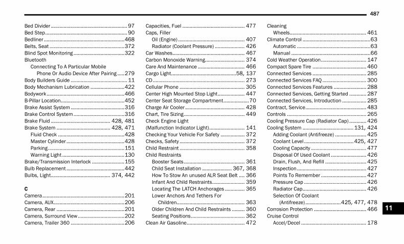
487
Bed Divider ...................................................... 97Bed Step.......................................................... 90Bedliner .........................................................468Belts, Seat .....................................................372Blind Spot Monitoring ....................................322Bluetooth
Connecting To A Particular Mobile Phone Or Audio Device After Pairing .....279
Body Builders Guide ........................................ 11Body Mechanism Lubrication ........................422Bodywork.......................................................466B-Pillar Location.............................................452Brake Assist System ......................................316Brake Control System....................................316Brake Fluid .......................................... 428, 481Brake System ...................................... 428, 471
Fluid Check ...............................................428Master Cylinder .........................................428Parking......................................................151Warning Light ............................................130
Brake/Transmission Interlock .......................155Bulb Replacement .........................................442Bulbs, Light.......................................... 374, 442
CCamera..........................................................201Camera, AUX..................................................206Camera, Rear ................................................201Camera, Surround View.................................202Camera, Trailer 360 ......................................206
Capacities, Fuel ............................................ 477Caps, Filler
Oil (Engine) ............................................... 407Radiator (Coolant Pressure) ..................... 426
Car Washes................................................... 467Carbon Monoxide Warning............................ 374Care And Maintenance ................................. 466Cargo Light..............................................58, 137CD................................................................. 273Cellular Phone .............................................. 305Center High Mounted Stop Light................... 447Center Seat Storage Compartment..................70Charge Air Cooler .......................................... 428Chart, Tire Sizing........................................... 449Check Engine Light(Malfunction Indicator Light)......................... 141Checking Your Vehicle For Safety ................. 372Checks, Safety .............................................. 372Child Restraint .............................................. 358Child Restraints
Booster Seats........................................... 361Child Seat Installation ..................... 367, 368How To Stow An unused ALR Seat Belt .... 366Infant And Child Restraints....................... 359Locating The LATCH Anchorages .............. 365Lower Anchors And Tethers For
Children................................................ 363Older Children And Child Restraints ......... 360Seating Positions...................................... 362
Clean Air Gasoline......................................... 472
CleaningWheels...................................................... 461
Climate Control ................................................63Automatic ....................................................63Manual ........................................................66
Cold Weather Operation................................ 147Compact Spare Tire ...................................... 460Connected Services ...................................... 285Connected Services FAQ ............................... 300Connected Services Features ....................... 288Connected Services, Getting Started ............ 287Connected Services, Introduction ................. 285Contract, Service........................................... 483Controls ........................................................ 265Cooling Pressure Cap (Radiator Cap) ............ 426Cooling System .................................... 131, 424
Adding Coolant (Antifreeze) ...................... 425Coolant Level ...................................425, 427Cooling Capacity ....................................... 477Disposal Of Used Coolant ......................... 426Drain, Flush, And Refill ............................. 425Inspection................................................. 427Points To Remember ................................ 427Pressure Cap ............................................ 426Radiator Cap............................................. 426Selection Of Coolant
(Antifreeze) .........................425, 477, 478Corrosion Protection ..................................... 466Cruise Control
Accel/Decel .............................................. 178
11
22_DT_OM_EN_USC_t.book Page 487
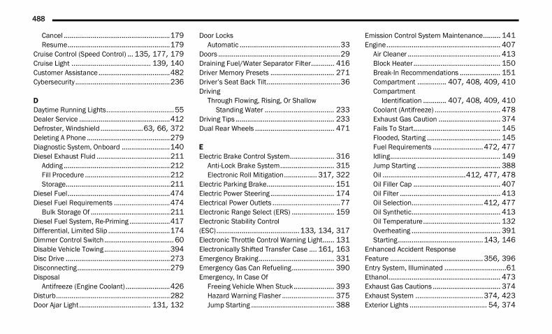
488
Cancel .......................................................179Resume.....................................................179
Cruise Control (Speed Control) ... 135, 177, 179Cruise Light ......................................... 139, 140Customer Assistance .....................................482Cybersecurity .................................................236
DDaytime Running Lights...................................55Dealer Service ...............................................412Defroster, Windshield ......................63, 66, 372Deleting A Phone ...........................................279Diagnostic System, Onboard .........................140Diesel Exhaust Fluid ......................................211
Adding .......................................................212Fill Procedure ............................................212Storage......................................................211
Diesel Fuel.....................................................474Diesel Fuel Requirements .............................474
Bulk Storage Of .........................................211Diesel Fuel System, Re-Priming .....................417Differential, Limited Slip ................................174Dimmer Control Switch.................................... 60Disable Vehicle Towing ..................................394Disc Drive ......................................................273Disconnecting................................................279Disposal
Antifreeze (Engine Coolant) .......................426Disturb...........................................................282Door Ajar Light..................................... 131, 132
Door LocksAutomatic ....................................................33
Doors ...............................................................29Draining Fuel/Water Separator Filter............ 416Driver Memory Presets ................................. 271Driver’s Seat Back Tilt......................................36Driving
Through Flowing, Rising, Or Shallow Standing Water .................................... 233
Driving Tips ................................................... 233Dual Rear Wheels ......................................... 471
EElectric Brake Control System....................... 316
Anti-Lock Brake System............................ 315Electronic Roll Mitigation................. 317, 322
Electric Parking Brake................................... 151Electric Power Steering ................................. 174Electrical Power Outlets ...................................77Electronic Range Select (ERS) ...................... 159Electronic Stability Control(ESC)...........................................133, 134, 317Electronic Throttle Control Warning Light...... 131Electronically Shifted Transfer Case .... 161, 163Emergency Braking....................................... 331Emergency Gas Can Refueling...................... 390Emergency, In Case Of
Freeing Vehicle When Stuck..................... 393Hazard Warning Flasher ........................... 375Jump Starting ........................................... 388
Emission Control System Maintenance......... 141Engine........................................................... 407
Air Cleaner ................................................ 413Block Heater ............................................. 150Break-In Recommendations ..................... 151Compartment ............... 407, 408, 409, 410Compartment
Identification ............ 407, 408, 409, 410Coolant (Antifreeze) .................................. 478Exhaust Gas Caution ................................ 374Fails To Start............................................. 145Flooded, Starting ...................................... 145Fuel Requirements ..........................472, 477Idling......................................................... 149Jump Starting ........................................... 388Oil ...........................................412, 477, 478Oil Filler Cap ............................................. 407Oil Filter .................................................... 413Oil Selection.....................................412, 477Oil Synthetic.............................................. 413Oil Temperature........................................ 132Overheating .............................................. 391Starting............................................143, 146
Enhanced Accident Response Feature ................................................356, 396Entry System, Illuminated ................................61Ethanol.......................................................... 473Exhaust Gas Cautions ................................... 374Exhaust System ...................................374, 423Exterior Lights ........................................ 54, 374
22_DT_OM_EN_USC_t.book Page 488
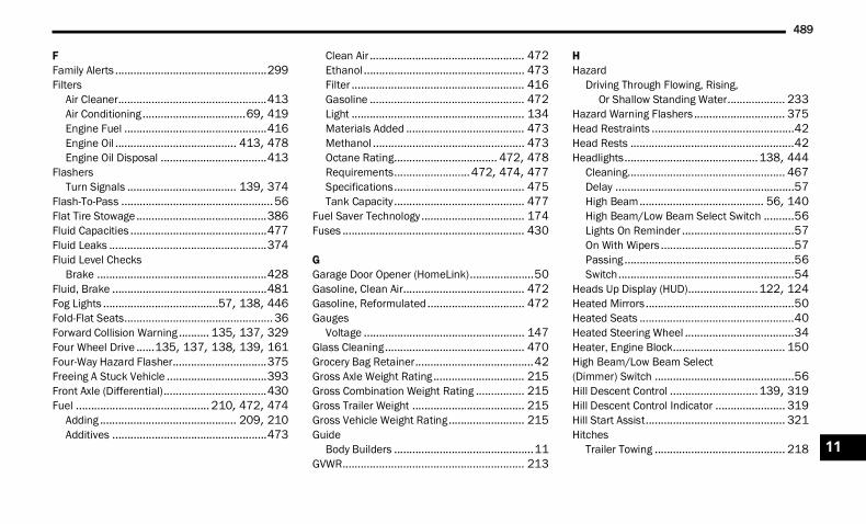
489
FFamily Alerts ..................................................299Filters
Air Cleaner.................................................413Air Conditioning ..................................69, 419Engine Fuel ...............................................416Engine Oil ........................................ 413, 478Engine Oil Disposal ...................................413
FlashersTurn Signals .................................... 139, 374
Flash-To-Pass ..................................................56Flat Tire Stowage...........................................386Fluid Capacities .............................................477Fluid Leaks ....................................................374Fluid Level Checks
Brake ........................................................428Fluid, Brake ...................................................481Fog Lights ......................................57, 138, 446Fold-Flat Seats................................................. 36Forward Collision Warning .......... 135, 137, 329Four Wheel Drive ......135, 137, 138, 139, 161Four-Way Hazard Flasher...............................375Freeing A Stuck Vehicle .................................393Front Axle (Differential)..................................430Fuel ............................................ 210, 472, 474
Adding ............................................. 209, 210Additives ...................................................473
Clean Air ................................................... 472Ethanol ..................................................... 473Filter ......................................................... 416Gasoline ................................................... 472Light ......................................................... 134Materials Added ....................................... 473Methanol .................................................. 473Octane Rating.................................. 472, 478Requirements.........................472, 474, 477Specifications........................................... 475Tank Capacity........................................... 477
Fuel Saver Technology .................................. 174Fuses ............................................................ 430
GGarage Door Opener (HomeLink).....................50Gasoline, Clean Air........................................ 472Gasoline, Reformulated ................................ 472Gauges
Voltage ..................................................... 147Glass Cleaning.............................................. 470Grocery Bag Retainer.......................................42Gross Axle Weight Rating .............................. 215Gross Combination Weight Rating ................ 215Gross Trailer Weight ..................................... 215Gross Vehicle Weight Rating......................... 215Guide
Body Builders ..............................................11GVWR............................................................ 213
HHazard
Driving Through Flowing, Rising, Or Shallow Standing Water................... 233
Hazard Warning Flashers .............................. 375Head Restraints ...............................................42Head Rests ......................................................42Headlights............................................138, 444
Cleaning.................................................... 467Delay ...........................................................57High Beam......................................... 56, 140High Beam/Low Beam Select Switch ..........56Lights On Reminder .....................................57On With Wipers ............................................57Passing ........................................................56Switch..........................................................54
Heads Up Display (HUD).......................122, 124Heated Mirrors.................................................50Heated Seats ...................................................40Heated Steering Wheel ....................................34Heater, Engine Block..................................... 150High Beam/Low Beam Select(Dimmer) Switch ..............................................56Hill Descent Control .............................139, 319Hill Descent Control Indicator ....................... 319Hill Start Assist.............................................. 321Hitches
Trailer Towing ........................................... 218 11
22_DT_OM_EN_USC_t.book Page 489
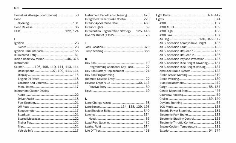
490
HomeLink (Garage Door Opener) ....................50Hood
Opening.....................................................131Hood Release ..................................................86HUD ..................................................... 122, 124
IIgnition ............................................................ 23
Switch ......................................................... 23Ignition Park Interlock....................................155Illuminated Entry ............................................. 61Inside Rearview Mirror............................46, 376Instrument Cluster ............ 106, 108, 110, 111, 113, 114
Descriptions ..................107, 109, 111, 114Display ......................................................115Engine Oil Reset........................................116Location And Controls ...............................115Menu Items...............................................117
Instrument Cluster DisplayAudio .........................................................122Driver Assist ..............................................118Fuel Economy............................................121Off-Road....................................................117Speedometer ............................................117StopStart...................................................121Stored Messages ......................................122Trailer Tow.................................................122Trip ............................................................121Vehicle Info ...............................................117
Instrument Panel Lens Cleaning................... 470Integrated Trailer Brake Control ................... 223Interior Appearance Care.............................. 469Interior Lights...................................................59Intervention Regeneration Strategy ..... 125, 418Inverter Outlet (115V) ......................................78
JJack Location................................................ 379Jump Starting ............................................... 388
KKey Fob............................................................19
Programming Additional Key Fobs...............22Key Fob Battery Replacement .........................21Key Fob Programming(Remote Keyless Entry)....................................22Keyless Enter-N-Go .................................30, 143
Passive Entry ...............................................30Keys.................................................................19
LLane Change Assist .........................................58LaneSense.........................134, 138, 139, 198Lap/Shoulder Belts....................................... 340Latches ......................................................... 374
Hood............................................................86Lead Free Gasoline....................................... 472Leaks, Fluid .................................................. 374Life Of Tires................................................... 458
Light Bulbs ...........................................374, 442Lights ............................................................ 374
4WD.......................................................... 1374WD AUTO ................................................ 1394WD High ................................................. 1384WD Low .................................................. 137Air Bag ....................................130, 346, 372Air Suspension Aerodynamic Height ......... 136Air Suspension Fault................................. 133Air Suspension Off-Road 1........................ 136Air Suspension Off-Road 2........................ 136Air Suspension Payload Protection ........... 136Air Suspension Ride Height Lowering ....... 137Air Suspension Ride Height Raising.......... 137Anti-Lock Brake System............................ 133Brake Assist Warning................................ 319Brake Warning.......................................... 130Bulb Replacement .................................... 442Cargo ................................................. 58, 137Center Mounted Stop ............................... 447Courtesy/Reading........................................59Cruise ..............................................139, 140Daytime Running .........................................55ECO Mode................................................. 138Electric Power Steering............................. 131Electronic Park Brake ............................... 133Electronic Stability Control........................ 133Electronic Throttle Control ........................ 131Engine Coolant Temperature .................... 131Exterior .............................................. 54, 374
22_DT_OM_EN_USC_t.book Page 490
491
Fog .................................................. 138, 446Forward Collision Warning.........................137Hazard Warning Flasher............................375Headlights............................................ 54, 56High Beam .........................................56, 140High Beam/Low Beam Select .....................56Hill Descent Control Indicator.......... 139, 319Hood Open ................................................131Illuminated Entry .........................................61Interior ........................................................59LaneSense ...................................... 138, 139Lights On Reminder..................................... 57Low Diesel Exhaust Fluid...........................137Low Fuel....................................................138Malfunction Indicator (Check Engine) .......134NEUTRAL ...................................................137Oil Temperature ........................................132Passing........................................................56Rear Axle Lock...........................................137Rear Axle Lock Fault..................................135Rear Tail Lamps ........................................446Seat Belt Reminder ...................................132Security Alarm...........................................133Service ......................................................442Service Stop Start .....................................135Stop Start Active........................................139TOW HAUL .................................................137Traction Control.........................................319
Transmission Temperature....................... 132Turn Signals .................................... 139, 444Wait To Start............................................. 138Warning Instrument Cluster
Descriptions ......................................... 139Limited-Slip Differential ....................... 174, 430Load Shed Battery Saver Mode .................... 128Load Shed Battery Saver On......................... 128Load Shed Electrical Load Reduction ........... 128Load Shed Intelligent Battery Sensor............ 128Loading Vehicle ............................................ 213
Tires ......................................................... 452Locks
Automatic Door............................................33Child Protection ...........................................33Power Door..................................................30
Low Tire Pressure System............................. 332Lubrication, Body .......................................... 422Lug Nuts ....................................................... 471Lug Nuts/Bolts.............................................. 471
MMaintenance.............................................83, 85Maintenance Free Battery ............................ 411Maintenance Schedule...............397, 402, 403Malfunction Indicator Light (Check Engine).............................................. 134
ManualService...................................................... 485
Media Hub .......................................................75Media Mode.................................................. 273Memory Seat....................................................35Memory Settings ..............................................35Methanol....................................................... 473Mirrors .............................................................46
Automatic Dimming .....................................46Digital ..........................................................47Electric Powered..........................................48Heated.........................................................50Manual Dimming .........................................46Memory .......................................................35Outside ........................................................48Power Folding ..............................................49Rearview............................................ 46, 376Tilt Side In Reverse......................................50Trailer Towing ..............................................50Vanity...........................................................47
Mobile App.................................................... 287Modifications/Alterations
Vehicle.........................................................13Monitor, Tire Pressure System ...................... 332Mopar Parts .................................................. 484MP3 Control .....................................................75Multi-Function Control Lever ............................55Multifunction Tailgate ......................................87 11
22_DT_OM_EN_USC_t.book Page 491
492
NNew Vehicle Break-In Period..........................151
OOccupant Restraints ......................................338Octane Rating, Gasoline (Fuel) ......................472Off Road Pages..............................................309
Accessory Gauges .....................................312Pitch And Roll ............................................313Status Bar .................................................310Vehicle Dynamics ......................................311
Off-Pavement Driving (Off-Road)....................235Off-Road Driving (Off-Pavement)....................235Oil Filter, Change ...........................................413Oil Filter, Selection.........................................413Oil Pressure Light ..........................................132Oil, Engine ........................................... 412, 478
Capacity ....................................................477Dipstick .....................................................411Disposal ....................................................413Filter................................................ 413, 478Filter Disposal ...........................................413Identification Logo.....................................413Materials Added To ...................................413Pressure Warning Light .............................132Recommendation............................ 412, 477Synthetic ...................................................413Viscosity ....................................................477
Onboard Diagnostic System ..........................140Operating Precautions ...................................140
Operator ManualOwner's Manual........................................ 485
Outside Rearview Mirrors ................................48Overheating, Engine...................................... 391
PPaddle Shifters ............................................. 159Paint Care..................................................... 466Pair (Link) Uconnect Phone To A Mobile Phone ¹ ............................................. 277Parallel Parking............................................. 195Parking Brake ...................................... 133, 151Parking Lights ..................................................56ParkSense Active Park Assist........................ 194ParkSense System, Rear .............................. 188Passive Entry ...................................................30Pedals, Adjustable ...........................................45Pedestrian Warning System.......................... 331Performance Features .................................. 119Pets .............................................................. 372Phone Mode ................................................. 275Pickup Box ................................................92, 94Pinch Protection .......................................83, 85Placard, Tire And Loading Information.......... 452Power
Distribution Center (Fuses).............. 431, 437Door Locks ..................................................30Mirrors.........................................................48Outlet (Auxiliary Electrical Outlet) .........77, 78Seats ...........................................................39
Side Steps ...................................................30Sliding Rear Window....................................81Steering ...........................................131, 174Sunroof.................................................82, 84Windows ......................................................80
Power SeatsDown ...........................................................39Forward .......................................................39Rearward .....................................................39Recline.........................................................39Tilt................................................................39Up ................................................................39
Power Steering.............................................. 174Pregnant Women And Seat Belts .................. 344Presets.......................................................... 271Pressure Washing ......................................... 412Pretensioners
Seat Belts ................................................. 344Profile Settings.............................................. 238
RRadial Ply Tires.............................................. 456Radiator Cap(Coolant Pressure Cap) ........................ 425, 426Radio
Off Road Pages......................................... 309Presets ..................................................... 271Settings .................................................... 237Sound Setting ........................................... 258
Radio Controls .............................................. 265
22_DT_OM_EN_USC_t.book Page 492
493
Radio Mode ...................................................265Radio Operation .................................. 265, 305Radio Remote Controls..................................264Rain Sensitive Wiper System........................... 62RamBox ...........................................................94RamBox Safety ................................................ 97Rear Axle (Differential)...................................430Rear Cargo Area Utility Rails ............................ 93Rear Cross Path.............................................325Rear ParkSense System ................................188Rear Window, Sliding....................................... 82Reclining Rear Seats ....................................... 38Recreational Towing ......................................230
Four-Wheel Drive Models ..........................231Shifting Into Transfer Case Neutral (N) .....232Shifting Out Of Transfer Case
Neutral (N) ............................................233Two-Wheel Drive Models ...........................231
Reformulated Gasoline..................................472Refrigerant ....................................................419Registering SiriusXM Guardian ......................286Release, Hood ................................................. 86Release, Tailgate ............................................. 86Reminder, Seat Belt ......................................339Remote Features, Door Lock/Unlock .. 293, 301Remote Features, Horn And Lights................294Remote Features, Starting .................. 293, 302
Remote Keyless EntryProgramming Additional Key Fobs...............22
Remote Sound System (Radio) Control......... 264Remote Start (Diesel) ......................................27Remote Start (Gasoline) ..................................24Remote Starting
Comfort Systems .........................................26Exit Remote Start Mode ..............................26
Remote Starting System ...........................24, 27Remove, Tailgate .............................................88Replacement Bulbs ...................................... 442Replacement Tires........................................ 458Reporting Safety Defects .............................. 484Restraints, Child ........................................... 358Restraints, Head..............................................42Roadside Assistance............................ 294, 301Rotation, Tires .............................................. 465
SSafety ........................................................... 263Safety Checks Inside Vehicle ........................ 372Safety Checks Outside Vehicle ..................... 373Safety Defects, Reporting ............................. 484Safety Features............................................. 263Safety Information, Tire ................................ 448Safety Tips .................................................... 372Safety, Exhaust Gas...................................... 374Satellite Radio .............................................. 267
Saved Radio Stations.................................... 271Schedule, Maintenance ..............397, 402, 403Seat Belt Reminder....................................... 132Seat Belts ............................................339, 372
Adjustable Shoulder Belt .......................... 342Adjustable Upper Shoulder Anchorage ..... 342Adjustable Upper Shoulder Belt
Anchorage ............................................ 342Automatic Locking Retractor (ALR) ........... 344Child Restraints ........................................ 358Energy Management Feature ................... 344Extender ................................................... 343Front Seat...............................339, 340, 341Inspection................................................. 372Lap/Shoulder Belt Operation.................... 341Lap/Shoulder Belt Untwisting................... 342Lap/Shoulder Belts................................... 340Operating Instructions .............................. 341Pregnant Women...................................... 344Pretensioners ........................................... 344Rear Seat.................................................. 340Reminder.................................................. 339Seat Belt Extender.................................... 343Seat Belt Pretensioner.............................. 344Seat Belt Reminder .................................. 339Untwisting Procedure................................ 342
Seat Belts Maintenance................................ 46911
22_DT_OM_EN_USC_t.book Page 493
494
Seats ................................................. 36, 38, 39Adjustment........................................... 36, 39Easy Entry ................................................... 40Head Restraints .......................................... 42Memory ....................................................... 35Power .......................................................... 39Rear Folding................................................ 36Reclining Rear............................................. 38Tilting .......................................................... 36
Second Row USB............................................. 75Security System......................................28, 133Selection Of Coolant (Antifreeze)...................478Send & Go ........................................... 295, 301Sentry Key (Immobilizer).................................. 23Service Assistance.........................................482Service Contract ............................................483Service Manuals ............................................485Settings, Audio ..............................................271Shifting ..........................................................154
Automatic Transmission............................156Transfer Case, Shifting Into Transfer
Case Neutral (N) ......................... 137, 232Transfer Case, Shifting Out Of
Transfer Case Neutral (N) .....................233Shoulder Belts ...............................................340Side Steps, Power............................................30
Signals, Turn................................. 58, 139, 374Sirius Satellite Radio..................................... 267
Favorites................................................... 270Replay ...................................................... 269
SiriusXM Satellite RadioBrowse in SXM ......................................... 270Favorites................................................... 270Replay ...................................................... 269
Sliding Rear Window, Power ............................81Smart Watch................................................. 300Snow Chains (Tire Chains) ............................ 463Snow Plow .................................................... 228Snow Tires .................................................... 459SOS Call ............................................... 288, 300Spare Tires .................................459, 460, 461Speed Control (Cruise Control) ..................... 179Starting .......................................142, 143, 146
Automatic Transmission ........................... 143Button .........................................................23Cold Weather............................................ 147Engine Fails To Start................................. 145
Starting And Operating................138, 143, 146Starting Procedures ............................. 143, 146
SteeringPower........................................................ 174Tilt Column...................................................34Wheel, Heated.............................................34Wheel, Tilt....................................................34Wheel, Voice Recognition ............................44
Steering Wheel Audio Controls...................... 264Steering Wheel Mounted Sound System....... 264Steps, Power Side ............................................30Stolen Vehicle Assistance ....................297, 302Stop/Start ............................................135, 175Storage ............................................................70
Below Seat...................................................75Door.............................................................70Front Bench Seat.........................................73Glove Compartment.....................................70In Floor ........................................................74Rear Console ...............................................73
Storage Compartment, Center Seat .................70Storage, Vehicle ..................................... 69, 466Store Radio Presets ...................................... 271Storing Your Vehicle ...................................... 466Sun Roof .....................................82, 83, 84, 85Sunglasses Storage .........................................72Sunshade Operation .................................83, 85
22_DT_OM_EN_USC_t.book Page 494
495
Surround View Camera..................................202Suspension
Air.................................................... 165, 169Sway Control, Trailer......................................322Symbol Glossary .............................................. 13Synthetic Engine Oil.......................................413
TTailgate............................................................ 86Tailgate Removal ............................................. 88Tailgate, Electronic Lowering ........................... 86Tailgate, Multifunction..................................... 87Telescoping Steering Column ..........................34Temperature Control, Automatic (ATC) ............68Tilt
Down...........................................................39Up................................................................ 39
Tilt Steering Column ........................................ 34Tip Start .........................................................143Tire And Loading Information Placard ...........452Tire Identification Number (TIN) ....................450Tire Markings.................................................448Tire Safety Information ..................................448Tire Terminology And Definitions ...................451
Tires......................... 373, 455, 459, 460, 465Aging (Life Of Tires) .................................. 458Air Pressure .............................................. 455Chains ...................................................... 463Compact Spare......................................... 460Dual.......................................................... 471General Information ...............455, 459, 460High Speed............................................... 456Inflation Pressure ..................................... 456Life Of Tires .............................................. 458Load Capacity........................................... 452Pressure Monitoring System
(TPMS) ........................................ 135, 332Quality Grading......................................... 465Radial ....................................................... 456Replacement ............................................ 458Rotation.................................................... 465Run Flat.................................................... 457Safety .............................................. 448, 455Sizes......................................................... 449Snow Tires................................................ 459Spare Tires .............................459, 460, 461Spinning ................................................... 457Trailer Towing ........................................... 222Tread Wear Indicators .............................. 457Types ........................................................ 459Wheel Nut Torque..................................... 471
To Open Hood ..................................................86Tongue Weight/Trailer Weight .............215, 219Tonneau Cover....................................... 99, 467Tonneau Cover Cleaning ............................... 467Tow/Haul Mode ............................................ 160Towing.........................................137, 214, 394
Disabled Vehicle ....................................... 394Guide ........................................................ 218Recreational ............................................. 230Weight ...................................................... 218
Towing Behind A Motorhome ........................ 230Traction......................................................... 233Traction Control ............................................ 322Trailer Reverse Steering Control ................... 219Trailer Sway Control (TSC) ....................215, 322Trailer Tire Pressure...................................... 336Trailer Towing....................................... 132, 214
Frontal Area .............................................. 215Hitches ..................................................... 218Minimum Requirements ........................... 221Mirrors .........................................................50Tips........................................................... 227Trailer And Tongue Weight........................ 219Weight Carrying Hitch ............................... 215Weight Distributing Hitch .......................... 216Wiring ....................................................... 225
11
22_DT_OM_EN_USC_t.book Page 495
496
Trailer Towing Guide ......................................218Trailer Weight ................................................218Transfer Case ................................................430
Electronically Shifted....................... 161, 163Fluid ..........................................................481
Transmission .................................................156Automatic........................................ 156, 429Fluid ..........................................................481Maintenance .............................................429Shifting......................................................154Temperature .............................................132
Transporting Pets ..........................................372Tread Wear Indicators ...................................457Tri-Fold Tonneau Cover.................................... 99
Cleaning ....................................................105Install ........................................................103Removal ....................................................100
Turn Signals......................... 58, 139, 444, 446
UUconnect
Phone Call Features ..................................280Things You Should Know About Your
Uconnect Phone....................................283Uconnect Settings .....................................237
Uconnect (Radio) .......................................... 236Uconnect 4C Nav With 12-Inch Display ........ 236Uconnect 4C/4C Nav With 8.4-InchDisplay .......................................................... 236Uconnect Phone ........................................... 277
Answer Or Ignore An Incoming Call — Call Currently In Progress ..................... 282
Answer Or Ignore An Incoming Call — No Call Currently In Progress................ 281
Bluetooth Communication Link ................ 285Call Continuation...................................... 283Call Controls ............................................. 281Call Termination ....................................... 283Cancel Command..................................... 277Connecting To A Particular Mobile
Phone Or Audio Device After Pairing .... 279Help Command......................................... 277Join Calls .................................................. 282Making A Phone Or Audio Device A
Favorite ................................................ 279Making A Second Call While Current
Call Is In Progress................................. 282Managing Your Favorites.......................... 280Natural Speech......................................... 277Operation ................................................. 276Overview................................................... 275
Pair (Link) Uconnect Phone To AMobile Phone ....................................... 277
Phonebook Download............................... 280Place/Retrieve A Call From Hold............... 282Power-Up .................................................. 285Recent Calls.............................................. 281Redial ....................................................... 283To Remove A Favorite ............................... 280Toggling Between Calls............................. 282Touch-Tone Number Entry ........................ 281Transfer Call To And From Mobile
Phone................................................... 283Voice Command ....................................... 283
Uconnect SettingsCustomer Programmable Features.... 30, 237Passive Entry Programming.........................30
Uconnect System .......................................... 262Uniform Tire Quality Grades .......................... 465Universal Garage Door Opener(Homelink®) — If Equipped b.......................50Unleaded Gasoline........................................ 472Untwisting Procedure, Seat Belt.................... 342USB..................................................................75Utility Rails, Rear Cargo Area ...........................93
22_DT_OM_EN_USC_t.book Page 496
497
VVehicle Finder...................................... 296, 302Vehicle Health Alert .......................................298Vehicle Health Report....................................297Vehicle Identification Number (VIN)...............471Vehicle Loading ................................... 213, 452Vehicle Maintenance.....................................412Vehicle Modifications/Alterations....................13Vehicle Notifications......................................298Vehicle Settings.............................................237Vehicle Storage ......................................69, 466Ventilated Seats .............................................. 41Voice Command .............................................. 44Voice Recognition System (VR)........................ 44
WWarning Lights And Messages...................... 129Warranty Information.................................... 483Washers, Windshield .................................... 411Washing Vehicle ........................................... 467Water
Driving Through ........................................ 233Water Separator
Diesel Fuel....................................... 138, 416Wheel And Wheel Tire Care .......................... 461Wheel And Wheel Tire Trim........................... 461Wi-Fi.............................................................. 296Wind Buffeting .................................................82Window Fogging...............................................69Window Lockout Switch ...................................81
Windows ..........................................................80Power...........................................................80Rear Sliding .................................................82Reset Auto-Up..............................................81
Windshield Defroster .................................... 372Windshield Washers ..................... 61, 134, 411
Fluid.......................................................... 411Windshield Wiper Blades .............................. 422Windshield Wipers ...........................................61Wipers Blade Replacement........................... 422Wipers, Rain Sensitive .....................................62Wireless Charging Pad .....................................79
11
22_DT_OM_EN_USC_t.book Page 497


The driver’s primary responsibility is the safe operation of the vehicle. Driving while distracted can result in loss of vehicle control, resulting in an accident and personal injury. FCA US LLC strongly recommends that the driver use extreme caution when using any device or feature that may take their attention off the road. Use of any electrical devices, such as cellular telephones, computers, portable radios, vehicle navigation or other devices, by the driver while the vehicle is moving is dangerous and could lead to a serious accident. Texting while driving is also dangerous and should never be done while the vehicle is moving. If you find yourself unable to devote your full attention to vehicle operation, pull off the road to a safe location and stop your vehicle. Some states or provinces prohibit the use of cellular telephones or texting while driving. It is always the driver’s responsibility to comply with all local laws.
This Owner’s Manual has been prepared to help you get acquainted with your new Ram brand vehicle and to provide a convenient reference for common questions.
Not all features shown in this manual may apply to your vehicle. For additional information on accessories to help personalize your vehicle, visit mopar.com/om (U.S.), owners.mopar.ca (Canada) or your local Ram brand dealer.
DRIVING AND ALCOHOLDrunk driving is one of the most frequent causes of accidents. Your driving ability can be seriously impaired with blood alcohol levels far below the legal minimum. If you are drinking, don’t drive. Ride with a designated non-drinking driver, call a cab, a friend or use public transportation.
WARNINGDriving after drinking can lead to an accident. Your perceptions are less sharp, your reflexes are slower and your judgment is impaired when you have been drinking. Never drink and then drive.
WARNING: Operating, servicing and maintaining a passenger vehicle or off-highway motor vehicle can expose you to chemicals including engine exhaust, carbon monoxide, phthalates, and lead, which are known to the State of California to cause cancer and birth defects or other reproductive harm. To minimize exposure, avoid breathing exhaust, do not idle the engine except as necessary, service your vehicle in a well-ventilated area and wear gloves or wash your hands frequently when servicing your vehicle. For more information go to www.P65Warnings.ca.gov/passenger-vehicle.
This Owner’s Manual illustrates and describes the operation of features and equipment that are either standard or optional on this vehicle. This manual may also include a description of features and equipment that are no longer available or were not ordered on this vehicle. Please disregard any features and equipment described in this manual that are not on this vehicle. FCA US LLC reserves the right to make changes in design and specifications, and/or make additions to or improvements to its products without imposing any obligation upon itself to install them on products previously manufactured.
With respect to any vehicles sold in Canada, the name FCA US LLC shall be deemed to be deleted and the name FCA Canada Inc. used in substitution therefore.
This Owner’s Manual is intended to familiarize you with the important features of your vehicle. Your most up-to-date Owner’s Manual, Navigation/Uconnect manuals and Warranty Booklet can be found by visiting the website on the back cover.
U.S. Residents: If you are the first registered retail owner of your vehicle, you may obtain a complimentary printed copy of the Warranty Booklet by calling 1-866-726-4636 or by contacting your dealer. Replacement kits can be purchased by visiting www.techauthority.com.
Canadian Residents: If you are the first registered retail owner of your vehicle, you may obtain a complimentary printed copy of the Warranty Booklet or purchase a replacement kit by calling 1-800-387-1143 or by contacting your dealer.
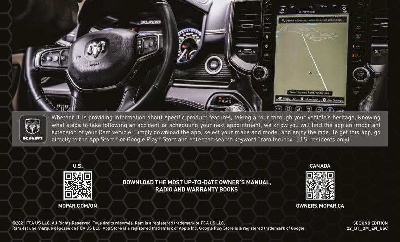
SECOND EDITION 22_DT_OM_EN_USC
©2021 FCA US LLC. All Rights Reserved. Tous droits réservés. Ram is a registered trademark of FCA US LLC. Ram est une marque déposée de FCA US LLC. App Store is a registered trademark of Apple Inc. Google Play Store is a registered trademark of Google.
2022 RAM 1500OWNER’S MANUAL
20
22
RA
M 1
50
0
Whether it is providing information about specific product features, taking a tour through your vehicle’s heritage, knowing what steps to take following an accident or scheduling your next appointment, we know you will find the app an important extension of your Ram vehicle. Simply download the app, select your make and model and enjoy the ride. To get this app, go directly to the App Store® or Google Play® Store and enter the search keyword “ram toolbox” (U.S. residents only).
DOWNLOAD THE MOST UP-TO-DATE OWNER’S MANUAL, RADIO AND WARRANTY BOOKS
OWNERS.MOPAR.CA
CANADA
MOPAR.COM/OM
U.S.