Embed Size (px)
Citation preview
Telex : 0535 - 2424 RDSO -IN
Fax 293 ~ 0522 - 2452581 Telephone : 2450374 & 2451200 Wa - 226011
Telegram : “RAILMANAK’, Lucknow Govemment of India - Ministry of
e-mail =: dell 1 @rdso_railnet.gov.in Railways
Research, Designs & Standards
Organization, LUCKNOW - 226011
No. EL/4.2.15 Date: 25-8-2005
Secretary (Electrical), Railway Board, Rail Bhawan, New Delhi — 110001.
(Kind Attn: Shri N. R. Dash, DEE/RS)
Sub: Specification for microprocessor based control and fault diagnostic system,
Ref: Railway Board’s letter nos — (i) 2003 /Blect(TRS)/44 1/3/Pt dt 21-4-2004, (ii) 2003/Elect(TRS)/441 3 /Pt dt 17-12-2004, (iii) 2003/Blect(TRS)/441/3/Pt dt 19-4-2005, (iv) 2000/Elec(TRS)/441/6 dt 11-8-2005.
Railway Board vide letter under reference (i) had asked RDSO to revise the
specification to overcome the problems of existing equipment and to increase the reliability. Accordingly, the draft specification no. ELRS/SPEC/MPC-FDS/0001 (Rev 2)
— July’2005 was sent to Railway Board vide this office letter of even no. dt 21-9-04. 154569
Railway Board vide letter no. 2000/Elec(FRS)/441/6 dt 11-8-2005 have approved the draft specification no. ELRS/SPEC/MPC-FDS/0001 (Rev 2) — July’2005 with some modifications. As advised by Railway Board this modification has been incorporated in the specification and the specification for microprocessor based control and fauit diagnostic system has been finalized and circulated to all railways and CLW.
A copy of final specification no. ELRS/SPEC/MPC-FDS/0001 (Rev 2) - Aug’2005 for microprocessor based contro! and fault diagnostic system for AC tap changer locomotive is enclosed herewith for kind information, please.
DA: 1 f Specn. copy of Specn R. (_- A NN
(Ram Prakash) SF Foy For Director General Std/Elect
Ce:
Chief Electrical Engineers:
1. Central Railway, Mumbai, CST-400001. 2. East Central Railway, Hazipur-844101. 3. East Coast Railway, Chandrashekharpur, Bhubaneshwar-75 1016,
4, Eastern Railway, Fairlie Place, Kolkata-700001 .
§. North Central Railway, Hastings Road, Allahabad- 211001. 6. Northem Railway, Baroda House, New Delhi-110001.
oc
7. South Central Railway, Secunderabad-500 071.
8. South East Central Railway, Bilagpur-495004.
9. South Eastem Railway, Garden Reach, Kolkata-700 043. 10. Southern Rail way, Park Town, Chennai-600 003. 11. West Central Railway, Jabalpur-482001.
12. Westem Railway, Churchgate, Mumbai-400 020.
13. Chittaranjan Locomotive Works, Chittaranjan-713331 (WB)
- a copy of specification no. ELRS/SPEC/MPC-FDS/0001 (Rev 2) — Aug’2005 for microprocessor based control and fault diagnostic system for AC tap changer locomotive is enclosed herewith for your record and necessary action, please,
DA: 1 copy of Specn. R / vv a
(Ram Prakash) BST ¥ ay For Director General Std/Elect
[| Page 10f43 | Issued on: Aug’2005 | Spec. No.: ELRS/SPEC/MPC-FDS/0001 (REV-2) Aug 2005
oe GOVERNMENT OF INDIA MINISTRY OF RAILWAYS
SPECIFICATION OF
MICROPROCESSOR BASED CONTROL
AND FAULT DIAGNOSTIC SYSTEM
FOR AC LOCOMOTIVE
SPECIFICATION No ELRS/SPEC/MPC-FDS/0001 (REV-2 Aug -2005)
RESEARCH DESIGNS & STANDARD ORGANISATION
MANAK NAGAR, LUCKNOW - 226 011
f . at
OF
154570
| Page 2 of 43 | Issued on: Aug’2005 | Spec. No.: ELRS/SPEC/MPC-FDS/0001 (REV-2) Aug 2005
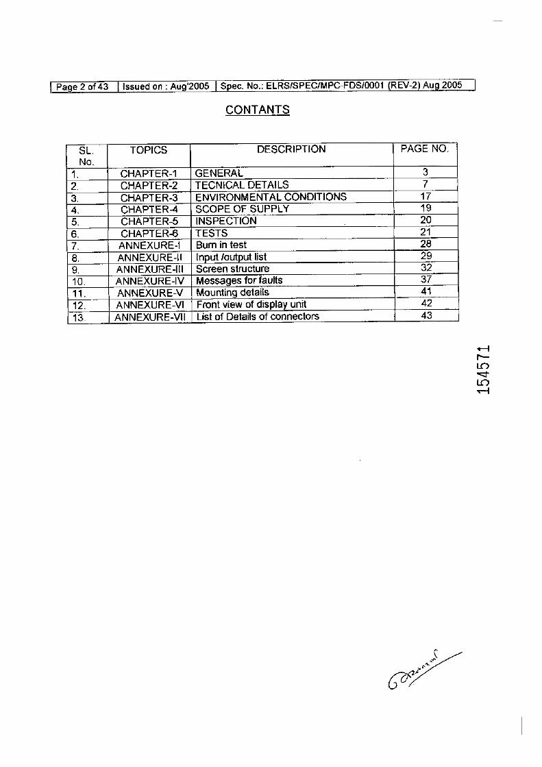
CONTANTS
SL. TOPICS DESCRIPTION PAGE NO.
No.
1. CHAPTER-1 | GENERAL 3
2. CHAPTER-2 | TECNICAL DETAILS 7
3. CHAPTER-3__| ENVIRONMENTAL CONDITIONS 17
4. CHAPTER-4 | SCOPE OF SUPPLY 19
5. CHAPTER-5 | INSPECTION 20
6. CHAPTERS | TESTS 21
7. ANNEXURE-1_ | Burm in test 28
8. ANNEXURE-I_ | Input /output list 29
9. ANNEXURE-II | Screen structure 32
10. ANNEXURE-IV_| Messages for faults 37
11. ANNEXURE-V | Mounting detaiis 41
12. ANNEXURE-VI | Front view of display unit 42
13. ANNEXURE-VII | List of Details of connectors 43
¢
154571
| Page 3 of 43 | Issued on: Aug’2005 | Spec. No.: ELRS/SPEC/MPC-FDS/0001 (REV-2) Aug 2005 |
CHAPTER - |
GENERAL
1.0 INTRODUCTION
1.1 Tap changer electric locomotives working on Indian Railways are provided with control based on electromechanical and Electro pneumatic relays/
contactors. Such controls involve large number of interlocks, contacts, inter connections and cabling, which are not only maintenance intensive but are unreliable too. It is proposed to modify the existing electric locomctives by providing microprocessor-based control. This is intended to primarily replace some of the existing conventional relays, reduce cabling and provide
additional fault diagnostic information with improved overail reliability.
1.2 This specification is for development of "Microprocessor Based Control And Fault Diagnostic System" for tap changer electric locomotives. The primary objectives of this system are
(i) To reduce the number of electromagnetic relays and interlocks by providing software based contro! logic using microprocessor.
(ii) To provide the fault information in text form, status of various interlocks and input commarid switches displayed on the driver's desk in each cab and
{iii) | Traction/braking notch position to display through seven segment indication on the driver's desk in each cab.
(iv) Analog inputs measurement.
1.3 This specification covers the design, development, supply, erection and commissioning of " Microprocessor Based Control and Fault Diagnostic System’ for tap changer electric locomotives which are provided with conventional relay/contactor based control system.
1.4 Contractor's responsibility
The contractor's responsibility will extend to the following:
1.4.1 Supply of detaited instructions for proper installation of the equipment on the
locomotives. For this purpose, the supplier shall depute his engineers/supervisors to CLWiSheds/workshops for installation of the
equipment on locomotive. However cabling to be done by railways.
1.4.2 Commissioning of the equipment in service and depute team of engineers/supervisors for this purpose.
1.4.3 Provide required instrumentation and carry out detailed tests and field trials
jointly with RDSO/CLW.
4 ww a
et
(0%
Page 4 of 43_| Issued on - Aug’2005 | Spec. No.- ELRS/SPEC/MPC-FDS/0001 (REV-2) Aug 2005 |
1.4.4
1.4.5
1.4.6 1.4.7
1.4.8
1.4.9
1.4.10
1.5
4.5.1
Provide special tools and instruments separately which may be required for maintenance.
Recommend list of spares required for satisfactory maintenance and operation of the microprocessor based controi and fault diagnostic Systern for a penod of five years after warranty and quote the prices for them separately.
Quote the cost of repair for cards. Details of inout & output and corresponding locomctive cable numbers wiil be provided by RDSO/CLW and the same should be incorporated in manual supplied by the firm.
Training: The supplier shail Arrange training of indian Railway personnel in maintenance & trouble shooting of the system supplied. Training will be provided in maintenance & trouble shooting aspects and the suppiier will provide detailed technical write-up to all the trainees. The syllabus for training
will have to be approved by the purchaser. The venue of training will be at the place of commissioning the system and at the destination shed.
Supply the user's manuat for maintenance and trouble shooting.
WARRANTY: The supplier will maintain the system under warranty for 24 months after successful installation and field tral and 36 months from the date of supply. He will keep necessary spares at the shed homing these locomotive during the period of warranty. Firm shail arrange rectification / modification / replacement of failed components / part of the equipment free of cost during this period
The contractor shali be responsible for any defect/failure of equipment, provided in the locomotive due to defective design, material or workmanship up to the period of 24 months from the date of successful commissioning. The contractor shall replace all such equipments during the warranty period at his
own cost Further, should any design modification is required to be made in
any part of the equipment, the period of 24 months will commence from the
date when the modified part is commissioned.
The firm should attend ithe lecomotive within the 24 hrs from the time
information is given about the failure of the equipment otherwise warranty
penalty should be 0.2 % of the equipment cost per day subject to maximum
10% of the total cast. ‘
APPROVAL FOR DESIGN
- The design shall be developed based on the requirements given in this spec.
and sound engineering practice. The entire design of the hardware shall be
supplied by the tenderer with required technical data and calculations to
RDSO/CLW for approval before commencing the manufacturing.
( one
154572
[Page 5 of 43 _| Issued on - Aug'2005 | Spec. No.- ELRS/SPEC/MPC-FDS/0001 (REV-2) Aug 2005 -
1.6.2 Approval of design means the approval of general design. features. Notwithstanding the approval, the supplier will be wholly responsible for the performance of the complete system.
1.6 MODIFICATION:
The supplier shall be responsible for carrying out improvements and modifications at his own expense on all the equipments during the period of warranty provided such modifications/mprovements are decided to be necessary for meeting the requirements of reliability, performance and safety etc, jointly between contractor and purchaser.
For the purpose of technical decisions on improvements/modifications etc. on equipment, the final authority from the purchaser's side will be RDSO.
1.7 FIELD TRIALS:
After successful completion of type tests, the equipments shall be subjected to field service trials for a minimum period of six months. The number of trial equipments and venue shall be as agreed between the purchaser and the supplier. The installation and commissioning of the equipments for field trials shall be carried out by the supplier.
1.8 Consumable materials, electrical energy for testing and commissioning of the microprocessor based sysiem will be provided by the purchaser free of cost.
|
1.9 © TRANSFER OF TECHNOLOGY (Special condition):
Tenderer should also quote if stipulated by railways as special condition for transfer of technology for hardware and software i.e. details of design and
manufacturing of system: and sub system, testing and commissioning including training for the same to the railways, so as to enable either in-house production by railways or by authorised vendor of raitways.
1.10 INFRASTRUCTURAL REQUIREMENTS:
The manufacturer should. have following minimum infrastructure for the manufacturing and supply of microprocessor based contro! and fault
diagnostic system.
i) In-house loco simulator far logic testing
ii) Dust free environment:for the assembly of PCBs. iii) Component lead forming machines/fxture. iv) Temperature controlléd wave soldering machine with auto-fluxing and
legs cutting facilities. v) Autamatic/manual (light guided manual placement) component
placement machine for PCBs. vi) SMD component soldering workstation with repair facility.
a
[ Page 6 of43 | issued on - Aug’2005 [ Spec. No.: ELRS/SPEC/MPC-FDS/0001 (REV-2) Aug 2005 __ |
1.91
vii) Temperature controlled Dry heat test chamber. vill) Multi-channel temperature scanner. ix) Functional testing of PCBs preferably with computer. x) Electro static discharge protection in fine with 1S:10087-1981. Work
procedure for following ESD practices needs to be submitted. xi) Testing jigs for checking the correctness of component in PCBs. xii) 4JSO 9001 : 2000 Certification,
However, supplier can avail Facilities from serial No. (ii) to (vi) from sub vender cleared by RDSO. In this regard supplier should submit along with offer the MOU with with sub vendors for undertaking above operation from S. No. (ii) to (vi)
The vendor should have region wise | North, East, West, South and central India (Nagpur)] service centres manned by experienced/ competent staff. to facilitate service support te all the homing sheds for {ecomotives fitted with microprocessor based contro! and fault diagnostic system.
IMPORTANT DOCUMENTS REFERRED IN THIS SPECIFICATION
1. \IEC-60571 Rules for etectronic equipment on rail vehicle 2. ALL CKT. CLW drawings / circuit diagram of tap changer
locos for WAG7, WAM4, WAGS & WAP4. 3, 1EC-61000 Electromagnetic compatibility for industrial process
measurement and coniro! equipment. 4. ELRS/SPEC/S!V Reliability of electronics used in rolling stock
0015 Latest application
OCT ‘2001
154573
‘[Page7-0f 43 [Issued on - Aug’'2005 | Spec, No.. ELRS/SPEC/MPC-FDS/0001 (REV-2) Aug 2005
2.0
2.1
2.1.1.1
2.1.2
CHAPTER Il
TECHNICAL DETAILS
System Requirements
The system shail have testability built in the design to ensure the reliability and safety level required to run the loco with such electronic equipment. Each Unit of the “Microprocessor: Based Control and Fault diagnostic System for
Electric Locomotive" will comprise of the foltowing:-
CPU CARD
There will be two CPU card: ‘each consisting of 16 bit microprocessor or above and necessary. hardware: ‘for operation of the system. 100% redundancy provision to avoid single fault that may lead to vehicle failure.
Both the processor will actively participate at every stage of input processing and output. In case of a fault with in the system it should be detected and necessary safety measure should be taken to avoid any hazardous situation.
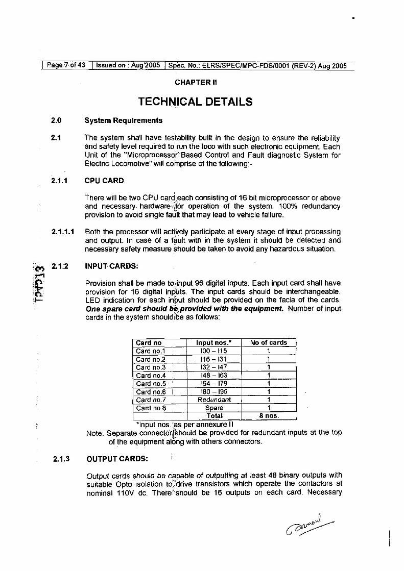
INPUT: CARDS:
Provision shall be made to:input 96 digital mputs. Each input card shall have provision for 16 digital inputs. The input cards should be interchangeable. LED indication for each input should be provided on the facia of the cards. One spare card should be’ provided with the equipment. Number of input cards in the system should! ibe as follows:
Card no Input nos.” No of cards Cardno.1 100-115 1
Card no.2 116 - 134 1
Card no.3 — 132 — 147 1
Cardno4 | 48 - 163 4
Card no5 | 164 - 179 1
Cardno.6 | 180 — 195 1
Card no.7 Redundant 1
Card no.8 Spare 1 Total & nos.
*input nos.“as per annexure II Note: Separate connector{should be provided for redundant inputs at the top
of the equipment along with others connectors.
OUTPUT CARDS:
Output cards should be capable of outputting at least 48 binary outputs with
suitable Opto-isolation to,-drive transistors which operate the contactors at
nominal 110V dc. There’should be 16 outputs on each card. Necessary
a
co
| Page 8 of 43 | Issued on : Aug’2005 | Spec. No.: ELRS/SPEC/MPC-FDS/0001 (REV-2) Aug 2005
2.1.4
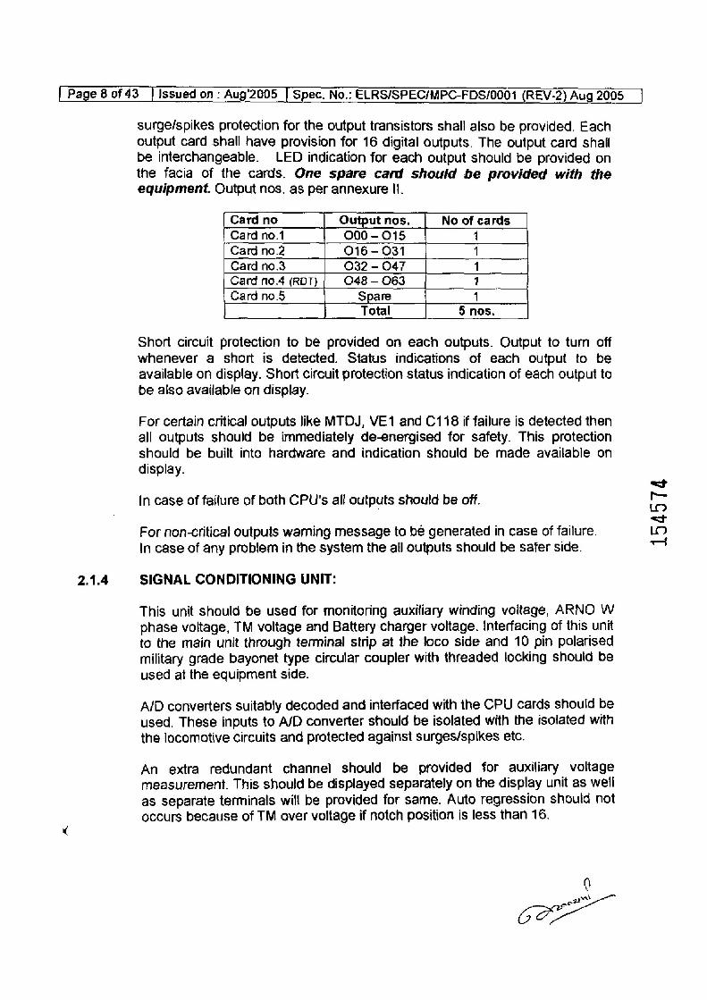
surge/spikes protection for the output transistors shall also be provided. Each output card shall have provision for 16 digital outputs. The output card shall be interchangeable. LED indication for each output should be provided on the facia of the cards. One spare card should be provided with the equipment. Output nos. as per annexure Il.
Card no Output nos. No of cards
Card no.1 000 - 015 1
Card no.2 016 - 031 1
Card no.3 032 — O47 1 Card 10.4 (RDT} 048 — 063 1
Card no.5 Spare 4 Total 5 nos.
Short circuit protection to be provided on each outputs. Output to turn off whenever a short is detected. Status indications of each output to be available on display. Short circuit protection status indication of each output to be also available on display.
For certain critical outputs like MTOJ, VE1 and C118 if failure is detected then all outputs should be immediately de-energised for safety. This protection should be built into hardware and indication should be made available on display.
in case of failure of both CPU's afl outputs should be off.
For non-critical outputs warning message to bé generated in case of failure. In case of any problem in the system the all outputs should be safer side.
SIGNAL CONDITIONING UNIT:
This unit should be used for monitoring auxiliary winding voltage, ARNO W phase voltage, TM voltage and Battery charger voltage. Interfacing of this unit to the main unit through terminal strip at the loco side and 10 pin polarised
military grade bayonet type circular coupler with threaded locking should be
used at the equipment side.
A/D converters suitably decoded and interfaced with the CPU cards should be
used. These inputs to A/D converter should be isolated with the isolated with
the locomative circuits and protected against surges/spikes etc.
An extra redundant channel should be provided for auxiliary voltage
measurement. This should be displayed separately on the display unit as well
as separate terminals will be provided for same. Auto regression should not
occurs because of TM over voltage if notch position is less than 16.
0 a
COE
154574
| Page 9 of 43 [Issued on : Aug’2005 | Spec. No.: ELRS/SPEC/MPC-FDS/0001 (REV-2) Aug 2005 __|
2.1.5 MEMORY :
Sufficient RAM/ROM non-volatile memory shall be provided to meet the system requirement. Adequate memory space shall be left blank for addition of atleast 96 or more digital inputs and 40 events (faults) on priority basis for
future expansion. Error detection mechanism shoud be provided for data base memory. This clause should also complied with clause no. 6.4.2 of specification no. ELRS/SPEC/ $1/0015. :
Memory should have the following categories:-
i) Text memory- Standardised fault text guidelines messages and event recording shall be stored in this part of memory which can be recalled on occurrence of different faults and put on display and also stored in fault memory. This part of memory is permanent.
ii) Fault memory - It shall have a memory capacity to store 100 faults which can be retrieved in sequence on display unit. if faults exceed the memory capacity of 100 faults, initial faults shall be over written and the same Shall be present in status memory, according to ring buffer principle.
iii) Status memory - Whenever a fault occurs, the actual defects shall be displayed on the display unit and also stored in the status memory. The
capacity of this memory is at least 512 faufis with background data as per annexure-lil A for 5 sec before and 3 sec after the incident with the 1 sec interval. :
This should be done as per first in first out basis.
2.1.6 Transducers and Interface cards All transducers and interlace cards required for satisfactory working of the system shall be provided by the supplier.
it is also proposed to measure analog signals corresponding to transformer oil temperature, traction motor temperature, currents and BP pressure etc. using Suitable transducers in future.
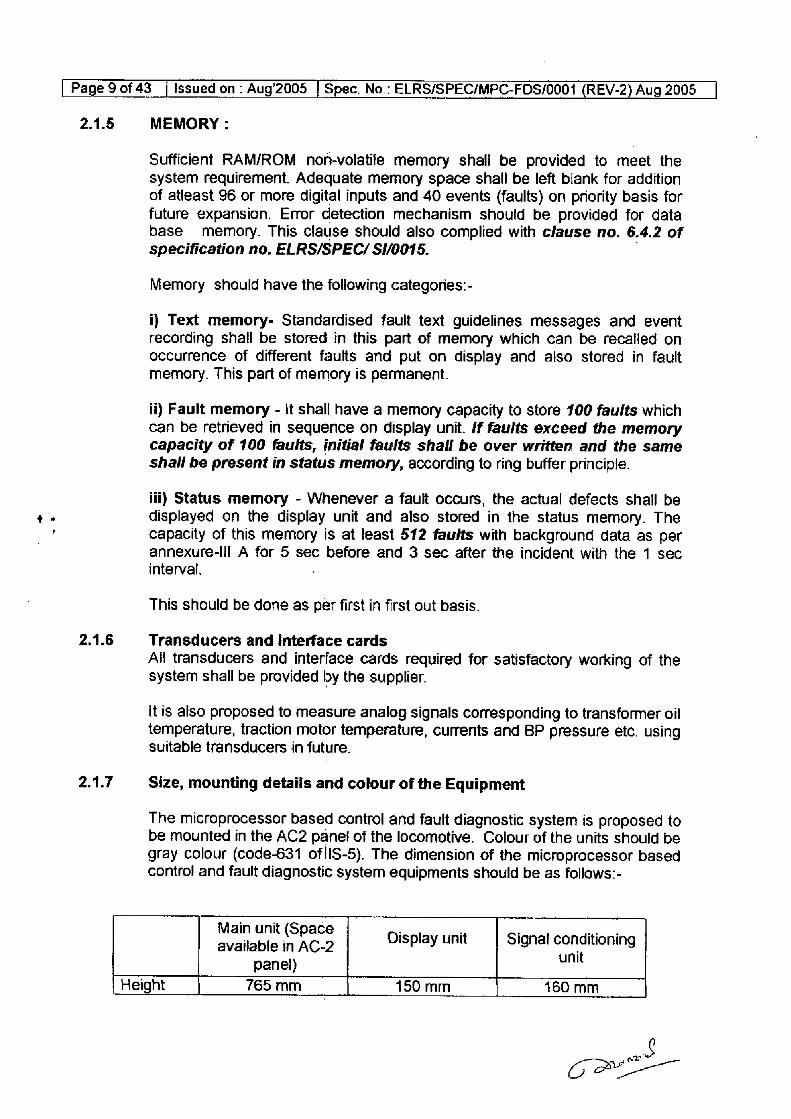
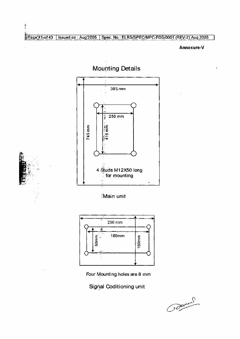
2.1.7 Size, mounting details and colour of the Equipment
The microprocessor based control and fault diagnostic system is proposed to be mounted in the AC2 panel of the locomotive. Colour of the units should be gray colour (code-631 oflIS-5). The dimension of the microprocessor based contro! and fault diagnostic system equipments should be as follows:-
Main unit (Space . . : sen at available in AC-2 Display unit Signal conationing
panel) unl
Height 765mm 150 mm 460 mm
a OO
[Page 10 of 43 | Issued on : Aug’2005 | Spec. No.: ELRS/SPEC/MPC-FDS/0001 (REV-2) Aug 2005
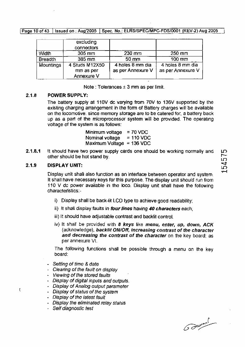
excluding
connectors Width 305 mm 230 mm 250 mm
Breadth 385 mm 50 mm 100 mm Mountings | 4 Studs M12X50 4holes 8 mm dia 4 holes 8 mm dia
mm as per as per Annexure V | as per Annexure V
Annexure V
Note : Tolerances + 3 mm as per limit.
2.1.8 POWER SUPPLY:
2.1.8.1
2.1.9
The battery supply at 110V dc varying from 70V to 136V supported by the existing charging arrangement in the form of Battery charges will be available on the locomotive. since memory storage are to be catered for, a battery back Up as a part of the microprocessor system will be provided. The operating voltage of the system is as follows:
Minimum voltage = 70 VDC Nominal voltage = 110 VDC Maximum Voltage = 136 VDC
It should have two power supply cards one should be working normally and other should be hot stand by.
DISPLAY UNIT:
Display unit shali aiso function as an interface between operator and system. It shall have necessary keys for this purpose. The display unit should run from 110 V de power available in the loco. Display unit shall have the following characteristics:-
i) Display shall be back4it LCD type to achieve good readability;
ii) It shall display faults in four fines having 40 characters each;
iii) It should have adjustable contrast and backlit control.
iv) It shall be provided with & keys like menu, enter, up, down, ACK
{acknowledge), backlit ON/Off, increasing contrast of the character and decreasing the contrast of the character on the key board: as per annexure VI.
The following functions shali be possible through a menu on the key board:
- Setting of time & date - Clearing of the fault on display - Viewing of the sfored faults - Display of digital inputs and outputs. - Display of Analog output parameter - Display of status of the system - Display of the latest fault - Display the eliminated relay status - Self diagnostic test
wt CPE
154575
[Page 11 of 43 | Issued on : Aug’2005 | Spec. No.: ELRS/SPEC/MPC-FDS/0001 (REV-2) Aug 2005
2.1.9.1
2.1.40
2.1.10.1
2.1.11
2.1.12
Each display unit should have 10 pin polarised military grade bayonet type circular coupler for communicate to CPU from both the cabs. And 3 pin same type of coupler used for power supply.
The display unit should act as a dumb tenninal simply to receive and display text strings from main unit and to send key press information to main unit.
Each key should be provided with tactile as well as audible feedback. The data on display should be updated once every 100 msec.
Screen structure: The screen structure of the display unit is give in the Annexure —Ill.
Interface:
Elastomeric cables of 750V grade having an overall diameter of 3 mm are used in the locomotive contro! circuit. Some of these cables will terminate within the main control panel. These cables will be terminated using socket crimped at each end.
For communication between the display units and the microprocessor multi core screened cable will be supplied by supplier with circular military grade 3 pin and 10 pin bayonet type couplers at both ends. However, layout is to be done by CLW/Railways.
Coupler: 17pin & 19 pin polarised military grade bayonet type circular coupler should be used on the cabinet of the equipment. The coupler shall be provided at the fop of the cabinet of the equipment.
Algorithm: Input & output relationship to be deduced as per the following
type AC tap-changer electric locomotive circuits diagram issued by the CLW.
a) WAG-7 b) WAP-4 c) WAG-5 d) WAM-~4
The supplier may depute their system analyst at RDSO/CLW for preparation of input / output relationship of locomotive togics.
Communication with other microprocessor based system.
For communication with other microprocessor systems the system should have provision to implement a CAN BUS 2.0 B bus by adding a suitable add on card. The software drivers for this will also be provided along with this card once RDSO stadardises the protocol.
Signal Conditioners: Monitoring of TM currents and elimination of QDs and QFs:
oe
CL
[Page 12 of 43 | Issued on : Aug’2005 | Spec. No.: ELRS/SPEC/MPC-FDS/0001 (REV-2) Aug 2005 __|
Two signal conditioners will be provided in BA-1 and BA-2 panels. These will interface with main unit on serial link and sense TM currents through shunts provided in series with each TM. These shunts will be similar to the ones provided in the traction ammeter circuits and will be used in place of QD coils. Response time should be better than 100 msec with 1% accuracy.
2.1.13 Provision for future expansion:-
It is proposed to bring other DU type of relays QOP1, QOP2, QOA, QRSI1, QRSI2, QPH, and air flow refays QVRH QVMT1, QVMT2, OVSI1, QVSI2, QVSL1, QVSL2, QPDJ under the ambit of diagnostic system in future. Provision should exist to design such add-on protection system in future.
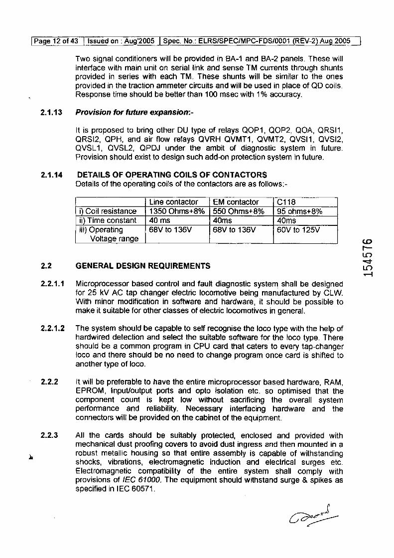
2.1.14 DETAILS OF OPERATING COILS OF CONTACTORS Details of the operating coils of the contactors are as follows:-
2.2
2.2.1.1
2.2.1.2
2.2.2
2.2.3
Line contactor £M contactor C118
i) Coil resistance 1350 Ohms+8% 550 Ohms+8% 95 ohms+8%
ii) Time constant 40 ms 40ms 40ms
68V to 136V 68V to 136V iit} Operating GOV to 125V Voltage range
GENERAL DESIGN REQUIREMENTS
Microprocessor based control and fault diagnostic system shall be designed for 25 kV AC tap changer efectric locomotive being manufactured by CLW. With minor modification in software and hardware, it should be possible to make it suitable for other classes of electric locomotives in general.
The system should be capable to self recognise the loco type with the help of hardwired detection and select the suitable software for the loco type. There
should be a common program in CPU card that caters to every tap-changer ioco and there should be no need to change program once card is shifted to another type of loco.
it will be preferable to have the entire microprocessor based hardware, RAM, EPROM, input/output ports and opto isolation etc. so optimised that the component count is kept low without sacrificing the overall system performance and reliability. Necessary interfacing hardware and the connectors will be provided on the cabinet of the equipment.
All the cards should be suitably protected, enclosed and provided with mechanical dust proofing covers to avoid dust ingress and then mounted in a robust metallic housing so that entire assembly is capable of withstanding shocks, vibrations, electromagnetic induction and electrical surges etc. Electromagnetic compatibility of the entire system shali comply with provisions of JEC 61000. The equipment should withstand surge & spikes as specified in IEC 60571.
154576
[Page 13 of 43 | Issued on . Aug'2005_| Spec. No.. ELRS/SPEC/MPC-FDS/0001 (REV-2) Aug 2005
2.2.4
2.2.5
2.2.6
2.2.7
2.2.8
2.2.10
2.2.41
2.2.12
2.2.13
Adequate provisions should be made in the design for suppression of internal transients, spikes and to withstand extemal transients, spikes and surges as per limits laid down in IEC-60571.
In the electronic equipments to be supplied to this specification, the suppliers shall use components and systems of high reliability, suitable in every way for the application on rolling stock. In this connection, supplier is well advised to refer to "Rules for Electronic Equipments used on Rail Vehicles IEC Publication 60571"
Minor deviations from the specification if any, can be mutually sorted out with RDSO during development stage if supported by justification on ground of cost and/or technical superiority.
|
All the components on PCBs should be wave soldered / surface mounted
devices should be mounted using SMT workstation and complied with clause no. 7 of specification no. ELRS/SPEC/ S1/0015.
All ICs i mounted on the bases should be mounted on heavy duty sockets and provision should be ‘made for tightening of the ICs on the base also complied with clause no. 6.1.3 of specification no. ELRS/SPEC/ SI/0015.
All electronic components and !Cs used shall be selected after proper bum in and screening tests and shall be adequately rated to withstand the service requirements. A quality assurance scheme should be submitted by the supplier for approval of RDSO. It should be provided as per specification no. ELRS/SPEC/ Si/0015.
Polarised Bayonet type Circular connector will be used for all external
connections. These should confirm to JSS no. 50815 design to meet the specification or equivalent.
System shail have real time clock for recording date & time.
System should have dust proof covers which are operated locked with loco BL keys / suitable common keys.
The provision should exist for printing data stored or down loading it using fault data extraction unit (Laptop) or personal computer with Microsoft windows 2000 operating system. The system should be compatible with future upgraded operating system. A USB 2.0 compatible port will be provided with USB connector on the system for data extraction. The system should accept pen drives memory sticks. Upon inserting this into the USB connector provided on the system automatic data downloading should begin. Data retrieved by a Windows based program to be provided by the supplier and stored ina Excel file. |
\
CME
[Page 14 of 43 | Issued on: Aug’2005 | Spec. No.: ELRS/SPEC/MPC-FDS/0001 (REV-2) Aug 2005 _|
2.2.14 There should be an indication in the display unit and fault logging in case of any cards fails. Spare card on each for input and output shall be provided.
2.2.15 The equipment should function satisfactorily under 25 kV ac electric traction. It should not be susceptible to malfunction due to interference from overhead traction power supply lines cr under abnormal conditions such as overloads and faults in the electrical traction circuits of the iocomotives.
2.2.16 Signals generated by the microprocessor based control and fault diagnostic system of the locomotive shall not cause interference to the Raiways Signal & Telecommunication equipment.
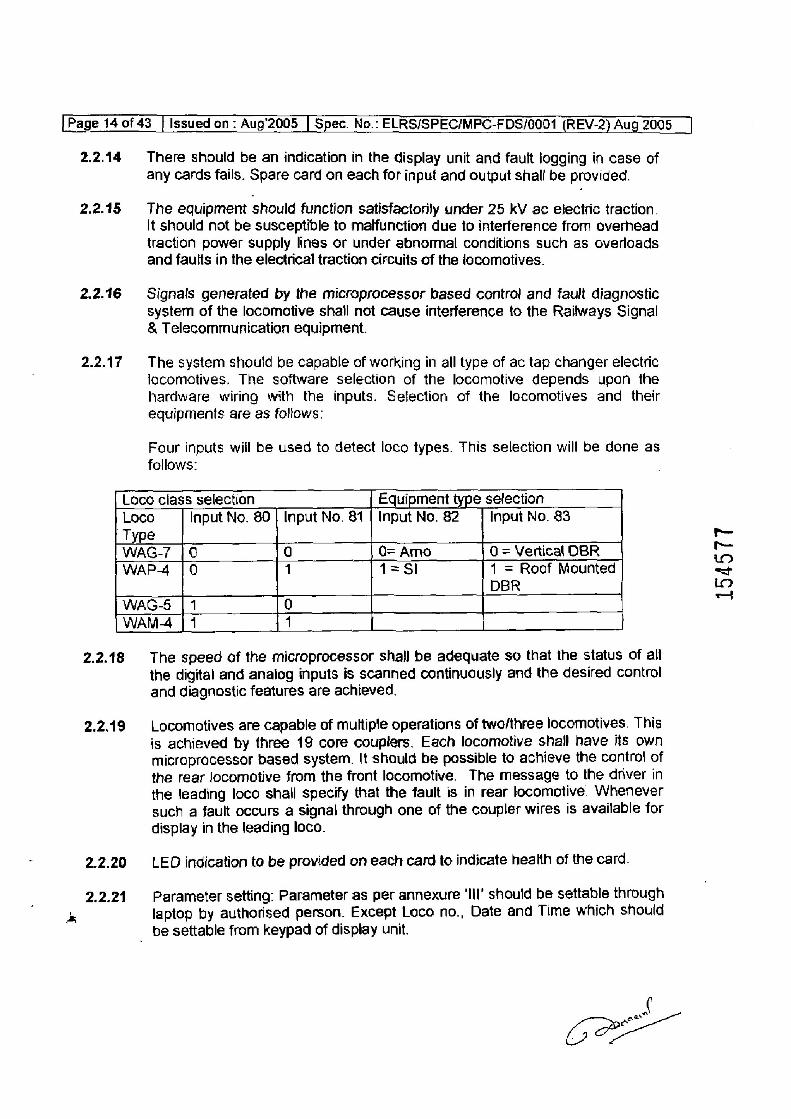
2.2.17 The system should be capable of working in all type of ac tap changer electric locomotives. The software selection of the locomotive depends upon the hardware wiring with the inputs. Selection cf the lacomotives and their equipments are as follows:
Four inputs will be used to detect loco types. This selection will be done as
follows:
Loco class selection Equipment type selection Loco Input No. 80 | Input No. 81 | Input No. 82 Input No. 83
| Type WAG-7 | 0 0 O= Amo 0 = Vertical OBR WAP-4 | 0 1 1=Sl 1 = Roof Mounted
DBR
WAG-5 | 1 0 WAM | 1 11 |
2.2.18 The speed of the microprocessor shalj be adequate so that the status of all
the digital and anaiog inputs is scanned continuously and the desired control
and diagnostic features are achieved.
2.2.19 Locomotives are capable of multiple operations of two/three locomotives. This
is achieved by three 19 core couplers. Each locomotive shall have its own
microprocessor based system. It should be possible to achieve the contro! of
the rear locomotive from the front locomotive. The message to the driver in
the leading loco shall specify that the fault is in rear locomotive. Whenever
such a fault occurs a signal through one of the coupler wires is available for
display in the leading loco.
2.2.20 LED indication to be provided on each card to indicate health of the card.
2.2.21 Parameter setting: Parameter as per annexure ‘Ill’ should be settable through
laptop by authorised person. Except Loco no., Date and Time which should
_ be settable from keypad of display unit.
awd
OPE
1545
77
. |Page 15 of 43 | Issued on : Aug’2005 | Spec. No.: ELRS/SPEC/MPC-FDS/0001 (REV-2} Aug 2005
2.3 PERFORMANCE REQUIREMENTS
2.3.1 The microprocessor based system will take the binary inputs from the
command switches on the drivers desk, air flow relays, contacts and other interlocks of the control/protection relays and analog signals from Traction
Motor, Aux. Transformer. Amo/ S| unit, pressure reservoir and Dynamic Braking circuit. etc. It will perform through software and hardware of microprocessor. The functions of QF1,QF2,0D1,QD2, Q20, Q30, QCVAR, QE, QV61, Q118, Q44, Q45, Q100, QTD105, QTD106, Q51, Q52, QV6N, QV62, QV63, OV64, O46, Q48, O49, O50, Q120, QVLSOL, QRS, QWC relays of traction as well as dynamic braking circuit and at the same time
minimise the requirement of total no. of N/O and N/C interlocks. The outputs for EFDJ, MTDJ, C118, VE1, VE2, C105, C106, C107, C101, C102, C103, JIFOR, JIREV, J2FOR, J2REV,CTFi RUN, CTF2RUN. CTF3RUN, CTFIBRK, CTF2BRK, CTF3BRK, C145, EVPHGR, $11, $12, S13, IP, VESA1, VESA2, L1, L2, L3, L4, L5, L6, LSDJ, LSCHBA, LSGR, LSB, LSP AND LSRSI will be controlled through the microprocessor. The notch display,
which is presently through’ Selsyn notch indicator will be performed through
two seven segment display of 1 inch size. Details of the circuits will be
finalised at the detail design stage.
2.3.2 The system should be capable of carrying out self diagnostics.
2:3.2.1 't should ensure that all functional units are working and all back up data are still valid ie, no important* data has been.corrupted during the period that power had been turned off: In case a critical failure is detected, alarm shall be generated and system should shut itself off. In case of a non critical failure, the system shall continue to operate after generating appropriate alarm.
2.3.2.2 — It should ensure the validity of the functioning of the system including failure detection of peripheral units by the main processing unit and failure of any
card in the main processing unit by another card in the same unit. It shall also ensure that system does ‘not malfunction due to the software crashing. It should be provided as |per clause no. 8.0 of latest specification no. ELRS/SPEC/ S1/0015.
2.3.3 The system shall be capable of working with both static converter and ARNO converter.
2.3.4 FAULTS
2.3.4.1. On occurrence of an event (fault), depending upon the type of fault, a
standard fault message and corrective action required to be cisplayed. The
fault thus displayed should remain on the screen until acknowledged by the driver. Fresh faults occurring during the period shall be lined up in memory to
be displayed one after the other. Occurrence of a fresh fault is to be declared
by a characteristic audio beep signal.
a (oes
[Page 16 of 43 [Issued on: Aug'2005 | Spec. No.. ELRS/SPEC/MPC-FDS/0001 (REV-2) Aug 2005 _ |
2.3.4.2
2.3.4.3
2.4
2.4.1
2.4.2
2.4.3
2.4.4
When more than one fault is occurring simultaneously or in quick succession, they should be stored in the order of occurrence. More serious faults is to be displayed first with an indication that there are more faults which can then be seen by giving appropriate command from key board. Priority of faults for indication in the display unit shall be as under
&) Protection relays
b) Reverser and CTF’s c) Master controller and GR d) All others
Faults should be grouped in two groups based on their severity level in
i) Priority 1 (OJ should trip or foco should be dead) ii) Priority 2 (Only indication & storage should be done)
SAFETY FEATURE:
In case of matfunction of any one of the processors or its associated hardware, it should be detected and isalated from its operation. The toco should continue its operation with the other processor and jts associated hardware and an alarm should be raised to notify the fault. Even under such condition the system must ensure a certain degree of safety through its own reliability and testability.
The supplier snould make an arrangement for protection of the equipment from fire.
A hardwired emergency switch will be provided with the MTDJ output (0-7 & O-4) in the locomotive for tipping of DJ when system fails and also lower the pantographs. This should be monitored and stored.
Bypass arrangement for Q51 relay shall be provided. This should be possibie by putting HQ51 (at input I-70) in position ‘0’ and this should be recorded in
the memory along with date & time.
Coe
154578
; [Pagelt7°0f 43 | Issued on: Aug’2005 | Spec. No.. ELRS/SPEC/MPC-FDS/0001 (REV-2) Aug 2005
3.1
3.1.1
3.2
3.3
3.4
3.6.
3.7
CHAPTER Ill
ENVIRONMENTAL CONDITIONS
The equipment should function satisfactorily under the foilowing environmental conditions... Which are encountered where equipment will be expected to work.
a) Maximum temperature } Stabled Locomotive under sun : 70 deg. C } On'board Workirig loco under sun. : 56 deg. C
b) Minimum temperature : Odeg.C c) Average temperature > 47 deg. C
Humidity: Up to 100% during rainy season.
Altitude: Up to 1200 m above mean sea level.
Rainfall: Very heavy in certain areas. The loco equipment shail be designed
suitably.
Environment: Extremelyidusty and desert terrain in certain areas. The dust concentration in air may. reach a high value of 1.6 mg/cm®. In many iron ore and coalmine areas, the dust concentration is very high affecting the filter and air ventilation system.
Coastal area: The equipment shall be designed to work in coastal area in humidity and salt laden‘and corrosive atmosphere. The maximum values of the condition will be as follows:
a) Maximum pH value : 8.5.
b) Sulphate : 7 mg per litre. c) Max. concentration
of chlorine : 6 mg per litre. d) Maximum conductivity :130 micro siemens /cm
Vibration and shocks: The equipment shall be designed to withstand
without damage, vibration and shock as generally encountered in the locomotives and shall confirm to the standards as_ per tests specified in JEC-60571 and are as under.-
{i} Max. vertical acceleration: ~ 1.0g. (ii) Max. longitudinal acceleration: -3.0g. (iii) Max. transverse acceleration: - 2.0g.
The vibrations are of the sine wave and the frequency of the vibration is between 1Hz and 5OHz. The amplitude ‘a’ expressed in mm is given as a function of 'f by the equation.
Boeck
6
[Page 18 of 43 | Issued on - Aug’2005 | Spec. No.: ELRS/SPEC/MPC-FDS/0001 (REV-2) Aug 2005 _|
a= 25ff for values of 'f from 1 Hz to 10 Hz.
a= 2504 square, for values of ‘f exceeding 10 Hz and up to 50 Hz.
43.7.1 In the diféction comesponding to longitudinal movement of the vehicle, the
equipment is subjected for two minutes to 50Hz vibrations of such a value that the maximum acceleration is equal to 3g (amplitude a= 0.3mm)
3.8 Electromagnetic and Radio Frequency Interference Pollution — High degree of electromagnetic pollution is anticipated in Jocomotive through high voltage contactor operation and RFI produced through walkee talkee hand set of the driver's, where the equipment will be mounted. Necessary precaution should be taken in this regard.
154579
[Page 19 of 43 | Issued on . Aug 2005 | Spec, No.. ELRS/SPEC/MPC-FDS/0001 (REV-2) Aug 2005 |
CHAPTER iV
SCOPE OF SUPPLY 4.1 Scope of work
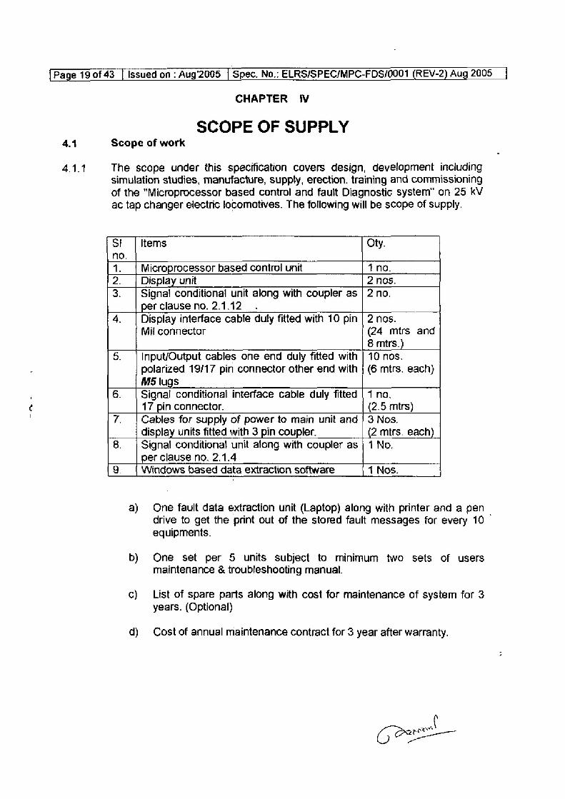
4.1.1 The scope under this specification covers design, development including simulation studies, manufacture, supply, erection. training and commissioning of the “Microprocessor based control and fault Diagnostic system" on 25 kV ac tap changer electric locomotives. The following will be scope of supply.
SI | Items Oty. no. 1. Microprocessor based control unit 4 no.
2. Display unit 2 nos. 3. Signal conditional unit along with coupler as | 2 no.
per clause no. 2.1.12 4. Display interface cable duly fitted with 10 pin | 2 nos.
Mil connector (24 mtrs and 8 mtrs.)
5. | Input/Output cables one end duly fitted with | 10 nos. polarized 19/17 pin connector other end with | (6 mtrs. each} M5 lugs
6. | Signal conditional interface cable duly fitted | 1 no. 17 pin connector. (2.5 mtrs}
7. Cables for supply of power to main unit and | 3 Nos. display units fitted with 3 pin coupler. (2 mirs. each)
8. | Signal conditional unit along with coupler as | 1 No. per clause no. 2.1.4
9, Windows based data extraction software 1 Nos.
a) One fault data extraction unit (Laptop) along with printer and a pen — drive to get the print out of the stored fault messages for every 10 equipments.
b) One set per 5 units subject to minimum two sets of users maintenance & troubleshooting manual.
c) List of spare parts along with cost for maintenance of system for 3 years. (Optional)
d) Cost of annual maintenance contract for 3 year after warranty.
wf
[Page 20 of 43 [Issued on : Aug’2005 | Spec. No.: ELRS/SPEC/MPC-FDS/0001 (REV-2) Aug 2005 |
dey
5.2
§.2.1
§.2.2
) 5.2.3
5.3
6.4
5.5
5.6
5.7
CHAPTER V
INSPECTION
The whole of the material or fittings used in the construction of the equipment shail be subjected to inspection by the Inspecting authority and shall be to his entire satisfaction.
The inspecting authority shail have the power to --
Adopt any means he may consider necessary to satisfy himself that all the materiais or fittings specified are actually used throughout the construction.
Visit at any reasonable time and without previous notice, either contractors works or his sub-contractors works to inspect the manufacturers and the quality of the work at any stage.
To reject any materials or fittings that do not conform ta the relevant standard specifications or have not been manufactured in accordance with the approved practices. The rejected materials or fittings shall be marked in a
distinguishable manner and shall be disposed on in such manner as the inspecting officer may direct to avoid its inadvertent use in the product order as per this specification.
The manufacturer shail offer all the testing facilities free of charge to inspecting authority. Testing of equipment and fittings shall, as far as possible be carried out at the works of the manufacturers. Testing of bought out components may also be carried out at sub-contractors premises, if so required. The contractor shall provide free of charge, such matenials or fittings
as may be required for testing whether at his own cr his subcontractor’s premises. The test for which facilities are not available may be carried out at RDSO or any other approved laboratory for which the testing charges shall be payable by the supplier.
All the equipments and the fittings required for test shail ba selected by the
inspecting officer and the tests shall be carried out in his presence.
No material shal! be packed or despatched until it has been passed by the inspecting officer but the contractors responsibility for its efficiency in every way, shall remain the same as if the work had been manufactured and tested by himself.
Should any part required alteration or any defect appear during the test or trial the contractor shall without any extra charges make such alteration or rectify the defects to the satisfaction of the inspecting authority.
Copies of Maker's test certificate, guarantee the performance of the equipment shall be supplied in duplicated along with the delivery of each unit.
awl GO
154580
[Page 21 of 43 | Issued on - Aug'2005 | Spec. No.. ELRS/SPEC/MPC-FDS/0001 (REV-2) Aug 2005 |
CHAPTER VI
TESTS
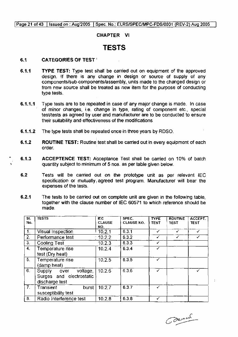
6.1 CATEGORIES OF TEST '
6.1.1 TYPE TEST: Type test shall be carried cut on equipment of the approved
design. if there is any change in design or source of supply of any components/sub-components/assembly, units made to the changed design or
from new source shail be treated as new item for the purpose of conducting type tests.
6.1.1.1. Type tests are to be repeated in case of any major change is made. In case ’ of minor changes, ie. change in type, rating of component etc., special
testtests as agreed by user and manufacturer are to be conducted to ensure
their suitability and effectiveness of the modifications
6.1.1.2 The type tests shall be repeated once in three years by RDSO.
6.1.2 ROUTINE TEST: Routine test shall be carried out in every equipment of each order.
6.1.3 ACCEPTENCE TEST: Acceptance Test shall be carried on 10% of batch quantity subject to minimum of 5 nos. as per table given below.
6.2 Tests will be caried out on the prototype unit as per relevant IEC
specification or mutually, agreed test program. Manufacturer will bear the expenses of the tests.
6.2.1 The tests to be carried out on complete unit are given in the following table, together with the clause number of IEC 60571 to which reference should be
made.
Si. | TESTS IEC SPEC, TYPE | ROUTINE | ACCEPT. No. CLAUSE CLAUSE NO, | TEST | TEST TEST
NO. 1. | Visual Inspection 10.2.4 6.3.1 v vo v 2. | Performance test - 10.2.2 6.3.2 v ¥ v 3. | Cooling Test 10.2.3 6.3.3 v 4. | Temperature rise 10.2.4 6.3.4 ¥
test (Dry heat) 5. | Temperature rise 10.2.5 6.3.5 ¥
(damp heat) 6. | Supply over voltage, | 10.2.6 6.3.6 ¥ v
Surges and electrostatic discharge test
7. | Transient burst | 10.2.7 6.3.7 ¥
susceptibility test 8. | Radio Interference test 10.2.8 6.3.8 ¥
C
{Page 22 of 43 [issued on: Aug2005 | Spec. No.. ELRS/SPEC/MPC-FDS/0001 (REV-2) Aug 2005 |
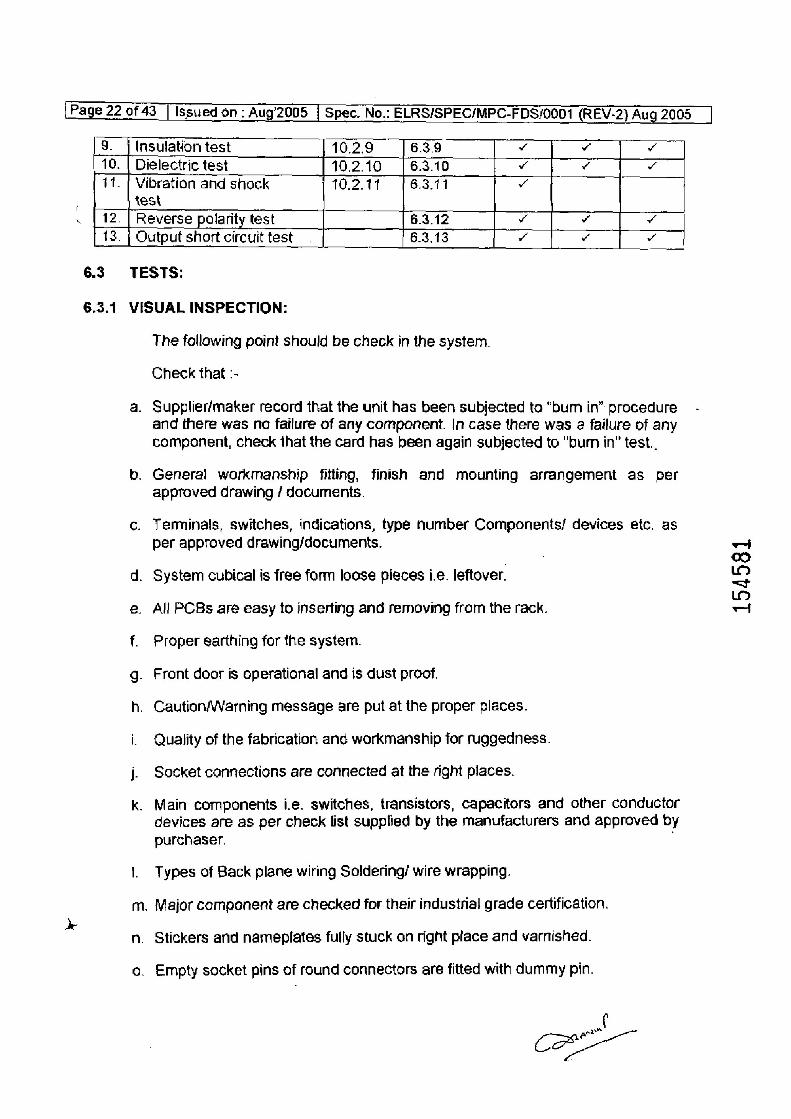
9. | Insulation test 10.2.9 6.3.9 v ¥ v 10. | Dielectric test 102.10 6.3.10 v ¥ v 11. | Vibration and shock 10.2.114 6.3.11 v
: test
. [ 12. | Reverse polarity test 6.3.12 w v v
13. | Output short circuit test. 6.3.13 v o v
6.3 TESTS:
6.3.1 VISUAL INSPECTION:
The following point should be check in the system.
Check that :-
a. Supplier/maker record that the unit has been subjected to “bum in” procedure and there was no failure of any component. |n case there was a failure of any component, check that the card has been again subjected to "bum in" test..
b. General workmanship fitting, finish and mounting arrangement as per approved drawing / documents.
c. Terminals, switches, indications, type number Components/ devices etc. as per approved drawing/documents.
d. System cubical is free form loose pieces i.e. leftover.
e. All PCBs are easy to inserting and removing from the rack.
f. Proper earthing for the system.
g. Front door is operational and is dust proof.
h. CautionWVarning message are put at the proper places.
i. Quality of the fabrication and workmanship for ruggedness.
j. Socket connections are connected at the right places.
k. Main components i.e. switches, transistors, capacitors and other conductor
devices are as per check list supplied by the manufacturers and approved by
purchaser.
1. Types of Back plane wiring Soldering/ wire wrapping.
m. Major component are checked for their industrial grade certification.
n. Stickers and nameplates fully stuck on right place and varnished.
6. Empty socket pins of round connectors are fitted with dummy pin.
J
154581
[Page 23 of 43 | Issued on . Aug’2005 | Spec. No.- ELRS/SPEC/MPC-FDS/0001 (KrV-2) Auy evs
6.3.2
6.3.2.1
6.3.2.2
6.3.2.3
6.3.3
Use of proper solder and flux grade on soldering of rub
Electronic cards are coated with CRC spray with suitable adhesive coating (CRC Spray) and it is in dry condition.
The sharp comers and hardware do not damage Cables.
Proper air gaps between live parts and metallic surface.
Proper shielding between signal Cables and power cables.
All bolts, Screws and connectors are marked with red permanent marker.
All covers and doors are proper fitted.
Dimensions as per clause no.2.1.7
Calour of the equipment as per clause no.2.1.7
PERFORMANCE TEST:
These tests are carried out to check and ensure that the performance of the equipment is in order and meets the specification requirements. These tests shall be carried out at the room temperature and magnetic field not significantly different from that of earth. The operating voltage should be as per clause no. 2.1.8
VOLTAGE VARIATION TEST:
This test should carried! out as per 10.2.2 (a) IEC 60571. During the test system voltage shail be as per clause no. 2.1.8
A test shall be done to verify that when the display unit has a clear audio indication at the time of fault occur and keys operating condition in the working cab to attract the attention of the driver.
Control circuit logic should be tested for all type of loco with different equipment modes.
COOLING TEST:
Bring down the temperature of the equipment to 0° + 2 and keep it at the temperature for 2 hours and the carried out insulation test, Dielectric test at 85% voltage of the previous test and performance test after the recovery period of 3 hrs.
Page 24 of 43 | Issuedon : Aug’2005 | Spec. No.: ELRSISPEC/NPC-FDS/0001 (REV-2) aug 2005 |
6.3.4
6.3.5
6.3.6
6.3.6.1
6.5.6.2
6.3.7
TEMPERATURE RISE TEST (DRY HEAT):
The temperature of the equipment is to be raised to 75°C al the rate of 1°c at 1.5 minute and to be kept at that temperature for 6 hours. In this fest equipment should be in energised condition and check the working of the system. Coal it to the room temperature (recovery period 3 Ars) and carried out insulation test, Dielectric test at 85% voltage of the previous test and pecfonmance test.
TEMPERATURE RISE (DAMP HEAT):
Damp heat test shall be done keeping the equipment in deenergised condition. It is to be ansured that the RH of the oven should be between 40 to 100% during the above test. The temperature of the equipment js to bs raised from ambient to 55°C in 2 hours and kept at that temperature for 6 hours. The temperature of the equipment 55°C should be brought down ta ambient {recovery period} in 3 hours. The cycle is to be repeated at least two times and carried out insutation test, Dielectric test at 85% voltage of the previous test and performance test.
SUPPLY OVER VOLTAGE, SURGES AND ELECTROSTATIC DISCHARGE TEST:
OVER VOLTAGE TEST:
The tast shall be conducted as per [EC-60571, clause 10.2.6.1.
1.8 times of the nominal system voltage (clause 2.1.8) shall be passed for two minute and the unit shall work satisfactory after the test.
SURGE TEST:
The test shall be conducted as per IEC-60571, clause 10.2.6.2. The surge pulse shall be 1.8 kV, 1.2750 micro Sec
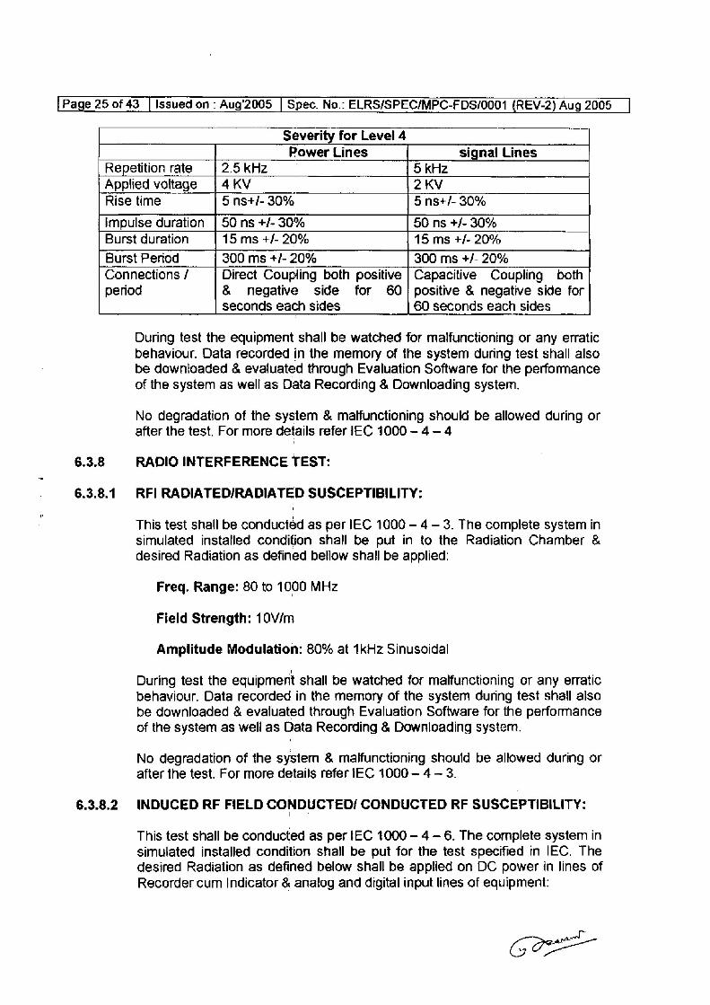
TRANSIENT BURST SUSCEPTIBILITY TEST:
This test shall be conducted as per [EC 1000 ~ 4 ~ 4.The complete sysiem in simulated installed condition shall be put for the test as specified in IEC. The recommended test severity level is level 4 with Direct Coupling for Power Lines & with Capacitive Coupling for Communication & Signai Lines. The EFT of defined severity shall be applied on Communication fine, Analog and digital
input lines as follows:
Coe
154582
{Page 25 of 43 | Issued on -
Severity for Level 4 Power Lines signal Lines
Repetition rate 2.5 kHz 5 kHz Applied voltage | 4KV 2 KV
Rise time 5 nst+/- 30% 5 nst/- 30%
impulse duration | 50 ns +/- 30% 50 ns +/- 30% Burst duration 15 ms +/- 20% 15 ms +/- 20%
Burst Period 300 ms +/- 20% 300 ms +/- 20%
Connections / Direct Coupling both positive | Capacitive Coupling both period & negative side for 60; positive & negative side for
seconds each sides 60 seconds each sides
6.3.8
6.3.8.1
6.3.8.2
During test the equipment shall be watched for malfunctioning or any erratic behaviour. Data recorded in the memory of the system during test shall also
be downloaded & evaluated through Evaluation Software for the performance of the system as well as Data Recording & Downloading system.
No degradation of the system & malfunctioning should be allowed during or after the test. For more details refer IEC 1000-4 -4
RADIO INTERFERENCE TEST:
RFI RADIATED/RADIATED SUSCEPTIBILITY:
This test shall be conducted as per IEC 1000 — 4 — 3. The complete system in simulated instalied condition shall be put in to the Radiation Chamber & desired Radiation as defined bellow shall be applied:
Freq. Range: 80 to 1000 MHz
Field Strength: 10V/m
Amplitude Modulation: 80% at 1kHz Sinusoidal
During test the equipment shall be watched for malfunctioning or any erratic behaviour. Data recorded in the memory of the system during test shall also be downloaded & evaluated through Evaluation Software for the performance of the system as well as Data Recording & Downloading system.
No degradation of the system & malfunctioning should be allowed during or after the test. For more details refer IEC 1006 - 4 — 3.
INDUCED RF FIELD CONDUCTED/ CONDUCTED RF SUSCEPTIBILITY:
This test shall be conducted as per EC 1000 — 4 — 6. The complete system in simulated installed condition shall be put for the test specified in IEC. The desired Radiation as defined below shall be applied on DC power in lines of Recorder cum Indicator & analog and digital input lines of equipment:
St
as
Aug’2005 | Spec. No.: ELRS/SPEC/MPC-FDS/0001 {REV-2) Aug 2005
{Page 26 of 43 | Issued on: Aug'2005 | Spec. No.: ELRS/SPEC/MPC-FDS/0001 (REV-2) Aug 2005 |
6.3.9
6.3.10
6.3.11
6.3.14.1
Freq. Range: 0.15 to 80 MHz
Amplitude: 10V/m
Modulation: 80% Amplitude Modulation
During test the equipment shall be watched for malfunctioning or any erratic behaviour. Data recorded in the memory of the system during test shall also be downloaded & evaluated through Evaluation Software for the performance of the system as well as Data Recording & Downloading system.
No degradation of the system & malfunctioning should be allowed during or after the test. For more details refer 1EC 1000 - 4-6.
INSULATION TEST:
Megger the electronics and control circuit, lamp unit with respect to earth and check the insulation level with 500V megger range and ensure that the insulation resistances are greater than the following minimum requirements and record the actual values obtained: The time of the meggering shall not less then 60 Sec.
- 110 V circuit and earth :20 M ohms.
- Control and Electronics to earth : 10 M ohms. - Screen to earth > 10M ohms. - Input/Output to earth >10M ohms.
DIELECTRIC TEST:
The signal conditioning unit should be subjected to 27000 V rms, main unit and display unit for 1000V mms. The test voltage should be of sine wave, 50 or 60 Hz applied for one minute between the terminals that interface with locomotive short circuited and the metallic frame of the assembly box.
VIBRATION AND SHOCK TEST
Vibration test:
The test is to cary out as per IEC-60571, clause 10.2.11.
The complete unit together with its mounting arrangements including shock absorbing devices if provided shall be subject to the following tests:
The unit under test shall be secured in a suitable position to a vibration machine producing vibrations of sinusoidal form with adjustable amplitude and frequency. The test frequency lowers than 5Hz may be omitted. The unit shall be tests in energized condition at no load with the following parameter.
154583
4 _“
[Page 27 of 43 | Issued on : Aug’2005 | Spec. No.: ELRS/SPEC/MPC-FDS/0001 (REV-2) Aug 2005
6.3.11.2
6.3.12
6.3.13
Vertical acc = 19 at 2 hours Longitudinal acc. © =3g at2 hours Transverse acc = 2g at 2 hours
Resonance search at 10 to 100 Hz. If resonance is not meet than 10 Hz at 15 min in each direction.
Shock test:
The complete unit shall be. subjected to a series of three successive shocks each corresponding to 50Hz at 3 g duration 2 min in all the three direction.
The tests are considered:to be satisfactory in case there is no resulting damage, loosening of connections/components/sub-assemblies, abnormality in operation. The unit shall be able to pass electrical performance tests after this test.
REVERSE POLARITY TEST:
The equipment shall be tested to verify the reverse polarity protection by making the connection to reverse polarity and unit shall function normal after restoring the connection to correct polarity.
OUTPUT SHORT CIRCUIT TEST:
The unit shall be tested by connecting a outputs, working at normal voltage short circuit shall be created at output through a switch of suitable rating and keep the unit for 2 minutes. Unit shall perform normal after the test.
[Page 28 of 46 | Issued on -Aug2005 | Spec. No.. ELRS/SPEC/MPC-FDS/0001 (REV-1) Aug 2005 _|
£
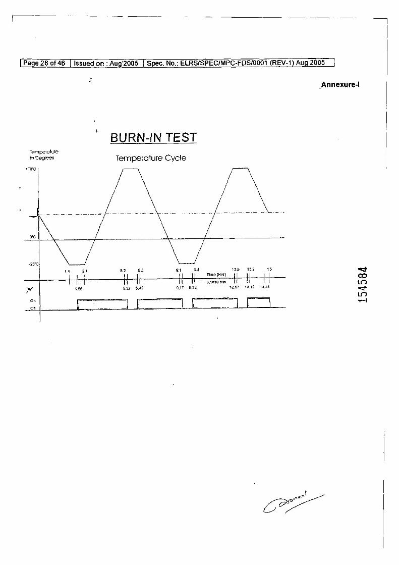
_Annexure-!
BURN-IN TEST Temperature
in Degrees Ternperature Cycle
470°C,
ofc
<25C \/
4 241 5.2 55 a1 94 rime t 125 i? 15 =f
me (Hes) | | H H H H oamtomin Tt Td 4 &
” 4.55 5.27 6.42 947 8.32 42.87 13.12 14.44 <j
On - io
of | i | i} 4
~
Loe
ee
eo
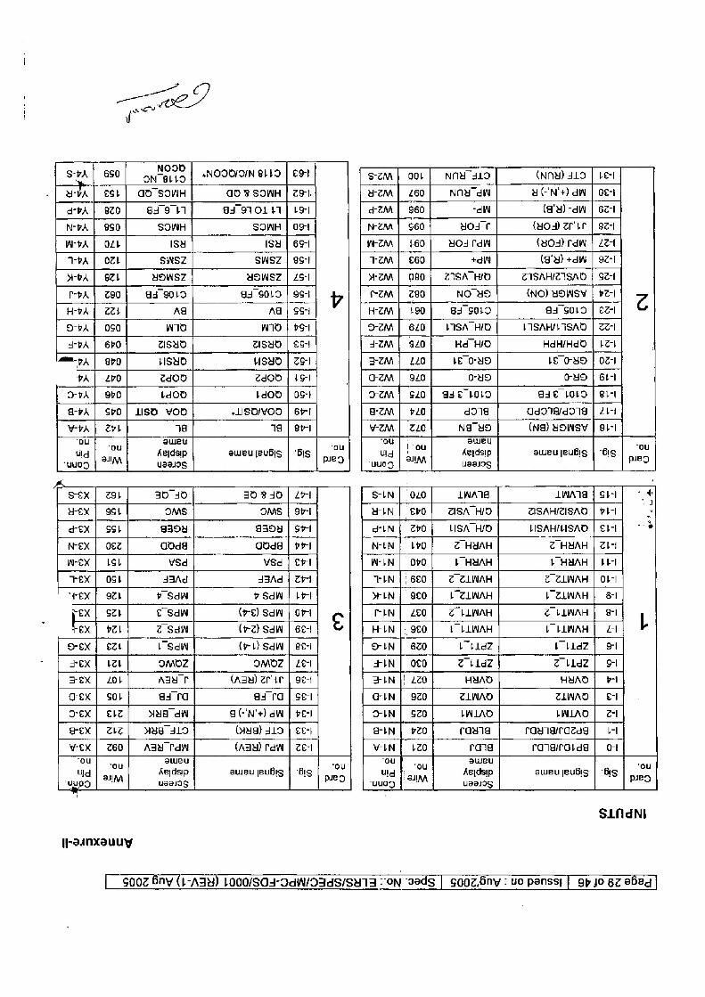
SPA | 650 one *NOOOIOIN BLED | EST Sz7M} ook} NNY 4L9 (NM) LO | Len apa | est | GO SOWH GO 8 SOWH | 791. wen | 260 Nn dW YC'N'+) dW | Oi
d-rA | 920 gio ad S1OL IT] bo azn | $60 “dw (a'4) -dWW | 62-1
N-PA | 850 SOIWH SOWH | og} Nem | $60 yolsT (4Os) rer | 92-1
W-rA | OLE ISH isu | 69-1 wemM | 160 yOd rdw (yOs) rdiW | 22-1
pA | Of SWSZ SWSZ | 9S tem | €60 +N (g'y) +dW | 92-1
WeA | 82h YOWSZ YOWSZ | 45+ +ZAA | O80} ZISAHYO ZISAHIZISAD | SZ-1
t-pA | Z90 ai 9010 ad 3010 | 9st v | SZM | 780 NO-NO (NO) BOWS | Fer | Z
HbA | 224 Ag Ag | SS-i H2M | 190 gj SOLD a4 S010 | €Z-1
O-pA | oso wio W109 | 9S az [| 620] isA7HO HISAH/FISAD | 2z-1
sPa | 6r0 ZISUD ZSYO | €S-! +zm [| $20 Hd HID HdH/Hdd | 12-1
jame-p | 8P0 LSYD HISHD | ZS" 3ZM | 440 L£ 07D be OSD | O71
PA! £0 z@dOd ZdOd | tS a2 | 920 0-uD OY | 6t-l
O-vA | obo tdoo bdOd | OS+ 22M] $20] ase FOLD ede 10D | ei
GA | Sho] Uso voo »LISO/YOD | BY T &2m | #20 doi adoledotg | Zt
WA | Zh 74 148 | eri vem | zZ0 Na YD (Na) HOWSY | 91-1
hg “Ou keidap aweu Bubs | ‘Bis ou tng | -ou kedaip aweujeubis | ‘bis “ou
wuo9 SHIA uaas9s : : PIED “yu05 SAAN uaaisg : : pe
A .
sex | zh 30-40 30 340 | tr SLN | (040 LWA LATS | SIH ft
Mex | St OMS OMS | 9r-1 wiN | €PO | ZISA HID ZISAHIZISAD | #1-I 2
dex | St g394 agoy | sr LN £ Zb0 LISA HID LISAH/LISAD | €t-1 *
ex | ez goad doag | rr len} ipo] = Z HYAH ~ ZHUAH | ZI! WeEexX | ISL WSd VW8d | ert WEN | OFO b HYAH } HYAH | FE
TEX | Ost Jd3Ad S3Ad | Zr TIN |: 660] Z ZLWAH 2 ZLINAH | O1-|
“ex | 9Zb + SdIN ¢ Sd | bel WIN | 8E0 L2LWAH EZLWAH | 6&1
pex | sz € Sd (re) SAW | OFT EIN] ZE0 Z LLWAH Z LLWWAH | 8
Fex ] pZl z Sd (rz) SAW | 6E4 C HLN |; 9€0 E L-LIWAH LF LLWAH | £1 L
S-EX | eZ Sd (rb) SAW | 8e-i SIN | 620 b bldZ bo bidZ | I
sex | ber IMOZ OMOZ | Ze +IN | 0¢0 Z t1dZ Z bldZ] S-
ex] LOL Agu e (Agy) erie | 9e-t TEN |! 220 HYAD HYAD | +!
arex |} SOL ai ra as rq} se GIN |. 920 ZLNAD ZTLWAD | E-I
Oex | €bz sue dW G(-'N'+) dW | Perl oOiIN | Szo LWLAD LWLAD | 2-1
ex | ZZ] wie slo (Hug) 319 | cer GN | ZO raya rawnarazda | it
wEX | 260] ASY Tdi (Adm) Pdi | ZE-1 EN | +20 raig rangratda | ot
og ain kerdsip aweu jeubig | Big ue ud 3 herdsip aweujeubls | Bs er [Yo ° usel0g wuog an uae19g PIED
SLAdNi
|Paunxauuy
[ S002 Bay (1-Aay) 1000/S0s-adW/OadS/SuTa ON ‘gadg | sooz.Sny : uo panss} | 9p Jo 6z ebed |
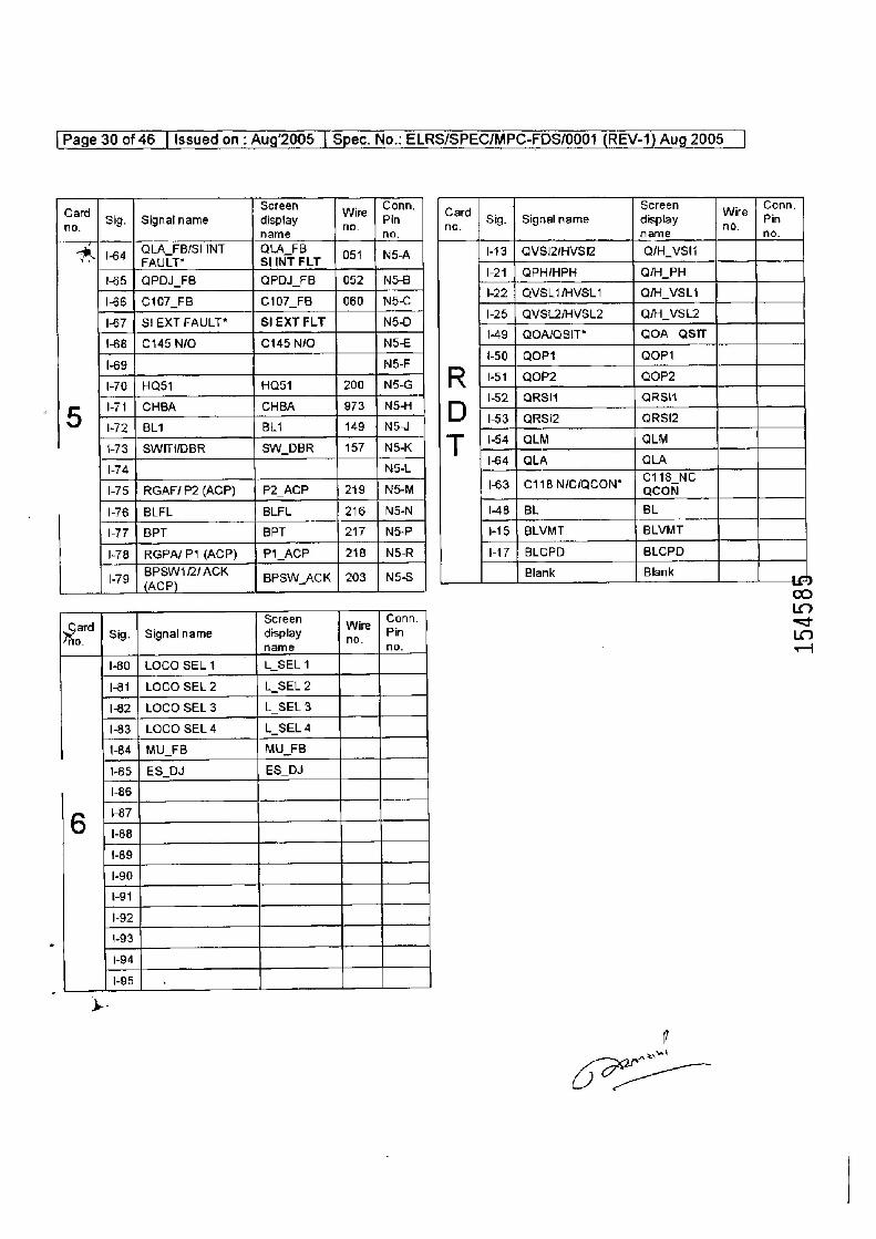
[Page 30 of 46 | Issued on : Aug'2005 | Spec. No.: ELRS/SPEC/MPC-FDS/0001 (REV-1) Aug 2005 |
care Sig. | Signalname deplay Wire er Card Sig. | Signal name ceplay wre oe
name ho, name no.
| 164 QUA FBISIINT | QtAFB | o51 | Ns-A 1-43 | QVSIZIHVSI2 QiH_vsii
165 | QPDJ_FB QPDI_FB | 052 | N5-B 1-24 | QPHIHPH Q/H_PH
66 | C407_FB c107_FB | 060 | N5C 122 | QVSLIVSL1 Q/H_VSL1 167 | SIEXTFAULT* | SIEXT FLT N5-D 25 | QVSLZIVSL2 QMH_VSL2 1-68 | C145 NiO C145 NIO NSE 49 | QOA/QsIT” QOA_QsiT 69 NF +50 | QOP41 QoPt
1-70 | Hast Hast m0 Tusa | | R [+51 | e0r2 gore
5 171 | CHBA CHBA 73 [NH | | EY — — a 1-72 | BLA BLi 149 | N5J +73 | SWITIDBR Sw_DBR | 157 |N5x | | | LtS4j au OLM 4 TEL 1-64 | QLA QLA
I-75 | RGAF/P2 (ACP) | P2_ACP 219 | N5-M 163 | C118 NIC/QCON" nea”
1-76 | BLFL BLFL 216 | NS-N 1-48 | BL BL (77 | BPT BPT 217 | N&P 1-15 | BLVMT BLVMT
1-78 | RGPA/P1(ACP) | PI_ACP | 218 | NOR 1417 | BLCPD BLCPD
I-79 (Ace) ACK | Bpsw_ack | 203 | N5-S Blank Blank id
to Screen . Conn.
year Sig. | Signal name display wre Pin 5
1-80 | LOCO SEL1 LSEL1 1-81 | LOCO SEL2 L_SEL2 1-82 | LOCO SEL3 L_SEL3 1-83 | LOCO SEL4 L_SEL4 1-84 | MU_FB MU_FB 1-85 | ES_DJ ES DJ 1-86 1-87
6 1-88 1-88 1-90 191 1-92 1-93 1-94 1-95
be
( an!
i
i
[Page 31 of 46 | Issued on ; Aug’2005 | Spec. No.. ELRS/SPEC/MPC-FDS/0001 (REV-1) Aug 2005 |
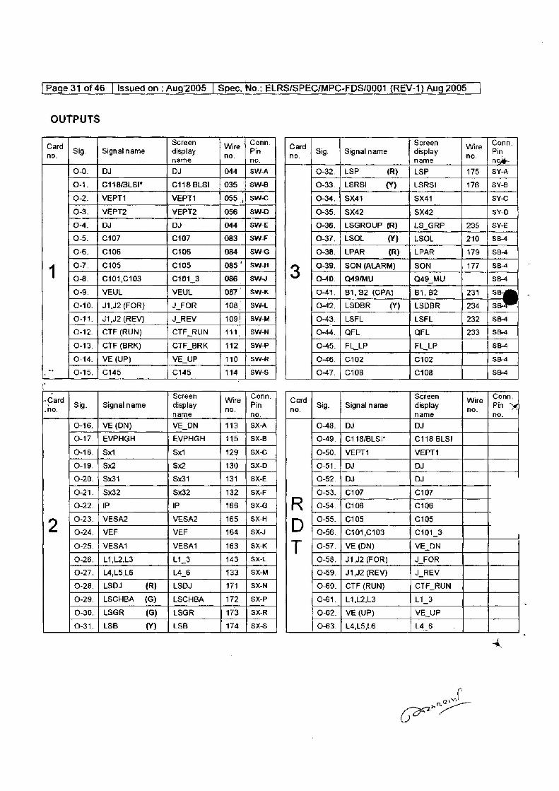
OUTPUTS
Card Sig. | Signatname deslsy Wire | Pn Card Sig. | Signal name Seplay ware Pn name | no. name : now
0-0. | Du Du 044 | SWA 0-32. | LSP (R} | LSP 175 | SY-A
o-1. | C118/BLSI" c1is Bis! | 035 || swe 0-33./LSRS! {¥) | LSRsI 176 | SY-8
0-2. | VEPT4 VEPTA 055 || swe 0-34. | Sx41 Sx41 sy-c
0-3. | VEPT2 VEPT2 056 | SW-D 0-35. | Sx42 SX42 SY-0
0-4, | DJ Ds 044 | SWE 0-36. | LSGROUP (R) | LS_GRP 235 | SY-E
o-5, | C107 C107 083 | swF 0-37. | LSOL vv) | LSOL 210 | SB4
0-6. | C106 C106 084 | swc 0-38. | LPAR (R) | LPAR 179 | SB4
1 0-7. | C105 C105 085‘ | SW 3 0-39. | SON(ALARM) | SON 177 | SB4
0-8. | €101,C103 c101_3 086 | SW 0-40. | Q49/MU 049 MU SB-4
0-9, | VEUL VEUL 087. | Sw-K 0-41. | 81,82 (GPA) Bi, 82 231 |s
Q-10. | J1,J2 (FOR} J_FOR 108 | SW-L o-42.|LSDBR — {¥)_ | LSDBR 234 | SB
0-11. | J1,J2 (REV) J_REV 109! | Sw-m 0-43. | LSFL LSFL 232 | sB4
0-12. | CTE (RUN) CTE_RUN | 141. | SWAN 0-44, | QFL QFL 233 | sea
0-13. | CTF (BRK) CTF_BRK | 112 | SwP 0-45. | FL_LP FL_LP SB4
0-14. | VE (UP) VE_UP 110 | SW-R 0-46, | C102 C102 SB4
ot 1 0-45, | C145 C145 114 | sw-s 0-47, | c108 C108 SB-4
r
© ‘ard Sig. Signal name Septey Wre er card Sig. Signal name ceplay were Pn
name na, name na.
0-16. | VE (DN) VE_DN 113 | SX-A 0-48. | DJ DJ
0-17. | EVPHGH EVPHGH 115 | SX-B 0-49. | C118/BLSI" C116 BLS!
0-18. | Sxt x1 129 | sxc 0-50. | VEPT1 VEPT1
0-19, | $x2 $2 130 | SX-D 0-51. | by DJ
0-20. | 8x31 8x31 131 | sxe 0-52. | DJ DJ
0-21, | $x32 8x32 132 | sx-F 0-53. | C107 C107
0-22. | IP IP 166 | SXG R 0-54. | C106 C106
9 0-23. | VESA2 VESA2 165 | SX-H D 0-55. | C105 C105
0-24. | VEF VEF 164 | Sx 0-56. | ¢101,0103 c101_3
0-25. | VESA1 VESAI 163 | SX-K T 0-87. | VE (DN) VE_DN
0-26. | L1,L2,L3 L1_3 143 | SxX-1 0-58. | J1,J2 (FOR) J_FOR
0-27. | L4,L5,L6 L4_6 133 | SXM 0-59. | J1,U2 (REV) J_REV
0-28. | LSDJ (R) | Usb 171 | SX-N 0-60. | CTF (RUN) CTF_RUN
0-29.|LSCHBA (G) | LSCHBA 172 | sxP 0-61. | L1,L2,.L3 L1_3
0-30. | LSGR (S) | tsGR 173 | Sx%R 0-62. | VE (UP) VE_UP
0-31. | LSB (vy) | LsB 174 | sxs 0-63. | L4,L5,L6 L46
] Page 32 of 43 | Issuedon-:- Aug’2005 | Spec. No.: ELRS/SPECIMPC-FDS/0001 (REV-2) Aug 2005 }
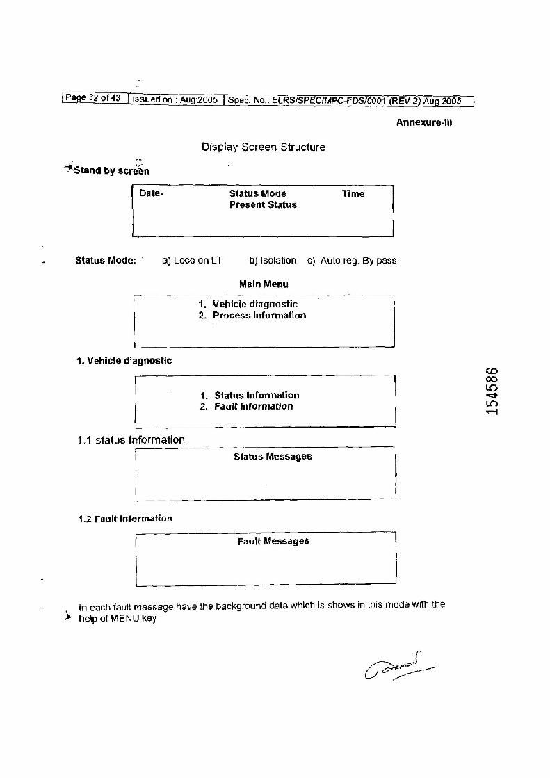
Annexure-iil
Display Screen Structure
+stanq by screen
Date- Status Mode Time Present Status
Status Mode: ' a) Loco on LT b) Isolation c} Auto reg. By pass
Main Menu
1. Vehicie diagnostic 2. Process Information
4. Vehicle diagnostic
1. Status Information 2. Fault information
1.1 status Information
Status Messages 4.2 Fault Information
Fault Messages
in each fault massage have the background data which is shows in this mode with the
>» help of MENU key
f CF
154586
[Page 33 of 43 | issued on - Aug’2005 | Spec. No.. ELRS/SPEG/MPC-FDS/0001 (REV-2) Aug 2008
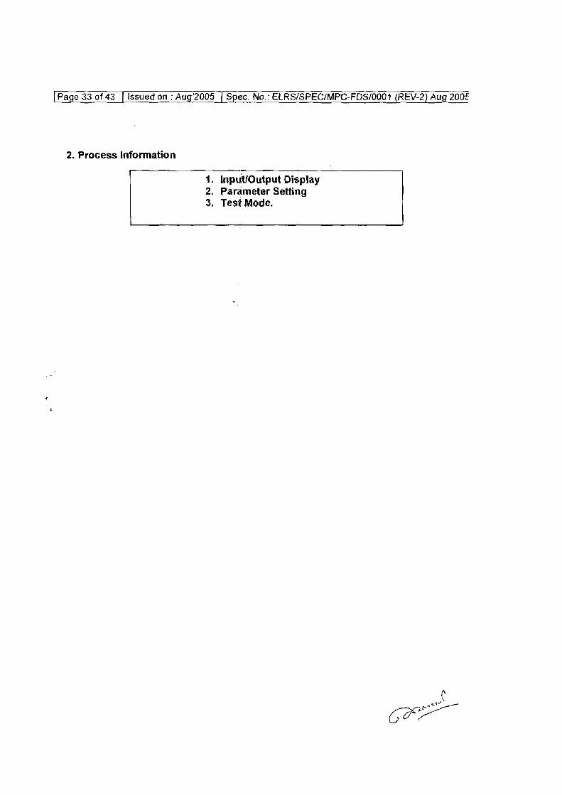
2. Process Information
1. Input/Output Display 2. Parameter Setting 3. Test Mode.
f CRE
Page 34 of 43 | issued on: Aug’2005 | Spec. No.: ELRS/SPEC/MPC-FDS/0001 (REV-2} Aug 2005 |
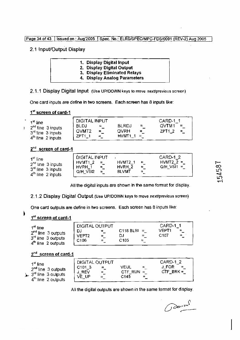
2.1 Input/Output Display
Pep > Display Digital Input
Display Digital Output Display Eliminated Relays Display Analog Parameters
2.1.1 Display Digital Input (Use UP/DOWN keys to move next/previous screen)
One card inputs are define in two screens. Each screen has 8 inputs like:
1* screen of card-1
4* line 2™ line 3 inputs 3" fine 3 inputs 4""tine 2 inputs
2°" screen of card-1
1 line 2™ line 3 inputs 3% line 3 inputs 4" line 2 inputs
DIGITAL INPUT
CARD-1_1 BLDJ =_ BLRDJ = -=_ QVTM1 = QVMT2 = QVRH = ZPT1_2 = ZPT1_i = HVMT1_1 =
DIGITAL INPUT CARD-1_2 HVMT1_2 =_ HVMT2_1. = HVMT2_2 =_ ~ HVRH_1 0 =_ HVRH_2 = Q/H_VSI1 =_ co QIH_VSI2. = BLVMT = o>
- <—J Lo <I
All the digital inputs are shown in the same format for display.
2.1.2 Display Digital Output (Use UP/DOWN keys to move next/previous screen)
One card outputs are define in two screens. Each screen has 8 inputs like:
1° screen of card-1
1* line 2" jine 3 outputs 3 line 3 outputs 4" line 2 outputs
2" screen of card-1
1* line 2™ line 3 outputs
- 3 line 3 outputs 4" line 2 outputs
DIGITAL OUTPUT CARD-1_1 DJ = C418 BLSI = VEPT1 = VEPT2 = DJ = C107 = C106 = C105 =
DIGITAL OUTPUT CARD-1_2 C1013 0 =. VEUL = JFOR = J_REV =" CTF_RUN =_ CTF_BRK =_ VE.UP =” C145 =
All the digital outputs are shown in the same format for display.
| ws Go
Ht (Paged5 0f43 [Issued on. Aug2008 | Spec. No.: ELRS/SPEC/MPC-FDS/0001 (REV-2) Aug 2005 _ |
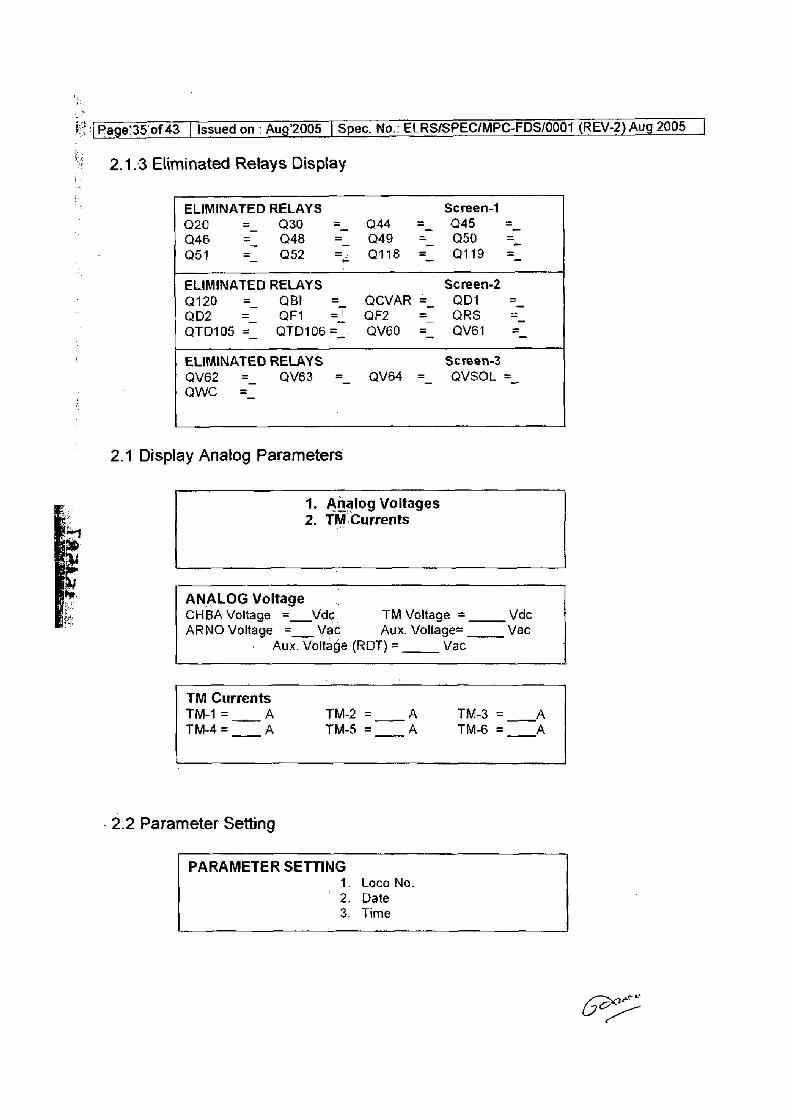
|} 2.4.3-Eliminated Relays Display
ELIMINATED RELAYS Screen-1
Q20 = O30 = Q44 = Q45 = Q46 = Q48 = Q49 = Q50 =
Q51 = Q52 =: Q118 = Q119 =
ELIMINATED RELAYS Screen-2 Q120 = OBI =_ QCVAR = QD = QD2 =. QFt = QF2 = QRS =, QT0105 =_— QTD106=.. QV60 = QV61 =
ELIMINATED RELAYS Screen-3
QV62 = _ QV63 =_ AV64 =_ QVSOL = awe =
2.1 Display Anatog Parameters
1. Analog Voltages 2. TM.Currents
ANALOG Voltage . CHBA Voltage =__Vde TM Voltage = Vde ARNO Voltage =__ Vac Aux. Voltage= Vac
Aux. Voltage (RDT) = Vac
TM Currents
TMi= A TM-2= A TM3=__A TM-4=__ A TM-5 =___A TM-6 =__A
. 2:2 Parameter Setting
PARAMETER SETTING 1. Loco No.
' 2. Date 3. Time
[Page 36 0f43 | Issued on. Aug2005 | Spec. No.. ELRS/SPEC/MPC-FDS/0001 (REV-2) Aug 2005 _|
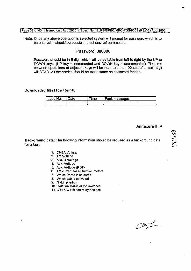
Note: Once any above operation is selected system wil! prompt for password which is to be entered. it should be possible to set desired parameters.
Password: 000000
Password should be in 6 digit which will be settable from left to right by the UP or DOWN keys. (UP key = incremented and DOWN key = decremented), The time between operations of adjacent keys will be not more than 02 sec after next digit
will STAR. All the entries should be make same as password feeded.
Downloaded Message Format
Loco No. | Date Time Fault messages
Annexure IILA
ce co tm
Background data: The following information should be required as a background data =<
for a fault. ae
CHBA Voltage TM Voltage ARNO Voltage Aux. Voltage
Aux. Voltage (RDT) TM current for all traction motors
Which Panto is selected
Which cab is activated
. Notch position 10. Isolation status of the switches
11.944 & 118 soft relay position
OONHARON
wt Ce
Page 37 of 43 | issued on : Aug’2005 [ Spec. No.: ELRS/SPEC/MPC-FDS/0001 (REV-2) Aug 2005 |
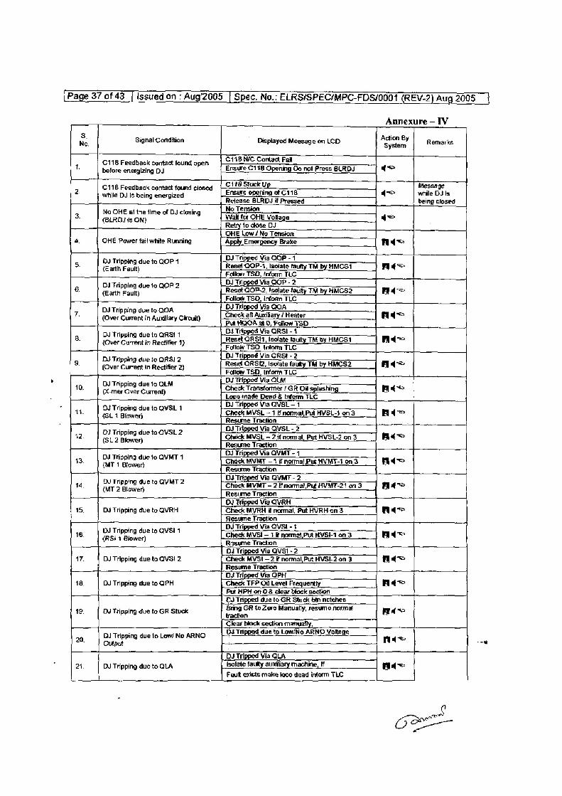
Annexure - IV
8. . 43 . i No. Signal Condition Displayed Message on LCD *Sycieme Remarks
CHB NIC Cortad Far C118 Feedback contact found open =
t. before energizing DJ Ensure C118 Opening Oo not Press BLRDVJ =
8 C118 Stuck Up _ Message
2, ne Aiisbeo orgies closed | Ensure epening of C116 (= while BJ Is Release BLRDJ it Pressed being closed
A : No Tension No OHE at the time of DJ closing ae
3. (BLRDJ is ON) Wai ‘a OHE vokoae c= etry 2 chase
OHE Low/ No Tension 4, OHE Power fail white Running Apply Emergency Brake Ad
DJ Tripped Via GOP - 4 5. eatheaay te QoP4 Resel QOP-1, Isolate fautty TM by HMOSI nt
Follow TSD, Info TLC ae DJ tripped Via QOP - 2 7
8 | ath ean a0F2 Reset QOP-2, Isolate faully TM by HMCS2 Ad Follcsy TSO, Inform TLC
aa OJ Tripped Via QOA DJ Tripping due to QOA =
7. (Over Current in Auxiliary Circuit) check af antony (Heater adt~ HOA at 0, Fr
DN Tripping due to QRSI 1 G3 Tapped Via ORSI - 4 8. {Over Current in Rectifier 1) Reset QRSi1, Isolate faulty TM by HMCS1 Ad=
Follow TSO, Inform TLC i OJ Tripped Via RSI - 2
9. ove re aue Restor?) Reset ORSI2, isolate faully TM by HMCSD Ad Follow TSD, Inform TLC
_—_ OJ Tipped Via QLM OJ Tripping due to QLM -
"0 _| emer ve Sen ce renee eer | : BJ tripped Via QVSL— 1
14, | Ou Tripping due to QVSL 4 Check MVSL — 1 i normal Put HVSL-1 on 3 nA SL 1 Blewar 5 Traci
a DJ Tripped Via QVSL - 2 42, | O4 Tipping due to OVSL 2 Check MVSL —2 4 nomal, Put HVSL2 on 3 ae
(SL 2 Blower Resume Traction DJ Tripped Via OVMT - 1
43, | D4 Tripping due to OVMT 4 Chick MVMT — 1 if normal Put HVMT4 on 3 fide (MT 1 Blower} Resume Tradion
_ DJ Tripped Via QVMT - 2 tq, | DY Tripping due to QVMT 2 Chack MVMT — 2 f normal Pik HUMT-31 on 3 nA
(MT 2 Blower) Resume Traction
DJ Tripped Via OVRH 15. DJ Tripping due to QVRH Chieck MVRH if normal, Put HVRH on 3 Ad
Resume Traction _ DJ Tripped Via QVSI- +
16. sit Blower toavst 1 Check MVSI — 1 normal,Pid HVS on 3 ade Resume Traction
DJ Tripped Via QVSI - 2 17. DJ Tripping due to QVS! 2 Check MVSI — 2 if normal,Put HVSI-2 on 3 Acc
Resume Traction
OJ Tripped Via GPH
18. DU Tripping due to QPH Check TFP Of Level Frequently Ad Pu HPH on 0 & clear block section CJ Tripped due to GR Stuck tin notches
12 Du Tripping due to GR Stuck Bring GR fo Zero Manually, resume normal aa
Clear block section m: i, 70 DU Tripping due to Lew’ No ARNO | OJ Tripped due to Low/No ARNO Voltage nee
. Output : A
DJ Tripped Via OLA 24. DJ Tripping due to QLA fsofate faulty aundiiary machine, ff _ ad=
Faut exists make toce dead inform TLC
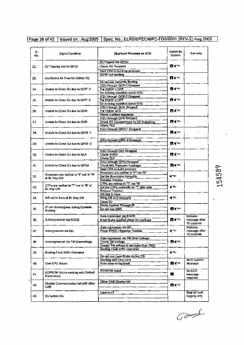
[Page 38 of 43 | Issued on : Aug’2005 | Spec. No.: ELRS/SPEC/MPC-FDS/0001 (REV-2) Aug 2005
s: . . . Action By No. Signal Candition Displayed Message on LCD System Remarks
OJ} Tripped Via QPDJ
22. DJ Tripping due to OPDJ Check RS Pressure A=
Start CPA to build up pressure
QVRE not working 23, Insufficient Alr Flow for OBR(I-73) Ads
Do na use Dynamic Braking
. {CDJ through QOP-1 Dropped
24. Unable to Close DJ due to QOP -1 Put HOOP-1 OFF At On running condition watch HTC
ICDJ through QOP-2 Dropped 25. Unable to Close DJ due to QOP -2 Put HQOP-2 OFF Adz
On sunning condition watch HTC ICDJ through QOA Dropped
26. Unable to Close DJ due to QOA Put HQOA on 0 = Check auxiliary machines iCDJ through OLM Dropped
27. Unable to Close DJ due to QLM Check HT Compartment for Oil Splashing Ad= inform TLC ICDS through ORSI-1 Dropped
28. Unable to Close DJ due fo QRS! -1 Ad
ICDS through QRSI-2 Dropped
29. Unable to Close Du due to QRS! -2 Bde
{CDJ through QLA Dropped 30. Unable ta Close DJ due to OLA Check ARNO Ade
(nform TLC ICDJ through QPDJ Dropped
31, Unable to Clase DJ due to QPBJ Check MS Pressure / Leakage Ads
| Start CPA to build pressure
4 a ~ ape |_Reversers are neither in *F™ nor *R”
32. eel Kev ON neither in“F" nor in“R Set the Reversers manually q= Resume Traction ‘
: ee CTFs are neither in “T” nor "B”
33. BLKeoN in“T nor in“Br at cetthe CTFs manually on “T side only = Resume Traction
GR Nat in Zero 34. GR not in Zero at BL Key ON Bring GR at 0 manually {c=
Close DJ
35. f not deenergises during Dynamic Brake Applied Through IP Ala
ig
Auto-+egression via RGEB Remove
36. Autoregression via RGEB If not Brake applied check for Leakage Bd message after 10 seconds
Auto-regression via QD Remove 37. Autorgression via QD Press BPQD / Resume Traction gq message after
10 seconds
Auto-regression via TM Over Voltage
38. Autoregression via TM Overvoltage Check TM Voltage Ade] Ensue TM voltage is not more than 750V Braking Fautt SWC Operated
39. Braking Fault SWC Operated qq
Do net use Loco Brake during DB
Working with One CPU MCS System 40, One CPU failure Note down in fog book q> | Message
EEPROM failure working with Defautt }| EEPROM feited NoLCD 41. Parameters a message
required
42 Display Communication fail with other Other CAB Display fail A= . CAB i
Loco in LT Stop all fault 43. BV switch ON fogging only
154589
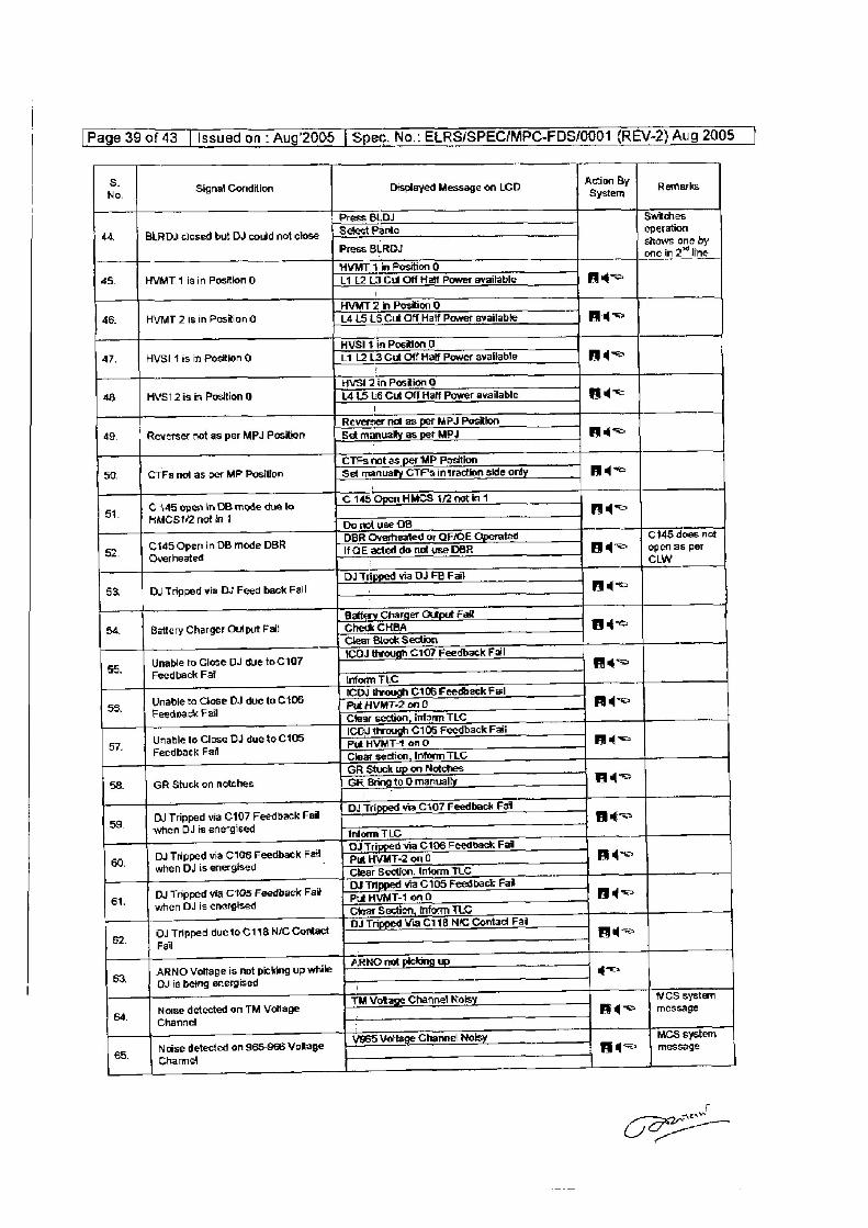
[Page 39 of 43 | Issued on - Aug'2005 | Spec. No.: ELRS/SPEC/MPC-FDS/0001 (REV-2) Aug 2005 |
8. . a7 , i No. Signal Condition Displayed Message on LCD vsratent Remarks
Press BLDJ Switches
44, | BLRDJ closed but DJ could net close | Sect Panto operation Press BLRDJ shaws one by
: one in 2” Ine
HVMT 7 in Position 0
45. HVMT 1 is in Position 0 L1 L2 L3 Cut Off Hatt Power available A= i
HVMT 2 in Position 0 46. HVMT 2 is in Position G (415 16 Cut Off Half Power available Ad=
7
HVSI1 in Position 0 47. HVSI fis in Position 0 L1 12 13 Gut Off Half Power available Ade
r
HVSI 2 in Position ©
48, HVSI 2is in Position 0 L415 L6 Cut Off Halt Power available Ads 1
Reverser not_as per MPJ Pesition
4g, Reverser not as per MPJ Position Set manually as pet MPJ ats
. CTFs not as per MP Position
50. CTFs nol as per MP Position ‘Set manualy CTF's in traction skie only Aq
51. | ©4458 open in DB mode due to Po 14 Open HMES M2 ont ni HMCS 1/2 not in 7 Do nl use DB °
. DBR Overheated or QF/CE Operated C145 does not
52. [145 Open in DB mode DBR If QE acted do nat use DBR fid~= =| openas per Overheated : cLW
DJ Tapped via DJ FB Fail 53, DU Tripped via DJ Feed back Fail . Adq=
Battery Charger Output Fall
54, Battery Charger Output Fail Check CHBA d= Clear Block Section
55 Unable to Close DJ due to C107 1C0J through C107 Feedback Fal Ac
Feedback Fail infem FLO
ICDJ through C105 Feedback Fail
os, | aes DJ due to C106 Put HVMT-2 on 0 Aq Clear section, inform TLC
Unable te Close BJ due to C105 ICO, through C105 Feedback Fa = 57. Feedback Fail Put HVMT-1 on 0 Bid
Clear section, Inform TLC GR Stuck up on Netches
58. GR Stuck on notches GR Bring to O manually Ad 1
. i fia C107 back Fail
DJ Tripped via C107 Feedback Fai | OY Tipped via C107 Feedback neo 59. when DJ is energised “
Inform TLC
. t fia Cth back Fail Du Tripped via C106 Feedback Fai | 24 Tipped ie C106 Feedback a=
60. when DJ is energised : Put HVMT-2 on 0 . Clear Section, Inform TLC
DJ Tripped via C105 Feedback Fat © | D2 a “ d via C105 Feedback Fai = 61. when DJ is energised ms F110 ad
Clear Section, Inform TLO rt ii F;
DJ Thpped duetoC118. NC Contact | 22 Tipped Via C118 NIC Contac Fal Ae 82. Fail
,
63. ARNO Voltage is not picking up while ARNO nol pickmg Up +=
. OJis being energised ;
Rots MCS system
oa, __ | Notse detected on TM Voltage 1 Vokage Channel Nofsy. nie moseage Channel :
- 1965 Voltage Channe! Nok MCS system 65. Noise detected on S65-966 VoRage ge my fia message |
mn
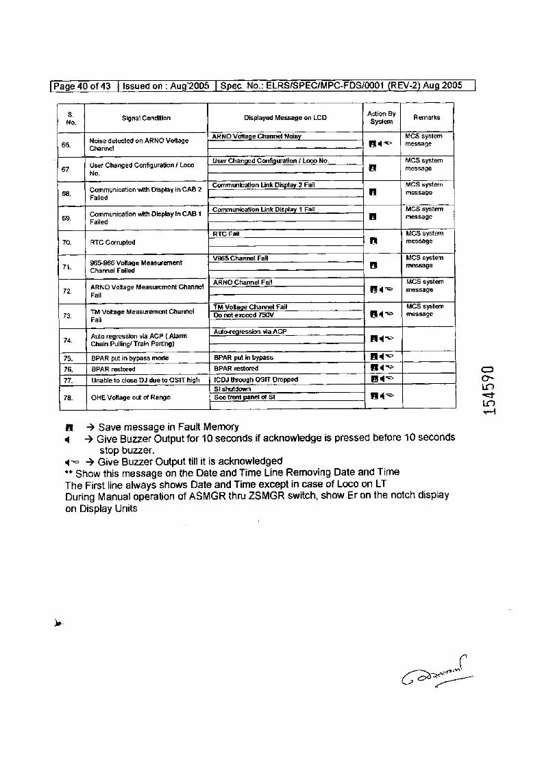
[Page 40 of 43 | Issued on; Aug’2005 | Spec. No.: ELRS/SPEC/MPC-FDS/0001 (REV-2) Aug 2005
8. ; i . Action By No. Signal Condition Oisplayed Message on LCD System Remarks
. ARNO Vottage Channe! Noisy MCS system Noise detected on ARNO Volt
86. Channel ase Fad | message
User Changed Configuration /Loco | -User Changed Configuration / Loco No. MCS system 87. No a message
Communication with Display inCAB2 [Communication Link Display 2 Fai MCS system 68. ‘ A message
Failed
Communication with Display in CAB 1 | ©2inunication Link Display 1 Fal MCS system 69. * BA message
Failed
RTC Fail MCS system
70. RTC Corrupted i] message
n 965-966 Voltage Measurement ¥965 Channel Fail 5 MCS system : Channel Failed 9
ARNO Channe! Fail MCS system 72, pRNO Voltage Measurement Channel Aye message
TM Voltage Channel Fail MCS system 73, rar naae Measurement Channel Do not exceed 750V nd message
Th Auto regression via ACP ( Alarm Auto-regression via AGP nA
: Chain Pulling/ Train Parting}
75. BPAR put in bypass mode BPAR pul in bypass Ad~
76. BPAR restored BPAR restored d=
77. Unable to close DJ due to QSIT high tCDJ through OSIT Dropped at
Si shutdown
78. OHE Vettage out of Range See front panel of SI ats
f «60> Save message in Fault Memory
4 ~~ Give Buzzer Output for 10 seconds if acknowledge is pressed before 10 seconds
stop buzzer.
d= > Give Buzzer Output till it is acknowledged ** Show this message an the Date and Time Line Removing Date and Time
The First line always shows Date and Time except in case of Loco on LT
During Manual operation of ASMGR thru ZSMGR switch, show Er on the notch display
on Display Units
£
154590
ere
eee
Page4tiof 43_| Issued on . Aug'2005 | Spec. No.. ELRS/SPEC/MPC-FDS/0001 (REV-2) Aug 2005 _|
Annexure-V
Mounting Details
+ ¥
385mm 745mm
4 Studs M12X50 long . for mounting
“Main unit
160mm
Four Mounting holes are 8 mm
Signa! Coditioning unit
an
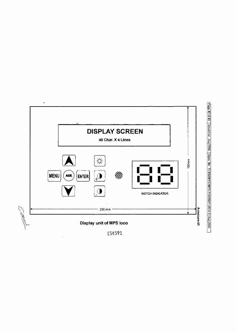
b>
DISPLAY SCREEN 40 Char. X 4 Lines
ven) (or) (9) Se
oS
NOTCH INDICATOR
150mm
230 mm
Display unit of MPS loco
154591
[A-a
anxa
uuy L__so0z Bny (Z-A3 4) 1 00
0/SGS-OdW/O3dS/SUTa
= ON
98dS
| so
0z,5
ny
<= uo pa
nss!
|
ey
Jo
zp abe]
[Page 43 of 43 | Issued on : Aug’2005 | Spec. No.: ELRS/SPEC/MPC-FDS/0001 (REV-2) Aug 2005
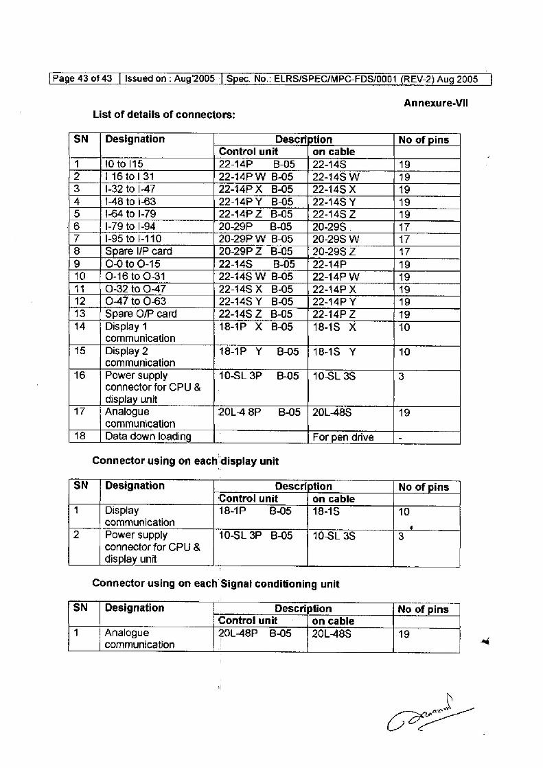
Annexure-VIl List of details of connectors:
SN _ | Designation Description No of pins Control unit on cable
1 10 to 115 22-14P B-05 | 22-148 19 2 1 16 tol 31 22-14P W B-05 =| 22-145 W 19 3 1-32 to |-47 22-14P X B-O5 | 22-145 X 19 4 1-48 to 1-63 22-14P Y B-05 | 22-148 Y 19 5 1-64 to I-79 22-14P 2 B-O5 | 22-145 2 19
16 1-79 to |-94 20-29P B-05 26-295 . 17 7 1-95 to |-110 20-29P W B-05 =| 20-298 W 17 8 Spare I/P card 20-29P Z B-05 | 20-298 Z 17 9 0-0 to 0-15 22-148 B-05 | 22-14P 19 10 | 0-16 to 0-31 22-148 W B-O05 =| 22-14P W 19 11 Q-32 to 0-47 22-145 X BO5 | 22-14P X 192 12 |047to 0-63 22-145 Y B-O5 | 22-14P Y 19 13 Spare O/P card 22-148 Z B-05 22-14P Z 19
14 | Display 1 18-1P X B-O5 | 18-1S xX 10 communication
15 | Display 2 18-1P Y BO5 {1818S Y 10 communication
16 Power supply 10-SL3P B-05 |10-SL3S 3 connector for CPU & display unit
17 ‘| Analogue 20L48P B-05 | 20L-48S 19 communication
18 __| Data down loading For pen drive -
Connector using on each display unit
SN_ | Designation Description No of pins Control unit on cable
4 Display 18-1P B-05 18-1S 10 communication ‘
2 Power supply 10-SL 3P B-05 10-SL 3S 3 connector for CPU & display unit
Connector using on each Signal conditioning unit
SN_ | Designation Description | No of pins Control unit on cable
4 Analogue 2OL48P 8-05 | 20L485S 19 communication
S


