Embed Size (px)
Citation preview
15D241-926-AARAM TRUCKS 1500/2500/3500SECOND REV 1 EDITIONUSER GUIDE
Download a FREE electronic copy of the Owner’s Manual and Warranty Booklet by visiting:
WWW.RAMTRUCKS.COM/EN/OWNERS/MANUALS OR WWW.RAMTRUCKS.COM/EN/WARRANTY (U.S.); WWW.OWNERS.MOPAR.CA/EN (CANADA).
1905562_15a_RAM_1500_2500_3500_UG_103114.indd 1 10/31/14 1:37 PM
The driver’s primary responsibility is the safe operation of the vehicle. Driving
while distracted can result in loss of vehicle control, resulting in a collision and
personal injury. Chrysler Group LLC strongly recommends that the driver use
extreme caution when using any device or feature that may take their attention
off the road. Use of any electrical devices, such as cellular telephones,
computers, portable radios, vehicle navigation or other devices, by the driver
while the vehicle is moving is dangerous and could lead to a serious collision.
Texting while driving is also dangerous and should never be done while the
vehicle is moving. If you find yourself unable to devote your full attention to
vehicle operation, pull off the road to a safe location and stop your vehicle.
Some states or provinces prohibit the use of cellular telephones or texting while
driving. It is always the driver’s responsibility to comply with all local laws.
If you are the first registered retail owner of your vehicle, you
may obtain a complimentary printed copy of the Owner’s
Manual, Navigation/Uconnect® Manuals or Warranty Booklet
by calling 1-866-726-4636 (U.S.) or 1-800-387-1143 (Canada) or
by contacting your dealer.
IMPORTANTThis User Guide is intended to familiarize you with the
important features of your vehicle. The DVD enclosed
contains your Owner’s Manual, Navigation/Uconnect®
Manuals, Warranty Booklets, Tire Warranty and Roadside
Assistance (new vehicles purchased in the U.S.) or Roadside
Assistance (new vehicles purchased in Canada) in electronic
format. We hope you find it useful. Replacement DVD kits
may be purchased by visiting www.techauthority.com.
Copyright 2014 Chrysler Group LLC. Driving and AlcoholDrunken driving is one of the most frequent causes
of collisions. Your driving ability can be seriously
impaired with blood alcohol levels far below the legal
minimum. If you are drinking, don’t drive. Ride with a
designated non-drinking driver, call a cab, a friend, or
use public transportation.
WARNINGDriving after drinking can lead to a collision. Your
perceptions are less sharp, your reflexes are slower, and
your judgment is impaired when you have been drinking.
Never drink and then drive.
This guide has been prepared to help you get quickly
acquainted with your new RAM and to provide a
convenient reference source for common questions.
However, it is not a substitute for your Owner’s Manual.
For complete operational instructions, maintenance
procedures and important safety messages, please consult
your Owner’s Manual, Navigation/Uconnect® Manuals and
other Warning Labels in your vehicle.
Not all features shown in this guide may apply to your
vehicle. For additional information on accessories to help
personalize your vehicle, visit www.mopar.com (U.S.),
www.mopar.ca (Canada) or your local RAM dealer.
1905562_15a_RAM_1500_2500_3500_UG_103114.indd 2 10/31/14 1:37 PM
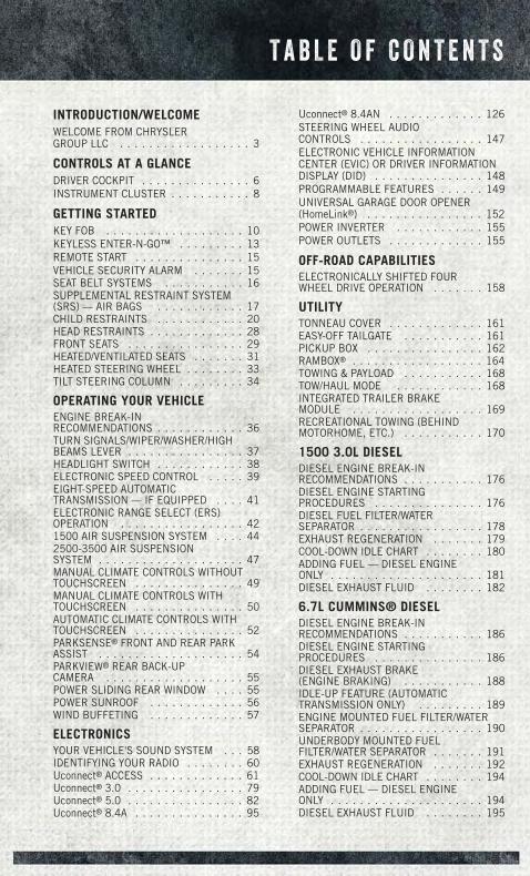
INTRODUCTION/WELCOMEWELCOME FROM CHRYSLERGROUP LLC . . . . . . . . . . . . . . . . . . 3
CONTROLS AT A GLANCEDRIVER COCKPIT . . . . . . . . . . . . . . . 6INSTRUMENT CLUSTER . . . . . . . . . . . 8
GETTING STARTEDKEY FOB . . . . . . . . . . . . . . . . . . . 10KEYLESS ENTER-N-GO™ . . . . . . . . . 13REMOTE START . . . . . . . . . . . . . . . 15VEHICLE SECURITY ALARM . . . . . . . 15SEAT BELT SYSTEMS . . . . . . . . . . . 16SUPPLEMENTAL RESTRAINT SYSTEM(SRS) — AIR BAGS . . . . . . . . . . . . 17CHILD RESTRAINTS . . . . . . . . . . . . 20HEAD RESTRAINTS . . . . . . . . . . . . . 28FRONT SEATS . . . . . . . . . . . . . . . . 29HEATED/VENTILATED SEATS . . . . . . . 31HEATED STEERING WHEEL . . . . . . . . 33TILT STEERING COLUMN . . . . . . . . . 34
OPERATING YOUR VEHICLEENGINE BREAK-INRECOMMENDATIONS . . . . . . . . . . . . 36TURN SIGNALS/WIPER/WASHER/HIGHBEAMS LEVER . . . . . . . . . . . . . . . . 37HEADLIGHT SWITCH . . . . . . . . . . . . 38ELECTRONIC SPEED CONTROL . . . . . 39EIGHT-SPEED AUTOMATICTRANSMISSION — IF EQUIPPED . . . . 41ELECTRONIC RANGE SELECT (ERS)OPERATION . . . . . . . . . . . . . . . . . 421500 AIR SUSPENSION SYSTEM . . . . 442500-3500 AIR SUSPENSIONSYSTEM . . . . . . . . . . . . . . . . . . . . 47MANUAL CLIMATE CONTROLS WITHOUTTOUCHSCREEN . . . . . . . . . . . . . . . 49MANUAL CLIMATE CONTROLS WITHTOUCHSCREEN . . . . . . . . . . . . . . . 50AUTOMATIC CLIMATE CONTROLS WITHTOUCHSCREEN . . . . . . . . . . . . . . . 52PARKSENSE® FRONT AND REAR PARKASSIST . . . . . . . . . . . . . . . . . . . . 54PARKVIEW® REAR BACK-UPCAMERA . . . . . . . . . . . . . . . . . . . 55POWER SLIDING REAR WINDOW . . . . 55POWER SUNROOF . . . . . . . . . . . . . 56WIND BUFFETING . . . . . . . . . . . . . 57
ELECTRONICSYOUR VEHICLE'S SOUND SYSTEM . . . 58IDENTIFYING YOUR RADIO . . . . . . . . 60Uconnect® ACCESS . . . . . . . . . . . . . 61Uconnect® 3.0 . . . . . . . . . . . . . . . . 79Uconnect® 5.0 . . . . . . . . . . . . . . . . 82Uconnect® 8.4A . . . . . . . . . . . . . . . 95
Uconnect® 8.4AN . . . . . . . . . . . . . 126STEERING WHEEL AUDIOCONTROLS . . . . . . . . . . . . . . . . . 147ELECTRONIC VEHICLE INFORMATIONCENTER (EVIC) OR DRIVER INFORMATIONDISPLAY (DID) . . . . . . . . . . . . . . . 148PROGRAMMABLE FEATURES . . . . . . 149UNIVERSAL GARAGE DOOR OPENER(HomeLink®) . . . . . . . . . . . . . . . . 152POWER INVERTER . . . . . . . . . . . . 155POWER OUTLETS . . . . . . . . . . . . . 155
OFF-ROAD CAPABILITIESELECTRONICALLY SHIFTED FOURWHEEL DRIVE OPERATION . . . . . . . 158
UTILITYTONNEAU COVER . . . . . . . . . . . . . 161EASY-OFF TAILGATE . . . . . . . . . . . 161PICKUP BOX . . . . . . . . . . . . . . . . 162RAMBOX® . . . . . . . . . . . . . . . . . . 164TOWING & PAYLOAD . . . . . . . . . . . 168TOW/HAUL MODE . . . . . . . . . . . . 168INTEGRATED TRAILER BRAKEMODULE . . . . . . . . . . . . . . . . . . 169RECREATIONAL TOWING (BEHINDMOTORHOME, ETC.) . . . . . . . . . . . 170
1500 3.0L DIESELDIESEL ENGINE BREAK-INRECOMMENDATIONS . . . . . . . . . . . 176DIESEL ENGINE STARTINGPROCEDURES . . . . . . . . . . . . . . . 176DIESEL FUEL FILTER/WATERSEPARATOR . . . . . . . . . . . . . . . . . 178EXHAUST REGENERATION . . . . . . . 179COOL-DOWN IDLE CHART . . . . . . . . 180ADDING FUEL — DIESEL ENGINEONLY . . . . . . . . . . . . . . . . . . . . . 181DIESEL EXHAUST FLUID . . . . . . . . 182
6.7L CUMMINS® DIESELDIESEL ENGINE BREAK-INRECOMMENDATIONS . . . . . . . . . . . 186DIESEL ENGINE STARTINGPROCEDURES . . . . . . . . . . . . . . . 186DIESEL EXHAUST BRAKE(ENGINE BRAKING) . . . . . . . . . . . 188IDLE-UP FEATURE (AUTOMATICTRANSMISSION ONLY) . . . . . . . . . 189ENGINE MOUNTED FUEL FILTER/WATERSEPARATOR . . . . . . . . . . . . . . . . . 190UNDERBODY MOUNTED FUELFILTER/WATER SEPARATOR . . . . . . . 191EXHAUST REGENERATION . . . . . . . 192COOL-DOWN IDLE CHART . . . . . . . . 194ADDING FUEL — DIESEL ENGINEONLY . . . . . . . . . . . . . . . . . . . . . 194DIESEL EXHAUST FLUID . . . . . . . . 195
T A B L E O F C O N T E N T S
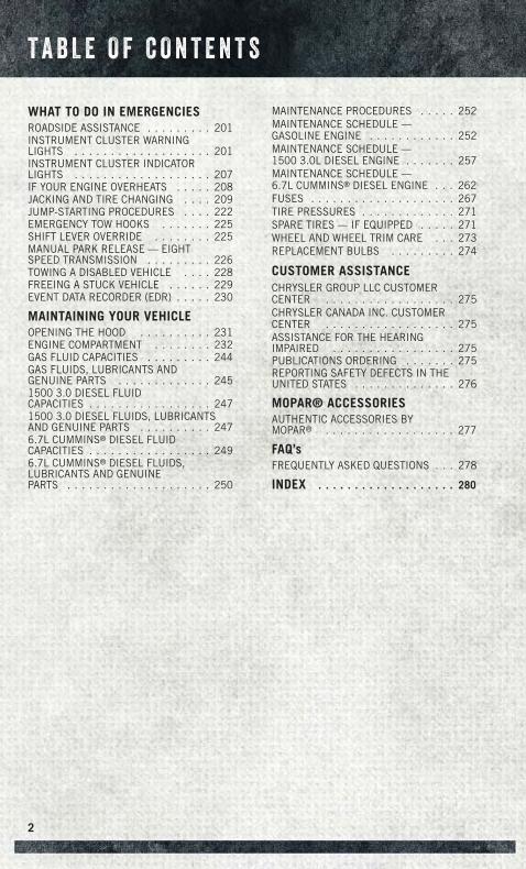
WHAT TO DO IN EMERGENCIESROADSIDE ASSISTANCE . . . . . . . . . 201INSTRUMENT CLUSTER WARNINGLIGHTS . . . . . . . . . . . . . . . . . . . 201INSTRUMENT CLUSTER INDICATORLIGHTS . . . . . . . . . . . . . . . . . . . 207IF YOUR ENGINE OVERHEATS . . . . . 208JACKING AND TIRE CHANGING . . . . 209JUMP-STARTING PROCEDURES . . . . 222EMERGENCY TOW HOOKS . . . . . . . 225SHIFT LEVER OVERRIDE . . . . . . . . 225MANUAL PARK RELEASE — EIGHTSPEED TRANSMISSION . . . . . . . . . 226TOWING A DISABLED VEHICLE . . . . 228FREEING A STUCK VEHICLE . . . . . . 229EVENT DATA RECORDER (EDR) . . . . . 230
MAINTAINING YOUR VEHICLEOPENING THE HOOD . . . . . . . . . . 231ENGINE COMPARTMENT . . . . . . . . 232GAS FLUID CAPACITIES . . . . . . . . . 244GAS FLUIDS, LUBRICANTS ANDGENUINE PARTS . . . . . . . . . . . . . 2451500 3.0 DIESEL FLUIDCAPACITIES . . . . . . . . . . . . . . . . . 2471500 3.0 DIESEL FLUIDS, LUBRICANTSAND GENUINE PARTS . . . . . . . . . . 2476.7L CUMMINS® DIESEL FLUIDCAPACITIES . . . . . . . . . . . . . . . . . 2496.7L CUMMINS® DIESEL FLUIDS,LUBRICANTS AND GENUINEPARTS . . . . . . . . . . . . . . . . . . . . 250
MAINTENANCE PROCEDURES . . . . . 252MAINTENANCE SCHEDULE —GASOLINE ENGINE . . . . . . . . . . . . 252MAINTENANCE SCHEDULE —1500 3.0L DIESEL ENGINE . . . . . . . 257MAINTENANCE SCHEDULE —6.7L CUMMINS® DIESEL ENGINE . . . 262FUSES . . . . . . . . . . . . . . . . . . . . 267TIRE PRESSURES . . . . . . . . . . . . . 271SPARE TIRES — IF EQUIPPED . . . . . 271WHEEL AND WHEEL TRIM CARE . . . 273REPLACEMENT BULBS . . . . . . . . . 274
CUSTOMER ASSISTANCECHRYSLER GROUP LLC CUSTOMERCENTER . . . . . . . . . . . . . . . . . . 275CHRYSLER CANADA INC. CUSTOMERCENTER . . . . . . . . . . . . . . . . . . 275ASSISTANCE FOR THE HEARINGIMPAIRED . . . . . . . . . . . . . . . . . 275PUBLICATIONS ORDERING . . . . . . . 275REPORTING SAFETY DEFECTS IN THEUNITED STATES . . . . . . . . . . . . . . 276
MOPAR® ACCESSORIESAUTHENTIC ACCESSORIES BYMOPAR® . . . . . . . . . . . . . . . . . . 277
FAQ’sFREQUENTLY ASKED QUESTIONS . . . 278
INDEX . . . . . . . . . . . . . . . . . . . 280
T A B L E O F C O N T E N T S
2
WELCOME FROM CHRYSLER GROUP LLC
Congratulations on selecting your new Chrysler Group LLC vehicle. Be assured that itrepresents precision workmanship, distinctive styling, and high quality - all essen-tials that are traditional to our vehicles.
Your new Chrysler Group LLC vehicle has characteristics to enhance the driver'scontrol under some driving conditions. These are to assist the driver and are never asubstitute for attentive driving. They can never take the driver's place. Always drivecarefully.
Your new vehicle has many features for the comfort and convenience of you and yourpassengers. Some of these should not be used when driving because they take youreyes from the road or your attention from driving. Never text while driving or take youreyes more than momentarily off the road.
This guide illustrates and describes the operation of features and equipment that areeither standard or optional on this vehicle. This guide may also include a descriptionof features and equipment that are no longer available or were not ordered on thisvehicle. Please disregard any features and equipment described in this guide that arenot available on this vehicle. Chrysler Group LLC reserves the right to make changesin design and specifications and/or make additions to or improvements to itsproducts without imposing any obligation upon itself to install them on productspreviously manufactured.
This User Guide has been prepared to help you quickly become acquainted with theimportant features of your vehicle. It contains most things you will need to operateand maintain the vehicle, including emergency information.
The DVD includes a computer application containing detailed owner's informationwhich can be viewed on a personal computer or MAC computer. The multimedia DVDalso includes videos which can be played on any standard DVD player (including theUconnect® Touchscreen Radios if equipped with DVD player capabilities). AdditionalDVD operational information is located on the back of the DVD sleeve.
For complete owner information, refer to your Owner's Manual on the DVD in the owner’skit provided at the time of new vehicle purchase. For your convenience, the informationcontained on the DVD may also be printed and saved for future reference.
Chrysler Group LLC is committed to protecting our environment and natural re-sources. By converting from paper to electronic delivery for the majority of the userinformation for your vehicle, together we greatly reduce the demand for tree-basedproducts and lessen the stress on our environment.
I N T R O D U C T I O N / W E L C O M E
3
VEHICLES SOLD IN CANADA
With respect to any vehicles sold in Canada, the name Chrysler Group LLC shall bedeemed to be deleted and the name Chrysler Canada Inc. used in substitution(excluding legal lines).
WARNING!
• Pedals that cannot move freely can cause loss of vehicle control and increasethe risk of serious personal injury.
• Always make sure that objects cannot fall into the driver foot well while thevehicle is moving. Objects can become trapped under the brake pedal andaccelerator pedal causing a loss of vehicle control.
• Failure to properly follow floor mat installation or mounting can cause inter-ference with the brake pedal and accelerator pedal operation causing loss ofcontrol of the vehicle.
• Never leave children alone in a vehicle, or with access to an unlocked vehicle.Allowing children to be in a vehicle unattended is dangerous for a number ofreasons. A child or others could be seriously or fatally injured. Children shouldbe warned not to touch the parking brake, brake pedal or the shift lever/transmission gear selector.
• Do not leave the key fob in or near the vehicle, or in a location accessible tochildren, and do not leave the ignition of a vehicle equipped with KeylessEnter-N-Go in the ACC or ON/RUN mode. A child could operate powerwindows, other controls, or move the vehicle.
• Never use the “PARK” position as a substitute for the parking brake. Alwaysapply the parking brake fully when parked to guard against vehicle movementand possible injury or damage.
• Refer to your Owner's Manual on the DVD for further details.
I N T R O D U C T I O N / W E L C O M E
4
USE OF AFTERMARKET PRODUCTS (ELECTRONICS)
The use of aftermarket devices including cell phones, MP3 players, GPS systems, orchargers may affect the performance of on-board wireless features including KeylessEnter-N-Go™ and Remote Start range. If you are experiencing difficulties with any ofyour wireless features, try disconnecting your aftermarket devices to see if thesituation improves. If your symptoms persist, please see an authorized dealer.
CHRYSLER, DODGE, JEEP, RAM, SRT, MOPAR and Uconnect are registered trade-marks of Chrysler Group LLC.
COPYRIGHT ©2014 CHRYSLER GROUP LLC
I N T R O D U C T I O N / W E L C O M E
5
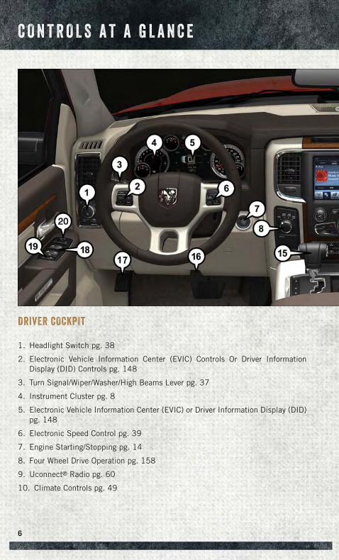
DRIVER COCKPIT
1. Headlight Switch pg. 38
2. Electronic Vehicle Information Center (EVIC) Controls Or Driver InformationDisplay (DID) Controls pg. 148
3. Turn Signal/Wiper/Washer/High Beams Lever pg. 37
4. Instrument Cluster pg. 8
5. Electronic Vehicle Information Center (EVIC) or Driver Information Display (DID)pg. 148
6. Electronic Speed Control pg. 39
7. Engine Starting/Stopping pg. 14
8. Four Wheel Drive Operation pg. 158
9. Uconnect® Radio pg. 60
10. Climate Controls pg. 49
C O N T R O L S A T A G L A N C E
6
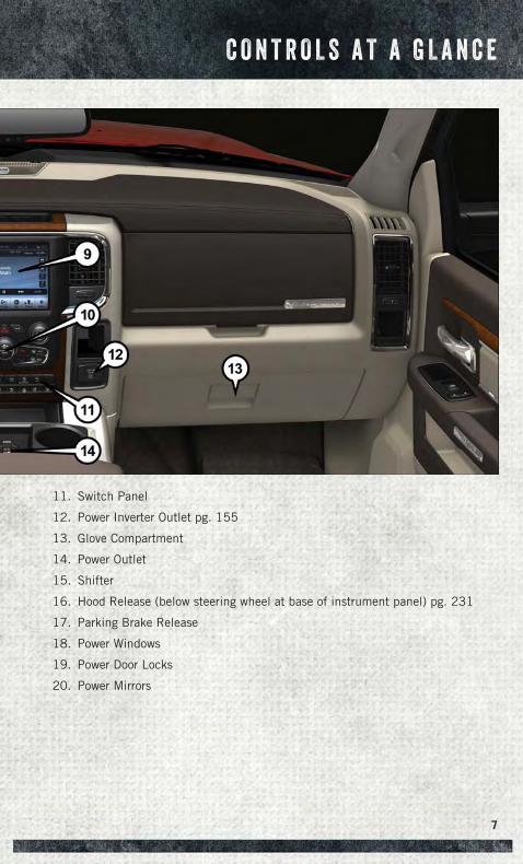
11. Switch Panel
12. Power Inverter Outlet pg. 155
13. Glove Compartment
14. Power Outlet
15. Shifter
16. Hood Release (below steering wheel at base of instrument panel) pg. 231
17. Parking Brake Release
18. Power Windows
19. Power Door Locks
20. Power Mirrors
C O N T R O L S A T A G L A N C E
7
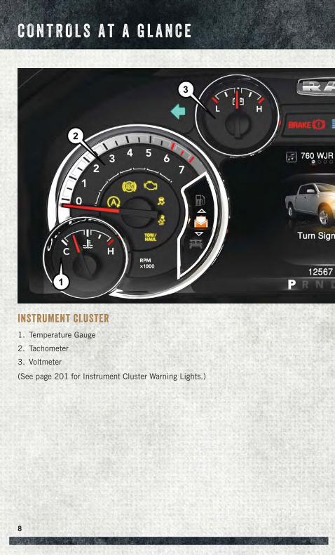
INSTRUMENT CLUSTER
1. Temperature Gauge
2. Tachometer
3. Voltmeter
(See page 201 for Instrument Cluster Warning Lights.)
C O N T R O L S A T A G L A N C E
8
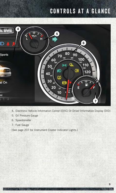
4. Electronic Vehicle Information Center (EVIC) Or Driver Information Display (DID)
5. Oil Pressure Gauge
6. Speedometer
7. Fuel Gauge
(See page 207 for Instrument Cluster Indicator Lights.)
C O N T R O L S A T A G L A N C E
9
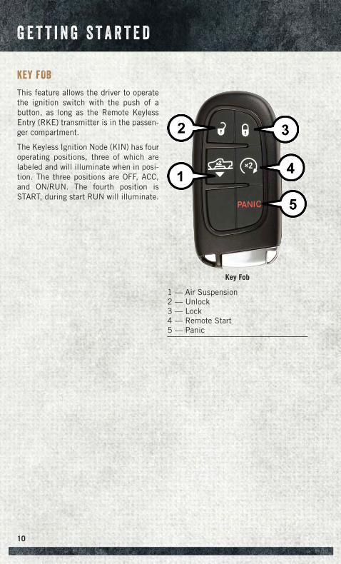
KEY FOB
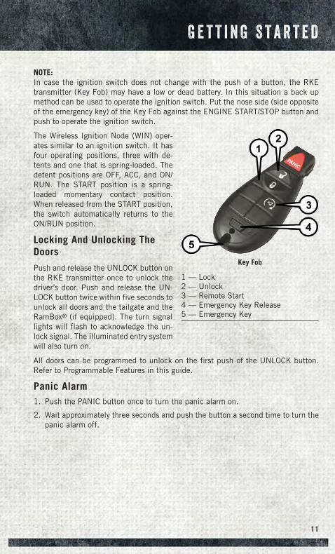
This feature allows the driver to operatethe ignition switch with the push of abutton, as long as the Remote KeylessEntry (RKE) transmitter is in the passen-ger compartment.
The Keyless Ignition Node (KIN) has fouroperating positions, three of which arelabeled and will illuminate when in posi-tion. The three positions are OFF, ACC,and ON/RUN. The fourth position isSTART, during start RUN will illuminate.
Key Fob
1 — Air Suspension2 — Unlock3 — Lock4 — Remote Start5 — Panic
G E T T I N G S T A R T E D
10
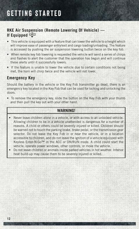
NOTE:In case the ignition switch does not change with the push of a button, the RKEtransmitter (Key Fob) may have a low or dead battery. In this situation a back upmethod can be used to operate the ignition switch. Put the nose side (side oppositeof the emergency key) of the Key Fob against the ENGINE START/STOP button andpush to operate the ignition switch.
The Wireless Ignition Node (WIN) oper-ates similar to an ignition switch. It hasfour operating positions, three with de-tents and one that is spring-loaded. Thedetent positions are OFF, ACC, and ON/RUN. The START position is a spring-loaded momentary contact position.When released from the START position,the switch automatically returns to theON/RUN position.
Locking And Unlocking TheDoors
Push and release the UNLOCK button onthe RKE transmitter once to unlock thedriver’s door. Push and release the UN-LOCK button twice within five seconds tounlock all doors and the tailgate and theRamBox® (if equipped). The turn signallights will flash to acknowledge the un-lock signal. The illuminated entry systemwill also turn on.
All doors can be programmed to unlock on the first push of the UNLOCK button.Refer to Programmable Features in this guide.
Panic Alarm1. Push the PANIC button once to turn the panic alarm on.
2. Wait approximately three seconds and push the button a second time to turn thepanic alarm off.
Key Fob
1 — Lock2 — Unlock3 — Remote Start4 — Emergency Key Release5 — Emergency Key
G E T T I N G S T A R T E D
11
RKE Air Suspension (Remote Lowering Of Vehicle) —If Equipped x2
• This vehicle is equipped with a feature that can lower the vehicle to a height whichwill improve ease of passenger entry/exit and cargo loading/unloading. The featureis accessed by pushing the air suspension lowering button twice on the key fob.
• When remote key fob lowering is requested the vehicle will send a series of chirpsand flashes to alert the customer that the operation has begun and will continuethese alerts until it successfully lowers.
• If the feature is unable to lower the vehicle due to certain conditions not beingmet, the horn will chirp twice and the vehicle will not lower.
Emergency Key
Should the battery in the vehicle or the Key Fob transmitter go dead, there is anemergency key located in the Key Fob that can be used for locking and unlocking thedoors.
• To remove the emergency key, slide the button on the Key Fob with your thumband then pull the key out with your other hand.
WARNING!
• Never leave children alone in a vehicle, or with access to an unlocked vehicle.Allowing children to be in a vehicle unattended is dangerous for a number ofreasons. A child or others could be severely injured or killed. Children shouldbe warned not to touch the parking brake, brake pedal, or the transmission gearselector. Do not leave the Key Fob in or near the vehicle, or in a locationaccessible to children, and do not leave the ignition of a vehicle equipped withKeyless Enter-N-Go™ in the ACC or ON/RUN mode. A child could start thevehicle, operate power windows, other controls, or move the vehicle.
• Do not leave children or animals inside parked vehicles in hot weather. Interiorheat build-up may cause them to be severely injured or killed.
G E T T I N G S T A R T E D
12
KEYLESS ENTER-N-GO™
The Keyless Enter-N-Go™ system is an enhancement to the vehicle's Key Fob. Thisfeature allows you to lock and unlock the vehicle's door(s) without having to push KeyFob lock or unlock buttons, as well as starting and stopping the vehicle with the pushof a button.
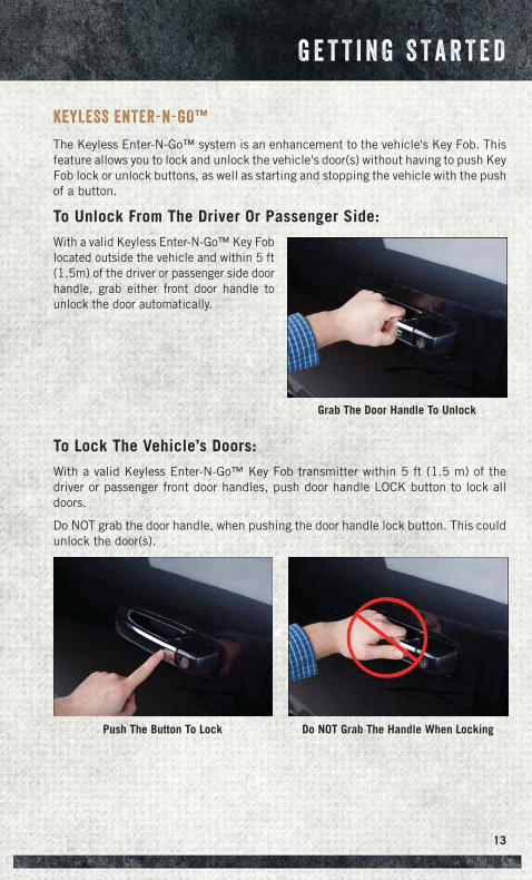
To Unlock From The Driver Or Passenger Side:
With a valid Keyless Enter-N-Go™ Key Foblocated outside the vehicle and within 5 ft(1.5m) of the driver or passenger side doorhandle, grab either front door handle tounlock the door automatically.
To Lock The Vehicle’s Doors:
With a valid Keyless Enter-N-Go™ Key Fob transmitter within 5 ft (1.5 m) of thedriver or passenger front door handles, push door handle LOCK button to lock alldoors.
Do NOT grab the door handle, when pushing the door handle lock button. This couldunlock the door(s).
Grab The Door Handle To Unlock
Push The Button To Lock Do NOT Grab The Handle When Locking
G E T T I N G S T A R T E D
13
NOTE:
• After pushing the door handle LOCK button, you must wait two seconds before youcan lock or unlock the doors, using either Passive Entry door handle. This is doneto allow you to check if the vehicle is locked by pulling the door handle without thevehicle reacting and unlocking.
• The Passive Entry system will not operate if the RKE transmitter battery is dead.
The vehicle doors can also be locked by using the RKE transmitter lock button or thelock button located on the vehicles interior door panel.
Engine Starting/Stopping
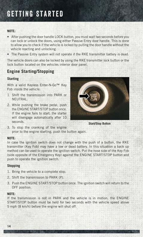
Starting
With a valid Keyless Enter-N-Go™ KeyFob inside the vehicle:
1. Shift the transmission into PARK orNEUTRAL.
2. While pushing the brake pedal, pushthe ENGINE START/STOP button once.If the engine fails to start, the starterwill disengage automatically after 10seconds.
3. To stop the cranking of the engineprior to the engine starting, push the button again.
NOTE:In case the ignition switch does not change with the push of a button, the RKEtransmitter (Key Fob) may have a low or dead battery. In this situation a back upmethod can be used to operate the ignition switch. Put the nose side of the Key Fob(side opposite of the Emergency Key) against the ENGINE START/STOP button andpush to operate the ignition switch.
Stopping
1. Bring the vehicle to a complete stop.
2. Shift the transmission to PARK (P).
3. Push the ENGINE START/STOP button once. The ignition switch will return to theOFF position.
NOTE:If the transmission is not in PARK and the vehicle is in motion, the ENGINESTART/STOP button must be held for two seconds with the vehicle speed above5 mph (8 km/h) before the engine will shut off.
Start/Stop Button
G E T T I N G S T A R T E D
14
REMOTE START
• Push REMOTE START button x2 on the Key Fob twice within five seconds.Pushing the REMOTE START x2 button a third time shuts the engine off.
• To drive the vehicle, push and release the UNLOCK button on the RKE transmitterto unlock the doors and disarm the Vehicle Security Alarm System (if equipped).Then cycle the ignition to the ON/RUN position.
With Remote Start, the engine will only run for 15 minutes (timeout) unless theignition is cycled to the ON/RUN position.
The vehicle must be started with the Key Fob after two consecutive timeouts.
WARNING!
• Do not start or run an engine in a closed garage or confined area. Exhaust gascontains Carbon Monoxide (CO) which is odorless and colorless. CarbonMonoxide is poisonous and can cause you or others to be severely injured orkilled when inhaled.
• Keep Key Fob transmitters away from children. Operation of the Remote StartSystem, windows, door locks or other controls could cause you and others to beseverely injured or killed.
VEHICLE SECURITY ALARM
The Vehicle Security Alarm monitors the vehicle doors for unauthorized entry and theKeyless Enter-N-Go™ START/STOP button for unauthorized operation. While theVehicle Security Alarm is armed, interior switches for door locks and decklid release aredisabled. If something triggers the alarm, the Vehicle Security Alarm will provide thefollowing audible and visible signals: the horn will pulse, the park lamps and/or turnsignals will flash, and the Vehicle Security Light in the instrument cluster will flash.
To Arm:• Lock the door using either the power door lock switch (one door must be open) or
the LOCK button on the Remote Keyless Entry (RKE) transmitter (doors can beopen or closed), and close all doors.
The Vehicle Security Light in the instrument cluster will flash for 16 seconds. Thisshows that the Vehicle Security Alarm is arming. During this period, if a door isopened, the ignition is cycled to ON/RUN, or the power door locks are unlocked in anymanner, the Vehicle Security Alarm will automatically disarm.
NOTE:
• The Vehicle Security Alarm will not arm if you lock the doors with the manual doorlock plungers.
• Once armed, the Vehicle Security Alarm disables the unlock switch on the driverdoor trim panel and passenger door trim panel.
G E T T I N G S T A R T E D
15
To Disarm The System:• Push the Key Fob UNLOCK button or cycle the ignition to the ON/RUN position.
The Vehicle Security Alarm is designed to protect your vehicle; however, you cancreate conditions where the Vehicle Security Alarm will give you a false alarm. If oneof the previously described arming sequences has occurred, the Vehicle SecurityAlarm will arm regardless of whether you are in the vehicle or not. If you remain in thevehicle and open a door, the alarm will sound. If this occurs, disarm the VehicleSecurity Alarm.
If the Vehicle Security Alarm is armed and the battery becomes disconnected theVehicle Security Alarm will remain armed when the battery is reconnected. Theexterior lights will flash, and the horn will sound. If this occurs, disarm the VehicleSecurity Alarm.
SEAT BELT SYSTEMS
Lap/Shoulder Belts• All seating positions except the Quad Cab®, Mega Cab® and Crew Cab front center
seating position have combination lap/shoulder belts.
• Be sure everyone in your vehicle is in a seat and using a seat belt properly.
• Position the lap belt so that it is snug and lies low across your hips, below yourabdomen. To remove slack in the lap belt portion, pull up on the shoulder belt.To loosen the lap belt if it is too tight, tilt the latch plate and pull on the lap belt.A snug seat belt reduces the risk of sliding under the seat belt in a collision.
• Position the shoulder belt across the shoulder and chest with minimal, if any slackso that it is comfortable and not resting on your neck. The retractor will withdrawany slack in the shoulder belt.
Center Lap Belts
The center seating position for the Quad Cab®, Mega Cab® and Crew Cab front seathas a lap belt only. To buckle the lap belt, slide the latch plate into the buckle untilyou hear a "click." To lengthen the lap belt, tilt the latch plate and pull.
G E T T I N G S T A R T E D
16
Seat Belt Pretensioner• The front seat belt system is equipped with pretensioning devices that are
designed to remove slack from the seat belt in the event of a collision.
• A deployed pretensioner or a deployed air bag must be replaced immediately.
WARNING!
• In a collision, you and your passengers can suffer much greater injuries if youare not properly buckled up. You can strike the interior of your vehicle or otherpassengers, or you can be thrown out of the vehicle. Always be sure you andothers in your vehicle are buckled up properly.
• A shoulder belt placed behind you will not protect you from injury during acollision. You are more likely to hit your head in a collision if you do not wearyour shoulder belt. The lap and shoulder belt are meant to be used together.
• A seat belt that is too loose will not protect you properly. In a sudden stop, youcould move too far forward, increasing the possibility of injury. Wear your seatbelt snugly.
• A frayed or torn seat belt could rip apart in a collision and leave you with noprotection. Inspect the seat belt system periodically, checking for cuts, frays,or loose parts. Damaged parts must be replaced immediately. Do not disas-semble or modify the system. Seat belt assemblies must be replaced after acollision.
SUPPLEMENTAL RESTRAINT SYSTEM (SRS) — AIR BAGS
Air Bag System Components
Your vehicle may be equipped with the following air bag system components:
• Occupant Restraint Controller (ORC)
• Air Bag Warning Light
• Steering Wheel and Column
• Instrument Panel
• Knee Impact Bolsters
• Advanced Front Air Bags
• Supplemental Side Air Bags
• Front and Side Impact Sensors (if equipped)
• Seat Belt Pretensioners
• Seat Belt Buckle Switch
G E T T I N G S T A R T E D
17
Advanced Front Air Bags• This vehicle has Advanced Front Air Bags for both the driver and front passenger
as a supplement to the seat belt restraint systems. The Advanced Front Air Bagswill not deploy in every type of collision.
• Advanced Front Air Bags are designed to provide additional protection bysupplementing the seat belts. Advanced Front Air Bags are not expected to reducethe risk of injury in rear, side, or rollover collisions.
• The Advanced Front Air Bags will not deploy in all frontal collisions, includingsome that may produce substantial vehicle damage — for example, some polecollisions, truck underrides, and angle offset collisions.
• On the other hand, depending on the type and location of impact, Advanced FrontAir Bags may deploy in crashes with little vehicle front-end damage but thatproduce a severe initial deceleration.
• Because air bag sensors measure vehicle deceleration over time, vehicle speedand damage by themselves are not good indicators of whether or not an air bagshould have deployed.
• Seat belts are necessary for your protection in all collisions, and also are neededto help keep you in position, away from an inflating air bag.
• The air bags must be ready to inflate for your protection in a collision. TheOccupant Restraint Controller (ORC) monitors the internal circuits and intercon-necting wiring associated with air bag system electrical components.
• The ORC turns on the Air Bag Warning Light in the instrument panel forapproximately four to eight seconds for a self-check when the ignition switch isfirst turned to the ON/RUN position. After the self-check, the Air Bag WarningLight will turn off. If the ORC detects a malfunction in any part of the system, itturns on the Air Bag Warning Light, either momentarily or continuously. A singlechime will sound to alert you if the light comes on again after initial startup.
• The ORC monitors the readiness of the electronic parts of the air bag systemwhenever the ignition switch is in the START or ON/RUN position. If the ignitionswitch is in the OFF position or in the ACC position, the air bag system is not onand the air bags will not inflate.
• If the Air Bag Warning Light in the instrument panel is not on during the four toeight seconds when the ignition switch is first turned to the ON/RUN position,stays on, or turns on while driving, have the vehicle serviced by an authorizedservice center immediately.
NOTE:If the speedometer, tachometer, or any engine related gauges are not working, theOccupant Restraint Controller (ORC) may also be disabled. In this condition the airbags may not be ready to inflate for your protection. Have an authorized dealerservice the air bag system immediately.
• After any collision, the vehicle should be taken to an authorized dealer immediately.
• Do not drive your vehicle after the air bags have deployed. If you are involved inanother collision, the air bags will not be in place to protect you.
G E T T I N G S T A R T E D
18

• If it is necessary to modify the air bag system for persons with disabilities, contactyour authorized dealer.
• Refer to the Owner's Manual on the DVD for further details regarding theSupplemental Restraint System (SRS).
Supplemental Side Air Bags• This vehicle is equipped with Supplemental Seat-Mounted Side Air Bags (SABs)
located in the outboard side of the front seats. The SABs are marked with a SRSAIRBAG label sewn into the outboard side of the seats.
• This vehicle is equipped with Supplemental Side Air Bag Inflatable Curtains(SABICs) located above the side windows. The trim covering the SABICs is labeledSRS AIRBAG. The SABICs may help reduce the risk of partial or complete ejectionof vehicle occupants through side windows in certain side impact events.
• The SABICs and SABs (“Side Air Bags”) are designed to activate in certain sideimpacts and certain rollover events. The Occupant Restraint Controller (“ORC”)determines whether the deployment of the Side Air Bags in a particular sideimpact or rollover event is appropriate, based on the severity and type of collision.Vehicle damage by itself is not a good indicator of whether or not Side Air Bagsshould have deployed.
WARNING!
• Side Air Bags need room to inflate. Do not lean against the door or window. Situpright in the center of the seat.
• Being too close to the Side Air Bags during deployment could cause you to beseverely injured or killed.
• Relying on the Side Air Bags alone could lead to more severe injuries in acollision. The Side Air Bags work with your seat belt to restrain you properly. Insome collisions, Side Air Bags won’t deploy at all. Always wear your seat belteven though you have Side Air Bags.
• This vehicle is equipped with left and right Supplemental Side Air BagInflatable Curtains (SABICs). Do not stack luggage or other cargo up highenough to block the deployment of the SABICs. The trim covering above theside windows where the SABIC and its deployment path are located shouldremain free from any obstructions.
• This vehicle is equipped with SABICs. In order for the SABICs to work asintended, do not install any accessory items in your vehicle which could alterthe roof. Do not add an aftermarket sunroof to your vehicle. Do not add roofracks that require permanent attachments (bolts or screws) for installation onthe vehicle roof. Do not drill into the roof of the vehicle for any reason.
• Do not use accessory seat covers or place objects between you and the Side AirBags; the performance could be adversely affected and/or objects could bepushed into you, causing serious injury.
G E T T I N G S T A R T E D
19
CHILD RESTRAINTS
Children 12 years or younger should ride properly buckled up in a rear seat, ifavailable. According to crash statistics, children are safer when properly restrained inthe rear seats rather than in the front.
Every state in the United States and all Canadian provinces require that smallchildren ride in proper restraint systems. This is the law, and you can be prosecutedfor ignoring it.
NOTE:
• For additional information, refer to www.Seatcheck.org or call 1-866-SEATCHECK.
• Canadian residents should refer to Transport Canada’s website for additional information:http://www.tc.gc.ca/eng/motorvehiclesafety/safedrivers-childsafety-index-53.htm
LATCH — Lower Anchors And Tethers For CHildren(Crew/Quad Cab Full Bench)• Your vehicle is equipped with the child restraint anchorage system called LATCH,
which stands for Lower Anchors and Tethers for CHildren.
• The rear outboard seating positions have lower anchors and top tether anchors.The rear center seating position has a top tether anchor only.
LATCH – Lower Anchors And Tethers For CHildren(Crew/Mega/Quad Cab Split Bench)• Your vehicle is equipped with the child restraint anchorage system called LATCH,
which stands for Lower Anchors and Tethers for CHildren.
• All rear seating positions have lower anchors and top tether anchors.
LATCH System Weight Limit
You may use the LATCH anchorage system until the combined weight of the child andthe child restraint is 65 lbs (29.5 kg). Use the seat belt and tether anchor instead ofthe LATCH system once the combined weight is more than 65 lbs (29.5 kg).
G E T T I N G S T A R T E D
20
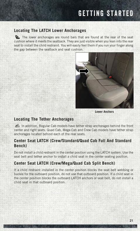
Locating The LATCH Lower Anchorages
The lower anchorages are round bars that are found at the rear of the seatcushion where it meets the seatback. They are just visible when you lean into the rearseat to install the child restraint. You will easily feel them if you run your finger alongthe gap between the seatback and seat cushion.
Locating The Tether Anchorages
In addition, Regular Cab models have tether strap anchorages behind the frontcenter and right seats. Quad Cab, Mega Cab and Crew Cab models have tether strapanchorages located behind each of the rear seats.
Center Seat LATCH (Crew/Standard/Quad Cab Full And StandardBench)
Do not install a child restraint in the center position using the LATCH system. Use theseat belt and tether anchor to install a child seat in the center seating position.
Center Seat LATCH (Crew/Mega/Quad Cab Split Bench)
If a child restraint installed in the center position blocks the seat belt webbing orbuckle for the outboard position, do not use that outboard position. If a child seat inthe center position blocks the outboard LATCH anchors or seat belt, do not install achild seat in that outboard position.
Lower Anchors
G E T T I N G S T A R T E D
21
Installing The Child Restraint Using The LATCH Lower Anchors
NOTE:Never “share” a LATCH anchorage with two or more child restraints.
1. Loosen the adjusters on the lower straps and on the tether strap of the child seatso that you can more easily attach the hooks or connectors to the vehicleanchorages.
2. Attach the lower hooks or connectors of the child restraint to the lower anchoragesin the selected seating position.
3. If the child restraint has a tether strap, connect it to the top tether anchorage. Seebelow for directions to attach a tether anchor.
4. Tighten all of the straps as you push the child restraint rearward and downwardinto the seat. Remove slack in the straps according to the child restraintmanufacturer’s instructions.
5. Test that the child restraint is installed tightly by pulling back and forth on thechild seat at the belt path. It should not move more than 1 inch (25.4 mm) in anydirection.
Installing The Child Restraint Using The Vehicle Seat Belts(Standard Cab)
The seat belts in the passenger seating positions are equipped with a SwitchableAutomatic Locking Retractor (ALR) that is designed to keep the lap portion of theseat belt tight around the child restraint. Any seat belt system will loosen with time,so check the belt occasionally, and pull it tight if necessary.
Installing The Child Restraint Using The Vehicle Seat Belts(Crew/Mega/Quad Cab Full And Split Bench)
The seat belts in the outboard passenger seating positions are equipped with aSwitchable Automatic Locking Retractor (ALR). The center seating positions areequipped with a cinching latch plate. Both types of seat belts are designed to keepthe lap portion of the seat belt tight around the child restraint. Any seat belt systemwill loosen with time, so check the belt occasionally, and pull it tight if necessary.
Tether Anchorage Weight Limit
Always use the tether anchor when using the seat belt to install a forward facing childrestraint, up to the recommended weight limit of the child restraint.
To Install A Child Seat Using An ALR:1. Pull enough of the seat belt webbing from the retractor to pass it through the belt
path of the child restraint. Do not twist the belt webbing in the belt path.
2. Slide the latch plate into the buckle until you hear a “click.”
3. Pull on the webbing to make the lap portion tight against the child seat.
G E T T I N G S T A R T E D
22
4. To lock the seat belt, pull down on the shoulder part of the belt until you havepulled all the seat belt webbing out of the retractor. Then, allow the webbing toretract back into the retractor. As the webbing retracts, you will hear a clickingsound. This means the seat belt is now in the Automatic Locking mode.
5. Try to pull the webbing out of the retractor. If it is locked, you should not be ableto pull out any webbing. If the retractor is not locked, repeat the last step.
6. Finally, pull up on any extra webbing to tighten the lap portion around the childrestraint while you push the child restraint rearward and downward into thevehicle seat.
7. If the child restraint has a top tether strap and the seating position has a top tetheranchorage, connect the tether strap to the anchorage and tighten the tether strap.See below for directions to attach a tether anchor.
8. Test that the child restraint is installed tightly by pulling back and forth on thechild seat at the belt path. It should not move more than 1 inch (25.4 mm) in anydirection.
To Install A Child Seat Using A Cinching Latch Plate:1. Place the child seat in the center of the seating position.
2. Next, pull enough of the seat belt webbing from the retractor to pass it through thebelt path of the child restraint. Do not twist the belt webbing in the belt path.
3. Slide the latch plate into the buckle until you hear a “click.”
4. Finally, pull up on any excess webbing to tighten the lap portion around the childrestraint while you push the child restraint rearward and downward into thevehicle seat.
5. If the child restraint has a top tether strap and the seating position has a top tetheranchorage, connect the tether strap to the anchorage and tighten the tether strap.See below for directions to attach a tether anchor.
6. Test that the child restraint is installed tightly by pulling back and forth on thechild seat at the belt path. It should not move more than 1 inch (25.4 mm) in anydirection.
Installing The Top Tether Strap (With Either Lower Anchors OrVehicle Seat Belt):
When installing a forward-facing child restraint, always secure the top tether strap,up to the tether anchor weight limit, whether the child restraint is installed with thelower anchors or the vehicle seat belt.
G E T T I N G S T A R T E D
23
Tether Anchorage Installation
Regular and Mega Cab Trucks:
In the regular cab truck, the top tether anchorages are located behind the center andright passenger seats. In the mega cab truck, the top tether anchorages are locatedbehind each rear seating position. There is a plastic cover over each anchorage.To attach the tether strap of the child restraint:
1. Place the child restraint on the seat and adjust the tether strap so that it will reachover the seat back, under the head restraint and to the tether anchor directlybehind the seat.
2. Route the tether strap to provide the most direct path between the anchorage andthe child seat. The tether strap should go between the head restraint postsunderneath the head restraint. You may need to adjust the head restraint to theupward position to pass the tether strap underneath the head restraint andbetween its posts.
3. Lift the cover (if equipped) and attach the hook to the square opening in the sheetmetal. Tighten the tether strap according to the child seat manufacturer’sinstructions.
Quad or Crew Cab Trucks:
The top tether anchorages in this vehicle are tether strap loops located between therear glass and the back of the rear seat. There is a tether strap loop located behindeach seating position. Follow the steps below to attach the tether strap of the childrestraint.
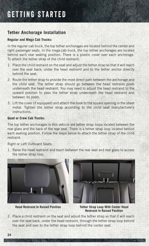
Right or Left Outboard Seats:
1. Raise the head restraint and reach between the rear seat and rear glass to accessthe tether strap loop.
2. Place a child restraint on the seat and adjust the tether strap so that it will reachover the seat back, under the head restraint, through the tether strap loop behindthe seat and over to the tether strap loop behind the center seat.
Head Restraint In Raised Position Tether Strap Loop With Center HeadRestraint In Raised Position
G E T T I N G S T A R T E D
24
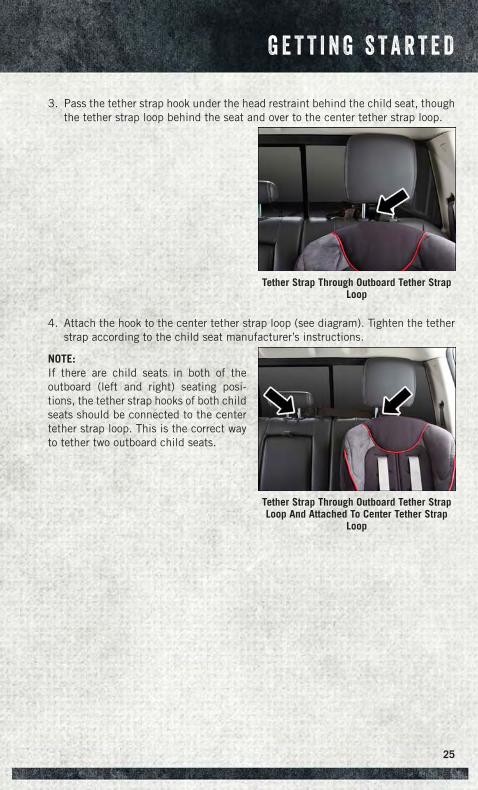
3. Pass the tether strap hook under the head restraint behind the child seat, thoughthe tether strap loop behind the seat and over to the center tether strap loop.
4. Attach the hook to the center tether strap loop (see diagram). Tighten the tetherstrap according to the child seat manufacturer’s instructions.
NOTE:If there are child seats in both of theoutboard (left and right) seating posi-tions, the tether strap hooks of both childseats should be connected to the centertether strap loop. This is the correct wayto tether two outboard child seats.
Tether Strap Through Outboard Tether StrapLoop
Tether Strap Through Outboard Tether StrapLoop And Attached To Center Tether Strap
Loop
G E T T I N G S T A R T E D
25
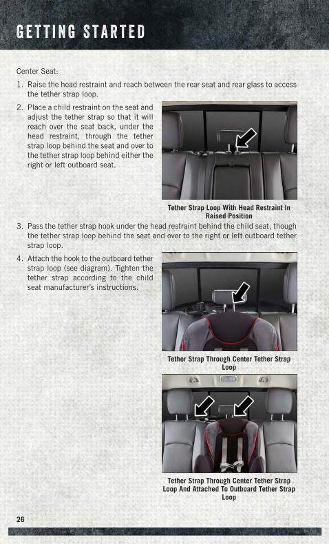
Center Seat:
1. Raise the head restraint and reach between the rear seat and rear glass to accessthe tether strap loop.
2. Place a child restraint on the seat andadjust the tether strap so that it willreach over the seat back, under thehead restraint, through the tetherstrap loop behind the seat and over tothe tether strap loop behind either theright or left outboard seat.
3. Pass the tether strap hook under the head restraint behind the child seat, thoughthe tether strap loop behind the seat and over to the right or left outboard tetherstrap loop.
4. Attach the hook to the outboard tetherstrap loop (see diagram). Tighten thetether strap according to the childseat manufacturer’s instructions.
Tether Strap Loop With Head Restraint InRaised Position
Tether Strap Through Center Tether StrapLoop
Tether Strap Through Center Tether StrapLoop And Attached To Outboard Tether Strap
Loop
G E T T I N G S T A R T E D
26
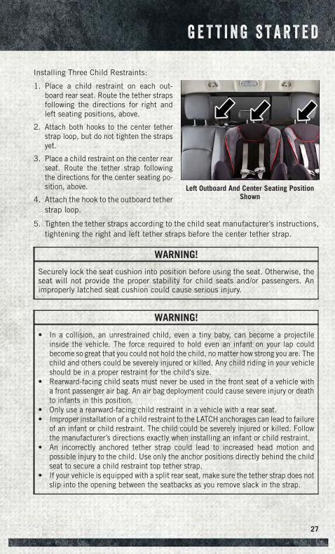
Installing Three Child Restraints:
1. Place a child restraint on each out-board rear seat. Route the tether strapsfollowing the directions for right andleft seating positions, above.
2. Attach both hooks to the center tetherstrap loop, but do not tighten the strapsyet.
3. Place a child restraint on the center rearseat. Route the tether strap followingthe directions for the center seating po-sition, above.
4. Attach the hook to the outboard tetherstrap loop.
5. Tighten the tether straps according to the child seat manufacturer’s instructions,tightening the right and left tether straps before the center tether strap.
WARNING!
Securely lock the seat cushion into position before using the seat. Otherwise, theseat will not provide the proper stability for child seats and/or passengers. Animproperly latched seat cushion could cause serious injury.
WARNING!
• In a collision, an unrestrained child, even a tiny baby, can become a projectileinside the vehicle. The force required to hold even an infant on your lap couldbecome so great that you could not hold the child, no matter how strong you are. Thechild and others could be severely injured or killed. Any child riding in your vehicleshould be in a proper restraint for the child's size.
• Rearward-facing child seats must never be used in the front seat of a vehicle witha front passenger air bag. An air bag deployment could cause severe injury or deathto infants in this position.
• Only use a rearward-facing child restraint in a vehicle with a rear seat.• Improper installation of a child restraint to the LATCH anchorages can lead to failure
of an infant or child restraint. The child could be severely injured or killed. Followthe manufacturer’s directions exactly when installing an infant or child restraint.
• An incorrectly anchored tether strap could lead to increased head motion andpossible injury to the child. Use only the anchor positions directly behind the childseat to secure a child restraint top tether strap.
• If your vehicle is equipped with a split rear seat, make sure the tether strap does notslip into the opening between the seatbacks as you remove slack in the strap.
Left Outboard And Center Seating PositionShown
G E T T I N G S T A R T E D
27
HEAD RESTRAINTS
Head restraints are designed to reduce the risk of injury by restricting headmovement in the event of a rear impact. Head restraints should be adjusted so thatthe top of the head restraint is located above the top of your ear.
WARNING!
The head restraints for all occupants must be properly installed and adjusted priorto operating the vehicle or occupying a seat. Head restraints should never beadjusted while the vehicle is in motion. Driving a vehicle with the head restraintsimproperly adjusted or removed could cause serious injury or death in the event ofa collision.
Front Head Restraints
To raise the head restraint, pull upward on the head restraint. To lower the headrestraint, press the adjustment button, located on the base of the head restraint, andpush downward on the head restraint.
To remove the head restraint, raise it as far as it can go then press the release buttonsat the base of each post while pulling the head restraint up. To reinstall the headrestraint, put the head restraint posts into the holes while pressing the releasebuttons. Then adjust it to the appropriate height.
WARNING!
A loose head restraint thrown forward in a collision or hard stop could causeserious injury or death to occupants of the vehicle. Always securely stow removedhead restraints in a location outside the occupant compartment.
WARNING!
ALL the head restraints MUST be reinstalled in the vehicle to properly protect theoccupants. Follow the re-installation instructions above prior to operating thevehicle or occupying a seat.
G E T T I N G S T A R T E D
28
Rear Head Restraints
The rear seats are equipped with adjustable head restraints. To raise the headrestraint, pull upward on the head restraint. To lower the head restraint, press theadjustment button, located on the base of the head restraint, and push downward onthe head restraint.
NOTE:
• The rear center head restraint (Crew Cab and Quad Cab) has only one adjustmentposition that is used to aid in the routing of a tether. Refer to “OccupantRestraints” in “Things to Know Before Starting Your Vehicle” in the Owner'sManual on the DVD.
• The head restraints should only be removed by qualified technicians, for servicepurposes only. If either of the head restraints require removal, see your authorizeddealer.
FRONT SEATS
Power Seats
The seat switch controls forward/backward and up/down. The recline switch controlsthe angle of the seatback.
• Push the switch forward or rearward and the seatback will move in either direction.
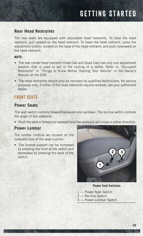
Power Lumbar
The lumbar controls are located on theoutboard side of the seat cushion.
• The lumbar support can be increasedby pressing the front of the switch anddecreased by pressing the back of theswitch.
Power Seat Switches
1 — Power Seat Switch2 — Recline Switch3 — Power Lumbar Switch
G E T T I N G S T A R T E D
29
Memory Seat
The memory seat feature allows you to save the driver's seat position (excluding lumbarposition), driver's outside mirror position, adjustable brake and accelerator pedals,Automatic Temperature Control (ATC) temperature setting and radio station presetsettings. The driver's memory buttons are located on the outboard side of the driver'sseat cushion.
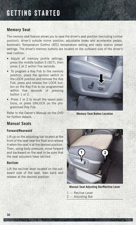
• Adjust all memory profile settings,press the middle button S (SET), thenpress 1 or 2 within five seconds.
• To program a Key Fob to the memoryposition, place the ignition switch inthe LOCK position and remove the KeyFob, press and release the LOCK but-ton on the Key Fob to be programmedwithin five seconds of pressingbutton 1 or 2.
• Press 1 or 2 to recall the saved posi-tions, or press UNLOCK on the pro-grammed Key Fob.
Refer to the Owner's Manual on the DVDfor further details.
Manual Seats
Forward/Rearward
Lift up on the adjusting bar located at thefront of the seat near the floor and releaseit when the seat is at the desired position.Then, using body pressure, move forwardand backward on the seat to be sure thatthe seat adjusters have latched.
Recliner
Lift the recliner lever located on the out-board side of the seat, lean back andrelease at the desired position.
Memory Seat Button Location
Manual Seat Adjusting Bar/Recline Lever
1 — Recline Lever2 — Adjusting Bar
G E T T I N G S T A R T E D
30
CAUTION!
Do not place any article under a power seat or impede its ability to move as it maycause damage to the seat controls. Seat travel may become limited if movementis stopped by an obstruction in the seat’s path.
WARNING!
• Adjusting a seat while the vehicle is moving is dangerous. The suddenmovement of the seat could cause you to lose control. The seat belt might notbe properly adjusted, and you could be severely injured or killed. Only adjust aseat while the vehicle is parked.
• Actuating the recliner handle will allow the seatback to swing forward. Do notstand or lean in front of the seatback while actuating the handle. The seatbackmay swing forward and strike you, causing injury. To avoid possible injury, placeyour hand on the seatback while actuating the recliner handle.
• Do not ride with the seatback reclined so that the seat belt is no longer restingagainst your chest. In a collision, you could slide under the seat belt and beseverely injured or killed. Use the recliner only when the vehicle is parked.
HEATED/VENTILATED SEATS
Front Ventilated Seats
Located in the seat cushion are small fans that draw the air from the passengercompartment and pull air through fine perforations in the seat cover to help keep thedriver and front passenger cooler in higher ambient temperatures. The fans operateat two speeds, HIGH and LOW.
The front ventilated seats control buttons are located on the center instrumentpanel below the climate controls.
If your vehicle is equipped with a touchscreen, the front ventilated seats controlbuttons are located within the climate or controls screen of the touchscreen.
• Press the ventilated seat button once to choose HIGH.
• Press the ventilated seat button a second time to choose LOW.
• Press the ventilated seat button a third time to turn the ventilated seat OFF.
G E T T I N G S T A R T E D
31
Vehicle Equipped With Remote Start
On models that are equipped with remote start, this feature can be programmed tocome on during a remote start.
If your vehicle is equipped with a touchscreen, this feature can be programmedthrough the Uconnect® system. Refer to “Uconnect® Settings” in “UnderstandingYour Instrument Panel” in the Owner's Manual on the DVD.
If your vehicle is not equipped with a touchscreen, this feature can be programmedthrough the Electronic Vehicle Information Center (EVIC). Refer to “ElectronicVehicle Information Center (EVIC)” in “Understanding Your Instrument Panel” in theOwner's Manual on the DVD.
Front Heated Seats
The front heated seats control buttons are located on the center instrumentpanel below the climate controls.
If your vehicle is equipped with a touchscreen, the front heated seats control buttonsare located within the climate or controls screen of the touchscreen.
• Press the heated seat button once to turn the High setting On.
• Press the heated seat button a second time to turn the Low setting On.
• Press the heated seat button a third time to turn the heating elements Off.
When the HI-level setting is selected, the heater will provide a boosted heat levelduring the first four minutes of operation. Then, the heat output will drop to thenormal HI-level. If the HI-level setting is selected, the system will automaticallyswitch to LO-level after a maximum of 60 minutes of continuous operation. At thattime, the display will change from HI to LO, indicating the change. The LO-levelsetting will turn OFF automatically after a maximum of 45 minutes.
Vehicle Equipped With Remote Start
On models that are equipped with remote start, this feature can be programmed tocome on during a remote start.
If your vehicle is equipped with a touchscreen, this feature can be programmedthrough the Uconnect® system. Refer to “Uconnect® Settings” in “UnderstandingYour Instrument Panel” in the Owner's Manual on the DVD.
If your vehicle is not equipped with a touchscreen, this feature can be programmedthrough the Electronic Vehicle Information Center (EVIC). Refer to “ElectronicVehicle Information Center (EVIC)” in “Understanding Your Instrument Panel” in theOwner's Manual on the DVD.
G E T T I N G S T A R T E D
32
REAR HEATED SEATS
The rear heated seat switches are located on the rear of the center console.
• Press the heated seat button once to turn the High setting On.
• Press the heated seat button a second time to turn the Low setting On.
• Press the heated seat button a third time to turn the heating elements Off.
When the HIGH-level setting is selected, the heater will provide a boosted heat levelduring the first four minutes of operation. Then, the heat output will drop to the normalHIGH-level. If the HIGH-level setting is selected, the system will automatically switch toLOW-level after a maximum of 60 minutes of continuous operation. At that time, thenumber of illuminated LEDs changes from two to one, indicating the change. TheLOW-level setting will turn OFF automatically after a maximum of 45 minutes.
WARNING!
• Persons who are unable to feel pain to the skin because of advanced age,chronic illness, diabetes, spinal cord injury, medication, alcohol use, exhaus-tion or other physical conditions must exercise care when using the seat heater.It may cause burns even at low temperatures, especially if used for long periodsof time.
• Do not place anything on the seat that insulates against heat, such as a blanketor cushion. This may cause the seat heater to overheat. Sitting in a seat thathas been overheated could cause serious burns due to the increased surfacetemperature of the seat.
HEATED STEERING WHEEL
The steering wheel contains a heating element that heats the steering wheel to onetemperature setting.
The heated steering wheel control button is located on the center instrumentpanel below the climate controls.
If your vehicle is equipped with a touchscreen, the heated steering wheel controlbutton is located within the climate or controls screen of the touchscreen.
• Press the heated steering wheel button once to turn the heating element On.
• Press the heated steering wheel button a second time to turn the heatingelement Off.
Once the heated steering wheel has been turned on, it will operate for approximately30 to 80 minutes before automatically shutting off. The heated steering wheel canshut off early or may not turn on when the steering wheel is already warm.
G E T T I N G S T A R T E D
33
Vehicle Equipped With Remote Start
On models that are equipped with remote start, this feature can be programmed tocome on during a remote start.
If your vehicle is equipped with a touchscreen, this feature can be programmedthrough the Uconnect® system. Refer to “Uconnect® Settings” in “UnderstandingYour Instrument Panel” in the Owner's Manual on the DVD.
If your vehicle is not equipped with a touchscreen, this feature can be programmedthrough the Electronic Vehicle Information Center (EVIC). Refer to “ElectronicVehicle Information Center (EVIC)” in “Understanding Your Instrument Panel” in theOwner's Manual on the DVD.
WARNING!
• Persons who are unable to feel pain to the skin because of advanced age,chronic illness, diabetes, spinal cord injury, medication, alcohol use, exhaus-tion, or other physical conditions must exercise care when using the steeringwheel heater. It may cause burns even at low temperatures, especially if usedfor long periods.
• Do not place anything on the steering wheel that insulates against heat, suchas a blanket or steering wheel covers of any type and material. This may causethe steering wheel heater to overheat.
TILT STEERING COLUMN
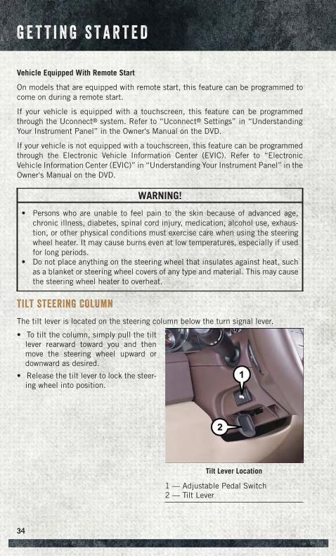
The tilt lever is located on the steering column below the turn signal lever.
• To tilt the column, simply pull the tiltlever rearward toward you and thenmove the steering wheel upward ordownward as desired.
• Release the tilt lever to lock the steer-ing wheel into position.
Tilt Lever Location
1 — Adjustable Pedal Switch2 — Tilt Lever
G E T T I N G S T A R T E D
34
ADJUSTABLE PEDALS
Press the switch located on the left side of the steering column forward to move thebrake and accelerator pedals away from the driver and press the switch rearward tomove the pedals closer to the driver.
NOTE:The pedals cannot be adjusted when the vehicle is in REVERSE or when theElectronic Speed Control is set.
CAUTION!
Do not place any article under the adjustable pedals or impede its ability to move,as it may cause damage to the pedal controls. Pedal travel may become limited ifmovement is stopped by an obstruction in the adjustable pedal's path.
WARNING!
• Tilting the steering column while the vehicle is moving is dangerous. Withouta stable steering column, you could lose control of the vehicle and have acollision. Adjust the column only while the vehicle is stopped. Be sure it islocked before driving.
• Do not adjust the pedals while the vehicle is moving. You could lose control andhave a collision. Always adjust the pedals while the vehicle is parked.
G E T T I N G S T A R T E D
35
ENGINE BREAK-IN RECOMMENDATIONS
A long break-in period is not required for the engine and drivetrain (transmission andaxle) in your vehicle.
Drive moderately during the first 300 miles (500 km). After the initial 60 miles(100 km), speeds up to 50 or 55 mph (80 or 90 km/h) are desirable.
While cruising, brief full-throttle acceleration within the limits of local traffic lawscontributes to a good break-in. Wide-open throttle acceleration in low gear can bedetrimental and should be avoided.
The engine oil installed in the engine at the factory is a high-quality energyconserving type lubricant. Oil changes should be consistent with anticipated climateconditions under which vehicle operations will occur. For the recommended viscosityand quality grades, refer to “Maintaining Your Vehicle.”
NOTE:A new engine may consume some oil during its first few thousand miles (kilometers)of operation. This should be considered a normal part of the break-in and notinterpreted as an indication of an engine problem or malfunction.
CAUTION!
Never use Non-Detergent Oil or Straight Mineral Oil in the engine or damage mayresult.
DIESEL ENGINE BREAK-IN RECOMMENDATIONS• For 3.0L diesel engine break-in recommendations, refer to Diesel Engine Break-In
Recommendations on pg. 176
• For 6.7L Cummins diesel engine break-in recommendations, refer to DieselEngine Break-In Recommendations on pg. 186
O P E R A T I N G Y O U R V E H I C L E
36
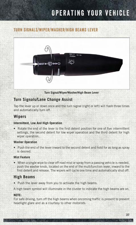
TURN SIGNALS/WIPER/WASHER/HIGH BEAMS LEVER
Turn Signals/Lane Change Assist
Tap the lever up or down once and the turn signal (right or left) will flash three timesand automatically turn off.
Wipers
Intermittent, Low And High Operation
• Rotate the end of the lever to the first detent position for one of five intermittentsettings, the second detent for low wiper operation and the third detent for highwiper operation.
Washer Operation
• Push the end of the lever inward to the second detent and hold for as long as sprayis desired.
Mist Feature
• When a single wipe to clear off road mist or spray from a passing vehicle is needed,push the washer knob, located on the end of the multifunction lever, inward to thefirst detent and release. The wipers will cycle one time and automatically shut off.
High Beams• Push the lever away from you to activate the high beams.
A high beam symbol will illuminate in the cluster to indicate the high beams are on.
NOTE:For safe driving, turn off the high beams when oncoming traffic is present to preventheadlight glare and as a courtesy to other motorists.
Turn Signal/Wiper/Washer/High Beam Lever
O P E R A T I N G Y O U R V E H I C L E
37
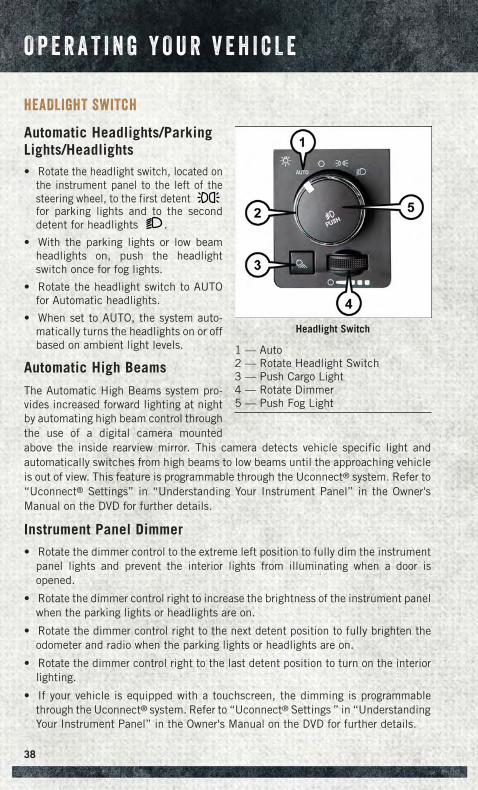
HEADLIGHT SWITCH
Automatic Headlights/ParkingLights/Headlights• Rotate the headlight switch, located on
the instrument panel to the left of thesteering wheel, to the first detentfor parking lights and to the seconddetent for headlights .
• With the parking lights or low beamheadlights on, push the headlightswitch once for fog lights.
• Rotate the headlight switch to AUTOfor Automatic headlights.
• When set to AUTO, the system auto-matically turns the headlights on or offbased on ambient light levels.
Automatic High Beams
The Automatic High Beams system pro-vides increased forward lighting at nightby automating high beam control throughthe use of a digital camera mountedabove the inside rearview mirror. This camera detects vehicle specific light andautomatically switches from high beams to low beams until the approaching vehicleis out of view. This feature is programmable through the Uconnect® system. Refer to“Uconnect® Settings” in “Understanding Your Instrument Panel” in the Owner'sManual on the DVD for further details.
Instrument Panel Dimmer• Rotate the dimmer control to the extreme left position to fully dim the instrument
panel lights and prevent the interior lights from illuminating when a door isopened.
• Rotate the dimmer control right to increase the brightness of the instrument panelwhen the parking lights or headlights are on.
• Rotate the dimmer control right to the next detent position to fully brighten theodometer and radio when the parking lights or headlights are on.
• Rotate the dimmer control right to the last detent position to turn on the interiorlighting.
• If your vehicle is equipped with a touchscreen, the dimming is programmablethrough the Uconnect® system. Refer to “Uconnect® Settings ” in “UnderstandingYour Instrument Panel” in the Owner's Manual on the DVD for further details.
Headlight Switch
1 — Auto2 — Rotate Headlight Switch3 — Push Cargo Light4 — Rotate Dimmer5 — Push Fog Light
O P E R A T I N G Y O U R V E H I C L E
38
Cargo Light
The cargo light is strategically placed lighting that helps illuminate the bed area ofthe truck. A cargo light symbol will illuminate in the cluster to indicate the light is on.
• Push the button to turn ON/OFF the cargo lighting.
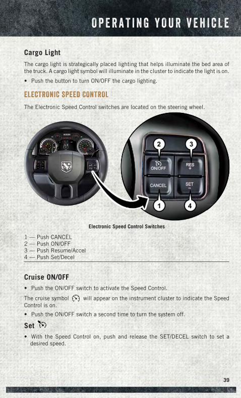
ELECTRONIC SPEED CONTROL
The Electronic Speed Control switches are located on the steering wheel.
Cruise ON/OFF• Push the ON/OFF switch to activate the Speed Control.
The cruise symbol will appear on the instrument cluster to indicate the SpeedControl is on.
• Push the ON/OFF switch a second time to turn the system off.
Set• With the Speed Control on, push and release the SET/DECEL switch to set a
desired speed.
Electronic Speed Control Switches
1 — Push CANCEL2 — Push ON/OFF3 — Push Resume/Accel4 — Push Set/Decel
O P E R A T I N G Y O U R V E H I C L E
39
Accel/Decel
To Increase Speed
• When the Electronic Speed Control is set, you can increase speed by pushing theRES + button.
The drivers preferred units can be selected through the instrument panel settings ifequipped. Refer to “ Understanding Your Instrument Panel” for more information.The speed increment shown is dependant on the chosen speed unit of U.S. (mph) orMetric (km/h):
U.S. Speed (mph)
• Pushing the RES + button once will result in a 1 mph increase in set speed. Eachsubsequent tap of the button results in an increase of 1 mph.
• If the button is continually pushed, the set speed will continue to increase untilthe button is released, then the new set speed will be established.
Metric Speed (km/h)
• Pushing the RES + button once will result in a 1 km/h increase in set speed. Eachsubsequent tap of the button results in an increase of 1 km/h.
• If the button is continually pushed, the set speed will continue to increase untilthe button is released, then the new set speed will be established.
To Decrease Speed
• When the Electronic Speed Control is set, you can decrease speed by pushing theSET - button.
The drivers preferred units can be selected through the instrument panel settings ifequipped. Refer to “ Understanding Your Instrument Panel” for more information.The speed decrement shown is dependant on the chosen speed unit of U.S. (mph) orMetric (km/h):
U.S. Speed (mph)
• Pushing the SET - button once will result in a 1 mph decrease in set speed. Eachsubsequent tap of the button results in a decrease of 1 mph.
• If the button is continually pushed, the set speed will continue to decrease untilthe button is released, then the new set speed will be established.
Metric Speed (km/h)
• Pushing the SET - button once will result in a 1 km/h decrease in set speed. Eachsubsequent tap of the button results in a decrease of 1 km/h.
• If the button is continually pushed, the set speed will continue to decrease untilthe button is released, then the new set speed will be established.
O P E R A T I N G Y O U R V E H I C L E
40
Resume• To resume a previously selected set speed in memory, push the RESUME/ACCEL
switch and release.
Cancel• Push the CANCEL switch or apply the brakes to cancel the set speed and maintain
the set speed memory.
• Push the ON/OFF switch to turn the system off and erase the set speed memory.
WARNING!
• Leaving the Electronic Speed Control system on when not in use is dangerous.You could accidentally set the system or cause it to go faster than you want. Youcould lose control and have a collision. Always leave the Electronic SpeedControl system off when you are not using it.
• Electronic Speed Control can be dangerous where the system cannot maintaina constant speed. Your vehicle could go too fast for the conditions, and youcould lose control. A collision could be the result. Do not use Electronic SpeedControl in heavy traffic or on roads that are winding, icy, snow-covered orslippery.
EIGHT-SPEED AUTOMATIC TRANSMISSION — IF EQUIPPED
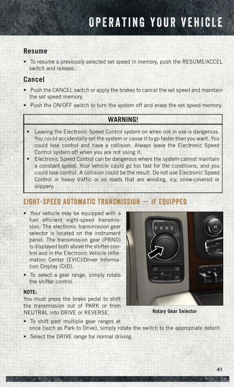
• Your vehicle may be equipped with afuel efficient eight-speed transmis-sion. The electronic transmission gearselector is located on the instrumentpanel. The transmission gear (PRND)is displayed both above the shifter con-trol and in the Electronic Vehicle Infor-mation Center (EVIC)/Driver Informa-tion Display (DID).
• To select a gear range, simply rotatethe shifter control.
NOTE:You must press the brake pedal to shiftthe transmission out of PARK or fromNEUTRAL into DRIVE or REVERSE.
• To shift past multiple gear ranges atonce (such as Park to Drive), simply rotate the switch to the appropriate detent.
• Select the DRIVE range for normal driving.
Rotary Gear Selector
O P E R A T I N G Y O U R V E H I C L E
41
ELECTRONIC RANGE SELECT (ERS) OPERATION
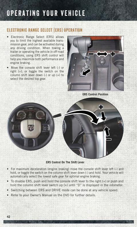
• Electronic Range Select (ERS) allowsyou to limit the highest available trans-mission gear, and can be activated duringany driving condition. When towing atrailer or operating the vehicle in off-roadconditions, using ERS shift control willhelp you maximize both performance andengine braking.
• Move the console shift lever left (-) orright (+), or toggle the switch on thecolumn shift lever down (-) or up (+) toselect the desired top gear.
• For maximum deceleration (engine braking) move the console shift lever left (-) andhold, or toggle the switch on the column shift lever down (-) and hold. Your vehicle willautomatically select the lowest safe gear for optimal engine braking.
• To disable ERS, push and hold the console shift lever to the right (+) or push andhold the column shift lever switch up (+) until “D” is displayed in the odometer.
• Switching between ERS and DRIVE mode can be done at any vehicle speed.
• Refer to your Owner's Manual on the DVD for further details.
ERS Control Position
ERS Control On The Shift Lever
O P E R A T I N G Y O U R V E H I C L E
42
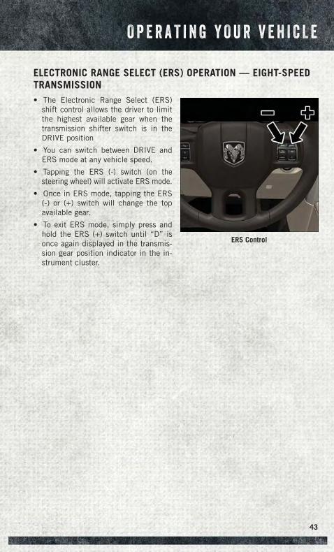
ELECTRONIC RANGE SELECT (ERS) OPERATION — EIGHT-SPEEDTRANSMISSION• The Electronic Range Select (ERS)
shift control allows the driver to limitthe highest available gear when thetransmission shifter switch is in theDRIVE position
• You can switch between DRIVE andERS mode at any vehicle speed.
• Tapping the ERS (-) switch (on thesteering wheel) will activate ERS mode.
• Once in ERS mode, tapping the ERS(-) or (+) switch will change the topavailable gear.
• To exit ERS mode, simply press andhold the ERS (+) switch until “D” isonce again displayed in the transmis-sion gear position indicator in the in-strument cluster.
ERS Control
O P E R A T I N G Y O U R V E H I C L E
43
1500 AIR SUSPENSION SYSTEM
The air suspension system provides full time load leveling capability along with thebenefit of being able to adjust vehicle height by the push of a button.
Automatic height changes will occur based on vehicle speed and the current vehicleheight. The indicator lamps and EVIC/DID messages will operate the same forautomatic changes and user requested changes.
Description
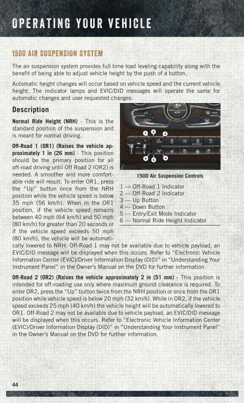
Normal Ride Height (NRH) - This is thestandard position of the suspension andis meant for normal driving.
Off-Road 1 (OR1) (Raises the vehicle ap-proximately 1 in (26 mm) - This positionshould be the primary position for alloff-road driving until Off Road 2 (OR2) isneeded. A smoother and more comfort-able ride will result. To enter OR1, pressthe “Up” button once from the NRHposition while the vehicle speed is below35 mph (56 km/h). When in the OR1position, if the vehicle speed remainsbetween 40 mph (64 km/h) and 50 mph(80 km/h) for greater than 20 seconds orif the vehicle speed exceeds 50 mph(80 km/h), the vehicle will be automati-cally lowered to NRH. Off-Road 1 may not be available due to vehicle payload, anEVIC/DID message will be displayed when this occurs. Refer to “Electronic VehicleInformation Center (EVIC)/Driver Information Display (DID)” in “Understanding YourInstrument Panel” in the Owner’s Manual on the DVD for further information.
Off-Road 2 (OR2) (Raises the vehicle approximately 2 in (51 mm) - This position isintended for off-roading use only where maximum ground clearance is required. Toenter OR2, press the “Up” button twice from the NRH position or once from the OR1position while vehicle speed is below 20 mph (32 km/h). While in OR2, if the vehiclespeed exceeds 25 mph (40 km/h) the vehicle height will be automatically lowered toOR1. Off-Road 2 may not be available due to vehicle payload, an EVIC/DID messagewill be displayed when this occurs. Refer to “Electronic Vehicle Information Center(EVIC)/Driver Information Display (DID)” in “Understanding Your Instrument Panel”in the Owner’s Manual on the DVD for further information.
1500 Air Suspension Controls
1 — Off-Road 1 Indicator2 — Off-Road 2 Indicator3 — Up Button4 — Down Button5 — Entry/Exit Mode Indicator6 — Normal Ride Height Indicator
O P E R A T I N G Y O U R V E H I C L E
44
Aero Mode (Lowers the vehicle approximately .6 in (15 mm) – 1500 Models Only - Thisposition provides improved aerodynamics by lowering the vehicle. The vehicle willautomatically enter Aero Mode when the vehicle speed remains between 62 mph(100 km/h) and 66 mph (106 km/h) for greater than 20 seconds or if the vehiclespeed exceeds 66 mph (106 km/h). The vehicle will return to NRH from Aero Modeif the vehicle speed remains between 30 mph (48 km/h) and 35 mph (56 km/h) forgreater than 20 seconds or if the vehicle speed falls below 30 mph (48 km/h).
NOTE:Automatic Aero Mode may be disabled through vehicle settings in the ElectronicVehicle Information Center (EVIC)/Driver Information Display (DID) when equippedwith Uconnect 3.0, or your Uconnect® Radio when equipped with UConnect® 5.0,8.4A, or 8.4AN.
Entry/Exit Mode (Lowers the vehicle approximately 2 in (51 mm) - This position lowers thevehicle for easier passenger entry and exit as well as lowering the rear of the vehicle foreasier loading and unloading of cargo. To enter Entry/Exit Mode, press the “Down”button once from the NHR while the vehicle speed is below 33 mph (53 km/h). Once thevehicle speed goes below 15 mph (24 km/h) the vehicle height will begin to lower. If thevehicle speed remains between 15 mph (24 km/h) and 25 mph (40 km/h) for greaterthan 60 seconds, or the vehicle speed exceeds 25 mph (40 km/h) the Entry/Exit changewill be cancelled. To return to Normal Height Mode, press the “Up” button once whilein Entry/Exit or drive the vehicle over 15 mph (24 km/h). Entry/Exit mode may not beavailable due to vehicle payload, an EVIC/DID message will be displayed when thisoccurs. Refer to "Electronic Vehicle Information Center (EVIC)/Driver InformationDisplay (DID)" in "Understanding Your Instrument Panel" in the Owner’s Manual on theDVD for further information.
Refer to your Owner’s Manual on the DVD for further details.
Air Suspension Modes
The Air Suspension system has multiple modes to protect the system in uniquesituations:
Tire Jack Mode
To assist with changing a spare tire, the air suspension system has a feature whichallows the automatic leveling to be disabled. Refer to “Electronic Vehicle InformationCenter (EVIC)/Driver Information Display (DID)” in “Understanding Your InstrumentPanel” in the Owner’s Manual on the DVD for further information.
NOTE:This mode is intended to be enabled with engine running.
O P E R A T I N G Y O U R V E H I C L E
45
Transport Mode
To assist with flat bed towing, the air suspension system has a feature which will putthe vehicle into Entry/Exit height and disable the automatic load leveling system.Refer to “Electronic Vehicle Information Center (EVIC)/Driver Information Display(DID)” in “Understanding Your Instrument Panel” in the Owner’s Manual on the DVDfor further information.
NOTE:This mode is intended to be enabled with engine running.
Wheel Alignment Mode
Before performing a wheel alignment this mode must be enabled. Refer to “Elec-tronic Vehicle Information Center (EVIC)/Driver Information Display (DID)” in “Un-derstanding Your Instrument Panel” in the Owner’s Manual on the DVD for furtherinformation.
NOTE:This mode is intended to be enabled with engine running.
Protection Mode
In order to “protect” the air suspension system, the vehicle will enter ProtectionMode when the payload has been exceeded or load leveling cannot be achieved.Refer to “Electronic Vehicle Information Center (EVIC)/Driver Information Display(DID)” in “Understanding Your Instrument Panel” in the Owner’s Manual on the DVDfor further information.
NOTE:This mode is intended to be enabled with engine running.
O P E R A T I N G Y O U R V E H I C L E
46
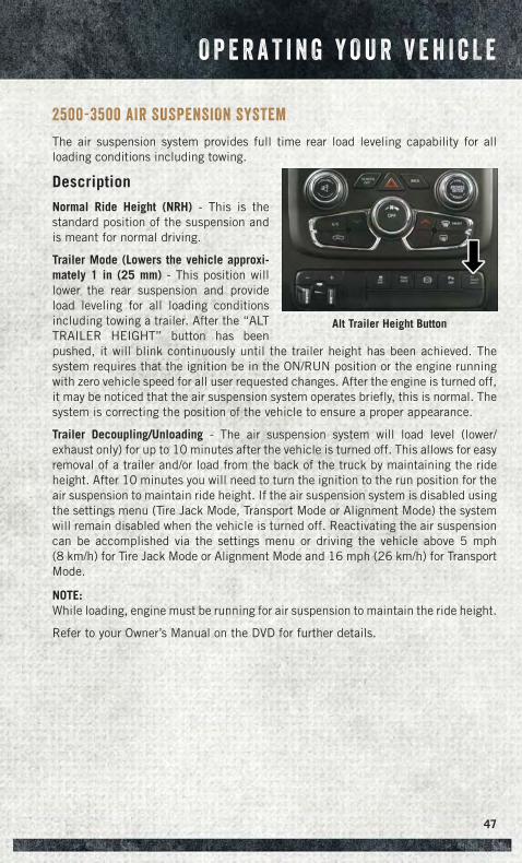
2500-3500 AIR SUSPENSION SYSTEM
The air suspension system provides full time rear load leveling capability for allloading conditions including towing.
Description
Normal Ride Height (NRH) - This is thestandard position of the suspension andis meant for normal driving.
Trailer Mode (Lowers the vehicle approxi-mately 1 in (25 mm) - This position willlower the rear suspension and provideload leveling for all loading conditionsincluding towing a trailer. After the “ALTTRAILER HEIGHT” button has beenpushed, it will blink continuously until the trailer height has been achieved. Thesystem requires that the ignition be in the ON/RUN position or the engine runningwith zero vehicle speed for all user requested changes. After the engine is turned off,it may be noticed that the air suspension system operates briefly, this is normal. Thesystem is correcting the position of the vehicle to ensure a proper appearance.
Trailer Decoupling/Unloading - The air suspension system will load level (lower/exhaust only) for up to 10 minutes after the vehicle is turned off. This allows for easyremoval of a trailer and/or load from the back of the truck by maintaining the rideheight. After 10 minutes you will need to turn the ignition to the run position for theair suspension to maintain ride height. If the air suspension system is disabled usingthe settings menu (Tire Jack Mode, Transport Mode or Alignment Mode) the systemwill remain disabled when the vehicle is turned off. Reactivating the air suspensioncan be accomplished via the settings menu or driving the vehicle above 5 mph(8 km/h) for Tire Jack Mode or Alignment Mode and 16 mph (26 km/h) for TransportMode.
NOTE:While loading, engine must be running for air suspension to maintain the ride height.
Refer to your Owner’s Manual on the DVD for further details.
Alt Trailer Height Button
O P E R A T I N G Y O U R V E H I C L E
47
Air Suspension Modes
The Air Suspension system has multiple modes to protect the system in uniquesituations:
Tire Jack Mode
To assist with changing a spare tire, the air suspension system has a feature whichallows the automatic leveling to be disabled. Refer to “Electronic Vehicle InformationCenter (EVIC)/Driver Information Display (DID)” in “Understanding Your InstrumentPanel” in the Owner’s Manual on the DVD for further information.
NOTE:This mode is intended to be enabled with engine running.
Transport Mode
To assist with flat bed towing, the air suspension system has a feature which will putthe vehicle into Entry/Exit height and disable the automatic load leveling system.Refer to “Electronic Vehicle Information Center (EVIC)/Driver Information Display(DID)” in “Understanding Your Instrument Panel” in the Owner’s Manual on the DVDfor further information.
NOTE:This mode is intended to be enabled with engine running.
Wheel Alignment Mode
Before performing a wheel alignment this mode must be enabled. Refer to “Elec-tronic Vehicle Information Center (EVIC)/Driver Information Display (DID)” in “Un-derstanding Your Instrument Panel” in the Owner’s Manual on the DVD for furtherinformation.
NOTE:This mode is intended to be enabled with engine running.
Protection Mode
In order to “protect” the air suspension system, the vehicle will enter ProtectionMode when the payload has been exceeded or load leveling cannot be achieved.Refer to “Electronic Vehicle Information Center (EVIC)/Driver Information Display(DID)” in “Understanding Your Instrument Panel” in the Owner’s Manual on the DVDfor further information.
NOTE:This mode is intended to be enabled with engine running.
O P E R A T I N G Y O U R V E H I C L E
48
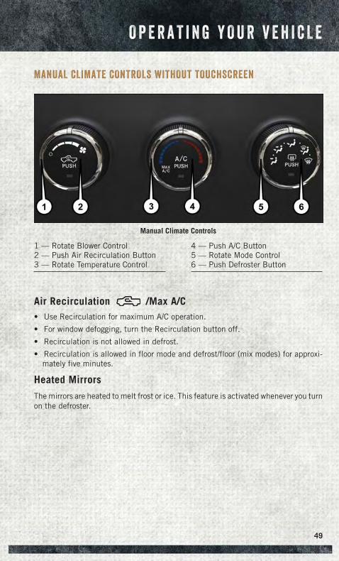
MANUAL CLIMATE CONTROLS WITHOUT TOUCHSCREEN
Air Recirculation /Max A/C• Use Recirculation for maximum A/C operation.
• For window defogging, turn the Recirculation button off.
• Recirculation is not allowed in defrost.
• Recirculation is allowed in floor mode and defrost/floor (mix modes) for approxi-mately five minutes.
Heated Mirrors
The mirrors are heated to melt frost or ice. This feature is activated whenever you turnon the defroster.
Manual Climate Controls
1 — Rotate Blower Control2 — Push Air Recirculation Button3 — Rotate Temperature Control
4 — Push A/C Button5 — Rotate Mode Control6 — Push Defroster Button
O P E R A T I N G Y O U R V E H I C L E
49
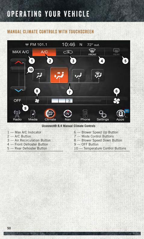
MANUAL CLIMATE CONTROLS WITH TOUCHSCREEN
Uconnect® 8.4 Manual Climate Controls
1 — Max A/C Indicator2 — A/C Button3 — Air Recirculation Button4 — Front Defroster Button5 — Rear Defroster Button
6 — Blower Speed Up Button7 — Mode Control Buttons8 — Blower Speed Down Button9 — OFF Button10 — Temperature Control Buttons
O P E R A T I N G Y O U R V E H I C L E
50
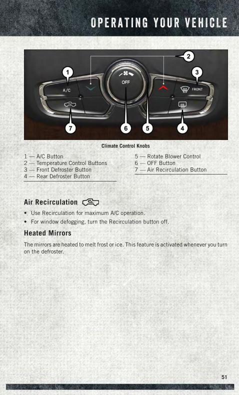
Air Recirculation• Use Recirculation for maximum A/C operation.
• For window defogging, turn the Recirculation button off.
Heated Mirrors
The mirrors are heated to melt frost or ice. This feature is activated whenever you turnon the defroster.
Climate Control Knobs
1 — A/C Button2 — Temperature Control Buttons3 — Front Defroster Button4 — Rear Defroster Button
5 — Rotate Blower Control6 — OFF Button7 — Air Recirculation Button
O P E R A T I N G Y O U R V E H I C L E
51
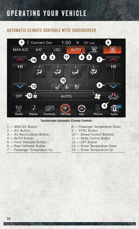
AUTOMATIC CLIMATE CONTROLS WITH TOUCHSCREEN
Touchscreen Automatic Climate Controls
1 — MAX A/C Button2 — A/C Button3 — Air Recirculation Button4 — AUTO Button5 — Front Defroster Button6 — Rear Defroster Button7 — Passenger Temperature Up
8 — Passenger Temperature Down9 — SYNC Button10 — Blower Control Buttons11 — Mode Control Button12 — OFF Button13 — Driver Temperature Down14 — Driver Temperature Up
O P E R A T I N G Y O U R V E H I C L E
52
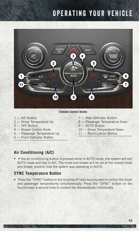
Air Conditioning (A/C)• If the air conditioning button is pressed while in AUTO mode, the system will exit
AUTO mode and stay in A/C. The mode and blower will be set at the closest modeand blower position that the system was operating in AUTO.
SYNC Temperature Button• Press the “SYNC” button on the Uconnect® radio touchscreen to control the driver
and passenger temperatures simultaneously. Press the “SYNC” button on thetouchscreen a second time to control the temperatures individually.
Climate Control Knobs
1 — A/C Button2 — Driver Temperature Up3 — OFF Button4 — Blower Control Knob5 — Passenger Temperature Up6 — Front Defroster Button
7 — Rear Defroster Button8 — Passenger Temperature Down9 — AUTO Button10 — Driver Temperature Down11 — Recirculation Button
O P E R A T I N G Y O U R V E H I C L E
53
Air Recirculation• Use Recirculation for maximum A/C operation.
• For window defogging, turn the Recirculation button off.
• If the Recirculation button is pushed while in the AUTO mode, the indicator lightmay flash three times to indicate the cabin air is being controlled automatically.
Heated Mirrors
The mirrors are heated to melt frost or ice. This feature is activated whenever you turnon the defroster.
PARKSENSE® FRONT AND REAR PARK ASSIST
ParkSense® can be enabled and disabled by pressing the ParkSense® switch locatedbelow the climate controls, on the switch panel.
The four ParkSense® sensors, located in the rear fascia/bumper, monitor the areabehind the vehicle that is within the sensors’ field of view. The sensors can detectobstacles from approximately 12 in (30 cm) up to 79 in (200 cm) from the rearfascia/bumper in the horizontal direction, depending on the location, type andorientation of the obstacle.
The six ParkSense® sensors, located in the front fascia/bumper, monitor the area infront of the vehicle that is within the sensors’ field of view. The sensors can detectobstacles from approximately 12 in (30 cm) up to 47 in (120 cm) from the frontfascia/bumper in the horizontal direction, depending on the location, type andorientation of the obstacle.
When an object is detected within 2 meters behind the rear bumper while the vehicleis in REVERSE, a warning will display in the Electronic Vehicle Information Center(EVIC) or Driver Information Display (DID). In addition a chime will sound (whenSound and Display is selected from the Customer Programmable Features section ofthe Uconnect® System screen). As the vehicle moves closer to the object, the chimerate will change from single 1/2 second tone (for rear only), to slow (for rear only), tofast, to continuous.
Refer to your Owner's Manual on the DVD for further details.
Cleaning The ParkSense® Sensors
If “PARKSENSE UNAVAILABLE WIPE REAR SENSORS" or "PARKSENSE UNAVAIL-ABLE WIPE FRONT SENSORS” appears in the “Electronic Vehicle InformationCenter (EVIC) or Driver Information Display (DID)”, clean the ParkSense® sensorswith water, car wash soap and a soft cloth. Do not use rough or hard cloths. Do notscratch or poke the sensors. Otherwise, you could damage the sensors.
O P E R A T I N G Y O U R V E H I C L E
54
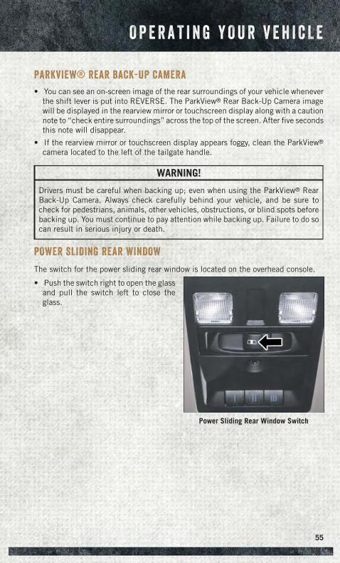
PARKVIEW® REAR BACK-UP CAMERA
• You can see an on-screen image of the rear surroundings of your vehicle wheneverthe shift lever is put into REVERSE. The ParkView® Rear Back-Up Camera imagewill be displayed in the rearview mirror or touchscreen display along with a cautionnote to “check entire surroundings” across the top of the screen. After five secondsthis note will disappear.
• If the rearview mirror or touchscreen display appears foggy, clean the ParkView®
camera located to the left of the tailgate handle.
WARNING!
Drivers must be careful when backing up; even when using the ParkView® RearBack-Up Camera. Always check carefully behind your vehicle, and be sure tocheck for pedestrians, animals, other vehicles, obstructions, or blind spots beforebacking up. You must continue to pay attention while backing up. Failure to do socan result in serious injury or death.
POWER SLIDING REAR WINDOW
The switch for the power sliding rear window is located on the overhead console.
• Push the switch right to open the glassand pull the switch left to close theglass.
Power Sliding Rear Window Switch
O P E R A T I N G Y O U R V E H I C L E
55
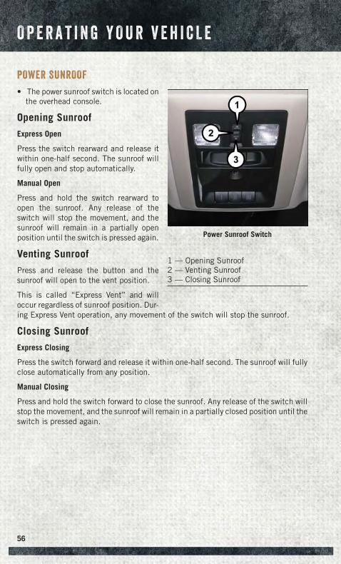
POWER SUNROOF
• The power sunroof switch is located onthe overhead console.
Opening Sunroof
Express Open
Press the switch rearward and release itwithin one-half second. The sunroof willfully open and stop automatically.
Manual Open
Press and hold the switch rearward toopen the sunroof. Any release of theswitch will stop the movement, and thesunroof will remain in a partially openposition until the switch is pressed again.
Venting Sunroof
Press and release the button and thesunroof will open to the vent position.
This is called “Express Vent” and willoccur regardless of sunroof position. Dur-ing Express Vent operation, any movement of the switch will stop the sunroof.
Closing Sunroof
Express Closing
Press the switch forward and release it within one-half second. The sunroof will fullyclose automatically from any position.
Manual Closing
Press and hold the switch forward to close the sunroof. Any release of the switch willstop the movement, and the sunroof will remain in a partially closed position until theswitch is pressed again.
Power Sunroof Switch
1 — Opening Sunroof2 — Venting Sunroof3 — Closing Sunroof
O P E R A T I N G Y O U R V E H I C L E
56
Pinch Protection Feature
This feature will detect an obstruction in the opening of the sunroof during ExpressClose operation. If an obstruction in the path of the sunroof is detected, the sunroofwill automatically retract. Remove the obstruction if this occurs. Next, press theswitch forward and release to Express Close.
NOTE:If three consecutive sunroof close attempts result in Pinch Protect reversals, thefourth close attempt will be a Manual Close movement with Pinch Protect disabled.
WARNING!
• Do not let children play with the sunroof. Never leave children unattended in avehicle, or with access to an unlocked vehicle. Do not leave the Key Fob in ornear the vehicle, and do not leave the ignition of a vehicle equipped withKeyless Enter-N-Go™ in the ACC or ON/RUN mode. Occupants, particularlyunattended children, can become entrapped by the power sunroof whileoperating the power sunroof switch. Such entrapment may result in seriousinjury or death.
• In a collision, there is a greater risk of being thrown from a vehicle with an opensunroof. You could also be severely injured or killed. Always fasten your seatbelt properly and make sure all passengers are properly secured.
• Do not allow small children to operate the sunroof. Never allow your fingers,other body parts, or any object to project through the sunroof opening. Injurymay result.
WIND BUFFETING
Wind buffeting can be described as a helicopter-type percussion sound. If buffetingoccurs with the rear windows open, adjust the front and rear windows together.
If buffeting occurs with the sunroof open, adjust the sunroof opening, or adjust anywindow. This will minimize buffeting.
O P E R A T I N G Y O U R V E H I C L E
57
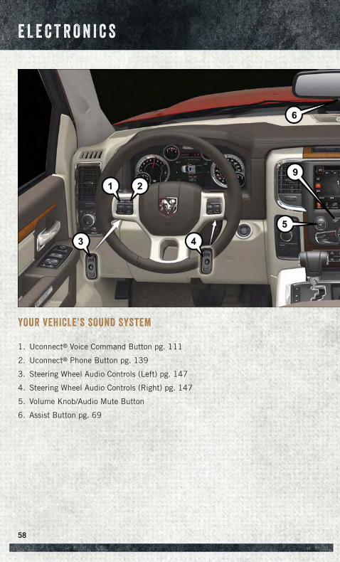
YOUR VEHICLE'S SOUND SYSTEM
1. Uconnect® Voice Command Button pg. 111
2. Uconnect® Phone Button pg. 139
3. Steering Wheel Audio Controls (Left) pg. 147
4. Steering Wheel Audio Controls (Right) pg. 147
5. Volume Knob/Audio Mute Button
6. Assist Button pg. 69
E L E C T R O N I C S
58

7. 9-1-1 Button pg. 69
8. Uconnect® 8.4 Radio pg. 95
9. Screen Off Button
10. Back Button
11. Tune/Scroll Knob/Browse/Enter Button
12. Media Hub: Audio Jack, USB Port, and SD Card Slot (located center console)pg. 101
13. CD Player (Inside Center Console — If Equipped) pg. 131
E L E C T R O N I C S
59
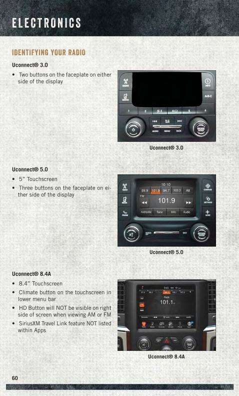
IDENTIFYING YOUR RADIO
Uconnect® 3.0
• Two buttons on the faceplate on eitherside of the display
Uconnect® 5.0
• 5” Touchscreen
• Three buttons on the faceplate on ei-ther side of the display
Uconnect® 8.4A
• 8.4” Touchscreen
• Climate button on the touchscreen inlower menu bar
• HD Button will NOT be visible on rightside of screen when viewing AM or FM
• SiriusXM Travel Link feature NOT listedwithin Apps
Uconnect® 3.0
Uconnect® 5.0
Uconnect® 8.4A
E L E C T R O N I C S
60
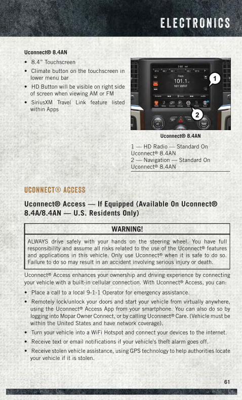
Uconnect® 8.4AN
• 8.4” Touchscreen
• Climate button on the touchscreen inlower menu bar
• HD Button will be visible on right sideof screen when viewing AM or FM
• SiriusXM Travel Link feature listedwithin Apps
Uconnect® ACCESS
Uconnect® Access — If Equipped (Available On Uconnect®8.4A/8.4AN — U.S. Residents Only)
WARNING!
ALWAYS drive safely with your hands on the steering wheel. You have fullresponsibility and assume all risks related to the use of the Uconnect® featuresand applications in this vehicle. Only use Uconnect® when it is safe to do so.Failure to do so may result in an accident involving serious injury or death.
Uconnect® Access enhances your ownership and driving experience by connectingyour vehicle with a built-in cellular connection. With Uconnect® Access, you can:
• Place a call to a local 9-1-1 Operator for emergency assistance.
• Remotely lock/unlock your doors and start your vehicle from virtually anywhere,using the Uconnect® Access App from your smartphone. You can also do so bylogging into Mopar Owner Connect, or by calling Uconnect® Care. (Vehicle must bewithin the United States and have network coverage).
• Turn your vehicle into a WiFi Hotspot and connect your devices to the internet.
• Receive text or email notifications if your vehicle's theft alarm goes off.
• Receive stolen vehicle assistance, using GPS technology to help authorities locateyour vehicle if it is stolen.
Uconnect® 8.4AN
1 — HD Radio — Standard OnUconnect® 8.4AN2 — Navigation — Standard OnUconnect® 8.4AN
E L E C T R O N I C S
61
• Listen to your text messages or send free-form text messages with your voice whilekeeping your hands on the wheel, using the Voice Texting feature. Requires a cellphone that supports Bluetooth Message Access Profile (MAP).
• Search for places to eat, shop, relax and play with Yelp®, using your voice oron-screen menu. Then navigate to them (navigation standard on Uconnect®8.4AN, optional on Uconnect® 8.4A).
• Get operator assistance using the ASSIST button on your interior rearview mirror.
Before you drive, familiarize yourself with the easy-to-use Uconnect® Access.
1. The ASSIST and 9-1-1 buttons are located on your rearview mirror. The ASSISTbutton is used for contacting Roadside Assistance, Vehicle Care and Uconnect®
Care. The 9-1-1 button connects you to emergency services.
NOTE:Vehicles sold in Canada and Mexico DO NOT have 9-1-1 Call system capabilities. 9-1-1or other emergency line operators in Canada and Mexico may not answer or respond to9-1-1 system calls.
2. The Uconnect® “Apps” button on the menu bar at the bottom right corner of theradio touchscreen. This is where you can begin your registration process, manageyour Apps and purchase WiFi on demand.
3. The Uconnect® Voice Command and Uconnect® Phone buttons are located on theleft side of your steering wheel. These buttons let you use your voice to givecommands, make phone calls, send and receive text messages hands-free, enternavigation destinations, and control your radio and media devices.
Included Trial Period For New Vehicles
Your new vehicle may come with an included trial period for use of the Uconnect®
Access Services starting at the date of vehicle purchase (date based on vehicle salesnotification from your dealer). To activate the trial, you must first register withUconnect® Access. After the trial period, if you wish to continue your Uconnect®
Access Services you can choose to purchase a subscription.
Features And Packages
• After the trial period, you can subscribe to continue your service by visitingthe Uconnect® Store located within the Mopar Owner Connect websitemoparownerconnect.com. If you need assistance, U.S. residents can callUconnect® Care at 1-855-792-4241.
• For the latest information on packages and pricing information: U.S. residentsvisit DriveUconnect.com.
E L E C T R O N I C S
62
Uconnect® Access Registration (Uconnect® 8.4A/8.4AN,U.S. 48 Contiguous States, Alaska And Hawaii)
To unlock the full potential of Uconnect® Access in your vehicle, you first need toregister with Uconnect® Access.
1. From the parked vehicle with the radio touchscreen powered on, select the“Apps” button located near the bottom right-hand corner of the radio touch-screen.
NOTE:Should you require assistance anytime during the registration process, simply callUconnect® Care at 1-855-792-4241.
2. Press “Start” on the reminder screen or select “Uconnect Registration” under the“All Apps” or “Favorites Apps” tab on the Apps list.
3. The Uconnect® Access Registration App will open and display step-by-stepinstructions to start your registration.
4. Enter your email address into the radio touchscreen.
5. A message will display on the touchscreen indicating your email submission wasaccepted. In a few minutes, you will receive an email which will allow you toregister your vehicle for Uconnect® Access. You should open this email and beginyour Uconnect® Access registration within 72 hours.
6. Check for an email from Uconnect® Access that contains your personalizedregistration link. If you don't see it, check your spam or junk mail folder. Open theemail and click on the link to continue registering.
NOTE:For security reasons, this link is valid for 72 hours from the time you’ve submittedyour email address into the radio touchscreen. If the link has expired, simply re-enteryour email address into the Uconnect® Registration App on the radio touchscreen toreceive another link. The secured registration link will take you through theUconnect® Access registration process step by step.
7. To unlock the full potential of Uconnect® Access in your vehicle, you will need tocreate or validate an existing Mopar Owner Connect account previously (OwnerCenter). Uconnect® along with Mopar Owner Connect have joined forces to createone destination to manage all of your vehicle needs, from managing yourUconnect® Access account, to tracking service history and finding recommendedaccessories for your vehicle. If you already have a Mopar Owner Connect account,log in to the website with your existing username/email and password. Forassistance with this web based registration process, call Uconnect® Care at1-855-792-4241.
E L E C T R O N I C S
63
8. Once you are logged in to your Mopar Owner Connect account, you will create apersonal Uconnect® Security PIN. The Uconnect® Security PIN will be requiredto authenticate you when accessing your account via Uconnect® Care or perform-ing any remote services such as Remote Door Lock/Unlock, Remote Horn & Lightsor Starting and Stopping the engine.
9. If your vehicle qualifies for a trial package it will be presented. Simply agree to theUconnect® Terms of Service (checkbox) and then select the “Start Service”button.
At this point your vehicle is registered with Uconnect® Access. Continue to set up ViaMobile. Apps will be downloaded the next time you start your vehicle. If the Appshave not appeared after 24 hours, please contact Uconnect® Care.
Download The Uconnect® Access App
The Uconnect® Access smartphone App allows you to remotely lock or unlock your doors,start your engine (if equipped) and activate your horn and lights from virtually anywhere.The smartphone App also features Via Mobile (if equipped) which uses your smartphone’sdata plan to access your personal Pandora®, iHeartRadio, Slacker Radio and Aha™ byHARMAN accounts and control them using your vehicle touchscreen.
The Uconnect® Access app is only compatible with select iPhone® and Androidsmartphones. Visit UconnectPhone.com or call 1–877–855–8400 to confirm thatyour smartphone is compatible with Uconnect®. Once you’ve confirmed your smart-phone is compatible, Android and iPhone® users should visit their respective appstore and search for “Uconnect Access” to download the app.
Set Up Your Via Mobile Profile — If Equipped
Setting up your Via Mobile profile means entering your login information for each Appso that they can work in your vehicle. Complete your Via Mobile Profile online duringregistration of your Uconnect® Access system. Access this page by logging into yourMopar Owner Connect account (moparownerconnect.com), going to Edit Profile,then Via Mobile Profile.
If you already have an account with these Apps, scroll down and press the “Link” buttonto enter your information. If you do not have an account, you can create a new one.
Aha™ by HARMAN (www.aharadio.com)
• Enter your email address and password for Aha™, or create a new Aha™ account.
• You can link your Facebook, Twitter or Slacker accounts on the Aha™ website.
iHeartRadio (www.iHeartRadio.com)
• Enter your email address and password for iHeartRadio, or create a new iHeart-Radio account.
• Select “Activate” to continue,
• Select “Close” to complete activation.
E L E C T R O N I C S
64
Pandora® (www.pandora.com)
• Enter your Pandora® username/email address and password, then click “Save.”
• Create a new Pandora® account.
Slacker Radio (www.slacker.com)
• Enter your Slacker username/email address and password, then click “Save.”
• Create a new Slacker Radio account.
Invite family and friends to use the Via Mobile Apps in your vehicle by setting up theirown Via Mobile profile.
Renewing Subscriptions And Purchasing WiFi Hotspot(Uconnect® 8.4A/8.4AN, U.S. 48 Contiguous States AndAlaska)
Subscriptions, and WiFi Hotspot, can be purchased from the Uconnect® Store within yourvehicle, and online at Mopar Owner Connect. If you need help push the ASSIST button onthe rearview mirror, then select Uconnect® Care (or dial 1-855-792-4241).
Purchasing Online
You can renew your subscription to a package or purchase WiFi from the Mopar OwnerConnect website. You must first set up a Uconnect® Access Payment Account online.Log into moparownerconnect.com
1. Log In to the Mopar Owner Connect website (moparownerconnect.com) with yourusername/email and password.
2. Click on the “Shop” tab, then click on the Uconnect® Store.
3. From the Uconnect® Store, select the item you wish to purchase.
4. This will launch the selected item into purchase mode along with providingadditional information.
5. The Uconnect® Store will display a “Purchase Overview” message confirming thefinancial details of your purchase. Click the “Purchase” key to continue.
6. The Uconnect® Store will ask you to “Confirm Payment” using your defaultpayment method on file in your Payment Account. Click the “Complete” key tocontinue.
7. The Uconnect® Payment Account will then ask for your “Payment Account PIN,”which you established when setting up your Uconnect® payment account. Afterentering this four digit PIN, click the “Complete” key to make the purchase.
8. You will receive a confirmation message that your purchase has been submitted.Click the “OK” button to end the process.
E L E C T R O N I C S
65
Purchasing WiFi Hotspot While In Your Vehicle
You must set up a Uconnect® Access Payment Account online (log in tomoparownerconnect.com, go to Edit Profile, then Uconnect® Payment Account, toset up and manage your Payment Account).
1. To purchase WiFi while in your vehicle, ensure the vehicle is running and in Park.Press the “Apps” button on the touchscreen, then select WiFi within the “Apps”menu. Follow the on-screen instructions. When asked for your payment PIN, usethe 4-digit PIN you established when setting up your payment account on MoparOwner Connect.
NOTE:This may be different than the Uconnect® Security PIN you established for usingfeatures such as Remote Vehicle Start. After purchasing WiFi, it may take up to30 minutes (with the vehicle running) before the WiFi will be active in your vehicle.
2. Select WiFi again, then note the hotspot name. Select this network whenconnecting devices to the hotspot. Also click on View/Edit Passphrase, then notethe security passphrase you will need to connect to the network on each device.
If your devices cannot see the WiFi Hotspot network after 30 minutes, please contactUconnect® Care by pushing the ASSIST button on the rearview mirror, or by calling1-855-792-4241.
Using Uconnect® Access
Getting Started With Apps
Applications (Apps) and features in your Uconnect® Access system deliver servicesthat are customized for the driver and are certified by Chrysler Group, LLC. Twodifferent types are:
1. Built-In Features — use the built-in 3G Cellular Network on your Uconnect®8.4A/8.4AN radio.
2. Uconnect® Access Via Mobile (if equipped) — Via Mobile uses the Uconnect®Access App and your smartphone's data plan to access your personal Pandora®,iHeartRadio, Aha™ by HARMAN and Slacker Radio accounts from the vehicleand control them using the vehicle touchscreen. Customer’s data plan chargeswill apply. Available on Uconnect® 8.4A and 8.4AN Radios (if equipped).
E L E C T R O N I C S
66
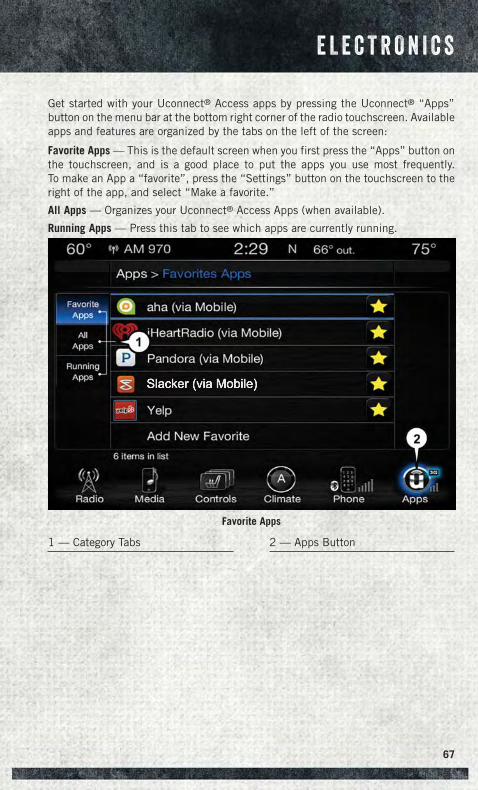
Get started with your Uconnect® Access apps by pressing the Uconnect® “Apps”button on the menu bar at the bottom right corner of the radio touchscreen. Availableapps and features are organized by the tabs on the left of the screen:
Favorite Apps — This is the default screen when you first press the “Apps” button onthe touchscreen, and is a good place to put the apps you use most frequently.To make an App a “favorite”, press the “Settings” button on the touchscreen to theright of the app, and select “Make a favorite.”
All Apps — Organizes your Uconnect® Access Apps (when available).
Running Apps — Press this tab to see which apps are currently running.
Favorite Apps
1 — Category Tabs 2 — Apps Button
E L E C T R O N I C S
67
Maintaining Your Uconnect® Access Account
Reinstalling An App (Uconnect® 8.4A/8.4AN)
You can easily correct many Application related issues you may be experiencing byresetting the App back to the factory setting. From the vehicle’s radio touchscreen,complete the following steps:
1. Press the Uconnect® “Apps” button and open the Uconnect® Store. Go to MyApps.
2. In My Apps, select “Settings,” then “Reinstall App.” Press “Continue.”
3. Your Apps have been successfully re-installed.
Canceling Your Subscription
Should you want to cancel your subscription, you can remove your account informa-tion using the same procedure contained in the Selling Your Vehicle section.
Selling Your Vehicle
When you sell your vehicle, we recommend that you remove your Uconnect® AccessAccount information from the vehicle. You can do this using the radio touchscreen inthe vehicle or on the Mopar Owner Connect website (moparownerconnect.com).Removing your account information cancels your subscription and makes yourvehicle factory-ready for a new owner/subscriber.
1. From your vehicle’s radio touchscreen, select “Uconnect® Store” from the AppsMenu.
2. Select “My Apps,” then “Settings.” Press “Remove Uconnect® Account.”
3. Enter your Uconnect® Security PIN, and select “Continue.”
For additional information on Uconnect®:
• U.S. residents - visit DriveUconnect.com or call 1-877-855-8400.
• Canadian Residents - visit DriveUconnect.ca or call, 1-800-465-2001 (English)or 1-800-387-9983 (French).
E L E C T R O N I C S
68
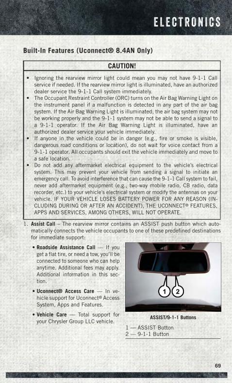
Built-In Features (Uconnect® 8.4AN Only)
CAUTION!
• Ignoring the rearview mirror light could mean you may not have 9-1-1 Callservice if needed. If the rearview mirror light is illuminated, have an authorizeddealer service the 9-1-1 Call system immediately.
• The Occupant Restraint Controller (ORC) turns on the Air Bag Warning Light onthe instrument panel if a malfunction is detected in any part of the air bagsystem. If the Air Bag Warning Light is illuminated, the air bag system may notbe working properly and the 9-1-1 system may not be able to send a signal toa 9-1-1 operator. If the Air Bag Warning Light is illuminated, have anauthorized dealer service your vehicle immediately.
• If anyone in the vehicle could be in danger (e.g., fire or smoke is visible,dangerous road conditions or location), do not wait for voice contact from a9-1-1 operator. All occupants should exit the vehicle immediately and move toa safe location.
• Do not add any aftermarket electrical equipment to the vehicle’s electricalsystem. This may prevent your vehicle from sending a signal to initiate anemergency call. To avoid interference that can cause the 9-1-1 Call system to fail,never add aftermarket equipment (e.g., two-way mobile radio, CB radio, datarecorder, etc.) to your vehicle’s electrical system or modify the antennas on yourvehicle. IF YOUR VEHICLE LOSES BATTERY POWER FOR ANY REASON (IN-CLUDING DURING OR AFTER AN ACCIDENT), THE UCONNECT® FEATURES,APPS AND SERVICES, AMONG OTHERS, WILL NOT OPERATE.
1. Assist Call – The rearview mirror contains an ASSIST push button which auto-matically connects the vehicle occupants to one of these predefined destinationsfor immediate support:
• Roadside Assistance Call — If youget a flat tire, or need a tow, you’ll beconnected to someone who can helpanytime. Additional fees may apply.Additional information in this sec-tion.
• Uconnect® Access Care — In ve-hicle support for Uconnect® AccessSystem, Apps and Features.
• Vehicle Care — Total support foryour Chrysler Group LLC vehicle.
ASSIST/9-1-1 Buttons
1 — ASSIST Button2 — 9-1-1 Button
E L E C T R O N I C S
69
2. Emergency 9-1-1 Call (If Equipped) — The rearview mirror contains a 9-1-1 buttonthat, when pressed, may place a call from your vehicle to a local 9-1-1 operatorto request help from local police, fire or ambulance personnel. If this button isaccidentally pressed, you will have 10 seconds to stop the call. To cancel, pressthe 9-1-1 Call button again or press the “Cancel” button shown on the touch-screen. After 10 seconds has passed, the 9-1-1 call will be placed and only the9-1-1 operator can cancel it. The LED light on the rearview mirror will turn greenonce a connection to a 9-1-1 operator has been made. The green LED light willturn off once the 9-1-1 call is terminated. Have an authorized dealer service thevehicle if the rearview mirror light is continuously red. On equipped vehicles, thisfeature requires a functioning electrical system and wireless coverage to functionproperly. If a connection is made between a 9-1-1 operator and your vehicle, youunderstand and agree that 9-1-1 operators may, like any other 9-1-1 call, recordconversations and sounds in and near your vehicle upon connection.
3. Roadside Assistance (If Equipped) — If your vehicle is equipped with this featureand within wireless range, you may be able to connect to Roadside Assistance bypressing the “ASSIST” button on the rearview mirror. You will be presented withAssist Care options. Make a selection by pressing the prompts displayed on theradio. If Roadside Assistance is provided to your vehicle, you agree to beresponsible for any additional roadside assistance service costs that you mayincur. In order to provide Uconnect® Services to you, we may record and monitoryour conversations with Roadside Assistance, Uconnect® Care or Vehicle Care,whether such conversations are initiated through the Uconnect® Services in yourvehicle, or via a landline or mobile telephone, and may share informationobtained through such recording and monitoring in accordance with regulatoryrequirements. You acknowledge, agree and consent to any recording, monitoringor sharing of information obtained through any such call recordings.
4. Yelp® — Customers have the ability to search for nearby destinations or a pointof interest (POI) either by category or custom search by using keywords (forexample, “Italian restaurant”). Searching can be done by either voice or by usingthe touchscreen keypad. Using the touchscreen, launch Yelp® by selecting the“Apps” icon. Press the “All Apps” tab, and then press “Yelp.” To use voicerecognition, push the VR button on the steering wheel and say “launch Yelp®,”then follow the instructions on the Teleprompter.
5. Security Alarm Notification — The Security Alarm Notification feature notifies youvia email or text (SMS) message when the vehicle’s factory-installed securityalarm system has been set-off. There are a number of reasons why your alarm mayhave been triggered, one of which could be that your vehicle was stolen. If so,please see the details of the Stolen Vehicle Assistance service below. When youregister, Security Alarm Notification is automatically set to send you an email atthe mail address you provide should the alarm go off. You may also opt to have atext message sent to your mobile device.
E L E C T R O N I C S
70
6. Stolen Vehicle Assistance — If your vehicle is stolen, contact local law enforce-ment immediately to file a stolen vehicle report. Once this report has been filed,Uconnect® care can help locate your vehicle. The Uconnect® Care agent will askfor the stolen vehicle report number issued by local law enforcement. Then, usingGPS technology and the built-in wireless connection within your vehicle, theUconnect® Care agent will be able to locate the stolen vehicle and work with lawenforcement to help recover it. (Vehicle must be within the United States, havenetwork coverage and must be registered with Uconnect® Access with an activesubscription that includes the applicable feature).
7. WiFi Hotspot — WiFi Hotspot is on-demand WiFi 3G connectivity that's built-inand ready to go where ever you are. Once your vehicle is registered for Uconnect®
Access, you can purchase a Wifi Hotspot subscription at the Uconnect® Store.After you've made your purchase, turn on your signal and connect your passengersdevices. It's never been easier to bring your home or office with you.
NOTE:Your vehicle must have a working electrical system for any of the in vehicleUconnect® features to operate.
Uconnect® Access Remote Features
If you own a compatible iPhone® or Android® powered device, the Uconnect® Access Appallows you to remotely lock or unlock your doors, start your engine or activate your horn andlights from virtually anywhere (Vehicle must be within the United States and have networkcoverage). You can download the App from Mopar Owner Connect or from the App Store(iPhone) or Google Play store. Visit UconnectPhone.com to determine if your device iscompatible. For Uconnect® Phone customer support and to determine if your deviceis compatible.
U.S. residents - visit UconnectPhone.com or call 1-877-855-8400
Remote Start — This feature provides the ability to start the engine on your vehicle,without the keys and from virtually any distance. You can send a request to yourvehicle in one of two ways:
1. Using the Uconnect® Access App from a compatible smartphone.
2. From the Mopar Owner Connect website.
• After 15 minutes if you have not entered your vehicle with the key, the enginewill shut off automatically.
• You can also send a command to turn-off an engine that has been remotestarted.
• This remote function requires your vehicle to be equipped with a factory-installed Remote Start system. To utilize this feature after the Uconnect®
Access App is downloaded, login with your user name and password.
E L E C T R O N I C S
71
NOTE:Your four digit Uconnect® Security PIN is required to confirm the request.
• You can set-up notifications for your account to receive an email or text (SMS)message every time a command is sent. Login to Mopar Owner Connect(moparownerconnect.com) and click on Edit Profile to manage Uconnect®Notifications.
Remote Door Lock/Unlock — This feature provides the ability to lock or unlock the dooron your vehicle, without the keys and from virtually any distance. You can send arequest to your vehicle in one of three ways:
1. Using the Uconnect® Access App from a compatible smartphone.
2. From the Mopar Owner Connect website.
3. By contacting the Uconnect® Care on the phone.
To use this feature after the Uconnect® Access App is downloaded, login using youruser name and password. You will need your four digit Uconnect® Security PIN toconfirm the request. Press the “closed lock” icon on your Uconnect® Access App tolock the doors, and press the “open Lock” icon to unlock the driver’s door.
You can set-up notifications for your account to receive an email or text (SMS)message every time a command is sent. Login to Mopar Owner Connect(moparownerconnect.com) and click on Edit Profile to manage Uconnect® Notifica-tions.
Remote Horn And Lights — It’s easy to locate a vehicle in a dark, crowded or noisyparking area by activating the horn and lights. It may also help if you need to drawattention to your vehicle for any reason. You can send a request to your vehicle in oneof three ways:
1. Using the Uconnect® Access App from a compatible smartphone.
2. From the Mopar Owner Connect website.
3. By contacting the Uconnect® Care on the phone.
To use this feature after the Uconnect® Access App is downloaded, login using your username and password. You will need your four digit Uconnect® Security PIN to confirm therequest. You can set-up notifications for your account to receive an email or text (SMS)message every time a command is sent. Login to Mopar Owner Connect(moparownerconnect.com) and click on Edit Profile to manage Uconnect® Notifica-tions.
E L E C T R O N I C S
72
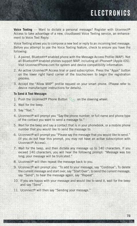
Voice Texting — Want to dictate a personal message? Register with Uconnect®Access to take advantage of a new, cloudbased Voice Texting service, an enhance-ment to Voice Text Reply.
Voice Texting allows you to compose a new text or reply to an incoming text message.Before you attempt to use the Voice Texting feature, check to ensure you have thefollowing:
1. A paired, Bluetooth® enabled phone with the Message Access Profile (MAP). Notall Bluetooth® enabled phones support MAP, including all iPhones® (Apple iOS).Visit UconnectPhone.com for system and device compatibility information.
2. An active Uconnect® Access trial or paid subscription. Press the “Apps” buttonon the lower right hand corner of the touchscreen to begin the registrationprocess.
3. Accept the “Allow MAP” profile request on your smart phone. (Please refer todevice manufacturer instructions for details).
To Send A Text Message:
1. Push the Uconnect® Phone Button on the steering wheel.
2. Wait for the beep.
3. Say “Text.”
4. Uconnect® will prompt you “Say the phone number, or full name and phone typeof the contact you want to send a message to.”
5. Wait for the beep and say a contact that is in your phonebook, or a mobile phonenumber that you would like to send the message to.
6. Uconnect® will prompt you “Please say the message that you would like to send.”(If you do not hear this prompt, you may not have an active subscription withUconnect® Access).
7. Wait for the beep, and then dictate any message up to 140 characters. If youexceed 140 characters, you will hear the following prompt: “Message was toolong; your message will be truncated.”
8. Uconnect® will then repeat the message back to you.
9. Uconnect® will prompt you: “To add to your message, say “Continue”; To deletethe current message and start over, say “Start Over”; to send the current message,say “Send”; to hear the message again, say “Repeat”.
10. If you are happy with your message and would like to send it, wait for the beepand say “Send”.
11. Uconnect® will then say “Sending your message.”
E L E C T R O N I C S
73
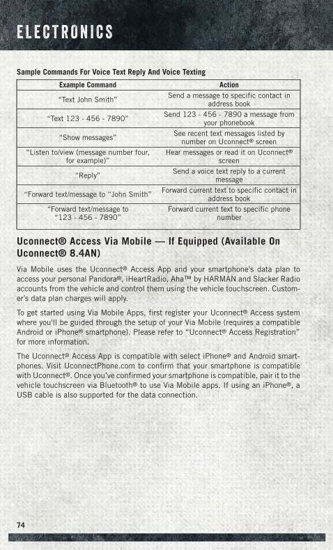
Sample Commands For Voice Text Reply And Voice Texting
Example Command Action
“Text John Smith” Send a message to specific contact inaddress book
“Text 123 - 456 - 7890” Send 123 - 456 - 7890 a message fromyour phonebook
“Show messages” See recent text messages listed bynumber on Uconnect® screen
“Listen to/view (message number four,for example)”
Hear messages or read it on Uconnect®screen
“Reply” Send a voice text reply to a currentmessage
“Forward text/message to “John Smith” Forward current text to specific contact inaddress book
“Forward text/message to“123 - 456 - 7890”
Forward current text to specific phonenumber
Uconnect® Access Via Mobile — If Equipped (Available OnUconnect® 8.4AN)
Via Mobile uses the Uconnect® Access App and your smartphone's data plan toaccess your personal Pandora®, iHeartRadio, Aha™ by HARMAN and Slacker Radioaccounts from the vehicle and control them using the vehicle touchscreen. Custom-er’s data plan charges will apply.
To get started using Via Mobile Apps, first register your Uconnect® Access systemwhere you'll be guided through the setup of your Via Mobile (requires a compatibleAndroid or iPhone® smartphone). Please refer to “Uconnect® Access Registration”for more information.
The Uconnect® Access App is compatible with select iPhone® and Android smart-phones. Visit UconnectPhone.com to confirm that your smartphone is compatiblewith Uconnect®. Once you’ve confirmed your smartphone is compatible, pair it to thevehicle touchscreen via Bluetooth® to use Via Mobile apps. If using an iPhone®, aUSB cable is also supported for the data connection.
E L E C T R O N I C S
74
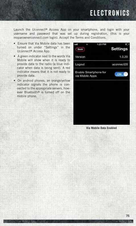
Launch the Uconnect® Access App on your smartphone, and login with yourusername and password that was set up during registration, (this is yourmoparownerconnect.com login). Accept the Terms and Conditions.
• Ensure that Via Mobile data has beenturned on under “Settings” in theUconnect® Access App.
• A green indicator next to the words ViaMobile will show when it is ready toprovide data to the radio (a blue indi-cator when data is being sent). A redindicator means that it is not ready toprovide data.
• On android phones, an orange/yellowindicator signals the phone is con-nected to the appropriate servers, how-ever Bluetooth® is turned off on themobile phone.
Via Mobile Data Enabled
E L E C T R O N I C S
75
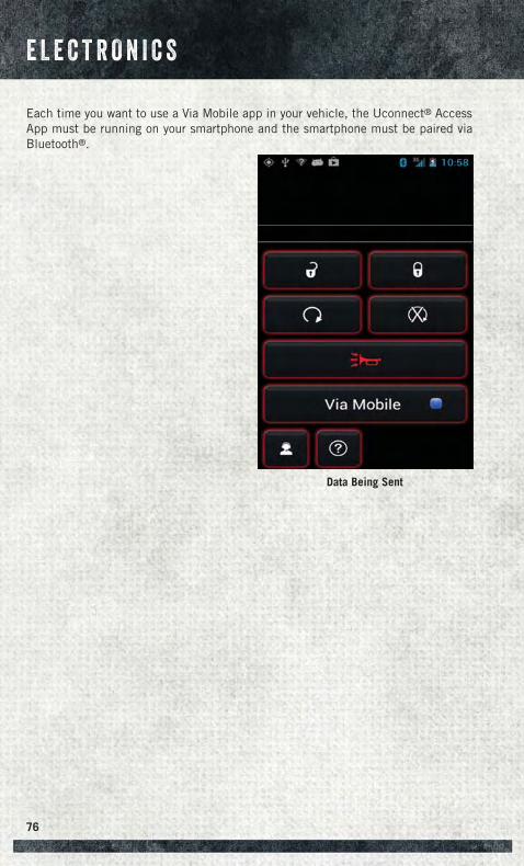
Each time you want to use a Via Mobile app in your vehicle, the Uconnect® AccessApp must be running on your smartphone and the smartphone must be paired viaBluetooth®.
Data Being Sent
E L E C T R O N I C S
76
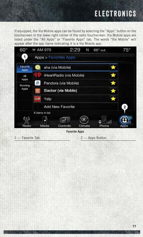
If equipped, the Via Mobile apps can be found by selecting the “Apps” button on thetouchscreen in the lower right corner of the radio touchscreen. Via Mobile apps arelisted under the “All Apps” or “Favorite Apps” tab. The words “Via Mobile” willappear after the app name indicating it is a Via Mobile app.
Favorite Apps
1 — Favorite Tab 2 — Apps Button
E L E C T R O N I C S
77
Via Mobile apps can also be launched through Voice Recognition by pressing the VRbutton on the steering wheel and stating “launch” and then the name of the app. Forexample, you can say “launch Aha Via Mobile.”
NOTE:For detailed information on how to use Via Mobile apps visit the Mopar OwnerConnect website (moparownerconnect.com) and login using the username andpassword you set up when registering for Uconnect® Access.
A message will be displayed to remind you that Via Mobile apps utilize the data planon your connected smartphone to provide content. Many smartphones have a limit tohow much data they can utilize before incurring additional charges. The amount ofdata being used varies by smartphone device, cellular service provider and specificapp. Check your mobile phone service plan for more details.* Press “OK” to continueor the “X” to exit.
(*Additional smartphone data usage charges may apply.)
Via Mobile Apps — If Equipped• Aha™ by HARMAN — Aha™ by HARMAN makes it easy to instantly access your
favorite Web content on the go. Choose from over 40,000+ stations spanninginternet radio, personalized music, news, entertainment, hotels, weather, audio-books, Facebook®, Twitter®, and more.
• iHeartRadio — iHeartRadio provides instant access to more than 1,500 live radiostations from across the country and allows listeners to create custom musicstations inspired by their favorite artists or songs.
• Pandora® — Pandora® gives people the music and comedy they love anytime,anywhere. Personalized stations launch instantly, with the input of a favorite artist,track, comedian, or genre.
• Slacker Radio — Enjoy millions of songs and hundreds of handcrafted stations.
NOTE:For detailed information on how to use Via Mobile apps visit the Mopar OwnerConnect website (moparownerconnect.com) and log in using the username andpassword you set up when registering for Uconnect® Access.
E L E C T R O N I C S
78
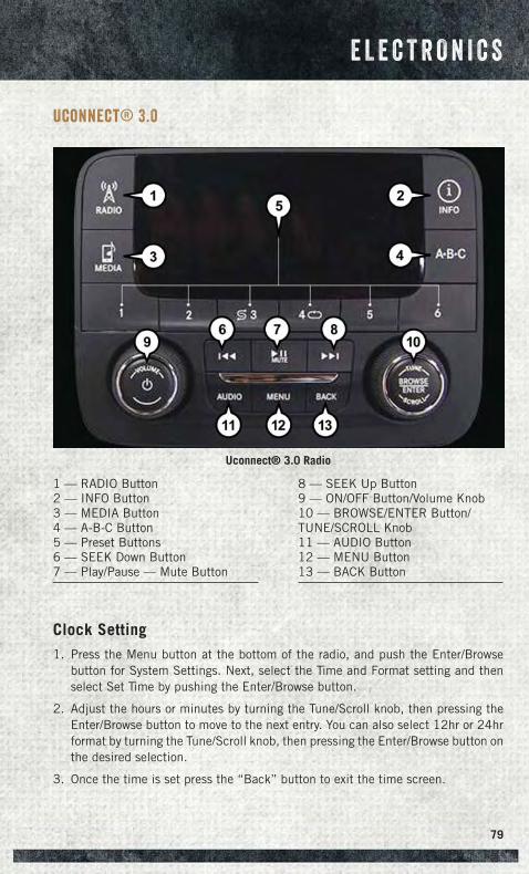
Uconnect® 3.0
Clock Setting1. Press the Menu button at the bottom of the radio, and push the Enter/Browse
button for System Settings. Next, select the Time and Format setting and thenselect Set Time by pushing the Enter/Browse button.
2. Adjust the hours or minutes by turning the Tune/Scroll knob, then pressing theEnter/Browse button to move to the next entry. You can also select 12hr or 24hrformat by turning the Tune/Scroll knob, then pressing the Enter/Browse button onthe desired selection.
3. Once the time is set press the “Back” button to exit the time screen.
Uconnect® 3.0 Radio
1 — RADIO Button2 — INFO Button3 — MEDIA Button4 — A-B-C Button5 — Preset Buttons6 — SEEK Down Button7 — Play/Pause — Mute Button
8 — SEEK Up Button9 — ON/OFF Button/Volume Knob10 — BROWSE/ENTER Button/TUNE/SCROLL Knob11 — AUDIO Button12 — MENU Button13 — BACK Button
E L E C T R O N I C S
79
Audio• Push the AUDIO button on the radio faceplate.
• The Audio Menu shows the following options for you to customize your audiosettings.
Treble, Mid, Bass, Fade, Balance, Speed Adjusted Volume, Loudness and Auto VolumeOffset
• Select the desired setting to adjust, then push the ENTER/BROWSE button. Turnthe TUNE/SCROLL knob to adjust the setting + or - 9. Push the “Back” buttonwhen done.
Radio Operation
Seek Up/Down Buttons
• Push to seek through radio stations in AM, FM or SXM bands.
• Hold either button to bypass stations without stopping.
Store Radio Presets
• The Presets are available for all Radio Modes, and are activated by pushing any ofthe six Preset buttons.
• When you are receiving a station that you wish to commit into memory, push andhold the desired numbered button for more than two seconds, or until you hear aconfirmation beep.
• The Radio stores up to 18 presets in each of the Radio modes. Push the A-B-Cbutton on the faceplate to select the A, B or C preset list.
Disc Operation (If Equipped)
Your vehicle may have a remote CD player located in the lower center console storagebin, or in the lower center bench seat bin.
• CD/Disc Mode is entered by either inserting a CD/Disc or by pushing the MEDIAbutton located on the side of the display. Once in Media Mode, select “Disc.”
Gently insert one CD into the CD player with the CD label facing as indicated on theillustration located on the Disc player.
Seek Up/Down Buttons
• Push to seek through CD tracks.
• Hold either button to bypass tracks without stopping.
E L E C T R O N I C S
80
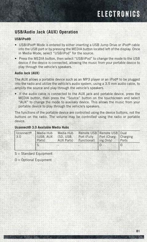
USB/Audio Jack (AUX) Operation
USB/iPod®
• USB/iPod® Mode is entered by either inserting a USB Jump Drive or iPod® cableinto the USB port or by pressing the MEDIA button located left of the display. Oncein Media Mode, select “USB/iPod” for the source.
• Press the MEDIA button, then select “USB/iPod” to change the mode to the USBdevice if the device is connected, allowing the music from your portable device toplay through the vehicle's speakers.
Audio Jack (AUX)
The AUX allows a portable device such as an MP3 player or an iPod® to be pluggedinto the radio and utilize the vehicle’s audio system, using a 3.5 mm audio cable, toamplify the source and play through the vehicle’s speakers.
• If the audio cable is connected to the AUX jack and portable device, press theMEDIA button, then press the “Source” button on the touchscreen and select“AUX” to change the mode to auxiliary device. This allows the music from yourportable device to play through the vehicle's speakers.
The functions of the portable device are controlled using the device buttons, not thebuttons on the radio. The volume may be controlled using the radio or portabledevice.
Uconnect® 3.0 Available Media Hubs
Uconnect®3.0
Media Hub(USB, AUXPorts)
Media Hub(SD, USB,AUX Ports)
Remote USBPort (FullyFunctional)
Remote USBPort (Charg-ing Only)
DualChargingPorts
S - - O O
S = Standard Equipment
O = Optional Equipment
E L E C T R O N I C S
81
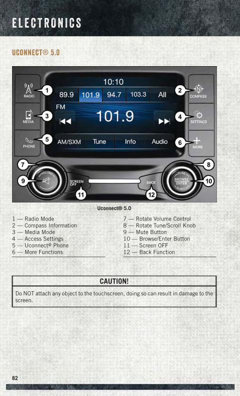
Uconnect® 5.0
CAUTION!
Do NOT attach any object to the touchscreen, doing so can result in damage to thescreen.
Uconnect® 5.0
1 — Radio Mode2 — Compass Information3 — Media Mode4 — Access Settings5 — Uconnect® Phone6 — More Functions
7 — Rotate Volume Control8 — Rotate Tune/Scroll Knob9 — Mute Button10 — Browse/Enter Button11 — Screen OFF12 — Back Function
E L E C T R O N I C S
82
Clock Setting
To start the clock setting procedure, perform the following:
1. Push the SETTINGS button on the faceplate on the right side of the display, thenpress the “Clock & Date” button on the touchscreen.
2. Press the “Set Time & Format” button on the touchscreen.
3. Press the “Up” or “Down” arrows to adjust the hours or minutes, next select the“AM” or “PM” button on the touchscreen. You can also select 12hr or 24hrformat by pressing the desired button on the touchscreen.
4. Once the time is set press the “Done” button on the touchscreen to exit the timescreen.
Equalizer, Balance And Fade1. Push the SETTINGS button on the faceplate on the right side of the unit.
2. Then scroll down and press the “Audio” button on the touchscreen to get to theAudio menu.
3. The Audio Menu shows the following options for you to customize your audiosettings.
Equalizer
• Press the “Equalizer” button on the touchscreen to adjust the Bass, Mid andTreble. Use the “+” or “–” button on the touchscreen to adjust the equalizer to yourdesired settings. Press the “Done” button on the touchscreen when finished.
Balance/Fade
• Press the “Balance/Fade” button on the touchscreen to adjust the sound from thespeakers. Use the “arrow” button on the touchscreen to adjust the sound levelfrom the front and rear or right and left side speakers. Press the Center “C” buttonon the touchscreen to reset the balance and fade to the factory setting. Press the“Done” button on the touchscreen when finished.
Speed Adjustable
• Press the “Speed Adjusted Volume” button on the touchscreen to select betweenOFF, 1, 2 or 3. This will decrease the radio volume relative to a decrease in vehiclespeed. Press the “Done” button on the touchscreen when finished.
Loudness
• Press the “Loudness” button on the touchscreen to select the Loudness feature.When this feature is activated it improves sound quality at lower volumes.
E L E C T R O N I C S
83
Radio Operation
Seek Up/Down Buttons
• Press to seek through radio stations in AM, FM or SXM bands.
• Hold either button to bypass stations without stopping.
Store Radio Presets
• When you are receiving a station that you wish to commit into memory, press andhold the desired preset button on the touchscreen for more that two seconds oruntil you hear a confirmation beep.
• The Radio stores up to 12 presets in each of the Radio modes. 4 presets are visibleat the top of the radio screen. Pressing the “all” button on the touchscreen on theradio home screen will display all of the preset stations for that mode.
SiriusXM Premier Over 160 channels
Get every channel available on your satellite radio, and enjoy all you want, all in oneplace. Hear commercial-free music plus sports, news, talk and entertainment. Get allthe premium programming, including Howard Stern, every NFL game, Oprah Radio®,every MLB® and NHL® game, every NASCAR® race, Martha Stewart and more. Andget 20+ extra channels, including SiriusXM Latino, offering 20 channels of commer-cial free music, news, talk, comedy, sports and more dedicated to Spanish languageprogramming.
To access SiriusXM Satellite Radio, press the “RADIO” button on the faceplate andthen the SXM button on the touchscreen.
SiriusXM services require subscriptions, sold separately after the 12-month trialincluded with the new vehicle purchase. If you decide to continue your service at theend of your trial subscription, the plan you choose will automatically renew and bill atthen-current rates until you call SiriusXM at 1-866-635-2349 for U.S. residents and1-888-539-7474 for Canadian residents to cancel. See SiriusXM Customer Agreementfor complete terms at www.siriusxm.com for U.S. residents and www.siriusxm.ca forCanadian residents. All fees and programming subject to change. Our satellite serviceis available only to those at least 18 and older in the 48 contiguous USA and D.C. OurSirius satellite service is also available in PR (with coverage limitations). Our Internetradio service is available throughout our satellite service area and in AK and HI.© 2014 Sirius XM Radio Inc. Sirius, XM and all related marks and logos aretrademarks of Sirius XM Radio Inc.
E L E C T R O N I C S
84
Disc Operation (If Equipped)
Your vehicle may have a remote CD player located in the lower center console storagebin, or in the lower center bench seat bin.
• CD/Disc Mode is entered by either inserting a CD/Disc or by pressing the MEDIAbutton located on the side of the display. Once in Media Mode, select “Disc.”
• Gently insert one CD into the CD player with the CD label facing as indicated onthe illustration located on the Disc player.
Seek Up/Down Buttons
• Press to seek through Disc tracks.
• Hold either button to bypass tracks without stopping.
Browse
• Press the “Browse” button on the touchscreen to scroll through and select adesired track on the Disc. Press the “Exit” button on the touchscreen if you wantto cancel the browse function.
USB/Audio Jack (AUX)/Bluetooth® Operation
USB/iPod®
• USB/iPod® Mode is entered by either inserting a USB Jump Drive or iPod® cableinto the USB port or by pressing the MEDIA button on the faceplate located left ofthe display. Once in Media Mode, press the “source” button on the touchscreenand select “USB/iPod.”
• Press the MEDIA button on the faceplate, then press the “source” button on thetouchscreen and then select “USB/iPod” to change the mode to the USB device ifthe device is connected, allowing the music from your portable device to playthrough the vehicle's speakers.
Audio Jack (AUX)
The AUX allows a portable device, such as an MP3 player or an iPod®, to be pluggedinto the radio and utilize the vehicle’s audio system, using a 3.5 mm audio cable, toamplify the source and play through the vehicle speakers.
• Press the MEDIA button on the faceplate, then press the “source” button on thetouchscreen and then select “AUX” to change the mode to auxiliary device if theaudio jack is connected, allowing the music from your portable device to playthrough the vehicle's speakers.
The functions of the portable device are controlled using the device buttons, not thebuttons on the radio. The volume may be controlled using the radio or portabledevice.
E L E C T R O N I C S
85
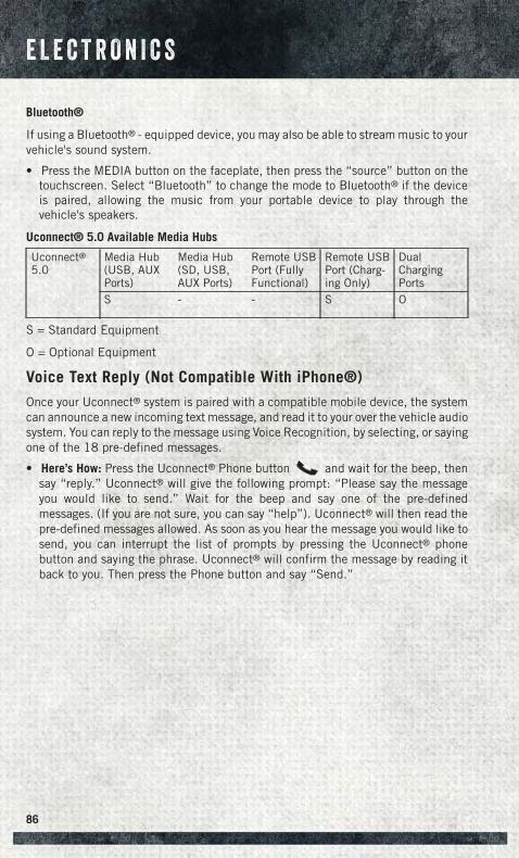
Bluetooth®
If using a Bluetooth® - equipped device, you may also be able to stream music to yourvehicle's sound system.
• Press the MEDIA button on the faceplate, then press the “source” button on thetouchscreen. Select “Bluetooth” to change the mode to Bluetooth® if the deviceis paired, allowing the music from your portable device to play through thevehicle's speakers.
Uconnect® 5.0 Available Media Hubs
Uconnect®5.0
Media Hub(USB, AUXPorts)
Media Hub(SD, USB,AUX Ports)
Remote USBPort (FullyFunctional)
Remote USBPort (Charg-ing Only)
DualChargingPorts
S - - S O
S = Standard Equipment
O = Optional Equipment
Voice Text Reply (Not Compatible With iPhone®)
Once your Uconnect® system is paired with a compatible mobile device, the systemcan announce a new incoming text message, and read it to your over the vehicle audiosystem. You can reply to the message using Voice Recognition, by selecting, or sayingone of the 18 pre-defined messages.
• Here’s How: Press the Uconnect® Phone button and wait for the beep, thensay “reply.” Uconnect® will give the following prompt: “Please say the messageyou would like to send.” Wait for the beep and say one of the pre-definedmessages. (If you are not sure, you can say “help”). Uconnect® will then read thepre-defined messages allowed. As soon as you hear the message you would like tosend, you can interrupt the list of prompts by pressing the Uconnect® phonebutton and saying the phrase. Uconnect® will confirm the message by reading itback to you. Then press the Phone button and say “Send.”
E L E C T R O N I C S
86
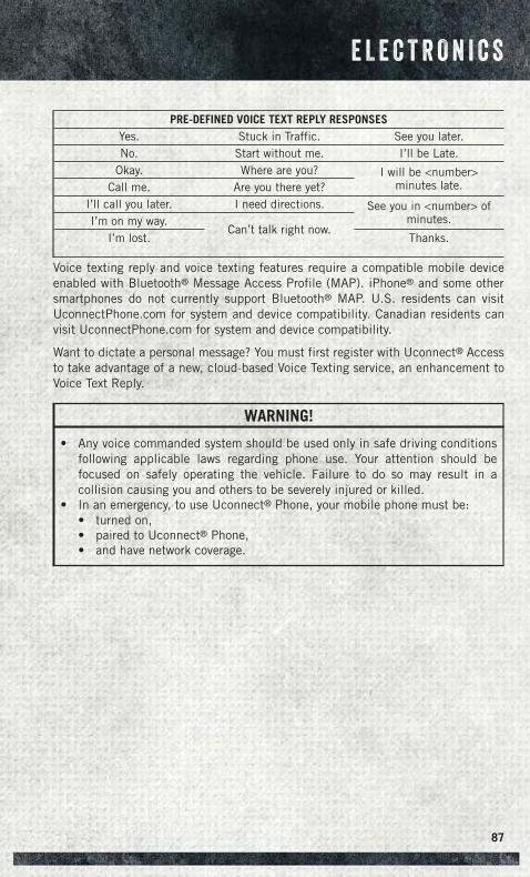
PRE-DEFINED VOICE TEXT REPLY RESPONSESYes. Stuck in Traffic. See you later.No. Start without me. I’ll be Late.
Okay. Where are you? I will be <number>minutes late.Call me. Are you there yet?
I’ll call you later. I need directions. See you in <number> ofminutes.I’m on my way.
Can’t talk right now.I’m lost. Thanks.
Voice texting reply and voice texting features require a compatible mobile deviceenabled with Bluetooth® Message Access Profile (MAP). iPhone® and some othersmartphones do not currently support Bluetooth® MAP. U.S. residents can visitUconnectPhone.com for system and device compatibility. Canadian residents canvisit UconnectPhone.com for system and device compatibility.
Want to dictate a personal message? You must first register with Uconnect® Accessto take advantage of a new, cloud-based Voice Texting service, an enhancement toVoice Text Reply.
WARNING!
• Any voice commanded system should be used only in safe driving conditionsfollowing applicable laws regarding phone use. Your attention should befocused on safely operating the vehicle. Failure to do so may result in acollision causing you and others to be severely injured or killed.
• In an emergency, to use Uconnect® Phone, your mobile phone must be:• turned on,• paired to Uconnect® Phone,• and have network coverage.
E L E C T R O N I C S
87
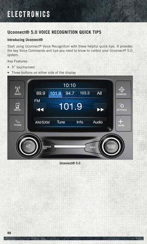
Uconnect® 5.0 VOICE RECOGNITION QUICK TIPS
Introducing Uconnect®
Start using Uconnect® Voice Recognition with these helpful quick tips. It providesthe key Voice Commands and tips you need to know to control your Uconnect® 5.0system.
Key Features:
• 5” touchscreen
• Three buttons on either side of the display
Uconnect® 5.0
E L E C T R O N I C S
88
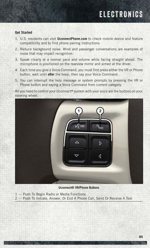
Get Started
1. U.S. residents can visit UconnectPhone.com to check mobile device and featurecompatibility and to find phone pairing instructions.
2. Reduce background noise. Wind and passenger conversations are examples ofnoise that may impact recognition.
3. Speak clearly at a normal pace and volume while facing straight ahead. Themicrophone is positioned on the rearview mirror and aimed at the driver.
4. Each time you give a Voice Command, you must first press either the VR or Phonebutton, wait until after the beep, then say your Voice Command.
5. You can interrupt the help message or system prompts by pressing the VR orPhone button and saying a Voice Command from current category.
All you need to control your Uconnect® system with your voice are the buttons on yoursteering wheel.
Uconnect® VR/Phone Buttons
1 — Push To Begin Radio or Media Functions2 — Push To Initiate, Answer, Or End A Phone Call, Send Or Receive A Text
E L E C T R O N I C S
89
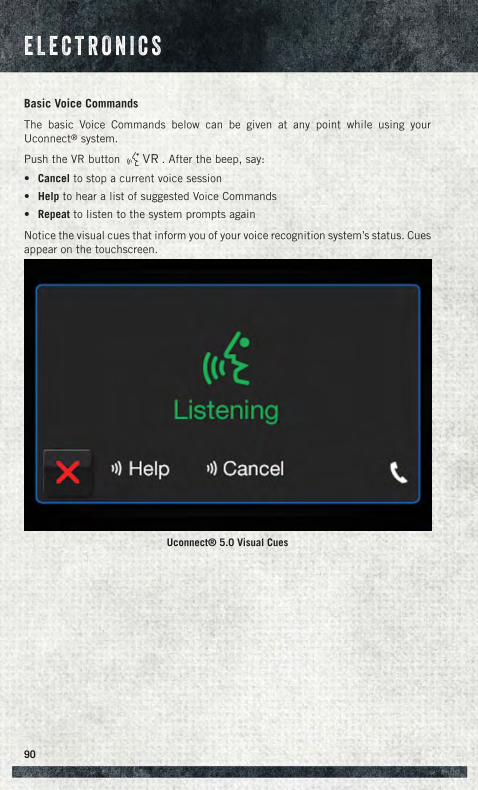
Basic Voice Commands
The basic Voice Commands below can be given at any point while using yourUconnect® system.
Push the VR button . After the beep, say:
• Cancel to stop a current voice session
• Help to hear a list of suggested Voice Commands
• Repeat to listen to the system prompts again
Notice the visual cues that inform you of your voice recognition system’s status. Cuesappear on the touchscreen.
Uconnect® 5.0 Visual Cues
E L E C T R O N I C S
90
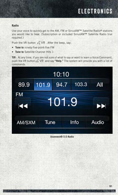
Radio
Use your voice to quickly get to the AM, FM or SiriusXM™ Satellite Radio® stationsyou would like to hear. (Subscription or included SiriusXM™ Satellite Radio trialrequired.)
Push the VR button . After the beep, say:
• Tune to ninety-five-point-five FM
• Tune to Satellite Channel Hits 1
TIP: At any time, if you are not sure of what to say or want to learn a Voice Command,push the VR button and say “Help.” The system will provide you with a list ofcommands.
Uconnect® 5.0 Radio
E L E C T R O N I C S
91
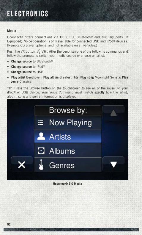
Media
Uconnect® offers connections via USB, SD, Bluetooth® and auxiliary ports (IfEquipped). Voice operation is only available for connected USB and iPod® devices.(Remote CD player optional and not available on all vehicles.)
Push the VR button . After the beep, say one of the following commands andfollow the prompts to switch your media source or choose an artist.
• Change source to Bluetooth®
• Change source to iPod®
• Change source to USB
• Play artist Beethoven; Play album Greatest Hits; Play song Moonlight Sonata; Playgenre Classical
TIP: Press the Browse button on the touchscreen to see all of the music on youriPod® or USB device. Your Voice Command must match exactly how the artist,album, song and genre information is displayed.
Uconnect® 5.0 Media
E L E C T R O N I C S
92
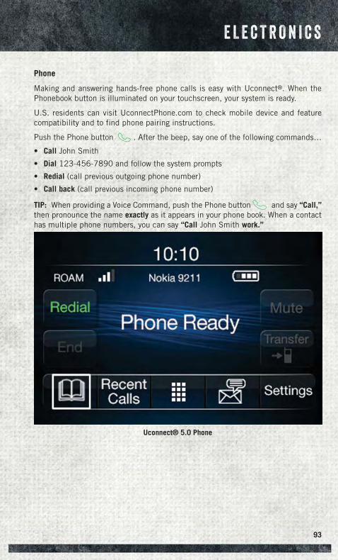
Phone
Making and answering hands-free phone calls is easy with Uconnect®. When thePhonebook button is illuminated on your touchscreen, your system is ready.
U.S. residents can visit UconnectPhone.com to check mobile device and featurecompatibility and to find phone pairing instructions.
Push the Phone button . After the beep, say one of the following commands…
• Call John Smith
• Dial 123-456-7890 and follow the system prompts
• Redial (call previous outgoing phone number)
• Call back (call previous incoming phone number)
TIP: When providing a Voice Command, push the Phone button and say “Call,”then pronounce the name exactly as it appears in your phone book. When a contacthas multiple phone numbers, you can say “Call John Smith work.”
Uconnect® 5.0 Phone
E L E C T R O N I C S
93
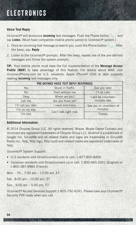
Voice Text Reply
Uconnect® will announce incoming text messages. Push the Phone button andsay Listen. (Must have compatible mobile phone paired to Uconnect® system.)
1. Once an incoming text message is read to you, push the Phone button . Afterthe beep, say: Reply
2. Listen to the Uconnect® prompts. After the beep, repeat one of the pre-definedmessages and follow the system prompts.
TIP: Your mobile phone must have the full implementation of the Message AccessProfile (MAP) to take advantage of this feature. For details about MAP, visitUconnectPhone.com for U.S. residents. Apple iPhone® iOS6 or later supportsreading incoming text messages only.
PRE-DEFINED VOICE TEXT REPLY RESPONSESYes. Stuck in Traffic. See you later.No. Start without me. I’ll be Late.
Okay. Where are you? I will be <number>minutes late.Call me. Are you there yet?
I’ll call you later. I need directions. See you in <number> ofminutes.I’m on my way.
Can’t talk right now.I’m lost. Thanks.
Additional Information
© 2014 Chrysler Group LLC. All rights reserved. Mopar, Mopar Owner Connect andUconnect are registered trademarks of Chrysler Group LLC. Android is a trademark ofGoogle Inc. SiriusXM and all related marks and logos are trademarks of SiriusXMRadio Inc. Yelp, Yelp logo, Yelp burst and related marks are registered trademarks ofYelp.
Uconnect® System Support:
• U.S residents visit DriveUconnect.com or call: 1-877-855-8400
• Canadian residents visit DriveUconnect.ca or call: 1-800-465-2001 (English) or1-800-387-9983 (French)
Mon. – Fri., 7:00 am – 12:00 am, ET
Sat., 8:00 am – 10:00 pm, ET
Sun., 9:00 am – 5:00 pm, ET
Uconnect® Access Services Support 1-855-792-4241. Please have your Uconnect®
Security PIN ready when you call.
E L E C T R O N I C S
94
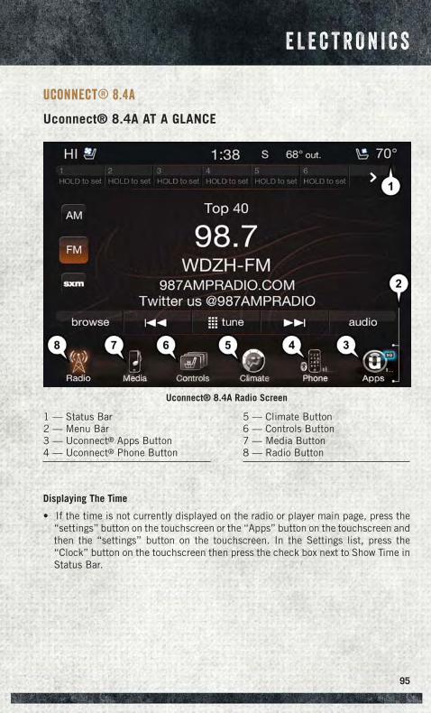
Uconnect® 8.4A
Uconnect® 8.4A AT A GLANCE
Displaying The Time
• If the time is not currently displayed on the radio or player main page, press the“settings” button on the touchscreen or the “Apps” button on the touchscreen andthen the “settings” button on the touchscreen. In the Settings list, press the“Clock” button on the touchscreen then press the check box next to Show Time inStatus Bar.
Uconnect® 8.4A Radio Screen
1 — Status Bar2 — Menu Bar3 — Uconnect® Apps Button4 — Uconnect® Phone Button
5 — Climate Button6 — Controls Button7 — Media Button8 — Radio Button
E L E C T R O N I C S
95
Setting The Time
• Turn the unit on, then press the time display at the top of the screen. Press “Yes.”
• If the time is not displayed at the top of the screen, press the “Controls” button onthe touchscreen, or the “Apps” button on the touchscreen, and then the “settings”button on the touchscreen. In the Settings screen, press the “Clock” button on thetouchscreen, then check or uncheck this option.
• Press “+” or “–” next to Set Time Hours and Set Time Minutes to adjust the time.
• If these features are not available, uncheck the Sync with GPS box.
• Press “X” to save your settings and exit out of the Clock Setting screen.
Audio Settings
• Press the “Audio” button on the touchscreen to activate the Audio settings screento adjust Balance\Fade, Equalizer, and Speed Adjusted Volume.
• You can return to the Radio screen by pressing the “X” located at the top right.
Balance/Fade
• Press the “Balance/Fade” button on the touchscreen to Balance the audiobetween the front speakers or fade the audio between the rear and front speakers.
• Pressing the “Front,” “Rear,” “Left,” or “Right” buttons on the touchscreen orpress and drag the Speaker Icon to adjust the Balance/Fade.
Equalizer
• Press the “Equalizer” button on the touchscreen to activate the Equalizer screen.
• Press the “+” or “–” buttons on the touchscreen, or by pressing and dragging overthe level bar for each of the equalizer bands. The level value, which spans betweenplus or minus 9, is displayed at the bottom of each of the Bands.
Speed Adjusted Volume
• Press the “Speed Adjusted Volume” button on the touchscreen to activate theSpeed Adjusted Volume screen. The Speed Adjusted Volume is adjusted bypressing the volume level indicator. This alters the automatic adjustment of theaudio volume with variation to vehicle speed.
E L E C T R O N I C S
96
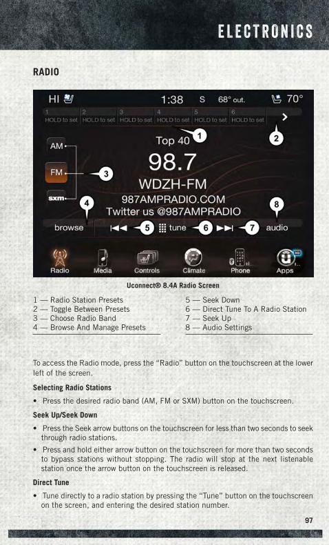
RADIO
To access the Radio mode, press the “Radio” button on the touchscreen at the lowerleft of the screen.
Selecting Radio Stations
• Press the desired radio band (AM, FM or SXM) button on the touchscreen.
Seek Up/Seek Down
• Press the Seek arrow buttons on the touchscreen for less than two seconds to seekthrough radio stations.
• Press and hold either arrow button on the touchscreen for more than two secondsto bypass stations without stopping. The radio will stop at the next listenablestation once the arrow button on the touchscreen is released.
Direct Tune
• Tune directly to a radio station by pressing the “Tune” button on the touchscreenon the screen, and entering the desired station number.
Uconnect® 8.4A Radio Screen
1 — Radio Station Presets2 — Toggle Between Presets3 — Choose Radio Band4 — Browse And Manage Presets
5 — Seek Down6 — Direct Tune To A Radio Station7 — Seek Up8 — Audio Settings
E L E C T R O N I C S
97
Store Radio Presets
Your radio can store 36 total preset stations, 12 presets per band (AM, FM and SXM).They are shown at the top of your radio screen. To see the 12 preset stations per band,press the arrow button on the touchscreen at the top right of the screen to togglebetween the two sets of six presets.
• To set a station into memory press and hold the desired numbered button on thetouchscreen for more than two seconds or until you hear a confirmation beep.
SiriusXM PREMIER OVER 160 CHANNELS
Get every channel available on your satellite radio, and enjoy all you want, all in oneplace. Hear commercial-free music plus sports, news, talk and entertainment. Get allthe premium programming, including Howard Stern, every NFL game, Oprah Radio®,every MLB® and NHL® game, every NASCAR® race, Martha Stewart and more. Andget 20+ extra channels, including SiriusXM Latino, offering 20 channels of commer-cial free music, news, talk, comedy, sports and more dedicated to Spanish languageprogramming.
• To access SiriusXM Satellite Radio, press the “SXM” button on the touchscreen onthe main Radio screen.
The following describes features that are available when in SiriusXM Satellite Radiomode:
Seek Up/Seek Down
• Press the Seek arrow buttons on the touchscreen for less than two seconds to seekthrough channels in SXM mode.
• Press and hold either arrow button on the touchscreen for more than two secondsto bypass channels without stopping. The radio will stop at the next listenablechannel once the arrow button on the touchscreen is released.
Direct Tune
• Tune directly to a SXM channel by pressing the “Tune” button on the touchscreenon the screen, and entering the desired station number.
Jump
• Automatically tells you when Traffic & Weather for a favorite city is available, andgives you the option to switch to that channel. Press “Jump” to activate thefeature. After listening to Traffic and Weather, press “Jump” again to return to theprevious channel.
Fav
• Activates the favorites menu. You can add up to 50 favorite artists or songs. Justpress “Add Fav Artist” or “Add Fav Song” while the song is playing. You will thenbe alerted any time one of these songs, or works by these artists, is playing on otherSiriusXM channels.
E L E C T R O N I C S
98
SiriusXM Parental Controls
• You can skip or hide certain channels from view if you do not want access to them.Press the “Apps” button on the touchscreen, then the “Settings” button on thetouchscreen, next press the “Sirius Setup” button on the touchscreen, then selectChannel Skip. Press the box check-mark next to the channel you want skipped.They will not show up in normal usage.
• SiriusXM also offers the option to permanently block selected channels. Call(1-888-601-6297 for U.S. customers, 1-877-438-9677 for Canadian custom-ers) and request the Family-Friendly Package.
Browse
Lets you browse the SiriusXM channel listing or Genre listing. Favorites, Game Zone,Weather and Jump settings also provide a way to browse the SiriusXM channel list.
BrowseSub-Menu
Sub-Menu Description
All Shows the channel listing.Genre Provides a list of all genres, and lets you jump to a channel within the
selected genre.Presets Lets you scroll the list of Preset satellite channels. Press the channel, or
press Enter on the Tune knob, to go to that channel. Press the trash canicon to delete a preset. Your presets are also shown at the top of the mainSatellite Radio screen.
Favorites Lets you manage artists and songs in the Favorites list and configure AlertSettings to let you know when favorite songs or artists are playing on otherchannels. Also, view a list of channels airing any of your Favorites.
Game Zone Provides alerts when your favorite sports teams are starting a game whichis being aired on other SiriusXM channels, or when their game score isannounced. You can select and manage your Teams list here, andconfigure alerts.
Jump Lets you select your favorite cities for Traffic & Weather information,which is used by the Jump feature on the main satellite radio screen.
Replay
Lets you replay up to 44 minutes of the content of the current SiriusXM channel.
ReplayOption
Option Description
Play/Pause Press to Pause content playback. Press Pause/Play again to resumeplayback.
Rewind/RW Rewinds the channel content in steps of five seconds. Press and hold torewind continuously, then release to begin playing content at that point.
FastForward/FW
Forwards the content, and works similarly to Rewind/RW. However, FastForward/FW can only be used when content has been previously rewound.
E L E C T R O N I C S
99
ReplayOption
Option Description
Replay Time Displays the amount of time in the upper center of the screen by whichyour content lags the Live channel.
Live Resumes playback of Live content at any time while replaying rewoundcontent.
• SiriusXM services require subscriptions, sold separately after the 12-month trialincluded with the new vehicle purchase. If you decide to continue your service at theend of your trial subscription, the plan you choose will automatically renew and bill atthen-current rates until you call SiriusXM at 1-866-635-2349 for U.S. residents and1-888-539-7474 for Canadian residents to cancel. See SiriusXM Customer Agreementfor complete terms at www.siriusxm.com (US residents) or siriusxm.ca (Canadianresidents). All fees and programming subject to change. Our satellite service isavailable only to those at least 18 and older in the 48 contiguous USA and D.C.Our Sirius satellite service is also available in PR (with coverage limitations). OurInternet radio service is available throughout our satellite service area and in AKand HI. ©2014 Sirius XM Radio Inc. Sirius, XM and all related marks and logos aretrademarks of Sirius XM Radio Inc.
Disc Operation (If Equipped)• Your vehicle may have a remote CD player located in the lower center console
storage bin, or in the lower center bench seat bin.
• CD/Disc Mode is entered by either inserting a CD/Disc or by pressing the MEDIAbutton located on the side of the display. Once in Media Mode, select “Disc.”
• Gently insert one CD into the CD player with the CD label facing as indicated onthe illustration located on the Disc player.
Seek Up/Down Buttons
• Press to seek through Disc tracks.
• Hold either button to bypass tracks without stopping.
Browse
• Press the “Browse” button on the touchscreen to scroll through and select adesired track on the Disc. Press the “Exit” button on the touchscreen if you wishto cancel the browse function.
E L E C T R O N I C S
100
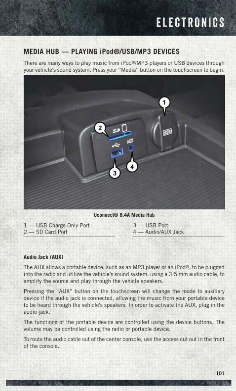
MEDIA HUB — PLAYING iPod®/USB/MP3 DEVICES
There are many ways to play music from iPod®/MP3 players or USB devices throughyour vehicle's sound system. Press your “Media” button on the touchscreen to begin.
Audio Jack (AUX)
The AUX allows a portable device, such as an MP3 player or an iPod®, to be pluggedinto the radio and utilize the vehicle’s sound system, using a 3.5 mm audio cable, toamplify the source and play through the vehicle speakers.
Pressing the “AUX” button on the touchscreen will change the mode to auxiliarydevice if the audio jack is connected, allowing the music from your portable deviceto be heard through the vehicle's speakers. In order to activate the AUX, plug in theaudio jack.
The functions of the portable device are controlled using the device buttons. Thevolume may be controlled using the radio or portable device.
To route the audio cable out of the center console, use the access cut out in the frontof the console.
Uconnect® 8.4A Media Hub
1 — USB Charge Only Port2 — SD Card Port
3 — USB Port4 — Audio/AUX Jack
E L E C T R O N I C S
101
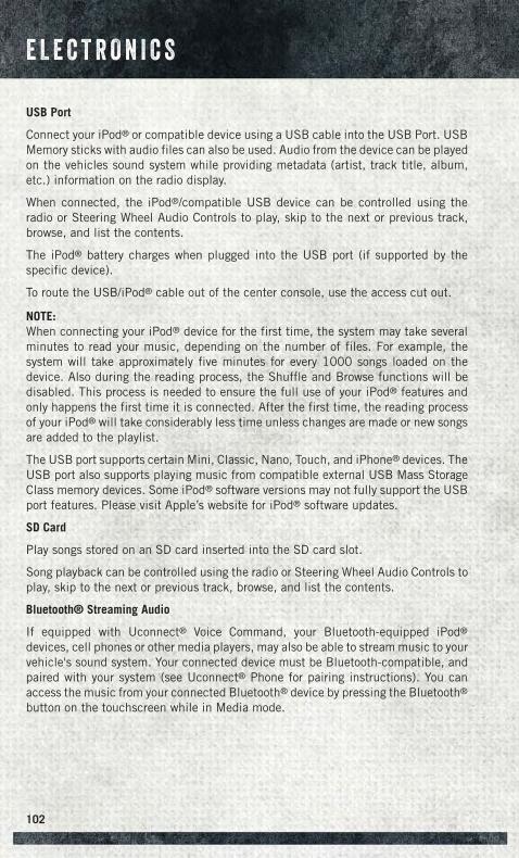
USB Port
Connect your iPod® or compatible device using a USB cable into the USB Port. USBMemory sticks with audio files can also be used. Audio from the device can be playedon the vehicles sound system while providing metadata (artist, track title, album,etc.) information on the radio display.
When connected, the iPod®/compatible USB device can be controlled using theradio or Steering Wheel Audio Controls to play, skip to the next or previous track,browse, and list the contents.
The iPod® battery charges when plugged into the USB port (if supported by thespecific device).
To route the USB/iPod® cable out of the center console, use the access cut out.
NOTE:When connecting your iPod® device for the first time, the system may take severalminutes to read your music, depending on the number of files. For example, thesystem will take approximately five minutes for every 1000 songs loaded on thedevice. Also during the reading process, the Shuffle and Browse functions will bedisabled. This process is needed to ensure the full use of your iPod® features andonly happens the first time it is connected. After the first time, the reading processof your iPod® will take considerably less time unless changes are made or new songsare added to the playlist.
The USB port supports certain Mini, Classic, Nano, Touch, and iPhone® devices. TheUSB port also supports playing music from compatible external USB Mass StorageClass memory devices. Some iPod® software versions may not fully support the USBport features. Please visit Apple’s website for iPod® software updates.
SD Card
Play songs stored on an SD card inserted into the SD card slot.
Song playback can be controlled using the radio or Steering Wheel Audio Controls toplay, skip to the next or previous track, browse, and list the contents.
Bluetooth® Streaming Audio
If equipped with Uconnect® Voice Command, your Bluetooth-equipped iPod®
devices, cell phones or other media players, may also be able to stream music to yourvehicle's sound system. Your connected device must be Bluetooth-compatible, andpaired with your system (see Uconnect® Phone for pairing instructions). You canaccess the music from your connected Bluetooth® device by pressing the Bluetooth®
button on the touchscreen while in Media mode.
E L E C T R O N I C S
102
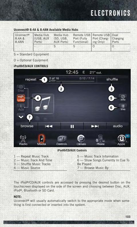
Uconnect® 8.4A & 8.4AN Available Media Hubs
Uconnect®8.4A &8.4AN
Media Hub(USB, AUXPorts)
Media Hub(SD, USB,AUX Ports)
Remote USBPort (FullyFunctional)
Remote USBPort (Charg-ing Only)
DualChargingPorts
- S S O O
S = Standard Equipment
O = Optional Equipment
iPod®/CD/AUX CONTROLS
The iPod®/CD/AUX controls are accessed by pressing the desired button on thetouchscreen displayed on the side of the screen and choosing between Disc, AUX,iPod®, Bluetooth or SD Card.
NOTE:Uconnect® will usually automatically switch to the appropriate mode when some-thing is first connected or inserted into the system.
iPod®/CD/AUX Controls
1 — Repeat Music Track2 — Music Track And Time3 — Shuffle Music Tracks4 — Music Source
5 — Music Track Information6 — Show Songs Currently In Cue ToBe Played7 — Browse Music By
E L E C T R O N I C S
103
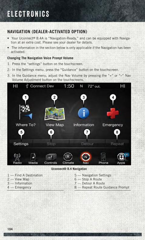
NAVIGATION (DEALER-ACTIVATED OPTION)• Your Uconnect® 8.4A is “Navigation-Ready,” and can be equipped with Naviga-
tion at an extra cost. Please see your dealer for details.
• The information in the section below is only applicable if the Navigation has beenactivated.
Changing The Navigation Voice Prompt Volume
1. Press the “settings” button on the touchscreen.
2. In the Settings menu, press the “Guidance” button on the touchscreen.
3. In the Guidance menu, adjust the Nav Volume by pressing the “+” or “–” NavVolume Adjustment button on the touchscreens.
Uconnect® 8.4 Navigation
1 — Find A Destination2 — View Map3 — Information4 — Emergency
5 — Navigation Settings6 — Stop A Route7 — Detour A Route8 — Repeat Route Guidance Prompt
E L E C T R O N I C S
104
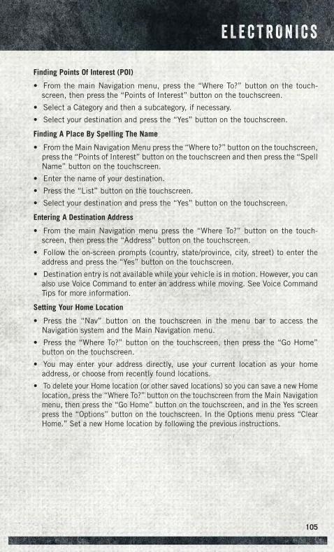
Finding Points Of Interest (POI)
• From the main Navigation menu, press the “Where To?” button on the touch-screen, then press the “Points of Interest” button on the touchscreen.
• Select a Category and then a subcategory, if necessary.
• Select your destination and press the “Yes” button on the touchscreen.
Finding A Place By Spelling The Name
• From the Main Navigation Menu press the “Where to?” button on the touchscreen,press the “Points of Interest” button on the touchscreen and then press the “SpellName” button on the touchscreen.
• Enter the name of your destination.
• Press the “List” button on the touchscreen.
• Select your destination and press the “Yes” button on the touchscreen.
Entering A Destination Address
• From the main Navigation menu press the “Where To?” button on the touch-screen, then press the “Address” button on the touchscreen.
• Follow the on-screen prompts (country, state/province, city, street) to enter theaddress and press the “Yes” button on the touchscreen.
• Destination entry is not available while your vehicle is in motion. However, you canalso use Voice Command to enter an address while moving. See Voice CommandTips for more information.
Setting Your Home Location
• Press the “Nav” button on the touchscreen in the menu bar to access theNavigation system and the Main Navigation menu.
• Press the “Where To?” button on the touchscreen, then press the “Go Home”button on the touchscreen.
• You may enter your address directly, use your current location as your homeaddress, or choose from recently found locations.
• To delete your Home location (or other saved locations) so you can save a new Homelocation, press the “Where To?” button on the touchscreen from the Main Navigationmenu, then press the “Go Home” button on the touchscreen, and in the Yes screenpress the “Options” button on the touchscreen. In the Options menu press “ClearHome.” Set a new Home location by following the previous instructions.
E L E C T R O N I C S
105
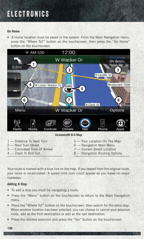
Go Home
• A Home location must be saved in the system. From the Main Navigation menu,press the “Where To?” button on the touchscreen, then press the “Go Home”button on the touchscreen.
Your route is marked with a blue line on the map. If you depart from the original route,your route is recalculated. A speed limit icon could appear as you travel on majorroadways.
Adding A Stop
• To add a stop you must be navigating a route.
• Press the “Menu” button on the touchscreen to return to the Main Navigationmenu.
• Press the “Where To?” button on the touchscreen, then search for the extra stop.When another location has been selected, you can choose to cancel your previousroute, add as the first destination or add as the last destination.
• Press the desired selection and press the “Yes” button on the touchscreen.
Uconnect® 8.4 Map
1 — Distance To Next Turn2 — Next Turn Street3 — Estimated Time Of Arrival4 — Zoom In And Out
5 — Your Location On The Map6 — Navigation Main Menu7 — Current Street Location8 — Navigation Routing Options
E L E C T R O N I C S
106
Taking A Detour
• To take a detour you must be navigating a route.
• Press the “Detour” button on the touchscreen.
NOTE:If the route you are currently taking is the only reasonable option, the device mightnot calculate a detour.
• For more information, see your Uconnect® Supplement Manual.
Uconnect® Phone (Bluetooth® HANDS FREE CALLING)• If the Uconnect® Phone Button exists on your steering wheel, then you have
the Uconnect® Phone features.
• The Uconnect® Phone is a voice-activated, hands-free, in-vehicle communica-tions system with Voice Command Capability (see Voice Command section).
• The Uconnect® Phone allows you to dial a phone number with your mobile phoneusing simple voice commands or pressing the buttons on the touchscreen.
• Refer to the Understand The Features Of Your Vehicle section of your vehicle'sOwner's Manual on the DVD for further details.
NOTE:The Uconnect® Phone requires a mobile phone equipped with the Bluetooth®
Hands-Free Profile, Version 1.0 or higher. For Uconnect® Customer Support: U.S.residents visit UconnectPhone.com or call 1-877-855-8400. Canadian Residents –visit UconnectPhone.com or call, 1-800-465-2001 (English) or 1-800-387-9983(French).
Pairing A Phone• To use the Uconnect® Phone feature, you must first pair your Bluetooth® phone
with the Uconnect® system.
Start Pairing Procedure On The Radio
• Press the “Phone” button on the touchscreen and then the “settings” button onthe touchscreen. Next, press “Add Device.”
• Uconnect® Phone will display an “In progress” screen while the system isconnecting.
Start Pairing Procedure On Mobile Phone
• Search for available devices on your Bluetooth® enabled mobile phone. This isusually within Settings or Options under “Bluetooth.” See your mobile phone’smanual for details.
• When your phone finds the system, select “Uconnect” as the paired device. Youmay be prompted by your phone to download the phonebook. This is so you canmake calls by saying the name of your contact (PBAP-Phone Book Access Profile).
E L E C T R O N I C S
107
Complete The Pairing Procedure
• When prompted on the phone, verify with the radio password shown on theUconnect® Screen.
• If your phone asks you to accept a connection request from Uconnect®, select“Yes.” If available, check the box telling it not to ask again – that way your phonewill automatically connect each time you start the vehicle.
Select The Mobile Phone's Priority Level
• When the pairing process has successfully completed, the system will prompt youto choose whether or not this is your favorite phone. Selecting “Yes” will make thisphone the highest priority. This phone will take precedence over other pairedphones within range. Only one phone can be paired at a time.
• You are now ready to make hands-free calls. Press the Uconnect® Phone button onyour steering wheel to begin.
Making A Phone Call
To begin a phone call using Uconnect® Voice Command:
• Push the Uconnect® Phone button .
• After the BEEP, say “dial” then the number (or “call” then the name as listed inyour phone; see Phonebook).
NOTE:You can also initiate a call by using the touchscreen on the Phone main screen.
Receiving A Call — Accept (And End)• When an incoming call rings/is announced on Uconnect®, push the Phone
button .
• To end a call, push the Phone button .
Mute (Or Unmute) Microphone During Call• During a call, press the “mute” button on the touchscreen to mute and unmute
the call.
Transfer Ongoing Call Between Handset And Vehicle
During an on-going call, press the “Transfer” button on the touchscreen to transfer anon-going call between handset and vehicle.
E L E C T R O N I C S
108
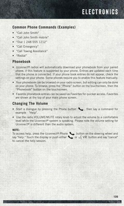
Common Phone Commands (Examples)• “Call John Smith”
• “Call John Smith mobile”
• “Dial 1 248 555 1212”
• “Call Emergency”
• “Call Towing Assistance”
• “Redial”
Phonebook• Uconnect® radios will automatically download your phonebook from your paired
phone, if this feature is supported by your phone. Entries are updated each timethat the phone is connected. If your phone book entries do not appear, check thesettings on your phone. Some phones require you to enable this feature manually.
• Your phonebook can be browsed on your radio screen, but editing can only be doneon your phone. To browse, press the “Phone” button on the touchscreen, then the“Phonebook” button on the touchscreen.
• Favorite phonebook entries can be saved as Favorites for quicker access. Favoritesare shown at the top of your main phone screen.
Changing The Volume• Start a dialogue by pressing the Phone button , then say a command for
example - "Help".
• Use the radio VOLUME/MUTE rotary knob to adjust the volume to a comfortablelevel while the Uconnect® system is speaking. Please note the volume setting forUconnect® is different than the audio system.
NOTE:To access help, press the Uconnect® Phone button on the steering wheel andsay "help." Touch the display or push either or button and say "cancel"to cancel the help session.
E L E C T R O N I C S
109

Voice Text Reply (Not Compatible With iPhone®)
Once your Uconnect® system is paired with a compatible mobile device, the systemcan announce a new incoming text message, and read it to your over the vehicle audiosystem. You can reply to the message using Voice Recognition, by selecting, or sayingone of the 18 pre-defined messages.
• Here’s How: Press the Uconnect® Phone button and wait for the beep, thensay “reply.” Uconnect® will give the following prompt: “Please say the messageyou would like to send.” Wait for the beep and say one of the pre-definedmessages. (If you are not sure, you can say “help”). Uconnect® will then read thepre-defined messages allowed. As soon as you hear the message you would like tosend, you can interrupt the list of prompts by pressing the Uconnect® phonebutton and saying the phrase. Uconnect® will confirm the message by reading itback to you. Then press the Phone button and say “Send.”
PRE-DEFINED VOICE TEXT REPLY RESPONSESYes. Stuck in Traffic. See you later.No. Start without me. I’ll be Late.
Okay. Where are you? I will be <number>minutes late.Call me. Are you there yet?
I’ll call you later. I need directions. See you in <number> ofminutes.I’m on my way.
Can’t talk right now.I’m lost. Thanks.
Voice texting reply and voice texting features require a compatible mobile deviceenabled with Bluetooth® Message Access Profile (MAP). iPhone® and some othersmartphones do not currently support Bluetooth® MAP. U.S. residents can visitUconnectPhone.com for system and device compatibility. Canadian residents canvisit UconnectPhone.com for system and device compatibility.
Want to dictate a personal message? You must first register with Uconnect® Accessto take advantage of a new, cloud-based Voice Texting service, an enhancement toVoice Text Reply.
WARNING!
• Any voice commanded system should be used only in safe driving conditionsfollowing applicable laws regarding phone use. Your attention should befocused on safely operating the vehicle. Failure to do so may result in acollision causing you and others to be severely injured or killed.
• In an emergency, to use Uconnect® Phone, your mobile phone must be:• turned on,• paired to Uconnect® Phone,• and have network coverage.
E L E C T R O N I C S
110
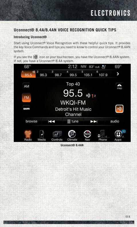
Uconnect® 8.4A/8.4AN VOICE RECOGNITION QUICK TIPS
Introducing Uconnect®
Start using Uconnect® Voice Recognition with these helpful quick tips. It providesthe key Voice Commands and tips you need to know to control your Uconnect® 8.4ANsystem.
If you see the icon on your touchscreen, you have the Uconnect® 8.4AN system.If not, you have a Uconnect® 8.4A system.
Uconnect® 8.4AN
E L E C T R O N I C S
111
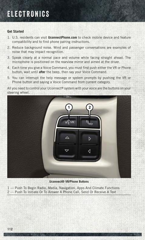
Get Started
1. U.S. residents can visit UconnectPhone.com to check mobile device and featurecompatibility and to find phone pairing instructions.
2. Reduce background noise. Wind and passenger conversations are examples ofnoise that may impact recognition.
3. Speak clearly at a normal pace and volume while facing straight ahead. Themicrophone is positioned on the rearview mirror and aimed at the driver.
4. Each time you give a Voice Command, you must first push either the VR or Phonebutton, wait until after the beep, then say your Voice Command.
5. You can interrupt the help message or system prompts by pushing the VR orPhone button and saying a Voice Command from current category.
All you need to control your Uconnect® system with your voice are the buttons on yoursteering wheel.
Uconnect® VR/Phone Buttons
1 — Push To Begin Radio, Media, Navigation, Apps And Climate Functions2 — Push To Initiate Or To Answer A Phone Call, Send Or Receive A Text
E L E C T R O N I C S
112
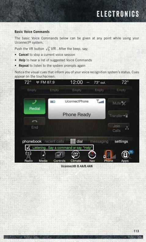
Basic Voice Commands
The basic Voice Commands below can be given at any point while using yourUconnect® system.
Push the VR button . After the beep, say:
• Cancel to stop a current voice session
• Help to hear a list of suggested Voice Commands
• Repeat to listen to the system prompts again
Notice the visual cues that inform you of your voice recognition system’s status. Cuesappear on the touchscreen.
Uconnect® 8.4A/8.4AN
E L E C T R O N I C S
113
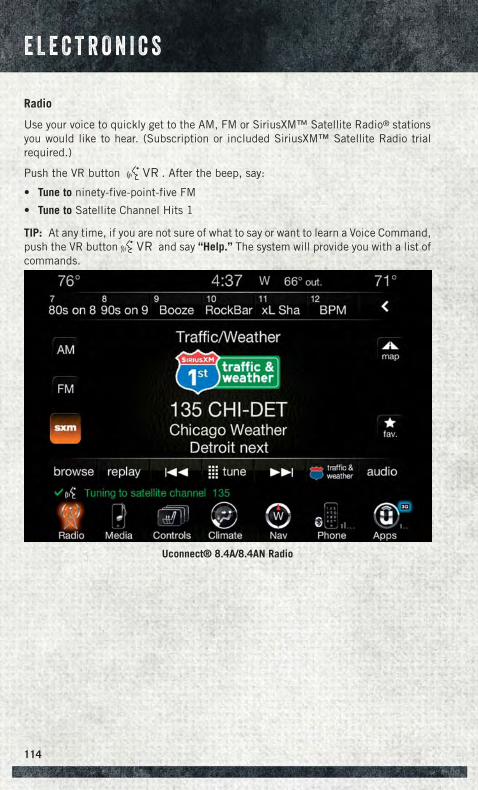
Radio
Use your voice to quickly get to the AM, FM or SiriusXM™ Satellite Radio® stationsyou would like to hear. (Subscription or included SiriusXM™ Satellite Radio trialrequired.)
Push the VR button . After the beep, say:
• Tune to ninety-five-point-five FM
• Tune to Satellite Channel Hits 1
TIP: At any time, if you are not sure of what to say or want to learn a Voice Command,push the VR button and say “Help.” The system will provide you with a list ofcommands.
Uconnect® 8.4A/8.4AN Radio
E L E C T R O N I C S
114
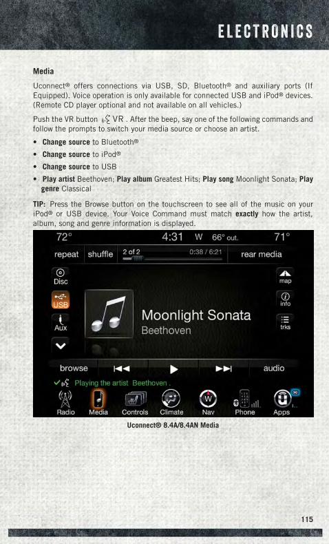
Media
Uconnect® offers connections via USB, SD, Bluetooth® and auxiliary ports (IfEquipped). Voice operation is only available for connected USB and iPod® devices.(Remote CD player optional and not available on all vehicles.)
Push the VR button . After the beep, say one of the following commands andfollow the prompts to switch your media source or choose an artist.
• Change source to Bluetooth®
• Change source to iPod®
• Change source to USB
• Play artist Beethoven; Play album Greatest Hits; Play song Moonlight Sonata; Playgenre Classical
TIP: Press the Browse button on the touchscreen to see all of the music on youriPod® or USB device. Your Voice Command must match exactly how the artist,album, song and genre information is displayed.
Uconnect® 8.4A/8.4AN Media
E L E C T R O N I C S
115
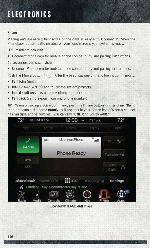
Phone
Making and answering hands-free phone calls is easy with Uconnect®. When thePhonebook button is illuminated on your touchscreen, your system is ready.
U.S. residents can visit:
• UconnectPhone.com for mobile phone compatibility and pairing instructions.
Canadian residents can visit:
• UconnectPhone.com for mobile phone compatibility and pairing instructions.
Push the Phone button . After the beep, say one of the following commands…
• Call John Smith
• Dial 123-456-7890 and follow the system prompts
• Redial (call previous outgoing phone number)
• Call back (call previous incoming phone number)
TIP: When providing a Voice Command, push the Phone button and say “Call,”then pronounce the name exactly as it appears in your phone book. When a contacthas multiple phone numbers, you can say “Call John Smith work.”
Uconnect® 8.4A/8.4AN Phone
E L E C T R O N I C S
116
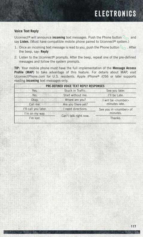
Voice Text Reply
Uconnect® will announce incoming text messages. Push the Phone button andsay Listen. (Must have compatible mobile phone paired to Uconnect® system.)
1. Once an incoming text message is read to you, push the Phone button . Afterthe beep, say: Reply
2. Listen to the Uconnect® prompts. After the beep, repeat one of the pre-definedmessages and follow the system prompts.
TIP: Your mobile phone must have the full implementation of the Message AccessProfile (MAP) to take advantage of this feature. For details about MAP, visitUconnectPhone.com for U.S. residents. Apple iPhone® iOS6 or later supportsreading incoming text messages only.
PRE-DEFINED VOICE TEXT REPLY RESPONSESYes. Stuck in Traffic. See you later.No. Start without me. I’ll be Late.
Okay. Where are you? I will be <number>minutes late.Call me. Are you there yet?
I’ll call you later. I need directions. See you in <number> ofminutes.I’m on my way.
Can’t talk right now.I’m lost. Thanks.
E L E C T R O N I C S
117
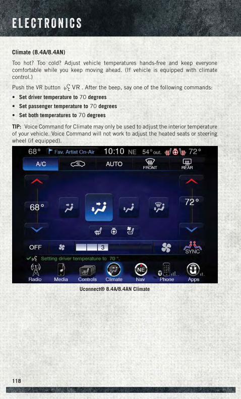
Climate (8.4A/8.4AN)
Too hot? Too cold? Adjust vehicle temperatures hands-free and keep everyonecomfortable while you keep moving ahead. (If vehicle is equipped with climatecontrol.)
Push the VR button . After the beep, say one of the following commands:
• Set driver temperature to 70 degrees
• Set passenger temperature to 70 degrees
• Set both temperatures to 70 degrees
TIP: Voice Command for Climate may only be used to adjust the interior temperatureof your vehicle. Voice Command will not work to adjust the heated seats or steeringwheel (if equipped).
Uconnect® 8.4A/8.4AN Climate
E L E C T R O N I C S
118
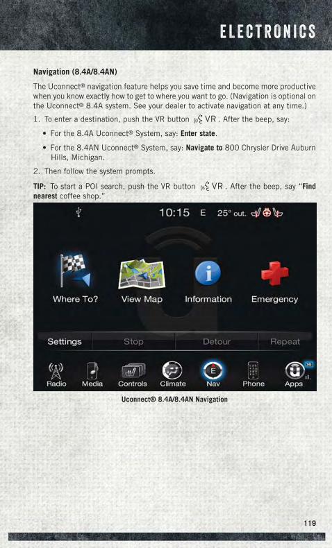
Navigation (8.4A/8.4AN)
The Uconnect® navigation feature helps you save time and become more productivewhen you know exactly how to get to where you want to go. (Navigation is optional onthe Uconnect® 8.4A system. See your dealer to activate navigation at any time.)
1. To enter a destination, push the VR button . After the beep, say:
• For the 8.4A Uconnect® System, say: Enter state.
• For the 8.4AN Uconnect® System, say: Navigate to 800 Chrysler Drive AuburnHills, Michigan.
2. Then follow the system prompts.
TIP: To start a POI search, push the VR button . After the beep, say “Findnearest coffee shop.”
Uconnect® 8.4A/8.4AN Navigation
E L E C T R O N I C S
119
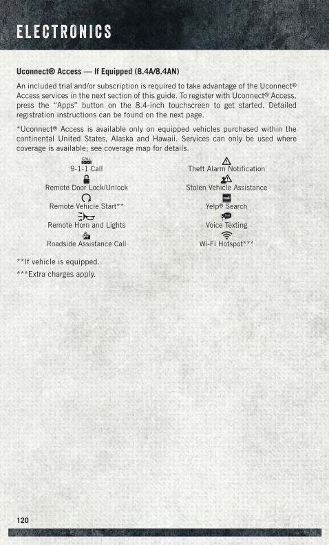
Uconnect® Access — If Equipped (8.4A/8.4AN)
An included trial and/or subscription is required to take advantage of the Uconnect®Access services in the next section of this guide. To register with Uconnect® Access,press the “Apps” button on the 8.4-inch touchscreen to get started. Detailedregistration instructions can be found on the next page.
*Uconnect® Access is available only on equipped vehicles purchased within thecontinental United States, Alaska and Hawaii. Services can only be used wherecoverage is available; see coverage map for details.
CALL9 1 1
9-1-1 Call Theft Alarm Notification
Remote Door Lock/Unlock Stolen Vehicle Assistance
Remote Vehicle Start** Yelp® Search
Remote Horn and Lights
Text
Voice Texting
Roadside Assistance Call Wi-Fi Hotspot***
**If vehicle is equipped.
***Extra charges apply.
E L E C T R O N I C S
120
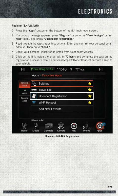
Register (8.4A/8.4AN)
1. Press the “Apps” button on the bottom of the 8.4-inch touchscreen.
2. If a pop-up message appears, press “Register” or go to the “Favorite Apps” or “AllApps” menu and press “Uconnect® Registration.”
3. Read through the registration instructions. Enter and confirm your personal emailaddress. Then press “Send.”
4. Check your personal inbox for an email from Uconnect® Access.
5. Click on the link inside the email within 72 hours and complete the easy onlineregistration process to create a personal Mopar® Owner Connect account linked toyour vehicle.
Uconnect® 8.4AN Registration
E L E C T R O N I C S
121
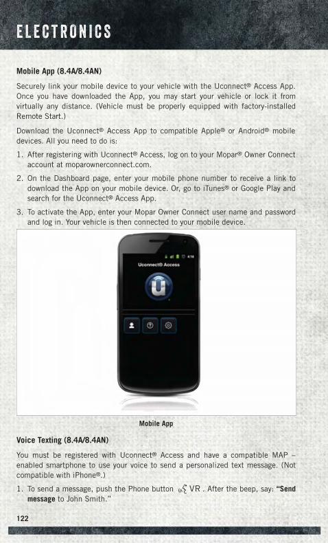
Mobile App (8.4A/8.4AN)
Securely link your mobile device to your vehicle with the Uconnect® Access App.Once you have downloaded the App, you may start your vehicle or lock it fromvirtually any distance. (Vehicle must be properly equipped with factory-installedRemote Start.)
Download the Uconnect® Access App to compatible Apple® or Android® mobiledevices. All you need to do is:
1. After registering with Uconnect® Access, log on to your Mopar® Owner Connectaccount at moparownerconnect.com.
2. On the Dashboard page, enter your mobile phone number to receive a link todownload the App on your mobile device. Or, go to iTunes® or Google Play andsearch for the Uconnect® Access App.
3. To activate the App, enter your Mopar Owner Connect user name and passwordand log in. Your vehicle is then connected to your mobile device.
Voice Texting (8.4A/8.4AN)
You must be registered with Uconnect® Access and have a compatible MAP –enabled smartphone to use your voice to send a personalized text message. (Notcompatible with iPhone®.)
1. To send a message, push the Phone button . After the beep, say: “Sendmessage to John Smith.”
Mobile App
E L E C T R O N I C S
122
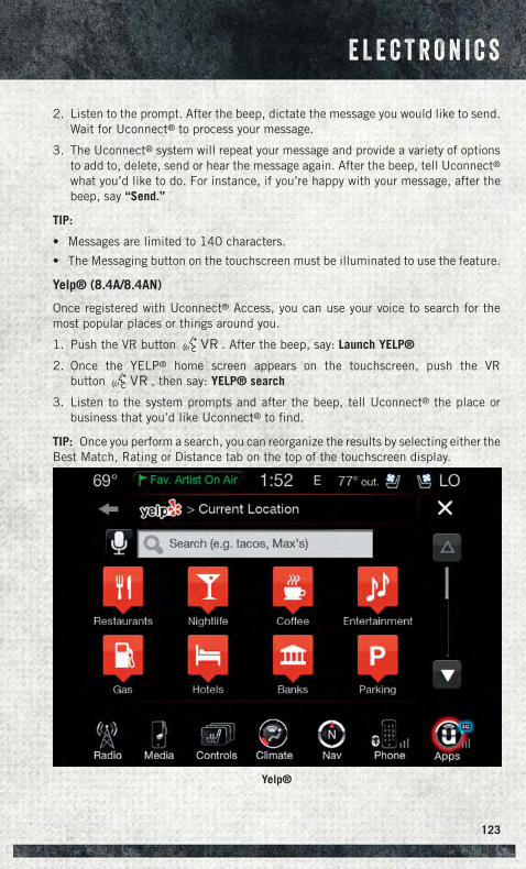
2. Listen to the prompt. After the beep, dictate the message you would like to send.Wait for Uconnect® to process your message.
3. The Uconnect® system will repeat your message and provide a variety of optionsto add to, delete, send or hear the message again. After the beep, tell Uconnect®what you’d like to do. For instance, if you’re happy with your message, after thebeep, say “Send.”
TIP:
• Messages are limited to 140 characters.
• The Messaging button on the touchscreen must be illuminated to use the feature.
Yelp® (8.4A/8.4AN)
Once registered with Uconnect® Access, you can use your voice to search for themost popular places or things around you.
1. Push the VR button . After the beep, say: Launch YELP®
2. Once the YELP® home screen appears on the touchscreen, push the VRbutton , then say: YELP® search
3. Listen to the system prompts and after the beep, tell Uconnect® the place orbusiness that you’d like Uconnect® to find.
TIP: Once you perform a search, you can reorganize the results by selecting either theBest Match, Rating or Distance tab on the top of the touchscreen display.
Yelp®
E L E C T R O N I C S
123
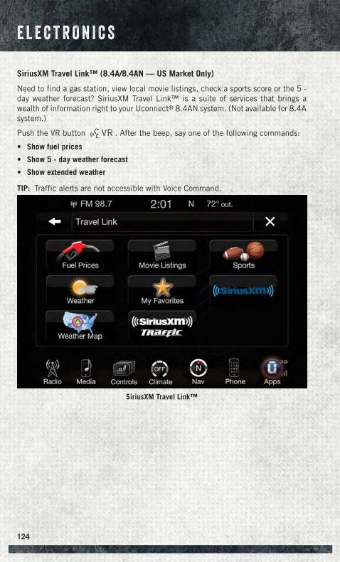
SiriusXM Travel Link™ (8.4A/8.4AN — US Market Only)
Need to find a gas station, view local movie listings, check a sports score or the 5 -day weather forecast? SiriusXM Travel Link™ is a suite of services that brings awealth of information right to your Uconnect® 8.4AN system. (Not available for 8.4Asystem.)
Push the VR button . After the beep, say one of the following commands:
• Show fuel prices
• Show 5 - day weather forecast
• Show extended weather
TIP: Traffic alerts are not accessible with Voice Command.
SiriusXM Travel Link™
E L E C T R O N I C S
124
Additional Information
© 2014 Chrysler Group LLC. All rights reserved. Mopar, Mopar Owner Connect andUconnect are registered trademarks of Chrysler Group LLC. Android is a trademark ofGoogle Inc. SiriusXM and all related marks and logos are trademarks of SiriusXM RadioInc. Yelp, Yelp logo, Yelp burst and related marks are registered trademarks of Yelp.
Uconnect® System Support:
• U.S residents visit DriveUconnect.com or call: 1-877-855-8400
• Canadian residents visit DriveUconnect.ca or call: 1-800-465-2001 (English) or1-800-387-9983 (French)
Mon. – Fri., 7:00 am – 12:00 am, ET
Sat., 8:00 am – 10:00 pm, ET
Sun., 9:00 am – 5:00 pm, ET
Uconnect® Access Services Support 1-855-792-4241. Please have your Uconnect®Security PIN ready when you call.
E L E C T R O N I C S
125
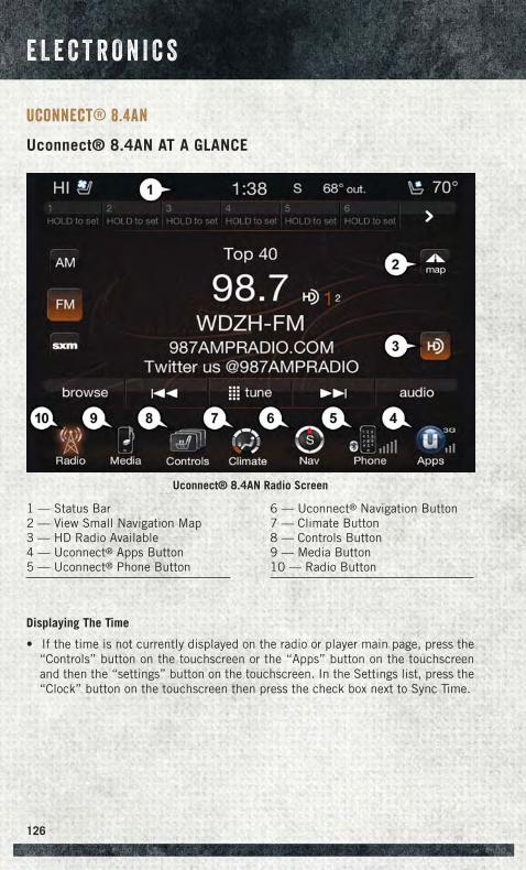
Uconnect® 8.4AN
Uconnect® 8.4AN AT A GLANCE
Displaying The Time
• If the time is not currently displayed on the radio or player main page, press the“Controls” button on the touchscreen or the “Apps” button on the touchscreenand then the “settings” button on the touchscreen. In the Settings list, press the“Clock” button on the touchscreen then press the check box next to Sync Time.
Uconnect® 8.4AN Radio Screen
1 — Status Bar2 — View Small Navigation Map3 — HD Radio Available4 — Uconnect® Apps Button5 — Uconnect® Phone Button
6 — Uconnect® Navigation Button7 — Climate Button8 — Controls Button9 — Media Button10 — Radio Button
E L E C T R O N I C S
126
Setting The Time
• Model 8.4AN synchronizes time automatically via GPS, so it should not requireany time adjustment. If you do need to set the time manually, follow theinstructions below for Model 8.4A.
• For Model 8.4A, turn the unit on, then press the time display at the top of thescreen. Press “Yes.”
• If the time is not displayed at the top of the screen, press the “Controls” button onthe touchscreen or the “Apps” button on the touchscreen and then the “settings”button on the touchscreen. In the Settings screen, press the “Clock” button on thetouchscreen, then check or uncheck this option.
• Press “+” or “–” next to Set Time Hours and Set Time Minutes to adjust the time.
• If these features are not available, uncheck the Sync Time box.
• Press “X” to save your settings and exit out of the Clock Setting screen.
Audio Settings
• Press of the “Audio” button on the touchscreen to activate the Audio settingsscreen to adjust Balance\Fade, Equalizer, and Speed Adjusted Volume.
• You can return to the Radio screen by pressing the “X” located at the top right.
Balance/Fade
• Press the “Balance/Fade” button on the touchscreen to Balance audio betweenthe front speakers or fade the audio between the rear and front speakers.
• Pressing the “Front,” “Rear,” “Left,” or “Right” buttons on the touchscreen orpress and drag the Speaker Icon to adjust the Balance/Fade.
Equalizer
• Press the “Equalizer” button on the touchscreen to activate the Equalizer screen.
• Press the “+” or “–” buttons on the touchscreen, or press and drag over the levelbar for each of the equalizer bands. The level value, which spans between plus orminus 9, is displayed at the bottom of each of the Bands.
Speed Adjusted Volume
• Press the “Speed Adjusted Volume” button on the touchscreen to activate theSpeed Adjusted Volume screen. The Speed Adjusted Volume is adjusted bypressing the volume level indicator. This alters the automatic adjustment of theaudio volume with variation to vehicle speed.
E L E C T R O N I C S
127
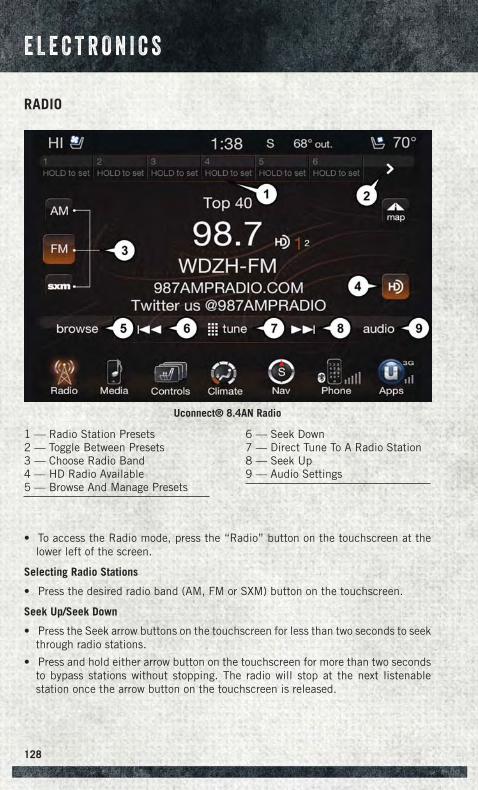
RADIO
• To access the Radio mode, press the “Radio” button on the touchscreen at thelower left of the screen.
Selecting Radio Stations
• Press the desired radio band (AM, FM or SXM) button on the touchscreen.
Seek Up/Seek Down
• Press the Seek arrow buttons on the touchscreen for less than two seconds to seekthrough radio stations.
• Press and hold either arrow button on the touchscreen for more than two secondsto bypass stations without stopping. The radio will stop at the next listenablestation once the arrow button on the touchscreen is released.
Uconnect® 8.4AN Radio
1 — Radio Station Presets2 — Toggle Between Presets3 — Choose Radio Band4 — HD Radio Available5 — Browse And Manage Presets
6 — Seek Down7 — Direct Tune To A Radio Station8 — Seek Up9 — Audio Settings
E L E C T R O N I C S
128
Direct Tune
• Tune directly to a radio station by pressing the “Tune” button on the screen, andentering the desired station number.
Store Radio Presets
• Your radio can store 36 total preset stations, 12 presets per band (AM, FM andSXM). They are shown at the top of your radio screen. To see the 12 preset stationsper band, press the arrow button on the touchscreen at the top right of the screento toggle between the two sets of six presets.
• To set a station into memory press and hold the desired numbered button on thetouchscreen for more than two seconds or until you hear a confirmation beep.
HD Radio (US RESIDENTS ONLY)
• HD Radio (available on Uconnect 8.4AN) operates similar to conventional radioexcept it allows broadcasters to transmit a high-quality digital signal.
• With an HD radio receiver, the listener is provided with a clear sound thatenhances the listening experience. HD radio can also transmit data such as songtitle or artist.
SiriusXM PREMIER OVER 160 CHANNELS
Get every channel available on your satellite radio, and enjoy all you want, all in oneplace. Hear commercial-free music plus sports, news, talk and entertainment. Get allthe premium programming, including Howard Stern, every NFL game, Oprah Radio®,every MLB® and NHL® game, every NASCAR® race, Martha Stewart and more. Andget 20+ extra channels, including SiriusXM Latino, offering 20 channels of commer-cial free music, news, talk, comedy, sports and more dedicated to Spanish languageprogramming.
• To access SiriusXM Satellite Radio, press the “SXM” button on the touchscreen onthe main Radio screen.
The following describes features that are available when in SiriusXM Satellite Radiomode:
Seek Up/Seek Down
• Press the Seek arrow buttons on the touchscreen for less than two seconds to seekthrough channels in SXM mode.
• Press and hold either arrow button on the touchscreen for more than two secondsto bypass channels without stopping. The radio will stop at the next listenablechannel once the arrow button on the touchscreen is released.
Direct Tune
• Tune directly to a SXM channel by pressing the “Tune” button on the touchscreenon the screen, and entering the desired station number.
E L E C T R O N I C S
129
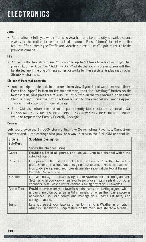
Jump
• Automatically tells you when Traffic & Weather for a favorite city is available, andgives you the option to switch to that channel. Press “Jump” to activate thefeature. After listening to Traffic and Weather, press “Jump” again to return to theprevious channel.
Fav
• Activates the favorites menu. You can add up to 50 favorite artists or songs. Justpress “Add Fav Artist” or “Add Fav Song” while the song is playing. You will thenbe alerted any time one of these songs, or works by these artists, is playing on otherSiriusXM channels.
SiriusXM Parental Controls
• You can skip or hide certain channels from view if you do not want access to them.Press the “Apps” button on the touchscreen, then the “Settings” button on thetouchscreen, next press the “Sirius Setup” button on the touchscreen, then selectChannel Skip. Press the box check-mark next to the channel you want skipped.They will not show up in normal usage.
• SiriusXM also offers the option to permanently block selected channels. Call(1-888-601-6297 for U.S. customers, 1-877-438-9677 for Canadian custom-ers) and request the Family-Friendly Package.
Browse
Lets you browse the SiriusXM channel listing or Genre listing. Favorites, Game Zone,Weather and Jump settings also provide a way to browse the SiriusXM channel list.
BrowseSub-Menu
Sub-Menu Description
All Shows the channel listing.Genre Provides a list of all genres, and lets you jump to a channel within the
selected genre.Presets Lets you scroll the list of Preset satellite channels. Press the channel, or
press Enter on the Tune knob, to go to that channel. Press the trash canicon to delete a preset. Your presets are also shown at the top of the mainSatellite Radio screen.
Favorites Lets you manage artists and songs in the Favorites list and configure AlertSettings to let you know when favorite songs or artists are playing on otherchannels. Also, view a list of channels airing any of your Favorites.
Game Zone Provides alerts when your favorite sports teams are starting a game whichis being aired on other SiriusXM channels, or when their game score isannounced. You can select and manage your Teams list here, andconfigure alerts.
Jump Lets you select your favorite cities for Traffic & Weather information,which is used by the Jump feature on the main satellite radio screen.
E L E C T R O N I C S
130
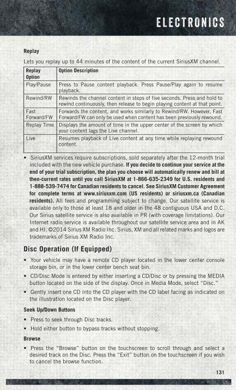
Replay
Lets you replay up to 44 minutes of the content of the current SiriusXM channel.
ReplayOption
Option Description
Play/Pause Press to Pause content playback. Press Pause/Play again to resumeplayback.
Rewind/RW Rewinds the channel content in steps of five seconds. Press and hold torewind continuously, then release to begin playing content at that point.
FastForward/FW
Forwards the content, and works similarly to Rewind/RW. However, FastForward/FW can only be used when content has been previously rewound.
Replay Time Displays the amount of time in the upper center of the screen by whichyour content lags the Live channel.
Live Resumes playback of Live content at any time while replaying rewoundcontent.
• SiriusXM services require subscriptions, sold separately after the 12-month trialincluded with the new vehicle purchase. If you decide to continue your service at theend of your trial subscription, the plan you choose will automatically renew and bill atthen-current rates until you call SiriusXM at 1-866-635-2349 for U.S. residents and1-888-539-7474 for Canadian residents to cancel. See SiriusXM Customer Agreementfor complete terms at www.siriusxm.com (US residents) or siriusxm.ca (Canadianresidents). All fees and programming subject to change. Our satellite service isavailable only to those at least 18 and older in the 48 contiguous USA and D.C.Our Sirius satellite service is also available in PR (with coverage limitations). OurInternet radio service is available throughout our satellite service area and in AKand HI. ©2014 Sirius XM Radio Inc. Sirius, XM and all related marks and logos aretrademarks of Sirius XM Radio Inc.
Disc Operation (If Equipped)• Your vehicle may have a remote CD player located in the lower center console
storage bin, or in the lower center bench seat bin.
• CD/Disc Mode is entered by either inserting a CD/Disc or by pressing the MEDIAbutton located on the side of the display. Once in Media Mode, select “Disc.”
• Gently insert one CD into the CD player with the CD label facing as indicated onthe illustration located on the Disc player.
Seek Up/Down Buttons
• Press to seek through Disc tracks.
• Hold either button to bypass tracks without stopping.
Browse
• Press the “Browse” button on the touchscreen to scroll through and select adesired track on the Disc. Press the “Exit” button on the touchscreen if you wishto cancel the browse function.
E L E C T R O N I C S
131
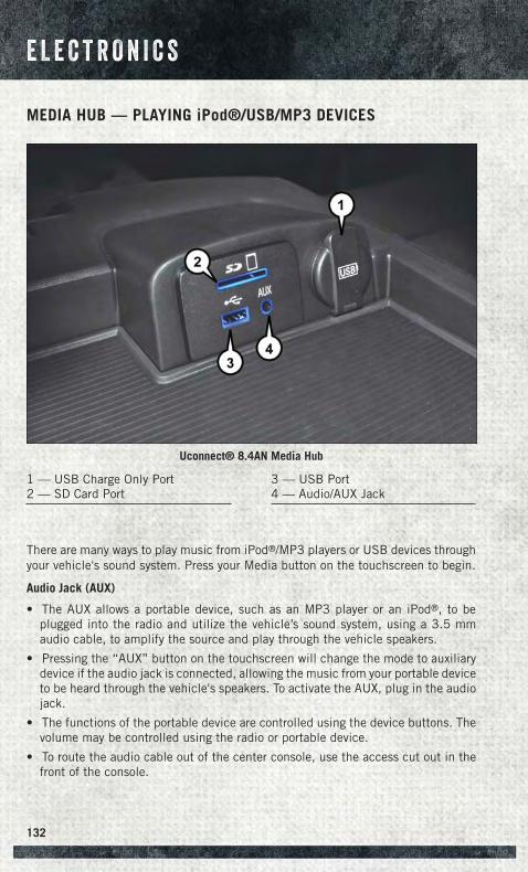
MEDIA HUB — PLAYING iPod®/USB/MP3 DEVICES
There are many ways to play music from iPod®/MP3 players or USB devices throughyour vehicle's sound system. Press your Media button on the touchscreen to begin.
Audio Jack (AUX)
• The AUX allows a portable device, such as an MP3 player or an iPod®, to beplugged into the radio and utilize the vehicle’s sound system, using a 3.5 mmaudio cable, to amplify the source and play through the vehicle speakers.
• Pressing the “AUX” button on the touchscreen will change the mode to auxiliarydevice if the audio jack is connected, allowing the music from your portable deviceto be heard through the vehicle's speakers. To activate the AUX, plug in the audiojack.
• The functions of the portable device are controlled using the device buttons. Thevolume may be controlled using the radio or portable device.
• To route the audio cable out of the center console, use the access cut out in thefront of the console.
Uconnect® 8.4AN Media Hub
1 — USB Charge Only Port2 — SD Card Port
3 — USB Port4 — Audio/AUX Jack
E L E C T R O N I C S
132
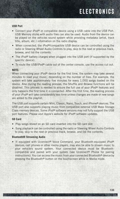
USB Port
• Connect your iPod® or compatible device using a USB cable into the USB Port.USB Memory sticks with audio files can also be used. Audio from the device canbe played on the vehicles sound system while providing metadata (artist, tracktitle, album, etc.) information on the radio display.
• When connected, the iPod®/compatible USB device can be controlled using theradio or Steering Wheel Audio Controls to play, skip to the next or previous track,browse, and list the contents.
• The iPod® battery charges when plugged into the USB port (if supported by thespecific device).
• To route the USB/iPod® cable out of the center console, use the access cut out.
NOTE:When connecting your iPod® device for the first time, the system may take severalminutes to read your music, depending on the number of files. For example, thesystem will take approximately five minutes for every 1,000 songs loaded on thedevice. Also during the reading process, the Shuffle and Browse functions will bedisabled. This process is needed to ensure the full use of your iPod® features andonly happens the first time it is connected. After the first time, the reading processof your iPod® will take considerably less time unless changes are made or new songsare added to the playlist.
The USB port supports certain Mini, Classic, Nano, Touch, and iPhone® devices. TheUSB port also supports playing music from compatible external USB Mass StorageClass memory devices. Some iPod® software versions may not fully support the USBport features. Please visit Apple’s website for iPod® software updates.
SD Card
• Play songs stored on an SD card inserted into the SD card slot.
• Song playback can be controlled using the radio or Steering Wheel Audio Controlsto play, skip to the next or previous track, browse, and list the contents.
Bluetooth® Streaming Audio
• If equipped with Uconnect® Voice Command, your Bluetooth-equipped iPod®
devices, cell phones or other media players, may also be able to stream music toyour vehicle's sound system. Your connected device must be Bluetooth-compatible and paired with your system (see Uconnect® Phone for pairinginstructions). You can access the music from your connected Bluetooth® device bypressing the Bluetooth® button on the touchscreen while in Media mode.
E L E C T R O N I C S
133
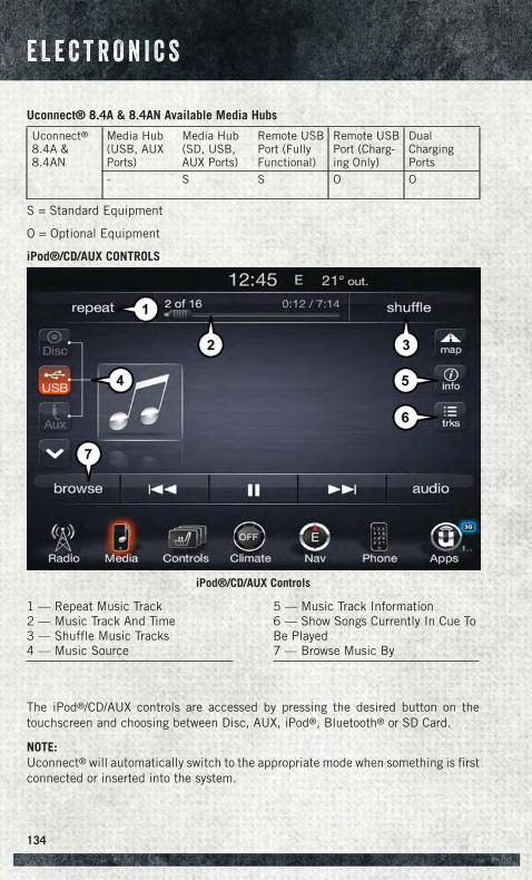
Uconnect® 8.4A & 8.4AN Available Media Hubs
Uconnect®8.4A &8.4AN
Media Hub(USB, AUXPorts)
Media Hub(SD, USB,AUX Ports)
Remote USBPort (FullyFunctional)
Remote USBPort (Charg-ing Only)
DualChargingPorts
- S S O O
S = Standard Equipment
O = Optional Equipment
iPod®/CD/AUX CONTROLS
The iPod®/CD/AUX controls are accessed by pressing the desired button on thetouchscreen and choosing between Disc, AUX, iPod®, Bluetooth® or SD Card.
NOTE:Uconnect® will automatically switch to the appropriate mode when something is firstconnected or inserted into the system.
iPod®/CD/AUX Controls
1 — Repeat Music Track2 — Music Track And Time3 — Shuffle Music Tracks4 — Music Source
5 — Music Track Information6 — Show Songs Currently In Cue ToBe Played7 — Browse Music By
E L E C T R O N I C S
134
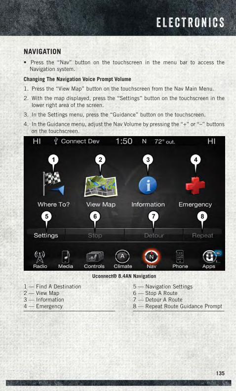
NAVIGATION• Press the “Nav” button on the touchscreen in the menu bar to access the
Navigation system.
Changing The Navigation Voice Prompt Volume
1. Press the “View Map” button on the touchscreen from the Nav Main Menu.
2. With the map displayed, press the “Settings” button on the touchscreen in thelower right area of the screen.
3. In the Settings menu, press the “Guidance” button on the touchscreen.
4. In the Guidance menu, adjust the Nav Volume by pressing the “+” or “–” buttonson the touchscreen.
Uconnect® 8.4AN Navigation
1 — Find A Destination2 — View Map3 — Information4 — Emergency
5 — Navigation Settings6 — Stop A Route7 — Detour A Route8 — Repeat Route Guidance Prompt
E L E C T R O N I C S
135
Finding Points Of Interest
• From the main Navigation menu, press the “Where To?” button on the touch-screen, then press the “Points of Interest” button on the touchscreen.
• Select a Category and then a subcategory, if necessary.
• Select your destination and press the “Yes” button on the touchscreen.
Finding A Place By Spelling The Name
• From the Main Navigation Menu press the “Where to?” button on the touchscreen,press the “Points of Interest” button on the touchscreen, then press the “SpellName” button on the touchscreen.
• Enter the name of your destination.
• Press the “List” button on the touchscreen.
• Select your destination and press the “Yes” button on the touchscreen.
One-Step Voice Destination Entry
• Enter a navigation destination without taking your hands off the wheel.
• Just press the Uconnect® Voice Command button on the steering wheel,wait for the beep and say something like, "800 Chrysler Drive Auburn Hills MI."
NOTE:Destination entry is not available while your vehicle is in motion. However, you canalso use Voice Commands to enter an address while moving. Refer to CommonNavigation Voice Commands in the Uconnect® Voice Command section.
Setting Your Home Location
• Press the “Nav” button on the touchscreen in the menu bar to access theNavigation system and the Main Navigation menu.
• Press the “Where To?” button on the touchscreen, then press the “Go Home”button on the touchscreen.
• You may enter your address directly, use your current location as your homeaddress, or choose from recently found locations.
• To delete your Home location (or other saved locations) so you can save a newHome location, press the “Where To?” button on the touchscreen from the MainNavigation menu, then press the “Go Home” button on the touchscreen, and in theYes screen press the “Options” button on the touchscreen. In the Options menupress the “Clear Home” button on the touchscreen. Set a new Home location byfollowing the previous instructions.
E L E C T R O N I C S
136
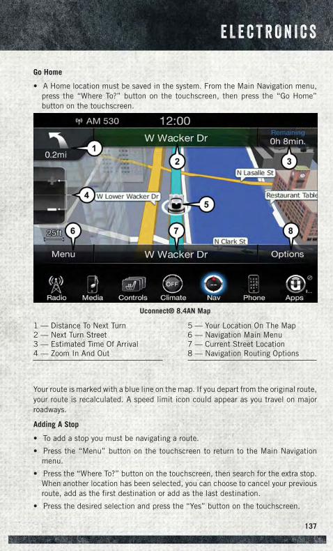
Go Home
• A Home location must be saved in the system. From the Main Navigation menu,press the “Where To?” button on the touchscreen, then press the “Go Home”button on the touchscreen.
Your route is marked with a blue line on the map. If you depart from the original route,your route is recalculated. A speed limit icon could appear as you travel on majorroadways.
Adding A Stop
• To add a stop you must be navigating a route.
• Press the “Menu” button on the touchscreen to return to the Main Navigationmenu.
• Press the “Where To?” button on the touchscreen, then search for the extra stop.When another location has been selected, you can choose to cancel your previousroute, add as the first destination or add as the last destination.
• Press the desired selection and press the “Yes” button on the touchscreen.
Uconnect® 8.4AN Map
1 — Distance To Next Turn2 — Next Turn Street3 — Estimated Time Of Arrival4 — Zoom In And Out
5 — Your Location On The Map6 — Navigation Main Menu7 — Current Street Location8 — Navigation Routing Options
E L E C T R O N I C S
137
Taking A Detour
• To take a detour you must be navigating a route.
• Press the “Detour” button on the touchscreen.
NOTE:If the route you are currently taking is the only reasonable option, the device may notcalculate a detour. For more information, see your Uconnect® User's Manual.
SiriusXM TRAFFIC (US Market Only)
Don't Drive Through Traffic. Drive Around It.
Avoid congestion before you reach it. By enhancing your vehicle's navigation systemwith the ability to see detailed traffic information, you can pinpoint traffic incidents,determine average traffic speed and estimate travel time along your route. Since theservice is integrated with a vehicle's navigation system, SiriusXM Traffic can helpdrivers pick the fastest route based on traffic conditions.
• Detailed information on traffic speed, accidents, construction, and road closings.
• Traffic information from multiple sources, including police and emergency ser-vices, cameras and road sensors.
• Coast-to-coast delivery of traffic information.
• View conditions for points along your route and beyond. Available in over 130markets.
SiriusXM TRAVEL LINK (US Market Only)
In addition to delivering over 130 channels of the best sports, entertainment, talk,and commercial-free music, SiriusXM offers premium data services that work inconjunction with compatible navigation systems. SiriusXM Travel Link brings awealth of useful information into your vehicle and right to your fingertips.
• Fuel Prices — Check local gas and diesel prices in your area and route to thestation of your choice.
• Movie Listings — Check local movie theatres and listings in your area and route tothe theater of your choice.
• Sports Scores — In-game and final scores as well as weekly schedules.
• Weather — Check variety of local and national weather information from radarmaps to current and 5-day forecast.
SiriusXM Travel Link feature is completely integrated into your vehicle. A few minutesafter you start your vehicle, Travel Link information arrives and updates in thebackground. You can access the information whenever you like, with no waiting.
E L E C T R O N I C S
138
To access SiriusXM Travel Link, press “Apps” button on the touchscreen, then pressthe “SiriusXM Travel Link” button on the touchscreen.
NOTE:SiriusXM Travel Link requires a subscription, sold separately after the five (5) yeartrial subscription included with your vehicle purchase.
SiriusXM Travel Link is only available in the United States.
Fuel Prices Check local gas and diesel prices in your area and route to the stationof your choice.
Movie Listings Check local movie theatres and listings in your area and route to thetheater of your choice.
Sports Scores In-game and final scores as well as weekly schedules.Weather Check variety of local and national weather information from radar
maps to current and 5-day forecast.
Uconnect® Phone (Bluetooth® HANDS FREE CALLING)• If the Uconnect® Phone Button exists on your steering wheel, then you have
the Uconnect® Phone features.
• The Uconnect® Phone is a voice-activated, hands-free, in-vehicle communica-tions system with Voice Command Capability (see Voice Command section).
• The Uconnect® Phone allows you to dial a phone number with your mobile phoneusing simple voice commands or pressing the buttons on the touchscreen.
• Refer to the Understand The Features Of Your Vehicle section of your vehicle'sOwner's Manual on the DVD for further details.
NOTE:The Uconnect® Phone requires a mobile phone equipped with the Bluetooth®
Hands-Free Profile, Version 1.0 or higher. For Uconnect® Customer Support: U.S.residents visit UconnectPhone.com or call 1-877-855-8400. Canadian Residents –visit UconnectPhone.com or call, 1-800-465-2001 (English) or 1-800-387-9983(French).
Pairing A Phone• To use the Uconnect® Phone feature, you must first pair your Bluetooth® phone
with the Uconnect® system.
Start Pairing Procedure On The Radio
• Press the “Phone” button on the touchscreen and then the “settings” button onthe touchscreen. Next, press “Add Device.”
• Uconnect® Phone will display an “In progress” screen while the system isconnecting.
E L E C T R O N I C S
139
Start Pairing Procedure On Mobile Phone
• Search for available devices on your Bluetooth® enabled mobile phone. This isusually within Settings or Options under “Bluetooth.” See your mobile phone’smanual for details.
• When your phone finds the system, select “Uconnect” as the paired device. Youmay be prompted by your phone to download the phonebook. This is so you canmake calls by saying the name of your contact (PBAP-Phone Book Access Profile).
Complete The Pairing Procedure
• When prompted on the phone, verify with the radio password shown on theUconnect® Screen.
• If your phone asks you to accept a connection request from Uconnect®, select“Yes.” If available, check the box telling it not to ask again – that way your phonewill automatically connect each time you start the vehicle.
Select The Mobile Phone's Priority Level
• When the pairing process has successfully completed, the system will prompt youto choose whether or not this is your favorite phone. Selecting “Yes” will make thisphone the highest priority. This phone will take precedence over other pairedphones within range. Only one phone can be paired at a time.
• You are now ready to make hands-free calls. Press the Uconnect® Phone button onyour steering wheel to begin.
Making A Phone Call
To begin a phone call using Uconnect® Voice Command:
• Push the Uconnect® Phone button .
• After the BEEP, say “dial” then the number (or “call” then the name as listed inyour phone; see Phonebook).
NOTE:You can also initiate a call by using the touchscreen on the Phone main screen.
Receiving A Call — Accept (And End)• When an incoming call rings/is announced on Uconnect®, push the Phone
button .
• To end a call, push the Phone button .
Mute (Or Unmute) Microphone During Call• During a call, press the “mute” button on the touchscreen to mute and unmute
the call.
E L E C T R O N I C S
140
Transfer Ongoing Call Between Handset And Vehicle
During an on-going call, press the “Transfer” button on the touchscreen to transfer anon-going call between handset and vehicle.
Common Phone Commands (Examples)• “Call John Smith”
• “Call John Smith mobile”
• “Dial 1 248 555 1212”
• “Call Emergency”
• “Call Towing Assistance”
• “Redial”
Phonebook• Uconnect® radios will automatically download your phonebook from your paired
phone, if this feature is supported by your phone. Entries are updated each timethat the phone is connected. If your phone book entries do not appear, check thesettings on your phone. Some phones require you to enable this feature manually.
• Your phonebook can be browsed on your radio screen, but editing can only be doneon your phone. To browse, press the “Phone” button on the touchscreen, then the“Phonebook” button on the touchscreen.
• Favorite phonebook entries can be saved as Favorites for quicker access. Favoritesare shown at the top of your main phone screen.
Changing The Volume• Start a dialogue by pressing the Phone button , then say a command for
example - "Help".
• Use the radio VOLUME/MUTE rotary knob to adjust the volume to a comfortablelevel while the Uconnect® system is speaking. Please note the volume setting forUconnect® is different than the audio system.
NOTE:To access help, press the Uconnect® Phone button on the steering wheel andsay "help." Touch the display or push either or button and say "cancel"to cancel the help session.
E L E C T R O N I C S
141
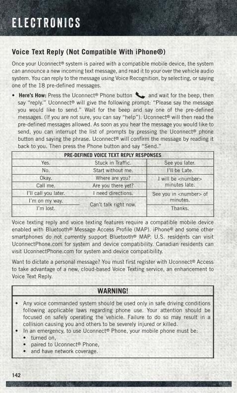
Voice Text Reply (Not Compatible With iPhone®)
Once your Uconnect® system is paired with a compatible mobile device, the systemcan announce a new incoming text message, and read it to your over the vehicle audiosystem. You can reply to the message using Voice Recognition, by selecting, or sayingone of the 18 pre-defined messages.
• Here’s How: Press the Uconnect® Phone button and wait for the beep, thensay “reply.” Uconnect® will give the following prompt: “Please say the messageyou would like to send.” Wait for the beep and say one of the pre-definedmessages. (If you are not sure, you can say “help”). Uconnect® will then read thepre-defined messages allowed. As soon as you hear the message you would like tosend, you can interrupt the list of prompts by pressing the Uconnect® phonebutton and saying the phrase. Uconnect® will confirm the message by reading itback to you. Then press the Phone button and say “Send.”
PRE-DEFINED VOICE TEXT REPLY RESPONSESYes. Stuck in Traffic. See you later.No. Start without me. I’ll be Late.
Okay. Where are you? I will be <number>minutes late.Call me. Are you there yet?
I’ll call you later. I need directions. See you in <number> ofminutes.I’m on my way.
Can’t talk right now.I’m lost. Thanks.
Voice texting reply and voice texting features require a compatible mobile deviceenabled with Bluetooth® Message Access Profile (MAP). iPhone® and some othersmartphones do not currently support Bluetooth® MAP. U.S. residents can visitUconnectPhone.com for system and device compatibility. Canadian residents canvisit UconnectPhone.com for system and device compatibility.
Want to dictate a personal message? You must first register with Uconnect® Accessto take advantage of a new, cloud-based Voice Texting service, an enhancement toVoice Text Reply.
WARNING!
• Any voice commanded system should be used only in safe driving conditionsfollowing applicable laws regarding phone use. Your attention should befocused on safely operating the vehicle. Failure to do so may result in acollision causing you and others to be severely injured or killed.
• In an emergency, to use Uconnect® Phone, your mobile phone must be:• turned on,• paired to Uconnect® Phone,• and have network coverage.
E L E C T R O N I C S
142
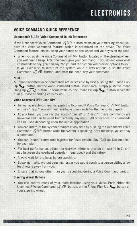
VOICE COMMAND QUICK REFERENCE
Uconnect® 8.4AN Voice Command Quick Reference
If the Uconnect® Voice Command button exists on your steering wheel, youhave the Voice Command feature, which is optimized for the driver. The VoiceCommand feature lets you keep your hands on the wheel and your eyes on the road.
• When you push the Voice Command button located on the steering wheel,you will hear a beep. After the beep, give your command. If you do not know whatcommands to say, you can say “help” and the system will provide options to you.If you ever wish to interrupt the system while it lists options, push the VoiceCommand button, and after the beep, say your command.
NOTE:All phone oriented voice commands are accessible by first pushing the Phone PickUp button, not the Voice Command button. To end a call simply push the PhoneHang Up button. In some vehicles, the Phone Pickup button serves thedual purpose of ending calls as well.
Voice Command (VR) User TIPs
• To hear available commands, push the Uconnect® Voice Command buttonand say “Help.” You will hear available commands for the menu displayed.
• At any time, you can say the words “Cancel” or “Help.” These commands areuniversal and can be used from virtually any menu. All other specific commandscan be used depending upon the active application.
• You can interrupt the system prompts at any time by pushing the Uconnect® VoiceCommand button while the system is speaking. After the beep, you can saya command.
• You can “chain” commands together for faster results. Say “Call Joe Doe mobile,”for example.
• For best performance, adjust the rearview mirror to provide at least ½ in (1 cm)gap between the overhead console (if equipped) and the mirror.
• Always wait for the beep before speaking.
• Speak normally, without pausing, just as you would speak to a person sitting a fewfeet/meters away from you.
• Ensure that no one other than you is speaking during a Voice Command period.
Steering Wheel Buttons
• You can control many of your radio features using your voice. Push either theUconnect® Voice Command button, or the Phone Pick Up button onyour steering wheel.
E L E C T R O N I C S
143
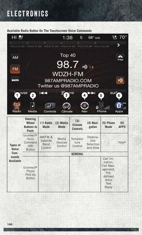
Available Radio Button On The Touchscreen Voice Commands
Types ofVoiceCom-mands
Available
SteeringWheel
Buttons toPush:
(1) RadioMode
(2) MediaMode
(3)ClimateControls
(4) Navi-gation
(5) PhoneMode
(6)APPS
Uconnect®Voice
Command(VR)
Button
AM/FM &Satellite
BandControl
MediaDevicesControl
Tempera-ture
Control
Destina-tion
Selectionand View
- Yelp®
GENERAL
Uconnect®Phone
Pick UpButton
- - - -
Call Ini-tiation,
Call Man-agement,
Pre-definedVoiceText
Reply
-
E L E C T R O N I C S
144
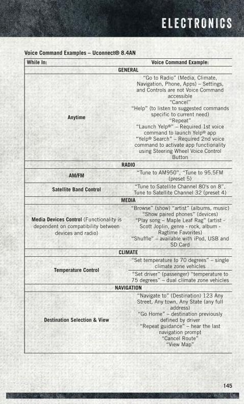
Voice Command Examples – Uconnect® 8.4AN
While In: Voice Command Example:GENERAL
Anytime
“Go to Radio” (Media, Climate,Navigation, Phone, Apps) – Settings,and Controls are not Voice Command
accessible“Cancel”
“Help” (to listen to suggested commandsspecific to current need)
“Repeat”“Launch Yelp®” – Required 1st voice
command to launch Yelp® app“Yelp® Search” – Required 2nd voicecommand to activate app functionality
using Steering Wheel Voice ControlButton
RADIO
AM/FM “Tune to AM950”, “Tune to 95.5FM(preset 5)
Satellite Band Control “Tune to Satellite Channel 80's on 8”,Tune to Satellite Channel 32 (preset 4)
MEDIA
Media Devices Control (Functionality isdependent on compatibility between
devices and radio)
“Browse” (show) “artist” (albums, music)“Show paired phones” (devices)
“Play song – Maple Leaf Rag” (artist -Scott Joplin, genre - rock, album -
Ragtime Favorites)“Shuffle” – available with iPod, USB and
SD CardCLIMATE
Temperature Control
“Set temperature to 70 degrees” – singleclimate zone vehicles
“Set driver” (passenger) “temperature to75 degrees” – dual climate zone vehicles
NAVIGATION
Destination Selection & View
“Navigate to” (Destination) 123 AnyStreet, Any town, Any State (any full
address)“Go Home” – destination previously
defined by driver“Repeat guidance” – hear the last
navigation prompt“Cancel Route”
“View Map”
E L E C T R O N I C S
145
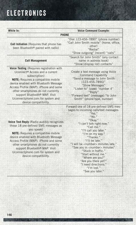
While In: Voice Command Example:PHONE
Call Initiation (Requires that phone hasbeen Bluetooth® paired with radio)
“Dial 123-456-7890” (phone number)“Call John Smith mobile” (home, office,
other)“Redial”
“Show outgoing” (recent) “calls”
Call Management“Search for John Smith” (any contact
name in address book)“Show (display list) contacts”
Voice Texting (Requires registration withUconnect® Access and a current
subscription)NOTE: Requires a compatible mobile
device enabled with Bluetooth MessageAccess Profile (MAP). iPhone and some
other smartphones do not currentlysupport Bluetooth® MAP. Visit
Uconnectphone.com for system anddevice compatibility.
Create a text message using VoiceCommand Capability
“Send a message to John Smith(123-456-7890)”“Show Messages”
“Listen to” (view) “number 4”“Reply”
“Forward text” (message) “to JohnSmith” (phone type, number)
Voice Text Reply (Radio audibly recognizesthese 18 pre-defined SMS messages as
you speak)NOTE: Requires a compatible mobile
device enabled with Bluetooth MessageAccess Profile (MAP). iPhone and some
other smartphones do not currentlysupport Bluetooth® MAP. Visit
Uconnectphone.com for system anddevice compatibility.
Forward one of 18 pre-defined SMS mes-sages to incoming calls/text messages:
“Yes.”“No.”
“Okay.”“I can’t talk right now.”
“Call me.”“I’ll call you later.”“I’m on my way.”
“Thanks.”“I’ll be late.”
“I will be <number> minutes late.”“See you in <number> minutes”
“Stuck in traffic.”“Start without me.”“Where are you?”
“Are you there yet?”“I need directions.”
“I’m lost.”“See you later.”
E L E C T R O N I C S
146
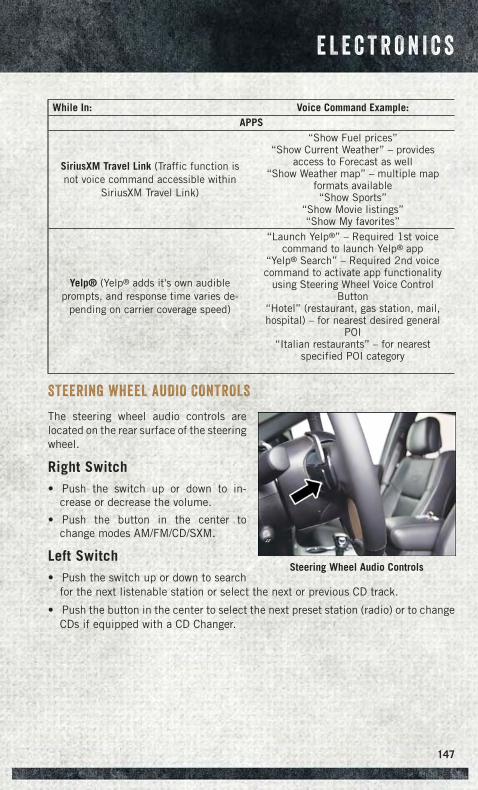
While In: Voice Command Example:APPS
SiriusXM Travel Link (Traffic function isnot voice command accessible within
SiriusXM Travel Link)
“Show Fuel prices”“Show Current Weather” – provides
access to Forecast as well“Show Weather map” – multiple map
formats available“Show Sports”
“Show Movie listings”“Show My favorites”
Yelp® (Yelp® adds it's own audibleprompts, and response time varies de-
pending on carrier coverage speed)
“Launch Yelp®” – Required 1st voicecommand to launch Yelp® app
“Yelp® Search” – Required 2nd voicecommand to activate app functionality
using Steering Wheel Voice ControlButton
“Hotel” (restaurant, gas station, mail,hospital) – for nearest desired general
POI“Italian restaurants” – for nearest
specified POI category
STEERING WHEEL AUDIO CONTROLS
The steering wheel audio controls arelocated on the rear surface of the steeringwheel.
Right Switch• Push the switch up or down to in-
crease or decrease the volume.
• Push the button in the center tochange modes AM/FM/CD/SXM.
Left Switch• Push the switch up or down to search
for the next listenable station or select the next or previous CD track.
• Push the button in the center to select the next preset station (radio) or to changeCDs if equipped with a CD Changer.
Steering Wheel Audio Controls
E L E C T R O N I C S
147
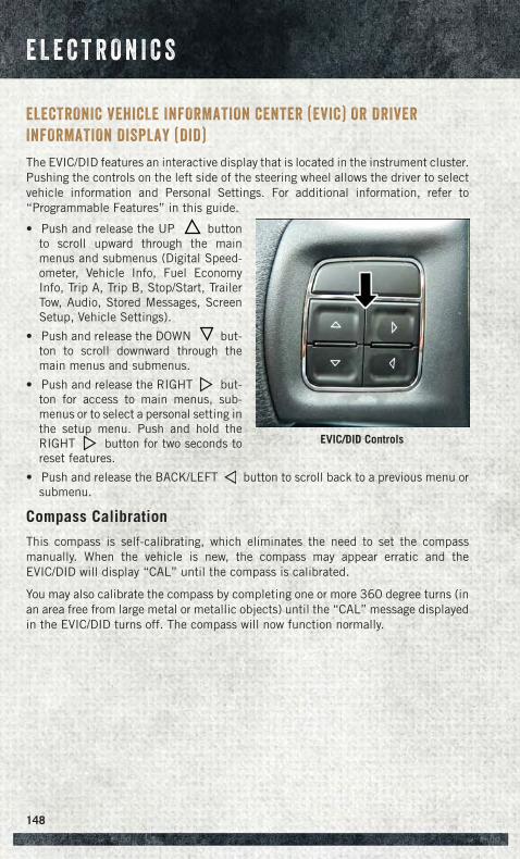
ELECTRONIC VEHICLE INFORMATION CENTER (EVIC) OR DRIVER
INFORMATION DISPLAY (DID)
The EVIC/DID features an interactive display that is located in the instrument cluster.Pushing the controls on the left side of the steering wheel allows the driver to selectvehicle information and Personal Settings. For additional information, refer to“Programmable Features” in this guide.
• Push and release the UP buttonto scroll upward through the mainmenus and submenus (Digital Speed-ometer, Vehicle Info, Fuel EconomyInfo, Trip A, Trip B, Stop/Start, TrailerTow, Audio, Stored Messages, ScreenSetup, Vehicle Settings).
• Push and release the DOWN but-ton to scroll downward through themain menus and submenus.
• Push and release the RIGHT but-ton for access to main menus, sub-menus or to select a personal setting inthe setup menu. Push and hold theRIGHT button for two seconds toreset features.
• Push and release the BACK/LEFT button to scroll back to a previous menu orsubmenu.
Compass Calibration
This compass is self-calibrating, which eliminates the need to set the compassmanually. When the vehicle is new, the compass may appear erratic and theEVIC/DID will display “CAL” until the compass is calibrated.
You may also calibrate the compass by completing one or more 360 degree turns (inan area free from large metal or metallic objects) until the “CAL” message displayedin the EVIC/DID turns off. The compass will now function normally.
EVIC/DID Controls
E L E C T R O N I C S
148
PROGRAMMABLE FEATURES
Programmable Features
The EVIC/DID can be used to view or change the following settings. Push the UPor DOWN button until System Setup displays, then push RIGHT button.Scroll through the settings using the UP or DOWN buttons. Push the RIGHTbutton to change the setting. Push the BACK/LEFT button to scroll back to aprevious menu or sub menu.
• Language Select • Remote Start Comfort System• Units • Easy Exit Seat• ParkSense • Key-off Power Delay• Tilt Mirror in Reverse • Commercial Settings• Rain Sensing Wipers • Air Suspension Display Alerts• Hill Start Assist • Aero Ride Height Mode• Headlights Off Delay • Tire/Jack Mode• Illuminated Approach • Transport Mode• Headlights On with Wipers • Wheel Alignment Mode• Automatic Highbeams • Horn w/ Remote Lower• Flash Lights with Lock • Lights w/ Remote Lower• Auto Lock Doors • Trailer Select• Auto Unlock Doors • Brake Type• Sound Horn with Remote Start • Trailer Name• Sound Horn with Remote Lock • Compass Variance• Remote Unlock Sequence • Calibrate Compass• Key Fob Linked to Me • Fuel Saver Display• Passive Entry • Park Assist Front Chime Volume
• Park Assist Rear Chime Volume
E L E C T R O N I C S
149
Uconnect® Customer Programmable Features
The Uconnect® system allows you to access Customer Programmable featuresettings such as Display, Voice, Clock, Safety & Driving Assistance, Lights, Doors &Locks, Auto-On Comfort, Engine Off Options, Compass Settings (Uconnect® 5.0,)Trailer Brake, Suspension, Audio, Phone/Bluetooth®, SiriusXM Setup, Restore Set-tings, Clear Personal Data, and System Information through buttons on the touch-screen.
• Push the SETTINGS button (Uconnect® 5.0), or press the “Apps” button(Uconnect® 8.4) located near the bottom of the touchscreen, then press the“Settings” button on the touchscreen to access the Settings screen. When makinga selection, scroll up or down until the preferred setting is highlighted, then pressthe preferred setting until a check-mark appears next to the setting, showing thatsetting has been selected. The following feature settings are available:
• Display • Suspension• Voice • Audio• Clock • Phone/Bluetooth®
• Safety & Driving Assistance • SiriusXM Setup• Lights • Restore Settings• Doors & Locks • Clear Personal Data• Auto-On Comfort • System Information• Engine Off Options • Compass Settings (Uconnect® 5.0)• Trailer Brake
NOTE:Depending on the vehicles options, feature settings may vary.
Refer to “Uconnect Settings/Customer Programmable Features” found within “Un-derstanding Your Instrument Panel” located in your Owner's Manual on the DVD forfurther information.
Instrument Cluster Reconfigurable Screen Setup
The following settings allow you to change what information is displayed in theinstrument cluster as well as the location that information is displayed.
Digital Speedometer
• Push the UP or DOWN arrow button until the Digital display icon is highlighted inthe EVIC/DID. Push the RIGHT arrow button to change the display between km/hand mph.
E L E C T R O N I C S
150
Vehicle Info (Customer Information Features)
• Push the UP or DOWN button until the Vehicle Info icon is highlighted in theEVIC/DID Display. Push the RIGHT or LEFT to scroll through the following VehicleInfo submenus:• Tire Pressure Monitor System• Air Suspension — If Equipped• Coolant Temperature (Diesel Only)• Transmission Temperature (ATX Only)• Oil Temperature• Oil Pressure• Oil Life• Fuel Filter Life (Diesel Only)• Battery Voltage• Exhaust Brake (Diesel Only)• Turbo Boost (Diesel Only)• Gauge Summary
• Coolant Temperature (Diesel Only)• Transmission Temperature (ATX Only)• Oil Temperature• Oil Pressure
• Engine Hours
Trip A
• Push the UP or DOWN arrow button until the Trip A icon is highlighted in theEVIC/DID. Push and hold the RIGHT arrow button to reset the Trip A information.
Trip B
• Push the UP or DOWN arrow button until the Trip B icon is highlighted in theEVIC/DID. Push and hold the RIGHT arrow button to reset the Trip B information.
Fuel Economy
• Push the UP or DOWN arrow button until the Fuel Economy icon is highlighted.The screen will display the following:• Average Fuel Economy/Miles Per Gallon• Range To Empty (RTE)• Current Miles Per Gallon (MPG)• Dual Tanks- If Equipped Heavy Duty only
Stop/Start
• Push the UP or DOWN arrow button until the Stop/Start icon is highlighted in theEVIC/DID. Push the RIGHT arrow button to display the Stop/Start status.
E L E C T R O N I C S
151
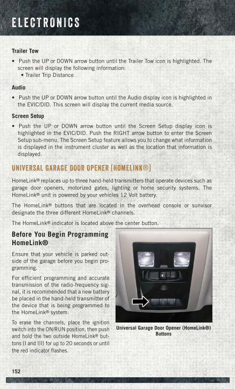
Trailer Tow
• Push the UP or DOWN arrow button until the Trailer Tow icon is highlighted. Thescreen will display the following information:• Trailer Trip Distance
Audio
• Push the UP or DOWN arrow button until the Audio display icon is highlighted inthe EVIC/DID. This screen will display the current media source.
Screen Setup
• Push the UP or DOWN arrow button until the Screen Setup display icon ishighlighted in the EVIC/DID. Push the RIGHT arrow button to enter the ScreenSetup sub-menu. The Screen Setup feature allows you to change what informationis displayed in the instrument cluster as well as the location that information isdisplayed.
UNIVERSAL GARAGE DOOR OPENER (HomeLink®)
HomeLink® replaces up to three hand-held transmitters that operate devices such asgarage door openers, motorized gates, lighting or home security systems. TheHomeLink® unit is powered by your vehicles 12 Volt battery.
The HomeLink® buttons that are located in the overhead console or sunvisordesignate the three different HomeLink® channels.
The HomeLink® indicator is located above the center button.
Before You Begin ProgrammingHomeLink®
Ensure that your vehicle is parked out-side of the garage before you begin pro-gramming.
For efficient programming and accuratetransmission of the radio-frequency sig-nal, it is recommended that a new batterybe placed in the hand-held transmitter ofthe device that is being programmed tothe HomeLink® system.
To erase the channels, place the ignitionswitch into the ON/RUN position, then pushand hold the two outside HomeLink® but-tons (I and III) for up to 20 seconds or untilthe red indicator flashes.
Universal Garage Door Opener (HomeLink®)Buttons
E L E C T R O N I C S
152
NOTE:Erasing all channels should only be performed when programming HomeLink® forthe first time. Do not erase channels when programming additional buttons.
If you have any problems, or require assistance, please call toll-free 1-800-355-3515 or,on the Internet at HomeLink.com for information or assistance.
Programming A Rolling Code
NOTE:For programming Garage Door Openers that were manufactured after 1995. TheseGarage Door Openers can be identified by the “LEARN” or “TRAIN” button locatedwhere the hanging antenna is attached to the Garage Door Opener. It is NOT thebutton that is normally used to open and close the door. The name and color of thebutton may vary by manufacturer.
1. Place the ignition switch into the ON/RUN position.
2. Place the hand-held transmitter 1 to 3 in (3 to 8 cm) away from the HomeLink®
button you wish to program while keeping the HomeLink® indicator light in view.
3. Simultaneously press and hold both the Homelink® button you want to programand the hand-held transmitter button.
4. Continue to hold the buttons until the EVIC/DID display changes from “CHANNEL# TRAINING” to “CHANNEL # TRAINED”, then release both buttons.
NOTE:If the EVIC/DID displays “DID NOT TRAIN” repeat from Step 2.
5. At the garage door opener motor (in the garage), locate the “LEARN” or“TRAINING” button. This can usually be found where the hanging antenna wireis attached to the garage door opener motor. Firmly press and release the“LEARN” or “TRAINING” button.
NOTE:You have 30 seconds in which to initiate the next step after the LEARN button hasbeen pressed.
6. Return to the vehicle and press the programmed HomeLink® button twice(holding the button for two seconds each time). The EVIC/DID will display“CHANNEL # TRANSMIT”. If the garage door opener/device activates, program-ming is complete.
NOTE:If the device does not activate, press the button a third time (for two seconds) tocomplete the training.
7. To program the remaining two HomeLink® buttons, repeat each step for eachremaining button. DO NOT erase the channels.
E L E C T R O N I C S
153
Programming A Non-Rolling Code
NOTE:For programming Garage Door Openers manufactured before 1995.
1. Turn the ignition switch to the ON/RUN position.
2. Place the hand-held transmitter 1 to 3 in (3 to 8 cm) away from the HomeLink®
button you wish to program while keeping the HomeLink® indicator light in view.
3. Simultaneously press and hold both the HomeLink® button you want to programand the hand-held transmitter button.
4. Continue to hold both buttons until the EVIC/DID display changes from “CHAN-NEL # TRAINING” to “CHANNEL # TRAINED”, then release both buttons.
5. Press and hold the programmed HomeLink® button and observe the indicatorlight.
NOTE:If the EVIC/DID displays “DID NOT TRAIN” repeat from Step 2.
• To program the two remaining HomeLink® buttons, repeat each step for eachremaining button. DO NOT erase the channels.
Using HomeLink®
To operate, push and release the programmed HomeLink® button. Activation will nowoccur for the programmed device (i.e., garage door opener, gate operator, securitysystem, entry door lock, home/office lighting, etc.,). The hand-held transmitter of thedevice may also be used at any time.
WARNING!
• Your motorized door or gate will open and close while you are programming theuniversal transceiver. Do not program the transceiver if people or pets are in thepath of the door or gate.
• Do not run your vehicle in a closed garage or confined area while programmingthe transceiver. Exhaust gas from your vehicle contains Carbon Monoxide (CO)which is odorless and colorless. Carbon Monoxide is poisonous when inhaledand can cause you and others to be severely injured or killed.
E L E C T R O N I C S
154
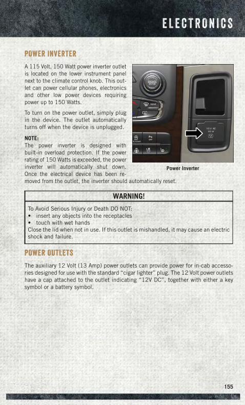
POWER INVERTER
A 115 Volt, 150 Watt power inverter outletis located on the lower instrument panelnext to the climate control knob. This out-let can power cellular phones, electronicsand other low power devices requiringpower up to 150 Watts.
To turn on the power outlet, simply plugin the device. The outlet automaticallyturns off when the device is unplugged.
NOTE:The power inverter is designed withbuilt-in overload protection. If the powerrating of 150 Watts is exceeded, the powerinverter will automatically shut down.Once the electrical device has been re-moved from the outlet, the inverter should automatically reset.
WARNING!
To Avoid Serious Injury or Death DO NOT:• insert any objects into the receptacles• touch with wet handsClose the lid when not in use. If this outlet is mishandled, it may cause an electricshock and failure.
POWER OUTLETS
The auxiliary 12 Volt (13 Amp) power outlets can provide power for in-cab accesso-ries designed for use with the standard “cigar lighter” plug. The 12 Volt power outletshave a cap attached to the outlet indicating “12V DC”, together with either a keysymbol or a battery symbol.
Power Inverter
E L E C T R O N I C S
155
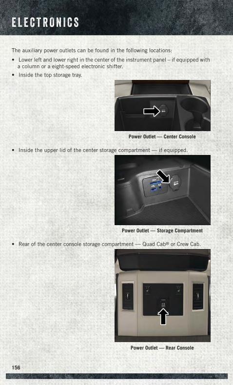
The auxiliary power outlets can be found in the following locations:
• Lower left and lower right in the center of the instrument panel – if equipped witha column or a eight-speed electronic shifter.
• Inside the top storage tray.
• Inside the upper lid of the center storage compartment — if equipped.
• Rear of the center console storage compartment — Quad Cab® or Crew Cab.
Power Outlet — Center Console
Power Outlet — Storage Compartment
Power Outlet — Rear Console
E L E C T R O N I C S
156
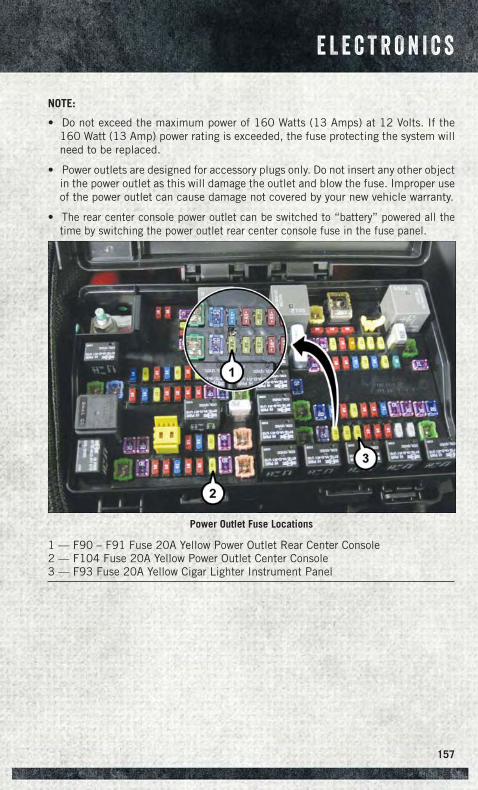
NOTE:
• Do not exceed the maximum power of 160 Watts (13 Amps) at 12 Volts. If the160 Watt (13 Amp) power rating is exceeded, the fuse protecting the system willneed to be replaced.
• Power outlets are designed for accessory plugs only. Do not insert any other objectin the power outlet as this will damage the outlet and blow the fuse. Improper useof the power outlet can cause damage not covered by your new vehicle warranty.
• The rear center console power outlet can be switched to “battery” powered all thetime by switching the power outlet rear center console fuse in the fuse panel.
Power Outlet Fuse Locations
1 — F90 – F91 Fuse 20A Yellow Power Outlet Rear Center Console2 — F104 Fuse 20A Yellow Power Outlet Center Console3 — F93 Fuse 20A Yellow Cigar Lighter Instrument Panel
E L E C T R O N I C S
157
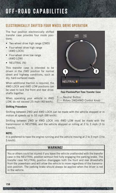
ELECTRONICALLY SHIFTED FOUR WHEEL DRIVE OPERATION
The four position electronically shiftedtransfer case provides four mode posi-tions:
• Two-wheel drive high range (2WD)
• Four-wheel drive high range(4WD LOCK)
• Four-wheel drive low range(4WD LOW)
• NEUTRAL (N)
This transfer case is intended to bedriven in the 2WD position for normalstreet and highway conditions, such asdry, hard-surfaced roads.
When additional traction is required, the4WD LOCK and 4WD LOW positions canbe used to lock the front and rear drive-shafts together.
When operating your vehicle in 4WDLOW, do not exceed 25 mph (40 km/h).
Shifting Procedure
Shifting between 2WD and 4WD LOCK can be made with the vehicle stopped or inmotion at speeds up to 55 mph (88 km/h).
Shifting between 2WD or 4WD LOCK into 4WD LOW must be made with thetransmission in NEUTRAL and the vehicle stopped or rolling at 2 to 3 mph (3 to5 km/h).
NOTE:It is preferred to have the engine running and the vehicle moving at 2 to 3 mph (3 to5 km/h).
WARNING!
You or others could be injured if you leave the vehicle unattended with the transfercase in the NEUTRAL position without first fully engaging the parking brake. Thetransfer case NEUTRAL position disengages both the front and rear driveshaftsfrom the powertrain and will allow the vehicle to move regardless of the transmis-sion position. The parking brake should always be applied when the driver is notin the vehicle.
Four-Position/Part Time Transfer Case
1 — Neutral Button2 — Rotary 2WD/4WD Control Knob
O F F - R O A D C A P A B I L I T I E S
158
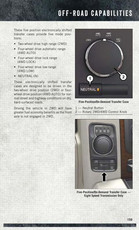
These five position electronically shiftedtransfer cases provide five mode posi-tions:
• Two-wheel drive high range (2WD)
• Four-wheel drive automatic range(4WD AUTO)
• Four-wheel drive lock range(4WD LOCK)
• Four-wheel drive low range(4WD LOW)
• NEUTRAL (N)
These electronically shifted transfercases are designed to be driven in thetwo-wheel drive position (2WD) or four-wheel drive position (4WD AUTO) for nor-mal street and highway conditions on dry,hard-surfaced roads.
Driving the vehicle in 2WD will havegreater fuel economy benefits as the frontaxle is not engaged in 2WD.
Five-Position/On-Demand Transfer Case
1 — Neutral Button2 — Rotary 2WD/4WD Control Knob
Five-Position/On-Demand Transfer Case —Eight Speed Transmission Only
O F F - R O A D C A P A B I L I T I E S
159
Shifting Procedure
Shifting between 2WD and 4WD AUTO or 4WD LOCK can be made with the vehiclestopped or in motion at speeds up to 55 mph (88 km/h).
Shifting between 2WD, 4WD AUTO and 4WD LOCK into 4WD LOW must be madewith the transmission in NEUTRAL and the vehicle stopped or rolling at 2 to 3 mph(3 to 5 km/h).
NOTE:It is preferred to have the engine running and the vehicle moving at 2 to 3 mph (3 to5 km/h).
WARNING!
You or others could be injured if you leave the vehicle unattended with the transfercase in the NEUTRAL position without first fully engaging the parking brake. Thetransfer case NEUTRAL position disengages both the front and rear driveshaftsfrom the powertrain and will allow the vehicle to move regardless of the transmis-sion position. The parking brake should always be applied when the driver is notin the vehicle.
O F F - R O A D C A P A B I L I T I E S
160
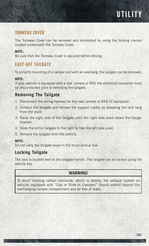
TONNEAU COVER
The Tonneau Cover can be removed and reinstalled by using the locking clampslocated underneath the Tonneau Cover.
NOTE:Be sure that the Tonneau Cover is secured before driving.
EASY-OFF TAILGATE
To simplify mounting of a camper unit with an overhang, the tailgate can be removed.
NOTE:If your vehicle is equipped with a rear camera or RKE the electrical connector mustbe disconnected prior to removing the tailgate.
Removing The Tailgate1. Disconnect the wiring harness for the rear camera or RKE (if equipped).
2. Unlatch the tailgate and remove the support cables by releasing the lock tangfrom the pivot.
3. Raise the right side of the tailgate until the right side pivot clears the hangerbracket.
4. Slide the entire tailgate to the right to free the left side pivot.
5. Remove the tailgate from the vehicle.
NOTE:Do not carry the tailgate loose in the truck pickup box.
Locking Tailgate
The lock is located next to the tailgate handle. The tailgate can be locked using thevehicle key.
WARNING!
To avoid inhaling carbon monoxide, which is deadly, the exhaust system onvehicles equipped with “Cap or Slide-In Campers” should extend beyond theoverhanging camper compartment and be free of leaks.
U T I L I T Y
161
PICKUP BOX
You can carry wide building materials (sheets of plywood, etc.) by building a raisedload floor. Place lumber across the box in the indentations provided above the wheelhousings and in the bulkhead dividers to form the floor.
There are stampings in the sheet metal on the inner side bulkheads of the box in frontof and behind both wheel housings. Place wooden boards across the box from side toside to create separate load compartments in the pickup box.
There are four tie-down cleats bolted to the lower sides of the pickup box that cansustain loads up to 1000 lbs (450 kg) total.
Cargo Camera
Your vehicle may be equipped with the Cargo Camera that allows you to see a imageof the inside of the pickup box. The image will be displayed in the Uconnect® screen.
• A display timer is initiated when the cargo camera image is displayed. The imagewill continue to be displayed until the display timer exceeds 10 seconds and thevehicle speed is above 8 mph (13 km/h) or the image is deactivated by touchingthe Uconnect® display.
NOTE:If the vehicle speed remains below 8 mph (13 km/h), the cargo camera image will bedisplayed continuously until deactivated by touching the Uconnect® display.
The Cargo Camera is located in the bottom center area of the center high-mountedstoplamp (CHMSL).
NOTE:If snow, ice, mud, or any foreign substance builds up on the camera lens, clean thelens, rinse with water, and dry with a soft cloth. Do not cover the lens.
U T I L I T Y
162
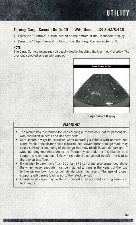
Turning Cargo Camera On Or Off — With Uconnect® 8.4A/8.4AN1. Press the “Controls” button located on the bottom of the Uconnect® display.
2. Press the “Cargo Camera” button to turn the Cargo Camera system ON.
NOTE:The Cargo Camera image may be deactivated by touching the Uconnect® display. Theprevious selected screen will appear.
WARNING!
• The pickup box is intended for load carrying purposes only, not for passengers,who should sit in seats and use seat belts.
• Care should always be exercised when operating a vehicle with unrestrainedcargo. Vehicle speeds may need to be reduced. Severe turns or rough roads maycause shifting or bouncing of the cargo that may result in vehicle damage. Ifwide building materials are to be frequently carried, the installation of asupport is recommended. This will restrain the cargo and transfer the load tothe pickup box floor.
• If you wish to carry more than 600 lbs (272 kg) of material suspended abovethe wheelhouse, supports must be installed to transfer the weight of the loadto the pickup box floor or vehicle damage may result. The use of propersupports will permit loading up to the rated payload.
• Unrestrained cargo may be thrown forward in an accident causing serious orfatal injury.
Cargo Camera Display
U T I L I T Y
163
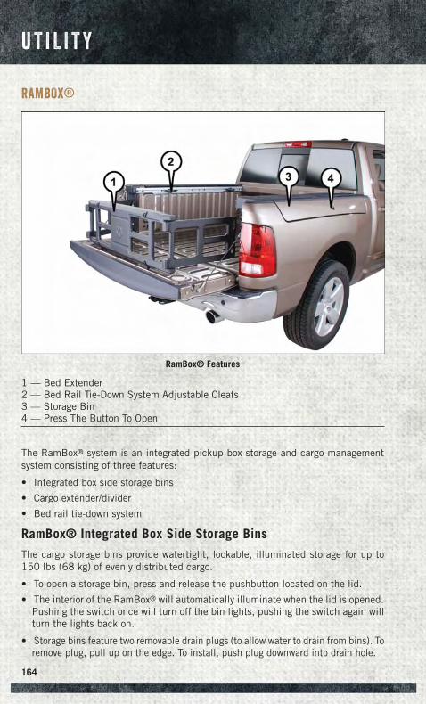
RAMBOX®
The RamBox® system is an integrated pickup box storage and cargo managementsystem consisting of three features:
• Integrated box side storage bins
• Cargo extender/divider
• Bed rail tie-down system
RamBox® Integrated Box Side Storage Bins
The cargo storage bins provide watertight, lockable, illuminated storage for up to150 lbs (68 kg) of evenly distributed cargo.
• To open a storage bin, press and release the pushbutton located on the lid.
• The interior of the RamBox® will automatically illuminate when the lid is opened.Pushing the switch once will turn off the bin lights, pushing the switch again willturn the lights back on.
• Storage bins feature two removable drain plugs (to allow water to drain from bins). Toremove plug, pull up on the edge. To install, push plug downward into drain hole.
RamBox® Features
1 — Bed Extender2 — Bed Rail Tie-Down System Adjustable Cleats3 — Storage Bin4 — Press The Button To Open
U T I L I T Y
164
The RamBox® storage bins can be locked and unlocked using the vehicle key or theremote keyless entry transmitter.
NOTE:Provisions are provided in the bins for cargo dividers and shelf supports. Theseaccessories (in addition to other RamBox® accessories) are available from MOPAR®.
RamBox® Storage Bin Cover Emergency Release Lever
As a security measure, a Storage Bin Cover Emergency Release is built into thestorage bin cover latching mechanism.
NOTE:In the event of an individual being locked inside the storage bin, the storage bin covercan be opened from inside of the bin by pulling on the glow-in-the-dark leverattached to the storage bin cover latching mechanism.
Bed Extender
The bed extender has three functional positions:
• Storage Position
• Divider Position
• Extender Position
Storage Position
The storage position for the bed extender is at the front of the truck bed.
To install the bed extender into the storage position, perform the following:
1. Make sure the center handle is unlocked using the vehicle key and rotate thecenter handle vertically to release the extender side gates.
2. With the side gates open, position the extender fully forward in the bed against thefront panel.
3. Rotate the side gates closed allowing the outboard ends to be positioned in frontof the cargo tie-down loops.
4. Rotate the center handle horizontally to secure the side gates in the closedposition.
5. Lock the center handle using the vehicle key to secure the panel into place andassist against theft.
U T I L I T Y
165
Divider Position
There are 11 divider slots along the bed inner panels which allow for various positionsto assist in managing your cargo.
To install the bed extender into a divider position perform the following:
1. Make sure the center handle is unlocked using the vehicle key and rotate thecenter handle vertically to release the extender side gates.
2. With the side gates open, position the extender so the outboard ends align withthe intended slots in the sides of the bed.
3. Rotate the side gates closed so that the outboard ends are secured into theintended slots of the bed.
4. Rotate the center handle horizontally to secure the side gates in the closedposition.
5. Lock the center handle to secure the panel into place and assist against theft.
Extender Position
The bed extender will add an additional 15 in (38 cm) in the back of the truck whenadditional cargo room is needed.
To install the bed extender into the extender position, perform the following:
1. Lower the tailgate.
2. Make sure the center handle is unlocked and rotate the center handle vertically inorder to release the extender side gates.
3. Fit the end of the side gate ends onto the pin and handle.
4. Rotate the handles to the horizontal position to secure into place.
Bed Rail Tie-Down System
There are two adjustable cleats on each side of the bed that can be used to assist insecuring cargo.
Each cleat must be located and tightened down in one of the detents, along eitherrail, in order to keep cargo properly secure.
• To move the cleat to any position on the rail, turn the nut counterclockwise,approximately three turns. Then, pull out on the cleat and slide it to the detentnearest the desired location. Make sure the cleat is seated in the detent andtighten the nut.
• To remove the cleats from the utility rail, remove the end cap by pushing up on thelocking tab, located on the bottom of the end cap. Slide the cleat off the end of therail.
U T I L I T Y
166
CAUTION!
Failure to follow the following items could cause damage to the vehicle:• Assure that all cargo inside the storage bins is properly secured.• Do not exceed cargo weight rating of 150 lb (68 kg) per bin.• Leaving the lid open for extended periods of time could cause the vehicle
battery to discharge. If the lid is required to stay open for extended periods oftime, it is recommended that the bin lights be turned off manually using theon/off switch.
• Ensure cargo bin lids are closed and latched before moving or driving vehicle.• Loads applied to the top of the bin lid should be minimized to prevent damage
to the lid and latching/hinging mechanisms.• Damage to the RamBox® bin may occur due to heavy/sharp objects placed in
bin that shift due to vehicle motion. In order to minimize potential for damage,secure all cargo to prevent movement and protect inside surfaces of bin fromheavy/sharp objects with appropriate padding.
• The maximum load per cleat should not exceed 250 lbs (113 kg) and the angleof the load on each cleat should not exceed 60 degrees above horizontal, ordamage to the cleat or cleat rail may occur.
WARNING!
• Always close the storage bin covers when your vehicle is unattended or inmotion.
• Do not allow children to have access to the storage bins. Once in the storagebin, young children may not be able to escape. If trapped in the storage bin,children can die from suffocation or heat stroke.
• In a collision, serious injury could result if the storage bin covers are notproperly latched.
• Do not use a storage bin latch as a tie down.• To reduce the risk of potential injury or property damage:
• Cargo must be secured.• Do not exceed cargo load rating of your vehicle.• Secure all loads to truck utilizing cargo tie-downs.• Extender should not be used as cargo tie-down.• When vehicle is in motion do not exceed 150 lbs (68 kg) load on the
tailgate.• The bed extender is not intended for off road use.• When not in use, the extender/divider should be in stowed or divider po-
sition with the tailgate closed.• When in use, all handles are to be in the locked position.
U T I L I T Y
167
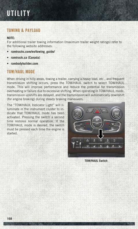
TOWING & PAYLOAD
NOTE:For additional trailer towing information (maximum trailer weight ratings) refer tothe following website addresses:
• ramtrucks.com/en/towing_guide/
• ramtruck.ca (Canada)
• rambodybuilder.com
TOW/HAUL MODE
When driving in hilly areas, towing a trailer, carrying a heavy load, etc., and frequenttransmission shifting occurs, press the TOW/HAUL switch to select TOW/HAULmode. This will improve performance and reduce the potential for transmissionoverheating or failure due to excessive shifting. When operating in TOW/HAUL mode,transmission upshifts are delayed, and the transmission will automatically downshift(for engine braking) during steady braking maneuvers.
The “TOW/HAUL Indicator Light” will il-luminate in the instrument cluster to in-dicate that TOW/HAUL mode has beenactivated. Pressing the switch a secondtime restores normal operation. If theTOW/HAUL mode is desired, the switchmust be pressed each time the engine isstarted.
TOW/HAUL Switch
U T I L I T Y
168
INTEGRATED TRAILER BRAKE MODULE
The Integrated Trailer Brake Controller allows you to automatically or manuallyactivate the Electric Trailer Brakes and Electric Over Hydraulic Trailer Brakes for abetter braking performance when towing a trailer.
NOTE:The Integrated Trailer Brake Controller is located in the center stack below theclimate controls.
This module will have four different options depending on the type of trailer you wantto tow and can be selected through the 3.5” Electronic Vehicle Information Center(EVIC) or touchscreen radio.
• Light Electric
• Heavy Electric
• Light EOH (Electric Over Hydraulic)
• Heavy EOH (Electric Over Hydraulic)
Setting with the Uconnect® Touchscreen Radio To make the proper selection in theUconnect® touchscreen radio, press the More hard-key (Uconnect® 5.0) or the Appssoft-key (Uconnect® 8.4), then press the Settings soft-key to display the menusetting screen and press trailer brake. For additional information, refer to yourOwner’s Manual on the DVD.
Setting with a 3.5” EVIC
1. Press the RIGHT arrow on the steering wheel to enter “VEHICLE SETTINGS.”
2. Press the UP or DOWN buttons until Trailer Brake Type appears on the screen.
3. Press the RIGHT arrow and then press the UP or DOWN buttons until the properTrailer Brake Type appears on the screen. For additional information, refer to yourOwner’s Manual on the DVD.
U T I L I T Y
169
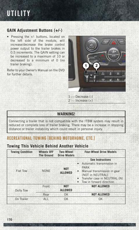
GAIN Adjustment Buttons (+/-)• Pressing the +/- buttons, located on
the left side of the module, willincrease/decrease the brake controlpower output to the trailer brakes in0.5 increments. The GAIN setting canbe increased to a maximum of 10 ordecreased to a minimum of 0 (notrailer braking).
Refer to your Owner's Manual on the DVDfor further details.
WARNING!
Connecting a trailer that is not compatible with the ITBM system may result inreduced or complete loss of trailer braking. There may be a increase in stoppingdistance or trailer instability which could result in personal injury.
RECREATIONAL TOWING (BEHIND MOTORHOME, ETC.)
Towing This Vehicle Behind Another VehicleTowing Condition Wheels OFF
The GroundTwo-Wheel
Drive ModelsFour-Wheel Drive Models
Flat Tow NONENOT
ALLOWED
See Instructions• Automatic transmission in
PARK• Manual transmission in gear
(NOT in NEUTRAL)• Transfer case in NEUTRAL (N)• Tow in forward direction
Dolly TowFront NOT
ALLOWEDNOT ALLOWED
Rear OK NOT ALLOWEDOn Trailer ALL OK OK
1 — Decrease (-)2 — Increase (+)
U T I L I T Y
170
NOTE:
• When recreationally towing your vehicle, always follow applicable state andprovincial laws. Contact state and provincial Highway Safety offices for additionaldetails.
• Vehicles equipped with air suspension must be placed in Transport mode beforetying them down (from the body) on a trailer or flatbed truck. Refer to “AirSuspension – If Equipped” for more information. If the vehicle cannot be placedin Transport mode (for example, engine will not run), tie-downs must be fastenedto the axles (not to the body). Failure to follow these instructions may cause faultcodes to be set and/or cause loss of proper tie-down tension.
Recreational Towing — Two-Wheel Drive Models
DO NOT flat tow this vehicle. Damage to the drivetrain will result.
Recreational towing (for two-wheel drive models) is allowed ONLY if the rear wheelsare OFF the ground. This may be accomplished using a tow dolly or vehicle trailer. Ifusing a tow dolly, follow this procedure:
1. Properly secure the dolly to the tow vehicle, following the dolly manufacturer'sinstructions.
NOTE:If vehicle is equipped with air suspension, ensure the vehicle is set to Normal RideHeight.
2. Drive the rear wheels onto the tow dolly.
3. Firmly apply the parking brake. Place automatic transmission in PARK, manualtransmission in gear (not in NEUTRAL).
4. Properly secure the rear wheels to the dolly, following the dolly manufacturer'sinstructions.
5. Turn the ignition switch to the OFF position and remove the Key Fob.
6. Install a suitable clamping device, designed for towing, to secure the front wheelsin the straight position.
CAUTION!
• Towing with the rear wheels on the ground will cause severe transmissiondamage. Damage from improper towing is not covered under the New VehicleLimited Warranty.
• Do not disconnect the driveshaft because fluid may leak from the transmission,causing damage to internal parts.
U T I L I T Y
171
Recreational Towing — Four-Wheel Drive Models
NOTE:Both the manual shift and electronic shift transfer cases must be shifted intoNEUTRAL (N) for recreational towing. Automatic transmissions must be shifted intoPARK for recreational towing. Manual transmissions must be placed in gear (NOT inNEUTRAL) for recreational towing. Refer to the following for the proper transfer caseNEUTRAL (N) shifting procedure for your vehicle.
CAUTION!
• Front or rear wheel lifts should not be used while recreational towing. Towingwith only one set of wheels on the ground (front or rear) will cause severedamage to the transmission and or transfer case. Tow with all four wheels eitherON the ground, or OFF the ground (using a vehicle trailer). Damage fromimproper towing is not covered under the New Vehicle Limited Warranty.
• Do not disconnect the driveshaft because fluid may leak from the transmission,causing damage to internal parts.
• Front or rear wheel lifts should not be used. Internal damage to the transmis-sion or transfer case will occur if a front or rear wheel lift is used whenrecreational towing.
• Tow only in the forward direction. Towing this vehicle backwards can causesevere damage to the transfer case.
• Before recreational towing, the transfer case must be in NEUTRAL. To becertain the transfer case is fully in NEUTRAL, perform the procedure outlinedunder “Shifting Into NEUTRAL”. Internal transmission damage will result, ifthe transfer case is not in NEUTRAL during towing.
• Manual transmissions must be placed in gear (not in Neutral) for recreationaltowing.
• Before recreational towing, perform the procedure outlined under “ShiftingInto NEUTRAL” to be certain that the transfer case is fully in NEUTRAL.Otherwise, internal damage will result.
• Towing this vehicle in violation of the above requirements can cause severetransmission and/or transfer case damage. Damage from improper towing isnot covered under the New Vehicle Limited Warranty.
• Do not disconnect the rear driveshaft because fluid will leak from the transfercase, causing damage to internal parts.
• Do not use a bumper-mounted clamp-on tow bar on your vehicle. The bumperface bar will be damaged.
U T I L I T Y
172
Shifting Into NEUTRAL (N)
Use the following procedure to prepare your vehicle for recreational towing.
WARNING!
You or others could be injured or killed if you leave the vehicle unattended with thetransfer case in the NEUTRAL (N) position without first fully engaging the parkingbrake. The transfer case NEUTRAL (N) position disengages both the front and reardriveshafts from the powertrain and will allow the vehicle to roll, even if thetransmission is in PARK. The parking brake should always be applied when thedriver is not in the vehicle.
CAUTION!
It is necessary to follow these steps to be certain that the transfer case is fully inNEUTRAL (N) before recreational towing to prevent damage to internal parts.
1. Bring the vehicle to a complete stop, with the engine running. Firmly apply theparking brake.
2. Shift the transmission to NEUTRAL.
NOTE:If vehicle is equipped with air suspension, ensure the vehicle is set to Normal RideHeight.
3. Press and hold the brake pedal.
4. Depress the clutch pedal on a manual transmission.
• With manual shift transfer case, shift the transfer case lever into NEUTRAL (N).
• With electronic shift transfer case, press and hold the transfer case NEUTRAL(N) button. Some models have a small, recessed "N" button (at the center of thetransfer case switches) that must be pressed using a ballpoint pen or similarobject. Other models have a rectangular NEUTRAL switch, below the rotarytransfer case control knob. The NEUTRAL (N) indicator light will blink whilethe shift is in progress. The light will stop blinking (stay on solid) when the shiftto NEUTRAL (N) is complete. After the shift is completed and the NEUTRAL(N) light stays on, release the NEUTRAL (N) button.
5. Release the parking brake.
6. Shift the transmission into REVERSE.
7. Release the brake pedal (and clutch pedal on manual transmissions) for fiveseconds and ensure that there is no vehicle movement.
8. Repeat steps 6 and 7 with automatic transmission in DRIVE or manual transmis-sion in first gear.
U T I L I T Y
173
9. Shift the transmission to NEUTRAL. Firmly apply the parking brake. Turn OFF theengine. For vehicles with Keyless Enter-N-Go™, press and hold the ENGINESTART/STOP button until the engine shuts off.
10. Shift the transmission into PARK or place manual transmission in gear (NOT inNeutral). On 8-speed transmissions the shifter will automatically select PARKwhen the engine is turned off.
11. Turn the ignition switch to the OFF position, then cycle the key or the KeylessEnter-N-Go™ button to the RUN position and back to the OFF position. Removethe key fob from the ignition switch.
12. Attach the vehicle to the tow vehicle using a suitable tow bar.
13. Release the parking brake.
NOTE:With electronic shift transfer case:
• Steps 2 through 4 are requirements that must be met before pressing theNEUTRAL (N) button, and must continue to be met until the shift has beencompleted. If any of these requirements are not met before pressing the NEUTRAL(N) button or are no longer met during the shift, the NEUTRAL (N) indicator lightwill flash continuously until all requirements are met or until the NEUTRAL (N)button is released.
• The ignition switch must be in the ON/RUN position for a shift to take place andfor the position indicator lights to be operable. If the ignition switch is not in theON/RUN position, the shift will not take place and no position indicator lights willbe on or flashing.
• A flashing NEUTRAL (N) position indicator light indicates that shift requirementshave not been met.
• If the vehicle is equipped with air suspension, the engine should be started andleft running for a minimum of 60 seconds (with all the doors closed) at least onceevery 24 hours. This process allows the air suspension to adjust the vehicle’s rideheight to compensate for temperature effects.
Shifting Out Of NEUTRAL (N)
Use the following procedure to prepare your vehicle for normal usage.
1. Bring the vehicle to a complete stop, leaving it connected to the tow vehicle.
2. Firmly apply the parking brake.
3. Press and hold the brake pedal.
4. Start the engine. Shift the transmission into NEUTRAL. Depress the clutch pedalon a manual transmission.
• With manual shift transfer case, shift the transfer case lever to the desiredposition.
U T I L I T Y
174
• With electronic shift transfer case with rotary selector switch, press and holdthe transfer case NEUTRAL (N) button until the NEUTRAL (N) indicator lightturns off. After the NEUTRAL (N) indicator light turns off, release theNEUTRAL (N) button. After the NEUTRAL (N) button has been released, thetransfer case will shift to the position indicated by the selector switch.
• With electronic shift transfer case with pushbutton selector switch, press andhold the switch for the desired transfer case position, until the NEUTRAL (N)indicator light turns off and the desired position indicator light turns on.
NOTE:When shifting out of transfer case NEUTRAL (N), turning the engine OFF is notrequired, but may be helpful to avoid gear clash. With the 8-speed automatictransmission, the engine must remain running, since turning the engine OFF willshift the transmission to PARK (and the transmission must be in NEUTRAL for thetransfer case to shift out of NEUTRAL).
5. Turn the engine OFF. Shift automatic transmission into PARK. On 8-speedtransmissions the shifter will automatically select PARK when the engine isturned off.
6. Release the brake pedal (and clutch pedal on a manual transmission).
7. Disconnect vehicle from the tow vehicle.
8. Start the engine.
9. Press and hold the brake pedal.
10. Release the parking brake.
11. Shift the transmission into gear, release the brake pedal (and clutch pedal onmanual transmissions), and check that the vehicle operates normally.
NOTE:With electronic shift transfer case:
• Steps 3 and 4 are requirements that must be met before pressing the button toshift out of NEUTRAL (N), and must continue to be met until the shift has beencompleted. If any of these requirements are not met before pressing the button orare no longer met during the shift, the NEUTRAL (N) indicator light will flashcontinuously until all requirements are met or until the button is released.
• The ignition switch must be in the ON/RUN position for a shift to take place andfor the position indicator lights to be operable. If the ignition switch is not in theON/RUN position, the shift will not take place and no position indicator lights willbe on or flashing.
• A flashing NEUTRAL (N) position indicator light indicates that shift requirementshave not been met.
U T I L I T Y
175
DIESEL ENGINE BREAK-IN RECOMMENDATIONS
• The 3.0 turbocharged diesel engine does not require a break-in period due to itsconstruction. Normal operation is allowed, providing the following recommenda-tions are followed:• Warm up the engine before placing it under load.• Do not operate the engine at idle for prolonged periods.• Use the appropriate transmission gear to prevent engine lugging.• Observe vehicle oil pressure and temperature indicators.• Check the coolant and oil levels frequently.• Vary throttle position at highway speeds when carrying or towing significant
weight.
NOTE:Light duty operation such as light trailer towing or no load operation will extend thetime before the engine is at full efficiency. Reduced fuel economy and power may beseen at this time.
• The engine oil installed in the engine at the factory is a high-quality energyconserving type lubricant. Oil changes should be consistent with anticipatedclimate conditions under which vehicle operations will occur. The recommendedviscosity and quality grades are shown under “FLUIDS AND CAPACITIES”, under“MAINTAINING YOUR VEHICLE” in this User Guide. NON-DETERGENT ORSTRAIGHT MINERAL OILS MUST NEVER BE USED.
DIESEL ENGINE STARTING PROCEDURES
Normal Starting Procedure1. Apply the parking brake.
2. Ensure the shift lever is in the PARK position.
3. Press and hold the brake pedal while pressing the ENGINE START/STOP buttononce and the system will engage the starter to crank the engine.
NOTE:
• A delay of the start of up to five seconds is possible under very cold conditions.The "Wait to Start" telltale will be illuminated during the pre-heat process, Whenthe engine Wait To Start light goes off the engine will automatically crank.
• If you wish to stop the cranking of the engine prior to the engine starting, pressthe button again.
4. Check that the oil pressure warning light has turned off.
5. Release the parking brake.
1 5 0 0 3 . 0 L D I E S E L
176
CAUTION!
If the “Water in Fuel Indicator Light” remains on, DO NOT START the enginebefore you drain the water from the fuel filters to avoid engine damage. Refer to“Maintenance Procedures/Draining Fuel/Water Separator Filter” in “MaintainingYour Vehicle” in your Diesel Supplement on the DVD for further information.
Extreme Cold Weather
The engine block heater is a resistance heater installed in the water jacket of theengine. It requires a 110–115 Volt AC electrical outlet with a grounded, three-wireextension cord.
Its use is recommended for environments that routinely fall below -10°F. It should beused when the vehicle has not been running overnight or longer periods and shouldbe plugged in two hours prior to start. Its use is required for cold starts withtemperatures under -20°F.
A 12 Volt heater built into the fuel filter housing aids in preventing fuel gelling. It iscontrolled by a built-in thermostat.
A Diesel Pre-Heat system both improves engine starting and reduces the amount ofwhite smoke generated by a warming engine.
NOTE:The engine block heater cord is a factory installed option. If your vehicle is notequipped, heater cords are available from your authorized MOPAR® dealer.
Water In Fuel Message
If a Water In Fuel message or indicator appears in the cluster and a chimesounds five times, the fuel/water separator will need to be drained immediately toprevent engine damage.
Refer to “Draining Fuel Water Separator” in this guide for draining instructions or seeyour dealer.
1 5 0 0 3 . 0 L D I E S E L
177
DIESEL FUEL FILTER/WATER SEPARATOR
Draining Fuel/Water Separator
If the “Water in Fuel” indicator light is illuminated and an audible chime isheard five times, you should stop the engine and drain the water from the separator.
The drain plug is located on the bottom of the Fuel Filter and Water Separatorassembly which is located above the rear axle next to the fuel tank.
Loosen the drain plug (located on the bottom filter assembly) then turn the ignitionswitch to the ON/RUN position to allow any accumulated water to drain.
When clean fuel is visible, close the drain and switch the ignition to the OFF position.
Refer to the Diesel Supplement on the DVD for further details.
Fuel Filter Replacement1. Ensure engine is turned off.
2. Place drain pan under the fuel filter assembly.
3. Open the water drain valve, and let any accumulated water drain.
4. Close the water drain valve.
5. Remove bottom cover using a strap wrench. Rotate counterclockwise for removal.Remove the used o-ring and discard it.
6. Remove the used filter cartridge from the housing and dispose of according toyour local regulations.
7. Wipe the sealing surfaces of the lid and housing clean.
8. Install new o-ring back into ring groove on the filter housing and lubricate withclean engine oil.
NOTE:The WIF (Water In Fuel) sensor is re-usable. Service kit comes with new o-ring forfilter canister and WIF (Water In Fuel) sensor.
CAUTION!
• Diesel fuel will damage blacktop paving surfaces. Drain the filter into anappropriate container.
• Do not prefill the fuel filter when installing a new fuel filter. There is apossibility debris could be introduced into the fuel filter during this action. Itis best to install the filter dry and allow the in-tank lift pump to prime the fuelsystem.
• If the “Water In Fuel Indicator Light” remains on, DO NOT START the enginebefore you drain water from the fuel filter to avoid engine damage.
1 5 0 0 3 . 0 L D I E S E L
178
EXHAUST REGENERATION
This engine meets all required EPA diesel engine emissions standards. To achievethese emissions standards, your vehicle is equipped with a state-of-the-art engineand exhaust system. These systems are seamlessly integrated into your vehicle andmanaged by the Powertrain Control Module (PCM). Additionally, your vehicle has theability to alert you to additional maintenance required on your vehicle or engine.Refer to the following messages that may be displayed on your Driver InformationDisplay (DID).
Exhaust System — Regeneration Required Now
This message Indicates that the Diesel Particulate Filter (DPF) reached 80% of itsmaximum storage capacity.
By simply driving your vehicle at highway speeds for up to 20 minutes, you canremedy the condition in the particulate filter system and allow your diesel engine andexhaust after-treatment system to cleanse the filter to remove the trapped PM andrestore the system to normal operating condition.
Exhaust System — Regeneration in Process Exhaust FilterXX% Full
Indicates that the Diesel Particulate Filter (DPF) is self-cleaning. Maintain yourcurrent driving condition until regeneration is completed.
Exhaust System — Regeneration Completed
This message indicates that the Diesel Particulate Filter (DPF) self-cleaning iscompleted. If this message is displayed, you will hear one chime to assist in alertingyou of this condition.
Exhaust Service Required — See Dealer Now
This message indicates regeneration has been disabled due to a system malfunction.The Powertrain control Module (PCM) will register a fault code and the instrumentpanel will display the Malfunction Indicator Light (MIL).
CAUTION!
See your authorized dealer, as damage to the exhaust system could occur soonwith continued operation.
1 5 0 0 3 . 0 L D I E S E L
179
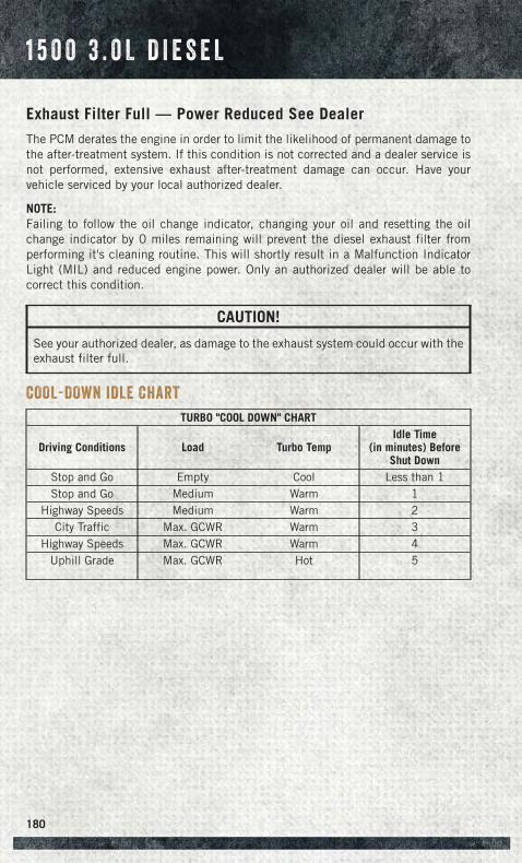
Exhaust Filter Full — Power Reduced See Dealer
The PCM derates the engine in order to limit the likelihood of permanent damage tothe after-treatment system. If this condition is not corrected and a dealer service isnot performed, extensive exhaust after-treatment damage can occur. Have yourvehicle serviced by your local authorized dealer.
NOTE:Failing to follow the oil change indicator, changing your oil and resetting the oilchange indicator by 0 miles remaining will prevent the diesel exhaust filter fromperforming it's cleaning routine. This will shortly result in a Malfunction IndicatorLight (MIL) and reduced engine power. Only an authorized dealer will be able tocorrect this condition.
CAUTION!
See your authorized dealer, as damage to the exhaust system could occur with theexhaust filter full.
COOL-DOWN IDLE CHART
TURBO "COOL DOWN" CHART
Driving Conditions Load Turbo TempIdle Time
(in minutes) BeforeShut Down
Stop and Go Empty Cool Less than 1Stop and Go Medium Warm 1
Highway Speeds Medium Warm 2City Traffic Max. GCWR Warm 3
Highway Speeds Max. GCWR Warm 4Uphill Grade Max. GCWR Hot 5
1 5 0 0 3 . 0 L D I E S E L
180
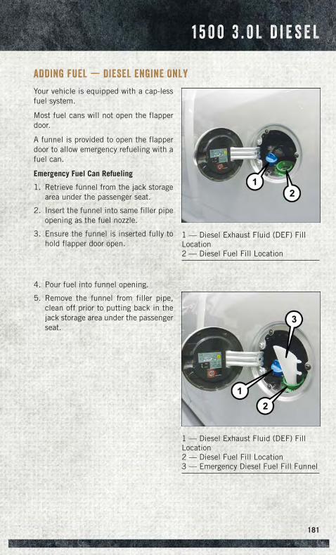
ADDING FUEL — DIESEL ENGINE ONLY
Your vehicle is equipped with a cap-lessfuel system.
Most fuel cans will not open the flapperdoor.
A funnel is provided to open the flapperdoor to allow emergency refueling with afuel can.
Emergency Fuel Can Refueling
1. Retrieve funnel from the jack storagearea under the passenger seat.
2. Insert the funnel into same filler pipeopening as the fuel nozzle.
3. Ensure the funnel is inserted fully tohold flapper door open.
4. Pour fuel into funnel opening.
5. Remove the funnel from filler pipe,clean off prior to putting back in thejack storage area under the passengerseat.
1 — Diesel Exhaust Fluid (DEF) FillLocation2 — Diesel Fuel Fill Location
1 — Diesel Exhaust Fluid (DEF) FillLocation2 — Diesel Fuel Fill Location3 — Emergency Diesel Fuel Fill Funnel
1 5 0 0 3 . 0 L D I E S E L
181
DIESEL EXHAUST FLUID
Diesel Exhaust Fluid (DEF) sometimes known simply by the name of its activecomponent, UREA – is a key component of selective catalytic reduction (SCR)systems, which help diesel vehicles meet stringent emission regulations. DEF is aliquid reducing agent that reacts with engine exhaust in the presence of a catalyst toconvert smog-forming nitrogen oxides (NOx) into harmless nitrogen and water vapor.
Your vehicle is equipped with a Selective Catalytic Reduction system in order to meetthe very stringent diesel emissions standards required by the Environmental Protec-tion Agency. Selective Catalytic Reduction (SCR) is the first and only technology indecades to be as good for the environment as it is good for business and vehicleperformance.
The purpose of the SCR system is to reduce levels of NOx (oxides of nitrogen emittedfrom engines) that are harmful to our health and the environment to an almostnear-zero level. Small quantities of Diesel Exhaust Fluid (DEF) are injected into theexhaust upstream of a catalyst where, when vaporized, convert smog-formingnitrogen oxides (NOx) into harmless nitrogen (N2) and water vapor (H2O), twonatural components of the air we breathe. You can operate with the comfort that yourvehicle is contributing to a cleaner, healthier world environment for this andgenerations to come.
System Overview
This vehicle is equipped with a Diesel Exhaust Fluid (DEF) injection system and aSelective Catalytic Reduction (SCR) catalyst to meet the emission requirements.
The DEF injection system consists of the following components:
• DEF tank
• DEF pump
• DEF injector
• Electronically-heated DEF lines
• NOx sensors
• Temperature sensors
• SCR catalyst
The DEF injection system and SCR catalyst enable the achievement of dieselemissions requirements; while maintaining outstanding fuel economy, drivability,torque and power ratings.
NOTE:
• Your vehicle is equipped with a DEF injection system. You may occasionally hearan audible clicking noise. This is normal operation.
• The DEF pump will run for a period of time after engine shutdown to purge the DEFsystem. This is normal operation.
1 5 0 0 3 . 0 L D I E S E L
182
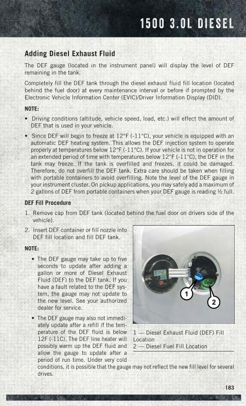
Adding Diesel Exhaust Fluid
The DEF gauge (located in the instrument panel) will display the level of DEFremaining in the tank.
Completely fill the DEF tank through the diesel exhaust fluid fill location (locatedbehind the fuel door) at every maintenance interval or before if prompted by theElectronic Vehicle Information Center (EVIC)/Driver Information Display (DID).
NOTE:
• Driving conditions (altitude, vehicle speed, load, etc.) will effect the amount ofDEF that is used in your vehicle.
• Since DEF will begin to freeze at 12°F (-11°C), your vehicle is equipped with anautomatic DEF heating system. This allows the DEF injection system to operateproperly at temperatures below 12°F (-11°C). If your vehicle is not in operation foran extended period of time with temperatures below 12°F (-11°C), the DEF in thetank may freeze. If the tank is overfilled and freezes, it could be damaged.Therefore, do not overfill the DEF tank. Extra care should be taken when fillingwith portable containers to avoid overfilling. Note the level of the DEF gauge inyour instrument cluster. On pickup applications, you may safely add a maximum of2 gallons of DEF from portable containers when your DEF gauge is reading ½ full.
DEF Fill Procedure
1. Remove cap from DEF tank (located behind the fuel door on drivers side of thevehicle).
2. Insert DEF container or fill nozzle intoDEF fill location and fill DEF tank.
NOTE:
• The DEF gauge may take up to fiveseconds to update after adding agallon or more of Diesel ExhaustFluid (DEF) to the DEF tank. If youhave a fault related to the DEF sys-tem, the gauge may not update tothe new level. See your authorizeddealer for service.
• The DEF gauge may also not immedi-ately update after a refill if the tem-perature of the DEF fluid is below12F (-11C). The DEF line heater willpossibly warm up the DEF fluid andallow the gauge to update after aperiod of run time. Under very coldconditions, it is possible that the gauge may not reflect the new fill level for severaldrives.
1 — Diesel Exhaust Fluid (DEF) FillLocation2 — Diesel Fuel Fill Location
1 5 0 0 3 . 0 L D I E S E L
183
3. Reinstall cap onto DEF tank.
Refer to your Diesel Supplement on the DVD for further details.
CAUTION!
• To avoid DEF spillage and overfilling, do not “top off” the DEF tank after filling.• When DEF is spilled, clean the area immediately with water or a mild solvent.• DO NOT OVERFILL. DEF will freeze below 12 degrees F (-11 degrees C). The
DEF system is designed to work in temperatures below the DEF freezing point,however, if the tank is overfilled and freezes, the system could be damaged.
Diesel Exhaust Fluid (DEF) Warning Messages
Your vehicle will begin displaying warning messages when the DEF level reaches adriving range of approximately 500 miles (800 km).
If the following warning message sequence is ignored, your vehicle may not restartunless DEF is added within the displayed mileage shown in the DID message.
Engine Will Not Restart in XXXX mi DEF Low Refill Soon – This message will display whenDEF driving range is less than 500 miles, DEF fluid top off is required with in thedisplayed mileage. The message will be displayed in the DID during vehicle start upwith the current allowed mileage and accompanied by a single chime. The remainingmileage can be pulled up anytime by way of the “Messages” list within the DID.
Engine Will Not Restart in XXXX mi Refill DEF – This message will display when DEFdriving range is less than 200 miles. It is also displayed at 150 miles and 100 miles.DEF fluid top off is required with in the displayed mileage. The message will bedisplayed in the DID during vehicle start up with an updated distance mileage, andit will be accompanied by a single chime. Stating at 100 miles, remaining range willbe continuously displayed while operating the vehicle. Chimes will also accompanythe 75, 50 and 25 mile remaining distances. The DEF Low telltale will be oncontinuously until DEF fluid is topped off.
Engine Will Not Restart Refill DEF – This message will display when the DEF drivingrange is less than 1 mile, DEF fluid top off is required or the engine will not restart.The message will be displayed in the DID during vehicle start up, and it will beaccompanied by a single chime. The DEF Low telltale will be illuminated continu-ously until DEF fluid tank is filled with a minimum of two gallons of DEF.
1 5 0 0 3 . 0 L D I E S E L
184
Diesel Exhaust Fluid (DEF) Fault Warning Messages
There are different messages which are displayed if the vehicle detects that the DEFsystem has been filled with a fluid other than DEF, has experienced componentfailures, or when tampering has been detected.
When the DEF system needs to be serviced the following warnings will display:
Service DEF System See Dealer – This message will display when the fault is initiallydetected and each time the vehicle is started. The message will be accompanied bya single chime and the Malfunction Indicator Light. We recommend you drive to yournearest authorized dealer and have your vehicle serviced immediately. If notcorrected in 50 miles, vehicle will enter the “Engine Will not restart in XXXmi ServiceDEF See dealer” warning stage and message.
Incorrect DEF Detected See Dealer – This message will display if the DEF system hasdetected the incorrect fluid has been introduced to the DEF tank. The message willbe accompanied by a single chime. We recommend you drive to your nearestauthorized dealer and have your vehicle serviced immediately. If not corrected in50 miles, vehicle will enter the Engine Will not restart in XXX mi Service DEF Seedealer warning stage and message.
Engine Will Not Restart in XXX mi Service DEF See Dealer – This message is firstdisplayed if the fault detected is not serviced after 50 miles of operation. It is alsodisplayed at 150 miles 125 miles and 100 miles. System service is required withinthe displayed mileage. The message will be displayed in the DID during vehicle startup with an updated distance mileage, and it will be accompanied by a single chime.Starting at 100 miles, remaining range will be continuously displayed while operat-ing the vehicle. Chimes will also accompany the 75, 50 and 25 mile remainingdistances. We recommend you drive to your nearest authorized dealer and have yourvehicle serviced immediately.
Engine Will Not Restart Service DEF System See Dealer – This message will display if theDEF system issue detected is not serviced during the allowed period. Your engine willnot restart unless your vehicle is serviced by your authorized dealer. This message willbe displayed when under 1 mile until the engine will not start and each time thevehicle is started. The message will be continuously displayed and be accompaniedby a single chime. Your Malfunction Indicator Light will also be continuouslyillumined. We highly recommend you drive to your nearest authorized dealerimmediately if the message appears while engine is running.
Engine Will Not Start Service DEF System See Dealer – This message will display whenthe fault detected is not serviced after the Engine will not restart Service DEF SystemSee Dealer message is displayed on the next subsequent restart. Your engine will notstart unless you vehicle is serviced by your authorized dealer. The message will beaccompanied by a single chime. Your Malfunction Indicator Light will be continuouslyilluminated. If the message appears and you can not start the engine, we recommendyou have your vehicle towed to your nearest authorized dealer immediately.
1 5 0 0 3 . 0 L D I E S E L
185
DIESEL ENGINE BREAK-IN RECOMMENDATIONS
The Cummins® turbocharged diesel engine does not require a break-in period due toits construction. Normal operation is allowed, providing the following recommenda-tions are followed:
• Warm up the engine before placing it under load.
• Do not operate the engine at idle for prolonged periods.
• Use the appropriate transmission gear to prevent engine lugging.
• Observe vehicle oil pressure and temperature indicators.
• Check the coolant and oil levels frequently.
• Vary throttle position at highway speeds when carrying or towing significantweight.
NOTE:Light duty operation such as light trailer towing or no load operation will extend thetime before the engine is at full efficiency. Reduced fuel economy and power may beseen at this time.
Because of the construction of the Cummins® turbocharged diesel engine, enginerun-in is enhanced by loaded operating conditions which allow the engine parts toachieve final finish and fit during the first 6,000 miles (10 000 km).
DIESEL ENGINE STARTING PROCEDURES
Engine Block Heater
For ambient temperatures below 0°F (-18°C), engine block heater usage is recom-mended.
For ambient temperatures below –20°F (-29°C), engine block heater usage isrequired.
The engine block heater cord is routed under the hood to the right side and can belocated just behind the grille near the headlamp.
Connect the heater cord to a ground-fault interrupter protected 110–115 volt ACelectrical outlet with a grounded, three-wire extension cord.
NOTE:The block heater will require 110 volts AC and 6.5 amps to activate the heaterelement.
The block heater must be plugged in at least one hour to have an adequate warmingeffect on the coolant.
6 . 7 L C U M M I N S ® D I E S E L
186
Water In Fuel Message
If a Water In Fuel message or indicator appears in the cluster and a chimesounds five times, the fuel/water separator will need to be drained immediately toprevent engine damage.
Refer to “Draining Fuel Water Separator” in this guide for draining instructions or seeyour dealer.
Cold Start Procedure
Turn the ignition switch to the ON position. If the Wait To Start light appears inthe cluster, wait for the light to turn off before starting.
In extremely cold weather below 0°F (-18°C) it may be beneficial to cycle themanifold heaters twice before attempting to start the engine. This can be accom-plished by turning the ignition OFF for at least five seconds and then back ON afterthe “Wait To Start Light” has turned off, but before the engine is started. However,excessive cycling of the manifold heaters will result in damage to the heater elementsor reduced battery voltage.
Refer to the Owner's Manual Diesel Supplement on the DVD for further details.
Engine Idling
Avoid prolonged engine idling. Long periods of idling may be harmful to your enginebecause combustion chamber temperatures can drop so low that the fuel may notburn completely.
Incomplete combustion allows carbon and varnish to form on piston rings, enginevalves, and injector nozzles. Also, the unburned fuel can enter the crankcase,diluting the oil and causing rapid wear to the engine.
If the engine is allowed to idle, under some conditions the idle speed may increaseto 900 RPM then return to normal idle speed. This is normal operation.
WARNING!
Remember to disconnect the cord before driving. Damage to the 110–115 voltelectrical cord could cause electrocution.
6 . 7 L C U M M I N S ® D I E S E L
187
DIESEL EXHAUST BRAKE (ENGINE BRAKING)
The Exhaust Brake switch is located on the switch bank below the audio system. Thisswitch is used to enable exhaust brake modes.
Pressing the exhaust brake switch once will enable full strength exhaust brake mode,indicated by a yellow icon in the EVIC/DID. This mode applies full exhaust brakingwhen the accelerator pedal is released. This is most useful for slowing the vehicle.
Pressing the exhaust brake switch again will enable the Smart Brake feature,indicated by a green icon in the EVIC/DID. This feature is intended to maintain thevehicle speed present when the accelerator pedal is released. However, when thebrakes are applied, full exhaust braking is still enabled to slow the vehicle.
A third press of the brake switch will turn the exhaust brake off, and will extinguishthe exhaust brake icon in the EVIC/DID.
NOTE:In general, higher engine speeds result in higher exhaust braking force. For optimumbraking power, it is recommended to use the exhaust brake while in TOW/HAULmode.
CAUTION!
Use of aftermarket exhaust brakes is not recommended and could lead to enginedamage.
WARNING!
Do not use the exhaust brake feature when driving in icy or slippery conditions asthe increased engine braking can cause the rear wheels to slide and the vehicle toswing around with the possible loss of vehicle control, which may cause a collisionpossibly resulting in personal injury or death.
6 . 7 L C U M M I N S ® D I E S E L
188
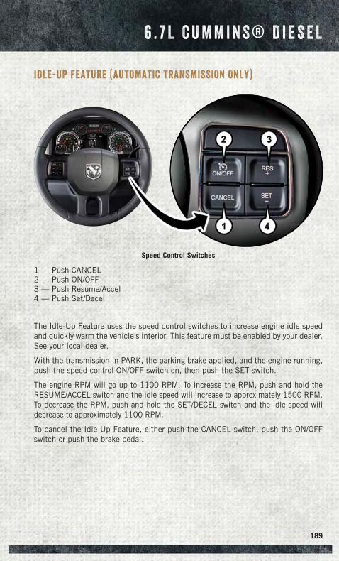
IDLE-UP FEATURE (AUTOMATIC TRANSMISSION ONLY)
The Idle-Up Feature uses the speed control switches to increase engine idle speedand quickly warm the vehicle’s interior. This feature must be enabled by your dealer.See your local dealer.
With the transmission in PARK, the parking brake applied, and the engine running,push the speed control ON/OFF switch on, then push the SET switch.
The engine RPM will go up to 1100 RPM. To increase the RPM, push and hold theRESUME/ACCEL switch and the idle speed will increase to approximately 1500 RPM.To decrease the RPM, push and hold the SET/DECEL switch and the idle speed willdecrease to approximately 1100 RPM.
To cancel the Idle Up Feature, either push the CANCEL switch, push the ON/OFFswitch or push the brake pedal.
Speed Control Switches
1 — Push CANCEL2 — Push ON/OFF3 — Push Resume/Accel4 — Push Set/Decel
6 . 7 L C U M M I N S ® D I E S E L
189
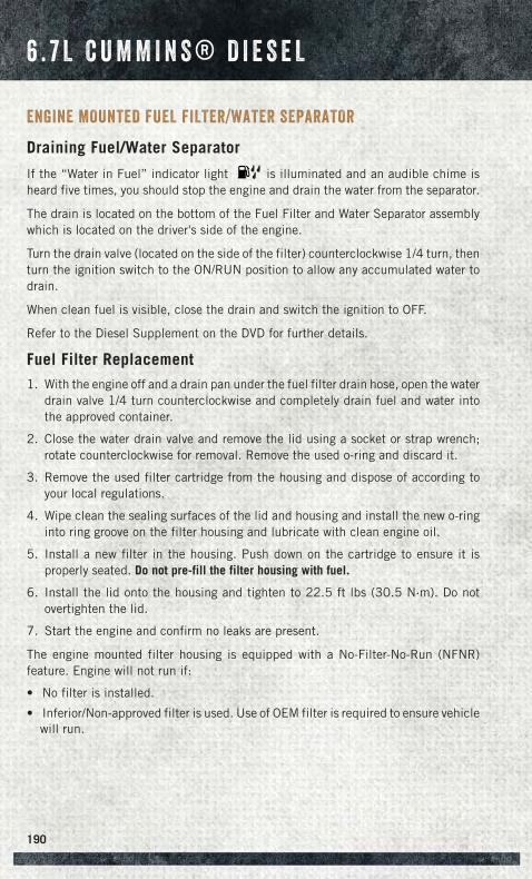
ENGINE MOUNTED FUEL FILTER/WATER SEPARATOR
Draining Fuel/Water Separator
If the “Water in Fuel” indicator light is illuminated and an audible chime isheard five times, you should stop the engine and drain the water from the separator.
The drain is located on the bottom of the Fuel Filter and Water Separator assemblywhich is located on the driver's side of the engine.
Turn the drain valve (located on the side of the filter) counterclockwise 1/4 turn, thenturn the ignition switch to the ON/RUN position to allow any accumulated water todrain.
When clean fuel is visible, close the drain and switch the ignition to OFF.
Refer to the Diesel Supplement on the DVD for further details.
Fuel Filter Replacement1. With the engine off and a drain pan under the fuel filter drain hose, open the water
drain valve 1/4 turn counterclockwise and completely drain fuel and water intothe approved container.
2. Close the water drain valve and remove the lid using a socket or strap wrench;rotate counterclockwise for removal. Remove the used o-ring and discard it.
3. Remove the used filter cartridge from the housing and dispose of according toyour local regulations.
4. Wipe clean the sealing surfaces of the lid and housing and install the new o-ringinto ring groove on the filter housing and lubricate with clean engine oil.
5. Install a new filter in the housing. Push down on the cartridge to ensure it isproperly seated. Do not pre-fill the filter housing with fuel.
6. Install the lid onto the housing and tighten to 22.5 ft lbs (30.5 N·m). Do notovertighten the lid.
7. Start the engine and confirm no leaks are present.
The engine mounted filter housing is equipped with a No-Filter-No-Run (NFNR)feature. Engine will not run if:
• No filter is installed.
• Inferior/Non-approved filter is used. Use of OEM filter is required to ensure vehiclewill run.
6 . 7 L C U M M I N S ® D I E S E L
190
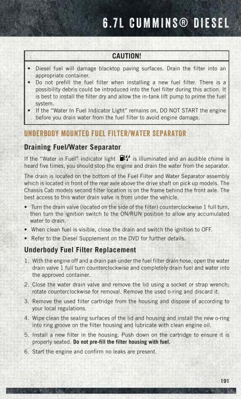
CAUTION!
• Diesel fuel will damage blacktop paving surfaces. Drain the filter into anappropriate container.
• Do not prefill the fuel filter when installing a new fuel filter. There is apossibility debris could be introduced into the fuel filter during this action. Itis best to install the filter dry and allow the in-tank lift pump to prime the fuelsystem.
• If the “Water In Fuel Indicator Light” remains on, DO NOT START the enginebefore you drain water from the fuel filter to avoid engine damage.
UNDERBODY MOUNTED FUEL FILTER/WATER SEPARATOR
Draining Fuel/Water Separator
If the “Water in Fuel” indicator light is illuminated and an audible chime isheard five times, you should stop the engine and drain the water from the separator.
The drain is located on the bottom of the Fuel Filter and Water Separator assemblywhich is located in front of the rear axle above the drive shaft on pick up models. TheChassis Cab models second filter location is on the frame behind the front axle. Thebest access to this water drain valve is from under the vehicle.
• Turn the drain valve (located on the side of the filter) counterclockwise 1 full turn,then turn the ignition switch to the ON/RUN position to allow any accumulatedwater to drain.
• When clean fuel is visible, close the drain and switch the ignition to OFF.
• Refer to the Diesel Supplement on the DVD for further details.
Underbody Fuel Filter Replacement1. With the engine off and a drain pan under the fuel filter drain hose, open the water
drain valve 1 full turn counterclockwise and completely drain fuel and water intothe approved container.
2. Close the water drain valve and remove the lid using a socket or strap wrench;rotate counterclockwise for removal. Remove the used o-ring and discard it.
3. Remove the used filter cartridge from the housing and dispose of according toyour local regulations.
4. Wipe clean the sealing surfaces of the lid and housing and install the new o-ringinto ring groove on the filter housing and lubricate with clean engine oil.
5. Install a new filter in the housing. Push down on the cartridge to ensure it isproperly seated. Do not pre-fill the filter housing with fuel.
6. Start the engine and confirm no leaks are present.
6 . 7 L C U M M I N S ® D I E S E L
191
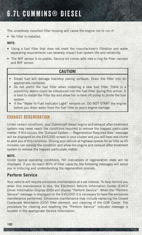
The underbody mounted filter housing will cause the engine not to run if:
• No filter is installed.
NOTE:
• Using a fuel filter that does not meet the manufacturer's filtration and waterseparating requirements can severely impact fuel system life and reliability.
• The WIF sensor is re-usable. Service kit comes with new o-ring for filter canisterand WIF sensor.
CAUTION!
• Diesel fuel will damage blacktop paving surfaces. Drain the filter into anappropriate container.
• Do not prefill the fuel filter when installing a new fuel filter. There is apossibility debris could be introduced into the fuel filter during this action. Itis best to install the filter dry and allow the in-tank lift pump to prime the fuelsystem.
• If the “Water In Fuel Indicator Light” remains on, DO NOT START the enginebefore you drain water from the fuel filter to avoid engine damage.
EXHAUST REGENERATION
Under certain conditions, your Cummins® diesel engine and exhaust after-treatmentsystem may never reach the conditions required to remove the trapped particulatematter. If this occurs, the “Exhaust System — Regeneration Required Now” messagewill be displayed on the EVIC/DID screen in your cluster and you will hear one chimeto alert you of this condition. Driving your vehicle at highway speeds for as little as 45minutes can remedy the condition and allow the engine and exhaust after-treatmentsystem to remove the trapped particulate matter.
NOTE:Under typical operating conditions, NO indications of regeneration state will bedisplayed. If you do reach 80% of filter capacity, the following messages will assistyou in inducing and understanding the regeneration process.
Perform Service
Your vehicle will require emissions maintenance at a set interval. To help remind youwhen this maintenance is due, the Electronic Vehicle Information Center (EVIC)/Driver Information Display (DID) will display “Perform Service”. When the “PerformService” message is displayed on the EVIC/DID it is necessary to have the emissionsmaintenance performed. Emissions maintenance may include replacing the ClosedCrankcase Ventilation (CCV) filter element, and cleaning of the EGR Cooler. Theprocedure for clearing and resetting the “Perform Service” indicator message islocated in the appropriate Service Information.
6 . 7 L C U M M I N S ® D I E S E L
192
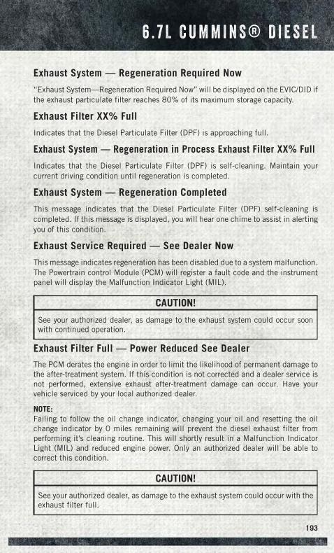
Exhaust System — Regeneration Required Now
“Exhaust System—Regeneration Required Now” will be displayed on the EVIC/DID ifthe exhaust particulate filter reaches 80% of its maximum storage capacity.
Exhaust Filter XX% Full
Indicates that the Diesel Particulate Filter (DPF) is approaching full.
Exhaust System — Regeneration in Process Exhaust Filter XX% Full
Indicates that the Diesel Particulate Filter (DPF) is self-cleaning. Maintain yourcurrent driving condition until regeneration is completed.
Exhaust System — Regeneration Completed
This message indicates that the Diesel Particulate Filter (DPF) self-cleaning iscompleted. If this message is displayed, you will hear one chime to assist in alertingyou of this condition.
Exhaust Service Required — See Dealer Now
This message indicates regeneration has been disabled due to a system malfunction.The Powertrain control Module (PCM) will register a fault code and the instrumentpanel will display the Malfunction Indicator Light (MIL).
CAUTION!
See your authorized dealer, as damage to the exhaust system could occur soonwith continued operation.
Exhaust Filter Full — Power Reduced See Dealer
The PCM derates the engine in order to limit the likelihood of permanent damage tothe after-treatment system. If this condition is not corrected and a dealer service isnot performed, extensive exhaust after-treatment damage can occur. Have yourvehicle serviced by your local authorized dealer.
NOTE:Failing to follow the oil change indicator, changing your oil and resetting the oilchange indicator by 0 miles remaining will prevent the diesel exhaust filter fromperforming it's cleaning routine. This will shortly result in a Malfunction IndicatorLight (MIL) and reduced engine power. Only an authorized dealer will be able tocorrect this condition.
CAUTION!
See your authorized dealer, as damage to the exhaust system could occur with theexhaust filter full.
6 . 7 L C U M M I N S ® D I E S E L
193
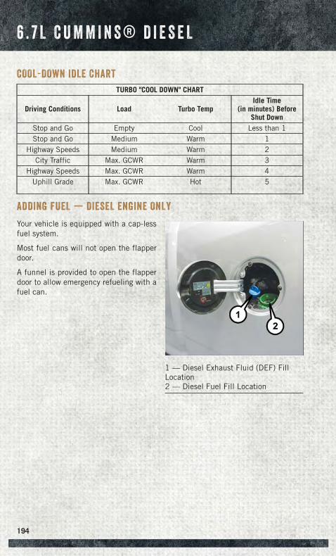
COOL-DOWN IDLE CHART
TURBO "COOL DOWN" CHART
Driving Conditions Load Turbo TempIdle Time
(in minutes) BeforeShut Down
Stop and Go Empty Cool Less than 1Stop and Go Medium Warm 1
Highway Speeds Medium Warm 2City Traffic Max. GCWR Warm 3
Highway Speeds Max. GCWR Warm 4Uphill Grade Max. GCWR Hot 5
ADDING FUEL — DIESEL ENGINE ONLY
Your vehicle is equipped with a cap-lessfuel system.
Most fuel cans will not open the flapperdoor.
A funnel is provided to open the flapperdoor to allow emergency refueling with afuel can.
1 — Diesel Exhaust Fluid (DEF) FillLocation2 — Diesel Fuel Fill Location
6 . 7 L C U M M I N S ® D I E S E L
194
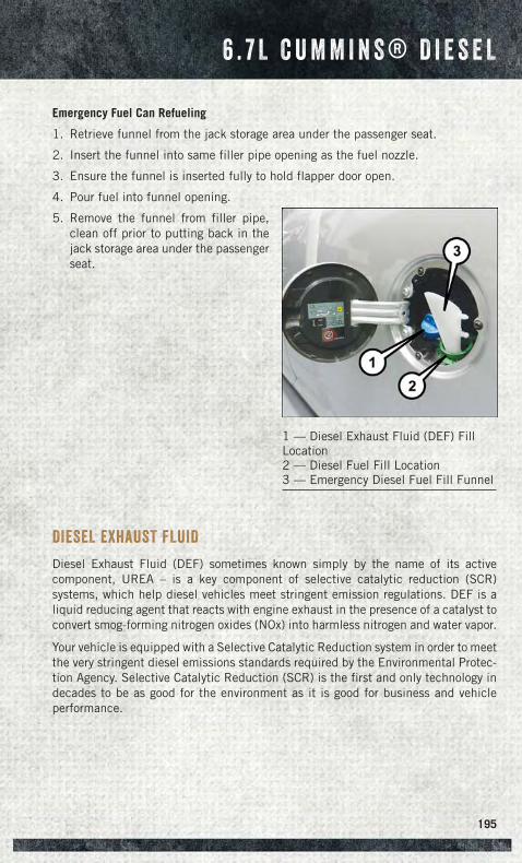
Emergency Fuel Can Refueling
1. Retrieve funnel from the jack storage area under the passenger seat.
2. Insert the funnel into same filler pipe opening as the fuel nozzle.
3. Ensure the funnel is inserted fully to hold flapper door open.
4. Pour fuel into funnel opening.
5. Remove the funnel from filler pipe,clean off prior to putting back in thejack storage area under the passengerseat.
DIESEL EXHAUST FLUID
Diesel Exhaust Fluid (DEF) sometimes known simply by the name of its activecomponent, UREA – is a key component of selective catalytic reduction (SCR)systems, which help diesel vehicles meet stringent emission regulations. DEF is aliquid reducing agent that reacts with engine exhaust in the presence of a catalyst toconvert smog-forming nitrogen oxides (NOx) into harmless nitrogen and water vapor.
Your vehicle is equipped with a Selective Catalytic Reduction system in order to meetthe very stringent diesel emissions standards required by the Environmental Protec-tion Agency. Selective Catalytic Reduction (SCR) is the first and only technology indecades to be as good for the environment as it is good for business and vehicleperformance.
1 — Diesel Exhaust Fluid (DEF) FillLocation2 — Diesel Fuel Fill Location3 — Emergency Diesel Fuel Fill Funnel
6 . 7 L C U M M I N S ® D I E S E L
195
The purpose of the SCR system is to reduce levels of NOx (oxides of nitrogen emittedfrom engines) that are harmful to our health and the environment to an almostnear-zero level. Small quantities of Diesel Exhaust Fluid (DEF) are injected into theexhaust upstream of a catalyst where, when vaporized, convert smog-formingnitrogen oxides (NOx) into harmless nitrogen (N2) and water vapor (H2O), twonatural components of the air we breathe. You can operate with the comfort that yourvehicle is contributing to a cleaner, healthier world environment for this andgenerations to come.
System Overview
This vehicle is equipped with a Diesel Exhaust Fluid (DEF) injection system and aSelective Catalytic Reduction (SCR) catalyst to meet the emission requirements.
The DEF injection system consists of the following components:
• DEF tank
• DEF pump
• DEF injector
• Electronically-heated DEF lines
• DEF control module
• NOx sensors
• NH3 sensor
• Temperature sensors
• SCR catalyst
The DEF injection system and SCR catalyst enable the achievement of dieselemissions requirements; while maintaining outstanding fuel economy, drivability,torque and power ratings.
NOTE:
• Your vehicle is equipped with a DEF injection system. You may occasionally hearan audible clicking noise. This is normal operation.
• The DEF pump will run for a period of time after engine shutdown to purge the DEFsystem. This is normal operation.
6 . 7 L C U M M I N S ® D I E S E L
196
Diesel Exhaust Fluid Storage
Diesel Exhaust Fluid (DEF) is considered a very stable product with a long shelf life.If DEF is kept in temperatures between 10° to 90°F (-12° to 32°C), it will last aminimum of one year.
DEF is subject to freezing at the lowest temperatures. For example, DEF may freezeat temperatures at or below 12° F (-11° C). The system has been designed to operatein this environment.
NOTE:When working with DEF, it is important to know that:
Any containers or parts that come into contact with DEF must be DEF compatible(plastic or stainless steel). Copper, brass, aluminum, iron or non-stainless steelshould be avoided as they are subject to corrosion by DEF.
If DEF is spilled, it should be wiped up completely.
Adding Diesel Exhaust Fluid
The DEF gauge (located in the instrument cluster) will display the level of DEFremaining in the tank.
Completely fill the DEF tank through the diesel exhaust fluid fill location at everymaintenance interval or before if prompted by the Electronic Vehicle InformationCenter (EVIC)/Driver Information Display (DID).
NOTE:
• Driving conditions (altitude, vehicle speed, load, etc.) will effect the amount ofDEF that is used in your vehicle.
• Since DEF will begin to freeze at 12°F (-11°C), your vehicle is equipped with anautomatic DEF heating system. This allows the DEF injection system to operateproperly at temperatures below 12°F (-11°C). If your vehicle is not in operation foran extended period of time with temperatures below 12°F (-11°C), the DEF in thetank may freeze. If the tank is overfilled and freezes, it could be damaged.Therefore, do not overfill the DEF tank. Extra care should be taken when fillingwith portable containers to avoid overfilling. Note the level of the DEF gauge inyour instrument cluster. On pickup applications, you may safely add a maximum of2 gallons of DEF from portable containers when your DEF gauge is reading ½ full.On Chassis Cab applications a maximum of 2 gallons may be added when the DEFgauge is reading ¾ full.
6 . 7 L C U M M I N S ® D I E S E L
197
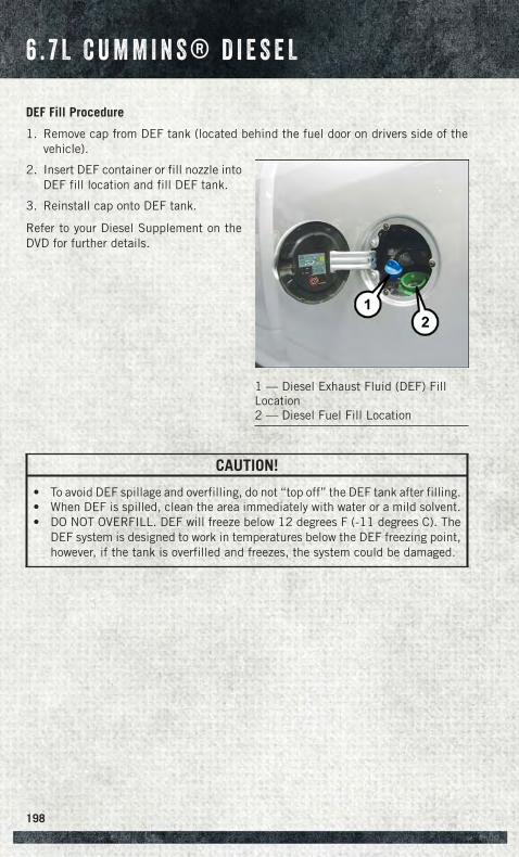
DEF Fill Procedure
1. Remove cap from DEF tank (located behind the fuel door on drivers side of thevehicle).
2. Insert DEF container or fill nozzle intoDEF fill location and fill DEF tank.
3. Reinstall cap onto DEF tank.
Refer to your Diesel Supplement on theDVD for further details.
CAUTION!
• To avoid DEF spillage and overfilling, do not “top off” the DEF tank after filling.• When DEF is spilled, clean the area immediately with water or a mild solvent.• DO NOT OVERFILL. DEF will freeze below 12 degrees F (-11 degrees C). The
DEF system is designed to work in temperatures below the DEF freezing point,however, if the tank is overfilled and freezes, the system could be damaged.
1 — Diesel Exhaust Fluid (DEF) FillLocation2 — Diesel Fuel Fill Location
6 . 7 L C U M M I N S ® D I E S E L
198
Diesel Exhaust Fluid (DEF) Warning Messages
Your vehicle will begin displaying warning messages when the DEF level reaches adriving range of approximately 350 miles (563 km). If the following warning messagesequence is ignored, your vehicle may be limited to a maximum speed of 5 MPH(8 km/H) unless DEF is added.
DEF Low Refill Soon — This message will display when the low level is reached, duringvehicle start up, and with increased frequency during vehicle operation. It will beaccompanied by a single chime. Approximately 5 gallons (19 Liters) of DEF isrequired to refill the tank when this message is initially displayed on pickupapplications, and approximately 7 gallons (28 Liters) are required on chassis-cabapplications.
Speed Limited to 5 MPH in XXX mi Refill DEF — This message will continuously displayif the “DEF Low Refill Soon” message is ignored, and the frequency of occurance ofthe chime will increase unless up to 2 gallons (7.5 Liters) of DEF is added to the tank.
5 MPH Max Speed on Restart, Long Idle or Refuel Refill DEF — This message willcontinuously display when the counter reaches zero, and will be accompanied by aperiodic chime.The vehicle will only be capable of a maximum speed of 5 MPH upon the first of thefollowing conditions to occur:
• If the vehicle is shutoff and restarted.• If the vehicle is idled for an extended period of time, approximately one hour or
greater.• If the system detects that the level of fuel in the tank has increased.
Add a minimum of 2 gallons (7.5 Liters) of DEF to the tank in order to avoid vehicleoperation at a maximum speed of 5 MPH (8 km/H).
5 MPH Max Speed Refill DEF — The vehicle will only be capable of a maximum speedof 5 MPH (8 km/H) when this message is displayed. Add up to 2.5 gallons (7.5 Liters)of DEF to the tank to restore normal vehicle operation.
NOTE:A minimum of 2 gallons (7.5 Liters) may be required to restore normal vehicleoperation. Although the vehicle will start normally and can be placed in gear after thismessage has been initially displayed, extreme caution should be utilized since thevehicle will only be capable of maneuvering at a maximum speed of 5 MPH (8 km/H).
6 . 7 L C U M M I N S ® D I E S E L
199
Diesel Exhaust Fluid (DEF) Fault Warning Messages
There are four different messages which are displayed if the vehicle detects that theDEF system has been filled with a fluid other than DEF, has experienced componentfailures, or when tampering has been detected. The vehicle may be limited to amaximum speed of 5 MPH (8 km/H) if the DEF system is not serviced within less than250 miles (402 km) of the fault being detected.
When the DEF system needs to be serviced the following warnings will display:
Service DEF System – See Dealer — This message will display when the fault is initiallydetected, each time the vehicle is started, and periodically during driving. Themessage will be accompanied by a single chime. We recommend you drive to yournearest authorized dealer and have your vehicle serviced as soon as possible.
5 MPH Max Speed in 150 mi Service DEF System See Dealer — This message willdisplay if the DEF system has not been serviced after the “Service DEF System – SeeDealer” message is displayed. This message will continuously display until themileage counter reaches zero, and will be accompanied by a periodic chime. Themessage will continue to countdown until it reaches zero unless the vehicle isserviced. We recommend you drive to your nearest authorized dealer and have yourvehicle serviced immediately.
NOTE:Under some circumstances this mileage counter may start with a value of less than150 miles (241 km). For example, if recurring faults are detected in a time intervalof less than 40 hours, the counter may restart at the value where it stopped when aprevious fault was temporarily remedied, or at a minimum of 50 miles (80 km).
5 MPH Max Speed on Restart, Long Idle or Refuel Service DEF See Dealer — Thismessage will continuously display when the mileage counter reaches zero, and willbe accompanied by a periodic chime.The vehicle will only be capable of a maximum speed of 5 MPH upon the first of thefollowing conditions to occur:
• If the vehicle is shutoff and restarted.• If the vehicle is idled for an extended period of time, approximately one hour or
greater.• If the system detects that the level of fuel in the tank has increased.
5 MPH Max Speed Service DEF System See Dealer — This message will continuouslydisplay, and will be accompanied by a periodic chime. Although the vehicle can bestarted and placed in gear, the vehicle will only operate at a maximum speed of5 MPH. Your vehicle will require towing, see your authorized dealer for service.
NOTE:When this message is displayed, the engine can still be started. However, the vehiclewill only operate at a maximum speed of 5 MPH.
6 . 7 L C U M M I N S ® D I E S E L
200
ROADSIDE ASSISTANCE
Dial toll-free 1-800-521-2779 for U.S. Residents or 1-800-363-4869 for CanadianResidents.
• Provide your name, vehicle identification number, license plate number, and yourlocation, including the telephone number from which you are calling.
• Briefly describe the nature of the problem and answer a few simple questions.
• You will be given the name of the service provider and an estimated time of arrival.If you feel you are in an “unsafe situation”, please let us know. With your consent,we will contact local police or safety authorities.
INSTRUMENT CLUSTER WARNING LIGHTS
- Electronic Stability Control (ESC) Activation/MalfunctionIndicator Light
If this indicator light flashes during acceleration, apply as little throttle as possible.While driving, ease up on the accelerator. Adapt your speed and driving to theprevailing road conditions. To improve the vehicle's traction when starting off in deepsnow, sand or gravel, it may be desirable to switch the ESC system off.
- Tire Pressure Monitoring System (TPMS) Light
Each tire, including the spare (if provided), should be checked monthly, when coldand inflated to the inflation pressure recommended by the vehicle manufacturer onthe vehicle placard or tire inflation pressure label. (If your vehicle has tires of adifferent size than the size indicated on the vehicle placard or tire inflation pressurelabel, you should determine the proper tire inflation pressure for those tires.)
IF THE LIGHT STARTS FLASHING INDICATING A LOW TIRE PRESSURE, ADJUST THE AIRPRESSURE IN THE LOW TIRE TO THE AIR PRESSURE SHOWN ON THE VEHICLE PLACARD ORTIRE INFLATION PRESSURE LABEL LOCATED ON THE DRIVER'S DOOR.
NOTE:After inflation, the vehicle may need to be driven for 20 minutes before the flashing lightwill turn off.
Your vehicle has also been equipped with a TPMS malfunction indicator to indicatewhen the system is not operating properly. The TPMS malfunction indicator iscombined with the low tire pressure telltale. When the system detects a malfunction,the telltale will flash for approximately one minute and then remain continuouslyilluminated. This sequence will continue each time the vehicle is restarted as long asthe malfunction exists.
W H A T T O D O I N E M E R G E N C I E S
201
When the malfunction indicator is illuminated, the system may not be able to detector signal low tire pressure as intended. TPMS malfunctions may occur for a variety ofreasons, including the installation of replacement or alternate tires or wheels on thevehicle that prevent the TPMS from functioning properly. Always check the TPMSmalfunction telltale after replacing one or more tires or wheels on your vehicle, toensure that the replacement or alternate tires and wheels allow the TPMS to continueto function properly.
NOTE:Tire pressures change by approximately 1 psi (7 kPa) per 12° F (7° C) of airtemperature change. Keep this in mind when checking tire pressure inside a garage,especially in the Winter. Example: If garage temperature is 68°F (20°C) and theoutside temperature is 32°F (0°C), then the cold tire inflation pressure should beincreased by 3 psi (21 kPa), which equals 1 psi (7 kPa) for every 12°F (7°C) for thisoutside temperature condition.
CAUTION!
The TPMS has been optimized for the original equipment tires and wheels. TPMSpressures and warning have been established for the tire size equipped on yourvehicle. Undesirable system operation or sensor damage may result when usingreplacement equipment that is not of the same size, type, and/or style. Aftermar-ket wheels can cause sensor damage. Do not use tire sealant from a can, orbalance beads if your vehicle is equipped with a TPMS, as damage to the sensorsmay result.
- Engine Temperature Warning Light
This light warns of an overheated engine condition.
If the light turns on and a warning chime sounds while driving, safely pull over andstop the vehicle. If the A/C system is on, turn it off. Also, shift the transmission intoNEUTRAL and idle the vehicle. If the temperature reading does not return to normal,turn the engine off immediately.
We recommend that you do not operate the vehicle or engine damage will occur. Havethe vehicle serviced immediately.
WARNING!
A hot engine cooling system is dangerous. You or others could be badly burned bysteam or boiling coolant.
W H A T T O D O I N E M E R G E N C I E S
202
- Brake Warning Light
This light monitors various brake functions, including brake fluid level and parkingbrake application. If the brake light turns on it may indicate that the parking brake isapplied, that the brake fluid level is low, or that there is a problem with the anti-lockbrake system reservoir.
If the light remains on when the parking brake has been disengaged, and the fluidlevel is at the full mark on the master cylinder reservoir, it indicates a possible brakehydraulic system malfunction or that a problem with the Brake Booster has beendetected by the Anti-Lock Brake System (ABS)/Electronic Stability Control (ESC)system. In this case, the light will remain on until the condition has been corrected.If the problem is related to the brake booster, the ABS pump will run when applyingthe brake and a brake pedal pulsation may be felt during each stop.
The dual brake system provides a reserve braking capacity in the event of a failure toa portion of the hydraulic system. A leak in either half of the dual brake system isindicated by the Brake Warning Light, which will turn on when the brake fluid levelin the master cylinder has dropped below a specified level. The light will remain onuntil the cause is corrected.
Vehicles equipped with the Anti-Lock Brake System (ABS), are also equipped withElectronic Brake Force Distribution (EBD). In the event of an EBD failure, the BrakeWarning Light will turn on along with the ABS Light. Immediate repair to the ABSsystem is required.
Operation of the Brake Warning Light can be checked by turning the ignition switchfrom the OFF position to the ON/RUN position. The light should illuminate forapproximately two seconds. The light should then turn off unless the parking brakeis applied or a brake fault is detected. If the light does not illuminate, have the lightinspected by an authorized dealer.
The light also will turn on when the parking brake is applied with the ignition switchin the ON/RUN position.
NOTE:This light shows only that the parking brake is applied. It does not show the degreeof brake application.
WARNING!
Driving a vehicle with the red brake light on is dangerous. Part of the brake systemmay have failed. It will take longer to stop the vehicle. You could have a collision.Have the vehicle checked immediately.
W H A T T O D O I N E M E R G E N C I E S
203
- Malfunction Indicator Light (MIL)
The Malfunction Indicator Light (MIL) is part of an onboard diagnostic system calledOBD II that monitors engine and automatic transmission control systems. The lightwill illuminate when the key is in the ON/RUN position before engine start. If the bulbdoes not come on when turning the key from OFF to ON/RUN, have the conditionchecked promptly.
Certain conditions, poor fuel quality, etc., may illuminate the light after engine start.The vehicle should be serviced if the light stays on through several of your typicaldriving cycles. In most situations, the vehicle will drive normally and will not requiretowing.
CAUTION!
Prolonged driving with the Malfunction Indicator Light (MIL) on could causedamage to the engine control system. It also could affect fuel economy anddriveability. If the MIL is flashing, severe catalytic converter damage and powerloss will soon occur. Immediate service is required.
WARNING!
A malfunctioning catalytic converter, as referenced above, can reach highertemperatures than in normal operating conditions. This can cause a fire if youdrive slowly or park over flammable substances such as dry plants, wood,cardboard, etc. This could result in death or serious injury to the driver, occupantsor others.
- Electronic Stability Control (ESC) OFF Indicator Light
The ESC OFF indicator will illuminate when the Electronic Stability Control (ESC) isturned off.
- Charging System Light
This light shows the status of the electrical charging system. If the charging systemlight remains on, it means that the vehicle is experiencing a problem with thecharging system.
We recommend you do not continue driving if the charging system light is on. Havethe vehicle serviced immediately.
- Oil Pressure Warning Light
This light indicates low engine oil pressure. If the light turns on while driving, stopthe vehicle and shut off the engine as soon as possible. A chime will sound for fourminutes when this light turns on.
We recommend you do not operate the vehicle or engine damage will occur. Have thevehicle serviced immediately.
W H A T T O D O I N E M E R G E N C I E S
204
- Anti-Lock Brake (ABS) Light
This light monitors the Anti-Lock Brake System (ABS). The light will turn on when theignition switch is turned to the ON/RUN position and may stay on for as long as fourseconds.
If the ABS light remains on or turns on while driving, it indicates that the Anti-Lockportion of the brake system is not functioning and that service is required. However,the conventional brake system will continue to operate normally if the BRAKEwarning light is not on.
If the ABS light is on, the brake system should be serviced as soon as possible torestore the benefits of Anti-Lock brakes. If the ABS light does not turn on when theignition switch is turned to the ON/RUN position, have the light inspected by anauthorized dealer.
- Electronic Throttle Control (ETC) Light
This light informs you of a problem with the Electronic Throttle Control (ETC) system.
If a problem is detected, the light will come on while the engine is running. Cycle theignition when the vehicle has completely stopped and the shift lever is placed in thePARK position; the light should turn off.
If the light remains lit with the engine running, your vehicle will usually be drivable;however, see an authorized service center immediately. If the light is flashing whenthe engine is running, immediate service is required and you may experience reducedperformance, an elevated/rough idle or engine stall and your vehicle may requiretowing.
- Air Bag Warning Light
This light will turn on for four to eight seconds as a bulb check when the ignitionswitch is first turned to the ON/RUN position. If the light is either not on duringstarting, stays on, or turns on while driving, have the system inspected at anauthorized dealer as soon as possible. Refer to “Occupant Restraints” in “Things ToKnow Before Starting Your Vehicle” of your Owner’s Manual for further information.
NOTE:The Air Bag System is designed to be maintenance free.
- SERV (Service) 4WD Indicator Light
The SERV 4WD light monitors the electric shift four-wheel drive system. If the SERV4WD light stays on or comes on during driving, it means that the four-wheel drivesystem is not functioning properly and that service is required.
For vehicles equipped with a premium cluster this indicator will display in the DriverInformation Display (DID).
W H A T T O D O I N E M E R G E N C I E S
205
- Transmission Temperature Warning Light
This light indicates that there is excessive transmission fluid temperature that mightoccur with severe usage such as trailer towing. If this light turns on, stop the vehicleand run the engine at idle, with the transmission in NEUTRAL, until the light turnsoff. Once the light turns off, you may continue to drive normally.
CAUTION!
Continuous driving with the Transmission Temperature Warning Light illuminatedwill eventually cause severe transmission damage or transmission failure.
WARNING!
If you continue operating the vehicle when the Transmission Temperature WarningLight is illuminated you could cause the fluid to boil over, come in contact with hotengine or exhaust components and cause a fire.
Oil Change Indicator
MessageIf an “oil change” message (shown as “Change Oil Soon” and “Oil Change Needed”)appears and a single chime sounds, it is time for your next required oil change.
Resetting The Light After Servicing
1. Turn the ignition switch to the ON/RUN position (do not start engine).
2. Fully depress the accelerator pedal three times within 10 seconds.
3. Turn the ignition switch to the OFF/LOCK position.
- Low Coolant Level Indicator Light
This light indicates low coolant level. If the light turns on while driving, stop thevehicle and shut off the engine as soon as possible.
We recommend you do not operate the vehicle or engine damage will occur. Have thevehicle serviced immediately.
W H A T T O D O I N E M E R G E N C I E S
206
INSTRUMENT CLUSTER INDICATOR LIGHTS
- Turn Signal Indicator
The arrows will flash with the exterior turn signals when the turn signal lever isoperated. A tone will chime, and a EVIC/DID message will appear if either turn signalis left on for more than 1 mile (1.6 km).
NOTE:If either indicator flashes at a rapid rate, check for a defective outside light bulb.
- High Beam Indicator
Indicates that headlights are on high beam.
- Park/Headlight ON Indicator
This indicator will illuminate when the park lights or headlights are turned on.
- Front Fog Light Indicator
This indicator will illuminate when the front fog lights are on.
- Vehicle Security Light
This light will flash rapidly for approximately 15 seconds when the vehicle securityalarm is arming. The light will flash at a slower speed continuously after the alarm isset. The security light will also come on for about three seconds when the ignition isfirst turned on.
— Tow/Haul Mode
Indicates that the Tow/Haul Mode is active.
— Four Wheel Drive Auto
Indicates that the Four Wheel Drive has engaged automatically.
— Electronic Stability Control OFF
This light indicates the ESC system has been turned off by the driver.
— Cargo Light
Indicates that the rear cargo light is on.
— Door Ajar
Indicates that one of the vehicles doors is open.
W H A T T O D O I N E M E R G E N C I E S
207
— Electronic Speed Control Set
Indicates that the Electronic Speed Control has been set.
- Fuel Cap/Loose Gas Cap Message
If a “gas cap” message appears, tighten the gas cap until a “clicking” sound is heard.
Press the odometer reset button to turn the message off.
If the message continues to appear for more than three days after tightening the gascap, see your authorized service center.
IF YOUR ENGINE OVERHEATS
In any of the following situations, you can reduce the potential for overheating bytaking the appropriate action:
• On the highways — slow down.
• In city traffic — while stopped, shift the transmission to NEUTRAL, but do notincrease engine idle speed.
NOTE:There are steps that you can take to slow down an impending overheat condition:
• If your air conditioner (A/C) is on, turn it off. The A/C system adds heat to theengine cooling system and turning the A/C off can help remove this heat.
• You can also turn the temperature control to maximum heat, the mode control tofloor and the blower control to high. This allows the heater core to act as asupplement to the radiator and aids in removing heat from the engine coolingsystem.
CAUTION!
Driving with a hot cooling system could damage your vehicle. If the temperaturegauge reads HOT (H), pull over and stop the vehicle. Idle the vehicle with the airconditioner turned off until the pointer drops back into the normal range. If thepointer remains on HOT (H), and you hear continuous chimes, turn the engine offimmediately, and call for service.
WARNING!
You or others can be badly burned by hot engine coolant (antifreeze) or steam fromyour radiator. If you see or hear steam coming from under the hood, do not openthe hood until the radiator has had time to cool. Never try to open a cooling systempressure cap when the radiator or coolant bottle is hot.
W H A T T O D O I N E M E R G E N C I E S
208
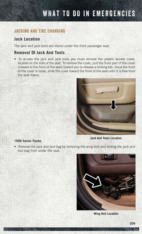
JACKING AND TIRE CHANGING
Jack Location
The jack and jack tools are stored under the front passenger seat.
Removal Of Jack And Tools• To access the jack and jack tools you must remove the plastic access cover,
located on the side of the seat. To remove the cover, pull the front part of the cover(closest to the front of the seat) toward you to release a locking tab. Once the frontof the cover is loose, slide the cover toward the front of the seat until it is free fromthe seat frame.
1500 Series Trucks
• Remove the jack and tool bag by removing the wing bolt and sliding the jack andtool bag from under the seat.
Jack And Tools Location
Wing Bolt Location
W H A T T O D O I N E M E R G E N C I E S
209
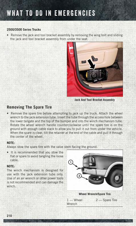
2500/3500 Series Trucks
• Remove the jack and tool bracket assembly by removing the wing bolt and slidingthe jack and tool bracket assembly from under the seat.
Removing The Spare Tire• Remove the spare tire before attempting to jack up the truck. Attach the wheel
wrench to the jack extension tube. Insert the tube through the access hole betweenthe lower tailgate and the top of the bumper and into the winch mechanism tube.Rotate the wheel wrench handle counterclockwise until the spare tire is on theground with enough cable slack to allow you to pull it out from under the vehicle.When the spare is clear, tilt the retainer at the end of the cable and pull it throughthe center of the wheel.
NOTE:Always stow the spare tire with the valve stem facing the ground.
• It is recommended that you stow theflat or spare to avoid tangling the loosecable.
NOTE:The winch mechanism is designed foruse with the jack extension tube only.Use of an air wrench or other power toolsis not recommended and can damage thewinch.
Jack And Tool Bracket Assembly
Wheel Wrench/Spare Tire
1 — WheelWrench
2 — Spare Tire
W H A T T O D O I N E M E R G E N C I E S
210
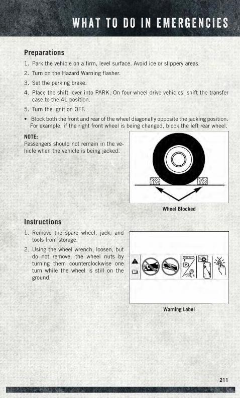
Preparations1. Park the vehicle on a firm, level surface. Avoid ice or slippery areas.
2. Turn on the Hazard Warning flasher.
3. Set the parking brake.
4. Place the shift lever into PARK. On four-wheel drive vehicles, shift the transfercase to the 4L position.
5. Turn the ignition OFF.
• Block both the front and rear of the wheel diagonally opposite the jacking position.For example, if the right front wheel is being changed, block the left rear wheel.
NOTE:Passengers should not remain in the ve-hicle when the vehicle is being jacked.
Instructions1. Remove the spare wheel, jack, and
tools from storage.
2. Using the wheel wrench, loosen, butdo not remove, the wheel nuts byturning them counterclockwise oneturn while the wheel is still on theground.
Wheel Blocked
Warning Label
W H A T T O D O I N E M E R G E N C I E S
211

3. Placement of the jack:
1500 Series Trucks• When changing a front wheel, place the scissors jack under the rear portion of the
lower control arm as shown below.
Front 4x2 Jacking Location
Front 4x4 Jacking Location
W H A T T O D O I N E M E R G E N C I E S
212
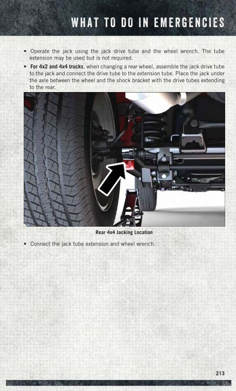
• Operate the jack using the jack drive tube and the wheel wrench. The tubeextension may be used but is not required.
• For 4x2 and 4x4 trucks, when changing a rear wheel, assemble the jack drive tubeto the jack and connect the drive tube to the extension tube. Place the jack underthe axle between the wheel and the shock bracket with the drive tubes extendingto the rear.
• Connect the jack tube extension and wheel wrench.
Rear 4x4 Jacking Location
W H A T T O D O I N E M E R G E N C I E S
213
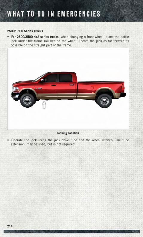
2500/3500 Series Trucks
• For 2500/3500 4x2 series trucks, when changing a front wheel, place the bottlejack under the frame rail behind the wheel. Locate the jack as far forward aspossible on the straight part of the frame.
• Operate the jack using the jack drive tube and the wheel wrench. The tubeextension, may be used, but is not required.
Jacking Location
W H A T T O D O I N E M E R G E N C I E S
214
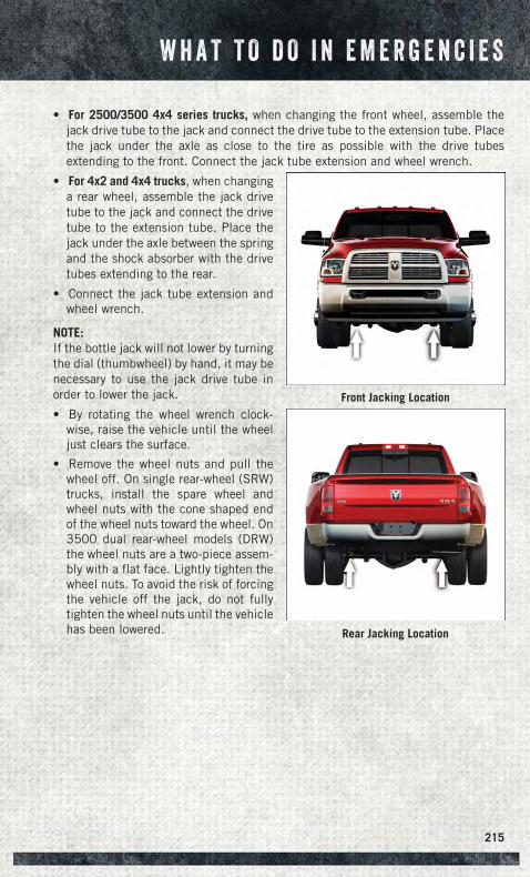
• For 2500/3500 4x4 series trucks, when changing the front wheel, assemble thejack drive tube to the jack and connect the drive tube to the extension tube. Placethe jack under the axle as close to the tire as possible with the drive tubesextending to the front. Connect the jack tube extension and wheel wrench.
• For 4x2 and 4x4 trucks, when changinga rear wheel, assemble the jack drivetube to the jack and connect the drivetube to the extension tube. Place thejack under the axle between the springand the shock absorber with the drivetubes extending to the rear.
• Connect the jack tube extension andwheel wrench.
NOTE:If the bottle jack will not lower by turningthe dial (thumbwheel) by hand, it may benecessary to use the jack drive tube inorder to lower the jack.
• By rotating the wheel wrench clock-wise, raise the vehicle until the wheeljust clears the surface.
• Remove the wheel nuts and pull thewheel off. On single rear-wheel (SRW)trucks, install the spare wheel andwheel nuts with the cone shaped endof the wheel nuts toward the wheel. On3500 dual rear-wheel models (DRW)the wheel nuts are a two-piece assem-bly with a flat face. Lightly tighten thewheel nuts. To avoid the risk of forcingthe vehicle off the jack, do not fullytighten the wheel nuts until the vehiclehas been lowered.
Front Jacking Location
Rear Jacking Location
W H A T T O D O I N E M E R G E N C I E S
215
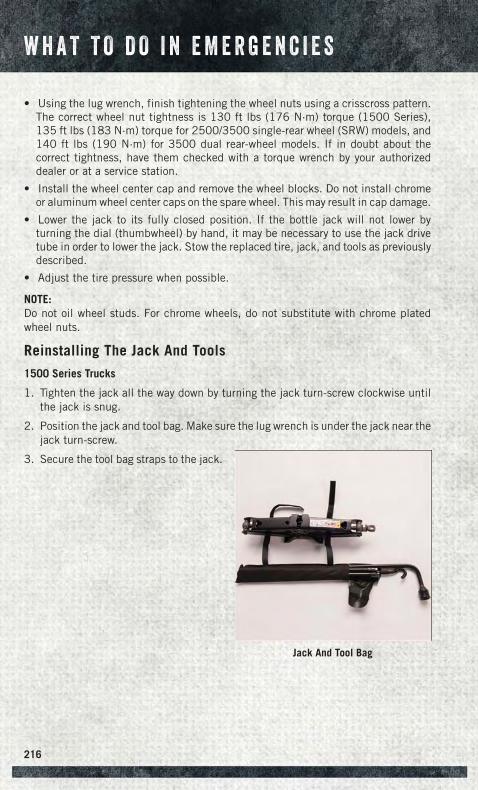
• Using the lug wrench, finish tightening the wheel nuts using a crisscross pattern.The correct wheel nut tightness is 130 ft lbs (176 N·m) torque (1500 Series),135 ft lbs (183 N·m) torque for 2500/3500 single-rear wheel (SRW) models, and140 ft lbs (190 N·m) for 3500 dual rear-wheel models. If in doubt about thecorrect tightness, have them checked with a torque wrench by your authorizeddealer or at a service station.
• Install the wheel center cap and remove the wheel blocks. Do not install chromeor aluminum wheel center caps on the spare wheel. This may result in cap damage.
• Lower the jack to its fully closed position. If the bottle jack will not lower byturning the dial (thumbwheel) by hand, it may be necessary to use the jack drivetube in order to lower the jack. Stow the replaced tire, jack, and tools as previouslydescribed.
• Adjust the tire pressure when possible.
NOTE:Do not oil wheel studs. For chrome wheels, do not substitute with chrome platedwheel nuts.
Reinstalling The Jack And Tools
1500 Series Trucks
1. Tighten the jack all the way down by turning the jack turn-screw clockwise untilthe jack is snug.
2. Position the jack and tool bag. Make sure the lug wrench is under the jack near thejack turn-screw.
3. Secure the tool bag straps to the jack.
Jack And Tool Bag
W H A T T O D O I N E M E R G E N C I E S
216
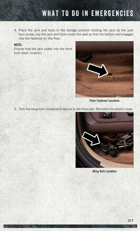
4. Place the jack and tools in the storage position holding the jack by the jackturn-screw, slip the jack and tools under the seat so that the bottom slot engagesinto the fastener on the floor.
NOTE:Ensure that the jack slides into the fronthold down location.
5. Turn the wing bolt clockwise to secure to the floor pan. Reinstall the plastic cover.
Floor Fastener Location
Wing Bolt Location
W H A T T O D O I N E M E R G E N C I E S
217
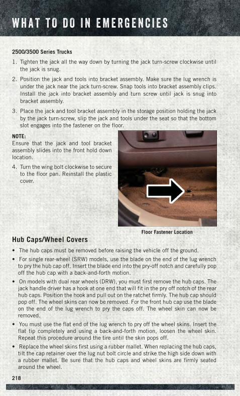
2500/3500 Series Trucks
1. Tighten the jack all the way down by turning the jack turn-screw clockwise untilthe jack is snug.
2. Position the jack and tools into bracket assembly. Make sure the lug wrench isunder the jack near the jack turn-screw. Snap tools into bracket assembly clips.Install the jack into bracket assembly and turn screw until jack is snug intobracket assembly.
3. Place the jack and tool bracket assembly in the storage position holding the jackby the jack turn-screw, slip the jack and tools under the seat so that the bottomslot engages into the fastener on the floor.
NOTE:Ensure that the jack and tool bracketassembly slides into the front hold downlocation.
4. Turn the wing bolt clockwise to secureto the floor pan. Reinstall the plasticcover.
Hub Caps/Wheel Covers• The hub caps must be removed before raising the vehicle off the ground.
• For single rear-wheel (SRW) models, use the blade on the end of the lug wrenchto pry the hub cap off. Insert the blade end into the pry-off notch and carefully popoff the hub cap with a back-and-forth motion.
• On models with dual rear wheels (DRW), you must first remove the hub caps. Thejack handle driver has a hook at one end that will fit in the pry off notch of the rearhub caps. Position the hook and pull out on the ratchet firmly. The hub cap shouldpop off. The wheel skins can now be removed. For the front hub cap use the bladeon the end of the lug wrench to pry the caps off. The wheel skin can now beremoved.
• You must use the flat end of the lug wrench to pry off the wheel skins. Insert theflat tip completely and using a back-and-forth motion, loosen the wheel skin.Repeat this procedure around the tire until the skin pops off.
• Replace the wheel skins first using a rubber mallet. When replacing the hub caps,tilt the cap retainer over the lug nut bolt circle and strike the high side down witha rubber mallet. Be sure that the hub caps and wheel skins are firmly seatedaround the wheel.
Floor Fastener Location
W H A T T O D O I N E M E R G E N C I E S
218
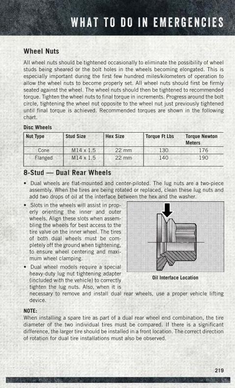
Wheel Nuts
All wheel nuts should be tightened occasionally to eliminate the possibility of wheelstuds being sheared or the bolt holes in the wheels becoming elongated. This isespecially important during the first few hundred miles/kilometers of operation toallow the wheel nuts to become properly set. All wheel nuts should first be firmlyseated against the wheel. The wheel nuts should then be tightened to recommendedtorque. Tighten the wheel nuts to final torque in increments. Progress around the boltcircle, tightening the wheel nut opposite to the wheel nut just previously tighteneduntil final torque is achieved. Recommended torques are shown in the followingchart.
Disc Wheels
Nut Type Stud Size Hex Size Torque Ft Lbs Torque NewtonMeters
Cone M14 x 1.5 22 mm 130 176Flanged M14 x 1.5 22 mm 140 190
8-Stud — Dual Rear Wheels• Dual wheels are flat-mounted and center-piloted. The lug nuts are a two-piece
assembly. When the tires are being rotated or replaced, clean these lug nuts andadd two drops of oil at the interface between the hex and the washer.
• Slots in the wheels will assist in prop-erly orienting the inner and outerwheels. Align these slots when assem-bling the wheels for best access to thetire valve on the inner wheel. The tiresof both dual wheels must be com-pletely off the ground when tightening,to ensure wheel centering and maxi-mum wheel clamping.
• Dual wheel models require a specialheavy-duty lug nut tightening adapter(included with the vehicle) to correctlytighten the lug nuts. Also, when it isnecessary to remove and install dual rear wheels, use a proper vehicle liftingdevice.
NOTE:When installing a spare tire as part of a dual rear wheel end combination, the tirediameter of the two individual tires must be compared. If there is a significantdifference, the larger tire should be installed in a front location. The correct directionof rotation for dual tire installations must also be observed.
Oil Interface Location
W H A T T O D O I N E M E R G E N C I E S
219
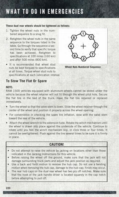
These dual rear wheels should be tightened as follows:
1. Tighten the wheel nuts in the num-bered sequence to a snug fit.
2. Retighten the wheel nuts in the samesequence to the torques listed in thetable. Go through the sequence a sec-ond time to verify that specific torquehas been achieved. Retighten tospecifications at 100 miles (160 km)and after 500 miles (800 km).
• It is recommended that wheel studnuts be kept torqued to specificationsat all times. Torque wheel stud nuts tospecifications at each lubrication interval.
To Stow The Flat Or Spare
NOTE:RAM 1500 vehicles equipped with aluminum wheels cannot be stored under thevehicle because the wheel retainer will not fit through the wheel pilot hole. Securethe flat tire in the bed of the truck. Have the flat tire repaired or replacedimmediately.
• Turn the wheel so that the valve stem is down. Slide the wheel retainer through thecenter of the wheel and position it properly across the wheel opening.
• For convenience in checking the spare tire inflation, stow with the valve stemtoward the rear of the vehicle.
• Attach the wheel wrench to the extension tube. Rotate the winch mechanism untilthe wheel is drawn into place against the underside of the vehicle. Continue torotate until you feel the winch mechanism slip, or click three or four times. Itcannot be overtightened. Push against the tire several times to be sure it is firmlyin place.
CAUTION!
• Do not attempt to raise the vehicle by jacking on locations other than thoseindicated in the Jacking Instructions for this vehicle.
• Before raising the wheel off the ground, make sure that the jack will notdamage surrounding truck parts and adjust the jack position as required.
• Use a back and forth motion to remove the hub cap. Do not use a twistingmotion when removing the hub cap, damage to the hub cap; finish may occur.
• The rear hub caps on the dual rear wheel has two pry off notches. Make surethat the hook of the jack handle driver is located squarely in the cap notchbefore attempting to pull off.
Wheel Nuts Numbered Sequence
W H A T T O D O I N E M E R G E N C I E S
220
WARNING!
• Do not attempt to change a tire on the side of the vehicle close to movingtraffic. Pull far enough off the road to avoid the danger of being hit whenoperating the jack or changing the wheel.
• Being under a jacked-up vehicle is dangerous. The vehicle could slip off thejack and fall on you. You could be crushed. Never put any part of your bodyunder a vehicle that is on a jack.
• Never start or run the engine while the vehicle is on a jack. If you need to get undera raised vehicle, take it to an authorized dealer where it can be raised on a lift.
• The jack is designed to be used as a tool for changing tires only. The jackshould not be used to lift the vehicle for service purposes. The vehicle shouldbe jacked on a firm level surface only. Avoid ice or slippery areas.
• Do not attempt to change a tire on the side of the vehicle close to movingtraffic, pull far enough off the road to avoid the danger of being hit whenoperating the jack or changing the wheel.
• Carefully follow these tire changing warnings to help prevent personal injury ordamage to your vehicle:• Always park on a firm, level surface as far from the edge of the roadway
as possible before raising the vehicle.• Turn on the Hazard Warning flashers.• Block the wheel diagonally opposite the wheel to be raised.• Set the parking brake firmly and set an automatic transmission in PARK;
a manual transmission in REVERSE.• Do not let anyone sit in the vehicle when it is on a jack.• Do not get under the vehicle when it is on a jack.• Only use the jack in the positions indicated and for lifting this vehicle
during a tire change.• If working on or near a roadway, be extremely careful of motor traffic.• To assure that spare tires, flat or inflated, are securely stowed, spares
must be stowed with the valve stem facing the ground.• Raising the vehicle higher than necessary can make the vehicle less
stable. It could slip off the jack and hurt someone near it. Raise the ve-hicle only enough to remove the tire.
• To avoid the risk of forcing the vehicle off the jack, do not fully tightenthe wheel bolts until the vehicle has been lowered. Failure to follow thiswarning may result in personal injury.
• To avoid possible personal injury, handle the wheel covers with care toavoid contact with any sharp edges.
• A loose tire or jack thrown forward in a collision or hard stop could en-danger the occupants of the vehicle. Always stow the jack parts and thespare tire in the places provided.
• A loose tire thrown forward in a collision or hard stop could injure theoccupants in the vehicle. Have the deflated (flat) tire repaired or re-placed immediately.
W H A T T O D O I N E M E R G E N C I E S
221
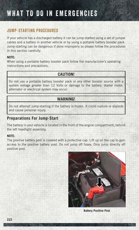
JUMP-STARTING PROCEDURES
If your vehicle has a discharged battery it can be jump-started using a set of jumpercables and a battery in another vehicle or by using a portable battery booster pack.Jump-starting can be dangerous if done improperly so please follow the proceduresin this section carefully.
NOTE:When using a portable battery booster pack follow the manufacturer’s operatinginstructions and precautions.
CAUTION!
Do not use a portable battery booster pack or any other booster source with asystem voltage greater than 12 Volts or damage to the battery, starter motor,alternator or electrical system may occur.
WARNING!
Do not attempt jump-starting if the battery is frozen. It could rupture or explodeand cause personal injury.
Preparations For Jump-Start
The battery in your vehicle is located in the front of the engine compartment, behindthe left headlight assembly.
NOTE:The positive battery post is covered with a protective cap. Lift up on the cap to gainaccess to the positive battery post. Do not jump off fuses. Only jump directly offpositive post.
Battery Positive Post
W H A T T O D O I N E M E R G E N C I E S
222
WARNING!
• Take care to avoid the radiator cooling fan whenever the hood is raised. It canstart anytime the ignition switch is ON. You can be injured by moving fanblades.
• Remove any metal jewelry such as rings, watch bands and bracelets that couldmake an inadvertent electrical contact. You could be seriously injured.
• Batteries contain sulfuric acid that can burn your skin or eyes and generatehydrogen gas which is flammable and explosive. Keep open flames or sparksaway from the battery.
1. Set the parking brake, shift the automatic transmission into PARK and turn theignition to LOCK.
2. Turn off the heater, radio, and all unnecessary electrical accessories.
3. If using another vehicle to jump-start the battery, park the vehicle within thejumper cables reach, set the parking brake and make sure the ignition is OFF.
WARNING!
Do not allow vehicles to touch each other as this could establish a groundconnection and personal injury could result.
Jump-Starting Procedure
WARNING!
Failure to follow this jump-starting procedure could result in personal injury orproperty damage due to battery explosion.
CAUTION!
Failure to follow these procedures could result in damage to the charging systemof the booster vehicle or the discharged vehicle.
Connecting The Jumper Cables
1. Connect the positive (+) end of the jumper cable to the positive (+) post of thedischarged vehicle.
NOTE:Do not jump off fuses. Only jump directly off positive post.
2. Connect the opposite end of the positive (+) jumper cable to the positive (+) postof the booster battery.
3. Connect the negative (-) end of the jumper cable to the negative (-) post of thebooster battery.
W H A T T O D O I N E M E R G E N C I E S
223
4. Connect the opposite end of the negative (-) jumper cable to a good engine ground(exposed metal part of the discharged vehicle’s engine) away from the battery andthe fuel injection system.
WARNING!
Do not connect the jumper cable to the negative (-) post of the discharged battery.The resulting electrical spark could cause the battery to explode and could resultin personal injury. Only use the specific ground point, do not use any other exposedmetal parts.
5. Start the engine in the vehicle that has the booster battery, let the engine idle afew minutes, and then start the engine in the vehicle with the discharged battery.
CAUTION!
Do not connect jumper cable to any of the fuses on the positive battery terminal.The resulting electrical current will blow the fuse.
6. Once the engine is started, remove the jumper cables in the reverse sequence:
Disconnecting The Jumper Cables
1. Disconnect the negative (-) end of the jumper cable from the engine ground of thevehicle with the discharged battery.
2. Disconnect the opposite end of the negative (-) jumper cable from the negative (-)post of the booster battery.
3. Disconnect the positive (+) end of the jumper cable from the positive (+) post ofthe booster battery.
4. Disconnect the opposite end of the positive (+) jumper cable from the positive (+)post of the vehicle with the discharged battery.
If frequent jump-starting is required to start your vehicle you should have the batteryand charging system inspected at your authorized dealer.
CAUTION!
Accessories plugged into the vehicle power outlets draw power from the vehicle’sbattery, even when not in use (i.e., cellular phones, etc.). Eventually, if plugged inlong enough without engine operation, the vehicle’s battery will discharge suffi-ciently to degrade battery life and/or prevent the engine from starting.
W H A T T O D O I N E M E R G E N C I E S
224
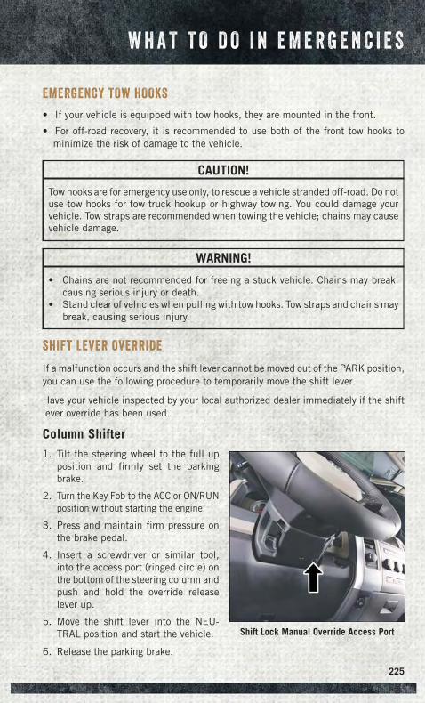
EMERGENCY TOW HOOKS
• If your vehicle is equipped with tow hooks, they are mounted in the front.
• For off-road recovery, it is recommended to use both of the front tow hooks tominimize the risk of damage to the vehicle.
CAUTION!
Tow hooks are for emergency use only, to rescue a vehicle stranded off-road. Do notuse tow hooks for tow truck hookup or highway towing. You could damage yourvehicle. Tow straps are recommended when towing the vehicle; chains may causevehicle damage.
WARNING!
• Chains are not recommended for freeing a stuck vehicle. Chains may break,causing serious injury or death.
• Stand clear of vehicles when pulling with tow hooks. Tow straps and chains maybreak, causing serious injury.
SHIFT LEVER OVERRIDE
If a malfunction occurs and the shift lever cannot be moved out of the PARK position,you can use the following procedure to temporarily move the shift lever.
Have your vehicle inspected by your local authorized dealer immediately if the shiftlever override has been used.
Column Shifter1. Tilt the steering wheel to the full up
position and firmly set the parkingbrake.
2. Turn the Key Fob to the ACC or ON/RUNposition without starting the engine.
3. Press and maintain firm pressure onthe brake pedal.
4. Insert a screwdriver or similar tool,into the access port (ringed circle) onthe bottom of the steering column andpush and hold the override releaselever up.
5. Move the shift lever into the NEU-TRAL position and start the vehicle.
6. Release the parking brake.
Shift Lock Manual Override Access Port
W H A T T O D O I N E M E R G E N C I E S
225
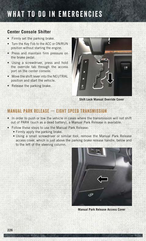
Center Console Shifter• Firmly set the parking brake.
• Turn the Key Fob to the ACC or ON/RUNposition without starting the engine.
• Press and maintain firm pressure onthe brake pedal.
• Using a screwdriver, press and holdthe override tab through the accessport on the center console.
• Move the shift lever into the NEUTRALposition and start the vehicle.
• Release the parking brake.
MANUAL PARK RELEASE — EIGHT SPEED TRANSMISSION
• In order to push or tow the vehicle in cases where the transmission will not shiftout of PARK (such as a dead battery), a Manual Park Release is available.
• Follow these steps to use the Manual Park Release:• Firmly apply the parking brake.• Using a small screwdriver or similar tool, remove the Manual Park Release
access cover, which is just above the parking brake release handle, below andto the left of the steering column.
Shift Lock Manual Override Cover
Manual Park Release Access Cover
W H A T T O D O I N E M E R G E N C I E S
226
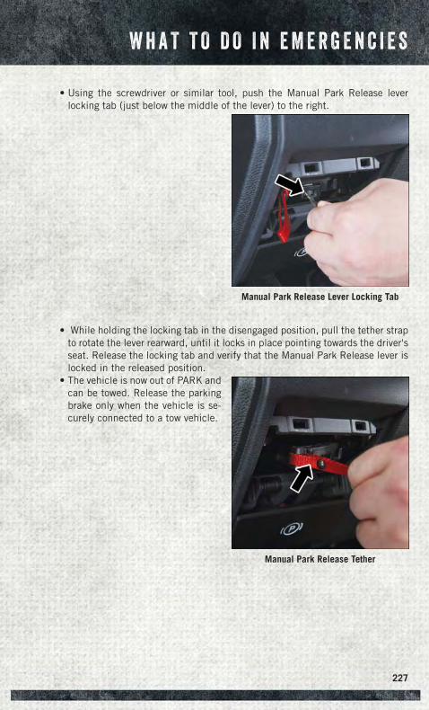
• Using the screwdriver or similar tool, push the Manual Park Release leverlocking tab (just below the middle of the lever) to the right.
• While holding the locking tab in the disengaged position, pull the tether strapto rotate the lever rearward, until it locks in place pointing towards the driver'sseat. Release the locking tab and verify that the Manual Park Release lever islocked in the released position.
• The vehicle is now out of PARK andcan be towed. Release the parkingbrake only when the vehicle is se-curely connected to a tow vehicle.
Manual Park Release Lever Locking Tab
Manual Park Release Tether
W H A T T O D O I N E M E R G E N C I E S
227
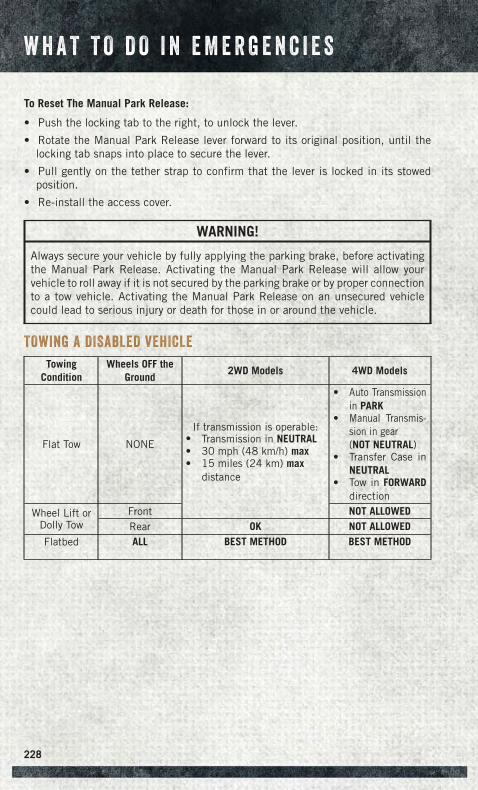
To Reset The Manual Park Release:
• Push the locking tab to the right, to unlock the lever.
• Rotate the Manual Park Release lever forward to its original position, until thelocking tab snaps into place to secure the lever.
• Pull gently on the tether strap to confirm that the lever is locked in its stowedposition.
• Re-install the access cover.
WARNING!
Always secure your vehicle by fully applying the parking brake, before activatingthe Manual Park Release. Activating the Manual Park Release will allow yourvehicle to roll away if it is not secured by the parking brake or by proper connectionto a tow vehicle. Activating the Manual Park Release on an unsecured vehiclecould lead to serious injury or death for those in or around the vehicle.
TOWING A DISABLED VEHICLE
TowingCondition
Wheels OFF theGround
2WD Models 4WD Models
Flat Tow NONE
If transmission is operable:• Transmission in NEUTRAL• 30 mph (48 km/h) max• 15 miles (24 km) max
distance
• Auto Transmissionin PARK
• Manual Transmis-sion in gear(NOT NEUTRAL)
• Transfer Case inNEUTRAL
• Tow in FORWARDdirection
Wheel Lift orDolly Tow
Front NOT ALLOWEDRear OK NOT ALLOWED
Flatbed ALL BEST METHOD BEST METHOD
W H A T T O D O I N E M E R G E N C I E S
228
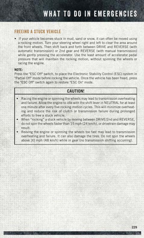
FREEING A STUCK VEHICLE
• If your vehicle becomes stuck in mud, sand or snow, it can often be moved usinga rocking motion. Turn your steering wheel right and left to clear the area aroundthe front wheels. Then shift back and forth between DRIVE and REVERSE (withautomatic transmission) or 2nd gear and REVERSE (with manual transmission)while gently pressing the accelerator. Use the least amount of accelerator pedalpressure that will maintain the rocking motion, without spinning the wheels orracing the engine.
NOTE:Press the "ESC Off" switch, to place the Electronic Stability Control (ESC) system in"Partial Off" mode before rocking the vehicle. Once the vehicle has been freed, pressthe "ESC Off" switch again to restore "ESC On" mode.
CAUTION!
• Racing the engine or spinning the wheels may lead to transmission overheatingand failure. Allow the engine to idle with the shift lever in NEUTRAL for at leastone minute after every five rocking-motion cycles. This will minimize overheat-ing and reduce the risk of clutch or transmission failure during prolongedefforts to free a stuck vehicle.
• When “rocking” a stuck vehicle by moving between DRIVE/2nd and REVERSE,do not spin the wheels faster than 15 mph (24 km/h), or drivetrain damage mayresult.
• Revving the engine or spinning the wheels too fast may lead to transmissionoverheating and failure. It can also damage the tires. Do not spin the wheelsabove 30 mph (48 km/h) while in gear (no transmission shifting occurring).
W H A T T O D O I N E M E R G E N C I E S
229
EVENT DATA RECORDER (EDR)
This vehicle is equipped with an Event Data Recorder (EDR). The main purpose of anEDR is to record, in certain crash or near crash-like situations, such as an air bagdeployment or hitting a road obstacle, data that will assist in understanding how avehicle’s systems performed. The EDR is designed to record data related to vehicledynamics and safety systems for a short period of time, typically 30 seconds or less.The EDR in this vehicle is designed to record such data as:
• How various systems in your vehicle were operating.
• Whether or not the driver and passenger safety belts were buckled/fastened.
• How far (if at all) the driver was depressing the accelerator and/or brake pedal.
• How fast the vehicle was traveling.
These data can help provide a better understanding of the circumstances in whichcrashes and injuries occur.
NOTE:EDR data is recorded by your vehicle only if a non-trivial crash situation occurs; nodata is recorded by the EDR under normal driving conditions and no personal data(e.g. name, gender, age, and crash location) is recorded. However, other parties, suchas law enforcement, could combine the EDR data with the type of personallyidentifying data routinely acquired during a crash investigation.
To read data recorded by an EDR, special equipment is required, and access to thevehicle or the EDR is needed. In addition to the vehicle manufacturer, other partiessuch as law enforcement, that have the special equipment, can read the informationif they have access to the vehicle or the EDR.
W H A T T O D O I N E M E R G E N C I E S
230
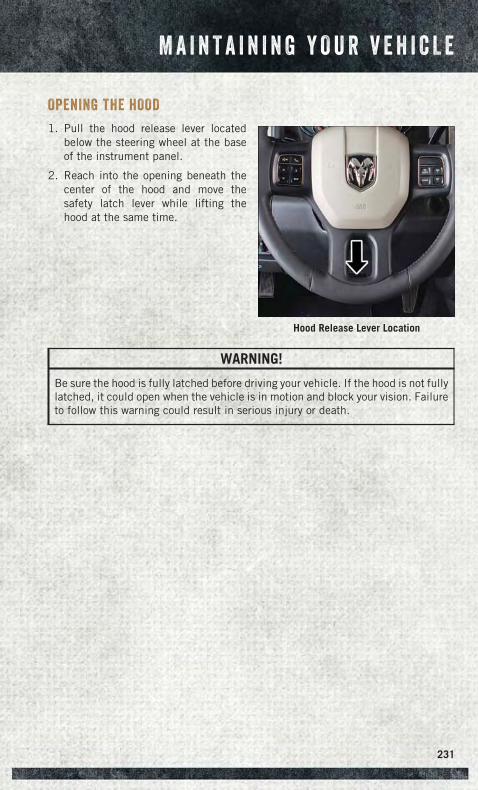
OPENING THE HOOD
1. Pull the hood release lever locatedbelow the steering wheel at the baseof the instrument panel.
2. Reach into the opening beneath thecenter of the hood and move thesafety latch lever while lifting thehood at the same time.
WARNING!
Be sure the hood is fully latched before driving your vehicle. If the hood is not fullylatched, it could open when the vehicle is in motion and block your vision. Failureto follow this warning could result in serious injury or death.
Hood Release Lever Location
M A I N T A I N I N G Y O U R V E H I C L E
231
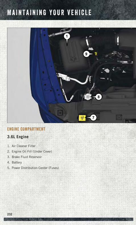
ENGINE COMPARTMENT
3.6L Engine
1. Air Cleaner Filter
2. Engine Oil Fill (Under Cover)
3. Brake Fluid Reservoir
4. Battery
5. Power Distribution Center (Fuses)
M A I N T A I N I N G Y O U R V E H I C L E
232
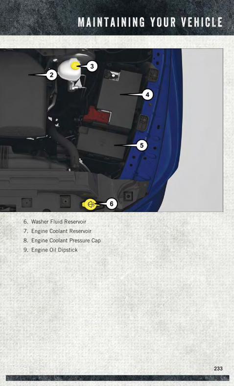
6. Washer Fluid Reservoir
7. Engine Coolant Reservoir
8. Engine Coolant Pressure Cap
9. Engine Oil Dipstick
M A I N T A I N I N G Y O U R V E H I C L E
233
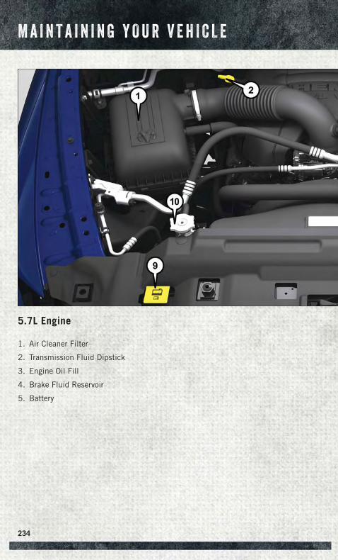
5.7L Engine
1. Air Cleaner Filter
2. Transmission Fluid Dipstick
3. Engine Oil Fill
4. Brake Fluid Reservoir
5. Battery
M A I N T A I N I N G Y O U R V E H I C L E
234
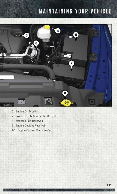
6. Engine Oil Dipstick
7. Power Distribution Center (Fuses)
8. Washer Fluid Reservoir
9. Engine Coolant Reservoir
10. Engine Coolant Pressure Cap
M A I N T A I N I N G Y O U R V E H I C L E
235
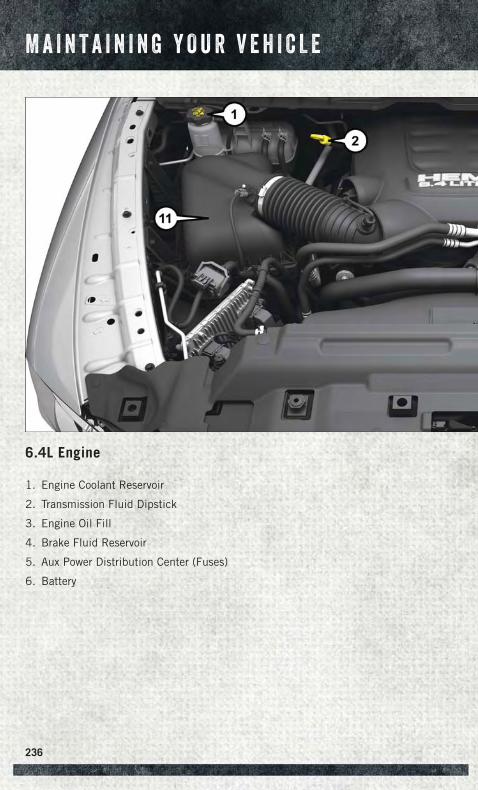
6.4L Engine
1. Engine Coolant Reservoir
2. Transmission Fluid Dipstick
3. Engine Oil Fill
4. Brake Fluid Reservoir
5. Aux Power Distribution Center (Fuses)
6. Battery
M A I N T A I N I N G Y O U R V E H I C L E
236
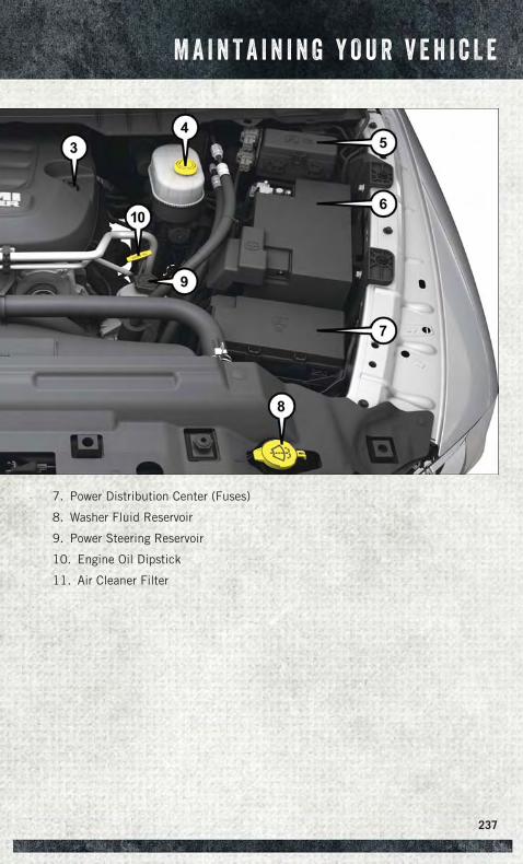
7. Power Distribution Center (Fuses)
8. Washer Fluid Reservoir
9. Power Steering Reservoir
10. Engine Oil Dipstick
11. Air Cleaner Filter
M A I N T A I N I N G Y O U R V E H I C L E
237
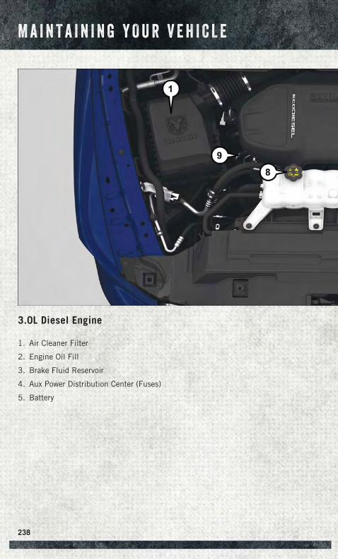
3.0L Diesel Engine
1. Air Cleaner Filter
2. Engine Oil Fill
3. Brake Fluid Reservoir
4. Aux Power Distribution Center (Fuses)
5. Battery
M A I N T A I N I N G Y O U R V E H I C L E
238
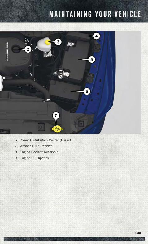
6. Power Distribution Center (Fuses)
7. Washer Fluid Reservoir
8. Engine Coolant Reservoir
9. Engine Oil Dipstick
M A I N T A I N I N G Y O U R V E H I C L E
239
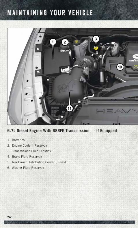
6.7L Diesel Engine With 68RFE Transmission — If Equipped
1. Batteries
2. Engine Coolant Reservoir
3. Transmission Fluid Dipstick
4. Brake Fluid Reservoir
5. Aux Power Distribution Center (Fuses)
6. Washer Fluid Reservoir
M A I N T A I N I N G Y O U R V E H I C L E
240
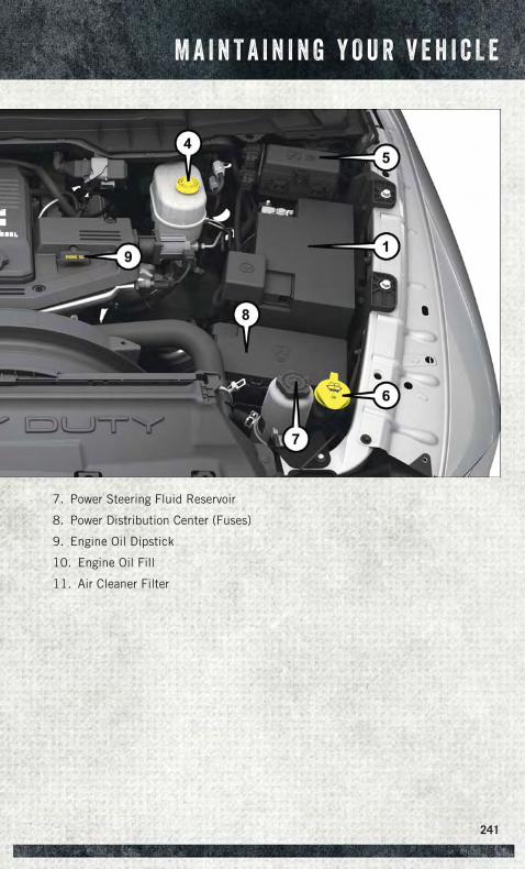
7. Power Steering Fluid Reservoir
8. Power Distribution Center (Fuses)
9. Engine Oil Dipstick
10. Engine Oil Fill
11. Air Cleaner Filter
M A I N T A I N I N G Y O U R V E H I C L E
241
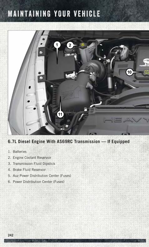
6.7L Diesel Engine With AS69RC Transmission — If Equipped
1. Batteries
2. Engine Coolant Reservoir
3. Transmission Fluid Dipstick
4. Brake Fluid Reservoir
5. Auz Power Distribution Center (Fuses)
6. Power Distribution Center (Fuses)
M A I N T A I N I N G Y O U R V E H I C L E
242
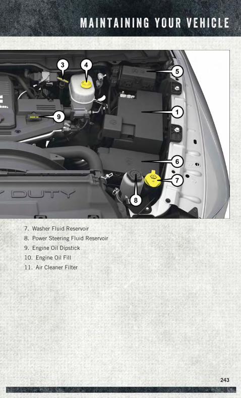
7. Washer Fluid Reservoir
8. Power Steering Fluid Reservoir
9. Engine Oil Dipstick
10. Engine Oil Fill
11. Air Cleaner Filter
M A I N T A I N I N G Y O U R V E H I C L E
243
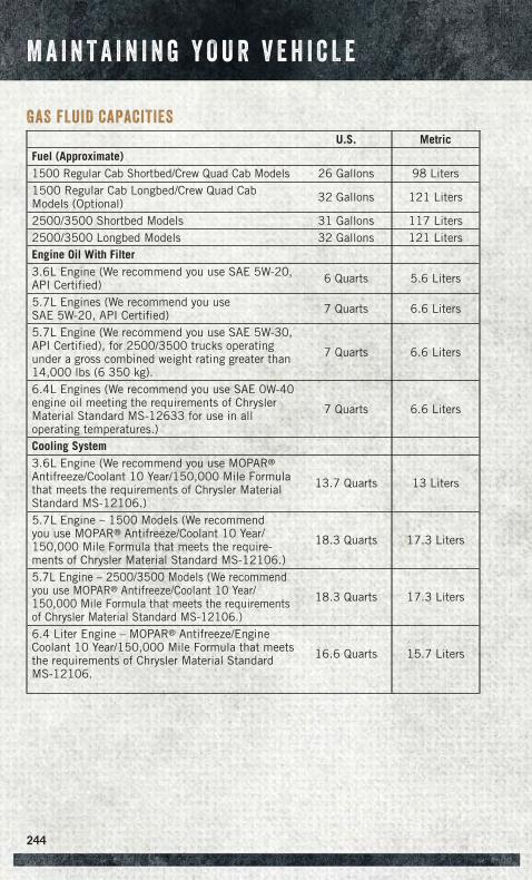
GAS FLUID CAPACITIES
U.S. MetricFuel (Approximate)1500 Regular Cab Shortbed/Crew Quad Cab Models 26 Gallons 98 Liters1500 Regular Cab Longbed/Crew Quad CabModels (Optional) 32 Gallons 121 Liters
2500/3500 Shortbed Models 31 Gallons 117 Liters2500/3500 Longbed Models 32 Gallons 121 LitersEngine Oil With Filter3.6L Engine (We recommend you use SAE 5W-20,API Certified) 6 Quarts 5.6 Liters
5.7L Engines (We recommend you useSAE 5W-20, API Certified) 7 Quarts 6.6 Liters
5.7L Engine (We recommend you use SAE 5W-30,API Certified), for 2500/3500 trucks operatingunder a gross combined weight rating greater than14,000 lbs (6 350 kg).
7 Quarts 6.6 Liters
6.4L Engines (We recommend you use SAE 0W-40engine oil meeting the requirements of ChryslerMaterial Standard MS-12633 for use in alloperating temperatures.)
7 Quarts 6.6 Liters
Cooling System3.6L Engine (We recommend you use MOPAR®
Antifreeze/Coolant 10 Year/150,000 Mile Formulathat meets the requirements of Chrysler MaterialStandard MS-12106.)
13.7 Quarts 13 Liters
5.7L Engine – 1500 Models (We recommendyou use MOPAR® Antifreeze/Coolant 10 Year/150,000 Mile Formula that meets the require-ments of Chrysler Material Standard MS-12106.)
18.3 Quarts 17.3 Liters
5.7L Engine – 2500/3500 Models (We recommendyou use MOPAR® Antifreeze/Coolant 10 Year/150,000 Mile Formula that meets the requirementsof Chrysler Material Standard MS-12106.)
18.3 Quarts 17.3 Liters
6.4 Liter Engine – MOPAR® Antifreeze/EngineCoolant 10 Year/150,000 Mile Formula that meetsthe requirements of Chrysler Material StandardMS-12106.
16.6 Quarts 15.7 Liters
M A I N T A I N I N G Y O U R V E H I C L E
244
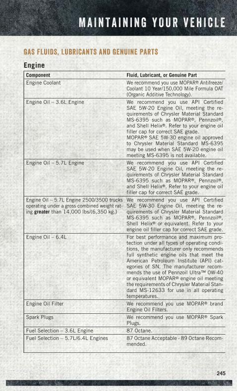
GAS FLUIDS, LUBRICANTS AND GENUINE PARTS
EngineComponent Fluid, Lubricant, or Genuine PartEngine Coolant We recommend you use MOPAR® Antifreeze/
Coolant 10 Year/150,000 Mile Formula OAT(Organic Additive Technology).
Engine Oil – 3.6L Engine We recommend you use API CertifiedSAE 5W-20 Engine Oil, meeting the re-quirements of Chrysler Material StandardMS-6395 such as MOPAR®, Pennzoil®,and Shell Helix®. Refer to your engine oilfiller cap for correct SAE grade.MOPAR® SAE 5W-30 engine oil approvedto Chrysler Material Standard MS-6395may be used when SAE 5W-20 engine oilmeeting MS-6395 is not available.
Engine Oil – 5.7L Engine We recommend you use API CertifiedSAE 5W-20 Engine Oil, meeting the re-quirements of Chrysler Material StandardMS-6395 such as MOPAR®, Pennzoil®,and Shell Helix®. Refer to your engine oilfiller cap for correct SAE grade.
Engine Oil – 5.7L Engine 2500/3500 trucksoperating under a gross combined weight rat-ing greater than 14,000 lbs/(6,350 kg.)
We recommend you use API CertifiedSAE 5W-30 Engine Oil, meeting the re-quirements of Chrysler Material StandardMS-6395 such as MOPAR®, Pennzoil®,Shell Helix® or equivalent. Refer to yourengine oil filler cap for correct SAE grade.
Engine Oil – 6.4L For best performance and maximum pro-tection under all types of operating condi-tions, the manufacturer only recommendsfull synthetic engine oils that meet theAmerican Petroleum Institute (API) cat-egories of SN. The manufacturer recom-mends the use of Pennzoil Ultra™ 0W-40or equivalent MOPAR® engine oil meetingthe requirements of Chrysler Material Stan-dard MS-12633 for use in all operatingtemperatures.
Engine Oil Filter We recommend you use MOPAR® brandEngine Oil Filters.
Spark Plugs We recommend you use MOPAR® SparkPlugs.
Fuel Selection – 3.6L Engine 87 Octane.Fuel Selection – 5.7L/6.4L Engines 87 Octane Acceptable - 89 Octane Recom-
mended.
M A I N T A I N I N G Y O U R V E H I C L E
245
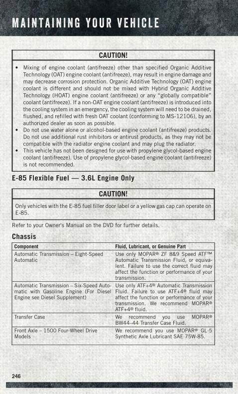
CAUTION!
• Mixing of engine coolant (antifreeze) other than specified Organic AdditiveTechnology (OAT) engine coolant (antifreeze), may result in engine damage andmay decrease corrosion protection. Organic Additive Technology (OAT) enginecoolant is different and should not be mixed with Hybrid Organic AdditiveTechnology (HOAT) engine coolant (antifreeze) or any “globally compatible”coolant (antifreeze). If a non-OAT engine coolant (antifreeze) is introduced intothe cooling system in an emergency, the cooling system will need to be drained,flushed, and refilled with fresh OAT coolant (conforming to MS-12106), by anauthorized dealer as soon as possible.
• Do not use water alone or alcohol-based engine coolant (antifreeze) products.Do not use additional rust inhibitors or antirust products, as they may not becompatible with the radiator engine coolant and may plug the radiator.
• This vehicle has not been designed for use with propylene glycol-based enginecoolant (antifreeze). Use of propylene glycol-based engine coolant (antifreeze)is not recommended.
E-85 Flexible Fuel — 3.6L Engine Only
CAUTION!
Only vehicles with the E-85 fuel filler door label or a yellow gas cap can operate onE-85.
Refer to your Owner's Manual on the DVD for further details.
ChassisComponent Fluid, Lubricant, or Genuine PartAutomatic Transmission – Eight-SpeedAutomatic
Use only MOPAR® ZF 8&9 Speed ATF™Automatic Transmission Fluid, or equiva-lent. Failure to use the correct fluid mayaffect the function or performance of yourtransmission.
Automatic Transmission – Six-Speed Auto-matic with Gasoline Engine (For DieselEngine see Diesel Supplement)
Use only ATF+4® Automatic TransmissionFluid. Failure to use ATF+4® fluid mayaffect the function or performance of yourtransmission. We recommend MOPAR®
ATF+4® fluid.Transfer Case We recommend you use MOPAR®
BW44–44 Transfer Case Fluid.Front Axle – 1500 Four-Wheel DriveModels
We recommend you use MOPAR® GL-5Synthetic Axle Lubricant SAE 75W-85.
M A I N T A I N I N G Y O U R V E H I C L E
246
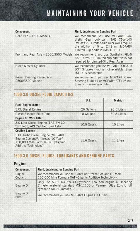
Component Fluid, Lubricant, or Genuine PartRear Axle – 1500 Models We recommend you use MOPAR® Syn-
thetic Gear Lubricant SAE 75W-140(MS-8985). Limited-Slip Rear Axles requirethe addition of 5 oz. (148 ml) MOPAR®
Limited Slip Additive (MS-10111).Front and Rear Axle – 2500/3500 Models We recommend you use Synthetic, GL-5
SAE, 75W-90. Limited slip additive is notrequired for Limited-Slip Rear Axles.
Brake Master Cylinder We recommend you use MOPAR® DOT 3. IfDOT 3 brake fluid is not available, thenDOT 4 is acceptable.
Power Steering Reservoir –2500/3500 Models
We recommend you use MOPAR® PowerSteering Fluid +4 or MOPAR® ATF+4® Au-tomatic Transmission Fluid.
1500 3.0 DIESEL FLUID CAPACITIES
U.S. MetricFuel (Approximate)3.0L Diesel Engine 26 Gallons 98.5 LitersDiesel Exhaust Fluid Tank 8 Gallons 30.3 LitersEngine Oil With Filter3.0 Liter Diesel Engine (SAE 5W-30Synthetic, API Certified Low Ash) 10.5 Quarts 10 Liters
Cooling System3.0L Turbo Diesel Engine (MOPAR®
Engine Coolant/Antifreeze 10 Year/150,000 Mile Formula OAT (OrganicAdditive Technology))
11.6 Quarts 11 Liters
1500 3.0 DIESEL FLUIDS, LUBRICANTS AND GENUINE PARTS
EngineComponent Fluid, Lubricant, or Genuine PartEngineCoolant
We recommend you use MOPAR® Antifreeze/Coolant 10 Year/150,000 Mile Formula OAT (Organic Additive Technology).
Engine OilOnly use ACEA C3 5W-30 Synthetic Low Ash engine oil meetingChrysler material standard MS-11106 or Pennzoil Ultra Euro L fullsynthetic 5W-30 motor oil.
Engine OilFilter We recommend you use MOPAR® Engine Oil Filters.
M A I N T A I N I N G Y O U R V E H I C L E
247
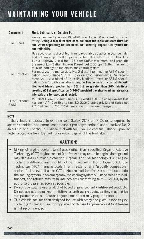
Component Fluid, Lubricant, or Genuine Part
Fuel Filters
We recommend you use MOPAR® Fuel Filter. Must meet 3 micronrating. Using a fuel filter that does not meet the manufacturers filtrationand water separating requirements can severely impact fuel system lifeand reliability.
Fuel Selection
Use good quality diesel fuel from a reputable supplier in your vehicle.Federal law requires that you must fuel this vehicle with Ultra LowSulfur Highway Diesel fuel (15 ppm Sulfur maximum) and prohibitsthe use of Low Sulfur Highway Diesel fuel (500 ppm Sulfur maximum)to avoid damage to the emissions control system.For most year-round service, No. 2 diesel fuel meeting ASTM specifi-cation D-975 Grade S15 will provide good performance. We recom-mend you use a blend of up to 5% biodiesel, meeting ASTM specifi-cation D-975 with your diesel engine.This vehicle is compatible withbiodiesel blends greater than 5% but no greater than 20% biodieselmeeting ASTM specification D-7467 provided the shortened maintenanceintervals are followed as directed.
Diesel ExhaustFluid
MOPAR® Diesel Exhaust Fluid (API Certified) (DEF) or equivalent thathas been API Certified to the ISO 22241 standard. Use of fluids notAPI Certified to ISO 22241 may result in system damage.
NOTE:If the vehicle is exposed to extreme cold (below 20°F or -7°C), or is required tooperate at colder-than-normal conditions for prolonged periods, use climatized No. 2diesel fuel or dilute the No. 2 diesel fuel with 50% No. 1 diesel fuel. This will providebetter protection from fuel gelling or wax-plugging of the fuel filter.
CAUTION!
• Mixing of engine coolant (antifreeze) other than specified Organic AdditiveTechnology (OAT) engine coolant (antifreeze), may result in engine damage andmay decrease corrosion protection. Organic Additive Technology (OAT) enginecoolant is different and should not be mixed with Hybrid Organic AdditiveTechnology (HOAT) engine coolant (antifreeze) or any “globally compatible”coolant (antifreeze). If a non-OAT engine coolant (antifreeze) is introduced intothe cooling system in an emergency, the cooling system will need to be drained,flushed, and refilled with fresh OAT coolant (conforming to MS-12106), by anauthorized dealer as soon as possible.
• Do not use water alone or alcohol-based engine coolant (antifreeze) products.Do not use additional rust inhibitors or antirust products, as they may not becompatible with the radiator engine coolant and may plug the radiator.
• This vehicle has not been designed for use with propylene glycol-based enginecoolant (antifreeze). Use of propylene glycol-based engine coolant (antifreeze)is not recommended.
M A I N T A I N I N G Y O U R V E H I C L E
248
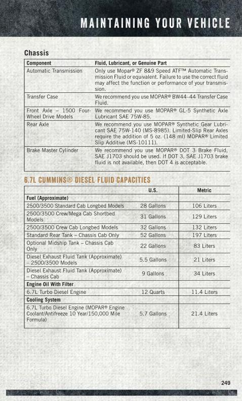
ChassisComponent Fluid, Lubricant, or Genuine PartAutomatic Transmission Only use Mopar® ZF 8&9 Speed ATF™ Automatic Trans-
mission Fluid or equivalent. Failure to use the correct fluidmay affect the function or performance of your transmis-sion.
Transfer Case We recommend you use MOPAR® BW44–44 Transfer CaseFluid.
Front Axle – 1500 Four-Wheel Drive Models
We recommend you use MOPAR® GL-5 Synthetic AxleLubricant SAE 75W-85.
Rear Axle We recommend you use MOPAR® Synthetic Gear Lubri-cant SAE 75W-140 (MS-8985). Limited-Slip Rear Axlesrequire the addition of 5 oz. (148 ml) MOPAR® LimitedSlip Additive (MS-10111).
Brake Master Cylinder We recommend you use MOPAR® DOT 3 Brake Fluid,SAE J1703 should be used. If DOT 3, SAE J1703 brakefluid is not available, then DOT 4 is acceptable.
6.7L CUMMINS® DIESEL FLUID CAPACITIES
U.S. MetricFuel (Approximate)2500/3500 Standard Cab Longbed Models 28 Gallons 106 Liters2500/3500 Crew/Mega Cab ShortbedModels 31 Gallons 129 Liters
2500/3500 Crew Cab Longbed Models 32 Gallons 132 LitersStandard Rear Tank – Chassis Cab Only 52 Gallons 197 LitersOptional Midship Tank – Chassis CabOnly 22 Gallons 83 Liters
Diesel Exhaust Fluid Tank (Approximate)– 2500/3500 Models 5.5 Gallons 21 Liters
Diesel Exhaust Fluid Tank (Approximate)– Chassis Cab 9 Gallons 34 Liters
Engine Oil With Filter6.7L Turbo Diesel Engine 12 Quarts 11.4 LitersCooling System6.7L Turbo Diesel Engine (MOPAR® EngineCoolant/Antifreeze 10 Year/150,000 MileFormula)
5.7 Gallons 21.4 Liters
M A I N T A I N I N G Y O U R V E H I C L E
249
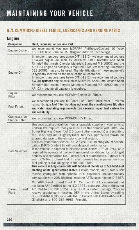
6.7L CUMMINS® DIESEL FLUIDS, LUBRICANTS AND GENUINE PARTS
EngineComponent Fluid, Lubricant, or Genuine Part
Engine Coolant We recommend you use MOPAR® Antifreeze/Coolant 10 Year/150,000 Mile Formula OAT (Organic Additive Technology).
Engine Oil
In ambient temperatures above 0°F (-18°C), we recommend you use15W-40 engine oil such as MOPAR®, Shell Rotella® and ShellRimula® that meets Chrysler Materials Standard MS-10902 and theAPI CJ-4 engine oil category is required. Products meeting Cummins®
CES 20081 may also be used. The identification of these engine oilsis typically located on the back of the oil container.In ambient temperatures below 0°F (-18°C), we recommend you use5W-40 synthetic engine oil such as MOPAR®, Shell Rotella® and ShellRimula® that meets Chrysler Materials Standard MS-10902 and theAPI CJ-4 engine oil category is required.
Engine OilFilter We recommend you use MOPAR® Engine Oil Filters.
Fuel Filters
We recommend you use MOPAR® Fuel Filter. Must meet 3 micronrating. Using a fuel filter that does not meet the manufacturers filtrationand water separating requirements can severely impact fuel system lifeand reliability.
Crankcase Ven-tilation Filter We recommend you use MOPAR® CCV Filter.
Fuel Selection
Use good quality diesel fuel from a reputable supplier in your vehicle.Federal law requires that you must fuel this vehicle with Ultra LowSulfur Highway Diesel fuel (15 ppm Sulfur maximum) and prohibitsthe use of Low Sulfur Highway Diesel fuel (500 ppm Sulfur maximum)to avoid damage to the emissions control system.For most year-round service, No. 2 diesel fuel meeting ASTM specifi-cation D-975 Grade S15 will provide good performance.If the vehicle is exposed to extreme cold (below 20°F or -7°C), or isrequired to operate at colder-than-normal conditions for prolongedperiods, use climatized No. 2 diesel fuel or dilute the No. 2 diesel fuelwith 50% No. 1 diesel fuel. This will provide better protection fromfuel gelling or wax-plugging of the fuel filters.This vehicle is fully compatible with biodiesel blends up to 5% biodieselmeeting ASTM specification D-975. Pickup models, and Chassis Cabmodels configured with optional B20 capability, are additionallycompatible with 20% biodiesel meeting ASTM specification D-7467.
Diesel ExhaustFluid
MOPAR® Diesel Exhaust Fluid (API Certified) (DEF) or equivalent thathas been API Certified to the ISO 22241 standard. Use of fluids notAPI Certified to ISO 22241 may result in system damage. You canreceive assistance in locating DEF in the United States by calling866-RAM-INFO (866-726-4636). In Canada call 1–800–465–2001(English) or 1–800–387–9983 (French).
M A I N T A I N I N G Y O U R V E H I C L E
250
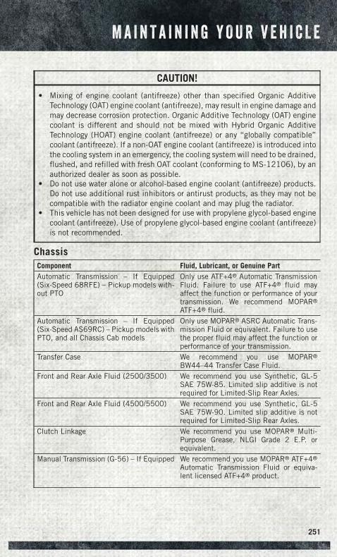
CAUTION!
• Mixing of engine coolant (antifreeze) other than specified Organic AdditiveTechnology (OAT) engine coolant (antifreeze), may result in engine damage andmay decrease corrosion protection. Organic Additive Technology (OAT) enginecoolant is different and should not be mixed with Hybrid Organic AdditiveTechnology (HOAT) engine coolant (antifreeze) or any “globally compatible”coolant (antifreeze). If a non-OAT engine coolant (antifreeze) is introduced intothe cooling system in an emergency, the cooling system will need to be drained,flushed, and refilled with fresh OAT coolant (conforming to MS-12106), by anauthorized dealer as soon as possible.
• Do not use water alone or alcohol-based engine coolant (antifreeze) products.Do not use additional rust inhibitors or antirust products, as they may not becompatible with the radiator engine coolant and may plug the radiator.
• This vehicle has not been designed for use with propylene glycol-based enginecoolant (antifreeze). Use of propylene glycol-based engine coolant (antifreeze)is not recommended.
ChassisComponent Fluid, Lubricant, or Genuine PartAutomatic Transmission – If Equipped(Six-Speed 68RFE) – Pickup models with-out PTO
Only use ATF+4® Automatic TransmissionFluid. Failure to use ATF+4® fluid mayaffect the function or performance of yourtransmission. We recommend MOPAR®
ATF+4® fluid.Automatic Transmission – If Equipped(Six-Speed AS69RC) – Pickup models withPTO, and all Chassis Cab models
Only use MOPAR® ASRC Automatic Trans-mission Fluid or equivalent. Failure to usethe proper fluid may affect the function orperformance of your transmission.
Transfer Case We recommend you use MOPAR®
BW44–44 Transfer Case Fluid.Front and Rear Axle Fluid (2500/3500) We recommend you use Synthetic, GL-5
SAE 75W-85. Limited slip additive is notrequired for Limited-Slip Rear Axles.
Front and Rear Axle Fluid (4500/5500) We recommend you use Synthetic, GL-5SAE 75W-90. Limited slip additive is notrequired for Limited-Slip Rear Axles.
Clutch Linkage We recommend you use MOPAR® Multi-Purpose Grease, NLGI Grade 2 E.P. orequivalent.
Manual Transmission (G-56) – If Equipped We recommend you use MOPAR® ATF+4®
Automatic Transmission Fluid or equiva-lent licensed ATF+4® product.
M A I N T A I N I N G Y O U R V E H I C L E
251
MAINTENANCE PROCEDURES
For information on the maintenance procedures for your vehicle, please refer to“Maintenance Procedures” in “Maintaining Your Vehicle” in your Owner’s Manual orapplicable supplement on the DVD for further details.
MAINTENANCE SCHEDULE — GASOLINE ENGINE
Your vehicle is equipped with an automatic oil change indicator system. The oilchange indicator system will remind you that it is time to take your vehicle in forscheduled maintenance.
Based on engine operation conditions, the oil change indicator message willilluminate. This means that service is required for your vehicle. Operating conditionssuch as frequent short-trips, trailer tow, extremely hot or cold ambient temperatures,and E85 fuel usage will influence when the “Oil Change Required” message isdisplayed. Severe Operating Conditions can cause the change oil message toilluminate as early as 3,500 miles (5,600 km) since last reset. Have your vehicleserviced as soon as possible, within the next 500 miles (805 km).
Your authorized dealer will reset the oil change indicator message after completingthe scheduled oil change. If a scheduled oil change is performed by someone otherthan your authorized dealer, the message can be reset by referring to the stepsdescribed under “Instrument Cluster Warning Lights” in “What To Do In Emergen-cies” in this guide or “Electronic Vehicle Information Center (EVIC)” or “DriverInformation Display (DID)” in “Understanding Your Instrument Panel” in yourOwner’s Manual on the DVD for further information.
NOTE:1500 Models Only
• Under no circumstances should oil change intervals exceed 10,000 miles(16,000 km) or twelve months on 1500 trucks, whichever comes first.
2500 – 3500 Models
• Under no circumstances should oil change intervals exceed 8,000 miles(13,000 km) or twelve months on 2500 – 3500 trucks, whichever comes first.
M A I N T A I N I N G Y O U R V E H I C L E
252
Severe Duty All Models
• Change Engine Oil at 4000 miles (6,500 km) if the vehicle is operated in a dustyand off road environment. This type of vehicle use is considered Severe Duty.
Once A Month Or Before A Long Trip:
• Check engine oil level
• Check windshield washer fluid level
• Check tire pressure and look for unusual wear or damage. Rotate tires at the firstsign of irregular wear, even if it occurs before the oil indicator system turns on.
• Check the fluid levels of the coolant reservoir, brake master cylinder, powersteering (2500/3500 Models Only) and automatic transmission (six-speed only)and fill as needed
• Check function of all interior and exterior lights
Required Maintenance
Refer to the Maintenance Schedules on the following pages for required mainte-nance.
At Every Oil Change Interval As Indicated By Oil Change Indicator System:• Change oil and filter.• Rotate the tires. Rotate at the first sign of irregular wear, even if it occurs before the oil
indicator system turns on.• Inspect battery and clean and tighten terminals as required.• Inspect automatic transmission fluid if equipped with dipstick.• Inspect brake pads, shoes, rotors, drums, hoses and park brake.• Inspect engine cooling system protection and hoses.• Inspect exhaust system.• Inspect engine air cleaner if using in dusty or off-road conditions.• Lube the front drive shaft fitting (2500/3500 (4x4) models only).
M A I N T A I N I N G Y O U R V E H I C L E
253
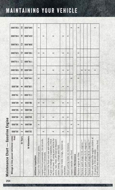
Mai
nten
ance
Char
t—
Gaso
line
Engi
neM
ileag
eor
time
pass
ed(w
hich
ever
com
esfir
st)
20,000
30,000
40,000
50,000
60,000
70,000
80,000
90,000
100,000
110,000
120,000
130,000
140,000
150,000
OrYe
ars:
23
45
67
89
1011
1213
1415
OrKi
lom
eter
s:
32,000
48,000
64,000
80,000
96,000
112,000
128,000
144,000
160,000
176,000
192,000
208,000
224,000
240,000
Addi
tiona
lIns
pect
ions
Insp
ect
the
CV/
Uni
vers
aljo
ints
.X
XX
XX
Insp
ect
fron
tsu
spen
sion
,ti
ero
den
ds,
and
repl
ace
ifne
cess
ary.
XX
XX
XX
X
Insp
ect
the
fron
tan
dre
arax
lesu
rfac
es.
Ifge
aroi
llea
kage
issu
spec
ted,
chec
kth
efl
uid
leve
l.If
usin
gyo
urve
hicl
efo
rpo
lice,
taxi
,fl
eet,
off-
road
orfr
eque
nttr
aile
rto
win
g,ch
ange
axle
flui
d.
XX
XX
XX
X
Insp
ect
the
brak
elin
ings
,re
plac
eas
nece
ssar
y.X
XX
XX
XX
Adj
ust
park
ing
brak
eas
nece
ssar
y.X
XX
XX
XX
Insp
ect
tran
sfer
case
flui
d.X
XX
Addi
tiona
lMai
nten
ance
Rep
lace
engi
neai
rfi
lter
.X
XX
XX
Rep
lace
spar
kpl
ugs
(3.6
Len
gine
).**
X
Rep
lace
spar
kpl
ugs
(5.7
Len
gine
).**
X
Rep
lace
spar
kpl
ugs
(6.4
Len
gine
).**
X
Flus
han
dre
plac
eth
een
gine
cool
ant
at1
0ye
ars
or1
50
,00
0m
iles
(24
0,0
00
km)
whi
chev
erco
mes
firs
t.X
X
M A I N T A I N I N G Y O U R V E H I C L E
254
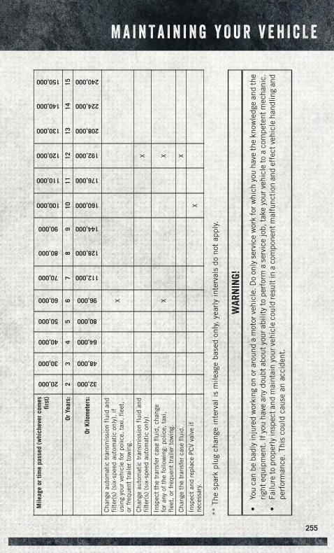
Mile
age
ortim
epa
ssed
(whi
chev
erco
mes
first
)
20,000
30,000
40,000
50,000
60,000
70,000
80,000
90,000
100,000
110,000
120,000
130,000
140,000
150,000
OrYe
ars:
23
45
67
89
1011
1213
1415
OrKi
lom
eter
s:
32,000
48,000
64,000
80,000
96,000
112,000
128,000
144,000
160,000
176,000
192,000
208,000
224,000
240,000
Cha
nge
auto
mat
ictr
ansm
issi
onfl
uid
and
filt
er(s
)(s
ix-s
peed
auto
mat
icon
ly),
ifus
ing
your
vehi
cle
for
polic
e,ta
xi,
flee
t,or
freq
uent
trai
ler
tow
ing.
X
Cha
nge
auto
mat
ictr
ansm
issi
onfl
uid
and
filt
er(s
)(s
ix-s
peed
auto
mat
icon
ly).
X
Insp
ect
the
tran
sfer
case
flui
d,ch
ange
for
any
ofth
efo
llow
ing:
polic
e,ta
xi,
flee
t,or
freq
uent
trai
ler
tow
ing.
XX
Cha
nge
the
tran
sfer
case
flui
d.X
Insp
ect
and
repl
ace
PC
Vva
lve
ifne
cess
ary.
X
**Th
esp
ark
plug
chan
gein
terv
alis
mile
age
base
don
ly,ye
arly
inte
rval
sdo
not
appl
y.
WAR
NIN
G!
•Yo
uca
nbe
badl
yin
jure
dw
orki
ngon
orar
ound
am
otor
vehi
cle.
Do
only
serv
ice
wor
kfo
rwhi
chyo
uha
veth
ekn
owle
dge
and
the
righ
tequ
ipm
ent.
Ifyo
uha
vean
ydo
ubta
bout
your
abili
tyto
perf
orm
ase
rvic
ejo
b,ta
keyo
urve
hicl
eto
aco
mpe
tent
mec
hani
c.•
Failu
reto
prop
erly
insp
ecta
ndm
aint
ain
your
vehi
cle
coul
dre
sult
ina
com
pone
ntm
alfu
ncti
onan
def
fect
vehi
cle
hand
ling
and
perf
orm
ance
.Th
isco
uld
caus
ean
acci
dent
.
M A I N T A I N I N G Y O U R V E H I C L E
255
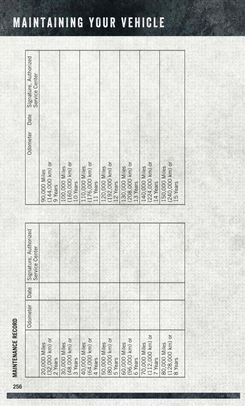
MAI
NTE
NAN
CERE
CORD Odo
met
erD
ate
Sig
natu
re,
Aut
hori
zed
Ser
vice
Cen
ter
20
,00
0M
iles
(32
,00
0km
)or
2Ye
ars
30
,00
0M
iles
(48
,00
0km
)or
3Ye
ars
40
,00
0M
iles
(64
,00
0km
)or
4Ye
ars
50
,00
0M
iles
(80
,00
0km
)or
5Ye
ars
60
,00
0M
iles
(96
,00
0km
)or
6Ye
ars
70
,00
0M
iles
(11
2,0
00
km)
or7
Year
s8
0,0
00
Mile
s(1
28
,00
0km
)or
8Ye
ars
Odo
met
erD
ate
Sig
natu
re,
Aut
hori
zed
Ser
vice
Cen
ter
90
,00
0M
iles
(14
4,0
00
km)
or9
Year
s1
00
,00
0M
iles
(16
0,0
00
km)
or1
0Ye
ars
11
0,0
00
Mile
s(1
76
,00
0km
)or
11
Year
s1
20
,00
0M
iles
(19
2,0
00
km)
or1
2Ye
ars
13
0,0
00
Mile
s(2
08
,00
0km
)or
13
Year
s1
40
,00
0M
iles
(22
4,0
00
km)
or1
4Ye
ars
15
0,0
00
Mile
s(2
40
,00
0km
)or
15
Year
s
M A I N T A I N I N G Y O U R V E H I C L E
256
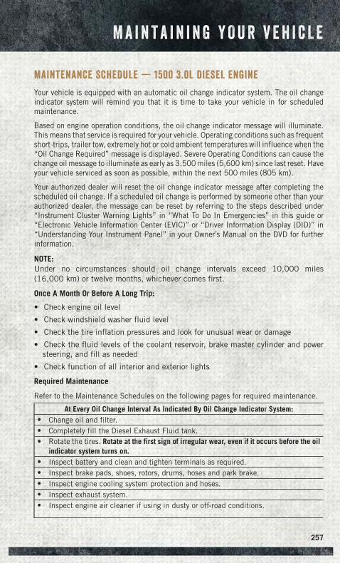
MAINTENANCE SCHEDULE — 1500 3.0L DIESEL ENGINE
Your vehicle is equipped with an automatic oil change indicator system. The oil changeindicator system will remind you that it is time to take your vehicle in for scheduledmaintenance.
Based on engine operation conditions, the oil change indicator message will illuminate.This means that service is required for your vehicle. Operating conditions such as frequentshort-trips, trailer tow, extremely hot or cold ambient temperatures will influence when the“Oil Change Required” message is displayed. Severe Operating Conditions can cause thechange oil message to illuminate as early as 3,500 miles (5,600 km) since last reset. Haveyour vehicle serviced as soon as possible, within the next 500 miles (805 km).
Your authorized dealer will reset the oil change indicator message after completing thescheduled oil change. If a scheduled oil change is performed by someone other than yourauthorized dealer, the message can be reset by referring to the steps described under“Instrument Cluster Warning Lights” in “What To Do In Emergencies” in this guide or“Electronic Vehicle Information Center (EVIC)” or “Driver Information Display (DID)” in“Understanding Your Instrument Panel” in your Owner’s Manual on the DVD for furtherinformation.
NOTE:Under no circumstances should oil change intervals exceed 10,000 miles(16,000 km) or twelve months, whichever comes first.
Once A Month Or Before A Long Trip:
• Check engine oil level
• Check windshield washer fluid level
• Check the tire inflation pressures and look for unusual wear or damage
• Check the fluid levels of the coolant reservoir, brake master cylinder and powersteering, and fill as needed
• Check function of all interior and exterior lights
Required Maintenance
Refer to the Maintenance Schedules on the following pages for required maintenance.
At Every Oil Change Interval As Indicated By Oil Change Indicator System:• Change oil and filter.• Completely fill the Diesel Exhaust Fluid tank.• Rotate the tires. Rotate at the first sign of irregular wear, even if it occurs before the oil
indicator system turns on.• Inspect battery and clean and tighten terminals as required.• Inspect brake pads, shoes, rotors, drums, hoses and park brake.• Inspect engine cooling system protection and hoses.• Inspect exhaust system.• Inspect engine air cleaner if using in dusty or off-road conditions.
M A I N T A I N I N G Y O U R V E H I C L E
257
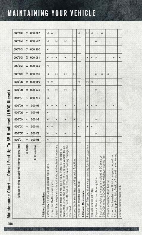
Mai
nten
ance
Char
t—
Dies
elFu
elU
pTo
B5Bi
odie
sel
(150
0Di
esel
)
Mile
age
ortim
epa
ssed
(whi
chev
erco
mes
first
)
10,000
20,000
30,000
40,000
50,000
60,000
70,000
80,000
90,000
100,000
110,000
120,000
130,000
140,000
150,000
OrYe
ars:
12
34
56
78
910
1112
1314
15
OrKi
lom
eter
s:
16,000
32,000
48,000
64,000
80,000
96,000
112,000
128,000
144,000
160,000
176,000
192,000
208,000
224,000
240,000
Addi
tiona
lIns
pect
ions
Com
plet
ely
fill
the
Die
selE
xhau
stFl
uid
tank
.X
XX
XX
XX
XX
XX
XX
XX
Insp
ect
the
CV/
Uni
vers
aljo
ints
.X
XX
XX
Insp
ect
fron
tsu
spen
sion
,tie
rod
ends
,and
repl
ace
ifne
cess
ary.
XX
XX
XX
X
Insp
ect
the
fron
tan
dre
arax
lefl
uid.
Ifge
aroi
llea
kage
issu
spec
ted,
chec
kth
efl
uid
leve
l.If
usin
gyo
urve
hicl
efo
rpo
-lic
e,ta
xi,
flee
t,of
f-ro
ador
freq
uent
trai
ler
tow
ing
chan
geth
eax
lefl
uid.
XX
XX
XX
X
Insp
ect
the
brak
elin
ings
,pa
rkin
gbr
ake
func
tion
.X
XX
XX
XX
Insp
ect
the
tran
sfer
case
flui
d.X
XX
Addi
tiona
lMai
nten
ance
Rep
lace
fuel
filte
ran
ddr
ain
wat
erfr
omth
efu
elfil
ter
asse
mbl
y.X
XX
XX
Rep
lace
engi
neai
rfi
lter
.X
XX
XX
Rep
lace
the
air
cond
itio
ning
filt
er.
XX
XX
XX
X
Flus
han
dre
plac
eth
een
gine
cool
ant
at1
0ye
ars
or1
50
,00
0m
iles
(24
0,0
00
km)
whi
chev
erco
mes
firs
t.X
X
Rep
lace
acce
ssor
ydr
ive
belt
(s).
X
Insp
ect
the
tran
sfer
case
flui
d,ch
ange
for
any
ofth
efo
llow
ing:
polic
e,ta
xi,
flee
t,or
freq
uent
trai
ler
tow
ing.
XX
Cha
nge
tran
sfer
case
flui
d.X
M A I N T A I N I N G Y O U R V E H I C L E
258
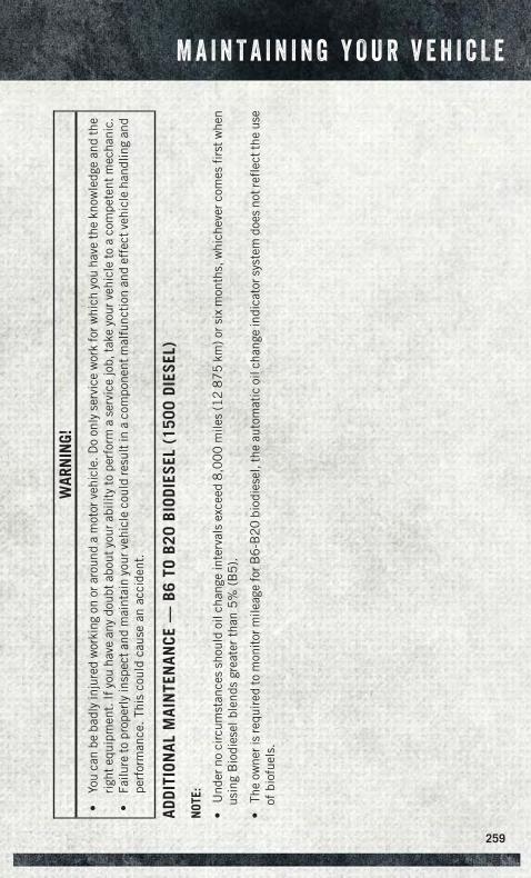
WAR
NIN
G!
•Yo
uca
nbe
badl
yin
jure
dw
orki
ngon
orar
ound
am
otor
vehi
cle.
Do
only
serv
ice
wor
kfo
rwhi
chyo
uha
veth
ekn
owle
dge
and
the
righ
tequ
ipm
ent.
Ifyo
uha
vean
ydo
ubta
bout
your
abili
tyto
perf
orm
ase
rvic
ejo
b,ta
keyo
urve
hicl
eto
aco
mpe
tent
mec
hani
c.•
Failu
reto
prop
erly
insp
ecta
ndm
aint
ain
your
vehi
cle
coul
dre
sult
ina
com
pone
ntm
alfu
ncti
onan
def
fect
vehi
cle
hand
ling
and
perf
orm
ance
.Th
isco
uld
caus
ean
acci
dent
.
ADDI
TION
ALM
AIN
TEN
ANCE
—B6
TOB2
0BI
ODIE
SEL
(150
0DI
ESEL
)
NOT
E:
•U
nder
noci
rcum
stan
ces
shou
ldoi
lcha
nge
inte
rval
sex
ceed
8,0
00
mile
s(1
28
75
km)o
rsix
mon
ths,
whi
chev
erco
mes
firs
twhe
nus
ing
Bio
dies
elbl
ends
grea
ter
than
5%
(B5
).
•Th
eow
neri
sre
quir
edto
mon
itor
mile
age
forB
6-B
20
biod
iese
l,th
eau
tom
atic
oilc
hang
ein
dica
tors
yste
mdo
esno
tref
lect
the
use
ofbi
ofue
ls.
M A I N T A I N I N G Y O U R V E H I C L E
259
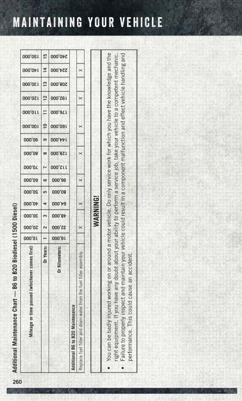
Addi
tiona
lMai
nten
ance
Char
t—B6
toB2
0Bi
odie
sel(
1500
Dies
el)
Mile
age
ortim
epa
ssed
(whi
chev
erco
mes
first
)
10,000
20,000
30,000
40,000
50,000
60,000
70,000
80,000
90,000
100,000
110,000
120,000
130,000
140,000
150,000
OrYe
ars:
12
34
56
78
910
1112
1314
15
OrKi
lom
eter
s:
16,000
32,000
48,000
64,000
80,000
96,000
112,000
128,000
144,000
160,000
176,000
192,000
208,000
224,000
240,000
Addi
tiona
lB6
toB2
0M
aint
enan
ce
Rep
lace
fuel
filte
rand
drai
nw
ater
from
the
fuel
filte
rass
embl
y.X
XX
XX
XX
WAR
NIN
G!
•Yo
uca
nbe
badl
yin
jure
dw
orki
ngon
orar
ound
am
otor
vehi
cle.
Do
only
serv
ice
wor
kfo
rwhi
chyo
uha
veth
ekn
owle
dge
and
the
righ
tequ
ipm
ent.
Ifyo
uha
vean
ydo
ubta
bout
your
abili
tyto
perf
orm
ase
rvic
ejo
b,ta
keyo
urve
hicl
eto
aco
mpe
tent
mec
hani
c.•
Failu
reto
prop
erly
insp
ecta
ndm
aint
ain
your
vehi
cle
coul
dre
sult
ina
com
pone
ntm
alfu
ncti
onan
def
fect
vehi
cle
hand
ling
and
perf
orm
ance
.Th
isco
uld
caus
ean
acci
dent
.
M A I N T A I N I N G Y O U R V E H I C L E
260
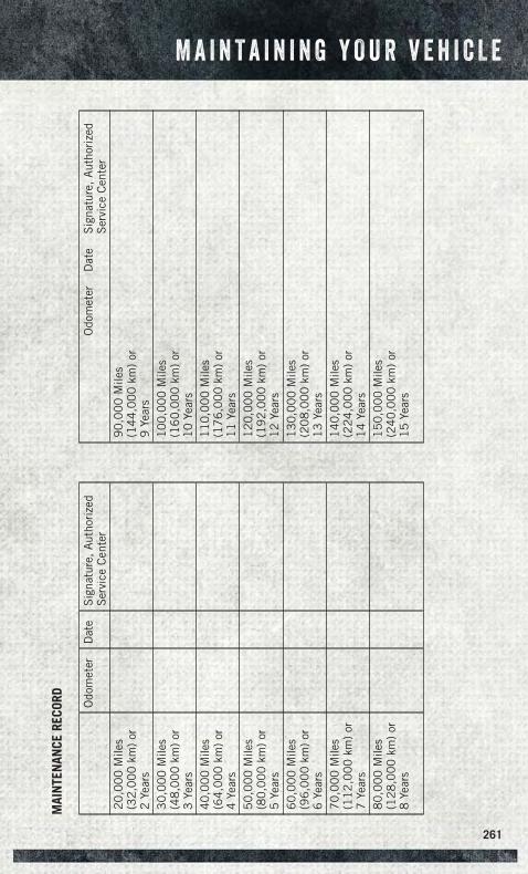
MAI
NTE
NAN
CERE
CORD Odo
met
erD
ate
Sig
natu
re,
Aut
hori
zed
Ser
vice
Cen
ter
20
,00
0M
iles
(32
,00
0km
)or
2Ye
ars
30
,00
0M
iles
(48
,00
0km
)or
3Ye
ars
40
,00
0M
iles
(64
,00
0km
)or
4Ye
ars
50
,00
0M
iles
(80
,00
0km
)or
5Ye
ars
60
,00
0M
iles
(96
,00
0km
)or
6Ye
ars
70
,00
0M
iles
(11
2,0
00
km)
or7
Year
s8
0,0
00
Mile
s(1
28
,00
0km
)or
8Ye
ars
Odo
met
erD
ate
Sig
natu
re,
Aut
hori
zed
Ser
vice
Cen
ter
90
,00
0M
iles
(14
4,0
00
km)
or9
Year
s1
00
,00
0M
iles
(16
0,0
00
km)
or1
0Ye
ars
11
0,0
00
Mile
s(1
76
,00
0km
)or
11
Year
s1
20
,00
0M
iles
(19
2,0
00
km)
or1
2Ye
ars
13
0,0
00
Mile
s(2
08
,00
0km
)or
13
Year
s1
40
,00
0M
iles
(22
4,0
00
km)
or1
4Ye
ars
15
0,0
00
Mile
s(2
40
,00
0km
)or
15
Year
s
M A I N T A I N I N G Y O U R V E H I C L E
261

MAINTENANCE SCHEDULE — 6.7L CUMMINS® DIESEL ENGINE
CAUTION!
Failure to perform the required maintenance items may result in damage to thevehicle.
At Each Stop For Fuel
• Check the engine oil level at least 30 minutes after a fully warmed engine is shutoff. Checking the oil level while the vehicle is on level ground will improve theaccuracy of the oil level reading. Add oil only when the level is at or below the ADDor MIN mark.
Once A Month
• Inspect the batteries, and clean and tighten the terminals as required.
• Check the fluid levels of the coolant reservoir, brake master cylinder, andautomatic transmission (if equipped), and add as needed.
At Each Oil Change
• Change the engine oil filter.
• Inspect the exhaust system.
• Check the coolant level, hoses, and clamps.
• Lubricate outer tie rod ends.
Inspection and service should also be performed anytime a malfunction is observedor suspected. Retain all receipts.
Oil Change Indicator System — Cummins® Diesel
Your vehicle is equipped with an engine oil change indicator system. This system willalert you when it is time to change your engine oil by displaying the words “OilChange Due” on your Electronic Vehicle Information Center (EVIC) or Driver Infor-mation Display (DID). The oil change reminder will remind the owner to change theengine oil every 15,000 miles or 500 hours, whichever comes first, except for theChassis Cab models that are using B20 biodiesel, which are 12,500 miles or400 hours, whichever comes first. Failure to change the engine oil per the mainte-nance schedule can result in internal engine damage.
M A I N T A I N I N G Y O U R V E H I C L E
262
Your authorized dealer will reset the oil change indicator message after completingthe scheduled oil change. If a scheduled oil change is performed by someone otherthan your authorized dealer, the message can be reset by referring to the stepsdescribed under “Instrument Cluster Warning Lights” in “What To Do In Emergen-cies” in this guide or “Electronic Vehicle Information Center (EVIC)” or “DriverInformation Display (DID)” in “Understanding Your Instrument Panel” in yourOwner’s Manual on the DVD for further information.
Replace the engine oil and oil filter every 15,000 miles (24 000 km) or six months, orsooner if prompted by the oil change indicator system. Under no circumstances should oilchange intervals exceed 15,000 miles (24 000 km) or six months, whichever comes first.
NOTE:
• Under no circumstances should oil change intervals exceed 15,000 miles(24,000 km) or six months or 500 Hours, whichever comes first.
• Replace the engine oil and oil filter every 12,500 miles (20 000 km) whenrunning B20 fuel (Chassis Cab Only).
If Chassis Cab models are operated with greater than 5% levels of Biodiesel, the oilchange interval must not exceed 12,500 miles (20 000 km) under any circum-stances. See the Fuel Requirements section for more information regarding opera-tion of Chassis Cab models configured for use with Biodiesel blend (B6-B20) fuelmeeting ASTM specification D-7467.
Perform Service Indicator — Cummins® Diesel
Your vehicle will require emissions maintenance at a set interval. To help remind youwhen this maintenance is due, the Electronic Vehicle Information Center (EVIC) orDriver information Display (DID) will display “Perform Service”. When the “PerformService” message is displayed on the EVIC/DID it is necessary to have the emissionsmaintenance performed. Emissions maintenance may include replacing the ClosedCrankcase Ventilation (CCV) filter element. The procedure for clearing and resettingthe “Perform Service” indicator message is located in the appropriate ServiceInformation.
M A I N T A I N I N G Y O U R V E H I C L E
263
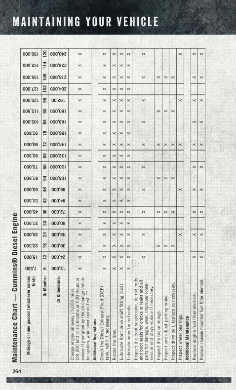
Mai
nten
ance
Char
t—
Cum
min
s®Di
esel
Engi
ne
Mile
age
ortim
epa
ssed
(whi
chev
erco
mes
first
):
7,500
15,000
22,500
30,000
37,500
45,000
52,500
60,000
67,500
75,000
82,500
90,000
97,500
105,000
112,500
120,000
127,000
135,000
142,500
150,000
OrM
onth
s:6
1218
2430
3642
4854
6066
7278
8490
9610
210
811
412
0
OrKi
lom
eter
s:
12,000
24,000
36,000
48,000
60,000
72,000
84,000
96,000
108,000
120,000
132,000
144,000
156,000
168,000
180,000
192,00
204,000
216,000
228,000
240,000
Chan
geen
gine
oile
very
15,0
00m
iles
(24
000
km)
orsi
xm
onth
sor
500
Hou
rsor
soon
erif
prom
pted
byth
eoi
lcha
nge
indi
ca-
tor
syst
em,w
hich
ever
com
esfir
st.*
*
XX
XX
XX
XX
XX
XX
XX
XX
XX
XX
Addi
tiona
lIns
pect
ions
Che
ckth
eD
iese
lExh
aust
Flui
d(D
EF)
tank
,re
fill
ifne
cess
ary.
XX
XX
XX
XX
XX
XX
XX
XX
XX
XX
Rot
ate
the
tire
s.X
XX
XX
XX
XX
XX
XX
XX
XX
XX
X
Lubr
icat
efr
ont
driv
esh
aft
fitt
ing
(4x4
).X
XX
XX
XX
XX
XX
XX
XX
XX
XX
X
Lubr
icat
eou
ter
tie
rod
ends
.X
XX
XX
XX
XX
XX
XX
XX
XX
XX
X
Insp
ect
the
fron
tsu
spen
sion
,ti
ero
den
dsan
dbo
otse
als
for
crac
ksor
leak
san
dal
lpa
rts
for
dam
age,
wea
r,im
prop
erlo
ose-
ness
oren
dpl
ay;
repl
ace
ifne
cess
ary.
XX
XX
XX
XX
XX
Insp
ect
the
brak
elin
ings
.X
XX
XX
X
Insp
ect
and
adju
stpa
rkin
gbr
ake.
XX
XX
XX
Insp
ect
driv
ebe
lt;
repl
ace
asne
cess
ary.
XX
XX
XX
Insp
ect
whe
elbe
arin
gs.
XX
XX
X
Addi
tiona
lMai
nten
ance
Rep
lace
engi
nefu
elfi
lter
elem
ent.
XX
XX
XX
XX
XX
Rep
lace
chas
sis
mou
nted
fuel
filte
rele
men
t.X
XX
XX
XX
XX
X
M A I N T A I N I N G Y O U R V E H I C L E
264
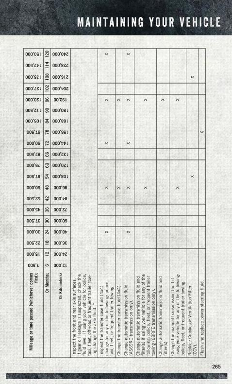
Mile
age
ortim
epa
ssed
(whi
chev
erco
mes
first
):
7,500
15,000
22,500
30,000
37,500
45,000
52,500
60,000
67,500
75,000
82,500
90,000
97,500
105,000
112,500
120,000
127,000
135,000
142,500
150,000
OrM
onth
s:6
1218
2430
3642
4854
6066
7278
8490
9610
210
811
412
0
OrKi
lom
eter
s:
12,000
24,000
36,000
48,000
60,000
72,000
84,000
96,000
108,000
120,000
132,000
144,000
156,000
168,000
180,000
192,00
204,000
216,000
228,000
240,000
Insp
ect
the
fron
tan
dre
arax
lesu
rfac
es.
Ifge
aroi
llea
kage
issu
spec
ted,
chec
kth
efl
uid
leve
l.If
usin
gyo
urve
hicl
efo
rpo
lice,
taxi
,fl
eet,
off-
road
orfr
eque
nttr
aile
rto
w-
ing
chan
geth
eax
lefl
uid.
*
Insp
ect
the
tran
sfer
case
flui
d(4
x4),
chan
gefo
ran
yof
the
follo
win
g:po
lice,
taxi
,fl
eet,
orfr
eque
nttr
aile
rto
win
g.X
XX
XX
Cha
nge
the
tran
sfer
case
flui
d(4
x4).
XX
Cha
nge
auto
mat
ictr
ansm
issi
onfl
uid
(AS
69
RC
tran
smis
sion
only
).X
XX
XX
Cha
nge
auto
mat
ictr
ansm
issi
onfl
uid
and
filt
er(s
)if
usin
gyo
urve
hicl
efo
ran
yof
the
follo
win
g:po
lice,
flee
t,or
freq
uent
trai
ler
tow
ing
(68
RFE
tran
smis
sion
only
).
XX
Cha
nge
auto
mat
ictr
ansm
issi
onfl
uid
and
filt
er(s
).X
Cha
nge
the
man
ualt
rans
mis
sion
flui
dif
usin
gyo
urve
hicl
efo
ran
yof
the
follo
win
g:po
lice,
flee
t,or
freq
uent
trai
ler
tow
ing.
XX
Rep
lace
Cra
nkca
seVe
ntila
tion
Filt
er(C
CV)
.X
X
Flus
han
dre
plac
epo
wer
stee
ring
flui
d.X
M A I N T A I N I N G Y O U R V E H I C L E
265
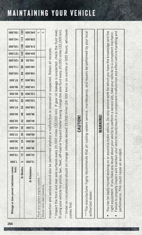
Mile
age
ortim
epa
ssed
(whi
chev
erco
mes
first
):
7,500
15,000
22,500
30,000
37,500
45,000
52,500
60,000
67,500
75,000
82,500
90,000
97,500
105,000
112,500
120,000
127,000
135,000
142,500
150,000
OrM
onth
s:6
1218
2430
3642
4854
6066
7278
8490
9610
210
811
412
0
OrKi
lom
eter
s:
12,000
24,000
36,000
48,000
60,000
72,000
84,000
96,000
108,000
120,000
132,000
144,000
156,000
168,000
180,000
192,00
204,000
216,000
228,000
240,000
Flus
han
dre
plac
een
gine
cool
ant.
***
X
Adj
ust
valv
ela
shcl
eara
nce.
X
Insp
ecti
onan
dse
rvic
esh
ould
also
bepe
rfor
med
anyt
ime
am
alfu
ncti
onis
obse
rved
orsu
spec
ted.
Ret
ain
allr
ecei
pts.
*In
spec
tth
efr
ont
and
rear
axle
surf
aces
ever
y2
0,0
00
mile
s(3
2,0
00
km).
Ifge
aroi
llea
kage
issu
spec
ted,
chec
kth
efl
uid
leve
l.If
usin
gyo
urve
hicl
efo
rpol
ice,
taxi
,fle
et,o
ff-r
oad
orfr
eque
nttr
aile
rtow
ing
chan
geth
eax
lefl
uid
ever
y2
0,0
00
mile
s(3
2,0
00
km).
**U
nder
noci
rcum
stan
ces
shou
ldoi
lcha
nge
inte
rval
sex
ceed
15
,00
0m
iles
(24
00
0km
)or
six
mon
ths
or5
00
Hou
rs,w
hich
ever
com
esfi
rst.
CAU
TION
!
***T
hem
anuf
actu
rer
high
lyre
com
men
dsth
atal
lco
olin
gsy
stem
serv
ice,
mai
nten
ance
,an
dre
pair
sbe
perf
orm
edby
your
loca
lau
thor
ized
deal
er.
WAR
NIN
G!
•Yo
uca
nbe
badl
yin
jure
dw
orki
ngon
orar
ound
am
otor
vehi
cle.
Do
only
serv
ice
wor
kfo
rwhi
chyo
uha
veth
ekn
owle
dge
and
the
righ
tequ
ipm
ent.
Ifyo
uha
vean
ydo
ubta
bout
your
abili
tyto
perf
orm
ase
rvic
ejo
b,ta
keyo
urve
hicl
eto
aco
mpe
tent
mec
hani
c.•
Failu
reto
prop
erly
insp
ecta
ndm
aint
ain
your
vehi
cle
coul
dre
sult
ina
com
pone
ntm
alfu
ncti
onan
def
fect
vehi
cle
hand
ling
and
perf
orm
ance
.Th
isco
uld
caus
ean
acci
dent
.
M A I N T A I N I N G Y O U R V E H I C L E
266
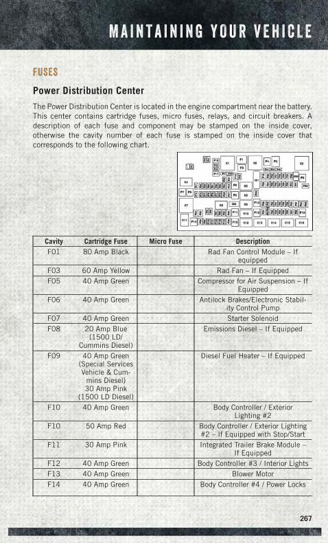
FUSES
Power Distribution Center
The Power Distribution Center is located in the engine compartment near the battery.This center contains cartridge fuses, micro fuses, relays, and circuit breakers. Adescription of each fuse and component may be stamped on the inside cover,otherwise the cavity number of each fuse is stamped on the inside cover thatcorresponds to the following chart.
Cavity Cartridge Fuse Micro Fuse DescriptionF01 80 Amp Black Rad Fan Control Module – If
equippedF03 60 Amp Yellow Rad Fan – If EquippedF05 40 Amp Green Compressor for Air Suspension – If
EquippedF06 40 Amp Green Antilock Brakes/Electronic Stabil-
ity Control PumpF07 40 Amp Green Starter SolenoidF08 20 Amp Blue
(1500 LD/Cummins Diesel)
Emissions Diesel – If Equipped
F09 40 Amp Green(Special ServicesVehicle & Cum-
mins Diesel)30 Amp Pink
(1500 LD Diesel)
Diesel Fuel Heater – If Equipped
F10 40 Amp Green Body Controller / ExteriorLighting #2
F10 50 Amp Red Body Controller / Exterior Lighting#2 – If Equipped with Stop/Start
F11 30 Amp Pink Integrated Trailer Brake Module –If Equipped
F12 40 Amp Green Body Controller #3 / Interior LightsF13 40 Amp Green Blower MotorF14 40 Amp Green Body Controller #4 / Power Locks
M A I N T A I N I N G Y O U R V E H I C L E
267
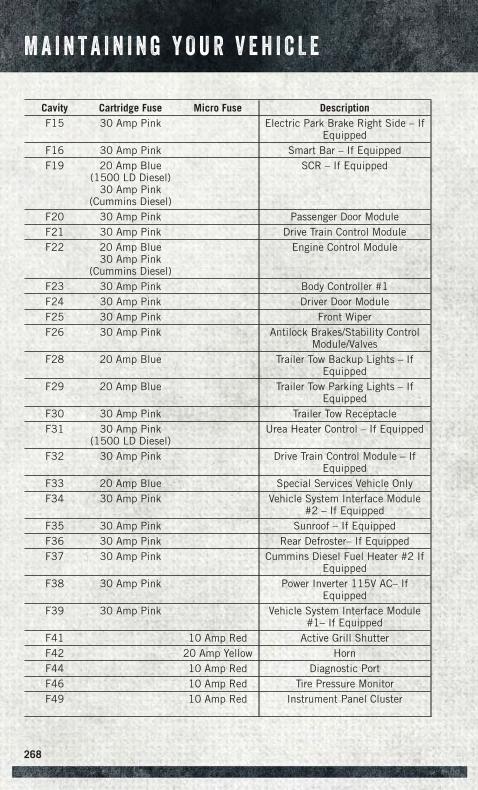
Cavity Cartridge Fuse Micro Fuse DescriptionF15 30 Amp Pink Electric Park Brake Right Side – If
EquippedF16 30 Amp Pink Smart Bar – If EquippedF19 20 Amp Blue
(1500 LD Diesel)30 Amp Pink
(Cummins Diesel)
SCR – If Equipped
F20 30 Amp Pink Passenger Door ModuleF21 30 Amp Pink Drive Train Control ModuleF22 20 Amp Blue
30 Amp Pink(Cummins Diesel)
Engine Control Module
F23 30 Amp Pink Body Controller #1F24 30 Amp Pink Driver Door ModuleF25 30 Amp Pink Front WiperF26 30 Amp Pink Antilock Brakes/Stability Control
Module/ValvesF28 20 Amp Blue Trailer Tow Backup Lights – If
EquippedF29 20 Amp Blue Trailer Tow Parking Lights – If
EquippedF30 30 Amp Pink Trailer Tow ReceptacleF31 30 Amp Pink
(1500 LD Diesel)Urea Heater Control – If Equipped
F32 30 Amp Pink Drive Train Control Module – IfEquipped
F33 20 Amp Blue Special Services Vehicle OnlyF34 30 Amp Pink Vehicle System Interface Module
#2 – If EquippedF35 30 Amp Pink Sunroof – If EquippedF36 30 Amp Pink Rear Defroster– If EquippedF37 30 Amp Pink Cummins Diesel Fuel Heater #2 If
EquippedF38 30 Amp Pink Power Inverter 115V AC– If
EquippedF39 30 Amp Pink Vehicle System Interface Module
#1– If EquippedF41 10 Amp Red Active Grill ShutterF42 20 Amp Yellow HornF44 10 Amp Red Diagnostic PortF46 10 Amp Red Tire Pressure MonitorF49 10 Amp Red Instrument Panel Cluster
M A I N T A I N I N G Y O U R V E H I C L E
268
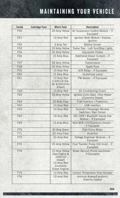
Cavity Cartridge Fuse Micro Fuse DescriptionF50 20 Amp Yellow Air Suspension Control Module – If
EquippedF51 10 Amp Red Ignition Node Module / Keyless
IgnitionF52 5 Amp Tan Battery SensorF53 20 Amp Yellow Trailer Tow – Left Turn/Stop LightsF54 20 Amp Yellow Adjustable PedalsF56 15 Amp Blue Additional Diesel Content – If
EquippedF57 20 Amp Yellow TransmissionF58 20 Amp Yellow Spare FuseF59 10 Amp Red SCR Relay – If EquippedF60 15 Amp Blue Underhood LampF61 10 Amp Red
(1500 LD Die-sel & Cummins
Diesel)
PM Sensor – If Equipped
F62 10 Amp Red Air Conditioning ClutchF63 20 Amp Yellow Ignition Coils (Gas), Urea Heater
(Cummins Diesel)F64 25 Amp Clear Fuel Injectors / PowertrainF65 10 Amp Red USB interfaceF66 10 Amp Red Sunroof / Passenger Window
Switches / Rain SensorF67 10 Amp Red CD / DVD / Bluetooth Hands-free
Module – If EquippedF69 15 Amp Blue Mod SCR 12V (Cummins Diesel) –
If EquippedF70 30 Amp Green Fuel Pump MotorF71 25 Amp Clear AmplifierF72 10 Amp Red Voltage Stabilizer Modules – If
EquippedF73 20 Amp Yellow Fuel Transfer Pump (HD Only) – If
EquippedF74 20 Amp Yellow
(Gas Engine &1500 LDDiesel)
10 Amp Red(Cummins
Diesel Engine)
Brake Vacuum Pump Gas/Diesel –If Equipped
F75 10 Amp Red Coolant Temperature Valve ActuatorF76 10 Amp Red Antilock Brakes/Electronic
Stability Control
M A I N T A I N I N G Y O U R V E H I C L E
269
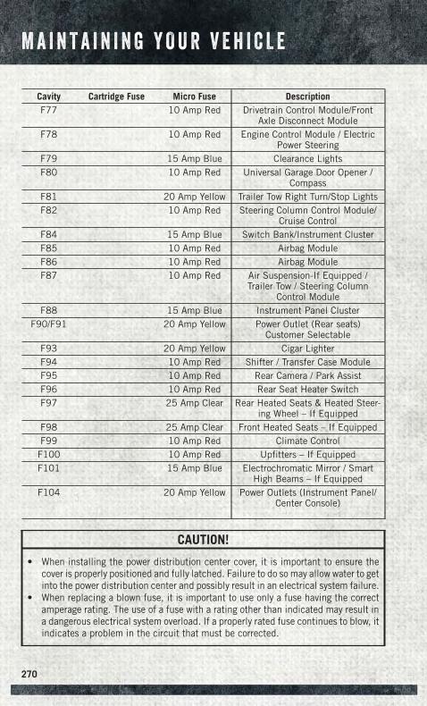
Cavity Cartridge Fuse Micro Fuse DescriptionF77 10 Amp Red Drivetrain Control Module/Front
Axle Disconnect ModuleF78 10 Amp Red Engine Control Module / Electric
Power SteeringF79 15 Amp Blue Clearance LightsF80 10 Amp Red Universal Garage Door Opener /
CompassF81 20 Amp Yellow Trailer Tow Right Turn/Stop LightsF82 10 Amp Red Steering Column Control Module/
Cruise ControlF84 15 Amp Blue Switch Bank/Instrument ClusterF85 10 Amp Red Airbag ModuleF86 10 Amp Red Airbag ModuleF87 10 Amp Red Air Suspension-If Equipped /
Trailer Tow / Steering ColumnControl Module
F88 15 Amp Blue Instrument Panel ClusterF90/F91 20 Amp Yellow Power Outlet (Rear seats)
Customer SelectableF93 20 Amp Yellow Cigar LighterF94 10 Amp Red Shifter / Transfer Case ModuleF95 10 Amp Red Rear Camera / Park AssistF96 10 Amp Red Rear Seat Heater SwitchF97 25 Amp Clear Rear Heated Seats & Heated Steer-
ing Wheel – If EquippedF98 25 Amp Clear Front Heated Seats – If EquippedF99 10 Amp Red Climate Control
F100 10 Amp Red Upfitters – If EquippedF101 15 Amp Blue Electrochromatic Mirror / Smart
High Beams – If EquippedF104 20 Amp Yellow Power Outlets (Instrument Panel/
Center Console)
CAUTION!
• When installing the power distribution center cover, it is important to ensure thecover is properly positioned and fully latched. Failure to do so may allow water to getinto the power distribution center and possibly result in an electrical system failure.
• When replacing a blown fuse, it is important to use only a fuse having the correctamperage rating. The use of a fuse with a rating other than indicated may result ina dangerous electrical system overload. If a properly rated fuse continues to blow, itindicates a problem in the circuit that must be corrected.
M A I N T A I N I N G Y O U R V E H I C L E
270
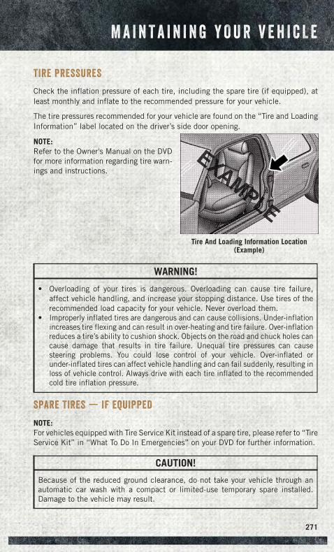
TIRE PRESSURES
Check the inflation pressure of each tire, including the spare tire (if equipped), atleast monthly and inflate to the recommended pressure for your vehicle.
The tire pressures recommended for your vehicle are found on the “Tire and LoadingInformation” label located on the driver’s side door opening.
NOTE:Refer to the Owner's Manual on the DVDfor more information regarding tire warn-ings and instructions.
WARNING!
• Overloading of your tires is dangerous. Overloading can cause tire failure,affect vehicle handling, and increase your stopping distance. Use tires of therecommended load capacity for your vehicle. Never overload them.
• Improperly inflated tires are dangerous and can cause collisions. Under-inflationincreases tire flexing and can result in over-heating and tire failure. Over-inflationreduces a tire’s ability to cushion shock. Objects on the road and chuck holes cancause damage that results in tire failure. Unequal tire pressures can causesteering problems. You could lose control of your vehicle. Over-inflated orunder-inflated tires can affect vehicle handling and can fail suddenly, resulting inloss of vehicle control. Always drive with each tire inflated to the recommendedcold tire inflation pressure.
SPARE TIRES — IF EQUIPPED
NOTE:For vehicles equipped with Tire Service Kit instead of a spare tire, please refer to “TireService Kit” in “What To Do In Emergencies” on your DVD for further information.
CAUTION!
Because of the reduced ground clearance, do not take your vehicle through anautomatic car wash with a compact or limited-use temporary spare installed.Damage to the vehicle may result.
Tire And Loading Information Location(Example)
M A I N T A I N I N G Y O U R V E H I C L E
271
Spare Tire Matching Original Equipped Tire And Wheel — IfEquipped
Your vehicle may be equipped with a spare tire and wheel equivalent in look andfunction to the original equipment tire and wheel found on the front or rear axle ofyour vehicle. This spare tire may be used in the tire rotation for your vehicle. If yourvehicle has this option, refer to an authorized tire dealer for the recommended tirerotation pattern.
Compact Spare Tire — If Equipped
The compact spare is for temporary emergency use only. You can identify if yourvehicle is equipped with a compact spare by looking at the spare tire description onthe Tire and Loading Information Placard located on the driver’s side door opening oron the sidewall of the tire. Compact spare tire descriptions begin with the letter “T”or “S” preceding the size designation. Example: T145/80D18 103M.
T, S = Temporary Spare Tire
Since this tire has limited tread life, the original equipment tire should be repaired(or replaced) and reinstalled on your vehicle at the first opportunity.
Do not install a wheel cover or attempt to mount a conventional tire on the compactspare wheel, since the wheel is designed specifically for the compact spare tire. Donot install more than one compact spare tire and wheel on the vehicle at any giventime.
WARNING!
Compact spares are for temporary emergency use only. With these spares, do notdrive more than 50 mph (80 km/h). Temporary use spares have limited tread life.When the tread is worn to the tread wear indicators, the temporary use spare tireneeds to be replaced. Be sure to follow the warnings, which apply to your spare.Failure to do so could result in spare tire failure and loss of vehicle control.
Full Size Spare — If Equipped
The full size spare is for temporary emergency use only. This tire may look like theoriginally equipped tire on the front or rear axle of your vehicle, but it is not. Thisspare tire may have limited tread life. When the tread is worn to the tread wearindicators, the temporary use full size spare tire needs to be replaced. Since it is notthe same as your original equipment tire, replace (or repair) the original equipmenttire and reinstall on the vehicle at the first opportunity.
M A I N T A I N I N G Y O U R V E H I C L E
272
Limited-Use Spare — If Equipped
The limited-use spare tire is for temporary emergency use only. This tire is identifiedby a label located on the limited-use spare wheel. This label contains the drivinglimitations for this spare. This tire may look like the original equipped tire on the frontor rear axle of your vehicle, but it is not. Installation of this limited-use spare tireaffects vehicle handling. Since it is not the same as your original equipment tire,replace (or repair) the original equipment tire and reinstall on the vehicle at the firstopportunity.
WARNING!
Limited-use spares are for emergency use only. Installation of this limited-usespare tire affects vehicle handling. With this tire, do not drive more than the speedlisted on the limit-use spare wheel. Keep inflated to the cold tire inflationpressures listed on your Tire and Loading Information Placard located on thedriver’s side B-Pillar or the rear edge of the driver’s side door. Replace (or repair)the original equipment tire at the first opportunity and reinstall it on your vehicle.Failure to do so could result in loss of vehicle control.
WHEEL AND WHEEL TRIM CARE
All wheels and wheel trim, especially aluminum and chrome plated wheels, shouldbe cleaned regularly with a mild soap and water to prevent corrosion.
To remove heavy soil and/or excessive brake dust, use MOPAR® Wheel Cleaner orequivalent or select a non-abrasive, non-acidic cleaner.
CAUTION!
Do not use scouring pads, steel wool, a bristle brush, or metal polishes. Do not useoven cleaner. These products may damage the wheel's protective finish. Avoidautomatic car washes that use acidic solutions or harsh brushes that may damagethe wheel's protective finish. Only MOPAR® Wheel Cleaner or equivalent isrecommended.
M A I N T A I N I N G Y O U R V E H I C L E
273
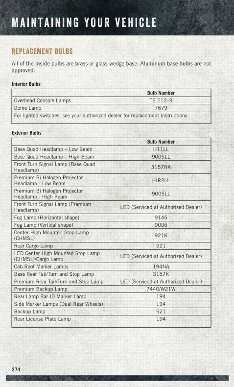
REPLACEMENT BULBS
All of the inside bulbs are brass or glass-wedge base. Aluminum base bulbs are notapproved.
Interior Bulbs
Bulb NumberOverhead Console Lamps TS 212–9Dome Lamp 7679For lighted switches, see your authorized dealer for replacement instructions.
Exterior Bulbs
Bulb NumberBase Quad Headlamp – Low Beam H11LLBase Quad Headlamp – High Beam 9005LLFront Turn Signal Lamp (Base QuadHeadlamp) 3157NA
Premium Bi Halogen ProjectorHeadlamp - Low Beam HIR2LL
Premium Bi Halogen ProjectorHeadlamp - High Beam 9005LL
Front Turn Signal Lamp (PremiumHeadlamp) LED (Serviced at Authorized Dealer)
Fog Lamp (Horizontal shape) 9145Fog Lamp (Vertical shape) 9006Center High Mounted Stop Lamp(CHMSL) 921K
Rear Cargo Lamp 921LED Center High Mounted Stop Lamp(CHMSL)/Cargo Lamp LED (Serviced at Authorized Dealer)
Cab Roof Marker Lamps 194NABase Rear Tail/Turn and Stop Lamp 3157KPremium Rear Tail/Turn and Stop Lamp LED (Serviced at Authorized Dealer)Premium Backup Lamp 7440/W21WRear Lamp Bar ID Marker Lamp 194Side Marker Lamps (Dual Rear Wheels) 194Backup Lamp 921Rear License Plate Lamp 194
M A I N T A I N I N G Y O U R V E H I C L E
274
CHRYSLER GROUP LLC CUSTOMER CENTER
P.O. Box 21–8004 Auburn Hills, MI 48321–8004 Phone: 1–866–726–4636
CHRYSLER CANADA INC. CUSTOMER CENTER
P.O. Box 1621 Windsor, Ontario N9A 4H6 Phone: 1–800–465–2001 (English)Phone: 1–800–387–9983 (French)
ASSISTANCE FOR THE HEARING IMPAIRED
To assist customers who have hearing difficulties, the manufacturer has installed specialTDD (Telecommunication Devices for the Deaf) equipment at its customer center. Anyhearing or speech impaired customer, who has access to a TDD or a conventionalteletypewriter (TTY) in the United States, can communicate with the manufacturer bydialing 1–800–380–CHRY. Canadian residents with hearing difficulties that requireassistance can use the special needs relay service offered by Bell Canada. For TTYteletypewriter users, dial 711 and for Voice callers, dial 1–800–855–0511 to connectwith a Bell Relay Service operator.
WARNING!
Engine exhaust, some of its constituents, and certain vehicle components con-tain, or emit, chemicals known to the State of California to cause cancer and birthdefects, or other reproductive harm. In addition, certain fluids contained invehicles and certain products of component wear contain, or emit, chemicalsknown to the State of California to cause cancer and birth defects, or otherreproductive harm.
PUBLICATIONS ORDERING
• If you are the first registered retail owner of your vehicle, you may obtain a complimen-tary printed copy of the Owner's Manual, Navigation/Uconnect® Manuals or WarrantyBooklet. United States customers may visit the Ram Truck Contact Us page atwww.ramtrucks.com scroll to the bottom of the page and select the “Contact Us”link, then select the “Owner’s Manual and Glove Box Material” from the left menu.You may also obtain a complimentary copy by calling 1–866–726–4636 (U.S.) or1–800–387–1143 (Canada).
• Replacement User Guide kits or DVDs or, if you prefer, additional printed copiesof the Owner's Manual, Warranty Booklet or Radio Manuals may be purchased byvisiting www.techauthority.com or by calling 1–800–890–4038 (U.S.) or1–800–387–1143 (Canada). Visa, Master Card, American Express and Discoverorders are accepted. If you prefer mailing your order, please call the abovenumbers for an order form.
C U S T O M E R A S S I S T A N C E
275
NOTE:
• A street address is required when ordering manuals (no P.O. Boxes).
• The Owner's Manual and User Guide electronic files are also available on theChrysler, Jeep, Ram Truck, Dodge and SRT websites.
• Click on the “For Owners” tab, select “Owner/Service Manuals”, then select yourdesired model year and vehicle from the drop down lists.
REPORTING SAFETY DEFECTS IN THE UNITED STATES
If you believe that your vehicle has a defect that could cause a collision or causeinjury or death, you should immediately inform the National Highway Traffic SafetyAdministration (NHTSA) in addition to notifying the manufacturer.
If NHTSA receives similar complaints, it may open an investigation, and if it findsthat a safety defect exists in a group of vehicles, it may order a recall and remedycampaign. However, NHTSA cannot become involved in individual problems betweenyou, your authorized dealer and the manufacturer.
To contact NHTSA, you may either call the Auto Safety Hotline toll free at1–888–327–4236 (TTY: 1–800–424–9153), or go to http://www.safercar.gov; orwrite to: Administrator, NHTSA, 1200 New Jersey Avenue, SE., West Building,Washington, D.C. 20590. You can also obtain other information about motor vehiclesafety from http://www.safercar.gov.
In Canada
If you believe that your vehicle has a safety defect, you should contact the CustomerService Department immediately. Canadian customers who wish to report a safetydefect to the Canadian government should contact Transport Canada, MotorVehicle Defect Investigations and Recalls at 1-800-333-0510 or go tohttp://www.tc.gc.ca/roadsafety/.
French Canadian customers who wish to report a safety defect to the Canadiangovernment should contact Transport Canada, Motor Vehicle Defect Investigationsand Recalls at 1-800-333-0510 or go to http://www.tc.gc.ca/securiteroutiere/ .
C U S T O M E R A S S I S T A N C E
276
AUTHENTIC ACCESSORIES BY MOPAR®
• In choosing Authentic Accessories you gain far more than expressive style,premium protection, or extreme entertainment, you also benefit from enhancingyour vehicle with accessories that have been thoroughly tested and factory-approved.
• The following highlights just some of the many Authentic Ram Accessories byMopar® featuring a fit, finish, and functionality specifically for your Ram.
• For the full line of Authentic Ram Accessories by Mopar®, visit your localdealership or online at mopar.com for U.S. residents and mopar.ca for Canadianresidents.
NOTE:All parts are subject to availability.
CHROME:• Exhaust Tip • Tubular Side Steps • Fuel Filler Door• Cast Aluminum Wheels • Front Air Deflector • Grille• Body Side Molding
EXTERIOR:• Bedliners • Running Boards • Bed Mat & Bed Rug• Composite Tonneau Cover • Bed Extender • Tool Box• Roll-up Tonneau Cover • Bed Step • Sports Performance Hood• Folding Tonneau Cover • Hitch Receiver • Body Kit• Molded Splash Guards • Tailgate Lock
INTERIOR:• Premium Carpet Mats • Door Sill Guards • Slush Mats• Ambient Light Kit • Bright Pedal Kit • Heated Seats
ELECTRONICS:• Kicker® Sound Systems • Remote Start • Electronic Vehicle Tracking• Mopar® Web (Wi-fi)
CARRIERS:• Bed Mounted Bike Carrier • Cargo Bed Divider • Cargo Ramps• Bed Mounted Ski and
Snowboard Carrier• Bed Mounted Cargo
Basket With Cargo Net
Kicker® is a registered trademark of Stillwater Designs and Audio, Inc.
M O P A R ® A C C E S S O R I E S
277
FREQUENTLY ASKED QUESTIONS
GETTING STARTED
How do I install my LATCH Equipped Child Seat? pg. 22
How do I program my Front Seat Memory? pg. 30
OPERATING YOUR VEHICLE
How does the Electronic Range Select (ERS) operate? pg. 42
ELECTRONICS
Which radio is in my vehicle?
• Uconnect® 3.0 pg. 79
• Uconnect® 5.0 pg. 82
• Uconnect® 8.4A pg. 95
• Uconnect® 8.4AN pg. 126
How do I activate the Audio Jack?
• Uconnect® 3.0 pg. 81
• Uconnect® 5.0 pg. 85
• Uconnect® 8.4A pg. 101
• Uconnect® 8.4AN pg. 101
How do I set the clock on my radio?
• Uconnect® 3.0 pg. 79
• Uconnect® 5.0 pg. 83
• Uconnect® 8.4A pg. 95
• Uconnect® 8.4AN pg. 126
How do I use the Navigation feature?
• Uconnect® 8.4A pg. 104
• Uconnect® 8.4AN pg. 135
How do I pair my cell phone via Bluetooth® with the Uconnect® Hands-Free VoiceActivation System?
• Uconnect® 8.4A pg. 139
• Uconnect® 8.4AN pg. 139
How do I use my iPod®? pg. 101
How do I use my USB port to listen to audio through my touch-screen radio? pg. 101
F A Q ’ s
278
OFF-ROAD CAPABILITIES
How do I shift into different four-wheel drive selections? pg. 158
UTILITY
How do I know how much I can tow with my Ram Truck? pg. 168
How do I adjust the gain on the Integrated Trailer Brake Module? pg. 169
WHAT TO DO IN EMERGENCIES
How do I change a flat tire? pg. 211
How do I Jump-Start my vehicle? pg. 222
MAINTAINING YOUR VEHICLE
Where is my Fuse Block located? pg. 267
What type of oil do I use? pg. 244
How often should I change my engine’s oil?
• Gasoline Engine pg. 252
• Cummins® Diesel Engine pg. 262
• 1500 Diesel Engine pg. 257
F A Q ’ s
279
AccessUconnect® . . . . . . . . . . . . .61
Adding Engine Coolant(Antifreeze). . . . . . . . . . . . .252
Adding Washer Fluid . . . . . . . . .252Adjustable Pedals . . . . . . . . . . .35Air Bag
Advanced Front Air Bag . . . . . .18Advance Front Air Bag . . . . . .17Air Bags . . . . . . . . . . . . . . .17Air Bag Warning Light . . . .17, 205Front Air Bag . . . . . . . . . . . .17Rollover . . . . . . . . . . . . . . .17Side Impacts . . . . . . . . . . . .17
Air Cleaner, Engine (Engine AirCleaner Filter) . . . . . . . . . . .252
Air Conditioner Maintenance . . . .252Air Conditioning . . . . .49, 50, 52, 53Air Conditioning Refrigerant . . . . .252Air Conditioning System . . . . . . .252Air Suspension. . . . . . . . . . .44, 47Alarm
Arm The System . . . . . . . . . .15Disarm The System . . . . . . . .16Vehicle Security Alarm . . . . . .15
Alarm (Security Alarm) . . . . .15, 207Antifreeze (Engine Coolant) . .244, 252
Capacities . . . . . . . . .247, 249Disposal . . . . . . . . . . . . . .252
Anti-Lock Brake System (ABS) . . .205APP
Uconnect® Access . . . . . . . . .64Appearance Care . . . . . . . . . . .252Assistance Towing . . . . . . . . . .201Automatic Headlights . . . . . .38, 208Automatic High Beams . . . . . . . .38Automatic Temperature
Control (ATC) . . . . . . . . . . . .52Automatic Transmission
Fluid Type . . . . . .246, 249, 251Axle Fluid. . . . . . . . .246, 249, 251
Back-Up Camera . . . . . . . . . . . .55Battery . . . . . . . . . . . . . . . . .252
Charging System Light . . . . .204Body Mechanism Lubrication . . . .252Brake Fluid . . . . . . . . . . .246, 249Brakes . . . . . . . . . . . . . . . . .252
Brake System . . . . . . . . . . . . .252Master Cylinder . . . . . . . . .252Warning Light . . . . . . . . . .203
Break-In Recommendations, NewVehicle . . . . . . . . . . . . . . . .36
Bulb Replacement . . . . . . . . . .274Bulbs, Light . . . . . . . . . . . . . .274
Calibration, Compass . . . . . . . . .148Capacities, Antifreeze
(Engine Coolant) . . . . . .247, 249Capacities, Fluid . . . . .244, 247, 249Caps, Filler
Oil (Engine) . . . . . . . . . . . .252Cargo Light . . . . . . . . . . . . . . .39Car Washes . . . . . . . . . . . . . .252Change Oil Indicator . . . . . . . . .206Charging System Light . . . . . . . .204Check Engine Light (Malfunction
Indicator Light) . . . . . . . . . .204Child Restraint . . . . . . . . . . . . .20Child Restraints
Lower Anchors And Tethers ForChildren . . . . . . . . . . . . . .20
CleaningWheels . . . . . . . . . . . . . .252Windshield Wiper Blades . . . .252
Climate Control . . . . . . . .49, 50, 52Cluster Warning/Indicator Lights
Air Bag Warning Light . . . . . .205Brake Warning Light . . . . . . .203Front Fog Light Indicator . . . .207Fuel Cap/Loose Gas Cap . . . . .208High Beam Indicator . . . . . .207Park/Headlight ON Indicator . .207Turn Signal Indicator . . . . . .207Vehicle Security Light . . . . . .207
Clutch . . . . . . . . . . . . . . . . .252Clutch Fluid . . . . . . . . . . . . . .252Compact Spare Tire. . . . . . . . . .272Compass Calibration . . . . . . . . .148Cooling System . . . . . . . . . . . .252
Adding Coolant (Antifreeze) . .252Coolant Capacity . .244, 247, 249Coolant Level . . . . . . . . . . .252Disposal of Used Coolant . . . .252Drain, Flush, and Refill . . . . .252Inspection . . . . . . . . . . . .252
I N D E X
280
Points to Remember . . . . . . .252Pressure Cap . . . . . . . . . . .252Selection of Coolant(Antifreeze) . .244, 245, 247, 250,
252Corrosion Protection . . . . . . . . .252Cruise Control (Speed Control) . . . .39Cruise Light . . . . . . . . . . . . . . .39Customer Assistance . . . . . . . . .275Customer Programmable
Features . . . . . . . . . . . . . .150
Defects, Reporting . . . . . . . . . .276Defroster, Rear Window . . . . . .49, 50Defroster, Windshield . . . . . . .49, 50Diesel Engine Maintenance . .178, 190Diesel Exhaust Fluid . . . . . .182, 195Diesel Fuel Water Separator. .178, 190Dimmer Control. . . . . . . . . . . . .38Disabled Vehicle Towing . . . . . . .201Disarming, Security System . . . . . .16Disposal
Antifreeze (Engine Coolant) . . .252
Electronic Range Select (ERS). .42, 43Electronics
Your Vehicle's Sound System . . .58Electronic Speed Control
(Cruise Control) . . . . . . . . . . .39Electronic Stability Control (ESC). .201Electronic Throttle Control Warning
Light . . . . . . . . . . . . . . . .205Electronic Vehicle Information
Center (EVIC) . . . . . . . . . . .148Emergency, In Case of
Freeing Vehicle When Stuck . .229Jump Starting . . . . . . . . . .222Overheating . . . . . . . . . . . .208Towing . . . . . . . . . . .201, 228
EngineAir Cleaner . . . . . . . . . . . .252Block Heater . . . . . . . . . . .186Break-InRecommendations . .36, 176, 186Checking Oil Level . . . . . . . .252Compartment . . . . . . . . . . .232Coolant(Antifreeze) . . . . . .245, 247, 250
Cooling . . . . . . . . . . . . . . .252Fuel Requirements . . . . . . . .244Jump Starting . . . . . . . . . .222Malfunction Indicator(Check Engine) . . . . . . . . . .204Oil . . . .244, 245, 247, 250, 252Oil Filler Cap . . . . . . . . . . .252Oil Selection . . . . . . . .244, 252Overheating . . . . . . . . . . . .208Starting . . . . . . . . . . . . . . .14Stopping . . . . . . . . . . . . . .14
Event Data Recorder . . . . . . . . .230Exhaust Brake. . . . . . . . . . . . .188Exhaust Regeneration . . . . . . . .179Exhaust System . . . . . . . . . . . .252
FiltersAir Cleaner . . . . . . . . . . . .252Engine Fuel . . . . . . . .178, 190Engine Oil . . .245, 247, 250, 252Engine Oil Disposal . . . . . . .252
FlashersTurn Signal . . . . . . . . . . . .207
Flat Tire Stowage . . . . . . . . . . .220Fluid, Brake. . . . . . . . . . .246, 249Fluid Capacities . . . . .244, 247, 249Fluids, Lubricants and Genuine
Parts . . . . . . . . . .245, 247, 250Fog Lights . . . . . . . . . . . .38, 207Four Wheel Drive . . . . . . . . . . .158Four Wheel Drive Operation . . . . .158Freeing A Stuck Vehicle . . . . . . .229Front And Rear ParkSense System . .54Front Heated Seats. . . . . . . . . . .32Front ParkSense System. . . . . . . .54Fuel
Diesel . . . . . . . . . . . .247, 250Filler Cap (Gas Cap) . . . . . . .208Octane Rating . . . . . . . . . .245Requirements . . . . . . . . . .244Tank Capacity . . . .244, 247, 249
Fuse . . . . . . . . . . . . . . . . . .267Fuses. . . . . . . . . . . . . . . . . .267
Garage Door Opener(HomeLink®) . . . . . . . . . . . .152
General Maintenance. . . . . . . . .252
I N D E X
281
Glass Cleaning . . . . . . . . . . . .252
Headlight . . . . . . . . . . . . . . . .38Headlights
Automatic . . . . . . . . . . . . .38Cleaning . . . . . . . . . . . . .252Dimmer Switch . . . . . . . . . .38High Beam . . . . . . . . . . . . .37Switch . . . . . . . . . . . . . . .38
Head Restraints . . . . . . . . . . . .28Heated Seats . . . . . . . . . . . . . .31Heated Steering Wheel . . . . . . . .33Heater, Engine Block . . . . . . . . .186High Beam Indicator . . . . . . . . .207High Beam/Low Beam Select
(Dimmer) Switch . . . . . . . . . .37HomeLink® (Garage Door
Opener) . . . . . . . . . . . . . . .152Hood Release . . . . . . . . . . . . .231Hub Caps . . . . . . . . . . . . . . .218
Idle Up Feature . . . . . . . . . . . .189Instrument Cluster Indicator
Lights . . . . . . . . . . . . . . . .207Instrument Panel Cover . . . . . . .252Instrument Panel Lens Cleaning . .252Integrated Trailer Brake Controls . .169Interior and Instrument Lights. . .7, 59Interior Appearance Care. . . . . . .252Intermittent Wipers (Delay Wipers) . .37Introduction . . . . . . . . . . . . . . .3In Vehicle Features
Uconnect® Access . . . . . . . . .69Inverter Outlet (115V) . . . . . . . .155Inverter, Power . . . . . . . . . . . .155
Jack Location . . . . . . . . . . . . .209Jump Starting . . . . . . . . . . . . .222
Key Fob . . . . . . . . . . . . . . . . .10Arm The Alarm . . . . . . . . . . .15Disarm The Alarm . . . . . . . . .16
Keyless Enter-N-Go. . . . . . . . . . .13Lock/Unlock . . . . . . . . . . . .13Starting/Stopping . . . . . . . . .14
Lane Change and Turn Signals . . . .37Lane Change Assist . . . . . . . . . .37
Light Bulbs . . . . . . . . . . . . . .274Lights
Engine Temperature Warning . .202Fog . . . . . . . . . . . . . . . .207High Beam Indicator . . . . . .207Security Alarm . . . . . . . . . .207Service . . . . . . . . . . . . . .274Turn Signal . . . . . . . . . . . . .37
Lower Anchors and Tether forCHildren (LATCH) . . . . . . . . . .21
Lubrication, Body . . . . . . . . . . .252
Maintenance Free Battery . . . . . .252Maintenance, General . . . . . . . .252Maintenance Procedures. . . . . . .252Maintenance Record . . . . . .256, 261Maintenance
Schedule . . . .252, 257, 262, 264Malfunction Indicator Light
(Check Engine) . . . . . . . . . .204Manual Transmission
Lubricant Selection . . . . . . .246Master Cylinder (Brakes) . . . . . . .252Memory Seat . . . . . . . . . . . . . .30Message Center
Water in Fuel . . . . . . . .177, 187MOPAR® Accessories. . . . . . . . .277
Navigation. . . . . . . . . . . .104, 135New Vehicle Break-In
Period . . . . . . . . . .36, 176, 186
Oil Change Indicator . . . . . .206, 262Oil Change Indicator, Reset . . . . .206Oil, Engine . . . . .245, 247, 250, 252
Capacity . . . . . . .244, 247, 249Change Interval . . . . . . . . .252Checking . . . . . . . . . . . . .252Disposal . . . . . . . . . . . . . .252Filter . . . . . .245, 247, 250, 252Filter Disposal . . . . . . . . . .252Materials Added to . . . . . . . .252Recommendation . . . . .244, 252Viscosity . . . . . . . . . .244, 252
Oil Filter, Selection . . . . . . . . . .252Outlet
Power . . . . . . . . . . . . . . .155
I N D E X
282
Overheating, Engine . . . . . . . . .208
Paint Care . . . . . . . . . . . . . . .252Panic Alarm . . . . . . . . . . . . . . .11ParkSense® System, Front And
Rear . . . . . . . . . . . . . . . . .54ParkSense® System, Rear . . . . . . .54Pedals, Adjustable . . . . . . . . . . .35Perform Service Indicator, Reset . .263Pickup Box . . . . . . . . . . . . . .161Placard, Tire and Loading
Information. . . . . . . . . . . . .271Power
Distribution Center (Fuses) . . .267Glass Sunroof . . . . . . . . . . .56Inverter . . . . . . . . . . . . . .155Outlet (Auxiliary ElectricalOutlet) . . . . . . . . . . . . . .155Seats . . . . . . . . . . . . . . . .29Sliding Rear Window . . . . . . .55
Power Steering Fluid . . . . . . . . .246Preparation for Jacking. . . . . . . .211Programmable Electronic
Features . . . . . . . . . . . . . .149Purchase Apps
Uconnect® Access . . . . . . . . .65
Rain Sensitive Wiper System . . . . .37Rear Camera . . . . . . . . . . . . . .55Rear Heated Seats . . . . . . . . . . .33Rear ParkSense System. . . . . .54, 55Recreational Towing . . . . . . . . .170
Shifting into Transfer CaseNeutral (N) . . . . . . . . . . . .173Shifting out of Transfer CaseNeutral (N) . . . . . . . . . . . .174
Refrigerant. . . . . . . . . . . . . . .252Remote Keyless Entry (RKE)
Arm The Alarm . . . . . . . . . . .15Disarm The Alarm . . . . . . . . .16
Remote Starting System . . . . . . . .15Replacement Bulbs. . . . . . . . . .274Reporting Safety Defects. . . . . . .276Resetting Perform Service
Indicator . . . . . . . . . . . . . .263Restraint, Head. . . . . . . . . . . . .28Rocking Vehicle When Stuck . . . .229
Schedule, Maintenance . . . .252, 257Seat Belt Maintenance . . . . . . . .252Seat Belts
Adjustable Shoulder Belt . . . . .16Pretensioners . . . . . . . . . . .16Seat Belt Warning . . . . . . . . .17
Seats. . . . . . . . . . . . . . . . . . .29Heated . . . . . . . . . . . . . . .31Lumbar Support . . . . . . . . . .29Memory . . . . . . . . . . . . . . .30Power . . . . . . . . . . . . . . . .29Ventilated . . . . . . . . . . . . .31
Security Alarm . . . . . . . . . . . .207Arm The System . . . . . . . . . .15Disarm The System . . . . . . . .16Security Alarm . . . . . . . . . . .15
Selection of Coolant(Antifreeze) . . . . . .245, 247, 250
Set Up Your Via Mobile ProfileUconnect® . . . . . . . . . . . . .64
ShiftingTransfer Case, Shifting into TransferCase Neutral (N) . . . . . . . . .173Transfer Case, Shifting out ofTransfer Case Neutral (N) . . . .174
Shift Lever Override . . . . . . . . .225Signals, Turn . . . . . . . . . . .37, 207SIRIUS Travel Link . . . . . . . . . .138Spare Tire . . . . . . . . . . . .272, 273Spark Plugs . . . . . . . . . . . . . .245Speed Control
Accel/Decel . . . . . . . . . . . .40Speed Control (Cruise Control) . . . .39Starting
Cold Weather . . . . . . . .177, 187Remote . . . . . . . . . . . . . . .15
Starting Procedures(Diesel Engines). . . . . . .176, 186
Steering Wheel Mounted SoundSystem Controls . . . . . . . . . .147
Stuck, Freeing. . . . . . . . . . . . .229Sun Roof . . . . . . . . . . . . . . . .56Supplemental Restraint System -
Airbag . . . . . . . . . . . . . . . .17
Tailgate . . . . . . . . . . . . . . . .161Temperature Control, Automatic
(ATC) . . . . . . . . . . . . . . . . .52
I N D E X
283
Tether Anchor, Child Restraint . . . .22Tires
Air Pressure . . . . . . . . . . .271Changing . . . . . . . . . . . . .211Compact Spare . . . . . . . . . .272Flat Changing . . . . . . . . . .211Jacking . . . . . . . . . . . . . .211Pressure Warning Light . . . . .201
Tow/Haul . . . . . . . . . . . . . . . .168Tow Hooks, Emergency. . . . . . . .225Towing
Disabled Vehicle . . . . . . . . .228Recreational . . . . . . . . . . .170
Towing Vehicle Behind aMotorhome . . . . . . . . . . . . .170
Traction Control . . . . . . . . . . . .204Trailer Towing
Trailer and Tongue Weight . . .168Transfer Case
Fluid . . . . . . . . .246, 249, 251Transmission
Fluid . . . . . .246, 249, 251, 252Maintenance . . . . . . . . . . .252Warning Light . . . . . . . . . .206
Turbo Cool Down . . . . . . . .180, 194Turn Signals . . . . . . . . . . .37, 207
Uconnect®Access . . . . . . . . . . . . . . . .61Set Up Your Via Mobile Profile . .64Using Access . . . . . . . . . . . .66Via Mobile Apps . . . . . . . . . .78
Uconnect® 3.0 . . . . . . . . . . . . .79Uconnect® 5.0 . . . . . . . . . . . . .82Uconnect® 8.4A . . . . . . . . . . . .95
Uconnect® 8.4AN . . . . . . . . . .126Uconnect® Access . . . . . . . . . . .61
APP . . . . . . . . . . . . . . . . .64In Vehicle Features . . . . . . . . .69Purchase Apps . . . . . . . . . . .65
Uconnect® Voice Command . .88, 111Using Access
Uconnect® . . . . . . . . . . . . .66
Vehicle Security Alarm Disarming . .16Ventilated Seats . . . . . . . . . . . .31Via Mobile Apps
Uconnect® . . . . . . . . . . . . .78Voice Command . . . . . . . . .88, 111Voice Recognition
System (VR) . . . . . . . . . .88, 111
WasherAdding Fluid . . . . . . . . . . .252
Washers, Windshield . . . . . . . . . .37Washing Vehicle. . . . . . . . . . . .252Water in Fuel . . .177, 178, 187, 190Water Separator, Diesel
Fuel. . . . . . . . . . . . . .178, 190Water Separator Draining . . .178, 190Wheel and Wheel Trim . . . . . . . .252Wheel and Wheel Trim Care . .252, 273Wheel Cover . . . . . . . . . . . . . .218Wheel Nut Torque. . . . . . . . . . .219Wind Buffeting . . . . . . . . . . . . .57Windshield Washers . . . . . . . . . .37Windshield Wiper Blades . . . . . .252Windshield Wipers . . . . . . . . . . .37Wiper Blade Replacement . . . . . .252
I N D E X
284

N O T E S
285

N O T E S
286

N O T E S
287

N O T E S
288
The driver’s primary responsibility is the safe operation of the vehicle. Driving
while distracted can result in loss of vehicle control, resulting in a collision and
personal injury. Chrysler Group LLC strongly recommends that the driver use
extreme caution when using any device or feature that may take their attention
off the road. Use of any electrical devices, such as cellular telephones,
computers, portable radios, vehicle navigation or other devices, by the driver
while the vehicle is moving is dangerous and could lead to a serious collision.
Texting while driving is also dangerous and should never be done while the
vehicle is moving. If you find yourself unable to devote your full attention to
vehicle operation, pull off the road to a safe location and stop your vehicle.
Some states or provinces prohibit the use of cellular telephones or texting while
driving. It is always the driver’s responsibility to comply with all local laws.
If you are the first registered retail owner of your vehicle, you
may obtain a complimentary printed copy of the Owner’s
Manual, Navigation/Uconnect® Manuals or Warranty Booklet
by calling 1-866-726-4636 (U.S.) or 1-800-387-1143 (Canada) or
by contacting your dealer.
IMPORTANTThis User Guide is intended to familiarize you with the
important features of your vehicle. The DVD enclosed
contains your Owner’s Manual, Navigation/Uconnect®
Manuals, Warranty Booklets, Tire Warranty and Roadside
Assistance (new vehicles purchased in the U.S.) or Roadside
Assistance (new vehicles purchased in Canada) in electronic
format. We hope you find it useful. Replacement DVD kits
may be purchased by visiting www.techauthority.com.
Copyright 2014 Chrysler Group LLC. Driving and AlcoholDrunken driving is one of the most frequent causes
of collisions. Your driving ability can be seriously
impaired with blood alcohol levels far below the legal
minimum. If you are drinking, don’t drive. Ride with a
designated non-drinking driver, call a cab, a friend, or
use public transportation.
WARNINGDriving after drinking can lead to a collision. Your
perceptions are less sharp, your reflexes are slower, and
your judgment is impaired when you have been drinking.
Never drink and then drive.
This guide has been prepared to help you get quickly
acquainted with your new RAM and to provide a
convenient reference source for common questions.
However, it is not a substitute for your Owner’s Manual.
For complete operational instructions, maintenance
procedures and important safety messages, please consult
your Owner’s Manual, Navigation/Uconnect® Manuals and
other Warning Labels in your vehicle.
Not all features shown in this guide may apply to your
vehicle. For additional information on accessories to help
personalize your vehicle, visit www.mopar.com (U.S.),
www.mopar.ca (Canada) or your local RAM dealer.
1905562_15a_RAM_1500_2500_3500_UG_103114.indd 2 10/31/14 1:37 PM
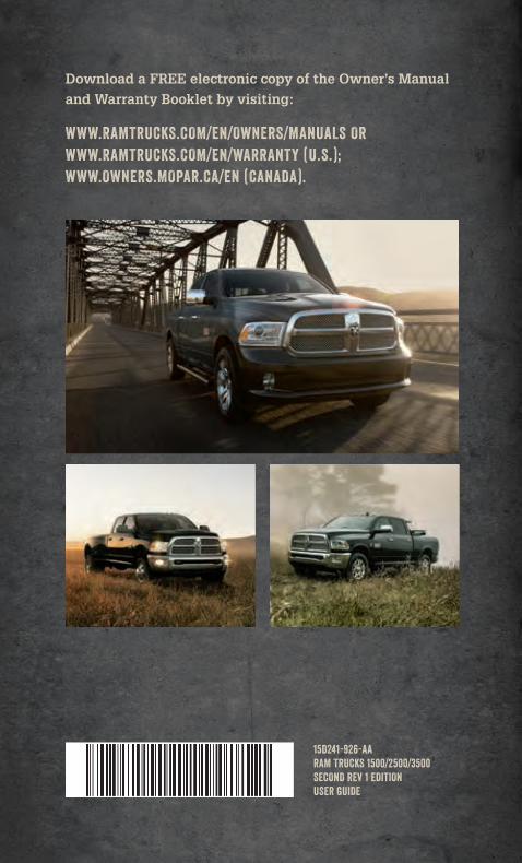
15D241-926-AARAM TRUCKS 1500/2500/3500SECOND REV 1 EDITIONUSER GUIDE
Download a FREE electronic copy of the Owner’s Manual and Warranty Booklet by visiting:
WWW.RAMTRUCKS.COM/EN/OWNERS/MANUALS OR WWW.RAMTRUCKS.COM/EN/WARRANTY (U.S.); WWW.OWNERS.MOPAR.CA/EN (CANADA).
1905562_15a_RAM_1500_2500_3500_UG_103114.indd 1 10/31/14 1:37 PM


