Embed Size (px)
Citation preview
EnglishOriginal Instructions 06-2020 A064Z135 (Issue 1)
S7 HV Alternators
OWNERS MANUAL

iA064Z135 (Issue 1) 06-2020 Copyright © 2020 Cummins Inc.
Table of Contents
1. FOREWORD ......................................................................................................................... 1
2. SAFETY PRECAUTIONS...................................................................................................... 3
3. INTRODUCTION................................................................................................................... 9
4. APPLICATION OF THE ALTERNATOR ............................................................................. 11
5. INSTALLATION INTO THE GENERATOR SET ................................................................. 17
6. SERVICE AND MAINTENANCE......................................................................................... 27
7. PARTS IDENTIFICATION................................................................................................... 45
8. TECHNICAL DATA.............................................................................................................. 51
9. SERVICE PARTS................................................................................................................ 53
10. END OF LIFE DISPOSAL ................................................................................................... 55

This page is intentionally blank.
-
ii A064Z135 (Issue 1) 06-2020Copyright © 2020 Cummins Inc.
1A064Z135 (Issue 1) 06-2020 Copyright © 2020 Cummins Inc.
1 Foreword
1.1 The ManualThis manual contains guidance and instructions for the installation and operation of the alternator. Thismanual does not include instructions for servicing and maintaining the alternator. Contact CumminsGenerator Technologies (CGT) Customer Service for details.
Before operating the alternator, read this manual and make sure that all personnel who work on theequipment have access to the manual and all additional documentation supplied with it. Misuse andfailure to follow the instructions, and the use of non-approved parts, may invalidate the productwarranty and lead to potential accidents.
This manual is an essential part of the alternator. Make sure that the manual is available to all usersthroughout the life of the alternator.
The manual is written for skilled electrical and mechanical technicians and engineers, who have priorknowledge and experience of generating equipment of this type. If in doubt, please seek expert adviceor contact your local CGT subsidiary.
NOTICEInformation in this manual was correct when published. It may be superseded due to ourpolicy of continuous improvement. Please visit www.stamford-avk.com for latestdocumentation.

This page is intentionally blank.
-
2 A064Z135 (Issue 1) 06-2020Copyright © 2020 Cummins Inc.
3A064Z135 (Issue 1) 06-2020 Copyright © 2020 Cummins Inc.
2 Safety Precautions
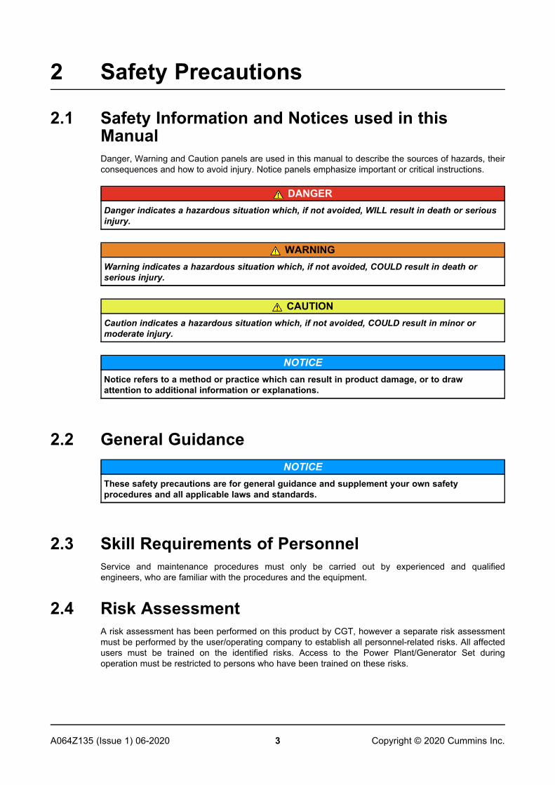
2.1 Safety Information and Notices used in thisManualDanger, Warning and Caution panels are used in this manual to describe the sources of hazards, theirconsequences and how to avoid injury. Notice panels emphasize important or critical instructions.
DANGERDanger indicates a hazardous situation which, if not avoided, WILL result in death or seriousinjury.
WARNINGWarning indicates a hazardous situation which, if not avoided, COULD result in death orserious injury.
CAUTIONCaution indicates a hazardous situation which, if not avoided, COULD result in minor ormoderate injury.
NOTICENotice refers to a method or practice which can result in product damage, or to drawattention to additional information or explanations.
2.2 General GuidanceNOTICE
These safety precautions are for general guidance and supplement your own safetyprocedures and all applicable laws and standards.
2.3 Skill Requirements of PersonnelService and maintenance procedures must only be carried out by experienced and qualifiedengineers, who are familiar with the procedures and the equipment.
2.4 Risk AssessmentA risk assessment has been performed on this product by CGT, however a separate risk assessmentmust be performed by the user/operating company to establish all personnel-related risks. All affectedusers must be trained on the identified risks. Access to the Power Plant/Generator Set duringoperation must be restricted to persons who have been trained on these risks.
-
4 A064Z135 (Issue 1) 06-2020Copyright © 2020 Cummins Inc.
2.5 Personal Protective Equipment (PPE)All persons operating, servicing, maintaining or working in or with a power plant or a generator setmust wear appropriate Personal Protective Equipment (PPE)
Recommended PPE includes:
• Ear and Eye Protection
• Head and face protection
• Safety footwear
• Overalls that protect the lower arms and legs
Ensure that all persons are fully aware of the emergency procedures in case of accidents.
2.6 NoiseWARNING
NoiseNoise from a running alternator can cause serious injury by permanent hearing damage.To prevent injury, wear appropriate personal protection equipment (PPE).
Maximum A-weighted noise emissions may reach 110 dB(A). Contact the supplier for application-specific details.
2.7 Electrical EquipmentDANGER
Live Electrical ConductorsLive electrical conductors can cause serious injury or death by electric shock and burns.To prevent injury and before removing covers over electrical conductors, isolate thegenerator set from all energy sources, remove stored energy and use lock out/tag out safetyprocedures.
All electrical equipment can be dangerous if not operated correctly. Always install, service andmaintain the alternator in accordance with this manual. Work that requires access to electricalconductors must comply with all applicable local and national electrical safety procedures for thevoltages involved and any site specific rules. Always use genuine branded replacement parts.
2.8 Lock Out/Tag OutWARNING
Reconnected Energy SourceAccidental reconnection of energy sources during service and maintenance work can causeserious injury or death by electric shock, burns, crushing, severing or trapping.To prevent injury and before starting service and maintenance work, use appropriate lockout/tag out safety procedures to keep the generator set isolated from energy sources. Do notdefeat or bypass the lock out/tag out safety procedures.
-
5A064Z135 (Issue 1) 06-2020 Copyright © 2020 Cummins Inc.
2.9 Strong Magnetic FieldWARNING
Strong Magnetic FieldThe strong magnetic field from a permanent magnet generator (PMG) or excitation boostsystem (EBS), can cause serious injury or death by interference with implanted medicaldevices.To prevent injury, do not work near a PMG or EBS if you have an implanted medical device.
2.10 LiftingDANGER
Falling Mechanical PartsFalling mechanical parts can cause serious injury or death by impact, crushing, severing ortrapping.To prevent injury and before lifting:
• Check the capacity, condition and attachment of lifting equipment (crane, hoists andjacks, including attachments to anchor, fix or support the equipment).
• Check the capacity, condition and attachment of accessories for lifting (hooks, slings,shackles and eye bolts for attaching loads to lifting equipment).
• Check the capacity, condition and attachment of lifting fixtures on the load.
• Check the mass, integrity and stability (e.g. unbalanced or shifting center of gravity) ofthe load.
WARNINGFalling Mechanical PartsFalling mechanical parts can cause serious injury or death by impact, crushing, severing ortrapping.To prevent injury and before lifting the alternator:
• Do not lift the complete generator set by the alternator lifting fixtures.
• Keep the alternator horizontal when lifting.
• Fit drive end and non-drive end transit fittings to single bearing alternators to keep themain rotor in the frame.
Do not remove the lifting label attached to one of the lifting points.
-
6 A064Z135 (Issue 1) 06-2020Copyright © 2020 Cummins Inc.
2.11 Alternator Operating AreasWARNING
Ejected DebrisDebris ejected during catastrophic failure can cause serious injury or death by impact,severing or stabbing.To prevent injury:
• Keep away from the air inlet and air outlet when the alternator is running.
• Do not put operator controls near the air inlet and air outlet.
• Do not cause overheating by running the alternator outside rating plate parameters.
• Do not overload the alternator.
• Do not run an alternator with excessive vibration.
• Do not synchronize parallel alternators outside the specified parameters.
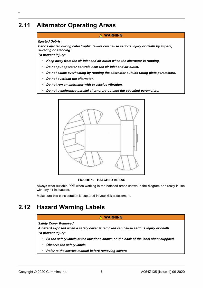
FIGURE 1. HATCHED AREAS
Always wear suitable PPE when working in the hatched areas shown in the diagram or directly in-linewith any air inlet/outlet.
Make sure this consideration is captured in your risk assessment.
2.12 Hazard Warning LabelsWARNING
Safety Cover RemovedA hazard exposed when a safety cover is removed can cause serious injury or death.To prevent injury:
• Fit the safety labels at the locations shown on the back of the label sheet supplied.
• Observe the safety labels.
• Refer to the service manual before removing covers.
-
7A064Z135 (Issue 1) 06-2020 Copyright © 2020 Cummins Inc.
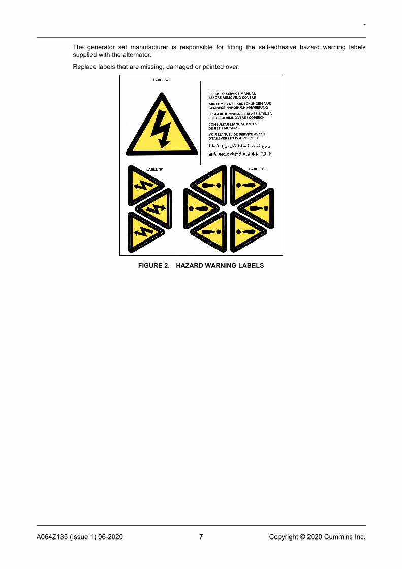
The generator set manufacturer is responsible for fitting the self-adhesive hazard warning labelssupplied with the alternator.
Replace labels that are missing, damaged or painted over.
FIGURE 2. HAZARD WARNING LABELS
This page is intentionally blank.
-
8 A064Z135 (Issue 1) 06-2020Copyright © 2020 Cummins Inc.

9A064Z135 (Issue 1) 06-2020 Copyright © 2020 Cummins Inc.
3 Introduction
3.1 General DescriptionS7 HV alternators are brushless rotating field design, available at 10.5kV and 11kV, 50 HZ (1500RPM,4 pole), and built to meet BS5000 Part 3 and international standard.
3.2 Alternator NameTABLE 1. S7_HV ALTERNATOR NAMING FORMAT
Example: S 7 H 1 D - C 4 2
STA
MFO
RD
Bra
nd
Fam
ilyS
erie
s
Vol
tage
(H=
high
)
Rev
isio
n
Des
crip
torD
=in
dust
rial
Cor
ele
ngth
(C,D
,E,F
...)
Num
bero
fpol
es
Num
bero
fbea
rings
(1=
ND
E,2
=D
E&
ND
E)
3.3 Serial Number LocationA unique serial number is stamped into the drive end ring of the alternator frame and shown on twolabels on the outside of the terminal box (if fitted).
3.4 Rating PlateThe fixed rating plate label states the intended operating parameters of the alternator.
FIGURE 3. GLOBAL STAMFORD AC ALTERNATOR RATING PLATE
-
10 A064Z135 (Issue 1) 06-2020Copyright © 2020 Cummins Inc.
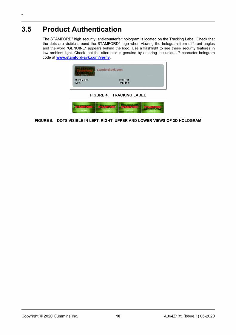
3.5 Product AuthenticationThe STAMFORD® high security, anti-counterfeit hologram is located on the Tracking Label. Check thatthe dots are visible around the STAMFORD® logo when viewing the hologram from different anglesand the word "GENUINE" appears behind the logo. Use a flashlight to see these security features inlow ambient light. Check that the alternator is genuine by entering the unique 7 character hologramcode at www.stamford-avk.com/verify.
FIGURE 4. TRACKING LABEL
FIGURE 5. DOTS VISIBLE IN LEFT, RIGHT, UPPER AND LOWER VIEWS OF 3D HOLOGRAM
11A064Z135 (Issue 1) 06-2020 Copyright © 2020 Cummins Inc.
4 Application of the AlternatorIt is the customer's responsibility to make sure that the selected alternator is suitable for the finalapplication.
4.1 EnvironmentThe alternators are protected to IP23 as standard. IP23 is not adequate protection for use outdoorswithout additional measures.
TABLE 2. ENVIRONMENTAL SPECIFICATION
Ambient Temperature -15 °C to 40 °C (5 °F to 104 °F)
Relative Humidity < 70%
Altitude < 1000 m (3280 ft)
The alternator has been designed for the environment shown in the table. The alternator can operateoutside these conditions if it is rated accordingly; the nameplate gives details. If the operatingenvironment is changed after purchase, refer to the factory for a revised alternator rating.
4.2 Air FlowTABLE 3. MINIMUM AIR FLOW AND MAXIMUM PRESSURE DIFFERENCE
Alternator type
Minimum Air flow @ 50 Hz, m3/s (ft3/min) Maximum intake tooutlet pressure
difference, mm (in)water gauge
50 Hz
S7 HV 2.541 (5384) 6 (0.25)
Make sure that the air inlets and outlets are not obstructed when the alternator is running.
4.3 Airborne ContaminantsContaminants such as salt, oil, exhaust fumes, chemicals, dust and sand will reduce the effectivenessof the insulation and the life of the windings. Consider using an enclosure to protect the alternator.
4.4 Humid ConditionsThe water carrying capacity of air depends on temperature. If the air temperature falls below itssaturation point, dew may form on the windings, reducing the electrical resistance of the insulation. Inhumid conditions, additional protection may be required even if the alternator is fitted inside anenclosure. Anti-condensation heaters are supplied on request.
-
12 A064Z135 (Issue 1) 06-2020Copyright © 2020 Cummins Inc.
4.5 Anti-Condensation HeatersDANGER
Live Electrical ConductorsLive electrical conductors can cause serious injury or death by electric shock and burns.To prevent injury and before removing covers over electrical conductors, isolate thegenerator set from all energy sources, remove stored energy and use lock out/tag out safetyprocedures.
Power to the anti-condensation heater is supplied from a separate source. Anti-condensation heatersraise the air temperature around the windings to deter condensation forming in humid conditions whenthe alternator is not operating. Best practice is to energize the heaters automatically when thealternator is off.
4.6 EnclosuresFit an enclosure to protect the alternator from adverse environmental conditions. Make sure that airentering the alternator is of adequate flowrate, free from moisture and contaminants, and below themaximum ambient temperature on the rating plate.
Make sure there is sufficient access around the alternator for safe maintenance.
4.7 VibrationThe alternators are designed to withstand the vibration levels encountered on generator sets built tomeet the requirements of ISO 8528-9 and BS 5000-3. (Where ISO 8528 is taken to be broad bandmeasurements and BS5000 refers to the predominant frequency of any vibrations on the generatorset).
NOTICEExceeding either of the above specifications will have a detrimental effect on the life of thebearings and other components, and may invalidate the alternator warranty.
NOTICEThe terminal box is designed to support the fitted busbars or terminals, transformers, loadcables and auxiliary terminal box. Additional mass could cause excessive vibration and leadto failure of the terminal box enclosure and mounting. Refer to the Installation Manual toconnect the load cables to the terminal box. Refer to CGT before fixing any additional massto the terminal box.
4.7.1 Definition of BS5000–3Alternators shall be capable of continuously withstanding linear vibration levels with amplitudes of 0.25mm between 5 Hz and 8 Hz, and velocities of 9.0 mm/s RMS between 8 Hz and 200 Hz, whenmeasured at any point directly on the carcass or main frame of the machine. These limits refer only tothe predominant frequency of vibration of any complex waveform.
4.7.2 Definition of ISO 8528-9ISO 8528-9 refers to a broad band of frequencies; the broad band is taken to be between 10 Hertzand 1000 Hertz. The table below is an extract from ISO 8528-9 (Table C.1, value 1). This simplifiedtable lists the vibration limits by kVA and speed for acceptable operation of standard generator setdesigns.
-
13A064Z135 (Issue 1) 06-2020 Copyright © 2020 Cummins Inc.
4.7.3 Vibration FrequenciesThe main vibration frequencies produced by the alternator are as follows:
• 4-pole 1500 RPM 25 Hz
Vibrations induced in the alternator by the engine are complex. It is the responsibility of the generatorset designer to ensure that the alignment and stiffness of the bedplate and mountings do not allowvibration to exceed BS5000 part 3 and ISO 8528 part 9 limits.
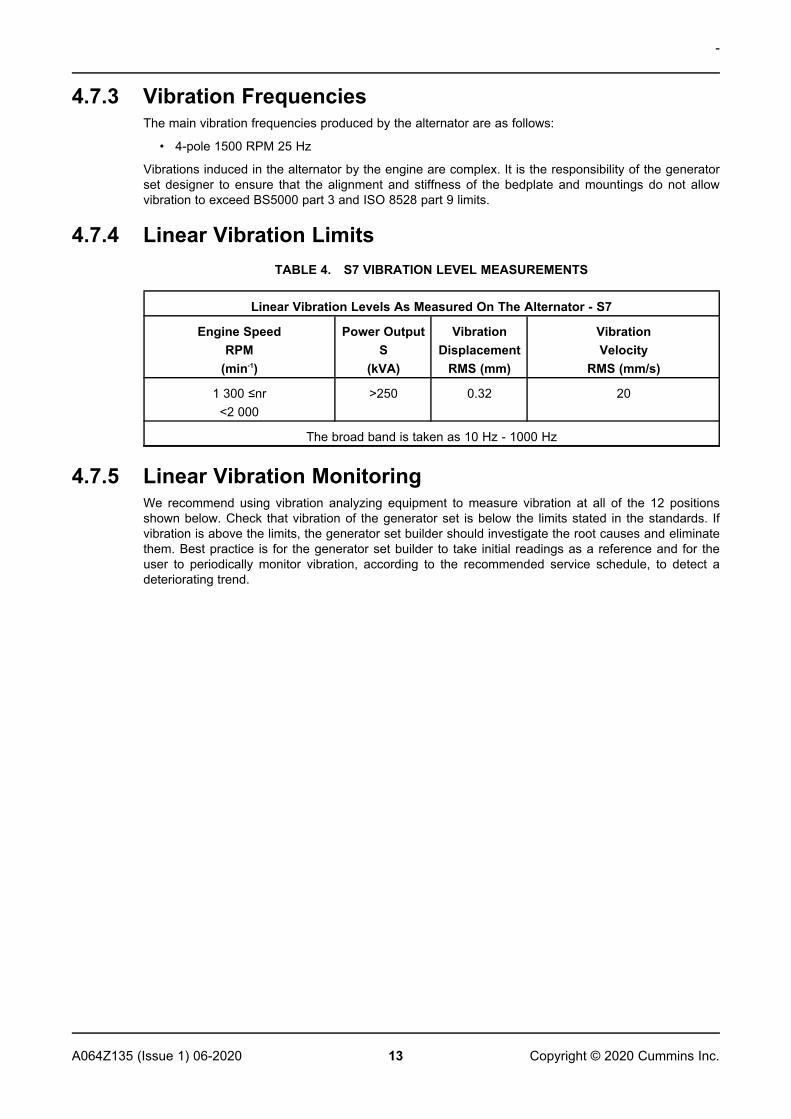
4.7.4 Linear Vibration LimitsTABLE 4. S7 VIBRATION LEVEL MEASUREMENTS
Linear Vibration Levels As Measured On The Alternator - S7
Engine SpeedRPM
(min-1)
Power OutputS
(kVA)
VibrationDisplacement
RMS (mm)
VibrationVelocity
RMS (mm/s)
1 300 ≤nr<2 000
>250 0.32 20
The broad band is taken as 10 Hz - 1000 Hz
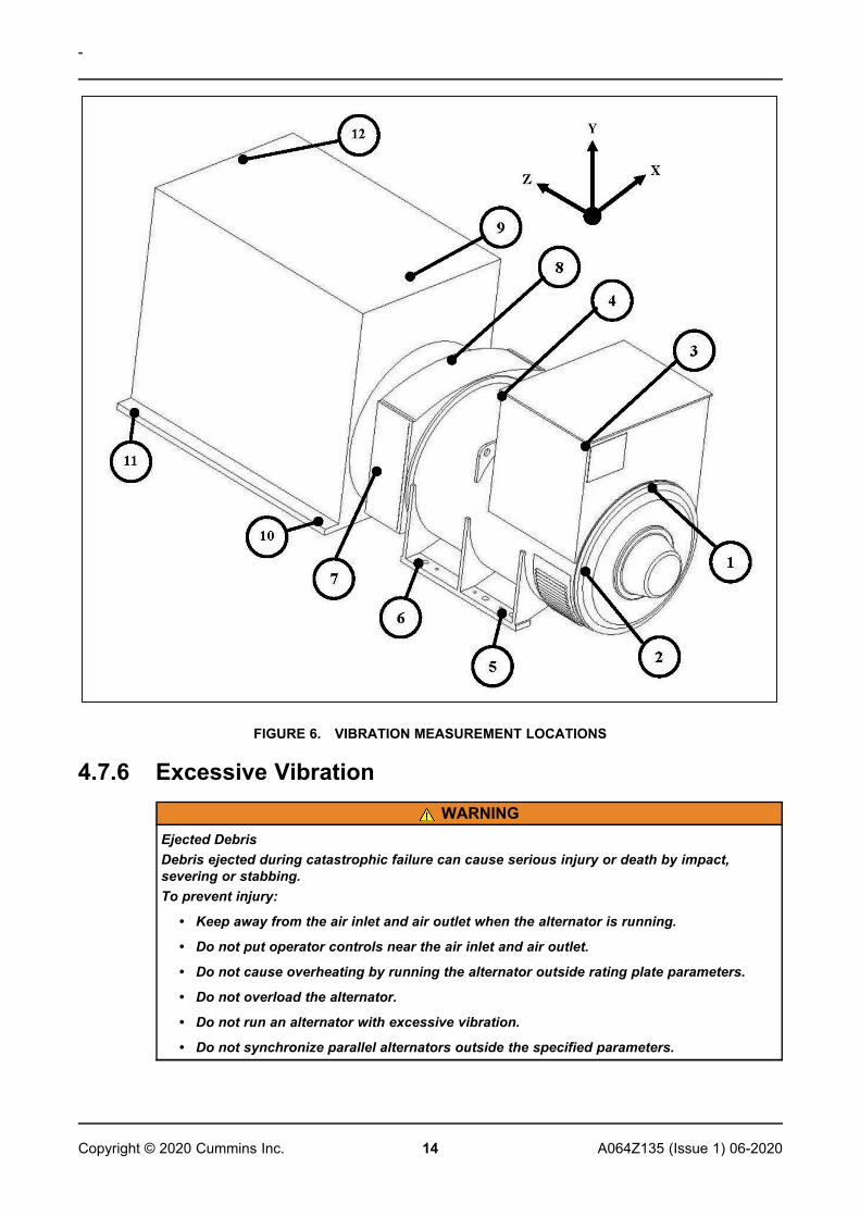
4.7.5 Linear Vibration MonitoringWe recommend using vibration analyzing equipment to measure vibration at all of the 12 positionsshown below. Check that vibration of the generator set is below the limits stated in the standards. Ifvibration is above the limits, the generator set builder should investigate the root causes and eliminatethem. Best practice is for the generator set builder to take initial readings as a reference and for theuser to periodically monitor vibration, according to the recommended service schedule, to detect adeteriorating trend.
-
14 A064Z135 (Issue 1) 06-2020Copyright © 2020 Cummins Inc.
FIGURE 6. VIBRATION MEASUREMENT LOCATIONS
4.7.6 Excessive VibrationWARNING
Ejected DebrisDebris ejected during catastrophic failure can cause serious injury or death by impact,severing or stabbing.To prevent injury:
• Keep away from the air inlet and air outlet when the alternator is running.
• Do not put operator controls near the air inlet and air outlet.
• Do not cause overheating by running the alternator outside rating plate parameters.
• Do not overload the alternator.
• Do not run an alternator with excessive vibration.
• Do not synchronize parallel alternators outside the specified parameters.
-
15A064Z135 (Issue 1) 06-2020 Copyright © 2020 Cummins Inc.
If the measured vibration of the generator set is not within the limits:
1. Consult with the generator set manufacturer to reduce vibration to an acceptable level.
2. Contact CGT Customer Service to assess the impact on bearing and alternator life expectancy.
4.8 Bearings4.8.1 Sealed Bearings
Inspect sealed-for-life bearings periodically, according to the recommended service schedule in thismanual. Check for signs of wear, fretting or other detrimental features. Damage to seals, greaseleakage or discoloration of the bearing races indicate that the bearing may need to be replaced.
4.8.2 Re-greasable BearingsEach bearing housing is connected by a grease pipe to an external grease nipple. A label gives thegrease type and quantity, and frequency for re-greasing. The recommended grease is a highspecification synthetic compound that must not be mixed with grease of a different specification. Referto the Service and Maintenance chapter for detailed instructions.
4.8.3 Bearing LifeFactors that reduce bearing life or lead to bearing failure include:
• Adverse operating conditions and environment
• Stress caused by misalignment of the generator set
• Vibration from the engine that exceeds the limits in BS 5000-3 and ISO 8528-9
• Long periods (including transportation) when the alternator is stationary and subjected tovibration can cause false brinelling wear (flats on the balls and grooves on the races)
• Humid or wet conditions that cause corrosion and deterioration of the grease by emulsification.
4.8.4 Health Monitoring of the BearingsWe recommend that the user checks the bearing condition using vibration monitoring equipment. Bestpractice is to take initial readings as a reference and periodically monitor the bearings to detect adeteriorating trend. It will then be possible to plan a bearing change at an appropriate generator set orengine service interval.
4.8.5 Bearing 'Service Life' ExpectancyBearing manufacturers recognize that the service life of bearings depends on factors that are outsidetheir control. Rather than quote a service life, practicable replacement intervals are based on the L10life of the bearing, the type of grease, and the recommendations of the bearing and greasemanufacturers.
For general purpose applications: If the correct maintenance is carried out, vibration levels do notexceed the levels stated in ISO 8528-9 and BS5000-3, and the ambient temperature does not exceed50 °C, plan to replace the bearings within 30,000 hours of operation.
If in doubt regarding any aspect of bearing life of a STAMFORD® alternator, contact the nearestauthorized supplier of the alternator or contact CGT Customer Service.
4.8.6 Standby ApplicationsRun alternators in standby applications at no load for a minimum of 10 minutes every week. Foralternators fitted with regreasable bearings, re-grease the bearings every 6 months, regardless of thenumber of accumulated running hours.

This page is intentionally blank.
-
16 A064Z135 (Issue 1) 06-2020Copyright © 2020 Cummins Inc.

17A064Z135 (Issue 1) 06-2020 Copyright © 2020 Cummins Inc.
5 Installation into the Generator Set
5.1 Alternator DimensionsDimensions are included in the data sheet specific to the alternator model. Refer to the rating plate toidentify the alternator model.
NOTICEData sheets are available from www.stamford-avk.com
5.2 Lifting the AlternatorWARNING
Falling Mechanical PartsFalling mechanical parts can cause serious injury or death by impact, crushing, severing ortrapping.To prevent injury and before lifting the alternator:
• Do not lift the complete generator set by the alternator lifting fixtures.
• Keep the alternator horizontal when lifting.
• Fit drive end and non-drive end transit fittings to single bearing alternators to keep themain rotor in the frame.
Lift the alternator by hooks or shackles attached to the lifting points (lugs or eyes) provided. A labelattached to a lifting point shows the correct lifting arrangement. Use chains of sufficient length, and aspreader bar if necessary, to make sure that the chains are vertical when lifting. Make sure that thecapacity of the lifting equipment is sufficient for the alternator mass shown on the label.
FIGURE 7. LIFTING LABEL
5.3 StorageIf the alternator will not be used immediately, it must be stored in a clean, dry, vibration-freeenvironment. We recommend the use of anti-condensation heaters, when available.
If the alternator can be rotated, turn the rotor a minimum of 6 revolutions every month during storage.
-
18 A064Z135 (Issue 1) 06-2020Copyright © 2020 Cummins Inc.
5.3.1 After StorageAfter a period of storage, carry out the pre-running checks to determine the condition of the windings.If the windings are damp or the insulation resistance is low, follow one of the drying out procedures(see Chapter 6 on page 27).
Before putting the alternator into service, refer to the following table.
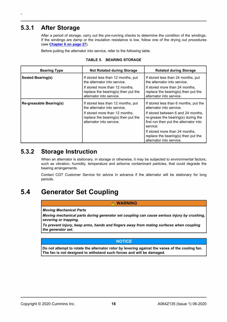
TABLE 5. BEARING STORAGE
Bearing Type Not Rotated during Storage Rotated during Storage
Sealed Bearing(s) If stored less than 12 months, putthe alternator into service.If stored more than 12 months,replace the bearing(s) then put thealternator into service.
If stored less than 24 months, putthe alternator into service.If stored more than 24 months,replace the bearing(s) then put thealternator into service.
Re-greasable Bearing(s) If stored less than 12 months, putthe alternator into service.If stored more than 12 months,replace the bearing(s) then put thealternator into service.
If stored less than 6 months, put thealternator into service.If stored between 6 and 24 months,re-grease the bearing(s) during thefirst run then put the alternator intoservice.If stored more than 24 months,replace the bearing(s) then put thealternator into service.
5.3.2 Storage InstructionWhen an alternator is stationary, in storage or otherwise, it may be subjected to environmental factors,such as vibration, humidity, temperature and airborne contaminant particles, that could degrade thebearing arrangements.
Contact CGT Customer Service for advice in advance if the alternator will be stationary for longperiods.
5.4 Generator Set CouplingWARNING
Moving Mechanical PartsMoving mechanical parts during generator set coupling can cause serious injury by crushing,severing or trapping.To prevent injury, keep arms, hands and fingers away from mating surfaces when couplingthe generator set.
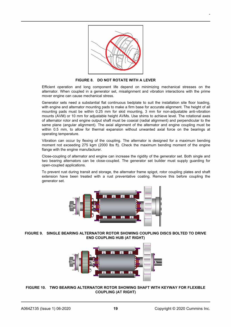
NOTICEDo not attempt to rotate the alternator rotor by levering against the vanes of the cooling fan.The fan is not designed to withstand such forces and will be damaged.
-
19A064Z135 (Issue 1) 06-2020 Copyright © 2020 Cummins Inc.
FIGURE 8. DO NOT ROTATE WITH A LEVER
Efficient operation and long component life depend on minimizing mechanical stresses on thealternator. When coupled in a generator set, misalignment and vibration interactions with the primemover engine can cause mechanical stress.
Generator sets need a substantial flat continuous bedplate to suit the installation site floor loading,with engine and alternator mounting pads to make a firm base for accurate alignment. The height of allmounting pads must be within 0.25 mm for skid mounting, 3 mm for non-adjustable anti-vibrationmounts (AVM) or 10 mm for adjustable height AVMs. Use shims to achieve level. The rotational axesof alternator rotor and engine output shaft must be coaxial (radial alignment) and perpendicular to thesame plane (angular alignment). The axial alignment of the alternator and engine coupling must bewithin 0.5 mm, to allow for thermal expansion without unwanted axial force on the bearings atoperating temperature.
Vibration can occur by flexing of the coupling. The alternator is designed for a maximum bendingmoment not exceeding 275 kgm (2000 lbs ft). Check the maximum bending moment of the engineflange with the engine manufacturer.
Close-coupling of alternator and engine can increase the rigidity of the generator set. Both single andtwo bearing alternators can be close-coupled. The generator set builder must supply guarding foropen-coupled applications.
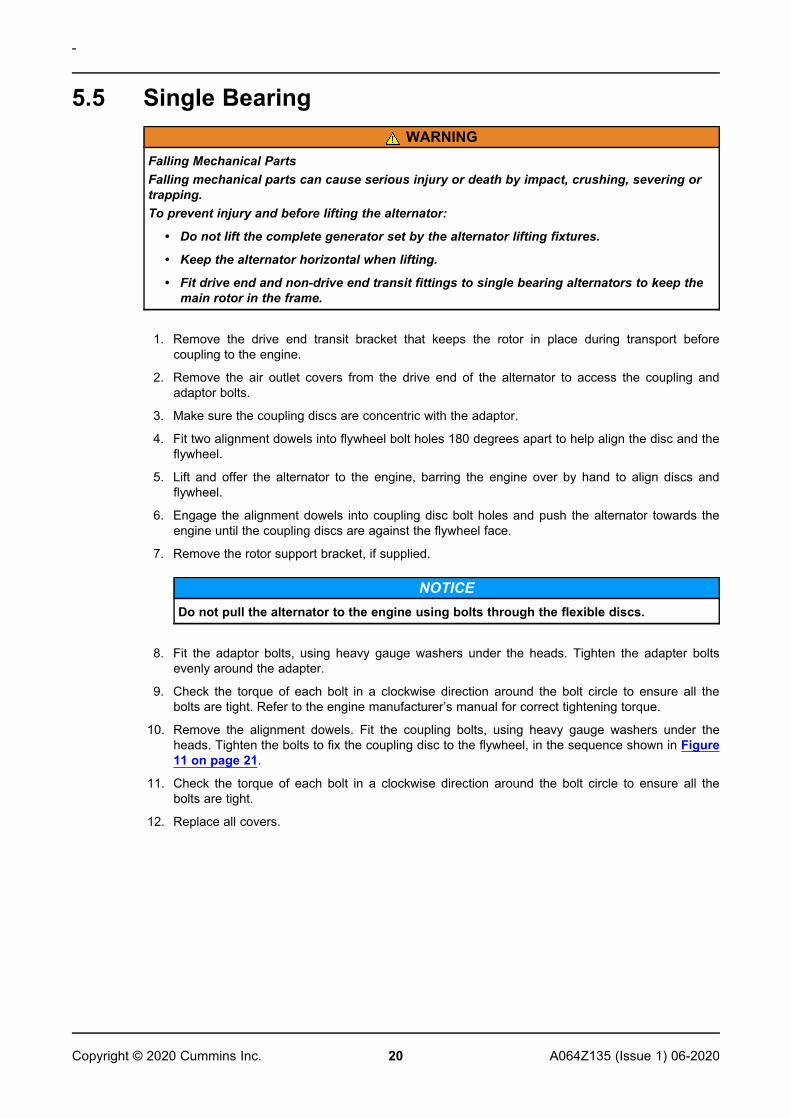
To prevent rust during transit and storage, the alternator frame spigot, rotor coupling plates and shaftextension have been treated with a rust preventative coating. Remove this before coupling thegenerator set.
FIGURE 9. SINGLE BEARING ALTERNATOR ROTOR SHOWING COUPLING DISCS BOLTED TO DRIVEEND COUPLING HUB (AT RIGHT)
FIGURE 10. TWO BEARING ALTERNATOR ROTOR SHOWING SHAFT WITH KEYWAY FOR FLEXIBLECOUPLING (AT RIGHT)
-
20 A064Z135 (Issue 1) 06-2020Copyright © 2020 Cummins Inc.
5.5 Single BearingWARNING
Falling Mechanical PartsFalling mechanical parts can cause serious injury or death by impact, crushing, severing ortrapping.To prevent injury and before lifting the alternator:
• Do not lift the complete generator set by the alternator lifting fixtures.
• Keep the alternator horizontal when lifting.
• Fit drive end and non-drive end transit fittings to single bearing alternators to keep themain rotor in the frame.
1. Remove the drive end transit bracket that keeps the rotor in place during transport beforecoupling to the engine.
2. Remove the air outlet covers from the drive end of the alternator to access the coupling andadaptor bolts.
3. Make sure the coupling discs are concentric with the adaptor.
4. Fit two alignment dowels into flywheel bolt holes 180 degrees apart to help align the disc and theflywheel.
5. Lift and offer the alternator to the engine, barring the engine over by hand to align discs andflywheel.
6. Engage the alignment dowels into coupling disc bolt holes and push the alternator towards theengine until the coupling discs are against the flywheel face.
7. Remove the rotor support bracket, if supplied.
NOTICEDo not pull the alternator to the engine using bolts through the flexible discs.
8. Fit the adaptor bolts, using heavy gauge washers under the heads. Tighten the adapter boltsevenly around the adapter.
9. Check the torque of each bolt in a clockwise direction around the bolt circle to ensure all thebolts are tight. Refer to the engine manufacturer’s manual for correct tightening torque.
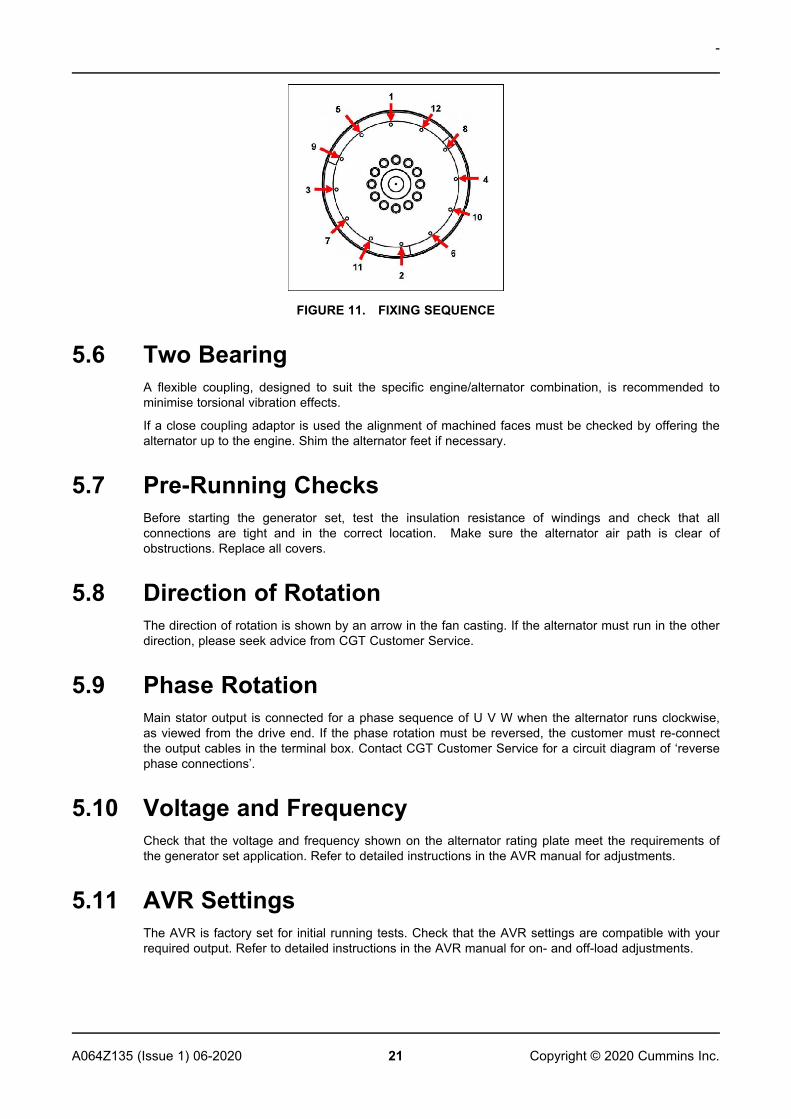
10. Remove the alignment dowels. Fit the coupling bolts, using heavy gauge washers under theheads. Tighten the bolts to fix the coupling disc to the flywheel, in the sequence shown in Figure11 on page 21.
11. Check the torque of each bolt in a clockwise direction around the bolt circle to ensure all thebolts are tight.
12. Replace all covers.
-
21A064Z135 (Issue 1) 06-2020 Copyright © 2020 Cummins Inc.
FIGURE 11. FIXING SEQUENCE
5.6 Two BearingA flexible coupling, designed to suit the specific engine/alternator combination, is recommended tominimise torsional vibration effects.
If a close coupling adaptor is used the alignment of machined faces must be checked by offering thealternator up to the engine. Shim the alternator feet if necessary.
5.7 Pre-Running ChecksBefore starting the generator set, test the insulation resistance of windings and check that allconnections are tight and in the correct location. Make sure the alternator air path is clear ofobstructions. Replace all covers.
5.8 Direction of RotationThe direction of rotation is shown by an arrow in the fan casting. If the alternator must run in the otherdirection, please seek advice from CGT Customer Service.
5.9 Phase RotationMain stator output is connected for a phase sequence of U V W when the alternator runs clockwise,as viewed from the drive end. If the phase rotation must be reversed, the customer must re-connectthe output cables in the terminal box. Contact CGT Customer Service for a circuit diagram of ‘reversephase connections’.
5.10 Voltage and FrequencyCheck that the voltage and frequency shown on the alternator rating plate meet the requirements ofthe generator set application. Refer to detailed instructions in the AVR manual for adjustments.
5.11 AVR SettingsThe AVR is factory set for initial running tests. Check that the AVR settings are compatible with yourrequired output. Refer to detailed instructions in the AVR manual for on- and off-load adjustments.
-
22 A064Z135 (Issue 1) 06-2020Copyright © 2020 Cummins Inc.
5.12 Electrical ConnectionsWARNING
Incorrect Electrical Installation and System ProtectionIncorrect electrical installation and system protection can cause serious injury or death byelectric shock and burns.To prevent injury, installers must be qualified and are responsible for meeting appropriateinspectorate and local electricity authority requirements and site safety rules.
NOTICEThe terminal box is designed to support the fitted busbars or terminals, transformers, loadcables and auxiliary terminal box. Additional mass could cause excessive vibration and leadto failure of the terminal box enclosure and mounting. Refer to CGT before fixing anyadditional mass to the terminal box. Panels must be removed to be drilled or cut, to preventswarf entering the terminal box or alternator.
Fault current curves and alternator reactance values are available on request from the factory so thatthe system designer can calculate the necessary fault protection and/or discrimination.
The installer must check that the alternator frame is bonded to the generator set bedplate, and mustbond to site earth. If anti-vibration mounts are fitted between the alternator frame and its bedplate, asuitably-rated earth conductor must bridge across the anti-vibration mount.
Refer to wiring diagrams for electrical connection of the load cables. Electrical connections are madein the terminal box, constructed with removable panels to suit site-specific cable entry and glanding.Route single core cables through the insulated or non-magnetic gland plates supplied. Panels must beremoved to be drilled or cut to prevent swarf entering the terminal box or alternator. After wiring,inspect the terminal box, remove all debris using a vacuum cleaner if necessary and check that nointernal components are damaged or disturbed.
As standard, the alternator neutral is not bonded to the alternator frame. If required, neutral may beconnected to the earth terminal in the terminal box, by a conductor of at least one half of the sectionalarea of a phase lead.
Load cables must be supported appropriately to avoid a tight radius at the point of entry into theterminal box, clamped at the terminal box gland, and allow at least ±25 mm movement by thealternator set on its anti-vibration mountings, without causing excessive stress to the cables andalternator load terminals.
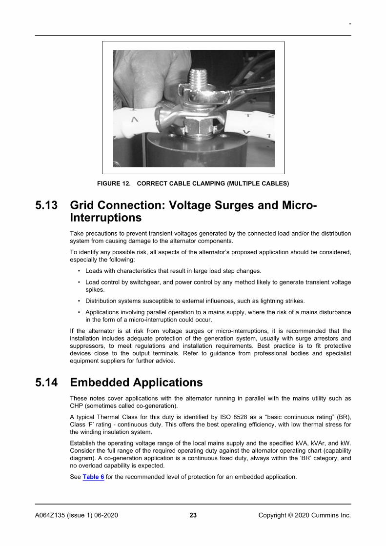
The palm (flattened part) of load cable lugs must be clamped in direct contact with the main statorload output terminals so that the whole palm area conducts the output current. The tightening torqueof M12 fasteners is 70 Nm (51.6 ft-lb) (main nut) and 45 Nm (33.2 ft-lb) (lock nut) on insulatedterminals.
-
23A064Z135 (Issue 1) 06-2020 Copyright © 2020 Cummins Inc.
FIGURE 12. CORRECT CABLE CLAMPING (MULTIPLE CABLES)
5.13 Grid Connection: Voltage Surges and Micro-InterruptionsTake precautions to prevent transient voltages generated by the connected load and/or the distributionsystem from causing damage to the alternator components.
To identify any possible risk, all aspects of the alternator’s proposed application should be considered,especially the following:
• Loads with characteristics that result in large load step changes.
• Load control by switchgear, and power control by any method likely to generate transient voltagespikes.
• Distribution systems susceptible to external influences, such as lightning strikes.
• Applications involving parallel operation to a mains supply, where the risk of a mains disturbancein the form of a micro-interruption could occur.
If the alternator is at risk from voltage surges or micro-interruptions, it is recommended that theinstallation includes adequate protection of the generation system, usually with surge arrestors andsuppressors, to meet regulations and installation requirements. Best practice is to fit protectivedevices close to the output terminals. Refer to guidance from professional bodies and specialistequipment suppliers for further advice.
5.14 Embedded ApplicationsThese notes cover applications with the alternator running in parallel with the mains utility such asCHP (sometimes called co-generation).
A typical Thermal Class for this duty is identified by ISO 8528 as a “basic continuous rating” (BR),Class ‘F’ rating - continuous duty. This offers the best operating efficiency, with low thermal stress forthe winding insulation system.
Establish the operating voltage range of the local mains supply and the specified kVA, kVAr, and kW.Consider the full range of the required operating duty against the alternator operating chart (capabilitydiagram). A co-generation application is a continuous fixed duty, always within the ‘BR’ category, andno overload capability is expected.
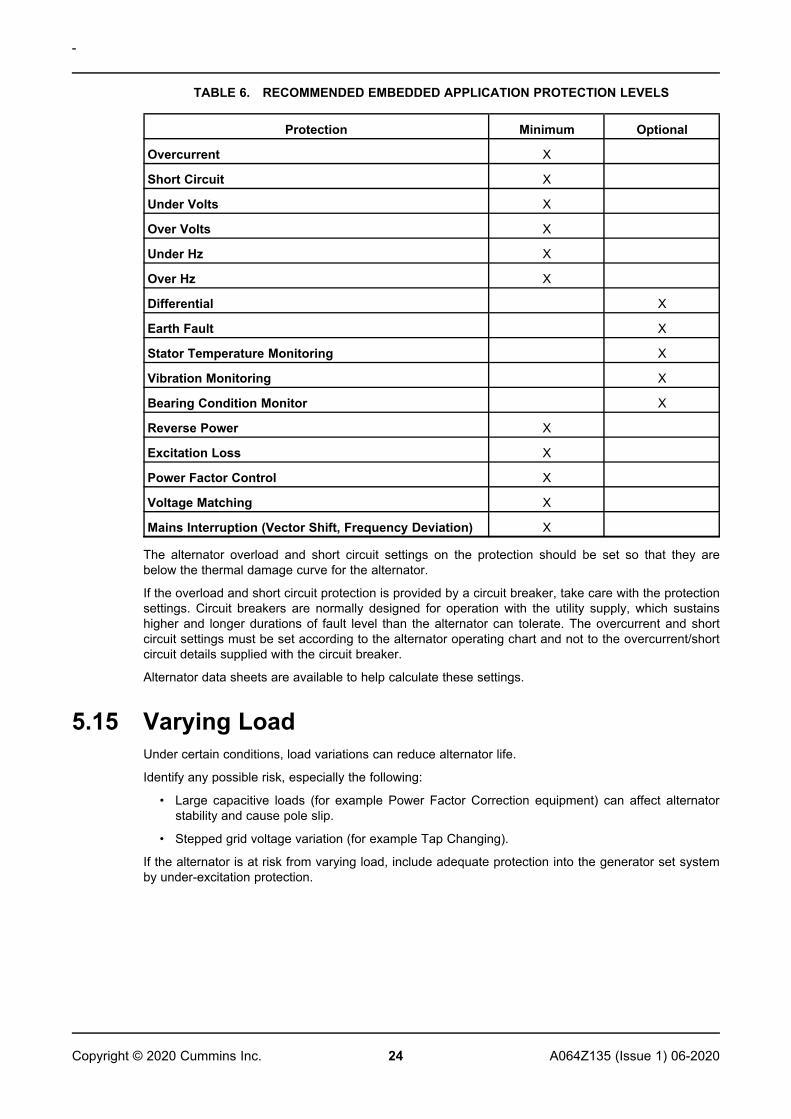
See Table 6 for the recommended level of protection for an embedded application.
-
24 A064Z135 (Issue 1) 06-2020Copyright © 2020 Cummins Inc.
TABLE 6. RECOMMENDED EMBEDDED APPLICATION PROTECTION LEVELS
Protection Minimum Optional
Overcurrent X
Short Circuit X
Under Volts X
Over Volts X
Under Hz X
Over Hz X
Differential X
Earth Fault X
Stator Temperature Monitoring X
Vibration Monitoring X
Bearing Condition Monitor X
Reverse Power X
Excitation Loss X
Power Factor Control X
Voltage Matching X
Mains Interruption (Vector Shift, Frequency Deviation) X
The alternator overload and short circuit settings on the protection should be set so that they arebelow the thermal damage curve for the alternator.
If the overload and short circuit protection is provided by a circuit breaker, take care with the protectionsettings. Circuit breakers are normally designed for operation with the utility supply, which sustainshigher and longer durations of fault level than the alternator can tolerate. The overcurrent and shortcircuit settings must be set according to the alternator operating chart and not to the overcurrent/shortcircuit details supplied with the circuit breaker.
Alternator data sheets are available to help calculate these settings.
5.15 Varying LoadUnder certain conditions, load variations can reduce alternator life.
Identify any possible risk, especially the following:
• Large capacitive loads (for example Power Factor Correction equipment) can affect alternatorstability and cause pole slip.
• Stepped grid voltage variation (for example Tap Changing).
If the alternator is at risk from varying load, include adequate protection into the generator set systemby under-excitation protection.
-
25A064Z135 (Issue 1) 06-2020 Copyright © 2020 Cummins Inc.
5.16 SynchronizationWARNING
Ejected DebrisDebris ejected during catastrophic failure can cause serious injury or death by impact,severing or stabbing.To prevent injury:
• Keep away from the air inlet and air outlet when the alternator is running.
• Do not put operator controls near the air inlet and air outlet.
• Do not cause overheating by running the alternator outside rating plate parameters.
• Do not overload the alternator.
• Do not run an alternator with excessive vibration.
• Do not synchronize parallel alternators outside the specified parameters.
5.16.1 Parallel or Synchronizing Alternators
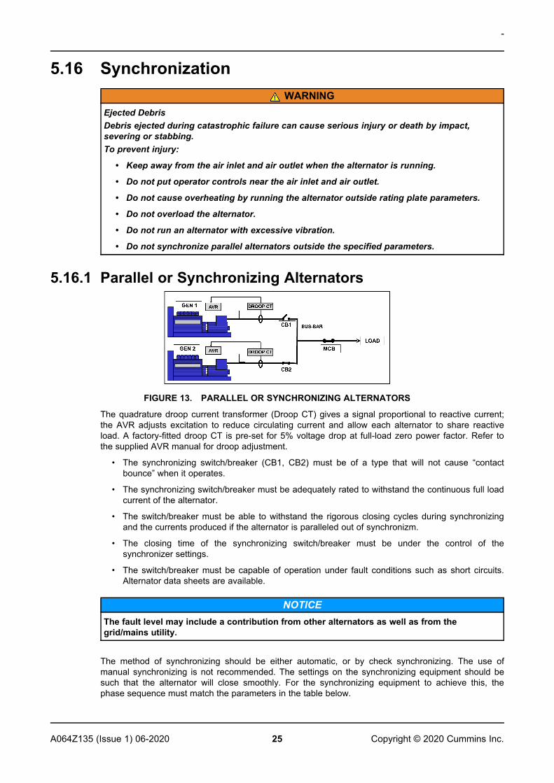
FIGURE 13. PARALLEL OR SYNCHRONIZING ALTERNATORS
The quadrature droop current transformer (Droop CT) gives a signal proportional to reactive current;the AVR adjusts excitation to reduce circulating current and allow each alternator to share reactiveload. A factory-fitted droop CT is pre-set for 5% voltage drop at full-load zero power factor. Refer tothe supplied AVR manual for droop adjustment.
• The synchronizing switch/breaker (CB1, CB2) must be of a type that will not cause “contactbounce” when it operates.
• The synchronizing switch/breaker must be adequately rated to withstand the continuous full loadcurrent of the alternator.
• The switch/breaker must be able to withstand the rigorous closing cycles during synchronizingand the currents produced if the alternator is paralleled out of synchronizm.
• The closing time of the synchronizing switch/breaker must be under the control of thesynchronizer settings.
• The switch/breaker must be capable of operation under fault conditions such as short circuits.Alternator data sheets are available.
NOTICEThe fault level may include a contribution from other alternators as well as from thegrid/mains utility.
The method of synchronizing should be either automatic, or by check synchronizing. The use ofmanual synchronizing is not recommended. The settings on the synchronizing equipment should besuch that the alternator will close smoothly. For the synchronizing equipment to achieve this, thephase sequence must match the parameters in the table below.
-
26 A064Z135 (Issue 1) 06-2020Copyright © 2020 Cummins Inc.
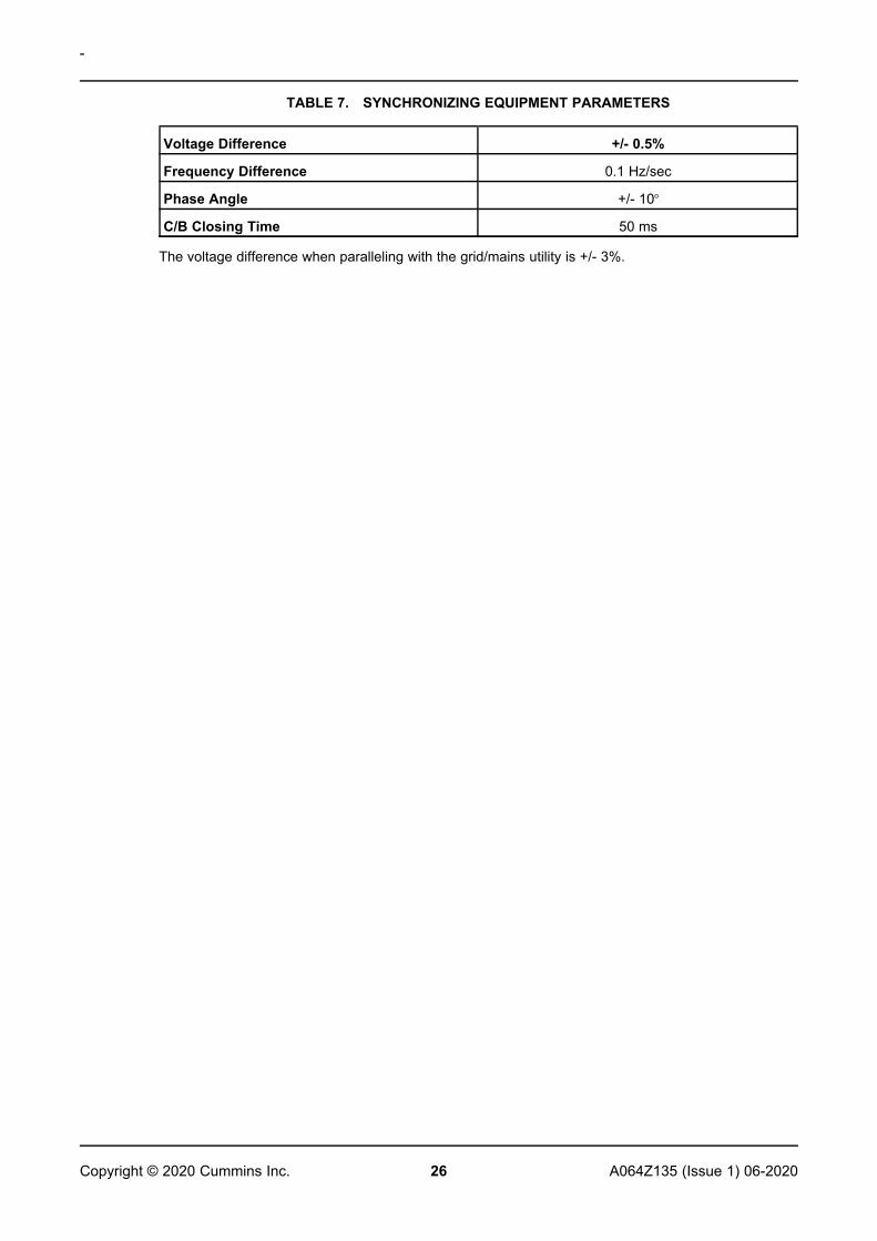
TABLE 7. SYNCHRONIZING EQUIPMENT PARAMETERS
Voltage Difference +/- 0.5%
Frequency Difference 0.1 Hz/sec
Phase Angle +/- 10o
C/B Closing Time 50 ms
The voltage difference when paralleling with the grid/mains utility is +/- 3%.
27A064Z135 (Issue 1) 06-2020 Copyright © 2020 Cummins Inc.
6 Service and Maintenance
6.1 Recommended Service ScheduleRefer to Safety Precautions section (Chapter 2 on page 3) of this manual before starting any serviceand maintenance activity.
Refer to Parts Identification section (Chapter 7 on page 45) for an exploded view of components andfastener information.
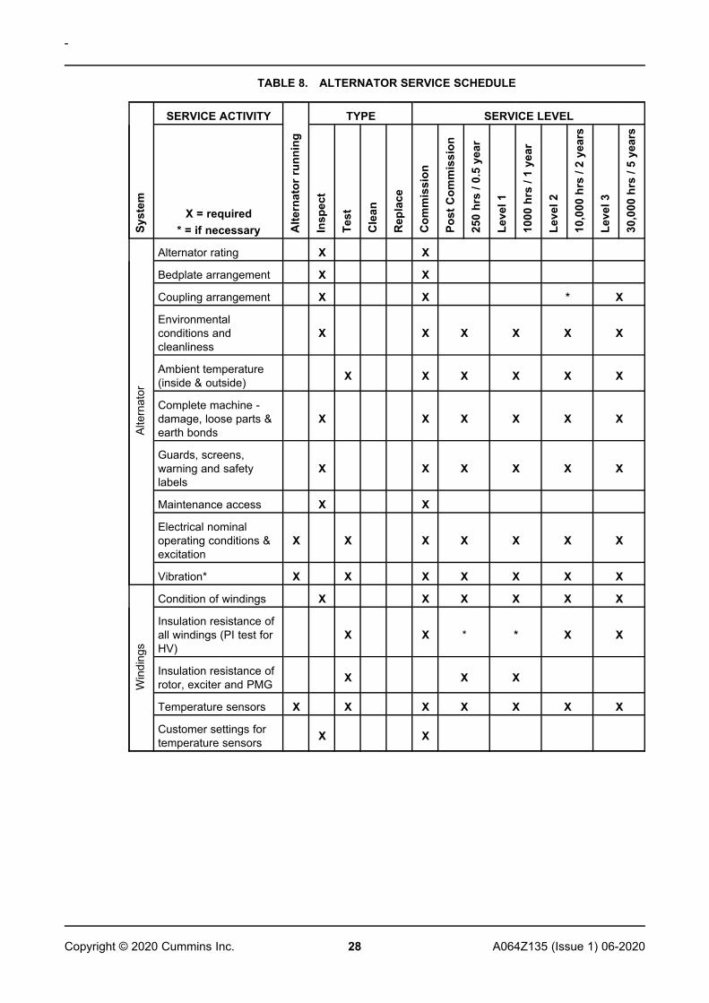
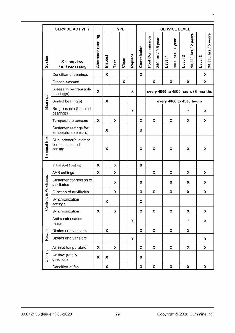
The recommended service schedule shows the recommended service activities in table rows, groupedby alternator subsystem. Columns of the table show the types of service activity, whether thealternator must be running, and the service levels. Service frequency is given in running hours or timeinterval, whichever is sooner. A cross (X) in the cells where a row intersects the columns shows aservice activity type and when it is required. An asterisk (*) shows a service activity done only whennecessary.
All service levels in the recommended service schedule can be purchased directly from CGTCustomer Service. For details of your nearest service outlet visit www.stamford-avk.com,
1. Proper service and repair are vital to the reliable operation of your alternator and the safety ofanyone coming into contact with the alternator.
2. These service activities are intended to maximize the life of the alternator but shall not vary,extend or change the terms of the manufacturer's standard warranty or your obligations in thatwarranty.
3. Each service interval is a guide only, and developed on the basis that the alternator was installedand is operated in accordance with the manufacturer's guidelines. If the alternator is locatedand/or operated in adverse or unusual environmental conditions, the service intervals may needto be more frequent. The alternator should be continually monitored between services to identifyany potential failure modes, signs of misuse, or excessive wear and tear.
-
28 A064Z135 (Issue 1) 06-2020Copyright © 2020 Cummins Inc.
TABLE 8. ALTERNATOR SERVICE SCHEDULE
Syst
em
SERVICE ACTIVITY
Alte
rnat
orru
nnin
g
TYPE SERVICE LEVEL
X = required* = if necessary In
spec
t
Test
Cle
an
Rep
lace
Com
mis
sion
Post
Com
mis
sion
250
hrs
/0.5
year
Leve
l1
1000
hrs
/1ye
ar
Leve
l2
10,0
00hr
s/2
year
s
Leve
l3
30,0
00hr
s/5
year
s
Alte
rnat
or
Alternator rating X X
Bedplate arrangement X X
Coupling arrangement X X * X
Environmentalconditions andcleanliness
X X X X X X
Ambient temperature(inside & outside) X X X X X X
Complete machine -damage, loose parts &earth bonds
X X X X X X
Guards, screens,warning and safetylabels
X X X X X X
Maintenance access X X
Electrical nominaloperating conditions &excitation
X X X X X X X
Vibration* X X X X X X X
Win
ding
s
Condition of windings X X X X X X
Insulation resistance ofall windings (PI test forHV)
X X * * X X
Insulation resistance ofrotor, exciter and PMG X X X
Temperature sensors X X X X X X X
Customer settings fortemperature sensors X X
-
29A064Z135 (Issue 1) 06-2020 Copyright © 2020 Cummins Inc.
Syst
em
SERVICE ACTIVITY
Alte
rnat
orru
nnin
g
TYPE SERVICE LEVEL
X = required* = if necessary In
spec
t
Test
Cle
an
Rep
lace
Com
mis
sion
Post
Com
mis
sion
250
hrs
/0.5
year
Leve
l1
1000
hrs
/1ye
ar
Leve
l2
10,0
00hr
s/2
year
s
Leve
l3
30,0
00hr
s/5
year
s
Bea
rings
Condition of bearings X X X
Grease exhaust X X X X X
Grease in re-greasablebearing(s) X X every 4000 to 4500 hours / 6 months
Sealed bearing(s) X every 4000 to 4500 hours
Re-greasable & sealedbearing(s) X * X
Temperature sensors X X X X X X X
Customer settings fortemperature sensors X X
Term
inal
Box All alternator/customer
connections andcabling X X X X X X
Con
trols
&A
uxili
arie
s
Initial AVR set up X X X
AVR settings X X X X X X
Customer connection ofauxiliaries X X X X X
Function of auxiliaries X X X X X X
Synchronizationsettings X X
Synchronization X X X X X X X
Anti condensationheater X * X
Rec
tifie
r
Diodes and varistors X X X X X
Diodes and varistors X X
Coo
ling
Air inlet temperature X X X X X X X
Air flow (rate &direction) X X X
Condition of fan X X X X X X
-
30 A064Z135 (Issue 1) 06-2020Copyright © 2020 Cummins Inc.
6.2 Bearings6.2.1 Introduction
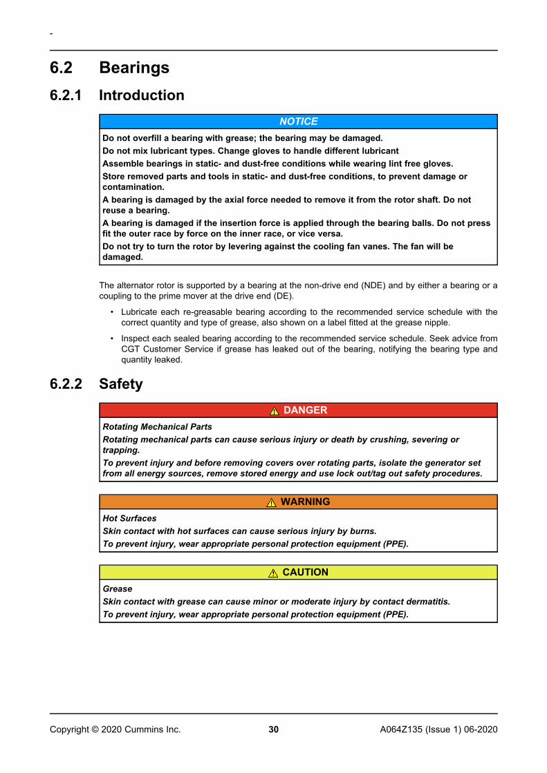
NOTICEDo not overfill a bearing with grease; the bearing may be damaged.Do not mix lubricant types. Change gloves to handle different lubricantAssemble bearings in static- and dust-free conditions while wearing lint free gloves.Store removed parts and tools in static- and dust-free conditions, to prevent damage orcontamination.A bearing is damaged by the axial force needed to remove it from the rotor shaft. Do notreuse a bearing.A bearing is damaged if the insertion force is applied through the bearing balls. Do not pressfit the outer race by force on the inner race, or vice versa.Do not try to turn the rotor by levering against the cooling fan vanes. The fan will bedamaged.
The alternator rotor is supported by a bearing at the non-drive end (NDE) and by either a bearing or acoupling to the prime mover at the drive end (DE).
• Lubricate each re-greasable bearing according to the recommended service schedule with thecorrect quantity and type of grease, also shown on a label fitted at the grease nipple.
• Inspect each sealed bearing according to the recommended service schedule. Seek advice fromCGT Customer Service if grease has leaked out of the bearing, notifying the bearing type andquantity leaked.
6.2.2 SafetyDANGER
Rotating Mechanical PartsRotating mechanical parts can cause serious injury or death by crushing, severing ortrapping.To prevent injury and before removing covers over rotating parts, isolate the generator setfrom all energy sources, remove stored energy and use lock out/tag out safety procedures.
WARNINGHot SurfacesSkin contact with hot surfaces can cause serious injury by burns.To prevent injury, wear appropriate personal protection equipment (PPE).
CAUTIONGreaseSkin contact with grease can cause minor or moderate injury by contact dermatitis.To prevent injury, wear appropriate personal protection equipment (PPE).
-
31A064Z135 (Issue 1) 06-2020 Copyright © 2020 Cummins Inc.
NOTICEDo not overfill a bearing with grease; the bearing may be damaged.Do not mix lubricant types. Change gloves to handle different lubricantAssemble bearings in static- and dust-free conditions while wearing lint free gloves.Store removed parts and tools in static- and dust-free conditions, to prevent damage orcontamination.A bearing is damaged by the axial force needed to remove it from the rotor shaft. Do notreuse a bearing.A bearing is damaged if the insertion force is applied through the bearing balls. Do not pressfit the outer race by force on the inner race, or vice versa.Do not try to turn the rotor by levering against the cooling fan vanes. The fan will bedamaged.
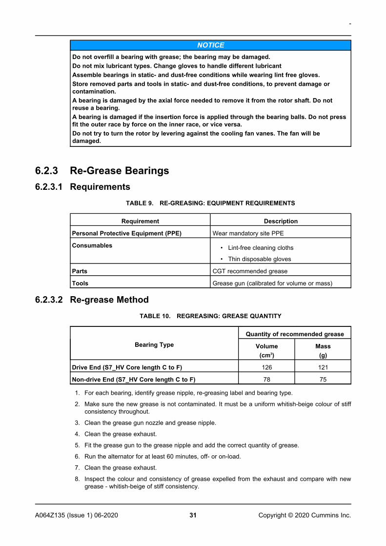
6.2.3 Re-Grease Bearings6.2.3.1 Requirements
TABLE 9. RE-GREASING: EQUIPMENT REQUIREMENTS
Requirement Description
Personal Protective Equipment (PPE) Wear mandatory site PPE
Consumables • Lint-free cleaning cloths
• Thin disposable gloves
Parts CGT recommended grease
Tools Grease gun (calibrated for volume or mass)
6.2.3.2 Re-grease MethodTABLE 10. REGREASING: GREASE QUANTITY
Bearing TypeQuantity of recommended grease
Volume(cm3)
Mass(g)
Drive End (S7_HV Core length C to F) 126 121
Non-drive End (S7_HV Core length C to F) 78 75
1. For each bearing, identify grease nipple, re-greasing label and bearing type.
2. Make sure the new grease is not contaminated. It must be a uniform whitish-beige colour of stiffconsistency throughout.
3. Clean the grease gun nozzle and grease nipple.
4. Clean the grease exhaust.
5. Fit the grease gun to the grease nipple and add the correct quantity of grease.
6. Run the alternator for at least 60 minutes, off- or on-load.
7. Clean the grease exhaust.
8. Inspect the colour and consistency of grease expelled from the exhaust and compare with newgrease - whitish-beige of stiff consistency.
-
32 A064Z135 (Issue 1) 06-2020Copyright © 2020 Cummins Inc.
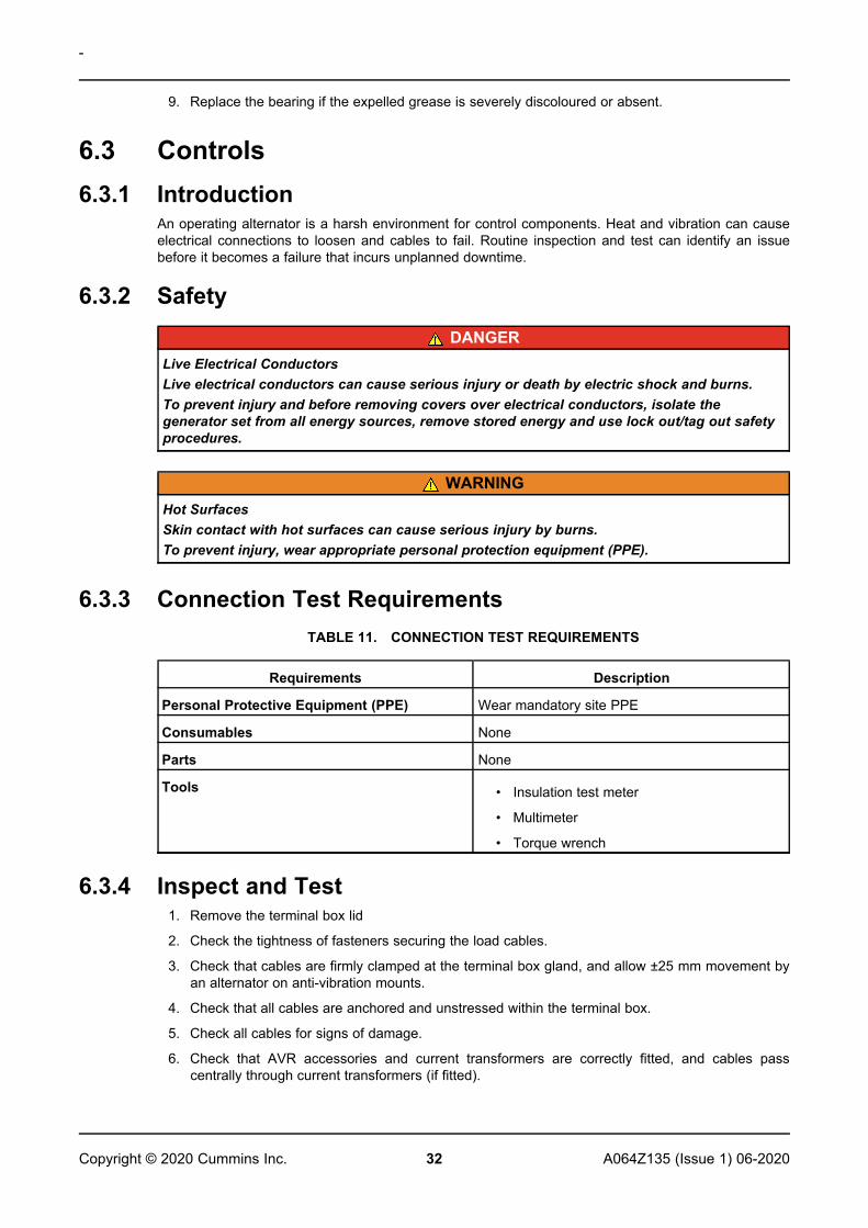
9. Replace the bearing if the expelled grease is severely discoloured or absent.
6.3 Controls6.3.1 Introduction
An operating alternator is a harsh environment for control components. Heat and vibration can causeelectrical connections to loosen and cables to fail. Routine inspection and test can identify an issuebefore it becomes a failure that incurs unplanned downtime.
6.3.2 SafetyDANGER
Live Electrical ConductorsLive electrical conductors can cause serious injury or death by electric shock and burns.To prevent injury and before removing covers over electrical conductors, isolate thegenerator set from all energy sources, remove stored energy and use lock out/tag out safetyprocedures.
WARNINGHot SurfacesSkin contact with hot surfaces can cause serious injury by burns.To prevent injury, wear appropriate personal protection equipment (PPE).
6.3.3 Connection Test RequirementsTABLE 11. CONNECTION TEST REQUIREMENTS
Requirements Description
Personal Protective Equipment (PPE) Wear mandatory site PPE
Consumables None
Parts None
Tools • Insulation test meter
• Multimeter
• Torque wrench
6.3.4 Inspect and Test1. Remove the terminal box lid
2. Check the tightness of fasteners securing the load cables.
3. Check that cables are firmly clamped at the terminal box gland, and allow ±25 mm movement byan alternator on anti-vibration mounts.
4. Check that all cables are anchored and unstressed within the terminal box.
5. Check all cables for signs of damage.
6. Check that AVR accessories and current transformers are correctly fitted, and cables passcentrally through current transformers (if fitted).
-
33A064Z135 (Issue 1) 06-2020 Copyright © 2020 Cummins Inc.
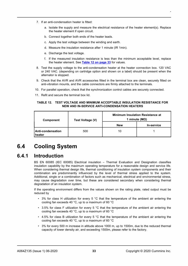
7. If an anti-condensation heater is fitted:
a. Isolate the supply and measure the electrical resistance of the heater element(s). Replacethe heater element if open circuit.
b. Connect together both ends of the heater leads.
c. Apply the test voltage between the winding and earth.
d. Measure the insulation resistance after 1 minute (IR 1min).
e. Discharge the test voltage.
f. If the measured insulation resistance is less than the minimum acceptable level, replacethe heater element. See Table 12 on page 33 for values.
8. Test the supply voltage to the anti-condensation heater at the heater connection box. 120 VACor 240 VAC. (depending on cartridge option and shown on a label) should be present when thealternator is stopped.
9. Check that the AVR and AVR accessories fitted in the terminal box are clean, securely fitted onanti-vibration mounts, and the cable connectors are firmly attached to the terminals.
10. For parallel operation, check that the synchronization control cables are securely connected.
11. Refit and secure the terminal box lid.
TABLE 12. TEST VOLTAGE AND MINIMUM ACCEPTABLE INSULATION RESISTANCE FORNEW AND IN-SERVICE ANTI-CONDENSATION HEATERS
Component Test Voltage (V)Minimum Insulation Resistance at
1 minute (MΩ)
New In-service
Anti-condensationheater
500 10 1
6.4 Cooling System6.4.1 Introduction
BS EN 60085 (IEC 60085) Electrical insulation – Thermal Evaluation and Designation classifiesinsulation capability by the maximum operating temperature for a reasonable design and service life.When considering thermal design life, thermal conditioning of insulation system components and theircombination are predominantly influenced by the level of thermal stress applied to the system.Additional, single or a combination of factors such as mechanical, electrical and environmental stress,may cause degradation over time, but these are considered secondary when considering thermaldegradation of an insulation system.
If the operating environment differs from the values shown on the rating plate, rated output must bereduced by
• 3% for class H utilization for every 5 °C that the temperature of the ambient air entering thecooling fan exceeds 40 °C, up to a maximum of 60 °C
• 3.5% for class F utilization for every 5 °C that the temperature of the ambient air entering thecooling fan exceeds 40 °C, up to a maximum of 60 °C
• 4.5% for class B utilization for every 5 °C that the temperature of the ambient air entering thecooling fan exceeds 40 °C, up to a maximum of 60 °C
• 3% for every 500 m increase in altitude above 1000 m, up to 1500m, due to the reduced thermalcapacity of lower density air, and exceeding 1500m, please refer to the factory.
-
34 A064Z135 (Issue 1) 06-2020Copyright © 2020 Cummins Inc.
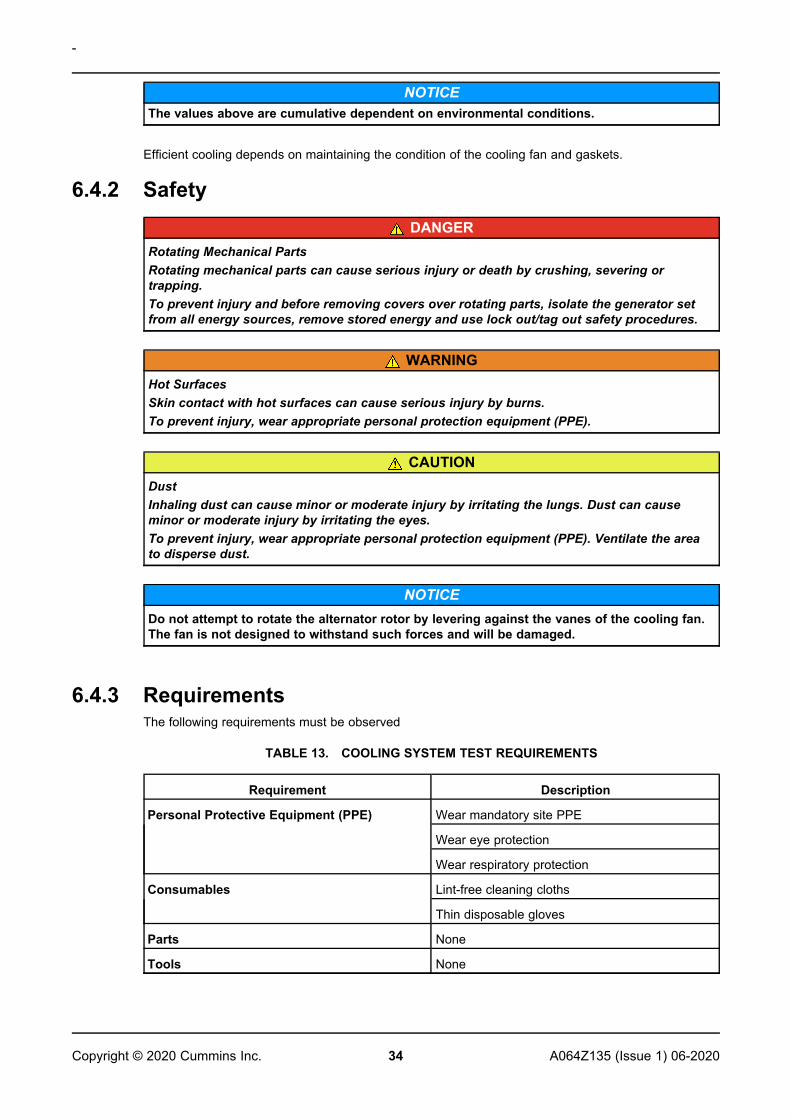
NOTICEThe values above are cumulative dependent on environmental conditions.
Efficient cooling depends on maintaining the condition of the cooling fan and gaskets.
6.4.2 SafetyDANGER
Rotating Mechanical PartsRotating mechanical parts can cause serious injury or death by crushing, severing ortrapping.To prevent injury and before removing covers over rotating parts, isolate the generator setfrom all energy sources, remove stored energy and use lock out/tag out safety procedures.
WARNINGHot SurfacesSkin contact with hot surfaces can cause serious injury by burns.To prevent injury, wear appropriate personal protection equipment (PPE).
CAUTIONDustInhaling dust can cause minor or moderate injury by irritating the lungs. Dust can causeminor or moderate injury by irritating the eyes.To prevent injury, wear appropriate personal protection equipment (PPE). Ventilate the areato disperse dust.
NOTICEDo not attempt to rotate the alternator rotor by levering against the vanes of the cooling fan.The fan is not designed to withstand such forces and will be damaged.
6.4.3 RequirementsThe following requirements must be observed
TABLE 13. COOLING SYSTEM TEST REQUIREMENTS
Requirement Description
Personal Protective Equipment (PPE) Wear mandatory site PPE
Wear eye protection
Wear respiratory protection
Consumables Lint-free cleaning cloths
Thin disposable gloves
Parts None
Tools None
-
35A064Z135 (Issue 1) 06-2020 Copyright © 2020 Cummins Inc.
6.5 Coupling6.5.1 Introduction
Efficient operation and long component life rely on minimizing mechanical stresses on the alternator.When coupled in a generator set, misalignment and vibration interactions with the prime mover enginecan cause mechanical stress.
The rotational axes of alternator rotor and engine output shaft must be coaxial (radial and angularalignment).
Torsional vibration can cause damage to internal combustion engine shaft-driven systems, if notcontrolled. The generator set manufacturer is responsible for assessing the effect of torsional vibrationon the alternator: Rotor dimensions and inertia, and coupling details are available on request.
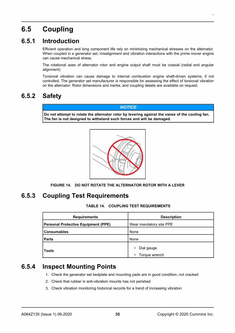
6.5.2 SafetyNOTICE
Do not attempt to rotate the alternator rotor by levering against the vanes of the cooling fan.The fan is not designed to withstand such forces and will be damaged.
FIGURE 14. DO NOT ROTATE THE ALTERNATOR ROTOR WITH A LEVER
6.5.3 Coupling Test RequirementsTABLE 14. COUPLING TEST REQUIREMENTS
Requirements Description
Personal Protective Equipment (PPE) Wear mandatory site PPE
Consumables None
Parts None
Tools• Dial gauge
• Torque wrench
6.5.4 Inspect Mounting Points1. Check the generator set bedplate and mounting pads are in good condition, not cracked
2. Check that rubber in anti-vibration mounts has not perished
3. Check vibration monitoring historical records for a trend of increasing vibration
-
36 A064Z135 (Issue 1) 06-2020Copyright © 2020 Cummins Inc.
6.5.4.1 Single Bearing Coupling1. Remove the DE adapter screen and cover to access the coupling.
2. Check that the coupling discs are not damaged, cracked or distorted, and the coupling disc holesare not elongated. If any are damaged, replace the complete set of discs.
3. Check tightness of bolts fixing the coupling discs to the engine flywheel. Tighten in the sequenceshown for alternator coupling in the Installation chapter, to the torque recommended by theengine manufacturer.
4. Replace the DE adapter screen and drip proof cover.
6.6 Rectifier System6.6.1 Introduction
The rectifier converts alternating current (AC) induced in the exciter rotor windings into direct current(DC) to magnetize the main rotor poles. The rectifier comprises two semicircular annular positive andnegative plates, each with three diodes. In addition to connecting to the main rotor, the DC output ofthe rectifier also connects to a matched pair of varistors (one at each end of the plates). Theseadditional components protect the rectifier from voltage spikes and surge voltages that may be presenton the rotor under various loading conditions of the alternator.
Diodes provide a low resistance to current in one direction only: Positive current will flow from anodeto cathode, or another way of viewing it is that negative current will flow from cathode to anode.
The exciter rotor windings are connected to 3 diode anodes to form the positive plate and to 3 diodecathodes to form the negative plate to give full wave rectification from AC to DC. The rectifier ismounted on, and rotates with, the exciter rotor at the non-drive end (NDE).
6.6.2 SafetyDANGER
Live Electrical ConductorsLive electrical conductors can cause serious injury or death by electric shock and burns.To prevent injury and before removing covers over electrical conductors, isolate thegenerator set from all energy sources, remove stored energy and use lock out/tag out safetyprocedures.
DANGERRotating Mechanical PartsRotating mechanical parts can cause serious injury or death by crushing, severing ortrapping.To prevent injury and before removing covers over rotating parts, isolate the generator setfrom all energy sources, remove stored energy and use lock out/tag out safety procedures.
-
37A064Z135 (Issue 1) 06-2020 Copyright © 2020 Cummins Inc.
6.6.3 RequirementsTABLE 15. RECTIFIER SYSTEM: TEST AND REPLACE COMPONENT REQUIREMENTS
Requirement Description
Personal ProtectiveEquipment (PPE)
Wear appropriate PPE.
Consumables • Loctite 241 thread-locking adhesive
• Dow Corning silicone heat sink compound type 340 or similar
Parts • Full set of three anode lead diodes and three cathode leaddiodes (all from the same manufacturer)
• Two metal-oxide varistors (same type, same manufacturer,same voltage grading: A, B, C, D, E, F)
Tools • Multimeter
• Insulation tester
• Torque wrench
6.6.4 Test and Replace Varistors1. Inspect both varistors.
2. Record varistor as faulty if there are signs of overheating (discoloration, blisters, melting) ordisintegration. Check for loose connectors vs. varistor body.
3. Disconnect one varistor lead. Store fastener and washers.
4. Measure the resistance across each varistor. Good varistors have a resistance greater than 100MΩ.
5. Record varistor as faulty if the resistance is short circuit or open circuit in either direction.
6. If either varistor is faulty, replace both varistors with a matched pair (same type, samemanufacturer and same voltage grading: A, B, C, D, E, F) and replace all diodes.
7. Reconnect and check that all leads are secure, washers fitted and fasteners tight.
6.6.5 Test and Replace DiodesNOTICE
Do not tighten a diode above the stated torque. The diode will be damaged.
1. Disconnect the lead of one diode where it joins the windings at the insulated terminal post. Storefastener and washers.
2. Measure the voltage drop across the diode in the forward direction, using the diode test functionof a multimeter.
3. Measure the resistance across the diode in the reverse direction, using the 1000 VDC testvoltage of an insulation tester.
4. Diode is faulty if the voltage drop in the forward direction is outside the range 0.3 to 0.9 VDC, orthe resistance is below 20 MΩ in the reverse direction.
5. Repeat the tests for the five remaining diodes.
6. If any diode is faulty, replace the full set of six diodes (same type, same manufacturer):
a. Remove diode(s).
-
38 A064Z135 (Issue 1) 06-2020Copyright © 2020 Cummins Inc.
b. Apply a small amount of heat sink compound only to the base of the replacement diode(s),not the threads.
c. Check polarity of diode(s).
d. Screw each replacement diode into a threaded hole in the rectifier plate.
e. Apply 2.6 to 3.1 Nm (23 to 27.4 in-lb) torque to give good mechanical, electrical andthermal contact.
f. Replace both varistors with a matched pair (same type, same manufacturer and samevoltage grading: A, B, C, D, E, F)
7. Reconnect and check that all leads are secure, washers fitted and fasteners tight.
6.7 Temperature Sensors6.7.1 Introduction
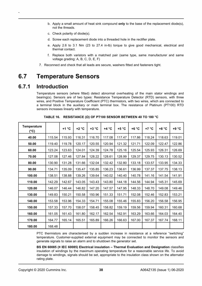
Temperature sensors (where fitted) detect abnormal overheating of the main stator windings andbearing(s). Sensors are of two types: Resistance Temperature Detector (RTD) sensors, with threewires, and Positive Temperature Coefficient (PTC) thermistors, with two wires, which are connected toa terminal block in the auxiliary or main terminal box. The resistance of Platinum (PT100) RTDsensors increases linearly with temperature.
TABLE 16. RESISTANCE (Ω) OF PT100 SENSOR BETWEEN 40 TO 180 °C
Temperature(°C)
+1 °C +2 °C +3 °C +4 °C +5 °C +6 °C +7 °C +8 °C +9 °C
40.00 115.54 115.93 116.31 116.70 117.08 117.47 117.86 118.24 118.63 119.01
50.00 119.40 119.78 120.17 120.55 120.94 121.32 121.71 122.09 122.47 122.86
60.00 123.24 123.63 124.01 124.39 124.78 125.16 125.54 125.93 126.31 126.69
70.00 127.08 127.46 127.84 128.22 128.61 128.99 129.37 129.75 130.13 130.52
80.00 130.90 131.28 131.66 132.04 132.42 132.80 133.18 133.57 133.95 134.33
90.00 134.71 135.09 135.47 135.85 136.23 136.61 136.99 137.37 137.75 138.13
100.00 138.51 138.88 139.26 139.64 140.02 140.40 140.78 141.16 141.54 141.91
110.00 142.29 142.67 143.05 143.43 143.80 144.18 144.56 144.94 145.31 145.69
120.00 146.07 146.44 146.82 147.20 147.57 147.95 148.33 148.70 149.08 149.46
130.00 149.83 150.21 150.58 150.96 151.33 151.71 152.08 152.46 152.83 153.21
140.00 153.58 153.96 154.33 154.71 155.08 155.46 155.83 156.20 156.58 156.95
150.00 157.33 157.70 158.07 158.45 158.82 159.19 159.56 159.94 160.31 160.68
160.00 161.05 161.43 161.80 162.17 162.54 162.91 163.29 163.66 164.03 164.40
170.00 164.77 165.14 165.51 165.89 166.26 166.63 167.00 167.37 167.74 168.11
180.00 168.48
PTC thermistors are characterised by a sudden increase in resistance at a reference “switching”temperature. Customer-supplied external equipment may be connected to monitor the sensors andgenerate signals to raise an alarm and to shutdown the generator set.
BS EN 60085 (≡ IEC 60085) Electrical insulation – Thermal Evaluation and Designation classifiesinsulation of windings by the maximum operating temperature for a reasonable service life. To avoiddamage to windings, signals should be set, appropriate to the insulation class shown on the alternatorrating plate.
-
39A064Z135 (Issue 1) 06-2020 Copyright © 2020 Cummins Inc.
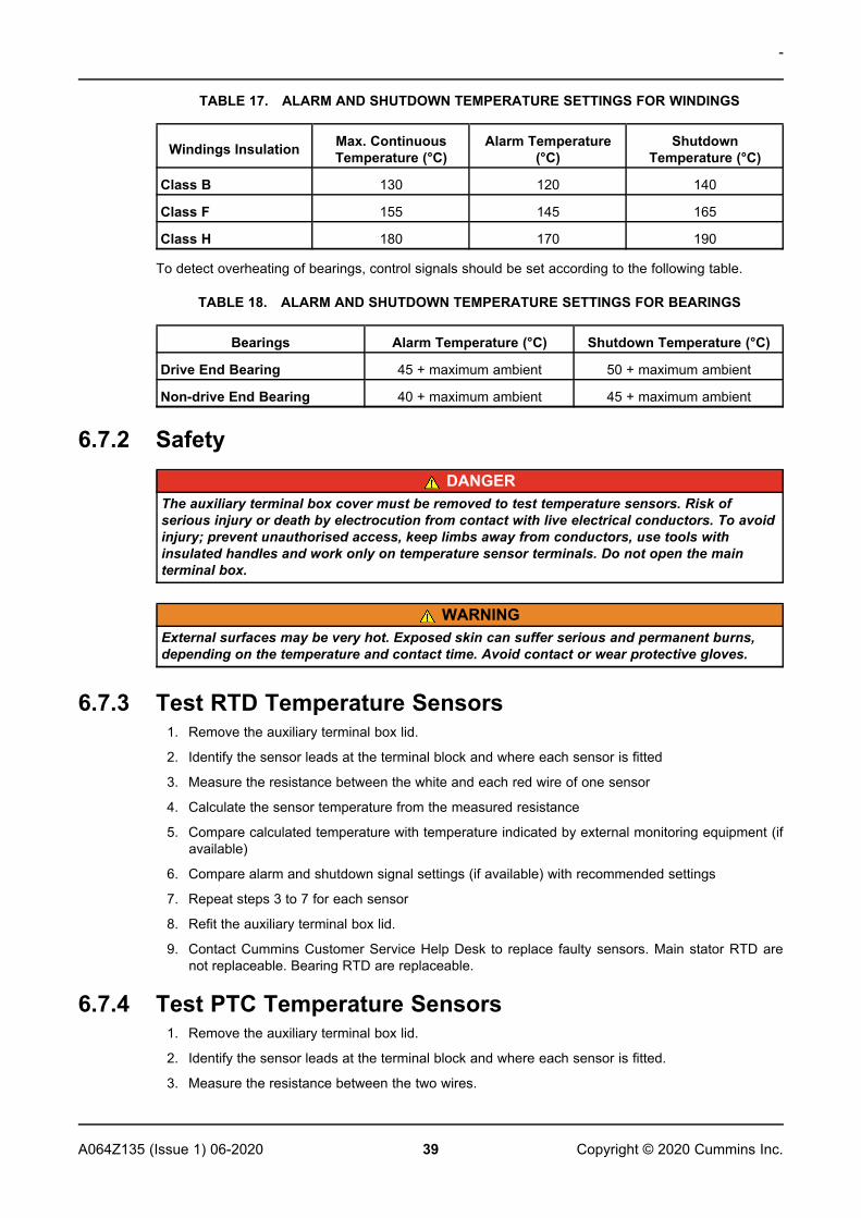
TABLE 17. ALARM AND SHUTDOWN TEMPERATURE SETTINGS FOR WINDINGS
Windings Insulation Max. ContinuousTemperature (°C)
Alarm Temperature(°C)
ShutdownTemperature (°C)
Class B 130 120 140
Class F 155 145 165
Class H 180 170 190
To detect overheating of bearings, control signals should be set according to the following table.
TABLE 18. ALARM AND SHUTDOWN TEMPERATURE SETTINGS FOR BEARINGS
Bearings Alarm Temperature (°C) Shutdown Temperature (°C)
Drive End Bearing 45 + maximum ambient 50 + maximum ambient
Non-drive End Bearing 40 + maximum ambient 45 + maximum ambient
6.7.2 SafetyDANGER
The auxiliary terminal box cover must be removed to test temperature sensors. Risk ofserious injury or death by electrocution from contact with live electrical conductors. To avoidinjury; prevent unauthorised access, keep limbs away from conductors, use tools withinsulated handles and work only on temperature sensor terminals. Do not open the mainterminal box.
WARNINGExternal surfaces may be very hot. Exposed skin can suffer serious and permanent burns,depending on the temperature and contact time. Avoid contact or wear protective gloves.
6.7.3 Test RTD Temperature Sensors1. Remove the auxiliary terminal box lid.
2. Identify the sensor leads at the terminal block and where each sensor is fitted
3. Measure the resistance between the white and each red wire of one sensor
4. Calculate the sensor temperature from the measured resistance
5. Compare calculated temperature with temperature indicated by external monitoring equipment (ifavailable)
6. Compare alarm and shutdown signal settings (if available) with recommended settings
7. Repeat steps 3 to 7 for each sensor
8. Refit the auxiliary terminal box lid.
9. Contact Cummins Customer Service Help Desk to replace faulty sensors. Main stator RTD arenot replaceable. Bearing RTD are replaceable.
6.7.4 Test PTC Temperature Sensors1. Remove the auxiliary terminal box lid.
2. Identify the sensor leads at the terminal block and where each sensor is fitted.
3. Measure the resistance between the two wires.
-
40 A064Z135 (Issue 1) 06-2020Copyright © 2020 Cummins Inc.
4. Sensor is faulty if resistance shows open circuit (infinity Ω) or short circuit (zero Ω).
5. Repeat steps 3 to 5 for each sensor.
6. Stop the alternator and inspect the change in resistance as the stator winding cools.
7. Sensor is faulty if resistance does not change or change is not smooth.
8. Repeat steps 6 and 7 for each sensor.
9. Refit the auxiliary terminal box lid.
10. Contact Cummins Customer Service Help Desk to replace faulty sensors.
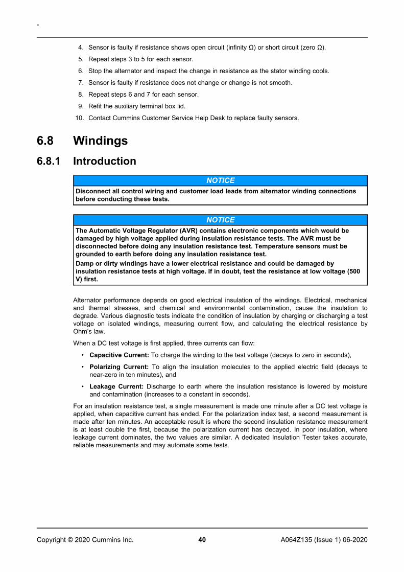
6.8 Windings6.8.1 Introduction
NOTICEDisconnect all control wiring and customer load leads from alternator winding connectionsbefore conducting these tests.
NOTICEThe Automatic Voltage Regulator (AVR) contains electronic components which would bedamaged by high voltage applied during insulation resistance tests. The AVR must bedisconnected before doing any insulation resistance test. Temperature sensors must begrounded to earth before doing any insulation resistance test.Damp or dirty windings have a lower electrical resistance and could be damaged byinsulation resistance tests at high voltage. If in doubt, test the resistance at low voltage (500V) first.
Alternator performance depends on good electrical insulation of the windings. Electrical, mechanicaland thermal stresses, and chemical and environmental contamination, cause the insulation todegrade. Various diagnostic tests indicate the condition of insulation by charging or discharging a testvoltage on isolated windings, measuring current flow, and calculating the electrical resistance byOhm’s law.
When a DC test voltage is first applied, three currents can flow:
• Capacitive Current: To charge the winding to the test voltage (decays to zero in seconds),
• Polarizing Current: To align the insulation molecules to the applied electric field (decays tonear-zero in ten minutes), and
• Leakage Current: Discharge to earth where the insulation resistance is lowered by moistureand contamination (increases to a constant in seconds).
For an insulation resistance test, a single measurement is made one minute after a DC test voltage isapplied, when capacitive current has ended. For the polarization index test, a second measurement ismade after ten minutes. An acceptable result is where the second insulation resistance measurementis at least double the first, because the polarization current has decayed. In poor insulation, whereleakage current dominates, the two values are similar. A dedicated Insulation Tester takes accurate,reliable measurements and may automate some tests.
-
41A064Z135 (Issue 1) 06-2020 Copyright © 2020 Cummins Inc.
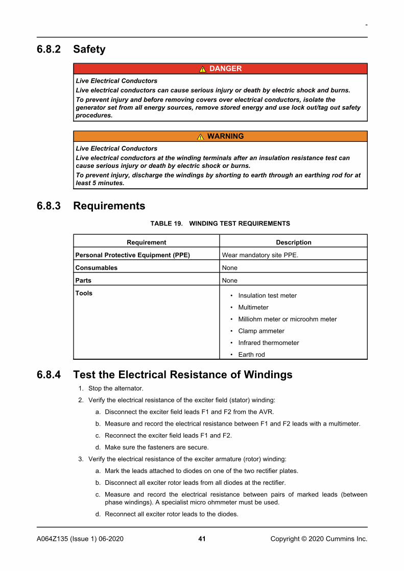
6.8.2 SafetyDANGER
Live Electrical ConductorsLive electrical conductors can cause serious injury or death by electric shock and burns.To prevent injury and before removing covers over electrical conductors, isolate thegenerator set from all energy sources, remove stored energy and use lock out/tag out safetyprocedures.
WARNINGLive Electrical ConductorsLive electrical conductors at the winding terminals after an insulation resistance test cancause serious injury or death by electric shock or burns.To prevent injury, discharge the windings by shorting to earth through an earthing rod for atleast 5 minutes.
6.8.3 RequirementsTABLE 19. WINDING TEST REQUIREMENTS
Requirement Description
Personal Protective Equipment (PPE) Wear mandatory site PPE.
Consumables None
Parts None
Tools • Insulation test meter
• Multimeter
• Milliohm meter or microohm meter
• Clamp ammeter
• Infrared thermometer
• Earth rod
6.8.4 Test the Electrical Resistance of Windings1. Stop the alternator.
2. Verify the electrical resistance of the exciter field (stator) winding:
a. Disconnect the exciter field leads F1 and F2 from the AVR.
b. Measure and record the electrical resistance between F1 and F2 leads with a multimeter.
c. Reconnect the exciter field leads F1 and F2.
d. Make sure the fasteners are secure.
3. Verify the electrical resistance of the exciter armature (rotor) winding:
a. Mark the leads attached to diodes on one of the two rectifier plates.
b. Disconnect all exciter rotor leads from all diodes at the rectifier.
c. Measure and record the electrical resistance between pairs of marked leads (betweenphase windings). A specialist micro ohmmeter must be used.
d. Reconnect all exciter rotor leads to the diodes.
-
42 A064Z135 (Issue 1) 06-2020Copyright © 2020 Cummins Inc.
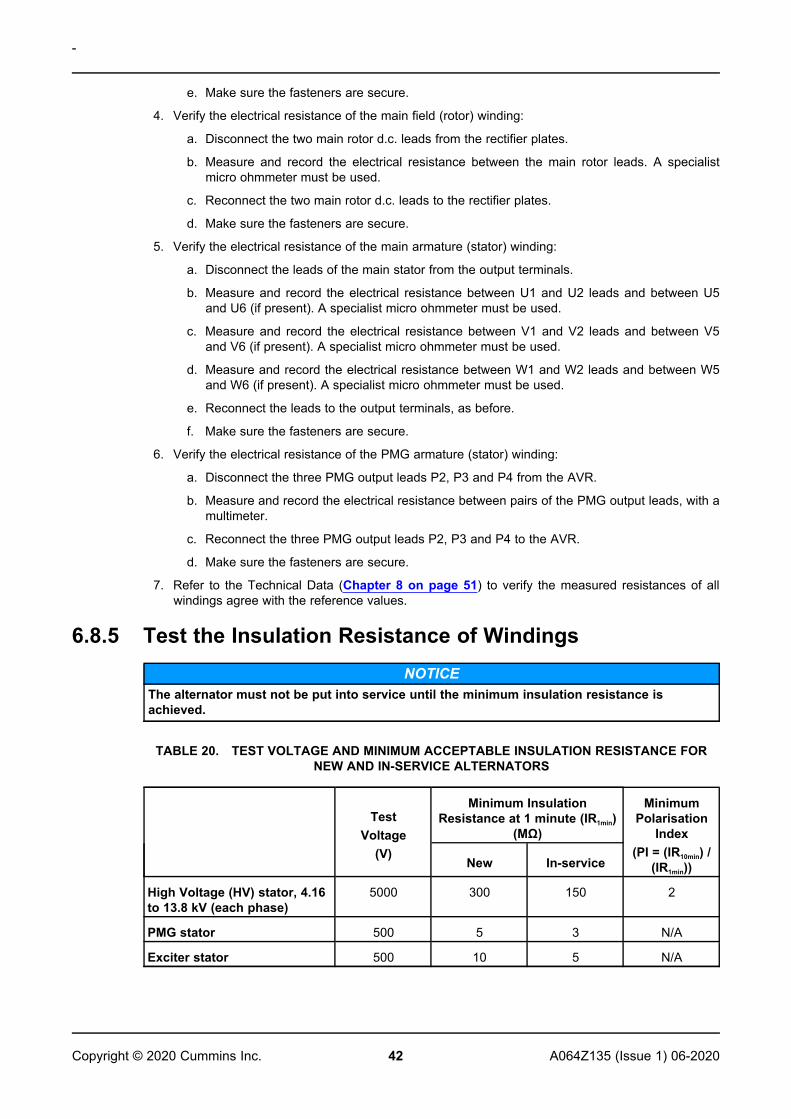
e. Make sure the fasteners are secure.
4. Verify the electrical resistance of the main field (rotor) winding:
a. Disconnect the two main rotor d.c. leads from the rectifier plates.
b. Measure and record the electrical resistance between the main rotor leads. A specialistmicro ohmmeter must be used.
c. Reconnect the two main rotor d.c. leads to the rectifier plates.
d. Make sure the fasteners are secure.
5. Verify the electrical resistance of the main armature (stator) winding:
a. Disconnect the leads of the main stator from the output terminals.
b. Measure and record the electrical resistance between U1 and U2 leads and between U5and U6 (if present). A specialist micro ohmmeter must be used.
c. Measure and record the electrical resistance between V1 and V2 leads and between V5and V6 (if present). A specialist micro ohmmeter must be used.
d. Measure and record the electrical resistance between W1 and W2 leads and between W5and W6 (if present). A specialist micro ohmmeter must be used.
e. Reconnect the leads to the output terminals, as before.
f. Make sure the fasteners are secure.
6. Verify the electrical resistance of the PMG armature (stator) winding:
a. Disconnect the three PMG output leads P2, P3 and P4 from the AVR.
b. Measure and record the electrical resistance between pairs of the PMG output leads, with amultimeter.
c. Reconnect the three PMG output leads P2, P3 and P4 to the AVR.
d. Make sure the fasteners are secure.
7. Refer to the Technical Data (Chapter 8 on page 51) to verify the measured resistances of allwindings agree with the reference values.
6.8.5 Test the Insulation Resistance of WindingsNOTICE
The alternator must not be put into service until the minimum insulation resistance isachieved.
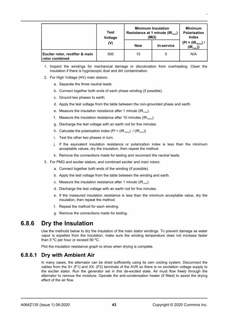
TABLE 20. TEST VOLTAGE AND MINIMUM ACCEPTABLE INSULATION RESISTANCE FORNEW AND IN-SERVICE ALTERNATORS
TestVoltage
(V)
Minimum InsulationResistance at 1 minute (IR1min)
(MΩ)
MinimumPolarisation
Index(PI = (IR10min) /
(IR1min))New In-service
High Voltage (HV) stator, 4.16to 13.8 kV (each phase)
5000 300 150 2
PMG stator 500 5 3 N/A
Exciter stator 500 10 5 N/A
-
43A064Z135 (Issue 1) 06-2020 Copyright © 2020 Cummins Inc.
TestVoltage
(V)
Minimum InsulationResistance at 1 minute (IR1min)
(MΩ)
MinimumPolarisation
Index(PI = (IR10min) /
(IR1min))New In-service
Exciter rotor, rectifier & mainrotor combined
500 10 5 N/A
1. Inspect the windings for mechanical damage or discoloration from overheating. Clean theinsulation if there is hygroscopic dust and dirt contamination.
2. For High Voltage (HV) main stators:
a. Separate the three neutral leads.
b. Connect together both ends of each phase winding (if possible).
c. Ground two phases to earth.
d. Apply the test voltage from the table between the non-grounded phase and earth.
e. Measure the insulation resistance after 1 minute (IR1min).
f. Measure the insulation resistance after 10 minutes (IR10min).
g. Discharge the test voltage with an earth rod for five minutes.
h. Calculate the polarization index (PI = (IR10min) / (IR1min))
i. Test the other two phases in turn.
j. If the equivalent insulation resistance or polarization index is less than the minimumacceptable values, dry the insulation, then repeat the method.
k. Remove the connections made for testing and reconnect the neutral leads.
3. For PMG and exciter stators, and combined exciter and main rotors:
a. Connect together both ends of the winding (if possible).
b. Apply the test voltage from the table between the winding and earth.
c. Measure the insulation resistance after 1 minute (IR1min).
d. Discharge the test voltage with an earth rod for five minutes.
e. If the measured insulation resistance is less than the minimum acceptable value, dry theinsulation, then repeat the method.
f. Repeat the method for each winding.
g. Remove the connections made for testing.
6.8.6 Dry the InsulationUse the methods below to dry the insulation of the main stator windings. To prevent damage as watervapor is expelled from the insulation, make sure the winding temperature does not increase fasterthan 5 ºC per hour or exceed 90 ºC.
Plot the insulation resistance graph to show when drying is complete.
6.8.6.1 Dry with Ambient AirIn many cases, the alternator can be dried sufficiently using its own cooling system. Disconnect thecables from the X+ (F1) and XX- (F2) terminals of the AVR so there is no excitation voltage supply tothe exciter stator. Run the generator set in this de-excited state. Air must flow freely through thealternator to remove the moisture. Operate the anti-condensation heater (if fitted) to assist the dryingeffect of the air flow.
-
44 A064Z135 (Issue 1) 06-2020Copyright © 2020 Cummins Inc.
After drying is complete, re-connect the cables between the exciter stator and AVR. If the generatorset is not put into service immediately, turn on the anti-condensation heater (if fitted) and retest theinsulation resistance before use.
6.8.6.2 Dry with Hot AirDirect the hot air from one or two 1 to 3 kW electrical fan heaters into the alternator air inlet. Makesure each heat source at least 300 mm away from the windings to avoid scorching or over-heatingdamage to the insulation. Air must flow freely through the alternator to remove the moisture.
After drying, remove the fan heaters and re-commission as appropriate.
If the generator set is not put into service immediately, turn on the anti-condensation heaters (wherefitted) and retest the insulation resistance before use.
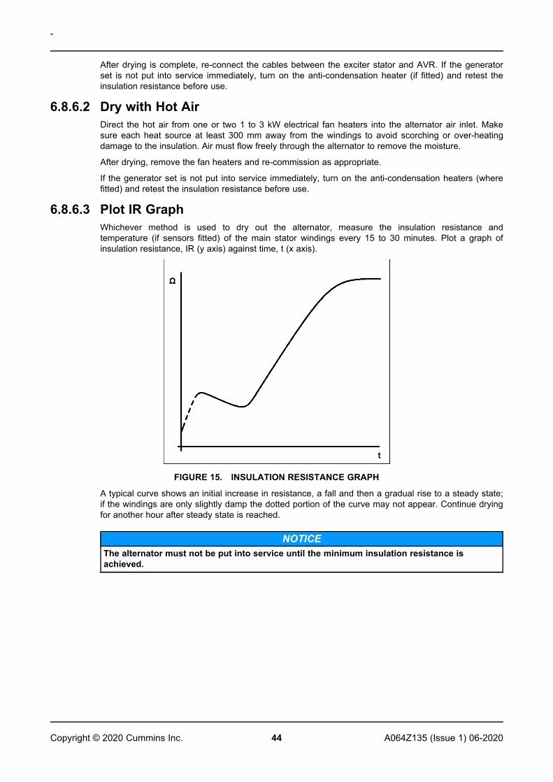
6.8.6.3 Plot IR GraphWhichever method is used to dry out the alternator, measure the insulation resistance andtemperature (if sensors fitted) of the main stator windings every 15 to 30 minutes. Plot a graph ofinsulation resistance, IR (y axis) against time, t (x axis).
FIGURE 15. INSULATION RESISTANCE GRAPH
A typical curve shows an initial increase in resistance, a fall and then a gradual rise to a steady state;if the windings are only slightly damp the dotted portion of the curve may not appear. Continue dryingfor another hour after steady state is reached.
NOTICEThe alternator must not be put into service until the minimum insulation resistance isachieved.
45A064Z135 (Issue 1) 06-2020 Copyright © 2020 Cummins Inc.
7 Parts Identification
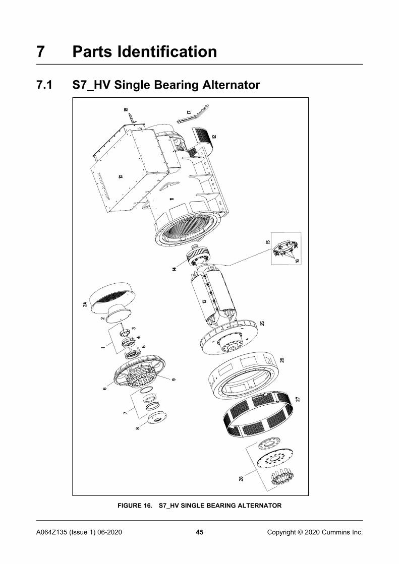
7.1 S7_HV Single Bearing Alternator
FIGURE 16. S7_HV SINGLE BEARING ALTERNATOR
-
46 A064Z135 (Issue 1) 06-2020Copyright © 2020 Cummins Inc.
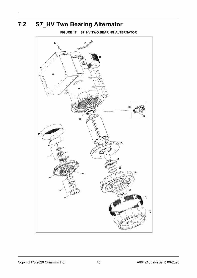
7.2 S7_HV Two Bearing AlternatorFIGURE 17. S7_HV TWO BEARING ALTERNATOR
-
47A064Z135 (Issue 1) 06-2020 Copyright © 2020 Cummins Inc.
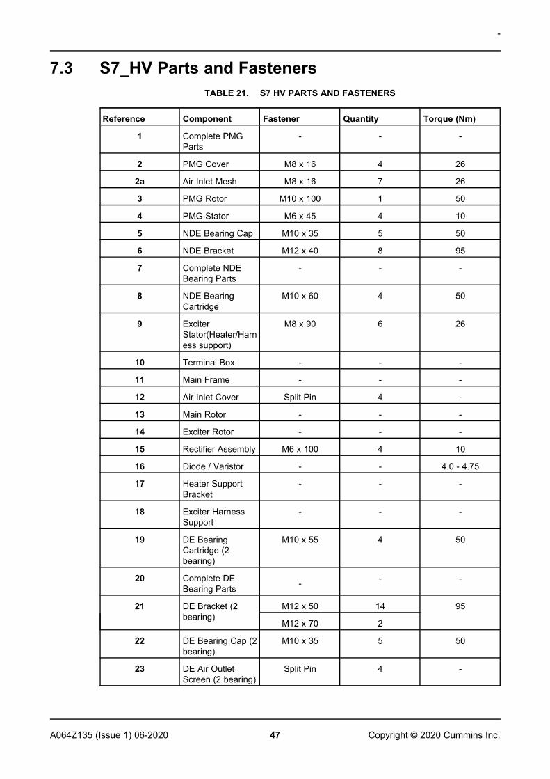
7.3 S7_HV Parts and FastenersTABLE 21. S7 HV PARTS AND FASTENERS
Reference Component Fastener Quantity Torque (Nm)
1 Complete PMGParts
- - -
2 PMG Cover M8 x 16 4 26
2a Air Inlet Mesh M8 x 16 7 26
3 PMG Rotor M10 x 100 1 50
4 PMG Stator M6 x 45 4 10
5 NDE Bearing Cap M10 x 35 5 50
6 NDE Bracket M12 x 40 8 95
7 Complete NDEBearing Parts
- - -
8 NDE BearingCartridge
M10 x 60 4 50
9 ExciterStator(Heater/Harness support)
M8 x 90 6 26
10 Terminal Box - - -
11 Main Frame - - -
12 Air Inlet Cover Split Pin 4 -
13 Main Rotor - - -
14 Exciter Rotor - - -
15 Rectifier Assembly M6 x 100 4 10
16 Diode / Varistor - - 4.0 - 4.75
17 Heater SupportBracket
- - -
18 Exciter HarnessSupport
- - -
19 DE BearingCartridge (2bearing)
M10 x 55 4 50
20 Complete DEBearing Parts - - -
21 DE Bracket (2bearing)
M12 x 50 14 95
M12 x 70 2
22 DE Bearing Cap (2bearing)
M10 x 35 5 50
23 DE Air OutletScreen (2 bearing)
Split Pin 4 -
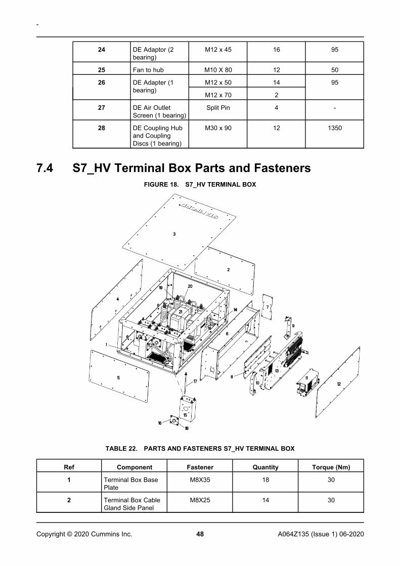
-
48 A064Z135 (Issue 1) 06-2020Copyright © 2020 Cummins Inc.
24 DE Adaptor (2bearing)
M12 x 45 16 95
25 Fan to hub M10 X 80 12 50
26 DE Adapter (1bearing)
M12 x 50 14 95
M12 x 70 2
27 DE Air OutletScreen (1 bearing)
Split Pin 4 -
28 DE Coupling Huband CouplingDiscs (1 bearing)
M30 x 90 12 1350
7.4 S7_HV Terminal Box Parts and FastenersFIGURE 18. S7_HV TERMINAL BOX
TABLE 22. PARTS AND FASTENERS S7_HV TERMINAL BOX
Ref Component Fastener Quantity Torque (Nm)
1 Terminal Box BasePlate
M8X35 18 30
2 Terminal Box CableGland Side Panel
M8X25 14 30
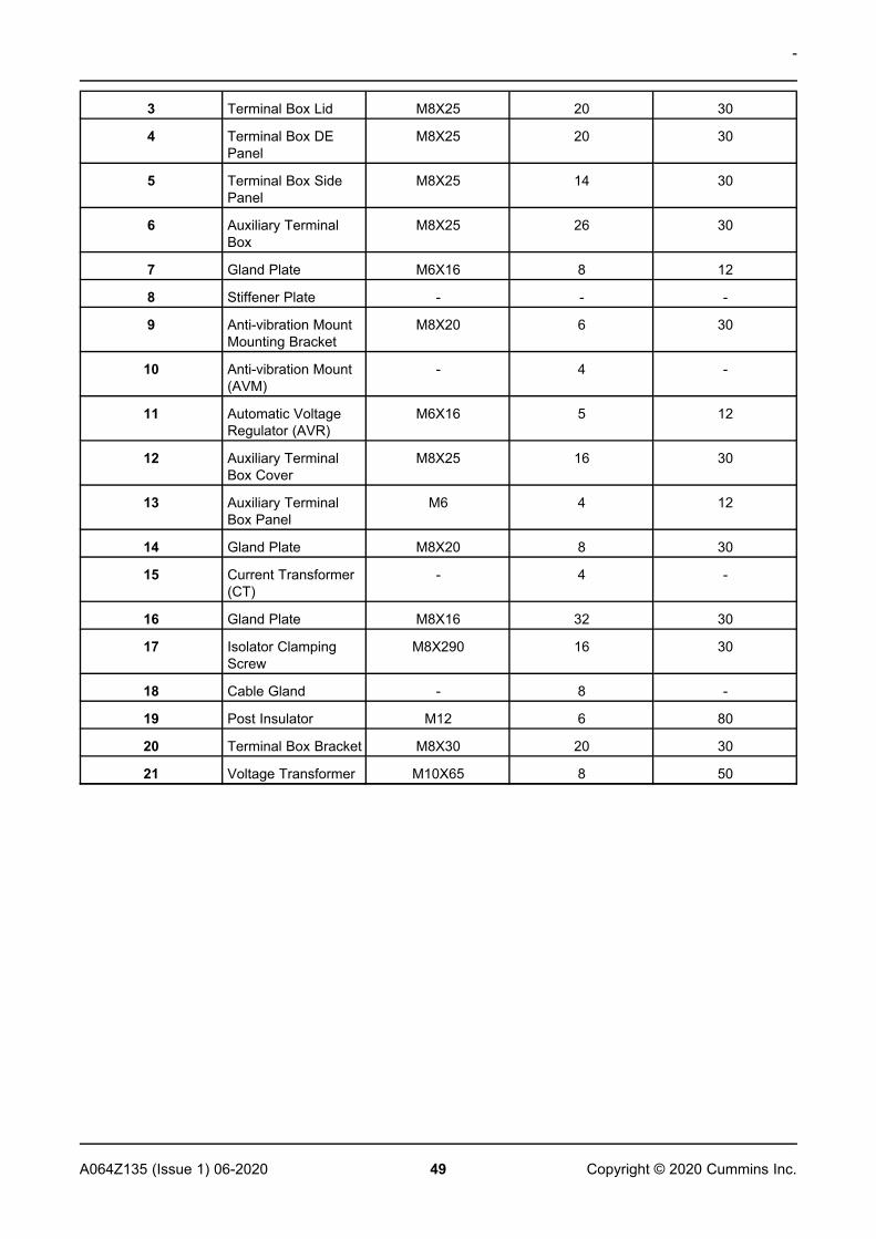
-
49A064Z135 (Issue 1) 06-2020 Copyright © 2020 Cummins Inc.
3 Terminal Box Lid M8X25 20 30
4 Terminal Box DEPanel
M8X25 20 30
5 Terminal Box SidePanel
M8X25 14 30
6 Auxiliary TerminalBox
M8X25 26 30
7 Gland Plate M6X16 8 12
8 Stiffener Plate - - -
9 Anti-vibration MountMounting Bracket
M8X20 6 30
10 Anti-vibration Mount(AVM)
- 4 -
11 Automatic VoltageRegulator (AVR)
M6X16 5 12
12 Auxiliary TerminalBox Cover
M8X25 16 30
13 Auxiliary TerminalBox Panel
M6 4 12
14 Gland Plate M8X20 8 30
15 Current Transformer(CT)
- 4 -
16 Gland Plate M8X16 32 30
17 Isolator ClampingScrew
M8X290 16 30
18 Cable Gland - 8 -
19 Post Insulator M12 6 80
20 Terminal Box Bracket M8X30 20 30
21 Voltage Transformer M10X65 8 50

This page is intentionally blank.
-
50 A064Z135 (Issue 1) 06-2020Copyright © 2020 Cummins Inc.
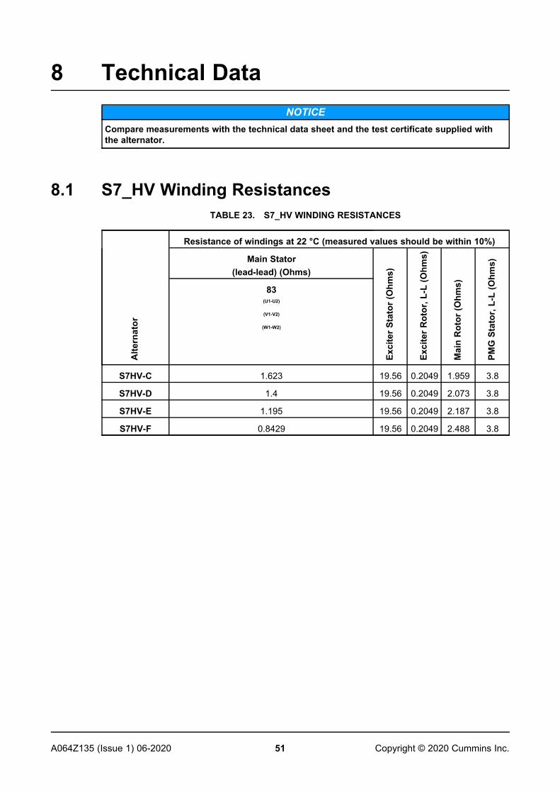
51A064Z135 (Issue 1) 06-2020 Copyright © 2020 Cummins Inc.
8 Technical DataNOTICE
Compare measurements with the technical data sheet and the test certificate supplied withthe alternator.
8.1 S7_HV Winding ResistancesTABLE 23. S7_HV WINDING RESISTANCES
Alte
rnat
or
Resistance of windings at 22 °C (measured values should be within 10%)
Main Stator(lead-lead) (Ohms)
Exci
terS
tato
r(O
hms)
Exci
terR
otor
,L-L
(Ohm
s)
Mai
nR
otor
(Ohm
s)
PMG
Stat
or,L
-L(O
hms)
83(U1-U2)
(V1-V2)
(W1-W2)
S7HV-C 1.623 19.56 0.2049 1.959 3.8
S7HV-D 1.4 19.56 0.2049 2.073 3.8
S7HV-E 1.195 19.56 0.2049 2.187 3.8
S7HV-F 0.8429 19.56 0.2049 2.488 3.8

This page is intentionally blank.
-
52 A064Z135 (Issue 1) 06-2020Copyright © 2020 Cummins Inc.
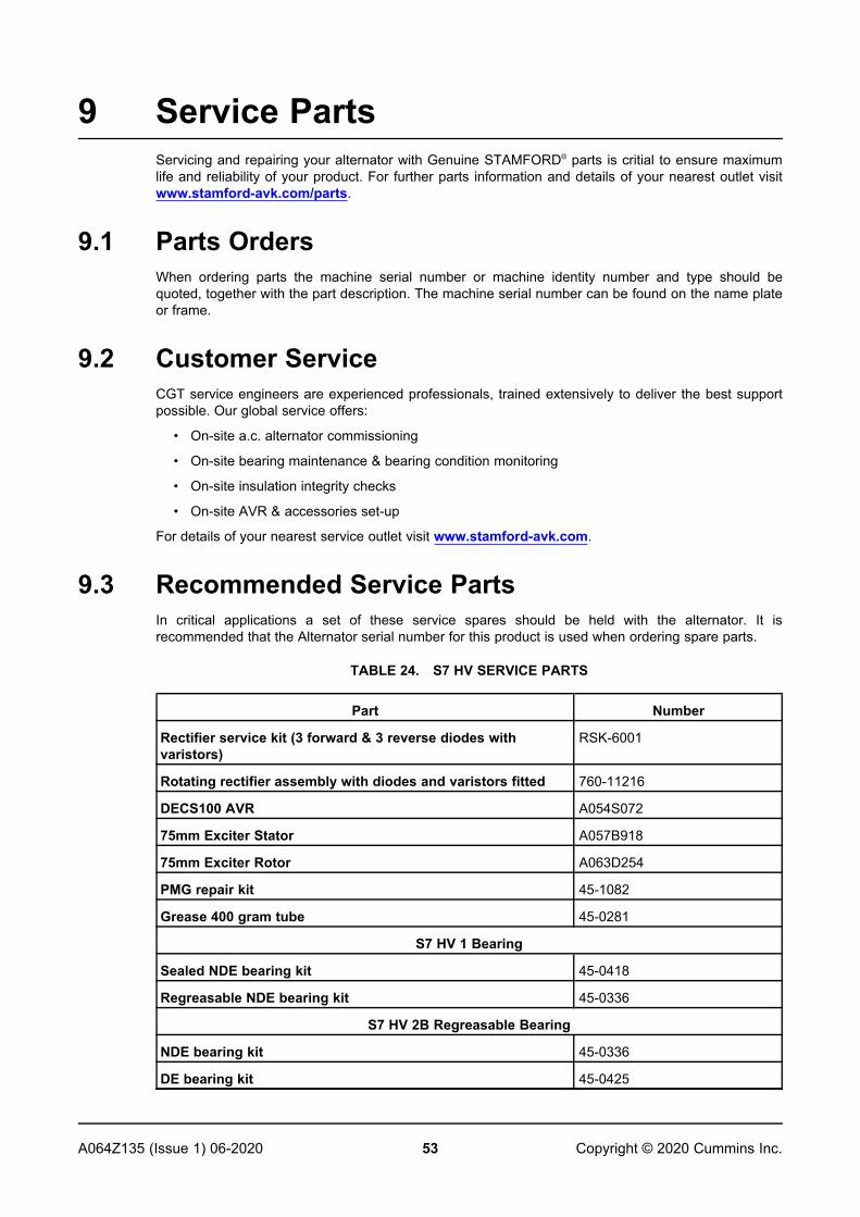
53A064Z135 (Issue 1) 06-2020 Copyright © 2020 Cummins Inc.
9 Service PartsServicing and repairing your alternator with Genuine STAMFORD® parts is critial to ensure maximumlife and reliability of your product. For further parts information and details of your nearest outlet visitwww.stamford-avk.com/parts.
9.1 Parts OrdersWhen ordering parts the machine serial number or machine identity number and type should bequoted, together with the part description. The machine serial number can be found on the name plateor frame.
9.2 Customer ServiceCGT service engineers are experienced professionals, trained extensively to deliver the best supportpossible. Our global service offers:
• On-site a.c. alternator commissioning
• On-site bearing maintenance & bearing condition monitoring
• On-site insulation integrity checks
• On-site AVR & accessories set-up
For details of your nearest service outlet visit www.stamford-avk.com.
9.3 Recommended Service PartsIn critical applications a set of these service spares should be held with the alternator. It isrecommended that the Alternator serial number for this product is used when ordering spare parts.
TABLE 24. S7 HV SERVICE PARTS
Part Number
Rectifier service kit (3 forward & 3 reverse diodes withvaristors)
RSK-6001
Rotating rectifier assembly with diodes and varistors fitted 760-11216
DECS100 AVR A054S072
75mm Exciter Stator A057B918
75mm Exciter Rotor A063D254
PMG repair kit 45-1082
Grease 400 gram tube 45-0281
S7 HV 1 Bearing
Sealed NDE bearing kit 45-0418
Regreasable NDE bearing kit 45-0336
S7 HV 2B Regreasable Bearing
NDE bearing kit 45-0336
DE bearing kit 45-0425
-
54 A064Z135 (Issue 1) 06-2020Copyright © 2020 Cummins Inc.
9.4 Klüber Asonic GHY72 GreaseAll bearings trials and calculated life expectancy are based on the use of Klüber Asonic GHY72.
55A064Z135 (Issue 1) 06-2020 Copyright © 2020 Cummins Inc.
10 End of Life DisposalCompanies specializing in reclaiming material from scrap products can reclaim most of the iron, steeland copper from the alternator. For more details, please contact Customer Service.
10.1 Recyclable materialMechanically separate the base materials, iron, copper and steel, removing paint, polyester resin, andinsulation tape and/or plastics residues from all components. Dispose of this ‘waste material’
The iron, steel and copper can now be recycled.
10.2 Items requiring specialist treatmentRemove electrical cable, electronic accessories and plastic materials from the alternator. Thesecomponents need special treatment to remove the waste from the reclaimable material.
Forward the reclaimed materials for recycling.
10.3 Waste materialDispose of waste material from both of the above processes via a specialist disposal company.

-
56 A064Z135 (Issue 1) 06-2020Copyright © 2020 Cummins Inc.
This page is intentionally blank.


www.stamford-avk.comCopyright 2020, Cummins Generator Technologies Ltd. All Rights ReservedCummins and the Cummins logo are registered trademarks of Cummins Inc.


