Embed Size (px)
Citation preview
EN
User manual
Self-regulatingAlternatorsSeries ECO 38Series ECO 40Series ECO 43Series ECO 46
Operating and maintenance instructions
Code: en_GBRevision: 1Date: 17/09/19 10:03
Translation of original language
Contents 1 1 General Information: scope of the manual 1
1.1 Intended Users 1 1.2 Professional Profiles Involved 1 1.3 Manual use and storage 1 1.4 How to consult the manual 3
1.4.1 Description of the symbols/pictographs in the manual 3
1.5 Reference Regulations and Directives 4 1.6 Marking data 5 1.7 Declaration of Conformity 6 1.8 Support 8 1.9 Glossary 8
2 Alternator Overview 9
2.1 Main components 9
2.1.1 DSR Digital Regulator 10 2.1.2 DER1 Digital Regulator 10
2.2 General description and working principle 10 2.3 Technical Data 11
2.3.1 IP Protection Rating 11 2.3.2 Radial Loads 11 2.3.3 Noise level [dB(A)] 11 2.3.4 Weight 12 2.3.5 Air volumes [m³/min] for local alternators 12 2.3.6 Alignment tolerances in B3B14 13 2.3.7 Positioning dimension in MD35 13 2.3.8 Resistance of windings at 20°C ambient temperature 14 2.3.9 Overall dimensions 15
Code: en_GBRevision: 1Date: 17/09/19 10:03
Self-regulated AlternatorsSeries ECO 38-40-43-46
ENGLISH
Mecc Alte S.p.A. - Full or partial reproduction prohibited, if not authorized
2.3.10 Materials 23
2.4 Operating ambient requirements 23
3 Safety 25
3.1 General Instructions 25 3.2 Alternator Safety devices 26 3.3 Safety tags 27 3.4 Personal Protective Equipment 28 3.5 Residual risks 28
4 Transportation, movement and storage. 29
4.1 General Instructions 29 4.2 Packing materials lifting and transportation 30 4.3 Unpacking 30 4.4 How to dispose of the packing materials 30 4.5 Alternator Movement 31 4.6 Storage 31
5 Installation instructions / drive motor coupling 33
5.1 Installation Setup 33 5.2 Unpacking and disposal of packing materials 33 5.3 Mechanical coupling 34
5.3.1 Alternator Preparation 35 5.3.2 Aligning the drive motor to the B3B14 alternator 35 5.3.3 Aligning the drive motor to the MD35 alternator 36 5.3.4 Thermal Expansion Compensation 36
6 Electrical connection 39
6.1 Terminal board configurations 42
6.1.1 ECO 38 regulation box and cable connection 42 6.1.2 ECO 40 regulation box and cable connection 43
Code: en_GBRevision: 1Date: 17/09/19 10:03
Self-regulated AlternatorsSeries ECO 38-40-43-46
ENGLISH
Mecc Alte S.p.A. - Full or partial reproduction prohibited, if not authorized
6.1.3 ECO 43 regulation box and cable connection 44 6.1.4 ECO 46 regulation box and cable connection 45
6.2 Parallel connection of alternators 46
6.2.1 Installation of a parallel device (series 38) 46
7 Startup Instructions 49 8 Electronic regulators 51
8.1 DSR Digital Regulator 51
8.1.1 Stability Adjustment 52 8.1.2 Protections 54 8.1.3 Inputs and Outputs: technical specifications 55
8.2 DER1 Digital Regulator 58
8.2.1 Stability Adjustment 59 8.2.2 Protections 61 8.2.3 Inputs and Outputs: technical specifications 62
8.3 UVR6-SR7 analog regulators 66
9 Maintenance 69
9.1 General Instructions 69 9.2 Maintenance summary table 70
9.2.1 Summary table of ordinary maintenance operations 70 9.2.2 Summary table of extraordinary maintenance operations 70 9.2.3 Summary table of maintenance operations in case of failure 71
9.3 Ordinary Maintenance 72
9.3.1 General cleaning 72 9.3.2 Air filter cleaning (if present) 73 9.3.3 Visual Inspection 74 9.3.4 Verification of winding state 75 9.3.5 Verification of correct alternator operation 76
Code: en_GBRevision: 1Date: 17/09/19 10:03
Self-regulated AlternatorsSeries ECO 38-40-43-46
ENGLISH
Mecc Alte S.p.A. - Full or partial reproduction prohibited, if not authorized
9.3.6 Tightening torque check 76 9.3.7 Alternator exterior and interior cleaning 77
9.4 Extraordinary maintenance 78
9.4.1 Maintenance and potential replacement of bearings 78 9.4.2 Winding state and diode bridge fastening check 78 9.4.3 Copy of the alarms of the digital regulator 79 9.4.4 Verification of correct PMG fastening (optional component) 80 9.4.5 Cleaning of windings 81
9.5 Maintenance in case of failure 82
9.5.1 Fan replacement assembly 82 9.5.2 Verification and potential replacement of diode bridge 84 9.5.3 Mechanical disassembly for inspection (40-43-46 series) 85
9.5.3.1 Note for removal of ECO 43 - 46 alternators 90
9.5.4 Mechanical assembling (40 - 43 - 46 series) 91 9.5.5 PMG disassembling 95 9.5.6 PMG assembling (38 series) 96 9.5.7 PMG assembling (40-43-46 series) 96 9.5.8 Removal of disc holder hub 99 9.5.9 Loss of residual magnetism (reexcitation of the machine) 100 9.5.10 Verification and replacement of voltage regulator 101 9.5.11 DSR test and setup on test bench 104 9.5.12 DER1 test and setup on test bench 106 9.5.13 DER 2 test and setup on test bench 108 9.5.14 Main stator windings voltage test 110
9.5.14.1 Resistance/Continuity Test 111 9.5.14.2 Insulation Test 112
9.6 General Tightening Torques 114
Code: en_GBRevision: 1Date: 17/09/19 10:03
Self-regulated AlternatorsSeries ECO 38-40-43-46
ENGLISH
Mecc Alte S.p.A. - Full or partial reproduction prohibited, if not authorized
9.6.1 ECO38 Series 114 9.6.2 ECO40 Series 116 9.6.3 ECO43 Series 118 9.6.4 ECO46 Series 120
9.7 Disc Tightening Torques 122 9.8 Terminal block Tightening Torques 122
10 DSR / DER1 alarm management 123
10.1 DSR/DER1 digital regulator alarms 124
11 Problems, causes and solutions 127 12 Electrical diagrams 129
12.1 DSR digital regulator electrical diagrams 130 12.2 DER 1 digital regulator electrical diagrams 133 12.3 Electrical diagrams with PMG 144 12.4 Electrical diagrams with UVR6 - SR7 regulators 149
13 Replacement parts 157
13.1 ECO 38A Construction type MD35 158 13.2 ECO 38A Construction type B3B14 160 13.3 ECO 40B Construction type MD35 162 13.4 ECO 40B Construction type B3B14 164 13.5 ECO 43A Construction type MD35 166 13.6 ECO 43A Construction type B3B14 168 13.7 ECO 46A Construction type MD35 170 13.8 ECO 46A Construction type B3B14 172
14 Dismantlement and disposal 175
Code: en_GBRevision: 1Date: 17/09/19 10:03
Self-regulated AlternatorsSeries ECO 38-40-43-46
ENGLISH
Mecc Alte S.p.A. - Full or partial reproduction prohibited, if not authorized
1 General Information: scope of the manual This manual is intended to provide support and guidance during the stages of work on the alternator. It contains information on
the use, maintenance and handling of faults and malfunctions providing indications for the most adequate behavior to the
correct use and to the correct operation of the machine as specified by the Manufacturer.
This manual is an essential safety requirement and it must accompany the alternator throughout its life cycle. It is indispensable
to store this manual and to make it available to everyone involved in using and servicing the alternator.
1.1 Intended Users This manual is intended for the authorized personnel adequately trained to operate this kind of product.
1.2 Professional Profiles Involved Below we describe the professional profiles who may operate the alternator based on the kind of activity to be carried out.
Handler
Mechanical maintenance technician
Electrical Maintenance Operator
Field Service Technician
This document and/or its parts may not be reproduced or disclosed to third parties without the prior consent of MECC
ALTE S.p.A.
MECC ALTE S.p.A. is not responsible or liable for any damages suffered by people or things as a result of improper use
not indicated in this manual and by failure to comply with the specifications of the technical characteristics table
pertaining to every model.
Warning
The operators must not carry out operations reserved to maintenance technicians or to specialized technicians. The
Manufacturer disclaims all responsibility for damages suffered as a result of failure to comply with this warning.
Authorized skilled personnel able to safely lift and handle the alternator. The operator is not authorized to carry outmaintenance operations.
A qualified technician able to carry out the installation, adjustment, maintenance and ordinary repair operationsrequired. Not allowed to carry out operations with the power on.
A qualified technician in charge with all the electrical works of connection, adjustment, maintenance and repair.Authorized to carry out operations with the power on.
A qualified technician provided by the manufacturer to carry out complex operations in special cases or, anyway, aspreviously agreed with the user.
Code: en_GBRevision: 1Date: 17/09/19 10:03
Self-regulated AlternatorsSeries ECO 38-40-43-46
ENGLISH
Mecc Alte S.p.A. - Full or partial reproduction prohibited, if not authorized 1
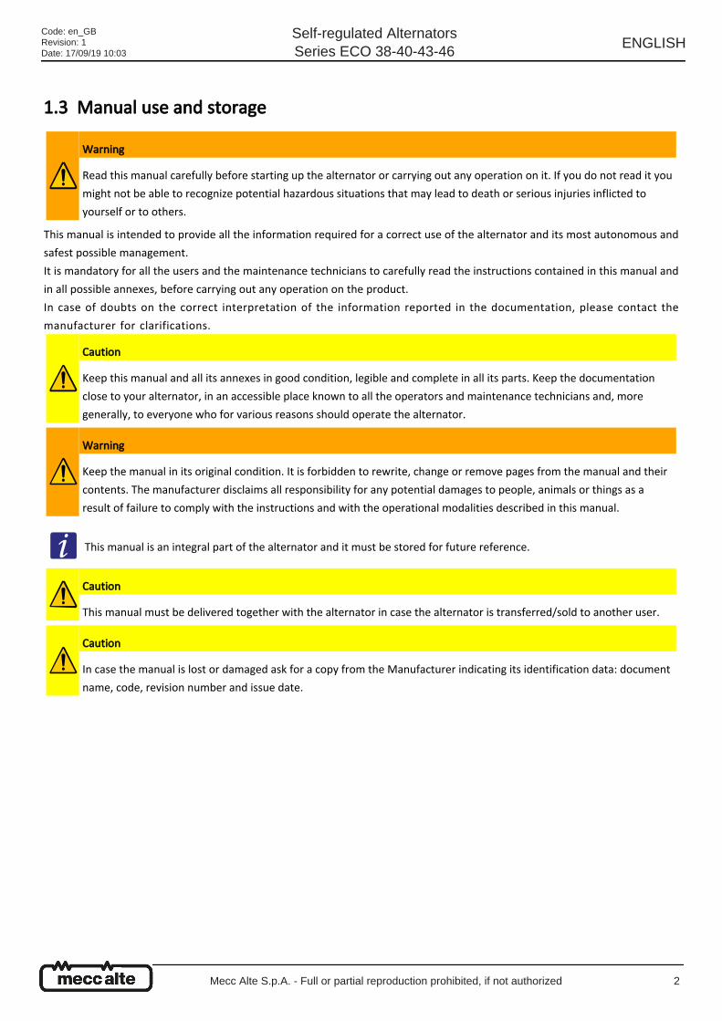
1.3 Manual use and storage
This manual is intended to provide all the information required for a correct use of the alternator and its most autonomous and
safest possible management.
It is mandatory for all the users and the maintenance technicians to carefully read the instructions contained in this manual and
in all possible annexes, before carrying out any operation on the product.
In case of doubts on the correct interpretation of the information reported in the documentation, please contact the
manufacturer for clarifications.
Warning
Read this manual carefully before starting up the alternator or carrying out any operation on it. If you do not read it you
might not be able to recognize potential hazardous situations that may lead to death or serious injuries inflicted to
yourself or to others.
Caution
Keep this manual and all its annexes in good condition, legible and complete in all its parts. Keep the documentation
close to your alternator, in an accessible place known to all the operators and maintenance technicians and, more
generally, to everyone who for various reasons should operate the alternator.
Warning
Keep the manual in its original condition. It is forbidden to rewrite, change or remove pages from the manual and their
contents. The manufacturer disclaims all responsibility for any potential damages to people, animals or things as a
result of failure to comply with the instructions and with the operational modalities described in this manual.
This manual is an integral part of the alternator and it must be stored for future reference.
Caution
This manual must be delivered together with the alternator in case the alternator is transferred/sold to another user.
Caution
In case the manual is lost or damaged ask for a copy from the Manufacturer indicating its identification data: document
name, code, revision number and issue date.
Code: en_GBRevision: 1Date: 17/09/19 10:03
Self-regulated AlternatorsSeries ECO 38-40-43-46
ENGLISH
Mecc Alte S.p.A. - Full or partial reproduction prohibited, if not authorized 2
●
●
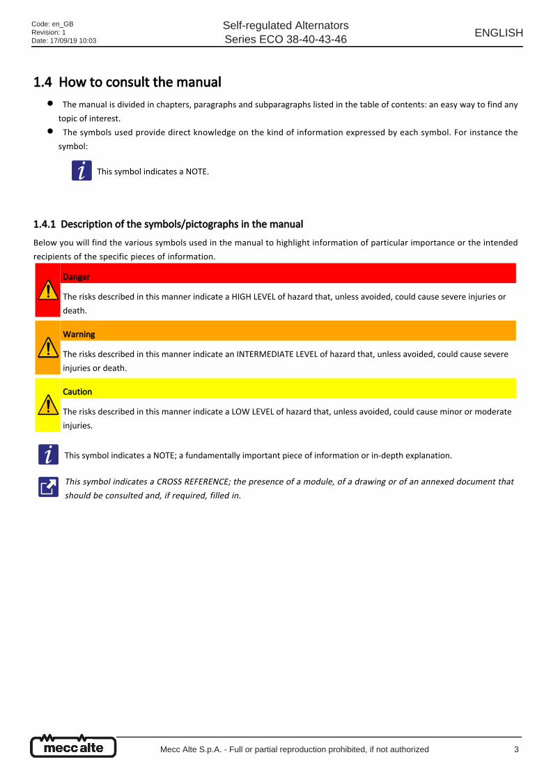
1.4 How to consult the manual
The manual is divided in chapters, paragraphs and subparagraphs listed in the table of contents: an easy way to find any
topic of interest.
The symbols used provide direct knowledge on the kind of information expressed by each symbol. For instance the
symbol:
1.4.1 Description of the symbols/pictographs in the manual Below you will find the various symbols used in the manual to highlight information of particular importance or the intended
recipients of the specific pieces of information.
This symbol indicates a NOTE.
Danger
The risks described in this manner indicate a HIGH LEVEL of hazard that, unless avoided, could cause severe injuries or
death.
Warning
The risks described in this manner indicate an INTERMEDIATE LEVEL of hazard that, unless avoided, could cause severe
injuries or death.
Caution
The risks described in this manner indicate a LOW LEVEL of hazard that, unless avoided, could cause minor or moderate
injuries.
This symbol indicates a NOTE; a fundamentally important piece of information or in-depth explanation.
This symbol indicates a CROSS REFERENCE; the presence of a module, of a drawing or of an annexed document that
should be consulted and, if required, filled in.
Code: en_GBRevision: 1Date: 17/09/19 10:03
Self-regulated AlternatorsSeries ECO 38-40-43-46
ENGLISH
Mecc Alte S.p.A. - Full or partial reproduction prohibited, if not authorized 3
●
●
●
●
●
●
●
●
●
●
●
●
●
●
●
●
●
●
1.5 Reference Regulations and Directives List of the reference regulations and directives used for the design and construction of the alternator.
Directives
Machinery Directive 2006/42/EC.
Low Voltage Directive 2014/35/EC.
EMC Directive 2014/30/EC.
Applicable Harmonized Technical Standards
EN ISO 12100 (2010) : Safety of machinery – General principles of design – Risk assessment and risk reduction
EN 60034-1 : Rotating Electrical Machines - Part 1 : Rating and performance.
EN 60204-1: Safety of machinery. Electrical equipment of machines. Part 1: General Requirements
EN61000-6-3 : Electromagnetic Compatibility (EMC) Part 6-3: Generic Standards - Emission standard for Residential,
Commercial and Light-industrial Environments.
EN61000-6-2 : Electromagnetic Compatibility (EMC) Part 6-2: Generic Standards - Immunity for industrial environments
Applicable Technical Standards
EN 60034-2 : Method for determining losses and efficiency
EN 60034-5 : Classification of degrees of protection (IP).
EN 60034-6 : Methods of cooling (IC)
EN 60034-7 : Types of construction (IM code)
EN 60034-8 : Terminal markings and direction of rotation
EN 60034-9 : Noise limits
EN 60034-14 : Mechanical vibration limits
EN 60085 : Classification of insulating materials
ISO 1940-1 : Balance quality requirements of rigid rotors
Technical standards to be applied by the installer
ISO 8528-9 : Reciprocating internal combustion engine driven alternating current generating sets Part 9: Measurement
and evaluation of mechanical vibrations.
Code: en_GBRevision: 1Date: 17/09/19 10:03
Self-regulated AlternatorsSeries ECO 38-40-43-46
ENGLISH
Mecc Alte S.p.A. - Full or partial reproduction prohibited, if not authorized 4
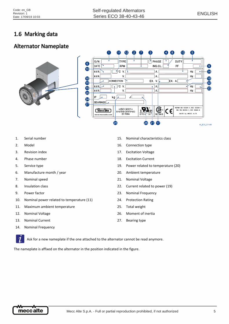
1.6 Marking data
Alternator Nameplate
The nameplate is affixed on the alternator in the position indicated in the figure.
1. Serial number
2. Model
3. Revision index
4. Phase number
5. Service type
6. Manufacture month / year
7. Nominal speed
8. Insulation class
9. Power factor
10. Nominal power related to temperature (11)
11. Maximum ambient temperature
12. Nominal Voltage
13. Nominal Current
14. Nominal Frequency
15. Nominal characteristics class
16. Connection type
17. Excitation Voltage
18. Excitation Current
19. Power related to temperature (20)
20. Ambient temperature
21. Nominal Voltage
22. Current related to power (19)
23. Nominal Frequency
24. Protection Rating
25. Total weight
26. Moment of inertia
27. Bearing type
Ask for a new nameplate if the one attached to the alternator cannot be read anymore.
Code: en_GBRevision: 1Date: 17/09/19 10:03
Self-regulated AlternatorsSeries ECO 38-40-43-46
ENGLISH
Mecc Alte S.p.A. - Full or partial reproduction prohibited, if not authorized 5
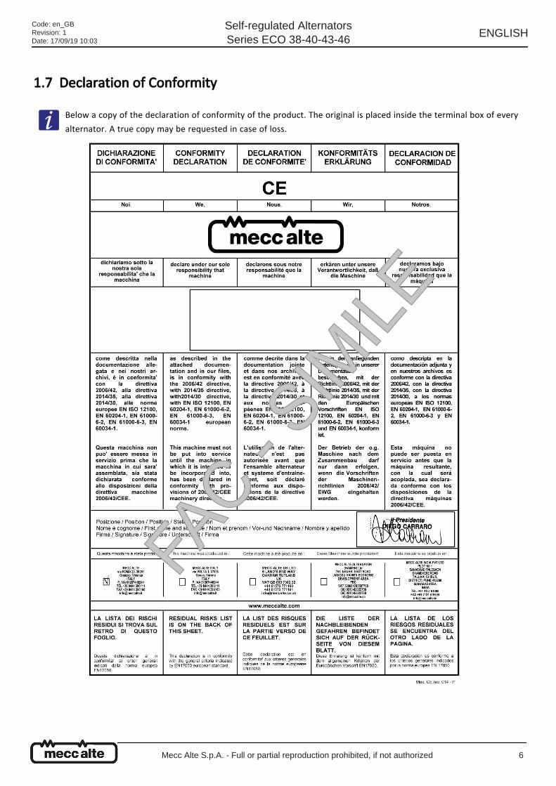
1.7 Declaration of Conformity
Below a copy of the declaration of conformity of the product. The original is placed inside the terminal box of every
alternator. A true copy may be requested in case of loss.
Code: en_GBRevision: 1Date: 17/09/19 10:03
Self-regulated AlternatorsSeries ECO 38-40-43-46
ENGLISH
Mecc Alte S.p.A. - Full or partial reproduction prohibited, if not authorized 6
Code: en_GBRevision: 1Date: 17/09/19 10:03
Self-regulated AlternatorsSeries ECO 38-40-43-46
ENGLISH
Mecc Alte S.p.A. - Full or partial reproduction prohibited, if not authorized 7
1.8 Support For any inquiry on the use, the maintenance or a request of replacement parts, the buyer must contact the Manufacturer
directly (or the help desk if present), specifying the alternator identification data indicated on the nameplate.
The Customer may resort to the technical and commercial support provided by the area representatives or by foreign branches,
which are in direct contact with MECC ALTE S.p.A. and have their addresses and contact data indicated on the back cover.
In case of fault or an insurmountable inconvenience, the Customer may contact directly the headquarters using the following
data:
1.9 Glossary
PHONE NUMBER (Landline): + 39 0444 396111FAX NUMBER: + 39 0444 396166E-MAIL: [email protected]: www.meccalte.com
MAILING ADDRESS:
MECC ALTE S.p.AVia Roma36051 Creazzo, VicenzaItaly
In case of ownership transfer or company transfers of the alternator you should always inform the manufacturing
company or your reference help desk.
System: System means, in brief, the drive motor and the alternator.
Installer: A person / company that is in charge of building the "Fully assembled Machine" and/or installing it atthe user's premises.
Fully AssembledMachine: It is the name of the complete machine mainly made up of a "drive motor" and the alternator.
Drive motor: It is the motor to which the alternator is connected. The manual also defines it as the "drive machine".PPE: Personal Protective Equipment.
Code: en_GBRevision: 1Date: 17/09/19 10:03
Self-regulated AlternatorsSeries ECO 38-40-43-46
ENGLISH
Mecc Alte S.p.A. - Full or partial reproduction prohibited, if not authorized 8
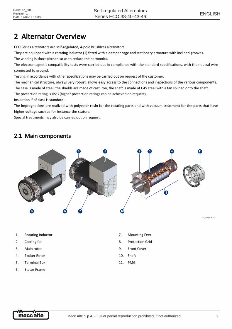
2 Alternator Overview ECO Series alternators are self-regulated, 4-pole brushless alternators.
They are equipped with a rotating inductor (1) fitted with a damper cage and stationary armature with inclined grooves.
The winding is short pitched so as to reduce the harmonics.
The electromagnetic compatibility tests were carried out in compliance with the standard specifications, with the neutral wire
connected to ground.
Testing in accordance with other specifications may be carried out on request of the customer.
The mechanical structure, always very robust, allows easy access to the connections and inspections of the various components.
The case is made of steel, the shields are made of cast iron, the shaft is made of C45 steel with a fan splined onto the shaft.
The protection rating is IP23 (higher protection ratings can be achieved on request).
Insulation if of class H standard.
The impregnations are realized with polyester resin for the rotating parts and with vacuum treatment for the parts that have
higher voltage such as for instance the stators.
Special treatments may also be carried out on request.
2.1 Main components
1. Rotating Inductor
2. Cooling fan
3. Main rotor
4. Exciter Rotor
5. Terminal Box
6. Stator Frame
7. Mounting Feet
8. Protection Grid
9. Front Cover
10. Shaft
11. PMG
Code: en_GBRevision: 1Date: 17/09/19 10:03
Self-regulated AlternatorsSeries ECO 38-40-43-46
ENGLISH
Mecc Alte S.p.A. - Full or partial reproduction prohibited, if not authorized 9
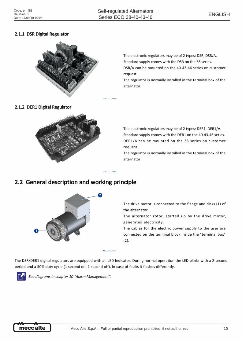
2.1.1 DSR Digital Regulator
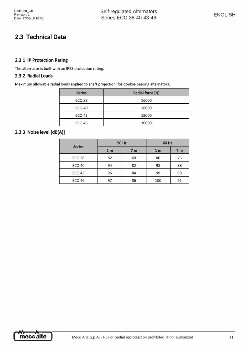
2.1.2 DER1 Digital Regulator
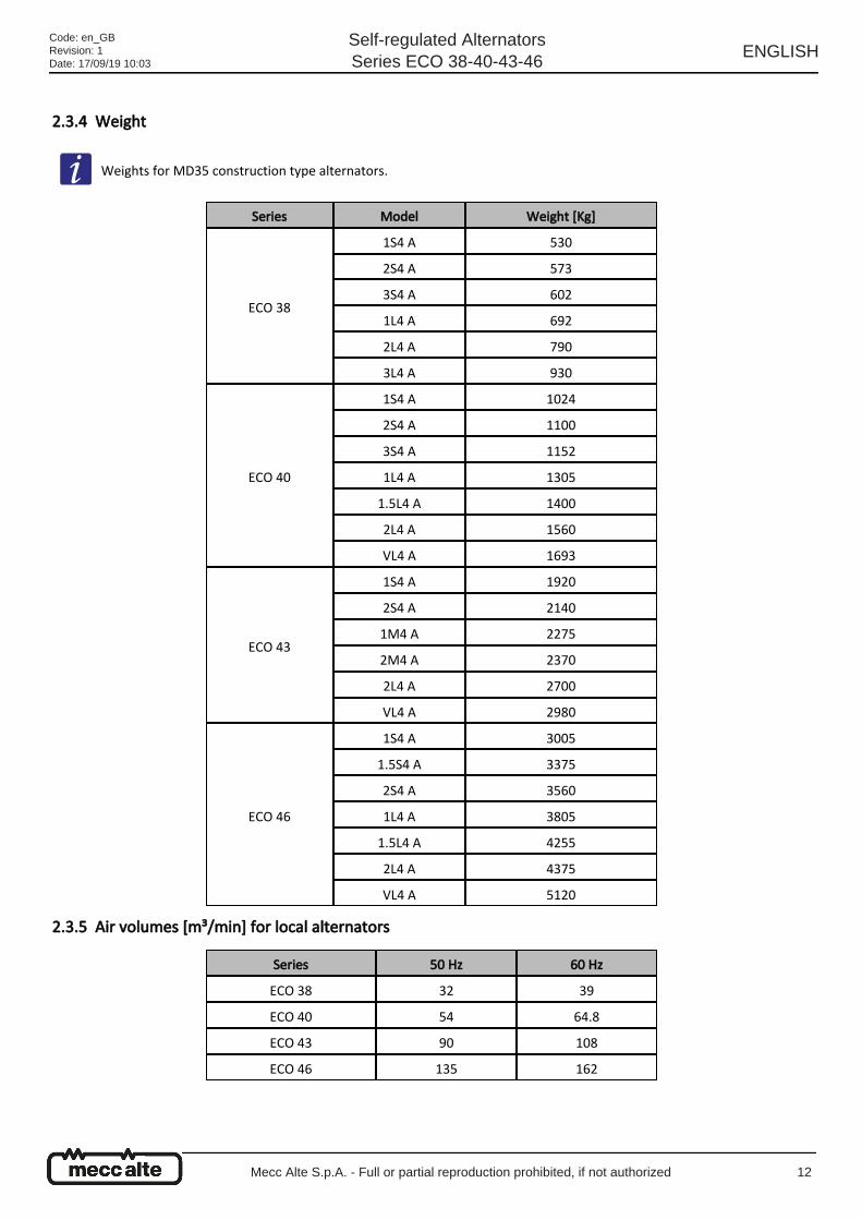
2.2 General description and working principle
The DSR/DER1 digital regulators are equipped with an LED Indicator. During normal operation the LED blinks with a 2-second
period and a 50% duty cycle (1 second on, 1 second off), in case of faults it flashes differently.
The electronic regulators may be of 2 types: DSR, DSR/A.
Standard supply comes with the DSR on the 38 series.
DSR/A can be mounted on the 40-43-46 series on customer
request.
The regulator is normally installed in the terminal box of the
alternator.
The electronic regulators may be of 2 types: DER1, DER1/A.
Standard supply comes with the DER1 on the 40-43-46 series.
DER1/A can be mounted on the 38 series on customer
request.
The regulator is normally installed in the terminal box of the
alternator.
The drive motor is connected to the flange and disks (1) of
the alternator.
The alternator rotor, started up by the drive motor,
generates electricity.
The cables for the electric power supply to the user are
connected on the terminal block inside the "terminal box"
(2).
See diagrams in chapter 10 "Alarm Management".
Code: en_GBRevision: 1Date: 17/09/19 10:03
Self-regulated AlternatorsSeries ECO 38-40-43-46
ENGLISH
Mecc Alte S.p.A. - Full or partial reproduction prohibited, if not authorized 10
2.3 Technical Data
2.3.1 IP Protection Rating The alternator is built with an IP23 protection rating.
2.3.2 Radial Loads Maximum allowable radial loads applied to shaft projection, for double-bearing alternators.
2.3.3 Noise level [dB(A)]
Series Radial force [N]
ECO 38 16000
ECO 40 16000
ECO 43 19000
ECO 46 30000
Series50 Hz 60 Hz
1 m 7 m 1 m 7 m
ECO 38 82 69 86 73
ECO 40 94 82 98 88
ECO 43 95 84 99 99
ECO 46 97 86 100 91
Code: en_GBRevision: 1Date: 17/09/19 10:03
Self-regulated AlternatorsSeries ECO 38-40-43-46
ENGLISH
Mecc Alte S.p.A. - Full or partial reproduction prohibited, if not authorized 11
2.3.4 Weight
2.3.5 Air volumes [m³/min] for local alternators
Weights for MD35 construction type alternators.
Series Model Weight [Kg]
ECO 38
1S4 A 530
2S4 A 573
3S4 A 602
1L4 A 692
2L4 A 790
3L4 A 930
ECO 40
1S4 A 1024
2S4 A 1100
3S4 A 1152
1L4 A 1305
1.5L4 A 1400
2L4 A 1560
VL4 A 1693
ECO 43
1S4 A 1920
2S4 A 2140
1M4 A 2275
2M4 A 2370
2L4 A 2700
VL4 A 2980
ECO 46
1S4 A 3005
1.5S4 A 3375
2S4 A 3560
1L4 A 3805
1.5L4 A 4255
2L4 A 4375
VL4 A 5120
Series 50 Hz 60 Hz
ECO 38 32 39
ECO 40 54 64.8
ECO 43 90 108
ECO 46 135 162
Code: en_GBRevision: 1Date: 17/09/19 10:03
Self-regulated AlternatorsSeries ECO 38-40-43-46
ENGLISH
Mecc Alte S.p.A. - Full or partial reproduction prohibited, if not authorized 12
2.3.6 Alignment tolerances in B3B14 Tolerance table of drive motor alignment with the alternator.
2.3.7 Positioning dimension in MD35 Positioning dimension for flywheel refered to flange face.
RPM Radial tolerance (mm) Angular tolerance (mm / 100 mm)
1200 0.08 0.05
1500 0.06 0.05
1800 0.05 0.05
3000 0.04 0.05
3600 0.03 0.05
Series SAE L (mm)
ECO 3811 ½ 39.6
14 25.4
ECO 4014 25.4
18 15.7
ECO 43
14 25.4
18 15.7
21 0
ECO 4618 15.7
21 0
Code: en_GBRevision: 1Date: 17/09/19 10:03
Self-regulated AlternatorsSeries ECO 38-40-43-46
ENGLISH
Mecc Alte S.p.A. - Full or partial reproduction prohibited, if not authorized 13
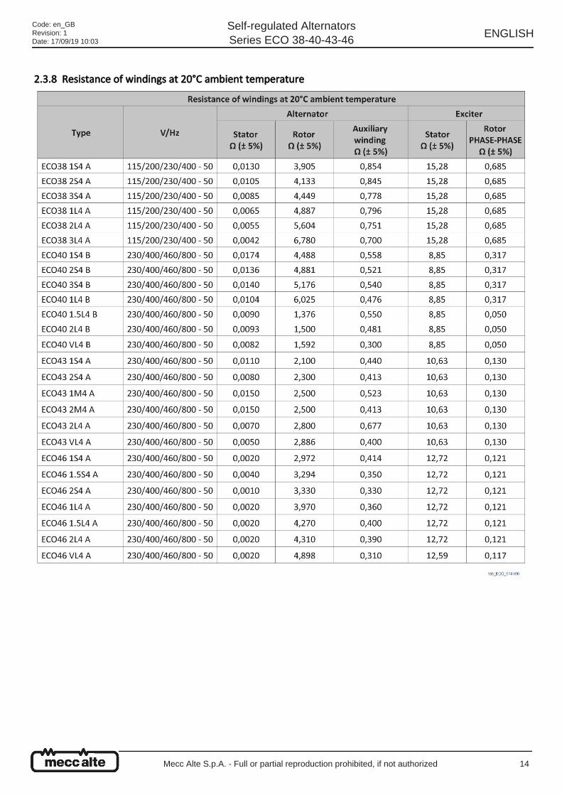
2.3.8 Resistance of windings at 20°C ambient temperature
Code: en_GBRevision: 1Date: 17/09/19 10:03
Self-regulated AlternatorsSeries ECO 38-40-43-46
ENGLISH
Mecc Alte S.p.A. - Full or partial reproduction prohibited, if not authorized 14
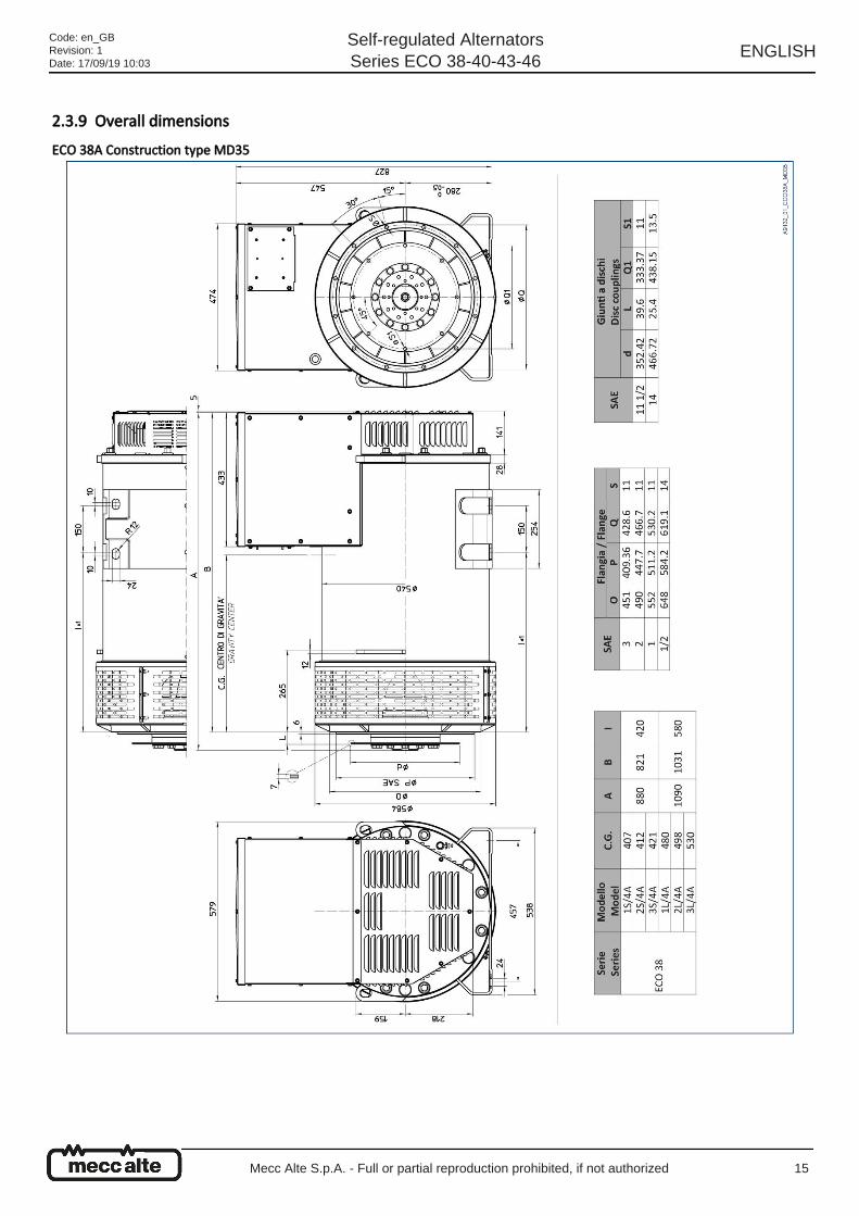
2.3.9 Overall dimensions ECO 38A Construction type MD35
Code: en_GBRevision: 1Date: 17/09/19 10:03
Self-regulated AlternatorsSeries ECO 38-40-43-46
ENGLISH
Mecc Alte S.p.A. - Full or partial reproduction prohibited, if not authorized 15
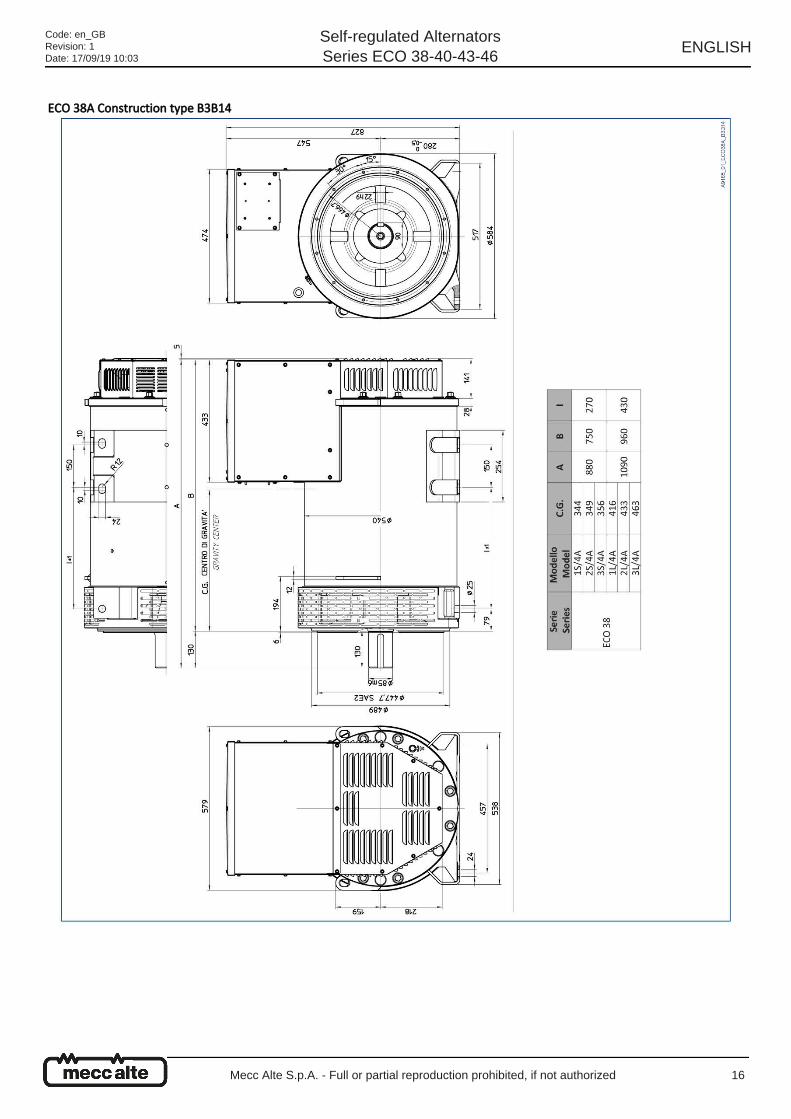
ECO 38A Construction type B3B14
Code: en_GBRevision: 1Date: 17/09/19 10:03
Self-regulated AlternatorsSeries ECO 38-40-43-46
ENGLISH
Mecc Alte S.p.A. - Full or partial reproduction prohibited, if not authorized 16
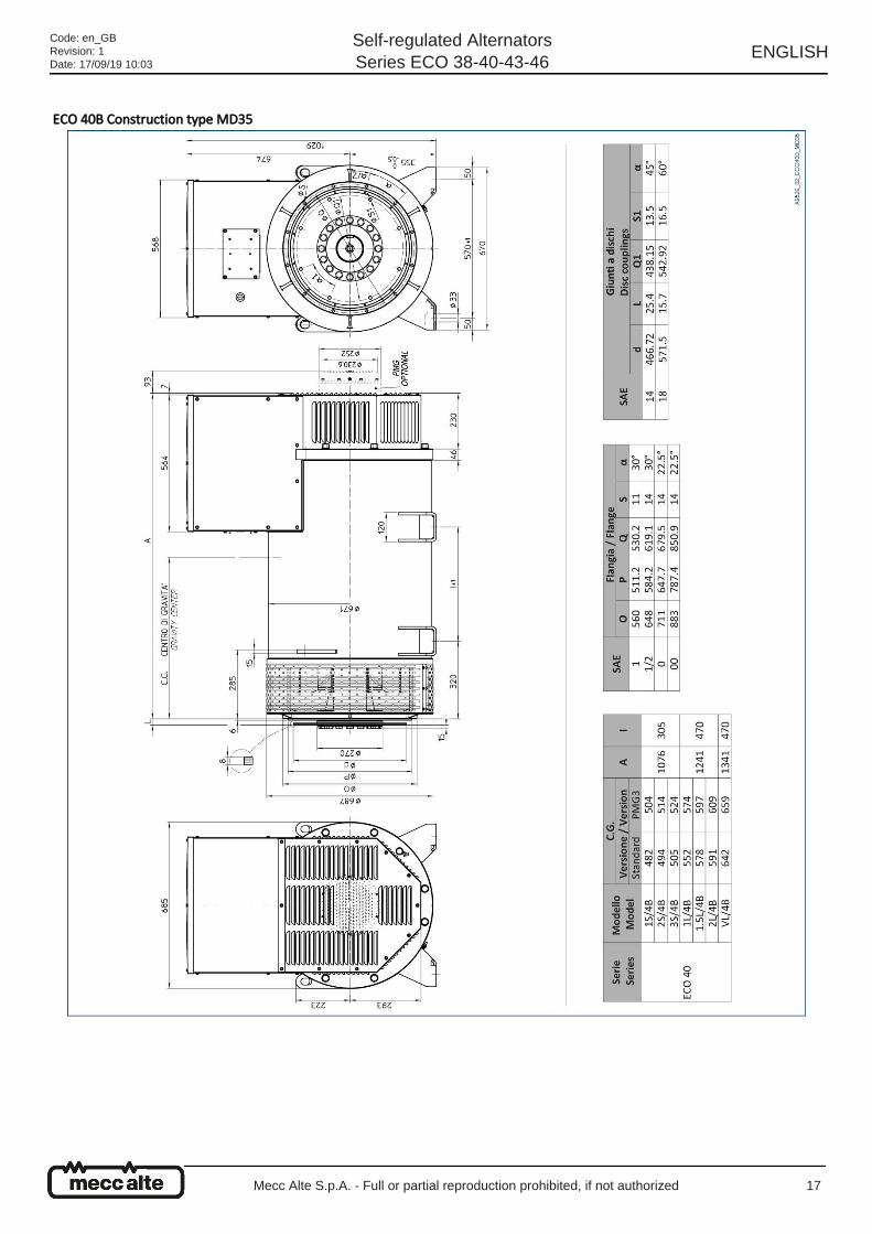
ECO 40B Construction type MD35
Code: en_GBRevision: 1Date: 17/09/19 10:03
Self-regulated AlternatorsSeries ECO 38-40-43-46
ENGLISH
Mecc Alte S.p.A. - Full or partial reproduction prohibited, if not authorized 17
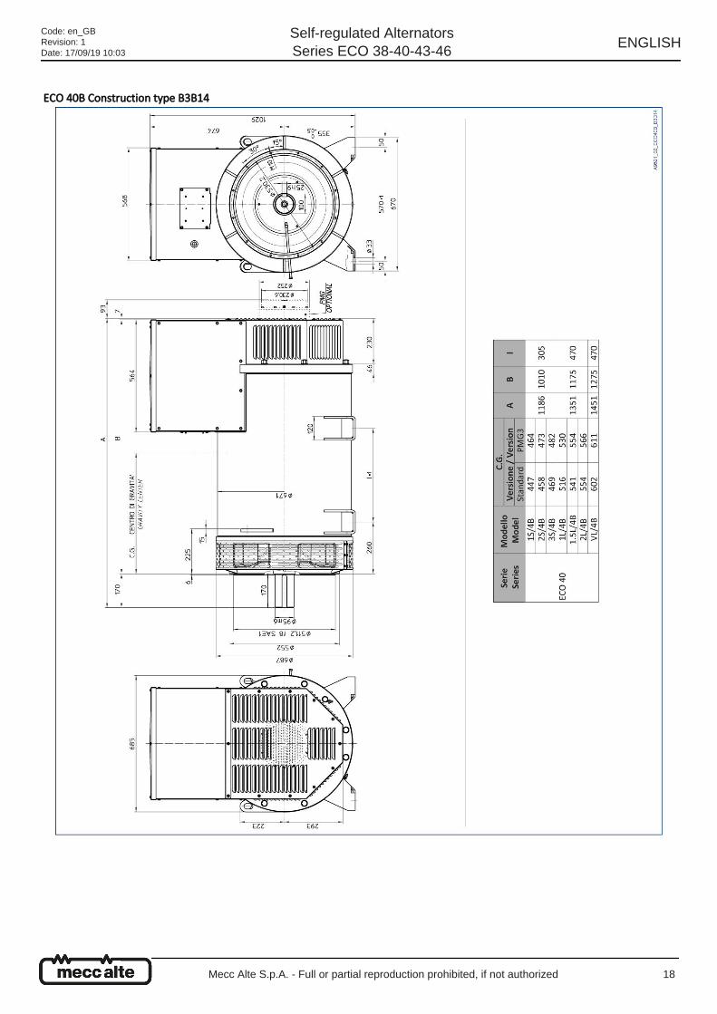
ECO 40B Construction type B3B14
Code: en_GBRevision: 1Date: 17/09/19 10:03
Self-regulated AlternatorsSeries ECO 38-40-43-46
ENGLISH
Mecc Alte S.p.A. - Full or partial reproduction prohibited, if not authorized 18
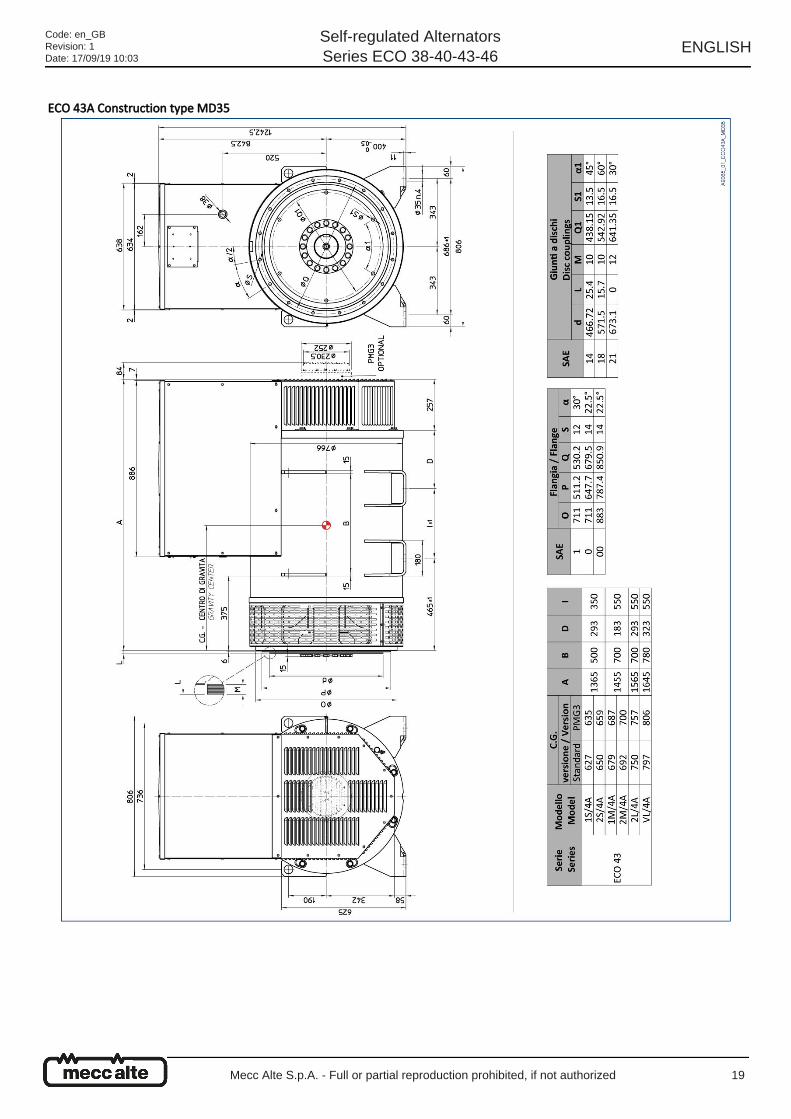
ECO 43A Construction type MD35
Code: en_GBRevision: 1Date: 17/09/19 10:03
Self-regulated AlternatorsSeries ECO 38-40-43-46
ENGLISH
Mecc Alte S.p.A. - Full or partial reproduction prohibited, if not authorized 19
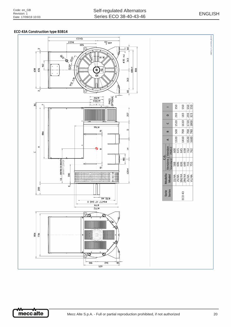
ECO 43A Construction type B3B14
Code: en_GBRevision: 1Date: 17/09/19 10:03
Self-regulated AlternatorsSeries ECO 38-40-43-46
ENGLISH
Mecc Alte S.p.A. - Full or partial reproduction prohibited, if not authorized 20
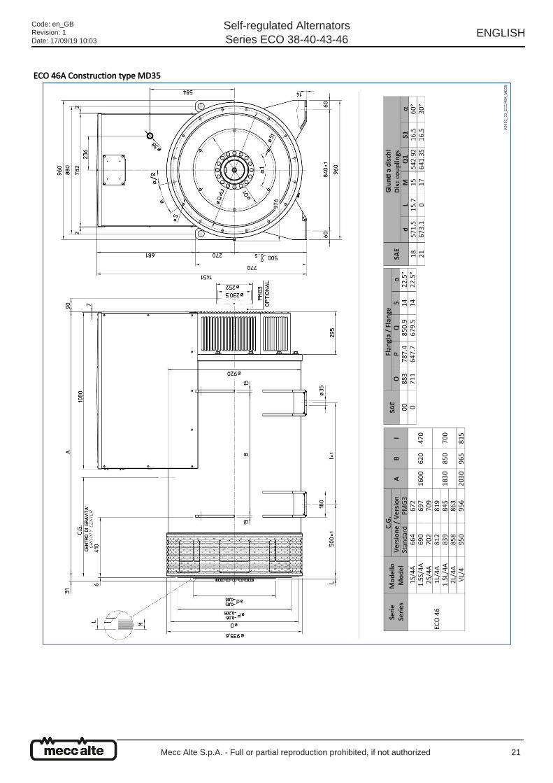
ECO 46A Construction type MD35
Code: en_GBRevision: 1Date: 17/09/19 10:03
Self-regulated AlternatorsSeries ECO 38-40-43-46
ENGLISH
Mecc Alte S.p.A. - Full or partial reproduction prohibited, if not authorized 21
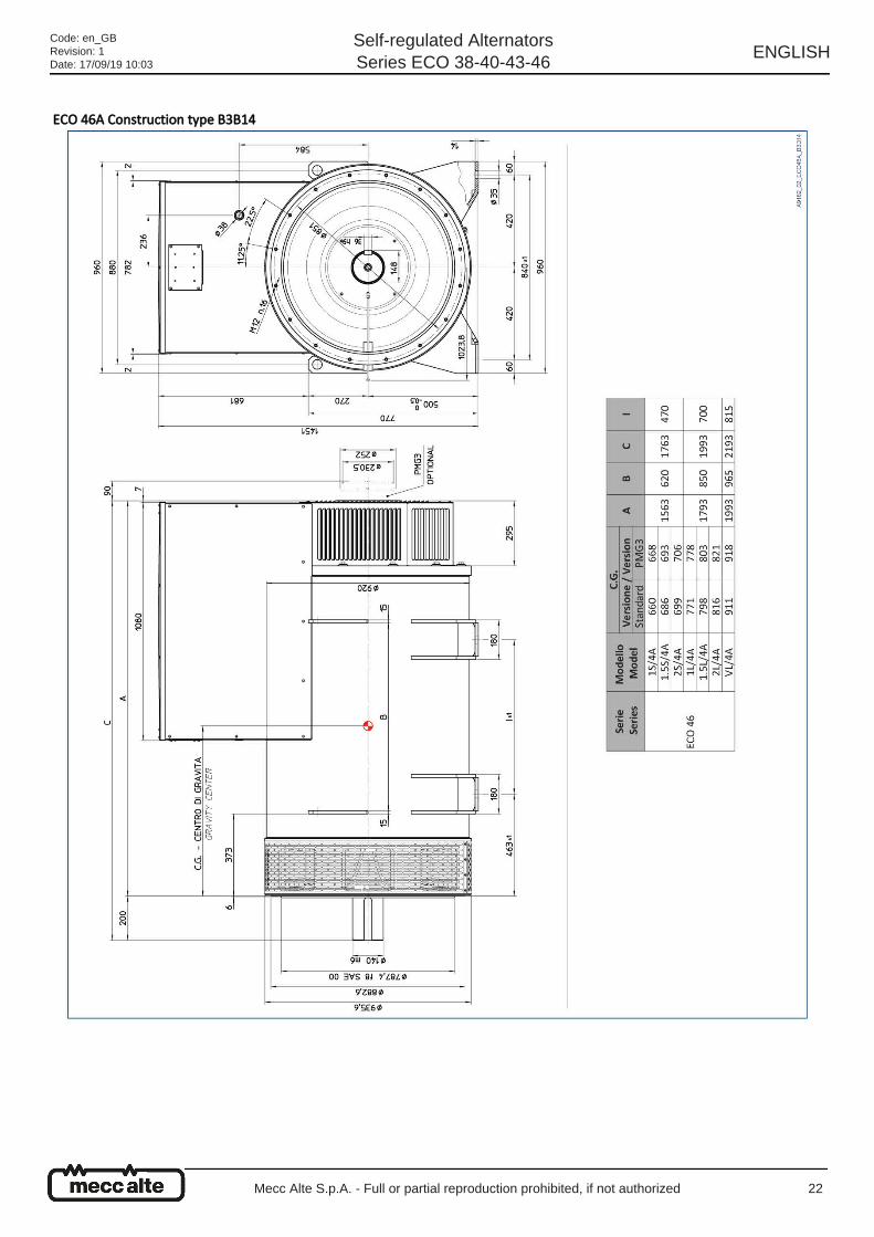
ECO 46A Construction type B3B14
Code: en_GBRevision: 1Date: 17/09/19 10:03
Self-regulated AlternatorsSeries ECO 38-40-43-46
ENGLISH
Mecc Alte S.p.A. - Full or partial reproduction prohibited, if not authorized 22
2.3.10 Materials The table below contains the approximate percentages of the materials used in Mecc Alte S.p.A's alternators.
2.4 Operating ambient requirements
Material Percentage
Steel Parts 45%
Cast Iron Parts 20%
Copper Parts 20%
Aluminum Parts 10%
Plastic Parts 3%
Electronic parts 2%
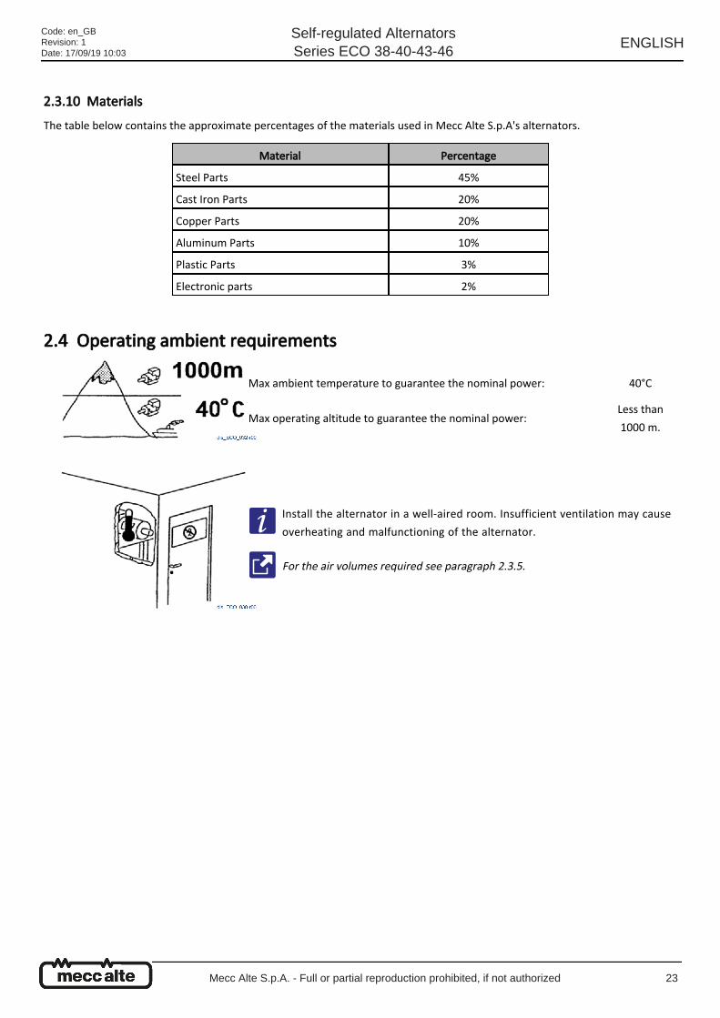
Max ambient temperature to guarantee the nominal power: 40°C
Max operating altitude to guarantee the nominal power: Less than
1000 m.
Install the alternator in a well-aired room. Insufficient ventilation may cause
overheating and malfunctioning of the alternator.
For the air volumes required see paragraph 2.3.5.
Code: en_GBRevision: 1Date: 17/09/19 10:03
Self-regulated AlternatorsSeries ECO 38-40-43-46
ENGLISH
Mecc Alte S.p.A. - Full or partial reproduction prohibited, if not authorized 23

Code: en_GBRevision: 1Date: 17/09/19 10:03
Self-regulated AlternatorsSeries ECO 38-40-43-46
ENGLISH
Mecc Alte S.p.A. - Full or partial reproduction prohibited, if not authorized 24
3 Safety
3.1 General Instructions The alternator may be used only for the purpose for which it was designed and built.
Caution
The ECO series alternators comply with the Directive 2006/42/EC as amended, therefore they do not pose threats to
the operators, if installed, used and serviced in accordance with the instructions provided by Mecc Alte and on
condition that the safety devices are kept in perfect state of efficiency.
Danger
Install the alternator only after having read and understood all the sections of this manual.
Danger
Do no operate it while under the influence of intoxicating agents that might delay reaction time such as, for instance,
alcohol or drugs.
Danger
The alternator installation, operation and maintenance technicians must be adequately qualified specialists who know
the characteristics of the alternators.
Warning
Adequate work clothing is recommended. Avoid wearing chains, bracelets, scarves and cumbersome clothing, long hair
must be tied.
Warning
Do not neutralize, remove, alter or otherwise render ineffective any safety, protection or control device of the
alternator.
Warning
Maintain the work areas and the routes defined for the installation of the alternator always free from materials and/or
elements that may hinder the movement of or cause accidents to the operator.
Caution
The work area must always be adequately lit.
Caution
Keep the floor in the operating area always clean and dry to prevent the forklift truck from sliding sideways when in
movement.
Danger
Never operate the alternator with wet hands and objects when it is energized.
Code: en_GBRevision: 1Date: 17/09/19 10:03
Self-regulated AlternatorsSeries ECO 38-40-43-46
ENGLISH
Mecc Alte S.p.A. - Full or partial reproduction prohibited, if not authorized 25
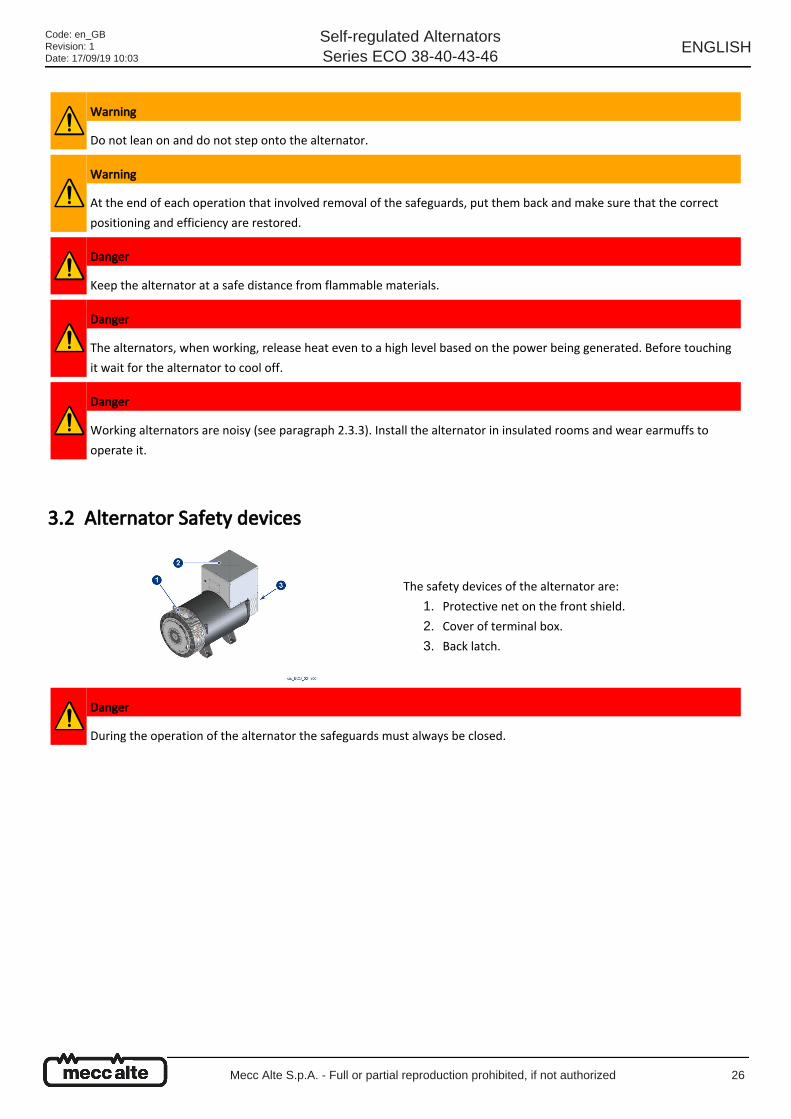
3.2 Alternator Safety devices
Warning
Do not lean on and do not step onto the alternator.
Warning
At the end of each operation that involved removal of the safeguards, put them back and make sure that the correct
positioning and efficiency are restored.
Danger
Keep the alternator at a safe distance from flammable materials.
Danger
The alternators, when working, release heat even to a high level based on the power being generated. Before touching
it wait for the alternator to cool off.
Danger
Working alternators are noisy (see paragraph 2.3.3). Install the alternator in insulated rooms and wear earmuffs to
operate it.
The safety devices of the alternator are:
Protective net on the front shield.1.
Cover of terminal box.2.
Back latch.3.
Danger
During the operation of the alternator the safeguards must always be closed.
Code: en_GBRevision: 1Date: 17/09/19 10:03
Self-regulated AlternatorsSeries ECO 38-40-43-46
ENGLISH
Mecc Alte S.p.A. - Full or partial reproduction prohibited, if not authorized 26
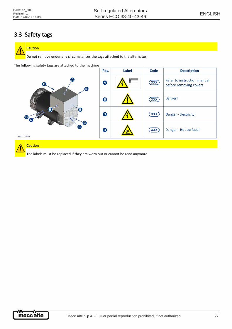
3.3 Safety tags
The following safety tags are attached to the machine
Caution
Do not remove under any circumstances the tags attached to the alternator.
Caution
The labels must be replaced if they are worn out or cannot be read anymore.
Code: en_GBRevision: 1Date: 17/09/19 10:03
Self-regulated AlternatorsSeries ECO 38-40-43-46
ENGLISH
Mecc Alte S.p.A. - Full or partial reproduction prohibited, if not authorized 27
3.4 Personal Protective Equipment
The manufacturer disclaims all responsibility for any potential damages caused to people by failure to use the PPE.
3.5 Residual risks The alternator presents the following residual risks:
Caution
The staff in charge with the operation of the alternator must wear the personal protective equipment (PPE) indicated in
the table below.
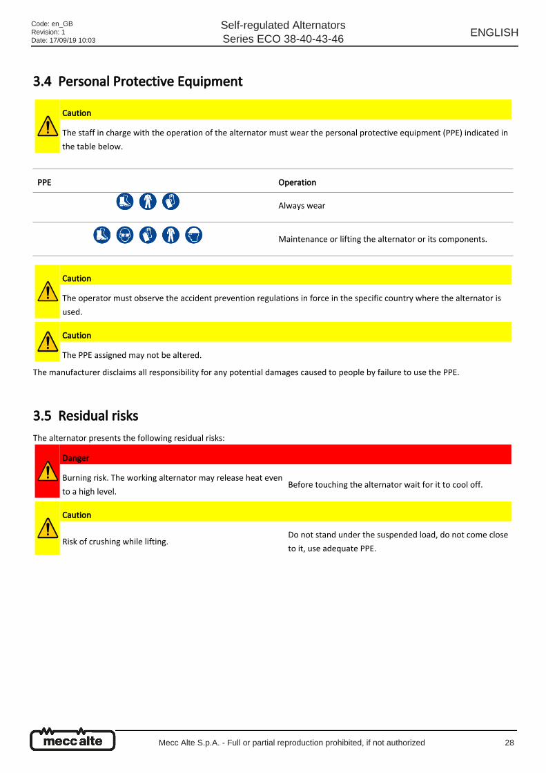
PPE Operation
Always wear
Maintenance or lifting the alternator or its components.
Caution
The operator must observe the accident prevention regulations in force in the specific country where the alternator is
used.
Caution
The PPE assigned may not be altered.
Danger
Burning risk. The working alternator may release heat even
to a high level.Before touching the alternator wait for it to cool off.
Caution
Risk of crushing while lifting.Do not stand under the suspended load, do not come close
to it, use adequate PPE.
Code: en_GBRevision: 1Date: 17/09/19 10:03
Self-regulated AlternatorsSeries ECO 38-40-43-46
ENGLISH
Mecc Alte S.p.A. - Full or partial reproduction prohibited, if not authorized 28
4 Transportation, movement and storage. The ECO series alternators are delivered by road on pallets, by sea in fumigated wood cases. Other shipment methods available
on customer request.
The cases shipped by sea are covered with nylon to avoid salt infiltration that could compromise the correct operation of the
alternator.
Any potential replacement parts are however shipped in cardboard packing that is disposed of according to the local regulations.
Packing is always accompanied by a packing list.
Transportation of the packing to the installation place will be provided by the customer.
4.1 General Instructions
Always make sure that the devices and means for packing materials removal, the alternator and any disassembled part are
suitable and undamaged.
Upon delivery of the alternator check against the delivery note that there are no missing parts and/or damages; in case
there are any, immediately inform the carrier, the insurance company and the reseller or Mecc Alte.
Warning
The instructions of this chapter must be strictly followed when lifting the alternator.
Warning
Use adequate, tested and certified lifting devices.
Warning
Lifting and transportation must be carried out by members of staff who were trained for this purpose.
Warning
To carry out any lifting, transportation and handling operation wear the PPE indicated by the regulations (see
paragraph 3.4).
Warning
When lifting the alternator with the forklift truck keep its forks at the longest possible distance one from the other so
as to prevent the alternator from falling or sliding off.
Code: en_GBRevision: 1Date: 17/09/19 10:03
Self-regulated AlternatorsSeries ECO 38-40-43-46
ENGLISH
Mecc Alte S.p.A. - Full or partial reproduction prohibited, if not authorized 29

4.2 Packing materials lifting and transportation
4.3 Unpacking
4.4 How to dispose of the packing materials Please recycle the packing materials in accordance with the applicable regulations in the country where the alternator is
installed.
Danger
Pay attention during all transportation and movement operations. Do not stand under suspended loads.
Warning
Check the packing or the documentation attached to it for the weight to lift, the predefined anchor points and use
suitable equipment for the lifting.
Unpack the alternator carefully without breaking/damaging the packing materials. Both the cases (equipped with
metal hinges so that they may be folded) and the pallet must be returned to Mecc Alte.
Once the single-bearing alternator is unpacked do not cut the tie strips of the rotor to
prevent it from sliding.
Code: en_GBRevision: 1Date: 17/09/19 10:03
Self-regulated AlternatorsSeries ECO 38-40-43-46
ENGLISH
Mecc Alte S.p.A. - Full or partial reproduction prohibited, if not authorized 30
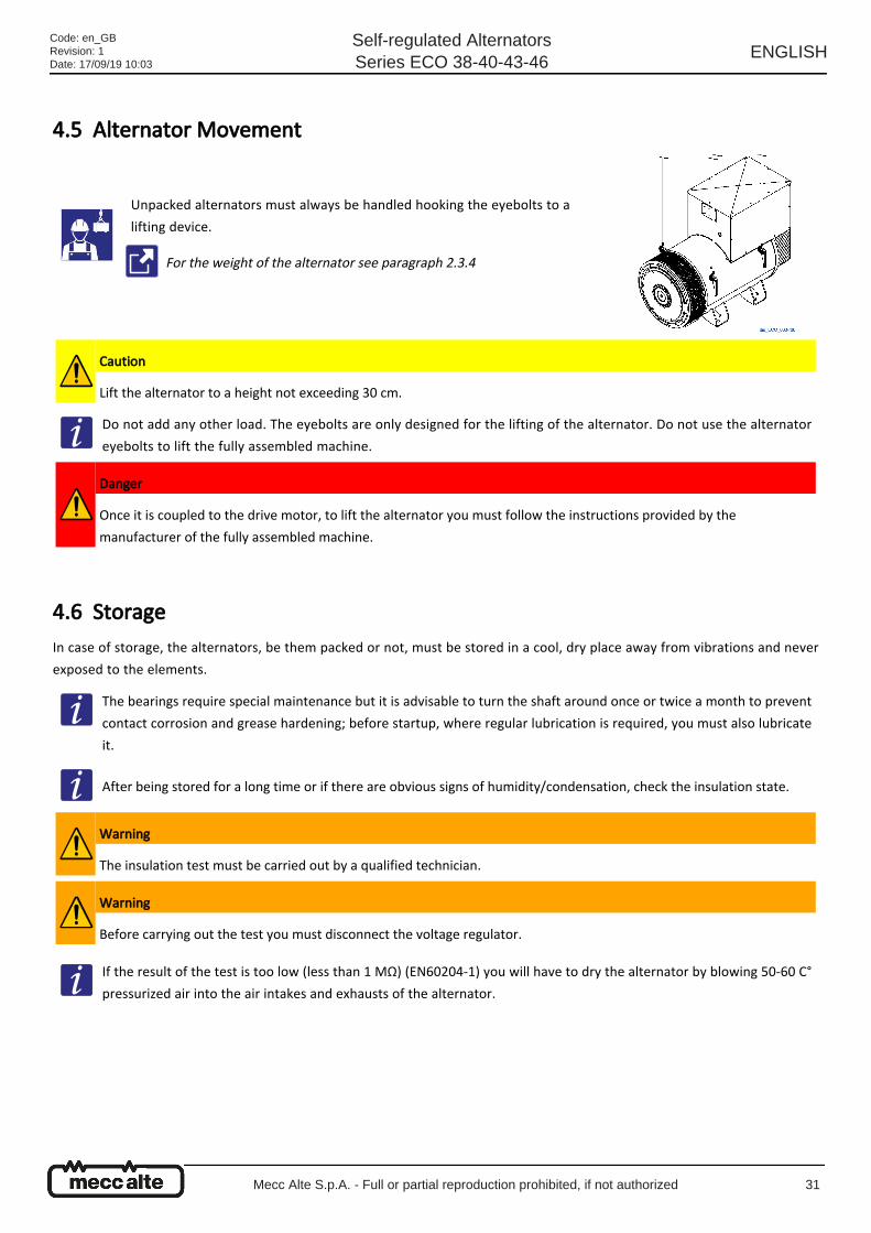
4.5 Alternator Movement
4.6 Storage In case of storage, the alternators, be them packed or not, must be stored in a cool, dry place away from vibrations and never
exposed to the elements.
Unpacked alternators must always be handled hooking the eyebolts to a
lifting device.
For the weight of the alternator see paragraph 2.3.4
Caution
Lift the alternator to a height not exceeding 30 cm.
Do not add any other load. The eyebolts are only designed for the lifting of the alternator. Do not use the alternator
eyebolts to lift the fully assembled machine.
Danger
Once it is coupled to the drive motor, to lift the alternator you must follow the instructions provided by the
manufacturer of the fully assembled machine.
The bearings require special maintenance but it is advisable to turn the shaft around once or twice a month to prevent
contact corrosion and grease hardening; before startup, where regular lubrication is required, you must also lubricate
it.
After being stored for a long time or if there are obvious signs of humidity/condensation, check the insulation state.
Warning
The insulation test must be carried out by a qualified technician.
Warning
Before carrying out the test you must disconnect the voltage regulator.
If the result of the test is too low (less than 1 MΩ) (EN60204-1) you will have to dry the alternator by blowing 50-60 C°
pressurized air into the air intakes and exhausts of the alternator.
Code: en_GBRevision: 1Date: 17/09/19 10:03
Self-regulated AlternatorsSeries ECO 38-40-43-46
ENGLISH
Mecc Alte S.p.A. - Full or partial reproduction prohibited, if not authorized 31

Code: en_GBRevision: 1Date: 17/09/19 10:03
Self-regulated AlternatorsSeries ECO 38-40-43-46
ENGLISH
Mecc Alte S.p.A. - Full or partial reproduction prohibited, if not authorized 32
5 Installation instructions / drive motor coupling
5.1 Installation Setup
The alternator is designed and built to be installed in well-ventilated environments.
Please ensure that the base of the alternator and of the drive motor is calculated so as to support the weight of all potential
stresses caused by the operation.
Warning
The final installer is in charge with assembling all the safeguards (disconnect switches, safeguards against direct and
indirect contact, safeguards against overcurrent and overvoltage, emergency stop and so on) required to make the
machine and the user system comply with the European and International Safety Regulations.
The installation and first startup operations of the fully assembled machine must be carried out by qualified personnel.
Danger
Working alternators are noisy (see paragraph 2.3.3). Install the alternator in insulated rooms and wear earmuffs to
operate it.
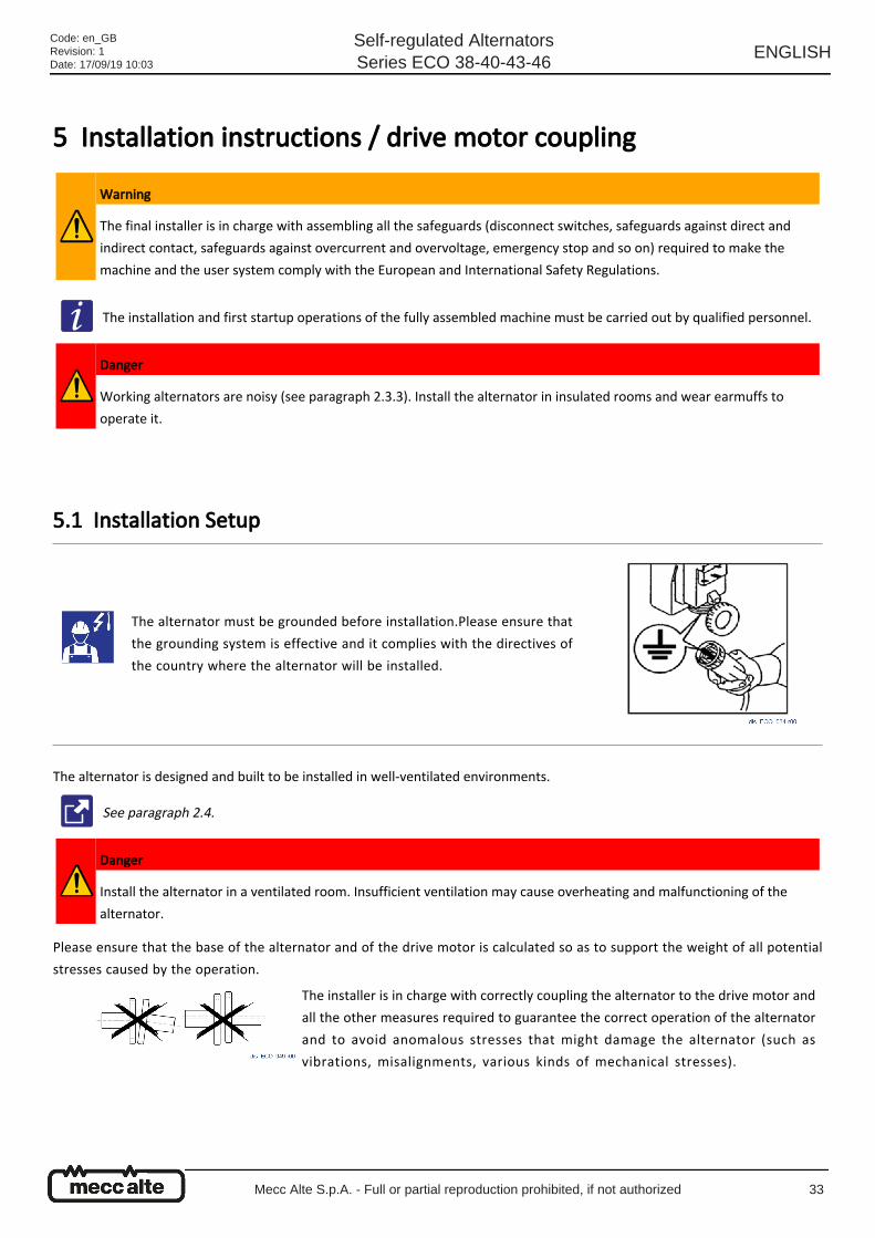
The alternator must be grounded before installation.Please ensure that
the grounding system is effective and it complies with the directives of
the country where the alternator will be installed.
See paragraph 2.4.
Danger
Install the alternator in a ventilated room. Insufficient ventilation may cause overheating and malfunctioning of the
alternator.
The installer is in charge with correctly coupling the alternator to the drive motor and
all the other measures required to guarantee the correct operation of the alternator
and to avoid anomalous stresses that might damage the alternator (such as
vibrations, misalignments, various kinds of mechanical stresses).
Code: en_GBRevision: 1Date: 17/09/19 10:03
Self-regulated AlternatorsSeries ECO 38-40-43-46
ENGLISH
Mecc Alte S.p.A. - Full or partial reproduction prohibited, if not authorized 33
●
●
●
●
●
5.2 Unpacking and disposal of packing materials
5.3 Mechanical coupling The coupling of the alternator to the drive motor must be carried out by the end user. It is carried out at his sole discretion, but
it must:
Be realized in accordance with the safety regulations in force.
Ensure the ideal operating conditions for the alternator (air temperature below 40 °C and air vents not blocked).
Ensure easy access for its verification and maintenance.
Be assembled on a strong base able to hold the total weight of the alternator and the drive motor.
Observe the assembly tolerances.
Control the correct fastening of the discs to the alternator rotor.
Moreover, it is advisable to check the compatibility of the torsional characteristics of the motor / alternator (to be carried out by
the customer).
Danger
Pay attention during all transportation and movement operations.
Danger
Do not stand under suspended loads.
Carefully remove the packing.
Please recycle the packing materials.
See paragraph 9.7
Imprecise alignment may cause vibrations and damages to the bearings.
Please see the related technical documentation.
In case of double-bearing alternators, ensure that the radial loads applied to the shaft protrusion do not exceed the
admissible values.
See paragraph 2.3.2.
Code: en_GBRevision: 1Date: 17/09/19 10:03
Self-regulated AlternatorsSeries ECO 38-40-43-46
ENGLISH
Mecc Alte S.p.A. - Full or partial reproduction prohibited, if not authorized 34
These values are calculated so as to prevent excessive shaft flexure. The load that may be supported by the bearings is statically
and dynamically higher than the one supported by the shaft, however, the presence of excessive vibrations or adverse
environmental conditions may reduce the bearing's life or lead to a lower maximum allowable load in proportion to the
bearing's life.
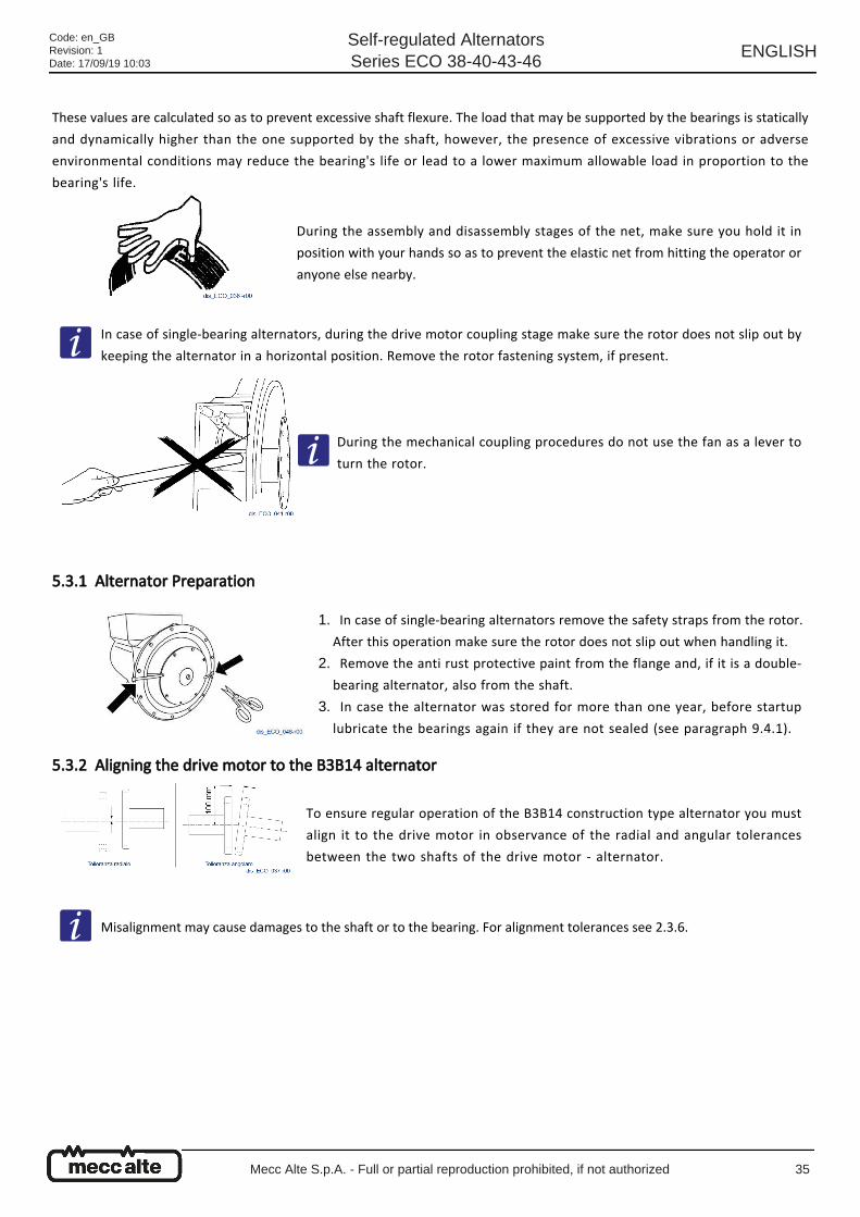
5.3.1 Alternator Preparation
5.3.2 Aligning the drive motor to the B3B14 alternator
During the assembly and disassembly stages of the net, make sure you hold it in
position with your hands so as to prevent the elastic net from hitting the operator or
anyone else nearby.
In case of single-bearing alternators, during the drive motor coupling stage make sure the rotor does not slip out by
keeping the alternator in a horizontal position. Remove the rotor fastening system, if present.
During the mechanical coupling procedures do not use the fan as a lever to
turn the rotor.
In case of single-bearing alternators remove the safety straps from the rotor.
After this operation make sure the rotor does not slip out when handling it.
1.
Remove the anti rust protective paint from the flange and, if it is a double-
bearing alternator, also from the shaft.
2.
In case the alternator was stored for more than one year, before startup
lubricate the bearings again if they are not sealed (see paragraph 9.4.1).
3.
To ensure regular operation of the B3B14 construction type alternator you must
align it to the drive motor in observance of the radial and angular tolerances
between the two shafts of the drive motor - alternator.
Misalignment may cause damages to the shaft or to the bearing. For alignment tolerances see 2.3.6.
Code: en_GBRevision: 1Date: 17/09/19 10:03
Self-regulated AlternatorsSeries ECO 38-40-43-46
ENGLISH
Mecc Alte S.p.A. - Full or partial reproduction prohibited, if not authorized 35
●
●
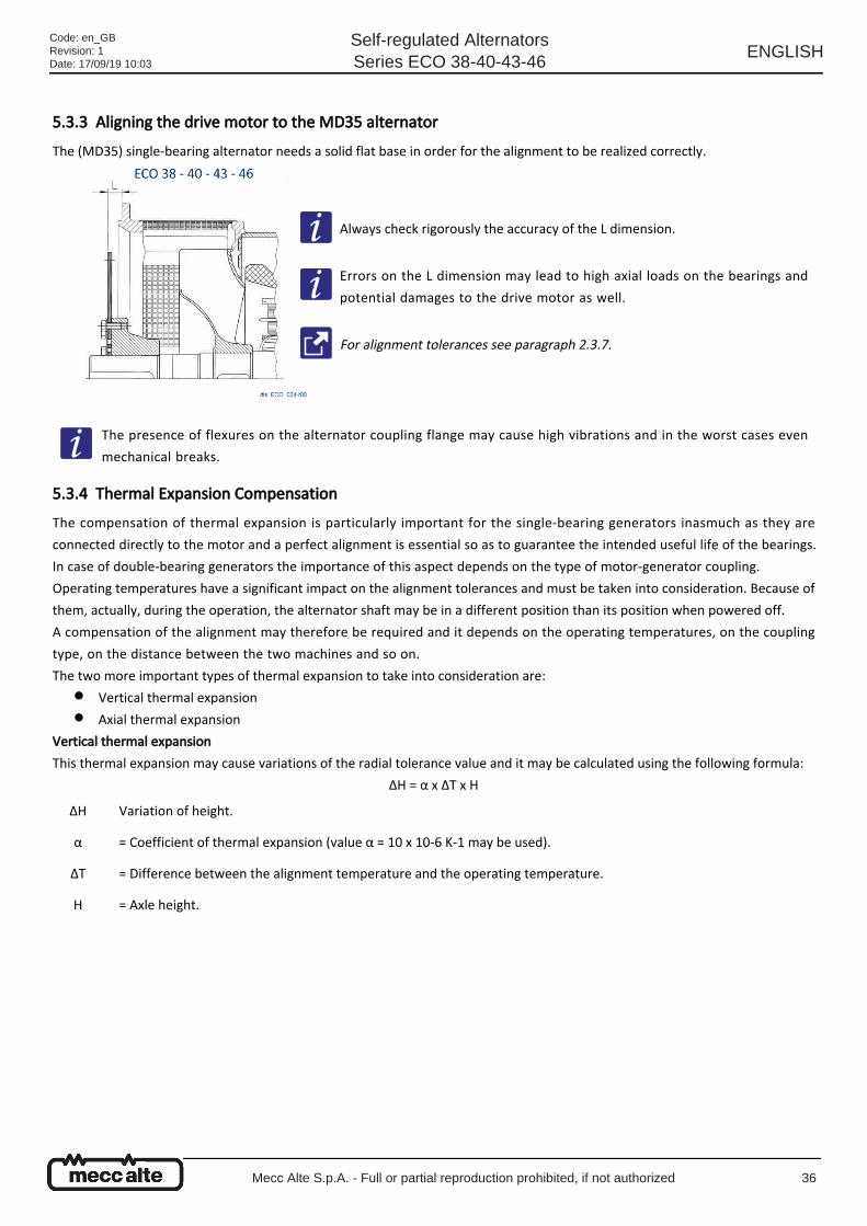
5.3.3 Aligning the drive motor to the MD35 alternator The (MD35) single-bearing alternator needs a solid flat base in order for the alignment to be realized correctly.
5.3.4 Thermal Expansion Compensation The compensation of thermal expansion is particularly important for the single-bearing generators inasmuch as they are
connected directly to the motor and a perfect alignment is essential so as to guarantee the intended useful life of the bearings.
In case of double-bearing generators the importance of this aspect depends on the type of motor-generator coupling.
Operating temperatures have a significant impact on the alignment tolerances and must be taken into consideration. Because of
them, actually, during the operation, the alternator shaft may be in a different position than its position when powered off.
A compensation of the alignment may therefore be required and it depends on the operating temperatures, on the coupling
type, on the distance between the two machines and so on.
The two more important types of thermal expansion to take into consideration are:
Vertical thermal expansion
Axial thermal expansion
Vertical thermal expansion
This thermal expansion may cause variations of the radial tolerance value and it may be calculated using the following formula:
ΔH = α x ΔT x H
Always check rigorously the accuracy of the L dimension.
Errors on the L dimension may lead to high axial loads on the bearings and
potential damages to the drive motor as well.
For alignment tolerances see paragraph 2.3.7.
The presence of flexures on the alternator coupling flange may cause high vibrations and in the worst cases even
mechanical breaks.
ΔH Variation of height.
α = Coefficient of thermal expansion (value α = 10 x 10-6 K-1 may be used).
ΔT = Difference between the alignment temperature and the operating temperature.
H = Axle height.
Code: en_GBRevision: 1Date: 17/09/19 10:03
Self-regulated AlternatorsSeries ECO 38-40-43-46
ENGLISH
Mecc Alte S.p.A. - Full or partial reproduction prohibited, if not authorized 36
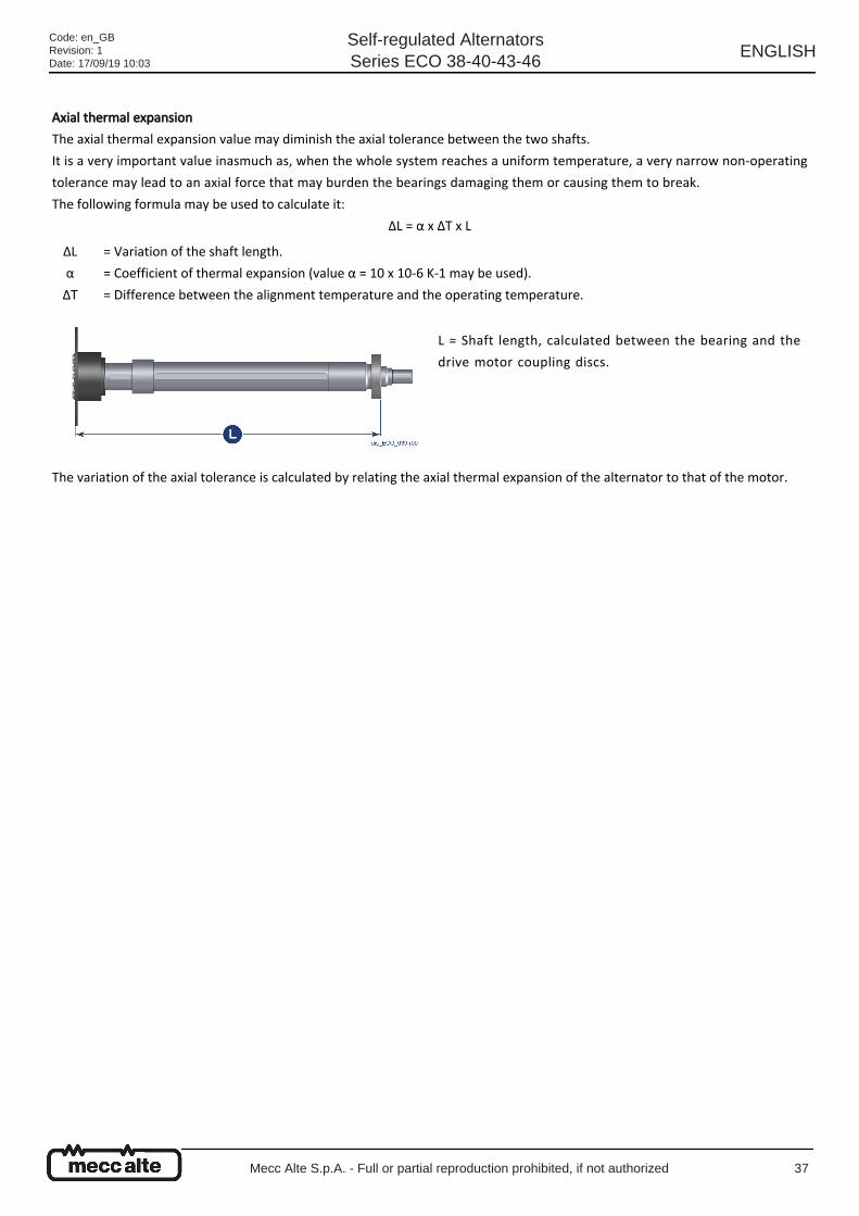
Axial thermal expansion
The axial thermal expansion value may diminish the axial tolerance between the two shafts.
It is a very important value inasmuch as, when the whole system reaches a uniform temperature, a very narrow non-operating
tolerance may lead to an axial force that may burden the bearings damaging them or causing them to break.
The following formula may be used to calculate it:
ΔL = α x ΔT x L
The variation of the axial tolerance is calculated by relating the axial thermal expansion of the alternator to that of the motor.
ΔL
α
ΔT
= Variation of the shaft length.
= Coefficient of thermal expansion (value α = 10 x 10-6 K-1 may be used).
= Difference between the alignment temperature and the operating temperature.
L = Shaft length, calculated between the bearing and the
drive motor coupling discs.
Code: en_GBRevision: 1Date: 17/09/19 10:03
Self-regulated AlternatorsSeries ECO 38-40-43-46
ENGLISH
Mecc Alte S.p.A. - Full or partial reproduction prohibited, if not authorized 37

Code: en_GBRevision: 1Date: 17/09/19 10:03
Self-regulated AlternatorsSeries ECO 38-40-43-46
ENGLISH
Mecc Alte S.p.A. - Full or partial reproduction prohibited, if not authorized 38
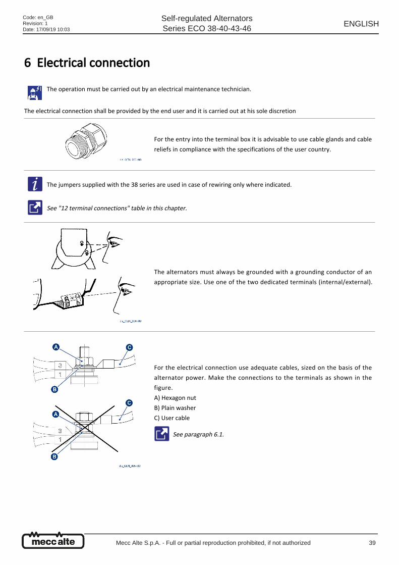
6 Electrical connection
The electrical connection shall be provided by the end user and it is carried out at his sole discretion
The operation must be carried out by an electrical maintenance technician.
For the entry into the terminal box it is advisable to use cable glands and cable
reliefs in compliance with the specifications of the user country.
The jumpers supplied with the 38 series are used in case of rewiring only where indicated.
See "12 terminal connections" table in this chapter.
The alternators must always be grounded with a grounding conductor of an
appropriate size. Use one of the two dedicated terminals (internal/external).
For the electrical connection use adequate cables, sized on the basis of the
alternator power. Make the connections to the terminals as shown in the
figure.
A) Hexagon nut
B) Plain washer
C) User cable
See paragraph 6.1.
Code: en_GBRevision: 1Date: 17/09/19 10:03
Self-regulated AlternatorsSeries ECO 38-40-43-46
ENGLISH
Mecc Alte S.p.A. - Full or partial reproduction prohibited, if not authorized 39
Once the connection was made check the terminal tightening torques that must comply with the instructions given in chapter
9.8
When the connection is finished reassemble the cover of the terminal box.
Phase rotation and sequence
Winding connection modalities
The alternators are manufactured with 12 standard outgoing cables in order to allow different voltage output, for instance, at 50
Hz, 115 V (ΔΔ) / 200 V (YY) / 230 V (Δ) / 400 V (Y) in the 38 standard series or 230 V (ΔΔ) / 400 V (YY) / 460 V (Δ) / 800 V (Y) in the
40, 43 and 46 standard series. To pass from a connection to another follow the diagrams shown in the "12 wires connection"
table on the next page.
The user power cables must be wired and supported adequately so as not to cause mechanical stress on the terminal
block of the alternator.
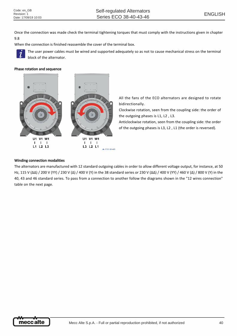
All the fans of the ECO alternators are designed to rotate
bidirectionally.
Clockwise rotation, seen from the coupling side: the order of
the outgoing phases is L1, L2 , L3.
Anticlockwise rotation, seen from the coupling side: the order
of the outgoing phases is L3, L2 , L1 (the order is reversed).
Code: en_GBRevision: 1Date: 17/09/19 10:03
Self-regulated AlternatorsSeries ECO 38-40-43-46
ENGLISH
Mecc Alte S.p.A. - Full or partial reproduction prohibited, if not authorized 40
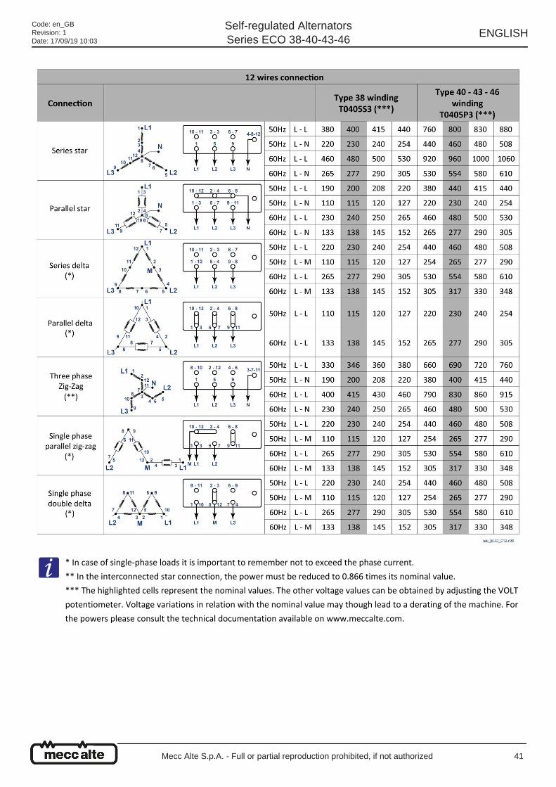
* In case of single-phase loads it is important to remember not to exceed the phase current.
** In the interconnected star connection, the power must be reduced to 0.866 times its nominal value.
*** The highlighted cells represent the nominal values. The other voltage values can be obtained by adjusting the VOLT
potentiometer. Voltage variations in relation with the nominal value may though lead to a derating of the machine. For
the powers please consult the technical documentation available on www.meccalte.com.
Code: en_GBRevision: 1Date: 17/09/19 10:03
Self-regulated AlternatorsSeries ECO 38-40-43-46
ENGLISH
Mecc Alte S.p.A. - Full or partial reproduction prohibited, if not authorized 41
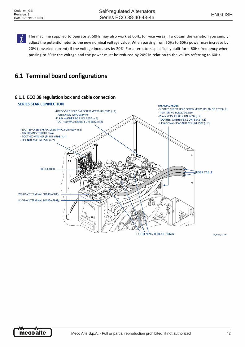
6.1 Terminal board configurations
6.1.1 ECO 38 regulation box and cable connection
The machine supplied to operate at 50Hz may also work at 60Hz (or vice versa). To obtain the variation you simply
adjust the potentiometer to the new nominal voltage value. When passing from 50Hz to 60Hz power may increase by
20% (unvaried current) if the voltage increases by 20%. For alternators specifically built for a 60Hz frequency when
passing to 50Hz the voltage and the power must be reduced by 20% in relation to the values referring to 60Hz.
Code: en_GBRevision: 1Date: 17/09/19 10:03
Self-regulated AlternatorsSeries ECO 38-40-43-46
ENGLISH
Mecc Alte S.p.A. - Full or partial reproduction prohibited, if not authorized 42
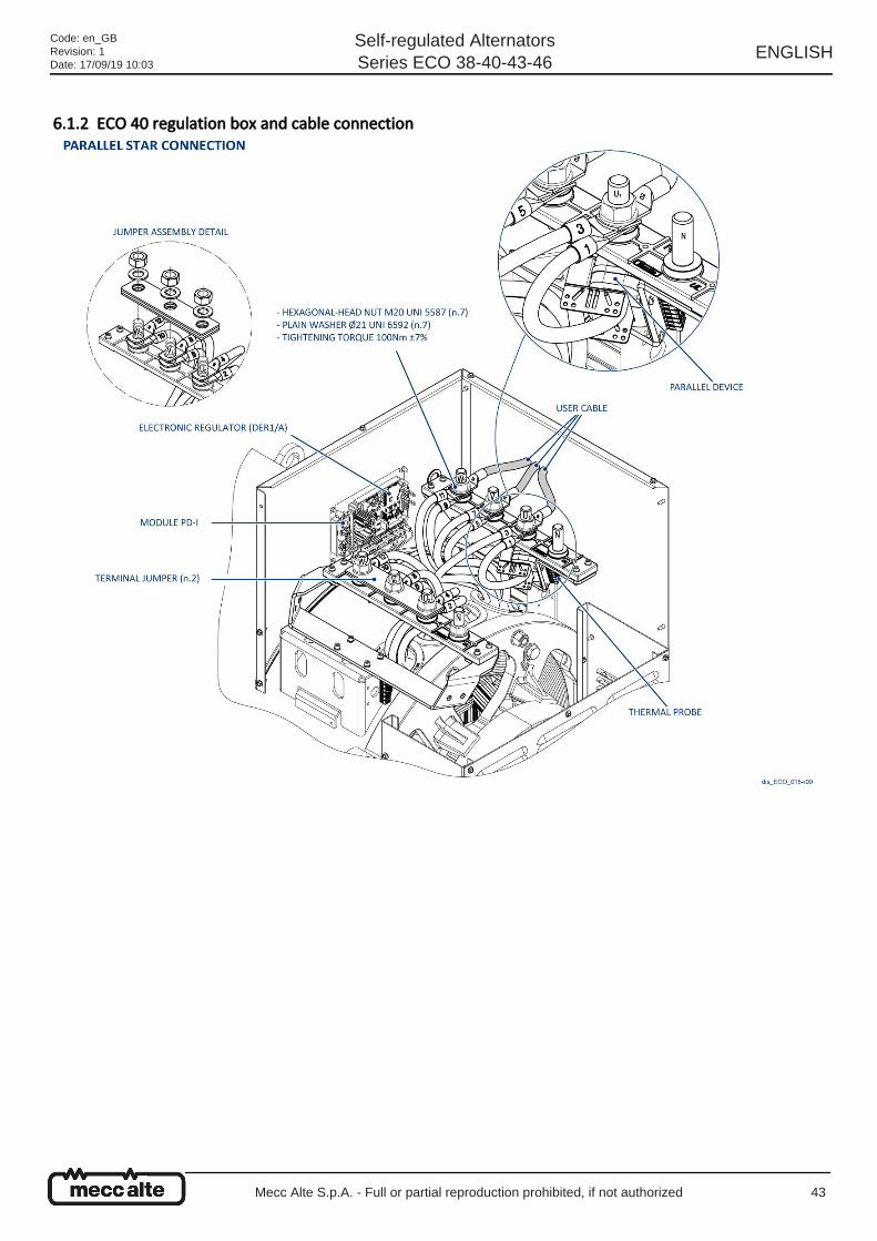
6.1.2 ECO 40 regulation box and cable connection
Code: en_GBRevision: 1Date: 17/09/19 10:03
Self-regulated AlternatorsSeries ECO 38-40-43-46
ENGLISH
Mecc Alte S.p.A. - Full or partial reproduction prohibited, if not authorized 43
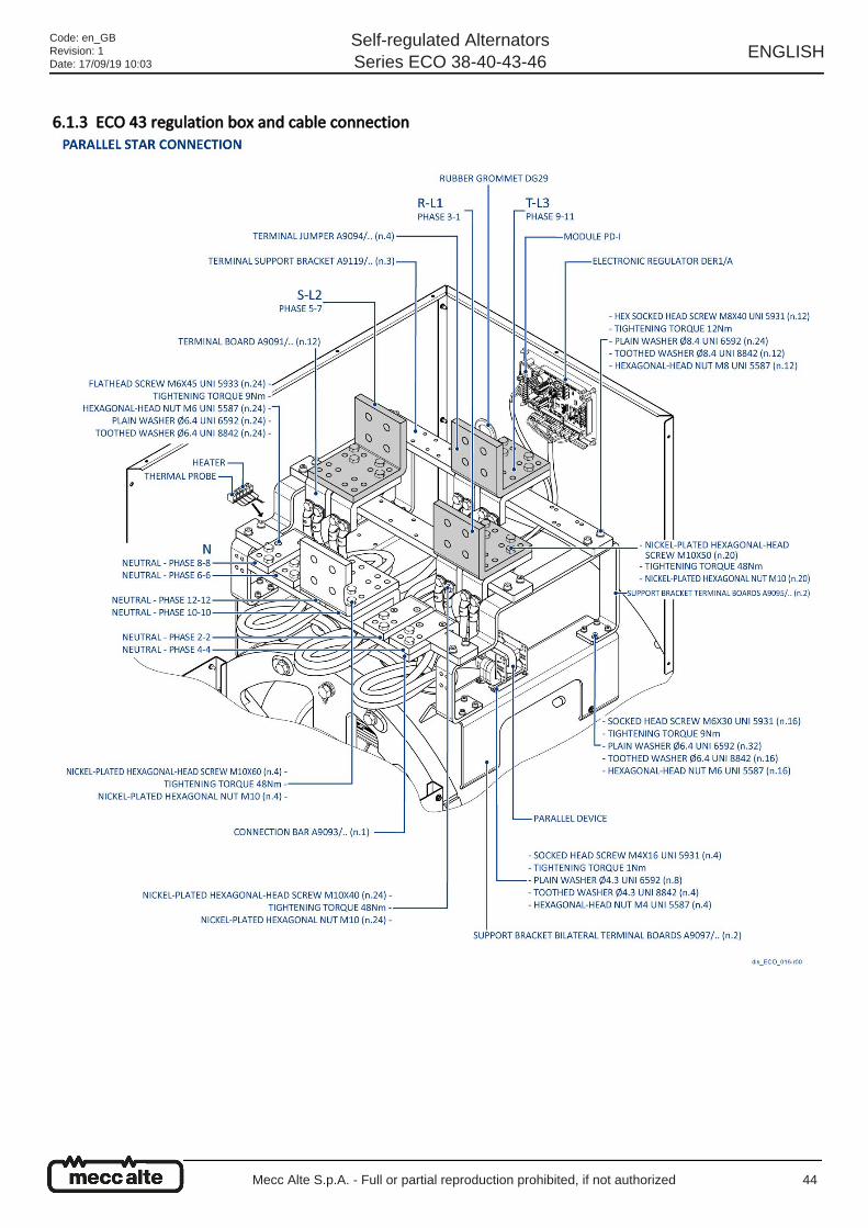
6.1.3 ECO 43 regulation box and cable connection
Code: en_GBRevision: 1Date: 17/09/19 10:03
Self-regulated AlternatorsSeries ECO 38-40-43-46
ENGLISH
Mecc Alte S.p.A. - Full or partial reproduction prohibited, if not authorized 44

6.1.4 ECO 46 regulation box and cable connection
Code: en_GBRevision: 1Date: 17/09/19 10:03
Self-regulated AlternatorsSeries ECO 38-40-43-46
ENGLISH
Mecc Alte S.p.A. - Full or partial reproduction prohibited, if not authorized 45
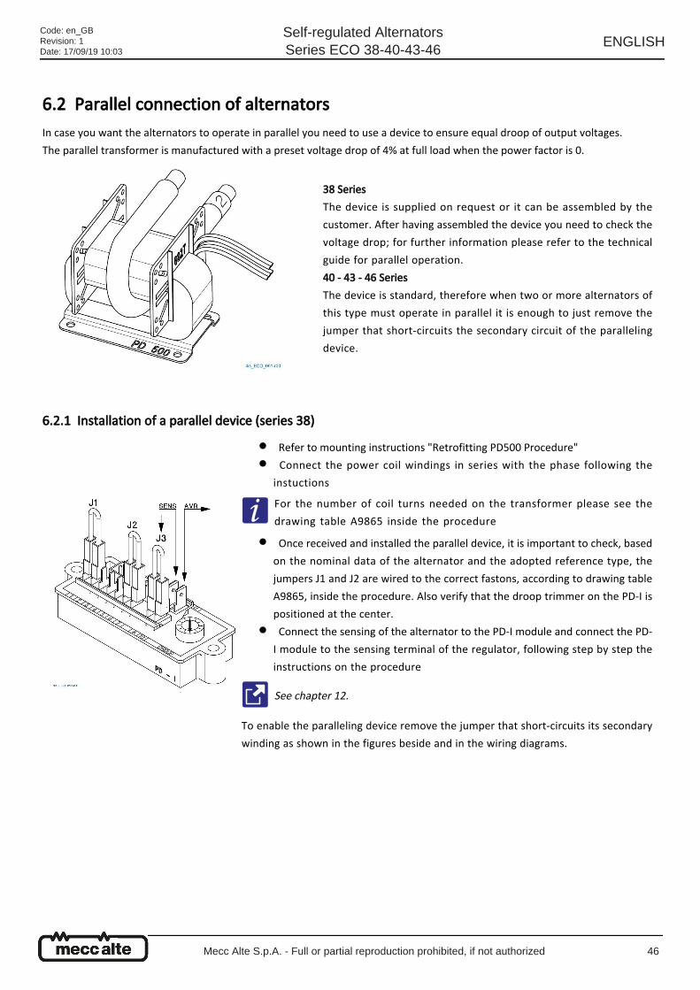
6.2 Parallel connection of alternators In case you want the alternators to operate in parallel you need to use a device to ensure equal droop of output voltages.
The parallel transformer is manufactured with a preset voltage drop of 4% at full load when the power factor is 0.
6.2.1 Installation of a parallel device (series 38)
38 Series
The device is supplied on request or it can be assembled by the
customer. After having assembled the device you need to check the
voltage drop; for further information please refer to the technical
guide for parallel operation.
40 - 43 - 46 Series
The device is standard, therefore when two or more alternators of
this type must operate in parallel it is enough to just remove the
jumper that short-circuits the secondary circuit of the paralleling
device.
Refer to mounting instructions "Retrofitting PD500 Procedure"●
Connect the power coil windings in series with the phase following the
instuctions
●
For the number of coil turns needed on the transformer please see the
drawing table A9865 inside the procedure
Once received and installed the parallel device, it is important to check, based
on the nominal data of the alternator and the adopted reference type, the
jumpers J1 and J2 are wired to the correct fastons, according to drawing table
A9865, inside the procedure. Also verify that the droop trimmer on the PD-I is
positioned at the center.
●
Connect the sensing of the alternator to the PD-I module and connect the PD-
I module to the sensing terminal of the regulator, following step by step the
instructions on the procedure
●
See chapter 12.
To enable the paralleling device remove the jumper that short-circuits its secondary
winding as shown in the figures beside and in the wiring diagrams.
Code: en_GBRevision: 1Date: 17/09/19 10:03
Self-regulated AlternatorsSeries ECO 38-40-43-46
ENGLISH
Mecc Alte S.p.A. - Full or partial reproduction prohibited, if not authorized 46
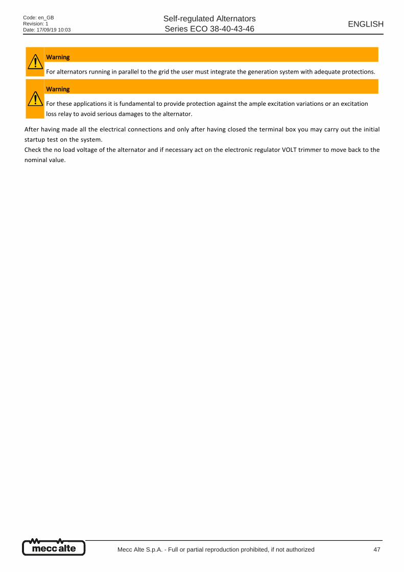
After having made all the electrical connections and only after having closed the terminal box you may carry out the initial
startup test on the system.
Check the no load voltage of the alternator and if necessary act on the electronic regulator VOLT trimmer to move back to the
nominal value.
Warning
For alternators running in parallel to the grid the user must integrate the generation system with adequate protections.
Warning
For these applications it is fundamental to provide protection against the ample excitation variations or an excitation
loss relay to avoid serious damages to the alternator.
Code: en_GBRevision: 1Date: 17/09/19 10:03
Self-regulated AlternatorsSeries ECO 38-40-43-46
ENGLISH
Mecc Alte S.p.A. - Full or partial reproduction prohibited, if not authorized 47
Code: en_GBRevision: 1Date: 17/09/19 10:03
Self-regulated AlternatorsSeries ECO 38-40-43-46
ENGLISH
Mecc Alte S.p.A. - Full or partial reproduction prohibited, if not authorized 48
●
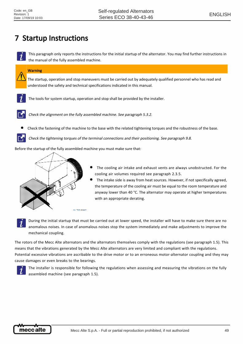
7 Startup Instructions
Check the fastening of the machine to the base with the related tightening torques and the robustness of the base.
Before the startup of the fully assembled machine you must make sure that:
The rotors of the Mecc Alte alternators and the alternators themselves comply with the regulations (see paragraph 1.5). This
means that the vibrations generated by the Mecc Alte alternators are very limited and compliant with the regulations.
Potential excessive vibrations are ascribable to the drive motor or to an erroneous motor-alternator coupling and they may
cause damages or even breaks to the bearings.
This paragraph only reports the instructions for the initial startup of the alternator. You may find further instructions in
the manual of the fully assembled machine.
Warning
The startup, operation and stop maneuvers must be carried out by adequately qualified personnel who has read and
understood the safety and technical specifications indicated in this manual.
The tools for system startup, operation and stop shall be provided by the installer.
Check the alignment on the fully assembled machine. See paragraph 5.3.2.
Check the tightening torques of the terminal connections and their positioning. See paragraph 9.8.
The cooling air intake and exhaust vents are always unobstructed. For the
cooling air volumes required see paragraph 2.3.5.
●
The intake side is away from heat sources. However, if not specifically agreed,
the temperature of the cooling air must be equal to the room temperature and
anyway lower than 40 °C. The alternator may operate at higher temperatures
with an appropriate derating.
●
During the initial startup that must be carried out at lower speed, the installer will have to make sure there are no
anomalous noises. In case of anomalous noises stop the system immediately and make adjustments to improve the
mechanical coupling.
The installer is responsible for following the regulations when assessing and measuring the vibrations on the fully
assembled machine (see paragraph 1.5).
Code: en_GBRevision: 1Date: 17/09/19 10:03
Self-regulated AlternatorsSeries ECO 38-40-43-46
ENGLISH
Mecc Alte S.p.A. - Full or partial reproduction prohibited, if not authorized 49
●
●
After the initial startup
After the initial startup of the fully assembled machine it is necessary to carry out the following verifications:
Make sure everything works correctly.
Monitor the vibration level and potential high temperatures of the windings and of the bearings.
In case the alternator, during operation, goes into protection mode for anomalous voltage, troubleshot the fault before
initiating another startup.
See "Problems, causes and solutions" chapter 11.
Code: en_GBRevision: 1Date: 17/09/19 10:03
Self-regulated AlternatorsSeries ECO 38-40-43-46
ENGLISH
Mecc Alte S.p.A. - Full or partial reproduction prohibited, if not authorized 50
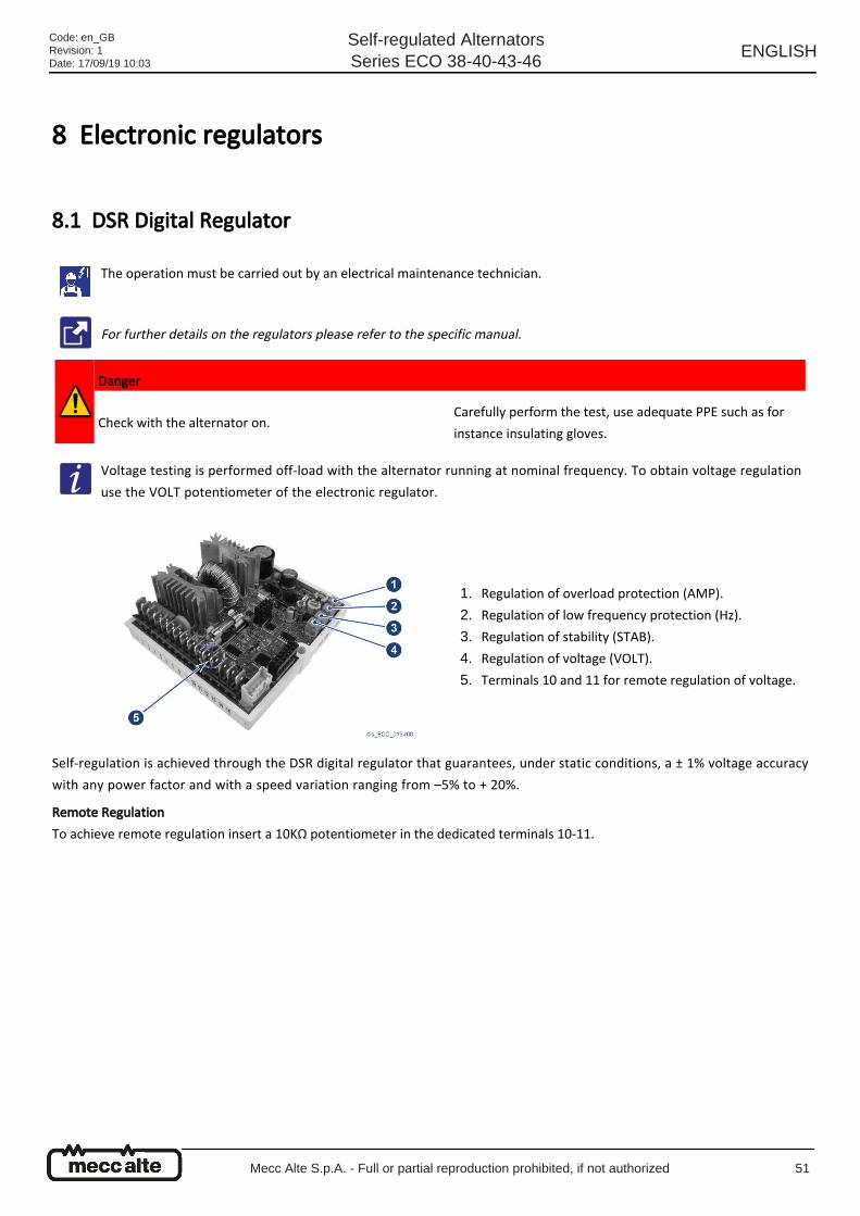
8 Electronic regulators
8.1 DSR Digital Regulator
Self-regulation is achieved through the DSR digital regulator that guarantees, under static conditions, a ± 1% voltage accuracy
with any power factor and with a speed variation ranging from –5% to + 20%.
Remote Regulation
To achieve remote regulation insert a 10KΩ potentiometer in the dedicated terminals 10-11.
The operation must be carried out by an electrical maintenance technician.
For further details on the regulators please refer to the specific manual.
Danger
Check with the alternator on.Carefully perform the test, use adequate PPE such as for
instance insulating gloves.
Voltage testing is performed off-load with the alternator running at nominal frequency. To obtain voltage regulation
use the VOLT potentiometer of the electronic regulator.
Regulation of overload protection (AMP).1.
Regulation of low frequency protection (Hz).2.
Regulation of stability (STAB).3.
Regulation of voltage (VOLT).4.
Terminals 10 and 11 for remote regulation of voltage.5.
Code: en_GBRevision: 1Date: 17/09/19 10:03
Self-regulated AlternatorsSeries ECO 38-40-43-46
ENGLISH
Mecc Alte S.p.A. - Full or partial reproduction prohibited, if not authorized 51
1.
2.
3.
4.
5.
6.
7.
8.
8.1.1 Stability Adjustment The alternators are part of a system that can be outlined as a motor + alternator. The alternator may therefore exhibit
instabilities of the rotation regime and of the voltage due to the irregular operation of the motor it is connected to.
There is a potentiometer dedicated to the adjustment of this stability (STAB potentiometer), because the alternator voltage and
motor speed regulation systems may go into conflict, causing both speed and voltage oscillations.
It is important to stress that Mecc Alte's alternators are tested using an electric motor, not a heat engine. Therefore, STAB
adjustment is set correctly for the alternator driven by an electric motor.
General instructions to follow in case of instability problems:
Check the STAB potentiometer setting and make sure it corresponds to the settings reported in the tables below.
If there is no correspondence, reset the potentiometer to the value indicated in the table below; in case of missing
information position in the middle.
If the problem persists, rotate the potentiometer anticlockwise a notch and repeat the test.
If no differences are noticed or the differences are minimal, rotate another notch anticlockwise; continue this procedure
until the problem is solved.
If by rotating the potentiometer anticlockwise, the voltage instability increases, set the potentiometer as indicated at
point 2. Rotate the potentiometer clockwise a notch and repeat the test
If there are no changes or they are minimal, rotate another notch clockwise and repeat the test.
Continue this procedure until the problem is solved.
If after these steps the problem is still not solved, you may need to adjust the stability (gain) of the motor speed
regulation system. If this does not solve the problem either, try to change the stability software parameters of the voltage
regulator. See the dedicated manual.
Code: en_GBRevision: 1Date: 17/09/19 10:03
Self-regulated AlternatorsSeries ECO 38-40-43-46
ENGLISH
Mecc Alte S.p.A. - Full or partial reproduction prohibited, if not authorized 52
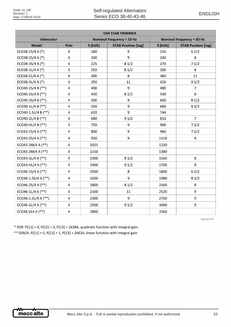
* DSR: P[11] = 4, P[12] = 3, P[13] = 16384, quadratic function with integral gain.
** DSR/A: P[11] = 5, P[12] = 1, P[13] = 26624, linear function with integral gain
Code: en_GBRevision: 1Date: 17/09/19 10:03
Self-regulated AlternatorsSeries ECO 38-40-43-46
ENGLISH
Mecc Alte S.p.A. - Full or partial reproduction prohibited, if not authorized 53
8.1.2 Protections To avoid anomalous and dangerous operation of the alternator, the DSR digital regulator is equipped with a low speed
protection and an overload protection.
Low speed protection
Its intervention is instantaneous and it causes the reduction of the alternator voltage when the frequency drops by 4 ±1 % under
the nominal frequency.
The intervention threshold is set using the "Hz" potentiometer.
Overload protection
A dedicated circuit compares the partialized excitation voltage. If the preset value for this voltage (a value corresponding with a
load current value equal to 1.1 times the current indicated on the alternator tag) is exceeded for more than 20 seconds, the
regulator steps in lowering the alternator voltage and subsequently limiting the current within a safe value range.
The delay is expressly introduced to allow the motors that normally start in 5÷10 seconds to pick-up. This intervention threshold
may be adjusted using the "AMP" potentiometer.
Causes that lead to protection intervention.
In case both protections intervene, the voltage supplied by the alternator will drop to a value that depends on the size of the
fault.
Voltage will be automatically restored to its nominal value when the fault is solved.
Instantaneous protection intervention for low speed 1 - Speed reduced by 4 ± 1 % as compared to the rated data.
Delayed protection intervention for overload
2 - Overload of 10% as compared to the rated data.
3 - Power factor (cos φ) lower than the rated data.
4 - Environmental temperature above 50°C.
Intervention of both protections 5 - Combination of factor 1 and factors 2, 3, 4.
Code: en_GBRevision: 1Date: 17/09/19 10:03
Self-regulated AlternatorsSeries ECO 38-40-43-46
ENGLISH
Mecc Alte S.p.A. - Full or partial reproduction prohibited, if not authorized 54
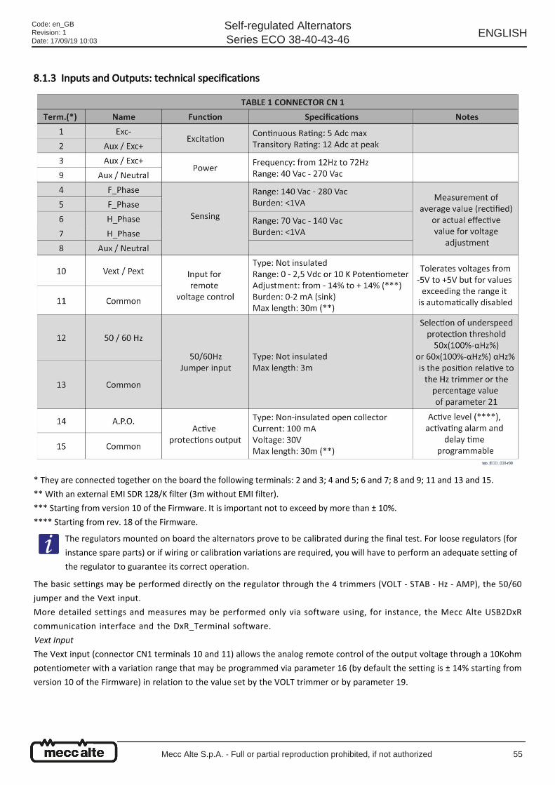
8.1.3 Inputs and Outputs: technical specifications
* They are connected together on the board the following terminals: 2 and 3; 4 and 5; 6 and 7; 8 and 9; 11 and 13 and 15.
** With an external EMI SDR 128/K filter (3m without EMI filter).
*** Starting from version 10 of the Firmware. It is important not to exceed by more than ± 10%.
**** Starting from rev. 18 of the Firmware.
The basic settings may be performed directly on the regulator through the 4 trimmers (VOLT - STAB - Hz - AMP), the 50/60
jumper and the Vext input.
More detailed settings and measures may be performed only via software using, for instance, the Mecc Alte USB2DxR
communication interface and the DxR_Terminal software.
Vext Input
The Vext input (connector CN1 terminals 10 and 11) allows the analog remote control of the output voltage through a 10Kohm
potentiometer with a variation range that may be programmed via parameter 16 (by default the setting is ± 14% starting from
version 10 of the Firmware) in relation to the value set by the VOLT trimmer or by parameter 19.
The regulators mounted on board the alternators prove to be calibrated during the final test. For loose regulators (for
instance spare parts) or if wiring or calibration variations are required, you will have to perform an adequate setting of
the regulator to guarantee its correct operation.
Code: en_GBRevision: 1Date: 17/09/19 10:03
Self-regulated AlternatorsSeries ECO 38-40-43-46
ENGLISH
Mecc Alte S.p.A. - Full or partial reproduction prohibited, if not authorized 55
●
●
If you want to use continuous voltage, it will have an effect if contained within the range from 0V to +2,5V.
The input tolerates voltages from -5V to + 5V, but for values exceeding the 0V / +2.5V limits (or in case of disconnection) there
are two available options:
Not to consider the value (default configuration) and go back to the regulation of the voltage value set through the
trimmer (if enabled) or through parameter 19.
Maintain the minimum (or the maximum) reachable voltage value.
The two options can be set through the RAM Voltage CTRL flag in the Configuration Menu corresponding to the B7 bit of the
configuration word P[10].
50/60 Signal
A jumper placed on the 50/60 input (connector CN1 terminals 12 and 13) entails the switching of the low speed protection
threshold from 50·(100%-αHz%) to 60·(100%-αHz%), where αHz% is the related position of the HZ trimmer.
APO Contact
Acronym for Active Protection Output: (connector CN1 terminals 14 and 15) uninsulated open collector 30V-100mA transistor,
by default normally closed (starting from revision 18 of the firmware; for firmware revisions up to 17 the transistor is normally
open and it closes in case of an active alarm). It opens (with a software programmable delay of 1 to 15 seconds) when, one or
several alarms, that may be selected separately via software, are active.
VOLT Trimmer
It allows regulation from approximately 70V to approximately 140V when terminals 4 and 5 are used for the sensing or from
approximately 140V to approximately 280V when terminals 6 and 7 are used.
STAB Trimmer
It regulates the dynamic response (droop) of the alternator under transient conditions.
The continuous voltage supply must be able to absorb at least 2 mA.
In the regulation it is advisable not to exceed by more than ± 10% the nominal voltage value of the alternator.
Code: en_GBRevision: 1Date: 17/09/19 10:03
Self-regulated AlternatorsSeries ECO 38-40-43-46
ENGLISH
Mecc Alte S.p.A. - Full or partial reproduction prohibited, if not authorized 56
1.
2.
3.
4.
5.
6.
7.
8.
1.
2.
3.
4.
5.
6.
MP Trimmer
It regulates the excitation overcurrent protection intervention threshold.
To calibrate the overload protection, perform the following procedure:
Rotate the Hz trimmer anticlockwise.
Apply nominal load to the alternator.
Reduce the speed by 10%.
Rotate the AMP trimmer completely in anticlockwise direction.
After a few seconds you should notice a reduction of the alternator voltage value and the activation of alarm 5 (indicated
by a change in the LED flashing).
In this case slowly rotate the "AMP" trimmer in clockwise direction until you get the output voltage value to 97% of its
nominal value: alarm 5 is still active.
If you go back to nominal speed, alarm 5 disappears after a few seconds and the alternator voltage rises back to the
nominal value.
Readjust the Hz trimmer as indicated.
Hz Trimmer
It allows the regulation of the low speed protection intervention threshold up to -20% compared to the nominal speed value set
by the 50/60 jumper (at 50 Hz the threshold may be adjusted from 40Hz to 50Hz, to 60 Hz the threshold may be adjusted from
48Hz to 60Hz).
The intervention of the protection diminishes the alternator voltage. Perform the adjustment as follows:
Rotate the Hz trimmer anticlockwise.
If the machine must operate at 60 Hz, make sure the jumper between terminals 12 and 13 of the CN1 connector is
inserted.
Take the alternator to a speed equal to 96% of its nominal speed.
Slowly turn the "Hz" trimmer. Rotate it in clockwise direction until the alternator voltage starts to diminish and at the
same time make sure the LED starts blinking fast.
By increasing the speed, the voltage of the generator should go back to normal and alarm should disappear.
Take the speed back to the nominal value.
Alarm management
Electrical diagrams
Even if still continuing to regulate the voltage, the DSR goes into switch-off mode when the frequency decreases under
20 Hz. To restore it you need to shut down the alternator completely.
See paragraph 10.1.
See paragraph 12.1.
Code: en_GBRevision: 1Date: 17/09/19 10:03
Self-regulated AlternatorsSeries ECO 38-40-43-46
ENGLISH
Mecc Alte S.p.A. - Full or partial reproduction prohibited, if not authorized 57
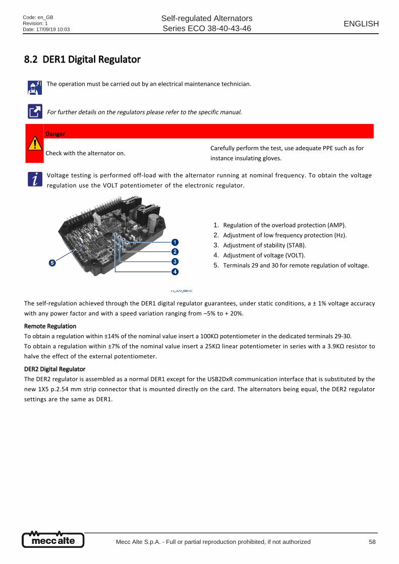
8.2 DER1 Digital Regulator
The self-regulation achieved through the DER1 digital regulator guarantees, under static conditions, a ± 1% voltage accuracy
with any power factor and with a speed variation ranging from –5% to + 20%.
Remote Regulation
To obtain a regulation within ±14% of the nominal value insert a 100KΩ potentiometer in the dedicated terminals 29-30.
To obtain a regulation within ±7% of the nominal value insert a 25KΩ linear potentiometer in series with a 3.9KΩ resistor to
halve the effect of the external potentiometer.
DER2 Digital Regulator
The DER2 regulator is assembled as a normal DER1 except for the USB2DxR communication interface that is substituted by the
new 1X5 p.2.54 mm strip connector that is mounted directly on the card. The alternators being equal, the DER2 regulator
settings are the same as DER1.
The operation must be carried out by an electrical maintenance technician.
For further details on the regulators please refer to the specific manual.
Danger
Check with the alternator on.Carefully perform the test, use adequate PPE such as for
instance insulating gloves.
Voltage testing is performed off-load with the alternator running at nominal frequency. To obtain the voltage
regulation use the VOLT potentiometer of the electronic regulator.
Regulation of the overload protection (AMP).1.
Adjustment of low frequency protection (Hz).2.
Adjustment of stability (STAB).3.
Adjustment of voltage (VOLT).4.
Terminals 29 and 30 for remote regulation of voltage.5.
Code: en_GBRevision: 1Date: 17/09/19 10:03
Self-regulated AlternatorsSeries ECO 38-40-43-46
ENGLISH
Mecc Alte S.p.A. - Full or partial reproduction prohibited, if not authorized 58

1.
2.
3.
4.
5.
6.
7.
8.
8.2.1 Stability Adjustment The alternators are part of a system that can be outlined as a motor + alternator. The alternator may therefore exhibit
instabilities of the rotation regime and of the voltage due to the irregular operation of the motor it is connected to.
There is a potentiometer dedicated to the adjustment of this stability (STAB potentiometer), because the alternator voltage and
motor speed regulation systems may go into conflict, causing both speed and voltage oscillations.
It is important to stress that Mecc Alte's alternators are testes using an electrical, and not a heat engine. Therefore, STAB
adjustment is set correctly for the alternator driven by an electric motor.
General instructions to follow in case of instability problems:
Check the STAB potentiometer setting and make sure it corresponds to the settings reported in the tables below.
If there is no correspondence, reset the potentiometer to the value indicated in the table below; in case of missing
information position in the middle.
If the problem persists, rotate the potentiometer anticlockwise a notch and repeat the test.
If no differences are noticed or the differences are minimal, rotate another notch anticlockwise; continue this procedure
until the problem is solved.
If by rotating the potentiometer anticlockwise, the voltage instability increases, set the potentiometer as indicated at
point 2. Rotate the potentiometer clockwise a notch and repeat the test
If there are no changes or they are minimal, rotate another notch clockwise and repeat the test.
Continue this procedure until the problem is solved.
If after these steps the problem is still not solved, you may need to adjust the stability (gain) of the motor speed
regulation system. If this does not solve the problem either, try to change the stability software parameters of the voltage
regulator. See the dedicated manual.
Code: en_GBRevision: 1Date: 17/09/19 10:03
Self-regulated AlternatorsSeries ECO 38-40-43-46
ENGLISH
Mecc Alte S.p.A. - Full or partial reproduction prohibited, if not authorized 59
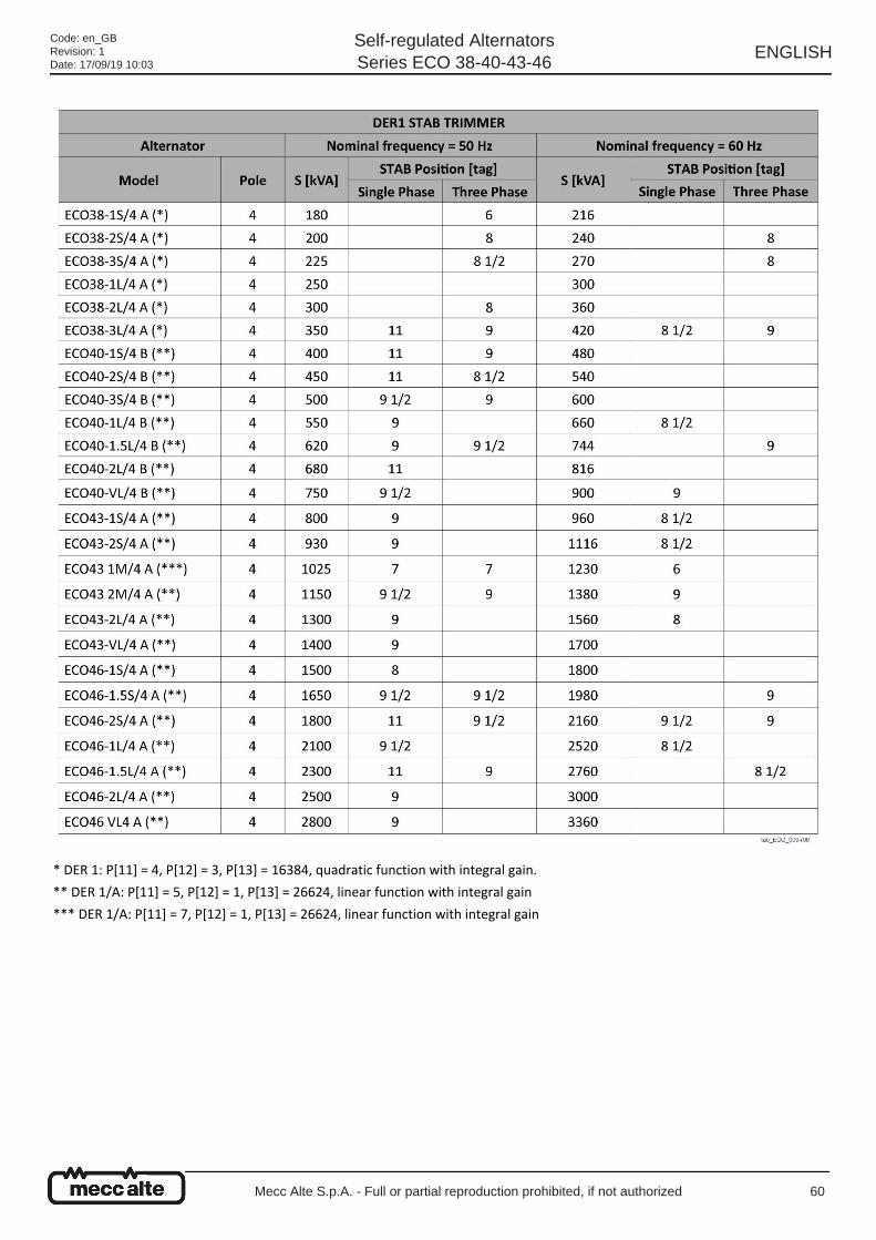
* DER 1: P[11] = 4, P[12] = 3, P[13] = 16384, quadratic function with integral gain.
** DER 1/A: P[11] = 5, P[12] = 1, P[13] = 26624, linear function with integral gain
*** DER 1/A: P[11] = 7, P[12] = 1, P[13] = 26624, linear function with integral gain
Code: en_GBRevision: 1Date: 17/09/19 10:03
Self-regulated AlternatorsSeries ECO 38-40-43-46
ENGLISH
Mecc Alte S.p.A. - Full or partial reproduction prohibited, if not authorized 60
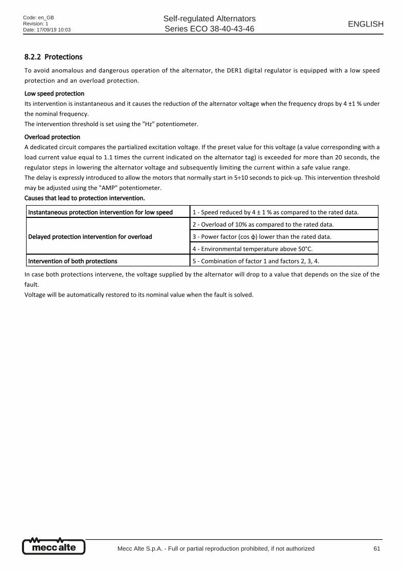
8.2.2 Protections To avoid anomalous and dangerous operation of the alternator, the DER1 digital regulator is equipped with a low speed
protection and an overload protection.
Low speed protection
Its intervention is instantaneous and it causes the reduction of the alternator voltage when the frequency drops by 4 ±1 % under
the nominal frequency.
The intervention threshold is set using the "Hz" potentiometer.
Overload protection
A dedicated circuit compares the partialized excitation voltage. If the preset value for this voltage (a value corresponding with a
load current value equal to 1.1 times the current indicated on the alternator tag) is exceeded for more than 20 seconds, the
regulator steps in lowering the alternator voltage and subsequently limiting the current within a safe value range.
The delay is expressly introduced to allow the motors that normally start in 5÷10 seconds to pick-up. This intervention threshold
may be adjusted using the "AMP" potentiometer.
Causes that lead to protection intervention.
In case both protections intervene, the voltage supplied by the alternator will drop to a value that depends on the size of the
fault.
Voltage will be automatically restored to its nominal value when the fault is solved.
Instantaneous protection intervention for low speed 1 - Speed reduced by 4 ± 1 % as compared to the rated data.
Delayed protection intervention for overload
2 - Overload of 10% as compared to the rated data.
3 - Power factor (cos φ) lower than the rated data.
4 - Environmental temperature above 50°C.
Intervention of both protections 5 - Combination of factor 1 and factors 2, 3, 4.
Code: en_GBRevision: 1Date: 17/09/19 10:03
Self-regulated AlternatorsSeries ECO 38-40-43-46
ENGLISH
Mecc Alte S.p.A. - Full or partial reproduction prohibited, if not authorized 61
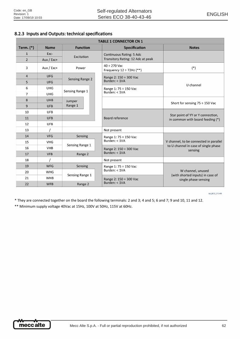
8.2.3 Inputs and Outputs: technical specifications
* They are connected together on the board the following terminals: 2 and 3; 4 and 5; 6 and 7; 9 and 10, 11 and 12.
** Minimum supply voltage 40Vac at 15Hz, 100V at 50Hz, 115V at 60Hz.
Code: en_GBRevision: 1Date: 17/09/19 10:03
Self-regulated AlternatorsSeries ECO 38-40-43-46
ENGLISH
Mecc Alte S.p.A. - Full or partial reproduction prohibited, if not authorized 62
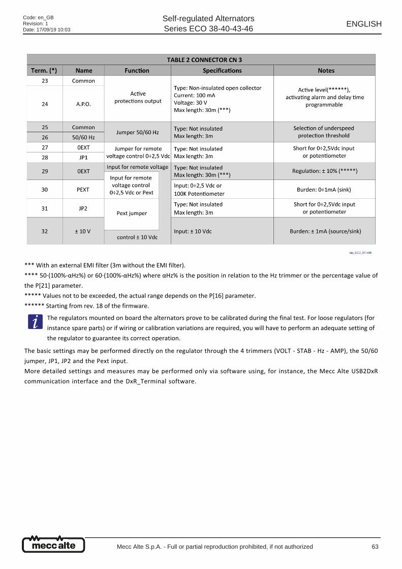
*** With an external EMI filter (3m without the EMI filter).
**** 50·(100%-αHz%) or 60·(100%-αHz%) where αHz% is the position in relation to the Hz trimmer or the percentage value of
the P[21] parameter.
***** Values not to be exceeded, the actual range depends on the P[16] parameter.
****** Starting from rev. 18 of the firmware.
The basic settings may be performed directly on the regulator through the 4 trimmers (VOLT - STAB - Hz - AMP), the 50/60
jumper, JP1, JP2 and the Pext input.
More detailed settings and measures may be performed only via software using, for instance, the Mecc Alte USB2DxR
communication interface and the DxR_Terminal software.
The regulators mounted on board the alternators prove to be calibrated during the final test. For loose regulators (for
instance spare parts) or if wiring or calibration variations are required, you will have to perform an adequate setting of
the regulator to guarantee its correct operation.
Code: en_GBRevision: 1Date: 17/09/19 10:03
Self-regulated AlternatorsSeries ECO 38-40-43-46
ENGLISH
Mecc Alte S.p.A. - Full or partial reproduction prohibited, if not authorized 63
●
●
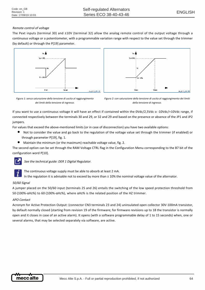
Remote control of voltage
The Pext inputs (terminal 30) and ±10V (terminal 32) allow the analog remote control of the output voltage through a
continuous voltage or a potentiometer, with a programmable variation range with respect to the value set through the trimmer
(by default) or through the P[19] parameter.
If you want to use a continuous voltage it will have an effect if contained within the 0Vdc/2,5Vdc o -10Vdc/+10Vdc range, if
connected respectively between the terminals 30 and 29, or 32 and 29 and based on the presence or absence of the JP1 and JP2
jumpers.
For values that exceed the above-mentioned limits (or in case of disconnection) you have two available options:
Not to consider the value and go back to the regulation of the voltage value set through the trimmer (if enabled) or
through parameter P[19], fig. 1.
Maintain the minimum (or the maximum) reachable voltage value, fig. 2.
The second option can be set through the RAM Voltage CTRL flag in the Configuration Menu corresponding to the B7 bit of the
configuration word P[10].
50/60 Signal
A jumper placed on the 50/60 input (terminals 25 and 26) entails the switching of the low speed protection threshold from
50·(100%-αHz%) to 60·(100%-αHz%), where αHz% is the related position of the HZ trimmer.
APO Contact
Acronym for Active Protection Output: (connector CN3 terminals 23 and 24) uninsulated open collector 30V-100mA transistor,
by default normally closed (starting from revision 19 of the firmware; for firmware revisions up to 18 the transistor is normally
open and it closes in case of an active alarm). It opens (with a software programmable delay of 1 to 15 seconds) when, one or
several alarms, that may be selected separately via software, are active.
Figura 1: senza saturazione della tensione di uscita al raggiungimento
dei limiti della tensione di ingresso.
Figura 2: con saturazione della tensione di uscita al raggiungimento dei limiti
della tensione di ingresso.
See the technical guide: DER 1 Digital Regulator.
The continuous voltage supply must be able to absorb at least 2 mA.
In the regulation it is advisable not to exceed by more than ± 10% the nominal voltage value of the alternator.
Code: en_GBRevision: 1Date: 17/09/19 10:03
Self-regulated AlternatorsSeries ECO 38-40-43-46
ENGLISH
Mecc Alte S.p.A. - Full or partial reproduction prohibited, if not authorized 64
1.
2.
3.
4.
5.
1.
2.
3.
4.
5.
6.
VOLT Trimmer
It allows regulation from approximately 75V to approximately 150V when terminals 6/7 - 10/11/12 (with an 8-9 jumper) 15-16
and 20-21 are used for the sensing or from approximately 150V to approximately 300V when terminals 4/5 - 9/10/11/12, 14-17
and 19-22 are used.
STAB Trimmer
It regulates the dynamic response (droop) of the alternator under transient conditions.
It must not be rotated to minus two notches counted in clockwise direction.
MP Trimmer
It regulates the excitation overcurrent protection intervention threshold.
To calibrate the overload protection, perform the following procedure:
Rotate the AMP trimmer completely in clockwise direction.
Feed the alternator an overload having cos phi = 0.8 or cos phi = 0 respectively equal to 125% or 110% of the nominal
load.
After two minutes slowly turn the AMP trimmer anti-clockwise until you get a reduction of the generator's voltage value
and the activation of alarm 5 (visible through a change in the LED flashing)
Adjust the AMP trimmer so as to get an output voltage value of 97% of the nominal value: alarm 5 is still active
If the load is removed, alarm 5 disappears after a few seconds and the generator voltage goes back to the nominal value.
Hz Trimmer
It allows the regulation of the low speed protection intervention threshold up to -20% compared to the nominal speed value set
by the 50/60 jumper (at 50 Hz the threshold may be adjusted from 40Hz to 50Hz, to 60 Hz the threshold may be adjusted from
48Hz to 60Hz).
The intervention of the protection diminishes the alternator voltage. Perform the adjustment as follows:
Rotate the Hz trimmer anticlockwise.
If the machine must operate at 60 Hz, make sure the jumper between terminals 25 and 26 is inserted.
Take the alternator to a speed equal to 96% of its nominal speed.
Slowly regulate the "Hz" trimmer. Rotate it in clockwise direction until the alternator voltage starts to diminish and at the
same time make sure the LED starts blinking fast.
By increasing the speed, the voltage of the generator should go back to normal and alarm should disappear.
Take the speed back to the nominal value.
Alarm management
Electrical diagrams
Even if still continuing to regulate the voltage, the DER1 goes into switch-off mode when the frequency decreases
under 20 Hz. To restore it you need to shut down the alternator completely.
See paragraph 10.2.
See paragraph 12.2.
Code: en_GBRevision: 1Date: 17/09/19 10:03
Self-regulated AlternatorsSeries ECO 38-40-43-46
ENGLISH
Mecc Alte S.p.A. - Full or partial reproduction prohibited, if not authorized 65
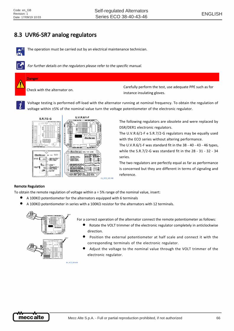
●
●
8.3 UVR6-SR7 analog regulators
Remote Regulation
To obtain the remote regulation of voltage within a ÷ 5% range of the nominal value, insert:
A 100KΩ potentiometer for the alternators equipped with 6 terminals
A 100KΩ potentiometer in series with a 100KΩ resistor for the alternators with 12 terminals.
The operation must be carried out by an electrical maintenance technician.
For further details on the regulators please refer to the specific manual.
Danger
Check with the alternator on.Carefully perform the test, use adequate PPE such as for
instance insulating gloves.
Voltage testing is performed off-load with the alternator running at nominal frequency. To obtain the regulation of
voltage within ±5% of the nominal value turn the voltage potentiometer of the electronic regulator.
The following regulators are obsolete and were replaced by
DSR/DER1 electronic regulators.
The U.V.R.6/1-F e S.R.7/2-G regulators may be equally used
with the ECO series without altering performance.
The U.V.R.6/1-F was standard fit in the 38 - 40 - 43 - 46 types,
while the S.R.7/2-G was standard fit in the 28 - 31 - 32 - 34
series.
The two regulators are perfectly equal as far as performance
is concerned but they are different in terms of signaling and
reference.
For a correct operation of the alternator connect the remote potentiometer as follows:
Rotate the VOLT trimmer of the electronic regulator completely in anticlockwise
direction.
●
Position the external potentiometer at half scale and connect it with the
corresponding terminals of the electronic regulator.
●
Adjust the voltage to the nominal value through the VOLT trimmer of the
electronic regulator.
●
Code: en_GBRevision: 1Date: 17/09/19 10:03
Self-regulated AlternatorsSeries ECO 38-40-43-46
ENGLISH
Mecc Alte S.p.A. - Full or partial reproduction prohibited, if not authorized 66
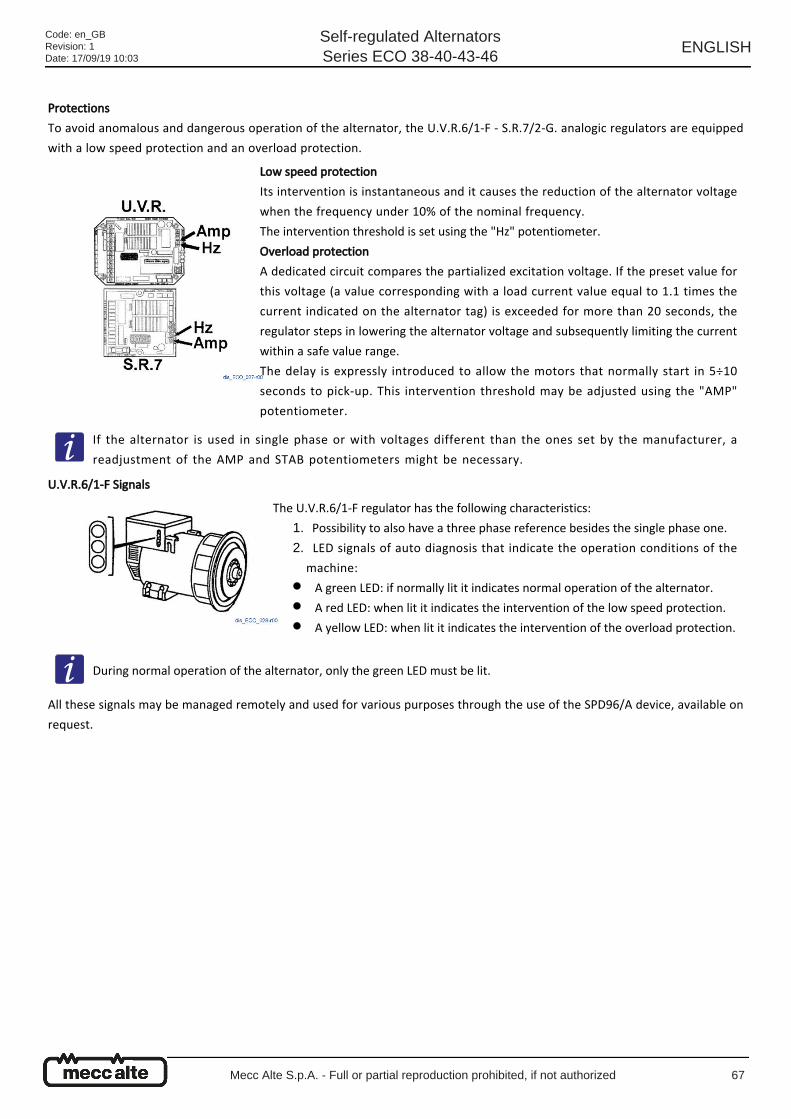
Protections
To avoid anomalous and dangerous operation of the alternator, the U.V.R.6/1-F - S.R.7/2-G. analogic regulators are equipped
with a low speed protection and an overload protection.
U.V.R.6/1-F Signals
All these signals may be managed remotely and used for various purposes through the use of the SPD96/A device, available on
request.
Low speed protection
Its intervention is instantaneous and it causes the reduction of the alternator voltage
when the frequency under 10% of the nominal frequency.
The intervention threshold is set using the "Hz" potentiometer.
Overload protection
A dedicated circuit compares the partialized excitation voltage. If the preset value for
this voltage (a value corresponding with a load current value equal to 1.1 times the
current indicated on the alternator tag) is exceeded for more than 20 seconds, the
regulator steps in lowering the alternator voltage and subsequently limiting the current
within a safe value range.
The delay is expressly introduced to allow the motors that normally start in 5÷10
seconds to pick-up. This intervention threshold may be adjusted using the "AMP"
potentiometer.
If the alternator is used in single phase or with voltages different than the ones set by the manufacturer, a
readjustment of the AMP and STAB potentiometers might be necessary.
The U.V.R.6/1-F regulator has the following characteristics:
Possibility to also have a three phase reference besides the single phase one.1.
LED signals of auto diagnosis that indicate the operation conditions of the
machine:
2.
A green LED: if normally lit it indicates normal operation of the alternator.●
A red LED: when lit it indicates the intervention of the low speed protection.●
A yellow LED: when lit it indicates the intervention of the overload protection.●
During normal operation of the alternator, only the green LED must be lit.
Code: en_GBRevision: 1Date: 17/09/19 10:03
Self-regulated AlternatorsSeries ECO 38-40-43-46
ENGLISH
Mecc Alte S.p.A. - Full or partial reproduction prohibited, if not authorized 67
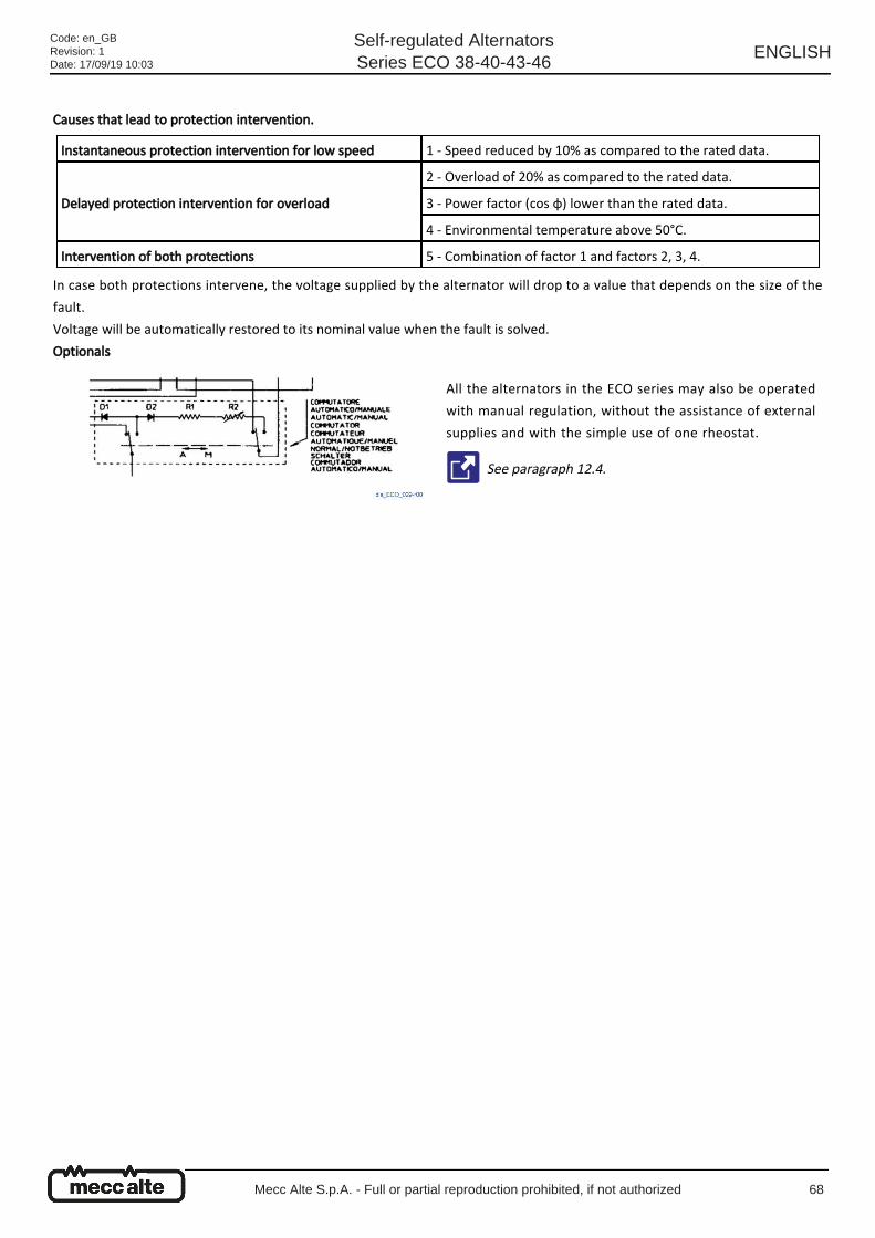
Causes that lead to protection intervention.
In case both protections intervene, the voltage supplied by the alternator will drop to a value that depends on the size of the
fault.
Voltage will be automatically restored to its nominal value when the fault is solved.
Optionals
Instantaneous protection intervention for low speed 1 - Speed reduced by 10% as compared to the rated data.
Delayed protection intervention for overload
2 - Overload of 20% as compared to the rated data.
3 - Power factor (cos φ) lower than the rated data.
4 - Environmental temperature above 50°C.
Intervention of both protections 5 - Combination of factor 1 and factors 2, 3, 4.
All the alternators in the ECO series may also be operated
with manual regulation, without the assistance of external
supplies and with the simple use of one rheostat.
See paragraph 12.4.
Code: en_GBRevision: 1Date: 17/09/19 10:03
Self-regulated AlternatorsSeries ECO 38-40-43-46
ENGLISH
Mecc Alte S.p.A. - Full or partial reproduction prohibited, if not authorized 68
9 Maintenance
9.1 General Instructions
The ECO series alternators are built to operate without maintenance for a long time.
The maintenance interventions on the Mecc Alte alternator are divided into ordinary and extraordinary.
Warning
Before executing any maintenance operation, read carefully the instructions in chapter 3 "Safety" of this manual.
Warning
The authorized operators are only allowed to carry out the works they are specifically qualified for on the alternator
and wear the required PPE (personal protective equipment).
Warning
Always disconnect the alternator from power supplies before carrying out any maintenance and/or replacement
operation.
Warning
The alternators, when working, release heat even to a high level based on the power being generated. Before touching
it wait for the alternator to cool off.
Danger
It is forbidden to pass through or stand under the alternator during the lifting and transportation stages.
It is advisable for the maintenance technician to keep a register of all the interventions.
Code: en_GBRevision: 1Date: 17/09/19 10:03
Self-regulated AlternatorsSeries ECO 38-40-43-46
ENGLISH
Mecc Alte S.p.A. - Full or partial reproduction prohibited, if not authorized 69
9.2 Maintenance summary table
9.2.1 Summary table of ordinary maintenance operations Acronyms of the intervention types: E = Electrical; M = Mechanical
9.2.2 Summary table of extraordinary maintenance operations Acronyms of the intervention types: E = Electrical; M = Mechanical; S = Software
Type Description Periodicity Reference
M Alternator exterior and interior cleaning Every 15 days 9.3.7
M General cleaning Every 400 hours 9.3.1
M Air filter cleaning (if present) Every 400 hours of use 9.3.2
M Visual Inspection Every 2500 hours 9.3.3
M Verification of winding state Every 2500 hours 9.3.4
M Verification of correct alternator operation Every 2500 hours 9.3.5
M Tightening torque check Every 2500 hours 9.3.6
Type Description Periodicity Reference
M Maintenance and potential replacement of bearings Every 4000 hours 9.4.1
E Winding state and diode bridge fastening checkEvery 8000 hours / 1
year9.4.2
S Copy of the alarms of the digital regulatorEvery 8000 hours / 1
year9.4.3
M Verification of correct PMG fastening (optional component)Every 8000 hours / 1
year9.4.4
M Cleaning of windingsEvery 20000 to 25000
hours9.4.5
Code: en_GBRevision: 1Date: 17/09/19 10:03
Self-regulated AlternatorsSeries ECO 38-40-43-46
ENGLISH
Mecc Alte S.p.A. - Full or partial reproduction prohibited, if not authorized 70
9.2.3 Summary table of maintenance operations in case of failure Acronyms of the intervention types: E = Electrical; M = Mechanical
Type Description Periodicity Reference
M Fan replacement assembling - 9.5.1
E Verification and potential replacement of diode bridge - 9.5.2
M Mechanical disassembling for inspection (40-43-46 series) - 9.5.3
M Mechanical assembling (40-43-46 series) - 9.5.4
M PMG disassembling - 9.5.5
M PMG assembling (38 series) - 9.5.6
M PMG assembling (40-43-46 series) - 9.5.7
M Disc Holder Hub Removal (43 and 46 series) - 9.5.8
E Loss of residual magnetism (re-excitation of the machine) - 9.5.9
E Verification and replacement of voltage regulator - 9.5.10
E DSR test and setup on test bench - 9.5.11
E DER1 test and setup on test bench - 9.5.12
E DER 2 test and setup on test bench - 9.5.13
E Main stator windings voltage test - 9.5.14
Code: en_GBRevision: 1Date: 17/09/19 10:03
Self-regulated AlternatorsSeries ECO 38-40-43-46
ENGLISH
Mecc Alte S.p.A. - Full or partial reproduction prohibited, if not authorized 71
9.3 Ordinary Maintenance Ordinary maintenance means the set of operations that are carried out on a regular basis.
Their purpose is to maintain the alternator in good operational state.
9.3.1 General cleaning
Carry out general cleaning of the alternator and the surrounding area.
During the cleaning check the state and make sure that the various parts of the alternator are undamaged.
In case of anomalies or damages contact the maintenance technician for a potential intervention/replacement.
Caution
Carry out ordinary maintenance with accuracy and as often as specified by the manufacturer.
The intervention described in this paragraph refers only to the alternator, the frequency proposed must be adapted to
the actual conditions and the frequency of use.
Danger
Disconnect the alternator from the power supplies. The drive motor must be off and unplugged from its power
supplies.
Warning
Never use liquids or water.
Warning
Never clean the internal electrical components of the terminal box with pressurized air because short circuits or other
malfunctions may occur.
Warning
Move close to the alternator only when it has zero power supply and it is at room temperature. It is only now that you
may clean it on the outside with pressurized air.
Code: en_GBRevision: 1Date: 17/09/19 10:03
Self-regulated AlternatorsSeries ECO 38-40-43-46
ENGLISH
Mecc Alte S.p.A. - Full or partial reproduction prohibited, if not authorized 72
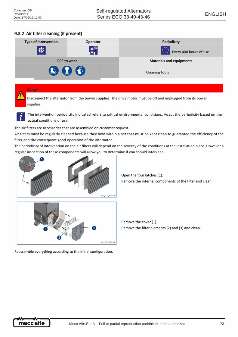
9.3.2 Air filter cleaning (if present)
The air filters are accessories that are assembled on customer request.
Air filters must be regularly cleaned because they hold within a net that must be kept clean to guarantee the efficiency of the
filter and the consequent good operation of the alternator.
The periodicity of intervention on the air filters will depend on the severity of the conditions at the installation place. However a
regular inspection of these components will allow you to determine if you should intervene.
Reassemble everything according to the initial configuration.
Type of intervention Operator Periodicity
Every 400 hours of use
PPE to wear Materials and equipments
Cleaning tools
Danger
Disconnect the alternator from the power supplies. The drive motor must be off and unplugged from its power
supplies.
The intervention periodicity indicated refers to critical environmental conditions. Adapt the periodicity based on the
actual conditions of use.
Open the four latches (1).
Remove the internal components of the filter and clean.
Remove the cover (1).
Remove the filter elements (2) and (3) and clean.
Code: en_GBRevision: 1Date: 17/09/19 10:03
Self-regulated AlternatorsSeries ECO 38-40-43-46
ENGLISH
Mecc Alte S.p.A. - Full or partial reproduction prohibited, if not authorized 73
●
●
●
9.3.3 Visual Inspection
Check for the presence of anomalies such as cracks, rust, leakages and any other anomalous event.
Check the tightening of the power cables and of the regulator cables.
Check the state of the insulations of the power cables and of the regulator cables (overtemperature, rubbing).
Type of intervention Operator Periodicity
Every 2500 hours.
PPE to wear Materials and equipments
Workshop tools.
Code: en_GBRevision: 1Date: 17/09/19 10:03
Self-regulated AlternatorsSeries ECO 38-40-43-46
ENGLISH
Mecc Alte S.p.A. - Full or partial reproduction prohibited, if not authorized 74
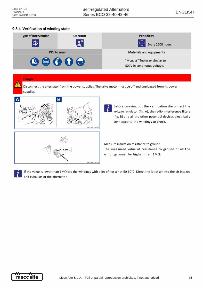
9.3.4 Verification of winding state
Type of intervention Operator Periodicity
Every 2500 hours
PPE to wear Materials and equipments
"Megger" Tester or similar to
500V in continuous voltage.
Danger
Disconnect the alternator from the power supplies. The drive motor must be off and unplugged from its power
supplies.
Before carrying out the verification disconnect the
voltage regulator (fig. A), the radio interference filters
(fig. B) and all the other potential devices electrically
connected to the windings to check.
Measure insulation resistance to ground.
The measured value of resistance to ground of all the
windings must be higher than 1MΩ.
If the value is lower than 1MΩ dry the windings with a jet of hot air at 50-60°C. Direct the jet of air into the air intakes
and exhausts of the alternator.
Code: en_GBRevision: 1Date: 17/09/19 10:03
Self-regulated AlternatorsSeries ECO 38-40-43-46
ENGLISH
Mecc Alte S.p.A. - Full or partial reproduction prohibited, if not authorized 75
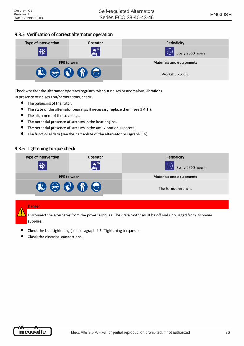
●
●
●
●
●
●
●
●
9.3.5 Verification of correct alternator operation
Check whether the alternator operates regularly without noises or anomalous vibrations.
In presence of noises and/or vibrations, check:
The balancing of the rotor.
The state of the alternator bearings. If necessary replace them (see 9.4.1.).
The alignment of the couplings.
The potential presence of stresses in the heat engine.
The potential presence of stresses in the anti-vibration supports.
The functional data (see the nameplate of the alternator paragraph 1.6).
9.3.6 Tightening torque check
Check the bolt tightening (see paragraph 9.6 "Tightening torques").
Check the electrical connections.
Type of intervention Operator Periodicity
Every 2500 hours
PPE to wear Materials and equipments
Workshop tools.
Type of intervention Operator Periodicity
Every 2500 hours
PPE to wear Materials and equipments
The torque wrench.
Danger
Disconnect the alternator from the power supplies. The drive motor must be off and unplugged from its power
supplies.
Code: en_GBRevision: 1Date: 17/09/19 10:03
Self-regulated AlternatorsSeries ECO 38-40-43-46
ENGLISH
Mecc Alte S.p.A. - Full or partial reproduction prohibited, if not authorized 76
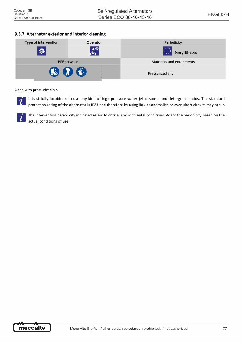
9.3.7 Alternator exterior and interior cleaning
Clean with pressurized air.
Type of intervention Operator Periodicity
Every 15 days
PPE to wear Materials and equipments
Pressurized air.
It is strictly forbidden to use any kind of high-pressure water jet cleaners and detergent liquids. The standard
protection rating of the alternator is IP23 and therefore by using liquids anomalies or even short circuits may occur.
The intervention periodicity indicated refers to critical environmental conditions. Adapt the periodicity based on the
actual conditions of use.
Code: en_GBRevision: 1Date: 17/09/19 10:03
Self-regulated AlternatorsSeries ECO 38-40-43-46
ENGLISH
Mecc Alte S.p.A. - Full or partial reproduction prohibited, if not authorized 77
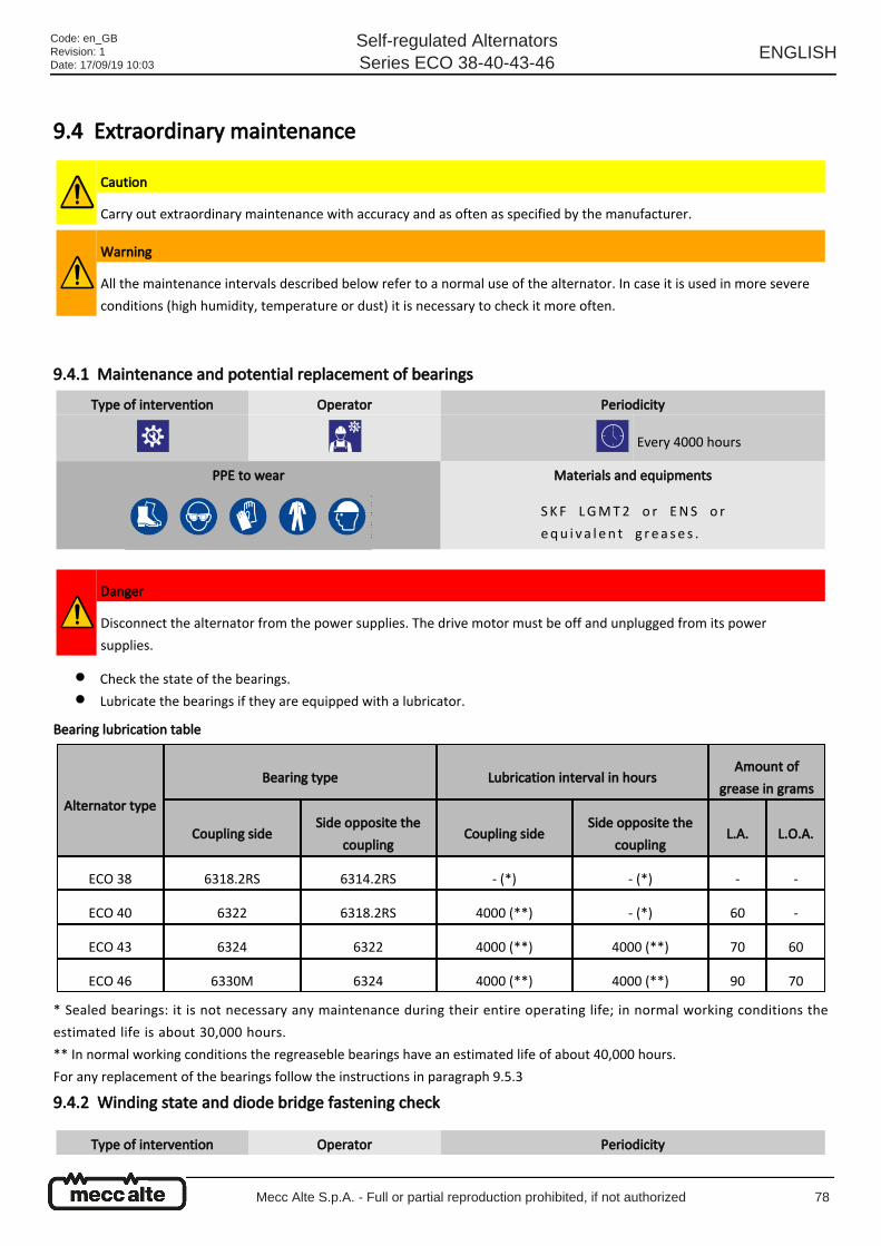
●
●
9.4 Extraordinary maintenance
9.4.1 Maintenance and potential replacement of bearings
Check the state of the bearings.
Lubricate the bearings if they are equipped with a lubricator.
Bearing lubrication table
* Sealed bearings: it is not necessary any maintenance during their entire operating life; in normal working conditions the
estimated life is about 30,000 hours.
** In normal working conditions the regreaseble bearings have an estimated life of about 40,000 hours.
For any replacement of the bearings follow the instructions in paragraph 9.5.3
9.4.2 Winding state and diode bridge fastening check
Caution
Carry out extraordinary maintenance with accuracy and as often as specified by the manufacturer.
Warning
All the maintenance intervals described below refer to a normal use of the alternator. In case it is used in more severe
conditions (high humidity, temperature or dust) it is necessary to check it more often.
Type of intervention Operator Periodicity
Every 4000 hours
PPE to wear Materials and equipments
SKF LGMT2 o r ENS o r
equ i v a l en t g r e a se s .
Danger
Disconnect the alternator from the power supplies. The drive motor must be off and unplugged from its power
supplies.
Alternator type
Bearing type Lubrication interval in hoursAmount of
grease in grams
Coupling sideSide opposite the
couplingCoupling side
Side opposite the
couplingL.A. L.O.A.
ECO 38 6318.2RS 6314.2RS - (*) - (*) - -
ECO 40 6322 6318.2RS 4000 (**) - (*) 60 -
ECO 43 6324 6322 4000 (**) 4000 (**) 70 60
ECO 46 6330M 6324 4000 (**) 4000 (**) 90 70
Type of intervention Operator Periodicity
Code: en_GBRevision: 1Date: 17/09/19 10:03
Self-regulated AlternatorsSeries ECO 38-40-43-46
ENGLISH
Mecc Alte S.p.A. - Full or partial reproduction prohibited, if not authorized 78
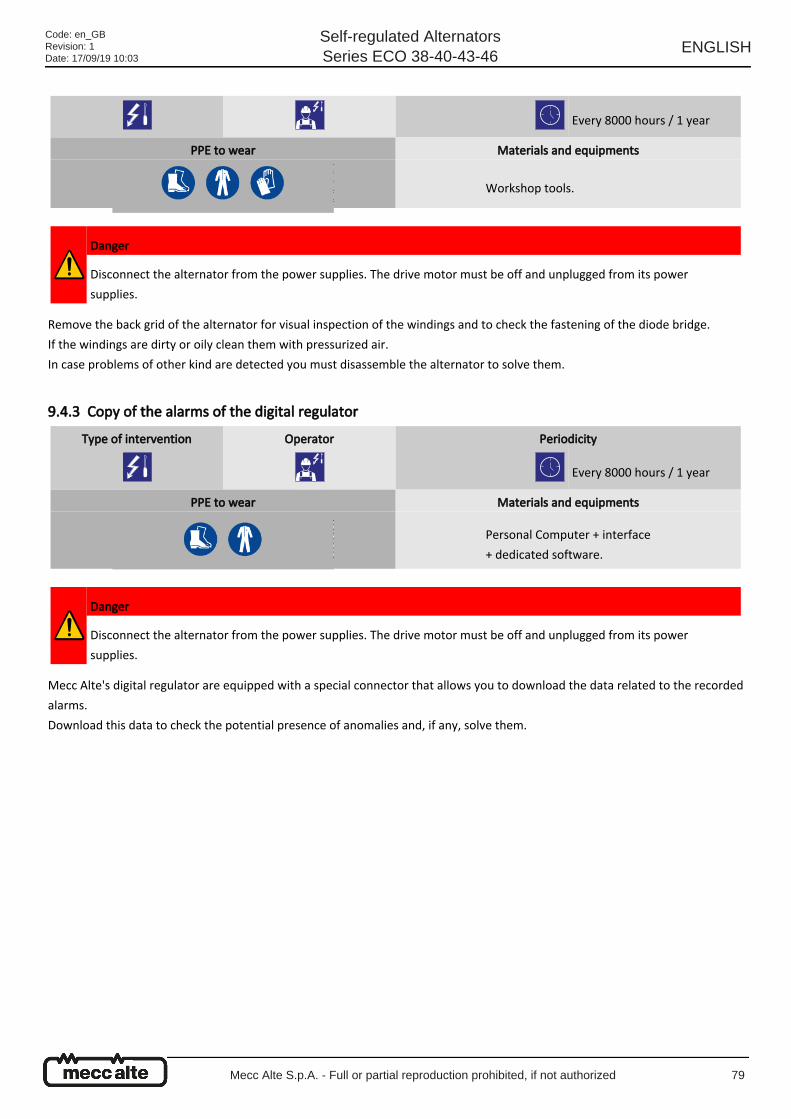
Remove the back grid of the alternator for visual inspection of the windings and to check the fastening of the diode bridge.
If the windings are dirty or oily clean them with pressurized air.
In case problems of other kind are detected you must disassemble the alternator to solve them.
9.4.3 Copy of the alarms of the digital regulator
Mecc Alte's digital regulator are equipped with a special connector that allows you to download the data related to the recorded
alarms.
Download this data to check the potential presence of anomalies and, if any, solve them.
Every 8000 hours / 1 year
PPE to wear Materials and equipments
Workshop tools.
Danger
Disconnect the alternator from the power supplies. The drive motor must be off and unplugged from its power
supplies.
Type of intervention Operator Periodicity
Every 8000 hours / 1 year
PPE to wear Materials and equipments
Personal Computer + interface
+ dedicated software.
Danger
Disconnect the alternator from the power supplies. The drive motor must be off and unplugged from its power
supplies.
Code: en_GBRevision: 1Date: 17/09/19 10:03
Self-regulated AlternatorsSeries ECO 38-40-43-46
ENGLISH
Mecc Alte S.p.A. - Full or partial reproduction prohibited, if not authorized 79
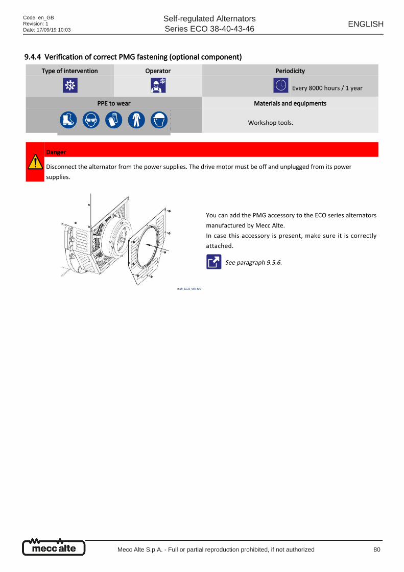
9.4.4 Verification of correct PMG fastening (optional component)
Type of intervention Operator Periodicity
Every 8000 hours / 1 year
PPE to wear Materials and equipments
Workshop tools.
Danger
Disconnect the alternator from the power supplies. The drive motor must be off and unplugged from its power
supplies.
You can add the PMG accessory to the ECO series alternators
manufactured by Mecc Alte.
In case this accessory is present, make sure it is correctly
attached.
See paragraph 9.5.6.
Code: en_GBRevision: 1Date: 17/09/19 10:03
Self-regulated AlternatorsSeries ECO 38-40-43-46
ENGLISH
Mecc Alte S.p.A. - Full or partial reproduction prohibited, if not authorized 80
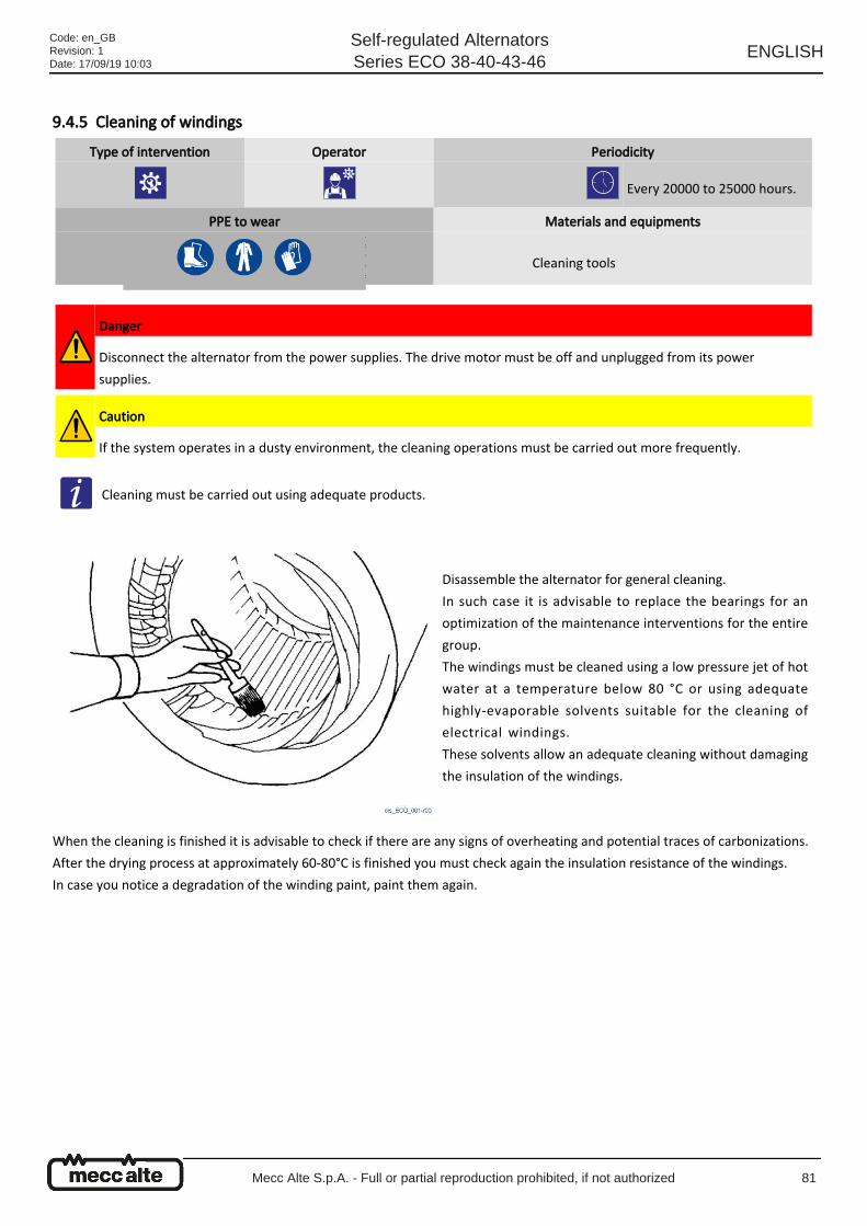
9.4.5 Cleaning of windings
When the cleaning is finished it is advisable to check if there are any signs of overheating and potential traces of carbonizations.
After the drying process at approximately 60-80°C is finished you must check again the insulation resistance of the windings.
In case you notice a degradation of the winding paint, paint them again.
Type of intervention Operator Periodicity
Every 20000 to 25000 hours.
PPE to wear Materials and equipments
Cleaning tools
Danger
Disconnect the alternator from the power supplies. The drive motor must be off and unplugged from its power
supplies.
Caution
If the system operates in a dusty environment, the cleaning operations must be carried out more frequently.
Cleaning must be carried out using adequate products.
Disassemble the alternator for general cleaning.
In such case it is advisable to replace the bearings for an
optimization of the maintenance interventions for the entire
group.
The windings must be cleaned using a low pressure jet of hot
water at a temperature below 80 °C or using adequate
highly-evaporable solvents suitable for the cleaning of
electrical windings.
These solvents allow an adequate cleaning without damaging
the insulation of the windings.
Code: en_GBRevision: 1Date: 17/09/19 10:03
Self-regulated AlternatorsSeries ECO 38-40-43-46
ENGLISH
Mecc Alte S.p.A. - Full or partial reproduction prohibited, if not authorized 81
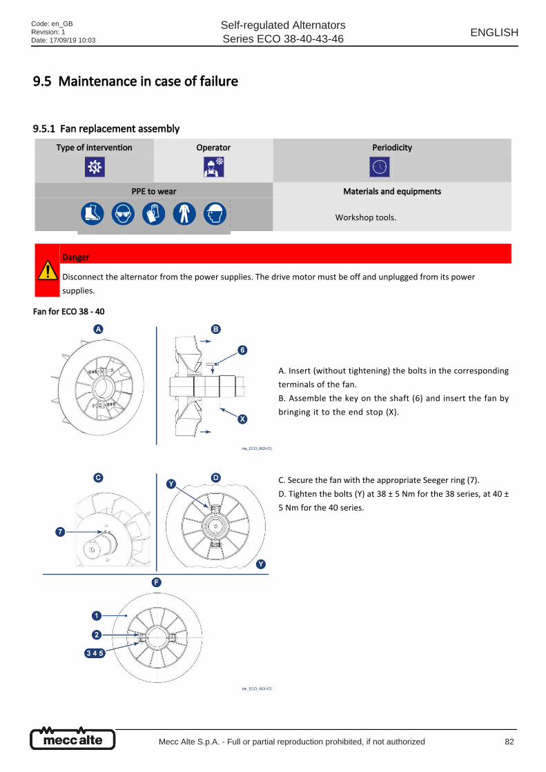
9.5 Maintenance in case of failure
9.5.1 Fan replacement assembly
Fan for ECO 38 - 40
Type of intervention Operator Periodicity
PPE to wear Materials and equipments
Workshop tools.
Danger
Disconnect the alternator from the power supplies. The drive motor must be off and unplugged from its power
supplies.
A. Insert (without tightening) the bolts in the corresponding
terminals of the fan.
B. Assemble the key on the shaft (6) and insert the fan by
bringing it to the end stop (X).
C. Secure the fan with the appropriate Seeger ring (7).
D. Tighten the bolts (Y) at 38 ± 5 Nm for the 38 series, at 40 ±
5 Nm for the 40 series.
Code: en_GBRevision: 1Date: 17/09/19 10:03
Self-regulated AlternatorsSeries ECO 38-40-43-46
ENGLISH
Mecc Alte S.p.A. - Full or partial reproduction prohibited, if not authorized 82
Fan for ECO 43 - 46
The ECO 43-46 Series alternators use aluminum fans with a cast iron internal sleeve.
Assembling is carried out by heating the fan to 200 °C for 1 hour and then inserting it into the shaft.
A special extractor is used to remove it.
No. Description Qty Code
1 ECO 38 Fan 1 6102217303
1 ECO 40 Fan 1 6102217355
2 TE M10x50 Screw 2 6110605417
3 Ø 10 flat washer 2 6110613053
4 Ø 10 serrated washer 2 6110603250
No. Description Qty Code
5 M10 Hexagonal nut 2 6110601046
6 ECO 38 A 16x10x60 key 1 9911130565
6 ECO 40 A 20x12x70 key 1 9911130595
7 ECO 38 D. 95 Seeger ring 1 9911136245
7 ECO 40 D. 120 Seeger ring 1 9911136265
Code: en_GBRevision: 1Date: 17/09/19 10:03
Self-regulated AlternatorsSeries ECO 38-40-43-46
ENGLISH
Mecc Alte S.p.A. - Full or partial reproduction prohibited, if not authorized 83
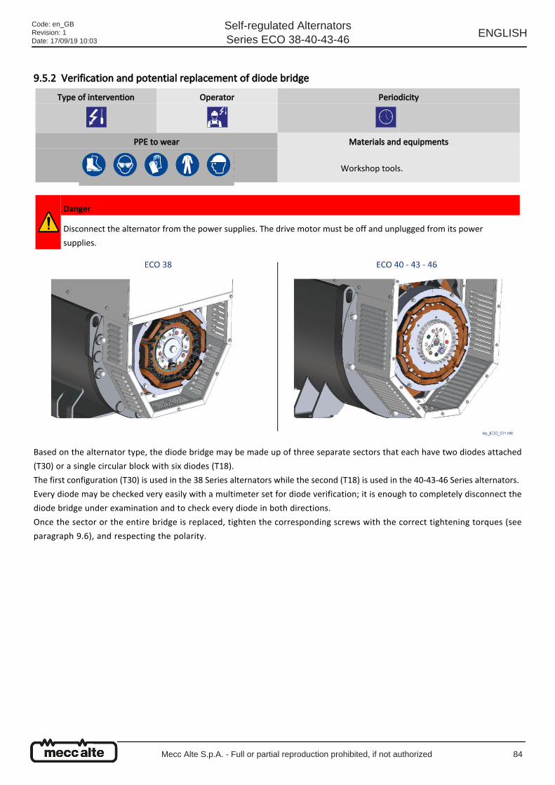
9.5.2 Verification and potential replacement of diode bridge
Based on the alternator type, the diode bridge may be made up of three separate sectors that each have two diodes attached
(T30) or a single circular block with six diodes (T18).
The first configuration (T30) is used in the 38 Series alternators while the second (T18) is used in the 40-43-46 Series alternators.
Every diode may be checked very easily with a multimeter set for diode verification; it is enough to completely disconnect the
diode bridge under examination and to check every diode in both directions.
Once the sector or the entire bridge is replaced, tighten the corresponding screws with the correct tightening torques (see
paragraph 9.6), and respecting the polarity.
Type of intervention Operator Periodicity
PPE to wear Materials and equipments
Workshop tools.
Danger
Disconnect the alternator from the power supplies. The drive motor must be off and unplugged from its power
supplies.
Code: en_GBRevision: 1Date: 17/09/19 10:03
Self-regulated AlternatorsSeries ECO 38-40-43-46
ENGLISH
Mecc Alte S.p.A. - Full or partial reproduction prohibited, if not authorized 84
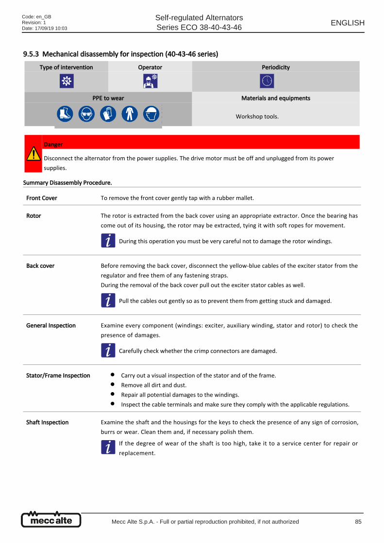
9.5.3 Mechanical disassembly for inspection (40-43-46 series)
Summary Disassembly Procedure.
Type of intervention Operator Periodicity
PPE to wear Materials and equipments
Workshop tools.
Danger
Disconnect the alternator from the power supplies. The drive motor must be off and unplugged from its power
supplies.
Front Cover To remove the front cover gently tap with a rubber mallet.
Rotor
The rotor is extracted from the back cover using an appropriate extractor. Once the bearing has
come out of its housing, the rotor may be extracted, tying it with soft ropes for movement.
During this operation you must be very careful not to damage the rotor windings.
Back cover
Before removing the back cover, disconnect the yellow-blue cables of the exciter stator from the
regulator and free them of any fastening straps.
During the removal of the back cover pull out the exciter stator cables as well.
Pull the cables out gently so as to prevent them from getting stuck and damaged.
General Inspection
Examine every component (windings: exciter, auxiliary winding, stator and rotor) to check the
presence of damages.
Carefully check whether the crimp connectors are damaged.
Stator/Frame Inspection
Carry out a visual inspection of the stator and of the frame.●
Remove all dirt and dust.●
Repair all potential damages to the windings.●
Inspect the cable terminals and make sure they comply with the applicable regulations.●
Shaft Inspection
Examine the shaft and the housings for the keys to check the presence of any sign of corrosion,
burrs or wear. Clean them and, if necessary polish them.
If the degree of wear of the shaft is too high, take it to a service center for repair or
replacement.
Code: en_GBRevision: 1Date: 17/09/19 10:03
Self-regulated AlternatorsSeries ECO 38-40-43-46
ENGLISH
Mecc Alte S.p.A. - Full or partial reproduction prohibited, if not authorized 85
Front/Back bearing
disassembling
Both bearings must be removed using the appropriate extractors.●
The sizes of the bearings must be measured accurately to check the presence of excessive
wear.
●
In case of excessive wear or anomalous noises / vibrations, replace them.●
Electrical Inspections
Check the cable terminals and make sure they guarantee good contact. Make sure there are no
signs of corrosion and/or oxidation.
Check whether the cable sheath is undamaged. If there are damage signs, repair or replace the
cable.
Using adequate tools, check the resistance, the continuity and the insulation of the following
windings (see paragraph 9.5.14):
Main Stator.●
Auxiliary Winding.●
Main rotor.●
Exciter Stator.●
Exciter Rotor.●
Thermal probes (if present).●
PMG (if present).●
Check whether the diodes and the varistor are damaged.
All the measurement tools must be calibrated.
Insulation checks
Check the insulation resistance of the following windings:
Main Stator:
Between phases and between phases and
ground.
●
Between phases and the auxiliary winding.●
Between auxiliary winding and ground.●
Main rotor and exciter rotor: Between winding and ground.●
Exciter Stator: Between winding and ground.●
PMG (if present): Between winding and ground.●
The AVR may be controlled on a static bench or during the operating test of the machine
See paragraph 9.5.10; 9.5.11; 9.5.12; 9.5.13.
The internal windings of the machine might need accurate cleaning. Use an appropriate solvent
or hot water. Dry them and, if necessary, impregnate them again.
Code: en_GBRevision: 1Date: 17/09/19 10:03
Self-regulated AlternatorsSeries ECO 38-40-43-46
ENGLISH
Mecc Alte S.p.A. - Full or partial reproduction prohibited, if not authorized 86
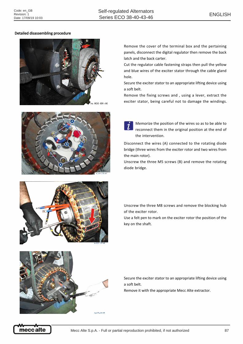
Detailed disassembling procedure
Remove the cover of the terminal box and the pertaining
panels, disconnect the digital regulator then remove the back
latch and the back carter.
Cut the regulator cable fastening straps then pull the yellow
and blue wires of the exciter stator through the cable gland
hole.
Secure the exciter stator to an appropriate lifting device using
a soft belt.
Remove the fixing screws and , using a lever, extract the
exciter stator, being careful not to damage the windings.
Memorize the position of the wires so as to be able to
reconnect them in the original position at the end of
the intervention.
Disconnect the wires (A) connected to the rotating diode
bridge (three wires from the exciter rotor and two wires from
the main rotor).
Unscrew the three M5 screws (B) and remove the rotating
diode bridge.
Unscrew the three M8 screws and remove the blocking hub
of the exciter rotor.
Use a felt pen to mark on the exciter rotor the position of the
key on the shaft.
Secure the exciter stator to an appropriate lifting device using
a soft belt.
Remove it with the appropriate Mecc Alte extractor.
Code: en_GBRevision: 1Date: 17/09/19 10:03
Self-regulated AlternatorsSeries ECO 38-40-43-46
ENGLISH
Mecc Alte S.p.A. - Full or partial reproduction prohibited, if not authorized 87
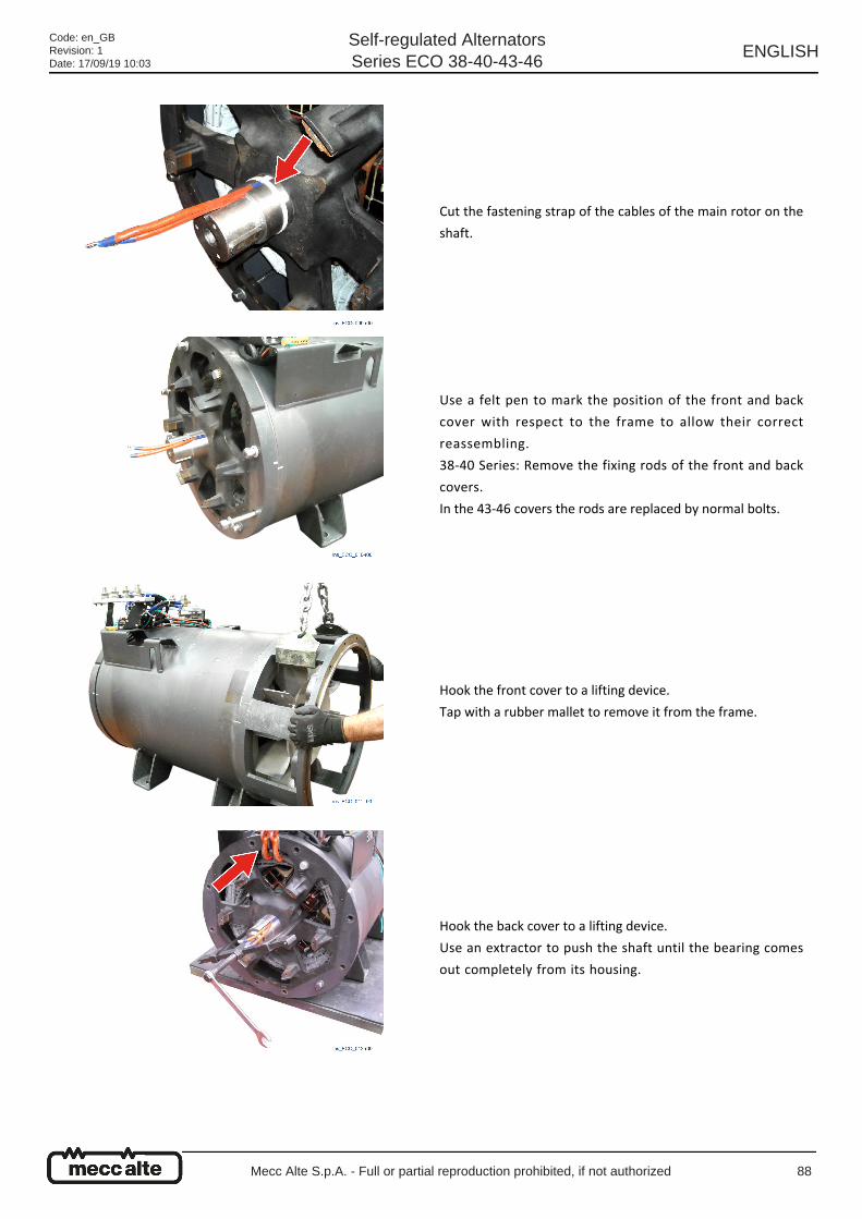
Cut the fastening strap of the cables of the main rotor on the
shaft.
Use a felt pen to mark the position of the front and back
cover with respect to the frame to allow their correct
reassembling.
38-40 Series: Remove the fixing rods of the front and back
covers.
In the 43-46 covers the rods are replaced by normal bolts.
Hook the front cover to a lifting device.
Tap with a rubber mallet to remove it from the frame.
Hook the back cover to a lifting device.
Use an extractor to push the shaft until the bearing comes
out completely from its housing.
Code: en_GBRevision: 1Date: 17/09/19 10:03
Self-regulated AlternatorsSeries ECO 38-40-43-46
ENGLISH
Mecc Alte S.p.A. - Full or partial reproduction prohibited, if not authorized 88
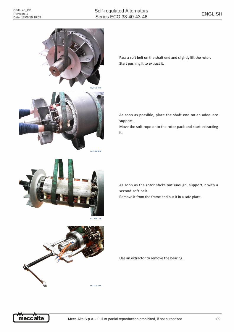
Pass a soft belt on the shaft end and slightly lift the rotor.
Start pushing it to extract it.
As soon as possible, place the shaft end on an adequate
support.
Move the soft rope onto the rotor pack and start extracting
it.
As soon as the rotor sticks out enough, support it with a
second soft belt.
Remove it from the frame and put it in a safe place.
Use an extractor to remove the bearing.
Code: en_GBRevision: 1Date: 17/09/19 10:03
Self-regulated AlternatorsSeries ECO 38-40-43-46
ENGLISH
Mecc Alte S.p.A. - Full or partial reproduction prohibited, if not authorized 89
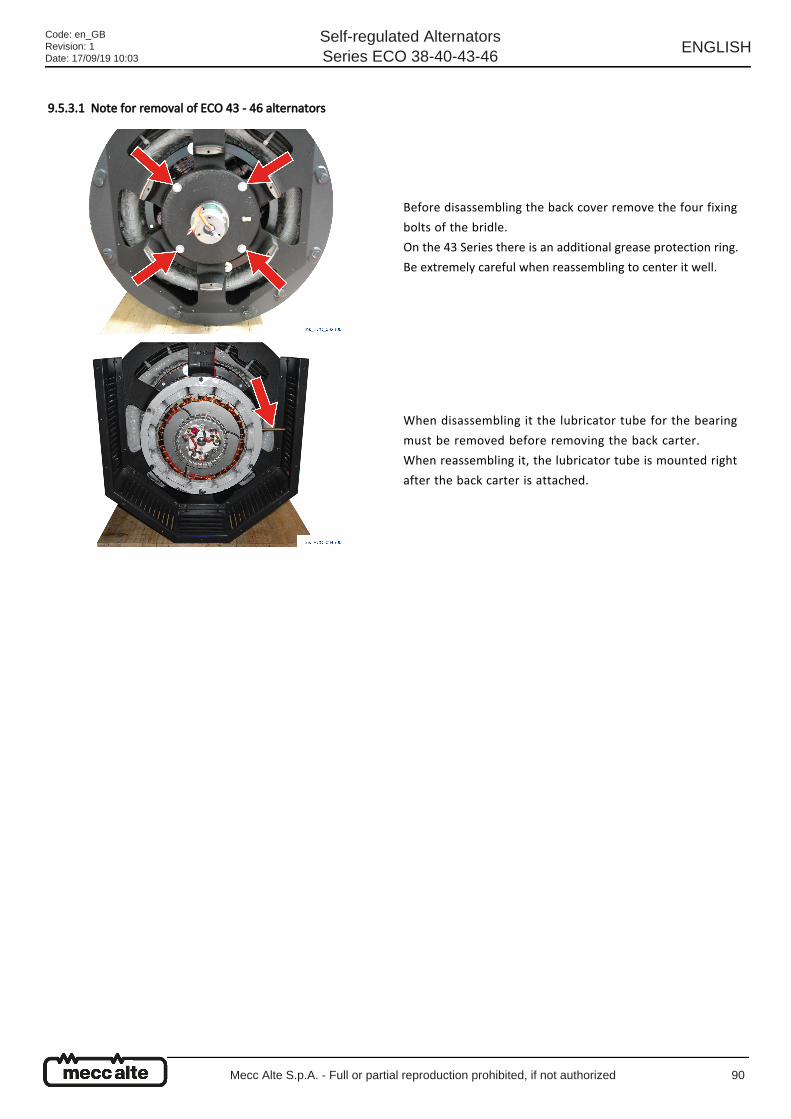
9.5.3.1 Note for removal of ECO 43 - 46 alternators
Before disassembling the back cover remove the four fixing
bolts of the bridle.
On the 43 Series there is an additional grease protection ring.
Be extremely careful when reassembling to center it well.
When disassembling it the lubricator tube for the bearing
must be removed before removing the back carter.
When reassembling it, the lubricator tube is mounted right
after the back carter is attached.
Code: en_GBRevision: 1Date: 17/09/19 10:03
Self-regulated AlternatorsSeries ECO 38-40-43-46
ENGLISH
Mecc Alte S.p.A. - Full or partial reproduction prohibited, if not authorized 90
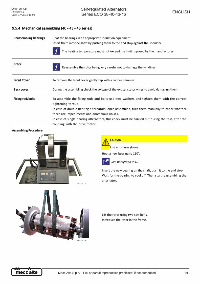
9.5.4 Mechanical assembling (40 - 43 - 46 series)
Assembling Procedure
Reassembling bearings
Heat the bearings in an appropriate induction equipment.
Insert them into the shaft by pushing them to the end stop against the shoulder.
The heating temperature must not exceed the limit imposed by the manufacturer.
Rotor Reassemble the rotor being very careful not to damage the windings.
Front Cover To remove the front cover gently tap with a rubber hammer.
Back cover During the assembling check the voltage of the exciter stator wires to avoid damaging them.
Fixing rod/bolts
To assemble the fixing rods and bolts use new washers and tighten them with the correct
tightening torque.
In case of double-bearing alternators, once assembled, turn them manually to check whether
there are impediments and anomalous noises.
In case of single-bearing alternators, this check must be carried out during the test, after the
coupling with the drive motor.
Caution
Use anti-burn gloves.
Heat a new bearing to 110°.
See paragraph 9.4.1.
Insert the new bearing on the shaft, push it to the end stop.
Wait for the bearing to cool off. Then start reassembling the
alternator.
Lift the rotor using two soft belts.
Introduce the rotor in the frame.
Code: en_GBRevision: 1Date: 17/09/19 10:03
Self-regulated AlternatorsSeries ECO 38-40-43-46
ENGLISH
Mecc Alte S.p.A. - Full or partial reproduction prohibited, if not authorized 91
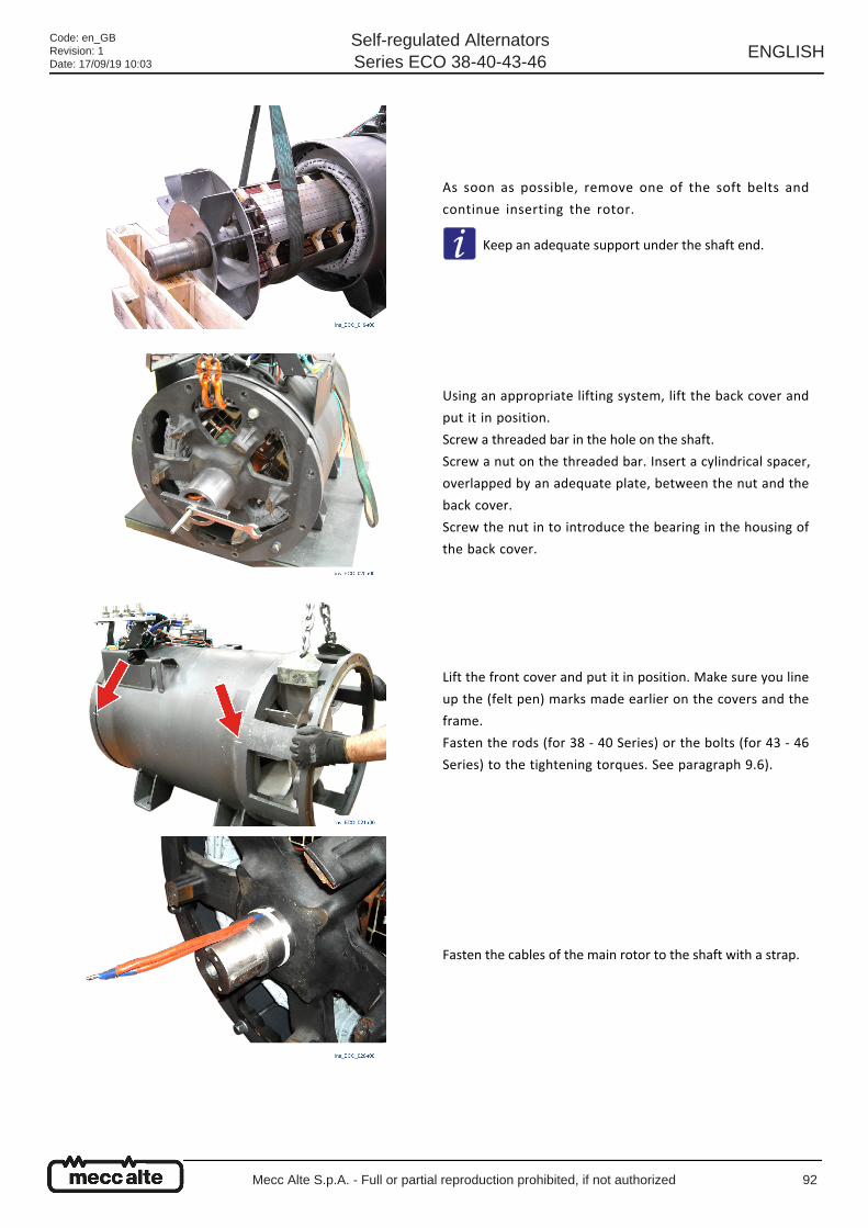
As soon as possible, remove one of the soft belts and
continue inserting the rotor.
Keep an adequate support under the shaft end.
Using an appropriate lifting system, lift the back cover and
put it in position.
Screw a threaded bar in the hole on the shaft.
Screw a nut on the threaded bar. Insert a cylindrical spacer,
overlapped by an adequate plate, between the nut and the
back cover.
Screw the nut in to introduce the bearing in the housing of
the back cover.
Lift the front cover and put it in position. Make sure you line
up the (felt pen) marks made earlier on the covers and the
frame.
Fasten the rods (for 38 - 40 Series) or the bolts (for 43 - 46
Series) to the tightening torques. See paragraph 9.6).
Fasten the cables of the main rotor to the shaft with a strap.
Code: en_GBRevision: 1Date: 17/09/19 10:03
Self-regulated AlternatorsSeries ECO 38-40-43-46
ENGLISH
Mecc Alte S.p.A. - Full or partial reproduction prohibited, if not authorized 92
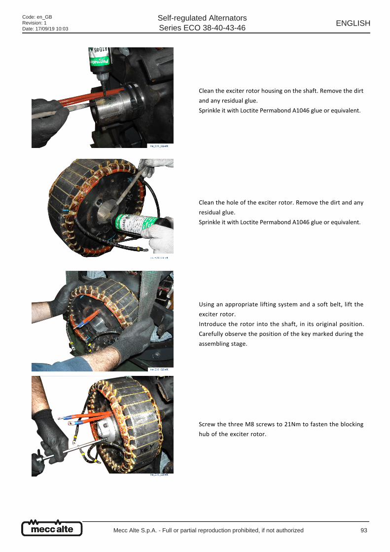
Clean the exciter rotor housing on the shaft. Remove the dirt
and any residual glue.
Sprinkle it with Loctite Permabond A1046 glue or equivalent.
Clean the hole of the exciter rotor. Remove the dirt and any
residual glue.
Sprinkle it with Loctite Permabond A1046 glue or equivalent.
Using an appropriate lifting system and a soft belt, lift the
exciter rotor.
Introduce the rotor into the shaft, in its original position.
Carefully observe the position of the key marked during the
assembling stage.
Screw the three M8 screws to 21Nm to fasten the blocking
hub of the exciter rotor.
Code: en_GBRevision: 1Date: 17/09/19 10:03
Self-regulated AlternatorsSeries ECO 38-40-43-46
ENGLISH
Mecc Alte S.p.A. - Full or partial reproduction prohibited, if not authorized 93
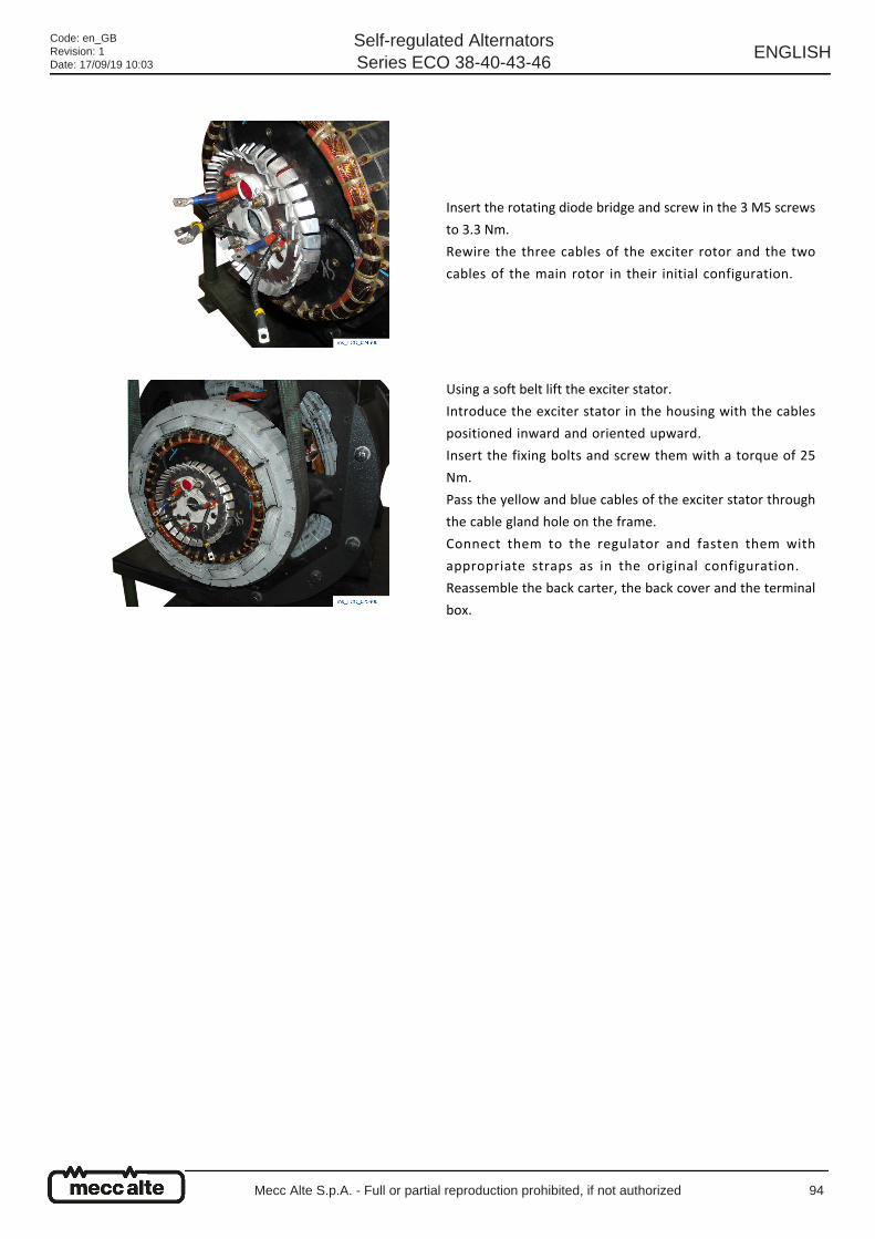
Insert the rotating diode bridge and screw in the 3 M5 screws
to 3.3 Nm.
Rewire the three cables of the exciter rotor and the two
cables of the main rotor in their initial configuration.
Using a soft belt lift the exciter stator.
Introduce the exciter stator in the housing with the cables
positioned inward and oriented upward.
Insert the fixing bolts and screw them with a torque of 25
Nm.
Pass the yellow and blue cables of the exciter stator through
the cable gland hole on the frame.
Connect them to the regulator and fasten them with
appropriate straps as in the original configuration.
Reassemble the back carter, the back cover and the terminal
box.
Code: en_GBRevision: 1Date: 17/09/19 10:03
Self-regulated AlternatorsSeries ECO 38-40-43-46
ENGLISH
Mecc Alte S.p.A. - Full or partial reproduction prohibited, if not authorized 94
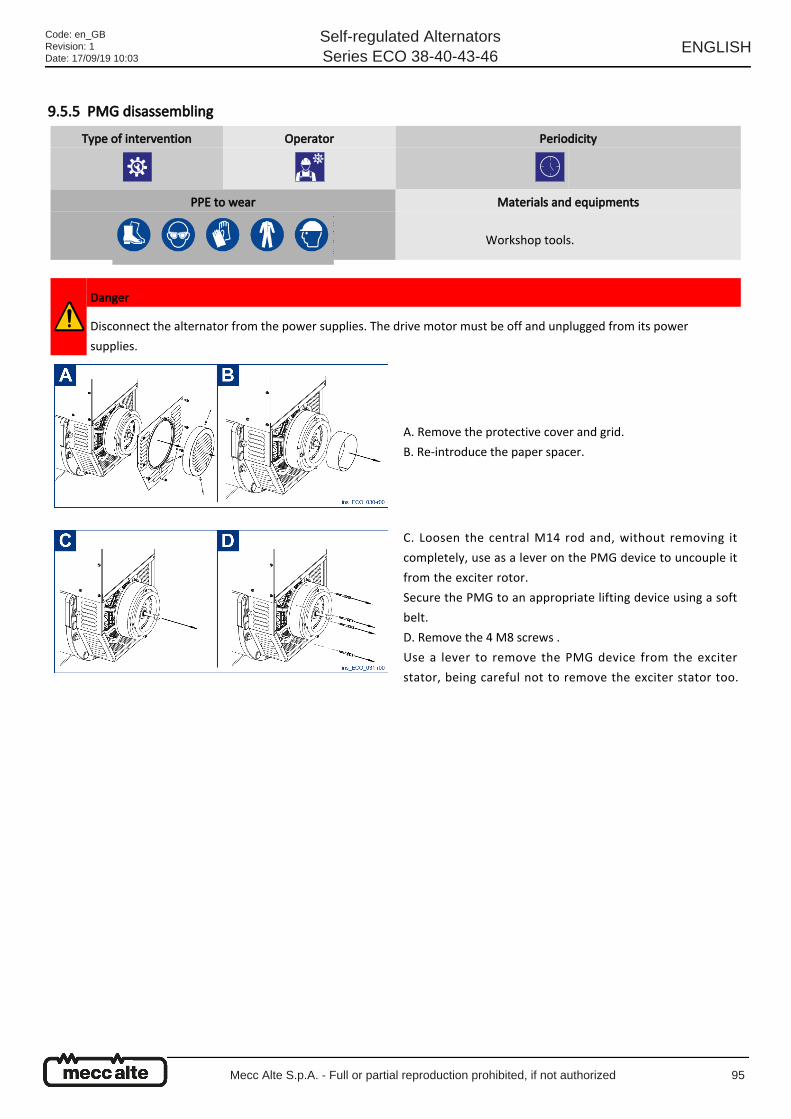
9.5.5 PMG disassembling
Type of intervention Operator Periodicity
PPE to wear Materials and equipments
Workshop tools.
Danger
Disconnect the alternator from the power supplies. The drive motor must be off and unplugged from its power
supplies.
A. Remove the protective cover and grid.
B. Re-introduce the paper spacer.
C. Loosen the central M14 rod and, without removing it
completely, use as a lever on the PMG device to uncouple it
from the exciter rotor.
Secure the PMG to an appropriate lifting device using a soft
belt.
D. Remove the 4 M8 screws .
Use a lever to remove the PMG device from the exciter
stator, being careful not to remove the exciter stator too.
Code: en_GBRevision: 1Date: 17/09/19 10:03
Self-regulated AlternatorsSeries ECO 38-40-43-46
ENGLISH
Mecc Alte S.p.A. - Full or partial reproduction prohibited, if not authorized 95
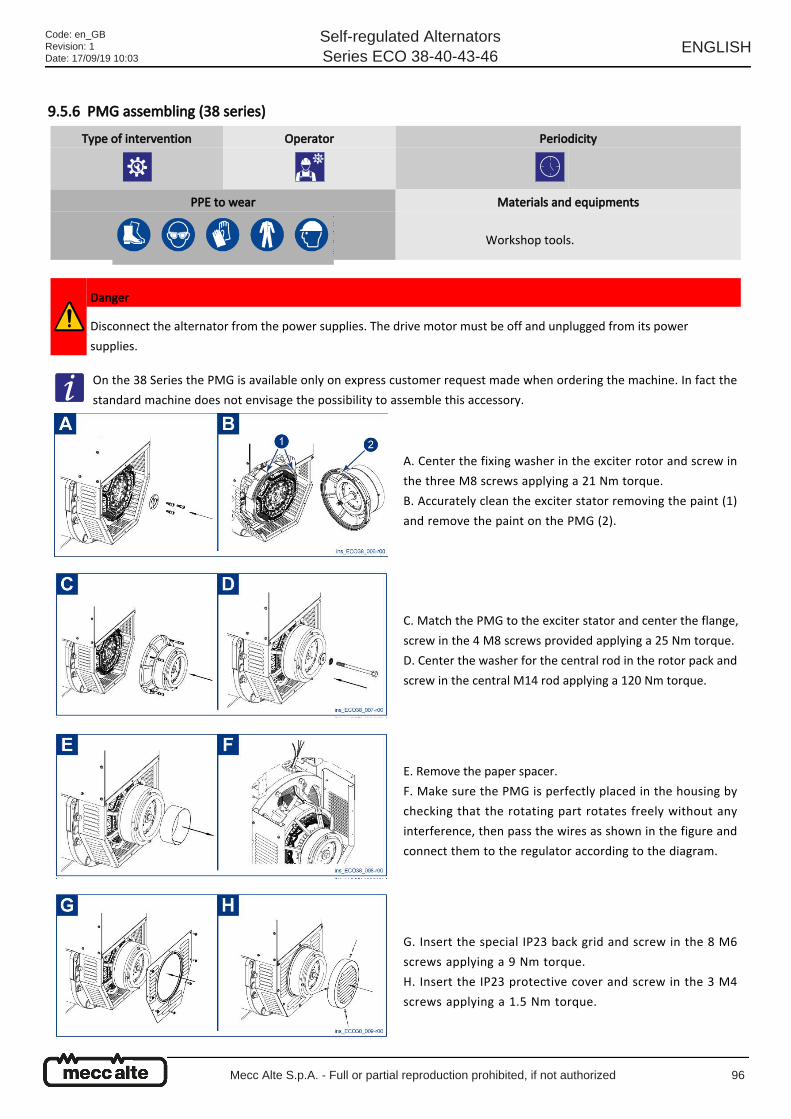
9.5.6 PMG assembling (38 series)
Type of intervention Operator Periodicity
PPE to wear Materials and equipments
Workshop tools.
Danger
Disconnect the alternator from the power supplies. The drive motor must be off and unplugged from its power
supplies.
On the 38 Series the PMG is available only on express customer request made when ordering the machine. In fact the
standard machine does not envisage the possibility to assemble this accessory.
A. Center the fixing washer in the exciter rotor and screw in
the three M8 screws applying a 21 Nm torque.
B. Accurately clean the exciter stator removing the paint (1)
and remove the paint on the PMG (2).
C. Match the PMG to the exciter stator and center the flange,
screw in the 4 M8 screws provided applying a 25 Nm torque.
D. Center the washer for the central rod in the rotor pack and
screw in the central M14 rod applying a 120 Nm torque.
E. Remove the paper spacer.
F. Make sure the PMG is perfectly placed in the housing by
checking that the rotating part rotates freely without any
interference, then pass the wires as shown in the figure and
connect them to the regulator according to the diagram.
G. Insert the special IP23 back grid and screw in the 8 M6
screws applying a 9 Nm torque.
H. Insert the IP23 protective cover and screw in the 3 M4
screws applying a 1.5 Nm torque.
Code: en_GBRevision: 1Date: 17/09/19 10:03
Self-regulated AlternatorsSeries ECO 38-40-43-46
ENGLISH
Mecc Alte S.p.A. - Full or partial reproduction prohibited, if not authorized 96
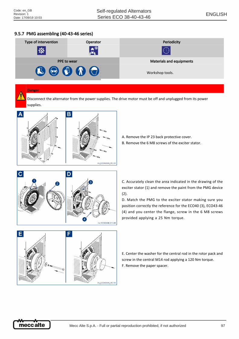
9.5.7 PMG assembling (40-43-46 series)
Type of intervention Operator Periodicity
PPE to wear Materials and equipments
Workshop tools.
Danger
Disconnect the alternator from the power supplies. The drive motor must be off and unplugged from its power
supplies.
A. Remove the IP 23 back protective cover.
B. Remove the 6 M8 screws of the exciter stator.
C. Accurately clean the area indicated in the drawing of the
exciter stator (1) and remove the paint from the PMG device
(2).
D. Match the PMG to the exciter stator making sure you
position correctly the reference for the ECO40 (3), ECO43-46
(4) and you center the flange, screw in the 6 M8 screws
provided applying a 25 Nm torque.
E. Center the washer for the central rod in the rotor pack and
screw in the central M14 rod applying a 120 Nm torque.
F. Remove the paper spacer.
Code: en_GBRevision: 1Date: 17/09/19 10:03
Self-regulated AlternatorsSeries ECO 38-40-43-46
ENGLISH
Mecc Alte S.p.A. - Full or partial reproduction prohibited, if not authorized 97
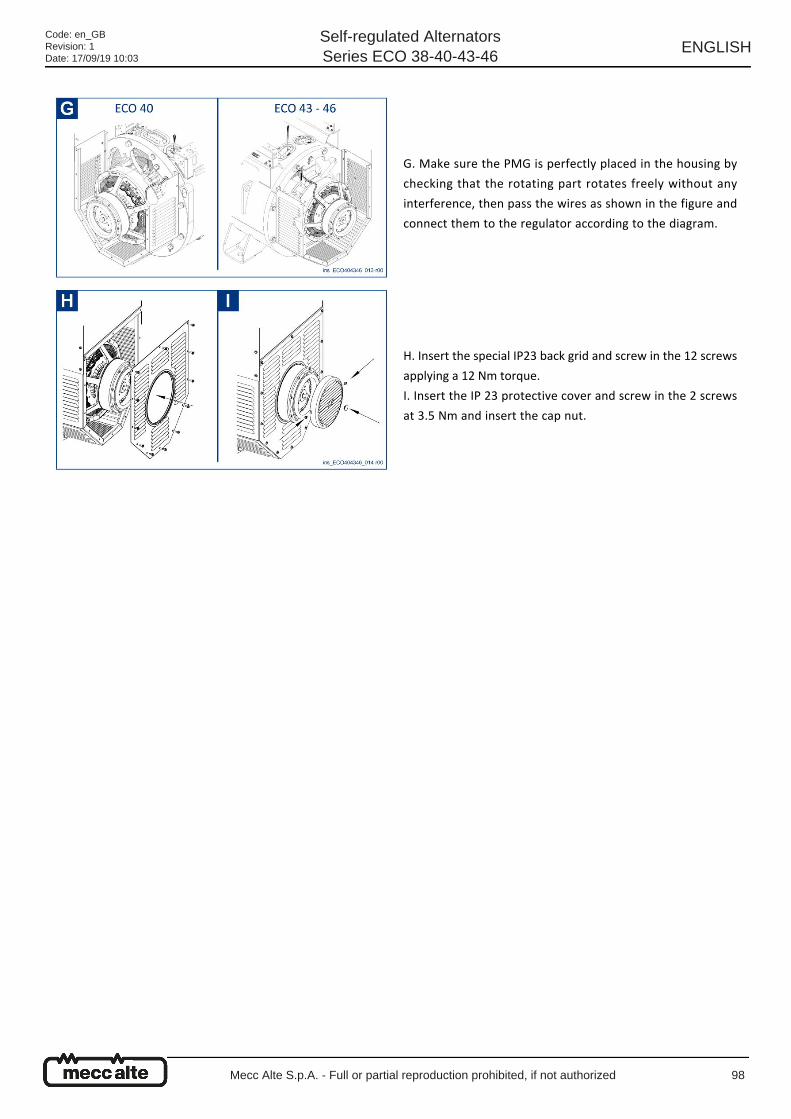
G. Make sure the PMG is perfectly placed in the housing by
checking that the rotating part rotates freely without any
interference, then pass the wires as shown in the figure and
connect them to the regulator according to the diagram.
H. Insert the special IP23 back grid and screw in the 12 screws
applying a 12 Nm torque.
I. Insert the IP 23 protective cover and screw in the 2 screws
at 3.5 Nm and insert the cap nut.
Code: en_GBRevision: 1Date: 17/09/19 10:03
Self-regulated AlternatorsSeries ECO 38-40-43-46
ENGLISH
Mecc Alte S.p.A. - Full or partial reproduction prohibited, if not authorized 98
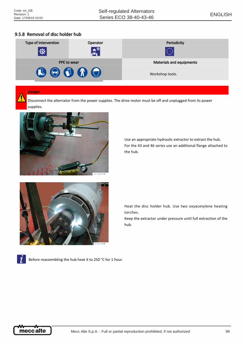
9.5.8 Removal of disc holder hub
Type of intervention Operator Periodicity
PPE to wear Materials and equipments
Workshop tools.
Danger
Disconnect the alternator from the power supplies. The drive motor must be off and unplugged from its power
supplies.
Use an appropriate hydraulic extractor to extract the hub.
For the 43 and 46 series use an additional flange attached to
the hub.
Heat the disc holder hub. Use two oxyacetylene heating
torches.
Keep the extractor under pressure until full extraction of the
hub.
Before reassembling the hub heat it to 250 °C for 1 hour.
Code: en_GBRevision: 1Date: 17/09/19 10:03
Self-regulated AlternatorsSeries ECO 38-40-43-46
ENGLISH
Mecc Alte S.p.A. - Full or partial reproduction prohibited, if not authorized 99
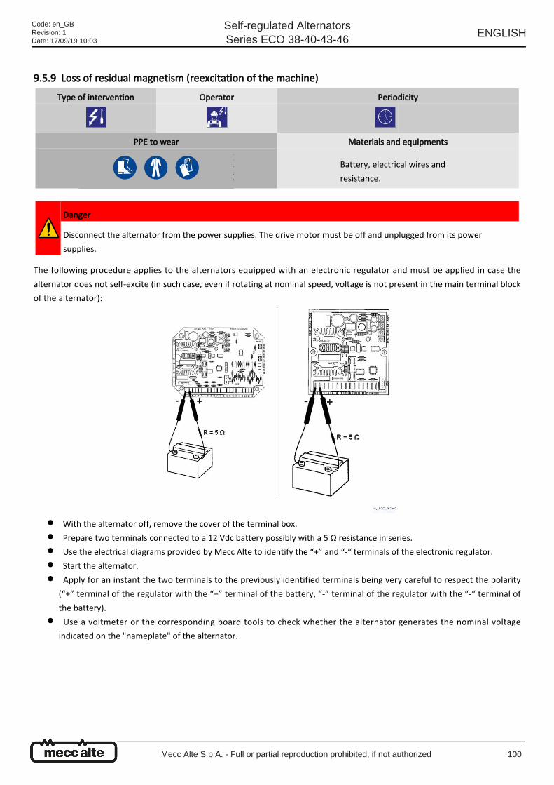
●
●
●
●
●
●
9.5.9 Loss of residual magnetism (reexcitation of the machine)
The following procedure applies to the alternators equipped with an electronic regulator and must be applied in case the
alternator does not self-excite (in such case, even if rotating at nominal speed, voltage is not present in the main terminal block
of the alternator):
With the alternator off, remove the cover of the terminal box.
Prepare two terminals connected to a 12 Vdc battery possibly with a 5 Ω resistance in series.
Use the electrical diagrams provided by Mecc Alte to identify the “+” and “-“ terminals of the electronic regulator.
Start the alternator.
Apply for an instant the two terminals to the previously identified terminals being very careful to respect the polarity
(“+” terminal of the regulator with the “+” terminal of the battery, “-” terminal of the regulator with the “-“ terminal of
the battery).
Use a voltmeter or the corresponding board tools to check whether the alternator generates the nominal voltage
indicated on the "nameplate" of the alternator.
Type of intervention Operator Periodicity
PPE to wear Materials and equipments
Battery, electrical wires and
resistance.
Danger
Disconnect the alternator from the power supplies. The drive motor must be off and unplugged from its power
supplies.
Code: en_GBRevision: 1Date: 17/09/19 10:03
Self-regulated AlternatorsSeries ECO 38-40-43-46
ENGLISH
Mecc Alte S.p.A. - Full or partial reproduction prohibited, if not authorized 100
●
●
●
●
●
●
●
9.5.10 Verification and replacement of voltage regulator
The alternators are equipped with an automated voltage regulator: depending on the alternator type, the electronic regulators
may be of 4 types: DSR, DSR/A, DER1, DER1/A.
The standard supply comes with the DSR on the 38 Series and the DER1/A on the 40-43-46 Series.
Visual Inspection of the Regulator
In particular check for:
Mechanical damages of various kinds.
State of fuses.
Undamaged state of electrical connections.
Potential presence of burned electrical components.
Presence of the silicone protection in the Hz and AMP potentiometers.
Check the SCR resistance and flyback diode.
Before doing this test, check that the fuse is inserted and undamaged.
Flyback diode: it is working if the diode test performed between pin 1 and 2 has a positive result.
SCR: it is working if a resistance of some hundred KΩ is measured between pin 1 and 8 (in the DSR) or between pin 1 and
2 (in the DER1 regulator).
A resistance measure close to zero signals a SCR failure.
A reason for the damaging of these components may be the erroneous cabling of the alternator regulator.
Copy the data and alarms of the regulator.
To avoid creating new alarms, the copy of the data and alarms existing in the regulator (.dat and .alr files) must be made feeding
the alternator with an appropriate continuous voltage, in accordance with the diagrams below.
Type of intervention Operator Periodicity
PPE to wear Materials and equipments
Workshop tools.
Danger
Disconnect the alternator from the power supplies. The drive motor must be off and unplugged from its power
supplies.
DER1 can be mounted on the 38 Series and DSR/A can be mounted on the 40-43-46 Series on customer request.
In case there are voltage regulation problems not ascribable to an erroneous adjustment of the VOLT, STAB, Hz and
AMP potentiometers and/or to the system (fully assembled machine + load), follow the procedure below for an in-
depth check of the voltage regulator.
Do not change the position of the VOLT, STAB, Hz and AMP potentiometers before marking their position.
Code: en_GBRevision: 1Date: 17/09/19 10:03
Self-regulated AlternatorsSeries ECO 38-40-43-46
ENGLISH
Mecc Alte S.p.A. - Full or partial reproduction prohibited, if not authorized 101
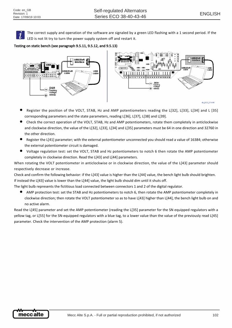
●
●
●
●
●
Testing on static bench (see paragraph 9.5.11, 9.5.12, and 9.5.13)
Register the position of the VOLT, STAB, Hz and AMP potentiometers reading the L[32], L[33], L[34] and L [35]
corresponding parameters and the state parameters, reading L[36], L[37], L[38] and L[39].
Check the correct operation of the VOLT, STAB, Hz and AMP potentiometers, rotate them completely in anticlockwise
and clockwise direction, the value of the L[32], L[33], L[34] and L[35] parameters must be 64 in one direction and 32760 in
the other direction.
Register the L[41] parameter; with the external potentiometer unconnected you should read a value of 16384; otherwise
the external potentiometer circuit is damaged.
Voltage regulation test: set the VOLT, STAB and Hz potentiometers to notch 6 then rotate the AMP potentiometer
completely in clockwise direction. Read the L[43] and L[44] parameters.
When rotating the VOLT potentiometer in anticlockwise or in clockwise direction, the value of the L[43] parameter should
respectively decrease or increase.
Check and confirm the following behavior: if the L[43] value is higher than the L[44] value, the bench light bulb should brighten.
If instead the L[43] value is lower than the L[44] value, the light bulb should dim until it shuts off.
The light bulb represents the fictitious load connected between connectors 1 and 2 of the digital regulator.
AMP protection test: set the STAB and Hz potentiometers to notch 6, then rotate the AMP potentiometer completely in
clockwise direction; then rotate the VOLT potentiometer so as to have L[43] higher than L[44], the bench light bulb on and
no active alarm.
Read the L[45] parameter and set the AMP potentiometer (reading the L[35] parameter for the SN equipped regulators with a
yellow tag, or L[55] for the SN-equipped regulators with a blue tag, to a lower value than the value of the previously read L[45]
parameter. Check the intervention of the AMP protection (alarm 5).
The correct supply and operation of the software are signaled by a green LED flashing with a 1 second period. If the
LED is not lit try to turn the power supply system off and restart it.
Code: en_GBRevision: 1Date: 17/09/19 10:03
Self-regulated AlternatorsSeries ECO 38-40-43-46
ENGLISH
Mecc Alte S.p.A. - Full or partial reproduction prohibited, if not authorized 102
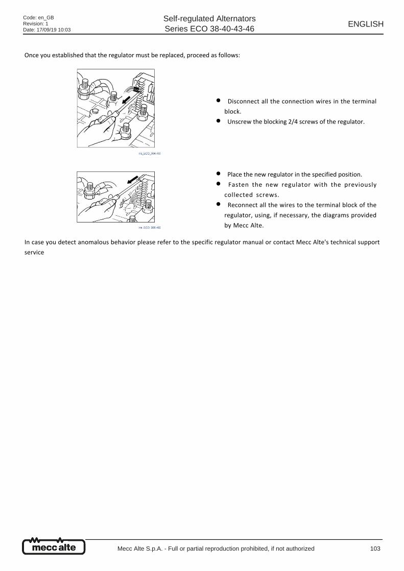
Once you established that the regulator must be replaced, proceed as follows:
In case you detect anomalous behavior please refer to the specific regulator manual or contact Mecc Alte's technical support
service
Disconnect all the connection wires in the terminal
block.
●
Unscrew the blocking 2/4 screws of the regulator.●
Place the new regulator in the specified position.●
Fasten the new regulator with the previously
collected screws.
●
Reconnect all the wires to the terminal block of the
regulator, using, if necessary, the diagrams provided
by Mecc Alte.
●
Code: en_GBRevision: 1Date: 17/09/19 10:03
Self-regulated AlternatorsSeries ECO 38-40-43-46
ENGLISH
Mecc Alte S.p.A. - Full or partial reproduction prohibited, if not authorized 103

9.5.11 DSR test and setup on test bench
The connection diagrams of the DSR and the USB2DxR communication interface are shown in figures (A), (B) or (C) in this
paragraph based on the requested function and on the available supply voltage.
Type of intervention Operator Periodicity
PPE to wear Materials and equipments
Personal
computer+interface+software
.
Danger
Disconnect the alternator from the power supplies. The drive motor must be off and unplugged from its power
supplies. Disconnect the regulator and connect to a computer according to the diagrams below. The operations of
functional checkout and parameter setting may be easier if they are performed on a test bench rather than with the
regulator still inside the terminal box.
Caution
Given that some parts of the DSR which work with a high potential are not isolated, for the safety of the operator, it is
necessary for the power source to be isolated from the electrical grid, for instance by a transformer.
Caution
The use of these types of connection is reserved to qualified personnel, able to assess the operational risks of high
voltage and who have a full knowledge of the content of this manual.
DSR 48Vdc power supply for the download of the alarms
without risking to change to content of the EEPROM because
of the tests.
No other connections besides the power supply are
needed.
Code: en_GBRevision: 1Date: 17/09/19 10:03
Self-regulated AlternatorsSeries ECO 38-40-43-46
ENGLISH
Mecc Alte S.p.A. - Full or partial reproduction prohibited, if not authorized 104
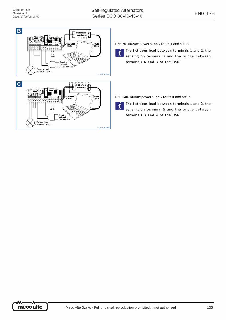
DSR 70-140Vac power supply for test and setup.
The fictitious load between terminals 1 and 2, the
sensing on terminal 7 and the bridge between
terminals 6 and 3 of the DSR.
DSR 140-140Vac power supply for test and setup.
The fictitious load between terminals 1 and 2, the
sensing on terminal 5 and the bridge between
terminals 3 and 4 of the DSR.
Code: en_GBRevision: 1Date: 17/09/19 10:03
Self-regulated AlternatorsSeries ECO 38-40-43-46
ENGLISH
Mecc Alte S.p.A. - Full or partial reproduction prohibited, if not authorized 105
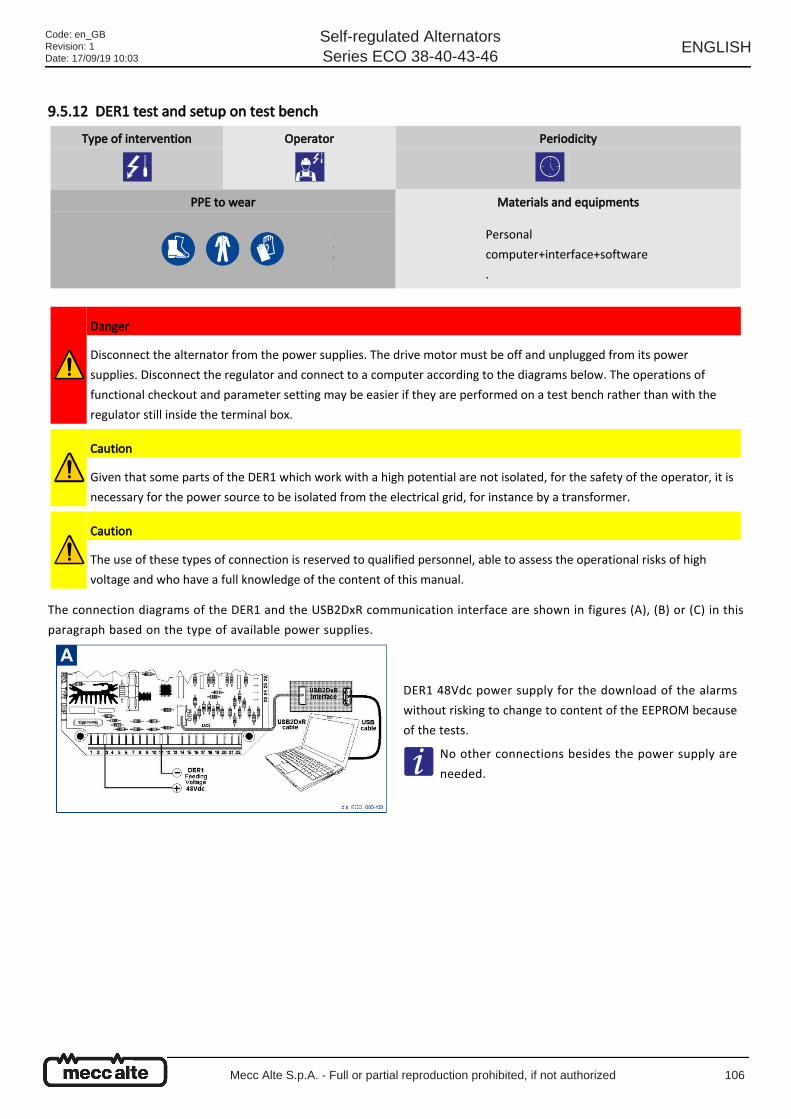
9.5.12 DER1 test and setup on test bench
The connection diagrams of the DER1 and the USB2DxR communication interface are shown in figures (A), (B) or (C) in this
paragraph based on the type of available power supplies.
Type of intervention Operator Periodicity
PPE to wear Materials and equipments
Personal
computer+interface+software
.
Danger
Disconnect the alternator from the power supplies. The drive motor must be off and unplugged from its power
supplies. Disconnect the regulator and connect to a computer according to the diagrams below. The operations of
functional checkout and parameter setting may be easier if they are performed on a test bench rather than with the
regulator still inside the terminal box.
Caution
Given that some parts of the DER1 which work with a high potential are not isolated, for the safety of the operator, it is
necessary for the power source to be isolated from the electrical grid, for instance by a transformer.
Caution
The use of these types of connection is reserved to qualified personnel, able to assess the operational risks of high
voltage and who have a full knowledge of the content of this manual.
DER1 48Vdc power supply for the download of the alarms
without risking to change to content of the EEPROM because
of the tests.
No other connections besides the power supply are
needed.
Code: en_GBRevision: 1Date: 17/09/19 10:03
Self-regulated AlternatorsSeries ECO 38-40-43-46
ENGLISH
Mecc Alte S.p.A. - Full or partial reproduction prohibited, if not authorized 106
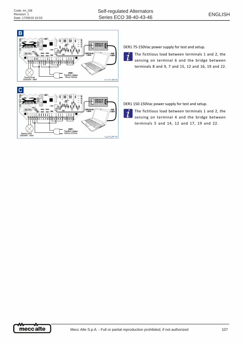
DER1 75-150Vac power supply for test and setup.
The fictitious load between terminals 1 and 2, the
sensing on terminal 6 and the bridge between
terminals 8 and 9, 7 and 15, 12 and 16, 19 and 22.
DER1 150-150Vac power supply for test and setup.
The fictitious load between terminals 1 and 2, the
sensing on terminal 4 and the bridge between
terminals 5 and 14, 12 and 17, 19 and 22.
Code: en_GBRevision: 1Date: 17/09/19 10:03
Self-regulated AlternatorsSeries ECO 38-40-43-46
ENGLISH
Mecc Alte S.p.A. - Full or partial reproduction prohibited, if not authorized 107
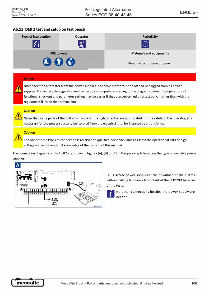
9.5.13 DER 2 test and setup on test bench
The connection diagrams of the DER2 are shown in figures (A), (B) or (C) in this paragraph based on the type of available power
supplies.
Type of intervention Operator Periodicity
PPE to wear Materials and equipments
Personal computer+software.
Danger
Disconnect the alternator from the power supplies. The drive motor must be off and unplugged from its power
supplies. Disconnect the regulator and connect to a computer according to the diagrams below. The operations of
functional checkout and parameter setting may be easier if they are performed on a test bench rather than with the
regulator still inside the terminal box.
Caution
Given that some parts of the DSR which work with a high potential are not isolated, for the safety of the operator, it is
necessary for the power source to be isolated from the electrical grid, for instance by a transformer.
Caution
The use of these types of connection is reserved to qualified personnel, able to assess the operational risks of high
voltage and who have a full knowledge of the content of this manual.
DER1 48Vdc power supply for the download of the alarms
without risking to change to content of the EEPROM because
of the tests.
No other connections besides the power supply are
needed.
Code: en_GBRevision: 1Date: 17/09/19 10:03
Self-regulated AlternatorsSeries ECO 38-40-43-46
ENGLISH
Mecc Alte S.p.A. - Full or partial reproduction prohibited, if not authorized 108
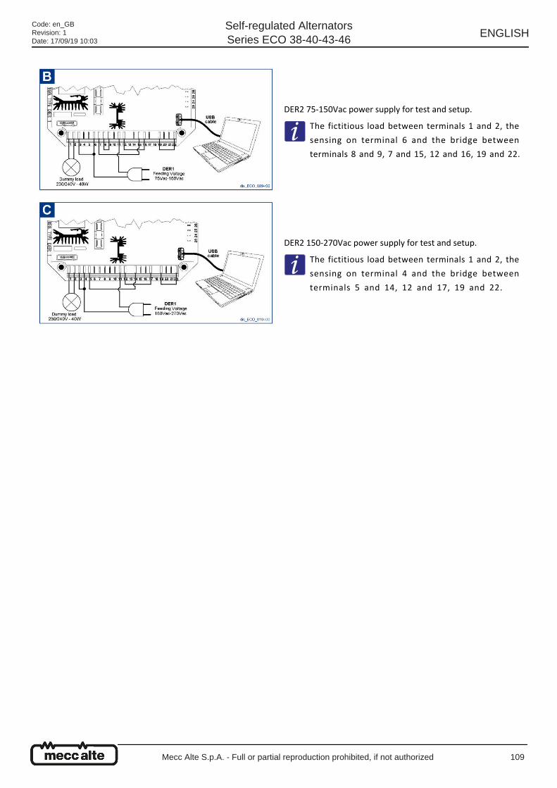
DER2 75-150Vac power supply for test and setup.
The fictitious load between terminals 1 and 2, the
sensing on terminal 6 and the bridge between
terminals 8 and 9, 7 and 15, 12 and 16, 19 and 22.
DER2 150-270Vac power supply for test and setup.
The fictitious load between terminals 1 and 2, the
sensing on terminal 4 and the bridge between
terminals 5 and 14, 12 and 17, 19 and 22.
Code: en_GBRevision: 1Date: 17/09/19 10:03
Self-regulated AlternatorsSeries ECO 38-40-43-46
ENGLISH
Mecc Alte S.p.A. - Full or partial reproduction prohibited, if not authorized 109
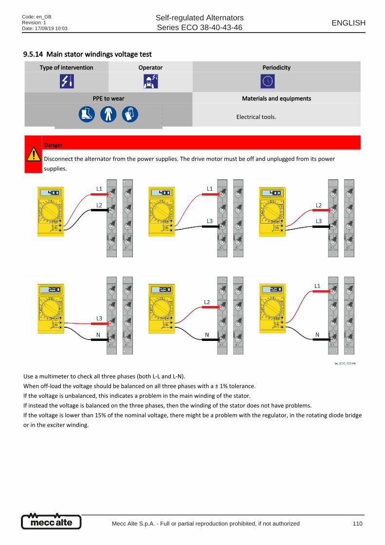
9.5.14 Main stator windings voltage test
Use a multimeter to check all three phases (both L-L and L-N).
When off-load the voltage should be balanced on all three phases with a ± 1% tolerance.
If the voltage is unbalanced, this indicates a problem in the main winding of the stator.
If instead the voltage is balanced on the three phases, then the winding of the stator does not have problems.
If the voltage is lower than 15% of the nominal voltage, there might be a problem with the regulator, in the rotating diode bridge
or in the exciter winding.
Type of intervention Operator Periodicity
PPE to wear Materials and equipments
Electrical tools.
Danger
Disconnect the alternator from the power supplies. The drive motor must be off and unplugged from its power
supplies.
Code: en_GBRevision: 1Date: 17/09/19 10:03
Self-regulated AlternatorsSeries ECO 38-40-43-46
ENGLISH
Mecc Alte S.p.A. - Full or partial reproduction prohibited, if not authorized 110
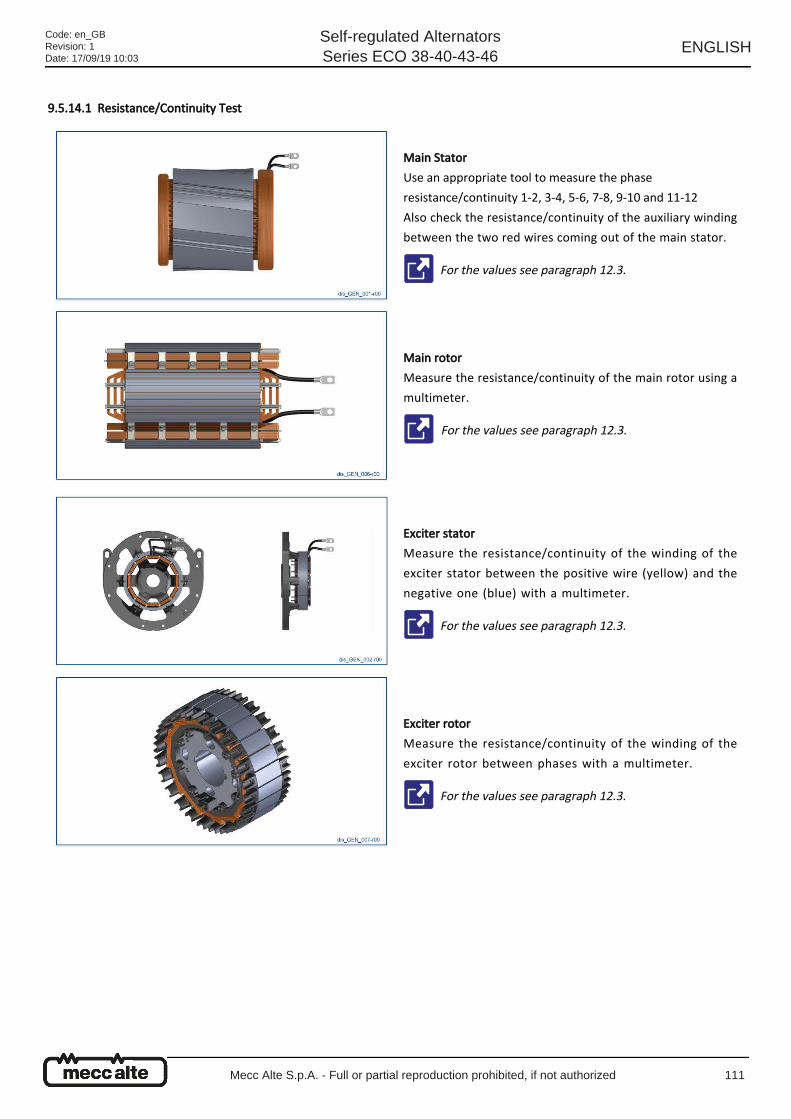
9.5.14.1 Resistance/Continuity Test
Main Stator
Use an appropriate tool to measure the phase
resistance/continuity 1-2, 3-4, 5-6, 7-8, 9-10 and 11-12
Also check the resistance/continuity of the auxiliary winding
between the two red wires coming out of the main stator.
For the values see paragraph 12.3.
Main rotor
Measure the resistance/continuity of the main rotor using a
multimeter.
For the values see paragraph 12.3.
Exciter stator
Measure the resistance/continuity of the winding of the
exciter stator between the positive wire (yellow) and the
negative one (blue) with a multimeter.
For the values see paragraph 12.3.
Exciter rotor
Measure the resistance/continuity of the winding of the
exciter rotor between phases with a multimeter.
For the values see paragraph 12.3.
Code: en_GBRevision: 1Date: 17/09/19 10:03
Self-regulated AlternatorsSeries ECO 38-40-43-46
ENGLISH
Mecc Alte S.p.A. - Full or partial reproduction prohibited, if not authorized 111
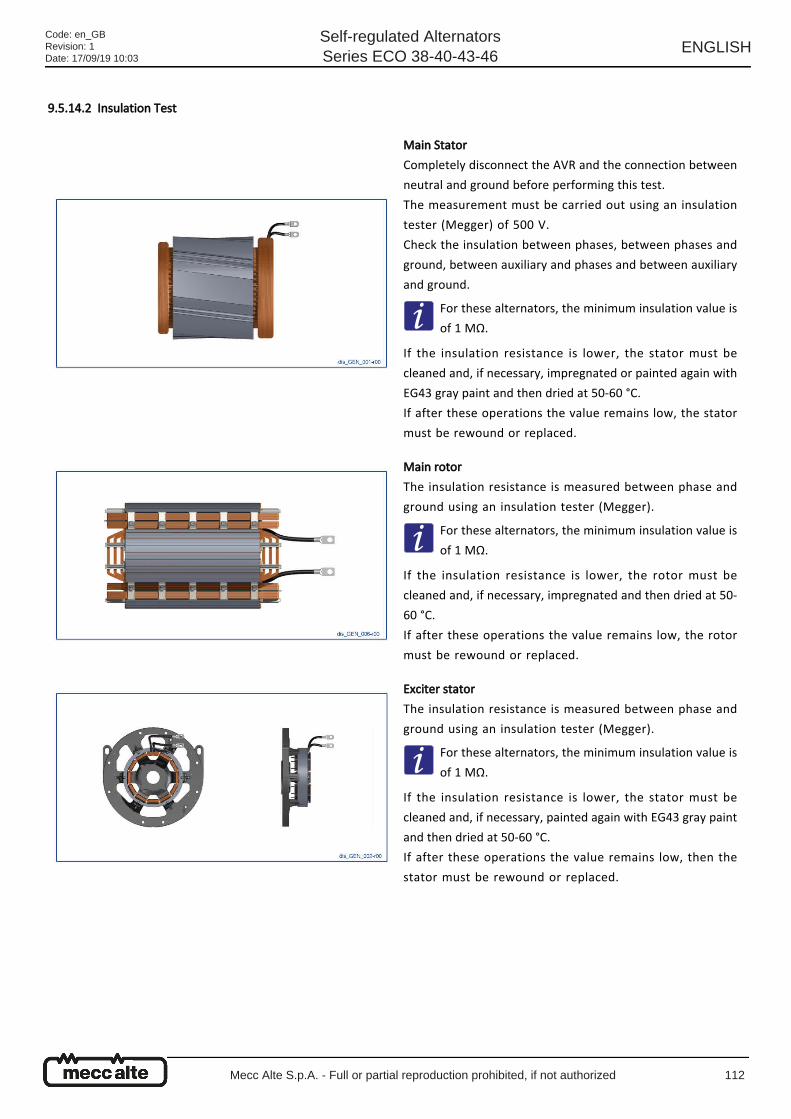
9.5.14.2 Insulation Test
Main Stator
Completely disconnect the AVR and the connection between
neutral and ground before performing this test.
The measurement must be carried out using an insulation
tester (Megger) of 500 V.
Check the insulation between phases, between phases and
ground, between auxiliary and phases and between auxiliary
and ground.
For these alternators, the minimum insulation value is
of 1 MΩ.
If the insulation resistance is lower, the stator must be
cleaned and, if necessary, impregnated or painted again with
EG43 gray paint and then dried at 50-60 °C.
If after these operations the value remains low, the stator
must be rewound or replaced.
Main rotor
The insulation resistance is measured between phase and
ground using an insulation tester (Megger).
For these alternators, the minimum insulation value is
of 1 MΩ.
If the insulation resistance is lower, the rotor must be
cleaned and, if necessary, impregnated and then dried at 50-
60 °C.
If after these operations the value remains low, the rotor
must be rewound or replaced.
Exciter stator
The insulation resistance is measured between phase and
ground using an insulation tester (Megger).
For these alternators, the minimum insulation value is
of 1 MΩ.
If the insulation resistance is lower, the stator must be
cleaned and, if necessary, painted again with EG43 gray paint
and then dried at 50-60 °C.
If after these operations the value remains low, then the
stator must be rewound or replaced.
Code: en_GBRevision: 1Date: 17/09/19 10:03
Self-regulated AlternatorsSeries ECO 38-40-43-46
ENGLISH
Mecc Alte S.p.A. - Full or partial reproduction prohibited, if not authorized 112
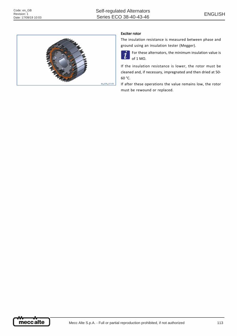
Exciter rotor
The insulation resistance is measured between phase and
ground using an insulation tester (Megger).
For these alternators, the minimum insulation value is
of 1 MΩ.
If the insulation resistance is lower, the rotor must be
cleaned and, if necessary, impregnated and then dried at 50-
60 °C.
If after these operations the value remains low, the rotor
must be rewound or replaced.
Code: en_GBRevision: 1Date: 17/09/19 10:03
Self-regulated AlternatorsSeries ECO 38-40-43-46
ENGLISH
Mecc Alte S.p.A. - Full or partial reproduction prohibited, if not authorized 113
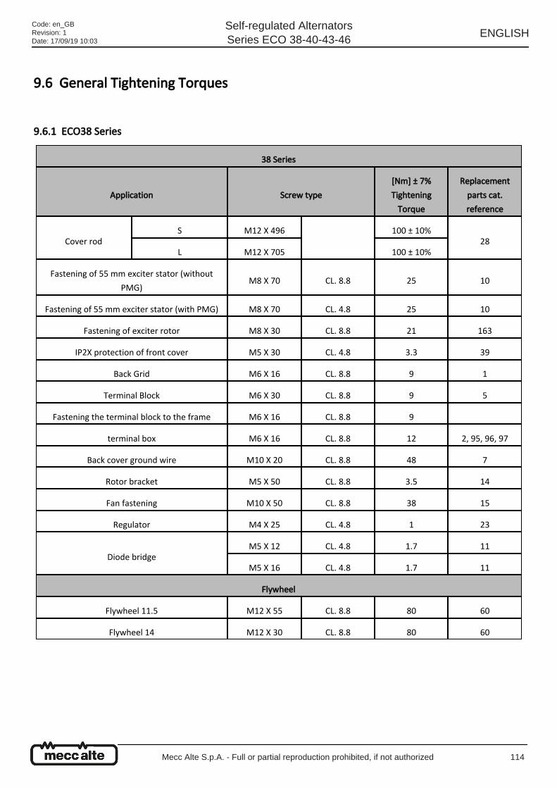
9.6 General Tightening Torques
9.6.1 ECO38 Series
38 Series
Application Screw type
[Nm] ± 7%
Tightening
Torque
Replacement
parts cat.
reference
Cover rodS M12 X 496 100 ± 10%
28L M12 X 705 100 ± 10%
Fastening of 55 mm exciter stator (without
PMG)M8 X 70 CL. 8.8 25 10
Fastening of 55 mm exciter stator (with PMG) M8 X 70 CL. 4.8 25 10
Fastening of exciter rotor M8 X 30 CL. 8.8 21 163
IP2X protection of front cover M5 X 30 CL. 4.8 3.3 39
Back Grid M6 X 16 CL. 8.8 9 1
Terminal Block M6 X 30 CL. 8.8 9 5
Fastening the terminal block to the frame M6 X 16 CL. 8.8 9
terminal box M6 X 16 CL. 8.8 12 2, 95, 96, 97
Back cover ground wire M10 X 20 CL. 8.8 48 7
Rotor bracket M5 X 50 CL. 8.8 3.5 14
Fan fastening M10 X 50 CL. 8.8 38 15
Regulator M4 X 25 CL. 4.8 1 23
Diode bridgeM5 X 12 CL. 4.8 1.7 11
M5 X 16 CL. 4.8 1.7 11
Flywheel
Flywheel 11.5 M12 X 55 CL. 8.8 80 60
Flywheel 14 M12 X 30 CL. 8.8 80 60
Code: en_GBRevision: 1Date: 17/09/19 10:03
Self-regulated AlternatorsSeries ECO 38-40-43-46
ENGLISH
Mecc Alte S.p.A. - Full or partial reproduction prohibited, if not authorized 114
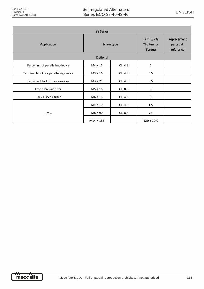
38 Series
Application Screw type
[Nm] ± 7%
Tightening
Torque
Replacement
parts cat.
reference
Optional
Fastening of paralleling device M4 X 16 CL. 4.8 1
Terminal block for paralleling device M3 X 16 CL. 4.8 0.5
Terminal block for accessories M3 X 25 CL. 4.8 0.5
Front IP45 air filter M5 X 16 CL. 8.8 5
Back IP45 air filter M6 X 16 CL. 4.8 9
PMG
M4 X 10 CL. 4.8 1.5
M8 X 90 CL. 8.8 25
M14 X 188 120 ± 10%
Code: en_GBRevision: 1Date: 17/09/19 10:03
Self-regulated AlternatorsSeries ECO 38-40-43-46
ENGLISH
Mecc Alte S.p.A. - Full or partial reproduction prohibited, if not authorized 115
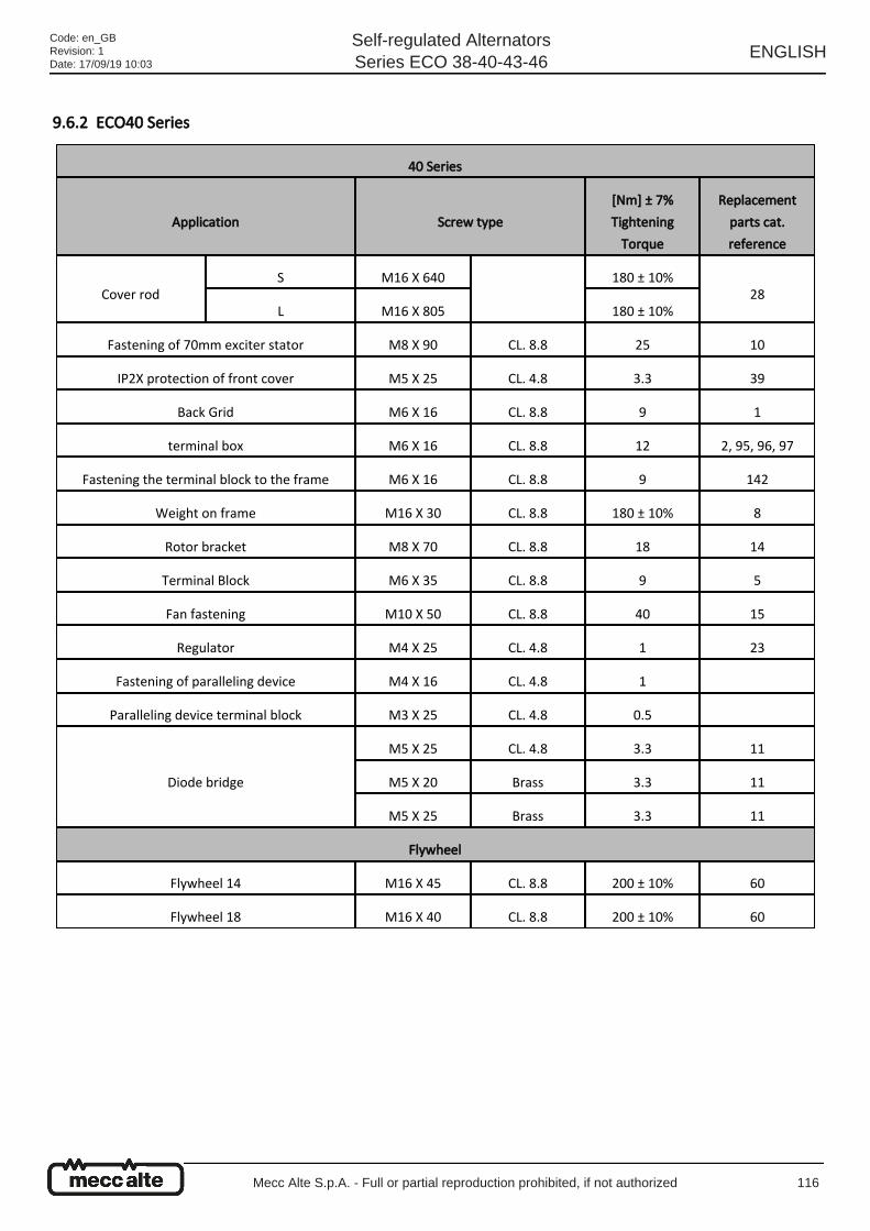
9.6.2 ECO40 Series
40 Series
Application Screw type
[Nm] ± 7%
Tightening
Torque
Replacement
parts cat.
reference
Cover rodS M16 X 640 180 ± 10%
28L M16 X 805 180 ± 10%
Fastening of 70mm exciter stator M8 X 90 CL. 8.8 25 10
IP2X protection of front cover M5 X 25 CL. 4.8 3.3 39
Back Grid M6 X 16 CL. 8.8 9 1
terminal box M6 X 16 CL. 8.8 12 2, 95, 96, 97
Fastening the terminal block to the frame M6 X 16 CL. 8.8 9 142
Weight on frame M16 X 30 CL. 8.8 180 ± 10% 8
Rotor bracket M8 X 70 CL. 8.8 18 14
Terminal Block M6 X 35 CL. 8.8 9 5
Fan fastening M10 X 50 CL. 8.8 40 15
Regulator M4 X 25 CL. 4.8 1 23
Fastening of paralleling device M4 X 16 CL. 4.8 1
Paralleling device terminal block M3 X 25 CL. 4.8 0.5
Diode bridge
M5 X 25 CL. 4.8 3.3 11
M5 X 20 Brass 3.3 11
M5 X 25 Brass 3.3 11
Flywheel
Flywheel 14 M16 X 45 CL. 8.8 200 ± 10% 60
Flywheel 18 M16 X 40 CL. 8.8 200 ± 10% 60
Code: en_GBRevision: 1Date: 17/09/19 10:03
Self-regulated AlternatorsSeries ECO 38-40-43-46
ENGLISH
Mecc Alte S.p.A. - Full or partial reproduction prohibited, if not authorized 116
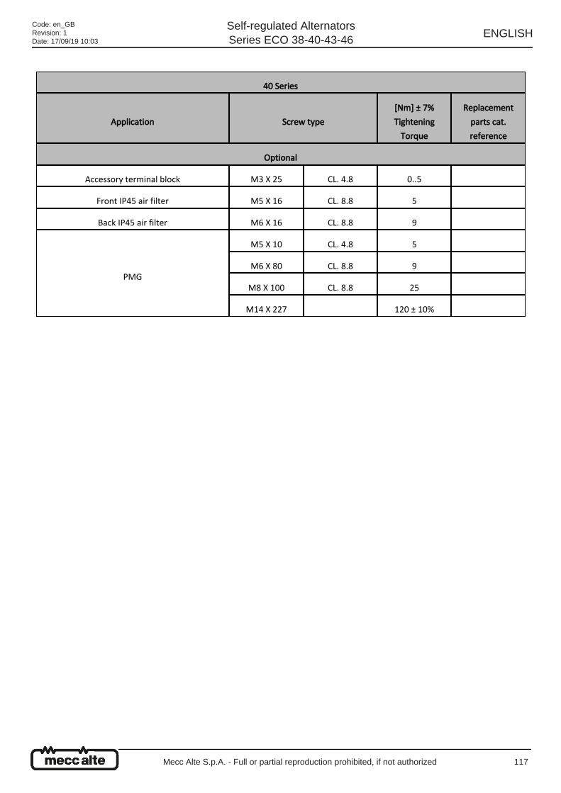
40 Series
Application Screw type
[Nm] ± 7%
Tightening
Torque
Replacement
parts cat.
reference
Optional
Accessory terminal block M3 X 25 CL. 4.8 0..5
Front IP45 air filter M5 X 16 CL. 8.8 5
Back IP45 air filter M6 X 16 CL. 8.8 9
PMG
M5 X 10 CL. 4.8 5
M6 X 80 CL. 8.8 9
M8 X 100 CL. 8.8 25
M14 X 227 120 ± 10%
Code: en_GBRevision: 1Date: 17/09/19 10:03
Self-regulated AlternatorsSeries ECO 38-40-43-46
ENGLISH
Mecc Alte S.p.A. - Full or partial reproduction prohibited, if not authorized 117
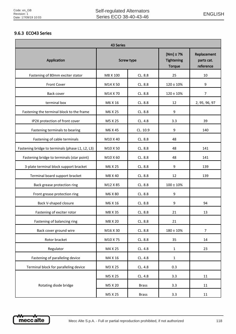
9.6.3 ECO43 Series
43 Series
Application Screw type
[Nm] ± 7%
Tightening
Torque
Replacement
parts cat.
reference
Fastening of 80mm exciter stator M8 X 100 CL. 8.8 25 10
Front Cover M14 X 50 CL. 8.8 120 ± 10% 9
Back cover M14 X 70 CL. 8.8 120 ± 10% 7
terminal box M6 X 16 CL. 8.8 12 2, 95, 96, 97
Fastening the terminal block to the frame M6 X 25 CL. 8.8 9
IP2X protection of front cover M5 X 25 CL. 4.8 3.3 39
Fastening terminals to bearing M6 X 45 CL. 10.9 9 140
Fastening of cable terminals M10 X 40 CL. 8.8 48
Fastening bridge to terminals (phase L1, L2, L3) M10 X 50 CL. 8.8 48 141
Fastening bridge to terminals (star point) M10 X 60 CL. 8.8 48 141
3-plate terminal block support bracket M6 X 25 CL. 8.8 9 139
Terminal board support bracket M8 X 40 CL. 8.8 12 139
Back grease protection ring M12 X 85 CL. 8.8 100 ± 10%
Front grease protection ring M6 X 80 CL. 8.8 9
Back V-shaped closure M6 X 16 CL. 8.8 9 94
Fastening of exciter rotor M8 X 35 CL. 8.8 21 13
Fastening of balancing ring M8 X 20 CL. 8.8 21
Back cover ground wire M16 X 30 CL. 8.8 180 ± 10% 7
Rotor bracket M10 X 75 CL. 8.8 35 14
Regulator M4 X 25 CL. 4.8 1 23
Fastening of paralleling device M4 X 16 CL. 4.8 1
Terminal block for paralleling device M3 X 25 CL. 4.8 0.3
Rotating diode bridge
M5 X 25 CL. 4.8 3.3 11
M5 X 20 Brass 3.3 11
M5 X 25 Brass 3.3 11
Code: en_GBRevision: 1Date: 17/09/19 10:03
Self-regulated AlternatorsSeries ECO 38-40-43-46
ENGLISH
Mecc Alte S.p.A. - Full or partial reproduction prohibited, if not authorized 118
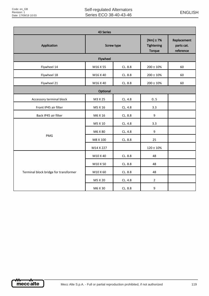
43 Series
Application Screw type
[Nm] ± 7%
Tightening
Torque
Replacement
parts cat.
reference
Flywheel
Flywheel 14 M16 X 55 CL. 8.8 200 ± 10% 60
Flywheel 18 M16 X 40 CL. 8.8 200 ± 10% 60
Flywheel 21 M16 X 40 CL. 8.8 200 ± 10% 60
Optional
Accessory terminal block M3 X 25 CL. 4.8 0..5
Front IP45 air filter M5 X 16 CL. 4.8 3.3
Back IP45 air filter M6 X 16 CL. 8.8 9
PMG
M5 X 10 CL. 4.8 3.3
M6 X 80 CL. 4.8 9
M8 X 100 CL. 8.8 25
M14 X 227 120 ± 10%
Terminal block bridge for transformer
M10 X 40 CL. 8.8 48
M10 X 50 CL. 8.8 48
M10 X 60 CL. 8.8 48
M5 X 20 CL. 4.8 2
M6 X 30 CL. 8.8 9
Code: en_GBRevision: 1Date: 17/09/19 10:03
Self-regulated AlternatorsSeries ECO 38-40-43-46
ENGLISH
Mecc Alte S.p.A. - Full or partial reproduction prohibited, if not authorized 119
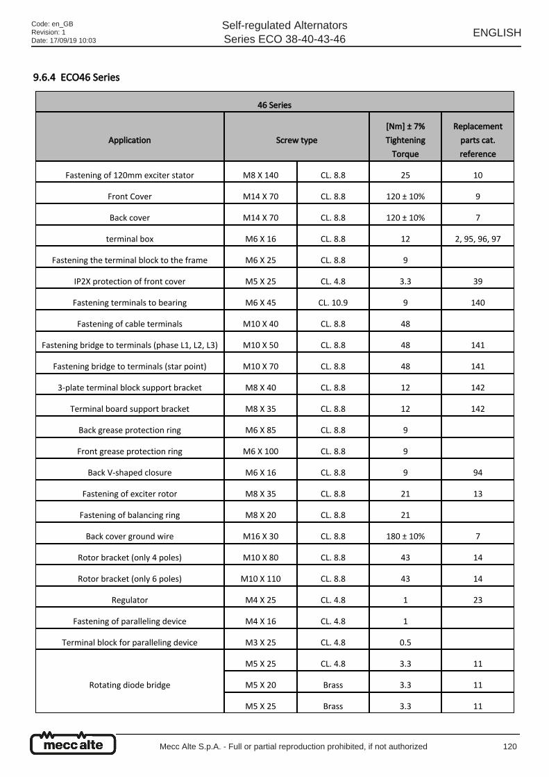
9.6.4 ECO46 Series
46 Series
Application Screw type
[Nm] ± 7%
Tightening
Torque
Replacement
parts cat.
reference
Fastening of 120mm exciter stator M8 X 140 CL. 8.8 25 10
Front Cover M14 X 70 CL. 8.8 120 ± 10% 9
Back cover M14 X 70 CL. 8.8 120 ± 10% 7
terminal box M6 X 16 CL. 8.8 12 2, 95, 96, 97
Fastening the terminal block to the frame M6 X 25 CL. 8.8 9
IP2X protection of front cover M5 X 25 CL. 4.8 3.3 39
Fastening terminals to bearing M6 X 45 CL. 10.9 9 140
Fastening of cable terminals M10 X 40 CL. 8.8 48
Fastening bridge to terminals (phase L1, L2, L3) M10 X 50 CL. 8.8 48 141
Fastening bridge to terminals (star point) M10 X 70 CL. 8.8 48 141
3-plate terminal block support bracket M8 X 40 CL. 8.8 12 142
Terminal board support bracket M8 X 35 CL. 8.8 12 142
Back grease protection ring M6 X 85 CL. 8.8 9
Front grease protection ring M6 X 100 CL. 8.8 9
Back V-shaped closure M6 X 16 CL. 8.8 9 94
Fastening of exciter rotor M8 X 35 CL. 8.8 21 13
Fastening of balancing ring M8 X 20 CL. 8.8 21
Back cover ground wire M16 X 30 CL. 8.8 180 ± 10% 7
Rotor bracket (only 4 poles) M10 X 80 CL. 8.8 43 14
Rotor bracket (only 6 poles) M10 X 110 CL. 8.8 43 14
Regulator M4 X 25 CL. 4.8 1 23
Fastening of paralleling device M4 X 16 CL. 4.8 1
Terminal block for paralleling device M3 X 25 CL. 4.8 0.5
Rotating diode bridge
M5 X 25 CL. 4.8 3.3 11
M5 X 20 Brass 3.3 11
M5 X 25 Brass 3.3 11
Code: en_GBRevision: 1Date: 17/09/19 10:03
Self-regulated AlternatorsSeries ECO 38-40-43-46
ENGLISH
Mecc Alte S.p.A. - Full or partial reproduction prohibited, if not authorized 120
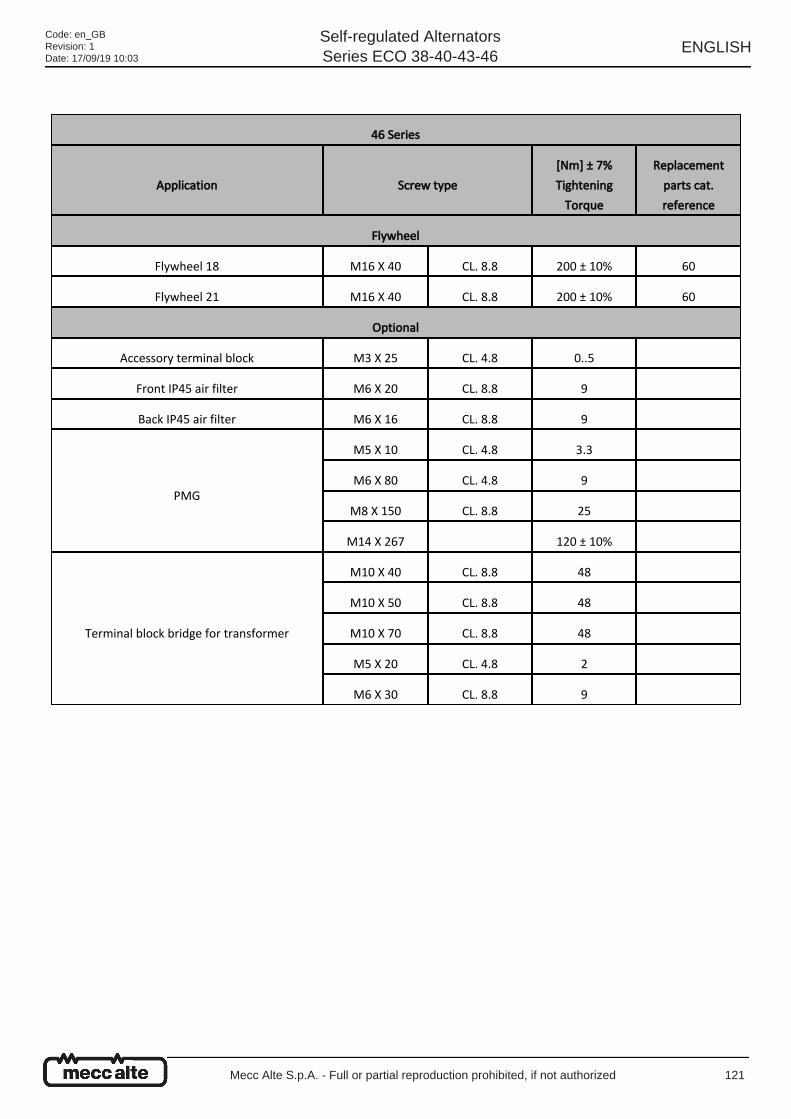
46 Series
Application Screw type
[Nm] ± 7%
Tightening
Torque
Replacement
parts cat.
reference
Flywheel
Flywheel 18 M16 X 40 CL. 8.8 200 ± 10% 60
Flywheel 21 M16 X 40 CL. 8.8 200 ± 10% 60
Optional
Accessory terminal block M3 X 25 CL. 4.8 0..5
Front IP45 air filter M6 X 20 CL. 8.8 9
Back IP45 air filter M6 X 16 CL. 8.8 9
PMG
M5 X 10 CL. 4.8 3.3
M6 X 80 CL. 4.8 9
M8 X 150 CL. 8.8 25
M14 X 267 120 ± 10%
Terminal block bridge for transformer
M10 X 40 CL. 8.8 48
M10 X 50 CL. 8.8 48
M10 X 70 CL. 8.8 48
M5 X 20 CL. 4.8 2
M6 X 30 CL. 8.8 9
Code: en_GBRevision: 1Date: 17/09/19 10:03
Self-regulated AlternatorsSeries ECO 38-40-43-46
ENGLISH
Mecc Alte S.p.A. - Full or partial reproduction prohibited, if not authorized 121
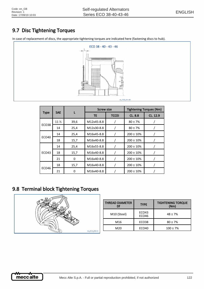
9.7 Disc Tightening Torques In case of replacement of discs, the appropriate tightening torques are indicated here (fastening discs to hub).
9.8 Terminal block Tightening Torques
Type SAE LScrew size Tightening Torques (Nm)
TE TCCEI CL. 8.8 CL. 12.9
ECO3811 ½ 39,6 M12x45-8.8 / 80 ± 7% /
14 25,4 M12x30-8.8 / 80 ± 7% /
ECO4014 25,4 M16x45-8.8 / 200 ± 10% /
18 15,7 M16x40-8.8 / 200 ± 10% /
ECO43
14 25,4 M16x55-8.8 / 200 ± 10% /
18 15,7 M16x40-8.8 / 200 ± 10% /
21 0 M16x40-8.8 / 200 ± 10% /
ECO4618 15,7 M16x40-8.8 / 200 ± 10% /
21 0 M16x40-8.8 / 200 ± 10% /
THREAD DIAMETERDf TYPE TIGHTENING TORQUE
(Nm)
M10 (Steel) ECO43ECO46 48 ± 7%
M16 ECO38 80 ± 7%
M20 ECO40 100 ± 7%
Code: en_GBRevision: 1Date: 17/09/19 10:03
Self-regulated AlternatorsSeries ECO 38-40-43-46
ENGLISH
Mecc Alte S.p.A. - Full or partial reproduction prohibited, if not authorized 122
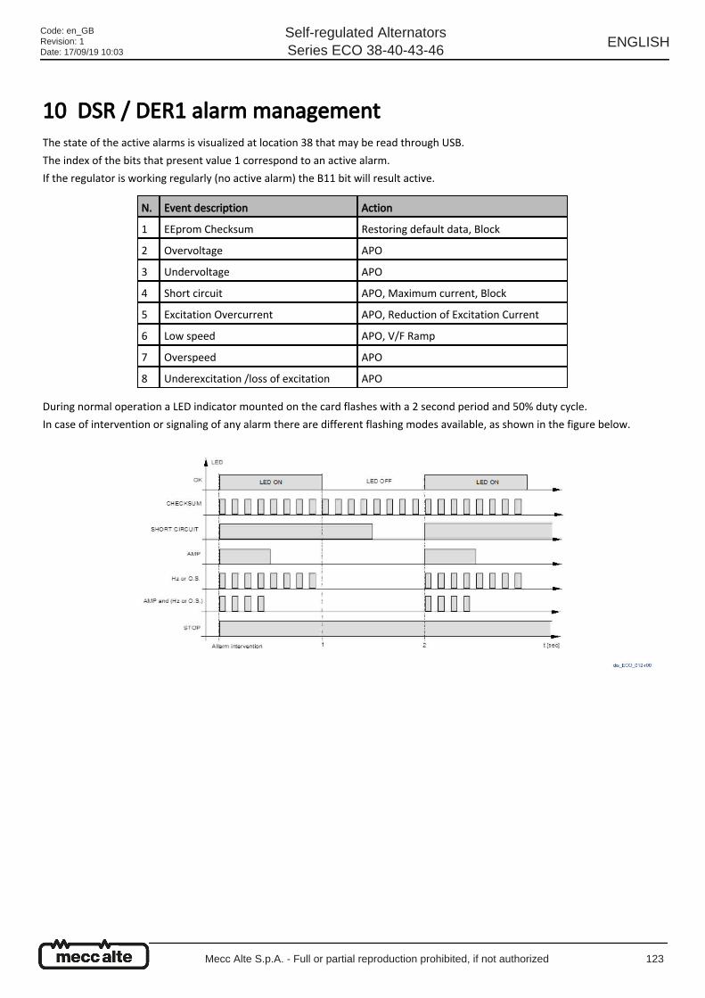
10 DSR / DER1 alarm management The state of the active alarms is visualized at location 38 that may be read through USB.
The index of the bits that present value 1 correspond to an active alarm.
If the regulator is working regularly (no active alarm) the B11 bit will result active.
During normal operation a LED indicator mounted on the card flashes with a 2 second period and 50% duty cycle.
In case of intervention or signaling of any alarm there are different flashing modes available, as shown in the figure below.
N. Event description Action
1 EEprom Checksum Restoring default data, Block
2 Overvoltage APO
3 Undervoltage APO
4 Short circuit APO, Maximum current, Block
5 Excitation Overcurrent APO, Reduction of Excitation Current
6 Low speed APO, V/F Ramp
7 Overspeed APO
8 Underexcitation /loss of excitation APO
Code: en_GBRevision: 1Date: 17/09/19 10:03
Self-regulated AlternatorsSeries ECO 38-40-43-46
ENGLISH
Mecc Alte S.p.A. - Full or partial reproduction prohibited, if not authorized 123
10.1 DSR/DER1 digital regulator alarms
ALARM DESCRIPTION
N. Eventdescription Action
1ErroneousEEPROM
control code
It is checked on start (after the DSP reset and the launch of the peripheral devices).The actions taken are: signaling, loading default settings, saving in EEPROM and blocking theregulator.Upon restart, if EEPROM is faulty, the alarm will be repeated, otherwise the regulator will startto operate on default parameters.
2 Overvoltage
The alarm does not determine a change in the LED flash, enables APO output and is memorized.It may be caused either by anomalous operating conditions (such as overspeed or capacitiveload) or by any fault in the regulator.The overvoltage alarm is activated only if the angle has already been reduced to zero and,therefore, output voltage control has been lost.Overvoltage is calculated using an appropriate window, based on the speed and it is inhibitedduring the transients, for 2 sec.In the calculation window the threshold is set to 5% above the nominal value.
3 Undervoltage(@ ωN)
The alarm does not determine a change in the LED flash, enables APO output and is memorized.Undervoltage is calculated using an appropriate window based on the speed (visible in theundervoltage alarm description), the threshold is set to 5% under the nominal value; itintervenes only above the intervention threshold of the low speed alarm, it basically is inhibitedby it.It is also inhibited in case of intervention of the "excitation overcurrent" alarm and duringtransients.
4 Short circuit
The alarm is disabled under 20Hz and visualized and memorized when action is activated.Tolerated short circuit time goes from 0.1 to 25,5 seconds (programmable in 100ms steps); thenthe regulator, after having saved DD and TT, turns to block mode and signals the STOP status.With the "short circuit time" parameter set to zero, the block is disabled.The reduction of the angle may cause an excitation drop, with a consequent stop andsubsequent restart of the regulator and then the cycle is repeated.
5 ExcitationOvercurrent
This alarm's function is not only to signal a state of excess accumulation of heating of the exciter,but also an active function of elimination of the cause.There is in fact a regulation ring that takes over after a threshold is exceeded; the actiondetermines the reduction of the excitation current and then of the output voltage.The available parameter is the "threshold", which determines, in the end, the balance value atwhich the system stabilizes.The alarm is signaled and memorized.For the adjustment see paragraph "Excitation overcurrent".
6 Low speed
(Immediate) Signaling and activation of the V/F ramp.This alarm also appears at start and at stop.The alarm does not trigger data saving in EEPROM.The alarm intervention threshold depends on the 50/60 jumper status (hardware or software)and on the Hz trimmer position or on the value of parameter 21.Under the threshold the V/F ramp is present.
Code: en_GBRevision: 1Date: 17/09/19 10:03
Self-regulated AlternatorsSeries ECO 38-40-43-46
ENGLISH
Mecc Alte S.p.A. - Full or partial reproduction prohibited, if not authorized 124
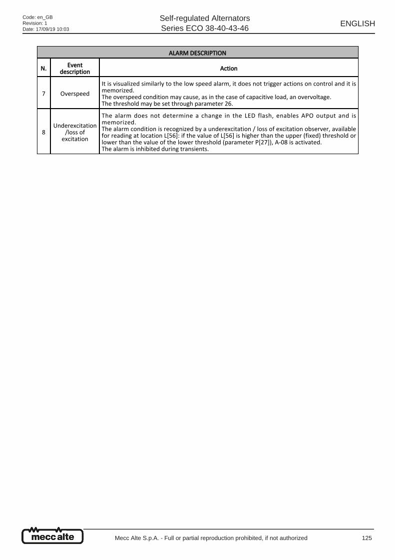
ALARM DESCRIPTION
N. Eventdescription Action
7 Overspeed
It is visualized similarly to the low speed alarm, it does not trigger actions on control and it ismemorized.The overspeed condition may cause, as in the case of capacitive load, an overvoltage.The threshold may be set through parameter 26.
8Underexcitation
/loss ofexcitation
The alarm does not determine a change in the LED flash, enables APO output and ismemorized.The alarm condition is recognized by a underexcitation / loss of excitation observer, availablefor reading at location L[56]: if the value of L[56] is higher than the upper (fixed) threshold orlower than the value of the lower threshold (parameter P[27]), A-08 is activated.The alarm is inhibited during transients.
Code: en_GBRevision: 1Date: 17/09/19 10:03
Self-regulated AlternatorsSeries ECO 38-40-43-46
ENGLISH
Mecc Alte S.p.A. - Full or partial reproduction prohibited, if not authorized 125

Code: en_GBRevision: 1Date: 17/09/19 10:03
Self-regulated AlternatorsSeries ECO 38-40-43-46
ENGLISH
Mecc Alte S.p.A. - Full or partial reproduction prohibited, if not authorized 126
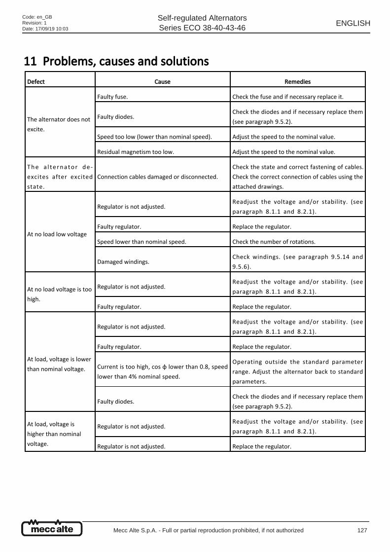
11 Problems, causes and solutions
Defect Cause Remedies
The alternator does not
excite.
Faulty fuse. Check the fuse and if necessary replace it.
Faulty diodes.Check the diodes and if necessary replace them
(see paragraph 9.5.2).
Speed too low (lower than nominal speed). Adjust the speed to the nominal value.
Residual magnetism too low. Adjust the speed to the nominal value.
The a l te rnator de -
excites after excited
state.
Connection cables damaged or disconnected.
Check the state and correct fastening of cables.
Check the correct connection of cables using the
attached drawings.
At no load low voltage
Regulator is not adjusted.Readjust the voltage and/or stability. (see
paragraph 8.1.1 and 8.2.1).
Faulty regulator. Replace the regulator.
Speed lower than nominal speed. Check the number of rotations.
Damaged windings.Check windings. (see paragraph 9.5.14 and
9.5.6).
At no load voltage is too
high.
Regulator is not adjusted.Readjust the voltage and/or stability. (see
paragraph 8.1.1 and 8.2.1).
Faulty regulator. Replace the regulator.
At load, voltage is lower
than nominal voltage.
Regulator is not adjusted.Readjust the voltage and/or stability. (see
paragraph 8.1.1 and 8.2.1).
Faulty regulator. Replace the regulator.
Current is too high, cos φ lower than 0.8, speed
lower than 4% nominal speed.
Operating outside the standard parameter
range. Adjust the alternator back to standard
parameters.
Faulty diodes.Check the diodes and if necessary replace them
(see paragraph 9.5.2).
At load, voltage is
higher than nominal
voltage.
Regulator is not adjusted.Readjust the voltage and/or stability. (see
paragraph 8.1.1 and 8.2.1).
Regulator is not adjusted. Replace the regulator.
Code: en_GBRevision: 1Date: 17/09/19 10:03
Self-regulated AlternatorsSeries ECO 38-40-43-46
ENGLISH
Mecc Alte S.p.A. - Full or partial reproduction prohibited, if not authorized 127
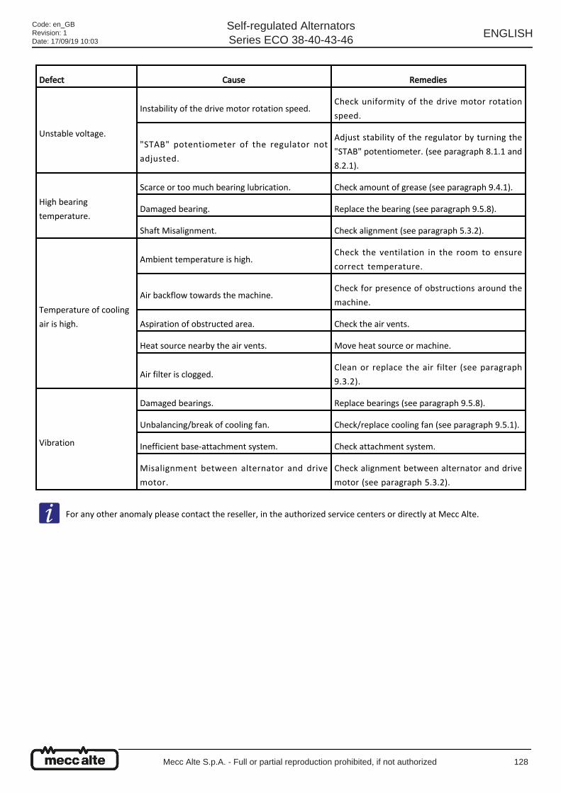
Defect Cause Remedies
Unstable voltage.
Instability of the drive motor rotation speed.Check uniformity of the drive motor rotation
speed.
"STAB" potentiometer of the regulator not
adjusted.
Adjust stability of the regulator by turning the
"STAB" potentiometer. (see paragraph 8.1.1 and
8.2.1).
High bearing
temperature.
Scarce or too much bearing lubrication. Check amount of grease (see paragraph 9.4.1).
Damaged bearing. Replace the bearing (see paragraph 9.5.8).
Shaft Misalignment. Check alignment (see paragraph 5.3.2).
Temperature of cooling
air is high.
Ambient temperature is high.Check the ventilation in the room to ensure
correct temperature.
Air backflow towards the machine.Check for presence of obstructions around the
machine.
Aspiration of obstructed area. Check the air vents.
Heat source nearby the air vents. Move heat source or machine.
Air filter is clogged.Clean or replace the air filter (see paragraph
9.3.2).
Vibration
Damaged bearings. Replace bearings (see paragraph 9.5.8).
Unbalancing/break of cooling fan. Check/replace cooling fan (see paragraph 9.5.1).
Inefficient base-attachment system. Check attachment system.
Misalignment between alternator and drive
motor.
Check alignment between alternator and drive
motor (see paragraph 5.3.2).
For any other anomaly please contact the reseller, in the authorized service centers or directly at Mecc Alte.
Code: en_GBRevision: 1Date: 17/09/19 10:03
Self-regulated AlternatorsSeries ECO 38-40-43-46
ENGLISH
Mecc Alte S.p.A. - Full or partial reproduction prohibited, if not authorized 128
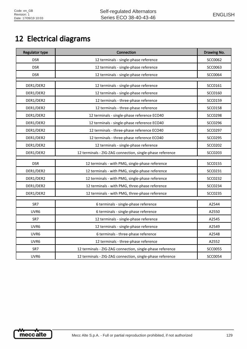
12 Electrical diagrams
Regulator type Connection Drawing No.
DSR 12 terminals - single-phase reference SCC0062
DSR 12 terminals - single-phase reference SCC0063
DSR 12 terminals - single-phase reference SCC0064
DER1/DER2 12 terminals - single-phase reference SCC0161
DER1/DER2 12 terminals - single-phase reference SCC0160
DER1/DER2 12 terminals - three-phase reference SCC0159
DER1/DER2 12 terminals - three-phase reference SCC0158
DER1/DER2 12 terminals - single-phase reference ECO40 SCC0298
DER1/DER2 12 terminals - single-phase reference ECO40 SCC0296
DER1/DER2 12 terminals - three-phase reference ECO40 SCC0297
DER1/DER2 12 terminals - three-phase reference ECO40 SCC0295
DER1/DER2 12 terminals - single-phase reference SCC0202
DER1/DER2 12 terminals - ZIG-ZAG connection, single-phase reference SCC0203
DSR 12 terminals - with PMG, single-phase reference SCC0155
DER1/DER2 12 terminals - with PMG, single-phase reference SCC0231
DER1/DER2 12 terminals - with PMG, single-phase reference SCC0232
DER1/DER2 12 terminals - with PMG, three-phase reference SCC0234
DER1/DER2 12 terminals - with PMG, three-phase reference SCC0235
SR7 6 terminals - single-phase reference A2544
UVR6 6 terminals - single-phase reference A2550
SR7 12 terminals - single-phase reference A2545
UVR6 12 terminals - single-phase reference A2549
UVR6 6 terminals - three-phase reference A2548
UVR6 12 terminals - three-phase reference A2552
SR7 12 terminals - ZIG-ZAG connection, single-phase reference SCC0055
UVR6 12 terminals - ZIG-ZAG connection, single-phase reference SCC0054
Code: en_GBRevision: 1Date: 17/09/19 10:03
Self-regulated AlternatorsSeries ECO 38-40-43-46
ENGLISH
Mecc Alte S.p.A. - Full or partial reproduction prohibited, if not authorized 129
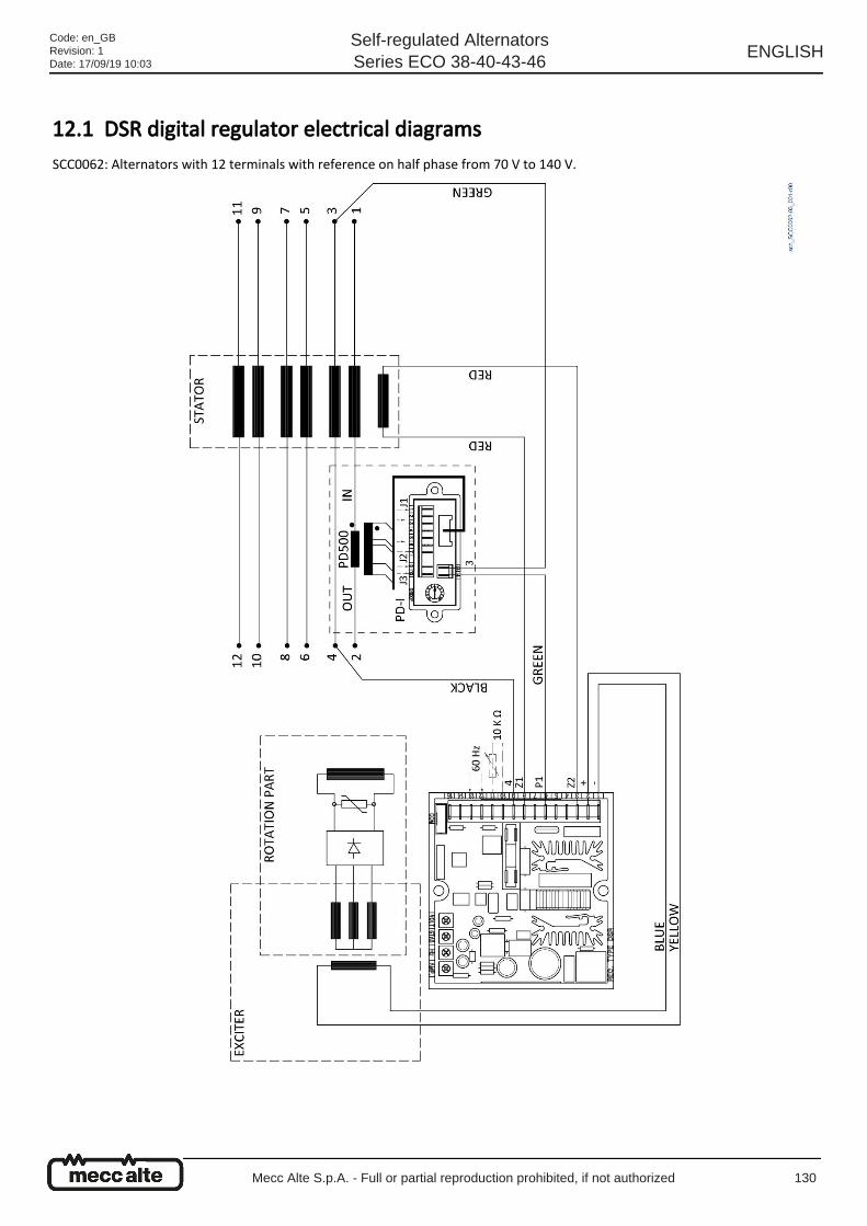
12.1 DSR digital regulator electrical diagrams SCC0062: Alternators with 12 terminals with reference on half phase from 70 V to 140 V.
Code: en_GBRevision: 1Date: 17/09/19 10:03
Self-regulated AlternatorsSeries ECO 38-40-43-46
ENGLISH
Mecc Alte S.p.A. - Full or partial reproduction prohibited, if not authorized 130
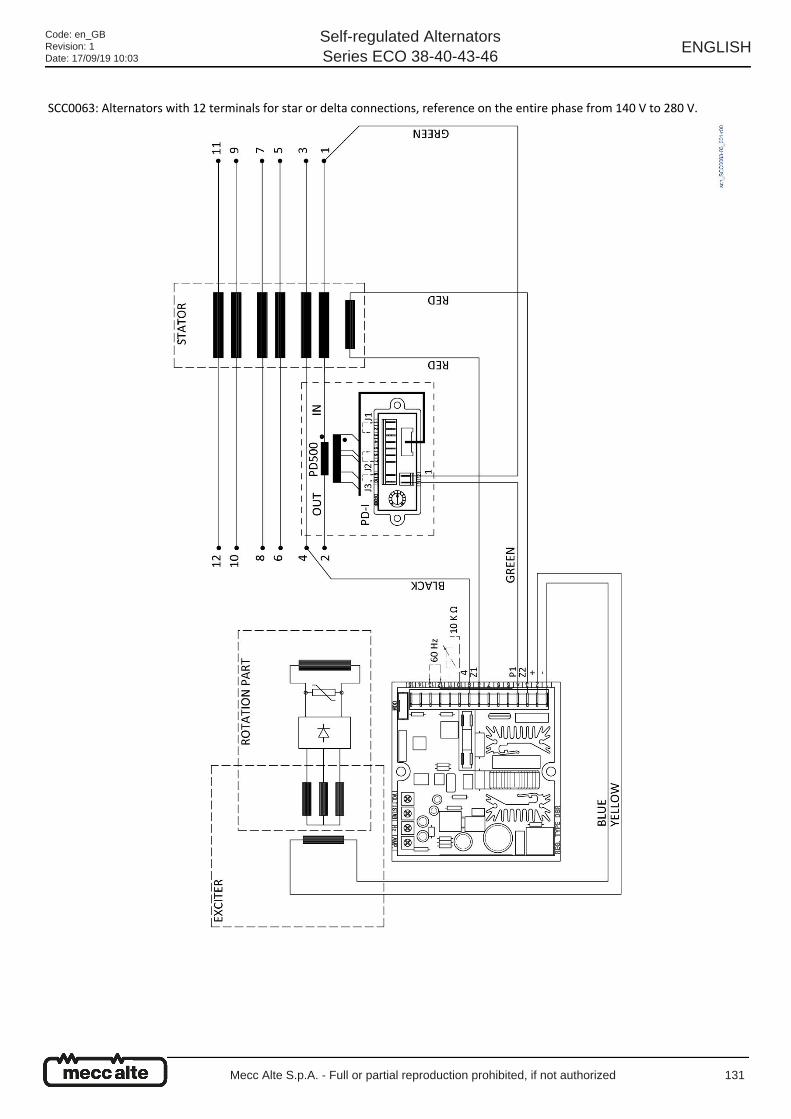
SCC0063: Alternators with 12 terminals for star or delta connections, reference on the entire phase from 140 V to 280 V.
Code: en_GBRevision: 1Date: 17/09/19 10:03
Self-regulated AlternatorsSeries ECO 38-40-43-46
ENGLISH
Mecc Alte S.p.A. - Full or partial reproduction prohibited, if not authorized 131
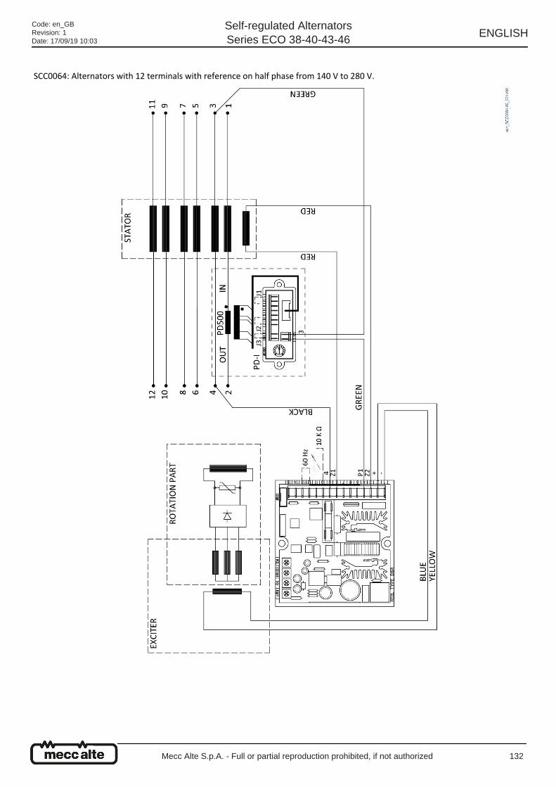
SCC0064: Alternators with 12 terminals with reference on half phase from 140 V to 280 V.
Code: en_GBRevision: 1Date: 17/09/19 10:03
Self-regulated AlternatorsSeries ECO 38-40-43-46
ENGLISH
Mecc Alte S.p.A. - Full or partial reproduction prohibited, if not authorized 132
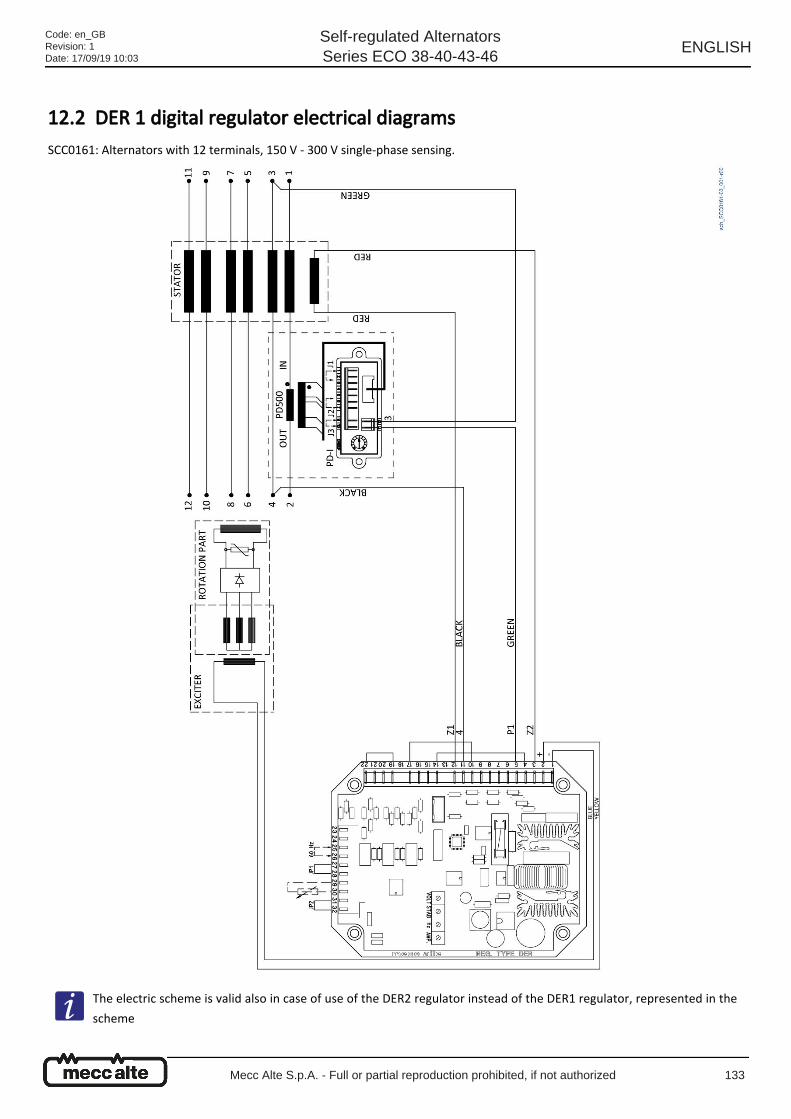
12.2 DER 1 digital regulator electrical diagrams SCC0161: Alternators with 12 terminals, 150 V - 300 V single-phase sensing.
The electric scheme is valid also in case of use of the DER2 regulator instead of the DER1 regulator, represented in the
scheme
Code: en_GBRevision: 1Date: 17/09/19 10:03
Self-regulated AlternatorsSeries ECO 38-40-43-46
ENGLISH
Mecc Alte S.p.A. - Full or partial reproduction prohibited, if not authorized 133

Code: en_GBRevision: 1Date: 17/09/19 10:03
Self-regulated AlternatorsSeries ECO 38-40-43-46
ENGLISH
Mecc Alte S.p.A. - Full or partial reproduction prohibited, if not authorized 134
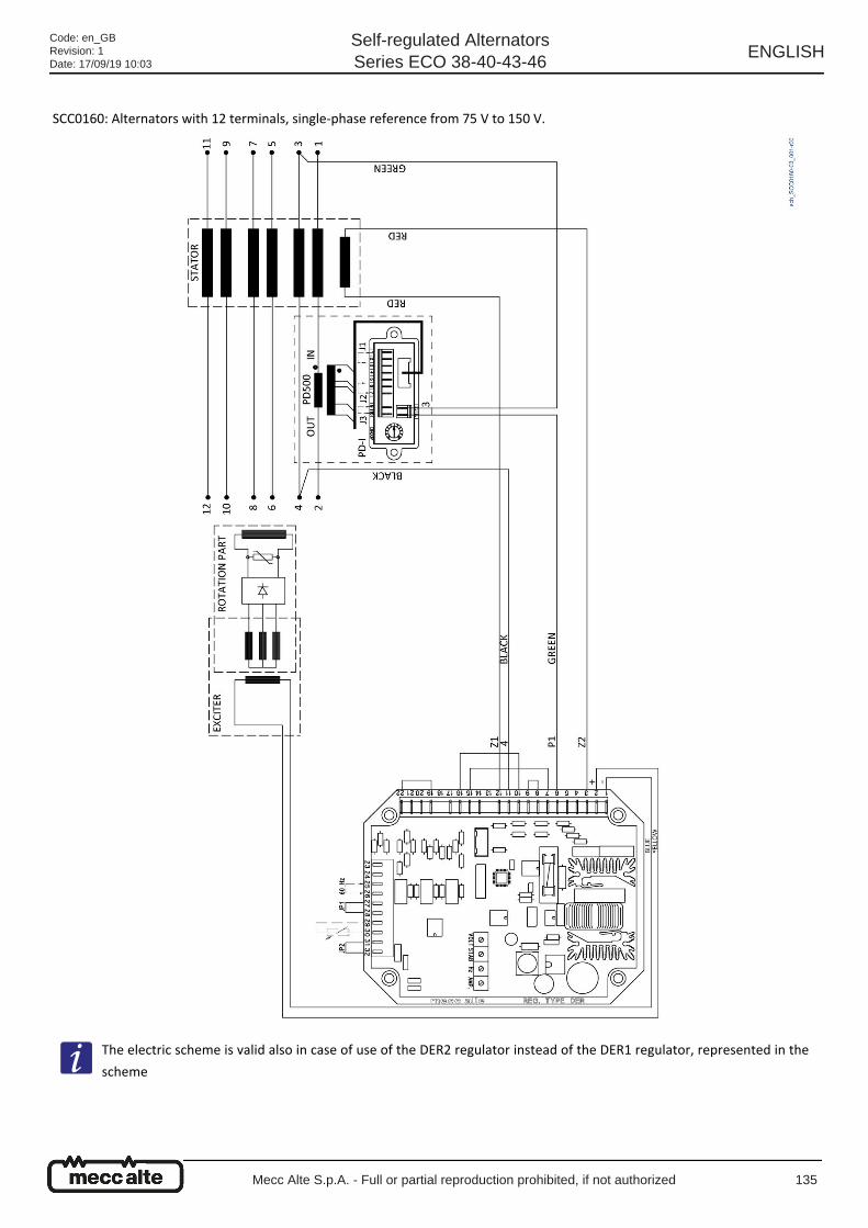
SCC0160: Alternators with 12 terminals, single-phase reference from 75 V to 150 V.
The electric scheme is valid also in case of use of the DER2 regulator instead of the DER1 regulator, represented in the
scheme
Code: en_GBRevision: 1Date: 17/09/19 10:03
Self-regulated AlternatorsSeries ECO 38-40-43-46
ENGLISH
Mecc Alte S.p.A. - Full or partial reproduction prohibited, if not authorized 135

SCC0159: Alternators with 12 terminals, three-phase reference from 150 V to 300 V.
The electric scheme is valid also in case of use of the DER2 regulator instead of the DER1 regulator, represented in the
scheme
Code: en_GBRevision: 1Date: 17/09/19 10:03
Self-regulated AlternatorsSeries ECO 38-40-43-46
ENGLISH
Mecc Alte S.p.A. - Full or partial reproduction prohibited, if not authorized 136
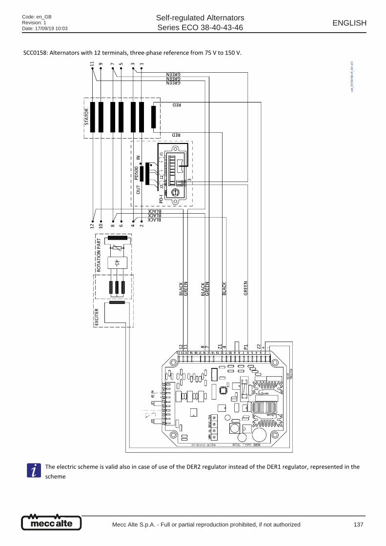
SCC0158: Alternators with 12 terminals, three-phase reference from 75 V to 150 V.
The electric scheme is valid also in case of use of the DER2 regulator instead of the DER1 regulator, represented in the
scheme
Code: en_GBRevision: 1Date: 17/09/19 10:03
Self-regulated AlternatorsSeries ECO 38-40-43-46
ENGLISH
Mecc Alte S.p.A. - Full or partial reproduction prohibited, if not authorized 137
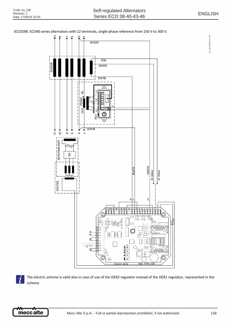
SCC0298: ECO40 series alternators with 12 terminals, single-phase reference from 150 V to 300 V.
The electric scheme is valid also in case of use of the DER2 regulator instead of the DER1 regulator, represented in the
scheme
Code: en_GBRevision: 1Date: 17/09/19 10:03
Self-regulated AlternatorsSeries ECO 38-40-43-46
ENGLISH
Mecc Alte S.p.A. - Full or partial reproduction prohibited, if not authorized 138
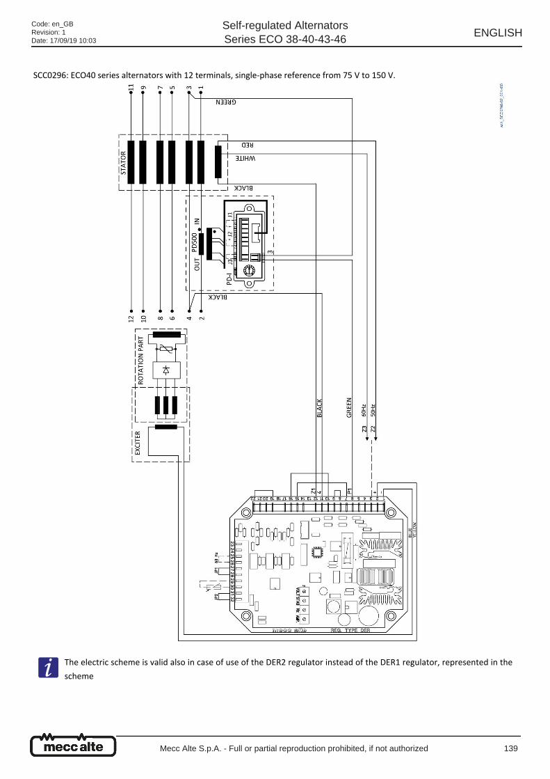
SCC0296: ECO40 series alternators with 12 terminals, single-phase reference from 75 V to 150 V.
The electric scheme is valid also in case of use of the DER2 regulator instead of the DER1 regulator, represented in the
scheme
Code: en_GBRevision: 1Date: 17/09/19 10:03
Self-regulated AlternatorsSeries ECO 38-40-43-46
ENGLISH
Mecc Alte S.p.A. - Full or partial reproduction prohibited, if not authorized 139
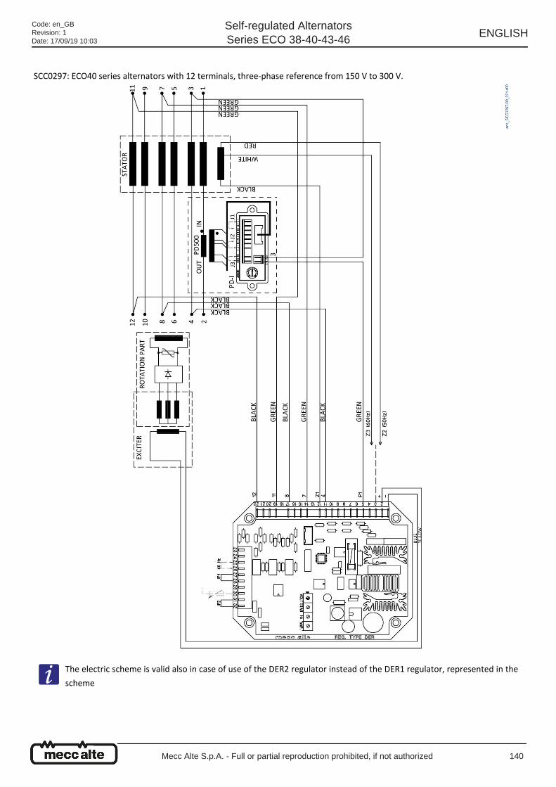
SCC0297: ECO40 series alternators with 12 terminals, three-phase reference from 150 V to 300 V.
The electric scheme is valid also in case of use of the DER2 regulator instead of the DER1 regulator, represented in the
scheme
Code: en_GBRevision: 1Date: 17/09/19 10:03
Self-regulated AlternatorsSeries ECO 38-40-43-46
ENGLISH
Mecc Alte S.p.A. - Full or partial reproduction prohibited, if not authorized 140
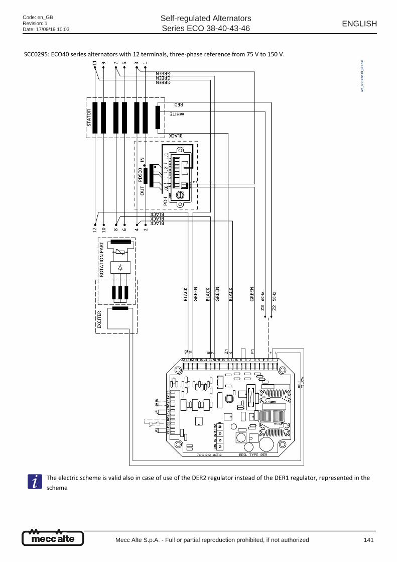
SCC0295: ECO40 series alternators with 12 terminals, three-phase reference from 75 V to 150 V.
The electric scheme is valid also in case of use of the DER2 regulator instead of the DER1 regulator, represented in the
scheme
Code: en_GBRevision: 1Date: 17/09/19 10:03
Self-regulated AlternatorsSeries ECO 38-40-43-46
ENGLISH
Mecc Alte S.p.A. - Full or partial reproduction prohibited, if not authorized 141
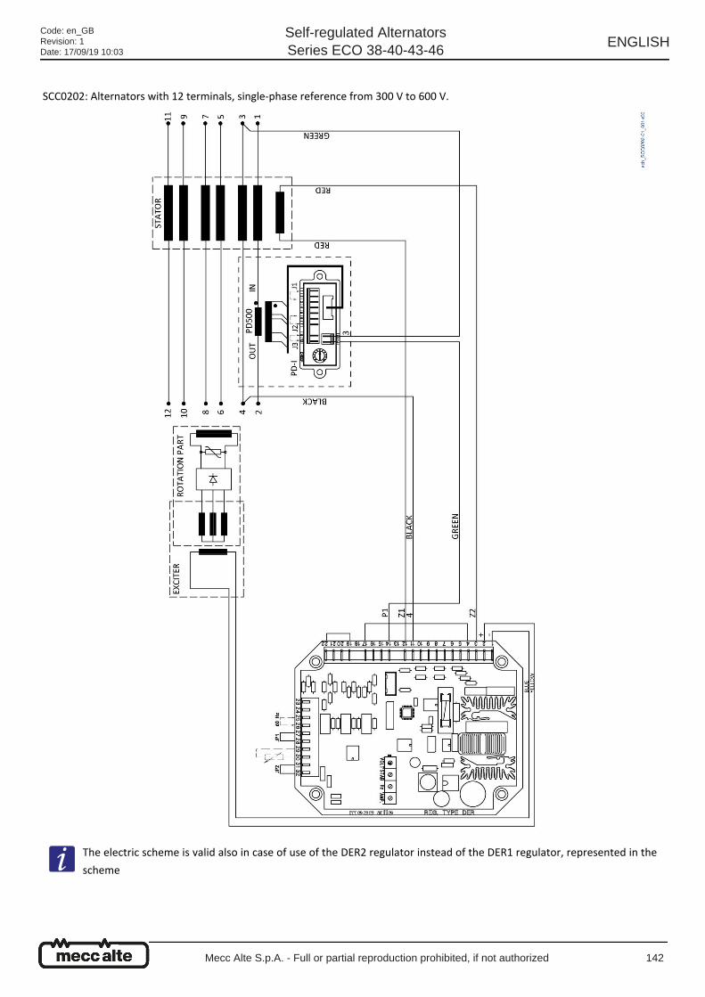
SCC0202: Alternators with 12 terminals, single-phase reference from 300 V to 600 V.
The electric scheme is valid also in case of use of the DER2 regulator instead of the DER1 regulator, represented in the
scheme
Code: en_GBRevision: 1Date: 17/09/19 10:03
Self-regulated AlternatorsSeries ECO 38-40-43-46
ENGLISH
Mecc Alte S.p.A. - Full or partial reproduction prohibited, if not authorized 142
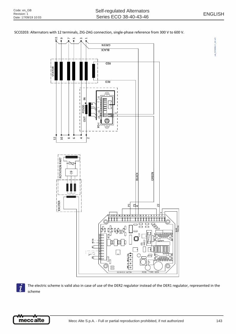
SCC0203: Alternators with 12 terminals, ZIG-ZAG connection, single-phase reference from 300 V to 600 V.
The electric scheme is valid also in case of use of the DER2 regulator instead of the DER1 regulator, represented in the
scheme
Code: en_GBRevision: 1Date: 17/09/19 10:03
Self-regulated AlternatorsSeries ECO 38-40-43-46
ENGLISH
Mecc Alte S.p.A. - Full or partial reproduction prohibited, if not authorized 143
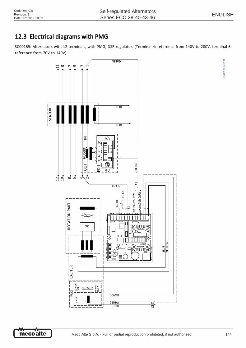
12.3 Electrical diagrams with PMG SCC0155: Alternators with 12 terminals, with PMG, DSR regulator. (Terminal 4: reference from 140V to 280V, terminal 6:
reference from 70V to 140V).
Code: en_GBRevision: 1Date: 17/09/19 10:03
Self-regulated AlternatorsSeries ECO 38-40-43-46
ENGLISH
Mecc Alte S.p.A. - Full or partial reproduction prohibited, if not authorized 144

SCC0231: Alternators with 12 terminals, with PMG, DER1 regulator, single-phase reference from 75V to 150V.
The electric scheme is valid also in case of use of the DER2 regulator instead of the DER1 regulator, represented in the
scheme
Code: en_GBRevision: 1Date: 17/09/19 10:03
Self-regulated AlternatorsSeries ECO 38-40-43-46
ENGLISH
Mecc Alte S.p.A. - Full or partial reproduction prohibited, if not authorized 145
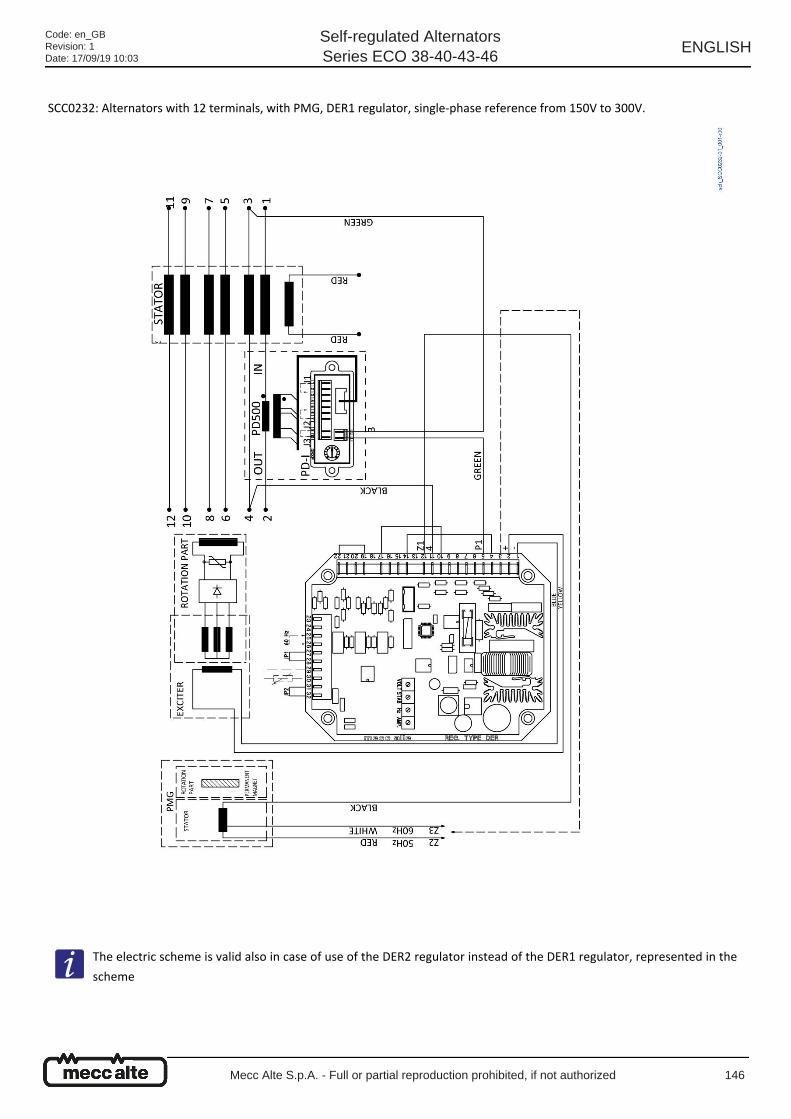
SCC0232: Alternators with 12 terminals, with PMG, DER1 regulator, single-phase reference from 150V to 300V.
The electric scheme is valid also in case of use of the DER2 regulator instead of the DER1 regulator, represented in the
scheme
Code: en_GBRevision: 1Date: 17/09/19 10:03
Self-regulated AlternatorsSeries ECO 38-40-43-46
ENGLISH
Mecc Alte S.p.A. - Full or partial reproduction prohibited, if not authorized 146
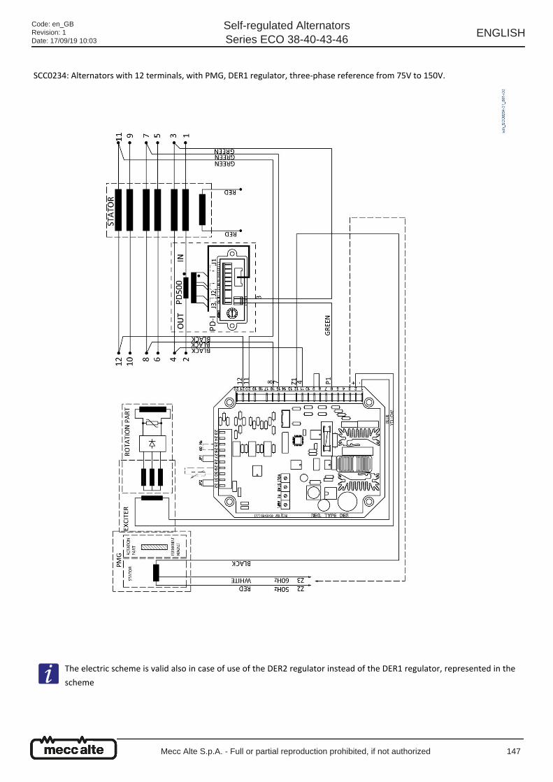
SCC0234: Alternators with 12 terminals, with PMG, DER1 regulator, three-phase reference from 75V to 150V.
The electric scheme is valid also in case of use of the DER2 regulator instead of the DER1 regulator, represented in the
scheme
Code: en_GBRevision: 1Date: 17/09/19 10:03
Self-regulated AlternatorsSeries ECO 38-40-43-46
ENGLISH
Mecc Alte S.p.A. - Full or partial reproduction prohibited, if not authorized 147

SCC0235: Alternators with 12 terminals, with PMG, DER1 regulator, three-phase reference from 150V to 300V.
The electric scheme is valid also in case of use of the DER2 regulator instead of the DER1 regulator, represented in the
scheme
Code: en_GBRevision: 1Date: 17/09/19 10:03
Self-regulated AlternatorsSeries ECO 38-40-43-46
ENGLISH
Mecc Alte S.p.A. - Full or partial reproduction prohibited, if not authorized 148

12.4 Electrical diagrams with UVR6 - SR7 regulators A2544: Alternators with 6 terminals, with SR7 analog regulator.
Code: en_GBRevision: 1Date: 17/09/19 10:03
Self-regulated AlternatorsSeries ECO 38-40-43-46
ENGLISH
Mecc Alte S.p.A. - Full or partial reproduction prohibited, if not authorized 149
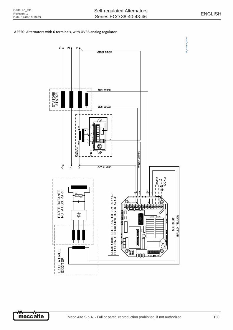
A2550: Alternators with 6 terminals, with UVR6 analog regulator.
Code: en_GBRevision: 1Date: 17/09/19 10:03
Self-regulated AlternatorsSeries ECO 38-40-43-46
ENGLISH
Mecc Alte S.p.A. - Full or partial reproduction prohibited, if not authorized 150
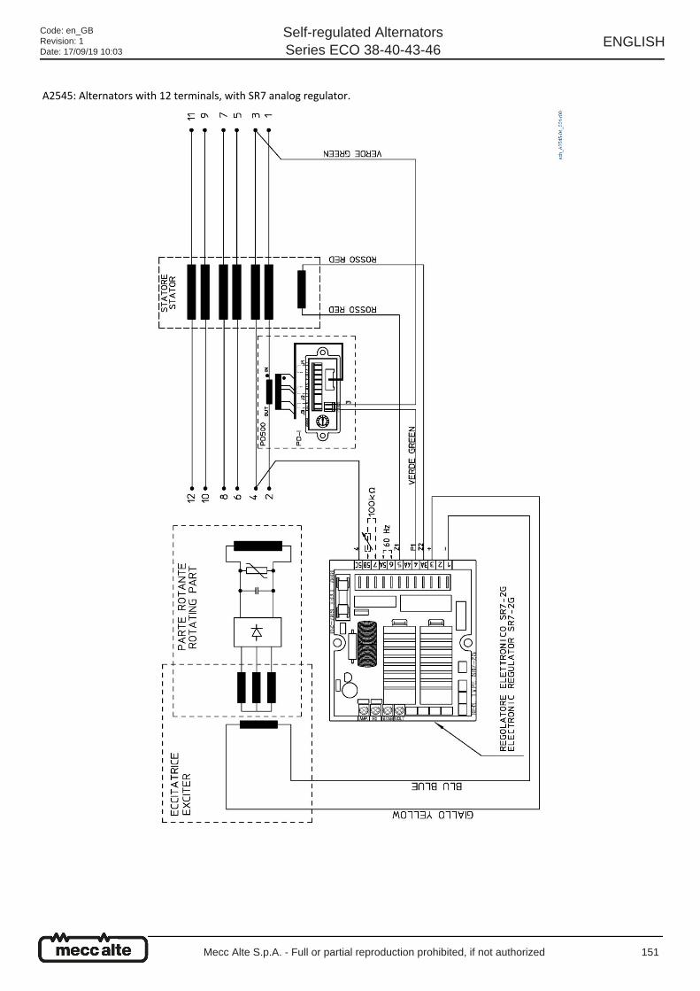
A2545: Alternators with 12 terminals, with SR7 analog regulator.
Code: en_GBRevision: 1Date: 17/09/19 10:03
Self-regulated AlternatorsSeries ECO 38-40-43-46
ENGLISH
Mecc Alte S.p.A. - Full or partial reproduction prohibited, if not authorized 151
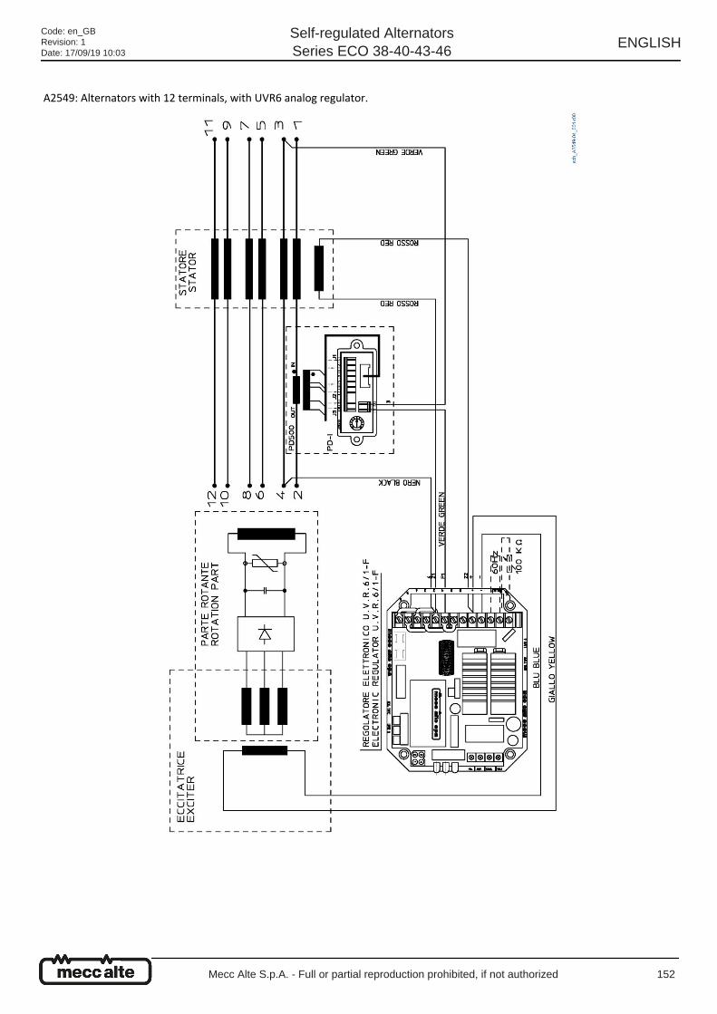
A2549: Alternators with 12 terminals, with UVR6 analog regulator.
Code: en_GBRevision: 1Date: 17/09/19 10:03
Self-regulated AlternatorsSeries ECO 38-40-43-46
ENGLISH
Mecc Alte S.p.A. - Full or partial reproduction prohibited, if not authorized 152
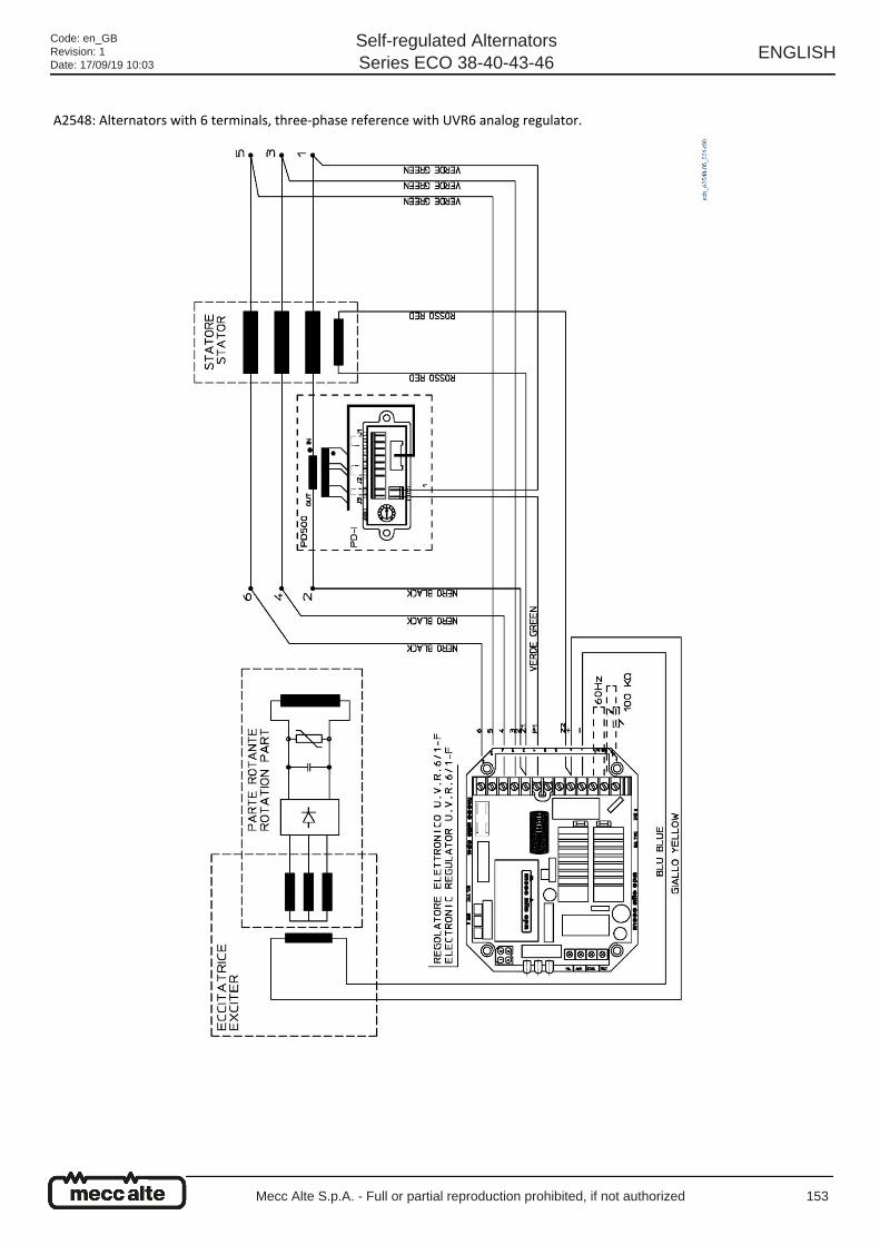
A2548: Alternators with 6 terminals, three-phase reference with UVR6 analog regulator.
Code: en_GBRevision: 1Date: 17/09/19 10:03
Self-regulated AlternatorsSeries ECO 38-40-43-46
ENGLISH
Mecc Alte S.p.A. - Full or partial reproduction prohibited, if not authorized 153
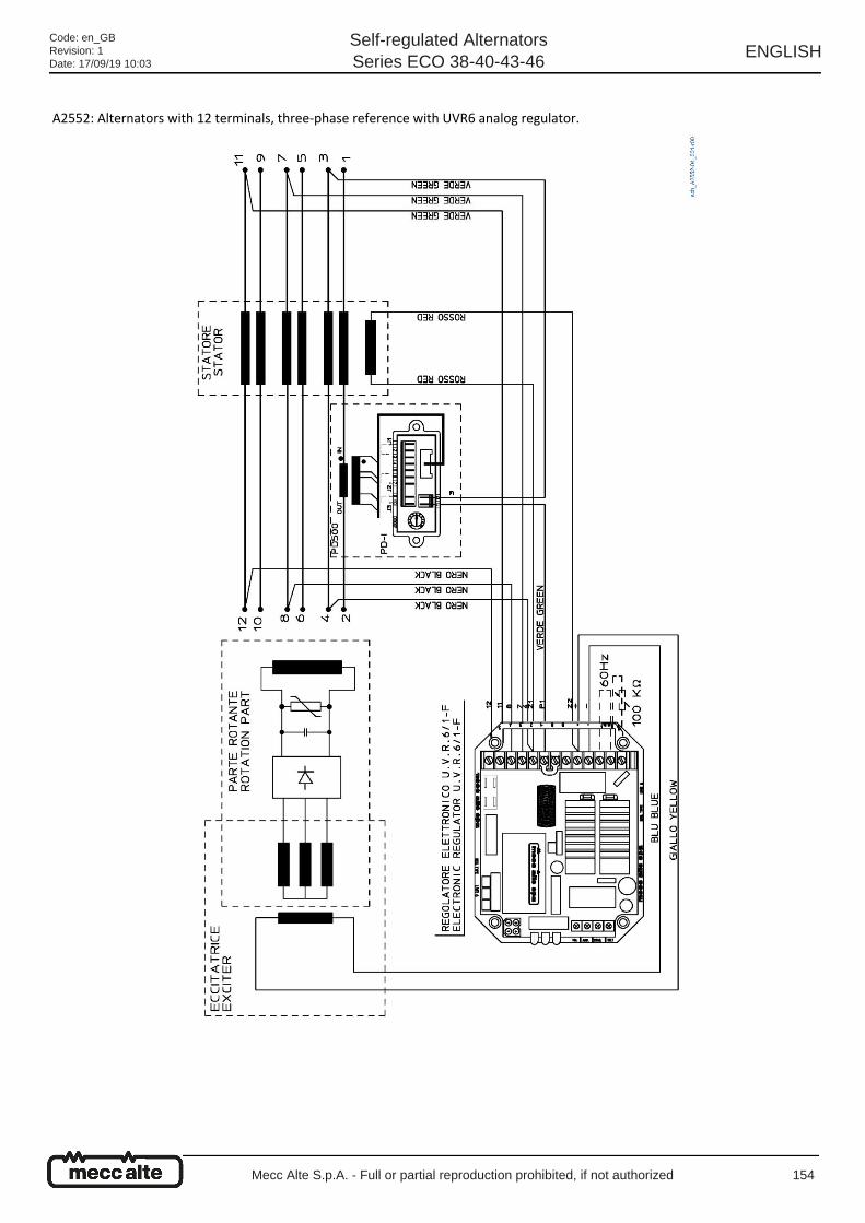
A2552: Alternators with 12 terminals, three-phase reference with UVR6 analog regulator.
Code: en_GBRevision: 1Date: 17/09/19 10:03
Self-regulated AlternatorsSeries ECO 38-40-43-46
ENGLISH
Mecc Alte S.p.A. - Full or partial reproduction prohibited, if not authorized 154
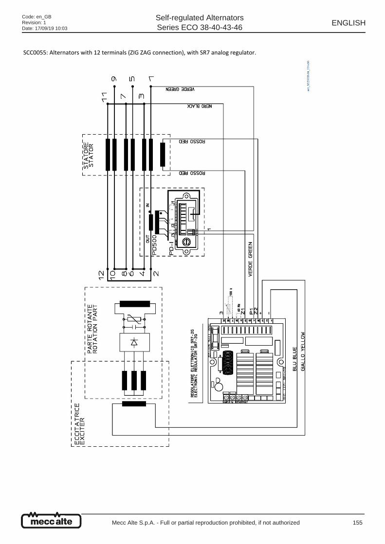
SCC0055: Alternators with 12 terminals (ZIG ZAG connection), with SR7 analog regulator.
Code: en_GBRevision: 1Date: 17/09/19 10:03
Self-regulated AlternatorsSeries ECO 38-40-43-46
ENGLISH
Mecc Alte S.p.A. - Full or partial reproduction prohibited, if not authorized 155
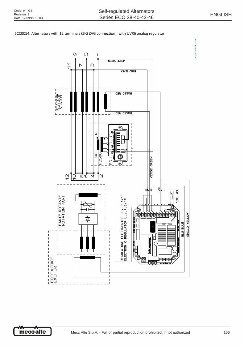
SCC0054: Alternators with 12 terminals (ZIG ZAG connection), with UVR6 analog regulator.
Code: en_GBRevision: 1Date: 17/09/19 10:03
Self-regulated AlternatorsSeries ECO 38-40-43-46
ENGLISH
Mecc Alte S.p.A. - Full or partial reproduction prohibited, if not authorized 156
13 Replacement parts
Code: en_GBRevision: 1Date: 17/09/19 10:03
Self-regulated AlternatorsSeries ECO 38-40-43-46
ENGLISH
Mecc Alte S.p.A. - Full or partial reproduction prohibited, if not authorized 157
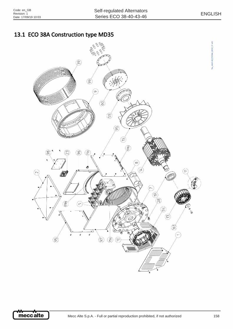
13.1 ECO 38A Construction type MD35
Code: en_GBRevision: 1Date: 17/09/19 10:03
Self-regulated AlternatorsSeries ECO 38-40-43-46
ENGLISH
Mecc Alte S.p.A. - Full or partial reproduction prohibited, if not authorized 158
ECO 38 List of replacement parts
Item Name
1 Back latch
2 Protective cover
5U1-V1-W1 use terminal block
U2-V2-W2 use terminal block
7 Back cover
8 Frame with stator
9 Front Cover MD35
SAE 0.5
SAE 1
SAE 2
SAE 3
10 Exciter stator
11 Rotating diode bridge
13 Exciter rotor
14 Rotating Inductor
15 Fan
19 Back bearing
23 DSR Electronic Regulator
Item Name
28a Cover rod S
28b Cover rod L
39 Single-bearing protective net
59 Flywheel disc holder hub 14-11 1/2
60SAE 14 Discs
SAE Discs 11 1/2
75a Cable gland rubber washer
75b Cable gland rubber washer DG 21
94 Back carter
95 Panel on terminal block side
96 Terminal block back panel
97 Terminal block back panel
98 Regulator holder panel
99 Disc blocking ring
163 Blocking washer
178a EPDM rubber profile size 8.5x5.5mm
178b UL EPDM+SP reinforced profile size 15.6x8.4mm
Code: en_GBRevision: 1Date: 17/09/19 10:03
Self-regulated AlternatorsSeries ECO 38-40-43-46
ENGLISH
Mecc Alte S.p.A. - Full or partial reproduction prohibited, if not authorized 159
13.2 ECO 38A Construction type B3B14
Code: en_GBRevision: 1Date: 17/09/19 10:03
Self-regulated AlternatorsSeries ECO 38-40-43-46
ENGLISH
Mecc Alte S.p.A. - Full or partial reproduction prohibited, if not authorized 160
ECO 38 List of replacement parts
Item Name
1 Back latch
2 Protective cover
5U1-V1-W1 use terminal block
U2-V2-W2 use terminal block
7 Back cover
8 Frame with stator
9 Front Cover B3B14
10 Exciter stator
11 Rotating diode bridge
13 Exciter rotor
14 Rotating Inductor
15 Fan
17 Front bearing
19 Back bearing
23 DSR Electronic Regulator
Item Name
28a Cover rod S
28b Cover rod L
39 Double-bearing protective net
75a Cable gland rubber washer
75b Cable gland rubber washer DG 21
94 Back carter
95 Panel on terminal block side
96 Terminal block back panel
97 Terminal block back panel
98 Regulator holder panel
99 Disc blocking ring
163 Blocking washer
178a EPDM rubber profile size 8.5x5.5mm
178b UL EPDM+SP reinforced profile size 15.6x8.4mm
Code: en_GBRevision: 1Date: 17/09/19 10:03
Self-regulated AlternatorsSeries ECO 38-40-43-46
ENGLISH
Mecc Alte S.p.A. - Full or partial reproduction prohibited, if not authorized 161
13.3 ECO 40B Construction type MD35
Code: en_GBRevision: 1Date: 17/09/19 10:03
Self-regulated AlternatorsSeries ECO 38-40-43-46
ENGLISH
Mecc Alte S.p.A. - Full or partial reproduction prohibited, if not authorized 162
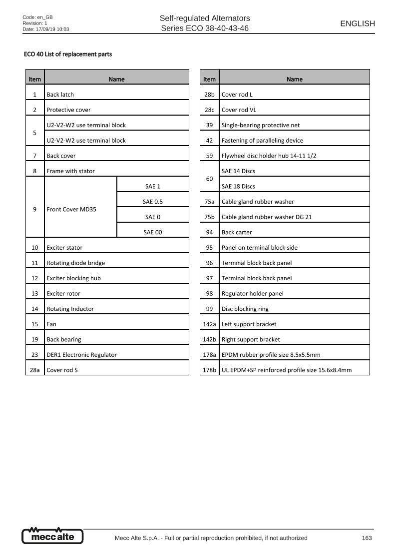
ECO 40 List of replacement parts
Item Name
1 Back latch
2 Protective cover
5U2-V2-W2 use terminal block
U2-V2-W2 use terminal block
7 Back cover
8 Frame with stator
9 Front Cover MD35
SAE 1
SAE 0.5
SAE 0
SAE 00
10 Exciter stator
11 Rotating diode bridge
12 Exciter blocking hub
13 Exciter rotor
14 Rotating Inductor
15 Fan
19 Back bearing
23 DER1 Electronic Regulator
28a Cover rod S
Item Name
28b Cover rod L
28c Cover rod VL
39 Single-bearing protective net
42 Fastening of paralleling device
59 Flywheel disc holder hub 14-11 1/2
60SAE 14 Discs
SAE 18 Discs
75a Cable gland rubber washer
75b Cable gland rubber washer DG 21
94 Back carter
95 Panel on terminal block side
96 Terminal block back panel
97 Terminal block back panel
98 Regulator holder panel
99 Disc blocking ring
142a Left support bracket
142b Right support bracket
178a EPDM rubber profile size 8.5x5.5mm
178b UL EPDM+SP reinforced profile size 15.6x8.4mm
Code: en_GBRevision: 1Date: 17/09/19 10:03
Self-regulated AlternatorsSeries ECO 38-40-43-46
ENGLISH
Mecc Alte S.p.A. - Full or partial reproduction prohibited, if not authorized 163
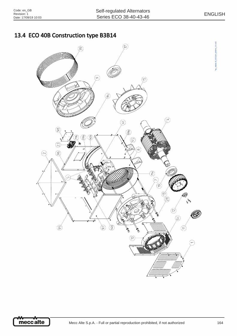
13.4 ECO 40B Construction type B3B14
Code: en_GBRevision: 1Date: 17/09/19 10:03
Self-regulated AlternatorsSeries ECO 38-40-43-46
ENGLISH
Mecc Alte S.p.A. - Full or partial reproduction prohibited, if not authorized 164
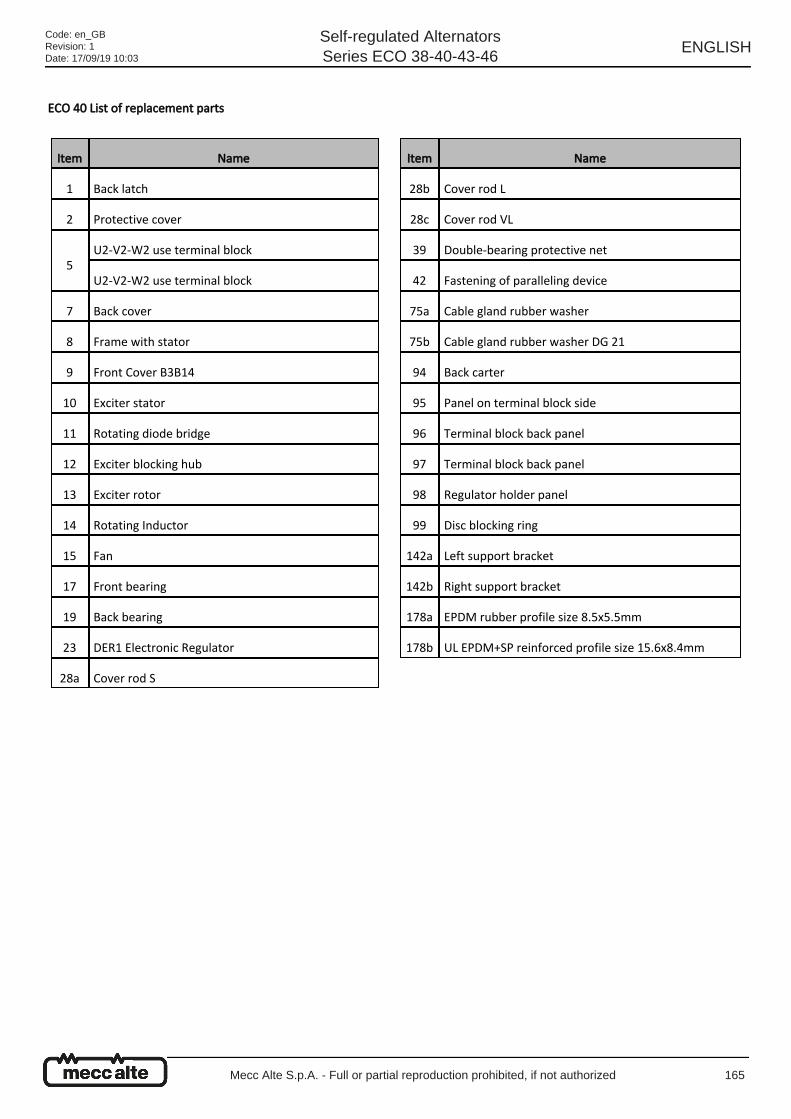
ECO 40 List of replacement parts
Item Name
1 Back latch
2 Protective cover
5U2-V2-W2 use terminal block
U2-V2-W2 use terminal block
7 Back cover
8 Frame with stator
9 Front Cover B3B14
10 Exciter stator
11 Rotating diode bridge
12 Exciter blocking hub
13 Exciter rotor
14 Rotating Inductor
15 Fan
17 Front bearing
19 Back bearing
23 DER1 Electronic Regulator
28a Cover rod S
Item Name
28b Cover rod L
28c Cover rod VL
39 Double-bearing protective net
42 Fastening of paralleling device
75a Cable gland rubber washer
75b Cable gland rubber washer DG 21
94 Back carter
95 Panel on terminal block side
96 Terminal block back panel
97 Terminal block back panel
98 Regulator holder panel
99 Disc blocking ring
142a Left support bracket
142b Right support bracket
178a EPDM rubber profile size 8.5x5.5mm
178b UL EPDM+SP reinforced profile size 15.6x8.4mm
Code: en_GBRevision: 1Date: 17/09/19 10:03
Self-regulated AlternatorsSeries ECO 38-40-43-46
ENGLISH
Mecc Alte S.p.A. - Full or partial reproduction prohibited, if not authorized 165
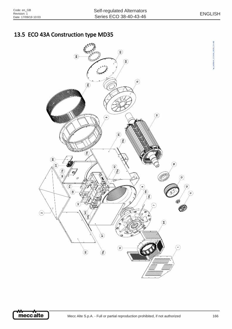
13.5 ECO 43A Construction type MD35
Code: en_GBRevision: 1Date: 17/09/19 10:03
Self-regulated AlternatorsSeries ECO 38-40-43-46
ENGLISH
Mecc Alte S.p.A. - Full or partial reproduction prohibited, if not authorized 166
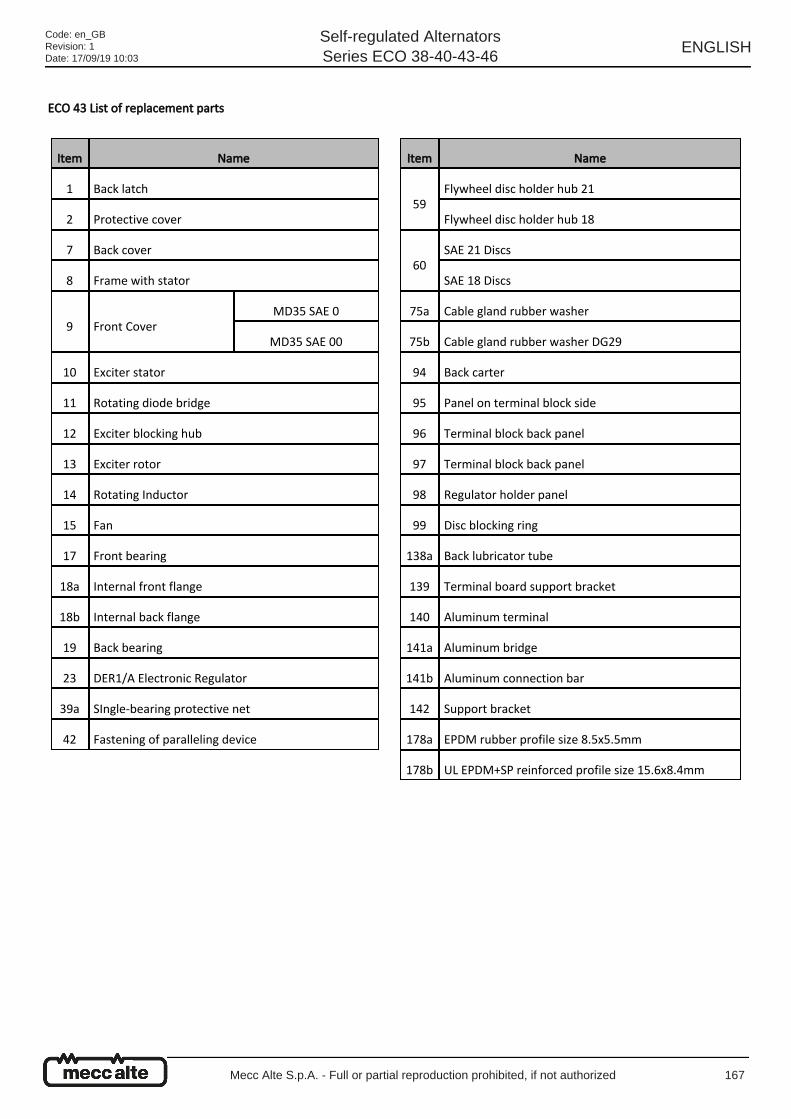
ECO 43 List of replacement parts
Item Name
1 Back latch
2 Protective cover
7 Back cover
8 Frame with stator
9 Front CoverMD35 SAE 0
MD35 SAE 00
10 Exciter stator
11 Rotating diode bridge
12 Exciter blocking hub
13 Exciter rotor
14 Rotating Inductor
15 Fan
17 Front bearing
18a Internal front flange
18b Internal back flange
19 Back bearing
23 DER1/A Electronic Regulator
39a SIngle-bearing protective net
42 Fastening of paralleling device
Item Name
59Flywheel disc holder hub 21
Flywheel disc holder hub 18
60SAE 21 Discs
SAE 18 Discs
75a Cable gland rubber washer
75b Cable gland rubber washer DG29
94 Back carter
95 Panel on terminal block side
96 Terminal block back panel
97 Terminal block back panel
98 Regulator holder panel
99 Disc blocking ring
138a Back lubricator tube
139 Terminal board support bracket
140 Aluminum terminal
141a Aluminum bridge
141b Aluminum connection bar
142 Support bracket
178a EPDM rubber profile size 8.5x5.5mm
178b UL EPDM+SP reinforced profile size 15.6x8.4mm
Code: en_GBRevision: 1Date: 17/09/19 10:03
Self-regulated AlternatorsSeries ECO 38-40-43-46
ENGLISH
Mecc Alte S.p.A. - Full or partial reproduction prohibited, if not authorized 167
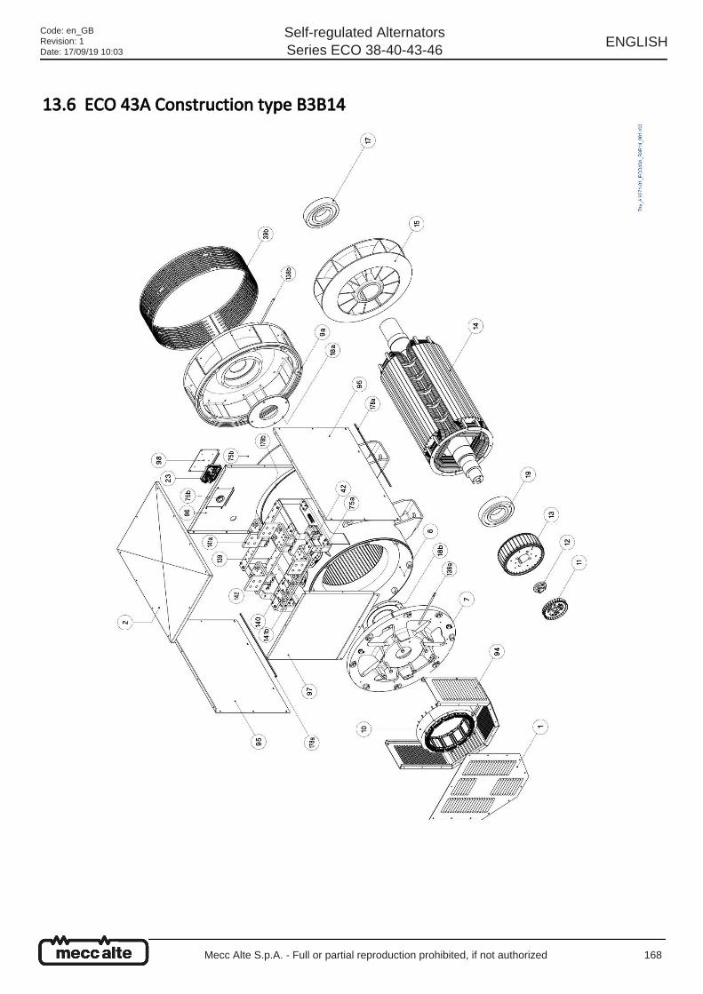
13.6 ECO 43A Construction type B3B14
Code: en_GBRevision: 1Date: 17/09/19 10:03
Self-regulated AlternatorsSeries ECO 38-40-43-46
ENGLISH
Mecc Alte S.p.A. - Full or partial reproduction prohibited, if not authorized 168
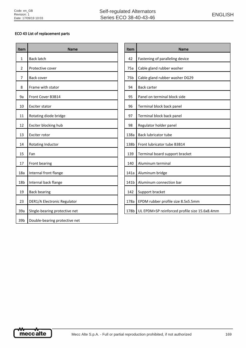
ECO 43 List of replacement parts
Item Name
1 Back latch
2 Protective cover
7 Back cover
8 Frame with stator
9a Front Cover B3B14
10 Exciter stator
11 Rotating diode bridge
12 Exciter blocking hub
13 Exciter rotor
14 Rotating Inductor
15 Fan
17 Front bearing
18a Internal front flange
18b Internal back flange
19 Back bearing
23 DER1/A Electronic Regulator
39a SIngle-bearing protective net
39b Double-bearing protective net
Item Name
42 Fastening of paralleling device
75a Cable gland rubber washer
75b Cable gland rubber washer DG29
94 Back carter
95 Panel on terminal block side
96 Terminal block back panel
97 Terminal block back panel
98 Regulator holder panel
138a Back lubricator tube
138b Front lubricator tube B3B14
139 Terminal board support bracket
140 Aluminum terminal
141a Aluminum bridge
141b Aluminum connection bar
142 Support bracket
178a EPDM rubber profile size 8.5x5.5mm
178b UL EPDM+SP reinforced profile size 15.6x8.4mm
Code: en_GBRevision: 1Date: 17/09/19 10:03
Self-regulated AlternatorsSeries ECO 38-40-43-46
ENGLISH
Mecc Alte S.p.A. - Full or partial reproduction prohibited, if not authorized 169
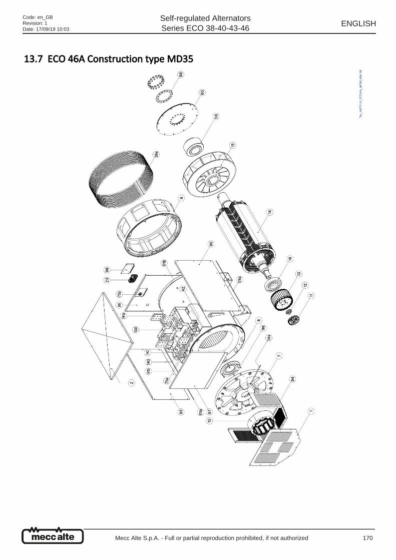
13.7 ECO 46A Construction type MD35
Code: en_GBRevision: 1Date: 17/09/19 10:03
Self-regulated AlternatorsSeries ECO 38-40-43-46
ENGLISH
Mecc Alte S.p.A. - Full or partial reproduction prohibited, if not authorized 170

ECO 46 List of replacement parts
Item Name
1 Back latch
2 Protective cover
7 Back cover
8 Frame with stator
9 Front CoverMD35 SAE 0
MD35 SAE 00
10 Exciter stator
11 Rotating diode bridge
12 Exciter blocking hub
13 Exciter rotor
14 Rotating Inductor
15 Fan
17 Front bearing
18a Internal front flange
18b Internal back flange
19 Back bearing
23 DER1/A Electronic Regulator
39a SIngle-bearing protective net
39b Double-bearing protective net
42 Fastening of paralleling device
Item Name
59Flywheel disc holder hub 21
Flywheel disc holder hub 18
60SAE 21 Discs
SAE 18 Discs
75a Cable gland rubber washer
75b Cable gland rubber washer DG29
94 Back carter
95 Panel on terminal block side
96 Terminal block back panel
97 Terminal block back panel
98 Regulator holder panel
99 Disc blocking ring
138a Back lubricator tube
139 Terminal board support bracket
140 Aluminum terminal
141a Aluminum bridge
141b Aluminum connection bar
142 Support bracket
178a EPDM rubber profile size 8.5x5.5mm
178b UL EPDM+SP reinforced profile size 15.6x8.4mm
Code: en_GBRevision: 1Date: 17/09/19 10:03
Self-regulated AlternatorsSeries ECO 38-40-43-46
ENGLISH
Mecc Alte S.p.A. - Full or partial reproduction prohibited, if not authorized 171
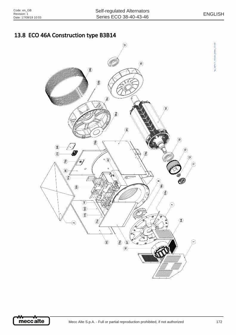
13.8 ECO 46A Construction type B3B14
Code: en_GBRevision: 1Date: 17/09/19 10:03
Self-regulated AlternatorsSeries ECO 38-40-43-46
ENGLISH
Mecc Alte S.p.A. - Full or partial reproduction prohibited, if not authorized 172
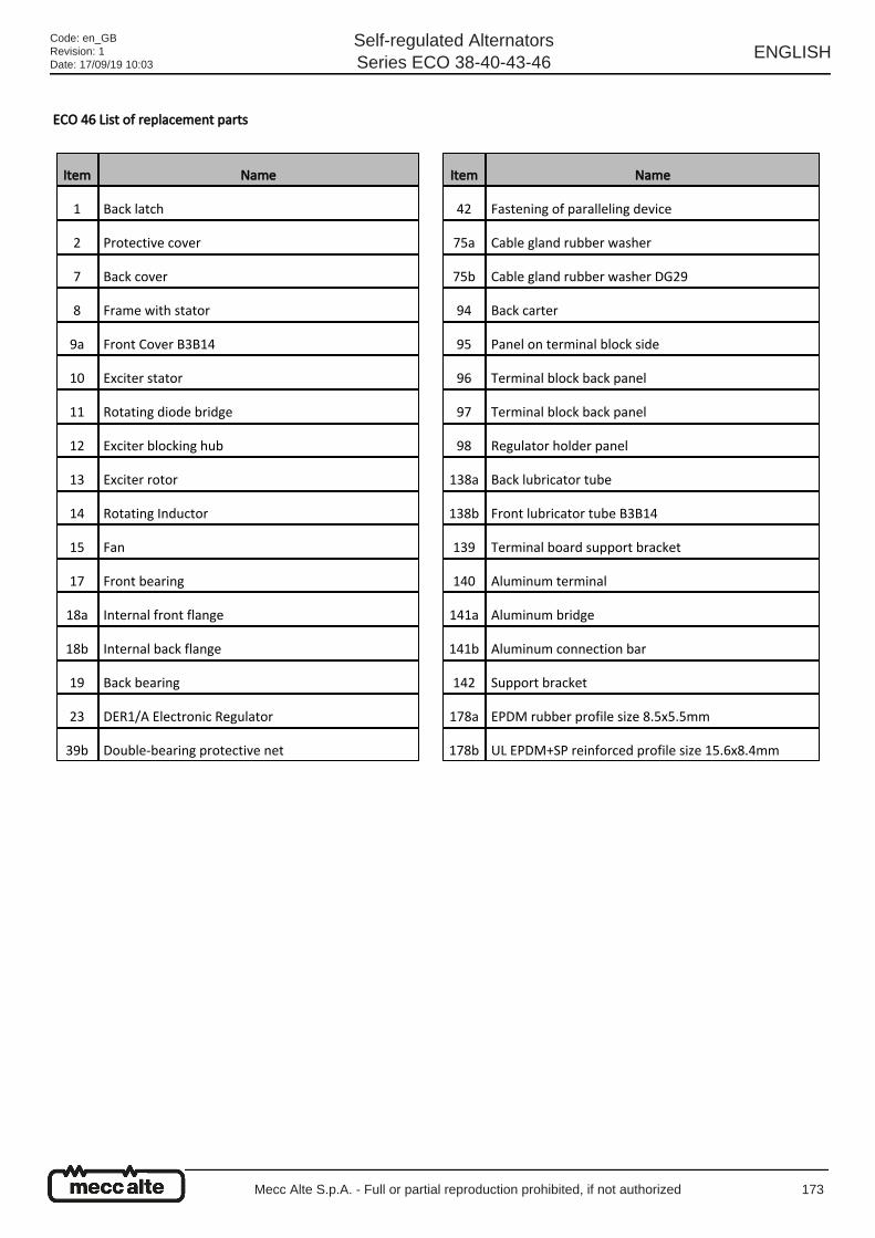
ECO 46 List of replacement parts
Item Name
1 Back latch
2 Protective cover
7 Back cover
8 Frame with stator
9a Front Cover B3B14
10 Exciter stator
11 Rotating diode bridge
12 Exciter blocking hub
13 Exciter rotor
14 Rotating Inductor
15 Fan
17 Front bearing
18a Internal front flange
18b Internal back flange
19 Back bearing
23 DER1/A Electronic Regulator
39b Double-bearing protective net
Item Name
42 Fastening of paralleling device
75a Cable gland rubber washer
75b Cable gland rubber washer DG29
94 Back carter
95 Panel on terminal block side
96 Terminal block back panel
97 Terminal block back panel
98 Regulator holder panel
138a Back lubricator tube
138b Front lubricator tube B3B14
139 Terminal board support bracket
140 Aluminum terminal
141a Aluminum bridge
141b Aluminum connection bar
142 Support bracket
178a EPDM rubber profile size 8.5x5.5mm
178b UL EPDM+SP reinforced profile size 15.6x8.4mm
Code: en_GBRevision: 1Date: 17/09/19 10:03
Self-regulated AlternatorsSeries ECO 38-40-43-46
ENGLISH
Mecc Alte S.p.A. - Full or partial reproduction prohibited, if not authorized 173

Code: en_GBRevision: 1Date: 17/09/19 10:03
Self-regulated AlternatorsSeries ECO 38-40-43-46
ENGLISH
Mecc Alte S.p.A. - Full or partial reproduction prohibited, if not authorized 174
14 Dismantlement and disposal To dispose of the alternator or its components you will have to recycle it, keeping in mind the nature of its various components
(for instance: metals, plastic parts, rubber, oil and so on).
You will have to designate specialized companies for this purpose and , however, observe the waste management applicable
laws.
Most of the materials used in the alternators can be recycled by specialized waste management companies. The
instructions contained in this chapter are recommendations to follow for environmentally sound disposal; the user has
the responsibility of observing local regulations.
For indicative percentages of the materials used in Mecc Alte alternators see paragraph 2.3.9.
Code: en_GBRevision: 1Date: 17/09/19 10:03
Self-regulated AlternatorsSeries ECO 38-40-43-46
ENGLISH
Mecc Alte S.p.A. - Full or partial reproduction prohibited, if not authorized 175
[$DirMod$]