Embed Size (px)
Citation preview
Disclaimer
Das folgende PDF-Dokument für dieses Fahrzeugmodell bezieht sich in allen Sprachversionen nur auf die Fahrzeuge, die für den deutschen Markt bestimmt sind und die den deutschen Vorschriften entsprechen. Bitte wenden Sie sich an Ihren autorisierten Mercedes-Benz Servicestützpunkt, um ein gedrucktes Exemplar für andere Fahrzeugmodelle und Fahrzeugmodelljahre zu erhalten.
Dieses PDF-Dokument stellt die aktuelle Version dar. Mögliche Abweichungen zu Ihrem konkreten Fahrzeug könnten nicht berücksichtigt sein, da Mercedes-Benz seine Fahrzeuge ständig dem neuesten Stand der Technik anpasst, sowie Änderungen in Form und Ausstattung vornimmt. Bitte beachten Sie daher, dass dieses PDF-Dokument in keinem Fall das gedruckte Exemplar ersetzt, das mit dem Fahrzeug ausgeliefert wurde.
Internal use only
Disclaimer
All language versions of the following PDF document for this vehicle model relate solely to vehicles intended for sale on the German market and which correspond to German regulations.
Please contact your authorised Mercedes-Benz Service Centre to obtain a printed version for other vehicle models and vehicle model years. This PDF document is the latest version. Possible variations to your vehicle may not be taken into account as Mercedes-Benz constantly updates their vehicles to the state of the art and introduces changes in design and equipment. Please therefore note that this PDF document in no way replaces the printed version which was delivered with your vehicle.
Internal use only
Disclaimer
The following version of the Owner‘s Manual describes all models, series and special equipment of your vehicle. Country-specific language variations are possible. Please note that your vehicle might not be equipped with all the described functions. This also affects safety-relevant systems and functions. Please contact your authorised Mercedes-Benz dealership if you would like to receive a printed Owner‘s Manual for other vehicle models and vehicle model years.
The online Owner‘s Manual is the current and valid version. It is possible that deviations affecting your specific vehicle could not be taken into account as Mercedes-Benz constantly adapts its vehicles according to the latest technology and makes changes to the form and the equipment.
Please also read the printed Owner‘s Manual, supplementary documents and the digital Owner‘s Manual in the vehicle.
CopyrightAll rights reserved. All texts, images and graphics are subject to copyright and other laws for the protection of intellectual property. They may not be copied or changed for any commercial use or for the purpose of being passed on nor used on other webistes.
Thank you for choosingMercedes-Benz.
Before you drive off, please familiariseyourself with your Mercedes-Benz andread this Owner's Manual. This will helpyou to obtain the maximum pleasure fromyour vehicle and avoid endangering your-self and others.
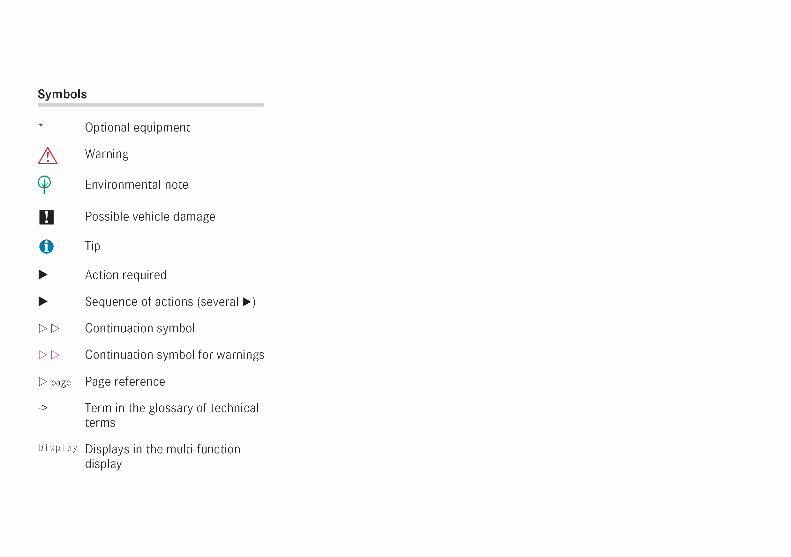
Items of optional equipment are markedwith an asterisk *. The equipment in yourvehicle may vary, depending on the model,country specifications and availability.Mercedes-Benz is constantly updatingits vehicles to the state of the art andtherefore reserves the right to introducechanges in design, equipment and techni-cal features at any time.
You cannot, therefore, base any claims onthe data, illustrations or descriptions inthis Owner's Manual.
The Owner's Manual, brief instructions, theService Booklet and the Service Centresbooklet are an integral part of the vehicle.You should always keep them in the vehi-cle and pass them on to the new owner ifyou sell the vehicle.
Please consult a Mercedes-Benz ServiceCentre if you have any questions.
The technical documentation team atDaimlerChrysler AG wishes you safe andpleasant motoring.
i You can also experience important func-tions of the CLK-Class in the interactive Owner'sManual on the internet at:www.mercedes-benz.de/betriebsanleitung/CLK-Class
209en_d2.boo Seite 1 Dienstag, 25. Mai 2004 7:26 19
Contents
i Please also refer to the index ( page 429)
Introduction . . . . . . . . . . . . . . . . . . . . . 4Protection of the environment . . . . . . . . 4Operating safety . . . . . . . . . . . . . . . . . . 5
At a glance . . . . . . . . . . . . . . . . . . . . . . 7Cockpit . . . . . . . . . . . . . . . . . . . . . . . . . 8Instrument cluster . . . . . . . . . . . . . . . . 12Multi-function steering wheel . . . . . . . 16Centre console . . . . . . . . . . . . . . . . . . 17Overhead control panel . . . . . . . . . . . . 19Door control panel . . . . . . . . . . . . . . . . 20
Getting started . . . . . . . . . . . . . . . . . 21Opening . . . . . . . . . . . . . . . . . . . . . . . . 22Adjusting . . . . . . . . . . . . . . . . . . . . . . . 25Driving . . . . . . . . . . . . . . . . . . . . . . . . . 32Parking and locking . . . . . . . . . . . . . . . 43
Safety . . . . . . . . . . . . . . . . . . . . . . . . . 45Occupant safety . . . . . . . . . . . . . . . . . 46Driving safety systems . . . . . . . . . . . . 68Anti-theft systems . . . . . . . . . . . . . . . . 72
Controls in detail . . . . . . . . . . . . . . . . 77Opening and closing . . . . . . . . . . . . . . 78Seats . . . . . . . . . . . . . . . . . . . . . . . . . . 90Storing settings*(memory package) . . . . . . . . . . . . . . . . 97Lighting . . . . . . . . . . . . . . . . . . . . . . . 100Instrument cluster . . . . . . . . . . . . . . . 106Operating system . . . . . . . . . . . . . . . 108Manual transmission . . . . . . . . . . . . . 137Automatic transmission* . . . . . . . . . . 138Good visibility . . . . . . . . . . . . . . . . . . 148Thermatic (automatic airconditioning) . . . . . . . . . . . . . . . . . . . 154Thermotronic* (intelligent airconditioning) . . . . . . . . . . . . . . . . . . . 164Heater booster system* forvehicles with a diesel engine . . . . . . . 174Auxiliary heating/ventilation* . . . . . . 175Open-air . . . . . . . . . . . . . . . . . . . . . . . 178Driving systems . . . . . . . . . . . . . . . . . 191Loading . . . . . . . . . . . . . . . . . . . . . . . 216Features . . . . . . . . . . . . . . . . . . . . . . . 225
209en_d2.boo Seite 2 Dienstag, 25. Mai 2004 7:26 19
Contents
Operation . . . . . . . . . . . . . . . . . . . . . 239The first 1,500 km . . . . . . . . . . . . . . . 240Refuelling . . . . . . . . . . . . . . . . . . . . . 241Engine compartment . . . . . . . . . . . . . 244Tyres and wheels . . . . . . . . . . . . . . . . 249Driving tips . . . . . . . . . . . . . . . . . . . . 255Winter driving . . . . . . . . . . . . . . . . . . 257Driving abroad . . . . . . . . . . . . . . . . . . 259Trailer towing . . . . . . . . . . . . . . . . . . 260Service . . . . . . . . . . . . . . . . . . . . . . . 265Care . . . . . . . . . . . . . . . . . . . . . . . . . . 267
Practical advice . . . . . . . . . . . . . . . . 273Where will I find...? . . . . . . . . . . . . . . 274Display messages . . . . . . . . . . . . . . . 280Troubleshooting . . . . . . . . . . . . . . . . 308Opening/closing in anemergency . . . . . . . . . . . . . . . . . . . . 341Changing the key batteries . . . . . . . . 354Changing bulbs . . . . . . . . . . . . . . . . . 357Replacing the wiper blades . . . . . . . . 362Flat tyre . . . . . . . . . . . . . . . . . . . . . . . 363Battery . . . . . . . . . . . . . . . . . . . . . . . . 375Jump-starting . . . . . . . . . . . . . . . . . . . 379Towing . . . . . . . . . . . . . . . . . . . . . . . . 381Fuses . . . . . . . . . . . . . . . . . . . . . . . . . 385
Technical data . . . . . . . . . . . . . . . . . 389Genuine Mercedes-Benz parts . . . . . 390Vehicle electronics . . . . . . . . . . . . . . 391Vehicle identification plates . . . . . . . 393Engine . . . . . . . . . . . . . . . . . . . . . . . . 394Performance . . . . . . . . . . . . . . . . . . . 395Tyres and wheels . . . . . . . . . . . . . . . . 399Vehicle dimensions . . . . . . . . . . . . . . 404Trailer tow hitch . . . . . . . . . . . . . . . . 405Vehicle weights . . . . . . . . . . . . . . . . . 408Service products and capacities . . . . 410Frequencies for garagedoor openers* . . . . . . . . . . . . . . . . . . 417
Technical terms . . . . . . . . . . . . . . . . 419
Index . . . . . . . . . . . . . . . . . . . . . . . . . 429
209en_d2.boo Seite 3 Dienstag, 25. Mai 2004 7:26 19
4
Protection of the environment
Introduction
Protection of the environment
H Environmental note
DaimlerChrysler's declared policy is one ofcomprehensive environmental protection.
The objectives are for the natural resourceswhich form the basis of our existence on thisplanet to be used sparingly and in a mannerwhich takes the requirements of both natureand humanity into account.
You too can make a contribution towardsprotecting the environment by operatingyour vehicle in an environmentally-responsi-ble manner.
Fuel consumption and the rate of engine,transmission, brake and tyre wear dependon the following:
the operating conditions of your vehicle
your driving style
You can influence both of these conditions.
Therefore, bear the following in mind:
Operating conditions
Avoid driving short distances as thisincreases fuel consumption.
Make sure that tyre pressures arealways correct.
Do not carry any unnecessary weight.
Keep an eye on the vehicle's fuel con-sumption.
Remove roof racks once you no longerneed them.
A regularly serviced vehicle will contrib-ute to environmental protection. Youshould therefore adhere to the serviceintervals.
Always have service work carried out ata qualified specialist workshop, e.g. at aMercedes-Benz Service Centre.
Style of driving:
Do not depress the accelerator pedalwhen starting the engine.
Do not warm up the engine with thevehicle stationary.
Drive carefully and maintain sufficientdistance from the vehicle in front.
Avoid frequent, powerful acceleration.
Change gear in good time and use eachgear only up to 2/3 of its maximumengine speed.
Switch off the engine in stationary traf-fic.
Vehicle take-back
Contact Mercedes-Benz on the followingphone numbers if you wish to return yourMercedes-Benz to have it disposed of in anenvironmentally-responsible manner:
Germany: 00800 1 777 7777International: +49 69 95 30 72 77
209en_d2.boo Seite 4 Dienstag, 25. Mai 2004 7:26 19
5
Introduction
Operating safety
Operating safety
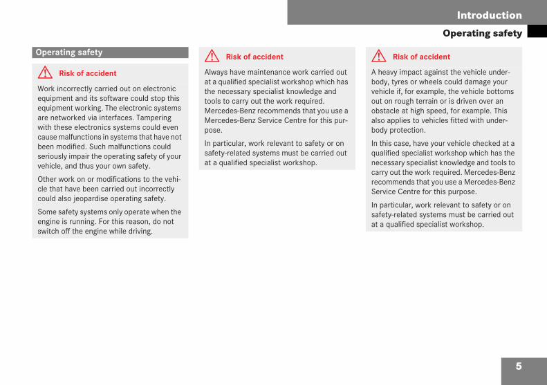
G Risk of accident
Work incorrectly carried out on electronicequipment and its software could stop thisequipment working. The electronic systemsare networked via interfaces. Tamperingwith these electronics systems could evencause malfunctions in systems that have notbeen modified. Such malfunctions couldseriously impair the operating safety of yourvehicle, and thus your own safety.
Other work on or modifications to the vehi-cle that have been carried out incorrectlycould also jeopardise operating safety.
Some safety systems only operate when theengine is running. For this reason, do notswitch off the engine while driving.
G Risk of accident
Always have maintenance work carried outat a qualified specialist workshop which hasthe necessary specialist knowledge andtools to carry out the work required.Mercedes-Benz recommends that you use aMercedes-Benz Service Centre for this pur-pose.
In particular, work relevant to safety or onsafety-related systems must be carried outat a qualified specialist workshop.
G Risk of accident
A heavy impact against the vehicle under-body, tyres or wheels could damage yourvehicle if, for example, the vehicle bottomsout on rough terrain or is driven over anobstacle at high speed, for example. Thisalso applies to vehicles fitted with under-body protection.
In this case, have your vehicle checked at aqualified specialist workshop which has thenecessary specialist knowledge and tools tocarry out the work required. Mercedes-Benzrecommends that you use a Mercedes-BenzService Centre for this purpose.
In particular, work relevant to safety or onsafety-related systems must be carried outat a qualified specialist workshop.
209en_d2.boo Seite 5 Dienstag, 25. Mai 2004 7:26 19
6
Introduction
Operating safety
Observe the following information whenusing your vehicle:
the safety notes in this manual
the "Technical data" section in thismanual
national road traffic regulations
national road traffic licensing regula-tions
Correct use
G Risk of injury
There are various warning stickers affixed toyour vehicle. These are intended to makeyou and others aware of various risks. Forthis reason, do not remove any warningstickers unless this is expressly stipulatedon the sticker.
If you remove these warning stickers, you orothers may not then be aware of risks andmay be injured as a result.
209en_d2.boo Seite 6 Dienstag, 25. Mai 2004 7:26 19
7
At a glance
Cockpit
Instrument cluster
Multi-function steering wheel
Centre console
Overhead control panel
Door control panel
209en_d2.boo Seite 7 Dienstag, 25. Mai 2004 7:26 19
8
At a glance
Cockpit
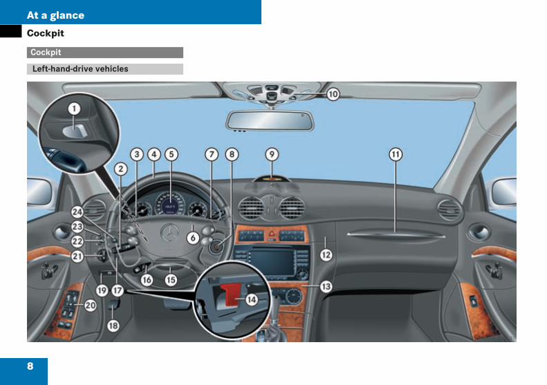
Cockpit
Left-hand-drive vehicles
P68.10-3077-31
209en_d2.boo Seite 8 Dienstag, 25. Mai 2004 7:26 19
9
At a glance
Cockpit
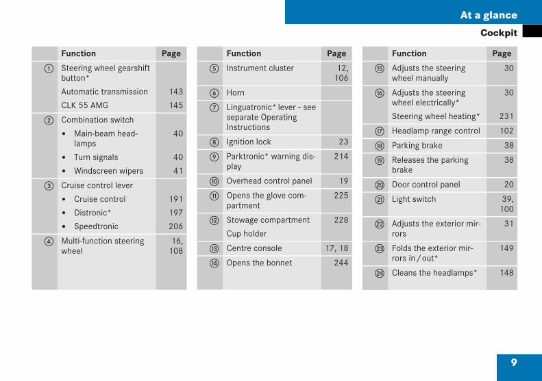
Function Page
1 Steering wheel gearshiftbutton*
Automatic transmission
CLK 55 AMG
143
145
2 Combination switch
Main-beam head-lamps
Turn signals
Windscreen wipers
40
40
41
3 Cruise control lever
Cruise control
Distronic*
Speedtronic
191
197
206
4 Multi-function steeringwheel
16,108
Function Page
5 Instrument cluster 12,106
6 Horn
7 Linguatronic* lever – seeseparate OperatingInstructions
8 Ignition lock 23
9 Parktronic* warning dis-play
214
a Overhead control panel 19
b Opens the glove com-partment
225
c Stowage compartment
Cup holder
228
d Centre console 17, 18
e Opens the bonnet 244
Function Page
f Adjusts the steeringwheel manually
30
g Adjusts the steeringwheel electrically*
Steering wheel heating*
30
231
h Headlamp range control 102
j Parking brake 38
k Releases the parkingbrake
38
l Door control panel 20
m Light switch 39,100
n Adjusts the exterior mir-rors
31
o Folds the exterior mir-rors in/out*
149
p Cleans the headlamps* 148
209en_d2.boo Seite 9 Dienstag, 25. Mai 2004 7:26 19
10
At a glance
Cockpit
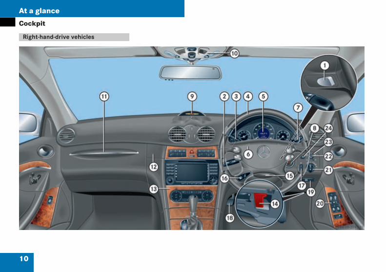
Right-hand-drive vehicles
P68.10-3077-31
209en_d2.boo Seite 10 Dienstag, 25. Mai 2004 7:26 19

11
At a glance
Cockpit
Function Page
1 Steering wheel gearshiftbutton*
Automatic transmission
CLK 55 AMG
143
145
2 Combination switch
Main-beam head-lamps
Turn signals
Windscreen wipers
40
40
41
3 Cruise control lever
Cruise control
Distronic*
Speedtronic
191
197
206
4 Multi-function steeringwheel
16,108
Function Page
5 Instrument cluster 14,106
6 Horn
7 Linguatronic* lever – seeseparate OperatingInstructions
8 Ignition lock 23
9 Parktronic* warningdisplay
214
a Overhead control panel 19
b Opens the glovecompartment
225
c Stowage compartment
Cup holder
228
d Centre console 17, 18
e Opens the bonnet 244
Function Page
f Adjusts the steeringwheel manually
30
g Adjusts the steeringwheel electrically*
Steering wheel heating*
30
231
h Headlamp range control 102
j Parking brake 38
k Releases the parkingbrake
38
l Door control panel 20
m Light switch 39,100
n Adjusts the exteriormirrors
31
o Folds the exteriormirrors in/out*
149
p Cleans the headlamps* 148
209en_d2.boo Seite 11 Dienstag, 25. Mai 2004 7:26 19
12
At a glance
Instrument cluster
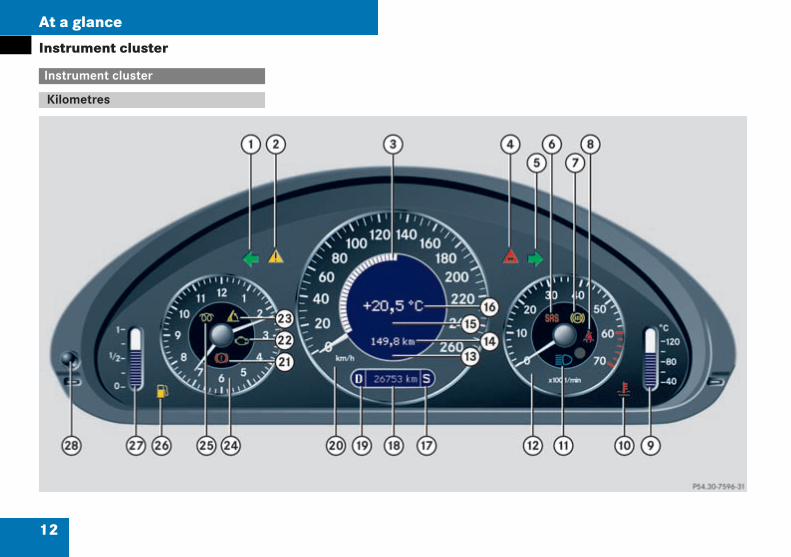
Instrument cluster
Kilometres
P54.30-7596-31
209en_d2.boo Seite 12 Dienstag, 25. Mai 2004 7:26 19
13
At a glance
Instrument cluster
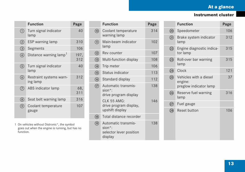
1 On vehicles without Distronic*, the symbolgoes out when the engine is running, but has nofunction.
Function Page
1 Turn signal indicatorlamp
40
2 ESP warning lamp 310
3 Segments 106
4 Distance warning lamp1 197,312
5 Turn signal indicatorlamp
40
6 Restraint systems warn-ing lamp
312
7 ABS indicator lamp 68,311
8 Seat belt warning lamp 316
9 Coolant temperaturegauge
107
Function Page
a Coolant temperaturewarning lamp
314
b Main-beam indicatorlamp
102
c Rev counter 107
d Multi-function display 108
e Trip meter 106
f Status indicator 113
g Standard display 112
h Automatic transmis-sion*:drive program display
CLK 55 AMG:drive program display,upshift display
138
146
j Total distance recorder
k Automatic transmis-sion*:selector lever positiondisplay
138
Function Page
l Speedometer 106
m Brake system indicatorlamp
312
n Engine diagnostic indica-tor lamp
315
o Roll-over bar warninglamp
315
p Clock 121
q Vehicles with a dieselengine:preglow indicator lamp
37
r Reserve fuel warninglamp
316
s Fuel gauge
t Reset button 106
209en_d2.boo Seite 13 Dienstag, 25. Mai 2004 7:26 19
14
At a glance
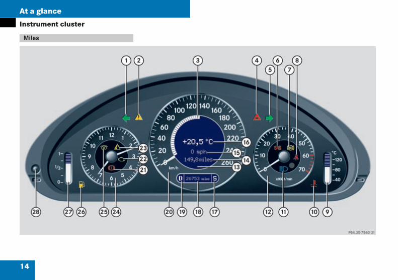
Instrument cluster
Miles
P54.30-7596-31
209en_d2.boo Seite 14 Dienstag, 25. Mai 2004 7:26 19

15
At a glance
Instrument cluster
1 On vehicles without Distronic*, the symbolgoes out when the engine is running, but has nofunction.
Function Page
1 Turn signal indicatorlamp
40
2 ESP warning lamp 310
3 Segments 106
4 Distance warning lamp1 197,312
5 Turn signal indicatorlamp
40
6 Restraint systems warn-ing lamp
312
7 ABS indicator lamp 68,311
8 Seat belt warning lamp 316
9 Coolant temperaturegauge
107
Function Page
a Coolant temperaturewarning lamp
314
b Main-beam indicatorlamp
102
c Rev counter 107
d Multi-function display 108
e Trip meter 106
f Status indicator 113
g Standard display 112
h Automatic transmis-sion*:drive program display
CLK 55 AMG:drive program display,upshift display
138
146
j Total distance recorder
k Automatic transmis-sion*:selector lever positiondisplay
138
Function Page
l Speedometer 106
m Brake system indicatorlamp
312
n Engine diagnostic indica-tor lamp
315
o Roll-over bar warninglamp
315
p Clock 121
q Vehicles with a dieselengine:preglow indicator lamp
37
r Reserve fuel warninglamp
316
s Fuel gauge
t Reset button 106
209en_d2.boo Seite 15 Dienstag, 25. Mai 2004 7:26 19
16
At a glance
Multi-function steering wheel
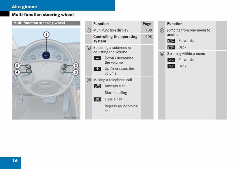
Multi-function steering wheel
P46.10-2455-31
Function Page
1 Multi-function display 108
Controlling the operatingsystem
108
2 Selecting a submenu oradjusting the volume
ç Down/decreasesthe volume
æ Up/increases thevolume
3 Making a telephone call
í Accepts a call
Starts dialling
ì Ends a call
Rejects an incomingcall
Function
4 Jumping from one menu toanother
è Forwards
ÿ Back
5 Scrolling within a menu
j Forwards
k Back
209en_d2.boo Seite 16 Dienstag, 25. Mai 2004 7:26 19
17
At a glance
Centre console
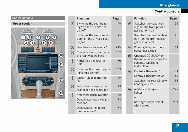
Centre console
Upper section
P68.20-3003-31
Function Page
1 Switches the seat heat-ing* on the driver's seaton/off
Switches the seat ventila-tion* on the driver's seaton/off
96
95
2 Deactivates Parktronic* 215
3 Coupé: extends/retractsthe rear window blind*
152
4 Activates/deactivatesESP
70
5 Switches the hazard warn-ing lamps on/off
103
6 Locks/unlocks the vehi-cle
89
7 Folds down/lowers therear seat head restraints
93
8 Anti-theft alarm system*
Deactivates tow-away pro-tection*
Deactivates the interiormotion sensor*
72
73
74
Function Page
9 Switches the seat heat-ing* on the front-passen-ger seat on/off
Switches the seat ventila-tion* on the front-passen-ger seat on/off
96
95
a Warning lamp for front-passenger airbag
64
b Operates COMAND* orthe audio system – see theseparate OperatingInstructions
c Controls Thermatic*
Controls Thermotronic*
Switches the rear windowheating on/off
154
164
153
d Ashtray with cigarettelighter*
or
Stowage compartmentwith socket
229
231
209en_d2.boo Seite 17 Dienstag, 25. Mai 2004 7:26 19
18
At a glance
Centre console
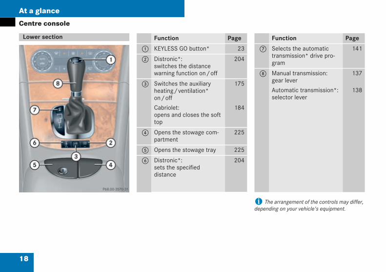
i The arrangement of the controls may differ,depending on your vehicle's equipment.
Lower section
P68.00-3570-31
Function Page
1 KEYLESS GO button* 23
2 Distronic*:switches the distancewarning function on/off
204
3 Switches the auxiliaryheating/ventilation*on/off
Cabriolet:opens and closes the softtop
175
184
4 Opens the stowage com-partment
225
5 Opens the stowage tray 225
6 Distronic*:sets the specifieddistance
204
Function Page
7 Selects the automatictransmission* drive pro-gram
141
8 Manual transmission:gear lever
Automatic transmission*:selector lever
137
138
209en_d2.boo Seite 18 Dienstag, 25. Mai 2004 7:26 19
19
At a glance
Overhead control panel
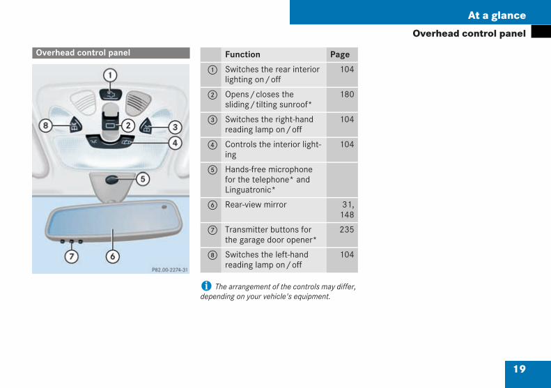
i The arrangement of the controls may differ,depending on your vehicle's equipment.
Overhead control panel
P82.00-2274-31
Function Page
1 Switches the rear interiorlighting on/off
104
2 Opens/closes thesliding/tilting sunroof*
180
3 Switches the right-handreading lamp on/off
104
4 Controls the interior light-ing
104
5 Hands-free microphonefor the telephone* andLinguatronic*
6 Rear-view mirror 31,148
7 Transmitter buttons forthe garage door opener*
235
8 Switches the left-handreading lamp on/off
104
209en_d2.boo Seite 19 Dienstag, 25. Mai 2004 7:26 19
20
At a glance
Door control panel
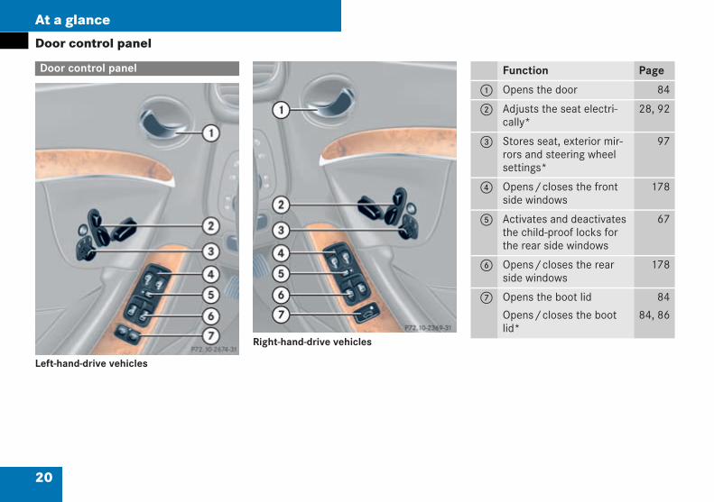
Left-hand-drive vehicles
Right-hand-drive vehicles
Door control panel
P72.10-2674-31
P72.10-2674-31
Function Page
1 Opens the door 84
2 Adjusts the seat electri-cally*
28, 92
3 Stores seat, exterior mir-rors and steering wheelsettings*
97
4 Opens/closes the frontside windows
178
5 Activates and deactivatesthe child-proof locks forthe rear side windows
67
6 Opens/closes the rearside windows
178
7 Opens the boot lid
Opens/closes the bootlid*
84
84, 86
209en_d2.boo Seite 20 Dienstag, 25. Mai 2004 7:26 19
21
Getting started
Opening
Adjusting
Driving
Parking and locking
209en_d2.boo Seite 21 Dienstag, 25. Mai 2004 7:26 19
22
Getting started
OpeningThe "Getting started" section containsbrief details of the basic functions of thevehicle. You should read this section par-ticularly thoroughly if this is your firstMercedes-Benz.
If you are already familiar with the basicfunctions described here, the "Controls indetail" section will help you with moredetailed information. You will find the ref-erence to the appropriate part of that sec-tion at the end of each segment.
I
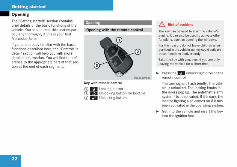
Key with remote control
1‹ Locking button2Š Unlocking button for boot lid3Œ Unlocking button
Press theΠunlocking button on theremote control.
The turn signals flash briefly. The vehi-cle is unlocked. The locking knobs inthe doors pop up. The anti-theft alarmsystem* is deactivated. If it is dark, thelocator lighting also comes on if it hasbeen activated in the operating system.
Get into the vehicle and insert the keyinto the ignition lock.
Opening
Opening with the remote control
P 80.35-2070-31
R230
G Risk of accident
The key can be used to start the vehicle'sengine. It can also be used to activate otherfunctions, such as opening the windows.
For this reason, do not leave children unsu-pervised in the vehicle as they could activatethese functions inadvertently.
Take the key with you, even if you are onlyleaving the vehicle for a short time.
209en_d2.boo Seite 22 Dienstag, 25. Mai 2004 7:26 19
23
Getting started
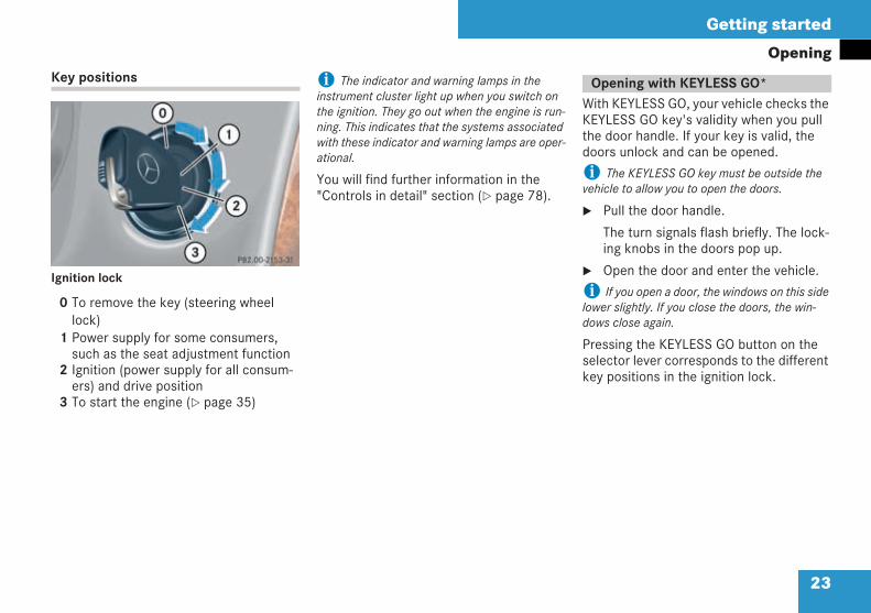
OpeningKey positions
Ignition lock
0 To remove the key (steering wheellock)
1 Power supply for some consumers,such as the seat adjustment function
2 Ignition (power supply for all consum-ers) and drive position
3 To start the engine ( page 35)
i The indicator and warning lamps in theinstrument cluster light up when you switch onthe ignition. They go out when the engine is run-ning. This indicates that the systems associatedwith these indicator and warning lamps are oper-ational.
You will find further information in the"Controls in detail" section ( page 78).
With KEYLESS GO, your vehicle checks theKEYLESS GO key's validity when you pullthe door handle. If your key is valid, thedoors unlock and can be opened.
i The KEYLESS GO key must be outside thevehicle to allow you to open the doors.
Pull the door handle.
The turn signals flash briefly. The lock-ing knobs in the doors pop up.
Open the door and enter the vehicle.
i If you open a door, the windows on this sidelower slightly. If you close the doors, the win-dows close again.
Pressing the KEYLESS GO button on theselector lever corresponds to the differentkey positions in the ignition lock.
P82.00-2153-31
neu
Opening with KEYLESS GO*
209en_d2.boo Seite 23 Dienstag, 25. Mai 2004 7:26 19
24
Getting started
Opening
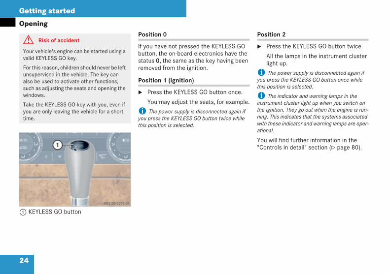
1 KEYLESS GO button
Position 0
If you have not pressed the KEYLESS GObutton, the on-board electronics have thestatus 0, the same as the key having beenremoved from the ignition.
Position 1 (ignition)
Press the KEYLESS GO button once.
You may adjust the seats, for example.
i The power supply is disconnected again ifyou press the KEYLESS GO button twice whilethis position is selected.
Position 2
Press the KEYLESS GO button twice.
All the lamps in the instrument clusterlight up.
i The power supply is disconnected again ifyou press the KEYLESS GO button once whilethis position is selected.
i The indicator and warning lamps in theinstrument cluster light up when you switch onthe ignition. They go out when the engine is run-ning. This indicates that the systems associatedwith these indicator and warning lamps are oper-ational.
You will find further information in the"Controls in detail" section ( page 80).
G Risk of accident
Your vehicle's engine can be started using avalid KEYLESS GO key.
For this reason, children should never be leftunsupervised in the vehicle. The key canalso be used to activate other functions,such as adjusting the seats and opening thewindows.
Take the KEYLESS GO key with you, even ifyou are only leaving the vehicle for a shorttime.
P 82.00-2271-31 neu
209en_d2.boo Seite 24 Dienstag, 25. Mai 2004 7:26 19
25
Getting started
Adjusting
You can adjust your seats either manuallyor electrically*, depending on your vehi-cle's equipment.
Adjusting
Seats
G Risk of accident
Only adjust the driver's seat when the vehi-cle is stationary. Otherwise, you may nolonger be able to observe road and trafficconditions and you could lose control of thevehicle as a result of the seat moving.
G Risk of accident and injury
Make sure that nobody can become trappedas you adjust the seat.
To reduce the risk of serious or fatal injuriesin the event of an accident or heavy deceler-ation, e.g. by an airbag inflating within milli-seconds, observe the following points:
All occupants must select a seatposition that allows the seat belt to beworn correctly and that is as far awayfrom the front airbags as possible.The position of the driver's seat mustallow the driver to drive the vehiclesafely. The distance from the driver'sseat to the pedals must be such that thedriver can fully depress the pedals. Thedistance between the driver's chest andthe centre of the airbag cover must bemore than 25 cm. The driver's armsshould be slightly bent when holding thesteering wheel.
Position the front-passenger seat as farback as possible, especially if a child issitting on this seat or if a child is securedin a restraint system on this seat.
Occupants must always wear their seatbelt correctly and position their back-rest as close to the vertical as possible.The head restraint should support theback of your head at about eye level.
Rearward-facing child restraint systemsmust not be fitted to the front-passen-ger seat unless the front passenger air-bag has been deactivated. In Mercedes-Benz vehicles, the front passenger air-bag is deactivated and the AIRBAG OFFwarning lamp is lit when a child restraintsystem with automatic child seat recog-nition is fitted to a front-passenger seatin a vehicle with automatic child seatrecognition.
209en_d2.boo Seite 25 Dienstag, 25. Mai 2004 7:26 19
26
Getting started
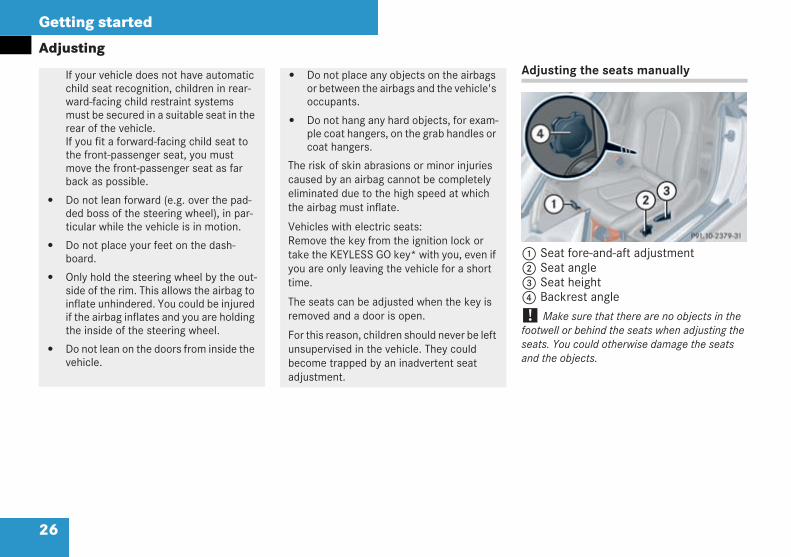
AdjustingAdjusting the seats manually
1 Seat fore-and-aft adjustment2 Seat angle3 Seat height4 Backrest angle
! Make sure that there are no objects in thefootwell or behind the seats when adjusting theseats. You could otherwise damage the seatsand the objects.
If your vehicle does not have automaticchild seat recognition, children in rear-ward-facing child restraint systemsmust be secured in a suitable seat in therear of the vehicle.If you fit a forward-facing child seat tothe front-passenger seat, you mustmove the front-passenger seat as farback as possible.
Do not lean forward (e.g. over the pad-ded boss of the steering wheel), in par-ticular while the vehicle is in motion.
Do not place your feet on the dash-board.
Only hold the steering wheel by the out-side of the rim. This allows the airbag toinflate unhindered. You could be injuredif the airbag inflates and you are holdingthe inside of the steering wheel.
Do not lean on the doors from inside thevehicle.
Do not place any objects on the airbagsor between the airbags and the vehicle'soccupants.
Do not hang any hard objects, for exam-ple coat hangers, on the grab handles orcoat hangers.
The risk of skin abrasions or minor injuriescaused by an airbag cannot be completelyeliminated due to the high speed at whichthe airbag must inflate.
Vehicles with electric seats:Remove the key from the ignition lock ortake the KEYLESS GO key* with you, even ifyou are only leaving the vehicle for a shorttime.
The seats can be adjusted when the key isremoved and a door is open.
For this reason, children should never be leftunsupervised in the vehicle. They couldbecome trapped by an inadvertent seatadjustment.
P 91.10-2379-31Bildgröße 6 x 5,8
209en_d2.boo Seite 26 Dienstag, 25. Mai 2004 7:26 19
27
Getting started
AdjustingSeat fore-and-aft adjustment
Pull handle1 up.
Slide the seat forwards or backwards.
Release handle1 again.
Make sure that you hear the seat clickinto position.
Seat angle
Adjust the seat angle in such a way thatyour thighs are lightly supported.
Turn handwheel2 forwards orbackwards.
Seat height
Pull handle3 up repeatedly until youhave raised the seat to the desiredheight.
or
Push handle3 down repeatedly untilyou have lowered the seat to thedesired height.
Backrest angle
Relieve the load on the backrest.
Turn handwheel4 forwards orbackwards.
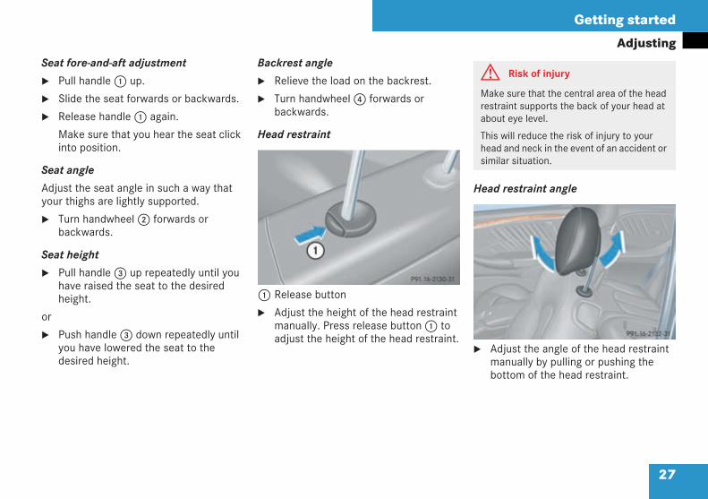
Head restraint
1 Release button
Adjust the height of the head restraintmanually. Press release button1 toadjust the height of the head restraint.
Head restraint angle
Adjust the angle of the head restraintmanually by pulling or pushing thebottom of the head restraint.
P 91.16-2130-31
G Risk of injury
Make sure that the central area of the headrestraint supports the back of your head atabout eye level.
This will reduce the risk of injury to yourhead and neck in the event of an accident orsimilar situation.
P91.16-2132-31
25
209en_d2.boo Seite 27 Dienstag, 25. Mai 2004 7:26 19
28
Getting started
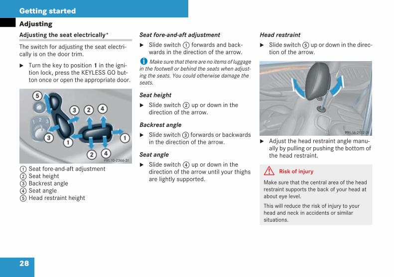
AdjustingAdjusting the seat electrically*
The switch for adjusting the seat electri-cally is on the door trim.
Turn the key to position 1 in the igni-tion lock, press the KEYLESS GO but-ton once or open the appropriate door.
1 Seat fore-and-aft adjustment2 Seat height3 Backrest angle4 Seat angle5 Head restraint height
Seat fore-and-aft adjustment
Slide switch1 forwards and back-wards in the direction of the arrow.
iMake sure that there are no items of luggagein the footwell or behind the seats when adjust-ing the seats. You could otherwise damage theseats.
Seat height
Slide switch2 up or down in thedirection of the arrow.
Backrest angle
Slide switch3 forwards or backwardsin the direction of the arrow.
Seat angle
Slide switch4 up or down in thedirection of the arrow until your thighsare lightly supported.
Head restraint
Slide switch5 up or down in the direc-tion of the arrow.
Adjust the head restraint angle manu-ally by pulling or pushing the bottom ofthe head restraint.
P 91.10-2366-31
neu
G Risk of injury
Make sure that the central area of the headrestraint supports the back of your head atabout eye level.
This will reduce the risk of injury to yourhead and neck in accidents or similarsituations.
P91.16-2132-31
209en_d2.boo Seite 28 Dienstag, 25. Mai 2004 7:26 19
29
Getting started
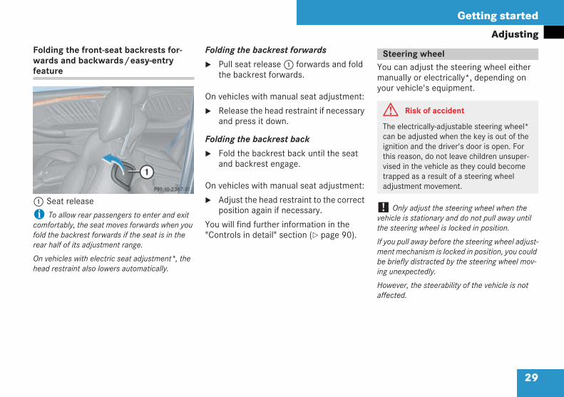
AdjustingFolding the front-seat backrests for-wards and backwards/easy-entryfeature
1 Seat release
i To allow rear passengers to enter and exitcomfortably, the seat moves forwards when youfold the backrest forwards if the seat is in therear half of its adjustment range.
On vehicles with electric seat adjustment*, thehead restraint also lowers automatically.
Folding the backrest forwards
Pull seat release1 forwards and foldthe backrest forwards.
On vehicles with manual seat adjustment:
Release the head restraint if necessaryand press it down.
Folding the backrest back
Fold the backrest back until the seatand backrest engage.
On vehicles with manual seat adjustment:
Adjust the head restraint to the correctposition again if necessary.
You will find further information in the"Controls in detail" section ( page 90).
You can adjust the steering wheel eithermanually or electrically*, depending onyour vehicle's equipment.
! Only adjust the steering wheel when thevehicle is stationary and do not pull away untilthe steering wheel is locked in position.
If you pull away before the steering wheel adjust-ment mechanism is locked in position, you couldbe briefly distracted by the steering wheel mov-ing unexpectedly.
However, the steerability of the vehicle is notaffected.
P 91.10-2367-31
neu
Steering wheel
G Risk of accident
The electrically-adjustable steering wheel*can be adjusted when the key is out of theignition and the driver's door is open. Forthis reason, do not leave children unsuper-vised in the vehicle as they could becometrapped as a result of a steering wheeladjustment movement.
209en_d2.boo Seite 29 Dienstag, 25. Mai 2004 7:26 19
30
Getting started
AdjustingAdjusting the steering wheel manually
The handle is located under the steeringcolumn.
1 Release handle
Pull handle1 to release the steeringcolumn.
Adjust the position of the steeringwheel manually.
When doing so, make sure that:
you can hold the steering wheelwith your arms slightly bent
your legs can move freely
you can see all displays in theinstrument cluster clearly
To lock the steering column, push han-dle1 in fully until you hear it click intoplace.
The steering wheel position is lockedagain.
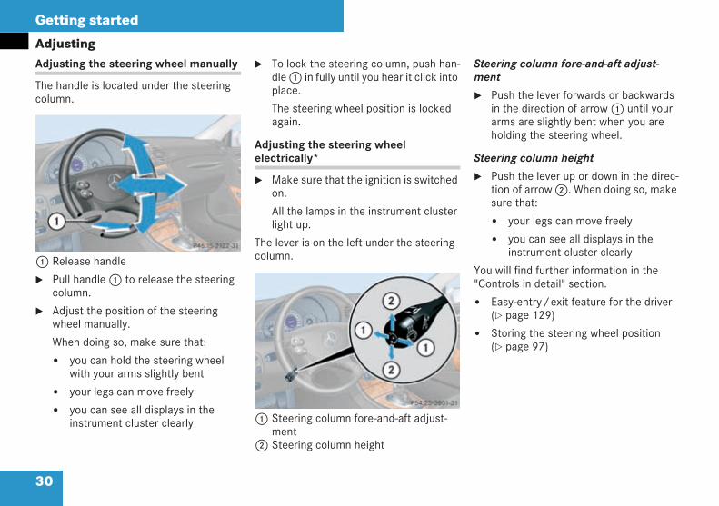
Adjusting the steering wheelelectrically*
Make sure that the ignition is switchedon.
All the lamps in the instrument clusterlight up.
The lever is on the left under the steeringcolumn.
1 Steering column fore-and-aft adjust-ment
2 Steering column height
Steering column fore-and-aft adjust-ment
Push the lever forwards or backwardsin the direction of arrow1 until yourarms are slightly bent when you areholding the steering wheel.
Steering column height
Push the lever up or down in the direc-tion of arrow2. When doing so, makesure that:
your legs can move freely
you can see all displays in theinstrument cluster clearly
You will find further information in the"Controls in detail" section.
Easy-entry/exit feature for the driver( page 129)
Storing the steering wheel position( page 97)
P 46.15-2122-31
P 54.25-3801-31
209en_d2.boo Seite 30 Dienstag, 25. Mai 2004 7:26 19
31
Getting started
Adjusting
Before starting off, adjust the rear-viewmirror and the exterior mirrors in such away that you can get a good overview ofroad and traffic conditions.
Rear-view mirror
Adjust the rear-view mirror manually.
Exterior mirrors
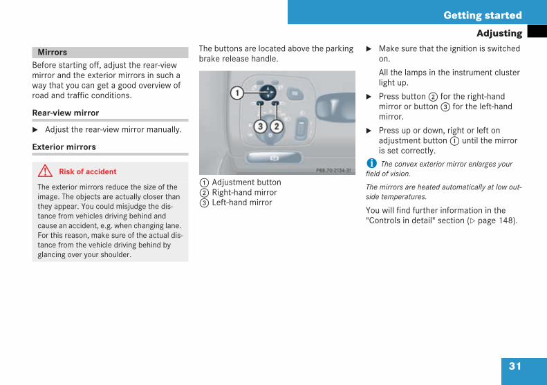
The buttons are located above the parkingbrake release handle.
1 Adjustment button2 Right-hand mirror3 Left-hand mirror
Make sure that the ignition is switchedon.
All the lamps in the instrument clusterlight up.
Press button2 for the right-handmirror or button3 for the left-handmirror.
Press up or down, right or left onadjustment button1 until the mirroris set correctly.
i The convex exterior mirror enlarges yourfield of vision.
The mirrors are heated automatically at low out-side temperatures.
You will find further information in the"Controls in detail" section ( page 148).
Mirrors
G Risk of accident
The exterior mirrors reduce the size of theimage. The objects are actually closer thanthey appear. You could misjudge the dis-tance from vehicles driving behind andcause an accident, e.g. when changing lane.For this reason, make sure of the actual dis-tance from the vehicle driving behind byglancing over your shoulder.
P88.70-2134-31
209en_d2.boo Seite 31 Dienstag, 25. Mai 2004 7:26 19
32
Getting started
Driving
Driving
G Risk of accident
Do not keep any objects in the driver's foot-well. Make sure that floormats or carpets inthe driver's footwell:
do not obstruct the pedals
are properly secured
The objects could otherwise get caughtbetween the pedals if you accelerate orbrake suddenly. You would then not be ableto brake or accelerate. This could lead toaccident and injury.
Wearing seat belts
G Risk of injury
A seat belt that is not worn correctly, or thatis not correctly engaged in the seat beltbuckle, cannot perform its intended protec-tive function. It could even cause severe orfatal injuries.
For this reason, make sure that all the occu-pants – in particular, pregnant women –always wear their seat belts correctly.
The seat belt must not be twisted andmust pass closely over your body. Youshould therefore avoid wearing bulkyclothing (e.g. winter coats). The shoul-der section of the belt must be routedover the middle of your shoulder – neveraround your neck or under your arm –and must be pulled tight against theupper body. The lap belt must cross overyour lap as low down as possible at alltimes, i.e. over your hip joints – notacross your stomach or lower abdomen.If necessary, press the belt strap down abit and retighten by pulling the seat beltupwards towards the belt reel.
Do not route the belt strap over sharp orfragile objects, especially if these are onor inside your clothing, e.g. spectacles,pens or keys. The belt strap could other-wise be damaged and you could beinjured as a result.
Only one person should use each seatbelt at any one time. Do not allow chil-dren to be carried on the lap of anotheroccupant since the child will then nolonger be secured in the event of anaccident, braking or a sudden change indirection. This could result in severe orfatal injuries to the child or other occu-pants.
Persons less than 1.50 m tall cannotwear the seat belts correctly. Personsless that 1.50 m tall therefore requiresuitable restraint systems.
209en_d2.boo Seite 32 Dienstag, 25. Mai 2004 7:26 19
33
Getting started
DrivingThe< seat belt warning lamp in theinstrument cluster reminds you to ensurethat all occupants are wearing their seatbelts.
If the driver has not fastened his seat belt,the< seat belt warning lamp lights upif the doors are closed and the engine isrunning. In addition, an intermittent signalsounds from a speed of 25 km/h upwards.
The intermittent signal ceases:
as soon as the driver has fastened hisseat belt
after a maximum of 93 seconds
when the vehicle is stationary
The< seat belt warning lamp only goesout once the driver has fastened his seatbelt.
Children less than 1.50 m tall andyounger than 12 years of age cannotwear the seat belts properly. Alwayssecure these children in suitable childrestraint systems on seats designed forthis purpose ( page 62). Please followthe manufacturer's installation instruc-tions when installing child restraint sys-tems.
Do not secure any objects with a seatbelt if it is also being used by one of thevehicle's occupants.
G Risk of injury
The seat belt only provides its intendeddegree of protection if the seat backrest ispositioned as close to the vertical as possi-ble, allowing the occupant to sit upright.Avoid seat positions which do not allow theseat belt to be routed correctly ( page 25).Therefore, position the backrests as close tothe vertical as possible. Never drive with thebackrest inclined too far backwards.
G Risk of injury
Airbags are designed not to be triggered inall accident situations, since a correctly fas-tened seat belt will often be sufficient forproviding an effective degree of protection.Airbags are not a substitute for seat belts.To reduce the risk of severe or even fatalinjury, make sure that all occupants – in par-ticular, pregnant women – always wear theirseat belts correctly, are seated in an uprightposition and have their seats positionedalmost vertically ( page 25).
209en_d2.boo Seite 33 Dienstag, 25. Mai 2004 7:26 19
34
Getting started
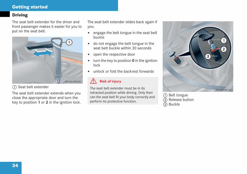
DrivingThe seat belt extender for the driver andfront passenger makes it easier for you toput on the seat belt.
1 Seat belt extender
The seat belt extender extends when youclose the appropriate door and turn thekey to position 1 or 2 in the ignition lock.
The seat belt extender slides back again ifyou:
engage the belt tongue in the seat beltbuckle
do not engage the belt tongue in theseat belt buckle within 30 seconds
open the respective door
turn the key to position 0 in the ignitionlock
unlock or fold the backrest forwards
1 Belt tongue2 Release button3 Buckle
P91.40-2306-31
G Risk of injury
The seat belt extender must be in itsretracted position while driving. Only thencan the seat belt fit your body correctly andperform its protective function.
P91.40-2307-31
209en_d2.boo Seite 34 Dienstag, 25. Mai 2004 7:26 19
35
Getting started
DrivingClick belt tongue1 into buckle3.
Pull up on the shoulder belt to tightenthe belt across your lap if necessary.
! Do not depress the accelerator pedal whenstarting the engine.
i If you depress the brake pedal when startingthe engine, the pedal travel is longer than usualand the pedal resistance is low.
If you depress the brake pedal after starting theengine, the pedal travel and resistance return tonormal.
G Risk of injury
You could injure yourself in an accident ifyou use seat belts which:
are damaged
have been subjected to a load in an acci-dent
have been modified
These seat belts can then no longer functionor protect as intended.
Do not pass the seat belt strap over sharpedges. It could tear.
Make sure that the seat belt is not caught inthe door or seat adjustment mechanism. Itcould be damaged.
G Risk of injury
Check the seat belts regularly for damage.
You should never modify the seat belts your-self. They might not function properly anymore.
Always have seat belts which are damagedor have been subjected to a load in anaccident replaced at a qualified specialistworkshop, which has the necessary special-ist knowledge and tools to carry out therequired work. Mercedes-Benz recommendsthat you use a Mercedes-Benz Service Cen-tre for this purpose. In particular, work rele-vant to safety or on safety-related systemsmust be carried out at a qualified specialistworkshop.
Starting the engine
G Risk of poisoning
Never run the engine when the vehicle is inan enclosed space. The exhaust fumes con-tain poisonous carbon monoxide. Breathingin exhaust fumes constitutes a health haz-ard and could lead to unconsciousness anddeath.
209en_d2.boo Seite 35 Dienstag, 25. Mai 2004 7:26 19
36
Getting started
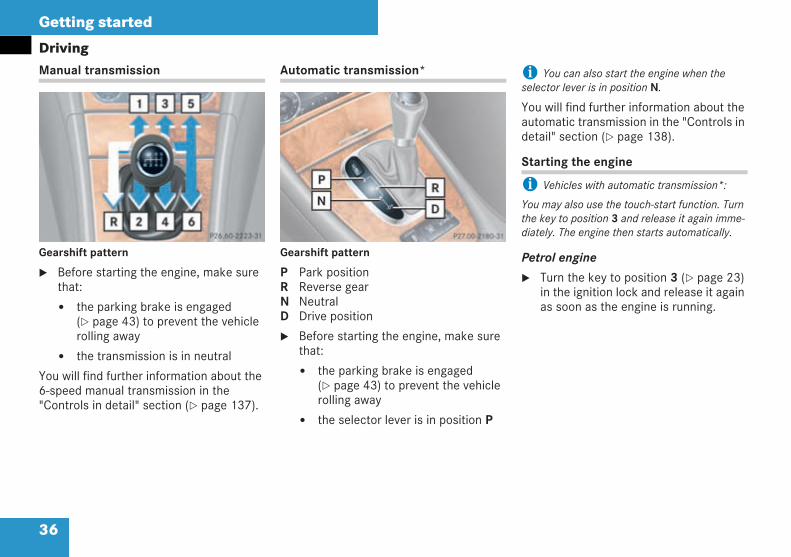
DrivingManual transmission
Gearshift pattern
Before starting the engine, make surethat:
the parking brake is engaged( page 43) to prevent the vehiclerolling away
the transmission is in neutral
You will find further information about the6-speed manual transmission in the"Controls in detail" section ( page 137).
Automatic transmission*
Gearshift pattern
P Park positionR Reverse gearN NeutralD Drive position
Before starting the engine, make surethat:
the parking brake is engaged( page 43) to prevent the vehiclerolling away
the selector lever is in position P
i You can also start the engine when theselector lever is in position N.
You will find further information about theautomatic transmission in the "Controls indetail" section ( page 138).
Starting the engine
i Vehicles with automatic transmission*:
You may also use the touch-start function. Turnthe key to position 3 and release it again imme-diately. The engine then starts automatically.
Petrol engine
Turn the key to position 3 ( page 23)in the ignition lock and release it againas soon as the engine is running.
P 26.60-2223-31 P 27.00-2180-31
209en_d2.boo Seite 36 Dienstag, 25. Mai 2004 7:26 19
37
Getting started
DrivingDiesel engine
Turn the key to position 2 in the igni-tion lock.
Theq preglow indicator lamp in theinstrument cluster lights up.
As soon as theq preglow indicatorlamp has gone out, turn the key in theignition lock to position 3 and release itas soon as the engine is running.
i If the engine is already at operating temper-ature, you can start it without preglow.
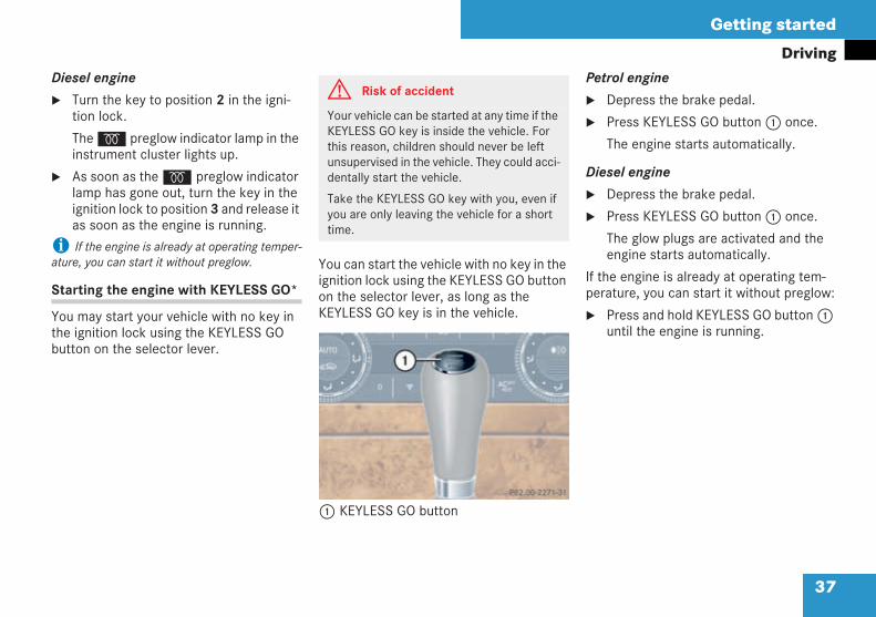
Starting the engine with KEYLESS GO*
You may start your vehicle with no key inthe ignition lock using the KEYLESS GObutton on the selector lever.
You can start the vehicle with no key in theignition lock using the KEYLESS GO buttonon the selector lever, as long as theKEYLESS GO key is in the vehicle.
1 KEYLESS GO button
Petrol engine
Depress the brake pedal.
Press KEYLESS GO button1 once.
The engine starts automatically.
Diesel engine
Depress the brake pedal.
Press KEYLESS GO button1 once.
The glow plugs are activated and theengine starts automatically.
If the engine is already at operating tem-perature, you can start it without preglow:
Press and hold KEYLESS GO button1until the engine is running.
G Risk of accident
Your vehicle can be started at any time if theKEYLESS GO key is inside the vehicle. Forthis reason, children should never be leftunsupervised in the vehicle. They could acci-dentally start the vehicle.
Take the KEYLESS GO key with you, even ifyou are only leaving the vehicle for a shorttime.
P 82.00-2271-31 neu
209en_d2.boo Seite 37 Dienstag, 25. Mai 2004 7:26 19
38
Getting started
Driving
Pull away immediately to warm theengine up quickly.
Do not run the engine at full speed untilit has reached operating temperature.
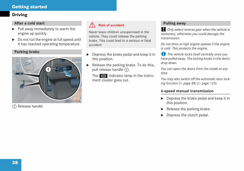
1 Release handle
Depress the brake pedal and keep it inthis position.
Release the parking brake. To do this,pull release handle1.
The3 indicator lamp in the instru-ment cluster goes out.
! Only select reverse gear when the vehicle isstationary, otherwise you could damage thetransmission.
Do not drive at high engine speeds if the engineis cold. This protects the engine.
i The vehicle locks itself centrally once youhave pulled away. The locking knobs in the doorsdrop down.
You can open the doors from the inside at anytime.
You may also switch off the automatic door lock-ing function ( page 88) ( page 125).
6-speed manual transmission
Depress the brake pedal and keep it inthis position.
Release the parking brake.
Depress the clutch pedal.
After a cold start
Parking brake
P 42.20-2198-31 neu
G Risk of accident
Never leave children unsupervised in thevehicle. They could release the parkingbrake. This could lead to a serious or fatalaccident.
Pulling away
209en_d2.boo Seite 38 Dienstag, 25. Mai 2004 7:26 19
39
Getting started
DrivingSelect either first or reverse gear.
Slowly release the clutch pedal andcarefully depress the accelerator.
! Change gear in good time. Make sure thatthe engine speed does not reach the red area inthe rev counter. There is otherwise a danger ofengine damage.
Do not allow the wheels to spin, if possible. Youcould otherwise damage the drive train.
Automatic transmission*
i You can only move the selector lever to therequired position by depressing the brake pedal.Only then is the selector lever lock disabled.
Depress the brake pedal and keep it inthis position.
The selector lever lock is released.
Release the parking brake.
Move the selector lever to position Dor R.
i Wait for the shift process to completebefore pulling away.
Release the brake pedal.
Carefully depress the acceleratorpedal.
i After a cold start, the automatic transmis-sion will shift at a higher engine speed. This helpsthe catalytic converter to reach its operatingtemperature more quickly.
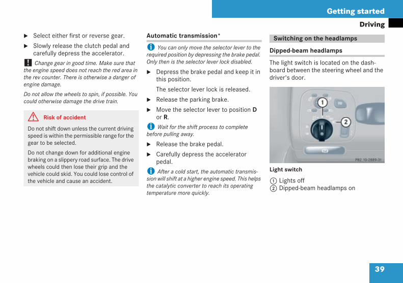
Dipped-beam headlamps
The light switch is located on the dash-board between the steering wheel and thedriver's door.
Light switch
1 Lights off2 Dipped-beam headlamps on
G Risk of accident
Do not shift down unless the current drivingspeed is within the permissible range for thegear to be selected.
Do not change down for additional enginebraking on a slippery road surface. The drivewheels could then lose their grip and thevehicle could skid. You could lose control ofthe vehicle and cause an accident.
Switching on the headlamps
P 82.10-2889-31 neu
209en_d2.boo Seite 39 Dienstag, 25. Mai 2004 7:26 19
40
Getting started
Driving
i Legal and optional additional requirementsmay impose variations in certain countries. Inthese countries, the dipped-beam headlampsare switched on when the ignition is switched on.
Turn the light switch toB.
The dipped-beam headlamps come on.
The fuel tank and coolant temperaturesymbols in the instrument cluster arelit more brightly.
TheB dipped-beam headlampssymbol in the instrument cluster lightsup.
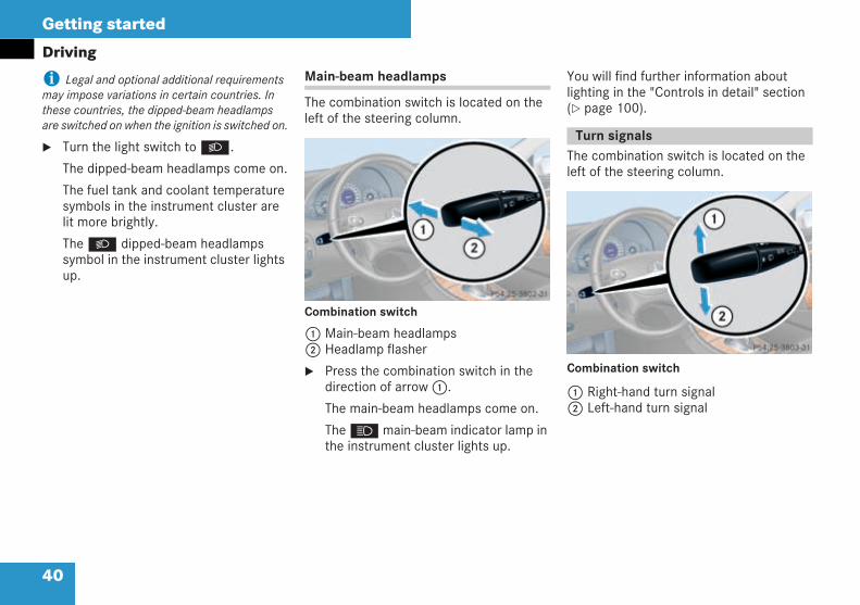
Main-beam headlamps
The combination switch is located on theleft of the steering column.
Combination switch
1 Main-beam headlamps2 Headlamp flasher
Press the combination switch in thedirection of arrow1.
The main-beam headlamps come on.
TheA main-beam indicator lamp inthe instrument cluster lights up.
You will find further information aboutlighting in the "Controls in detail" section( page 100).
The combination switch is located on theleft of the steering column.
Combination switch
1 Right-hand turn signal2 Left-hand turn signal
P 54.25-3802-31 neu
Turn signals
P54.25-3803-31 neu
209en_d2.boo Seite 40 Dienstag, 25. Mai 2004 7:26 19
41
Getting started
DrivingPress the combination switch in thedirection of arrow1 or2.
The corresponding turn signal indicatorlamp flashes in the instrument cluster.
The combination switch moves back toits basic position automatically afterlarge steering wheel movements.
i Press the switch briefly to signal a minorchange in direction. The appropriate turn signalflashes three times.
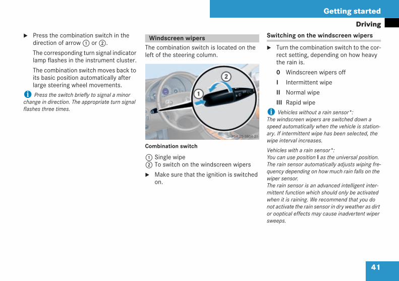
The combination switch is located on theleft of the steering column.
Combination switch
1 Single wipe2 To switch on the windscreen wipers
Make sure that the ignition is switchedon.
Switching on the windscreen wipers
Turn the combination switch to the cor-rect setting, depending on how heavythe rain is.
0 Windscreen wipers off
I Intermittent wipe
II Normal wipe
III Rapid wipe
i Vehicles without a rain sensor*:The windscreen wipers are switched down aspeed automatically when the vehicle is station-ary. If intermittent wipe has been selected, thewipe interval increases.
Vehicles with a rain sensor*:You can use position I as the universal position.The rain sensor automatically adjusts wiping fre-quency depending on how much rain falls on thewiper sensor.The rain sensor is an advanced intelligent inter-mittent function which should only be activatedwhen it is raining. We recommend that you donot activate the rain sensor in dry weather as dirtor ooptical effects may cause inadvertent wipersweeps.
Windscreen wipers
P 54.25-3804-31 neu
209en_d2.boo Seite 41 Dienstag, 25. Mai 2004 7:26 19
42
Getting started
Driving
i Vehicles with a rain sensor*:
The windscreen wipers are automaticallyswitched to intermittent wipe when the vehicle isstationary.
The intermittent wipe stops as soon as you openthe driver's or passenger door. This protects per-sons getting into or out of the vehicle from beingsprayed. Intermittent wipe continues when you:
turn the combination switch to II or III
or when the engine is running and you:
close the doors again
move the selector lever to D or R (vehicleswith automatic transmission*)
Single wipe
Briefly push the combination switch upto the pressure point in the direction ofarrow1.
The windscreen wipers wipe once with-out washer fluid.
Wiping the windscreen using washerfluid
Push the combination switch beyondthe pressure point in the direction ofarrow1.
The windscreen wipers wipe withwasher fluid.
i Wipe with washer fluid, even if it is raining.This will help to prevent smears on the wind-screen.
Intermittent wipe
i Vehicles with a rain sensor*:
The rain sensor controls the windscreen wipersautomatically, depending on how wet the wind-screen is.
Turn the combination switch to I.A wiper sweep takes place and subsequentwipe intervals depend on how wet the wind-screen is.
209en_d2.boo Seite 42 Dienstag, 25. Mai 2004 7:26 19
43
Getting started
Parking and locking
You have now completed your first trip.You have stopped your vehicle and haveparked properly. End your trip as follows.
i When you close a door, the windows on thesame side close.
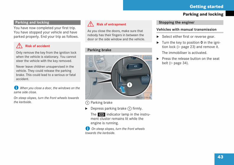
On steep slopes, turn the front wheels towardsthe kerbside. 1 Parking brake
Depress parking brake1 firmly.
The3 indicator lamp in the instru-ment cluster remains lit while theengine is running.
i On steep slopes, turn the front wheelstowards the kerbside.
Vehicles with manual transmission
Select either first or reverse gear.
Turn the key to position 0 in the igni-tion lock ( page 23) and remove it.
The immobiliser is activated.
Press the release button on the seatbelt ( page 34).
Parking and locking
G Risk of accident
Only remove the key from the ignition lockwhen the vehicle is stationary. You cannotsteer the vehicle with the key removed.
Never leave children unsupervised in thevehicle. They could release the parkingbrake. This could lead to a serious or fatalaccident.
G Risk of entrapment
As you close the doors, make sure thatnobody has their fingers in between thedoor or the side window and the vehicle.
Parking brake
P 42.20-2199-31 neu
Stopping the enginel
209en_d2.boo Seite 43 Dienstag, 25. Mai 2004 7:26 19
44
Getting started
Parking and lockingVehicles with automatic transmission*
Move the selector lever to P.
With the key
Turn the key to position 0 in the igni-tion lock ( page 23) and remove it.
The immobiliser is activated.
i You can only remove the key when theselector lever is in position P.
Press the release button on the seatbelt ( page 34).
With KEYLESS GO*
Press the KEYLESS GO button on theselector lever.
The engine is switched off and all thelights in the instrument cluster go out.The on-board electronics have status 1( page 23).
Press the release button on the seatbelt ( page 34).
Get out of the vehicle and close thedoors.
Locking with the remote control
Press the‹ locking button on theremote control ( page 22).
The locking knobs in the doors dropdown. The turn signals flash threetimes/light up briefly.
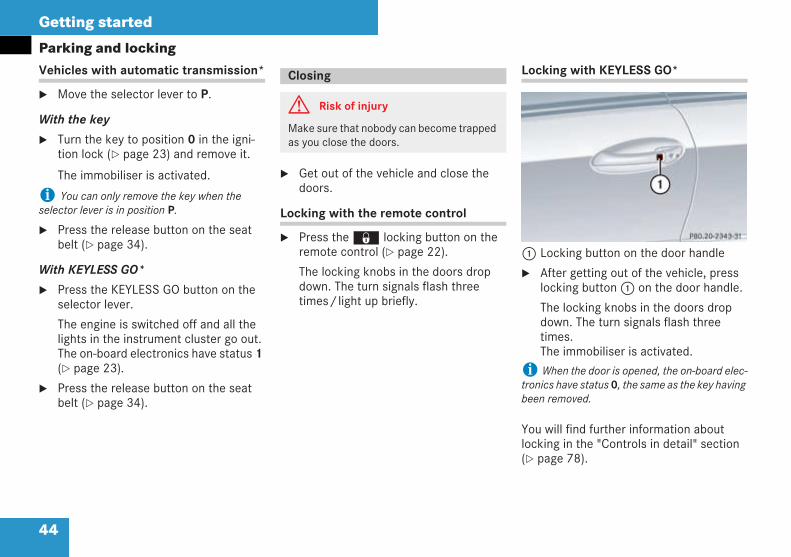
Locking with KEYLESS GO*
1 Locking button on the door handle
After getting out of the vehicle, presslocking button1 on the door handle.
The locking knobs in the doors dropdown. The turn signals flash threetimes.The immobiliser is activated.
i When the door is opened, the on-board elec-tronics have status 0, the same as the key havingbeen removed.
You will find further information aboutlocking in the "Controls in detail" section( page 78).
Closing
G Risk of injury
Make sure that nobody can become trappedas you close the doors.
P80.20-2343-31
209en_d2.boo Seite 44 Dienstag, 25. Mai 2004 7:26 19
45
Safety
Occupant safety
Driving safety systems
Anti-theft systems
209en_d2.boo Seite 45 Dienstag, 25. Mai 2004 7:26 19
46
Safety
Occupant safety
This section will familiarise you with themost important features of the restraintsystems in your vehicle. In the event of anaccident, your vehicle may collide withanother object, e.g. another vehicle. Thismay result in rapid acceleration or deceler-ation of your vehicle. During this accelera-tion or deceleration, the vehicle occupantswill be moved in the opposite direction tothe force of the impact. There is thereforethe risk of vehicle occupants injuring them-selves on the vehicle interior or on parts ofthe vehicle. The purpose of supplementalrestraint systems – first and foremost theseat belts supplemented where necessaryby belt tensioners, belt force limiters andairbags – is to minimise this risk of injury.However, seat belts and airbags are gener-ally unable to prevent injuries caused byobjects penetrating the vehicle from theoutside.
The most important restraint systems are:
Seat belts
Restraint systems for children, sincethey are the most effective means ofreducing the extent to which occu-pants are moved in the event of anaccident
Additional protection is provided by:
The SRS (Supplemental RestraintSystem) comprising:
Belt tensioners
Belt force limiters
Airbags
Roll-over bars (Cabriolet)
i An airbag increases the degree of protectionfor vehicle occupants wearing a seat belt and istherefore to be considered only as an additionalrestraint system to the seat belt. Airbags are nota substitute for wearing a seat belt correctly atall times. This is because, on the one hand, air-bags are not triggered in all types of accident, asin some situations their deployment would notincrease the protection enjoyed by the vehicleoccupants, provided they are wearing their seatbelts correctly.
i And on the other hand, airbag deploymentonly provides increased protection if the seatbelt is worn correctly, because:
the belt helps to keep the vehicle occupantin the best position in relation to the airbag
the belt protects to a large extent the vehicleoccupant from being propelled towards theforce of impact, e.g. in the event of a frontalcollision, and is therefore better able toreduce the risk of injury
In an accident in which an airbag is triggered, itsdeployment will only enhance the protection pro-vided by the seat belt, if the seat belt is worn cor-rectly.
Occupant safety
Restraint systems
209en_d2.boo Seite 46 Dienstag, 25. Mai 2004 7:26 19
47
Safety
Occupant safety
Seat belts and restraint systems for chil-dren travelling in the vehicle are the mostimportant restraint systems. They are themost effective means of restraining themovement of vehicle occupants towardsthe impact force and thus reduce the dan-ger of them hitting parts of the vehicle inte-rior.
G Risk of injury
Modifications to or work incorrectly carriedout on a restraint system (seat belt and seatbelt anchorages, belt tensioner, belt forcelimiter or airbag) or its wiring, or tamperingwith other networked electronic systems,could cause the restraint systems to stopworking correctly. The airbags or belt ten-sioners might, for example, be activatedinadvertently or fail to be triggered in anaccident even though the decelerationwould be sufficient to trigger the airbag orbelt tensioner. Under no circumstances,therefore, should you modify the restraintsystems yourself. Never tamper with elec-tronic components or their software.
G Risk of injury
Airbags do offer additional protection butthey are not a substitute for the seat belts.To reduce the risk of severe or even fatalinjury, make sure that all occupants – in par-ticular, pregnant women – always wear theirseat belts correctly, are seated in an uprightposition and have their seats positionedalmost vertically.
Seat belts
G Risk of injury
If you do not wear your seat belt, or wear itincorrectly, or do not engage the belt tonguein the buckle, the belt cannot fulfil itsintended protective function. It could evencause severe or fatal injuries. For this rea-son, make sure that all the occupants – inparticular, pregnant women – always weartheir seat belts correctly.
Make sure that the belt:
is routed across your pelvic area as lowdown as possible, i.e. across your hipjoints and not your abdomen
fits closely
is not twisted
is routed across the middle of yourshoulder
is not routed across your neck or underyour arm
is pulled tight over your hip joints bypulling the shoulder section of the beltupwards
209en_d2.boo Seite 47 Dienstag, 25. Mai 2004 7:26 19
48
Safety
Occupant safety
Do not secure any objects with a seat belt ifit is also being used by one of the vehicle'soccupants.
Avoid wearing bulky clothing, e.g. a wintercoat.
Do not route the seat belt strap over sharp-edged or fragile objects, especially if theseare on or in your clothing, e.g. spectacles,pencils or keys.
The belt strap could otherwise tear and youor other vehicle occupants could be injuredas a result.
Only one person should use each seat beltat any one time.
On no account should children travel sittingon the lap of another occupant. It would notbe possible to restrain the children and theyand other vehicle occupants could be seri-ously injured in the event of abrupt brakingor fatally injured in the event of an accident.
Persons less than 1.50 m tall or childrenunder twelve years of age cannot wear theirseat belts properly. They therefore requireadditional restraint systems installed onsuitable vehicle seats for protection in anaccident. Always observe the installationinstructions issued by the manufacturer ofthe child restraint systems.
G Risk of injury
The seat belt only provides its intendeddegree of protection if the seat backrest ispositioned as close to the vertical as possi-ble, allowing the occupant to sit upright.Avoid seat positions that do not allow theseat belt to be routed correctly. To do so,position the backrest as close to the verticalas possible. Never drive with the backrestreclined too far back. You could otherwisebe seriously or even fatally injured in theevent of an accident or abrupt braking.
G Risk of injury
The seat belt cannot perform its protectivefunction correctly if the seat belt strap orbuckle are dirty or damaged. For this rea-son, keep the seat belt strap and buckleclean, otherwise the belt tongue cannotengage correctly.
Check the seat belts regularly that they:
are not damaged
are not routed over sharp edges
are not trapped
The seat belt strap could otherwise tear inan accident.
You or others could be seriously or fatallyinjured.
Have seat belts replaced and their anchor-ages checked if the belts have been dam-aged or subjected to a heavy load in anaccident.
For safety reasons, Mercedes-Benz recom-mends that you only use seat belts whichhave been specially approved for your vehi-cle by Mercedes-Benz.
209en_d2.boo Seite 48 Dienstag, 25. Mai 2004 7:26 19
49
Safety
Occupant safety
i In many countries, there are legal regula-tions concerning the use of seat belts and childrestraint systems.
Lap-shoulder seat belt
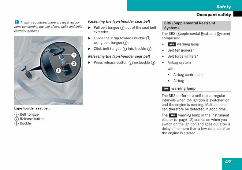
1 Belt tongue2 Release button3 Buckle
Fastening the lap-shoulder seat belt
Pull belt tongue1 out of the seat beltextender.
Guide the strap towards buckle3using belt tongue1.
Click belt tongue1 into buckle3.
Releasing the lap-shoulder seat belt
Press release button2 on buckle3.
The SRS (Supplemental Restraint System)comprises:
1 warning lamp
Belt tensioners*
Belt force limiters*
Airbag system
with
Airbag control unit
Airbag
1 warning lamp
The SRS performs a self-test at regularintervals when the ignition is switched onand the engine is running. Malfunctionscan therefore be detected in good time.
The1 warning lamp in the instrumentcluster ( page 12) comes on when youswitch on the ignition and goes out after adelay of no more than a few seconds afterthe engine is started.
P91.40-2307-31
SRS (Supplemental RestraintSystem)
209en_d2.boo Seite 49 Dienstag, 25. Mai 2004 7:26 19
50
Safety
Occupant safetyTriggering of belt tensioners, belt forcelimiters and airbags
In the event of a collision, the sensor in theairbag control unit evaluates importantphysical data, such as duration, directionand rate of vehicle deceleration or acceler-ation. Based on this evaluation and pre-emptively, the belt tensioners are the firstto be triggered by the airbag control unit ina collision with longitudinal deceleration asa function of the rate of vehicle decelera-tion.
The front airbags are not triggered unless asecond activation threshold is reached, i.e.an even higher rate of vehicle decelerationin the longitudinal direction is exceeded.
i The front airbag on the front-passenger sideis only triggered if:
the front-passenger seat occupancy sensorhas detected that the seat is occupied
the PASSENGER AIRBAG OFF warning lampon the centre console is not lit ( page 64)
The belt tensioners are only activated if the seatbelt buckle tongue is correctly engaged in theseat belt buckle.
Criteria for the activation of belttensioners and airbags
To determine whether it is necessary toactivate a belt tensioner or airbag, the air-bag control unit evaluates the duration anddirection of vehicle deceleration or accel-eration during the initial phase of the colli-sion.
The activation thresholds for the belt ten-sioners and the airbags are variable andare adapted in accordance with the rate ofvehicle deceleration. This process is pre-emptive in nature as airbag deploymentmust take place during the impact and notat the end of the collision.
G Risk of injury
A malfunction has occurred if the1warning lamp:
does not come on when you switch onthe ignition
does not go out after a few secondswhen the engine is running
comes on again
Individual systems could be activated inad-vertently or may not be triggered at all in theevent of an accident with a high rate of vehi-cle deceleration. If this happens, have theSRS system checked and repaired immedi-ately at a qualified specialist workshopwhich has the necessary specialist know-ledge and tools to carry out the workrequired.
Mercedes-Benz recommends that you use aMercedes-Benz Service Centre for this pur-pose. In particular, work relevant to safetyor on safety-related systems must be car-ried out at a qualified specialist workshop.
209en_d2.boo Seite 50 Dienstag, 25. Mai 2004 7:26 19
51
Safety
Occupant safety
i Airbags are not activated in all types of acci-dent. They are controlled by complex sensortechnology and evaluation logic. This is pre-emp-tive in nature since the airbag must be activatedas the accident occurs and must be adapted toprovide the calculated, additional protection forthe vehicle occupants. Not all the airbags areactivated in an accident.
The various airbag systems operate independ-ently. However, each system is dependent onthe type of accident (frontal/side/rear impactand overturning) and severity of the accident(mainly vehicle deceleration or acceleration)predicted during the initial phase of the accident.
Vehicle deceleration or acceleration andforce direction are essentially determinedby:
the distribution of forces during thecollision
the collision angle
the deformation characteristics of thevehicle
the characteristics of the other objectinvolved in the collision, e.g. the othervehicle
Factors which can only be seen and meas-ured after the collision has taken place donot play a decisive role in the deploymentof an airbag, nor do they provide an indica-tion of it.
The vehicle may be substantially deformedwithout an airbag being triggered, e.g. ifonly relatively easily-deformable vehicleparts such as the bonnet or wings areaffected by the collision and the requireddeceleration threshold is not reached. Onthe other hand, airbags may be triggeredeven though the vehicle only displaysminor deformation, if rigid vehicle parts,for example, longitudinal members, areaffected by the impact, causing vehicledeceleration to exceed the pre-determinedthreshold.
Belt tensioners, belt force limiters
The front seat belts are equipped with:
Belt tensioners
Belt force limiters
An automatic comfort-fit feature
The rear seat belts are equipped with:
Belt tensioners
Belt force limiters
! Do not insert the belt tongue into the front-passenger seat belt buckle if the front-passengerseat is unoccupied. The belt tensioner could oth-erwise be triggered in the event of an accident.
Belt tensioners tension the seat belts in anaccident, pulling them tight against thebody.
209en_d2.boo Seite 51 Dienstag, 25. Mai 2004 7:26 19
52
Safety
Occupant safety
i Belt tensioners do not correct:
incorrect sitting positions
incorrectly worn seat belts
Belt tensioners do not pull occupants backtowards the backrests.
The belt force limiter reduces the beltforce on the occupant when a belt ten-sioner is activated.
The belt force limiter is fine-tuned to thefront airbag, which takes over from theseat belt a part of its restraining forces,thus spreading the forces exerted on theoccupant over a greater area.
The automatic comfort-fit feature on thefront seats reduces the retraction force ofthe seat belts.
When the ignition is switched on, the belttensioner will be triggered:
only if the restraint systems are opera-tional (the1 warning lamp lights upafter the ignition is switched on andgoes out when the engine is running)( page 12)
for each lap-shoulder seat belt, pro-vided the belt tongue is engaged in theseat belt buckle
if a head-on or rear-end collision occursand the vehicle decelerates or acceler-ates rapidly in a longitudinal directionduring the initial stages of the collision
on the front-passenger side only if thefront-passenger seat is occupied andthe belt tongue is engaged in the seatbelt buckle
in the event of a severe frontal impactif the vehicle decelerates rapidly in alongitudinal direction during the initialstages of the collision
If the belt tensioners are triggered, you willhear a bang that is generally harmless toyour hearing. A small amount of dust mayalso be released. The1 warning lamplights up.
An indication that a belt tensioner in the rear hasbeen triggered is that the seat belt buckle ispulled down and is almost flush with the top ofthe seat.
G Risk of injury
The belt tensioners in the rear only functioncorrectly if the buckles can be pulled downunimpeded.
Since this downwards movement must notbe restricted:
Do not grasp the buckles.
Do not place any objects underneaththe buckles.
Otherwise, the action of the belt tensionerswill be impaired or completely ineffective.You will then have no additional protection.
209en_d2.boo Seite 52 Dienstag, 25. Mai 2004 7:26 19
53
Safety
Occupant safetyAirbag systemG Risk of injury
If the belt tensioners have been triggered,have them replaced at a qualified specialistworkshop which has the necessary special-ist knowledge and tools to carry out thework required. Mercedes-Benz recommendsthat you use a Mercedes-Benz ServiceCentre for this purpose.
In particular, work relevant to safety or onsafety-related systems must be carried outat a qualified specialist workshop.
Observe the safety regulations for the dis-posal of belt tensioners. Any Mercedes-BenzService Centre can provide details of theseregulations.
G Risk of injury
To reduce the risk of serious or fatal injury inan accident with a high rate of deceleration,e.g. injuries caused by an airbag inflatingwithin milliseconds or in the event of abruptbraking, please observe the followinginstructions:
All vehicle occupants must select a seatposition in which it is possible to wearthe seat belt correctly but which is as farback from the airbag as possible. Theposition of the driver's seat must allowthe driver to drive the vehicle safely. Thedriver's arms should be slightly bentwhen holding the steering wheel. Thedistance from the driver's seat to thepedals must be such that the driver canfully depress the pedals.
Vehicle occupants should wear theirseat belt correctly at all times and leanback against the backrest, which shouldbe positioned almost vertically. Thehead restraint should support the backof your head at about eye level.
Move the front-passenger seat as far tothe rear as possible, especially if a childis secured in a restraint system installedon this seat.
Never secure a rearward-facing childrestraint system on the front-passengerseat if the front-passenger front airbagis not deactivated. In the CLK-Class, thefront-passenger front airbag is deacti-vated if a child restraint system withautomatic child seat recognition issecured to a front-passenger seat andthe AIRBAG OFF lamp is lit. If the auto-matic child seat recognition is defective,children must be secured in a childrestraint system installed on a suitablerear seat. If you are using a forward-fac-ing child seat on the front-passengerseat, the front-passenger seat must bemoved as far to the rear as possible.
209en_d2.boo Seite 53 Dienstag, 25. Mai 2004 7:26 19
54
Safety
Occupant safetyYour vehicle is equipped with the followingairbags:
Driver's front airbag accommodated inthe steering wheel housing
Front-passenger front airbag above theglove compartment
Sidebags (Coupé)
in the middle of the doors
in the rear sidewall
Head/thorax airbags (Cabriolet)
in the outer sides of the front seats
in the rear sidewall
Windowbags (Coupé)
along the roof frame between thefront and rear doors
Airbag deployment
The airbag inflates in milliseconds. The1 warning lamp lights up.
i If the airbags are triggered, you will hear abang and a small amount of dust may also bereleased. This bang will not damage your hearingand the dust does not constitute a health hazard.
Airbag inflation slows down and restrictsthe movement of the vehicle occupant.
If a vehicle occupant comes into contactwith an airbag which has been triggered,the airbag will release some hot gas. Thisfeature is designed to reduce the force act-ing on the occupant's head and chest.These airbags are therefore in a depressu-rised state following the accident.
Do not lean forwards, e.g. over the pad-ded boss of the steering wheel, particu-larly while the vehicle is in motion.
Do not put your feet on the dashboard.
Only hold the steering wheel by the rim.This allows the airbag to inflate fully.If you hold the inside of the steeringwheel, you could be injured if the airbagis triggered.
Do not lean on the doors from inside thevehicle.
Do not place any objects on the airbagsor between the airbags and the vehicle'soccupants.
Do not hang any hard objects, e.g. coathangers, on the grab handles or coathooks.
Because of the high speed at which airbagshave to inflate, it is not possible to rule outentirely the risk of injuries caused by aninflating airbag.
209en_d2.boo Seite 54 Dienstag, 25. Mai 2004 7:26 19
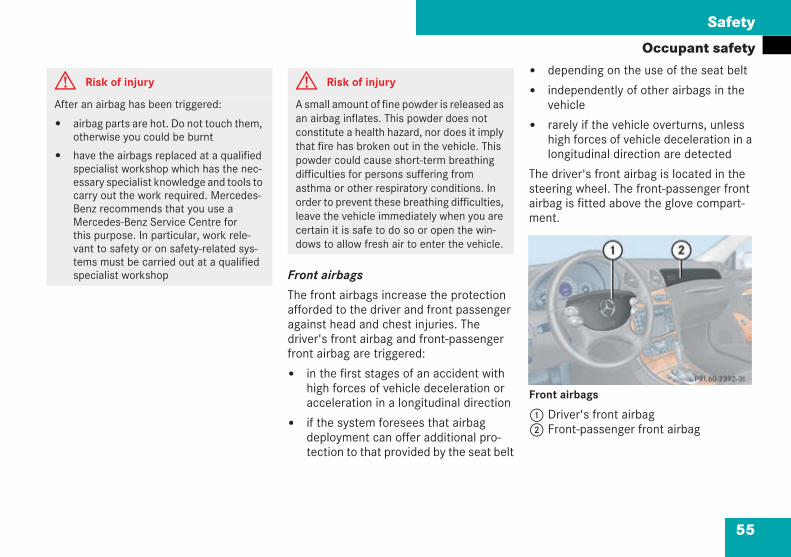
55
Safety
Occupant safety
Front airbags
The front airbags increase the protectionafforded to the driver and front passengeragainst head and chest injuries. Thedriver's front airbag and front-passengerfront airbag are triggered:
in the first stages of an accident withhigh forces of vehicle deceleration oracceleration in a longitudinal direction
if the system foresees that airbagdeployment can offer additional pro-tection to that provided by the seat belt
depending on the use of the seat belt
independently of other airbags in thevehicle
rarely if the vehicle overturns, unlesshigh forces of vehicle deceleration in alongitudinal direction are detected
The driver's front airbag is located in thesteering wheel. The front-passenger frontairbag is fitted above the glove compart-ment.
Front airbags
1 Driver's front airbag2 Front-passenger front airbag
G Risk of injury
After an airbag has been triggered:
airbag parts are hot. Do not touch them,otherwise you could be burnt
have the airbags replaced at a qualifiedspecialist workshop which has the nec-essary specialist knowledge and tools tocarry out the work required. Mercedes-Benz recommends that you use aMercedes-Benz Service Centre forthis purpose. In particular, work rele-vant to safety or on safety-related sys-tems must be carried out at a qualifiedspecialist workshop
G Risk of injury
A small amount of fine powder is released asan airbag inflates. This powder does notconstitute a health hazard, nor does it implythat fire has broken out in the vehicle. Thispowder could cause short-term breathingdifficulties for persons suffering fromasthma or other respiratory conditions. Inorder to prevent these breathing difficulties,leave the vehicle immediately when you arecertain it is safe to do so or open the win-dows to allow fresh air to enter the vehicle.
P91.60-2392-31
209en_d2.boo Seite 55 Dienstag, 25. Mai 2004 7:26 19
56
Safety
Occupant safetyThe driver's front airbag inflates in front ofthe steering wheel and the front-passengerfront airbag inflates in front of and abovethe glove compartment.
Front-passenger front airbag2 is onlytriggered if:
the front-passenger seat is laden oroccupied
the PASSENGER AIRBAG OFF warninglamp on the centre console is not lit( page 64).This indicates that a child seat withoutautomatic child seat recognition is fit-ted or that a child seat with automaticchild seat recognition is fitted incor-rectly.
! Do not place heavy objects on the front-passenger seat. If the system assumes the seatis occupied because there are objects placed onit, the restraint systems on the front-passengerside could be triggered in the event of an acci-dent and will then need to be replaced.
Sidebags (Coupé)
G Risk of injury
To reduce the risk of injury to occupants if asidebag is triggered, make sure that:
there are no other persons, animals orobjects between the vehicle occupantsand the deployment range of the side-bags
no accessories, e.g. cup holders, aresecured to the doors
only light items of clothing are hung onthe coat hooks in the vehicle
no heavy or sharp objects are left in thepockets in clothing
G Risk of injury
Observe the following notes to reduce therisk of serious or fatal injury if the sidebag istriggered:
Vehicle occupants – in particular, chil-dren – must never lean their head intothe area of the window in which thesidebag is triggered.
Vehicle occupants must wear their seatbelt correctly at all times and lean backagainst the backrest, which should bepositioned almost vertically.
Always secure children less than 1.50 mtall and under twelve years of age in suit-able child restraint systems.
209en_d2.boo Seite 56 Dienstag, 25. Mai 2004 7:26 19
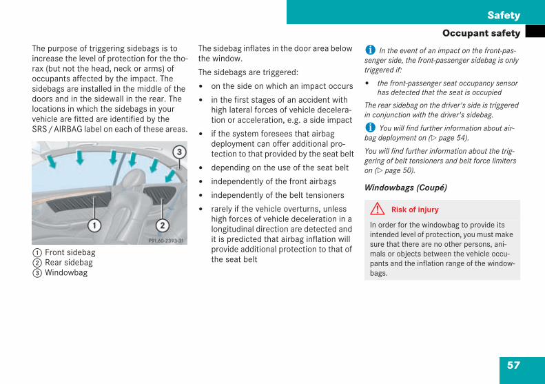
57
Safety
Occupant safetyThe purpose of triggering sidebags is toincrease the level of protection for the tho-rax (but not the head, neck or arms) ofoccupants affected by the impact. Thesidebags are installed in the middle of thedoors and in the sidewall in the rear. Thelocations in which the sidebags in yourvehicle are fitted are identified by theSRS/AIRBAG label on each of these areas.
1 Front sidebag2 Rear sidebag3 Windowbag
The sidebag inflates in the door area belowthe window.
The sidebags are triggered:
on the side on which an impact occurs
in the first stages of an accident withhigh lateral forces of vehicle decelera-tion or acceleration, e.g. a side impact
if the system foresees that airbagdeployment can offer additional pro-tection to that provided by the seat belt
depending on the use of the seat belt
independently of the front airbags
independently of the belt tensioners
rarely if the vehicle overturns, unlesshigh forces of vehicle deceleration in alongitudinal direction are detected andit is predicted that airbag inflation willprovide additional protection to that ofthe seat belt
i In the event of an impact on the front-pas-senger side, the front-passenger sidebag is onlytriggered if:
the front-passenger seat occupancy sensorhas detected that the seat is occupied
The rear sidebag on the driver's side is triggeredin conjunction with the driver's sidebag.
i You will find further information about air-bag deployment on ( page 54).
You will find further information about the trig-gering of belt tensioners and belt force limiterson ( page 50).
Windowbags (Coupé)
P91.40-2393-31
G Risk of injury
In order for the windowbag to provide itsintended level of protection, you must makesure that there are no other persons, ani-mals or objects between the vehicle occu-pants and the inflation range of the window-bags.
209en_d2.boo Seite 57 Dienstag, 25. Mai 2004 7:26 19
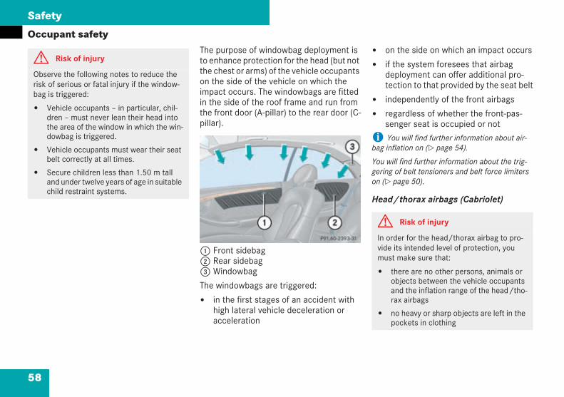
58
Safety
Occupant safetyThe purpose of windowbag deployment isto enhance protection for the head (but notthe chest or arms) of the vehicle occupantson the side of the vehicle on which theimpact occurs. The windowbags are fittedin the side of the roof frame and run fromthe front door (A-pillar) to the rear door (C-pillar).
1 Front sidebag2 Rear sidebag3 Windowbag
The windowbags are triggered:
in the first stages of an accident withhigh lateral vehicle deceleration oracceleration
on the side on which an impact occurs
if the system foresees that airbagdeployment can offer additional pro-tection to that provided by the seat belt
independently of the front airbags
regardless of whether the front-pas-senger seat is occupied or not
i You will find further information about air-bag inflation on ( page 54).
You will find further information about the trig-gering of belt tensioners and belt force limiterson ( page 50).
Head/thorax airbags (Cabriolet)
G Risk of injury
Observe the following notes to reduce therisk of serious or fatal injury if the window-bag is triggered:
Vehicle occupants – in particular, chil-dren – must never lean their head intothe area of the window in which the win-dowbag is triggered.
Vehicle occupants must wear their seatbelt correctly at all times.
Secure children less than 1.50 m talland under twelve years of age in suitablechild restraint systems.
P91.40-2393-31
G Risk of injury
In order for the head/thorax airbag to pro-vide its intended level of protection, youmust make sure that:
there are no other persons, animals orobjects between the vehicle occupantsand the inflation range of the head/tho-rax airbags
no heavy or sharp objects are left in thepockets in clothing
209en_d2.boo Seite 58 Dienstag, 25. Mai 2004 7:26 19
59
Safety
Occupant safety
The purpose of head/thorax airbag deploy-ment is to enhance the protection for thehead and chest (but not the arms) of thevehicle occupants on the side of the vehi-cle on which the impact occurs. The head/thorax airbags are fitted in the outer sidesof the front seat backrests and in the side-wall in the rear.
The head/thorax airbags are triggered:
in the first stages of an accident withhigh lateral forces of vehicle decelera-tion or acceleration
on the side on which an impact occurs
if the system foresees that airbagdeployment can offer additional pro-tection to that provided by the seat belt
if the seat belt is fastened
independently of the front airbags
The front-passenger head/thorax airbagwill only be triggered if the front-passengerseat has objects placed on it or if it is actu-ally occupied.
On vehicles with automatic child seat rec-ognition on the front-passenger seat, thefront-passenger head/thorax airbag willonly be triggered if the PASSENGERAIRBAG OFF warning lamp on the centreconsole is lit, i.e. a child seat with auto-matic child seat recognition transponderis installed on this seat.
In an accident, the head/thorax airbaginflates in the area of the front side win-dow.
i You will find further information about air-bag inflation on ( page 54).
You will find further information about the trig-gering of belt tensioners and belt force limiterson ( page 50).
G Risk of injury
Observe the following notes to reduce therisk of serious or fatal injury if the head/thorax airbag is triggered:
Vehicle occupants – in particular, chil-dren – must never lean their head intothe area of the window in which thehead/thorax airbag is triggered.
Vehicle occupants must wear their seatbelt correctly at all times.
Always secure children less than 1.50 mtall and under twelve years of age in suit-able child restraint systems.
G Risk of injury
For safety reasons, Mercedes-Benz recom-mends that you use seat covers that havebeen approved for Mercedes-Benz vehicles.Otherwise, a head/thorax airbag may notinflate correctly and could fail to provide itsintended protective function in the event ofan accident. These covers can be obtainedfrom a Mercedes-Benz Service Centre, forexample.
209en_d2.boo Seite 59 Dienstag, 25. Mai 2004 7:26 19
60
Safety
Occupant safety
The roll-over bars are deployed automati-cally if it is detected that there is a risk ofthe vehicle overturning.
The roll-over bars are located below therear head restraints. You may retract theextended roll-over bars manually when thesoft top is open ( page 344).
i You cannot lower the rear head restraints ifthe roll-over bars are deployed.
If the roll-over bars deploy automatically, you willhear a rattling noise and the rear head restraintsmay also be extended.
If a child is travelling in the vehicle:
secure the child using a child restraintsystem which is appropriate to its ageand size and which has been approvedfor Mercedes-Benz, preferably on asuitable rear seat
make sure that the child is securedthroughout the trip
You can obtain child seats and informationabout the correct child restraint systemfrom any Mercedes-Benz Service Centre.
Roll-over bars (Cabriolet)
G Risk of injury
Make sure that the range of movement ofthe roll-over bars is not obstructed, other-wise persons could be injured when the roll-over bars are extended.For this reason, always pull the rear seathead restraints out to the stop if passengersare travelling in the rear.
G Risk of injury
If the\ warning lamp in the rev counterremains lit for a long time after the enginehas been started, there is a fault.
The roll-over bars will then fail to deployautomatically in the event of an accidenteven if the system detects that there is adanger of the vehicle overturning. This couldresult in serious or fatal injury to yourself orother vehicle occupants. For safety reasons,therefore, always drive with the roll-overbars extended manually until the malfunc-tion has been rectified.
Have your vehicle checked at a qualifiedspecialist workshop which has the neces-sary specialist knowledge and tools to carryout the work required. Mercedes-Benz rec-ommends that you use a Mercedes-BenzService Centre for this purpose. In particu-lar, work relevant to safety or on safety-related systems must be carried out at aqualified specialist workshop.
Children in the vehicle
209en_d2.boo Seite 60 Dienstag, 25. Mai 2004 7:26 19
61
Safety
Occupant safety
Child restraint systems
Mercedes-Benz recommends that you onlyuse the child restraint systems listedon ( page 63).
G Risk of injury
Do not leave children unsupervised in thevehicle, even if they are secured in a childrestraint system. The children could:
injure themselves on parts of the vehicle
press the central locking switch, therebyreleasing the child-proof locks, and thenopen the doors. This could result ininjury to themselves and other persons.Or they could get out of the vehicle,injuring themselves as they do so orthey could be injured by passing vehi-cles
be seriously or even fatally harmed byprolonged exposure to heat
G Risk of injury
To reduce the risk of serious or fatal injury tothe child in the event of an accident, brakingor a sudden change in direction:
Always secure children less than 1.50 mtall and under twelve years of age in spe-cial child restraint systems installed ona suitable vehicle seat, since they can-not wear the seat belts correctly
Do not secure children under twelveyears of age on the front-passenger seatunless the child is secured in a childrestraint system equipped with auto-matic child seat recognition
On no account should children travel sit-ting on the lap of another occupant. Itwould not be possible to restrain thechildren as a result of the forces actingin the event of an accident, suddenbraking or abrupt changes in direction.They would be thrown against parts ofthe vehicle interior and be seriously orfatally injured
All vehicle occupants must wear theirseat belt correctly at all times
G Risk of injury
If the child restraint system has not been fit-ted correctly to a suitable vehicle seat, thechild cannot be restrained in the event of anaccident or sudden braking and could there-fore be seriously or fatally injured.
For this reason, observe the installationinstructions issued by the child restraintsystem manufacturer when fitting the childrestraint system.
It is preferable to fit the child restraint sys-tem to the rear seats. The child is generallybetter protected there.
For this reason, do not place objects (e.g. acushion) underneath the child restraint sys-tem. The entire base of the child restraintsystem must be in contact with the seat sur-face at all times.
209en_d2.boo Seite 61 Dienstag, 25. Mai 2004 7:26 19
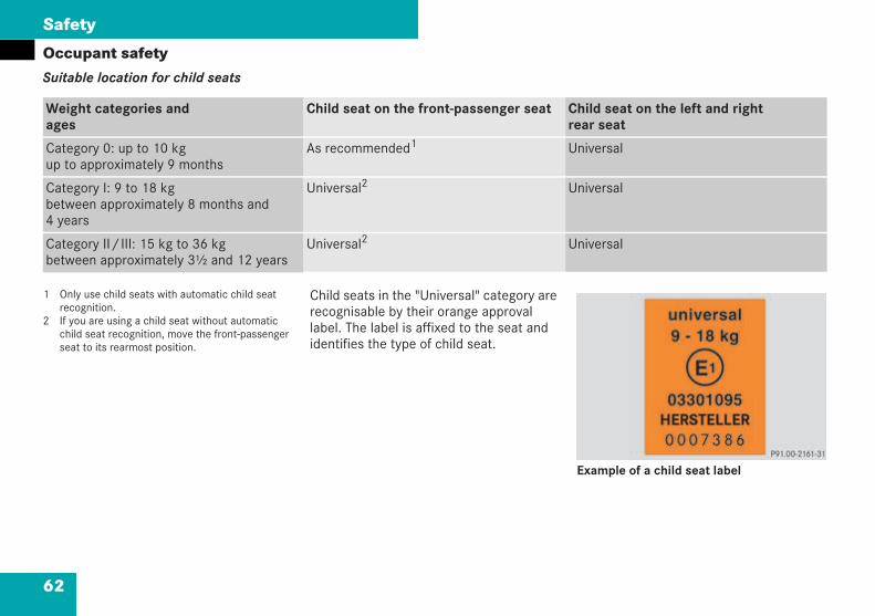
62
Safety
Occupant safetySuitable location for child seats
1 Only use child seats with automatic child seatrecognition.
2 If you are using a child seat without automaticchild seat recognition, move the front-passengerseat to its rearmost position.
Child seats in the "Universal" category arerecognisable by their orange approvallabel. The label is affixed to the seat andidentifies the type of child seat.
Example of a child seat label
Weight categories andages
Child seat on the front-passenger seat Child seat on the left and rightrear seat
Category 0: up to 10 kgup to approximately 9 months
As recommended1 Universal
Category I: 9 to 18 kgbetween approximately 8 months and4 years
Universal2 Universal
Category II/III: 15 kg to 36 kgbetween approximately 3½ and 12 years
Universal2 Universal
209en_d2.boo Seite 62 Dienstag, 25. Mai 2004 7:26 19
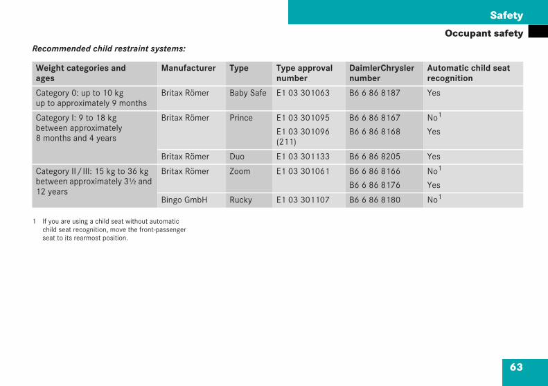
63
Safety
Occupant safetyRecommended child restraint systems:
1 If you are using a child seat without automaticchild seat recognition, move the front-passengerseat to its rearmost position.
Weight categories andages
Manufacturer Type Type approvalnumber
DaimlerChryslernumber
Automatic child seatrecognition
Category 0: up to 10 kgup to approximately 9 months
Britax Römer Baby Safe E1 03 301063 B6 6 86 8187 Yes
Category I: 9 to 18 kgbetween approximately8 months and 4 years
Britax Römer Prince E1 03 301095
E1 03 301096(211)
B6 6 86 8167
B6 6 86 8168
No1
Yes
Britax Römer Duo E1 03 301133 B6 6 86 8205 Yes
Category II/III: 15 kg to 36 kgbetween approximately 3½ and12 years
Britax Römer Zoom E1 03 301061 B6 6 86 8166
B6 6 86 8176
No1
Yes
Bingo GmbH Rucky E1 03 301107 B6 6 86 8180 No1
209en_d2.boo Seite 63 Dienstag, 25. Mai 2004 7:26 19

64
Safety
Occupant safety
Rearward-facing child seat warning symbol
Automatic child seat recognition
The sensor system for the front-passengerseat automatically recognises whether aspecial Mercedes-Benz rearward-facingchild seat is fitted. If this is the case, thePASSENGER AIRBAG OFF warning lamp onthe centre console lights up.
G Risk of injury
A rearward-facing child restraint systemmust not be used on a seat protected by anairbag installed in front of the seat unlessthe airbag is deactivated. To make this clear,an appropriate warning sticker is affixed toeither side of the front-passenger sun visor.
G Risk of injury
A rearward-facing child restraint systemmust not be used on a seat protected by anairbag installed in front of the seat unlessthe airbag is deactivated.
On the front-passenger seat, only use childrestraint systems with automatic child seatrecognition which have been recommendedfor Mercedes-Benz vehicles. You can obtaininformation from any Mercedes-Benz Serv-ice Centre.
If you use a rearward-facing child seat onthe front-passenger seat, it must be a spe-cial Mercedes-Benz rearward-facing childseat with automatic child seat recognition.
If other rearward-facing child seats are usedon the front-passenger seat, the front-pas-senger airbag is not deactivated and thechild could be seriously or fatally injured bythe airbag inflating. To make this clear, anappropriate warning symbol is affixed in thecockpit.
If you use a forward-facing child seat with-out automatic child seat recognition on thefront-passenger seat, you must move thefront-passenger seat to its rearmost posi-tion.
Do not leave children unsupervised in thevehicle, even if they are secured in a childrestraint system. They would otherwise beunable to rescue themselves if dangerthreatens, e.g. excessive heat. Or they couldotherwise be injured by moving parts in thevehicle, such as seats, or open the doorsand thereby endanger themselves and oth-ers, for example.
209en_d2.boo Seite 64 Dienstag, 25. Mai 2004 7:26 19
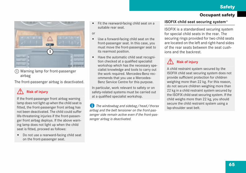
65
Safety
Occupant safety
1 Warning lamp for front-passengerairbag
The front-passenger airbag is deactivated.
i The windowbag and sidebag/head/thoraxairbag and the belt tensioner on the front-pas-senger side remain active even if the front-pas-senger airbag is deactivated.
ISOFIX child seat securing system*
ISOFIX is a standardised securing systemfor special child seats in the rear. Thesecuring rings provided for two child seatsare located on the left and right-hand sidesof the rear seats between the seat cush-ions and the backrest.
G Risk of injury
If the front-passenger front airbag warninglamp does not light up when the child seat isfitted, the front-passenger front airbag hasnot been deactivated. The child could sufferlife-threatening injuries if the front-passen-ger front airbag deploys. If the above warn-ing lamp does not light up when the childseat is fitted, proceed as follows:
Do not use a rearward-facing child seaton the front-passenger seat.
P68.10-3078-31
Fit the rearward-facing child seat on asuitable rear seat.
or
Use a forward-facing child seat on thefront-passenger seat. In this case, youmust move the front-passenger seat toits rearmost position.
Have the automatic child seat recogni-tion checked at a qualified specialistworkshop which has the necessary spe-cialist knowledge and tools to carry outthe work required. Mercedes-Benz rec-ommends that you use a Mercedes-Benz Service Centre for this purpose.
In particular, work relevant to safety or onsafety-related systems must be carried outat a qualified specialist workshop.
G Risk of injury
A child restraint system secured by theISOFIX child seat securing system does notprovide sufficient protection for childrenweighing more than 22 kg. For this reason,do not secure children weighing more than22 kg in a child restraint system secured bythe ISOFIX child seat securing system. If thechild weighs more than 22 kg, you shouldsecure the child restraint system using alap-shoulder seat belt.
209en_d2.boo Seite 65 Dienstag, 25. Mai 2004 7:26 19
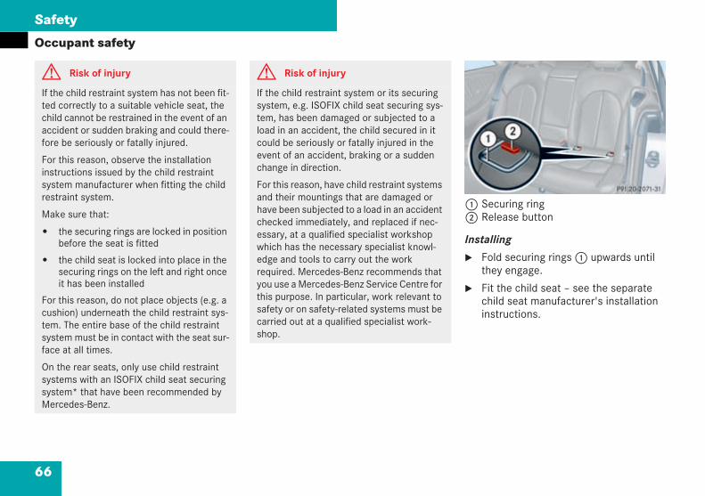
66
Safety
Occupant safety
1 Securing ring2 Release button
Installing
Fold securing rings1 upwards untilthey engage.
Fit the child seat – see the separatechild seat manufacturer's installationinstructions.
G Risk of injury
If the child restraint system has not been fit-ted correctly to a suitable vehicle seat, thechild cannot be restrained in the event of anaccident or sudden braking and could there-fore be seriously or fatally injured.
For this reason, observe the installationinstructions issued by the child restraintsystem manufacturer when fitting the childrestraint system.
Make sure that:
the securing rings are locked in positionbefore the seat is fitted
the child seat is locked into place in thesecuring rings on the left and right onceit has been installed
For this reason, do not place objects (e.g. acushion) underneath the child restraint sys-tem. The entire base of the child restraintsystem must be in contact with the seat sur-face at all times.
On the rear seats, only use child restraintsystems with an ISOFIX child seat securingsystem* that have been recommended byMercedes-Benz.
G Risk of injury
If the child restraint system or its securingsystem, e.g. ISOFIX child seat securing sys-tem, has been damaged or subjected to aload in an accident, the child secured in itcould be seriously or fatally injured in theevent of an accident, braking or a suddenchange in direction.
For this reason, have child restraint systemsand their mountings that are damaged orhave been subjected to a load in an accidentchecked immediately, and replaced if nec-essary, at a qualified specialist workshopwhich has the necessary specialist knowl-edge and tools to carry out the workrequired. Mercedes-Benz recommends thatyou use a Mercedes-Benz Service Centre forthis purpose. In particular, work relevant tosafety or on safety-related systems must becarried out at a qualified specialist work-shop.
P91.20-2071-31
209en_d2.boo Seite 66 Dienstag, 25. Mai 2004 7:26 19
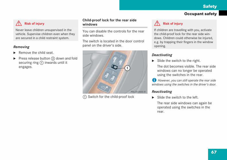
67
Safety
Occupant safety
Removing
Remove the child seat.
Press release button2 down and foldsecuring ring1 inwards until itengages.
Child-proof lock for the rear sidewindows
You can disable the controls for the rearside windows.
The switch is located in the door controlpanel on the driver's side.
1 Switch for the child-proof lock
Deactivating
Slide the switch to the right.
The dot becomes visible. The rear sidewindows can no longer be operatedusing the switches in the rear.
i However, you can still operate the rear sidewindows using the switches in the driver's door.
Reactivating
Slide the switch to the left.
The rear side windows can again beoperated using the switches in therear.
G Risk of injury
Never leave children unsupervised in thevehicle. Supervise children even when theyare secured in a child restraint system.
P 54.25-2602-31 neu
G Risk of injury
If children are travelling with you, activatethe child-proof lock for the rear side win-dows. Children could otherwise be injured,e.g. by trapping their fingers in the windowopening.
209en_d2.boo Seite 67 Dienstag, 25. Mai 2004 7:26 19
68
Safety
Driving safety systems
In this section, you will find informationabout the following driving safety systems:
ABS (Anti-lock Braking System)
BAS (Brake Assist)
ESP (Electronic Stability Program)
i In wintry conditions, use winter tyres (M+Styres), with snow chains if necessary. The maxi-mum effect of ABS, BAS, ESP and SBC can onlybe achieved in this way.
ABS regulates the brake pressure in such away that the wheels do not lock when youbrake. This allows you to continue steer-ing.
ABS works from a speed of approximately8 km/h upwards, regardless of road sur-face conditions.
ABS works on slippery road surfaces, evenwhen you only brake gently.
The- indicator lamp in the instrumentcluster ( page 12) lights up when youturn the key to position 2 in the ignitionlock. It goes out when the engine is run-ning. This indicates that ABS is opera-tional.
Driving safety systems G Risk of accident
The risk of an accident increases especially ifyou:
drive too fast, particularly when corneringand on a wet or slippery road surface
drive too close to the vehicle in front
The driving safety systems described in thissection are unable to reduce this risk or over-ride the laws of physics.
For this reason, always adapt your drivingstyle to suit the current road and weather con-ditions and maintain a sufficient distance fromother road users and objects on the road.
ABS
G Risk of accident
Do not depress the brake pedal several timesin quick succession (pumping). Depress thebrake firmly and evenly. Pumping the brakepedal reduces the braking effect.
209en_d2.boo Seite 68 Dienstag, 25. Mai 2004 7:26 19
69
Safety
Driving safety systemsBraking
If ABS cuts in while you are braking, youwill feel:
the vehicle vibrating
the brake pedal pulsating
This will indicate to you that ABS has beenactivated. Always adapt your driving styleto suit the prevailing road and weatherconditions.
Continue to depress the brake pedal,even when ABS has been activated.
Brake Assist operates in emergency brak-ing situations. If you depress the brakepedal quickly, BAS boosts the brakingforce automatically and thus shortens thestopping distance.
Depress the brake pedal firmly until theemergency-braking situation is over.
ABS prevents the wheels from locking.
When you release the brake pedal, thebrakes work as normal again. BAS is thendeactivated.
The Electronic Stability Program monitorsthe traction, i.e. the power transmissionbetween the tyres and the road, and thestability of the vehicle.
ESP detects when a wheel is spinning orwhen the vehicle has begun to skid. ESPstabilises the vehicle by applying specificbraking to individual wheels and limitingthe engine power output. ESP assists youin particular when pulling away on a wet orslippery road surface.
If ESP cuts in, thev warning lampflashes in the speedometer.
Thev ESP warning lamp in the instru-ment cluster lights up when you turn thekey to position 2 in the ignition lock. Itgoes out when the engine is running. Thisindicates that ESP is operational.
G Risk of accident
Always adapt your driving style to suit theprevailing road and weather conditions andmaintain a sufficient distance from otherroad users and objects on the road.
BAS
G Risk of accident
If BAS malfunctions, the brake system is stillavailable with the full brake boosting effect.In an emergency braking situation, however,the braking force is not automaticallyboosted and may lengthen the stopping dis-tance.
ESP
209en_d2.boo Seite 69 Dienstag, 25. Mai 2004 7:26 19
70
Safety
Driving safety systems
! ESP only functions properly if wheels withthe recommended tyre sizes are used( page 399).
The engine must not be running if:
the parking brake is being tested using adynamometer
the vehicle is being towed with the front axleraised
Application of the brakes by ESP may otherwisedestroy the braking system on the rear axle.
i Only use wheels with the recommended tyresizes. Only then will ESP function properly.
Activating/deactivating ESP
It may be best to deactivate ESP in thefollowing situations:
if snow chains are being used
in deep snow
on sand or gravel
When you deactivate ESP:
ESP no longer improves driving stability
the engine's torque is then no longerlimited and the drive wheels could spin.This results in a cutting action of thespinning wheels for better grip
traction control is still activated
you can still brake with support fromESP
i Thev warning lamp in the instrumentcluster flashes if ESP is deactivated and one ormore wheels start to spin. ESP does not then sta-bilise the vehicle.
G Risk of accident
Proceed as follows if thevwarning lampin the speedometer flashes:
under no circumstances should youdeactivate ESP
only depress the accelerator pedal asfar as necessary when pulling away
do not keep your foot on the acceleratorwhile you are driving
adapt your driving style to suit the roadand weather conditions
Otherwise, the vehicle could begin to skid.
ESP cannot reduce the risk of an accident ifyou drive too fast.
G Risk of accident
Activate ESP as soon as the situationsdescribed above no longer apply. ESP willotherwise be unable to stabilise the vehicleif the vehicle starts to skid or when a wheelspins.
209en_d2.boo Seite 70 Dienstag, 25. Mai 2004 7:26 19
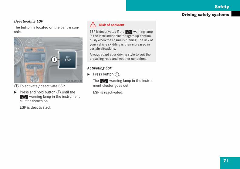
71
Safety
Driving safety systemsDeactivating ESP
The button is located on the centre con-sole.
1 To activate/deactivate ESP
Press and hold button1 until thev warning lamp in the instrumentcluster comes on.
ESP is deactivated.
Activating ESP
Press button1.
Thev warning lamp in the instru-ment cluster goes out.
ESP is reactivated.
P54.25-3805-31
G Risk of accident
ESP is deactivated if thevwarning lampin the instrument cluster lights up continu-ously when the engine is running. The risk ofyour vehicle skidding is then increased incertain situations.
Always adapt your driving style to suit theprevailing road and weather conditions.
209en_d2.boo Seite 71 Dienstag, 25. Mai 2004 7:26 19
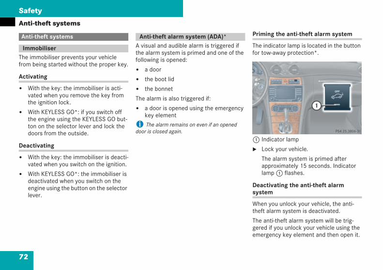
72
Safety
Anti-theft systems
The immobiliser prevents your vehiclefrom being started without the proper key.
Activating
With the key: the immobiliser is acti-vated when you remove the key fromthe ignition lock.
With KEYLESS GO*: if you switch offthe engine using the KEYLESS GO but-ton on the selector lever and lock thedoors from the outside.
Deactivating
With the key: the immobiliser is deacti-vated when you switch on the ignition.
With KEYLESS GO*: the immobiliser isdeactivated when you switch on theengine using the button on the selectorlever.
A visual and audible alarm is triggered ifthe alarm system is primed and one of thefollowing is opened:
a door
the boot lid
the bonnet
The alarm is also triggered if:
a door is opened using the emergencykey element
i The alarm remains on even if an openeddoor is closed again.
Priming the anti-theft alarm system
The indicator lamp is located in the buttonfor tow-away protection*.
1 Indicator lamp
Lock your vehicle.
The alarm system is primed afterapproximately 15 seconds. Indicatorlamp1 flashes.
Deactivating the anti-theft alarmsystem
When you unlock your vehicle, the anti-theft alarm system is deactivated.
The anti-theft alarm system will be trig-gered if you unlock your vehicle using theemergency key element and then open it.
Anti-theft systems
Immobiliser
Anti-theft alarm system (ADA)*
P54.25-3806-31
209en_d2.boo Seite 72 Dienstag, 25. Mai 2004 7:26 19
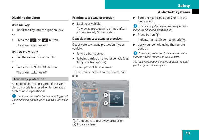
73
Safety
Anti-theft systemsDisabling the alarm
With the key
Insert the key into the ignition lock.
or
Press theŒ or‹ button.
The alarm switches off.
With KEYLESS GO*
Pull the exterior door handle.
or
Press the KEYLESS GO button.
The alarm switches off.
An audible alarm is triggered if the vehi-cle's tilt angle is altered while tow-awayprotection is operational.
i The tow-away protection alarm is triggeredif the vehicle is jacked up on one side, for exam-ple.
Priming tow-away protection
Lock your vehicle.
Tow-away protection is primed afterapproximately 30 seconds.
Deactivating tow-away protection
Deactivate tow-away protection if yourvehicle:
is to be transported
is being carried on another vehicle (e.g.ferry, car transporter)
This will prevent false alarms.
The button is located on the centre con-sole.
1 To deactivate tow-away protection2 Indicator lamp
Turn the key to position 0 or 1 in theignition lock.
i You can only deactivate tow-away protec-tion if the ignition is switched off.
Press button1.
Indicator lamp2 comes on briefly.
Lock your vehicle using the remotecontrol.
i Tow-away protection is deactivated auto-matically when you unlock your vehicle.
Tow-away protection remains deactivated untilyou lock your vehicle again.
Tow-away protection*
P54.25-3807-31
209en_d2.boo Seite 73 Dienstag, 25. Mai 2004 7:26 19
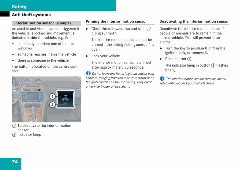
74
Safety
Anti-theft systems
An audible and visual alarm is triggered ifthe vehicle is locked and movement isdetected inside the vehicle, e.g. if:
somebody smashes one of the sidewindows
someone reaches inside the vehicle
there is someone in the vehicle
The button is located on the centre con-sole.
1 To deactivate the interior motionsensor
2 Indicator lamp
Priming the interior motion sensor
Close the side windows and sliding/tilting sunroof*.
The interior motion sensor cannot beprimed if the sliding/tilting sunroof* isopen.
Lock your vehicle.
The interior motion sensor is primedafter approximately 30 seconds.
i Do not leave any items (e.g. mascots or coathangers) hanging from the rear-view mirror or onthe grab handles on the roof lining. They couldotherwise trigger a false alarm.
Deactivating the interior motion sensor
Deactivate the interior motion sensor ifpeople or animals are to remain in thelocked vehicle. This will prevent falsealarms.
Turn the key to position 0 or 1 in theignition lock, or remove it.
Press button1.
The indicator lamp in button2 flashesbriefly.
i The interior motion sensor remains deacti-vated until you lock your vehicle again.
Interior motion sensor* (Coupé)
P 54.25-3808-31 neu
209en_d2.boo Seite 74 Dienstag, 25. Mai 2004 7:26 19
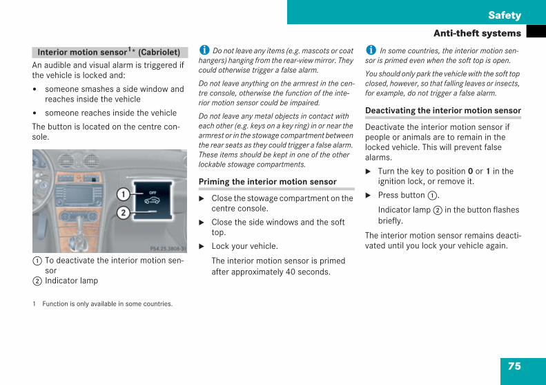
75
Safety
Anti-theft systems
An audible and visual alarm is triggered ifthe vehicle is locked and:
someone smashes a side window andreaches inside the vehicle
someone reaches inside the vehicle
The button is located on the centre con-sole.
1 To deactivate the interior motion sen-sor
2 Indicator lamp
1 Function is only available in some countries.
i Do not leave any items (e.g. mascots or coathangers) hanging from the rear-view mirror. Theycould otherwise trigger a false alarm.
Do not leave anything on the armrest in the cen-tre console, otherwise the function of the inte-rior motion sensor could be impaired.
Do not leave any metal objects in contact witheach other (e.g. keys on a key ring) in or near thearmrest or in the stowage compartment betweenthe rear seats as they could trigger a false alarm.These items should be kept in one of the otherlockable stowage compartments.
Priming the interior motion sensor
Close the stowage compartment on thecentre console.
Close the side windows and the softtop.
Lock your vehicle.
The interior motion sensor is primedafter approximately 40 seconds.
i In some countries, the interior motion sen-sor is primed even when the soft top is open.
You should only park the vehicle with the soft topclosed, however, so that falling leaves or insects,for example, do not trigger a false alarm.
Deactivating the interior motion sensor
Deactivate the interior motion sensor ifpeople or animals are to remain in thelocked vehicle. This will prevent falsealarms.
Turn the key to position 0 or 1 in theignition lock, or remove it.
Press button1.
Indicator lamp2 in the button flashesbriefly.
The interior motion sensor remains deacti-vated until you lock your vehicle again.
Interior motion sensor1* (Cabriolet)
P 54.25-3808-31
209en_d2.boo Seite 75 Dienstag, 25. Mai 2004 7:26 19

76
209en_d2.boo Seite 76 Dienstag, 25. Mai 2004 7:26 19
77
Controls in detail
Opening and closing
Seats
Storing settings* (memory package)
Lighting
Instrument cluster
Operating system
Manual transmission
Automatic transmission*
Good visibility
Thermatic (automatic air conditioning)
Thermotronic* (intelligent air conditioning)
Heater booster system* for vehicles with a diesel engine*
Auxiliary heating*/ventilation*
Open-air
Driving systems
Loading
Features
209en_d2.boo Seite 77 Dienstag, 25. Mai 2004 7:26 19
78
Controls in detail
Opening and closingYou will find detailed information about thefunctions of the vehicle in the "Controls indetail" section. You will find this sectionmost useful if you are already familiar withthe basic functions of the vehicle.
If you are not yet familiar with these basicfunctions, the "Getting started" section willprovide you with more information. Youwill find the reference to the appropriatepages of that section at the start of eachsegment.
The vehicle's equipment includes tworemote control keys.
There is an emergency key element in eachkey. The release catches for the emer-gency key element have different coloursto help distinguish between the two keys.
The key allows you to lock and unlock thevehicle from some distance away. To pre-vent theft, only use the key in the immedi-ate vicinity of the vehicle.
The key's factory setting enables you tocentrally lock and unlock the following:
The doors
The boot
The fuel filler flap
The glove compartment
i If you open a door, the windows on this sidelower slightly. If you close the door, the windowsclose again.
! The side windows will not open or close ifthey are iced up or if the battery is flat. You willthen no longer be able to close the door. Do notattempt to force the door closed. You could oth-erwise damage the door or the window.
Opening and closing
Key with remote control
G Risk of accident
Never leave children unsupervised in thevehicle. They could open a door from theinside, even if it is locked, or start the engineusing a key left in the vehicle and therebyendanger themselves and others. For thisreason, take the key with you, even if youare only leaving the vehicle for a short time.
209en_d2.boo Seite 78 Dienstag, 25. Mai 2004 7:26 19
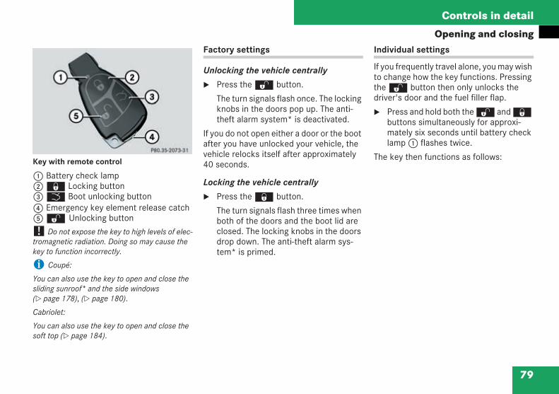
79
Controls in detail
Opening and closing
Key with remote control
1 Battery check lamp2‹ Locking button3Š Boot unlocking button4 Emergency key element release catch5Œ Unlocking button
! Do not expose the key to high levels of elec-tromagnetic radiation. Doing so may cause thekey to function incorrectly.
i Coupé:
You can also use the key to open and close thesliding sunroof* and the side windows( page 178), ( page 180).
Cabriolet:
You can also use the key to open and close thesoft top ( page 184).
Factory settings
Unlocking the vehicle centrally
Press theΠbutton.
The turn signals flash once. The lockingknobs in the doors pop up. The anti-theft alarm system* is deactivated.
If you do not open either a door or the bootafter you have unlocked your vehicle, thevehicle relocks itself after approximately40 seconds.
Locking the vehicle centrally
Press the‹ button.
The turn signals flash three times whenboth of the doors and the boot lid areclosed. The locking knobs in the doorsdrop down. The anti-theft alarm sys-tem* is primed.
Individual settings
If you frequently travel alone, you may wishto change how the key functions. PressingtheΠbutton then only unlocks thedriver's door and the fuel filler flap.
Press and hold both theŒ and‹buttons simultaneously for approxi-mately six seconds until battery checklamp1 flashes twice.
The key then functions as follows:
209en_d2.boo Seite 79 Dienstag, 25. Mai 2004 7:26 19
80
Controls in detail
Opening and closingUnlocking the driver's door
Press theΠbutton once.
The turn signals flash once. The lockingknob in the driver's door pops up. Theanti-theft alarm system* is deacti-vated.
Unlocking the vehicle centrally
Press theΠbutton twice.
The turn signals flash once. The lockingknobs in the doors pop up. The anti-theft alarm system* is deactivated.
Locking the vehicle centrally
Press the‹ button.
The turn signals flash three times. Thelocking knobs in the doors drop down.The anti-theft alarm system* is primed.
Restoring the factory settings
Press and hold both theŒ and‹buttons simultaneously for approxi-mately six seconds until battery checklamp1 flashes twice.
Checking the batteries
Press the‹ orŒ button.
The batteries in the key are working ifthe battery check lamp lights up briefly.
i You could lock or unlock the vehicle acci-dentally if you press the buttons on the key.
Two KEYLESS GO keys form part of yourvehicle's optional equipment.
When you grasp the door handle, your vehi-cle checks the key's validity. The followingare centrally unlocked if the KEYLESS GOkey is valid and configured to the factorysetting ( page 80):
The doors
The boot
The fuel filler flap
The glove compartment
KEYLESS GO key*
G Risk of accident
Never leave children unsupervised in thevehicle. They could open a door from theinside, even if it is locked, or start the vehi-cle using a valid KEYLESS GO key left in thevehicle or the KEYLESS GO button on theselector lever and thereby endanger them-selves and others. Switch off the engine andtake the KEYLESS GO key with you, even ifyou are only leaving the vehicle for a shorttime.
209en_d2.boo Seite 80 Dienstag, 25. Mai 2004 7:26 19
81
Controls in detail
Opening and closing! Do not expose the KEYLESS GO key to highlevels of electromagnetic radiation. Doing somay cause the key to function incorrectly.
i You can also use the KEYLESS GO key justlike a normal key with remote control( page 78).
If the vehicle has been parked up for a longperiod, it may be necessary to pull on the doorhandle to activate the KEYLESS GO function.
Coupé:
You can also use the KEYLESS GO key to simul-taneously close the side windows and the slidingsunroof* ( page 178), ( page 180).
Points to bear in mind
Always carry the KEYLESS GO key onyour person.
Never store the KEYLESS GO keytogether with:
electronic equipment, e.g. a mobilephone
metallic objects such as coins orfoil
This could otherwise impair the key'seffectiveness.
To lock or unlock the vehicle using theKEYLESS GO key, the key must be out-side the vehicle and no more than ametre away from the door or boot.
To start the engine with the KEYLESSGO button on the selector lever:
the KEYLESS GO key must be in thevehicle and
both of the doors must be closed
If you have started the engine using theKEYLESS GO button on the selectorlever, you can stop the engine using:
the KEYLESS GO button
the key if it is in the ignition lockand the selector lever is at P (vehi-cles with automatic transmission*)
The key in the ignition lock thenhas priority over the KEYLESS GOfunction and the vehicle electricalsystem will be controlled in accord-ance with the position of the key inthe ignition lock.
If the KEYLESS GO key is removed fromthe vehicle (e.g. in luggage or an articleof clothing), it is no longer possible tolock or start the vehicle.
209en_d2.boo Seite 81 Dienstag, 25. Mai 2004 7:26 19
82
Controls in detail
Opening and closingIf the KEYLESS GO key is removed fromthe vehicle while the ignition is onand a door is open, e.g. if the front pas-senger leaves the vehicle with theKEYLESS GO key, you will see the fol-lowing message in the multi-functiondisplay when pulling away: Key notdetected!
The vehicle can be started at any timeif the KEYLESS GO key is in the vehicle.If you have forgotten the KEYLESS GOkey, you will see the following messagein the multi-function display when youlock the vehicle: Key still in vehicle!
Factory settings
Unlocking the vehicle centrally
Grasp the door handle.
The turn signals flash once. The lockingknobs in the doors pop up. The anti-theft alarm system* is deactivated.
If you do not open either a door or theboot lid after you have unlocked yourvehicle, the vehicle relocks itself afterapproximately 40 seconds.
i The vehicle could unlock inadvertently if theKEYLESS GO key is one meter away and
the door handle is splashed by a gush ofwater
you clean the door handle
Locking the vehicle centrally
Press the locking button on the doorhandle ( page 82) or on the boot( page 82).
The turn signals flash three times. Thelocking knobs in the doors drop down.The anti-theft alarm system* is primed.
Locking the vehicle centrally from thebooti If the vehicle was centrally locked before theboot is opened, the boot will be relocked auto-matically when the boot lid is closed.
i The boot cannot be closed if the KEYLESSGO key* has been left in the vehicle.
209en_d2.boo Seite 82 Dienstag, 25. Mai 2004 7:26 19
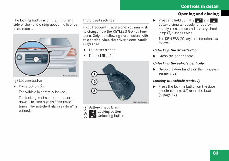
83
Controls in detail
Opening and closingThe locking button is on the right-handside of the handle strip above the licenceplate recess.
1 Locking button
Press button1.
The vehicle is centrally locked.
The locking knobs in the doors dropdown. The turn signals flash threetimes. The anti-theft alarm system* isprimed.
Individual settings
If you frequently travel alone, you may wishto change how the KEYLESS GO key func-tions. Only the following are unlocked withthis setting when the driver's door handleis grasped:
The driver's door
The fuel filler flap
1 Battery check lamp2‹ Locking button3Œ Unlocking button
Press and hold both theŒ and‹buttons simultaneously for approxi-mately six seconds until battery checklamp1 flashes twice.
The KEYLESS GO key then functions asfollows:
Unlocking the driver's door
Grasp the door handle.
Unlocking the vehicle centrally
Grasp the door handle on the front-pas-senger side.
Locking the vehicle centrally
Press the locking button on the doorhandle ( page 82) or on the boot( page 82).
209en_d2.boo Seite 83 Dienstag, 25. Mai 2004 7:26 19
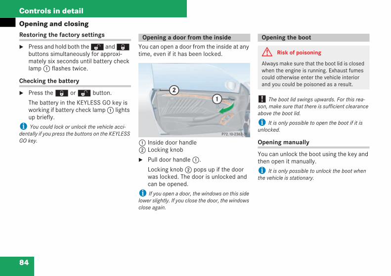
84
Controls in detail
Opening and closingRestoring the factory settings
Press and hold both theŒ and‹buttons simultaneously for approxi-mately six seconds until battery checklamp1 flashes twice.
Checking the battery
Press the‹ orŒ button.
The battery in the KEYLESS GO key isworking if battery check lamp1 lightsup briefly.
i You could lock or unlock the vehicle acci-dentally if you press the buttons on the KEYLESSGO key.
You can open a door from the inside at anytime, even if it has been locked.
1 Inside door handle2 Locking knob
Pull door handle1.
Locking knob2 pops up if the doorwas locked. The door is unlocked andcan be opened.
i If you open a door, the windows on this sidelower slightly. If you close the door, the windowsclose again.
! The boot lid swings upwards. For this rea-son, make sure that there is sufficient clearanceabove the boot lid.
i It is only possible to open the boot if it isunlocked.
Opening manually
You can unlock the boot using the key andthen open it manually.
i It is only possible to unlock the boot whenthe vehicle is stationary.
Opening a door from the inside Opening the boot
G Risk of poisoning
Always make sure that the boot lid is closedwhen the engine is running. Exhaust fumescould otherwise enter the vehicle interiorand you could be poisoned as a result.
209en_d2.boo Seite 84 Dienstag, 25. Mai 2004 7:26 19
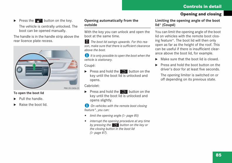
85
Controls in detail
Opening and closingPress theΠbutton on the key.
The vehicle is centrally unlocked. Theboot can be opened manually.
The handle is in the handle strip above therear licence plate recess.
To open the boot lid
Pull the handle.
Raise the boot lid.
Opening automatically from theoutside
With the key you can unlock and open theboot at the same time.
! The boot lid swings upwards. For this rea-son, make sure that there is sufficient clearanceabove the boot.
i It is only possible to open the boot when thevehicle is stationary.
Coupé:
Press and hold theŠ button on thekey until the boot lid is unlocked andopens.
Cabriolet:
Press and hold theŠ button on thekey until the boot lid is unlocked andopens slightly.
i On vehicles with the remote boot closingfeature*, you can:
limit the opening angle ( page 85)
interrupt the opening procedure at any timeby pressing theŠ button on the key orthe closing button in the boot lid( page 87).
Limiting the opening angle of the bootlid* (Coupé)
You can limit the opening angle of the bootlid on vehicles with the remote boot clos-ing feature*. The boot lid will then onlyopen as far as the height of the roof. Thiscan be useful if there is insufficient clear-ance above the boot lid, for example.
Make sure that the boot lid is closed.
Press and hold the boot button on thedriver's door for at least five seconds.
The opening limiter is switched on oroff depending on its previous state.
209en_d2.boo Seite 85 Dienstag, 25. Mai 2004 7:26 19
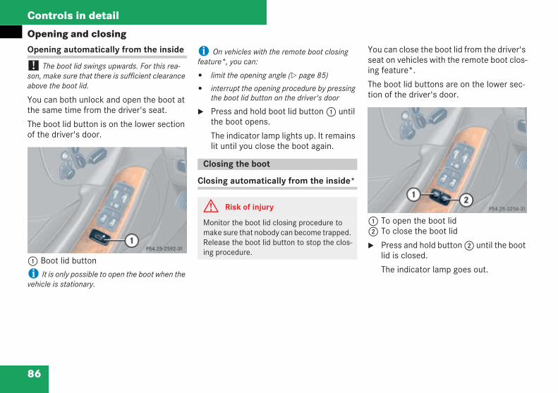
86
Controls in detail
Opening and closingOpening automatically from the inside
! The boot lid swings upwards. For this rea-son, make sure that there is sufficient clearanceabove the boot lid.
You can both unlock and open the boot atthe same time from the driver's seat.
The boot lid button is on the lower sectionof the driver's door.
1 Boot lid buttoni It is only possible to open the boot when thevehicle is stationary.
i On vehicles with the remote boot closingfeature*, you can:
limit the opening angle ( page 85)
interrupt the opening procedure by pressingthe boot lid button on the driver's door
Press and hold boot lid button1 untilthe boot opens.
The indicator lamp lights up. It remainslit until you close the boot again.
Closing automatically from the inside*
You can close the boot lid from the driver'sseat on vehicles with the remote boot clos-ing feature*.
The boot lid buttons are on the lower sec-tion of the driver's door.
1 To open the boot lid2 To close the boot lid
Press and hold button2 until the bootlid is closed.
The indicator lamp goes out.
Closing the boot
G Risk of injury
Monitor the boot lid closing procedure tomake sure that nobody can become trapped.Release the boot lid button to stop the clos-ing procedure.
209en_d2.boo Seite 86 Dienstag, 25. Mai 2004 7:26 19
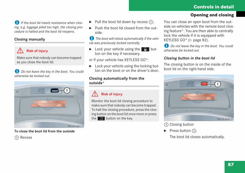
87
Controls in detail
Opening and closing
i If the boot lid meets resistance when clos-ing, e.g. luggage piled too high, the closing pro-cedure is halted and the boot lid reopens.
Closing manually
i Do not leave the key in the boot. You couldotherwise be locked out.
To close the boot lid from the outside
1 Recess
Pull the boot lid down by recess1.
Push the boot lid closed from the out-side.
i The boot will relock automatically if the vehi-cle was previously locked centrally.
Lock your vehicle using the‹ but-ton on the key if necessary.
or if your vehicle has KEYLESS GO*:
Lock your vehicle using the locking but-ton on the boot or on the driver's door.
Closing automatically from theoutside*
You can close an open boot from the out-side on vehicles with the remote boot clos-ing feature*. You are then able to centrallylock the vehicle if it is equipped withKEYLESS GO* ( page 82).
i Do not leave the key in the boot. You couldotherwise be locked out.
Closing button in the boot lid
The closing button is on the inside of theboot lid on the right-hand side.
1 Closing button
Press button1.
The boot lid closes automatically.
G Risk of injury
Make sure that nobody can become trappedas you close the boot lid.
G Risk of injury
Monitor the boot lid closing procedure tomake sure that nobody can become trapped.To halt the closing procedure, press the clos-ing button on the boot lid once more or presstheŠ button on the key.
209en_d2.boo Seite 87 Dienstag, 25. Mai 2004 7:26 19
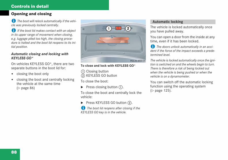
88
Controls in detail
Opening and closing
i The boot will relock automatically if the vehi-cle was previously locked centrally.
i If the boot lid makes contact with an objectin its upper range of movement when closing,e.g. luggage piled too high, the closing proce-dure is halted and the boot lid reopens to its ini-tial position.
Automatic closing and locking withKEYLESS GO*
On vehicles KEYLESS GO*, there are twoseparate buttons in the boot lid for:
closing the boot only
closing the boot and centrally lockingthe vehicle at the same time( page 86)
To close and lock with KEYLESS GO*
1 Closing button2 KEYLESS GO button
To close the boot:
Press closing button1.
To close the boot and centrally lock thevehicle:
Press KEYLESS GO button2.i The boot lid reopens after closing if theKEYLESS GO key is in the vehicle.
The vehicle is locked automatically onceyou have pulled away.
You can open a door from the inside at anytime, even if it has been locked.
i The doors unlock automatically in an acci-dent if the force of the impact exceeds a prede-termined level.
The vehicle is locked automatically once the igni-tion is switched on and the wheels begin to turn.There is therefore a risk of being locked outwhen the vehicle is being pushed or when thevehicle is on a dynamometer.
You can switch off the automatic lockingfunction using the operating system( page 125).
Automatic locking
209en_d2.boo Seite 88 Dienstag, 25. Mai 2004 7:26 19
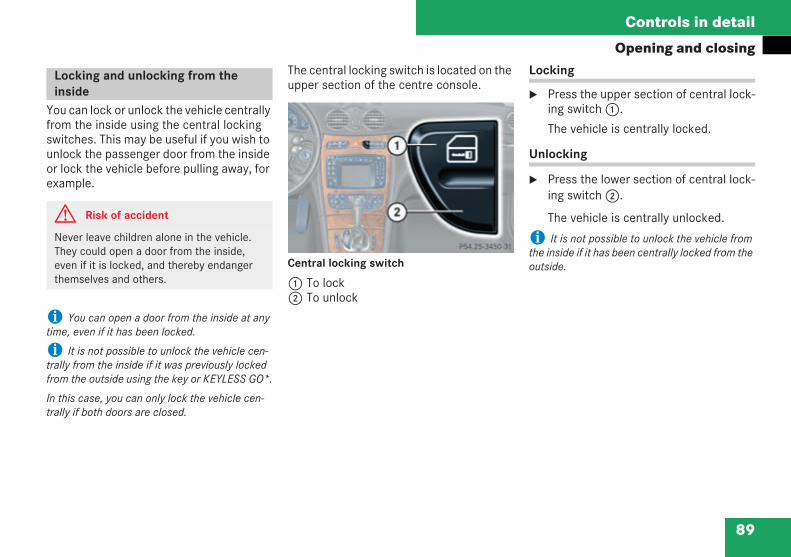
89
Controls in detail
Opening and closing
You can lock or unlock the vehicle centrallyfrom the inside using the central lockingswitches. This may be useful if you wish tounlock the passenger door from the insideor lock the vehicle before pulling away, forexample.
i You can open a door from the inside at anytime, even if it has been locked.
i It is not possible to unlock the vehicle cen-trally from the inside if it was previously lockedfrom the outside using the key or KEYLESS GO*.
In this case, you can only lock the vehicle cen-trally if both doors are closed.
The central locking switch is located on theupper section of the centre console.
Central locking switch
1 To lock2 To unlock
Locking
Press the upper section of central lock-ing switch1.
The vehicle is centrally locked.
Unlocking
Press the lower section of central lock-ing switch2.
The vehicle is centrally unlocked.
i It is not possible to unlock the vehicle fromthe inside if it has been centrally locked from theoutside.
Locking and unlocking from theinside
G Risk of accident
Never leave children alone in the vehicle.They could open a door from the inside,even if it is locked, and thereby endangerthemselves and others.
209en_d2.boo Seite 89 Dienstag, 25. Mai 2004 7:26 19
90
Controls in detail
Seats
You will find information about adjustingthe seats in the "Getting started" section( page 25).
You will find information about folding for-ward the rear bench seat in the Through-loading feature* (Coupé) section( page 223).
The easy-entry/exit feature facilitates get-ting into and out of the vehicle.
The driver's seat moves back and thesteering wheel moves up when you:
remove the key from the ignition lock
open the driver's door and the key is inposition 0 or 1 in the ignition lock
If you insert the key into the ignition lockwhen the driver's door is closed, thedriver's seat and the steering wheel returnto their previous position depending on thesettings stored and the key being used.
i The driver's seat only moves back if it wasnot already positioned in the rear part of itsadjustment range.The steering wheel only moves up if it was notalready positioned at the upper limit.
i The adjustment procedure is:interrupted briefly when you start the enginehalted completely if you start the engine andpull away immediately
i To prevent entrapment, the driver's seatonly moves forwards if it was not already posi-tioned in the front part of its adjustment range.
The last positions of the driver's seat,steering wheel and exterior mirrors will bestored if you:
switch off the ignition
or
store a memory position ( page 97)
You can configure the easy-entry/exitfeature using the operating system( page 129).
Seats
Easy-entry/exit feature*
G Risk of injury
Make sure that nobody can become trappedwhen you activate the easy-entry/exit fea-ture.
Halt the adjustment procedure if there is arisk of entrapment. To halt the adjustmentprocedure:
move the seat adjustment switch
move the steering column adjustmentswitch
press the storage position switch
The seat and steering column stop movingimmediately.
Never leave children unsupervised in thevehicle. They could open the driver's door,inadvertently activate the easy-entry featureand become trapped.
209en_d2.boo Seite 90 Dienstag, 25. Mai 2004 7:26 19
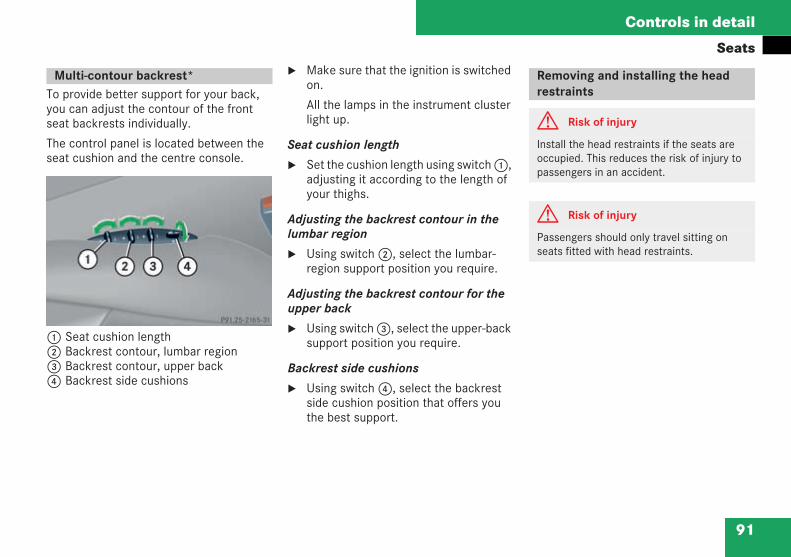
91
Controls in detail
Seats
To provide better support for your back,you can adjust the contour of the frontseat backrests individually.
The control panel is located between theseat cushion and the centre console.
1 Seat cushion length2 Backrest contour, lumbar region3 Backrest contour, upper back4 Backrest side cushions
Make sure that the ignition is switchedon.
All the lamps in the instrument clusterlight up.
Seat cushion length
Set the cushion length using switch1,adjusting it according to the length ofyour thighs.
Adjusting the backrest contour in thelumbar region
Using switch2, select the lumbar-region support position you require.
Adjusting the backrest contour for theupper back
Using switch3, select the upper-backsupport position you require.
Backrest side cushions
Using switch4, select the backrestside cushion position that offers youthe best support.
Multi-contour backrest*
P 91.25-2165-31
Removing and installing the headrestraints
G Risk of injury
Install the head restraints if the seats areoccupied. This reduces the risk of injury topassengers in an accident.
G Risk of injury
Passengers should only travel sitting onseats fitted with head restraints.
209en_d2.boo Seite 91 Dienstag, 25. Mai 2004 7:26 19
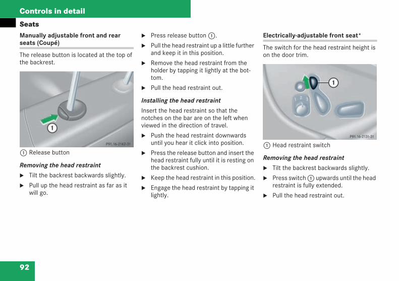
92
Controls in detail
SeatsManually adjustable front and rearseats (Coupé)
The release button is located at the top ofthe backrest.
1 Release button
Removing the head restraint
Tilt the backrest backwards slightly.
Pull up the head restraint as far as itwill go.
Press release button1.
Pull the head restraint up a little furtherand keep it in this position.
Remove the head restraint from theholder by tapping it lightly at the bot-tom.
Pull the head restraint out.
Installing the head restraint
Insert the head restraint so that thenotches on the bar are on the left whenviewed in the direction of travel.
Push the head restraint downwardsuntil you hear it click into position.
Press the release button and insert thehead restraint fully until it is resting onthe backrest cushion.
Keep the head restraint in this position.
Engage the head restraint by tapping itlightly.
Electrically-adjustable front seat*
The switch for the head restraint height ison the door trim.
1 Head restraint switch
Removing the head restraint
Tilt the backrest backwards slightly.
Press switch1 upwards until the headrestraint is fully extended.
Pull the head restraint out.
P 91.16-2142-31P91.16-2131-31
209en_d2.boo Seite 92 Dienstag, 25. Mai 2004 7:26 19
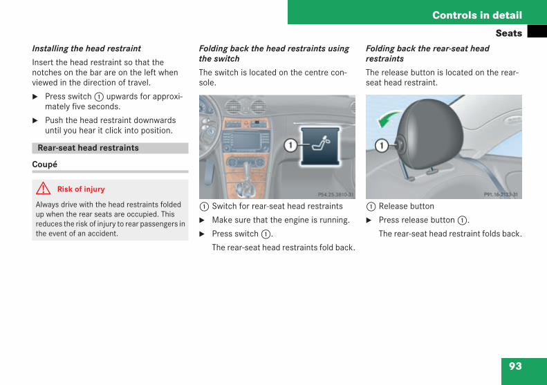
93
Controls in detail
SeatsInstalling the head restraint
Insert the head restraint so that thenotches on the bar are on the left whenviewed in the direction of travel.
Press switch1 upwards for approxi-mately five seconds.
Push the head restraint downwardsuntil you hear it click into position.
Coupé
Folding back the head restraints usingthe switch
The switch is located on the centre con-sole.
1 Switch for rear-seat head restraints
Make sure that the engine is running.
Press switch1.
The rear-seat head restraints fold back.
Folding back the rear-seat headrestraints
The release button is located on the rear-seat head restraint.
1 Release button
Press release button1.
The rear-seat head restraint folds back.
Rear-seat head restraints
G Risk of injury
Always drive with the head restraints foldedup when the rear seats are occupied. Thisreduces the risk of injury to rear passengers inthe event of an accident.
P 54.25-3810-31 neu P 91.16-2133-31
209en_d2.boo Seite 93 Dienstag, 25. Mai 2004 7:26 19
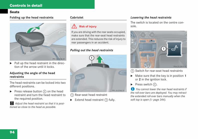
94
Controls in detail
SeatsFolding up the head restraints
Pull up the head restraint in the direc-tion of the arrow until it locks.
Adjusting the angle of the headrestraints
The head restraints can be locked into twodifferent positions.
Press release button1 on the headrestraint and turn the head restraint tothe required position.
! Adjust the head restraint so that it is posi-tioned as close to the head as possible.
Cabriolet
Pulling out the head restraints
1 Rear-seat head restraint
Extend head restraint1 fully.
Lowering the head restraints
The switch is located on the centre con-sole.
1 Switch for rear-seat head restraints
Make sure that the key is in position 1or 2 in the ignition lock.
Press switch1.
i You cannot lower the rear head restraints ifthe roll-over bars are deployed. You may retractthe extended roll-over bars manually when thesoft top is open ( page 344).
P 91.16-2136-31
G Risk of injury
If you are driving with the rear seats occupied,make sure that the rear-seat head restraintsare extended. This reduces the risk of injury torear passengers in an accident.
P 91.16-2146-31
P 54.25-3810-31 B1
209en_d2.boo Seite 94 Dienstag, 25. Mai 2004 7:26 19
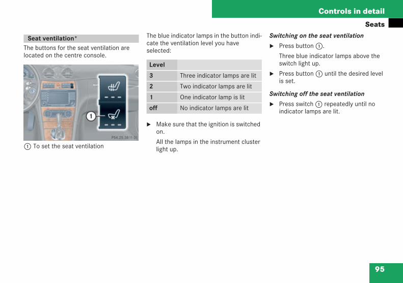
95
Controls in detail
Seats
The buttons for the seat ventilation arelocated on the centre console.
1 To set the seat ventilation
The blue indicator lamps in the button indi-cate the ventilation level you haveselected:
Make sure that the ignition is switchedon.
All the lamps in the instrument clusterlight up.
Switching on the seat ventilation
Press button1.
Three blue indicator lamps above theswitch light up.
Press button1 until the desired levelis set.
Switching off the seat ventilation
Press switch1 repeatedly until noindicator lamps are lit.
Seat ventilation*
P 54.25-3811-31 neu
Level
3 Three indicator lamps are lit
2 Two indicator lamps are lit
1 One indicator lamp is lit
off No indicator lamps are lit
209en_d2.boo Seite 95 Dienstag, 25. Mai 2004 7:26 19
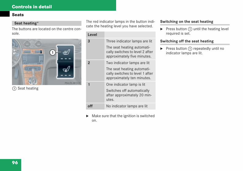
96
Controls in detail
Seats
The buttons are located on the centre con-sole.
1 Seat heating
The red indicator lamps in the button indi-cate the heating level you have selected.
Make sure that the ignition is switchedon.
Switching on the seat heating
Press button1 until the heating levelrequired is set.
Switching off the seat heating
Press button1 repeatedly until noindicator lamps are lit.
Seat heating*
P54.25-3813-31
Level
3 Three indicator lamps are lit
The seat heating automati-cally switches to level 2 afterapproximately five minutes.
2 Two indicator lamps are lit
The seat heating automati-cally switches to level 1 afterapproximately ten minutes.
1 One indicator lamp is lit
Switches off automaticallyafter approximately 20 min-utes.
off No indicator lamps are lit
209en_d2.boo Seite 96 Dienstag, 25. Mai 2004 7:26 19
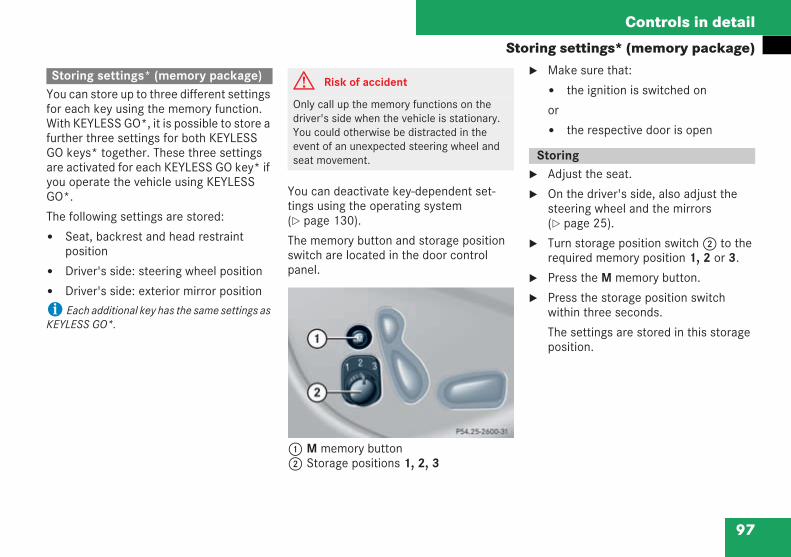
97
Controls in detail
Storing settings* (memory package)
You can store up to three different settingsfor each key using the memory function.With KEYLESS GO*, it is possible to store afurther three settings for both KEYLESSGO keys* together. These three settingsare activated for each KEYLESS GO key* ifyou operate the vehicle using KEYLESSGO*.
The following settings are stored:
Seat, backrest and head restraintposition
Driver's side: steering wheel position
Driver's side: exterior mirror position
i Each additional key has the same settings asKEYLESS GO*.
You can deactivate key-dependent set-tings using the operating system( page 130).
The memory button and storage positionswitch are located in the door controlpanel.
1 M memory button2 Storage positions 1, 2, 3
Make sure that:
the ignition is switched on
or
the respective door is open
Adjust the seat.
On the driver's side, also adjust thesteering wheel and the mirrors( page 25).
Turn storage position switch2 to therequired memory position 1, 2 or 3.
Press the M memory button.
Press the storage position switchwithin three seconds.
The settings are stored in this storageposition.
Storing settings* (memory package) G Risk of accident
Only call up the memory functions on thedriver's side when the vehicle is stationary.You could otherwise be distracted in theevent of an unexpected steering wheel andseat movement.
P 54.25-2600-31 neu
Storing
209en_d2.boo Seite 97 Dienstag, 25. Mai 2004 7:26 19
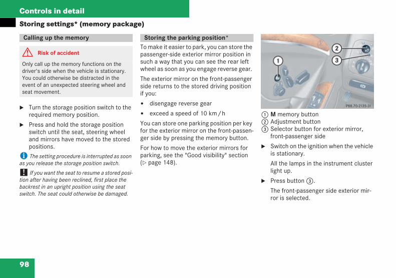
98
Controls in detail
Storing settings* (memory package)
Turn the storage position switch to therequired memory position.
Press and hold the storage positionswitch until the seat, steering wheeland mirrors have moved to the storedpositions.
i The setting procedure is interrupted as soonas you release the storage position switch.
! If you want the seat to resume a stored posi-tion after having been reclined, first place thebackrest in an upright position using the seatswitch. The seat could otherwise be damaged.
To make it easier to park, you can store thepassenger-side exterior mirror position insuch a way that you can see the rear leftwheel as soon as you engage reverse gear.
The exterior mirror on the front-passengerside returns to the stored driving positionif you:
disengage reverse gear
exceed a speed of 10 km/h
You can store one parking position per keyfor the exterior mirror on the front-passen-ger side by pressing the memory button.
For how to move the exterior mirrors forparking, see the "Good visibility" section( page 148).
1 M memory button2 Adjustment button3 Selector button for exterior mirror,
front-passenger side
Switch on the ignition when the vehicleis stationary.
All the lamps in the instrument clusterlight up.
Press button3.
The front-passenger side exterior mir-ror is selected.
Calling up the memory
G Risk of accident
Only call up the memory functions on thedriver's side when the vehicle is stationary.You could otherwise be distracted in theevent of an unexpected steering wheel andseat movement.
Storing the parking position*
P88.70-2135-31
209en_d2.boo Seite 98 Dienstag, 25. Mai 2004 7:26 19
99
Controls in detail
Storing settings* (memory package)Press button2 to adjust the exteriormirror in such a way that you can seethe rear wheel and the kerb.
Press the M memory button in thedoor.
Then press adjustment button2 up ordown and to the left or right withinthree seconds.
The parking position is stored if themirror does not move.
i If the mirror does move, repeat the steps.You can move the mirror again after storing thesetting.
The exterior mirror returns to its originalposition:
approximately 10 seconds after a for-ward gear is engaged
approximately 10 seconds after youmove the selector lever to position D
if you exceed a speed of approximately10 km/h regardless of the gearengaged
if you press the button for the exteriormirror on the driver's side
You can activate and deactivate this func-tion using the operating system( page 130).
You can store one parking position per keyand one parking position for the twoKEYLESS GO keys*.
209en_d2.boo Seite 99 Dienstag, 25. Mai 2004 7:26 19
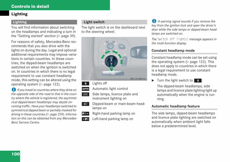
100
Controls in detail
Lighting
You will find information about switchingon the headlamps and indicating a turn inthe "Getting started" section ( page 39).
For reasons of safety, Mercedes-Benz rec-ommends that you also drive with thelights on during the day. Legal and optionaladditional requirements may impose varia-tions in certain countries. In these coun-tries, the dipped-beam headlamps areswitched on when the ignition is switchedon. In countries in which there is no legalrequirement to use constant headlampmode, this setting can be altered using theoperating system ( page 122).
i If you travel to countries where they drive onthe opposite side of the road to that in the coun-try where the vehicle is registered, the asymmet-rical dipped-beam headlamps may dazzle on-coming traffic. Have your headlamps switched tosymmetrical dipped beam or partially masked fordriving in these countries ( page 259). Informa-tion on this can be obtained from any Mercedes-Benz Service Centre.
The light switch is on the dashboard nextto the steering wheel.
M Lights offU Automatic light controlC Side lamps, licence plate and
instrument lighting onB Dipped-beam or main-beam head-
lamps onˆ Right-hand parking lamp on‚ Left-hand parking lamp on
i A warning signal sounds if you remove thekey from the ignition lock and open the driver'sdoor while the side lamps or dipped-beam head-lamps are switched on.
The Switch off lights!message appears inthe multi-function display.
Constant headlamp mode
Constant headlamp mode can be set usingthe operating system ( page 122). Thisdoes not apply to countries in which thereis a legal requirement to use constantheadlamp mode.
Turn the light switch toM.
The dipped-beam headlamps, sidelamps and licence plate lighting light upautomatically when the engine is run-ning.
Automatic headlamp feature
The side lamps, dipped-beam headlampsand licence plate lighting are switched onautomatically when ambient light fallsbelow a predetermined level.
Lighting Light switch
P 82.10-2890-31
209en_d2.boo Seite 100 Dienstag, 25. Mai 2004 7:26 19
101
Controls in detail
Lighting
Turn the light switch toU.
The side lamps are switched on/offautomatically when the key is in posi-tion 1 in the ignition lock ( page 23).
The dipped-beam headlamps, sidelamps and licence plate lighting areswitched on/off automatically whenthe engine is running.
Front foglamps/rear foglamp
i When the light switch is set toU, youcannot switch on the front or rear foglamps. Toswitch on the front foglamps, you must first turnthe light switch toB.
Switching on the front foglamps
Make sure that theB dipped-beamheadlamps are switched on.
Pull the light switch to the first stop.
The green‡ indicator lamp next tothe switch lights up.
Switching on the rear foglamp
Make sure that theB dipped-beamheadlamps are switched on.
Pull the light switch to the second stop.
The yellow† indicator lamp next tothe switch lights up.
G Risk of accident
If the light switch is set toU:
the headlamps could automaticallyswitch off temporarily as a consequenceof strong glare (e.g. from oncoming traf-fic).
the lights do not switch on automaticallyin foggy conditions.
Set the light switch toB in good time.You will otherwise endanger yourself andothers.
For this reason, only move the light switchfromU toB when it is dark if thevehicle is stationary. You could otherwisecause an accident if the headlamps were toswitch off temporarily.
The automatic headlamp feature is only anaid. You are responsible for the vehicle'slighting at all times.
G Risk of accident
Set the light switch:
fromU toB when it is dark onlyif the vehicle is stationary
toB before driving in what youexpect to be foggy conditions
You could otherwise cause an accident if theheadlamps were to switch off temporarily.
209en_d2.boo Seite 101 Dienstag, 25. Mai 2004 7:26 19
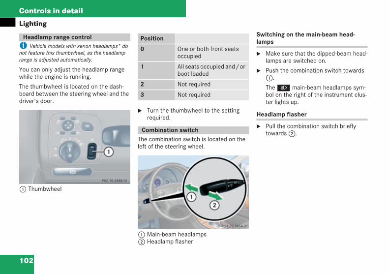
102
Controls in detail
Lighting
i Vehicle models with xenon headlamps* donot feature this thumbwheel, as the headlamprange is adjusted automatically.
You can only adjust the headlamp rangewhile the engine is running.
The thumbwheel is located on the dash-board between the steering wheel and thedriver's door.
1 Thumbwheel
Turn the thumbwheel to the settingrequired.
The combination switch is located on theleft of the steering wheel.
1 Main-beam headlamps2 Headlamp flasher
Switching on the main-beam head-lamps
Make sure that the dipped-beam head-lamps are switched on.
Push the combination switch towards1.
TheB main-beam headlamps sym-bol on the right of the instrument clus-ter lights up.
Headlamp flasher
Pull the combination switch brieflytowards2.
Headlamp range control
P 82.10-2888-31 neu
Position
0 One or both front seatsoccupied
1 All seats occupied and/orboot loaded
2 Not required
3 Not required
Combination switch
P 54.25-3854-31 neu
209en_d2.boo Seite 102 Dienstag, 25. Mai 2004 7:26 19
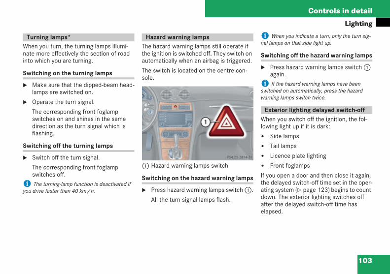
103
Controls in detail
Lighting
When you turn, the turning lamps illumi-nate more effectively the section of roadinto which you are turning.
Switching on the turning lamps
Make sure that the dipped-beam head-lamps are switched on.
Operate the turn signal.
The corresponding front foglampswitches on and shines in the samedirection as the turn signal which isflashing.
Switching off the turning lamps
Switch off the turn signal.
The corresponding front foglampswitches off.
i The turning-lamp function is deactivated ifyou drive faster than 40 km/h.
The hazard warning lamps still operate ifthe ignition is switched off. They switch onautomatically when an airbag is triggered.
The switch is located on the centre con-sole.
1 Hazard warning lamps switch
Switching on the hazard warning lamps
Press hazard warning lamps switch1.
All the turn signal lamps flash.
i When you indicate a turn, only the turn sig-nal lamps on that side light up.
Switching off the hazard warning lamps
Press hazard warning lamps switch1again.
i If the hazard warning lamps have beenswitched on automatically, press the hazardwarning lamps switch twice.
When you switch off the ignition, the fol-lowing light up if it is dark:
Side lamps
Tail lamps
Licence plate lighting
Front foglamps
If you open a door and then close it again,the delayed switch-off time set in the oper-ating system ( page 123) begins to countdown. The exterior lighting switches offafter the delayed switch-off time haselapsed.
Turning lamps* Hazard warning lamps
P 54.25-3814-31 neuExterior lighting delayed switch-off
209en_d2.boo Seite 103 Dienstag, 25. Mai 2004 7:26 19
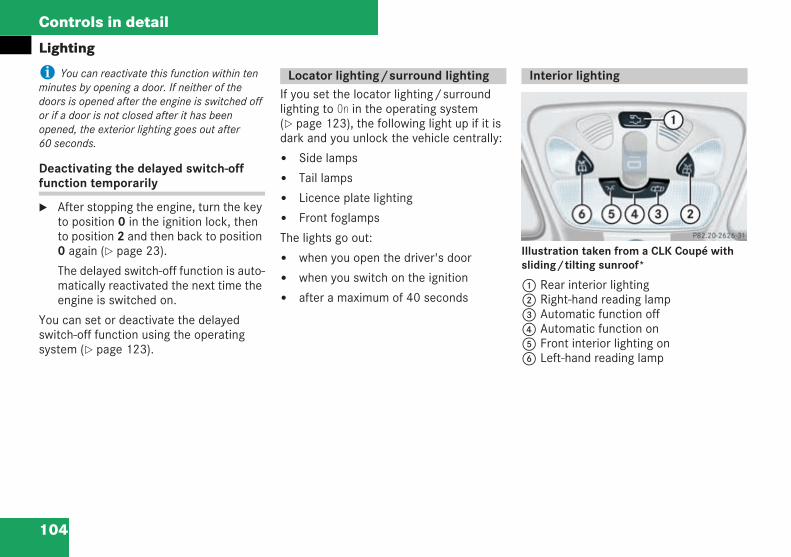
104
Controls in detail
Lighting
i You can reactivate this function within tenminutes by opening a door. If neither of thedoors is opened after the engine is switched offor if a door is not closed after it has beenopened, the exterior lighting goes out after60 seconds.
Deactivating the delayed switch-offfunction temporarily
After stopping the engine, turn the keyto position 0 in the ignition lock, thento position 2 and then back to position0 again ( page 23).
The delayed switch-off function is auto-matically reactivated the next time theengine is switched on.
You can set or deactivate the delayedswitch-off function using the operatingsystem ( page 123).
If you set the locator lighting/surroundlighting to On in the operating system( page 123), the following light up if it isdark and you unlock the vehicle centrally:
Side lamps
Tail lamps
Licence plate lighting
Front foglamps
The lights go out:
when you open the driver's door
when you switch on the ignition
after a maximum of 40 seconds
Illustration taken from a CLK Coupé withsliding/tilting sunroof*
1 Rear interior lighting2 Right-hand reading lamp3 Automatic function off4 Automatic function on5 Front interior lighting on6 Left-hand reading lamp
Locator lighting/surround lighting Interior lighting
P 82.20-2626-31 neu
209en_d2.boo Seite 104 Dienstag, 25. Mai 2004 7:26 19
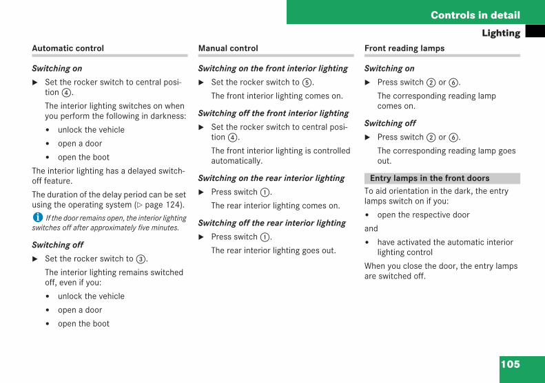
105
Controls in detail
LightingAutomatic control
Switching on
Set the rocker switch to central posi-tion4.
The interior lighting switches on whenyou perform the following in darkness:
unlock the vehicle
open a door
open the boot
The interior lighting has a delayed switch-off feature.
The duration of the delay period can be setusing the operating system ( page 124).
i If the door remains open, the interior lightingswitches off after approximately five minutes.
Switching off
Set the rocker switch to3.
The interior lighting remains switchedoff, even if you:
unlock the vehicle
open a door
open the boot
Manual control
Switching on the front interior lighting
Set the rocker switch to5.
The front interior lighting comes on.
Switching off the front interior lighting
Set the rocker switch to central posi-tion4.
The front interior lighting is controlledautomatically.
Switching on the rear interior lighting
Press switch1.
The rear interior lighting comes on.
Switching off the rear interior lighting
Press switch1.
The rear interior lighting goes out.
Front reading lamps
Switching on
Press switch2 or6.
The corresponding reading lampcomes on.
Switching off
Press switch2 or6.
The corresponding reading lamp goesout.
To aid orientation in the dark, the entrylamps switch on if you:
open the respective door
and
have activated the automatic interiorlighting control
When you close the door, the entry lampsare switched off.
Entry lamps in the front doors
209en_d2.boo Seite 105 Dienstag, 25. Mai 2004 7:26 19
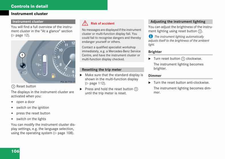
106
Controls in detail
Instrument cluster
You will find a full overview of the instru-ment cluster in the "At a glance" section( page 12).
1 Reset button
The displays in the instrument cluster areactivated when you:
open a door
switch on the ignition
press the reset button
switch on the lights
You can modify the instrument cluster dis-play settings, e.g. the language selection,using the operating system ( page 108).
Make sure that the standard display isshown in the multi-function display( page 112).
Press and hold the reset button1until the trip meter is reset.
You can adjust the brightness of the instru-ment lighting using reset button1.
i The instrument lighting automaticallyadjusts itself to the brightness of the ambientlight.
Brighter
Turn reset button1 clockwise.
The instrument lighting becomesbrighter.
Dimmer
Turn the reset button anti-clockwise.
The instrument lighting becomes dim-mer.
Instrument cluster G Risk of accident
No messages are displayed if the instrumentcluster or multi-function display fail. Youcould fail to recognise dangers and therebyendanger yourself or others.
Contact a qualified specialist workshopimmediately, e.g. a Mercedes-Benz ServiceCentre, and have the instrument cluster ormulti-function display checked.
Resetting the trip meter
Adjusting the instrument lighting
209en_d2.boo Seite 106 Dienstag, 25. Mai 2004 7:26 19
107
Controls in detail
Instrument cluster
The coolant temperature gauge is locatedon the right-hand side of the instrumentcluster.
The temperature displayed may climb to120 °C when the vehicle is being driven innormal conditions and if the coolant con-tains the correct concentration of corro-sion inhibitor and antifreeze.
The red band in the rev counter indicatesthe engine's overrevving range. The enginespeed is limited to protect the engine whenthe red band is reached.
! Do not drive in the overrevving range. Doingso could damage the engine.
There may be a short delay before a loweroutside temperature is displayed, forexample after leaving a garage.
There may also be a short delay before arise in the outside temperature is dis-played. This prevents an incorrect temper-ature display caused by heat from theengine when the vehicle is stationary ormoving slowly.
i You can set the unit for the outside temper-ature display using the operating system( page 119).
Coolant temperature gauge
Rev counter
Outside temperature display
G Risk of accident
Even if the temperature displayed is justabove freezing point, the road surface maystill be icy, especially in wooded areas or onbridges. The vehicle could skid if you fail toadapt your driving style accordingly. For thisreason, always adapt your driving style andspeed to the weather conditions.
209en_d2.boo Seite 107 Dienstag, 25. Mai 2004 7:26 19
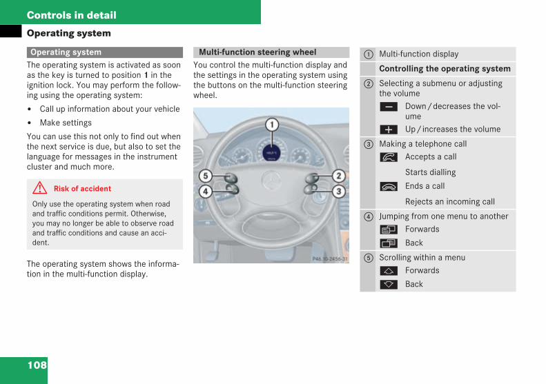
108
Controls in detail
Operating system
The operating system is activated as soonas the key is turned to position 1 in theignition lock. You may perform the follow-ing using the operating system:
Call up information about your vehicle
Make settings
You can use this not only to find out whenthe next service is due, but also to set thelanguage for messages in the instrumentcluster and much more.
The operating system shows the informa-tion in the multi-function display.
You control the multi-function display andthe settings in the operating system usingthe buttons on the multi-function steeringwheel.
Operating system
G Risk of accident
Only use the operating system when roadand traffic conditions permit. Otherwise,you may no longer be able to observe roadand traffic conditions and cause an acci-dent.
Multi-function steering wheel
P46.10-2456-31
1 Multi-function display
Controlling the operating system
2 Selecting a submenu or adjustingthe volumeç Down/decreases the vol-
umeæ Up/increases the volume
3 Making a telephone callí Accepts a call
Starts dialling
ì Ends a call
Rejects an incoming call
4 Jumping from one menu to anotherè Forwards
ÿ Back
5 Scrolling within a menuj Forwards
k Back
209en_d2.boo Seite 108 Dienstag, 25. Mai 2004 7:26 19
109
Controls in detail
Operating systemThe multi-function display changes whenyou press one of these buttons on themulti-function steering wheel.
Several functions are combined themati-cally in each menu. For example, the Audiomenu contains functions for controllingthe radio or CD player. You can use a func-tion to call up information or to change thesettings for your vehicle.
You can think of the order of the menusand functions in a menu as a circle:
If you press theè orÿ buttonrepeatedly, each menu appears in turn.
If you press thek orj buttonrepeatedly, each menu functionappears in turn.
The Settings...menu contains submenusinstead of functions with which you cancall up or change a setting. For notes onhow to control these submenus, see the"Settings menu" section ( page 116).
The number of menus depends on theoptional equipment installed in your vehi-cle.
The following page describes the menusand their functions.
209en_d2.boo Seite 109 Dienstag, 25. Mai 2004 7:26 19
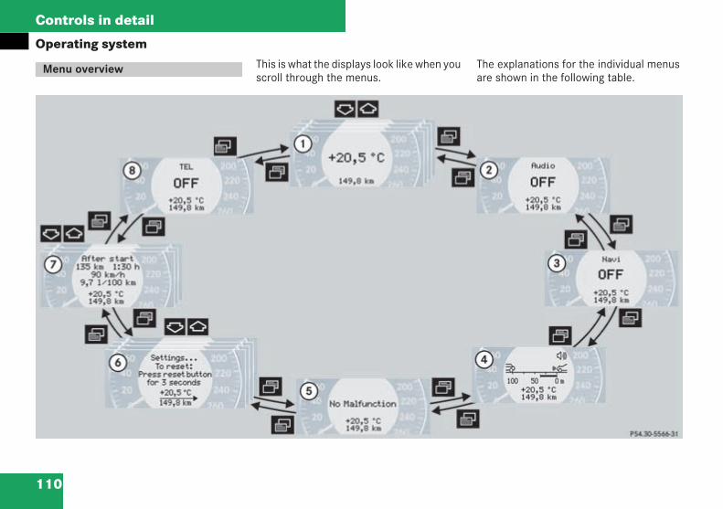
110
Controls in detail
Operating systemThis is what the displays look like when youscroll through the menus.
The explanations for the individual menusare shown in the following table.
Menu overview
P54.30-5196-31
209en_d2.boo Seite 110 Dienstag, 25. Mai 2004 7:26 19
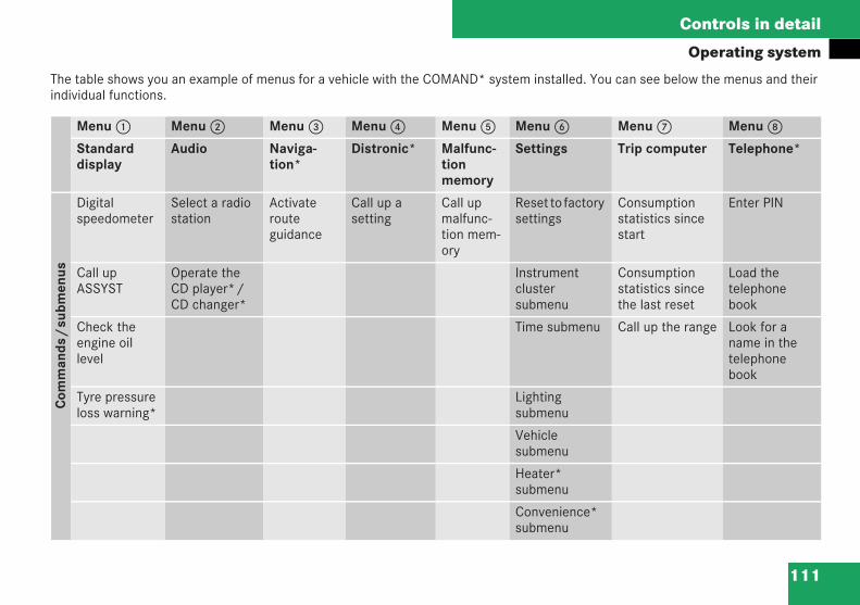
111
Controls in detail
Operating system
The table shows you an example of menus for a vehicle with the COMAND* system installed. You can see below the menus and theirindividual functions.
Menu1 Menu2 Menu3 Menu4 Menu5 Menu6 Menu7 Menu8
Standarddisplay
Audio Naviga-tion*
Distronic* Malfunc-tionmemory
Settings Trip computer Telephone*
Com
man
ds/
subm
enus
Digitalspeedometer
Select a radiostation
Activaterouteguidance
Call up asetting
Call upmalfunc-tion mem-ory
Reset to factorysettings
Consumptionstatistics sincestart
Enter PIN
Call upASSYST
Operate theCD player*/CD changer*
Instrumentclustersubmenu
Consumptionstatistics sincethe last reset
Load thetelephonebook
Check theengine oillevel
Time submenu Call up the range Look for aname in thetelephonebook
Tyre pressureloss warning*
Lightingsubmenu
Vehiclesubmenu
Heater*submenu
Convenience*submenu
209en_d2.boo Seite 111 Dienstag, 25. Mai 2004 7:26 19
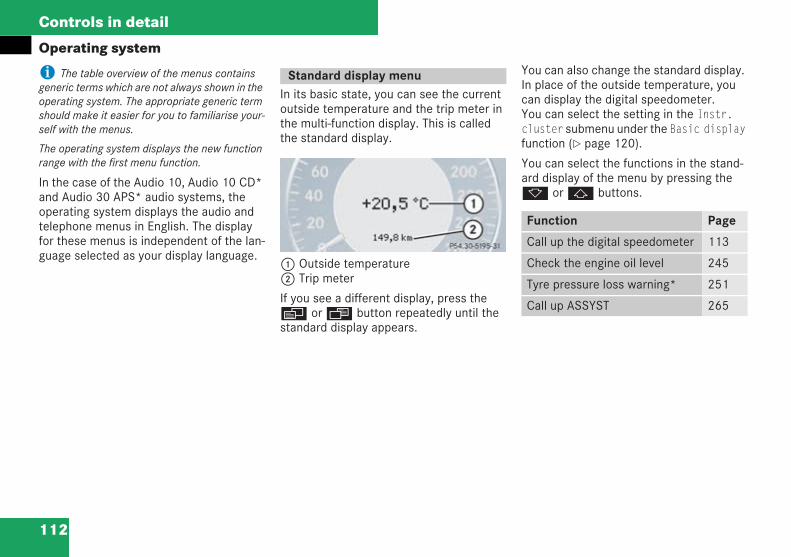
112
Controls in detail
Operating system
i The table overview of the menus containsgeneric terms which are not always shown in theoperating system. The appropriate generic termshould make it easier for you to familiarise your-self with the menus.
The operating system displays the new functionrange with the first menu function.
In the case of the Audio 10, Audio 10 CD*and Audio 30 APS* audio systems, theoperating system displays the audio andtelephone menus in English. The displayfor these menus is independent of the lan-guage selected as your display language.
In its basic state, you can see the currentoutside temperature and the trip meter inthe multi-function display. This is calledthe standard display.
1 Outside temperature2 Trip meter
If you see a different display, press theè orÿ button repeatedly until thestandard display appears.
You can also change the standard display.In place of the outside temperature, youcan display the digital speedometer.You can select the setting in the Instr.cluster submenu under the Basic displayfunction ( page 120).
You can select the functions in the stand-ard display of the menu by pressing thek orj buttons.
Standard display menu
P54.30-5195-31Function Page
Call up the digital speedometer 113
Check the engine oil level 245
Tyre pressure loss warning* 251
Call up ASSYST 265
209en_d2.boo Seite 112 Dienstag, 25. Mai 2004 7:26 19
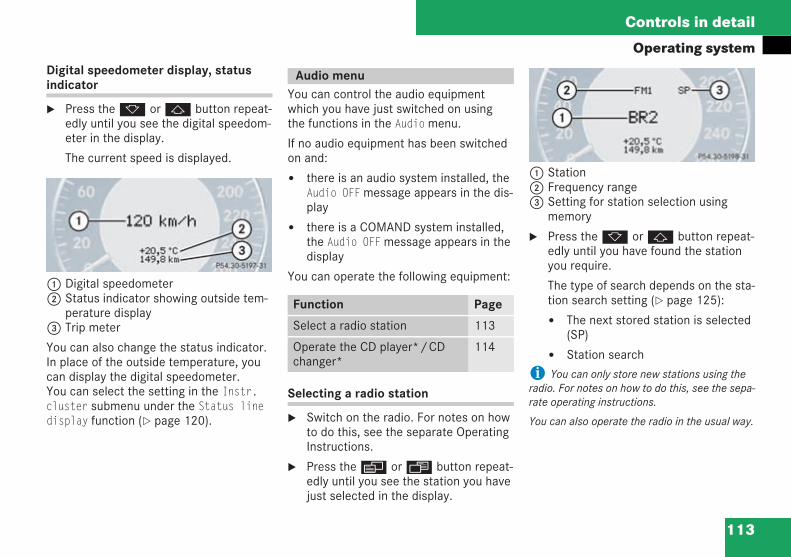
113
Controls in detail
Operating systemDigital speedometer display, statusindicator
Press thek orj button repeat-edly until you see the digital speedom-eter in the display.
The current speed is displayed.
1 Digital speedometer2 Status indicator showing outside tem-
perature display3 Trip meter
You can also change the status indicator.In place of the outside temperature, youcan display the digital speedometer.You can select the setting in the Instr.cluster submenu under the Status linedisplay function ( page 120).
You can control the audio equipmentwhich you have just switched on usingthe functions in the Audiomenu.
If no audio equipment has been switchedon and:
there is an audio system installed, theAudio OFFmessage appears in the dis-play
there is a COMAND system installed,the Audio OFFmessage appears in thedisplay
You can operate the following equipment:
Selecting a radio station
Switch on the radio. For notes on howto do this, see the separate OperatingInstructions.
Press theè orÿ button repeat-edly until you see the station you havejust selected in the display.
1 Station2 Frequency range3 Setting for station selection using
memory
Press thek orj button repeat-edly until you have found the stationyou require.
The type of search depends on the sta-tion search setting ( page 125):
The next stored station is selected(SP)
Station search
i You can only store new stations using theradio. For notes on how to do this, see the sepa-rate operating instructions.
You can also operate the radio in the usual way.
P54.30-5197-31
Audio menu
Function Page
Select a radio station 113
Operate the CD player*/CDchanger*
114
P54.30-5198-31
209en_d2.boo Seite 113 Dienstag, 25. Mai 2004 7:26 19
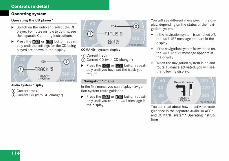
114
Controls in detail
Operating systemOperating the CD player*
Switch on the radio and select the CDplayer. For notes on how to do this, seethe separate Operating Instructions.
Press theè orÿ button repeat-edly until the settings for the CD beingplayed are shown in the display.
Audio system display
1 Current track2 Current CD (with CD changer)
COMAND* system display
1 Current track2 Current CD (with CD changer)
Press thek orj button repeat-edly until you have set the track yourequire.
In the Navmenu, you can display naviga-tion system route guidance.
Press theè orÿ button repeat-edly until you see the Navimessage inthe display.
You will see different messages in the dis-play, depending on the status of the navi-gation system:
If the navigation system is switched off,the Navi OFFmessage appears in thedisplay.
If the navigation system is switched on,the Navi activemessage appears inthe display.
When the navigation system is on androute guidance activated, you will seethe following display:
You can read about how to activate routeguidance in the separate Audio 30 APS*and COMAND system* Operating Instruc-tions.
P54.30-5199-31
Navigation* menu
P54.30-5200-31
P54.30-5202-31
209en_d2.boo Seite 114 Dienstag, 25. Mai 2004 7:26 19
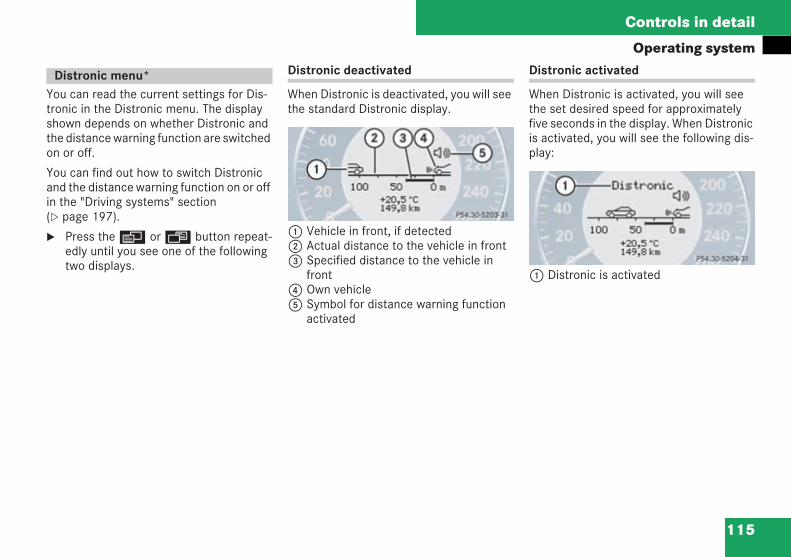
115
Controls in detail
Operating system
You can read the current settings for Dis-tronic in the Distronic menu. The displayshown depends on whether Distronic andthe distance warning function are switchedon or off.
You can find out how to switch Distronicand the distance warning function on or offin the "Driving systems" section( page 197).
Press theè orÿ button repeat-edly until you see one of the followingtwo displays.
Distronic deactivated
When Distronic is deactivated, you will seethe standard Distronic display.
1 Vehicle in front, if detected2 Actual distance to the vehicle in front3 Specified distance to the vehicle in
front4 Own vehicle5 Symbol for distance warning function
activated
Distronic activated
When Distronic is activated, you will seethe set desired speed for approximatelyfive seconds in the display. When Distronicis activated, you will see the following dis-play:
1 Distronic is activated
Distronic menu*
P54.30-5203-31
P54.30-5204-31
209en_d2.boo Seite 115 Dienstag, 25. Mai 2004 7:26 19
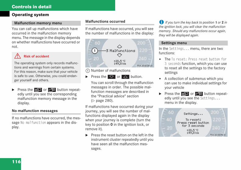
116
Controls in detail
Operating system
You can call up malfunctions which haveoccurred in the malfunction memorymenu. The message in the display dependson whether malfunctions have occurred ornot.
Press theè orÿ button repeat-edly until you see the correspondingmalfunction memory message in thedisplay.
No malfunction messages
If no malfunctions have occurred, the mes-sage No malfunction appears in the dis-play.
Malfunctions occurred
If malfunctions have occurred, you will seethe number of malfunctions in the display:
1 Number of malfunctions
Press thek orj button.
You can scroll through the malfunctionmessages in order. The possible mal-function messages are described inthe "Practical advice" section( page 280).
If malfunctions have occurred during yourjourney, you will see the number of mal-functions displayed again in the displaywhen your journey is complete (turn thekey to position 0 in the ignition lock, orremove it).
Press the reset button on the left in theinstrument cluster repeatedly until youhave seen all the malfunction mes-sages.
i If you turn the key back to position 1 or 2 inthe ignition lock, you will clear the malfunctionmemory. Should any malfunctions occur again,they will be displayed again.
In the Settings...menu, there are twofunctions:
The To reset: Press reset button for3 seconds function, which you can useto reset all the settings to the factorysettings
A collection of submenus which youcan use to make individual settings foryour vehicle
Press theè orÿ button repeat-edly until you see the Settings...menu in the display.
Malfunction memory menu
G Risk of accident
The operating system only records malfunc-tions and warnings from certain systems.For this reason, make sure that your vehicleis safe to use. Otherwise, you could endan-ger yourself and others.
P54.30-5205-31
Settings menu
P54.30-5206-31
209en_d2.boo Seite 116 Dienstag, 25. Mai 2004 7:26 19
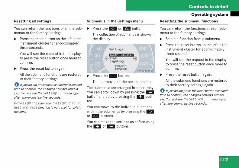
117
Controls in detail
Operating systemResetting all settings
You can return the functions of all the sub-menus to the factory settings.
Press the reset button on the left in theinstrument cluster for approximatelythree seconds.
You will see the request in the displayto press the reset button once more toconfirm.
Press the reset button again.
All the submenu functions are restoredto their factory settings.
i If you do not press the reset button a secondtime to confirm, the changed settings remainset. You will see the Settings...menu againafter approximately five seconds.
In the Lighting submenu, the Light circuitheadlamp mode function is not reset for safetyreasons.
Submenus in the Settings menu
Press thek orj button.
The collection of submenus is shown inthe display.
Press theç button.
The bar moves to the next submenu.
The submenus are arranged in a hierarchy.You can scroll down by pressing theçbutton and up by pressing theæ but-ton.
You can move to the individual functionswithin the submenus by pressing thekorj buttons.
You can make the settings as before usingtheæ orç buttons.
Resetting the submenu functions
You can return the functions in each sub-menu to the factory settings.
Select a function from a submenu.
Press the reset button on the left in theinstrument cluster for approximatelythree seconds.
You will see the request in the displayto press the reset button once more toconfirm.
Press the reset button again.
All the submenu functions are restoredto their factory settings again.
i If you do not press the reset button a secondtime to confirm, the changed settings remainset. You will see the Settings...menu againafter approximately five seconds.
P54.30-5207-31
209en_d2.boo Seite 117 Dienstag, 25. Mai 2004 7:26 19
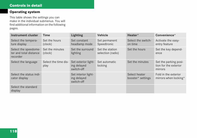
118
Controls in detail
Operating systemThis table shows the settings you canmake in the individual submenus. You willfind additional information on the followingpages.:
Instrument cluster Time Lighting Vehicle Heater* Convenience*
Select the tempera-ture display
Set the hours(clock)
Set constantheadlamp mode
Set permanentSpeedtronic
Select the switch-on time
Activate the easy-entry feature
Select the speedome-ter and total distancerecorder
Set the minutes(clock)
Set the surroundlighting
Set the stationselection (radio)
Set the hours Set the key depend-ence
Select the language Select the time dis-play
Set exterior light-ing delayedswitch-off
Set automaticlocking
Set the minutes Set the parking posi-tion for the exteriormirrors
Select the status indi-cator display
Set interior light-ing delayedswitch-off
Select heaterbooster* settings
Fold in the exteriormirrors when locking*
Select the standarddisplay
209en_d2.boo Seite 118 Dienstag, 25. Mai 2004 7:26 19
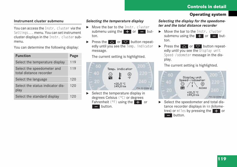
119
Controls in detail
Operating systemInstrument cluster submenu
You can access the Instr. cluster via theSettings...menu. You can set instrumentcluster displays in the Instr. cluster sub-menu.
You can determine the following display:
Selecting the temperature display
Move the bar to the Instr. clustersubmenu using theæ or ç but-ton.
Press thej ork button repeat-edly until you see the Temp. indicatormessage.
The current setting is highlighted.
Select the temperature display indegrees Celsius (°C) or degreesFahrenheit (°F) using theæ orç button.
Selecting the display for the speedome-ter and the total distance recorder
Move the bar to the Instr. clustersubmenu using theæ or ç but-ton.
Press thej ork button repeat-edly until you see the Display unitSpeed-/odometermessage in the dis-play.
The current setting is highlighted.
Select the speedometer and total dis-tance recorder displays in km (kilome-tres) or miles by pressing theæ orç button.
Function Page
Select the temperature display 119
Select the speedometer andtotal distance recorder
119
Select the language 120
Select the status indicator dis-play
120
Select the standard display 120
P54.30-5208-31P54.30-5209-31
209en_d2.boo Seite 119 Dienstag, 25. Mai 2004 7:26 19
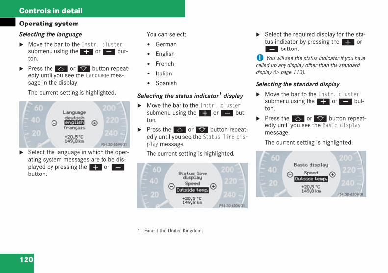
120
Controls in detail
Operating systemSelecting the language
Move the bar to the Instr. clustersubmenu using theæ orç but-ton.
Press thej ork button repeat-edly until you see the Languagemes-sage in the display.
The current setting is highlighted.
Select the language in which the oper-ating system messages are to be dis-played by pressing theæ orçbutton.
You can select:
German
English
French
Italian
Spanish
Selecting the status indicator1 display
Move the bar to the Instr. clustersubmenu using theæ orç but-ton.
Press thej ork button repeat-edly until you see the Status line dis-playmessage.
The current setting is highlighted.
1 Except the United Kingdom.
Select the required display for the sta-tus indicator by pressing theæ orç button.
i You will see the status indicator if you havecalled up any display other than the standarddisplay ( page 113).
Selecting the standard display
Move the bar to the Instr. clustersubmenu using theæ orç but-ton.
Press thej ork button repeat-edly until you see the Basic displaymessage.
The current setting is highlighted.
P54.30-5210-31
P54.30-5211-31
P54.30-5212-31
209en_d2.boo Seite 120 Dienstag, 25. Mai 2004 7:26 19
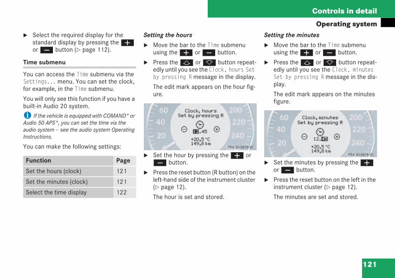
121
Controls in detail
Operating systemSelect the required display for thestandard display by pressing theæorç button ( page 112).
Time submenu
You can access the Time submenu via theSettings...menu. You can set the clock,for example, in the Time submenu.
You will only see this function if you have abuilt-in Audio 20 system.
i If the vehicle is equipped with COMAND* orAudio 50 APS*, you can set the time via theaudio system – see the audio system OperatingInstructions.
You can make the following settings:
Setting the hours
Move the bar to the Time submenuusing theæ orç button.
Press thej ork button repeat-edly until you see the Clock, hours Setby pressing Rmessage in the display.
The edit mark appears on the hour fig-ure.
Set the hour by pressing theæ orç button.
Press the reset button (R button) on theleft-hand side of the instrument cluster( page 12).
The hour is set and stored.
Setting the minutes
Move the bar to the Time submenuusing theæ orç button.
Press thej ork button repeat-edly until you see the Clock, minutesSet by pressing Rmessage in the dis-play.
The edit mark appears on the minutesfigure.
Set the minutes by pressing theæorç button.
Press the reset button on the left in theinstrument cluster ( page 12).
The minutes are set and stored.
Function Page
Set the hours (clock) 121
Set the minutes (clock) 121
Select the time display 122
P54.30-5214-31P54.30-5215-31
209en_d2.boo Seite 121 Dienstag, 25. Mai 2004 7:26 19
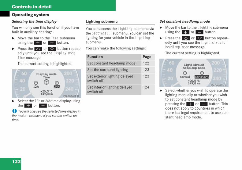
122
Controls in detail
Operating systemSelecting the time display
You will only see this function if you havebuilt-in auxiliary heating*.
Move the bar to the Time submenuusing theæ orç button.
Press thej ork button repeat-edly until you see the Display modeTimemessage.
The current setting is highlighted.
Select the 12h or 24h time display usingtheæ or ç button.
i You will only see the selected time display inthe Heater submenu if you set the switch-ontime.
Lighting submenu
You can access the Lighting submenu viathe Settings... submenu. You can set thelighting for your vehicle in the Lightingsubmenu.
You can make the following settings:
Set constant headlamp mode
Move the bar to the Lighting submenuusing theæ orç button.
Press thej ork button repeat-edly until you see the Light circuitheadlamp modemessage.
The current setting is highlighted.
Select whether you wish to operate thelighting manually or whether you wishto set constant headlamp mode bypressing theæ orç button. Thisdoes not apply to countries in whichthere is a legal requirement to use con-stant headlamp mode.
P54.30-5216-31
Function Page
Set constant headlamp mode 122
Set the surround lighting 123
Set exterior lighting delayedswitch-off
123
Set interior lighting delayedswitch-off
124
P54.30-5851-31
209en_d2.boo Seite 122 Dienstag, 25. Mai 2004 7:26 19
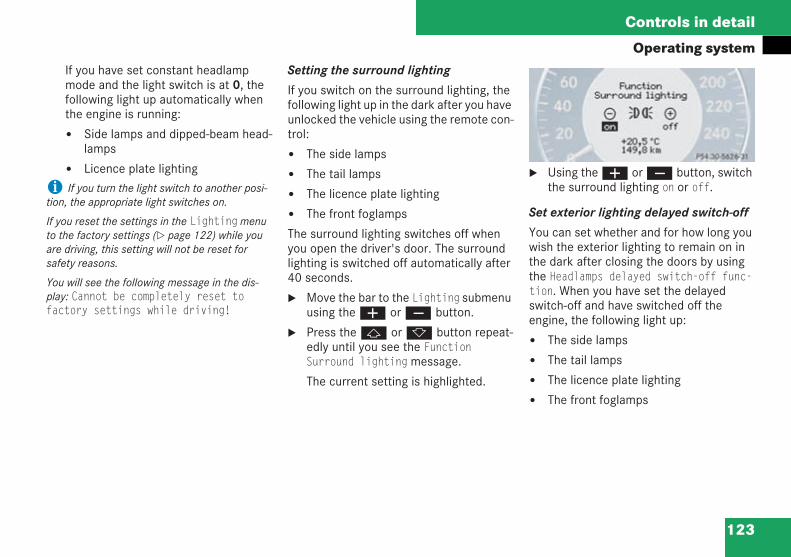
123
Controls in detail
Operating systemIf you have set constant headlampmode and the light switch is at 0, thefollowing light up automatically whenthe engine is running:
Side lamps and dipped-beam head-lamps
Licence plate lighting
i If you turn the light switch to another posi-tion, the appropriate light switches on.
If you reset the settings in the Lightingmenuto the factory settings ( page 122) while youare driving, this setting will not be reset forsafety reasons.
You will see the following message in the dis-play: Cannot be completely reset tofactory settings while driving!
Setting the surround lighting
If you switch on the surround lighting, thefollowing light up in the dark after you haveunlocked the vehicle using the remote con-trol:
The side lamps
The tail lamps
The licence plate lighting
The front foglamps
The surround lighting switches off whenyou open the driver's door. The surroundlighting is switched off automatically after40 seconds.
Move the bar to the Lighting submenuusing theæ orç button.
Press thej ork button repeat-edly until you see the FunctionSurround lightingmessage.
The current setting is highlighted.
Using theæ orç button, switchthe surround lighting on or off.
Set exterior lighting delayed switch-off
You can set whether and for how long youwish the exterior lighting to remain on inthe dark after closing the doors by usingthe Headlamps delayed switch-off func-tion. When you have set the delayedswitch-off and have switched off theengine, the following light up:
The side lamps
The tail lamps
The licence plate lighting
The front foglamps
P54.30-5218-31
209en_d2.boo Seite 123 Dienstag, 25. Mai 2004 7:26 19
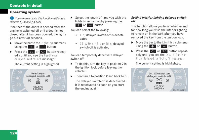
124
Controls in detail
Operating system
i You can reactivate this function within tenminutes by opening a door.
If neither of the doors is opened after theengine is switched off or if a door is notclosed after it has been opened, the lightsgo out after 60 seconds.
Move the bar to the Lighting submenuusing theæ orç button.
Press thej ork button repeat-edly until you see the Headlampsdelayed switch-offmessage.
The current setting is highlighted.
Select the length of time you wish thelights to remain on by pressing theæ orç button.
You can select the following:
0 s, delayed switch-off is deacti-vated
15 s, 30 s, 45 s or 60 s, delayedswitch-off is activated
You can temporarily deactivate delayedswitch-off:
To do this, turn the key to position 0 inthe ignition lock before leaving thevehicle.
Then turn it to position 2 and back to 0.
The delayed switch-off is deactivated.It is reactivated as soon as you startthe engine again.
Setting interior lighting delayed switch-off
This function allows you to set whether andfor how long you wish the interior lightingto remain on in the dark after you haveremoved the key from the ignition lock.
Move the bar to the Lighting submenuusing theæ orç button.
Press thej ork button repeat-edly until you see the Int. illumina-tion delayed switch-off message.
The current setting is highlighted.
P54.30-5219-31 P54.30-5220-31
209en_d2.boo Seite 124 Dienstag, 25. Mai 2004 7:26 19
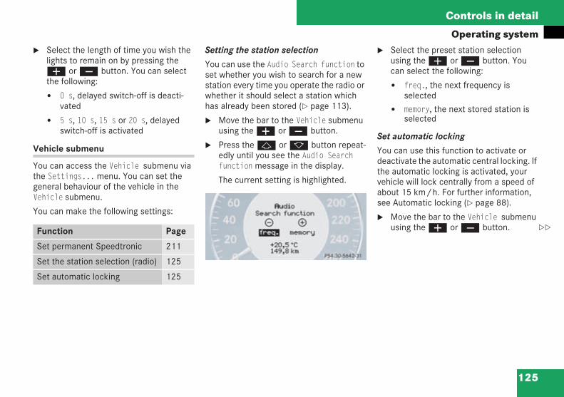
125
Controls in detail
Operating systemSelect the length of time you wish thelights to remain on by pressing theæ orç button. You can selectthe following:
0 s, delayed switch-off is deacti-vated
5 s, 10 s, 15 s or 20 s, delayedswitch-off is activated
Vehicle submenu
You can access the Vehicle submenu viathe Settings...menu. You can set thegeneral behaviour of the vehicle in theVehicle submenu.
You can make the following settings:
Setting the station selection
You can use the Audio Search function toset whether you wish to search for a newstation every time you operate the radio orwhether it should select a station whichhas already been stored ( page 113).
Move the bar to the Vehicle submenuusing theæ orç button.
Press thej ork button repeat-edly until you see the Audio Searchfunctionmessage in the display.
The current setting is highlighted.
Select the preset station selectionusing theæ orç button. Youcan select the following:
freq., the next frequency isselected
memory, the next stored station isselected
Set automatic locking
You can use this function to activate ordeactivate the automatic central locking. Ifthe automatic locking is activated, yourvehicle will lock centrally from a speed ofabout 15 km/h. For further information,see Automatic locking ( page 88).
Move the bar to the Vehicle submenuusing theæ orç button.Function Page
Set permanent Speedtronic 211
Set the station selection (radio) 125
Set automatic locking 125
P54.30-5222-31
209en_d2.boo Seite 125 Dienstag, 25. Mai 2004 7:26 19
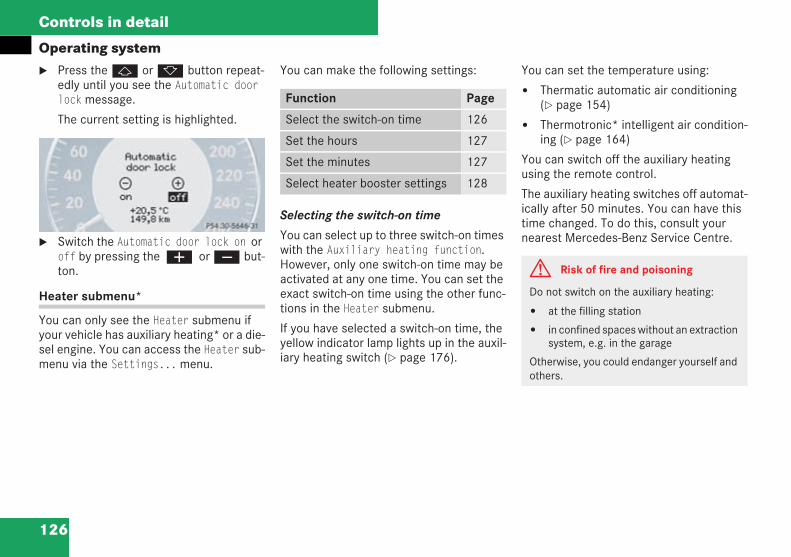
126
Controls in detail
Operating systemPress thej ork button repeat-edly until you see the Automatic doorlockmessage.
The current setting is highlighted.
Switch the Automatic door lock on oroff by pressing the æ orç but-ton.
Heater submenu*
You can only see the Heater submenu ifyour vehicle has auxiliary heating* or a die-sel engine. You can access the Heater sub-menu via the Settings...menu.
You can make the following settings:
Selecting the switch-on time
You can select up to three switch-on timeswith the Auxiliary heating function.However, only one switch-on time may beactivated at any one time. You can set theexact switch-on time using the other func-tions in the Heater submenu.
If you have selected a switch-on time, theyellow indicator lamp lights up in the auxil-iary heating switch ( page 176).
You can set the temperature using:
Thermatic automatic air conditioning( page 154)
Thermotronic* intelligent air condition-ing ( page 164)
You can switch off the auxiliary heatingusing the remote control.
The auxiliary heating switches off automat-ically after 50 minutes. You can have thistime changed. To do this, consult yournearest Mercedes-Benz Service Centre.
P54.30-5223-31
Function Page
Select the switch-on time 126
Set the hours 127
Set the minutes 127
Select heater booster settings 128
G Risk of fire and poisoning
Do not switch on the auxiliary heating:
at the filling station
in confined spaces without an extractionsystem, e.g. in the garage
Otherwise, you could endanger yourself andothers.
209en_d2.boo Seite 126 Dienstag, 25. Mai 2004 7:26 19
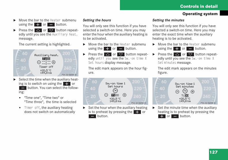
127
Controls in detail
Operating systemMove the bar to the Heater submenuusing theæ orç button.
Press thej ork button repeat-edly until you see the Auxiliary heat.message.
The current setting is highlighted.
Select the time when the auxiliary heat-ing is to switch on using theæ orç button. You can select the follow-ing:
"Time one", "Time two" or"Time three", the time is selected
Timer off, the auxiliary heatingdoes not switch on automatically
Setting the hours
You will only see this function if you haveselected a switch-on time. Here you mayenter the hour when the auxiliary heating isto be activated.
Move the bar to the Heater submenuusing theæ orç button.
Press thej ork button repeat-edly until you see the Sw.-on time XSet hours display message.
The edit mark appears on the hour fig-ure.
Set the hour when the auxiliary heatingis to preheat by pressing theæ orç button.
Setting the minutes
You will only see this function if you haveselected a switch-on time. Here you mayenter the exact time when the auxiliaryheating is to be activated.
Move the bar to the Heater submenuusing theæ orç button.
Press thej ork button repeat-edly until you see the Sw.-on time XSet minutesmessage.
The edit mark appears on the minutesfigure.
Set the minute time when the auxiliaryheating is to preheat by pressing theæ orç button.
P54.30-5224-31
P54.30-5225-31 P54.30-5226-31
209en_d2.boo Seite 127 Dienstag, 25. Mai 2004 7:26 19
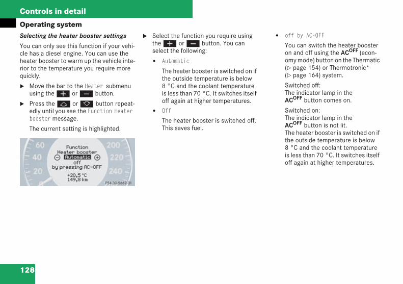
128
Controls in detail
Operating systemSelecting the heater booster settings
You can only see this function if your vehi-cle has a diesel engine. You can use theheater booster to warm up the vehicle inte-rior to the temperature you require morequickly.
Move the bar to the Heater submenuusing theæ orç button.
Press thej ork button repeat-edly until you see the Function Heaterboostermessage.
The current setting is highlighted.
Select the function you require usingtheæ orç button. You canselect the following:
Automatic
The heater booster is switched on ifthe outside temperature is below8 °C and the coolant temperatureis less than 70 °C. It switches itselfoff again at higher temperatures.
Off
The heater booster is switched off.This saves fuel.
off by AC-OFF
You can switch the heater boosteron and off using the ACOFF (econ-omy mode) button on the Thermatic( page 154) or Thermotronic*( page 164) system.
Switched off:The indicator lamp in theACOFF button comes on.
Switched on:The indicator lamp in theACOFF button is not lit.The heater booster is switched on ifthe outside temperature is below8 °C and the coolant temperatureis less than 70 °C. It switches itselfoff again at higher temperatures.
P54.30-5227-31
209en_d2.boo Seite 128 Dienstag, 25. Mai 2004 7:26 19
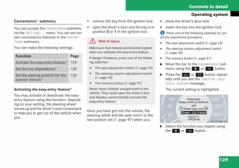
129
Controls in detail
Operating systemConvenience* submenu
You can access the Convenience submenuvia the Settings...menu. You can set cer-tain convenience features in the Conven-ience submenu.
You can make the following settings:
Activating the easy-entry feature*
You may activate or deactivate the easy-entry feature using this function. Depend-ing on your setting, the steering wheelmoves up and the driver's seat moves backto help you to get out of the vehicle whenyou:
remove the key from the ignition lock
open the driver's door and the key is inposition 0 or 1 in the ignition lock
Once you have got into the vehicle, thesteering wheel and the seat return to thelast position set ( page 97) when you:
close the driver's door and
insert the key into the ignition lock
i Press one of the following switches to can-cel the adjustment procedure:
The seat adjustment switch ( page 25)
The steering column adjustment switch( page 30)
The memory button ( page 97)
Move the bar to the Convenience sub-menu using theæ orç button.
Press thej ork button repeat-edly until you see the Function Easy-entry featuremessage.
The current setting is highlighted.
Select the function you require usingtheæ orç button.
Function Page
Activate the easy-entry feature* 129
Set the key dependence* 130
Set the parking position for theexterior mirrors*
130
G Risk of injury
Make sure that nobody can become trappedwhen you activate the easy-entry feature.
If danger threatens, press one of the follow-ing switches:
The seat adjustment switch ( page 25)
The steering column adjustment switch( page 30)
The memory button ( page 97)
Never leave children unsupervised in thevehicle. They could open the driver's doorand thereby unintentionally activate theeasy-entry feature.
P54.30-5228-31
209en_d2.boo Seite 129 Dienstag, 25. Mai 2004 7:26 19
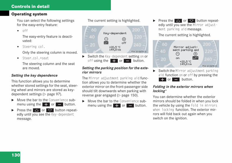
130
Controls in detail
Operating systemYou can select the following settingsfor the easy-entry feature:
off
The easy-entry feature is deacti-vated:
Steering col.
Only the steering column is moved.
Steer.col.+seat
The steering column and the seatare moved.
Setting the key dependence
This function allows you to determinewhether stored settings for the seat, steer-ing wheel and mirrors are stored as key-dependent settings ( page 97).
Move the bar to the Convenience sub-menu using theæ orç button.
Press thej ork button repeat-edly until you see the Key-dependentmessage.
The current setting is highlighted.
Switch the Key-dependent setting on oroff using the æ orç button.
Setting the parking position for the exte-rior mirrors
The Mirror adjustment parking aid func-tion allows you to determine whether theexterior mirror on the front-passenger sideshould tilt downwards when parking withreverse gear engaged ( page 150).
Move the bar to the Convenience sub-menu using theæ orç button.
Press thej ork button repeat-edly until you see the Mirror adjust-ment parking aidmessage.
The current setting is highlighted.
Switch the Mirror adjustment parkingaid function on or off by pressing theæ orç button.
Folding in the exterior mirrors whenlocking*
You can determine whether the exteriormirrors should be folded in when you lockthe vehicle by using the Fold in mirrorswhen locking function. The exterior mir-rors will fold back out again when youswitch on the ignition.
P54.30-5229-31
P54.30-5230-31
209en_d2.boo Seite 130 Dienstag, 25. Mai 2004 7:26 19
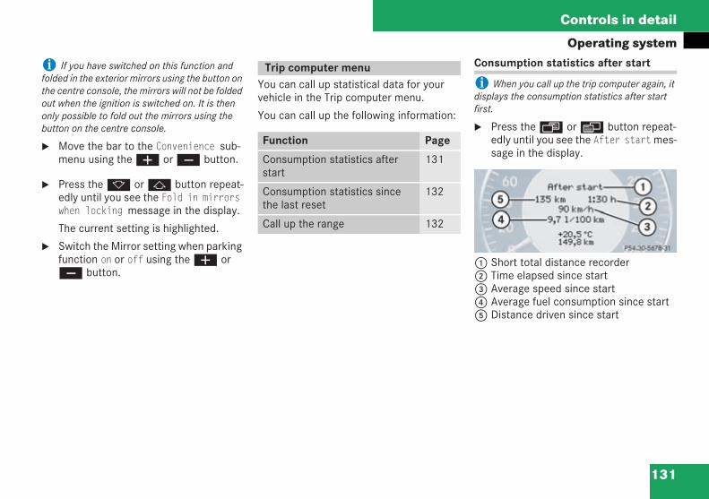
131
Controls in detail
Operating system
i If you have switched on this function andfolded in the exterior mirrors using the button onthe centre console, the mirrors will not be foldedout when the ignition is switched on. It is thenonly possible to fold out the mirrors using thebutton on the centre console.
Move the bar to the Convenience sub-menu using theæ orç button.
Press thek orj button repeat-edly until you see the Fold in mirrorswhen locking message in the display.
The current setting is highlighted.
Switch the Mirror setting when parkingfunction on or off using theæ orç button.
You can call up statistical data for yourvehicle in the Trip computer menu.
You can call up the following information:
Consumption statistics after start
i When you call up the trip computer again, itdisplays the consumption statistics after startfirst.
Press theÿ orè button repeat-edly until you see the After startmes-sage in the display.
1 Short total distance recorder2 Time elapsed since start3 Average speed since start4 Average fuel consumption since start5 Distance driven since start
Trip computer menu
Function Page
Consumption statistics afterstart
131
Consumption statistics sincethe last reset
132
Call up the range 132
P54.30-5231-31
209en_d2.boo Seite 131 Dienstag, 25. Mai 2004 7:26 19
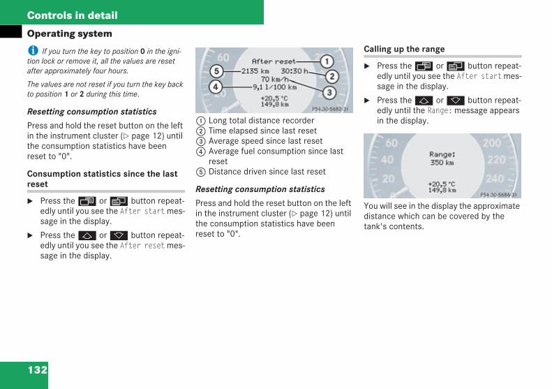
132
Controls in detail
Operating system
i If you turn the key to position 0 in the igni-tion lock or remove it, all the values are resetafter approximately four hours.
The values are not reset if you turn the key backto position 1 or 2 during this time.
Resetting consumption statistics
Press and hold the reset button on the leftin the instrument cluster ( page 12) untilthe consumption statistics have beenreset to "0".
Consumption statistics since the lastreset
Press theÿ orè button repeat-edly until you see the After startmes-sage in the display.
Press thej ork button repeat-edly until you see the After resetmes-sage in the display.
1 Long total distance recorder2 Time elapsed since last reset3 Average speed since last reset4 Average fuel consumption since last
reset5 Distance driven since last reset
Resetting consumption statistics
Press and hold the reset button on the leftin the instrument cluster ( page 12) untilthe consumption statistics have beenreset to "0".
Calling up the range
Press theÿ orè button repeat-edly until you see the After startmes-sage in the display.
Press thej ork button repeat-edly until the Range:message appearsin the display.
You will see in the display the approximatedistance which can be covered by thetank's contents.
P54.30-5232-31
P54.30-5233-31
209en_d2.boo Seite 132 Dienstag, 25. Mai 2004 7:26 19
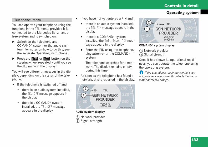
133
Controls in detail
Operating system
You can operate your telephone using thefunctions in the TELmenu, provided it isconnected to the Mercedes-Benz hands-free system and is switched on.
Switch on the telephone andCOMAND* system or the audio sys-tem. For notes on how to do this, seethe separate Operating Instructions.
Press theÿ orè button on thesteering wheel repeatedly until you seethe TELmenu in the display.
You will see different messages in the dis-play, depending on the status of the tele-phone:
If the telephone is switched off and:
there is an audio system installed,the TEL OFFmessage appears inthe display
there is a COMAND* systeminstalled, the TEL OFFmessageappears in the display
If you have not yet entered a PIN and:
there is an audio system installed,the TEL PINmessage appears in thedisplay
there is a COMAND* systeminstalled, the Tel. Enter PINmes-sage appears in the display
Enter the PIN using the telephone,Linguatronic* or the COMAND*system.
The telephone searches for a net-work. The display remains emptyduring this time.
As soon as the telephone has found anetwork, this is reported in the display.
Audio system display
1 Network provider2 Signal strength
COMAND* system display
1 Network provider2 Signal strength
Once it has shown its operational readi-ness, you can operate the telephone usingthe operating system.
i If the operational readiness symbol goesout, your vehicle is currently outside the trans-mitter or receiver range.
Telephone* menu
P54.30-5234-31
P54.30-5235-31
209en_d2.boo Seite 133 Dienstag, 25. Mai 2004 7:26 19
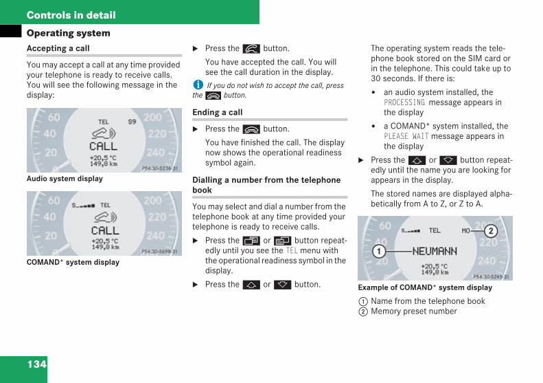
134
Controls in detail
Operating systemAccepting a call
You may accept a call at any time providedyour telephone is ready to receive calls.You will see the following message in thedisplay:
Audio system display
COMAND* system display
Press theí button.
You have accepted the call. You willsee the call duration in the display.
i If you do not wish to accept the call, presstheì button.
Ending a call
Press theì button.
You have finished the call. The displaynow shows the operational readinesssymbol again.
Dialling a number from the telephonebook
You may select and dial a number from thetelephone book at any time provided yourtelephone is ready to receive calls.
Press theÿ orè button repeat-edly until you see the TELmenu withthe operational readiness symbol in thedisplay.
Press thej ork button.
The operating system reads the tele-phone book stored on the SIM card orin the telephone. This could take up to30 seconds. If there is:
an audio system installed, thePROCESSING message appears inthe display
a COMAND* system installed, thePLEASE WAITmessage appears inthe display
Press thej ork button repeat-edly until the name you are looking forappears in the display.
The stored names are displayed alpha-betically from A to Z, or Z to A.
Example of COMAND* system display
1 Name from the telephone book2 Memory preset number
P54.30-5236-31
P54.30-5237-31
P54.30-5245-31
209en_d2.boo Seite 134 Dienstag, 25. Mai 2004 7:26 19
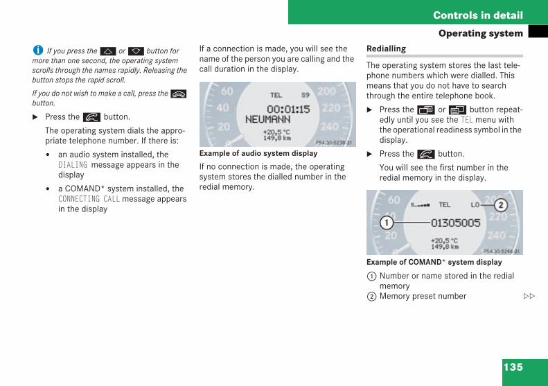
135
Controls in detail
Operating system
i If you press thej ork button formore than one second, the operating systemscrolls through the names rapidly. Releasing thebutton stops the rapid scroll.
If you do not wish to make a call, press theìbutton.
Press theí button.
The operating system dials the appro-priate telephone number. If there is:
an audio system installed, theDIALING message appears in thedisplay
a COMAND* system installed, theCONNECTING CALLmessage appearsin the display
If a connection is made, you will see thename of the person you are calling and thecall duration in the display.
Example of audio system display
If no connection is made, the operatingsystem stores the dialled number in theredial memory.
Redialling
The operating system stores the last tele-phone numbers which were dialled. Thismeans that you do not have to searchthrough the entire telephone book.
Press theÿ orè button repeat-edly until you see the TELmenu withthe operational readiness symbol in thedisplay.
Press theí button.
You will see the first number in theredial memory in the display.
Example of COMAND* system display
1 Number or name stored in the redialmemory
2 Memory preset number
P54.30-5238-31
P54.30-5246-31
209en_d2.boo Seite 135 Dienstag, 25. Mai 2004 7:26 19
136
Controls in detail
Operating systemPress thej ork button repeat-edly until the number you are lookingfor is shown in the display.
i If you do not wish to make a call, presstheì button.
Press theí button.
The operating system dials the appro-priate telephone number.
If a connection is made, you will see thecall duration and:
the name in the display, if it is stored inthe telephone book
or
the number of the person you are call-ing
Memory preset number
The last numbers dialled are alwaysstored. The number of stored numbersdepends on the type of telephone you areusing.
Most recently dialled number:
Audio system display:L1
COMAND* system display:LO
Numbers dialled previously:
Audio system display:L2 to Ln
COMAND* system display:L1 to Ln
209en_d2.boo Seite 136 Dienstag, 25. Mai 2004 7:26 19
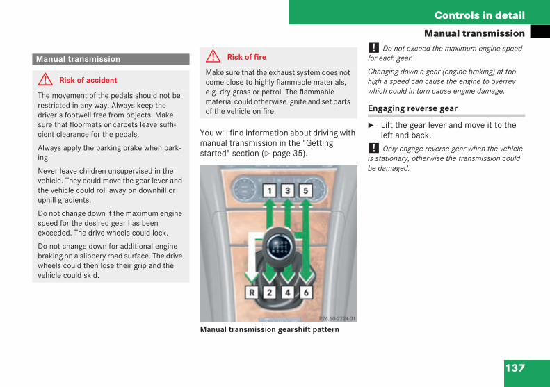
137
Controls in detail
Manual transmission
You will find information about driving withmanual transmission in the "Gettingstarted" section ( page 35).
Manual transmission gearshift pattern
! Do not exceed the maximum engine speedfor each gear.
Changing down a gear (engine braking) at toohigh a speed can cause the engine to overrevwhich could in turn cause engine damage.
Engaging reverse gear
Lift the gear lever and move it to theleft and back.
! Only engage reverse gear when the vehicleis stationary, otherwise the transmission couldbe damaged.
Manual transmission
G Risk of accident
The movement of the pedals should not berestricted in any way. Always keep thedriver's footwell free from objects. Makesure that floormats or carpets leave suffi-cient clearance for the pedals.
Always apply the parking brake when park-ing.
Never leave children unsupervised in thevehicle. They could move the gear lever andthe vehicle could roll away on downhill oruphill gradients.
Do not change down if the maximum enginespeed for the desired gear has beenexceeded. The drive wheels could lock.
Do not change down for additional enginebraking on a slippery road surface. The drivewheels could then lose their grip and thevehicle could skid.
G Risk of fire
Make sure that the exhaust system does notcome close to highly flammable materials,e.g. dry grass or petrol. The flammablematerial could otherwise ignite and set partsof the vehicle on fire.
P26.60-2224-31
209en_d2.boo Seite 137 Dienstag, 25. Mai 2004 7:26 19
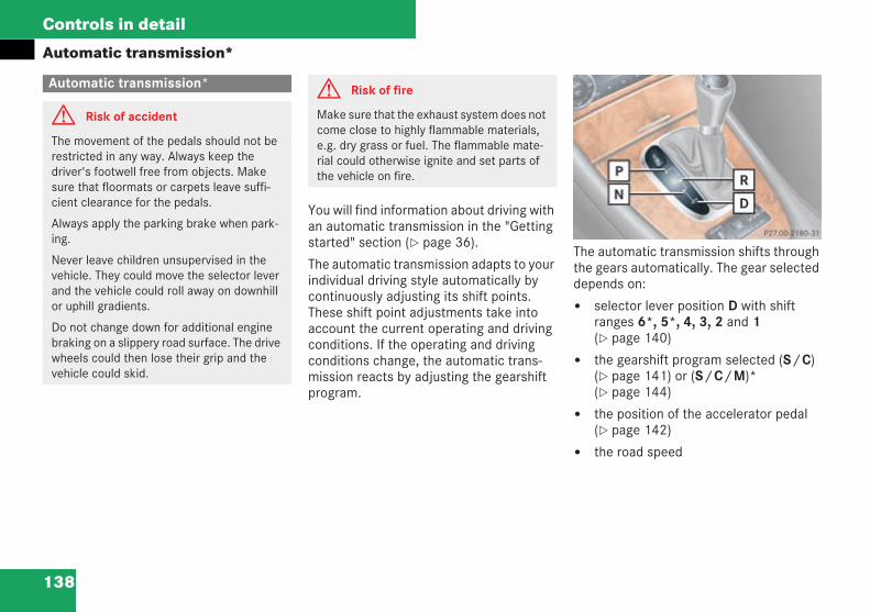
138
Controls in detail
Automatic transmission*
You will find information about driving withan automatic transmission in the "Gettingstarted" section ( page 36).
The automatic transmission adapts to yourindividual driving style automatically bycontinuously adjusting its shift points.These shift point adjustments take intoaccount the current operating and drivingconditions. If the operating and drivingconditions change, the automatic trans-mission reacts by adjusting the gearshiftprogram.
The automatic transmission shifts throughthe gears automatically. The gear selecteddepends on:
selector lever position D with shiftranges 6*, 5*, 4, 3, 2 and 1( page 140)
the gearshift program selected (S/C)( page 141) or (S/C/M)*( page 144)
the position of the accelerator pedal( page 142)
the road speed
Automatic transmission*
G Risk of accident
The movement of the pedals should not berestricted in any way. Always keep thedriver's footwell free from objects. Makesure that floormats or carpets leave suffi-cient clearance for the pedals.
Always apply the parking brake when park-ing.
Never leave children unsupervised in thevehicle. They could move the selector leverand the vehicle could roll away on downhillor uphill gradients.
Do not change down for additional enginebraking on a slippery road surface. The drivewheels could then lose their grip and thevehicle could skid.
G Risk of fire
Make sure that the exhaust system does notcome close to highly flammable materials,e.g. dry grass or fuel. The flammable mate-rial could otherwise ignite and set parts ofthe vehicle on fire.
P 27.00-2180-31
209en_d2.boo Seite 138 Dienstag, 25. Mai 2004 7:26 19
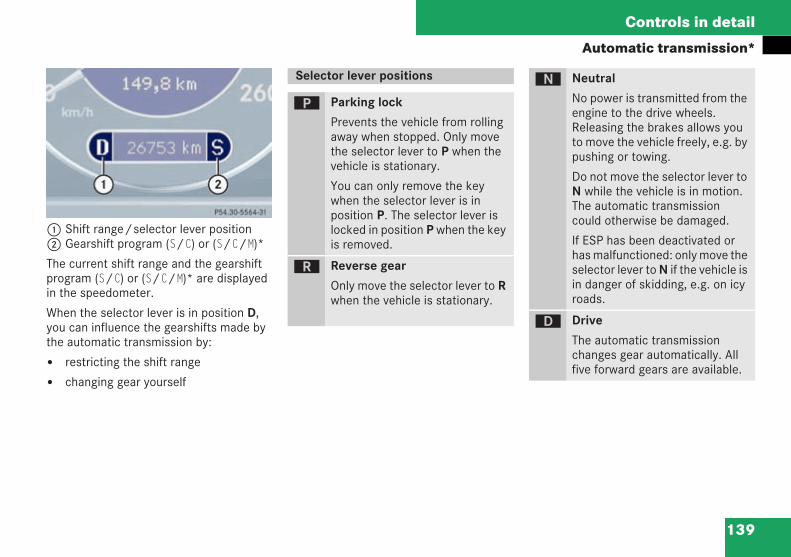
139
Controls in detail
Automatic transmission*
1 Shift range/selector lever position2 Gearshift program (S/C) or (S/C/M)*
The current shift range and the gearshiftprogram (S/C) or (S/C/M)* are displayedin the speedometer.
When the selector lever is in position D,you can influence the gearshifts made bythe automatic transmission by:
restricting the shift range
changing gear yourself
P 54.30-5564-31
Selector lever positions
ì Parking lock
Prevents the vehicle from rollingaway when stopped. Only movethe selector lever to P when thevehicle is stationary.
You can only remove the keywhen the selector lever is inposition P. The selector lever islocked in position P when the keyis removed.
í Reverse gear
Only move the selector lever to Rwhen the vehicle is stationary.
ë Neutral
No power is transmitted from theengine to the drive wheels.Releasing the brakes allows youto move the vehicle freely, e.g. bypushing or towing.
Do not move the selector lever toN while the vehicle is in motion.The automatic transmissioncould otherwise be damaged.
If ESP has been deactivated orhas malfunctioned: only move theselector lever to N if the vehicle isin danger of skidding, e.g. on icyroads.
ê Drive
The automatic transmissionchanges gear automatically. Allfive forward gears are available.
209en_d2.boo Seite 139 Dienstag, 25. Mai 2004 7:26 19
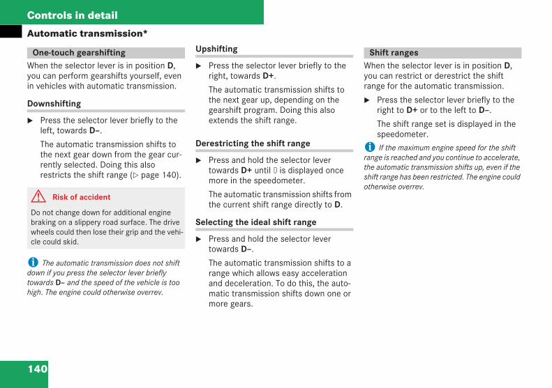
140
Controls in detail
Automatic transmission*
When the selector lever is in position D,you can perform gearshifts yourself, evenin vehicles with automatic transmission.
Downshifting
Press the selector lever briefly to theleft, towards D–.
The automatic transmission shifts tothe next gear down from the gear cur-rently selected. Doing this alsorestricts the shift range ( page 140).
i The automatic transmission does not shiftdown if you press the selector lever brieflytowards D– and the speed of the vehicle is toohigh. The engine could otherwise overrev.
Upshifting
Press the selector lever briefly to theright, towards D+.
The automatic transmission shifts tothe next gear up, depending on thegearshift program. Doing this alsoextends the shift range.
Derestricting the shift range
Press and hold the selector levertowards D+ until D is displayed oncemore in the speedometer.
The automatic transmission shifts fromthe current shift range directly to D.
Selecting the ideal shift range
Press and hold the selector levertowards D–.
The automatic transmission shifts to arange which allows easy accelerationand deceleration. To do this, the auto-matic transmission shifts down one ormore gears.
When the selector lever is in position D,you can restrict or derestrict the shiftrange for the automatic transmission.
Press the selector lever briefly to theright to D+ or to the left to D–.
The shift range set is displayed in thespeedometer.
i If the maximum engine speed for the shiftrange is reached and you continue to accelerate,the automatic transmission shifts up, even if theshift range has been restricted. The engine couldotherwise overrev.
One-touch gearshifting
G Risk of accident
Do not change down for additional enginebraking on a slippery road surface. The drivewheels could then lose their grip and the vehi-cle could skid.
Shift ranges
209en_d2.boo Seite 140 Dienstag, 25. Mai 2004 7:26 19
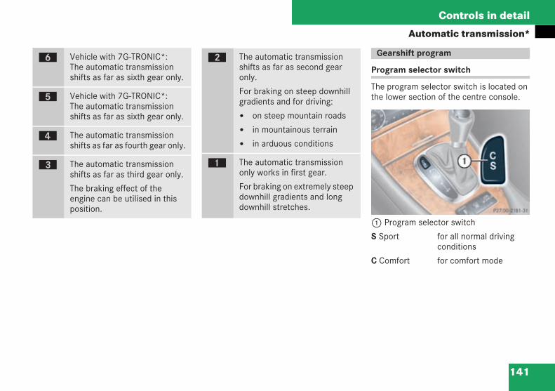
141
Controls in detail
Automatic transmission*
Program selector switch
The program selector switch is located onthe lower section of the centre console.
1 Program selector switch
S Sport for all normal drivingconditions
C Comfort for comfort mode
ï Vehicle with 7G-TRONIC*:The automatic transmissionshifts as far as sixth gear only.
î Vehicle with 7G-TRONIC*:The automatic transmissionshifts as far as sixth gear only.
é The automatic transmissionshifts as far as fourth gear only.
è The automatic transmissionshifts as far as third gear only.
The braking effect of theengine can be utilised in thisposition.
ç The automatic transmissionshifts as far as second gearonly.
For braking on steep downhillgradients and for driving:
on steep mountain roads
in mountainous terrain
in arduous conditions
æ The automatic transmissiononly works in first gear.
For braking on extremely steepdownhill gradients and longdownhill stretches.
Gearshift program
P 27.00-2181-31 neu
209en_d2.boo Seite 141 Dienstag, 25. Mai 2004 7:26 19
142
Controls in detail
Automatic transmission*! Only press program selector switch1when the selector lever is in position P, N or D.
Press program selector switch1repeatedly until the letter (S/C) for thegearshift program appears in the dis-play ( page 141).
Select C for comfort mode:
The vehicle pulls away and reversesmore gently unless full throttle isapplied.
Traction is increased. This meansthat driving stability is increased onslippery road surfaces, for example.
The automatic transmission shiftsup sooner. This means that youdrive at lower engine speeds andthe wheels are less likely to spin.
Accelerator pedal position
Your style of driving influences how theautomatic transmission shifts gear:
Little throttle:early upshifts
More throttle:later upshifts
Kickdown
Use kickdown for maximum acceleration:
Depress the accelerator pedal beyondthe pressure point.
The automatic transmission shifts to alower gear, depending on the enginespeed.
Release the accelerator pedal as soonas the desired speed has beenreached.
The automatic transmission shifts backup.
Stopping
If you are only stopping briefly:
leave the selector lever in the driveposition
apply the brake to prevent the vehiclefrom rolling away
Manoeuvring
If you are manoeuvring in a tight space:
control the speed of the vehicle bybraking carefully
accelerate gently and smoothly
Trailer towing
Allow the engine to run in the middleengine speed range when driving onuphill gradients.
Depending on the steepness of theuphill or downhill gradient, shift downto shift range 3 or 2 ( page 140), evenif cruise control is activated.
Driving tips
209en_d2.boo Seite 142 Dienstag, 25. Mai 2004 7:26 19
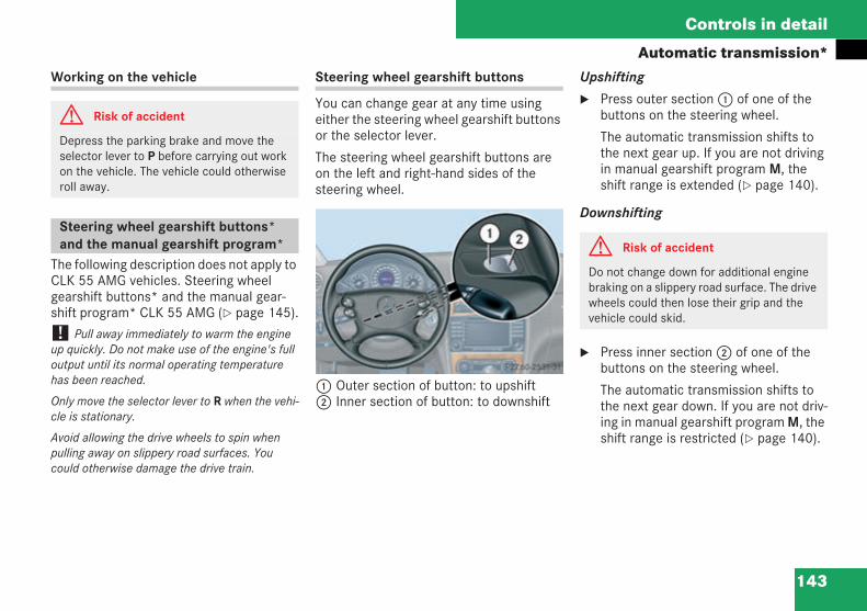
143
Controls in detail
Automatic transmission*Working on the vehicle
The following description does not apply toCLK 55 AMG vehicles. Steering wheelgearshift buttons* and the manual gear-shift program* CLK 55 AMG ( page 145).
! Pull away immediately to warm the engineup quickly. Do not make use of the engine's fulloutput until its normal operating temperaturehas been reached.
Only move the selector lever to R when the vehi-cle is stationary.
Avoid allowing the drive wheels to spin whenpulling away on slippery road surfaces. Youcould otherwise damage the drive train.
Steering wheel gearshift buttons
You can change gear at any time usingeither the steering wheel gearshift buttonsor the selector lever.
The steering wheel gearshift buttons areon the left and right-hand sides of thesteering wheel.
1 Outer section of button: to upshift2 Inner section of button: to downshift
Upshifting
Press outer section1 of one of thebuttons on the steering wheel.
The automatic transmission shifts tothe next gear up. If you are not drivingin manual gearshift program M, theshift range is extended ( page 140).
Downshifting
Press inner section2 of one of thebuttons on the steering wheel.
The automatic transmission shifts tothe next gear down. If you are not driv-ing in manual gearshift program M, theshift range is restricted ( page 140).
G Risk of accident
Depress the parking brake and move theselector lever to P before carrying out workon the vehicle. The vehicle could otherwiseroll away.
Steering wheel gearshift buttons*and the manual gearshift program* P27.60-2531-31 G Risk of accident
Do not change down for additional enginebraking on a slippery road surface. The drivewheels could then lose their grip and thevehicle could skid.
209en_d2.boo Seite 143 Dienstag, 25. Mai 2004 7:26 19
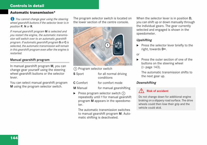
144
Controls in detail
Automatic transmission*
i You cannot change gear using the steeringwheel gearshift buttons if the selector lever is inposition P, N or R.
If manual gearshift program M is selected andyou restart the engine, the automatic transmis-sion will switch over to an automatic gearshiftprogram. If automatic gearshift program S or C isselected, the automatic transmission will remainin this gearshift program even after the engine isrestarted.
Manual gearshift program
In manual gearshift program M, you canchange gear yourself using the steeringwheel gearshift buttons or the selectorlever.
You can select manual gearshift programM using the program selector switch.
The program selector switch is located onthe lower section of the centre console.
1 Program selector switch
S Sport for all normal drivingconditions
C Comfort for comfort mode
M Manual for manual gearshifting
Press program selector switch1repeatedly until M for manual gearshiftprogram M appears in the speedome-ter.
The automatic transmission switchesto manual gearshift program M. Auto-matic shifting is deactivated.
When the selector lever is in position D,you can shift up or down manually throughthe individual gears. The gear currentlyselected and engaged is shown in thespeedometer.
Upshifting
Press the selector lever briefly to theright, towards D+.
or
Press the outer section of one of thebuttons on the steering wheel( page 143).
The automatic transmission shifts tothe next gear up.
Downshifting
P27.60-2510-31
G Risk of accident
Do not change down for additional enginebraking on a slippery road surface. The drivewheels could then lose their grip and thevehicle could skid.
209en_d2.boo Seite 144 Dienstag, 25. Mai 2004 7:26 19
145
Controls in detail
Automatic transmission*Press the selector lever briefly to theleft, towards D–.
or
Press the inner section of one of thebuttons on the steering wheel( page 143).
The automatic transmission shifts tothe next gear down.
Kickdown
You can also use kickdown in manual gear-shift program M if you wish to achievemaximum acceleration:
Depress the accelerator pedal beyondthe pressure point.
The automatic transmission shifts tothe next gear down, depending on theengine speed.
Shift up again as soon as the desiredspeed has been reached.
i If you apply full throttle, the automatic trans-mission will shift to the next gear up when themaximum engine speed is reached. This protectsthe engine against overspeeding.
If you brake or come to a halt, the automatictransmission will shift down to a gear from whichyou can accelerate or pull away easily.
Manual gearshift program M is deselected if you:
press the program selector switch( page 141).S or C appears in the speedometer in thiscase.
restart the engine.The automatic transmission switches to anautomatic gearshift program in this case.
The CLK 55 AMG can be driven in the auto-matic or manual gearshift program.
! Drive the vehicle to warm the engine upquickly. Do not make use of the engine's full out-put until its normal operating temperature hasbeen reached.
Only move the selector lever to R when the vehi-cle is stationary.
Avoid allowing the drive wheels to spin whenpulling away on slippery road surfaces. Youcould otherwise damage the drive train.
Steering wheel gearshift buttons
You can change gear at any time usingeither the steering wheel gearshift buttonsor the selector lever.
Steering wheel gearshift buttons*and the manual gearshift program*CLK 55 AMG
209en_d2.boo Seite 145 Dienstag, 25. Mai 2004 7:26 19
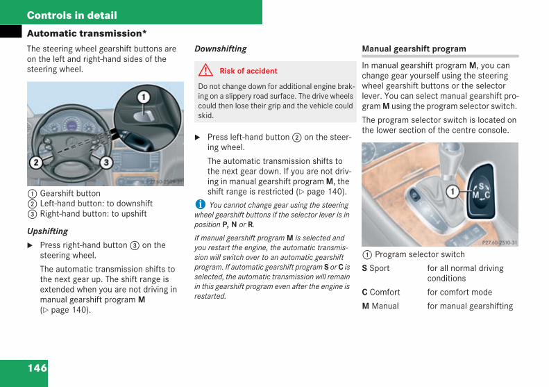
146
Controls in detail
Automatic transmission*The steering wheel gearshift buttons areon the left and right-hand sides of thesteering wheel.
1 Gearshift button2 Left-hand button: to downshift3 Right-hand button: to upshift
Upshifting
Press right-hand button3 on thesteering wheel.
The automatic transmission shifts tothe next gear up. The shift range isextended when you are not driving inmanual gearshift program M( page 140).
Downshifting
Press left-hand button2 on the steer-ing wheel.
The automatic transmission shifts tothe next gear down. If you are not driv-ing in manual gearshift program M, theshift range is restricted ( page 140).
i You cannot change gear using the steeringwheel gearshift buttons if the selector lever is inposition P, N or R.
If manual gearshift program M is selected andyou restart the engine, the automatic transmis-sion will switch over to an automatic gearshiftprogram. If automatic gearshift program S or C isselected, the automatic transmission will remainin this gearshift program even after the engine isrestarted.
Manual gearshift program
In manual gearshift program M, you canchange gear yourself using the steeringwheel gearshift buttons or the selectorlever. You can select manual gearshift pro-gram M using the program selector switch.
The program selector switch is located onthe lower section of the centre console.
1 Program selector switch
S Sport for all normal drivingconditions
C Comfort for comfort mode
M Manual for manual gearshifting
P27.60-2509-31
G Risk of accident
Do not change down for additional engine brak-ing on a slippery road surface. The drive wheelscould then lose their grip and the vehicle couldskid.
P27.60-2510-31
209en_d2.boo Seite 146 Dienstag, 25. Mai 2004 7:26 19
147
Controls in detail
Automatic transmission*Press program selector switch1repeatedly until M for manual gearshiftprogram M appears in the speedome-ter display.
The automatic transmission switchesto manual gearshift program M. Auto-matic shifting is deactivated. The shiftrange is not restricted.
When the selector lever is in position D,you can shift up or down manually throughthe individual gears. The gear currentlyselected and engaged is shown in thespeedometer display.
Upshifting! In manual gearshift program M, the auto-matic transmission does not shift up even if theengine speed reaches the overrevving range.When the maximum permissible speed for thecurrent gear is reached, the fuel supply is cut offto prevent the engine from overrevving. Youmust make sure that the engine speed does notreach the red area in the rev counter. There isotherwise a danger of engine damage.
Shift up a gear if the^ upshift symbol appearsin the rev counter display instead of M.
Press the selector lever briefly to theright, towards D+.
or
Press the right-hand button on thesteering wheel ( page 145).
The automatic transmission shifts tothe next gear up.
Downshifting
Press the selector lever briefly to theleft, towards D–.
or
Press the left-hand button on the steer-ing wheel ( page 145).
The automatic transmission shifts tothe next gear down.
i If you brake or come to a halt without chang-ing to a lower gear, the automatic transmissionwill shift down to a gear from which you canaccelerate or pull away easily.
Kickdown
It is not possible to use kickdown in man-ual gearshift program M.
i Manual gearshift program M is deselected ifyou:
press the program selector switch( page 141).
S or C appears in the speedometer display inthis case.
restart the engine.The automatic transmission switches to anautomatic gearshift program in this case.
G Risk of accident
Do not change down for additional enginebraking on a slippery road surface. The drivewheels could lose their grip and the vehiclecould skid.
209en_d2.boo Seite 147 Dienstag, 25. Mai 2004 7:26 19
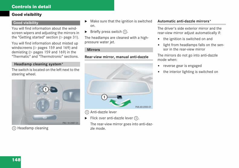
148
Controls in detail
Good visibility
You will find information about the wind-screen wipers and adjusting the mirrors inthe "Getting started" section ( page 31).
You will find information about misted upwindscreens ( pages 159 and 169) anddemisting ( pages 159 and 169) in the"Thermatic" and "Thermotronic" sections.
The switch is located on the left next to thesteering wheel.
1 Headlamp cleaning
Make sure that the ignition is switchedon.
Briefly press switch1.
The headlamps are cleaned with a high-pressure water jet.
Rear-view mirror, manual anti-dazzle
1 Anti-dazzle lever
Flick over anti-dazzle lever1.
The rear-view mirror goes into anti-daz-zle mode.
Automatic anti-dazzle mirrors*
The driver's side exterior mirror and therear-view mirror adjust automatically if:
the ignition is switched on and
light from headlamps falls on the sen-sor in the rear-view mirror
The mirrors do not go into anti-dazzlemode when:
reverse gear is engaged
the interior lighting is switched on
Good visibility
Headlamp cleaning system*
P 82.10-2887-31 neu
Mirrors
P68.40-2050-31
209en_d2.boo Seite 148 Dienstag, 25. Mai 2004 7:26 19
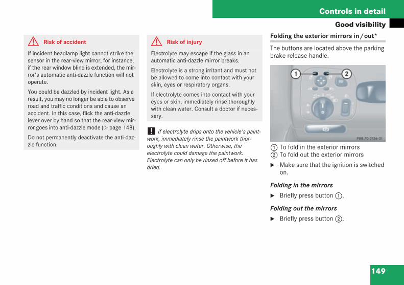
149
Controls in detail
Good visibility
! If electrolyte drips onto the vehicle's paint-work, immediately rinse the paintwork thor-oughly with clean water. Otherwise, theelectrolyte could damage the paintwork.Electrolyte can only be rinsed off before it hasdried.
Folding the exterior mirrors in/out*
The buttons are located above the parkingbrake release handle.
1 To fold in the exterior mirrors2 To fold out the exterior mirrors
Make sure that the ignition is switchedon.
Folding in the mirrors
Briefly press button1.
Folding out the mirrors
Briefly press button2.
G Risk of accident
If incident headlamp light cannot strike thesensor in the rear-view mirror, for instance,if the rear window blind is extended, the mir-ror's automatic anti-dazzle function will notoperate.
You could be dazzled by incident light. As aresult, you may no longer be able to observeroad and traffic conditions and cause anaccident. In this case, flick the anti-dazzlelever over by hand so that the rear-view mir-ror goes into anti-dazzle mode ( page 148).
Do not permanently deactivate the anti-daz-zle function.
G Risk of injury
Electrolyte may escape if the glass in anautomatic anti-dazzle mirror breaks.
Electrolyte is a strong irritant and must notbe allowed to come into contact with yourskin, eyes or respiratory organs.
If electrolyte comes into contact with youreyes or skin, immediately rinse thoroughlywith clean water. Consult a doctor if neces-sary.
P88.70-2136-31
209en_d2.boo Seite 149 Dienstag, 25. Mai 2004 7:26 19
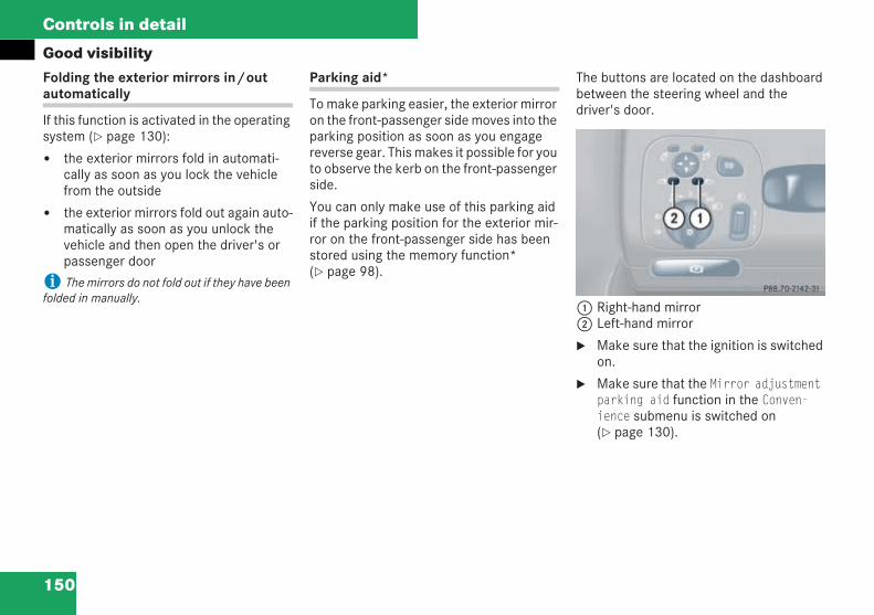
150
Controls in detail
Good visibilityFolding the exterior mirrors in/outautomatically
If this function is activated in the operatingsystem ( page 130):
the exterior mirrors fold in automati-cally as soon as you lock the vehiclefrom the outside
the exterior mirrors fold out again auto-matically as soon as you unlock thevehicle and then open the driver's orpassenger door
i The mirrors do not fold out if they have beenfolded in manually.
Parking aid*
To make parking easier, the exterior mirroron the front-passenger side moves into theparking position as soon as you engagereverse gear. This makes it possible for youto observe the kerb on the front-passengerside.
You can only make use of this parking aidif the parking position for the exterior mir-ror on the front-passenger side has beenstored using the memory function*( page 98).
The buttons are located on the dashboardbetween the steering wheel and thedriver's door.
1 Right-hand mirror2 Left-hand mirror
Make sure that the ignition is switchedon.
Make sure that the Mirror adjustmentparking aid function in the Conven-ience submenu is switched on( page 130).
P88.70-2142-31
209en_d2.boo Seite 150 Dienstag, 25. Mai 2004 7:26 19
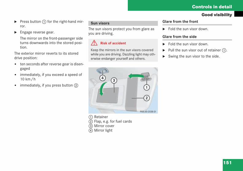
151
Controls in detail
Good visibilityPress button1 for the right-hand mir-ror.
Engage reverse gear.
The mirror on the front-passenger sideturns downwards into the stored posi-tion.
The exterior mirror reverts to its storeddrive position:
ten seconds after reverse gear is disen-gaged
immediately, if you exceed a speed of10 km/h
immediately, if you press button2
The sun visors protect you from glare asyou are driving.
1 Retainer2 Flap, e.g. for fuel cards3 Mirror cover4 Mirror light
Glare from the front
Fold the sun visor down.
Glare from the side
Fold the sun visor down.
Pull the sun visor out of retainer1.
Swing the sun visor to the side.
Sun visors
G Risk of accident
Keep the mirrors in the sun visors coveredwhile you are driving. Dazzling light may oth-erwise endanger yourself and others.
P68.60-2038-31
209en_d2.boo Seite 151 Dienstag, 25. Mai 2004 7:26 19
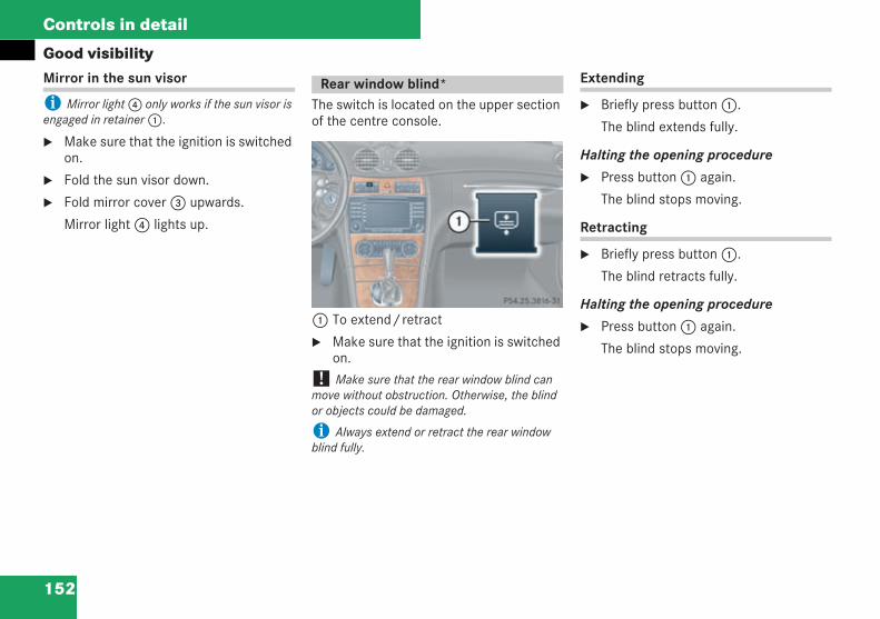
152
Controls in detail
Good visibilityMirror in the sun visor
i Mirror light4 only works if the sun visor isengaged in retainer1.
Make sure that the ignition is switchedon.
Fold the sun visor down.
Fold mirror cover3 upwards.
Mirror light4 lights up.
The switch is located on the upper sectionof the centre console.
1 To extend/retract
Make sure that the ignition is switchedon.
! Make sure that the rear window blind canmove without obstruction. Otherwise, the blindor objects could be damaged.
i Always extend or retract the rear windowblind fully.
Extending
Briefly press button1.
The blind extends fully.
Halting the opening procedure
Press button1 again.
The blind stops moving.
Retracting
Briefly press button1.
The blind retracts fully.
Halting the opening procedure
Press button1 again.
The blind stops moving.
Rear window blind*
P54.25-3816-31
209en_d2.boo Seite 152 Dienstag, 25. Mai 2004 7:26 19
153
Controls in detail
Good visibility
The rear window heating has a high currentdraw. You should therefore switch off therear window heating as soon as the win-dow is clear. The rear window heatingswitches off automatically after a maxi-mum of twelve minutes.
Make sure that the ignition is switchedon.
! The rear window heating has a high currentdraw. You should therefore switch off the rearwindow heating as soon as the window is clear.
Switching on
Press theF button on the controlpanel:
Thermatic ( page 154)
or
Thermotronic* ( page 164)
The indicator lamp in the button lightsup.
Switching off
Press theF button on the controlpanel:
Thermatic ( page 154)
or
Thermotronic* ( page 164)
The indicator lamp in the button goesout.
Rear window heating
G Risk of accident
Clear the rear window of ice or snow.Impaired visibility could otherwise endangeryourself and others.
209en_d2.boo Seite 153 Dienstag, 25. Mai 2004 7:26 19
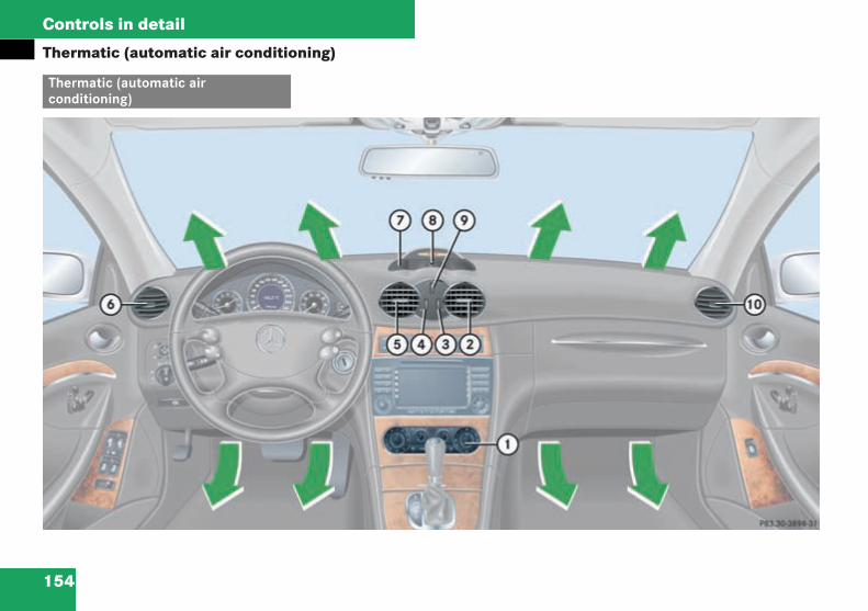
154
Controls in detail
Thermatic (automatic air conditioning)
Thermatic (automatic airconditioning)
P83.30-3898-31
209en_d2.boo Seite 154 Dienstag, 25. Mai 2004 7:26 19
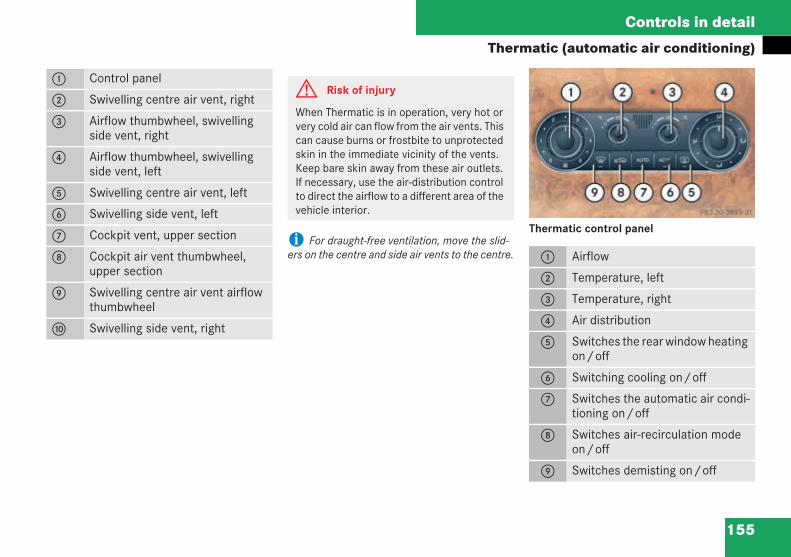
155
Controls in detail
Thermatic (automatic air conditioning)
i For draught-free ventilation, move the slid-ers on the centre and side air vents to the centre.
Thermatic control panel
1 Control panel
2 Swivelling centre air vent, right
3 Airflow thumbwheel, swivellingside vent, right
4 Airflow thumbwheel, swivellingside vent, left
5 Swivelling centre air vent, left
6 Swivelling side vent, left
7 Cockpit vent, upper section
8 Cockpit air vent thumbwheel,upper section
9 Swivelling centre air vent airflowthumbwheel
a Swivelling side vent, right
G Risk of injury
When Thermatic is in operation, very hot orvery cold air can flow from the air vents. Thiscan cause burns or frostbite to unprotectedskin in the immediate vicinity of the vents.Keep bare skin away from these air outlets.If necessary, use the air-distribution controlto direct the airflow to a different area of thevehicle interior.
1 Airflow
2 Temperature, left
3 Temperature, right
4 Air distribution
5 Switches the rear window heatingon/off
6 Switching cooling on/off
7 Switches the automatic air condi-tioning on/off
8 Switches air-recirculation modeon/off
9 Switches demisting on/off
P83.30-3899-31
209en_d2.boo Seite 155 Dienstag, 25. Mai 2004 7:26 19
156
Controls in detail
Thermatic (automatic air conditioning)Thermatic is only operational if the engineis running. Optimum performance is onlyguaranteed if you drive with the windowsand sliding/tilting sunroof* closed.
You can switch Thermatic off completelyas you require ( page 157).
You can allow the air conditioning to adjustautomatically ( page 157) or you cancontrol it manually ( page 159).
In automatic mode, Thermatic cools orheats the vehicle interior depending on:
the temperature selected
outside temperature
sunlight
In automatic mode, you rarely need to alterthe temperature, airflow or air distribution.
The combination filter installed filters outmost dust particles and pollen completely.
i The interval for replacing the filter dependson environmental influences, such as high levelsof air pollution. The interval may be shorter thanthat specified in the Service Booklet. A filterreduces the quantity of air supplied to the vehi-cle interior.
In warm weather, ventilate the vehiclefor a short time, e.g. using the summeropening feature ( page 183).
This ensures that the desired interiortemperature is achieved more rapidly.
i Observe the following instructions to ensurethat Thermatic functions correctly:
Keep the air inlet on the bonnet free fromdeposits, e.g. ice or snow, to ensure the flowof fresh air to the vehicle interior.
Make sure that the air vents and ventilationgrilles in the vehicle interior are always keptclear.
i Condensation may drip from the undersideof the vehicle when Thermatic is in coolingmode.
G Risk of accident
Follow the settings recommended on the fol-lowing pages for heating or cooling. The win-dows could otherwise mist up. As a result, youmay no longer be able to observe road andtraffic conditions and cause an accident.
H Environmental note
The cooling system uses the refrigerantR134A. This refrigerant does not damagethe earth's ozone layer.
209en_d2.boo Seite 156 Dienstag, 25. Mai 2004 7:26 19
157
Controls in detail
Thermatic (automatic air conditioning)
Switching off
Turn airflow control1 to 0.
i Air supply and air circulation are alsoswitched off when Thermatic is switched off.Only use these settings for a short time. The win-dows could otherwise mist up.
Switching on
Turn airflow control1 to 1 or higher.
You can switch automatic air-conditioningcontrol on or off control as required.
i In automatic mode, you will only rarely needto adjust the temperature, airflow and air distri-bution.
Switching on
Briefly press theU button when theengine is running.
The indicator lamp in the button lightsup. Temperature, airflow and air distri-bution are controlled automatically.
Set the desired temperature separatelyfor driver's side2 and front-passen-ger side3 using the temperature con-troller.
The temperature of the vehicle interioris adjusted automatically.
Switching off
Press theU button.
The indicator lamp in the button goesout. Automatic temperature, airflowand air-distribution control areswitched off.
You can now adjust air distribution( page 158) and airflow ( page 159)manually.
Switching Thermatic on and off Controlling the air conditioningautomatically
209en_d2.boo Seite 157 Dienstag, 25. Mai 2004 7:26 19

158
Controls in detail
Thermatic (automatic air conditioning)
Set the temperature separately for eachside of the vehicle using controls2 and3.
Only change the temperature in smallincrements, ideally starting at 22 °C.
Increasing the temperature
Turn temperature controllers2 and3 clockwise.
Thermatic adjusts to the set tempera-ture.
Reducing the temperature
Turn temperature controllers2 and3 anti-clockwise.
Thermatic adjusts to the set tempera-ture.
Air distribution can be adjusted automati-cally using control4 or manually for theentire vehicle.
The symbols on the control panel have thefollowing meaning:
Controlling air distribution manually
Press theU button.
The indicator lamp in the button goesout. Automatic air distribution isswitched off. Air distribution is control-led according to the position of thecontrol.
Turn air-distribution control4 to thedesired symbol.
Controlling air distribution for the cock-pit air vent
Open the air vent at the top of the cock-pit.
The air is distributed evenly in coolingmode.
Setting the temperature Controlling air distribution manually
Symbol Meaning
Z Directs air to the windscreenand through the demistervents to the side windows
b Directs air to the wind-screen, through the centre,side and cockpit air vents,through the demister ventsto the side windows, andinto the front and rear footwells
Y Directs air through the frontand rear footwell air vents
a Directs air through the cen-tre, side and cockpit airvents
209en_d2.boo Seite 158 Dienstag, 25. Mai 2004 7:26 19
159
Controls in detail
Thermatic (automatic air conditioning)
You can set the airflow to six different lev-els automatically ( page 157) or manuallyusing control1.
Press theU button.
The indicator lamp in theU buttongoes out. Automatic airflow control isswitched off. The airflow is controlledaccording to the setting currentlyselected.
Turn the airflow control to the desiredsetting.
The airflow is controlled according tothe setting selected.
The following settings can be used to clearthe windscreen, e.g. if it is covered withfrost.
Switching on
Press theP button.
The indicator lamp in theP buttonlights up.
Thermatic switches automatically tothe following functions:
Maximum blower and heat output
Air is directed towards the wind-screen and front side windows
Air-recirculation mode is switchedoff
i This setting should only be maintained untilthe windscreen is clear again.
Switching off
Press theP button again.
The indicator lamp in theP buttongoes out.
Windows misted up on the inside
If the blower is switched off and air-recir-culation mode is switched on, the vehicleinterior will no longer be ventilated and thewindows could mist up.
Press theP button.
The indicator lamp in theP buttonlights up.
Thermatic switches automatically tothe following functions:
Maximum blower and heat output
Air is directed towards the wind-screen and front side windows
Air-recirculation mode is switchedoff
i This setting should only be maintained untilthe windscreen is clear again.
Controlling the airflow manually Demist button Misted up windows
209en_d2.boo Seite 159 Dienstag, 25. Mai 2004 7:26 19
160
Controls in detail
Thermatic (automatic air conditioning)When the windscreen is clear, presstheP button again.
The indicator lamp in theP buttongoes out.
Windscreen misted up on the outside
Switch on the windscreen wipers( page 41).
Close the air vent at the top of thecockpit.
If Thermatic automatic mode is switchedoff:
Turn air-distribution control4 toaorY.
You can switch off the flow of fresh air ifunpleasant smells are entering the vehiclefrom outside. No more fresh air is taken inand the air inside the vehicle is recircu-lated.
Switching on
Press theO button.
The indicator lamp in the button lightsup.
i Air-recirculation mode switches on automat-ically at high outside temperatures. The indicatorlamp in theO button does not light up if air-recirculation mode is switched on automatically.
Outside air is taken in after approximately30 minutes.
Switching off
Press theO button.
The indicator lamp in the button goesout.
i Air-recirculation mode switches off auto-matically:
after around five minutes at outside temper-atures below approximately 5 °C
after around five minutes if the cooling func-tion is switched off ( page 161)
after around 30 minutes at outside tempera-tures above approximately 5 °C
Air-recirculation mode
G Risk of accident
Only switch over to air-recirculation modebriefly if the outside temperature is below5 °C. Otherwise, the windows could mist up,thus impairing visibility and endangeringyourself and others. As a result, you may nolonger be able to observe road and trafficconditions and could cause an accident.
209en_d2.boo Seite 160 Dienstag, 25. Mai 2004 7:26 19
161
Controls in detail
Thermatic (automatic air conditioning)Air-recirculation mode with conven-ience opening/closing feature
Switching on/closing
Press theO button for longer thantwo seconds.
The indicator lamp in the button lightsup. The side windows and the sliding/tilting sunroof* close. Air-recirculationmode is switched on.
Switching off/opening
Press theO button for longer thantwo seconds.
The indicator lamp in the button goesout. The side windows and sliding/tilting sunroof* move back to their orig-inal position. Air-recirculation mode isswitched off.
i If you open a window or the sliding/tiltingsunroof* manually after they have been closedusing the convenience closing feature, they willremain in this position when opened using theconvenience opening feature.
The cooling function is operational whenthe engine is running and cools accordingto the temperature selected for the vehicleinterior. The cooling function also dries theair inside the vehicle, thereby providingeffective protection against the windowsmisting up.
G Risk of accident
Make sure that nobody can become trappedwhen the sliding/tilting sunroof* and theside windows are being closed.
Press the roof switch in the appropriatedirection to halt the closing procedure andopen the sliding/tilting sunroof*.
Switching cooling on/off
G Risk of accident
If you switch off the cooling function, thevehicle will not be cooled in the event ofwarmer weather conditions. The windowscould therefore mist up more quickly. As aresult, you may no longer be able to observeroad and traffic conditions and cause anaccident.
209en_d2.boo Seite 161 Dienstag, 25. Mai 2004 7:26 19
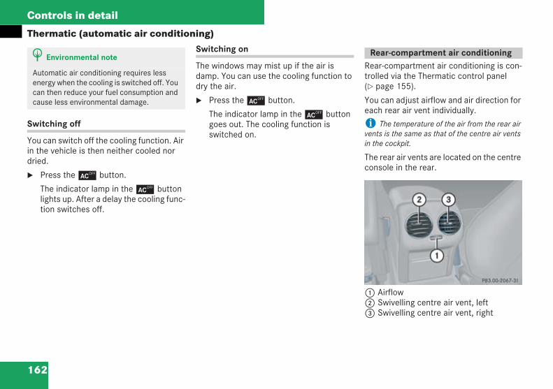
162
Controls in detail
Thermatic (automatic air conditioning)
Switching off
You can switch off the cooling function. Airin the vehicle is then neither cooled nordried.
Press the ± button.
The indicator lamp in the ± buttonlights up. After a delay the cooling func-tion switches off.
Switching on
The windows may mist up if the air isdamp. You can use the cooling function todry the air.
Press the ± button.
The indicator lamp in the ± buttongoes out. The cooling function isswitched on.
Rear-compartment air conditioning is con-trolled via the Thermatic control panel( page 155).
You can adjust airflow and air direction foreach rear air vent individually.
i The temperature of the air from the rear airvents is the same as that of the centre air ventsin the cockpit.
The rear air vents are located on the centreconsole in the rear.
1 Airflow2 Swivelling centre air vent, left3 Swivelling centre air vent, right
H Environmental note
Automatic air conditioning requires lessenergy when the cooling is switched off. Youcan then reduce your fuel consumption andcause less environmental damage.
Rear-compartment air conditioning
P83.00-2067-31
209en_d2.boo Seite 162 Dienstag, 25. Mai 2004 7:26 19
163
Controls in detail
Thermatic (automatic air conditioning)Controlling air distribution
Slide the slider for left-hand centre airvent2 or right-hand centre air vent3to the left, right, up or down.
The airflow is directed accordingly.
i For draught-free ventilation, move the slid-ers for the rear vents upwards.
Controlling the airflow
Turn thumbwheel1 upwards or down-wards.
The airflow is increased or reduced.
209en_d2.boo Seite 163 Dienstag, 25. Mai 2004 7:26 19
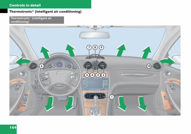
164
Controls in detail
Thermotronic* (intelligent air conditioning)
Thermotronic* (intelligent airconditioning)
P83.40-2672-31_G1
209en_d2.boo Seite 164 Dienstag, 25. Mai 2004 7:26 19
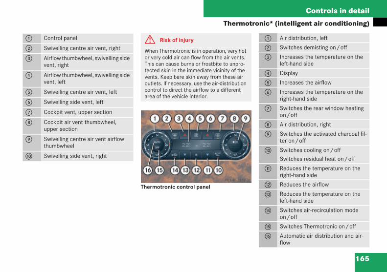
165
Controls in detail
Thermotronic* (intelligent air conditioning)
Thermotronic control panel
1 Control panel
2 Swivelling centre air vent, right
3 Airflow thumbwheel, swivelling sidevent, right
4 Airflow thumbwheel, swivelling sidevent, left
5 Swivelling centre air vent, left
6 Swivelling side vent, left
7 Cockpit vent, upper section
8 Cockpit air vent thumbwheel,upper section
9 Swivelling centre air vent airflowthumbwheel
a Swivelling side vent, right
G Risk of injury
When Thermotronic is in operation, very hotor very cold air can flow from the air vents.This can cause burns or frostbite to unpro-tected skin in the immediate vicinity of thevents. Keep bare skin away from these airoutlets. If necessary, use the air-distributioncontrol to direct the airflow to a differentarea of the vehicle interior.
P83.40-2673-31_G1
1 Air distribution, left
2 Switches demisting on/off
3 Increases the temperature on theleft-hand side
4 Display
5 Increases the airflow
6 Increases the temperature on theright-hand side
7 Switches the rear window heatingon/off
8 Air distribution, right
9 Switches the activated charcoal fil-ter on/off
a Switches cooling on/offSwitches residual heat on/off
b Reduces the temperature on theright-hand side
c Reduces the airflow
d Reduces the temperature on theleft-hand side
e Switches air-recirculation modeon/off
f Switches Thermotronic on/off
g Automatic air distribution and air-flow
209en_d2.boo Seite 165 Dienstag, 25. Mai 2004 7:26 19
166
Controls in detail
Thermotronic* (intelligent air conditioning)Thermotronic is only operational when theengine is running. Optimum performanceis only guaranteed if you drive with the win-dows and sliding/tilting sunroof* closed.
You can switch off Thermotronic com-pletely if required ( page 167).
You can allow the air conditioning to adjustautomatically ( page 167) or you cancontrol it manually ( page 168).
In automatic mode, Thermotronic cools orheats the vehicle interior depending on:
the temperature selected
outside temperature
sunlight
The combination filter installed filters outall:
dust particles of a certain size
pollen
i The interval for replacing the filter dependsupon environmental influences, such as high lev-els of air pollution. The interval may be shorterthan that specified in the Service Booklet. A filterreduces the quantity of air supplied to the vehi-cle interior.
In warm weather, ventilate the vehiclefor a short time, e.g. using the summeropening feature ( page 183).
This ensures that the desired interiortemperature is achieved more rapidly.
i Observe the following instructions to ensurethat Thermotronic functions correctly:
Keep the air inlet on the bonnet free fromdeposits, e.g. ice or snow, to ensure the flowof fresh air to the vehicle interior.
Make sure that the air vents and ventilationgrilles in the vehicle interior are always keptclear.
i Condensation may drip from the undersideof the vehicle when Thermotronic is in coolingmode.
G Risk of accident
Follow the settings recommended on the fol-lowing pages for heating or cooling. The win-dows could otherwise mist up. As a result, youmay no longer be able to observe road andtraffic conditions and cause an accident.
H Environmental note
The cooling system uses the refrigerantR134A. This refrigerant does not damagethe earth's ozone layer.
209en_d2.boo Seite 166 Dienstag, 25. Mai 2004 7:26 19
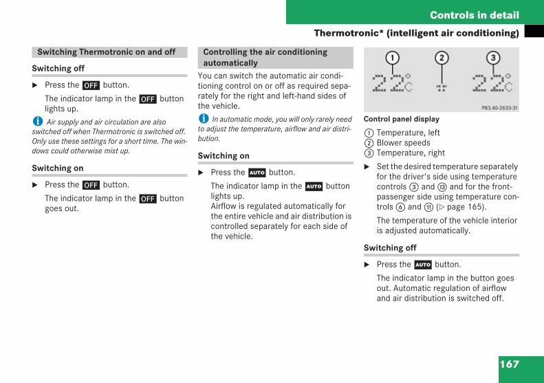
167
Controls in detail
Thermotronic* (intelligent air conditioning)
Switching off
Press the ´ button.
The indicator lamp in the ´ buttonlights up.
i Air supply and air circulation are alsoswitched off when Thermotronic is switched off.Only use these settings for a short time. The win-dows could otherwise mist up.
Switching on
Press the ´ button.
The indicator lamp in the ´ buttongoes out.
You can switch the automatic air condi-tioning control on or off as required sepa-rately for the right and left-hand sides ofthe vehicle.
i In automatic mode, you will only rarely needto adjust the temperature, airflow and air distri-bution.
Switching on
Press theU button.
The indicator lamp in theU buttonlights up.Airflow is regulated automatically forthe entire vehicle and air distribution iscontrolled separately for each side ofthe vehicle.
Control panel display
1 Temperature, left2 Blower speeds3 Temperature, right
Set the desired temperature separatelyfor the driver's side using temperaturecontrols3 andd and for the front-passenger side using temperature con-trols6 andb ( page 165).
The temperature of the vehicle interioris adjusted automatically.
Switching off
Press theU button.
The indicator lamp in the button goesout. Automatic regulation of airflowand air distribution is switched off.
Switching Thermotronic on and off Controlling the air conditioningautomatically P83.40-2633-31 aus 203
209en_d2.boo Seite 167 Dienstag, 25. Mai 2004 7:26 19
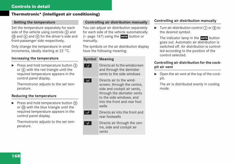
168
Controls in detail
Thermotronic* (intelligent air conditioning)
Set the temperature separately for eachside of the vehicle using controls3 andd and6 andb for the driver's side andfront-passenger side respectively.
Only change the temperature in smallincrements, ideally starting at 22 °C.
Increasing the temperature
Press and hold temperature button3or6 with the red triangle until therequired temperature appears in thecontrol panel display.
Thermotronic adjusts to the set tem-perature.
Reducing the temperature
Press and hold temperature buttonbord with the blue triangle until therequired temperature appears in thecontrol panel display.
Thermotronic adjusts to the set tem-perature.
You can adjust air distribution separatelyfor each side of the vehicle automatically( page 167) using theU button ormanually.
The symbols on the air distribution displayhave the following meaning:
Controlling air distribution manually
Turn air-distribution control1 or8 tothe desired symbol.
The indicator lamp in theU buttongoes out. Automatic air distribution isswitched off. Air distribution is control-led according to the position of thecontrol selected.
Controlling air distribution for the cock-pit air vent
Open the air vent at the top of the cock-pit.
The air is distributed evenly in coolingmode.
Setting the temperature Controlling air distribution manually
Symbol Meaning
Z Directs air to the windscreenand through the demistervents to the side windows
b Directs air to the wind-screen, through the centre,side and cockpit air vents,through the demister ventsto the side windows, andinto the front and rear footwells
Y Directs air into the front andrear footwells
a Directs air through the cen-tre, side and cockpit airvents
209en_d2.boo Seite 168 Dienstag, 25. Mai 2004 7:26 19
169
Controls in detail
Thermotronic* (intelligent air conditioning)
You can set the airflow to seven levelsautomatically ( page 167) or manuallyusing theQ and buttons.
Increasing the airflow
Press theQ button.
The indicator lamp in theU button goesout. Automatic air distribution remains on.
Reducing the airflow
Press the button.
The indicator lamp in theU buttongoes out. Automatic air distributionremains on.
The following settings can be used to clearthe windscreen, e.g. if it is covered withfrost.
Switching on
Press theP button.
The indicator lamp in theP buttonlights up.
Thermotronic automatically switchesto the following functions:
Maximum blower and heat output
Air is directed to the windscreenand the front side windows
Air-recirculation mode is switchedoff
i This setting should only be maintained untilthe windscreen is clear again.
Switching off
Press theP button again.
The indicator lamp in the button goesout. The previous settings are restored.
Windows misted up on the inside
If the blower is switched off and air-recir-culation mode is switched on, the vehicleinterior will no longer be ventilated and thewindows could mist up.
Press theP button.
The indicator lamp in theP buttonlights up.
Thermotronic automatically switchesto the following functions:
Maximum blower and heat output
Air is directed to the windscreenand the front side windows
Air-recirculation mode is switchedoff
i This setting should only be maintained untilthe windscreen is clear again.
Controlling the airflow manually Demist button Misted up windows
209en_d2.boo Seite 169 Dienstag, 25. Mai 2004 7:26 19
170
Controls in detail
Thermotronic* (intelligent air conditioning)When the windscreen is clear, presstheP button again.
The indicator lamp in theP buttongoes out.
Windscreen misted up on the outside
Switch on the windscreen wipers( page 41).
Close the air vent at the top of thecockpit.
If Thermotronic automatic mode isswitched off:
Turn air-distribution control1 or8 toa orY.
You can switch off the flow of fresh air ifunpleasant smells are entering the vehiclefrom outside. No more fresh air is taken inand the air inside the vehicle is recircu-lated.
Switching on
Press theO button.
The indicator lamp in the button lightsup.
i Air-recirculation mode switches on automat-ically at high outside temperatures. The indicatorlamp in theO button is not lit.
Outside air is taken in after approximately30 minutes.
Switching off
Press theO button.
The indicator lamp in the button goesout.
i Air-recirculation mode switches off auto-matically:
after around 30 minutes at outside tempera-tures above approximately 5 °C
after around five minutes at outside temper-atures below approximately 5 °C
after around five minutes if the cooling func-tion is switched off ( page 172)
Air-recirculation mode with conven-ience opening/closing feature
Switching on/closing
Press theO button for longer thantwo seconds.
The indicator lamp in the button lightsup. The side windows and the sliding/tilting sunroof* close. Air-recirculationmode is switched on.
Air-recirculation mode
G Risk of accident
Only switch over to air-recirculation modebriefly if the outside temperature is below5 °C. The windows could otherwise mist up.As a result, you may no longer be able toobserve road and traffic conditions and causean accident.
209en_d2.boo Seite 170 Dienstag, 25. Mai 2004 7:26 19
171
Controls in detail
Thermotronic* (intelligent air conditioning)
Switching off/opening
Press theO button for longer thantwo seconds.
The indicator lamp in the button goesout. The side windows and the sliding/tilting sunroof* move back to their orig-inal position. Air-recirculation mode isswitched off.
i If you open a window or the sliding/tiltingsunroof* manually after they have been closedusing the convenience closing feature, they willremain in this position when opened using theconvenience opening feature.
Activated charcoal filter with pollutant-sensitive air-recirculation mode
The activated charcoal filter reduces pol-lutants and odours taken into the vehiclefrom the outside air. You can switch theactivated charcoal filter on or off as youwish.
Thermotronic automatically switches toair-recirculation mode if:
the activated charcoal filter is switchedon
specified carbon monoxide or nitrogenoxide values are exceeded in the out-side air
i Pollutant-sensitive air-recirculation mode isnot available if the cooling function is switchedoff ( page 172) or the outside temperature hasfallen below 5 °C.
Switching on
Press thee button.
The indicator lamp in the button lightsup. The activated charcoal filter isswitched on.
Switching off
Press thee button.
The indicator lamp in the button goesout. The activated charcoal filter isswitched off.
When you switch off the engine, you canheat the vehicle for up to a further 30 min-utes using the engine's residual heat.
i The heating time depends on:
the interior temperature set on the controlpanel ( page 165)
the coolant temperature
The blower runs at a low speed regardless of theairflow setting.
G Risk of accident
Make sure that nobody can become trappedwhen the sliding/tilting sunroof* and theside windows are being closed.
Press the roof switch in the appropriatedirection to halt the closing procedure andopen the sliding/tilting sunroof*.
Residual heat
209en_d2.boo Seite 171 Dienstag, 25. Mai 2004 7:26 19
172
Controls in detail
Thermotronic* (intelligent air conditioning)Switching on
Switch off the ignition.
Press theT button.
The indicator lamp in the button lightsup.
Switching off
Press theT button.
The indicator lamp in the button goesout.
i The residual heat function is automaticallyswitched off:
when you switch on the ignition
after about 30 minutes
if the battery voltage drops
The cooling function is operational whenthe engine is running and cools accordingto the temperature selected for the vehicleinterior. The cooling function also dries theair inside the vehicle, thereby providingeffective protection against the windowsmisting up.
Switching off
You can switch off the cooling function. Airin the vehicle is then neither cooled nordried.
Press the ± button.
The indicator lamp in the ± buttonlights up. After a delay the cooling func-tion switches off.
Switching on
The windows may mist up if the air isdamp. You can use the cooling function todry the air.
Press the ± button.
The indicator lamp in the ± buttongoes out. The cooling function isswitched on.
Switching cooling on/off
G Risk of accident
If you switch off the cooling function, thevehicle will not be cooled in the event ofwarmer weather conditions. The windowscould therefore mist up more quickly. As aresult, you may no longer be able to observeroad and traffic conditions and cause anaccident.
H Environmental note
Automatic air conditioning requires lessenergy when the cooling is switched off. Youcan then reduce your fuel consumption andcause less environmental damage.
209en_d2.boo Seite 172 Dienstag, 25. Mai 2004 7:26 19
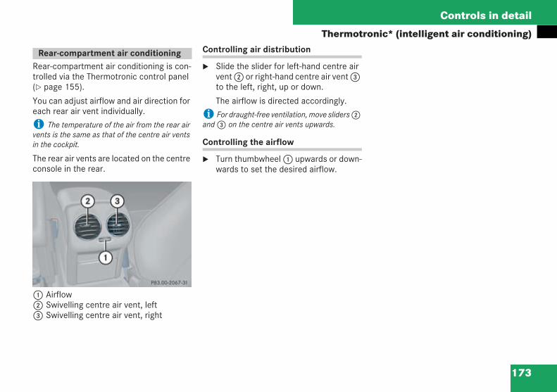
173
Controls in detail
Thermotronic* (intelligent air conditioning)
Rear-compartment air conditioning is con-trolled via the Thermotronic control panel( page 155).
You can adjust airflow and air direction foreach rear air vent individually.
i The temperature of the air from the rear airvents is the same as that of the centre air ventsin the cockpit.
The rear air vents are located on the centreconsole in the rear.
1 Airflow2 Swivelling centre air vent, left3 Swivelling centre air vent, right
Controlling air distribution
Slide the slider for left-hand centre airvent2 or right-hand centre air vent3to the left, right, up or down.
The airflow is directed accordingly.
i For draught-free ventilation, move sliders2and3 on the centre air vents upwards.
Controlling the airflow
Turn thumbwheel1 upwards or down-wards to set the desired airflow.
Rear-compartment air conditioning
P83.00-2067-31
209en_d2.boo Seite 173 Dienstag, 25. Mai 2004 7:26 19
174
Controls in detail
Heater booster system* for vehicles with a diesel engine
During the warm-up phase after the engineis started, the heater booster systemensures that:
the engine reaches normal operatingtemperature more quickly
the vehicle interior is heated morequickly
The heater booster system is switched onwhen:
the heater booster system is activated
the outside temperature is below 8 °C
the coolant temperature is below70 °C
You can use the operating system to con-figure the settings for heater booster sys-tem operation ( page 128)
Automatic:The heater booster system is activatedand is switched on and off automati-cally as required
Off:The heater booster system is deacti-vated
Using Thermatic/Thermotronic*
AC-OFF off:The heater booster system and coolingcan be switched on or off using the± button
Thermatic ( page 154)
Thermotronic* ( page 164)
The heater booster system is switchedoff if the indicator lamp in the ± but-ton is lit.
Heater booster system* for vehicleswith a diesel engine
209en_d2.boo Seite 174 Dienstag, 25. Mai 2004 7:26 19
175
Controls in detail
Auxiliary heating/ventilation*
The auxiliary heating heats or ventilatesthe vehicle interior to the temperature thatyou have set using the temperature con-trol.
You can set up to three switch-on timesusing the operating system, one of whichcan be preselected ( page 126).
You can switch the auxiliary heating/ventilation on and off immediately using:
the switch on the centre console( page 176)
the remote control ( page 176)
In order to call up the Heater submenu inthe operating system directly:
Make sure that the ignition is set to 1or 2.
Briefly press the auxiliary heating/ventilation switch ( page 176).
The auxiliary heating switches off automat-ically after 50 minutes. You can have thistime changed. To have this done, pleasevisit a qualified specialist workshop, e.g. aMercedes-Benz Service Centre.
i The fuel tank must be at least a quarter fullto ensure that the auxiliary heating can operate.
i The auxiliary heating/ventilation automati-cally adjusts to variations in the outside temper-ature and changes in weather. It is thereforepossible for the auxiliary heating to switch fromventilation mode to heating mode or from heat-ing mode to ventilation mode.
It is preferable to set the air condition-ing toU.
i The auxiliary heating/ventilation can beswitched on even if the air conditioning is set tomanual. However, optimum comfort will only beachieved if the air conditioning is set toU.
Set the interior temperature to thedesired value.
The auxiliary heating/ventilationadjusts to the temperature set.
i It is recommended that you set the temper-ature to 22 °C.
Auxiliary heating/ventilation* G Risk of fire and poisoning
Exhaust fumes are produced when the auxil-iary heating is in operation. For this reason,switch off the auxiliary heating in confinedspaces which do not have an extraction sys-tem, e.g. a garage.
Operating the auxiliary heating at filling sta-tions or when refuelling your vehicle is prohib-ited. For this reason, switch off the auxiliaryheating when refuelling.
Before switching on
209en_d2.boo Seite 175 Dienstag, 25. Mai 2004 7:26 19
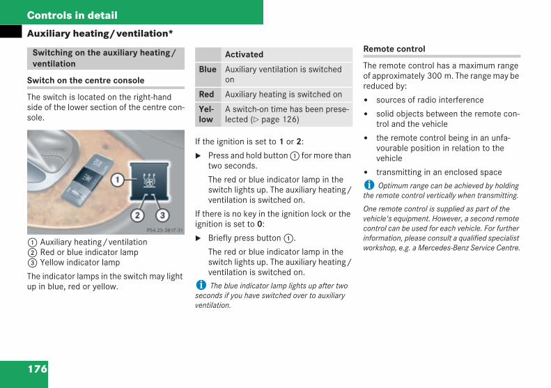
176
Controls in detail
Auxiliary heating/ventilation*
Switch on the centre console
The switch is located on the right-handside of the lower section of the centre con-sole.
1 Auxiliary heating/ventilation2 Red or blue indicator lamp3 Yellow indicator lamp
The indicator lamps in the switch may lightup in blue, red or yellow.
If the ignition is set to 1 or 2:
Press and hold button1 for more thantwo seconds.
The red or blue indicator lamp in theswitch lights up. The auxiliary heating/ventilation is switched on.
If there is no key in the ignition lock or theignition is set to 0:
Briefly press button1.
The red or blue indicator lamp in theswitch lights up. The auxiliary heating/ventilation is switched on.
i The blue indicator lamp lights up after twoseconds if you have switched over to auxiliaryventilation.
Remote control
The remote control has a maximum rangeof approximately 300 m. The range may bereduced by:
sources of radio interference
solid objects between the remote con-trol and the vehicle
the remote control being in an unfa-vourable position in relation to thevehicle
transmitting in an enclosed space
i Optimum range can be achieved by holdingthe remote control vertically when transmitting.
One remote control is supplied as part of thevehicle's equipment. However, a second remotecontrol can be used for each vehicle. For furtherinformation, please consult a qualified specialistworkshop, e.g. a Mercedes-Benz Service Centre.
Switching on the auxiliary heating/ventilation
P54.25-3817-31-Farbe.eps
Activated
Blue Auxiliary ventilation is switchedon
Red Auxiliary heating is switched on
Yel-low
A switch-on time has been prese-lected ( page 126)
209en_d2.boo Seite 176 Dienstag, 25. Mai 2004 7:26 19
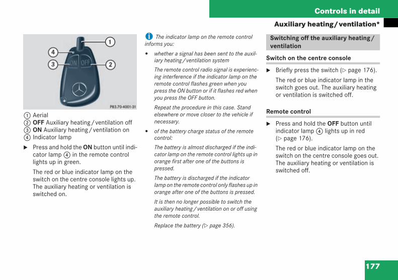
177
Controls in detail
Auxiliary heating/ventilation*
1 Aerial2 OFF Auxiliary heating/ventilation off3 ON Auxiliary heating/ventilation on4 Indicator lamp
Press and hold the ON button until indi-cator lamp4 in the remote controllights up in green.
The red or blue indicator lamp on theswitch on the centre console lights up.The auxiliary heating or ventilation isswitched on.
i The indicator lamp on the remote controlinforms you:
whether a signal has been sent to the auxil-iary heating/ventilation system
The remote control radio signal is experienc-ing interference if the indicator lamp on theremote control flashes green when youpress the ON button or if it flashes red whenyou press the OFF button.
Repeat the procedure in this case. Standelsewhere or move closer to the vehicle ifnecessary.
of the battery charge status of the remotecontrol:
The battery is almost discharged if the indi-cator lamp on the remote control lights up inorange first after one of the buttons ispressed.
The battery is discharged if the indicatorlamp on the remote control only flashes up inorange after one of the buttons is pressed.
It is then no longer possible to switch theauxiliary heating/ventilation on or off usingthe remote control.
Replace the battery ( page 356).
Switch on the centre console
Briefly press the switch ( page 176).
The red or blue indicator lamp in theswitch goes out. The auxiliary heatingor ventilation is switched off.
Remote control
Press and hold the OFF button untilindicator lamp4 lights up in red( page 176).
The red or blue indicator lamp on theswitch on the centre console goes out.The auxiliary heating or ventilation isswitched off.
P83.70-4001-31-Farbe.eps
Switching off the auxiliary heating/ventilation
209en_d2.boo Seite 177 Dienstag, 25. Mai 2004 7:26 19
178
Controls in detail
Open-air
You can open and close the side windowselectrically.
i From the outside it is also possible to:
open the side windows using the summeropening feature ( page 183)
close the side windows using the conven-ience closing feature ( page 184)
From the driver's seat you can disable operationof the rear side windows ( page 67).
Open-air
Opening and closing the windows
G Risk of injury
Make sure that nobody can become trappedbetween the side window and the door frameas you open the side windows. Do not touchor lean against the side window during theopening procedure, otherwise you could becaught between the side window and the doorframe by the downwards movement of theside window. If there is a risk of entrapment,release or press the switch to close the win-dow.
G Risk of injury
Make sure that nobody can become trappedas you close a side window. If there is a risk ofentrapment, release the switch to reopen theside window.
G Risk of injury
Your vehicle can be started using a validKEYLESS GO key. For this reason, childrenshould never be left unsupervised in thevehicle. Always take the KEYLESS GO keywith you, even if you are only leaving thevehicle for a short time.
Do not leave children unsupervised in thevehicle even if they are secured in a childrestraint system. The children could:
injure themselves on parts of the vehicle
be seriously or even fatally harmed byprolonged exposure to heat
press the central locking switch, therebyreleasing the child-proof locks, and thenopen the doors.
If the children open a door:
they could cause injury to others
they could get out of the vehicle, injuringthemselves as they do so or they couldbe injured by passing vehicles
Activate the child-proof locks in the rear anddisable rear operation of the windows( page 67) if children are travelling in thevehicle. Children could otherwise open adoor or window while the vehicle is inmotion, adjust the steering wheel manuallyor electrically and thereby injure themselvesor others.
209en_d2.boo Seite 178 Dienstag, 25. Mai 2004 7:26 19
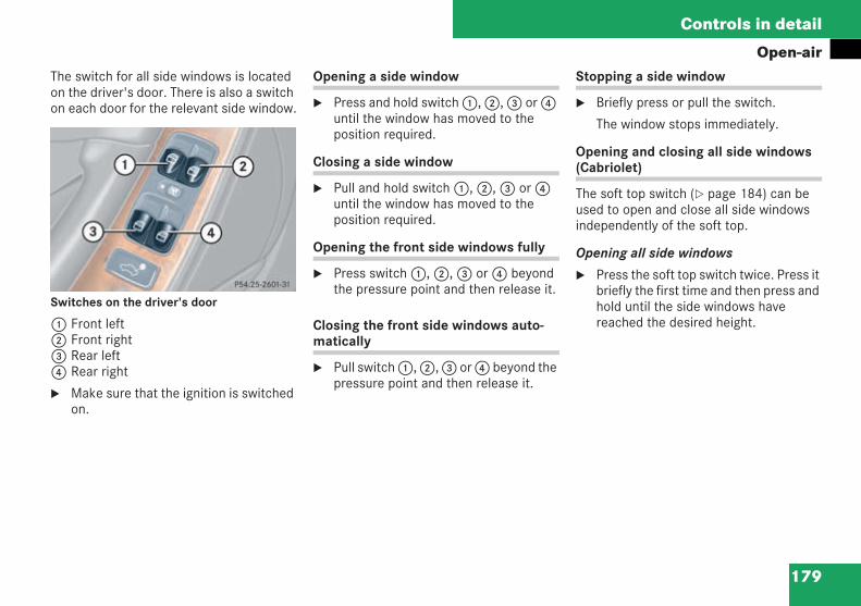
179
Controls in detail
Open-airThe switch for all side windows is locatedon the driver's door. There is also a switchon each door for the relevant side window.
Switches on the driver's door
1 Front left2 Front right3 Rear left4 Rear right
Make sure that the ignition is switchedon.
Opening a side window
Press and hold switch1,2,3 or4until the window has moved to theposition required.
Closing a side window
Pull and hold switch1,2,3 or4until the window has moved to theposition required.
Opening the front side windows fully
Press switch1,2,3 or4 beyondthe pressure point and then release it.
Closing the front side windows auto-matically
Pull switch1,2,3 or4 beyond thepressure point and then release it.
Stopping a side window
Briefly press or pull the switch.
The window stops immediately.
Opening and closing all side windows(Cabriolet)
The soft top switch ( page 184) can beused to open and close all side windowsindependently of the soft top.
Opening all side windows
Press the soft top switch twice. Press itbriefly the first time and then press andhold until the side windows havereached the desired height.
P54.25-2601-31 209
209en_d2.boo Seite 179 Dienstag, 25. Mai 2004 7:26 19
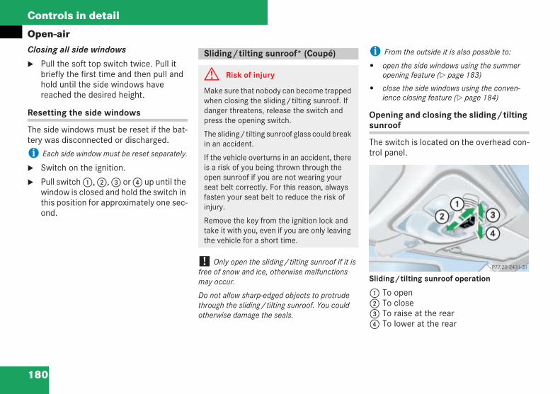
180
Controls in detail
Open-airClosing all side windows
Pull the soft top switch twice. Pull itbriefly the first time and then pull andhold until the side windows havereached the desired height.
Resetting the side windows
The side windows must be reset if the bat-tery was disconnected or discharged.
i Each side window must be reset separately.
Switch on the ignition.
Pull switch1,2,3 or4 up until thewindow is closed and hold the switch inthis position for approximately one sec-ond.
! Only open the sliding/tilting sunroof if it isfree of snow and ice, otherwise malfunctionsmay occur.
Do not allow sharp-edged objects to protrudethrough the sliding/tilting sunroof. You couldotherwise damage the seals.
i From the outside it is also possible to:
open the side windows using the summeropening feature ( page 183)
close the side windows using the conven-ience closing feature ( page 184)
Opening and closing the sliding/tiltingsunroof
The switch is located on the overhead con-trol panel.
Sliding/tilting sunroof operation
1 To open2 To close3 To raise at the rear4 To lower at the rear
Sliding/tilting sunroof* (Coupé)
G Risk of injury
Make sure that nobody can become trappedwhen closing the sliding/tilting sunroof. Ifdanger threatens, release the switch andpress the opening switch.
The sliding/tilting sunroof glass could breakin an accident.
If the vehicle overturns in an accident, thereis a risk of you being thrown through theopen sunroof if you are not wearing yourseat belt correctly. For this reason, alwaysfasten your seat belt to reduce the risk ofinjury.
Remove the key from the ignition lock andtake it with you, even if you are only leavingthe vehicle for a short time.
P77.20-2431-31
209en_d2.boo Seite 180 Dienstag, 25. Mai 2004 7:26 19
181
Controls in detail
Open-airMake sure that the ignition is switchedon.
Opening
Press the switch to the pressure pointin the direction of arrow1 and hold itin this position until the sliding/tiltingsunroof and the cover have moved tothe required position.
or
Briefly press the switch beyond thepressure point in the direction of arrow1 and release it.
The sliding/tilting sunroof opens com-pletely.
To stop:
Press the switch in any direction.
The sliding/tilting sunroof stops inits current position.
Closing
Press the switch to the pressure pointin the direction of arrow2 and hold itin this position until the sliding/tiltingsunroof has moved to the positiondesired
or
Briefly press the switch beyond thepressure point in the direction of arrow2 and release it.
The sliding/tilting sunroof closes com-pletely.
To stop:
Press the switch in any direction.
The sliding/tilting sunroof stops inits current position.
Close the cover manually if necessary( page 182).
i If the sliding/tilting sunroof becomesobstructed when it is being closed automatically,the closing procedure will be halted and the win-dow will open a little again.
Raising
The sliding/tilting sunroof can be raised atthe rear to ventilate the vehicle.
Press the switch back as far as thepressure point in the direction ofarrow3 and hold it there until thesliding/tilting sunroof has moved tothe desired position.
or
Briefly press the switch beyond thepressure point in the direction of arrow3 and release it.
The sliding/tilting sunroof is raised atthe rear.
209en_d2.boo Seite 181 Dienstag, 25. Mai 2004 7:26 19
182
Controls in detail
Open-airTo stop:
Press the switch in any direction.
The sliding/tilting sunroof stops inits current position.
Lowering and closing
Pull the switch in the direction of arrow4 and hold it in this position until thesliding/tilting sunroof has moved tothe required position.
or
Briefly press the switch beyond thepressure point in the direction of arrow4 and release it.
The sliding/tilting sunroof is loweredat the rear.
To stop:
Press the switch in any direction.
The sliding/tilting sunroof stops inits current position.
Opening and closing the cover
The cover is intended to block out the sun-light. When you open the sliding/tiltingsunroof, the cover automatically slidesback with it.
It is possible to open the cover manuallywhen the sliding/tilting sunroof is closedor raised at the rear.
Rain closing feature
The sliding/tilting sunroof closes auto-matically:
when it starts to rain
at extreme outside temperatures
after twelve hours
if there are malfunctions in the powersupply
The sliding/tilting sunroof is then raised atthe rear to continue to ventilate the vehicleinterior.
i The sliding/tilting sunroof does not close if:
it is raised at the rear
it is blocked
it is not raining on the windscreen (e.g. if thevehicle is under a bridge or in a carport)
G Risk of injury
If the sliding/tilting sunroof has beenclosed using the rain closing feature andbecomes blocked, it will not open automati-cally.
209en_d2.boo Seite 182 Dienstag, 25. Mai 2004 7:26 19
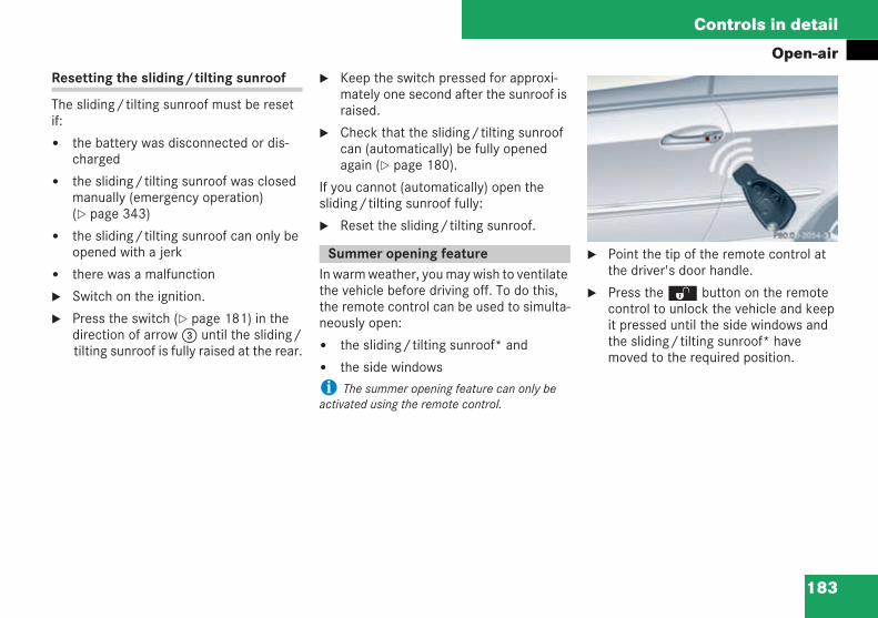
183
Controls in detail
Open-airResetting the sliding/tilting sunroof
The sliding/tilting sunroof must be resetif:
the battery was disconnected or dis-charged
the sliding/tilting sunroof was closedmanually (emergency operation)( page 343)
the sliding/tilting sunroof can only beopened with a jerk
there was a malfunction
Switch on the ignition.
Press the switch ( page 181) in thedirection of arrow3 until the sliding/tilting sunroof is fully raised at the rear.
Keep the switch pressed for approxi-mately one second after the sunroof israised.
Check that the sliding/tilting sunroofcan (automatically) be fully openedagain ( page 180).
If you cannot (automatically) open thesliding/tilting sunroof fully:
Reset the sliding/tilting sunroof.
In warm weather, you may wish to ventilatethe vehicle before driving off. To do this,the remote control can be used to simulta-neously open:
the sliding/tilting sunroof* and
the side windows
i The summer opening feature can only beactivated using the remote control.
Point the tip of the remote control atthe driver's door handle.
Press theΠbutton on the remotecontrol to unlock the vehicle and keepit pressed until the side windows andthe sliding/tilting sunroof* havemoved to the required position.
Summer opening feature
P80.00-2054-31
209en_d2.boo Seite 183 Dienstag, 25. Mai 2004 7:26 19
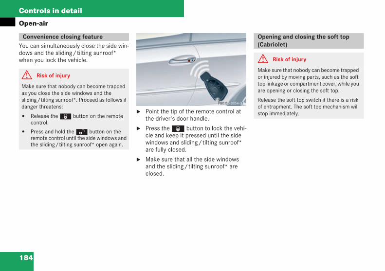
184
Controls in detail
Open-air
You can simultaneously close the side win-dows and the sliding/tilting sunroof*when you lock the vehicle.
Point the tip of the remote control atthe driver's door handle.
Press the‹ button to lock the vehi-cle and keep it pressed until the sidewindows and sliding/tilting sunroof*are fully closed.
Make sure that all the side windowsand the sliding/tilting sunroof* areclosed.
Convenience closing feature
G Risk of injury
Make sure that nobody can become trappedas you close the side windows and thesliding/tilting sunroof*. Proceed as follows ifdanger threatens:
Release the‹ button on the remotecontrol.
Press and hold theΠbutton on theremote control until the side windows andthe sliding/tilting sunroof* open again.
P80.00-2054-31
Opening and closing the soft top(Cabriolet)
G Risk of injury
Make sure that nobody can become trappedor injured by moving parts, such as the softtop linkage or compartment cover, while youare opening or closing the soft top.
Release the soft top switch if there is a riskof entrapment. The soft top mechanism willstop immediately.
209en_d2.boo Seite 184 Dienstag, 25. Mai 2004 7:26 19
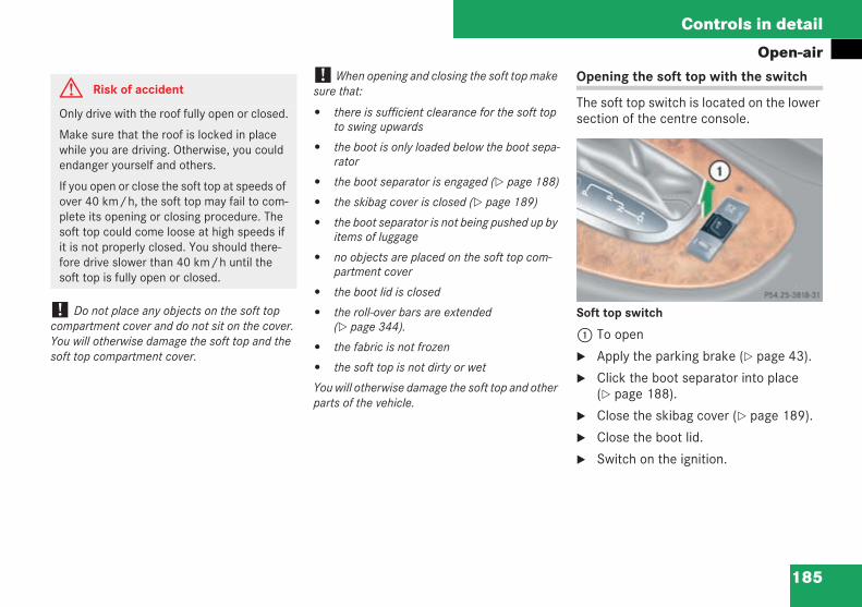
185
Controls in detail
Open-air
! Do not place any objects on the soft topcompartment cover and do not sit on the cover.You will otherwise damage the soft top and thesoft top compartment cover.
! When opening and closing the soft top makesure that:
there is sufficient clearance for the soft topto swing upwards
the boot is only loaded below the boot sepa-rator
the boot separator is engaged ( page 188)
the skibag cover is closed ( page 189)
the boot separator is not being pushed up byitems of luggage
no objects are placed on the soft top com-partment cover
the boot lid is closed
the roll-over bars are extended( page 344).
the fabric is not frozen
the soft top is not dirty or wet
You will otherwise damage the soft top and otherparts of the vehicle.
Opening the soft top with the switch
The soft top switch is located on the lowersection of the centre console.
Soft top switch
1 To open
Apply the parking brake ( page 43).
Click the boot separator into place( page 188).
Close the skibag cover ( page 189).
Close the boot lid.
Switch on the ignition.
G Risk of accident
Only drive with the roof fully open or closed.
Make sure that the roof is locked in placewhile you are driving. Otherwise, you couldendanger yourself and others.
If you open or close the soft top at speeds ofover 40 km/h, the soft top may fail to com-plete its opening or closing procedure. Thesoft top could come loose at high speeds ifit is not properly closed. You should there-fore drive slower than 40 km/h until thesoft top is fully open or closed.
P54.25-3818-31-Farbe.eps
209en_d2.boo Seite 185 Dienstag, 25. Mai 2004 7:26 19
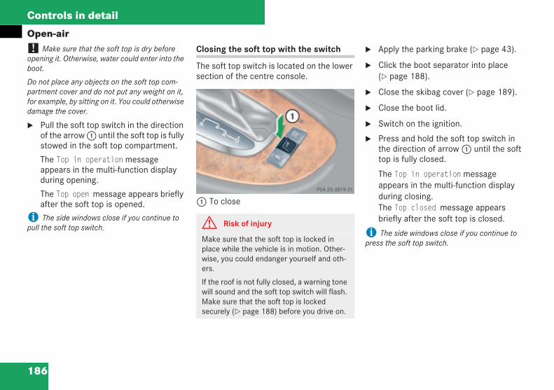
186
Controls in detail
Open-air! Make sure that the soft top is dry beforeopening it. Otherwise, water could enter into theboot.
Do not place any objects on the soft top com-partment cover and do not put any weight on it,for example, by sitting on it. You could otherwisedamage the cover.
Pull the soft top switch in the directionof the arrow1 until the soft top is fullystowed in the soft top compartment.
The Top in operationmessageappears in the multi-function displayduring opening.
The Top open message appears brieflyafter the soft top is opened.
i The side windows close if you continue topull the soft top switch.
Closing the soft top with the switch
The soft top switch is located on the lowersection of the centre console.
1 To close
Apply the parking brake ( page 43).
Click the boot separator into place( page 188).
Close the skibag cover ( page 189).
Close the boot lid.
Switch on the ignition.
Press and hold the soft top switch inthe direction of arrow1 until the softtop is fully closed.
The Top in operationmessageappears in the multi-function displayduring closing.The Top closed message appearsbriefly after the soft top is closed.
i The side windows close if you continue topress the soft top switch.
G Risk of injury
Make sure that the soft top is locked inplace while the vehicle is in motion. Other-wise, you could endanger yourself and oth-ers.
If the roof is not fully closed, a warning tonewill sound and the soft top switch will flash.Make sure that the soft top is lockedsecurely ( page 188) before you drive on.
P54.25-3819-31-Farbe.eps
209en_d2.boo Seite 186 Dienstag, 25. Mai 2004 7:26 19
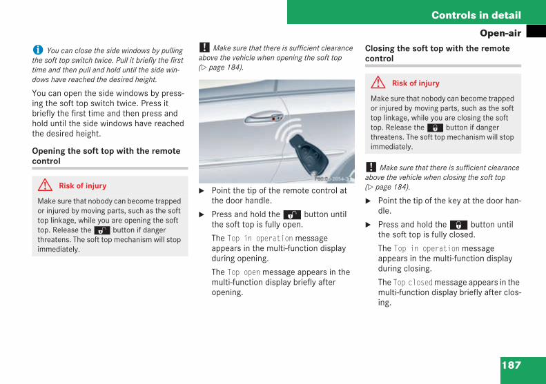
187
Controls in detail
Open-air
i You can close the side windows by pullingthe soft top switch twice. Pull it briefly the firsttime and then pull and hold until the side win-dows have reached the desired height.
You can open the side windows by press-ing the soft top switch twice. Press itbriefly the first time and then press andhold until the side windows have reachedthe desired height.
Opening the soft top with the remotecontrol
! Make sure that there is sufficient clearanceabove the vehicle when opening the soft top( page 184).
Point the tip of the remote control atthe door handle.
Press and hold theΠbutton untilthe soft top is fully open.
The Top in operationmessageappears in the multi-function displayduring opening.
The Top openmessage appears in themulti-function display briefly afteropening.
Closing the soft top with the remotecontrol
! Make sure that there is sufficient clearanceabove the vehicle when closing the soft top( page 184).
Point the tip of the key at the door han-dle.
Press and hold the‹ button untilthe soft top is fully closed.
The Top in operationmessageappears in the multi-function displayduring closing.
The Top closedmessage appears in themulti-function display briefly after clos-ing.
G Risk of injury
Make sure that nobody can become trappedor injured by moving parts, such as the softtop linkage, while you are opening the softtop. Release theΠbutton if dangerthreatens. The soft top mechanism will stopimmediately.
P 80.00-2054-31-Farbe.eps
G Risk of injury
Make sure that nobody can become trappedor injured by moving parts, such as the softtop linkage, while you are closing the softtop. Release the‹ button if dangerthreatens. The soft top mechanism will stopimmediately.
209en_d2.boo Seite 187 Dienstag, 25. Mai 2004 7:26 19
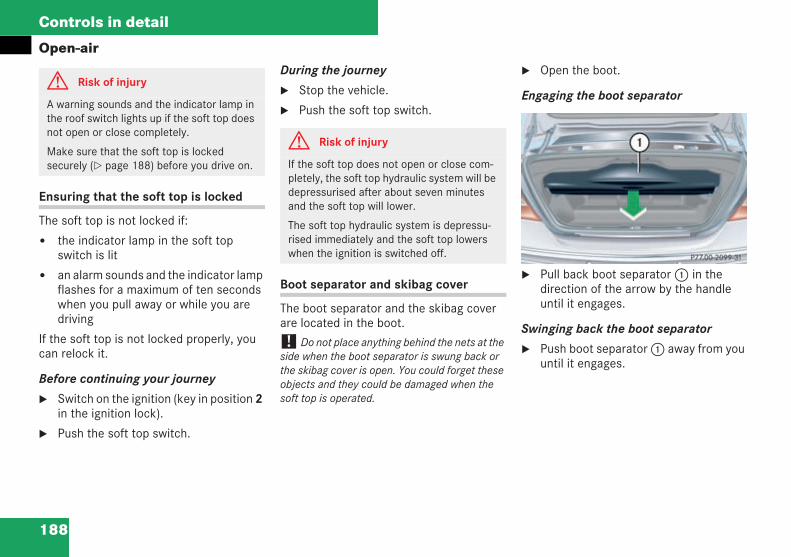
188
Controls in detail
Open-air
Ensuring that the soft top is locked
The soft top is not locked if:
the indicator lamp in the soft topswitch is lit
an alarm sounds and the indicator lampflashes for a maximum of ten secondswhen you pull away or while you aredriving
If the soft top is not locked properly, youcan relock it.
Before continuing your journey
Switch on the ignition (key in position 2in the ignition lock).
Push the soft top switch.
During the journey
Stop the vehicle.
Push the soft top switch.
Boot separator and skibag cover
The boot separator and the skibag coverare located in the boot.
! Do not place anything behind the nets at theside when the boot separator is swung back orthe skibag cover is open. You could forget theseobjects and they could be damaged when thesoft top is operated.
Open the boot.
Engaging the boot separator
Pull back boot separator1 in thedirection of the arrow by the handleuntil it engages.
Swinging back the boot separator
Push boot separator1 away from youuntil it engages.
G Risk of injury
A warning sounds and the indicator lamp inthe roof switch lights up if the soft top doesnot open or close completely.
Make sure that the soft top is lockedsecurely ( page 188) before you drive on.
G Risk of injury
If the soft top does not open or close com-pletely, the soft top hydraulic system will bedepressurised after about seven minutesand the soft top will lower.
The soft top hydraulic system is depressu-rised immediately and the soft top lowerswhen the ignition is switched off.
P 77.00-2099-31-Farbe.eps
209en_d2.boo Seite 188 Dienstag, 25. Mai 2004 7:26 19
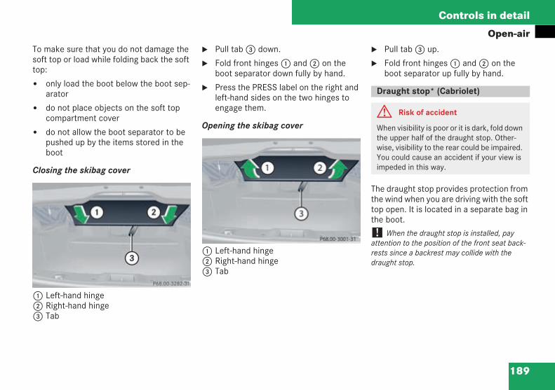
189
Controls in detail
Open-airTo make sure that you do not damage thesoft top or load while folding back the softtop:
only load the boot below the boot sep-arator
do not place objects on the soft topcompartment cover
do not allow the boot separator to bepushed up by the items stored in theboot
Closing the skibag cover
1 Left-hand hinge2 Right-hand hinge3 Tab
Pull tab3 down.
Fold front hinges1 and2 on theboot separator down fully by hand.
Press the PRESS label on the right andleft-hand sides on the two hinges toengage them.
Opening the skibag cover
1 Left-hand hinge2 Right-hand hinge3 Tab
Pull tab3 up.
Fold front hinges1 and2 on theboot separator up fully by hand.
The draught stop provides protection fromthe wind when you are driving with the softtop open. It is located in a separate bag inthe boot.
! When the draught stop is installed, payattention to the position of the front seat back-rests since a backrest may collide with thedraught stop.
P 68.00-3282-31-Farbe.eps
P 68.00-3001-31-Farbe.eps
Draught stop* (Cabriolet)
G Risk of accident
When visibility is poor or it is dark, fold downthe upper half of the draught stop. Other-wise, visibility to the rear could be impaired.You could cause an accident if your view isimpeded in this way.
209en_d2.boo Seite 189 Dienstag, 25. Mai 2004 7:26 19
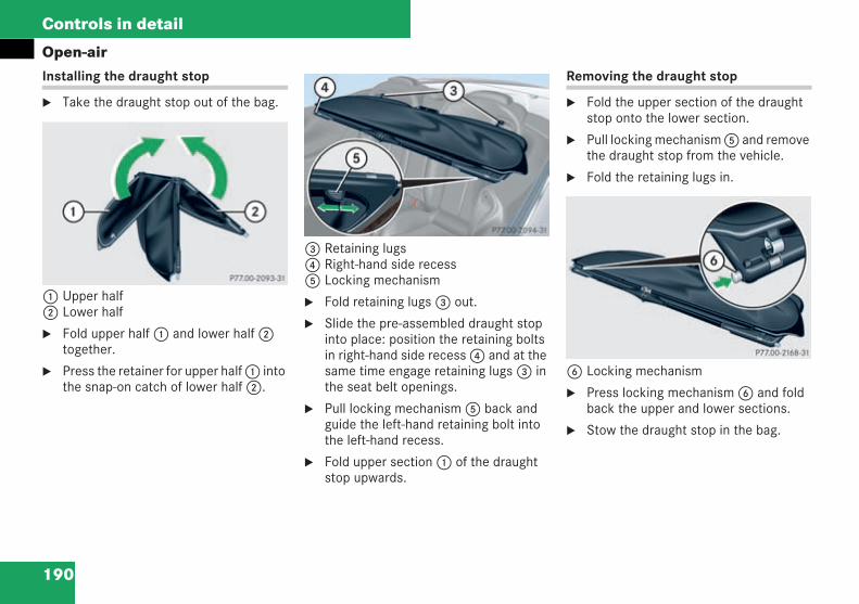
190
Controls in detail
Open-airInstalling the draught stop
Take the draught stop out of the bag.
1 Upper half2 Lower half
Fold upper half1 and lower half2together.
Press the retainer for upper half1 intothe snap-on catch of lower half2.
3 Retaining lugs4 Right-hand side recess5 Locking mechanism
Fold retaining lugs3 out.
Slide the pre-assembled draught stopinto place: position the retaining boltsin right-hand side recess4 and at thesame time engage retaining lugs3 inthe seat belt openings.
Pull locking mechanism5 back andguide the left-hand retaining bolt intothe left-hand recess.
Fold upper section1 of the draughtstop upwards.
Removing the draught stop
Fold the upper section of the draughtstop onto the lower section.
Pull locking mechanism5 and removethe draught stop from the vehicle.
Fold the retaining lugs in.
6 Locking mechanism
Press locking mechanism6 and foldback the upper and lower sections.
Stow the draught stop in the bag.
P 77.00-2093-31-Farbe.eps
P 77.00-2094-31-Farbe.eps
P 77.00-2168-31-S_W.eps
209en_d2.boo Seite 190 Dienstag, 25. Mai 2004 7:26 19
191
Controls in detail
Driving systems
Your vehicle's driving systems aredescribed on the following pages:
Cruise control, Distronic* andSpeedtronic, which can be used to con-trol your vehicle's speed
Parktronic*, which assists you withparking and manoeuvring
The BAS, ABS, ESP and SBC driving safetysystems are described in the "Safety" sec-tion ( page 68).
Cruise control maintains your vehicle'sspeed.
Use cruise control if road and traffic condi-tions make it appropriate to maintain asteady speed for a prolonged period. Youcan store any road speed above 30 km/h.
Driving systems Cruise control
G Risk of accident
The cruise control function cannot takeaccount of road and traffic conditions.
Always pay attention to road and traffic con-ditions, even when cruise control is acti-vated.
Cruise control is only an aid designed toassist driving. You are responsible for thevehicle's speed and for braking in goodtime.
G Risk of accident
Do not use cruise control:
if road and traffic conditions do not per-mit a constant driving speed to be main-tained (e.g. dense traffic or windingroads). You could otherwise cause anaccident
on slippery road surfaces. The drivewheels may lose their grip when brakingor accelerating and the vehicle couldskid
when visibility is bad, e.g. in fog, heavyrain or snow
209en_d2.boo Seite 191 Dienstag, 25. Mai 2004 7:26 19
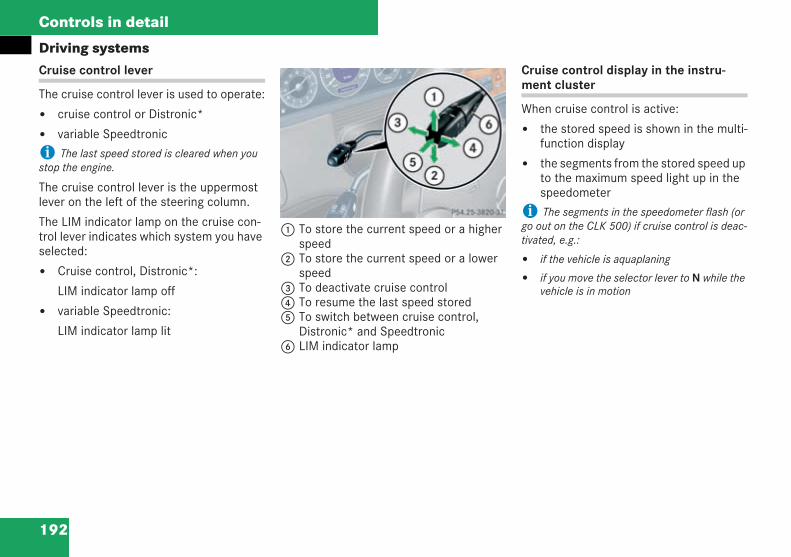
192
Controls in detail
Driving systemsCruise control lever
The cruise control lever is used to operate:
cruise control or Distronic*
variable Speedtronic
i The last speed stored is cleared when youstop the engine.
The cruise control lever is the uppermostlever on the left of the steering column.
The LIM indicator lamp on the cruise con-trol lever indicates which system you haveselected:
Cruise control, Distronic*:
LIM indicator lamp off
variable Speedtronic:
LIM indicator lamp lit
1 To store the current speed or a higherspeed
2 To store the current speed or a lowerspeed
3 To deactivate cruise control4 To resume the last speed stored5 To switch between cruise control,
Distronic* and Speedtronic6 LIM indicator lamp
Cruise control display in the instru-ment cluster
When cruise control is active:
the stored speed is shown in the multi-function display
the segments from the stored speed upto the maximum speed light up in thespeedometer
i The segments in the speedometer flash (orgo out on the CLK 500) if cruise control is deac-tivated, e.g.:
if the vehicle is aquaplaning
if you move the selector lever to N while thevehicle is in motion
P54.25-3820-31
209en_d2.boo Seite 192 Dienstag, 25. Mai 2004 7:26 19
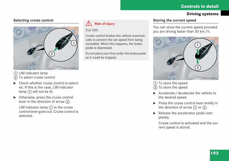
193
Controls in detail
Driving systemsSelecting cruise control
1 LIM indicator lamp2 To select cruise control
Check whether cruise control is select-ed. If this is the case, LIM indicatorlamp1 will not be lit.
Otherwise, press the cruise controllever in the direction of arrow2.
LIM indicator lamp1 in the cruisecontrol lever goes out. Cruise control isselected.
Storing the current speed
You can store the current speed providedyou are driving faster than 30 km/h.
1 To store the speed2 To store the speed
Accelerate/decelerate the vehicle tothe desired speed.
Press the cruise control lever briefly inthe direction of arrow1 or2.
Release the accelerator pedal com-pletely.
Cruise control is activated and the cur-rent speed is stored.
P54.25-3855-31
G Risk of injury
CLK 500:
Cruise control brakes the vehicle automati-cally to prevent the set speed from beingexceeded. When this happens, the brakepedal is depressed.
Do not place your foot under the brake pedalas it could be trapped.
209en_d2.boo Seite 193 Dienstag, 25. Mai 2004 7:26 19
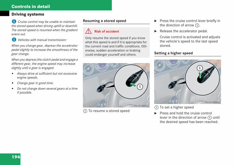
194
Controls in detail
Driving systems
i Cruise control may be unable to maintainthe stored speed when driving uphill or downhill.The stored speed is resumed when the gradientevens out.
i Vehicles with manual transmission:
When you change gear, depress the acceleratorpedal slightly to increase the smoothness of thegear change.
When you depress the clutch pedal and engage adifferent gear, the engine speed may increaseslightly until a gear is engaged.
Always drive at sufficient but not excessiveengine speeds.
Change gear in good time.
Do not change down several gears at a timeif possible.
Resuming a stored speed
1 To resume a stored speed
Press the cruise control lever briefly inthe direction of arrow1.
Release the accelerator pedal.
Cruise control is activated and adjuststhe vehicle's speed to the last speedstored.
Setting a higher speed
1 To set a higher speed
Press and hold the cruise controllever in the direction of arrow1 untilthe desired speed has been reached.
G Risk of accident
Only resume the stored speed if you knowwhat this speed is and if it is appropriate forthe current road and traffic conditions. Oth-erwise, sudden acceleration or brakingcould endanger yourself and others.
209en_d2.boo Seite 194 Dienstag, 25. Mai 2004 7:26 19
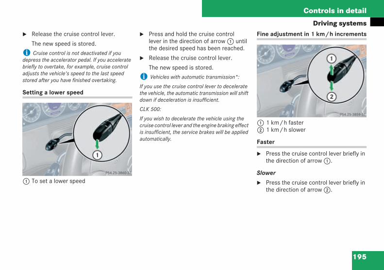
195
Controls in detail
Driving systemsRelease the cruise control lever.
The new speed is stored.
i Cruise control is not deactivated if youdepress the accelerator pedal. If you acceleratebriefly to overtake, for example, cruise controladjusts the vehicle's speed to the last speedstored after you have finished overtaking.
Setting a lower speed
1 To set a lower speed
Press and hold the cruise controllever in the direction of arrow1 untilthe desired speed has been reached.
Release the cruise control lever.
The new speed is stored.
i Vehicles with automatic transmission*:
If you use the cruise control lever to deceleratethe vehicle, the automatic transmission will shiftdown if deceleration is insufficient.
CLK 500:
If you wish to decelerate the vehicle using thecruise control lever and the engine braking effectis insufficient, the service brakes will be appliedautomatically.
Fine adjustment in 1 km/h increments
1 1 km/h faster2 1 km/h slower
Faster
Press the cruise control lever briefly inthe direction of arrow1.
Slower
Press the cruise control lever briefly inthe direction of arrow2.
209en_d2.boo Seite 195 Dienstag, 25. Mai 2004 7:26 19
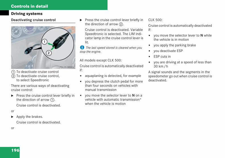
196
Controls in detail
Driving systemsDeactivating cruise control
1 To deactivate cruise control2 To deactivate cruise control,
to select Speedtronic
There are various ways of deactivatingcruise control:
Press the cruise control lever briefly inthe direction of arrow1.
Cruise control is deactivated.
or
Apply the brakes.
Cruise control is deactivated.
or
Press the cruise control lever briefly inthe direction of arrow2.
Cruise control is deactivated. VariableSpeedtronic is selected. The LIM indi-cator lamp in the cruise control lever islit.
i The last speed stored is cleared when youstop the engine.
All models except CLK 500:
Cruise control is automatically deactivatedif:
aquaplaning is detected, for example
you depress the clutch pedal for morethan four seconds on vehicles withmanual transmission
you move the selector lever to N on avehicle with automatic transmission*when the vehicle is motion
CLK 500:
Cruise control is automatically deactivatedif:
you move the selector lever to N whilethe vehicle is in motion
you apply the parking brake
you deactivate ESP
ESP cuts in
you are driving at a speed of less than30 km/h
A signal sounds and the segments in thespeedometer go out when cruise control isdeactivated.
209en_d2.boo Seite 196 Dienstag, 25. Mai 2004 7:26 19
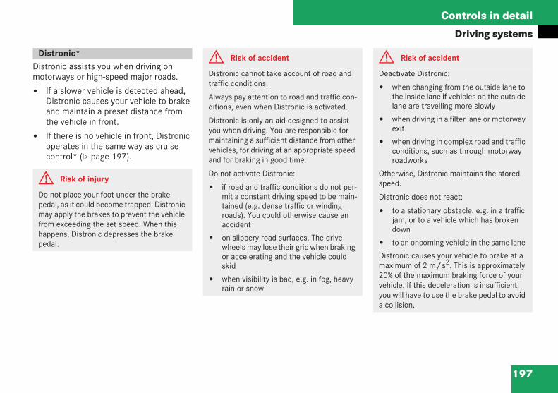
197
Controls in detail
Driving systems
Distronic assists you when driving onmotorways or high-speed major roads.
If a slower vehicle is detected ahead,Distronic causes your vehicle to brakeand maintain a preset distance fromthe vehicle in front.
If there is no vehicle in front, Distronicoperates in the same way as cruisecontrol* ( page 197).
Distronic*
G Risk of injury
Do not place your foot under the brakepedal, as it could become trapped. Distronicmay apply the brakes to prevent the vehiclefrom exceeding the set speed. When thishappens, Distronic depresses the brakepedal.
G Risk of accident
Distronic cannot take account of road andtraffic conditions.
Always pay attention to road and traffic con-ditions, even when Distronic is activated.
Distronic is only an aid designed to assistyou when driving. You are responsible formaintaining a sufficient distance from othervehicles, for driving at an appropriate speedand for braking in good time.
Do not activate Distronic:
if road and traffic conditions do not per-mit a constant driving speed to be main-tained (e.g. dense traffic or windingroads). You could otherwise cause anaccident
on slippery road surfaces. The drivewheels may lose their grip when brakingor accelerating and the vehicle couldskid
when visibility is bad, e.g. in fog, heavyrain or snow
G Risk of accident
Deactivate Distronic:
when changing from the outside lane tothe inside lane if vehicles on the outsidelane are travelling more slowly
when driving in a filter lane or motorwayexit
when driving in complex road and trafficconditions, such as through motorwayroadworks
Otherwise, Distronic maintains the storedspeed.
Distronic does not react:
to a stationary obstacle, e.g. in a trafficjam, or to a vehicle which has brokendown
to an oncoming vehicle in the same lane
Distronic causes your vehicle to brake at amaximum of 2 m/s2. This is approximately20% of the maximum braking force of yourvehicle. If this deceleration is insufficient,you will have to use the brake pedal to avoida collision.
209en_d2.boo Seite 197 Dienstag, 25. Mai 2004 7:26 19
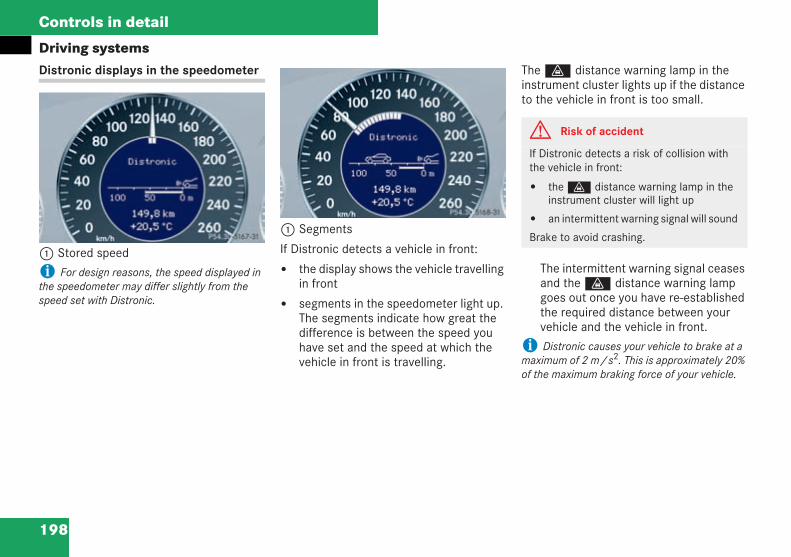
198
Controls in detail
Driving systemsDistronic displays in the speedometer
1 Stored speed
i For design reasons, the speed displayed inthe speedometer may differ slightly from thespeed set with Distronic.
1 Segments
If Distronic detects a vehicle in front:
the display shows the vehicle travellingin front
segments in the speedometer light up.The segments indicate how great thedifference is between the speed youhave set and the speed at which thevehicle in front is travelling.
The l distance warning lamp in theinstrument cluster lights up if the distanceto the vehicle in front is too small.
The intermittent warning signal ceasesand the l distance warning lampgoes out once you have re-establishedthe required distance between yourvehicle and the vehicle in front.
i Distronic causes your vehicle to brake at amaximum of 2 m/s2. This is approximately 20%of the maximum braking force of your vehicle.
P54.30-5167-31 209
P54.30-5167-31 209
G Risk of accident
If Distronic detects a risk of collision withthe vehicle in front:
the l distance warning lamp in theinstrument cluster will light up
an intermittent warning signal will sound
Brake to avoid crashing.
209en_d2.boo Seite 198 Dienstag, 25. Mai 2004 7:26 19
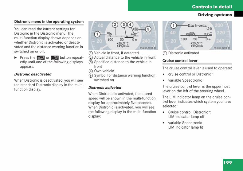
199
Controls in detail
Driving systemsDistronic menu in the operating system
You can read the current settings forDistronic in the Distronic menu. Themulti-function display shown depends onwhether Distronic is activated or deacti-vated and the distance warning function isswitched on or off.
Press theè orÿ button repeat-edly until one of the following displaysappears.
Distronic deactivated
When Distronic is deactivated, you will seethe standard Distronic display in the multi-function display.
1 Vehicle in front, if detected2 Actual distance to the vehicle in front3 Specified distance to the vehicle in
front4 Own vehicle5 Symbol for distance warning function
switched on
Distronic activated
When Distronic is activated, the storedspeed will be shown in the multi-functiondisplay for approximately five seconds.When Distronic is activated, you will seethe following display in the multi-functiondisplay:
1 Distronic activated
Cruise control lever
The cruise control lever is used to operate:
cruise control or Distronic*
variable Speedtronic
The cruise control lever is the uppermostlever on the left of the steering wheel.
The LIM indicator lamp on the cruise con-trol lever indicates which system you haveselected:
Cruise control, Distronic*:LIM indicator lamp off
variable SpeedtronicLIM indicator lamp lit
P54.30-5203-31 209 P54.30-5204-31 209
209en_d2.boo Seite 199 Dienstag, 25. Mai 2004 7:26 19
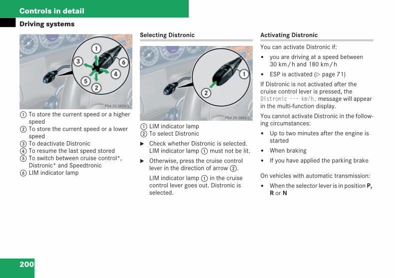
200
Controls in detail
Driving systems
1 To store the current speed or a higherspeed
2 To store the current speed or a lowerspeed
3 To deactivate Distronic4 To resume the last speed stored5 To switch between cruise control*,
Distronic* and Speedtronic6 LIM indicator lamp
Selecting Distronic
1 LIM indicator lamp2 To select Distronic
Check whether Distronic is selected.LIM indicator lamp1 must not be lit.
Otherwise, press the cruise controllever in the direction of arrow2.
LIM indicator lamp1 in the cruisecontrol lever goes out. Distronic isselected.
Activating Distronic
You can activate Distronic if:
you are driving at a speed between30 km/h and 180 km/h
ESP is activated ( page 71)
If Distronic is not activated after thecruise control lever is pressed, theDistronic --– km/h.message will appearin the multi-function display.
You cannot activate Distronic in the follow-ing circumstances:
Up to two minutes after the engine isstarted
When braking
If you have applied the parking brake
On vehicles with automatic transmission:
When the selector lever is in position P,R or N
P54.25-3820-31
209en_d2.boo Seite 200 Dienstag, 25. Mai 2004 7:26 19
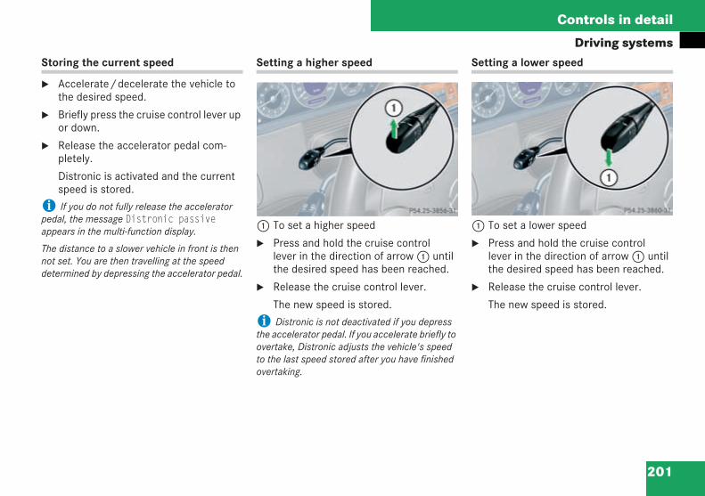
201
Controls in detail
Driving systemsStoring the current speed
Accelerate/decelerate the vehicle tothe desired speed.
Briefly press the cruise control lever upor down.
Release the accelerator pedal com-pletely.
Distronic is activated and the currentspeed is stored.
i If you do not fully release the acceleratorpedal, the message Distronic passiveappears in the multi-function display.
The distance to a slower vehicle in front is thennot set. You are then travelling at the speeddetermined by depressing the accelerator pedal.
Setting a higher speed
1 To set a higher speed
Press and hold the cruise controllever in the direction of arrow1 untilthe desired speed has been reached.
Release the cruise control lever.
The new speed is stored.
i Distronic is not deactivated if you depressthe accelerator pedal. If you accelerate briefly toovertake, Distronic adjusts the vehicle's speedto the last speed stored after you have finishedovertaking.
Setting a lower speed
1 To set a lower speed
Press and hold the cruise controllever in the direction of arrow1 untilthe desired speed has been reached.
Release the cruise control lever.
The new speed is stored.
209en_d2.boo Seite 201 Dienstag, 25. Mai 2004 7:26 19
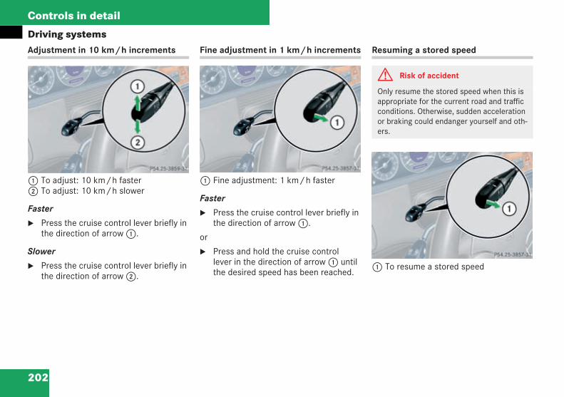
202
Controls in detail
Driving systemsAdjustment in 10 km/h increments
1 To adjust: 10 km/h faster2 To adjust: 10 km/h slower
Faster
Press the cruise control lever briefly inthe direction of arrow1.
Slower
Press the cruise control lever briefly inthe direction of arrow2.
Fine adjustment in 1 km/h increments
1 Fine adjustment: 1 km/h faster
Faster
Press the cruise control lever briefly inthe direction of arrow1.
or
Press and hold the cruise controllever in the direction of arrow1 untilthe desired speed has been reached.
Resuming a stored speed
1 To resume a stored speed
G Risk of accident
Only resume the stored speed when this isappropriate for the current road and trafficconditions. Otherwise, sudden accelerationor braking could endanger yourself and oth-ers.
209en_d2.boo Seite 202 Dienstag, 25. Mai 2004 7:26 19
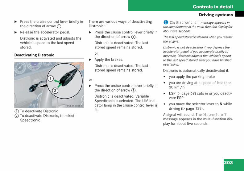
203
Controls in detail
Driving systemsPress the cruise control lever briefly inthe direction of arrow1.
Release the accelerator pedal.
Distronic is activated and adjusts thevehicle's speed to the last speedstored.
Deactivating Distronic
1 To deactivate Distronic2 To deactivate Distronic, to select
Speedtronic
There are various ways of deactivatingDistronic:
Press the cruise control lever briefly inthe direction of arrow1.
Distronic is deactivated. The laststored speed remains stored.
or
Apply the brakes.
Distronic is deactivated. The laststored speed remains stored.
or
Press the cruise control lever briefly inthe direction of arrow2.
Distronic is deactivated. VariableSpeedtronic is selected. The LIM indi-cator lamp in the cruise control lever islit.
i The Distronic offmessage appears inthe speedometer in the multi-function display forabout five seconds.
The last speed stored is cleared when you restartthe engine.
Distronic is not deactivated if you depress theaccelerator pedal. If you accelerate briefly toovertake, Distronic adjusts the vehicle's speedto the last speed stored after you have finishedovertaking.
Distronic is automatically deactivated if:
you apply the parking brake
you are driving at a speed of less than30 km/h
ESP ( page 69) cuts in or you deacti-vate ESP
you move the selector lever to N whiledriving ( page 139).
A signal will sound. The Distronic offmessage appears in the multi-function dis-play for about five seconds.
209en_d2.boo Seite 203 Dienstag, 25. Mai 2004 7:26 19
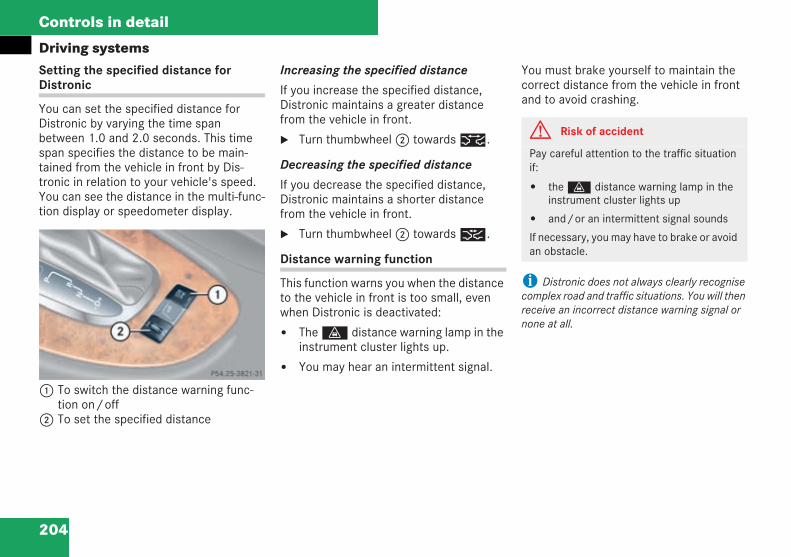
204
Controls in detail
Driving systemsSetting the specified distance forDistronic
You can set the specified distance forDistronic by varying the time spanbetween 1.0 and 2.0 seconds. This timespan specifies the distance to be main-tained from the vehicle in front by Dis-tronic in relation to your vehicle's speed.You can see the distance in the multi-func-tion display or speedometer display.
1 To switch the distance warning func-tion on/off
2 To set the specified distance
Increasing the specified distance
If you increase the specified distance,Distronic maintains a greater distancefrom the vehicle in front.
Turn thumbwheel2 towards¯.
Decreasing the specified distance
If you decrease the specified distance,Distronic maintains a shorter distancefrom the vehicle in front.
Turn thumbwheel2 towards®.
Distance warning function
This function warns you when the distanceto the vehicle in front is too small, evenwhen Distronic is deactivated:
The l distance warning lamp in theinstrument cluster lights up.
You may hear an intermittent signal.
You must brake yourself to maintain thecorrect distance from the vehicle in frontand to avoid crashing.
i Distronic does not always clearly recognisecomplex road and traffic situations. You will thenreceive an incorrect distance warning signal ornone at all.
P54.25-3821-31 209
G Risk of accident
Pay careful attention to the traffic situationif:
the l distance warning lamp in theinstrument cluster lights up
and/or an intermittent signal sounds
If necessary, you may have to brake or avoidan obstacle.
209en_d2.boo Seite 204 Dienstag, 25. Mai 2004 7:26 19
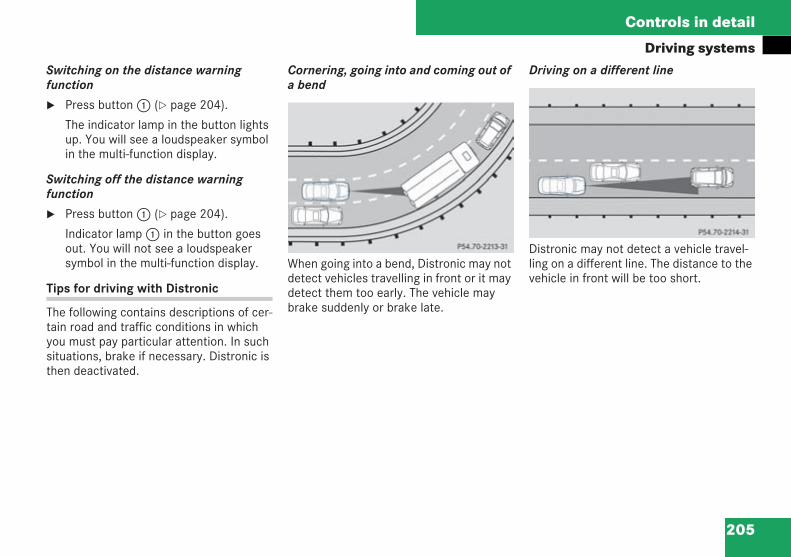
205
Controls in detail
Driving systemsSwitching on the distance warningfunction
Press button1 ( page 204).
The indicator lamp in the button lightsup. You will see a loudspeaker symbolin the multi-function display.
Switching off the distance warningfunction
Press button1 ( page 204).
Indicator lamp1 in the button goesout. You will not see a loudspeakersymbol in the multi-function display.
Tips for driving with Distronic
The following contains descriptions of cer-tain road and traffic conditions in whichyou must pay particular attention. In suchsituations, brake if necessary. Distronic isthen deactivated.
Cornering, going into and coming out ofa bend
When going into a bend, Distronic may notdetect vehicles travelling in front or it maydetect them too early. The vehicle maybrake suddenly or brake late.
Driving on a different line
Distronic may not detect a vehicle travel-ling on a different line. The distance to thevehicle in front will be too short.
P54.70-2213-31P54.70-2214-31
209en_d2.boo Seite 205 Dienstag, 25. Mai 2004 7:26 19
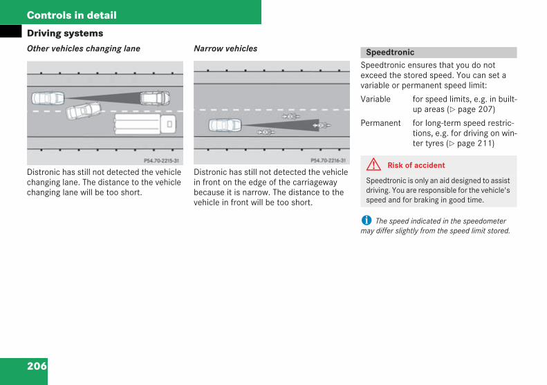
206
Controls in detail
Driving systemsOther vehicles changing lane
Distronic has still not detected the vehiclechanging lane. The distance to the vehiclechanging lane will be too short.
Narrow vehicles
Distronic has still not detected the vehiclein front on the edge of the carriagewaybecause it is narrow. The distance to thevehicle in front will be too short.
Speedtronic ensures that you do notexceed the stored speed. You can set avariable or permanent speed limit:
Variable for speed limits, e.g. in built-up areas ( page 207)
Permanent for long-term speed restric-tions, e.g. for driving on win-ter tyres ( page 211)
i The speed indicated in the speedometermay differ slightly from the speed limit stored.
P54.70-2215-31 P54.70-2216-31
Speedtronic
G Risk of accident
Speedtronic is only an aid designed to assistdriving. You are responsible for the vehicle'sspeed and for braking in good time.
209en_d2.boo Seite 206 Dienstag, 25. Mai 2004 7:26 19
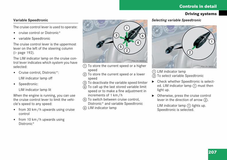
207
Controls in detail
Driving systemsVariable Speedtronic
The cruise control lever is used to operate:
cruise control or Distronic*
variable Speedtronic
The cruise control lever is the uppermostlever on the left of the steering column( page 192).
The LIM indicator lamp on the cruise con-trol lever indicates which system you haveselected:
Cruise control, Distronic*:
LIM indicator lamp off
Speedtronic:
LIM indicator lamp lit
When the engine is running, you can usethe cruise control lever to limit the vehi-cle's speed to any speed:
from 30 km/h upwards using cruisecontrol
from 10 km/h upwards usingDistronic*
1 To store the current speed or a higherspeed
2 To store the current speed or a lowerspeed
3 To deactivate the variable speed limiter4 To call up the last stored variable limit
speed or to make a fine adjustment inincrements of 1 km/h
5 To switch between cruise control,Distronic* and variable Speedtronic
6 LIM indicator lamp
Selecting variable Speedtronic
1 LIM indicator lamp2 To select variable Speedtronic
Check whether Speedtronic is select-ed. LIM indicator lamp1 must thenlight up.
Otherwise, press the cruise controllever in the direction of arrow2.
LIM indicator lamp1 lights up.Speedtronic is selected.
P54.25-3820-31
209en_d2.boo Seite 207 Dienstag, 25. Mai 2004 7:26 19
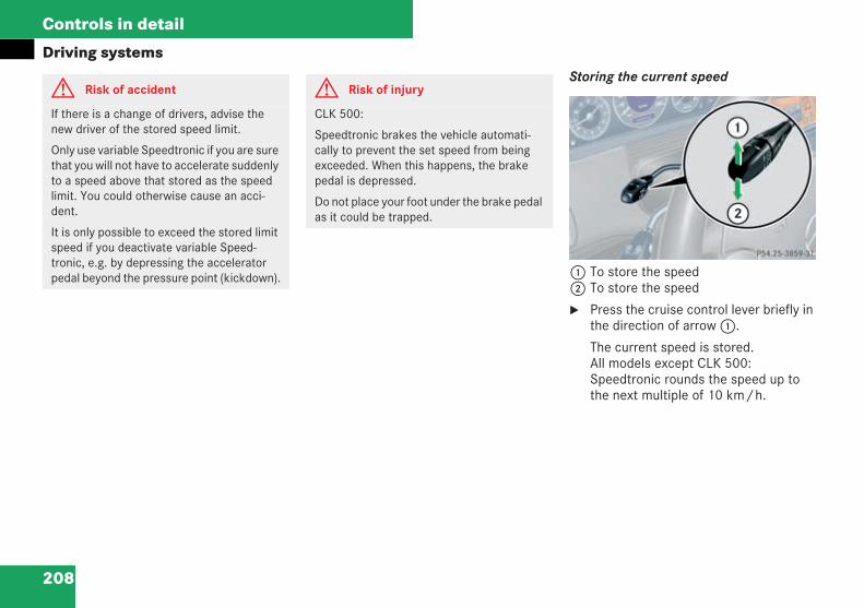
208
Controls in detail
Driving systemsStoring the current speed
1 To store the speed2 To store the speed
Press the cruise control lever briefly inthe direction of arrow1.
The current speed is stored.All models except CLK 500:Speedtronic rounds the speed up tothe next multiple of 10 km/h.
G Risk of accident
If there is a change of drivers, advise thenew driver of the stored speed limit.
Only use variable Speedtronic if you are surethat you will not have to accelerate suddenlyto a speed above that stored as the speedlimit. You could otherwise cause an acci-dent.
It is only possible to exceed the stored limitspeed if you deactivate variable Speed-tronic, e.g. by depressing the acceleratorpedal beyond the pressure point (kickdown).
G Risk of injury
CLK 500:
Speedtronic brakes the vehicle automati-cally to prevent the set speed from beingexceeded. When this happens, the brakepedal is depressed.
Do not place your foot under the brake pedalas it could be trapped.
209en_d2.boo Seite 208 Dienstag, 25. Mai 2004 7:26 19
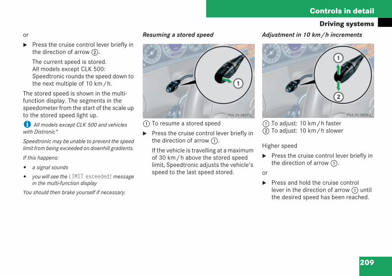
209
Controls in detail
Driving systemsor
Press the cruise control lever briefly inthe direction of arrow2.
The current speed is stored.All models except CLK 500:Speedtronic rounds the speed down tothe next multiple of 10 km/h.
The stored speed is shown in the multi-function display. The segments in thespeedometer from the start of the scale upto the stored speed light up.
i All models except CLK 500 and vehicleswith Distronic*
Speedtronic may be unable to prevent the speedlimit from being exceeded on downhill gradients.
If this happens:
a signal sounds
you will see the LIMIT exceeded!messagein the multi-function display
You should then brake yourself if necessary.
Resuming a stored speed
1 To resume a stored speed
Press the cruise control lever briefly inthe direction of arrow1.
If the vehicle is travelling at a maximumof 30 km/h above the stored speedlimit, Speedtronic adjusts the vehicle'sspeed to the last speed stored.
Adjustment in 10 km/h increments
1 To adjust: 10 km/h faster2 To adjust: 10 km/h slower
Higher speed
Press the cruise control lever briefly inthe direction of arrow1.
or
Press and hold the cruise controllever in the direction of arrow1 untilthe desired speed has been reached.
209en_d2.boo Seite 209 Dienstag, 25. Mai 2004 7:26 19
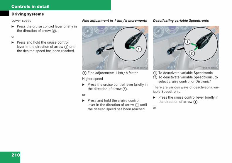
210
Controls in detail
Driving systemsLower speed
Press the cruise control lever briefly inthe direction of arrow2.
or
Press and hold the cruise controllever in the direction of arrow2 untilthe desired speed has been reached.
Fine adjustment in 1 km/h increments
1 Fine adjustment: 1 km/h faster
Higher speed
Press the cruise control lever briefly inthe direction of arrow1.
or
Press and hold the cruise controllever in the direction of arrow1 untilthe desired speed has been reached.
Deactivating variable Speedtronic
1 To deactivate variable Speedtronic2 To deactivate variable Speedtronic, to
select cruise control or Distronic*
There are various ways of deactivating var-iable Speedtronic:
Press the cruise control lever briefly inthe direction of arrow1.
or
209en_d2.boo Seite 210 Dienstag, 25. Mai 2004 7:26 19
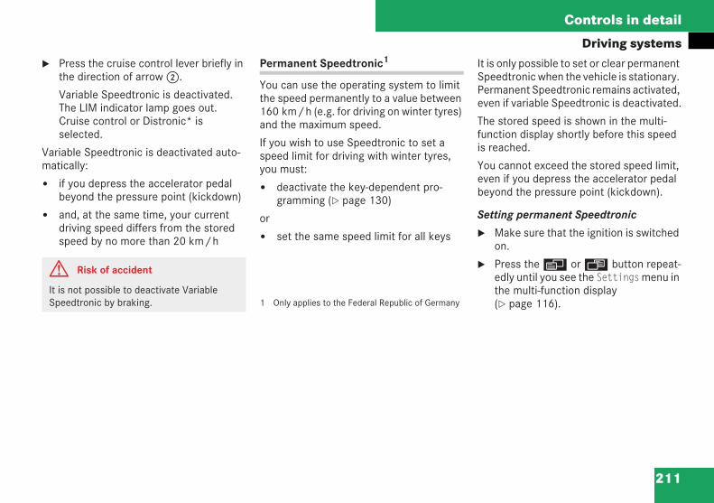
211
Controls in detail
Driving systemsPress the cruise control lever briefly inthe direction of arrow2.
Variable Speedtronic is deactivated.The LIM indicator lamp goes out.Cruise control or Distronic* isselected.
Variable Speedtronic is deactivated auto-matically:
if you depress the accelerator pedalbeyond the pressure point (kickdown)
and, at the same time, your currentdriving speed differs from the storedspeed by no more than 20 km/h
Permanent Speedtronic1
You can use the operating system to limitthe speed permanently to a value between160 km/h (e.g. for driving on winter tyres)and the maximum speed.
If you wish to use Speedtronic to set aspeed limit for driving with winter tyres,you must:
deactivate the key-dependent pro-gramming ( page 130)
or
set the same speed limit for all keys
1 Only applies to the Federal Republic of Germany
It is only possible to set or clear permanentSpeedtronic when the vehicle is stationary.Permanent Speedtronic remains activated,even if variable Speedtronic is deactivated.
The stored speed is shown in the multi-function display shortly before this speedis reached.
You cannot exceed the stored speed limit,even if you depress the accelerator pedalbeyond the pressure point (kickdown).
Setting permanent Speedtronic
Make sure that the ignition is switchedon.
Press theè orÿ button repeat-edly until you see the Settingsmenu inthe multi-function display( page 116).
G Risk of accident
It is not possible to deactivate VariableSpeedtronic by braking.
209en_d2.boo Seite 211 Dienstag, 25. Mai 2004 7:26 19
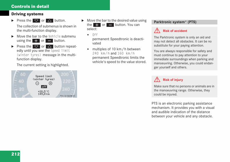
212
Controls in detail
Driving systemsPress thek orj button.
The collection of submenus is shown inthe multi-function display.
Move the bar to the Vehicle submenuusing theæ orç button.
Press thek orj button repeat-edly until you see the Speed limit(winter tyres) message in the multi-function display.
The current setting is highlighted.
Move the bar to the desired value usingtheæ orç button. You canselect:
Offpermanent Speedtronic is deacti-vated
multiples of 10 km/h between240 km/h and 160 km/hpermanent Speedtronic limits thevehicle's speed to the value stored.
PTS is an electronic parking assistancemechanism. It provides you with a visualand audible indication of the distancebetween your vehicle and any obstacle.
P54.30-5221-31
Parktronic system* (PTS)
G Risk of accident
The Parktronic system is only an aid andmay not detect all obstacles. It can be nosubstitute for your paying attention.
You are always responsible for safety andmust continue to pay attention to yourimmediate surroundings when parking andmanoeuvring. Otherwise, you could endan-ger yourself and others.
G Risk of injury
Make sure that no persons or animals are inthe manoeuvring range. Otherwise, theycould be injured.
209en_d2.boo Seite 212 Dienstag, 25. Mai 2004 7:26 19
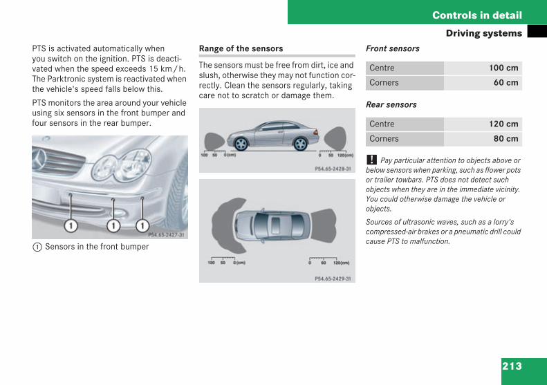
213
Controls in detail
Driving systemsPTS is activated automatically whenyou switch on the ignition. PTS is deacti-vated when the speed exceeds 15 km/h.The Parktronic system is reactivated whenthe vehicle's speed falls below this.
PTS monitors the area around your vehicleusing six sensors in the front bumper andfour sensors in the rear bumper.
1 Sensors in the front bumper
Range of the sensors
The sensors must be free from dirt, ice andslush, otherwise they may not function cor-rectly. Clean the sensors regularly, takingcare not to scratch or damage them.
Front sensors
Rear sensors
! Pay particular attention to objects above orbelow sensors when parking, such as flower potsor trailer towbars. PTS does not detect suchobjects when they are in the immediate vicinity.You could otherwise damage the vehicle orobjects.
Sources of ultrasonic waves, such as a lorry'scompressed-air brakes or a pneumatic drill couldcause PTS to malfunction.
P54.65-2427-31
P54.65-2428-31
P54.65-2429-31
Centre 100 cm
Corners 60 cm
Centre 120 cm
Corners 80 cm
209en_d2.boo Seite 213 Dienstag, 25. Mai 2004 7:26 19
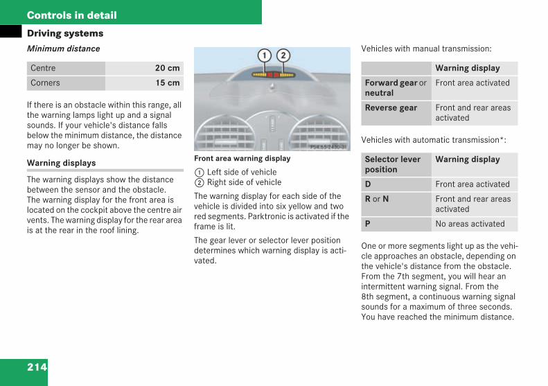
214
Controls in detail
Driving systemsMinimum distance
If there is an obstacle within this range, allthe warning lamps light up and a signalsounds. If your vehicle's distance fallsbelow the minimum distance, the distancemay no longer be shown.
Warning displays
The warning displays show the distancebetween the sensor and the obstacle.The warning display for the front area islocated on the cockpit above the centre airvents. The warning display for the rear areais at the rear in the roof lining.
Front area warning display
1 Left side of vehicle2 Right side of vehicle
The warning display for each side of thevehicle is divided into six yellow and twored segments. Parktronic is activated if theframe is lit.
The gear lever or selector lever positiondetermines which warning display is acti-vated.
Vehicles with manual transmission:
Vehicles with automatic transmission*:
One or more segments light up as the vehi-cle approaches an obstacle, depending onthe vehicle's distance from the obstacle.From the 7th segment, you will hear anintermittent warning signal. From the8th segment, a continuous warning signalsounds for a maximum of three seconds.You have reached the minimum distance.
Centre 20 cm
Corners 15 cm
P54.65-2430-31 Warning display
Forward gear orneutral
Front area activated
Reverse gear Front and rear areasactivated
Selector leverposition
Warning display
D Front area activated
R or N Front and rear areasactivated
P No areas activated
209en_d2.boo Seite 214 Dienstag, 25. Mai 2004 7:26 19
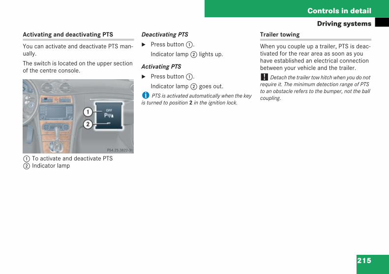
215
Controls in detail
Driving systemsActivating and deactivating PTS
You can activate and deactivate PTS man-ually.
The switch is located on the upper sectionof the centre console.
1 To activate and deactivate PTS2 Indicator lamp
Deactivating PTS
Press button1.
Indicator lamp2 lights up.
Activating PTS
Press button1.
Indicator lamp2 goes out.
i PTS is activated automatically when the keyis turned to position 2 in the ignition lock.
Trailer towing
When you couple up a trailer, PTS is deac-tivated for the rear area as soon as youhave established an electrical connectionbetween your vehicle and the trailer.
! Detach the trailer tow hitch when you do notrequire it. The minimum detection range of PTSto an obstacle refers to the bumper, not the ballcoupling.P54.25-3822-31
209en_d2.boo Seite 215 Dienstag, 25. Mai 2004 7:26 19
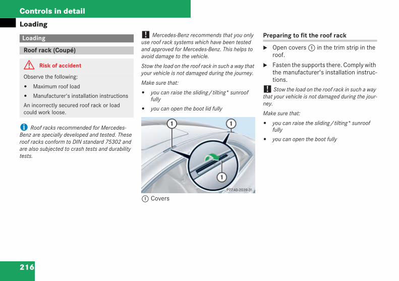
216
Controls in detail
Loading
i Roof racks recommended for Mercedes-Benz are specially developed and tested. Theseroof racks conform to DIN standard 75302 andare also subjected to crash tests and durabilitytests.
! Mercedes-Benz recommends that you onlyuse roof rack systems which have been testedand approved for Mercedes-Benz. This helps toavoid damage to the vehicle.
Stow the load on the roof rack in such a way thatyour vehicle is not damaged during the journey.
Make sure that:
you can raise the sliding/tilting* sunrooffully
you can open the boot lid fully
1 Covers
Preparing to fit the roof rack
Open covers1 in the trim strip in theroof.
Fasten the supports there. Comply withthe manufacturer's installation instruc-tions.
! Stow the load on the roof rack in such a waythat your vehicle is not damaged during the jour-ney.
Make sure that:
you can raise the sliding/tilting* sunrooffully
you can open the boot fully
Loading
Roof rack (Coupé)
G Risk of accident
Observe the following:
Maximum roof load
Manufacturer's installation instructions
An incorrectly secured roof rack or loadcould work loose.
P77.40-2039-31
209en_d2.boo Seite 216 Dienstag, 25. Mai 2004 7:26 19
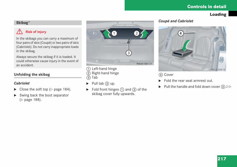
217
Controls in detail
Loading
Unfolding the skibag
Cabriolet
Close the soft top ( page 184).
Swing back the boot separator( page 188).
1 Left-hand hinge2 Right-hand hinge3 Tab
Pull tab3 up.
Fold front hinges1 and2 of theskibag cover fully upwards.
Coupé and Cabriolet
4 Cover
Fold the rear seat armrest out.
Pull the handle and fold down cover4.
Skibag*
G Risk of injury
In the skibags you can carry a maximum offour pairs of skis (Coupé) or two pairs of skis(Cabriolet). Do not carry inappropriate loadsin the skibag.
Always secure the skibag if it is loaded. Itcould otherwise cause injury in the event ofan accident.
P 68.00-3001-31 P 91.12-2461-31 neu
209en_d2.boo Seite 217 Dienstag, 25. Mai 2004 7:26 19
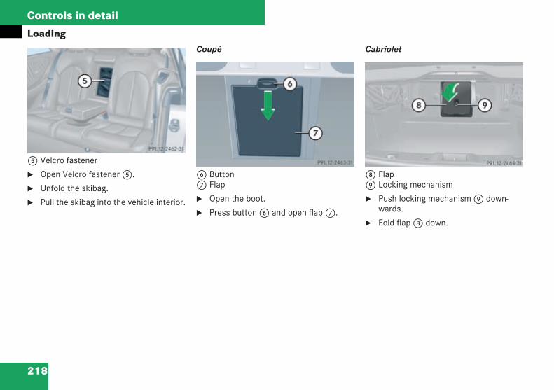
218
Controls in detail
Loading
5 Velcro fastener
Open Velcro fastener5.
Unfold the skibag.
Pull the skibag into the vehicle interior.
Coupé
6 Button7 Flap
Open the boot.
Press button6 and open flap7.
Cabriolet
8 Flap9 Locking mechanism
Push locking mechanism9 down-wards.
Fold flap8 down.
P 91.12-2462-31 neu
P 91.12-2463-31 neu P 91.12-2464-31
209en_d2.boo Seite 218 Dienstag, 25. Mai 2004 7:26 19
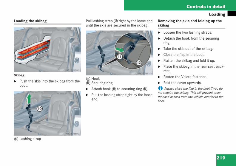
219
Controls in detail
LoadingLoading the skibag
Skibag
Push the skis into the skibag from theboot.
a Lashing strap
Pull lashing strapa tight by the loose enduntil the skis are secured in the skibag.
b Hookc Securing ring
Attach hookb to securing ringc.
Pull the lashing strap tight by the looseend.
Removing the skis and folding up theskibag
Loosen the two lashing straps.
Detach the hook from the securingring.
Take the skis out of the skibag.
Close the flap in the boot.
Flatten the skibag and fold it up.
Place the skibag in the rear seat back-rest.
Fasten the Velcro fastener.
Fold the cover upwards.
i Always close the flap in the boot if you donot require the skibag. This will prevent unau-thorised access from the vehicle interior to theboot.
P91.12-2659-31
P91.12-2660-31
P91.12-2661-31
209en_d2.boo Seite 219 Dienstag, 25. Mai 2004 7:26 19
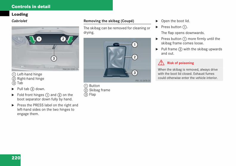
220
Controls in detail
LoadingCabriolet
1 Left-hand hinge2 Right-hand hinge3 Tab
Pull tab3 down.
Fold front hinges1 and2 on theboot separator down fully by hand.
Press the PRESS label on the right andleft-hand sides on the two hinges toengage them.
Removing the skibag (Coupé)
The skibag can be removed for cleaning ordrying.
1 Button2 Skibag frame3 Flap
Open the boot lid.
Press button1.
The flap opens downwards.
Press button1 more firmly until theskibag frame comes loose.
Pull frame2 with the skibag upwardsand out.
P 68.00-3282-31 neu
P91.12-2476-31
G Risk of poisoning
When the skibag is removed, always drivewith the boot lid closed. Exhaust fumescould otherwise enter the vehicle interior.
209en_d2.boo Seite 220 Dienstag, 25. Mai 2004 7:26 19
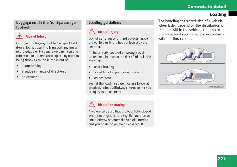
221
Controls in detail
LoadingThe handling characteristics of a vehiclewhen laden depend on the distribution ofthe load within the vehicle. You shouldtherefore load your vehicle in accordancewith the illustrations.
Luggage net in the front-passengerfootwell
G Risk of injury
Only use the luggage net to transport lightitems. Do not use it to transport any heavy,sharp-edged or breakable objects. You andothers could otherwise be injured by objectsbeing thrown around in the event of:
sharp braking
a sudden change of direction or
an accident
Loading guidelines
G Risk of injury
Do not carry heavy or hard objects insidethe vehicle or in the boot unless they aresecured.
An incorrectly secured or wrongly posi-tioned load increases the risk of injury in theevent of:
sharp braking
a sudden change of direction or
an accident
Even if the loading guidelines are followedprecisely, a load will always increase the riskof injury in an accident.
G Risk of poisoning
Always make sure that the boot lid is closedwhen the engine is running. Exhaust fumescould otherwise enter the vehicle interiorand you could be poisoned as a result.
P 00.01-2133-31
209en_d2.boo Seite 221 Dienstag, 25. Mai 2004 7:26 19
222
Controls in detail
Loading
i Observe the following notes on loading thevehicle and transporting a load in the vehicle:
Taking passengers in the vehicle as well asthe vehicle's load into account, do notexceed the vehicle's maximum permissiblegross vehicle weight or axle loads.
Slide a heavy load as far towards the front ofthe vehicle as possible and stow it as fardown in the boot as possible.
The load should not be higher than the top ofthe backrests.
Always lean the load against the front or rearbackrests if the load is to be carried in thevehicle interior.
When possible, always transport the loadbehind seats which are not occupied.
Secure the load with sufficiently strong andwear-resistant lashing material. Pad sharpedges for protection.
Lashing material can be obtained at a qualifiedspecialist workshop, e.g. at a Mercedes-BenzService Centre.
In the boot there are four lashing eyelets.
Secure the load to the lashing eyelets.
Please note:
Do not use elastic straps or nets tosecure a load, as these are onlyintended as an anti-slip protection forlight loads.
If you use securing straps, only use astrap with a:
permissible tensile forceFperm. = 600 daN
relative elongation of about 7%
Do not route lashing material oversharp corners or rough surfaces.
Pad sharp edges for protection.
Spread the load evenly between thelashing points.
Use all the lashing eyelets if possible.
Do not overload the lashing eyeletswhen using tensioners.
Read and observe the instructionsissued with the lashing material used.
Securing a load (Coupé)
G Risk of injury
Spread the load evenly between the lashingeyelets.Observe the loading guidelines( page 221).
209en_d2.boo Seite 222 Dienstag, 25. Mai 2004 7:26 19
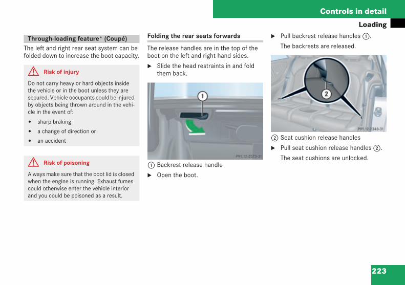
223
Controls in detail
Loading
The left and right rear seat system can befolded down to increase the boot capacity.
Folding the rear seats forwards
The release handles are in the top of theboot on the left and right-hand sides.
Slide the head restraints in and foldthem back.
1 Backrest release handle
Open the boot.
Pull backrest release handles1.
The backrests are released.
2 Seat cushion release handles
Pull seat cushion release handles2.
The seat cushions are unlocked.
Through-loading feature* (Coupé)
G Risk of injury
Do not carry heavy or hard objects insidethe vehicle or in the boot unless they aresecured. Vehicle occupants could be injuredby objects being thrown around in the vehi-cle in the event of:
sharp braking
a change of direction or
an accident
G Risk of poisoning
Always make sure that the boot lid is closedwhen the engine is running. Exhaust fumescould otherwise enter the vehicle interiorand you could be poisoned as a result.
P 91.12-2573-31 neu
P 91.12-2343-31 neu
209en_d2.boo Seite 223 Dienstag, 25. Mai 2004 7:26 19
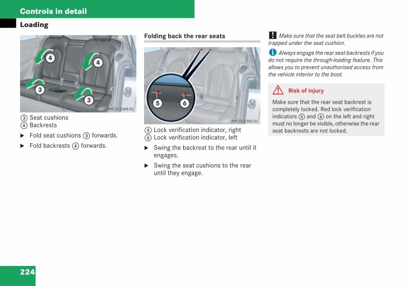
224
Controls in detail
Loading
3 Seat cushions4 Backrests
Fold seat cushions3 forwards.
Fold backrests4 forwards.
Folding back the rear seats
5 Lock verification indicator, right6 Lock verification indicator, left
Swing the backrest to the rear until itengages.
Swing the seat cushions to the rearuntil they engage.
! Make sure that the seat belt buckles are nottrapped under the seat cushion.
i Always engage the rear seat backrests if youdo not require the through-loading feature. Thisallows you to prevent unauthorised access fromthe vehicle interior to the boot.
P 91.12-2349-31 neu
P 91.12-2350-31neu
G Risk of injury
Make sure that the rear seat backrest iscompletely locked. Red lock verificationindicators5 and6 on the left and rightmust no longer be visible, otherwise the rearseat backrests are not locked.
209en_d2.boo Seite 224 Dienstag, 25. Mai 2004 7:26 19
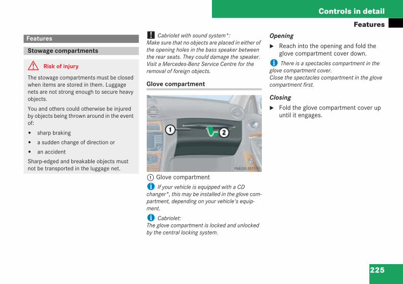
225
Controls in detail
Features! Cabriolet with sound system*:Make sure that no objects are placed in either ofthe opening holes in the bass speaker betweenthe rear seats. They could damage the speaker.Visit a Mercedes-Benz Service Centre for theremoval of foreign objects.
Glove compartment
1 Glove compartmenti If your vehicle is equipped with a CDchanger*, this may be installed in the glove com-partment, depending on your vehicle's equip-ment.
i Cabriolet:The glove compartment is locked and unlockedby the central locking system.
Opening
Reach into the opening and fold theglove compartment cover down.
i There is a spectacles compartment in theglove compartment cover.Close the spectacles compartment in the glovecompartment first.
Closing
Fold the glove compartment cover upuntil it engages.
Features
Stowage compartments
G Risk of injury
The stowage compartments must be closedwhen items are stored in them. Luggagenets are not strong enough to secure heavyobjects.
You and others could otherwise be injuredby objects being thrown around in the eventof:
sharp braking
a sudden change of direction or
an accident
Sharp-edged and breakable objects mustnot be transported in the luggage net.
P 68.00-3571-31 neu
209en_d2.boo Seite 225 Dienstag, 25. Mai 2004 7:26 19
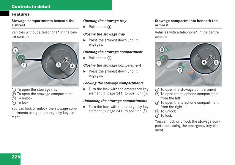
226
Controls in detail
FeaturesStowage compartments beneath thearmrest
Vehicles without a telephone* in the cen-tre console
1 To open the stowage tray2 To open the stowage compartment3 To unlock4 To lock
You can lock or unlock the stowage com-partments using the emergency key ele-ment.
Opening the stowage tray
Pull handle1.
Closing the stowage tray
Press the armrest down until itengages.
Opening the stowage compartment
Pull handle2.
Closing the stowage compartment
Press the armrest down until itengages.
Locking the stowage compartments
Turn the lock with the emergency keyelement ( page 341) to position4.
Unlocking the stowage compartments
Turn the lock with the emergency keyelement ( page 341) to position3.
Stowage compartments beneath thearmrest
Vehicles with a telephone* in the centreconsole
1 To open the stowage compartment2 To open the telephone compartment
from the left3 To open the telephone compartment
from the right4 To unlock5 To lock
You can lock or unlock the stowage com-partments using the emergency key ele-ment.
P 68.00-2911-31 neu P 68.00-2914-31 neu
209en_d2.boo Seite 226 Dienstag, 25. Mai 2004 7:26 19
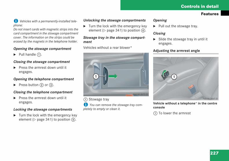
227
Controls in detail
Features
i Vehicles with a permanently-installed tele-phone:Do not insert cards with magnetic strips into thecard compartment in the stowage compartmentcover. The information on the strips could beerased by the magnets in the telephone holder.
Opening the stowage compartment
Pull handle1.
Closing the stowage compartment
Press the armrest down until itengages.
Opening the telephone compartment
Press button2 or3.
Closing the telephone compartment
Press the armrest down until itengages.
Locking the stowage compartments
Turn the lock with the emergency keyelement ( page 341) to position5.
Unlocking the stowage compartments
Turn the lock with the emergency keyelement ( page 341) to position4.
Stowage tray in the stowage compart-ment
Vehicles without a rear blower*
1 Stowage trayi You can remove the stowage tray com-pletely to empty or clean it.
Opening
Pull out the stowage tray.
Closing
Slide the stowage tray in until itengages.
Adjusting the armrest angle
Vehicle without a telephone* in the centreconsole
1 To lower the armrest
P 68.00-3572-31 neuP 68.00-3067-31 neu
209en_d2.boo Seite 227 Dienstag, 25. Mai 2004 7:26 19
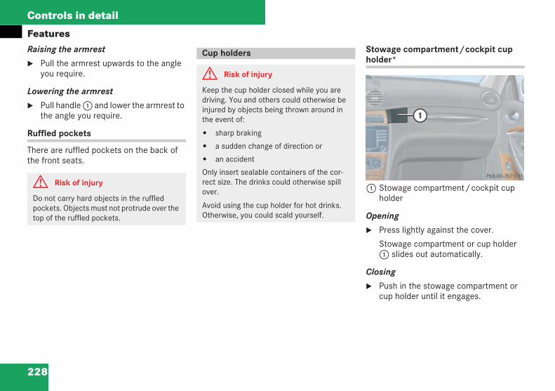
228
Controls in detail
FeaturesRaising the armrest
Pull the armrest upwards to the angleyou require.
Lowering the armrest
Pull handle1 and lower the armrest tothe angle you require.
Ruffled pockets
There are ruffled pockets on the back ofthe front seats.
Stowage compartment/cockpit cupholder*
1 Stowage compartment/cockpit cupholder
Opening
Press lightly against the cover.
Stowage compartment or cup holder1 slides out automatically.
Closing
Push in the stowage compartment orcup holder until it engages.
G Risk of injury
Do not carry hard objects in the ruffledpockets. Objects must not protrude over thetop of the ruffled pockets.
Cup holders
G Risk of injury
Keep the cup holder closed while you aredriving. You and others could otherwise beinjured by objects being thrown around inthe event of:
sharp braking
a sudden change of direction or
an accident
Only insert sealable containers of the cor-rect size. The drinks could otherwise spillover.
Avoid using the cup holder for hot drinks.Otherwise, you could scald yourself.
P 68.00-3573-31 neu
209en_d2.boo Seite 228 Dienstag, 25. Mai 2004 7:26 19
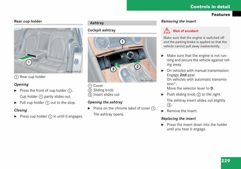
229
Controls in detail
FeaturesRear cup holder
1 Rear cup holder
Opening
Press the front of cup holder1.
Cup holder1 partly slides out.
Pull cup holder1 out to the stop.
Closing
Press cup holder1 in until it engages.
Cockpit ashtray
1 Cover2 Sliding knob3 Insert slides out
Opening the ashtray
Press on the chrome label of cover1.
The ashtray opens.
Removing the insert
Make sure that the engine is not run-ning and secure the vehicle against roll-ing away.
On vehicles with manual transmission:Engage 2nd gear.On vehicles with automatic transmis-sion*:Move the selector lever to D.
Push sliding knob2 to the right.
The ashtray insert slides out slightly3.
Remove the insert.
Replacing the insert
Press the insert down into the holderuntil you hear it engage.
P 68.00-2918-31 neu
Ashtray
P 68.00-3374-31 neu
G Risk of accident
Make sure that the engine is switched offand the parking brake is applied so that thevehicle cannot pull away inadvertently.
209en_d2.boo Seite 229 Dienstag, 25. Mai 2004 7:26 19
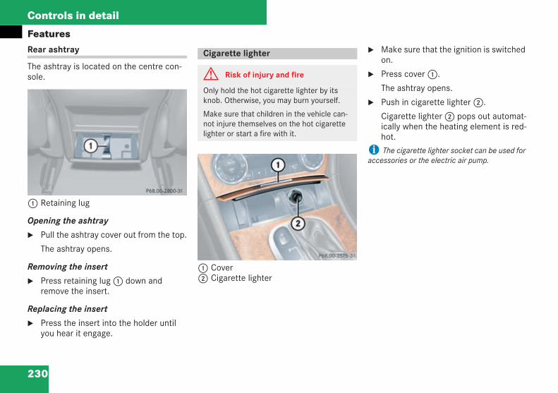
230
Controls in detail
FeaturesRear ashtray
The ashtray is located on the centre con-sole.
1 Retaining lug
Opening the ashtray
Pull the ashtray cover out from the top.
The ashtray opens.
Removing the insert
Press retaining lug1 down andremove the insert.
Replacing the insert
Press the insert into the holder untilyou hear it engage.
1 Cover2 Cigarette lighter
Make sure that the ignition is switchedon.
Press cover1.
The ashtray opens.
Push in cigarette lighter2.
Cigarette lighter2 pops out automat-ically when the heating element is red-hot.
i The cigarette lighter socket can be used foraccessories or the electric air pump.
P 68.00-2800-31 neu
Cigarette lighter
G Risk of injury and fire
Only hold the hot cigarette lighter by itsknob. Otherwise, you may burn yourself.
Make sure that children in the vehicle can-not injure themselves on the hot cigarettelighter or start a fire with it.
P 68.00-3575-31 neu
209en_d2.boo Seite 230 Dienstag, 25. Mai 2004 7:26 19
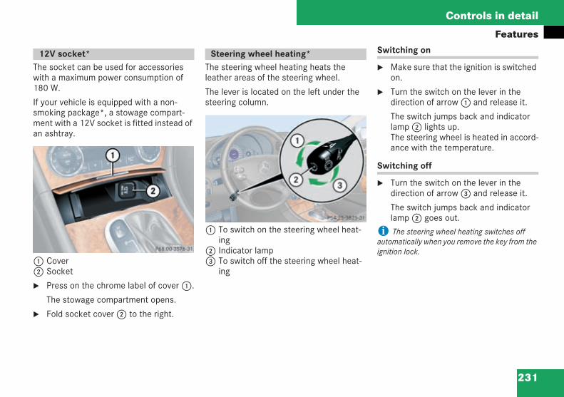
231
Controls in detail
Features
The socket can be used for accessorieswith a maximum power consumption of180 W.
If your vehicle is equipped with a non-smoking package*, a stowage compart-ment with a 12V socket is fitted instead ofan ashtray.
1 Cover2 Socket
Press on the chrome label of cover1.
The stowage compartment opens.
Fold socket cover2 to the right.
The steering wheel heating heats theleather areas of the steering wheel.
The lever is located on the left under thesteering column.
1 To switch on the steering wheel heat-ing
2 Indicator lamp3 To switch off the steering wheel heat-
ing
Switching on
Make sure that the ignition is switchedon.
Turn the switch on the lever in thedirection of arrow1 and release it.
The switch jumps back and indicatorlamp2 lights up.The steering wheel is heated in accord-ance with the temperature.
Switching off
Turn the switch on the lever in thedirection of arrow3 and release it.
The switch jumps back and indicatorlamp2 goes out.
i The steering wheel heating switches offautomatically when you remove the key from theignition lock.
12V socket*
P P68.00-3576-31 neu
Steering wheel heating*
P54.25-3825-31_A
209en_d2.boo Seite 231 Dienstag, 25. Mai 2004 7:26 19
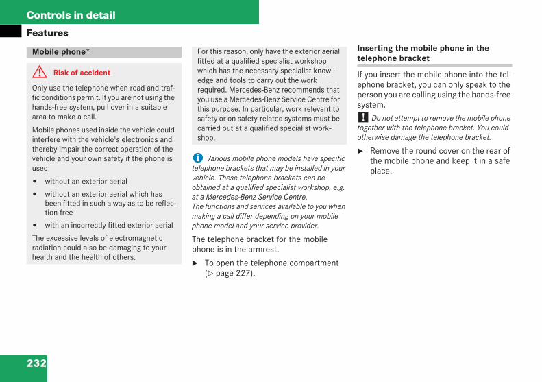
232
Controls in detail
Features
i Various mobile phone models have specifictelephone brackets that may be installed in yourvehicle. These telephone brackets can beobtained at a qualified specialist workshop, e.g.at a Mercedes-Benz Service Centre.The functions and services available to you whenmaking a call differ depending on your mobilephone model and your service provider.
The telephone bracket for the mobilephone is in the armrest.
To open the telephone compartment( page 227).
Inserting the mobile phone in thetelephone bracket
If you insert the mobile phone into the tel-ephone bracket, you can only speak to theperson you are calling using the hands-freesystem.
! Do not attempt to remove the mobile phonetogether with the telephone bracket. You couldotherwise damage the telephone bracket.
Remove the round cover on the rear ofthe mobile phone and keep it in a safeplace.
Mobile phone*
G Risk of accident
Only use the telephone when road and traf-fic conditions permit. If you are not using thehands-free system, pull over in a suitablearea to make a call.
Mobile phones used inside the vehicle couldinterfere with the vehicle's electronics andthereby impair the correct operation of thevehicle and your own safety if the phone isused:
without an exterior aerial
without an exterior aerial which hasbeen fitted in such a way as to be reflec-tion-free
with an incorrectly fitted exterior aerial
The excessive levels of electromagneticradiation could also be damaging to yourhealth and the health of others.
For this reason, only have the exterior aerialfitted at a qualified specialist workshopwhich has the necessary specialist knowl-edge and tools to carry out the workrequired. Mercedes-Benz recommends thatyou use a Mercedes-Benz Service Centre forthis purpose. In particular, work relevant tosafety or on safety-related systems must becarried out at a qualified specialist work-shop.
209en_d2.boo Seite 232 Dienstag, 25. Mai 2004 7:26 19
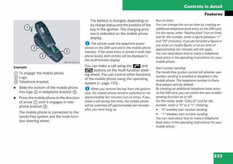
233
Controls in detail
Features
Example
1 To engage the mobile phone2 Lugs3 Telephone bracket
Slide the bottom of the mobile phoneinto lugs2 in telephone bracket3.
Press the mobile phone in the directionof arrow1 until it engages in tele-phone bracket3.
The mobile phone is connected to thehands-free system and the multi-func-tion steering wheel.
The battery is charged, depending onits charge status and the position of thekey in the ignition. The charging proc-ess is indicated on the mobile phonedisplay.
i The vehicle reads the telephone booksstored on the SIM card and in the mobile phonememory. If the same entry is stored in both tele-phone books, both entries will be displayed inthe multi-function display.
You can make a call using the s andt buttons on the multi-function steer-ing wheel. You can control other functionsof the mobile phone using the operatingsystem ( page 133).
i When you remove the key from the ignitionlock, the mobile phone remains switched on forapproximately ten minutes (run-on time). If youmake a call during this time, the mobile phonewill be switched off approximately ten minutesafter you have hung up.
Run-on time:You can change the run-on time by creating anadditional telephone book entry on the SIM card.For the name, enter "Nachlaufzeit" (run-on time)and for the number, enter a figure between "1"and "30" (minutes). If you do not enter a figure oryou enter an invalid figure, a run-on time ofapproximately ten minutes will still apply.You can read about how to make a telephonebook entry in the operating instructions for yourmobile phone.
Own number sending:The hands-free system cannot tell whether ownnumber sending is enabled or disabled in themobile phone. The telephone number is there-fore always sent by default.By creating an additional telephone book entryon the SIM card, you can switch the own numbersending function on or off:For the name, enter "CALLID" and for thenumber, enter a "0" or a "1". Entering:
"0" enables own number sending"1" disables own number sending
You can read about how to make a telephonebook entry in the operating instructions for yourmobile phone.
P82.70-5034-31_neu_neutral
209en_d2.boo Seite 233 Dienstag, 25. Mai 2004 7:26 19
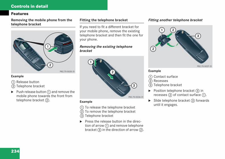
234
Controls in detail
FeaturesRemoving the mobile phone from thetelephone bracket
Example
1 Release button2 Telephone bracket
Push release button1 and remove themobile phone towards the front fromtelephone bracket2.
Fitting the telephone bracket
If you need to fit a different bracket foryour mobile phone, remove the existingtelephone bracket and then fit the one foryour phone.
Removing the existing telephonebracket
Example
1 To release the telephone bracket2 To remove the telephone bracket3 Telephone bracket
Press the release button in the direc-tion of arrow1 and remove telephonebracket3 in the direction of arrow2.
Fitting another telephone bracket
Example
1 Contact surface2 Recesses3 Telephone bracket
Position telephone bracket3 inrecesses2 of contact surface1.
Slide telephone bracket3 forwardsuntil it engages.
P82.70-5035-31_neu_neutral
P82.70-5036-31_G1
P82.70-5037-31_G1
209en_d2.boo Seite 234 Dienstag, 25. Mai 2004 7:26 19
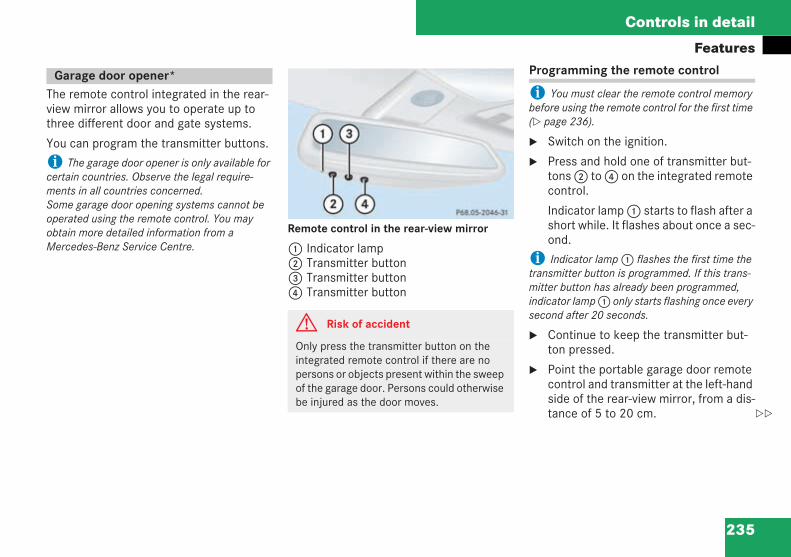
235
Controls in detail
Features
The remote control integrated in the rear-view mirror allows you to operate up tothree different door and gate systems.
You can program the transmitter buttons.
i The garage door opener is only available forcertain countries. Observe the legal require-ments in all countries concerned.Some garage door opening systems cannot beoperated using the remote control. You mayobtain more detailed information from aMercedes-Benz Service Centre.
Remote control in the rear-view mirror
1 Indicator lamp2 Transmitter button3 Transmitter button4 Transmitter button
Programming the remote control
i You must clear the remote control memorybefore using the remote control for the first time( page 236).
Switch on the ignition.
Press and hold one of transmitter but-tons2 to4 on the integrated remotecontrol.
Indicator lamp1 starts to flash after ashort while. It flashes about once a sec-ond.
i Indicator lamp1 flashes the first time thetransmitter button is programmed. If this trans-mitter button has already been programmed,indicator lamp1 only starts flashing once everysecond after 20 seconds.
Continue to keep the transmitter but-ton pressed.
Point the portable garage door remotecontrol and transmitter at the left-handside of the rear-view mirror, from a dis-tance of 5 to 20 cm.
Garage door opener*
G Risk of accident
Only press the transmitter button on theintegrated remote control if there are nopersons or objects present within the sweepof the garage door. Persons could otherwisebe injured as the door moves.
P68.05-2046-31
209en_d2.boo Seite 235 Dienstag, 25. Mai 2004 7:26 19
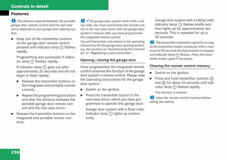
236
Controls in detail
Features
i The distance required between the portablegarage door remote control and the rear-viewmirror depends on your garage door opening sys-tem.
Keep one of the transmitter buttonson the garage door remote controlpressed until indicator lamp1 flashesrapidly.
Programming was successful if indica-tor lamp1 flashes rapidly.
If indicator lamp1 goes out afterapproximately 20 seconds and did notbegin to flash rapidly:
Release the transmitter buttons onthe integrated and portable remotecontrols.
Repeat the programming procedureand alter the distance between theportable garage door remote con-trol and the rear-view mirror.
Release the transmitter buttons on theintegrated and portable remote con-trols.
i If the garage door system works with a roll-ing code, you must synchronise the remote con-trol in the rear-view mirror with the garage doorsystem's receiver after you have programmedthe integrated remote control.You will find further information in the operatinginstructions for the garage door opening system,e.g. the sections on "Synchronising the transmit-ter" or "Registering a new transmitter".
Opening/closing the garage door
Once programmed, the integrated remotecontrol assumes the function of the garagedoor system's remote control. Please readthe Operating Instructions for the garagedoor system.
Switch on the ignition.
Press the transmitter button in therear-view mirror which you have pro-grammed to operate this garage door.
Garage door system with a fixed code:Indicator lamp1 lights up continu-ously.
Garage door system with a rolling code:Indicator lamp1 flashes briefly andthen lights up for approximately twoseconds. This is repeated for up to20 seconds.
i The transmitter transmits a signal for as longas the transmitter button is pressed. After a max-imum of 20 seconds the transmission is stoppedand indicator lamp1 flashes. Press the trans-mitter button again if necessary.
Clearing the remote control memory
Switch on the ignition.
Press and hold transmitter buttons2and4 for about 20 seconds until indi-cator lamp1 flashes rapidly.
The memory is cleared.
i Clear the remote control memory beforeselling the vehicle.
209en_d2.boo Seite 236 Dienstag, 25. Mai 2004 7:26 19
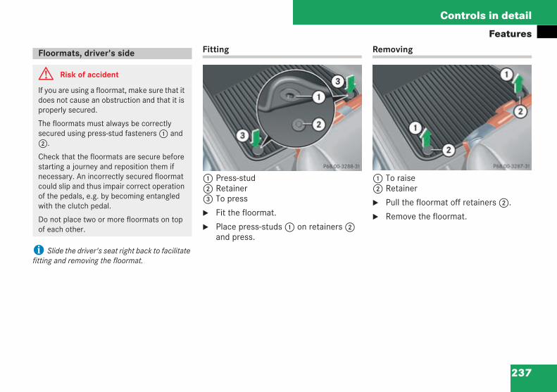
237
Controls in detail
Features
i Slide the driver's seat right back to facilitatefitting and removing the floormat.
Fitting
1 Press-stud2 Retainer3 To press
Fit the floormat.
Place press-studs1 on retainers2and press.
Removing
1 To raise2 Retainer
Pull the floormat off retainers2.
Remove the floormat.
Floormats, driver's side
G Risk of accident
If you are using a floormat, make sure that itdoes not cause an obstruction and that it isproperly secured.
The floormats must always be correctlysecured using press-stud fasteners1 and2.
Check that the floormats are secure beforestarting a journey and reposition them ifnecessary. An incorrectly secured floormatcould slip and thus impair correct operationof the pedals, e.g. by becoming entangledwith the clutch pedal.
Do not place two or more floormats on topof each other.
P68.00-3287-31 P68.00-3288-31
209en_d2.boo Seite 237 Dienstag, 25. Mai 2004 7:26 19

238
209en_d2.boo Seite 238 Dienstag, 25. Mai 2004 7:26 19
239
Operation
The first 1,500 km
Refuelling
Engine compartment
Tyres and wheels
Driving tips
Winter driving
Driving abroad
Trailer towing
Service
Care
209en_d2.boo Seite 239 Dienstag, 25. Mai 2004 7:26 19
240
Operation
The first 1,500 kmYou will find detailed information aboutoperating, maintaining and caring for yourvehicle in the "Operation" section. If you treat the engine with sufficient care
from the very start, it will reward you withexcellent performance for a very long peri-od afterwards.
You should therefore drive at varyingroad and engine speeds for the first1,500 km.
Avoid heavy loads during this time, e.g.driving at full throttle. Do not exceed2/3 of the permissible maximum enginespeed for each gear (red area in the revcounter).
Change gear in good time.
Do not change down a gear manually inorder to brake.
Vehicles with automatic transmission*
Only use ranges 3, 2 or 1 for slow driv-ing, e.g. in mountainous terrain.
It is best to use drive program C forcomfort mode.
Vehicles with automatic transmission*
Try to avoid depressing the acceleratorpedal beyond the pressure point (kick-down).
After 1,500 km you may gradually bringthe vehicle up to full road and enginespeeds.
Additional driving tips for AMG vehicles
Do not exceed 140 km/h during thefirst 1,500 km.
Only bring the engine up to the maxi-mum engine speed of 4,500 rpm forshort periods.
i These guidelines also apply if a new engineor rear-axle differential has been fitted to yourvehicle.
The first 1,500 km
209en_d2.boo Seite 240 Dienstag, 25. Mai 2004 7:26 19
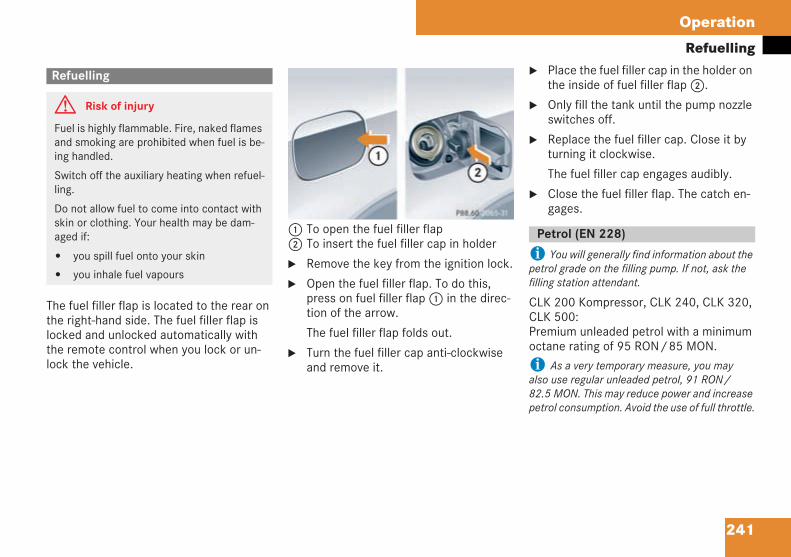
241
Operation
Refuelling
The fuel filler flap is located to the rear onthe right-hand side. The fuel filler flap islocked and unlocked automatically withthe remote control when you lock or un-lock the vehicle.
1 To open the fuel filler flap2 To insert the fuel filler cap in holder
Remove the key from the ignition lock.
Open the fuel filler flap. To do this,press on fuel filler flap1 in the direc-tion of the arrow.
The fuel filler flap folds out.
Turn the fuel filler cap anti-clockwiseand remove it.
Place the fuel filler cap in the holder onthe inside of fuel filler flap2.
Only fill the tank until the pump nozzleswitches off.
Replace the fuel filler cap. Close it byturning it clockwise.
The fuel filler cap engages audibly.
Close the fuel filler flap. The catch en-gages.
i You will generally find information about thepetrol grade on the filling pump. If not, ask thefilling station attendant.
CLK 200 Kompressor, CLK 240, CLK 320,CLK 500:Premium unleaded petrol with a minimumoctane rating of 95 RON/85 MON.
i As a very temporary measure, you mayalso use regular unleaded petrol, 91 RON/82.5 MON. This may reduce power and increasepetrol consumption. Avoid the use of full throttle.
Refuelling
G Risk of injury
Fuel is highly flammable. Fire, naked flamesand smoking are prohibited when fuel is be-ing handled.
Switch off the auxiliary heating when refuel-ling.
Do not allow fuel to come into contact withskin or clothing. Your health may be dam-aged if:
you spill fuel onto your skin
you inhale fuel vapours
P88.60-2065-31 neu
Petrol (EN 228)
209en_d2.boo Seite 241 Dienstag, 25. Mai 2004 7:26 19
242
Operation
RefuellingCLK 200 CGI, CLK 55 AMG:Super unleaded sulphur-free petrol witha minimum octane rating of 98 RON/88 MON.
i As a very temporary measure, you mayalso use premium unleaded petrol, 95 RON/85 MON. This may reduce power and increasepetrol consumption. Avoid the use of full throttle.
! The following may lead to increased wear orengine damage:
The use of petrol which does not comply withEN 228
The use of fuel additives
The use of fuels and/or fuel additives whichhave not been approved may result in limitationof warranty rights.
Leaded petrol
You may fill up with leaded petrol in coun-tries where unleaded petrol is not availa-ble. This shortens the interval for replacingspark plugs to 20,000 km.
Consult a Mercedes-Benz ServiceCentre before using leaded petrol.
! Leaded petrol damages the catalytic con-verter and the Lambda probe.
If you exceed the interval for replacing the sparkplugs, this may cause increased wear and enginedamage.
You may obtain further information from anyMercedes-Benz Service Centre.
i You will generally find information about thediesel grade on the filling pump. If not, ask thefilling station attendant.
We recommend having the engine oilchanged every 7,500 km in countrieswhere only diesel fuel with a sulphur con-tent exceeding 0.5 percent by weight isavailable.
! Use of the following may lead to increasedwear or engine damage:
Diesel which does not comply with EN 590
Marine diesel fuel
Heating oil
Vegetable oil methyl ester (VOME)
Fuel additives ("biodiesel", FAME fuels)
The use of fuels and/or fuel additives whichhave not been approved may result in limitationof warranty rights.
Diesel (EN 590)
209en_d2.boo Seite 242 Dienstag, 25. Mai 2004 7:26 19
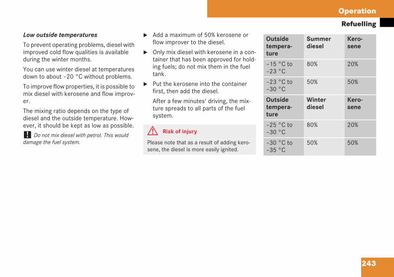
243
Operation
RefuellingLow outside temperatures
To prevent operating problems, diesel withimproved cold flow qualities is availableduring the winter months.
You can use winter diesel at temperaturesdown to about –20 °C without problems.
To improve flow properties, it is possible tomix diesel with kerosene and flow improv-er.
The mixing ratio depends on the type ofdiesel and the outside temperature. How-ever, it should be kept as low as possible.
! Do not mix diesel with petrol. This woulddamage the fuel system.
Add a maximum of 50% kerosene orflow improver to the diesel.
Only mix diesel with kerosene in a con-tainer that has been approved for hold-ing fuels; do not mix them in the fueltank.
Put the kerosene into the containerfirst, then add the diesel.
After a few minutes' driving, the mix-ture spreads to all parts of the fuelsystem.
G Risk of injury
Please note that as a result of adding kero-sene, the diesel is more easily ignited.
Outsidetempera-ture
Summerdiesel
Kero-sene
–15 °C to–23 °C
80% 20%
–23 °C to–30 °C
50% 50%
Outsidetempera-ture
Winterdiesel
Kero-sene
–25 °C to–30 °C
80% 20%
–30 °C to–35 °C
50% 50%
209en_d2.boo Seite 243 Dienstag, 25. Mai 2004 7:26 19
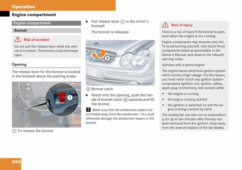
244
Operation
Engine compartment
Opening
The release lever for the bonnet is locatedin the footwell above the parking brake.
1 To release the bonnet
Pull release lever1 in the driver'sfootwell.
The bonnet is released.
2 Bonnet catch
Reach into the opening, push the han-dle of bonnet catch2 upwards and liftthe bonnet.
! Make sure that the windscreen wipers arenot folded away from the windscreen. You couldotherwise damage the windscreen wipers or thebonnet.
Engine compartment
Bonnet
G Risk of accident
Do not pull the release lever while the vehi-cle is in motion. The bonnet could otherwiseopen.
P 88.40-2427-31 neu
P 88.40-2215-31 neu
G Risk of injury
There is a risk of injury if the bonnet is open,even when the engine is not running.
Engine components may become very hot.To avoid burning yourself, only touch thosecomponents listed as permissible in theOwner's Manual, and observe the relevantwarning notes.
Vehicles with a petrol engine:
The engine has an electronic ignition systemwhich carries a high voltage. For this reason,you must never touch any ignition systemcomponents (ignition coil, ignition cables,spark plug connections, test socket) while:
the engine is running
the engine is being started
the ignition is switched on and the en-gine is being cranked by hand
The cooling fan can also run on automatical-ly for up to ten minutes after the key hasbeen removed from the ignition. Keep awayfrom the area of rotation of the fan blades.
209en_d2.boo Seite 244 Dienstag, 25. Mai 2004 7:26 19
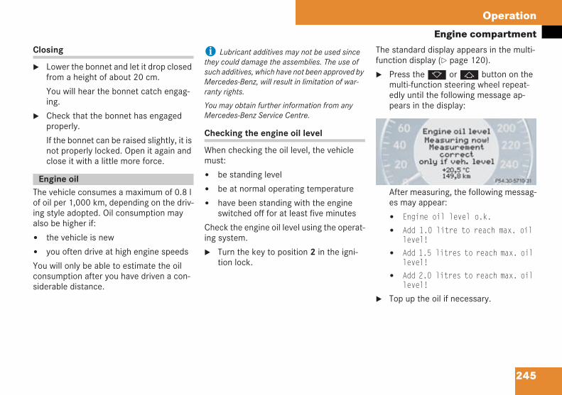
245
Operation
Engine compartmentClosing
Lower the bonnet and let it drop closedfrom a height of about 20 cm.
You will hear the bonnet catch engag-ing.
Check that the bonnet has engagedproperly.
If the bonnet can be raised slightly, it isnot properly locked. Open it again andclose it with a little more force.
The vehicle consumes a maximum of 0.8 lof oil per 1,000 km, depending on the driv-ing style adopted. Oil consumption mayalso be higher if:
the vehicle is new
you often drive at high engine speeds
You will only be able to estimate the oilconsumption after you have driven a con-siderable distance.
i Lubricant additives may not be used sincethey could damage the assemblies. The use ofsuch additives, which have not been approved byMercedes-Benz, will result in limitation of war-ranty rights.
You may obtain further information from anyMercedes-Benz Service Centre.
Checking the engine oil level
When checking the oil level, the vehiclemust:
be standing level
be at normal operating temperature
have been standing with the engineswitched off for at least five minutes
Check the engine oil level using the operat-ing system.
Turn the key to position 2 in the igni-tion lock.
The standard display appears in the multi-function display ( page 120).
Press thek orj button on themulti-function steering wheel repeat-edly until the following message ap-pears in the display:
After measuring, the following messag-es may appear:
Engine oil level o.k.
Add 1.0 litre to reach max. oillevel!
Add 1.5 litres to reach max. oillevel!
Add 2.0 litres to reach max. oillevel!
Top up the oil if necessary.
Engine oil
P 54.30-5240-31
209en_d2.boo Seite 245 Dienstag, 25. Mai 2004 7:26 19

246
Operation
Engine compartmentTopping up the engine oil
The illustration shows an 8-cylinder engine
1 Filler neck
Unscrew the cap on filler neck1.Make sure that you do not add toomuch oil.
! You must have any excess oil drained or si-phoned off at a Mercedes-Benz Service Centre,for example. The engine or the catalytic convert-er could otherwise be damaged.
Screw the cap back onto the filler neck.
Other messages in the display
If the engine is at normal operating tem-perature and there is too much oil, you willsee the following message:Engine oil level Reduce oil level!
Siphon off any excess engine oil.
If too much oil is added, there is a riskof damage to the engine or the catalyt-ic converter.
If the key is not in position 2 in the ignitionlock, you will see the following message:Turn on ignition to see engine oillevel!
Switch on the ignition.
If you see the following message:Observe waiting time:
You may repeat the measurement infive minutes when the engine is atnormal operating temperature.
You may repeat the measurement in30 minutes when the engine is no long-er at normal operating temperature.
If you see the following message:Engine oil level Not when engine on!
Switch off the engine and wait forfive minutes before measuring whenthe engine is at normal operating tem-perature.
You will find further information aboutengine oil in the "Technical data" section( page 414).i Press thek orj button on the multi-function steering wheel if you wish to clear themessage.
P 18.00-2066-31
H Environmental note
When topping up the oil, take care not tospill any. Oil must not be allowed to escapeinto the soil or waterways. You would other-wise be damaging the environment.
209en_d2.boo Seite 246 Dienstag, 25. Mai 2004 7:26 19
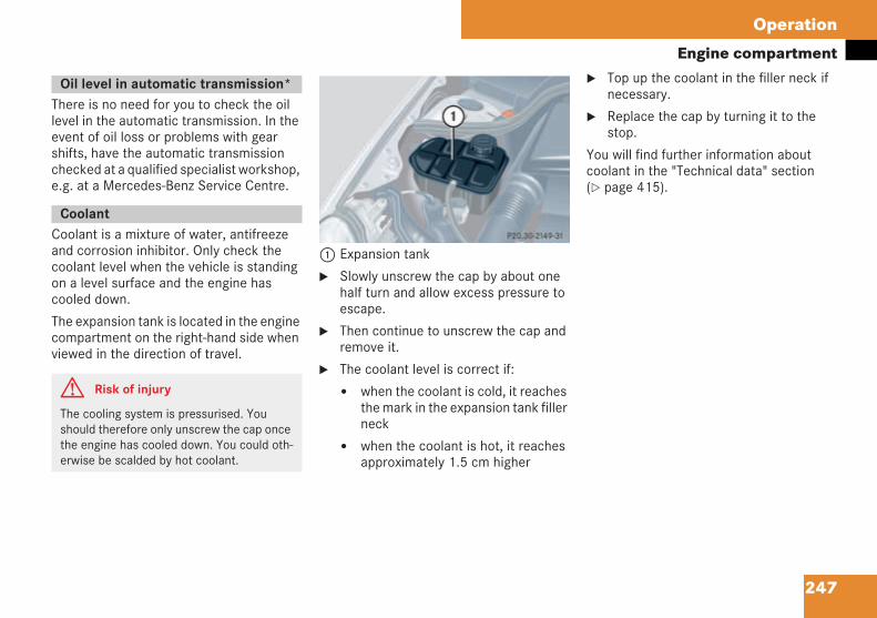
247
Operation
Engine compartment
There is no need for you to check the oillevel in the automatic transmission. In theevent of oil loss or problems with gearshifts, have the automatic transmissionchecked at a qualified specialist workshop,e.g. at a Mercedes-Benz Service Centre.
Coolant is a mixture of water, antifreezeand corrosion inhibitor. Only check thecoolant level when the vehicle is standingon a level surface and the engine hascooled down.
The expansion tank is located in the enginecompartment on the right-hand side whenviewed in the direction of travel.
1 Expansion tank
Slowly unscrew the cap by about onehalf turn and allow excess pressure toescape.
Then continue to unscrew the cap andremove it.
The coolant level is correct if:
when the coolant is cold, it reachesthe mark in the expansion tank fillerneck
when the coolant is hot, it reachesapproximately 1.5 cm higher
Top up the coolant in the filler neck ifnecessary.
Replace the cap by turning it to thestop.
You will find further information aboutcoolant in the "Technical data" section( page 415).
Oil level in automatic transmission*
Coolant
G Risk of injury
The cooling system is pressurised. Youshould therefore only unscrew the cap oncethe engine has cooled down. You could oth-erwise be scalded by hot coolant.
P20.30-2149-31
209en_d2.boo Seite 247 Dienstag, 25. Mai 2004 7:26 19
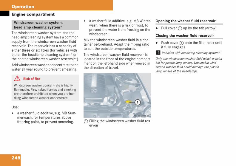
248
Operation
Engine compartment
The windscreen washer system and theheadlamp cleaning system have a commonsupply from the windscreen washer fluidreservoir. The reservoir has a capacity ofeither three or six litres (for vehicles witheither the headlamp cleaning system* orthe heated windscreen washer reservoir*).
Add windscreen washer concentrate to thewater all year round to prevent smearing.
Use:
a washer fluid additive, e.g. MB Sum-merwash, for temperatures abovefreezing point, to prevent smearing.
a washer fluid additive, e.g. MB Winter-wash, when there is a risk of frost, toprevent the water from freezing on thewindscreen.
Mix the windscreen washer fluid in a con-tainer beforehand. Adapt the mixing ratioto suit the outside temperatures.
The windscreen washer fluid reservoir islocated in the front of the engine compart-ment on the left-hand side when viewed inthe direction of travel.
1 Filling the windscreen washer fluid res-ervoir
Opening the washer fluid reservoir
Pull cover1 up by the tab (arrow).
Closing the washer fluid reservoir
Push cover1 onto the filler neck untilit fully engages.
! Vehicles with headlamp cleaning system*:
Only use windscreen washer fluid which is suita-ble for plastic lamp lenses. Unsuitable wind-screen washer fluid could damage the plasticlamp lenses of the headlamps.
Windscreen washer system,headlamp cleaning system*
G Risk of fire
Windscreen washer concentrate is highlyflammable. Fire, naked flames and smokingare therefore prohibited when you are han-dling windscreen washer concentrate.
P01.00-2226-31
209en_d2.boo Seite 248 Dienstag, 25. Mai 2004 7:26 19
249
Operation
Tyres and wheels
! For safety reasons, Mercedes-Benz recom-mends you only use tyres which have been spe-cially approved for your vehicle by Mercedes-Benz. These tyres are specially suited to yourvehicle's control systems, such as ABS or ESP.Mercedes-Benz can accept no responsibility fordamage resulting from using tyres other thanthose approved for your vehicle. Informationabout tyres may be obtained from anyMercedes-Benz Service Centre.
If you use tyres other than those which havebeen tested and recommended for Mercedes-Benz, characteristics such as handling, noiselevels and fuel consumption may be adverselyaffected. Moreover, dimensional variations anddifferent tyre deformation characteristics whenrunning under load could cause the tyre to makecontact with the bodywork or axle components.The consequence could be damage to the tyre orto the vehicle.
! Retreaded tyres are neither tested norrecommended for Mercedes-Benz vehicles, asprevious damage cannot always be detected onretreaded tyres. As a result, Mercedes-Benzcannot guarantee driving safety.
Modification work on the brake systemand wheels is not permitted, nor is the useof spacer plates or brake dust shields. Anysuch modifications invalidate the vehicle'sgeneral operating permit.
Only fit tyres and wheels of the sametype and make.
Only fit tyres of the correct size to thewheels.
Run in new tyres at moderate speedsfor the first 100 km.
Check the tyres and wheels for damageregularly, at least every 14 days. Dam-aged rims could cause a loss of tyrepressure and damage to the wheels.
Check the tyre pressures regularly andcorrect them if necessary – see Fuelfiller cap ( page 241).
Do not continue to use tyres with se-verely worn treads. Tyre grip decreasesrapidly on wet roads below a treaddepth of 3 mm.
Tyres and wheels
G Risk of accident
Only use wheels of the dimensions stated inthe vehicle registration documents. If otherwheel sizes are used:
the wheel brakes or chassis compo-nents could be damaged
wheel and tyre clearances can be nolonger guaranteed
Points to bear in mind
209en_d2.boo Seite 249 Dienstag, 25. Mai 2004 7:26 19
250
Operation
Tyres and wheelsFit single new tyres on the front wheelsfirst if tyres of the same size are fittedon the front and rear wheels.
Remove the rust from corroded steelwheels and repaint them.
Replace the tyres at least every6 years, irrespective of their degreeof wear.
Adjust the tyre pressures if the vehicleis laden – see Fuel filler cap( page 241).
! Store tyres in a cool, dry place, preferably inthe dark. Protect the tyres from oil, grease,petrol and diesel.
Do not clean your wheels with acidic wheelcleaners since these could corrode the wheelbolts.
Tyres with a specified direction of rotationoffer additional benefits, e.g. with regardto aquaplaning. These benefits are onlyavailable to you if the correct direction ofrotation is observed.
An arrow on the sidewall of the tyre indi-cates its correct direction of rotation.
i A spare wheel* may also be fitted againstthe direction of rotation.
The MOExtended run-flat system allowsyou to continue driving your vehicle, evenif there is a complete loss of air in one ormore tyres.
You can only use the MOExtended run-flatsystem in conjunction with the tyre pres-sure loss warning system.
For notes about driving in the event of aflat tyre, see the Practical advice section( page 373).
Direction of rotation MOExtended run-flat system*
209en_d2.boo Seite 250 Dienstag, 25. Mai 2004 7:26 19
251
Operation
Tyres and wheels
Only correct the tyre pressures when thetyres are cold.
The pressures of warm tyres should onlybe corrected if they are too low for the cur-rent operating conditions. Warm tyres al-ways have higher tyre pressures than coldtyres.
You will find a table of tyre pressures forvarious operating conditions on the insideof the vehicle's fuel filler flap.
i Tyre pressure values given for low loads areminimum values which offer you good ride com-fort characteristics.
You can, however, also use the values for higherloads. These are permissible and do not adverse-ly affect the running of the vehicle. However, ridecomfort will be impaired to some degree.
Also check the tyre pressure of the sparewheel*.
Tyre pressure changes by approximately0.1 bar for every 10 °C change in ambienttemperature. If you measure the tyre pres-sures indoors where the temperature dif-fers from the outside temperature, you willhave to correct the measured values ac-cordingly.
When the vehicle is driven, the tyre tem-perature, and with it the tyre pressure, in-crease as a function of the road speed andthe load on the tyres.
During the journey, the tyre pressure losswarning system monitors the set tyre pres-sure by comparing the speed of rotation ofthe wheels. This enables the system to de-tect whether there has been a significantdrop in tyre pressure in one of the tyres. Ifthe rotation speed of a wheel changes be-cause of a drop in tyre pressure, a corre-sponding warning message appears in themulti-function display.
Tyre pressure
G Risk of accident
If the pressure in a tyre drops repeatedly:
inspect the tyre for foreign objects
check whether the wheel or valve isleaking
H Environmental note
Check the tyre pressures regularly, at leastevery 14 days.
Tyre pressure loss warning system
209en_d2.boo Seite 251 Dienstag, 25. Mai 2004 7:26 19
252
Operation
Tyres and wheelsThe tyre pressure loss warning system isrestricted in its function or delayed if:
snow chains are fitted to your vehicle
road and traffic conditions are affectedby wintry conditions
you are driving over a loose surface(e.g. sand or gravel)
you adopt a sporty driving style (withhigh cornering speed or rapid accelera-tion)
you are driving with a very heavy orlarge trailer
you are driving with roof loads or veryheavy loads
Reactivating the tyre pressure losswarning feature
You must reactivate the tyre pressure losswarning feature in the following cases, ifyou:
have changed the tyre pressure
have changed the wheels or tyres
have fitted new wheels or tyres
Before reactivating, make sure that thetyre pressure of all four tyres is set cor-rectly for local driving conditions usingthe table on the inside of the fuel fillerflap.
Make sure that the ignition is switchedon.
G Risk of accident
The tyre pressure loss warning system doesnot warn you of an incorrectly set tyre pres-sure. The table on the inside of the fuel fillerflap will help you to decide whether the tyrepressure should be corrected.
The tyre pressure loss warning system is nota substitute for checking the tyre pressureson a regular basis since equal pressure lossin all four tyres cannot be detected by thetyre pressure loss warning system.
The tyre pressure loss warning system is notable to warn you of a sudden loss of pres-sure, e.g. following penetration by a foreignobject. In such cases, stop the vehicle bybraking carefully. Do not make any suddensteering movements.
G Risk of accident
The tyre pressure loss warning system canonly work reliably if you have set the tyrepressure correctly.
If an incorrect tyre pressure is set, this in-correct value will be monitored.
209en_d2.boo Seite 252 Dienstag, 25. Mai 2004 7:26 19
253
Operation
Tyres and wheelsThe standard display appears in the multi-function display ( page 112).
Press thej ork button on themulti-function steering wheel repeat-edly until the following message ap-pears in the multi-function display:
Tyre pressure monitor Reactivationusingæ
Press theæ button on the multi-function steering wheel.
The following message appears in thedisplay:
Tyre press. now OK?
If you want to confirm activation:
Press theæ button on the multi-function steering wheel again.
The following message appears in thedisplay:
Tyre pressure monitoringreactivated
After a certain teach-in period, the tyrepressure loss warning feature monitorsthe wheels for loss of pressure.
If you want to cancel activation:
Press theç button on the multi-function steering wheel.
or
Wait until the Tyre press. now OK?message disappears.
On vehicles with the same size wheels atthe front and rear, the wheels can be inter-changed every 5,000 to 10,000 km, de-pending on the degree of tyre wear. Thesame direction of rotation must be main-tained.
The front and rear wheels wear differently,depending on the operating conditions.Interchange the wheels before too definitea wear pattern forms on the tyres. Thefront tyres typically wear more on the out-er shoulder, and the rear tyres in the cen-tre of the tread.
Each time you interchange the wheels,you should clean the contact areas on thewheels and brake discs thoroughly. Checkthe tyre pressures.
Interchanging wheels
G Risk of accident
Interchange the front and rear wheels only ifthey have the same dimensions, e.g. size,tread depth, etc.
209en_d2.boo Seite 253 Dienstag, 25. Mai 2004 7:26 19
254
Operation
Tyres and wheels
Although you may be able to control thevehicle fully at a given speed on a dry roadsurface, you must reduce your speed on awet or icy road surface to achieve thesame level of road safety.
You should pay particular attention to theroad conditions when the temperaturesare around freezing.
If ice has formed on the road surface (e.g.due to fog), a thin film of water quicklyforms on the ice when you brake, whichgreatly reduces tyre grip. You should driveparticularly carefully in such weather con-ditions.
G Risk of accident
Have the tightening torque checked after awheel change at a qualified specialist work-shop which has the necessary specialistknowledge and tools to carry out the workrequired. Mercedes-Benz recommends thatyou use a Mercedes-Benz Service Centre forthis purpose. In particular, work relevant tosafety or on safety-related systems must becarried out at a qualified specialist work-shop.
The wheel bolts could work loose if they arenot tightened to a torque of 110 Nm.
Mercedes-Benz recommends that, for safetyreasons, you only use suitable wheel boltswhich have been approved for Mercedes-Benz.
Tyre grip
209en_d2.boo Seite 254 Dienstag, 25. Mai 2004 7:26 19
255
Operation
Driving tips
You will find basic driving tips in the"Getting started" section ( page 32).
On long and steep downward gradients,you should shift to a lower gear (shift rang-es 1, 2 or 3) ( page 137). This preventsthe brakes overheating and wearing tooquickly.
If you have subjected the brakes to a veryhigh load, do not switch the vehicle off im-mediately, but drive on for a short dis-tance. The brakes will cool more quickly inthe airflow.
If you drive for a long period in heavy rainwithout braking, the first time you brake:
the brakes may not react immediately
you may have to depress the brakemore firmly
You should therefore maintain a greaterdistance from the vehicle in front.
Brake carefully after driving on a wet roadsurface, particularly if salt has been spreadon the road. The brake discs will becomewarm, will dry quicker and will be protect-ed from corrosion.
If you only use the brakes moderately, youshould occasionally check their effective-ness. To do so, brake more firmly and at ahigher speed. This improves brake grip.
Mercedes-Benz recommends that, forsafety reasons, you only fit brake pads toyour vehicle which have been approved forMercedes-Benz. Brake pads which havenot been approved for Mercedes-Benz ve-hicles may adversely affect the safety ofyour vehicle.
Driving tips
Rolling with the engine switched off
G Risk of accident
There is no power assistance for the steer-ing or service brake when the engine is notrunning.
You will require considerably more effort tosteer and brake and you could thereforelose control of the vehicle and cause anaccident.
Never switch the engine off while the vehicleis in motion.
Braking
G Risk of accident
Make sure that other road users are not en-dangered when you brake.
209en_d2.boo Seite 255 Dienstag, 25. Mai 2004 7:26 19
256
Operation
Driving tipsCLK 55 AMG High-performance brakesystem
The high-performance brake system is de-signed for heavy loads. This means thatthere may be noise under braking. This de-pends on:
Speed
Braking force
Environmental conditions, e.g. temper-ature and humidity
The wear of individual components in thebrake system, e.g. brake pads or brakediscs, depends on:
your individual driving style
the operating conditions
For this reason, it is not possible to providea general indication of wear based on mile-age. Wear is particularly high if an aggres-sive style of driving is adopted.
If a certain amount of water has accumu-lated on the road surface, there is a dangerof aquaplaning, even if:
you are driving at low speeds
the tyre tread is of sufficient depth
You should therefore avoid driving in tyreruts and should brake carefully.
If you have to drive on stretches of road onwhich water has collected, please notethat:
you must not drive on stretches of roadflooded to a still water depth greaterthan 25 cm
the maximum speed you may drive at iswalking speed
! Note that vehicles in front or oncoming vehi-cles create waves. This may mean that the max-imum permitted water depth is exceeded.
You must observe these notes, otherwise dam-age may occur to the:
Engine
Electrics
Transmission
Driving in wet weather Driving on flooded roads
209en_d2.boo Seite 256 Dienstag, 25. Mai 2004 7:26 19
257
Operation
Winter driving
Have your vehicle winterproofed at aqualified specialist workshop, e.g. at aMercedes-Benz Service Centre, at the on-set of winter. This service includes the fol-lowing:
Engine oil change,if the current oil used has not beenapproved for winter use
The antifreeze/anti-corrosionconcentration is checked
A concentrated cleaning agent isadded to the windscreen and headlampcleaning system fluid*
The battery is checked
A tyre change
Use winter tyres at temperatures below+7 °C and on snow or ice-covered roads.The maximum effect of the ABS and ESPdriving systems is only achieved in winterwith these tyres.
Use winter tyres of the same make andtread on all wheels to maintain safe han-dling characteristics.
Always observe the maximum permittedspeed specified for the winter tyres youhave fitted. If you fit winter tyres whichhave a lower maximum permitted speedthan that of the vehicle, affix an appropri-ate warning sign in the driver's field ofvision. This can be obtained at a qualifiedspecialist workshop, e.g. at a Mercedes-Benz Service Centre.
In such circumstances, you should alsorestrict the maximum speed of the vehicleto the maximum permitted speed for thewinter tyres using permanent Speedtronic( page 211).
Winter driving Winter tyres*
G Risk of accident
You must replace winter tyres with treaddepths of less than 4 mm immediately.These tyres are not suitable for use in winterand do not provide sufficient grip. You couldtherefore lose control of the vehicle andcause an accident.
209en_d2.boo Seite 257 Dienstag, 25. Mai 2004 7:26 19
258
Operation
Winter driving
Do not exceed the maximum permissiblespeed of 50 km/h. Remove the snowchains as soon as possible if you are nolonger driving on snow-covered roads.
i You may wish to deactivate ESP when pull-ing away on snow chains ( page 70). This willhelp you to achieve an effective cutting action.
If you are intending to fit snow chains,please remember the following:
Snow chains cannot be fitted on allwheel/tyre combinations.
Fit snow chains only to the rear wheels.Comply with the manufacturer's instal-lation instructions.
Mercedes-Benz recommends that, forsafety reasons, you only use snowchains which have been approved forMercedes-Benz.
! You must not fit snow chains to AMG tyres.
You should drive particularly carefully onicy roads. Avoid sudden acceleration,steering movements and braking.
If the vehicle threatens to skid or cannotbe brought to a standstill at a low speed:
shift into neutral
move the selector lever to N
try to keep the vehicle under controlusing corrective steering
G Risk of accident
If you fit the spare wheel* when driving withwinter tyres, please be aware that drivingstability will be impaired owing to unstablecornering characteristics caused by the dif-ferent tyres. You should therefore adaptyour driving style and drive carefully.
Have the spare wheel* changed at the near-est qualified specialist workshop which hasthe necessary specialist knowledge andtools to carry out the work required.Mercedes-Benz recommends that you use aMercedes-Benz Service Centre for this pur-pose. In particular, work relevant to safetyor on safety-related systems must be car-ried out at a qualified specialist workshop.
Snow chains Winter driving
G Risk of accident
Do not change down for additional enginebraking on a slippery road surface. The drivewheels may lose grip.
209en_d2.boo Seite 258 Dienstag, 25. Mai 2004 7:26 19
259
Operation
Driving abroad
An extensive network of Mercedes-BenzService Centres is also at your disposalwhen you are travelling abroad. The appro-priate workshop directories are availablefrom any Mercedes-Benz Service Centre.
Only low-octane fuel is available in certaincountries.
You will find further information about fuelgrades in the "Operation" section( page 241).
If your journey takes you to countries inwhich traffic drives on the opposite sideof the road to the country where the vehi-cle is registered, your headlamps shouldbe masked or partially masked to ensurethat the headlamps are at symmetricaldipped beam*. Oncoming traffic will thenbe dazzled less.
Mask the headlamps with special adhe-sive sheets.
These special masking sheets can beobtained at a qualified specialist work-shop, e.g. at a Mercedes-Benz ServiceCentre.
Or depending on your vehicle's equipment:
Have the bi-xenon headlamps*switched to symmetrical dipped beamat a qualified specialist workshop, e.g.at a Mercedes-Benz Service Centre.
You may obtain further information from aMercedes-Benz Service Centre.
! Mercedes-Benz recommends that you onlyuse genuine Mercedes-Benz adhesive sheets,otherwise your headlamps could be damaged.
Remember to switch the headlamps to asym-metrical dipped-beam headlamps again onceyou are driving on the side of the road for thecountry in which your vehicle is registered.
Driving abroad Symmetrical dipped-beamheadlamps
209en_d2.boo Seite 259 Dienstag, 25. Mai 2004 7:26 19
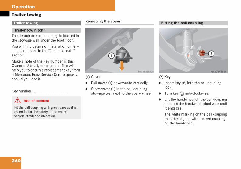
260
Operation
Trailer towing
The detachable ball coupling is located inthe stowage well under the boot floor.
You will find details of installation dimen-sions and loads in the "Technical data"section.
Make a note of the key number in thisOwner's Manual, for example. This willhelp you to obtain a replacement key froma Mercedes-Benz Service Centre quickly,should you lose it.
Key number.: ________________
Removing the cover
1 Cover
Pull cover1 downwards vertically.
Store cover1 in the ball couplingstowage well next to the spare wheel.
2 Key
Insert key2 into the ball couplinglock.
Turn key2 anti-clockwise.
Lift the handwheel off the ball couplingand turn the handwheel clockwise untilit engages.
The white marking on the ball couplingmust be aligned with the red markingon the handwheel.
Trailer towing
Trailer tow hitch*
G Risk of accident
Fit the ball coupling with great care as it isessential for the safety of the entirevehicle/trailer combination.
P 31.10-2451-31
Fitting the ball coupling
P 31.10-2452-31
209en_d2.boo Seite 260 Dienstag, 25. Mai 2004 7:26 19
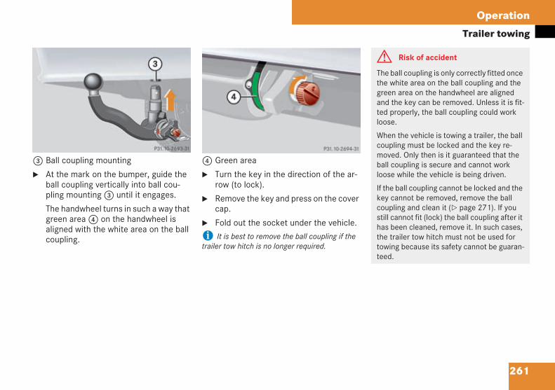
261
Operation
Trailer towing
3 Ball coupling mounting
At the mark on the bumper, guide theball coupling vertically into ball cou-pling mounting3 until it engages.
The handwheel turns in such a way thatgreen area4 on the handwheel isaligned with the white area on the ballcoupling.
4 Green area
Turn the key in the direction of the ar-row (to lock).
Remove the key and press on the covercap.
Fold out the socket under the vehicle.
i It is best to remove the ball coupling if thetrailer tow hitch is no longer required.
P 31.10-2453-31 P 31.10-2454-31
G Risk of accident
The ball coupling is only correctly fitted oncethe white area on the ball coupling and thegreen area on the handwheel are alignedand the key can be removed. Unless it is fit-ted properly, the ball coupling could workloose.
When the vehicle is towing a trailer, the ballcoupling must be locked and the key re-moved. Only then is it guaranteed that theball coupling is secure and cannot workloose while the vehicle is being driven.
If the ball coupling cannot be locked and thekey cannot be removed, remove the ballcoupling and clean it ( page 271). If youstill cannot fit (lock) the ball coupling after ithas been cleaned, remove it. In such cases,the trailer tow hitch must not be used fortowing because its safety cannot be guaran-teed.
209en_d2.boo Seite 261 Dienstag, 25. Mai 2004 7:26 19
262
Operation
Trailer towing
i The maximum permissible weights are givenin the vehicle documents and on the type platesof the trailer and the trailer tow hitch. The lowestvalue given is decisive.
The maximum trailer drawbar noseweight for thetrailer towbar on the ball neck is 75 kg. The draw-bar noseweight must not, however, exceed thatspecified on the type plates for the trailer towhitch and the trailer.
If you couple a trailer, the driving charac-teristics of your vehicle change.
The vehicle/trailer combination:
is heavier
is restricted in its acceleration andgradient-climbing capability
has a longer stopping distance
is more susceptible to gusting cross-winds
demands more sensitive steering
Fuel consumption is higher when towing atrailer.
Tips for driving when towing a trailer:
We recommend utilising the maximumpermissible drawbar noseweight, andalways at least 50 kg.
The vehicle's payload must be reducedto compensate for the drawbar nose-weight so that the maximum permissi-ble rear axle load is not exceeded.
Have the entire trailer tow hitch checked ata qualified specialist workshop which hasthe necessary specialist knowledge andtools to carry out the work required.Mercedes-Benz recommends that you use aMercedes-Benz Service Centre for this pur-pose. In particular, work relevant to safetyor on safety-related systems must be car-ried out at a qualified specialist workshop.
Driving tips
G Risk of accident
Maximum care and attention is called forwhen coupling and decoupling a trailer.
Make sure that no-one is present betweenthe trailer and the vehicle when the vehicleis being reversed up to the trailer.
Do not uncouple a trailer with an overrunbrake when the brake is engaged.
If you have coupled the trailer to the vehicleincorrectly, there is a risk that the trailermay break away.
Make sure that the following values havebeen observed:
Maximum permissible gross vehicleweight
Maximum permissible trailer drawbarnoseweight
Maximum permissible trailer load
Maximum permissible rear load on thetowing vehicle
209en_d2.boo Seite 262 Dienstag, 25. Mai 2004 7:26 19
263
Operation
Trailer towingYou should not exceed a maximumspeed of 80 km/h, even in countrieswhere higher speeds are permitted.
Avoid sudden braking. Instead, applythe brake lightly at first, to allow thetrailer to overrun. Then increase thebraking force rapidly.
If the trailer starts to swing, reduceyour speed, do not attempt correctivesteering, and brake if necessary. On noaccount should you attempt to drawthe vehicle/trailer combination out byincreasing your speed.
The gradient-climbing capabilities froma standstill are correct for sea level.When driving in mountainous areas,note that the power output of the en-gine, and with it its gradient-climbingcapability from a standstill, decreaseswith increasing altitude.
! Do not uncouple a trailer with an overrunbrake when the brake is engaged. The springaction of the overrunning brake mechanismcould damage the bumper.
Fold out the socket under the vehicle.
Remove the locked protective cap onthe handwheel.
Unlock the lock on the handwheelusing the key.
Hold the ball coupling firmly. Lift thehandwheel off the ball coupling andturn the handwheel clockwise until itengages.
The red marking on the handwheel isaligned with the white marking.
Remove the ball coupling by pullingdownwards.
Press the ball coupling cover into theball coupling recess.
Make sure that the cover is fitted se-curely.
Stowing the ball coupling
Stow the ball coupling in the ballcoupling well by the spare wheel.
Removing the ball coupling
G Risk of accident
Do not carry the ball coupling unsecured inthe vehicle interior.
Vehicle occupants could be injured by theball coupling being thrown around in thevehicle in the event of:
sharp braking
a change of direction or
an accident
209en_d2.boo Seite 263 Dienstag, 25. Mai 2004 7:26 19
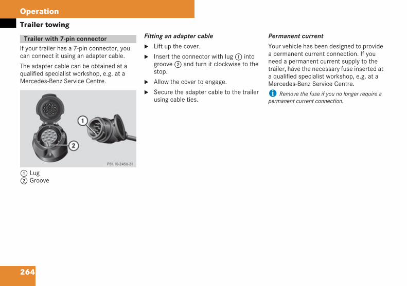
264
Operation
Trailer towing
If your trailer has a 7-pin connector, youcan connect it using an adapter cable.
The adapter cable can be obtained at aqualified specialist workshop, e.g. at aMercedes-Benz Service Centre.
1 Lug2 Groove
Fitting an adapter cable
Lift up the cover.
Insert the connector with lug1 intogroove2 and turn it clockwise to thestop.
Allow the cover to engage.
Secure the adapter cable to the trailerusing cable ties.
Permanent current
Your vehicle has been designed to providea permanent current connection. If youneed a permanent current supply to thetrailer, have the necessary fuse inserted ata qualified specialist workshop, e.g. at aMercedes-Benz Service Centre.
i Remove the fuse if you no longer require apermanent current connection.
Trailer with 7-pin connector
P 31.10-2456-31
209en_d2.boo Seite 264 Dienstag, 25. Mai 2004 7:26 19
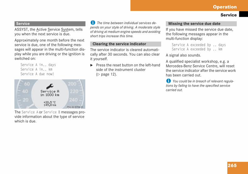
265
Operation
Service
ASSYST, the Active Service System, tellsyou when the next service is due.
Approximately one month before the nextservice is due, one of the following mes-sages will appear in the multi-function dis-play while you are driving or the ignition isswitched on:
Service A in.. daysService A in.. kmService A due now!
The Service A or Service Bmessages pro-vide information about the type of servicewhich is due.
i The time between individual services de-pends on your style of driving. A moderate styleof driving at medium engine speeds and avoidingshort trips increase this time.
The service indicator is cleared automati-cally after 30 seconds. You can also clearit yourself.
Press the reset button on the left-handside of the instrument cluster( page 12).
If you have missed the service due date,the following messages appear in themulti-function display:
Service A exceeded by .. daysService A exceeded by .. km
A signal also sounds.
A qualified specialist workshop, e.g. aMercedes-Benz Service Centre, will resetthe service indicator after the service workhas been carried out.
i You could be in breach of relevant regula-tions by failing to have the specified servicecarried out.
Service
P54.30-5239-31
Clearing the service indicator
Missing the service due date
209en_d2.boo Seite 265 Dienstag, 25. Mai 2004 7:26 19
266
Operation
Service
Switch on the ignition.
The standard display appears in the multi-function display ( page 120).
Press thek orj button on themulti-function steering wheel repeat-edly until the9 or´ servicesymbol appears in the multi-functiondisplay with the service due date.
i Periods when the battery is disconnectedare not recorded by the timed service indicator.You must therefore subtract such periods fromthe service due date yourself.
Do not confuse the service indicator with the: engine oil level display.
If your vehicle is ever serviced other thanat a Mercedes-Benz Service Centre, youcan reset the service indicator yourself.
Switch on the ignition.
The standard display appears in the multi-function display ( page 120).
Press thek orj button on themulti-function steering wheel repeat-edly until the9 or´ servicesymbol appears in the multi-functiondisplay with the service due date.
Press and hold the reset button on theleft in the instrument cluster for aboutfour seconds.
The following message appears in thedisplay:
Reset service interval?To confirm press reset button
To confirm, press and hold the resetbutton until a signal sounds.
The service indicator now displays thenew value.
i If you have reset the service indicator acci-dentally, a qualified specialist workshop, e.g. aMercedes-Benz Service Centre, will be able toupdate it again.
Calling up the service due date Resetting the service indicator
209en_d2.boo Seite 266 Dienstag, 25. Mai 2004 7:26 19
267
Operation
Care
Regular and proper care will help to main-tain the value of your vehicle. The best wayto protect your vehicle from harmful envi-ronmental influences is to wash it and useprotective treatments regularly.
i It is best to use Mercedes-Benz care prod-ucts. These have been specially adapted toMercedes-Benz vehicles and are state of the art.Mercedes-Benz care products are available fromany Mercedes-Benz Service Centre.
Scratches, corrosive deposits, etching anddamage caused by neglect or inadequatecare cannot always be completely reme-died. If this is the case, please consult aqualified specialist workshop, e.g. aMercedes-Benz Service Centre.
Repair damage caused by loose chippingsand remove the following substances assoon as possible:
Insect remains
Bird droppings
Tree resin
Oils and grease
Fuel
Tar stains
! Under no circumstances should you affix un-suitable stickers, films, magnets or similar topainted surfaces. Doing so could damage thepaintwork.
Additional care notes for AMG vehicleswith nubuck leather upholstery:
The nubuck leather is already treated witha protective coating. You should not there-fore use:
MB leather care agents
MB stain remover
other solvent-based cleaning agents
Avoid rubbing the leather upholstery vigor-ously. Remove dirt using a damp microfi-bre cloth.
Care
G Risk of poisoning
Always follow the instructions for using thecare products.
Always keep care products tightly closedand out of the reach of children.
H Environmental note
Dispose of empty containers, cleaningcloths and polishing wads in an environmen-tally-responsible manner.
209en_d2.boo Seite 267 Dienstag, 25. Mai 2004 7:26 19
268
Operation
Care
Automatic car wash
You can clean the vehicle in an automaticcar wash from the very start. It is advisableto use automatic car washes withoutbrushes.
If the vehicle is very dirty, prewash it be-fore you drive into the car wash.
After using an automatic car wash, wipe offwax from the windscreen and the wiperblades. This prevents smears.
! Make sure that the automatic car wash issuitable for the size of the vehicle. Fold in the ex-terior mirrors before going through a car wash.Make sure that the windscreen-wiper switch isset to 0 ( page 41). The exterior mirrors orwindscreen wipers could otherwise be damaged.
i Make sure that the mirrors are fully foldedout when you leave the automatic car wash. Theycould otherwise vibrate.
High-pressure cleaners
! Do not use high-pressure cleaners withround-spray jets for cleaning the tyres. You couldotherwise damage the tyres. Replace damagedtyres.
Direct the high-pressure cleaner nozzleat the vehicle from a distance of atleast 30 cm.
Move the high-pressure cleaner nozzlearound when cleaning your vehicle.
! Do not direct it at door joints, air springbellows, electrical components, connectors orseals.
Cleaning the windscreen and wiperblades
Turn the ignition key to position 1.
Turn the windscreen wipers toposition I on the combination switch( page 41).
Turn the ignition key to 0 when the wip-er arms are vertical.
! Fold the windscreen wipers away from thewindscreen only when they are vertical, other-wise you will damage the bonnet.
Fold the wiper arms away from thewindscreen until you feel them clickinto place.
You can now clean the windscreen.
Fold the windscreen wipers back againbefore you switch on the ignition.
Vehicle care G Risk of injury
Turn the ignition key to 0 before cleaningthe windscreen or wiper blades. The wind-screen wipers could otherwise move and in-jure you.
209en_d2.boo Seite 268 Dienstag, 25. Mai 2004 7:26 19
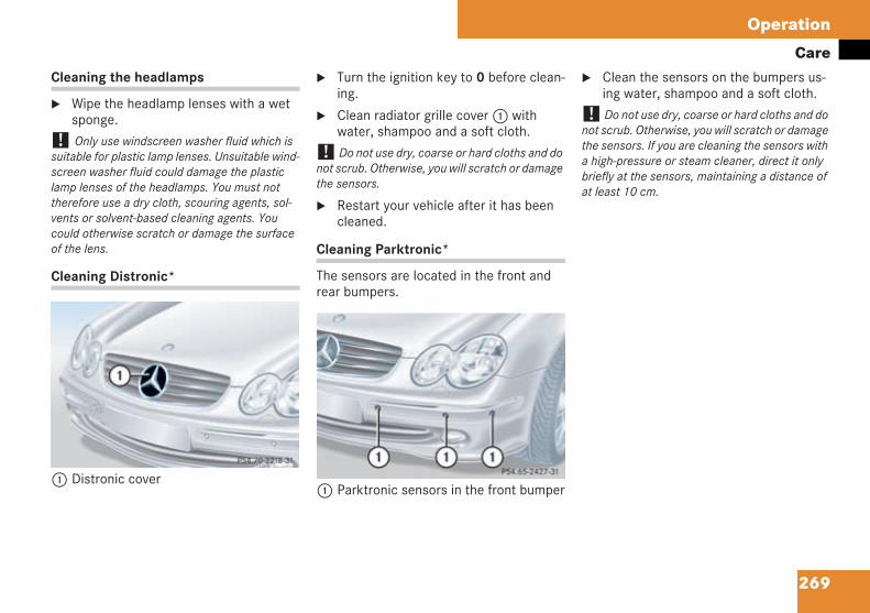
269
Operation
CareCleaning the headlamps
Wipe the headlamp lenses with a wetsponge.
! Only use windscreen washer fluid which issuitable for plastic lamp lenses. Unsuitable wind-screen washer fluid could damage the plasticlamp lenses of the headlamps. You must nottherefore use a dry cloth, scouring agents, sol-vents or solvent-based cleaning agents. Youcould otherwise scratch or damage the surfaceof the lens.
Cleaning Distronic*
1 Distronic cover
Turn the ignition key to 0 before clean-ing.
Clean radiator grille cover1 withwater, shampoo and a soft cloth.
! Do not use dry, coarse or hard cloths and donot scrub. Otherwise, you will scratch or damagethe sensors.
Restart your vehicle after it has beencleaned.
Cleaning Parktronic*
The sensors are located in the front andrear bumpers.
1 Parktronic sensors in the front bumper
Clean the sensors on the bumpers us-ing water, shampoo and a soft cloth.
! Do not use dry, coarse or hard cloths and donot scrub. Otherwise, you will scratch or damagethe sensors. If you are cleaning the sensors witha high-pressure or steam cleaner, direct it onlybriefly at the sensors, maintaining a distance ofat least 10 cm.
P 54.70-2218-31P 54.65-2427-31
209en_d2.boo Seite 269 Dienstag, 25. Mai 2004 7:26 19
270
Operation
CareCabriolet
Frequent cleaning reduces the dirt-repel-lent effect of the soft top.
Through intensive cleaning with the prod-ucts found in a Mercedes-Benz cleaningagents kit for convertible soft top the dirt-repellent effect can be restored.
Incorrect cleaning and care, as well as age-ing, can cause the soft-top seams to leak.Have the soft-top seams sealed at a quali-fied specialist workshop, e.g. a Mercedes-Benz Service Centre.
i Place a suitable cover over the soft top if youare leaving the vehicle parked in the open for anextended period of time.
! Remove bird droppings immediately, sincethese are corrosive and could therefore causethe soft top seal to leak. Do not use a high-pres-sure cleaner to wash the vehicle. Do not removesnow or ice using a sharp-edged appliance.
i You may have your vehicle washed in an au-tomatic car wash. Do not, under any circum-stance, use a hot wax treatment on your vehicle.
Do not use any of the following to clean thesoft top:
Petrol
Thinner
Tar or stain remover
Other organic solvents
Cleaning the soft top
The following methods are sufficient if thesoft top is only lightly soiled:
Dry cleaning
or
Rinsing/spraying with clean water
If it is soiled to a normal extent, clean thesoft top using a brush and clean water.Always direct the brush strokes from thefront to the rear along the grain of the fab-ric.
If the soft top is very dirty and stained,clean it with a suitable soft-top cleaningagent and a brush. Always direct the brushstrokes from the front to the rear along thegrain of the fabric.
209en_d2.boo Seite 270 Dienstag, 25. Mai 2004 7:26 19
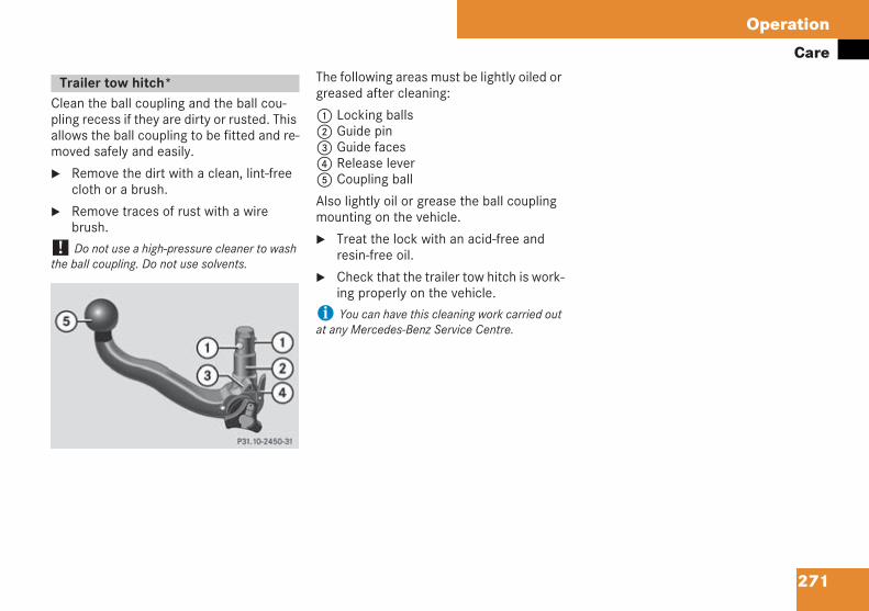
271
Operation
Care
Clean the ball coupling and the ball cou-pling recess if they are dirty or rusted. Thisallows the ball coupling to be fitted and re-moved safely and easily.
Remove the dirt with a clean, lint-freecloth or a brush.
Remove traces of rust with a wirebrush.
! Do not use a high-pressure cleaner to washthe ball coupling. Do not use solvents.
The following areas must be lightly oiled orgreased after cleaning:
1 Locking balls2 Guide pin3 Guide faces4 Release lever5 Coupling ball
Also lightly oil or grease the ball couplingmounting on the vehicle.
Treat the lock with an acid-free andresin-free oil.
Check that the trailer tow hitch is work-ing properly on the vehicle.
i You can have this cleaning work carried outat any Mercedes-Benz Service Centre.
Trailer tow hitch*
P 31.10-2450-31
209en_d2.boo Seite 271 Dienstag, 25. Mai 2004 7:26 19

272
209en_d2.boo Seite 272 Dienstag, 25. Mai 2004 7:26 19
273
Practical advice
Where will I find...?
Display messages
Troubleshooting
Opening/closing in an emergency
Changing the key batteries
Changing bulbs
Replacing the wiper blades
Flat tyre
Battery
Jump-starting
Towing
Fuses
209en_d2.boo Seite 273 Dienstag, 25. Mai 2004 7:26 19
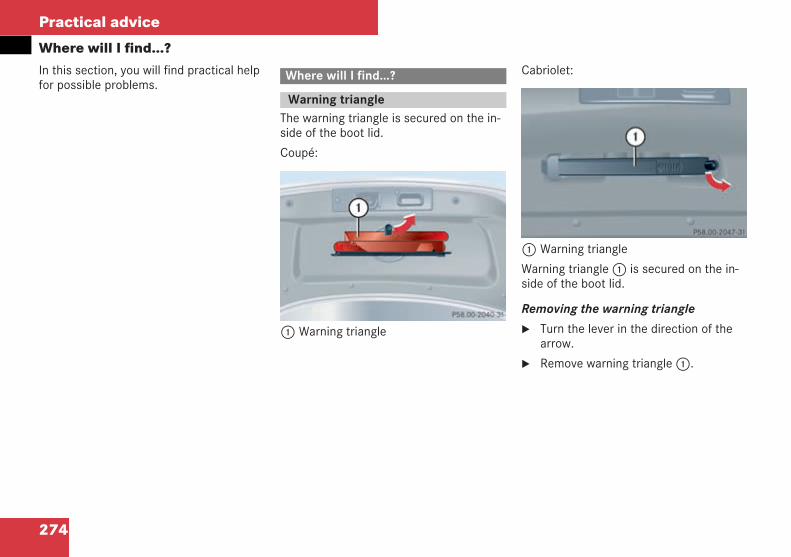
274
Practical advice
Where will I find...?In this section, you will find practical helpfor possible problems.
The warning triangle is secured on the in-side of the boot lid.
Coupé:
1 Warning triangle
Cabriolet:
1 Warning triangle
Warning triangle1 is secured on the in-side of the boot lid.
Removing the warning triangle
Turn the lever in the direction of thearrow.
Remove warning triangle1.
Where will I find...?
Warning triangle
P 58.00-2040-31 neu
P 58.00-2047-31 neu
209en_d2.boo Seite 274 Dienstag, 25. Mai 2004 7:26 19
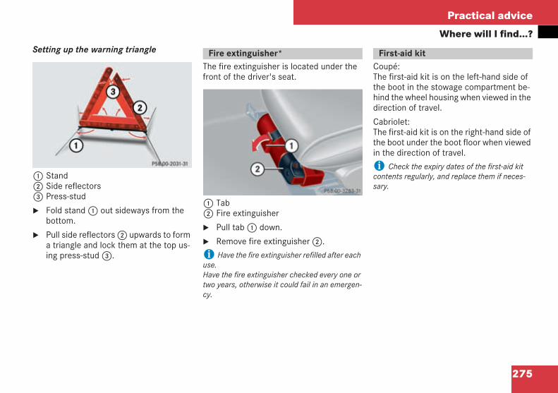
275
Practical advice
Where will I find...?Setting up the warning triangle
1 Stand2 Side reflectors3 Press-stud
Fold stand1 out sideways from thebottom.
Pull side reflectors2 upwards to forma triangle and lock them at the top us-ing press-stud3.
The fire extinguisher is located under thefront of the driver's seat.
1 Tab2 Fire extinguisher
Pull tab1 down.
Remove fire extinguisher2.
i Have the fire extinguisher refilled after eachuse.Have the fire extinguisher checked every one ortwo years, otherwise it could fail in an emergen-cy.
Coupé:The first-aid kit is on the left-hand side ofthe boot in the stowage compartment be-hind the wheel housing when viewed in thedirection of travel.
Cabriolet:The first-aid kit is on the right-hand side ofthe boot under the boot floor when viewedin the direction of travel.
i Check the expiry dates of the first-aid kitcontents regularly, and replace them if neces-sary.
P58.00-2031-31
Fire extinguisher*
P 68.00-3283-31 neu
First-aid kit
209en_d2.boo Seite 275 Dienstag, 25. Mai 2004 7:26 19
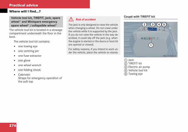
276
Practical advice
Where will I find...?
The vehicle tool kit is located in a stowagecompartment underneath the floor in theboot.
The vehicle tool kit contains:
one towing eye
one centring pin
one fuse extractor
one glove
one wheel wrench
one folding chock
Cabriolet:Straps for emergency operation ofthe soft top
Coupé with TIREFIT kit
1 Jack2 TIREFIT kit3 Electric air pump4 Vehicle tool kit5 Towing eye
Vehicle tool kit, TIREFIT, jack, sparewheel* and Minispare emergencyspare wheel*/collapsible wheel*
G Risk of accident
The jack is only designed to raise the vehiclewhen changing a wheel. Do not crawl underthe vehicle while it is supported by the jack.If you do not raise the vehicle in the way de-scribed, it could slip off the jack (e.g. whenthe engine is started or the doors or boot lidare opened or closed).
For safety reasons, if you intend to work un-der the vehicle, place the vehicle on stands.
P 40.10-2597-31 neu
209en_d2.boo Seite 276 Dienstag, 25. Mai 2004 7:26 19
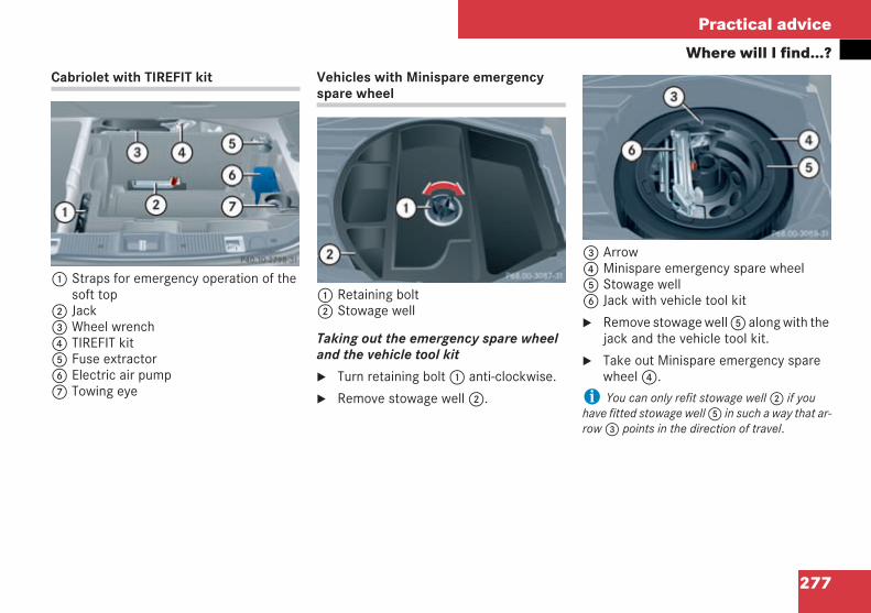
277
Practical advice
Where will I find...?Cabriolet with TIREFIT kit
1 Straps for emergency operation of thesoft top
2 Jack3 Wheel wrench4 TIREFIT kit5 Fuse extractor6 Electric air pump7 Towing eye
Vehicles with Minispare emergencyspare wheel
1 Retaining bolt2 Stowage well
Taking out the emergency spare wheeland the vehicle tool kit
Turn retaining bolt1 anti-clockwise.
Remove stowage well2.
3 Arrow4 Minispare emergency spare wheel5 Stowage well6 Jack with vehicle tool kit
Remove stowage well5 along with thejack and the vehicle tool kit.
Take out Minispare emergency sparewheel4.
i You can only refit stowage well2 if youhave fitted stowage well5 in such a way that ar-row3 points in the direction of travel.
P 40.10-2798-31 neuP 68.00-3087-31 neu
P 68.00-3088-31 neu
209en_d2.boo Seite 277 Dienstag, 25. Mai 2004 7:26 19
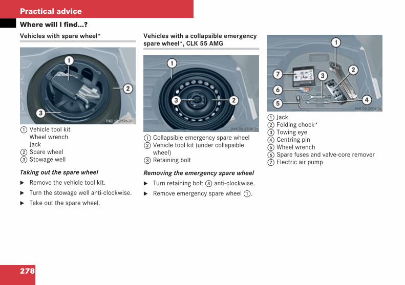
278
Practical advice
Where will I find...?Vehicles with spare wheel*
1 Vehicle tool kitWheel wrenchJack
2 Spare wheel3 Stowage well
Taking out the spare wheel
Remove the vehicle tool kit.
Turn the stowage well anti-clockwise.
Take out the spare wheel.
Vehicles with a collapsible emergencyspare wheel*, CLK 55 AMG
1 Collapsible emergency spare wheel2 Vehicle tool kit (under collapsible
wheel)3 Retaining bolt
Removing the emergency spare wheel
Turn retaining bolt3 anti-clockwise.
Remove emergency spare wheel1.
1 Jack2 Folding chock*3 Towing eye4 Centring pin5 Wheel wrench6 Spare fuses and valve-core remover7 Electric air pump
P 40.10-2596-31 neuP68.00-3596-31
P68.00-3597-31
209en_d2.boo Seite 278 Dienstag, 25. Mai 2004 7:26 19
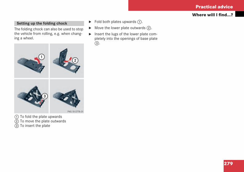
279
Practical advice
Where will I find...?
The folding chock can also be used to stopthe vehicle from rolling, e.g. when chang-ing a wheel.
1 To fold the plate upwards2 To move the plate outwards3 To insert the plate
Fold both plates upwards1.
Move the lower plate outwards2.
Insert the lugs of the lower plate com-pletely into the openings of base plate3.
Setting up the folding chock
P40.10-2776-31
209en_d2.boo Seite 279 Dienstag, 25. Mai 2004 7:26 19
280
Practical advice
Display messages
The operating system shows warnings ormalfunctions in the multi-function display.
Certain messages are accompanied by anaudible warning signal or a continuoustone.
High-priority messages are highlighted inred in the display. These messages areprinted in red in the following tables.
Please respond in accordance with themessages and follow the additional notesin this Owner's Manual.
You can acknowledge low-priority mes-sages by pressing theè,·,j ork buttons on the multi-function steering wheel or the resetbutton on the left in the instrumentcluster. They will then be stored in themalfunction memory.
Highest-priority messages cannot beacknowledged and are automaticallystored in the malfunction memory.
If you select the malfunction memorymenu in the operating system, the ac-knowledged and unacknowledged mes-sages will appear ( page 116).
! Malfunctions and faults are only indicatedand displayed by certain systems. The messagesserve merely to make sure that the vehicle oper-ates safely.
i Turning the key to position 2 in the ignitionlock or pressing the KEYLESS GO* button twiceactivates all the warning and indicator lamps(except for the turn signal indicator lamps) andthe multi-function display. Please check thatthey are working properly before commencing ajourney.
The following tables show all the displaymessages. The messages are divided intosections to make it easier to find the rele-vant message:
Text-style messages from( page 281) onwards are displayedalphabetically
Symbol messages from ( page 293)onwards
Display messages
G Risk of accident
No messages are displayed if the instrumentcluster or multi-function display fails. Othersystems which significantly affect the vehi-cle's handling characteristics may havefailed.
Contact a qualified specialist workshop im-mediately which has the necessary special-ist knowledge and tools to carry out thework required. Mercedes-Benz recommendsthat you use a Mercedes-Benz Service Cen-tre for this purpose. In particular, work rele-vant to safety or on safety-related systemsmust be carried out at a qualified specialistworkshop.
209en_d2.boo Seite 280 Dienstag, 25. Mai 2004 7:26 19
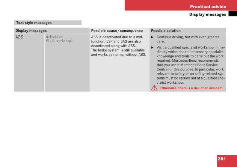
281
Practical advice
Display messages
Text-style messages
Display messages Possible cause/consequence Possible solution
ABS defective!Visit workshop!
ABS is deactivated due to a mal-function. ESP and BAS are alsodeactivated along with ABS.The brake system is still availableand works as normal without ABS.
Continue driving, but with even greatercare.
Visit a qualified specialist workshop imme-diately which has the necessary specialistknowledge and tools to carry out the workrequired. Mercedes-Benz recommendsthat you use a Mercedes-Benz ServiceCentre for this purpose. In particular, workrelevant to safety or on safety-related sys-tems must be carried out at a qualified spe-cialist workshop.
G Otherwise, there is a risk of an accident.
209en_d2.boo Seite 281 Dienstag, 25. Mai 2004 7:26 19
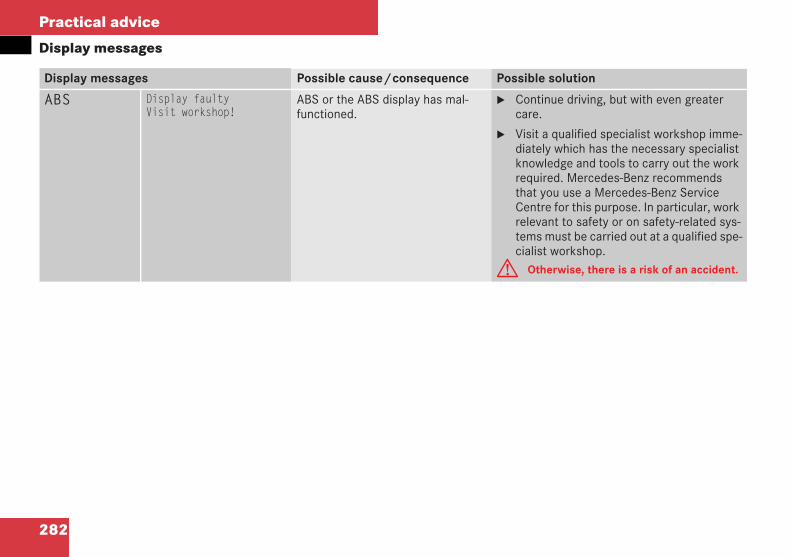
282
Practical advice
Display messages
Display messages Possible cause/consequence Possible solution
ABS Display faultyVisit workshop!
ABS or the ABS display has mal-functioned.
Continue driving, but with even greatercare.
Visit a qualified specialist workshop imme-diately which has the necessary specialistknowledge and tools to carry out the workrequired. Mercedes-Benz recommendsthat you use a Mercedes-Benz ServiceCentre for this purpose. In particular, workrelevant to safety or on safety-related sys-tems must be carried out at a qualified spe-cialist workshop.
G Otherwise, there is a risk of an accident.
209en_d2.boo Seite 282 Dienstag, 25. Mai 2004 7:26 19
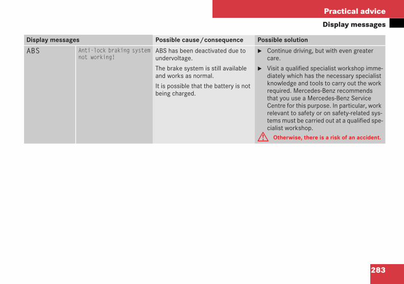
283
Practical advice
Display messages
Display messages Possible cause/consequence Possible solution
ABS Anti-lock braking systemnot working!
ABS has been deactivated due toundervoltage.
The brake system is still availableand works as normal.
It is possible that the battery is notbeing charged.
Continue driving, but with even greatercare.
Visit a qualified specialist workshop imme-diately which has the necessary specialistknowledge and tools to carry out the workrequired. Mercedes-Benz recommendsthat you use a Mercedes-Benz ServiceCentre for this purpose. In particular, workrelevant to safety or on safety-related sys-tems must be carried out at a qualified spe-cialist workshop.
G Otherwise, there is a risk of an accident.
209en_d2.boo Seite 283 Dienstag, 25. Mai 2004 7:26 19

284
Practical advice
Display messages
Display messages Possible cause/consequence Possible solution
BAS defective!Visit workshop!
BAS is deactivated due to a mal-function.
The brake system is still availableand works as normal but withoutBAS.
Continue driving, but with even greatercare.
Visit a qualified specialist workshop imme-diately which has the necessary specialistknowledge and tools to carry out the workrequired. Mercedes-Benz recommendsthat you use a Mercedes-Benz ServiceCentre for this purpose. In particular, workrelevant to safety or on safety-related sys-tems must be carried out at a qualified spe-cialist workshop.
G Otherwise, there is a risk of an accident.
209en_d2.boo Seite 284 Dienstag, 25. Mai 2004 7:26 19
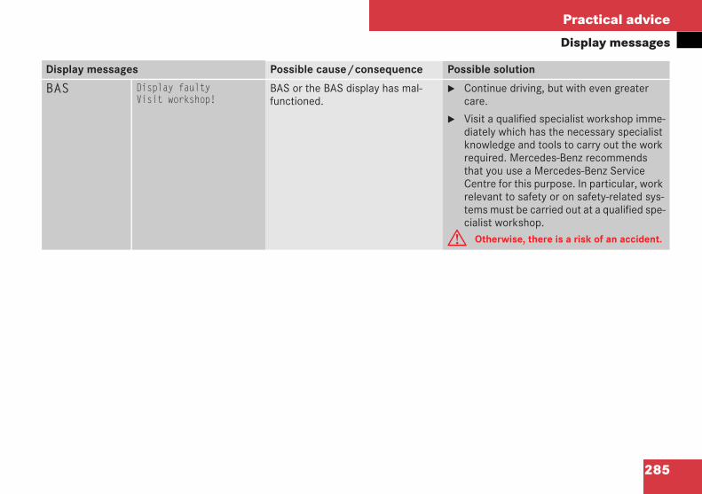
285
Practical advice
Display messages
Display messages Possible cause/consequence Possible solution
BAS Display faultyVisit workshop!
BAS or the BAS display has mal-functioned.
Continue driving, but with even greatercare.
Visit a qualified specialist workshop imme-diately which has the necessary specialistknowledge and tools to carry out the workrequired. Mercedes-Benz recommendsthat you use a Mercedes-Benz ServiceCentre for this purpose. In particular, workrelevant to safety or on safety-related sys-tems must be carried out at a qualified spe-cialist workshop.
G Otherwise, there is a risk of an accident.
209en_d2.boo Seite 285 Dienstag, 25. Mai 2004 7:26 19
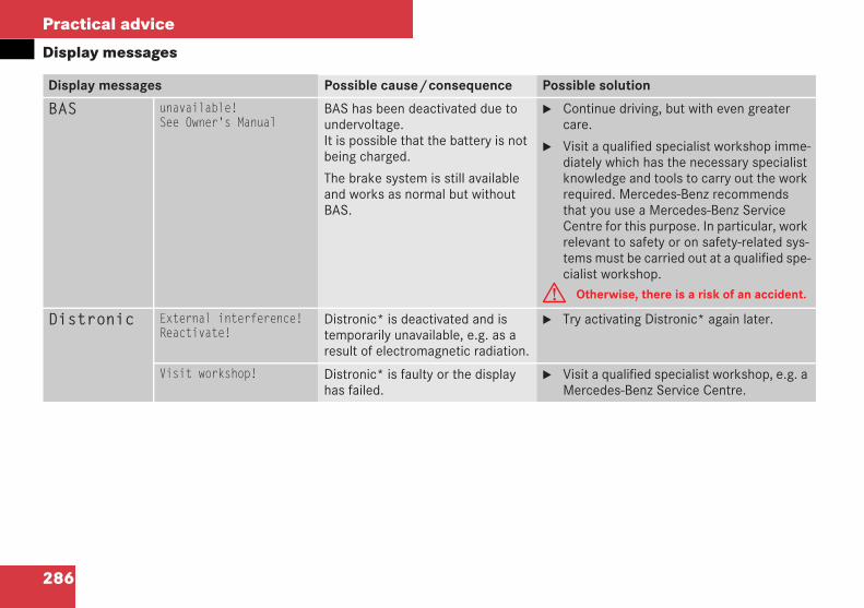
286
Practical advice
Display messages
Display messages Possible cause/consequence Possible solution
BAS unavailable!See Owner's Manual
BAS has been deactivated due toundervoltage.It is possible that the battery is notbeing charged.
The brake system is still availableand works as normal but withoutBAS.
Continue driving, but with even greatercare.
Visit a qualified specialist workshop imme-diately which has the necessary specialistknowledge and tools to carry out the workrequired. Mercedes-Benz recommendsthat you use a Mercedes-Benz ServiceCentre for this purpose. In particular, workrelevant to safety or on safety-related sys-tems must be carried out at a qualified spe-cialist workshop.
G Otherwise, there is a risk of an accident.
Distronic External interference!Reactivate!
Distronic* is deactivated and istemporarily unavailable, e.g. as aresult of electromagnetic radiation.
Try activating Distronic* again later.
Visit workshop! Distronic* is faulty or the displayhas failed.
Visit a qualified specialist workshop, e.g. aMercedes-Benz Service Centre.
209en_d2.boo Seite 286 Dienstag, 25. Mai 2004 7:26 19
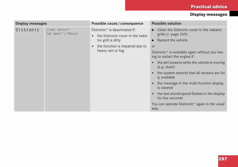
287
Practical advice
Display messages
Display messages Possible cause/consequence Possible solution
Distronic Clean sensor!See Owner's Manual
Distronic* is deactivated if:
the Distronic cover in the radia-tor grill is dirty
the function is impaired due toheavy rain or fog
Clean the Distronic cover in the radiatorgrille ( page 269).
Restart the vehicle.
or
Distronic* is available again without you hav-ing to restart the engine if:
the dirt loosens while the vehicle is moving(e.g. slush)
the system detects that all sensors are ful-ly available
the message in the multi-function displayis cleared
the last stored speed flashes in the displayfor five seconds
You can operate Distronic* again in the usualway.
209en_d2.boo Seite 287 Dienstag, 25. Mai 2004 7:26 19
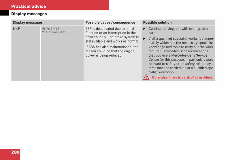
288
Practical advice
Display messages
Display messages Possible cause/consequence Possible solution
ESP defective!Visit workshop!
ESP is deactivated due to a mal-function or an interruption in thepower supply. The brake system isstill available and works as normal.
If ABS has also malfunctioned, thereason could be that the enginepower is being reduced.
Continue driving, but with even greatercare.
Visit a qualified specialist workshop imme-diately which has the necessary specialistknowledge and tools to carry out the workrequired. Mercedes-Benz recommendsthat you use a Mercedes-Benz ServiceCentre for this purpose. In particular, workrelevant to safety or on safety-related sys-tems must be carried out at a qualified spe-cialist workshop.
G Otherwise, there is a risk of an accident.
209en_d2.boo Seite 288 Dienstag, 25. Mai 2004 7:26 19
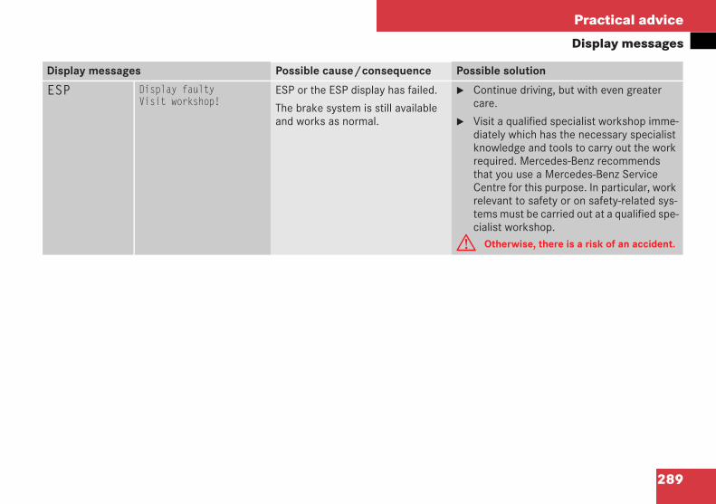
289
Practical advice
Display messages
Display messages Possible cause/consequence Possible solution
ESP Display faultyVisit workshop!
ESP or the ESP display has failed.
The brake system is still availableand works as normal.
Continue driving, but with even greatercare.
Visit a qualified specialist workshop imme-diately which has the necessary specialistknowledge and tools to carry out the workrequired. Mercedes-Benz recommendsthat you use a Mercedes-Benz ServiceCentre for this purpose. In particular, workrelevant to safety or on safety-related sys-tems must be carried out at a qualified spe-cialist workshop.
G Otherwise, there is a risk of an accident.
209en_d2.boo Seite 289 Dienstag, 25. Mai 2004 7:26 19
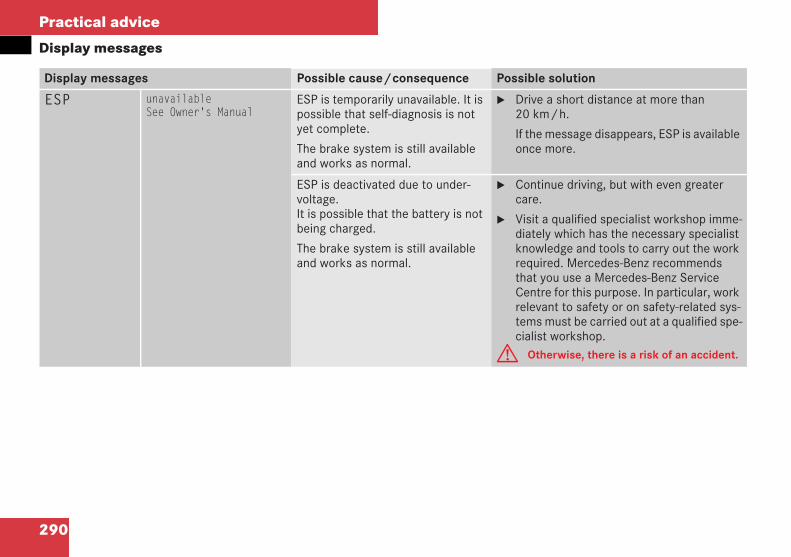
290
Practical advice
Display messages
Display messages Possible cause/consequence Possible solution
ESP unavailableSee Owner's Manual
ESP is temporarily unavailable. It ispossible that self-diagnosis is notyet complete.
The brake system is still availableand works as normal.
Drive a short distance at more than20 km/h.
If the message disappears, ESP is availableonce more.
ESP is deactivated due to under-voltage.It is possible that the battery is notbeing charged.
The brake system is still availableand works as normal.
Continue driving, but with even greatercare.
Visit a qualified specialist workshop imme-diately which has the necessary specialistknowledge and tools to carry out the workrequired. Mercedes-Benz recommendsthat you use a Mercedes-Benz ServiceCentre for this purpose. In particular, workrelevant to safety or on safety-related sys-tems must be carried out at a qualified spe-cialist workshop.
G Otherwise, there is a risk of an accident.
209en_d2.boo Seite 290 Dienstag, 25. Mai 2004 7:26 19
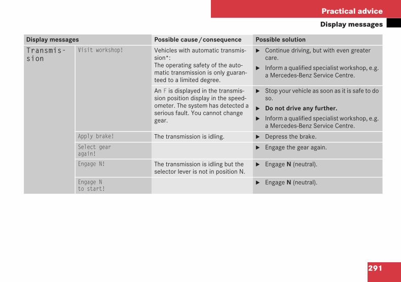
291
Practical advice
Display messages
Display messages Possible cause/consequence Possible solution
Transmis-sion
Visit workshop! Vehicles with automatic transmis-sion*:The operating safety of the auto-matic transmission is only guaran-teed to a limited degree.
Continue driving, but with even greatercare.
Inform a qualified specialist workshop, e.g.a Mercedes-Benz Service Centre.
An F is displayed in the transmis-sion position display in the speed-ometer. The system has detected aserious fault. You cannot changegear.
Stop your vehicle as soon as it is safe to doso.
Do not drive any further.
Inform a qualified specialist workshop, e.g.a Mercedes-Benz Service Centre.
Apply brake! The transmission is idling. Depress the brake.
Select gearagain!
Engage the gear again.
Engage N! The transmission is idling but theselector lever is not in position N.
Engage N (neutral).
Engage Nto start!
Engage N (neutral).
209en_d2.boo Seite 291 Dienstag, 25. Mai 2004 7:26 19
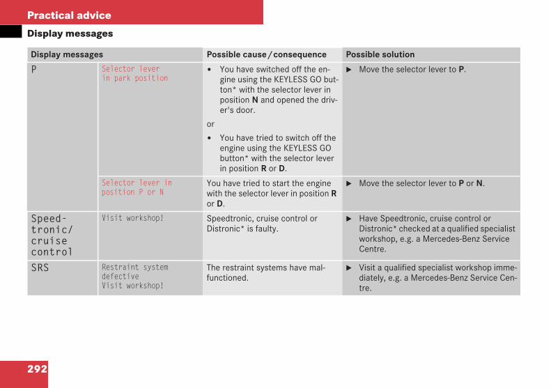
292
Practical advice
Display messages
Display messages Possible cause/consequence Possible solution
P Selector leverin park position
You have switched off the en-gine using the KEYLESS GO but-ton* with the selector lever inposition N and opened the driv-er's door.
or
You have tried to switch off theengine using the KEYLESS GObutton* with the selector leverin position R or D.
Move the selector lever to P.
Selector lever inposition P or N
You have tried to start the enginewith the selector lever in position Ror D.
Move the selector lever to P or N.
Speed-tronic/cruisecontrol
Visit workshop! Speedtronic, cruise control orDistronic* is faulty.
Have Speedtronic, cruise control orDistronic* checked at a qualified specialistworkshop, e.g. a Mercedes-Benz ServiceCentre.
SRS Restraint systemdefectiveVisit workshop!
The restraint systems have mal-functioned.
Visit a qualified specialist workshop imme-diately, e.g. a Mercedes-Benz Service Cen-tre.
209en_d2.boo Seite 292 Dienstag, 25. Mai 2004 7:26 19
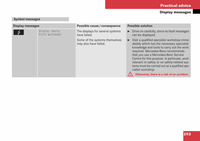
293
Practical advice
Display messages
Symbol messages
Display messages Possible cause/consequence Possible solution
G Display faultyVisit workshop!
The displays for several systemshave failed.
Some of the systems themselvesmay also have failed.
Drive on carefully, since no fault messagescan be displayed.
Visit a qualified specialist workshop imme-diately which has the necessary specialistknowledge and tools to carry out the workrequired. Mercedes-Benz recommendsthat you use a Mercedes-Benz ServiceCentre for this purpose. In particular, workrelevant to safety or on safety-related sys-tems must be carried out at a qualified spe-cialist workshop.
G Otherwise, there is a risk of an accident.
209en_d2.boo Seite 293 Dienstag, 25. Mai 2004 7:26 19
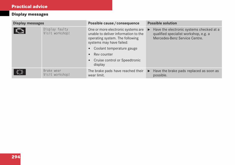
294
Practical advice
Display messages
Display messages Possible cause/consequence Possible solution
± Display faultyVisit workshop!
One or more electronic systems areunable to deliver information to theoperating system. The followingsystems may have failed:
Coolant temperature gauge
Rev counter
Cruise control or Speedtronicdisplay
Have the electronic systems checked at aqualified specialist workshop, e.g. aMercedes-Benz Service Centre.
2 Brake wearVisit workshop!
The brake pads have reached theirwear limit.
Have the brake pads replaced as soon aspossible.
209en_d2.boo Seite 294 Dienstag, 25. Mai 2004 7:26 19
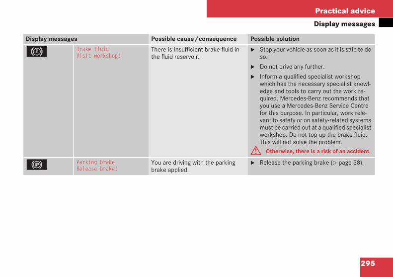
295
Practical advice
Display messages
Display messages Possible cause/consequence Possible solution
3 Brake fluidVisit workshop!
There is insufficient brake fluid inthe fluid reservoir.
Stop your vehicle as soon as it is safe to doso.
Do not drive any further.
Inform a qualified specialist workshopwhich has the necessary specialist knowl-edge and tools to carry out the work re-quired. Mercedes-Benz recommends thatyou use a Mercedes-Benz Service Centrefor this purpose. In particular, work rele-vant to safety or on safety-related systemsmust be carried out at a qualified specialistworkshop. Do not top up the brake fluid.This will not solve the problem.
G Otherwise, there is a risk of an accident.
! Parking brakeRelease brake!
You are driving with the parkingbrake applied.
Release the parking brake ( page 38).
209en_d2.boo Seite 295 Dienstag, 25. Mai 2004 7:26 19
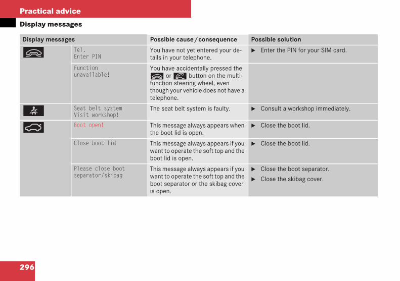
296
Practical advice
Display messages
Display messages Possible cause/consequence Possible solution
ì Tel.Enter PIN
You have not yet entered your de-tails in your telephone.
Enter the PIN for your SIM card.
Functionunavailable!
You have accidentally pressed theì orí button on the multi-function steering wheel, eventhough your vehicle does not have atelephone.
< Seat belt systemVisit workshop!
The seat belt system is faulty. Consult a workshop immediately.
Ê Boot open! This message always appears whenthe boot lid is open.
Close the boot lid.
Close boot lid This message always appears if youwant to operate the soft top and theboot lid is open.
Close the boot lid.
Please close bootseparator/skibag
This message always appears if youwant to operate the soft top and theboot separator or the skibag coveris open.
Close the boot separator.
Close the skibag cover.
209en_d2.boo Seite 296 Dienstag, 25. Mai 2004 7:26 19
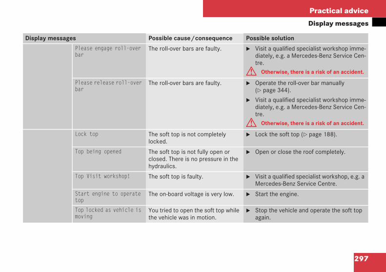
297
Practical advice
Display messages
Display messages Possible cause/consequence Possible solution
Please engage roll-overbar
The roll-over bars are faulty. Visit a qualified specialist workshop imme-diately, e.g. a Mercedes-Benz Service Cen-tre.
G Otherwise, there is a risk of an accident.
Please release roll-overbar
The roll-over bars are faulty. Operate the roll-over bar manually( page 344).
Visit a qualified specialist workshop imme-diately, e.g. a Mercedes-Benz Service Cen-tre.
G Otherwise, there is a risk of an accident.
Lock top The soft top is not completelylocked.
Lock the soft top ( page 188).
Top being opened The soft top is not fully open orclosed. There is no pressure in thehydraulics.
Open or close the roof completely.
Top Visit workshop! The soft top is faulty. Visit a qualified specialist workshop, e.g. aMercedes-Benz Service Centre.
Start engine to operatetop
The on-board voltage is very low. Start the engine.
Top locked as vehicle ismoving
You tried to open the soft top whilethe vehicle was in motion.
Stop the vehicle and operate the soft topagain.
209en_d2.boo Seite 297 Dienstag, 25. Mai 2004 7:26 19
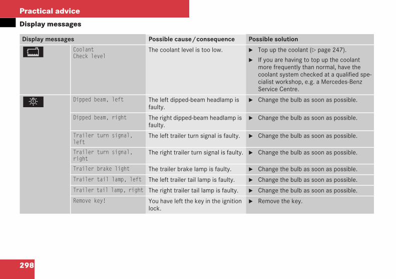
298
Practical advice
Display messages
Display messages Possible cause/consequence Possible solution
B CoolantCheck level
The coolant level is too low. Top up the coolant ( page 247).
If you are having to top up the coolantmore frequently than normal, have thecoolant system checked at a qualified spe-cialist workshop, e.g. a Mercedes-BenzService Centre.
. Dipped beam, left The left dipped-beam headlamp isfaulty.
Change the bulb as soon as possible.
Dipped beam, right The right dipped-beam headlamp isfaulty.
Change the bulb as soon as possible.
Trailer turn signal,left
The left trailer turn signal is faulty. Change the bulb as soon as possible.
Trailer turn signal,right
The right trailer turn signal is faulty. Change the bulb as soon as possible.
Trailer brake light The trailer brake lamp is faulty. Change the bulb as soon as possible.
Trailer tail lamp, left The left trailer tail lamp is faulty. Change the bulb as soon as possible.
Trailer tail lamp, right The right trailer tail lamp is faulty. Change the bulb as soon as possible.
Remove key! You have left the key in the ignitionlock.
Remove the key.
209en_d2.boo Seite 298 Dienstag, 25. Mai 2004 7:26 19
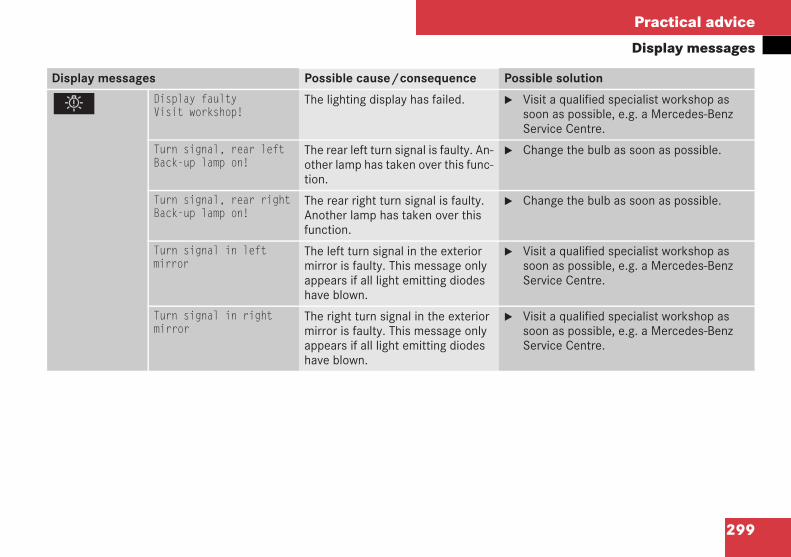
299
Practical advice
Display messages
Display messages Possible cause/consequence Possible solution
. Display faultyVisit workshop!
The lighting display has failed. Visit a qualified specialist workshop assoon as possible, e.g. a Mercedes-BenzService Centre.
Turn signal, rear leftBack-up lamp on!
The rear left turn signal is faulty. An-other lamp has taken over this func-tion.
Change the bulb as soon as possible.
Turn signal, rear rightBack-up lamp on!
The rear right turn signal is faulty.Another lamp has taken over thisfunction.
Change the bulb as soon as possible.
Turn signal in leftmirror
The left turn signal in the exteriormirror is faulty. This message onlyappears if all light emitting diodeshave blown.
Visit a qualified specialist workshop assoon as possible, e.g. a Mercedes-BenzService Centre.
Turn signal in rightmirror
The right turn signal in the exteriormirror is faulty. This message onlyappears if all light emitting diodeshave blown.
Visit a qualified specialist workshop assoon as possible, e.g. a Mercedes-BenzService Centre.
209en_d2.boo Seite 299 Dienstag, 25. Mai 2004 7:26 19
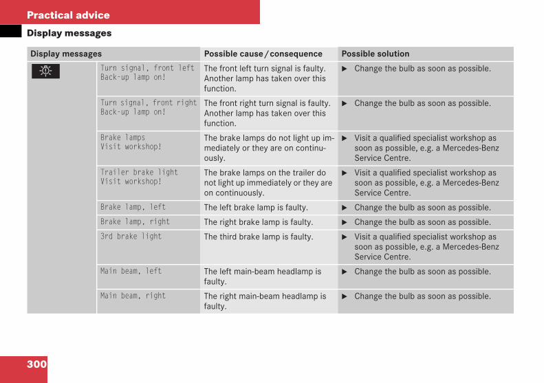
300
Practical advice
Display messages
Display messages Possible cause/consequence Possible solution
. Turn signal, front leftBack-up lamp on!
The front left turn signal is faulty.Another lamp has taken over thisfunction.
Change the bulb as soon as possible.
Turn signal, front rightBack-up lamp on!
The front right turn signal is faulty.Another lamp has taken over thisfunction.
Change the bulb as soon as possible.
Brake lampsVisit workshop!
The brake lamps do not light up im-mediately or they are on continu-ously.
Visit a qualified specialist workshop assoon as possible, e.g. a Mercedes-BenzService Centre.
Trailer brake lightVisit workshop!
The brake lamps on the trailer donot light up immediately or they areon continuously.
Visit a qualified specialist workshop assoon as possible, e.g. a Mercedes-BenzService Centre.
Brake lamp, left The left brake lamp is faulty. Change the bulb as soon as possible.
Brake lamp, right The right brake lamp is faulty. Change the bulb as soon as possible.
3rd brake light The third brake lamp is faulty. Visit a qualified specialist workshop assoon as possible, e.g. a Mercedes-BenzService Centre.
Main beam, left The left main-beam headlamp isfaulty.
Change the bulb as soon as possible.
Main beam, right The right main-beam headlamp isfaulty.
Change the bulb as soon as possible.
209en_d2.boo Seite 300 Dienstag, 25. Mai 2004 7:26 19
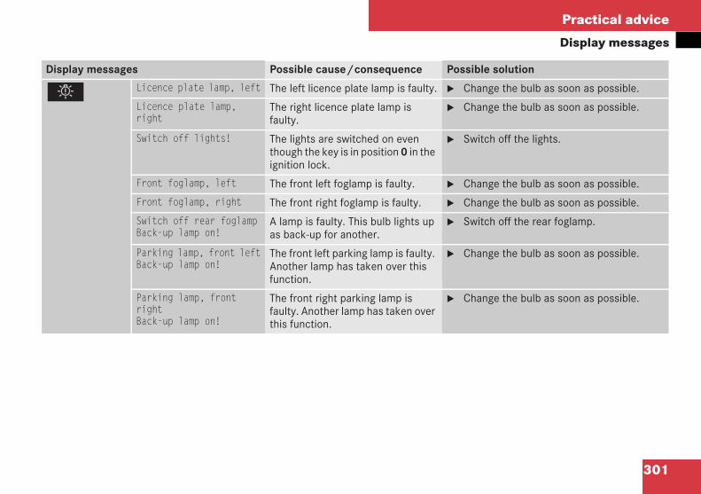
301
Practical advice
Display messages
Display messages Possible cause/consequence Possible solution
. Licence plate lamp, left The left licence plate lamp is faulty. Change the bulb as soon as possible.
Licence plate lamp,right
The right licence plate lamp isfaulty.
Change the bulb as soon as possible.
Switch off lights! The lights are switched on eventhough the key is in position 0 in theignition lock.
Switch off the lights.
Front foglamp, left The front left foglamp is faulty. Change the bulb as soon as possible.
Front foglamp, right The front right foglamp is faulty. Change the bulb as soon as possible.
Switch off rear foglampBack-up lamp on!
A lamp is faulty. This bulb lights upas back-up for another.
Switch off the rear foglamp.
Parking lamp, front leftBack-up lamp on!
The front left parking lamp is faulty.Another lamp has taken over thisfunction.
Change the bulb as soon as possible.
Parking lamp, frontrightBack-up lamp on!
The front right parking lamp isfaulty. Another lamp has taken overthis function.
Change the bulb as soon as possible.
209en_d2.boo Seite 301 Dienstag, 25. Mai 2004 7:26 19

302
Practical advice
Display messages
Display messages Possible cause/consequence Possible solution
. Reversing lamp, left The left reversing lamp is faulty. Change the bulb as soon as possible.
Reversing lamp, right The right reversing lamp is faulty. Change the bulb as soon as possible.
Tail light, leftBack-up lamp on!
The left tail lamp is faulty. Anotherlamp has taken over this function.
Change the bulb as soon as possible.
Tail light, rightBack-up lamp on!
The right tail lamp is faulty. Anotherlamp has taken over this function.
Change the bulb as soon as possible.
Light sensorVisit workshop!
The light sensor is faulty. The lightsswitch on automatically.
Change the lights back to manual opera-tion in the operating system ( page 122).
Switch on the lights by pressing the lightswitch.
209en_d2.boo Seite 302 Dienstag, 25. Mai 2004 7:26 19
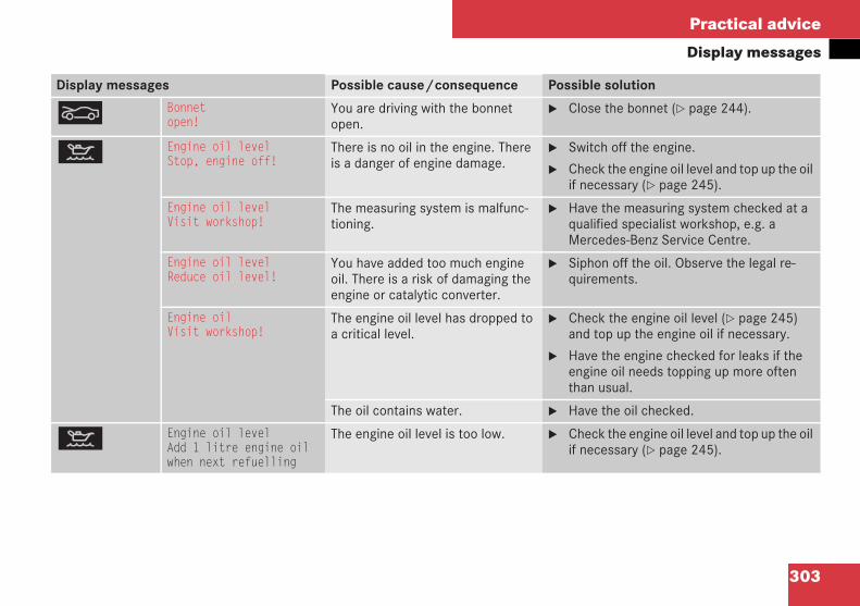
303
Practical advice
Display messages
Display messages Possible cause/consequence Possible solution
O Bonnetopen!
You are driving with the bonnetopen.
Close the bonnet ( page 244).
: Engine oil levelStop, engine off!
There is no oil in the engine. Thereis a danger of engine damage.
Switch off the engine.
Check the engine oil level and top up the oilif necessary ( page 245).
Engine oil levelVisit workshop!
The measuring system is malfunc-tioning.
Have the measuring system checked at aqualified specialist workshop, e.g. aMercedes-Benz Service Centre.
Engine oil levelReduce oil level!
You have added too much engineoil. There is a risk of damaging theengine or catalytic converter.
Siphon off the oil. Observe the legal re-quirements.
Engine oilVisit workshop!
The engine oil level has dropped toa critical level.
Check the engine oil level ( page 245)and top up the engine oil if necessary.
Have the engine checked for leaks if theengine oil needs topping up more oftenthan usual.
The oil contains water. Have the oil checked.
: Engine oil levelAdd 1 litre engine oilwhen next refuelling
The engine oil level is too low. Check the engine oil level and top up the oilif necessary ( page 245).
209en_d2.boo Seite 303 Dienstag, 25. Mai 2004 7:26 19
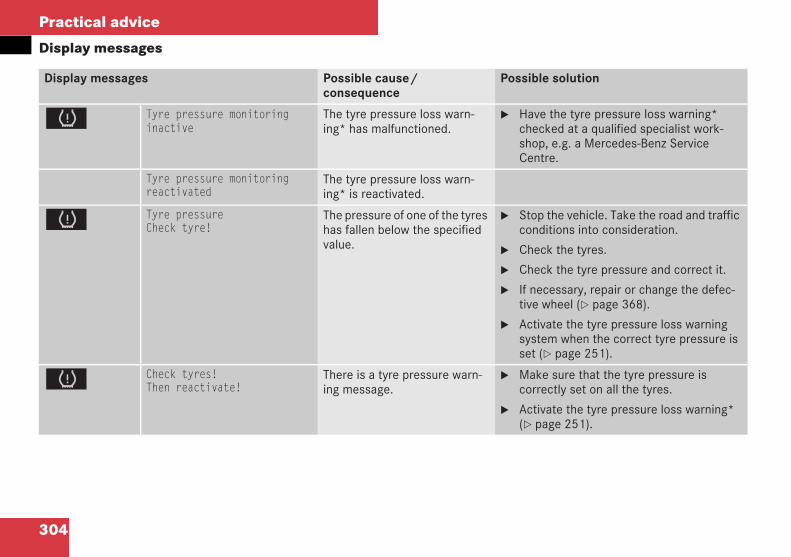
304
Practical advice
Display messages
Display messages Possible cause/consequence
Possible solution
H Tyre pressure monitoringinactive
The tyre pressure loss warn-ing* has malfunctioned.
Have the tyre pressure loss warning*checked at a qualified specialist work-shop, e.g. a Mercedes-Benz ServiceCentre.
Tyre pressure monitoringreactivated
The tyre pressure loss warn-ing* is reactivated.
H Tyre pressureCheck tyre!
The pressure of one of the tyreshas fallen below the specifiedvalue.
Stop the vehicle. Take the road and trafficconditions into consideration.
Check the tyres.
Check the tyre pressure and correct it.
If necessary, repair or change the defec-tive wheel ( page 368).
Activate the tyre pressure loss warningsystem when the correct tyre pressure isset ( page 251).
H Check tyres!Then reactivate!
There is a tyre pressure warn-ing message.
Make sure that the tyre pressure iscorrectly set on all the tyres.
Activate the tyre pressure loss warning*( page 251).
209en_d2.boo Seite 304 Dienstag, 25. Mai 2004 7:26 19
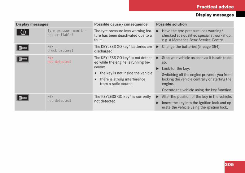
305
Practical advice
Display messages
Display messages Possible cause/consequence Possible solution
H Tyre pressure monitornot available!
The tyre pressure loss warning fea-ture has been deactivated due to afault.
Have the tyre pressure loss warning*checked at a qualified specialist workshop,e.g. a Mercedes-Benz Service Centre.
F KeyCheck battery!
The KEYLESS GO key* batteries aredischarged.
Change the batteries ( page 354).
F Keynot detected!
The KEYLESS GO key* is not detect-ed while the engine is running be-cause:
the key is not inside the vehicle
there is strong interferencefrom a radio source
Stop your vehicle as soon as it is safe to doso.
Look for the key.
Switching off the engine prevents you fromlocking the vehicle centrally or starting theengine.
Operate the vehicle using the key function.
F Keynot detected!
The KEYLESS GO key* is currentlynot detected.
Alter the position of the key in the vehicle.
Insert the key into the ignition lock and op-erate the vehicle using the ignition lock.
209en_d2.boo Seite 305 Dienstag, 25. Mai 2004 7:26 19
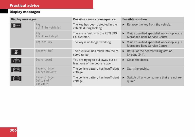
306
Practical advice
Display messages
Display messages Possible cause/consequence Possible solution
F Keystill in vehicle!
The key has been detected in thevehicle during locking.
Remove the key from the vehicle.
KeyVisit workshop!
There is a fault with the KEYLESSGO system*.
Visit a qualified specialist workshop, e.g. aMercedes-Benz Service Centre.
Replace key The key is no longer working. Visit a qualified specialist workshop, e.g. aMercedes-Benz Service Centre.
A Reserve fuel The fuel level has fallen into the re-serve range.
Refuel at the nearest filling station( page 241).
J Doors open! You are trying to pull away but atleast one of the doors is open.
Close the doors.
# UndervoltageCharge battery
The vehicle battery has insufficientvoltage.
Start the engine.
# UndervoltageSwitch offconsumers
The vehicle battery has insufficientvoltage.
Switch off any consumers that are not re-quired.
209en_d2.boo Seite 306 Dienstag, 25. Mai 2004 7:26 19
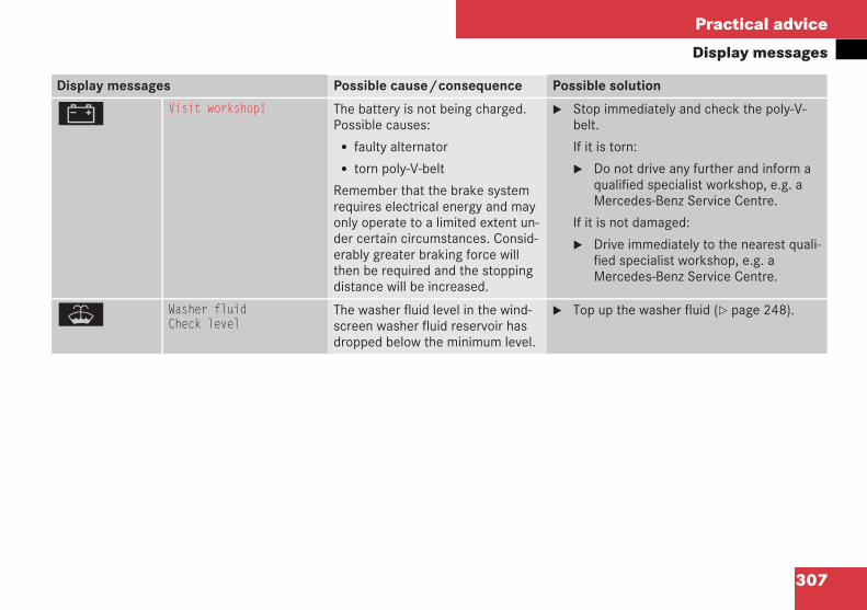
307
Practical advice
Display messages
Display messages Possible cause/consequence Possible solution
# Visit workshop! The battery is not being charged.Possible causes:
faulty alternator
torn poly-V-belt
Remember that the brake systemrequires electrical energy and mayonly operate to a limited extent un-der certain circumstances. Consid-erably greater braking force willthen be required and the stoppingdistance will be increased.
Stop immediately and check the poly-V-belt.
If it is torn:
Do not drive any further and inform aqualified specialist workshop, e.g. aMercedes-Benz Service Centre.
If it is not damaged:
Drive immediately to the nearest quali-fied specialist workshop, e.g. aMercedes-Benz Service Centre.
W Washer fluidCheck level
The washer fluid level in the wind-screen washer fluid reservoir hasdropped below the minimum level.
Top up the washer fluid ( page 248).
209en_d2.boo Seite 307 Dienstag, 25. Mai 2004 7:26 19
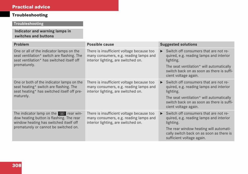
308
Practical advice
Troubleshooting
Troubleshooting
Indicator and warning lamps inswitches and buttons
Problem Possible cause Suggested solutions
One or all of the indicator lamps on theseat ventilation* switch are flashing. Theseat ventilation* has switched itself offprematurely.
There is insufficient voltage because toomany consumers, e.g. reading lamps andinterior lighting, are switched on.
Switch off consumers that are not re-quired, e.g. reading lamps and interiorlighting.
The seat ventilation* will automaticallyswitch back on as soon as there is suffi-cient voltage again.
One or both of the indicator lamps on theseat heating* switch are flashing. Theseat heating* has switched itself off pre-maturely.
There is insufficient voltage because toomany consumers, e.g. reading lamps andinterior lighting, are switched on.
Switch off consumers that are not re-quired, e.g. reading lamps and interiorlighting.
The seat ventilation* will automaticallyswitch back on as soon as there is suffi-cient voltage again.
The indicator lamp on theF rear win-dow heating button is flashing. The rearwindow heating has switched itself offprematurely or cannot be switched on.
There is insufficient voltage because toomany consumers, e.g. reading lamps andinterior lighting, are switched on.
Switch off consumers that are not re-quired, e.g. reading lamps and interiorlighting.
The rear window heating will automati-cally switch back on as soon as there issufficient voltage again.
209en_d2.boo Seite 308 Dienstag, 25. Mai 2004 7:26 19
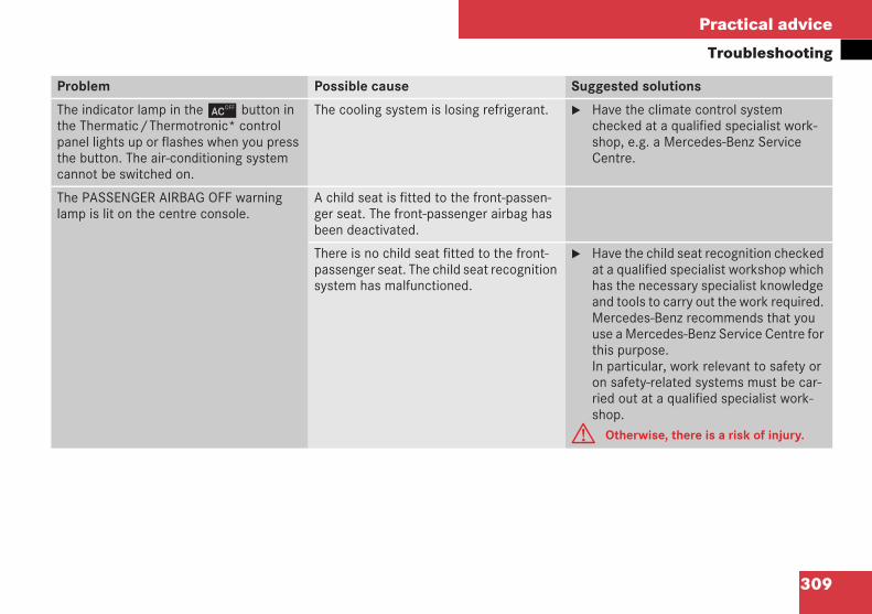
309
Practical advice
Troubleshooting
Problem Possible cause Suggested solutions
The indicator lamp in the ± button inthe Thermatic/Thermotronic* controlpanel lights up or flashes when you pressthe button. The air-conditioning systemcannot be switched on.
The cooling system is losing refrigerant. Have the climate control systemchecked at a qualified specialist work-shop, e.g. a Mercedes-Benz ServiceCentre.
The PASSENGER AIRBAG OFF warninglamp is lit on the centre console.
A child seat is fitted to the front-passen-ger seat. The front-passenger airbag hasbeen deactivated.
There is no child seat fitted to the front-passenger seat. The child seat recognitionsystem has malfunctioned.
Have the child seat recognition checkedat a qualified specialist workshop whichhas the necessary specialist knowledgeand tools to carry out the work required.Mercedes-Benz recommends that youuse a Mercedes-Benz Service Centre forthis purpose.In particular, work relevant to safety oron safety-related systems must be car-ried out at a qualified specialist work-shop.
G Otherwise, there is a risk of injury.
selbsthi.fm Seite 309 Dienstag, 1. Juni 2004 7:03 19
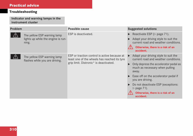
310
Practical advice
Troubleshooting
Indicator and warning lamps in theinstrument cluster
Problem Possible cause Suggested solutions
v The yellow ESP warning lamplights up while the engine is run-ning.
ESP is deactivated. Reactivate ESP ( page 71).
Adapt your driving style to suit thecurrent road and weather conditions.
G Otherwise, there is a risk of anaccident.
v The yellow ESP warning lampflashes while you are driving.
ESP or traction control is active because atleast one of the wheels has reached its tyregrip limit. Distronic* is deactivated.
Adapt your driving style to suit thecurrent road and weather conditions.
Only depress the accelerator pedal asmuch as necessary when pullingaway.
Ease off on the accelerator pedal ifyou are driving.
Do not deactivate ESP (exceptions:page 71).
G Otherwise, there is a risk of anaccident.
209en_d2.boo Seite 310 Dienstag, 25. Mai 2004 7:26 19
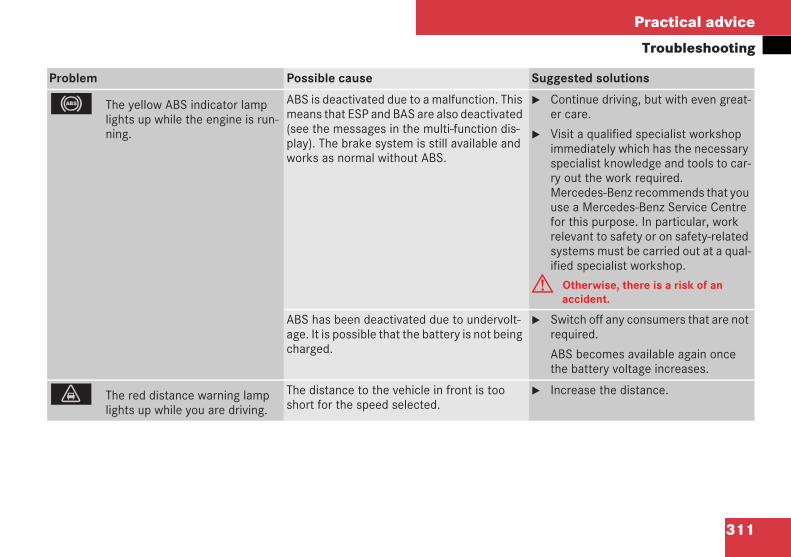
311
Practical advice
Troubleshooting
Problem Possible cause Suggested solutions
- The yellow ABS indicator lamplights up while the engine is run-ning.
ABS is deactivated due to a malfunction. Thismeans that ESP and BAS are also deactivated(see the messages in the multi-function dis-play). The brake system is still available andworks as normal without ABS.
Continue driving, but with even great-er care.
Visit a qualified specialist workshopimmediately which has the necessaryspecialist knowledge and tools to car-ry out the work required.Mercedes-Benz recommends that youuse a Mercedes-Benz Service Centrefor this purpose. In particular, workrelevant to safety or on safety-relatedsystems must be carried out at a qual-ified specialist workshop.
G Otherwise, there is a risk of anaccident.
ABS has been deactivated due to undervolt-age. It is possible that the battery is not beingcharged.
Switch off any consumers that are notrequired.
ABS becomes available again oncethe battery voltage increases.
l The red distance warning lamplights up while you are driving.
The distance to the vehicle in front is tooshort for the speed selected.
Increase the distance.
209en_d2.boo Seite 311 Dienstag, 25. Mai 2004 7:26 19
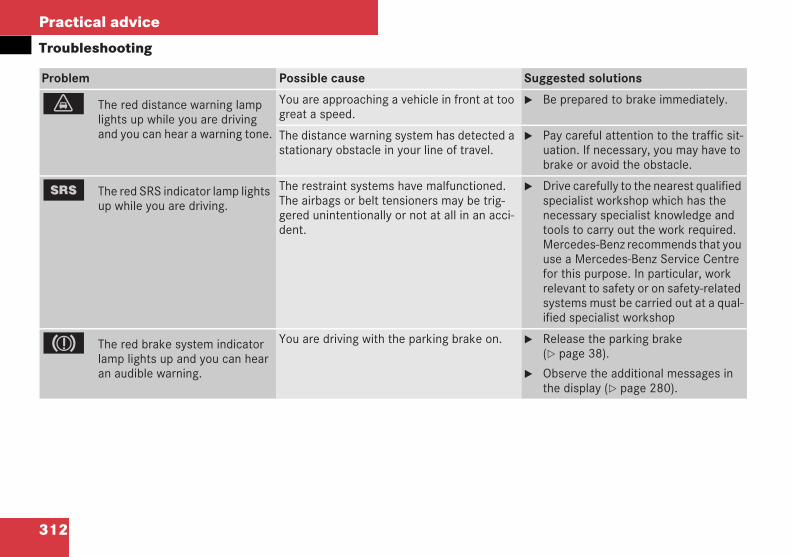
312
Practical advice
Troubleshooting
Problem Possible cause Suggested solutions
l The red distance warning lamplights up while you are drivingand you can hear a warning tone.
You are approaching a vehicle in front at toogreat a speed.
Be prepared to brake immediately.
The distance warning system has detected astationary obstacle in your line of travel.
Pay careful attention to the traffic sit-uation. If necessary, you may have tobrake or avoid the obstacle.
1 The red SRS indicator lamp lightsup while you are driving.
The restraint systems have malfunctioned.The airbags or belt tensioners may be trig-gered unintentionally or not at all in an acci-dent.
Drive carefully to the nearest qualifiedspecialist workshop which has thenecessary specialist knowledge andtools to carry out the work required.Mercedes-Benz recommends that youuse a Mercedes-Benz Service Centrefor this purpose. In particular, workrelevant to safety or on safety-relatedsystems must be carried out at a qual-ified specialist workshop
3 The red brake system indicatorlamp lights up and you can hearan audible warning.
You are driving with the parking brake on. Release the parking brake( page 38).
Observe the additional messages inthe display ( page 280).
209en_d2.boo Seite 312 Dienstag, 25. Mai 2004 7:26 19
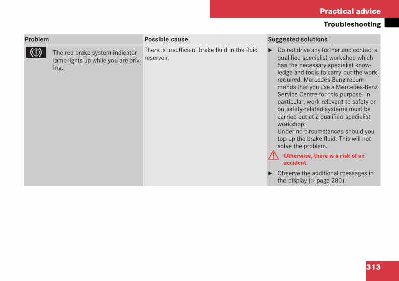
313
Practical advice
Troubleshooting
Problem Possible cause Suggested solutions
3 The red brake system indicatorlamp lights up while you are driv-ing.
There is insufficient brake fluid in the fluidreservoir.
Do not drive any further and contact aqualified specialist workshop whichhas the necessary specialist know-ledge and tools to carry out the workrequired. Mercedes-Benz recom-mends that you use a Mercedes-BenzService Centre for this purpose. Inparticular, work relevant to safety oron safety-related systems must becarried out at a qualified specialistworkshop.Under no circumstances should youtop up the brake fluid. This will notsolve the problem.
G Otherwise, there is a risk of anaccident.
Observe the additional messages inthe display ( page 280).
209en_d2.boo Seite 313 Dienstag, 25. Mai 2004 7:26 19
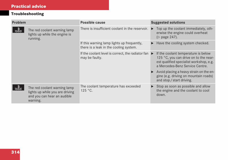
314
Practical advice
Troubleshooting
Problem Possible cause Suggested solutions
D The red coolant warning lamplights up while the engine isrunning.
There is insufficient coolant in the reservoir. Top up the coolant immediately, oth-erwise the engine could overheat( page 247).
If this warning lamp lights up frequently,there is a leak in the cooling system.
Have the cooling system checked.
If the coolant level is correct, the radiator fanmay be faulty.
If the coolant temperature is below125 °C, you can drive on to the near-est qualified specialist workshop, e.g.a Mercedes-Benz Service Centre.
Avoid placing a heavy strain on the en-gine (e.g. driving on mountain roads)and stop/start driving.
D The red coolant warning lamplights up while you are drivingand you can hear an audiblewarning.
The coolant temperature has exceeded125 °C.
Stop as soon as possible and allowthe engine and the coolant to cooldown.
209en_d2.boo Seite 314 Dienstag, 25. Mai 2004 7:26 19
315
Practical advice
Troubleshooting
Problem Possible cause Suggested solutions
± The yellow engine diagnostic in-dicator lamp lights up while youare driving.
There is a malfunction:
in the engine management system
in the fuel injection system
in the ignition system, or
in the exhaust system
The emission limit values may be exceededand the engine may be running in emergencymode.
Have the vehicle checked as soon aspossible at a qualified specialist work-shop, e.g. a Mercedes-Benz ServiceCentre.
The fuel tank has run dry. Start the engine three to four timesafter refuelling.
Emergency mode is cancelled. Youdo not need to have your vehiclechecked.
\ The yellow roll-over bar warninglamp lights up or flickers whenthe engine is switched on.
The roll-over bar release system is faulty. Release the roll-over bars manuallyand have them checked immediatelyat a qualified specialist workshop, e.g.a Mercedes-Benz Service Centre.
G Otherwise, there is a risk of anaccident.
209en_d2.boo Seite 315 Dienstag, 25. Mai 2004 7:26 19
316
Practical advice
Troubleshooting
Problem Possible cause Suggested solutions
< The red seat belt warning lamplights up and you also hear an in-termittent audible signal.
The warning lamp is to remind you to fastenthe seat belt.It lights up if the driver has not fastened hisseat belt as soon as:
the engine is running
the driver's door is closed
The intermittent signal sounds for approxi-mately 93 seconds as soon as you exceed aroad speed of 25 km/h.
Fasten your seat belt ( page 32).
The warning lamp goes out and theaudible signal ceases.
The audible signal ceases automati-cally after no more than 93 seconds,even if you have not fastened yourseat belt.
You have placed objects on the seat. Remove the objects from the seat.
or
Secure them with the seat belt.
A The yellow reserve fuel warninglamp lights up while you are driv-ing.
The petrol or diesel level has fallen into thereserve range.
Refuel at the nearest filling station( page 241).
209en_d2.boo Seite 316 Dienstag, 25. Mai 2004 7:26 19
317
Practical advice
Troubleshooting1
Audible warning signals
Problem Possible cause/consequence Suggested solutions
The anti-theft alarm system* is suddenlytriggered.
You have opened the vehicle using theemergency key element while the anti-theft alarm system* was still primed.
Remote control:
Press theŒ or‹ button.
or
Insert the key into the ignition lock.
The anti-theft alarm system* is deacti-vated.
KEYLESS GO*:
Press the KEYLESS GO button* on theselector lever. The KEYLESS GO keymust be in the vehicle.
The anti-theft alarm system is deactivat-ed.
209en_d2.boo Seite 317 Dienstag, 25. Mai 2004 7:26 19
318
Practical advice
Troubleshooting
Problem Possible cause/consequence Suggested solutions
You hear a warning signal. A message appears in the multi-functiondisplay.
Comply with the notes on ( page 281).
You are driving with the parking brake ap-plied.
Release the parking brake ( page 43).
You have opened the driver's door and for-gotten to switch off the lights.
Turn the light switch to 0.
You have not fastened your seat belt. Fasten your seat belt ( page 32).G There is otherwise a risk of injury.
Vehicles with automatic transmission*:
You have:
switched off the engine
opened the driver's door
not moved the selector lever to P
Move the selector lever to P.
209en_d2.boo Seite 318 Dienstag, 25. Mai 2004 7:26 19
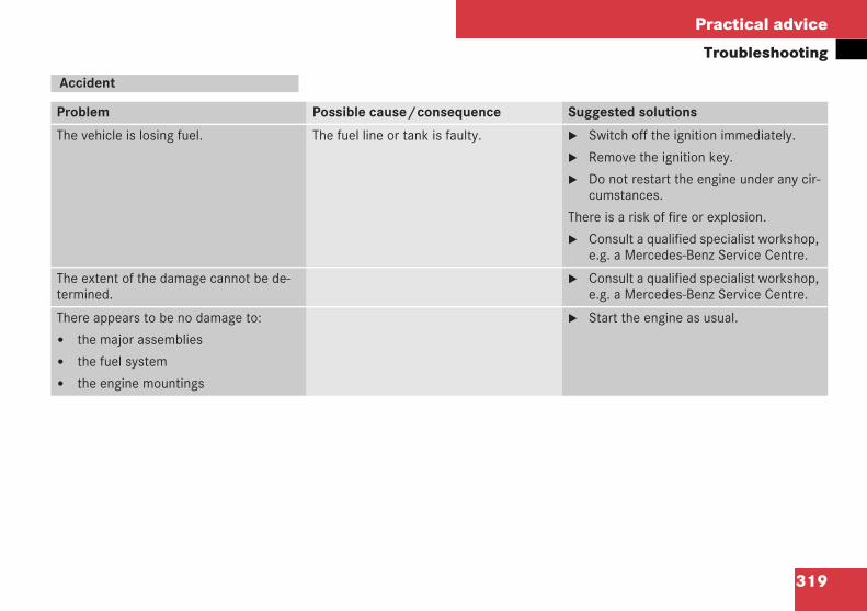
319
Practical advice
Troubleshooting
Accident
Problem Possible cause/consequence Suggested solutions
The vehicle is losing fuel. The fuel line or tank is faulty. Switch off the ignition immediately.
Remove the ignition key.
Do not restart the engine under any cir-cumstances.
There is a risk of fire or explosion.
Consult a qualified specialist workshop,e.g. a Mercedes-Benz Service Centre.
The extent of the damage cannot be de-termined.
Consult a qualified specialist workshop,e.g. a Mercedes-Benz Service Centre.
There appears to be no damage to:
the major assemblies
the fuel system
the engine mountings
Start the engine as usual.
209en_d2.boo Seite 319 Dienstag, 25. Mai 2004 7:26 19

320
Practical advice
Troubleshooting
Seat belt
Problem Possible cause/consequence Suggested solutions
The seat belt extender does not slide back. The seat belt extender is defective. Push the seat belt extender back withforce.
Have the seat belt extender checkedat a qualified specialist workshop, e.g.a Mercedes-Benz Service Centre.
If you are unable to push the seat beltextender back:
Do not drive any further and inform aqualified specialist workshop, e.g. aMercedes-Benz Service Centre.
G There is otherwise a risk of injury.
209en_d2.boo Seite 320 Dienstag, 25. Mai 2004 7:26 19
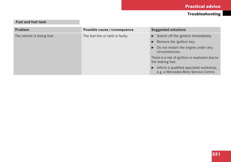
321
Practical advice
Troubleshooting
Fuel and fuel tank
Problem Possible cause/consequence Suggested solutions
The vehicle is losing fuel. The fuel line or tank is faulty. Switch off the ignition immediately.
Remove the ignition key.
Do not restart the engine under anycircumstances.
There is a risk of ignition or explosion due tothe leaking fuel.
Inform a qualified specialist workshop,e.g. a Mercedes-Benz Service Centre.
209en_d2.boo Seite 321 Dienstag, 25. Mai 2004 7:26 19
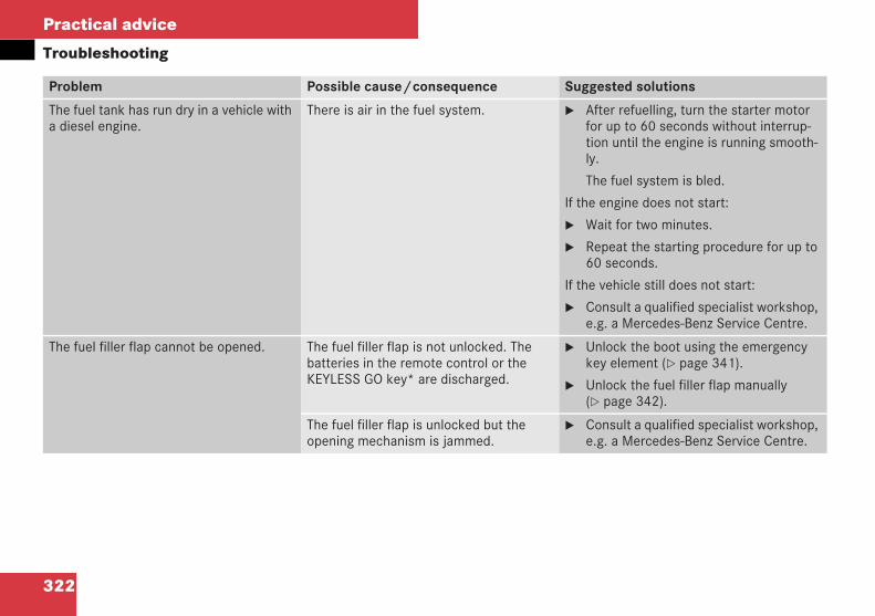
322
Practical advice
Troubleshooting
Problem Possible cause/consequence Suggested solutions
The fuel tank has run dry in a vehicle witha diesel engine.
There is air in the fuel system. After refuelling, turn the starter motorfor up to 60 seconds without interrup-tion until the engine is running smooth-ly.
The fuel system is bled.
If the engine does not start:
Wait for two minutes.
Repeat the starting procedure for up to60 seconds.
If the vehicle still does not start:
Consult a qualified specialist workshop,e.g. a Mercedes-Benz Service Centre.
The fuel filler flap cannot be opened. The fuel filler flap is not unlocked. Thebatteries in the remote control or theKEYLESS GO key* are discharged.
Unlock the boot using the emergencykey element ( page 341).
Unlock the fuel filler flap manually( page 342).
The fuel filler flap is unlocked but theopening mechanism is jammed.
Consult a qualified specialist workshop,e.g. a Mercedes-Benz Service Centre.
209en_d2.boo Seite 322 Dienstag, 25. Mai 2004 7:26 19
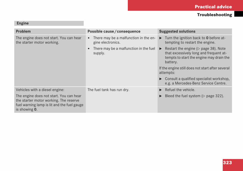
323
Practical advice
Troubleshooting
Engine
Problem Possible cause/consequence Suggested solutions
The engine does not start. You can hearthe starter motor working.
There may be a malfunction in the en-gine electronics.
There may be a malfunction in the fuelsupply.
Turn the ignition back to 0 before at-tempting to restart the engine.
Restart the engine ( page 38). Notethat excessively long and frequent at-tempts to start the engine may drain thebattery.
If the engine still does not start after severalattempts:
Consult a qualified specialist workshop,e.g. a Mercedes-Benz Service Centre.
Vehicles with a diesel engine:
The engine does not start. You can hearthe starter motor working. The reservefuel warning lamp is lit and the fuel gaugeis showing 0.
The fuel tank has run dry. Refuel the vehicle.
Bleed the fuel system ( page 322).
209en_d2.boo Seite 323 Dienstag, 25. Mai 2004 7:26 19
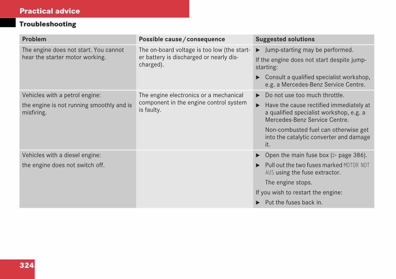
324
Practical advice
Troubleshooting
Problem Possible cause/consequence Suggested solutions
The engine does not start. You cannothear the starter motor working.
The on-board voltage is too low (the start-er battery is discharged or nearly dis-charged).
Jump-starting may be performed.
If the engine does not start despite jump-starting:
Consult a qualified specialist workshop,e.g. a Mercedes-Benz Service Centre.
Vehicles with a petrol engine:
the engine is not running smoothly and ismisfiring.
The engine electronics or a mechanicalcomponent in the engine control systemis faulty.
Do not use too much throttle.
Have the cause rectified immediately ata qualified specialist workshop, e.g. aMercedes-Benz Service Centre.
Non-combusted fuel can otherwise getinto the catalytic converter and damageit.
Vehicles with a diesel engine:
the engine does not switch off.
Open the main fuse box ( page 386).
Pull out the two fuses marked MOTOR NOTAUS using the fuse extractor.
The engine stops.
If you wish to restart the engine:
Put the fuses back in.
209en_d2.boo Seite 324 Dienstag, 25. Mai 2004 7:26 19
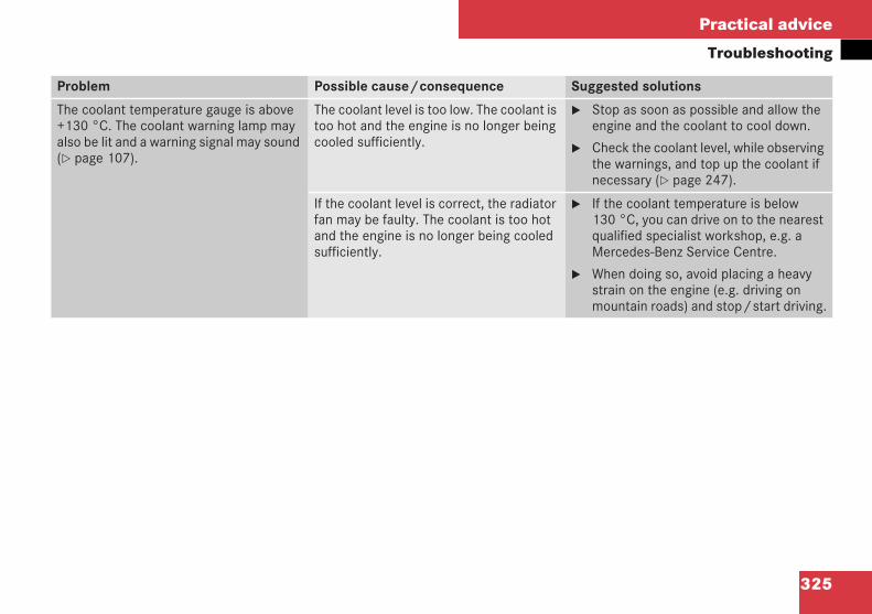
325
Practical advice
Troubleshooting
Problem Possible cause/consequence Suggested solutions
The coolant temperature gauge is above+130 °C. The coolant warning lamp mayalso be lit and a warning signal may sound( page 107).
The coolant level is too low. The coolant istoo hot and the engine is no longer beingcooled sufficiently.
Stop as soon as possible and allow theengine and the coolant to cool down.
Check the coolant level, while observingthe warnings, and top up the coolant ifnecessary ( page 247).
If the coolant level is correct, the radiatorfan may be faulty. The coolant is too hotand the engine is no longer being cooledsufficiently.
If the coolant temperature is below130 °C, you can drive on to the nearestqualified specialist workshop, e.g. aMercedes-Benz Service Centre.
When doing so, avoid placing a heavystrain on the engine (e.g. driving onmountain roads) and stop/start driving.
209en_d2.boo Seite 325 Dienstag, 25. Mai 2004 7:26 19
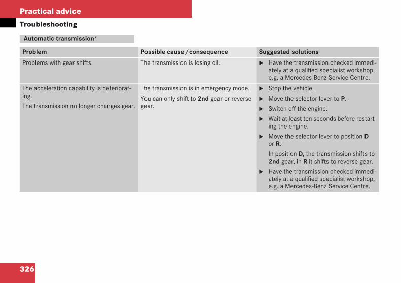
326
Practical advice
Troubleshooting
Automatic transmission*
Problem Possible cause/consequence Suggested solutions
Problems with gear shifts. The transmission is losing oil. Have the transmission checked immedi-ately at a qualified specialist workshop,e.g. a Mercedes-Benz Service Centre.
The acceleration capability is deteriorat-ing.
The transmission no longer changes gear.
The transmission is in emergency mode.
You can only shift to 2nd gear or reversegear.
Stop the vehicle.
Move the selector lever to P.
Switch off the engine.
Wait at least ten seconds before restart-ing the engine.
Move the selector lever to position Dor R.
In position D, the transmission shifts to2nd gear, in R it shifts to reverse gear.
Have the transmission checked immedi-ately at a qualified specialist workshop,e.g. a Mercedes-Benz Service Centre.
209en_d2.boo Seite 326 Dienstag, 25. Mai 2004 7:26 19
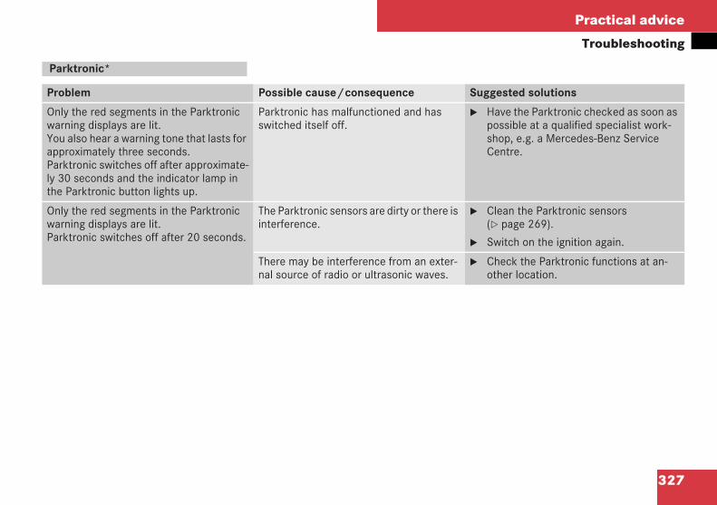
327
Practical advice
Troubleshooting
Parktronic*
Problem Possible cause/consequence Suggested solutions
Only the red segments in the Parktronicwarning displays are lit.You also hear a warning tone that lasts forapproximately three seconds.Parktronic switches off after approximate-ly 30 seconds and the indicator lamp inthe Parktronic button lights up.
Parktronic has malfunctioned and hasswitched itself off.
Have the Parktronic checked as soon aspossible at a qualified specialist work-shop, e.g. a Mercedes-Benz ServiceCentre.
Only the red segments in the Parktronicwarning displays are lit.Parktronic switches off after 20 seconds.
The Parktronic sensors are dirty or there isinterference.
Clean the Parktronic sensors( page 269).
Switch on the ignition again.
There may be interference from an exter-nal source of radio or ultrasonic waves.
Check the Parktronic functions at an-other location.
209en_d2.boo Seite 327 Dienstag, 25. Mai 2004 7:26 19
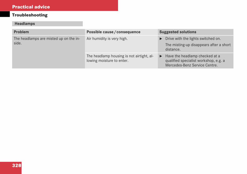
328
Practical advice
Troubleshooting
Headlamps
Problem Possible cause/consequence Suggested solutions
The headlamps are misted up on the in-side.
Air humidity is very high. Drive with the lights switched on.
The misting-up disappears after a shortdistance.
The headlamp housing is not airtight, al-lowing moisture to enter.
Have the headlamp checked at aqualified specialist workshop, e.g. aMercedes-Benz Service Centre.
209en_d2.boo Seite 328 Dienstag, 25. Mai 2004 7:26 19
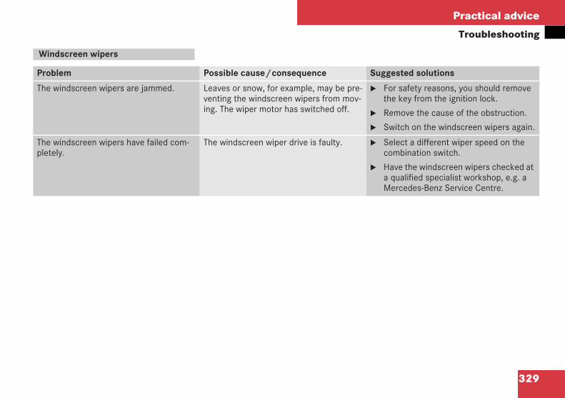
329
Practical advice
Troubleshooting
Windscreen wipers
Problem Possible cause/consequence Suggested solutions
The windscreen wipers are jammed. Leaves or snow, for example, may be pre-venting the windscreen wipers from mov-ing. The wiper motor has switched off.
For safety reasons, you should removethe key from the ignition lock.
Remove the cause of the obstruction.
Switch on the windscreen wipers again.
The windscreen wipers have failed com-pletely.
The windscreen wiper drive is faulty. Select a different wiper speed on thecombination switch.
Have the windscreen wipers checked ata qualified specialist workshop, e.g. aMercedes-Benz Service Centre.
209en_d2.boo Seite 329 Dienstag, 25. Mai 2004 7:26 19
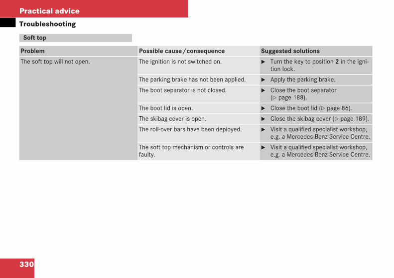
330
Practical advice
Troubleshooting
Soft top
Problem Possible cause/consequence Suggested solutions
The soft top will not open. The ignition is not switched on. Turn the key to position 2 in the igni-tion lock.
The parking brake has not been applied. Apply the parking brake.
The boot separator is not closed. Close the boot separator( page 188).
The boot lid is open. Close the boot lid ( page 86).
The skibag cover is open. Close the skibag cover ( page 189).
The roll-over bars have been deployed. Visit a qualified specialist workshop,e.g. a Mercedes-Benz Service Centre.
The soft top mechanism or controls arefaulty.
Visit a qualified specialist workshop,e.g. a Mercedes-Benz Service Centre.
209en_d2.boo Seite 330 Dienstag, 25. Mai 2004 7:26 19
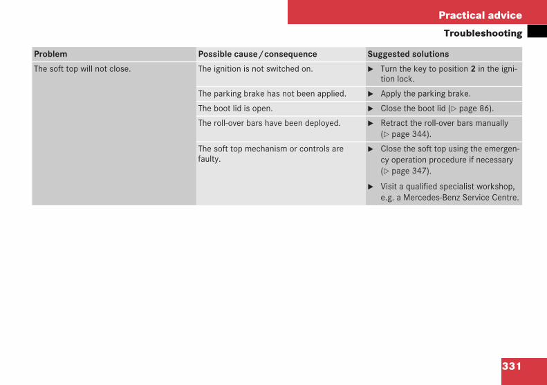
331
Practical advice
Troubleshooting
Problem Possible cause/consequence Suggested solutions
The soft top will not close. The ignition is not switched on. Turn the key to position 2 in the igni-tion lock.
The parking brake has not been applied. Apply the parking brake.
The boot lid is open. Close the boot lid ( page 86).
The roll-over bars have been deployed. Retract the roll-over bars manually( page 344).
The soft top mechanism or controls arefaulty.
Close the soft top using the emergen-cy operation procedure if necessary( page 347).
Visit a qualified specialist workshop,e.g. a Mercedes-Benz Service Centre.
209en_d2.boo Seite 331 Dienstag, 25. Mai 2004 7:26 19
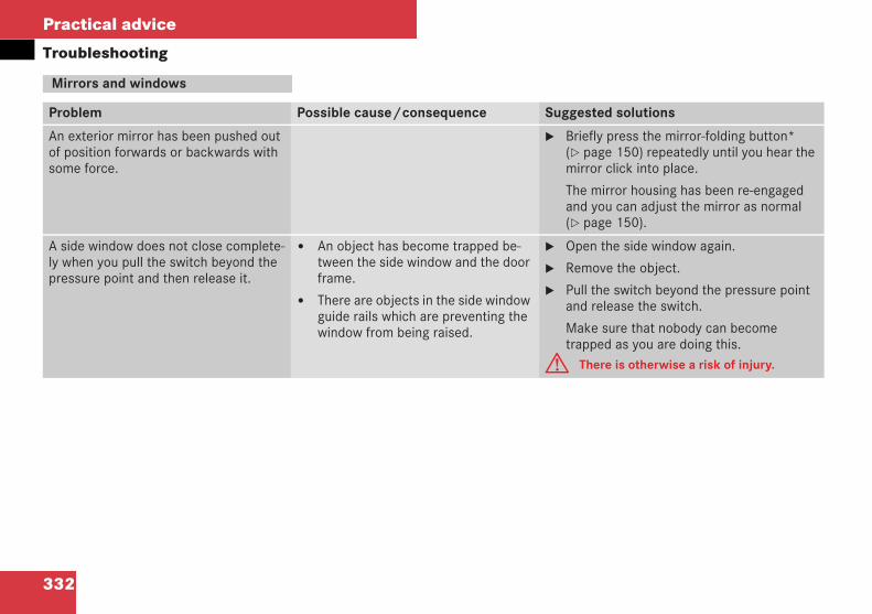
332
Practical advice
Troubleshooting
Mirrors and windows
Problem Possible cause/consequence Suggested solutions
An exterior mirror has been pushed outof position forwards or backwards withsome force.
Briefly press the mirror-folding button*( page 150) repeatedly until you hear themirror click into place.
The mirror housing has been re-engagedand you can adjust the mirror as normal( page 150).
A side window does not close complete-ly when you pull the switch beyond thepressure point and then release it.
An object has become trapped be-tween the side window and the doorframe.
There are objects in the side windowguide rails which are preventing thewindow from being raised.
Open the side window again.
Remove the object.
Pull the switch beyond the pressure pointand release the switch.
Make sure that nobody can becometrapped as you are doing this.
G There is otherwise a risk of injury.
209en_d2.boo Seite 332 Dienstag, 25. Mai 2004 7:26 19
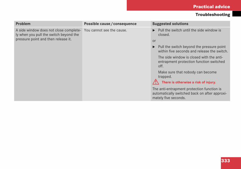
333
Practical advice
Troubleshooting
Problem Possible cause/consequence Suggested solutions
A side window does not close complete-ly when you pull the switch beyond thepressure point and then release it.
You cannot see the cause. Pull the switch until the side window isclosed.
or
Pull the switch beyond the pressure pointwithin five seconds and release the switch.
The side window is closed with the anti-entrapment protection function switchedoff.
Make sure that nobody can becometrapped.
G There is otherwise a risk of injury.
The anti-entrapment protection function isautomatically switched back on after approxi-mately five seconds.
209en_d2.boo Seite 333 Dienstag, 25. Mai 2004 7:26 19
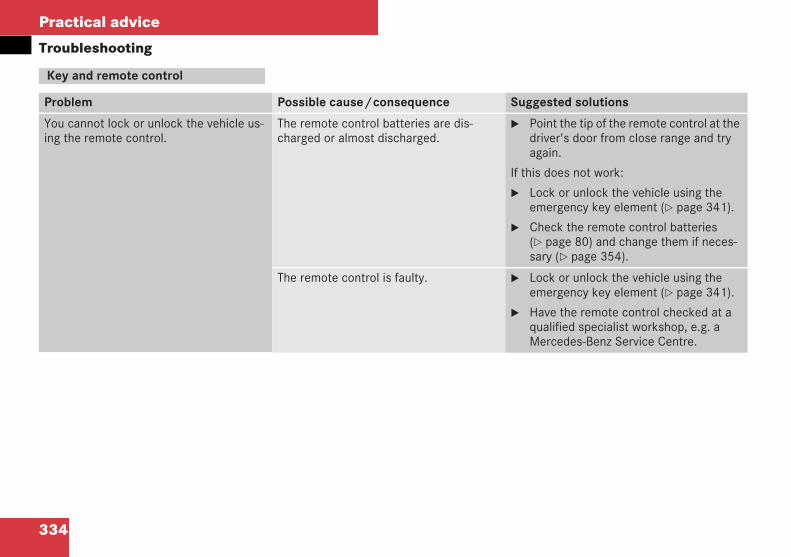
334
Practical advice
Troubleshooting
Key and remote control
Problem Possible cause/consequence Suggested solutions
You cannot lock or unlock the vehicle us-ing the remote control.
The remote control batteries are dis-charged or almost discharged.
Point the tip of the remote control at thedriver's door from close range and tryagain.
If this does not work:
Lock or unlock the vehicle using theemergency key element ( page 341).
Check the remote control batteries( page 80) and change them if neces-sary ( page 354).
The remote control is faulty. Lock or unlock the vehicle using theemergency key element ( page 341).
Have the remote control checked at aqualified specialist workshop, e.g. aMercedes-Benz Service Centre.
209en_d2.boo Seite 334 Dienstag, 25. Mai 2004 7:26 19
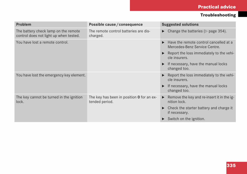
335
Practical advice
Troubleshooting
Problem Possible cause/consequence Suggested solutions
The battery check lamp on the remotecontrol does not light up when tested.
The remote control batteries are dis-charged.
Change the batteries ( page 354).
You have lost a remote control. Have the remote control cancelled at aMercedes-Benz Service Centre.
Report the loss immediately to the vehi-cle insurers.
If necessary, have the manual lockschanged too.
You have lost the emergency key element. Report the loss immediately to the vehi-cle insurers.
If necessary, have the manual lockschanged too.
The key cannot be turned in the ignitionlock.
The key has been in position 0 for an ex-tended period.
Remove the key and re-insert it in the ig-nition lock.
Check the starter battery and charge itif necessary.
Switch on the ignition.
209en_d2.boo Seite 335 Dienstag, 25. Mai 2004 7:26 19
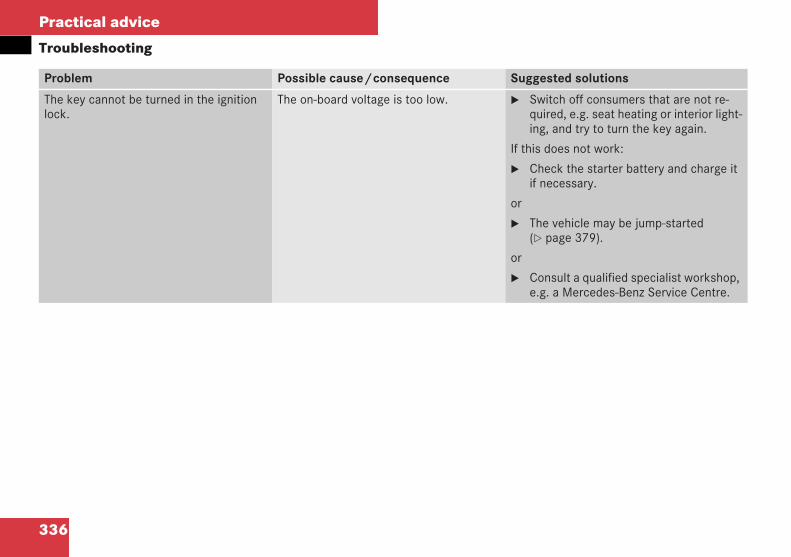
336
Practical advice
Troubleshooting
Problem Possible cause/consequence Suggested solutions
The key cannot be turned in the ignitionlock.
The on-board voltage is too low. Switch off consumers that are not re-quired, e.g. seat heating or interior light-ing, and try to turn the key again.
If this does not work:
Check the starter battery and charge itif necessary.
or
The vehicle may be jump-started( page 379).
or
Consult a qualified specialist workshop,e.g. a Mercedes-Benz Service Centre.
209en_d2.boo Seite 336 Dienstag, 25. Mai 2004 7:26 19
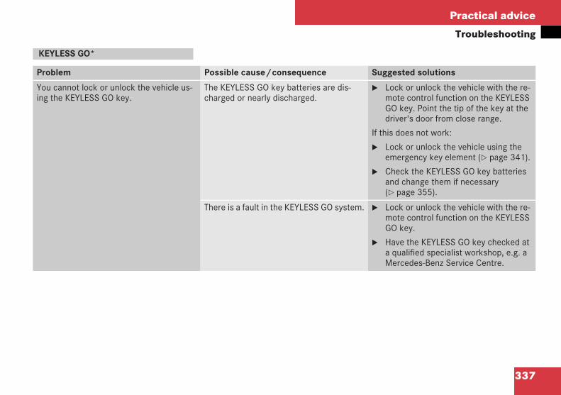
337
Practical advice
Troubleshooting
KEYLESS GO*
Problem Possible cause/consequence Suggested solutions
You cannot lock or unlock the vehicle us-ing the KEYLESS GO key.
The KEYLESS GO key batteries are dis-charged or nearly discharged.
Lock or unlock the vehicle with the re-mote control function on the KEYLESSGO key. Point the tip of the key at thedriver's door from close range.
If this does not work:
Lock or unlock the vehicle using theemergency key element ( page 341).
Check the KEYLESS GO key batteriesand change them if necessary( page 355).
There is a fault in the KEYLESS GO system. Lock or unlock the vehicle with the re-mote control function on the KEYLESSGO key.
Have the KEYLESS GO key checked ata qualified specialist workshop, e.g. aMercedes-Benz Service Centre.
209en_d2.boo Seite 337 Dienstag, 25. Mai 2004 7:26 19
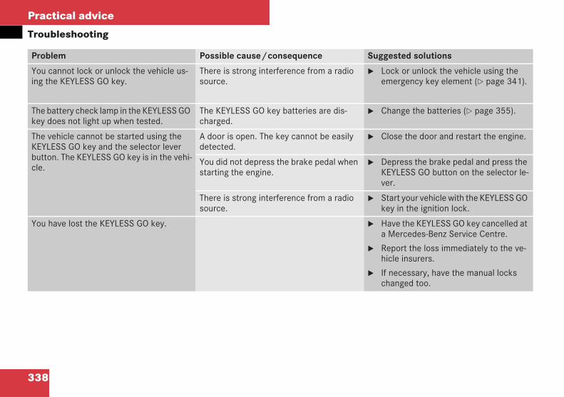
338
Practical advice
Troubleshooting
Problem Possible cause/consequence Suggested solutions
You cannot lock or unlock the vehicle us-ing the KEYLESS GO key.
There is strong interference from a radiosource.
Lock or unlock the vehicle using theemergency key element ( page 341).
The battery check lamp in the KEYLESS GOkey does not light up when tested.
The KEYLESS GO key batteries are dis-charged.
Change the batteries ( page 355).
The vehicle cannot be started using theKEYLESS GO key and the selector leverbutton. The KEYLESS GO key is in the vehi-cle.
A door is open. The key cannot be easilydetected.
Close the door and restart the engine.
You did not depress the brake pedal whenstarting the engine.
Depress the brake pedal and press theKEYLESS GO button on the selector le-ver.
There is strong interference from a radiosource.
Start your vehicle with the KEYLESS GOkey in the ignition lock.
You have lost the KEYLESS GO key. Have the KEYLESS GO key cancelled ata Mercedes-Benz Service Centre.
Report the loss immediately to the ve-hicle insurers.
If necessary, have the manual lockschanged too.
209en_d2.boo Seite 338 Dienstag, 25. Mai 2004 7:26 19
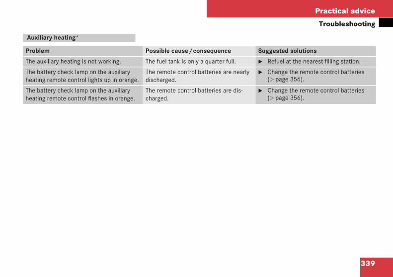
339
Practical advice
Troubleshooting
Auxiliary heating*
Problem Possible cause/consequence Suggested solutions
The auxiliary heating is not working. The fuel tank is only a quarter full. Refuel at the nearest filling station.
The battery check lamp on the auxiliaryheating remote control lights up in orange.
The remote control batteries are nearlydischarged.
Change the remote control batteries( page 356).
The battery check lamp on the auxiliaryheating remote control flashes in orange.
The remote control batteries are dis-charged.
Change the remote control batteries( page 356).
209en_d2.boo Seite 339 Dienstag, 25. Mai 2004 7:26 19
340
Practical advice
Troubleshooting
Leaving the vehicle parked up
Problem Possible cause/consequence Suggested solutions
You wish to leave the vehicle parked upfor a long period of time (longer thansix weeks).
Consult a qualified specialist workshop,e.g. a Mercedes-Benz Service Centre.
Disconnect the battery ( page 377).
209en_d2.boo Seite 340 Dienstag, 25. Mai 2004 7:26 19
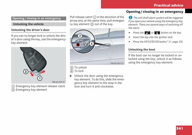
341
Practical advice
Opening/closing in an emergency
Unlocking the driver's door
If you can no longer lock or unlock the driv-er's door using the key, use the emergencykey element.
1 Emergency key element release catch2 Emergency key element
Pull release catch1 in the direction of thearrow and, at the same time, pull emergen-cy key element2 out of the key.
3 To unlock4 To lock
Unlock the door using the emergencykey element. To do this, slide the emer-gency key element to the stop in thelock and turn it anti-clockwise.
i The anti-theft alarm system will be triggeredif you open your vehicle using the emergency keyelement. There are several ways of switching offthe alarm:
Press theŒ or‹ button on the key.
Insert the key into the ignition lock.
Press the KEYLESS GO button* ( page 23).
Unlocking the boot
If the boot can no longer be locked or un-locked using the key, unlock it as followsusing the emergency key element:
Opening/closing in an emergency
Unlocking the vehicle
P 80.20-2319-31
P 80.00-2057-31
209en_d2.boo Seite 341 Dienstag, 25. Mai 2004 7:26 19
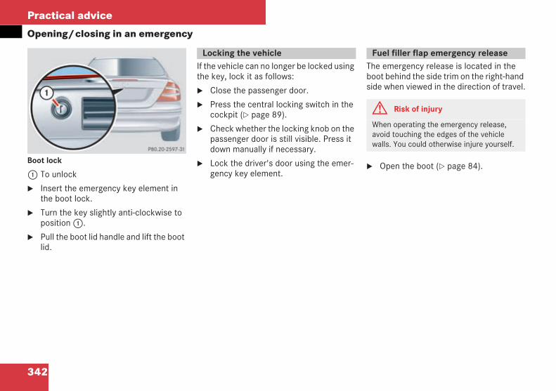
342
Practical advice
Opening/closing in an emergency
Boot lock
1 To unlock
Insert the emergency key element inthe boot lock.
Turn the key slightly anti-clockwise toposition1.
Pull the boot lid handle and lift the bootlid.
If the vehicle can no longer be locked usingthe key, lock it as follows:
Close the passenger door.
Press the central locking switch in thecockpit ( page 89).
Check whether the locking knob on thepassenger door is still visible. Press itdown manually if necessary.
Lock the driver's door using the emer-gency key element.
The emergency release is located in theboot behind the side trim on the right-handside when viewed in the direction of travel.
Open the boot ( page 84).
P 80.20-2597-31
Locking the vehicle Fuel filler flap emergency release
G Risk of injury
When operating the emergency release,avoid touching the edges of the vehiclewalls. You could otherwise injure yourself.
209en_d2.boo Seite 342 Dienstag, 25. Mai 2004 7:26 19
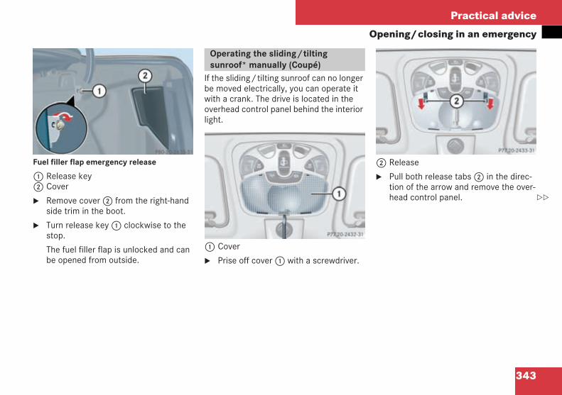
343
Practical advice
Opening/closing in an emergency
Fuel filler flap emergency release
1 Release key2 Cover
Remove cover2 from the right-handside trim in the boot.
Turn release key1 clockwise to thestop.
The fuel filler flap is unlocked and canbe opened from outside.
If the sliding/tilting sunroof can no longerbe moved electrically, you can operate itwith a crank. The drive is located in theoverhead control panel behind the interiorlight.
1 Cover
Prise off cover1 with a screwdriver.
2 Release
Pull both release tabs2 in the direc-tion of the arrow and remove the over-head control panel.
P80.20-2635-31
Operating the sliding/tiltingsunroof* manually (Coupé)
P 77.20-2432-31 neu
P 77.20-2433-31
209en_d2.boo Seite 343 Dienstag, 25. Mai 2004 7:26 19
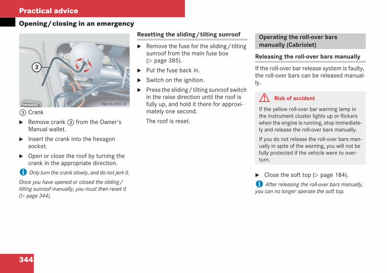
344
Practical advice
Opening/closing in an emergency
3 Crank
Remove crank3 from the Owner'sManual wallet.
Insert the crank into the hexagonsocket.
Open or close the roof by turning thecrank in the appropriate direction.
i Only turn the crank slowly, and do not jerk it.
Once you have opened or closed the sliding/tilting sunroof manually, you must then reset it( page 344).
Resetting the sliding/tilting sunroof
Remove the fuse for the sliding/tiltingsunroof from the main fuse box( page 385).
Put the fuse back in.
Switch on the ignition.
Press the sliding/tilting sunroof switchin the raise direction until the roof isfully up, and hold it there for approxi-mately one second.
The roof is reset.
Releasing the roll-over bars manually
If the roll-over bar release system is faulty,the roll-over bars can be released manual-ly.
Close the soft top ( page 184).
i After releasing the roll-over bars manually,you can no longer operate the soft top.
P 68.00-2852-31
Operating the roll-over barsmanually (Cabriolet)
G Risk of accident
If the yellow roll-over bar warning lamp inthe instrument cluster lights up or flickerswhen the engine is running, stop immediate-ly and release the roll-over bars manually.
If you do not release the roll-over bars man-ually in spite of the warning, you will not befully protected if the vehicle were to over-turn.
209en_d2.boo Seite 344 Dienstag, 25. Mai 2004 7:26 19
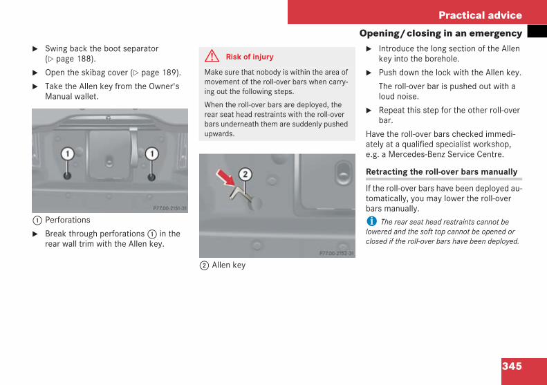
345
Practical advice
Opening/closing in an emergencySwing back the boot separator( page 188).
Open the skibag cover ( page 189).
Take the Allen key from the Owner'sManual wallet.
1 Perforations
Break through perforations1 in therear wall trim with the Allen key.
2 Allen key
Introduce the long section of the Allenkey into the borehole.
Push down the lock with the Allen key.
The roll-over bar is pushed out with aloud noise.
Repeat this step for the other roll-overbar.
Have the roll-over bars checked immedi-ately at a qualified specialist workshop,e.g. a Mercedes-Benz Service Centre.
Retracting the roll-over bars manually
If the roll-over bars have been deployed au-tomatically, you may lower the roll-overbars manually.
i The rear seat head restraints cannot belowered and the soft top cannot be opened orclosed if the roll-over bars have been deployed.
P 77.00-2151-31
G Risk of injury
Make sure that nobody is within the area ofmovement of the roll-over bars when carry-ing out the following steps.
When the roll-over bars are deployed, therear seat head restraints with the roll-overbars underneath them are suddenly pushedupwards.
P 77.00-2152-31
209en_d2.boo Seite 345 Dienstag, 25. Mai 2004 7:26 19
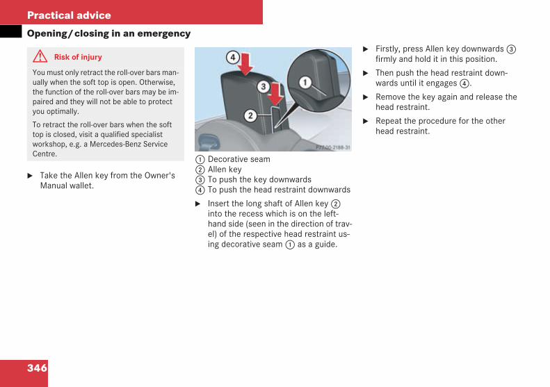
346
Practical advice
Opening/closing in an emergency
Take the Allen key from the Owner'sManual wallet.
1 Decorative seam2 Allen key3 To push the key downwards4 To push the head restraint downwards
Insert the long shaft of Allen key2into the recess which is on the left-hand side (seen in the direction of trav-el) of the respective head restraint us-ing decorative seam1 as a guide.
Firstly, press Allen key downwards3firmly and hold it in this position.
Then push the head restraint down-wards until it engages4.
Remove the key again and release thehead restraint.
Repeat the procedure for the otherhead restraint.
G Risk of injury
You must only retract the roll-over bars man-ually when the soft top is open. Otherwise,the function of the roll-over bars may be im-paired and they will not be able to protectyou optimally.
To retract the roll-over bars when the softtop is closed, visit a qualified specialistworkshop, e.g. a Mercedes-Benz ServiceCentre.
P 77.00-2188-31
209en_d2.boo Seite 346 Dienstag, 25. Mai 2004 7:26 19
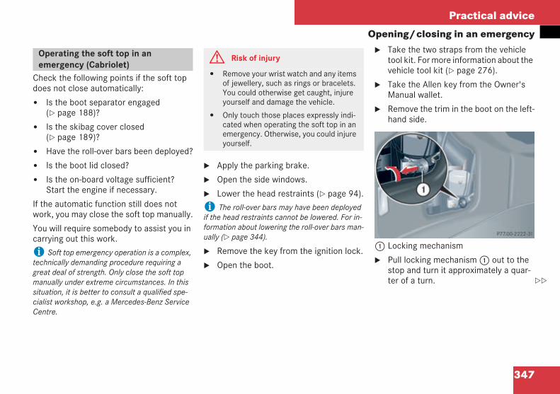
347
Practical advice
Opening/closing in an emergency
Check the following points if the soft topdoes not close automatically:
Is the boot separator engaged( page 188)?
Is the skibag cover closed( page 189)?
Have the roll-over bars been deployed?
Is the boot lid closed?
Is the on-board voltage sufficient?Start the engine if necessary.
If the automatic function still does notwork, you may close the soft top manually.
You will require somebody to assist you incarrying out this work.
i Soft top emergency operation is a complex,technically demanding procedure requiring agreat deal of strength. Only close the soft topmanually under extreme circumstances. In thissituation, it is better to consult a qualified spe-cialist workshop, e.g. a Mercedes-Benz ServiceCentre.
Apply the parking brake.
Open the side windows.
Lower the head restraints ( page 94).
i The roll-over bars may have been deployedif the head restraints cannot be lowered. For in-formation about lowering the roll-over bars man-ually ( page 344).
Remove the key from the ignition lock.
Open the boot.
Take the two straps from the vehicletool kit. For more information about thevehicle tool kit ( page 276).
Take the Allen key from the Owner'sManual wallet.
Remove the trim in the boot on the left-hand side.
1 Locking mechanism
Pull locking mechanism1 out to thestop and turn it approximately a quar-ter of a turn.
Operating the soft top in anemergency (Cabriolet)
G Risk of injury
Remove your wrist watch and any itemsof jewellery, such as rings or bracelets.You could otherwise get caught, injureyourself and damage the vehicle.
Only touch those places expressly indi-cated when operating the soft top in anemergency. Otherwise, you could injureyourself.
P 77.00-2222-31
209en_d2.boo Seite 347 Dienstag, 25. Mai 2004 7:26 19
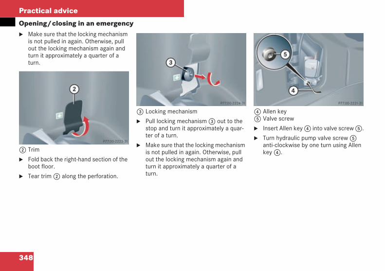
348
Practical advice
Opening/closing in an emergencyMake sure that the locking mechanismis not pulled in again. Otherwise, pullout the locking mechanism again andturn it approximately a quarter of aturn.
2 Trim
Fold back the right-hand section of theboot floor.
Tear trim2 along the perforation.
3 Locking mechanism
Pull locking mechanism3 out to thestop and turn it approximately a quar-ter of a turn.
Make sure that the locking mechanismis not pulled in again. Otherwise, pullout the locking mechanism again andturn it approximately a quarter of aturn.
4 Allen key5 Valve screw
Insert Allen key4 into valve screw5.
Turn hydraulic pump valve screw5anti-clockwise by one turn using Allenkey4.
P 77.00-2223-31
P 77.00-2224-31 P 77.00-2221-31
209en_d2.boo Seite 348 Dienstag, 25. Mai 2004 7:26 19
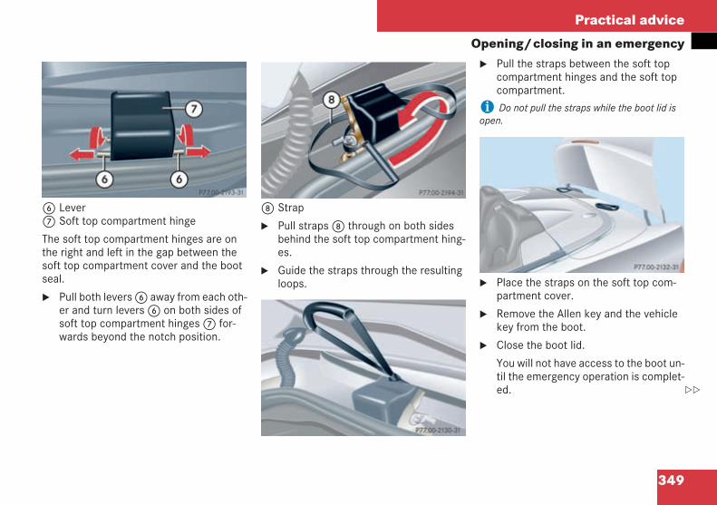
349
Practical advice
Opening/closing in an emergency
6 Lever7 Soft top compartment hinge
The soft top compartment hinges are onthe right and left in the gap between thesoft top compartment cover and the bootseal.
Pull both levers6 away from each oth-er and turn levers6 on both sides ofsoft top compartment hinges7 for-wards beyond the notch position.
8 Strap
Pull straps8 through on both sidesbehind the soft top compartment hing-es.
Guide the straps through the resultingloops.
Pull the straps between the soft topcompartment hinges and the soft topcompartment.
i Do not pull the straps while the boot lid isopen.
Place the straps on the soft top com-partment cover.
Remove the Allen key and the vehiclekey from the boot.
Close the boot lid.
You will not have access to the boot un-til the emergency operation is complet-ed.
P 77.00-2193-31 P 77.00-2194-31
P 77.00-2130-31
P 77.00-2132-31
209en_d2.boo Seite 349 Dienstag, 25. Mai 2004 7:26 19
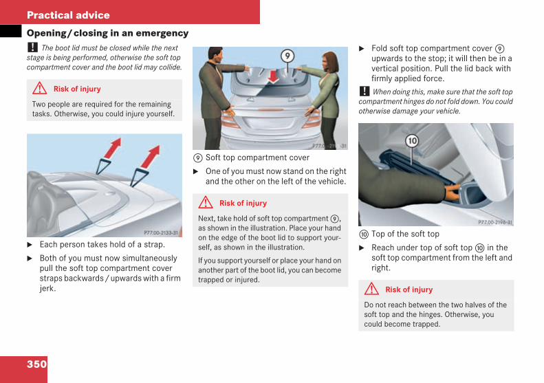
350
Practical advice
Opening/closing in an emergency! The boot lid must be closed while the nextstage is being performed, otherwise the soft topcompartment cover and the boot lid may collide.
Each person takes hold of a strap.
Both of you must now simultaneouslypull the soft top compartment coverstraps backwards/upwards with a firmjerk.
9 Soft top compartment cover
One of you must now stand on the rightand the other on the left of the vehicle.
Fold soft top compartment cover9upwards to the stop; it will then be in avertical position. Pull the lid back withfirmly applied force.
! When doing this, make sure that the soft topcompartment hinges do not fold down. You couldotherwise damage your vehicle.
a Top of the soft top
Reach under top of soft topa in thesoft top compartment from the left andright.
G Risk of injury
Two people are required for the remainingtasks. Otherwise, you could injure yourself.
P 77.00-2133-31
G Risk of injury
Next, take hold of soft top compartment9,as shown in the illustration. Place your handon the edge of the boot lid to support your-self, as shown in the illustration.
If you support yourself or place your hand onanother part of the boot lid, you can becometrapped or injured.
P 77.00-2195-31
G Risk of injury
Do not reach between the two halves of thesoft top and the hinges. Otherwise, youcould become trapped.
P 77.00-2196-31
209en_d2.boo Seite 350 Dienstag, 25. Mai 2004 7:26 19
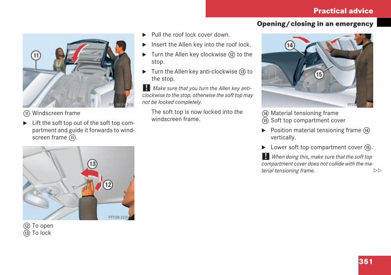
351
Practical advice
Opening/closing in an emergency
b Windscreen frame
Lift the soft top out of the soft top com-partment and guide it forwards to wind-screen frameb.
c To opend To lock
Pull the roof lock cover down.
Insert the Allen key into the roof lock.
Turn the Allen key clockwisec to thestop.
Turn the Allen key anti-clockwised tothe stop.
! Make sure that you turn the Allen key anti-clockwise to the stop, otherwise the soft top maynot be locked completely.
The soft top is now locked into thewindscreen frame.
e Material tensioning framef Soft top compartment cover
Position material tensioning frameevertically.
Lower soft top compartment coverf.
! When doing this, make sure that the soft topcompartment cover does not collide with the ma-terial tensioning frame.
P 77.00-2197-31
P 77.00-2231-31
P 77.00-2199-31
209en_d2.boo Seite 351 Dienstag, 25. Mai 2004 7:26 19
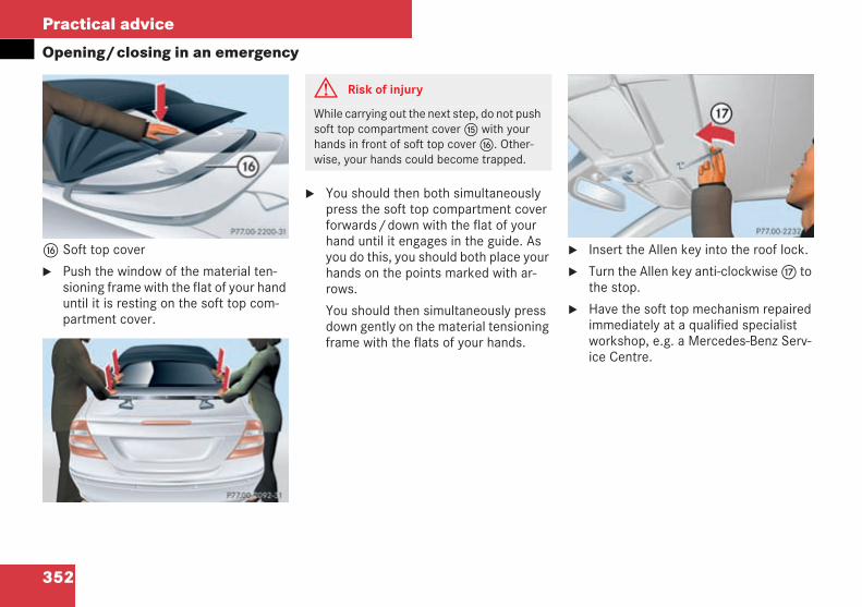
352
Practical advice
Opening/closing in an emergency
g Soft top cover
Push the window of the material ten-sioning frame with the flat of your handuntil it is resting on the soft top com-partment cover.
You should then both simultaneouslypress the soft top compartment coverforwards/down with the flat of yourhand until it engages in the guide. Asyou do this, you should both place yourhands on the points marked with ar-rows.
You should then simultaneously pressdown gently on the material tensioningframe with the flats of your hands.
Insert the Allen key into the roof lock.
Turn the Allen key anti-clockwiseh tothe stop.
Have the soft top mechanism repairedimmediately at a qualified specialistworkshop, e.g. a Mercedes-Benz Serv-ice Centre.
P 77.00-2200-31
P 77.00-2092-31
G Risk of injury
While carrying out the next step, do not pushsoft top compartment coverf with yourhands in front of soft top coverg. Other-wise, your hands could become trapped.
P 77.00-2232-31
209en_d2.boo Seite 352 Dienstag, 25. Mai 2004 7:26 19
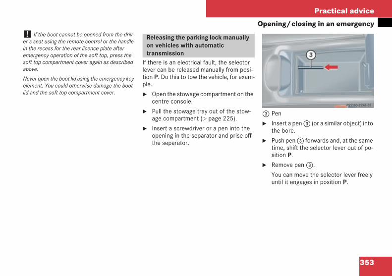
353
Practical advice
Opening/closing in an emergency! If the boot cannot be opened from the driv-er's seat using the remote control or the handlein the recess for the rear licence plate afteremergency operation of the soft top, press thesoft top compartment cover again as describedabove.
Never open the boot lid using the emergency keyelement. You could otherwise damage the bootlid and the soft top compartment cover.
If there is an electrical fault, the selectorlever can be released manually from posi-tion P. Do this to tow the vehicle, for exam-ple.
Open the stowage compartment on thecentre console.
Pull the stowage tray out of the stow-age compartment ( page 225).
Insert a screwdriver or a pen into theopening in the separator and prise offthe separator.
3 Pen
Insert a pen3 (or a similar object) intothe bore.
Push pen3 forwards and, at the sametime, shift the selector lever out of po-sition P.
Remove pen3.
You can move the selector lever freelyuntil it engages in position P.
Releasing the parking lock manuallyon vehicles with automatictransmission
P 27.60-2241-31 neu
209en_d2.boo Seite 353 Dienstag, 25. Mai 2004 7:26 19
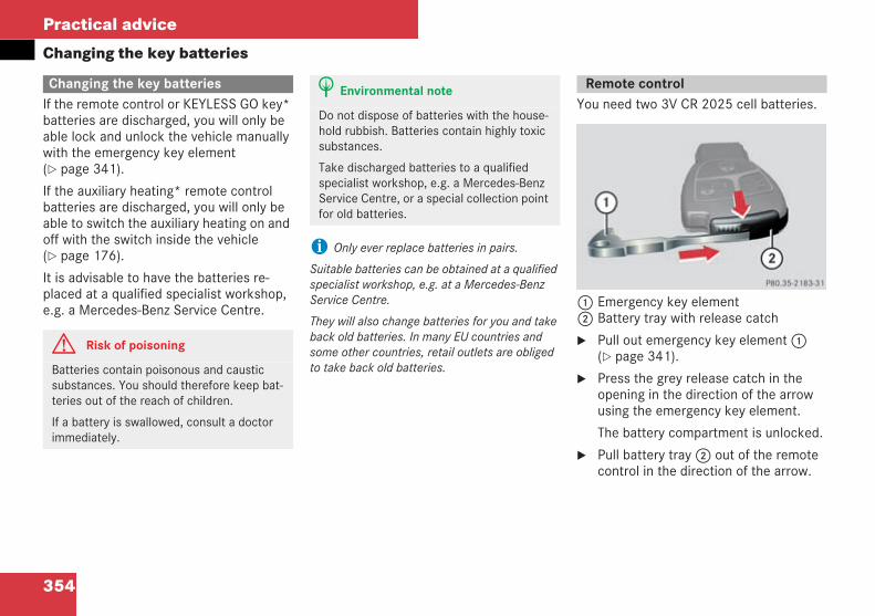
354
Practical advice
Changing the key batteries
If the remote control or KEYLESS GO key*batteries are discharged, you will only beable lock and unlock the vehicle manuallywith the emergency key element( page 341).
If the auxiliary heating* remote controlbatteries are discharged, you will only beable to switch the auxiliary heating on andoff with the switch inside the vehicle( page 176).
It is advisable to have the batteries re-placed at a qualified specialist workshop,e.g. a Mercedes-Benz Service Centre.
i Only ever replace batteries in pairs.
Suitable batteries can be obtained at a qualifiedspecialist workshop, e.g. at a Mercedes-BenzService Centre.
They will also change batteries for you and takeback old batteries. In many EU countries andsome other countries, retail outlets are obligedto take back old batteries.
You need two 3V CR 2025 cell batteries.
1 Emergency key element2 Battery tray with release catch
Pull out emergency key element1( page 341).
Press the grey release catch in theopening in the direction of the arrowusing the emergency key element.
The battery compartment is unlocked.
Pull battery tray2 out of the remotecontrol in the direction of the arrow.
Changing the key batteries
G Risk of poisoning
Batteries contain poisonous and causticsubstances. You should therefore keep bat-teries out of the reach of children.
If a battery is swallowed, consult a doctorimmediately.
H Environmental note
Do not dispose of batteries with the house-hold rubbish. Batteries contain highly toxicsubstances.
Take discharged batteries to a qualifiedspecialist workshop, e.g. a Mercedes-BenzService Centre, or a special collection pointfor old batteries.
Remote control
209en_d2.boo Seite 354 Dienstag, 25. Mai 2004 7:26 19
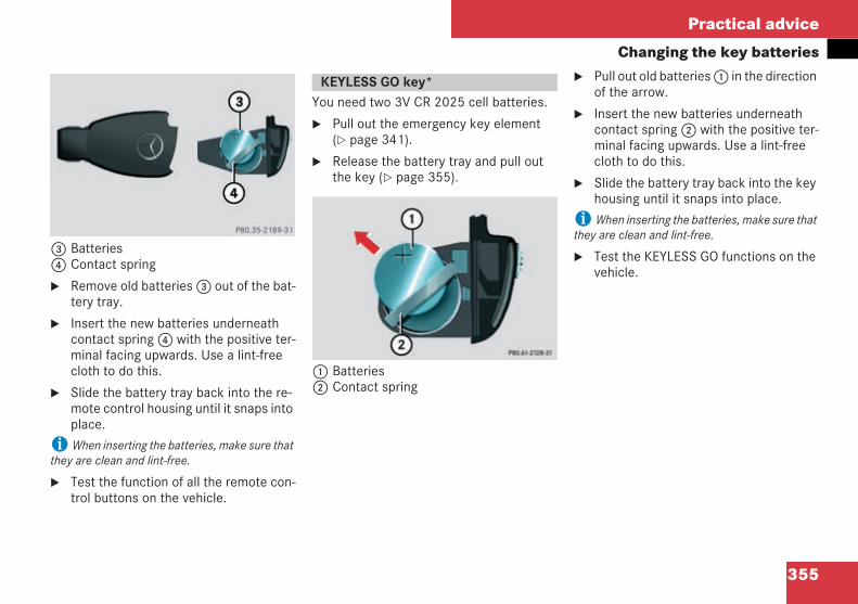
355
Practical advice
Changing the key batteries
3 Batteries4 Contact spring
Remove old batteries3 out of the bat-tery tray.
Insert the new batteries underneathcontact spring4 with the positive ter-minal facing upwards. Use a lint-freecloth to do this.
Slide the battery tray back into the re-mote control housing until it snaps intoplace.
i When inserting the batteries, make sure thatthey are clean and lint-free.
Test the function of all the remote con-trol buttons on the vehicle.
You need two 3V CR 2025 cell batteries.
Pull out the emergency key element( page 341).
Release the battery tray and pull outthe key ( page 355).
1 Batteries2 Contact spring
Pull out old batteries1 in the directionof the arrow.
Insert the new batteries underneathcontact spring2 with the positive ter-minal facing upwards. Use a lint-freecloth to do this.
Slide the battery tray back into the keyhousing until it snaps into place.
i When inserting the batteries, make sure thatthey are clean and lint-free.
Test the KEYLESS GO functions on thevehicle.
KEYLESS GO key*
209en_d2.boo Seite 355 Dienstag, 25. Mai 2004 7:26 19
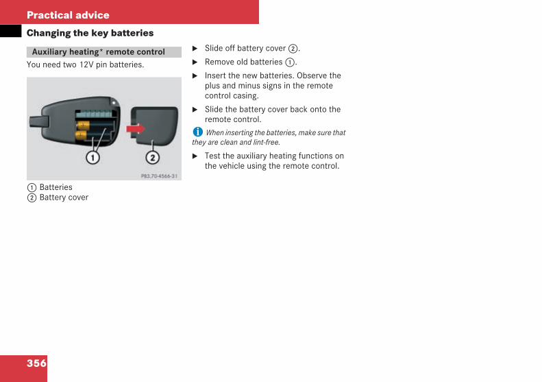
356
Practical advice
Changing the key batteries
You need two 12V pin batteries.
1 Batteries2 Battery cover
Slide off battery cover2.
Remove old batteries1.
Insert the new batteries. Observe theplus and minus signs in the remotecontrol casing.
Slide the battery cover back onto theremote control.
i When inserting the batteries, make sure thatthey are clean and lint-free.
Test the auxiliary heating functions onthe vehicle using the remote control.
Auxiliary heating* remote control
209en_d2.boo Seite 356 Dienstag, 25. Mai 2004 7:26 19
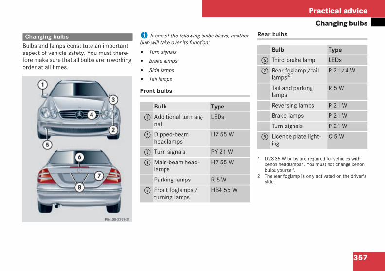
357
Practical advice
Changing bulbs
Bulbs and lamps constitute an importantaspect of vehicle safety. You must there-fore make sure that all bulbs are in workingorder at all times.
i If one of the following bulbs blows, anotherbulb will take over its function:
Turn signals
Brake lamps
Side lamps
Tail lamps
Front bulbs
Rear bulbs
1 D2S-35 W bulbs are required for vehicles withxenon headlamps*. You must not change xenonbulbs yourself.
2 The rear foglamp is only activated on the driver'sside.
Changing bulbs
P 54.00-2291-31
Bulb Type
1 Additional turn sig-nal
LEDs
2 Dipped-beamheadlamps1
H7 55 W
3 Turn signals PY 21 W
4 Main-beam head-lamps
H7 55 W
Parking lamps R 5 W
5 Front foglamps/turning lamps
HB4 55 W
Bulb Type
6 Third brake lamp LEDs
7 Rear foglamp/taillamps2
P 21/4 W
Tail and parkinglamps
R 5 W
Reversing lamps P 21 W
Brake lamps P 21 W
Turn signals P 21 W
8 Licence plate light-ing
C 5 W
209en_d2.boo Seite 357 Dienstag, 25. Mai 2004 7:26 19
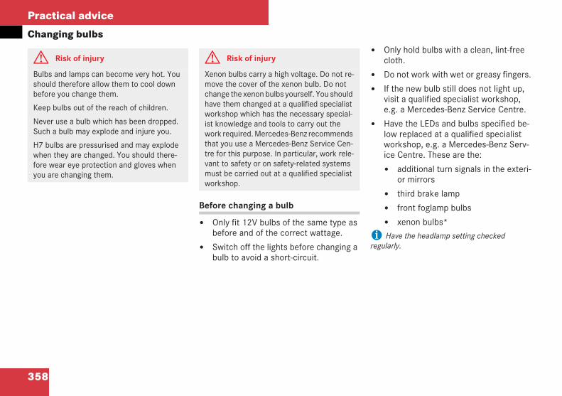
358
Practical advice
Changing bulbs
Before changing a bulb
Only fit 12V bulbs of the same type asbefore and of the correct wattage.
Switch off the lights before changing abulb to avoid a short-circuit.
Only hold bulbs with a clean, lint-freecloth.
Do not work with wet or greasy fingers.
If the new bulb still does not light up,visit a qualified specialist workshop,e.g. a Mercedes-Benz Service Centre.
Have the LEDs and bulbs specified be-low replaced at a qualified specialistworkshop, e.g. a Mercedes-Benz Serv-ice Centre. These are the:
additional turn signals in the exteri-or mirrors
third brake lamp
front foglamp bulbs
xenon bulbs*
i Have the headlamp setting checkedregularly.
G Risk of injury
Bulbs and lamps can become very hot. Youshould therefore allow them to cool downbefore you change them.
Keep bulbs out of the reach of children.
Never use a bulb which has been dropped.Such a bulb may explode and injure you.
H7 bulbs are pressurised and may explodewhen they are changed. You should there-fore wear eye protection and gloves whenyou are changing them.
G Risk of injury
Xenon bulbs carry a high voltage. Do not re-move the cover of the xenon bulb. Do notchange the xenon bulbs yourself. You shouldhave them changed at a qualified specialistworkshop which has the necessary special-ist knowledge and tools to carry out thework required. Mercedes-Benz recommendsthat you use a Mercedes-Benz Service Cen-tre for this purpose. In particular, work rele-vant to safety or on safety-related systemsmust be carried out at a qualified specialistworkshop.
209en_d2.boo Seite 358 Dienstag, 25. Mai 2004 7:26 19
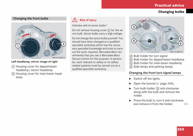
359
Practical advice
Changing bulbs
Left headlamp, mirror image of right
1 Housing cover for dipped-beamheadlamp/xenon headlamp
2 Housing cover for main-beam head-lamp
3 Bulb holder for turn signal4 Bulb holder for dipped-beam headlamp5 Bulb holder for main-beam headlamp6 Side lamps and parking lamps
Changing the front turn signal lamps
Switch off the lights.
Open the bonnet ( page 244).
Turn bulb holder3 anti-clockwisealong with the bulb and remove theholder.
Press the bulb in, turn it anti-clockwiseand remove it from the holder.
Changing the front bulbs
P 82.10-2905-31
G Risk of injury
Vehicles with bi-xenon bulbs*:
Do not remove housing cover1 for the xe-non bulb. Xenon bulbs carry a high voltage.
Do not change the xenon bulbs yourself. Youshould have them changed at a qualifiedspecialist workshop which has the neces-sary specialist knowledge and tools to carryout the work required. Mercedes-Benz rec-ommends that you use a Mercedes-BenzService Centre for this purpose. In particu-lar, work relevant to safety or on safety-related systems must be carried out at aqualified specialist workshop.
P 82.10-2906-31
209en_d2.boo Seite 359 Dienstag, 25. Mai 2004 7:26 19
360
Practical advice
Changing bulbsPress the new bulb into the holder andscrew it in clockwise.
Place the bulb holder in the lamp andturn it clockwise.
Changing the dipped-beam or main-beam headlamps
Switch off the lights.
Open the bonnet ( page 244).
Turn appropriate housing cover1 or2 anti-clockwise and remove it.
Turn bulb holder4 or5 anti-clock-wise along with the bulb and removethe holder.
Pull the bulb out of the bulb holder bythe base plate (not the glass bulb).
Insert the new bulb so that the baseplate:
fits in the recess on the bulb holderand
lies level on the bulb holder
Place the bulb holder in the lamp andturn it clockwise.
Refit the appropriate housing coverand turn it clockwise.
Changing the side and parking lamps
Switch off the lights.
Open the bonnet ( page 244).
Turn housing cover2 anti-clockwiseand remove it.
Remove bulb holder6 along with thebulb.
Turn the bulb gently anti-clockwise andremove it from the holder.
Insert the new bulb into the holder andturn it clockwise.
Replace the housing cover and let thetabs lock into place.
Refit the appropriate housing coverand turn it clockwise.
Replace the bulb holder.
209en_d2.boo Seite 360 Dienstag, 25. Mai 2004 7:26 19
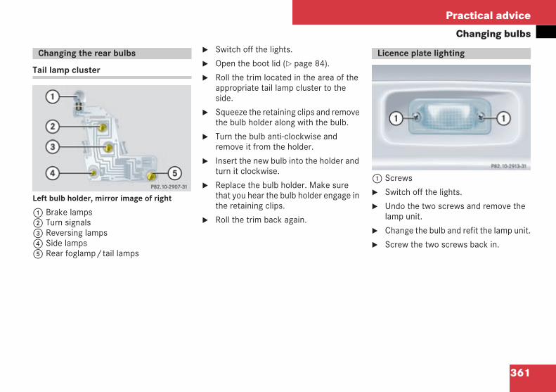
361
Practical advice
Changing bulbs
Tail lamp cluster
Left bulb holder, mirror image of right
1 Brake lamps2 Turn signals3 Reversing lamps4 Side lamps5 Rear foglamp/tail lamps
Switch off the lights.
Open the boot lid ( page 84).
Roll the trim located in the area of theappropriate tail lamp cluster to theside.
Squeeze the retaining clips and removethe bulb holder along with the bulb.
Turn the bulb anti-clockwise andremove it from the holder.
Insert the new bulb into the holder andturn it clockwise.
Replace the bulb holder. Make surethat you hear the bulb holder engage inthe retaining clips.
Roll the trim back again.
1 Screws
Switch off the lights.
Undo the two screws and remove thelamp unit.
Change the bulb and refit the lamp unit.
Screw the two screws back in.
Changing the rear bulbs
P 82.10-2907-31 neu
Licence plate lighting
P 82.10-2913-31
209en_d2.boo Seite 361 Dienstag, 25. Mai 2004 7:26 19
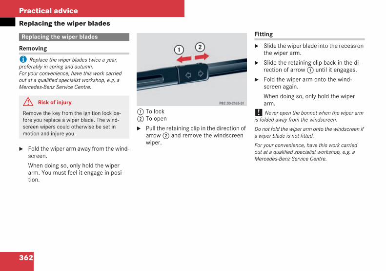
362
Practical advice
Replacing the wiper blades
Removing
i Replace the wiper blades twice a year,preferably in spring and autumn.For your convenience, have this work carriedout at a qualified specialist workshop, e.g. aMercedes-Benz Service Centre.
Fold the wiper arm away from the wind-screen.
When doing so, only hold the wiperarm. You must feel it engage in posi-tion.
1 To lock2 To open
Pull the retaining clip in the direction ofarrow2 and remove the windscreenwiper.
Fitting
Slide the wiper blade into the recess onthe wiper arm.
Slide the retaining clip back in the di-rection of arrow1 until it engages.
Fold the wiper arm onto the wind-screen again.
When doing so, only hold the wiperarm.
! Never open the bonnet when the wiper armis folded away from the windscreen.
Do not fold the wiper arm onto the windscreen ifa wiper blade is not fitted.
For your convenience, have this work carriedout at a qualified specialist workshop, e.g. aMercedes-Benz Service Centre.
Replacing the wiper blades
G Risk of injury
Remove the key from the ignition lock be-fore you replace a wiper blade. The wind-screen wipers could otherwise be set inmotion and injure you.
P 82.30-2165-31
209en_d2.boo Seite 362 Dienstag, 25. Mai 2004 7:26 19
363
Practical advice
Flat tyre
Your vehicle may be equipped with:
the TIREFIT kit ( page 276)
a spare wheel* ( page 278)
a "Minispare" emergency spare wheel*( page 277)
a collapsible emergency spare wheel( page 278)
the MOE run-flat system* ( page 373)
Stop your vehicle as far away as possi-ble from traffic and on a surface whichis firm, even and not slippery.
Switch on the hazard warning lamps.
Apply the handbrake.
Vehicles with manual transmission
Select either first or reverse gear.
Vehicles with automatic transmission*
Move the selector lever to P.
For all vehicles
Any passengers should leave the vehi-cle, ensuring that they are not endan-gered as they do so.
Place the warning triangle or switch onhazard warning lamps at a suitable dis-tance. Observe legal requirements.
Flat tyre
Preparing the vehicle
G Risk of injury
The jack is designed only to raise the vehiclefor a short while when a wheel is changed.
If you intend to work under the vehicle,place the vehicle on stands.
Prepare the vehicle as described.
Make sure that the standing surface for thevehicle and jack is firm and not slippery. Donot use blocks of wood or similar as jackingsupports, as the jack will not be able toachieve its load-bearing capacity due to therestricted height.
Do not start the engine at any time while thewheel is being changed.
Do not crawl under the vehicle while it issupported by the jack. If you do not raise thevehicle in the way described, it could slip offthe jack (e.g. when the engine is started orthe doors or boot lid are opened or closed).
209en_d2.boo Seite 363 Dienstag, 25. Mai 2004 7:26 19
364
Practical advice
Flat tyre
You can use the TIREFIT kit to seal smallpunctures, particularly those in the tyre'stread. TIREFIT may be used at outside tem-peratures of down to –20 °C.
Do not remove any foreign bodieswhich have penetrated the tyre, e.g.screws or nails.
Remove the TIREFIT kit, the accompa-nying "max. 80 km/h" sticker and theelectric air pump from the boot( page 276).
Affix the sticker in the driver's field ofvision.
Using the TIREFIT kit
G Risk of fire
Smoking, fire and naked flames are prohibit-ed when using TIREFIT.
Avoid creating sparks.
G Risk of accident
Your safety is at particular risk and TIREFITis unable to repair a flat tyre in the followingsituations:
If there are cuts or punctures in the tyregreater than 4 mm in size
If the wheel is damaged
If you have driven at very low tyre pres-sures or with flat tyres
Do not drive any further. Consult a qualifiedspecialist workshop which has the neces-sary specialist knowledge and tools to carryout the work required. Mercedes-Benz rec-ommends that you use a Mercedes-BenzService Centre for this purpose. In particu-lar, work relevant to safety or on safety-related systems must be carried out at aqualified specialist workshop.
209en_d2.boo Seite 364 Dienstag, 25. Mai 2004 7:26 19
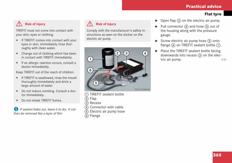
365
Practical advice
Flat tyre
i If sealant leaks out, leave it to dry. It canthen be removed like a layer of film.
1 TIREFIT sealant bottle2 Flap3 Recess4 Connector with cable5 Electric air pump hose6 Flange
Open flap2 on the electric air pump.
Pull connector4 and hose5 out ofthe housing along with the pressuregauge.
Screw electric air pump hose5 ontoflange6 on TIREFIT sealant bottle1.
Place the TIREFIT sealant bottle facingdownwards into recess3 on the elec-tric air pump.
G Risk of injury
TIREFIT must not come into contact withyour skin, eyes or clothing.
If TIREFIT comes into contact with youreyes or skin, immediately rinse thor-oughly with clean water.
Change out of clothing which has beenin contact with TIREFIT immediately.
If an allergic reaction occurs, consult adoctor immediately.
Keep TIREFIT out of the reach of children.
If TIREFIT is swallowed, rinse the mouththoroughly immediately and drink alarge amount of water.
Do not induce vomiting. Consult a doc-tor immediately.
Do not inhale TIREFIT fumes.
G Risk of injury
Comply with the manufacturer's safety in-structions as seen on the sticker on theelectric air pump.
P40.10-3308-31
209en_d2.boo Seite 365 Dienstag, 25. Mai 2004 7:26 19
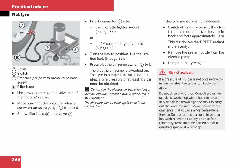
366
Practical advice
Flat tyre
7 Valve8 Switch9 Pressure gauge with pressure release
screwa Filler hose
Unscrew and remove the valve cap ofthe flat tyre's valve.
Make sure that the pressure releasescrew on pressure gauge9 is closed.
Screw filler hosea onto valve7.
Insert connector4 into:
the cigarette lighter socket( page 230)
or
a 12V socket* in your vehicle( page 231)
Turn the key to position 1 in the igni-tion lock ( page 23).
Press electric air pump switch8 to I.
The electric air pump is switched on.The tyre is pumped up. After five min-utes, a tyre pressure of at least 1.8 barmust be obtained.
! Do not run the electric air pump for longerthan six minutes without a break, otherwise itmay overheat.The air pump can be used again once it hascooled down.
If this tyre pressure is not obtained:
Switch off and disconnect the elec-tric air pump, and drive the vehicleback and forth approximately 10 m.
This distributes the TIREFIT sealantmore evenly.
Remove the sealant bottle from theelectric pump.
Pump up the tyre again.
P40.10-3328-31
G Risk of accident
If a pressure of 1.8 bar is not obtained with-in five minutes, the tyre is too badly dam-aged.
Do not drive any further. Consult a qualifiedspecialist workshop which has the neces-sary specialist knowledge and tools to carryout the work required. Mercedes-Benz rec-ommends that you use a Mercedes-BenzService Centre for this purpose. In particu-lar, work relevant to safety or on safety-related systems must be carried out at aqualified specialist workshop.
209en_d2.boo Seite 366 Dienstag, 25. Mai 2004 7:26 19
367
Practical advice
Flat tyreIf you have obtained a pressure of1.8 bar, press the switch on the elec-tric air pump to 0.
The electric air pump is switched off.
Disconnect the electric air pump.
Pull away immediately.
This allows the TIREFIT sealant to dis-tribute throughout the tyre.
Stop after about ten minutes andcheck the tyre pressure with the elec-tric air pump.
If the tyre pressure is at least 1.3 bar,correct it (see fuel filler flap for values).
To increase the tyre pressure:
switch on the electric air pump
To decrease the tyre pressure:
open the pressure release screw onpressure gauge9
Drive to the nearest workshop andhave the tyre replaced.
Have the TIREFIT kit replaced as soonas possible at a qualified specialistworkshop, e.g. a Mercedes-Benz Serv-ice Centre.
Have the TIREFIT kit replaced everyfour years at a qualified specialistworkshop, e.g. a Mercedes-Benz Serv-ice Centre.
G Risk of accident
If the pressure has fallen below 1.3 bar, thetyre is too badly damaged.
Do not drive any further. Consult a qualifiedspecialist workshop which has the neces-sary specialist knowledge and tools to carryout the work required. Mercedes-Benz rec-ommends that you use a Mercedes-BenzService Centre for this purpose. In particu-lar, work relevant to safety or on safety-related systems must be carried out at aqualified specialist workshop.
G Risk of accident
Do not exceed the maximum speed of80 km/h.
The "max. 80 km/h" sticker must be affixedwithin the driver's field of vision.
The vehicle's handling characteristics maybe affected.
H Environmental note
Have the TIREFIT kit disposed of profession-ally, e.g. at a Mercedes-Benz Service Centre.
209en_d2.boo Seite 367 Dienstag, 25. Mai 2004 7:26 19
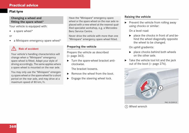
368
Practical advice
Flat tyre
Your vehicle is equipped with:
a spare wheel*
or
a Minispare emergency spare wheel*
Preparing the vehicle
Prepare the vehicle as described( page 363).
Turn the spare-wheel bracket anti-clockwise.
The bracket loosens.
Remove the wheel from the boot.
Engage the steering wheel lock.
Raising the vehicle
Prevent the vehicle from rolling awayusing chocks or similar:
On a level road:
place the chocks in front of and be-hind the wheel diagonally oppositethe wheel to be changed.
On uphill gradients:
place chocks behind both wheelson the other axle.
Take the vehicle tool kit and the jackout of the boot ( page 276).
1 Wheel wrench
Changing a wheel andfitting the spare wheel*
G Risk of accident
Your vehicle's handling characteristics willchange when a "Minispare" emergencyspare wheel is fitted. Adapt your style ofdriving accordingly. The same applies wherea spare wheel is mounted on the rear axle.
You may only use the "Minispare" emergen-cy spare wheel or the spare wheel for a shortperiod on the rear axle, and may drive at amaximum speed of 80 km/h.
Have the "Minispare" emergency sparewheel or the spare wheel on the rear axle re-placed with a new wheel at the nearest qual-ified specialist workshop, e.g. a Mercedes-Benz Service Centre.
Never drive the vehicle with more than one"Minispare" emergency spare wheel fitted.
P 40.10-2599-31
209en_d2.boo Seite 368 Dienstag, 25. Mai 2004 7:26 19
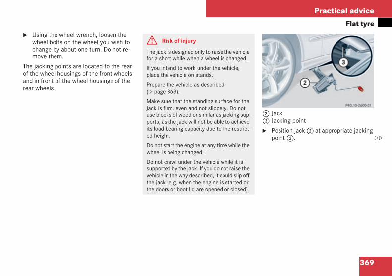
369
Practical advice
Flat tyreUsing the wheel wrench, loosen thewheel bolts on the wheel you wish tochange by about one turn. Do not re-move them.
The jacking points are located to the rearof the wheel housings of the front wheelsand in front of the wheel housings of therear wheels.
2 Jack3 Jacking point
Position jack2 at appropriate jackingpoint3.
G Risk of injury
The jack is designed only to raise the vehiclefor a short while when a wheel is changed.
If you intend to work under the vehicle,place the vehicle on stands.
Prepare the vehicle as described( page 363).
Make sure that the standing surface for thejack is firm, even and not slippery. Do notuse blocks of wood or similar as jacking sup-ports, as the jack will not be able to achieveits load-bearing capacity due to the restrict-ed height.
Do not start the engine at any time while thewheel is being changed.
Do not crawl under the vehicle while it issupported by the jack. If you do not raise thevehicle in the way described, it could slip offthe jack (e.g. when the engine is started orthe doors or boot lid are opened or closed).
P 40.10-2600-31
209en_d2.boo Seite 369 Dienstag, 25. Mai 2004 7:26 19
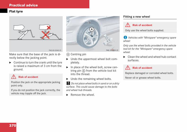
370
Practical advice
Flat tyre
Make sure that the base of the jack is di-rectly below the jacking point.
Continue to turn the crank until the tyreis raised a maximum of 3 cm from theground.
4 Centring pin
Undo the uppermost wheel bolt com-pletely.
In place of the wheel bolt, screw cen-tring pin4 from the vehicle tool kitinto the thread.
Undo the remaining wheel bolts.
! Do not place wheel bolts in sand or on a dirtysurface. This could cause damage to the boltsand wheel hub threads.
Remove the wheel.
Fitting a new wheel
i Vehicles with "Minispare" emergency sparewheel:
Only use the wheel bolts provided in the vehicletool kit for the "Minispare" emergency sparewheel.
Clean the wheel and wheel hub contactsurfaces.
G Risk of accident
Position the jack on the appropriate jackingpoint only.
If you do not position the jack correctly, thevehicle may topple off the jack.
P 40.00-2040-31 P 40.10-2601-31 neu
G Risk of accident
Only use the wheel bolts supplied.
G Risk of accident
Replace damaged or corroded wheel bolts.
Never oil or grease wheel bolts.
209en_d2.boo Seite 370 Dienstag, 25. Mai 2004 7:26 19
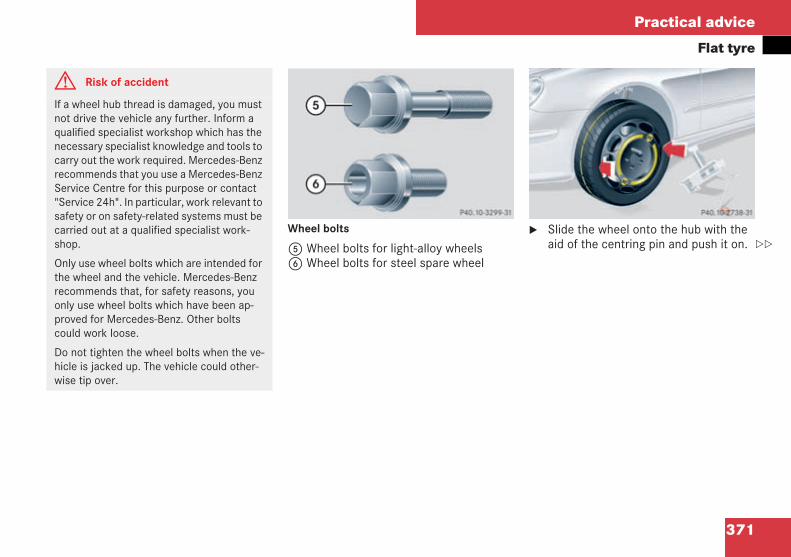
371
Practical advice
Flat tyre
Wheel bolts
5 Wheel bolts for light-alloy wheels6 Wheel bolts for steel spare wheel
Slide the wheel onto the hub with theaid of the centring pin and push it on.
G Risk of accident
If a wheel hub thread is damaged, you mustnot drive the vehicle any further. Inform aqualified specialist workshop which has thenecessary specialist knowledge and tools tocarry out the work required. Mercedes-Benzrecommends that you use a Mercedes-BenzService Centre for this purpose or contact"Service 24h". In particular, work relevant tosafety or on safety-related systems must becarried out at a qualified specialist work-shop.
Only use wheel bolts which are intended forthe wheel and the vehicle. Mercedes-Benzrecommends that, for safety reasons, youonly use wheel bolts which have been ap-proved for Mercedes-Benz. Other boltscould work loose.
Do not tighten the wheel bolts when the ve-hicle is jacked up. The vehicle could other-wise tip over.
P 40.10-3299-31 neu P 40.10-2738-31
209en_d2.boo Seite 371 Dienstag, 25. Mai 2004 7:26 19
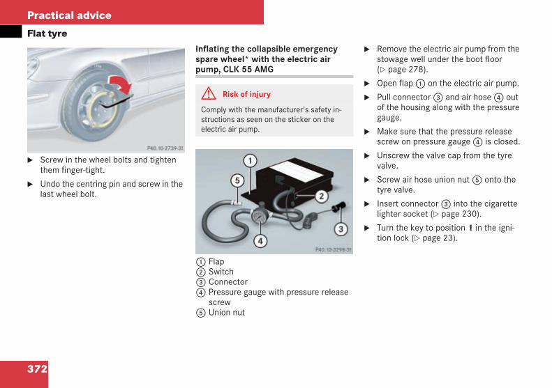
372
Practical advice
Flat tyre
Screw in the wheel bolts and tightenthem finger-tight.
Undo the centring pin and screw in thelast wheel bolt.
Inflating the collapsible emergencyspare wheel* with the electric airpump, CLK 55 AMG
1 Flap2 Switch3 Connector4 Pressure gauge with pressure release
screw5 Union nut
Remove the electric air pump from thestowage well under the boot floor( page 278).
Open flap1 on the electric air pump.
Pull connector3 and air hose4 outof the housing along with the pressuregauge.
Make sure that the pressure releasescrew on pressure gauge4 is closed.
Unscrew the valve cap from the tyrevalve.
Screw air hose union nut5 onto thetyre valve.
Insert connector3 into the cigarettelighter socket ( page 230).
Turn the key to position 1 in the igni-tion lock ( page 23).
P 40.10-2739-31 G Risk of injury
Comply with the manufacturer's safety in-structions as seen on the sticker on theelectric air pump.
P40.10-3298-31_von R171
209en_d2.boo Seite 372 Dienstag, 25. Mai 2004 7:26 19
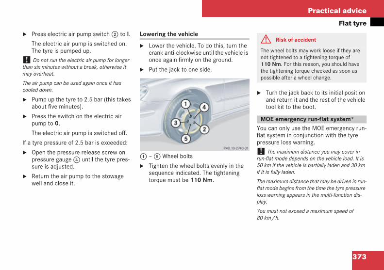
373
Practical advice
Flat tyrePress electric air pump switch2 to I.
The electric air pump is switched on.The tyre is pumped up.
! Do not run the electric air pump for longerthan six minutes without a break, otherwise itmay overheat.
The air pump can be used again once it hascooled down.
Pump up the tyre to 2.5 bar (this takesabout five minutes).
Press the switch on the electric airpump to 0.
The electric air pump is switched off.
If a tyre pressure of 2.5 bar is exceeded:
Open the pressure release screw onpressure gauge4 until the tyre pres-sure is adjusted.
Return the air pump to the stowagewell and close it.
Lowering the vehicle
Lower the vehicle. To do this, turn thecrank anti-clockwise until the vehicle isonce again firmly on the ground.
Put the jack to one side.
1 –5 Wheel bolts
Tighten the wheel bolts evenly in thesequence indicated. The tighteningtorque must be 110 Nm.
Turn the jack back to its initial positionand return it and the rest of the vehicletool kit to the boot.
You can only use the MOE emergency run-flat system in conjunction with the tyrepressure loss warning.
! The maximum distance you may cover inrun-flat mode depends on the vehicle load. It is50 km if the vehicle is partially laden and 30 kmif it is fully laden.
The maximum distance that may be driven in run-flat mode begins from the time the tyre pressureloss warning appears in the multi-function dis-play.
You must not exceed a maximum speed of80 km/h.
P 40.10-2740-31
G Risk of accident
The wheel bolts may work loose if they arenot tightened to a tightening torque of110 Nm. For this reason, you should havethe tightening torque checked as soon aspossible after a wheel change.
MOE emergency run-flat system*
209en_d2.boo Seite 373 Dienstag, 25. Mai 2004 7:26 19
374
Practical advice
Flat tyre
i The maximum distance can be increasedconsiderably by using TIREFIT before startingrun-flat mode. If the type of damage is such thatTIREFIT cannot seal the tyre, you can still drivethe maximum possible distance in run-flat mode.
i If you are replacing one or more tyres, makesure you use tyres with the "MOExtended” markand which are the specified size for the vehicle.If you are replacing one or more rims, makesure you use rims approved for use with"MOExtended” tyres and which are the specifiedsize for the vehicle.G Risk of accident
The handling characteristics of your vehicleare adversely affected in run-flat mode, forexample:
when cornering
when braking
when accelerating suddenly
You should therefore adapt your drivingstyle accordingly and avoid making suddensteering movements, accelerating suddenlyand driving over obstacles (kerbs, pot holes,off-road). The applies especially if the vehi-cle is heavily laden.
The distance that can be travelled in run-flatmode depends largely on the loads placedon the vehicle. Speed, load, sudden acceler-ation, road-surface conditions, outside tem-peratures, etc. can considerably reduce thisdistance, whereas a conservative drivingstyle may increase it.
Run-flat mode must be stopped in the eventof:
banging noises
the vehicle shaking
smoke development accompanied bythe smell of rubber
ESP continuously intervening
tears in the tyre side walls
After driving in run-flat mode, you must havethe rim checked to see if it can still be used.For this purpose, visit a qualified specialistworkshop which has the necessary special-ist knowledge and tools to carry out thework required. The flat tyre must be re-placed in any case.
Mercedes-Benz recommends that you use aMercedes-Benz Service Centre for this pur-pose. In particular, work relevant to safetyor on safety-related systems must be car-ried out at a qualified specialist workshop.
209en_d2.boo Seite 374 Dienstag, 25. Mai 2004 7:26 19
375
Practical advice
Battery
Your vehicle is equipped with a battery.The battery must always be sufficientlycharged so that it achieves its intendedservice life.
Have the battery charge checked morefrequently if you use the vehicle mainly forshort trips or if you do not use it for an ex-tended period.
To prevent corrosion damage, only replacethe battery with a battery that has a centralventilation cover. For safety reasons,Mercedes-Benz recommends that you onlyuse batteries which have been speciallytested and approved for your vehicle byMercedes-Benz.
Consult a Mercedes-Benz Service Centre ifyou wish to leave your vehicle parked upfor an extended period.
Battery G Risk of injury
Take safety precautions and protectivemeasures when handling batteries.
Risk of explosion
Fire, naked flames and smok-ing are prohibited when han-dling the battery. Avoidcreating sparks.
Battery acid is caustic. Avoidcontact with the skin, eyes orclothing.
Immediately rinse acid splash-es off with clean water. Con-sult a doctor if necessary.
G Risk of injury
Wear eye protection.
Keep children away.
Observe this Owner's Manual.
H Environmental note
Do not dispose of batteries with the house-hold rubbish. Dispose of a faulty battery inan environmentally-responsible manner.Take it to a Mercedes-Benz Service Centreor a special collection point for old batteries.
209en_d2.boo Seite 375 Dienstag, 25. Mai 2004 7:26 19
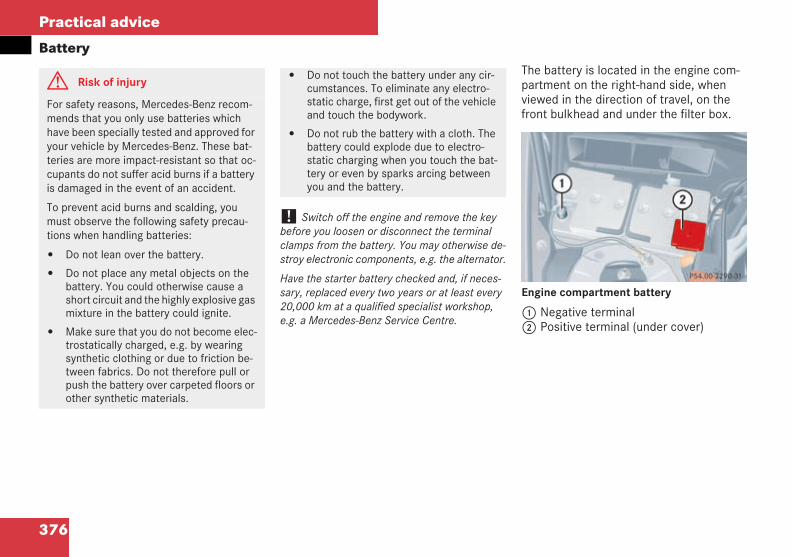
376
Practical advice
Battery
! Switch off the engine and remove the keybefore you loosen or disconnect the terminalclamps from the battery. You may otherwise de-stroy electronic components, e.g. the alternator.
Have the starter battery checked and, if neces-sary, replaced every two years or at least every20,000 km at a qualified specialist workshop,e.g. a Mercedes-Benz Service Centre.
The battery is located in the engine com-partment on the right-hand side, whenviewed in the direction of travel, on thefront bulkhead and under the filter box.
Engine compartment battery
1 Negative terminal2 Positive terminal (under cover)
G Risk of injury
For safety reasons, Mercedes-Benz recom-mends that you only use batteries whichhave been specially tested and approved foryour vehicle by Mercedes-Benz. These bat-teries are more impact-resistant so that oc-cupants do not suffer acid burns if a batteryis damaged in the event of an accident.
To prevent acid burns and scalding, youmust observe the following safety precau-tions when handling batteries:
Do not lean over the battery.
Do not place any metal objects on thebattery. You could otherwise cause ashort circuit and the highly explosive gasmixture in the battery could ignite.
Make sure that you do not become elec-trostatically charged, e.g. by wearingsynthetic clothing or due to friction be-tween fabrics. Do not therefore pull orpush the battery over carpeted floors orother synthetic materials.
Do not touch the battery under any cir-cumstances. To eliminate any electro-static charge, first get out of the vehicleand touch the bodywork.
Do not rub the battery with a cloth. Thebattery could explode due to electro-static charging when you touch the bat-tery or even by sparks arcing betweenyou and the battery.
P 54.00-2290-31
209en_d2.boo Seite 376 Dienstag, 25. Mai 2004 7:26 19
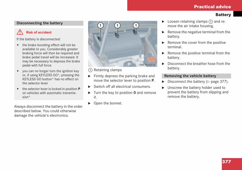
377
Practical advice
Battery
Always disconnect the battery in the orderdescribed below. You could otherwisedamage the vehicle's electronics.
1 Retaining clamps
Firmly depress the parking brake andmove the selector lever to position P.
Switch off all electrical consumers.
Turn the key to position 0 and removeit.
Open the bonnet.
Loosen retaining clamps1 and re-move the air intake housing.
Remove the negative terminal from thebattery.
Remove the cover from the positiveterminal.
Remove the positive terminal from thebattery.
Disconnect the breather hose from thebattery.
Disconnect the battery ( page 377).
Unscrew the battery holder used toprevent the battery from slipping andremove the battery.
Disconnecting the battery
G Risk of accident
If the battery is disconnected:
the brake boosting effect will not beavailable to you. Considerably greaterbraking force will then be required andbrake pedal travel will be increased. Itmay be necessary to depress the brakepedal with full force
you can no longer turn the ignition keyor, if using KEYLESS GO*, pressing theKEYLESS GO button* has no effect onthe selector lever
the selector lever is locked in position Pon vehicles with automatic transmis-sion*
P 54.10-2137-31
Removing the vehicle battery
209en_d2.boo Seite 377 Dienstag, 25. Mai 2004 7:26 19
378
Practical advice
Battery
! Only use battery chargers with a maximumcharging voltage of 14.8 V.
Charge the battery.
Observe the notes in the operatinginstructions for your battery charger.
Refit the charged battery.
To do so, follow the steps describedunder "Removing the battery" in thereverse order.
! Always connect the battery in the order de-scribed below. Never swap the terminal clamps.You could otherwise damage the vehicle's elec-tronics.
Switch off all electrical consumers.
Connect the positive terminal andsecure the cover.
Connect the negative terminal.
Connect the breather hose.
Make sure that the battery is fitted witha stopper opposite the breather hose.
i If the power supply to the battery has beeninterrupted (e.g. it has been reconnected), youmust carry out the following tasks:
Set the clock ( page 121)
Reset the side windows ( page 180)
Charging and fitting the battery
G Risk of injury
Never charge the battery when it is fitted inthe vehicle. You could otherwise damagethe vehicle's electronics. Only charge thebattery in a well ventilated area. During thecharging process, gases may escape andgenerate minor explosions which could in-jure you and others or cause paint damageor acid corrosion to the vehicle.
G Risk of acid burns
During the charging process, there is a riskof acid burns due to the gases escapingfrom the battery. Do not lean over the bat-tery while the engine is being jump-started.
Connecting the battery
209en_d2.boo Seite 378 Dienstag, 25. Mai 2004 7:26 19
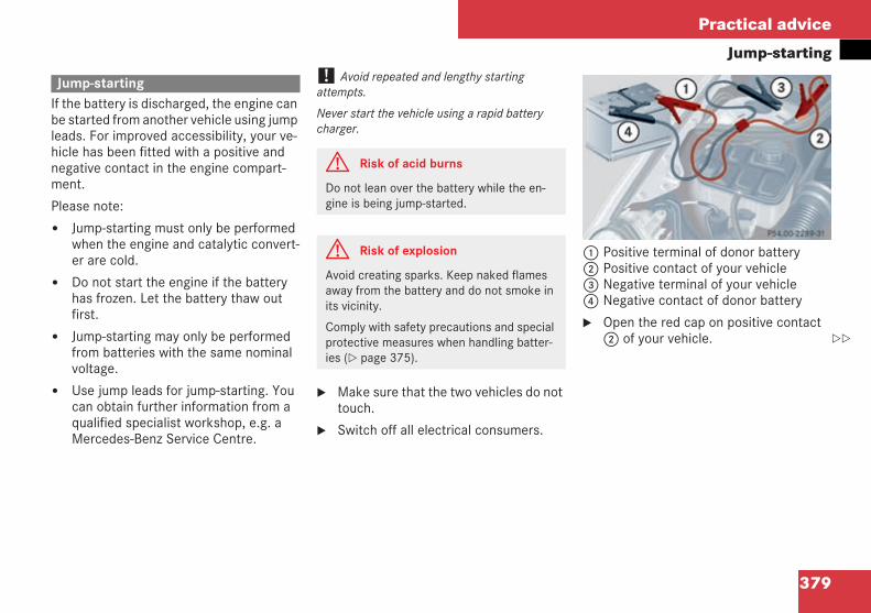
379
Practical advice
Jump-starting
If the battery is discharged, the engine canbe started from another vehicle using jumpleads. For improved accessibility, your ve-hicle has been fitted with a positive andnegative contact in the engine compart-ment.
Please note:
Jump-starting must only be performedwhen the engine and catalytic convert-er are cold.
Do not start the engine if the batteryhas frozen. Let the battery thaw outfirst.
Jump-starting may only be performedfrom batteries with the same nominalvoltage.
Use jump leads for jump-starting. Youcan obtain further information from aqualified specialist workshop, e.g. aMercedes-Benz Service Centre.
! Avoid repeated and lengthy startingattempts.
Never start the vehicle using a rapid batterycharger.
Make sure that the two vehicles do nottouch.
Switch off all electrical consumers.
1 Positive terminal of donor battery2 Positive contact of your vehicle3 Negative terminal of your vehicle4 Negative contact of donor battery
Open the red cap on positive contact2 of your vehicle.
Jump-starting
G Risk of acid burns
Do not lean over the battery while the en-gine is being jump-started.
G Risk of explosion
Avoid creating sparks. Keep naked flamesaway from the battery and do not smoke inits vicinity.
Comply with safety precautions and specialprotective measures when handling batter-ies ( page 375).
209en_d2.boo Seite 379 Dienstag, 25. Mai 2004 7:26 19
380
Practical advice
Jump-startingConnect positive terminal1 to posi-tive contact2 on your vehicle usingthe jump lead. Start with the donor bat-tery.
Run the donor vehicle's engine at idlingspeed.
Connect negative terminal4 of thedonor battery to negative contact3 ofyour vehicle using the jump lead. Startwith the donor battery.
Start the engine.
You can now switch electrical consum-ers back on. Do not under any circum-stances switch on the lights.
First undo the jump leads from nega-tive terminals3 and4 of the batter-ies, and then from positive terminals1 and2.
Have the battery checked at a qualifiedspecialist workshop, e.g. a Mercedes-Benz Service Centre.
209en_d2.boo Seite 380 Dienstag, 25. Mai 2004 7:26 19
381
Practical advice
Towing
Comply with national regulations whentowing.
Having the vehicle carried away on a trans-porter or trailer is preferable to towing itaway. We recommend the use of a rigidtowbar if towing is necessary.
You may only tow the vehicle a maximumof 50 km. A maximum towing speed of50 km/h must not be exceeded.
i Deactivate the automatic locking while driv-ing function when towing. You could otherwisebecome locked out when pushing or towing thevehicle.
Vehicles with automatic transmissionmust not be tow-started.
If the engine does not start, try jump-starting it ( page 379).
If the vehicle does not start afterjump-starting, have it towed to a quali-fied specialist workshop, e.g. to aMercedes-Benz Service Centre.
If the vehicle is to be towed for a longerdistance, only tow it with the rear axleraised.
If the vehicle has suffered transmissiondamage, only tow it with the propellershaft disconnected.
Before towing the vehicle, make surethe battery is connected and charged.Otherwise, you will not be able toswitch on the ignition and will haveno steering and braking assistance.
Shift the transmission to position N.
Opening the front cover
The fixing points for the bolt-on towing eyeare located in the bumpers. They are locat-ed under the cover on the right-hand sidewhen viewed in the direction of travel bothat the front and the rear.
! Only secure the tow cable or towbar to thetowing eye. The vehicle could otherwise bedamaged.
Towing
G Risk of accident
Tow the vehicle using a rigid towbar if:
the engine will not start
there is a malfunction in the power sup-ply or the vehicle's electrical system
There is no power assistance for the steer-ing when the engine is not running. Signifi-cantly greater force is then needed to steerthe vehicle and to brake.
When towing or tow-starting another vehi-cle, its weight should not be greater than thepermissible gross weight of your vehicle.
Points to bear in mind
Fitting the towing eye
209en_d2.boo Seite 381 Dienstag, 25. Mai 2004 7:26 19
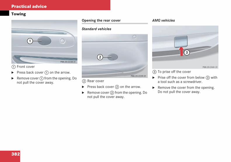
382
Practical advice
Towing
1 Front cover
Press back cover1 on the arrow.
Remove cover1 from the opening. Donot pull the cover away.
Opening the rear cover
Standard vehicles
2 Rear cover
Press back cover2 on the arrow.
Remove cover2 from the opening. Donot pull the cover away.
AMG vehicles
3 To prise off the cover
Prise off the cover from below3 witha tool such as a screwdriver.
Remove the cover from the opening.Do not pull the cover away.
P 88.20-2238-31 neu
P 88.20-2239-31 neu
P 88.20-2441-31
209en_d2.boo Seite 382 Dienstag, 25. Mai 2004 7:26 19
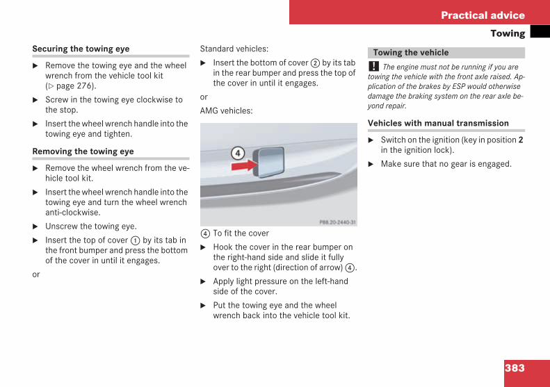
383
Practical advice
TowingSecuring the towing eye
Remove the towing eye and the wheelwrench from the vehicle tool kit( page 276).
Screw in the towing eye clockwise tothe stop.
Insert the wheel wrench handle into thetowing eye and tighten.
Removing the towing eye
Remove the wheel wrench from the ve-hicle tool kit.
Insert the wheel wrench handle into thetowing eye and turn the wheel wrenchanti-clockwise.
Unscrew the towing eye.
Insert the top of cover1 by its tab inthe front bumper and press the bottomof the cover in until it engages.
or
Standard vehicles:
Insert the bottom of cover2 by its tabin the rear bumper and press the top ofthe cover in until it engages.
or
AMG vehicles:
4 To fit the cover
Hook the cover in the rear bumper onthe right-hand side and slide it fullyover to the right (direction of arrow)4.
Apply light pressure on the left-handside of the cover.
Put the towing eye and the wheelwrench back into the vehicle tool kit.
! The engine must not be running if you aretowing the vehicle with the front axle raised. Ap-plication of the brakes by ESP would otherwisedamage the braking system on the rear axle be-yond repair.
Vehicles with manual transmission
Switch on the ignition (key in position 2in the ignition lock).
Make sure that no gear is engaged.P 88.20-2440-31
Towing the vehicle
209en_d2.boo Seite 383 Dienstag, 25. Mai 2004 7:26 19
384
Practical advice
TowingVehicles with automatic transmission*
Switch on the ignition (key in position 2in the ignition lock).
Move the selector lever to N.
! Do not tow the vehicle further than 50 km.Do not exceed a towing speed of 50 km/h, oth-erwise the transmission could be damaged.
Only tow the vehicle with the rear axleraised if:
you need to tow the vehicle for a longerdistance
the transmission has been damaged
Instead of raising the rear axle, the propel-ler shaft to the driven axle can be removed.
Points to bear in mind:
Vehicles with automatic transmission*must not be tow-started.
The battery must be connected.
The engine and the catalytic convertermust be cold.
Avoid repeated or lengthy attempts tostart the engine.
Vehicles with manual transmission
Switch on the ignition (key in position 2in the ignition lock).
Make sure that no gear is engaged.
Tow the vehicle to set it in motion, or al-low it to roll.
Engage a suitable gear and graduallyrelease the clutch. Do not depress theaccelerator.
The engine is started.
The towing eyes can be used to pull the ve-hicle onto a trailer or transporter for trans-porting purposes.
Make sure that no gear is engaged. On ve-hicles with automatic transmission*, theselector lever must be in position N! Lash the vehicle securely, and only by thewheels or wheel rims.
Your vehicle could otherwise be damaged.
Tow-starting the vehicle(emergency engine start)
Transporting the vehicle
209en_d2.boo Seite 384 Dienstag, 25. Mai 2004 7:26 19
385
Practical advice
Fuses
The electrical fuses in your vehicle inter-rupt the power supply to the equipment inthe event of a malfunction. This preventsdamage to the rest of the on-boardelectrics.
The following are available for changingfuses ( page 385):
Fuse allocation chart
Spare fuses
Fuse extractor
! Only use fuses with the specified amperagefor the system in question, and which have beenapproved for Mercedes-Benz. Electrical parts orsystems could otherwise be damaged.
Do not attempt to repair or bridge faulty fuses.Have the cause traced and rectified at a qualifiedspecialist workshop, e.g. a Mercedes-Benz Serv-ice Centre.
The electrical fuses are located in differentfuse boxes:
Main fuse box on the left of the dash-board ( page 386).
Fuse box in the engine compartmenton the left ( page 386).
Fuse box in the boot on the left( page 387).
Fuse allocation chart
The fuse allocation chart is located in thecover of the main fuse box on the dash-board ( page 386). The amperage of thefuses is also given there.
Spare fuses
Spare fuses can be found in the vehicletool kit ( page 276).
Fuse extractor
Coupé
The fuse extractor can be found in the cov-er of the fuse box in the boot ( page 387).
Cabriolet
The fuse extractor can be found in the ve-hicle tool kit ( page 276).
Fuses
G Risk of fire
Only use fuses with the specified amperagefor the system in question, and which havebeen approved for Mercedes-Benz. Other-wise, a short-circuit could occur, whichcould cause a fire.
Changing fuses
209en_d2.boo Seite 385 Dienstag, 25. Mai 2004 7:26 19
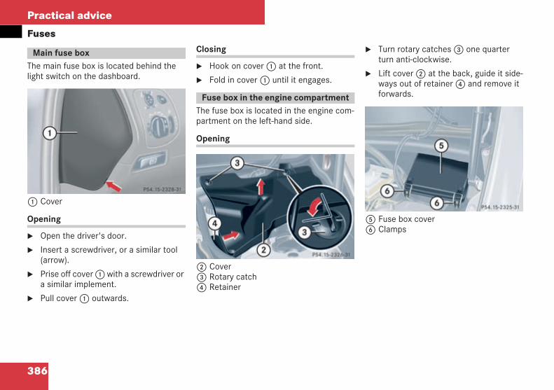
386
Practical advice
Fuses
The main fuse box is located behind thelight switch on the dashboard.
1 Cover
Opening
Open the driver's door.
Insert a screwdriver, or a similar tool(arrow).
Prise off cover1with a screwdriver ora similar implement.
Pull cover1 outwards.
Closing
Hook on cover1 at the front.
Fold in cover1 until it engages.
The fuse box is located in the engine com-partment on the left-hand side.
Opening
2 Cover3 Rotary catch4 Retainer
Turn rotary catches3 one quarterturn anti-clockwise.
Lift cover2 at the back, guide it side-ways out of retainer4 and remove itforwards.
5 Fuse box cover6 Clamps
Main fuse box
P 54.15-2328-31 neu
Fuse box in the engine compartment
P 54.15-2326-31 neu
P 54.15-2325-31 neu
209en_d2.boo Seite 386 Dienstag, 25. Mai 2004 7:26 19
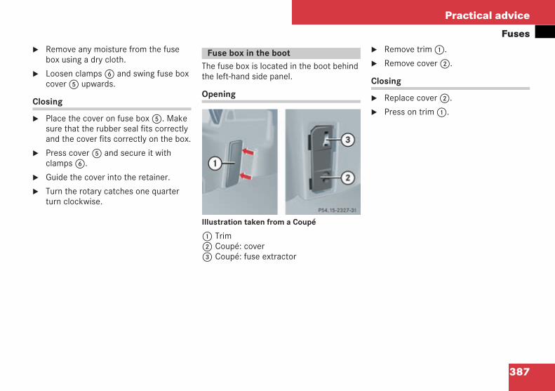
387
Practical advice
FusesRemove any moisture from the fusebox using a dry cloth.
Loosen clamps6 and swing fuse boxcover5 upwards.
Closing
Place the cover on fuse box5. Makesure that the rubber seal fits correctlyand the cover fits correctly on the box.
Press cover5 and secure it withclamps6.
Guide the cover into the retainer.
Turn the rotary catches one quarterturn clockwise.
The fuse box is located in the boot behindthe left-hand side panel.
Opening
Illustration taken from a Coupé
1 Trim2 Coupé: cover3 Coupé: fuse extractor
Remove trim1.
Remove cover2.
Closing
Replace cover2.
Press on trim1.
Fuse box in the boot
P 54.15-2327-31 neu
209en_d2.boo Seite 387 Dienstag, 25. Mai 2004 7:26 19

388
209en_d2.boo Seite 388 Dienstag, 25. Mai 2004 7:26 19
389
Technical data
Genuine Mercedes-Benz parts
Vehicle electronics
Vehicle identification plates
Engine
Performance
Tyres and wheels
Vehicle dimensions
Trailer tow hitch
Vehicle weights
Service products and capacities
Frequencies for garage door openers*
209en_d2.boo Seite 389 Dienstag, 25. Mai 2004 7:26 19
390
Technical data
Genuine Mercedes-Benz partsThe "Technical data" section contains allthe necessary technical data for your vehi-cle. Some of the values given are provi-sional and, in some cases, calculatedvalues. Final values were not availablewhen this manual was printed.
i The technical data was determined in ac-cordance with EU Directives. All data applies tothe vehicle's standard equipment. The data maytherefore differ for vehicles with optional equip-ment. You may obtain further information from aMercedes-Benz Service Centre.
You will find information about your vehicle'snoise level in the vehicle's documentation.
Mercedes-Benz tests genuine parts andconversion parts and accessories whichhave been specifically approved for yourvehicle in terms of their reliability, safetyand suitability.
Despite ongoing market research,Mercedes-Benz is unable to guarantee oth-er parts. Mercedes-Benz therefore acceptsno responsibility for the use of such partsin Mercedes-Benz vehicles, even if theyhave been independently or officially ap-proved.
In Germany and other countries, certainparts are only officially approved for instal-lation or modification work if they complywith legal requirements. All genuineMercedes-Benz parts satisfy theseregulations.
Make sure that replacement parts are suit-able for your vehicle. In many countries,parts that constitute a modification to thevehicle could invalidate the vehicle's gen-eral operating permit. This is the case if:
there is a change in the vehicle type ap-proved in the general operating permit
road users could be endangered
exhaust emissions or noise levels areadversely affected
The use of parts which have not been offi-cially approved can jeopardise the safetyof your vehicle.
Mercedes-Benz therefore recommendsthat you use genuine Mercedes-Benz partsand conversion parts and accessorieswhich have been approved for your vehi-cle.
You can obtain genuine Mercedes-Benzparts and approved conversion parts andaccessories from any Mercedes-BenzService Centre. Here you will receive ad-vice about technical modifications, and theparts will be professionally fitted.
Always quote the vehicle identificationnumber and the engine number when or-dering genuine parts. You will find thesenumbers on the vehicle data card in the"Service Booklet" or on your vehicle's iden-tification plates ( page 393).
Genuine Mercedes-Benz parts
H Environmental note
DaimlerChrysler also supplies reconditionedassemblies and parts which are of the samequality as new parts. These parts have thesame warranty as new parts.
209en_d2.boo Seite 390 Dienstag, 25. Mai 2004 7:26 19
391
Technical data
Vehicle electronics
! Only have the engine electronics and asso-ciated parts, such as control units, sensors orconnector leads, serviced at a qualified special-ist workshop. Otherwise, vehicle parts may wearmore quickly and the vehicle warranty and gen-eral operating permit may be invalidated.
Electrical and electronic equipment canjeopardise the operational safety of yourvehicle. If equipment of this kind is retrofit-ted, it must be type approved and mustbear the e mark. The e mark can be ob-tained from the equipment manufactureror an authorised testing authority.
If you wish to install telephones or two-wayradios in the vehicle, you must obtain for-mal approval. Mercedes-Benz approvesthe installation of mobile telephones andtwo-way radios provided that they are in-stalled professionally and a low-reflectionexterior aerial is used.
The transmission output of the telephoneor two-way radio must not exceed the max-imum transmission outputs specified onthe next page.
Vehicle electronics
Tampering with the engineelectronics
G Risk of accident
Only have the engine electronics and associ-ated parts serviced at a qualified specialistworkshop which has the necessary special-ist knowledge and tools to carry out thework required. Mercedes-Benz recommendsthat you use a Mercedes-Benz Service Cen-tre for this purpose.In particular, work relevant to safety or onsafety-related systems must be carried outat a qualified specialist workshop. Roadsafety could otherwise be affected.
Retrofitting electrical/electronicequipment
G Risk of accident
Mobile phones and two-way radios could in-terfere with the vehicle's electronics andthereby impair the vehicle's operating safetyand your safety if:
they do not have an exterior aerial
the exterior aerial is not reflection-free
the exterior aerial has been fitted incor-rectly
Health risks may also occur due to exces-sive electromagnetic radiation.
For this reason, only have the exterior aerialfitted at a qualified specialist workshopwhich has the necessary specialist knowl-edge and tools to carry out the work re-quired. Mercedes-Benz recommends thatyou use a Mercedes-Benz Service Centre forthis purpose. In particular, work relevant tosafety or on safety-related systems must becarried out at a qualified specialist work-shop.
209en_d2.boo Seite 391 Dienstag, 25. Mai 2004 7:26 19
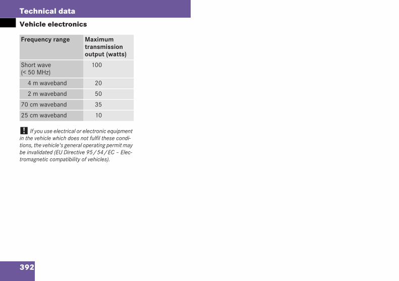
392
Technical data
Vehicle electronics
! If you use electrical or electronic equipmentin the vehicle which does not fulfil these condi-tions, the vehicle's general operating permit maybe invalidated (EU Directive 95/54/EC – Elec-tromagnetic compatibility of vehicles).
Frequency range Maximumtransmissionoutput (watts)
Short wave(< 50 MHz)
100
4 m waveband 20
2 m waveband 50
70 cm waveband 35
25 cm waveband 10
209en_d2.boo Seite 392 Dienstag, 25. Mai 2004 7:26 19
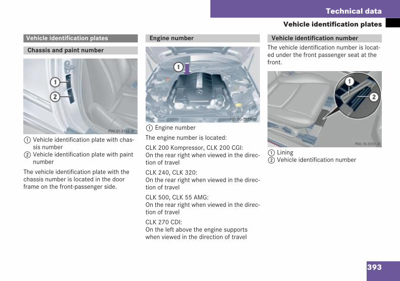
393
Technical data
Vehicle identification plates
1 Vehicle identification plate with chas-sis number
2 Vehicle identification plate with paintnumber
The vehicle identification plate with thechassis number is located in the doorframe on the front-passenger side.
1 Engine number
The engine number is located:
CLK 200 Kompressor, CLK 200 CGI:On the rear right when viewed in the direc-tion of travel
CLK 240, CLK 320:On the rear right when viewed in the direc-tion of travel
CLK 500, CLK 55 AMG:On the rear right when viewed in the direc-tion of travel
CLK 270 CDI:On the left above the engine supportswhen viewed in the direction of travel
The vehicle identification number is locat-ed under the front passenger seat at thefront.
1 Lining2 Vehicle identification number
Vehicle identification plates
Chassis and paint number
P 00.01-2132-31 neu
Engine number
P 01.00-2229-31 neu
Vehicle identification number
P00.10-3231-31
209en_d2.boo Seite 393 Dienstag, 25. Mai 2004 7:26 19
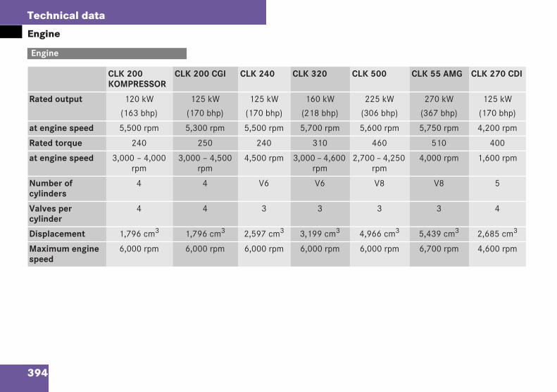
394
Technical data
Engine
Engine
CLK 200KOMPRESSOR
CLK 200 CGI CLK 240 CLK 320 CLK 500 CLK 55 AMG CLK 270 CDI
Rated output 120 kW
(163 bhp)
125 kW
(170 bhp)
125 kW
(170 bhp)
160 kW
(218 bhp)
225 kW
(306 bhp)
270 kW
(367 bhp)
125 kW
(170 bhp)
at engine speed 5,500 rpm 5,300 rpm 5,500 rpm 5,700 rpm 5,600 rpm 5,750 rpm 4,200 rpm
Rated torque 240 250 240 310 460 510 400
at engine speed 3,000 – 4,000rpm
3,000 – 4,500rpm
4,500 rpm 3,000 – 4,600rpm
2,700 – 4,250rpm
4,000 rpm 1,600 rpm
Number ofcylinders
4 4 V6 V6 V8 V8 5
Valves percylinder
4 4 3 3 3 3 4
Displacement 1,796 cm3 1,796 cm3 2,597 cm3 3,199 cm3 4,966 cm3 5,439 cm3 2,685 cm3
Maximum enginespeed
6,000 rpm 6,000 rpm 6,000 rpm 6,000 rpm 6,000 rpm 6,700 rpm 4,600 rpm
209en_d2.boo Seite 394 Dienstag, 25. Mai 2004 7:26 19
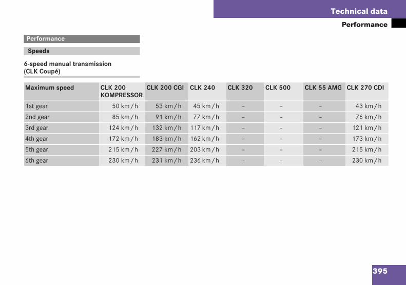
395
Technical data
Performance
6-speed manual transmission(CLK Coupé)
Performance
Speeds
Maximum speed CLK 200KOMPRESSOR
CLK 200 CGI CLK 240 CLK 320 CLK 500 CLK 55 AMG CLK 270 CDI
1st gear 50 km/h 53 km/h 45 km/h – – – 43 km/h
2nd gear 85 km/h 91 km/h 77 km/h – – – 76 km/h
3rd gear 124 km/h 132 km/h 117 km/h – – – 121 km/h
4th gear 172 km/h 183 km/h 162 km/h – – – 173 km/h
5th gear 215 km/h 227 km/h 203 km/h – – – 215 km/h
6th gear 230 km/h 231 km/h 236 km/h – – – 230 km/h
209en_d2.boo Seite 395 Dienstag, 25. Mai 2004 7:26 19
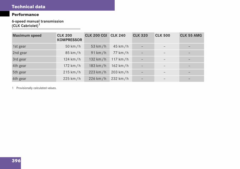
396
Technical data
Performance6-speed manual transmission(CLK Cabriolet)1
1 Provisionally calculated values.
Maximum speed CLK 200KOMPRESSOR
CLK 200 CGI CLK 240 CLK 320 CLK 500 CLK 55 AMG
1st gear 50 km/h 53 km/h 45 km/h – – –
2nd gear 85 km/h 91 km/h 77 km/h – – –
3rd gear 124 km/h 132 km/h 117 km/h – – –
4th gear 172 km/h 183 km/h 162 km/h – – –
5th gear 215 km/h 223 km/h 203 km/h – – –
6th gear 225 km/h 226 km/h 232 km/h – – –
209en_d2.boo Seite 396 Dienstag, 25. Mai 2004 7:26 19
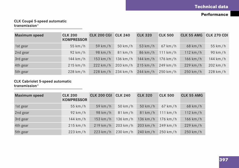
397
Technical data
PerformanceCLK Coupé 5-speed automatictransmission*
CLK Cabriolet 5-speed automatictransmission*
Maximum speed CLK 200KOMPRESSOR
CLK 200 CGI CLK 240 CLK 320 CLK 500 CLK 55 AMG CLK 270 CDI
1st gear 55 km/h 59 km/h 50 km/h 53 km/h 67 km/h 68 km/h 55 km/h
2nd gear 92 km/h 98 km/h 81 km/h 86 km/h 111 km/h 112 km/h 90 km/h
3rd gear 144 km/h 153 km/h 136 km/h 144 km/h 176 km/h 166 km/h 144 km/h
4th gear 215 km/h 222 km/h 203 km/h 215 km/h 249 km/h 229 km/h 202 km/h
5th gear 228 km/h 228 km/h 234 km/h 244 km/h 250 km/h 250 km/h 228 km/h
Maximum speed CLK 200KOMPRESSOR
CLK 200 CGI CLK 240 CLK 320 CLK 500 CLK 55 AMG
1st gear 55 km/h 59 km/h 50 km/h 50 km/h 67 km/h 68 km/h
2nd gear 92 km/h 98 km/h 81 km/h 81 km/h 111 km/h 112 km/h
3rd gear 144 km/h 153 km/h 136 km/h 136 km/h 176 km/h 166 km/h
4th gear 215 km/h 219 km/h 203 km/h 203 km/h 249 km/h 229 km/h
5th gear 223 km/h 223 km/h 230 km/h 240 km/h 250 km/h 250 km/h
209en_d2.boo Seite 397 Dienstag, 25. Mai 2004 7:26 19
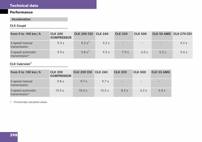
398
Technical data
Performance
CLK Coupé
CLK Cabriolet1
1 Provisionally calculated values.
Acceleration
from 0 to 100 km/h CLK 200KOMPRESSOR
CLK 200 CGI CLK 240 CLK 320 CLK 500 CLK 55 AMG CLK 270 CDI
6-speed manualtransmission
9.3 s 9.2 s1 9.2 s – – – 9.2 s
5-speed automatictransmission*
9.9 s 9.8 s1 9.5 s 7.9 s 6.0 s 5.2 s 9.4 s
from 0 to 100 km/h CLK 200KOMPRESSOR
CLK 200 CGI CLK 240 CLK 320 CLK 500 CLK 55 AMG
6-speed manualtransmission
9.8 s 9.7 s 9.7 s – – –
5-speed automatictransmission*
10.5 s 10.4 s 10.2 s 8.2 s 6.2 s 5.4 s
tech_dat.fm Seite 398 Dienstag, 1. Juni 2004 1:34 13
399
Technical data
Tyres and wheels
! Mercedes-Benz recommends that, for safe-ty reasons, you use tyres which have been spe-cially approved by Mercedes-Benz for yourvehicle. These tyres are specially suited to yourvehicle's control systems, such as ABS or ESP.Mercedes-Benz can accept no responsibility fordamage resulting from using tyres other thanthose approved for your vehicle. You may obtainfurther information about tyres from anyMercedes-Benz Service Centre.
! If you use tyres other than those which havebeen tested and recommended by Mercedes-Benz, characteristics such as handling, noise lev-els and fuel consumption could be adversely af-fected. Moreover, dimensional variations anddifferent tyre deformation characteristics whenrunning under load could cause the tyre to makecontact with the bodywork or axle components.The consequence could be damage to the tyre orto the vehicle.
i You may obtain further information abouttyres and wheels from any Mercedes-Benz Serv-ice Centre.
You will find a table of tyre pressures on the in-side of the vehicle's fuel filler flap. You will findfurther information about tyre pressures in the"Operation" section ( page 251).
Tyres and wheels
209en_d2.boo Seite 399 Dienstag, 25. Mai 2004 7:26 19
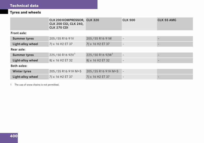
400
Technical data
Tyres and wheels
1 The use of snow chains is not permitted.
CLK 200 KOMPRESSOR,CLK 200 CGI, CLK 240,CLK 270 CDI
CLK 320 CLK 500 CLK 55 AMG
Front axle:
Summer tyres 205/55 R16 91V 205/55 R16 91W – –
Light-alloy wheel 7J x 16 H2 ET 37 7J x 16 H2 ET 37 – –
Rear axle:
Summer tyres 225/50 R16 92V1 225/50 R16 92W1 – –
Light-alloy wheel 8J x 16 H2 ET 32 8J x 16 H2 ET 32 – –
Both axles:
Winter tyres 205/55 R16 91H M+S 205/55 R16 91H M+S –
Light-alloy wheel 7J x 16 H2 ET 37 7J x 16 H2 ET 37 – –
209en_d2.boo Seite 400 Dienstag, 25. Mai 2004 7:26 19
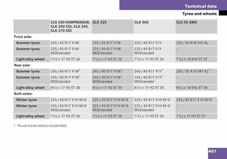
401
Technical data
Tyres and wheels
1 The use of snow chains is not permitted.
CLK 200 KOMPRESSOR,CLK 200 CGI, CLK 240,CLK 270 CDI
CLK 320 CLK 500 CLK 55 AMG
Front axle:
Summer tyres 225/45 R17 91W 225/45 R17 91W 225/45 R17 91Y 225/40 R18 92Y XL
Summer tyres 225/45 R17 91WMOExtended
225/45 R17 91WMOExtended
225/45 R17 91YMOExtended
–
Light-alloy wheel 7½J x 17 H2 ET 36 7½J x 17 H2 ET 36 7½J x 17 H2 ET 36 7½J x 18 EH2 ET 37
Rear axle:
Summer tyres 245/40 R17 91W1 245/40 R17 91W1 245/40 R17 91Y1 255/35 R18 94Y XL1
Summer tyres 245/40 R17 91W1
MOExtended245/40 R17 91W1
MOExtended245/40 R17 91Y1
MOExtended–
Light-alloy wheel 8½J x 17 H2 ET 30 8½J x 17 H2 ET 30 8½J x 17 H2 ET 30 8½J x 18 EH2 ET 30
Both axles:
Winter tyres 225/45 R17 91H M+S 225/45 R17 91H M+S 225/45 R17 91H M+S 225/45 R17 91H M+S
Winter tyres 225/45 R17 91H M+SMOExtended
225/45 R17 91H M+SMOExtended
225/45 R17 91H M+SMOExtended
–
Light-alloy wheel 7½J x 17 H2 ET 36 7½J x 17 H2 ET 36 7½J x 17 H2 ET 36 7½J x 17 H2 ET 37
209en_d2.boo Seite 401 Dienstag, 25. Mai 2004 7:26 19
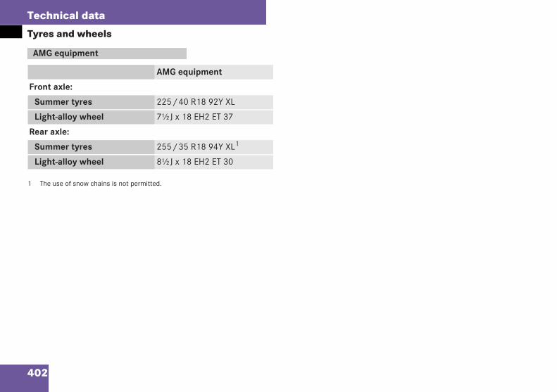
402
Technical data
Tyres and wheels
1 The use of snow chains is not permitted.
AMG equipment
AMG equipment
Front axle:
Summer tyres 225/40 R18 92Y XL
Light-alloy wheel 7½J x 18 EH2 ET 37
Rear axle:
Summer tyres 255/35 R18 94Y XL1
Light-alloy wheel 8½J x 18 EH2 ET 30
209en_d2.boo Seite 402 Dienstag, 25. Mai 2004 7:26 19
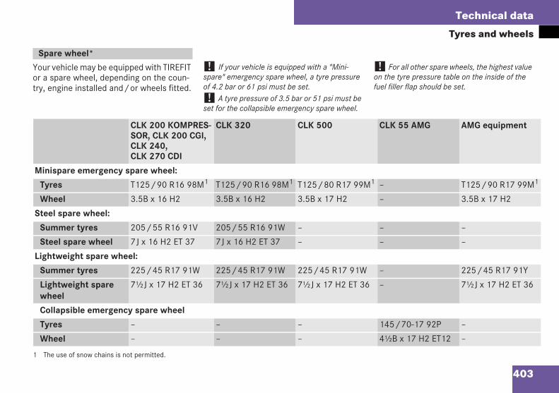
403
Technical data
Tyres and wheels
Your vehicle may be equipped with TIREFITor a spare wheel, depending on the coun-try, engine installed and/or wheels fitted.
! If your vehicle is equipped with a "Mini-spare" emergency spare wheel, a tyre pressureof 4.2 bar or 61 psi must be set.! A tyre pressure of 3.5 bar or 51 psi must beset for the collapsible emergency spare wheel.
! For all other spare wheels, the highest valueon the tyre pressure table on the inside of thefuel filler flap should be set.
1 The use of snow chains is not permitted.
Spare wheel*
CLK 200 KOMPRES-SOR, CLK 200 CGI,CLK 240,CLK 270 CDI
CLK 320 CLK 500 CLK 55 AMG AMG equipment
Minispare emergency spare wheel:
Tyres T125/90 R16 98M1 T125/90 R16 98M1 T125/80 R17 99M1 – T125/90 R17 99M1
Wheel 3.5B x 16 H2 3.5B x 16 H2 3.5B x 17 H2 – 3.5B x 17 H2
Steel spare wheel:
Summer tyres 205/55 R16 91V 205/55 R16 91W – – –
Steel spare wheel 7J x 16 H2 ET 37 7J x 16 H2 ET 37 – – –
Lightweight spare wheel:
Summer tyres 225/45 R17 91W 225/45 R17 91W 225/45 R17 91W – 225/45 R17 91Y
Lightweight sparewheel
7½J x 17 H2 ET 36 7½J x 17 H2 ET 36 7½J x 17 H2 ET 36 – 7½J x 17 H2 ET 36
Collapsible emergency spare wheel
Tyres – – – 145/70-17 92P –
Wheel – – – 4½B x 17 H2 ET12 –
209en_d2.boo Seite 403 Dienstag, 25. Mai 2004 7:26 19
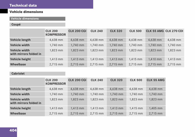
404
Technical data
Vehicle dimensions
Vehicle dimensions
Coupé
CLK 200KOMPRESSOR
CLK 200 CGI CLK 240 CLK 320 CLK 500 CLK 55 AMG CLK 270 CDI
Vehicle length 4,638 mm 4,638 mm 4,638 mm 4,638 mm 4,638 mm 4,638 mm 4,638 mm
Vehicle width 1,740 mm 1,740 mm 1,740 mm 1,740 mm 1,740 mm 1,740 mm 1,740 mm
Vehicle widthwith mirrors folded in
1,823 mm 1,823 mm 1,823 mm 1,823 mm 1,823 mm 1,823 mm 1,823 mm
Vehicle height 1,413 mm 1,413 mm 1,413 mm 1,413 mm 1,415 mm 1,410 mm 1,413 mm
Wheelbase 2,715 mm 2,715 mm 2,715 mm 2,715 mm 2,715 mm 2,715 mm 2,715 mm
Cabriolet
CLK 200KOMPRESSOR
CLK 200 CGI CLK 240 CLK 320 CLK 500 CLK 55 AMG
Vehicle length 4,638 mm 4,638 mm 4,638 mm 4,638 mm 4,638 mm 4,638 mm
Vehicle width 1,740 mm 1,740 mm 1,740 mm 1,740 mm 1,740 mm 1,740 mm
Vehicle widthwith mirrors folded in
1,823 mm 1,823 mm 1,823 mm 1,823 mm 1,823 mm 1,823 mm
Vehicle height 1,413 mm 1,413 mm 1,413 mm 1,413 mm 1,415 mm 1,405 mm
Wheelbase 2,715 mm 2,715 mm 2,715 mm 2,715 mm 2,715 mm 2,715 mm
209en_d2.boo Seite 404 Dienstag, 25. Mai 2004 7:26 19
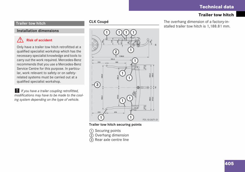
405
Technical data
Trailer tow hitch
! If you have a trailer coupling retrofitted,modifications may have to be made to the cool-ing system depending on the type of vehicle.
CLK Coupé
Trailer tow hitch securing points
1 Securing points2 Overhang dimension3 Rear axle centre line
The overhang dimension of a factory-in-stalled trailer tow hitch is 1,188.81 mm.
Trailer tow hitch
Installation dimensions
G Risk of accident
Only have a trailer tow hitch retrofitted at aqualified specialist workshop which has thenecessary specialist knowledge and tools tocarry out the work required. Mercedes-Benzrecommends that you use a Mercedes-BenzService Centre for this purpose. In particu-lar, work relevant to safety or on safety-related systems must be carried out at aqualified specialist workshop.
P31.10-2671-31
209en_d2.boo Seite 405 Dienstag, 25. Mai 2004 7:26 19
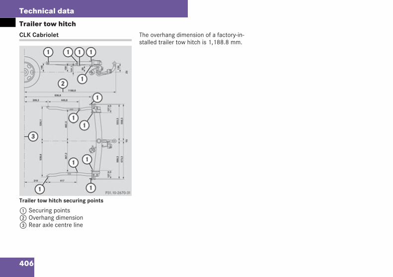
406
Technical data
Trailer tow hitchCLK Cabriolet
Trailer tow hitch securing points
1 Securing points2 Overhang dimension3 Rear axle centre line
The overhang dimension of a factory-in-stalled trailer tow hitch is 1,188.8 mm.
P31.10-2670-31
209en_d2.boo Seite 406 Dienstag, 25. Mai 2004 7:26 19
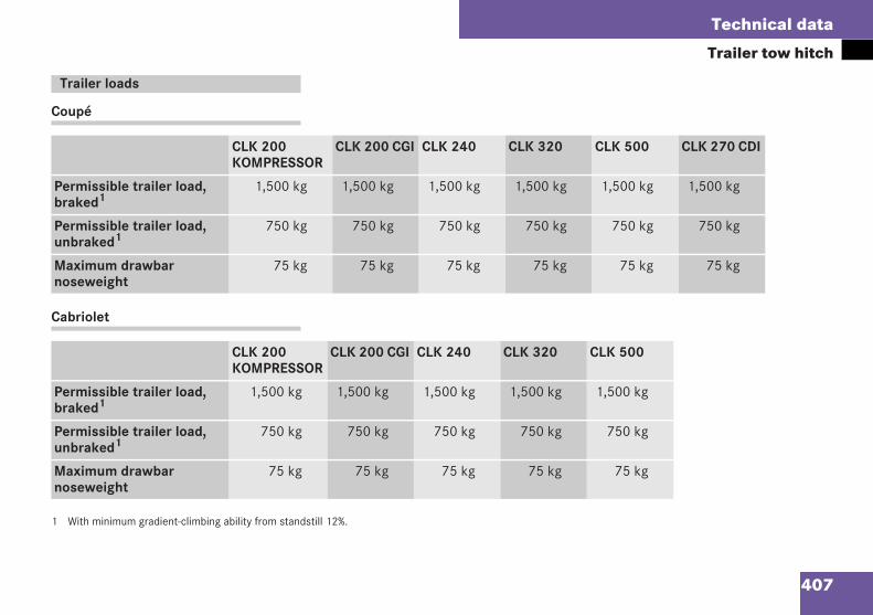
407
Technical data
Trailer tow hitch
Coupé
Cabriolet
1 With minimum gradient-climbing ability from standstill 12%.
Trailer loads
CLK 200KOMPRESSOR
CLK 200 CGI CLK 240 CLK 320 CLK 500 CLK 270 CDI
Permissible trailer load,braked1
1,500 kg 1,500 kg 1,500 kg 1,500 kg 1,500 kg 1,500 kg
Permissible trailer load,unbraked1
750 kg 750 kg 750 kg 750 kg 750 kg 750 kg
Maximum drawbarnoseweight
75 kg 75 kg 75 kg 75 kg 75 kg 75 kg
CLK 200KOMPRESSOR
CLK 200 CGI CLK 240 CLK 320 CLK 500
Permissible trailer load,braked1
1,500 kg 1,500 kg 1,500 kg 1,500 kg 1,500 kg
Permissible trailer load,unbraked1
750 kg 750 kg 750 kg 750 kg 750 kg
Maximum drawbarnoseweight
75 kg 75 kg 75 kg 75 kg 75 kg
209en_d2.boo Seite 407 Dienstag, 25. Mai 2004 7:26 19
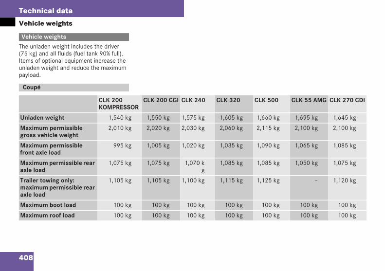
408
Technical data
Vehicle weights
The unladen weight includes the driver(75 kg) and all fluids (fuel tank 90% full).Items of optional equipment increase theunladen weight and reduce the maximumpayload.
Vehicle weights
Coupé
CLK 200KOMPRESSOR
CLK 200 CGI CLK 240 CLK 320 CLK 500 CLK 55 AMG CLK 270 CDI
Unladen weight 1,540 kg 1,550 kg 1,575 kg 1,605 kg 1,660 kg 1,695 kg 1,645 kg
Maximum permissiblegross vehicle weight
2,010 kg 2,020 kg 2,030 kg 2,060 kg 2,115 kg 2,100 kg 2,100 kg
Maximum permissiblefront axle load
995 kg 1,005 kg 1,020 kg 1,035 kg 1,090 kg 1,065 kg 1,085 kg
Maximum permissible rearaxle load
1,075 kg 1,075 kg 1,070 kg
1,085 kg 1,085 kg 1,050 kg 1,075 kg
Trailer towing only:maximum permissible rearaxle load
1,105 kg 1,105 kg 1,100 kg 1,115 kg 1,125 kg – 1,120 kg
Maximum boot load 100 kg 100 kg 100 kg 100 kg 100 kg 100 kg 100 kg
Maximum roof load 100 kg 100 kg 100 kg 100 kg 100 kg 100 kg 100 kg
209en_d2.boo Seite 408 Dienstag, 25. Mai 2004 7:26 19
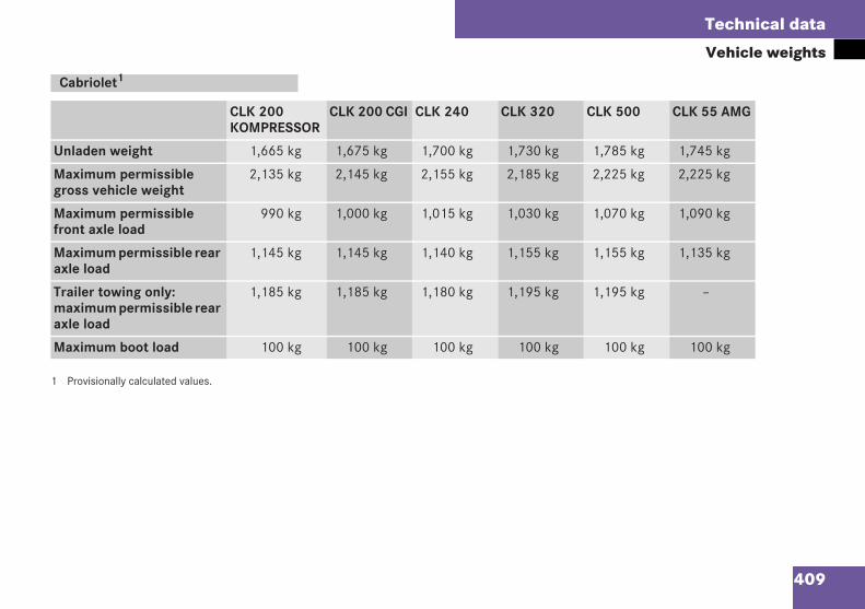
409
Technical data
Vehicle weights
1 Provisionally calculated values.
Cabriolet1
CLK 200KOMPRESSOR
CLK 200 CGI CLK 240 CLK 320 CLK 500 CLK 55 AMG
Unladen weight 1,665 kg 1,675 kg 1,700 kg 1,730 kg 1,785 kg 1,745 kg
Maximum permissiblegross vehicle weight
2,135 kg 2,145 kg 2,155 kg 2,185 kg 2,225 kg 2,225 kg
Maximum permissiblefront axle load
990 kg 1,000 kg 1,015 kg 1,030 kg 1,070 kg 1,090 kg
Maximum permissible rearaxle load
1,145 kg 1,145 kg 1,140 kg 1,155 kg 1,155 kg 1,135 kg
Trailer towing only:maximum permissible rearaxle load
1,185 kg 1,185 kg 1,180 kg 1,195 kg 1,195 kg –
Maximum boot load 100 kg 100 kg 100 kg 100 kg 100 kg 100 kg
209en_d2.boo Seite 409 Dienstag, 25. Mai 2004 7:26 19
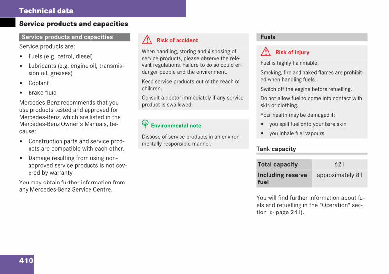
410
Technical data
Service products and capacities
Service products are:
Fuels (e.g. petrol, diesel)
Lubricants (e.g. engine oil, transmis-sion oil, greases)
Coolant
Brake fluid
Mercedes-Benz recommends that youuse products tested and approved forMercedes-Benz, which are listed in theMercedes-Benz Owner's Manuals, be-cause:
Construction parts and service prod-ucts are compatible with each other.
Damage resulting from using non-approved service products is not cov-ered by warranty
You may obtain further information fromany Mercedes-Benz Service Centre.
Tank capacity
You will find further information about fu-els and refuelling in the "Operation" sec-tion ( page 241).
Service products and capacities G Risk of accident
When handling, storing and disposing ofservice products, please observe the rele-vant regulations. Failure to do so could en-danger people and the environment.
Keep service products out of the reach ofchildren.
Consult a doctor immediately if any serviceproduct is swallowed.
H Environmental note
Dispose of service products in an environ-mentally-responsible manner.
Fuels
G Risk of injury
Fuel is highly flammable.
Smoking, fire and naked flames are prohibit-ed when handling fuels.
Switch off the engine before refuelling.
Do not allow fuel to come into contact withskin or clothing.
Your health may be damaged if:
you spill fuel onto your bare skin
you inhale fuel vapours
Total capacity 62 l
Including reservefuel
approximately 8 l
209en_d2.boo Seite 410 Dienstag, 25. Mai 2004 7:26 19
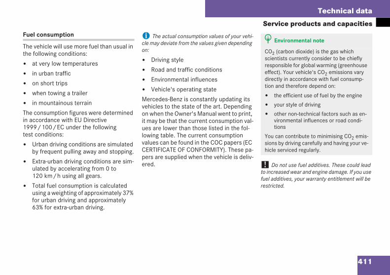
411
Technical data
Service products and capacitiesFuel consumption
The vehicle will use more fuel than usual inthe following conditions:
at very low temperatures
in urban traffic
on short trips
when towing a trailer
in mountainous terrain
The consumption figures were determinedin accordance with EU Directive1999/100/EC under the followingtest conditions:
Urban driving conditions are simulatedby frequent pulling away and stopping.
Extra-urban driving conditions are sim-ulated by accelerating from 0 to120 km/h using all gears.
Total fuel consumption is calculatedusing a weighting of approximately 37%for urban driving and approximately63% for extra-urban driving.
i The actual consumption values of your vehi-cle may deviate from the values given dependingon:
Driving style
Road and traffic conditions
Environmental influences
Vehicle's operating state
Mercedes-Benz is constantly updating itsvehicles to the state of the art. Dependingon when the Owner's Manual went to print,it may be that the current consumption val-ues are lower than those listed in the fol-lowing table. The current consumptionvalues can be found in the COC papers (ECCERTIFICATE OF CONFORMITY). These pa-pers are supplied when the vehicle is deliv-ered. ! Do not use fuel additives. These could lead
to increased wear and engine damage. If you usefuel additives, your warranty entitlement will berestricted.
H Environmental note
CO2 (carbon dioxide) is the gas whichscientists currently consider to be chieflyresponsible for global warming (greenhouseeffect). Your vehicle's CO2 emissions varydirectly in accordance with fuel consump-tion and therefore depend on:
the efficient use of fuel by the engine
your style of driving
other non-technical factors such as en-vironmental influences or road condi-tions
You can contribute to minimising CO2 emis-sions by driving carefully and having your ve-hicle serviced regularly.
209en_d2.boo Seite 411 Dienstag, 25. Mai 2004 7:26 19
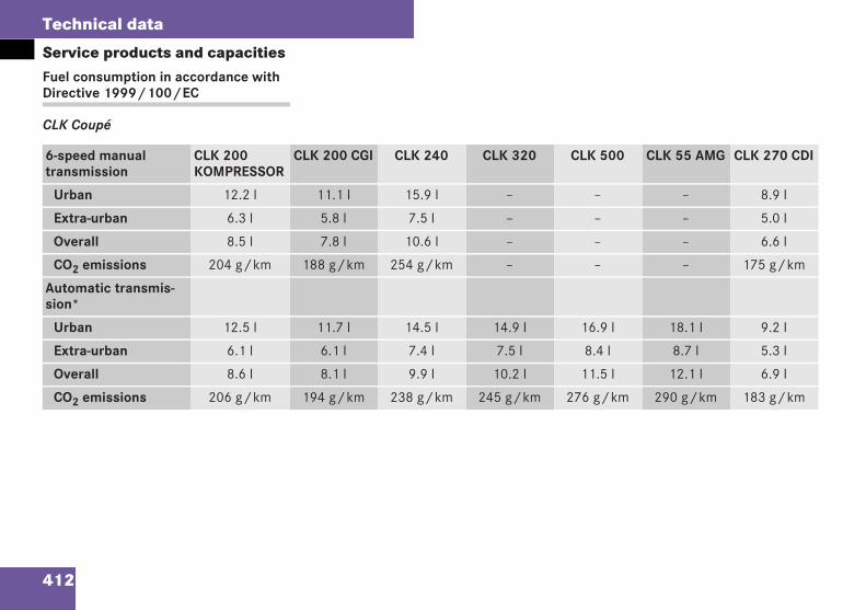
412
Technical data
Service products and capacitiesFuel consumption in accordance withDirective 1999/100/EC
CLK Coupé
6-speed manualtransmission
CLK 200KOMPRESSOR
CLK 200 CGI CLK 240 CLK 320 CLK 500 CLK 55 AMG CLK 270 CDI
Urban 12.2 l 11.1 l 15.9 l – – – 8.9 l
Extra-urban 6.3 l 5.8 l 7.5 l – – – 5.0 l
Overall 8.5 l 7.8 l 10.6 l – – – 6.6 l
CO2 emissions 204 g/km 188 g/km 254 g/km – – – 175 g/km
Automatic transmis-sion*
Urban 12.5 l 11.7 l 14.5 l 14.9 l 16.9 l 18.1 l 9.2 l
Extra-urban 6.1 l 6.1 l 7.4 l 7.5 l 8.4 l 8.7 l 5.3 l
Overall 8.6 l 8.1 l 9.9 l 10.2 l 11.5 l 12.1 l 6.9 l
CO2 emissions 206 g/km 194 g/km 238 g/km 245 g/km 276 g/km 290 g/km 183 g/km
209en_d2.boo Seite 412 Dienstag, 25. Mai 2004 7:26 19
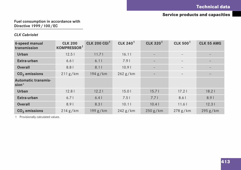
413
Technical data
Service products and capacitiesFuel consumption in accordance withDirective 1999/100/EC
CLK Cabriolet
6-speed manualtransmission
CLK 200KOMPRESSOR1
CLK 200 CGI1 CLK 2401 CLK 3201 CLK 5001 CLK 55 AMG
Urban 12.5 l 11.7 l 16.1 l – – –
Extra-urban 6.6 l 6.1 l 7.9 l – – –
Overall 8.8 l 8.1 l 10.9 l – – –
CO2 emissions 211 g/km 194 g/km 262 g/km – – –
Automatic transmis-sion*
Urban 12.8 l 12.2 l 15.0 l 15.7 l 17.2 l 18.2 l
Extra-urban 6.7 l 6.4 l 7.5 l 7.7 l 8.6 l 8.9 l
Overall 8.9 l 8.3 l 10.1 l 10.4 l 11.6 l 12.3 l
CO2 emissions 214 g/km 199 g/km 242 g/km 250 g/km 278 g/km 295 g/km
1 Provisionally calculated values.
209en_d2.boo Seite 413 Dienstag, 25. Mai 2004 7:26 19
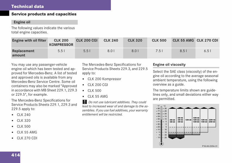
414
Technical data
Service products and capacities
The following values indicate the varioustotal engine capacities.
You may use any passenger-vehicleengine oil which has been tested and ap-proved for Mercedes-Benz. A list of testedand approved oils is available from anyMercedes-Benz Service Centre. Some oilcontainers may also be marked "Approvedin accordance with MB Sheet 229.1, 229.3or 229.5", for example.
The Mercedes-Benz Specifications forService Products Sheets 229.1, 229.3 and229.5 apply to:
CLK 240
CLK 320
CLK 500
CLK 55 AMG
CLK 270 CDI
The Mercedes-Benz Specifications forService Products Sheets 229.3, and 229.5apply to:
CLK 200 Kompressor
CLK 200 CGI
CLK 500
CLK 55 AMG
! Do not use lubricant additives. They couldlead to increased wear of and damage to the as-semblies. If you use fuel additives, your warrantyentitlement will be restricted.
Engine oil viscosity
Select the SAE class (viscosity) of the en-gine oil according to the average seasonalambient temperature, using the followingoverview as a guide.
The temperature limits shown are guide-lines only, and small deviations either wayare permitted.
Engine oil
Engine with oil filter CLK 200KOMPRESSOR
CLK 200 CGI CLK 240 CLK 320 CLK 500 CLK 55 AMG CLK 270 CDI
Replacementamount
5.5 l 5.5 l 8.0 l 8.0 l 7.5 l 8.5 l 6.5 l
209en_d2.boo Seite 414 Dienstag, 25. Mai 2004 7:26 19
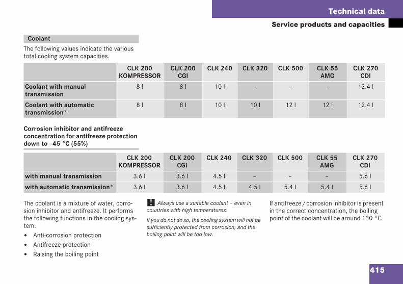
415
Technical data
Service products and capacities
The following values indicate the varioustotal cooling system capacities.
Corrosion inhibitor and antifreezeconcentration for antifreeze protectiondown to –45 °C (55%)
The coolant is a mixture of water, corro-sion inhibitor and antifreeze. It performsthe following functions in the cooling sys-tem:
Anti-corrosion protectionAntifreeze protectionRaising the boiling point
! Always use a suitable coolant – even incountries with high temperatures.
If you do not do so, the cooling system will not besufficiently protected from corrosion, and theboiling point will be too low.
If antifreeze/corrosion inhibitor is presentin the correct concentration, the boilingpoint of the coolant will be around 130 °C.
Coolant
CLK 200KOMPRESSOR
CLK 200CGI
CLK 240 CLK 320 CLK 500 CLK 55AMG
CLK 270CDI
Coolant with manualtransmission
8 l 8 l 10 l – – – 12.4 l
Coolant with automatictransmission*
8 l 8 l 10 l 10 l 12 l 12 l 12.4 l
CLK 200KOMPRESSOR
CLK 200CGI
CLK 240 CLK 320 CLK 500 CLK 55AMG
CLK 270CDI
with manual transmission 3.6 l 3.6 l 4.5 l – – – 5.6 l
with automatic transmission* 3.6 l 3.6 l 4.5 l 4.5 l 5.4 l 5.4 l 5.6 l
209en_d2.boo Seite 415 Dienstag, 25. Mai 2004 7:26 19
416
Technical data
Service products and capacitiesThe antifreeze and corrosion inhibitor con-centration in the cooling system should:
be at least 50%. This will protect thecooling system against freezing downto approximately –37 °C.
not exceed 55% (antifreeze protectiondown to –45 °C), since the heat is thennot dissipated as effectively.
If the vehicle has lost coolant, top it up withequal parts of water and an antifreeze andcorrosion inhibitor. Mercedes-Benz recom-mends that you use an antifreeze and cor-rosion inhibitor which has been approvedfor Mercedes-Benz.
! The cooling system has a permanent supplywhich must be renewed after 15 years or250,000 km at the most.
Mercedes-Benz recommends that you use an an-tifreeze and corrosion inhibitor which has beenapproved for Mercedes-Benz.
Over a period of time, the brake fluid ab-sorbs moisture from the air; this reducesits boiling point.
i There is usually a notice in the engine com-partment to remind you when the next brake flu-id change is due.
The windscreen washer reservoir holdsapproximately 3 litres on all models witha windscreen washer system. On modelswith a heated windscreen washer fluid res-ervoir or a headlamp cleaning system*, thereservoir holds 6 litres.
The headlamp cleaning system* and thewindscreen washer system have a com-mon supply from the windscreen washerfluid reservoir.
Fill the windscreen washer fluid reser-voir with a solution of water and wind-screen washer concentrate. Adapt themixing ratio to suit the outside temper-atures.
The windscreen wipers leave no marks.The headlamp cleaning system and thewindscreen washer system do notfreeze.
Brake fluid
G Risk of accident
If the boiling point of the brake fluid is toolow, vapour pockets may form in the brakesystem when the brakes are applied hard(e.g. when driving downhill). This would im-pair braking efficiency.
Have the brake fluid renewed everytwo years.
Windscreen washer system
G Risk of fire
Windscreen washer concentrate is highlyflammable. Fire, naked flames and smokingare prohibited when you are handling wind-screen washer concentrate.
209en_d2.boo Seite 416 Dienstag, 25. Mai 2004 7:26 19
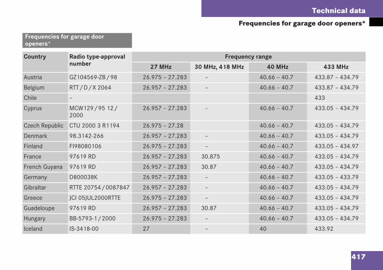
417
Technical data
Frequencies for garage door openers*
Frequencies for garage dooropeners*
Country Radio type-approvalnumber
Frequency range
27 MHz 30 MHz, 418 MHz 40 MHz 433 MHz
Austria GZ104569-ZB/98 26.975 – 27.283 – 40.66 – 40.7 433.87 – 434.79
Belgium RTT/D/X 2064 26.957 – 27.283 – 40.66 – 40.7 433.87 – 434.79
Chile – 433
Cyprus MCW129/95 12/2000
26.957 – 27.283 – 40.66 – 40.7 433.05 – 434.79
Czech Republic CTU 2000 3 R1194 26.975 – 27.28 40.66 – 40.7 433.05 – 434.79
Denmark 98.3142-266 26.957 – 27.283 – 40.66 – 40.7 433.05 – 434.79
Finland FI98080106 26.975 – 27.283 – 40.66 – 40.7 433.05 – 434.97
France 97619 RD 26.957 – 27.283 30.875 40.66 – 40.7 433.05 – 434.79
French Guyana 97619 RD 26.957 – 27.283 30.87 40.66 – 40.7 433.05 – 434.79
Germany D800038K 26.957 – 27.283 – 40.66 – 40.7 433.05 – 433.79
Gibraltar RTTE 20754/0087847 26.957 – 27.283 – 40.66 – 40.7 433.05 – 434.79
Greece JCI 05JUL2000RTTE 26.975 – 27.283 – 40.66 – 40.7 433.05 – 434.79
Guadeloupe 97619 RD 26.957 – 27.283 30.87 40.66 – 40.7 433.05 – 434.79
Hungary BB-5793-1/2000 26.975 – 27.283 – 40.66 – 40.7 433.05 – 434.79
Iceland IS-3418-00 27 – 40 433.92
209en_d2.boo Seite 417 Dienstag, 25. Mai 2004 7:26 19
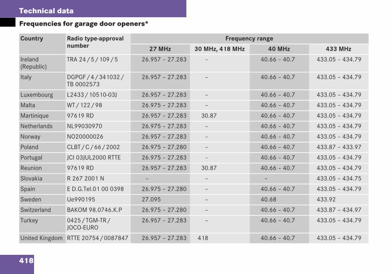
418
Technical data
Frequencies for garage door openers*
Country Radio type-approvalnumber
Frequency range
27 MHz 30 MHz, 418 MHz 40 MHz 433 MHz
Ireland(Republic)
TRA 24/5/109/5 26.957 – 27.283 – 40.66 – 40.7 433.05 – 434.79
Italy DGPGF/4/341032/TB 0002573
26.957 – 27.283 – 40.66 – 40.7 433.05 – 434.79
Luxembourg L2433/10510-03J 26.957 – 27.283 – 40.66 – 40.7 433.05 – 434.79
Malta WT/122/98 26.975 – 27.283 – 40.66 – 40.7 433.05 – 434.79
Martinique 97619 RD 26.957 – 27.283 30.87 40.66 – 40.7 433.05 – 434.79
Netherlands NL99030970 26.975 – 27.283 – 40.66 – 40.7 433.05 – 434.79
Norway NO20000026 26.957 – 27.283 – 40.66 – 40.7 433.05 – 434.79
Poland CLBT/C/66/2002 26.975 – 27.280 – 40.66 – 40.7 433.87 – 433.97
Portugal JCI 03JUL2000 RTTE 26.975 – 27.283 – 40.66 – 40.7 433.05 – 434.79
Reunion 97619 RD 26.957 – 27.283 30.87 40.66 – 40.7 433.05 – 434.79
Slovakia R 267 2001 N – – – 433.05 – 434.75
Spain E D.G.Tel.01 00 0398 26.975 – 27.280 – 40.66 – 40.7 433.05 – 434.79
Sweden Ue990195 27.095 – 40.68 433.92
Switzerland BAKOM 98.0746.K.P 26.975 – 27.280 – 40.66 – 40.7 433.87 – 434.97
Turkey 0425/TGM-TR/JOCO-EURO
26.957 – 27.283 – 40.66 – 40.7 433.05 – 434.79
United Kingdom RTTE 20754/0087847 26.957 – 27.283 418 40.66 – 40.7 433.05 – 434.79
209en_d2.boo Seite 418 Dienstag, 25. Mai 2004 7:26 19
419
Technical terms
A-pillarFront structural pillar connecting theroof and body (->B-pillar, ->C-pillar).
ABS(anti-lock braking system)Prevents the wheels from locking un-der braking. ->Steerability is thus main-tained.
ASR(Acceleration skid control)Component of ->ESP. ASR controls thedrive force to the wheels and therebyimproves ->traction.
ASSYST(Active Service System)Service indicator of the ->operatingsystem which displays when the nextservice is due.
Asymmetrical dipped-beam headlampsPosition of the dipped-beam head-lamps which directs the light towardsthe edge of the carriageway.
Audio 20*, Audio 50 APS* systemName used to describe your vehicle'sradio and the built-in loudspeakers.The system may also include naviga-tion software, depending on your vehi-cle's equipment.
B-pillarThere is no B-pillar on Cabriolet andCoupé models for design reasons.
Ball coupling*Holder on the vehicle; part of the trailertow hitch on the vehicle to which a trail-er can be hitched up.
BAS(Brake Assist)System for shortening the stopping dis-tance in hazardous situations, activat-ed by the driver depressing the brakepedal suddenly. The system boosts thebraking force.
Belt driveDrive connection from the engine toassociated assemblies such as the al-ternator or the air-conditioning com-pressor.
Bi-xenon headlamps*->Xenon headlamps in which thedipped beam and main beam are pro-duced by a single light source.
BulbArtificial light source.
C-pillarThe C-pillar is the rear structural pillarconnecting the roof and body (->A-pil-lar, ->B-pillar). There is no C-pillar onCabriolet models for design reasons.
CAC(Customer Assistance Center)DaimlerChrysler customer assistancecentre.
209en_d2.boo Seite 419 Dienstag, 25. Mai 2004 7:26 19
420
Technical terms
CAN system(Controller Area Network)Uses vehicle or environmental factorsto control certain functions of your ve-hicle, such as central locking or thewindscreen wipers, and transmits thisinformation to the ->operating system.This system works through the inter-connection of all the electronic sys-tems in the vehicle.
CDI(Common Rail Direct Injection)Diesel injection technology, in which allcylinders have a common feed line.Fine injection nozzles allow very pre-cise dosages, which reduces dieselconsumption.
Centring pinThreaded metal pin. Tool for precisepositioning of the wheel on the wheelhub when changing a tyre.
Chassis numberNumber determined by the manufac-turer and affixed to the body, by whicheach vehicle can be clearly identified.
Child seat recognitionSpecial child seats are available for ve-hicles with automatic child seat recog-nition on the front-passenger seat. Ifyou have fitted a child seat of this kindto the front-passenger seat, the front-passenger airbag is automatically disa-bled (the PASSENGER AIRBAG OFF/7warning lamp on the centre consolelights up).
CockpitAll the instruments, switches, buttonsand warning and indicator lamps withinthe driver's reach, which are necessaryfor monitoring and controlling the vehi-cle.
COMAND APS*(Cockpit Management and DataSystem)Information and operating centre forvarious vehicle functions such as theradio, DVD player, navigation systemwith map display and other items of op-tional equipment, e.g. DVD changer*,Dolby Surround System*, TV tuner*,telephone*.
Control unitElectronic component of the engineelectronics; controls engine and trans-mission functions, e.g. ->automatictransmission or ->ESP.
Cruise controlSystem which enables a vehicle speedset by the driver to be maintained auto-matically.
209en_d2.boo Seite 420 Dienstag, 25. Mai 2004 7:26 19
421
Technical terms
Distronic*System which helps the driver to keepto a pre-selected speed on motorwaysand major roads:
If there is no vehicle in front, thesystem operates in the same wayas ->cruise control.
If a vehicle is detected ahead,Distronic automatically adjusts thespeed of the vehicle so that you al-ways maintain the set minimum dis-tance to the vehicle in front.
Draught stopScreen behind driver's seat and pas-senger seat which reduces the draughtin the vehicle interior when the roof hasbeen lowered.
Drive trainCollective term for all vehicle compo-nents which belong to the drive, suchas the:
engine
clutch
->transmission
->automatic transmission
->torque converter
->differential lock
->transfer case
propeller shafts
drive shafts
->wheels
DTR*(->Distronic)
e markMark of certification in accordancewith current EU directives.
Easy entryFacilitates getting into the rear of thevehicle by moving the front seats for-wards.
ELCODE(Electronic Code System)System which electronically checkswhether a person entering or drivingthe vehicle is entitled to do so, andwhich forms part of the anti-theft sys-tem in Mercedes-Benz vehicles.
EMC(Electromagnetic Compatibility)The electrical and electronic compo-nents of the vehicle are protected frominterference fields, such as transmit-ters, radar systems, overhead powerlines or mobile phones.
209en_d2.boo Seite 421 Dienstag, 25. Mai 2004 7:26 19
422
Technical terms
Emergency spare wheelNarrow spare wheel which is lighterand takes up less space than a full-sized spare wheel.
EN 228European standard for unleaded petrol.
Engine control systemControls the various engine functions,e.g. the engine speed.
Engine numberNumber determined by the manufac-turer and marked on the cylindercrankcase, by which each engine canbe clearly identified.
Engine oil viscosityMeasure of the internal oil friction (vis-cosity) at different temperatures. Thehigher the temperature the oil can tol-erate without thinning too much, or thelower the temperature it can toleratewithout thickening too much, the bet-ter the viscosity characteristics of theoil.
ESP(Electronic Stability Program)Improves driving stability and ->trac-tion when cornering and in emergencysituations, e.g. when there is a risk ofskidding.
GPS(Global Positioning System)System for determining geographicallocation. A GPS unit located in the vehi-cle receives satellite signals, comparesthem to a digital map (e.g. on CD ROM)and uses them to determine the posi-tion of the vehicle and for navigationpurposes.
GSM(Global System for Mobile Communica-tions)International communication standardfor mobile phones. Thanks to this uni-form standard, you can also use yourmobile phone abroad. The transmis-sion method is digital.
Head/thorax airbagThis type of airbag is located in thebackrests of the front seats and behindthe side panel in the rear of the vehicleand protects the occupants in theevent of a side impact. It provides pro-tection to the head area in addition tothat provided by the sidebag.
Headlamp range controlAdjusts the headlamps according to ve-hicle load, so that oncoming traffic isnot dazzled.
Heater booster systemProvides additional heat in the vehicleinterior on vehicles with a diesel en-gine.
Instrument clusterDisplays and indicator lamps in thedriver's field of vision, e.g. the revcounter, the speedometer and the fuelgauge.
209en_d2.boo Seite 422 Dienstag, 25. Mai 2004 7:26 19
423
Technical terms
Interior motion sensor*Anti-theft system which triggers analarm if the side windows are smashedand someone reaches into the vehiclewhen the vehicle is locked.
IRS*(->Interior motion sensor)
KEYLESS GO*System for operating the vehicle with-out a key.
KickdownOn vehicles with ->automatic transmis-sion*, the transmission is shifted downto a lower gear when the acceleratorpedal is depressed beyond the pres-sure point. This increases the rate ofvehicle acceleration.
Knock resistanceResistance of petrol against uncon-trolled self-ignition of the gas-air mix-ture in the cylinder head (knocking).The octane number is a measure ofknock resistance. The higher the oc-tane number, the higher the knock re-sistance.
LampSpreads and forms the beam of lightfrom a ->bulb, e.g. headlamps.
LED(Light-Emitting Diode);Semiconductor element that convertselectricity directly into light.
Light emitting diode->LED
Light sensorDetects ambient light conditions tocontrol whether the following lampsshould be switched on and off automat-ically:
Dipped-beam headlamps
Side lamps
Licence plate lighting
LIM indicator lamp(Limiter)Indicator lamp in the ->cruise controllever which indicates whether the->Speedtronic variable speed limiter isactivated.
Locking knobKnob on the door which shows whetherthe door is locked or unlocked.
209en_d2.boo Seite 423 Dienstag, 25. Mai 2004 7:26 19
424
Technical terms
Maximum torqueMaximum ->torque that is achieved at agiven engine speed. The higher themaximum torque, the greater the pow-er delivered to the wheels by the en-gine.
Memory function*Memory for three individual seat, steer-ing wheel and mirror positions. Posi-tions are saved for each key and/or->KEYLESS GO key*.
MenuThe ->operating system displays are ar-ranged in menus. Several commandsare grouped together in the menus, e.g.the Audio menu contains the Selectstation or Operate the CD player com-mands. You can change the settings foryour vehicle directly using these com-mands.
Minispare->Emergency spare wheel
MON(Motor Octane Number)Indicates the petrol octane number de-termined by standard methods. MON isa measure of the ->knock resistance ofthe petrol.
Multi-function displayDisplay in the ->instrument clusterwhich shows information about the->operating system and system mes-sages.
Multi-function steering wheelSteering wheel with buttons which youuse to control the ->operating system.
On-board voltageThe vehicle's voltage, influenced byoutgoing lines, electrical consumersand return lines. The battery can re-ceive and produce extremely high elec-trical current without causing asignificant change in the voltage.
Operating systemYou can use the operating system tolook up information about your vehicleand to make settings. This informationis displayed on the ->multi-function dis-play. The buttons on the ->multi-func-tion steering wheel are used to controlthe display and the settings in the oper-ating system.
Overrevving rangeSpeeds in the red area of the rev coun-ter at which the engine can only oper-ate for a short period.
Overrun modePassive acceleration (deceleration) ofthe vehicle, e.g. if you drive downhill orrelease the accelerator pedal.
Parking brakePrevents the vehicle from rolling awaywhen it is parked.
209en_d2.boo Seite 424 Dienstag, 25. Mai 2004 7:26 19
425
Technical terms
Parktronic*System which makes parking easier bygiving the driver visual and audible sig-nals.
Partial load modeEngine operating status in which onlypart of the maximum engine output ormaximum torque is used, e.g. in ->over-run mode.
Program selector switchIn vehicles with ->automatic transmis-sion*, switch used to shift between"sport mode" and "comfort mode" orto select the "manual gearshift pro-gram"*. This affects the gearshiftingcharacteristics of the transmission.
PTS*(->Parktronic system*)
Rain sensorAutomatically switches the windscreenwipers on in the event of rain.
RDS(Radio Data System)Digital data transfer system for UHF ra-dio stations.
Rearward-facing child seatSpecial ->restraint system for childrenup to nine months of age or weighingup to 10 kg. If a rearward-facing childseat with automatic ->child seat recog-nition is fitted, the sensor system pre-vents the front-passenger airbag frombeing triggered.
Restraint systemsSeat belts, belt tensioners, belt forcelimiters, airbags and child restraint sys-tems. As independent systems, theirprotective functions complement oneanother.
Ribbed matsFloormats with anti-slip rubber surface.
RimPart of the ->wheel to which the tyre isfitted. Term commonly used for bothrim and wheel disc.
Roll-over barsOccupant protection system consistingof plastic-coated steel pipes. The roll-over bars are retracted in the bodyworkunder normal driving conditions.
The roll-over bars are raised auto-matically in critical driving situa-tions.
You can raise and lower the roll-over bars manually.
RON(Research Octane Number)Indicates the petrol octane number de-termined by standard methods. RON isa measure of the ->knock resistance ofthe petrol. The RON is approximatelyten points higher than the ->MON.
209en_d2.boo Seite 425 Dienstag, 25. Mai 2004 7:26 19
426
Technical terms
Selector lever lockLock which prevents the ->automatictransmission selector lever from acci-dentally shifting from position P to an-other position while the vehicle is beingparked.
Shift rangeNumber of selectable gears available tothe ->automatic transmission. The shiftrange can be restricted or extended asrequired.
ShouldersOn tyres: edges of the tyre tread.
SMS(Short Message Service)Mobile network service for sending textmessages (commonly used to refer tothe text message itself).
Speed indexPart of the tyre designation; indicatesthe speed range permitted for a tyre.
SpeedtronicFeature of ->cruise control that enablesthe driver to set a variable speed limit(specific to the current trip) or a perma-nent speed limit (->LIM indicator lamp).
SRS(Supplemental Restraint System)Additional ->restraint systems such asbelt tensioners and belt force limiters.
SteerabilitySteerability describes the extent towhich the driver's steering movementsare translated into actual changes in di-rection of the vehicle.
Symmetrical dipped-beam headlampsPosition of the dipped-beam head-lamps whereby the light is distributedevenly between the inside and the out-side of the carriageway.
Thermatic->Climate control system which usescold air or residual heat to heat andventilate the vehicle, even when the en-gine is switched off. The temperaturecan be controlled by the driver andfront passenger separately.
Thermotronic*->Climate control system which usescold air or residual heat to heat andventilate the vehicle, even when the en-gine is switched off. The temperatureand air distribution can be controlledby the driver and front passenger sepa-rately.
Tightening torqueForce with which bolts, such as thewheel bolts, are tightened (->torque).
209en_d2.boo Seite 426 Dienstag, 25. Mai 2004 7:26 19
427
Technical terms
TIREFIT kitAccessories for temporary repairs toflat tyres. The TIREFIT kit consists of afiller bottle with sealant, a filler hose,and a valve core extractor with valveand an electric air pump.
TorqueForce exerted around a central axis ofrotation, e.g. when a wheel bolt is tight-ened. For engines, the torque is theforce transferred to the ->transmission.
Torque converterThis has the same function on vehicleswith ->automatic transmission as theclutch has on vehicles with manual->transmission.
TractionForce which is transferred from the ve-hicle to the road via the tyres andwhich describes the grip.
Traction modeActive acceleration of the vehicle byadding more throttle.
TransmissionComponent of the ->drive train thatconverts the high speed of the engineto lower rotation speeds at the drivewheels and thus optimises the transferof engine ->torque to the wheels.
WheelTerm used in everyday language to de-note ->rim, wheel disc and tyre.
Xenon headlamps*Headlamps which use an electric arcinstead of a heated filament to gener-ate a more intense light.
209en_d2.boo Seite 427 Dienstag, 25. Mai 2004 7:26 19

428
209en_d2.boo Seite 428 Dienstag, 25. Mai 2004 7:26 19
429
Index
AABS . . . . . . . . . . . . . . . . . . . . . . . . . . . 68
Display message . . . . . . . . . . 281–283Explanation . . . . . . . . . . . . . . . . . . 419Malfunction . . . . . . . . . . . . . . . . . . 311Warning lamp . . . . . . . . . . . . . . . . . 311
Acceleration . . . . . . . . . . . . . . . . . . 398Active Service System –see ASSYSTAdditional turn signals(exterior mirrors) . . . . . . . . . . . . . . 357Air pump, electric . . . . . . . . . . . . . . 276Airbag . . . . . . . . . . . . . . . . . . . . . . . . . 49
Activation . . . . . . . . . . . . . . . . . . . . . 50Control . . . . . . . . . . . . . . . . . . . . . . . 50Front . . . . . . . . . . . . . . . . . . . . . . . . 55Front-passenger . . . . . . . . . . . . . . . . 55Head/thorax . . . . . . . . . . . . . . . . . . 58Inflation . . . . . . . . . . . . . . . . . . . . . . 54Sidebags . . . . . . . . . . . . . . . . . . . . . 56System . . . . . . . . . . . . . . . . . . . . . . . 53Windowbags . . . . . . . . . . . . . . . . . . . 57
Airflow/distributionAdjusting (Thermatic) . . . . . . . . . . . 158Adjusting (Thermotronic) . . . . . . . . 168
Air-recirculation modeThermatic . . . . . . . . . . . . . . . . . . . . 160Thermotronic . . . . . . . . . . . . . . . . . 170
AlarmDisabling(anti-theft alarm system) . . . . . . . . . 73
Antifreeze concentration . . . . . . . . 415Antifreeze protection . . . . . . . . . . . 415Anti-lock braking system – see ABSAnti-theft alarm system . . . . . . . . . . 72
Malfunction . . . . . . . . . . . . . . . . . . 317Disabling the alarm . . . . . . . . . . . . . 73
Anti-theft systems . . . . . . . . . . . . . . 72Armrest
Adjusting the angle . . . . . . . . . . . . 227Ashtray
Cockpit . . . . . . . . . . . . . . . . . . . . . . 229Rear . . . . . . . . . . . . . . . . . . . . . . . . 230
ASSYST . . . . . . . . . . . . . . . . . . . . . . . 265Audible warning signal . . . . . . . . . . 318Automatic air conditioning –see ThermaticAutomatic car wash . . . . . . . . . . . . 268Automatic transmission . . . . . . . . . 138
Display message . . . . . . . . . . . . . . 291Driving tips . . . . . . . . . . . . . . . . . . . 142
Emergency mode . . . . . . . . . . . . . . 326Gearshift program . . . . . . . . . . . . . 141Malfunction . . . . . . . . . . . . . . . . . . 326Oil level . . . . . . . . . . . . . . . . . . . . . 247One-touch gearshifting . . . . . . . . . . 140Releasing the parking lockmanually . . . . . . . . . . . . . . . . . . . . . 353Selector lever positions . . . . . . . . . 139Shift ranges . . . . . . . . . . . . . . . . . . 140Trailer towing . . . . . . . . . . . . . . . . . 142
Auxiliary heating . . . . . . . . . . . . . . . 175Changing the battery . . . . . . . . . . . 356Malfunction . . . . . . . . . . . . . . . . . . 339Remote control . . . . . . . . . . . . . . . 176Setting the switch-on time(operating system) . . . . . . . . . . . . . 126
Auxiliary ventilation . . . . . . . . . . . . 175Axle load, permissible . . . . . . . . . . 408
BBall coupling
Fitting . . . . . . . . . . . . . . . . . . . . . . . 260Removing . . . . . . . . . . . . . . . . . . . . 263
BAS . . . . . . . . . . . . . . . . . . . . . . . . . . . 69Display message . . . . . . . . . . 284–286Explanation . . . . . . . . . . . . . . . . . . 419
209en_d2.boo Seite 429 Dienstag, 25. Mai 2004 7:26 19
430
Index
BatteryChanging (auxiliary heating) . . . . . . 356Changing (key) . . . . . . . . . . . . . . . . 354Changing (KEYLESS GO) . . . . . . . . 355Charging . . . . . . . . . . . . . . . . . . . . . 378Checking (key) . . . . . . . . . . . . . . . . . 80Checking (KEYLESS GO key) . . . . . . 84Connecting . . . . . . . . . . . . . . . . . . . 378Disconnecting (vehicle) . . . . . . . . . 377Display message . . . . . . . . . . . . . . 306Indicator lamp (key) . . . . . . . . . . . . . 80Indicator lamp (KEYLESS GO key) . . 84Removing (vehicle) . . . . . . . . . . . . . 377
Belt force limiters . . . . . . . . . . . . . . . 51Activation . . . . . . . . . . . . . . . . . . . . . 50
Belt tensioners . . . . . . . . . . . . . . . . . 51Activation . . . . . . . . . . . . . . . . . . . . . 50
Bonnet . . . . . . . . . . . . . . . . . . . . . . . 244Bonnet catch . . . . . . . . . . . . . . . . . 244Display message . . . . . . . . . . . . . . 303Opening/closing . . . . . . . . . . . . . . 244
BootClosing . . . . . . . . . . . . . . . . . . . . . . . 86Display message . . . . . . . . . . . . . . 296Lock . . . . . . . . . . . . . . . . . . . . . . . . 342Locking button (KEYLESS GO) . . . . . 83Opening . . . . . . . . . . . . . . . . . . . . . . 84
Remote closing feature . . . . . . . . . . 87Remote control . . . . . . . . . . . . . . . . 86Separator . . . . . . . . . . . . . . . . . . . . 188Unlocking in an emergency . . . . . . 341
Boot lidLimiting the opening angle . . . . . . . . 85
Boot load, maximum . . . . . . . . . . . . 408Brake Assist – see BASBrake fluid . . . . . . . . . . . . . . . . . . . . 416
Display message . . . . . . . . . . . . . . 295Brake lamp
Third . . . . . . . . . . . . . . . . . . . . . . . . 357Brake lamps . . . . . . . . . . . . . . . . . . . 357
Display message . . . . . . . . . . . . . . 300Brake pads
Display message . . . . . . . . . . . . . . 294Brake system
Driving tips . . . . . . . . . . . . . . . . . . . 255High-performance brake system(CLK 55 AMG) . . . . . . . . . . . . . . . . 256Indicator lamp . . . . . . . . . . . 312, 313
BulbsChanging the front bulbs . . . . . . . . 359Changing the rear bulbs . . . . . . . . . 361Front . . . . . . . . . . . . . . . . . . . . . . . . 357Rear . . . . . . . . . . . . . . . . . . . . . . . . 357
CCall
Accepting/ending (telephone) . . . . 134Care . . . . . . . . . . . . . . . . . . . . . . . . . . 267
Automatic car wash . . . . . . . . . . . . 268Distronic . . . . . . . . . . . . . . . . . . . . . 269Headlamps . . . . . . . . . . . . . . . . . . . 269Parktronic . . . . . . . . . . . . . . . . . . . . 269Soft top . . . . . . . . . . . . . . . . . . . . . 270Trailer tow hitch . . . . . . . . . . . . . . . 271Windscreen . . . . . . . . . . . . . . . . . . 268Wiper blades . . . . . . . . . . . . . . . . . . 268
CD changerGlove compartment storagelocation . . . . . . . . . . . . . . . . . . . . . 225
CD playerOperating (operating system) . . . . . 114
Central lockingActivating/deactivating(operating system) . . . . . . . . . . . . . 125Key . . . . . . . . . . . . . . . . . . . . . . . . . . 79KEYLESS GO . . . . . . . . . . . . . . . . . . . 83Switches on the centre console . . . . 89
Centre consoleOverview . . . . . . . . . . . . . . . . . . . . . . 17
Changing a wheel – see Flat tyre
209en_d2.boo Seite 430 Dienstag, 25. Mai 2004 7:26 19
431
Index
Chassis number . . . . . . . . . . . . . . . 393Explanation . . . . . . . . . . . . . . . . . . 420
Child seatAutomatic recognition . . . . . . . . . . . 64Automatic recognition (fault) . . . . . 309ISOFIX . . . . . . . . . . . . . . . . . . . . . . . 65Position . . . . . . . . . . . . . . . . . . . . . . 62Rearward-facing . . . . . . . . . . . . . . . . 64Recommendations . . . . . . . . . . . . . . 63
Child-proof locksRear side windows . . . . . . . . . . . . . . 67
ChildrenIn the vehicle . . . . . . . . . . . . . . . . . . 60Restraint systems . . . . . . . . . . . . . . 61
Chock, folding . . . . . . . . . . . . . . . . . 279Cigarette lighter . . . . . . . . . . . . . . . 230Cleaning
Vehicle . . . . . . . . . . . . . . . . . . . . . . 268Cleaning – see CareClock
Setting (operating system) . . . . . . . 121Closing (vehicle) . . . . . . . . . . . . . . . . 44COC papers (EC CERTIFICATE OFCONFORMITY) . . . . . . . . . . . . . . . . . 411Cockpit
Explanation . . . . . . . . . . . . . . . . . . 420Overview . . . . . . . . . . . . . . . . . . . . . . 8
Cold start . . . . . . . . . . . . . . . . . . . . . . 38Collapsible spare wheel
Inflating . . . . . . . . . . . . . . . . . . . . . 372Storage location . . . . . . . . . . . . . . . 278
Combination switch . . . . . . . . . . . . 102Constant headlamp mode . . . . . . . 100
Setting (operating system) . . . . . . . 122Consumption statistics
Calling up/resetting(operating system) . . . . . . . . . . . . . 131Resetting . . . . . . . . . . . . . . . . . . . . 132
Convenience closing feature . . . . . 184Convenience opening/closing feature
Air-recirculation mode(Thermatic) . . . . . . . . . . . . . . . . . . . 161Air-recirculation mode(Thermotronic) . . . . . . . . . . . . . . . . 170
Coolant . . . . . . . . . . . . . . . . . . . 247, 415Checking the level . . . . . . . . . . . . . 247Display message . . . . . . . . . . . . . . 298Gauge high . . . . . . . . . . . . . . . . . . . 325Mixture . . . . . . . . . . . . . . . . . . . . . . 415Temperature gauge . . . . . . . . . . . . 107Warning lamp . . . . . . . . . . . . . . . . . 314
CoolingThermatic . . . . . . . . . . . . . . . . . . . . 161Thermotronic . . . . . . . . . . . . . . . . . 172
Corrosion inhibitorconcentration . . . . . . . . . . . . . . . . . 415Crank (sliding/tilting sunroof) . . . 344Cruise control . . . . . . . . . . . . . . . . . 191
Display message . . . . . . . . . . . . . . 292Explanation . . . . . . . . . . . . . . . . . . 420
Cup holderCockpit . . . . . . . . . . . . . . . . . . . . . . 228Rear . . . . . . . . . . . . . . . . . . . . . . . . 229
DDemist button
Thermatic . . . . . . . . . . . . . . . . . . . . 159Thermotronic . . . . . . . . . . . . . . . . . 169
DieselConsumption . . . . . . . . . . . . . . . . . 411Low outside temperatures . . . . . . . 243Mixing ratio . . . . . . . . . . . . . . . . . . 243
Diesel engineWinter driving . . . . . . . . . . . . . . . . . 243
Digital speedometer . . . . . . . . . . . . 113
209en_d2.boo Seite 431 Dienstag, 25. Mai 2004 7:26 19
432
Index
Dipped-beam headlamps . . . . . . . . 357Changing . . . . . . . . . . . . . . . . . . . . 360Display message . . . . . . . . . . . . . . 298Driving abroad . . . . . . . . . . . . . . . . 259Switching on . . . . . . . . . . . . . . . . . . 39Symmetrical . . . . . . . . . . . . . . . . . . 259
Direction of rotation (tyres) . . . . . . 250Distance warning lamp . . . . . . . . . . 311Distronic . . . . . . . . . . . . . . . . . . . . . . 197
Cleaning the sensors . . . . . . . . . . . 269Display message . . . . . . . . . . 286, 287Distance warning function . . . . . . . 204Driving tips . . . . . . . . . . . . . . . . . . . 205Explanation . . . . . . . . . . . . . . . . . . 421Operating system . . . . . . . . . . . . . . 115
DoorAutomatic locking . . . . . . . . . . . . . . 88Display message . . . . . . . . . . . . . . 306Entry lamps . . . . . . . . . . . . . . . . . . 105Opening (from the inside) . . . . . . . . 84
Door control panelOverview . . . . . . . . . . . . . . . . . . . . . 20
Draught stop . . . . . . . . . . . . . . . . . . 189Explanation . . . . . . . . . . . . . . . . . . 421
Drinks holder – see Cup holderDriving abroad . . . . . . . . . . . . . . . . . 259Driving on flooded roads . . . . . . . . 256Driving safety system . . . . . . . . . . . . 68
ABS . . . . . . . . . . . . . . . . . . . . . . . . . 68BAS . . . . . . . . . . . . . . . . . . . . . . . . . 69ESP . . . . . . . . . . . . . . . . . . . . . . . . . . 69
Driving system . . . . . . . . . . . . . . . . 191Cruise control . . . . . . . . . . . . . . . . . 191Distronic . . . . . . . . . . . . . . . . . . . . . 197Parktronic . . . . . . . . . . . . . . . . . . . . 212Speedtronic . . . . . . . . . . . . . . . . . . 206
Driving tip . . . . . . . . . . . . . . . . . . . . 255Braking . . . . . . . . . . . . . . . . . . . . . . 255Driving abroad . . . . . . . . . . . . . . . . 259Driving in wet weather . . . . . . . . . . 256Driving on flooded roads . . . . . . . . 256MOExtended run-flat system . . . . . 373Running in the engine . . . . . . . . . . 240Trailer towing . . . . . . . . . . . . . . . . . 262Winter . . . . . . . . . . . . . . . . . . . . . . . 258
Driving tipsAutomatic transmission . . . . . . . . . 142Distronic . . . . . . . . . . . . . . . . . . . . . 205
Ee mark . . . . . . . . . . . . . . . . . . . . . . . . 391
Explanation . . . . . . . . . . . . . . . . . . . 421Easy-entry feature . . . . . . . . . . . . 29, 90
Activating (operating system) . . . . . 129Easy-exit feature . . . . . . . . . . . . . . . . 90Electrical/electronic equipment
Retrofitting . . . . . . . . . . . . . . . . . . . 391Electronic Stability Program –see ESPElectronic systems
Display message . . . . . . . . . . . . . . 294Emergency
Operating the soft top . . . . . . . . . . 347Emergency engine start . . . . . . . . . 384Emergency key element . . . . . . . . . 341
Loss . . . . . . . . . . . . . . . . . . . . . . . . 335Emergency release
Fuel filler flap . . . . . . . . . . . . . . . . . 342Engine
Cannot be switched off(diesel engine) . . . . . . . . . . . . . . . . 324Cold start . . . . . . . . . . . . . . . . . . . . . 38Fuel tank run dry (diesel engine) . . 322Not running smoothly . . . . . . . . . . . 324Running in . . . . . . . . . . . . . . . . . . . 240Starting problems . . . . . . . . . 323, 324
209en_d2.boo Seite 432 Dienstag, 25. Mai 2004 7:26 19
433
Index
Starting the engine . . . . . . . . . . . . . 35Starting the engine withKEYLESS GO . . . . . . . . . . . . . . . . . . 37Stopping the engine . . . . . . . . . . . . . 43Technical data . . . . . . . . . . . . . . . . 394
Engine diagnostic indicatorlamp . . . . . . . . . . . . . . . . . . . . . . . . . 315Engine electronics . . . . . . . . . . . . . 391
Malfunction . . . . . . . . . . . . . . . . . . 323Engine number . . . . . . . . . . . . . . . . 393Engine oil
Checking the oil level(operating system) . . . . . . . . . . . . . 245Consumption . . . . . . . . . . . . . . . . . 245Display message . . . . . . . . . . 246, 303Filler neck . . . . . . . . . . . . . . . . . . . 246Quantity . . . . . . . . . . . . . . . . . . . . . 414Topping up . . . . . . . . . . . . . . . . . . . 246Viscosity . . . . . . . . . . . . . . . . . . . . 414
Entry lamps (door) . . . . . . . . . . . . . 105ESP . . . . . . . . . . . . . . . . . . . . . . . . . . . 69
Activating/deactivating . . . . . . . . . . 70Display message . . . . . . . . . . 288–290Explanation . . . . . . . . . . . . . . . . . . 422Warning lamp . . . . . . . . . . . . . . 69, 310
Exterior lighting . . . . . . . . . . . . . . . 357Parking lamps . . . . . . . . . . . . . . . . 357
Exterior lighting delayedswitch-off . . . . . . . . . . . . . . . . . . . . . 103
Setting (operating system) . . . . . . . 123Exterior mirror parking position
Setting (operating system) . . . . . . . 130Storing . . . . . . . . . . . . . . . . . . . 98, 150
Exterior mirrorsAdjusting . . . . . . . . . . . . . . . . . . . . . 31Anti-dazzle mode (automatic) . . . . 148Folding in/out . . . . . . . . . . . . . . . . 149Folding in/out (automatic) . . . . . . 150Malfunction . . . . . . . . . . . . . . . . . . 332Parking position . . . . . . . . . . . . . . . 150Setting the fold-in function(operating system) . . . . . . . . . . . . . 130Setting the parking position(operating system) . . . . . . . . . . . . . 130Storing settings . . . . . . . . . . . . . . . . 97Storing the parking position . . . . . . . 98
FFire extinguisher . . . . . . . . . . . . . . . 275First-aid kit . . . . . . . . . . . . . . . . . . . . 275Flat tyre . . . . . . . . . . . . . . . . . . . . . . 363
Preparing the vehicle . . . . . . . . . . . 363TIREFIT kit . . . . . . . . . . . . . . . . . . . 364
Floormat . . . . . . . . . . . . . . . . . . . . . . 237Folding chock . . . . . . . . . . . . . . . . . 279Frequencies
Garage door opener . . . . . . . . . . . . 417Telephone . . . . . . . . . . . . . . . . . . . 392
Front airbags . . . . . . . . . . . . . . . . . . . 55Front bulbs . . . . . . . . . . . . . . . . . . . . 357Front foglamps . . . . . . . . . . . . 101, 357
Display message . . . . . . . . . . . . . . 301Front-passenger airbag . . . . . . . . . . 55
Deactivated . . . . . . . . . . . . . . . . . . 309Fuel . . . . . . . . . . . . . . . . . . . . . . . . . . 410
Diesel . . . . . . . . . . . . . . . . . . . . . . . 242Loss . . . . . . . . . . . . . . . . . . . . 319, 321Petrol . . . . . . . . . . . . . . . . . . . . . . . 241
Fuel consumption . . . . . . . . . . . . . . 411In accordance with Directive1999/100/EC . . . . . . . . . . . . . . . 412
209en_d2.boo Seite 433 Dienstag, 25. Mai 2004 7:26 19
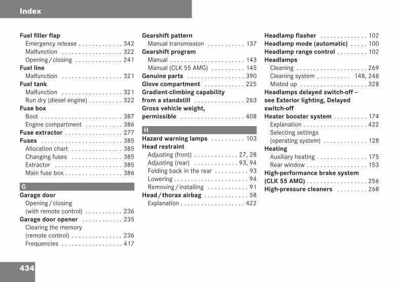
434
Index
Fuel filler flapEmergency release . . . . . . . . . . . . . 342Malfunction . . . . . . . . . . . . . . . . . . 322Opening/closing . . . . . . . . . . . . . . 241
Fuel lineMalfunction . . . . . . . . . . . . . . . . . . 321
Fuel tankMalfunction . . . . . . . . . . . . . . . . . . 321Run dry (diesel engine) . . . . . . . . . . 322
Fuse boxBoot . . . . . . . . . . . . . . . . . . . . . . . . 387Engine compartment . . . . . . . . . . . 386
Fuse extractor . . . . . . . . . . . . . . . . . 277Fuses . . . . . . . . . . . . . . . . . . . . . . . . 385
Allocation chart . . . . . . . . . . . . . . . 385Changing fuses . . . . . . . . . . . . . . . 385Extractor . . . . . . . . . . . . . . . . . . . . 385Main fuse box . . . . . . . . . . . . . . . . . 386
GGarage door
Opening/closing(with remote control) . . . . . . . . . . . 236
Garage door opener . . . . . . . . . . . . 235Clearing the memory(remote control) . . . . . . . . . . . . . . . 236Frequencies . . . . . . . . . . . . . . . . . . 417
Gearshift patternManual transmission . . . . . . . . . . . 137
Gearshift programManual . . . . . . . . . . . . . . . . . . . . . . 143Manual (CLK 55 AMG) . . . . . . . . . . 145
Genuine parts . . . . . . . . . . . . . . . . . 390Glove compartment . . . . . . . . . . . . 225Gradient-climbing capabilityfrom a standstill . . . . . . . . . . . . . . . 263Gross vehicle weight,permissible . . . . . . . . . . . . . . . . . . . 408
HHazard warning lamps . . . . . . . . . . 103Head restraint
Adjusting (front) . . . . . . . . . . . . . 27, 28Adjusting (rear) . . . . . . . . . . . . . 93, 94Folding back in the rear . . . . . . . . . . 93Lowering . . . . . . . . . . . . . . . . . . . . . . 94Removing/installing . . . . . . . . . . . . 91
Head/thorax airbag . . . . . . . . . . . . . 58Explanation . . . . . . . . . . . . . . . . . . . 422
Headlamp flasher . . . . . . . . . . . . . . 102Headlamp mode (automatic) . . . . . 100Headlamp range control . . . . . . . . . 102Headlamps
Cleaning . . . . . . . . . . . . . . . . . . . . . 269Cleaning system . . . . . . . . . . 148, 248Misted up . . . . . . . . . . . . . . . . . . . . 328
Headlamps delayed switch-off –see Exterior lighting, Delayedswitch-offHeater booster system . . . . . . . . . . 174
Explanation . . . . . . . . . . . . . . . . . . . 422Selecting settings(operating system) . . . . . . . . . . . . . 128
HeatingAuxiliary heating . . . . . . . . . . . . . . . 175Rear window . . . . . . . . . . . . . . . . . . 153
High-performance brake system(CLK 55 AMG) . . . . . . . . . . . . . . . . . . 256High-pressure cleaners . . . . . . . . . 268
209en_d2.boo Seite 434 Dienstag, 25. Mai 2004 7:26 19
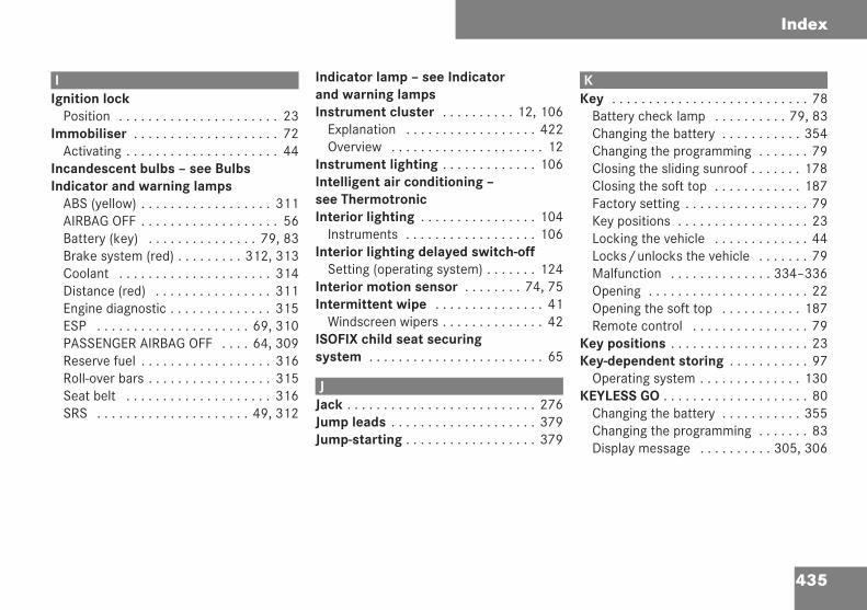
435
Index
IIgnition lock
Position . . . . . . . . . . . . . . . . . . . . . . 23Immobiliser . . . . . . . . . . . . . . . . . . . . 72
Activating . . . . . . . . . . . . . . . . . . . . . 44Incandescent bulbs – see BulbsIndicator and warning lamps
ABS (yellow) . . . . . . . . . . . . . . . . . . 311AIRBAG OFF . . . . . . . . . . . . . . . . . . . 56Battery (key) . . . . . . . . . . . . . . . 79, 83Brake system (red) . . . . . . . . . 312, 313Coolant . . . . . . . . . . . . . . . . . . . . . 314Distance (red) . . . . . . . . . . . . . . . . 311Engine diagnostic . . . . . . . . . . . . . . 315ESP . . . . . . . . . . . . . . . . . . . . . 69, 310PASSENGER AIRBAG OFF . . . . 64, 309Reserve fuel . . . . . . . . . . . . . . . . . . 316Roll-over bars . . . . . . . . . . . . . . . . . 315Seat belt . . . . . . . . . . . . . . . . . . . . 316SRS . . . . . . . . . . . . . . . . . . . . . 49, 312
Indicator lamp – see Indicatorand warning lampsInstrument cluster . . . . . . . . . . 12, 106
Explanation . . . . . . . . . . . . . . . . . . 422Overview . . . . . . . . . . . . . . . . . . . . . 12
Instrument lighting . . . . . . . . . . . . . 106Intelligent air conditioning –see ThermotronicInterior lighting . . . . . . . . . . . . . . . . 104
Instruments . . . . . . . . . . . . . . . . . . 106Interior lighting delayed switch-off
Setting (operating system) . . . . . . . 124Interior motion sensor . . . . . . . . 74, 75Intermittent wipe . . . . . . . . . . . . . . . 41
Windscreen wipers . . . . . . . . . . . . . . 42ISOFIX child seat securingsystem . . . . . . . . . . . . . . . . . . . . . . . . 65
JJack . . . . . . . . . . . . . . . . . . . . . . . . . . 276Jump leads . . . . . . . . . . . . . . . . . . . . 379Jump-starting . . . . . . . . . . . . . . . . . . 379
KKey . . . . . . . . . . . . . . . . . . . . . . . . . . . 78
Battery check lamp . . . . . . . . . . 79, 83Changing the battery . . . . . . . . . . . 354Changing the programming . . . . . . . 79Closing the sliding sunroof . . . . . . . 178Closing the soft top . . . . . . . . . . . . 187Factory setting . . . . . . . . . . . . . . . . . 79Key positions . . . . . . . . . . . . . . . . . . 23Locking the vehicle . . . . . . . . . . . . . 44Locks/unlocks the vehicle . . . . . . . 79Malfunction . . . . . . . . . . . . . . 334–336Opening . . . . . . . . . . . . . . . . . . . . . . 22Opening the soft top . . . . . . . . . . . 187Remote control . . . . . . . . . . . . . . . . 79
Key positions . . . . . . . . . . . . . . . . . . . 23Key-dependent storing . . . . . . . . . . . 97
Operating system . . . . . . . . . . . . . . 130KEYLESS GO . . . . . . . . . . . . . . . . . . . . 80
Changing the battery . . . . . . . . . . . 355Changing the programming . . . . . . . 83Display message . . . . . . . . . . 305, 306
209en_d2.boo Seite 435 Dienstag, 25. Mai 2004 7:26 19
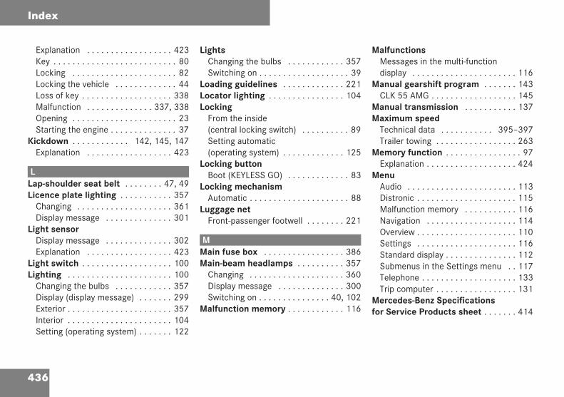
436
Index
Explanation . . . . . . . . . . . . . . . . . . 423Key . . . . . . . . . . . . . . . . . . . . . . . . . . 80Locking . . . . . . . . . . . . . . . . . . . . . . 82Locking the vehicle . . . . . . . . . . . . . 44Loss of key . . . . . . . . . . . . . . . . . . . 338Malfunction . . . . . . . . . . . . . . 337, 338Opening . . . . . . . . . . . . . . . . . . . . . . 23Starting the engine . . . . . . . . . . . . . . 37
Kickdown . . . . . . . . . . . . 142, 145, 147Explanation . . . . . . . . . . . . . . . . . . 423
LLap-shoulder seat belt . . . . . . . . 47, 49Licence plate lighting . . . . . . . . . . . 357
Changing . . . . . . . . . . . . . . . . . . . . 361Display message . . . . . . . . . . . . . . 301
Light sensorDisplay message . . . . . . . . . . . . . . 302Explanation . . . . . . . . . . . . . . . . . . 423
Light switch . . . . . . . . . . . . . . . . . . . 100Lighting . . . . . . . . . . . . . . . . . . . . . . 100
Changing the bulbs . . . . . . . . . . . . 357Display (display message) . . . . . . . 299Exterior . . . . . . . . . . . . . . . . . . . . . . 357Interior . . . . . . . . . . . . . . . . . . . . . . 104Setting (operating system) . . . . . . . 122
LightsChanging the bulbs . . . . . . . . . . . . 357Switching on . . . . . . . . . . . . . . . . . . . 39
Loading guidelines . . . . . . . . . . . . . 221Locator lighting . . . . . . . . . . . . . . . . 104Locking
From the inside(central locking switch) . . . . . . . . . . 89Setting automatic(operating system) . . . . . . . . . . . . . 125
Locking buttonBoot (KEYLESS GO) . . . . . . . . . . . . . 83
Locking mechanismAutomatic . . . . . . . . . . . . . . . . . . . . . 88
Luggage netFront-passenger footwell . . . . . . . . 221
MMain fuse box . . . . . . . . . . . . . . . . . 386Main-beam headlamps . . . . . . . . . . 357
Changing . . . . . . . . . . . . . . . . . . . . 360Display message . . . . . . . . . . . . . . 300Switching on . . . . . . . . . . . . . . . 40, 102
Malfunction memory . . . . . . . . . . . . 116
MalfunctionsMessages in the multi-functiondisplay . . . . . . . . . . . . . . . . . . . . . . 116
Manual gearshift program . . . . . . . 143CLK 55 AMG . . . . . . . . . . . . . . . . . . 145
Manual transmission . . . . . . . . . . . 137Maximum speed
Technical data . . . . . . . . . . . 395–397Trailer towing . . . . . . . . . . . . . . . . . 263
Memory function . . . . . . . . . . . . . . . . 97Explanation . . . . . . . . . . . . . . . . . . . 424
MenuAudio . . . . . . . . . . . . . . . . . . . . . . . 113Distronic . . . . . . . . . . . . . . . . . . . . . 115Malfunction memory . . . . . . . . . . . 116Navigation . . . . . . . . . . . . . . . . . . . 114Overview . . . . . . . . . . . . . . . . . . . . . 110Settings . . . . . . . . . . . . . . . . . . . . . 116Standard display . . . . . . . . . . . . . . . 112Submenus in the Settings menu . . 117Telephone . . . . . . . . . . . . . . . . . . . . 133Trip computer . . . . . . . . . . . . . . . . . 131
Mercedes-Benz Specificationsfor Service Products sheet . . . . . . . 414
209en_d2.boo Seite 436 Dienstag, 25. Mai 2004 7:26 19
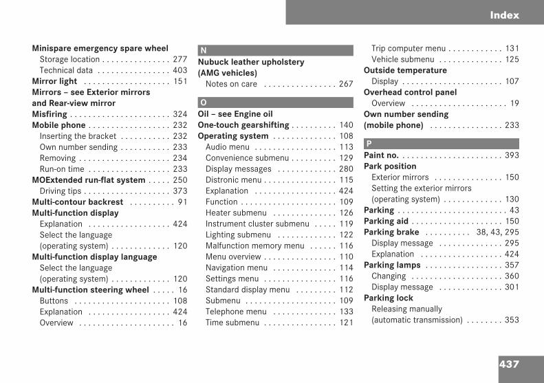
437
Index
Minispare emergency spare wheelStorage location . . . . . . . . . . . . . . . 277Technical data . . . . . . . . . . . . . . . . 403
Mirror light . . . . . . . . . . . . . . . . . . . 151Mirrors – see Exterior mirrorsand Rear-view mirrorMisfiring . . . . . . . . . . . . . . . . . . . . . . 324Mobile phone . . . . . . . . . . . . . . . . . . 232
Inserting the bracket . . . . . . . . . . . 232Own number sending . . . . . . . . . . . 233Removing . . . . . . . . . . . . . . . . . . . . 234Run-on time . . . . . . . . . . . . . . . . . . 233
MOExtended run-flat system . . . . . 250Driving tips . . . . . . . . . . . . . . . . . . . 373
Multi-contour backrest . . . . . . . . . . 91Multi-function display
Explanation . . . . . . . . . . . . . . . . . . 424Select the language(operating system) . . . . . . . . . . . . . 120
Multi-function display languageSelect the language(operating system) . . . . . . . . . . . . . 120
Multi-function steering wheel . . . . . 16Buttons . . . . . . . . . . . . . . . . . . . . . 108Explanation . . . . . . . . . . . . . . . . . . 424Overview . . . . . . . . . . . . . . . . . . . . . 16
NNubuck leather upholstery(AMG vehicles)
Notes on care . . . . . . . . . . . . . . . . 267
OOil – see Engine oilOne-touch gearshifting . . . . . . . . . . 140Operating system . . . . . . . . . . . . . . 108
Audio menu . . . . . . . . . . . . . . . . . . 113Convenience submenu . . . . . . . . . . 129Display messages . . . . . . . . . . . . . 280Distronic menu . . . . . . . . . . . . . . . . 115Explanation . . . . . . . . . . . . . . . . . . 424Function . . . . . . . . . . . . . . . . . . . . . 109Heater submenu . . . . . . . . . . . . . . 126Instrument cluster submenu . . . . . 119Lighting submenu . . . . . . . . . . . . . 122Malfunction memory menu . . . . . . 116Menu overview . . . . . . . . . . . . . . . . 110Navigation menu . . . . . . . . . . . . . . 114Settings menu . . . . . . . . . . . . . . . . 116Standard display menu . . . . . . . . . 112Submenu . . . . . . . . . . . . . . . . . . . . 109Telephone menu . . . . . . . . . . . . . . 133Time submenu . . . . . . . . . . . . . . . . 121
Trip computer menu . . . . . . . . . . . . 131Vehicle submenu . . . . . . . . . . . . . . 125
Outside temperatureDisplay . . . . . . . . . . . . . . . . . . . . . . 107
Overhead control panelOverview . . . . . . . . . . . . . . . . . . . . . 19
Own number sending(mobile phone) . . . . . . . . . . . . . . . . 233
PPaint no. . . . . . . . . . . . . . . . . . . . . . . 393Park position
Exterior mirrors . . . . . . . . . . . . . . . 150Setting the exterior mirrors(operating system) . . . . . . . . . . . . . 130
Parking . . . . . . . . . . . . . . . . . . . . . . . . 43Parking aid . . . . . . . . . . . . . . . . . . . . 150Parking brake . . . . . . . . . . 38, 43, 295
Display message . . . . . . . . . . . . . . 295Explanation . . . . . . . . . . . . . . . . . . 424
Parking lamps . . . . . . . . . . . . . . . . . 357Changing . . . . . . . . . . . . . . . . . . . . 360Display message . . . . . . . . . . . . . . 301
Parking lockReleasing manually(automatic transmission) . . . . . . . . 353
209en_d2.boo Seite 437 Dienstag, 25. Mai 2004 7:26 19
438
Index
Parktronic . . . . . . . . . . . . . . . . . . . . 212Activating/deactivating . . . . . . . . . 215Cleaning the sensors . . . . . . . . . . . 269Explanation . . . . . . . . . . . . . . . . . . 425Malfunction . . . . . . . . . . . . . . . . . . 327Range of the sensors . . . . . . . . . . . 213Trailer towing . . . . . . . . . . . . . . . . . 215Warning display . . . . . . . . . . . . . . . 214
PASSENGER AIRBAG OFFwarning lamp . . . . . . . . . . . . . . . 64, 309Payload . . . . . . . . . . . . . . . . . . . . . . . 408Permanent current
Connection . . . . . . . . . . . . . . . . . . . 264Permanent Speedtronic . . . . . . . . . 211Petrol
Consumption . . . . . . . . . . . . . . . . . 411Minimum grade . . . . . . . . . . . . . . . 242Reserve fuel warning lamp . . . . . . . 316
Power windows – see Side windowsPressure – see Tyre pressureProgram selector switch
Automatic transmission . . . . . . . . . 141Manual gearshift programCLK 55 AMG . . . . . . . . . . . . . . . . . 146
Protection of the environment . . . . . 4PTS – see ParktronicPulling away . . . . . . . . . . . . . . . . . . . 38
RRadio
Select station (operatingsystem) . . . . . . . . . . . . . . . . . . . . . . 113
Rain closing featureSliding/tilting sunroof . . . . . . . . . . 182
RangeCalling up (operating system) . . . . . 132
Reading lamp . . . . . . . . . . . . . . . . . . 105Rear air vents
Thermatic . . . . . . . . . . . . . . . 162, 173Rear bulbs . . . . . . . . . . . . . . . . . . . . 357Rear foglamp . . . . . . . . . . . . . 101, 357
Display message . . . . . . . . . . . . . . 301Rear interior lighting . . . . . . . . . . . . 105Rear seat
Folding forward/back . . . . . . . . . . 223Rear window blind . . . . . . . . . . . . . . 152Rear window heating . . . . . . . . . . . 153
Malfunction . . . . . . . . . . . . . . . . . . 308Rear-compartment airconditioning
Thermatic . . . . . . . . . . . . . . . . . . . . 162Thermotronic . . . . . . . . . . . . . . . . . 173
Rear-view mirrorAdjusting . . . . . . . . . . . . . . . . . . . . . 31Anti-dazzle mode (automatic) . . . . . 148Manual anti-dazzle . . . . . . . . . . . . . 148
Rearward-facing child seat . . . . . . . . 64Refuelling . . . . . . . . . . . . . . . . . . . . . 241Remote control
Auxiliary heating . . . . . . . . . . . . . . . 176Boot . . . . . . . . . . . . . . . . . . . . . . . . . 86Changing the keybatteries . . . . . . . . . . . . 354, 355, 356Key . . . . . . . . . . . . . . . . . . . . . . . . . . 79
Replacement parts . . . . . . . . . . . . . 390Reserve
Fuel tank . . . . . . . . . . . . . . . . . . . . 410Reserve fuel . . . . . . . . . . . . . . . . . . . 410
Warning lamp . . . . . . . . . . . . . . . . . 316Residual heat
Thermotronic . . . . . . . . . . . . . . . . . 171Restraint system . . . . . . . . . . . . . . . . 46
Airbags . . . . . . . . . . . . . . . . . . . . . . . 49Belt force limiters . . . . . . . . . . . . . . . 51Belt tensioners . . . . . . . . . . . . . . . . . 51
209en_d2.boo Seite 438 Dienstag, 25. Mai 2004 7:26 19
439
Index
Display message . . . . . . . . . . . . . . 292Malfunction . . . . . . . . . . . . . . . . . . 312Seat belt . . . . . . . . . . . . . . . . . . . . . 47SRS (supplemental) . . . . . . . . . . . . . 49
Restraint systemsfor children . . . . . . . . . . . . . . . . . . . 61
Retracting . . . . . . . . . . . . . . . . . . . . 240Rev counter . . . . . . . . . . . . . . . . . . . 107Reverse gear
Engaging (manual transmission) . . 137Reversing lamp
Display message . . . . . . . . . . . . . . 302Reversing lamps . . . . . . . . . . . . . . . 357Roll-over bars . . . . . . . . . . . . . . . . . . 60
Display message . . . . . . . . . . . . . . 297Explanation . . . . . . . . . . . . . . . . . . 425Malfunction . . . . . . . . . . . . . . . . . . 315Operating manually . . . . . . . . . . . . 344Warning lamp . . . . . . . . . . . . . . . . . 315
Roof – see Soft top . . . . . . . . . . . . . 184Roof load, maximum . . . . . . . . . . . . 408Roof rack . . . . . . . . . . . . . . . . . . . . . 216Roof switch . . . . . . . . . . . . . . . . . . . 185Ruffled pockets . . . . . . . . . . . . . . . . 228Run-on time (mobile phone) . . . . . 233
SSeat . . . . . . . . . . . . . . . . . . . . . . . . . . 25
Adjusting . . . . . . . . . . . . . . . . . . . . . 26Storing settings . . . . . . . . . . . . . . . . 97
Seat belt . . . . . . . . . . . . . . . . . . . . . . . 32Display message . . . . . . . . . . . . . . 296Warning lamp . . . . . . . . . . . . . . . . . 316
Seat belt extender . . . . . . . . . . . . . . 34Problems . . . . . . . . . . . . . . . . . . . . 320
Seat heating . . . . . . . . . . . . . . . . . . . 96Malfunction . . . . . . . . . . . . . . . . . . 308
Seat ventilation . . . . . . . . . . . . . . . . . 95Malfunction . . . . . . . . . . . . . . . . . . 308
Securing a load . . . . . . . . . . . . . . . . 222Securing straps . . . . . . . . . . . . . . . . 222Selector lever
Display message . . . . . . . . . . . . . . 292Position (automatictransmission) . . . . . . . . . . . . . . . . . 139
ServiceCalling up the due date . . . . . . . . . 266Clearing the indicator . . . . . . . . . . 265Display message . . . . . . . . . . . . . . 265Missing the due date . . . . . . . . . . . 265Resetting the indicator . . . . . . . . . . 266Type . . . . . . . . . . . . . . . . . . . . . . . . 265
Service products . . . . . . . . . . . . . . . 410Brake fluid . . . . . . . . . . . . . . . . . . . 416Coolant . . . . . . . . . . . . . . . . . . . . . . 415Engine oil . . . . . . . . . . . . . . . . . . . . 414Safety precautions . . . . . . . . . . . . . 410Windscreen washer fluid . . . . . . . . 416
SettingsCalling up the memory . . . . . . . . . . . 98Factory (key) . . . . . . . . . . . . . . . . . . 79Factory (KEYLESS GO key) . . . . . . . . 82Resetting all (operating system) . . 117Setting key dependence(operating system) . . . . . . . . . . . . . 130Storing key-dependent . . . . . . . . . . . 97
Shift rangeAutomatic transmission . . . . . . . . . 140
Side lampsChanging . . . . . . . . . . . . . . . . . . . . 360
Side windowMalfunction . . . . . . . . . . . . . . 332, 333Resetting . . . . . . . . . . . . . . . . . . . . 180
Side windowsOpening/closing . . . . . . . . . . . . . . 178
Sidebags . . . . . . . . . . . . . . . . . . . . . . . 56Skibag . . . . . . . . . . . . . . . . . . . . . . . . 217
Removing . . . . . . . . . . . . . . . . . . . . 220
209en_d2.boo Seite 439 Dienstag, 25. Mai 2004 7:26 19
440
Index
Skibag cover . . . . . . . . . . . . . . . . . . 188Sliding/tilting sunroof . . . . . . . . . . 180
Crank . . . . . . . . . . . . . . . . . . . . . . . 344Opening/closing . . . . . . . . . . . . . . 180Opening/closing (manually) . . . . . 343Rain closing feature . . . . . . . . . . . . 182Resetting . . . . . . . . . . . . . . . . 183, 344
Snow chains . . . . . . . . . . . . . . . . . . 258Socket . . . . . . . . . . . . . . . . . . . . . . . 231Soft top . . . . . . . . . . . . . . . . . . . . . . . 184
Cleaning . . . . . . . . . . . . . . . . . . . . . 270Closing (key) . . . . . . . . . . . . . . . . . 187Closing (switch) . . . . . . . . . . . . . . . 186Display message . . . . . . . . . . . . . . 297Ensuring that it is locked . . . . . . . . 188Malfunction . . . . . . . . . . . . . . . . . . 330Opening (key) . . . . . . . . . . . . . . . . . 187Opening (switch) . . . . . . . . . . . . . . 185Operating in an emergency . . . . . . 347
Spare fuses . . . . . . . . . . . . . . . . . . . 385Spare wheel
Fitting . . . . . . . . . . . . . . . . . . . . . . . 368Storage location . . . . . . . . . . . . . . . 278Technical data . . . . . . . . . . . . . . . . 403
SpeedTechnical data . . . . . . . . . . . 395–397
Speed limiterSpeedtronic . . . . . . . . . . . . . . . . . . 206
SpeedometerDigital display(operating system) . . . . . . . . . . . . . 113Selecting the display(operating system) . . . . . . . . . . . . . 119
Speedtronic . . . . . . . . . . . . . . . . . . . 206Display message . . . . . . . . . . . . . . 292Explanation . . . . . . . . . . . . . . . . . . . 426Permanent . . . . . . . . . . . . . . . . . . . 211Variable . . . . . . . . . . . . . . . . . . . . . 207
SRS (Supplemental RestraintSystem) . . . . . . . . . . . . . . . . . . . . . . . 49
Warning lamp . . . . . . . . . . . . . . 49, 312Standard display
Select the display(operating system) . . . . . . . . . . . . . 120
Starting, see Starting the engineStation selection
Setting (operating system) . . . . . . . 125Status indicator
Select the display(operating system) . . . . . . . . . . . . . 120
Steering wheelAdjusting . . . . . . . . . . . . . . . . . . . . . 29Buttons (operating system) . . . . . . 108Storing settings . . . . . . . . . . . . . . . . 97
Steering wheel gearshiftbuttons . . . . . . . . . . . . . . . . . . 143, 145Steering wheel heating . . . . . . . . . . 231Stowage tray . . . . . . . . . . . . . . . . . . 227Stowage well . . . . . . . . . . . . . . . . . . 225
Armrest (beneath) . . . . . . . . . . . . . 226Glove compartment . . . . . . . . . . . . 225Ruffled pockets . . . . . . . . . . . . . . . 228Stowage tray . . . . . . . . . . . . . . . . . 227
Submenu . . . . . . . . . . . . . . . . . . . . . 109Convenience . . . . . . . . . . . . . . . . . . 129Heating . . . . . . . . . . . . . . . . . . . . . . 126Instrument cluster . . . . . . . . . . . . . 119Lighting . . . . . . . . . . . . . . . . . . . . . 122Resetting a function . . . . . . . . . . . . 117Settings menu . . . . . . . . . . . . . . . . 117Settings overview . . . . . . . . . . . . . . 118Time . . . . . . . . . . . . . . . . . . . . . . . . 121Vehicle . . . . . . . . . . . . . . . . . . . . . . 125
Summer opening feature . . . . . . . . 183Sun visor . . . . . . . . . . . . . . . . . . . . . 151Surround lighting . . . . . . . . . . . . . . 104
Setting (operating system) . . . . . . . 123
209en_d2.boo Seite 440 Dienstag, 25. Mai 2004 7:26 19
441
Index
TTail lamp cluster
Changing . . . . . . . . . . . . . . . . . . . . 361Tail lamps
Display message . . . . . . . . . . . . . . 302Tank capacity . . . . . . . . . . . . . . . . . 410
Calling up the range(operating system) . . . . . . . . . . . . . 132Gauge . . . . . . . . . . . . . . . . . . . . . 13, 15
Technical dataAcceleration . . . . . . . . . . . . . . . . . . 398Engine . . . . . . . . . . . . . . . . . . . . . . 394Frequencies for garagedoor openers . . . . . . . . . . . . . . . . . 417Speed . . . . . . . . . . . . . . . . . . . 395–397Trailer loads . . . . . . . . . . . . . . . . . . 407Trailer tow hitch . . . . . . . . . . . . . . . 405Tyres . . . . . . . . . . . . . . . . . . . 399–403Vehicle dimensions . . . . . . . . . . . . 404Vehicle weight . . . . . . . . . . . . . . . . 408Wheels . . . . . . . . . . . . . . . . . . 399–403
TelephoneDisplay message . . . . . . . . . . . . . . 296Operating (operating system) . . . . 133Redialling (operating system) . . . . 135
Telephone bookDialling a number(operating system) . . . . . . . . . . . . . 134
Telephone bracketInstalling/removing . . . . . . . . . . . . 234
Telephone compartment . . . . . . . . 227Temperature
Adjusting (Thermatic) . . . . . . . . . . . 158Adjusting (Thermotronic) . . . . . . . . 168Selecting the display(operating system) . . . . . . . . . . . . . 119
Thermatic . . . . . . . . . . . . . . . . . . . . . 154Control panel . . . . . . . . . . . . . . . . . 155Explanation . . . . . . . . . . . . . . . . . . 426Malfunction . . . . . . . . . . . . . . . . . . 309Notes on operation . . . . . . . . . . . . 156Rear air vents . . . . . . . . . . . . . 162, 173Rear-compartment airconditioning . . . . . . . . . . . . . . . . . . 162Switching on/off . . . . . . . . . . . . . . 157
Thermotronic . . . . . . . . . . . . . . . . . . 164Control panel . . . . . . . . . . . . . . . . . 165Explanation . . . . . . . . . . . . . . . . . . 426Malfunction . . . . . . . . . . . . . . . . . . 309Notes on operation . . . . . . . . . . . . 166Rear-compartment airconditioning . . . . . . . . . . . . . . . . . . 173Switching on/off . . . . . . . . . . . . . . 167
Third brake lamp . . . . . . . . . . . . . . . 357Through-loading feature . . . . . . . . . 223Tightening torque . . . . . . . . . . . . . . 373Time
Selecting the display(operating system) . . . . . . . . . . . . . 122
TIREFIT kitExplanation . . . . . . . . . . . . . . . . . . 427Storage location . . . . . . . . . . . . . . . 276Using . . . . . . . . . . . . . . . . . . . . . . . 364
Tool . . . . . . . . . . . . . . . . . . . . . . . . . . 276Tow-away protection . . . . . . . . . . . . 73Towing . . . . . . . . . . . . . . . . . . . . . . . 381Towing eye . . . . . . . . . . . . . . . . . . . . 276
Fitting . . . . . . . . . . . . . . . . . . . . . . . 381Tow-starting . . . . . . . . . . . . . . . . . . . 384Trailer
7-pin connector . . . . . . . . . . . . . . . 264Trailer loads . . . . . . . . . . . . . . . . . . . 407Trailer tow hitch . . . . . . . . . . . . . . . 260
Care . . . . . . . . . . . . . . . . . . . . . . . . 271Fitting the ball coupling . . . . . . . . . 260Installation dimensions . . . . . . . . . 405Removing the ball coupling . . . . . . 263
Trailer towing . . . . . . . . . . . . . . . . . 260Automatic transmission . . . . . . . . . 142Driving tips . . . . . . . . . . . . . . . . . . . 262Maximum speed . . . . . . . . . . . . . . . 263
209en_d2.boo Seite 441 Dienstag, 25. Mai 2004 7:26 19
442
Index
Parktronic . . . . . . . . . . . . . . . . . . . 215Trailer turn signals
Display message . . . . . . . . . . . . . . 298Transport (vehicle) . . . . . . . . . . . . . 384Trip computer . . . . . . . . . . . . . . . . . 131Trip meter . . . . . . . . . . . . . . . . . . . . 106Turn signals . . . . . . . . . . . . . . . . 40, 357
Changing the front turnsignal lamps . . . . . . . . . . . . . . . . . . 359Display message . . . . . . . . . . . . . . 299
Turning lamps . . . . . . . . . . . . . 103, 357Tyre grip . . . . . . . . . . . . . . . . . . . . . . 254Tyre pressure . . . . . . . . . . . . . . . . . . 251
Display message . . . . . . . . . . . . . . 304Tyre pressure loss warningsystem . . . . . . . . . . . . . . . . . . . . . . . 251Tyre pressure table . . . . . . . . . . . . . 399Tyres . . . . . . . . . . . . . . . . . . . . . . . . . 249
Direction of rotation . . . . . . . . . . . . 250MOExtended run-flatsystem . . . . . . . . . . . . . . . . . . 250, 373Technical data . . . . . . . . . . . 399–403
UUnlocking
From the inside(central locking switch) . . . . . . . . . . 89
Unlocking buttonBoot . . . . . . . . . . . . . . . . . . . . . . . . . 86
Unlocking in an emergencyBoot . . . . . . . . . . . . . . . . . . . . . . . . 341Vehicle . . . . . . . . . . . . . . . . . 341, 342
VVariable Speedtronic . . . . . . . . . . . 207Vehicle
Cleaning . . . . . . . . . . . . . . . . . . . . . 268Leaving it parked up . . . . . . . . . . . . 340Towing . . . . . . . . . . . . . . . . . . . . . . 381Tow-starting . . . . . . . . . . . . . . . . . . 384Transporting . . . . . . . . . . . . . . . . . . 384Unlocking in anemergency . . . . . . . . . . . . . . 341, 342
Vehicle dimensions . . . . . . . . . . . . . 404Vehicle electronics . . . . . . . . . . . . . 391Vehicle identification number . . . . 393Vehicle tool kit . . . . . . . . . . . . . . . . 276Vehicle weight . . . . . . . . . . . . . . . . . 408Viscosity . . . . . . . . . . . . . . . . . . . . . . 414
WWarning signal
Audible . . . . . . . . . . . . . . . . . . . . . . 318Warning triangle . . . . . . . . . . . . . . . 274Washer fluid
Display message . . . . . . . . . . . . . . 307Washer fluid container . . . . . . . . . . 248Wearing seat belts . . . . . . . . . 32, 316Wheel bolts . . . . . . . . . . . . . . . . . . . 371
Tightening torque . . . . . . . . . . . . . . 373Wheel wrench . . . . . . . . . . . . 277, 278Wheels . . . . . . . . . . . . . . . . . . . . . . . 249
Interchanging . . . . . . . . . . . . . . . . . 253Technical data . . . . . . . . . . . 399–403
Windowbags . . . . . . . . . . . . . . . . . . . 57Windows
Cleaning the windscreen . . . . . . . . 268Misted up (Thermatic) . . . . . . . . . . 159Misted up (Thermotronic) . . . . . . . . 169Side windows . . . . . . . . . . . . . . . . . 178
WindscreenCleaning . . . . . . . . . . . . . . . . . . . . . 268
Windscreen washer fluid . . . . . . . . 416Topping up . . . . . . . . . . . . . . . . . . . 248
Windscreen washer reservoir . . . . 416Capacity . . . . . . . . . . . . . . . . . . . . . 416
209en_d2.boo Seite 442 Dienstag, 25. Mai 2004 7:26 19
443
Index
Windscreen washersystem . . . . . . . . . . . . . . . . 42, 248, 416Windscreen wipers . . . . . . . . . . . . . . 41
Intermittent wipe . . . . . . . . . . . . . . . 41Malfunction . . . . . . . . . . . . . . . . . . 329Replacing the wiper blades . . . . . . 362
Winter diesel . . . . . . . . . . . . . . . . . . 243Winter driving . . . . . . . . . . . . . . . . . 257
Driving tips . . . . . . . . . . . . . . . . . . . 258Snow chains . . . . . . . . . . . . . . . . . . 258
Winter tyres . . . . . . . . . . . . . . . . . . . 257Limiting the speed(operating system) . . . . . . . . . . . . . 211
Wiper bladesCleaning . . . . . . . . . . . . . . . . . . . . . 268Replacing . . . . . . . . . . . . . . . . . . . . 362
XXenon bulbs . . . . . . . . . . . . . . . . . . . 358
209en_d2.boo Seite 443 Dienstag, 25. Mai 2004 7:26 19

444
209en_d2.boo Seite 444 Dienstag, 25. Mai 2004 7:26 19

209en_d2.boo Seite 445 Dienstag, 25. Mai 2004 7:26 19

209en_d2.boo Seite 446 Dienstag, 25. Mai 2004 7:26 19

209en_d2.boo Seite 447 Dienstag, 25. Mai 2004 7:26 19

209en_d2.boo Seite 448 Dienstag, 25. Mai 2004 7:26 19