Embed Size (px)
Citation preview

Body and Equipment Guideline
Mercedes-Benz USA, LLC
Sprinter – Model Designation 907
Edition MY2023
1 Introduction .................................................61.1 Purpose of Body and Equipment Guideline .....71.2 Conventions ..................................................81.3 Vehicle safety ...............................................91.4 Operational safety .......................................101.5 Note on copyright .......................................101.6 Granting of body technical assistance .........101.7 Contact ......................................................111.8 Definitions ..................................................121.9 Parts Use ....................................................13
2 General ......................................................142.1 Advice for Upfitters .....................................142.1.1 Regulatory Overview ...................................142.1.2 Emissions and safety information ................152.1.3 Vehicle safety standards information ..........152.1.4 Exhaust emission control information ..........162.1.5 Vehicle noise emission control information .162.2 Upfitter responsibilities ..............................172.3 Product and vehicle information for upfitters .. 182.3.1 Upfitter Portal .............................................182.3.2 Workshop Information System (WIS) ............182.3.3 XENTRY Kit .................................................192.4 Product safety and product liability ..............202.4.1 Product safety .............................................202.4.2 Product liability ...........................................202.4.3 Safety-relevant features ..............................212.4.4 Guarantee of traceability .............................212.5 Trademarks .................................................222.5.1 Mercedes-Benz brand in interaction with
external upfitters .........................................222.5.2 Function of a brand .....................................222.5.3 Trademark protection ..................................222.5.4 Trademark rights .........................................222.5.5 Advice on applying Mercedes-Benz trade-
marks to vans .............................................232.5.6 Use of Mercedes-Benz trademarks ..............232.5.7 Brand separation/identity ...........................232.6 Accident prevention ....................................252.7 Recycling ....................................................262.8 Quality system ............................................272.9 Key Pre-Upfit Considerations .......................28
3 Planning of bodies .....................................293.1 Vehicle and model designation ....................303.2 Model overview ...........................................343.3 Selecting the basic vehicle ..........................353.4 Vehicle Modifications ..................................363.5 Dimensions and weights..............................37
3.6 Vehicle identification data ...........................393.6.1 VIN plate .....................................................393.6.2 QR code rescue sticker ...............................403.6.3 Safety Label location ...................................413.6.4 Noise Emission Label ..................................413.6.5 Complete Vehicle Identification Label ..........413.6.6 Incomplete Vehicle Identification Label ........423.6.7 Vehicle Emission Control Information Label ....423.6.8 Airbag Warning Label ..................................433.6.9 Tire and Loading Information Label ..............433.6.10 Unloaded Vehicle Weight UVW rating and
Label ..........................................................433.7 Vehicle stability ...........................................443.8 Tires ...........................................................453.9 Bolted and welded connections ...................463.9.1 Threaded connections .................................463.9.2 Welded connections ....................................473.10 Soundproofing ............................................503.11 Maintenance and repairs .............................513.11.1 Storing the vehicle ......................................523.11.2 Battery maintenance and storage ................533.11.3 Work before handing over the modified
vehicle ........................................................533.12 Special equipment ......................................553.13 Adhesive decals on the exterior ...................56
4 Technical limit values for planning ...........584.1 Limit values for the basic vehicle .................584.1.1 Steerability .................................................584.1.2 Maximum permissible position of the center
of gravity.....................................................584.1.3 Vehicle dimensions .....................................594.1.4 Parts which must not be welded: .................624.1.5 Drilling must not take place .........................634.1.6 Service lift points .......................................654.1.7 Weights ......................................................664.1.8 Weight limits ...............................................674.2 Limit values for the suspension ...................684.2.1 Suspension of Sprinter – BR 907 .................684.2.2 Permissible axle loads .................................694.2.3 Approved tire sizes ......................................704.2.4 Diameter of turning circle ............................714.2.5 Modifications to the axles ..........................714.2.6 Modifications to the steering .......................714.2.7 Modifications to the brake system ..............714.2.8 Modifications to springs, spring suspen-
sion/shock absorbers ................................714.2.9 Wheel alignment .........................................714.3 Limit values for the body in white ................724.3.1 Modifications to the body in white ...............72
2
Contents
Mercedes-Benz | Body and Equipment Guideline Sprinter - BM907, Edition 2022-5

4.3.2 Limit values for the vehicle frame ................724.3.3 Roof/roof load ............................................734.4 Limit values for engine peripherals/dri-
vetrain ........................................................744.4.1 Modifications to engine/drivetrain compo-
nents .........................................................744.4.2 Engine cooling system .................................744.5 Limit values for the interior ..........................774.5.1 Modifications to airbags and seat belt tensi-
oners ..........................................................774.5.2 Modifications to seats .................................774.5.3 Seat Reference Point ..................................794.6 Limit values for electrics/electronics ..........804.6.1 Vehicle position lamps and side marker
lamps .........................................................804.6.2 Retrofitting electrical equipment .................804.6.3 Mobile communications systems .................804.6.4 CAN bus .....................................................804.7 Limit values for additional assemblies ..........814.8 Limit values for attachments .......................814.9 Limit values for the box body .......................824.9.1 Assembly frame ..........................................82
5 Damage prevention ...................................835.1 Brake hoses/cables and lines .....................845.2 Welding work ..............................................855.3 Anti-corrosion protection measures .............865.4 Painting work/preservation work ................885.5 Storing and handing over the vehicle ...........91
6 Modifications to the basic vehicle ............926.1 Suspension .................................................926.1.1 General information on the suspension........926.1.2 Springs/shock absorbers/stabilizer bars ....946.1.3 Brake system ..............................................946.1.4 Air suspension ............................................986.1.5 Wheels/tires ..............................................986.1.6 Spare wheel ..............................................1006.2 Body in white/body ...................................1016.2.1 General information on the body in white/
body .........................................................1016.2.2 Attachment to the frame ...........................1056.2.3 Material for the chassis frame ..................1076.2.4 Overhang extension ..................................1076.2.5 Modifications to the cab ............................1106.2.6 Side wall, windows, doors and flaps ...........1116.2.7 Fenders and wheel wells ...........................1146.2.8 Frame end crossmember ..........................1186.2.9 Cargo Van/Passenger Van roof .................118
6.2.10 Cutting the cab roof and B-pillar roof bow ..1236.3 Engine peripherals/drivetrain ....................1266.3.1 Fuel system ..............................................1266.3.2 SCR system ..............................................1306.3.3 Exhaust system .........................................1326.3.4 Engine cooling ..........................................1356.3.5 Engine air intake .......................................1356.3.6 Clearance for major assemblies ................1366.3.7 Propeller shafts .........................................1366.4 Interior ......................................................1386.4.1 General information ..................................1386.4.2 Safety equipment ......................................1396.4.3 Seats .......................................................1476.4.4 Reducing interior noise..............................1486.4.5 Ventilation ...............................................1496.4.6 Attachment points for load compartment
trim parts on the side wall/roof .................1506.5 Additional assemblies ...............................1526.5.1 Retrofitting an air conditioning system .......1526.5.2 Auxiliary heating ......................................1546.5.3 Engine power take-off ...............................1546.5.4 Retrofitting an alternator ...........................1566.6 Attachments .............................................1576.6.1 Wind deflectors .........................................1576.6.2 Attachment above cab .............................1576.6.3 Roof racks ...............................................1586.6.4 Shelf systems/vehicle interior installations ... 1586.6.5 Loading cranes .........................................1666.6.6 Lifting platform (cargo liftgate) ..................1696.6.7 Trailer hitch ...............................................1726.6.8 Underrun protection ..................................1766.6.9 Positioning placard holders .......................178
7 Design of bodies ......................................1807.1 Assembly frame ........................................1807.1.1 Material quality, general ............................1807.1.2 Design ......................................................1817.1.3 Section dimensions/dimensioning ...........1827.1.4 Attachment to the chassis bed ..................1837.1.5 Assembly frame as floor assembly ............1887.2 Self-supporting bodies ..............................1897.3 Modifications to the interior ......................1907.4 Modifications to closed cargo vans ............1927.5 Platform bodies ........................................1967.6 Box bodies ................................................1977.7 Refrigerated vehicles/temperature-control-
led vehicles ...............................................1987.8 Vehicles for transportation
of technical gases .....................................1997.9 Dump trucks .............................................200
3
Contents
Mercedes-Benz | Body and Equipment Guideline Sprinter - BM907, Edition 2022-5

7.10 Light duty truck .........................................2017.11 Recovery vehicles .....................................2047.12 Torsionally stiff body types ........................2057.13 Lifting work platform .................................2067.14 Bodies on chassis with base (F28) .............2097.14.1 Base/windshield support structure and
base with doors F28 .................................2097.14.2 Mechanical equipment ..............................2107.14.3 Wiring harness connecting points ..............2117.14.4 Headlamp Assist (code LA2) .....................2127.14.5 Rain sensor (code JF1) ..............................2137.14.6 Driver’s and front passenger’s doors
connection point .......................................2137.14.7 Headlamp connecting point - series pro-
duction packages and special equipment options .....................................................214
7.14.8 Connecting point for antenna switchover box for third-party antennas (code E4A).....215
7.14.9 Pre-installation for upfitter interface H (code E2A) and upfitter interface M (code E5M) ..215
7.14.10 Pre-installation for rear speakers (code EP7) 217
7.14.11 E-call on base vehicles ..............................2177.15 RV – Recreational vehicles ........................2197.15.1 Body in white of RVs .................................2197.15.2 Suspension of RVs ....................................2207.15.3 Electrics/electronics of RVs ......................2217.15.4 Additional main fuses for RVs (codes E1R
and E1Y) ...................................................2217.15.5 New features for RVs ................................2227.15.6 Airbags for RVs .........................................2237.16 Bodies on chassis with lowered roof ..........2247.16.1 Mounting the auxiliary roof frame ..............2257.16.2 Mounting the body on the auxiliary roof
frame ........................................................2257.17 Semi-integrated bodies and optional moun-
ting of free-standing bodies .......................2267.18 Buses and People Mover ...........................231
8 Electrics/electronics ..............................2338.1 General information ..................................2338.2 Electromagnetic compatibility (EMC) .........2348.3 Battery......................................................2358.3.1 Main battery .............................................2358.3.2 Retrofitting an auxiliary battery ..................2368.3.3 Battery maintenance and storage ..............2388.4 Interfaces .................................................2398.4.1 CAN bus and networking ...........................2398.4.2 Electric lines/fuses ...................................2398.4.3 Cable extension ........................................239
8.4.4 Additional electric circuits .........................2418.4.5 Operating switches (pre-installation) ..........2418.4.6 Retrofitting electrical equipment................2428.4.7 Retrofitting an alternator ..........................2428.4.8 Power tapping ...........................................2438.4.9 Interface overview .....................................2488.4.10 Speed signal .............................................2508.4.11 Travel distance signal ................................2508.4.12 Ground bolts .............................................2508.4.13 Additional ground weld studs ....................2528.4.14 Deep discharge protection (hibernation
mode) .......................................................2538.5 Illumination ...............................................2548.5.1 Adjusting the headlamps ...........................2548.5.2 Mounting additional lamps ........................2558.5.3 Tail lamps ..................................................2558.5.4 Marker lamps ............................................2568.5.5 Exterior lamps ...........................................2568.5.6 Interior lamps............................................2608.6 Mobile communications systems ...............2638.6.1 Equipment ................................................2638.6.2 Antenna connection and cable routing
(radio communication) ..............................2648.7 Electronic ignition lock (EZS) .....................2658.7.1 General information ..................................2658.7.2 Central locking system/post-delivery integ-
ration of doors of upfitter ..........................2658.8 Windows and doors ...................................2698.8.1 Window lifters/window hinges ...................2698.8.2 Sliding door ..............................................2698.8.3 Windshield wipers .....................................2708.8.4 Outside mirrors .........................................2708.8.5 Windshield heating/rear window heating ...2708.9 Driving assistance systems .......................2718.9.1 Electronic Stability Program (ESP®) ...........2728.9.2 Crosswind Assist .......................................2738.9.3 Active Brake Assist/Active Distance Assist
(DISTRONIC PLUS) ...................................2758.9.4 Blind Spot Assist/Rear Cross Traffic Alert
(RCTA)/Exit Warning .................................2778.9.5 Highbeam Assist, Lane Keeping Assist and
traffic sign recognition ..............................2868.9.6 Rain sensor and Headlamp Assist ..............2868.9.7 Tire pressure loss detection system ...........2888.9.8 Parking Package with 360° camera (JB6)/
Parking Package with reversing camera (JB7) ..2898.9.9 Reversing camera .....................................2908.9.10 Parktronic sensors ....................................2958.10 Parameterizable Special Module (PSM/
MPM)........................................................296
4
Contents
Mercedes-Benz | Body and Equipment Guideline Sprinter - BM907, Edition 2022-5

8.10.1 PSM (MPM) Functions ...............................2978.10.2 PSM (MPM) Pin Assignment ......................2988.10.3 Additional information on PSM (MPM) .......2998.11 Signal acquisition and actuation module
(SAM) .......................................................3008.12 Electrical circuit diagrams .........................3018.13 Telematics ................................................3018.13.1 Overview of the Infotainment system .........3028.13.2 Antennas ..................................................3038.13.3 Speakers ..................................................3078.14 Connectivity solutions
Mercedes me connect ..............................3088.14.1 Mercedes me connect for personal use .....3088.14.2 Mercedes me connect for business use .....308
9 Calculations .............................................3099.1 Center of gravity .......................................3099.1.1 Determination of the center of gravity in the
x-direction ................................................3099.1.2 Determination of the center of gravity in the
z-direction ................................................3119.2 Location of fifth wheel coupling .................315
10 Technical details ......................................31610.1 Signal acquisition and actuation module
(SAM) .......................................................31610.2 Bulb ratings of exterior lights .....................31710.2.1 Conventional headlamps ...........................31810.2.2 Conventional tail lamps .............................31910.2.3 Conventional tail lamps on cab-chassis with
code L90 ..................................................31910.2.4 LED tail lamps on cab-chassis with
code L91 ..................................................32010.2.5 Additional lighting functions ......................32110.3 Trailer hitch hole patterns ..........................32210.3.1 Installation dimensions, version 1 ..............32310.3.2 Installation dimensions, version 2 ..............32410.3.3 Installation dimensions, version 3 ..............32510.4 Soundproofing ..........................................326
Index......................................................................327
5
Contents
Mercedes-Benz | Body and Equipment Guideline Sprinter - BM907, Edition 2022-5

This Body and Equipment Guideline (BEG) provides upfitters and converters, hereinafter referred to collectively as "upfitters", with important technical information which should reflect a vehicle that is safe and compliant. The attachments, bodies, equipment, or modifications installed and implemented by the upfitter are subsequently referred to as "upfit work".
In the Body and Equipment Guideline (BEG) for Mer-cedes-Benz vans, different models and vehicle variants directly released from a production plant are grouped together under the generic term "basic vehicle".
Mercedes-Benz Sprinter models and vehicle variants are listed in Chapter 3.1 Vehicle and model designation (→ page 30).
This Body and Equipment Guideline (BEG) is based on the development of the Sprinter vehicles - BM 907 for the U.S. and Canada market.
Please refer to the Upfitter Portal for the Body and Equipment Guideline (BEG).
www.UpfitterPortal.com
Due to the large number of upfitters and upfit types, Mercedes-Benz AG cannot take into account all the possible modifications to the vehicle, e.g. performance, stability, load distribution, center of gravity and han-dling characteristics, that may result from upfit work. For this reason, Mercedes-Benz AG cannot accept any liability for accidents or injuries sustained as a result of such modifications to your vehicles. The upfitter undertakes to ensure that their body modifications are free from defects - including with regard to the overall vehicle - and do not cause danger to persons or prop-erty. If this obligation is violated in any way, the upfitter shall assume full product liability.
This Body and Equipment Guideline (BEG) is aimed at professional upfitters. As a result, BEG assumes that the upfitter has suitable background knowledge.
Moreover, the upfitter must adhere to the operator's manual valid for the respective vehicle. Please be aware that certain types of work (e.g. welding work on load-bearing components) may only be carried out by appropriately qualified personnel. This will avoid the risk of injury and will attain the degree of quality required for the upfit work.
The BEG provides upfitters with engineering and tech-nical data for educational and informational purposes only. The specifications and descriptions contained in this book are believed to be accurate at time of publi-cation. Nevertheless, upfitters should consult with legal coun sel to ensure compliance with pertinent federal, state, and local laws and regulations.
Periodically, this book will be updated without notice as new products are introduced and additional information regarding these products become available. It is the responsibility of the upfitter to ensure they have the most up-to-date version.
The latest copies of this BEG, 2D drawings, and model specifications may be obtained 24 hours/day and 7 days/week through the Upfitter Portal. Other rele-vant information and guidelines that supplement the BEG are also available for download on the Upfitter Portal under "Technical Information", same location as the BEG.
⑴ NOTE
As an upfitter, you must always bear in mind that only the upfit work described in the BEG is permissible. All upfit work not described here is prohibited. If any upfit work not described here is necessary, please consult with Upfitter Management Vans and appro-priate support teams through the Upfitter Portal for eXpertUpfitters.
Upfitters, as the final-stage manufacturer and / or alterer, are completely responsible for its upfitting (including any and all associated van modifications), designing, validating the upfit, along with ensuring that the upfit complies with all applicable local, state and federal regulatory guidelines and laws.
Mercedes-Benz | Body and Equipment Guideline Sprinter - BM907, Edition 2022-56
1 Introduction
1 Introduction

1.1 Purpose of Body and Equipment Guideline
The Body and Equipment Guideline (BEG) is divided into 10 interlinked chapters to help you find the information you require more quickly:
Chapter 1 Introduction (→ page 6)
Chapter 2 General (→ page 14)
Chapter 3 Planning of bodies (→ page 29)
Chapter 4 Technical limit values for planning (→ page 58)
Chapter 5 Damage prevention (→ page 83)
Chapter 6 Modifications to the basic vehicle (→ page 92)
Chapter 7 Design of bodies (→ page 180)
Chapter 8 Electrics/electronics (→ page 233)
Chapter 9 Calculations (→ page 309)
Chapter 10 Technical details (→ page 316)
Appendix:
Index (→ page 327)
For more information see 2.3 Product and vehicle infor-mation for upfitters (→ page 18).
The index in PDF format is linked to help you find the information you require quickly.
Make certain that you observe the limit values described in Chapter 4 Technical limit values for plan-ning (→ page 58) as planning must be based on these values.
The chapters entitled "Modifications to the basic vehi-cle", "Design of bodies" and "Electrics/electronics" are the main source of technical information contained in this Body and Equipment Guideline.
ⓘ To ensure the operational reliability and road safety of the overall vehicles, the information given in this Body and Equipment Guideline must be strictly followed.
ⓘ On account of the ongoing technical evolution of Mercedes-Benz van products, the upfitters are notified at points between the regular publication dates about the latest topics or contents/updates as part of a “BEG Addendum”.
ⓘ The “BEG Addendums” are available for free access in the Upfitter Portal (www.UpfitterPortal.com) along with the Body and Equipment Guideline. BEG Addendums are extensions of the latest BEG for the van model in question and must be complied with by the upfitters.
If you are using a printed version of the Body and Equipment Guideline, the following should be noted: important revisions to BEG, such as updates in the time period before a new full BEG release will be published as "Adden dums" on the Upfitter Portal.
On the publication in the Upfitter Portal, these revisions to the BEG become a component of the current BEG or supersede the previous version of the BEG and must be complied with.
Illustrations and schematic drawings are examples only and serve to explain the texts and tables.
⑴ NOTE
All graphics are for illustrative purposes only and they do not depict all the technical details faithfully.
You can obtain further information from any Mercedes-Benz Service Partner.
Mercedes-Benz | Body and Equipment Guideline Sprinter - BM907, Edition 2022-5 7
1 Introduction

1.2 Conventions
The following conventions are used in this Body and Equipment Guideline:
⚠ WARNING
Warning notes draw attention to issues which could endanger the health or life of yourself or others.
� Action
⑴ NOTE
This note draws your attention to possible damage to the vehicle and/or other objects.
� Action
ENVIRONMENTAL NOTE
An environmental note provides you with notes on environmental protection.
� Action
ⓘ This symbol indicates useful notes or further infor-mation and information sources which could be helpful to you.
→ This symbol indicates where you can find further information about a topic.
� Action
Basic vehicle
Under this symbol you will find information concerning the delivered basic vehicle (cab chassis, cargo van, crew van, and passenger van).
Body
Under this symbol you will find information concerning the modification or mounting/attachment of the body by the upfitter.
Mercedes-Benz | Body and Equipment Guideline Sprinter - BM907, Edition 2022-58
1 General
1 Introduction

1.3 Vehicle safety
⚠ WARNING
Before installing any upfit bodies or aftermarket equipment, please read the relevant chapters of the Body and Equipment Guideline, the instructions and information from the equipment supplier, and the owner's manual for the base model vehicle. You could otherwise fail to recognize dangers, which could result in serious injury to yourself or others.
Notes on vehicle safety
We recommend that you only use Mercedes-Benz parts, assemblies, conversion parts, and/ or accessory parts that have been recommended by Mercedes-Benz for the specific model of Sprinter in question.
If using non-recommended parts, assemblies, conver-sion parts, and/ or accessory parts, it is the upfitter's sole responsibility to ensure the safety and correct fit as outlined in this BEG for the model of Sprinter in question.
⑴ NOTE
Make absolutely sure that you comply with national, state, and local registration regulations as well as Department of Transportation requirements as upfit work to the vehicle may change the vehicle type for registration purposes and may invalidate the operat-ing permit. This applies in partic ular to:
• modifications which change the vehicle type approved in the general operating permit
• modifications which could endanger road users
• modifications which adversely affect exhaust gas emissions or noise levels.
Vehicle modifications by the upfitter
Before starting upfit work, the upfitter must check whether
• the vehicle is suitable for the planned upfit
• the vehicle model and equipment are suitable for the operating conditions intended for the upfit
The upfitter must ensure that the vehicle meets the local and national registration requirements after the modifications have been carried out.
⑴ NOTE
National and local laws, directives and registration regulations must be complied with.
⚠ WARNING
Rollover stability is an important consideration in the safety design of a vehicle. Stability is influenced by many factors including chassis and body config-uration, suspension, axle track width, tire size, tire pressure, etc. The cargo type and weight (payload), the body size, shape, and center of gravity height are particularly important.
• Therefore, alterations or installation of additional equipment to the Sprinter by any upfitter or intermediate and/or Final-Stage Manufacturer may adversively affect rollover stability of the vehicle.
The Office of Vehicle Safety Research at NHTSA (National Highway Traffic Safety Administration) has conducted research and established guidelines to improve rollover stability. Upfitters are advised to consult with that Office and/or visit the NHTSA web-site at www.nhtsa.gov for more information.
Inspections conducted by official test centers or official approvals do not inevitably guarantee compatibility with all the functions and systems in the basic vehicle.
For any questions regarding the compatibility valida-tion, please contact Mercedes-Benz through the Upfit-ter Portal. See Chapter 1.7 Contact (→ page 11).
Mercedes-Benz | Body and Equipment Guideline Sprinter - BM907, Edition 2022-5 9
1 Introduction

1.4 Operational safety
⚠ WARNING
Modifications to electronic components, their software or wiring can impair their functioning and/or the functioning of other networked components. Safety-relevant systems, in particular, may also be affected and, therefore, they may no longer function properly and/or compromise the operational safety of the vehicle.
As a result, there is a heightened risk of accident and injury!
As such, upfitter should avoid making any modifica-tions to the wiring and electronic components or their software. Have all work on electrical and electronic equipment carried out at a qualified specialist workshop.
We recommend that you use an authorized Mercedes-Benz Sprinter Service Center for this purpose.
Some of the safety systems only function when the engine is running. For this reason, do not switch off the engine when the vehicle is in motion.
1.5 Note on copyright
All the text, illustrations and data contained in these Body and Equipment Guidelines are protected by copy-right.
This also applies for the editions on CD-ROM, DVD or other media.
If you have any questions, please contact Upfitter Management Vans through the Upfitter Portal.www.UpfitterPortal.com
1.6 Granting of body technical assistance
Modifications by upfitters should not affect the safety of the Sprinter or its occupants. Mercedes-Benz AG will offer technical assistance concerning Sprinter, including technical data and drawings and product info brochures, but it is the sole responsibility of upfitter to ensure modifications do not affect safety of the vehicle.
Mercedes-Benz AG neither approves nor disapproves Sprinter modifications or equipment installations made by upfitters, or dealers/agents of upfitters. Mercedes-Benz AG do not control the actions and manufacturing techniques of such upfitters and dis-claims all liability and responsibility with regard to any claims for damages related to any modifications and equipment installations that upfitter performs on any Sprinter.
Mercedes-Benz | Body and Equipment Guideline Sprinter - BM907, Edition 2022-510
1 General
1 Introduction

1.6 Granting of body technical assistance 1.7 Contact
Technical advice on body compatibility and on the basis vehicle
To obtain technical assistance or product/parts infor-mation ONLY as it pertains to upfitting and modifying Sprinter vans please contact the Upfitter Management Vans through the Upfitter Portal:
www.UpfitterPortal.com
To contact Upfitter Management Vans, create an inquiry through the Upfitter Portal inquiry center (please allow up to 5 business days for more complex inquiries).
Technical advice on the parameterizable special module (PSM)
The PSM (parameterizable special module) familiar from the Metris BM 447 and Sprinter BM 906 vans has been developed further. For the new Sprinter model designated as BM 907, PSM is now internally labeled as Multi-Purpose Module (MPM). MPM can still be ordered under the option code ED5 (PSM).
Additional information on PSM or MPM can be found under chapter Chapter 8.10 Parameterizable Special Module (PSM/ MPM) (→ page 296)
Advanced support for eXpertUpfitter program members.
Members of the self-certification quality program, or eXpertUpfitters can enjoy a dedicated eXpertUpfitter Dashboard that is reached via a special login on the Upfitter Portal. From the dashboard, eXpertUpfitters can receive VIP Technical Support and have the ability to propose upfit solutions for review by Upfitter Man-agement Vans. Proposed solutions will be considered based on scale and complexity and should fall outside of the contents described in this BEG. For more infor-mation about the eXpertUpfitter program please visit
www.UpfitterPortal.com/en-us/upfitters/ program-overview
For all other inquiries non-related to upfitting or modifying Sprinter, but pertaining to model availability, ordering/purchasing a van, service center capabilities and to get local support, please contact an authorized dealership authorized by Upfitter Management Vans.
The most current list of dealers can be found here:
Mercedes-Benz USA Dealers
www.mbvans.com
Mercedes-Benz Canada Dealers
www.mercedes-benz-vans.ca
Mercedes-Benz | Body and Equipment Guideline Sprinter - BM907, Edition 2022-5 11
1 Introduction

1.8 Definitions
Upfitters include Final-Stage Manufactures, Intermedi-ate Manufacturers, Incomplete Vehicle Manufacturers, Vehicle Alterers and Equipment Manufacturers.
Complete vehicle means a vehicle that requires no fur-ther manufacturing operations to perform its intended function, other than the addition of readily attachable components, such as mirrors, tires or tire and rim assemblies, of finishing operations such as painting.
Completed Sprinters “As Delivered” mean Sprinters manufactured by Mercedes-Benz AG reas-sembled if necessary by Mercedes-Benz AG’s designee, certified to comply with all applicable laws and regula-tions and delivered as a complete vehicle (cargo, crew, and passenger vans) to dealers, upfitters and others engaged in the manufacturing and marketing of new motor vehicles and equipment.
Mercedes-Benz parts mean genuine parts, accesso-ries for installation on or attached to vehicles, com-ponents, aggregates and assemblies, including those for exchange or replacement which are supplied by or through MBUSA, MBCAN, and MBVANS or any of its parent companies, affiliates or subsidiaries.
Dealers mean entities authorized by MBUSA, MBCAN, and MBVANS to sell and/or service Sprinters.
Final-stage manufacturer means a person who per-forms manufacturing operations on an incomplete vehicle such that it becomes a completed vehicle. Final-stage manufacturers are responsible for ensuring the previously certified vehicle meets all emissions and FMVSS/CMVSS (Federal/Canadian Motor Vehicle Safety Standards) standards.
Incomplete vehicle means an assembly consisting, as a minimum, of a frame and chassis structure. Power-train, steering system, suspension system and braking system, to the extent that those systems are to be part of the completed vehicle that requires further manu-facturing operations, other than the addition of readily attachable components, such as mirrors or tire and rim assembles, or minor finishing operations such as painting, to become a completed vehicle.
Incomplete vehicle manufacturer means a person who manufactures an incomplete vehicle by assembling such components that none of the components, taken separately, may constitute an incomplete vehicle.
Vehicle alterer is a person or company who modifies a previously certified vehicle other than by the addition, substitution or removal of readily attachable com-ponents. Readily attachable components can mean mirrors, tire and rim assemblies, or minor finishing operations such as painting. Alterers are responsible for ensuring the previously certified vehicle meets all emissions and FMVSS/CMVSS (Federal/Canadian Motor Vehicle Safety Standards) standards; compre-hensive regulatory information is available at www.nhtsa.gov.
Mercedes-Benz | Body and Equipment Guideline Sprinter - BM907, Edition 2022-512
1 Introduction

1.9 Parts Use
⚠ WARNING
Mercedes-Benz AG strongly recommends that upfitters use genuine Mercedes-Benz parts and Mercedes-Benz replacement and conversion parts, or replacement and conversion parts and acces-sories expressly approved for the Sprinter by Mer-cedes-Benz in order for upfitters to maintain regula-tory compliance of these components or equipment as well as the durable and safe operation of Sprint-ers. In areas beyond regulatory compliance, upfitters may elect to use other parts or conversion parts or accessories and assume the manufacturers’ warranty of these parts themselves.
In the case that these conversion parts cause damage to the original Mercedes-Benz parts, the warranty of the original Mercedes-Benz parts will become void. It is the upfitters responsibility to ensure that non-approved replacement conversion parts and accessories do not render the vehicle unsafe.
Mercedes-Benz | Body and Equipment Guideline Sprinter - BM907, Edition 2022-5 13
1 Introduction

2.1 Advice for Upfitters
2.1.1 Regulatory Overview
The U.S and Canadian Governments have established emission standards and motor vehicle safety standards for new engines and/or new vehicles and equipment under the provisions of the Clean Air Act, the Noise Control Act and the National Traffic and Motor Vehicle Safety Act in the U.S., and the Canadian Motor Vehicle Safety Act in Canada (“Acts”). The acts govern origi-nal equipment manufacturers of the Mercedes-Benz Sprinter vans, dealers, upfitters and others engaged in the manufacturing and marketing of new motor vehicles and equipment.
Part 568 of the Title 49 Code of Federal regulations (CFR) specifies detailed regulatory requirements for vehicles manufactured in two or more stages, including Final Stage Manufacturers. This document is intended to fulfill a part of Daimler AG’s obligations as the original equipment manufacturer or as an incomplete vehicle manufacturer. Section 2.1.2 Emissions and safety information (→ page 15) identifies regulatory requirements to assist Intermediate and Final Stage Manufacturers in determining their obligations to con-form to these standards.
Completed Sprinters “As Delivered” are certified to comply with the aforementioned applicable standards. Compliance labels affixed to Sprinters and engines provide the status of initial compliance at the date of manufactured by Daimler AG (DAG).
Upfitters and dealers who make any modifications that may affect the final certification of the engine, vehicle or equipment assume the sole responsibility for the vehicle.
Upfitters should consult with their legal counsel con-cerning the final certification status of the vehicle.
Further, it is the upfitters’ responsibility to ensure that such modifications do not affect the safety of the vehi-cle. Contact the Environment Protection Agency (U.S. EPA) and the California Air Resources Board (CARB) concerning the applicable U.S. and California exhaust emissions and noise standards, and the National High-way Traffic Safety Administration (NHTSA) concern-ing the applicable U.S. vehicle safety standards. For Canadian standards, contact Environment Canada and Transport Canada respectively.
Upon completion of the modified vehicle, the upfitter is required by law (Title 49 of the Code of Federal Regulations S567.7 in the United States, the Clean Air Act section 203(a), and under provisions of, EPA CFR Part 86 section 86.09911; Emissions standards for 1999 and later model year diesel heavy duty engines and vehicles) to certify that it continues to comply with all applicable Federal and Canada Motor Vehicle Safety standards/Regulations. In addition, the modified vehi-cle must continue to comply with all applicable Federal, Canada and/or California Emissions regulations. In the United States, sale of a non-complying new vehi-cle is illegal and is punishable by a fine of up $25,000 (Federal) and $5,000 (California) per vehicle for emis-sions non-compliance, $1,000 per vehicle for safety non-compliance, plus a recall and other sanctions.
Upfitters are responsible for certifying the altered vehicle pursuant to Title 49 of the Code of Federal Regulations S567.7 and S568.8 in the United States or to Section 9 of the Canadian Motor Vehicle safety Regulations in Canada.
Daimler AG and Upfitter Management Vans make no representations with regard to conformity of the altered vehicle to any other Federal or Canada Motor Vehicle Safety Standards or Regulations that may be affected by the vehicle alteration; it is the responsibility of the upfitter to certify that the vehicle conforms to any other standards affected by the vehicle alteration.
Mercedes-Benz | Body and Equipment Guideline Sprinter - BM907, Edition 2022-514
1 General
2 General
2 General

2.1.2 Emissions and safety information
A complete Sprinter Van “As Delivered” or a Chassis Cab/Cutaway, i.e. an incomplete vehicle, delivered by MBUSA, MBCAN and MBVANS to dealers or upfitters is certified for by Mercedes-Benz AG for compliance with the U.S. and Canadian emissions and safety standards at the time of manufacture. If this vehicle is altered, after delivery by MBUSA, MBCAN and MBVANS, upfit-ters and/or dealers assume the regulatory responsibil-ity for certification.
This section provides general information concerning applicable emissions and safety standards at the time of the vehicle manufacture. This section is written to assist upfitters in understanding the U.S. EPA and the CARB exhaust emission and noise standards, Federal Motor Vehicle Safety Standards (FMVSS) and Canadian Motor Vehicle Safety Standards (CMVSS). Upfitter Man-agement Vans neither approves nor recommends any modifications or additions to the Sprinter vehicle, which may cause noncompliance with any EPA or FMVSS or CMVSS standards, or render the vehicle unsafe.
Questions concerning the content of this Section can be directed to MBUSA, MBCAN or MBVANS designee through the Upfitter Portal:
Contact via website
www.UpfitterPortal.com
Engine calibrations such as fuel output settings, injec-tion timings, emission control device calibration and location, charge air and cooling system calibration and locations are prohibited from any alterations from the certified configurations.
Provisions of the Clean Air Act also prohibit any per-sons, including but not limited to, dealers or upfitters to remove or render inoperative any devices or elements of design installed in a motor vehicle engine in compli-ance with the regulations.
2.1.3 Vehicle safety standards information
In the U.S. National Traffic and Motor Vehicle Safety Act of 1966 and NHTSA’s FMVSS regulations and in Canada, Motor Safety Act of 1993 and Transport Can-ada’s (TC) CMVSS, identify certain requirements and certification responsibilities for the various stages of vehicle manufacturing.
Therefore, upfitters and dealers need to review all regu-latory requirements carefully to ensure compliance with applicable standards.
Please consult with an attorney to ensure compliance with applicable laws or standards.
All vehicles as manufactured by Mercedes-Benz AG meet all safety and emissions standards as set forth by the National Highway Traffic Safety Administration (NHTSA) and the Environmental Protection Agency (EPA). If any modifications or alterations are made to the vehicle that takes the vehicle out of compliance with federal and local regulations, it is the responsibility of the vehicle alterer, intermediate manufacturer, or final stage manufacturer to ensure the vehicle meets all emissions and FMVSS/CMVSS standards.
For manufacturers who are defined as alterers, please visit www.nhtsa.gov for regulatory direction.
For intermediate or final stage manufacturers please visit www.nhtsa.gov as well as reviewing the Incomplete Vehicle Document (IVD) that is included in each incom-plete vehicle as manufactured by Mercedes-Benz AG. At no time the BEG should ever be used as a regula-tory source for certification. Each alterer or modifier is advised to have their own regulatory department or consultant.
Mercedes-Benz | Body and Equipment Guideline Sprinter - BM907, Edition 2022-5 15
2 General

2.1.4 Exhaust emission control information
The Sprinter engines, Mercedes-Benz OM642, Mercedes-Benz OM651 and Mercedes-Benz M274 are certified with the U.S. EPA, and the Environment Canada and CARB, to comply with the heavy-duty diesel engine exhaust emission standards under Title II, Section 206 of the Clean Air Act and 40 CFR Part 86 regulations. Proof of this EPA certification is shown by an exhaust emission control label, i.e., an “import-ant Engine information” label, 3.6.7 Vehicle Emission Control Information Label (→ page 42), affixed to the rocker cover of the engine for diesel powered vehicles and VEC I label affixed to the front cross member for gasoline power vehicles.
Provisions of the EPA regulations require that the emis-sion-related components functions in-use over the pre-scribed full useful life period as certified, i.e., 5 years or 100,000 miles (short term emission control system) and 7 years or 70,000 miles (long term emission con-trol system), whichever occurs first. To be certain that these components function properly, the end users are required to use appropriate fuels and lubricants and maintain these components properly in accordance with the Operator’s Manual and Service Booklet.
Additionally, there is a requirement for applicable noise control packages that were tested at over 100% reduc-tion in noise levels below the aforementioned noise standards. Final Stage Manufacturers should consult with their attorney concerning the compliance of their vehicles with appropriate regulations and laws once they have been altered or modified. The law and regu-lations prohibit tampering with noise control devices or components.
Specifically, the removal or rendering inoperative of any devices or elements of design incorporated into any new vehicle for the purpose of noise control is not permitted. Such devices or elements are identified as noise emission related components, such as engine calibrations including governor settings, exhaust sys-tem components, air induction system components, radiator, shield, fan/drive, noise shields or acoustical absorptive material, etc.
The regulations also require maintenance of the noise control performance in use, to comply with the U.S. EPA 40 CFR Part 202, or DOT 49 CFR part 325, Exte-rior Drive-By Noise Emission Standards for Interstate Motor Carrier.
2.1.5 Vehicle noise emission control information
The Noise Control Act of 1972 and the 40 CFR Part 205 U.S. EPA regulations, “Transportation Noise Emis-sion Controls”, require new medium and heavy trucks over 10,000lbs. GVWR to comply with an exterior drive-by noise standard of 80 dB(A). In Canada, CMVSS 1106 Noise Emissions Standard requires an additional interior sound level certification at 90 dB(A).
All Sprinter vehicles come equipped with extensive NVH equipment.
Upfitter should, however, consult with an attorney con-cerning interpretations of the applicable laws and reg-ulations and determine if the modifications the upfitter made to the Sprinter may affect the final certification of compliance of the vehicle.
Furthermore, it is the upfitter’s responsibility to ensure modifications do not render the vehicle unsafe.
Mercedes-Benz | Body and Equipment Guideline Sprinter - BM907, Edition 2022-516
1 General
2 General

2.2 Upfitter responsibilities
Each completed Sprinter “As Delivered” in the U.S. is certified for the U.S. EPA or CARB exhaust emissions in accordance with 40 CFR Part 86, or Title 13 of CCR, and an exhaust emission control information label is affixed thereto. While the complete Sprinter van “As delivered” is certified to comply with the applicable FMVSS safety regulations in accordance with 49 CFR Section 567.4 and a complete vehicle certification label is affixed thereto, the Chassis Cab is certified to comply with the applicable FMVSS safety regulations in accordance with 49 CR Section 567.5 and 568.4 and an incomplete vehicle certification label is affixed thereto.
In addition, every individual Sprinter Cab Chassis contains an Incomplete Vehicle Documentation infor-mation packet. Sprinter vehicles intended for Canada are similarly certified and labeled in accordance with the Canadian regulations.
Once these Sprinter vehicles are altered or completed with the installation of additional equipment, upfitters assume the responsibility of final certifica-tion to all applicable emissions and safety regulations, including labeling and documentation, affected by their modifications.
Chapter 2.1 of these Guidelines provides upfitter with general information concerning modifications. Provi-sions of 49 CFR Sections 567.5 through 567.7, and 568.8 specifically set the regulatory responsibility for the upfitters to comply with the vehicle safety stan-dards. These provisions are available in full at www.nhtsa.gov. upfitters should consult with legal counsel concerning these responsibilities.
Any alterations or installations by upfitters must comply with the following:
• Do not alter or modify Sprinter components forward of the rear cab wall for Cab Chassis or forward of the seating reference point for Sprinters, unless modifications are approved component installations (such as air conditioning, radio, etc.) which are man-ufactured, approved or endorsed by Mercedes-Benz AG, MBUSA, MBCAN, MBVANS, or their designee, Upfitter Management Vans.
• Do not alter the location or impair functional reliabil-ity and or the clearance of all movable chassis com-ponents, i.e., axles, springs, drive shafts, steering systems, braking systems, gearshift linkages, exhaust systems, etc.
• Do not drill, alter, impair or damage the frame top and bottom flanges.
• Do not alter, damage, or relocate the Sprinter fuel system, seat belt assemblies and anchorages, brak-ing system and steering.
• Do not impair the operational reliability, road wor- thiness and drivability of the Sprinter by body or accessory equipment installation of modification.
Upfitter is responsible for ensuring that modification or equipment installation does not affect the safety of the Sprinter. MBUSA, MBCAN, MBVANS, and Upfitter Management Vans are not responsible for any final certification or claims for damages related to product liability of breach of warranty which result from any component, assembly, or system being altered, or which cause non-compliance with any of the emission control standards of motor vehicle safety standards, or which would otherwise cause the vehicle to be or become defective or unsafe.
Mercedes-Benz | Body and Equipment Guideline Sprinter - BM907, Edition 2022-5 17
2 General

2.3 Product and vehicle information for upfit-ters
As a upfitter, you are also able to obtain detailed infor-mation on our products and systems in addition to the possibility of directly contacting the upfitter support staff at 1.7 Contact (→ page 11).
2.3.1 Upfitter Portal
General
The Upfitter Portal is the central communications plat-form between Mercedes-Benz and you, our partners in the body manufacturing industry. The Upfitter Portal provides information and access to body-related topics for all model series of Mercedes-Benz vans. The portal can be accessed at the following address:
www.UpfitterPortal.com/en-us/
Technical Information
In the Technical Information section of the portal, you can find the relevant technical data sheets, 2D chassis drawings, technical bulletins, and the Body and Equip-ment Guideline.
Design data
From the beginning of 2018, 3D standard data pack-ages in STEP AP214 format will be available for eXpert-Upfitters to download for the Sprinter BM 907 in the Upfitter Portal.
2.3.2 Workshop Information System (WIS)
The Workshop Information System (WIS) is available under the following website:
https://www.startekinfo.com/homehttps://xentry.daimler.com
Upfitters can purchase access to WIS also under this link.
For example, WIS contains:
• Basic data (dimensions, tightening torques)
• Function descriptions
• Circuit diagrams
• Repair instructions
• Maintenance sheets
Mercedes-Benz | Body and Equipment Guideline Sprinter - BM907, Edition 2022-518
1 General
2 General

2.3.3 XENTRY Kit
Xentry kit is a Mercedes-Benz diagnostic tool that performs a complete vehicle diagnosis. Xentry kit can analyze the electronic control units on the vehicle and read or erase the fault codes on the control units. For example, fault codes that arise while upftting the vehicle can be detected and deleted using a Xentry kit. Xentry kit can also be used to upload PSM/MPM programs to the connected vehicle.
XENTRY kit is available for purchase to all eXpertUpfit-ters and customers. For more information on obtaining a Xentry kit, please visit the following website:
"http://www.startekinfo.com/home" www.startekinfo.com/home
For any questions or issues on a Xentry kit hardware or software, please reach out to Star Diagnosis Support Desk by phone at 201-505-4630 or by email at [email protected]. The help desk is open Monday through Friday from 8 a.m. to 8 p.m. (EST).
For any further questions, please contact [email protected]."
Mercedes-Benz | Body and Equipment Guideline Sprinter - BM907, Edition 2022-5 19
2 General

2.4 Product safety and product liability
2.4.1 Product safety
Both vehicle manufacturers and upfitters must always ensure that the products they manufacture are safe when they are brought into circulation and do not pres-ent any danger to persons or property. Otherwise there may be consequences under civil, criminal or adminis-trative law. Every manufacturer is always liable for the product they manufactured.
The upfitter must guarantee compliance with standards relating to functional safety (preferably ISO 26262).
2.4.2 Product liability
The upfitter bears sole legal responsibility for the oper-ational characteristics and road safety of the upfit work that he or she performs, and in particular for:
• Testing and maintaining the operating and driving safety of the vehicle after the body/equipment is mounted (the body and/or equipment must not have a negative effect on the driving, braking or steering characteristics of the vehicle)
• The effects of upfit work on the chassis
• Consequential damage arising from upfit work
• Consequential damage resulting from retrofitted electrical and electronic systems
• Maintaining the functional reliability and unob-structed movement of all moving parts of the chassis (e.g. axles, springs, propeller shafts, steering, gear-shift linkage, etc.) after the upfit work is complete; even in the case of diagonal torsion of the vehicle
Work carried out or modifications on the chassis or body must be entered in the maintenance booklet, section "Confirmations of the upfitter".
Mercedes-Benz | Body and Equipment Guideline Sprinter - BM907, Edition 2022-520
1 General
2 General

2.4.3 Safety-relevant features
Components and systems are safety-relevant when their fault or failure could result in an immediate danger to the life and health of vehicle occupants and other of road users.
Mercedes-Benz AG recommends that an assessment of the safety relevance of the components or functions be carried out for the following work:
• Chassis modifications
• Vehicle installations
• Interface between vehicle and body (mechanical components, electrics/electronics, power take-offs, hydraulic components, pneumatics)
A component or function must be classified as safe-ty-relevant if one of the following ten safety functions in particular is affected:
• Occupant protection in accidents
• Avoiding momentary loss of road view
• Avoiding steering failure
• Avoiding loss or partial failure of braking function
• Avoiding failure of driving function
• Avoiding uncontrolled drive
• Avoiding sudden failure of drive force
• Avoiding leakage of operating fluids/risk of fire
• Avoiding loosening of cargo/trailers/parts/bodies/semitrailers
• Avoiding injury while driving and during alternative operation of the vehicle
The following customer-related influences must be considered when evaluating safety relevance:
• Extreme operating conditions
• Wear and tear
• Ambient conditions
Documentation
If safety relevance is identified according to the ten safety aspects, these aspects are to be appropriately marked as safety-relevant in paper and data records and the associated functions and features documented as well as the measures taken to avoid the dangers.
2.4.4 Guarantee of traceability
There is a possibility that body-related hazards may only be detected after the vehicle is delivered, making retroactive market measures necessary (customer information bulletins, warnings, recalls). To ensure that these measures can be implemented as efficiently as possible, it must be possible to trace the product after delivery.
We strongly recommend that upfitters file the serial number/identification number of their body together with the vehicle identification number of the basic vehicle in their databases for this purpose and to allow them to use the NHTSA or Transport Canada to deter-mine the affected vehicle owners. On this note, the storage of customer addresses is also recommended as is giving subsequent owners the possibility to regis-ter their details.
Mercedes-Benz | Body and Equipment Guideline Sprinter - BM907, Edition 2022-5 21
2 General
2.5 Trademarks
2.5.1 Mercedes-Benz brand in interaction with external upfitters
In terms of the relationship between Mercedes-Benz and upfitters, it is not just product safety and product liability which are of particularly high importance. The usage of the brand is also very important.
The aim of these guidelines is to explain the brand- related interests of Mercedes-Benz for Sprinter vehicles to upfitters.
The individual provisions of the guidelines do not release upfitters from their liability for aftermarket modifications to Mercedes-Benz vehicles.
2.5.2 Function of a brand
Every company which wishes to operate a successful brand must ensure that the characteristics of the brand are consistently protected. This also applies to the brands of Mercedes-Benz AG and Upfitter Management Vans.
The brand indicates the origin of a product and allows the product to be recognized and remembered. The brand acts as a guarantee for the quality of a product, embodying its characteristic values and identity.
2.5.3 Trademark protection
The trademark protection laws give Mercedes-Benz AG and Upfitter Management Vans the exclusive right to use its brands.
In particular, this applies to the use of Mercedes-Benz trademarks on vehicles and vehicle parts/accessories (e.g. rims) and in communication of the brand name.
2.5.4 Trademark rights
The "Mercedes star", the "Mercedes badge" and the "Mercedes-Benz" wordmark/logo are registered trade-marks of Mercedes-Benz AG.
Mercedes-Benz | Body and Equipment Guideline Sprinter - BM907, Edition 2022-522
1 General
2 General
2.5.5 Advice on applying Mercedes-Benz trademarks to vans
If you have any questions about applying Mer cedes-Benz trademarks to Mercedes-Benz vans, the Upfitter Management Vans will be pleased to assist you. Please contact via Upfitter Portal:
www.UpfitterPortal.com
2.5.6 Use of Mercedes-Benz trademarks
Principle
Only Mercedes-Benz trademarks may be applied to completely unchanged Mercedes-Benz vehicles.
Modification of the Mercedes-Benz trademarks on vehicles of the Mercedes-Benz brand is not permitted.
The application of Mercedes-Benz trademarks to vehi-cles and parts other than those of the Mercedes-Benz brand is not permitted.
Mercedes-Benz trademarks on vehicles with technical modifications
When vehicles are modified in accordance with the Mercedes-Benz Body and Equipment Guidelines, the Mercedes-Benz trademarks may remain unchanged on the vehicle.
Extensive vehicle modifications significantly change the original condition of the vehicle e.g. through modifica-tions to the suspension, body structure, engine, brake system and on-board electronics. These modifications are generally not covered by the Body and Equipment Guidelines. This can result in deterioration of the overall vehicle with associated risks which Mercedes-Benz is not liable for according to product liability and product safety legislation.
For extensive vehicle modifications, an evaluation with the responsible department is necessary. As part of the eXpertUpfitter program, please refer to www.Upfitter-Portal.com.
If the vehicle does not meet the requirements of Mercedes-Benz, Mercedes-Benz reserves the right to demand removal of its trademarks.
2.5.7 Brand separation/identity
Principle
Mercedes-Benz model series have specific characte- ristics and values as well as a brand-specific design. The modifications should be in the style of the Mercedes-Benz design characteristics.
Separating the Mercedes-Benz trademarks from the upfitter trademarks ensures that a distinction can be made between the brands. This applies, in particular, to product origin and the resulting responsibilities.
Mercedes-Benz reserves the right to demand imme-diate removal of the Mercedes-Benz trademarks if the vehicle fails to comply with the requirements of Mer-cedes-Benz.
Trademarks on the front of the vehicle
Use of the Mercedes star
• On vehicles with genuine Mercedes-Benz cabs, the Mercedes star must be retained in the as-delivered state.
• On vehicles with a cab designed separately by the upfitter, the Mercedes star may be applied to the front-end assembly in the center in order to identify the chassis. If the upfitter brand is also applied, it must be applied at an appropriate distance from the Mercedes star.
Use of the Mercedes badge
• The Mercedes badge signifies an original Mercedes-Benz design. It may only be retained on vehicles with a genuine Mercedes-Benz cab.
• The use of the Mercedes badge is not permissible on vehicles with a cab separately designed by the upfitter.
Model series and vehicle model designation at front of vehicle
The Sprinter does not have any model series des-ignations at the front of the vehicle. Model series designations may not therefore be applied to vehicles modified by upfitters.
Mercedes-Benz | Body and Equipment Guideline Sprinter - BM907, Edition 2022-5 23
2 General

Trademarks at the vehicle rear
Use of the Mercedes star
When the Mercedes star is applied to the rear of vehi-cles whose appearance has been extensively changed by a body or other modifications, Mercedes-Benz reserves the right to demand immediate removal of the Mercedes star. It is recommended that the upfitter should discuss the matter with Upfitter Management Vans before application.
Upfitter trademarks in combination with Mercedes-Benz trademarks
Upfitters that attach their trademarks to their body must ensure that they are located at a suit able distance away from Mercedes-Benz trademarks or badges.
Use of Mercedes-Benz trademarks in communication
• The use of Mercedes-Benz trademarks in communi-cation instruments such as, e.g. brochures, flyers, advertisements or pennants will be governed in future by the style guide for the upfitters of Mercedes-Benz AG.
• The upfitter must be clearly identifiable in all its communication media and channels as the originator of the communication.
• When displaying modified vehicles that comply with the Mercedes-Benz guidelines and that bear our trademarks, care should be taken to ensure that any modification to the vehicle or the vehicle body made by the upfitter is visible in the display. Only the obvious accentuation of Mercedes-Benz trademarks without any visible attachment, extension or conver-sion is not permissible.
• The use of Mercedes-Benz trademarks in corporate design, i.e. on letterhead paper, business cards, on work clothes, etc. and in the showrooms, offices and workshops is not permitted.
Mercedes-Benz | Body and Equipment Guideline Sprinter - BM907, Edition 2022-524
1 General
2 General

2.6 Accident prevention
The upfit and attached or installed equipment must comply with all applicable laws and regulations, and with health and safety and accident prevention regula-tions, safety regulations and information sheets issued by accident insurers.
The laws, standards, directives etc. for work safety and accident prevention regulations when operating vehicles, equipment and machines (general machinery directives) are to be complied with to avoid any unsafe operating conditions when using the vehicle, and all necessary technical measures shall comply with the latest state of the art technology.
National and local laws, directives and registration regulations must be complied with.
The upfitter shall be responsible for compliance with these laws and regulations.
Mercedes-Benz | Body and Equipment Guideline Sprinter - BM907, Edition 2022-5 25
2 General

2.7 Recycling
ENVIRONMENTAL NOTE
When planning bodies or equipment, the following principles for environmentally compatible design and material selection is recommended to be taken into account.
Upfitters shall ensure that attachments and bodies (or conversions) comply with current environmental legisla-tion and applicable regulations.
The installation documentation for the conversions shall be kept by the vehicle owner and, if the vehicle is to be scrapped, handed over to the dismantling com-pany concerned at the time of vehicle handover. This is intended to ensure that even converted vehicles are processed in an environmentally responsible manner.
Materials with risk potential such as halogen addi-tions, heavy metals, asbestos, CFC and CHC, are to be avoided.
• It is preferable to use materials which permit recy-cling and closed material cycles.
• Materials and production processes that generate only low quantities of easily recyclable waste during production must be selected.
• Plastics are to be used only where they provide advantages in terms of cost, function or weight.
• In the case of plastics, and composite materials in particular, only compatible substances within one material family are to be used.
• For components which are relevant to recycling, the number of different types of plastics used must be kept to a minimum.
• It must be assessed whether a component can be made from recycled material or with recycled ele-ments.
• It must be ensured that components can be disman-tled easily for recycling, e.g. by snap connections, predetermined breaking points, easy accessibility, or by using standard tools.
• It must be ensured that service fluids can be removed simply and in an environmentally responsi-ble manner by means of drain screws etc.
• Wherever possible, components should not be painted or coated; pigmented plastic parts are to be used instead.
• Components in areas at risk from accidents must be designed in such a way that they are damage-toler-ant, repairable and easy to replace.
• All plastic parts are to be marked in accordance with the VDA Materials Leaflet 260 ("Components of motor vehicles; identification of materials"), e.g. "PP - GF30R".
Mercedes-Benz | Body and Equipment Guideline Sprinter - BM907, Edition 2022-526
1 General
2 General

2.8 Quality system
World-wide competition, increased quality standards demanded by the customer from the van as a whole, national and international product liability laws, new organizational forms and rising cost pressures make efficient quality assurance systems a necessity in all sectors of the automotive industry.
The requirements for a quality management system of this kind are described in DIN EN ISO 9001.
For the reasons quoted above, Mercedes-Benz AG urgently advises all upfitters to set up and maintain a quality management system, based on the specifi-cations in DIN EN ISO 9001, including the following requirements among others:
• To define responsibilities and authorities including organizational planning
• To describe processes and procedures as well as their interactions
• To carry out contractual inspections and structural rigidity checks
• Comprehensible development documentation including risk assessment of process and product for scopes relevant in terms of safety, compliance and emissions (SCE).
• Comprehensible management of SCE scopes in production, quality assurance and service
• Definition of product-related quality goals, SCE-rele vant scopes here with target value "Zero".
• To carry out product tests in accordance with the specified procedure stated in the test instructions
• To regulate the handling of faulty products
• To document and archive test results
• To ensure that all employees have currently valid proof of the qualification required
• To systematically monitor the test equipment
• To systematically identify materials and parts
• To carry out quality assurance measures at the suppliers
• To ensure that the instructions for processes, work and inspections are up-to-date and available in all departments and at all workplaces
Mercedes-Benz | Body and Equipment Guideline Sprinter - BM907, Edition 2022-5 27
2 General

2.9 Key Pre-Upfit Considerations
⑴ NOTE
The following topics represent key pre-upfit consid-erations based on frequency of exposure during the conversion process. As a result, these considerations are not comprehensive and shall be considered along with all other applicable requirements as stated in the BEG.
• Upfitted vehicle is compliant with the given limit of Unloaded Vehicle Weight (UVW). (Reference: 4.1.8 Weight limits (→ page 67))
• Upfitted vehicle is compliant with the given limit of max. Center of Gravity (CoG). (Reference: 4.1.2 Max-imum permissible position of the center of gravity (→ page 58))
• Upfitted vehicle does not exceed/undercut the required axle load. (Reference: 3.5 Dimensions and weights (→ page 37), 4.1.1 Steerability (→ page 58))
• The label information correctly reflects modification to vehicle. (Reference: 3.6 Vehicle identification data (→ page 39))
• No heavy equipment is installed on the doors/ especially rear doors. (Reference: 6.2.6 Side wall, windows, doors and flaps (→ page 111))
• Load attached to the roof does not exceed BEG recommendation. (Reference: 6.6.3 Roof racks (→ page 158), 6.6.4 Shelf systems/vehicle interior installations (→ page 158))
• No equipment is installed in front of sensors/radar which are located in the front and rear bumper. (Reference: 8.9 Driving assistance systems (→ page 271))
• Painted bumpers are compliant with BEG recommen-dation in regards to not affecting the sensors/radar. (Reference: 5.4 Painting work/preservation work (→ page 88))
• No drilling through the top and bottom chord of the longitudinal members. (Reference: 4.1.5 Drilling must not take place (→ page 63))
• No Mercedes-Benz lift points are blocked by upfit-ted equipment (Reference: 4.1.6 Service lift points (-->page 62))
• Corrosion protection compliant with BEG. (Reference: 5.3 Anti-corrosion protection measures (→ page 86))
• Aftermarket seats comply with FMVSS/CMVSS 207/210. (Reference: 7.3 Retrofitting additional seats (→ page 190))
• Modifications to upper roof interior comply with FMVSS/CMVSS 201. (Reference: 7.4 Modifications to closed cargo vans (→ page 192))
• When adding an auxiliary power take-off device (alternators, compressors), utilize N62/63 bracket for a connection to the vehicle. (Reference: 6.5.3 Engine power take-off (→ page 154)) (Reference: 6.2.9 Cargo Van/Passenger Van roof (→ page 118))
• For Cargo Vans with Window Prep package, after-market Emergency Window Exit is installed for Bus conversions (per FMVSS/CMVSS 217). (Reference: 7.18 Buses and People Mover (→ page 231))
• Aftermarket rear view camera meets FMVSS 111. (Reference: 8.9.9 Reversing camera (→ page 290))
• Front seats re-installed per BEG seat belt torques. (Reference: 4.5.2 Modifications to seats (→ page 77))
• It is strongly recommended that the upfitter does not modify the seat cover in any way. It is the upfitter’s responsibility to ensure that all applicable technical and regulatory requirements are met. (Reference: 6.4.3 Seats (→ page 147))
• EK1 (Upfitter Connector) is utilized, if connection to vehicle power is required. (Reference: 8.4.8 Power tapping (→ page 243))
• Additional batteries to the starter and auxiliary battery connected with a charge limiter of 80A. (Reference: 8.3.2 Retrofitting an auxiliary battery (→ page 236))
• If the discharged demand is above 25A, E2I / E2M (auxilliary battery) and E36 (Cut-off Relay) are uti-lized. (Reference: 8.3.1 Main battery (→ page 235))
• No connection to CAN Bus, ED5 (PSM – Parametric Special Module) is utilized. (Reference: 8.10 Param-etrizable Special Module (PSM/MPM) 8.10.1 PSM (MPM) Functions (→ page 297))
• Modifications to safety relevant lights comply with FMVSS/CMVSS108. (Reference: 8.5 Illumination (→ page 254))
• Modifications to the width of the vehicle, which exceed 80 inches, comply with FMVSS/CMVSS108. (Reference: 8.5.4 Marker lamps (→ page 256))
• The Mercedes-Benz logo is not used for upfit-ted equipment. (Reference: 2.5 Trademarks (→ page 22))
Mercedes-Benz | Body and Equipment Guideline Sprinter - BM907, Edition 2022-528
1 General
2 General

General
The relevant operating conditions of the subsequent complete vehicle are crucial to the selection of a suit-able basic vehicle or chassis when planning work on the vehicle body. Observe the following points:
• Customized design of vehicle or chassis
• Body variant
• Standard and special equipment
For better orientation when planning, the identification plate, the model designation and the vehicle identi-fication number (VIN) must be used as well; see 3.6 Vehicle identification data (→ page 39).
For more information on the chassis and body variants on offer, see 3.2 Model overview (→ page 34) or under 1.7 Contact (→ page 11).
For the most up-to date model overview and specifications please visit www.UpfitterPortal.com (see section 1.7)
⑴ NOTE
It is important when planning bodies that along with a user-friendly and maintenance-friendly design, the materials are chosen carefully and, consequently, the associated anti-corrosion protection measures are observed (→ page 86).
Mercedes-Benz | Body and Equipment Guideline Sprinter - BM907, Edition 2022-5 29
3 Planning of bodies
3 Planning of bodies

3.1 Vehicle and model designation
ⓘ For information on the position of the identifica-tion plates, see 3.6 Vehicle identification data (→ page 39).
This Body and Equipment Guideline is valid for the following vehicle model designations of the Sprinter BM 907 (see tables on next pages).
The table "Base versions and model designations" on the following pages provides model information on the standard Sprinter variants. Note that the following table only lists the base Sprinter variants and does not include all available Sprinter variants.
Mercedes-Benz | Body and Equipment Guideline Sprinter - BM907, Edition 2022-530
1 General
3 Planning of bodies

Base versions and model designations
Model Label/GVWR Wheelbase Roof German Type Engine Model designation
Mercedes-Benz Model
Cargo Vans
1500 (8,550 GVWR)
144’’ WB Standard roof 3,88 t A2 LH1 Gas 907.643.13 M1CA4G
2500(9,050 GVWR)
144’’ WB Standard roof 4,1 t A2 LH1 Gas 907.643.13 M2CA4GStandard roof 4,1 t A2 LH1 4 Cyl 907.643.13 M2CA44Standard roof 4,1 t A2 LH1 6 Cyl 907.643.13 M2CA46Standard roof 4,1 t A2 LH1 4x4 907.643.13 M2CA4X
170’’ WB High roof 4,1 t A3 LH2 Gas 907.645.13 M2CA7GHigh roof 4,1 t A3 LH2 4 Cyl 907.645.13 M2CA74High roof 4,1 t A3 LH2 6 Cyl 907.645.13 M2CA76High roof 4,1 t A3 LH2 4x4 907.645.13 M2CA7X
170’’ WB Ext. High roof 4,1 t A4 LH2 4 Cyl 907.647.13 M2CAE4High roof 4,1 t A4 LH2 6 Cyl 907.647.13 M2CAE6High roof 4,1 t A4 LH2 4x4 907.647.13 M2CAEX
3500 (9,990 lbs for U.S. and 9,900 lbs for Canada GVWR)
144’’ WB Standard roof 4,53 t A2 LH1 4 Cyl 907.653.13 M3CA44Standard roof 4,53 t A2 LH1 6 Cyl 907.653.13 M3CA46
170’’ WB High roof 4,53 t A3 LH2 4 Cyl 907.655.13 M3CA74High roof 4,53 t A3 LH2 6 Cyl 907.655.13 M3CA76
170’’ WB Ext. High roof 4,53 t A4 LH2 4 Cyl 907.657.13 M3CAE4High roof 4,53 t A4 LH2 6 Cyl 907.657.13 M3CAE6
3500XD(11,030 GVWR)
144” WB Standard roof 5,0 t A2 LH1 4 Cyl 907.653.13 MXCA44Standard roof 5,0 t A2 LH1 6 Cyl 907.653.13 MXCA46Standard roof 5,0 t A2 LH1 4x4 907.653.13 MXCA4X
170’’ WB High roof 5,0 t A3 LH2 4 Cyl 907.655.13 MXCA74High roof 5,0 t A3 LH2 6 Cyl 907.655.13 MXCA76High roof 5,0 t A3 LH2 4x4 907.655.13 MXCA7X
170’’ WB Ext. High roof 5,0 t A4 LH2 4 Cyl 907.657.13 MXCAE4High roof 5,0 t A4 LH2 6 Cyl 907.657.13 MXCAE6High roof 5,0 t A4 LH2 4x4 907.657.13 MXCAEX
4500(12,125 GVWR)
144” WB Standard roof 5,5 t A2 LH1 4 Cyl 907.653.13 M4CA44Standard roof 5,5 t A2 LH1 6 Cyl 907.653.13 M4CA46
170” WB High roof 5,5 t A3 LH2 4 Cyl 907.655.13 M4CA74High roof 5,5 t A3 LH2 6 Cyl 907.655.13 M4CA76
170” WB Ext. High roof 5,5 t A4 LH2 4 Cyl 907.657.13 M4CAE4High roof 5,5 t A4 LH2 6 Cyl 907.657.13 M4CAE6
Mercedes-Benz | Body and Equipment Guideline Sprinter - BM907, Edition 2022-5 31
3 Planning of bodies

Model Label/GVWR Wheelbase Roof German Type Engine Model designation
Mercedes-Benz Model
Crew Vans
2500(9,050 GVWR)
144” WB Standard roof 4,1 t A2 LH1 Gas 907.643.13 M2CV4GStandard roof 4,1 t A2 LH1 4 Cyl 907.643.13 M2CV44Standard roof 4,1 t A2 LH1 6 Cyl 907.643.13 M2CV46Standard roof 4,1 t A2 LH1 4x4 907.643.13 M2CV4X
170” WB High roof 4,1 t A3 LH2 Gas 907.645.13 M2CV7GHigh roof 4,1 t A3 LH2 4 Cyl 907.645.13 M2CV74High roof 4,1 t A3 LH2 6 Cyl 907.645.13 M2CV76High roof 4,1 t A3 LH2 4x4 907.645.13 M2CV7X
3500 (9,990 GVWR)
144” WB Standard roof 4,53 t A2 LH1 4 Cyl 907.653.13 M3CV44Standard roof 4,53 t A2 LH1 6 Cyl 907.653.13 M3CV46
170” WB High roof 4,53 t A3 LH2 4 Cyl 907.655.13 M3CV74High roof 4,53 t A3 LH2 6 Cyl 907.655.13 M3CV76
3500XD(11,030 GVWR)
144” WB Standard roof 5,0 t A2 LH1 4 Cyl 907.653.13 MXCV44Standard roof 5,0 t A2 LH1 6 Cyl 907.653.13 MXCV46Standard roof 5,0 t A2 LH1 4x4 907.653.13 MXCV4X
170” WB High roof 5,0 t A3 LH2 4 Cyl 907.655.13 MXCV74High roof 5,0 t A3 LH2 6 Cyl 907.655.13 MXCV76High roof 5,0 t A3 LH2 4x4 907.655.13 MXCV7X
4500(12,125 GVWR)
144” WB Standard roof 5,5 t A2 LH1 4 Cyl 907.653.13 M4CV44Standard roof 5,5 t A2 LH1 6 Cyl 907.653.13 M4CV46
170” WB High roof 5,5 t A3 LH2 4 Cyl 907.655.13 M4CV74High roof 5,5 t A3 LH2 6 Cyl 907.655.13 M4CV76
Pas-senger Vans
1500 (8,550 GVWR)
144” WB High roof 3,88 t A2 LH1 Gas 907.743.13 M1PV4G
2500(9,050/ 9,480 GVWR)
144” WB12 seater
Standard roof 4,1 t A2 LH1 11+1
Gas 907.743.13 M2PV4G
Standard roof 4,1 t A2 LH1 11+1
4 Cyl 907.743.13 M2PV44
Standard roof 4,1 t A2 LH1 11+1
6 Cyl 907.743.13 M2PV46
Standard roof 4,1 t A2 LH1 11+1
4x4 907.743.13 M2PV4X
170” WB15 seater
High roof 4,3 t A3 LH2 14+1
4 Cyl 907.745.13 M2PV74
High roof 4,3 t A3 LH2 14+1
6 Cyl 907.745.13 M2PV76
Cab Chassis
3500XD(11,030 GVWR)
144” WB n/a 5,0 t A2 4 Cyl 907.153.1 MXCC44n/a 5,0 t A2 6 Cyl 907.153.1 MXCC46
170” WB n/a 5,0 t A3 4 Cyl 907.155.1 MXCC74n/a 5,0 t A3 6 Cyl 907.155.1 MXCC76
4500(12,125 GVWR)
144” WB n/a 5,5 t A2 4 Cyl 907.153.1 M4CC44n/a 5,5 t A2 6 Cyl 907.153.1 M4CC46
170” WB n/a 5,5 t A3 4 Cyl 907.155.1 M4CC74n/a 5,5 t A3 6 Cyl 907.155.1 M4CC76
Mercedes-Benz | Body and Equipment Guideline Sprinter - BM907, Edition 2022-532
1 General
3 Planning of bodies

Legend of Mercedes-Benz
Digit 1 Digit 2 Digits 3 and 4 Digit 5 Digit 6Brand GVWR Body Style Wheelbase EngineM (Mercedes-Benz) 1 (1500) CA (Cargo) 4 (144”) 4 (4-Cyl DSL)
2 (2500) CV (Crew Van) 7 (170”) 6 (6-Cyl DSL)3 (3500) PV (Passenger) E (170 EXT”) X (4x4 DSL)X (3500XD) CC (Cab Chassis) G (Gas)4 (4500)
Engine variants
Code Engine Gas/Diesel Details Max. powerMM3 4 cyl. M274 Gas 350 Nm at 2500-3500 rpm
9G-TRONIC -SULEV-188 hp140 kW
MG5 6 cyl. OM642 Diesel 440 Nm at 1400 -2400 rpm7G-TRONIC PLUS - SULEV/ULEV-
188 hp140 kW
MG3 4 cyl. OM651 Diesel 360 Nm at 1400-2400 rpm7G-TRONIC PLUS -SULEV-
161 hp120 kW
MU5 4 cyl. OM654 Diesel 400 Nm (295 lb-ft) at 1300-2400 rpm 9G-TRONIC-SULEV-
168 hp125 kW
M5N 4 cyl. OM654 Diesel 450 Nm (332 lb-ft) at 1400-2400 rpm 9G-TRONIC-SULEV-
208 hp155 kW
Special codes and body designs (selection)
Code VersionD03 High roof
Technical advice on body compatibility and on the basis vehicle (→ page 11)
Mercedes-Benz | Body and Equipment Guideline Sprinter - BM907, Edition 2022-5 33
3 Planning of bodies

3.2 Model overview
1500GVWR 8,550 lbsSingle Tires
2500GVWR 9,050 lbsSingle Tires
3500GVWR 9,990 lbsSuper Single and DRW
3500XDGVWR 11,030 lbsSuper Single and DRW
4500GVWR 12,125 lbsDual Rear Wheel
Cargo Van 144” SR 144” SR 144” SR 144” SR 144” SRHR HR HR HR HR
170” HR 170” HR 170” HR 170” HR170” EXT HR 170”EXT HR 170”EXT HR 170”EXT HR
Crew Van 144” SR 144” SR 144” SR 144” SRHR HR HR HR
170” HR 170” HR 170” HR 170” HRPassenger Van 144”
(12 Seater)SR 144”
(12 Seater)SR
HR HR170” (15 Seater)*
HR
Cab Chassis 144” 144”170” 170”
* 170" Passenger van (15 Seater) GVWR 9,480 lbs
ⓘ Detailed drawings with dimensions are available on the Upfitter Portal under 'Technical Information' in '2D Drawings' page.
Mercedes-Benz | Body and Equipment Guideline Sprinter - BM907, Edition 2022-534
1 General
3 Planning of bodies

3.3 Selecting the basic vehicle
In order to ensure safe operation of the vehicle, it is essential to choose the basic vehicle carefully in accor-dance with the intended use.
Planning should therefore consider the following items in particular:
• Wheelbase
• Engine/transmission
• Final drive ratio
• Permissible gross mass
• Position of the center of gravity
and adapt them for the intended use.
⑴ NOTE
Before carrying out any work on the body or mod-ification work, the delivered basic vehicle must be submitted to a check to verify whether it fulfills the necessary requirements.
For more information on the chassis and body variants on offer, see 3.2 Model overview (→ page 34) or subchapter 1.7 Contact (→ page 11). Further infor-mation are available in the Upfitter Portal:
www.UpfitterPortal.com
ⓘ On the Mercedes-Benz homepages, you can assemble your vehicle in the Configurator and view the available items of special equipment:
www.mbvans.comwww.mercedes-benz-vans.ca
Mercedes-Benz | Body and Equipment Guideline Sprinter - BM907, Edition 2022-5 35
3 Planning of bodies

3.4 Vehicle Modifications
Before starting vehicle modifications, the upfitter must check whether
• the base vehicle is suitable for the planned body,
• the chassis model and equipment are suitable for the operating conditions intended for the body.
The upfitter can request for 2D chassis drawings, product information, and technical data from the Upfitter Portal (→ page 18).
Furthermore, you should note the special equipment that is available from the factory (→ page 55).
The vehicles must comply with local and national regulations after modifications have been carried out.
⑴ NOTE
Adequate clearances must be maintained in order to ensure the function and operational safety of major assemblies.
⚠ WARNING
Any modifications to the steering and the brake sys-tem may result in these systems malfunctioning and ultimately failing. This could cause the driver to lose control of the vehicle. There is a risk of accident!
Do not carry out any modifications to the steering or brake system!
⑴ NOTE
On no account should modifications be made to the noise encapsulation.
Vehicle approval
The upfitter must inform the officially recognized approval authority or inspector of any modifications to the chassis.
⑴ NOTE
Federal and local laws, directives and registration regulations must be complied with!
Mercedes-Benz | Body and Equipment Guideline Sprinter - BM907, Edition 2022-536
1 General
3 Planning of bodies

3.5 Dimensions and weights
On no account should modifications be made to the vehicle width, vehicle height or vehicle length if they exceed the limit values specified in the current version of the Body and Equipment Guideline.
Dimensions and weights are located in the 2D chas-sis drawings and technical data in the Upfitter Portal 1.7 Contact (→ page 11) and in the Technical Limit Values. They are based on a vehicle that is fitted with standard equipment. Items of special equipment are not taken into consideration. Weight tolerances of up to +5 % in production must be taken into consideration.
The permissible axle loads and the maximum permis-sible gross mass must not be exceeded. Information on the axle loads and the maximum permissible gross mass is available on Chapter 4 Technical limit values for planning. Information about weight limits can be found here (→ page 67).
� Before beginning any upfit work, the actual vehi-cle upfitted curb weight and the corresponding axle loads must be determined and documented by weighing (see notes on weighing under Chap-ter 9.1.1 Determination of the center of gravity in the x-direction (→ page 309)), or by means of the vehicle identification number with the aid of the curb weight of your vehicle ex factory and its load distribution from your Mercedes-Benz partner.
� On completion of all the upfit work, the mea-surement of the actual vehicle curb weight by weighing must be repeated (Chapter 9.1.1 Deter-mination of the center of gravity in the x-direction (→ page 309)). The corresponding axle loads are likewise to be determined by weighing. The three variables of vehicle curb weight in the completed state, the front axle load and rear axle load in the completed state, must be documented again.
� In the case of a permanent axle load increase of 250 kg/551 lbs or more at the front axle on completion of all upfit work compared to the actual base model vehicle delivered to the upfitter (curb weight in standard configuration), the suspension must be measured and the correct toe and camber values must be set at the front axle.
Vehicle dimensions and weights may also be obtained from Mercedes-Benz Service Partners or directly from the Workshop Information System (WIS) documents about wheel alignment. Informa-tion on the Mercedes-Benz WIS can be found under Chapter 2.3.2 Workshop Information System (WIS) (→ page 18).
The information on the vehicle curb weight and corresponding axle loads before and after upfit work, "Checking wheel alignment" in Chap-ter 3.11.3 Work before handing over the modified vehicle (→ page 53), Chapter 3.12 Special equip-ment (→ page 55), Chapter 4.2.9 Wheel alignment (→ page 71) and Chapter 6.1.1 General information on the suspension (→ page 92) must be imple-mented.
⚠ WARNING
The vehicle tire load capacity must not be exceeded by overloading the vehicle beyond its specified gross vehicle weight. The tires could otherwise overheat and suffer damage. This could cause the driver to lose control of the vehicle. There is a risk of accident, personal injuries and death if such systems no longer function correctly!
The braking distance may increase considerably when the vehicle is overloaded.
Refer to 3.6 Vehicle identification data (→ page 39) for further information about the vehicle weights.
Mercedes-Benz | Body and Equipment Guideline Sprinter - BM907, Edition 2022-5 37
3 Planning of bodies

⚠ WARNING
If the permissible axle loads are exceeded, the ESP® system may not function correctly on vehicles equipped with this feature. This could cause the driver to lose control of the vehicle. There is a risk of accident, personal injuries and death if such systems no longer function correctly!
Make sure that you do not exceed the permissible axle loads.
⚠ WARNING
Do not exceed the unloaded vehicle weight rating (UVW), the gross axle weight rating (GAWR) and the gross vehicle weight rating (GVWR). Information about GAWR and GVWR is contained in the “Techni-cal limiting values” section 4 Technical limit values for planning (→ page 58).
⑴ NOTE
All bodies must comply with the individual axle loads and the permissible gross mass
Following vehicle modifications which can result in the longitudinal and lateral inclination (e.g. installa-tion of heavy equipment), the sensor cluster must be re-calibrated in order to ensure the ESP® is function-ing properly.
Mercedes-Benz AG recommends that you have this work performed at a qualified specialist workshop.
Further information on the operating principle of the ESP® is available in Chapter 8.9.1 Electronic Stability Program (ESP®) (→ page 272).
The permitted number of vehicle occupants and a sufficient margin for the payload must also be taken into account. Take the weight of special equipment into consideration when making calculations. Local and national regulations and guidelines must be observed.
Mercedes-Benz | Body and Equipment Guideline Sprinter - BM907, Edition 2022-538
1 General
3 Planning of bodies

3.6 Vehicle identification data
The following Mercedes-Benz compliance labels are affixed at the locations noted below.
⚠ WARNING
Do not remove any of these labels!
The depicted labels below are not intended to be used as a source for certification, but as a pictorial description and visual location indicator. These may not be the most updated pictures. For vehicle label-ing requirements please visit the national highway traffic safety administration online at www.nhtsa.gov and the environmental protection agency online at www.epa.gov.
⑴ NOTE
On the following sections, data shown on the labels are for illustration purposes only.
Position of vehicle identification data
ⓘ The VIN decoder for the Sprinter is available on the Upfitter Portal www.UpfitterPortal.com
3.6.1 VIN plate
The vehicle identification number (VIN) and the vehicle identification plate may neither be changed nor fitted to a different point on the vehicle.
The vehicle identification number is embossed in the belt rail in the engine compartment.
For certain countries, the externally visible vehicle identification number is attached as a plate to the lower end of the windshield.
The identification plate bearing the vehicle identifica-tion number and details of the permissible weights is located at the side on the base of the driver's seat.
Mercedes-Benz | Body and Equipment Guideline Sprinter - BM907, Edition 2022-5 39
3 Planning of bodies

3.6.2 QR code rescue sticker
N00.01-2720-00
Attachment (example) of QR code rescue sticker on left B- pillar (driver’s side)
All vehicles are supplied with a QR code rescue sticker from production. The rescue stickers in the Sprinter are affixed to the left and right B-pillars.
When the QR code on the sticker is scanned using a smartphone or tablet and there is an existing internet connection, the rescue card for the vehicle is displayed.
Rescue crews can thus immediately see where airbags, battery, fuel tanks, high-voltage lines (above 30 V AC, above 60 V DC), pressure cylinders and other compo-nents critical for the rescue are located, enabling them for example to use rescue shears with low risk.
If parts such as airbags, batteries, fuel tanks, high-volt-age lines (above 30 V AC, above 60 V DC), pressure cylinders and other rescue-relevant components are removed, modified or added, the ex-factory rescue stick-ers will be rendered unusable. In this case, the upfitter must produce a new rescue card to ISO17840-1 to 4 for the vehicle which illustrates this information. The rescue cards can be made available either online or via a QR code, or can be provided in the vehicle in printed form (preferably behind the driv er's sun visor).
If the QR code is destroyed in the course of your upfit work, but the rescue-relevant components remain unchanged, you must obtain a replacement via your Mercedes-Benz Service Partner and affix it to the B-pillars. Alternatively, the same partner can provide you with a printed version of the vehicle's rescue card.
ⓘ Further information on the rescue sticker in Mer cedes-Benz vehicles is available from: http://rk.mb-qr.com/en/
ⓘ Rescue cards for the individual model series can be downloaded from: http://rk.mb-qr.com/en/#rescue-card-selector
Mercedes-Benz | Body and Equipment Guideline Sprinter - BM907, Edition 2022-540
1 General
3 Planning of bodies

3.6.3 Safety Label location
N00.01-2813-00
1 Noise Emission Label2 Safety Certification Label Location: below driver’s seat, outward facing
3.6.4 Noise Emission Label
Location: below driver’s seat, outward facing
3.6.5 Complete Vehicle Identification Label
Vehicle identification plate, USA Location: on driver’s seat base, outward facing1 Vehicle manufacturer2 VIN (vehicle identification number)3 Permissible gross mass4 Permissible gross mass of vehicle combination5 Permissible front axle load6 Permissible rear axle load7 Date of manufacture8 Paint code
Vehicle identification plate, CanadaLocation: on driver’s seat base, outward facing1 Vehicle manufacturer2 VIN (vehicle identification number)3 Permissible gross mass4 Permissible gross mass of vehicle combination5 Permissible front axle load6 Permissible rear axle load7 Date of manufacture8 Paint code
Mercedes-Benz | Body and Equipment Guideline Sprinter - BM907, Edition 2022-5 41
3 Planning of bodies

3.6.6 Incomplete Vehicle Identification Label
Vehicle identification plate, USALocation: on driver’s seat base, outward facing1 Vehicle manufacturer2 VIN (vehicle identification number)3 Permissible gross mass4 Permissible gross mass of vehicle combination5 Permissible front axle load6 Permissible rear axle load7 Date of manufacture8 Paint code
Vehicle identification plate, CanadaLocation: on driver’s seat base, outward facing1 Vehicle manufacturer2 VIN (vehicle identification number)3 Permissible gross mass4 Permissible gross mass of vehicle combination5 Permissible front axle load6 Permissible rear axle load7 Date of manufacture8 Paint code
3.6.7 Vehicle Emission Control Information Label
Mercedes-Benz | Body and Equipment Guideline Sprinter - BM907, Edition 2022-542
1 General
3 Planning of bodies

3.6.8 Airbag Warning Label
Location: on sun visor
Location: on sun visor
3.6.9 Tire and Loading Information Label
N00.01-2818-00 Location: on driver’s door frame
⚠ WARNING
For an alterer, there is a re-labeling required if any of the equipment installed changes
• payload limit data• seating data
of the vehicle!
Additional Tire and Loading Information: 4.2 Limit values for the suspension (→ page 68).
3.6.10 Unloaded Vehicle Weight UVW rating and Label
N00.01-2819-00
Example UVW Label
Location: engine compartment above grill
The UVW definition is found under FMVSS guidelines in 49 CFR 571.3 and 40 CFR 86.1803-01. This is the curb weight of the base Sprinter vehicle + a maximum upfit weight on the vehicle (including maximum capac-ity of all fluids necessary for operation of the vehicle but without cargo, passengers or accessories that are usually removed from the vehicle when not in use).
GVWR (Gross Vehicle Weight Rating) is a theoretical maximum weight that can handle the base vehicle weight and upfit weight as well as the weights of the cargo/lug-gage and passengers.
Do not exceed the maximum permissible gross vehicle weight or the maximum gross axle weight rating for the front or rear axle.
Mercedes-Benz | Body and Equipment Guideline Sprinter - BM907, Edition 2022-5 43
3 Planning of bodies

3.7 Vehicle stability
Refer to Chapter 4 Technical limit values for planning (→ page 58) for the permissible center of gravity heights.
Mercedes-Benz AG will make no statements concerning
• driving characteristics
• braking characteristics
• steering characteristics
• ESP® control response
This applies to bodies intended for operation with loads with unfavorable centers of gravity (e.g. loads at the rear end, high loads and side loads), as these aspects are primarily influenced by the upfit work and can therefore be assessed exclusively by the upfitter.
⚠ WARNING
If an attachment to the body, mounted equipment or modifications cause an extreme displacement of the center of gravity on a vehicle equipped with ESP®, it may be necessary to deactivate ESP® if this is possible while still observing and complying with all national registration requirements.
If ESP® has been deactivated, the driver will then have to adapt his/her style of driving accordingly (reducing cornering speed, avoiding sudden steer-ing wheel movements, etc.). When driving dynamics become critical, the vehicle behaves like a vehicle without ESP®. The permissible axle loads, gross vehicle masses and center of gravity locations must be complied with.
For more information, reach out on the Upfitter Portal. See Chapter 1.7 Contact 1.7 Contact (→ page 11).
The permissible wheel and axle loads and the permissi-ble gross masses must not be exceeded in all situations including after upfit and/or equipment installation.
⚠ WARNING
If the permissible axle loads are exceeded, the ESP® system may not function correctly on vehicles which are equipped with this feature. This could cause the driver to lose control of the vehicle. There is a risk of accident, personal injuries and death if such systems no longer function correctly!
Make sure that you do not exceed the permissible axle loads.
Following vehicle modifications which can result in changes to the longitudinal and lateral inclination (e.g. the installation of heavy parts), the sensor clus-ter must be recalibrated in order to ensure that the ESP® is functioning correctly.
This work should be performed at your nearest Mercedes-Benz authorized dealer.
Further information on the operating principle of the ESP® is available in Chapter 8.9.1 Electronic Stability Program (ESP®) (→ page 272).
Additional information on permissible weights is available in the identification data on the vehicle (→ page 39).
Mercedes-Benz | Body and Equipment Guideline Sprinter - BM907, Edition 2022-544
1 General
3 Planning of bodies

3.8 Tires
The upfitter must ensure that:
• There is always a sufficient space between the tire and the fender or wheel arch, even when snow or anti-skid chains are fitted and the suspension is fully compressed (also allowing for axle twist) (→ page 114) and that the relevant data in the 2D chassis drawings are observed
• Only tire sizes approved by Mercedes-Benz are used (see “Permissible wheel and tire combinations for BM 907 (RWD)”) (→ page 70)
In particular, comply with local and national regulations concerning the approval of tires. These regulations may define a specific type of tire for the vehicle or may restrict the use of certain tire types which are approved in other countries.
⚠ WARNING
Exceeding the specified tire load capacity or the per-missible tire maximum speed can lead to tire damage or tire failure. This could cause you to lose control of the vehicle and cause an accident with possible injury to yourself and others.
Therefore, only use Mercedes-Benz approved tires for your vehicle model and observe the tire load capacity required for your vehicle and the tire speed rating.
If you have other wheels (not approved by Mercedes-Benz) fitted:
• The brakes or components of the suspension sys-tem could be damaged
• Wheel and tire clearance can no longer be guaranteed
• The wheel brakes or components of the suspension system may no longer function correctly.
ⓘ For more information, please contact the Upfitter Portal (→ page 18) and chapter 4.2.3 Approved tire sizes (→ page 70).
⑴ NOTE
If different tires (not certified by Mercedes-Benz) are used on the vehicle, the vehicle driving assistance systems may have impaired functionality.
For further information, please refer to chapter 8.9 Driving assistance systems (→ page 271).
The determined speed information of the vehicle is
displayed in the instrument cluster and is important for controlling the driving assistance systems. The display accuracy of the speedometer and the odometer is gov-erned by law. The determination of the speed informa-tion depends on the tire size and the rolling circumfer-ence of the wheels and thus on their rim diameter. The rim diameter is always given in inches.
Therefore, the control units of the vehicle can be coded for the following three wheel size groups:
Wheel size group Tires BR 907Wheel size group 1: 195/75 R16C
205/75 R16C235/65 R16C235/60 R17C
Wheel size group 2: 225/75 R16CWheel size group 3: 225/75 R16C FA
285/65 R16C RA
ⓘ It is recommended to stay within one wheel size group when changing tires. This avoids the need to recode control units.
• When changing the tires and if the wheel size group changes for the new tires, please recode the control units of the vehicle at a local dealership.
• If the control units are not recoded, then the accu-racy of the speedometer and the odometer will be outside the legal restrictions. The speedometer and the odometer can deviate downwards, e.g. the cur-rent vehicle speed is higher than the speed indicated by the speedometer.
• Driving assistance systems may be impaired in their functionality in the event of a deviation outside the tolerance range or may detect a fault and shut down.
Mercedes-Benz | Body and Equipment Guideline Sprinter - BM907, Edition 2022-5 45
3 Planning of bodies
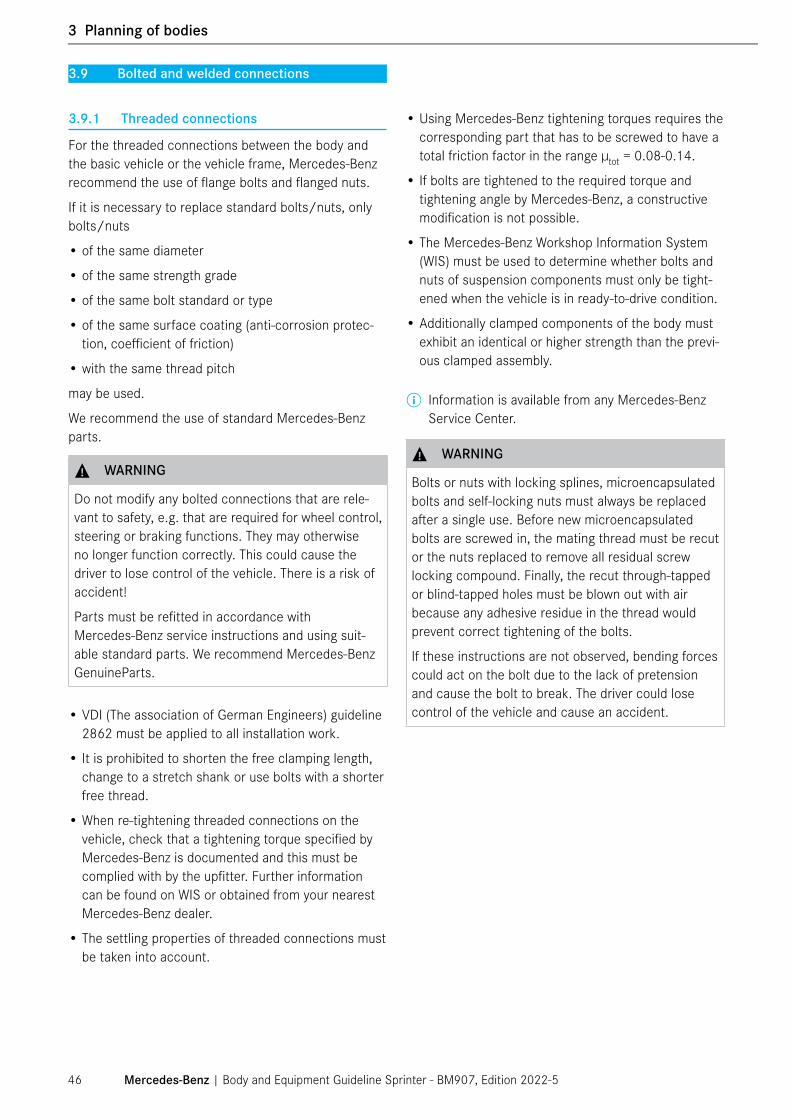
3.9 Bolted and welded connections
3.9.1 Threaded connections
For the threaded connections between the body and the basic vehicle or the vehicle frame, Mercedes-Benz recommend the use of flange bolts and flanged nuts.
If it is necessary to replace standard bolts/nuts, only bolts/nuts
• of the same diameter
• of the same strength grade
• of the same bolt standard or type
• of the same surface coating (anti-corrosion protec-tion, coefficient of friction)
• with the same thread pitch
may be used.
We recommend the use of standard Mercedes-Benz parts.
⚠ WARNING
Do not modify any bolted connections that are rele-vant to safety, e.g. that are required for wheel control, steering or braking functions. They may otherwise no longer function correctly. This could cause the driver to lose control of the vehicle. There is a risk of accident!
Parts must be refitted in accordance with Mercedes-Benz service instructions and using suit-able standard parts. We recommend Mercedes-Benz GenuineParts.
• VDI (The association of German Engineers) guideline 2862 must be applied to all installation work.
• It is prohibited to shorten the free clamping length, change to a stretch shank or use bolts with a shorter free thread.
• When re-tightening threaded connections on the vehicle, check that a tightening torque specified by Mercedes-Benz is documented and this must be complied with by the upfitter. Further information can be found on WIS or obtained from your nearest Mercedes-Benz dealer.
• The settling properties of threaded connections must be taken into account.
• Using Mercedes-Benz tightening torques requires the corresponding part that has to be screwed to have a total friction factor in the range µtot = 0.08-0.14.
• If bolts are tightened to the required torque and tightening angle by Mercedes-Benz, a constructive modification is not possible.
• The Mercedes-Benz Workshop Information System (WIS) must be used to determine whether bolts and nuts of suspension components must only be tight-ened when the vehicle is in ready-to-drive condition.
• Additionally clamped components of the body must exhibit an identical or higher strength than the previ-ous clamped assembly.
ⓘ Information is available from any Mercedes-Benz Service Center.
⚠ WARNING
Bolts or nuts with locking splines, microencapsulated bolts and self-locking nuts must always be replaced after a single use. Before new microencapsulated bolts are screwed in, the mating thread must be recut or the nuts replaced to remove all residual screw locking compound. Finally, the recut through-tapped or blind-tapped holes must be blown out with air because any adhesive residue in the thread would prevent correct tightening of the bolts.
If these instructions are not observed, bending forces could act on the bolt due to the lack of pretension and cause the bolt to break. The driver could lose control of the vehicle and cause an accident.
Mercedes-Benz | Body and Equipment Guideline Sprinter - BM907, Edition 2022-546
1 General
3 Planning of bodies
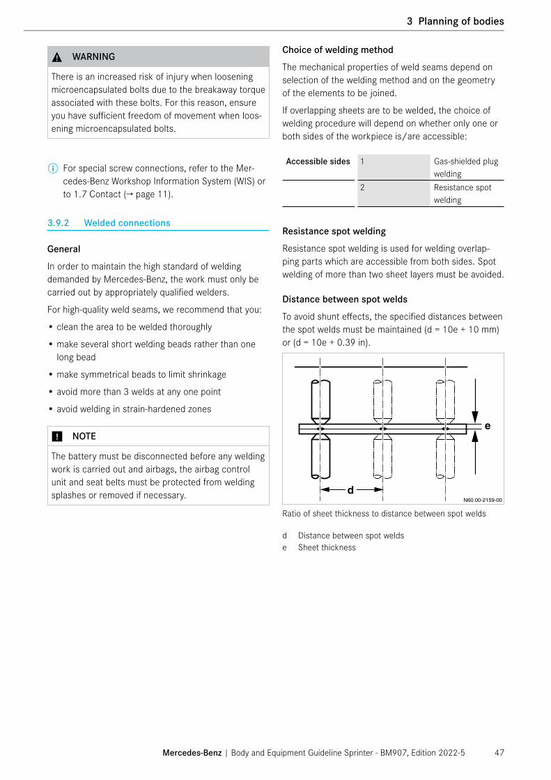
⚠ WARNING
There is an increased risk of injury when loosening microencapsulated bolts due to the breakaway torque associated with these bolts. For this reason, ensure you have sufficient freedom of movement when loos-ening microencapsulated bolts.
ⓘ For special screw connections, refer to the Mer-cedes-Benz Workshop Information System (WIS) or to 1.7 Contact (→ page 11).
3.9.2 Welded connections
General
In order to maintain the high standard of welding demanded by Mercedes-Benz, the work must only be carried out by appropriately qualified welders.
For high-quality weld seams, we recommend that you:
• clean the area to be welded thoroughly
• make several short welding beads rather than one long bead
• make symmetrical beads to limit shrinkage
• avoid more than 3 welds at any one point
• avoid welding in strain-hardened zones
⑴ NOTE
The battery must be disconnected before any welding work is carried out and airbags, the airbag control unit and seat belts must be protected from welding splashes or removed if necessary.
Choice of welding method
The mechanical properties of weld seams depend on selection of the welding method and on the geometry of the elements to be joined.
If overlapping sheets are to be welded, the choice of welding procedure will depend on whether only one or both sides of the workpiece is/are accessible:
Accessible sides 1 Gas-shielded plug welding
2 Resistance spot welding
Resistance spot welding
Resistance spot welding is used for welding overlap-ping parts which are accessible from both sides. Spot welding of more than two sheet layers must be avoided.
Distance between spot welds
To avoid shunt effects, the specified distances between the spot welds must be maintained (d = 10e + 10 mm) or (d = 10e + 0.39 in).
Ratio of sheet thickness to distance between spot welds
d Distance between spot weldse Sheet thickness
Mercedes-Benz | Body and Equipment Guideline Sprinter - BM907, Edition 2022-5 47
3 Planning of bodies

Distance from sheet edge
To avoid melting core damage, the specified distances to the sheet edge must be maintained (L = 3e +2 mm) or (L = 3e + 0.08 in).
Ratio of sheet thickness to distance from the edge
e Sheet thicknessL Distance from sheet edge
Gas-shielded plug welding
If overlapping sheets are only accessible from one side, use either gas-shielded plug welding or tack welding for the weld joint.
If the joint is produced by stamping or drilling followed by plug welding, the drilled area must be deburred before welding.
Ratio of sheet thickness to plug hole diameter
D = Plug hole diameter e = Sheet thickness4.5 mm/0.18 in 0.6 mm/0.02 in5.0 mm/0.2 in 0.7 mm/0.03 in5.5 mm/0.22 in 1.0 mm/0.04 in6.0 mm/0.24 in 1.25 mm/0.05 in6.5 mm/0.26 in 1.5 mm/0.06 in7.0 mm/0.28 in 2.0 mm/0.08 in
Mercedes-Benz | Body and Equipment Guideline Sprinter - BM907, Edition 2022-548
1 General
3 Planning of bodies

Mechanical quality can be additionally improved by the use of "elongated holes" (l = 2b).
Ratio of width to length of elongated holes
b Width of elongated holeI Length of elongated hole
Tack welding
In case of sheet thicknesses > 2 mm/0.08 in, over-lapping sheets may also be joined by tack welding (30 mm/1.18 in < L < 40e; d > 2L).
Dimensions for tack welds
d Distance between tack weld centerse Sheet thicknessL Length of tack weld
Do not perform welding work on
• assemblies such as the engine, transmission, axles, etc.
• chassis frames except on longitudinal frame mem-bers for wheelbase modifications or overhang modi-fications.
ⓘ For additional information, see Chapters 4 Techni-cal limit values for planning (→ page 58) and 5 Damage prevention (→ page 83) as well as the section 6.2.1 General information on the body in white/body (→ page 101) and the Mercedes-Benz Workshop Information System (WIS).
Anti-corrosion protection after welding
On completion of all welding work on the vehicle, you must comply with the specified anti-corrosion protec-tion measures (→ page 86).
⑴ NOTE
When carrying out welding work, observe the instruc-tions specified by Mercedes-Benz AG under 5.2 Welding work (→ page 85) and "Modifications to the basic vehicle" (→ page 101).
Mercedes-Benz | Body and Equipment Guideline Sprinter - BM907, Edition 2022-5 49
3 Planning of bodies

3.10 Soundproofing
If modifications are carried out on any parts whose operation produces noise, e.g.:
• Engine
• Exhaust system
• Air intake system
• Tires, etc.
sound level measurements must be taken.
Federal and local regulations and guidelines must be observed.
Noise-insulating parts fitted as standard must not be removed or modified.
The level of interior noise must not be adversely affected.
⑴ NOTE
To ensure that modifications do not change the vehi cle's sound levels, the interior sound levels must be minimized when planning bodies 6.4.4 Reducing interior noise (→ page 148).
Mercedes-Benz | Body and Equipment Guideline Sprinter - BM907, Edition 2022-550
1 General
3 Planning of bodies

3.11 Maintenance and repairs
Maintenance and repair of the vehicle should not be made unnecessarily difficult by the body. The opera-tor's manual must be observed.
• Maintenance points and major assemblies must be easily accessible (→ page 65).
• Stowage boxes must be fitted with maintenance flaps or removable rear panels.
• For maintenance and servicing purposes, accessi-bility to the attachment points of series production parts on the basic vehicle shall be ensured. This also affects parts on the door mechanism (e.g. hinges on hinged doors, guide rails/carriages of load compart-ment sliding door etc.).
ⓘ Any additional work that arises due to the body in terms of warranty-related work, maintenance or repair work will be assessed in each instance by Mercedes-Benz AG and may not accept liability. Should you have any queries, please get in touch with your contact person at Mercedes-Benz Service.
• The battery box must be sufficiently ventilated, with provision for air to enter and exit.
• Check the condition and capacity of batteries and service them in accordance with the manufacturer's specifications (→ page 53).
⑴ NOTE
Leaving the vehicle non-operational for long periods of time can lead to battery damage. This can be avoided by disconnecting the battery and storing it in an appropriate manner (→ page 53) or by activating hibernation mode (power-saving function) (→ page 253).
N54.10-2563-00
1
Schematic installation position of the main battery1 Main battery
In model designation 907 RWD (rear wheel drive), two auxiliary batteries for retrofitted consumers are avail-able:
• E2I: Auxiliary battery for retrofit consumers, interior (92 Ah AGM)
• E2M: Auxiliary battery for retrofit consumers, engine compartment (70 Ah AGM)
N82.00-3421-00
E2I: Auxiliary battery in front passenger seat base
E2M: Auxiliary battery in engine compartment
1 Auxiliary batteryArrow Direction of travel
If the vehicle is to be started using an external power supply, then either the jump-start connection point or the main battery must be used.
⑴ NOTE
The auxiliary battery (E2I, E2M) must not be used for connection to an external power supply as this could result in damage to the vehicle (→ page 235).
Mercedes-Benz | Body and Equipment Guideline Sprinter - BM907, Edition 2022-5 51
3 Planning of bodies

Any additional work which arises due to the body in terms of warranty-related work, maintenance or repair work will not be paid for by Mercedes-Benz.
The following must be observed by the upfitter before delivery of the vehicle:
� Check the headlamp adjustment or have this checked at a qualified specialist workshop. We recommend a Mercedes-Benz Service Center.
� Retighten the wheel nuts/wheel bolts to the speci-fied tightening torque.
Mercedes-Benz recommends adapting the scopes of maintenance work on the body to each individual vehicle using the relevant Mercedes-Benz maintenance systems. This applies to both the scope and type of service work, and for determining the service due dates for servicing intervals based on time elapsed or distance covered.
The upfitter must provide the vehicle with operator's manual and maintenance instructions for the body and any additional assemblies installed. These instructions must be in the language of the country in which the vehicle is to be used.
3.11.1 Storing the vehicle
Storing the vehicle � Clean the entire vehicle. � Check the oil and coolant levels. � Inflate the tires to 0.5 bar above the specified tire
pressures. � Release the parking brake and chock the wheels. � Chapter 3.11.2 Battery maintenance and storage
(→ page 53) must be observed.
Storing the vehicle outside (< 1 month) � Carry out the same procedure as for storing in an
enclosed space. � Close all air inlets and set the heating system to
"Off". � Chapter 3.11.2 Battery maintenance and storage
(→ page 53) must be observed.
Storing the vehicle outside(> 1 month) � Carry out the same procedure as for storing in an
enclosed space. � Fold the windshield wipers away from the wind-
shield. � Close all air inlets and set the heating system to
"Off". � Chapter 3.11.2 Battery maintenance and storage
(→ page 53) must be observed.
Maintenance work on the stored vehicle (in storage for > 1 month)
� Check the oil level once a month. � Check the coolant once a month. � Check the tire pressures once a month.
Removing the vehicle from storage � Check the fluid levels in the vehicle. � Observance of manufacturer-specific information
on operating fluids (e.g. maximum durability useful life, seasonal use etc.) and, where applicable replacement of respective operating fluids.
� Adjust the tire pressures to the manufacturer’s specifications.
� Check the battery charge and install the battery. � Clean the entire vehicle.
Mercedes-Benz | Body and Equipment Guideline Sprinter - BM907, Edition 2022-552
1 General
3 Planning of bodies

3.11.2 Battery maintenance and storage
For long non-operational times or storage, ensure that the battery is always in a charged state (more than 80% which corresponds to an open circuit voltage of approx-imately 12.55 V).
For non-operational periods longer than 4 weeks, the batteries must comply with one of the following:
� The battery main switch (code E30) must be isolated and fuse 32 must be removed. For more information on code E30, please refer to the Upfitter Portal technical bulletin: Sprinter MY2019+ Emergency Battery
� Hibernation mode (energy-saving mode) must be activated (→ page 253)
⚠ WARNING
If the E30 battery main switch or the battery itself is disconnected on a vehicle with an automatic trans-mission, the fuse 32 (10A red) “automatic trans-mission” in the fuse holder driver’s seat fuse block F55/4 must be removed if the vehicle is inactive. For further questions, please reach out via Upfitter-Portal.com. To reactivate the vehicle, reinstall the 10A fuse (red) at fuse position 32, fuse block F55/4 and connect the E30 battery main switch.
� If the vehicle is unused for longer than 4 weeks,xe remove and store the battery in an upright position at a dry place at temperature between 0 °C/32 °F and 30 °C/86 °F.
� The battery must be charged before removal and storage.
� The residual charging current should be less than 5A and the voltage higher than 13.5V.
� The battery must be recharged every 4 weeks when installed on the vehicle, or every 6 months if removed from the vehicle, until the residual charging current is less than 5A.
� The battery voltage must be kept above 12.55 V at all times. If the battery voltage drops below 12.55 V but not below 12.1 V, the battery must be recharged.
⑴ NOTE
If the open circuit voltage (unloaded for 4 hours in the removed state) of the battery voltage drops below 11 V, the battery is damaged and will have to be replaced.
3.11.3 Work before handing over the modified vehicle
The upfitter must confirm the work and modifications carried out by making an entry in the maintenance booklet.
Checking the overall vehicle � Check the vehicle for perfect condition. � Damage must be repaired where necessary. � Special care shall be taken to not impair or nega-
tively impact the following systems and areas: heat management, electrical systems, driver assistance systems, reliability, durability, fit and finish of Mercedes-Benz parts, functionality of drivetrain, weight/dimensions (other than explicitly labeled) and any other customer expectation and perfor-mance of the vans.
� Do not remove Mercedes-Benz heat shields. � Use Mercedes-Benz defined engine coolant
(Antifreeze). � Do not use after-market wheel ends, wheels
spacers, wheels studs. � Do not change, modify or relocate steering gear,
linkage, power steering hose or steering column. � Do not change, modify or relocate any driver assis-
tance systems such as backup cameras, sensors etc.
� Do not change, modify or relocate any airbags, seatbelts or other Mercedes-Benz restraining systems.
Checking the brake system � The brake fluid must be renewed regularly in accor-
dance with the Mercedes-Benz specifications, but at least every two years.
� If it is not known how long a vehicle equipped with a hydraulic brake system has been non-operational, the brake fluid must be renewed.
� Check electric and hydraulic lines for damage of any kind and repair or replace if necessary.
Mercedes-Benz | Body and Equipment Guideline Sprinter - BM907, Edition 2022-5 53
3 Planning of bodies

Checking the batteries � Check, and correct if necessary, the charge levels
of the vehicle battery and the auxiliary battery before handing over the vehicle.
Checking the tires � Before delivering the vehicle, check that the tires
are inflated to the specified air pressure and check the tires for damage. Damaged tires must be replaced.
Checking wheel alignment � We recommend that the suspension geometry (toe
adjustment etc.) be checked if modifications have been made by a body repair workshop.
⑴ NOTE
The information under 3.5 Dimensions and weights (→ page 37) on the vehicle curb weight and cor-responding axle loads before and after body mount-ing work, 4.2.9 Wheel alignment (→ page 71) and 6.1.1 General information on the suspension (→ page 92), must always be complied with.
More detailed information is contained in the Mercedes-Benz Workshop Information System (WIS).
Quality control
• All relevant quality control documentation should be saved by the upfitter.
• It is recommended to upfitter keeps quality control records including pictures, customer information, and copy of quality control sheets, VIN #, PO #, Height, Weight and other relevant information (ex. part numbers of installed equipment) in an electronic quality control system.
• Upfitter is responsible for any damages incurring during or due to modification while in his possession. Vehicles arrive at upfitter with a completed factory inspection/ready for dealer delivery.
Deactivating transport mode
To avoid excessive discharge of the battery during long periods of non-operation, the electrical system of the Sprinter is in transport mode by default ex-factory, which is only deactivated right before vehicle delivery.
In transport mode, the speed is limited to 40 km/h or 25 mph and limited electrical and electronic systems are active. This results in lower power consumption and reduces battery load.
For eXpertUpfitters where conditions dictate that the vehicles are idle for long periods of time, it is possi-ble to deactivate transport mode at the registered Mercedes-Benz service center just before vehicle operation. Please contact Mercedes-Benz for further information.
It is possible to operate vehicles in transport mode. However, please note that transport mode must always be deactivated before the vehicle is operated on public roads.
To deactivate transport mode with button combinations before the vehicle is taken in to service:
� Press the starter button once to switch on the ignition (terminal 15R). The emergency blinkers must be switched off.
� Activate the left turn signal for at least 2 blinking cycles
� Activate the right turn signal for at least 2 blinking cycles
� Switch off the turn signals � Switch on the emergency blinkers for at least 2
blinking cycles � Switch off the emergency blinkers � Activate the left turn signals for at least 2 blinking
cycles � Activate the right turn signals for at least 2 blinking
cycles � Switch off the turn signals � Press the starter button for a second time (terminal
15) and check that the message "Transport Mode" is no longer displayed on the instrument cluster
Mercedes-Benz | Body and Equipment Guideline Sprinter - BM907, Edition 2022-554
1 General
3 Planning of bodies

3.12 Special equipment
⚠ WARNING
The use of unapproved parts, major assemblies, con-version parts, or accessory parts can have detrimen-tal effects on the safety of the vehicle.
Before starting any work on the vehicle, please read the chapters of the vehicle owner's manual relevant to the upfit and the operating and installation guides from the manufacturers of accessories and equip-ment. You could otherwise fail to recognize dangers which could result in injury to yourself or others.
We recommend the use of special equipment available as Mercedes-Benz option codes, if possible, to ensure that the special equipment is properly fitted to the vehicle.
Information about the special equipment available as codes is available from your Mercedes-Benz Service Center 1.7 Contact (→ page 11).
ⓘ On the following homepages, you can assemble your vehicle in the Configurator and view the avail-able items of special equipment:
www.mbvans.comwww.mercedes-benz-vans.ca
Special equipment (e.g. reinforced springs, frame rein-forcements, additional fuel tanks, stabilizer bars etc.) or retrofitted equipment increases the curb weight of the vehicle.
The actual vehicle mass and axle loads must be deter-mined by weighing before mounting.
On completion of all body mounting work, the measure-ment of the actual vehicle curb weight and the corre-sponding axle loads by weighing must be repeated; for this, comply with e.g. 9.1.1 Determination of the center of gravity in the x-direction (→ page 309).
The measured values must be documented and checked. Refer to the following sections for more infor-mation: 3.5 Dimensions and weights (→ page 37), 3.11.3 Work before handing over the modified vehicle (→ page 53), 4.2.9 Wheel alignment (→ page 71) and 6.1.1 General information on the suspension (→ page 92).
Be aware that problems may occur when retrofitting an auxiliary equipment.
Mercedes-Benz | Body and Equipment Guideline Sprinter - BM907, Edition 2022-5 55
3 Planning of bodies

3.13 Adhesive decals on the exterior
The following specifications must be observed for adhe-sive films (wrapping) on the exterior of the vehicle:
• Films may only be applied to the exterior surfaces of the vehicle that are not labeled as impermissible areas in the schematic diagrams below (cargo van model designation).
• In areas with sensors, films are generally not per-mitted; also refer to Chapter 8.9.4 Blind Spot Assist/Rear Cross Traffic Alert (RCTA)/Exit Warning (→ page 277).
• All local and national legal requirements of any kind pertaining to the application of films or similar materials on vehicles must be observed and com-plied with. In particular, the regulations on wrapping around the windshield, the windows and lighting systems must be adhered to.
⚠ WARNING
Depending on the type and thickness, paints or films can cause attenuation of radar waves. This could lead to malfunction or system failure. This could cause the driver to lose control of the vehicle.
There is a risk of accident!
Front of vehicle - speckled areas: Areas where wrapping is not permissible (example cargo van model designation, schematic diagram)
When applying decals to the exterior of the vehicle, the upfitter should ensure compatibility to the vehicle paint.
Please note the following points during decal application:
• Ensure that the surface is clean before applying (free of fingerprints, grease, oil etc.)
• Check the decal material supplier’s recommenda-tions for an appropriate cleaning solution mixture
• Apply adequate contact pressure at every point on the vinyl surface to reduce risks of failure
• It is recommended to test at various extreme environmental conditions when choosing an appro-priate material for decals (consider temperature, humidity, etc.)
Mercedes-Benz | Body and Equipment Guideline Sprinter - BM907, Edition 2022-556
1 General
3 Planning of bodies

1
Sides of vehicle - speckled areas: Areas where wrapping is not permissible (example cargo van model designation, schematic diagram)
1 With Blind Spot Assist, code JA7
11
Rear of vehicle - speckled areas: Areas where wrapping is not permissible (example cargo van model designation, schematic diagram)
1 With Blind Spot Assist, code JA7
Mercedes-Benz | Body and Equipment Guideline Sprinter - BM907, Edition 2022-5 57
3 Planning of bodies

4.1 Limit values for the basic vehicle
⑴ NOTE
This chapter contains the technical limit values of the basic vehicle which are important for planning an upfit. In addition, you will find more information in the other chapters of the current version of the Body and Equipment Guideline.
4.1.1 Steerability
In all load states, the front axle load must represent at least the following proportion of the gross permissible vehicle mass:
General Up to 4.2 t > 35% of gross vehicle massUp to 5 t > 30% of gross vehicle mass
The permissible axle loads must be observed regard-less of the load situation.
Sprinter is equipped with electric power steering.
⚠ WARNING
Modifications must not be made to the steering sys-tem. This includes any change and/or limiting of the steering angle.
Modifications to the steering can cause the power steering assistance to fail.
There is a risk of accident, personal injuries and death if such systems no longer function correctly!
4.1.2 Maximum permissible position of the center of gravity
y-axis: The maximum wheel load (1/2 the axle load) of the laden vehicle may only be exceeded by 4%.
Maximum permissible center of gravity height
The overall height of the center of gravity of a vehicle has a significant influence on its braking and handling characteristics. When designing bodies and attach-ments, care must therefore be taken to ensure that the center of gravity of the basic vehicle and of the laden vehicle is kept as low as possible.
The basic function of the ESP® is designed for an overall center of gravity no more than 1300 mm/51.2 in above the road. The overall center of gravity height must not exceed 1300 mm/51.2 in.
Irrespective of this, the tendency of vehicles to tip over becomes more likely as the center of gravity height in- creases. The ESP® in the Sprinter is optimized to reduce the vehicle’s tendency to tip over at overall cen-ter of gravity heights up to approx. 1000 mm/39.4 in. In this context, it must always be ensured that the ve- hicles are fitted with the recommended suspension and ESP® variants. This applies in particular to vehicles with an overall center of gravity higher than 1000 mm/39.4 in.
Make sure that the correct variant is selected when ordering the vehicle. The calculation of the vehicle centers of gravity and compliance with the information in the MY22 Dealer Ordering Guide (DOG) must be ensured by the upfitter.
The upfitter is responsible for determining and complying with the vehicle maximum center of gravity restrictions.
For any questions, please contact the Mercedes-Benz.
ⓘ For more information see Chapter 9.1 Center of gravity (→ page 309). Information on vehicle selection and the configura-tion of the basic vehicle can be found in the MY22 Dealer Ordering Guide (DOG).
Mercedes-Benz | Body and Equipment Guideline Sprinter - BM907, Edition 2022-558
1 General
4 Technical limit values for planning
4 Technical limit values for planning

4.1.3 Vehicle dimensions
This chapter provides information about the maximum permissible dimensions of the vehicle including the upfit.
Side mirrors based on vehicle width
Mirror/code Box/vehicle widthStandard mirror(non-cab chassis)
≤2100 mm/83 in
Special equipmentCode FS1 –Extended mirror bracket
2190 mm/86 in to 2300 mm/91 in
Standard mirror for cab chassisCode FS2 –Extra-long mirror bracket
2300 mm/91 in to 2440 mm/96 in
Maximum permissible vehicle dimensionsThe maximum dimensions provided in the following tables must not be exceeded:
• The maximum box width is 96 in.
• The maximum box height is 109 in (measured from the top of the chassis frame to the top of the box) or 138 in (measured from the ground level).
• If roof mounts on top of the box exceeds the height of 157 in (measured from the ground level), then option code JA8 needs to be deactivated by activat-ing option code JA0. (Please reach out to the nearest local dealer for deactivation).
Dimension Descriptiona 2440 mm/96 in Maximum permissible width of the upfitted boxb 2770 mm/109 in Maximum permissible distance measured from the top of the chassis frame to the top of
the upfitted boxc 735 mm/29 in Body frame height measured from ground level (may vary depending on load,
suspension)b + c 3505 mm/138 in Maximum permissible box height from ground level (excluding roof mounts)d 4000 mm/157 in Maximum permissible height with roof mounts from ground level (with code JA8)e 2776 mm/109.3 in Width of the vehicle including the extended mirrors (with code FS2)f 2019 mm/79.5 in Width of the vehicle without mirrors and upfit
Consider both the maximum box height and width as well as the maximum frontal surface area of the vehicle when determining the measurements of the box.
A nose cone may be installed on the front surface of the box to reduce wind resistance.
Additionally, for frontal surface areas higher than 6.8 m2/10540 in2, the following requirements are mandatory (for smaller frontal surface areas these requirements are preferable but not mandatory):
• The transition between cab housing and box has to be chamfered by 45˚.
• The box is required to have edge radii ≥ 100 mm/ 3.94 in (especially in the rear area) for improving aerodynamics.
Mercedes-Benz | Body and Equipment Guideline Sprinter - BM907, Edition 2022-5 59
4 Technical limit values for planning
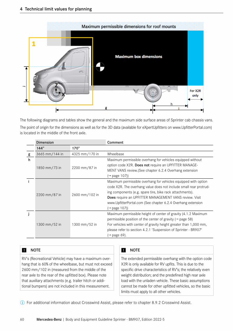
Dimension Comment144” 170”
g 3665 mm/144 in 4325 mm/170 in Wheelbaseh
1850 mm/73 in 2200 mm/87 in
Maximum permissible overhang for vehicles equipped without option code X2R. Does not require an UPFITTER MANAGE-MENT VANS review.(See chapter 6.2.4 Overhang extension (→ page 107))
i
2200 mm/87 in 2600 mm/102 in
Maximum permissible overhang for vehicles equipped with option code X2R. The overhang value does not include small rear protrud-ing components (e.g. spare tire, bike rack attachments). Does require an UPFITTER MANAGEMENT VANS review. Visit www.UpfitterPortal.com (See chapter 6.2.4 Overhang extension (→ page 107))
j
1300 mm/52 in 1300 mm/52 in
Maximum permissible height of center of gravity (4.1.2 Maximum permissible position of the center of gravity (→ page 58)For vehicles with center of gravity height greater than 1,000 mm, please refer to section 4.2.1 'Suspension of Sprinter - BR907' (→ page 69).
⑴ NOTE
RV's (Recreational Vehicle) may have a maximum over-hang that is 60% of the wheelbase, but must not exceed 2600 mm/102 in (measured from the middle of the rear axle to the rear of the upfitted box). Please note that auxiliary attachments (e.g. trailer hitch or addi-tional bumpers) are not included in this measurement.
⑴ NOTE
The extended permissible overhang with the option code X2R is only available for RV upfits. This is due to the specific drive characteristics of RV’s; the relatively even weight distribution; and the predefined high rear axle load with the unladen vehicle. These basic assumptions cannot be made for other upfitted vehicles, so the basic limits must apply to all other vehicles.
The following diagrams and tables show the general and the maximum side surface areas of Sprinter cab chassis vans.
The point of origin for the dimensions as well as for the 3D data (available for eXpertUpfitters on www.UpfitterPortal.com) is located in the middle of the front axle.
ⓘ For additional information about Crosswind Assist, please refer to chapter 8.9.2 Crosswind Assist.
Mercedes-Benz | Body and Equipment Guideline Sprinter - BM907, Edition 2022-560
1 General
4 Technical limit values for planning

Dimension Commentk 1021 mm/40 in Distance between front end and point of originl 1503 mm/59 in Distance between point of origin and the back of the B-pillar
m Up to 4.2t > 35% of gross vehicle mass Up to 5t > 30% of gross vehicle mass
Front axle load (see chapter 4.1.1 Steerability)
Dimension Descriptionn
50 mm/2 inMinimum permissible distance between back of B-pillar and non-integrated body/box upfits (see chapter 4.9 Limit values for the box body (→ page 82)).
o20 mm/0.8 in
Minimum permissible distance between the rear edge of the door and an integrated body (see chapter 4.9 Limit values for the box body (→ page 82)).
p 726 mm/29 in Distance from back of B-pillar to point ‘t’ (see bottom of table).q up to 200 mm/
7.9 inAlcove length measured from ‘t’ where no sensors are impaired (see chapter 8.9.5 Highbeam Assist, Lane Keeping Assist and traffic sign recognition and 8.9.6 Rain sensor and Headlamp Assist).
rup to 400mm/ 15.8 in
Alcove length measured from ‘t’ where option codes LA2 (Headlamp assist sensor at upper posi-tion) and JF1 (Rain sensor) may have impaired functionality. Therefore, option code LA3 (headlamp assist sensor at lower position) can be ordered (see chapter 7.14.4 Headlamp Assist (code LA2) and 7.14.5 Rain sensor (code JF1)). If the option code LA3 is ordered, the rain sensor (code JF1) cannot be ordered.
sup to 1150 mm/ 45 in
Maximum permissible alcove overhang. Option code LA2 (Headlamp assist sensor at upper position) and JF1 (Rain sensor) are covered by the shade of the alcove and the functionality will be impaired. Therefore, option code LA3 (Headlamp assist sensor at lower position) can be ordered.
t - Accessible start point for measuring the alcove overhang (outer edge of windshield).
Mercedes-Benz | Body and Equipment Guideline Sprinter - BM907, Edition 2022-5 61
4 Technical limit values for planning

4.1.4 Parts which must not be welded:
• On the A and B-pillars
• On the upper and lower flange of the frame
• In bending radii
• In the vicinity of the airbags, airbag sensors, airbag control unit, and seat belts
• Plug welding is only permissible in the vertical webs of the longitudinal frame member.
• In the area of the assistance systems, (e.g. front and rear radars for Parktronic or Distronic)
ⓘ Additional information can be found under Chapter 3.9 Bolted and welded connections (→ page 46), Chapter 5.2 Welding work (→ page 85), Chapter 6 Modifications to the basic vehicle (→ page 92), 6.2 Body in white/body (→ page 101) and the Mercedes-Benz Workshop Information System (WIS).
Permissible towing capacities when relocating the trailer coupling point
Permissible gross mass
Wheelbase Relocation of trailer coupling point from standard configuration0-200 mm 0-8 in
201-500 mm/ 8-20 in
501-600 mm/20-24 in
601-700 mm/24-28 in
> 700 mm/> 28 in
1500, 2500 3665 mm/ 144 in
3500 kg/ 7720 lbs
3000 kg*/6610 lbs
2500 kg*/5510 lbs
2000 kg*/4410 lbs
* +**
4325 mm/ 170 in
3500 kg/ 7720 lbs
3000 kg*/6610 lbs
2500 kg*/5510 lbs
2000 kg*/4410 lbs
* +**
3500, 3500XD, 4500
3665 mm/ 144 in
3500 kg/ 7720 lbs
3500 kg*/6610 lbs
3000 kg*/6610 lbs
2500 kg*/5510 lbs
* +**
4325 mm/ 170 in
3500 kg/ 7720 lbs
3500 kg*/6610 lbs
3000 kg*/6610 lbs
2500 kg*/5510 lbs
* +**
* If the trailer coupling point is relocated by > 200 mm/8 in in relation to the standard configuration, the Trailer Stability Assist (TSA) must be deactivated through the use of code O19.
** If the relocation of the trailer coupling point from the standard configuration is > 700 mm/28 in, we recommend seeking the advice of the relevant department1.7 Contact (→ page 11).
Mercedes-Benz | Body and Equipment Guideline Sprinter - BM907, Edition 2022-562
1 General
4 Technical limit values for planning

4.1.5 Drilling must not take place
This chapter provides information about areas which should not be modified or changed due to safety and crash reasons.
The following pictures show the safety and crash rel-evant areas. Mercedes-Benz recommends not to drill into the marked areas.
Safety and crash relevant areas (marked in blue)
The diagram below shows where drilling into the longitudinal member is not allowed.
Longitudinal member, non-drilling areas
Drilling must not take place:
• On the A and B-pillars
• In the upper or lower flange/chord of the longitudinal frame member
• In the vicinity of load application points (e.g. spring brackets)
• In the vicinity of front axle or rear axle supporting points
• On underbody reinforcement or longitudinal supports under the B-Pillar
• In the vicinity of the airbags, airbag sensors, airbag control unit, seat belts
• In the area of the assistance systems, (e.g. front and rear radars for Parktronic or Distronic)
⑴ NOTE
Holes in the longitudinal frame member are the result of the production process and are not suitable for body mounting work. On no account may holes resulting from the production process be used, as this could damage the frame.
For mounting of partition walls, please use existing holes.
Mercedes-Benz | Body and Equipment Guideline Sprinter - BM907, Edition 2022-5 63
4 Technical limit values for planning

Underbody reinforcement non-drilling areas
Both views show the reinforcement piece with grooves in the highlighted region. Drilling should not take place in this area because of its structural importance.
In relation to the highlighted zone, an important note about fuel-related part integrity is below.
⑴ NOTE
Clearances for fuel filler necks, fuel tank lines and fuel lines must be maintained. Sharp edges of the upfit can impact the fuel integrity of the vehicle.
ⓘ Additional information can be found under 3.9 Threaded and welded connections (→ page 46) and 5.2 Welding work (→ page 85).
Underbody reinforcement non-drilling areas
Mercedes-Benz | Body and Equipment Guideline Sprinter - BM907, Edition 2022-564
1 General
4 Technical limit values for planning

4.1.6 Service lift points
Front lifting points
This section provides information about the location of the lifting points in the front part of the underbody.
B
B
A
Front lifting points1) Front support to spring clamp plate2) Front support to longitudinal member011) Lifting platform012) Support plate013) Long support plate017) Support drift
Front underbody non-drilling areas
• Vehicles which have been modified in areas of main-tenance points/lifting points are not serviceable at Mercedes-Benz dealerships.
• Due to safety reasons Mercedes-Benz dealerships will not use any other lifting points than those desig-nated by Mercedes-Benz standards (see above).
• Mercedes-Benz highly recommends not to modify the highlighted areas.
Rear lifting points
This section provides information about the location of the lifting points in the rear part of the underbody.
D
C
D
Rear lifting points3) Rear jack tube on front rear spring bracket4) Rear jack tube on longitudinal frame member6) Mount on front rear spring bracket011) Lifting platform013) Long support plate014) V-block016) Ram
Rear underbody non-drilling areas
Mercedes-Benz | Body and Equipment Guideline Sprinter - BM907, Edition 2022-5 65
4 Technical limit values for planning

4.1.7 Weights
The upfitter has to comply with certain limit values of the vehicle. This subsection explains where the maxi-mum limits can be found and how they are connected to each other.
Nomenclature Meaning Description LocationGross Vehicle Weight Rating (GVWR1)
Gross Vehicle Weight Rating
Permissible total weight of the vehicle (limited)
Can be found on this sticker2:
Payload1 Payload Includes driver, passengers, cargo, luggage, etc.
Can be found on this sticker2:
Curb Weight (CW1) Curb Weight Weight of the vehicle, depend-ing on the option code (actual value)
Has to be calculated by formula1
UVW1 Unloaded Vehicle Weight Maximum weight of the vehicle including the upfit (limited)
Can be found on this sticker2:
1 Specific to vehicle2 Refer to subsection 3.6 Vehicle identification data
(→ page 39) for further information and labels
Mercedes-Benz | Body and Equipment Guideline Sprinter - BM907, Edition 2022-566
1 General
4 Technical limit values for planning

4.1.8 Weight limits
The diagram below provides an overview of the weight limits that must be considered when upfitting a Sprinter. This chapter serves as a guide to upfitters when modifying their vehicles, but this cannot serve as a replacement for reviewing the latest version of federal and local regulations on weight limitations. It is the upfitter’s responsibility to ensure compliance with all federal and local regulations on weight limitations.
The table below contains the maximum weight limit values for Sprinters based on the model type. Do not exceed the maximum weight limits of UVW, GVWR, and GCWR, listed below.
A = Base Curb Weight (BCW). BCW is the sum of the Sprinter vehicle weight and liquids necessary for vehi-cle operation at full capacity (e.g. fuel). The weight of the vehicle is variable and depends on the variant of the Sprinter and the option codes included in the spe-cific vehicle. Liquids that are not necessary for vehicle operation should not be included.
B = Unloaded Vehicle Weight (UVW). UVW is the sum of the BCW value and the weight of permanently installed equipment added by the upfitter. Liquids that are not necessary for vehicle operation as well as any acces-sories should not be included. The UVW restriction does not include the driver, passengers, cargo/luggage items in its weight limit.
C = Gross Vehicle Weight Rating (GVWR). GVWR is the sum of UVW value and the driver and passenger(s) weights as well as weights of the added cargo and/or luggage.
D = Gross Combination Weight Rating (GCWR). GCWR is the sum of GVWR value and the weight of any attached trailer and the cargo in the trailer.
Payload before the upfit is payload of the vehicle without any upfit modifications and is calculated by subtracting the BCW from the GVWR. The payload value is provided on the tire label located on the B-pillar driver side door.
Payload after the upfit includes the weight of perma-nently installed equipment added by the upfitter and is calculated by subtracting the weight of the vehicle after the upfit from the GVWR. The label with payload (tire label on the B-pillar driver side door) provided by Mercedes-Benz will need to be updated by the upfitter with the payload after upfit value.
Mercedes-Benz | Body and Equipment Guideline Sprinter - BM907, Edition 2022-5 67
4 Technical limit values for planning

4.2 Limit values for the suspension
4.2.1 Suspension of Sprinter – BR 907
Use of the suspension design
Mercedes-Benz provides a range of suspension pack-ages to meet varying customer needs for a wide range of body possibilities.
Suspension package overview
Code DescriptionCB1 Suspension for comfort and load protectionCB7 Stabilization level I - roll stabilization with high body dampingCB8 Stabilization level II - enhanced roll stabilization with higher body damping compared to CB7CB4 Stabilization level III - maximum roll stabilization with higher body damping compared to CB8CT1 Rear spring vibration absorbersA50 Front axle reinforcedCE8 Raised rear body mounts
Contents of the suspension packages
Code BenefitCB1 Enhanced comfort due to adapted damper characteristics and the use of progressive
spring characteristics.CB7 CB7 compensates for rolling behavior due to high centers of gravity of loads or bodies. Torsion
bars with an increased diameter are added to the front and rear axles. Furthermore, shock absorbers with an adapted characteristic are installed.
CB8 Additional roll stabilization and body damping compared to CB7. Increases torsion bar diameters at the front and rear axles and provides an adapted shock absorber characteristic. Furthermore, rear axle springs with increased rigidity are installed.
CB4 Suspension with maximum roll stabilization for upfitted vehicles. CB4 includes the stabilization stage II (CB8) with adapted springs/shock absorbers, stabilizer bar characteristics and the use of a progres-sive spring characteristic.
CT1 Includes vibration absorbers fitted on the left and right rear spring and lowers the resonant vibrations of the rear springs, thus hindering noise development.
A50 Includes an increased load capacity of the front axle, such that heavier bodies and equipment can be fitted. The higher capacity front axle caters for heavier cabs and special equipment (e.g. for fire-fighting vehicles and ambulances).
CE8 Raised body on rear axle (35mm). For RV only.
Code overview
Please find up-to-date suspension packages and codes on the Upfitter Portal:
www.UpfitterPortal.com
Mercedes-Benz | Body and Equipment Guideline Sprinter - BM907, Edition 2022-568
1 General
4 Technical limit values for planning

An additional ESP variant is available for the Sprinter van models in the form of the option code B01 (vehicle version for high loads). The code B01 can be ordered for vehicles with high loads and is recommended for upfitted vehicles with high centers of gravity.
For more information, please refer to Chapter 4.1.2 Maximum permissible position of the center of grav-ity (→ page 58) and Chapter 9.1 Center of gravity (→ page 309)
Code B01 contains a combination of suspension, tires, ESP parameters, driver assistance system param-eters specially designed and developed for upfitted vehi-cles with a center of gravity of more than 1000 mm/39 in above the ground level. This also applies to all-wheel drive vehicles. Code B01 is not available for 3500, 3500XD, or 4500 vans with 144" wheelbase.
In the Dealer Ordering Guide (DOG) (please review www.UpfitterPortal.com) the suspension matrix will provide a recommendation for the specific suspensions depending on the vehicle characteristics. If the upfit/body required by the customer is not included in the suspension matrix, then please reach out via www.UpfitterPortal.com.
4.2.2 Permissible axle loads
See Chapter 2 General (→ page 14).
⚠ WARNING
If the permissible axle loads are exceeded on vehicles equipped with the ESP® system, this may no longer function correctly. Furthermore, any overloading may result in damage to the suspension and load-bearing parts. This could cause the driver to lose control of the vehicle. There is a risk of accident, personal injuries and death if such systems no longer function correctly!
Permissible axle loads are not to be exceeded.
For information on axle loads and maximum permis- sible gross mass, see 1.7 Contact (→ page 11).
Mercedes-Benz | Body and Equipment Guideline Sprinter - BM907, Edition 2022-5 69
4 Technical limit values for planning

4.2.3 Approved tire sizes
The table below provides a general overview of tires according to tonnage.
Gross mass Equipment Tire size Weight and speed ratingReference: 1500/2500 LT245/75 R16 120/116Q
See note
2 LT245/75 R16 120/116Q Reference: 3500/3500XD Super Single
1 (on front axle) 225/75 R16 C 121/120R (122L)1 (on rear axle) 285/65 R16 C 131R1 (as spare wheel) 225/75 R16 C 121/120R (122L)
Reference: 3500/3500XD/4500
LT215/85 R16 115/112Q 2 LT215/85 R16 115/112Q
1 With super single tires special equipment, code R9A2 All-wheel drive (4x4)
The table below outlines the tire pressures on Sprinter vehicles. These tire pressures are the same, regardless of tire brand and are measured as fully laden. Weights quoted are GVWR values.
Tire Front axle (psi) Rear axle (psi) Spare tire (psi)Vehicles below 10,000 lbs.LT 215/85 R16 (without code A50) 55 54 55LT 215/85 R16 (with code A50) 61 54 61LT245/75 R16 (without code A50) 46 70 70LT245/75 R16 (with code A50) 52 70 70225/75 R16C (without code A50) 49 - 100225/75 R16C (with code A50) 54 - 100285/65 R16C - 67 -Vehicles above 10,000 lbs. and below 12, 125 lbs.LT 215/85 R16 (without code A50) 55 58 -LT 215/85 R16 (with code A50) 61 58 -285/65 R16C - 67 -Vehicles at 12,125 lbs.LT 215/85 R16 (with code A50) 65 62 -285/65 R16C - 75 -
⑴ NOTE
The tire sizes listed comply with the approved weight and speed ratings for each vehicle tonnage rating.
Mercedes-Benz | Body and Equipment Guideline Sprinter - BM907, Edition 2022-570
1 General
4 Technical limit values for planning

4.2.4 Diameter of turning circle
Wheelbase Diameter of turning circleRWD 4x2
1500, 25004x23500XD, 4500
4x41500, 2500, 3500, 3500XD
3665 mm/144 in 13.4 m/528 in 13.2 m/520 in 14.0 m/551 in4325 mm/170 in 15.3 m/602 in 15.2 m/598 in 16.1 m/634 in
4.2.5 Modifications to the axles
No modifications may be made to the suspension or the axles (→ page 92).
4.2.6 Modifications to the steering
No modifications may be made to the steering system (→ page 92).
⑴ NOTE
Modifications must not be made to the steering sys-tem . This includes any change and/or limiting of the steering angle.
Modifications to the steering can cause the power steering assistance to fail.
4.2.7 Modifications to the brake system
No modifications may be made to the brake system.
No modifications may be made to disk brake air inflow and air outflow (→ page 94).
4.2.8 Modifications to springs, spring suspension/shock absorbers
Modifications to spring suspension, shock absorbers, and stabilizers using non-Mercedes Benz parts are not recommended.
If modification to the suspension system is desired, then only Mercedes-Benz parts must be used. When replacing the suspension package, the entire suspen-sion system must be replaced including all the relevant parts and the software system. Please reach out to the local dealership for obtaining all the necessary parts and flashing of the software system.
On no account should modifications be made to the spring suspesnsion (→ page 92).
4.2.9 Wheel alignment
No modifications may be made to the steering geome-try and to the wheel alignment settings (→ page 92).
If the upfit or any permanent equipment that belongs to the vehicle leads to increased vehicle curb weight or if the vehicle is mostly used in fully loaded state, refer to the notes under 6.1.1 General information on the suspension (→ page 92).
This could apply to, for example, recovery vehicles, fire-fighting vehicles, ambulances, semitrailer trucks, workshop vehicles or RVs.
Mercedes-Benz | Body and Equipment Guideline Sprinter - BM907, Edition 2022-5 71
4 Technical limit values for planning

4.3 Limit values for the body in white
4.3.1 Modifications to the body in white
See "Modifications to the basic vehicle" (→ page 101) for more information.
• No modifications may be made to the crossmember structure from the front of the vehicle back to, and including, the B-pillar.
• No modifications may be made to the rear portal including the roof area (→ page 111).
• In the event of modifications to the load-bearing structure, the total equivalent rigidity of the structure fitted by the upfitter must equal that of the standard vehicle.
• Clearances for fuel filler necks, fuel tank lines and fuel lines must be maintained.
• It is not permissible to drill holes in or perform weld-ing work on the A-pillar or B-pillar.
• If modifications are made to the side wall of the cargo van or the passenger van, the rigidity of the modified body must equal that of the basic vehicle.
• If bodies are mounted on basic vehicle cabs, a fuel level sensor shield may be necessary depending on the body type. See section 6.3.1 Fuel system (→ page 126).
4.3.2 Limit values for the vehicle frame
If the frame is extended, the material of the extension element must have the same quality and dimensions as the standard chassis frame, see Chapter 7.1 Assembly frame (→ page 180).
Vehicle name Model designation MaterialSprinter 907 CR240 LA or
S235 JRG
Mercedes-Benz | Body and Equipment Guideline Sprinter - BM907, Edition 2022-572
1 General
4 Technical limit values for planning

4.3.3 Roof/roof load
The following chapter provides information and limit values for applying loads to the roof.
Exterior roof mounts:
Please review chapter 6.2.9 Cargo Van/Passenger Van roof (→ page 118). Mercedes-Benz recommends to utilize roof rails and order option code D13 (mounting rails for roof rack) to mount equipment or distribute the load evenly over the entire roof surface.
Maximum roof loadsCargo vanLH1
High roof cargo van LH2 (static)
High roof cargo vanLH2 (dynamic)
Cab
300 kg/661 lbs 300 kg/ 661 lbs 150 kg/331 lbs 100 kg/220 lbs
⑴ NOTE
For high roof vans (LH2), if a vehicle is parked on a horizontal plane, the maximum permissible static roof load on a stationary vehicle is 300 kg or 661 lbs, evenly distrbuted. For example, the weight of an occupied pop-up roof with passengers included can be up to 300 kg or 661 lbs.
Interior roof mounts:
If equipment needs to be installed in the interior under-neath the roof, it is recommended to utilize a support-ing structure to distribute loads through the sidewalls and not through roofbows itself. The limit values may be used from the table above.
If the upfitter decides to use the roof bows to mount equipment, Mercedes-Benz recommends to order option code D17 (interior roof rack). The maximum interior roof load with option code D17 is limited to 50Kg / 110lbs.
General roof information:
The sheet metal thickness of the roof bows is 0.8mm.
Roof bows or load-bearing parts may not be removed or damaged without being replaced.
For further information in regards of roof modification, please review see Chapter 6.2.9 Cargo Van/Passenger Van roof (→ page 118).
The connection between the roof bow and the side wall must be of sufficient bending resistance (→ page 111).
Wheelbase Quantity required3665 mm/144 in ≥ 5 bows4325 mm/170 in ≥ 6 bows
Roof bows Position1 Behind the front doors (B-pillar)2 At the center of the sliding door to
the load compartment (between the B- and C-pillars)
3 At the center of the vehicle behind the load compartment sliding door (C-pillar)
4-6 Between the C-pillar and the rear area of the vehicle (rear pillar)
Roof height increase
Moment of inertia Ix per roof bow
≤ 250 mm/10 in ≥ 40 000 mm4/0.096 in4
≤ 400 mm/16 in ≥ 65 000 mm4/0.156 in4
≤ 550 mm/22 in ≥ 86 000 mm4/0.201 in4
Refer to 8.9.2 Crosswind Assist (→ page 273) for modifications to the projected lateral face.
Mercedes-Benz | Body and Equipment Guideline Sprinter - BM907, Edition 2022-5 73
4 Technical limit values for planning

4.4 Limit values for engine peripherals/drive-train
4.4.1 Modifications to engine/drivetrain components
Modifications to the engine timing/performance enhancement
⑴ NOTE
Any interference in the engine timing by customers and upfitters is not permitted.
Manipulations or modifications to the engine timing cause changes in the certified engine data and emis-sion values, and thus result in the immediate invalida-tion of the operating permit.
Further changes to engine/drivetrain
• On no account should modifications be made to the air intake system.
• On no account may any modifications be made to the propeller shafts. If any modifications are neces-sary (e.g. adjustment of the lengths), these may only be carried out by a company qualified in propeller shaft engineering. This company shall be responsible for the effects on the vehicle (e.g. NVH behavior, durability, package). When modifications are made, the fastening ele ments must not be reused.
• It is not possible to retrofit any engine speed regula-tion equipment, other than that which is available as Mercedes-Benz special equipment.
• On no account should modifications be made to the exhaust system, especially in the vicinity of exhaust gas aftertreatment components (diesel particulate filter, catalytic converter, lambda sensor etc.).
4.4.2 Engine cooling system
a) Vehicles with engine OM651/OM642
On no account should modifications be made to the cooling system (cooler, radiator grille, air ducts, coolant circuit, etc.) because a sufficient flow of cooling air must be guaranteed.
The flow areas of the cooling air intake areas are to be kept free. This means:
• At least 11 dm2 free air cross-section for the front grill (coolant radiator and condenser)
• At least 7 dm2 free air cross-section for the opening in the bumper (charge air cooler flow)
Engine cooling, specification for intake air cross-section1 Front radiator grille2 Charge air cooler
b) Vehicles with engine OM654
The cooling module for the engine OM654 is shown in the following figure.
The cooler components A/C condenser, low-tempera-ture cooler (LT cooler), high-temperature cooler (HT cooler) and electric E suction-type fan are arranged in succession. The new water-cooled charge air cooler and the transmission oil cooler (with automatic trans-mission) are positioned on the engine and the LT cooler supplies them.
To prevent any return flow of heated recirculated air from the engine compartment, the cooling module with air recirculation partitions or air ducting are sealed off all the way round (for details, see description below).
Mercedes-Benz | Body and Equipment Guideline Sprinter - BM907, Edition 2022-574
1 General
4 Technical limit values for planning

Cooling module for engine OM654 1 A/C condenser2 LT cooler3 HT cooler4 E suction-type fan5 Air recirculation partitions (exemplary, circumferential
installation)6 Coolant expansion reservoir
Modifications may not be made to the cooling system (cooler components, air ducting, hoses and other detachable parts that are part of the cooling system).
Modifications to the front of the vehicle can fundamen-tally be made under the following boundary conditions.
The free cross-section areas of the cooling air intake openings in total from the upper front grate plus the lower bumper grille (see figure "Cooling air intake openings at front of vehicle" (→ page 76)) must be complied with for technical reasons with the following limit values:
• Minimum: 18.2 dm² / 282 in2
• Maximum: 26.4 dm² / 409 in2
Mercedes-Benz | Body and Equipment Guideline Sprinter - BM907, Edition 2022-5 75
4 Technical limit values for planning

Adding equipment to Mercedes-Benz vehicle grille
For vehicles with a genuine Mercedes-Benz Van vehicle front, detachable parts (horn, front flasher or similar) can be mounted in the hatched areas 1 and 2 of the front grille (see following schematic diagram).
1 2
Front grille of genuine Mercedes-Benz Van vehicle front
1, 2 Areas in which detachable parts can be mounted (schematic diagram)
As the detachable parts are to be placed outside the marked areas 1 and 2 in the front grille, the resulting cooling output should be verified through the test cycle specified at the end of this chapter. eXpertUpfitters should open a new UIS on the Upfitter Portal in relation to this upfit.
If the free cooling air intake openings are reduced in size, the cooling output of the air conditioning system is lowered and - depending on the given operating status - the duration and intensity of fan operation is increased.
Modifications may not be made to covers for the lower opening area in the bumper grille (see following figure).
Cooling air intake openings at front of vehicle
1 Front grille2 Bumper grille
Mercedes-Benz | Body and Equipment Guideline Sprinter - BM907, Edition 2022-576
1 General
4 Technical limit values for planning

4.5 Limit values for the interior
4.5.1 Modifications to airbags and seat belt tensioners
⚠ WARNING
Modifications to or work incorrectly carried out on restraint systems (seat belt and seat belt anchorings, seat belt tensioners or airbags) or their sensor sys-tems of wiring could cause the restraint systems to stop functioning correctly. This means, for example, that airbags or seat belt tensioners may be activated inadvertently or may fail in the event of an accident even though the rate of deceleration exceeds the deployment threshold.
There is a risk of accident, personal injuries and death if such systems no longer function correctly!
Modifications to restraint systems are therefore not permitted.
• On no account should modifications be made to airbag components or in the vicinity of airbag compo-nents and sensors.
• On no account should modifications be made to the headliner or its attachment if the vehicle is equipped with window airbags.
• The vehicle interior must be designed in such a way that airbags can fully deploy without impediment (→ page 139).
• On no account should modifications be made around the airbag control unit (→ page 139).
ⓘ More information can be found under "Modifica-tions to the basic vehicle" (→ page 139).
4.5.2 Modifications to seats
⚠ WARNING
Only seat combinations that match as-delivered state are permitted. It is not permissible to rotate seats or to create conditions which do not match the series production state.
Modifications to the seat system, particularly in the case of seats with a seat occupancy sensor, or the mounting of seats to the wheel well are not permit-ted. Otherwise the seats could become detached from their anchorages in the event of an accident.
Furthermore, the functioning of safety-relevant driver assistance systems cannot be guaranteed. (See 8 Electrics/electronics (→ page 233))
Seat covers and protective covers could interfere with the functioning of the thorax/pelvis side airbag and the seat occupancy recognition system.
Seat Covers
• Seats with integrated thorax-pelvis-airbags feature security seam with the flag “Airbag”.
• Modifications to the seat or seat cover requires compliance with applicable technical and regulatory requirements.
• Aftermarket seat covers may affect the performance of the thorax-pelvis-airbag.
Mercedes-Benz | Body and Equipment Guideline Sprinter - BM907, Edition 2022-5 77
4 Technical limit values for planning
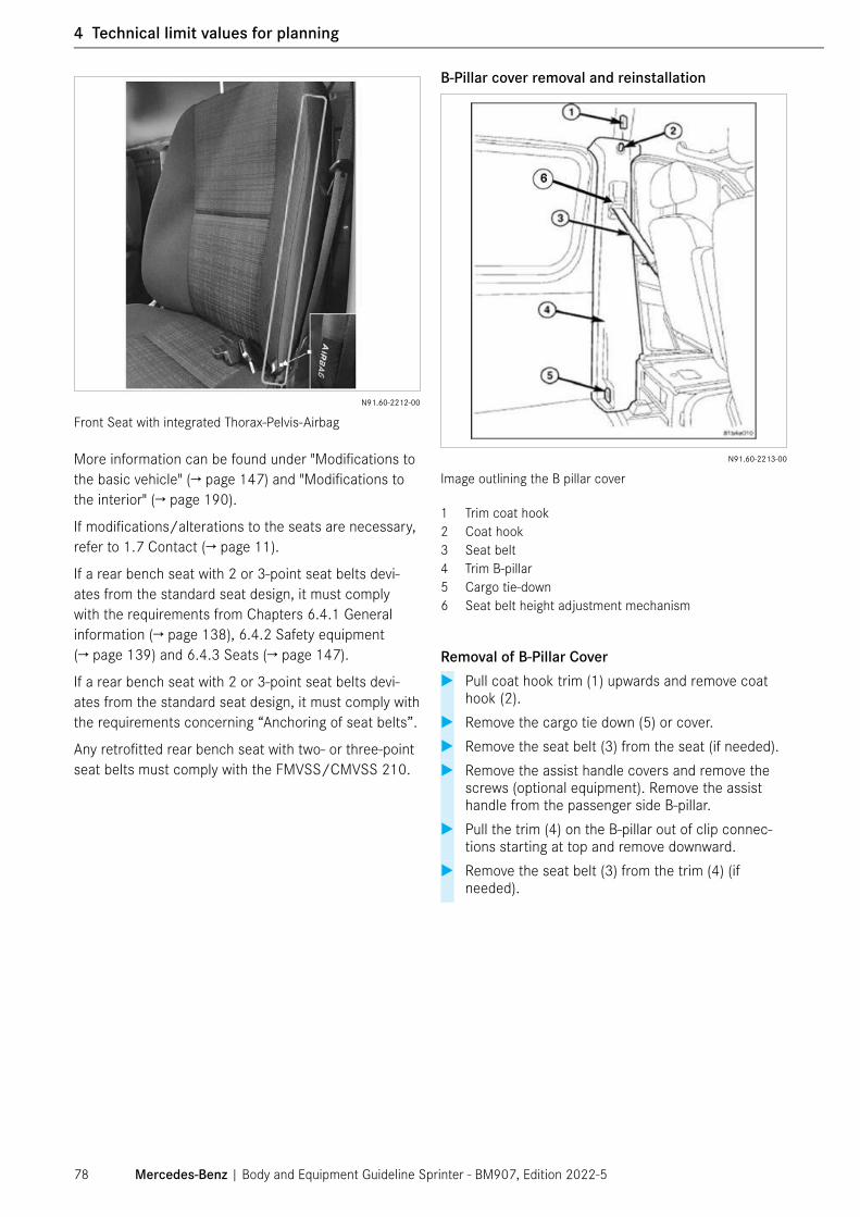
N91.60-2212-00
Front Seat with integrated Thorax-Pelvis-Airbag
More information can be found under "Modifications to the basic vehicle" (→ page 147) and "Modifications to the interior" (→ page 190).
If modifications/alterations to the seats are necessary, refer to 1.7 Contact (→ page 11).
If a rear bench seat with 2 or 3-point seat belts devi-ates from the standard seat design, it must comply with the requirements from Chapters 6.4.1 General information (→ page 138), 6.4.2 Safety equipment (→ page 139) and 6.4.3 Seats (→ page 147).
If a rear bench seat with 2 or 3-point seat belts devi-ates from the standard seat design, it must comply with the requirements concerning “Anchoring of seat belts”.
Any retrofitted rear bench seat with two- or three-point seat belts must comply with the FMVSS/CMVSS 210.
B-Pillar cover removal and reinstallation
N91.60-2213-00
Image outlining the B pillar cover
1 Trim coat hook2 Coat hook3 Seat belt4 Trim B-pillar5 Cargo tie-down6 Seat belt height adjustment mechanism
Removal of B-Pillar Cover � Pull coat hook trim (1) upwards and remove coat
hook (2). � Remove the cargo tie down (5) or cover. � Remove the seat belt (3) from the seat (if needed). � Remove the assist handle covers and remove the
screws (optional equipment). Remove the assist handle from the passenger side B-pillar.
� Pull the trim (4) on the B-pillar out of clip connec-tions starting at top and remove downward.
� Remove the seat belt (3) from the trim (4) (if needed).
Mercedes-Benz | Body and Equipment Guideline Sprinter - BM907, Edition 2022-578
1 General
4 Technical limit values for planning

Reinstallation of B-Pillar Cover � Pull the seat belt through the B-pillar cover. � IMPORTANT: Slide adjustment part of B-pillar cover
to top position before reinstallation. Insure that the seat belt height adjustment fits correctly into guide. Make sure that the door rubber seals are seated correctly.
N91.60-2214-00
Correct Alignment of B pillar cover
� Install the trim onto B-pillar and seat clips starting from bottom moving upwards. Install the seat belt to the seat. Install the cargo tie down or cover. Install the coat hook and seat trim fully. Bolt the end fitting to seat. Please refer to WIS or contact the local dealership for the most accurate torque values.
� Check seat belt and its height adjustment for proper functionality otherwise check step 2 again.
⑴ NOTE
If the seat is removed and reinstalled, please make sure that the seat is torqued to the correct value. The torque value is found on WIS or the local dealership.
Dampening Device on Height Adjustment (Partition Wall Only)
Sprinter Cargo Vans with partition walls (D50, D51, D53, D93 and D64) come with a (1) dampening device (left and right side) on top of the height adjustment mechanism. Make sure dampening device is fitted properly into height adjustment before reassembly.
⑴ NOTE
Dampening devices are not used on Sprinter Cab Chassis and Passenger Vans.
N91.60-2215-00
Left: Dampening Device Interior, Right: B-Pillar Cover Exterior
4.5.3 Seat Reference Point
The rear most Seat Reference Point of the front seats has the following coordinates:
X = 1111 mm/ 43.74 in
Z = 530 mm/ 20.87 in
Mercedes-Benz | Body and Equipment Guideline Sprinter - BM907, Edition 2022-5 79
4 Technical limit values for planning

4.6 Limit values for electrics/electronics
See Chapter 8 Electrics/electronics (→ page 233).
4.6.1 Vehicle position lamps and side marker lamps
Vehicle marker and clearance lamps are required by law on all vehicles with total width of 2032 mm/80 inch and above according to FMVSS/CMVSS standards.
4.6.2 Retrofitting electrical equipment
All electrical equipment fitted must be tested in accor-dance with FCC, CE and UL in the US, and with CSA and ULC in Canada.
⑴ NOTE
In isolated cases there may be some inconveniences.
4.6.3 Mobile communications systems
The maximum transmission output (PEAK) at the base of the antenna must not exceed the values from the local and federal laws on the maximum transmission output.
4.6.4 CAN bus
On no account should modifications be made to the CAN bus or the components connected to it.
The parameterizable special module (PSM/ MPM, code ED5) can be used to access individual types of data available on the CAN bus (→ page 296).
Mercedes-Benz | Body and Equipment Guideline Sprinter - BM907, Edition 2022-580
1 General
4 Technical limit values for planning

4.7 Limit values for additional assemblies
If additional assemblies (e.g. additional air conditioning compressors, pumps, etc.) are retrofitted, the following must be observed:
• The operation of vehicle components must not be adversely affected.
• The freedom of movement of vehicle parts must be guaranteed in all driving situations.
• Refer to option codes N62 and N63 (→ page 154).
4.8 Limit values for attachments
• A lateral protection is necessary when:
- the distance between the rear of the vehicle and the rear axle is more than 1000 mm/39 in.
- with the vehicle in its unladen condition, the distance between the roadway and the chas-sis or main parts of the body is greater than 550 mm/21 in across the entire width of the vehicle.
• The maximum permissible lifting load of a lifting platform is 500 kg/1102 lbs on a cargo van and 1000 kg/2205 lbs on chassis. Attachment as per section 6.6.6 Lifting platform (cargo liftgate) (→ page 169) is essential.
Attachment to the rear frame section:
On cab-chassis, the reinforcement of the trailer cou-pling in the left/ right rear longitudinal member for BR 907 is installed on the vehicle as standard. If this is not required, it must be deleted when the vehicle is ordered (code QW1). For cargo and passenger vans, the longi-tudinal member reinforcement must be ordered at the same time (code Q11).
Mercedes-Benz | Body and Equipment Guideline Sprinter - BM907, Edition 2022-5 81
4 Technical limit values for planning

4.9 Limit values for the box body
Box body
See Chapter 7 Design of bodies (→ page 180).
⑴ NOTE
The standard fuel filler cap must not be removed or covered with any "blocking" parts, see Chapter 6.2.5 Modifications to the cab (→ page 110).
⑴ NOTE
The minimum distance between the cab and a sepa-rate body must be > 50 mm/2 in.
⑴ NOTE
The minimum distance between the rear edge of the door and an integrated box body must be > 20 mm/0.8 in. Otherwise the rear edge of the door may come into contact with the box body in the event of an accident, and in extreme cases the door may be jammed.
⚠ WARNING
Do not attach side bars to the outside of the under-body. In the event of an accident (e.g. a side crash), these could bend updwards and block the door. This could mean that the rescue services are not able to open the door and could make recovery of the occu-pants more difficult.
N40.00-2053-00
min. 20 mm0.8 in
Minimum distance between rear edge of door and integrated box body
4.9.1 Assembly frame
Minimum section modulus required for assembly frame Wx1
Version Platform/box body2
Dumper/lifting work platform
Loading crane
All weight variants
17 cm3/1.04 in3
30 cm3/1.83 in3
40 cm3/2.44 in3
1 The minimum section modulus required for assembly frames applies for the material properties specified in the table below, and each individual longitudinal member of the assembly frame must have this section modulus.
2 Up to the maximum standard wheelbase; above that: +10%.
ⓘ Observe any differing specifications which may apply, see 7.5 Platform bodies (→ page 196) and 7.9 Dump trucks (→ page 200).
Material quality of specified assembly frames made of steel
Material Yield strength Tensile strength CR240LA 260-340 N/mm2
37700-49300 psi≥ 240 N/mm2
≥ 34800 psiS235JRG2 ≥ 235 N/mm2
≥ 34075 psi340-510 N/mm2
49300-73950 psi
Mercedes-Benz | Body and Equipment Guideline Sprinter - BM907, Edition 2022-582
1 General
4 Technical limit values for planning

General
⚠ WARNING
Tampering with or unauthorized installations in vehi-cle systems, safety-relevant components and driver assistance systems can impair the functioning of these systems. This may lead to the failure or mal-functioning of components or safety-relevant com-ponent parts. There is a risk of accident, personal injuries and death associated with such tampering and unauthorized installations!
Always have work on vehicle systems, safety-relevant components and driver assistance systems per-formed at a qualified workshop.
ⓘ Tampering with the vehicle, safety or driver assis-tance systems and safety-relevant components can invalidate the warranty or the general operating permit.
Mercedes-Benz | Body and Equipment Guideline Sprinter - BM907, Edition 2022-5 83
5 Damage prevention
5 Damage prevention

5.1 Brake hoses/cables and lines
⑴ NOTE
Any work carried out on the vehicle must comply with accident prevention regulations.
⑴ NOTE
Comply with all national directives and laws.
Cover plastic lines and brake hoses before carrying out any welding, drilling and grinding work or before work-ing with cutting disks. If necessary, the plastic lines and brake hoses should be removed.
Test each of the systems for chafing points, pressure loss and sealing after installing compressed-air lines and hydraulic lines.
No other lines may be attached to brake hoses and brake lines.
No other lines may be attached to brake lines, other than those installed as standard.
Lines must be protected from heat by means of insula-tion.
⚠ WARNING
Work carried out incorrectly on the brake hoses or cables may impair their function. This may lead to the failure of components or safety-relevant component parts. There is a risk of accident, personal injuries and death associated with such tampering and unau-thorized installations!
Have all work on brake hoses and cables carried out at a qualified specialist workshop.
Mercedes-Benz | Body and Equipment Guideline Sprinter - BM907, Edition 2022-584
1 General
5 Damage prevention

5.2 Welding work
⚠ WARNING
Welding in the vicinity of the restraint systems (air-bags, airbag sensors, airbag control unit, or seat belt components) can cause these systems to no longer function correctly.
If restraint systems no longer function correctly, the occupants may be unprotected in the event of an accident. There is a risk of accident, personal injuries and death if such restraint systems no longer func-tion correctly!
Welding is therefore not permitted in the vicinity of the restraint systems.
⚠ WARNING
Welding work that is not performed correctly could lead to failure of components relevant to safety. It would then not be possible to rule out the risk of an accident. There is a risk of accident, personal injuries and death if such work is carried out incorrectly!
Have welding work carried out by a qualified special-ist workshop.
⚠ WARNING
If handled incorrectly, welding work can result in a fire. There is a risk of accident, personal injuries and death if such work is carried out incorrectly!
Always comply with the legal requirements when performing welding work.
For this reason, the following safety measures must always be observed during any work involving welding:
• Welding work on the chassis may only be carried out by trained personnel.
• Before performing welding work, components which may contain flammable or explosive gases, e.g. fuel system (→ page 126), must be removed or pro-tected from sparking with a fire-resistant covering.
• Before performing welding work in the vicinity of the seat belts, airbag sensors or the airbag control unit, these components must be removed for the duration of the work. Important information about handling, transporting, and storing airbag units is available under 6.4 Interior (→ page 138).
• Before welding, cover springs and air suspension bellows to protect them from welding spatter. Do not touch springs with welding electrodes or welding tongs.
• Welding work is not permitted on assemblies such as the engine, transmission, axles.
• Disconnect the positive and negative terminals from the batteries and cover them.
• Connect the welder ground clamp directly to the part to be welded. Do not connect the ground clamp to assemblies such as the engine, transmission or axles.
• Do not touch electronic component housings (e.g. control units) and electric lines with the welding elec-trode or the ground clamp of the welder.
• Weld only with electrodes connected to the positive pole of a direct current source. Always weld from bottom to top.
• The maximum current may be 40 A per mm/ 1016 A per in of electrode diameter.
• Use only completely dry basic-coated electrodes (diameter 2.5 mm/0.098 in).
• Gas-shielded welding is permissible.
• Only use welding wires with a thickness of between 1 mm and 1.2 mm/0.04 in and 0.05 in.
• The yield and tensile strength of the welding material must be at least equal to that of the material to be welded.
• Plug welding is only permissible in the vertical webs of the longitudinal frame member.
• Weld seams must be ground down and reinforced with angular profiles to prevent notching from weld-ing penetration.
• Avoid welds in bends.
• There must be at least 15 mm/0.59 in between the weld seams and the outer edges.
ⓘ For further information on welding, see Chapter 3.9 Bolted and welded connections (→ page 46), Chapter 4.1.4 Parts which must not be welded (→ page 62), Chapter 6 Modifications to the basic vehicle (→ page 92), 6.2 Body in white/body (→ page 101) and the Mercedes-Benz Work-shop Information System (WIS).
Mercedes-Benz | Body and Equipment Guideline Sprinter - BM907, Edition 2022-5 85
5 Damage prevention

5.3 Anti-corrosion protection measures
Surface and anti-corrosion protection measures must be carried out on the affected areas after modifications and installation work have been performed on the vehicle.
⑴ NOTE
Only preservation agents tested and approved by Mercedes-Benz may be used for any anti-corrosion protection measures performed.
Planning measures
Anti-corrosion protection measures should be included in the planning and design stages by selecting suitable materials and designing components accordingly.
ⓘ A galvanic connection occurs if two different metals are brought into contact with each other through an electrolyte (e.g. air humidity). This causes electrochemical corrosion and the less noble of the two metals is damaged. The further apart the two metals are in the electrochemical potential series, the more intense electrochemical corrosion becomes. For this reason, electrochemical corrosion must be prevented by insulation or by treating the compo-nent parts accordingly, or it can be minimized by selecting suitable materials.
Preventing contact corrosion by means of electrical insulation
Preventing contact corrosion
1 Insulating washer2 Insulating sleeve
Contact corrosion can be prevented by using electrical insulation such as washers, sleeves or bushings.
Avoid welding work on inaccessible cavities.
Component design measures
Corrosion can be prevented by design measures, in particular the design of joints between different materi-als or the same kind of materials:
There is a risk of dirt or moisture accumulating in cor-ners, edges, creases and folds.
Design measures for counteracting corrosion can be implemented using inclined surfaces and drains, and by avoiding gaps in the joints between components.
Mercedes-Benz | Body and Equipment Guideline Sprinter - BM907, Edition 2022-586
1 General
5 Damage prevention

Gaps inherent in the design of weld joints and how to avoid them
Examples of types of weld joints A Correct (through-welded) B Incorrect (gap)
Coating measures
The vehicle can be protected against corrosion by applying protective coatings (e.g. galvanization, paint-ing or zinc coating applied by flame) (→ page 88).
After all work on the vehicle:
• Remove drilling chips
• Deburr sharp edges
• Remove any burned paintwork and thoroughly pre-pare surfaces for painting
• Prime and paint all unprotected parts
• Preserve cavities with wax preservative
• Carry out anti-corrosion protection measures on the underbody and frame parts
Mercedes-Benz | Body and Equipment Guideline Sprinter - BM907, Edition 2022-5 87
5 Damage prevention

5.4 Painting work/preservation work
⑴ NOTE
For drying the paint, the object temperature must be maximum 60 °C/140 °F and the drying time must be 30 min. Control units or other components can be damaged at higher temperatures.
Painting or preservation damaged by the upfitter must be repaired by the upfitter.
Observe the following points:
• Mercedes-Benz quality standards for initial painting and repair paintwork must be adhered to.
• Only materials tested and approved by Mercedes-Benz or equivalently suitable materials may be used for any painting or preservation work performed.
• The upfitter must observe the coat thickness for each individual coat as specified by the factory.
• Paint compatibility must be guaranteed when repainting.
ⓘ You can obtain information on the paint materials and coat thicknesses used at the factory and Mercedes-Benz paint numbers from any Mercedes-Benz Service Center.
Mask at least the following areas before painting:
• Disk brakes
• Brake hoses
• Transmission unit of the park brake
• Contact areas between disk wheels and wheel hubs
• Contact surfaces of wheel nuts/wheel bolts
• Brake fluid reservoir
• Breathers on transmissions, axles, etc.
• Sealing surfaces
• Windows
• Door locks
• Door catches in the hinges of the hinged rear door
• Door catches and opening limiters in the center guide rails
• Contact surfaces on the runner rails of sliding doors
• Moving parts of the sliding door carriage
• Airbags and seat belts
• Sensors of the Parking Packages (→ page 289)
• Active Brake Assist/Active Distance Assist (DISTRONIC-PLUS) (→ page 275)
• Blind Spot Assist sensors (→ page 277)
• Parking Package with 360° camera/Parking Package with reversing camera and sensors (→ page 289)
ⓘ Additional information on paintwork and preserva-tion can be found at
https://xentry.daimler.com
⚠ WARNING
Depending on the type and thickness, paints or films can cause attenuation of radar waves. This could lead to malfunction or failure of the system and may even cause the driver to lose control of the vehicle.
There is a risk of accident, personal injuries, and death if the system no longer functions correctly!
In repair cases, the existing coat of paint must be removed in such a way that the plastic cover is not damaged and the material thickness of the cover is not significantly reduced. The new paint coat structure must not exceed the following limits:
• A maximum of 2 color coats with a thickness of 15 μm plus 2 clearcoats may be applied.
• With metallic silver, only one coat with a thickness of 15 μm plus one coat in white 15 μm thick are permissible.
• The material thickness must be homogeneous in order to prevent distortion of the radar waves.
• Specified thickness for unpainted covers: 2.42 mm (0.095 in) front bumper/ 2.72 mm (0.107 in) rear bumper, each +/-0.1 mm (0.004 in), without paint
• Specified thickness for painted covers: 2.42 mm (0.095 in) front bumper/ 2.72 mm (0.107 in) rear bumper, each +0.1 mm/-0.2 mm (+0.004 in/ -0.008 in), without paint
Mercedes-Benz | Body and Equipment Guideline Sprinter - BM907, Edition 2022-588
1 General
5 Damage prevention

⑴ NOTE
For the subsequent painting of sensors, particular instructions in the relevant chapters on the sensors concerned must be observed.
• Active Brake Assist/Active Distance Assist (DIS TRONIC PLUS) sensor (→ page 275)
• Blind Spot Assist/Rear Cross Traffic Alert (RCTA) sensors (→ page 277)
• Parking Package with 360° camera/ Parking Package with reversing camera and sensors (→ page 289)
Sensors affected by paint
The “Parktronic”, “Collision Prevent Assist” and “Blind Spot Assist” sensors are located inside and behind the plastic bumpers of the vehicle. Modifications to the bumper exterior surface must comply with Mercedes-Benz standards. All integrated bumper sensors must be accounted for and considered when re-painting.
N88.20-2182-00
Front bumper sensors
N88.20-2183-00
Rear bumper sensors
1 In case of a step at the rear bumper, the sensors of the Parking Package are located in the step
LegendSensor Front
bumperRear bumper
A Parking Package 6 6B Active Brake Assist/
Active Distance Assist1 0
C Blind Spot Assist 0 2
Among other things, radar sensors are sensitive to:
• the thickness of the paint layers
• the relative permittivity of the paint
• the amount of conductive materials in the paint (e.g. metals, graphite, etc.)
Available Codes:
• Code CM0: painted metallic front and rear bumper
• Code C72: bumper front/rear primed
• Code CM9: primed side moldings
Recommended paint brands:
• Mercedes-Benz paints only
• USA: Glasurit, R-M, Standox, Spies Hecker, PPG
• Canada: Glasurit, R-M, Standox
Thickness limitation for metallic paint:
• max. 15 μm/5.9e-4 in of paint + 1 layer of clear coat
Thickness limitation non metallic paint:
• max. 15 μm/5.9e-4 in of paint + 2 layers of clear coat
Mercedes-Benz | Body and Equipment Guideline Sprinter - BM907, Edition 2022-5 89
5 Damage prevention

Locations of the sensor affecting areas on the front bumper:
N88.20-2184-00
Front view
Locations of the sensor affecting areas on the rear bumper:
N88.20-2185-00
Side view
Mercedes-Benz | Body and Equipment Guideline Sprinter - BM907, Edition 2022-590
1 General
5 Damage prevention

5.5 Storing and handing over the vehicle
Storage
To prevent any damage while vehicles are in storage, Mercedes-Benz recommends that they be serviced and stored in accordance with the manufacturer's specifi-cations (→ page 51).
Handover
To prevent damage to the vehicle or to repair any existing damage, Mercedes-Benz recommends that the vehicle be subjected to a full function check and a complete visual inspection before it is handed over.
Mercedes-Benz | Body and Equipment Guideline Sprinter - BM907, Edition 2022-5 91
5 Damage prevention

6.1 Suspension
6.1.1 General information on the suspension
No additional detachable parts may be mounted to the bolted connection points on the front axle.
⚠ WARNING
Modifications to suspension system components can result in impaired and unstable vehicle handling char-acteristics. This could cause the driver to lose control of the vehicle. There is a risk of accident, personal injuries and death if such systems no longer function correctly!
For this reason, no modifications whatsoever may be made to components of the suspension system.
Front axle
1 Bolting points on the front axleArrow Direction of travel
Mercedes-Benz | Body and Equipment Guideline Sprinter - BM907, Edition 2022-592
1 General
6 Modifications to the basic vehicle
6 Modifications to the basic vehicle

In the front axle area, the following should be noted:
• Specifications for steering in Chapter 4.2.6 Modifica-tions to the steering (→ page 71) must be com-plied with.
• Front transverse control arms: Changes to wheel alignment settings are not permitted.
• The front axle must not be changed in any way or used to mount additional assemblies and other mod-ifications.
• Rigid rear axle: Modifications are not permitted.
• Brakes: Modifications are not permitted.
• Devices, sensors, line installation for ESP®/ABS: Modifications are not permitted.
• New bolts must be used when installing the front axle. All bolts and threaded connections are to be tightened in accordance with the Mercedes-Benz tightening instructions. Information on this is avail-able from your Mercedes-Benz Service Center.
• VDI (The association of German Engineers) guideline 2862, in particular the section entitled “Threaded connections with special safety relevance”, must be implemented for all installations.
• Any shortening of the free grip lengths, conversion to a stretch shank or the use of bolts with a shorter free thread cannot be approved.
• The settling properties of threaded connections must be taken into account.
ⓘ Information is available from any Mercedes-Benz Service Center.
Additionally clamped component parts must exhibit an identical or higher strength than the previous clamped assembly.
The use of Mercedes-Benz tightening torques assumes coefficients of friction for the bolts in the tolerance range [= 0.08-0.14].
We recommend the use of standard Mercedes-Benz parts.
⑴ NOTE
In order to prevent tire wear, a change in the stan-dard wheel alignment values (camber, toe-in) at the front axle can be economical in the case of vehicles with increased curb weight due to upfit or equipment.
The information under 3.5 Dimensions and weights (→ page 37) on the vehicle curb weight and corresponding axle loads before and after body mounting work, "Checking wheel alignment" under 3.11.3 Work before handing over the modified vehicle (→ page 53), 3.12 Special equipment (→ page 55) and under 8.4.9 Interface overview (→ page 248) must be complied with.
Examples of this are recovery vehicles, fire-fighting vehicles, ambulances, semi-trailer tractors, workshop vehicles or motorhomes. For a planned change in the standard wheel alignment values, consulting a Mercedes-Benz partner is recommended. Based on the exact axle load conditions of the complete vehi-cle, the Mercedes-Benz partner can determine the ideal camber and toe-in values based on the work-shop documents stored in the Workshop Information System (WIS) (→ page 18).
The same applies to fully laden vehicles as it can be assumed that the maximum permissible axle loads are mainly marginally utilized here as well.
Mercedes-Benz | Body and Equipment Guideline Sprinter - BM907, Edition 2022-5 93
6 Modifications to the basic vehicle

6.1.2 Springs/shock absorbers/stabilizer bars
General
Several suspension variants are available from ex factory. A suitable suspension variant must be selected depending on the planned body, see 4.2 Limit values for the suspension (→ page 68)
Modifications to springs, shock absorbers and stabilizer bars can only be made in the combinations specified by Mercedes-Benz on the front and rear axle. Any modifi-cations over and above this must be evaluated by the relevant specialist department in each individual case. Please reach out to the Upfitter Portal for more infor-mation, refer to 1.7 Contact (→ page 11).
• We recommend the use of Mercedes-Benz genuine springs.
• Do not damage the surface or anti-corrosion protec-tion of the spring leaves during installation work.
• Before carrying out welding work, springs must be covered to protect them against welding spatter.
• Do not touch springs with welding electrodes or welding tongs.
• For modifications to springs, shock absorbers and stabilizers as a part of the Mercedes-Benz AG approved combinations on the front and rear axle on vehicles with front radar sensor, code BA3/ET4 – for more detailed explanation see Chapter 8.9.3 Active Brake Assist/Active Distance Assist (DISTRONIC PLUS) (→ page 275) – where applica-ble, the installation height of the front radar sensor must be compared against and adapted to the value entered there, depending on the type of modifica-tion involved. A service calibration of the front radar sensor must also be performed, as this modification also causes the driving axis to change.
⚠ WARNING
On no account should springs or shock absorbers be used if they are not standard Mercedes-Benz parts. Otherwise, the ESP and suspension system may no longer work correctly and could ultimately fail. This could cause the driver to lose control of the vehicle. There is a risk of accident, personal injuries and death if such systems no longer function correctly!
6.1.3 Brake system
⚠ WARNING
Work carried out incorrectly on the brake lines or brake hoses may impair their function. This may lead to the failure of components or safety-relevant component parts. This could cause the driver to lose control of the vehicle. There is a risk of accident, personal injuries and death if such systems no longer function correctly!
Work on brake lines or brake hoses may only be car-ried out by an authorized specialist workshop.
After completion of the work, check that the brake system is working correctly. We recommend that the brake system be inspected and approved by a technical inspection station.
If the routing has to be altered, avoid routing across sharp edges and through narrow cavities or near mov-ing components.
Hydraulic brake system � Hydraulic brake lines must be replaced with-
out additional connecting points using Mer-cedes-Benz-approved double-walled wrapped tubes of 4.75 mm x 0.7 mm/0.19 in x 0.03 in or fully assembled brake lines with connecting parts (genu-ine Mercedes-Benz replacement parts).
� Brake lines between the master brake cylinder and the hydraulic assembly must not be modified.
� The bending radius must be >18 mm/0.71 in. � Lines must only be shaped in a bending machine.
The cross-section must not be reduced. � Attach nuts (part no. 000 997 66 34)
or retaining screws (genuine Mercedes-Benz replacement parts) to the ends of lines and make a flange.
� The inside of the lines must be cleaned before installation.
� The brake fluid must be renewed regularly in accor-dance with the Mercedes-Benz specifications, but at least every two years. If necessary, renew the brake fluid before delivery to the customer.
� If the change interval of the brake fluid has been exceeded or if the age of the brake fluid is unknown, the brake fluid must be replaced.
� For routing between two components which move in relation to each other, a high-pressure-resistant flexible line (brake hose, genuine Mercedes-Benz brake components if possible) must be used. Make sure that the flexible lines are not placed under stress in any operating statuses and cannot chafe against other components.
Mercedes-Benz | Body and Equipment Guideline Sprinter - BM907, Edition 2022-594
1 General
6 Modifications to the basic vehicle

Installation of lines
⚠ WARNING
A sufficient distance must be maintained between brake lines and heat sources, sharp-edged or moving parts. Otherwise the brake system function could be impaired or the brake system could suffer total failure as a result of bubbles forming in the brake fluid or from chafe marks in the brake lines.
This could cause the driver to lose control of the vehi-cle. There is a risk of accident, personal injuries and death if such systems no longer function correctly!
Work on brake lines may only be carried out by an authorized specialist workshop.
• We recommend the use of genuine Mercedes-Benz brake line brackets for the attachment of the brake lines.
• The distance from bracket to bracket may not exceed a maximum of 500 mm/19.7 in. � The brake lines must be routed without kinks.
Routing lines along the brake hoses and brake lines
No other lines may be attached to brake hoses and brake lines.
Brake cable for the parking brake/modifying the length of the brake cable
� If a new brake cable is required for the parking brake, the new length of the cable must be deter-mined and a suitable new cable must be procured.
The brake cable retainers are moment-optimized; modi-fications are not permitted.
� The brake cables must be routed without kinks.
There must be no angle changes at the end pieces of the brake cable conduit.
No other lines may be attached to brake lines, other than those installed as standard.
Disk brakes
Cooling must not be impaired by attaching spoilers below the bumper, additional wheel trims or brake disk covers, etc.
For fully integrated bodies (7.14 Bodies on chassis with base (F28) (→ page 209), it must be ensured that the ventilation of the wheel wells, for cooling the brakes, exists to the same extend as in a corresponding BM 907 cargo van.
⚠ WARNING
On no account should modifications be made to the air inflow and air outflow of the brake system. Any modifications to the steering and the brake system may result in these systems malfunctioning and ultimately failing. This could cause the driver to lose control of the vehicle. There is a risk of accident, personal injuries and death if such systems no longer function correctly!
For this reason, make sure that there is a sufficient supply of cooling air at all times.
⚠ WARNING
Any modifications to brake components may result in these systems not functioning correctly and ultimately failing. This could cause the driver to lose control of the vehicle. There is a risk of accident, personal injuries and death if such systems no longer function correctly!
Modifications to brake system components are not permitted.
Mercedes-Benz | Body and Equipment Guideline Sprinter - BM907, Edition 2022-5 95
6 Modifications to the basic vehicle

Trailer Brake Control Preparation
The brake signal from the trailer control module is not directly hardwired to the 7-way trailer tow connector. Instead, the brake signal circuit is routed to the green 4-pin connector (pin 3) and from there a separate wire (pin 4) is routed to the trailer tow 7-way connector.
The green connector has power, ground, and brake signal input and output. Use the green connector for aftermarket trailer brake control.
⚠ WARNING
All cables for fitting a trailer brake controller should be routed using the green connector only. Maximum circuit warning may not be exceeded.
Pin Color Size Description1 Red/Yellow 2.5 mm2/0.004 in2, max 18 A 12 V Positive fused via F55/6 (max. 30 A) on
position 302 Brown 2.5 mm2/0.004 in2, max 18 A Ground (via Seatbase)3 Blue 0.75 mm2/0.001 in2, max 7 A Brake Signal from vehicle (via Trailer Control Unit
Code E40) Output Only4 Blue 2.5 mm2/0.004 in2, max 18 A Signal to 7-pin Connector at Trailer Hitch
Trailer brake control preparation driver seat box
Mercedes-Benz | Body and Equipment Guideline Sprinter - BM907, Edition 2022-596
1 General
6 Modifications to the basic vehicle

� Crimp pins to your wiring harness and attach to the plug connector making sure that your wires match the female connector pin layout as outlined:
N42.70-2022-00
12
34
Plug Connector (completed)
N42.70-2023-00
Fig. 1: Plug Connector housing
N42.70-2024-00
Fig. 2: Flag plug terminal
N42.70-2025-00
Fig. 3: Flag plug terminal
Figure Part Number Description1 A0395453528 Plug Connector 4-pin2 A0355457428 Flag plug terminal (male)
1.5 mm2 – 2.5 mm2/ 0.002 in2 – 0.004 in2
3 A0465454028 Flag plug terminal (male) 0.75 mm2 – 1.0 mm2/ 0.001 in2 – 0.002 in2
N42.70-2026-00
Electric Brakes
N42.70-2027-00
Front view and insertion end connectors
Mercedes-Benz | Body and Equipment Guideline Sprinter - BM907, Edition 2022-5 97
6 Modifications to the basic vehicle

6.1.4 Air suspension
For latest information on Mercedes-Benz air suspen-sion option, please refer to the most current Dealer Ordering Guide (DOG).
Please note that retrofitting an air suspension to the front axle is not permitted due to potential impairment to the front crash structure.
⚠ WARNING
If attachments are fitted to the front part of the frame, this modified crash structure may cause the airbag units to function incorrectly on vehicles with this equipment. This applies in particular to the retrofitting of air suspension to the front axle. For this reason, air suspension must not be retrofitted to the front axle.
⚠ WARNING
On no account should springs and shock absorbers be used if they do not correspond to the characteris-tics of standard parts, certified components or parts obtainable as special equipment. This applies in par-ticular to the retrofitting of air suspension systems. Otherwise, if the vehicle is fitted with ESP®, this system may no longer work correctly and could ulti-mately fail. This could cause the driver to lose control of the vehicle. There is a risk of accident!
6.1.5 Wheels/tires
ⓘ Only fit wheels or tires of a type and size approved by Mercedes-Benz for your vehicle model and observe the tire load capacity required for your vehicle and the tire speed rating.
In particular, comply with national regulations concerning the approval of tires. These regulations may define a specific type of tire for the vehicle or may forbid the use of certain tire types which are approved in other countries.
If you have other wheels or tires (not approved by Mercedes-Benz) fitted,
- wheel brakes and components of the suspension system may be damaged
- wheel and tire clearance can no longer be guaran-teed
- wheel brakes or components of the suspension system may no longer function correctly
The upfitter must ensure that:
• there is always sufficient space between the tire and the fender or wheel arch, even when snow or anti-skid chains are fitted and the suspension is fully compressed (also allowing for axle twist) (→ page 114) and that the relevant data in the 2D chassis drawings (offer drawings) (→ page 18) are observed.
• only wheels and tires approved by Mercedes-Benz are used (see vehicle registration document, 2D chassis drawings (offer drawings) (→ page 70) or the table below).
ⓘ More information about tires and wheels is avail-able from any Mercedes-Benz Service Center or under 3.12 Special equipment (→ page 55).
Mercedes-Benz | Body and Equipment Guideline Sprinter - BM907, Edition 2022-598
1 General
6 Modifications to the basic vehicle

Tire sizes
Gross mass Equipment Tire size Weight and speed ratingReference: 1500/2500 LT245/75 R16 120/116Q
See note
2 LT245/75 R16 120/116Q Reference: 3500/3500XD Super Single
1 (on front axle) 225/75 R16 C 121/120R (122L)1 (on rear axle) 285/65 R16 C 131R1 (as spare wheel) 225/75 R16 C 121/120R (122L)
Reference: 3500/3500XD/4500
LT215/85 R16 115/112Q 2 LT215/85 R16 115/112Q
1 With super single tires special equipment, code R9A2 All-wheel drive and rough-road code Z12C Commercial = lightweight truck tires
⑴ NOTE
We explicitly remind you that the use of appropriate tire sizes only applies in the context of the weight and speed ratings approved and intended for these.
For more information on the wheel size groups and recoding of control units, please refer to chapter 3.8 Tires (→ page 45).
The determined speed information of the vehicle is displayed in the instrument cluster and is important for controlling the driving assistance systems. The display accuracy of the speedometer and the odometer is gov-erned by law. The determination of the speed informa-tion depends on the tire size and the rolling circumfer-ence of the wheels and thus on their rim diameter. The rim diameter is always given in inches.
Therefore, the control units of the vehicle can be coded for the following wheel size groups:
Wheel size group Tires BR 907 Wheel size group 1: 195/75 R16C
205/75 R16C235/65 R16C235/60 R17C
Wheel size group 2: 225/75 R16CWheel size group 3: 225/75 R16C FA
285/65 R16C RA or205/75 R16C FA285/65 R16C RA
Wheel size group 4: 245/65 R17XL
ⓘ We recommend that you stay within one wheel size group when changing tires.
• This avoids the need to recode control units.• If you change the wheel size of your vehicle,
e.g. when changing wheels for winter operation, please check their assignment to the wheel size group. If the assignment to the wheel size group changes, you must have the control units of your vehicle recoded at a qualified specialist work-shop.
• The display accuracy of the speedometer and the odometer will otherwise be outside the legally prescribed tolerance. It can also deviate downwards, i.e. the current vehicle speed is then higher than the speed indicated by the speedom-eter.
• Driving assistance systems may be impaired in their function in the event of a deviation outside the tolerance range or may detect a fault and shut down.
Mercedes-Benz | Body and Equipment Guideline Sprinter - BM907, Edition 2022-5 99
6 Modifications to the basic vehicle

6.1.6 Spare wheel
As standard, the Sprinter BM 907 is equipped with a spare wheel and tire (code R87).
For dual rear wheel cab-chassis, a temporary mounting of the spare wheel on the longitudinal frame member is also avail able as a standard (code R60).
When mounting an aftermarket spare wheel, observe the following:
• Fixing is only permitted to frame or structural com-ponents with sufficient strength and rigidity.
• For mounting systems on the rear or roof of the vehicle, the maximum permissible loads in Chap-ter 6.2 Body in white/body (→ page 101) must be observed.
• Observe local and national requirements
• The spare wheel must be easily accessible and the fastening mechanism must be easy to operate.
• The spare wheel must be secured twice against falling off.
⑴ NOTE
The temporary attachment is not permitted for opera-tion of the vehicle on public roads, therefore the upfitter is responsible for attaching the spare wheel in a suitable, alternative position for this variant before driving on public road. Ensuring road safety in all operating situations of the vehicle is the responsibility of the upfitter.
Mercedes-Benz | Body and Equipment Guideline Sprinter - BM907, Edition 2022-5100
1 General
6 Modifications to the basic vehicle

6.2 Body in white/body
6.2.1 General information on the body in white/body
Modifications to the body must not have a negative effect on the function nor on the strength of the vehicle equipment, controls, or load-bearing parts.
When converting vehicles and mounting bodies, it is not permissible to make modifications that affect the function or freedom of movement of chassis parts (e.g. during maintenance and inspection work) or accessibility to these parts.
Observe the following:
• Wheelbase modifications are not permitted on all Sprinter vehicles.
• The Tire Pressure Management System (TPMS) may malfunction if modifications are made in the immediate vicinity of the antennas and wheels (→ page 288).
• On no account should modifications be made to the structure of the longitudinal members and cross members from the front to 1 m (3.28 ft) behind the B-pillar because this can disrupt the structure neces-sary for passive safety. See Chapter 4.3.1 Modifica-tions to the body in white(→ page 72).
⑴ NOTE
Longitudinal frame members are crash-relevant structures.
If work is performed in these areas, the structure necessary for passive safety can be disrupted.
Ex-factory holes on the longitudinal frame member are not suitable for securing attachments, bodies, equipment, and conversions; there is a risk of dam-age to the frame.
• The clearance for the fuel filler neck, fuel tank and fuel lines must be maintained (→ page 126).
• Changes to the rigidity in the area of the filler neck can result in leakage of the fuel tank after a crash.
• Avoid sharp-edged corners.
• It is not permissible to make cuts in the A-pillar or B-pillar, including the associated roof bows.
• It is not permissible to make cuts in the C-pillar or D-pillar, including the associated roof bows.
• If the roof skin and roof bows are removed and it is not possible to install a continuous sectional frame,
then additional roof bows must be fitted. The overall design of the side, front and rear roof structure must be retained, and sufficient rigidity of the modified parts must be guaranteed. 6.2.10 Cutting the cab roof and B-pillar roof bow (→ page 123))
• Modifications in the roof area and to the rear portal are permitted only when adequate equivalent rigidity can be provided. Modifications in these areas must be coordinated with Mercedes-Benz. Upon comple-tion of all work on the vehicle, you must comply with the specified anti-corrosion protection measures (→ page 86).
• Mounting consoles (plug welds) must be used to attach additional equipment to the longitudinal frame members and cross members. These require a review by Mercedes-Benz. Please reach out via technical inquiry on www.UpfitterPortal.com.
• Trailer connections must be checked for correct operation.
• If a trailer hitch is installed, the necessary reinforce-ments must be present.
• If bodies are mounted on basic vehicle “chas-sis”, a fuel level sensor shield may be necessary depending on the body type see 6.3.1 Fuel system (→ page 126).
As part of the eXpertUpfitter program please refer to www.UpfitterPortal.com.
⑴ NOTE
The factory-fitted wooden or plastic floors, including the integrated tie-down eyes, represent a certified as-built configuration in the cargo van.
If the wooden or plastic floor is removed from these vehicles, it must be ensured that an equivalent substi-tute is restored for securing loads in accordance with the international requirements of ISO 27956.
Mercedes-Benz | Body and Equipment Guideline Sprinter - BM907, Edition 2022-5 101
6 Modifications to the basic vehicle

Section dimensions of longitudinal frame members
Dimensions of the upper flange and lower flange
1 Upper flange2 Lower flange
Permissible gross mass [t] a b c d e f3500, 3500XD, 4500 Chassis
3 mm/ 0.12 in
3 mm/ 0.12 in
70 mm/ 2.76 in
80 mm/ 3.15 in
120 mm/ 4.72 in1001 mm/3.93 in
126 mm/4.96 in
1500, 2500 Cargo van/passenger van
- 1.5 mm/ 0.06 in
70 mm/ 2.76 in
- 120 mm/ 4.72 in851 mm/3.35 in
93 mm/ 3.66 in
3500, 3500XD, 4500 Cargo van/passenger van
- 3 mm/ 0.12 in
70 mm/ 2.76 in
- 120 mm/ 4.72 in1001 mm/3.93 in
118 mm/ 4.65 in
1 In the area of the rear axle
Mercedes-Benz | Body and Equipment Guideline Sprinter - BM907, Edition 2022-5102
1 General
6 Modifications to the basic vehicle

1500, 2500 longitudinal frame member
h h1 h h2
N31.00-2174-00
Dimensions of the lower flange of the longitudinal frame member
h 120 mm/4.72 inh1 85 mm/3.35 inh2 110 mm/4.33 in
3500, 3500XD, 4500 longitudinal frame member
h h1
N31.00-2175-00
Dimensions of the lower flange of the longitudinal frame member
h 120 mm/4.72 inh1 100 mm/3.94 in
Welding work on the body in white
Welding work may only be performed by trained per-sonnel.
ⓘ For additional information on welding work, see Chapters 3 Planning of bodies (→ page 29), 5 Damage prevention (→ page 83) and 6.2.1 General information on the body in white/body (→ page 101) and the Mercedes-Benz Workshop Information System (WIS).
⑴ NOTE
On no account should welding work be carried out on the upper and lower flanges of the chassis frame (including the front end longitudinal members).
Plug welding is only permissible in the vertical webs of the longitudinal frame member.
Do not perform any welding work in bends.
⚠ WARNING
Drilling or welding in the vicinity of the restraint sys-tems (airbag or belts) can cause these systems to no longer function correctly.
If restraint systems no longer function correctly, the occupants may be unprotected in the event of an accident. There is a risk of accident, personal injuries and death if such restraint systems no longer func-tion correctly!
Drilling or welding is therefore not permitted in the vicinity of the restraint systems.
The handling, transportation and storage of airbag units are subject to the hazardous materials law regulated by FMCSA under 49 CFR Part 173 in the US, and to the Transportation of Dangerous Goods Act (Transport Canada) in Canada.
Mercedes-Benz | Body and Equipment Guideline Sprinter - BM907, Edition 2022-5 103
6 Modifications to the basic vehicle

Drilling work on the frame
⑴ NOTE
Existing holes in the longitudinal frame member result from the production process and must not be used. As part of the eXpertUpfitter program, possi-ble deviations can be evaluated with the responsible department.
Drilling in the longitudinal member web is only possi-ble in accordance with the following illustration and if spacer bushings welded to the longitudinal member are used. The attachment of implements and body parts must be calculated according to their load. An evalu-tion with the responsible department is necessary. As part of the eXpertUpfitter program please refer to www.UpfitterPortal.com.
Drilling work on the longitudinal frame members (at the rear end only)
1 Chassis frame2 Spacer bushingsa Distance of at least 20% of the frame heightb Distance between drill holes at least 50 mm/1.97 in
� After drilling holes, deburr and ream all holes. � Remove chips from the frame and apply cavity
sealant through the holes � Restore the anti-corrosion protection in accordance
with Mercedes-Benz guidelines.
⑴ NOTE
Upon completion of all work on the vehicle, you must comply with the specified anti-corrosion protection measures (→ page 86).
Drilling must not take place:
• On the upper and lower flanges of the frame (except if drill holes are at the rear end of the frame).
• Areas with a load-bearing function for the rear axle or parts fastened to the frame
• At load application points (e.g. spring brackets, holders etc.)
• Any weakening of the system is not permissible!
Mercedes-Benz | Body and Equipment Guideline Sprinter - BM907, Edition 2022-5104
1 General
6 Modifications to the basic vehicle

⚠ WARNING
Drilling in the vicinity of the restraint systems (airbag or belts) can cause these systems to no longer func-tion correctly.
If restraint systems no longer function correctly, the occupants may be unprotected in the event of an accident. There is a risk of accident, personal injuries and death if such restraint systems no longer func-tion correctly!
Drilling is therefore not permitted in the vicinity of the restraint systems.
The handling, transportation and storage of airbag units are subject to the hazardous materials law regulated by FMCSA under 49 CFR Part 173 in the US, and to the Transportation of Dangerous Goods Act (Transport Canada) in Canada.
6.2.2 Attachment to the frame
Attachment to the front frame section
On no account should modifications (holes, cuts, etc.) be made to the structure of the longitudinal members and crossmembers from the front through to 1 m/ 39.4 in" behind the B-pillar (see picture), or to the mountings of implements, brackets, components etc. in the area of the front-end assembly and front axle, because this can disrupt the structure necessary for passive safety.
N31.00-2260-00
Longitudinal member and crossmember structure in the area of the front-end assembly (viewed from below)
Arrow Direction of travel
⚠ WARNING
If attachments are mounted on the front frame sec-tion, the function of the forward crash structure and the airbag units may be impaired.
Attachments are therefore only permitted to be mounted on the front section of the frame after evalu-ation with the responsible department. As part of the eXpertUpfitter program please refer to www.UpfitterPortal.com.
⑴ NOTE
The modifications must not hinder possible repair work on the standard vehicle.
Mercedes-Benz | Body and Equipment Guideline Sprinter - BM907, Edition 2022-5 105
6 Modifications to the basic vehicle

Attachment to the rear frame section
The reinforcement of the trailer hitch (Q11) in the rear longitudinal member on the left/right is available as standard for model designation 907 and can not be deleted.
If this special equipment is not included, attachment of a trailer coupling is not permissible (see warning notice).
The attachment of additional assemblies or bodies to the rear frame section must be analogous to the attachment of the trailer hitch available as special equipment.
For the application of greater forces and moments, an additional support on the end frame crossmember is required.
End crossmember on longitudinal frame member (right)
a Attachment of mounting plate to longitudinal frame member
b Lower flange of longitudinal frame memberc Frame end crossmemberd Mounting plate for trailer hitch
⚠ WARNING
Risk of accident due to the unapproved attachment of a trailer hitch!
If a trailer hitch is retrofitted and you attach a trailer hitch or other components, the longitudinal frame member will be weakened and can break. In this case, the trailer can detach from the vehicle.
There is a risk of accident, personal injuries and death as a result of the improper attachment of a trailer hitch!
Only retrofit a trailer hitch if this is permissible.
Inside view of end crossmember on right longitudinal frame member
a Attachment of mounting plate to longitudinal frame member
b Lower flange of longitudinal frame memberc Frame end crossmemberd Mounting plate for trailer hitch
An evalution with the responsible department is neces-sary. As part of the eXpertUpfitter program please refer to www.UpfitterPortal.com.
Attachment by means of body consoles
All the factory-installed body consoles must be used for attaching bodies to the vehicle frame. The bodies must rest on the body consoles and may also rest on the longitudinal frame members. Mercedes-Benz recommends that the body should not rest on the end crossmember. Additional information can be found under 7.1.4 Attachment to the chassis bed (→ page 183).
Mercedes-Benz | Body and Equipment Guideline Sprinter - BM907, Edition 2022-5106
1 General
6 Modifications to the basic vehicle

6.2.3 Material for the chassis frame
If the frame is extended, the material of the extension element must have the same quality and dimensions as the standard chassis frame (only permissible in the underfloor area).
⑴ NOTE
Lengthening in the area of the front-end assembly is not permissible (impact load path)!
Material Yield strength Tensile strength CR240LA 260-340 N/mm2
37700-49300 psi≥ 240 N/mm2
≥ 34800 psiS235JRG2 ≥ 235 N/mm2
≥ 34075 psi340-510 N/mm2
49300-73950 psi
Material specifications should comply with the DIN Standard MBN11251.
6.2.4 Overhang extension
Modifications to the vehicle overhang are possible and must always take the permissible axle loads and the minimum front axle load into account.
For crew, passenger, and cargo vans, an overhang extension is only permitted to upfitters in the eXpertUp-fitter program for whom the possible deviations can be evaluated by the responsible department.
Frame extensions are possible for cab-chassis when the following requirements are met:
� A frame extension with enforcement is to be exe-cuted according to the following schematic diagram
� Fastening (in X-direction) a frame extension to the mounting brackets at the end of the frame is not permitted.
� It is recommended to select the following codes for bodies when a frame extension is planned:
� Frame end without mounting brackets, code Q74 � Omission of end crossmember, code Q72 � For frame extension of over 350 mm/14 in, an
additional crossmember must be installed. � Any additional frame crossmembers must have the
same functionality as standard crossmembers. � Standard body consoles must be used at the end of
the frame. � The interval between the body consoles must not
exceed 500 mm/20 in. � If the overhang is lengthened, the new overhang
dimension and the distance of the rear end radar from the rear axle must be entered in both rear radars (BSM) by new SCN coding with O-codes.
� If the frame overhang is extended, the function of the Trailer Stability Assist (TSA) and the permissible towing capacity specified in the vehicle registration document must be checked and, if necessary, be reduced or even omitted, see 4.1.3 Vehicle dimen-sions (→ page 59).
� On no account may the original positions of the radar sensors in the bumpers be changed. This adjustment must be performed by a Mer cedes-Benz Service Center. More information is given in Chapter 8.9.4 Blind Spot Assist/Rear Cross Traffic Alert (RCTA)/Exit Warning (→ page 277).
� The frame overhang must be reinforced accordingly. � Make sure that you do not exceed the permissible
axle loads. Ensure that you maintain the position of the center of gravity within the permissible limits.
� After the upfit, the upfitter must determine the vehicle's centers of gravity according to the explanations in Chapter 9.1 Center of gravity (→ page 309).
• The minimum front axle load must be complied with in all load states (→ page 58).
You can obtain more information from the department responsible 1.7 Contact (→ page 11).
Mercedes-Benz | Body and Equipment Guideline Sprinter - BM907, Edition 2022-5 107
6 Modifications to the basic vehicle

Maximum overhang lengths
If you stay within the limits of the following overhang lengths and the maximum rear axle load, the original towing capacity still applies and ESP® operation is not affected when the trailer coupling point is not relo-cated. If the trailer coupling point is to be relocated, Chapter 4.1.3 Vehicle dimensions (→ page 59) must be observed.
Maximum overhang lengths
Wheelbase I Overhang length X
3665 mm/144 in 1850 mm/73 in4325 mm/170 in 2200 mm/87 in
ⓘ The vehicle overhang length is part of the total overhang from the rear axle, including the frame overhang extension as well as the body and attach-ments.
N60.00-2215-00
Maximum overhang lengths (using a lifting work platform as illustration)
X Vehicle overhang
If the lateral protection needs to be repositioned due to the overhang extension, the attachment must be the same as that of the original vehicle (→ page 152).The illustration depicts the implementation of a frame extension for an overhang extension.
The effects on permissible towing capacity and functioning of the Trailer Stability Assist (TSA) must be checked; see Chapter 4.1.3 Vehicle dimensions (→ page 59)
Mercedes-Benz | Body and Equipment Guideline Sprinter - BM907, Edition 2022-5108
1 General
6 Modifications to the basic vehicle

Frame extension with overhang extension
1 Chassis frame longitudinal member2 Frame extension3 Outer reinforcement4 Inner reinforcement
(wall thickness 11030 lbs: 3 mm/0.12 in)5 Body support extension6 Chassis frame extension
(wall thickness 11030 lbs: 3 mm/0.12 in)7 Reinforcement plate min. 2 mm/0.08 in8 Spacer bushing, tube 24 x 4
M steel or St 35 NBK
A longitudinal member reinforcement (see 7 and 8) is required when attachments are fitted (e.g. trailer cou-pling or underride guard).
a Bore holes, 3665 mm/144 in wheelbaseb Bore holes, 4325 mm/170 in wheelbasec 350 mm/13.8 in (3665 mm/144 in wheelbase),
300 mm/11.8 in (4325 mm/170 in wheelbase)d Dimension defined by upfitter
⑴ NOTE
Comply with all applicable FMVSS/CMVSS guidelines and regulations.
⑴ NOTE
Upon completion of all work on the vehicle, observe the specified anti-corrosion protection measures (→ page 86).
Mercedes-Benz | Body and Equipment Guideline Sprinter - BM907, Edition 2022-5 109
6 Modifications to the basic vehicle

6.2.5 Modifications to the cab
For modifications on the cab, an evalution with the responsible department is necessary. As part of the eXpertUpfitter program please refer to www.UpfitterPortal.com.
Rigidly installed equipment or conversions must satisfy the requirements of legislation relating to head-on impact as specified in FMVSS/CMVSS 201.
⚠ WARNING
Modifications to the cab must not impair the function of any components relevant to safety (e.g. airbag units, sensors, pedals, gearshift lever, lines or others). This may lead to the failure of components or safe-ty-relevant component parts.
There is a risk of accident, personal injuries and death if such systems no longer function correctly!
⑴ NOTE
If the fuel filler cap is removed or parts are attached to the fuel filler cap, blocking may occur in the event of an accident. Because of this, the protrusion space in the B-pillar may no longer function correctly. On no account should the cap be covered with paneling parts, and "blocking" parts must never be mounted on the B-pillar.
The strength and rigidity of the cab structure must not be impaired.
The intake of air into the engine must not be hindered.
Modifications to the cab will cause a change in the cen-ter of gravity. The permissible center of gravity limits and axle loads must be maintained.
⑴ NOTE
Upon completion of all work on the vehicle, you must comply with the specified anti-corrosion protection measures (→ page 86).
Changes to cab roof, general
⚠ WARNING
If aftermarket modifications are made to the head-liner or the roof panel between the A-pillar and the B-pillar, the deployment of the window airbag may no longer function correctly.
If window airbags no longer function correctly, the occupants may be unprotected in the event of an accident. There is a risk of accident, personal injuries and death if such systems no longer function cor-rectly!
On no account should any subsequent modifications be made to the headliner or the roof panel between the A-pillar and the B-pillar if the vehicle is equipped with window airbags.
Modifications to the cab roof (e.g. lowering the roof height) may only be undertaken after consulting the department responsible 1.7 Contact (→ page 11) or as described under 6.2.10 Cutting the cab roof and B-pillar roof bow (→ page 123).
Plastic roofs are suitable for the installation of roof hatches only to a limited extent.
The roof load-bearing capacity is limited (→ page 73).
⑴ NOTE
Roof bows or supporting parts may not be removed or modified without being replaced.
ⓘ You will find information on over-cab attachments and wind deflectors in the chapter "Attachments" (→ page 157).
Observe the permissible center of gravity; the permissi-ble axle loads must be maintained.
Mercedes-Benz | Body and Equipment Guideline Sprinter - BM907, Edition 2022-5110
1 General
6 Modifications to the basic vehicle

Modifying the cab rear panel
If it is necessary to cut through the cab rear panel, it is possible to do this in connection with a continuous surrounding frame. The equivalent rigidity of the frame must be at least equal to the original rigidity.
Partitions may be totally or partially removed. Also observe 7.4 Modifications to closed cargo vans (→ page 192).
The statutory standards (ISO, etc.) and the relevant licensing regulations must be complied with.
⚠ WARNING
If aftermarket modifications are made to the head-liner or the roof panel between the A-pillar and the B-pillar, the deployment of the window airbag may no longer function correctly.
If window airbags no longer function correctly, the occupants may be unprotected in the event of an accident. There is a risk of accident, personal injuries and death if such systems no longer function cor-rectly!
On no account should any subsequent modifications be made to the headliner or the roof panel between the A-pillar and the B-pillar if the vehicle is equipped with window airbags.
6.2.6 Side wall, windows, doors and flaps
Side wall
If modifications are made to the side wall of the cargo van or the passenger van, the rigidity of the modified body must be equal to that of the basic vehicle.
The front of the roof frame, the roof bow at the B-pillar, and the A-pillar and the B-pillar themselves must be retained and their function may not be impaired in any way.
Refer to 8.9.2 Crosswind Assist (→ page 273) for modifications to the projected lateral face.
An evalution with the responsible department is neces-sary. As part of the eXpertUpfitter program please refer to www.UpfitterPortal.com.
⑴ NOTE
Upon completion of all work on the vehicle, you must comply with the specified anti-corrosion protection measures (→ page 86).
Windows � Windows must be inserted with a stable frame. � The frame must then be joined by a non-positive
attachment to other body elements. � If modifications need to be carried out to the
supporting structure of the basic vehicle (pillars, reinforcements, attachment of roof bows) in order to retrofit windows (panoramic glazing), the rigidity of the modified body must be equal to that of the basic vehicle.
If the upfitter installs window panes on his or her own, the code W94 "Window openings without glass " can be used.
Laminated glass is regulated under FMVSS/CMVSS 205 Glazing Materials.
ⓘ Additional information on modifications to the side wall can be found under 6.6.4 Shelf systems/vehi-cle interior installations (→ page 158).
⑴ NOTE
It is not permissible to install panoramic glazing on a cargo van basic vehicle by cutting out the stamped window shape without ensuring equivalent rigidity. Otherwise there is a risk of damage to the side wall.
Mercedes-Benz | Body and Equipment Guideline Sprinter - BM907, Edition 2022-5 111
6 Modifications to the basic vehicle

Example for cargo van/passenger van side wall body in white structure and glass area
ⓘ For modifications which involve cutting out the stamped window shape and adding reinforcements, an evalution with the responsible department is necessary. As part of the eXpertUpfitter program please refer to www.UpfitterPortal.com.
ⓘ A design proposal with reinforcement measures can be provided by the department responsible 1.7 Contact (→ page 11). Please also observe 7.4 Modifications to closed cargo vans (→ page 192).
If the upfitter is going to install its own windows in the hinged rear doors, the following should be noted in connection with code W78 "Windshield wiper on hinged rear door":
• To guarantee proper functioning of the rear window wipers, the geometry of the windows supplied by the upfitter must match that of the windows available as standard equipment.
• The wiper blades of the rear window wipers must make contact with the windows across the entire swept area.
• The rear windows must be 3 mm/0.1 in thick.
• The rear windows must not protrude above the door paneling.
Doors and flaps
If modifications need to be carried out to the support-ing structure of the basic vehicle (frame crossmem-bers, pillars, reinforcements, attachment of roof bows) in order to retrofit doors, the rigidity of the modified body must be equal to that of the basic vehicle.
The upfitter must comply with all applicable FMVSS/ CMVSS and warranty responsibility for those modifica-tions. The rigidity of the modified body must be equal to that of the basic vehicle.
The trigger sensor of the occupant protection systems is located in the door body on vehicles with window airbags or thorax/pelvis side airbags. On no account should modifications be made to the door body (see illustration).
N91.60-2202-00
1
Door body with sensor system
1 Pressure sensor (trigger sensor of the occupant protection systems)
Seats in the living and passenger compartment must be directly accessible from the outside by a door or from the cab.
It must be possible to open locked doors quickly and easily from the inside.
The doors must open wide enough and the door entrances must be shaped in such a way as to enable persons to get in and out of the vehicle safely and comfortably.
Mercedes-Benz | Body and Equipment Guideline Sprinter - BM907, Edition 2022-5112
1 General
6 Modifications to the basic vehicle

The maximum permitted height of the bottom step above the roadway is 400 mm/15.75 in.
Installations must allow a sufficient clearance from the inside handles in all positions (anti-pinch protection).
Upon completion of all work on the vehicle, you must comply with the specified anti-corrosion protection measures (→ page 86).
⑴ NOTE
For all versions of vehicle doors (front doors, sliding doors, hinged rear doors), modifications to the lock-ing system, in the immediate vicinity of the door and in the area of pillars/crossmembers must be avoided.
The attachment of additional mechanical locks (e.g. latch locks/"slam-locks") is not permitted.
Sliding door to load compartment
The system for the load compartment sliding door was designed for a maximum door weight of 143.3 lbs./ 65 kg. Modifications must not cause this weight to be exceeded.
The ex-factory weight of the load compartment sliding door for each vehicle model and wheelbase is listed in the table. The delta corresponds to the maximum permissible additional weight on the sliding door to the load compartment.
Maximum permissible additional weight(total weight of load compartment sliding door - basic equipment = additional weight)Roof heightLH1 143.30 - 108.03 = 35.27 lbs,
65 - 49 = 16 kgLH2 143.30 - 119.05 = 24.25 lbs,
65 - 54 = 11 kg
For the special equipment items with the codes listed below, the following weights must be added to the basic equipment (see table).
If items of equipment are removed, they must be taken into account in the weight calculation.
• Electric closing assist (code T50/T51): 6.61 lbs./ 3 kg
• Electric operation (code T55/T56): 13.23 lbs./ 6 kg (including code T50/T51)
• Window at front of sliding door (code W17): 8.82 lbs./ 4 kg
• Laminated glass (code W17+F43): 15.43 lbs./ 7 kg
• Sliding window in side wall (code W18): 14.33 lbs./ 6.5 kg
• Luxury door trim (code V21): 4.41 lbs./ 2 kg (only for RWD A2LH2 RE)
• Speakers (code EL9): 4.41 lbs./ 2 kg
Hinged rear doors
The system for the hinged rear doors was designed for a maximum weight of 83.78 lbs./ 38 kg per hinged rear door, and this must not be exceeded due to modi-fications.
The ex-factory weight of the hinged rear door for each vehicle model and roof height is listed in the table. The delta weight, including special equipment, corresponds to the maximum permissible additional weight on the hinged rear door.
Maximum permissible additional weight(total weight of rear doors - basic equipment = additional weight)Roof height
Hinged rear doorLeft [lbs], [kg] Right [lbs], [kg]
LH1 83.78 - 60.63 = 23.15,38 - 27.5 = 10.5
83.78 - 57.32 = 26.46,38 - 26 = 12
LH2 83.78 - 66.14 = 17.64,38 - 30 = 8
83.78 - 61.73 = 22.05,38 - 28 = 10
For the special equipment items with the codes listed below, the following weights must be added to the basic equipment (see table).
If items of equipment are removed, they must be taken into account in the weight calculation.
• Window (code W61/W78): 4.41 lbs./ 2 kg
• Luxury interior trim (code V21): 3.31 lbs./ 1.5 kg
• Window washer system (code W78): 2.20 lbs./ 1 kg
Mercedes-Benz | Body and Equipment Guideline Sprinter - BM907, Edition 2022-5 113
6 Modifications to the basic vehicle

⚠ WARNING
Modifications to
• door kinematics
• guidance systems (rails, sliding carriages etc.)
• locking systems (closing assists, anti-entrapment strips, locks, arresters etc.)
• end stop systems (buffers etc.)
• bodyshell structure
may result in the door opening unintentionally.
There is a risk of accident!
No modifications may be made to any of these sys-tems.
Furthermore, care must be taken to ensure an extensive connection and CoG distribution at the doors.
The upfitter is responsible for his/her conversions and modifications on the vehicle.
⑴ NOTE
When selecting a carrier system for bicycles or other transported items on the rear end, observe the spec-ified restrictions on additional masses on the hinged rear doors. The mass of the carrier system including the transported items, e.g. bicycles, must be taken into account.
If the additional mass restriction cannot be complied with, it is recommended to use a suitable carrier system supported by or attached to the ball head of the trailer coupling.
Rear portal
Any modifications to the rear door opening including the roof area are only permitted in exceptional cases and an UIS must be requested online via the Upfit ter Portal (→ page 18).
Upon completion of all work on the vehicle, you must comply with the specified anti-corrosion protection measures (→ page 86).
Rear door opening and roof area
Do not modify the rear door opening including the roof area.
Rear door opening
1 Non modifying areas
6.2.7 Fenders and wheel wells
Ensure that there is sufficient space between the tire and the fender or wheel well even with snow or anti-skid chains fitted and the suspension completely compressed (allowing for axle twist). Pay attention to the dimensional data in the 2D chassis drawings (offer drawings).
⚠ WARNING
If modifications are made to the mountings of seats on the wheel well or to lowered wheel wells, the vehi-cle (e.g. the wheel well and tires) could be damaged. There is a risk of accident, personal injuries and death if such systems no longer function correctly!
On no account may seats be mounted on the wheel well.
Upon completion of all work on the vehicle, you must comply with the specified anti-corrosion protection measures (→ page 86).
Reductions in the width of the wheel wells are not permitted.
Mercedes-Benz | Body and Equipment Guideline Sprinter - BM907, Edition 2022-5114
1 General
6 Modifications to the basic vehicle

Wheel wells (side wall and substructure scope)
It is possible to lower the wheel wells as long as the following preconditions and limit values are complied with:
• No components or sharp edges (e.g. folded seams or edges) may protrude into the wheel well.
• The maximum permitted lowering dimension may not be exceeded by any component in the wheel well.
• Unrestricted use of snow chains is not possible: The entry "Use of snow chains subject to limitations" must be entered in the vehicle documents.
Wheel well lowering/clearance requirement
a
1
N40.10-2299-00
Clearance requirement
1 Contour of standard cargo van wheel wella Clearance requirement
If the clearance is inadequate, the fitting of snow and anti-skid chains is prohibited.
Permissible gross mass Tires Dimension aReference: 1500/2500(single)
LT245/75 R16 120/116Q 260 mm/10.24 in
Reference: 3500, 3500XD(super single)
285/65 R16 131R 260 mm/10.24 in
Reference: 3500, 3500XD/4500(twin tires)
LT215/85 R16 115/112Q 210 mm/8.23 in
Reference: 1500/2500 (all-wheel drive)
LT245/75 R16 120/116Q 200 mm/7.87 in
Reference: 3500, 3500XD/4500 (all-wheel drive)
LT215/85 R16 115/112Q 190 mm/7.48 in
ⓘ The minimum distance of the wheel well is mea-sured from the floor of the cargo van to the lowest point of the wheel well contour. More information can be found under "Modifications to the basic vehicle" (→ page 114).
Mercedes-Benz | Body and Equipment Guideline Sprinter - BM907, Edition 2022-5 115
6 Modifications to the basic vehicle

Wheel well of upfitter (chassis)
The following limit values must be complied with for the design of wheel wells on chassis (e.g. for box bodies) by the upfitter:
• No components or sharp edges (e.g. folded seams or edges) may protrude into the wheel well.
Limit values for chassis wheel wells
• The maximum permitted lowering dimension may not be exceeded by any component in the wheel well.
• Unrestricted use of snow chains is not possible: The entry "Use of snow chains subject to limitations" must be entered in the vehicle documents.
The diagram below shows the reference edges for the dimensions Y1 and Y2 on vehicles with tapering frame section (twin tires).
Y1 Y2
5 t vehicle frame with taper
Mercedes-Benz | Body and Equipment Guideline Sprinter - BM907, Edition 2022-5116
1 General
6 Modifications to the basic vehicle

Limit values for the vehicle frame (RWD)
Permissible gross mass [t]
Tires Dimensions [mm], [in]X1 X2 Y1 Y2
2) A3)
4.6 285/65 R16 C 445, 17.52 445, 17.52 245, 9.65 635, 25 260, 10.244.6 - 5.01) 2 x 195/75 R16 C 405, 15.94 405, 15.94 120, 4.72 630, 24.80 240, 9.45
2 x 205/75 R16 C 410, 16.14 410, 16.14 115, 4.53 635, 25 250, 9.845.0 (all-wheel drive)1)
2 x 205/75 R16 C 410, 16.14 410, 16.14 115, 4.53 638, 25.12 205, 8.07
5.51) 2 x 205/75 R16 C 410, 16.14 410, 16.14 115, 4.53 635, 25 250, 9.84
1) On vehicles with twin tires, the inside of the inner wheel was used for Y1 and the outside of the outer wheel for Y2.
2) With maximum wheel well trim to wheel center3) Minimum distance from frame flange to wheel well
contour
The minimum distance A of the wheel well is measured from the flange between the upper and lower flanges of the longitudinal frame member up to the lowest point of the wheel well contour.
The dimensions Y1 and Y2 are measured from the outer edge of the frame flange on the longitudinal frame member.
ⓘ For more information on tires, see Chapter 4.2.3 Approved tire sizes (→ page 70)
ⓘ More information can be found under "Modifica-tions to the basic vehicle" (→ page 114).
Mercedes-Benz | Body and Equipment Guideline Sprinter - BM907, Edition 2022-5 117
6 Modifications to the basic vehicle

6.2.8 Frame end crossmember
If special bodies are mounted, the end panel cross-member acting as a rear underrun may be omitted at the factory (code Q72) (→ page 157).
You will find more information on the underrun protection in the chapter 6.6.2 Attachment above cab (→ page 157)
⑴ NOTE
Upon completion of all work on the vehicle, you must comply with the specified anti-corrosion protection measures (→ page 86).
Comply with all applicable FMVSS/CMVSS guidelines and regulations.
6.2.9 Cargo Van/Passenger Van roof
If modifications are made to the roof structure of Cargo Vans/Passenger Vans, the following points must be observed:
• If the roof skin and roof bows are removed and if no continuous sectional frame is possible, additional roof bows must be fitted. The overall design must be retained, and sufficient rigidity of the modified parts must be guaranteed.
• In order to prevent function impairments, the body limits for camera-based support systems must be observed; see 8.9.5 Highbeam Assist, Lane Keeping Assist and traffic sign recognition (→ page 286) and 8.9.6 Rain sensor and Headlamp Assist (→ page 286).
• Refer to 8.9.2 Crosswind Assist (→ page 273) for modifications to the projected lateral face.
• Observe the limit values for the suspension (→ page 68).
⑴ NOTE
The rigidity of the new roof structure must be equal to that of the original standard roof.
On no account should modifications be made to the rear portal including the roof area.
Upon completion of all work on the vehicle, you must comply with the specified anti-corrosion protection measures (→ page 86).
Mercedes-Benz | Body and Equipment Guideline Sprinter - BM907, Edition 2022-5118
1 General
6 Modifications to the basic vehicle

Attachment to the roof
Securing elements similar to roof racks are possible for retrofitting attachments (→ page 158).
For attachments to the roof skin and to roof bows, an evalution with the responsible department is necessary. As part of the eXpertUpfitter program please refer to www.UpfitterPortal.com.
⚠ WARNING
If aftermarket modifications are made to the head-liner or the roof panel between the A-pillar and the B-pillar, the deployment of the window airbag may no longer function correctly.
If window airbags no longer function correctly, the occupants may be unprotected in the event of an accident. There is a risk of accident, personal injuries and death if such systems no longer function cor-rectly!
On no account should any subsequent modifications be made to the headliner or the roof panel between the A-pillar and the B-pillar if the vehicle is equipped with window airbags.
Cutouts in the roof
Cutouts in the roof are permissible when the following specifications are observed:
• A distance of at least 0.8 in (20 mm) must be main-tained between structural components of the roof (roof bows, side wall attachment) and the cut out.
• The roof structure may only be modified in accor-dance with the above-mentioned specifications.
• The corners of the roof cutout must have a radius of at least 75 mm.
• In the case of plastic roofs, particular attention must be paid to the material properties due to possible susceptibility to cracking.
• All edges must be deburred and sealed with anti- cor rosion protection.
• For deviating designs, an evalution with the responsible department is necessary. As part of the eXpertUpfitter program please refer to www.UpfitterPortal.com.
• For cutouts in the cab roof, the specifications in Chapter 6.2.10 Cutting the cab roof and B-pillar roof bow (→ page 123) must be observed.
Roof height increase
Any modifications to the rear door opening including the roof area are only permitted in exceptional cases and an evalution with the responsible department is necessary. As part of the eXpertUpfitter program please refer to www.UpfitterPortal.com.
The rigidity of the new roof structure must be equal to that of the original standard roof.
Number of roof bows
Wheelbase Quantity required3665 mm/144 in ≥ 5 bows4325 mm/170 in ≥ 6 bows
Location of roof bows
Cargo van roof bows
Mercedes-Benz | Body and Equipment Guideline Sprinter - BM907, Edition 2022-5 119
6 Modifications to the basic vehicle

⑴ NOTE
The bows must be secured to the side walls in such a way that a non-positive connection is guaranteed (bend-resistant connection of bow and roof frame).
The roof bows must be reinforced in the event of any increase in the height of the roof.
The minimum moment of inertia required Ix per roof bow can be seen in the table below:
Roof height increase Moment of inertia Ix per bow250/10 in ≥ 40,000 mm4/0.09 in4
400/16 in ≥ 65,000 mm4/0.15 in4
550/22 in ≥ 86,000 mm4/0.20 in4
If the roof height is either reduced or not modified, a minimum required moment of inertia per roof bow of
Ix = 33000 mm4 /0.08 in4 must be maintained.
The maximum roof load of the high panel roof is 150 kg/331 lbs if the load is evenly distributed over the entire roof surface (→ page 158).
⚠ WARNING
If the maximum permissible center of gravity is exceeded on vehicles with ESP®, this system may no longer work correctly and could ultimately fail. This could cause the driver to lose control of the vehicle. There is a risk of accident, personal injuries and death if such systems no longer function correctly!
Make sure that the permissible height for the center of gravity is not exceeded.
Refer to 8.9.2 Crosswind Assist (→ page 273) for modifications on the projected lateral face (increase in the height of the roof).
N65.20-2101-00
60
57,5
55
52,5
50
47,5
45
42,5
40
37,5
35
32,5
30
3000
0
3500
0
4000
0
4500
0
5000
0
5500
0
6000
0
6500
0
7000
0
7500
0
8000
0
8500
0
9000
0
9500
0
1000
00H[mm]
I [mm4]
20 mm0.8 in 0.8 in
B
s
20 mm
H
21 3 4 5
x
Required moments of inertia for roof bows with 20 mm/0.8 in flange with the roof skin
1 B: 50 x s: 0.82 B: 40 x s: 1.03 B: 50 x s: 1.04 B: 60 x s: 1.05 B: 50 x s: 1.2
Mercedes-Benz | Body and Equipment Guideline Sprinter - BM907, Edition 2022-5120
1 General
6 Modifications to the basic vehicle

Retrofitting a lifting roof
⚠ WARNING
If aftermarket modifications are made to the head-liner or the roof panel between the A-pillar and the B-pillar, the deployment of the window airbag may no longer function correctly.
If window airbags and thorax/pelvis side airbags no longer function correctly, the occupants may be unprotected in the event of an accident. There is a risk of accident, personal injuries and death if such systems no longer function correctly!
On no account should any subsequent modifications be made to the headliner or the roof panel between the A-pillar and the B-pillar if the vehicle is equipped with window airbags.
The following points must be observed for the installa-tion of roof hatches/lifting roofs:
• The specifications regarding cutouts in the roof and changes to the roof structure must be observed.
• Roof hatches should be positioned as centrally as possible (symmetrically to the longitudinal axis of the vehicle).
• The roof load limit values given below must be com-plied with, see table.
• Plastic roofs are suitable for the installation of roof hatches only to a limited extent. The roof hatch must be glued over the entire surface in the area of the overlap to stiffen the roof section. The compo-nent weight must not exceed 8 kg or 17.64 lbs. It is recommended to use a suitable solution from the camper van sector.
• If a lifting roof is fitted, at least 2/3 of the original roof area must be retained.
• A seal between the installation and the roof surface against water and dust ingress must be provided.
For any deviations to above points, an evalution with the responsible department is necessary. As part of the eXpertUpfitter program please refer to www.UpfitterPortal.com.
⑴ NOTE
Roof bows or supporting parts may not be removed or damaged without being replaced (→ page 123).
Maximum roof loads
Cargo van LH1
High-roof cargo van LH2
Cab
300 kg/661 lbs 150 kg/330 lbs 100 kg/220 lbs
The limit value of the vehicle's maximum center of gravity must not be exceeded.
Mercedes-Benz | Body and Equipment Guideline Sprinter - BM907, Edition 2022-5 121
6 Modifications to the basic vehicle

Retrofitting of roof hatch
If the GVWR of a bus exceeds 10,000 lbs, a roof hatch installed with proper roof frame reinforcement is required by FMVSS/CMVSS 217.
The roof is part of the body which forms a self-support-ing unit.
To insert a roof hatch, it might be necessary to have a cutout in the roof (skin and arch) of the van.
If you are cutting the roof, ensure corrosion protection. 5.3 Anti-corrosion protection measures (→ page 86)
Reinforce the remaining body and consider the extra weight of the added parts to ensure a stable structure.
N65.00-2089-00
Roof hatch
� Reinforcement brackets (1) must be installed at both ends of the arches which are located next to the cutout (see “Stress lines”).
� Corner braces (3) connected to the arches next to the cutout must be installed.
� The sturdy frame (2) must be integrated without deforming the arches next to the cutout. Avoid tension or pressure.
� Ensure sealing.
Mercedes-Benz | Body and Equipment Guideline Sprinter - BM907, Edition 2022-5122
1 General
6 Modifications to the basic vehicle

6.2.10 Cutting the cab roof and B-pillar roof bow
For semi-integrated bodies, e.g. RVs or integral box bodies, the cab roof including B-pillar roof bow can be cut out in the indicated area (see illustration) where necessary:
N60.80-2473-00
1270 mm50 in
610
mm
24 in
Permissible roof cut
⑴ NOTE
When cutting the B-pillar roof bow, it is essential to ensure equivalent rigidity in one of the ways listed below.
For alternative methods of ensuring equivalent rigidity developed by the upfitter, an evalution with the responsible department is necessary. As part of the eXpertUpfitter program please refer to www.UpfitterPortal.com.
Equivalent rigidity when cutting B-pillar roof bow
For the following variants, an evalution with the respon-sible department is necessary. As part of the eXpertUpfitter program please refer to www.UpfitterPortal.com.
Variant 1: Sandwich construction/wooden board
When the B-pillar roof bow is cut, the equivalent rigidity requirements can be met by means of a wooden board or sandwich construction bonded to the basic vehicle over its entire surface (e.g. with Sikaflex 221). The arched roof contour must be adapted to form a non-positive fit with the sandwich construction or wooden board by means of an auxiliary construction.
Required bending resistance of sandwich construc-tion/wooden boardy-axis El2 = 7 x 10⁸ N/mm²; 1015 x 108 psiz-axis El1 = 2 x 10¹¹ N/mm²; 290 x 1011 psi
N60.80-2474-00.
350 mm
13.8 in
350 mm
13.8 in
1270 mm50 in
Simulating structure (sandwich construction/wooden board) bonded to cut roof structure over entire surface
Material characteristicsSandwich construction Wooden boardStructure: 2.0 mm/0.08 in GRP 26.0 mm/1 in foam 2.0 mm/0.08 in GRP
Structure: 20.0 mm/0.8 in wood
EGRP = 12000 N/mm²; 1740000 psi EFoam = 80 N/mm²; 11600 psi
EWood = 3000 N/mm² 435000 psi
Mercedes-Benz | Body and Equipment Guideline Sprinter - BM907, Edition 2022-5 123
6 Modifications to the basic vehicle

Variant 2: Welded structure under cab roof
When the B-pillar roof bow is cut, the equivalent rigidity requirements can be met by means of a welded struc-ture installed in the basic vehicle under the cut cab roof.
Required bending resistance for welded structuresy-axis El2 = 8.35 x 10⁹ N/mm²
1.21 x 10¹² psiz-axis El1 = 2.36 x 10¹¹ N/mm²
3.42 x 10¹³ psi4325 mm/170.3 in ≥ 6 bows
Welded structure
1 Roof paneling2 Rectangular profile
Material characteristics of subframeMaterial At least DC01 or S235JRG2Height 20 mm/0.8 inWidth 100 mm/3.9 inWall thickness 1.5 mm/0.06 inE 210000 N/mm²; 3.045 x 10⁷ psi
Welded structure
1 Plug weld2 Overlap seam3 Rectangular profile4 End plate
Mercedes-Benz | Body and Equipment Guideline Sprinter - BM907, Edition 2022-5124
1 General
6 Modifications to the basic vehicle

N60.80-2475-00
12 mm0.5 in
50 mm2.0 in
100 mm3.9 in
20 mm0.8 in
Cross-section of welded structure
1 Fillet weld2 Rectangular profile (2 mm/0.08 in wall thickness)3 Overlap seam
4 Plug weld5 End plate
Mercedes-Benz | Body and Equipment Guideline Sprinter - BM907, Edition 2022-5 125
6 Modifications to the basic vehicle

6.3 Engine peripherals/drivetrain
⑴ NOTE
Maintenance and repair of the vehicle must not be hindered by the body (→ page 51).
Modifications to the engine timing/performance enhancement
⑴ NOTE
Any interference in the engine timing by customer and upfitter is not permitted.
Manipulations or modifications to the engine timing cause changes in the certified engine data and emis-sion values and thus result in the immediate invalida-tion of the operating permit.
6.3.1 Fuel system
General
Modifications to the fuel system may only be carried out with the approval of the department responsible 1.7 Contact (→ page 11).
⚠ WARNING
Fuels are highly flammable. There is a risk of fire and explosion if fuels are improperly handled!
Avoid all fire, open flames, smoking and sparks.
⑴ NOTE
Non-approved modifications to the fuel system (fuel tank, lines, etc.) may lead to impaired performance and engine limp-home mode.
Note the following when working on the fuel system:
• The attachment of heat-conducting components or components which restrict installation space is not permitted.
• Modifications to the fuel pump, fuel line length and fuel line routing are not permitted. Any changes here to components that are matched to each other may impair engine operation.
• Modifications and attachments (e.g. additional eye-lets) are not permitted in the vicinity of the fuel filler neck in the area of the B-pillar.
• If the box bodies are mounted on cab-chassis, a fuel level sensor shield is necessary when the fuel level sensor is not protected by the box body. Fuel level sensor shield with part number A906 471 00 87 is available. It is installed by means of the standard weld screws with two M6-8 nut-and-washer assem-blies (MBN10104).
⑴ NOTE
If box bodies are mounted on the cab-chassis, the fuel level sensor may have to be protected against any falling cargo, depending on the box type. Oth-erwise damage could occur, rendering the vehicle inoperative.
Fuel level sensor shield
N47.50-2008-00
Fuel level sensor shield
Mercedes-Benz | Body and Equipment Guideline Sprinter - BM907, Edition 2022-5126
1 General
6 Modifications to the basic vehicle
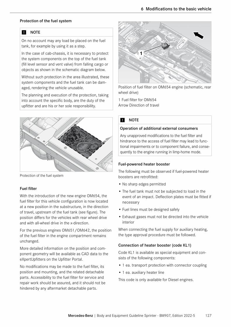
Protection of the fuel system
⑴ NOTE
On no account may any load be placed on the fuel tank, for example by using it as a step.
In the case of cab-chassis, it is necessary to protect the system components on the top of the fuel tank (fill level sensor and vent valve) from falling cargo or objects as shown in the schematic diagram below.
Without such protection in the area illustrated, these system components and the fuel tank can be dam-aged, rendering the vehicle unusable.
The planning and execution of the protection, taking into account the specific body, are the duty of the upfitter and are his or her sole responsibility.
Protection of the fuel system
Fuel filter
With the introduction of the new engine OM654, the fuel filter for this vehicle configuration is now located at a new position in the substructure, in the direction of travel, upstream of the fuel tank (see figure). The position differs for the vehicles with rear wheel drive and with all-wheel drive in the x-direction.
For the previous engines OM651/OM642, the position of the fuel filter in the engine compartment remains unchanged.
More detailed information on the position and com-ponent geometry will be available as CAD data to the eXpertUpfitters on the Upfitter Portal.
No modifications may be made to the fuel filter, its position and mounting, and the related detachable parts. Accessibility to the fuel filter for service and repair work should be assured, and it should not be hindered by any aftermarket detachable parts.
Position of fuel filter on OM654 engine (schematic, rear wheel drive)
1 Fuel filter for OM654 Arrow Direction of travel
⑴ NOTE
Operation of additional external consumers
Any unapproved modifications to the fuel filter and hindrance to the access of fuel filter may lead to func-tional impairments or to component failure, and conse-quently to the engine running in limp-home mode.
Fuel-powered heater booster
The following must be observed if fuel-powered heater boosters are retrofitted:
• No sharp edges permitted
• The fuel tank must not be subjected to load in the event of an impact. Deflection plates must be fitted if necessary
• Fuel lines must be designed safely
• Exhaust gases must not be directed into the vehicle interior
When connecting the fuel supply for auxiliary heating, the type approval procedure must be followed.
Connection of heater booster (code KL1)
Code KL1 is available as special equipment and con-sists of the following components:
• 1 ea. transport protection with connector coupling
• 1 ea. auxiliary heater line
This code is only available for Diesel engines.
Mercedes-Benz | Body and Equipment Guideline Sprinter - BM907, Edition 2022-5 127
6 Modifications to the basic vehicle

⑴ NOTE
Operation of additional external consumers
When the fuel level is at the reserve level, do not tap fuel from externally operated consumers via the auxiliary heater line.
⑴ NOTE
Tank fill level indicator
Modifications to the fuel tank are not permitted. If the upfitter installs a tank of a different size, the fill level will no longer be displayed correctly on the instru-ment cluster.
When using externally operated consumers via the auxiliary heater line in vehicles with code J51 "Fuel gauge, adapted for additional fuel tapping", the indi-cated range remaining varies from the series produc-tion configuration.
ENVIRONMENTAL NOTE
Modifications carried out incorrectly to the fuel system may have a detrimental effect on the environ-ment.
A fuel tap is standard equipment on Diesel engines. This fuel tap prevents the fuel tank from running empty.
KL1 Auxiliary Diesel Fuel Tap (standard)
The fuel gauge sensor is fitted with an additional fuel connection to facilitate retrofitting of a fuel-powered auxiliary heater. The fuel tank can be consumed down to approximately 5 gallons.
The picture shows a cap which can be removed. The connector piece is ø 7.89 mm/0.31in. Aftermarket quick connects have to be compatible with SAEJ2044 specified tube end forms.
N47.00-2059-00
View from underneath without a fuel fired heater
N47.00-2060-00
Top view showing a fuel pump unit on a chassis cab
ENVIRONMENTAL NOTE
Modifications carried out incorrectly to the fuel system may have a detrimental effect on the environ-ment.
Mercedes-Benz | Body and Equipment Guideline Sprinter - BM907, Edition 2022-5128
1 General
6 Modifications to the basic vehicle

The male connector piece which is coming with KL1 is shown in detail below. The measurements are shown in metric (mm).
Male connector piece drawing
For connecting an aftermarket fuel line the upfitter can order the female connector from the supplier Rayconnect Incorporated (https://catalog.araymond-automotive.com).
Female connector drawing
Example for a female connector for KL1
Mercedes-Benz | Body and Equipment Guideline Sprinter - BM907, Edition 2022-5 129
6 Modifications to the basic vehicle

6.3.2 SCR system
The SCR system (Selective Catalytic Reduction, code KP6) is related to emission and certification. The SCR system is an exhaust gas aftertreatment system which aims at reducing nitrogen oxide (NOx).
Modifying the components of the SCR system or changing their installation positions is not permitted. This includes the AdBlue® tank, the AdBlue® lines and all other SCR system components.
Apart from electronic control units and sensors, the SCR system requires a catalytic converter and the additive AdBlue®/DEF.
AdBlue®/DEF
AdBlue®/DEF is a solution of urea (32.5%) and water. AdBlue®/DEF is a noncombustible, nontoxic, colorless, odorless and water-soluble liquid.
AdBlue®/DEF has a limited shelf life, which is affected by the ambient temperature and air humidity. When filling it from containers, the following points must be observed.
Information on handling AdBlue® and its material char-acteristics can be found in ISO 22241.
Local and national laws and regulations for proper and correct disposal and handling must be observed.
If AdBlue®/DEF comes into contact with painted sur-faces or aluminum, the affected area must immediately be cleaned with water.
Any AdBlue®/DEF pumped out of the SCR tank must not be reused. As the AdBlue®/DEF that is pumped out is not always pure, it must be properly disposed of.
ⓘ For further information, observe the operator's manual of the vehicle.
AdBlue®/DEF tank
The AdBlue®/DEF tank system is part of the SCR exhaust gas aftertreatment system.
The AdBlue®/DEF tank system is designed for all com-mon AdBlue containers and delivery nozzles.
The tank flange module (preheater package) with pumps, heating and sensors, which is part of the SCR system, is welded together with the AdBlue®/DEF tank. The AdBlue®/DEF tank is located in the front-end assembly on the right side in front of the front axle, and is connected to the longitudinal frame member and the inside of the A-pillar.
On the series production vehicle, the components of the AdBlue® tank and tank flange module, as well as the electrical and hydraulic connections, are protected against damage by the front apron, e.g. when driving over low curbs or other obstacles.
If the factory-fitted front apron is omitted, measures must be taken to protect the components on the under-side of the SCR exhaust gas aftertreatment system.
The filler neck is located in an opening at the front of the front module carrier under the hood.
Mercedes-Benz | Body and Equipment Guideline Sprinter - BM907, Edition 2022-5130
1 General
6 Modifications to the basic vehicle

Modifications to the tank flange module may only be made with the consent of Mercedes-Benz.
The AdBlue®/DEF line connects the AdBlue®/DEF tank to the injection point at the engine.
The AdBlue®/DEF line is electrically heated and designed for this system in terms of its rigidity.
Modifications to the heat AdBlue®/DEF line may only be made with the consent of Mercedes-Benz.
The SCR systems of the vehicles with the previous engines OM651/OM642 and the new engine OM654 differ in terms of the number of AdBlue® injection points on the exhaust system, and consequently the number of injection valves and lines:
• OM651/OM642: Single metering near engine
• OM654: Double metering near engine and in substructure area
N14.40-2038-00
1
2
3
2N14.40-2037-00N14.40-2038-00
3
1
SCR system for engines OM651/ OM642
1 AdBlue®/DEF tank2 AdBlue®/DEF line3 AdBlue®/DEF filler neck
The newly designed AdBlue® tank for OM654 is located at the same position in the engine compartment as in the previous engines.
SCR system for engine OM654
1 AdBlue® tank2 AdBlue® line for metering near engine3 AdBlue® filler neck4 AdBlue® line for metering in substructure area
Arrow Direction of travel
Mercedes-Benz | Body and Equipment Guideline Sprinter - BM907, Edition 2022-5 131
6 Modifications to the basic vehicle

6.3.3 Exhaust system
Mercedes-Benz AG recommends that you refrain from modifying the exhaust system of Sprinter vehicles. The upfit scope should be planned according to the avail-able special equipment of exhaust system variants.
If a vehicle's exhaust system is replaced, we rec-ommend the use of Mercedes-Benz genuine parts. When selecting a different exhaust system as special equipment, ensure that it is also available for the same engine variant and emissions rating from the produc-tion plant of Mercedes-Benz AG. This guarantees that the planned special exhaust system has been certified in this vehicle configuration. Further information can be obtained from the local Mercedes-Benz Service Center.
Comply with all local and national guidelines and regulations.
General
It is important to note that modifications to the geom-etry of the exhaust system and its piping are only per-mitted under the boundary conditions described below.
As part of such modifications, measurements of the exhaust gas back pressure must be taken (before/after) to ensure that it has not increased in compar-ison to the unmodified exhaust system. The upfitter concerned must be able to provide evidence of these measurements to Mercedes-Benz AG on request.
All modifications above and beyond these constitute an alteration of a certified state in terms of emissions and noise levels.
⑴ NOTE
Upon completion of all work on the vehicle, you must comply with the specified anti-corrosion protection measures (→ page 86).
Exhaust system geometry
The following dimensions must be observed when mod-ifying the geometry of the exhaust system:
N49.10-2054-00
1,5
Example of a pipe bend design
• Maximum pipe bend 90°
• Avoid the use of additional pipe bends
• Bending radii >1.5 d
Minimum clearances to lines
When the vehicle is in operation, the temperature between the exhaust system (diesel particulate filter, catalytic converter or main muffler) and the floor panel may rise above 80°C/ 176°F depending on the loca-tion. During regeneration, the diesel particulate filter can reach a surface temperature in excess of 500°C/ 932°F. For this reason, shielding or insulation must be mounted on the substructure to reduce the effects of radiated heat.
Specification for minimum clearances for fuel lines, plastic lines, electrical cables and spare wheels, and for all components made of non-heat-resistant materials:
• 200 mm/ 7.87 in. for exhaust systems without shielding
• 80 mm/ 3.15 in. in areas with sheet metal shielding
• 40 mm/ 1.57 in. in areas with sheet metal shielding with additional insulation
⚠ WARNING
If the minimum distances to fuel lines, plastic lines and electrical cables are not maintained, severe heat can result in a fire.
There is a risk of fire and explosion!
Always comply with the specified minimum clear-ances.
Mercedes-Benz | Body and Equipment Guideline Sprinter - BM907, Edition 2022-5132
1 General
6 Modifications to the basic vehicle

It is important to not only consider the radiant heat emitted by the exhaust system, but also the jet of exhaust emitted behind the exhaust pipe outlet under all operating conditions.
⑴ NOTE
When using the power take-off, refer to the informa-tion and notes in the operator's manual of the vehicle regarding regeneration of the diesel particulate filter in the exhaust system.
Additional shielding is required
• Near control panels
• Near major assemblies, attachments and equipment, unless they are made of heat-resistant material.
Exhaust emission
It must be ensured that the exhaust gases emitted from the tailpipe cannot enter the passenger compartment. Particular attention must be paid to this in the layout of accesses and doors.
Ex-factory exhaust system variants
The following exhaust system versions are available from the factory as special equipment:
Code DescriptionK63 Exhaust, to the side behind the rear axleKA3 Exhaust, to the side in front of the rear axle
ⓘ Additional information on special equipment can be obtained from your Mercedes-Benz Service Center, under 1.7 Contact (→ page 11) or under 3.12 Special equipment (→ page 55).
Exhaust system without SCR system (gas engine)
The length and installation position of the flexible metal hose between the exhaust manifold and the exhaust pipe must not be changed.
The free cross-section of the exhaust pipe behind the main muffler must not be reduced.
⚠ WARNING
The lengths and routings, e.g. between the diesel particulate filter and the main muffler, are optimized with regards to temperature characteristics. Modifi-cations could lead to higher or extreme temperatures in the exhaust system and surrounding components (propeller shafts, fuel tank, floor panel, etc.). There is a risk of fire!
Modifications to the exhaust system as far as the muffler are not permitted.
Mercedes-Benz | Body and Equipment Guideline Sprinter - BM907, Edition 2022-5 133
6 Modifications to the basic vehicle

Exhaust system with SCR system
Modifications to the exhaust system with SCR sys-tem are only allowed at a minimum distance of 100 mm/3.94 in behind the last sensor (NOx sensor). The positions and installation positions of the sensors and the throttle valve as well as the spatial geometry of the overall system or other components may not be modified.
It is the upfitter's sole responsibility to guarantee adequate clearance between the exhaust system and all the components relative to its body scopes. The above-mentioned minimum distances to the exhaust system components must be observed.
Schematic illustration of exhaust system OM651/ OM642
1 NOx sensor2 SCR catalytic converter3 Area in which modifications are not permitted4 Particulate matter sensor
Schematic diagram of exhaust system OM654
1 NOx sensor2 SCR catalytic converter3 Area in which modifications are not permitted4 Throttle valve
.
100 mm / 3.94 in
Mercedes-Benz | Body and Equipment Guideline Sprinter - BM907, Edition 2022-5134
1 General
6 Modifications to the basic vehicle

6.3.4 Engine cooling
a) Vehicles with engine OM651/ OM642
It is not permissible to modify the cooling system (cooler, radiator grille, air ducts, coolant circuit, etc.) because a sufficient flow of cooling air must be assured.
The flow areas of the cooling air intake areas are to be kept free. This means:
• at least 11 dm²/170.5 in² for the front grille (radiator and condenser)
• at least 7 dm²/108.5 in² for the opening in the bumper (charge air cooler flow)
Engine cooling, flow areas directives
1 Front grill radiator: 11 dm²/170.5 in²2 Front grill charge air cooler: 7 dm²/108.5 in²
For vehicles with a modified front end (e.g.fully inte-grated RVs), the further specifications in Chapter 4.4.2 Engine cooling system (→ page 74) must be observed.
b) Vehicles with engine OM654
The new information and specifications for engine OM654 cooling is available in Chapter 4.4.2 Engine cooling (→ page 74)).
6.3.5 Engine air intake
N14.40-2040-00
1
Engine air intake opening for OM651/ OM642
1 Area of engine air intake
Engine air intake opening for OM654
1 Area of engine air intake
⑴ NOTE
On no account should modifications be made in the area of engine air intake (see illustration).
The engine air intake for engines OM651/ OM642 is located in the left area of the front grill.
The engine air intake for the new engine OM654 is integrated into the area of the upper cross-member of the new front module.
The air filter is secured by two rubber mounted brack-ets in the front module. The design of the attachment of the air filter must be retained in the event of any modification to the front module.
Mercedes-Benz | Body and Equipment Guideline Sprinter - BM907, Edition 2022-5 135
6 Modifications to the basic vehicle

Warm air
The intake of warm air will lead to a loss of engine power. A bulkhead between the engine compartment, the vehicle interior and the intake point is therefore essential. The intake temperature should not exceed the outside temperature by more than 10 °C/50 °F.
Water
When being drained off, water, splash water or car wash water must not flow directly past the intake area from the body. Make sure that water cannot reach the intake points through any fresh air supply inlets. The flow velocity at the intake points must not be increased by modifications to the opening of the intake points.
Dust/dirt
Increased dust intake will lead to shorter maintenance intervals for the air filter.
6.3.6 Clearance for major assemblies
To guarantee proper functioning and operational safety of the major assemblies, sufficient clearance must be main-tained (in particular to electrical, brake and fuel lines).
The dimensional data in the 2D chassis drawings (offer drawings) must be observed (→ page 18).
The distance between the cab and the body must be at least 50 mm/2.0 in.
6.3.7 Propeller shafts
The correct layout of the propeller shaft drive prevents noise and the development of vibrations. We recommend the use of genuine Mercedes-Benz parts.
Working angles
If necessary, use several propeller shafts with interme-diate bearings.
The working angles must be identical at both universal joints (β1 ≠ β2). The working angles must generally not exceed 4.5° and in exceptional cases must be no greater than 6° (proper functioning of the universal joints must be assured). The angular difference should not exceed 1°.
⑴ NOTE
Working angles greater than 6° and angle errors (β1 ≠ β2) lead to vibrations on the drivetrain. They shorten the service life of major assemblies and may cause damage.In addition, problems due to noise and vibrations should be expected.
N41.00-2014-00
Types of angular offset
b1 = b2
Mercedes-Benz | Body and Equipment Guideline Sprinter - BM907, Edition 2022-5136
1 General
6 Modifications to the basic vehicle

Angle in one plane (two-dimensional offset):“W” or “Z” layout
Angles in two planes (three-dimensional offset):With three-dimensional offset, the input and output shafts intersect in different planes (com-bined W and Zoffset).
In order to compensate for any irregularities, the inner joint forks can be offset. This fork offset must be designed and secured by a company qualified in propel-ler shaft engineering.
Propeller shafts must be balanced before installation.
Modifications should not exceed the limit values.
⑴ NOTE
Any temporary dismantling of the rebound straps during the upfit must be returned to the Mer-cedes-Benz specification before returning to use.
The Mercedes-Benz screws must be bolted at the designated points with a tightening torque of 70 Nm +/- 7 Nm (52 ft lb +/- 5 ft lb). The number of rebound straps varies depending on the length of the body.
All Mercedes-Benz passenger vans come standard withthe option code AP2 (protection bar for drivesh-aft). The option code AP2 ensures compliance with all federal regulations for driveshaft protection regarding passenger vans and bus conversions. If any conversion of a non-passenger van to a passenger van is carried out, the upfitter is obligated to ensure that the van is compliant with all relevant driveshaft protection regulations and may order the option code AP2.
The driveshaft underneath the cab must be secured with at least one bracket.
Rebound straps
Mercedes-Benz | Body and Equipment Guideline Sprinter - BM907, Edition 2022-5 137
6 Modifications to the basic vehicle

6.4 Interior
6.4.1 General information
⚠ WARNING
Any modifications to restraint systems or their wiring could result in these restraint systems not functioning correctly. A restraint system can fail or unintention-ally activate. There is a risk of accident, personal injuries and death if such systems no longer function correctly!
Modifications to restraint systems or their wiring are therefore not permitted.
This includes modifications to the belt mounting points and their positioning on the B-pillar and any modi-fication of genuine Mercedes-Benz belt system compo-nents.
The driver and front passenger airbag units, the window airbags and thorax/pelvis side airbags and the seat belt tensioners are pyrotechnical components.
The handling, transportation and storage of airbag units are subject to the hazardous materials law regulated by FMCSA under 49 CFR Part 173 in the US, and to the Transportation of Dangerous Goods Act (Transport Canada) in Canada.
The purchase, transportation, storage, fitting, removal and disposal of potentially explosive substances may only be carried out by trained personnel and in accor-dance with the relevant safety regulations.
Modifications in the cockpit area and above the belt trail line must fulfill the criteria associated with the head impact tests as per FMVSS/CMVSS 201.
In the area of the airbag deployment zones, modifica-tions to the surface of the cockpit, interior trim and seats (wooden trim, additional fixtures, mobile phone cradle, bottle holder, etc.) are not permitted. For more information, see the schematic diagrams for the airbag deployment areas (→ page 143).
Painting or surface treatment is not permissible on the instrument panel, steering wheel impact absorber or airbag tear seams.
This also applies for restraint systems integrated in the seats (e.g. flush-mounted modules).
Protective covers could interfere with the functioning of the thorax/pelvis side airbag and the seat mat detection system.
⚠ WARNING
If paint or surface treatment is applied to the instru-ment panel, the window airbags, the steering wheel impact absorber and the airbag tear seams, chemical reactions can occur on the treated surfaces. This could weaken or damage the materials meaning that the restraint systems no longer operate properly. There is a risk of accident, personal injuries and death if such systems no longer function correctly!
Painting or surface treatment is not permissible on the instrument panel, the window airbags, the steer-ing wheel impact absorber and the airbag tear seams.
The permissible center of gravity and maximum permis-sible axle loads must not be exceeded.
Information on camper conversions can be found under 7.15 RV – Recreational vehicles (→ page 219).
The interior must be designed with soft edges and surfaces.
Fittings must be made of flame-resistant materials and be fitted securely.
Unimpeded access to the seats must be ensured. There must not be any protruding parts, edges or cor-ners which could cause injury in the area of the seats.
⑴ NOTE
Attachments with rigid connections to the front, side and rear of the vehicle at the height of possible acci-dent zones could modify the characteristics of the vehicle's passive safety.
⚠ WARNING
Modifications to or work incorrectly carried out on a restraint system (seat belt and seat belt anchor-ings, seat belt tensioners or airbags) or its wiring could cause the restraint systems to stop functioning correctly. There is a risk of accident, personal injuries and death if such systems no longer function cor-rectly!
On no account may any modifications be made to the airbag system or the seat belt tensioner system.
Mercedes-Benz | Body and Equipment Guideline Sprinter - BM907, Edition 2022-5138
1 General
6 Modifications to the basic vehicle

⚠ WARNING
If, for example, the following alterations are made to the structure of the vehicle, the safe function of the front airbag, window airbag, thorax/pelvis side airbag and seat belt tensioners is no longer guaranteed:
• modifications to the seats and thus changes in the kinematics of the occupants in the event of an impact
• modifications to the front-end assembly
• installation of parts in the vicinity of airbag inflation points or in airbag deployment areas
• installation of non-MB seats
• modifications to the A-pillar and B-pillar, the roof frame and its lining
• modifications to the doors and door trim
• modification or replacement of the seat cover in case of integrated Thorax-Pelvis-Airbag
These modifications are therefore not permitted.
No systems or components which influence passive safety may be modified. This could otherwise result in personal injury.
6.4.2 Safety equipment
Airbag control unit and sensors
It is not permitted to modify the installation location, installation position, and attachment of airbag control units and satellite sensors by comparison with the stan-dard vehicle on vehicles equipped with window airbags and thorax/pelvis side airbags. Any changes to the lines of these components are also not permitted.
Other vehicle components must not be secured to the airbag control unit, the satellite sensors, their lines or the attachment points. When installing components in the vicinity of these components, a minimum distance of 6 mm/ 0.236 in must be maintained.
When components (e.g. the airbag control unit) have been removed, all the components must be reinstalled with the appropriate tightening torques in accordance with the repair instructions when reassembling.
⚠ WARNING
When, for example, the following alterations are made to the structure of the vehicle, the safe operation of restraint systems is no longer guaranteed:
• modifications to the front-end assembly
• installation of parts in the vicinity of airbag inflation points or in airbag deployment areas
• modifications to the A-pillar and B-pillar, the roof frame and its lining
• modifications to the doors
These modifications are therefore not permitted.
No systems or components which influence passive safety may be modified. This could otherwise result in personal injury.
In the case of the following interventions in the struc-ture of the vehicle, pay attention to the particular provisions of Mercedes-Benz in Chapter 6.4.3:
• Modifications to the seats
• Installation of non-Mercedes-Benz seats
⑴ NOTE
Attachments with rigid connections to the front, side and rear of the vehicle at the height of possible acci-dent zones could modify the characteristics of the vehicle's passive safety.
Mercedes-Benz | Body and Equipment Guideline Sprinter - BM907, Edition 2022-5 139
6 Modifications to the basic vehicle

⚠ WARNING
Any modifications to the components of the restraint systems (airbag control unit, satellite sensors, airbags, seat belt tensioners, etc.), their lines and attachments are not permitted.
Vehicle parts that generate vibrations may not be mounted in the proximity of the airbag control unit or the sensor installation locations. Nor may modifica-tions be made to the floor structure in the proximity of the airbag control unit or the satellite sensors.
Otherwise, reliable operation of the restraint systems is no longer guaranteed, and there is a risk of injury.
The airbag control unit is located on the center tunnel under the center console.
N91.60-2204-00
1
Location of airbag control unit
1 Airbag control unit Arrow Direction of travel
In vehicles equipped with window airbags and/or thorax/pelvis side airbags, the satellite sensors are located towards the bottom of the B-pillar behind the door sill trim in the driver's and front passenger's entrance boxes.
The pressure sensors are located in the driver and/or front passenger door.
N91.60-2202-00
1
Front pressure sensor
1 Pressure sensor (trigger sensor of the occupant protection systems)
Mercedes-Benz | Body and Equipment Guideline Sprinter - BM907, Edition 2022-5140
1 General
6 Modifications to the basic vehicle

N91.60-2205-00
1
Sectional view of left entrance box at B-pillar
1 Satellite sensor (trigger sensor of the occupant protection systems)
Arrow Direction of travel
Seat belts and seat belt tensioners
⚠ WARNING
Parts relevant to safety such as seat belts or belt anchorages and seat belt tensioners must not be damaged or soiled when work is carried out on the vehicle. Otherwise these restraint systems may no longer function properly, and in the event of an acci-dent they would fail to provide sufficient protection.
⑴ NOTE
Only the original seat belts may be fitted, otherwise the general operating permit of the vehicle would be invalidated.
For seat belts, seat belt tensioners and seat belt anchoring points, the specifications of the FMVSS/CMVSS, plus the national regulations concerning seat belts must be complied with and verified insofar as the FMVSS/CMVSS do not completely cover the national regulations or have priority over them.
Vehicles must be equipped with seat belts.
The anchoring of the seat belts must be tested as per FMVSS/CMVSS 210.
All vehicles, except vehicles without front airbags and with special attachments (e.g. snowplow), are fitted with pyrotechnical seat belt tensioners in the retractors on the front seats.
The retractors are located in the B-pillars. There is an additional retractor in the seat backrest of the bench seat on vehicles with two-seater front passenger bench seat.
Mercedes-Benz | Body and Equipment Guideline Sprinter - BM907, Edition 2022-5 141
6 Modifications to the basic vehicle

N91.60-2207-00
1
Retractor with pyrotechnical seat belt tensioner
1 Connector
⚠ WARNING
When installing an aftermarket partition do not drill or attach any fasteners in the area between the bottom of the seat belt retractor and the bottom of the seat belt height adjustment.
N91.40-2195-00
Location of seat belt retractor between 620-770 mm/ 24.25–30.5 in above floor
N91.60-2208-00
1
Front passenger bench seat with retractor
1 Retractor
⑴ NOTE
Please ensure to comply with local and federal regulations.
N91.60-2209-00
1
Securing point for seat belt end fitting in B-pillar
1 Seat belt end fittingArrow Direction of travel
Mercedes-Benz | Body and Equipment Guideline Sprinter - BM907, Edition 2022-5142
1 General
6 Modifications to the basic vehicle

Front airbag
All airbag units are labeled "Airbag":
• The driver's airbag unit is identified by the "Airbag" inscription on the steering wheel boss.
• If the vehicle is equipped with a front passenger airbag, this unit is also identified by the "Airbag" inscription.
• If the vehicle is equipped with window airbags, they are identified by the "Airbag" inscription on the cover.
• If the vehicle is equipped with thorax/pelvis side air-bags, these are identified by the "Airbag" inscription on the seat backrest.
The indicator lamp signals a malfunction in the restraint system, which includes functions of the seat belt warn-ing and the ESP® sensor system.
• Because ESP® is standard equipment, the lamp is present in every instrument cluster and is active in the lamp check even when no restraint equipment is installed.
• The seat belt reminder warning is also triggered by the restraint system, even when no restraint equip-ment is installed.
The following illustrations show the location and deployment areas of the driver’s and front passenger airbags as well as that of window airbag and thorax/pelvis side airbag. The deployment areas shown are greater than the actual volume of the airbag because space is required for airbag rebound as it deploys.
Schematic diagram of deployment area of driver's airbag
Schematic diagram of deployment area of front passenger airbag
Mercedes-Benz | Body and Equipment Guideline Sprinter - BM907, Edition 2022-5 143
6 Modifications to the basic vehicle

Sidebags
On no account should modifications be made to the B-pillar, door bodies, trim and seat covers.
Schematic diagram of deployment area of thorax/pelvis side airbag on left side of vehicle
Schematic diagram of deployment area of window airbag on right side of vehicle
The preceding illustrations of the airbag deployment areas show the approximate maximum schematic deployment states (for illustration purposes only; no responsibility is accepted for the correctness of the information).
Mercedes-Benz | Body and Equipment Guideline Sprinter - BM907, Edition 2022-5144
1 General
6 Modifications to the basic vehicle

⚠ WARNING
Working on the A-pillar can cause damage to the window airbag. This can result in the window airbag no longer functioning properly and it may not provide adequate protection in the event of an accident.
N91.60-2210-00
1
2
3
Window airbag installation position
1 Cover2 Window airbag in protective sleeve3 Gas generator in window airbagArrow Direction of travel
Mercedes-Benz | Body and Equipment Guideline Sprinter - BM907, Edition 2022-5 145
6 Modifications to the basic vehicle

Working with airbag and seat belt tensioner units
⚠ WARNING
Removed airbag units must always be stored in such a way that the padded side faces upwards. If the padded side faces downwards, the airbag unit will be catapulted through the air if it is triggered acciden-tally.
Observe the following specifications when handling airbag and seat belt tensioner components:
• Only qualified personnel may work with removed components and perform testing and assembly operations.
• Electrical inspection is to be conducted in installed condition only, using specified test equipment. We recommend that tests be carried out at a Mer-cedes-Benz Service Center.
• Assembly and disassembly are to be conducted only when the battery is disconnected, with covered up negative terminal or covered up negative clamp, and disconnected test coupling/ connector.
• After disassembling, components must be stored in a suitable storeroom only and must only be removed just before they are to be assembled.
• If work has to be interrupted, store components involved under lock and key.
• Do not treat with grease, cleaning agents or similar agents.
• Do not expose components to temperatures over 100°C/ 212°F.
• Replace any airbag and seat belt tensioner compo-nents that have been dropped to the floor.
• The airbag and seat belt tensioner units may only be electrically tested in the installed condition with the prescribed test equipment. For safety reasons, the test should only be performed at a Mercedes-Benz Service Center or at a specialist workshop that has been specially trained to service these safety systems.
Transporting and storing airbag units and seat belt tensioner units
Transportation should always be carried out using the replacement part packaging in the vehicle trunk or load compartment and in observance of the below warning notice.
⑴ NOTE
Do not transport any airbag and seat belt tensioner units in the passenger compartment.
The airbag units fitted to the Sprinter BM 907 include the driver and front passenger airbags as well as the window airbag and thorax/pelvis side airbag.
The handling, transportation and storage of airbag units are subject to the hazardous materials law regulated by FMCSA under 49 CFR Part 173 in the US, and to the Transportation of Dangerous Goods Act (Transport Canada) in Canada.
The weights of the individual components are:
Driver's airbag 1.5 kg/3.3 lbsFront passenger airbag 3.3 kg/7.3 lbsWindow airbag 2.1 kg/4.6 lbsThorax/pelvis side airbag 0.7 kg/1.5 lbsSeat belt 1.4 kg/3.1 lbs
Mercedes-Benz | Body and Equipment Guideline Sprinter - BM907, Edition 2022-5146
1 General
6 Modifications to the basic vehicle

Disposing of airbag and seat belt tensioner units
Dispose of airbag and seat belt tensioner units in accordance with the local and country specific laws and guidelines.
� If seat belt tensioners that have not been triggered require detonation for disposal purposes, place them in the footwell of a vehicle which has been sent for scrapping, and connect them directly using a 2-pin connector coupling.
� If the bolster plates on the airbag units have not been destroyed, the airbag units must be detonated by trained personnel using the 2-pin connector coupling.
These safety measures are necessary because flammability materials could cause injury if activated incorrectly.
ⓘ Airbag and seat belt tensioner units must be disposed of by personnel who have undergone special training for this task. Accident prevention regulations must be observed.
Hazards arise from disposal using cutting torches, by smelting, or if primed parts are disposed of on open fires or smoldering fires on waste disposal sites.
In order to ensure that no additional work arises due to these safety measures, we recommend that you entrust the disposal of pyrotechnical substances to an external waste disposal company, which will implement the required safety measures (incl. 10 m/39.4 in safe distance, special ignition equipment).
When the materials are handed over, the waste dis-posal company must sign a declaration containing the obligation to dispose of the pyrotechnical materials in accordance with accident prevention regulations. Agreements of this kind must ensure that it is not pos-sible to extract pyrotechnical materials after disposal and to pass them on for repairs.
6.4.3 Seats
Proof of the strength of the seats delivered from the factory is only valid if the seats are secured in original mountings.
As part of the eXpertUpfitter program, possible deviations can be evaluated with the responsible (→ page 11).
The test reports in relation to FMVSS 202a /CMVSS 202, FMVSS/CMVSS 207, FMVSS/CMVSS 209 and FMVSS/CMVSS 210 are a requirement to be an eXpertUpfitter.
It is essential to observe the H-point for each seat. The seats installed ex factory (driver/front passenger) must not be secured directly to the low seat base when the vehicle is delivered to the end customer. The H-point on seats available ex factory (driver/front passenger) in combination with the low seat base can be achieved using the swivel console available ex factory.
A rear seat system with 2- or 3-point seat belts that deviates from the standard seating arrangement must meet the requirements of the FMVSS/CMVSS 207 (seating systems) and the FMVSS/CMVSS 210 (seat belt assembly anchorages) standard. Furthermore, the standard FMVSS/CMVSS 209 (Seat belt assem-blies) must be adhered to. For the headrests, proof of compliance with the FMVSS 202a/CMVSS 202 (Head restraints) standard is required. Always comply with local and national regulations.
Seats without belts are not permitted.
When seat belts and seats (including seat bases) are reinstalled, new bolts must be tightened, tested, and documented to the specified torque, including tolerance.
In the case of vehicle orders where the driver's seat (Code S90) or front passenger seat (Code S91) is deleted, it is not possible to retrofit standard seats in the body-in-white, as there are no reinforcements or suitable connection points. However, retrofitting after-market seats is possible, see Chap ter 7.3 Modifications to the interior (→ page 190).
Test certificates for seats on a rigid plate are not per-missible. Mercedes-Benz reserves the right to request these test certificates at any time as part of its product monitoring processes.
ⓘ Information on retrofitting seats can be found under Retrofitting additional seats (→ page 190).
Mercedes-Benz | Body and Equipment Guideline Sprinter - BM907, Edition 2022-5 147
6 Modifications to the basic vehicle

⚠ WARNING
Unsuitable seat covers could hinder, or even prevent, the deployment of the airbags integrated in the seats. The airbags would then not protect the vehicle occu-pants as intended. There is a heightened risk of injury or even of death!
It is strongly recommended that the upfitter does not modify the seat cover in any way. It is the upfitter’s responsibility to ensure that all applicable technical and regulatory requirements are met.
⚠ WARNING
On no account may seats be mounted on the wheel well. This also applies for lowered wheel wells. Other-wise the vehicle could be damaged (e.g. wheel wells and tires), resulting in accidents.
6.4.4 Reducing interior noise
Soundproofing material can be installed in order to reduce the noise level in the vehicle interior. It must not be flammable.
Floor area
A structure as shown in the illustration is advisable for insulation and soundproofing. An additional covering with heavy-duty insulating foil may be provided in the area of the wheel wells.
⑴ NOTE
Insulating foils, e.g. bituminous felt, have limited temperature resistance. They should therefore not be installed in the immediate vicinity of the engine or exhaust system.
1 Carpet (rubberized underside)2 Wooden floor (12 mm/0.47 in plywood)3 Heavy-duty insulating foil (weight per unit area
8-10 kg/m2 ; 1.636–2.045 lbs/ft2)4 Load-bearing construction
Mercedes-Benz | Body and Equipment Guideline Sprinter - BM907, Edition 2022-5148
1 General
6 Modifications to the basic vehicle

Roof and side walls
Apart from providing insulation, the materials used for insulation should exhibit the following properties:
• Not hygroscopic
• Not water-retaining
• Not water-absorbing
• Not water-attracting
• Water-repellent
Arrangements are to be made for the rapid and unhin-dered drainage of accumulated moisture or condensa-tion in order to avoid conditions that promote corrosion.
The standard drain holes must be preserved intact. If necessary, additional drain holes must be created with the responsible department. As part of the eXpertUpfit-ter program please refer to www.UpfitterPortal.com.
The inside must be covered with a sound-transmitting material (perforated card, plastic, fabric cover).
⚠ WARNING
On no account should any subsequent modifications be made to the headliner or the roof panel between the A-pillar and the B-pillar if the vehicle is equipped with window airbags. Otherwise the window airbag may no longer function correctly (e.g. window airbag deployment is delayed or incomplete).
Seals
Openings, gaps and slots between the engine compart-ment or the vehicle underside or the firewall and the vehicle interior must be carefully sealed with elastic material. Vent openings must not be fitted in the imme-diate vicinity of sources of noise.
In addition, manufacturers or suppliers of soundproof-ing materials should be consulted.
They will be able to provide you with suggestions on how to design optimum noise insulation for your modi-fied vehicle body.
6.4.5 Ventilation
The living compartment and the driver area must have adequate ventilation with provision for air to enter and exit.
The windshield and side window defrosting function must remain operational, especially if the driver area is integrated into the living compartment or if the layout and design of the interior does not correspond to that of the standard equipment.
When modifying/removing the standard windshield, adequate defrosting/deicing must be provided and the solar sensor must be reinstalled (standard with HH4 Front automatic air conditioning). An incorrectly installed solar sensor or a different inclination of the windshield results in deviations in the climate control with HH4 (Front automatic air conditioning).
New vehicles can be delivered from the factory with the special equipment code HH9 (Manual front air condition-ing), code HH4 (Front automatic air condi tioning), code HH9+HH7 (Manual front air conditioning + roof-mounted air conditioning system), code HH9/ HH4+H08 (Front air conditioning + roof-mounted air conditioning system) and code HH9/HH4+HK4 (Front air conditioning + roof-mounted air conditioning sys tem).
Observe 6.5 Additional assemblies (→ page 152) when retrofitting major assemblies.
Mercedes-Benz | Body and Equipment Guideline Sprinter - BM907, Edition 2022-5 149
6 Modifications to the basic vehicle

6.4.6 Attachment points for load compartment trim parts on the side wall/roof
To line the load compartment in cargo van model des-ignations, it is recommended to use the load compart-ment trim parts available from Mercedes-Benz AG ex factory.
If the upfitter installs specific load compartment trim parts, the following specifications must be observed:
• Load compartment trim parts in the lower area of the side wall and on the roof are to be fastened at exist-ing mounting holes in the body-in-white (for clips, expansion rivets or similar fasteners) for the inner parts of the side wall and the cross bows of the roof, see schematic diagram.
• In places where there are no existing mounting holes (e.g. the upper part of the side wall), additional mounting holes are permissible only in the marked areas of the side wall inner parts, see schematic diagram.
• To prevent cracks from occurring when drilling extra mounting holes, a distance of at least 15 mm/ 0.59 in. must be maintained from the edge of the hole to all cuts and joints, openings, other holes and panel edges of the body-in-white.
• Proper execution of the drilled holes must be assured, with the avoidance of shavings, the deburring of holes and subsequent anti-corrosion protection.
• On completion of the body mounting work, all shavings must be entirely eliminated from joints, profiles and cavities.
• The specifications in these Body/Equipment Mount-ing Directives for the work to be performed must be observed, see Chapter 3.9.1 Threaded connections (→ page 46), Chapter 4.1.5 Drilling must not take place (→ page 63), Chapter 5.3 Anti-cor-rosion protection measures (→ page 86), Chapter 5.4 Painting work/preservation work (→ page 88) and Chapter 6.2.1 General informa-tion on the body in white/body (→ page 101).
For any questions, please reach out to the Upfitter Portal:
www.UpfitterPortal.com
Mercedes-Benz | Body and Equipment Guideline Sprinter - BM907, Edition 2022-5150
1 General
6 Modifications to the basic vehicle

Cargo van model designation, inside of right side wall: Permissible areas for the attachment of load compartment trim parts (dark markings, schematic diagram)
Cargo van model designation, inside of left side wall: Permissible areas for the attachment of load compartment trim parts (dark markings, schematic diagram)
Cargol van model designation, inside of roof: Permissible areas for the attachment of load compartment trim parts at the cross bows (dark markings, schematic diagram)
Mercedes-Benz | Body and Equipment Guideline Sprinter - BM907, Edition 2022-5 151
6 Modifications to the basic vehicle

6.5 Additional assemblies
If additional assemblies are fitted, the factory-fit-ted power take-offs or auxiliary drives must be used (→ page 132).
6.5.1 Retrofitting an air conditioning system
⚠ WARNING
Prior to all mechanical and electrical work, the vehi-cle must be rendered free of voltage/current (discon-necting the battery is absolutely essential).
All electrical equipment fitted must be tested in accor-dance with FCC, CE and UL in the US, and with CSA and ULC in Canada.
The installation of additional air conditioning compo-nents (compressor, evaporator, lines etc.) on the air conditioning systems available as special equipment ex factory is not permissible.
Air conditioning system special equipment options
• HH9 (Manual front air conditioning)
• HH4 (Front automatic air conditioning)
• HH9+HH7 (Manual front air conditioning + roof-mounted air conditioning system)
• HH9/HH4+H08 (Front air conditioning + roof-mounted air conditioning system)
• HH9/HH4+HK4 (Front air conditioning + roof-mounted air conditioning system)
If other air conditioning systems are installed, the equipment manufacturer's guidelines must be observed.
The following points must be observed with regard to compatibility with the base model vehicle:
• On no account should the installation of an air condi-tioning system impair vehicle parts or their function.
• The battery must have sufficient capacity and the alternator must generate sufficient power (→ page 242).
• Additional fuse protection for the air conditioning power circuit (→ page 239).
• Air conditioning compressors must be attached using the major assembly carrier provided (→ page 155).
• The additional pulley for driving air conditioning compressors is available from the factory as special equipment under code N63 (maximum output 8 kW) (→ page 154).
• Ensure that all lines (→ page 84) and electrical lines (→ page 239) are routed correctly.
• There should be no impairment of the accessibility or easy maintenance of installed equipment.
• The operating instructions and the maintenance manual for the additional assemblies must be sup-plied on handing over the vehicle.
• The air supply and cooling required for the engine must not be impaired (→ page 135).
• If compact systems are mounted on the cab roof (evaporator, condenser and blower), the permissible roof loads must not be exceeded (→ page 121).
• For attachments to the roof, an evalution with the responsible department is necessary. As part of the eXpertUpfitter program please refer to www.UpfitterPortal.com.
⑴ NOTE
When using refrigeration systems/components in combination with the refrigerant R1234yf, all applica-ble laws, regulations and safety specifications must be observed.
In particular, compliance with the safety regulations according to ISO 13043 at both the component and overall system level (FMEA, leaktightness require-ments, concentration measurements etc.) must be guaranteed.
Along with this, also observe the safety requirements with regard to inflammability and risk of combustibil-ity in combination with R1234yf (maintain best-pos-sible packaging or largest-possible distance to hot parts, if necessary, install additional devices for assuring the required safety).
If R1234yf is used, a specific information label with details of the quantity and combustion risk must be considered or installed in a visible location.
Mercedes-Benz | Body and Equipment Guideline Sprinter - BM907, Edition 2022-5152
1 General
6 Modifications to the basic vehicle

Optimum belt tensioner position on OM651
If a different belt pulley diameter is used, it is important to ensure that the belt length for the main belt drive is adapted accordingly.
N83.30-3189-00
1
Position of belt tensioner in engine compartment
1 Belt tensioner
To ensure that all engine functions work properly, the marking on the belt tensioner indicated by the arrow must be in area 1. The marking indicated by the arrow must NEVER be in area 2.
N83.30-3190-00
1 2
Belt tensioner position
1 Correct belt tensioner position2 Incorrect belt tensioner position
Note on belt tension on engine OM654
The specified marking on the engine-mounted belt tensioner of the main belt drive is only present in engine OM651. Engine OM654 no longer bears this marking and therefore the following specification must be observed:
⑴ NOTE
Modifications may not be made to the belt pulley diameter in the main belt drive (primary drive) on engine OM654.
The belt tensioning method for the engine-mounted power take-off is specified in Chapter 6.5.3 Engine power take-off (→ page 154).
Mercedes-Benz | Body and Equipment Guideline Sprinter - BM907, Edition 2022-5 153
6 Modifications to the basic vehicle

6.5.2 Auxiliary heating
If auxiliary heaters and their operating units are retrofit-ted, make sure that no exhaust gases enter the vehicle interior during operation.
The following auxiliary heating system is available from the factory as serial equipment:
Description CodeHot-air auxiliary heater electric (PTC)
HH2
The following auxiliary heating systems are available from the factory as special equipment:
Description CodeHot-water auxiliary heater (stationary heater)
H12
Hot-water auxiliary heater (only as heater booster)
HZ9
Additional heat exchanger on sub-structure
H13
Code H88 (Preparation for additional heat exchanger), available as special equipment ex factory, allows an aftermarket auxiliary heat exchanger to be connected to the existing heater circuit (including the stationary heater). The mechanical and electrical requirements, including adjustment of the coolant quantity for reliable engine operation, must be taken into account.
Additional information can be found under 3.12 Special equipment (→ page 55).
For further information regarding the code H88, please refer to the bulletin on the Upfitter Portal, Sprinter MY2019+ Auxiliary Heat Exchanger Prep (H88).
6.5.3 Engine power take-off
Additional assemblies (e.g. an A/C compressor or an additional alternator) can be driven by an additional pulley on the front of the crankshaft, see also 6.5 Addi-tional assemblies (→ page 152).
The following codes are available for power take-offs:
Code N62 Front engine bracket for additional alternator
Code N63 Front engine bracket for auxiliary A/C compressor
These power take-offs can be obtained from the factory as special equipment.
For the power take-off with code N62, an alternator with freewheeling belt pulley must be used.
These are available only for Diesel.
The maximum transferable torques for each of the power take-offs are guide values for shock-free and vibration-free operation.
These figures are based on a highly durable gearing design and a service life calculated in compliance with the German standard DIN 622. The additional inertia forces of the driven major assemblies are not taken into account.
The ratio chosen should ensure that a minimum engine speed of 1200 rpm with a power output of P = 28 kW is maintained. The power output should be within the range of the maximum engine torque.
⑴ NOTE
Mercedes-Benz does not provide any power take-off options (e.g. auxiliary alternator or AC compressor) for gas engines (engine type M274).
Mercedes-Benz does not permit any after-market power take-off options for gas engines (engine type M274).
Mercedes-Benz | Body and Equipment Guideline Sprinter - BM907, Edition 2022-5154
1 General
6 Modifications to the basic vehicle

Maximum transferable output
Code N62 8.5 kWCode N63 8.0 kW
Required belt pulley for additional assemblies
• V-ribbed belt pulley, 6-groove
• Outside diameter
- Code N62: 50 mm/ 1.97 in
- Code N63: 119 mm/ 4.69 in
The following Mercedes-Benz genuine parts must be used as belts:
OM642Code N62 A001 993 47 96Code N63 A001 993 37 96
OM651Code N62 A001 993 95 96 Stretch fitCode N63 A002 993 28 96 Stretch fit
OM654Code N62 A000 993 58 00 Stretch fitCode N63 A000 993 57 00 Stretch fit
ⓘ Please consult your Mercedes-Benz Service Partner for advice regarding successor item numbers if the above item number is unavailable.
Additional assemblies can be mounted on a major assembly carrier fixed to the engine.
Additional assembly on engine-mounted major assembly carrier
1 Additional refrigerant compressor2 Major assembly carrier
Maximum weight of additional assemblies
Code N62 7.3 kg/16.1 lbsCode N63 7.3 kg/16.1 lbs
Mercedes-Benz | Body and Equipment Guideline Sprinter - BM907, Edition 2022-5 155
6 Modifications to the basic vehicle

Setting of belt tension on engine power take-off OM654
The tension of the stretch fit belt on the engine-mounted power take-off can be adjusted using the eccentric pulley, which is known as an eccentric belt tensioner (eccentric RSP) (see following figure).
Belt tensioner on engine OM654 in as-delivered state (with code N63)
1 Engine-mounted belt pulley2 Eccentric belt tensioner in as-delivered state3 Internal Torx bolt (T55) 4 External Torx bolt (E12)5 Guide pulley only with power take-off, code N63 (not
available with code N62)
In the as-delivered state (still without belt), the eccen-tric belt tensioner is in a position in which the stretch fit belt can be easily placed over the guide pulley and the belt pulley of the power take-off and auxiliary assembly. In this assembly state, the internal Torx bolt (T55) of the eccentric belt tensioner is set to an 11 o'clock position, which is the upper end stop, and the eccentric belt tensioner is preset at this position.
After fitting the stretch fit belt and checking if the belt is correctly positioned, the eccentric belt tensioner is rotated clockwise using the internal Torx bolt (T55) up to the lower end stop, which is just after the dead cen-ter position, so that the eccentric belt tensioner then remains in this position (see following figure).
After fixing the eccentric belt tensioner in place by tightening the external Torx bolt (E12) to a torque of 30 Nm, the stretch fit belt then has the required pre-load force.
Belt tensioner in final state after assembly and tensioning of belt (with code N63)
1 Engine-mounted belt pulley2 Eccentric belt tensioner in final state3 Internal Torx bolt (T55) 4 External Torx bolt (E12)5 Guide pulley only with power take-off, code N63 (not
available with code N62)6 Stretch fit belt in tensioned assembly state7 Auxiliary assembly (example here of refrigerant compres-
sor with power take-off, code N63)
6.5.4 Retrofitting an alternator
For the subsequent drive of an additional alternator, the power take-off special equipment with code N62 must be used. Only alternators with a freewheel alter-nator pulley are permitted.
More detailed information on additional alternators can be found under 8.4.7 Retrofitting an alternator (→ page 242).
Mercedes-Benz | Body and Equipment Guideline Sprinter - BM907, Edition 2022-5156
1 General
6 Modifications to the basic vehicle

6.6 Attachments
For attachments to the frame, an evalution with the responsible department is necessary. As part of the eXpertUpfitter program please refer to www.UpfitterPortal.com.
Make sure that you adhere to the permissible axle loads in all cases.
Attachments must not impair the function of vehicle parts.
Comply with local and national legal requirements.
Winch
If winches are attached behind the cab, they must be mounted on an assembly frame of sufficient size and strength.
⑴ NOTE
On no account should a winch be attached to the front section of the frame.
6.6.1 Wind deflectors
Wind deflectors may only be fitted onto the cab roof by applying high-strength adhesive to the whole area around the lateral roof frame, the front roof frame and the 1st roof bow (level with the B-pillar).
The load applied by air resistance or contact pressure must be taken into consideration. The deflectors must only be fitted in such a way that the basic vehicle is not damaged.
Note that this may interfere with driving assis-tance systems, see 8.9 Driving assistance systems (→ page 271).
Area for applying adhesive when fitting wind deflectors
⑴ NOTE
Additional holes for mounting in the cab roof are not permitted.
For other roof attachments, an evalution with the responsible department is necessary. As part of the eXpertUpfitter program please refer to www.UpfitterPortal.com.
6.6.2 Attachment above cab
• The permissible center of gravity location and the front axle load must be observed (→ page 58).
• The roof attachment must be designed as per 6.2.9 Cargo Van/Passenger Van roof (→ page 118).
• If the conversion causes vibrations or noise, the assembly frame must be extended through the cab rear panel to underneath the seat bases and secured. Auxiliary battery under code E2I (located in the front passenger's seat base) is not possible with this design.
Note that this may interfere with driving assis-tance systems, see 8.9 Driving assistance systems (→ page 271).
Mercedes-Benz | Body and Equipment Guideline Sprinter - BM907, Edition 2022-5 157
6 Modifications to the basic vehicle

6.6.3 Roof racks
Sprinter cargo and passenger vans
• Make sure that the load is distributed evenly across the entire roof area.
• Support feet must be spaced at regular intervals. 50 kg/110 lbs per pair of feet and strut is recom-mended as a basic rule.
• With shorter roof racks, the load must be reduced proportionally.
Limit values for roof rack (laden)Max. roof load Minimum num-
ber of support feet pairs
Low roof 300 kg/661 lbs 6High roof 150 kg/331 lbs 3Cab 100 kg/220 lbs 2
To make it possible to fit roof rack systems, the Sprinter BM 907 can be equipped with C-rails (special equipment code D13).
Note: C-rails, code D13, are not available ex factory for cabs.
N31.20-2110-00
1
Mounting of roof racks
1 C-rail (roof rack)Note that there may be interference with driving assis-tance systems due to large objects on the roof rack; see 8.9 Driving assistance systems (→ page 271).
6.6.4 Shelf systems/vehicle interior installations
Shelf systems must not collapse in the event of a crash. Shelf systems must have no negative influences on the base model vehicle and its functions (passive safety in particular).
General
Shelf systems must:
• be sufficiently strong and self-supporting
• rest on the crossmembers and longitudinal members of the vehicle floor
• distribute forces evenly
• be attached to the load rails and tie-down eyes or to the entire contact surface on the body-in-white in the same way as the standard rails or to the pre-in-stallation for shelf systems (code ZE6)
• be installed free of mechanical stresses (including the installations with the shelving preparations (code ZE6) as well as without this pre-installation. The gap between the roof bow bracket and the longitudinal tube of the shelving must be reduced and must not exceed 1 mm/ 0.04 in, before fastening the shelf system onto the vehicle body.
⑴ NOTE
Fastenings with side wall applications of the vehicle or in the roof structure, as well as selective force application to the vehicle wall must be avoided. Otherwise there is a risk of damage to the side wall and the roof.
We recommend the load rails available as a special equipment option for mounting and attaching shelves (code VC4 or code V42).
ⓘ For further information about the side wall (→ page 111).
Mercedes-Benz | Body and Equipment Guideline Sprinter - BM907, Edition 2022-5158
1 General
6 Modifications to the basic vehicle
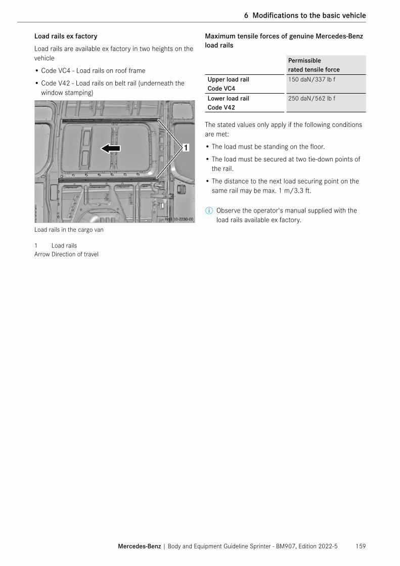
Load rails ex factory
Load rails are available ex factory in two heights on the vehicle
• Code VC4 - Load rails on roof frame
• Code V42 - Load rails on belt rail (underneath the window stamping)
Load rails in the cargo van
1 Load railsArrow Direction of travel
Maximum tensile forces of genuine Mercedes-Benz load rails
Permissible rated tensile force
Upper load rail Code VC4
150 daN/337 lb f
Lower load rail Code V42
250 daN/562 lb f
The stated values only apply if the following conditions are met:
• The load must be standing on the floor.
• The load must be secured at two tie-down points of the rail.
• The distance to the next load securing point on the same rail may be max. 1 m/3.3 ft.
ⓘ Observe the operator's manual supplied with the load rails available ex factory.
Mercedes-Benz | Body and Equipment Guideline Sprinter - BM907, Edition 2022-5 159
6 Modifications to the basic vehicle

Retrofitting load rails/tie-down rails
⑴ NOTE
Load rails or tie-down rails may only be retrofitted to the areas of the vehicle side wall designed for this purpose in the same way as the load rails available ex factory.
The maximum tensile forces (see table) must be com-plied with in all driving conditions. Otherwise there is a risk of damage to the side wall.
Position for retrofitting tie-down rails to vehicle side wall
Center of load rail DimensionBased on standard wooden floor a = 718 mm/28 in b = 1552 mm/61 inBased on vehicle floor (upper rib-bing)
a = 729 mm/29 in b = 1563 mm/62 in
The following points must be observed with respect to retrofitting load rails to the vehicle side wall:
• The instructions of the load rail manufacturer must be observed.
• The maximum tensile forces (see table) must be clearly indicated in the area of the load rails (e.g. using adhesive labels) and enclosed in a suitable form with the operator's manual in the vehicle.
Mercedes-Benz | Body and Equipment Guideline Sprinter - BM907, Edition 2022-5160
1 General
6 Modifications to the basic vehicle

Connection to vehicle side wall though riveting plus adhesive bonding
Permissible rated tensile force
Upper load rail (in area of roof frame)
120 daN/270 lb f
Lower load rail (in area of belt rail)
200 daN/450 lb f
Connection to vehicle side wall through riveting
Permissible rated tensile force
Upper load rail (in area of roof frame)
60 daN/135 lb f
Lower load rail (in area of belt rail)
100 daN/225 lb f
The stated values only apply if the following conditions are met:
• The load must be standing on the floor.
• The load must be secured at two tie-down points of the rail.
• The distance to the next load securing point on the same rail may be max. 1 m/ 3.28 ft.
Requirements of rivets
When retrofitting load rails on the vehicle side walls with rivets, the following values must be complied with:
• Cross-tension strength min. 3800 N
• Shear strength min. 3300 N
• Rivet diameter = 4.8 mm/0.19 in
• Head diameter = 9.3 mm/0.37 in
• Clamping range = 3.5 mm/0.14 in to 6.0 mm/0.24 in
Recommended process adhesives
Körapur 140Use AdhesiveSupplier Kömmerling,
Suppl. no. 110/75074Part no. A 009 989 17 71Chemical base 1K-PU that hardens in air
humidityUse-by date 6 months,
date specified on container
Köracur 110Use Accelerator pasteSupplier Kömmerling,
Suppl. no. 110/75074Part no. A 009 989 18 71Chemical base Water-based gel pasteUse-by date 9 months,
date specified on container
Körabond HG81Use ActivatorSupplier Kömmerling,
Suppl. no. 110/75074Part no. A 001 986 90 71Chemical base Silane, artificial resinUse-by date 12 months
Mercedes-Benz | Body and Equipment Guideline Sprinter - BM907, Edition 2022-5 161
6 Modifications to the basic vehicle

Recommended process steps for adhesive bonding
• Roughen load rail � The entire length of the bonding surface at the rear
of the mounting rail must be roughened with a wire brush. Roughened rails must be activated immedi-ately.
• Activate bonding surface � The entire roughened bonding surface must be
activated with a PE bottle with a felt insert. Straight afterwards, the activator that has not yet evapo-rated must be completely wiped off with a cleaning cloth (wipe on/wipe off procedure).
- Flash-off time: At least 10 minutes
- Time until application of adhesive: Max. 24 hours
- Replacement cycle for felt insert: When no longer functional
- Replacement cycle of PE bottle: At least once daily
• Bonding mounting rail � The adhesive must be applied to the entire length
of the activated bonding surface as a straight, round bead. There must be a gap in the adhesive bead of approx. 10 mm/0.39 in at the rivet holes to prevent adhesive from being squeezed out in the visible area.
• Adhesive application
- Bead geometry: Round bead
- Bead diameter: Approx. 6 mm/0.24 in
- Dwell time of adhesive in static mixer: Max. 15 minutes
- Time between adhesive application and joining: Max. 15 minutes
- Dwell time of adhesive on rail: Max. 15 minutes
- Time until load may be applied (curing time) Approx. 7 days
⑴ NOTE
The handling instructions of the adhesive manu-facturer must be followed. If the specified bonding instructions are not followed, the bond will not be of the required quality.
The mounting rail with adhesive must be bonded to the inside of the vehicle within 15 minutes. Otherwise excessive forces may result, causing damage to the side wall.
Mercedes-Benz | Body and Equipment Guideline Sprinter - BM907, Edition 2022-5162
1 General
6 Modifications to the basic vehicle

Rivet distances for load rails retrofitted to vehicle side wall
⑴ NOTE
The maximum rivet distances (see table) must be complied with in all driving conditions. Otherwise excessive forces may result, causing damage to the side wall.
Rivet distances for load rails retrofitted to vehicle side wall
Rivet distance Dimension x max. Dimension y max.Riveting plus adhesive bonding 75 mm/3 in 450 mm/18 inRiveting (without adhesive bonding) 25 mm/1 in 225 mm/9 in
Mercedes-Benz | Body and Equipment Guideline Sprinter - BM907, Edition 2022-5 163
6 Modifications to the basic vehicle

Pre-installation for fitted shelving
Code ZE6 "Pre-installation for fitted shelving" is available from the factory to facilitate the retrofitting of shelves. The package includes angles attached to the roof bows and body consoles mounted on the vehicle floor.
ZE6 package contents in shaded areas
Arrow Direction of travel
The following must be observed when using the shelf pre-installation:
• Shelves must not be wider than 450 mm/17.7 in.
• The max. load-bearing capacity is 80 kg/m; 53.7 lbs/ft.
• The shelf supports must be made of steel (at least ST235JO according to DIN EN 10025) complying with the US SAE/ASTM standards can be used with a minimum cross-section of 60 mm x 40 mm x 3 mm/2.4 in x 1.6 in x 0.1 in (length x width x thickness). � The shelf supports are bolted to the floor with the
mounting consoles.
Bolting the mounting consoles to the floor
� To fix the wooden floor, 2 angles per support must be mounted at the bolt connection between the support and the mounting console (contact surface per angle at least 1200 mm²/1.9 in², dimensions 60 mm x 20 mm/2.4 in x 0.8 in).
� A steel tube with a rectangular profile measuring 60 mm x 40 mm x 3 mm/2.4 in x 1.6 in x 0.1 in is bolted onto the brackets on the roof bows. The shelf supports are bolted to this rectangular profile at the top.
Mercedes-Benz | Body and Equipment Guideline Sprinter - BM907, Edition 2022-5164
1 General
6 Modifications to the basic vehicle

Connecting the shelf longitudinal tube to the roof bow bracket
Connecting the longitudinal tube to the support
• The longitudinal tube must not be connected with the partition wall or the rear door frame.
Suggested design for mounting console on belt rail
� In addition to fixing the shelf supports to the floor or to the roof bows, it is necessary to fix them to the belt rail by means of a mounting console.
� The connection must be made by bonding and riveting. A minimum bonding surface area of 7000 mm2/10.85 in2 is required.
⚠ WARNING
Improper shelf attachment may result in mechanical stress and may affect vehicle durability.
In the case of an accident, this could increase the risk of personal injuries. Please refer to the General subsection on section 6.6.4 Shelf systems/ vehicle interior installations (→ page 158).
Mercedes-Benz | Body and Equipment Guideline Sprinter - BM907, Edition 2022-5 165
6 Modifications to the basic vehicle

Additional connection of the longitudinal tubes
1 Connecting rail2 Longitudinal tube3 Support brace
� If the first or last support is more than 300 mm/11.8 in away from the roof bow, the longi-tudinal tubes must be connected together.
Suggested shelf attachment with ZE6
6.6.5 Loading cranes
The size of the crane must be selected in accordance with the chassis size.
Loading cranes must be secured on an assembly frame to relieve the load acting on the frame (→ page 180).
The permissible axle loads must be verified by calculat-ing a weight balance.
The vehicle's stability must be ensured by the upfit-ter. The slewing range of the crane must be limited accordingly.
Comply with local and national legal requirements.
The mounting instructions of the crane manufacturer must be observed.
ⓘ If additional platform or dump trucks are mounted, the dimensions of the assembly frame longitu-dinal members must be taken from the table for platform bodies (→ page 196) or dump trucks (→ page 200).
⑴ NOTE
Outriggers must be provided for every loading crane. We recommend using hydraulic outriggers.
The vehicle must not be raised using the outriggers, as this would damage the frame.
Mercedes-Benz | Body and Equipment Guideline Sprinter - BM907, Edition 2022-5166
1 General
6 Modifications to the basic vehicle

Loading crane mounted behind the cab
Loading cranes and outriggers must not impair the function of other equipment. For connecting the assembly frame to the vehicle frame Mercedes-Benz recommends a shear-resistant connection.
Assembly frame
• Maximum crane load moment (kN x l): 25 kNm/5175 ft lb
• Section moduli (Wx) and material properties can be found under 7.1 Assembly frame (→ page 180).
• Assembly frame longitudinal member section dimen-sions (→ page 180).
• While the crane is in operation, vehicle stability must be ensured by extending support feet. � Indicate supports that protrude beyond the vehicle
when the vehicle is stationary by means of conspic-uous colors, rear reflectors and warning lights.
� Determine the platform length according to the position and weight of the loading crane, complying with the permissible axle loads.
• If the maximum crane load moments are exceeded, an evalution with the responsible department is nec-essary. As part of the eXpertUpfitter program, please refer to www.UpfitterPortal.com.
• The vehicle may only be used on flat, paved roads.
• A frame extension may become necessary as a result of the load distribution.
• If a stronger assembly frame is required than for the body when a loading crane is mounted behind the cab, the loading crane can be secured on a shorter assembly frame (see illustration below). The short chamfered assembly frame must have a length lM corresponding to 35% of the wheelbase.
• For this type of attachment, an evalution with the responsible department is necessary. As part of the eXpertUpfitter program please refer to www.UpfitterPortal.com.
Mercedes-Benz | Body and Equipment Guideline Sprinter - BM907, Edition 2022-5 167
6 Modifications to the basic vehicle

Loading crane
1 Loading crane assembly frame2 Body consoles3 Loading crane attachment4 OutriggerlM Length of loading crane assembly frame
Mercedes-Benz | Body and Equipment Guideline Sprinter - BM907, Edition 2022-5168
1 General
6 Modifications to the basic vehicle

Loading crane mounted at end of frame
⚠ WARNING
The minimum front axle load (→ page 58) must be complied with in all load states. Otherwise adequate driving stability is no longer guaranteed.
• Loading cranes must be secured to an assembly frame made of steel. The assembly frame is to be joined to the vehicle frame by a shear-resistant connection.
• Maximum crane load moment (kN x l): 25 kNm/5175 ft lb
• Section moduli (Wx) and material properties can be found under 7.1 Assembly frame (→ page 180).
• For the section dimensions of assembly frame longi-tudinal members, see (→ page 180).
• While the crane is in operation, vehicle stability must be ensured by extending support feet, which must be designed as described on (→ page 167).
6.6.6 Lifting platform (cargo liftgate)
General
Before installing a cargo liftgate, the available installa-tion space must be checked by the upfitter. Note the limitations in the installation space due to the installed exhaust system and tank system.
⑴ NOTE
The reinforcement of the trailer hitch (Q11) in the rear longitudinal member on the left/right is available as standard for model designation 907 and cannot be deleted.
Mounting a lifting platform on cargo vans
Please consult with Mercedes-Benz if you intend to retrofit a lifting platform to a cargo van 1.7 Contact (→ page 11).
Preconditions for mounting a lifting platform
⑴ NOTE
An alternator and a battery with higher capacity as well as an auxiliary battery must be fitted if an elec-trohydraulic lifting platform is fitted.
• The permissible rear axle load must not be exceeded.
• The minimum front axle load must be complied with in all load states (→ page 58).
• Vehicle stability must be ensured by the upfitter in all operating statuses.
• Loading platforms must comply with the local and national regulations.
Mercedes-Benz | Body and Equipment Guideline Sprinter - BM907, Edition 2022-5 169
6 Modifications to the basic vehicle

� Use calculations to determine the load distribution. Take all special equipment into account when doing so.
� If necessary, shorten the body length and the rear chassis overhang accordingly (chassis).
• We recommend using hydraulic outriggers.
• Maximum load clearance 600 mm/23.6 in, relative to the standard rear portal/standard rear crossmember.
• The legal requirements in various countries relating to "Underride guard" and "Lighting system" must be observed when a lifting platform is mounted.
• Cuts in the end crossmember are only permitted after consultation with the department responsible 1.7 Contact (→ page 11).
• Vehicle stability when loading and unloading the vehicle must be ensured by the user.
⑴ NOTE
The permissible nominal live load on the lifting platform used must not be exceeded and the load clearance must be observed.
⑴ NOTE
The standard tail lamps of chassis vehicles may only be installed in the approved horizontal installation position as in the original condition.
For other installation positions, alternative tail lamps are available from the manufacturer of the standard tail lamps, see Chapter 8.5.3 Tail lamps (→ page 255).
Lifting platform attachment
The lifting platform must be attached as per Attach-ment to the rear frame section (→ page 106).
Additional torque support must be provided by means of at least two bolted connections fitted with spacer bushes (e.g. on the assembly frame).
� Extend the assembly frame as far forwards as pos-sible and attach it with a non-positive connection to the chassis frame.
• No assembly frame is required on vehicles with a standard cargo van body.
At the least, all the factory-installed body consoles, and in particular those at the rear end of the frame, must be used to connect the assembly frame (body and lifting platform) to the vehicle frame.
Attention must also be paid to the need for reinforce-ments in the left and right rear longitudinal members in vehicles with trailer coupling or the pre-installation for a trailer coupling, see note in Chapter 6.6.7 Trailer hitch (→ page 172).
If modifications are required to the rear underrun protection due to the attachment of a lifting platform, the strength and bending resistance of the rear under-run protection must not be changed (→ page 176).
⚠ WARNING
The vehicle must not be raised using the outriggers, as this would damage the frame.
Mercedes-Benz | Body and Equipment Guideline Sprinter - BM907, Edition 2022-5170
1 General
6 Modifications to the basic vehicle

Permissible lifting force of lifting platform
Type Wheelbase Maximum lifting force [kN]2 Minimum dimension of assembly frameChassis Cargo van1
1500, 25003500, 3500XD, 4500
144”170”
55
55
None
144”170”
7.57.5
55
80 x 45 x 3 mm (3.15 x 1.77 x 0.12 in)or factory platform, code P02
144”170”
1010
55
120 x 50 x 4 mm (4.72 x 1.97 x 0.16 in)
1 Without assembly frame2 For rated load distance of 600 mm/23.5 in
Mercedes-Benz | Body and Equipment Guideline Sprinter - BM907, Edition 2022-5 171
6 Modifications to the basic vehicle

6.6.7 Trailer hitch
⑴ NOTE
The reinforcement of the trailer hitch (Q11) in the rear longitudinal member on the left/right is available as standard for model designation 907 and cannot be deleted.
• We recommend only using trailer hitches which are approved by Mercedes-Benz or equivalently safe trailer hitches which are attached to the special mounting points on the body in white (rear longitudi-nal member) (→ page 322).
• Access to the spare wheel must be guaranteed if a trailer hitch with a non-detachable ball head is fitted (especially with a fully laden vehicle).
• The trailer hitch attachment and clearance dimen-sions must comply with FMVSS/CMVSS 110 for the Sprinters below 10,000 lbs GVWR (model 1500, 2500, 3500).
• There is no technical problem retrofitting a trailer hitch when special equipment code E40 Trailer plug socket 7-poles is already fitted.
ⓘ For information on the relationships between towing capacity, vehicle overhang and Trailer Stability Assist (TSA), see 4.1.3 Vehicle dimensions (→ page 59).
⑴ NOTE
Never attach a trailer hitch to the end crossmember of the frame.
⚠ WARNING
Risk of accident due to the impermissible attachment of a trailer hitch!
If a trailer hitch is retrofitted and you attach a trailer hitch or other components, the longitudinal frame member will be weakened and can break. In this case, the trailer can detach from the vehicle.
There is a risk of accident, personal injuries and death as a result of the improper attachment of a trailer hitch!
Only retrofit a trailer hitch if this is permissible.
Mercedes-Benz | Body and Equipment Guideline Sprinter - BM907, Edition 2022-5172
1 General
6 Modifications to the basic vehicle

Dimensioning the trailer hitch
The size of the trailer hitch is defined by the drawbar ratio.
D = g × mk × ma
mk + ma(kN)
D = Drawbar ratiomk = Permissible gross mass of tractor unit (vehicle) in tma = Permissible gross mass of trailer in tg = 9.80665 m/s2 ; 386 in/s2
In order to allow the trailer to be exchanged when used in international transport, the clearance between the center of the trailer hitch and the end of the towing vehicle must be no more than 300 mm/11.8 in. Please refer to FMVSS/CMVSS 110.
Clearance dimensions of trailer hitch
Clearance dimensions of FMVSS/CMVSS 110 must be taken into account.
The height of the trailer hitch above the ground must be between 350 mm and 420 mm/12 in and 18 in when the vehicle is laden to the permissible gross mass. The reliable operation of the hitch must not be impaired. Do not install an open-jaw hitch fitted to the front of the vehicle. The specified clearances must be maintained.
Mercedes-Benz | Body and Equipment Guideline Sprinter - BM907, Edition 2022-5 173
6 Modifications to the basic vehicle

Trailer hitch
In the USA and Canada, the following trailer hitch is used:
N31.10-2335-00
Trailer hitch
The ball neck (orange) for the specific trailers can be purchased in the accessories trade.
⚠ WARNING
If the towing vehicle is unladen, only an unladen trailer may be towed. Otherwise, the vehicle may become unstable.
⑴ NOTE
If trailer hitches have removable ball heads, the oper-ating instructions must be supplied in the vehicle and they must refer to the special features and operation of the hitch.
Attachment of the trailer hitch
Only secure trailer hitches/trailer brackets to the spe-cial mounting points on the body in white (rear longitu-dinal member) (→ page 322).
In addition, cargo vans require an additional attach-ment as support on the rear cross member of the vehicle frame.
Interior view
a Attachment of mounting plate to longitudinal frame member
b Lower flange of longitudinal frame memberc Frame end crossmemberd Mounting plate for trailer hitch
• No attachment may be made to the rear underrun protection.
• If the frame needs extending, spacer bushes must be fitted to the frame to attach the mounting plate or the rear crossmember (→ page 104). They may lead to a reduction in the towing weight or the tongue weight.
Hole patterns with dimensions for attaching trailer hitches can be found under 10.3 Trailer hitch hole pat-terns (→ page 322).
⚠ WARNING
Risk of accident due to the impermissible attachment of a trailer hitch!
If a trailer hitch is retrofitted and you attach a trailer hitch or other components, the longitudinal frame member will be weakened and can break. In this case, the trailer can detach from the vehicle.
There is a risk of accident, personal injuries and death as a result of the improper attachment of a trailer hitch!
Only retrofit a trailer hitch if this is permissible.
Mercedes-Benz | Body and Equipment Guideline Sprinter - BM907, Edition 2022-5174
1 General
6 Modifications to the basic vehicle

Depending on the model series, the following special equipment is available as an option code from the fac-tory to retrofit trailer hitches:
Code DescriptionE40 Trailer Plug Socket 7-pin
Provides power for trailer lightning systems (tail lights, brake lights, direction indicators, rear fog lights and reversing light) and allows electrical operation. It is installed with the corresponding wire harness and trailer control unit.Required for: trailer couplings (QA2/Q24)
QA9 Cross Member with Integral StepStep (on right sight of the trailer hitch) consisting of a tubular steel frame with welded-on anti-slip tread surface is bolted onto the right-hand side of the trailer coupling cross memberStep dimensions: 520 mm x 190 mm/20.5 in x 7.5 in
Q24 Trailer Cross Member (towing capacity 2268 kg/5000 lbs)Enables retrofit of a trailer coupling. Trailer socket (E40) is included.Max. permissible tongue weight is 500 lbs (227 kg)Max. towing capacity is 5000 lbs (2268 kg)Not for 170EXT cargo van. Available in combination with QA9.
QA2 Trailer Cross Member (towing capacity 3402 kg/7500 lbs)Enables retrofit of a trailer coupling. Trailer socket (E40) is included.Max. permissible tongue weight is 750 lbs (340 kg)Max. towing capacity is 7500 lbs (3402 kg)Not for cargo van with length 170EXT. Available in combination with QA9.
⑴ NOTE
The reinforcement of the trailer hitch (Q11) in the rear longitudinal member on the left/right is available as standard for model designation 907 and can not be deleted.
Mercedes-Benz | Body and Equipment Guideline Sprinter - BM907, Edition 2022-5 175
6 Modifications to the basic vehicle

6.6.8 Underrun protection
Rear underrun protection
The rear underrun protection fitted at the factory (except on cargo vans and passenger vans) complies with the regulation UN R 58.
Rear underrun protections are based on state level regulations.
N31.30-2336-00
max.400 mm
15.7 inmax
.55
0 m
m21
.7 in
min
.10
0 m
m3.
9 in
Side view of the rear underrun protection location
On no account should modifications be made to the underrun protection.
The regulation UN R 58 stipulates a underrun protec-tion when:
• with the vehicle in its unladen condition, the dis-tance between the roadway and the chassis or main parts of the body in the area between the insides of the tires -100 mm/4 in per side, is more than 550 mm/22 in
Exceptions to this regulation are semitrailer trucks, working machines and vehicles whose purpose cannot be fulfilled if an rear underrun protection is fitted.
The underride guard must be mounted as far back as possible.
Dimensions of the rear underrun protection
• Maximum height of rear underrun protection (unladen vehicle) above roadway: 550 mm/22 in.
• Width:
- � Maximum = Width of the rear axle (outer tire edges).
- � Minimum = Width of rear axle minus 100 mm/4 in on each side. The decisive factor is the widest axle.
• The crossmember must have a section height of at least 100 mm/4 in.
• Edge radius at least 2.5 mm/0.1 in.
Mercedes-Benz | Body and Equipment Guideline Sprinter - BM907, Edition 2022-5176
1 General
6 Modifications to the basic vehicle

Front underrun protection
Front underrun protections are based on state level regulations. Please refer to CMVSS 215/US 49 CFR Part 581.
N31.30-2337-00
Side view of the front underrun protection location
Dimensions of the front underrun protection:
• Height of front underrun protection above roadway: 406 mm/16 in.
• The crossmember must have a section height of at least 100 mm/4 in.
• In case of code ZG1/ZG3 (4x4), the front underrun protection lies 74 mm/2.9 in lower.
Torques for remounting:
N31.30-2338-00
Torques for remounting ront underrun protections
Modifications to the underrun protection
If the underrun protection needs to be repositioned due to the overhang extension, the attachment must be the same as that of the original vehicle.
If modifications are required to the underrun protec-tion (e.g. due to the attachment of a lifting platform), the strength and bending resistance of the underrun protection must not be modified.
Any modifications to the underrun protection must comply with local and national regulations and laws.
⑴ NOTE
On cab-chassis, the reinforcement of the trailer coupling in the left/right rear longitudinal member for BR 907 is installed in the vehicle as standard. If this is not required, it must be deleted when the vehicle is ordered (code QW1). For cargo, crew, and passenger vans, the longitudinal member reinforcement must be ordered at the same time (code Q11).
Lateral protections
N31.30-2339-00
550
mm
21.7
in
950
mm
37.4
in
350
mm
13.8
in
Side view of the lateral protection location
Mercedes-Benz | Body and Equipment Guideline Sprinter - BM907, Edition 2022-5 177
6 Modifications to the basic vehicle

Protective equipment on the sides has to comply with applicable legal regulations.
Components may be mounted within the lateral pro-tections, e.g. battery box, air tank, fuel tank, lamps, reflectors, spare wheel and tool box, provided that the specified clearances are maintained.
Brake, air or hydraulic lines and other parts must not be fastened to the lateral protection.
The function and accessibility of all equipment on the vehicle must not be impaired.
If lateral protections are retrofitted:
• The dimensions specified in the illustration may not be exceeded.
• Protective equipment must comply with applicable legal regulations.
• The lateral protections must extend continuously from the front to the rear wherever possible.
Adjacent parts may overlap. The overlapping edge must point to the rear or downwards. The maximum permis-sible width of any gap between segments is 25 mm / 0.98 in, provided the rear part does not protrude signifi-cantly beyond the front part.
The lateral protection may consist of a continuous level surface. The outer surface must be smooth and generally flat. The lateral protection parts must be rigid and permanently fixed into place. They must be made of metal or another suitable material. The distance between the outer surface of the lateral protection and the outer edge of the vehicle must not be more than 120 mm/4.7 in. The edge radius must be at least 2.5 mm/0.1 in.
6.6.9 Positioning placard holders
This chapter provides information about positioning and fastening methods to add aftermarket placard holders to the Sprinter vehicle.
⑴ NOTE
It is the upfitter’s responsibility to adhere to all appli-cable rules and regulations, particularly Canadian laws mandated by Transport Canada regarding the Transportation of Dangerous Goods.
The upfitter may choose the below mentioned posi-tions. For fastening the placard holders, it is recom-mended to use a gluing method to reduce the risk of corrosion due to drilling through the body shell. If the upfitter fastens the placard holders by drilling holes and using bolts, please refer to Chapter 5.3 Anti-corrosion protection measures (→ page 86). The upfitter needs to ensure enough clearance between the sliding door and the placard holder. The upfitter needs to ensure that the equipment installed to the exterior of the vehicle must not become loose and be lost during the vehicle operation.
The following picture indicates the Mercedes-Benz recommended left, right, and rear position of the placard holders. For positioning the placard holder to the front-bumper of the vehicle, it needs to be ensured that no sensors are covered or impaired if the vehicle is equipped with Parktronic or Collision Prevent Assist/Active Brake Assist - code BA3/Active Distance Assist – ET4. The sensor positions are described in chapter 5.4 Painting work/preservation work (→ page 88), chapter 8.9.3 Active Brake Assist/Active Distance Assist (DISTRONIC PLUS) (→ page 275) and chapter 8.9.10 Parktronic sensors (→ page 295).
144” 170” 170”EXTx1 450 mm /
17.7 in450 mm / 17.7 in
450 mm / 17.7 in
Y1 584 mm / 23 in
584 mm / 23 in
584 mm / 23 in
x2 485 mm / 19 in
485 mm / 19 in
485 mm / 19 in
y2 584 mm / 23 in
584 mm / 23 in
584 mm / 23 in
x3 289 mm / 11.3 in
289 mm / 11.3 in
289 mm / 11.3 in
y3 181 mm / 7.1 in
181 mm / 7.1 in
181 mm / 7.1 in
Mercedes-Benz | Body and Equipment Guideline Sprinter - BM907, Edition 2022-5178
1 General
6 Modifications to the basic vehicle
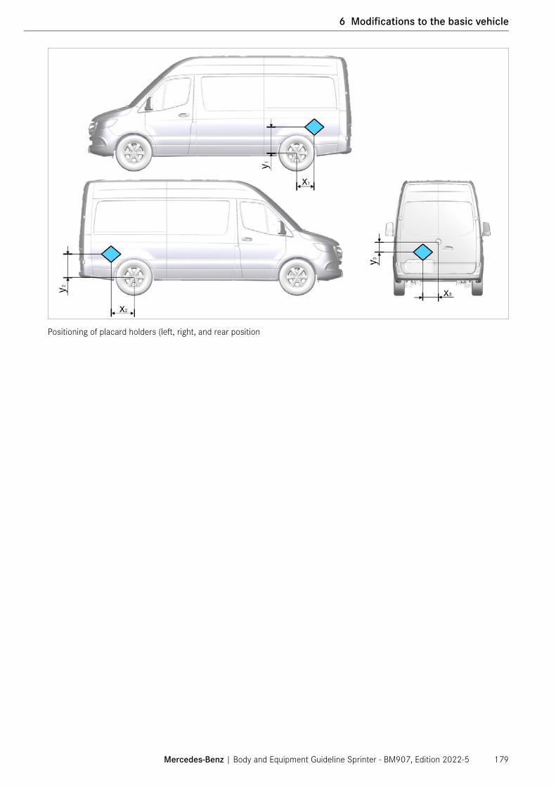
Positioning of placard holders (left, right, and rear position
Mercedes-Benz | Body and Equipment Guideline Sprinter - BM907, Edition 2022-5 179
6 Modifications to the basic vehicle

7.1 Assembly frame
This chapter contains information concerning the upfit made by the upfitter.
All upfits require a continuous assembly frame or a substructure that acts as a continuous assembly frame in order to ensure a flawless connection between the chassis and upfit, see 7.1.5 Assembly frame as floor assembly (→ page 188) and 7.2 Self-supporting bod-ies (→ page 189).
The attachment to the frame must run along the frame using the body consoles attached to the frame at the factory, see 7.1.2 Design (→ page 181) and 7.1.4 Attachment to the chassis bed (→ page 183). Exception: On vehicles with a dropped frame (model designation 907.x5x) (7.1.2 Design (→ page 181)), the assembly frame longitudinal members can run continu-ously in a straight line.
7.1.1 Material quality, general
Material quality of specified assembly frame made of steel:
• Assembly frame mounted with mounting consoles (non-positive) = CR240LA or S235JRG2.
• For CR240LA or S235JRG2 steels complying with the DIN EN standard, analogous materials complying with the US SAE/ASTM J403/J412/J413 standards, the Japanese JIS G3445 standards or the UK BS 970 standards can be used. .
Material Yield strength Tensile strength CR240LA 260-340 N/mm2;
37700 psi-49300 psi
≥ 240 N/mm2;≥ 34800 psi
S235JRG2 ≥ 235 N/mm2;≥ 34075 psi
340-510 N/mm2;49300 psi-73950 psi
Material specifications should correspond to DIN stan-dard MBN11251
Minimum section modulus required for assembly frame Wx
1
Version Platform/box body
Dumper/lifting work platform
Loading crane
All weight variants
17[2] cm3/1.0 in3
30 cm3/1.8 in3
40 cm3/1.0 in3
1 The minimum section modulus required for assembly frames is relevant to the material characteristics speci-fied in the table of materials above, and each individual assembly frame longitudinal member must have this section modulus.
2 Up to the maximum standard wheelbase; above that: +10%.
• If high-strength steel is used for the assembly frames, their strength must be at least equivalent to that of steel assembly frames.
• When using an assembly frame made of aluminum, for example, it must have at least the bending strength (E x I) of a steel assembly frame. Observe the specifications of the manufacturer.
Guideline values for modulus of elasticity:
• Aluminum: 70000 N/mm2; 1015000 psi
• Steel: 210000 N/mm2; 3045000 psi
If a lifting platform (cargo liftgate) is being fitted, observe the relevant chapter and refer to the overview (→ page 169).
ⓘ Observe any deviations in the specifications in this chapter, see 7.5 Platform bodies (→ page 196) and 7.9 Dump trucks (→ page 200).
Mercedes-Benz | Body and Equipment Guideline Sprinter - BM907, Edition 2022-5180
1 General
7 Design of bodies
7 Design of bodies

7.1.2 Design
General � On model designations 907.X2X, 907.X3X and
907.X4X, the mounting frame longitudinal members must be arranged above the straight chassis frame longitudinal members.
� On model designation 907.X5X, the mounting frame longitudinal members can be straight through, see note on offset frames at the end of this chapter.
� At the position of the double body brackets (see 2 in illustration Chapter 6.2.2 Attachment to the frame (→ page 105)), the mounting frame cross-members must be positioned about the chas-sis frame cross-members.
� For the other mounting frame cross-members, an arrangement above the chassis frame cross-mem-bers is recommended.
� The assembly frame longitudinal members must extend as far towards the front of the vehicle as possible, to reinforce the point behind the cab which is critical with regard to bending stress, as well as to prevent vibration problems.
� The body must have a torsion-free attachment to the body consoles on the longitudinal frame member.
� Place the vehicle on a flat, horizontal surface before mounting the body.
If very high longitudinal members are required, or if low overall frame heights are achieved, the following non-positive connections are possible for U-sections:
• Closed as a box
• Nested
• Overlapping
This increases the section modulus and torsional stability.
Frame sections
A Open U-sectionB Closed U-sectionC Nested U-sectionD Overlapping U-section
Assembly frame with dropped frame
On vehicles with a dropped frame (permissible gross mass ≥ 4.6 t/10141 lbs), the assembly frame longitudi-nal members can run continuously in a straight line.
Mercedes-Benz | Body and Equipment Guideline Sprinter - BM907, Edition 2022-5 181
7 Design of bodies

7.1.3 Section dimensions/dimensioning
Folded U sections or commercially available U sections for vehicle construction (not rolled steel sections) are to be used for the longitudinal members. Box sections are also permitted as longitudinal member sections.
The dimensions of the longitudinal members are a func-tion of the section modulus (Wx) required for the body and the chassis (→ page 180).
The specified section moduli and section dimensions refer to longitudinal frame members subjected to iden-tical loads on both sides.
Please refer to the table below for the section dimen-sions of assembly frame longitudinal members (open section).
The assembly frame and the chassis frame should have approximately the same flange width.
⑴ NOTE
If more than one body is mounted on the same chassis (e.g. platform and lifting platform), the larger of the specified section moduli must be taken to determine the assembly frame.
Longitudinal member dimensioning
h: Section height in mm Wx: Section modulus in cm3
Mercedes-Benz | Body and Equipment Guideline Sprinter - BM907, Edition 2022-5182
1 General
7 Design of bodies

7.1.4 Attachment to the chassis bed
At the least, all the factory-installed body consoles must be used for attaching bodies to the vehicle frame. The consoles are located on the longitudinal frame members and additional body consoles may be fitted to the longitudinal frame members as required. All the body consoles, in particular those at the rear end of the frame, must be used to attach a lifting platform (cargo liftgate) and the body.
⑴ NOTE
The minimum distance between the body and the cab must be > 50 mm/2 in.
The bodies must rest on the body consoles and may also rest on the frame crossmembers. It is recom-mended that the body should not rest on the end crossmember. If prefabricated assembly frames are used, the production tolerances of the chassis frame width (maximum +6/–3 mm; +0.2/-0.1 in) must be taken into consideration.
ⓘ The positions for the body consoles are indicated in the 2D chassis drawings (offer drawings) depending on the model series (→ page 18).
N60.00-2506-00
N60.00-2228-00
11
11 22
22
18 mm0.71 in
66 mm2.60 in
180 mm7.09 in
134 mm5.28 in
13 mm0.51in
13 mm0.51in
70 mm2.76 in
118 mm4.65 in
60 mm2.36 in
195 mm7.68 in
25 mm0.98 in
23 mm0.91 in
18 mm0.71 in
18 mm0.71 in
120 mm4.72 in
70 mm2.76 in70 mm2.76 in
Designs of attachment points on the frame
Mercedes-Benz | Body and Equipment Guideline Sprinter - BM907, Edition 2022-5 183
7 Design of bodies

Additional body consoles
If it is necessary to fit additional body consoles, make sure that you comply with the welding directives (→ page 85).
• Plug welding is only permissible in the vertical webs of the longitudinal frame member.
• Do not perform any welding work in bends.
The body consoles must be attached using two bolts for each body console.
Attachment of the body consoles
If a mounted box body is rigid, then it is recommended to ensure that there is a large contact area between the mounting consoles and the body. If possible, the mounting consoles of the subframe should have identical dimensions to the body consoles on the vehicle.
The force at these threaded connections must be distributed across the maximum possible surface area using washers with a diameter of approximately 35-40 mm (1.37-1.57 in) or square shims with a length along each edge of approximately 35-40 mm (1.37-1.57 in)
Body consoles (dimensions in mm/in)
Example of a body console design
I Box sectionII U-section1 Chassis frame2 Assembly frame3 Standard mounting console4 Mounting console
Attachment to a longitudinal member
Mercedes-Benz | Body and Equipment Guideline Sprinter - BM907, Edition 2022-5184
1 General
7 Design of bodies

Attachment to a crossmember
Attachment to a crossmember
1 Body console
Select the number of attachments to ensure adequate transfer of all longitudinal and lateral forces.
Correct attachment is a decisive factor for:
• vehicle handling and operating safety
• the durability of the chassis frame and the body
Shear-resistant connection
ⓘ Also refer to 7.10 Light duty truck (→ page 201).
For a shear-resistant connection, the assembly frame longitudinal members must be secured in both longitu-dinal and transverse directions. This will allow move-ment of the assembly frame longitudinal member only under specific conditions.
The body can be secured to the sides of the upper flan- ges on the longitudinal frame member. Spacer bushes welded to the frame must be used for reinforcement.
For shear-resistant connections, a double support is required for each longitudinal frame member as depicted in the figure below. The shear-resistant connection is required e.g. for "Loading crane at frame end" and is recommended for "Loading crane behind the cab".
Double support (shear-resistant connection)
a Shear-resistant connection at frame endb Standard holes at frame end
Mercedes-Benz | Body and Equipment Guideline Sprinter - BM907, Edition 2022-5 185
7 Design of bodies

Chassis connection for rigid body upfits
For fully integrated bodies (continuous connection between the upfit and the rear of the B-pillar):
It is recommended to utilize standard bolted or rigid connections with maximized grip length between all mounting consoles and the mounting frame (the upfit-ter’s frame connecting to the chassis frame).
For non-fully integrated bodies (no connection between the upfit and the rear of the B-pillar) and upfits with a rigid mounting frame, please follow the out-lined recommendations below.
The upfitter needs to ensure that the equipment installed to the vehicle must not become loose and be lost during the vehicle operation.
⑴ NOTE
Definition of rigid body upfits: Mounting frames or box upfits connected to the longitudinal members of the cab chassis frame which substantially modify the torsional rigidity and bending behavior of the vehicle frame particularly in the area behind the B-Pillar.
The following mounting concept is recommended to decrease potential stress peaks directly behind the B-Pillar (transition between rear of cab and longitudi-nal members) by using a combination of elastic and rigid connections:
• An elastic connection should be used for the first and second mounting consoles to prevent stress peaks in the transition area between the rear of the cab and the longitudinal members (see pictures on following page).
The picture below shows an example using multiple disc springs. As an alternative, an elastic element out of elas-tomer material (e.g. rubber) may be used as well.
Elastic connection with spring discs
a Flanged bolt M12 x 90, strength 10.9b Spacer sleeve 22-13 x 50c Washer DIN 7349-13-STd Nut with flange M12, strength 10.9e Elastic element (e.g. multiple disc springs or
polymer springs)
Elastomer bearings/ bushings"
• A rigid connection with maximized grip length should be used at the last connecting console of the chassis frame, and if necessary, place the rigid connections with maximized grip length from the third console to the mounting console immediately behind the rear axle. The spacer sleeve is used to maximize the grip length to prevent connection from loosening. The dimensions of the spacer sleeves must be thick enough to ensure they do not deform. These rigid con-nections should also be used for attaching bodies such as garbage presses or box bodies ≥ 1000 mm/39.8 in (measured from behind the B-pillar) in combination with a dump bed or platform on the chassis frame
Rigid connection with maximized grip length
• A standard bolted should be used from the third con-sole to the mounting console immediately behind the rear axle. Also a rigid connection with maximized grip length (described in B) may be used in this area.
Mercedes-Benz | Body and Equipment Guideline Sprinter - BM907, Edition 2022-5186
1 General
7 Design of bodies

Standard bolted connectionIf there are additional loads on the chassis frame besides the body upfit, then it may be required to reinforce the rear end of the mounting frame by fitting a diagonal cross.
Please also observe Chapter 8.4.6 Retrofitting electri-cal equipment (→ page 242)
ⓘ If additional information is required, please refer to www.UpfitterPortal.com.
Mounting concept for body upfits with rigidity:
Sprinter cab chassis with 144” wheelbase – recommended attachment to the chassis frame/longitudinal members
Sprinter cab chassis with 144” wheelbase – recommended attachment to the chassis frame/longitudinal members
Mercedes-Benz | Body and Equipment Guideline Sprinter - BM907, Edition 2022-5 187
7 Design of bodies

7.1.5 Assembly frame as floor assembly
An assembly frame with continuous longitudinal mem-bers is not required if the body floor assembly can take on the function of the assembly frame.
The longitudinal members can also be integrated in the body. If the assembly frame longitudinal members are intersected by the crossmembers, the connection between the longitudinal and crossmembers must be rigid and resistant to torsion and bending.
Example of a floor assembly design
Mercedes-Benz | Body and Equipment Guideline Sprinter - BM907, Edition 2022-5188
1 General
7 Design of bodies

7.2 Self-supporting bodies
An assembly frame with continuous longitudinal mem-bers is not required if the body's floor assembly can assume the functions of the assembly frame.
Self-supporting bodies must comply with the proper-ties of the specified assembly frame. The body's floor assembly must have equivalent rigidity and a section modulus similar to the assembly frame. The floor assembly of the self-supporting body must be attached to the vehicle frame in the same way as a body frame/ assembly frame by means of a stretch bolt connection locked to prevent loosening (→ page 188).
max. 600 mm
23.6 in
N31.20-2200-00
Example of a body design
Mercedes-Benz | Body and Equipment Guideline Sprinter - BM907, Edition 2022-5 189
7 Design of bodies
7.3 Modifications to the interior
Retrofitting additional seats
The strength of the seats delivered from the factory is only valid if the seats are secured in their original mountings
When retrofitting seats, it is absolutely essential to keep to the H-point. The seat adjustment range must not be enlarged. For up to date documentation, see 1.7 Contact (→ page 11).
If a rear bench seat with 2 or 3-point seat belts devi-ates from the standard seat design, it must comply with the requirements from chapters 6.4.1 General information (→ page 138), 6.4.2 Safety equipment (→ page 139) and 6.4.3 Seats (→ page 147).
A rear seat system with 2- or 3-point seat belts that deviates from the standard seating arrangement must meet the requirements of the FMVSS/CMVSS 207 (seating systems) and the FMVSS/CMVSS 210 (seat belt assembly anchorages) standard. Furthermore, the standard FMVSS/CMVSS 209 (Seat belt assemblies) must be adhered to. For the headrests, proof of compli-ance with the FMVSS/CMVSS 202a (Head restraints) standard is required. The test reports in relation to FMVSS/CMVSS 202a, FMVSS/CMVSS 207, FMVSS/CMVSS 209 and FMVSS/CMVSS 210 must be submit-ted for approval by Mercedes-Benz.
When reinstalling seat belts, the specified bolts must be replaced and tightened to the original torque with the tolerances for connecting and fastening elements including the classification (A/B/C) as per VDI 2862 (The Association of German Engineers).
⚠ WARNING
It is not permitted to mount seats on the wheel well, partitions or other sheets metal parts of the vehicle as they could become detached from their anchor-ages in the event of an accident. Passengers will not be protected as intended. There is a risk of accident, personal injuries and death if such systems no longer function correctly.
In the case of vehicle orders where the driver's seat (code S90) or front passenger seat (code S91) is omit-ted, subsequent installation of standard seats (driver's or front passenger seat) in the body-in-white is not permitted, as no reinforcements or suitable connection points are available. However retrofitting of aftermarket seats is possible.
For modifications to the seat attachments (including seat bases) and seat belt anchorages or for the instal-lation of seats other than those available from the factory, an evalution with the responsible department is necessary. As part of the eXpertUpfitter program please refer to www.UpfitterPortal.com.
⚠ WARNING
If seats other than those fitted at the factory are fitted in conjunction with seat belts available from the factory, only seat belt buckles that are compatible with the belt tongues of the factory-supplied seat belts may be used. Otherwise the seat belt cannot be locked in the seat belt buckle as intended. Pas-sengers will not be protected as intended. There is a risk of accident, personal injuries and death if such systems no longer function correctly!
Only use latch plates which are approved for the factory-fitted seat belts.
Only the components of the series production supplier may be used for the installation of seat belts and seat belt buckles:
Contact details
Postal address: Autoliv B.V. and Co. KGPostfach 109D-25333 Elmshorn, Germany
Telephone: +49 (0)4121 - 797-0
All regulations relevant to approval (e.g. seat belt buckle position) must be observed when fitting seat belts and seat belt buckles other than those available from the factory.
Mercedes-Benz | Body and Equipment Guideline Sprinter - BM907, Edition 2022-5190
1 General
7 Design of bodies

Rear seats in the passenger compartment/cargo area
On cargo vans of model series BR 907, the body-in-white floor assembly is available from the factory as special equipment under code V40 (Crewbus floor assembly) for retrofitting bench seats. The number of mounting options for the crewbus floor assembly depends on the model series and the equipment or registration variants (the mounting shells for the bench seats are not included in the scope of delivery).
⑴ NOTE
The upfitter is responsible for ensuring compliance with the legal requirements for transporting passen-gers in the rear.
Additional information on special equipment code V40 can be obtained from your Mercedes-Benz Service Center, the relevant department (→ page 14) or under 3.12 Special equipment (→ page 55).
If rear seats with 2 or 3-point seat belts deviate from the standard seat design, they must comply with the requirements of the regulations UN-R 14 (seat belt anchoring), UN-R 16 (seat belts) and UN-R 17 (seats and head restraints).
⚠ WARNING
If seats other than those fitted at the factory are fitted in conjunction with seat belts available from the factory, only seat belt buckles that are compatible with the belt tongues of the factory-supplied seat belts may be used. Otherwise the seat belt cannot be locked in the seat belt buckle as intended. Passen-gers cannot be protected as intended. There is a risk of injury!
Only use latch plates which are approved for the factory-fitted seat belts.
Reinforcement of sliding door to load compartment with rear seats
For the Sprinter BR 907 the impact protection rein-forcement is added automatically as required for vehi-cles with a long sliding door to the load compartment (vehicle length A2 and over, not for A1) and vehicles with crewbus floor assembly (code V40) for countries with appropriate legislation which requires the installa-tion of this reinforcement.
N91.12-2191-00
1
Right load compartment sliding door from outside without paneling
1 Assembly part "impact protection reinforcement"
The reinforcement is required when installing rear seats in the cargo van and crewbus in the following coun-tries:
• Mexico, USA, Canada
• GCC Arab States of the Gulf (Kuwait, Bahrain, Saudi Arabia, Qatar, United Arab Emirates, Oman) GCC = Gulf Cooperation Council
If the upfitter retrofits of rear seating for these coun-tries, it must be ensured that the impact protection reinforcement is installed.
In combination with the special equipment crewbus floor assembly (code V40), the impact protection rein-forcement is already installed at the factory.
For retrofit installation, the assembly part is available from your Mercedes-Benz Service partner under the following item numbers:
• A 910 730 47 00 left reinforcement
• A 910 730 48 00 right reinforcement
The fasteners and tightening torques documented in WIS (see Chapter 2.3.2 Workshop Information System (WIS) (→ page 18)) must be used for installation.
⑴ NOTE
The upfitter must check and comply with all national laws, directives and registration regulations.
Mercedes-Benz | Body and Equipment Guideline Sprinter - BM907, Edition 2022-5 191
7 Design of bodies

7.4 Modifications to closed cargo vans
Floor assembly/side walls
On cargo vans, the body and the chassis frame form a self-supporting unit. If body parts are modified or fitted, they must only be welded if a bonded connection is not possible.
For this reason, windows, roof hatches and vent open-ings must be mounted in a sturdy frame. The frame must then be joined by a non-positive attachment to other body elements.
Underbody Supporting Structure
N61.00-2035-00
Underbody Supporting Structure
Depending on the coding, there is an underbody sup-porting structure (A 906 312 16 61) in the cargo van and passenger van integrated. The amount of installed structures at the different positions for different config-urations is shown in the following table:
Tonnage Wheelbase
170 170 EXT
Support-ing struc-ture 1
Support-ing struc-ture 2
Support-ing struc-ture 1
Support-ing struc-ture 2
2500 1 1 1 33500,3500 EXT
1 1 1 1
The underbody supporting structure may have parts installed, if the following codes are used:
Code Description Supporting Structure 1 Supporting Structure 2UT1 Seat Attachment Fond, Fixing Point No YesV39 Artificial Surface
People MoverNo No
V43 Wooden Floor No NoZE6 Structure for the Installation of
ShelvesNo No
Mercedes-Benz | Body and Equipment Guideline Sprinter - BM907, Edition 2022-5192
1 General
7 Design of bodies

Cab rear panel
If an opening is made in the cab rear panel, it must be surrounded by a sectional frame.
The remaining braces and pillars must be reinforced by additional gussets and connected to the sectional frame (e.g. by bonding).
Also please refer to 6.2.5 Modifications to the cab (→ page 110).
Partitions in the BM 907
Vehicles upfitted as commercial vehicles with out a partition do not satisfy the requirements of ISO 27956, which describes the fixtures for the proper securing of cargo in delivery vans. If the vehicle is used to trans-port goods, the installation of a ISO 27956 compliant partition is recommended.
If retrofits, modifications, or attachments of any kind are performed on the partition, compliance with ISO 27956 is recommended.
If the partition is removed, the vehicle will no longer comply with ISO 27956. In this case, the tie-down eyes must be installed. If the partition/divider is modified or removed or has parts attached to the partition wall, the functionality of safety equipment (e.g. the deployment areas of airbags) must not be affected (see Chapter 6.4.2 Safety equipment (→ page 139)).
In these cases the upfitter must ensure that the prod-uct satisfies the requirements of a safe product, if nec-essary by means of other measures as he or she sees fit. In this respect, the ISO standard represents only the technical minimum standard.
The following partition walls are available as special equipment from the factory:
Code Description
D50 Full-width partition wall (standard)D51 Full-width partition wall with windowD56* Full-width partition wall at C-pillarD64 Partition wall with sliding doorD93 Omission of partition wall
* Only available in Canada
Additional information on special equipment can be obtained from your Mercedes-Benz Service Center or under 3.12 Special equipment (→ page 55).
Mercedes-Benz | Body and Equipment Guideline Sprinter - BM907, Edition 2022-5 193
7 Design of bodies

Head Impact
Certain precautionary measures are necessary to ensure the safety of all passengers.
Mercedes-Benz offers two different solutions:
1. Mercedes-Benz partition wall meeting the FMVSS 201 requirements.
2. If there is no Mercedes-Benz partition wall installed, foam pads are provided in order to meet FMVSS 201.
ⓘ In the case you are installing an aftermarket partition wall, please ensure to meet FMVSS 201 requirements.
It is upfitter’s ultimate responsibility to review and com-ply with FMVSS 201 as it relates to its installation of Mercedes-Benz partition walls and foam pads, as well as its decision to use and install non-Mercedes-Benz partition walls and parts.
• If the vehicle has no partition wall installed and has a GVWR ≤ 10,000 lbs, it is fitted with foam pads (see pictures below)
High roof
• If the vehicle has a partition wall installed, it is not fitted with foam pads (see pictures below)
High roof
⑴ NOTE
Following FMVSS 201 requirements, all Mercedes- Benz Vans ≤10,000 lbs and without a partition wall are fitted with foam pads (see picture). Vehicles >10,000 lbs with and without a partition wall are fitted without foam pads.
It is not recommended to modify the foam pads and their surrounding area in order to comply with FMVSS 201.
Standard roof
Standard roof
Mercedes-Benz | Body and Equipment Guideline Sprinter - BM907, Edition 2022-5194
1 General
7 Design of bodies

• If the vehicle has no partition wall installed and has a GVWR ≥ 10,000 lbs, it is not fitted with foam pads (see pictures below)
High roof Standard roof
Mercedes-Benz | Body and Equipment Guideline Sprinter - BM907, Edition 2022-5 195
7 Design of bodies

7.5 Platform bodies
To ensure the uniform loading of the chassis frame, the body must be attached to the chassis frame by means of an assembly frame (U-section longitudinal members) (→ page 180).
At the least, all the factory-installed body consoles must be used for attaching platforms to the vehicle frame.
If the standard platform is subjected to point loads (e.g. for the transportation of cable drums, coils, etc.), the substructure and the platform floor must be reinforced to support the load.
Before start of installation:
� Weigh the chassis and establish body length.
• Section moduli (Wx) and material properties can be found under 7.1 Assembly frame (→ page 180).
• For the section dimensions of the assembly frame longitudinal members, see the diagram (→ page 182).
⑴ NOTE
Where bodies include detachable parts which move independently, ensure that there is adequate clear-ance between the detachable parts and the basic vehicle, otherwise they may collide with the basic vehicle, resulting in damage.
Mercedes-Benz | Body and Equipment Guideline Sprinter - BM907, Edition 2022-5196
1 General
7 Design of bodies

7.6 Box bodies
To ensure the uniform loading of the chassis frame, the box body must be attached to the chassis frame by means of an assembly frame (U-section longitudinal members) (→ page 180). In the case of self-support-ing box bodies, its function and the equivalent rigidity of the floor assembly of the box body must be guaran-teed. Refer to the chapters 7.1.5 Assembly frame as floor assembly (→ page 188) and 7.2 Self-supporting bodies (→ page 189).
At the least, all the factory-installed body consoles must be used for attaching box bodies to the vehicle frame. The information on mounting on the vehicle frame in chapters 6.2.2 Attachment to the frame (→ page 105) and 7.1.4 Attachment to the chassis bed (→ page 183) must be implemented.
The floor assembly, see Chapter 7.1.5 Assembly frame as floor assembly (→ page 188), and a self-support-ing body, see Chapter 7.2 Self-supporting bodies (→ page 189), must be attached to the vehicle frame in the same way as a body assembly frame is mounted on the vehicle frame.
On self-supporting or box bodies with assembly frames, stretch bolt connections locked to prevent loosening and spacer sleeves must be provided behind the cab at the first and second body consoles. The dimensions of the spacer sleeves must be adequate to ensure that they cannot become deformed (→ page 188).
Section moduli (Wx) and material properties can be found under 7.1 Assembly frame (→ page 180).
⑴ NOTE
The minimum distance between the cab and a sepa-rate body must be > 50 mm or 1.97 in.
ⓘ For integral box bodies (→ page 226).
Mercedes-Benz | Body and Equipment Guideline Sprinter - BM907, Edition 2022-5 197
7 Design of bodies
7.7 Refrigerated vehicles/temperature-con-trolled vehicles
Refer also to the following chapters:
• 6.5.1 Retrofitting an air conditioning system (→ page 152).
• 6.5.3 Engine power take-off (→ page 154)
• 6.2.9 Cargo Van/Passenger Van roof (→ page 118).
• 8.4.6 Retrofitting electrical equipment (→ page 242).
• The requirements for reducing noise in the vehicle interior must be met, based on the cargo van, by means of insulation material for refrigerated vehicles, see 6.4.4 Reducing interior noise (→ page 148).
With cargo vans, easy access to the components of the door mechanism (e.g. guide rails and hinges) must be retained so as not to hinder possible repair work.
⑴ NOTE
On cargo vans, the insulation increases the weight of the doors and therefore the load on the hinges, carriages and locking systems.
These requirements and notes are also applicable for vehicles used to transport loads under constant condi-tions within the load compartment, for example with a constant temperature higher than 0 °C/32 °F.
⑴ NOTE
People working inside the vehicle may inadvertently become trapped by doors closing by themselves or being closed by other persons.
The bodies of refrigerated/temperature-controlled vehicles must be designed so that any persons shut inside can open the door outwards from the inside in every situation.
We recommended fitting the doors of refrigerated bodies with an emergency release so that they can be opened easily from the inside at any time even when locked.
⑴ NOTE
When using refrigeration systems/components in combination with the refrigerant R1234yf, all applica-ble laws, regulations and safety specifications must be observed.
In particular, compliance with the safety regulations according to ISO 13043 at both the component and overall system level (FMEA, leaktightness require-ments, concentration measurements etc.) must be guaranteed.
Along with this, also observe the safety requirements with regard to inflammability and risk of combustibil-ity in combination with R1234yf (maintain best-pos-sible packaging or largest-possible distance to hot parts, if necessary, install additional devices for assuring the required safety).
If R1234yf is used, a specific information label with details of the quantity and combustion risk must be considered or installed in a visible location.
Mercedes-Benz | Body and Equipment Guideline Sprinter - BM907, Edition 2022-5198
1 General
7 Design of bodies

7.8 Vehicles for transportation of technical gases
Vehicles for transporting technical gases with tanks and lines for liquefied gases must be equipped with adequate heat insulation from the rest of the vehicle. This is even more important for lines that are passed through the vehicle chassis or the body in white. To allow venting of supercooled liquefied gases, a dis-tance of at least three meters is required between the vent opening and the vehicle. If venting is necessary, make sure that the vent opening points away from the vehicle. Any escaping condensation must be caught in a suitable container.
Transport of gases is subject to the hazardous materi-als law regulated by FMCSA under 49 CFR Part 173 in the US, and to the Transportation of Dangerous Goods Act (Transport Canada) in Canada.
Mercedes-Benz | Body and Equipment Guideline Sprinter - BM907, Edition 2022-5 199
7 Design of bodies

7.9 Dump trucks
Vehicles with dump trucks are subject to local and countryspecific directives and laws.
Vehicles with dump bodies can only be used under nor-mal operating conditions. As part of the eXpertUpfitter program, possible deviations can be evaluated with the responsible department.
Make sure that you do not exceed the permissible axle loads.
ⓘ Also see Chapter 6.6.8 Underrun protection (→ page 176) and see subsection Lateral protec-tions (→ page 177)
ⓘ Tilt support � The rear tilt support for three-way and rear-end
dump trucks should be mounted as close as possi-ble to the rear axle.
� The dropside must not impact the frame end, the lighting equipment or the trailer hitch when folded down.
� Provide guide brackets for the front pivots, so that the pivots are guided when the dump body is lowered.
Restraining facilities � Local and country-specific directives and laws must
be observed. � Install a support (fold-out support) to prevent the
dump body from dropping. � Secure operating devices against accidental oper-
ation. � Connect a "Dump truck" indicator lamp to provide
a visual warning that the dump truck has not folded back completely (in driving position).
Tilting ram � The press carrier is attached to crossmembers in
the assembly frame. � The crossmembers of the assembly frame and the
chassis must be placed on top of each other as far as possible.
� On three-way dump trucks, the application point of the lifting press must be in front of the center of gravity of the body and the payload.
Assembly frame
If chassis are provided with dump trucks, the assembly frame must have the correct dimensions to support the high loads to which the vehicle will be subjected.
Pay attention to the following points: � Attach assembly frames to body consoles
as per 7.1.4 Attachment to the chassis bed (→ page 183).
� Make sure that the steel longitudinal and cross-members have the correct dimensions.
� Close off the rear area of the assembly frame towards the cargo van and, if necessary, reinforce the assembly frame by installing a diagonal cross or by taking other appropriate measures.
� At the least, all the factory-installed body consoles must be used for attaching dump trucks to the vehicle frame.
� Vehicles with dump trucks can only be used under normal operating conditions. As part of the eXpert-Upfitter program, possible deviations can be evalu-ated with the responsible department.
� Section moduli (Wx) and material properties can be found under 7.1 Assembly frame (→ page 180).
Mercedes-Benz | Body and Equipment Guideline Sprinter - BM907, Edition 2022-5200
1 General
7 Design of bodies

7.10 Light duty truck
Chassis may generally be converted into light duty truck vehicles provided that this conversion com-plies with national regulations and laws. The different regional and national vehicle registration requirements are too diverse to be covered here, so please obtain comprehensive details from your local licensing author-ity or office before ordering and modifying the vehicle.
Among others, the specific registration requirements in terms of the Electronic Stability Program (ESP®) and tire pressure loss detection system must be obtained and complied with.
The Sprinter (BM: 907.133, 907.233, 907.153, 907.253) may be operated as a light duty truck with ESP® under the following condition:
1. Combining the Sprinter with a semi-trailer without ABS is not permitted.
However, in order to achieve optimum handling char-acteristics, we recommend the use of an RSC system (Roll Stability Control) in the light duty truck which will automatically intervene whenever the light duty truck becomes unstable. These systems are available e.g. from the manufacturers Knorr-Bremse (TEBS) or Wabco (EBS).
Since the RSC of the light duty truck acts autono-mously, no provision is made for signal transmission from the towing vehicle, and no additional electrical connections are necessary. The manufacturer of the semitrailer brake system must be consulted to ascer-tain whether it is possible to retrofit an RSC system on a semitrailer with ABS.
Consult your local licensing authority/office if you are unsure whether a semitrailer without ABS can continue to be used in your registration area.
It is not permitted to combine the Sprinter BR 907.xxx with a semitrailer without ABS.
For vehicles of these classes which are not equipped with ESP® ex factory, no CoC documents will be provided from now on (code XC1 or code XC9). These affect the following:
• Code O27 - Brake control system retrofitted for ABS with MSR
Please note that this applies to all vehicles if they are to be registered with a gross mass of no more than 12000 kg/26455 lbs. This also applies, for example, to light duty trucks with the codes XP6 and XP7.
To convert a chassis to a light duty truck, an evalution with the responsible department is necessary. As part of the eXpertUpfitter program please refer to www.UpfitterPortal.com.
The longitudinal frame members must be reinforced by a subframe or a semitrailer bracket.
The vehicle must be equipped with stabilizer bars on the front and rear axles.
Mercedes-Benz | Body and Equipment Guideline Sprinter - BM907, Edition 2022-5 201
7 Design of bodies

Recommended special equipment (option codes) for conversion to light duty truck
Code E57: Electronic trailer socket
Code E2I: Auxiliary battery for retrofit consumers, vehicle interior
Code E2M: Auxiliary battery for retrofit consumers, engine compartment
Code EK1: Terminal strip for auxiliary consumers
For information regarding the available code combina-tions, please refer to 1.7 Contact (→ page 11).
We also recommend the use of additional stabilizer bars as special equipment to optimize handling charac-teristics, depending on the type of semitrailer used.
For information on recommended special equipment, please refer to 1.7 Contact (→ page 11).
Assembly frame for light duty truck
If the vehicle is used as a light duty truck vehicle, a steel assembly frame made of rectangular tubes, 100 mm x 60 mm x 3 mm (or s = 4 mm)/ 3.94 in x 2.36 in x 0.12 in (or s = 0.16 in) with a sec-tion modulus Wx of at least 25 cm3 is required.
The assembly frame must extend rearwards as far as the standard chassis end and, towards the front, as far as the first body console behind the cab.
The assembly frame must be mounted according to 7.1.4 Attachment to the chassis bed (→ page 183) using, at the least, all the factory-installed body con-soles.
In addition, the connection between the frame and the assembly frame must be shear-resistant at the frame end. The attachment must be made to the upper flange of the longitudinal frame members on the model desig-nations 907.1 and 907.2 (→ page 183).
An additional shear-resistant connection must be made at the front end of the longitudinal frame members.
Electrical connection for the light duty truck
All additional electrical consumers must be connected as per 8.4 Interfaces (→ page 239) and 8.4.6 Retrofit-ting electrical equipment (→ page 242).
• The connection lines must not chafe against body components.
• The upfitter must ensure freedom of movement when cornering.
• Connection lines must not get caught on the light duty truck or pull on the trailer socket.
• When the tractor is driven without a light duty truck, the connection lines must be secured correctly.
Brake system
The light duty truck brake system must be connected to the light duty truck vehicle. On no account should inertia-activated brakes be fitted.
An evalution with the responsible department is nec-essary. (As part of the eXpertUpfitter program please refer to www.UpfitterPortal.com.) Therefore, the upfitter must ensure:
• The brake system of the light duty truck and light duty truck, the compressed-air supply system and the compressed air reservoir must be designed in accordance with national guidelines and legislation.
• A hydraulic-pneumatic control valve must be installed in the vehicle brake system for actuation of the light duty truck brake. Two valves manufactured by Beka are approved by Mercedes-Benz.
Mercedes-Benz | Body and Equipment Guideline Sprinter - BM907, Edition 2022-5202
1 General
7 Design of bodies

⑴ NOTE
The light duty truck brake system must be designed with a sufficient supply of energy in accordance with national guidelines and legislation.
The light duty truck manufacturer and the upfitter are responsible for the correct functioning of the semi-trailer brake.
Mounting plate and fifth wheel coupling
The upfitter must ensure that the mounting plate and fifth wheel coupling are adequately dimensioned.
Comply with all national directives and laws.
The mounting plate and the fifth wheel coupling must be mounted in compliance with the manufacturer's specifications and mounting instructions.
Mercedes-Benz | Body and Equipment Guideline Sprinter - BM907, Edition 2022-5 203
7 Design of bodies

7.11 Recovery vehicles
Vehicles with bodies for rescue or recovery equipment must be attached with assembly frames of adequate dimensions (→ page 183).
In addition, the bodies must be fitted with two shear-re-sistant connections for each longitudinal frame mem-ber.
For bodies for recovery and towing vehicles, an evalu-tion with the responsible department is necessary. As part of the eXpertUpfitter program please refer to www.UpfitterPortal.com.
National/Country-specific regulations, as well as accident prevention regulations and general machin-ery directives must be observed. Lateral protec-tions (→ page 177) and 6.6.8 Underrun protection (→ page 176)
Mercedes-Benz | Body and Equipment Guideline Sprinter - BM907, Edition 2022-5204
1 General
7 Design of bodies

7.12 Torsionally stiff body types
The bodies and assembly frames for torsionally rigid bodies (e.g. municipal vehicles, refuse presses or closed box bodies ≥ 1000 mm/39.4 in long behind the cab in combination with a dump body or platform and firetruck cargo vans or street-cleaning vehicles) must be attached by means of threaded connections locked to prevent loosening with spacer sleeves and stretch bolts at the front of the frame (→ page 188). At the least, all the factory-installed body consoles must be used.
If required, the assembly frame must be additionally reinforced at the rear by fitting a diagonal cross.
Please also observe 8.4.6 Retrofitting electrical equip-ment (→ page 242).
An evalution with the responsible department is neces-sary. As part of the eXpertUpfitter program please refer to www.UpfitterPortal.com.
Mercedes-Benz | Body and Equipment Guideline Sprinter - BM907, Edition 2022-5 205
7 Design of bodies

7.13 Lifting work platform
General
⑴ NOTE
Where bodies include detachable parts which move independently, ensure that there is adequate clear-ance between the detachable parts and the basic vehicle, otherwise they may collide with the basic vehicle, resulting in damage.
⑴ NOTE
The lifting work platform may only be used when the vehicle is fully raised on its outriggers. When the platform is raised, there must be no additional loads in or on the cab. There is otherwise a risk of damage to the frame. The vehicle must not be moved with the lifting work platform extended. The frame may be damaged if the vehicle is moved with the lifting work platform extended. The upfitter must implement a safety facility to prevent the vehicle from being moved with the lifting work platform extended. This may be done through the control system of the lifting work platform, for example, or in conjunction with the parameterizable special module (PSM, Code ED5) (→ page 296).
If chassis are equipped with lifting work platforms, the following points must be observed due to high loads:
• Retrofitting of lifting work platforms, an evalution with the responsible department is necessary. As part of the eXpertUpfitter program please refer to www.UpfitterPortal.com.
• The stability of the lifting work platform must be ensured by the upfitter.
• The outriggers must comply with the information (→ page 166) on outriggers for loading cranes.
• The upfitter must produce additional operating instructions for the lifting facility, which are to be supplied with the vehicle. The operating instructions must contain the warning that no persons or loads are permitted in the cab when the vehicle is in the raised state.
• To ensure the uniform loading of the chassis frame, the body must be attached to the chassis frame by means of an assembly frame.
• At the least, all the factory-installed body consoles must be fastened to the assembly frame.
• An additional body console must be installed for each longitudinal frame member in the area behind the cab (see example illustration).
• The attachment of the first and additional mount-ing consoles must be with threaded connections locked to prevent loosening and spacer sleeves (→ page 188).
• The introduction of force onto the supports must be exactly halfway between the two standard double bracket pairs behind the cab on the assembly frame. In addition, the assembly frame must be sufficiently protected against torsion in the area of force intro-duction by means of a crossmember.
Mercedes-Benz | Body and Equipment Guideline Sprinter - BM907, Edition 2022-5206
1 General
7 Design of bodies

Required additional body console
To ensure a uniform introduction of force onto the chassis frame, one additional body console is required for each longitudinal frame member in the area behind the cab.
The body consoles must be of at least the same quality as the standard material CR240LA and have a wall thickness of 3 mm/0.19 in.
The hole spacing of the additional body console to the next adjacent hole in the existing body console must measure 100 mm/3.94 in.
Body consoles
1 Additional body consoles
When installing additional body consoles, we recom- mend the use of genuine Mercedes-Benz parts.
For more detailed information on the standard posi-tions and dimensions of the body consoles, see 2.3.1 Upfitter Portal (→ page 18) and 7.1.4 Attachment to the chassis bed (→ page 183).
Mercedes-Benz | Body and Equipment Guideline Sprinter - BM907, Edition 2022-5 207
7 Design of bodies

Assembly frame
The installation of lifting work platforms on a chassis requires an assembly frame of sufficient size.
Section moduli (Wx) and material properties can be found under 7.1 Assembly frame (→ page 180).
The assembly frame must be attached in the same way to all body consoles. The attachment of the assembly frame at the first and additional mounting consoles must be with threaded connections locked to prevent loosening and spacer sleeves (→ page 296). The introduction of force onto the assembly frame by the outriggers must take place exactly halfway between the two double bracket pairs installed behind the cab as standard.
In the area of the introduction of force onto the assem-bly frame by the outriggers, a rigid crossmember (front and rear) must be installed to protect the assembly frame against torsion.
Attachment of assembly frame to body consoles
a Area of additional mounting consolesb Required crossmembers for assembly frame in area of
force introduction from outriggersc Outriggers
Mercedes-Benz | Body and Equipment Guideline Sprinter - BM907, Edition 2022-5208
1 General
7 Design of bodies

7.14 Bodies on chassis with base (F28)
7.14.1 Base/windshield support structure and base with doors F28
Note regarding registration eligibility of base vehicles (F28)
On leaving the factory, the base vehicles (F28) initially only have incomplete vehicle documents. The upfit-ter must ensure that the vehicle has complete type approval.
Please refer to the information on requirements for the approval and registration eligibility of vehicles given in Chapter 2.3 Product and vehicle information for upfit-ters (→ page 18).
Modifications or conversions to standard vehicles (e.g. the installation of a lifting roof) may invalidate the operating permit. Please refer to country and/or state-specific legal regulations. For US operating per-mits, the approval conditions and requirements of the Department of Motor Vehicles (DMV) must be met. For Canadian operating permits, please refer to provincial transportation ministries.
Base with doors F28
On vehicles with cab base and doors, the cab rear panel and cab roof are omitted ex factory. In addition, an auxiliary roof bow is fitted above the B-pillars to stiffen the cab.
N60.80-2415-00
Base with doors F28
Omission/cutting of B-pillar auxiliary roof bow
If the B-pillar auxiliary roof bows are cut or omitted, reinforcement measures (→ page 123) are necessary.
⑴ NOTE
For alternative methods of ensuring equivalent rigidity developed by the upfitter, an evalution with the responsible department is necessary. As part of the eXpertUpfitter program please refer to www.UpfitterPortal.com.
For the design of the measures ensuring equivalent rigidity, an evalution with the responsible department is necessary. As part of the eXpertUpfitter program please refer to www.UpfitterPortal.com.
Mercedes-Benz | Body and Equipment Guideline Sprinter - BM907, Edition 2022-5 209
7 Design of bodies

7.14.2 Mechanical equipment
The following information is relevant to all upfitters who use base vehicles (F28) as a basis, even if the text addresses specific upfitters, e.g. RV manufacturers.
Reinforced seat base for seat with integrated three-point seat belt (code S86)
The seat with integrated 3-point seat belt is not included in the package supplied by Mercedes-Benz.
N60.80-2465-00
1
Schematic diagram of reinforced seat base
1 Reinforced seat base
Function description
The reinforced seat base is designed to absorb increased forces (caused by the seat with integrated three-point seat belt).
Boundary conditions:
• Certification takes place in the system (seat + seat base + body) and must be performed by the upfitter.
• The assumed point of load application on the seat (when designing the reinforced seat base) must be considered when selecting the seat.
N60.80-2466-00
1
Side view of reinforced seat base
1 Swivel console
Pre-installation in seat (driver/front passenger) for mounting second armrest
Function description
The seats (driver and front passenger) of the Sprinter can be ordered by the upfitter with an additional mount for a second armrest.
Boundary conditions:
• The geometry of the connection element of the Sprinter’s armrest must be adopted.
• The second armrest is a retrofit.
N60.80-2467-00
1
2
Schematic diagram of seat
1 Swivel console2 Armrest
For further information on the seat/seat load, see Chap-ter 4.5 Limit values for the interior (→ page 77) and Chapter 6.4 Interior (→ page 138) in these guidelines.
Mercedes-Benz | Body and Equipment Guideline Sprinter - BM907, Edition 2022-5210
1 General
7 Design of bodies

7.14.3 Wiring harness connecting points
Overviews of wiring harness connecting points
The connecting points shown below, divided into series production packages and special equipment options, mainly concern the chassis versions with base (F28).
Certain connecting points are only relevant in the case of conversion to RVs.
Other connecting points are specific to the traction head. They are shown in the overview, but are not described in further detail.
N60.80-2468-00
41
13
2
Overview of connecting points for series production packages
Series production packages:1 Wiring harness for connecting point for Headlamp Assist
(LA2) and rain sensor (JF1 option) with omission of wind-shield
2 Wiring harness for driver’s seat connecting point / with omission of seat (front passenger in mirror reverse) for seat belt warning system and seat belt buckle pre-instal-lation.
3 Wiring harness for door connecting point for driver and front passenger with omission of door (front passenger in mirror reverse)
4 Wiring harness for connecting point for headlamps, (front passenger in mirror reverse)
5 Wiring harness connecting point for pre-installation for Blind Spot Assist (code J1V), for electrics of rear speak-ers (code EP7) and for reversing camera (code FR7)
6 Wiring harness connecting point for antenna box/GPS interface
N60.80-2469-00
7
8
10
9
Overview of connecting points for special equipment options
Special equipment: 7 Body manufacturer interface H (code E2A); for traction
head-specific details, see Body/Equipment Mounting Directives for BR 910, chap. 7.15
8 Body manufacturer interface M (code E5M); for traction head-specific details, see Body/Equipment Mounting Directives for BR 910, chap. 7.15
9 Wiring harness seat connecting point for driver with omission of seat (front passenger in mirror reverse) for seat heating pre-installation
10 Additional fuses for camper vans (code E1R and E1Y)
N60.80-2469-00
13
128
9
6 711
10
N60.80-2469-00
13
128
9
6 711
10
Mercedes-Benz | Body and Equipment Guideline Sprinter - BM907, Edition 2022-5 211
7 Design of bodies

7.14.4 Headlamp Assist (code LA2)
Relevance
• On base vehicles (code F28) with windshield: When the vehicle leaves the factory, this system is fully functional.
Function description of Headlamp Assist
If the ambient brightness drops below a certain value, the Headlamp Assist switches on the driving lights automatically. If the value measured by the light sensor increases to a certain level, the Headlamp Assist switches the driving lights off again.
Weather-related visibility impediments such as fog, snow or rain are automatically taken into account by the Headlamp Assist.
The Headlamp Assist increases visibility and safety in road traffic.
Boundary conditions/completion
If a superstructure is fitted (e.g. on alcove vehicles), this can have a negative effect on the Headlamp Assist. For the superstructure, an evaluation with the responsi-ble department is necessary as part of the eXpertUpfit-ter program.
N60.80-2470-00
Example of sensor on windshield
For detailed information on the Headlamp Assist and rain sensor, see Chapter 8.9.6 Rain sensor and Head-lamp Assist (→ page 286) in this guideline.
Mercedes-Benz | Body and Equipment Guideline Sprinter - BM907, Edition 2022-5212
1 General
7 Design of bodies

7.14.5 Rain sensor (code JF1)
Relevance
• On base vehicles (code F28) with windshield: When the vehicle leaves the factory, this system is fully functional.
Function description of rain sensor
When the windshield wiper lever is set to the appropri-ate position, the windshield wipers are activated.
The rain sensor transmits infrared light at a certain angle into the windshield which then reflects the light differently depending on how wet it is. An electronics system uses the amount of light detected to control the wiping cycle from a single wipe to continuous wiping. This means relaxed driving even under unfavorable weather conditions by doing away with manual actua-tion of the wiping interval.
Boundary conditions/completion
If a superstructure is fitted (e.g. on alcove vehicles), this can have a negative effect on the Headlamp Assist.
For detailed information on the Headlamp Assist and rain sensor, see Chapter 8.9.6 Rain sensor and Head-lamp Assist (→ page 286) in this guideline.
7.14.6 Driver’s and front passenger’s doors connection point
Relevance
• Base vehicles (code F28) with omission of left cab door (code FW8) and right cab door (code FW9)
Function description of door connecting point
The two vehicle doors ensure reliable operation of a wide variety of functions which can or must be imple-mented in combination with the door control unit.
The door control unit is connected to the body CAN and sends or receives necessary vehicle information via this CAN.
The installation and commissioning of both door control units is also necessary if only a side panel without access is implemented instead of the driver's or front passenger door.
The door connecting point is an interface used for com-pleting the following scopes.
• Door control unit and functions implemented by the door control unit
• Speaker connection (special equipment, added via radio)
Functions which are implemented by the door control unit
• Exterior light functions: Entrance lamp, exit warning lamp (only with code JB6)
• Exterior mirror functions: Turn signals, Blind Spot Assist display (only with code JA7/JV1+OB2), heater, motors
• Actuators: Power window motor, central locking system
• Rotary tumbler door contact
• Actuation: Window lifter, seat heating, central lock-ing, mirror adjustment
• Front side turn signal lamps with code L44 (instead of mirror indicators, pin assignment must be observed)
Mercedes-Benz | Body and Equipment Guideline Sprinter - BM907, Edition 2022-5 213
7 Design of bodies
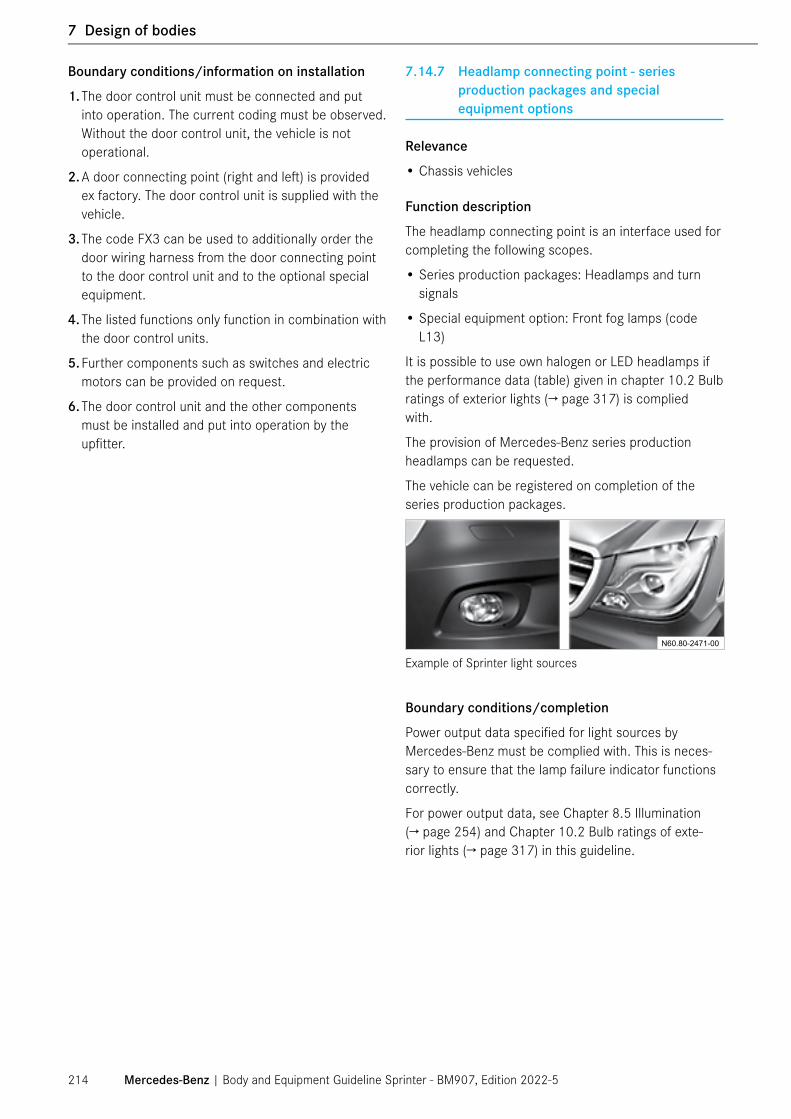
Boundary conditions/information on installation
1. The door control unit must be connected and put into operation. The current coding must be observed. Without the door control unit, the vehicle is not operational.
2. A door connecting point (right and left) is provided ex factory. The door control unit is supplied with the vehicle.
3. The code FX3 can be used to additionally order the door wiring harness from the door connecting point to the door control unit and to the optional special equipment.
4. The listed functions only function in combination with the door control units.
5. Further components such as switches and electric motors can be provided on request.
6. The door control unit and the other components must be installed and put into operation by the upfitter.
7.14.7 Headlamp connecting point - series production packages and special equipment options
Relevance
• Chassis vehicles
Function description
The headlamp connecting point is an interface used for completing the following scopes.
• Series production packages: Headlamps and turn signals
• Special equipment option: Front fog lamps (code L13)
It is possible to use own halogen or LED headlamps if the performance data (table) given in chapter 10.2 Bulb ratings of exterior lights (→ page 317) is complied with.
The provision of Mercedes-Benz series production headlamps can be requested.
The vehicle can be registered on completion of the series production packages.
N60.80-2471-00
Example of Sprinter light sources
Boundary conditions/completion
Power output data specified for light sources by Mercedes-Benz must be complied with. This is neces-sary to ensure that the lamp failure indicator functions correctly.
For power output data, see Chapter 8.5 Illumination (→ page 254) and Chapter 10.2 Bulb ratings of exte-rior lights (→ page 317) in this guideline.
Mercedes-Benz | Body and Equipment Guideline Sprinter - BM907, Edition 2022-5214
1 General
7 Design of bodies

7.14.8 Connecting point for antenna switchover box for third-party antennas (code E4A)
Relevance
• All vehicles without roof ex factory including cab chassis with doors with code F28
Function description of antenna switchover box
With the special equipment option “Antenna interface for radio, navigation and mobile radio (code E4A)”, Mercedes-Benz provides an interface for connecting a third-party antenna with AM/FM and DAB. This inter-face is located in the driver’s seat box.
An antenna box is connected downstream of this connecting point ex factory. This box splits the incom-ing AM/FM and DAB signal into two signals and feeds them to the head unit.
A 12 V power supply for the third-party antenna is pro-vided at this connecting point.
For the upfitter, the connecting point enables simple connection of a third-party to the Mercedes-Benz head unit by means of a defined interface.
Boundary conditions/completion
The antenna switchover box must be supplied with the following signals.
• FM (87 MHz – 108 MHz)/AM (531 kHz – 1720 kHz)
• DAB band III (174–240 MHz)
• Impedance 50 ohms
The connection of the navigation system must be supplied with the following signal:
• GNSS 1575 MHz – 1606 MHz
• RHC (right-hand circulation) polarization
• Impedance 50 ohms
• Operating voltage 4.5 V – 5.5 V
• Power consumption 20 mA ±3 mA
For further information on the upfitter antenna inter-face, see Chapter 8.13.2 Antennas (→ page 303).
7.14.9 Pre-installation for upfitter interface H (code E2A) and upfitter interface M (code E5M)
Pre-installation for upfitter interfaces H and M
The pre-installation for upfitter interface H (tapping of upfitter special signals in cockpit, code E2A) and for upfitter interface M (expansion of MPM (PSM) standard contact, code E5M) allows the upfitter to tap the follow-ing signals in the cockpit.
• Battery network
• Exterior lights
• Instrument lighting
• Signal lines routed through from interface H. In combination with the MPM/PSM (code ED5), vehicle signals can also be supplied.
N60.80-2444-00
1
2
Upfitter interfaces
1 Upfitter interface H2 Upfitter interface M
Mercedes-Benz | Body and Equipment Guideline Sprinter - BM907, Edition 2022-5 215
7 Design of bodies

Function description of upfitter interface H
Upfitter interface H (code E2A) provides an additional interface in the area of the A-pillar on the driver’s side. Upfitter interface H allows the signals described below to be tapped more easily.
In addition, 5 signals are routed from interface H through to interface M. These signals are freely avail-able to the upfitter. They can be used to, for example, send signals from the MPM/PSM (code ED5) to inter-face M (code E5M).
Boundary conditions/completion
The plug can be fitted with a wiring harness from the upfitter according to requirements.
The following lines/signals are provided:
• Five signal lines
• Left and right turn signal indicators and one revers-ing light
• Tml. 58d dimmable instrument lighting
• Tml. 15, tml. 30T (shutoff on weak battery) and tml. 31.
The max. performance data and parameters of the connections must be complied with.
Function description of upfitter interface M
Upfitter interface M (code E5M) allows the signals from the MPM/PSM to be tapped more easily without the need for complex cable routing.
Upfitter interface M provides an additional interface in the driver’s seat box. The signals from the MPM/PSM are routed out from this interface. In addition, 5 signals can be routed from upfitter interface M through to upfitter interface H. These signals are freely available to the upfitter.
See section 8.10.2 (→ page 298) for more information on the upfitter interface M plugs
Details on the following interfaces can be obtained from the respective specialist unit.
Body manufacturer interface M - plug 1
Body manufacturer interface M - plug 2
Body manufacturer interface M - plug 3
Requirements
• The fuse ratings can be found in the “Supplement - Fuse assignments”.
• Access to the signals from the exterior lights is only permitted in combination with the additional turn signal module.
• Access to the reversing light signal is only permit-ted in combination with the additional turn signal module.
• Tml. 58d driver module requests (battery voltage): Maximum current ≤1 A
Mercedes-Benz | Body and Equipment Guideline Sprinter - BM907, Edition 2022-5216
1 General
7 Design of bodies

7.14.10 Pre-installation for rear speakers (code EP7)
The electrical pre-installation for rear speakers, code EP7, provides an additional electrical interface.
This interface enables the upfitter to install his or her own rear speakers.
Completion
The pre-installation provides a plug which is connected to the speakers.
Requirements
In combination with the telematics and infotainment system of Mercedes-Benz, the speakers must satisfy certain requirements. For this, see Chapter 8.13.3 Speakers (→ page 307).
Electrical interface
1 Connectors for additional rear speakers.
For more information, please use bulletin, Sprinter MY2019+ Additional Speaker (code EP7), on Upfitter Portal.
7.14.11 E-call on base vehicles
The Mercedes-Benz emergency call system can help to decisively reduce the time between an accident and the arrival of emergency services at the site of the acci-dent. The data is relayed via the communications mod-ule for Mercedes PRO in the vehicle. The emergency call is thus not dependent on whether a mobile phone is switched on, but requires a GSM connection and the ability to locate the vehicle via GPS. It can be triggered automatically by the crash sensors or manually by the driver pressing the SOS button. The emergency call will then be directed to the Mercedes-Benz emergency call number or to a local emergency call center.
N60.80-2447-00
SOS push button switch
Completion
On F28 base vehicles (cab without roof and rear panel), the SOS button and the associated microphone are integrated in the overhead control panel. This is sup-plied ex factory. For integration in the body, particular attention must be paid to the accessibility of the push button switch for the driver and front passenger.
Mercedes-Benz | Body and Equipment Guideline Sprinter - BM907, Edition 2022-5 217
7 Design of bodies
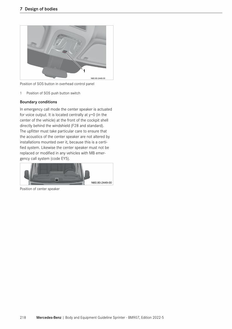
N60.80-2448-00
1
Position of SOS button in overhead control panel
1 Position of SOS push button switch
Boundary conditions
In emergency call mode the center speaker is actuated for voice output. It is located centrally at y=0 (in the center of the vehicle) at the front of the cockpit shell directly behind the windshield (F28 and standard). The upfitter must take particular care to ensure that the acoustics of the center speaker are not altered by installations mounted over it, because this is a certi-fied system. Likewise the center speaker must not be replaced or modified in any vehicles with MB emer-gency call system (code EY5).
N60.80-2449-00
Position of center speaker
Mercedes-Benz | Body and Equipment Guideline Sprinter - BM907, Edition 2022-5218
1 General
7 Design of bodies

7.15 RV – Recreational vehicles
General
Prior to conversion into an RV, please note:
• The legal requirements must be complied with.
• The legal requirements for interior design and equip-ment for RVs must be fulfilled.
Information on registration eligibility of RVs
On leaving the factory, the base vehicles (F28) initially only have incomplete vehicle documents.
The upfitter must ensure that the vehicle has complete type approval.
Modifications or conversions to standard vehicles (e.g. the installation of a lifting roof) may invalidate the operating permit. Please refer to country and/or state-specific legal regulations. For US operating per-mits, the approval conditions and requirements of the Department of Motor Vehicles (DMV) must be met. For Canadian operating permits, please refer to provincial transportation ministries.
The vehicle registration documents must be presented. After the modifications have been entered, the vehi-cle registration documents must be submitted to the relevant registration office so that a new type approval can be issued.
7.15.1 Body in white of RVs
Boundary conditions/notes
• Easy access to the engine, drivetrain, suspension, door mechanism (e.g. guide rails and hinges) must be ensured so as not to hinder possible repair work, see Chapter 3.11 Maintenance and repairs (→ page 51).
• The standard fuel filler cap must not be removed or covered with any "blocking" parts.
⑴ NOTE
If the fuel cap is removed or parts are attached to the fuel cap, blocking may occur in the event of an accident. Because of this, the protrusion space in the B-pillar may no longer function correctly. On no account should the cap be covered with paneling parts, and “blocking” parts must never be mounted on the B-pillar.
Attachment to the frame
• Chassis must be attached to the basic vehicle using at the least all of the factory-fitted body consoles (→ page 183). These permissible body mounting points are located only on the longitudinal frame members and may be supplemented as required by additional body consoles on the longitudinal frame members.
• The body brackets must be secured using two bolts for each body bracket.
• For information on integrated RVs, see Chapter 7.17 Semi-integrated bodies and optional mounting of free-standing bodies (→ page 226).
Mercedes-Benz | Body and Equipment Guideline Sprinter - BM907, Edition 2022-5 219
7 Design of bodies

⑴ NOTE
The minimum distance between the rear edge of the door and an integrated body must be > 20 mm/0.79 in.
Otherwise, the rear edge of the door may come into contact with the body in the event of an accident, and in extreme cases the door may be jammed.
N40.00-2053-00
min. 20 mm0.8 in
Minimum distance between rear edge of door and integrated body
Particular attention must be paid to the following sec-tions of the Body and Equipment Guidelines:
• 3.5 Dimensions and weights (→ page 37)
• 4.2 Limit values for the suspension (→ page 68)
• 4.2.2 Permissible axle loads (→ page 69)
• 6 Modifications to the basic vehicle (→ page 92)
• 6.2.7 Fenders and wheel wells (→ page 114)
• 6.4.3 Seats (→ page 147)
• 7.4 Modifications to closed cargo vans (→ page 192): ensure compliance with FMVSS/CMVSS for head impact
• 8 Electrics/electronics (→ page 233)
• 8.9.2 Crosswind Assist (→ page 273)
• 8.9.5 Highbeam Assist, Lane Keeping Assist and traffic sign recognition (→ page 286)
• 8.9.6 Rain sensor and Headlamp Assist (→ page 286)
7.15.2 Suspension of RVs
Detailed information on the suspension of RVs can be found under Chapter 4.2 Limit values for the suspen-sion (→ page 68).
Special considerations for RVs
For upfitters who build a RV on the Sprinter chassis, the option code X2R - Conversion to RV requirement must be ordered. When the code X2R is ordered, the code B01 (Vehicle version for high center of gravity) will be automatically added.
Please pay attention to the correct variant when order-ing the vehicle. For more information please review Chapter 9.1.2 Determination of the center of gravity in the z-direction (→ page 311).
ⓘ Detailed information on base vehicles can be found in 7.14 Bodies on chassis with base (F28) (→ page 209).
⑴ NOTE
Mercedes-Benz recommends a reinforcement of the front axle using an option code A50 (Front axle reinforced)
Mercedes-Benz | Body and Equipment Guideline Sprinter - BM907, Edition 2022-5220
1 General
7 Design of bodies

7.15.3 Electrics/electronics of RVs
Overviews of wiring harness connecting points for series production packages and special equipment options.
A detailed presentation of all connecting points can be found in Chapter 7.14.3 Wiring harness connecting points (→ page 211) for cab base vehicles
Particular attention must be paid to the following chap-ters of the Body and Equipment Guideline:
• 6.5 Additional assemblies (→ page 152)
• 8 Electrics/electronics (→ page 233)
• 8.3 Battery (→ page 235)
• 8.4 Interfaces (→ page 239)
• 8.9.2 Crosswind Assist (→ page 273)
• 8.9.3 Active Brake Assist/Active Distance Assist (DISTRONIC PLUS) (→ page 275)
• 8.9.4 Blind Spot Assist/Rear Cross Traffic Alert (RCTA)/Exit Warning (→ page 277)
• 8.9.5 Highbeam Assist, Lane Keeping Assist and traffic sign recognition (→ page 286)
• 8.9.6 Rain sensor and Headlamp Assist (→ page 286)
• 8.9.7 Tire pressure loss detection system (→ page 288)
• 10.2 Bulb ratings of exterior lights (→ page 317)
⑴ NOTE
If a significant weight is upfitted to the vehicle, it is recommended to measure the upfitted vehicle height and recalibrate the DISTRONIC PLUS sensor height accordingly. Please visit a local Mercedes-Benz deal-ership.
⑴ NOTE
For easier integration of aftermarket electrics/ elec-tronics, we recommend the use of PSM (ED5) and its extension harness (E5M). For more information, please see section 8.10 Parametrerizable Special Module (PSM/ MPM) (→ page 296).
7.15.4 Additional main fuses for RVs (codes E1R and E1Y)
Function description
The main fuse box contains 4 additional fuses that are not used by the basic vehicle. These are available to the upfitter with code E1R and E1Y with different fuse ratings at fuse slot F9 (see table at the end of the chap-ter) in order to connect defined consumers.
Three 30 A output fuses are provided in the seat base, which are connected to F8 via a line (see illustration "Additional fuse for camper vans").
This facilitates the connection of electrical consumers to terminal 30T.
Fuse location F10 is occupied if the special equipment rear air conditioning system with code HH7, HK4 or H08 is used, and is therefore no longer available.
Fuse location F12 is occupied if the special equipment air spring (code CB2) is used, and is therefore no lon-ger available.
Position of fuse box in BR 907 vehicle
1 Position of fuse box
Additional fuse for camper vans
Mercedes-Benz | Body and Equipment Guideline Sprinter - BM907, Edition 2022-5 221
7 Design of bodies

Code E1R E1Y
Main fuse locations lmax.[A]
F8 100 100F9 150 80F10 80 80F12 40 40
ⓘ The valid fuse assignments and values for each of the vehicles are available in the supplement "Fuse assignment", which is part of the accompanying vehicle documents and which is available in XENTRY (see Chapter 2.3.3 XENTRY Kit (→ page 19) ).
https://xentry.daimler.com/home/
7.15.5 New features for RVs
Pre-installation for switch panel (code E3J)
Sprinter is equipped with two switch panels ex-factory: a two-switch panel (to the left of the steering wheel on left-hand drive vehicles) and a six-switch panel (to the right of the steering wheel on left-hand drive vehicles). The switch frames have dummy covers.
The upfitter can use special switches (switches avail-able from Eugen Kurz KG), i.e. instead of installation of the dummy covers and actuation via the PSM (MPM).
Advantage: By using the available switch panels and switches, upfitters can utilize their own functions in the Sprinter design.
For further information on operating switches, see Chapter 8.4.5 Operating switches (pre-installation) (→ page 241) in this guideline.
Radio operating time
With the special equipment code E1X (MBUX multime-dia system with longer shutoff delay), the radio operat-ing time has been increased to 6 hours (depending on the battery state of charge).
For a long radio operating time, we recommend fully charging the starter battery.
For RVs with code X2R (Conversion to RV requirement), this code E1X is added automatically.
⑴ NOTE
In order to use multimedia systems while stationary with an external power supply, a power feed to the starter battery of at least 140 W is required.
Long-term startabilityTo ensure startability even with long non-operational times, an extra function has been developed for the Sprinter. When the battery reaches a critical value, this function becomes active and maintains the startability of the vehicle.
Own points of interest (POIs) in navigation system
Upfitters for RVs have the option of integrating their own points of interest (POIs) in the Mercedes-Benz vehicle navigation system. This allows the end customer of the RV manufacturer to navigate directly to the nearest Mercedes-Benz service point or contract partner.
Pre-installation for rear speakersA pre-installaton for rear speakers (code EP7) is avail-able to allow RV manufacturers to connect additional speakers to the radio in their body.
For further information on this pre-installation, see Chapter 7.14.10 Pre-installation for rear speakers (code EP7) (→ page 217).
Retrofitting rear seats
For the retrofitting of seats in the rear, the information and specifications in Chapter 7.3 Retrofitting seats (→ page 190) must be observed.
Mercedes-Benz | Body and Equipment Guideline Sprinter - BM907, Edition 2022-5222
1 General
7 Design of bodies

7.15.6 Airbags for RVs
Additional airbag systems can be ordered for RVs under the following special equipment codes:
• Driver thorax/pelvis side airbag (code SH1)
• Front passenger thorax/pelvis side airbag (code SH2)
• Window airbags for driver and front passenger (code SH9)
Special requirements and information apply to the use of these special equipment options in RVs, which can be found in the following chapters and must be observed:
• Chapter 4.5.1 Modifications to airbags and seat belt tensioners (→ page 77)
• Chapter 5.2 Welding work (→ page 85)
• Chapter 5.4 Painting work/preservation work (→ page 88)
• Chapter 6.1.4 Air suspension (→ page 98)
• Chapter 6.2.1 General information on the body in white/body (→ page 101))
• Chapter 6.2.2 Attachment to the frame (→ page 105)
• Chapter 6.4.1 General information (→ page 138)
• Chapter 6.4.2 Safety equipment (→ page 139)
• Chapter 7.4 Modifications to closed cargo vans (→ page 192)
Additional requirements for window airbags (code SH9):
• Code SH9 can only be ordered in combination with code F28 or for panel vans.
• Side window blackout curtains or awnings on side windows are not permitted in combination with this equipment.
• Installed windshield blackout curtains/awnings/shelves and their retaining systems must not impede the deployment areas of the airbags.
• All work on an A-pillar with window airbags is prohib-ited.
• The attachment of holders and brackets to the A-pil-lar trim is to be avoided.
Additional requirements for thorax/pelvis side airbags (code SH1/SH2):
• Code SH1/SH2 can only be ordered in combination with code F28 or for panel vans.
• Installed window blackout curtains/awnings and their retaining systems on driver/front passenger side windows must not impede the deployment areas of the airbags.
• The use of armrests on both sides of the seat is not permitted in combination with this system.
• Aftermarket seat covers are not permitted in combi-nation with the thorax/pelvis side airbag system.
• Safe routing of the airbag ignition lines must be guar-anteed by means of dedicated seat swivel consoles (no twisting/pressure points on ignition lines).
Mercedes-Benz | Body and Equipment Guideline Sprinter - BM907, Edition 2022-5 223
7 Design of bodies

7.16 Bodies on chassis with lowered roof
Code FA1 "Lowered roof" is available for semi-inte-grated and alcove bodies on vehicles with code F28 "Base with doors". Code FA1 comprises the following changes from the standard version:
• The height of the roof is reduced by approx. 70 mm/2.76 in.
• The vehicle is cut in the area of the roof/door portal, reinforced by means of body in white modifications and then painted in the area of the body in white modifications.
• The standard-equipment sun visors and grab handles are mounted in the same position at modified attach-ment points.
• The roof lining can be attached at the previous attachment points, but must be trimmed and adjusted to fit the interior at the front and sides by the upfitter.
• The vehicle is fitted with a temporary roof bow for transportation.
• Before the body is erected it is necessary for the upfitter to install the auxiliary roof frame supplied at the attachment points provided in order to ensure adequate equivalent rigidity. This provides a lowered attachment plane for bodies.
• Body limits for camera-based support systems must be observed, see 8.9.5 Highbeam Assist, Lane Keeping Assist and traffic sign recognition (→ page 286) and 8.9.6 Rain sensor and Headlamp Assist (→ page 286).
Location of auxiliary roof frame
2 Auxiliary roof framea Distance between top edge of longitudinal frame mem-
ber and top edge of auxiliary roof frame:
3500XD, 4500 a = 1540 mm/60.47 in
Mercedes-Benz | Body and Equipment Guideline Sprinter - BM907, Edition 2022-5224
1 General
7 Design of bodies

7.16.1 Mounting the auxiliary roof frame
The temporary roof bow (1) must be detached before mounting the auxiliary roof frame (2).
The auxiliary roof frame (2) must then be mounted at the points provided using six M10 x 20 10.9 round headed bolts (tightening torque 40 Nm +/- 2 Nm; 8.28 ft lb +/- 0.41 ft lb).
Mounting of auxiliary roof frame
1 Transport roof bow2 Auxiliary roof frame3 Cutting area with reinforcements (body in white modifi-
cations)
7.16.2 Mounting the body on the auxiliary roof frame
The body can be attached to the auxiliary roof frame by
• Bolts
• Rivets
• Adhesive bonding
• Welding
⑴ NOTE
Holes must not be drilled in the corners of the auxil-iary roof frame.
The auxiliary roof frame must not be cut.
The introduction of force to the auxiliary roof frame must occur by way of an area load (line load). Point loads must not be introduced into the auxiliary roof frame.
The load on the auxiliary roof frame while driving must not exceed 100 kg/220.5 lbs. When the vehicle is stationary, a load of 200 kg/491 lbs is permissible.
Attachment areas for auxiliary roof frame on vehicles with lowered roof
b Attachment areac No drilling allowedPlease also observe 5.3 Anti-corrosion protection measures (→ page 86). The department responsible will be happy to answer any questions 1.7 Contact (→ page 11).
Mercedes-Benz | Body and Equipment Guideline Sprinter - BM907, Edition 2022-5 225
7 Design of bodies

7.17 Semi-integrated bodies and optional mount-ing of free-standing bodies
A non-positive connection between cab and body is required on vehicles with semi-integrated bodies e.g. semi-integrated RVs, integral box bodies etc.
For vehicles with free-standing bodies (e.g. box bodies), it is also possible to optionally connect it to the cab. For this, the same specifications apply as for semi-integrated bodies. The body must have adequate inherent rigidity in the attachment area (avoid local compression).
The connection between the cab and the body must be continuous at the B-pillars and the roof frame (either full length or in sections). For a specific implementation and other measures, an evalution with the responsible department is necessary. As part of the eXpertUpfitter program, please refer to www.UpfitterPortal.com.
The descriptions apply for cabs both with and without rear panel.
N60.80-2416-00
1
2
Attachment of body to B-pillar and roof (example of free-standing body, schematic diagram)
1 Roof2 B-pillar
Mercedes-Benz | Body and Equipment Guideline Sprinter - BM907, Edition 2022-5226
1 General
7 Design of bodies
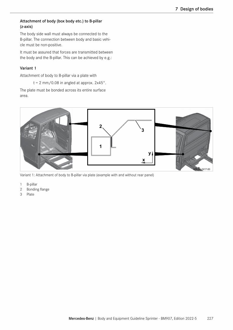
Attachment of body (box body etc.) to B-pillar (z-axis)
The body side wall must always be connected to the B-pillar. The connection between body and basic vehi-cle must be non-positive.
It must be assured that forces are transmitted between the body and the B-pillar. This can be achieved by e.g.:
Variant 1
Attachment of body to B-pillar via a plate with
t = 2 mm/0.08 in angled at approx. 2x45°.
The plate must be bonded across its entire surface area.
N60.80-2417-00
32
1y
x
Variant 1: Attachment of body to B-pillar via plate (example with and without rear panel)
1 B-pillar2 Bonding flange3 Plate
Mercedes-Benz | Body and Equipment Guideline Sprinter - BM907, Edition 2022-5 227
7 Design of bodies

Variant 2
Attachment of body to welding flange of B-pillar with angle pieces.
N60.80-2418-00
34
25
1
yx
Variant 2: Attachment of body to B-pillar via bracket (example with and without rear panel)
1 B-pillar2 Bonding flange3 Front wall of body4 Bracket5 Rivet
Mercedes-Benz | Body and Equipment Guideline Sprinter - BM907, Edition 2022-5228
1 General
7 Design of bodies

Attachment of body (box body etc.) to roof frame (y-axis)
In addition to the connection between body side wall and basic vehicle, it is necessary to form a non-positive connection between body and basic vehicle in the area of the roof frame on vehicles with integral bodies. This can be achieved by e.g.:
Variant 1
Attachment of body to roof frame via a plate with
t = 2 mm/0.08 in angled at approx. 2x45°.
The plate must be bonded across its entire surface area.
N60.80-2419-00
yx
32
1
Variant 1: Attachment of body to roof frame via plate (example with and without rear panel)
1 Roof frame2 Bonding flange3 Plate
Mercedes-Benz | Body and Equipment Guideline Sprinter - BM907, Edition 2022-5 229
7 Design of bodies

Variant 2
Attachment of body to welding flanges of roof frame using angle pieces.
N60.80-2420-00
34
25
1
yx
Variant 2: Attachment of body to roof frame welding flange via bracket (example of with and without rear panel)
1 Roof frame2 Bonding flange3 Front wall of body4 Bracket 5 Rivet
On vehicles with cut roof frame, the upfitter must ensure force transfer to the simulating structure (→ page 123). Therefore, an evalution with the respon-sible department is necessary. As part of the eXpertUpfitter program please refer to www.UpfitterPortal.com.
Mercedes-Benz | Body and Equipment Guideline Sprinter - BM907, Edition 2022-5230
1 General
7 Design of bodies

7.18 Buses and People Mover
Prior to conversion into a bus, please note:
Conversions to standard vehicles may invalidate the operating permit. Please refer to country and/or state-specific legal regulations. For US operating per-mits, the approval conditions and requirements of the Department of Motor Vehicles (DMV) must be met. For Canadian operating permits, please refer to provincial transportation ministries.
Further general technical information:
• Local and country-specific laws and regulations must be observed.
• Ensure an equivalent replacement structure in the body-in-white for modifications to the roof and roof bow structure.
• Ensure that all installed components are not under static load.
• All solutions must be coordinated with Mercedes-Benz (development, calculation, rough roads, durability, NVH, anti-corrosion protection, sealing, etc.).
As part of the eXpertUpfitter program please refer to www.UpfitterPortal.com.
Body-in-white
If the body-in-white is modified or cut, e.g. to lower the vehicle floor in order to gain cargo capacity, to install emergency exits or similar, the anti-corrosion protec-tion measures specified by Mercedes-Benz AG (as per the currently valid Sprinter Body and Equipment Guide-line) must be carried out and all other specifications in the current Body and Equipment Guideline regarding modifications to the body-in-white must be observed.
Particular attention must be paid to the following chap-ters of the BEG:
• Chapter 4.3.1 Modifications to the body in white (→ page 72)
• Chapter 4.3.2 Limit values for the vehicle frame (→ page 72)
• Chapter 4.3.3 Roof/roof load (→ page 73)
• Chapter 6.2 Body in white/body (→ page 101)
• Chapter 6.3.3 Exhaust system (→ page 132))
Installation of third-party windows
If the upfitter is going to install aftermarket windows, code W94 “No windows in bus version” is available from the factory. It is not permissible to install pan-oramic windows on a cargo van without code W78 by cutting out the stamped window shape without ensuring equivalent rigidity.
Ensure compliance with FMVSS/CMVSS regarding escape windows.
For cargo vans with window prep package, aftermarket emergency window exit needs to be installed for bus conversions. Please ensure that all applicable regula-tions pertaining to FMVSS/CMVSS 217 are followed.
Mercedes-Benz | Body and Equipment Guideline Sprinter - BM907, Edition 2022-5 231
7 Design of bodies

Retrofitting an air conditioning system
See Chapter 6.5.1 Retrofitting an air conditioning sys-tem (→ page 152)
• The additional belt pulley, code N63, is available from the factory as special equipment for driving air-conditioning compressors and should be utilized.
• If other air conditioning systems are installed, the equipment manufacturer’s guidelines must be observed.
• On no account should the installation of an air condi-tioning system impair vehicle parts or their function.
• If compact systems are mounted on the cab roof (evaporator, condenser and blower), the permissible roof loads must not be exceeded: Chapter 4.3.3 Roof/roof load (→ page 73).
• Pipes and electric lines must be routed correctly.
• More detailed information on retrofitting air condi-tioning systems can be obtained from the relevant department 1.7 Contact (→ page 11).
As part of the eXpertUpfitter program, please refer to www.UpfitterPortal.com.
Interior
Refer to local and country-specific legal regulations.
See also the following chapters on the vehicle interior:
• Chapter 4.5.1 Modifications to airbags and seat belt tensioners (→ page 77)
• Chapter 4.5.2 Modifications to seats (→ page 77)
• Chapter 6.4 Interior (→ page 138)
Doors and entrances
All modifications to doors or entrances must comply with the specifications described in this Body and Equipment Guideline:
• Chapter 8.8 Windows and doors (→ page 269)
• Chapter 6.2.6 Side wall, windows, doors and flaps (→ page 111)
• Chapter 6.4.2 Safety equipment (→ page 139)
Local and country-specific legal regulations for door locks and hinges as well as for rearview mirrors (espe-cially in the case of modifications which affect the view of the rearview mirror) must be observed in particular.
Further information on subsequent modifications (e.g. to the body in white, interior, and doors and entrances) can be obtained from the Upfitter Portal (→ page 11).
Mercedes-Benz | Body and Equipment Guideline Sprinter - BM907, Edition 2022-5232
1 General
7 Design of bodies

8.1 General information
⚠ WARNING
Modifications to electronic components, their soft-ware, or wiring can impair the functioning of those electronic components and/or of other networked components. Safety-relevant systems in particular may be affected. Because of this, they may no longer function properly and/or compromise the operational safety of the vehicle.
There is a heightened risk of accident and injury! Never carry out any modifications to the wiring and electronic components or their software. Have all work on electrical and electronic equipment carried out at a qualified specialist workshop.
Some of the safety systems only function when the engine is running. For this reason, do not switch off the engine when the vehicle is in motion.
⑴ NOTE
A positive total charge balance must be ensured when additional electrical consumers are installed (see Chapter 7.17 Semi-integrated bodies and optional mounting of free-standing bodies (→ page 226) and Chapter 8.4.6 Retrofitting electri-cal equipment (→ page 242)).
Do not release or remove the battery terminals when the engine is running. If the vehicle is equipped with code E30 (1-pin battery main switch), the isolator must not be actuated while the engine is running.
Use rapid charger on the batteries only after discon-necting them from the vehicle's electrical system. Both the positive and negative terminals must be disconnected.
• Electrical and electronic components must fulfill local and national test requirements as well as ISO 16750 test requirements.
• Observe the notes on (→ page 235) when installing auxiliary batteries.
• Cables routed around the exhaust systems must be insulated against high temperatures (→ page 255).
• Cables must be routed in such a way that there are no kinked points (→ page 95).
• Before any long non-operational periods (> 20 days), the chapter on maintenance and storage of batteries (→ page 53) must be observed.
• Observe the operator's manual.
ⓘ You can obtain more information from the depart-ment responsible 1.7 Contact (→ page 11).
⑴ NOTE
The upfitter is responsible for functional safety of the body modification work performed by the upfitter as well as for the observance of the applicable stan-dard and regulations. Furthermore, the upfitter must guarantee compliance with the international standard ISO 26262 concerning functional safety, if applicable. Please also refer to 49 CFR 567.5 in the US and to Motor Vehicle Safety Regulation 6(1)-6(7) in Canada for requirements for manufacturers of vehicles manu-factured in two or more stages.
See Chapter 2.4 Product safety and product liability (→ page 20).
Mercedes-Benz | Body and Equipment Guideline Sprinter - BM907, Edition 2022-5 233
8 Electrics/electronics
8 Electrics/electronics

8.2 Electromagnetic compatibility (EMC)
Electromagnetic compatibility describes the ability of an electrical system to act neutrally in the vicinity of other systems when operating at full function. The system in question does not interfere with any of the active systems in the vicinity, nor does it suffer any interference.
Electrical interference occurs in vehicle on-board elec-trical systems because of the various consumers.
Mercedes-Benz tests all factory-installed electrical and electronic components for their electromagnetic com-patibility in the vehicle. If subsequent modifications are made, this may cause a reduction in comfort in some cases (e.g. radio noise).
When retrofitting electrical or electronic systems, they must be tested for electromagnetic compatibility and this must be documented.
All electrical equipment fitted must be tested in accor-dance with FCC, CE and UL in the US, and with CSA and ULC in Canada.
The notes under Chapter 8.4.6 Retrofitting electrical equipment (→ page 242), Chapter 8.6 Mobile com-munications systems (→ page 263), and Chapter 4.6 Limit values for electrics/ electronics (→ page 80) must be observed.
The following standards provide information on this:
• CISPR 12
• CISPR 25
• DIN EN 55012
• DIN EN 55025
• ISO 7637
• ISO 10605
• ISO 11451
• ISO 11452
• MBN 10284
• UN R 10
Mercedes-Benz | Body and Equipment Guideline Sprinter - BM907, Edition 2022-5234
1 General
8 Electrics/electronics

8.3 Battery
8.3.1 Main battery
The main battery is located on the floor on the left-hand side to the front of the driver’s seat.
Installation position of the main battery
1 Main battery
In the case any additional electrical consumers other than the standard vehicle power requirements are needed, please use the upgraded battery (code ED4). An auxiliary battery must be used for high electrical demand. If current draw is 25A or greater, an auxiliary battery (code E2M or E2I) must be used. An AGM bat-tery must always be used.
ⓘ In order to facilitate tapping power from the auxiliary battery (code E2I or E2M), a tapping point (fuse box) is available in the driver seat frame. This means that it is not necessary to install additional wires from the vehicle interior (upfitter consumers) to the auxiliary battery in the engine compartment or under the passenger's seat, see Chapter 8.4.8 Power tapping (→ page 243)
⑴ NOTE
Electrical cables must not connect directly to the ground terminal of the battery.
⑴ NOTE
The vehicle systems (standard and ex-factory special equipment) are powered by the main battery.
The on-board electrical management system mon-itors the voltage of the main battery and stops the vehicle systems functioning when the state of charge drops below the 40% limit in order preserve enough voltage to start the vehicle. The electronic ignition lock (EIS) and the tachograph are not affected by this shut-down.
If an auxiliary battery is used (see Chapter 8.3.2 Aux-iliary battery (→ page 236)), ensure that the function of connected consumers is not impaired.
If one or more vehicle systems are operated while the vehicle is in a stationary position (e.g. radio oper-ations in a RV), then ensure that the main battery maintains a positive charge balance by starting the engine or through an external power supply.
Mercedes-Benz | Body and Equipment Guideline Sprinter - BM907, Edition 2022-5 235
8 Electrics/electronics

8.3.2 Retrofitting an auxiliary battery
Auxiliary battery, general
⑴ NOTE
Aftermarket battery with capacities > 100 Ah must not be connected directly to the vehicle electrical system because this may damage the base vehicle.
Please select a suitable generator to ensure a posi-tive overall charge balance.
When operating loads on the auxiliary battery, ensure that the permissible total current of 80A across the battery cut off relay is not exceeded. The battery charging current with the engine running must also be taken into account.
Only the same type of battery (AGM) must be used for main and auxiliary batteries.
It is recommended to always use the ex-factory special equipment options offered by Mercedes-Benz AG if these equipment are required for an auxiliary battery.
Two auxiliary batteries are available:
• Code E2I: Auxiliary battery for retrofitted consumers, in front passenger seat base, battery size H8 (92 Ah AGM)
• Code E2M: Auxiliary battery for retrofitted consum-ers, in engine compartment, battery size H6 (70 Ah AGM)
N82.00-3421-00
E2I: Auxiliary battery in front passenger seat base (e.g. LHD vehicle)
E2M: Auxiliary battery in engine compartment (e.g. LHD vehicle)
If the vehicle is to be started using an external power supply, then either the jump-start connection point or the main battery must be used.
⑴ NOTE
The auxiliary battery (E2I, E2M) must not be used for jump starting as this could result in damage to the vehicle.
Aftermarket auxiliary batteries must be connected to the vehicle on-board electrical system using a suitable cutoff relay and fuse. For more information, refer to 1.7 Contact (→ page 11).
When installing an auxiliary battery, ensure that the same type of battery (AGM battery) is used as the starter battery.
If the auxiliary battery is located in the passenger compartment, sufficiently dimensioned ventilation must be realized through a central vent hose leading into the atmosphere. If necessary, the second channel in the battery should be sealed with a stop plug.
The auxiliary battery may only be used to power auxil-iary consumers such as the stationary heater, loading aids or electrical equipment in RVs (refrigerator, etc.).
Mercedes-Benz | Body and Equipment Guideline Sprinter - BM907, Edition 2022-5236
1 General
8 Electrics/electronics

Other auxiliary batteries
⑴ NOTE
If the vehicle is already equipped with an auxiliary battery, no further auxiliary batteries may be con-nected in parallel without a charging current limiter. This can be realized through supplementary elec-tronics. A maximum charging current of 80 A for all auxiliary batteries must be ensured. If this is not the case, the basic vehicle may be damaged.
A positive total charge balance is to be assured through selection of a suitable alternator.
Retrofitting multiple auxiliary batteries requires an evalution with the responsible department. As a part of the eXpertUpfitter program please refer to www.UpfitterPortal.com.
The current limitation system, which limits to 80 A, allows for multiple batteries to be added in parallel if the batteries are the same type, have the same capac-ity and same age in cross connection.
The charging current limiter (DC/DC converter) between the electrical system (vehicle battery) and additional battery allows for different battery technolo-gies and additional batteries to be used.
N82.00-2212-00
Current limitation system
Mercedes-Benz | Body and Equipment Guideline Sprinter - BM907, Edition 2022-5 237
8 Electrics/electronics

8.3.3 Battery maintenance and storage
Batteries must be regularly checked for voltage drop (self-discharge) - even when removed. With low-mainte-nance batteries, only the fluid level does not need to be checked.
Information on maintaining and storing batteries can be found under 3.11.2 Battery maintenance and storage (→ page 53).
Mercedes-Benz | Body and Equipment Guideline Sprinter - BM907, Edition 2022-5238
1 General
8 Electrics/electronics

8.4 Interfaces
8.4.1 CAN bus and networking
⚠ WARNING
As all consumers are networked and internally monitored by the system, no modifications should be made to the CAN bus (e.g. breaking, extending or tapping). Any change to the cable harness in terms of length, cross-section or resistance can result in safety-relevant component failures or comfort impair-ments.
Internal and external vehicle diagnosis can be car-ried out by means of the OBD diagnostic socket (SAE 1962). Every control unit is capable of self-diagnosis and is equipped with an internal fault memory.
Communication with the control units can be estab-lished using a diagnostic device and the software devel-oped for this unit. At Mercedes-Benz, this diagnostic tool is called the “XENTRY” diagnostic system and has the associated hardware and software, XENTRY Kit.
ⓘ You can obtain further information on this topic from your Mercedes-Benz Service Center.
⑴ NOTE
Do not make any permanent connection to the OBD diagnostic socket as this can impair vehicle functions.
8.4.2 Electric lines/fuses
If the routing has to be altered, avoid routing across sharp edges and through narrow cavities or near mov-ing components.
Only unleaded PVC-jacketed cables with an insulation operating temperature limit > 105 °C/221 °F may be used. Connections must be made in a professional manner and must be watertight.
The line must be dimensioned in accordance with the current level drawn and protected with fuses.
Please do not block any access points to fuse box.
The following table applies to cables with an insulating limit temperature of > 105 °C/221 °F
Max. permanent current
Fuse rating Line cross-section
[A] [A] [mm2] [in2]0 - 4.9 51 0.5 0.0015 - 9.9 101 1 0.00210 - 18 201 2.5 0.00419 - 28 301 4 0.00629 - 35 402 6 0.00936 - 48 502 10 0.01549 - 69 702 16 0.02570 - 98 100 25 0.03999 - 123 125 35 0.054124 - 148 150 50 0.078
1 Type C; DIN 72581 male spade connector2 Type E; DIN 72581 male spade connector
8.4.3 Cable extension
If cables are lengthened (e.g. in connection with a wheelbase extension), cables of the same or a greater cross-section must be used. We recommend the use of lines complying with LV112. The protective effect of retaining elements must not be impaired.
Connections between electric lines and electrical components (e.g. plugs) are to be secured against rocking to and fro, through the use of suitable mount-ing material.
All connections must be made professionally and water-tight in accordance with IP 69k (protected for high-pressure cleaning).
Lines to the ABS sensors of the rear axle must be adapted for the specific vehicle and may be length-ened by maximum 2.7 m (8.86 ft). The lines to each sensor must be twisted with a loop length of 30±5 mm (1.18±0.2 in).
Mercedes-Benz | Body and Equipment Guideline Sprinter - BM907, Edition 2022-5 239
8 Electrics/electronics

Lengthening of wiring harnesses - Comfort and passive safety systems, on-board electrical system, bus system
The Mercedes-Benz work instructions on the repair of cables also apply for the lengthening of cables. The instructions can be found in WIS (→ page 18). Work on the vehicle must always be carried out using the latest workshop aids (e.g. EPC net, WIS net, XENTRY, special tools) from the manufacturer for the vehicle in question. The safety notes and safety precautions must be observed and precautions against electrostatic discharge (ESD) must be taken. Please get in touch with the contact person responsible for your mar-ket. ESD protection is only effective when the safety regulations/safety precautions are complied with. All operation steps, including test procedures, must be carried out in accordance with the WIS instructions. Information about ESD are available in the WIS docu-ment AH54.00-P-0001-01A.
The following must not be modified or extended:
• Airbag control unit connector coupling
• ESP® control unit connector coupling
• Engine control unit connector coupling
• High-voltage lines
• Antenna lines
• Fiber-optic cables
• Lines of bus systems, see Chapter 8.4.1 CAN bus and networking (→ page 239)
• Lines with a cross-section > 4 mm² (0.0062 in2)
Refer to the WIS document AH00.19-P-1000-08A, e.g. an ESP® plug must not be "modified".
Further information on lengthening wiring harnesses can be found in the WIS documents:
• AR00.19-P-0100A (Wiring harness, general methods)
• AH00.19-P-1000-08A (Parts solutions and what may/may not be repaired/extended)
If the prescribed methods are followed and approved materials and tools are used, it is possible to lengthen lines without any loss in quality.
The following repair methods are approved:
• Soldering
• Raychem (use of solder connectors)
• Raychem in combination with pigtail
• Crimping
Refer to the WIS document AR00.19-D-0100A to select the suitable work method.
Soldering
Select the line connectors or solder sleeves. Solder the stripped lines in accordance with the WIS instructions:
• AR00.19-P-0100-05A
• AR00.19-P-0100-09A
Crimping
Crimp the stripped lines in accordance with the WIS instructions:
• AR00.19-P-0100-03A
• AH00.19-P-1000-09A
ⓘ For further information consult the Workshop Infor-mation System (WIS) and also see Chapter 2.3.2 Workshop Information System (WIS) (→ page 18) WIS can be accessed at the following address:
www.startekinfo.com/home
Mercedes-Benz | Body and Equipment Guideline Sprinter - BM907, Edition 2022-5240
1 General
8 Electrics/electronics

The methods focus on soldering (specifically Raychem) and crimping.
Soldering (specifically Raychem):
In the Raychem method, special solder connectors are used. The solder connectors contain the solder and are insulated and sealed. A special hot-air blower is used to heat them. Do not use a cigarette lighter!
The connections must be checked for a resistance of less than 0.5 ohms using an appropriate multimeter according to the circuit diagram.
8.4.4 Additional electric circuits
If additional electric circuits are installed, they must be protected against the main power circuit by fuses of adequate rating.
The lines used must be rated for the load and they must be protected against the effects of breakaway, impact and heat.
8.4.5 Operating switches (pre-installation)
Switch panel pre-installation
As a pre-installation for operating switches installed by the upfitter, two switch panels are available in the area of the steering wheel. These contain two slots on the left of the steering wheel and six slots on the right of the steering wheel. Depending on the equip-ment installed, these may be added automatically and partially populated with switches. If they are not added automatically due to the vehicle equipment, the pre-in-stallation can be ordered separately under the code E3J (Switch panel pre-installation).
N54.15-2312-00
1 2Switch panels
1 Van switch panel to left of steering wheel (LHD vehicle)2 Van switch panel to right of steering wheel (LHD vehicle)
These switches are load switches which supply the interface for the upfitter. The switches bear no symbols and can be individually inscribed with laser lettering at a size of 8x8 mm.
ⓘ For information regarding the procurement of the operating switches, reach out to local Mercedes-Benz Service Center.
The reserved load switch part numbers are:
Three different versions of load switches are available from factory for installation in the aforementioned switch panel for upfit functions:
• A907 905 3902 9107 (Single pole changeover (CO) contact, latching, function lighting)
A907 905 3902 9107
• A907 905 4002 9107 (Sing pole normally open (NO)) contact, momentary, function lighting)
A907 905 3902 9107
• A 907 905 4102 9107 (Double pole changeover contact (CO), latching, NO function lighting)
A907 905 4102 9107
Part numbers for mating parts to the switch:• Connector (housing): A013 545 4026• Contact for wires 0.35 qmm: A008 982 2426• Contact for wires 0.5 qmm: A011 545 7826• Contact for wires 0.75 qmm: A011 545 7926
Parts can be ordered directly from the supplier through the following contact:Eugen Kurz KGUlrich PflügerRebengasse 12D-89073 UlmTel. +49 731 66535 / Fax +49 731 601283Mail: [email protected]
Mercedes-Benz | Body and Equipment Guideline Sprinter - BM907, Edition 2022-5 241
8 Electrics/electronics

8.4.6 Retrofitting electrical equipment
Please observe the following if electrical accessories are retrofitted:
• A positive charge balance must be ensured by the upfitter.
• For higher electrical power requirements, the alterna-tors reviewed by Mercedes-Benz must be used, see the following Chapter 8.4.7 Retrofitting an alterna-tor(→ page 242).
• Do not connect additional alternators to the existing on-board electrical system; the electrical systems should be galvanically isolated.
• Do not connect additional consumers to fuses already assigned.
• Do not connect additional lines (e.g. with insulation piercing devices) to existing lines.
• Provide sufficient protection for consumers using additional fuses.
• Do not block access to any fuse box
• All installed electrical consumers must be tested as per UN-R 10 in its currently valid version, see Chapter 8.2 Electromagnetic compatibility (EMC) (→ page 234).
• Additional electrical consumers must be connected by means of the terminal strip for auxiliary con-sumers (code EK1) available from the factory as described under 8.4.8 Power tapping (→ page 243).
⚠ WARNING
Tampering with or unauthorized installations in the vehicle electrical/electronic systems can impair the functioning of these systems. This can lead to failure or malfunctioning of components or of parts relevant to safety, and may result in accidents or damage to the vehicle.
ⓘ Furthermore, tampering with the vehicle electrical/electronic systems can invalidate the implied war-ranty or the general operating permit.
8.4.7 Retrofitting an alternator
If additional electrical consumers are retrofitted, the increased power requirement can be met by fitting higher-rated alternators.
The following alternators are available as special equip-ment (option codes) from the factory:
Alternator availabilityDiesel Gas
Code 4 cyl(OM651)
6 cyl(OM642)
4 cyl(M274)
M40 (200 A) Standard - -M46 (220 A) - Standard -M60 (250 A) Option* - Standard
* M60 is standard in some cases depending on codingAlternator voltage 14.3 V
If additional assemblies are fitted, the factory-fitted power take-offs must be used (→ page 154).
Mercedes-Benz | Body and Equipment Guideline Sprinter - BM907, Edition 2022-5242
1 General
8 Electrics/electronics

For retrofitting alternators, we recommend N62 ver-sions available from the factory as special equipment (front engine power take-off with carrier for additional alternator).
For retrofitting N62 or N63, Mercedes-Benz recom-mends that a Mercedes-Benz qualified technician per-forms the retrofit. Please visit the local Mercedes-Benz dealership for servicing. For eXpertUpfitters, the installation guide for retrofitting N62 or N63 is available on WIS. For engine OM642, please refer to document 'AN23.10-D-0001TSB' on WIS. For engine OM651, please refer to document 'AN23.10-D-0001TS' on WIS.
The following points must be observed if you intend to have other alternators retrofitted:
• On no account should the installation of an alterna-tor impair vehicle parts or their function.
• The battery must have sufficient capacity and the alternator must generate sufficient power (→ page 242).
• The alternator circuit must be provided with addi-tional fuse protection (→ page 239).
• The cable cross-section must be dimensioned accord-ing to the current level drawn (→ page 239). The higher power draw may necessitate the replacement of the starter/alternator wiring harness. For this we recommend Mercedes-Benz GenuineParts.
• The additional belt pulley, code N63, is available from the factory as special equipment for driving air-con-ditioning compressors.
• Electric lines must be routed correctly (→ page 239).
• There must be no impairment of the accessibility or easy maintenance of installed equipment.
• There must be no impairment of the required engine air supply and cooling (→ page 135).
• The guidelines of the equipment manufacturer for compatibility with the basic vehicle must be observed.
• The operating instructions and the maintenance manual for the additional assemblies must be sup-plied on handing over the vehicle.
The characteristics of the LIN alternators are fixed in the engine control unit – for this reason the Mercedes-Benz alternator cannot be replaced by an aftermarket alternator.
No D+ (engine running positive signal) output available at alternator with LIN Bus technology, only at upfitter socket EK1 under driver seat.
8.4.8 Power tapping
Depending on the vehicle's as-built configuration, there are different possibilities for auxiliary consumers to tap current. Power can be tapped via the terminal strip for electrical connection (special equipment EK1) or at the auxiliary battery tapping point.
ⓘ For more information on tapping power for special equipment, refer to 1.7 Contact (→ page 11).
⑴ NOTE
When installing additional electrical consumers, espe-cially on vehicles with special equipment installed ex factory which uses the auxiliary battery (fuse box in driver seat frame), the upfitter must ensure a positive overall charging balance.
Additional information on special equipment can be obtained from your Mercedes-Benz Service Center or under 3.12 Special equipment (→ page 55).
Mercedes-Benz | Body and Equipment Guideline Sprinter - BM907, Edition 2022-5 243
8 Electrics/electronics

Power tapping via terminal strip for electrical connection
The terminal strip (special equipment code EK1) is installed inside the driver seat frame (at the center, on the left-hand side in direction of travel) and has three connectors:
N54.15-2308-00
1
Position of terminal strip EK1 in driver seat base (LHD vehicle)
1 Terminal strip EK1Arrow Direction of travel
N54.15-2309-001 2 3
Terminal strip EK1 (X145/1)
Terminal Power Voltage/ fuse rating
1 Terminal D+ Power with engine running
12 V/10 A
2 Terminal 30T Battery direct power 12 V/25 A3 Terminal 15 Ignition power 12 V/15 A
Electrical joint bolts in the fuse box must be tightened to the following torques:
Bolt size Tightening torque [Nm]M4 3M6 6
The terminal strip EK1 is supplied directly from the main battery and is the supply point in the main on-board electrical system at which the upfitter may connect his or her consumers. Other consumers can be connected via the PSM (MPM) and the auxiliary bat-tery. If terminal 30T is used, a positive overall charge balance must be ensured in all vehicle conditions. Do not connect any consumers on terminal 30T of the EK1 which require a quiescent current > 1mA when vehicle is idle.
In start/stop mode, brief voltage dips (at restart) up to 7.0 V at the EK1 are possible. The voltage dips are typically in the region of 9.0 V. Proper circuit protection should take this into account.
When the vehicle is locked and CAN is awake, in rare cases up to three brief voltage interruptions can occur at intervals of approximately 40 minutes.
Mercedes-Benz | Body and Equipment Guideline Sprinter - BM907, Edition 2022-5244
1 General
8 Electrics/electronics

Power tap at auxiliary battery tapping point
In order to facilitate tapping power from the auxiliary battery (code E2I or E2M), a tapping point (fuse box) is available in the driver seat frame. The tapping point is the busbar in the fuse box with the direct line from the auxiliary battery (positive pole).
The cover must be removed to connect and install the fuse.
N54.15-2310-00
2
Position of auxiliary battery fuse box in driver seat base (LHD vehicle)
2 Fuse boxArrow Direction of travel
Mercedes-Benz | Body and Equipment Guideline Sprinter - BM907, Edition 2022-5 245
8 Electrics/electronics

Fuse box
N54.15-2311-00
129 ± 0,7
A2 A1
13456
2
A6 A5 A4 A3
Assignment of fuse box (top view)
Connec-tionno.
Min./max.permissible fuse rating
Fuse type
Function Maximumline cross-sec-tion
Cable lug Coding Bolt
A1 -/100A SF30 Any upfit usage 25 mm2/0.039 in2
Complies with work spec., see drawing
2 M6
A2 -/250A SF51 Any upfit usage 35 mm2/0.054 in2
Complies with work spec., see drawing
8 M8
A3 - - Auxiliary battery 35 mm2/0.054 in2
Complies with work spec., see drawing
2 M8
A4 125A/150A SF30 Battery cutoff relay 35 mm2/0.054 in2
N046234006005 - M6
A5 -/8OA SF30 Sockets, auxiliary heating
2 x 16 mm2/ 2 x 0.025 in2
Complies with work spec., see drawing
8 M6
A6 -/8OA SF30 Sockets, auxiliary heating
2 x 16 mm2/ 2 x 0.025 in2
Complies with work spec., see drawing
7 M6
Cable lugs complying with the work specification (see table) are preferred. Torque relief on these is through the housing. If other cable lugs are used, separate torque reliefs (A 907 545 52 00) must be used at the M6 bolt.
Work specification for cable lugsM6 A0030002599 ZGS001M8 A0040024499 ZGS002
Mercedes-Benz | Body and Equipment Guideline Sprinter - BM907, Edition 2022-5246
1 General
8 Electrics/electronics

The electrical connecting bolts in the fuse box must be tightened to the following torques:
Bolt size Tightening torqueM6 8 Nm/1.66 ft lb ±10%M8 16 Nm/3.31 ft lb ±10%
⑴ NOTE
If a vehicle is already equipped at the factory with a consumer which uses the fuse box in the seat box, this is only available under certain conditions. The sum of the individual currents must not exceed the maximum current-carrying capacity of the fuse box of 300 A. There is otherwise a risk of overload.
Fuse
The auxiliary consumer can be connected to the auxil-iary battery with a suitable fuse as per ISO 8820 SF30 (contact cavities 1, 5 and 6) or SF51 (contact cavity 2).
Preconditions for connection to the auxiliary battery include:
• Auxiliary battery fuse box ex factory in seat base
• Use of the following retaining plates (busbar side), part number M6 A 907 545 60 00 or M8 A 907 545 61 00 for torque relief
• Suitable fuses as per ISO 8820 (SF30 or SF51)
Please note:
• No additional consumers may be connected to facto-ry-installed fuses.
• If all the connections at the fuse box are fully occu-pied, the positive pole of the auxiliary battery is to be used for connecting further consumers.
• A suitable fuse box with fuse is required for these additional consumers.
• A positive total charge balance must be ensured in all vehicle conditions.
• Connection numbers A1 and A2 are available with auxiliary battery to any upfitters to connect any electrical consumers.
Mercedes-Benz | Body and Equipment Guideline Sprinter - BM907, Edition 2022-5 247
8 Electrics/electronics

8.4.9 Interface overview
The electrical interfaces available as special equipment on the vehicle are depicted in the illustration below:
2 66
44
5
3
Schematic diagram: Electrical interfaces on the vehicle
Code Description1 EK1 Terminal strip for the electrical connection on the driver's seat base2 L72 Electrics for body interior lighting, 3-pin connecting point in the left seat base
(applies only for Cab Chassis)3 LC4 Push button switch in overhead control panel (OCP)4 L76 Extended tail lamp wiring harness (2 m/78.7 in)5 L77 Additional electrical equipment for turn signal lamps6 E5M Expansion of PSM (MPM) standard contact
Mercedes-Benz | Body and Equipment Guideline Sprinter - BM907, Edition 2022-5248
1 General
8 Electrics/electronics

Code table for Sprinter BM 907 (further special equip-ment)
Code DescriptionLV4 PRE-INSTALLATION FOR FRONT FOG LAMPS WITH CORNERING LIGHT FUNCTIONLV6 PRE-INSTALLATION OF ELECTR. EQUIPMENT FOR 3RD BRAKE LAMPE2F PRE-INSTALLATION FOR WINDSHIELD HEATERFR7 PRE-INSTALLATION OF ELECTRICS FOR REVERSING AIDFV1 PRE-INSTALLATION FOR REVERSING CAMERA WITH INSIDE REARVIEW MIRROR DISPLAYE3J PRE-INSTALLATION FOR SWITCH PANELED8 PRE-INSTALLATION OF ELECTRICS, PARAMETERIZABLE SPECIAL MODULEE2A TAPPING OF BODY MANUFACTURER SPECIAL SIGNALS IN COCKPIT.EP7 PRE-INSTALLATION OF ELECTRICS FOR REAR SPEAKERS
E4A ANTENNA INTERFACE FOR RADIO, NAVIGATION AND MOBILE RADIOJH6 PRE-INSTALLATION OF COM MODULE FOR DIG. SERVICES (LTE)ER0 RADIO PRE-INSTALLATIONJ1V PRE-INSTALLATION FOR BLIND SPOT ASSISTL90 OMISSION OF TAIL LAMPSL91 PRE-INSTALLATION FOR LED TAIL LAMPS
⑴ NOTE
The regulatory requirements for installing lighting systems must be observed, see Chapter 8.5 Illumina-tion (→ page 254)).
A description of the codes and specifications for exterior lights can be found in Chapter 10.2 Bulb ratings of exterior lights (→ page 317)).
Mercedes-Benz | Body and Equipment Guideline Sprinter - BM907, Edition 2022-5 249
8 Electrics/electronics

8.4.10 Speed signal
The analog vehicle speed signal in the instrument clus-ter has been discontinued. If required, a digital signal can be provided by the PSM (MPM) via a special data entry.
The digital speed signal (positive to ground) acts as a distance and speed signal for external electronics, e.g. speed-dependent volume control. The signal is protected against short-circuit to ground and battery voltage and is not monitored.
The signal is output at 4 pulses per meter/1.22 pulses per foot. The pulse width is 4 ms.
At 112.5 km/h or 69.9 mph, the pulse duration is the same as the pulse pause. This 1:1 ratio is maintained for higher speeds. This means that, at higher speeds, the pulse length and the pause length become shorter at the same time.
The speed signal is made available on the upfitter CAN in a format complying with SAE-J1939.
Value range: 0 - 250,996 km/h or 156.0 mph
Resolution: 1/256 km/h or 0.0024 mph
Note: This signal is not suitable for calibrated taxime-ters or similar
.THigh
TLOW TLOWN30.00-2014-00
Ratio of pulse duration/pulse pause
Speed signal (Imax = 20 mA):THigh Ua ≥ 8 VTLow Ua ≤ 1 V
8.4.11 Travel distance signal
A digital travel distance signal is permanently present at PSM output 15 (plug 2, pin 3). When the ignition is off, no wheel speed pulses are output. The pulses are accurate at speeds of 3 km/h (1.86 mph) and above. When the PSM control unit is in OFF mode, the wheel speed (RDZ) signal output driver is deactivated. 48 pulses/revolution are output (96 signal flanks/revolution) in the vehicle speed range from 0 km/h to 362 km/h or 225 mph. This results in an output frequency from min. 0 Hz to max. 2414 Hz.
8.4.12 Ground bolts
For retrofitted electrical bodies or implements, the ground bolts approved by Mercedes-Benz must be used to achieve an optimum ground connection to the basic vehicle.
There are two ground bolts (M6) in the area of the driver seat in the left seat base; a further ground bolt (M6) is located under the vehicle on the crossmember in front of the rear axle.
Mercedes-Benz | Body and Equipment Guideline Sprinter - BM907, Edition 2022-5250
1 General
8 Electrics/electronics

The following specifications must be observed:
• No other electrical consumers may be connected to factory ground bolts other than those listed below.
⚠ WARNING
The use of any other ground bolts may lead to mal-functions of safety systems. This in turn can lead to the failure of components or safety-relevant compo-nents and to fault messages in the instrument cluster.
• A maximum of 4 cable lugs may be bolted to a ground bolt.
• The nuts must be tightened to a torque of 6 Nm or 1.242 ft lb.
• The ground bolts for the safety systems must not be used for attachments.
For other requirements, please refer to 1.7 Contact (→ page 11).
N54.18-2184-00
1
Cab ground connection, body in white (e.g. LHD vehicle)
1 Ground bolt
Frame ground connection (3.5 t to the front of the rear axle)
1 Ground boltArrow Direction of travel
Mercedes-Benz | Body and Equipment Guideline Sprinter - BM907, Edition 2022-5 251
8 Electrics/electronics

8.4.13 Additional ground weld studs
This chapter provides information for optional ground studs in addition to the ones installed as a standard.
The code VV4 includes, depending on the weight vari-ant of the vehicle, three to four additional ground studs (M6/M8) located in the area of the front seat bases and under the vehicle on the cross members. This allows upfitters to attach auxiliary electrical equipment to the base vehicle.
For specific model variants, 3D CAD data for additional ground weld studs (code VV4) is available for eXpertUpfitters on the Upfitter Portal (www.UpfitterPortal.com).
⑴ NOTE
The use of any other ground studs may lead to mal-functions of safety systems. This in turn can lead to the failure of safety-relevant components and fault messages in the instrument cluster.
Mercedes-Benz | Body and Equipment Guideline Sprinter - BM907, Edition 2022-5252
1 General
8 Electrics/electronics

8.4.14 Deep discharge protection (hibernation mode)
The deep discharge protection system is intended to prevent impermissible deep discharging of the battery with the vehicle at a standstill (no-load phase). This function should ensure the startability of the vehicle after an extended period of time or in the event of elevated quiescent currents.
In addition, excessive quiescent currents caused by faulty components are minimized by hardware resets of the components.
The functions of the system are distributed between the vehicle locking system (component Electronic Ignition Lock (EIS)) and the on-board electrical system management system (component Body Controller (BC)). The hardware component responsible is the battery disconnect switch (BTS).
Terminal 30 (BM 906) is transformed into a switchable terminal 30T (BM 907).
Another function in the deep discharge protection system is the "hibernation mode" or "quiescent state" function. This opens the battery disconnect switch prematurely, allowing the vehicle to be parked up for long periods.
The mode can be selected in the instrument cluster (Hibernation Mode). If a head unit is installed, it is activated there.
The hibernation mode or the quiescent state allows almost all of the control units to be switched off. Then almost the only signal present at terminal 30T is the EIS or the control unit that is necessary to receive the signal of the radio remote control. PSM and the anti-theft alarm system also continue to be supplied depending on their operating status.
Mercedes-Benz | Body and Equipment Guideline Sprinter - BM907, Edition 2022-5 253
8 Electrics/electronics

8.5 Illumination
Local and national regulations must be observed. All applicable FMVSS/ CMVSS guidelines and regulations must also be complied with.
⑴ NOTE
The specifications and notes in Chapter 10.2 Bulb ratings of exterior lights (→ page 317) must be observed for all exterior lights.
8.5.1 Adjusting the headlamps
Once the upfit has been completed, the upfitter, at his or her own responsibility and expense, must adjust the headlamps or check their factory settings and correct them if they deviate from the specified values. The adjustment instructions with the valid adjustment values for the finished vehicle in combination with the version of headlamp used can be performed by a local Mercedes-Benz Service Partner. The WIS system (→ page 18) also allows the upfitter to establish the currently applicable adjustment specifications for his or her own headlamp adjustment. Ensure that local and national registration requirements apply.
The headlamp basic setting must be observed (see vehicle identification plate).
For the following model designations, the headlamp adjustment for the type approval must always be car-ried out by the upfitter at his or her own responsibility and expense when all the upfit work has been com-pleted:
• Cab-chassis
• Cowl and doors version chassis (code F28)
Mercedes-Benz | Body and Equipment Guideline Sprinter - BM907, Edition 2022-5254
1 General
8 Electrics/electronics

8.5.2 Mounting additional lamps
The national registration regulations apply.
If moving vehicle parts cover lighting equipment by more than 50% during operation, the vehicle must be safeguarded accordingly.
Reflectors at the rear of the vehicle must not be obscured by moving parts. If this is the case, the reflec-tors must be duplicated.
An appropriate note must be attached at a point where it can easily be seen by the driver of the vehicle.
8.5.3 Tail lamps
The following chapter explains how to connect the aftermarket tail lamps to avoid any failures on the instrument cluster. The chapter also contains informa-tion on available option codes needed for tail lamps on cab chassis.
Main tail lamp
Please make sure to connect the tail lamp using an adaptor that has the same pinning assignment as shown in the table. If the tail lamp pinning assignment does not match as guided or the connection is not secured, then an error will appear on the instrument cluster.
Please do not connect the main tail lamps via PSM or E2A. The use of PSM or E2A for main tail lamps cannot detect any tail lamp failure.
Two available options of tail lamps:
• LED tail lamps: Please order option code L91 (Pre-wiring for LED tail lamps)
• Bulb tail lamps: Please order option code L90 (Pre-wiring for incandescent tail lamps)
⑴ NOTE
• The upfitter must ensure that the operating loads consume a constant current of at least 20 mA in each of the brake lights, tail lights, and turn signals if the upfitter is using codes L90 or L91. The par-allel connection of, for example, side marker lights on the tail lights is not permitted.
Additional lightsFor additional lights please connect to PSM or E2A-in-terface. Please note that these methods do not track bulb-out-detection.
Code Comment PurposeL90 Tail lamp deleted For customer using non-
OEM incandescent lampL91 Pre-installation for
LED tail lampFor customer using non-OEM LED lamp
L22 Tail lamp, partial LED
For customer using Mercedes-Benz LED lamp
L76 Extended cable for tail lamp
For customer who needs to extend tail lamp cable
L77 Additional electrical equipment for turn signal lamp
For customer who needs additional turn signal lamps on the body
Tail lamp pin connector for cab chassisPin Color Function1 BN Ground2 GYGN License lamp3 WHBU Backup lamp4 BKWH Turn signal5 BKRD Stop lamp6 VTWH Fog lamp (only if PSM)7 GYBK Tail lampLeft tail lamp
Pin Color Function1 BN Ground2 GYGN License lamp3 WHBU Backup lamp4 BKGN Turn signal5 WHGN Stop lamp67 GYRD Tail LampRight tail lamp
Mercedes-Benz | Body and Equipment Guideline Sprinter - BM907, Edition 2022-5 255
8 Electrics/electronics

8.5.4 Marker lamps
Clearance lamps/vehicle position lamps
Clearance lamps increase passive safety and are required by law on vehicles with a width of over 2.032 m/80 in (FMVSS/CMVSS 108).
For cab chassis, there are two options provided by Mercedes-Benz that conform to FMVSS/CMVSS 108:
1. Code L49 (Identification lamps) includes five identi- fication lamps mounted on the windshield of the vehicle roof.
2. Code LV7 (clearance lights pre-wiring) includes wir-ing harness tied to the roof and allows easy installation of after-market lights on the roof.
8.5.5 Exterior lamps
Front: Halogen headlamps
The exterior lighting functions in the headlamp are actuated discretely by the Body Controller (BCMFA2). This means that each exterior lighting function in the headlamp has a separate line.
The exception to this rule are the parking and stand-ing lights functions. These functions are actuated via the same lines, i.e. they are implemented by the same lamps.
Fault monitoring is implemented via the signal acquisi-tion and actuation module (SAM) and is always active when the relevant function is active and the corre-sponding light source is actuated. This implemented function is to be taken into account particularly when designing and using the upfitter's own electronic bal-lasts, otherwise faults will be logged in the control unit.
The table below provides an overview of the individual lighting functions.
Explanations of the following function descriptions:
• Ignition in terminal (tml.) 15 position: Ignition "on", engine start possible or engine running
• Ignition in terminal (tml.) 15r position: Radio position, ignition "off", engine not running, radio operation possible or on-board electrical system voltage "on"
• Ignition in terminal (tml.) 15c position: Ignition "off", engine not running, driver's door open, on-board electrical system voltage "on"
Mercedes-Benz | Body and Equipment Guideline Sprinter - BM907, Edition 2022-5256
1 General
8 Electrics/electronics

Overview of exterior lighting functions in headlamps
Hardware outputBC VS30
Front
Function Low beams Perimeter lights Daytime running lights
High beams Turn signals
Side Left Right Left Right Left Right Left Right Left RightPlug MR1 MR2 MR2 MR1 RBA1 RBA2 MR2 MR1 MR1 MR2Pin 20 02 01 21 17 56 04 18 01 05
Light pattern, open model Conventional ECELeft parking light XRight parking light XStanding lights X XLow beams X XHigh beam/headlamp flasher
X X
Daytime running lights X XTurn signals (left/right)/hazard warning light system
X X
Notes on headlamps
Low beams
Requirements for activation:
• Ignition in terminal 15 position
• Engine running.
• Rotary light switch in AUTO position
• Light sensor detects NIGHT.
• OR rotary light switch in MAN position (manual driv-ing lights)
Standing lights/perimeter lights
Requirements for activation:
• Rotary light switch in STL position (standing lights); the standing lights are activated regardless of the state of the vehicle.
• OR rotary light switch in AUTO position, ignition in terminal 15r position and light sensor detects NIGHT. If the light sensor detects DAY, no lighting function is activated.
• OR rotary light switch in MAN position and ignition in terminal 15r position
⑴ NOTE
In the Sprinter, the standing lights are not activated when the daytime running lights or low beams are active. Only the above requirements apply.
Parking lights
Requirements for activation:
• Ignition at terminal 15c or below, i.e. ignition off and driver's door open
Daytime running lights
Requirements for activation:
• Ignition in terminal 15 position
• Engine running.
• Rotary light switch in AUTO position
• Light sensor detects DAY.
Mercedes-Benz | Body and Equipment Guideline Sprinter - BM907, Edition 2022-5 257
8 Electrics/electronics
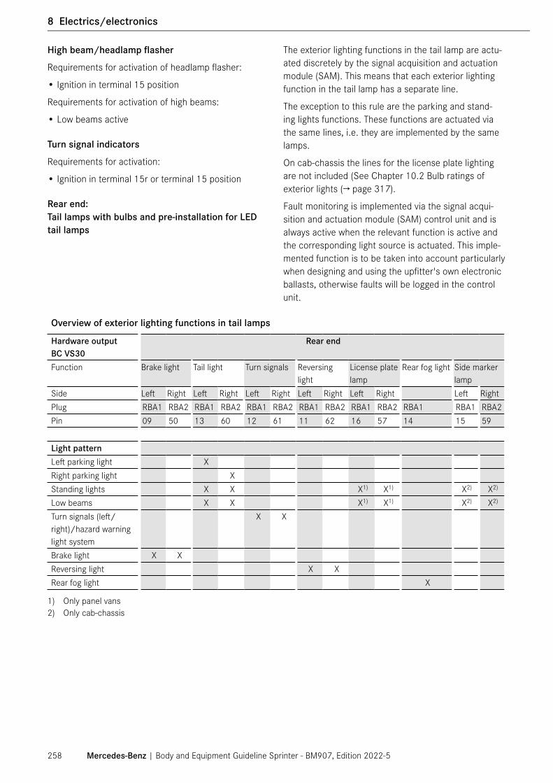
High beam/headlamp flasher
Requirements for activation of headlamp flasher:
• Ignition in terminal 15 position
Requirements for activation of high beams:
• Low beams active
Turn signal indicators
Requirements for activation:
• Ignition in terminal 15r or terminal 15 position
Rear end: Tail lamps with bulbs and pre-installation for LED tail lamps
The exterior lighting functions in the tail lamp are actu-ated discretely by the signal acquisition and actuation module (SAM). This means that each exterior lighting function in the tail lamp has a separate line.
The exception to this rule are the parking and stand-ing lights functions. These functions are actuated via the same lines, i.e. they are implemented by the same lamps.
On cab-chassis the lines for the license plate lighting are not included (See Chapter 10.2 Bulb ratings of exterior lights (→ page 317).
Fault monitoring is implemented via the signal acqui-sition and actuation module (SAM) control unit and is always active when the relevant function is active and the corresponding light source is actuated. This imple-mented function is to be taken into account particularly when designing and using the upfitter's own electronic ballasts, otherwise faults will be logged in the control unit.
Overview of exterior lighting functions in tail lamps
Hardware outputBC VS30
Rear end
Function Brake light Tail light Turn signals Reversing light
License plate lamp
Rear fog light Side marker lamp
Side Left Right Left Right Left Right Left Right Left Right Left RightPlug RBA1 RBA2 RBA1 RBA2 RBA1 RBA2 RBA1 RBA2 RBA1 RBA2 RBA1 RBA1 RBA2Pin 09 50 13 60 12 61 11 62 16 57 14 15 59
Light patternLeft parking light XRight parking light XStanding lights X X X1) X1) X2) X2)
Low beams X X X1) X1) X2) X2)
Turn signals (left/right)/hazard warning light system
X X
Brake light X XReversing light X XRear fog light X
1) Only panel vans2) Only cab-chassis
Mercedes-Benz | Body and Equipment Guideline Sprinter - BM907, Edition 2022-5258
1 General
8 Electrics/electronics

Notes on tail lamps
Brake light
Requirements for activation:
• Ignition in tml. 15 position
• Brake pedal operated
Tail light
Requirements for activation:
• Ignition in tml. 15 position
• Engine running.
• Rotary light switch in AUTO position
• Light sensor detects NIGHT.
• OR rotary light switch in MAN position ( manual driving lights)
• OR standing lights are active.
• OR parking lights are active (left or right).
Turn signal lights (indicators)
Requirements for activation:
• Ignition in tml. 15r or tml. 15 position
Reversing light
Requirements for activation:
• Ignition in tml. 15 position
• Reverse gear is engaged.
License plate lamps
Requirements for activation:
• Low beams are active.
Rear fog light
Requirements for activation:
• Ignition in tml. 15 position
• Rear fog light activated via pushbutton switch
• Rotary light switch in MAN position
• OR rotary light switch in STL position and front fog lamps are active.
• OR rotary light switch in AUTO position and engine is running (the low beams are activated automatically).
• OR rotary light switch in AUTO position and standing lights and front fog lamps are active.
Side marker lamps
Requirements for activation:
• Low beams are active.
See Chapter 10.2 Bulb ratings of exterior lights (→ page 317).
Additional exterior lighting functions:
Front fog lamps
Requirements for activation:
• Ignition in tml. 15 position
• Rotary light switch in STL or MAN position
• OR rotary light switch in AUTO position (AUTO: If the light sensor detects DAY, the standing lights are activated automatically too. If the light sen-sor detects NIGHT, the low beams are already active and no further automatic activations occur.)
⑴ NOTE
In the Sprinter, the cornering light function is imple-mented in the control unit as standard. This also applies for the pre-installation for front fog lamps with cornering light function (LV4). For these the upfitter may only use his or her own, certified front fog lamps.
Mercedes-Benz | Body and Equipment Guideline Sprinter - BM907, Edition 2022-5 259
8 Electrics/electronics

Side marker lamps
Requirements for activation:
• The side marker lamps are activated as described under "Tail lights". The same conditions and notes apply.
Clearance lamp
Requirements for activation:
• The side marker lamps are activated as described under "Tail lights". The same conditions and notes apply.
8.5.6 Interior lamps
The information about the lamps and switches installed and the switching commands for the interior lights are transmitted by the Body Controller via LIN to the over-head control panel.
The overhead control panel also transmits the informa-tion about whether and which push button switches are actuated over LIN to the Body Controller.
The following SA codes for interior lighting are available ex factory.
SA code Name/descriptionL65 Additional LED dome lamps in the load
compartment of cargo vans provide more light in the load compartment. One or two additional lamps are installed, depending on the wheelbase. The lamp above the hinged rear door has one push button switch.
L71 Motion detector, available for cargo van. The interior light is activated when a valid movement is detected.
L72 Interface for electrics of body interior light-ing for cab-chassis.
LD0 Overhead control panel with 2 reading spotlamps.
LC4 Comfort overhead control panel (LED), including cockpit incident illumination.
LC2 Two LED light strips/work lamps in the load compartment of the cargo van.
LB9 Exit lamps are integrated in the door on the driver or front passenger side. These shine down onto the floor when the doors are opened. The sliding door has another step illumination lamp (only in BM 907).
L1D Overhead control panel with bus interior lighting control
Mercedes-Benz | Body and Equipment Guideline Sprinter - BM907, Edition 2022-5260
1 General
8 Electrics/electronics
⑴ NOTE
All interior lamps can be replaced by other upfit-ter-specific lamps. In order to ensure that the stan-dard bulb failure monitor functions correctly, only light sources of the same type and same output rating as standard bulbs may be installed.
Lamp monitoring
The overhead control panel or the Body Controller monitors all outputs for open load (wire break) and short circuit.
If a lamp is not connected or is overloaded, a fault entry is stored in the fault memory of the Body Control-ler. The owner or driver of the vehicle must be informed about this. The fault entry must be addressed during a service if the fault memory is read.
The interior lights can also be actuated via the PSM (MPM). See Chapter 8.10 Parameterizable Special Module (PSM/ MPM) (→ page 296)
Electrical interface for body interior lighting (code L72)
In the case of cab-chassis models, the upfitter is offered an electrical interface in the driver's seat base for further body modification in the rear of the vehicle via the special equipment with code L72.
Aftermarket lamps (upfitter lamps) can be connected to this interface in accordance with the following specifi-cations.
Optionally, it is possible to connect a pushbutton switch in the vehicle upfit, which can be used to activate and deactivate these aftermarket lamps. Functionally, this pushbutton switch corresponds to the rear light button in the overhead control panel. If the aftermarket lamps in the body/ equipment are active, the symbol for the rear light button in the overhead control panel is illumi-nated red and thus serves as a function feedback.
Function description:
• The aftermarket lamps can only be activated by pressing a button manually and do not react to auto-matic light functions (door opening, unlocking, etc.).
• After the manual activation of the aftermarket lamps, they remain active for approx. 20 minutes, provided that the on-board electrical system does not detect any undervoltage (battery protection). The time runs independently of the locking status of the vehicle in particular.
• After the aftermarket lamps have been deactivated due to undervoltage by the on-board electrical sys-tem, an engine start is required before the aftermar-ket lamps can be reactivated manually.
• The aftermarket lamps are actuated via a relay and are pro tected by a 10 A fuse.
Mercedes-Benz | Body and Equipment Guideline Sprinter - BM907, Edition 2022-5 261
8 Electrics/electronics

Schematic diagram: Circuit diagram of interface of code L72
1 Overhead control panel (with 10-pin connection)2 Rear interior lamp connection3 Relay actuation connection special equipment code L724 Rear pushbutton switch connection (input)5 Interior lamp in rear passenger compartment for FHL
model designation6 Relay7 Rear pushbutton switch for FHL model designation8 ABH lamps interface special equipment code L729 ABH lamps (scope of body/equipment of upfitter)10 ABH lamps pushbutton switch
Parameter Symbol Min Type Max Unit RemarksSeries resistor to push-button switch
RSer Ω At RSer < 390 Ω, reliable diagnosis of a short circuit to ground is no longer possible
Input voltage (normal mode)
UILL_RS_Norm 3.1 3.3 3.5 V Pushbutton switch not actuated
Input voltage(sleep mode)
UILL_RS_Sleep 4.1 4.3 5 V Pushbutton switch actuated
Input capacitance Cin 10 nFPushbutton switch current
IT 10 mA RSer= 0 Ω, pushbutton switch actuated
Pushbutton switch current with pushbutton switch stuck
IH 150 μA RSer= 0 Ω, pushbutton switch stuck
Short-circuit current IK 10 mA Short circuit to groundPermissible shunt resis-tance
RS 5 kΩ Permissible shunt resistance to ground and tml. 30
Mercedes-Benz | Body and Equipment Guideline Sprinter - BM907, Edition 2022-5262
1 General
8 Electrics/electronics

8.6 Mobile communications systems
If mobile communication systems (→ page 80)(e.g. telephone, CB radio) are retrofitted, the following requirements must be fulfilled in order to avoid mal-functions developing on the vehicle at a later stage:
All electrical equipment fitted must be tested in accor-dance with FCC, CE and UL in the US, and with CSA and ULC in Canada.
⑴ NOTE
The fiber-optic cable must not be kinked. The mini-mum bending radius is 25 mm/0.98 in.
8.6.1 Equipment
The maximum transmission outputs (PEAK) at the base point of the antenna must not exceed the following values. National and local laws regarding the maximum allowed transmission output must be observed.
• The mobile communications systems and brackets must not be positioned in the deployment areas of the airbags (→ page 143).
• The equipment must be permanently installed. Mobile devices may only be operated inside the cab if they are connected to an exterior antenna which has been installed in such a manner that it is reflec-tion-free.
• The transmitter unit must be installed as far away from the vehicle's electronic system as possible.
• The unit must be protected against moisture and heavy physical shocks; the permissible operating temperature must be observed.
Mercedes-Benz | Body and Equipment Guideline Sprinter - BM907, Edition 2022-5 263
8 Electrics/electronics

8.6.2 Antenna connection and cable routing (radio communication)
• Comply with manufacturer's notes and installation instructions.
• An antenna can be installed anywhere on the roof. The maximum transmission output according to the installation specifications must not be exceeded. � The connection should be made directly to terminal
30T via an additional fuse. Disconnect the unit from the electrical system before starting assistance.
� The lines must be kept as short as possible. The lines must be twisted and screened (coaxial cable). Chafe marks must be avoided.
� Ensure that the system has a good ground connec-tion to the body (antenna and equipment).
� The antenna and connecting cables among the transmitter, receiver and operating panel must be routed separately from the vehicle wiring harness in the vicinity of the body ground.
� Route the antenna line in such a way that it is not kinked or pinched.
� Comply with the local and national regulations on the transport of hazardous goods.
Mercedes-Benz | Body and Equipment Guideline Sprinter - BM907, Edition 2022-5264
1 General
8 Electrics/electronics

8.7 Electronic ignition lock (EZS)
8.7.1 General information
• The processes involved in the access authorization for the central locking system (CL) are verified and controlled by the signal acquisition and actuation module (SAM) and the door control unit (DCU).
• Access is authorized at the press of a button on the remote control key.
• Drive authorization is obtained by pressing the start/stop push button switch by means of Keyless-Start. The remote control key must be located in the area between the A- and B-pillars.
• Where control units are networked, the electronic ignition lock sends global information such as the model series and the country variant to the control units (global variant coding) on the network.
⑴ NOTE
Drive authorization via Keyless-Start only operates when the body is not modified in the areas of the A- and B-pillars, and the roof frame in between. (See Chapter 4.3.1 Modifications to the body in white (→ page 72).
The vehicle keys must be stored in such a way that the engine cannot be started unintentionally. In the case of RVs, special attention must be paid to the storage of the keys on account of the design features of these vehicles. This means that it is particularly important not to store the keys in the area between the A- and B-pillar including the roof area between the A and B-pillar.
8.7.2 Central locking system/post-delivery integration of doors of upfitter
General
Upfitters have the option of adapting the central lock-ing system to the aftermarket equipment. The following functions can be implemented via variant coding in the electronic ignition lock (EIS) with XENTRY:
• Automatic locking when last open door is closed (post function)
• Post-delivery integration of upfitter doors into the central locking system
An automatic locking function for speeds above 15 km/h or 9.3 mph is implemented in the vehicle as standard. Further details on this function can be found in the operator's manual.
Automatic locking when last open door is closed (post function)
It is possible to use the O-code O22 to implement auto-matic locking when the last open door is closed. The function provides that when the ignition is in the radio position (terminal 15r) and the last door is closed, the vehicle is globally locked, but in the ignition "on" (termi-nal 15) position, no locking of the doors is triggered.
This function requires the use of door locks with a feedback function, as the open/ closed state of each door is polled and monitored. If aftermarket doors are integrated via the PSM, it is not recommended to use the O22 function.
This code can be parametrized via XENTRY, e.g. at a Mercedes-Benz Service Center. The O-code must first be entered in the vehicle data card, and then a new SCN coding of the EIS must be carried out.
Mercedes-Benz | Body and Equipment Guideline Sprinter - BM907, Edition 2022-5 265
8 Electrics/electronics

Post-delivery integration of upfitter doors
Depending on the vehicle equipment, it is possible for upfitters to integrate additional doors in the body into the central locking system of the chassis. They are operated via the ignition key of the basic vehicle.
Example of upfitter doors
1 Hinged rear door2 Side doorThere are two options for integrating additional doors into the central locking system of the chassis:
• Integration of additional doors via PSM (MPM)
• Integration of additional doors via SAM
Integration of additional doors via PSM (MPM)
The PSM (MPM) can be used to read out signal IDs (e.g. "close door", "open door") from the vehicle CAN in order to actuate additional central locking system elements or relays in the body via a PSM (MPM) output.
ⓘ Information on parametrization can be found on the PSM/ MPM (ED5) Information page on the Upfitter Portal.
www.UpfitterPortal.com
Advantage:
• Upfitters can use their own door locks and compo-nents.
Disadvantage:
• The additional doors actuated via the PSM (MPM) are not monitored for their "open" or "closed" state. The vehicle is thus not able to recognize whether all additional doors are closed and locked after a lock-ing procedure and no indications are given on the instrument cluster. Furthermore, the vehicle locks itself automatically 40 seconds after unlocking if only the aftermarket door is opened. The reason for this is that the open-ing of the rotary tumbler is not detected.
Condition:
• The special equipment PSM (MPM) (code ED5) and a custom PSM (MPM) program are required.
Mercedes-Benz | Body and Equipment Guideline Sprinter - BM907, Edition 2022-5266
1 General
8 Electrics/electronics

Integration of additional doors via SAM
Ordering the special equipment code EA5 "Pre-wiring central locking (upfitter doors rear)" allows you to inte-grate additional doors in the central locking system of the basic vehicle.
This means that a wiring harness connection point is installed in the vehicle near the seat on the left for con-necting up to three aftermarket doors behind the B-pil-lar. Activation of the door signals must be configured individually via XENTRY using O-codes. These codes can be parameterized via XENTRY at a Mercedes-Benz Service Center. The desired O-code must first be writ-ten in the vehicle data card, and then an SCN coding of the signal acquisition and actuation module must be carried out.
The O-codes for body doors are:
• OA5 - Parameterization for left side door present
• OA6 - Parameterization for right side door present
• O04 - Parameterization for hinged rear door present
Now all the doors can be opened and closed with the vehicle key. The locks used must have an appropriate feedback function so that the central locking system in the SAM can poll the door status and the instrument cluster can display this door status correctly.
Schematic diagram of an example for a body with three aftermarket doors in combination with the special equipment "Pre-wiring central locking (upfitter doors rear)" code EA5:
Ex-factory equipment Doors/flaps completed by upfitter
Schematic diagram: Top view of open model with box or RV body
1 Electrical connecting point with code EA52 Body Controller3 Door4 Tailgate5 Flap
Mercedes-Benz | Body and Equipment Guideline Sprinter - BM907, Edition 2022-5 267
8 Electrics/electronics

Advantage:
• Parameterization and installation of a PSM is not required.
• The additional doors actuated via the signal acquisi-tion and actuation module (SAM) are monitored for their "open" or "closed" state. The vehicle is thus able to recognize whether all additional doors are closed and locked after a locking procedure and an indica-tion is given in the instrument cluster.
Disadvantage:
The door status indicators in the instrument cluster are as represented in the Sprinter panel van and have not been adapted to different body situations (e.g. box body, RV etc.).
In combination with the three-button key, code FY7:
Three-button key, code FY7
With correct use of the interfaces and parameteriza-tion, the three-button key (code FY7) makes it possible to unlock the body door which is being used as a tail-gate separately, although the body doors can only be locked globally, i.e. all doors and the tailgate.
Conditions:
• Vehicle configuration with special equipment "Pre-wiring central locking (upfitter doors rear)", code EA5
• Locks with a feedback function must be used. The use of genuine Mercedes-Benz locks is recom-mended.
• Max. three additional doors (right door, left door, rear doors) are possible
ⓘ More detailed information on the integration of additional doors can be found on the Upfitter Portal as a bulletin under Technical Documents, Sprinter MY2019+ Electric preparation for additional door (Code EA5).
Ambulance pre-installation
The settings required for ambulances, e.g. passive circuits for rear-end door and sliding door actuator motors, can be applied with XENTRY as follows:
• Right-hand sliding door "not present"
• Left-hand sliding door "not present"
• Rear-end door "not present"
• Common unlocking of control circuits 1 and 2
• Front passenger door "not present"
Mercedes-Benz | Body and Equipment Guideline Sprinter - BM907, Edition 2022-5268
1 General
8 Electrics/electronics

8.8 Windows and doors
8.8.1 Window lifters/window hinges
Anti-pinch protection and automatic window raising can only be guaranteed with the original power window equipment.
The motor is thermally protected, i.e. the availability of the power window function may be restricted after long operating periods.
The window lifters and the window hinges can be con-trolled using the switches in the door control panel. The switches in the driver's door are electronically con-trolled and are connected to the LIN bus. The switches in the front passenger door are voltage coded. All switches may only be replaced with equivalent genuine parts.
Actuation can also occur via the parameterizable spe-cial module (PSM/MPM).
8.8.2 Sliding door
The electrical components of the sliding door on the Sprinter BM 907 (only for the electric load compart-ment sliding door and particular special equipment) are connected to the on-board electrical system via a fixed electrical connection in the form of a cable track (drag chain). This is located under the step for the sliding door.
The cable track must be taken into consideration in the event of any modifications around the entrance. If the upfitter wants to use the cable track, an evalution with the responsible department is necessary. As part of the eXpertUpfitter program, please refer to www.Upfitter-Portal.com.
The system for the electric sliding door has been designed for a maximum door weight of 65 kg/143 lbs, and this value must not be exceeded due to modifica-tions.
⚠ WARNING
On no account should modifications be made to the door kinematics or the locks, rails, carriages, closing aids and anti-entrapment strips.
The ex-factory weight of the load compartment slid-ing door for each vehicle model and wheelbase, and additional weights for some items of special equipment, is listed in Chapter 6.2.6 Side wall, windows, doors and flaps (→ page 111).
The delta corresponds to the maximum permissible additional weight on the sliding door to the load com-partment.
Certain weights must be added to the basic equipment depending on the special equipment installed.
If some items of equipment are removed, they must be taken into account in the weight calculation.
Additional data and information can be found in Chapter 6.2.6 Side wall, windows, doors and flaps (→ page 111)).
Furthermore, the specifications on "Reinforcement of the sliding door load compartment with rear seats" for the countries in question must be observed, see Chap-ter 6.4.3 Seats (→ page 147)
⚠ WARNING
Modifications to
• door kinematics
• guidance systems (rails, sliding carriages, etc.)
• locking systems (closing assists, anti-entrapment strips, locks, arresters, etc.)
• end stop systems (buffers etc.)
• extensive modification of the body-in-white struc-ture
may result in the door opening unintentionally.
There is a risk of accident!
No modifications may be made to any of these systems. Furthermore, care must be taken to ensure an extensive connection and center of gravity (CoG) distribution at the doors.
ⓘ The upfitter is responsible for the conversions and modifications on the vehicle.
⑴ NOTE
Correct operation of the integrated anti-pinch protec-tion function (anti-entrapment strip and path/time monitoring) must be ensured in the event of any mod-ifications in this area, e.g. the window installation.
Mercedes-Benz | Body and Equipment Guideline Sprinter - BM907, Edition 2022-5 269
8 Electrics/electronics

Sliding door with cable track
1 Cable track (drag chain)Arrow Direction of travel
8.8.3 Windshield wipers
Mercedes-Benz recommends the use of genuine Mercedes-Benz wiper motors.
If necessary, a second wiper motor can be connected via a relief relay (Ri >80 ohms).
The wiper motor must be connected to the signal acquisition and actuation module (SAM) by means of a readback line. If there is no readback line, a fault mes-sage will be stored in the fault memory of the SAM.
8.8.4 Outside mirrors
The output of the mirror heater (12 V/20 W) is moni-tored by the door control unit. The mirror heater (if a genuine part) is deactivated if a fault entry is stored.
The mirror heater must be designed to be equivalent to the genuine part.
The door control unit must be modified by coding if different mirrors (without heating) are used.
The mirrors are adjusted via the operating switch in the driver's door and the adjustments are transmitted via the LIN bus to the door control unit. The door control unit in turn actuates the actuator motors.
The mirror adjustment drives must be designed to be equivalent to the genuine drives.
The design of the outside mirror (with or without Blind Spot Assist (→ page 277)) must be observed.
8.8.5 Windshield heating/rear window heating
The original heaters can be replaced with heaters with the same power rating:
• Windshield heater: P = max. 790 W at 13 V
• Rear window heater: P = 2 x 151 W ± 15 W at 13.5 V
If higher heating outputs are required, the relays, lines and fuses must be modified accordingly.
If the vehicle has the battery management function, it may be necessary to adapt this function.
Mercedes-Benz | Body and Equipment Guideline Sprinter - BM907, Edition 2022-5270
1 General
8 Electrics/electronics

8.9 Driving assistance systems
⚠ WARNING
Driving safety and driver assistance systems are merely aids.
If you fail to adapt your driving style or if you are inattentive, the driving safety systems and driver assistance systems can neither reduce the risk of an accident nor override the laws of physics. The driver is responsible for driving safely and in keeping with traffic regulations. The driver's driving style must always be adapted to suit the current road, traffic and weather conditions.
The driving safety systems described only work as effectively as possible when there is adequate contact between the tires and the roadway. Refer in particular to the information on tires, recommended minimum tread depths etc. under 3.8 Tires (→ page 45), Checking the tires (→ page 54), 4.2 Limit values for the suspension (→ page 68) with 4.2.3 Approved tire sizes (→ page 70), 6.1.5 Wheels/tires (→ page 98), 6.2.7 Fenders and wheel wells (→ page 114).
In wintry driving conditions, always use winter tires (M+S tires) and, if necessary, snow chains. Only in this way will the driving safety systems described in this section work as effectively as possible.
⚠ WARNING
Tampering with or unauthorized installations in vehicle systems, safety-relevant components and driver assistance systems can impair the functioning of these systems. This can lead to failure or malfunc-tioning of components or of parts relevant to safety, and may result in accidents or damage to the vehicle.
ⓘ Furthermore, tampering with the vehicle safety or driver assistance systems and safety-relevant com-ponents can invalidate the warranty or the general operating permit.
ⓘ For information regarding the equipment on vehicles with driving assistance systems and the combinations thereof, please refer to 1.7 Contact (→ page 11).
Mercedes-Benz | Body and Equipment Guideline Sprinter - BM907, Edition 2022-5 271
8 Electrics/electronics

8.9.1 Electronic Stability Program (ESP®)
ESP® is a dynamic vehicle control system which regu-lates both the longitudinal and lateral dynamics of the vehicle.
Greater driving stability is provided by ESP® with an extended sensor system that constantly compares the current actual vehicle direction with the desired direc-tion of movement.
ESP® can improve vehicle stability in all driving situ-ations, e.g. when accelerating, braking and coasting, when driving in a straight line and cornering.
Together with the signals of other sensors, a processor monitors that the direction specified by the driver is maintained.
If the vehicle deviates from the correct path (over-steer-ing or under-steering), the system can produce a stabi-lizing counteraction by applying the brakes on individual wheels.
A new ESP® variant is available for Sprinter. This variant can be ordered with the vehicle version for high load (code B01) separately for specific applications.
Detailed information can be found in Chap ter 4.2.1 Suspension of Sprinter – BR 907 (→ page 68)
This code is only recommended for upfitted vehicles with high center of gravity according to the specifica-tions in Chapter 9.1 Center of gravity (→ page 309)
ESP® is required on passenger cars, multipurpose pas-senger vehicles, trucks and buses with a gross vehicle weight rating of 4536 kg/10000 lbs or less (according to FMVSS/CMVSS 126).
For vehicles where exceptions apply, the ESP® can be deactivated under certain conditions. More infor-mation can be requested from the Upfitter Portal (→ page 18)
If there are any deviations from the specifications on the ESP®, UIS must be requested online via the Upfit-ter Portal (→ page 18).
For more information on the mandatory ESP®, please reach out on the Upfitter Portal (→ page 18).
www.UpfitterPortal.coms
Mercedes-Benz | Body and Equipment Guideline Sprinter - BM907, Edition 2022-5272
1 General
8 Electrics/electronics

⚠ WARNING
On no account may any of the following modifications be made to vehicles equipped with ESP®:
• Modifications to the permissible gross mass
• Wheelbase modifications
• Modifications to the sensors (steering angle sen-sor, yaw rate sensor, wheel speed sensor)
• Changes to the vibration characteristics at the installation location of the yaw rate sensor by mod-ifications to the body
• Changes to the position of ESP® components
• Modifications to the suspension
• Modifications to wheels and tires
• Modifications to the engine
• Modifications to the steering
• Modifications to the brake system
• Changes to the installation position of the hydrau-lic assembly, its bracket and its mounting on the basic vehicle
• Fastening of any vibration-generating devices in the vicinity of the ESP® control unit
Modifications to vehicles with ESP® may cause this system to stop functioning correctly and may lead to system shutdowns and incorrect control interven-tions. The driver could lose control of the vehicle and cause an accident.
Following vehicle modifications which can result in changes to the longitudinal and lateral inclination (e.g. the installation of heavy parts), the sensor clus-ter must be recalibrated in order to ensure that the ESP is functioning correctly.
⑴ NOTE
Changes to the center of gravity height of more than 51.18 in/ 1300 mm (for more information, see Chap-ter 4.1.2 Maximum permissible position of the center of gravity (→ page 58)) require an inspection of the vehicle body by the responsible technical department of Mercedes-Benz AG (see Chapter 2.1 Advice for Upfitters (→ page 14)).
In addition, the explanation in Chapter 8.9.2 Cross-wind Assist (→ page 273) must be observed.
It is recommended to have the recalibration of the sensor cluster carried out at a Mercedes-Benz Service Center.
8.9.2 Crosswind Assist
Crosswind Assist (code JA8) detects the influence of crosswind (lane keeping) through the installed ESP® components and can counteract it by applying the brakes on individual wheels with the help of the ESP®.
Crosswind Assist (code JA8) is added automatically as standard in combination with ESP® 9.3 for the Sprinter BR 907.
All modifications to the vehicle crosswind area should not exceed the maximum permissible dimensions of the Crosswind Assist function.
⚠ WARNING
Modifications that increase the vehicle crosswind area include (but not limited to), changes to the overhang or retrofitting of roof mounts. Increasing the maximum permissible dimensions of the crosswind area can impair the intended function of the system.
⑴ NOTE
The Crosswind Assist can be deactivated under the following conditions:
• When the code JA0 "Omission of Crosswind Assist" is ordered
• For post-delivery deactivation of Crosswind Assist code JA8, this code JA8 must be deleted from the data card and the JA0 must be added. After the data card has been updated, the ESP® must be recoded by Mercedes-Benz certified technicians.
If the modifications exceed the maximum permissible dimensions of the crosswind area, the O-code OB3 (deviation from the Crosswind Assist test body) must be added to the vehicle data card in addition to delet-ing the code JA8 and adding the code JA0. After this step, the ESP must be recoded by Mercedes-Benz certified technicians.
ⓘ For further questions please reach out to Mercedes-Benz on www.UpfitterPortal.com.
Mercedes-Benz | Body and Equipment Guideline Sprinter - BM907, Edition 2022-5 273
8 Electrics/electronics

⑴ NOTE
The Electronic Stability Program (ESP® 9.3) is a prerequisite for the Crosswind Assist function. The addition of code JA8 ex-factory or as a retrofitting option code is valid for all vehicle variants. With vehicle modifications that require the deactivation of the ESP® 9.3 the Crosswind Assist function must be deactivated as well (see chapter 8.9.1 Electronic Stability Program (ESP®) (→ page 272)
ⓘ The local and federal registration regulations must be observed and complied with when working on the body of the vehicle.
Crosswind Assist (code JA8) is not permissible and is blocked for these configurations:
Code DescriptionO27 Brake control system retrofitted for ABS
with engine
ⓘ For further questions please reach out to Mercedes-Benz on www.UpfitterPortal.com.
The following general considerations must be followed:
• Option code JA8 is valid for a vehicle width (without side mirrors) of up to 2500 mm/98 in, but needs to be deactivated with option code JA0 if this value is exceeded. Please note that the maximum permissi-ble box width is 2300 mm/96 in (see chapter 4.1.3 Vehicle dimensions (→ page 59).
• The body/vehicle width limit values (→ page 58)in terms of the installation of headlamps and outside mirrors on the vehicle are the responsibility of the upfitter and must be guaranteed by them.
• The upfit body must be within the parameters out-lined in the maximum permissible dimension chapter 4.1.3 Vehicle dimensions (→ page 59).
ⓘ For further information regarding permissible vehicle dimensions please refer to chapter 4.1.3 Vehicle dimensions (→ page 59).
Mercedes-Benz | Body and Equipment Guideline Sprinter - BM907, Edition 2022-5274
1 General
8 Electrics/electronics

8.9.3 Active Brake Assist/Active Distance Assist (DISTRONIC PLUS)
The integrated distance warning function (Active Dis-tance Assist) can alert (warn) the driver with a visual signal when he approaches too close to the vehicle in front.
Active Brake Assist (ABA) can help to prevent rear-end collisions by warning the driver when there is an imminent danger of collision and then, if the driver fails to react, by braking the vehicle autonomously or, if necessary, by boosting the driver's braking command according to the situation.
Active Brake Assist can also apply the brakes autono-mously (up to maximum 37.28 mph or 60 km/h) in the event of imminent collisions with crossing pedestrians and cyclists.
The sensor for Active Brake Assist, code BA3, and for Active Distance Assist (DISTRONIC PLUS), code ET4, is integrated behind the step in the front bumper.
⑴ NOTE
After changes to the vehicle width or overhang length, the corresponding O-codes must be entered in the vehicle documentation via XENTRY, an SCN coding of the control unit must be carried out and, in the case of changes to the vehicle position due to a change in vehicle weight, the height of the radar sensor above the roadway must be documented.
The following note on changing the inclination of the vehicle in the longitudinal direction must also be observed.
N54.70-2062-001
2
Position of Active Brake Assist sensor
1 Position of sensor2 Signal funnel
N54.70-2063-00
13
2
Position of Active Brake Assist sensor (front view)
1 Position of sensor2 Sensor holder3 Signal funnelTo ensure that the functioning of the system is not affected, on no account should the following changes be made:
• Changing the position of the sensor
• Replacing the original holder with a different one
• Removing the original front bumper or the original cover
• Replacing the original front bumper or the original cover with a different one
• Installing detachable parts which protrude into the signal funnel
• Installing metallic detachable parts which could shade or affect the area around the sensor
• Metal or metal-plated pipes (see note) or rounded metal or metalized surfaces located in front of or beside the radar sensor. Exception: When these are covered with an insulating or radar wave-absorbing plastic/paint in the direction of the radar sensor.
• Parallel metal surfaces (see note) on both sides of the radar. Exception: When these are covered with an insulating or radar wave-absorbing plastic/paint in the direction of the radar sensor.
• No metal or metalized surfaces perpendicular to each other (see note) beside, above and below the radar, where the opening of the 90° angle is "visi-ble" to the radar sensor. Exception: When these are covered with an insulating or radar wave-absorbing plastic/paint in the direction of the radar sensor.
• Additional paintwork on the cover in front of the radar sensor. (See warning!)
• Application of adhesive films (wrapping) in the vicin-ity of the radar sensors, see Chapter 3.13 Adhesive decals on the exterior (→ page 56).
• Application of filler on the cover in front of the radar sensor. (See warning!)
Mercedes-Benz | Body and Equipment Guideline Sprinter - BM907, Edition 2022-5 275
8 Electrics/electronics

⚠ WARNING
Depending on the type and thickness, paints or films can cause attenuation of radar waves. This could lead to malfunction or system failure. This could cause the driver to lose control of the vehicle.
There is a risk of accident!
In repair cases, the existing coat of paint must be removed in such a way that the plastic cover is not damaged and the material thickness of the cover is not significantly reduced. The new paint coat structure must not exceed the following limits:
• A maximum of 2 color coats with a thickness of 15 μm/ 5.9e-4 in plus 2 clearcoats may be applied.
• With metallic silver, only one coat with a thickness of 15 μm/ 5.9e-4 in plus one coat in white 15 μm/ 5.9e-4 in thick are permissible.
• The material thickness must be homogeneous in order to prevent distortion of the radar waves.
• Specified thickness for unpainted covers: 2.42 mm +/-0.1 mm (0.095 in +/- 0.004 in), without paint.
• Specified thickness for painted covers: 2.42 mm +0.1 mm/-0.2 mm (0.095 in +0.004 in/ -0.008 in), without paint.
• Further information on painting can be found in Chapter 5.4 Painting work/preservation work (→ page 88).
• For suspension modifications (e.g. number of axles), see Chapter 6.1 Suspension (→ page 92).
⑴ NOTE
The area in front of the sensor also includes parts which are located beside, above or below the sensor, but which protrude further forward than the front edge of the sensor itself.
If the instructions on prohibited modifications are ignored, the system must be deactivated. The deactiva-tion of the system can only be carried out at a qualified specialist workshop and requires the following actions:
• Deletion of code BA3/ET4 from the vehicle data card
• Subsequent recoding of the control units: EIS, instru-ment cluster, head unit and radar sensor
• In vehicles with code ET4, the ESP® must also be recoded.
⑴ NOTE
Active Brake Assist is a certified system. Modifica-tions of any kind made to the individual components, the system or the basic vehicle (including the wheel-base, track width etc.) which are not explicitly cov-ered by the Body and Equipment Guideline constitute an alteration of the certified state.
⑴ NOTE
The Active Distance Assist (DISTRONIC PLUS) requires the installation of a functioning driver seat occupancy recognition system which has been approved by Mercedes-Benz AG. This can be done by ordering either the standard equipment "Driver's seat occupancy recognition" (code SK2).
Further information in Chapter 4.5.2 Modifications to seats (→ page 77), Chapter 6.4.1 General information (→ page 138) and Chapter 7.14.6 Driv-er’s and front passenger’s doors connection point (→ page 213).
Active Brake Assist (code BA3) can be temporarily deactivated via the instrument cluster. The system is always reactivated after an ignition off/on cycle.
Active Distance Assist (DISTRONIC PLUS, code ET4) can be temporarily activated and deactivated via a pushbutton switch on the steering wheel (refer to the description in the operator's manual for instructions on activating/deactivating Active Distance Assist).
⑴ NOTE
If a body installed by the upfitter changes the incli-nation of the vehicle in the longitudinal direction by more than 1.5°, a service calibration of the front radar system must be performed. If this is not done, the intermittent or permanent failure of Active Brake Assist and Active Distance Assist can be expected in subsequent operations.
⑴ NOTE
If a significant weight is upfitted to the vehicle, it is recommended to measure the upfitted vehicle height and recalibrate the DISTRONIC PLUS sensor height accordingly. Please visit a local Mercedes-Benz deal-ership.
Mercedes-Benz | Body and Equipment Guideline Sprinter - BM907, Edition 2022-5276
1 General
8 Electrics/electronics

The following must be observed when determining the change in angle:
• For the angle measurement, either the vehicle must be standing on a leveled surface or
• the angle measurement should always be taken at the same measuring station.
• The spirit level must have an accuracy of at least 0.1°.
• The spirit level must output or display the angles digitally.
• The angle measurement before and after the conver-sion of the vehicle must always be taken at the same point on the chassis. Therefore a location should be selected which will still be accessible for the angle measurement after the conversion. Measuring at dif-ferent points on the chassis or at points on the body (indirect angle measurement) is not permissible.
⑴ NOTE
After any damage to the front of the vehicle, have the setting and function of the radar sensor checked and recalibrated at a qualified specialist workshop. This also applies to mild collisions at low speeds, where no damage to the front end of the vehicle is visible.
The parameterization of the front radar must be adjusted after the following changes:
• Springs (refer to Chapter 4.2.8 Modifications to springs, spring suspension/shock absorbers (→ page 71))
• Tire size (refer to Chapter 4.1.3 Vehicle dimensions (→ page 59))
• Track width (only in combination with an UIS, Chapter 2.1.1 Regulatory Overview (→ page 14))
• Vehicle width (without outside mirrors/detachable parts)
8.9.4 Blind Spot Assist/Rear Cross Traffic Alert (RCTA)/Exit Warning
Ex-factory option code JA7
The Blind Spot Assist/ Rear Cross Traffic Alert (RCTA)/ Exit Warning functions are available as a special equip-ment, code JA7, from the factory.
Blind Spot Assist, also known as Blind Spot Monitoring (BSM), can warn the driver of vehicles in the respective adjacent lane when changing lanes.
The Rear Cross Traffic Alert (RCTA) function can warn the driver of traffic crossing behind the vehicle while reversing, e.g. when unparking.
The Exit Warning function can provide warnings of traf-fic approaching from behind when the driver or front passenger door is opened.
In order for the Exit Warning to operate correctly, it must be ensured that the door sensor signals (open or closed state) are available on the CAN bus.
The radar sensors for Blind Spot Assist, RCTA and Exit Warning (code JA7) are installed behind the rear bumper on cargo, crew, and passenger vans.
The signal is transmitted to the driver by means of a luminous symbol in the outside mirrors and an acoustic warning. The system status is displayed in the instru-ment cluster, RCTA and, in the head unit, if the parking package special equipment (code JB6/ JB7) is installed.
N54.70-2064-00
1
2
Positions of sensors of Blind Spot Assist (top view)
N54.70-2065-00
1
2
Positions of sensors of Blind Spot Assist (ISO layout)
1 Position of sensors2 Radar range
Mercedes-Benz | Body and Equipment Guideline Sprinter - BM907, Edition 2022-5 277
8 Electrics/electronics

N91.60-2202-00
21
Sensor positions of Blind Spot Assist (schematic based on example of passenger van)1 Display of BSM function2 Position of sensors (location symmetrical to vehicle's
longitudinal axis)
To ensure that the functioning of the system is not affected, on no account should the following changes be made:
• Changing the warning lamps in the outside mirror (if no custom warning lamps are used, e.g. with omis-sion of the doors, code FW8/FW9)
• Relocating the radar sensors
• Replacing the original holder with a different one
• Modifications to the rear bumper in the area of the radar sensor on cargo, crew, and passenger vans
• Application of adhesive films (wrapping) in the vicin-ity of the radar sensors, see Chapter 3.13 Adhesive decals on the exterior (→ page 56).
• Attachment of detachable parts that can shade the area of or around the radar sensor
• Removing or modifying genuine Mercedes-Benz detachable parts in the area of the radar sensors
• Installing detachable parts which protrude into the signal funnel of the radar sensors.
• Metal or metal-plated pipes or rounded metal or metalized surfaces protruding beyond the sensor at the side. Exception: when these are covered with an insulating or radar wave-absorbing plastic/paint in the direction of the radar sensor.
• Parallel metal surfaces on both sides of the radar. Exception: when these are covered with an insulating or radar wave-absorbing plastic/paint in the direc-tion of the radar sensor.
• No metal or metalized surfaces perpendicular to each other beside, above and below the radar sen-sor, where the opening of the 90° angle is "visible" to the radar sensor. Exception: when these are covered with an insulating or radar wave-absorbing plastic/paint in the direction of the radar sensor.
• No additional paintwork and no film on the cover (corner bumper) in front of the radar sensor (see warning!).
• Application of filler to the cover or bumper corner in front of the radar sensor (see warning!).
• Lengthening and shortening of the overhang are only permitted after consultation with the department responsible (see Chapter 2.1 Advice for Upfit-ters (→ page 14)) and after the code has been changed accordingly.
If the instructions on prohibited modifications are ignored, the system may have to be deactivated. The deactivation of the system can only be carried out at a qualified specialist workshop and requires the following actions:
• Deletion of code JA7 from the vehicle data card
• Subsequent recoding of the control units: EIS, instru-ment cluster, head unit, door control units and blind spot sensors
• Replacement of the mirrors with a variant without warning indicator
Blind Spot Assist can be deactivated via the Assis-tance menu in the instrument cluster. If a head unit is installed, it is deactivated via the Assistance menu in the multimedia system.
⚠ WARNING
Depending on the type and thickness, paints or films can cause attenuation of radar waves. This could lead to malfunction or system failure. This could cause the driver to lose control of the vehicle.
There is a risk of accident!
Mercedes-Benz | Body and Equipment Guideline Sprinter - BM907, Edition 2022-5278
1 General
8 Electrics/electronics

In repair cases, the existing coat of paint must be removed in such a way that the plastic cover is not damaged and the material thickness of the cover is not significantly reduced. The new paint coat structure must not exceed the following limits:
• A maximum of 2 color coats with a thickness of 15 μm/ 5.9e-4 in plus 2 clearcoats may be applied.
• With metallic silver, only one coat with a thickness of 15 μm/ 5.9e-4 in plus one coat in white 15 μm/ 5.9e-4 in thick are permissible.
• The material thickness must be homogeneous in order to prevent distortion of the radar waves.
• Specified thickness for unpainted covers: 2.72 mm +/-0.1 mm (0.107 in +/- 0.004 in), without paint
• Specified thickness for painted covers: 2.72 mm +0.1 mm/-0.2 mm (0.107 in +0.004 in/-0.008 in), without paint
• Further information on painting can be found in Chapter 5.4 Painting work/preservation work (→ page 88).
⑴ NOTE
After any damage to the rear end of the vehicle, have the function of the radar sensor checked at a qual-ified specialist workshop. This also applies to mild collisions at low speeds, where no damage to the rear area of the vehicle is visible.
The parameterization of both rear radars must be adjusted after the following changes:
• Rear overhang, see Chapter 6.2.4 Overhang exten-sion (→ page 107)
• Wheelbase
• Vehicle width (without outside mirrors/detachable parts)
"Pre-installation for Blind Spot Assist/Exit Warning for Cab-Chassis" (code J1V)
The pre-installation for Blind Spot Assist/Exit Warning (code J1V) will be available as ex-factory option code for cab-chassis.
In contrast to the ex-factory option with code JA7, the Rear Cross Traffic Alert (RCTA) function is not available with this pre-installation.
This pre-installation is not available for cargo, crew, and passenger vans.
The factory scope of the pre-installation for Blind Spot
Assist/Exit Warning (code J1V) comprises the following components:
• Wiring harness interface in the seat base (further information in Chapter 7.14.3 Wiring harness con-necting points (→ page 211)
• Two identical radar sensors with plastic holder and cover for the left and right side of the vehicle, see the following image.
Scope of delivery for Blind Spot Assist/Exit Warning on cab-chassis models, code JV1 (wiring harness of pre-installa-tion is not shown)
1 Plastic cover2 Radar sensor3 Plastic holder4 Screws
The CAD data of the components for the pre-instal-lation code J1V are available for the eXpertUpfitters on the Upfitter Portal.
Both radar sensors are to be installed and commis-sioned in accordance with the following specifications using the original holders and covers provided, as well as an upfitter mounting bracket.
⑴ NOTE
This work must be carried out by the upfitter before the vehicle is delivered to the end customer because when the pre-installation for Blind Spot Assist/Exit Warning (code J1V) is ordered, the vehicle is precon-figured at the factory for operation with Blind Spot Assist.
The above components may only be retrofitted when the vehicle is fitted with the pre-installation, code J1V.
/0.87 in
Mercedes-Benz | Body and Equipment Guideline Sprinter - BM907, Edition 2022-5 279
8 Electrics/electronics

Special requirements apply for all upfit types in which specific outside mirrors installed by the upfitter are used (including fully integrated RVs). In these vehicles, appropriate warning lamps must be integrated in the mirrors or at a suitable alternative location.
Information on the basic layout for the positioning of the radar sensor system in the vehicle:
Radar sensors reference point:
• In order for the system to function correctly, the position of the radar sensor in the overall vehicle must be known.
The reference point for dimensioning is on the front surface of the radar sensor and is defined as follows:
• Centrally at a distance of 22 mm/ 0.87 in from the lower edge of the radar sensor housing.
It must be ensured that the plug points downward as specified; refer to the diagram and installation notes.
Positioning of the radar sensor system
1 Reference point
Specifications for the positioning of the radar sensor system:
• The radar sensor must always be mounted in the area of the vehicle overhang.
• The maximum distance between the reference point of the radar sensor and the wheel center of the front axle must be no more than 6250 mm/ 246 in in the x-direction.
• The maximum distance between the reference point of the radar sensor and the rearmost reference point for the limit dimension in the x-direction must not exceed 1650 mm/ 65 in, see illustration.
Positioning of the radar sensor system, limit dimensions in the rear area
1 Vehicle body (box upfit)2 Bumper3 Radar sensor4 Radar sensor reference point5 Limit dimension reference point
• The height between the reference point of the radar sensor and the roadway in the z-direction must be ≥ 350 mm/ 13.78 in and ≤ 1000 mm/ 39.37 in. This height specification applies for the permissible gross mass and the curb weight, for all suspension and wheel/tire combinations, and for all-wheel drive vehicles.
Mercedes-Benz | Body and Equipment Guideline Sprinter - BM907, Edition 2022-5280
1 General
8 Electrics/electronics

• No add-on parts protruding from the outer skin (door handles, turn signal lamps etc.) may be installed between the sensor and the rear end of the vehicle in a vertical angle of +/- 20° from the sensor reference point.
• When positioning detachable parts in the rear area (particularly round metallic objects, such as lad-ders), it must be ensured that the area defined in the principle drawing is kept as clear as possible. Aftermarket parts mounted on the vehicle, such as bicycle racks, can also interfere with the radar sensor system (cf. graphics of sensor radar ranges). This note must transposed to the upfitter's operating instructions for the Mercedes special equipment "J1V = Pre-installation for blind spot sensor system".
Positioning of the radar sensor system, possible installation positions at the rear
1 Vehicle body (box upfit)2 Bumper3 Planar rear panel4 Planar side wall5 Radar sensor6 Area in which detachable parts are permitted7 Area in which detachable parts are not permitted
In the event of deviations from these specifications, it is recommended that the upfitter reach out on Upfitter Portal (→ page 18) during the planning phase.
Specifications for mounting the radar sensor � The radar sensor may only be installed in combina-
tion with the plastic holder and the cover from the ex works scope of delivery. Installation with other holders and covers is not permitted.
� For the installation of the scope of delivery on the vehicle, the upfitter must provide a mirror-symmet-rical fastening bracket for each side of the vehicle in accordance with the following specifications and illustrations.
� The mounting bracket must accommodate the radar sensor holder so that the plug of the radar sensor points downwards.
� The mounting bracket shall ensure the mounting of the radar sensor on both sides of the vehicle with a horizontal angle to the rear of 10.5° ±1°, see schematic diagram.
� Vertical inclination must be avoided, i.e. the installation must be at right angles (90° ±1°) to the roadway.
� After mounting, the cover must protrude at least 2 mm over the outer surface of the side wall at the rear edge, see schematic diagram.
� For mounting the plastic holder, rectangular clip holes and round holes for screw connections must be made in the mounting bracket according to the hole pattern shown below. Please use the CAD data of the plastic holder A9078840100 for your design adaptation of the mounting bracket.
� To ensure that the scope of delivery of the radar sensor is securely fastened, the plastic holder must also be screwed in place in addition to the clips. The screws are available under item number A0059907612.
� A recess must be provided at the bottom edge for the passage of the electrical cable and for the drainage of condensation water.
� A recess must be provided in the side panel at the position in accordance with the specifica-tions for the limit dimensions on the vehicle (see above), into which the mounting bracket with the preassembled components of the radar sensor is installed. An opening of approx. 150 x 150 mm is usually sufficient for this purpose.
Mercedes-Benz | Body and Equipment Guideline Sprinter - BM907, Edition 2022-5 281
8 Electrics/electronics

� The mounting bracket must be connected to the side panel in such a way that the radar sensor is firmly connected for all operating conditions, with-out contact with surrounding components (avoid-ance of rattling noises). Additional sealing and anti-corrosion protection between the body and the mounting bracket is recommended.
� The radar sensors are to be mounted symmetrically on the left and right. This means that the installa-tion locations of the radar sensors on the left and right sides of the vehicle must be symmetrical in terms of their positioning relative to the design level of the vehicle on both sides.
� Under no circumstances may the radar sensors be installed in doors, flaps or other movable parts, but must always be connected to the vehicle body in a fixed, immovable position.
� The wiring between the plug on the radar sensor and the plug of the wiring harness pre-installation must be designed and installed by the upfitters on their own responsibility, see the following informa-tion.
� After successful assembly and electrical connec-tion, the O-code for wheelbase, track width, body width, vehicle rear overhang must be added to the vehicle documentation via XENTRY if there are any deviations from the standard configuration. See the corresponding chapters in these body/equipment mounting directives.
� In addition, the corresponding O-codes for the installation position (height above roadway and distance to rear axle) of the radar sensor must be entered in the vehicle documentation via XENTRY, see the following overview.
Overview of O-codes for documentation of rear radar with code J1V for open model designations (FHS, FHL)
a) Height above roadwayO-code DesignationO8K Rear blind spot radar, Z above ground
350 ±50 mmO8L Rear blind spot radar, Z above ground
450 ±50 mmO8M Rear blind spot radar, Z above ground
550 ±50 mmO8N Rear blind spot radar, Z above ground
650 ±50 mmO8O Rear blind spot radar, Z above ground
750 ±50 mmO8P Rear blind spot radar, Z above ground
850 ±50 mmO8Q Rear blind spot radar, Z above ground
950 ±50 mmO8R Rear blind spot radar, Z above ground
1050 ±50 mmO8S Rear blind spot radar, Z above ground
1150 ±50 mm
b) Distance from rear axle (RA)O-code DesignationO7K Rear blind spot radar, X to RA 100 ±100 mmO7L Rear blind spot radar, X to RA 300 ±100 mmO7M Rear blind spot radar, X to RA 500 ±100 mmO7N Rear blind spot radar, X to RA 700 ±100 mmO7O Rear blind spot radar, X to RA 900 ±100 mmO7P Rear blind spot radar, additional X to RA
+1000 mmO7Q Rear blind spot radar, additional X to RA
+2000 mm
Mercedes-Benz | Body and Equipment Guideline Sprinter - BM907, Edition 2022-5282
1 General
8 Electrics/electronics

Schematic illustration of assembly on vehicle: Horizontal section (left, Z plane), Vertical section (right, X plane)
1 Plastic cover2 Radar sensor3 Plastic holder 4 Screw connection5 Clips6 Radar sensor plug7 Mounting bracket (exemplary)8 Side panel structureArrow Direction of travel
Hole pattern for mounting bracket (for details see CAD data)
X Z
Y Y
Mercedes-Benz | Body and Equipment Guideline Sprinter - BM907, Edition 2022-5 283
8 Electrics/electronics

Notes on the electrical connection
The connecting point of the vehicle-side wiring harness for the Blind Spot Assist pre-installation code J1V in the driver's seat base area has the plug with item number A2105404381. The mating connector has the item number A2105404981 and the following PIN assign-ment:
Pin assignment for 4-pin plug
4-pin plug A2105404981
Pin Function1 Ignition (terminal 15)2 Peripherals CAN High3 Peripherals CAN Low4 Ground (terminal 31)
The plug of the electrical connection on the radar sensor has the item number A2100072999. The mating connector has the item number A2105404581 and the following PIN assignment (different left/right):
Pin assignment for 8-pin plug
8-pin plug A2105404581
Pin Function, right Function, left1 Ground (terminal 31) Ground (terminal 31)2 CAN High CAN High3 CAN Low CAN Low4 - -5 - -6 - -7 Ground -8 Ignition (terminal 15) Ignition (terminal 15)
Please contact your Mercedes-Benz Service contact person to procure the connector plugs under the above item numbers or, if necessary, under a successor part number.
The upfitter is solely responsible for routing the wiring harness from the radar sensor to the pre-installation connection point. The specifications and information in Chapter 8.4 Interfaces (→ page 239) must be observed.
⑴ NOTE
When installing and testing the radar sensors, it should be noted that the workplace and the workers must have ESD protection (safety measures against electrostatic discharge). This also applies for the shipping container and the warehouse areas where the sensors are packed or unpacked.
If this is not observed, damage to the radar sensors from electrostatic discharges should be expected. Generally, only slight damage occurs at first, but with continued operation this initial damage gradually spreads until the sensor starts failing from time to time and eventually fails permanently. This means that Mercedes-Benz AG will not assume any war-ranty or goodwill costs in the event of failing radar sensors in combination with code J1V in the event of non-compliance with the ESD protection specifica-tions and hardware failure attributable to this, unless the component damage demonstrably occurred before or during delivery to the upfitter.
Mercedes-Benz | Body and Equipment Guideline Sprinter - BM907, Edition 2022-5284
1 General
8 Electrics/electronics

To guarantee proper operation of the system, the following modifications are prohibited in addition to the prohibited modifications listed in the Chapter 6.6.2 Attachment(→ page 157):
• Replacement of the supplied genuine Mercedes-Benz components with other parts.
If the instructions on prohibited modifications are ignored, the system must not be ordered.
Blind Spot Assist can be deactivated via the Assis-tance menu in the instrument cluster. If a head unit is installed, it is deactivated via the Assistance menu in the multimedia system.
⚠ WARNING
Depending on the type and thickness, paints or films can cause attenuation of radar waves. This could lead to malfunction or system failure. This could cause the driver to lose control of the vehicle.
There is a risk of accident!
In repair cases, the existing coat of paint must be removed in such a way that the plastic cover is not damaged and the material thickness of the cover is not significantly reduced. The new paint coat structure must not exceed the following limits:
• A maximum of 2 color coats with a thickness of 15 µm plus 2 clearcoats may be applied.
• With metallic silver, only one coat with a thickness of 15 µm plus one coat in white 15 µm thick are permissible.
• The material thickness must be homogeneous in order to prevent distortion of the radar waves.
• Specified thickness of base material for unpainted covers: 2.42 mm ±0.1 mm
• Specified thickness of base material for painted cover (measured without paint): 2.42 mm +0.1 mm/-0.2 mm
• More detailed information on the paint is available in Chapter 5.4 Painting work/preservation work (→ page 88).
⑴ NOTE
After any damage to the rear end of the vehicle, have the adjustment and function of the radar sensor checked at a qualified specialist workshop. This also applies to mild collisions at low speeds, where no damage to the rear area of the vehicle is visible.
The parameterization of both rear radars must be adapted in case of the following changes (examples, list is not complete):
• Rear overhang, see Chapter 6.2.4 Overhang exten-sion (→ page 107)
• Wheelbase
• Vehicle width (without outside mirrors/detachable parts)
⑴ NOTE
It is recommended to include this information in regards to code J1V in the upfitter's supplemental instructions.
ⓘ For more information on the code J1V, please refer to Upfitter Portal technical bulletin: Sprinter MY2023+ Pre-installation of Blind Spot Sensor f or Cab-chassis (J1V)
Mercedes-Benz | Body and Equipment Guideline Sprinter - BM907, Edition 2022-5 285
8 Electrics/electronics

8.9.5 Highbeam Assist, Lane Keeping Assist and traffic sign recognition
⑴ NOTE
On vehicles with bodies that protrude beyond the limit shown below (e.g. RVs with alcove bodies), the function of the camera may be impaired.
Therefore, it is not recommended to install Highbeam Assist (code LA1), Lane Keeping Assist (code JW5), Active Lane Keeping Assist (code JB4), and Traffic Sign Assist (code JA9), on vehicles with alcoves longer than 1150 mm/45 in, measured from zero (zero: top right/left outer corner of windsield) or with alcoves below zero.
⑴ NOTE
On no account should any modifications be made to the position of the camera or the surrounding area (e.g. changing the standard windshield). Otherwise the camera may not be able to function properly.
In case of modifications to the vehicle that lead to a change in the angle, e.g. increase in weight or replace-ment of suspension strut, the camera must be read-justed. Have the readjustment carried out at a qualified specialist workshop possessing the required expertise and tools in order to perform the necessary work. Mercedes-Benz recommends that you use a Mer-cedes-Benz Service Center for this purpose.
Highbeam Assist, code LA1, can be deactivated via the rotary light switch. When the rotary light switch is at "Auto" and the lever is at "high beams", Intelligent Headlight Control is active.
Lane Keeping Assist,code JW5, and Active Lane Keep-ing Assist, code JB4, are activated/deactivated via a menu item in the instrument cluster or or head unit.
Traffic Sign Assist, code JA9, is usable under identical conditions. It can only be used in combination with the navigation system of the NTG6 and the high instrument cluster. The functions of Traffic Sign Assist can be switched on and off in the menu of the head unit.
Highbeam Assist (code LA1), Lane Keeping Assist (code JW5), Active Lane Keeping Assist (code JB4), and Traffic Sign Assist (code JA9), may only be installed with the windshields available as standard or special equipment. There is otherwise a risk of malfunction.
ⓘ Further information on the calibration of Highbeam Assist, Lane Keeping Assist and Traffic Sign Assist can be found in the Workshop Information System (WIS) (→ page 18).
8.9.6 Rain sensor and Headlamp Assist
The rain sensor (code JF1) and Headlamp Assist (code LA2) may only be installed with the windshields avail-able as standard or special equipment. There is other-wise a risk of malfunction. The overhead control panel (OCP) must also be fitted (contains the interface).
⑴ NOTE
On vehicles with bodies that protrude beyond the limit shown below (e.g. RVs with alcove bodies), the function of the rain sensor, code JF1, and Headlamp Assist, code LA2, may be impaired.
Limit for bodies on vehicles with rain and light sensor
1 Rain and light sensor2 Body limit
⑴ NOTE
On no account should any modifications be made to the position of the rain and light sensor or the surrounding area (e.g. changing the standard wind-shield). Otherwise the rain and light sensor may no longer function correctly.
Mercedes-Benz | Body and Equipment Guideline Sprinter - BM907, Edition 2022-5286
1 General
8 Electrics/electronics

Information on installation on base vehicles (code F28)
Proper functioning can be impaired by overhanging parts:
• Deviations from the standard occur depending on the overhang. It should be noted that there may be other effects on the system depending on the weather situa-tion/ shade or seasons (height of the sun).
• With overhangs of 200 mm/ 7.87 in or more, the function of the light sensor is impaired in terms of its ability to measure the correct light intensity. With longer overhangs, the automatic activation of the wind shield wipers in rain (the rain function) can also be impaired.
N82.35-2102-00
113,8 mm4.48 in
yx
Lead angle
x Position sensory Lead angle (ideally 90°)
N82.35-2103-00
1
2
400 mm15.75 in
750 mm29.53 in
Overhand deviation
1 Position of sensor2 Position of sensor for alcove vehicles
With a roof overhang up to max. 400 mm/ 15.8 in (measured from the outer edge of the windshield, see picture), the rain sensor (code JF1) and Headlamp Assist (code LA2) can still function correctly.
If an overhang longer than 400 mm/ 15.8 in over the windshield is planned, the Headlamp Assist for roof overhangs (code LA3) must be ordered ex factory. With this, the sensor of the Headlamp Assist (code LA2) is relocated at the factory to a lower position on the windshield so that there are no functional limitations due to the body.
It must be ensured that the overhang does not exceed the specified limit value 1150 mm/ 45.3 in (measured from the outer edge of the windshield, see picture).
On vehicles with roof overhangs of more than 400 mm/ 15.8 in, the rain sensor (code JF1) is blocked and cannot be ordered in combination with the special Headlamp Assist for roof overhangs (code LA3).
⑴ NOTE
There must be no infrared-absorbing films on the windshield in the area of the sensor.
Mercedes-Benz | Body and Equipment Guideline Sprinter - BM907, Edition 2022-5 287
8 Electrics/electronics

8.9.7 Tire pressure loss detection system
⚠ WARNING
Modifications in the hatched/gray area (see figure) can impair the function of the tire pressure loss detection system due to the effects of electromag-netic reflections. This might result in the driver being unaware of any tire pressure loss in certain driving situations.
There is a risk of accident!
Do not carry out any modifications in the hatched/ gray-shaded area (see illustration) of the vehicle sub-structure, including the vehicle axles and the com-ponents of the tire pressure loss detection system (code RY2).
Furthermore, the vehicle may no longer meet certifica-tion requirements.
727 mm28.62 in
ECU
N40.15-2032-00
Restricted areas for tire pressure monitoring system (applies for both versions of the system used in the Sprinter)
Mercedes-Benz | Body and Equipment Guideline Sprinter - BM907, Edition 2022-5288
1 General
8 Electrics/electronics

Modifications to the components of tire pressure loss detection system (code RY2) or influencing them by modifying or adding electromagnetic fields or reposition-ing the system components is not permitted.
If, despite this, body work is planned for the vehicle underbody, an evalution with the responsible depart-ment is necessary. As part of the eXpertUpfitter pro-gram please refer to www.UpfitterPortal.com.
All the crite ria of UN-R 64 must be satisfied. After a maximum of 10 minutes of driving (over 25 km/h), the tire pressures of all 4 wheels must be evident in the instrument clus ter. If this is the case, then the control unit has received signals from all four sensors. It is rec-ommended that the vehicles be tested with maximum equipment. All electrical consumers (radio, headlamps, refrigerator etc.) should be switched on.
Mercedes-Benz does not issue certificates for body equipment in connection with this vehicle system.
After upfit has been carried out in this area, it may be necessary for the tire pressure loss detection sys tem to be retested in accordance with UN Regulation No. 64 or No. 141 by a state-recognized inspection organisa-tion at the expense of the upfitter. This serves to prove that the vehicle registration eligibility as per this regu-lation still exists as the tire pressure monitoring system has not been affected.
The pressure sensors with battery and transmitter are integrated into the tire valves. The optional spare wheel must be identically equipped (→ page 100).
If the rims used are not standard wheels on the planned Sprinters BM 907, they must be assembled with the valve and tested for correct seating and sealing. The costs of any tests are to be borne by the upfitter.
The system includes a control unit (ECU), located below the underbody between the axles. The unit can receive tire pressure information from sensors that are screwed into the rims and connected with the valves. These transmit the measured pressure as 433 MHz radio-frequency telegram to the control unit.
Shields and pulsing consumers on the underbody can impair radio reception, with the result that some tire pressures may not be displayed. A maximum of 4 sensors are assigned to the system and monitored simultaneously.
8.9.8 Parking Package with 360° camera (JB6)/ Parking Package with reversing camera (JB7)
• If approved detachable parts are retrofitted, it is necessary to have the respective Parking Package JB6/JB7 coded with the appropriate parameter set by your Mercedes-Benz partner.
• Aftermarket painting of the bumper is not permitted with the ultrasonic sensors fitted. The coat of paint impairs the emission and reception of the ultrasonic signals.
⑴ NOTE
Sensors which are already painted must not be repainted or touched up.
Unpainted sensors and sensors painted in a range of colors are available from Mercedes-Benz.
The maximum thickness the paint coat on the cover may have without impairing sensor operation is 120 μm/ 4.72e-3 in. This also includes repeated paint applications and the coat from cathodic electrodeposi-tion (KTL coat). The KTL coat thickness is between 12 μm/ 4.7e-4 in and 25 μm/ 9.8e-4 in.
It is therefore necessary to make spot checks of the paint coat thickness to ensure faultless operation of the sensors.
It is essential that the cover and the cylindrical edge of the sensor diaphragm to be coated evenly with paint and covering at least 2 mm/0.08 in.
Mercedes-Benz | Body and Equipment Guideline Sprinter - BM907, Edition 2022-5 289
8 Electrics/electronics

N98.00-2211-00
1
2 mm0.08 in
Area of cylindrical edge of the sensor membrane to be painted
1 Area to be painted2 Maximum coat thickness 120 µm/4.72e-3 in
⑴ NOTE
The coat of paint may not be removed mechanically, as this could damage the cathodic dip coating or the sensor diaphragm.
⑴ NOTE
If the surface has been cathodic dip primed, the paint-must not be removed by chemical means. This could damage the cathodic dip coating and a new coating cannot be applied afterwards. Nor is it permitted to touch up damaged areas chemically or mechanically.
⑴ NOTE
Detachable parts fitted in the detection range of the sensors may impair operation of the Park Assist system (e.g. trailer hitch, overhangs of bodies, wheel carriers, steps, brush guards).
8.9.9 Reversing camera
Overview of the available codes
Code Description1)
FR3 Analog reversing camera with inside rearview mirror display
FR8 Digital reversing camera with head unit displayFV1 Pre-installation for analog reversing camera
with inside rearview mirror displayFR7 Pre-installation for digital reversing camera
with head unit displayE3M MBUX multimedia system with 7-inch touch-
screenE4M MBUX multimedia system with 10.25-inch
touchscreenO1N Activation of digital reversing camera without
guide lines
1) This description is intended as an explanation and is not the same as the code designation.
A) Reversing camera from Mercedes-Benz production plant
Two reversing camera systems are available from the factory:
• Analog reversing camera with inside rearview mirror display (code FR3)
• Digital reversing camera with display via the head unit (code FR8)
⑴ NOTE
No modifications of any kind may be made to the factory-installed camera systems.
Mercedes-Benz | Body and Equipment Guideline Sprinter - BM907, Edition 2022-5290
1 General
8 Electrics/electronics

⑴ NOTE
The guide lines of the digital reversing camera (code FR8) in the head unit display are designed exclusively for the base model vehicle.
Therefore, if approved detachable parts are retrofitted to the rear area of the panel van models, it is neces-sary to have the relevant parameter set coded in the reversing camera by a local Mercedes-Benz/ Freight-line Service Partner.
If the vehicle is lengthened at the rear with the upfitter's own detachable parts so that it deviates from this configuration, the guide lines of the reversing camera must be deactivated.
To hide the guide lines, SCN coding must be carried out using O-code O1N "Activate reversing camera without guide lines" via XENTRY (see Chapter 2.3.3 XENTRY Kit (→ page 19)).
B) Retrofitting of a reversing camera
There are two options for retrofitting a reversing cam-era:
Variant 1: Analog reversing camera
• Pre-installation of reversing camera with inside rear-view mirror display (code FV1)
This special equipment is available for panel vans and cab-chassis.
It is recommended to use the analog camera approved by Mercedes-Benz AG. This is available as a single part from the Mercedes-Benz Service Partner under the following item number:
• A 000 905 61 13
From mid-2022, the analog camera will be replaced by a new type of camera. This is available under the following item number:
• A 000 905 68 15
The relevant wiring harness is available under the fol-lowing item number:
• A 907 540 90 82
ⓘ Please consult your Mercedes-Benz Service Partner for advice regarding successor item numbers if the above item numbers are unavailable.
ⓘ For more information, please reach out to the Upfit-ter Portal (→ page 18). www.UpfitterPortal.com
⑴ NOTE
If you are using analog cameras other than those approved by Mercedes-Benz, these must comply with the analog standard NTSC 60 Hz.
ⓘ This pre-installation provides interfaces for con-necting the reversing camera in the driver seat frame in open models and in the area of the 3rd brake lamp on closed models (on the roof at the top of the rear), see the further information at the end of this chapter.
⑴ NOTE
The reversing camera system is classified as ASIL Level A according to ISO 26262. For all the compo-nents involved, it must be ensured that no delayed or frozen images can occur (see the section on com-missioning at the end of this chapter). For eXpert-Upfitters, an appropriate verification of this must be provided to Mercedes-Benz AG (see Chapter 1.7 Contact (→ page 11)).
Mercedes-Benz | Body and Equipment Guideline Sprinter - BM907, Edition 2022-5 291
8 Electrics/electronics
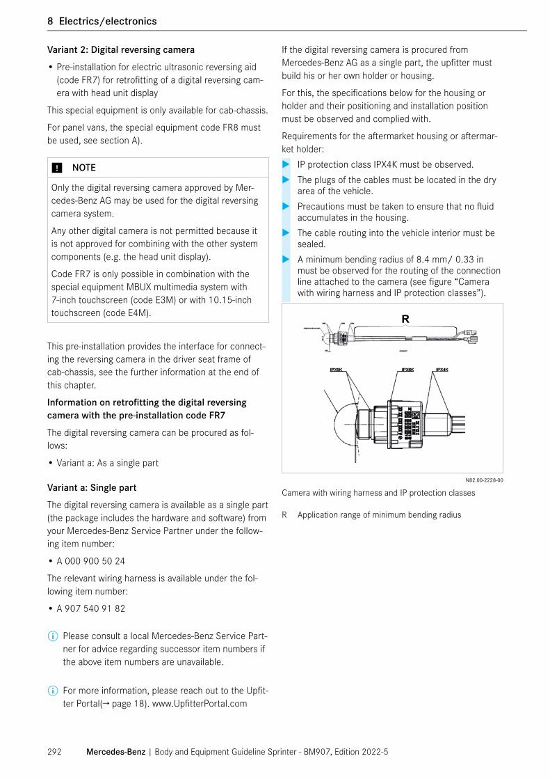
Variant 2: Digital reversing camera
• Pre-installation for electric ultrasonic reversing aid (code FR7) for retrofitting of a digital reversing cam-era with head unit display
This special equipment is only available for cab-chassis.
For panel vans, the special equipment code FR8 must be used, see section A).
⑴ NOTE
Only the digital reversing camera approved by Mer-cedes-Benz AG may be used for the digital reversing camera system.
Any other digital camera is not permitted because it is not approved for combining with the other system components (e.g. the head unit display).
Code FR7 is only possible in combination with the special equipment MBUX multimedia system with 7-inch touchscreen (code E3M) or with 10.15-inch touchscreen (code E4M).
This pre-installation provides the interface for connect-ing the reversing camera in the driver seat frame of cab-chassis, see the further information at the end of this chapter.
Information on retrofitting the digital reversing camera with the pre-installation code FR7
The digital reversing camera can be procured as fol-lows:
• Variant a: As a single part
Variant a: Single part
The digital reversing camera is available as a single part (the package includes the hardware and software) from your Mercedes-Benz Service Partner under the follow-ing item number:
• A 000 900 50 24
The relevant wiring harness is available under the fol-lowing item number:
• A 907 540 91 82
ⓘ Please consult a local Mercedes-Benz Service Part-ner for advice regarding successor item numbers if the above item numbers are unavailable.
ⓘ For more information, please reach out to the Upfit-ter Portal(→ page 18). www.UpfitterPortal.com
If the digital reversing camera is procured from Mercedes-Benz AG as a single part, the upfitter must build his or her own holder or housing.
For this, the specifications below for the housing or holder and their positioning and installation position must be observed and complied with.
Requirements for the aftermarket housing or aftermar-ket holder:
� IP protection class IPX4K must be observed. � The plugs of the cables must be located in the dry
area of the vehicle. � Precautions must be taken to ensure that no fluid
accumulates in the housing. � The cable routing into the vehicle interior must be
sealed. � A minimum bending radius of 8.4 mm/ 0.33 in
must be observed for the routing of the connection line attached to the camera (see figure “Camera with wiring harness and IP protection classes”).
R
N82.00-2228-00
Camera with wiring harness and IP protection classes
R Application range of minimum bending radius
Mercedes-Benz | Body and Equipment Guideline Sprinter - BM907, Edition 2022-5292
1 General
8 Electrics/electronics

Requirements concerning positioning and installation position:
• The camera must be positioned so that the rear-most contour of the rear end of the vehicle is clearly visible in the head unit display (see figure “Camera positioning with upfitter housing”).
• The positioning and installation position of the cam-era must meet the specifications, see figures “Cam-era positioning with upfitter housing” and “Permissi-ble installation position”.
• The cable outlet of the camera is positioned off-cen-ter. To ensure the image is displayed correctly, the camera must always be installed with the cable out-let pointing upward (see figure “Camera positioning with upfitter housing”).
3
45
1
2
N82.00-2229-00
Camera positioning with upfitter housing (schematic diagram)
1 Cable outlet (specification: must always point upward)2 Viewing angle = 37°3 Viewing area (asymmetrical)4 Center line of camera lens5 Viewing angle limit
ⓘ The reference point for the camera height and the offset to the center is always the center of the camera lens.
1
2
3 3
4
N82.00-2230-00
Permissible installation position (schematic diagram)
1 Minimum height hmin= 1675 mm/ 65.94 in2 Maximum height hmax= 2785 mm/ 109.65 in3 Maximum deviation bmax= ±200 mm/ 7.87 in (relative to
the center of the vehicle)4 Upper edge of vehicle longitudinal frame member
Mercedes-Benz | Body and Equipment Guideline Sprinter - BM907, Edition 2022-5 293
8 Electrics/electronics

Electrical requirements for camera system and connecting points
The connecting points for the analog and digital reversing cameras are located in the driver seat frame in open models. The connecting point for the analog reversing camera in closed models is located in the area of the 3rd brake light (on the roof at the top of the rear).
The wiring harness and plug to be connected to this wiring harness must satisfy the following requirements:
• The connectors of the camera are only approved for a dry environment.
• No further connecting points are permissible
• The quality of the video/high-frequency line must meet at least the requirements of the 50-ohm LEONI Dacar® 462 for mobile applications up to 6 GHz.
• The line quality was designed for a line length of 9600 mm/ 377.95 in from the seat base connecting point to the camera. If a longer line is required, its functional capability must be assured by means of tests conducted by the upfitter.
• The reversing camera system must not be disrupted by EMC influences, e.g. by 230 V systems, actuators etc.
ⓘ Further information can be found on the Upfitter Portal.
Requirements for commissioning
The digital reversing camera must be put into operation by coding using the XENTRY Kit (see Chapter 2.3.3 XENTRY Kit (→ page 19)). We recommend that you have this carried out in a Mercedes-Benz workshop.
⑴ NOTE
In addition to code FR7, the code O1N "Activation of reversing camera without guide lines" must be coded into the vehicle.
The reversing camera system must be tested and must function flawlessly under real-life conditions (including upfitter requirements):
• When reverse gear is engaged, the picture from the reversing camera is displayed completely and with out errors in the head unit display.
• No guide lines are displayed.
• The rear end of the vehicle is clearly visible.
• Image noise, distortions, mirroring or delays must not occur.
For a detailed description of the commissioning pro-cess, please refer to the WIS (Workshop Information System).
For further questions, please reach out on the Upfitter Portal.
⑴ NOTE
The reversing camera system is classified as ASIL Level A according to ISO 26262. For all the compo-nents involved, it must be ensured that no delayed or frozen images can occur (see the section on commis-sioning at the end of this chapter). Appropriate verifi-cation of this must be provided to Mercedes-Benz AG via your contact person at Technical Consulting (see Chapter 2.1 Advice for Upfitters (→ page 14)).
ⓘ For a detailed description of the commissioning process, please refer to the WIS (Workshop Infor-mation System).
ⓘ If you have any further questions, get in touch with your contact person at Technical Consulting (see Chapter 2.1 Advice for Upfitters (→ page 14)).
Mercedes-Benz | Body and Equipment Guideline Sprinter - BM907, Edition 2022-5294
1 General
8 Electrics/electronics
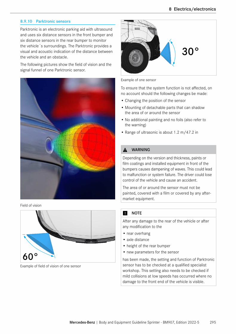
8.9.10 Parktronic sensors
Parktronic is an electronic parking aid with ultrasound and uses six distance sensors in the front bumper and six distance sensors in the rear bumper to monitor the vehicle´s surroundings. The Parktronic provides a visual and acoustic indication of the distance between the vehicle and an obstacle.
The following pictures show the field of vision and the signal funnel of one Parktronic sensor.
Field of vision
60°Example of field of vision of one sensor
30°
Example of one sensor
To ensure that the system function is not affected, on no account should the following changes be made:
• Changing the position of the sensor
• Mounting of detachable parts that can shadow the area of or around the sensor
• No additional painting and no foils (also refer to the warning)
• Range of ultrasonic is about 1.2 m/47.2 in
⚠ WARNING
Depending on the version and thickness, paints or film coatings and installed equipment in front of the bumpers causes dampening of waves. This could lead to malfunction or system failure. The driver could lose control of the vehicle and cause an accident.
The area of or around the sensor must not be painted, covered with a film or covered by any after-market equipment.
⑴ NOTE
After any damage to the rear of the vehicle or after any modification to the• rear overhang• axle distance• height of the rear bumper• new parameters for the sensor
has been made, the setting and function of Parktronic sensor has to be checked at a qualified specialist workshop. This setting also needs to be checked if mild collisions at low speeds has occurred where no damage to the front end of the vehicle is visible.
Mercedes-Benz | Body and Equipment Guideline Sprinter - BM907, Edition 2022-5 295
8 Electrics/electronics

8.10 Parameterizable Special Module (PSM/ MPM)
Parameterizable Special Module (PSM), or also known as Multi-Purpose Module (MPM) for Sprinter BM 907, is an electronic control unit that connects to the vehicle’s CAN bus system and can read and control various vehi-cle functions. Because Mercedes-Benz restricts modifi-cations of the CAN bus system and direct access to the vehicle networks, PSM has been developed to provide an indirect access to the vehicle CAN bus. PSM can be purchased under the option code ED5 and part number A907 900 53 03. Pre-wiring for PSM (MPM) can be ordered using the option code ED8 for the customer who wishes to install PSM in the future. Without the option code ED8, PSM cannot be retrofitted onto the vehicle.
⑴ NOTE
The wirings on the vehicle must not be tampered with for this could lead to fault messages from the other control units on the CAN bus.
Please utilize fuses for any electronic consumers connected to PSM.
The PSM control unit is located in the driver seat box. PSM can be installed or removed by first removing the driver’s seat and then the driver seat base cover. Once the seat has been removed, the bracket for PSM control unit can be found directly beneath the parking system control unit.
Front
PSM
PSM is connected to two fuses in the fuse box on the driver’s seat frame. Fuses for PSM, F14 and F15 are shown in the picture below.
Location of fuses for PSM (MPM)
PSM is connected to the vehicle network via the body CAN bus and therefore has access to the specific mes-sages sent by the linked control units (e.g. door status, vehicle speed, engine speed, parking brake active). PSM can translate the messages from various bus data into switching signals at the outputs provided ("high" or "low") or PWM signals (pulse width modulation). Indi-vidual signals is monitored or generated at analog and digital inputs and outputs.
PSM provides a clearly defined, diagnostics-com patible and EMC-tested interface between the vehicle and the body.
PSM provides an interface, not a system. The PSM functionality available via the interface is protected as per ISO 26262, generally by a QM process. The pro-tection of functions in which the PSM is involved and compliance with applicable standards (e.g. ISO 26262 on functional safety) and specifications are always the responsibility of the upfitter.
⑴ NOTE
When uploading a new PSM coding, all previous parameterizations are erased. We recommend backing up stored PSM program beforehand.
ⓘ For additional information, please refer to the Upfitter Portal technical bulletin: Sprinter MY2019+ Parameterizable Special Module (ED5). Inquiries on PSM programs as well as requests for custom-ized PSM programs for eXpertUpfitters can be requested on www.UpfitterPortal.com.
ⓘ PSM is parameterized using XENTRY. Further infor-mation on XENTRY (→ page 19).
ⓘ Information on standard PSM programs can be obtained from your local Mercedes-Benz Service Center.
Mercedes-Benz | Body and Equipment Guideline Sprinter - BM907, Edition 2022-5296
1 General
8 Electrics/electronics

8.10.1 PSM (MPM) Functions
Some of the functions provided by PSM (MPM) using the interior CAN bus (CAN B) are reading and controlling:• Inputs
- Digital - Analog
• Outputs - Pulse-Width-Modulation (PWM) signals
• Illumination and signaling horn - Low beams - High beams - Headlight flasher - Horn
• Central locking - Lock/ unlock vehicle - Lock/ unlock cab - Lock/ unlock cargo
• Windshield wipers - Speed control of windshield wipers
• Electric sliding door• Displays in instrument cluster• Further data from interior CAN
- Audio muting - Acoustic warning tone (internal buzzer)
• Electric step
The above list is not a complete list of all the functions offered by PSM (MPM). More information on the PSM (MPM) functions are available on the Upfitter Portal.
The mini-PLC (mini programmable logic controller) used in PSM programming is a module with freely program-mable and freely intercon nectable function blocks for creating any signal links that may be required:
• 96 AND/ NAND/ OR/ EXOR/ NOR/ EXNOR
• 24 RS and D flip-flops
• 12 retriggerable/ non-retriggerable timer stages
• 12 hysteresis links with adjustable thresholds
• 24 threshold switches with 3 stages
• 12 counters
⑴ NOTE
Lock/ unlock function by PSM is internal lock/ unlock feature cannot override the external lock/ unlock function by the key FOB.
⑴ NOTE
For vehicles with a factory-installed communication module:
Based on the group-wide resolution from the control committee on fully automated driving, ethics and the law, Mercedes-Benz AG only makes vehicle data available via internal back ends. Internal backends are Mercedes me connect or the Extended Vehicle Back-end. External vehicle data transmission via the PSM is no longer available as standard.
Exceptions continue to exist for multi-brand appli-cations, fleet applications and car-sharing. This is also so for use cases in which the PSM serves as the basis for an additional vehicle body and no vehicle data are sent to a third-party back end.The Mercedes-Benz AG will continue to support for individual PSM request for usage inside the vehicle environment. For more infor-mation, please reach out to: www.UpfitterPortal.com.
For individual support, please use the inquiry function on www.UpfitterPortal.com.
Mercedes-Benz | Body and Equipment Guideline Sprinter - BM907, Edition 2022-5 297
8 Electrics/electronics

8.10.2 PSM (MPM) Pin Assignment
PSM consists of two plugs upfitters can connect to. Plug 1 is composed of fifteen 2.8 mm MCP pins, and plug 2 is composed of thirty-two 0.64 mm MQS pins. Below image provides detailed information on each pins on PSM (MPM).
Pin Assignment of the PSM (MPM)
A plug and play solution is provided with the option code E5M (extension of PSM standard contact). Upfit-ters can directly connect their own wiring harness to the PSM extension plugs, E5M (non-retrofitable Y-harness).
Mercedes-Benz | Body and Equipment Guideline Sprinter - BM907, Edition 2022-5298
1 General
8 Electrics/electronics

E5M input and output extension plugs pin assignment
8.10.3 Additional information on PSM (MPM)
PSM (MPM) programs are parameterized using XENTRY (→ page 19)
Programming of PSM (MPM) software can only be performed by trained and authorized Mercedes-Benz personnel. Uploading of PSM (MPM) software can be performed by any individual trained and authorized by Mercedes-Benz personnel.
ⓘ Additional information on standard parameterization possibilities can be obtained from Mercedes-Benz Service Center. Standard PSM programs for Sprint-ers are available at local dealerships. Inquiries on PSM programs as well as requests for customized PSM programs for eXpertUpfitters can be requested on www.UpfitterPortal.com.
Mercedes-Benz | Body and Equipment Guideline Sprinter - BM907, Edition 2022-5 299
8 Electrics/electronics

8.11 Signal acquisition and actuation module (SAM)
The power circuit on the Sprinter BM 907 comprises the signal acquisition and actuation module (SAM) in connection with a fuse and relay block (SRB). These limit switches supply the systems and control units with power, depending on the function sequence. The requirements are relayed to the SAM either over CAN or via directly scanned switches and sensors. The fuses on the fuse and relay blocks also provide protection for individual components.
The fuse and relay box acts as a monitor for electrome-chanical switching units.
You will find information about other functions in the chapter "Technical details" (→ page 316).
Mercedes-Benz | Body and Equipment Guideline Sprinter - BM907, Edition 2022-5300
1 General
8 Electrics/electronics

8.12 Electrical circuit diagrams
Electrical circuit diagrams can be made available to eXpertUpfitters as part of the eXpertUpfitter Program.
As part of the eXpertUpfitter program please refer to www.UpfitterPortal.com.
Electrical circuit diagrams can also be called up in the Workshop Information System (WIS) (→ page 18).
https://www.startekinfo.com/homehttps://xentry.daimler.com
8.13 Telematics
The table below lists the abbreviations used in the field of telematics.
Abbrevia-tion
Meaning/description
HU Head UnitConnect5 Multimedia system with 7" displayNTG6 Multimedia system incl. navigation with 7" or
10.25" displayDVI Digital Visualization InterfaceCAN Controller Area NetworkCAR PC Control unit or PC installed in the vehicleTMDS Transition-Minimized Differential SignalingRGB signal Red, Green and Blue signal
PSM Parameterizable Special ModuleDAB Digital Audio BroadcastingLTE Long Term EvolutionAM/FM Amplitude Modulation/Frequency Modula-
tionSDARS Satellite Digital Audio Radio ServicesHDMI High-Definition Multimedia InterfaceRHC Right hand circulation polarizationMBUX Mercedes-Benz User Experience (multime-
dia system based on Connect5 or NTG6)AUB Antenna switchover boxGPS Global Positioning SystemGNSS Global Navigation Satellite System
For further questions regarding telematics, please refer to 1.7 Contact (→ page 11).
Mercedes-Benz | Body and Equipment Guideline Sprinter - BM907, Edition 2022-5 301
8 Electrics/electronics

8.13.1 Overview of the Infotainment system
The new NTG6 telematics generation has been inte-grated in the Sprinter and thus offers the entertainment convenience familiar from the passenger car model series. Numerous entertainment and user experience applications are available with the Mercedes-Benz User Experience MBUX special equipment.
In addition to the radio pre-installation special equip-ment (Code ER0) and radio pre-installation with DAB (Code E7A), the following infotainment systems are also available:
Code Infotainment system Telephony (Bluetooth®)
Smartphoneintegration
Navigation Reversing camera
360° camera
Voice control ("Hey Mercedes")
E1O MB audio system Yes No No No No NoE3M MBUX multimedia sys-
tem with 7" touchscreen (Connect5)
Yes Yes1) No Yes Yes No
E3M + E1E
MBUX multimedia sys-tem including navigation with 7" touchscreen (NTG6)
Yes Yes2) Yes Yes Yes Yes
E4M MBUX multimedia sys-tem including navigation with 10.25" touchscreen (NTG6)
Yes Yes2) Yes Yes Yes Yes
1) Smartphone integration via Apple CarPlay® (ACP) and Android Auto® (AA) wireless, country-dependent availability only in combination with the "Communication module for digital services" in the vehicle (Code JH3), see Chapter 8.14 Connectivity solutions (→ page 308)
2) Smartphone integration via Apple CarPlay® (ACP) and Android Auto® (AA) via cable (USB-C)
Further details on the Infotainment systems, the other special equipment and the equipment packages can be obtained from the corresponding sales information and from your Mercedes-Benz sales partner.
The functions of the various telematics equipment are described in the operator's manual for your vehicle.
ⓘ The information and specifications on operat-ing multimedia and vehicle systems in Chap-ter 7.15.f New features for RVs (→ page 222) and Chapter 8.3.1 Main battery (→ page 235) must be observed.
The functions of the various head units are described in the operator's manual.
ⓘ The notes and specifications for operating the multi-media and vehicle systems in Chapter 7.15.5 New features for RVs (→ page 222) and Chap-ter 8.3.1 Main battery (→ page 235) must be observed.
Mercedes-Benz | Body and Equipment Guideline Sprinter - BM907, Edition 2022-5302
1 General
8 Electrics/electronics

8.13.2 Antennas
Antenna variants with equipmentEquipment/ function
Antenna type Picture Explanation
Radio pre-instal-lation/entry-level radio/Connect5
ANTENNA FOR RADIOObject no. A9079051702
N82.62-2054-00
4
3
1
2
1 AM/FM1 FAKRA code A2 FM2 FAKRA code E3 Not available4 Not available
NTG6/navigation/ ED3
ANTENNA FOR RADIO TEL GNSSObject no. A9079051802
1 TEL FAKRA code D2 FM2 FAKRA code E3 GNSS FAKRA code C4 AM/FM1 FAKRA code A
DAB ANTENNA FOR RADIO TEL GNSS DABObject no. A9079051902
1 Tel FAKRA Code D 2 FM2/DAB2 FAKRA Code E 3 GNSS FAKRA Code C 4 AM/FM1/DAB1 FAKRA Code B
Mercedes-Benz | Body and Equipment Guideline Sprinter - BM907, Edition 2022-5 303
8 Electrics/electronics

Overview of antennas for vehicles with and without cab roof ex factory
For vehicles without cab roof (cab base vehicles code F28) a pre-installation for antennas is available as special equipment (code E4A) instead of the antenna ex works, see Chapter 7.14.8 Connecting point for antenna switchover box for third-party antennas (code E4A) (→ page 215).
This special equipment includes an antenna switch box in the driver's seat base as an interface for an acces-sory antenna used by the upfitter and the associated cable set for the power supply.
The following illustrations of the connection diagrams must be observed.
The installation instructions and specifications of the manufacturer of the accessory antenna must also be observed.
The antenna switch box is used exclusively for mod-ulating signals from an accessory antenna for further signal processing in the Mercedes-Benz head unit. It is not permissible to connect the factory-fitted antenna, which is available from Mercedes-Benz Service, to the antenna switch box.
Connection diagram: Vehicles with ex factory antenna
1 Power supply (external feed) through HU (Head Unit)
Connection diagram: Vehicles with pre-installation for antenna (code E4A)
1 Power supply 12 V (tml. 30 from wiring harness)2 Antenna switch box (AUB)3 Antenna ABH interface (code E4A)4 Power supply 12 V through AUB5 Accessory antenna6 GSM interface in radio slot7 Two LTE antennas in the cockpit (second antenna always
with code F28)
Mercedes-Benz | Body and Equipment Guideline Sprinter - BM907, Edition 2022-5304
1 General
8 Electrics/electronics

Requirements on antenna switchover box for upfitter antenna
The antenna switchover box must be supplied with the following signals:
• FM (87 MHz – 108 MHz)• AM (531 kHz – 1720 kHz and 5.9 MHz – 26.1 MHz)• DAB band III (174–240 MHz)• Impedance 50 ohms
Global Navigation Satellite System (GNSS)
The connection of the navigation system must be sup-plied with the following signal:
AntennaAntenna type PatchFrequency 1575 MHz – 1606 MHzGain in antenna 2 dBic, mean value Theta 0 - 20°Polarization RHC
AmplifierReinforcement 28 dB coreNoise factor ≤1 dB (without filter) Impedance 50 ohm
Power supply Operating voltage 4.5 V – 5.5 VPower consumption 20 mA± 3 mAPhantom power Yes
Satellite radio for USA/Canada
For SDARS (Satellite Digital Audio Radio Services), the antenna A2139055105 and the antenna dome A2388270100 must be used. Please contact your Mer-cedes-Benz Service Partner to obtain these com ponents. The design specifications can be found in the current SiriusXM guideline, which can be requested from this antenna manufacturer.
There are two positions associated with the location of the above parts depending on the vehicle type.
N82.62-2061-00
Position of antenna for the cab chassis
Position of antenna for the cargo van
⑴ NOTE
To ensure that no interference with the satellite signals occurs due to upfitting, the antenna must be positioned at the highest point on the vehicle.
⑴ NOTE
For vehicles that do not have code E1S (Sirius XM satellite radio), satellite antenna can be installed by following the WIS document SM82.62-D-0009SG.
Mercedes-Benz | Body and Equipment Guideline Sprinter - BM907, Edition 2022-5 305
8 Electrics/electronics

Modification Guidelines:
If the vehicle is equipped with a roof cut-out (option code FA1 or F28), please adhere to the following points:
• Do not modify the wiring connections around the roof cut-out. Please use the following figures for refer-ence.
• A portable antenna is provided as an additional part which is located in the glovebox.
If the vehicle is equipped with an antenna but the position needs to be modified, please adhere to the following points:
• The cable connection to the antenna is a FAKRA connector with a female connection. Extension cables are available from third party sources and can be used to reposition the wiring harness.
• Ensure that the new antenna position complies with Sirius XM requirements. (http://pixelsatradio.com/content/pdfs/antenna_aiming.pdf)
N82.62-2063-00
Cable harness layout for cab chassis
N82.62-2064-00
Cable harness layout for cargo van
Mercedes-Benz | Body and Equipment Guideline Sprinter - BM907, Edition 2022-5306
1 General
8 Electrics/electronics

8.13.3 Speakers
Connect5 and NTG6 have 5 channels for connecting speakers to the system.
As standard with Connect5 and NTG6, two pairs of speakers (woofer/ mid-range speaker and tweeter) are fitted in the front left (FL) and front right (FR) in the doors. For a better sound experience, the NTG6 has an additional mid-range speaker (Cen).
Additional speaker pairs are available for the cargo and crew van model designations as a special equipment (Code EL9) in the rear passenger compartment. This enables fade-in/fade-out of the rear left (RL) and rear right (RR) audio sources in Connect5 and NTG6.
The total impedance per channel must not be less than 2 ohms.
Ch2 A3 FR - Aeff 4.5 A 1,5 mm² 0.0023 in²Ch2 A2 FR + Aeff 4.5 A 1,5 mm² 0.0023 in²Ch1 A12 FL + Aeff 4.5 A 1,5 mm² 0.0023 in²Ch1 A11 FL - Aeff 4.5 A 1,5 mm² 0.0023 in²Ch3 A24 RL - Aeff 4.5 A 1,5 mm² 0.0023 in²Ch3 A25 RL + Aeff 4.5 A 1,5 mm² 0.0023 in²Ch4 A15 RR + Aeff 4.5 A 1,5 mm² 0.0023 in²Ch4 A16 RR - Aeff 4.5 A 1,5 mm² 0.0023 in²Ch5 B1 Cen + Aeff 4.5 A 1,5 mm² 0.0023 in²Ch5 B10 Cen - Aeff 4.5 A 1,5 mm² 0.0023 in²
N82.62-2065-00.
Connections for speakers
1) Only with NTG6
Mercedes-Benz | Body and Equipment Guideline Sprinter - BM907, Edition 2022-5 307
8 Electrics/electronics

8.14 Connectivity solutions Mercedes me connect
8.14.1 Mercedes me connect for personal use
Mercedes-Benz Vans offers Mercedes me connect for individual customers2. Mercedes me connect provides an individual experience through the vehicle-integrated Communication Module (LTE)3 and the Mercedes me connect App. Your Mercedes me connect equipped Van will enhance your experience during purchase, service, and throughout your ownership. Mercedes me connect is focused on your comfort and individual experience.
Mercedes me connect consists of a multitude of ser-vices1,3. Because your safety is our priority, we encour-age you to take advantage of Software Updates for your Van and to stay connected with our Customer Assistance Center in case of an emergency or breakdown. Keep track of your Van’s location status when parked by using the Mercedes me connect App. Easily lock/unlock doors remotely through the App. If your Van is equipped with an MBUX Multimedia System, Mercedes me connect provides you with online services such as Live Traffic Information4 and Online Map Updates4 to keep your Van’s navigation system up to date.
8.14.2 Mercedes me connect for business use
As a commercial customer you also have the opportunity to use Mercedes me connect for your business. The Mer-cedes me connect services for commercial customers ensure that you and your company remain connected to your Van(s) at all times and from anywhere1,2,3. With the Mercedes me connect App, you will have the most up to date and important information about your vehicle right at the palm of your hands2. Take advantage of software updates, maintenance information and more with Mer-cedes me connect for business use.
As a company administrator, you can reach out to your preferred dealer and register for a new Mercedes me connect company profile. The dealer can assist with add-ing your company vehicles to your new company profile. Upon completion of your newly created company profile the company admin listed on the account will be able to manage company vehicles, users and services, and more in the Mercedes me connect Portal. Additional users, such as drivers, will be able to use many of the Mercedes me connect services that are already available for per-sonal use in the Mercedes me connect App and the Van1.
⚠ WARNING
Using the Mercedes me connect App while driving will distract you from traffic conditions. This could cause you to lose control of the vehicle, which could result in an increased risk of endangering yourself and others, including the risk of accidents, personal injuries and death. In order to help prevent distracted driving, the use of the Mercedes me connect App is not permitted while operating a motor vehicle. Please follow all appli-cable federal, state and local laws and restrictions and observe the legal requirements of the country in which you are currently located.
For further information on Mercedes me connect visit https://www.mbvans.com/en/connectivity. For information on service availability and eligibility of your Van1,2,3, visit https://www.mbusa.com/en/legal- notices/connected-vehicle or contact your dealer.
1 Models shown may include options/packages not stan-dard on a Sprinter (as of MY19 and newer) or a Metris (as of September 2019 production, MY 20). Specifica-tions are subject to change. Services require vehicle cel-lular connectivity and availability of vehicle GPS signal.
2 Mercedes me connect is available for the United States of America for Sprinter (as of MY19 and newer) and Metris equipped with a Communication Module (LTE) (as of Sep-tember 2019 production, MY20). Contact an authorized Mercedes-Benz Vans dealership for more information.
3 The availability of services in addition to the integrated Communication Module for Digital Services (LTE) depends on the network coverage of the mobile network provider. The Communication Module for Digital Services (LTE) is not available in the US Virgin Islands or Puerto Rico. The Communication Module for Digital Services (LTE) is equip-ped in the Sprinter (as of MY 19 and newer) and optionally equipped in the Metris (as of September 2019 production, MY20 and newer). The availability of certain features may be impacted at the current time.
4 The information from this service is shown on the touch-screen of the MBUX Multimedia System. Live Traffic Infor-mation can only be used in conjunction with the MBUX Multimedia System with 17.8 cm (7-inch) touchscreen and navigation or the MBUX Multimedia System with 26 cm (10.25-inch) touchscreen options. While the navigation sys-tem provides directional assistance, the driver must remain focused on safe driving behavior, including paying attention to traffic and street signs. The driver should utilize the sys-tem's audio cues while driving and should only consult the map or visual displays once the vehicle has been stopped in a safe place. Maps do not cover all areas or all routes within an area. Please follow all applicable federal, state and local laws and restrictions.
Mercedes-Benz | Body and Equipment Guideline Sprinter - BM907, Edition 2022-5308
1 General
8 Electrics/electronics

9.1 Center of gravity
The overall height of the center of gravity (vehicle with equipment/complete body but without load) should be kept as low as possible.
The position of the center of gravity in the longitudinal direction of the vehicle (x-direction) is specified relative to the center of the front axle.
The center of gravity height (z-direction) is specified with reference to the roadway.
Mercedes-Benz recommends that you have the position of the center of gravity checked by a approved and experienced testing institution.
If the center of gravity is determined by the upfitter, the procedures described under 9.1.1 Determination of the center of gravity in the x-direction (→ page 309) and 9.1.2 Determination of the center of gravity in the z-di-rection (→ page 311) must be followed and qualified person must perform the services to achieve realistic and useful results.
The vehicle must be measured in a load condition appropriate for its intended purpose. (See the following pages for examples.)
Likewise, the web-based “Vehicle Center of Gravity and Axle Weight Calculator” provided by NTEA might be helpful. Mercedes-Benz does not take responsibility of the accuracy of the calculated values by the NTEA web-based calculator.
www.ntea.com/weightcalculator
⑴ NOTE
Practical determination of the center of gravity position in the x and z-directions may only be carried out by appropriately qualified staff using suitable and calibrated vehicle scales.
In order to reduce measuring errors, each measure-ment value should be determined at least three times and the average should be calculated from these three values.
⑴ NOTE
The calculated center of gravity position in the z-di-rection (CoG height) must not exceed the limit values specified under Chapter 4.1.2 Maximum permissible position of the center of gravity (→ page 58)
9.1.1 Determination of the center of gravity in the x-direction
Center of gravity coordinates in x-direction (front/rear axle load distribution)
Recommended Procedure: � In the first series of measurements, the vehicle
should be weighed with the complete equipment or body but without payload.
� In the second series of measurements, the vehicle should be weighed with the complete equipment or body and with a payload appropriate for its intended purpose, taking into account the permissi-ble gross mass and the permissible axle loads.
� For the measurements, the tire pressure at all wheels should be set to 6 bar.
� Completely fill all fluid reservoirs for operating fluids (fuel tank, AdBlue® tank, washer fluid reser-voirs and, if installed, hydraulic fluid reservoir).
� Shut off the engine on the scales, shift the trans-mission to neutral position and release the brakes.
� The vehicle must be parked horizontally on level ground for weighing.
� First weigh the individual axle loads (front and rear axle loads) and then the gross vehicle mass.
� Using these measurements, the position of the center of gravity in the longitudinal direction of the vehicle can be calculated using equations (3) and (4).
� Use (2) to check the results from (3) and (4).
Mercedes-Benz | Body and Equipment Guideline Sprinter - BM907, Edition 2022-5 309
9 Calculations
9 Calculations

Illustration of coordinates and dimensions
Axle load calculation
GG = GHA + GVA(1)
l = lV + lH (2)
Calculation of the center of gravity in the x-direction
lV =GHA × l
GG
(3)
lH =GV A × l
GG
(4)
Weights:GG Gross mass of vehicleGVA Front axle load of empty vehicle
(specification or weighing of the chassis in question)GHA Rear axle load of empty vehicle (specification or weighing of the chassis in question)
DimensionslV Distance of overall center of mass of empty vehicle
from front axlelH Distance of overall center of mass of empty vehicle
from rear axlel WheelbaseSG Overall vehicle center of gravity
ⓘ The wheelbase "I" is defined by the vehicle model designation (see order) or must be determined by means of a length measurement according to coun-try and/or state specific regulations.
Mercedes-Benz | Body and Equipment Guideline Sprinter - BM907, Edition 2022-5310
1 General
9 Calculations

9.1.2 Determination of the center of gravity in the z-direction
Center of gravity coordinates in z-direction (height of center of gravity hS for the overall vehicle)
For determination of the overall center of gravity height of the vehicle above the roadway hS by the upfitter, Mercedes-Benz recommends the following procedure after completion of the vehicle:
After conversion, the vehicle should be weighed on a plate-type scale or suitable wheel load scale in two different drive positions in succession. Here, the axle loads measured when the vehicle stands horizontal and level (GVA or GHA, see 9.1.1 Determination of the center of gravity in the x-direction (→ page 309)) and the axle loads for an axle raised by h' (QHA or QVA) must be determined. The lift height h' should be as large as possible in accordance with the front and rear overhang angle of the vehicle (also known as the angle of approach or departure). The target value is h' > 1100 mm/43 in (wheelbase 3250 mm/144 in) and 1400 mm/55 in (wheelbase 4325 mm/170 in).
In order to reduce measuring errors, at least six individ-ual measurements must be performed for each vehicle axle when measuring the axle load: three per axle when the vehicle is in a level state and three when an axle is raised. Based on the three measurements in each con-dition, an average should be calculated for each axle.
For this, the equations (5) to (7) are to be used. Import-ant: The measurement results must be close together. If individual measurements vary widely from each other, the deviating individual measurement must be repeated. The total value between the raised front and rear axles is then calculated.
In order to improve the accuracy of the final result, the axle load change should be determined both with a raised rear axle and with a raised front axle.
⑴ NOTE
In order to avoid erroneous measurements, please note:
� When weighing with the vehicle level, the vehicle must be exactly horizontal. Any height differences between the axles caused by the scales must be compensated for accordingly.
� Both axles must be blocked to prevent suspen-sion jounce and rebound when raising to the required lift height.
� When raising, the left and right sides must be raised in parallel.
� No part of the vehicle may bottom out when rais-ing to the required lift height.
� All vehicle wheels must be able to roll: Gearshift system in neutral position, all brakes including parking brake released, chocks placed at a suffi-cient distance from the wheels if necessary.
� Set all tires to an internal pressure of 6 bar.
� Between the individual measurements and to turn it around (in order to weigh the other axle), move the vehicle under its own power so that any stresses in the vehicle are relaxed.
� Make sure that no objects inside the vehicle can move during the measurements.
� It must be ensured that all fluids (operating fluids and other media specified/required for the intended purpose (e.g. hydraulic oil, fresh water etc.)) and the gear and equipment required for operation as well as the necessary counter bal-lasts are all topped up and present.
Mercedes-Benz | Body and Equipment Guideline Sprinter - BM907, Edition 2022-5 311
9 Calculations

Recommended Procedure � In the first series of measurements, the vehicle
should be weighed with the complete equipment or body with axle blocking but without payload.
� In the second series of measurements, the vehicle should be weighed with the complete equipment or body with axle blocking and with a payload appro-priate for its intended purpose, taking into account the permissible gross mass and the permissible axle loads.
� Inflate the tires up to an internal pressure of 6 bar. � Completely fill all fluid reservoirs or operating fluids
(fuel tank, washer fluid reservoirs, hydraulic fluid reservoir, coolant reservoir, AdBlue® tank etc.) and load or attach all the gear and equipment required for operation as well as the necessary counter ballasts.
� Shut off the engine on the scales, shift the trans-mission to neutral position and release the brakes.
� Position the vehicle with the rear axle (HA) at a horizontal and level position on the scales and determine the axle load.
� Raise the front axle (VA) by the lift height h'. Increasing the height h' while taking the other boundary conditions of the vehicle into account improves the final result. The value h' must be determined for all individual measurements with raised axle and should be identical wherever possible. As an alternative to measuring the raised height h', the angle a between the wheel hubs can be determined.
� Determine the resulting axle load shift (QHA) at the rear axle (HA) on the scales.
� Lower the vehicle and perform lifting measure-ments 2 and 3. Between all the individual measure-ments and to turn it around (in order to weigh the other axle), move the vehicle under its own engine power so that any stresses in the vehicle/chassis are relaxed.
� After the third measurement, lower the vehicle, turn it around, and carry out corresponding mea-surements on the front axle (initially GVA with the vehicle level, and then QVA with the rear axle raised by height h').
� Using the calculated values, the height of center of gravity can be calculated using equations (5) to (7).
� When calculating using the equations (3) to (9), all length measurements must be used in millimeters (mm) and all weights must be used in decanewtons (1 daN = 10 N). G = 1 daN = 10 N is the weight force correspond-ing to the mass m = 1 kg/2.2 lbs.
Mercedes-Benz | Body and Equipment Guideline Sprinter - BM907, Edition 2022-5312
1 General
9 Calculations

Illustration of coordinates and dimensions
Determining the height of the center of gravity
hS = ha + rstat(5)
rstat Loaded tire radiusQVA Front axle load with vehicle raised at rearQHA Rear axle load with vehicle raised at fronthS Height of center of gravity above roadwayha Height of center of gravity above wheel centerh' Height by which the vehicle was raisedSG Overall vehicle center of gravity1 Weighing device
ⓘ The wheelbase "I" is defined by the vehicle model designation (see order) or must be determined by means of a length measurement according to coun-try and/or state specific regulations.
Formulas for raised front axle:
hS =
(l
h′ ×QHA − GHA
GG×
√l2 − h′2
)+ rstat (6)
Formulas for raised rear axle:
hS =
(l
h′ ×QV A − GV A
GG×
√l2 − h′2
)+ rstat (7)
⑴ NOTE
The calculated center of gravity must not exceed the limit values specified under 4.1.2 Maximum permissi-ble position of the center of gravity (→ page 58).
Mercedes-Benz | Body and Equipment Guideline Sprinter - BM907, Edition 2022-5 313
9 Calculations

Examples for loads appropriate for the intended purpose for:
• RVs
- All reservoirs for operating fluids 100% full, includ-ing fuel tanks
- Number of registered seats each loaded with 80 kg/ 176.37 lbs.
- Fresh water tank empty if located in the under-body, full if locates above the vehicle floor (depending on the layout of the vehicle)
- Waste water tank empty
- All cabinets, stowage boxes and the rear hold with typical RV loads, if appropriate up to the maximum possible load capacity of the stowage compart-ments
- Including all planned and available special equip-ment (e.g. awning, roof-mounted air conditioning system, bicycle rack, SAT system, solar system, pop-up roof etc.)
- Unavailable special equipment is to be simulated by appropriate dummy weights at the correspond-ing installation location.
• Box bodies
- All reservoirs for operating fluids must be 100% full, including fuel tanks
- 1x driver 80 kg/ 176.37 lbs.
- The box body must be loaded appropriately for the intended purpose in terms of weight and load height.
- Including the refrigeration unit, if planned for the body
• Touring coaches
- All reservoirs for operating fluids 100% full, including fuel tanks
- 1x driver 80 kg/ 176.37 lbs.
- All registered seats and standing room occupied with 80 kg/ 176.37 lbs.
- The luggage compartment must be loaded appro-priately for the intended purpose in terms of weight and load height.
- Stowage areas above the passengers filled
- For roof-mounted air conditioning systems, simulate the weight and installation location
Mercedes-Benz | Body and Equipment Guideline Sprinter - BM907, Edition 2022-5314
1 General
9 Calculations

9.2 Location of fifth wheel coupling
Calculating the position of the fifth wheel coupling
ⓘ For information on modifications to the light duty truck, see 7.10 Light duty truck (→ page 201).
N00.00-2724-00
Drawbar ratio of fifth wheel coupling
D =0, 6 × 9, 81 × Z × A
Z + A − L(8)
To avoid exceeding the maximum axle loads, the posi-tion of the fifth wheel coupling is calculated as follows:
H =FH∗ × IR
L(9)
FH∗ = FH − FHL (10)
L = Z + A − 0, 6 × 9, 81 × Z × A
D(11)
A Permissible gross mass of semitrailerD Drawbar ratio of couplingFH Maximum permissible rear axle loadFHL Rear axle load of unladen vehicleFH* Resulting max. rear axle load
The permissible axle loads must be maintained at the front and rear axles.H Distance between front axle and fifth wheel couplinglR WheelbaseL Max. fifth wheel loadZ Permissible gross mass of towing vehicle
..
..
Mercedes-Benz | Body and Equipment Guideline Sprinter - BM907, Edition 2022-5 315
9 Calculations

10.1 Signal acquisition and actuation module (SAM)
Not all functions are supported by all control unit variants. Depending on the equipment, only "minimal" variants of the SAM or door control unit are fitted, for example. In such cases, the control unit concerned must be retrofitted if necessary.
Function Codes affected SAMVAR1 SAMVAR2
Wipe/wash windshield Standard without code X XRain sensor JF1 X XWipe/wash rear window W78 XWasher fluid level Standard without code X XFront halogen exterior lighting Standard without code X XFront LED exterior lighting LG7 X XRear bulb exterior lighting Standard without code X XFull LED exterior lighting L22 X XFog/cornering lights L13 XHighbeam Assist LA1 X XLight sensor LA2 X XDaytime running lights Standard without code X XClearance lamps L07 X XSide marker lamps LB1 X XAdditional turn signal lamps on the roof LB3 X XSide markers for USA Standard without code X XAdditional lamps for USA L49 X3rd brake lamp LB5 X XCentral locking for mechanical sliding door on right T16 X XCentral locking for mechanical sliding door on left T19 XCentral locking for mechanical rear-end doors W54 X XCentral locking system for rear doors on crewcab Standard without code
(for FHL)X X
Additional lock (double lock) FY2 XRear interior lights L65, LB9 X XDriver/front passenger seat heating H16, H15 XHeating Standard without code X XFront air conditioning system HH4, HH9 X XRear air conditioning HH7, HK4, H08 XBrake wear indicator Standard without code X XOutside temperature/brake fluid/coolant level indicator Standard without code X XWindshield heater F49 XRear window heater H22 XStationary heater H12 XMotion detector for interior lights L71 XElectronic theft warning (ATA) FZ5, FY1 X XEngine hood switch MJ8 X XBattery management Standard without code X XAlternator management Standard without code X XSupport battery for automatic transmission G42, G43 X XCutoff relay for ABH auxiliary battery E36 XTerminal strip for electrical connection (ABH) EK1 XRear 12 V socket ES2 X
Mercedes-Benz | Body and Equipment Guideline Sprinter - BM907, Edition 2022-5316
1 General
10 Technical details
10 Technical details

10.2 Bulb ratings of exterior lights
The tables below describe the different variants of the exterior lights with the corresponding light source types and power output data. Differences between panel van models and cab-chassis models are described in each case.
These specifications must be observed when install-ing lighting systems, see Chapter 8.5 Illumination (→ page 254).
Special equipment scope "Deactivation of lamp failure indicator" (code JW2) - Notes on the meaning of the entries in the tables in the following chapters:
• "Yes" means that, in the event of a malfunction of the lamp, e.g. due to bulb failure, there is no message in the instrument cluster and no entry in the fault memory of the diagnostic interface.
• "No" means that this function is not available and therefore there is still a message in the instrument cluster and an entry in the fault memory of the diag-nostic interface.
Light sources of the conventional exterior lighting are actuated via pulse width modulation. An effective value is always set. The frequency varies according to coun-try, and is 100 Hz for all countries except for the USA and Canada where it is 120 Hz.
ⓘ Information on plugs/mating connectors on the basic vehicle is available from the depart-ment responsible (→ page 14) or in Chap-ter 2.3.2 Workshop Information System (WIS) (→ page 18).
Mercedes-Benz | Body and Equipment Guideline Sprinter - BM907, Edition 2022-5 317
10 Technical details

10.2.1 Conventional headlamps
Function Type Power [W] Remarks Deactivation of lamp failure indicator Code JW2
High beams H15 2×55 Operated via control unit BCMFA2 YesLow beams H7 2×55 Operated via control unit BCMFA2 NoDaytime running lights H15 2×21 Operated via control unit BCMFA2 YesStanding lights W5 W 2×5 Operated via control unit BCMFA2 YesTurn signals PY21 W 2×21 Operated via control unit BCMFA2 No
Mercedes-Benz | Body and Equipment Guideline Sprinter - BM907, Edition 2022-5318
1 General
10 Technical details

10.2.2 Conventional tail lamps
Function Type Power [W] Remarks Deactivation of lamp failure indi-cator Code JW2
Turn signals PY21 W 2×21 Standard in tail lamp, panel van/ cab-chassis
No
Tail light P21 W 2×21 Standard in tail lamp, panel van NoR5 W 4×5 Standard in tail lamp, cab-chassis No
Reversing light P21 W 2×21 Standard in tail lamp, panel van/ cab-chassis
Yes
Rear fog lamp P21 W 1×21 Standard in tail lamp, panel van/ cab-chassis
Yes
Brake light P21 W 2×21 Standard in tail lamp, panel van/ cab-chassis
No
Rear license plate lamp – – Standard in cab-chassis: Illuminated via a windows in the bottom of the left tail lamppanel van: See table of additional lighting functions
Code JW2 not available
10.2.3 Conventional tail lamps on cab-chassis with code L90
Code L90 causes the tail lamp to be omitted and also the coding in the Body Controller to be adapted to suit
the installation of conventional tail lamps (bulbs) on cab-chassis.
Function Type Power [W] Remarks Deactivation of lamp failure indi-cator Code JW2
Turn signals PY21 W 2×211) NoTail light R5 W 2×51) NoReversing light P21 W 2×211) YesRear fog lamp P21 W 1×211) YesBrake light P21 W 2×211) NoRear license plate lamp – – Code JW2 not
available
1) The current dropping below a minimum value of 60 mA results in fault entries and fault messages in the instru-ment cluster if the code JW2 is not used.
Mercedes-Benz | Body and Equipment Guideline Sprinter - BM907, Edition 2022-5 319
10 Technical details

10.2.4 LED tail lamps on cab-chassis with code L91
Code L91 causes the tail lamp to be omitted and also the coding in the Body Controller to be adapted to suit the installation of LED tail lamps on cab-chassis models.
Function Type Power [W] Remarks Deactivation of lamp failure indi-cator Code JW2
Turn signals LED 2×61) NoTail light LED 2×91) NoReversing light LED 2×3.51) YesRear fog lamp LED 1×3.51) YesBrake light LED 2×61) NoRear license plate lamp LED - Yes
1) The current dropping below a minimum value of 60 mA results in fault entries and fault messages in the instru-ment cluster if the code JW2 is not used.
Mercedes-Benz | Body and Equipment Guideline Sprinter - BM907, Edition 2022-5320
1 General
10 Technical details

10.2.5 Additional lighting functions
Function Type Power [W] Remarks Deactivation of lamp failure indicator Code JW2
Third brake light LED 1×1.3 Standard for closed modelPre-installation for 3rd brake lamp, code LV6, available for open models1)
No
Clearance lamps LED 2×1 Open model, special equipment code L07 YesSide marker lamp LED 6×1 Closed/open model, code LB1
Pre-installation for side marker lamps, code LB2
Yes
Rotating beacon H1 2×55 Closed model, code LB7 Rotating beacon, yellow, front left/rear rightOpen model, code LB8 Rotating beacon, yellow, front leftClosed/open model, code LV1 Pre-installation for rotating beacon
Code JW2 not avail-able7
Fog light with cornering light function
H11 2×55 Closed/open model, integrated in bumper, code L13Pre-installation for fog light, code LV42)
LED fog light with code L933)
YesLED 2×55 Yes
Fog light without cornering light function
H11 2×55 Closed/open model, integrated in bumper, code L16Pre-installation is not availableLED fog light in combination with code L933)
YesLED 2×553) Yes
Additional turn signal lights
LED 2×5 Open model, special equipment, additional turn signal lamps, code L774)
Code JW2 not avail-able7)
W16W 2×16 Closed/open model designation, standard in outside mirror5)
No
LED 2×3.8 Closed model, special equipment, additional turn signal lamps on roof, code LB36)
Code JW2 not avail-able7
P21 W 2×21 Closed/open model designation, side turn signals on fender with code L44 (without turn signal light in outside mirror)5)
No
Rear license plate lamp W5W 2×5 Standard in license plate holder, closed model
Yes
1) Note that the fault monitoring for the pre-installation is always active, so the installation and use of a 3rd brake light are required.
2) The current dropping below a minimum value of 500 mA results in fault entries and fault messages in the instru-ment cluster if the code JW2 is not used.
3) The current dropping below a minimum value of 100 mA results in fault entries and fault messages in the instru-ment cluster if the code JW2 is not used.
4) Additional turn signal lights with the code L77 can only be ordered on open models. They are actuated via the additional turn signal module. There is no failure moni-toring of these additional turn signal lights.
5) It is possible to actuate a turn signal light either in the outside mirror or on the fender. The same connection on the door control unit is used. Therefore, it is not possible to combine turn signal lights in the outside mirror and on the fender.
6) Additional turn signal lights with the code LB3 can only be ordered on closed models. These are mounted on the roof at the rear. They are actuated in parallel with the turn signal lights in the tail lamp. Due to the failure monitoring of the turn signal lights in the tail lamp, the specified power rating of the additional turn signal lamps must not be exceeded. There is no failure monitoring of these additional turn signal lights.
7) Fault monitoring does not occur.
Mercedes-Benz | Body and Equipment Guideline Sprinter - BM907, Edition 2022-5 321
10 Technical details

10.3 Trailer hitch hole patterns
On cab-chassis, the reinforcement of the trailer coupling in the left/ right rear longitudinal member is installed in the vehicle as a standard. If this is not desired, then the code QW1 must be deleted when the vehicle is ordered. For cab-chassis, it is not possible to retrofit a trailer coupling with omission of the longitudi-nal member reinforcement (code QW1).
For cargo, crew, and passenger vans, the longitudinal member reinforcement must be ordered at the same time (code Q11). If the vehicle does not have this special equipment, it is not permitted to install a trailer coupling (see warning).
N31.10-2322-00
1
Longitudinal member on BM 907 Cab Chassis with code Q11
1 Trailer hitch insert, code Q11
N31.10-2321-00
1
Longitudinal member on BM 907 Crew, Passenger and Cargo Van model with code Q11
1 Trailer hitch insert, code Q11
⚠ WARNING
Risk of accident due to the impermissible attachment of a trailer hitch!
If a trailer hitch is retrofitted and you attach a trailer hitch or other components, the longitudinal frame member will be weakened and can break. In this case, the trailer can detach from the vehicle.
There is a risk of accident!
Only retrofit a trailer hitch if this is permissible.
Mercedes-Benz | Body and Equipment Guideline Sprinter - BM907, Edition 2022-5322
1 General
10 Technical details

10.3.1 Installation dimensions, version 1
N31.10-2340-00
100 mm3.94 in
55 mm2.17 in
x
a
Vehicle model Wheelbase Dimension a Dimension x Overhang dimensionCargo van/ passenger van 8550 lbs to 11030 lbs
3665 mm/144 in (A2) 35 mm/1.4 in 26 mm/1.02 in 1246 mm/49 in4325 mm/170 in (A3) 35 mm/1.4 in 26 mm/1.02 in 1621 mm/64 in4325 mm/170 in (A3) 35 mm/1.4 in 26 mm/1.02 in 2021 mm/80 in
Overhang dimension = vehicle overhang
Mercedes-Benz | Body and Equipment Guideline Sprinter - BM907, Edition 2022-5 323
10 Technical details

10.3.2 Installation dimensions, version 2
N31.10-2341-00
100 mm3.94 in
55 mm2.17 in
25 mm0.98 in
34 mm1.34 in
ø 13 mm
0.51 in
Single cab; basic variants 3.5 t (2.8 t - 4.1 t)/8550 lbs (8550 lbs - 9040 lbs)
Overhang dimension = vehicle overhang including rear lamp
Mercedes-Benz | Body and Equipment Guideline Sprinter - BM907, Edition 2022-5324
1 General
10 Technical details

10.3.3 Installation dimensions, version 3
N31.10-2342-00
44 mm1.73 in
90 mm3.54 in
a
x
Vehicle model Wheelbase Dimension a Dimension x Overhang dimensionChassis/platform with cab 11030 lbs
3665 mm/144 in (A2) 27 mm/1.1 in 34 mm/1.3 in 1418 mm/55.8 in4325 mm/170 in (A3) 27 mm/1.1 in 34 mm/1.3 in 1518 mm/59.8 in
Overhang dimension = vehicle overhang including rear lamp
Mercedes-Benz | Body and Equipment Guideline Sprinter - BM907, Edition 2022-5 325
10 Technical details

10.4 Soundproofing
If modifications are carried out on any parts whose operation produces noise, e.g.:
• Engine
• Exhaust system
• Air intake system
• Tires, etc.
sound level measurements must be taken.
National and local regulations and guidelines must be observed.
Noise-insulating parts fitted as standard must not be removed or modified.
The level of interior noise must not be adversely affected.
⑴ NOTE
To prevent modifications from changing the vehi-cle's sound levels, it must be ensured that interior sound levels are minimized when planning bodies (→ page 148).
Mercedes-Benz | Body and Equipment Guideline Sprinter - BM907, Edition 2022-5326
1 General
10 Technical details

A
Additional assemblies .................................... 81, 152Additional lamps ................................................... 255Airbag .............................................................. 77, 146Airbag control unit ................................................ 140Air conditioning system ....................................... 152Air intake .......................................................110, 135Air suspension ........................................................ 98Alternator ......................................................156, 242Antenna ................................................................. 263Anti-corrosion protection ................................. 49, 86Area to be painted ................................................ 287Assembly frame .................................................... 180Assembly frame as floor assembly ...................... 188Assembly frame limit values .................................. 82Assembly frame section dimensions ................... 182Attachment above cab ......................................... 157Attachments ......................................................... 157Attachment to the frame ..............................105, 183Auxiliary heating ................................................... 154Axle loads................................................................ 69
B
Battery .................................................................. 235Blind Spot Assist................................................... 277Body ...................................................................... 101Body in white .................................................. 72, 101Box bodies ............................................................ 197Brake hoses ............................................................ 84Brake system .................................................... 71, 94Bulb ratings of exterior lights .............................. 314
C
Cab ........................................................................ 110Cable extension .................................................... 239Cables and lines ..................................................... 84Cab roof ................................................................ 110CAN bus .......................................................... 80, 239Cargo liftgate ........................................................ 169Cargo Van .............................................................. 192Cargo Van/Passenger Van roof ........................... 118CB radio ................................................................ 263Center of gravity calculation ................................ 306Central locking system ......................................... 265Collision Prevention Assist .................................. 275Conventions ...............................................................8Copyright ................................................................ 10Crosswind Assist .................................................. 273
D
Damage prevention ................................................ 83Design data ............................................................. 18Design of bodies ................................................... 180Doors .............................................................265, 269Drivetrain .............................................................. 126Drivetrain limit values ............................................ 74Driving assistance systems ................................. 271Dump trucks ......................................................... 200
E
Electrical circuit diagrams ................................... 298Electric lines ......................................................... 239Electrics ................................................................ 233Electrics/electronics limit values .......................... 80Electromagnetic compatibility (EMC) .................. 234Electronic ignition lock (EZS) ............................... 265Electronic Stability Program (ESP) ...................... 272Engine air intake ................................................... 135Engine cooling ...................................................... 135Engine cooling system ......................................... 135Engine peripherals .......................................... 74, 126Exhaust system .................................................... 132Exterior lamps ....................................................... 256
F
Fenders ................................................................. 114Fifth wheel coupling .....................................203, 312Frame end crossmember ..................................... 118Front axle (FA)......................................................... 92Front axle load ........................................................ 58Fuel ........................................................................ 126Fuel level sensor shield ........................................ 126Fuel system ........................................................... 126Functional reliability ............................................. 271Fuses ..................................................................... 239
G
Gas-shielded plug welding ..................................... 48Ground bolts ......................................................... 250
H
Handover ................................................................. 53Highbeam Assist and Lane Keeping Assist ......... 283
I
Identification data .................................................. 39Illumination ........................................................... 254Installations .......................................................... 158
327
Index
Mercedes-Benz | Body and Equipment Guideline Sprinter - BM907, Edition 2022-5
Index
Interface overview ................................................ 248Interfaces .............................................................. 239Interior .................................................................. 190Interior lamps ....................................................... 260Interior noise ........................................................ 148
J
Jaw-type coupling ................................................. 173
L
Lifting platform ..................................................... 169Lifting work platform ............................................ 206Limit values for additional assemblies .................. 81Limit values for attachments ................................. 81Limit values for electrics/electronics ................... 80Limit values for engine peripherals/drivetrain ..... 74Limit values for the basic vehicle .......................... 58Limit values for the body ....................................... 82Limit values for the body in white ......................... 72Limit values for the suspension ............................. 68Limit values for tire sizes ....................................... 70Load compartment sliding door .......................... 269Loading cranes ..................................................... 166Load rails .............................................................. 158Lowering the roof height ...................................... 110
M
Maintenance ........................................................... 51Major assemblies ................................................. 136Marker lamps ........................................................ 256Material quality ..................................................... 180Maximum permissible position of the center of gravity ..................................................................... 58Mercedes PRO ...................................................... 305Mobile communications systems .................. 80, 263Model code ............................................................. 30Model designation .................................................. 34Model overview....................................................... 34Modifications to seats ............................................ 77Modifications to the basic vehicle ......................... 92Modifications to the interior ................................ 190Motorhomes.......................................................... 219Mounting plate...................................................... 203
N
Noise level ............................................................ 148
O
Operational safety .................................................. 10Outside mirrors .................................................... 270
Overhang extension .............................................. 107
P
Painting work .......................................................... 88Platform bodies .................................................... 196Position of the center of gravity ............................ 58Power tapping ....................................................... 243Preservation work .................................................. 88Product liability ...................................................... 20Product safety ........................................................ 20Propeller shafts .................................................... 137
R
Radiator grille ....................................................... 135Rain and light sensor ............................................ 283Recovery vehicles ................................................. 204Refrigerated vehicles ............................................ 198Remote control key .............................................. 265Repair ...................................................................... 51Rescue card/QR code rescue sticker.................... 40Retrofitting electrical equipment ......................... 241Reversing camera ................................................. 287Roof loads ............................................................... 73Roof racks ............................................................. 158RV - Recreational vehicles .................................... 219
S
Safety equipment ................................................. 139Seat belt tensioners ............................................... 77Seats .............................................................147, 190Selecting the basic vehicle .................................... 35Self-supporting bodies ......................................... 189Semitrailer tractors .............................................. 201Shelf systems ....................................................... 158Shock absorbers ............................................... 71, 94Side marker lamps .................................................. 80Signal acquisition and actuation module (SAM) 297, 313Sliding door ........................................................... 269Soundproofing ................................................ 50, 323Special equipment .................................................. 55Springing ........................................................... 71, 94Stabilizer bars ......................................................... 94Steerability .............................................................. 58Steering geometry .................................................. 71Storing and handing over ....................................... 91Storing the vehicle.................................................. 52Suspension ............................................................. 92Suspension limit values ......................................... 68
328
Index
Mercedes-Benz | Body and Equipment Guideline Sprinter - BM907, Edition 2022-5

T
Tack welding ........................................................... 49Tail lamps .............................................................. 255Technical limit values for planning ........................ 58Telephone .............................................................. 263Thorax/pelvis side airbag .................................... 144Threaded connections ............................................ 46Tie-down eyes ....................................................... 158Tire load capacity ................................................... 37Tire pressure monitoring ...................................... 285Tires .................................................................. 45, 98Tire sizes ................................................................. 70Torsionally stiff body types .................................. 205TPMS ..................................................................... 285Trademarks ............................................................. 22Trailer hitch ...........................................106, 172, 176Trailer hitch hole patterns .................................... 319Transmission output ....................................... 80, 263Two-way radio ....................................................... 263
U
Underrun protection ............................................. 176Upfitter Portal ......................................................... 18
V
Vehicle identification data ..................................... 39Vehicle position lamps ........................................... 80Vehicle safety ............................................................9Vehicle speed signal ............................................. 250Vehicle stability ...................................................... 44Ventilation ............................................................. 149
W
Welded connections ............................................... 47Welding work .......................................................... 85Wheel alignment ..................................................... 71Wheels .................................................................... 98Wheel wells ........................................................... 114Wind deflectors .................................................... 157Window airbag ...................................................... 145Window heater ...................................................... 270Window lifters/window hinges ............................ 269Windows ................................................................ 269Windshield wipers ................................................ 270Workshop Information System (WIS) .................... 18
X
XENTRY Kit .............................................................. 19
329
Index
Mercedes-Benz | Body and Equipment Guideline Sprinter - BM907, Edition 2022-5

© 2022 Mercedes-Benz USA, LLC. All rights reserved.