Embed Size (px)
Citation preview
B-ClassOperator's Manual
Order no. 65151760 13 Part no. 2465846500 Edition A 2016
É2465846500MËÍ2465846500
B-Clas
sOperat
or'sM
anual
Publication detailsInternet
Further information about Mercedes-Benz vehi-cles and about Daimler AG can be found on thefollowing websites:http://www.mercedes-benz.ca
Editorial office
©Daimler AG: not to be reprinted, translated orotherwise reproduced, in whole or in part, with-out written permission from Daimler AG.
Vehicle manufacturer
Daimler AGMercedesstraße 13770327 StuttgartGermany
SymbolsRegistered trademarks:RBluetooth® is a registered trademark of Blue-
tooth SIG Inc.RDTS is a registered trademark of DTS, Inc.RDolby and MLP are registered trademarks of
DOLBY Laboratories.RBabySmart™, ESP® and PRE-SAFE® are reg-
istered trademarks of Daimler AG.RHomeLink® is a registered trademark of John-
son Controls.RiPod® and iTunes® are registered trademarks
of Apple Inc.RLogic7® is a registered trademark of Harman
International Industries.RMicrosoft® and Windows media® are regis-
tered trademarks of Microsoft Corporation.RSIRIUS is a registered trademark of Sirius XM
Radio Inc.RHD Radio is a registered trademark of iBiquity
Digital Corporation.RGracenote® is a registered trademark of
Gracenote, Inc.RZAGATSurvey® and related brands are regis-
tered trademarks of ZagatSurvey, LLC.In this Operator's Manual you will find the fol-lowing symbols:
G WARNINGWarning notes make you aware of dangerswhich could pose a threat to your health orlife, or to the health and life of others.
H Environmental noteEnvironmental notes provide you with infor-mation on environmentally aware actions ordisposal.
! Notes on material damage alert you to dan-gers that could lead to damage to your vehi-cle.
i Practical tips or further information thatcould be helpful to you.
X This symbol indicates an instructionthat must be followed.
X Several of these symbols in successionindicate an instruction with severalsteps.
(Ypage)
This symbol tells you where you can findmore information about a topic.
YY This symbol indicates a warning or aninstruction that is continued on the nextpage.
Disхplay This text indicates a message on themultifunction display/multimedia dis-play.
~ This symbol tells you that you can findfurther information in the Digital Oper-ator's Manual.
As at 08.01.2015
Welcome to the world of Mercedes-BenzWe urge you to read this Operator's Manualcarefully and familiarize yourself with the vehi-cle before driving. For your own safety and alonger vehicle life, follow the instructions andwarning notices in this manual. Ignoring themcould result in damage to the vehicle or personalinjury to you or others.Vehicle damage caused by failure to followinstructions is not covered by the Mercedes-Benz Limited Warranty.This Operator's Manual provides information onthe most important functions of your vehicle.Additional information on convenience func-tions can be found in your Digital Operator'sManual.The equipment or product designation of yourvehicle may vary depending on:RmodelRorderRcountry specificationRavailabilityMercedes-Benz therefore reserves the right tointroduce changes in the following areas:RdesignRequipmentRtechnical featuresThe equipment in your vehicle may thereforediffer from that shown in the descriptions andillustrations.The following are integral components of thevehicle:RDigital Operator's ManualROperator's ManualRMaintenance BookletREquipment-dependent supplementsKeep these documents in the vehicle at alltimes. If you sell the vehicle, always pass alldocuments on to the new owner.
i You can purchase a printed Operator'sMan-ual with the same contents as the DigitalOperator's Manual in an authorizedMercedes-Benz Center.The printed Operator's Manual is available inthe following versions:RVehicle Operator's ManualRCOMAND SupplementRAudio 20 Operating Instructions
You can also use the Mercedes-Benz GuidesApp:
Apple® iOS
Android™Please note that theMercedes-Benz Guides Appmay not yet be available in your country.The technical documentation team atDaimler AGwishes you safe and pleasantmotor-ing.Mercedes-Benz USA, LLCMercedes-Benz Canada, Inc.A Daimler Company
2465846500 É2465846500MËÍ
Index ....................................................... 3
Digital Operator's Manual .................. 21
Introduction ......................................... 23
At a glance ........................................... 29
Safety ................................................... 37
Opening and closing ........................... 65
Seats, steering wheel and mirrors .... 80
Lights and windshield wipers ............ 84
Climate control .................................... 94
Driving and parking ............................ 97
On-board computer and displays .... 130
Audio 20/COMAND .......................... 150
Stowage and features ...................... 169
Maintenance and care ...................... 183
Breakdown assistance ..................... 189
Wheels and tires ............................... 205
Technical data ................................... 231
2 Contents
1, 2, 3 ...4ETS (Electronic Traction System)
see ETS/4ETS (Electronic Trac-tion System)
4MATIC (permanent four-wheeldrive) .................................................. 12112 V socket
see Sockets
AABS (Anti-lock Braking System)
Display message ............................ 133Function/notes ................................ 58Important safety notes .................... 58Warning lamp ................................. 144
Access data of the mobile phonenetwork provider
Making entries ............................... 167Selecting ........................................ 167
AccidentAutomaticmeasures after an acci-dent ................................................. 51
Activating/deactivating coolingwith air dehumidification ................... 96Active Parking Assist
Display message ............................ 132Function/notes ............................. 123Important safety notes .................. 123
ADAPTIVE BRAKE ................................. 63Adaptive Brake Assist
Function/notes ................................ 60Additives (engine oil) ........................ 236Address book
see also Digital Operator's Man-ual .................................................. 150
Air bagsDeployment ..................................... 49Display message ............................ 137Front air bag (driver, frontpassenger) ....................................... 43Important safety notes .................... 42Introduction ..................................... 42Knee bag .......................................... 44Occupant Classification System(OCS) ............................................... 45
PASSENGER AIR BAG indicatorlamps ............................................... 38Side impact air bag .......................... 44Window curtain air bag .................... 45
Air ventsSetting ............................................. 96
Air-conditioning systemsee Climate control
AlarmATA (Anti-Theft Alarm system) ......... 64Switching off (ATA) .......................... 64Switching the function on/off(ATA) ................................................ 64
Alarm systemsee ATA (Anti-Theft Alarm system)
Anti-lock braking systemsee ABS (Anti-lock Braking System)
Anti-Theft Alarm systemsee ATA (Anti-Theft Alarm system)
Ashtray ............................................... 177Assistance display (on-board com-puter) .................................................. 131Assistance menu (on-board com-puter) .................................................. 131ASSYST PLUS
Displaying a service message ........ 187Driving abroad ............................... 187Hiding a service message .............. 187Resetting the service interval dis-play ................................................ 187Service message ............................ 187Special service requirements ......... 187
ATA (Anti-Theft Alarm system)Activating/deactivating ................... 64Function ........................................... 64Switching off the alarm .................... 64
ATTENTION ASSISTActivating/deactivating ................. 131Display message ............................ 132Function/notes ............................. 125
Audio 20Components .................................. 152Controller ...................................... 157Display ........................................... 153Functions ....................................... 152
Audio menu (on-board computer) .... 131Authorized Mercedes-Benz Center
see Qualified specialist workshop
Index 3
Authorized workshopsee Qualified specialist workshop
AUTO lightsDisplay message ............................ 132
Automatic car wash (care) ............... 187Automatic engine start (ECO start/stop function) .................................... 102Automatic engine switch-off (ECOstart/stop function) .......................... 102Automatic headlamp mode ................ 84Automatic transmission
Accelerator pedal position ............. 104Changing gear ............................... 104DIRECT SELECT lever ..................... 103Display message ............................ 132Drive program ................................ 104Drive program display .................... 103Driving tips .................................... 104DYNAMIC SELECT button .............. 102Emergency running mode .............. 104Engaging drive position .................. 103Engaging neutral ............................ 103Engaging park position automati-cally ............................................... 103Engaging reverse gear ................... 103Engaging the park position ............ 103Holding the vehicle stationary onuphill gradients .............................. 104Kickdown ....................................... 104Manual shifting .............................. 104Overview ........................................ 103Problem (malfunction) ................... 104Pulling away ................................... 101Starting the engine ........................ 100Steering wheel paddle shifters ...... 104Transmission position display(DIRECT SELECT lever) ................... 103Transmission positions .................. 104
Automatic transmission emer-gency mode ....................................... 104
BBack button ....................................... 157Backup lamp
Changing bulbs ................................ 87Bag hook ............................................ 174BAS (Brake Assist System) ................. 58
Battery (SmartKey)Checking .......................................... 68Important safety notes .................... 68Replacing ......................................... 68
Battery (vehicle)Charging ........................................ 196Important safety notes .................. 194Jump starting ................................. 197
Beltsee Seat belts
Blind Spot AssistActivating/deactivating (on-board computer) ............................ 131Notes/function .............................. 127
Bluetooth®
Connecting another mobilephone ............................................ 165Entering the passcode ................... 163Searching for a mobile phone ........ 163see also Digital Operator's Man-ual .................................................. 150Telephony ...................................... 162
Brake Assistsee BAS (Brake Assist System)
Brake fluidDisplay message ............................ 135Notes ............................................. 236
Brake force distributionsee EBD (electronic brake forcedistribution)
Brake lampsDisplay message ............................ 132
BrakesABS .................................................. 58Adaptive Brake Assist ...................... 60BAS .................................................. 58Brake fluid (notes) ......................... 236Display message ............................ 133EBD .................................................. 63Hill start assist ............................... 101HOLD function ............................... 119Important safety notes .................. 109Maintenance .................................. 110Parking brake ................................ 108Riding tips ...................................... 109Warning lamp ................................. 143
BreakdownWhere will I find...? ........................ 189
4 Index
see Flat tiresee Tow-startingsee Towing away
Brightness control (instrumentcluster lighting) ................................... 30Buttons and controller ...................... 157Buttons on the steering wheel ......... 130
CCalling up a malfunction
see Display messagesCar
see VehicleCare
Car wash ........................................ 187Carpets .......................................... 188Display ........................................... 188Exhaust pipe .................................. 188Exterior lights ................................ 188Gear or selector lever .................... 188Interior ........................................... 188Matte finish ................................... 188Notes ............................................. 187Paint .............................................. 188Plastic trim .................................... 188Power washer ................................ 188Rear view camera .......................... 188Roof lining ...................................... 188Seat belt ........................................ 188Seat cover ..................................... 188Sensors ......................................... 188Trim pieces .................................... 188Washing by hand ........................... 188Wheels ........................................... 188Windows ........................................ 188Wiper blades .................................. 188Wooden trim .................................. 188
Cargo compartment coverImportant safety notes .................. 174Installing/removing ....................... 175Notes/how to use ......................... 174
Cargo compartment enlargement ... 171Cargo compartment floor
Height adjustment ......................... 176Important safety notes .................. 176Opening/closing ............................ 176Stowage well (under) ..................... 176
Cargo netAttaching ....................................... 175Important safety information ......... 175
Cargo tie down rings ......................... 173CD
see also Digital Operator's Man-ual .................................................. 150
CD player (on-board computer) ........ 131Center console
Lower section .................................. 34Upper section .................................. 33
Central lockingAutomatic locking (on-board com-puter) ............................................. 131Locking/unlocking (SmartKey) ........ 65
Changing bulbsHigh-beam headlamps ..................... 87License plate lighting ....................... 89Low-beam headlamps ...................... 86Rear fog lamp .................................. 87Reversing lamps .............................. 87Turn signals (front) ........................... 87
ChildRestraint system .............................. 53
Child seatForward-facing restraint system ...... 56LATCH-type (ISOFIX) child seatanchors ............................................ 54On the front-passenger seat ............ 55Rearward-facing restraint system .... 55Top Tether ....................................... 54
Child-proof locksImportant safety notes .................... 56Rear doors ....................................... 57
ChildrenSpecial seat belt retractor ............... 52
Cigarette lighter ................................ 177Cleaning
Mirror turn signal ........................... 188Clear button ....................................... 157Climate control
Air-conditioning system ................... 95Automatic climate control (dual-zone) ................................................ 95Controlling automatically ................. 96Cooling with air dehumidification ..... 96Defrosting the windows ................... 96Defrosting the windshield ................ 96
Index 5
General notes .................................. 94Indicator lamp .................................. 96Overview of systems ........................ 94Problem with the rear windowdefroster .......................................... 96Problems with cooling with airdehumidification .............................. 96Refrigerant ..................................... 237Refrigerant filling capacity ............. 238Setting the air distribution ............... 96Setting the airflow ........................... 96Setting the temperature .................. 96Switching air-recirculation modeon/off .............................................. 96Switching on/off .............................. 96Switching residual heat on/off ........ 96Switching the rear windowdefroster on/off ............................... 96Switching the ZONE function on/off .................................................... 96
CockpitOverview .......................................... 29see Instrument cluster
COLLISION PREVENTION ASSISTPLUS
Activating/deactivating ................. 131Display message ............................ 132Operation/notes .............................. 59
COMANDComponents .................................. 152Control panel ................................. 154Controller ...................................... 157Display ........................................... 153Functions ....................................... 152
Combination switch ............................ 85Compass
Calibrating ..................................... 181Calling up ....................................... 181Magnetic field zone maps .............. 182Setting ........................................... 181
Connecting a USB devicesee also Digital Operator's Man-ual .................................................. 150
Consumption statistics (on-boardcomputer) .......................................... 131Control panel ..................................... 156Controller ........................................... 157
Convenience closing feature .............. 75Convenience opening feature ............ 75Coolant (engine)
Checking the level ......................... 186Display message ............................ 139Filling capacity ............................... 237Important safety notes .................. 236Temperature gauge ........................ 130Warning lamp ................................. 149
Coolingsee Climate control
Copyright ............................................. 28Cornering light function
Display message ............................ 132Crash-responsive emergency light-ing ......................................................... 85Cruise control
Activation conditions ..................... 112Cruise control lever ....................... 111Deactivating ................................... 112Display message ............................ 132Driving system ............................... 111Function/notes ............................. 111Important safety notes .................. 111Setting a speed .............................. 112Storing and maintaining currentspeed ............................................. 112
Cup holderCenter console .............................. 177Important safety notes .................. 177Rear compartment ......................... 177
Customer Assistance Center(CAC) ..................................................... 27Customer Relations Department ....... 27
DDashboard
see Instrument clusterData
see Technical dataDaytime running lamps
Display message ............................ 132Function/notes ................................ 84
Declarations of conformity ................. 26Diagnostics connection ...................... 26Digital Operator's Manual
Help ................................................. 21
6 Index
Introduction ..................................... 21Digital speedometer ......................... 131DIRECT SELECT lever
Automatic transmission ................. 103Display (cleaning instructions) ........ 188Display messages
ASSYST PLUS ................................ 187Calling up (on-board computer) ..... 132Engine ............................................ 139General notes ................................ 132Hiding (on-board computer) ........... 132KEYLESS-GO .................................. 132Lights ............................................. 132Safety systems .............................. 133SmartKey ....................................... 132Tires ............................................... 140Vehicle ........................................... 141
Distance display (on-board com-puter) .................................................. 131Distance recorder ............................. 131
see Odometersee Trip odometer
Distance warning (warning lamp) .... 149Distance warning function
Function/notes ................................ 59Warning lamp ................................. 149
DISTRONIC PLUSActivation conditions ..................... 114Cruise control lever ....................... 114Deactivating ................................... 116Display message ............................ 132Displays in the multifunction dis-play ................................................ 117Driving tips .................................... 118Function/notes ............................. 113Important safety notes .................. 113Setting the specified minimumdistance ......................................... 116Stopping ........................................ 115
DoorsAutomatic locking (on-board com-puter) ............................................. 131Automatic locking (switch) ............... 72Central locking/unlocking(SmartKey) ....................................... 65Control panel ................................... 35Display message ............................ 132
Emergency locking ........................... 72Emergency unlocking ....................... 72Important safety notes .................... 72Opening (from inside) ...................... 72
Drinking and driving ......................... 109Drive program
Automatic transmission ................. 104Display (DIRECT SELECT lever) ...... 103
Driver's doorsee Doors
Driving abroadMercedes-Benz Service ................. 187
Driving on flooded roads .................. 111Driving safety systems
ABS (Anti-lock Braking System) ....... 58ADAPTIVE BRAKE ............................. 63Adaptive Brake Assist ...................... 60BAS (Brake Assist System) .............. 58COLLISION PREVENTION ASSISTPLUS ................................................ 59Distance warning function ............... 59EBD (electronic brake force distri-bution) ............................................. 63ESP® (Electronic Stability Pro-gram) ............................................... 61Important safety information ........... 57Overview .......................................... 57STEER CONTROL ............................. 63
Driving systemStart-off assist ............................... 121
Driving systemsActive Parking Assist ..................... 123ATTENTION ASSIST ........................ 125Blind Spot Assist ............................ 127Cruise control ................................ 111DISTRONIC PLUS ........................... 113HOLD function ............................... 119Lane Keeping Assist ...................... 128Lane Tracking package .................. 127PARKTRONIC ................................. 121Rear view camera .......................... 124
Driving tipsAutomatic transmission ................. 104Brakes ........................................... 109Break-in period ................................ 97Checking brake lining thickness .... 110DISTRONIC PLUS ........................... 118Downhill gradient ........................... 109
Index 7
Drinking and driving ....................... 109Driving in winter ............................. 111Driving on flooded roads ................ 111Driving on wet roads ...................... 111Exhaust check ............................... 109Fuel ................................................ 108General .......................................... 108Hydroplaning ................................. 111Icy road surfaces ........................... 111Limited braking efficiency on sal-ted roads ....................................... 110Snow chains .................................. 207The first 1000 miles (1500 km) ....... 97Wet road surface ........................... 110
DVD videoOperating (on-board computer) ..... 131see also Digital Operator's Man-ual .................................................. 150
DYNAMIC SELECT button .................. 102
EEASY-VARIO-PLUS system
Cargo compartment enlargement .. 171EBD (electronic brake force distri-bution)
Display message ............................ 135Function/notes ................................ 63
ECO displayFunction/notes ............................. 109
ECO start/stop functionAutomatic engine start .................. 102Automatic engine switch-off .......... 102Deactivating/activating ................. 102General information ....................... 102Important safety notes .................. 102Introduction ................................... 101
Electronic Stability Programsee ESP® (Electronic Stability Program)
EmergencyAutomaticmeasures after an acci-dent ................................................. 51
Emergency releaseDriver's door .................................... 72Vehicle ............................................. 72
Emergency spare wheelGeneral notes ................................ 228Important safety notes .................. 228
Removing ....................................... 229Technical data ............................... 230
Emergency Tensioning DevicesActivation ......................................... 49
Emergency unlockingTailgate ............................................ 74
Emissions controlService and warranty information .... 24
EngineCheck Engine warning lamp ........... 142Display message ............................ 139ECO start/stop function ................ 101Engine number ............................... 233Irregular running ............................ 102Jump-starting ................................. 197Starting (important safety notes) ..... 99Starting problems .......................... 102Starting the engine with theSmartKey ....................................... 100Starting with the Start/Stop but-ton ................................................. 100Switching off .................................. 107Tow-starting (vehicle) ..................... 202
Engine electronicsProblem (malfunction) ................... 102
Engine jump startingsee Jump starting (engine)
Engine oilAdding ........................................... 185Additives ........................................ 236Checking the oil level ..................... 184Checking the oil level using thedipstick .......................................... 184Display message ............................ 132Filling capacity ............................... 236Notes about oil grades ................... 235Notes on oil level/consumption .... 184Viscosity ........................................ 236
Entering an addresssee also Digital Operator's Man-ual .................................................. 150
ESP® (Electronic Stability Pro-gram)
Activating/deactivating (on-board computer) ............................ 131Characteristics ................................. 62Deactivating/activating (notes) ....... 62Display message ............................ 133
8 Index
Function/notes ................................ 61General notes .................................. 61Important safety information ........... 61Trailer stabilization ........................... 63Warning lamp ................................. 146
ETS/4ETS (Electronic Traction Sys-tem) ...................................................... 61Exhaust check ................................... 109Exhaust pipe (cleaning instruc-tions) .................................................. 188Exterior lighting
see LightsExterior mirrors
Adjusting ......................................... 82Dipping (automatic) ......................... 82Folding in/out (automatically) ......... 82Folding in/out (electrically) ............. 82Out of position (troubleshooting) ..... 82Setting ............................................. 82Storing settings (memory func-tion) ................................................. 83Storing the parking position ............. 82
Eyeglasses compartment ................. 170
FFavorites
Adding ........................................... 158Deleting ......................................... 159Displaying and calling up ............... 158Moving ........................................... 158Overview ........................................ 157Renaming ....................................... 158
Filler capsee Refueling
Flat tireMOExtended tires .......................... 190Preparing the vehicle ..................... 189TIREFIT kit ...................................... 191see Emergency spare wheel
Floormats ........................................... 182Fog lamps
Switching on/off .............................. 84Folding table ...................................... 170Frequencies
Mobile phone ................................. 231Two-way radio ................................ 231
Front fog lampsSwitching on/off .............................. 84
Front-passenger seatFolding the backrest forward/back ............................................... 170
FuelAdditives ........................................ 235Consumption information .............. 235Consumption statistics .................. 131Displaying the current consump-tion ................................................ 131Displaying the range ...................... 131Driving tips .................................... 108E10 ................................................ 234Fuel gauge ....................................... 30Grade (gasoline) ............................ 234Important safety notes .................. 234Problem (malfunction) ................... 107Refueling ........................................ 105Tank content/reserve fuel ............. 234
Fuel filler flapOpening ......................................... 106
Fuel levelCalling up the range (on-boardcomputer) ...................................... 131
Fuel tankCapacity ........................................ 234Problem (malfunction) ................... 107
FusesAllocation chart ............................. 203Before changing ............................. 202Fuse box in the engine compart-ment .............................................. 203Fuse box in the front-passengerfootwell .......................................... 203Important safety notes .................. 202
GGarage door opener
Clearing the memory ..................... 181General notes ................................ 178Important safety notes .................. 178Opening/closing the garage door .. 180Programming (button in the rear-view mirror) ................................... 179Synchronizing the rolling code ....... 179
Gasoline ............................................. 234
Index 9
Gear or selector lever (cleaningguidelines) ......................................... 188Genuine parts ...................................... 23Glove box ........................................... 170Google™ Local Search
see also Digital Operator's Man-ual .................................................. 150
HHandbrake
see Parking brakeHazard warning lamps ........................ 84Head restraints
Adjusting ......................................... 81Adjusting (electrically) ..................... 81Adjusting (manually) ........................ 81Adjusting (rear) ................................ 81Installing/removing (rear) ................ 81
HeadlampsFogging up ....................................... 84see Automatic headlamp mode
Heatingsee Climate control
High-beam headlampsChanging bulbs ................................ 87Display message ............................ 132Switching on/off .............................. 85
Hill start assist .................................. 101HOLD function
Activating ....................................... 120Deactivating ................................... 120Function/notes ............................. 119
Home addresssee also Digital Operator's Man-ual .................................................. 150
HoodClosing ........................................... 184Display message ............................ 141Important safety notes .................. 183Opening ......................................... 183
Horn ...................................................... 29Hydroplaning ..................................... 111
IIgnition lock
see Key positions
Immobilizer .......................................... 63Indicator and warning lamps
COLLISION PREVENTION ASSISTPLUS .............................................. 149
Indicator lampssee Warning and indicator lamps
Indicatorssee Turn signals
Instrument clusterOverview .......................................... 30Warning and indicator lamps ........... 31
Interior lightingAutomatic control ............................ 85Emergency lighting .......................... 85Manual control ................................. 85Overview .......................................... 85Reading lamp ................................... 85
InternetSelecting/setting access data ....... 166Setting up an Internet connection .. 166
iPod®
see also Digital Operator's Man-ual .................................................. 150
JJack
Storage location ............................ 189Using ............................................. 223
Jump starting (engine) ...................... 197
KKey positions
Start/Stop button ............................ 98KEYLESS-GO
Deactivation ..................................... 66Display message ............................ 132Locking ............................................ 66Unlocking ......................................... 66
KickdownDriving tips .................................... 104Manual gearshifting ....................... 104
Knee bag .............................................. 44
LLamps
see Warning and indicator lamps
10 Index
Lane Keeping AssistActivating/deactivating (on-board computer) ............................ 131Function/information .................... 128
Lane Tracking package ..................... 127LATCH-type (ISOFIX) child seatanchors ................................................ 54License plate lamp
Changing bulbs ................................ 89License plate lamp (display mes-sage) ................................................... 132Light function, active
Display message ............................ 132Light sensor (display message) ....... 132Lights
Automatic headlamp mode .............. 84Fog lamps ........................................ 84Hazard warning lamps ..................... 84High beam flasher ............................ 85High-beam headlamps ..................... 85Light switch ..................................... 84Low-beam headlamps ...................... 84Parking lamps .................................. 84Rear fog lamp .................................. 84Setting exterior lighting ................... 84Standing lamps ................................ 84Turn signals ..................................... 85
LIM indicator lampDISTRONIC PLUS ........................... 114
List of access dataNew provider ................................. 167
List of mobile phone network pro-viders
With the selected provider ............. 167Loading guidelines ............................ 169Locking
see Central lockingLocking (doors)
Automatic ........................................ 72Emergency locking ........................... 72From inside (central locking but-ton) .................................................. 72
Locking centrallysee Central locking
Locking verification signal (on-board computer) ............................... 131
Low-beam headlampsChanging bulbs ................................ 86Display message ............................ 132Switching on/off .............................. 84
Lumbar supportAdjusting the 4-way lumbar sup-port .................................................. 81
MM+S tires ............................................ 207Malfunction message
see Display messagesMatte finish (cleaning instruc-tions) .................................................. 188mbrace
Display message ............................ 132Mechanical key
Function/notes ................................ 67Inserting .......................................... 68Locking vehicle ................................ 72Removing ......................................... 68Unlocking the driver's door .............. 72
Memory card (audio) ......................... 131Memory function ................................. 83Message memory (on-board com-puter) .................................................. 132Messages
see Display messagesMirrors
see Exterior mirrorssee Rear-view mirrorsee Vanity mirror (in the sun visor)
Mobile phoneAuthorizing .................................... 163Connecting (Bluetooth® inter-face) .............................................. 162Connecting another mobilephone ............................................ 165De-authorizing ............................... 165Enabling for Internet access .......... 166Frequencies ................................... 231Installation ..................................... 231Transmission output (maximum) .... 231
Modifying the programming(SmartKey) ........................................... 67MOExtended tires .............................. 190
Index 11
Mounting wheelsLowering the vehicle ...................... 224Mounting a new wheel ................... 224Preparing the vehicle ..................... 222Raising the vehicle ......................... 223Removing a wheel .......................... 224Securing the vehicle against roll-ing away ........................................ 222
MP3Operation ....................................... 131see also Digital Operator's Man-ual .................................................. 150see separate operating instructions
Multifunction displayFunction/notes ............................. 130Permanent display ......................... 131
Multifunction steering wheelOperating the on-board computer .. 130Overview .......................................... 32
Music filessee also Digital Operator's Man-ual .................................................. 150
NNavigation
Menu (on-board computer) ............ 131see also Digital Operator's Man-ual .................................................. 150Showing/hiding the menu ............. 159Switching to ................................... 159see separate operating instructions
Notes on breaking-in a new vehi-cle ......................................................... 97
OOccupant Classification System(OCS)
Conditions ....................................... 45Faults ............................................... 49Operation ......................................... 45System self-test ............................... 47
Occupant safetyAutomaticmeasures after an acci-dent ................................................. 51Children in the vehicle ..................... 51Important safety notes .................... 37
Introduction to the restraint sys-tem .................................................. 37Occupant Classification System(OCS) ............................................... 45PASSENGER AIR BAG indicatorlamps ............................................... 38Pets in the vehicle ........................... 57Restraint system warning lamp ........ 38Seat belt .......................................... 39
OCSConditions ....................................... 45Faults ............................................... 49Operation ......................................... 45System self-test ............................... 47
Odometer ........................................... 131On-board computer
Assistance menu ........................... 131Audio menu ................................... 131Display messages .......................... 132Displaying a service message ........ 187DISTRONIC PLUS ........................... 117Factory settings submenu ............. 131Important safety notes .................. 130Menu overview .............................. 131Message memory .......................... 132Navigation menu ............................ 131Operation ....................................... 130Service menu ................................. 131Standard display ............................ 131Video DVD operation ..................... 131
Online and Internet functionsEnabling a mobile phone for Inter-net access ..................................... 166Manually setting the access dataof the mobile phone network pro-vider .............................................. 167Selecting the access data of themobile phone network provider ..... 167Setting up an Internet connection .. 166
Operating safetyDeclaration of conformity ................ 26Important safety notes .................... 25
Operating systemsee On-board computer
OperationDigital Operator's Manual ................ 21
Operator's ManualVehicle equipment ........................... 24
12 Index
Outside temperature display ........... 130Overhead control panel ...................... 36Override feature
Rear side windows ........................... 57
PPaint code number ............................ 232Paintwork (cleaning instructions) ... 188Panic alarm .......................................... 37Panorama roof with power tilt/sliding panel
Important safety notes .................... 75Operating ......................................... 76Operating the roller sunblinds forthe sliding sunroof ........................... 77Problem (malfunction) ..................... 79Reversing feature ............................. 76
ParkingImportant safety notes .................. 107Parking brake ................................ 108Position of exterior mirror, front-passenger side ................................. 82Rear view camera .......................... 124see Active Parking Assistsee PARKTRONIC
Parking aidActive Parking Assist ..................... 123see Exterior mirrorssee PARKTRONIC
Parking assistancesee PARKTRONIC
Parking brakeDisplay message ............................ 132Electric parking brake .................... 108Warning lamp ................................. 148
Parking lampsSwitching on/off .............................. 84
PARKTRONICDeactivating/activating ................. 123Driving system ............................... 121Function/notes ............................. 121Important safety notes .................. 121Problem (malfunction) ................... 123Range of the sensors ..................... 122Warning display ............................. 123
PASSENGER AIR BAGDisplay message ............................ 137
Indicator lamps ................................ 38Problem (malfunction) ................... 137
Pets in the vehicle ............................... 57Phone book
see also Digital Operator's Man-ual .................................................. 150
Phone callDialing ........................................... 165
Plastic trim (cleaning instruc-tions) .................................................. 188Power washers .................................. 188Power windows
see Side windowsProtection against theft
ATA (Anti-Theft Alarm system) ......... 64Immobilizer ...................................... 63
Protection of the environmentGeneral notes .................................. 23
Pulling awayAutomatic transmission ................. 101General notes ................................ 101Hill start assist ............................... 101
QQR code
Mercedes-Benz Guide App ................. 1Rescue card ..................................... 27
Qualified specialist workshop ........... 26
RRadio
Displaying radio text ...................... 168Overview ........................................ 168Selecting a station ......................... 131Setting the waveband .................... 168Switching on .................................. 168see separate operating instructions
Radio modesee also Digital Operator's Man-ual .................................................. 150
Radio-wave reception/transmis-sion in the vehicle
Declaration of conformity ................ 26Rain closing feature (panoramaroof with power tilt/sliding panel) .... 77Reading lamp ....................................... 85
Index 13
Rear fog lampChanging bulbs ................................ 87Display message ............................ 132Switching on/off .............................. 84
Rear lampssee Lights
Rear seatAdjusting the angle of the backr-ests ................................................ 173Folding the backrest forwards/back (vehicles with the EASY-VARIO-PLUS system) ..................... 172Folding the backrest forwards/back (vehicles without the EASY-VARIO-PLUS system) ..................... 171Fore-and-aft adjustment ................ 173
Rear view cameraCleaning instructions ..................... 188Displays in the Audio display ......... 125Displays in the COMAND display ... 125Function/notes ............................. 124Switching on/off ........................... 125
Rear window defrosterProblem (malfunction) ..................... 96Switching on/off .............................. 96
Rear window wiperReplacing the wiper blade ................ 92Switching on/off .............................. 90
Rear-view mirrorAnti-glare (manual) .......................... 82Dipping (automatic) ......................... 82
Refrigerant (air-conditioning sys-tem)
Important safety notes .................. 237Refueling
Fuel gauge ....................................... 30Important safety notes .................. 105Refueling process .......................... 105see Fuel
Remote controlGarage door opener ....................... 178Programming (garage dooropener) .......................................... 179
Replacing bulbsImportant safety notes .................... 85Overview of bulb types .................... 85Removing/replacing the cover(front wheel arch) ............................ 86
Rescue card ......................................... 27Reserve (fuel tank)
see FuelReserve fuel
Display message ............................ 132Warning lamp ................................. 142see Fuel
Residual heat (climate control) .......... 96Restraint system
Display message ............................ 135Introduction ..................................... 37Warning lamp ................................. 148Warning lamp (function) ................... 38
Reversing featurePanorama sliding sunroof ................ 76Roller sunblind ................................. 77Side windows ................................... 75
Reversing lamps (display mes-sage) ................................................... 132Roadside Assistance (breakdown) .... 24Roller sunblind
Panorama roof with power tilt/sliding panel ..................................... 77
Roof carrier ........................................ 177Roof lining and carpets (cleaningguidelines) ......................................... 188Roof load (maximum) ........................ 238Route (navigation)
see Route guidance (navigation)Route guidance
see also Digital Operator's Man-ual .................................................. 150
Route guidance (navigation) ............ 131
SSafety
Children in the vehicle ..................... 51Safety system
see Driving safety systemsSD memory card
see also Digital Operator's Man-ual .................................................. 150
Search & Sendsee also Digital Operator's Man-ual .................................................. 150
Seat beltsAdjusting the height ......................... 41
14 Index
center rear-compartment seat ......... 41Cleaning ......................................... 188Correct usage .................................. 40Fastening ......................................... 41Important safety guidelines ............. 39Introduction ..................................... 39Releasing ......................................... 41Warning lamp ................................. 142Warning lamp (function) ................... 42
SeatsAdjusting (electrically) ..................... 81Adjusting (manually) ........................ 81Adjusting the 4-way lumbar sup-port .................................................. 81Adjusting the head restraint ............ 81Cleaning the cover ......................... 188Correct driver's seat position ........... 80Folding the backrest (rear com-partment) forwards/back (vehi-cles with the EASY-VARIO-PLUSsystem) .......................................... 172Folding the backrest (rear com-partment) forwards/back (vehi-cles without the EASY-VARIO-PLUS system) ................................ 171Important safety notes .................... 81Seat heating problem ...................... 82Storing settings (memory func-tion) ................................................. 83Switching seat heating on/off ......... 82
Securing cargo .................................. 173Selecting stations
Radio ............................................. 168Sensors (cleaning instructions) ....... 188Service menu (on-board com-puter) .................................................. 131Service message
see ASSYST PLUSService products
Brake fluid ..................................... 236Coolant (engine) ............................ 236Engine oil ....................................... 235Fuel ................................................ 233Important safety notes .................. 233Refrigerant (air-conditioning sys-tem) ............................................... 237Washer fluid ................................... 237
Setting access dataOnline and Internet ........................ 167
Setting the air distribution ................. 96Setting the airflow .............................. 96Setting the date/time format
see also Digital Operator's Man-ual .................................................. 150
Setting the languagesee also Digital Operator's Man-ual .................................................. 150
Setting the timesee also Digital Operator's Man-ual .................................................. 150
SettingsFactory (on-board computer) ......... 131On-board computer ....................... 131
Side impact air bag ............................. 44Side marker lamp (display mes-sage) ................................................... 132Side windows
Cleaning ......................................... 188Convenience closing feature ............ 75Convenience opening feature .......... 75Important safety information ........... 74Opening/closing (all) ....................... 75Opening/closing (front) ................... 75Resetting ......................................... 75Reversing feature ............................. 75
SIRIUS servicessee also Digital Operator's Man-ual .................................................. 150
Sliding sunroofsee Panorama roof with powertilt/sliding panel
SmartKeyChanging the battery ....................... 68Changing the programming ............. 67Checking the battery ....................... 68Display message ............................ 132Door central locking/unlocking ....... 65Important safety notes .................... 65KEYLESS-GO start function .............. 67Loss ................................................. 70Mechanical key ................................ 67Positions (ignition lock) .................... 98Problem (malfunction) ..................... 70Starting the engine ........................ 100
Index 15
SmartKey positions (ignition lock) .... 98SMS
see also Digital Operator's Man-ual .................................................. 150
Snow chains ...................................... 207Sockets
Center console .............................. 177General notes ................................ 177Luggage compartment ................... 177Rear compartment ......................... 177
Special seat belt retractor .................. 52Specialist workshop ............................ 26Speed, controlling
see Cruise controlSpeedometer
In the Instrument cluster ................. 30Segments ...................................... 130Selecting the display unit ............... 131
Standing lampsDisplay message ............................ 132Switching on/off .............................. 84
Start-off assistActivating ....................................... 121Important safety notes .................. 121
Start/Stop buttonRemoving ......................................... 99Starting the engine ........................ 100
Start/stop functionsee ECO start/stop function
Starting (engine) .................................. 99Status overview (on-board com-puter) .................................................. 131STEER CONTROL .................................. 63Steering
Display message ............................ 141Steering assistant STEER CON-TROL
see STEER CONTROLSteering wheel
Adjusting (manually) ........................ 82Button overview ............................... 32Buttons (on-board computer) ......... 130Important safety notes .................... 82Paddle shifters ............................... 104
Steering wheel (cleaning instruc-tions) .................................................. 188Steering wheel paddle shifters ........ 104
Stowage compartmentsArmrest (under) ............................. 170Center console .............................. 170Cup holders ................................... 177Display message) ........................... 132Eyeglasses compartment ............... 170Glove box ....................................... 170Important safety information ......... 170Map pockets .................................. 170Rear ............................................... 170Stowage net ................................... 170
Stowage net ....................................... 170Summer tires ..................................... 207Sun visor ............................................ 178Suspension
Adaptive Damping System ............. 121Switching air-recirculation modeon/off ................................................... 96
TTachometer ........................................ 130Tail lamps
Display message ............................ 132see Lights
TailgateDisplay message .................... 132, 141Emergency unlocking ....................... 74Important safety notes .................... 73Opening dimensions ...................... 238Opening/closing (from outside) ....... 73
Tanksee Fuel tank
Tank contentFuel gauge ....................................... 30
Technical dataCapacities ...................................... 233Emergency spare wheel ................. 230Information .................................... 231Tires/wheels ................................. 225Vehicle data ................................... 238
TelephoneAccepting a call ............................. 165Accepting a call (multifunctionsteering wheel) .............................. 131Authorizing a mobile phone (con-necting) ......................................... 163
16 Index
Connecting a mobile phone (gen-eral information) ............................ 162De-authorizing (disconnecting) amobile phone ................................. 165Ending an active call ...................... 165Entering phone numbers ................ 165Establishing the connection fromthe mobile phone ........................... 164Making a call ................................. 165Number from the phone book ........ 131Reconnecting a mobile phoneautomatically ................................. 164Redialing ........................................ 131Rejecting a call .............................. 165Rejecting/ending a call ................. 131see also Digital Operator's Man-ual .................................................. 150Switching between mobilephones ........................................... 165Using the telephone ....................... 165
Telephone numberEntering ......................................... 165
TemperatureSetting (climate control) .................. 96
Through-loading feature ................... 171Tire pressure
Checking manually ........................ 211Display message ............................ 140Maximum ....................................... 210Not reached (TIREFIT) .................... 192Notes ............................................. 209Reached (TIREFIT) .......................... 193Recommended ............................... 208
Tire pressure loss warning systemGeneral notes ................................ 211Important safety notes .................. 211Restarting ...................................... 211
TIREFIT kit .......................................... 191Tire pressure not reached .............. 192Tire pressure reached .................... 193
TiresAspect ratio (definition) ................. 221Average weight of the vehicleoccupants (definition) .................... 219Bar (definition) ............................... 219Changing a wheel .......................... 221Characteristics .............................. 219Checking ........................................ 206
Curb weight (definition) ................. 220Definition of terms ......................... 219Direction of rotation ...................... 222Display message ............................ 140Distribution of the vehicle occu-pants (definition) ............................ 221DOT (Department of Transporta-tion) (definition) ............................. 219DOT, Tire Identification Number(TIN) ............................................... 219GAWR (Gross Axle Weight Rating)(definition) ..................................... 220General notes ................................ 225GVW (Gross Vehicle Weight) (def-inition) ........................................... 220GVWR (Gross Vehicle Weight Rat-ing) (definition) .............................. 220Important safety notes .................. 205Increased vehicle weight due tooptional equipment (definition) ...... 220Information on driving .................... 205Kilopascal (kPa) (definition) ........... 220Labeling (overview) ........................ 216Load bearing index (definition) ...... 221Load index ..................................... 218Load index (definition) ................... 220M+S tires ....................................... 207Maximum load on a tire (defini-tion) ............................................... 220Maximum loaded vehicle weight(definition) ..................................... 220Maximum permissible tire pres-sure (definition) ............................. 220Maximum tire load ......................... 218Maximum tire load (definition) ....... 220MOExtended tires .......................... 207Optional equipment weight (defi-nition) ............................................ 221PSI (pounds per square inch) (def-inition) ........................................... 221Replacing ....................................... 221Service life ..................................... 206Sidewall (definition) ....................... 221Speed rating (definition) ................ 220Storing ........................................... 222Structure and characteristics(definition) ..................................... 219Summer tires ................................. 207
Index 17
Temperature .................................. 216TIN (Tire Identification Number)(definition) ..................................... 221Tire bead (definition) ...................... 221Tire pressure (definition) ................ 221Tire pressures (recommended) ...... 220Tire size (data) ............................... 225Tire size designation, load-bearingcapacity, speed rating .................... 216Tire tread ....................................... 206Tire tread (definition) ..................... 221Total load limit (definition) ............. 221Traction ......................................... 215Traction (definition) ....................... 221Tread wear ..................................... 215Uniform Tire Quality GradingStandards ...................................... 215Uniform Tire Quality GradingStandards (definition) .................... 220Wear indicator (definition) ............. 221Wheel and tire combination ........... 227Wheel rim (definition) .................... 220see Flat tire
Top Tether ............................................ 54Tow-starting
Emergency engine starting ............ 202Important safety notes .................. 199Installing the towing eye ................ 200Removing the towing eye ............... 200
Towing a trailerESP® (Electronic Stability Pro-gram) ............................................... 63
Towing awayImportant safety guidelines ........... 199Installing the towing eye ................ 200Notes for 4MATIC vehicles ............ 202Removing the towing eye ............... 200Transporting the vehicle ................ 201With both axles on the ground ....... 201With front axle raised ..................... 201
Towing eye ......................................... 189Traffic reports
see also Digital Operator's Man-ual .................................................. 150
Transmissionsee Automatic transmission
Transmission position display(DIRECT SELECT lever) ...................... 103Transporting the vehicle .................. 201Trim pieces (cleaning instruc-tions) .................................................. 188Trip computer (on-board com-puter) .................................................. 131Trip odometer
Calling up ....................................... 131Trunk lid
see TailgateTrunk load (maximum) ...................... 238Turn signals
Changing bulbs (front) ..................... 87Display message ............................ 132Switching on/off .............................. 85
Two-way radioFrequencies ................................... 231Installation ..................................... 231Transmission output (maximum) .... 231
Type identification platesee Vehicle identification plate
UUnlocking
Emergency unlocking ....................... 72From inside the vehicle (centralunlocking button) ............................. 72
VVanity mirror (in the sun visor) ........ 178Vehicle
Correct use ...................................... 27Data acquisition ............................... 27Display message ............................ 141Equipment ....................................... 24Limited Warranty ............................. 27Loading .......................................... 212Locking (in an emergency) ............... 72Locking (SmartKey) .......................... 65Lowering ........................................ 224Maintenance .................................... 24Parking for a long period ................ 108Pulling away ................................... 101Raising ........................................... 223Reporting problems ......................... 27
18 Index
Securing from rolling away ............ 222Transporting .................................. 201Unlocking (in an emergency) ........... 72Unlocking (SmartKey) ...................... 65Vehicle data ................................... 238
Vehicle dataRoof load (maximum) ..................... 238Trunk load (maximum) ................... 238
Vehicle dimensions ........................... 238Vehicle emergency locking ................ 72Vehicle identification number
see VINVehicle identification plate .............. 232Vehicle tool kit .................................. 189Video
see also Digital Operator's Man-ual .................................................. 150
Video (DVD) ........................................ 131VIN
Seat ............................................... 233Type plate ...................................... 232
Voice Control Systemsee Separate operating instructions
WWarning and indicator lamps
ABS ................................................ 144Brakes ........................................... 143Check Engine ................................. 142Coolant .......................................... 149Distance warning ........................... 149ESP® .............................................. 146ESP® OFF ....................................... 146General notes ................................ 142LIM (DISTRONIC PLUS) .................. 114Overview .......................................... 31PASSENGER AIR BAG ...................... 38Reserve fuel ................................... 142Restraint system ............................ 148Seat belt ........................................ 142
Warranty .............................................. 24Washer fluid
Display message ............................ 132Wheel and tire combinations
Tires ............................................... 227Wheel bolt tightening torque ........... 224Wheel chock ...................................... 222
WheelsChanging a wheel .......................... 221Checking ........................................ 206Cleaning ......................................... 188Emergency spare wheel ................. 228General notes ................................ 225Important safety notes .................. 205Information on driving .................... 205Interchanging/changing ................ 221Mounting a new wheel ................... 224Removing a wheel .......................... 224Storing ........................................... 222Tightening torque ........................... 224Wheel size/tire size ....................... 225
Window curtain air bagDisplay message ............................ 136Operation ......................................... 45
Windowssee Side windows
WindshieldDefrosting ........................................ 96
Windshield washer systemAdding washer fluid ....................... 186Important safety notes .................. 237
Windshield wipersProblem (malfunction) ..................... 93Rear window wiper .......................... 90Replacing the wiper blades .............. 90Switching on/off .............................. 89
Winter drivingSlippery road surfaces ................... 111Snow chains .................................. 207
Winter operationGeneral notes ................................ 207
Winter tiresM+S tires ....................................... 207
Wiper bladesCleaning ......................................... 188Important safety notes .................... 90Replacing (rear window) .................. 92Replacing (windshield) ..................... 90
Wooden trim (cleaning instruc-tions) .................................................. 188Workshop
see Qualified specialist workshop
Index 19
ZZONE function
Switching on/off .............................. 96
20 Index
Introduction
The printed Operator's Manual provides infor-mation about the safe operation of your vehicle.The Digital Operator's Manual additionallydescribes further functions and equipmentinstalled in your vehicle. The vehicle functionsand functions of Audio 20 or COMAND aredescribed in the Digital Operator's Manual. Youcan call up the Digital Operator's Manual viaAudio 20 or COMAND.
i You will not incur any costs when calling upthe Digital Operator's Manual. The DigitalOperator's Manual works without connectingto the Internet.
There are three ways to access the topics of theDigital Operator's Manual:RVisual searchThe visual search allows you to explore yourvehicle "virtually". Starting from either thevehicle exterior view or interior view, you canaccess many of the different topics coveredby the Digital Operator's Manual. To accessthe vehicle interior section, select the "Vehi-cle interior" view.
RKeyword searchThe keyword search allows you to search for akeyword by entering characters. Furtherinformation can be found in the Digital Oper-ator's Manual in the "Audio 20" or "COMAND"section under the "Character entry (teleph-ony)" keyword.
RContentsYou can select individual sections in the con-tents.
i The Digital Operator's Manual is deactiva-ted for safety reasons while driving.
Operation
Calling up the Digital Operator's Man-ualX Press theØ button in the center console.The overview relating to the vehicle appears.X Select the "Operator's Manual" menu item byturning3 or pressing7 the controller.X Confirm7 the message about the warningand safety notes.The basic menu for the Digital Operator'sManual appears.
Operating the Digital Operator's Man-ual
General notesPlease observe the information about the oper-ation of the controller (Y page 157).
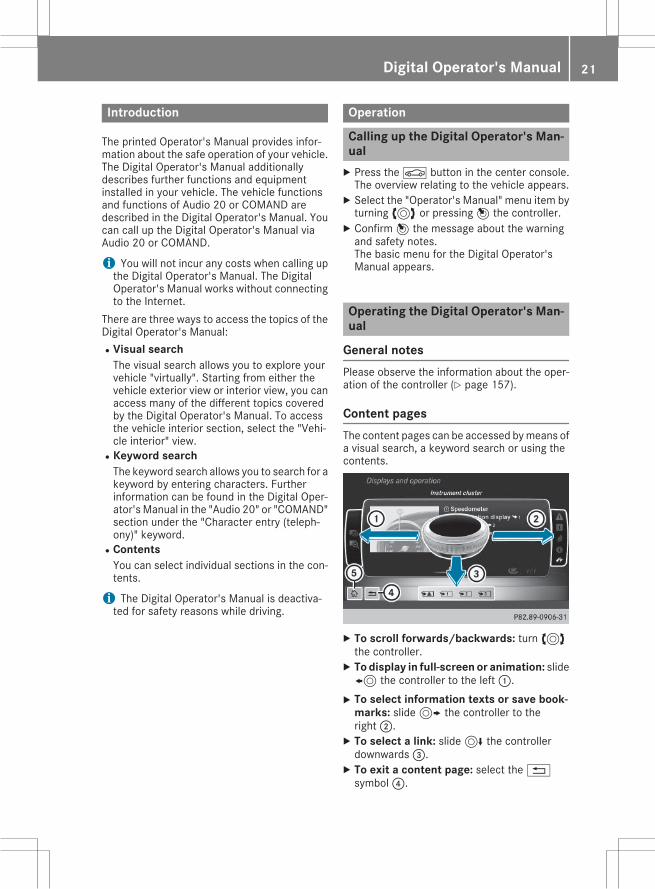
Content pagesThe content pages can be accessed bymeans ofa visual search, a keyword search or using thecontents.
X To scroll forwards/backwards: turn3the controller.X To display in full-screen or animation: slide8 the controller to the left:.X To select information texts or save book-
marks: slide9 the controller to theright;.X To select a link: slide6 the controllerdownwards=.X To exit a content page: select the%symbol?.
Digital Operator's Manual 21

X To call up the basic menu of the DigitalOperator's Manual: selectÞ symbolA.X To switch functions to Audio 20 or
COMAND using the buttons on the centerconsole: press the$,%,Õ orØbutton.The selected menu appears. The Digital Oper-ator's Manual remains open in the back-ground.
22 Digital Operator's Manual
Protection of the environment
General notes
H Environmental noteDaimler's declared policy is one of compre-hensive environmental protection.The objectives are for the natural resourcesthat form the basis of our existence on thisplanet to be used sparingly and in a mannerthat takes the requirements of both natureand humanity into account.You too can help to protect the environmentby operating your vehicle in an environmen-tally responsible manner.Fuel consumption and the rate of engine,transmission, brake and tire wear are affectedby these factors:Roperating conditions of your vehicleRyour personal driving styleYou can influence both factors. You shouldbear the following in mind:Operating conditions:Ravoid short trips as these increase fuel con-sumption.
Ralways make sure that the tire pressuresare correct.
Rdo not carry any unnecessary weight.Rremove roof racks once you no longer needthem.
Ra regularly serviced vehicle will contributeto environmental protection. You shouldtherefore adhere to the service intervals.
Ralways have service work carried out at aqualified specialist workshop.
Personal driving style:Rdo not depress the accelerator pedal whenstarting the engine.
Rdo notwarmup the enginewhen the vehicleis stationary.
Rdrive carefully and maintain a safe distancefrom the vehicle in front.
Ravoid frequent, sudden acceleration andbraking.
Rchange gear in good time and use each gearonly up toÔ of its maximum engine speed.
Rswitch off the engine in stationary traffic.Rkeep an eye on the vehicle's fuel consump-tion.
Environmental concerns and recom-mendationsWherever the operating instructions require youto dispose of materials, first try to regenerate orre-use them. Observe the relevant environmen-tal rules and regulations when disposing ofmaterials. In this way you will help to protect theenvironment.
Genuine Mercedes-Benz parts
H Environmental noteDaimler AG also supplies reconditionedmajorassemblies and parts which are of the samequality as new parts. They are covered by thesame Limited Warranty entitlements as newparts.
! Air bags and Emergency Tensioning Devi-ces, as well as control units and sensors forthese restraint systems, may be installed inthe following areas of your vehicle:RdoorsRdoor pillarsRdoor sillsRseatsRcockpitRinstrument clusterRcenter consoleDo not install accessories such as audio sys-tems in these areas. Do not carry out repairsor welding. You could impair the operatingefficiency of the restraint systems.Have aftermarket accessories installed at aqualified specialist workshop.
You could jeopardize the operating safety ofyour vehicle if you use parts, tires and wheels aswell as accessories relevant to safety whichhave not been approved byMercedes-Benz. Thiscould lead to malfunctions in safety-relevant
Introduction 23
Z
systems, e.g. the brake system. Use only genu-ine Mercedes-Benz parts or parts of equal qual-ity. Only use tires, wheels and accessories thathave been specifically approved for your vehi-cle.Genuine Mercedes-Benz parts are subject tostrict quality control. Every part has been spe-cifically developed, manufactured or selectedfor and adapted to Mercedes-Benz vehicles.Only genuine Mercedes-Benz parts shouldtherefore be used.More than 300,000 different genuineMercedes-Benz parts are available forMercedes-Benz models.All authorized Mercedes-Benz Centers maintaina supply of genuine Mercedes-Benz parts fornecessary service and repair work. In addition,strategically located parts delivery centers pro-vide quick and reliable parts service.Always specify the vehicle identification number(VIN) when ordering genuine Mercedes-Benzparts (Y page 232).
Operator's Manual
Vehicle equipmentThis Operator's Manual describes all modelsand all standard and optional equipment of yourvehicle available at the time of going to print.Country-specific differences are possible. Bearin mind that your vehicle may not feature allfunctions described here. This also applies tosafety-relevant systems and functions. Theequipment in your vehicle may therefore differfrom that shown in the descriptions and illus-trations.The original purchase agreement lists all sys-tems installed in your vehicle.Should you have any questions concerningequipment and operation, please consult anauthorized Mercedes-Benz Center.The Operator's Manual and Maintenance Book-let are important documents and should be keptin the vehicle.
Service and vehicle operation
WarrantyThe implied warranty for your vehicle applies inaccordance with the warranty terms and condi-
tions in the Service and Warranty Informationbooklet.Your authorized Mercedes-Benz Center willreplace and repair all factory-installed parts inaccordance with the following warranty termsand conditions:RNew Vehicle Limited WarrantyREmission System WarrantyREmission Performance WarrantyRCalifornia, Connecticut, Maine, Massachu-setts, New York, Pennsylvania, Rhode Islandand Vermont Emission Control System War-ranty
RState warranty enforcement laws (lemonlaws)
Replacement parts and accessories are coveredby the Mercedes-Benz Parts and Accessorieswarranties. These are available at any author-ized Mercedes-Benz Center.
i Should you lose your Service and WarrantyInformation booklet, have an authorizedMercedes-Benz Center arrange for a replace-ment. The new Service and Warranty Infor-mation booklet will be posted to you.
MaintenanceThe Service and Warranty Booklet describes allthe necessary maintenance work which shouldbe done at regular intervals.Always have the Service and Warranty Bookletwith you when you bring the vehicle to anauthorized Mercedes-Benz Center. The serviceadvisor will record every service for you in theService and Warranty Booklet.
Roadside AssistanceThe Mercedes-Benz Roadside Assistance Pro-gram offers technical help in the event of abreakdown. Calls to the toll-free Roadside Assis-tance Hotline are answered by our agents 24hours a day, 365 days a year.1-800-FOR-MERCedes(1-800-367-6372)(USA)1-800-387-0100 (Canada)For additional information, refer to theMercedes-Benz Roadside Assistance Programbrochure (USA) or the "Roadside Assistance"section in the Service and Warranty booklet
24 Introduction
(Canada). You will find both in your vehicle lit-erature portfolio.
Change of address or change of own-ershipIn the event of a change of address, please sendus the "Notification of Address Change" in theService andGuarantee booklet or simply call theMercedes-Benz Customer Assistance Center(USA) at the hotline number1-800-FOR-MERCedes(1-800-367-6372) orCustomer Service Center (Canada) at1-800-387-0100. This will assist us in contact-ing you in a timelymanner should the need arise.If you sell yourMercedes, please leave the entireliterature in the vehicle so that it is available tothe next owner.If you have purchased a used car, please send usthe "Notification of Used Car Purchase" in theService andGuarantee booklet or simply call theMercedes-Benz Customer Assistance Center(USA) at the hotline number1-800-FOR-MERCedes(1-800-367-6372) orCustomer Service (Canada) at 1-800-387-0100.
Vehicle operation outside CanadaIf you plan to operate your vehicle in foreigncountries, please be aware that:Rservice facilities or replacement parts maynot be readily available.
Runleaded fuel for vehicles with a catalyticconverter may not be available. Leaded fuelmay cause damage to the catalytic converter.
Rthe fuelmay have a considerably lower octanerating. Unsuitable fuel can cause engine dam-age.
Some Mercedes-Benz models are available fordelivery in Europe through our European Deliv-ery Program. For details, consult an authorizedMercedes-Benz Center or write to one of thefollowing addresses.In the USAMercedes-Benz USA, LLCEuropean Delivery DepartmentOne Mercedes DriveMontvale, NJ 07645-0350In CanadaMercedes-Benz Canada, Inc.
European Delivery Department98 Vanderhoof AvenueToronto, Ontario M4G 4C9
Operating safety
Important safety notes
G WARNINGIf you do not have the prescribed service/maintenance work or any required repairscarried out, this can result in malfunctions orsystem failures. There is a risk of an accident.Always have the prescribed service/mainte-nance work as well as any required repairscarried out at a qualified specialist workshop.
G WARNINGFlammable material such as leaves, grass ortwigsmay ignite if they come into contactwithhot parts of the exhaust system. There is a riskof fire.When driving off road or on unpaved roads,check the vehicle's underside regularly. Inparticular, remove parts of plants or otherflammable materials which have becometrapped. In the case of damage, contact aqualified specialist workshop.
G WARNINGModifications to electronic components, theirsoftware as well as wiring can impair theirfunction and/or the function of other net-worked components. In particular, systemsrelevant to safety could also be affected. As aresult, these may no longer function as inten-ded and/or jeopardize the operating safety ofthe vehicle. There is an increased risk of anaccident and injury.Never tamper with the wiring as well as elec-tronic components or their software. Youshould have all work to electrical and elec-tronic equipment carried out at a qualifiedspecialist workshop.
Introduction 25
Z
! There is a risk of damage to the vehicle if:Rthe vehicle becomes stuck, e.g. on a highcurb or an unpaved road
Ryou drive too fast over an obstacle, e.g. acurb or a hole in the road
Ra heavy object strikes the undercarriage orparts of the chassis
In situations like this, the body, the undercar-riage, chassis parts, wheels or tires could bedamaged without the damage being visible.Components damaged in this way can unex-pectedly fail or, in the case of an accident, nolonger withstand the strain they are designedto.If the underbody paneling is damaged, com-bustible materials such as leaves, grass ortwigs can gather between the underbody andthe underbody paneling. If these materialscome in contact with hot parts of the exhaustsystem, they can catch fire.In such situations, have the vehicle checkedand repaired immediately at a qualified spe-cialist workshop. If on continuing your jour-ney you notice that driving safety is impaired,pull over and stop the vehicle immediately,paying attention to road and traffic condi-tions. In such cases, consult a qualified spe-cialist workshop.
Declarations of conformity
Vehicle components which receiveand/or transmit radio wavesUSA: "The wireless devices of this vehicle com-ply with Part 15 of the FCC Rules. Operation issubject to the following two conditions: 1) Thesedevices may not cause harmful interference,and 2) These devices must accept any interfer-ence received, including interference that maycause undesired operation. Changes or modifi-cations not expressly approved by the partyresponsible for compliance could void the user’sauthority to operate the equipment."Canada: "The wireless devices of this vehiclecomply with Industry Canada license-exemptRSS standard(s). Operation is subject to the fol-lowing two conditions: (1) These devices maynot cause interference, and (2) These devicesmust accept any interference, including inter-ference that may cause undesired operation ofthe device."
Diagnostics connectionThe diagnostics connection is only intended forthe connection of diagnostic equipment at aqualified specialist workshop.
G WARNINGIf you connect equipment to the diagnosticsconnection in the vehicle, it may affect theoperation of the vehicle systems. As a result,the operating safety of the vehicle could beaffected. There is a risk of an accident.Do not connect any equipment to a diagnos-tics connection in the vehicle.
G WARNINGObjects in the driver's footwell can restrict thepedal travel or obstruct a depressed pedal.The operating and road safety of the vehicle isjeopardized. There is a risk of an accident.Make sure that all objects in the vehicle arestowed correctly, and that they cannot enterthe driver's footwell. Install the floormatssecurely and as specified in order to ensuresufficient clearance for the pedals. Do not useloose floormats and do not place floormats ontop of one another.
! If the engine is switched off and equipmenton the diagnostics connection is used, thestarter battery may discharge.
Connecting equipment to the diagnostics con-nection can lead to emissions monitoring infor-mation being reset, for example. This may leadto the vehicle failing tomeet the requirements ofthe next emissions test during the main inspec-tion.
Qualified specialist workshopAn authorized Mercedes-Benz Center is a quali-fied specialist workshop. It has the necessaryspecialist knowledge, tools and qualifications tocorrectly carry out the work required on yourvehicle. This is especially the case for work rel-evant to safety.Observe the notes in the Maintenance Booklet.
26 Introduction
Always have the following work carried out at anauthorized Mercedes-Benz Center:Rwork relevant to safetyRservice and maintenance workRrepair workRalterations, installation work and modifica-tions
Rwork on electronic components
Correct useIf you remove any warning stickers, you or oth-ers could fail to recognize certain dangers.Leave warning stickers in position.Observe the following information when drivingyour vehicle:Rthe safety notes in this manualRthe vehicle technical dataRtraffic rules and regulationsRlaws and safety standards pertaining tomotorvehicles
Problems with your vehicleIf you should experience a problem with yourvehicle, particularly one that you believe mayaffect its safe operation, we urge you to contactan authorized Mercedes-Benz Center immedi-ately to have the problem diagnosed and recti-fied. If the problem is not resolved to your sat-isfaction, please discuss the problem again witha Mercedes-Benz Center or contact us at one ofthe following addresses.In the USACustomer Assistance CenterMercedes-Benz USA, LLCOne Mercedes DriveMontvale, NJ 07645-0350In CanadaCustomer Relations DepartmentMercedes-Benz Canada, Inc.98 Vanderhoof AvenueToronto, Ontario M4G 4C9
Limited Warranty! Follow the instructions in this manual aboutthe proper operation of your vehicle as well as
about possible vehicle damage. Damage toyour vehicle that arises from culpable contra-ventions against these instructions is not cov-ered either by the Mercedes-Benz LimitedWarranty or by the New or Used-Vehicle War-ranty.
QR codes for the rescue card
The QR codes are secured in the fuel filler flapand on the opposite side on the B-pillar. In theevent of an accident, rescue services can usethe QR code to quickly find the appropriate res-cue card for your vehicle. The current rescuecard contains the most important informationabout your vehicle in a compact form, e.g. therouting of the electric cables.You can find more information under http://portal.aftersales.i.daimler.com/public/content/asportal/en/communication/informationen_fuer/QRCode.html.
Data stored in the vehicle
Data recordingThis vehicle is capable of recording diagnosticinformation relating to vehicle operation, mal-functions, and user settings. This may includeinformation about the performance or status ofvarious systems, including but not limited to,engine, throttle, steering or brake systems, thatis stored and can be read out with suitable devi-ces, particularly when the vehicle is serviced.The data obtained is used to properly diagnoseand service your vehicle or to further optimizeand develop vehicle functions.
Event data recordersThis vehicle is equipped with an event datarecorder (EDR). The main purpose of an EDR isto record data that will assist in understandinghow a vehicle’s systems performed in certaincrash or near crash-like situations, such as dur-ing air bag deployment or when hitting a roadobstacle. The EDR is designed to record datarelated to vehicle dynamics and safety systemsfor a short period of time, typically 30 secondsor less.
Introduction 27
Z
The EDR in this vehicle is designed to recordsuch data as:Rhow various systems in your vehicle are oper-ating
Rwhether or not the driver and passenger seatbelts are fastened
Rhow far (if at all) the driver is depressing theaccelerator and/or brake pedal and
Rhow fast the vehicle is travelingThis data can help provide a better understand-ing of the circumstances in which crashes andinjuries occur. NOTE: EDR data is recorded byyour vehicle only if a non-trivial crash situationoccurs; no data is recorded by the EDR undernormal driving conditions and no personal data(e.g., name, gender, age, and crash location) arerecorded. However, other parties, such as lawenforcement, can combine the EDR data withthe type of personal identification data routinelyacquired during a crash investigation.To read data recorded by an EDR, special equip-ment is required, and access to the vehicle orthe EDR is needed. In addition to the vehiclemanufacturer, other parties that have the spe-cial equipment, such as law enforcement, canread the information by accessing the vehicle orthe EDR.EDR data may be used in civil and criminal mat-ters as a tool in accident reconstruction, acci-dent claims, and vehicle safety. Since the CrashData Retrieval CDR tool that is used to extractdata from the EDR is commercially available,Mercedes-Benz USA, LLC ("MBUSA") expresslydisclaims any and all liability arising from theextraction of this information by unauthorizedMercedes-Benz personnel.MBUSA will not share EDR data with otherswithout the consent of the vehicle owners or, ifthe vehicle is leased, without the consent of thelessee. Exceptions to this representationinclude responses to subpoenas by law enforce-ment; by federal, state or local government; inconnectionwith or arising out of litigation involv-ing MBUSA or its subsidiaries and affiliates; or,as required by law.Warning: The EDR is a component of theRestraint SystemModule. Tamperingwith, alter-ing, modifying or removing the EDR componentmay result in a malfunction of the Restraint Sys-tem Module and other systems.State laws or regulations regarding EDRs thatconflict with federal regulation are pre-empted.Thismeans that in the event of such conflict, the
federal regulation governs. As of February 2013,13 states have enacted laws relating to EDRs.
Information on copyright
General informationInformation on license for free and open-sourcesoftware used in your vehicle and its electroniccomponents is available on the following web-site:http://www.mercedes-benz.com/opensource
28 Introduction
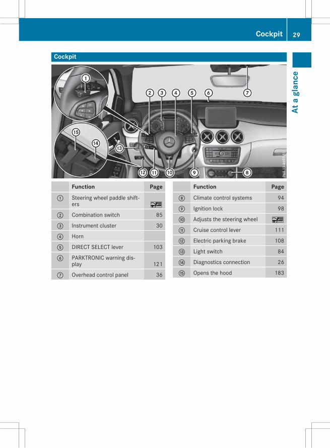
Cockpit
Function Page
: Steering wheel paddle shift-ers ~
; Combination switch 85
= Instrument cluster 30
? Horn
A DIRECT SELECT lever 103
B PARKTRONIC warning dis-play 121
C Overhead control panel 36
Function Page
D Climate control systems 94
E Ignition lock 98
F Adjusts the steering wheel ~
G Cruise control lever 111
H Electric parking brake 108
I Light switch 84
J Diagnostics connection 26
K Opens the hood 183
Cockpit 29
Ata
glan
ce
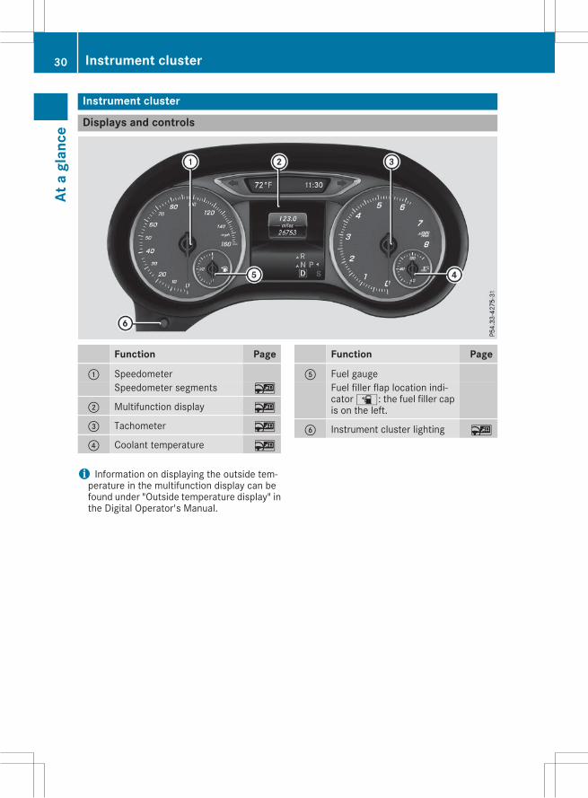
Instrument cluster
Displays and controls
Function Page
: SpeedometerSpeedometer segments ~
; Multifunction display ~
= Tachometer ~
? Coolant temperature ~
Function Page
A Fuel gaugeFuel filler flap location indi-catoræ: the fuel filler capis on the left.
B Instrument cluster lighting ~
i Information on displaying the outside tem-perature in the multifunction display can befound under "Outside temperature display" inthe Digital Operator's Manual.
30 Instrument clusterAt
agl
ance
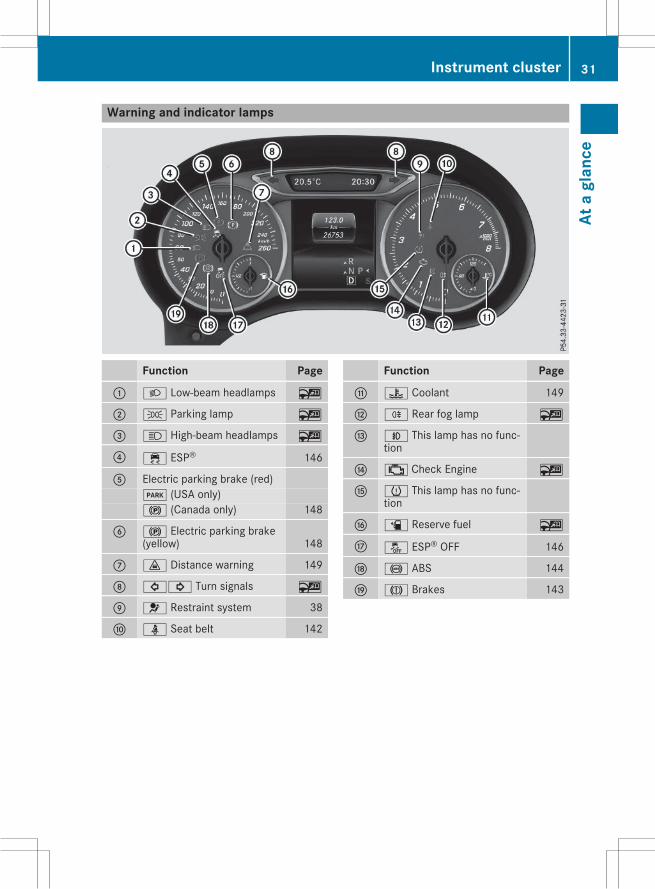
Warning and indicator lamps
Function Page
: L Low-beam headlamps ~
; T Parking lamp ~
= K High-beam headlamps ~
? ÷ ESP® 146
A Electric parking brake (red)F (USA only)! (Canada only) 148
B ! Electric parking brake(yellow) 148
C · Distance warning 149
D #! Turn signals ~
E 6 Restraint system 38
F ü Seat belt 142
Function Page
G ? Coolant 149
H R Rear fog lamp ~
I N This lamp has no func-tion
J ; Check Engine ~
K h This lamp has no func-tion
L æ Reserve fuel ~
M å ESP® OFF 146
N ! ABS 144
O J Brakes 143
Instrument cluster 31
Ata
glan
ce
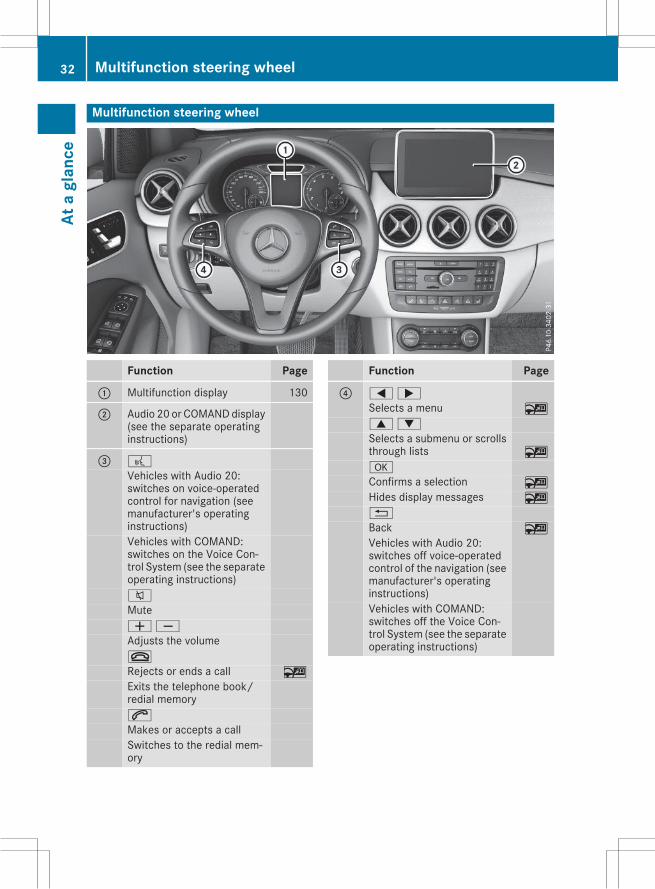
Multifunction steering wheel
Function Page
: Multifunction display 130
; Audio 20 or COMANDdisplay(see the separate operatinginstructions)
= ?Vehicles with Audio 20:switches on voice-operatedcontrol for navigation (seemanufacturer's operatinginstructions)Vehicles with COMAND:switches on the Voice Con-trol System (see the separateoperating instructions)8
MuteWX
Adjusts the volume~
Rejects or ends a call ~
Exits the telephone book/redial memory6
Makes or accepts a callSwitches to the redial mem-ory
Function Page
? =;
Selects a menu ~
9:
Selects a submenu or scrollsthrough lists ~
a
Confirms a selection ~
Hides display messages ~
%
Back ~
Vehicles with Audio 20:switches off voice-operatedcontrol of the navigation (seemanufacturer's operatinginstructions)Vehicles with COMAND:switches off the Voice Con-trol System (see the separateoperating instructions)
32 Multifunction steering wheelAt
agl
ance
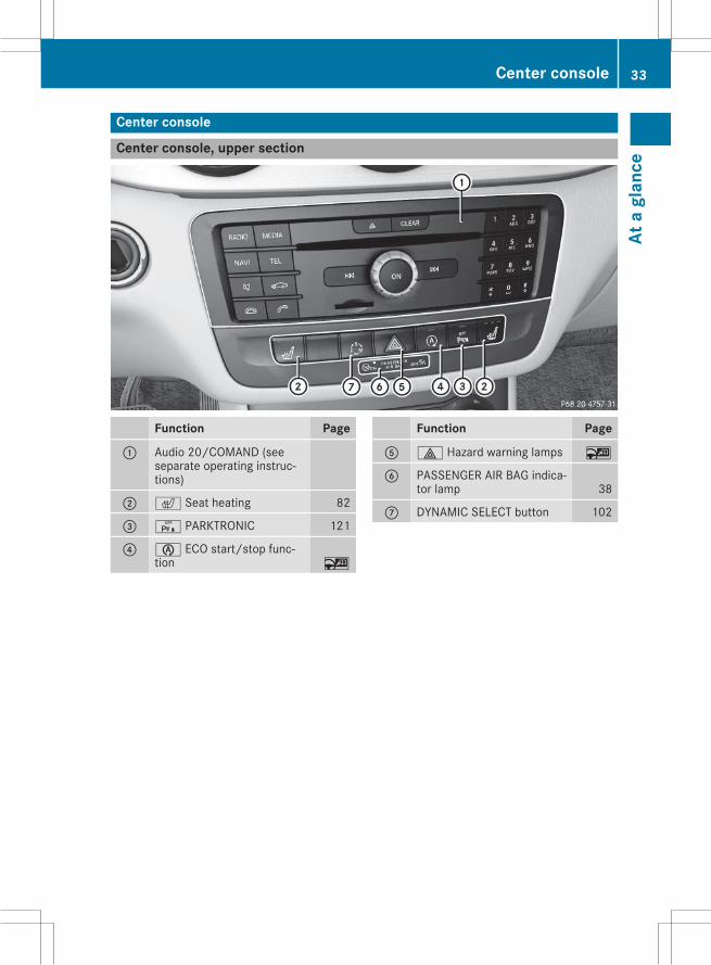
Center console
Center console, upper section
Function Page
: Audio 20/COMAND (seeseparate operating instruc-tions)
; c Seat heating 82
= c PARKTRONIC 121
? è ECO start/stop func-tion ~
Function Page
A £ Hazard warning lamps ~
B PASSENGER AIR BAG indica-tor lamp 38
C DYNAMIC SELECT button 102
Center console 33
Ata
glan
ce
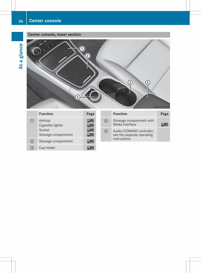
Center console, lower section
Function Page
: Ashtray ~
Cigarette lighter ~
Socket ~
Stowage compartment ~
; Stowage compartment ~
= Cup holder ~
Function Page
? Stowage compartment withMedia Interface ~
A Audio/COMAND controller;see the separate operatinginstructions
34 Center consoleAt
agl
ance
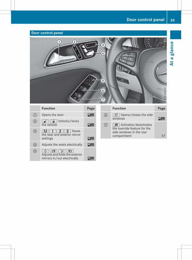
Door control panel
Function Page
: Opens the door ~
; %& Unlocks/locksthe vehicle ~
= r45= Savesthe seat and exterior mirrorsettings ~
? Adjusts the seats electrically ~
A 7Zö\Adjusts and folds the exteriormirrors in/out electrically ~
Function Page
B W Opens/closes the sidewindows ~
C n Activates/deactivatesthe override feature for theside windows in the rearcompartment 57
Door control panel 35
Ata
glan
ce
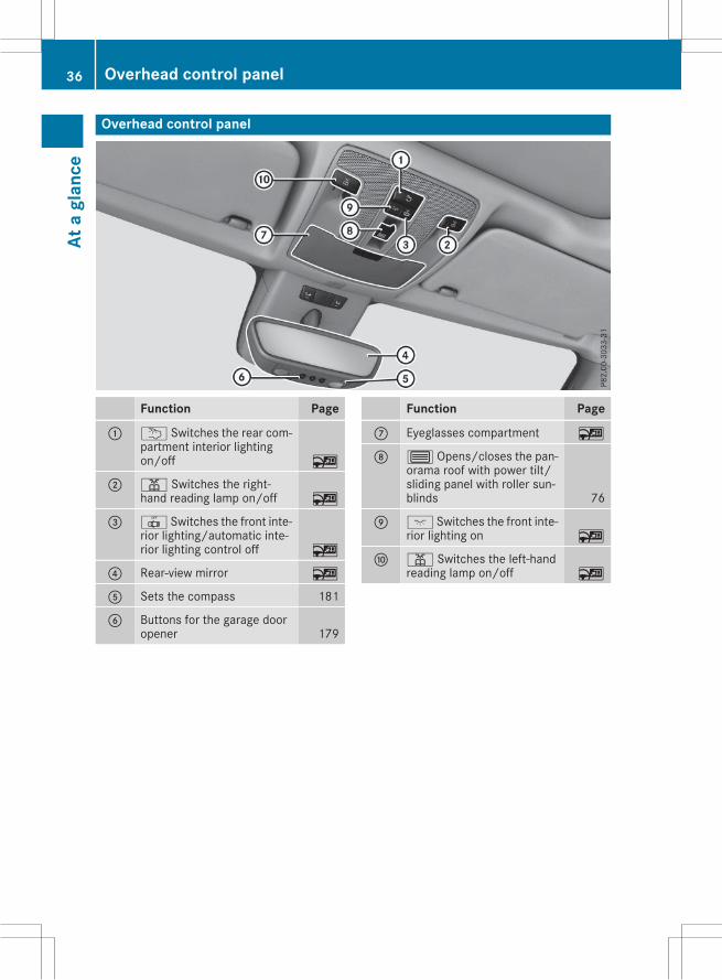
Overhead control panel
Function Page
: u Switches the rear com-partment interior lightingon/off ~
; p Switches the right-hand reading lamp on/off ~
= | Switches the front inte-rior lighting/automatic inte-rior lighting control off ~
? Rear-view mirror ~
A Sets the compass 181
B Buttons for the garage dooropener 179
Function Page
C Eyeglasses compartment ~
D 3 Opens/closes the pan-orama roof with power tilt/sliding panel with roller sun-blinds 76
E c Switches the front inte-rior lighting on ~
F p Switches the left-handreading lamp on/off ~
36 Overhead control panelAt
agl
ance
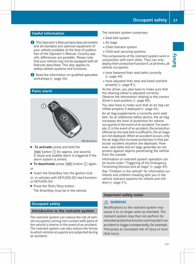
Useful information
i ThisOperator'sManual describes allmodelsand all standard and optional equipment ofyour vehicle available at the time of publica-tion of the Operator's Manual. Country-spe-cific differences are possible. Please notethat your vehicle may not be equipped with allfeatures described. This also applies tosafety-related systems and functions.
i Read the information on qualified specialistworkshops (Y page 26).
Panic alarm
X To activate: press and hold the! button: for approx. one second.A visual and audible alarm is triggered if thealarm system is armed.X To deactivate: press! button: again.orX Insert the SmartKey into the ignition lock.or, in vehicles with KEYLESS-GO start-functionor KEYLESS゙GOX Press the Start/Stop button.The SmartKey must be in the vehicle.
Occupant safety
Introduction to the restraint systemThe restraint system can reduce the risk of vehi-cle occupants coming into contact with parts ofthe vehicle's interior in the event of an accident.The restraint system can also reduce the forcestowhich vehicle occupants are subjected duringan accident.
The restraint system comprises:RSeat belt systemRAir bagsRChild restraint systemRChild seat securing systemsThe components of the restraint system work inconjunction with each other. They can onlydeploy their protective function if, at all times, allvehicle occupants:Rhave fastened their seat belts correctly(Y page 40)
Rhave adjusted their seat and head restraintproperly (Y page 81).
As the driver, you also have to make sure thatthe steering wheel is adjusted correctly.Observe the information relating to the correctdriver's seat position (Y page 80).You also have to make sure that an air bag caninflate properly if deployed (Y page 42).An air bag supplements a correctly worn seatbelt. As an additional safety device, the air bagincreases the level of protection for vehicleoccupants in the event of an accident. For exam-ple, if, in the event of an accident, the protectionoffered by the seat belt is sufficient, the air bagsare not deployed.When an accident occurs, onlythe air bags that increase protection in that par-ticular accident situation are deployed. How-ever, seat belts and air bags generally do notprotect against objects penetrating the vehiclefrom the outside.Information on restraint system operation canbe found under "Triggering of the EmergencyTensioning Devices and air bags" (Y page 49).See "Children in the vehicle" for information oninfants and children traveling with you in thevehicle restraint systems for infants and chil-dren (Y page 51).
Important safety notes
G WARNINGModifications to the restraint system maycause it to no longer work as intended. Therestraint system may then not perform itsintended protective function andmay fail in anaccident or trigger unexpectedly, for example.This poses an increased risk of injury or evenfatal injury.
Occupant safety 37
Safe
ty
Z
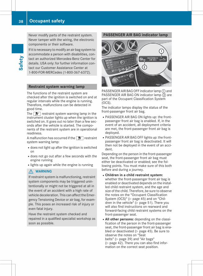
Never modify parts of the restraint system.Never tamper with the wiring, the electroniccomponents or their software.If it is necessary tomodify an air bag system toaccommodate a person with disabilities, con-tact an authorized Mercedes-Benz Center fordetails. USA only: for further information con-tact our Customer Assistance Center at1-800-FOR-MERCedes (1゙800゙367゙6372).
Restraint system warning lampThe functions of the restraint system arechecked after the ignition is switched on and atregular intervals while the engine is running.Therefore, malfunctions can be detected ingood time.The6 restraint system warning lamp in theinstrument cluster lights up when the ignition isswitched on. It goes out no later than a few sec-onds after the vehicle is started. The compo-nents of the restraint system are in operationalreadiness.Amalfunction has occurred if the6 restraintsystem warning lamp:Rdoes not light up after the ignition is switchedon
Rdoes not go out after a few seconds with theengine running
Rlights up again while the engine is running
G WARNINGIf restraint system is malfunctioning, restraintsystem components may be triggered unin-tentionally or might not be triggered at all inthe event of an accident with a high rate ofvehicle deceleration. This can affect the Emer-gency Tensioning Device or air bag, for exam-ple. This poses an increased risk of injury oreven fatal injury.Have the restraint system checked andrepaired in a qualified specialist workshop assoon as possible.
PASSENGER AIR BAG indicator lamp
PASSENGERAIRBAGOFF indicator lamp: andPASSENGER AIR BAG ON indicator lamp; arepart of the Occupant Classification System(OCS).The indicator lamps display the status of thefront-passenger front air bag.RPASSENGER AIR BAG ON lights up: the front-passenger front air bag is enabled. If, in theevent of an accident, all deployment criteriaare met, the front-passenger front air bag isdeployed.
RPASSENGER AIR BAGOFF lights up: the front-passenger front air bag is deactivated. It willthen not be deployed in the event of an acci-dent.
Depending on the person in the front-passengerseat, the front-passenger front air bag musteither be deactivated or enabled; see the fol-lowing points. You must make sure of this bothbefore and during a journey.RChildren in a child restraint system:whether the front-passenger front air bag isenabled or deactivated depends on the instal-led child restraint system, and the age andsize of the child. Therefore, be sure to observethe notes on the "Occupant ClassificationSystem (OCS)" (Y page 45) and on "Chil-dren in the vehicle" (Y page 51). There youwill also find instructions on rearward andforward-facing child restraint systems on thefront-passenger seat.
RAll other persons: depending on the classi-fication of the person in the front-passengerseat, the front-passenger front air bag is ena-bled or deactivated (Y page 45). Be sure toobserve the notes on "Seatbelts“ (Y page 39) and "Air bags"(Y page 42). There you can also find infor-mation on the correct seat position.
38 Occupant safetySa
fety
Seat belts
IntroductionSeat belts are the most effective means ofrestricting the movement of vehicle occupantsin the event of an accident or the vehicle rollingover. This reduces the risk of vehicle occupantscoming into contact with parts of the vehicleinterior or being ejected from the vehicle. Fur-thermore, the seat belt helps to keep the vehicleoccupant in the best position in relation to theair bag.The seat belt system comprises:RSeat beltsREmergency Tensioning Devices for the frontseat belts and the outer seat belts in the rear
RSeat belt force limiters for the front seat beltsand the outer seat belts in the rear
If the seat belt is pulled out of the belt outletquickly or with a jerky movement, the beltretractor locks. The belt strap cannot be extrac-ted any further.The Emergency Tensioning Device tightens theseat belt in an accident, pulling the belt closeagainst the body. However it does not pull thevehicle occupant back in the direction of thebackrest.The Emergency Tensioning Device does not cor-rect an incorrect seat position or the routing ofan incorrectly fastened seat belt.When triggered, a seat belt force limiter helps toreduce the force exerted by the seat belt on thevehicle occupant.The seat belt force limiters for the front seats aresynchronized with the front air bags, whichabsorb part of the deceleration force. This canreduce the force exerted on the vehicle occu-pants during an accident.
! If the front-passenger seat is unoccupied,do not insert the belt tongue into the buckle ofthe front-passenger seat. This may otherwiselead to the triggering of the Emergency Ten-sioning Device in the event of an accident,which will then need to be replaced.
Important safety notesThe use of seat belts and child restraint systemsis required by law in:Rall 50 statesRthe U.S. territories
Rthe District of ColumbiaRall Canadian provincesEvenwhere this is not required by law, all vehicleoccupants should correctly fasten their seatbelts before starting the journey.
G WARNINGIf the seat belt is incorrectly fastened, it can-not protect as intended. Furthermore, anincorrectly fastened seat belt can cause addi-tional injury, for example, in an accident, dur-ing braking or when abruptly changing direc-tion. This poses an increased risk of injury oreven fatal injury.Make sure that all vehicle occupants areseated properly with a correctly fastened seatbelt.
G WARNINGThe seat belt does not offer the intended levelof protection if you have not moved the back-rest to an almost vertical position. When brak-ing or in the event of an accident, you couldslide underneath the seat belt and sustainabdomen or neck injuries, for example. Thisposes an increased risk of injury or even fatalinjury.Adjust the seat properly before beginningyour journey. Always ensure that the backrestis in an almost vertical position and that theshoulder section of your seat belt is routedacross the center of your shoulder.
G WARNINGPersons under 5 ft (1.50 m) in height cannotfasten the seat belt correctly without an addi-tional suitable restraint system. If the seatbelt is incorrectly fastened, it cannot protectas intended. Furthermore, an incorrectly fas-tened seat belt can cause additional injury, forexample, in an accident, during braking or anabrupt change of direction. This poses anincreased risk of injury or even fatal injury.For this reason, always secure persons under5 ft (1.50 m) in height in suitable restraintsystems.
Occupant safety 39
Safe
ty
Z
If a child younger than twelve years old andunder 5 ft (1.50 m) in height is traveling in thevehicle:Ralways secure the child in a child restraintsystem suitable for this Mercedes-Benz vehi-cle. The child restraint systemmust be appro-priate to the age, weight and size of the child
Ralways observe the instructions and safetynotes in the "Children in the vehicle" sectionof this Operator's Manual (Y page 51) inaddition to the child restraint system manu-facturer's installation instructions
Rbe sure to observe the instructions and safetynotes on the "Occupant classification system(OCS)" (Y page 45)
G WARNINGThe seat belts may not perform their intendedprotective function if:Rthey are damaged, modified, extremelydirty, bleach or dyed
Rthe seat belt buckle is damaged orextremely dirty
Rthe Emergency Tensioning Devices, beltanchorages or inertia reels have beenmodi-fied
Seat belts may sustain non-visible damage inan accident, e.g. due to glass splinters. Modi-fied or damaged seat belts may tear or fail,e.g. in an accident. Modified Emergency Ten-sioning Devices could accidentally trigger orfail to deploy when necessary. This poses anincreased risk of injury or even fatal injury.Never modify the seat belts, Emergency Ten-sioning Devices, belt anchorages or inertiareels. Make sure that the seat belts areundamaged, not worn out and clean. Follow-ing an accident, have the seat belts checkedimmediately at a qualified specialist work-shop.
Only use seat belts that have been approved foryour vehicle by Mercedes-Benz.
Proper use of the seat beltsObserve the safety notes on the seat belt(Y page 39).
All vehicle occupants must be wearing the seatbelt correctly before beginning the journey. Alsomake sure that all vehicle occupants are alwayswearing the seat belt correctly while the vehicleis in motion.When fastening the seat belt, always make surethat:Rthe seat belt tongue is only inserted to the beltbuckle belonging to that seat.
Rthe seat belt is tight across your body.Avoid wearing bulky clothing, e.g. a wintercoat.
Rthe seat belt is not twisted.Only then can the forces which occur be dis-tributed over the area of the belt.
Rthe shoulder section of the belt is alwaysrouted across the center of your shoulder.The shoulder section of the belt must notcome into contact with your neck or be routedunder your arm. Where possible, adjust theseat belt to the appropriate height.
Rthe lap belt passes tightly and as low down aspossible across your lap.The lap belt must always be routed acrossyour hip joints and not across your abdomen.This applies particularly to pregnant women.If necessary, push the lap belt down to yourhip joint and pull it tight using the shouldersection of the belt.
Rthe seat belt is not routed across sharp, poin-ted or fragile objects.If you have such items located on or in yourclothing, e.g. pens, keys or eyeglasses, storethese in a suitable place.
Ronly one person is using a seat belt at a time.Infants and children must never travel sittingon the lap of a vehicle occupant. In the eventof an accident, they could be crushedbetween the vehicle occupant and seat belt.
Robjects are never secured with a seat belt ifthe seat belt is also being used by one of thevehicle's occupants.Also ensure that there are never objectsbetween a person and the seat, e.g. cushions.
Seat belts are only intended to secure andrestrain vehicle occupants. Always observe the"Loading guidelines" for securing objects, lug-gage or loads (Y page 169).
40 Occupant safetySa
fety
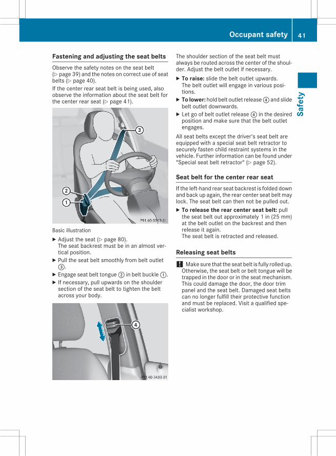
Fastening and adjusting the seat beltsObserve the safety notes on the seat belt(Y page 39) and the notes on correct use of seatbelts (Y page 40).If the center rear seat belt is being used, alsoobserve the information about the seat belt forthe center rear seat (Y page 41).
Basic illustrationX Adjust the seat (Y page 80).The seat backrest must be in an almost ver-tical position.X Pull the seat belt smoothly from belt outlet=.X Engage seat belt tongue; in belt buckle:.X If necessary, pull upwards on the shouldersection of the seat belt to tighten the beltacross your body.
The shoulder section of the seat belt mustalways be routed across the center of the shoul-der. Adjust the belt outlet if necessary.X To raise: slide the belt outlet upwards.The belt outlet will engage in various posi-tions.X To lower: hold belt outlet release? and slidebelt outlet downwards.X Let go of belt outlet release? in the desiredposition and make sure that the belt outletengages.
All seat belts except the driver's seat belt areequipped with a special seat belt retractor tosecurely fasten child restraint systems in thevehicle. Further information can be found under"Special seat belt retractor" (Y page 52).
Seat belt for the center rear seatIf the left-hand rear seat backrest is folded downand back up again, the rear center seat belt maylock. The seat belt can then not be pulled out.X To release the rear center seat belt: pullthe seat belt out approximately 1 in (25 mm)at the belt outlet on the backrest and thenrelease it again.The seat belt is retracted and released.
Releasing seat belts! Make sure that the seat belt is fully rolled up.Otherwise, the seat belt or belt tongue will betrapped in the door or in the seat mechanism.This could damage the door, the door trimpanel and the seat belt. Damaged seat beltscan no longer fulfill their protective functionand must be replaced. Visit a qualified spe-cialist workshop.
Occupant safety 41
Safe
ty
Z
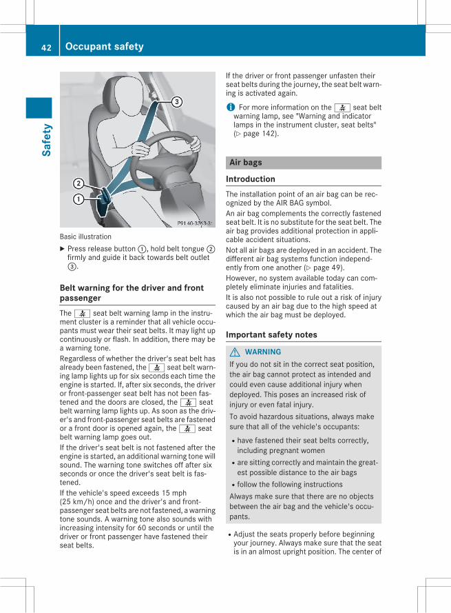
Basic illustrationX Press release button:, hold belt tongue;firmly and guide it back towards belt outlet=.
Belt warning for the driver and frontpassengerThe7 seat belt warning lamp in the instru-ment cluster is a reminder that all vehicle occu-pants must wear their seat belts. It may light upcontinuously or flash. In addition, there may bea warning tone.Regardless of whether the driver's seat belt hasalready been fastened, the7 seat belt warn-ing lamp lights up for six seconds each time theengine is started. If, after six seconds, the driveror front-passenger seat belt has not been fas-tened and the doors are closed, the7 seatbelt warning lamp lights up. As soon as the driv-er's and front-passenger seat belts are fastenedor a front door is opened again, the7 seatbelt warning lamp goes out.If the driver's seat belt is not fastened after theengine is started, an additional warning tone willsound. The warning tone switches off after sixseconds or once the driver's seat belt is fas-tened.If the vehicle's speed exceeds 15 mph(25 km/h) once and the driver's and front-passenger seat belts are not fastened, awarningtone sounds. A warning tone also sounds withincreasing intensity for 60 seconds or until thedriver or front passenger have fastened theirseat belts.
If the driver or front passenger unfasten theirseat belts during the journey, the seat belt warn-ing is activated again.
i For more information on the7 seat beltwarning lamp, see "Warning and indicatorlamps in the instrument cluster, seat belts"(Y page 142).
Air bags
IntroductionThe installation point of an air bag can be rec-ognized by the AIR BAG symbol.An air bag complements the correctly fastenedseat belt. It is no substitute for the seat belt. Theair bag provides additional protection in appli-cable accident situations.Not all air bags are deployed in an accident. Thedifferent air bag systems function independ-ently from one another (Y page 49).However, no system available today can com-pletely eliminate injuries and fatalities.It is also not possible to rule out a risk of injurycaused by an air bag due to the high speed atwhich the air bag must be deployed.
Important safety notes
G WARNINGIf you do not sit in the correct seat position,the air bag cannot protect as intended andcould even cause additional injury whendeployed. This poses an increased risk ofinjury or even fatal injury.To avoid hazardous situations, always makesure that all of the vehicle's occupants:Rhave fastened their seat belts correctly,including pregnant women
Rare sitting correctly andmaintain the great-est possible distance to the air bags
Rfollow the following instructionsAlways make sure that there are no objectsbetween the air bag and the vehicle's occu-pants.
RAdjust the seats properly before beginningyour journey. Always make sure that the seatis in an almost upright position. The center of
42 Occupant safetySa
fety
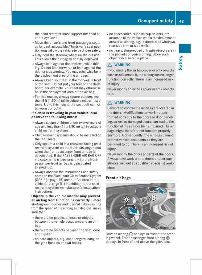
the head restraint must support the head atabout eye level.
RMove the driver's and front-passenger seatsas far back as possible. The driver's seat posi-tionmust allow the vehicle to be driven safely.
ROnly hold the steering wheel on the outside.This allows the air bag to be fully deployed.
RAlways lean against the backrest while driv-ing. Do not lean forwards or lean against thedoor or side window. Youmay otherwise be inthe deployment area of the air bags.
RAlways keep your feet in the footwell in frontof the seat. Do not put your feet on the dash-board, for example. Your feet may otherwisebe in the deployment area of the air bag.
RFor this reason, always secure persons lessthan 5 ft (1.50 m) tall in suitable restraint sys-tems. Up to this height, the seat belt cannotbe worn correctly.
If a child is traveling in your vehicle, alsoobserve the following notes:RAlways secure children under twelve years ofage and less than 5 ft (1.50 m) tall in suitablechild restraint systems.
RChild restraint systems should be installed onthe rear seats.
ROnly secure a child in a rearward-facing childrestraint system on the front-passenger seatwhen the front-passenger front air bag isdeactivated. If the PASSENGER AIR BAG OFFindicator lamp is permanently lit, the front-passenger front air bag is deactivated(Y page 38).
RAlways observe the instructions and safetynotes on the "Occupant Classification System(OCS)" (Y page 45) and on "Children in thevehicle" (Y page 51) in addition to the childrestraint system manufacturer's installationinstructions.
Objects in the vehicle interior may preventan air bag from functioning correctly. Beforestarting your journey and to avoid risks resultingfrom the speed of the air bag as it deploys, makesure that:Rthere are no people, animals or objectsbetween the vehicle occupants and an airbag.
Rthere are no objects between the seat, doorand B-pillar.
Rno hard objects, e.g. coat hangers, hang onthe grab handles or coat hooks.
Rno accessories, such as cup holders, areattached to the vehicle within the deploymentarea of an air bag, e.g. to doors, side windows,rear side trim or side walls.
Rno heavy, sharp-edged or fragile objects are inthe pockets of your clothing. Store suchobjects in a suitable place.
G WARNINGIf you modify the air bag cover or affix objectssuch as stickers to it, the air bag can no longerfunction correctly. There is an increased riskof injury.Never modify an air bag cover or affix objectsto it.
G WARNINGSensors to control the air bags are located inthe doors. Modifications or work not per-formed correctly to the doors or door panel-ing, as well as damaged doors, can lead to thefunction of the sensors being impaired. The airbags might therefore not function properlyanymore. Consequently, the air bags cannotprotect vehicle occupants as they aredesigned to do. There is an increased risk ofinjury.Never modify the doors or parts of the doors.Always have work on the doors or door pan-eling carried out at a qualified specialist work-shop.
Front air bags
Driver's air bag: deploys in front of the steer-ing wheel. Front-passenger front air bag;deploys in front of and above the glove box.
Occupant safety 43
Safe
ty
Z
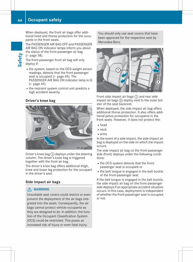
When deployed, the front air bags offer addi-tional head and thorax protection for the occu-pants in the front seats.The PASSENGER AIR BAG OFF and PASSENGERAIR BAG ON indicator lamps inform you aboutthe status of the front-passenger air bag(Y page 38).The front-passenger front air bag will onlydeploy if:Rthe system, based on the OCS weight sensorreadings, detects that the front-passengerseat is occupied (Y page 45). ThePASSENGER AIR BAG ON indicator lamp is lit(Y page 45)
Rthe restraint system control unit predicts ahigh accident severity
Driver's knee bag
Driver's knee bag: deploys under the steeringcolumn. The driver's knee bag is triggeredtogether with the front air bag.The driver's knee bag offers additional thigh,knee and lower leg protection for the occupantin the driver's seat.
Side impact air bags
G WARNINGUnsuitable seat covers could restrict or evenprevent the deployment of the air bags inte-grated into the seats. Consequently, the airbags cannot protect vehicle occupants asthey are designed to do. In addition, the func-tion of the Occupant Classification System(OCS) could be restricted. This poses anincreased risk of injury or even fatal injury.
You should only use seat covers that havebeen approved for the respective seat byMercedes-Benz.
Front side impact air bags: and rear sideimpact air bags; deploy next to the outer bol-ster of the seat backrest.When deployed, the side impact air bag offersadditional thorax protection. It also offers addi-tional pelvis protection for occupants in thefront seats. However, it does not protect the:RheadRneckRarmsIn the event of a side impact, the side impact airbag is deployed on the side on which the impactoccurs.The side impact air bag on the front-passengerside (front) deploys under the following condi-tions:Rthe OCS system detects that the front-passenger seat is occupied or
Rthe belt tongue is engaged in the belt buckleof the front-passenger seat
If the belt tongue is engaged in the belt buckle,the side impact air bag on the front-passengerside deploys if an appropriate accident situationoccurs. In this case, deployment is independentof whether the front-passenger seat is occupiedor not.
44 Occupant safetySa
fety
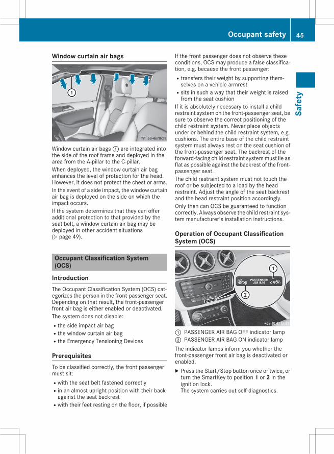
Window curtain air bags
Window curtain air bags: are integrated intothe side of the roof frame and deployed in thearea from the A-pillar to the C-pillar.When deployed, the window curtain air bagenhances the level of protection for the head.However, it does not protect the chest or arms.In the event of a side impact, the window curtainair bag is deployed on the side on which theimpact occurs.If the system determines that they can offeradditional protection to that provided by theseat belt, a window curtain air bag may bedeployed in other accident situations(Y page 49).
Occupant Classification System(OCS)
IntroductionThe Occupant Classification System (OCS) cat-egorizes the person in the front-passenger seat.Depending on that result, the front-passengerfront air bag is either enabled or deactivated.The system does not disable:Rthe side impact air bagRthe window curtain air bagRthe Emergency Tensioning Devices
PrerequisitesTo be classified correctly, the front passengermust sit:Rwith the seat belt fastened correctlyRin an almost upright position with their backagainst the seat backrest
Rwith their feet resting on the floor, if possible
If the front passenger does not observe theseconditions, OCS may produce a false classifica-tion, e.g. because the front passenger:Rtransfers their weight by supporting them-selves on a vehicle armrest
Rsits in such a way that their weight is raisedfrom the seat cushion
If it is absolutely necessary to install a childrestraint system on the front-passenger seat, besure to observe the correct positioning of thechild restraint system. Never place objectsunder or behind the child restraint system, e.g.cushions. The entire base of the child restraintsystem must always rest on the seat cushion ofthe front-passenger seat. The backrest of theforward-facing child restraint systemmust lie asflat as possible against the backrest of the front-passenger seat.The child restraint system must not touch theroof or be subjected to a load by the headrestraint. Adjust the angle of the seat backrestand the head restraint position accordingly.Only then can OCS be guaranteed to functioncorrectly. Always observe the child restraint sys-tem manufacturer's installation instructions.
Operation of Occupant ClassificationSystem (OCS)
: PASSENGER AIR BAG OFF indicator lamp; PASSENGER AIR BAG ON indicator lampThe indicator lamps inform you whether thefront-passenger front air bag is deactivated orenabled.X Press the Start/Stop button once or twice, orturn the SmartKey to position 1 or 2 in theignition lock.The system carries out self-diagnostics.
Occupant safety 45
Safe
ty
Z
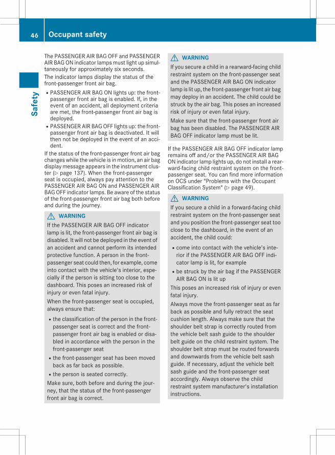
The PASSENGER AIR BAG OFF and PASSENGERAIR BAGON indicator lampsmust light up simul-taneously for approximately six seconds.The indicator lamps display the status of thefront-passenger front air bag.RPASSENGER AIR BAG ON lights up: the front-passenger front air bag is enabled. If, in theevent of an accident, all deployment criteriaare met, the front-passenger front air bag isdeployed.
RPASSENGER AIR BAGOFF lights up: the front-passenger front air bag is deactivated. It willthen not be deployed in the event of an acci-dent.
If the status of the front-passenger front air bagchangeswhile the vehicle is inmotion, an air bagdisplaymessage appears in the instrument clus-ter (Y page 137). When the front-passengerseat is occupied, always pay attention to thePASSENGER AIR BAG ON and PASSENGER AIRBAGOFF indicator lamps. Be aware of the statusof the front-passenger front air bag both beforeand during the journey.
G WARNINGIf the PASSENGER AIR BAG OFF indicatorlamp is lit, the front-passenger front air bag isdisabled. It will not be deployed in the event ofan accident and cannot perform its intendedprotective function. A person in the front-passenger seat could then, for example, comeinto contact with the vehicle's interior, espe-cially if the person is sitting too close to thedashboard. This poses an increased risk ofinjury or even fatal injury.When the front-passenger seat is occupied,always ensure that:Rthe classification of the person in the front-passenger seat is correct and the front-passenger front air bag is enabled or disa-bled in accordance with the person in thefront-passenger seat
Rthe front-passenger seat has been movedback as far back as possible.
Rthe person is seated correctly.Make sure, both before and during the jour-ney, that the status of the front-passengerfront air bag is correct.
G WARNINGIf you secure a child in a rearward-facing childrestraint system on the front-passenger seatand the PASSENGER AIR BAG ON indicatorlamp is lit up, the front-passenger front air bagmay deploy in an accident. The child could bestruck by the air bag. This poses an increasedrisk of injury or even fatal injury.Make sure that the front-passenger front airbag has been disabled. The PASSENGER AIRBAG OFF indicator lamp must be lit.
If the PASSENGER AIR BAG OFF indicator lampremains off and/or the PASSENGER AIR BAGON indicator lamp lights up, do not install a rear-ward-facing child restraint system on the front-passenger seat. You can find more informationon OCS under "Problems with the OccupantClassification System" (Y page 49).
G WARNINGIf you secure a child in a forward-facing childrestraint system on the front-passenger seatand you position the front-passenger seat tooclose to the dashboard, in the event of anaccident, the child could:Rcome into contact with the vehicle's inte-rior if the PASSENGER AIR BAG OFF indi-cator lamp is lit, for example
Rbe struck by the air bag if the PASSENGERAIR BAG ON is lit up
This poses an increased risk of injury or evenfatal injury.Always move the front-passenger seat as farback as possible and fully retract the seatcushion length. Always make sure that theshoulder belt strap is correctly routed fromthe vehicle belt sash guide to the shoulderbelt guide on the child restraint system. Theshoulder belt strap must be routed forwardsand downwards from the vehicle belt sashguide. If necessary, adjust the vehicle beltsash guide and the front-passenger seataccordingly. Always observe the childrestraint system manufacturer's installationinstructions.
46 Occupant safetySa
fety
If OCS determines that:Rthe front-passenger seat is unoccupied, thePASSENGER AIR BAG OFF indicator lamplights up after the system self-test andremains lit. This indicates that the front-passenger front air bag is deactivated.
Rthe front-passenger seat is occupied by achild of up to twelvemonths old, in a standardchild restraint system, the PASSENGER AIRBAG OFF indicator lamp lights up after thesystem self-test and remains lit. This indi-cates that the front-passenger front air bag isdeactivated.But even in the case of a twelve-month-oldchild, in a standard child restraint system, thePASSENGER AIR BAG ON can light up perma-nently after the system self-test. This indi-cates that the front-passenger front air bag isactivated. The result of the classification isdependent on, among other factors, the childrestraint system and the child's stature. It isrecommended that you install the childrestraint system on a suitable rear seat.
Rthe front-passenger seat is occupied by a per-son of smaller stature (e.g. a teenager orsmall adult), either the PASSENGER AIR BAGON or PASSENGER AIR BAG OFF indicatorlamp lights up and remains lit after the systemself-test depending on the result of the clas-sification.- If the PASSENGER AIR BAG ON indicatorlamp lights up, move the front-passengerseat as far back as possible. Alternatively, aperson of smaller stature can sit on a rearseat.
- If the PASSENGER AIR BAG OFF indicatorlamp is lit, a person of smaller statureshould not use the front-passenger seat.
Rthe front-passenger seat is occupied by anadult or a person of adult stature, thePASSENGER AIR BAG ON indicator lamplights up after the system self-test andremains lit. This indicates that the front-passenger front air bag is activated.
If children are traveling in the vehicle, be sure toobserve the notes on "Children in the vehicle"(Y page 51).When OCS is malfunctioning, the red6restraint systemwarning lamp in the instrumentcluster and the PASSENGER AIR BAG OFF indi-cator lamp light up simultaneously. The front-passenger front air bag is deactivated in thiscase and does not deploy during an accident.
Have the system checked by qualified techni-cians as soon as possible. Consult an authorizedMercedes-Benz Center. The front-passengerseat should only be repaired at an authorizedMercedes-Benz Center.If the front-passenger seat, the seat cover or theseat cushion is damaged, have the necessaryrepair work carried out at an authorizedMercedes-Benz Center.For safety reasons, Mercedes-Benz recom-mends that you only use seat accessories thathave been approved by Mercedes-Benz.If the driver's air bag deploys, this does notmean that the front-passenger front air bag willalso deploy. The Occupant Classification Sys-tem (OCS) categorizes the occupant in the front-passenger seat. Depending on that result, thefront-passenger front air bag is either enabled ordeactivated.
System self-test
G DANGERIf both the PASSENGER AIR BAG OFF andPASSENGER AIR BAG ON indicator lamps donot light up during the system self-test, thesystem is malfunctioning. The front-passenger front air bag might be triggeredunintentionally or might not be triggered at allin the event of an accident with high deceler-ation. This poses an increased risk of injury oreven fatal injury.In this case the front-passenger seat may notbe used. Do not install a child restraint systemon the front-passenger seat. Have the Occu-pant Classification System (OCS) checkedand repaired immediately at a qualified spe-cialist workshop.
G DANGERIf the PASSENGER AIR BAG OFF indicatorlamp remains lit after the system self-test, thefront-passenger front air bag is disabled. It willnot be deployed in the event of an accident. Inthis case, the front-passenger front air bagcannot perform its intended protective func-tion, e.g. when a person is seated in the front-passenger seat.
Occupant safety 47
Safe
ty
Z
That person could, for example, come intocontact with the vehicle's interior, especiallyif the person is sitting too close to the dash-board. This poses an increased risk of injury oreven fatal injury.When the front-passenger seat is occupied,always ensure that:Rthe classification of the person in the front-passenger seat is correct and the front-passenger front air bag is enabled or disa-bled in accordance with the person in thefront-passenger seat
Rthe person is seated properly with a cor-rectly fastened seatbelt
Rthe front-passenger seat has been movedback as far back as possible
If the PASSENGER AIR BAG OFF indicatorlamp remains lit when it should not, the front-passenger seat may not be used. Do notinstall a child restraint system on the front-passenger seat. Have the Occupant Classifi-cation System (OCS) checked and repairedimmediately at a qualified specialist work-shop.
G WARNINGObjects between the seat surface and thechild restraint system could affect OCS oper-ation. This could result in the front-passengerair bag not functioning as intended during anaccident. This poses an increased risk ofinjury or even fatal injury.Do not place any objects between the seatsurface and the child restraint system. Theentire base of the child restraint system mustalways rest on the seat cushion of the front-passenger seat. The backrest of the forward-facing child restraint system must, as far aspossible, be resting on the backrest of thefront-passenger seat. Always comply with thechild restraint system manufacturer's instal-lation instructions.
After the system self-test, the PASSENGER AIRBAG OFF or PASSENGER AIR BAG ON indicatorlamp displays the status of the front-passengerfront air bag (Y page 45).
For more information about the OCS, see "Prob-lems with the Occupant Classification System"(Y page 49).
48 Occupant safetySa
fety
Problems with the Occupant Classification System (OCS)Be sure to observe the notes on "System self-test" (Y page 47).Problem Possible causes/consequences and M Solutions
The PASSENGER AIRBAG OFF indicator lamplights up and remains lit,even though the front-passenger seat is occu-pied by an adult or a per-son of a stature corre-sponding to that of anadult.
The classification of the person on the front-passenger seat is incor-rect.X Make sure the conditions for a correct classification of the personon the front-passenger seat are met (Y page 45).X If the PASSENGERAIR BAGOFF indicator lamp remains lit, the front-passenger seat may not be used.X Have OCS checked as soon as possible at an authorized Mercedes-Benz Center.
The PASSENGER AIRBAG OFF indicator lampdoes not light up and/ordoes not stay on.The front-passenger seatis:RunoccupiedRoccupied with theweight of a child up totwelve months old in achild restraint system
OCS is malfunctioning.X Make sure there is nothing between the seat cushion and the childseat.X Make sure that the entire base of the child restraint system rests onthe seat cushion of the front-passenger seat. The backrest of theforward-facing child restraint system must lie as flat as possibleagainst the backrest of the front-passenger seat. If necessary,adjust the position of the front-passenger seat.X Make sure that the seat cushion length is fully retracted.X When installing the child restraint system, make sure that the seatbelt is tight. Do not pull the seat belt tight using the front-passengerseat adjustment. This could result in the seat belt and the childrestraint system being pulled too tightly.X Check for correct installation of the child restraint system.Make sure that the head restraint does not apply a load to the childrestraint system. If necessary, adjust the head restraint accord-ingly.X Make sure that no objects are applying additional weight onto theseat.X If the PASSENGER AIR BAG OFF indicator lamp remains off and/orthe PASSENGER AIR BAG ON indicator lamp lights up, do not installa child restraint system on the front-passenger seat. It is recom-mended that you install the child restraint system on a suitable rearseat.X Have OCS checked as soon as possible at an authorized Mercedes-Benz Center.
Deployment of Emergency TensioningDevices and air bags
Important safety notes
G WARNINGThe air bag parts are hot after an air bag hasbeen deployed. There is a risk of injury.
Do not touch the air bag parts. Have adeployed air bag replaced at a qualified spe-cialist workshop as soon as possible.
G WARNINGA deployed air bag no longer offers any pro-tection and cannot provide the intended pro-
Occupant safety 49
Safe
ty
Z
tection in an accident. There is an increasedrisk of injury.Have the vehicle towed to a qualified special-ist workshop in order to have a deployed airbag replaced.
It is important for your safety and that of yourpassenger to have deployed air bags replacedand to have any malfunctioning air bagsrepaired. This will help to make sure the air bagscontinue to perform their protective function forthe vehicle occupants in the event of a crash.
G WARNINGPyrotechnic Emergency Tensioning Devicesthat have been deployed are no longer opera-tional and are unable to perform their inten-ded protective function. This poses anincreased risk of injury or even fatal injury.Therefore, have pyrotechnic Emergency Ten-sioning Devices which have been triggeredimmediately replaced at a qualified specialistworkshop.
If Emergency Tensioning Devices are triggeredor air bags are deployed, you will hear a bang,and a small amount of powder may also bereleased. The6 restraint system warninglamp lights up.Only in rare cases will the bang affect your hear-ing. The powder that is released generally doesnot constitute a health hazard, but it may causeshort-term breathing difficulties in people withasthma or other respiratory problems. Providedit is safe to do so, you should leave the vehicleimmediately or open the window in order to pre-vent breathing difficulties.Air bags and pyrotechnic Emergency TensioningDevices (ETDs) contain perchlorate material,which may require special handling and regardfor the environment. National guidelines mustbe observed during disposal. In California, seewww.dtsc.ca.gov/HazardousWaste/Perchlorate/index.cfm.
Method of operationDuring the first stage of a collision, the restraintsystem control unit evaluates important physi-cal data relating to vehicle deceleration or accel-eration, such as:RdurationRdirectionRintensityBased on the evaluation of this data, therestraint system control unit triggers the Emer-gency Tensioning Devices during a frontal orrear collision.An Emergency Tensioning Device can only betriggered, if:Rthe ignition is switched onRthe components of the restraint system areoperational. You can find further informationunder: "Restraint system warning lamp"(Y page 38)
Rthe belt tongue is engaged in the buckle onthe respective front-passenger seat
The Emergency Tensioning Devices in the rearcompartment are triggered independently of thelock status of the seat belts.If the restraint system control unit detects amore severe accident, further components ofthe restraint system are activated independ-ently of each other in certain frontal collisionsituations:RFront air bags and driver's knee bagRWindow curtain air bag, if the system deter-mines that deployment can offer additionalprotection to that provided by the seat belt
The front-passenger front air bag is activated ordeactivated depending on the person on thefront-passenger seat. The front-passenger frontair bag can only deploy in an accident if thePASSENGER AIR BAG ON indicator lamp is lit.Observe the information on the PASSENGERAIRBAG indicator lamps (Y page 38).Your vehicle has two-stage front air bags. Duringthe first deployment stage, the front air bag isfilled with propellant gas to reduce the risk ofinjuries. The front air bag is fully deployed withthe maximum amount of propellant gas if a sec-ond deployment threshold is reached within afew milliseconds.The activation threshold of the Emergency Ten-sioning Devices and the air bag are determinedby evaluating the rate of vehicle deceleration oracceleration which occurs at various points in
50 Occupant safetySa
fety
the vehicle. This process is pre-emptive innature. Deployment should take place in goodtime at the start of the collision.The rate of vehicle deceleration or accelerationand the direction of the force are essentiallydetermined by:Rthe distribution of forces during the collisionRthe collision angleRthe deformation characteristics of the vehicleRthe characteristics of the object with whichthe vehicle has collided
Factors which can only be seen and measuredafter a collision has occurred do not play a deci-sive role in the deployment of an air bag. Nor dothey provide an indication of air bag deploy-ment.The vehicle can be deformed considerably, with-out an air bag being deployed. This is the case ifonly parts which are relatively easily deformedare affected and the rate of deceleration is nothigh. Conversely, air bagsmay be deployed eventhough the vehicle suffers only minor deforma-tion. This is the case if, for example, very rigidvehicle parts such as longitudinal body mem-bers are hit, and sufficient deceleration occursas a result.If the restraint systemcontrol unit detects a sideimpact, the relevant restraint system compo-nents are deployed independently of each other.RSide impact air bags on the side where theimpact takes place, independently of theEmergency Tensioning Device and the use ofthe seat belt on the driver's seat and outerseats in the second rowThe side impact air bag on the front-passenger side (front) deploys under the fol-lowing conditions:- the OCS system detects that the front-passenger seat is occupied or
- the belt tongue is engaged in the beltbuckle of the front-passenger seat
RWindow curtain air bag on the side of impact,independently of the use of the seat belt andindependently of whether the front-passenger seat is occupied
REmergency Tensioning Devices, if the systemdetermines that deployment can offer addi-tional protection in this situation
i Not all air bags are deployed in an accident.The different air bag systems work independ-ently of each other.
How the air bag system works is determinedby the severity of the accident detected,especially the vehicle deceleration or accel-eration and the apparent type of accident:Rfrontal collisionRside impact
Automatic measures after an acci-dentImmediately after an accident, the followingmeasures are implemented, depending on thetype and severity of the impact:Rthe hazard warning lamps are activatedRthe emergency lighting is activatedRthe vehicle doors are unlockedRthe front side windows are loweredRthe engine is switched off and the fuel supplyis cut off
Rvehicles with mbrace: automatic emergencycall
Children in the vehicle
Important safety notesAccident statistics show that children securedin the rear seats are safer than children securedin the front-passenger seat. For this reason,Mercedes-Benz strongly advises that you installa child restraint system on a rear seat. Childrenare generally better protected there.If a child younger than twelve years old andunder 5 ft (1.50 m) in height is traveling in thevehicle:Ralways secure the child in a child restraintsystem suitable for Mercedes-Benz vehicles.The child restraint system must be appropri-ate to the age, weight and size of the child
Rbe sure to observe the instructions and safetynotes in this section in addition to the childrestraint system manufacturer's installationinstructions
Rbe sure to observe the instructions and safetynotes on the "Occupant Classification System(OCS)" (Y page 45)
Children in the vehicle 51
Safe
ty
Z
G WARNINGIf you leave children unsupervised in the vehi-cle, they could set it inmotion by, for example:Rrelease the parking brake.Rshift the automatic transmission out of theparking position P.
Rstart the engine.In addition, they may operate vehicle equip-ment and become trapped. There is a risk ofan accident and injury.When leaving the vehicle, always take theSmartKeywith you and lock the vehicle. Neverleave children unsupervised in the vehicle.
G WARNINGIf persons, particularly children are subjectedto prolonged exposure to extreme heat orcold, there is a risk of injury, possibly evenfatal. Never leave children unattended in thevehicle.
G WARNINGIf the child restraint system is subjected todirect sunlight, parts may get very hot. Chil-dren may burn themselves on these parts,particularly on the metal parts of the childrestraint system. There is a risk of injury.If you leave the vehicle, taking the child withyou, always ensure that the child restraintsystem is not exposed to direct sunlight. Pro-tect it with a blanket, for example. If the childrestraint system has been exposed to directsunlight, let it cool down before securing thechild in it. Never leave children unattended inthe vehicle.
Always ensure that all vehicle occupants havetheir seat belts fastened correctly and are sittingproperly. Particular attention must be paid tochildren.Observe the safety notes on the seat belt(Y page 39) and the notes on correct use of seatbelts (Y page 40).A booster seat may be necessary to achieveproper seat belt positioning for children over41 lbs (18 kg) until they reach a height where a
three-point seat belt can be properly fastenedwithout a booster seat.
Special seat belt retractor
G WARNINGIf the seat belt is released while driving, thechild restraint system will no longer besecured properly. The special seat belt retrac-tor is disabled and the inertia real draws in aportion of the seat belt. The seat belt cannotbe immediately refastened. There is anincreased risk of injury, possibly even fatal.Stop the vehicle immediately, paying atten-tion to road and traffic conditions. Reactivatethe special seat belt retractor and secure thechild restraint system properly.
All seat belts in the vehicle, except the driver'sseat belt, are equipped with a special seat beltretractor. When activated, the special seat beltretractor ensures that the seat belt cannotslacken once the child seat is secured.Installing a child restraint system:X Make sure you observe the child restraintsystem manufacturer's installation instruc-tions.X Pull the seat belt smoothly from the belt out-let.X Engage seat belt tongue in belt buckle.Activating the special seat belt retractor:X Pull the seat belt out fully and let the inertiareel retract it again.While the seat belt is retracting, you shouldhear a ratcheting sound. The special seat beltretractor is enabled.X Push the child restraint system down so thatthe seat belt is tight and does not loosen.
Removing the child restraint system and deac-tivating the special seat belt retractor:X Make sure you observe the child restraintsystem manufacturer's installation instruc-tions.X Press the release button of the seat beltbuckle and guide the seat belt tongue backtowards the belt sash guide.The special seat belt retractor is deactivated.
52 Children in the vehicleSa
fety
Child restraint systemThe use of seat belts and child restraint systemsis required by law in:Rall 50 statesRthe U.S. territoriesRthe District of ColumbiaRall Canadian provincesIf you install a rearward-facing child restraintsystem on the center rear seat, the rear arm restmust be folded back as far as possible.You can obtain further information about thecorrect child restraint system from any author-ized Mercedes-Benz Center.
G WARNINGIf the child restraint system is installed incor-rectly on a suitable seat, it cannot protect asintended. The child cannot then be restrainedin the event of an accident, heavy braking orsudden changes of direction. There is anincreased risk of injury, possibly even fatal.Make sure that you observe the child restraintsystem manufacturer's installation instruc-tions and the notes on use. Please ensure,that the base of the child restraint system isalways resting completely on the seat cush-ion. Never place objects, e.g. cushions, underor behind the child restraint system. Only usechild restraint systems with the original coverdesigned for them. Only replace damagedcovers with genuine covers.
G WARNINGIf the child restraint system is installed incor-rectly or is not secured, it can come loose inthe event of an accident, heavy braking or asudden change in direction. The childrestraint system could be thrown about, strik-ing vehicle occupants. There is an increasedrisk of injury, possibly even fatal.Always install child restraint systems prop-erly, even if they are not being used. Makesure that you observe the child restraint sys-tem manufacturer's installation instructions.
You will find further information on stowingobjects, luggage or loads under "Loading guide-lines" (Y page 169).
G WARNINGChild restraint systems or their securing sys-tems which have been damaged or subjectedto a load in an accident can no longer protectas intended. The child cannot then berestrained in the event of an accident, heavybraking or sudden changes of direction. Thereis an increased risk of injury, possibly evenfatal.Replace child restraint systems which havebeen damaged or subjected to a load in anaccident as soon as possible. Have the secur-ing systems on the child restraint systemchecked at a qualified specialist workshop,before you install a child restraint systemagain.
The securing systems of child restraint systemsare:Rthe seat belt systemRthe LATCH-type (ISOFIX) securing ringsRthe Top Tether anchoragesIf it is absolutely necessary to carry a child onthe front-passenger seat, be sure to observe theinformation on the "Occupant ClassificationSystem (OCS)" (Y page 45). There you will alsofind information on deactivating the front-passenger front air bag.All child restraint systems must meet the fol-lowing standards:RU.S. Federal Motor Vehicle Safety Standards213 and 225
RCanadian Motor Vehicle Safety Standards213 and 210.2
Confirmation that the child restraint system cor-responds to the standards can be found on aninstruction label on the child restraint system.This confirmation can also be found in the instal-lation instructions that are included with thechild restraint system.Observe the warning labels in the vehicle inte-rior and on the child restraint system.
Children in the vehicle 53
Safe
ty
Z
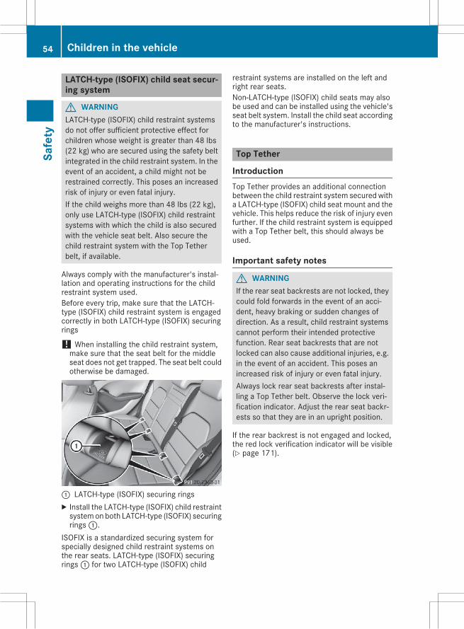
LATCH-type (ISOFIX) child seat secur-ing system
G WARNINGLATCH-type (ISOFIX) child restraint systemsdo not offer sufficient protective effect forchildren whose weight is greater than 48 lbs(22 kg) who are secured using the safety beltintegrated in the child restraint system. In theevent of an accident, a child might not berestrained correctly. This poses an increasedrisk of injury or even fatal injury.If the child weighs more than 48 lbs (22 kg),only use LATCH-type (ISOFIX) child restraintsystems with which the child is also securedwith the vehicle seat belt. Also secure thechild restraint system with the Top Tetherbelt, if available.
Always comply with the manufacturer's instal-lation and operating instructions for the childrestraint system used.Before every trip, make sure that the LATCH-type (ISOFIX) child restraint system is engagedcorrectly in both LATCH-type (ISOFIX) securingrings
! When installing the child restraint system,make sure that the seat belt for the middleseat does not get trapped. The seat belt couldotherwise be damaged.
: LATCH-type (ISOFIX) securing ringsX Install the LATCH-type (ISOFIX) child restraintsystemon both LATCH-type (ISOFIX) securingrings:.
ISOFIX is a standardized securing system forspecially designed child restraint systems onthe rear seats. LATCH-type (ISOFIX) securingrings: for two LATCH-type (ISOFIX) child
restraint systems are installed on the left andright rear seats.Non-LATCH-type (ISOFIX) child seats may alsobe used and can be installed using the vehicle'sseat belt system. Install the child seat accordingto the manufacturer's instructions.
Top Tether
IntroductionTop Tether provides an additional connectionbetween the child restraint system secured witha LATCH-type (ISOFIX) child seat mount and thevehicle. This helps reduce the risk of injury evenfurther. If the child restraint system is equippedwith a Top Tether belt, this should always beused.
Important safety notes
G WARNINGIf the rear seat backrests are not locked, theycould fold forwards in the event of an acci-dent, heavy braking or sudden changes ofdirection. As a result, child restraint systemscannot perform their intended protectivefunction. Rear seat backrests that are notlocked can also cause additional injuries, e.g.in the event of an accident. This poses anincreased risk of injury or even fatal injury.Always lock rear seat backrests after instal-ling a Top Tether belt. Observe the lock veri-fication indicator. Adjust the rear seat backr-ests so that they are in an upright position.
If the rear backrest is not engaged and locked,the red lock verification indicator will be visible(Y page 171).
54 Children in the vehicleSa
fety
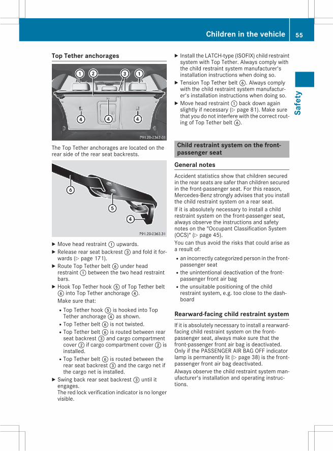
Top Tether anchorages
The Top Tether anchorages are located on therear side of the rear seat backrests.
X Move head restraint: upwards.X Release rear seat backrest= and fold it for-wards (Y page 171).X Route Top Tether beltB under headrestraint: between the two head restraintbars.X Hook Top Tether hookA of Top Tether beltB into Top Tether anchorage?.Make sure that:RTop Tether hookA is hooked into TopTether anchorage? as shown.
RTop Tether beltB is not twisted.RTop Tether beltB is routed between rearseat backrest= and cargo compartmentcover; if cargo compartment cover; isinstalled.
RTop Tether beltB is routed between therear seat backrest= and the cargo net ifthe cargo net is installed.
X Swing back rear seat backrest= until itengages.The red lock verification indicator is no longervisible.
X Install the LATCH-type (ISOFIX) child restraintsystem with Top Tether. Always comply withthe child restraint system manufacturer'sinstallation instructions when doing so.X Tension Top Tether beltB. Always complywith the child restraint system manufactur-er's installation instructions when doing so.X Move head restraint: back down againslightly if necessary (Y page 81). Make surethat you do not interfere with the correct rout-ing of Top Tether beltB.
Child restraint system on the front-passenger seat
General notesAccident statistics show that children securedin the rear seats are safer than children securedin the front-passenger seat. For this reason,Mercedes-Benz strongly advises that you installthe child restraint system on a rear seat.If it is absolutely necessary to install a childrestraint system on the front-passenger seat,always observe the instructions and safetynotes on the "Occupant Classification System(OCS)" (Y page 45).You can thus avoid the risks that could arise asa result of:Ran incorrectly categorized person in the front-passenger seat
Rthe unintentional deactivation of the front-passenger front air bag
Rthe unsuitable positioning of the childrestraint system, e.g. too close to the dash-board
Rearward-facing child restraint systemIf it is absolutely necessary to install a rearward-facing child restraint system on the front-passenger seat, always make sure that thefront-passenger front air bag is deactivated.Only if the PASSENGER AIR BAG OFF indicatorlamp is permanently lit (Y page 38) is the front-passenger front air bag deactivated.Always observe the child restraint system man-ufacturer's installation and operating instruc-tions.
Children in the vehicle 55
Safe
ty
Z
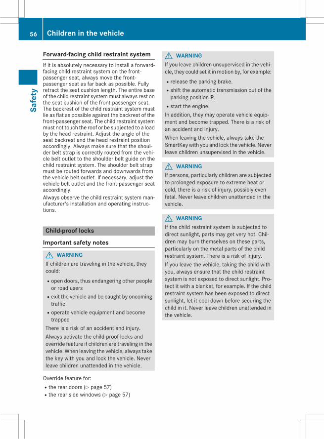
Forward-facing child restraint systemIf it is absolutely necessary to install a forward-facing child restraint system on the front-passenger seat, always move the front-passenger seat as far back as possible. Fullyretract the seat cushion length. The entire baseof the child restraint systemmust always rest onthe seat cushion of the front-passenger seat.The backrest of the child restraint system mustlie as flat as possible against the backrest of thefront-passenger seat. The child restraint systemmust not touch the roof or be subjected to a loadby the head restraint. Adjust the angle of theseat backrest and the head restraint positionaccordingly. Always make sure that the shoul-der belt strap is correctly routed from the vehi-cle belt outlet to the shoulder belt guide on thechild restraint system. The shoulder belt strapmust be routed forwards and downwards fromthe vehicle belt outlet. If necessary, adjust thevehicle belt outlet and the front-passenger seataccordingly.Always observe the child restraint system man-ufacturer's installation and operating instruc-tions.
Child-proof locks
Important safety notes
G WARNINGIf children are traveling in the vehicle, theycould:Ropen doors, thus endangering other peopleor road users
Rexit the vehicle and be caught by oncomingtraffic
Roperate vehicle equipment and becometrapped
There is a risk of an accident and injury.Always activate the child-proof locks andoverride feature if children are traveling in thevehicle. When leaving the vehicle, always takethe key with you and lock the vehicle. Neverleave children unattended in the vehicle.
Override feature for:Rthe rear doors (Y page 57)Rthe rear side windows (Y page 57)
G WARNINGIf you leave children unsupervised in the vehi-cle, they could set it inmotion by, for example:Rrelease the parking brake.Rshift the automatic transmission out of theparking position P.
Rstart the engine.In addition, they may operate vehicle equip-ment and become trapped. There is a risk ofan accident and injury.When leaving the vehicle, always take theSmartKeywith you and lock the vehicle. Neverleave children unsupervised in the vehicle.
G WARNINGIf persons, particularly children are subjectedto prolonged exposure to extreme heat orcold, there is a risk of injury, possibly evenfatal. Never leave children unattended in thevehicle.
G WARNINGIf the child restraint system is subjected todirect sunlight, parts may get very hot. Chil-dren may burn themselves on these parts,particularly on the metal parts of the childrestraint system. There is a risk of injury.If you leave the vehicle, taking the child withyou, always ensure that the child restraintsystem is not exposed to direct sunlight. Pro-tect it with a blanket, for example. If the childrestraint system has been exposed to directsunlight, let it cool down before securing thechild in it. Never leave children unattended inthe vehicle.
56 Children in the vehicleSa
fety
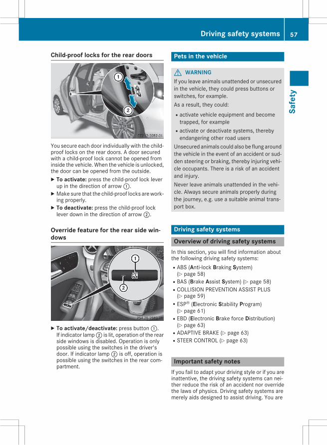
Child-proof locks for the rear doors
You secure each door individually with the child-proof locks on the rear doors. A door securedwith a child-proof lock cannot be opened frominside the vehicle. When the vehicle is unlocked,the door can be opened from the outside.X To activate: press the child-proof lock leverup in the direction of arrow:.X Make sure that the child-proof locks arework-ing properly.X To deactivate: press the child-proof locklever down in the direction of arrow;.
Override feature for the rear side win-dows
X To activate/deactivate: press button:.If indicator lamp; is lit, operation of the rearside windows is disabled. Operation is onlypossible using the switches in the driver'sdoor. If indicator lamp; is off, operation ispossible using the switches in the rear com-partment.
Pets in the vehicle
G WARNINGIf you leave animals unattended or unsecuredin the vehicle, they could press buttons orswitches, for example.As a result, they could:Ractivate vehicle equipment and becometrapped, for example
Ractivate or deactivate systems, therebyendangering other road users
Unsecured animals could also be flung aroundthe vehicle in the event of an accident or sud-den steering or braking, thereby injuring vehi-cle occupants. There is a risk of an accidentand injury.Never leave animals unattended in the vehi-cle. Always secure animals properly duringthe journey, e.g. use a suitable animal trans-port box.
Driving safety systems
Overview of driving safety systemsIn this section, you will find information aboutthe following driving safety systems:RABS (Anti-lock Braking System)(Y page 58)
RBAS (Brake Assist System) (Y page 58)RCOLLISION PREVENTION ASSIST PLUS(Y page 59)
RESP® (Electronic Stability Program)(Y page 61)
REBD (Electronic Brake force Distribution)(Y page 63)
RADAPTIVE BRAKE (Y page 63)RSTEER CONTROL (Y page 63)
Important safety notesIf you fail to adapt your driving style or if you areinattentive, the driving safety systems can nei-ther reduce the risk of an accident nor overridethe laws of physics. Driving safety systems aremerely aids designed to assist driving. You are
Driving safety systems 57
Safe
ty
Z
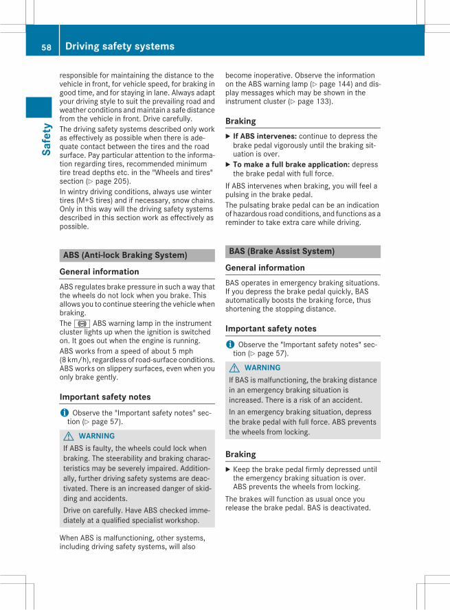
responsible for maintaining the distance to thevehicle in front, for vehicle speed, for braking ingood time, and for staying in lane. Always adaptyour driving style to suit the prevailing road andweather conditions andmaintain a safe distancefrom the vehicle in front. Drive carefully.The driving safety systems described only workas effectively as possible when there is ade-quate contact between the tires and the roadsurface. Pay particular attention to the informa-tion regarding tires, recommended minimumtire tread depths etc. in the "Wheels and tires"section (Y page 205).In wintry driving conditions, always use wintertires (M+S tires) and if necessary, snow chains.Only in this way will the driving safety systemsdescribed in this section work as effectively aspossible.
ABS (Anti-lock Braking System)
General informationABS regulates brake pressure in such a way thatthe wheels do not lock when you brake. Thisallows you to continue steering the vehiclewhenbraking.The! ABS warning lamp in the instrumentcluster lights up when the ignition is switchedon. It goes out when the engine is running.ABS works from a speed of about 5 mph(8 km/h), regardless of road-surface conditions.ABS works on slippery surfaces, even when youonly brake gently.
Important safety notesi Observe the "Important safety notes" sec-tion (Y page 57).
G WARNINGIf ABS is faulty, the wheels could lock whenbraking. The steerability and braking charac-teristics may be severely impaired. Addition-ally, further driving safety systems are deac-tivated. There is an increased danger of skid-ding and accidents.Drive on carefully. Have ABS checked imme-diately at a qualified specialist workshop.
When ABS is malfunctioning, other systems,including driving safety systems, will also
become inoperative. Observe the informationon the ABS warning lamp (Y page 144) and dis-play messages which may be shown in theinstrument cluster (Y page 133).
BrakingX If ABS intervenes: continue to depress thebrake pedal vigorously until the braking sit-uation is over.X To make a full brake application: depressthe brake pedal with full force.
If ABS intervenes when braking, you will feel apulsing in the brake pedal.The pulsating brake pedal can be an indicationof hazardous road conditions, and functions as areminder to take extra care while driving.
BAS (Brake Assist System)
General informationBAS operates in emergency braking situations.If you depress the brake pedal quickly, BASautomatically boosts the braking force, thusshortening the stopping distance.
Important safety notesi Observe the "Important safety notes" sec-tion (Y page 57).
G WARNINGIf BAS is malfunctioning, the braking distancein an emergency braking situation isincreased. There is a risk of an accident.In an emergency braking situation, depressthe brake pedal with full force. ABS preventsthe wheels from locking.
BrakingX Keep the brake pedal firmly depressed untilthe emergency braking situation is over.ABS prevents the wheels from locking.
The brakes will function as usual once yourelease the brake pedal. BAS is deactivated.
58 Driving safety systemsSa
fety
COLLISION PREVENTION ASSISTPLUS
General informationi Observe the "Important safety notes" sec-tion (Y page 57).
COLLISION PREVENTIONASSIST PLUS consistsof a distance warning function with an autono-mous braking function and adaptive BrakeAssist.COLLISION PREVENTIONASSIST PLUS can helpyou to minimize the risk of a front-end collisionwith a vehicle ahead or reduce the effects ofsuch a collision.If COLLISION PREVENTION ASSIST PLUSdetects that there is a risk of a collision, you willbewarned visually and acoustically. If you do notreact to the visual and audible collision warning,autonomous braking can be initiated in criticalsituations. If you apply the brake yourself in acritical situation, the COLLISION PREVENTIONASSIST PLUS adaptive Brake Assist assists you.
Important safety notesDetection of hazardous situations can be par-ticularly impaired by:Rthere is dirt on the sensors or anything elsecovering the sensors
Rthere is snow or heavy rainRthere is interference by other radar sourcesRthere are strong radar reflections, for exam-ple in parking garages
Ra narrow vehicle traveling in front, e.g. amotorbike
Ra vehicle traveling in front on a different lineRnew vehicles or after a service on the COLLI-SION PREVENTION ASSIST PLUS systemObserve the important safety notes in the"Breaking-in notes" section (Y page 97).
Following damage to the front end of the vehicle,have the configuration and operation of theradar sensor checked at a qualified specialistworkshop. This also applies to collisions at lowspeeds where there is no visible damage to thefront of the vehicle.
Switching on/offThe COLLISION PREVENTION ASSIST PLUS isautomatically active after switching on the igni-tion.You can activate or deactivate COLLISION PRE-VENTION ASSIST PLUS in the on-board com-puter (Y page 131). When deactivated, the dis-tance warning function and the autonomousbraking function are also deactivated.Vehicles with black and white multifunctiondisplay:whenCOLLISIONPREVENTIONASSISTPLUS is activated, the multifunction display inthe status overview shows theÄ symbol.Vehicles with color multifunction display:when COLLISION PREVENTION ASSIST PLUS isdeactivated, the multifunction display showstheæ symbol in the assistance graphic.
Distance warning function
General informationThe distance warning function can help you tominimize the risk of a front-end collision with avehicle ahead or reduce the effects of such acollision. If the distance warning functiondetects that there is a risk of a collision, you willbe warned visually and acoustically.
Important safety notesi Observe the "Important safety notes" sec-tion for driving safety systems (Y page 57).
G WARNINGThe distance warning function does not react:Rto people or animalsRto oncoming vehiclesRto crossing trafficRwhen corneringThus, the distance warning function cannotprovide a warning in all critical situations.There is a risk of an accident.Always pay careful attention to the traffic sit-uation and be ready to brake.
G WARNINGThe distance warning function cannot alwaysclearly identify objects and complex trafficsituations.
Driving safety systems 59
Safe
ty
Z
In such cases, the distance warning functionmay:Rgive an unnecessary warningRnot give a warningThere is a risk of an accident.Always pay careful attention to the traffic sit-uation and do not rely solely on the distancewarning function.
FunctionStarting at a speed of approximately 4 mph(7 km/h), the distance warning function warnsyou if you rapidly approach a vehicle in front. Anintermittent warning tone will then sound, andthe· distance warning lamp will light up inthe instrument cluster.X Brake immediately in order to increase thedistance from the vehicle in front.
orX Take evasive action, provided it is safe to doso.
Due to the nature of the system, particularlycomplicated but non-critical driving conditionsmay also cause the system to display a warning.With the help of the radar sensor system, thedistance warning function can detect obstaclesthat are in the path of your vehicle for an exten-ded period of time.Up to a speed of approximately 44 mph(70 km/h), the distance warning function canalso react to stationary obstacles, such as stop-ped or parked vehicles.
Autonomous braking functionIf the driver does not react to the distance warn-ing signal in a critical situation, COLLISION PRE-VENTION ASSIST PLUS can assist with theautonomous braking function.The autonomous braking function:Rgives the driver more time to react to criticaldriving situations
Rcan help the driver to avoid an accident orRreduces the effects of an accident
Vehicles without DISTRONIC PLUS: theautonomous braking function is available in thefollowing speed ranges:R4 - 65 mph (7 - 105 km/h) for moving objectsR4 - 31 mph (7 - 50 km/h) for stationaryobjects
Vehicles with DISTRONIC PLUS: the autono-mous braking function is available in the follow-ing speed ranges:R4 - 124 mph (7 - 200 km/h) for movingobjects
R4 - 31 mph (7 - 50 km/h) for stationaryobjects
Due to the nature of the system, particularlycomplicated but non-critical driving conditionsmay also cause the Autonomous Braking Func-tion to intervene.
Adaptive Brake Assist
General informationi Observe the "Important safety notes" sec-tion (Y page 57).
With the help of adaptive Brake Assist, the dis-tance warning signal can detect obstacles thatare in the path of your vehicle for an extendedperiod of time.If adaptive Brake Assist detects a risk of colli-sion with the vehicle in front, it calculates thebraking force necessary to avoid a collision. Ifyou apply the brakes forcefully, adaptive BrakeAssist will automatically increase the brakingforce to a level suitable for the traffic conditions.Adaptive Brake Assist provides braking assis-tance in hazardous situations at speeds above4mph (7 km/h). It uses radar sensor technologyto assess the traffic situation.Up to a speed of approximately 155 mph(250 km/h), adaptive Brake Assist is capable ofreacting to moving objects that have alreadybeen detected as such at least once over theperiod of observation.Up to a speed of approximately 44 mph(70 km/h), adaptive Brake Assist reacts to sta-tionary obstacles.X Keep the brake pedal depressed until theemergency braking situation is over.ABS prevents the wheels from locking.
60 Driving safety systemsSa
fety
The brakes will work normally again if:Ryou release the brake pedal.Rthere is no longer any danger of a collision.Rno obstacle is detected in front of your vehi-cle.
Adaptive Brake Assist is then deactivated.
Important safety notesi Observe the "Important safety notes" sec-tion for driving safety systems (Y page 57).
G WARNINGAdaptive Brake Assist cannot always clearlyidentify objects and complex traffic situa-tions.In such cases, Adaptive Brake Assist can:Rintervene unnecessarilyRnot interveneThere is a risk of an accident.Always pay careful attention to the traffic sit-uation and be ready to brake. Terminate theintervention in a non-critical driving situation.
G WARNINGAdaptive Brake Assist does not react:Rto people or animalsRto oncoming vehiclesRto crossing trafficRwhen corneringAs a result, the Adaptive Brake Assist may notintervene in all critical conditions. There is arisk of an accident.Always pay careful attention to the traffic sit-uation and be ready to brake.
Due to the nature of the system, particularlycomplicated but non-critical driving conditionsmay also cause Brake Assist to intervene.If adaptive Brake Assist is not available due to amalfunction in the radar sensor system, thebrake system remains available with full brakeboosting effect and BAS.
ESP® (Electronic Stability Program)
General notesi Observe the "Important safety notes" sec-tion (Y page 57).
ESP®monitors driving stability and traction, i.e.power transmission between the tires and theroad surface.If ESP® detects that the vehicle is deviating fromthe direction desired by the driver, one or morewheels are braked to stabilize the vehicle. Theengine output is also modified to keep the vehi-cle on the desired course within physical limits.ESP® assists the driver when pulling away onwet or slippery roads. ESP® can also stabilizethe vehicle during braking.
ETS/4ETS (Electronic Traction System)i Observe the "Important safety notes" sec-tion (Y page 57).
ETS traction control is part of ESP®. On vehicleswith 4MATIC, 4ETS is part of ESP®.Traction control brakes the drive wheels indi-vidually if they spin. This enables you to pullaway and accelerate on slippery surfaces, forexample if the road surface is slippery on oneside. In addition, more drive torque is transfer-red to the wheel or wheels with traction.Traction control remains active, even if youdeactivate ESP®.
Important safety notesi Observe the "Important safety notes" sec-tion (Y page 57).
G WARNINGIf ESP® is malfunctioning, ESP® is unable tostabilize the vehicle. Additionally, further driv-ing safety systems are deactivated. Thisincreases the risk of skidding and an accident.Drive on carefully. Have ESP® checked at aqualified specialist workshop.
If theå ESP® OFF warning lamp lights upcontinuously, ESP® is deactivated.If the÷ ESP® warning lamp and theåwarning lamp are lit continuously, ESP® is notavailable due to a malfunction.
Driving safety systems 61
Safe
ty
Z
Observe the information on warning lamps(Y page 146) and display messages which maybe shown in the instrument cluster(Y page 133).Only use wheels with the recommended tiresizes. Only then will ESP® function properly.
Characteristics of ESP®
General informationIf the÷ ESP® warning lamp goes out beforebeginning the journey, ESP® is automaticallyactive.If ESP® intervenes, the÷ ESP®warning lampflashes in the instrument cluster.If ESP® intervenes:X Do not deactivate ESP® under any circum-stances.X Only depress the accelerator pedal as far asnecessary when pulling away.X Adapt your driving style to suit the prevailingroad and weather conditions.
ECO start/stop functionThe ECO start/stop function switches theengine off automatically when the vehicle stopsmoving. The engine starts automatically whenthe driver wants to pull away again. ESP®remains in its previously selected status. Exam-ple: if ESP® was deactivated before the enginewas switched off, ESP® remains deactivatedwhen the engine is switched on again.
Deactivating/activating ESP®
Important safety notesi Observe the "Important safety notes" sec-tion (Y page 57).
You can select between the following states ofESP®:RESP® is activated.RESP® is deactivated.
G WARNINGIf you deactivate ESP®, ESP® no longer sta-bilizes the vehicle. There is an increased riskof skidding and an accident.
Only deactivate ESP® in the situations descri-bed in the following.
It may be best to deactivate ESP® in the follow-ing situations:Rwhen using snow chainsRin deep snowRon sand or gravel
i Activate ESP® as soon as the situationsdescribed above no longer apply. ESP® willotherwise not be able to stabilize the vehicle ifthe vehicle starts to skid or a wheel starts tospin.
! Avoid spinning the driven wheels for anextended period with ESP® deactivated. Youcould otherwise damage the drivetrain.
Deactivating/activating ESP®
You can deactivate or activate ESP® via the on-board computer (Y page 131).ESP® deactivated:Theå ESP® OFF warning lamp in the instru-ment cluster lights up.ESP® activated:Theå ESP® OFF warning lamp in the instru-ment cluster goes out.
Characteristics when ESP® is deactivatedIf ESP® is deactivated and one or more wheelsstart to spin, the÷ ESP®warning lamp in theinstrument cluster flashes. In such situations,ESP® will not stabilize the vehicle.If you deactivate ESP®:RESP® no longer improves driving stability.REngine torque is no longer limited and thedrive wheels are able to spin.The spinning of the wheels results in a cuttingaction for better traction on loose surfaces.
RTraction control is still activated.RCOLLISION PREVENTION ASSIST is no longeravailable; nor is it activated if you brake firmlywith assistance from ESP®.
RESP® still provides support when you brakefirmly.
62 Driving safety systemsSa
fety
ESP® trailer stabilization
General informationIf your vehicle/trailer combination begins toswerve, ESP® assists you in this situation. ESP®slows the vehicle down by braking and limitingthe engine output until the vehicle/trailer com-bination has stabilized.
Important safety notesG WARNINGIf road and weather conditions are poor,trailer stabilization will not be able to preventthe vehicle/trailer combination from swerv-ing. Trailers with a high center of gravity cantip over before ESP® can detect this. There isa risk of an accident.Always adapt your driving style to the prevail-ing road and weather conditions.
If your vehicle with trailer (vehicle/trailer com-bination) begins to lurch, you can only stabilizethe vehicle/trailer combination by depressingthe brake firmly.ESP® trailer stabilization is active above speedsof about 65 km/h.ESP® trailer stabilization does not work if ESP®is deactivated or disabled because of amalfunc-tion.
EBD (electronic brake force distribu-tion)
General informationEBD monitors and controls the brake pressureon the rear wheels to improve driving stabilitywhile braking.
Important safety notesi Observe the "Important safety notes" sec-tion (Y page 57).
G WARNINGIf EBD is malfunctioning, the rear wheels canlock, e.g. under full braking. This increases therisk of skidding and an accident.
You should therefore adapt your driving styleto the different handling characteristics. Havethe brake system checked at a qualified spe-cialist workshop.
Observe information regarding indicator andwarning lamps (Y page 144) as well as displaymessages (Y page 135).
ADAPTIVE BRAKEADAPTIVE BRAKE enhances braking safety andoffers increased braking comfort. In addition tothe braking function, ADAPTIVE BRAKE also hasthe HOLD function (Y page 119) and hill startassist (Y page 101).
STEER CONTROL
General informationSTEER CONTROL helps you by transmitting anoticeable steering force to the steering wheelin the direction required for vehicle stabilization.This steering assistance is provided in particularif:Rboth right wheels or both left wheels are on awet or slippery road surface when you brake.
Rthe vehicle starts to skid.
Important safety notesi Observe the "Important safety notes" sec-tion (Y page 57).
No steering assistance is provided from STEERCONTROL, if:RESP® is malfunctioning.Rthe lighting is faulty.If ESP® is malfunctioning, you will be assistedfurther by the electrical power steering.
Protection against theft
ImmobilizerThe immobilizer prevents your vehicle frombeing started without the correct SmartKey.
Protection against theft 63
Safe
ty
Z
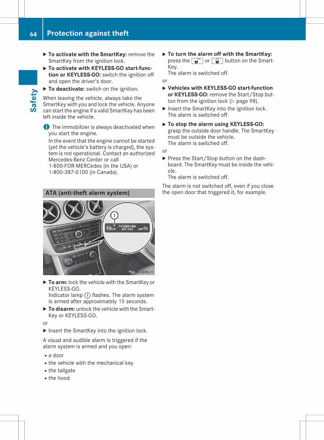
X To activate with the SmartKey: remove theSmartKey from the ignition lock.X To activate with KEYLESS-GO start-func-
tion or KEYLESS-GO: switch the ignition offand open the driver's door.X To deactivate: switch on the ignition.When leaving the vehicle, always take theSmartKey with you and lock the vehicle. Anyonecan start the engine if a valid SmartKey has beenleft inside the vehicle.
i The immobilizer is always deactivated whenyou start the engine.In the event that the engine cannot be started(yet the vehicle's battery is charged), the sys-tem is not operational. Contact an authorizedMercedes-Benz Center or call1-800-FOR-MERCedes (in the USA) or1-800-387-0100 (in Canada).
ATA (anti-theft alarm system)
X To arm: lock the vehicle with the SmartKey orKEYLESS-GO.Indicator lamp: flashes. The alarm systemis armed after approximately 15 seconds.X To disarm: unlock the vehicle with the Smart-Key or KEYLESS-GO.
orX Insert the SmartKey into the ignition lock.A visual and audible alarm is triggered if thealarm system is armed and you open:Ra doorRthe vehicle with the mechanical keyRthe tailgateRthe hood
X To turn the alarm off with the SmartKey:press the% or& button on the Smart-Key.The alarm is switched off.
orX Vehicles with KEYLESS-GO start-function
or KEYLESS-GO: remove the Start/Stop but-ton from the ignition lock (Y page 98).X Insert the SmartKey into the ignition lock.The alarm is switched off.X To stop the alarm using KEYLESS-GO:grasp the outside door handle. The SmartKeymust be outside the vehicle.The alarm is switched off.
orX Press the Start/Stop button on the dash-board. The SmartKey must be inside the vehi-cle.The alarm is switched off.
The alarm is not switched off, even if you closethe open door that triggered it, for example.
64 Protection against theftSa
fety
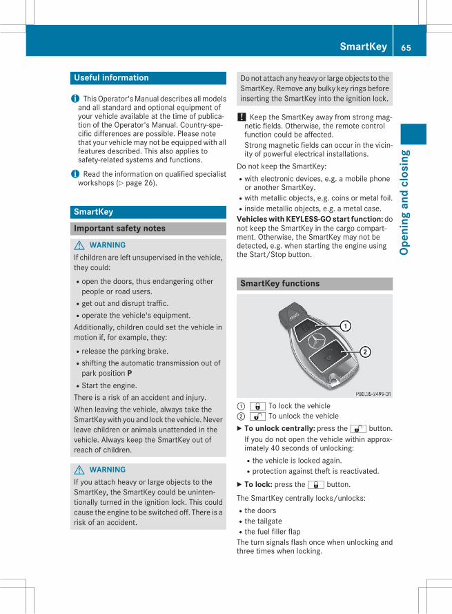
Useful information
i ThisOperator'sManual describes allmodelsand all standard and optional equipment ofyour vehicle available at the time of publica-tion of the Operator's Manual. Country-spe-cific differences are possible. Please notethat your vehicle may not be equipped with allfeatures described. This also applies tosafety-related systems and functions.
i Read the information on qualified specialistworkshops (Y page 26).
SmartKey
Important safety notes
G WARNINGIf children are left unsupervised in the vehicle,they could:Ropen the doors, thus endangering otherpeople or road users.
Rget out and disrupt traffic.Roperate the vehicle's equipment.Additionally, children could set the vehicle inmotion if, for example, they:Rrelease the parking brake.Rshifting the automatic transmission out ofpark position P
RStart the engine.There is a risk of an accident and injury.When leaving the vehicle, always take theSmartKeywith you and lock the vehicle. Neverleave children or animals unattended in thevehicle. Always keep the SmartKey out ofreach of children.
G WARNINGIf you attach heavy or large objects to theSmartKey, the SmartKey could be uninten-tionally turned in the ignition lock. This couldcause the engine to be switched off. There is arisk of an accident.
Do not attach any heavy or large objects to theSmartKey. Remove any bulky key rings beforeinserting the SmartKey into the ignition lock.
! Keep the SmartKey away from strong mag-netic fields. Otherwise, the remote controlfunction could be affected.Strong magnetic fields can occur in the vicin-ity of powerful electrical installations.
Do not keep the SmartKey:Rwith electronic devices, e.g. a mobile phoneor another SmartKey.
Rwith metallic objects, e.g. coins or metal foil.Rinside metallic objects, e.g. a metal case.Vehicles with KEYLESS-GO start function: donot keep the SmartKey in the cargo compart-ment. Otherwise, the SmartKey may not bedetected, e.g. when starting the engine usingthe Start/Stop button.
SmartKey functions
: & To lock the vehicle; % To unlock the vehicleX To unlock centrally: press the% button.If you do not open the vehicle within approx-imately 40 seconds of unlocking:Rthe vehicle is locked again.Rprotection against theft is reactivated.X To lock: press the& button.
The SmartKey centrally locks/unlocks:Rthe doorsRthe tailgateRthe fuel filler flapThe turn signals flash once when unlocking andthree times when locking.
SmartKey 65
Open
ing
and
clos
ing
Z
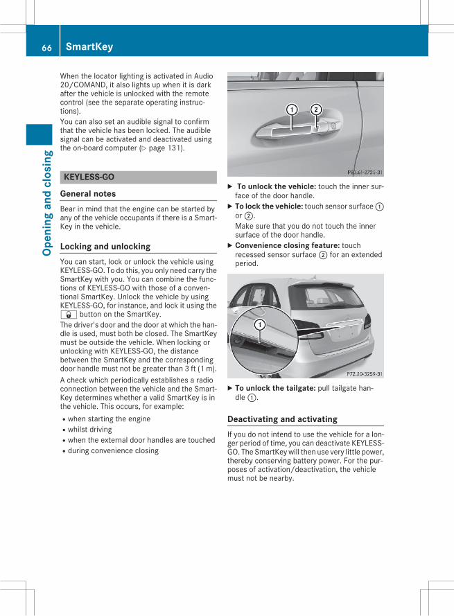
When the locator lighting is activated in Audio20/COMAND, it also lights up when it is darkafter the vehicle is unlocked with the remotecontrol (see the separate operating instruc-tions).You can also set an audible signal to confirmthat the vehicle has been locked. The audiblesignal can be activated and deactivated usingthe on-board computer (Y page 131).
KEYLESS-GO
General notesBear in mind that the engine can be started byany of the vehicle occupants if there is a Smart-Key in the vehicle.
Locking and unlockingYou can start, lock or unlock the vehicle usingKEYLESS-GO. To do this, you only need carry theSmartKey with you. You can combine the func-tions of KEYLESS-GO with those of a conven-tional SmartKey. Unlock the vehicle by usingKEYLESS-GO, for instance, and lock it using the& button on the SmartKey.The driver's door and the door at which the han-dle is used, must both be closed. The SmartKeymust be outside the vehicle. When locking orunlocking with KEYLESS-GO, the distancebetween the SmartKey and the correspondingdoor handle must not be greater than 3 ft (1 m).A check which periodically establishes a radioconnection between the vehicle and the Smart-Key determines whether a valid SmartKey is inthe vehicle. This occurs, for example:Rwhen starting the engineRwhilst drivingRwhen the external door handles are touchedRduring convenience closing
X To unlock the vehicle: touch the inner sur-face of the door handle.X To lock the vehicle: touch sensor surface:or;.Make sure that you do not touch the innersurface of the door handle.X Convenience closing feature: touchrecessed sensor surface; for an extendedperiod.
X To unlock the tailgate: pull tailgate han-dle:.
Deactivating and activatingIf you do not intend to use the vehicle for a lon-ger period of time, you can deactivate KEYLESS-GO. The SmartKeywill then use very little power,thereby conserving battery power. For the pur-poses of activation/deactivation, the vehiclemust not be nearby.
66 SmartKeyOp
enin
gan
dcl
osin
g
X To deactivate: press the& button on theSmartKey twice in rapid succession.The battery check lamp of the SmartKeyflashes twice briefly and lights up once, thenKEYLESS-GO is deactivated (Y page 68).X To activate: press any button on the Smart-Key.
orX Insert the SmartKey into the ignition lock.KEYLESS-GO and all of its associated featuresare available again.
KEYLESS-GO start function
General notesBear in mind that the engine can be started byany of the vehicle occupants if there is a Smart-Key in the vehicle.
Changing the settings of the lockingsystemYou can change the settings of the locking sys-tem. This means that only the driver's door andthe fuel filler flap are unlocked when the vehicleis unlocked. This is useful if you frequently travelon your own.X To change the setting: press and hold the% and& buttons simultaneously forapproximately six seconds until the batteryindicator lamp flashes twice (Y page 68).
If the setting of the locking system is changedwithin the signal range of the vehicle, pressingthe& or% button:Rlocks orRunlocks the vehicleThe SmartKey now functions as follows:X To unlock: press the% button once.X To unlock centrally: press the% buttontwice.X To lock centrally: press the& button.
The KEYLESS-GO function is changed as fol-lows:X To unlock the driver's door: touch the innersurface of the door handle on the driver'sdoor.X To unlock centrally: touch the inner surfaceof the door handle on the front-passengerdoor or the rear door.X To lock centrally: touch the outer sensorsurface on one of the door handles.X To restore the factory settings: press andhold the% and& buttons simultane-ously for approximately six seconds until thebattery check lamp flashes twice(Y page 68).
Mechanical key
General notesIf the vehicle can no longer be locked orunlocked with the SmartKey or KEYLESS-GO,use the mechanical key.If you use the mechanical key to unlock andopen the driver's door or the trunk lid, the anti-theft alarm systemwill be triggered (Y page 64).There are several ways to turn off the alarm:X To deactivate the alarm with the key: pressthe% or& button on the key.
orX Insert the SmartKey into the ignition lock.orX To deactivate the alarm with KEYLESS-GO:press the Start/Stop button in the ignitionlock. The SmartKey must be in the vehicle.
orX Lock or unlock the vehicle using KEYLESS-GO. The SmartKey must be outside the vehi-cle.
If you unlock the vehicle using the mechanicalkey, the fuel filler flap will not be unlocked auto-matically.X To unlock the fuel filler flap: insert theSmartKey into the ignition lock.
SmartKey 67
Open
ing
and
clos
ing
Z
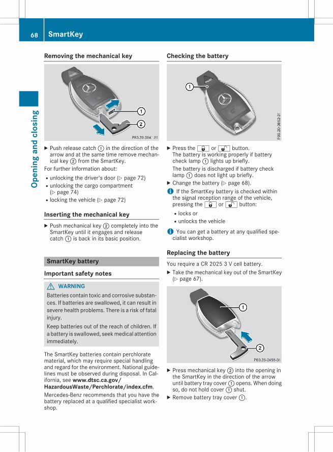
Removing the mechanical key
X Push release catch: in the direction of thearrow and at the same time remove mechan-ical key; from the SmartKey.
For further information about:Runlocking the driver's door (Y page 72)Runlocking the cargo compartment(Y page 74)
Rlocking the vehicle (Y page 72)
Inserting the mechanical keyX Push mechanical key; completely into theSmartKey until it engages and releasecatch: is back in its basic position.
SmartKey battery
Important safety notes
G WARNINGBatteries contain toxic and corrosive substan-ces. If batteries are swallowed, it can result insevere health problems. There is a risk of fatalinjury.Keep batteries out of the reach of children. Ifa battery is swallowed, seekmedical attentionimmediately.
The SmartKey batteries contain perchloratematerial, which may require special handlingand regard for the environment. National guide-lines must be observed during disposal. In Cal-ifornia, see www.dtsc.ca.gov/HazardousWaste/Perchlorate/index.cfm.Mercedes-Benz recommends that you have thebattery replaced at a qualified specialist work-shop.
Checking the battery
X Press the& or% button.The battery is working properly if batterycheck lamp: lights up briefly.The battery is discharged if battery checklamp: does not light up briefly.X Change the battery (Y page 68).i If the SmartKey battery is checked withinthe signal reception range of the vehicle,pressing the& or% button:Rlocks orRunlocks the vehicle
i You can get a battery at any qualified spe-cialist workshop.
Replacing the batteryYou require a CR 2025 3 V cell battery.X Take the mechanical key out of the SmartKey(Y page 67).
X Press mechanical key; into the opening inthe SmartKey in the direction of the arrowuntil battery tray cover: opens. When doingso, do not hold cover: shut.X Remove battery tray cover:.
68 SmartKeyOp
enin
gan
dcl
osin
g
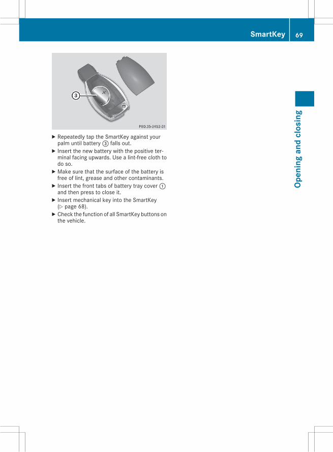
X Repeatedly tap the SmartKey against yourpalm until battery= falls out.X Insert the new battery with the positive ter-minal facing upwards. Use a lint-free cloth todo so.X Make sure that the surface of the battery isfree of lint, grease and other contaminants.X Insert the front tabs of battery tray cover:and then press to close it.X Insert mechanical key into the SmartKey(Y page 68).X Check the function of all SmartKey buttons onthe vehicle.
SmartKey 69
Open
ing
and
clos
ing
Z
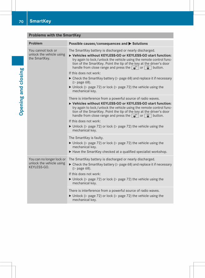
Problems with the SmartKey
Problem Possible causes/consequences and M Solutions
You cannot lock orunlock the vehicle usingthe SmartKey.
The SmartKey battery is discharged or nearly discharged.X Vehicles without KEYLESS-GO or KEYLESS-GO start function:try again to lock/unlock the vehicle using the remote control func-tion of the SmartKey. Point the tip of the key at the driver's doorhandle from close range and press the% or& button.
If this does not work:X Check the SmartKey battery (Y page 68) and replace it if necessary(Y page 68).X Unlock (Y page 72) or lock (Y page 72) the vehicle using themechanical key.
There is interference from a powerful source of radio waves.X Vehicles without KEYLESS-GO or KEYLESS-GO start function:try again to lock/unlock the vehicle using the remote control func-tion of the SmartKey. Point the tip of the key at the driver's doorhandle from close range and press the% or& button.
If this does not work:X Unlock (Y page 72) or lock (Y page 72) the vehicle using themechanical key.
The SmartKey is faulty.X Unlock (Y page 72) or lock (Y page 72) the vehicle using themechanical key.X Have the SmartKey checked at a qualified specialist workshop.
You can no longer lock orunlock the vehicle usingKEYLESS-GO.
The SmartKey battery is discharged or nearly discharged.X Check the SmartKey battery (Y page 68) and replace it if necessary(Y page 68).
If this does not work:X Unlock (Y page 72) or lock (Y page 72) the vehicle using themechanical key.
There is interference from a powerful source of radio waves.X Unlock (Y page 72) or lock (Y page 72) the vehicle using themechanical key.
70 SmartKeyOp
enin
gan
dcl
osin
g
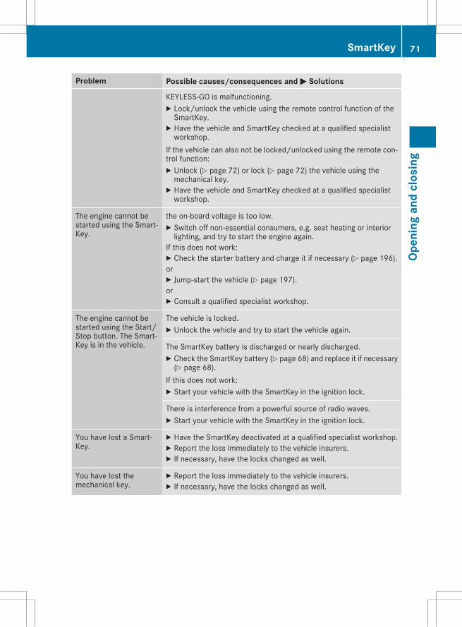
Problem Possible causes/consequences and M Solutions
KEYLESS-GO is malfunctioning.X Lock/unlock the vehicle using the remote control function of theSmartKey.X Have the vehicle and SmartKey checked at a qualified specialistworkshop.
If the vehicle can also not be locked/unlocked using the remote con-trol function:X Unlock (Y page 72) or lock (Y page 72) the vehicle using themechanical key.X Have the vehicle and SmartKey checked at a qualified specialistworkshop.
The engine cannot bestarted using the Smart-Key.
the on-board voltage is too low.X Switch off non-essential consumers, e.g. seat heating or interiorlighting, and try to start the engine again.
If this does not work:X Check the starter battery and charge it if necessary (Y page 196).orX Jump-start the vehicle (Y page 197).orX Consult a qualified specialist workshop.
The engine cannot bestarted using the Start/Stop button. The Smart-Key is in the vehicle.
The vehicle is locked.X Unlock the vehicle and try to start the vehicle again.
The SmartKey battery is discharged or nearly discharged.X Check the SmartKey battery (Y page 68) and replace it if necessary(Y page 68).
If this does not work:X Start your vehicle with the SmartKey in the ignition lock.
There is interference from a powerful source of radio waves.X Start your vehicle with the SmartKey in the ignition lock.
You have lost a Smart-Key.
X Have the SmartKey deactivated at a qualified specialist workshop.X Report the loss immediately to the vehicle insurers.X If necessary, have the locks changed as well.
You have lost themechanical key.
X Report the loss immediately to the vehicle insurers.X If necessary, have the locks changed as well.
SmartKey 71
Open
ing
and
clos
ing
Z
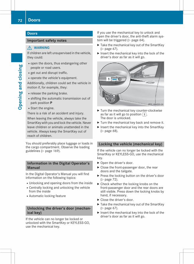
Doors
Important safety notes
G WARNINGIf children are left unsupervised in the vehicle,they could:Ropen the doors, thus endangering otherpeople or road users.
Rget out and disrupt traffic.Roperate the vehicle's equipment.Additionally, children could set the vehicle inmotion if, for example, they:Rrelease the parking brake.Rshifting the automatic transmission out ofpark position P
RStart the engine.There is a risk of an accident and injury.When leaving the vehicle, always take theSmartKeywith you and lock the vehicle. Neverleave children or animals unattended in thevehicle. Always keep the SmartKey out ofreach of children.
You should preferably place luggage or loads inthe cargo compartment. Observe the loadingguidelines (Y page 169).
Information in the Digital Operator'sManualIn the Digital Operator's Manual you will findinformation on the following topics:RUnlocking and opening doors from the insideRCentrally locking and unlocking the vehiclefrom the inside
RAutomatic locking feature
Unlocking the driver's door (mechan-ical key)If the vehicle can no longer be locked orunlocked with the SmartKey or KEYLESS-GO,use the mechanical key.
If you use the mechanical key to unlock andopen the driver's door, the anti-theft alarm sys-tem will be triggered (Y page 64).X Take the mechanical key out of the SmartKey(Y page 67).X Insert the mechanical key into the lock of thedriver's door as far as it will go.
X Turn the mechanical key counter-clockwiseas far as it will go to position1.The door is unlocked.X Turn the mechanical key back and remove it.X Insert the mechanical key into the SmartKey(Y page 68).
Locking the vehicle (mechanical key)If the vehicle can no longer be locked with theSmartKey or KEYLESS-GO, use the mechanicalkey.X Open the driver's door.X Close the front-passenger door, the reardoors and the tailgate.X Press the locking button on the driver’s door(Y page 72).X Check whether the locking knobs on thefront-passenger door and the rear doors arestill visible. Press down the locking knobs byhand, if necessary.X Close the driver's door.X Take the mechanical key out of the SmartKey(Y page 67).X Insert the mechanical key into the lock of thedriver's door as far as it will go.
72 DoorsOp
enin
gan
dcl
osin
g
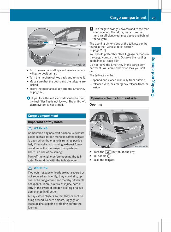
X Turn the mechanical key clockwise as far as itwill go to position1.X Turn the mechanical key back and remove it.X Make sure that the doors and the tailgate arelocked.X Insert the mechanical key into the SmartKey(Y page 68).
i If you lock the vehicle as described above,the fuel filler flap is not locked. The anti-theftalarm system is not armed.
Cargo compartment
Important safety notes
G WARNINGCombustion engines emit poisonous exhaustgases such as carbonmonoxide. If the tailgateis open when the engine is running, particu-larly if the vehicle is moving, exhaust fumescould enter the passenger compartment.There is a risk of poisoning.Turn off the engine before opening the tail-gate. Never drive with the tailgate open.
G WARNINGIf objects, luggage or loads are not secured ornot secured sufficiently, they could slip, tipover or be flung around and thereby hit vehicleoccupants. There is a risk of injury, particu-larly in the event of sudden braking or a sud-den change in direction.Always store objects so that they cannot beflung around. Secure objects, luggage orloads against slipping or tipping before thejourney.
! The tailgate swings upwards and to the rearwhen opened. Therefore, make sure thatthere is sufficient clearance above and behindthe tailgate.
The opening dimensions of the tailgate can befound in the "Vehicle data" section(Y page 238).You should preferably place luggage or loads inthe cargo compartment. Observe the loadingguidelines (Y page 169).Do not leave the SmartKey in the cargo com-partment. You could otherwise lock yourselfout.The tailgate can be:Ropened and closed manually from outsideRreleasedwith the emergency release from theinside
Opening/closing from outside
Opening
X Press the% button on the key.X Pull handle:.X Raise the tailgate.
Cargo compartment 73
Open
ing
and
clos
ing
Z
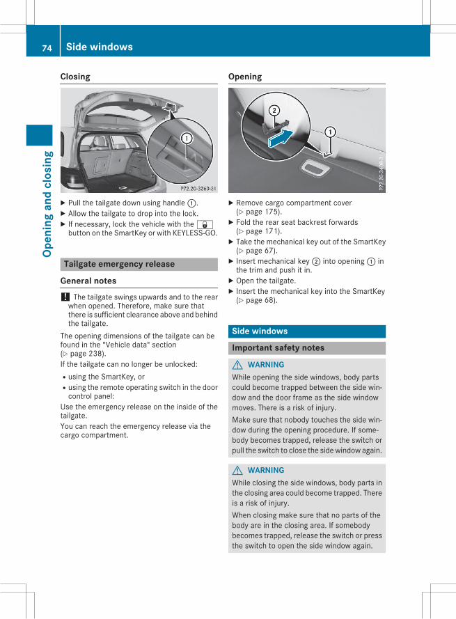
Closing
X Pull the tailgate down using handle:.X Allow the tailgate to drop into the lock.X If necessary, lock the vehicle with the&button on the SmartKey or with KEYLESS-GO.
Tailgate emergency release
General notes! The tailgate swings upwards and to the rearwhen opened. Therefore, make sure thatthere is sufficient clearance above and behindthe tailgate.
The opening dimensions of the tailgate can befound in the "Vehicle data" section(Y page 238).If the tailgate can no longer be unlocked:Rusing the SmartKey, orRusing the remote operating switch in the doorcontrol panel:
Use the emergency release on the inside of thetailgate.You can reach the emergency release via thecargo compartment.
Opening
X Remove cargo compartment cover(Y page 175).X Fold the rear seat backrest forwards(Y page 171).X Take the mechanical key out of the SmartKey(Y page 67).X Insert mechanical key; into opening: inthe trim and push it in.X Open the tailgate.X Insert the mechanical key into the SmartKey(Y page 68).
Side windows
Important safety notes
G WARNINGWhile opening the side windows, body partscould become trapped between the side win-dow and the door frame as the side windowmoves. There is a risk of injury.Make sure that nobody touches the side win-dow during the opening procedure. If some-body becomes trapped, release the switch orpull the switch to close the sidewindow again.
G WARNINGWhile closing the side windows, body parts inthe closing area could become trapped. Thereis a risk of injury.When closing make sure that no parts of thebody are in the closing area. If somebodybecomes trapped, release the switch or pressthe switch to open the side window again.
74 Side windowsOp
enin
gan
dcl
osin
g
G WARNINGIf children operate the side windows theycould become trapped, particularly if they areleft unsupervised. There is a risk of injury.Activate the override feature for the rear sidewindows. When leaving the vehicle, alwaystake the SmartKey with you and lock the vehi-cle. Never leave children unsupervised in thevehicle.
Side window reversing featureThe side windows are equipped with an auto-matic reversing feature. If a solid object blocksor restricts a side window from travelingupwards during the automatic closing process,the sidewindowopens again automatically. Dur-ing themanual closing process, the side windowonly opens again automatically after the corre-sponding switch is released. The automaticreversing feature is only an aid and is no substi-tute for your attention when closing a side win-dow.
G WARNINGThe reversing feature does not react:Rto soft, light and thin objects, e.g. small fin-gers
Rwhile resettingThis means that the reversing feature cannotprevent someone being trapped in these sit-uations. There is a risk of injury.Make sure that no body parts are in closeproximity during the closing procedure. Ifsomeone becomes trapped, press the switchto open the side window again.
Information in the Digital Operator'sManualIn the Digital Operator's Manual you will findinformation on the following topics:ROpening and closing the side windowsRConvenience openingRConvenience closing featureRResetting the side windows
Panorama roof with power tilt/slidingpanel
Important safety notesIn the following section, the term "sliding sun-roof" refers to the panorama roof with powertilt/sliding panel.
G WARNINGWhile opening and closing the sliding sunroof,body parts in close proximity could becometrapped. There is a risk of injury.Make sure that no body parts are in closeproximity during the opening and closing pro-cedures.If somebody becomes trapped:Rrelease the switch immediately, orRduring automatic operation, push theswitch briefly in any direction
The opening or closing procedure will be stop-ped.
G WARNINGIf children operate the sliding sunroof theycould become trapped, particularly if they areleft unsupervised. There is a risk of injury.When leaving the vehicle, always take theSmartKeywith you and lock the vehicle. Neverleave children unsupervised in the vehicle.
! Only open the sliding sunroof if it is free ofsnow and ice. Otherwise, malfunctions mayoccur.Do not allow anything to protrude from thesliding sunroof. Otherwise, the seals could bedamaged.
! The weather can change abruptly. It couldstart to rain or snow. Make sure that the slid-ing sunroof is closed when you leave the vehi-cle. The vehicle electronics can be damaged ifwater enters the vehicle interior.
i Resonance noises can occur in addition tothe usual airflow noises when the sliding sun-roof is open. They are caused by minor pres-sure fluctuations in the vehicle interior.Change the position of the sliding sunroof oropen a side window slightly to reduce or elim-inate these noises.
Panorama roof with power tilt/sliding panel 75
Open
ing
and
clos
ing
Z
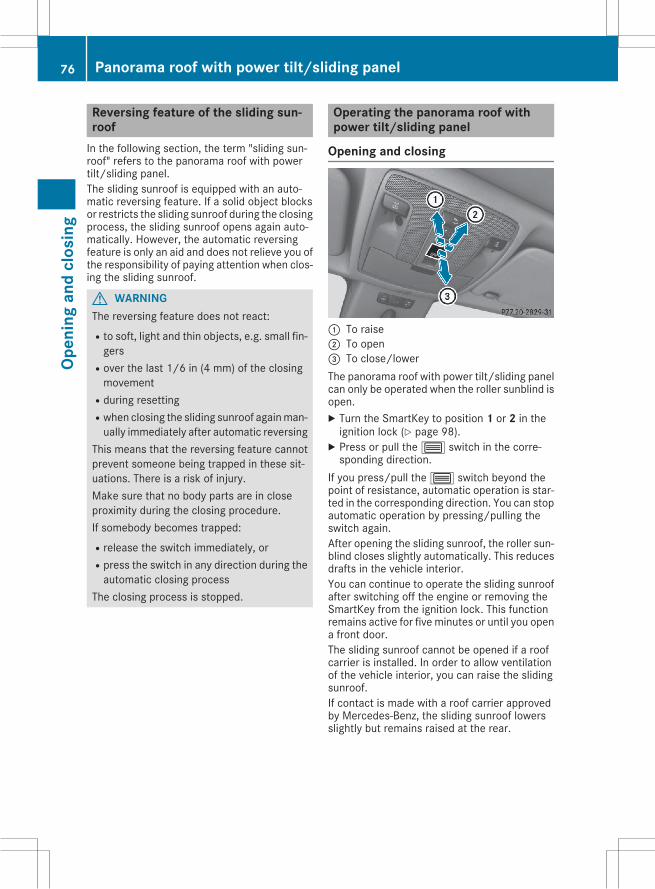
Reversing feature of the sliding sun-roofIn the following section, the term "sliding sun-roof" refers to the panorama roof with powertilt/sliding panel.The sliding sunroof is equipped with an auto-matic reversing feature. If a solid object blocksor restricts the sliding sunroof during the closingprocess, the sliding sunroof opens again auto-matically. However, the automatic reversingfeature is only an aid and does not relieve you ofthe responsibility of paying attention when clos-ing the sliding sunroof.
G WARNINGThe reversing feature does not react:Rto soft, light and thin objects, e.g. small fin-gers
Rover the last 1/6 in (4 mm) of the closingmovement
Rduring resettingRwhen closing the sliding sunroof againman-ually immediately after automatic reversing
This means that the reversing feature cannotprevent someone being trapped in these sit-uations. There is a risk of injury.Make sure that no body parts are in closeproximity during the closing procedure.If somebody becomes trapped:Rrelease the switch immediately, orRpress the switch in any direction during theautomatic closing process
The closing process is stopped.
Operating the panorama roof withpower tilt/sliding panel
Opening and closing
: To raise; To open= To close/lowerThe panorama roof with power tilt/sliding panelcan only be operated when the roller sunblind isopen.X Turn the SmartKey to position 1 or 2 in theignition lock (Y page 98).X Press or pull the3 switch in the corre-sponding direction.
If you press/pull the3 switch beyond thepoint of resistance, automatic operation is star-ted in the corresponding direction. You can stopautomatic operation by pressing/pulling theswitch again.After opening the sliding sunroof, the roller sun-blind closes slightly automatically. This reducesdrafts in the vehicle interior.You can continue to operate the sliding sunroofafter switching off the engine or removing theSmartKey from the ignition lock. This functionremains active for five minutes or until you opena front door.The sliding sunroof cannot be opened if a roofcarrier is installed. In order to allow ventilationof the vehicle interior, you can raise the slidingsunroof.If contact is made with a roof carrier approvedby Mercedes-Benz, the sliding sunroof lowersslightly but remains raised at the rear.
76 Panorama roof with power tilt/sliding panelOp
enin
gan
dcl
osin
g
Rain-closing featureThe rain-closing feature is only available for vehi-cles with a rain sensor.When the SmartKey is in position 0 in the igni-tion lock or is removed, the sliding sunroofcloses automatically:Rif it starts to rain.Rat extreme outside temperatures.Rafter six hours.Rif there is a malfunction in the power supply.The panorama roof with power tilt/sliding panelremains raised at the rear in order to allow ven-tilation of the vehicle interior.If the panorama roof with power tilt/slidingpanel is obstructed while being closed by therain-closing feature, it opens again slightly. Therain-closing feature is then deactivated.The panorama roof with power tilt/sliding paneldoes not close if:Rit is raised at the rear.Rit is blocked.Rno rain is falling on the area of the windshieldbeing monitored by the rain sensor. If thevehicle is under a bridge or in a carport, forexample, the field of the sensor may be cov-ered.
Operating the roller sunblind for thepanorama roof with power tilt/slidingpanel
Important safety notes
G WARNINGParts of the body could become trappedbetween the roller sunblind and frame or slid-ing sunroof during automatic opening or clos-ing. There is a risk of injury.When opening or closing, make sure that nobody parts are in the sweep of the roller sun-blind.If somebody becomes trapped:Rrelease the switch immediately, orRduring automatic operation, push theswitch briefly in any direction
The opening or closing procedure will be stop-ped.
The roller sunblind shields the vehicle interiorfrom sunlight. The roller sunblind can only beopened and closed when the panorama roofwith power tilt/sliding panel is closed.
Roller sunblind reversing featureThe roller sunblind is equipped with an auto-matic reversing feature. If a solid object blocksor restricts the roller sunblind during the closingprocess, the roller sunblind opens again auto-matically. However, the automatic reversingfeature is only an aid and does not relieve you ofthe responsibility of paying attention when clos-ing the roller sunblind.
G WARNINGThe reversing feature does not react:Rto soft, light and thin objects, e.g. small fin-gers
Rwhen closing the roller sunblind again man-ually immediately after automatic reversal
This means that the reversing feature cannotprevent someone being trapped in these sit-uations. There is a risk of injury.When closing the roller sunblind, make surethat no body parts are in the sweep area.If somebody becomes trapped:Rrelease the switch immediately, orRpress the switch in any direction during theautomatic closing process
The closing process is stopped.
Panorama roof with power tilt/sliding panel 77
Open
ing
and
clos
ing
Z
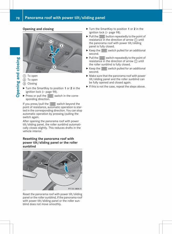
Opening and closing
: To open; To open= ClosingX Turn the SmartKey to position 1 or 2 in theignition lock (Y page 98).X Press or pull the3 switch in the corre-sponding direction.
If you press/pull the3 switch beyond thepoint of resistance, automatic operation is star-ted in the corresponding direction. You can stopautomatic operation by pressing/pulling theswitch again.After opening the panorama roof with powertilt/sliding panel, the roller sunblind automati-cally closes slightly. This reduces drafts in thevehicle interior.
Resetting the panorama roof withpower tilt/sliding panel or the rollersunblind
Reset the panorama roof with power tilt/slidingpanel or the roller sunblind, if the panorama roofwith power tilt/sliding panel or the roller sun-blind does not move smoothly.
X Turn the SmartKey to position 1 or 2 in theignition lock (Y page 98).X Pull the3 button repeatedly to the point ofresistance in the direction of arrow: untilthe panorama roof with power tilt/slidingpanel is fully closed.X Keep the3 switch pulled for an additionalsecond.X Pull the3 switch repeatedly to the point ofresistance in the direction of arrow: untilthe roller sunblind is fully closed.X Keep the3 switch pulled for an additionalsecond.X Make sure that the panorama roof with powertilt/sliding panel and the roller sunblind canbe fully opened and closed again.X If this is not the case, repeat the steps above.
78 Panorama roof with power tilt/sliding panelOp
enin
gan
dcl
osin
g
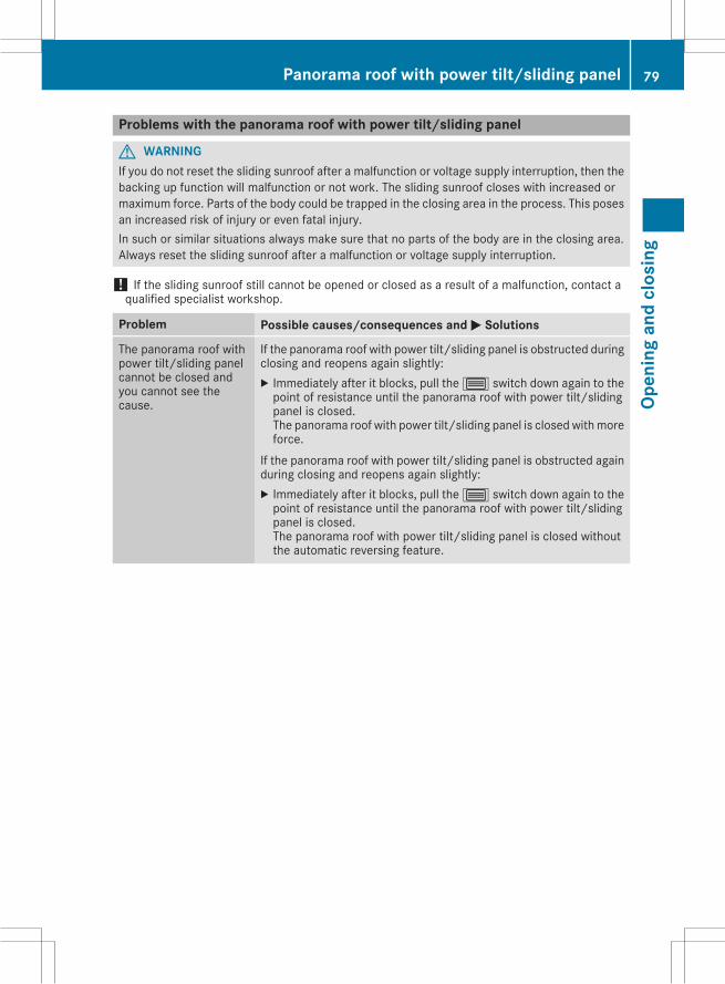
Problems with the panorama roof with power tilt/sliding panel
G WARNINGIf you do not reset the sliding sunroof after a malfunction or voltage supply interruption, then thebacking up function will malfunction or not work. The sliding sunroof closes with increased ormaximum force. Parts of the body could be trapped in the closing area in the process. This posesan increased risk of injury or even fatal injury.In such or similar situations always make sure that no parts of the body are in the closing area.Always reset the sliding sunroof after a malfunction or voltage supply interruption.
! If the sliding sunroof still cannot be opened or closed as a result of a malfunction, contact aqualified specialist workshop.
Problem Possible causes/consequences and M Solutions
The panorama roof withpower tilt/sliding panelcannot be closed andyou cannot see thecause.
If the panorama roof with power tilt/sliding panel is obstructed duringclosing and reopens again slightly:X Immediately after it blocks, pull the3 switch down again to thepoint of resistance until the panorama roof with power tilt/slidingpanel is closed.The panorama roof with power tilt/sliding panel is closed withmoreforce.
If the panorama roof with power tilt/sliding panel is obstructed againduring closing and reopens again slightly:X Immediately after it blocks, pull the3 switch down again to thepoint of resistance until the panorama roof with power tilt/slidingpanel is closed.The panorama roof with power tilt/sliding panel is closed withoutthe automatic reversing feature.
Panorama roof with power tilt/sliding panel 79
Open
ing
and
clos
ing
Z
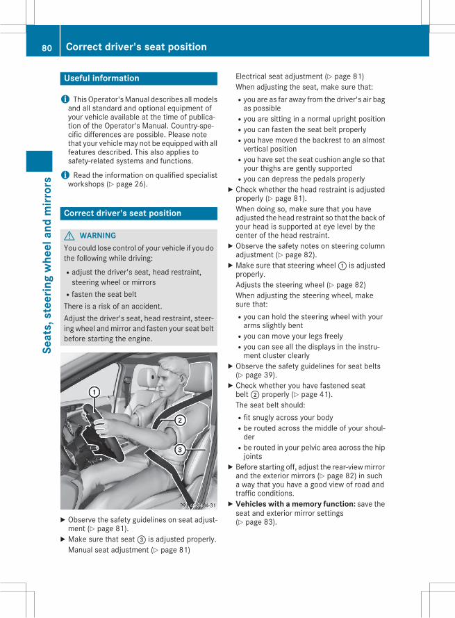
Useful information
i ThisOperator'sManual describes allmodelsand all standard and optional equipment ofyour vehicle available at the time of publica-tion of the Operator's Manual. Country-spe-cific differences are possible. Please notethat your vehicle may not be equipped with allfeatures described. This also applies tosafety-related systems and functions.
i Read the information on qualified specialistworkshops (Y page 26).
Correct driver's seat position
G WARNINGYou could lose control of your vehicle if you dothe following while driving:Radjust the driver's seat, head restraint,steering wheel or mirrors
Rfasten the seat beltThere is a risk of an accident.Adjust the driver's seat, head restraint, steer-ing wheel andmirror and fasten your seat beltbefore starting the engine.
X Observe the safety guidelines on seat adjust-ment (Y page 81).X Make sure that seat= is adjusted properly.Manual seat adjustment (Y page 81)
Electrical seat adjustment (Y page 81)When adjusting the seat, make sure that:Ryou are as far away from the driver's air bagas possible
Ryou are sitting in a normal upright positionRyou can fasten the seat belt properlyRyou have moved the backrest to an almostvertical position
Ryou have set the seat cushion angle so thatyour thighs are gently supported
Ryou can depress the pedals properlyX Check whether the head restraint is adjustedproperly (Y page 81).When doing so, make sure that you haveadjusted the head restraint so that the back ofyour head is supported at eye level by thecenter of the head restraint.X Observe the safety notes on steering columnadjustment (Y page 82).X Make sure that steering wheel: is adjustedproperly.Adjusts the steering wheel (Y page 82)When adjusting the steering wheel, makesure that:Ryou can hold the steering wheel with yourarms slightly bent
Ryou can move your legs freelyRyou can see all the displays in the instru-ment cluster clearly
X Observe the safety guidelines for seat belts(Y page 39).X Check whether you have fastened seatbelt; properly (Y page 41).The seat belt should:Rfit snugly across your bodyRbe routed across the middle of your shoul-der
Rbe routed in your pelvic area across the hipjoints
X Before starting off, adjust the rear-viewmirrorand the exterior mirrors (Y page 82) in sucha way that you have a good view of road andtraffic conditions.X Vehicles with a memory function: save theseat and exterior mirror settings(Y page 83).
80 Correct driver's seat positionSe
ats,
stee
ring
whe
elan
dm
irror
s
Seats
Important safety notes
G WARNINGChildren could become trapped if they adjustthe seats, particularly when unattended.There is a risk of injury.When leaving the vehicle, always take theSmartKeywith you and lock the vehicle. Neverleave children unsupervised in the vehicle.
The seats can still be adjusted when there is noSmartKey in the ignition lock.
G WARNINGWhen you adjust a seat, you or other vehicleoccupants could become trapped, e.g. on theseat guide rail. There is a risk of injury.Make sure when adjusting a seat that no onehas any body parts in the sweep of the seat.
Observe the safety notes on "Air bags"(Y page 42) and "Children in the vehicle"(Y page 51).
G WARNINGIf the driver's seat is not engaged, it couldmove unexpectedly while the vehicle is inmotion. This could cause you to lose control ofthe vehicle. There is a risk of an accident.Always make sure that the driver's seat isengaged before starting the vehicle.
G WARNINGYou could lose control of your vehicle if you dothe following while driving:Radjust the driver's seat, head restraint,steering wheel or mirrors
Rfasten the seat beltThere is a risk of an accident.Adjust the driver's seat, head restraint, steer-ing wheel andmirror and fasten your seat beltbefore starting the engine.
G WARNINGIf you adjust the seat height carelessly, you orother vehicle occupants could be trapped and
thereby injured. Children in particular couldaccidentally press the electrical seat adjust-ment buttons and become trapped. There is arisk of injury.While moving the seats, make sure that yourhands or other body parts do not get under thelever assembly of the seat adjustment sys-tem.
! To avoid damage to the seats and the seatheating, observe the following information:Rkeep liquids from spilling on the seats. Ifliquid is spilled on the seats, dry them assoon as possible.
Rif the seat covers are damp or wet, do notswitch on the seat heating. The seat heat-ing should also not be used to dry the seats.
Rclean the seat covers as recommended;see the "Interior care" section.
Rdo not transport heavy loads on the seats.Do not place sharp objects on the seatcushions, e.g. knives, nails or tools. Theseats should only be occupied by passen-gers, if possible.
Rwhen the seat heating is in operation, donot cover the seats with insulating materi-als, e.g. blankets, coats, bags, seat covers,child seats or booster seats.
! Make sure that there are no objects in thefootwell under or behind the seats whenmov-ing the seats back. There is a risk that theseats and/or the objects could be damaged.
i Further related subjects:Rcargo compartment enlargement (foldingdown the rear seats) (Y page 171)
Information in the Digital Operator'sManualIn the Digital Operator's Manual you will findinformation on the following topics:RAdjusting the seatsRAdjusting the head restraintsRAdjusting the 4-way lumbar support
Seats 81
Seat
s,st
eerin
gw
heel
and
mirr
ors
Z
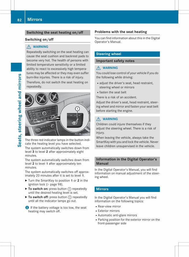
Switching the seat heating on/off
Switching on/off
G WARNINGRepeatedly switching on the seat heating cancause the seat cushion and backrest pads tobecome very hot. The health of persons withlimited temperature sensitivity or a limitedability to react to excessively high tempera-tures may be affected or they may even sufferburn-like injuries. There is a risk of injury.Therefore, do not switch the seat heating onrepeatedly.
The three red indicator lamps in the button indi-cate the heating level you have selected.The system automatically switches down fromlevel 3 to level 2 after approximately eightminutes.The system automatically switches down fromlevel 2 to level 1 after approximately tenminutes.The system automatically switches off approx-imately 20 minutes after it is set to level 1.X Turn the SmartKey to position 1 or 2 in theignition lock (Y page 98).X To switch on: press button: repeatedlyuntil the desired heating level is set.X To switch off: press button: repeatedlyuntil all the indicator lamps go out.
i If the battery voltage is too low, the seatheating may switch off.
Problems with the seat heatingYou can find information about this in the DigitalOperator's Manual.
Steering wheel
Important safety notes
G WARNINGYou could lose control of your vehicle if you dothe following while driving:Radjust the driver's seat, head restraint,steering wheel or mirrors
Rfasten the seat beltThere is a risk of an accident.Adjust the driver's seat, head restraint, steer-ing wheel andmirror and fasten your seat beltbefore starting the engine.
G WARNINGChildren could injure themselves if theyadjust the steering wheel. There is a risk ofinjury.When leaving the vehicle, always take theSmartKeywith you and lock the vehicle. Neverleave children unsupervised in the vehicle.
Information in the Digital Operator'sManualIn the Digital Operator's Manual, you will findinformation on manual adjustment of the steer-ing wheel.
Mirrors
In the Digital Operator's Manual you will findinformation on the following topics:RRear-view mirrorRExterior mirrorsRAutomatic anti-glare mirrorsRParking position for the exterior mirror on thefront-passenger side
82 MirrorsSe
ats,
stee
ring
whe
elan
dm
irror
s
Memory function
In the Digital Operator's Manual you will findinformation on the following topics:RStoring settingsRCalling up a stored setting
Memory function 83
Seat
s,st
eerin
gw
heel
and
mirr
ors
Z
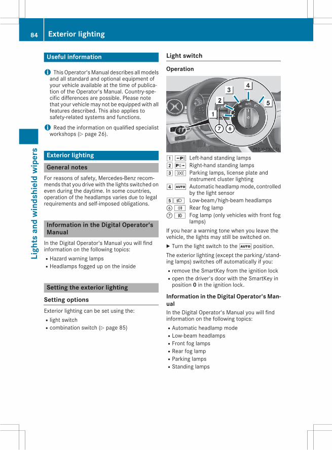
Useful information
i ThisOperator'sManual describes allmodelsand all standard and optional equipment ofyour vehicle available at the time of publica-tion of the Operator's Manual. Country-spe-cific differences are possible. Please notethat your vehicle may not be equipped with allfeatures described. This also applies tosafety-related systems and functions.
i Read the information on qualified specialistworkshops (Y page 26).
Exterior lighting
General notesFor reasons of safety, Mercedes-Benz recom-mends that you drive with the lights switched oneven during the daytime. In some countries,operation of the headlamps varies due to legalrequirements and self-imposed obligations.
Information in the Digital Operator'sManualIn the Digital Operator's Manual you will findinformation on the following topics:RHazard warning lampsRHeadlamps fogged up on the inside
Setting the exterior lighting
Setting optionsExterior lighting can be set using the:Rlight switchRcombination switch (Y page 85)
Light switch
Operation
1W Left-hand standing lamps2X Right-hand standing lamps3T Parking lamps, license plate and
instrument cluster lighting4Ã Automatic headlampmode, controlled
by the light sensor5L Low-beam/high-beam headlampsBR Rear fog lampCN Fog lamp (only vehicles with front fog
lamps)If you hear a warning tone when you leave thevehicle, the lights may still be switched on.X Turn the light switch to theà position.The exterior lighting (except the parking/stand-ing lamps) switches off automatically if you:Rremove the SmartKey from the ignition lockRopen the driver's door with the SmartKey inposition 0 in the ignition lock.
Information in the Digital Operator's Man-ualIn the Digital Operator's Manual you will findinformation on the following topics:RAutomatic headlamp modeRLow-beam headlampsRFront fog lampsRRear fog lampRParking lampsRStanding lamps
84 Exterior lightingLi
ghts
and
win
dshi
eld
wip
ers
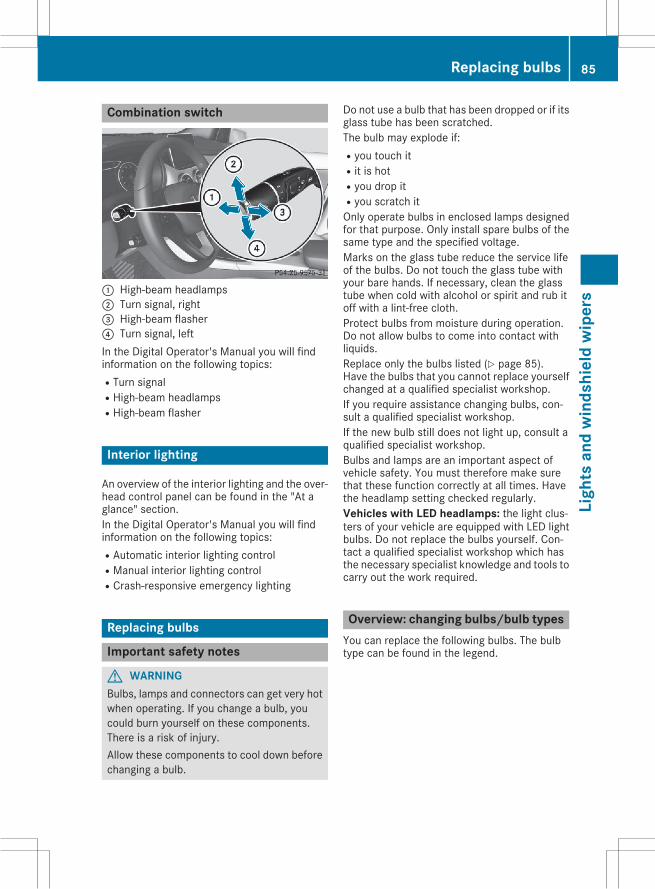
Combination switch
: High-beam headlamps; Turn signal, right= High-beam flasher? Turn signal, leftIn the Digital Operator's Manual you will findinformation on the following topics:RTurn signalRHigh-beam headlampsRHigh-beam flasher
Interior lighting
An overview of the interior lighting and the over-head control panel can be found in the "At aglance" section.In the Digital Operator's Manual you will findinformation on the following topics:RAutomatic interior lighting controlRManual interior lighting controlRCrash-responsive emergency lighting
Replacing bulbs
Important safety notes
G WARNINGBulbs, lamps and connectors can get very hotwhen operating. If you change a bulb, youcould burn yourself on these components.There is a risk of injury.Allow these components to cool down beforechanging a bulb.
Do not use a bulb that has been dropped or if itsglass tube has been scratched.The bulb may explode if:Ryou touch itRit is hotRyou drop itRyou scratch itOnly operate bulbs in enclosed lamps designedfor that purpose. Only install spare bulbs of thesame type and the specified voltage.Marks on the glass tube reduce the service lifeof the bulbs. Do not touch the glass tube withyour bare hands. If necessary, clean the glasstube when cold with alcohol or spirit and rub itoff with a lint-free cloth.Protect bulbs from moisture during operation.Do not allow bulbs to come into contact withliquids.Replace only the bulbs listed (Y page 85).Have the bulbs that you cannot replace yourselfchanged at a qualified specialist workshop.If you require assistance changing bulbs, con-sult a qualified specialist workshop.If the new bulb still does not light up, consult aqualified specialist workshop.Bulbs and lamps are an important aspect ofvehicle safety. You must therefore make surethat these function correctly at all times. Havethe headlamp setting checked regularly.Vehicles with LED headlamps: the light clus-ters of your vehicle are equipped with LED lightbulbs. Do not replace the bulbs yourself. Con-tact a qualified specialist workshop which hasthe necessary specialist knowledge and tools tocarry out the work required.
Overview: changing bulbs/bulb typesYou can replace the following bulbs. The bulbtype can be found in the legend.
Replacing bulbs 85
Ligh
tsan
dw
inds
hiel
dw
iper
s
Z
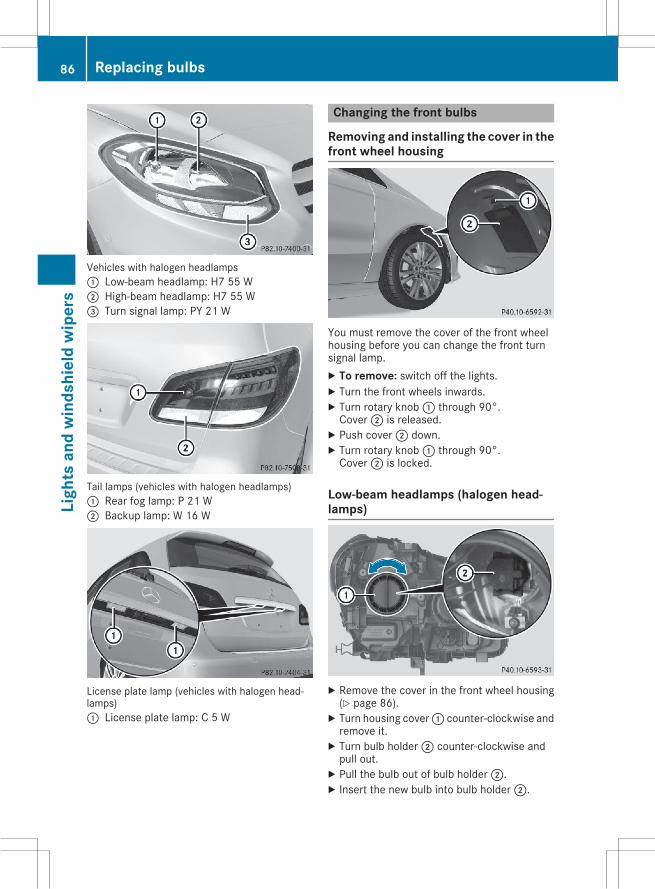
Vehicles with halogen headlamps: Low-beam headlamp: H7 55 W; High-beam headlamp: H7 55 W= Turn signal lamp: PY 21 W
Tail lamps (vehicles with halogen headlamps): Rear fog lamp: P 21 W; Backup lamp: W 16 W
License plate lamp (vehicles with halogen head-lamps): License plate lamp: C 5 W
Changing the front bulbs
Removing and installing the cover in thefront wheel housing
You must remove the cover of the front wheelhousing before you can change the front turnsignal lamp.X To remove: switch off the lights.X Turn the front wheels inwards.X Turn rotary knob: through 90°.Cover; is released.X Push cover; down.X Turn rotary knob: through 90°.Cover; is locked.
Low-beam headlamps (halogen head-lamps)
X Remove the cover in the front wheel housing(Y page 86).X Turn housing cover: counter-clockwise andremove it.X Turn bulb holder; counter-clockwise andpull out.X Pull the bulb out of bulb holder;.X Insert the new bulb into bulb holder;.
86 Replacing bulbsLi
ghts
and
win
dshi
eld
wip
ers
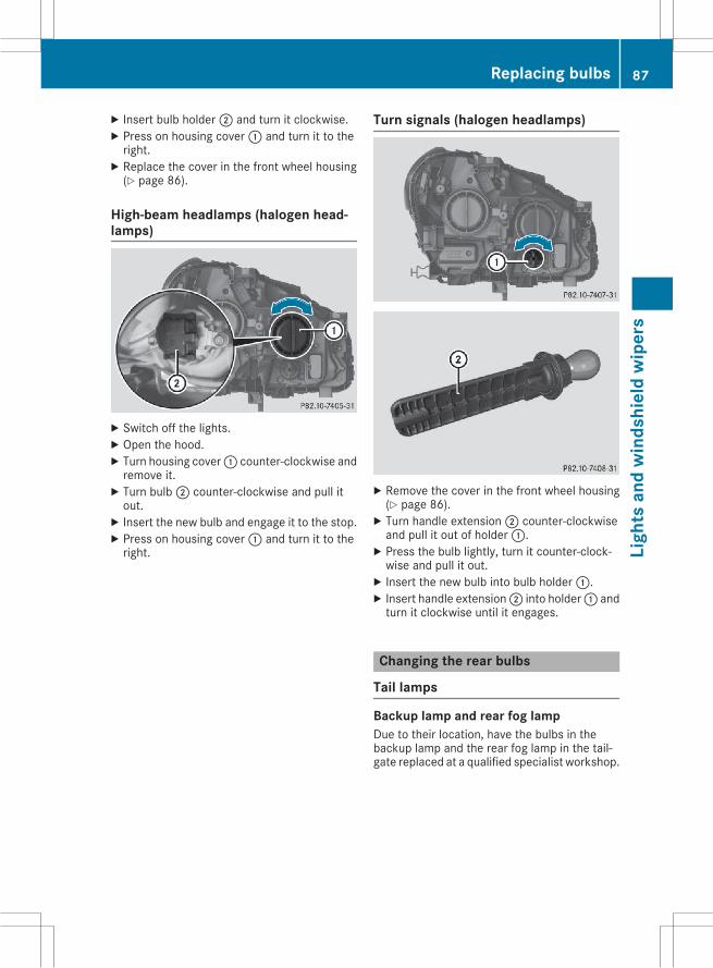
X Insert bulb holder; and turn it clockwise.X Press on housing cover: and turn it to theright.X Replace the cover in the front wheel housing(Y page 86).
High-beam headlamps (halogen head-lamps)
X Switch off the lights.X Open the hood.X Turn housing cover: counter-clockwise andremove it.X Turn bulb; counter-clockwise and pull itout.X Insert the new bulb and engage it to the stop.X Press on housing cover: and turn it to theright.
Turn signals (halogen headlamps)
X Remove the cover in the front wheel housing(Y page 86).X Turn handle extension; counter-clockwiseand pull it out of holder:.X Press the bulb lightly, turn it counter-clock-wise and pull it out.X Insert the new bulb into bulb holder:.X Insert handle extension; into holder: andturn it clockwise until it engages.
Changing the rear bulbs
Tail lamps
Backup lamp and rear fog lampDue to their location, have the bulbs in thebackup lamp and the rear fog lamp in the tail-gate replaced at a qualified specialist workshop.
Replacing bulbs 87
Ligh
tsan
dw
inds
hiel
dw
iper
s
Z
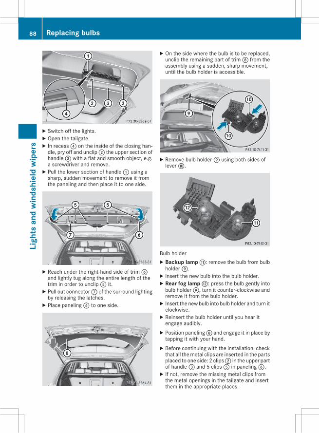
X Switch off the lights.X Open the tailgate.X In recess? on the inside of the closing han-dle, pry off and unclip; the upper section ofhandle= with a flat and smooth object, e.g.a screwdriver and remove.X Pull the lower section of handle: using asharp, sudden movement to remove it fromthe paneling and then place it to one side.
X Reach under the right-hand side of trimBand lightly tug along the entire length of thetrim in order to unclipA it.X Pull out connectorC of the surround lightingby releasing the latches.X Place panelingB to one side.
X On the side where the bulb is to be replaced,unclip the remaining part of trimD from theassembly using a sudden, sharp movement,until the bulb holder is accessible.
X Remove bulb holderE using both sides ofleverF.
Bulb holderX Backup lamp G: remove the bulb from bulbholderE.X Insert the new bulb into the bulb holder.X Rear fog lamp H: press the bulb gently intobulb holderE, turn it counter-clockwise andremove it from the bulb holder.X Insert the new bulb into bulb holder and turn itclockwise.X Reinsert the bulb holder until you hear itengage audibly.X Position panelingD and engage it in place bytapping it with your hand.X Before continuing with the installation, checkthat all themetal clips are inserted in the partsplaced to one side: 2 clips; in the upper partof handle= and 5 clipsA in panelingB.X If not, remove the missing metal clips fromthe metal openings in the tailgate and insertthem in the appropriate places.
88 Replacing bulbsLi
ghts
and
win
dshi
eld
wip
ers
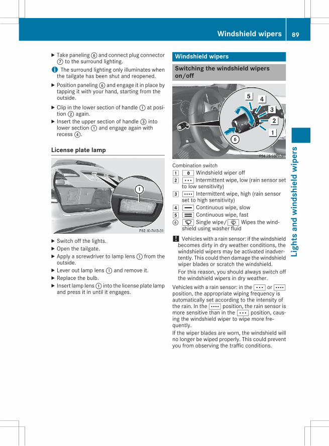
X Take panelingB and connect plug connectorC to the surround lighting.i The surround lighting only illuminates whenthe tailgate has been shut and reopened.X Position panelingB and engage it in place bytapping it with your hand, starting from theoutside.X Clip in the lower section of handle: at posi-tion; again.X Insert the upper section of handle= intolower section: and engage again withrecess?.
License plate lamp
X Switch off the lights.X Open the tailgate.X Apply a screwdriver to lamp lens: from theoutside.X Lever out lamp lens: and remove it.X Replace the bulb.X Insert lamp lens: into the license plate lampand press it in until it engages.
Windshield wipers
Switching the windshield wiperson/off
Combination switch1 $ Windshield wiper off2 Ä Intermittent wipe, low (rain sensor set
to low sensitivity)3 Å Intermittent wipe, high (rain sensor
set to high sensitivity)4 ° Continuous wipe, slow5 ¯ Continuous wipe, fastB í Single wipe/î Wipes the wind-
shield using washer fluid
! Vehicles with a rain sensor: if the windshieldbecomes dirty in dry weather conditions, thewindshield wipers may be activated inadver-tently. This could then damage the windshieldwiper blades or scratch the windshield.For this reason, you should always switch offthe windshield wipers in dry weather.
Vehicles with a rain sensor: in theÄ orÅposition, the appropriate wiping frequency isautomatically set according to the intensity ofthe rain. In theÅ position, the rain sensor ismore sensitive than in theÄ position, caus-ing the windshield wiper to wipe more fre-quently.If the wiper blades are worn, the windshield willno longer be wiped properly. This could preventyou from observing the traffic conditions.
Windshield wipers 89
Ligh
tsan
dw
inds
hiel
dw
iper
s
Z
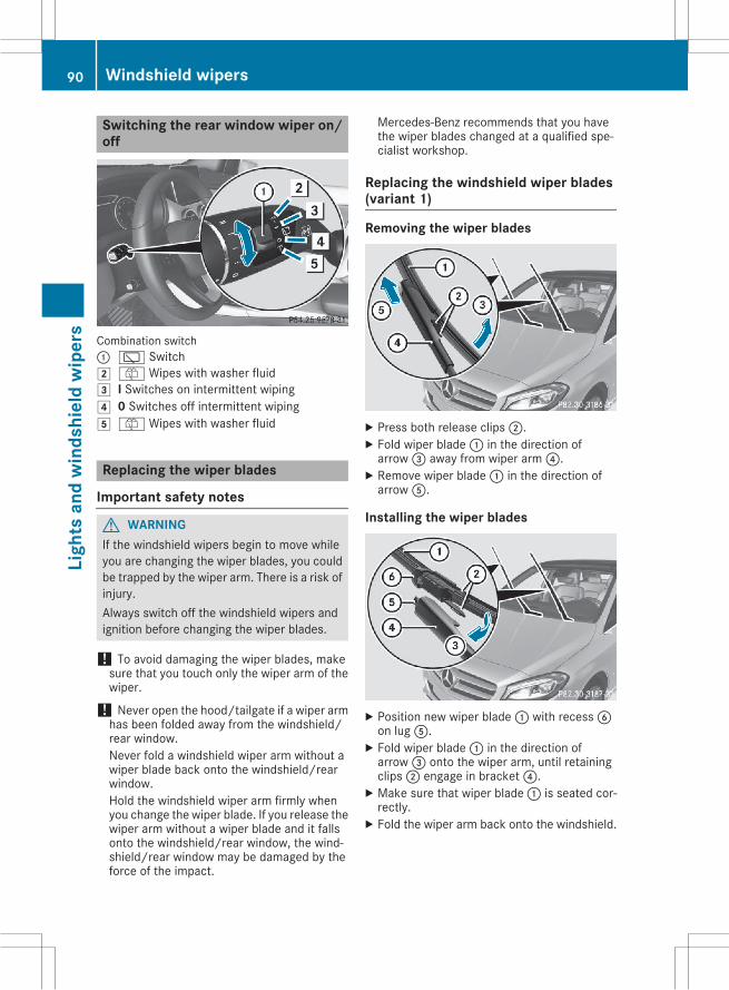
Switching the rear window wiper on/off
Combination switch: è Switch2 ô Wipes with washer fluid3 I Switches on intermittent wiping4 0 Switches off intermittent wiping5 ô Wipes with washer fluid
Replacing the wiper blades
Important safety notes
G WARNINGIf the windshield wipers begin to move whileyou are changing the wiper blades, you couldbe trapped by the wiper arm. There is a risk ofinjury.Always switch off the windshield wipers andignition before changing the wiper blades.
! To avoid damaging the wiper blades, makesure that you touch only the wiper arm of thewiper.
! Never open the hood/tailgate if a wiper armhas been folded away from the windshield/rear window.Never fold a windshield wiper arm without awiper blade back onto the windshield/rearwindow.Hold the windshield wiper arm firmly whenyou change the wiper blade. If you release thewiper arm without a wiper blade and it fallsonto the windshield/rear window, the wind-shield/rear window may be damaged by theforce of the impact.
Mercedes-Benz recommends that you havethe wiper blades changed at a qualified spe-cialist workshop.
Replacing the windshield wiper blades(variant 1)
Removing the wiper blades
X Press both release clips;.X Fold wiper blade: in the direction ofarrow= away from wiper arm?.X Remove wiper blade: in the direction ofarrowA.
Installing the wiper blades
X Position new wiper blade: with recessBon lugA.X Fold wiper blade: in the direction ofarrow= onto the wiper arm, until retainingclips; engage in bracket?.X Make sure that wiper blade: is seated cor-rectly.X Fold the wiper arm back onto the windshield.
90 Windshield wipersLi
ghts
and
win
dshi
eld
wip
ers
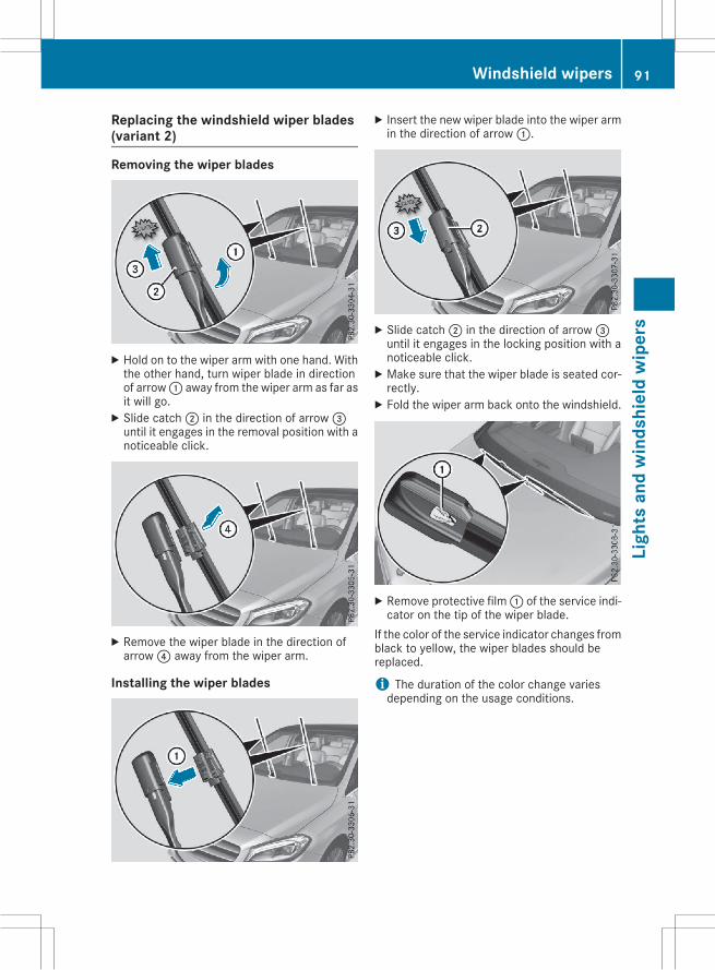
Replacing the windshield wiper blades(variant 2)
Removing the wiper blades
X Hold on to the wiper arm with one hand. Withthe other hand, turn wiper blade in directionof arrow: away from the wiper arm as far asit will go.X Slide catch; in the direction of arrow=until it engages in the removal position with anoticeable click.
X Remove the wiper blade in the direction ofarrow? away from the wiper arm.
Installing the wiper blades
X Insert the new wiper blade into the wiper armin the direction of arrow:.
X Slide catch; in the direction of arrow=until it engages in the locking position with anoticeable click.X Make sure that the wiper blade is seated cor-rectly.X Fold the wiper arm back onto the windshield.
X Remove protective film: of the service indi-cator on the tip of the wiper blade.
If the color of the service indicator changes fromblack to yellow, the wiper blades should bereplaced.
i The duration of the color change variesdepending on the usage conditions.
Windshield wipers 91
Ligh
tsan
dw
inds
hiel
dw
iper
s
Z
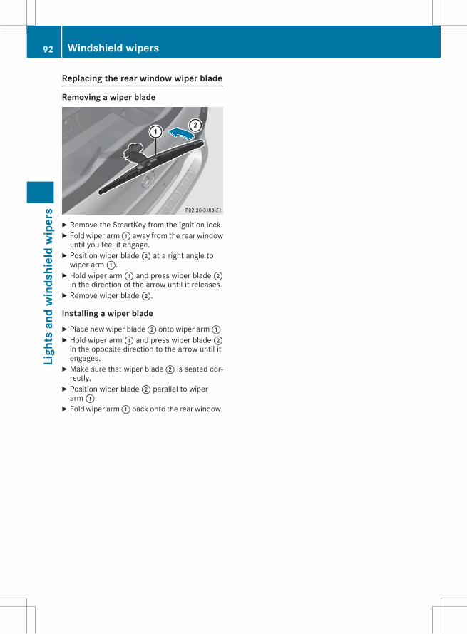
Replacing the rear window wiper blade
Removing a wiper blade
X Remove the SmartKey from the ignition lock.X Fold wiper arm: away from the rear windowuntil you feel it engage.X Position wiper blade; at a right angle towiper arm:.X Hold wiper arm: and press wiper blade;in the direction of the arrow until it releases.X Remove wiper blade;.
Installing a wiper bladeX Place new wiper blade; onto wiper arm:.X Hold wiper arm: and press wiper blade;in the opposite direction to the arrow until itengages.X Make sure that wiper blade; is seated cor-rectly.X Position wiper blade; parallel to wiperarm:.X Fold wiper arm: back onto the rear window.
92 Windshield wipersLi
ghts
and
win
dshi
eld
wip
ers
Problems with the windshield wipers
Problem Possible causes/consequences and M Solutions
The windshield wipersare jammed.
Leaves or snow, for example, may be obstructing the windshield wipermovement. The wiper motor has been deactivated.X For safety reasons, you should remove the SmartKey from the igni-tion lock.X Remove the cause of the obstruction.X Switch the windshield wipers back on.
The windshield wipersfail completely.
The windshield wiper drive is malfunctioning.X Select another wiper speed on the combination switch.X Have the windshield wipers checked at a qualified specialist work-shop.
The windshield washerfluid from the spray noz-zles no longer hits thecenter of the windshield.
The spray nozzles are misaligned.X Have the spray nozzles adjusted at a qualified specialist workshop.
Windshield wipers 93
Ligh
tsan
dw
inds
hiel
dw
iper
s
Z
Useful information
i ThisOperator'sManual describes allmodelsand all standard and optional equipment ofyour vehicle available at the time of publica-tion of the Operator's Manual. Country-spe-cific differences are possible. Please notethat your vehicle may not be equipped with allfeatures described. This also applies tosafety-related systems and functions.
i Read the information on qualified specialistworkshops (Y page 26).
Overview of climate control systems
General notesObserve the settings recommended on the fol-lowing pages. The windows could otherwise fogup.To prevent the windows from fogging up:Rswitch off climate control only brieflyRswitch on air-recirculation mode only brieflyRswitch on the cooling with air dehumidifica-tion function
Rswitch on the defrost windshield functionbriefly, if required
The air-conditioning system/dual-zone auto-matic climate control regulates the temperatureand the humidity of the vehicle interior and fil-ters out undesirable substances from the air.The air-conditioning system/dual-zone auto-matic climate control can only be operatedwhen the engine is running. Optimum operationis only achieved with the side windows and pan-orama roof with power tilt/sliding panel closed.If you start the engine using your smartphone,the last selected climate control setting is reac-tivated (Y page 107).The residual heat function can only be activatedor deactivated with the ignition switched off(Y page 96).Always keep the ventilation flaps behind theside paneling in the cargo compartment clear.Otherwise the vehicle will not be ventilated cor-rectly.
i Ventilate the vehicle for a brief period duringwarm weather, e.g. using the convenienceopening feature (Y page 75). This will speedup the cooling process and the desired inte-
rior temperature will be reached morequickly.
i The integrated filter filters out most parti-cles of dust and soot and completely filtersout pollen. It also reduces gaseous pollutantsand odors. A clogged filter reduces theamount of air supplied to the vehicle interior.For this reason, you should always observethe interval for replacing the filter, which isspecified in the Maintenance Booklet. As itdepends on environmental conditions, e.g.heavy air pollution, the interval may beshorter than stated in the Maintenance Book-let.
94 Overview of climate control systemsCl
imat
eco
ntro
l
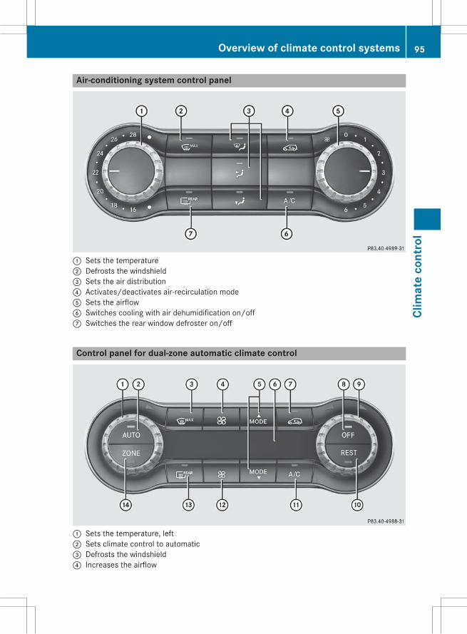
Air-conditioning system control panel
: Sets the temperature; Defrosts the windshield= Sets the air distribution? Activates/deactivates air-recirculation modeA Sets the airflowB Switches cooling with air dehumidification on/offC Switches the rear window defroster on/off
Control panel for dual-zone automatic climate control
: Sets the temperature, left; Sets climate control to automatic= Defrosts the windshield? Increases the airflow
Overview of climate control systems 95
Clim
ate
cont
rol
A Sets the air distributionB DisplayC Activates/deactivates air-recirculation modeD Switches climate control on/offE Sets the temperature, rightF Switches the residual heat function on/offG Switches cooling with air dehumidification on/offH Reduces the airflowI Switches the rear window defroster on/offJ Switches the ZONE function on/off
Operating the climate control sys-tems
In the Digital Operator's Manual you will findinformation on the following topics:RSwitching climate control on/offRSwitching cooling with air dehumidificationon/off
RSetting climate control to automaticRSetting the temperatureRSetting the air distributionRSetting the airflowRSwitching the ZONE function on/offRDefrosting the windshieldRDefrosting the windowsRSwitching the rear window defroster on/offRActivating/deactivating air-recirculationmode
RSwitching the residual heat function on/offRSetting the air vents
96 Operating the climate control systemsCl
imat
eco
ntro
l
Useful information
i ThisOperator'sManual describes allmodelsand all standard and optional equipment ofyour vehicle available at the time of publica-tion of the Operator's Manual. Country-spe-cific differences are possible. Please notethat your vehicle may not be equipped with allfeatures described. This also applies tosafety-related systems and functions.
i Read the information on qualified specialistworkshops (Y page 26).
Notes on breaking-in a new vehicle
Important safety notesThe sensor system of some driving and drivingsafety systems adjusts automatically while acertain distance is being driven after the vehiclehas been delivered or after repairs. Full systemeffectiveness is not reached until the end of thisteach-in procedure.New and replaced brake pads and discs onlyreach their optimum braking effect after severalhundred kilometers of driving. Compensate forthis by applying greater force to the brake pedal.
The first 1000 miles (1500 km)The more you look after the engine when it isnew, the more satisfied you will be with its per-formance in the future.RYou should therefore drive at varying vehicleand engine speeds for the first 1000 miles(1500 km).
RAvoid heavy loads, e.g. driving at full throttle,during this period.
RChange gear in good time, before the tach-ometer needle isÔ of the way to the red areaof the tachometer.
RDo not manually shift to a lower gear to brakethe vehicle.
RTry to avoid depressing the accelerator pedalbeyond the point of resistance (kickdown).
RIdeally, for the first 1000 miles (1500 km),drive in program E.
After 1,000 miles (1,500 km), you can increasethe engine speed gradually and bring the vehicleto full speed.
You should also observe these notes on break-ing-in if the engine or parts of the drive train onyour vehicle have been replaced.Always observe the maximum permissiblespeed.
Driving
Important safety notes
G WARNINGObjects in the driver's footwell can restrict thepedal travel or obstruct a depressed pedal.The operating and road safety of the vehicle isjeopardized. There is a risk of an accident.Make sure that all objects in the vehicle arestowed correctly, and that they cannot enterthe driver's footwell. Install the floormatssecurely and as specified in order to ensuresufficient clearance for the pedals. Do not useloose floormats and do not place floormats ontop of one another.
G WARNINGUnsuitable footwear can hinder correct usageof the pedals, e.g.:Rshoes with thick solesRshoes with high heelsRslippersThere is a risk of an accident.Wear suitable footwear to ensure correctusage of the pedals.
G WARNINGIf you switch off the ignition while driving,safety-relevant functions are only availablewith limitations, or not at all. This could affect,for example, the power steering and the brakeboosting effect. You will require considerablymore effort to steer and brake. There is a riskof an accident.Do not switch off the ignition while driving.
Driving 97
Driv
ing
and
park
ing
Z
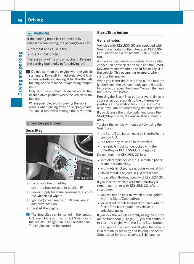
G WARNINGIf the parking brake has not been fullyreleased when driving, the parking brake can:Roverheat and cause a fireRlose its hold function.There is a risk of fire and an accident. Releasethe parking brake fully before driving off.
! Do not warm up the engine with the vehiclestationary. Drive off immediately. Avoid highengine speeds and driving at full throttle untilthe engine has reached its operating temper-ature.Only shift the automatic transmission to thedesired drive position when the vehicle is sta-tionary.Where possible, avoid spinning the drivewheels when pulling away on slippery roads.You could otherwise damage the drive train.
SmartKey positions
SmartKey
g To remove the SmartKey(shift the transmission to position P)
1 Power supply for some consumers, such asthe windshield wipers
2 Ignition (power supply for all consumers)and drive position
3 To start the engine
i The SmartKey can be turned in the ignitionlock even if it is not the correct SmartKey forthe vehicle. The ignition is not switched on.The engine cannot be started.
Start/Stop button
General notesVehicles with KEYLESS-GO are equipped withSmartKeys featuring the integrated KEYLESS-GO function and a detachable Start/Stop but-ton.A check which periodically establishes a radioconnection between the vehicle and the Smart-Key determines whether a valid SmartKey is inthe vehicle. This occurs, for example, whenstarting the engine.When you insert the Start/Stop button into theignition lock, the system needs approximatelytwo seconds recognition time. You can then usethe Start/Stop button.Pressing the Start/Stop button several times insuccession corresponds to the different keypositions in the ignition lock. This is only thecase if you are not depressing the brake pedal.If you depress the brake pedal and press theStart/Stop button, the engine starts immedi-ately.To start the vehicle without actively using theSmartKey:Rthe Start/Stop buttonmust be inserted in theignition lock.
Rthe SmartKey must be in the vehicle.Rthe vehicle must not be locked with theSmartKey or KEYLESS-GO (Y page 66).
Do not keep the KEYLESS-GO key:Rwith electronic devices, e.g. a mobile phoneor another SmartKey.
Rwith metallic objects, e.g. coins or metal foil.Rinside metallic objects, e.g. a metal case.This can affect the functionality of KEYLESS-GO.If you lock the vehicle with the SmartKey'sremote control or with KEYLESS-GO, after ashort time:Ryou will not be able to switch on the ignitionwith the Start/Stop button.
Ryouwill not be able to start the enginewith theStart/Stop button until the vehicle isunlocked again.
If you lock the vehicle centrally using the buttonon the front door (Y page 72), you can continueto start the engine with the Start/Stop button.The engine can be switched off while the vehicleis in motion by pressing and holding the Start/Stop button for three seconds. This function
98 DrivingDr
ivin
gan
dpa
rkin
g
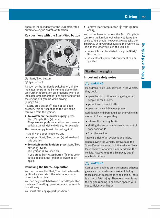
operates independently of the ECO start/stopautomatic engine switch-off function.
Key positions with the Start/Stop button
: Start/Stop button; Ignition lockAs soon as the ignition is switched on, all theindicator lamps in the instrument cluster lightup. Further information on situations where anindicator lamp either fails to go out after startingthe engine or lights up while driving(Y page 143).If Start/Stop button: has not yet beenpressed, this corresponds to the key beingremoved from the ignition.X To switch on the power supply: pressStart/Stop button: once.The power supply is switched on. You can nowactivate the windshield wipers, for example.
The power supply is switched off again if:Rthe driver's door is opened andRyou press Start/Stop button: twicewhen inthis positionX To switch on the ignition: press Start/Stopbutton: twice.The ignition is switched on.If you press Start/Stop button: once whenin this position, the ignition is switched offagain.
Removing the Start/Stop buttonYou can remove the Start/Stop button from theignition lock and start the vehicle as normalusing the SmartKey.You can only switch between Start/Stop buttonmode and SmartKey operation when the vehicleis stationary.You must also engage park position P.
X Remove Start/Stop button: from ignitionlock;.
You do not have to remove the Start/Stop but-ton from the ignition lock when you leave thevehicle. You should, however, always take theSmartKey with you when leaving the vehicle. Aslong as the SmartKey is in the vehicle:Rthe vehicle can be started using the Start/Stop button
Rthe electrically powered equipment can beoperated
Starting the engine
Important safety notes
G WARNINGIf children are left unsupervised in the vehicle,they could:Ropen the doors, thus endangering otherpeople or road users.
Rget out and disrupt traffic.Roperate the vehicle's equipment.Additionally, children could set the vehicle inmotion if, for example, they:Rrelease the parking brake.Rshifting the automatic transmission out ofpark position P
RStart the engine.There is a risk of an accident and injury.When leaving the vehicle, always take theSmartKeywith you and lock the vehicle. Neverleave children or animals unattended in thevehicle. Always keep the SmartKey out ofreach of children.
G WARNINGCombustion engines emit poisonous exhaustgases such as carbon monoxide. Inhalingthese exhaust gases leads to poisoning. Thereis a risk of fatal injury. Therefore never leavethe engine running in enclosed spaces with-out sufficient ventilation.
Driving 99
Driv
ing
and
park
ing
Z
G WARNINGFlammable materials introduced throughenvironmental influence or by animals canignite if in contact with the exhaust system orparts of the engine that heat up. There is a riskof fire.Carry out regular checks to make sure thatthere are no flammable foreign materials inthe engine compartment or in the exhaustsystem.
! Do not depress the accelerator when start-ing the engine.
General notesDuring a cold start, the engine runs at higherspeeds to enable the catalytic converter toreach its operating temperature. The sound ofthe engine may change during this time.
Automatic transmissionX Shift the transmission to position P. You canfind information about this in the Digital Oper-ator's Manual.The transmission position display in the mul-tifunction display shows P. You can find infor-mation about this in the Digital Operator'sManual.
i You can start the engine in transmissionposition P and N.
Starting procedure with the SmartKeyTo start the engine using the SmartKey insteadof the Start/Stop button, pull the Start/Stopbutton out of the ignition lock.X Turn the SmartKey to position3 in the ignitionlock and release it as soon as the engine isrunning (Y page 98).
Starting procedure with the Start/StopbuttonThe Start/Stop button can be used to start thevehiclemanually without inserting the SmartKeyinto the ignition lock. The Start/Stop buttonmust be inserted in the ignition lock and theSmartKey must be in the vehicle. This mode forstarting the engine operates independently of
the ECO start/stop automatic engine start func-tion.You can start the engine if a valid SmartKey is inthe vehicle. Switch off the engine and alwaystake the SmartKey with you when leaving thevehicle, even if you only leave it for a short time.Pay attention to the important safety notes.X Depress the brake pedal and keep itdepressed.X Press the Start/Stop button once(Y page 98).The engine starts.
Starting procedure via smartphoneObserve the important safety notes on startingthe engine (Y page 99).You can also start your engine via your smart-phone from outside the vehicle. In this case, thepreviously selected climate control setting isactivated. In this way you can cool or heat theinterior of the vehicle before starting the jour-ney.Only start the engine via your smartphone if it issafe to start and run the engine where your vehi-cle is parked.Observe the legal stipulations in the area whereyour vehicle is parked. Engine start via smart-phone may be limited to certain countries orregions.You can execute amaximum of two consecutivestarting attempts via your smartphone. If youinsert the key into the ignition lock, you cancarry out two more starting attempts.Once you have started the engine, you canswitch the engine off via your smartphone at anytime.You can only start the engine via your smart-phone if:Rthe key is in the ignition lockRpark position P is selectedRthe accelerator pedal is not depressedRthe anti-theft alarm system is not activatedRthe panic alarm is not activatedRthe hazard warning lamps are switched offRthe hood is closed.Rthe doors are closed and lockedRthe windows and sliding sunroof are closed
100 DrivingDr
ivin
gan
dpa
rkin
g
Also make sure that:Rthe fuel tank is sufficiently filledRthe starter battery is sufficiently charged
G WARNINGLimbs could be crushed or trapped if theengine is started unintentionally during ser-vice or maintenance work. There is a risk ofinjury.Always secure the engine against uninten-tional starting before carrying out mainte-nance or repair work.
Make sure that the engine cannot be started viayour smartphone before carrying out mainte-nance or repairs. You can prevent an enginestart via your smartphone, for example, if you:Rswitch on the hazard warning lampsRdo not lock the doorsRopen the hood.
Pulling away
General notes
G WARNINGIf the engine speed is above the idling speedand you engage transmission position D or R,the vehicle could pull away suddenly. There isa risk of an accident.When engaging transmission position D or R,always firmly depress the brake pedal and donot simultaneously accelerate.
Depress the accelerator carefully when pullingaway.The vehicle locks centrally once you have pulledaway. The locking knobs in the doors drop down.You can open the doors from the inside at anytime.You can also deactivate the automatic lockingfeature (Y page 131).It is only possible to shift the transmission fromposition P to the desired position if you depressthe brake pedal. Only then can the parking lockbe deactivated.If you do not depress the brake pedal, theDIRECT SELECT lever can still be moved but theparking lock remains engaged.
At transmission fluid temperatures below Ò4 ‡(Ò20†), you can only shift out of park position Pinto another transmission position when theengine is running.
i Upshifts take place at higher engine speedsafter a cold start. This helps the catalytic con-verter to reach its operating temperaturemore quickly.
Information on the automatic release of theelectric parking brake can be found in the DigitalOperator's Manual.
Hill start assistHill start assist helps you when pulling away for-wards or in reverse on an uphill gradient. It holdsthe vehicle for a short time after you haveremoved your foot from the brake pedal. Thisgives you enough time to move your foot fromthe brake pedal to the accelerator pedal and todepress it before the vehicle begins to roll.
G WARNINGAfter a short time, hill start assist will no lon-ger brake your vehicle and it could roll away.There is a risk of an accident and injury.Therefore, quickly move your foot from thebrake pedal to the accelerator pedal. Neverleave the vehicle when it is held by hill startassist.
Hill start assist is not active if:Ryou are pulling away on a level road or on adownhill gradient.
Rthe transmission is in position N.Rthe electric parking brake is applied.RESP® is malfunctioning.Further information on holding the vehicle sta-tionary on uphill gradients (Y page 104).
ECO start/stop function
IntroductionThe ECO start/stop function switches theengine off automatically if the vehicle is stoppedunder certain conditions.The engine starts automatically when the driverwants to pull away again. The ECO start/stop
Driving 101
Driv
ing
and
park
ing
Z
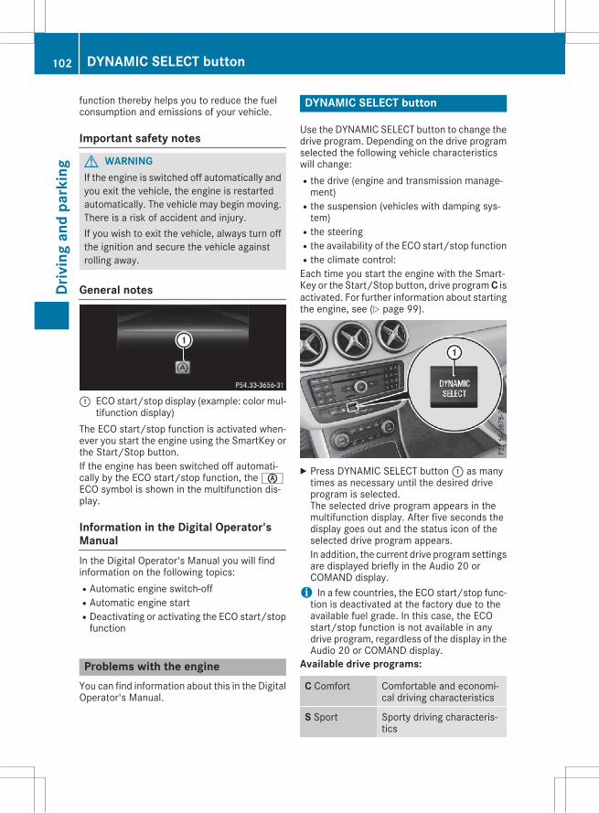
function thereby helps you to reduce the fuelconsumption and emissions of your vehicle.
Important safety notes
G WARNINGIf the engine is switched off automatically andyou exit the vehicle, the engine is restartedautomatically. The vehicle may begin moving.There is a risk of accident and injury.If you wish to exit the vehicle, always turn offthe ignition and secure the vehicle againstrolling away.
General notes
: ECO start/stop display (example: color mul-tifunction display)
The ECO start/stop function is activated when-ever you start the engine using the SmartKey orthe Start/Stop button.If the engine has been switched off automati-cally by the ECO start/stop function, theèECO symbol is shown in the multifunction dis-play.
Information in the Digital Operator'sManualIn the Digital Operator's Manual you will findinformation on the following topics:RAutomatic engine switch-offRAutomatic engine startRDeactivating or activating the ECO start/stopfunction
Problems with the engineYou can find information about this in the DigitalOperator's Manual.
DYNAMIC SELECT button
Use the DYNAMIC SELECT button to change thedrive program. Depending on the drive programselected the following vehicle characteristicswill change:Rthe drive (engine and transmission manage-ment)
Rthe suspension (vehicles with damping sys-tem)
Rthe steeringRthe availability of the ECO start/stop functionRthe climate control:Each time you start the engine with the Smart-Key or the Start/Stop button, drive programC isactivated. For further information about startingthe engine, see (Y page 99).
X Press DYNAMIC SELECT button: as manytimes as necessary until the desired driveprogram is selected.The selected drive program appears in themultifunction display. After five seconds thedisplay goes out and the status icon of theselected drive program appears.In addition, the current drive programsettingsare displayed briefly in the Audio 20 orCOMAND display.i In a few countries, the ECO start/stop func-tion is deactivated at the factory due to theavailable fuel grade. In this case, the ECOstart/stop function is not available in anydrive program, regardless of the display in theAudio 20 or COMAND display.
Available drive programs:
C Comfort Comfortable and economi-cal driving characteristics
S Sport Sporty driving characteris-tics
102 DYNAMIC SELECT buttonDr
ivin
gan
dpa
rkin
g
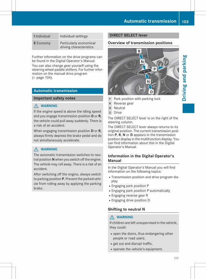
I Individual Individual settings
E Economy Particularly economicaldriving characteristics
Further information on the drive programs canbe found in the Digital Operator's Manual.You can also change gear yourself using thesteering wheel paddle shifters. For further infor-mation on the manual drive program(Y page 104).
Automatic transmission
Important safety notes
G WARNINGIf the engine speed is above the idling speedand you engage transmission position D or R,the vehicle could pull away suddenly. There isa risk of an accident.When engaging transmission position D or R,always firmly depress the brake pedal and donot simultaneously accelerate.
G WARNINGThe automatic transmission switches to neu-tral positionNwhen you switch off the engine.The vehicle may roll away. There is a risk of anaccident.After switching off the engine, always switchto parking positionP. Prevent the parked vehi-cle from rolling away by applying the parkingbrake.
DIRECT SELECT lever
Overview of transmission positions
j Park position with parking lockk Reverse geari Neutralh DriveThe DIRECT SELECT lever is on the right of thesteering column.The DIRECT SELECT lever always returns to itsoriginal position. The current transmission posi-tion P, R, N or D appears in the transmissionposition display in themultifunction display. Youcan find information about this in the DigitalOperator's Manual.
Information in the Digital Operator'sManualIn the Digital Operator's Manual you will findinformation on the following topics:RTransmission position and drive program dis-play
REngaging park position PREngaging park position P automaticallyREngaging reverse gear RREngaging drive position D
Shifting to neutral N
G WARNINGIf children are left unsupervised in the vehicle,they could:Ropen the doors, thus endangering otherpeople or road users.
Rget out and disrupt traffic.Roperate the vehicle's equipment.
Automatic transmission 103
Driv
ing
and
park
ing
Z
Additionally, children could set the vehicle inmotion if, for example, they:Rrelease the parking brake.Rshifting the automatic transmission out ofpark position P
RStart the engine.There is a risk of an accident and injury.When leaving the vehicle, always take theSmartKeywith you and lock the vehicle. Neverleave children or animals unattended in thevehicle. Always keep the SmartKey out ofreach of children.
X If the transmission is in position D or R: pushthe DIRECT SELECT lever up or down to thefirst point of resistance.X If the transmission is in position P: depressthe brake pedal and push the DIRECT SELECTlever up or down to the first point of resist-ance.
If you switch the engine off with the transmis-sion in position R or D, the automatic transmis-sion shifts to N automatically.With the SmartKey: if you then open the driv-er's door or the front-passenger door or removethe SmartKey from the ignition, the automatictransmission shifts to P automatically.With the Start/Stop button: if you then openthe driver's door or the front-passenger door,the automatic transmission shifts to P automat-ically.If you want the automatic transmission toremain in neutralN, e.g. when having the vehiclecleaned in an automatic car wash with a towingsystem:Using the SmartKey:X Switch on the ignition.X Depress the brake pedal and keep itdepressed.X Shift to neutral N.X Release the brake pedal.X Release the electric parking brake.X Switch off the ignition and leave the SmartKeyin the ignition lock.
With the Start/Stop button:X Remove the Start/Stop button from the igni-tion lock.X Insert the SmartKey into the ignition lock.X Switch on the ignition.X Depress the brake pedal and keep itdepressed.X Shift to neutral N.X Release the brake pedal.X Release the electric parking brake.X Switch off the ignition and leave the SmartKeyin the ignition lock.
Information in the Digital Operator'sManualIn the Digital Operator's Manual you will findinformation on the following topics:RTransmission positionsRDrive programsRManual gear shiftingRProblems with the transmission
Driving tips
Information in the Digital Operator'sManualIn the Digital Operator's Manual you will findinformation on the following topics:RChanging gearRAccelerator pedal positionRKickdownRRocking the vehicle free
Holding the vehicle stationary on uphillgradients
G WARNINGIf the clutch overheats, the electronic man-agement system is automatically deactivated.This interrupts the power transmission. Thevehicle may, for example, roll backwards ongradients. There is a risk of an accident.Never hold the vehicle stationary on uphillgradients by depressing the accelerator.
104 Automatic transmissionDr
ivin
gan
dpa
rkin
g
The clutch may overheat if you hold the vehiclestationary on uphill gradients by depressing theaccelerator pedal. If the clutch overheats, awarning tone sounds.The Stop Vehicle Shift to P LeaveEngine Running display message appears inthemultifunction display. Youwill only be able tocontinue your journey once the clutch hascooled down and the display message in themultifunction display has disappeared.Do not hold the vehicle stationary on uphill gra-dients by depressing the accelerator pedal.Instead, only ever hold the vehicle stationary onuphill gradients by:Rdepressing the brake pedalRactivating the HOLD functionRengaging the electric parking brake
Refueling
Important safety notes
G WARNINGFuel is highly flammable. If you handle fuelincorrectly, there is a risk of fire and explo-sion.You must avoid fire, open flames, creatingsparks and smoking. Switch off the engineand, if applicable, the auxiliary heating beforerefueling.
G WARNINGFuel is poisonous and hazardous to health.There is a risk of injury.You must make sure that fuel does not comeinto contact with your skin, eyes or clothingand that it is not swallowed. Do not inhale fuelvapors. Keep fuel away from children.If you or others come into contact with fuel,observe the following:RWash away fuel from skin immediatelyusing soap and water.
RIf fuel comes into contact with your eyes,immediately rinse them thoroughly withclean water. Seek medical assistance with-out delay.
RIf fuel is swallowed, seek medical assis-tance without delay. Do not induce vomit-ing.
RImmediately change out of clothing whichhas come into contact with fuel.
G WARNINGElectrostatic buildup can create sparks andignite fuel vapors. There is a risk of fire andexplosion.Always touch the vehicle body before openingthe fuel filler flap or touching the fuel pumpnozzle. Any existing electrostatic buildup isthereby discharged.
! Do not use diesel to refuel vehicles with agasoline engine. Do not switch on the ignitionif you accidentally refuel with the wrong fuel.Otherwise, the fuel will enter the fuel system.Even small amounts of the wrong fuel couldresult in damage to the fuel system and theengine. Notify a qualified specialist workshopand have the fuel tank and fuel lines drainedcompletely.
! Overfilling the fuel tank could damage thefuel system.
! Take care not to spill any fuel on paintedsurfaces. You could otherwise damage thepaintwork.
! Use a filter when refueling from a fuel can.Otherwise, the fuel lines and/or injection sys-tem could be blocked by particles from thefuel can.
Do not get into the vehicle again during the refu-eling process. Otherwise, electrostatic chargecould build up again.If you overfill the fuel tank, fuel could spray outwhen the fuel pump nozzle is removed.For further information on fuel and fuel quality(Y page 233).
Refueling
General informationThe fuel filler flap is unlocked/locked automat-ically when you unlock/lock the vehicle with theSmartKey.
Refueling 105
Driv
ing
and
park
ing
Z
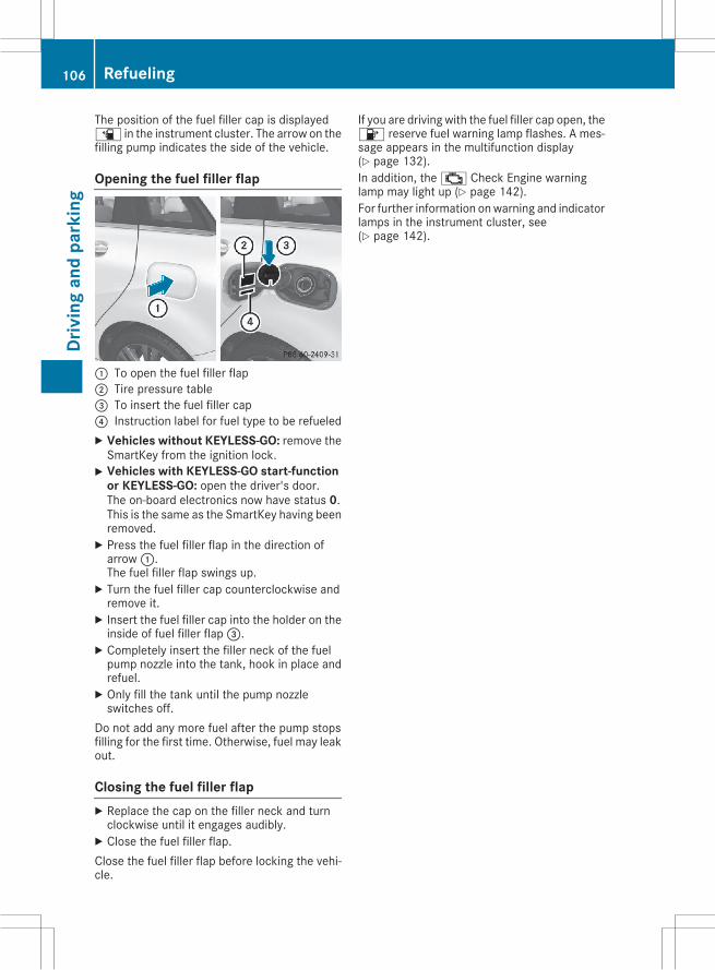
The position of the fuel filler cap is displayedæ in the instrument cluster. The arrow on thefilling pump indicates the side of the vehicle.
Opening the fuel filler flap
: To open the fuel filler flap; Tire pressure table= To insert the fuel filler cap? Instruction label for fuel type to be refueledX Vehicles without KEYLESS-GO: remove theSmartKey from the ignition lock.X Vehicles with KEYLESS-GO start-function
or KEYLESS-GO: open the driver's door.The on-board electronics now have status 0.This is the same as the SmartKey having beenremoved.X Press the fuel filler flap in the direction ofarrow:.The fuel filler flap swings up.X Turn the fuel filler cap counterclockwise andremove it.X Insert the fuel filler cap into the holder on theinside of fuel filler flap=.X Completely insert the filler neck of the fuelpump nozzle into the tank, hook in place andrefuel.X Only fill the tank until the pump nozzleswitches off.
Do not add any more fuel after the pump stopsfilling for the first time. Otherwise, fuel may leakout.
Closing the fuel filler flapX Replace the cap on the filler neck and turnclockwise until it engages audibly.X Close the fuel filler flap.Close the fuel filler flap before locking the vehi-cle.
If you are driving with the fuel filler cap open, the8 reserve fuel warning lamp flashes. A mes-sage appears in the multifunction display(Y page 132).In addition, the; Check Engine warninglamp may light up (Y page 142).For further information onwarning and indicatorlamps in the instrument cluster, see(Y page 142).
106 RefuelingDr
ivin
gan
dpa
rkin
g
Problems with fuel and the fuel tankThis section provides descriptions of and solutions to safety-relevant problems. Descriptions of andsolutions to further problems can be found in the Digital Operator's Manual.
Problem Possible causes/consequences and M Solutions
Fuel is leaking from thevehicle.
The fuel line or the fuel tank is faulty.
G WARNINGRisk of explosion or fire.X Turn the SmartKey to position 0 immediately and remove it(Y page 98).X Do not restart the engine under any circumstances.X Consult a qualified specialist workshop.
Parking
Important safety notes
G WARNINGFlammable material such as leaves, grass ortwigsmay ignite if they come into contactwithhot parts of the exhaust system or exhaustgas flow. There is a risk of fire.Park the vehicle so that no flammable mate-rials come into contact with parts of the vehi-cle which are hot. Take particular care not topark on dry grassland or harvested grainfields.
G WARNINGIf you leave children unsupervised in the vehi-cle, they could set it inmotion by, for example:Rrelease the parking brake.Rshift the automatic transmission out of theparking position P.
Rstart the engine.In addition, they may operate vehicle equip-ment and become trapped. There is a risk ofan accident and injury.When leaving the vehicle, always take theSmartKeywith you and lock the vehicle. Neverleave children unsupervised in the vehicle.
! Always secure the vehicle correctly againstrolling away. Otherwise, the vehicle or its driv-etrain could be damaged.
To ensure that the vehicle is secured againstrolling away unintentionally:Rthe electric parking brake must be applied.Rthe transmissionmust be in positionP and thetransmission position display must show P.
Rthe SmartKey must be removed from the igni-tion lock.
Ron uphill or downhill gradients, the frontwheels must be turned towards the curb.
Switching off the engine
Important safety notes
G WARNINGThe automatic transmission switches to neu-tral positionNwhen you switch off the engine.The vehicle may roll away. There is a risk of anaccident.After switching off the engine, always switchto parking positionP. Prevent the parked vehi-cle from rolling away by applying the parkingbrake.
Information in the Digital Operator'sManualA description of how to switch off the engine canbe found in the Digital Operator's Manual.
Parking 107
Driv
ing
and
park
ing
Z
Electric parking brake
General notes
G WARNINGIf you leave children unsupervised in the vehi-cle, they could set it inmotion by, for example:Rrelease the parking brake.Rshift the automatic transmission out of theparking position P.
Rstart the engine.In addition, they may operate vehicle equip-ment and become trapped. There is a risk ofan accident and injury.When leaving the vehicle, always take theSmartKeywith you and lock the vehicle. Neverleave children unsupervised in the vehicle.
The function of the electric parking brake isdependent on the on-board voltage. If the on-board voltage is low or there is a malfunction inthe system, it may not be possible to apply thereleased parking brake.X If this is the case, only park the vehicle onlevel ground and secure it to prevent it rollingaway.X Shift the automatic transmission to position
P.It may not be possible to release an appliedparking brake if the on-board voltage is low orthere is a malfunction in the system. Contact aqualified specialist workshop.The electric parking brake performs a functiontest at regular intervals while the engine isswitched off. The sounds that can be heardwhilethis is occurring are normal.
Information in the Digital Operator'sManualIn the Digital Operator's Manual you will findinformation on the following topics:RApplying or releasing manuallyRApplying automaticallyRReleasing automaticallyREmergency braking
Parking the vehicle for a long periodYou can find information about this in the DigitalOperator's Manual.
Driving tips
General notes
Important safety notes
G WARNINGIf you switch off the ignition while driving,safety-relevant functions are only availablewith limitations, or not at all. This could affect,for example, the power steering and the brakeboosting effect. You will require considerablymore effort to steer and brake. There is a riskof an accident.Do not switch off the ignition while driving.
G WARNINGIf you operate mobile communication equip-ment while driving, you will be distracted fromtraffic conditions. You could also lose controlof the vehicle. There is a risk of an accident.Only operate this equipment when the vehicleis stationary.
Observe the legal requirements for the countryin which you are driving. Some jurisdictions pro-hibit the driver from using a mobile phone whiledriving a vehicle.If you make a call while driving, always usehands-free mode. Only operate the telephonewhen the traffic situation permits. If you areunsure, pull over to a safe location and stopbefore operating the telephone.Bear in mind that at a speed of only 30 mph(approximately 50 km/h), the vehicle covers adistance of 44 ft (approximately 14 m) per sec-ond.
Drive sensibly – save fuelObserve the following tips to save fuel:RThe tires should always be inflated to the rec-ommended tire pressure.
RRemove unnecessary loads.RRemove roof racks when they are not needed.
108 Driving tipsDr
ivin
gan
dpa
rkin
g
RWarm up the engine at low engine speeds.RAvoid frequent acceleration or braking.RHave all maintenance work carried out asindicated by the service intervals in the Main-tenance Booklet or by the service interval dis-play.
Fuel consumption also increaseswhen driving incold weather, in stop-start traffic and in hilly ter-rain.
Drinking and driving
G WARNINGDrinking and driving and/or taking drugs anddriving are very dangerous combinations.Even a small amount of alcohol or drugs canaffect your reflexes, perceptions and judg-ment.The possibility of a serious or even fatal acci-dent is greatly increased when you drink ortake drugs and drive.Do not drink or take drugs and drive or allowanyone to drive who has been drinking or tak-ing drugs.
Emission control
G WARNINGCombustion engines emit poisonous exhaustgases such as carbon monoxide. Inhalingthese exhaust gases leads to poisoning. Thereis a risk of fatal injury. Therefore never leavethe engine running in enclosed spaces with-out sufficient ventilation.
Certain engine systems are designed to keepthe level of poisonous components in exhaustfumes within legal limits.These systems only work at peak efficiency ifthey are serviced exactly in accordance with themanufacturer's specifications. Always havework on the engine carried out at a qualifiedspecialist workshop. Mercedes-Benz recom-mends that you use an authorized Mercedes-Benz Center for this purpose. In particular, workrelevant to safety or on safety-related systemsmust be carried out at a qualified specialistworkshop.The engine settings must not be changed underany circumstances. Furthermore, all specific
service work must be carried out at regularintervals and in accordance with the Mercedes-Benz service requirements. Details can be foundin the Maintenance Booklet.
ECO display
Vehicles with a black and white multi-function displayYou can find information about this in the DigitalOperator's Manual.
Vehicles with a color multifunction dis-playYou can find information about this in the DigitalOperator's Manual.
Braking
Important safety notes
G WARNINGIf you shift down on a slippery road surface inan attempt to increase the engine's brakingeffect, the drive wheels could lose their grip.There is an increased danger of skidding andaccidents.Do not shift down for additional engine brak-ing on a slippery road surface.
Downhill gradientsYou can find information about this in the DigitalOperator's Manual.
Heavy and light loads
G WARNINGIf you rest your foot on the brake pedal whiledriving, the braking system can overheat. Thisincreases the stopping distance and can evencause the braking system to fail. There is arisk of an accident.Never use the brake pedal as a footrest. Neverdepress the brake pedal and the acceleratorpedal at the same time.
Driving tips 109
Driv
ing
and
park
ing
Z
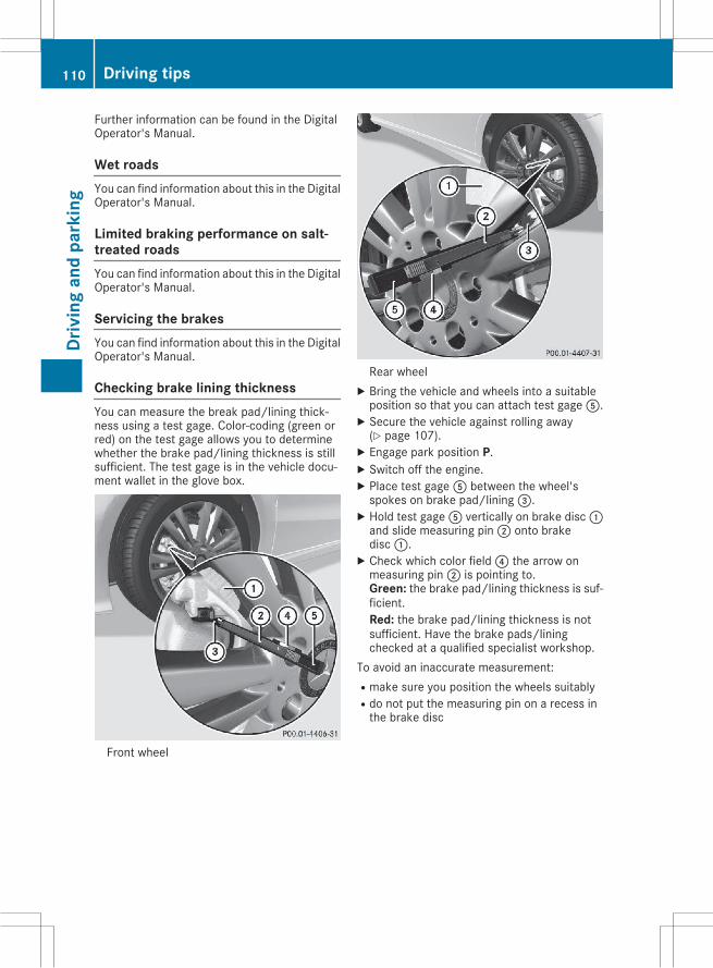
Further information can be found in the DigitalOperator's Manual.
Wet roadsYou can find information about this in the DigitalOperator's Manual.
Limited braking performance on salt-treated roadsYou can find information about this in the DigitalOperator's Manual.
Servicing the brakesYou can find information about this in the DigitalOperator's Manual.
Checking brake lining thicknessYou can measure the break pad/lining thick-ness using a test gage. Color-coding (green orred) on the test gage allows you to determinewhether the brake pad/lining thickness is stillsufficient. The test gage is in the vehicle docu-ment wallet in the glove box.
Front wheel
Rear wheelX Bring the vehicle and wheels into a suitableposition so that you can attach test gageA.X Secure the vehicle against rolling away(Y page 107).X Engage park position P.X Switch off the engine.X Place test gageA between the wheel'sspokes on brake pad/lining=.X Hold test gageA vertically on brake disc:and slide measuring pin; onto brakedisc:.X Check which color field? the arrow onmeasuring pin; is pointing to.Green: the brake pad/lining thickness is suf-ficient.Red: the brake pad/lining thickness is notsufficient. Have the brake pads/liningchecked at a qualified specialist workshop.
To avoid an inaccurate measurement:Rmake sure you position the wheels suitablyRdo not put the measuring pin on a recess inthe brake disc
110 Driving tipsDr
ivin
gan
dpa
rkin
g
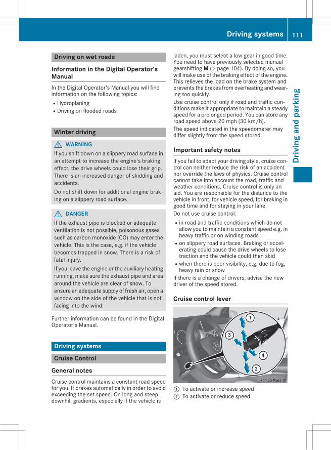
Driving on wet roads
Information in the Digital Operator'sManualIn the Digital Operator's Manual you will findinformation on the following topics:RHydroplaningRDriving on flooded roads
Winter driving
G WARNINGIf you shift down on a slippery road surface inan attempt to increase the engine's brakingeffect, the drive wheels could lose their grip.There is an increased danger of skidding andaccidents.Do not shift down for additional engine brak-ing on a slippery road surface.
G DANGERIf the exhaust pipe is blocked or adequateventilation is not possible, poisonous gasessuch as carbon monoxide (CO) may enter thevehicle. This is the case, e.g. if the vehiclebecomes trapped in snow. There is a risk offatal injury.If you leave the engine or the auxiliary heatingrunning, make sure the exhaust pipe and areaaround the vehicle are clear of snow. Toensure an adequate supply of fresh air, open awindow on the side of the vehicle that is notfacing into the wind.
Further information can be found in the DigitalOperator's Manual.
Driving systems
Cruise Control
General notesCruise control maintains a constant road speedfor you. It brakes automatically in order to avoidexceeding the set speed. On long and steepdownhill gradients, especially if the vehicle is
laden, you must select a low gear in good time.You need to have previously selected manualgearshifting M (Y page 104). By doing so, youwill make use of the braking effect of the engine.This relieves the load on the brake system andprevents the brakes from overheating and wear-ing too quickly.Use cruise control only if road and traffic con-ditions make it appropriate to maintain a steadyspeed for a prolonged period. You can store anyroad speed above 20 mph (30 km/h).The speed indicated in the speedometer maydiffer slightly from the speed stored.
Important safety notesIf you fail to adapt your driving style, cruise con-trol can neither reduce the risk of an accidentnor override the laws of physics. Cruise controlcannot take into account the road, traffic andweather conditions. Cruise control is only anaid. You are responsible for the distance to thevehicle in front, for vehicle speed, for braking ingood time and for staying in your lane.Do not use cruise control:Rin road and traffic conditions which do notallow you to maintain a constant speed e.g. inheavy traffic or on winding roads
Ron slippery road surfaces. Braking or accel-erating could cause the drive wheels to losetraction and the vehicle could then skid
Rwhen there is poor visibility, e.g. due to fog,heavy rain or snow
If there is a change of drivers, advise the newdriver of the speed stored.
Cruise control lever
: To activate or increase speed; To activate or reduce speed
Driving systems 111
Driv
ing
and
park
ing
Z
= To deactivate cruise control? To activate at the current speed/last stored
speedWhen you activate cruise control, the storedspeed is shown in the multifunction display forfive seconds.
Activation conditionsTo activate cruise control, all of the followingactivation conditions must be fulfilled:Rthe electric parking brake must be released.RESP® must be active, but not intervening.Rthe transmission must be in position D.
Storing, maintaining and calling up aspeed
Storing and maintaining the currentspeedYou can store the current speed if you are driv-ing faster than 20 mph (30 km/h).X Accelerate the vehicle to the desired speed.X Briefly press the cruise control lever up: ordown?.X Remove your foot from the accelerator pedal.Cruise control is activated. The vehicle auto-matically maintains the stored speed.i Cruise control may be unable to maintainthe stored speed on uphill gradients. Thestored speed is resumed when the gradientevens out. Cruise control maintains thestored speed on downhill gradients by auto-matically applying the brakes.
Storing the current speed or calling up thelast stored speedG WARNINGIf you call up the stored speed and it differsfrom the current speed, the vehicle acceler-ates or decelerates. If you do not know thestored speed, the vehicle could accelerate orbrake unexpectedly. There is a risk of an acci-dent.Pay attention to the road and traffic condi-tions before calling up the stored speed. If youdo not know the stored speed, store thedesired speed again.
X Briefly pull the cruise control lever towardsyou=.X Remove your foot from the accelerator pedal.The first time cruise control is activated, itstores the current speed or regulates thespeed of the vehicle to the previously storedspeed.
Setting a speedKeep in mind that it may take a brief momentuntil the vehicle has accelerated or braked tothe speed set.X Press the cruise control lever up: for ahigher speed or down? for a lower speed.X To adjust the set speed in 1 mph incre-
ments (1 km/h increments): briefly pressthe cruise control lever up: or down? tothe pressure point.The last stored speed increases or decreasesin 1 mph (1 km/h) increments.X To adjust the set speed in 5 mph incre-
ments (10 km/h increments): briefly pressthe cruise control lever up: or down? tothe pressure point.The last stored speed increases or decreasesin 5 mph (10 km/h) increments.i Cruise control is not deactivated if youdepress the accelerator pedal. For example, ifyou accelerate briefly to overtake, cruise con-trol adjusts the vehicle's speed to the lastspeed stored after you have finished overtak-ing.
Deactivating cruise controlThere are several ways to deactivate cruise con-trol:X Briefly press the cruise control lever forwards=.
orX Brake.Cruise control is automatically deactivated if:Rthe vehicle is secured with the electric park-ing brake
Ryou are driving at less than 20mph (30 km/h)RESP® intervenes or you deactivate ESP®Ryou shift the transmission to position N whiledriving
If cruise control is deactivated, you will hear awarning tone. You will see the Cruise conх
112 Driving systemsDr
ivin
gan
dpa
rkin
g
trol Offtrol Offmessage in the multifunction displayfor approximately five seconds.
i When you switch off the engine, the lastspeed stored is cleared.
DISTRONIC PLUS
General notesDISTRONIC PLUS regulates the speed and auto-matically helps you maintain the distance to thevehicle detected in front. Vehicles are detectedwith the aid of the radar sensor system.DISTRONIC PLUS brakes automatically to avoidexceeding the set speed or to maintain the des-ignated distance from the vehicle in front.Change into a lower gear in good time on longand steep downhill gradients. This is especiallyimportant if the vehicle is laden. By doing so, youwill make use of the braking effect of the engine.This relieves the load on the brake system andprevents the brakes from overheating and wear-ing too quickly.If DISTRONIC PLUS detects that there is a risk ofa collision, you will be warned visually andacoustically. DISTRONIC PLUS cannot prevent acollision without your intervention. An intermit-tent warning tone will then sound and the dis-tance warning lamp will light up in the instru-ment cluster. Brake immediately in order toincrease the distance to the vehicle in front ortake evasive action provided it is safe to do so.DISTRONIC PLUS operates in range between0 mph (0 km/h) and 120 mph (200 km/h).Do not use DISTRONIC PLUS while driving onroads with steep gradients.
Important safety notes
G WARNINGDISTRONIC PLUS does not react to:Rpeople or animalsRstationary obstacles on the road, e.g. stop-ped or parked vehicles
Roncoming and crossing trafficAs a result, DISTRONIC PLUSmay neither givewarnings nor intervene in such situations.There is a risk of an accident.
Always pay careful attention to the traffic sit-uation and be ready to brake.
G WARNINGDISTRONIC PLUS cannot always clearly iden-tify other road users and complex traffic sit-uations.In such cases, DISTRONIC PLUS may:Rgive an unnecessary warning and thenbrake the vehicle
Rneither give a warning nor interveneRaccelerate or brake unexpectedlyThere is a risk of an accident.Continue to drive carefully and be ready tobrake, in particular when warned to do so byDISTRONIC PLUS.
G WARNINGDISTRONIC PLUS brakes your vehicle with upto 50% of themaximumpossible deceleration.If this braking force is insufficient, DISTRONICPLUS warns you visually and audibly. There isa risk of an accident.In such cases, apply the brakes yourself andtry to take evasive action.
! If DISTRONIC PLUS or the HOLD function isactivated, the vehicle brakes automatically incertain situations.To prevent damage to the vehicle, deactivateDISTRONIC PLUS and the HOLD function inthe following or other similar situations:Rwhen towing the vehicleRin the car wash
If you fail to adapt your driving style, DISTRONICPLUS can neither reduce the risk of accident noroverride the laws of physics. DISTRONIC PLUScannot take into account the road, traffic andweather conditions. DISTRONIC PLUS is only anaid. You are responsible for the distance to thevehicle in front, for vehicle speed, for braking ingood time and for staying in your lane.
Driving systems 113
Driv
ing
and
park
ing
Z
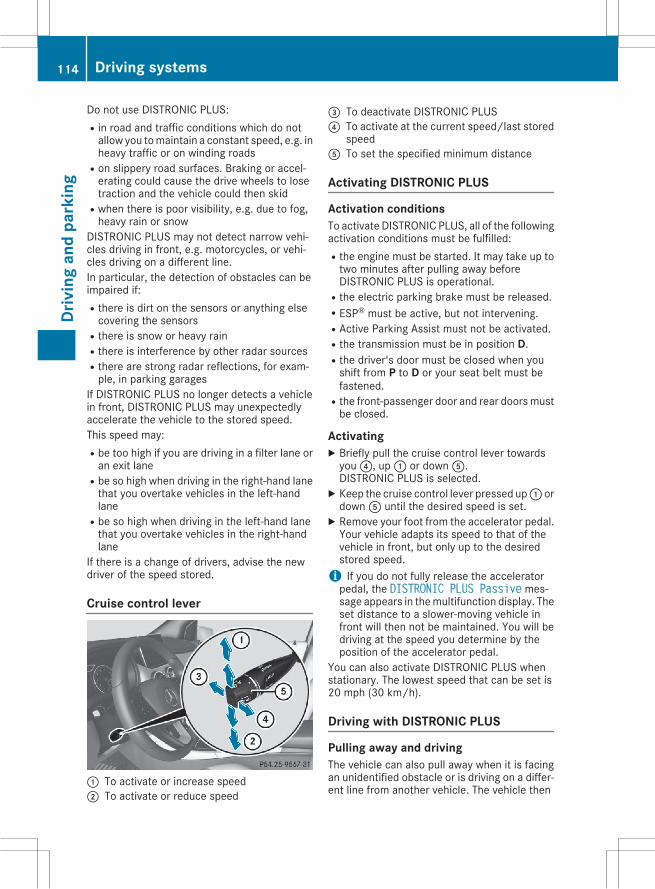
Do not use DISTRONIC PLUS:Rin road and traffic conditions which do notallow you tomaintain a constant speed, e.g. inheavy traffic or on winding roads
Ron slippery road surfaces. Braking or accel-erating could cause the drive wheels to losetraction and the vehicle could then skid
Rwhen there is poor visibility, e.g. due to fog,heavy rain or snow
DISTRONIC PLUS may not detect narrow vehi-cles driving in front, e.g. motorcycles, or vehi-cles driving on a different line.In particular, the detection of obstacles can beimpaired if:Rthere is dirt on the sensors or anything elsecovering the sensors
Rthere is snow or heavy rainRthere is interference by other radar sourcesRthere are strong radar reflections, for exam-ple, in parking garages
If DISTRONIC PLUS no longer detects a vehiclein front, DISTRONIC PLUS may unexpectedlyaccelerate the vehicle to the stored speed.This speed may:Rbe too high if you are driving in a filter lane oran exit lane
Rbe so high when driving in the right-hand lanethat you overtake vehicles in the left-handlane
Rbe so high when driving in the left-hand lanethat you overtake vehicles in the right-handlane
If there is a change of drivers, advise the newdriver of the speed stored.
Cruise control lever
: To activate or increase speed; To activate or reduce speed
= To deactivate DISTRONIC PLUS? To activate at the current speed/last stored
speedA To set the specified minimum distance
Activating DISTRONIC PLUS
Activation conditionsTo activate DISTRONIC PLUS, all of the followingactivation conditions must be fulfilled:Rthe engine must be started. It may take up totwo minutes after pulling away beforeDISTRONIC PLUS is operational.
Rthe electric parking brake must be released.RESP® must be active, but not intervening.RActive Parking Assist must not be activated.Rthe transmission must be in position D.Rthe driver's door must be closed when youshift from P to D or your seat belt must befastened.
Rthe front-passenger door and rear doorsmustbe closed.
ActivatingX Briefly pull the cruise control lever towardsyou?, up: or downA.DISTRONIC PLUS is selected.X Keep the cruise control lever pressed up: ordownA until the desired speed is set.X Remove your foot from the accelerator pedal.Your vehicle adapts its speed to that of thevehicle in front, but only up to the desiredstored speed.i If you do not fully release the acceleratorpedal, the DISTRONIC PLUS Passive mes-sage appears in themultifunction display. Theset distance to a slower-moving vehicle infront will then not be maintained. You will bedriving at the speed you determine by theposition of the accelerator pedal.
You can also activate DISTRONIC PLUS whenstationary. The lowest speed that can be set is20 mph (30 km/h).
Driving with DISTRONIC PLUS
Pulling away and drivingThe vehicle can also pull away when it is facingan unidentified obstacle or is driving on a differ-ent line from another vehicle. The vehicle then
114 Driving systemsDr
ivin
gan
dpa
rkin
g
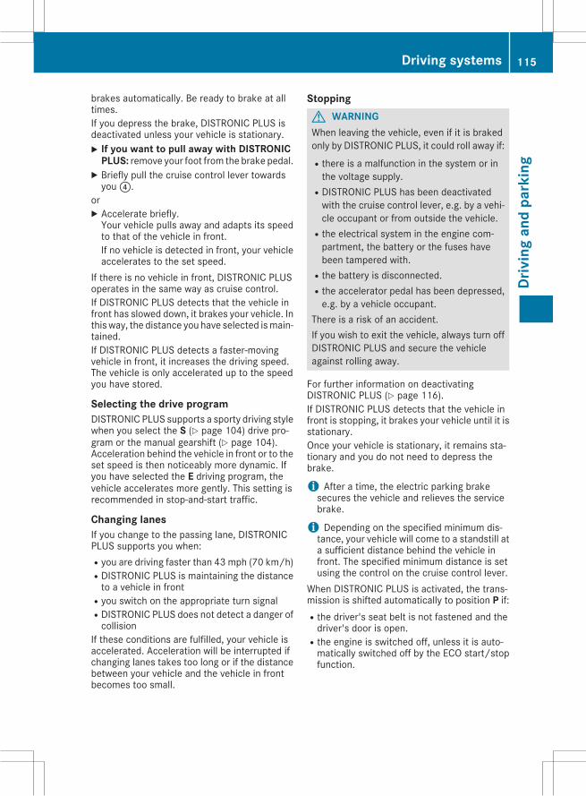
brakes automatically. Be ready to brake at alltimes.If you depress the brake, DISTRONIC PLUS isdeactivated unless your vehicle is stationary.X If you want to pull away with DISTRONIC
PLUS: remove your foot from the brake pedal.X Briefly pull the cruise control lever towardsyou?.
orX Accelerate briefly.Your vehicle pulls away and adapts its speedto that of the vehicle in front.If no vehicle is detected in front, your vehicleaccelerates to the set speed.
If there is no vehicle in front, DISTRONIC PLUSoperates in the same way as cruise control.If DISTRONIC PLUS detects that the vehicle infront has slowed down, it brakes your vehicle. Inthis way, the distance you have selected ismain-tained.If DISTRONIC PLUS detects a faster-movingvehicle in front, it increases the driving speed.The vehicle is only accelerated up to the speedyou have stored.
Selecting the drive programDISTRONIC PLUS supports a sporty driving stylewhen you select the S (Y page 104) drive pro-gram or the manual gearshift (Y page 104).Acceleration behind the vehicle in front or to theset speed is then noticeably more dynamic. Ifyou have selected the E driving program, thevehicle accelerates more gently. This setting isrecommended in stop-and-start traffic.
Changing lanesIf you change to the passing lane, DISTRONICPLUS supports you when:Ryou are driving faster than 43 mph (70 km/h)RDISTRONIC PLUS is maintaining the distanceto a vehicle in front
Ryou switch on the appropriate turn signalRDISTRONIC PLUS does not detect a danger ofcollision
If these conditions are fulfilled, your vehicle isaccelerated. Acceleration will be interrupted ifchanging lanes takes too long or if the distancebetween your vehicle and the vehicle in frontbecomes too small.
StoppingG WARNINGWhen leaving the vehicle, even if it is brakedonly by DISTRONIC PLUS, it could roll away if:Rthere is a malfunction in the system or inthe voltage supply.
RDISTRONIC PLUS has been deactivatedwith the cruise control lever, e.g. by a vehi-cle occupant or from outside the vehicle.
Rthe electrical system in the engine com-partment, the battery or the fuses havebeen tampered with.
Rthe battery is disconnected.Rthe accelerator pedal has been depressed,e.g. by a vehicle occupant.
There is a risk of an accident.If you wish to exit the vehicle, always turn offDISTRONIC PLUS and secure the vehicleagainst rolling away.
For further information on deactivatingDISTRONIC PLUS (Y page 116).If DISTRONIC PLUS detects that the vehicle infront is stopping, it brakes your vehicle until it isstationary.Once your vehicle is stationary, it remains sta-tionary and you do not need to depress thebrake.
i After a time, the electric parking brakesecures the vehicle and relieves the servicebrake.
i Depending on the specified minimum dis-tance, your vehicle will come to a standstill ata sufficient distance behind the vehicle infront. The specified minimum distance is setusing the control on the cruise control lever.
When DISTRONIC PLUS is activated, the trans-mission is shifted automatically to position P if:Rthe driver's seat belt is not fastened and thedriver's door is open.
Rthe engine is switched off, unless it is auto-matically switched off by the ECO start/stopfunction.
Driving systems 115
Driv
ing
and
park
ing
Z
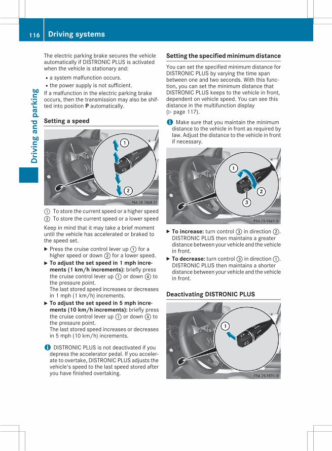
The electric parking brake secures the vehicleautomatically if DISTRONIC PLUS is activatedwhen the vehicle is stationary and:Ra system malfunction occurs.Rthe power supply is not sufficient.If a malfunction in the electric parking brakeoccurs, then the transmission may also be shif-ted into position P automatically.
Setting a speed
: To store the current speed or a higher speed; To store the current speed or a lower speedKeep in mind that it may take a brief momentuntil the vehicle has accelerated or braked tothe speed set.X Press the cruise control lever up: for ahigher speed or down; for a lower speed.X To adjust the set speed in 1 mph incre-
ments (1 km/h increments): briefly pressthe cruise control lever up: or down? tothe pressure point.The last stored speed increases or decreasesin 1 mph (1 km/h) increments.X To adjust the set speed in 5 mph incre-
ments (10 km/h increments): briefly pressthe cruise control lever up: or down? tothe pressure point.The last stored speed increases or decreasesin 5 mph (10 km/h) increments.
i DISTRONIC PLUS is not deactivated if youdepress the accelerator pedal. If you acceler-ate to overtake, DISTRONIC PLUS adjusts thevehicle's speed to the last speed stored afteryou have finished overtaking.
Setting the specified minimum distanceYou can set the specified minimum distance forDISTRONIC PLUS by varying the time spanbetween one and two seconds. With this func-tion, you can set the minimum distance thatDISTRONIC PLUS keeps to the vehicle in front,dependent on vehicle speed. You can see thisdistance in the multifunction display(Y page 117).
i Make sure that you maintain the minimumdistance to the vehicle in front as required bylaw. Adjust the distance to the vehicle in frontif necessary.
X To increase: turn control= in direction;.DISTRONIC PLUS then maintains a greaterdistance between your vehicle and the vehiclein front.X To decrease: turn control= in direction:.DISTRONIC PLUS then maintains a shorterdistance between your vehicle and the vehiclein front.
Deactivating DISTRONIC PLUS
116 Driving systemsDr
ivin
gan
dpa
rkin
g
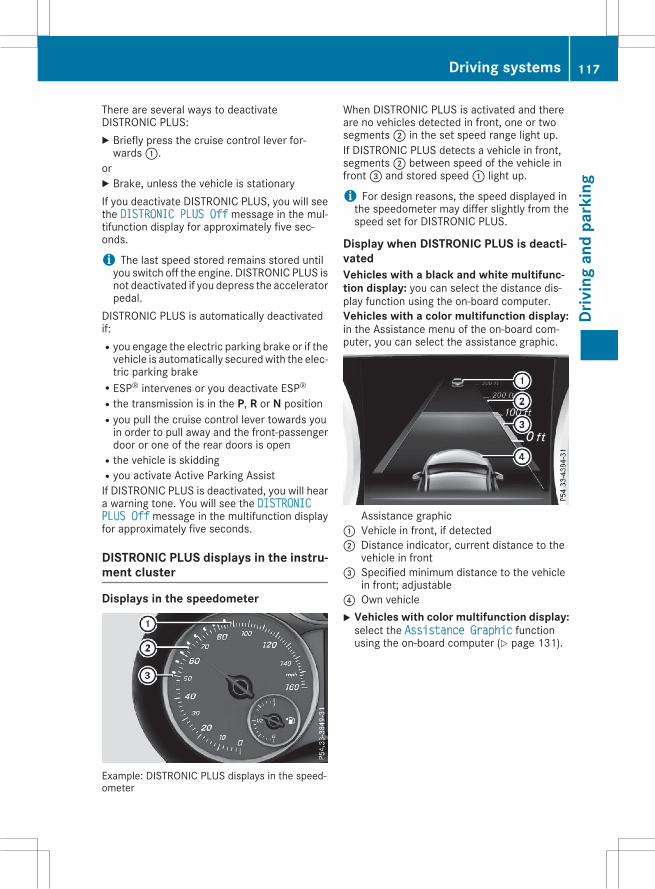
There are several ways to deactivateDISTRONIC PLUS:X Briefly press the cruise control lever for-wards:.
orX Brake, unless the vehicle is stationaryIf you deactivate DISTRONIC PLUS, you will seethe DISTRONIC PLUS Off message in the mul-tifunction display for approximately five sec-onds.
i The last speed stored remains stored untilyou switch off the engine. DISTRONIC PLUS isnot deactivated if you depress the acceleratorpedal.
DISTRONIC PLUS is automatically deactivatedif:Ryou engage the electric parking brake or if thevehicle is automatically securedwith the elec-tric parking brake
RESP® intervenes or you deactivate ESP®Rthe transmission is in the P, R or N positionRyou pull the cruise control lever towards youin order to pull away and the front-passengerdoor or one of the rear doors is open
Rthe vehicle is skiddingRyou activate Active Parking AssistIf DISTRONIC PLUS is deactivated, you will heara warning tone. You will see the DISTRONICPLUS Offmessage in the multifunction displayfor approximately five seconds.
DISTRONIC PLUS displays in the instru-ment cluster
Displays in the speedometer
Example: DISTRONIC PLUS displays in the speed-ometer
When DISTRONIC PLUS is activated and thereare no vehicles detected in front, one or twosegments; in the set speed range light up.If DISTRONIC PLUS detects a vehicle in front,segments; between speed of the vehicle infront= and stored speed: light up.
i For design reasons, the speed displayed inthe speedometer may differ slightly from thespeed set for DISTRONIC PLUS.
Display when DISTRONIC PLUS is deacti-vatedVehicles with a black and white multifunc-tion display: you can select the distance dis-play function using the on-board computer.Vehicles with a color multifunction display:in the Assistance menu of the on-board com-puter, you can select the assistance graphic.
Assistance graphic: Vehicle in front, if detected; Distance indicator, current distance to the
vehicle in front= Specified minimum distance to the vehicle
in front; adjustable? Own vehicleX Vehicles with color multifunction display:select the Assistance Graphic functionusing the on-board computer (Y page 131).
Driving systems 117
Driv
ing
and
park
ing
Z
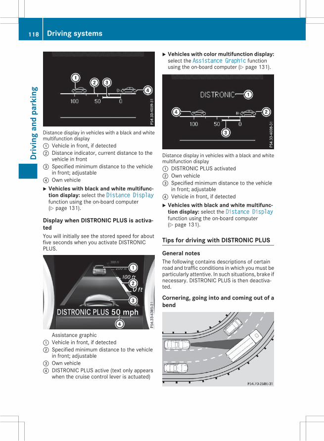
Distance display in vehicles with a black and whitemultifunction display: Vehicle in front, if detected; Distance indicator, current distance to the
vehicle in front= Specified minimum distance to the vehicle
in front; adjustable? Own vehicleX Vehicles with black and white multifunc-
tion display: select the Distance Displayfunction using the on-board computer(Y page 131).
Display when DISTRONIC PLUS is activa-tedYou will initially see the stored speed for aboutfive seconds when you activate DISTRONICPLUS.
Assistance graphic: Vehicle in front, if detected; Specified minimum distance to the vehicle
in front; adjustable= Own vehicle? DISTRONIC PLUS active (text only appears
when the cruise control lever is actuated)
X Vehicles with color multifunction display:select the Assistance Graphic functionusing the on-board computer (Y page 131).
Distance display in vehicles with a black and whitemultifunction display: DISTRONIC PLUS activated; Own vehicle= Specified minimum distance to the vehicle
in front; adjustable? Vehicle in front, if detectedX Vehicles with black and white multifunc-
tion display: select the Distance Displayfunction using the on-board computer(Y page 131).
Tips for driving with DISTRONIC PLUS
General notesThe following contains descriptions of certainroad and traffic conditions in which you must beparticularly attentive. In such situations, brake ifnecessary. DISTRONIC PLUS is then deactiva-ted.
Cornering, going into and coming out of abend
118 Driving systemsDr
ivin
gan
dpa
rkin
g
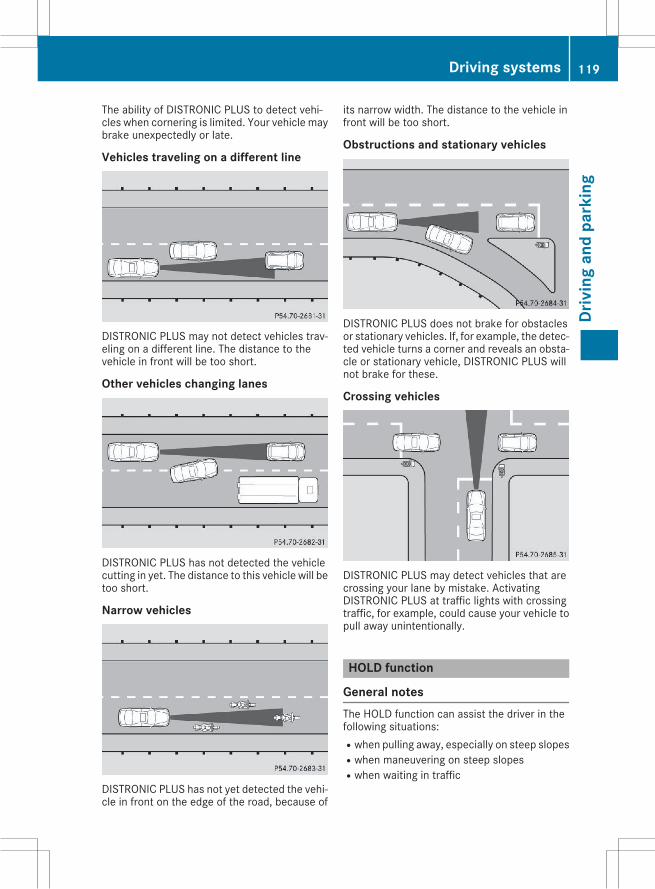
The ability of DISTRONIC PLUS to detect vehi-cles when cornering is limited. Your vehicle maybrake unexpectedly or late.
Vehicles traveling on a different line
DISTRONIC PLUS may not detect vehicles trav-eling on a different line. The distance to thevehicle in front will be too short.
Other vehicles changing lanes
DISTRONIC PLUS has not detected the vehiclecutting in yet. The distance to this vehicle will betoo short.
Narrow vehicles
DISTRONIC PLUS has not yet detected the vehi-cle in front on the edge of the road, because of
its narrow width. The distance to the vehicle infront will be too short.
Obstructions and stationary vehicles
DISTRONIC PLUS does not brake for obstaclesor stationary vehicles. If, for example, the detec-ted vehicle turns a corner and reveals an obsta-cle or stationary vehicle, DISTRONIC PLUS willnot brake for these.
Crossing vehicles
DISTRONIC PLUS may detect vehicles that arecrossing your lane by mistake. ActivatingDISTRONIC PLUS at traffic lights with crossingtraffic, for example, could cause your vehicle topull away unintentionally.
HOLD function
General notesThe HOLD function can assist the driver in thefollowing situations:Rwhen pulling away, especially on steep slopesRwhen maneuvering on steep slopesRwhen waiting in traffic
Driving systems 119
Driv
ing
and
park
ing
Z
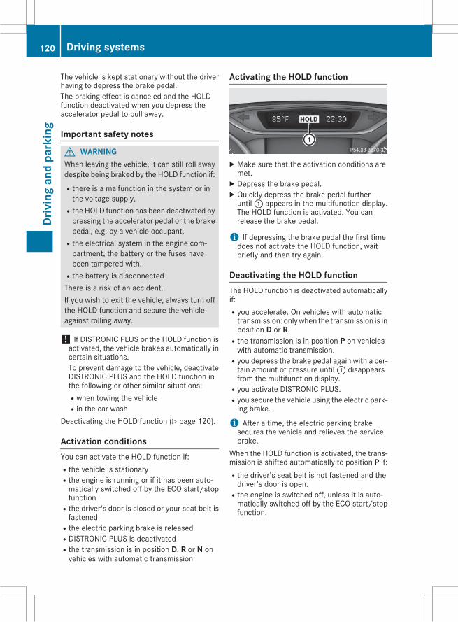
The vehicle is kept stationary without the driverhaving to depress the brake pedal.The braking effect is canceled and the HOLDfunction deactivated when you depress theaccelerator pedal to pull away.
Important safety notes
G WARNINGWhen leaving the vehicle, it can still roll awaydespite being braked by the HOLD function if:Rthere is a malfunction in the system or inthe voltage supply.
Rthe HOLD function has been deactivated bypressing the accelerator pedal or the brakepedal, e.g. by a vehicle occupant.
Rthe electrical system in the engine com-partment, the battery or the fuses havebeen tampered with.
Rthe battery is disconnectedThere is a risk of an accident.If you wish to exit the vehicle, always turn offthe HOLD function and secure the vehicleagainst rolling away.
! If DISTRONIC PLUS or the HOLD function isactivated, the vehicle brakes automatically incertain situations.To prevent damage to the vehicle, deactivateDISTRONIC PLUS and the HOLD function inthe following or other similar situations:Rwhen towing the vehicleRin the car wash
Deactivating the HOLD function (Y page 120).
Activation conditionsYou can activate the HOLD function if:Rthe vehicle is stationaryRthe engine is running or if it has been auto-matically switched off by the ECO start/stopfunction
Rthe driver's door is closed or your seat belt isfastened
Rthe electric parking brake is releasedRDISTRONIC PLUS is deactivatedRthe transmission is in position D, R or N onvehicles with automatic transmission
Activating the HOLD function
X Make sure that the activation conditions aremet.X Depress the brake pedal.X Quickly depress the brake pedal furtheruntil: appears in the multifunction display.The HOLD function is activated. You canrelease the brake pedal.
i If depressing the brake pedal the first timedoes not activate the HOLD function, waitbriefly and then try again.
Deactivating the HOLD functionThe HOLD function is deactivated automaticallyif:Ryou accelerate. On vehicles with automatictransmission: onlywhen the transmission is inposition D or R.
Rthe transmission is in position P on vehicleswith automatic transmission.
Ryou depress the brake pedal again with a cer-tain amount of pressure until: disappearsfrom the multifunction display.
Ryou activate DISTRONIC PLUS.Ryou secure the vehicle using the electric park-ing brake.
i After a time, the electric parking brakesecures the vehicle and relieves the servicebrake.
When the HOLD function is activated, the trans-mission is shifted automatically to position P if:Rthe driver's seat belt is not fastened and thedriver's door is open.
Rthe engine is switched off, unless it is auto-matically switched off by the ECO start/stopfunction.
120 Driving systemsDr
ivin
gan
dpa
rkin
g
The electric parking brake secures the vehicleautomatically if the HOLD function is activatedwhen the vehicle is stationary and:Ra system malfunction occurs.Rthe power supply is not sufficient.
Start-off assist
Important safety notes
G WARNINGIf you use start-off assist, individual wheelsmay start to spin and the vehicle may skid. IfESP® is deactivated, there is a greater dangerof skidding and having an accident.Make surethat no persons or obstacles are in the vicinityof the vehicle.
Start-off assist enables optimum accelerationfrom a standstill. For this, a suitably high-griproad surface is required, along with the tires andvehicle being in proper operating condition.Do not activate start-off assist on public roads.Observe the safety notes on driving safety sys-tems (Y page 57).Be sure to read the safety notes and informationon ESP® (Y page 61).
Activating start-off assistYouwill find information on start-off assist in theDigital Operator's Manual.
4MATIC! Never tow the vehicle with one axle raised.This may damage the differential. Damage ofthis sort is not covered by theMercedes-BenzLimited Warranty. All wheels must remaineither on the ground or be fully raised.Observe the instructions for towing the vehi-cle with all wheels in full contact with theground.
4MATIC, together with ESP®, improves the trac-tion of your vehicle whenever a drive wheelspins due to insufficient grip.If you fail to adapt your driving style, 4MATIC canneither reduce the risk of accident nor overridethe laws of physics. 4MATIC cannot takeaccount of road, weather and traffic conditions.
4MATIC is only an aid. You are responsible forthe distance to the vehicle in front, for vehiclespeed, for braking in good time and for staying inyour lane.If a drive wheel spins due to insufficient grip:ROnly depress the accelerator pedal as far asnecessary when pulling away.
RAccelerate less when driving.
i In wintry driving conditions, the maximumeffect of 4MATIC can only be achieved if youuse winter tires (M+S tires), with snow chainsif necessary.
Chassis with adaptive adjustabledamping
General notesSuspension with the Adaptive Damping Systemprovides improved driving comfort and contin-uously controls the calibration of the dampers.The damping characteristics adapt to the cur-rent operating and driving situation.The damping is tuned individually to each wheeland depends on:Ryour driving style, e.g. sportyRthe road surface conditionsRthe drive program selectedRthe vehicle level settingThe drive program can be set using theDYNAMIC SELECT button (Y page 102).
Information in the Digital Operator'sManualIn the Digital Operator's Manual you will findinformation on the following topics:RSelecting Comfort modeRSelecting Sport mode
PARKTRONIC
Important safety notesPARKTRONIC is an electronic parking aid withultrasonic sensors. It monitors the area aroundyour vehicle using six sensors in the frontbumper and six sensors in the rear bumper.
Driving systems 121
Driv
ing
and
park
ing
Z
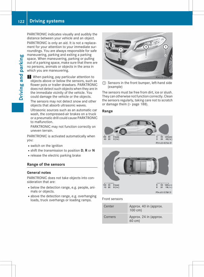
PARKTRONIC indicates visually and audibly thedistance between your vehicle and an object.PARKTRONIC is only an aid. It is not a replace-ment for your attention to your immediate sur-roundings. You are always responsible for safemaneuvering, parking and exiting a parkingspace. When maneuvering, parking or pullingout of a parking space, make sure that there areno persons, animals or objects in the area inwhich you are maneuvering.
! When parking, pay particular attention toobjects above or below the sensors, such asflower pots or trailer drawbars. PARKTRONICdoes not detect such objects when they are inthe immediate vicinity of the vehicle. Youcould damage the vehicle or the objects.The sensors may not detect snow and otherobjects that absorb ultrasonic waves.Ultrasonic sources such as an automatic carwash, the compressed-air brakes on a truckor a pneumatic drill could cause PARKTRONICto malfunction.PARKTRONIC may not function correctly onuneven terrain.
PARKTRONIC is activated automatically whenyou:Rswitch on the ignitionRshift the transmission to position D, R or NRrelease the electric parking brake
Range of the sensors
General notesPARKTRONIC does not take objects into con-sideration that are:Rbelow the detection range, e.g. people, ani-mals or objects.
Rabove the detection range, e.g. overhangingloads, truck overhangs or loading ramps.
: Sensors in the front bumper, left-hand side(example)
The sensors must be free from dirt, ice or slush.They can otherwise not function correctly. Cleanthe sensors regularly, taking care not to scratchor damage them (Y page 188).
Range
Front sensors
Center Approx. 40 in (approx.100 cm)
Corners Approx. 24 in (approx.60 cm)
122 Driving systemsDr
ivin
gan
dpa
rkin
g
Rear sensors
Center Approx. 48 in (approx.120 cm)
Corners Approx. 32 in (approx.80 cm)
Minimum distance
Center Approx. 8 in (approx. 20 cm)
Corners Approx. 6 in (approx. 15 cm)
If there is an obstacle within this range, the rel-evant warning displays light up and a warningtone sounds. If the distance falls below the min-imum, the distance may no longer be shown.
Information in the Digital Operator'sManualIn the Digital Operator's Manual you will findinformation on the following topics:RWarning displaysRDeactivating/activating PARKTRONICRProblems with PARKTRONIC
Active Parking Assist
General notesActive Parking Assist is an electronic parking aidwith ultrasound. It measures the road on bothsides of the vehicle. A parking symbol indicatesa suitable parking space. Active steering inter-vention and brake application can assist youduring parking and when exiting a parkingspace. You may also use PARKTRONIC(Y page 121).
Important safety notesActive Parking Assist is merely an aid. It is not areplacement for your attention to your immedi-ate surroundings. You are always responsiblefor safe maneuvering, parking and exiting aparking space. Make sure that no persons, ani-mals or objects are in the maneuvering range.When PARKTRONIC is switched off, Active Park-ing Assist is also unavailable.
G WARNINGIf there are objects above the detection range:RActive Park Assist may steer too earlyRthe vehicle may not stop in front of theseobjects
You may cause a collision as a result. There isa risk of an accident.If objects are located above the detectionrange, stop and deactivate Active ParkingAssist.
G WARNINGWhile parking or pulling out of a parkingspace, the vehicle swings out and can driveonto areas of the oncoming lane. This couldresult in a collision with another road user.There is a risk of an accident.Pay attention to other road users. Stop thevehicle if necessary or cancel the Active Park-ing Assist parking procedure.
! If unavoidable, you should drive over obsta-cles such as curbs slowly and not at a sharpangle. Otherwise, you may damage thewheels or tires.
Active Parking Assist may possibly indicateparking spaces which are not suitable for park-ing, for example:RWhere parking or stopping is prohibitedRIn front of driveways or entrances and exitsROn unsuitable surfacesParking tips:ROn narrow roads, drive as close to the parkingspace as possible.
RParking spaces that are littered or overgrownmight be identified or measured incorrectly.
RParking spaces that are partially occupied bytrailer drawbars might not be identified assuch or be measured incorrectly.
RSnowfall or heavy rain may lead to a parkingspace being measured inaccurately.
RPay attention to the PARKTRONIC(Y page 123) warning messages during theparking procedure.
RYou can intervene in the steering procedureto correct it at any time. Active Parking Assistwill then be canceled.
Driving systems 123
Driv
ing
and
park
ing
Z
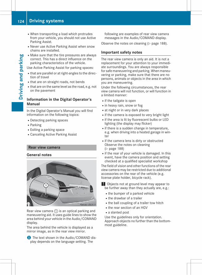
RWhen transporting a load which protrudesfrom your vehicle, you should not use ActiveParking Assist.
RNever use Active Parking Assist when snowchains are installed.
RMake sure that the tire pressures are alwayscorrect. This has a direct influence on theparking characteristics of the vehicle.
Use Active Parking Assist for parking spaces:Rthat are parallel or at right-angles to the direc-tion of travel
Rthat are on straight roads, not bendsRthat are on the same level as the road, e.g. noton the pavement
Information in the Digital Operator'sManualIn the Digital Operator's Manual you will findinformation on the following topics:RDetecting parking spacesRParkingRExiting a parking spaceRCanceling Active Parking Assist
Rear view camera
General notes
Rear view camera: is an optical parking andmaneuvering aid. It uses guide lines to show thearea behind your vehicle in the Audio/COMANDdisplay.The area behind the vehicle is displayed as amirror image, as in the rear view mirror.
i The text shown in the Audio/COMAND dis-play depends on the language setting. The
following are examples of rear view cameramessages in the Audio/COMAND display.
Observe the notes on cleaning (Y page 188).
Important safety notesThe rear view camera is only an aid. It is not areplacement for your attention to your immedi-ate surroundings. You are always responsiblefor safemaneuvering and parking.Whenmaneu-vering or parking, make sure that there are nopersons, animals or objects in the area in whichyou are maneuvering.Under the following circumstances, the rearview camera will not function, or will function ina limited manner:Rif the tailgate is openRin heavy rain, snow or fogRat night or in very dark placesRif the camera is exposed to very bright lightRif the area is lit by fluorescent bulbs or LEDlighting (the display may flicker)
Rif there is a sudden change in temperature,e.g. when driving into a heated garage in win-ter
Rif the camera lens is dirty or obstructedObserve the notes on cleaning(Y page 188)
Rif the rear of your vehicle is damaged. In thisevent, have the camera position and settingchecked at a qualified specialist workshop
The field of vision and other functions of the rearview camera may be restricted due to additionalaccessories on the rear of the vehicle (e.g.license plate holder, bicycle rack).
! Objects not at ground level may appear tobe further away than they actually are, e.g.:Rthe bumper of a parked vehicleRthe drawbar of a trailerRthe ball coupling of a trailer tow hitchRthe rear section of an HGVRa slanted postUse the guidelines only for orientation.Approach objects no further than the bottom-most guideline.
124 Driving systemsDr
ivin
gan
dpa
rkin
g
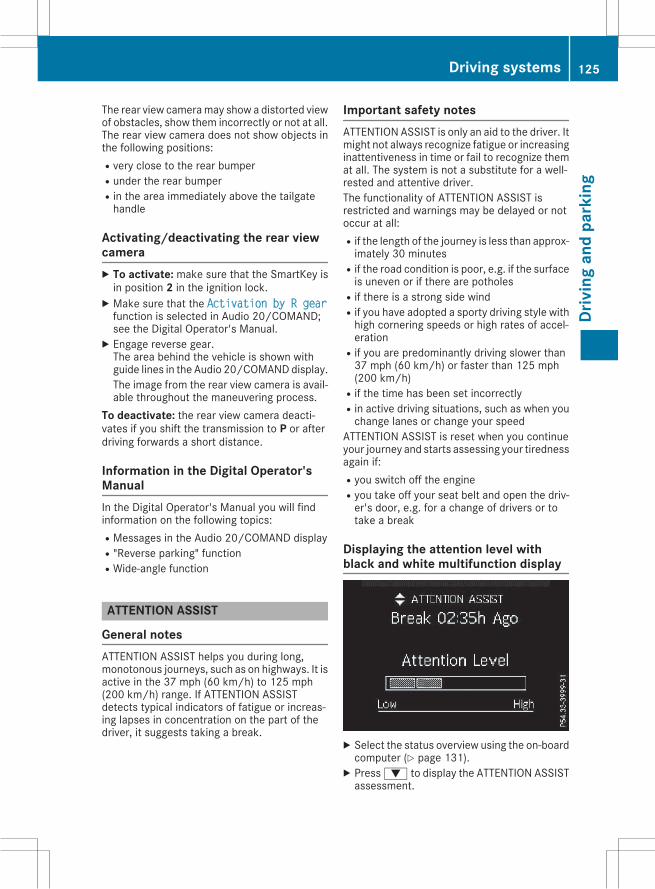
The rear view cameramay show a distorted viewof obstacles, show them incorrectly or not at all.The rear view camera does not show objects inthe following positions:Rvery close to the rear bumperRunder the rear bumperRin the area immediately above the tailgatehandle
Activating/deactivating the rear viewcameraX To activate: make sure that the SmartKey isin position 2 in the ignition lock.X Make sure that the Activation by R gearfunction is selected in Audio 20/COMAND;see the Digital Operator's Manual.X Engage reverse gear.The area behind the vehicle is shown withguide lines in the Audio 20/COMANDdisplay.The image from the rear view camera is avail-able throughout the maneuvering process.
To deactivate: the rear view camera deacti-vates if you shift the transmission to P or afterdriving forwards a short distance.
Information in the Digital Operator'sManualIn the Digital Operator's Manual you will findinformation on the following topics:RMessages in the Audio 20/COMAND displayR"Reverse parking" functionRWide-angle function
ATTENTION ASSIST
General notesATTENTION ASSIST helps you during long,monotonous journeys, such as on highways. It isactive in the 37 mph (60 km/h) to 125 mph(200 km/h) range. If ATTENTION ASSISTdetects typical indicators of fatigue or increas-ing lapses in concentration on the part of thedriver, it suggests taking a break.
Important safety notesATTENTION ASSIST is only an aid to the driver. Itmight not always recognize fatigue or increasinginattentiveness in time or fail to recognize themat all. The system is not a substitute for a well-rested and attentive driver.The functionality of ATTENTION ASSIST isrestricted and warnings may be delayed or notoccur at all:Rif the length of the journey is less than approx-imately 30 minutes
Rif the road condition is poor, e.g. if the surfaceis uneven or if there are potholes
Rif there is a strong side windRif you have adopted a sporty driving style withhigh cornering speeds or high rates of accel-eration
Rif you are predominantly driving slower than37 mph (60 km/h) or faster than 125 mph(200 km/h)
Rif the time has been set incorrectlyRin active driving situations, such as when youchange lanes or change your speed
ATTENTION ASSIST is reset when you continueyour journey and starts assessing your tirednessagain if:Ryou switch off the engineRyou take off your seat belt and open the driv-er's door, e.g. for a change of drivers or totake a break
Displaying the attention level withblack and white multifunction display
X Select the status overview using the on-boardcomputer (Y page 131).X Press: to display the ATTENTION ASSISTassessment.
Driving systems 125
Driv
ing
and
park
ing
Z

The following information is displayed:Rlength of the journey since the last break.Rthe attention level determined by ATTENTIONASSIST (Attention Level), displayed in abar display in five levels from high to low
Rif ATTENTION ASSIST is unable to calculatethe attention level and cannot issue a warn-ing, the System Suspended messageappears. The bar display then changes thedisplay, e.g. if you are driving at a speed below37 mph (60 km/h) or above 124 mph(200 km/h).
Displaying Attention Level with colormultifunction display
You can have current status information dis-played in the assistance menu (Y page 131) ofthe on-board computer.X Select the Assistance display for AttentionAssist using the on-board computer(Y page 131).
The following information is displayed:Rlength of the journey since the last break.Rthe attention level determined by ATTENTIONASSIST (Attention Level), displayed in abar display in five levels from high to low
Rif ATTENTION ASSIST is unable to calculatethe attention level and cannot issue a warn-ing, the System Suspended messageappears. The bar display then changes thedisplay, e.g. if you are driving at a speed below37 mph (60 km/h) or above 124 mph(200 km/h).
Activating ATTENTION ASSISTX Activate ATTENTION ASSIST using the on-board computer (Y page 131).The system determines the attention level ofthe driver depending on the setting selected:
If Standard is selected: the sensitivity withwhich the system determines the attention levelis set to normal.If Sensitive is selected: the sensitivity is sethigher. The attention level detected by AttentionAssist is adapted accordingly and the driver iswarned earlier.Vehicles with black and white multifunctiondisplay: when ATTENTION ASSIST is activated,the multifunction display in the status overviewshows theÀ symbol.Vehicles with color multifunction display:when ATTENTION ASSIST is deactivated, themultifunction display in the assistance graphicshows theé symbol.WhenATTENTIONASSIST has been deactivated,it is automatically reactivated after the enginehas been stopped. The sensitivity selected cor-responds to the last selection activated (stand-ard/sensitive).
Warning in the multifunction displayIf fatigue or increasing lapses in concentrationare detected, a warning appears in the multi-function display: ATTENTION ASSIST Take aBreak!.In addition to the message shown in the multi-function display, you will then hear a warningtone.X If necessary, take a break.X Confirm the message by pressing theabutton on the steering wheel.
On long journeys, take regular breaks in goodtime to allow yourself to rest properly. If you donot take a break and ATTENTION ASSIST stilldetects increasing lapses in concentration, youwill be warned again after 15 minutes at theearliest. This will only happen if ATTEN-TION ASSIST still detects typical indicators offatigue or increasing lapses in concentration.If a warning is output in the multifunction dis-play, a service station search is performed inCOMAND. You can select a service station andnavigation to this service station will then begin.This function can be activated and deactivatedin COMAND.
126 Driving systemsDr
ivin
gan
dpa
rkin
g
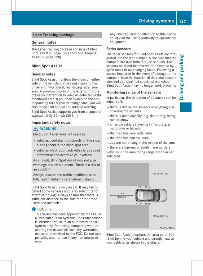
Lane Tracking package
General notesThe Lane Tracking package consists of BlindSpot Assist (Y page 127) and Lane KeepingAssist (Y page 128).
Blind Spot Assist
General notesBlind Spot Assist monitors the areas on eitherside of the vehicle that are not visible to thedriver with two lateral, rear-facing radar sen-sors. A warning display in the exterior mirrorsdraws your attention to vehicles detected in themonitored area. If you then switch on the cor-responding turn signal to change lane, you willalso receive an optical and audible warning.Blind Spot Assist supports you from a speed ofapproximately 20 mph (30 km/h).
Important safety notesG WARNINGBlind Spot Assist does not react to:Rvehicles overtaken too closely on the side,placing them in the blind spot area
Rvehicles which approach with a large speeddifferential and overtake your vehicle
As a result, Blind Spot Assist may not givewarnings in such situations. There is a risk ofan accident.Always observe the traffic conditions care-fully, and maintain a safe lateral distance.
Blind Spot Assist is only an aid. It may fail todetect some vehicles and is no substitute forattentive driving. Always ensure that there issufficient distance to the side for other roadusers and obstacles.
i USA only:This device has been approved by the FCC asa "Vehicular Radar System". The radar sensoris intended for use in an automotive radarsystem only. Removing, tampering with, oraltering the device will void any warranties,and is not permitted by the FCC. Do not tam-per with, alter, or use in any non-approvedway.
Any unauthorized modification to this devicecould void the user’s authority to operate theequipment.
Radar sensorsThe radar sensors for Blind Spot Assist are inte-grated into the rear bumper. Make sure that thebumpers are free from dirt, ice or slush. Thesensors must not be covered, for example bycycle racks or overhanging loads. Following asevere impact or in the event of damage to thebumpers, have the function of the radar sensorschecked at a qualified specialist workshop.Blind Spot Assist may no longer work properly.
Monitoring range of the sensorsIn particular, the detection of obstacles can beimpaired if:Rthere is dirt on the sensors or anything elsecovering the sensors
Rthere is poor visibility, e.g. due to fog, heavyrain or snow
Ra narrow vehicle traveling in front, e.g. amotorbike or bicycle
Rthe road has very wide lanesRthe road has narrow lanesRyou are not driving in the middle of the laneRthere are barriers or similar lane bordersVehicles in the monitoring range are then notindicated.
Blind Spot Assist monitors the area up to 10 ft(3 m) behind your vehicle and directly next toyour vehicle, as shown in the diagram.
Driving systems 127
Driv
ing
and
park
ing
Z
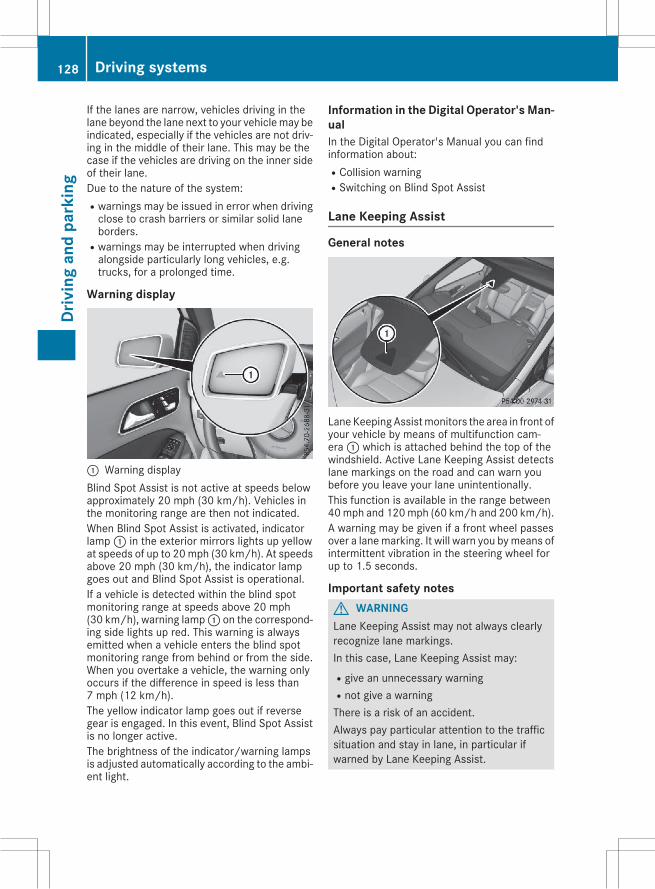
If the lanes are narrow, vehicles driving in thelane beyond the lane next to your vehiclemay beindicated, especially if the vehicles are not driv-ing in the middle of their lane. This may be thecase if the vehicles are driving on the inner sideof their lane.Due to the nature of the system:Rwarnings may be issued in error when drivingclose to crash barriers or similar solid laneborders.
Rwarnings may be interrupted when drivingalongside particularly long vehicles, e.g.trucks, for a prolonged time.
Warning display
: Warning displayBlind Spot Assist is not active at speeds belowapproximately 20 mph (30 km/h). Vehicles inthe monitoring range are then not indicated.When Blind Spot Assist is activated, indicatorlamp: in the exterior mirrors lights up yellowat speeds of up to 20mph (30 km/h). At speedsabove 20 mph (30 km/h), the indicator lampgoes out and Blind Spot Assist is operational.If a vehicle is detected within the blind spotmonitoring range at speeds above 20 mph(30 km/h), warning lamp: on the correspond-ing side lights up red. This warning is alwaysemitted when a vehicle enters the blind spotmonitoring range from behind or from the side.When you overtake a vehicle, the warning onlyoccurs if the difference in speed is less than7 mph (12 km/h).The yellow indicator lamp goes out if reversegear is engaged. In this event, Blind Spot Assistis no longer active.The brightness of the indicator/warning lampsis adjusted automatically according to the ambi-ent light.
Information in the Digital Operator's Man-ualIn the Digital Operator's Manual you can findinformation about:RCollision warningRSwitching on Blind Spot Assist
Lane Keeping Assist
General notes
LaneKeepingAssistmonitors the area in front ofyour vehicle by means of multifunction cam-era: which is attached behind the top of thewindshield. Active Lane Keeping Assist detectslane markings on the road and can warn youbefore you leave your lane unintentionally.This function is available in the range between40mph and 120mph (60 km/h and 200 km/h).A warning may be given if a front wheel passesover a lanemarking. It will warn you bymeans ofintermittent vibration in the steering wheel forup to 1.5 seconds.
Important safety notesG WARNINGLane Keeping Assist may not always clearlyrecognize lane markings.In this case, Lane Keeping Assist may:Rgive an unnecessary warningRnot give a warningThere is a risk of an accident.Always pay particular attention to the trafficsituation and stay in lane, in particular ifwarned by Lane Keeping Assist.
128 Driving systemsDr
ivin
gan
dpa
rkin
g
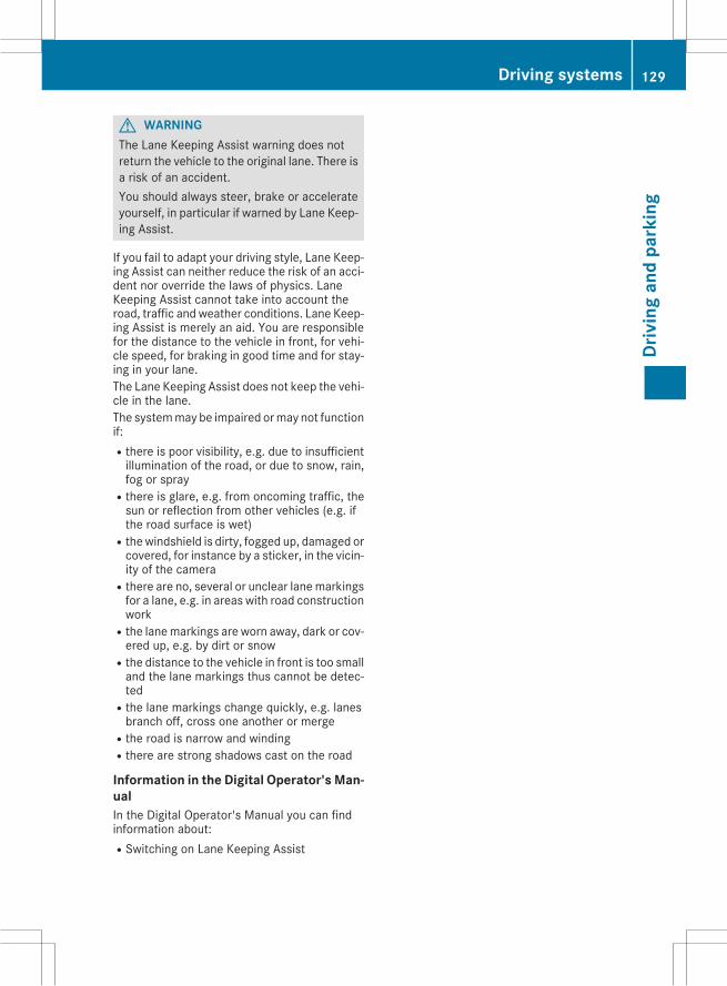
G WARNINGThe Lane Keeping Assist warning does notreturn the vehicle to the original lane. There isa risk of an accident.You should always steer, brake or accelerateyourself, in particular if warned by Lane Keep-ing Assist.
If you fail to adapt your driving style, Lane Keep-ing Assist can neither reduce the risk of an acci-dent nor override the laws of physics. LaneKeeping Assist cannot take into account theroad, traffic and weather conditions. Lane Keep-ing Assist is merely an aid. You are responsiblefor the distance to the vehicle in front, for vehi-cle speed, for braking in good time and for stay-ing in your lane.The Lane Keeping Assist does not keep the vehi-cle in the lane.The systemmay be impaired ormay not functionif:Rthere is poor visibility, e.g. due to insufficientillumination of the road, or due to snow, rain,fog or spray
Rthere is glare, e.g. from oncoming traffic, thesun or reflection from other vehicles (e.g. ifthe road surface is wet)
Rthewindshield is dirty, fogged up, damaged orcovered, for instance by a sticker, in the vicin-ity of the camera
Rthere are no, several or unclear lanemarkingsfor a lane, e.g. in areas with road constructionwork
Rthe lanemarkings are worn away, dark or cov-ered up, e.g. by dirt or snow
Rthe distance to the vehicle in front is too smalland the lane markings thus cannot be detec-ted
Rthe lane markings change quickly, e.g. lanesbranch off, cross one another or merge
Rthe road is narrow and windingRthere are strong shadows cast on the road
Information in the Digital Operator's Man-ualIn the Digital Operator's Manual you can findinformation about:RSwitching on Lane Keeping Assist
Driving systems 129
Driv
ing
and
park
ing
Z
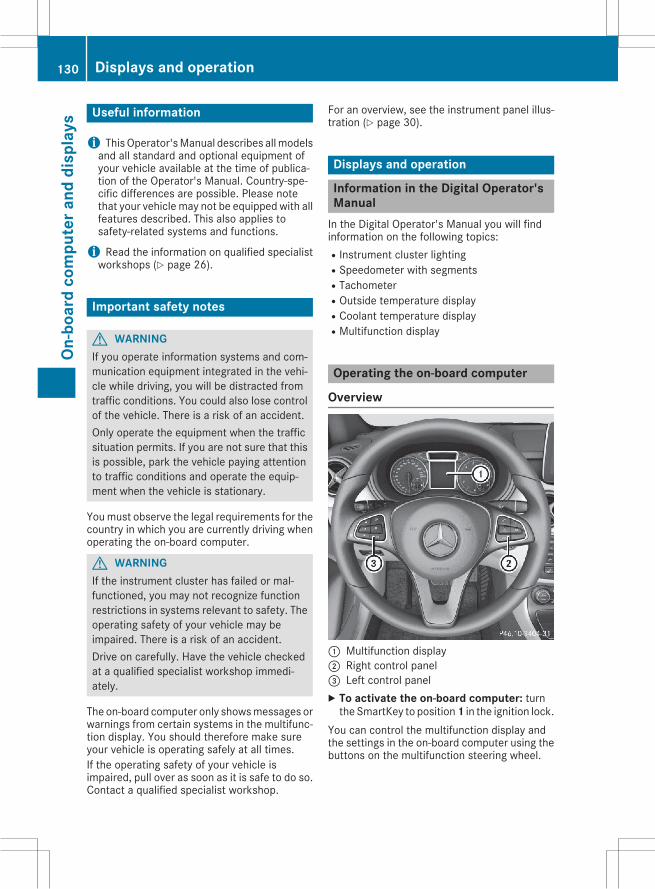
Useful information
i ThisOperator'sManual describes allmodelsand all standard and optional equipment ofyour vehicle available at the time of publica-tion of the Operator's Manual. Country-spe-cific differences are possible. Please notethat your vehicle may not be equipped with allfeatures described. This also applies tosafety-related systems and functions.
i Read the information on qualified specialistworkshops (Y page 26).
Important safety notes
G WARNINGIf you operate information systems and com-munication equipment integrated in the vehi-cle while driving, you will be distracted fromtraffic conditions. You could also lose controlof the vehicle. There is a risk of an accident.Only operate the equipment when the trafficsituation permits. If you are not sure that thisis possible, park the vehicle paying attentionto traffic conditions and operate the equip-ment when the vehicle is stationary.
Youmust observe the legal requirements for thecountry in which you are currently driving whenoperating the on-board computer.
G WARNINGIf the instrument cluster has failed or mal-functioned, you may not recognize functionrestrictions in systems relevant to safety. Theoperating safety of your vehicle may beimpaired. There is a risk of an accident.Drive on carefully. Have the vehicle checkedat a qualified specialist workshop immedi-ately.
The on-board computer only showsmessages orwarnings from certain systems in the multifunc-tion display. You should therefore make sureyour vehicle is operating safely at all times.If the operating safety of your vehicle isimpaired, pull over as soon as it is safe to do so.Contact a qualified specialist workshop.
For an overview, see the instrument panel illus-tration (Y page 30).
Displays and operation
Information in the Digital Operator'sManualIn the Digital Operator's Manual you will findinformation on the following topics:RInstrument cluster lightingRSpeedometer with segmentsRTachometerROutside temperature displayRCoolant temperature displayRMultifunction display
Operating the on-board computer
Overview
: Multifunction display; Right control panel= Left control panelX To activate the on-board computer: turnthe SmartKey to position1 in the ignition lock.
You can control the multifunction display andthe settings in the on-board computer using thebuttons on the multifunction steering wheel.
130 Displays and operationOn
-boa
rdco
mpu
tera
nddi
spla
ys
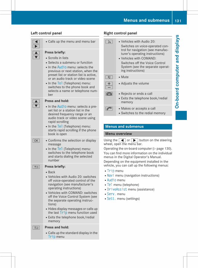
Left control panel
=
;
RCalls up the menu and menu bar
9
:
Press briefly:RScrolls in listsRSelects a submenu or functionRIn the Audio menu: selects theprevious or next station, when thepreset list or station list is active,or an audio track or video scene
RIn the Tel (Telephone) menu:switches to the phone book andselects a name or telephone num-ber
9
:
Press and hold:RIn the Audio menu: selects a pre-set list or a station list in thedesired frequency range or anaudio track or video scene usingrapid scrolling
RIn the Tel (Telephone) menu:starts rapid scrolling if the phonebook is open
a RConfirms the selection or displaymessage
RIn the Tel (Telephone) menu:switches to the telephone bookand starts dialing the selectednumber
% Press briefly:RBackRVehicles with Audio 20: switchesoff voice-operated control of thenavigation (see manufacturer'soperating instructions)
RVehicles with COMAND: switchesoff the Voice Control System (seethe separate operating instruc-tions)
RHides displaymessages or calls upthe last Trip menu function used
RExits the telephone book/redialmemory
% Press and hold:RCalls up the standard display in theTrip menu
Right control panel
ó RVehicles with Audio 20:Switches on voice-operated con-trol for navigation (see manufac-turer's operating instructions)
RVehicles with COMAND:Switches off the Voice ControlSystem (see the separate operat-ing instructions)
8 RMute
WX
RAdjusts the volume
~ RRejects or ends a callRExits the telephone book/redialmemory
6 RMakes or accepts a callRSwitches to the redial memory
Menus and submenus
Menu overviewUsing the= or; button on the steeringwheel, open the menu bar.Operating the on-board computer (Y page 130).You can find more information on the individualmenus in the Digital Operator's Manual.Depending on the equipment installed in thevehicle, you can call up the following menus:RTrip menuRNavi menu (navigation instructions)RAudio menuRTel menu (telephone)RDriveAssist menu (assistance)RServ. menuRSett. menu (settings)
Menus and submenus 131
On-b
oard
com
pute
rand
disp
lays
Z
Display messages
Introduction
General notesThis section describes display messages relevant to safety together with their solutions. A descrip-tion of other messages and their solutions can be found in the Digital Operator's Manual.Display messages appear in the multifunction display.Display messages with graphic displays may be shown in simplified form in the Operator's Manualand may therefore differ from the multifunction display.Please respond in accordance with the display messages and follow the additional notes in thisOperator's Manual.Certain display messages are accompanied by an audible warning tone or a continuous tone.When the ignition is switched off, all display messages are deleted, apart from some high-prioritydisplay messages. Once the causes of the high-priority display messages have been rectified, thecorresponding display messages are also deleted.When you stop and park the vehicle, please observe the notes on the HOLD function (Y page 119)and parking (Y page 107).
Hiding display messagesX Press thea or% button on the steering wheel.The multifunction display hides the display message.
The multifunction display shows high-priority display messages in red. Some high-priority displaymessages cannot be hidden.The multifunction display shows these messages continuously until the causes for the messageshave been remedied.
Message memoryThe on-board computer saves certain display messages in the message memory. You can call upthe display messages:X Press the= or; button on the steering wheel to select the Serv. menu.If there are display messages, the multifunction display shows 2 Messages, for example.X Press the9 or: button to select the entry, e.g. 2 Messages.X Pressa to confirm.X Press the9 or: button to scroll through the display messages.
132 Display messagesOn
-boa
rdco
mpu
tera
nddi
spla
ys
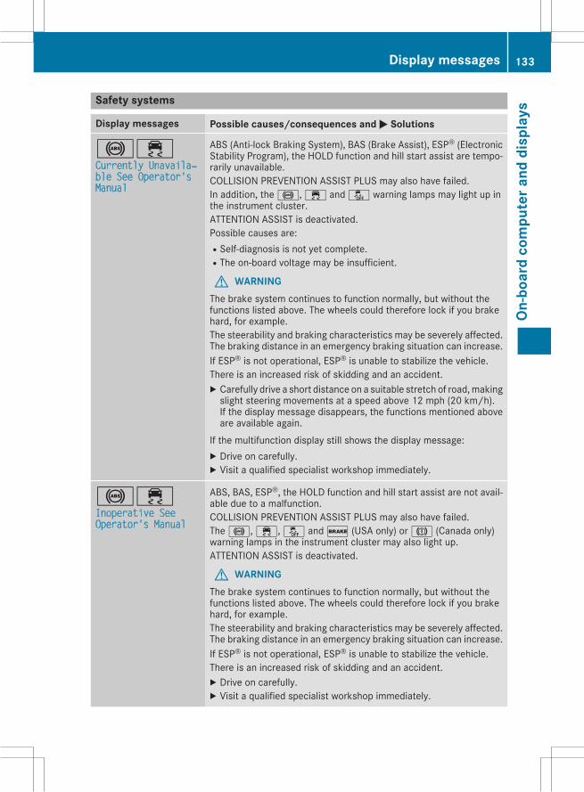
Safety systems
Display messages Possible causes/consequences and M Solutions
!÷Currently Unavailaхble See Operator'sManual
ABS (Anti-lock Braking System), BAS (Brake Assist), ESP® (ElectronicStability Program), the HOLD function and hill start assist are tempo-rarily unavailable.COLLISION PREVENTION ASSIST PLUS may also have failed.In addition, the!,÷ andå warning lamps may light up inthe instrument cluster.ATTENTION ASSIST is deactivated.Possible causes are:RSelf-diagnosis is not yet complete.RThe on-board voltage may be insufficient.
G WARNINGThe brake system continues to function normally, but without thefunctions listed above. The wheels could therefore lock if you brakehard, for example.The steerability and braking characteristics may be severely affected.The braking distance in an emergency braking situation can increase.If ESP® is not operational, ESP® is unable to stabilize the vehicle.There is an increased risk of skidding and an accident.X Carefully drive a short distance on a suitable stretch of road,makingslight steering movements at a speed above 12 mph (20 km/h).If the display message disappears, the functions mentioned aboveare available again.
If the multifunction display still shows the display message:X Drive on carefully.X Visit a qualified specialist workshop immediately.
!÷Inoperative SeeOperator's Manual
ABS, BAS, ESP®, the HOLD function and hill start assist are not avail-able due to a malfunction.COLLISION PREVENTION ASSIST PLUS may also have failed.The!,÷,å and$ (USA only) orJ (Canada only)warning lamps in the instrument cluster may also light up.ATTENTION ASSIST is deactivated.
G WARNINGThe brake system continues to function normally, but without thefunctions listed above. The wheels could therefore lock if you brakehard, for example.The steerability and braking characteristics may be severely affected.The braking distance in an emergency braking situation can increase.If ESP® is not operational, ESP® is unable to stabilize the vehicle.There is an increased risk of skidding and an accident.X Drive on carefully.X Visit a qualified specialist workshop immediately.
Display messages 133
On-b
oard
com
pute
rand
disp
lays
Z
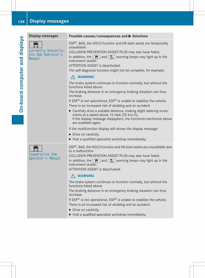
Display messages Possible causes/consequences and M Solutions
÷Currently Unavailaхble See Operator'sManual
ESP®, BAS, the HOLD function and hill start assist are temporarilyunavailable.COLLISION PREVENTION ASSIST PLUS may also have failed.In addition, the÷ andå warning lamps may light up in theinstrument cluster.ATTENTION ASSIST is deactivated.The self-diagnosis function might not be complete, for example.
G WARNINGThe brake system continues to function normally, but without thefunctions listed above.The braking distance in an emergency braking situation can thusincrease.If ESP® is not operational, ESP® is unable to stabilize the vehicle.There is an increased risk of skidding and an accident.X Carefully drive a suitable distance, making slight steering move-ments at a speed above 12 mph (20 km/h).If the display message disappears, the functions mentioned aboveare available again.
If the multifunction display still shows the display message:X Drive on carefully.X Visit a qualified specialist workshop immediately.
÷Inoperative SeeOperator's Manual
ESP®, BAS, the HOLD function and hill start assist are unavailable dueto a malfunction.COLLISION PREVENTION ASSIST PLUS may also have failed.In addition, the÷ andå warning lamps may light up in theinstrument cluster.ATTENTION ASSIST is deactivated.
G WARNINGThe brake system continues to function normally, but without thefunctions listed above.The braking distance in an emergency braking situation can thusincrease.If ESP® is not operational, ESP® is unable to stabilize the vehicle.There is an increased risk of skidding and an accident.X Drive on carefully.X Visit a qualified specialist workshop immediately.
134 Display messagesOn
-boa
rdco
mpu
tera
nddi
spla
ys
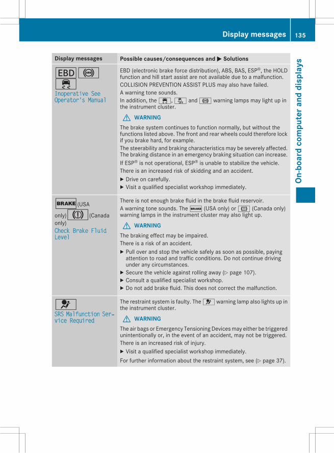
Display messages Possible causes/consequences and M Solutions
T!÷Inoperative SeeOperator's Manual
EBD (electronic brake force distribution), ABS, BAS, ESP®, the HOLDfunction and hill start assist are not available due to a malfunction.COLLISION PREVENTION ASSIST PLUS may also have failed.A warning tone sounds.In addition, the÷,å and! warning lamps may light up inthe instrument cluster.
G WARNINGThe brake system continues to function normally, but without thefunctions listed above. The front and rear wheels could therefore lockif you brake hard, for example.The steerability and braking characteristics may be severely affected.The braking distance in an emergency braking situation can increase.If ESP® is not operational, ESP® is unable to stabilize the vehicle.There is an increased risk of skidding and an accident.X Drive on carefully.X Visit a qualified specialist workshop immediately.
$(USA
only)J(Canadaonly)Check Brake FluidLevel
There is not enough brake fluid in the brake fluid reservoir.A warning tone sounds. The$ (USA only) orJ (Canada only)warning lamps in the instrument cluster may also light up.
G WARNINGThe braking effect may be impaired.There is a risk of an accident.X Pull over and stop the vehicle safely as soon as possible, payingattention to road and traffic conditions. Do not continue drivingunder any circumstances.X Secure the vehicle against rolling away (Y page 107).X Consult a qualified specialist workshop.X Do not add brake fluid. This does not correct the malfunction.
6SRS Malfunction Serхvice Required
The restraint system is faulty. The6warning lamp also lights up inthe instrument cluster.
G WARNINGThe air bags or Emergency Tensioning Devicesmay either be triggeredunintentionally or, in the event of an accident, may not be triggered.There is an increased risk of injury.X Visit a qualified specialist workshop immediately.For further information about the restraint system, see (Y page 37).
Display messages 135
On-b
oard
com
pute
rand
disp
lays
Z
Display messages Possible causes/consequences and M Solutions
6Front Left Malfuncхtion ServiceRequired or FrontRight MalfunctionService Required
The restraint system hasmalfunctioned at the front on the left or right.The6 warning lamp also lights up in the instrument cluster.
G WARNINGThe air bags or Emergency Tensioning Devicesmay either be triggeredunintentionally or, in the event of an accident, may not be triggered.There is an increased risk of injury.X Visit a qualified specialist workshop immediately.
6Rear Left Malfuncхtion ServiceRequired or RearRight MalfunctionService Required
The rear left-hand or right-hand restraint system has malfunctioned.The6 warning lamp also lights up in the instrument cluster.
G WARNINGThe air bags or Emergency Tensioning Devicesmay either be triggeredunintentionally or, in the event of an accident, may not be triggered.There is an increased risk of injury.X Visit a qualified specialist workshop immediately.
6Rear Center Malfuncхtion ServiceRequired
The rear center restraint systemhasmalfunctioned. The6warninglamp also lights up in the instrument cluster.
G WARNINGThe air bags or Emergency Tensioning Devicesmay either be triggeredunintentionally or, in the event of an accident, may not be triggered.There is an increased risk of injury.X Visit a qualified specialist workshop immediately.
6Left Side CurtainAirbag MalfunctionService Required orRight Side CurtainAirbag MalfunctionService Required
There is amalfunction in the left-hand or right-handwindow curtain airbag. The6 warning lamp also lights up in the instrument cluster.
G WARNINGThe left or right window curtain air bag may either be triggered unin-tentionally or, in the event of an accident, may not be triggered.There is an increased risk of injury.X Visit a qualified specialist workshop immediately.
136 Display messagesOn
-boa
rdco
mpu
tera
nddi
spla
ys
Display messages Possible causes/consequences and M Solutions
Front Passenger Airхbag Disabled SeeOperator's ManualThe front-passenger air bag is deactivated during the journey, eventhough:Ran adultor
Ra person of the corresponding stature is on the front-passenger seatIf additional forces are applied to the seat, the system may interpretthe occupant's weight as lower than it actually is.
G WARNINGThe front-passenger air bag does not deploy during an accident.There is an increased risk of injury.X Pull over and stop the vehicle safely as soon as possible, payingattention to road and traffic conditions.X Secure the vehicle against rolling away (Y page 107).X Switch the ignition off.X Have the occupant get out of the vehicle.X Keep the seat unoccupied, close the front-passenger door andswitch on the ignition.X Observe the PASSENGER AIR BAG indicator lamps in the centerconsole and the multifunction display and check the following:Seat unoccupied and ignition switched on:Ra self-diagnosis is carried out. The PASSENGER AIR BAG OFF andPASSENGER AIR BAG ON indicator lamps must light up simulta-neously for approximately six seconds
Rthe PASSENGER AIR BAG OFF indicator lamp must then light upand remain lit after the self-diagnosis. If the indicator lamp is on,OCS (Occupant Classification System) has disabled the front-passenger front air bag (Y page 45)
Rthe Front Passenger Air Bag Enabled See Operator'sManual or Front Passenger Air Bag Disabled See Operхator's Manual display messages must not be shown in themultifunction display
X Wait for a period of at least 60 seconds until the necessary systemchecks have been completed.X Make sure that the display messages do not appear in the multi-function display.
If these conditions are fulfilled, the front-passenger seat can be occu-pied again. Whether the PASSENGER AIR BAG OFF or ON indicatorlamp remains lit or goes out depends on how OCS classifies the occu-pant.If the conditions are not fulfilled, the system is not operating correctly.X Visit a qualified specialist workshop immediately.For further information about theOccupant Classification System, see(Y page 45).
Display messages 137
On-b
oard
com
pute
rand
disp
lays
Z
Display messages Possible causes/consequences and M Solutions
Front Passenger Airхbag Enabled SeeOperator's ManualThe front-passenger air bag is enabled during the journey, eventhough:Ra child, a small adult or an object weighing less than the system'sweight threshold is located on the front-passenger seator
Rthe front-passenger seat is unoccupiedThe systemmay detect objects or forces applying additional weight onthe seat.
G WARNINGThe air bag may deploy unintentionally.There is an increased risk of injury.X Pull over and stop the vehicle safely as soon as possible, payingattention to road and traffic conditions.X Secure the vehicle against rolling away (Y page 107).X Switch the ignition off.X Open the front-passenger door.X Remove the child and the child restraint system from the front-passenger seat.X Make sure that there are no objects on the seat adding to theweight.The system may otherwise detect the additional weight and inter-pret the seat occupant's weight as greater than it actually is.X Keep the seat unoccupied, close the front-passenger door andswitch on the ignition.X Observe the PASSENGER AIR BAG indicator lamps in the centerconsole and the multifunction display and check the following:Seat unoccupied and ignition switched on:Ra self-diagnosis is carried out. The PASSENGER AIR BAG OFF andPASSENGER AIR BAG ON indicator lamps must light up simulta-neously for approximately six seconds
Rthe PASSENGER AIR BAG OFF indicator lamp must then light upand remain lit after the self-diagnosis. If the indicator lamp is on,OCS has disabled the front-passenger front air bag (Y page 45)
Rthe Front Passenger Air Bag Enabled See Operator'sManual or Front Passenger Air Bag Disabled See Operхator's Manual display messages must not be shown in themultifunction display
X Wait for a period of at least 60 seconds until the necessary systemchecks have been completed.X Make sure that the display messages do not appear in the multi-function display.
If these conditions are fulfilled, the front-passenger seat can be occu-pied again. Whether the PASSENGER AIR BAG OFF or ON indicatorlamp remains lit or goes out depends on how OCS classifies the occu-pant.If the conditions are not fulfilled, the system is not operating correctly.
138 Display messagesOn
-boa
rdco
mpu
tera
nddi
spla
ys
Display messages Possible causes/consequences and M SolutionsX Visit a qualified specialist workshop immediately.For further information about theOccupant Classification System, see(Y page 45).
Engine
Display messages Possible causes/consequences and M Solutions
?Coolant Too HotStop Vehicle TurnEngine Off
The coolant is too hot.A warning tone also sounds.
G WARNINGDo not drive when your engine is overheated. This can cause somefluids which may have leaked into the engine compartment to catchfire.Steam from the overheated engine can also cause serious burnswhichcan occur just by opening the hood.There is a risk of injury.X Pull over and stop the vehicle safely and switch off the engine, pay-ing attention to road and traffic conditions.X Secure the vehicle against rolling away (Y page 107).X Wait until the engine has cooled down.X Make sure that the air supply to the engine radiator is not blocked,e.g. by snow, slush or ice.X Donot start the engine again until the displaymessage goes out andthe coolant temperature is below 248 ‡ (120 †). Otherwise, theengine could be damaged.X Pay attention to the coolant temperature display.If the temperature increases again:X Visit a qualified specialist workshop immediately.Under normal operating conditions and with the specified coolantlevel, the coolant temperature may rise to 248 ‡ (120 †).
Display messages 139
On-b
oard
com
pute
rand
disp
lays
Z
Tires
Display messages Possible causes/consequences and M Solutions
Check Tire PressureSoon The tire pressure loss warning system has detected a significant lossin pressure.A warning tone also sounds.Possible causes:Ryou have changed the positions of the wheels and tires or installednew wheels and tires.
Rthe tire pressure in one or more tires has dropped
G WARNINGTire pressures that are too low pose the following hazards:Rthey may burst, especially as the load and vehicle speed increase.Rthey may wear excessively and/or unevenly, which may greatlyimpair tire traction.
Rthe driving characteristics, as well as steering and braking, may begreatly impaired.
There is a risk of an accident.X Stop the vehicle without making any sudden steering or brakingmaneuvers. Pay attention to the traffic conditions as you do so.X Secure the vehicle against rolling away (Y page 107).X Check the tires and, if necessary, follow the instructions for a flattire (Y page 189).X Check the tire pressures and, if necessary, correct the tire pressure.X Restart the tire pressure loss warning system when the tire pres-sure is correct (Y page 211).
140 Display messagesOn
-boa
rdco
mpu
tera
nddi
spla
ys
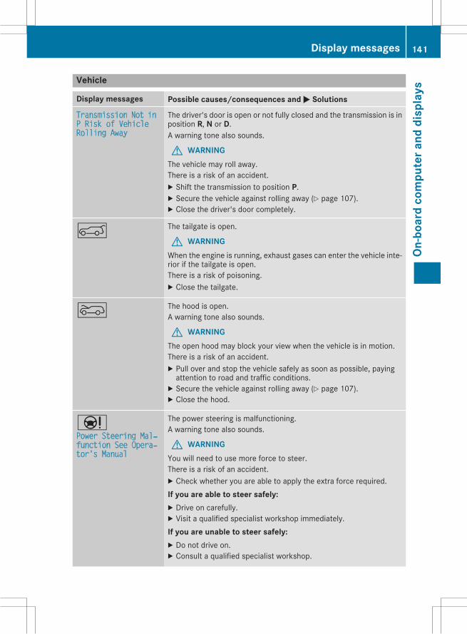
Vehicle
Display messages Possible causes/consequences and M Solutions
Transmission Not inP Risk of VehicleRolling AwayThe driver's door is open or not fully closed and the transmission is inposition R, N or D.A warning tone also sounds.
G WARNINGThe vehicle may roll away.There is a risk of an accident.X Shift the transmission to position P.X Secure the vehicle against rolling away (Y page 107).X Close the driver's door completely.
A The tailgate is open.
G WARNINGWhen the engine is running, exhaust gases can enter the vehicle inte-rior if the tailgate is open.There is a risk of poisoning.X Close the tailgate.
? The hood is open.A warning tone also sounds.
G WARNINGThe open hood may block your view when the vehicle is in motion.There is a risk of an accident.X Pull over and stop the vehicle safely as soon as possible, payingattention to road and traffic conditions.X Secure the vehicle against rolling away (Y page 107).X Close the hood.
ÐPower Steering Malхfunction See Operaхtor's Manual
The power steering is malfunctioning.A warning tone also sounds.
G WARNINGYou will need to use more force to steer.There is a risk of an accident.X Check whether you are able to apply the extra force required.If you are able to steer safely:X Drive on carefully.X Visit a qualified specialist workshop immediately.If you are unable to steer safely:X Do not drive on.X Consult a qualified specialist workshop.
Display messages 141
On-b
oard
com
pute
rand
disp
lays
Z
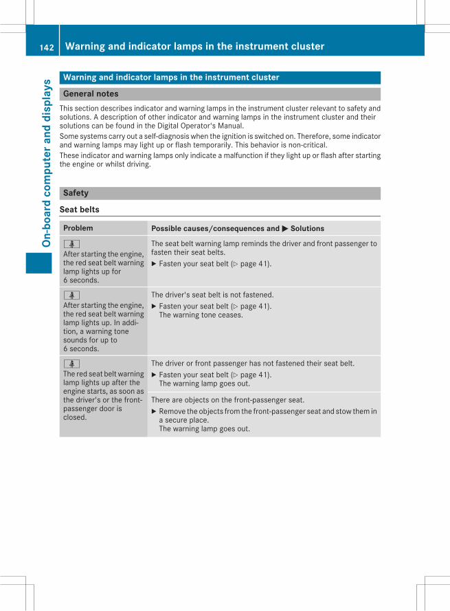
Warning and indicator lamps in the instrument cluster
General notesThis section describes indicator and warning lamps in the instrument cluster relevant to safety andsolutions. A description of other indicator and warning lamps in the instrument cluster and theirsolutions can be found in the Digital Operator's Manual.Some systems carry out a self-diagnosis when the ignition is switched on. Therefore, some indicatorand warning lamps may light up or flash temporarily. This behavior is non-critical.These indicator and warning lamps only indicate a malfunction if they light up or flash after startingthe engine or whilst driving.
Safety
Seat belts
Problem Possible causes/consequences and M Solutions
üAfter starting the engine,the red seat belt warninglamp lights up for6 seconds.
The seat belt warning lamp reminds the driver and front passenger tofasten their seat belts.X Fasten your seat belt (Y page 41).
üAfter starting the engine,the red seat belt warninglamp lights up. In addi-tion, a warning tonesounds for up to6 seconds.
The driver's seat belt is not fastened.X Fasten your seat belt (Y page 41).The warning tone ceases.
üThe red seat belt warninglamp lights up after theengine starts, as soon asthe driver's or the front-passenger door isclosed.
The driver or front passenger has not fastened their seat belt.X Fasten your seat belt (Y page 41).The warning lamp goes out.
There are objects on the front-passenger seat.X Remove the objects from the front-passenger seat and stow them ina secure place.The warning lamp goes out.
142 Warning and indicator lamps in the instrument clusterOn
-boa
rdco
mpu
tera
nddi
spla
ys
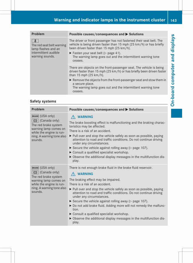
Problem Possible causes/consequences and M Solutions
üThe red seat belt warninglamp flashes and anintermittent audiblewarning sounds.
The driver or front passenger has not fastened their seat belt. Thevehicle is being driven faster than 15 mph (25 km/h) or has brieflybeen driven faster than 15 mph (25 km/h).X Fasten your seat belt (Y page 41).The warning lamp goes out and the intermittent warning toneceases.
There are objects on the front-passenger seat. The vehicle is beingdriven faster than 15 mph (25 km/h) or has briefly been driven fasterthan 15 mph (25 km/h).X Remove the objects from the front-passenger seat and stow them ina secure place.The warning lamp goes out and the intermittent warning toneceases.
Safety systems
Problem Possible causes/consequences and M Solutions
$ (USA only)J (Canada only)The red brake systemwarning lamp comes onwhile the engine is run-ning. Awarning tone alsosounds.
G WARNINGThe brake boosting effect is malfunctioning and the braking charac-teristics may be affected.There is a risk of an accident.X Pull over and stop the vehicle safely as soon as possible, payingattention to road and traffic conditions. Do not continue drivingunder any circumstances.X Secure the vehicle against rolling away (Y page 107).X Consult a qualified specialist workshop.X Observe the additional display messages in the multifunction dis-play.
$ (USA only)J (Canada only)The red brake systemwarning lamp comes onwhile the engine is run-ning. Awarning tone alsosounds.
There is not enough brake fluid in the brake fluid reservoir.
G WARNINGThe braking effect may be impaired.There is a risk of an accident.X Pull over and stop the vehicle safely as soon as possible, payingattention to road and traffic conditions. Do not continue drivingunder any circumstances.X Secure the vehicle against rolling away (Y page 107).X Do not add brake fluid. Adding more will not remedy the malfunc-tion.X Consult a qualified specialist workshop.X Observe the additional display messages in the multifunction dis-play.
Warning and indicator lamps in the instrument cluster 143
On-b
oard
com
pute
rand
disp
lays
Z
Problem Possible causes/consequences and M Solutions
!The yellow ABS warninglamp is lit while theengine is running.
ABS (Anti-lock Braking System) is deactivated due to a malfunction.Therefore, BAS (Brake Assist), COLLISION PREVENTION ASSISTPLUS, ESP® (Electronic Stability Program), the HOLD function and hillstart assist are also deactivated, for example.ATTENTION ASSIST is deactivated.
G WARNINGThe brake system continues to function normally, but without thefunctions listed above. The wheels could therefore lock if you brakehard, for example.The steerability and braking characteristics may be severely affected.The braking distance in an emergency braking situation can increase.If ESP® is not operational, ESP® is unable to stabilize the vehicle.There is an increased risk of skidding and an accident.X Observe the additional display messages in the multifunction dis-play.X Drive on carefully.X Visit a qualified specialist workshop immediately.If the ABS control unit is faulty, there is also a possibility that othersystems, such as the navigation system or the automatic transmis-sion, will not be available.
144 Warning and indicator lamps in the instrument clusterOn
-boa
rdco
mpu
tera
nddi
spla
ys
Problem Possible causes/consequences and M Solutions
!The yellow ABS warninglamp is lit while theengine is running.
ABS is temporarily unavailable. Therefore, BAS, COLLISION PREVEN-TION ASSIST PLUS, ESP®, EBD (electronic brake force distribution),the HOLD function and hill start assist are also deactivated, for exam-ple.Possible causes are:RSelf-diagnosis is not yet complete.RThe on-board voltage may be insufficient.ATTENTION ASSIST is deactivated.
G WARNINGThe brake system continues to function normally, but without thefunctions listed above. The front and rear wheels could therefore lockif you brake hard, for example.The steerability and braking characteristics may be severely affected.The braking distance in an emergency braking situation can increase.If ESP® is not operational, ESP® is unable to stabilize the vehicle.There is a risk of an accident.X Carefully drive a suitable distance, making slight steering move-ments at a speed above 12 mph (20 km/h).The functions mentioned above are available again when the warn-ing lamp goes out.
If the warning lamp is still on:X Observe the additional display messages in the multifunction dis-play.X Drive on carefully.X Visit a qualified specialist workshop immediately.
!The yellow ABS warninglamp is lit while theengine is running. Awarning tone alsosounds.
EBD ismalfunctioning. Therefore, ABS, BAS, COLLISION PREVENTIONASSIST PLUS, ESP®, the HOLD function and hill start assist for exam-ple, are also not available.ATTENTION ASSIST is deactivated.
G WARNINGThe brake system continues to function normally, but without thefunctions listed above. The front and rear wheels could therefore lockif you brake hard, for example.The steerability and braking characteristics may be severely affected.The braking distance in an emergency braking situation can increase.If ESP® is not operational, ESP® is unable to stabilize the vehicle.There is an increased risk of skidding and an accident.X Observe the additional display messages in the multifunction dis-play.X Drive on carefully.X Visit a qualified specialist workshop immediately.
Warning and indicator lamps in the instrument cluster 145
On-b
oard
com
pute
rand
disp
lays
Z
Problem Possible causes/consequences and M Solutions
$ (USA only)J (Canada only)!÷åThe red brake systemwarning lamp and theyellow ABS, ESP® andESP®OFFwarning lampsare lit while the drive sys-tem is running.
ABS and ESP® are malfunctioning. Therefore, BAS, COLLISION PRE-VENTION ASSIST PLUS, EBD, the HOLD function and hill start assistfor example, are also not available.ATTENTION ASSIST is deactivated.
G WARNINGThe brake system continues to function normally, but without thefunctions listed above. The front and rear wheels could therefore lockif you brake hard, for example.The steerability and braking characteristics may be severely affected.The braking distance in an emergency braking situation can increase.If ESP® is not operational, ESP® is unable to stabilize the vehicle.There is an increased risk of skidding and an accident.X Observe the additional display messages in the multifunction dis-play.X Drive on carefully.X Visit a qualified specialist workshop immediately.
÷
The yellow ESP®warninglamp flashes while thevehicle is in motion.
ESP® or traction control has intervened because there is a risk ofskidding or at least one wheel has started to spin.Cruise control or DISTRONIC PLUS is deactivated.X When pulling away, only depress the accelerator pedal as far asnecessary.X Ease off the accelerator pedal while the vehicle is in motion.X Adapt your driving style to suit the road and weather conditions.X Do not deactivate ESP®.In rare cases (Y page 62) , it may be best to deactivate ESP®.Observe the important safety notes on ESP® (Y page 61).
å
The yellow ESP® OFFwarning lamp is lit whilethe engine is running.
ESP® is deactivated. ESP® will not stabilize the vehicle if it starts toskid or if a wheel starts to spin.
G WARNINGIf ESP® is switched off, ESP® is unable to stabilize the vehicle.Further driving systems or driving safety systems are thus restricted.There is an increased risk of skidding and an accident.X Reactivate ESP®.In rare cases (Y page 62) , it may be best to deactivate ESP®.Observe the important safety notes on ESP® (Y page 61).X Adapt your driving style to suit the road and weather conditions.If ESP® cannot be activated:X Drive on carefully.X Contact a qualified specialist workshop and have ESP® checked.
146 Warning and indicator lamps in the instrument clusterOn
-boa
rdco
mpu
tera
nddi
spla
ys
Problem Possible causes/consequences and M Solutions
֌
The yellow ESP® andESP®OFFwarning lampsare lit while the engine isrunning.
ESP®, BAS, COLLISION PREVENTION ASSIST PLUS, the HOLD func-tion and hill start assist are not available due to a malfunction.ATTENTION ASSIST is deactivated.
G WARNINGThe brake system continues to function normally, but without thefunctions listed above.The braking distance in an emergency braking situation can thusincrease.If ESP® is not operational, ESP® is unable to stabilize the vehicle.There is an increased risk of skidding and an accident.X Observe the additional display messages in the multifunction dis-play.X Drive on carefully.X Visit a qualified specialist workshop immediately.
֌
The yellow ESP® andESP®OFFwarning lampsare lit while the engine isrunning.
ESP®, BAS, the HOLD function and hill start assist are temporarilyunavailable.COLLISION PREVENTION ASSIST PLUS may also have failed.ATTENTION ASSIST is deactivated.Self-diagnosis is not yet complete.
G WARNINGThe brake system continues to function normally, but without thefunctions listed above.The braking distance in an emergency braking situation can thusincrease.If ESP® is not operational, ESP® is unable to stabilize the vehicle.There is an increased risk of skidding and an accident.X Carefully drive a suitable distance, making slight steering move-ments at a speed above 12 mph (20 km/h).The functions mentioned above are available again when the warn-ing lamp goes out.
If the warning lamp is still on:X Observe the additional display messages in the multifunction dis-play.X Drive on carefully.X Visit a qualified specialist workshop immediately.
Warning and indicator lamps in the instrument cluster 147
On-b
oard
com
pute
rand
disp
lays
Z
Problem Possible causes/consequences and M Solutions
F (USA only)! (Canada only)The red indicator lampfor the electric parkingbrake flashes or lights upand/or the yellow warn-ing lamp for the electricparking brake lights up.
X Observe the additional display messages in the multifunction dis-play.
6The red restraint systemwarning lamp is lit whilethe engine is running.
The restraint system is faulty.
G WARNINGThe air bags or Emergency Tensioning Devicesmay either be triggeredunintentionally or, in the event of an accident, may not be triggered.There is an increased risk of injury.X Observe the additional display messages in the multifunction dis-play.X Drive on carefully.X Contact a qualified specialist workshop and have the restraint sys-tem checked.
For further information about the restraint system, see (Y page 37).
148 Warning and indicator lamps in the instrument clusterOn
-boa
rdco
mpu
tera
nddi
spla
ys
Engine
Problem Possible causes/consequences and M Solutions
?The red coolant warninglamp comes on while theengine is running. Awarning tone alsosounds.
The coolant temperature has exceeded 248‡ (120†). The airflow tothe engine radiator may be blocked or the coolant level may be toolow.
G WARNINGThe engine is not being cooled sufficiently and may be damaged.Do not drive when your engine is overheated. This can cause somefluids which may have leaked into the engine compartment to catchfire.Steam from the overheated engine can also cause serious burnswhichcan occur just by opening the hood.There is a risk of injury.X Observe the additional display messages in the multifunction dis-play.X Pull over and stop the vehicle safely and switch off the engine, pay-ing attention to road and traffic conditions.X Secure the vehicle against rolling away (Y page 107).X Leave the vehicle and keep a safe distance from the vehicle until theengine has cooled down.X Check the coolant level and add coolant, observing the warningnotes (Y page 186).X If you have to add coolant frequently, have the engine cooling sys-tem checked.X Make sure that the air supply to the engine radiator is not blocked,e.g. by snow, slush or ice.X At coolant temperatures below 248‡ (120†), drive to the nearestqualified specialist workshop.X Avoid heavy loads on the engine as you do so, e.g. driving in moun-tainous terrain and stop-start traffic.
Driving systems
Problem Possible causes/consequences and M Solutions
·The red distancewarninglamp lights up while thevehicle is in motion. Awarning tone alsosounds.
You are approaching a vehicle or a stationary obstacle in your line oftravel at too high a speed.X Be prepared to brake immediately.X Pay careful attention to the traffic situation. You may have to brakeor take evasive action.
For further information about the distance warning function of COL-LISION PREVENTION ASSIST PLUS, see (Y page 59).
Warning and indicator lamps in the instrument cluster 149
On-b
oard
com
pute
rand
disp
lays
Z
General notes
The Audio 20/COMAND section in these oper-ating instructions describes the basic operatingprinciples. More information can be found in theDigital Operator's Manual.
Important safety notes
G WARNINGModifications to electronic components, theirsoftware as well as wiring can impair theirfunction and/or the function of other net-worked components. In particular, systemsrelevant to safety could also be affected. As aresult, these may no longer function as inten-ded and/or jeopardize the operating safety ofthe vehicle. There is an increased risk of anaccident and injury.Never tamper with the wiring as well as elec-tronic components or their software. Youshould have all work to electrical and elec-tronic equipment carried out at a qualifiedspecialist workshop.
If you make any changes to the vehicle elec-tronics, the general operating permit is ren-dered invalid.
G WARNINGIf you operate information systems and com-munication equipment integrated in the vehi-cle while driving, you will be distracted fromtraffic conditions. You could also lose controlof the vehicle. There is a risk of an accident.Only operate the equipment when the trafficsituation permits. If you are not sure that thisis possible, park the vehicle paying attentionto traffic conditions and operate the equip-ment when the vehicle is stationary.
Youmust observe the legal requirements for thecountry in which you are currently driving whenoperating Audio 20/COMAND.
Audio 20/COMAND calculates the route to thedestination without taking account of the fol-lowing, for example:Rtraffic lightsRstop and yield signsRmerging lanesRparking or stopping in a no parking/no stop-ping zone
Rother road and traffic rules and regulationsRnarrow bridgesAudio 20/COMAND can give incorrect naviga-tion commands if the actual street/traffic sit-uation does not correspond with the digitalmap's data. Digital maps do not cover all areasnor all routes in an area. For example, a routemay have beendiverted or the direction of a one-way street may have changed.For this reason, you must always observe roadand traffic rules and regulations during yourjourney. Road and traffic rules and regulationsalways have priority over the system's drivingrecommendations.Navigation announcements are intended todirect you while driving without diverting yourattention from the road and driving.Please always use this feature instead of con-sulting the map display for directions. Lookingat the icons ormap display can distract you fromtraffic conditions and driving, and increase therisk of an accident.Bear in mind that at a speed of only 30 mph(approximately 50 km/h) your vehicle covers adistance of 44 feet (approximately 14 m) persecond.This equipment complies with FCC radiationexposure limits set forth for uncontrolled equip-ment and meets the FCC radio frequency (RF)Exposure Guidelines in Supplement C to OET65.This equipment has very low levels of RF energythat is deemed to comply without maximumpermissive exposure evaluation (MPE). But it isdesirable that it should be installed and oper-ated with at least 8 inches (20cm) and morebetween the radiator and a person's body(excluding extremities: hands, wrists, feet andlegs.)
Function restrictions
For safety reasons, some functions are restric-ted or unavailable while the vehicle is in motion.
150 Function restrictionsAu
dio
20/C
OMAN
D
You will notice this, for example, because eitheryou will not be able to select certain menu itemsor a message will appear to this effect.
Function restrictions 151
Audi
o20
/COM
AND
Z
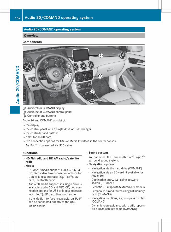
Audio 20/COMAND operating system
Overview
Components
: Audio 20 or COMAND display; Audio 20 or COMAND control panel= Controller and buttonsAudio 20 and COMAND consist of:Rthe displayRthe control panel with a single drive or DVD changerRthe controller and buttonsRa slot for an SD cardRtwo connection options for USB or Media Interface in the center consoleAn iPod® is connected via USB cable.
FunctionsRHD FM radio and HD AM radio/satellite
radioRMedia
- COMAND media support: audio CD, MP3CD, DVD video, two connection options forUSB or Media Interface (e.g. iPod®), SDcard, Bluetooth audioAudio 20 media support: if a single drive isavailable, audio CD and MP3 CD, two con-nection options for USB or Media Interface(e.g. iPod®), SD card, Bluetooth audioIf the Media Interface is available, an iPod®can be connected directly to the USB.
- Media search
RSound systemYou can select the Harman/Kardon® Logic7®surround sound system.
RNavigation system- Navigation via the hard drive (COMAND)- Navigation via an SD card (if available forAudio 20)
- Destination entry, e.g. using keywordsearch (COMAND)
- Realistic 3D map with textured city models- Personal POIs and routes using SDmemorycard (COMAND)
- Navigation functions, e.g. compass display(COMAND)
- Dynamic route guidancewith traffic reportsvia SIRIUS satellite radio (COMAND)
152 Audio 20/COMAND operating systemAu
dio
20/C
OMAN
D
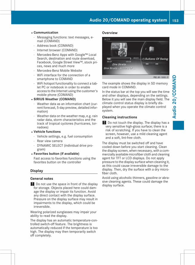
RCommunication- Messaging functions: text messages, e-mail (COMAND)
- Address book (COMAND)- Internet browser (COMAND)- Mercedes-Benz Apps with Google™ LocalSearch, destination and route download,Facebook, Google Street View™, stock pri-ces, news and much more
- Mercedes-Benz Mobile Website- WiFi interface for the connection of asmartphone to COMAND
- WiFi hotspot functionality to connect a tab-let PC or notebook in order to enableaccess to the Internet using the customer'smobile phone (COMAND)
RSIRIUS Weather (COMAND)- Weather data as an information chart (cur-rent forecast, 5-day preview, detailed infor-mation)
- Weather data on the weather map, e.g. rainradar data, storm characteristics and thetrack of tropical cyclones (hurricanes, tor-nadoes)
RVehicle functions- Vehicle settings, e.g. fuel consumption- Rear view camera- DYNAMIC SELECT (individual drive pro-gram)
RFavorites button (if available)Fast access to favorites functions using thefavorites button on the controller
Display
General notes! Do not use the space in front of the displayfor storage. Objects placed here could dam-age the display or impair its function. Avoidany direct contact with the display surface.Pressure on the display surface may result inimpairments to the display, which could beirreversible.
Wearing polarized sunglasses may impair yourability to read the display.The display has an automatic temperature-con-trolled switch-off feature. The brightness isautomatically reduced if the temperature is toohigh. The display may then temporarily switchoff completely.
Overview
The example shows the display in SD memorycard mode in COMAND.In the status bar at the top you will see the timeand other displays, depending on the settings.Below it you will see the main display field. Theclimate control status display is briefly dis-played when you operate the climate controlsystem.
Cleaning instructions! Do not touch the display. The display has avery sensitive high-gloss surface; there is arisk of scratching. If you have to clean thescreen, however, use a mild cleaning agentand a soft, lint-free cloth.
The display must be switched off and havecooled down before you start cleaning. Cleanthe display screen, when necessary, with a com-mercially availablemicrofiber cloth and cleaningagent for TFT or LCD displays. Do not applypressure to the display surface when cleaning it,as this could cause irreversible damage to thedisplay. Then, dry the surface with a dry micro-fiber cloth.Avoid using alcoholic thinners, gasoline or abra-sive cleaning agents. These could damage thedisplay surface.
Audio 20/COMAND operating system 153
Audi
o20
/COM
AND
Z
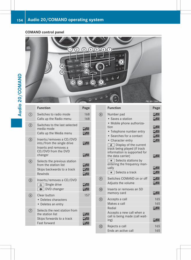
COMAND control panel
Function Page
: Switches to radio mode 168Calls up the Radio menu 168
; Switches to the last selectedmedia mode ~
Calls up the Media menu ~
= Inserts/removes a CD/DVDinto/from the single drive ~
Inserts and removes aCD/DVD from the DVDchanger ~
? Selects the previous stationfrom the station list ~
Skips backwards to a track ~
Rewinds ~
A Inserts/removes a CD/DVD8 Single drive ~
V DVD changer ~
B Clear button 157• Deletes characters• Deletes an entry
C Selects the next station fromthe station list ~
Skips forwards to a track ~
Fast forward ~
Function Page
D Number pad ~
• Saves a station ~
• Mobile phone authoriza-tion ~
• Telephone number entry ~
• Searches for a contact ~
• Character entry ~
z Display of the currenttrack being played (if trackinformation is supported forthe data carrier) ~
g Selects stations byentering the frequency man-ually ~
g Selects a track ~
E Switches COMAND on or off ~
Adjusts the volume ~
F Inserts or removes an SDmemory card ~
G Accepts a call 165Makes a call 165Redial ~
Accepts a new call when acall is being made (call wait-ing) ~
H Rejects a call 165Ends an active call 165
154 Audio 20/COMAND operating systemAu
dio
20/C
OMAN
D
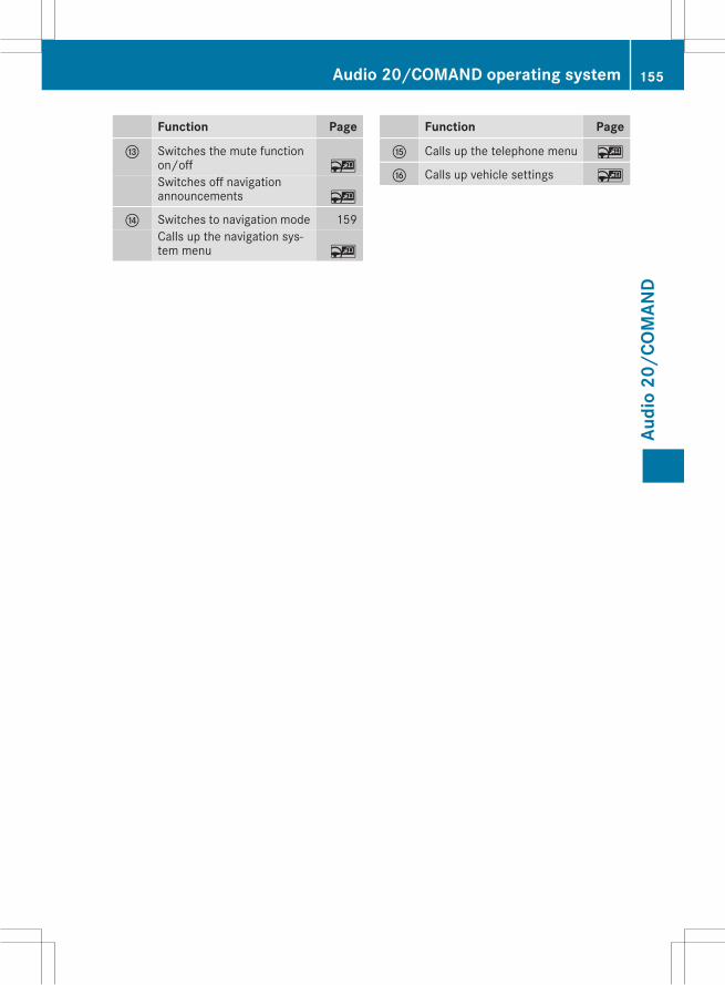
Function Page
I Switches the mute functionon/off ~
Switches off navigationannouncements ~
J Switches to navigation mode 159Calls up the navigation sys-tem menu ~
Function Page
K Calls up the telephone menu ~
L Calls up vehicle settings ~
Audio 20/COMAND operating system 155
Audi
o20
/COM
AND
Z
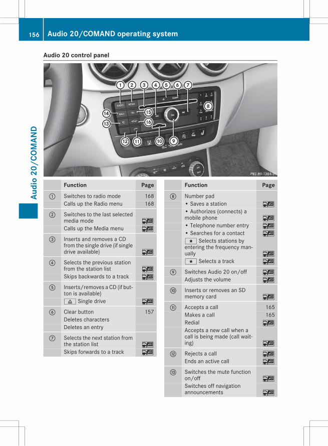
Audio 20 control panel
Function Page
: Switches to radio mode 168Calls up the Radio menu 168
; Switches to the last selectedmedia mode ~
Calls up the Media menu ~
= Inserts and removes a CDfrom the single drive (if singledrive available) ~
? Selects the previous stationfrom the station list ~
Skips backwards to a track ~
A Inserts/removes a CD (if but-ton is available)8 Single drive ~
B Clear button 157Deletes charactersDeletes an entry
C Selects the next station fromthe station list ~
Skips forwards to a track ~
Function Page
D Number pad• Saves a station ~
• Authorizes (connects) amobile phone ~
• Telephone number entry ~
• Searches for a contact ~
g Selects stations byentering the frequency man-ually ~
g Selects a track ~
E Switches Audio 20 on/off ~
Adjusts the volume ~
F Inserts or removes an SDmemory card ~
G Accepts a call 165Makes a call 165Redial ~
Accepts a new call when acall is being made (call wait-ing) ~
H Rejects a call ~
Ends an active call ~
I Switches the mute functionon/off ~
Switches off navigationannouncements ~
156 Audio 20/COMAND operating systemAu
dio
20/C
OMAN
D
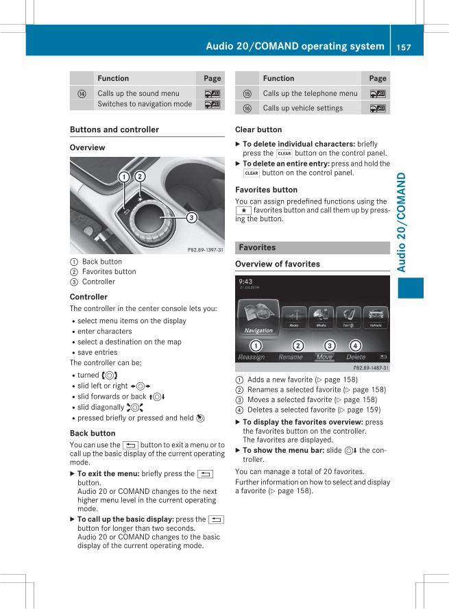
Function Page
J Calls up the sound menu ~
Switches to navigation mode ~
Function Page
K Calls up the telephone menu ~
L Calls up vehicle settings ~
Buttons and controller
Overview
: Back button; Favorites button= Controller
ControllerThe controller in the center console lets you:Rselect menu items on the displayRenter charactersRselect a destination on the mapRsave entriesThe controller can be:Rturned3Rslid left or right1Rslid forwards or back4Rslid diagonally2Rpressed briefly or pressed and held7
Back buttonYou can use the% button to exit amenu or tocall up the basic display of the current operatingmode.X To exit the menu: briefly press the%button.Audio 20 or COMAND changes to the nexthigher menu level in the current operatingmode.X To call up the basic display: press the%button for longer than two seconds.Audio 20 or COMAND changes to the basicdisplay of the current operating mode.
Clear buttonX To delete individual characters: brieflypress the$ button on the control panel.X To delete an entire entry: press and hold the$ button on the control panel.
Favorites buttonYou can assign predefined functions using theg favorites button and call them up by press-ing the button.
Favorites
Overview of favorites
: Adds a new favorite (Y page 158); Renames a selected favorite (Y page 158)= Moves a selected favorite (Y page 158)? Deletes a selected favorite (Y page 159)X To display the favorites overview: pressthe favorites button on the controller.The favorites are displayed.X To show the menu bar: slide6 the con-troller.
You can manage a total of 20 favorites.Further information on how to select and displaya favorite (Y page 158).
Audio 20/COMAND operating system 157
Audi
o20
/COM
AND
Z
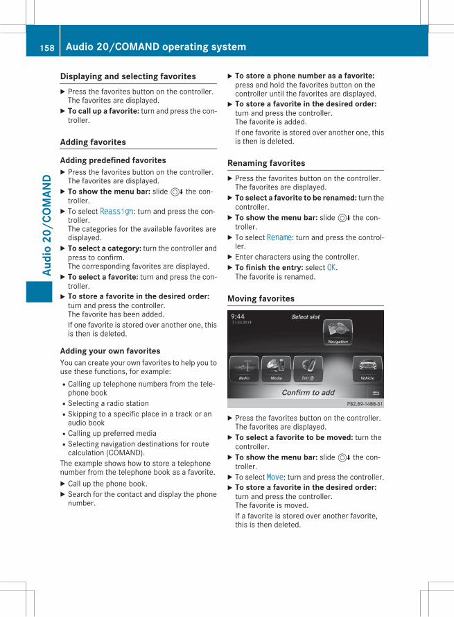
Displaying and selecting favoritesX Press the favorites button on the controller.The favorites are displayed.X To call up a favorite: turn and press the con-troller.
Adding favorites
Adding predefined favoritesX Press the favorites button on the controller.The favorites are displayed.X To show the menu bar: slide6 the con-troller.X To select Reassign: turn and press the con-troller.The categories for the available favorites aredisplayed.X To select a category: turn the controller andpress to confirm.The corresponding favorites are displayed.X To select a favorite: turn and press the con-troller.X To store a favorite in the desired order:turn and press the controller.The favorite has been added.If one favorite is stored over another one, thisis then is deleted.
Adding your own favoritesYou can create your own favorites to help you touse these functions, for example:RCalling up telephone numbers from the tele-phone book
RSelecting a radio stationRSkipping to a specific place in a track or anaudio book
RCalling up preferred mediaRSelecting navigation destinations for routecalculation (COMAND).
The example shows how to store a telephonenumber from the telephone book as a favorite.X Call up the phone book.X Search for the contact and display the phonenumber.
X To store a phone number as a favorite:press and hold the favorites button on thecontroller until the favorites are displayed.X To store a favorite in the desired order:turn and press the controller.The favorite is added.If one favorite is stored over another one, thisis then is deleted.
Renaming favoritesX Press the favorites button on the controller.The favorites are displayed.X To select a favorite to be renamed: turn thecontroller.X To show the menu bar: slide6 the con-troller.X To select Rename: turn and press the control-ler.X Enter characters using the controller.X To finish the entry: select OK.The favorite is renamed.
Moving favorites
X Press the favorites button on the controller.The favorites are displayed.X To select a favorite to be moved: turn thecontroller.X To show the menu bar: slide6 the con-troller.X To select Move: turn and press the controller.X To store a favorite in the desired order:turn and press the controller.The favorite is moved.If a favorite is stored over another favorite,this is then deleted.
158 Audio 20/COMAND operating systemAu
dio
20/C
OMAN
D
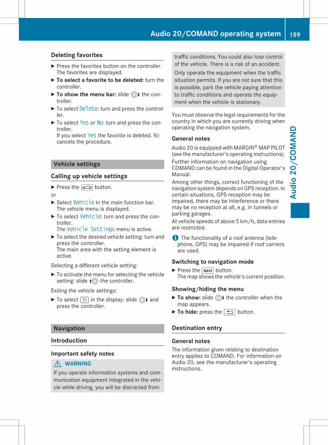
Deleting favoritesX Press the favorites button on the controller.The favorites are displayed.X To select a favorite to be deleted: turn thecontroller.X To show the menu bar: slide6 the con-troller.X To select Delete: turn and press the control-ler.X To select Yes or No: turn and press the con-troller.If you select Yes the favorite is deleted. Nocancels the procedure.
Vehicle settings
Calling up vehicle settingsX Press theØ button.orX Select Vehicle in the main function bar.The vehicle menu is displayed.X To select Vehicle: turn and press the con-troller.The Vehicle Settings menu is active.X To select the desired vehicle setting: turn andpress the controller.The main area with the setting element isactive.
Selecting a different vehicle setting:X To activate the menu for selecting the vehiclesetting: slide5 the controller.
Exiting the vehicle settings:X To select& in the display: slide6 andpress the controller.
Navigation
Introduction
Important safety notesG WARNINGIf you operate information systems and com-munication equipment integrated in the vehi-cle while driving, you will be distracted from
traffic conditions. You could also lose controlof the vehicle. There is a risk of an accident.Only operate the equipment when the trafficsituation permits. If you are not sure that thisis possible, park the vehicle paying attentionto traffic conditions and operate the equip-ment when the vehicle is stationary.
Youmust observe the legal requirements for thecountry in which you are currently driving whenoperating the navigation system.
General notesAudio 20 is equipped with MARGIN®MAP PILOT(see themanufacturer's operating instructions).Further information on navigation usingCOMAND can be found in the Digital Operator'sManual.Among other things, correct functioning of thenavigation systemdepends onGPS reception. Incertain situations, GPS reception may beimpaired, there may be interference or theremay be no reception at all, e.g. in tunnels orparking garages.At vehicle speeds of above 5 km/h, data entriesare restricted.
i The functionality of a roof antenna (tele-phone, GPS) may be impaired if roof carriersare used.
Switching to navigation modeX Press theß button.Themap shows the vehicle's current position.
Showing/hiding the menuX To show: slide6 the controller when themap appears.X To hide: press the% button.
Destination entry
General notesThe information given relating to destinationentry applies to COMAND. For information onAudio 20, see the manufacturer's operatinginstructions.
Audio 20/COMAND operating system 159
Audi
o20
/COM
AND
Z
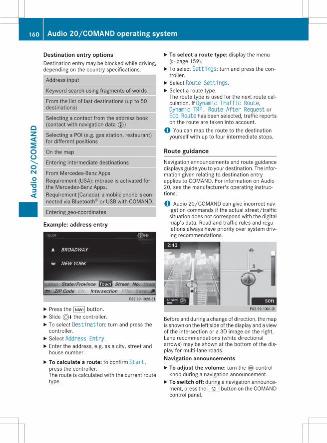
Destination entry optionsDestination entry may be blocked while driving,depending on the country specifications.
Address input
Keyword search using fragments of words
From the list of last destinations (up to 50destinations)
Selecting a contact from the address book(contact with navigation dataL)
Selecting a POI (e.g. gas station, restaurant)for different positions
On the map
Entering intermediate destinations
From Mercedes-Benz AppsRequirement (USA): mbrace is activated forthe Mercedes-Benz Apps.Requirement (Canada): amobile phone is con-nected via Bluetooth® or USB with COMAND.
Entering geo-coordinates
Example: address entry
X Press theß button.X Slide6 the controller.X To select Destination: turn and press thecontroller.X Select Address Entry.X Enter the address, e.g. as a city, street andhouse number.X To calculate a route: to confirm Start,press the controller.The route is calculated with the current routetype.
X To select a route type: display the menu(Y page 159).X To select Settings: turn and press the con-troller.X Select Route Settings.X Select a route type.The route type is used for the next route cal-culation. If Dynamic Traffic Route,Dynamic TRF. Route After Request orEco Route has been selected, traffic reportson the route are taken into account.i You can map the route to the destinationyourself with up to four intermediate stops.
Route guidanceNavigation announcements and route guidancedisplays guide you to your destination. The infor-mation given relating to destination entryapplies to COMAND. For information on Audio20, see the manufacturer's operating instruc-tions.
i Audio 20/COMAND can give incorrect nav-igation commands if the actual street/trafficsituation does not correspond with the digitalmap's data. Road and traffic rules and regu-lations always have priority over system driv-ing recommendations.
Before and during a change of direction, themapis shownon the left side of the display and a viewof the intersection or a 3D image on the right.Lane recommendations (white directionalarrows) may be shown at the bottom of the dis-play for multi-lane roads.Navigation announcementsX To adjust the volume: turn theo controlknob during a navigation announcement.X To switch off: during a navigation announce-ment, press the8 button on the COMANDcontrol panel.
160 Audio 20/COMAND operating systemAu
dio
20/C
OMAN
D
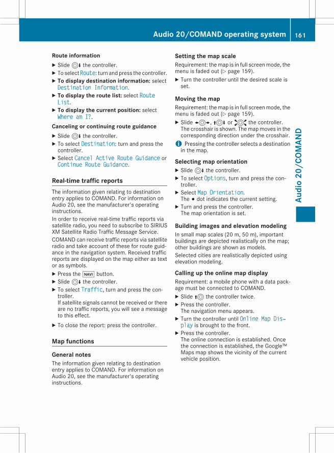
Route informationX Slide6 the controller.X To select Route: turn and press the controller.X To display destination information: selectDestination Information.X To display the route list: select RouteList.X To display the current position: selectWhere am I?.
Canceling or continuing route guidanceX Slide6 the controller.X To select Destination: turn and press thecontroller.X Select Cancel Active Route Guidance orContinue Route Guidance.Real-time traffic reportsThe information given relating to destinationentry applies to COMAND. For information onAudio 20, see the manufacturer's operatinginstructions.In order to receive real-time traffic reports viasatellite radio, you need to subscribe to SIRIUSXM Satellite Radio Traffic Message Service.COMAND can receive traffic reports via satelliteradio and take account of these for route guid-ance in the navigation system. Received trafficreports are displayed on the map either as textor as symbols.X Press theØ button.X Slide6 the controller.X To select Traffic, turn and press the con-troller.If satellite signals cannot be received or thereare no traffic reports, you will see a messageto this effect.X To close the report: press the controller.
Map functions
General notesThe information given relating to destinationentry applies to COMAND. For information onAudio 20, see the manufacturer's operatinginstructions.
Setting the map scaleRequirement: themap is in full screenmode, themenu is faded out (Y page 159).X Turn the controller until the desired scale isset.
Moving the mapRequirement: themap is in full screenmode, themenu is faded out (Y page 159).X Slide1,4 or2 the controller.The crosshair is shown. Themapmoves in thecorresponding direction under the crosshair.i Pressing the controller selects a destinationin the map.
Selecting map orientationX Slide6 the controller.X To select Options, turn and press the con-troller.X Select Map Orientation.The # dot indicates the current setting.X Turn and press the controller.The map orientation is set.
Building images and elevation modelingIn small map scales (20 m, 50 m), importantbuildings are depicted realistically on the map;other buildings are shown as models.Selected cities are realistically depicted usingelevation modeling.
Calling up the online map displayRequirement: a mobile phone with a data pack-age must be connected to COMAND.X Slide5 the controller twice.X Press the controller.The navigation menu appears.X Turn the controller until Online Map Disхplay is brought to the front.X Press the controller.The online connection is established. Oncethe connection is established, the Google™Maps map shows the vicinity of the currentvehicle position.
Audio 20/COMAND operating system 161
Audi
o20
/COM
AND
Z
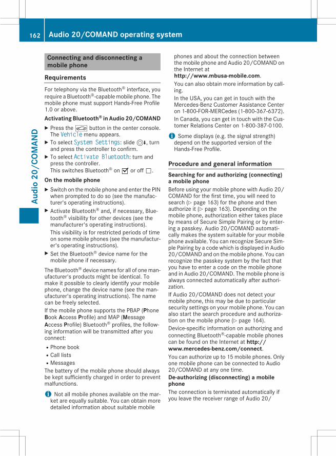
Connecting and disconnecting amobile phone
RequirementsFor telephony via the Bluetooth® interface, yourequire a Bluetooth®-capablemobile phone. Themobile phone must support Hands-Free Profile1.0 or above.Activating Bluetooth® in Audio 20/COMANDX Press theØ button in the center console.The Vehicle menu appears.X To select System Settings: slide6, turnand press the controller to confirm.X To select Activate Bluetooth: turn andpress the controller.This switches Bluetooth® onO or offª.
On the mobile phoneX Switch on themobile phone and enter the PINwhen prompted to do so (see the manufac-turer's operating instructions).X Activate Bluetooth® and, if necessary, Blue-tooth® visibility for other devices (see themanufacturer's operating instructions).This visibility is for restricted periods of timeon some mobile phones (see the manufactur-er's operating instructions).X Set the Bluetooth® device name for themobile phone if necessary.
The Bluetooth® device names for all of oneman-ufacturer's products might be identical. Tomake it possible to clearly identify your mobilephone, change the device name (see the man-ufacturer's operating instructions). The namecan be freely selected.If the mobile phone supports the PBAP (PhoneBook Access Profile) and MAP (MessageAccess Profile) Bluetooth® profiles, the follow-ing information will be transmitted after youconnect:RPhone bookRCall listsRMessagesThe battery of the mobile phone should alwaysbe kept sufficiently charged in order to preventmalfunctions.
i Not all mobile phones available on the mar-ket are equally suitable. You can obtain moredetailed information about suitable mobile
phones and about the connection betweenthe mobile phone and Audio 20/COMAND onthe Internet athttp://www.mbusa-mobile.com.You can also obtain more information by call-ing.In the USA, you can get in touch with theMercedes-Benz Customer Assistance Centeron 1-800-FOR-MERCedes (1-800-367-6372).In Canada, you can get in touch with the Cus-tomer Relations Center on 1-800-387-0100.
i Some displays (e.g. the signal strength)depend on the supported version of theHands-Free Profile.
Procedure and general informationSearching for and authorizing (connecting)a mobile phoneBefore using your mobile phone with Audio 20/COMAND for the first time, you will need tosearch (Y page 163) for the phone and thenauthorize it (Y page 163). Depending on themobile phone, authorization either takes placeby means of Secure Simple Pairing or by enter-ing a passkey. Audio 20/COMAND automati-cally makes the system suitable for your mobilephone available. You can recognize Secure Sim-ple Pairing by a code which is displayed in Audio20/COMAND and on themobile phone. You canrecognize the passkey system by the fact thatyou have to enter a code on the mobile phoneand in Audio 20/COMAND. The mobile phone isalways connected automatically after authori-zation.If Audio 20/COMAND does not detect yourmobile phone, this may be due to particularsecurity settings on your mobile phone. You canalso start the search procedure and authoriza-tion on the mobile phone (Y page 164).Device-specific information on authorizing andconnecting Bluetooth®-capable mobile phonescan be found on the Internet at http://www.mercedes-benz.com/connect.You can authorize up to 15 mobile phones. Onlyone mobile phone can be connected to Audio20/COMAND at any one time.De-authorizing (disconnecting) a mobilephoneThe connection is terminated automatically ifyou leave the receiver range of Audio 20/
162 Audio 20/COMAND operating systemAu
dio
20/C
OMAN
D
COMAND or deactivate Bluetooth® on yourmobile phone.If you no longer want the Bluetooth® connectionto be established automatically, the mobilephone must be de-authorized (disconnected)(Y page 165).
Searching for a mobile phone
X To call up the telephone menu: press the% button.X To switch to the menu bar in the telephonemenu: slide6 the controller.X To select Conn. Device: turn and press thecontroller.The device list is displayed.X To select Search for Phones: turn andpress the controller.A message is displayed that Bluetooth®mustbe activated on themobile phone andmust bemade visible to other devices.X To select Start Search: press the controller.The available mobile phones are displayed inthe device list.
The duration of the search depends on the num-ber of Bluetooth® telephones within range andtheir characteristics.If a new phone is found, it appears in the devicelist with theÏ symbol. You can now author-ize (connect) the mobile phone found(Y page 163).If the device list is already full, you will berequested to de-authorize a mobile phone(Y page 165).When you call up the device list again, de-authorized devices will be removed from the list.To update the device list, start the search again.
Symbols in the device list
Sym-bol
Explanation
Ï New mobile phone found, not yetauthorized.
Ñ Mobile phone is authorized, but isnot connected.
# Mobile phone is authorized andconnected.
Authorizing a mobile phone (connect-ing)
Authorization via Secure Simple PairingOnce Audio 20/COMAND has found yourmobile phone, you can authorize (connect) it.X To select a mobile phone from the device list:turn the controller and press to confirm.A code is displayed in Audio 20/COMANDand on the mobile phone.
The code is the sameX Audio 20/COMAND Online: select Yes.X Mobile phone: confirm the code. Dependingon the mobile phone used, you may have toconfirm the connection to Audio 20/COMAND as well as confirm for the PBAP andMAP Bluetooth® profiles. The prompt to con-firm may take up to two minutes to be dis-played. You may also save the confirmationon the mobile phone (see the manufacturer'soperating instructions).The mobile phone is now authorized and con-nected to Audio 20/COMAND. You can nowspeak using the hands-free system.
Further information on setting the transmissionand reception volume of the mobile phone canbe found in the Digital Operator's Manual.The code is differentX Audio 20/COMAND Online: select No.The process is canceled. Repeat the authori-zation.
Authorization via passkey entry (accesscode)Once Audio 20/COMAND has found yourmobile phone, you can authorize (connect) it.
Audio 20/COMAND operating system 163
Audi
o20
/COM
AND
Z
X To select the Bluetooth® name of the desiredmobile phone in the device list: turn and pressthe controller.The input menu for the passkey is displayed.The passkey is a one- to sixteen-digit numbercombination which you can choose yourself.X Audio 20/COMAND: enter the passkeyusing the character bar.X Select¬ once all the numbers have beenentered.X Mobile phone: enter the same passkey andconfirm your entry. Depending on the mobilephone used, you may have to confirm theconnection to Audio 20/COMAND as well asconfirm for the PBAP and MAP Bluetooth®profiles. The prompt to confirm may take upto two minutes to be displayed. You may alsosave the confirmation on the mobile phone(see the manufacturer's operating instruc-tions).The mobile phone is now authorized and con-nected to Audio 20/COMAND. You can nowspeak using the hands-free system.
Further information on setting the transmissionand reception volume of the mobile phone canbe found in the Digital Operator's Manual.If the Authorization Failed messageappears, you may have entered a different pass-key or exceeded the prescribed time limit.Repeat the procedure.
i Somemobile phones require a passkey withfour or more digits.
i If you wish to re-authorize the mobile phoneafter de-authorizing it, you can chooseanother passkey for it.
Establishing a connection from themobile phoneThe Bluetooth® device name of Audio 20/COMAND is "MB Bluetooth".X Audio 20/COMAND: call up the telephonemenu.X To switch to the menu bar: slide6 the con-troller.X To select Conn. Device: turn and press thecontroller.The device list is displayed.
X To select Connect via Phone: turn andpress the controller.A message is displayed, stating that you canstart the search on your mobile phone.X Mobile phone: start the search for a Blue-tooth® device (see manufacturer's operatinginstructions).Audio 20/COMAND is displayed with thename "MB Bluetooth" in the mobile phone'sdevice list.X Select "MB Bluetooth".A prompt appears in the Audio 20/COMANDdisplay asking whether the mobile phoneshould be authorized.X Audio 20/COMAND Online: select Yes.If No is selected, the procedure is canceled.If your mobile phone supports Secure SimplePairing, a code is now displayed on both devi-ces.
The code is the sameX Audio 20/COMAND Online: select Yes.X Mobile phone: confirm the code. Dependingon the mobile phone used, you may have toconfirm the connection to Audio 20/COMAND as well as confirm for the PBAP andMAP Bluetooth® profiles. The prompt to con-firm may take up to two minutes to be dis-played. You may also save the confirmationon the mobile phone (see the manufacturer'soperating instructions).The mobile phone is now authorized and con-nected to Audio 20/COMAND. You can nowspeak using the hands-free system.
The code is differentX Audio 20/COMAND Online: select No.The process is canceled. Repeat the proce-dure.
If your mobile phone does not support SecureSimple Pairing, you can find more informationabout connecting themobile phone in theDigitalOperator's Manual.
Reconnecting automaticallyAudio 20/COMANDalways searches for the lastconnected mobile phone.If no connection can be made to the mostrecently connected mobile phone, the systemsearches for the mobile phone that was con-nected before that one.
164 Audio 20/COMAND operating systemAu
dio
20/C
OMAN
D
Switching between mobile phonesIf you have authorized more than one mobilephone, you can switch between the individualphones.X To call up the telephone menu: press the% button.X To show the menu bar: slide6 the control-ler.X To select Conn. Device: turn and press thecontroller.The device list is displayed.X To select the desired mobile phone: turn andpress the controller.The selected mobile phone is searched forand connected if it is within Bluetooth® rangeand if Bluetooth® is activated.
Only one mobile phone can be connected at anyone time. The currently connected mobilephone is indicated by the# dot in the device list.
i You can only switch to another authorizedmobile phone if you are not currently makinga call.
De-authorizing (disconnecting) a mobilephoneMercedes-Benz USA, LLC recommends de-authorization in Audio 20/COMAND and on themobile phone. Subsequent authorization mayotherwise fail.X To call up the telephone menu: press the% button.X To show the menu bar: slide6 the control-ler.X To select Conn. Device: turn and press thecontroller.X To highlight the desired mobile phone in thedevice list: turn the controller.X To selectG: slide9 the controller.X To select Deauthorize: turn and press thecontroller.A prompt appears, asking whether you reallywish to de-authorize this device.X To select Yes: turn and press the controller.The mobile phone is de-authorized.
i Before re-authorizing the mobile phone, youshould also delete the device name MB Blueхtooth from your mobile phone's Bluetooth®list.
Using the telephone
Accepting a callX To select Accept: press the controller.orX Press6 on the multifunction steeringwheel.The call is accepted.
Further information on the functions you canuse during a call can be found in the DigitalOperator's Manual.
i You can also accept the call by voice com-mandusing theVoiceControl System (see theseparate operating instructions).
i If the phone number of the caller is trans-ferred, it appears in the display. If the phonenumber is saved in the phone book, the con-tact's name is also displayed. If the phonenumber is withheld, Unknown is shown in thedisplay.
Rejecting a callX To select Accept: turn and press the control-ler.
orX Press~ on the multifunction steeringwheel.
Ending an active callX To select= in the telephone menu: turnand press the controller.
orX Press~ on the multifunction steeringwheel.The active call is ended.
Making a call
Using the telephone menuX To call up the telephone menu: press the% button.X To select all numbers one after the other inthe telephone menu: turn and press the con-troller each time.X To selectw in the telephone menu: turnand press the controller.The call is made.
Audio 20/COMAND operating system 165
Audi
o20
/COM
AND
Z
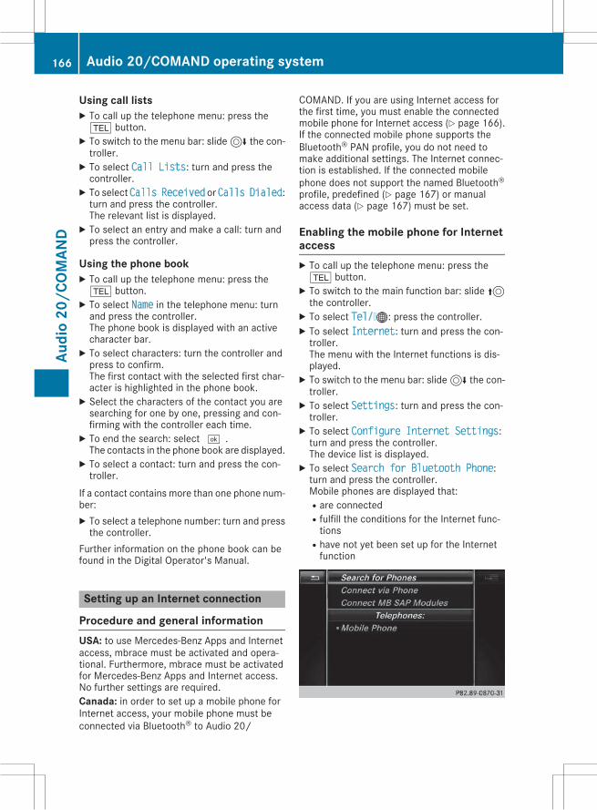
Using call listsX To call up the telephone menu: press the% button.X To switch to the menu bar: slide6 the con-troller.X To select Call Lists: turn and press thecontroller.X To select Calls Received or Calls Dialed:turn and press the controller.The relevant list is displayed.X To select an entry and make a call: turn andpress the controller.
Using the phone bookX To call up the telephone menu: press the% button.X To select Name in the telephone menu: turnand press the controller.The phone book is displayed with an activecharacter bar.X To select characters: turn the controller andpress to confirm.The first contact with the selected first char-acter is highlighted in the phone book.X Select the characters of the contact you aresearching for one by one, pressing and con-firming with the controller each time.X To end the search: select¬.The contacts in the phone book are displayed.X To select a contact: turn and press the con-troller.
If a contact contains more than one phone num-ber:X To select a telephone number: turn and pressthe controller.
Further information on the phone book can befound in the Digital Operator's Manual.
Setting up an Internet connection
Procedure and general informationUSA: to use Mercedes-Benz Apps and Internetaccess, mbrace must be activated and opera-tional. Furthermore, mbrace must be activatedfor Mercedes-Benz Apps and Internet access.No further settings are required.Canada: in order to set up a mobile phone forInternet access, your mobile phone must beconnected via Bluetooth® to Audio 20/
COMAND. If you are using Internet access forthe first time, you must enable the connectedmobile phone for Internet access (Y page 166).If the connected mobile phone supports theBluetooth® PAN profile, you do not need tomake additional settings. The Internet connec-tion is established. If the connected mobilephone does not support the named Bluetooth®profile, predefined (Y page 167) or manualaccess data (Y page 167) must be set.
Enabling the mobile phone for InternetaccessX To call up the telephone menu: press the% button.X To switch to the main function bar: slide5the controller.X To select Tel/®: press the controller.X To select Internet: turn and press the con-troller.The menu with the Internet functions is dis-played.X To switch to the menu bar: slide6 the con-troller.X To select Settings: turn and press the con-troller.X To select Configure Internet Settings:turn and press the controller.The device list is displayed.X To select Search for Bluetooth Phone:turn and press the controller.Mobile phones are displayed that:Rare connectedRfulfill the conditions for the Internet func-tions
Rhave not yet been set up for the Internetfunction
166 Audio 20/COMAND operating systemAu
dio
20/C
OMAN
D
X To select a mobile phone from the device list:turn the controller and press to confirm.If the mobile phone supports the Bluetooth®PAN profile, Internet access is set up. You canuse the Internet functions.If the connected mobile phone does not sup-port the named Bluetooth® profile, prede-fined (Y page 167) or personalized accessdata (Y page 167) must be set.
Setting access data of the mobile phonenetwork provider
Selecting the predefined access data ofthe mobile phone network providerX To select Predefined Settings: turn andpress the controller.A list of countries appears.X To select Confirm Settings: turn and pressthe controller.
If the mobile phone network provider providesmultiple access data options, the relevantaccess data still has to be selected. Thisdepends on the data package used, for example.
Manually setting the access data of themobile phone network providerX To select Manual Settings: turn and pressthe controller.An overview of the provider settings appears.X Set access data (Y page 167).X To confirm settings: select Confirm Setхtings and turn and press the controller.The access data for the mobile phone networkprovider is selected once for the mobile phoneconnected and is loaded again each time themobile phone is connected.You must set the access data of the mobilephone network provider who provides the SIMcard and the associated data package (accesssettings) for the connected mobile phone. Theaccess data remains the samewhen you are in adifferent country (roaming). The access data ofanother network is not selected.
Setting access dataSet the access data in accordance with yourdata package. You can contact your mobilephone network provider to obtain the preciseaccess data.
Explanation of the access data
Input field Meaning
Phone Numхber: Access number for estab-lishing the connectionThe access numberdepends on the mobilephone used. For GSM/UMTS mobile phones,*99***1# is used as astandard.
AccessPoint: APN network access point(Access Point Name)You can obtain this infor-mation from your mobilephone network provider.Entry is not necessary forall mobile phone networkproviders and mobilephones.
PDP Type: Internet protocol used.You can obtain this infor-mation from your mobilephone network provider.
User ID: The user identification canbe obtained from yourmobile phone network pro-vider.Entry is not necessary forall mobile phone networkproviders.
Password: The password can beobtained from your mobilephone network provider.Entry is not necessary forall mobile phone networkproviders.
Auto DNS: Automatic allocation ofDNS servers is activated. Ifthe function is deactivated,the DNS server addressesmust be entered manually.DNS (Domain NameService)
DNS1:DNS2:
Fields for entering the DNSserver addresses manually.The address can beobtained from your mobilephone network provider.
Audio 20/COMAND operating system 167
Audi
o20
/COM
AND
Z
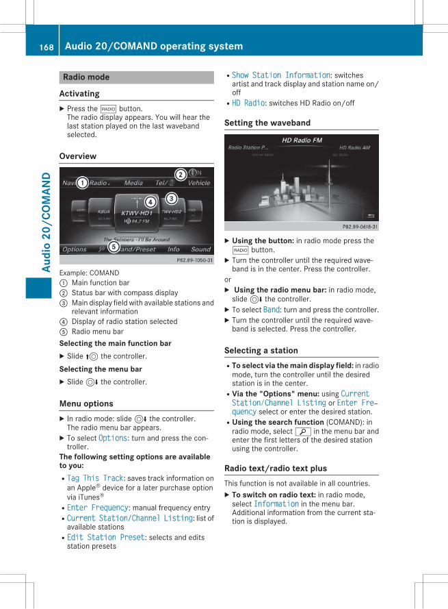
Radio mode
ActivatingX Press the$ button.The radio display appears. You will hear thelast station played on the last wavebandselected.
Overview
Example: COMAND: Main function bar; Status bar with compass display= Main display field with available stations and
relevant information? Display of radio station selectedA Radio menu barSelecting the main function barX Slide5 the controller.Selecting the menu barX Slide6 the controller.
Menu optionsX In radio mode: slide6 the controller.The radio menu bar appears.X To select Options: turn and press the con-troller.
The following setting options are availableto you:RTag This Track: saves track information onan Apple® device for a later purchase optionvia iTunes®
REnter Frequency: manual frequency entryRCurrent Station/Channel Listing: list ofavailable stations
REdit Station Preset: selects and editsstation presets
RShow Station Information: switchesartist and track display and station name on/off
RHD Radio: switches HD Radio on/off
Setting the waveband
X Using the button: in radio mode press the$ button.X Turn the controller until the required wave-band is in the center. Press the controller.
orX Using the radio menu bar: in radio mode,slide6 the controller.X To select Band: turn and press the controller.X Turn the controller until the required wave-band is selected. Press the controller.
Selecting a stationRTo select via the main display field: in radiomode, turn the controller until the desiredstation is in the center.
RVia the "Options" menu: using CurrentStation/Channel Listing or Enter Freхquency select or enter the desired station.
RUsing the search function (COMAND): inradio mode, selectè in the menu bar andenter the first letters of the desired stationusing the controller.
Radio text/radio text plusThis function is not available in all countries.X To switch on radio text: in radio mode,select Information in the menu bar.Additional information from the current sta-tion is displayed.
168 Audio 20/COMAND operating systemAu
dio
20/C
OMAN
D
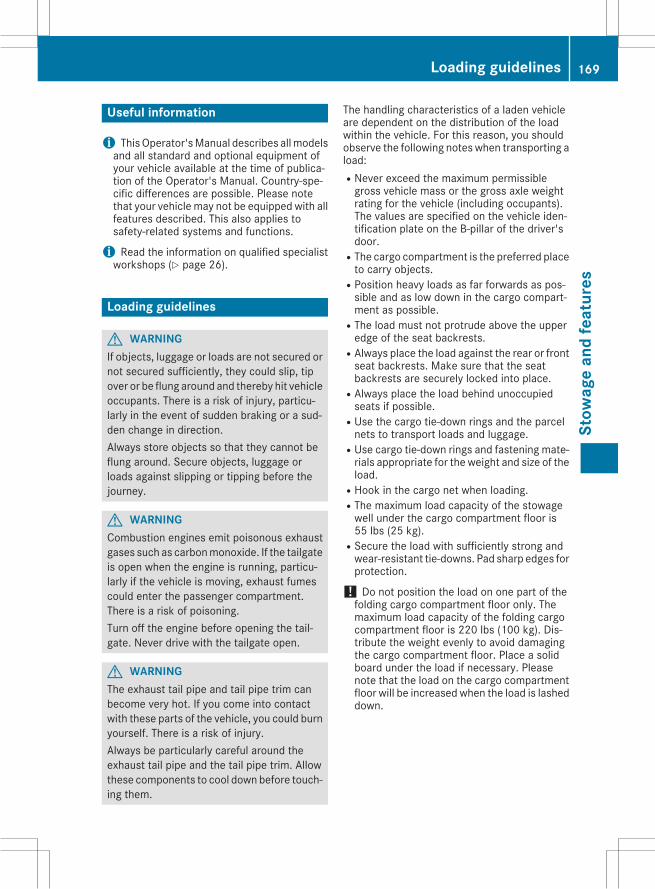
Useful information
i ThisOperator'sManual describes allmodelsand all standard and optional equipment ofyour vehicle available at the time of publica-tion of the Operator's Manual. Country-spe-cific differences are possible. Please notethat your vehicle may not be equipped with allfeatures described. This also applies tosafety-related systems and functions.
i Read the information on qualified specialistworkshops (Y page 26).
Loading guidelines
G WARNINGIf objects, luggage or loads are not secured ornot secured sufficiently, they could slip, tipover or be flung around and thereby hit vehicleoccupants. There is a risk of injury, particu-larly in the event of sudden braking or a sud-den change in direction.Always store objects so that they cannot beflung around. Secure objects, luggage orloads against slipping or tipping before thejourney.
G WARNINGCombustion engines emit poisonous exhaustgases such as carbonmonoxide. If the tailgateis open when the engine is running, particu-larly if the vehicle is moving, exhaust fumescould enter the passenger compartment.There is a risk of poisoning.Turn off the engine before opening the tail-gate. Never drive with the tailgate open.
G WARNINGThe exhaust tail pipe and tail pipe trim canbecome very hot. If you come into contactwith these parts of the vehicle, you could burnyourself. There is a risk of injury.Always be particularly careful around theexhaust tail pipe and the tail pipe trim. Allowthese components to cool down before touch-ing them.
The handling characteristics of a laden vehicleare dependent on the distribution of the loadwithin the vehicle. For this reason, you shouldobserve the following notes when transporting aload:RNever exceed the maximum permissiblegross vehicle mass or the gross axle weightrating for the vehicle (including occupants).The values are specified on the vehicle iden-tification plate on the B-pillar of the driver'sdoor.
RThe cargo compartment is the preferred placeto carry objects.
RPosition heavy loads as far forwards as pos-sible and as low down in the cargo compart-ment as possible.
RThe load must not protrude above the upperedge of the seat backrests.
RAlways place the load against the rear or frontseat backrests. Make sure that the seatbackrests are securely locked into place.
RAlways place the load behind unoccupiedseats if possible.
RUse the cargo tie-down rings and the parcelnets to transport loads and luggage.
RUse cargo tie-down rings and fastening mate-rials appropriate for the weight and size of theload.
RHook in the cargo net when loading.RThe maximum load capacity of the stowagewell under the cargo compartment floor is55 lbs (25 kg).
RSecure the load with sufficiently strong andwear-resistant tie-downs. Pad sharp edges forprotection.
! Do not position the load on one part of thefolding cargo compartment floor only. Themaximum load capacity of the folding cargocompartment floor is 220 lbs (100 kg). Dis-tribute the weight evenly to avoid damagingthe cargo compartment floor. Place a solidboard under the load if necessary. Pleasenote that the load on the cargo compartmentfloor will be increased when the load is lasheddown.
Loading guidelines 169
Stow
age
and
feat
ures
Z
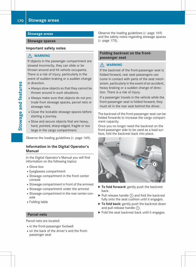
Stowage areas
Stowage spaces
Important safety notes
G WARNINGIf objects in the passenger compartment arestowed incorrectly, they can slide or bethrown around and hit vehicle occupants.There is a risk of injury, particularly in theevent of sudden braking or a sudden changein direction.RAlways stow objects so that they cannot bethrown around in such situations.
RAlways make sure that objects do not pro-trude from stowage spaces, parcel nets orstowage nets.
RClose the lockable stowage spaces beforestarting a journey.
RStow and secure objects that are heavy,hard, pointed, sharp-edged, fragile or toolarge in the cargo compartment.
Observe the loading guidelines (Y page 169).
Information in the Digital Operator'sManualIn the Digital Operator's Manual you will findinformation on the following topics:RGlove boxREyeglasses compartmentRStowage compartment in the front centerconsole
RStowage compartment in front of the armrestRStowage compartment under the armrestRStowage compartment in the rear center con-sole
RFolding table
Parcel netsParcel nets are located:Rin the front-passenger footwellRon the back of the driver's and the front-passenger seat
Observe the loading guidelines (Y page 169)and the safety notes regarding stowage spaces(Y page 170).
Folding backrest on the front-passenger seat
G WARNINGIf the backrest of the front-passenger seat isfolded forward, rear seat passengers cancome in contact with parts of the seat mech-anism. particularly in the event of an accident,heavy braking or a sudden change of direc-tion. There is a risk of injury.If a passenger travels in the vehicle while thefront-passenger seat is folded forward, theymust sit in the rear seat behind the driver.
The backrest of the front-passenger seat can befolded forwards to increase the cargo compart-ment capacity.Once you no longer need the backrest on thefront-passenger side to be used as a load sur-face, fold the backrest back into place.
X To fold forward: gently push the backrestback.X Pull release handle: and fold the backrestfully onto the seat cushion until it engages.X To fold back: gently push the backrest downand pull release handle:.X Fold the seat backrest back until it engages.
170 Stowage areasSt
owag
ean
dfe
atur
es

Through-loading facility in the rear
X To open: fold down seat armrest:.X Pull the center head restraint on the rearbench seat into the uppermost position(Y page 81).
X Slide locking mechanism= in the directionof the arrow.X Swing flap; fully to the side.Flap; is held open by a magnet.X To close: swing flap; in the cargo compart-ment back until it engages.X Fold armrest: up fully if necessary.Observe the loading guidelines (Y page 169).
Cargo compartment enlargement
Important safety notes
G WARNINGIf the rear bench seat/rear seat and seatbackrest are not engaged they could fold for-wards, e.g. when braking suddenly or in theevent of an accident.
RThe vehicle occupant would thereby bepushed into the seat belt by the rear benchseat/rear seat or by the seat backrest. Theseat belt can no longer offer the intendedlevel of protection and could even causeinjuries.
RObjects or loads in the trunk/cargo com-partment cannot be restrained by the seatbackrest.
There is an increased risk of injury.Before every trip, make sure that the seatbackrests and the rear bench seat/rear seatare engaged.
! Before folding the backrest in the rear com-partment forwards, make sure that the rearcompartment armrest and the cupholder arefolded in. They may otherwise be damaged.
Observe the loading guidelines (Y page 169).The left-hand and right-hand rear seat backrestscan be folded forwards separately to increasethe cargo compartment capacity.
Vehicles without the EASY-VARIO-PLUSsystem
Folding the rear seat backrests forward
X Fully insert the backrest head restraints ifnecessary (Y page 81).X Move the driver's or front-passenger seatforward if necessary.X Pull left-hand or right-hand release handle;of the seat backrest forwards.Corresponding seat backrest: is released.X Fold backrest: forwards.X Move the driver's or front-passenger seatback if necessary.
Stowage areas 171
Stow
age
and
feat
ures
Z
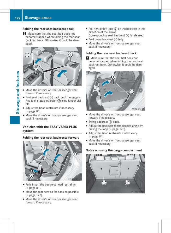
Folding the rear seat backrest back! Make sure that the seat belt does notbecome trapped when folding the rear seatbackrest back. Otherwise, it could be dam-aged.
X Move the driver's or front-passenger seatforward if necessary.X Fold seat backrest: back until it engages.Red lock status indicator; is no longer visi-ble.X Adjust the head restraints if necessary(Y page 81).X Move the driver's or front-passenger seatback if necessary.
Vehicles with the EASY-VARIO-PLUSsystem
Folding the rear seat backrests forward
X Fully insert the backrest head restraints(Y page 81).X Move the rear seat as far back as possible(Y page 173).X Move the driver's or front-passenger seatforward if necessary.
X Pull right or left loop; on the backrest in thedirection of the arrow.Corresponding seat backrest: is released.X Fold down backrest: fully.X Move the driver's or front-passenger seatback if necessary.
Folding the rear seat backrest back! Make sure that the seat belt does notbecome trapped when folding the rear seatbackrest back. Otherwise, it could be dam-aged.
X Move the driver's or front-passenger seatforward if necessary.X Swing backrest: back.X Adjust the backrest to the desired angle bypulling the loop (Y page 173).X Adjust the head restraints if necessary(Y page 81).X Move the driver's or front-passenger seatback if necessary.
Notes on using the cargo compartment
172 Stowage areasSt
owag
ean
dfe
atur
es
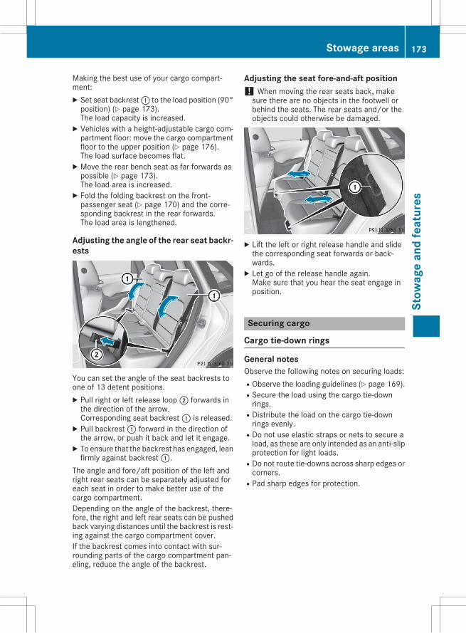
Making the best use of your cargo compart-ment:X Set seat backrest: to the load position (90°position) (Y page 173).The load capacity is increased.X Vehicles with a height-adjustable cargo com-partment floor: move the cargo compartmentfloor to the upper position (Y page 176).The load surface becomes flat.X Move the rear bench seat as far forwards aspossible (Y page 173).The load area is increased.X Fold the folding backrest on the front-passenger seat (Y page 170) and the corre-sponding backrest in the rear forwards.The load area is lengthened.
Adjusting the angle of the rear seat backr-ests
You can set the angle of the seat backrests toone of 13 detent positions.X Pull right or left release loop; forwards inthe direction of the arrow.Corresponding seat backrest: is released.X Pull backrest: forward in the direction ofthe arrow, or push it back and let it engage.X To ensure that the backrest has engaged, leanfirmly against backrest:.
The angle and fore/aft position of the left andright rear seats can be separately adjusted foreach seat in order to make better use of thecargo compartment.Depending on the angle of the backrest, there-fore, the right and left rear seats can be pushedback varying distances until the backrest is rest-ing against the cargo compartment cover.If the backrest comes into contact with sur-rounding parts of the cargo compartment pan-eling, reduce the angle of the backrest.
Adjusting the seat fore-and-aft position! When moving the rear seats back, makesure there are no objects in the footwell orbehind the seats. The rear seats and/or theobjects could otherwise be damaged.
X Lift the left or right release handle and slidethe corresponding seat forwards or back-wards.X Let go of the release handle again.Make sure that you hear the seat engage inposition.
Securing cargo
Cargo tie-down rings
General notesObserve the following notes on securing loads:RObserve the loading guidelines (Y page 169).RSecure the load using the cargo tie-downrings.
RDistribute the load on the cargo tie-downrings evenly.
RDo not use elastic straps or nets to secure aload, as these are only intended as an anti-slipprotection for light loads.
RDo not route tie-downs across sharp edges orcorners.
RPad sharp edges for protection.
Stowage areas 173
Stow
age
and
feat
ures
Z
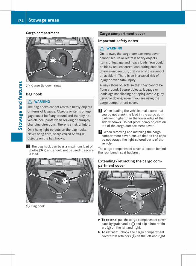
Cargo compartment
: Cargo tie-down rings
Bag hook
G WARNINGThe bag hooks cannot restrain heavy objectsor items of luggage. Objects or items of lug-gage could be flung around and thereby hitvehicle occupants when braking or abruptlychanging directions. There is a risk of injury.Only hang light objects on the bag hooks.Never hang hard, sharp-edged or fragileobjects on the bag hooks.
! The bag hook can bear a maximum load of6.6lbs (3kg) and should not be used to securea load.
: Bag hook
Cargo compartment cover
Important safety notes
G WARNINGOn its own, the cargo compartment covercannot secure or restrain heavy objects,items of luggage and heavy loads. You couldbe hit by an unsecured load during suddenchanges in direction, braking or in the event ofan accident. There is an increased risk ofinjury or even fatal injury.Always store objects so that they cannot beflung around. Secure objects, luggage orloads against slipping or tipping over, e.g. byusing tie downs, even if you are using thecargo compartment cover.
! When loading the vehicle, make sure thatyou do not stack the load in the cargo com-partment higher than the lower edge of theside windows. Do not place heavy objects ontop of the cargo compartment cover.
! When removing and installing the cargocompartment cover, ensure that its end capsdo not scrape the light-colored parts of thevehicle.
The cargo compartment cover is located behindthe rear bench seat backrest.
Extending/retracting the cargo com-partment cover
X To extend: pull the cargo compartment coverback by grab handle: and clip it into retain-ers; on the left and right.X To retract: unhook the cargo compartmentcover from retainers; on the left and right
174 Stowage areasSt
owag
ean
dfe
atur
es
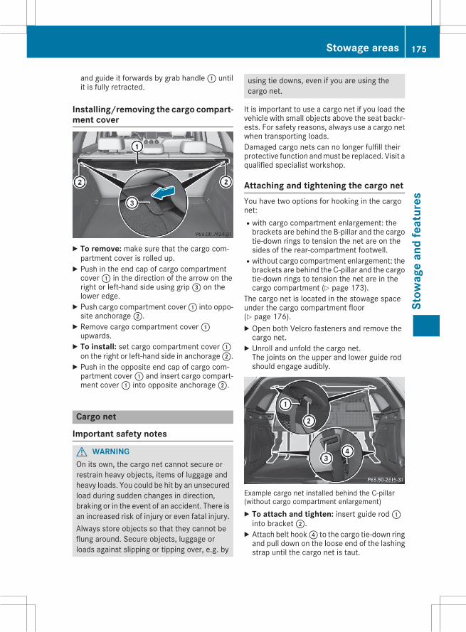
and guide it forwards by grab handle: untilit is fully retracted.
Installing/removing the cargo compart-ment cover
X To remove: make sure that the cargo com-partment cover is rolled up.X Push in the end cap of cargo compartmentcover: in the direction of the arrow on theright or left-hand side using grip= on thelower edge.X Push cargo compartment cover: into oppo-site anchorage;.X Remove cargo compartment cover:upwards.X To install: set cargo compartment cover:on the right or left-hand side in anchorage;.X Push in the opposite end cap of cargo com-partment cover: and insert cargo compart-ment cover: into opposite anchorage;.
Cargo net
Important safety notes
G WARNINGOn its own, the cargo net cannot secure orrestrain heavy objects, items of luggage andheavy loads. You could be hit by an unsecuredload during sudden changes in direction,braking or in the event of an accident. There isan increased risk of injury or even fatal injury.Always store objects so that they cannot beflung around. Secure objects, luggage orloads against slipping or tipping over, e.g. by
using tie downs, even if you are using thecargo net.
It is important to use a cargo net if you load thevehicle with small objects above the seat backr-ests. For safety reasons, always use a cargo netwhen transporting loads.Damaged cargo nets can no longer fulfill theirprotective function andmust be replaced. Visit aqualified specialist workshop.
Attaching and tightening the cargo netYou have two options for hooking in the cargonet:Rwith cargo compartment enlargement: thebrackets are behind the B゙pillar and the cargotie-down rings to tension the net are on thesides of the rear-compartment footwell.
Rwithout cargo compartment enlargement: thebrackets are behind the C-pillar and the cargotie-down rings to tension the net are in thecargo compartment (Y page 173).
The cargo net is located in the stowage spaceunder the cargo compartment floor(Y page 176).X Open both Velcro fasteners and remove thecargo net.X Unroll and unfold the cargo net.The joints on the upper and lower guide rodshould engage audibly.
Example cargo net installed behind the C-pillar(without cargo compartment enlargement)X To attach and tighten: insert guide rod:into bracket;.X Attach belt hook? to the cargo tie-down ringand pull down on the loose end of the lashingstrap until the cargo net is taut.
Stowage areas 175
Stow
age
and
feat
ures
Z
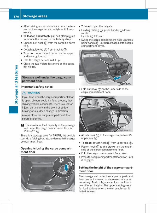
X After driving a short distance, check the ten-sion of the cargo net and retighten it if nec-essary.X To loosen and detach: pull belt clamp= upto reduce the tension in the lashing strap.X Unhook belt hook? from the cargo tie-downring.X Detach guide rod: from bracket;.X To stow: press the red button on the upperand lower guide rod.X Fold the cargo net and roll it up.X Close the two Velcro fasteners on the cargonet holder.
Stowage well under the cargo com-partment floor
Important safety notes
G WARNINGIf you drivewhen the cargo compartment flooris open, objects could be flung around, thusstriking vehicle occupants. There is a risk ofinjury, particularly in the event of suddenbraking or a sudden change in direction.Always close the cargo compartment floorbefore a journey.
! The maximum load capacity of the stowagewell under the cargo compartment floor is55 lbs (25 kg).
There is a stowage area for TIREFIT, the vehicletool kit, a folding box, etc. underneath the cargocompartment floor.
Opening/closing the cargo compart-ment floor
X To open: open the tailgate.X Holding ribbing;, press handle: down-wards.Handle: folds up.X Swing the cargo compartment floor upwardsusing handle: until it rests against the cargocompartment cover.
X Fold out hook= on the underside of thecargo compartment floor.
X Attach hook= to the cargo compartment'supper seal?.X To close: detach hook= from upper seal?.X Fasten hook= to the bracket on the under-side of the cargo compartment floor.X Fold the cargo compartment floor down.X Press the cargo compartment floor down untilit engages.
Setting the height of the cargo compart-ment floorThe stowage well under the cargo compartmentfloor can be increased or decreased in size asnecessary. To do this, you can lock the floor attwo different heights. The upper catch gives aflat load surface when the rear bench seat isfolded forward.
176 Stowage areasSt
owag
ean
dfe
atur
es
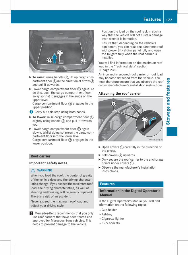
X To raise: using handle:, lift up cargo com-partment floor; in the direction of arrow=and pull it upwards.X Lower cargo compartment floor; again. Todo this, push the cargo compartment flooraway so that it engages in the guide on theupper level.Cargo compartment floor; engages in theupper position.i Carry out this step using both hands.X To lower: raise cargo compartment floor;slightly using handle: and pull it towardsyou.X Lower cargo compartment floor; againslowly. Whilst doing so, press the cargo com-partment floor into the lower level.Cargo compartment floor; engages in thelower position.
Roof carrier
Important safety notes
G WARNINGWhen you load the roof, the center of gravityof the vehicle rises and the driving character-istics change. If you exceed themaximum roofload, the driving characteristics, as well assteering and braking, will be greatly impaired.There is a risk of an accident.Never exceed the maximum roof load andadjust your driving style.
! Mercedes-Benz recommends that you onlyuse roof carriers that have been tested andapproved for Mercedes-Benz vehicles. Thishelps to prevent damage to the vehicle.
Position the load on the roof rack in such away that the vehicle will not sustain damageeven when it is in motion.Ensure that, depending on the vehicle'sequipment, you can raise the panorama roofwith power tilt/sliding panel fully and openthe tailgate fully when the roof carrier isinstalled.
You will find information on the maximum roofload in the "Technical data" section(Y page 238).An incorrectly secured roof carrier or roof loadmay become detached from the vehicle. Youmust therefore ensure that you observe the roofcarrier manufacturer's installation instructions.
Attaching the roof carrier
X Open covers: carefully in the direction ofthe arrow.X Fold covers: upwards.X Only secure the roof carrier to the anchoragepoints under covers:.X Observe the manufacturer's installationinstructions.
Features
Information in the Digital Operator'sManualIn the Digital Operator's Manual you will findinformation on the following topics:RCup holderRAshtrayRCigarette lighterR12 V sockets
Features 177
Stow
age
and
feat
ures
Z
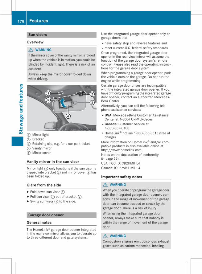
Sun visors
Overview
G WARNINGIf themirror cover of the vanitymirror is foldedup when the vehicle is in motion, you could beblinded by incident light. There is a risk of anaccident.Always keep the mirror cover folded downwhile driving.
: Mirror light; Bracket= Retaining clip, e.g. for a car park ticket? Vanity mirrorA Mirror cover
Vanity mirror in the sun visorMirror light: only functions if the sun visor isclipped into bracket; and mirror coverA hasbeen folded up.
Glare from the sideX Fold down sun visor:.X Pull sun visor: out of bracket;.X Swing sun visor: to the side.
Garage door opener
General notesThe HomeLink® garage door opener integratedin the rear-view mirror allows you to operate upto three different door and gate systems.
Use the integrated garage door opener only ongarage doors that:Rhave safety stop and reverse features andRmeet current U.S. federal safety standardsOnce programed, the integrated garage dooropener in the rear-view mirror will assume thefunction of the garage door system's remotecontrol. Please also read the operating instruc-tions for the garage door system.When programming a garage door opener, parkthe vehicle outside the garage. Do not run theengine while programming.Certain garage door drives are incompatiblewith the integrated garage door opener. If youhave difficulty programing the integrated garagedoor opener, contact an authorized Mercedes-Benz Center.Alternatively, you can call the following tele-phone assistance services:RUSA: Mercedes-Benz Customer AssistanceCenter at 1-800-FOR-MERCedes
RCanada: Customer Service at1-800-387-0100
RHomeLink® hotline 1-800-355-3515 (free ofcharge)
More information on HomeLink® and/or com-patible products is also available online athttp://www.homelink.com.Notes on the declaration of conformity(Y page 26).USA: FCC ID: CB2HMIHL4Canada: IC: 279B-HMIHL4
Important safety notes
G WARNINGWhen you operate or program the garage doorwith the integrated garage door opener, per-sons in the range of movement of the garagedoor can become trapped or struck by thegarage door. There is a risk of injury.When using the integrated garage dooropener, always make sure that nobody iswithin the range of movement of the garagedoor.
G WARNINGCombustion engines emit poisonous exhaustgases such as carbon monoxide. Inhaling
178 FeaturesSt
owag
ean
dfe
atur
es
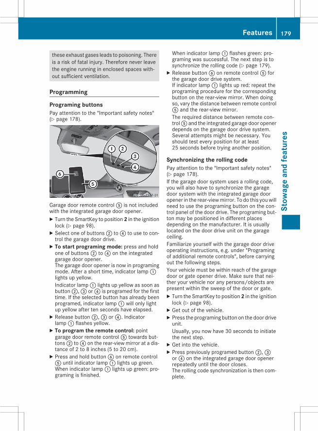
these exhaust gases leads to poisoning. Thereis a risk of fatal injury. Therefore never leavethe engine running in enclosed spaces with-out sufficient ventilation.
Programming
Programing buttonsPay attention to the "Important safety notes"(Y page 178).
Garage door remote controlA is not includedwith the integrated garage door opener.X Turn the SmartKey to position2 in the ignitionlock (Y page 98).X Select one of buttons; to? to use to con-trol the garage door drive.X To start programing mode: press and holdone of buttons; to? on the integratedgarage door opener.The garage door opener is now in programingmode. After a short time, indicator lamp:lights up yellow.Indicator lamp: lights up yellow as soon asbutton;,= or? is programed for the firsttime. If the selected button has already beenprogramed, indicator lamp: will only lightup yellow after ten seconds have elapsed.X Release button;,= or?. Indicatorlamp: flashes yellow.X To program the remote control: pointgarage door remote controlA towards but-tons; to? on the rear-view mirror at a dis-tance of 2 to 8 inches (5 to 20 cm).X Press and hold buttonB on remote controlA until indicator lamp: lights up green.When indicator lamp: lights up green: pro-graming is finished.
When indicator lamp: flashes green: pro-graming was successful. The next step is tosynchronize the rolling code (Y page 179).X Release buttonB on remote controlA forthe garage door drive system.If indicator lamp: lights up red: repeat theprograming procedure for the correspondingbutton on the rear-view mirror. When doingso, vary the distance between remote controlA and the rear-view mirror.The required distance between remote con-trolA and the integrated garage door openerdepends on the garage door drive system.Several attempts might be necessary. Youshould test every position for at least25 seconds before trying another position.
Synchronizing the rolling codePay attention to the "Important safety notes"(Y page 178).If the garage door system uses a rolling code,you will also have to synchronize the garagedoor system with the integrated garage dooropener in the rear-viewmirror. To do this youwillneed to use the programing button on the con-trol panel of the door drive. The programing but-ton may be positioned in different placesdepending on the manufacturer. It is usuallylocated on the door drive unit on the garageceiling.Familiarize yourself with the garage door driveoperating instructions, e.g. under "Programingof additional remote controls", before carryingout the following steps.Your vehicle must be within reach of the garagedoor or gate opener drive. Make sure that nei-ther your vehicle nor any persons/objects arepresent within the sweep of the door or gate.X Turn the SmartKey to position2 in the ignitionlock (Y page 98).X Get out of the vehicle.X Press the programing button on the door driveunit.Usually, you now have 30 seconds to initiatethe next step.X Get into the vehicle.X Press previously programed button;,=or? on the integrated garage door openerrepeatedly until the door closes.The rolling code synchronization is then com-plete.
Features 179
Stow
age
and
feat
ures
Z
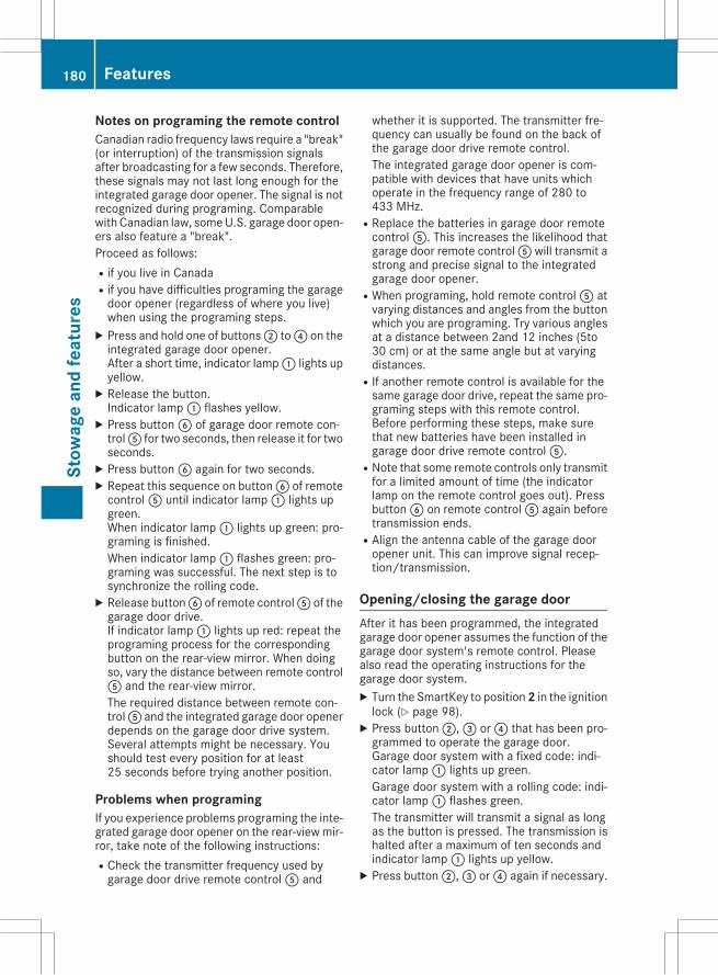
Notes on programing the remote controlCanadian radio frequency laws require a "break"(or interruption) of the transmission signalsafter broadcasting for a few seconds. Therefore,these signals may not last long enough for theintegrated garage door opener. The signal is notrecognized during programing. Comparablewith Canadian law, someU.S. garage door open-ers also feature a "break".Proceed as follows:Rif you live in CanadaRif you have difficulties programing the garagedoor opener (regardless of where you live)when using the programing steps.X Press and hold one of buttons; to? on theintegrated garage door opener.After a short time, indicator lamp: lights upyellow.X Release the button.Indicator lamp: flashes yellow.X Press buttonB of garage door remote con-trolA for two seconds, then release it for twoseconds.X Press buttonB again for two seconds.X Repeat this sequence on buttonB of remotecontrolA until indicator lamp: lights upgreen.When indicator lamp: lights up green: pro-graming is finished.When indicator lamp: flashes green: pro-graming was successful. The next step is tosynchronize the rolling code.X Release buttonB of remote controlA of thegarage door drive.If indicator lamp: lights up red: repeat theprograming process for the correspondingbutton on the rear-view mirror. When doingso, vary the distance between remote controlA and the rear-view mirror.The required distance between remote con-trolA and the integrated garage door openerdepends on the garage door drive system.Several attempts might be necessary. Youshould test every position for at least25 seconds before trying another position.
Problems when programingIf you experience problems programing the inte-grated garage door opener on the rear-viewmir-ror, take note of the following instructions:RCheck the transmitter frequency used bygarage door drive remote controlA and
whether it is supported. The transmitter fre-quency can usually be found on the back ofthe garage door drive remote control.The integrated garage door opener is com-patible with devices that have units whichoperate in the frequency range of 280 to433 MHz.
RReplace the batteries in garage door remotecontrolA. This increases the likelihood thatgarage door remote controlA will transmit astrong and precise signal to the integratedgarage door opener.
RWhen programing, hold remote controlA atvarying distances and angles from the buttonwhich you are programing. Try various anglesat a distance between 2and 12 inches (5to30 cm) or at the same angle but at varyingdistances.
RIf another remote control is available for thesame garage door drive, repeat the same pro-graming steps with this remote control.Before performing these steps, make surethat new batteries have been installed ingarage door drive remote controlA.
RNote that some remote controls only transmitfor a limited amount of time (the indicatorlamp on the remote control goes out). PressbuttonB on remote controlA again beforetransmission ends.
RAlign the antenna cable of the garage dooropener unit. This can improve signal recep-tion/transmission.
Opening/closing the garage doorAfter it has been programmed, the integratedgarage door opener assumes the function of thegarage door system's remote control. Pleasealso read the operating instructions for thegarage door system.X Turn the SmartKey to position2 in the ignitionlock (Y page 98).X Press button;,= or? that has been pro-grammed to operate the garage door.Garage door system with a fixed code: indi-cator lamp: lights up green.Garage door system with a rolling code: indi-cator lamp: flashes green.The transmitter will transmit a signal as longas the button is pressed. The transmission ishalted after a maximum of ten seconds andindicator lamp: lights up yellow.X Press button;,= or? again if necessary.
180 FeaturesSt
owag
ean
dfe
atur
es
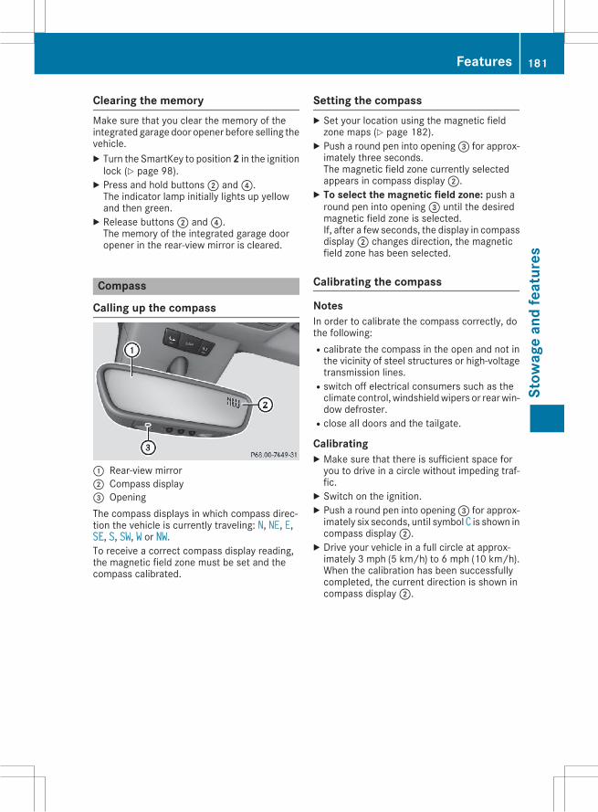
Clearing the memoryMake sure that you clear the memory of theintegrated garage door opener before selling thevehicle.X Turn the SmartKey to position2 in the ignitionlock (Y page 98).X Press and hold buttons; and?.The indicator lamp initially lights up yellowand then green.X Release buttons; and?.The memory of the integrated garage dooropener in the rear-view mirror is cleared.
Compass
Calling up the compass
: Rear-view mirror; Compass display= OpeningThe compass displays in which compass direc-tion the vehicle is currently traveling: N, NE, E,SE, S, SW, W or NW.To receive a correct compass display reading,the magnetic field zone must be set and thecompass calibrated.
Setting the compassX Set your location using the magnetic fieldzone maps (Y page 182).X Push a round pen into opening= for approx-imately three seconds.The magnetic field zone currently selectedappears in compass display;.X To select the magnetic field zone: push around pen into opening= until the desiredmagnetic field zone is selected.If, after a few seconds, the display in compassdisplay; changes direction, the magneticfield zone has been selected.
Calibrating the compass
NotesIn order to calibrate the compass correctly, dothe following:Rcalibrate the compass in the open and not inthe vicinity of steel structures or high-voltagetransmission lines.
Rswitch off electrical consumers such as theclimate control, windshieldwipers or rearwin-dow defroster.
Rclose all doors and the tailgate.
CalibratingX Make sure that there is sufficient space foryou to drive in a circle without impeding traf-fic.X Switch on the ignition.X Push a round pen into opening= for approx-imately six seconds, until symbol C is shown incompass display;.X Drive your vehicle in a full circle at approx-imately 3 mph (5 km/h) to 6 mph (10 km/h).When the calibration has been successfullycompleted, the current direction is shown incompass display;.
Features 181
Stow
age
and
feat
ures
Z
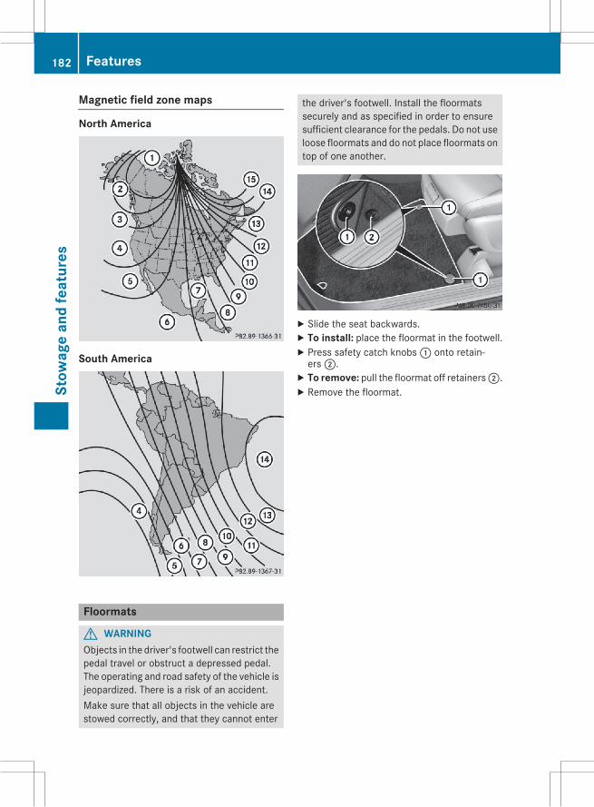
Magnetic field zone maps
North America
South America
Floormats
G WARNINGObjects in the driver's footwell can restrict thepedal travel or obstruct a depressed pedal.The operating and road safety of the vehicle isjeopardized. There is a risk of an accident.Make sure that all objects in the vehicle arestowed correctly, and that they cannot enter
the driver's footwell. Install the floormatssecurely and as specified in order to ensuresufficient clearance for the pedals. Do not useloose floormats and do not place floormats ontop of one another.
X Slide the seat backwards.X To install: place the floormat in the footwell.X Press safety catch knobs: onto retain-ers;.X To remove: pull the floormat off retainers;.X Remove the floormat.
182 FeaturesSt
owag
ean
dfe
atur
es
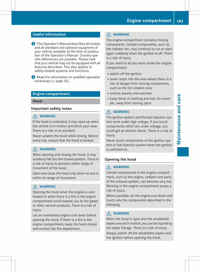
Useful information
i ThisOperator'sManual describes allmodelsand all standard and optional equipment ofyour vehicle available at the time of publica-tion of the Operator's Manual. Country-spe-cific differences are possible. Please notethat your vehicle may not be equipped with allfeatures described. This also applies tosafety-related systems and functions.
i Read the information on qualified specialistworkshops (Y page 26).
Engine compartment
Hood
Important safety notes
G WARNINGIf the hood is unlatched, it may open up whenthe vehicle is in motion and block your view.There is a risk of an accident.Never unlatch the hood while driving. Beforeevery trip, ensure that the hood is locked.
G WARNINGWhen opening and closing the hood, it maysuddenly fall into the closed position. There isa risk of injury to persons within range ofmovement of the hood.Open and close the hood only when no one iswithin its range of movement.
G WARNINGOpening the hood when the engine is over-heated or when there is a fire in the enginecompartment could expose you to hot gasesor other service products. There is a risk ofinjury.Let an overheated engine cool down beforeopening the hood. If there is a fire in theengine compartment, keep the hood closedand contact the fire department.
G WARNINGThe engine compartment contains movingcomponents. Certain components, such asthe radiator fan, may continue to run or startagain suddenly when the ignition is off. Thereis a risk of injury.If you need to do any work inside the enginecompartment:Rswitch off the ignitionRnever reach into the area where there is arisk of danger from moving components,such as the fan rotation area
Rremove jewelry and watchesRkeep items of clothing and hair, for exam-ple, away from moving parts
G WARNINGThe ignition system and the fuel injection sys-tem work under high voltage. If you touchcomponents which are under voltage, youcould get an electric shock. There is a risk ofinjury.Never touch components of the ignition sys-tem or fuel injection system when the ignitionis switched on.
Opening the hood
G WARNINGCertain components in the engine compart-ment, such as the engine, radiator and partsof the exhaust system, can become very hot.Working in the engine compartment poses arisk of injury.Where possible, let the engine cool down andtouch only the components described in thefollowing.
G WARNINGWhen the hood is open and the windshieldwipers are set inmotion, you can be injured bythe wiper linkage. There is a risk of injury.Always switch off the windshield wipers andthe ignition before opening the hood.
Engine compartment 183
Mai
nten
ance
and
care
Z
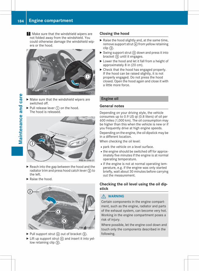
! Make sure that the windshield wipers arenot folded away from the windshield. Youcould otherwise damage the windshield wip-ers or the hood.
X Make sure that the windshield wipers areswitched off.X Pull release lever: on the hood.The hood is released.
X Reach into the gap between the hood and theradiator trim and press hood catch lever; tothe left.X Raise the hood.
X Pull support strut? out of bracketA.X Lift up support strut? and insert it into yel-low retaining clip=.
Closing the hoodX Raise the hood slightly and, at the same time,remove support strut? from yellow retainingclip=.X Swing support strut? down and press it intobracketA until it engages.X Lower the hood and let it fall from a height ofapproximately 8 in (20 cm).X Check that the hood has engaged properly.If the hood can be raised slightly, it is notproperly engaged. Do not press the hoodclosed. Open the hood again and close it witha little more force.
Engine oil
General notesDepending on your driving style, the vehicleconsumes up to 0.9 US qt (0.8 liters) of oil per600 miles (1,000 km). The oil consumption maybe higher than this when the vehicle is new or ifyou frequently drive at high engine speeds.Depending on the engine, the oil dipstickmay bein a different location.When checking the oil level:Rpark the vehicle on a level surface.Rthe engine should be switched off for approx-imately five minutes if the engine is at normaloperating temperature.
Rif the engine is not at normal operating tem-perature, e.g. if the engine was only startedbriefly, wait about 30minutes before carryingout the measurement.
Checking the oil level using the oil dip-stick
G WARNINGCertain components in the engine compart-ment, such as the engine, radiator and partsof the exhaust system, can become very hot.Working in the engine compartment poses arisk of injury.Where possible, let the engine cool down andtouch only the components described in thefollowing.
184 Engine compartmentM
aint
enan
cean
dca
re
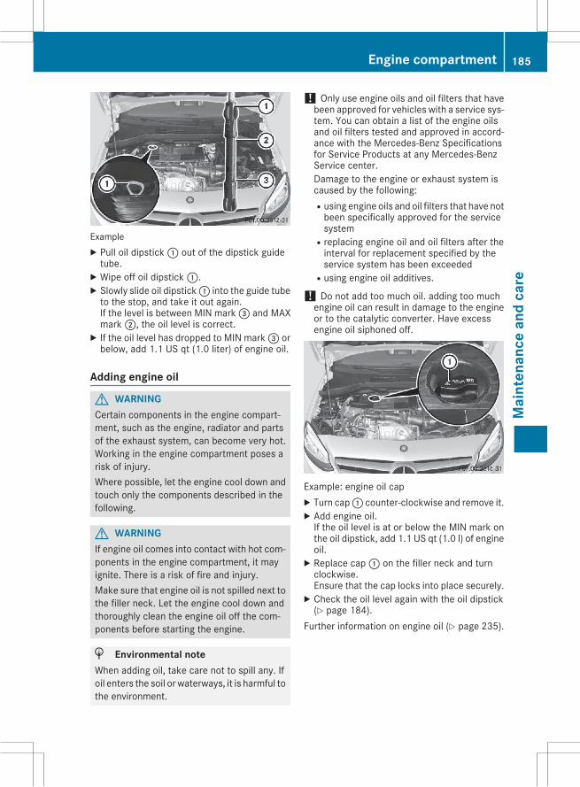
ExampleX Pull oil dipstick: out of the dipstick guidetube.X Wipe off oil dipstick:.X Slowly slide oil dipstick: into the guide tubeto the stop, and take it out again.If the level is between MIN mark= and MAXmark;, the oil level is correct.X If the oil level has dropped to MIN mark= orbelow, add 1.1 US qt (1.0 liter) of engine oil.
Adding engine oil
G WARNINGCertain components in the engine compart-ment, such as the engine, radiator and partsof the exhaust system, can become very hot.Working in the engine compartment poses arisk of injury.Where possible, let the engine cool down andtouch only the components described in thefollowing.
G WARNINGIf engine oil comes into contact with hot com-ponents in the engine compartment, it mayignite. There is a risk of fire and injury.Make sure that engine oil is not spilled next tothe filler neck. Let the engine cool down andthoroughly clean the engine oil off the com-ponents before starting the engine.
H Environmental noteWhen adding oil, take care not to spill any. Ifoil enters the soil or waterways, it is harmful tothe environment.
! Only use engine oils and oil filters that havebeen approved for vehicles with a service sys-tem. You can obtain a list of the engine oilsand oil filters tested and approved in accord-ance with the Mercedes-Benz Specificationsfor Service Products at any Mercedes-BenzService center.Damage to the engine or exhaust system iscaused by the following:Rusing engine oils and oil filters that have notbeen specifically approved for the servicesystem
Rreplacing engine oil and oil filters after theinterval for replacement specified by theservice system has been exceeded
Rusing engine oil additives.
! Do not add too much oil. adding too muchengine oil can result in damage to the engineor to the catalytic converter. Have excessengine oil siphoned off.
Example: engine oil capX Turn cap: counter-clockwise and remove it.X Add engine oil.If the oil level is at or below the MIN mark onthe oil dipstick, add 1.1 US qt (1.0 l) of engineoil.X Replace cap: on the filler neck and turnclockwise.Ensure that the cap locks into place securely.X Check the oil level again with the oil dipstick(Y page 184).
Further information on engine oil (Y page 235).
Engine compartment 185
Mai
nten
ance
and
care
Z
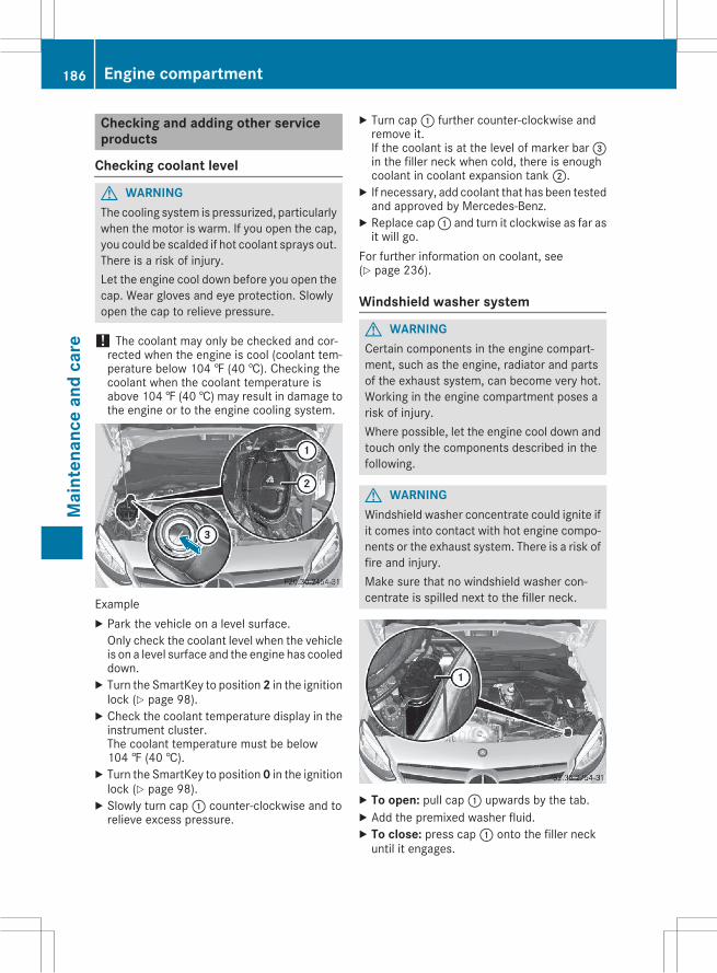
Checking and adding other serviceproducts
Checking coolant level
G WARNINGThe cooling system is pressurized, particularlywhen the motor is warm. If you open the cap,you could be scalded if hot coolant sprays out.There is a risk of injury.Let the engine cool down before you open thecap. Wear gloves and eye protection. Slowlyopen the cap to relieve pressure.
! The coolant may only be checked and cor-rected when the engine is cool (coolant tem-perature below 104 ‡ (40 †). Checking thecoolant when the coolant temperature isabove 104 ‡ (40 †) may result in damage tothe engine or to the engine cooling system.
ExampleX Park the vehicle on a level surface.Only check the coolant level when the vehicleis on a level surface and the engine has cooleddown.X Turn the SmartKey to position2 in the ignitionlock (Y page 98).X Check the coolant temperature display in theinstrument cluster.The coolant temperature must be below104 ‡ (40 †).X Turn the SmartKey to position0 in the ignitionlock (Y page 98).X Slowly turn cap: counter-clockwise and torelieve excess pressure.
X Turn cap: further counter-clockwise andremove it.If the coolant is at the level of marker bar=in the filler neck when cold, there is enoughcoolant in coolant expansion tank;.X If necessary, add coolant that has been testedand approved by Mercedes-Benz.X Replace cap: and turn it clockwise as far asit will go.
For further information on coolant, see(Y page 236).
Windshield washer system
G WARNINGCertain components in the engine compart-ment, such as the engine, radiator and partsof the exhaust system, can become very hot.Working in the engine compartment poses arisk of injury.Where possible, let the engine cool down andtouch only the components described in thefollowing.
G WARNINGWindshield washer concentrate could ignite ifit comes into contact with hot engine compo-nents or the exhaust system. There is a risk offire and injury.Make sure that no windshield washer con-centrate is spilled next to the filler neck.
X To open: pull cap: upwards by the tab.X Add the premixed washer fluid.X To close: press cap: onto the filler neckuntil it engages.
186 Engine compartmentM
aint
enan
cean
dca
re
If the washer fluid level drops below the recom-mended minimum of 1 liter, a message appearsin the multifunction display prompting you toadd washer fluid.Further information on windshield washer fluid/antifreeze (Y page 237).
ASSYST PLUS
The Digital Operator's Manual contains moreinformation on the ASSYST PLUS service inter-val display.
Care
General notes
H Environmental noteDispose of empty packaging and cleaningcloths in an environmentally responsibleman-ner.
! For cleaning your vehicle, do not use any ofthe following:Rdry, rough or hard clothsRabrasive cleaning agentsRsolventsRcleaning agents containing solventsDo not scrub.Do not touch the surfaces or protective filmswith hard objects, e.g. a ring or ice scraper.You could otherwise scratch or damage thesurfaces and protective film.
! Do not park the vehicle for an extendedperiod straight after cleaning it, particularlyafter having cleaned the wheels with wheelcleaner. Wheel cleaners could causeincreased corrosion of the brake discs andbrake pads/linings. For this reason, youshould drive for a few minutes after cleaning.Braking heats the brake discs and the brakepads/linings, thus drying them. The vehiclecan then be parked.
Regular care of your vehicle is a condition forretaining the quality in the long term.Use care products and cleaning agents recom-mended and approved by Mercedes-Benz.
Exterior care
Automatic car wash
G WARNINGBraking efficiency is reduced after washingthe vehicle. There is a risk of an accident.After the vehicle has been washed, brakecarefully while paying attention to the trafficconditions until full braking power is restored.
! If DISTRONIC PLUS or the HOLD function isactivated, the vehicle brakes automatically incertain situations.To prevent damage to the vehicle, deactivateDISTRONIC PLUS and the HOLD function inthe following or other similar situations:Rwhen towing the vehicleRin the car wash
! Never clean your vehicle in a TouchlessAutomatic Car Wash as these use specialcleaning agents. These cleaning agents candamage the paintwork or plastic parts.
! Make sure that the automatic transmissionis in position N when washing your vehicle ina tow-through car wash. The vehicle could bedamaged if the transmission is in anotherposition.
! Make sure that:Rthe side windows and the sliding sunroofare fully closed.
Rthe ventilation/heating is switched off (theOFF button has been pressed/the airflowcontrol is set to position 0).
Rthe windshield wiper switch is in position0.Otherwise, the vehicle might be damaged.
You can wash the vehicle in an automatic carwash from the very start.If the vehicle is very dirty, pre-wash it beforecleaning it in an automatic car wash.After using an automatic car wash, wipe off waxfrom the windshield and the wiper blades. Thiswill prevent smears and reduce wiping noisescaused by residue on the windshield.
Care 187
Mai
nten
ance
and
care
Z
Information in the Digital Operator'sManualIn the Digital Operator's Manual you will findinformation on the following topics:RWashing by handRPower washersRCleaning the paintworkRMatte finish careRCleaning the wheelsRCleaning the windowsRCleaning wiper bladesRCleaning the exterior lightingRCleaning the mirror turn signalsRCleaning the sensorsRCleaning the rear view cameraRCleaning the exhaust pipe
Interior careIn the Digital Operator's Manual you will findinformation on the following topics:RCleaning the displayRCleaning the plastic trimRCleaning the steering wheel and selectorlever
RCleaning genuine wood and trim stripsRCleaning the seat coversRCleaning the seat beltsRCleaning the headliner and carpets
188 CareM
aint
enan
cean
dca
re
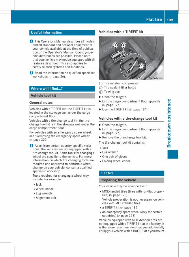
Useful information
i ThisOperator'sManual describes allmodelsand all standard and optional equipment ofyour vehicle available at the time of publica-tion of the Operator's Manual. Country-spe-cific differences are possible. Please notethat your vehicle may not be equipped with allfeatures described. This also applies tosafety-related systems and functions.
i Read the information on qualified specialistworkshops (Y page 26).
Where will I find...?
Vehicle tool kit
General notesVehicles with a TIREFIT kit: the TIREFIT kit islocated in the stowage well under the cargocompartment floor.Vehicles with a tire-change tool kit: the tire-change tool kit is in the stowage well under thecargo compartment floor.For vehicles with an emergency spare wheel,see "Removing the emergency spare wheel"(Y page 229).
i Apart from certain country-specific varia-tions, the vehicles are not equipped with atire-change tool kit. Some tools for changing awheel are specific to the vehicle. For moreinformation on which tire changing tools arerequired and approved to perform a wheelchange on your vehicle, consult a qualifiedspecialist workshop.Tools required for changing a wheel mayinclude, for example:RJackRWheel chockRLug wrenchRAlignment bolt
Vehicles with a TIREFIT kit
: Tire inflation compressor; Tire sealant filler bottle= Towing eyeX Open the tailgate.X Lift the cargo compartment floor upwards(Y page 176).X Use the TIREFIT kit (Y page 191).
Vehicles with a tire-change tool kitX Open the tailgate.X Lift the cargo compartment floor upwards(Y page 176).X Remove the tire-change tool kit.The tire-change tool kit contains:RJackRLug wrenchROne pair of glovesRFolding wheel chock
Flat tire
Preparing the vehicleYour vehicle may be equipped with:RMOExtended tires (tires with run-flat proper-ties) (Y page 190)Vehicle preparation is not necessary on vehi-cles with MOExtended tires
Ra TIREFIT kit (Y page 189)Ran emergency spare wheel (only for certaincountries) (Y page 228)
Vehicles equipped with MOExtended tires arenot equipped with a TIREFIT kit at the factory. Itis therefore recommended that you additionallyequip your vehiclewith a TIREFIT kit if youmount
Flat tire 189
Brea
kdow
nas
sist
ance
tires that do not feature run-flat properties, e.g.winter tires. A TIREFIT kit may be obtained froma qualified specialist workshop.Information on changing and mounting wheels(Y page 221).X Stop the vehicle on solid, non-slippery andlevel ground, as far away as possible fromtraffic.X Switch on the hazard warning lamps.X Secure the vehicle against rolling away(Y page 107).X If possible, bring the front wheels into thestraight-ahead position.X Switch off the engine.X Vehicles without KEYLESS-GO: remove theSmartKey from the ignition lock.X Vehicles with KEYLESS-GO start-function
or KEYLESS-GO: open the driver's door.The on-board electronics now have status 0.This is the same as the SmartKey having beenremoved.X Vehicles with KEYLESS-GO start-function
or KEYLESS-GO: remove the Start/Stop but-ton from the ignition lock (Y page 98).X Make sure that the engine cannot be startedvia your smartphone (Y page 107).X Make sure that the passengers are not endan-gered as they do so. Make sure that no one isnear the danger area while a wheel is beingchanged. Anyone who is not directly assistingin the wheel change should, for example,stand behind the barrier.X Get out of the vehicle. Pay attention to trafficconditions when doing so.X Close the driver's door.
MOExtended tires (tires with run-flatproperties)
General notesWith MOExtended tires (tires with run flat char-acteristics), you can continue to drive your vehi-cle even if there is a total loss of pressure in oneor more tires. The affected tire must not showany clearly visible damage.You can recognize MOExtended tires by theMOExtended marking which appears on thesidewall of the tire. You will find this markingnext to the tire size designation, the load-bear-ing capacity and the speed index (Y page 216).
MOExtended tires may only be used in conjunc-tion with an active tire pressure loss warningsystem.If a pressure loss warning message appearsin the multifunction display:Robserve the instructions in the display mes-sages (Y page 140).
Rcheck the tire for damage.Rif driving on, observe the following notes.The driving distance possible in run-flat mode isapproximately 50 miles (80 km) when the vehi-cle is partially laden. When the vehicle is fullyladen it is approximately 19 miles (30 km).In addition to the vehicle load, the driving dis-tance possible depends upon:Rvehicle speedRroad conditionRoutside temperatureThe driving distance possible in run-flat modemay be reduced by extreme driving conditionsor maneuvers, or it can be increased through amoderate style of driving.The driving distance possible in run-flat mode iscounted from the moment the tire pressure losswarning appears in the multifunction display.You must not exceed a maximum speed of50 mph (80 km/h).When replacing one or all tires, please observethe following specifications for your vehicle'stires:RsizeRtype andRthe "MOExtended" markIf a tire has gone flat and cannot be replacedwith a MOExtended tire, a standard tire may beused as a temporary measure. Make sure thatyou use the proper size and type (summer orwinter tire).Vehicles equipped with MOExtended tires arenot equipped with a TIREFIT kit at the factory. Itis therefore recommended that you additionallyequip your vehiclewith a TIREFIT kit if youmounttires that do not feature run-flat properties, e.g.winter tires. A TIREFIT kit may be obtained froma qualified specialist workshop.
190 Flat tireBr
eakd
own
assi
stan
ce
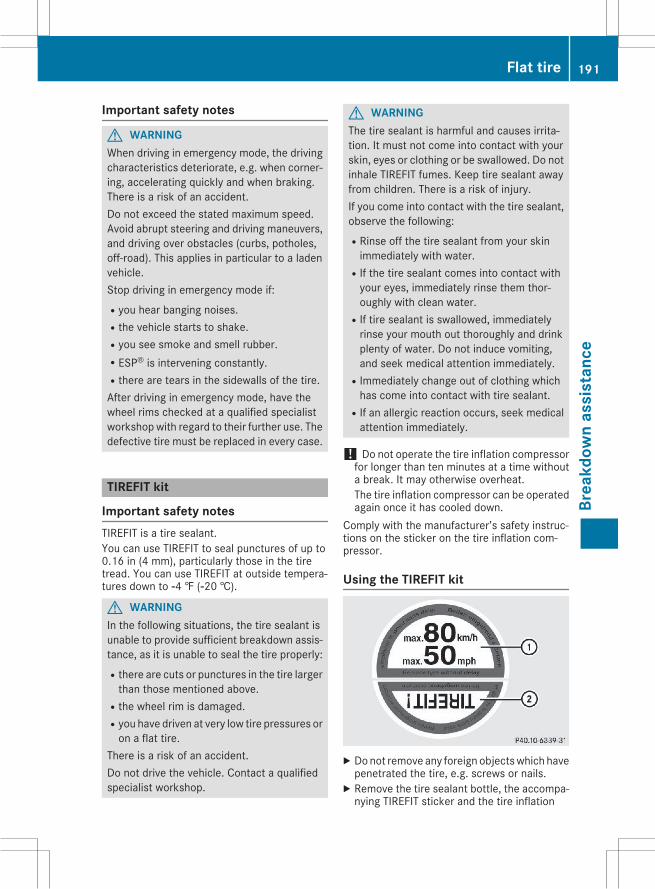
Important safety notes
G WARNINGWhen driving in emergency mode, the drivingcharacteristics deteriorate, e.g. when corner-ing, accelerating quickly and when braking.There is a risk of an accident.Do not exceed the stated maximum speed.Avoid abrupt steering and driving maneuvers,and driving over obstacles (curbs, potholes,off-road). This applies in particular to a ladenvehicle.Stop driving in emergency mode if:Ryou hear banging noises.Rthe vehicle starts to shake.Ryou see smoke and smell rubber.RESP® is intervening constantly.Rthere are tears in the sidewalls of the tire.After driving in emergency mode, have thewheel rims checked at a qualified specialistworkshop with regard to their further use. Thedefective tire must be replaced in every case.
TIREFIT kit
Important safety notesTIREFIT is a tire sealant.You can use TIREFIT to seal punctures of up to0.16 in (4 mm), particularly those in the tiretread. You can use TIREFIT at outside tempera-tures down to Ò4 ‡ (Ò20 †).
G WARNINGIn the following situations, the tire sealant isunable to provide sufficient breakdown assis-tance, as it is unable to seal the tire properly:Rthere are cuts or punctures in the tire largerthan those mentioned above.
Rthe wheel rim is damaged.Ryou have driven at very low tire pressures oron a flat tire.
There is a risk of an accident.Do not drive the vehicle. Contact a qualifiedspecialist workshop.
G WARNINGThe tire sealant is harmful and causes irrita-tion. It must not come into contact with yourskin, eyes or clothing or be swallowed. Do notinhale TIREFIT fumes. Keep tire sealant awayfrom children. There is a risk of injury.If you come into contact with the tire sealant,observe the following:RRinse off the tire sealant from your skinimmediately with water.
RIf the tire sealant comes into contact withyour eyes, immediately rinse them thor-oughly with clean water.
RIf tire sealant is swallowed, immediatelyrinse your mouth out thoroughly and drinkplenty of water. Do not induce vomiting,and seek medical attention immediately.
RImmediately change out of clothing whichhas come into contact with tire sealant.
RIf an allergic reaction occurs, seek medicalattention immediately.
! Do not operate the tire inflation compressorfor longer than ten minutes at a time withouta break. It may otherwise overheat.The tire inflation compressor can be operatedagain once it has cooled down.
Comply with the manufacturer’s safety instruc-tions on the sticker on the tire inflation com-pressor.
Using the TIREFIT kit
X Donot remove any foreign objectswhich havepenetrated the tire, e.g. screws or nails.X Remove the tire sealant bottle, the accompa-nying TIREFIT sticker and the tire inflation
Flat tire 191
Brea
kdow
nas
sist
ance
Z
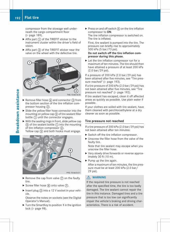
compressor from the stowage well under-neath the cargo compartment floor(Y page 189).X Affix part: of the TIREFIT sticker to theinstrument cluster within the driver's field ofvision.X Affix part; of the TIREFIT sticker near thevalve on the wheel with the defective tire.
X Remove filler hoseB and connector= fromthe bottom section of the tire inflation com-pressor housing;.X Slide the yellow filler hose connector into themounting on yellow capA of tire sealant fillerbottle: until the connector engages.X With the sealing rings in front, slide yellow capA of tire sealant bottle: into the mountingof tire inflation compressor;.Yellow capA and both hooks must engage.
X Remove the cap from valveC on the faultytire.X Screw filler hoseD onto valveC.X Insert plug= into a 12 V socket in your vehi-cle.Observe the notes on sockets (see the DigitalOperator's Manual).X Turn the SmartKey to position1 in the ignitionlock (Y page 98).
X Press on and off switch? on the tire inflationcompressor to ON.The tire inflation compressor is switched on.The tire is inflated.First, tire sealant is pumped into the tire. Thepressure can briefly rise to approximately500 kPa (5 bar/73 psi).Do not switch off the tire inflation com-pressor during this phase.X Let the tire inflation compressor run for amaximumof tenminutes. The tire should thenhave attained a pressure of at least 200 kPa(2.0 bar/29 psi).
If a pressure of 200 kPa (2.0 bar/29 psi) hasbeen attained after five minutes, see "Tire pres-sure reached" (Y page 193).If a tire pressure of 200 kPa (2.0 bar/29 psi) hasnot been attained after five minutes, see "Tirepressure not reached" (Y page 192).If tire sealant has escaped, clean it off affectedareas as quickly as possible. Use plain water ifpossible.If your clothes are soiled with tire sealant, havethem cleaned with perchloroethylene at a drycleaner as soon as possible.
Tire pressure not reachedIf a tire pressure of 200 kPa (2.0 bar/29 psi) hasnot been attained after ten minutes:X Switch off the tire inflation compressor.X Unscrew the filler hose from the valve of thefaulty tire.Note that tire sealant may escape when youunscrew the filler hose.X Very slowly drive forwards or reverse approx-imately 30 ft (10 m).X Pump up the tire again.After amaximumof tenminutes, the tire pres-sure must be at least 200 kPa (2.0 bar/29 psi).
G WARNINGIf the required tire pressure is not reachedafter the specified time, the tire is too badlydamaged. The tire sealant cannot repair thetire in this instance. Damaged tires and a tirepressure that is too low can significantlyimpair the vehicle's braking and driving char-acteristics. There is a risk of accident.
192 Flat tireBr
eakd
own
assi
stan
ce
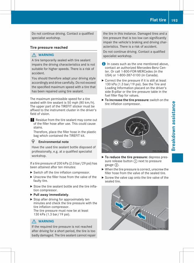
Do not continue driving. Contact a qualifiedspecialist workshop.
Tire pressure reached
G WARNINGA tire temporarily sealed with tire sealantimpairs the driving characteristics and is notsuitable for higher speeds. There is a risk ofaccident.You should therefore adapt your driving styleaccordingly and drive carefully. Do not exceedthe specified maximum speed with a tire thathas been repaired using tire sealant.
The maximum permissible speed for a tiresealed with tire sealant is 50 mph (80 km/h).The upper part of the TIREFIT sticker must beaffixed to the instrument cluster in the driver'sfield of vision.
! Residue from the tire sealant may come outof the filler hose after use. This could causestains.Therefore, place the filler hose in the plasticbag which contained the TIREFIT kit.
H Environmental noteHave the used tire sealant bottle disposed ofprofessionally, e.g. at a qualified specialistworkshop.
If a tire pressure of 200 kPa (2.0 bar/29 psi) hasbeen attained after ten minutes:X Switch off the tire inflation compressor.X Unscrew the filler hose from the valve of thefaulty tire.X Stow the tire sealant bottle and the tire infla-tion compressor.X Pull away immediately.X Stop after driving for approximately tenminutes and check the tire pressure with thetire inflation compressor.The tire pressure must now be at least130 kPa (1.3 bar/19 psi).
G WARNINGIf the required tire pressure is not reachedafter driving for a short period, the tire is toobadly damaged. The tire sealant cannot repair
the tire in this instance. Damaged tires and atire pressure that is too low can significantlyimpair the vehicle's braking and driving char-acteristics. There is a risk of accident.Do not continue driving. Contact a qualifiedspecialist workshop.
i In cases such as the one mentioned above,contact an authorized Mercedes-Benz Cen-ter. Or call 1-800-FOR-MERCedes (in theUSA) or 1-800-387-0100 (in Canada).X Correct the tire pressure if it is still at least130 kPa (1.3 bar/19 psi). See the Tire andLoading Information placard on the driver'sside B-pillar or the tire pressure table in thefuel filler flap for values.X To increase the tire pressure: switch on thetire inflation compressor.
X To reduce the tire pressure: depress pres-sure release button: next to pressuregauge;.X When the tire pressure is correct, unscrew thefiller hose from the valve of the sealed tire.X Screw the valve cap onto the tire valve of thesealed tire.
Flat tire 193
Brea
kdow
nas
sist
ance
Z
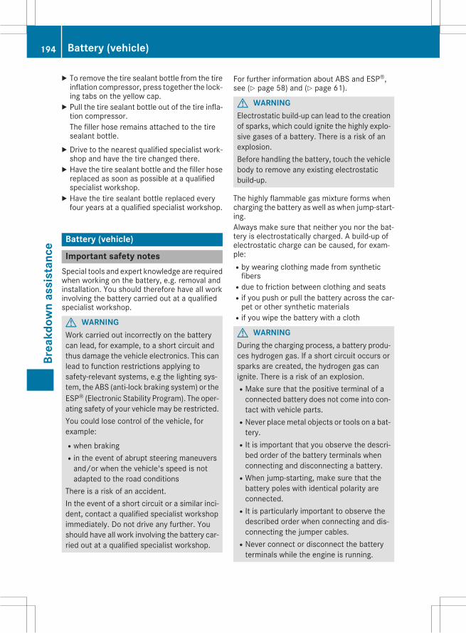
X To remove the tire sealant bottle from the tireinflation compressor, press together the lock-ing tabs on the yellow cap.X Pull the tire sealant bottle out of the tire infla-tion compressor.The filler hose remains attached to the tiresealant bottle.X Drive to the nearest qualified specialist work-shop and have the tire changed there.X Have the tire sealant bottle and the filler hosereplaced as soon as possible at a qualifiedspecialist workshop.X Have the tire sealant bottle replaced everyfour years at a qualified specialist workshop.
Battery (vehicle)
Important safety notesSpecial tools and expert knowledge are requiredwhen working on the battery, e.g. removal andinstallation. You should therefore have all workinvolving the battery carried out at a qualifiedspecialist workshop.
G WARNINGWork carried out incorrectly on the batterycan lead, for example, to a short circuit andthus damage the vehicle electronics. This canlead to function restrictions applying tosafety-relevant systems, e.g the lighting sys-tem, the ABS (anti-lock braking system) or theESP® (Electronic Stability Program). The oper-ating safety of your vehicle may be restricted.You could lose control of the vehicle, forexample:Rwhen brakingRin the event of abrupt steering maneuversand/or when the vehicle's speed is notadapted to the road conditions
There is a risk of an accident.In the event of a short circuit or a similar inci-dent, contact a qualified specialist workshopimmediately. Do not drive any further. Youshould have all work involving the battery car-ried out at a qualified specialist workshop.
For further information about ABS and ESP®,see (Y page 58) and (Y page 61).
G WARNINGElectrostatic build-up can lead to the creationof sparks, which could ignite the highly explo-sive gases of a battery. There is a risk of anexplosion.Before handling the battery, touch the vehiclebody to remove any existing electrostaticbuild-up.
The highly flammable gas mixture forms whencharging the battery as well as when jump-start-ing.Always make sure that neither you nor the bat-tery is electrostatically charged. A build-up ofelectrostatic charge can be caused, for exam-ple:Rby wearing clothing made from syntheticfibers
Rdue to friction between clothing and seatsRif you push or pull the battery across the car-pet or other synthetic materials
Rif you wipe the battery with a cloth
G WARNINGDuring the charging process, a battery produ-ces hydrogen gas. If a short circuit occurs orsparks are created, the hydrogen gas canignite. There is a risk of an explosion.RMake sure that the positive terminal of aconnected battery does not come into con-tact with vehicle parts.
RNever placemetal objects or tools on a bat-tery.
RIt is important that you observe the descri-bed order of the battery terminals whenconnecting and disconnecting a battery.
RWhen jump-starting, make sure that thebattery poles with identical polarity areconnected.
RIt is particularly important to observe thedescribed order when connecting and dis-connecting the jumper cables.
RNever connect or disconnect the batteryterminals while the engine is running.
194 Battery (vehicle)Br
eakd
own
assi
stan
ce
G WARNINGBattery acid is caustic. There is a risk of injury.Avoid contact with skin, eyes or clothing. Donot inhale any battery gases. Do not lean overthe battery. Keep children away from batter-ies. Wash away battery acid immediately withplenty of clean water and seek medical atten-tion.
H Environmental noteBatteries contain dangeroussubstances. It is against thelaw to dispose of them withthe household rubbish. Theymust be collected separatelyand recycled to protect theenvironment.Dispose of batteries in anenvironmentally friendlymanner. Take dischargedbatteries to a qualified spe-cialist workshop or a specialcollection point for used bat-teries.
! Have the battery checked regularly at aqualified specialist workshop.Observe the service intervals in the Mainte-nanceBooklet or contact a qualified specialistworkshop for more information.
! You should have all work involving the bat-tery carried out at a qualified specialist work-shop. In the exceptional case that it is neces-sary for you to disconnect the battery your-self, make sure that:Ryou switch off the engine and remove thekey. On vehicles with KEYLESS-GO, ensurethat the ignition is switched off. Check thatall the indicator lamps in the instrumentcluster are off. Otherwise, electronic com-ponents, such as the alternator, may bedamaged.
Ryou first remove the negative terminalclamp and then the positive terminalclamp. Never swap the terminal clamps.Otherwise, the vehicle's electronic systemmay be damaged.
Rin vehicles with automatic transmission,the transmission is locked in position P
after disconnecting the battery. The vehicleis secured against rolling away. You canthen no longer move the vehicle.
The battery and the cover of the positive ter-minal clampmust be installed securely duringoperation.
Comply with safety precautions and take pro-tective measures when handling batteries.
Risk of explosion.
Fire, open flames and smoking areprohibited when handling the bat-tery. Avoid creating sparks.
Battery acid is caustic. Avoid contactwith skin, eyes or clothing.Wear suitable protective clothing,especially gloves, apron and face-guard.Rinse any acid spills immediatelywith clear water. Contact a physicianif necessary.Wear eye protection.
Keep children away.
Observe this Operator's Manual.
For safety reasons, Mercedes-Benz recom-mends that you only use batteries which havebeen tested and approved for your vehicle byMercedes-Benz. These batteries provideincreased impact protection to prevent vehicleoccupants from suffering acid burns should thebattery be damaged in the event of an accident.In order for the battery to achieve the maximumpossible service life, it must always be suffi-ciently charged.Like other batteries, the vehicle battery maydischarge over time if you do not use the vehicle.In this case, have the battery disconnected at aqualified specialist workshop. You can alsocharge the battery with a charger recommendedby Mercedes-Benz. Contact a qualified special-ist workshop for further information.
Battery (vehicle) 195
Brea
kdow
nas
sist
ance
Z
Have the battery condition of charge checkedmore frequently if you use the vehicle mainly forshort trips or if you leave it standing idle for alengthy period. Consult a qualified specialistworkshop if you wish to leave your vehicleparked for a long period of time.Only replace a battery with a battery that hasbeen recommended by Mercedes-Benz.Remove the SmartKey if you park the vehicleand do not require any electrical consumers.The vehicle will then use very little energy, thusconserving battery power.If the power supply has been interrupted, e.g. ifyou reconnect the battery, you will have to:Rset the clock via Audio 20 or COMAND (seeseparate operating instructions).
Rreset the function for folding the exterior mir-rors in/out automatically, by folding the mir-rors out once (Y page 82).
Charging the battery
G WARNINGDuring charging and jump-starting, explosivegases can escape from the battery. There is arisk of an explosion.Particularly avoid fire, open flames, creatingsparks and smoking. Ensure there is sufficientventilation while charging and jump-starting.Do not lean over a battery.
G WARNINGBattery acid is caustic. There is a risk of injury.Avoid contact with skin, eyes or clothing. Donot inhale any battery gases. Do not lean overthe battery. Keep children away from batter-ies. Wash away battery acid immediately withplenty of clean water and seek medical atten-tion.
G WARNINGA discharged battery can freeze at tempera-tures below freezing point. When jump-start-ing the vehicle or charging the battery, gasescan escape from the battery. There is a risk ofan explosion.
Allow the frozen battery to thaw out beforecharging it or jump-starting.
! Only use battery chargers with a maximumcharging voltage of 14.8 V.
! Only charge the battery using the jump-starting connection point.
The jump-starting connection point is in theengine compartment (Y page 197).X Open the hood.X Connect the battery charger to the positiveterminal and ground point in the same orderas when connecting the donor battery in thejump-starting procedure (Y page 197).
If the indicator/warning lamps do not light up atlow temperatures, it is very likely that the dis-charged battery has frozen. In this case youmayneither jump-start the vehicle nor charge thebattery. The service life of a thawed-out batterymay be shorter. The starting characteristics canbe impaired, particularly at low temperatures.Have the thawed-out battery checked at a quali-fied specialist workshop.Only charge the installed battery with a batterycharger which has been tested and approved byMercedes-Benz. A battery charger unit speciallyadapted for Mercedes-Benz vehicles and testedand approved by Mercedes-Benz is available asan accessory. It permits the charging of the bat-tery in its installed position. Contact an author-ized Mercedes-Benz Center for further informa-tion and availability. Read the battery charger'soperating instructions before charging the bat-tery.
196 Battery (vehicle)Br
eakd
own
assi
stan
ce
Jump-starting
For the jump-starting procedure, use only the jump-starting connection point, consisting of a pos-itive terminal and a ground point, in the engine compartment.
G WARNINGBattery acid is caustic. There is a risk of injury.Avoid contact with skin, eyes or clothing. Do not inhale any battery gases. Do not lean over thebattery. Keep children away from batteries. Wash away battery acid immediately with plenty ofclean water and seek medical attention.
G WARNINGDuring charging and jump-starting, explosive gases can escape from the battery. There is a riskof an explosion.Particularly avoid fire, open flames, creating sparks and smoking. Ensure there is sufficient ven-tilation while charging and jump-starting. Do not lean over a battery.
G WARNINGDuring the charging process, a battery produces hydrogen gas. If a short circuit occurs or sparksare created, the hydrogen gas can ignite. There is a risk of an explosion.RMake sure that the positive terminal of a connected battery does not come into contact withvehicle parts.
RNever place metal objects or tools on a battery.RIt is important that you observe the described order of the battery terminals when connectingand disconnecting a battery.
RWhen jump-starting, make sure that the battery poles with identical polarity are connected.RIt is particularly important to observe the described order when connecting and disconnectingthe jumper cables.
RNever connect or disconnect the battery terminals while the engine is running.
G WARNINGA discharged battery can freeze at temperatures below freezing point. When jump-starting thevehicle or charging the battery, gases can escape from the battery. There is a risk of an explosion.Allow the frozen battery to thaw out before charging it or jump-starting.
! Avoid repeated and lengthy starting attempts. Otherwise, the catalytic converter could bedamaged by the non-combusted fuel.
If the indicator/warning lamps do not light up at low temperatures, it is very likely that the dis-charged battery has frozen. In this case you may neither jump-start the vehicle nor charge thebattery. Let the battery thaw first. The service life of a thawed-out battery may be shorter. Thestarting characteristics can be impaired, particularly at low temperatures. Have the thawed-outbattery checked at a qualified specialist workshop.
Jump-starting 197
Brea
kdow
nas
sist
ance
Z
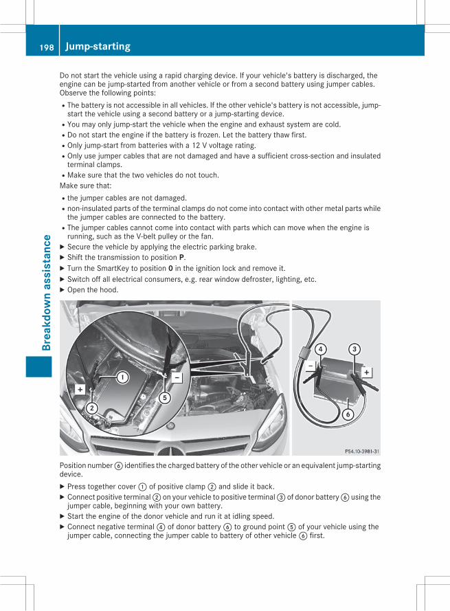
Do not start the vehicle using a rapid charging device. If your vehicle's battery is discharged, theengine can be jump-started from another vehicle or from a second battery using jumper cables.Observe the following points:RThe battery is not accessible in all vehicles. If the other vehicle's battery is not accessible, jump-start the vehicle using a second battery or a jump-starting device.
RYou may only jump-start the vehicle when the engine and exhaust system are cold.RDo not start the engine if the battery is frozen. Let the battery thaw first.ROnly jump-start from batteries with a 12 V voltage rating.ROnly use jumper cables that are not damaged and have a sufficient cross-section and insulatedterminal clamps.
RMake sure that the two vehicles do not touch.Make sure that:Rthe jumper cables are not damaged.Rnon-insulated parts of the terminal clamps do not come into contact with other metal parts whilethe jumper cables are connected to the battery.
RThe jumper cables cannot come into contact with parts which can move when the engine isrunning, such as the V-belt pulley or the fan.X Secure the vehicle by applying the electric parking brake.X Shift the transmission to position P.X Turn the SmartKey to position 0 in the ignition lock and remove it.X Switch off all electrical consumers, e.g. rear window defroster, lighting, etc.X Open the hood.
Position numberB identifies the charged battery of the other vehicle or an equivalent jump-startingdevice.X Press together cover: of positive clamp; and slide it back.X Connect positive terminal; on your vehicle to positive terminal= of donor batteryB using thejumper cable, beginning with your own battery.X Start the engine of the donor vehicle and run it at idling speed.X Connect negative terminal? of donor batteryB to ground pointA of your vehicle using thejumper cable, connecting the jumper cable to battery of other vehicleB first.
198 Jump-startingBr
eakd
own
assi
stan
ce
X If the battery is fully discharged, leave the battery that is being used to jump-start connected fora few minutes before attempting to start. This charges the battery slightly.X Start the engine.X Before disconnecting the jumper cables, let the engine run for several minutes.X First, remove the jumper cables from ground pointA and negative terminal?, then from pos-itive clamp; and positive terminal=. Begin each time at the contacts on your own vehicle first.X Close cover: of positive terminal; after removing the jumper cables.X Close the hood.X Have the battery checked at a qualified specialist workshop.
i Jump-starting is not considered to be a normal operating condition.
i Jumper cables and further information regarding jump-starting can be obtained at any qualifiedspecialist workshop.
Towing and tow-starting
Important safety notes
G WARNINGFunctions relevant to safety are restricted orno longer available if:Rthe engine is not running.Rthe brake system or the power steering ismalfunctioning.
Rthere is a malfunction in the voltage supplyor the vehicle's electrical system.
If your vehicle is being towed, much moreforce may be necessary to steer or brake.There is a risk of an accident.In such cases, use a tow bar. Before towing,make sure that the steering moves freely.
G WARNINGYou can no longer steer the vehicle if thesteering wheel lock has been engaged. Thereis a risk of an accident.Always switch off the ignitionwhen towing thevehicle with a tow cable or a tow bar.
G WARNINGWhen towing or tow-starting another vehicleand its weight is greater than the permissiblegross weight of your vehicle, the:Rthe towing eye could detach itselfRthe vehicle/trailer combination could roll-over.
There is a risk of an accident.When towing or tow-starting another vehicle,its weight should not be greater than the per-missible gross weight of your vehicle.
Details on the permissible gross vehicle weightof your vehicle can be found on the vehicle iden-tification plate (Y page 232).
! When COLLISION PREVENTION ASSISTPLUS, DISTRONIC PLUS or theHOLD functionis activated, the vehicle brakes automaticallyin certain situations. To avoid damage to thevehicle, deactivate these systems in the fol-lowing or similar situations:Rwhen towing the vehicleRin the car wash
! Make sure that the electric parking brake isreleased. If the electric parking brake is faulty,visit a qualified specialist workshop.
! Only secure the tow rope or tow bar at thetowing eyes. Otherwise, the vehicle could bedamaged.
! Do not use the towing eyes for recovery pur-poses as this could damage the vehicle. If indoubt, recover the vehicle with a crane.
Towing and tow-starting 199
Brea
kdow
nas
sist
ance
Z
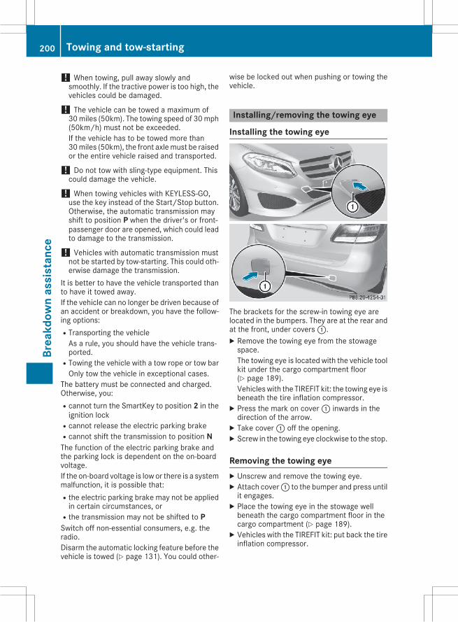
! When towing, pull away slowly andsmoothly. If the tractive power is too high, thevehicles could be damaged.
! The vehicle can be towed a maximum of30miles (50km). The towing speed of 30mph(50km/h) must not be exceeded.If the vehicle has to be towed more than30miles (50km), the front axlemust be raisedor the entire vehicle raised and transported.
! Do not tow with sling-type equipment. Thiscould damage the vehicle.
! When towing vehicles with KEYLESS-GO,use the key instead of the Start/Stop button.Otherwise, the automatic transmission mayshift to position P when the driver's or front-passenger door are opened, which could leadto damage to the transmission.
! Vehicles with automatic transmission mustnot be started by tow-starting. This could oth-erwise damage the transmission.
It is better to have the vehicle transported thanto have it towed away.If the vehicle can no longer be driven because ofan accident or breakdown, you have the follow-ing options:RTransporting the vehicleAs a rule, you should have the vehicle trans-ported.
RTowing the vehicle with a tow rope or tow barOnly tow the vehicle in exceptional cases.
The battery must be connected and charged.Otherwise, you:Rcannot turn the SmartKey to position 2 in theignition lock
Rcannot release the electric parking brakeRcannot shift the transmission to position NThe function of the electric parking brake andthe parking lock is dependent on the on-boardvoltage.If the on-board voltage is low or there is a systemmalfunction, it is possible that:Rthe electric parking brake may not be appliedin certain circumstances, or
Rthe transmission may not be shifted to PSwitch off non-essential consumers, e.g. theradio.Disarm the automatic locking feature before thevehicle is towed (Y page 131). You could other-
wise be locked out when pushing or towing thevehicle.
Installing/removing the towing eye
Installing the towing eye
The brackets for the screw-in towing eye arelocated in the bumpers. They are at the rear andat the front, under covers:.X Remove the towing eye from the stowagespace.The towing eye is located with the vehicle toolkit under the cargo compartment floor(Y page 189).Vehicleswith the TIREFIT kit: the towing eye isbeneath the tire inflation compressor.X Press the mark on cover: inwards in thedirection of the arrow.X Take cover: off the opening.X Screw in the towing eye clockwise to the stop.
Removing the towing eyeX Unscrew and remove the towing eye.X Attach cover: to the bumper and press untilit engages.X Place the towing eye in the stowage wellbeneath the cargo compartment floor in thecargo compartment (Y page 189).X Vehicles with the TIREFIT kit: put back the tireinflation compressor.
200 Towing and tow-startingBr
eakd
own
assi
stan
ce
Towing the vehicle with the front axleraisedObserve the important safety notes when tow-ing your vehicle with the front axle raised(Y page 199).Only vehicles without 4MATIC can be towedwith the front axle raised.
! Vehicles with 4MATIC must not be towedwith either the front or the rear axle raised, asdoing so will damage the transmission.
Vehicleswith 4MATICmay either be towed awaywith both axles on the ground or be loaded upand transported.
! The ignition must be switched off if the vehi-cle is being towed with the front axle raised.Otherwise, ESP® may intervene and damagethe brake system.X On vehicles with KEYLESS-GO or the KEY-
LESS-GO start function: you must use theSmartKey instead of the Start/Stop button(Y page 99).X Make sure that the vehicle is stationary.X Turn the SmartKey to position2 in the ignitionlock.X When the vehicle is stationary, depress thebrake pedal and keep it depressed.X Shift the automatic transmission to posi-tion P.X Release the brake pedal.X Release the electric parking brake.X Switch off the automatic locking(Y page 131).X Switch on the hazard warning lamps(Y page 84).X Turn the SmartKey in the ignition lock to posi-tion 0 and leave the SmartKey in the ignitionlock.
Towing a vehicle with both axles onthe groundIt is important that you observe the safetyinstructions when towing away your vehicle(Y page 199).X On vehicles with KEYLESS-GO or the KEY-
LESS-GO start function: you must use theSmartKey instead of the Start/Stop button(Y page 99).
The automatic transmission automatically shiftsto positionPwhen you open the driver's or front-passenger door or when you remove the Smart-Key from the ignition lock. In order to ensurethat the automatic transmission stays in posi-tion N when towing the vehicle, you mustobserve the following points:X Make sure that the vehicle is stationary.X Turn the SmartKey to position2 in the ignitionlock.X Depress and hold the brake pedal.X Shift the automatic transmission to position
N.X Leave the SmartKey in position 2 in the igni-tion lock.X Release the brake pedal.X Release the electric parking brake.X Switch on the hazard warning lamps(Y page 84).
i In order to signal a change of direction whentowing the vehicle with the hazard warninglamps switched on, use the combinationswitch as usual. In this case, only the indicatorlamps for the direction of travel flash. Afterresetting the combination switch, the hazardwarning lamp starts flashing again.
Transporting the vehicle
4MATIC vehicles/vehicles with auto-matic transmission
! When the vehicle is loaded for transport, thefront and rear axlesmust be stationary and onthe same transportation vehicle. Positioningover the connection point of the transportvehicle is not permitted. The drive train mayotherwise be damaged.
Towing and tow-starting 201
Brea
kdow
nas
sist
ance
Z
All vehicles! You may only secure the vehicle by thewheels, not by parts of the vehicle such asaxle or steering components. Otherwise, thevehicle could be damaged.X Turn the SmartKey to position2 in the ignitionlock (Y page 98).X Shift the transmission to position N.As soon as the vehicle has been loaded:X Prevent the vehicle from rolling away byapplying the electric parking brake.X Shift the transmission to position P.X Turn the SmartKey to position0 in the ignitionlock and remove it.X Secure the vehicle.The towing eye can be used to pull the vehicleonto a trailer or transporter for transporting pur-poses.
Notes on 4MATIC vehicles! Vehicles with 4MATIC must not be towedwith either the front or the rear axle raised, asdoing so will damage the transmission.
Vehicles with 4MATIC may only either be towedaway with both axles on the ground or be loadedup and transported.If the vehicle's transmission, front, or rear axle isdamaged, have the vehicle transported on atruck or trailer.In the event of damage to the electrical sys-tem:If the battery is defective, the automatic trans-mission will be locked in position P. To shift theautomatic transmission to position N, you mustprovide power to the vehicle's electrical systemin the same way as when jump-starting(Y page 197).Have the vehicle transported on a transporter ortrailer.
Tow-starting (emergency enginestarting)! Vehicles with automatic transmission mustnot be tow-started. You could otherwise dam-age the automatic transmission.
i You can find information on "Jump-starting"under (Y page 197).
Fuses
Important safety notes
G WARNINGIf you manipulate or bridge a faulty fuse or ifyou replace it with a fuse with a higher amper-age, the electric cables could be overloaded.This could result in a fire. There is a risk of anaccident and injury.Always replace faulty fuses with the specifiednew fuses having the correct amperage.
Blown fuses must be replaced with fuses of thesame rating, which you can recognize by thecolor and value. The fuse ratings are listed in thefuse allocation chart.If a newly inserted fuse also blows, have thecause traced and rectified at a qualified special-ist workshop, e.g. an authorizedMercedes-BenzCenter.
! Only use fuses that have been approved forMercedes-Benz vehicles and which have thecorrect fuse rating for the system concerned.Only use fuses marked with an "S". Other-wise, components or systems could be dam-aged.
The fuses in your vehicle serve to close downfaulty circuits. If a fuse blows, all the compo-nents on the circuit and their functions stopoperating.
Before changing a fuseX Secure the vehicle against rolling away(Y page 107).X Switch off all electrical consumers.X Vehicles without KEYLESS-GO: remove theSmartKey from the ignition lock.X Vehicles with KEYLESS-GO start-function
or KEYLESS-GO: open the driver's door.The on-board electronics now have status 0.This is the same as the SmartKey having beenremoved.
202 FusesBr
eakd
own
assi
stan
ce
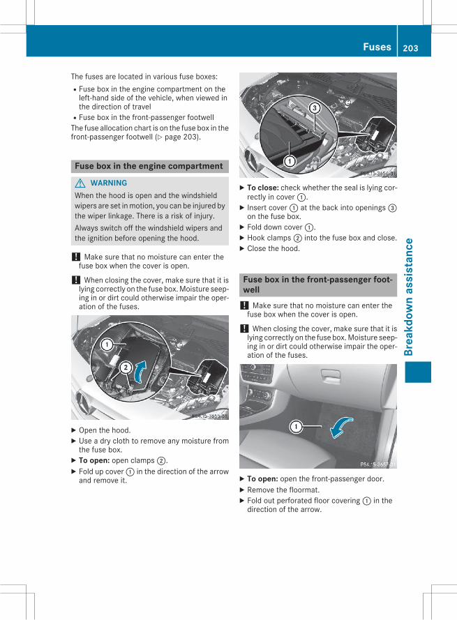
The fuses are located in various fuse boxes:RFuse box in the engine compartment on theleft-hand side of the vehicle, when viewed inthe direction of travel
RFuse box in the front-passenger footwellThe fuse allocation chart is on the fuse box in thefront-passenger footwell (Y page 203).
Fuse box in the engine compartment
G WARNINGWhen the hood is open and the windshieldwipers are set inmotion, you can be injured bythe wiper linkage. There is a risk of injury.Always switch off the windshield wipers andthe ignition before opening the hood.
! Make sure that no moisture can enter thefuse box when the cover is open.
! When closing the cover, make sure that it islying correctly on the fuse box.Moisture seep-ing in or dirt could otherwise impair the oper-ation of the fuses.
X Open the hood.X Use a dry cloth to remove any moisture fromthe fuse box.X To open: open clamps;.X Fold up cover: in the direction of the arrowand remove it.
X To close: check whether the seal is lying cor-rectly in cover:.X Insert cover: at the back into openings=on the fuse box.X Fold down cover:.X Hook clamps; into the fuse box and close.X Close the hood.
Fuse box in the front-passenger foot-well! Make sure that no moisture can enter thefuse box when the cover is open.
! When closing the cover, make sure that it islying correctly on the fuse box.Moisture seep-ing in or dirt could otherwise impair the oper-ation of the fuses.
X To open: open the front-passenger door.X Remove the floormat.X Fold out perforated floor covering: in thedirection of the arrow.
Fuses 203
Brea
kdow
nas
sist
ance
Z
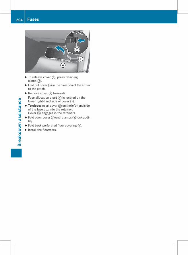
X To release cover=, press retainingclamp;.X Fold out cover= in the direction of the arrowto the catch.X Remove cover= forwards.Fuse allocation chart? is located on thelower right-hand side of cover=.X To close: insert cover= on the left-hand sideof the fuse box into the retainer.Cover= engages in the retainers.X Fold down cover= until clamps; lock audi-bly.X Fold back perforated floor covering:.X Install the floormats.
204 FusesBr
eakd
own
assi
stan
ce
Useful information
i ThisOperator'sManual describes allmodelsand all standard and optional equipment ofyour vehicle available at the time of publica-tion of the Operator's Manual. Country-spe-cific differences are possible. Please notethat your vehicle may not be equipped with allfeatures described. This also applies tosafety-related systems and functions.
i Read the information on qualified specialistworkshops (Y page 26).
Important safety notes
G WARNINGIf wheels and tires of the wrong size are used,the wheel brakes or suspension componentsmay be damaged. There is a risk of an acci-dent.Always replace wheels and tires with thosethat fulfill the specifications of the originalpart.When replacing wheels, make sure to use thecorrect:RdesignationRmodelWhen replacing tires, make sure to use thecorrect:RdesignationRmanufacturerRmodel
G WARNINGA flat tire severely impairs the driving, steer-ing and braking characteristics of the vehicle.There is a risk of accident.Tires without run-flat characteristics:Rdo not drive with a flat tire.Rimmediately replace the flat tire with youremergency spare wheel or spare wheel, orconsult a qualified specialist workshop.
Tires with run-flat characteristics:Rpay attention to the information and warn-ing notices on MOExtended tires (tires withrun-flat characteristics).
Accessories that are not approved for your vehi-cle by Mercedes-Benz or are not being used cor-rectly can impair the operating safety.Before purchasing and using non-approvedaccessories, visit a qualified specialist work-shop and inquire about:RsuitabilityRlegal stipulationsRfactory recommendationsInformation on the sizes and types ofwheels andtires for your vehicle can be found under"Wheel/tire combinations" (Y page 225).Information on tire pressure can be found:Ron the Tire and Loading Information placardon the B-pillar on the driver's side(Y page 212)
Rin the tire pressure table in the fuel filler flap(Y page 106)
Runder "Tire pressure" (Y page 208)
Operation
Information on drivingCheck the tire pressure when the vehicle isheavily laden and adjust prior to a trip.While driving, pay attention to vibrations, noisesand unusual handling characteristics, e.g. pull-ing to one side. This may indicate that thewheels or tires are damaged. If you suspect thata tire is defective, reduce your speed immedi-ately. Stop the vehicle as soon as possible tocheck the wheels and tires for damage. Hiddentire damage could also be causing the unusualhandling characteristics. If you find no signs ofdamage, have the tires and wheels checked at aqualified specialist workshop.When parking your vehicle, make sure that thetires do not get deformed by the curb or otherobstacles. If they cannot be avoided, drive overobstacles such as curbs slowly and at an obtuseangle. Otherwise, you may damage the wheelsor tires.
Operation 205
Whe
els
and
tires
Z
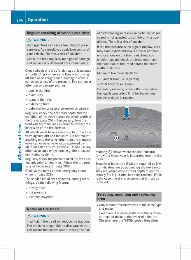
Regular checking of wheels and tires
G WARNINGDamaged tires can cause tire inflation pres-sure loss. As a result, you could lose control ofyour vehicle. There is a risk of accident.Check the tires regularly for signs of damageand replace any damaged tires immediately.
Checkwheels and tires for damage at least oncea month. Check wheels and tires after drivingoff-road or on rough roads. Damaged wheelscan cause a loss of tire pressure. Pay particularattention to damage such as:Rcuts in the tiresRpuncturesRtears in the tiresRbulges on tiresRdeformation or severe corrosion on wheelsRegularly check the tire tread depth and thecondition of the tread across the whole width ofthe tire (Y page 206). If necessary, turn thefront wheels to full lock in order to inspect theinner side of the tire surface.All wheels must have a valve cap to protect thevalve against dirt and moisture. Do not mountanything onto the valve other than the standardvalve cap or other valve caps approved byMercedes-Benz for your vehicle. Do not use anyother valve caps or systems, e.g. tire pressuremonitoring systems.Regularly check the pressure of all the tires par-ticularly prior to long trips. Adjust the tire pres-sure as necessary (Y page 208).Observe the notes on the emergency sparewheel (Y page 228).The service life of tires depends, among otherthings, on the following factors:Rdriving styleRtire pressureRdistance covered
Notes on tire tread
G WARNINGInsufficient tire tread will reduce tire traction.The tire is no longer able to dissipate water.This means that on wet road surfaces, the risk
of hydroplaning increases, in particular wherespeed is not adapted to suit the driving con-ditions. There is a risk of accident.If the tire pressure is too high or too low, tiresmay exhibit different levels of wear at differ-ent locations on the tire tread. Thus, youshould regularly check the tread depth andthe condition of the tread across the entirewidth of all tires.Minimum tire tread depth for:RSummer tires:â in (3 mm)RM+S tires:ã in (4 mm)For safety reasons, replace the tires beforethe legally prescribed limit for the minimumtire tread depth is reached.
Marking: shows where the bar indicator(arrow) for tread wear is integrated into the tiretread.Treadwear indicators (TWI) are required by law.Six indicators are positioned on the tire tread.They are visible once a tread depth of approx-imatelyá in (1.6mm) has been reached. If thisis the case, the tire is so worn that it must bereplaced.
Selecting, mounting and replacingtires
ROnly mount tires and wheels of the same typeand make.Exception: it is permissible to install a differ-ent type or make in the event of a flat tire.Observe here the "MOExtended tires (tires
206 OperationW
heel
san
dtir
es
with run-flat characteristics)" section(Y page 190).
ROnly mount tires of the correct size onto thewheels.
RBreak in new tires at moderate speeds for thefirst 60 miles (100 km). They only reach theirfull performance after this distance.
RDo not drive with tires which have too littletread depth, as this significantly reduces thetraction on wet roads (hydroplaning).
RReplace the tires after six years at the latest,regardless of wear.
Observe the notes on the emergency sparewheel (Y page 228).
MOExtended tires (tires with run-flatproperties)With MOExtended tires (tires with run flat char-acteristics), you can continue to drive your vehi-cle even if there is a total loss of pressure in oneor more tires.MOExtended tires may only be used in conjunc-tion with an active tire pressure loss warningsystem and only onwheels specifically tested byMercedes-Benz.Notes on driving with MOExtended tires with aflat tire (Y page 190).Vehicles equipped with MOExtended tires arenot equipped with a TIREFIT kit at the factory. Itis therefore recommended that you additionallyequip your vehiclewith a TIREFIT kit if youmounttires that do not feature run-flat properties, e.g.winter tires. A TIREFIT kit may be obtained froma qualified specialist workshop.
Winter operation
General notesYou can find information about this in the DigitalOperator's Manual.
Driving with summer tiresAt temperatures below 45 ‡ (+7 †), summertires lose elasticity and therefore traction andbraking power. Change the tires on your vehicleto M+S tires. Using summer tires at very coldtemperatures could cause cracks to form,thereby damaging the tires permanently.
Mercedes-Benz cannot accept responsibility forthis type of damage.
G WARNINGDamaged tires can cause tire inflation pres-sure loss. As a result, you could lose control ofyour vehicle. There is a risk of accident.Check the tires regularly for signs of damageand replace any damaged tires immediately.
M+S tires
G WARNINGM+S tires with a tire tread depth of less thanã in (4 mm) are not suitable for use in winterand do not provide sufficient traction. There isa risk of an accident.M+S tires with a tread depth of less thanã in(4 mm) must be replaced immediately.
Further information can be found in the DigitalOperator's Manual.
Snow chains
G WARNINGIf snow chains are mounted on the rearwheels, the snow chains could cause abrasionto the vehicle body or to chassis components.This could cause damage to the vehicle or thetires. There is a risk of an accident.To avoid hazardous situations:Rnever mount snow chains on the rearwheels
Ronly mount snow chains in pairs on thefront wheels.
Further information can be found in the DigitalOperator's Manual.
Winter operation 207
Whe
els
and
tires
Z
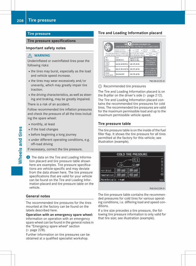
Tire pressure
Tire pressure specifications
Important safety notes
G WARNINGUnderinflated or overinflated tires pose thefollowing risks:Rthe tires may burst, especially as the loadand vehicle speed increase.
Rthe tires may wear excessively and/orunevenly, which may greatly impair tiretraction.
Rthe driving characteristics, as well as steer-ing and braking, may be greatly impaired.
There is a risk of an accident.Follow recommended tire inflation pressuresand check the pressure of all the tires includ-ing the spare wheel:Rmonthly, at leastRif the load changesRbefore beginning a long journeyRunder different operating conditions, e.g.off-road driving
If necessary, correct the tire pressure.
i The data on the Tire and Loading Informa-tion placard and tire pressure table shownhere are examples. Tire pressure specifica-tions are vehicle-specific and may deviatefrom the data shown here. The tire pressurespecifications that are valid for your vehiclecan be found on the Tire and Loading Infor-mation placard and tire pressure table on thevehicle.
General notesThe recommended tire pressures for the tiresmounted at the factory can be found on thelabels described here.Operation with an emergency spare wheel:information on operation with an emergencyspare wheel can be found in the general notes inthe "Emergency spare wheel" section(Y page 228).Further information on tire pressures can beobtained at a qualified specialist workshop.
Tire and Loading Information placard
: Recommended tire pressuresThe Tire and Loading Information placard is onthe B-pillar on the driver's side (Y page 212).The Tire and Loading Information placard con-tains the recommended tire pressures for coldtires. The recommended tire pressures are validfor the maximum permissible load and up to themaximum permissible vehicle speed.
Tire pressure tableThe tire pressure table is on the inside of the fuelfiller flap. It shows the tire pressure for all tirespermitted at the factory for this vehicle; seeillustration (example).
The tire pressure table contains the recommen-ded pressures for cold tires for various operat-ing conditions, i.e. differing load and speed con-ditions.If a tire size precedes a tire pressure, the fol-lowing tire pressure information is only valid forthat tire size; see illustration (example).
208 Tire pressureW
heel
san
dtir
es
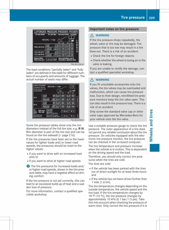
The load conditions "partially laden" and "fullyladen" are defined in the table for different num-bers of occupants and amounts of luggage. Theactual number of seats may differ.
Some tire pressure tables show only the rimdiameters instead of the full tire size, e.g. R18.Rim diameter is part of the tire size and can befound on the tire sidewall (Y page 216).If the tire pressures have been set to the lowervalues for lighter loads and/or lower roadspeeds, the pressures should be reset to thehigher values:Rif you want to drive with an increased loadand/or
Rif you want to drive at higher road speeds
i The tire pressures for increased loads and/or higher road speeds, shown in the tire pres-sure table, may have a negative effect on driv-ing comfort.
If the tire pressure is not set correctly, this canlead to an excessive build-up of heat and a sud-den loss of pressure.For more information, contact a qualified spe-cialist workshop.
Important notes on tire pressure
G WARNINGIf the tire pressure drops repeatedly, thewheel, valve or tire may be damaged. Tirepressure that is too low may result in a tireblow-out. There is a risk of an accident.RCheck the tire for foreign objects.RCheck whether the wheel is losing air or thevalve is leaking.
If you are unable to rectify the damage, con-tact a qualified specialist workshop.
G WARNINGIf you fit unsuitable accessories onto tirevalves, the tire valves may be overloaded andmalfunction, which can cause tire pressureloss. Due to their design, retrofitted tire pres-sure monitors keep the tire valve open. Thiscan also result in tire pressure loss. There is arisk of an accident.Only screw the standard valve cap or othervalve caps approved by Mercedes-Benz foryour vehicle onto the tire valve.
Use a suitable pressure gauge to check the tirepressure. The outer appearance of a tire doesnot permit any reliable conclusion about the tirepressure. On vehicles equipped with the elec-tronic tire pressure monitor, the tire pressurecan be checked in the on-board computer.The tire temperature and pressure increasewhen the vehicle is in motion. This is dependenton the driving speed and the load.Therefore, you should only correct tire pres-sures when the tires are cold.The tires are cold:Rif the vehicle has been parked with the tiresout of direct sunlight for at least three hoursand
Rif the vehicle has not been driven further than1 mile (1.6 km)
The tire temperature changes depending on theoutside temperature, the vehicle speed and thetire load. If the tire temperature changes by18 ‡ (10 †), the tire pressure changes byapproximately 10 kPa (0.1 bar/1.5 psi). Takethis into account when checking the pressure ofwarm tires. Only correct the tire pressure if it is
Tire pressure 209
Whe
els
and
tires
Z
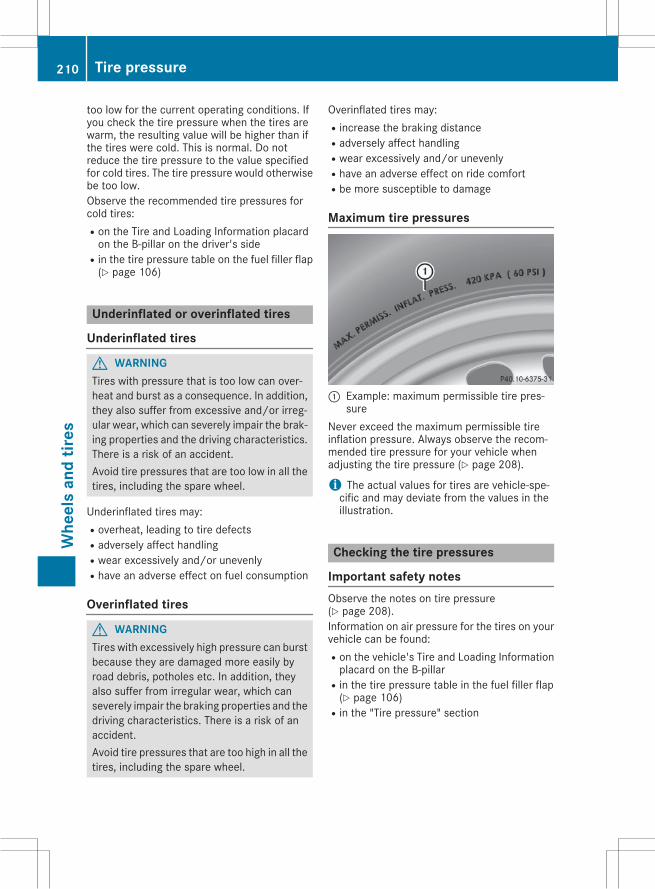
too low for the current operating conditions. Ifyou check the tire pressure when the tires arewarm, the resulting value will be higher than ifthe tires were cold. This is normal. Do notreduce the tire pressure to the value specifiedfor cold tires. The tire pressure would otherwisebe too low.Observe the recommended tire pressures forcold tires:Ron the Tire and Loading Information placardon the B-pillar on the driver's side
Rin the tire pressure table on the fuel filler flap(Y page 106)
Underinflated or overinflated tires
Underinflated tires
G WARNINGTires with pressure that is too low can over-heat and burst as a consequence. In addition,they also suffer from excessive and/or irreg-ular wear, which can severely impair the brak-ing properties and the driving characteristics.There is a risk of an accident.Avoid tire pressures that are too low in all thetires, including the spare wheel.
Underinflated tires may:Roverheat, leading to tire defectsRadversely affect handlingRwear excessively and/or unevenlyRhave an adverse effect on fuel consumption
Overinflated tires
G WARNINGTires with excessively high pressure can burstbecause they are damaged more easily byroad debris, potholes etc. In addition, theyalso suffer from irregular wear, which canseverely impair the braking properties and thedriving characteristics. There is a risk of anaccident.Avoid tire pressures that are too high in all thetires, including the spare wheel.
Overinflated tires may:Rincrease the braking distanceRadversely affect handlingRwear excessively and/or unevenlyRhave an adverse effect on ride comfortRbe more susceptible to damage
Maximum tire pressures
: Example: maximum permissible tire pres-sure
Never exceed the maximum permissible tireinflation pressure. Always observe the recom-mended tire pressure for your vehicle whenadjusting the tire pressure (Y page 208).
i The actual values for tires are vehicle-spe-cific and may deviate from the values in theillustration.
Checking the tire pressures
Important safety notesObserve the notes on tire pressure(Y page 208).Information on air pressure for the tires on yourvehicle can be found:Ron the vehicle's Tire and Loading Informationplacard on the B-pillar
Rin the tire pressure table in the fuel filler flap(Y page 106)
Rin the "Tire pressure" section
210 Tire pressureW
heel
san
dtir
es
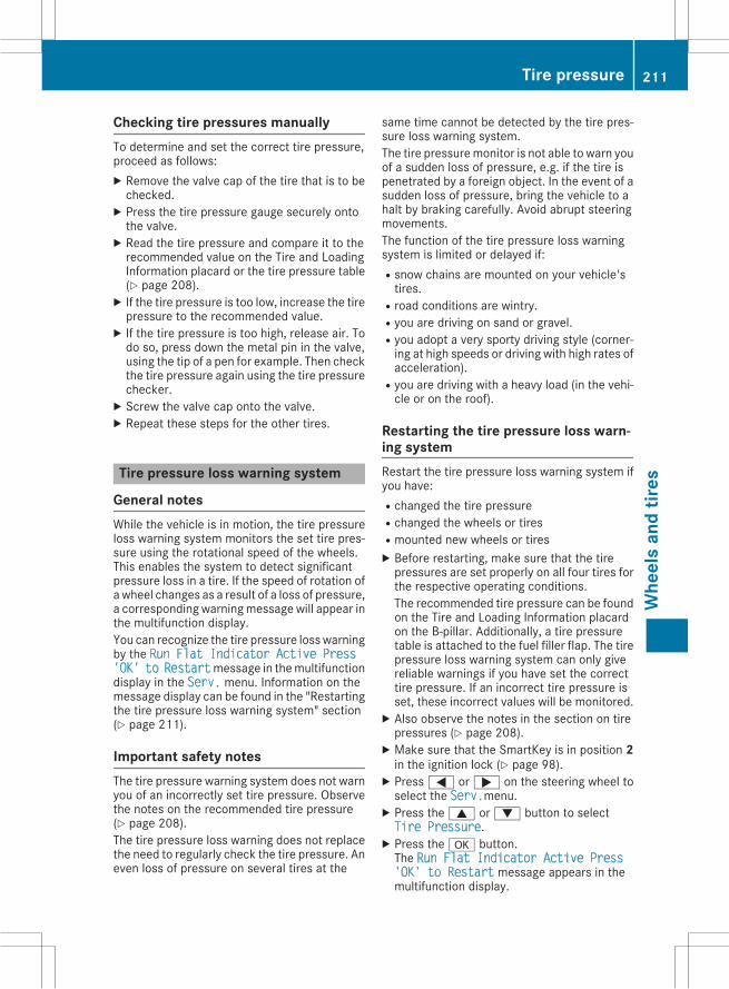
Checking tire pressures manuallyTo determine and set the correct tire pressure,proceed as follows:X Remove the valve cap of the tire that is to bechecked.X Press the tire pressure gauge securely ontothe valve.X Read the tire pressure and compare it to therecommended value on the Tire and LoadingInformation placard or the tire pressure table(Y page 208).X If the tire pressure is too low, increase the tirepressure to the recommended value.X If the tire pressure is too high, release air. Todo so, press down the metal pin in the valve,using the tip of a pen for example. Then checkthe tire pressure again using the tire pressurechecker.X Screw the valve cap onto the valve.X Repeat these steps for the other tires.
Tire pressure loss warning system
General notesWhile the vehicle is in motion, the tire pressureloss warning system monitors the set tire pres-sure using the rotational speed of the wheels.This enables the system to detect significantpressure loss in a tire. If the speed of rotation ofa wheel changes as a result of a loss of pressure,a corresponding warningmessage will appear inthe multifunction display.You can recognize the tire pressure losswarningby the Run Flat Indicator Active Press'OK' to Restartmessage in themultifunctiondisplay in the Serv. menu. Information on themessage display can be found in the "Restartingthe tire pressure loss warning system" section(Y page 211).
Important safety notesThe tire pressure warning system does not warnyou of an incorrectly set tire pressure. Observethe notes on the recommended tire pressure(Y page 208).The tire pressure loss warning does not replacethe need to regularly check the tire pressure. Aneven loss of pressure on several tires at the
same time cannot be detected by the tire pres-sure loss warning system.The tire pressuremonitor is not able to warn youof a sudden loss of pressure, e.g. if the tire ispenetrated by a foreign object. In the event of asudden loss of pressure, bring the vehicle to ahalt by braking carefully. Avoid abrupt steeringmovements.The function of the tire pressure loss warningsystem is limited or delayed if:Rsnow chains are mounted on your vehicle'stires.
Rroad conditions are wintry.Ryou are driving on sand or gravel.Ryou adopt a very sporty driving style (corner-ing at high speeds or driving with high rates ofacceleration).
Ryou are driving with a heavy load (in the vehi-cle or on the roof).
Restarting the tire pressure loss warn-ing systemRestart the tire pressure loss warning system ifyou have:Rchanged the tire pressureRchanged the wheels or tiresRmounted new wheels or tiresX Before restarting, make sure that the tirepressures are set properly on all four tires forthe respective operating conditions.The recommended tire pressure can be foundon the Tire and Loading Information placardon the B-pillar. Additionally, a tire pressuretable is attached to the fuel filler flap. The tirepressure loss warning system can only givereliable warnings if you have set the correcttire pressure. If an incorrect tire pressure isset, these incorrect values will be monitored.X Also observe the notes in the section on tirepressures (Y page 208).X Make sure that the SmartKey is in position 2in the ignition lock (Y page 98).X Press= or; on the steering wheel toselect the Serv.menu.X Press the9 or: button to selectTire Pressure.X Press thea button.The Run Flat Indicator Active Press'OK' to Restart message appears in themultifunction display.
Tire pressure 211
Whe
els
and
tires
Z
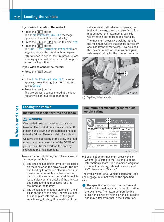
If you wish to confirm the restart:X Press thea button.The Tire Pressure Now OK? messageappears in the multifunction display.X Press the9 or: button to select Yes.X Press thea button.The Run Flat Indicator Restarted mes-sage appears in the multifunction display.After a teach-in period, the tire pressure losswarning system will monitor the set tire pres-sures of all four tires.
If you wish to cancel the restart:X Press the% button.orX If the Tire Pressure Now OK? messageappears, press the9 or: button toselect Cancel.X Press thea button.The tire pressure values stored at the lastrestart will continue to be monitored.
Loading the vehicle
Instruction labels for tires and loads
G WARNINGOverloaded tires can overheat, causing ablowout. Overloaded tires can also impair thesteering and driving characteristics and leadto brake failure. There is a risk of accident.Observe the load rating of the tires. The loadrating must be at least half of the GAWR ofyour vehicle. Never overload the tires byexceeding the maximum load.
Two instruction labels on your vehicle show themaximum possible load.(1) The Tire and Loading Information placard is
on the B-pillar on the driver's side. The Tireand Loading Information placard shows themaximum permissible number of occu-pants and themaximumpermissible vehicleload. It also contains details of the tire sizesand corresponding pressures for tiresmounted at the factory.
(2) The vehicle identification plate is on the B-pillar on the driver's side. The vehicle iden-tification plate informs you of the grossvehicle weight rating. It is made up of the
vehicle weight, all vehicle occupants, thefuel and the cargo. You can also find infor-mation about the maximum gross axleweight rating on the front and rear axle.The maximum gross axle weight rating isthe maximum weight that can be carried byone axle (front or rear axle). Never exceedthe maximum load or the maximum grossaxle weight rating for the front or rear axle.
: B-pillar, driver's side
Maximum permissible gross vehicleweight rating
X Specification for maximum gross vehicleweight: is listed in the Tire and LoadingInformation placard: "The combinedweight ofoccupants and cargo should never exceedXXX kilograms or XXX lbs."
The gross weight of all vehicle occupants, loadand luggage must not exceed the specifiedvalue.
i The specifications shown on the Tire andLoading Information placard in the illustrationare examples. The maximum permissiblegross vehicle weight rating is vehicle-specificand may differ from that in the illustration.
212 Loading the vehicleW
heel
san
dtir
es
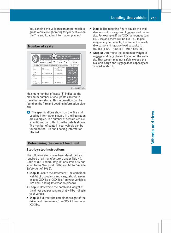
You can find the valid maximum permissiblegross vehicle weight rating for your vehicle onthe Tire and Loading Information placard.
Number of seats
Maximum number of seats: indicates themaximum number of occupants allowed totravel in the vehicle. This information can befound on the Tire and Loading Information plac-ard.
i The specifications shown on the Tire andLoading Information placard in the illustrationare examples. The number of seats is vehicle-specific and can differ from the details shown.The number of seats in your vehicle can befound on the Tire and Loading Informationplacard.
Determining the correct load limit
Step-by-step instructionsThe following steps have been developed asrequired of all manufacturers under Title 49,Code of U.S. Federal Regulations, Part 575 pur-suant to the "National Traffic and Motor VehicleSafety Act of 1966".X Step 1: Locate the statement "The combinedweight of occupants and cargo should neverexceed XXX kg or XXX lbs." on your vehicle’sTire and Loading Information placard.X Step 2: Determine the combined weight ofthe driver and passengers that will be riding inyour vehicle.X Step 3: Subtract the combined weight of thedriver and passengers from XXX kilograms orXXX lbs.
X Step 4: The resulting figure equals the avail-able amount of cargo and luggage load capa-city. For example, if the "XXX" amount equals1400 lbs and there will be five 150-lb pas-sengers in your vehicle, the amount of avail-able cargo and luggage load capacity is650 lbs (1400 - 750 (5 x 150) = 650 lbs).X Step 5: Determine the combined weight ofluggage and cargo being loaded on the vehi-cle. That weight may not safely exceed theavailable cargo and luggage load capacity cal-culated in step 4.
Loading the vehicle 213
Whe
els
and
tires
Z
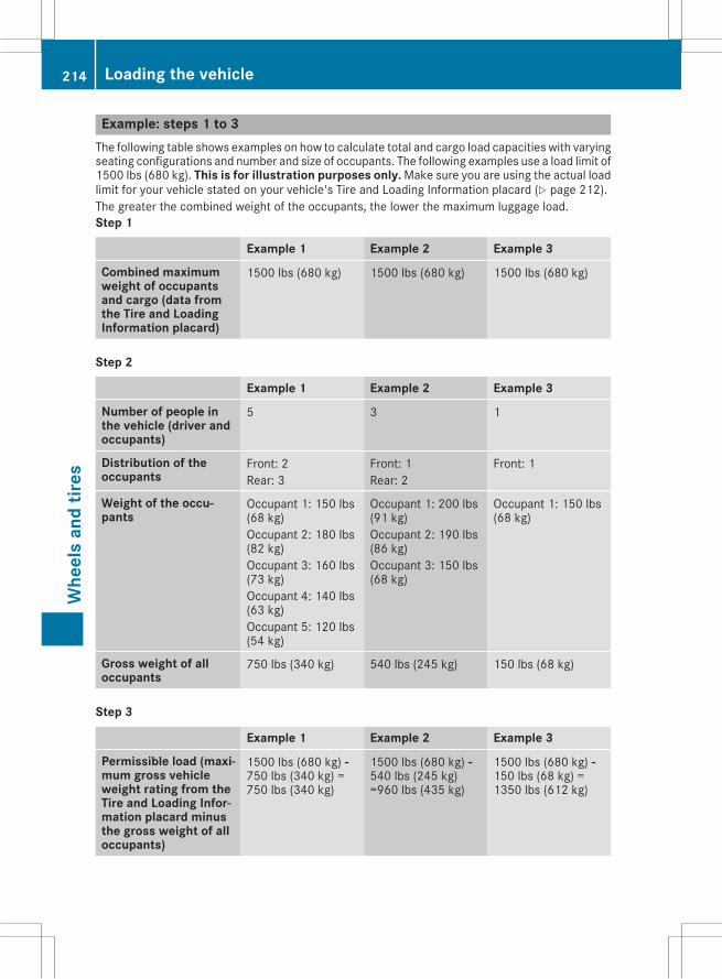
Example: steps 1 to 3The following table shows examples on how to calculate total and cargo load capacities with varyingseating configurations and number and size of occupants. The following examples use a load limit of1500 lbs (680 kg). This is for illustration purposes only. Make sure you are using the actual loadlimit for your vehicle stated on your vehicle's Tire and Loading Information placard (Y page 212).The greater the combined weight of the occupants, the lower the maximum luggage load.Step 1
Example 1 Example 2 Example 3
Combined maximumweight of occupantsand cargo (data fromthe Tire and LoadingInformation placard)
1500 lbs (680 kg) 1500 lbs (680 kg) 1500 lbs (680 kg)
Step 2
Example 1 Example 2 Example 3
Number of people inthe vehicle (driver andoccupants)
5 3 1
Distribution of theoccupants
Front: 2Rear: 3
Front: 1Rear: 2
Front: 1
Weight of the occu-pants
Occupant 1: 150 lbs(68 kg)Occupant 2: 180 lbs(82 kg)Occupant 3: 160 lbs(73 kg)Occupant 4: 140 lbs(63 kg)Occupant 5: 120 lbs(54 kg)
Occupant 1: 200 lbs(91 kg)Occupant 2: 190 lbs(86 kg)Occupant 3: 150 lbs(68 kg)
Occupant 1: 150 lbs(68 kg)
Gross weight of alloccupants
750 lbs (340 kg) 540 lbs (245 kg) 150 lbs (68 kg)
Step 3
Example 1 Example 2 Example 3
Permissible load (maxi-mum gross vehicleweight rating from theTire and Loading Infor-mation placard minusthe gross weight of alloccupants)
1500 lbs (680 kg) Ò750 lbs (340 kg) =750 lbs (340 kg)
1500 lbs (680 kg) Ò540 lbs (245 kg)=960 lbs (435 kg)
1500 lbs (680 kg) Ò150 lbs (68 kg) =1350 lbs (612 kg)
214 Loading the vehicleW
heel
san
dtir
es
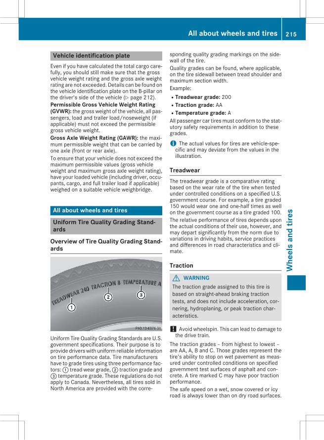
Vehicle identification plateEven if you have calculated the total cargo care-fully, you should still make sure that the grossvehicle weight rating and the gross axle weightrating are not exceeded. Details can be found onthe vehicle identification plate on the B-pillar onthe driver's side of the vehicle (Y page 212).Permissible Gross Vehicle Weight Rating(GVWR): the gross weight of the vehicle, all pas-sengers, load and trailer load/noseweight (ifapplicable) must not exceed the permissiblegross vehicle weight.Gross Axle Weight Rating (GAWR): the maxi-mum permissible weight that can be carried byone axle (front or rear axle).To ensure that your vehicle does not exceed themaximum permissible values (gross vehicleweight and maximum gross axle weight rating),have your loaded vehicle (including driver, occu-pants, cargo, and full trailer load if applicable)weighed on a suitable vehicle weighbridge.
All about wheels and tires
Uniform Tire Quality Grading Stand-ards
Overview of Tire Quality Grading Stand-ards
Uniform Tire Quality Grading Standards are U.S.government specifications. Their purpose is toprovide drivers with uniform reliable informationon tire performance data. Tire manufacturershave to grade tires using three performance fac-tors:: tread wear grade,; traction grade and= temperature grade. These regulations do notapply to Canada. Nevertheless, all tires sold inNorth America are provided with the corre-
sponding quality grading markings on the side-wall of the tire.Quality grades can be found, where applicable,on the tire sidewall between tread shoulder andmaximum section width.Example:RTreadwear grade: 200RTraction grade: AARTemperature grade: AAll passenger car tiresmust conform to the stat-utory safety requirements in addition to thesegrades.
i The actual values for tires are vehicle-spe-cific and may deviate from the values in theillustration.
TreadwearThe treadwear grade is a comparative ratingbased on the wear rate of the tire when testedunder controlled conditions on a specified U.S.government course. For example, a tire graded150 would wear one and one-half times as wellon the government course as a tire graded 100.The relative performance of tires depends uponthe actual conditions of their use, however, andmay depart significantly from the norm due tovariations in driving habits, service practicesand differences in road characteristics and cli-mate.
Traction
G WARNINGThe traction grade assigned to this tire isbased on straight-ahead braking tractiontests, and does not include acceleration, cor-nering, hydroplaning, or peak traction char-acteristics.
! Avoid wheelspin. This can lead to damage tothe drive train.
The traction grades – from highest to lowest –are AA, A, B and C. Those grades represent thetire's ability to stop on wet pavement as meas-ured under controlled conditions on specifiedgovernment test surfaces of asphalt and con-crete. A tire marked C may have poor tractionperformance.The safe speed on a wet, snow covered or icyroad is always lower than on dry road surfaces.
All about wheels and tires 215
Whe
els
and
tires
Z
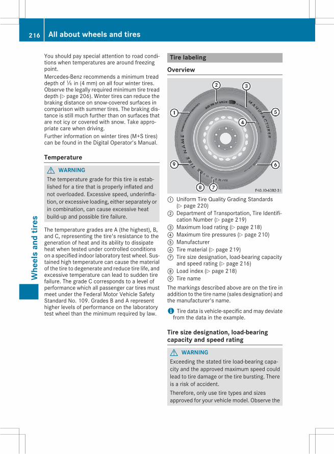
You should pay special attention to road condi-tions when temperatures are around freezingpoint.Mercedes-Benz recommends a minimum treaddepth ofã in (4 mm) on all four winter tires.Observe the legally required minimum tire treaddepth (Y page 206). Winter tires can reduce thebraking distance on snow-covered surfaces incomparison with summer tires. The braking dis-tance is still much further than on surfaces thatare not icy or covered with snow. Take appro-priate care when driving.Further information on winter tires (M+S tires)can be found in the Digital Operator's Manual.
Temperature
G WARNINGThe temperature grade for this tire is estab-lished for a tire that is properly inflated andnot overloaded. Excessive speed, underinfla-tion, or excessive loading, either separately orin combination, can cause excessive heatbuild-up and possible tire failure.
The temperature grades are A (the highest), B,and C, representing the tire's resistance to thegeneration of heat and its ability to dissipateheat when tested under controlled conditionson a specified indoor laboratory test wheel. Sus-tained high temperature can cause the materialof the tire to degenerate and reduce tire life, andexcessive temperature can lead to sudden tirefailure. The grade C corresponds to a level ofperformance which all passenger car tires mustmeet under the Federal Motor Vehicle SafetyStandard No. 109. Grades B and A representhigher levels of performance on the laboratorytest wheel than the minimum required by law.
Tire labeling
Overview
: Uniform Tire Quality Grading Standards(Y page 220)
; Department of Transportation, Tire Identifi-cation Number (Y page 219)
= Maximum load rating (Y page 218)? Maximum tire pressures (Y page 210)A ManufacturerB Tire material (Y page 219)C Tire size designation, load-bearing capacity
and speed rating (Y page 216)D Load index (Y page 218)E Tire nameThe markings described above are on the tire inaddition to the tire name (sales designation) andthe manufacturer's name.
i Tire data is vehicle-specific and may deviatefrom the data in the example.
Tire size designation, load-bearingcapacity and speed rating
G WARNINGExceeding the stated tire load-bearing capa-city and the approved maximum speed couldlead to tire damage or the tire bursting. Thereis a risk of accident.Therefore, only use tire types and sizesapproved for your vehicle model. Observe the
216 All about wheels and tiresW
heel
san
dtir
es
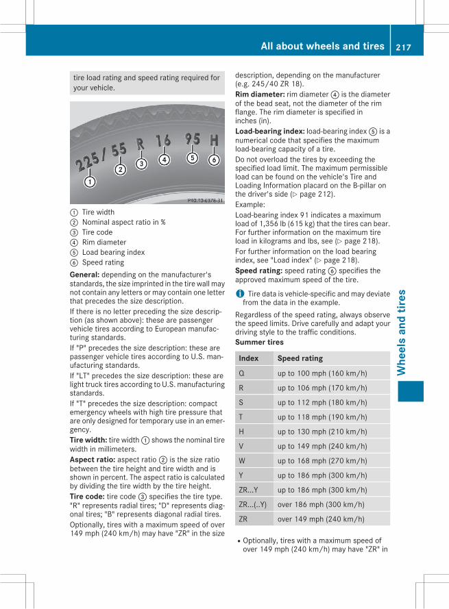
tire load rating and speed rating required foryour vehicle.
: Tire width; Nominal aspect ratio in %= Tire code? Rim diameterA Load bearing indexB Speed ratingGeneral: depending on the manufacturer'sstandards, the size imprinted in the tire wall maynot contain any letters or may contain one letterthat precedes the size description.If there is no letter preceding the size descrip-tion (as shown above): these are passengervehicle tires according to European manufac-turing standards.If "P" precedes the size description: these arepassenger vehicle tires according to U.S. man-ufacturing standards.If "LT" precedes the size description: these arelight truck tires according to U.S. manufacturingstandards.If "T" precedes the size description: compactemergency wheels with high tire pressure thatare only designed for temporary use in an emer-gency.Tire width: tire width: shows the nominal tirewidth in millimeters.Aspect ratio: aspect ratio; is the size ratiobetween the tire height and tire width and isshown in percent. The aspect ratio is calculatedby dividing the tire width by the tire height.Tire code: tire code= specifies the tire type."R" represents radial tires; "D" represents diag-onal tires; "B" represents diagonal radial tires.Optionally, tires with a maximum speed of over149 mph (240 km/h) may have "ZR" in the size
description, depending on the manufacturer(e.g. 245/40 ZR 18).Rim diameter: rim diameter? is the diameterof the bead seat, not the diameter of the rimflange. The rim diameter is specified ininches (in).Load-bearing index: load-bearing indexA is anumerical code that specifies the maximumload-bearing capacity of a tire.Do not overload the tires by exceeding thespecified load limit. The maximum permissibleload can be found on the vehicle's Tire andLoading Information placard on the B-pillar onthe driver's side (Y page 212).Example:Load-bearing index 91 indicates a maximumload of 1,356 lb (615 kg) that the tires can bear.For further information on the maximum tireload in kilograms and lbs, see (Y page 218).For further information on the load bearingindex, see "Load index" (Y page 218).Speed rating: speed ratingB specifies theapproved maximum speed of the tire.
i Tire data is vehicle-specific and may deviatefrom the data in the example.
Regardless of the speed rating, always observethe speed limits. Drive carefully and adapt yourdriving style to the traffic conditions.Summer tires
Index Speed rating
Q up to 100 mph (160 km/h)
R up to 106 mph (170 km/h)
S up to 112 mph (180 km/h)
T up to 118 mph (190 km/h)
H up to 130 mph (210 km/h)
V up to 149 mph (240 km/h)
W up to 168 mph (270 km/h)
Y up to 186 mph (300 km/h)
ZR...Y up to 186 mph (300 km/h)
ZR...(..Y) over 186 mph (300 km/h)
ZR over 149 mph (240 km/h)
ROptionally, tires with a maximum speed ofover 149 mph (240 km/h) may have "ZR" in
All about wheels and tires 217
Whe
els
and
tires
Z
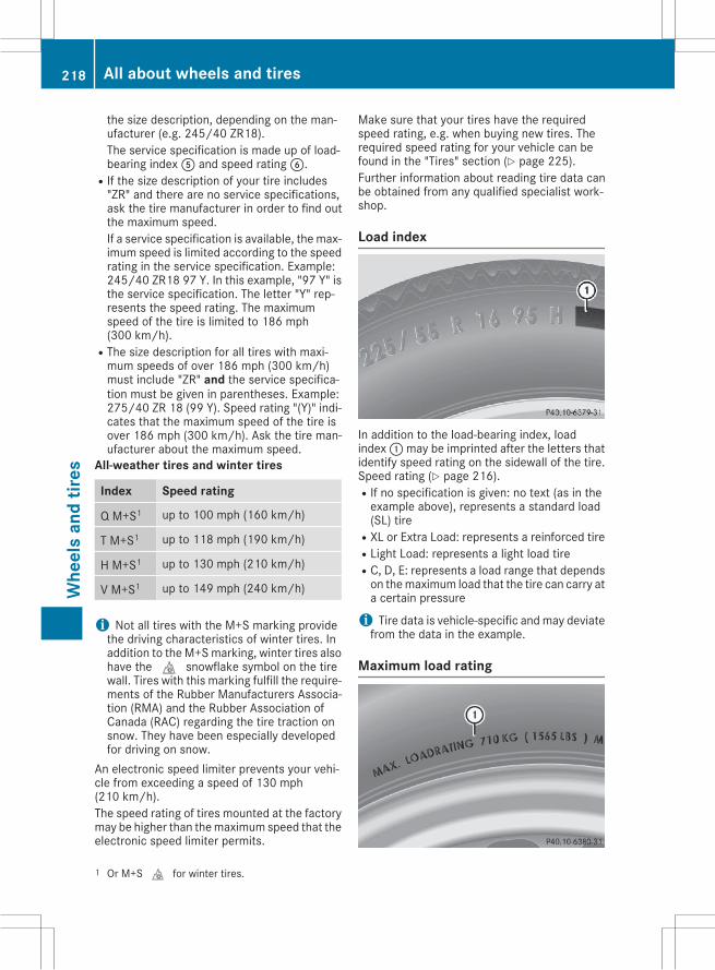
the size description, depending on the man-ufacturer (e.g. 245/40 ZR18).The service specification is made up of load-bearing indexA and speed ratingB.
RIf the size description of your tire includes"ZR" and there are no service specifications,ask the tire manufacturer in order to find outthe maximum speed.If a service specification is available, the max-imum speed is limited according to the speedrating in the service specification. Example:245/40 ZR18 97 Y. In this example, "97 Y" isthe service specification. The letter "Y" rep-resents the speed rating. The maximumspeed of the tire is limited to 186 mph(300 km/h).
RThe size description for all tires with maxi-mum speeds of over 186 mph (300 km/h)must include "ZR" and the service specifica-tion must be given in parentheses. Example:275/40 ZR 18 (99 Y). Speed rating "(Y)" indi-cates that the maximum speed of the tire isover 186 mph (300 km/h). Ask the tire man-ufacturer about the maximum speed.
All-weather tires and winter tires
Index Speed rating
Q M+S1 up to 100 mph (160 km/h)
T M+S1 up to 118 mph (190 km/h)
H M+S1 up to 130 mph (210 km/h)
V M+S1 up to 149 mph (240 km/h)
i Not all tires with the M+S marking providethe driving characteristics of winter tires. Inaddition to the M+Smarking, winter tires alsohave thei snowflake symbol on the tirewall. Tires with this marking fulfill the require-ments of the Rubber Manufacturers Associa-tion (RMA) and the Rubber Association ofCanada (RAC) regarding the tire traction onsnow. They have been especially developedfor driving on snow.
An electronic speed limiter prevents your vehi-cle from exceeding a speed of 130 mph(210 km/h).The speed rating of tires mounted at the factorymay be higher than themaximum speed that theelectronic speed limiter permits.
Make sure that your tires have the requiredspeed rating, e.g. when buying new tires. Therequired speed rating for your vehicle can befound in the "Tires" section (Y page 225).Further information about reading tire data canbe obtained from any qualified specialist work-shop.
Load index
In addition to the load-bearing index, loadindex:may be imprinted after the letters thatidentify speed rating on the sidewall of the tire.Speed rating (Y page 216).RIf no specification is given: no text (as in theexample above), represents a standard load(SL) tire
RXL or Extra Load: represents a reinforced tireRLight Load: represents a light load tireRC, D, E: represents a load range that dependson themaximum load that the tire can carry ata certain pressure
i Tire data is vehicle-specific and may deviatefrom the data in the example.
Maximum load rating
1 Or M+Si for winter tires.
218 All about wheels and tiresW
heel
san
dtir
es
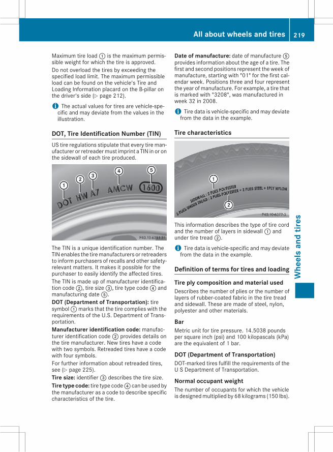
Maximum tire load: is the maximum permis-sible weight for which the tire is approved.Do not overload the tires by exceeding thespecified load limit. The maximum permissibleload can be found on the vehicle's Tire andLoading Information placard on the B-pillar onthe driver's side (Y page 212).
i The actual values for tires are vehicle-spe-cific and may deviate from the values in theillustration.
DOT, Tire Identification Number (TIN)US tire regulations stipulate that every tire man-ufacturer or retreadermust imprint a TIN in or onthe sidewall of each tire produced.
The TIN is a unique identification number. TheTIN enables the tiremanufacturers or retreadersto inform purchasers of recalls and other safety-relevant matters. It makes it possible for thepurchaser to easily identify the affected tires.The TIN is made up of manufacturer identifica-tion code;, tire size=, tire type code? andmanufacturing dateA.DOT (Department of Transportation): tiresymbol:marks that the tire complies with therequirements of the U.S. Department of Trans-portation.Manufacturer identification code: manufac-turer identification code; provides details onthe tire manufacturer. New tires have a codewith two symbols. Retreaded tires have a codewith four symbols.For further information about retreaded tires,see (Y page 225).Tire size: identifier= describes the tire size.Tire type code: tire type code? can be used bythe manufacturer as a code to describe specificcharacteristics of the tire.
Date of manufacture: date of manufactureAprovides information about the age of a tire. Thefirst and second positions represent the week ofmanufacture, starting with "01" for the first cal-endar week. Positions three and four representthe year of manufacture. For example, a tire thatis marked with "3208", was manufactured inweek 32 in 2008.
i Tire data is vehicle-specific and may deviatefrom the data in the example.
Tire characteristics
This information describes the type of tire cordand the number of layers in sidewall: andunder tire tread;.
i Tire data is vehicle-specific and may deviatefrom the data in the example.
Definition of terms for tires and loading
Tire ply composition and material usedDescribes the number of plies or the number oflayers of rubber-coated fabric in the tire treadand sidewall. These are made of steel, nylon,polyester and other materials.
BarMetric unit for tire pressure. 14.5038 poundsper square inch (psi) and 100 kilopascals (kPa)are the equivalent of 1 bar.
DOT (Department of Transportation)DOT-marked tires fulfill the requirements of theU S Department of Transportation.
Normal occupant weightThe number of occupants for which the vehicleis designedmultiplied by 68 kilograms (150 lbs).
All about wheels and tires 219
Whe
els
and
tires
Z
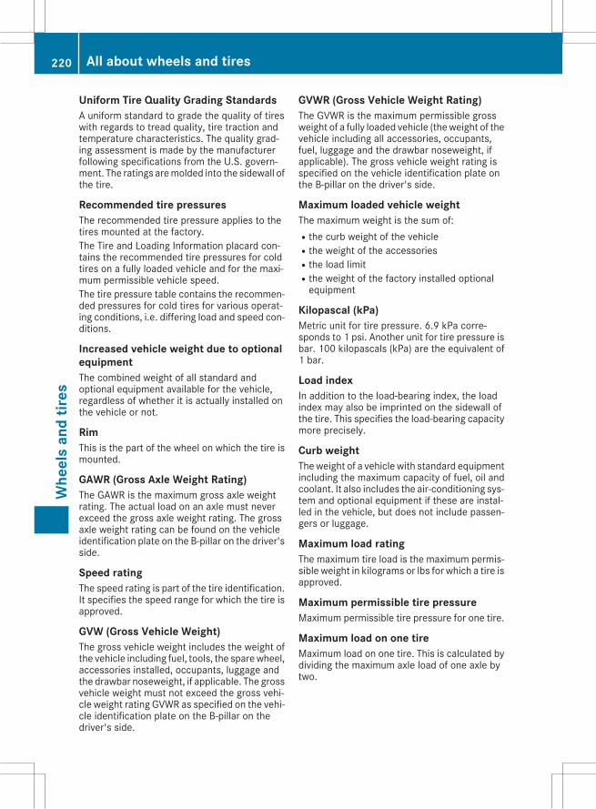
Uniform Tire Quality Grading StandardsA uniform standard to grade the quality of tireswith regards to tread quality, tire traction andtemperature characteristics. The quality grad-ing assessment is made by the manufacturerfollowing specifications from the U.S. govern-ment. The ratings aremolded into the sidewall ofthe tire.
Recommended tire pressuresThe recommended tire pressure applies to thetires mounted at the factory.The Tire and Loading Information placard con-tains the recommended tire pressures for coldtires on a fully loaded vehicle and for the maxi-mum permissible vehicle speed.The tire pressure table contains the recommen-ded pressures for cold tires for various operat-ing conditions, i.e. differing load and speed con-ditions.
Increased vehicle weight due to optionalequipmentThe combined weight of all standard andoptional equipment available for the vehicle,regardless of whether it is actually installed onthe vehicle or not.
RimThis is the part of the wheel on which the tire ismounted.
GAWR (Gross Axle Weight Rating)The GAWR is the maximum gross axle weightrating. The actual load on an axle must neverexceed the gross axle weight rating. The grossaxle weight rating can be found on the vehicleidentification plate on the B-pillar on the driver'sside.
Speed ratingThe speed rating is part of the tire identification.It specifies the speed range for which the tire isapproved.
GVW (Gross Vehicle Weight)The gross vehicle weight includes the weight ofthe vehicle including fuel, tools, the sparewheel,accessories installed, occupants, luggage andthe drawbar noseweight, if applicable. The grossvehicle weight must not exceed the gross vehi-cle weight rating GVWR as specified on the vehi-cle identification plate on the B-pillar on thedriver's side.
GVWR (Gross Vehicle Weight Rating)The GVWR is the maximum permissible grossweight of a fully loaded vehicle (theweight of thevehicle including all accessories, occupants,fuel, luggage and the drawbar noseweight, ifapplicable). The gross vehicle weight rating isspecified on the vehicle identification plate onthe B-pillar on the driver's side.
Maximum loaded vehicle weightThe maximum weight is the sum of:Rthe curb weight of the vehicleRthe weight of the accessoriesRthe load limitRthe weight of the factory installed optionalequipment
Kilopascal (kPa)Metric unit for tire pressure. 6.9 kPa corre-sponds to 1 psi. Another unit for tire pressure isbar. 100 kilopascals (kPa) are the equivalent of1 bar.
Load indexIn addition to the load-bearing index, the loadindex may also be imprinted on the sidewall ofthe tire. This specifies the load-bearing capacitymore precisely.
Curb weightTheweight of a vehicle with standard equipmentincluding the maximum capacity of fuel, oil andcoolant. It also includes the air-conditioning sys-tem and optional equipment if these are instal-led in the vehicle, but does not include passen-gers or luggage.
Maximum load ratingThe maximum tire load is the maximum permis-sible weight in kilograms or lbs for which a tire isapproved.
Maximum permissible tire pressureMaximum permissible tire pressure for one tire.
Maximum load on one tireMaximum load on one tire. This is calculated bydividing the maximum axle load of one axle bytwo.
220 All about wheels and tiresW
heel
san
dtir
es
PSI (pounds per square inch)A standard unit of measure for tire pressure.
Aspect ratioRelationship between tire height and tire widthin percent.
Tire pressureThis is pressure inside the tire applying an out-ward force to each square inch of the tire's sur-face. The tire pressure is specified in pounds persquare inch (psi), in kilopascal (kPa) or in bar.The tire pressure should only be corrected whenthe tires are cold.
Cold tire pressureThe tires are cold:Rif the vehicle has been parked with the tiresout of direct sunlight for at least three hoursand
Rif the vehicle has not been driven further than1 mile (1.6 km)
TreadThe part of the tire that comes into contact withthe road.
BeadThe tire bead ensures that the tire sits securelyon thewheel. There are several steel wires in thebead to prevent the tire from coming loose fromthe wheel rim.
SidewallThe part of the tire between the tread and thebead.
Weight of optional extrasThe combined weight of those optional extrasthat weigh more than the replaced standardparts and more than 2.3 kg (5 lbs). Theseoptional extras, such as high-performancebrakes, level control, a roof rack or a high-per-formance battery, are not included in the curbweight and the weight of the accessories.
TIN (Tire Identification Number)This is a unique identifier which can be used bya tire manufacturer to identify tires, for examplefor a product recall, and thus identify the pur-chasers. The TIN is made up of the manufactur-er's identity code, tire size, tire type code andthe manufacturing date.
Load bearing indexThe load bearing index (also load index) is a codethat contains the maximum load bearing capa-city of a tire.
TractionTraction is the result of friction between the tiresand the road surface.
Treadwear indicatorsNarrow bars (tread wear bars) that are distrib-uted over the tire tread. If the tire tread is levelwith the bars, the wear limit ofá in (1.6 mm)has been reached.
Occupant distributionThe distribution of occupants in a vehicle at theirdesignated seating positions.
Total load limitNominal load and luggage load plus 68 kg(150 lbs) multiplied by the number of seats inthe vehicle.
Changing a wheel
Flat tireThe "Breakdown assistance" section(Y page 189) contains information and notes onhow to deal with a flat tire. Information on driv-ing with MOExtended tires in the event of a flattire can be found under "MOExtended tires (tireswith run-flat characteristics" (Y page 190).
Rotating the wheels
G WARNINGInterchanging the front and rear wheels mayseverely impair the driving characteristics ifthe wheels or tires have different dimensions.The wheel brakes or suspension componentsmay also be damaged. There is a risk of acci-dent.Rotate front and rearwheels only if thewheelsand tires are of the same dimensions.
Observe the instructions and safety notes in the"Changing a wheel" section (Y page 221).
Changing a wheel 221
Whe
els
and
tires
Z
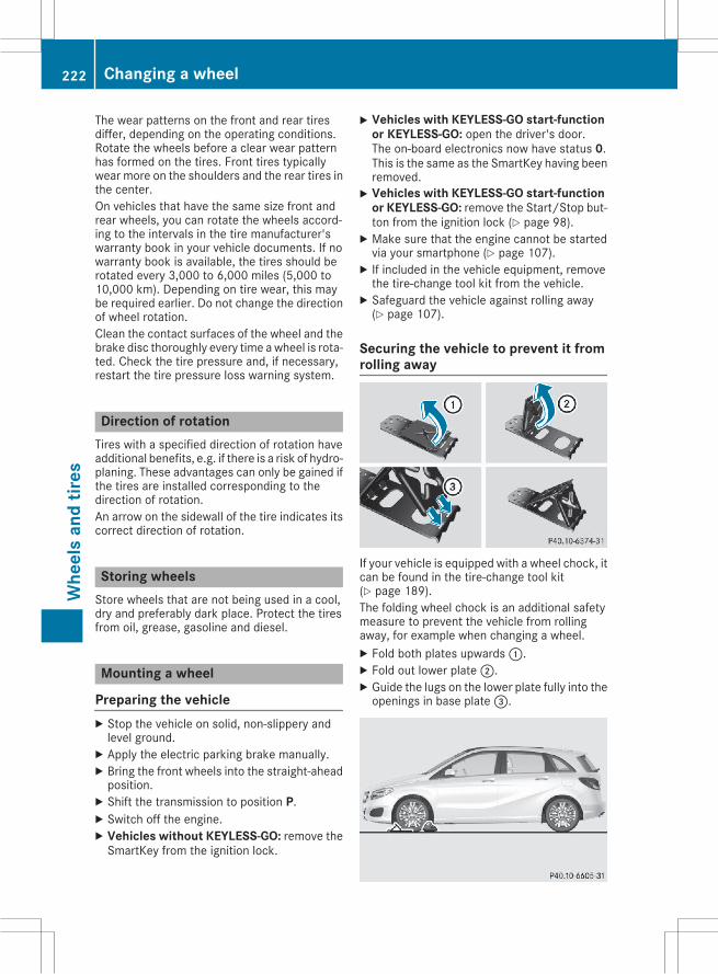
The wear patterns on the front and rear tiresdiffer, depending on the operating conditions.Rotate the wheels before a clear wear patternhas formed on the tires. Front tires typicallywear more on the shoulders and the rear tires inthe center.On vehicles that have the same size front andrear wheels, you can rotate the wheels accord-ing to the intervals in the tire manufacturer'swarranty book in your vehicle documents. If nowarranty book is available, the tires should berotated every 3,000 to 6,000 miles (5,000 to10,000 km). Depending on tire wear, this maybe required earlier. Do not change the directionof wheel rotation.Clean the contact surfaces of the wheel and thebrake disc thoroughly every time awheel is rota-ted. Check the tire pressure and, if necessary,restart the tire pressure loss warning system.
Direction of rotationTires with a specified direction of rotation haveadditional benefits, e.g. if there is a risk of hydro-planing. These advantages can only be gained ifthe tires are installed corresponding to thedirection of rotation.An arrow on the sidewall of the tire indicates itscorrect direction of rotation.
Storing wheelsStore wheels that are not being used in a cool,dry and preferably dark place. Protect the tiresfrom oil, grease, gasoline and diesel.
Mounting a wheel
Preparing the vehicleX Stop the vehicle on solid, non-slippery andlevel ground.X Apply the electric parking brake manually.X Bring the front wheels into the straight-aheadposition.X Shift the transmission to position P.X Switch off the engine.X Vehicles without KEYLESS-GO: remove theSmartKey from the ignition lock.
X Vehicles with KEYLESS-GO start-functionor KEYLESS-GO: open the driver's door.The on-board electronics now have status 0.This is the same as the SmartKey having beenremoved.X Vehicles with KEYLESS-GO start-function
or KEYLESS-GO: remove the Start/Stop but-ton from the ignition lock (Y page 98).X Make sure that the engine cannot be startedvia your smartphone (Y page 107).X If included in the vehicle equipment, removethe tire-change tool kit from the vehicle.X Safeguard the vehicle against rolling away(Y page 107).
Securing the vehicle to prevent it fromrolling away
If your vehicle is equipped with a wheel chock, itcan be found in the tire-change tool kit(Y page 189).The folding wheel chock is an additional safetymeasure to prevent the vehicle from rollingaway, for example when changing a wheel.X Fold both plates upwards:.X Fold out lower plate;.X Guide the lugs on the lower plate fully into theopenings in base plate=.
222 Changing a wheelW
heel
san
dtir
es
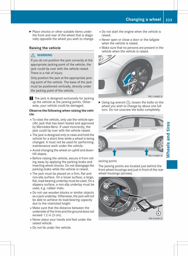
X Place chocks or other suitable items underthe front and rear of the wheel that is diago-nally opposite the wheel you wish to change.
Raising the vehicle
G WARNINGIf you do not position the jack correctly at theappropriate jacking point of the vehicle, thejack could tip over with the vehicle raised.There is a risk of injury.Only position the jack at the appropriate jack-ing point of the vehicle. The base of the jackmust be positioned vertically, directly underthe jacking point of the vehicle.
! The jack is designed exclusively for jackingup the vehicle at the jacking points. Other-wise, your vehicle could be damaged.
Observe the following when raising the vehi-cle:RTo raise the vehicle, only use the vehicle-spe-cific jack that has been tested and approvedby Mercedes-Benz. If used incorrectly, thejack could tip over with the vehicle raised.
RThe jack is designed only to raise and hold thevehicle for a short time while a wheel is beingchanged. It must not be used for performingmaintenance work under the vehicle.
RAvoid changing the wheel on uphill and down-hill slopes.
RBefore raising the vehicle, secure it from roll-ing away by applying the parking brake andinserting wheel chocks. Do not disengage theparking brake while the vehicle is raised.
RThe jack must be placed on a firm, flat andnon-slip surface. On a loose surface, a large,flat, load-bearing underlaymust be used. On aslippery surface, a non-slip underlay must beused, e.g. rubber mats.
RDo not use wooden blocks or similar objectsas a jack underlay. Otherwise, the jackwill notbe able to achieve its load-bearing capacitydue to the restricted height.
RMake sure that the distance between theunderside of the tires and the ground does notexceed 1.2 in (3 cm).
RNever place your hands and feet under theraised vehicle.
RDo not lie under the vehicle.
RDo not start the engine when the vehicle israised.
RNever open or close a door or the tailgatewhen the vehicle is raised.
RMake sure that no persons are present in thevehicle when the vehicle is raised.
X Using lug wrench:, loosen the bolts on thewheel you wish to change by about one fullturn. Do not unscrew the bolts completely.
Jacking pointsThe jacking points are located just behind thefront wheel housings and just in front of the rearwheel housings (arrows).
Changing a wheel 223
Whe
els
and
tires
Z
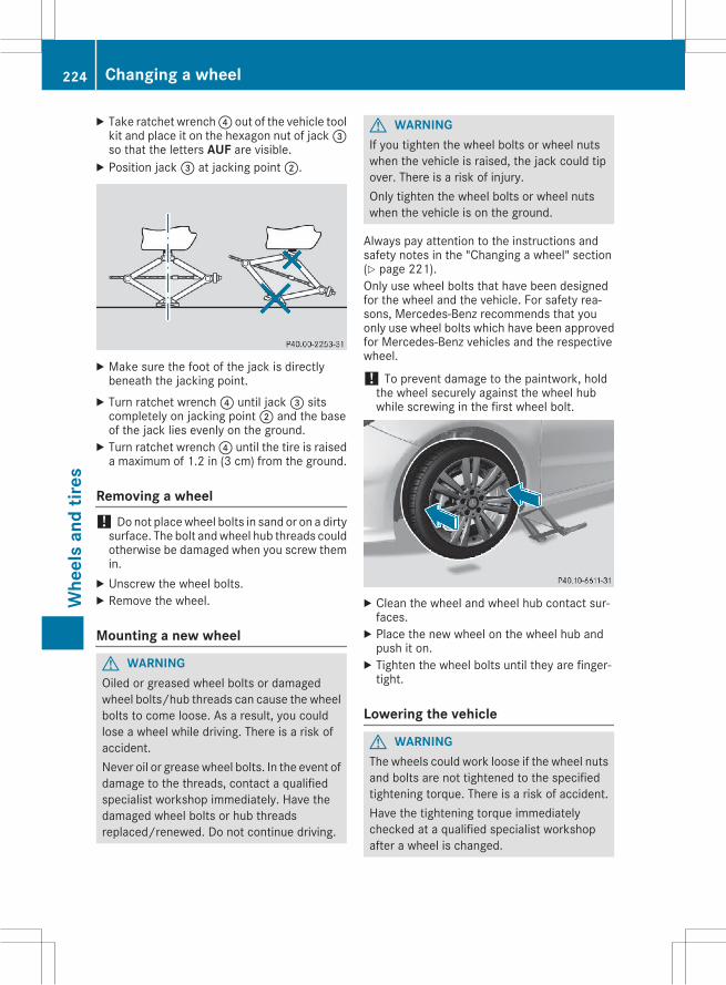
X Take ratchet wrench? out of the vehicle toolkit and place it on the hexagon nut of jack=so that the letters AUF are visible.X Position jack= at jacking point;.
X Make sure the foot of the jack is directlybeneath the jacking point.X Turn ratchet wrench? until jack= sitscompletely on jacking point; and the baseof the jack lies evenly on the ground.X Turn ratchet wrench? until the tire is raiseda maximum of 1.2 in (3 cm) from the ground.
Removing a wheel! Do not placewheel bolts in sand or on a dirtysurface. The bolt andwheel hub threads couldotherwise be damaged when you screw themin.X Unscrew the wheel bolts.X Remove the wheel.
Mounting a new wheel
G WARNINGOiled or greased wheel bolts or damagedwheel bolts/hub threads can cause the wheelbolts to come loose. As a result, you couldlose a wheel while driving. There is a risk ofaccident.Never oil or greasewheel bolts. In the event ofdamage to the threads, contact a qualifiedspecialist workshop immediately. Have thedamaged wheel bolts or hub threadsreplaced/renewed. Do not continue driving.
G WARNINGIf you tighten the wheel bolts or wheel nutswhen the vehicle is raised, the jack could tipover. There is a risk of injury.Only tighten the wheel bolts or wheel nutswhen the vehicle is on the ground.
Always pay attention to the instructions andsafety notes in the "Changing a wheel" section(Y page 221).Only use wheel bolts that have been designedfor the wheel and the vehicle. For safety rea-sons, Mercedes-Benz recommends that youonly use wheel bolts which have been approvedfor Mercedes-Benz vehicles and the respectivewheel.
! To prevent damage to the paintwork, holdthe wheel securely against the wheel hubwhile screwing in the first wheel bolt.
X Clean the wheel and wheel hub contact sur-faces.X Place the new wheel on the wheel hub andpush it on.X Tighten the wheel bolts until they are finger-tight.
Lowering the vehicle
G WARNINGThe wheels could work loose if the wheel nutsand bolts are not tightened to the specifiedtightening torque. There is a risk of accident.Have the tightening torque immediatelychecked at a qualified specialist workshopafter a wheel is changed.
224 Changing a wheelW
heel
san
dtir
es
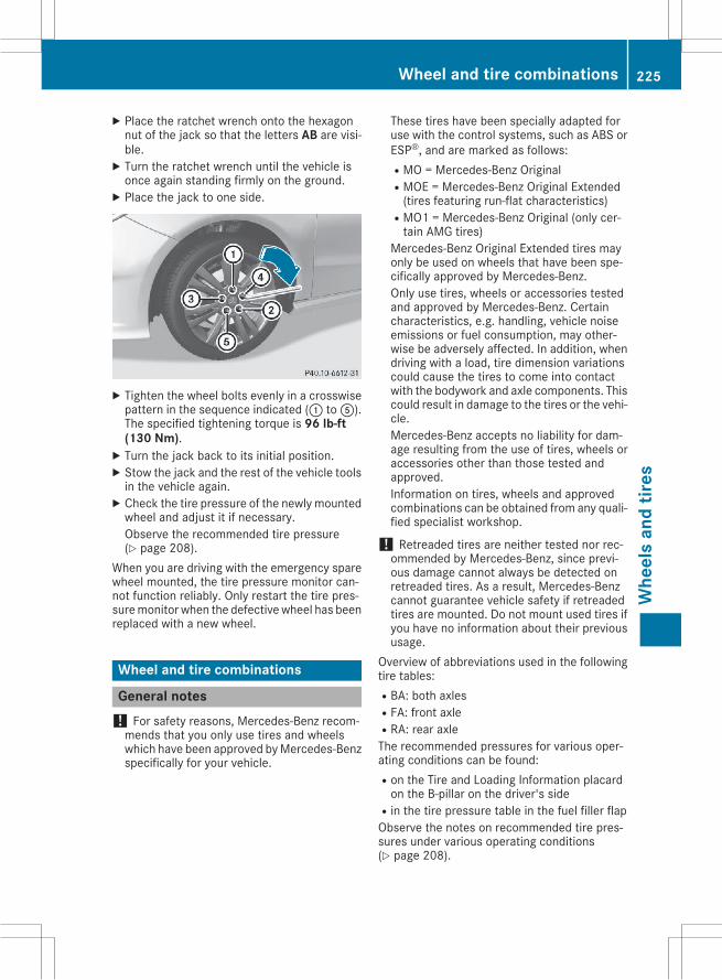
X Place the ratchet wrench onto the hexagonnut of the jack so that the letters AB are visi-ble.X Turn the ratchet wrench until the vehicle isonce again standing firmly on the ground.X Place the jack to one side.
X Tighten the wheel bolts evenly in a crosswisepattern in the sequence indicated (: toA).The specified tightening torque is 96 lb-ft(130 Nm).X Turn the jack back to its initial position.X Stow the jack and the rest of the vehicle toolsin the vehicle again.X Check the tire pressure of the newly mountedwheel and adjust it if necessary.Observe the recommended tire pressure(Y page 208).
When you are driving with the emergency sparewheel mounted, the tire pressure monitor can-not function reliably. Only restart the tire pres-suremonitor when the defectivewheel has beenreplaced with a new wheel.
Wheel and tire combinations
General notes! For safety reasons, Mercedes-Benz recom-mends that you only use tires and wheelswhich have been approved byMercedes-Benzspecifically for your vehicle.
These tires have been specially adapted foruse with the control systems, such as ABS orESP®, and are marked as follows:RMO = Mercedes-Benz OriginalRMOE = Mercedes-Benz Original Extended(tires featuring run-flat characteristics)
RMO1 = Mercedes-Benz Original (only cer-tain AMG tires)
Mercedes-Benz Original Extended tires mayonly be used on wheels that have been spe-cifically approved by Mercedes-Benz.Only use tires, wheels or accessories testedand approved by Mercedes-Benz. Certaincharacteristics, e.g. handling, vehicle noiseemissions or fuel consumption, may other-wise be adversely affected. In addition, whendriving with a load, tire dimension variationscould cause the tires to come into contactwith the bodywork and axle components. Thiscould result in damage to the tires or the vehi-cle.Mercedes-Benz accepts no liability for dam-age resulting from the use of tires, wheels oraccessories other than those tested andapproved.Information on tires, wheels and approvedcombinations can be obtained from any quali-fied specialist workshop.
! Retreaded tires are neither tested nor rec-ommended by Mercedes-Benz, since previ-ous damage cannot always be detected onretreaded tires. As a result, Mercedes-Benzcannot guarantee vehicle safety if retreadedtires are mounted. Do not mount used tires ifyou have no information about their previoususage.
Overview of abbreviations used in the followingtire tables:RBA: both axlesRFA: front axleRRA: rear axleThe recommended pressures for various oper-ating conditions can be found:Ron the Tire and Loading Information placardon the B-pillar on the driver's side
Rin the tire pressure table in the fuel filler flapObserve the notes on recommended tire pres-sures under various operating conditions(Y page 208).
Wheel and tire combinations 225
Whe
els
and
tires
Z
Check tire pressures regularly, and only whenthe tires are cold. Comply with the maintenancerecommendations of the tire manufacturer inthe vehicle document wallet.Notes on the vehicle equipment – always equipthe vehicle with:Rwith tires of the same size on a given axle (leftand right)
Rthe same type of tires at a given time (summertires, winter tires, MOExtended tires)Exception: it is permissible to install a differ-ent type or make in the event of a flat tire.Observe the "MOExtended tires (tires withrun-flat characteristics" section (Y page 190).
Vehicles equipped with MOExtended tires arenot equipped with a TIREFIT kit at the factory. Itis therefore recommended that you additionallyequip your vehiclewith a TIREFIT kit if youmounttires that do not feature run-flat properties, e.g.winter tires. A TIREFIT kit may be obtained froma qualified specialist workshop.
i Not all wheel and tire combinations areavailable at the factory for all countries.
i The following pages contain information onapproved wheel rims and tire sizes for equip-ping your vehicle with winter tires. Wintertires are not available at the factory as stand-ard equipment or optional extras.If you want to equip your vehicle withapproved winter tires, it may be necessary toobtain wheel rims in the corresponding size.The size of the approved winter tires may dif-fer from the standard tires. This is dependenton the model and the equipment installed atthe factory.The tires and wheel rims, as well as furtherinformation, can be obtained at a qualifiedspecialist workshop.
226 Wheel and tire combinationsW
heel
san
dtir
es
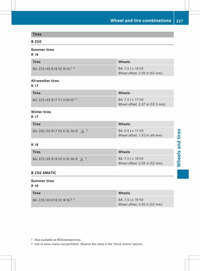
Tires
B 250
Summer tiresR 18
Tires Wheels
BA: 225/40 R18 92 W XL2, 3 BA: 7.5 J x 18 H2Wheel offset: 2.05 in (52 mm)
All-weather tiresR 17
Tires Wheels
BA: 225/45 R17 91 H M+S2, 3 BA: 7.5 J x 17 H2Wheel offset: 2.07 in (52.5 mm)
Winter tiresR 17
Tires Wheels
BA: 205/50 R17 93 H XL M+Si2 BA: 6.5 J x 17 H2Wheel offset: 1.93 in (49 mm)
R 18
Tires Wheels
BA: 225/40 R18 92 H XL M+Si3 BA: 7.5 J x 18 H2Wheel offset: 2.05 in (52 mm)
B 250 4MATIC
Summer tiresR 18
Tires Wheels
BA: 225/40 R18 92 W XL2, 3 BA: 7.5 J x 18 H2Wheel offset: 2.05 in (52 mm)
2 Also available as MOExtended tires.3 Use of snow chains not permitted. Observe the notes in the "Snow chains" section.
Wheel and tire combinations 227
Whe
els
and
tires
Z
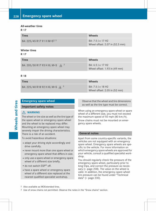
All-weather tiresR 17
Tires Wheels
BA: 225/45 R17 91 H M+S2, 3 BA: 7.5 J x 17 H2Wheel offset: 2.07 in (52.5 mm)
Winter tiresR 17
Tires Wheels
BA: 205/50 R17 93 H XL M+Si2 BA: 6.5 J x 17 H2Wheel offset: 1.93 in (49 mm)
R 18
Tires Wheels
BA: 225/40 R18 92 H XL M+Si3 BA: 7.5 J x 18 H2Wheel offset: 2.05 in (52 mm)
Emergency spare wheel
Important safety notes
G WARNINGThewheel or tire size as well as the tire type ofthe spare wheel or emergency spare wheeland the wheel to be replaced may differ.Mounting an emergency spare wheel mayseverely impair the driving characteristics.There is a risk of an accident.To avoid hazardous situations:Radapt your driving style accordingly anddrive carefully.
Rnever mount more than one spare wheel oremergency spare wheel that differs in size.
Ronly use a spare wheel or emergency sparewheel of a different size briefly.
Rdo not switch ESP® off.Rhave a spare wheel or emergency sparewheel of a different size replaced at thenearest qualified specialist workshop.
Observe that the wheel and tire dimensionsas well as the tire type must be correct.
When using an emergency spare wheel or sparewheel of a different size, you must not exceedthe maximum speed of 50 mph (80 km/h).Snow chains must not be mounted on emer-gency spare wheels.
General notesApart from some country-specific variants, thevehicles are not equipped with an emergencyspare wheel. Emergency spare wheels are spe-cific to the vehicle. For more information onwhich emergency sparewheels are approved foryour vehicle, consult a qualified specialist work-shop.You should regularly check the pressure of theemergency spare wheel, particularly prior tolong trips, and correct the pressure as neces-sary (Y page 208). The value on the wheel isvalid. In addition, the emergency spare wheeltire pressure can be found under "Technicaldata" (Y page 230).
2 Also available as MOExtended tires.3 Use of snow chains not permitted. Observe the notes in the "Snow chains" section.
228 Emergency spare wheelW
heel
san
dtir
es
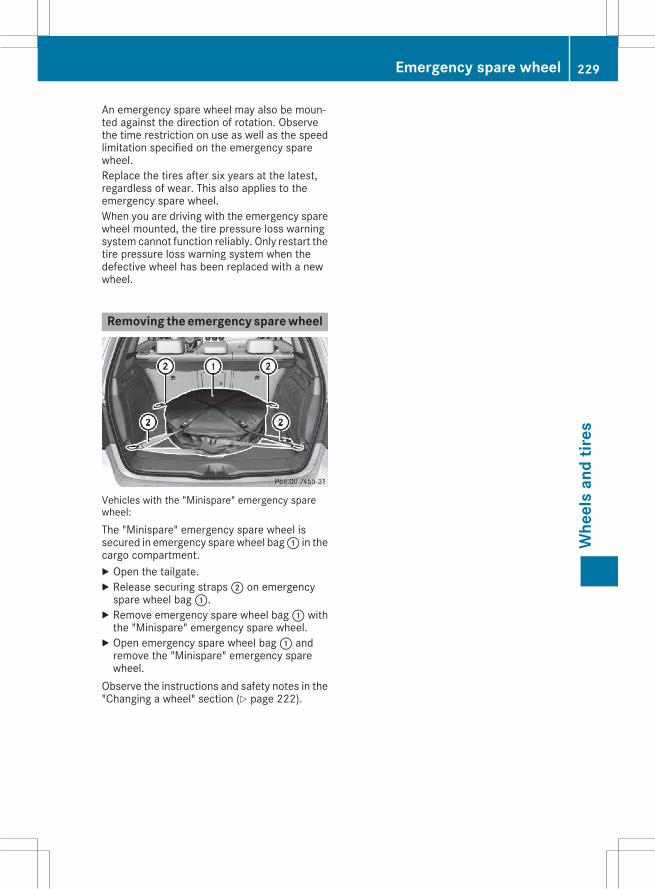
An emergency spare wheel may also be moun-ted against the direction of rotation. Observethe time restriction on use as well as the speedlimitation specified on the emergency sparewheel.Replace the tires after six years at the latest,regardless of wear. This also applies to theemergency spare wheel.When you are driving with the emergency sparewheel mounted, the tire pressure loss warningsystem cannot function reliably. Only restart thetire pressure loss warning system when thedefective wheel has been replaced with a newwheel.
Removing the emergency spare wheel
Vehicles with the "Minispare" emergency sparewheel:The "Minispare" emergency spare wheel issecured in emergency spare wheel bag: in thecargo compartment.X Open the tailgate.X Release securing straps; on emergencyspare wheel bag:.X Remove emergency spare wheel bag: withthe "Minispare" emergency spare wheel.X Open emergency spare wheel bag: andremove the "Minispare" emergency sparewheel.
Observe the instructions and safety notes in the"Changing a wheel" section (Y page 222).
Emergency spare wheel 229
Whe
els
and
tires
Z
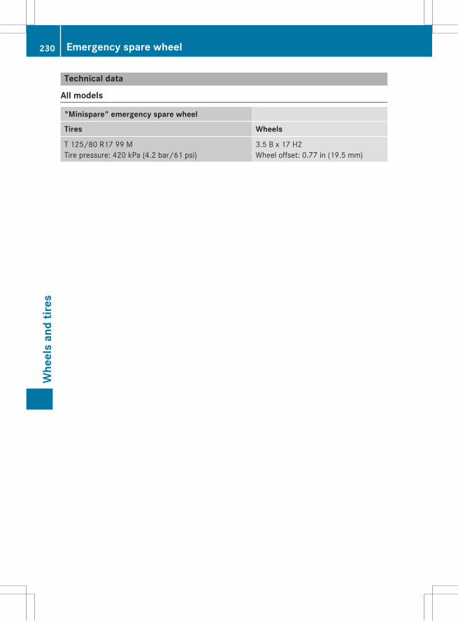
Technical data
All models
"Minispare" emergency spare wheel
Tires Wheels
T 125/80 R17 99 MTire pressure: 420 kPa (4.2 bar/61 psi)
3.5 B x 17 H2Wheel offset: 0.77 in (19.5 mm)
230 Emergency spare wheelW
heel
san
dtir
es
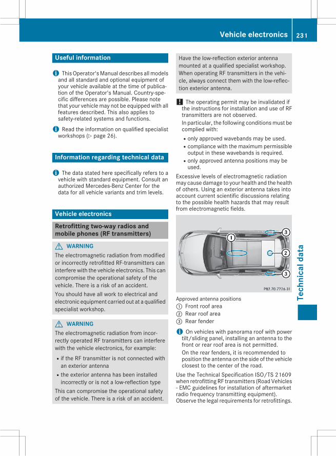
Useful information
i ThisOperator'sManual describes allmodelsand all standard and optional equipment ofyour vehicle available at the time of publica-tion of the Operator's Manual. Country-spe-cific differences are possible. Please notethat your vehicle may not be equipped with allfeatures described. This also applies tosafety-related systems and functions.
i Read the information on qualified specialistworkshops (Y page 26).
Information regarding technical data
i The data stated here specifically refers to avehicle with standard equipment. Consult anauthorized Mercedes-Benz Center for thedata for all vehicle variants and trim levels.
Vehicle electronics
Retrofitting two-way radios andmobile phones (RF transmitters)
G WARNINGThe electromagnetic radiation from modifiedor incorrectly retrofitted RF-transmitters caninterfere with the vehicle electronics. This cancompromise the operational safety of thevehicle. There is a risk of an accident.You should have all work to electrical andelectronic equipment carried out at a qualifiedspecialist workshop.
G WARNINGThe electromagnetic radiation from incor-rectly operated RF transmitters can interferewith the vehicle electronics, for example:Rif the RF transmitter is not connected withan exterior antenna
Rthe exterior antenna has been installedincorrectly or is not a low-reflection type
This can compromise the operational safetyof the vehicle. There is a risk of an accident.
Have the low-reflection exterior antennamounted at a qualified specialist workshop.When operating RF transmitters in the vehi-cle, always connect them with the low-reflec-tion exterior antenna.
! The operating permit may be invalidated ifthe instructions for installation and use of RFtransmitters are not observed.In particular, the following conditionsmust becomplied with:Ronly approved wavebands may be used.Rcompliance with the maximum permissibleoutput in these wavebands is required.
Ronly approved antenna positions may beused.
Excessive levels of electromagnetic radiationmay cause damage to your health and the healthof others. Using an exterior antenna takes intoaccount current scientific discussions relatingto the possible health hazards that may resultfrom electromagnetic fields.
Approved antenna positions: Front roof area; Rear roof area= Rear fender
i On vehicles with panorama roof with powertilt/sliding panel, installing an antenna to thefront or rear roof area is not permitted.On the rear fenders, it is recommended toposition the antenna on the side of the vehicleclosest to the center of the road.
Use the Technical Specification ISO/TS 21609when retrofitting RF transmitters (RoadVehicles- EMC guidelines for installation of aftermarketradio frequency transmitting equipment).Observe the legal requirements for retrofittings.
Vehicle electronics 231
Tech
nica
ldat
a
Z
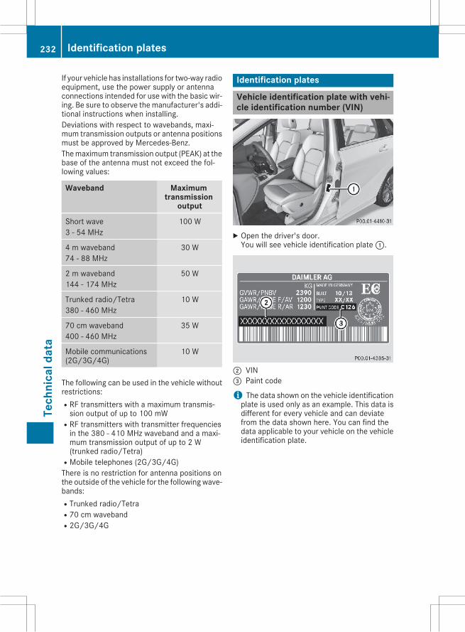
If your vehicle has installations for two-way radioequipment, use the power supply or antennaconnections intended for use with the basic wir-ing. Be sure to observe themanufacturer's addi-tional instructions when installing.Deviations with respect to wavebands, maxi-mum transmission outputs or antenna positionsmust be approved by Mercedes-Benz.Themaximum transmission output (PEAK) at thebase of the antenna must not exceed the fol-lowing values:
Waveband Maximumtransmission
output
Short wave3 - 54 MHz
100 W
4 m waveband74 - 88 MHz
30 W
2 m waveband144 - 174 MHz
50 W
Trunked radio/Tetra380 - 460 MHz
10 W
70 cm waveband400 - 460 MHz
35 W
Mobile communications(2G/3G/4G)
10 W
The following can be used in the vehicle withoutrestrictions:RRF transmitters with a maximum transmis-sion output of up to 100 mW
RRF transmitters with transmitter frequenciesin the 380 - 410 MHz waveband and a maxi-mum transmission output of up to 2 W(trunked radio/Tetra)
RMobile telephones (2G/3G/4G)There is no restriction for antenna positions onthe outside of the vehicle for the following wave-bands:RTrunked radio/TetraR70 cm wavebandR2G/3G/4G
Identification plates
Vehicle identification plate with vehi-cle identification number (VIN)
X Open the driver's door.You will see vehicle identification plate:.
; VIN= Paint code
i The data shown on the vehicle identificationplate is used only as an example. This data isdifferent for every vehicle and can deviatefrom the data shown here. You can find thedata applicable to your vehicle on the vehicleidentification plate.
232 Identification platesTe
chni
cald
ata
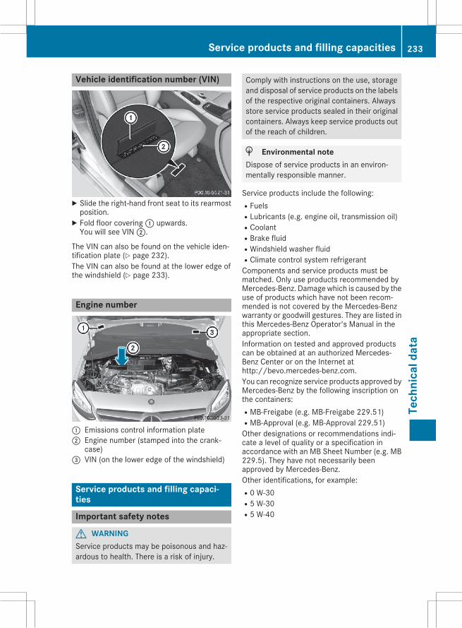
Vehicle identification number (VIN)
X Slide the right-hand front seat to its rearmostposition.X Fold floor covering: upwards.You will see VIN;.
The VIN can also be found on the vehicle iden-tification plate (Y page 232).The VIN can also be found at the lower edge ofthe windshield (Y page 233).
Engine number
: Emissions control information plate; Engine number (stamped into the crank-
case)= VIN (on the lower edge of the windshield)
Service products and filling capaci-ties
Important safety notes
G WARNINGService products may be poisonous and haz-ardous to health. There is a risk of injury.
Comply with instructions on the use, storageand disposal of service products on the labelsof the respective original containers. Alwaysstore service products sealed in their originalcontainers. Always keep service products outof the reach of children.
H Environmental noteDispose of service products in an environ-mentally responsible manner.
Service products include the following:RFuelsRLubricants (e.g. engine oil, transmission oil)RCoolantRBrake fluidRWindshield washer fluidRClimate control system refrigerantComponents and service products must bematched. Only use products recommended byMercedes-Benz. Damagewhich is caused by theuse of products which have not been recom-mended is not covered by the Mercedes-Benzwarranty or goodwill gestures. They are listed inthis Mercedes-Benz Operator's Manual in theappropriate section.Information on tested and approved productscan be obtained at an authorized Mercedes-Benz Center or on the Internet athttp://bevo.mercedes-benz.com.You can recognize service products approved byMercedes-Benz by the following inscription onthe containers:RMB-Freigabe (e.g. MB-Freigabe 229.51)RMB-Approval (e.g. MB-Approval 229.51)Other designations or recommendations indi-cate a level of quality or a specification inaccordance with an MB Sheet Number (e.g. MB229.5). They have not necessarily beenapproved by Mercedes-Benz.Other identifications, for example:R0 W-30R5 W-30R5 W-40
Service products and filling capacities 233
Tech
nica
ldat
a
Z
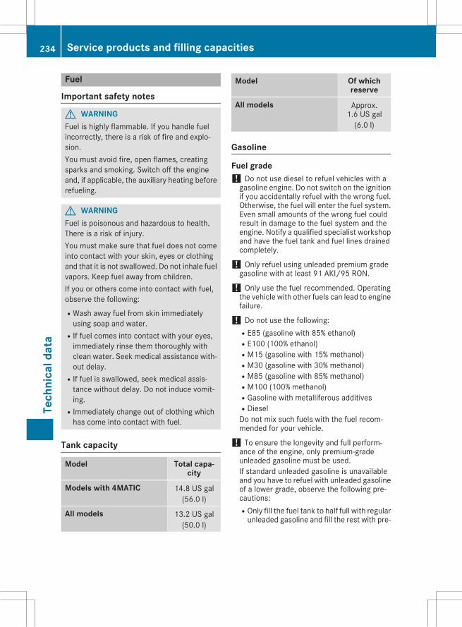
Fuel
Important safety notes
G WARNINGFuel is highly flammable. If you handle fuelincorrectly, there is a risk of fire and explo-sion.You must avoid fire, open flames, creatingsparks and smoking. Switch off the engineand, if applicable, the auxiliary heating beforerefueling.
G WARNINGFuel is poisonous and hazardous to health.There is a risk of injury.You must make sure that fuel does not comeinto contact with your skin, eyes or clothingand that it is not swallowed. Do not inhale fuelvapors. Keep fuel away from children.If you or others come into contact with fuel,observe the following:RWash away fuel from skin immediatelyusing soap and water.
RIf fuel comes into contact with your eyes,immediately rinse them thoroughly withclean water. Seek medical assistance with-out delay.
RIf fuel is swallowed, seek medical assis-tance without delay. Do not induce vomit-ing.
RImmediately change out of clothing whichhas come into contact with fuel.
Tank capacity
Model Total capa-city
Models with 4MATIC 14.8 US gal(56.0 l)
All models 13.2 US gal(50.0 l)
Model Of whichreserve
All models Approx.1.6 US gal(6.0 l)
Gasoline
Fuel grade! Do not use diesel to refuel vehicles with agasoline engine. Do not switch on the ignitionif you accidentally refuel with the wrong fuel.Otherwise, the fuel will enter the fuel system.Even small amounts of the wrong fuel couldresult in damage to the fuel system and theengine. Notify a qualified specialist workshopand have the fuel tank and fuel lines drainedcompletely.
! Only refuel using unleaded premium gradegasoline with at least 91 AKI/95 RON.
! Only use the fuel recommended. Operatingthe vehicle with other fuels can lead to enginefailure.
! Do not use the following:RE85 (gasoline with 85% ethanol)RE100 (100% ethanol)RM15 (gasoline with 15% methanol)RM30 (gasoline with 30% methanol)RM85 (gasoline with 85% methanol)RM100 (100% methanol)RGasoline with metalliferous additivesRDieselDo not mix such fuels with the fuel recom-mended for your vehicle.
! To ensure the longevity and full perform-ance of the engine, only premium-gradeunleaded gasoline must be used.If standard unleaded gasoline is unavailableand you have to refuel with unleaded gasolineof a lower grade, observe the following pre-cautions:ROnly fill the fuel tank to half full with regularunleaded gasoline and fill the rest with pre-
234 Service products and filling capacitiesTe
chni
cald
ata
mium-grade unleaded gasoline as soon aspossible.
RDo not drive at the maximum speed.RAvoid sudden acceleration and enginespeeds over 3,000 rpm.
You will usually find information about the fuelgrade on the pump. If you cannot find the labelon the pump, ask the staff for assistance.
i For more information, contact a qualifiedspecialist workshop.
B 250, B 250 4MATIC: as a temporary meas-ure, if the recommended fuel is not available,youmay also use regular unleaded gasoline withan octane rating of 88 AKI/93 RON.All other models: as a temporary measure, ifthe recommended fuel is not available, you mayalso use regular unleaded gasoline with anoctane rating of 87 AKI/91 RON. This mayreduce engine performance and increase fuelconsumption. Avoid driving at full throttle andsudden acceleration. Never refuel using fuelwith a lower AKI.Information on refueling (Y page 105).
Additives! Operating the engine with fuel additivesadded later can lead to engine failure. Do notmix fuel additives with fuel. This does notinclude additives for the removal and preven-tion of residue buildup. gasoline must only bemixed with additives recommended byMercedes-Benz. Comply with the instructionsfor use on the product label.More informationabout recommended additives can beobtained from any authorizedMercedes-BenzCenter.
Mercedes-Benz recommends that you use bran-ded fuels that have additives.The quality of the fuel available in some coun-tries may not be sufficient. Residue could buildup in the injection system as a result. In suchcases, and in consultation with an authorizedMercedes-Benz Center, the gasoline may bemixed with the cleaning additive recommendedby Mercedes-Benz. You must observe the notesand mixing ratios specified on the container.
Fuel consumption information
H Environmental noteCO2 (carbon dioxide) is the gas which scien-tists believe to be principally responsible forglobal warming (the greenhouse effect). Yourvehicle's CO2 emissions are directly related tofuel consumption and therefore depend on:Refficient use of the fuel by the engineRdriving styleRother non-technical factors, such as envi-ronmental influences, road conditions ortraffic flow
You can minimize your vehicle's CO2 emis-sions by driving carefully and having it serv-iced regularly.
The vehicle will use more fuel than usual in thefollowing situations:Rat very low outside temperaturesRin city trafficRon short journeysRin mountainous terrain
Engine oil
General notes! Never use engine oil or an oil filter of a spec-ification other than is necessary to fulfill theprescribed service intervals. Do not changethe engine oil or oil filter in order to achievelonger replacement intervals than those pre-scribed. You could otherwise cause enginedamage or damage to the exhaust gas after-treatment.Follow the instructions in the service intervaldisplay regarding the oil change. Otherwise,you may damage the engine and the exhaustgas aftertreatment.
When handling engine oil, observe the importantsafety notes on service products (Y page 233).The engine oils are matched to the performanceofMercedes-Benz engines and service intervals.You should therefore only use engine oils and oilfilters that are approved for vehicles with main-tenance systems.For a list of approved engine oils and oil filters,consult an authorized Mercedes-Benz Center.
Service products and filling capacities 235
Tech
nica
ldat
a
Z
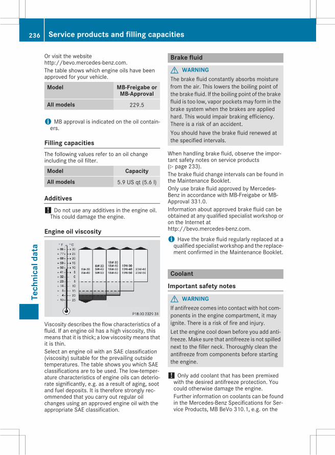
Or visit the websitehttp://bevo.mercedes-benz.com.The table shows which engine oils have beenapproved for your vehicle.
Model MB-Freigabe orMB-Approval
All models 229.5
i MB approval is indicated on the oil contain-ers.
Filling capacitiesThe following values refer to an oil changeincluding the oil filter.
Model Capacity
All models 5.9 US qt (5.6 l)
Additives! Do not use any additives in the engine oil.This could damage the engine.
Engine oil viscosity
Viscosity describes the flow characteristics of afluid. If an engine oil has a high viscosity, thismeans that it is thick; a low viscosity means thatit is thin.Select an engine oil with an SAE classification(viscosity) suitable for the prevailing outsidetemperatures. The table shows you which SAEclassifications are to be used. The low-temper-ature characteristics of engine oils can deterio-rate significantly, e.g. as a result of aging, sootand fuel deposits. It is therefore strongly rec-ommended that you carry out regular oilchanges using an approved engine oil with theappropriate SAE classification.
Brake fluid
G WARNINGThe brake fluid constantly absorbs moisturefrom the air. This lowers the boiling point ofthe brake fluid. If the boiling point of the brakefluid is too low, vapor pockets may form in thebrake system when the brakes are appliedhard. This would impair braking efficiency.There is a risk of an accident.You should have the brake fluid renewed atthe specified intervals.
When handling brake fluid, observe the impor-tant safety notes on service products(Y page 233).The brake fluid change intervals can be found inthe Maintenance Booklet.Only use brake fluid approved by Mercedes-Benz in accordance with MB-Freigabe or MB-Approval 331.0.Information about approved brake fluid can beobtained at any qualified specialist workshop oron the Internet athttp://bevo.mercedes-benz.com.
i Have the brake fluid regularly replaced at aqualified specialist workshop and the replace-ment confirmed in the Maintenance Booklet.
Coolant
Important safety notes
G WARNINGIf antifreeze comes into contact with hot com-ponents in the engine compartment, it mayignite. There is a risk of fire and injury.Let the engine cool down before you add anti-freeze.Make sure that antifreeze is not spillednext to the filler neck. Thoroughly clean theantifreeze from components before startingthe engine.
! Only add coolant that has been premixedwith the desired antifreeze protection. Youcould otherwise damage the engine.Further information on coolants can be foundin the Mercedes-Benz Specifications for Ser-vice Products, MB BeVo 310.1, e.g. on the
236 Service products and filling capacitiesTe
chni
cald
ata
Internet at http://bevo.mercedes-benz.com.Or contact a qualified specialist workshop.
! Always use a suitable coolant mixture, evenin countries where high temperatures prevail.Otherwise, the engine cooling system is notsufficiently protected from corrosion andoverheating.
i Have the coolant regularly replaced at aqualified specialist workshop and the replace-ment confirmed in the Maintenance Booklet.
Comply with the important safety precautionsfor service products when handling coolant(Y page 233).The coolant is a mixture of water and anti-freeze/corrosion inhibitor. It performs the fol-lowing tasks:Rcorrosion protectionRantifreeze protectionRraising the boiling pointIf the coolant has antifreeze protection down to-35 ‡ (-37 †), the boiling point of the coolantduring operation is approximately 266 ‡(130 †).The antifreeze/corrosion inhibitor concentra-tion in the engine cooling system should:Rbe at least 50%. This will protect the enginecooling system against freezing down toapproximately -35 ‡ (-37 †).
Rnot exceed 55% (antifreeze protection downto -49 ‡ [-45 †]). Otherwise, heat will not bedissipated as effectively.
Mercedes-Benz recommends coolant or anti-freeze/corrosion inhibitor concentrate inaccordance with MB Specifications for ServiceProducts 310.1.
i When the vehicle is first delivered, it is filledwith a coolant mixture that ensures adequateantifreeze and corrosion protection.
i The coolant is checked with every mainte-nance interval at a qualified specialist work-shop.
Filling capacities
Model Capacity
All models Approx. 8.2 US qt(7.8 l)
Windshield washer system
Important safety notes
G WARNINGWindshield washer concentrate could ignite ifit comes into contact with hot engine compo-nents or the exhaust system. There is a risk offire and injury.Make sure that no windshield washer con-centrate is spilled next to the filler neck.
! Do not add distilled or de-ionized water tothe washer fluid container. Otherwise, thelevel sensor may be damaged.
! Only MB SummerFit and MB WinterFitwasher fluid should be mixed together. Thespray nozzles may otherwise becomeblocked.
When handling washer fluid, observe the impor-tant safety notes on service products(Y page 233).At temperatures above freezing:X Fill thewasher fluid reservoir with amixture ofwater and windshield washer fluid, e.g. MBSummerFit.
Add 1 part MB SummerFit to 100 parts water.At temperatures below freezing:X Fill thewasher fluid reservoir with amixture ofwater and washer fluid, e.g. MB WinterFit.For the correct mixing ratio refer to the infor-mation on the antifreeze reservoir.
i Add windshield washer fluid, e.g. MB Sum-merFit or MB WinterFit, to the washer fluid allyear round.
Climate control system refrigerant
Important safety notesThe climate control system of your vehicle is fil-led with refrigerant R゙134a.The instruction label regarding the refrigeranttype used can be found on the left, on the under-side of the hood.
! Only the refrigerant R゙134a and the PAG oilapproved by Mercedes-Benz may be used.The approved PAG oil may not be mixed with
Service products and filling capacities 237
Tech
nica
ldat
a
Z
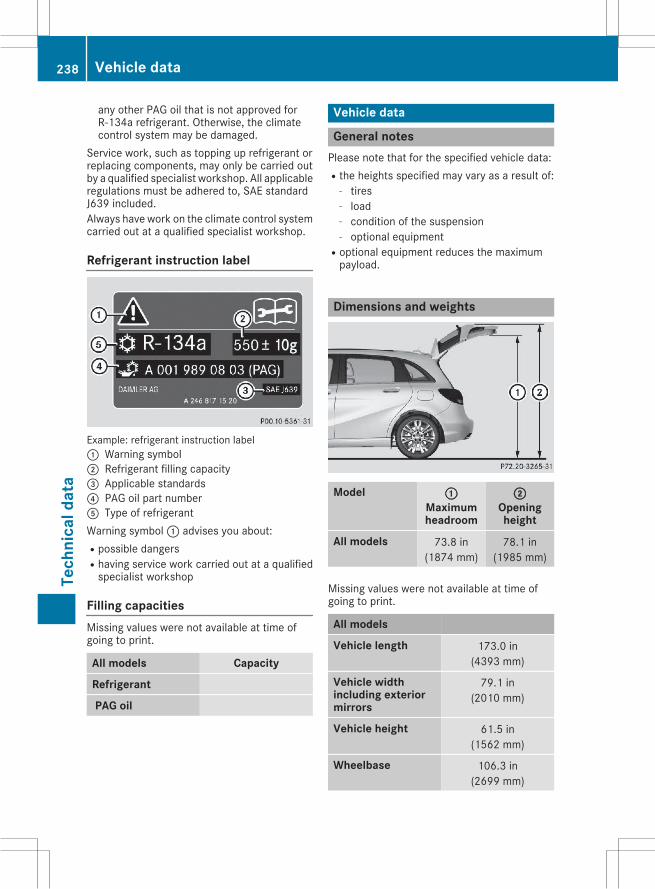
any other PAG oil that is not approved forR-134a refrigerant. Otherwise, the climatecontrol system may be damaged.
Service work, such as topping up refrigerant orreplacing components, may only be carried outby a qualified specialist workshop. All applicableregulations must be adhered to, SAE standardJ639 included.Always have work on the climate control systemcarried out at a qualified specialist workshop.
Refrigerant instruction label
Example: refrigerant instruction label: Warning symbol; Refrigerant filling capacity= Applicable standards? PAG oil part numberA Type of refrigerantWarning symbol: advises you about:Rpossible dangersRhaving service work carried out at a qualifiedspecialist workshop
Filling capacitiesMissing values were not available at time ofgoing to print.
All models Capacity
Refrigerant
PAG oil
Vehicle data
General notesPlease note that for the specified vehicle data:Rthe heights specified may vary as a result of:
- tires- load- condition of the suspension- optional equipment
Roptional equipment reduces the maximumpayload.
Dimensions and weights
Model :Maximumheadroom
;Openingheight
All models 73.8 in(1874 mm)
78.1 in(1985 mm)
Missing values were not available at time ofgoing to print.
All models
Vehicle length 173.0 in(4393 mm)
Vehicle widthincluding exteriormirrors
79.1 in(2010 mm)
Vehicle height 61.5 in(1562 mm)
Wheelbase 106.3 in(2699 mm)
238 Vehicle dataTe
chni
cald
ata
All models
Turning radius 36.1 ft(11.0 m)
Maximum trunkload
220.5 lb(100 kg)
Maximum roof load 165 lb(75.0 kg)
Vehicle data 239
Tech
nica
ldat
a
Z

240