Embed Size (px)
Citation preview
1ASRock A55iCafe Motherboard
Eng
lish
Copyright Notice:No part of this installation guide may be reproduced, transcribed, transmitted, or trans-lated in any language, in any form or by any means, except duplication of documentation by the purchaser for backup purpose, without written consent of ASRock Inc.Products and corporate names appearing in this guide may or may not be registered trademarks or copyrights of their respective companies, and are used only for identifica-tion or explanation and to the owners’ benefit, without intent to infringe.
Disclaimer:Specifications and information contained in this guide are furnished for informational use only and subject to change without notice, and should not be constructed as a commit-ment by ASRock. ASRock assumes no responsibility for any errors or omissions that may appear in this guide. With respect to the contents of this guide, ASRock does not provide warranty of any kind, either expressed or implied, including but not limited to the implied warranties or condi-tions of merchantability or fitness for a particular purpose. In no event shall ASRock, its directors, officers, employees, or agents be liable for any indirect, special, incidental, or consequential damages (including damages for loss of profits, loss of business, loss of data, interruption of business and the like), even if ASRock has been advised of the pos-sibility of such damages arising from any defect or error in the guide or product.
This device complies with Part 15 of the FCC Rules. Operation is subject to the following two conditions: (1) this device may not cause harmful interference, and (2) this device must accept any interference received, including interference that
may cause undesired operation.
CALIFORNIA, USA ONLYThe Lithium battery adopted on this motherboard contains Perchlorate, a toxic substance controlled in Perchlorate Best Management Practices (BMP) regulations passed by the California Legislature. When you discard the Lithium battery in California, USA, please follow the related regulations in advance.“Perchlorate Material-special handling may apply, see www.dtsc.ca.gov/hazardouswaste/perchlorate”
ASRock Website: http://www.asrock.com
Published August 2011Copyright©2011 ASRock INC. All rights reserved.
2ASRock A55iCafe Motherboard
English
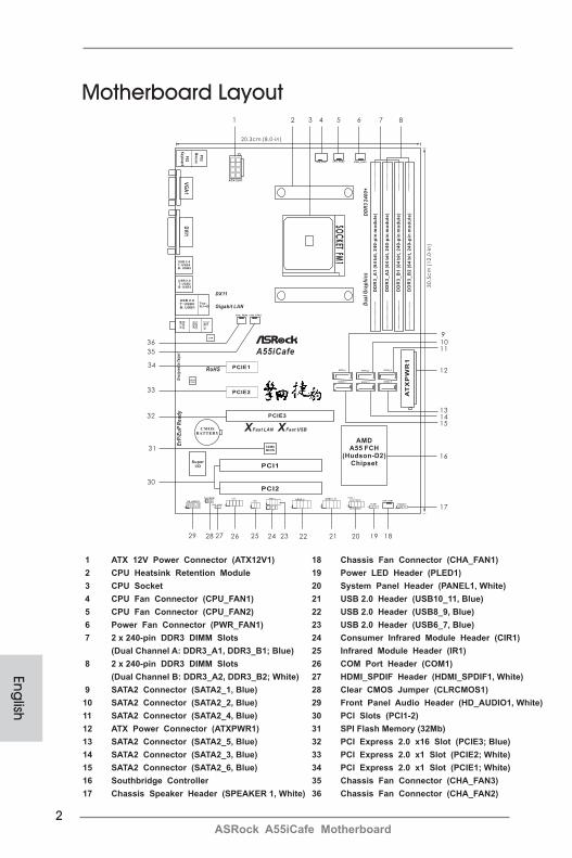
Motherboard Layout
1 ATX 12V Power Connector (ATX12V1) 18 Chassis Fan Connector (CHA_FAN1) 2 CPU Heatsink Retention Module 19 Power LED Header (PLED1) 3 CPU Socket 20 System Panel Header (PANEL1, White) 4 CPU Fan Connector (CPU_FAN1) 21 USB 2.0 Header (USB10_11, Blue) 5 CPU Fan Connector (CPU_FAN2) 22 USB 2.0 Header (USB8_9, Blue) 6 Power Fan Connector (PWR_FAN1) 23 USB 2.0 Header (USB6_7, Blue) 7 2 x 240-pin DDR3 DIMM Slots 24 Consumer Infrared Module Header (CIR1) (Dual Channel A: DDR3_A1, DDR3_B1; Blue) 25 Infrared Module Header (IR1) 8 2 x 240-pin DDR3 DIMM Slots 26 COM Port Header (COM1) (Dual Channel B: DDR3_A2, DDR3_B2; White) 27 HDMI_SPDIF Header (HDMI_SPDIF1, White) 9 SATA2 Connector (SATA2_1, Blue) 28 Clear CMOS Jumper (CLRCMOS1) 10 SATA2 Connector (SATA2_2, Blue) 29 Front Panel Audio Header (HD_AUDIO1, White) 11 SATA2 Connector (SATA2_4, Blue) 30 PCI Slots (PCI1-2)12 ATX Power Connector (ATXPWR1) 31 SPI Flash Memory (32Mb)13 SATA2 Connector (SATA2_5, Blue) 32 PCI Express 2.0 x16 Slot (PCIE3; Blue) 14 SATA2 Connector (SATA2_3, Blue) 33 PCI Express 2.0 x1 Slot (PCIE2; White)15 SATA2 Connector (SATA2_6, Blue) 34 PCI Express 2.0 x1 Slot (PCIE1; White)16 Southbridge Controller 35 Chassis Fan Connector (CHA_FAN3)17 Chassis Speaker Header (SPEAKER 1, White) 36 Chassis Fan Connector (CHA_FAN2)
20.3cm (8.0-in)
30
.5c
m(1
2.0
-in
)
SOC
KET
FM1
AT
XP
WR
1
DD
R3
_A
1(6
4b
it,
24
0-p
inm
od
ule
)
DD
R3
_A
2(6
4b
it,
24
0-p
inm
od
ule
)
DD
R3
_B
1(6
4b
it,
24
0-p
inm
od
ule
)
DD
R3
_B
2(6
4b
it,
24
0-p
inm
od
ule
)
AMDA55 FCH
(Hudson-D2)Chipset
A55iCafe
CMOS
BATTERY
ATX12V1
CPU_FAN1 CPU_FAN2 PWR_FAN1
CHA_FAN3CHA_FAN2
Du
alG
rap
hic
s
32MbBIOS
XFast USBXFast LAN
ErP
/Eu
PR
ea
dy
SuperI/O
AUDIOCODEC
LAN
PCIE1
PCIE2
PCIE3
PCI1
PCI2
RoHS
DX11
DD
R3
24
00
+
Des
igne
din
Taip
ei
SATA2_6 SATA2_3 SATA2_5
SATA2_2 SATA2_4SATA2_1
HDLED RESET
PLED PWRBTN
1
PANEL 1
SPEAKER1
1
PLED1
1
CHA_FAN1USB8_9
1
USB10_11
1
USB6_7
CIR1
1 1
COM1
1
CLRCMOS1
1
HD_AUDIO1
1
IR1
11
HDMI_SPDIF1
Gigabit LAN
VG
A1
PS
2
Mo
us
e
PS
2K
eyboardD
VI1
USB 2.0T: USB2B: USB3
Top:RJ-45
USB 2.0T: USB0B: USB1
Top:LIN
EIN
Center:
FRO
NT
Bottom
:M
ICIN
6 71 2 43 5 8
91011
12
131415
16
17
181920212223242526272829
30
31
32
33
34
35
36
USB 2.0T: USB4B: USB5
3ASRock A55iCafe Motherboard
Eng
lish
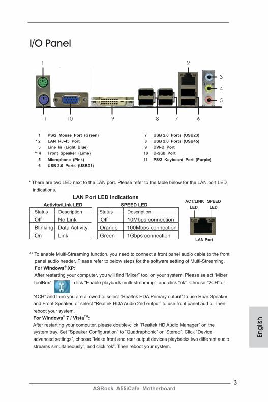
I/O Panel
* There are two LED next to the LAN port. Please refer to the table below for the LAN port LED indications. LAN Port LED Indications
Activity/Link LED SPEED LEDStatus Description Status Description Off No Link Off 10Mbps connectionBlinking Data Activity Orange 100Mbps connectionOn Link Green 1Gbps connection
LAN Port
ACT/LINK LED
SPEED LED
1 PS/2 Mouse Port (Green) 7 USB 2.0 Ports (USB23) * 2 LAN RJ-45 Port 8 USB 2.0 Ports (USB45) 3 Line In (Light Blue) 9 DVI-D Port ** 4 Front Speaker (Lime) 10 D-Sub Port 5 Microphone (Pink) 11 PS/2 Keyboard Port (Purple) 6 USB 2.0 Ports (USB01)
679
2
4
3
5
81011
1
** To enable Multi-Streaming function, you need to connect a front panel audio cable to the front panel audio header. Please refer to below steps for the software setting of Multi-Streaming. For Windows® XP: After restarting your computer, you will find “Mixer” tool on your system. Please select “Mixer ToolBox” , click “Enable playback multi-streaming”, and click “ok”. Choose “2CH” or
“4CH” and then you are allowed to select “Realtek HDA Primary output” to use Rear Speaker and Front Speaker, or select “Realtek HDA Audio 2nd output” to use front panel audio. Then reboot your system. For Windows® 7 / VistaTM: After restarting your computer, please double-click “Realtek HD Audio Manager” on the system tray. Set “Speaker Configuration” to “Quadraphonic” or “Stereo”. Click “Device advanced settings”, choose “Make front and rear output devices playbacks two different audio streams simultaneously”, and click “ok”. Then reboot your system.

4ASRock A55iCafe Motherboard
English
1. IntroductionThank you for purchasing ASRock A55iCafe motherboard, a reliable motherboard produced under ASRock’s consistently stringent quality control. It delivers excellent performance with robust design conforming to ASRock’s commitment to quality and endurance.This Quick Installation Guide contains introduction of the motherboard and step-by-step installation guide. More detailed information of the motherboard can be found in the user manual presented in the Support CD.
Because the motherboard specifications and the BIOS software might be updated, the content of this manual will be subject to change without no-tice. In case any modifications of this manual occur, the updated version will be available on ASRock website without further notice. You may find the latest VGA cards and CPU support lists on ASRock website as well. ASRock website http://www.asrock.comIf you require technical support related to this motherboard, please visit our website for specific information about the model you are using.www.asrock.com/support/index.asp
1.1 Package ContentsASRock A55iCafe Motherboard (ATX Form Factor: 12.0-in x 8.0-in, 30.5 cm x 20.3 cm)ASRock A55iCafe Quick Installation GuideASRock A55iCafe Support CD2 x Serial ATA (SATA) Data Cables (Optional)1 x I/O Panel Shield
ASRock Reminds You...To get better performance in Windows® 7 / 7 64-bit / VistaTM / VistaTM 64-bit, it is recommended to set the BIOS option in Storage Configuration to AHCI mode. For the BIOS setup, please refer to the “User Manual” in our support CD for details.

5ASRock A55iCafe Motherboard
Eng
lish
1.2 Specifications
Platform - ATX Form Factor: 12.0-in x 8.0-in, 30.5 cm x 20.3 cm - All Solid Capacitor design CPU - Support for Socket FM1 100W processors - V4 + 1 Power Phase Design - Supports AMD’s Cool ‘n’ QuietTM Technology - UMI-Link GEN2 Chipset - AMD A55 FCH (Hudson-D2) Memory - Dual Channel DDR3 Memory Technology (see CAUTION 1) - 4 x DDR3 DIMM slots - Support DDR3 2400+(OC)/1866/1600/1333/1066/ 800 non-ECC, un-buffered memory (see CAUTION 2) - Max. capacity of system memory: 32GB (see CAUTION 3) Expansion Slot - 1 x PCI Express 2.0 x16 slot (PCIE3 @ x16 mode) - 2 x PCI Express 2.0 x1 slots - 2 x PCI slots - Supports AMD Dual Graphics Graphics - AMD Radeon HD 65XX/64XX graphics - DirectX 11, Pixel Shader 5.0 - Max. shared memory 512MB (see CAUTION 4) - Dual VGA Output: support D-Sub and DVI-D ports by independent display controllers - Supports DVI with max. resolution up to 1920x1200 @ 75Hz - Supports D-Sub with max. resolution up to 1920x1600 @ 60Hz - Supports AMD Steady VideoTM: New video post processing capability for automatic jutter reduction on home/online video - Supports HDCP function with DVI port - Supports Full HD 1080p Blu-ray (BD) / HD-DVD playback with DVI port Audio - 5.1 CH HD Audio (Realtek ALC662 Audio Codec) - Premium Blu-ray audio support - Supports THX TruStudioTM
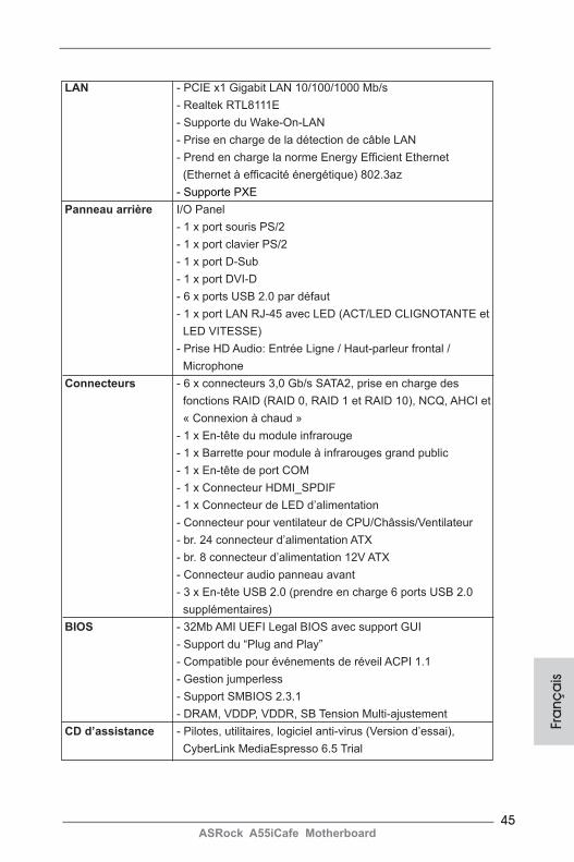
LAN - PCIE x1 Gigabit LAN 10/100/1000 Mb/s - Realtek RTL8111E - Supports Wake-On-LAN - Supports LAN Cable Detection - Supports Energy Efficient Ethernet 802.3az - Supports PXE

6ASRock A55iCafe Motherboard
English
Rear Panel I/O I/O Panel - 1 x PS/2 Mouse Port - 1 x PS/2 Keyboard Port - 1 x D-Sub Port - 1 x DVI-D Port - 6 x Ready-to-Use USB 2.0 Ports - 1 x RJ-45 LAN Port with LED (ACT/LINK LED and SPEED LED) - HD Audio Jack: Line in/Front Speaker/Microphone Connector - 6 x SATA2 3.0 Gb/s connectors, support RAID (RAID 0, RAID 1 and RAID 10), NCQ, AHCI and “Hot Plug” functions - 1 x IR header - 1 x CIR header - 1 x COM port header - 1 x HDMI_SPDIF header - 1 x Power LED header - CPU/Chassis/Power FAN connector - 24 pin ATX power connector - 8 pin 12V power connector - Front panel audio connector - 3 x USB 2.0 headers (support 6 USB 2.0 ports) BIOS Feature - 32Mb AMI UEFI Legal BIOS with GUI support - Supports “Plug and Play” - ACPI 1.1 Compliance Wake Up Events - Supports jumperfree - SMBIOS 2.3.1 Support - DRAM, VDDP, VDDR, SB Voltage Multi-adjustment Support CD - Drivers, Utilities, AntiVirus Software (Trial Version), CyberLink MediaEspresso 6.5 Trial Unique Feature - ASRock Extreme Tuning Utility (AXTU) (see CAUTION 5) - ASRock Instant Boot - ASRock Instant Flash (see CAUTION 6) - ASRock APP Charger (see CAUTION 7) - ASRock XFast USB (see CAUTION 8) - ASRock XFast LAN (see CAUTION 9) - Hybrid Booster: - ASRock U-COP (see CAUTION 10)
7ASRock A55iCafe Motherboard
Eng
lish
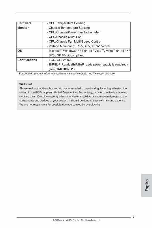
Hardware - CPU Temperature Sensing Monitor - Chassis Temperature Sensing - CPU/Chassis/Power Fan Tachometer - CPU/Chassis Quiet Fan - CPU/Chassis Fan Multi-Speed Control - Voltage Monitoring: +12V, +5V, +3.3V, Vcore OS - Microsoft® Windows® 7 / 7 64-bit / VistaTM / VistaTM 64-bit / XP SP3 / XP 64-bit compliant Certifications - FCC, CE, WHQL - ErP/EuP Ready (ErP/EuP ready power supply is required) (see CAUTION 11) * For detailed product information, please visit our website: http://www.asrock.com
WARNINGPlease realize that there is a certain risk involved with overclocking, including adjusting the setting in the BIOS, applying Untied Overclocking Technology, or using the third-party over-clocking tools. Overclocking may affect your system stability, or even cause damage to the components and devices of your system. It should be done at your own risk and expense. We are not responsible for possible damage caused by overclocking.
8ASRock A55iCafe Motherboard
English
CAUTION!1. This motherboard supports Dual Channel Memory Technology. Before
you implement Dual Channel Memory Technology, make sure to read the installation guide of memory modules on page 12 for proper installation.
2. Whether 2400/1866/1600MHz memory speed is supported depends on the CPU you adopt. If you want to adopt DDR3 2400/1866/1600 memory module on this motherboard, please refer to the memory support list on our website for the compatible memory modules.
ASRock website http://www.asrock.com3. Due to the operating system limitation, the actual memory size may be
less than 4GB for the reservation for system usage under Windows® 7 / VistaTM / XP. For Windows® 64-bit OS with 64-bit CPU, there is no such limitation.
4. The maximum shared memory size is defined by the chipset vendor and is subject to change. Please check AMD website for the latest informa-tion.
5. ASRock Extreme Tuning Utility (AXTU) is an all-in-one tool to ne-tune different system functions in a user-friendly interface, which is including Hardware Monitor, Fan Control, Overclocking, OC DNA and IES. In Hard-ware Monitor, it shows the major readings of your system. In Fan Control, it shows the fan speed and temperature for you to adjust. In Overclock-ing, you are allowed to overclock CPU frequency for optimal system performance. In OC DNA, you can save your OC settings as a profile and share with your friends. Your friends then can load the OC profile to their own system to get the same OC settings. In IES (Intelligent Energy Saver), the voltage regulator can reduce the number of output phases to improve efficiency when the CPU cores are idle without sacrificing com-puting performance. Please visit our website for the operation procedures of ASRock Extreme Tuning Utility (AXTU).
ASRock website: http://www.asrock.com6. ASRock Instant Flash is a BIOS flash utility embedded in Flash ROM.
This convenient BIOS update tool allows you to update system BIOS without entering operating systems first like MS-DOS or Windows®. With this utility, you can press <F6> key during the POST or press <F2> key to BIOS setup menu to access ASRock Instant Flash. Just launch this tool and save the new BIOS file to your USB flash drive, floppy disk or hard drive, then you can update your BIOS only in a few clicks without prepar-ing an additional floppy diskette or other complicated flash utility. Please be noted that the USB flash drive or hard drive must use FAT32/16/12 file system.
9ASRock A55iCafe Motherboard
Eng
lish
7. If you desire a faster, less restricted way of charging your Apple devices, such as iPhone/iPod/iPad Touch, ASRock has prepared a wonderful so-lution for you - ASRock APP Charger. Simply installing the APP Charger driver, it makes your iPhone charged much quickly from your computer and up to 40% faster than before. ASRock APP Charger allows you to quickly charge many Apple devices simultaneously and even supports continuous charging when your PC enters into Standby mode (S1), Sus-pend to RAM (S3), hibernation mode (S4) or power off (S5). With APP Charger driver installed, you can easily enjoy the marvelous charging experience than ever.
ASRock website: http://www.asrock.com/Feature/AppCharger/index.asp8. ASRock XFast USB can boost USB storage device performance. The
performance may depend on the property of the device.9. ASRock XFast LAN provides a faster internet access, which includes
below benefits. LAN Application Prioritization: You can configure your application priority ideally and/or add new programs. Lower Latency in Game: After setting online game priority higher, it can lower the latency in game. Traffic Shaping: You can watch Youtube HD video and download files simultaneously. Real-Time Analysis of Your Data: With the status window, you can easily recognize which data streams you are currently transferring.
10. While CPU overheat is detected, the system will automatically shutdown.Before you resume the system, please check if the CPU fan on the motherboard functions properly and unplug the power cord, then plug it back again. To improve heat dissipation, remember to spray thermal grease between the CPU and the heatsink when you install the PC sys-tem.
11. EuP, stands for Energy Using Product, was a provision regulated by Eu-ropean Union to define the power consumption for the completed system. According to EuP, the total AC power of the completed system shall be under 1.00W in off mode condition. To meet EuP standard, an EuP ready motherboard and an EuP ready power supply are required. According to Intel’s suggestion, the EuP ready power supply must meet the standard of 5v standby power efficiency is higher than 50% under 100 mA current consumption. For EuP ready power supply selection, we recommend you checking with the power supply manufacturer for more details.
10ASRock A55iCafe Motherboard
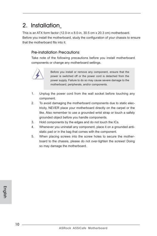
2. Installation This is an ATX form factor (12.0-in x 8.0-in, 30.5 cm x 20.3 cm) motherboard.Before you install the motherboard, study the configuration of your chassis to ensure that the motherboard fits into it.
Pre-installation PrecautionsTake note of the following precautions before you install motherboard components or change any motherboard settings.
Before you install or remove any component, ensure that the power is switched off or the power cord is detached from the power supply. Failure to do so may cause severe damage to the motherboard, peripherals, and/or components.
1. Unplug the power cord from the wall socket before touching any component.
2. To avoid damaging the motherboard components due to static elec-tricity, NEVER place your motherboard directly on the carpet or the like. Also remember to use a grounded wrist strap or touch a safety grounded object before you handle components.
3. Hold components by the edges and do not touch the ICs. 4. Whenever you uninstall any component, place it on a grounded anti-
static pad or in the bag that comes with the component.5. When placing screws into the screw holes to secure the mother-
board to the chassis, please do not over-tighten the screws! Doing so may damage the motherboard.
English

11ASRock A55iCafe Motherboard
Eng
lish
2.1 CPU Installation Step 1. Unlock the socket by lifting the lever up to a 90
o angle.Step 2. Position the CPU directly above the socket such that the CPU corner with the golden triangle matches the socket corner with a small triangle.Step 3. Carefully insert the CPU into the socket until it fits in place.
The CPU fits only in one correct orientation. DO NOT force the CPU into the socket to avoid bending of the pins.
Step 4. When the CPU is in place, press it firmly on the socket while you push down the socket lever to secure the CPU. The lever clicks on the side tab to indicate that it is locked.
2.2 Installation of CPU Fan and Heatsink
After you install the CPU into this motherboard, it is necessary to install a larger heatsink and cooling fan to dissipate heat. You also need to spray thermal grease between the CPU and the heatsink to improve heat dis-sipation. Make sure that the CPU and the heatsink are securely fastened and in good contact with each other. Then connect the CPU fan to the CPU FAN connector (CPU_FAN1, see Page 2, No. 4 or CPU_FAN2, see Page 2, No. 5). For proper installation, please kindly refer to the instruc-tion manuals of the CPU fan and the heatsink.
STEP 1:Lift Up The Socket Lever
STEP 2 / STEP 3: Match The CPU Golden TriangleTo The Socket Corner Small Triangle
STEP 4:Push Down And LockThe Socket Lever
CPU Golden Triangle
Lever 90° Up
Socket Corner Small Triangle
12ASRock A55iCafe Motherboard
English
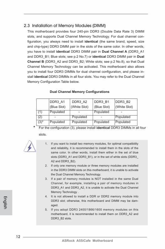
2.3 Installation of Memory Modules (DIMM) This motherboard provides four 240-pin DDR3 (Double Data Rate 3) DIMM slots, and supports Dual Channel Memory Technology. For dual channel con-figuration, you always need to install identical (the same brand, speed, size and chip-type) DDR3 DIMM pair in the slots of the same color. In other words, you have to install identical DDR3 DIMM pair in Dual Channel A (DDR3_A1 and DDR3_B1; Blue slots; see p.2 No.7) or identical DDR3 DIMM pair in Dual Channel B (DDR3_A2 and DDR3_B2; White slots; see p.2 No.8), so that Dual Channel Memory Technology can be activated. This motherboard also allows you to install four DDR3 DIMMs for dual channel configuration, and please in-stall identical DDR3 DIMMs in all four slots. You may refer to the Dual Channel Memory Configuration Table below.
Dual Channel Memory Configurations
DDR3_A1 DDR3_A2 DDR3_B1 DDR3_B2 (Blue Slot) (White Slot) (Blue Slot) (White Slot)(1) Populated - Populated -(2) - Populated - Populated(3)* Populated Populated Populated Populated
* For the configuration (3), please install identical DDR3 DIMMs in all four
slots.
1. If you want to install two memory modules, for optimal compatibility and reliability, it is recommended to install them in the slots of the same color. In other words, install them either in the set of blue slots (DDR3_A1 and DDR3_B1), or in the set of white slots (DDR3_A2 and DDR3_B2).
2. If only one memory module or three memory modules are installed in the DDR3 DIMM slots on this motherboard, it is unable to activate the Dual Channel Memory Technology.
3. If a pair of memory modules is NOT installed in the same Dual Channel, for example, installing a pair of memory modules in DDR3_A1 and DDR3_A2, it is unable to activate the Dual Channel Memory Technology .
4. It is not allowed to install a DDR or DDR2 memory module into DDR3 slot; otherwise, this motherboard and DIMM may be dam-aged.
5. If you adopt DDR3 2400/1866/1600 memory modules on this motherboard, it is recommended to install them on DDR3_A2 and DDR3_B2 slots.
13ASRock A55iCafe Motherboard
Eng
lish
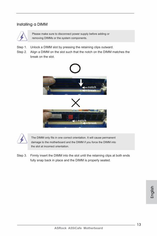
Installing a DIMM
Please make sure to disconnect power supply before adding or removing DIMMs or the system components.
Step 1. Unlock a DIMM slot by pressing the retaining clips outward. Step 2. Align a DIMM on the slot such that the notch on the DIMM matches the break on the slot.
The DIMM only fits in one correct orientation. It will cause permanent damage to the motherboard and the DIMM if you force the DIMM into the slot at incorrect orientation.
Step 3. Firmly insert the DIMM into the slot until the retaining clips at both ends fully snap back in place and the DIMM is properly seated.
14ASRock A55iCafe Motherboard
English
2.4 Expansion Slots (PCI and PCI Express Slots)There are 2 PCI slots and 3 PCI Express slots on this motherboard. PCI Slots: PCI slots are used to install expansion cards that have the 32-bit PCI interface. PCIE Slots: PCIE1 / PCIE2 (PCIE x1 slot; White) is used for PCI Express cards with
x1 lane width cards, such as Gigabit LAN card and SATA2 card. PCIE3 (PCIE x16 slot; Blue) is used for PCI Express x16 lane width
graphics cards.
Installing an expansion card
Step 1. Before installing the expansion card, please make sure that the power supply is switched off or the power cord is unplugged. Please read the documentation of the expansion card and make necessary hardware
settings for the card before you start the installation.Step 2. Remove the system unit cover (if your motherboard is already installed
in a chassis).Step 3. Remove the bracket facing the slot that you intend to use. Keep the
screws for later use. Step 4. Align the card connector with the slot and press firmly until the card is
completely seated on the slot. Step 5. Fasten the card to the chassis with screws. Step 6. Replace the system cover.
15ASRock A55iCafe Motherboard
Eng
lish
2.5 AMD Dual Graphics Operation GuideThis motherboard supports AMD Dual Graphics feature. AMD Dual Graphics brings multi-GPU performance capabilities by enabling an AMD A55 FCH (Hudson-D2) integrated graphics processor and a discrete graphics processor to operate simultaneously with combined output to a single display for blisteringly-fast frame rates. Currently, AMD Dual Graphics Technology is only supported with Windows® 7 OS, and is not available with Windows® VistaTM / XP OS.
What does an AMD Dual Graphics system include? An AMD Dual Graphics system includes an AMD Radeon HD 65XX/64XX graphics processor and a motherboard based on an AMD A55 FCH (Hudson-D2) integrated chipset, all operating in a Windows® 7 environment. Please refer to below PCI Express graphics card support list for AMD Dual Graphics. For the future update of more compatible PCI Express graphics cards, please visit AMD website for further information.
Chipset Model DriverAMD RADEON HD6670 ASUS DIS-PCIE2.1-ASUS-HDMI-EAH6670-DI-1GD3/1G-DDR3 8.863AMD RADEON HD6570 MSI DIS-PCIE2.1-MSI-HDMI-R6570-MD1GD3-LP/1G-DDR3 8.863AMD RADEON HD6450 MSI DIS-PCIE2.1-MSI-HDMI-R6450-MD1GD3-LP/1G-DDR3 8.863
Enjoy the benefit of AMD Dual Graphics Step 1. Please keep the default UEFI setting of “Dual Graphics“ option on [Auto]. Step 2. Install one AMD RADEON HD6670 / 6570 / 6450 PCI Express graphics
card to PCIE3 slot (blue). Step 3. Connect the monitor cable to the onboard VGA port. Please be noted that
the current VGA driver / VBIOS can allow Dual Graphics output from on-board display only. For any future update, please refer to our website for further information.
Step 4. Boot into OS. Please remove the AMD driver if you have any VGA driver installed in your system. Step 5. Install the onboard VGA driver from our support CD to your system for
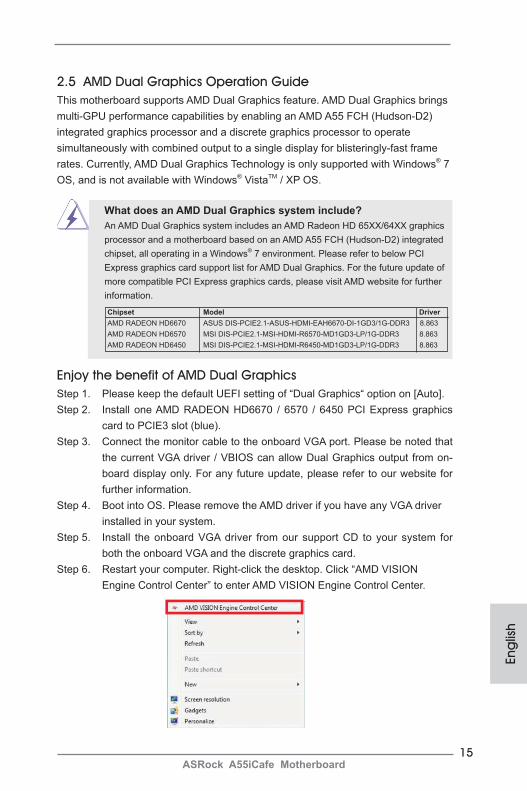
both the onboard VGA and the discrete graphics card.Step 6. Restart your computer. Right-click the desktop. Click “AMD VISION Engine Control Center” to enter AMD VISION Engine Control Center.
16ASRock A55iCafe Motherboard
English
* Dual Graphics appearing here is a registered trademark of AMD Technologies Inc., and is used only for identification or explanation and to the owners’ benefit, without intent to infringe.* For further information of AMD Dual Graphics technology, please check AMD website for up dates and details.
Step 9. Click “Enable CrossFireTM” and click “Apply“ to save your change.
Step 10. Reboot your system. Then you can freely enjoy the benefit of Dual Graphics feature.
AMD VISION Engine Control Center
Step 7. You can also click “AMD VISION Engine Control Center” on your Windows® taskbar to enter AMD VISION Engine Control Center.
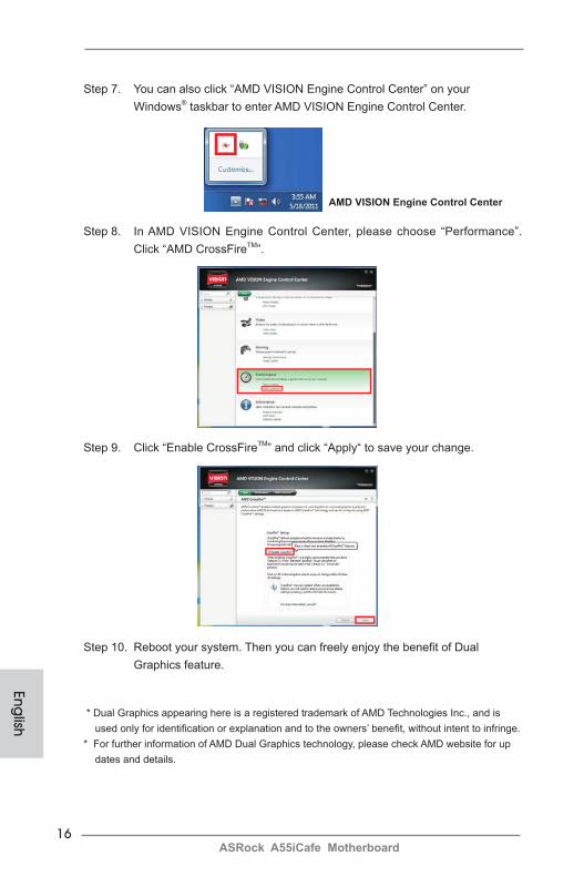
Step 8. In AMD VISION Engine Control Center, please choose “Performance”. Click “AMD CrossFireTM”.

17ASRock A55iCafe Motherboard
Eng
lish
2. If you have installed onboard VGA driver from our support CD to your system already, you can freely enjoy the benefits of dual monitor function after your system boots. If you haven’t installed onboard VGA driver yet, please install onboard VGA driver from our support CD to your system and restart your computer.
2.6 Dual Monitor and Surround Display Features
Dual Monitor Feature
This motherboard supports dual monitor feature. With the internal VGA output sup-port (D-Sub and DVI-D), you can easily enjoy the benefits of dual monitor feature without installing any add-on VGA card to this motherboard. This motherboard also provides independent display controllers for D-Sub and DVI-D to support dual VGA output so that D-sub and DVI-D can drive same or different display contents.To enable dual monitor feature, please follow the below steps:
1. Connect D-Sub monitor cable to D-Sub port on the I/O panel, or connect DVI-D monitor cable to DVI-D port on the I/O panel.
DVI-D portD-Sub port
18ASRock A55iCafe Motherboard
English
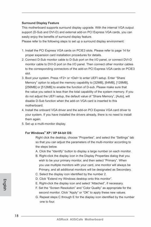
Surround Display FeatureThis motherboard supports surround display upgrade. With the internal VGA output support (D-Sub and DVI-D) and external add-on PCI Express VGA cards, you can easily enjoy the benefits of surround display feature. Please refer to the following steps to set up a surround display environment:
1. Install the PCI Express VGA cards on PCIE3 slots. Please refer to page 14 for proper expansion card installation procedures for details.2. Connect D-Sub monitor cable to D-Sub port on the I/O panel, or connect DVI-D monitor cable to DVI-D port on the I/O panel. Then connect other monitor cables to the corresponding connectors of the add-on PCI Express VGA cards on PCIE3 slot.3. Boot your system. Press <F2> or <Del> to enter UEFI setup. Enter “Share Memory” option to adjust the memory capability to [32MB], [64MB], [128MB], [256MB] or [512MB] to enable the function of D-sub. Please make sure that the value you select is less than the total capability of the system memory. If you do not adjust the UEFI setup, the default value of “Share Memory”, [Auto], will disable D-Sub function when the add-on VGA card is inserted to this motherboard.4. Install the onboard VGA driver and the add-on PCI Express VGA card driver to your system. If you have installed the drivers already, there is no need to install them again. 5. Set up a multi-monitor display.
For Windows® XP / XP 64-bit OS: Right click the desktop, choose “Properties”, and select the “Settings” tab so that you can adjust the parameters of the multi-monitor according to the steps below. A. Click the “Identify” button to display a large number on each monitor. B. Right-click the display icon in the Display Properties dialog that you wish to be your primary monitor, and then select “Primary”. When you use multiple monitors with your card, one monitor will always be Primary, and all additional monitors will be designated as Secondary. C. Select the display icon identified by the number 2. D. Click “Extend my Windows desktop onto this monitor”. E. Right-click the display icon and select “Attached”, if necessary. F. Set the “Screen Resolution” and “Color Quality” as appropriate for the second monitor. Click “Apply” or “OK” to apply these new values. G. Repeat steps C through E for the diaplay icon identified by the number one to four.

19ASRock A55iCafe Motherboard
Eng
lish
For Windows® 7 / 7 64-bit / VistaTM / VistaTM 64-bit OS: Right click the desktop, choose “Personalize”, and select the “Display Settings” tab so that you can adjust the parameters of the multi-monitor according to the steps below. A. Click the number ”2” icon. B. Click the items “This is my main monitor” and “Extend the desktop onto this monitor”. C. Click “OK” to save your change. D. Repeat steps A through C for the display icon identified by the number three to four.6. Use Surround Display. Click and drag the display icons to positions representing the physical setup of your monitors that you would like to use. The placement of display icons determines how you move items from one monitor to another.
HDCP Function HDCP function is supported on this motherboard. To use HDCP function with this motherboard, you need to adopt the monitor that supports HDCP function as well. Therefore, you can enjoy the superior display quality with high-definition HDCP encryption contents. Please refer to below instruction for more details about HDCP function.
What is HDCP? HDCP stands for High-Bandwidth Digital Content Protection, a specification developed by Intel® for protecting digital entertainment content that uses the DVI interface. HDCP is a copy protection scheme to eliminate the possibility of intercepting digital data midstream between the video source, or transmitter - such as a computer, DVD player or set-top box - and the digital display, or receiver - such as a monitor, television or projector. In other words, HDCP specification is designed to protect the integrity of content as it is being transmitted.
Products compatible with the HDCP scheme such as DVD players, satellite and cable HDTV set-top-boxes, as well as few entertainment PCs requires a secure connection to a compliant display. Due to the increase in manufacturers employing HDCP in their equipment, it is highly recommended that the HDTV or LCD monitor you purchase is compatible.
20ASRock A55iCafe Motherboard
English
* ASRock Smart Remote is only supported by some of ASRock motherboards. Please refer to ASRock website for the motherboard support list: http://www.asrock.com
USB 2.0 header (9-pin, blue)
CIR header (4-pin, white)
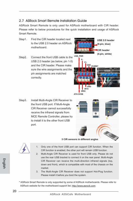
2.7 ASRock Smart Remote Installation GuideASRock Smart Remote is only used for ASRock motherboard with CIR header. Please refer to below procedures for the quick installation and usage of ASRock Smart Remote.
Step1. Find the CIR header located next to the USB 2.0 header on ASRock motherboard.
Step2. Connect the front USB cable to the USB 2.0 header (as below, pin 1-5) and the CIR header. Please make sure the wire assignments and the pin assignments are matched correctly.
USB_PWR
P-P+
GND
ATX+5VSBIRRX
IRTXGND
DUMMY
Step3. Install Multi-Angle CIR Receiver to the front USB port. If Multi-Angle CIR Receiver cannot successfully receive the infrared signals from MCE Remote Controller, please try to install it to the other front USB port.
3 CIR sensors in different angles
1. Only one of the front USB port can support CIR function. When the CIR function is enabled, the other port will remain USB function.
2. Multi-Angle CIR Receiver is used for front USB only. Please do not use the rear USB bracket to connect it on the rear panel. Multi-Angle CIR Receiver can receive the multi-direction infrared signals (top, down and front), which is compatible with most of the chassis on the market.
3. The Multi-Angle CIR Receiver does not support Hot-Plug function. Please install it before you boot the system.
21ASRock A55iCafe Motherboard
Eng
lish
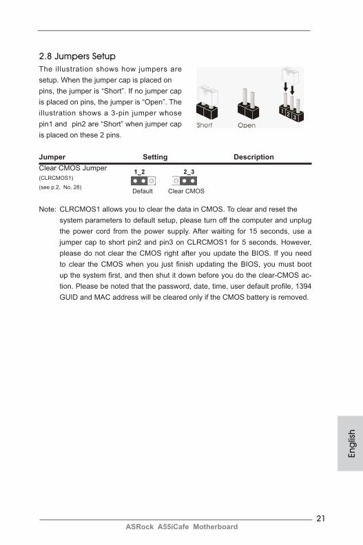
2.8 Jumpers Setup The illustration shows how jumpers are setup. When the jumper cap is placed on pins, the jumper is “Short”. If no jumper cap is placed on pins, the jumper is “Open”. The illustration shows a 3-pin jumper whose pin1 and pin2 are “Short” when jumper cap is placed on these 2 pins.
Jumper Setting DescriptionClear CMOS Jumper (CLRCMOS1)
(see p.2, No. 28)
Note: CLRCMOS1 allows you to clear the data in CMOS. To clear and reset the system parameters to default setup, please turn off the computer and unplug
the power cord from the power supply. After waiting for 15 seconds, use a jumper cap to short pin2 and pin3 on CLRCMOS1 for 5 seconds. However, please do not clear the CMOS right after you update the BIOS. If you need to clear the CMOS when you just finish updating the BIOS, you must boot up the system first, and then shut it down before you do the clear-CMOS ac-tion. Please be noted that the password, date, time, user default profile, 1394 GUID and MAC address will be cleared only if the CMOS battery is removed.
Clear CMOSDefault
22ASRock A55iCafe Motherboard
English
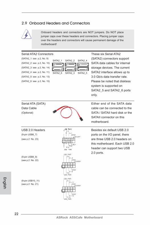
2.9 Onboard Headers and Connectors
Onboard headers and connectors are NOT jumpers. Do NOT place jumper caps over these headers and connectors. Placing jumper caps over the headers and connectors will cause permanent damage of the motherboard!
1
USB_PWRP-8
GND
DUMMY
USB_PWR
P+8
GND
P-9P+9
1
USB_PWRP-10
GND
DUMMY
USB_PWR
P+10
GND
P-11P+11
USB 2.0 Headers Besides six default USB 2.0(9-pin USB6_7) ports on the I/O panel, there (see p.2 No. 23) are three USB 2.0 headers on this motherboard. Each USB 2.0 header can support two USB 2.0 ports.(9-pin USB8_9)(see p.2 No. 22)
(9-pin USB10_11)(see p.2 No. 21)
Serial ATA2 Connectors These six Serial ATA2 (SATA2_1: see p.2, No. 9) (SATA2) connectors support (SATA2_2: see p.2, No. 10) SATA data cables for internal (SATA2_3: see p.2, No. 14) storage devices. The current (SATA2_4: see p.2, No. 11) SATA2 interface allows up to(SATA2_5: see p.2, No. 13) 3.0 Gb/s data transfer rate.(SATA2_6: see p.2, No. 15) Please be noted that diskless system is supported on SATA2_5 and SATA2_6 ports only.
Serial ATA (SATA) Either end of the SATA data Data Cable cable can be connected to the (Optional) SATA / SATAII hard disk or the SATAII connector on this motherboard.
SATA2_6 SATA2_3 SATA2_5
SATA2_1 SATA2_2 SATA2_4
23ASRock A55iCafe Motherboard
Eng
lish
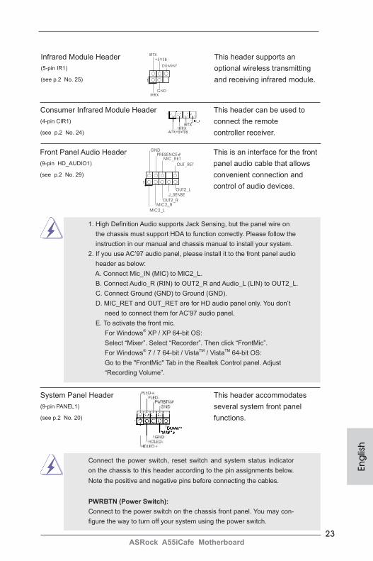
Infrared Module Header This header supports an(5-pin IR1) optional wireless transmitting(see p.2 No. 25) and receiving infrared module.
Front Panel Audio Header This is an interface for the front (9-pin HD_AUDIO1) panel audio cable that allows (see p.2 No. 29) convenient connection and control of audio devices.
Consumer Infrared Module Header This header can be used to (4-pin CIR1) connect the remote (see p.2 No. 24) controller receiver.
1
IRTX
+5VSB
DUMMY
IRRXGND
J_SENSE
OUT2_L
1
MIC_RETPRESENCE#
GND
OUT2_RMIC2_R
MIC2_L
OUT_RET
1. High Definition Audio supports Jack Sensing, but the panel wire on the chassis must support HDA to function correctly. Please follow the instruction in our manual and chassis manual to install your system.
2. If you use AC’97 audio panel, please install it to the front panel audio header as below:
A. Connect Mic_IN (MIC) to MIC2_L. B. Connect Audio_R (RIN) to OUT2_R and Audio_L (LIN) to OUT2_L. C. Connect Ground (GND) to Ground (GND). D. MIC_RET and OUT_RET are for HD audio panel only. You don’t
need to connect them for AC’97 audio panel. E. To activate the front mic. For Windows® XP / XP 64-bit OS: Select “Mixer”. Select “Recorder”. Then click “FrontMic”. For Windows® 7 / 7 64-bit / VistaTM / VistaTM 64-bit OS: Go to the "FrontMic" Tab in the Realtek Control panel. Adjust
“Recording Volume”.
System Panel Header This header accommodates(9-pin PANEL1) several system front panel (see p.2 No. 20) functions.
Connect the power switch, reset switch and system status indicator on the chassis to this header according to the pin assignments below. Note the positive and negative pins before connecting the cables.
PWRBTN (Power Switch): Connect to the power switch on the chassis front panel. You may con-figure the way to turn off your system using the power switch.
24ASRock A55iCafe Motherboard
English
RESET (Reset Switch): Connect to the reset switch on the chassis front panel. Press the reset switch to restart the computer if the computer freezes and fails to per-form a normal restart.
PLED (System Power LED): Connect to the power status indicator on the chassis front panel. The LED is on when the system is operating. The LED keeps blinking when the sys-tem is in S1 sleep state. The LED is off when the system is in S3/S4 sleep state or powered off (S5).
HDLED (Hard Drive Activity LED): Connect to the hard drive activity LED on the chassis front panel. The LED is on when the hard drive is reading or writing data.
The front panel design may differ by chassis. A front panel module mainly consists of power switch, reset switch, power LED, hard drive activity LED, speaker and etc. When connecting your chassis front panel module to this header, make sure the wire assignments and the pin assign-ments are matched correctly.
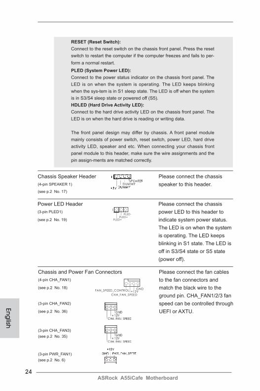
Power LED Header Please connect the chassis (3-pin PLED1) power LED to this header to (see p.2 No. 19) indicate system power status. The LED is on when the system is operating. The LED keeps blinking in S1 state. The LED is off in S3/S4 state or S5 state (power off).
Chassis Speaker Header Please connect the chassis (4-pin SPEAKER 1) speaker to this header.(see p.2 No. 17)
1
PLED+PLED+
PLED-
Chassis and Power Fan Connectors Please connect the fan cables (4-pin CHA_FAN1) to the fan connectors and (see p.2 No. 18) match the black wire to the ground pin. CHA_FAN1/2/3 fan(3-pin CHA_FAN2) speed can be controlled through(see p.2 No. 36) UEFI or AXTU.
(3-pin CHA_FAN3)(see p.2 No. 35)
(3-pin PWR_FAN1)(see p.2 No. 6)
GND+12V
CHA_FAN_SPEED
FAN_SPEED_CONTROL

25ASRock A55iCafe Motherboard
Eng
lish
CPU Fan Connectors Please connect the CPU fan (4-pin CPU_FAN1) cable to the connector and (see p.2 No. 4) match the black wire to the ground pin.
Though this motherboard provides 4-Pin CPU fan (Quiet Fan) support, the 3-Pin CPU fan still can work successfully even without the fan speed control function. If you plan to connect the 3-Pin CPU fan to the CPU fan connector on this motherboard, please connect it to Pin 1-3.
ATX Power Connector Please connect an ATX power (24-pin ATXPWR1) supply to this connector. (see p.2 No. 12)
12
1
Though this motherboard provides 24-pin ATX power connector, it can still work if you adopt a traditional 20-pin ATX power supply. To use the 20-pin ATX power supply, please plug your power supply along with Pin 1 and Pin 13.
ATX 12V Power Connector Please connect an ATX 12V (8-pin ATX12V1) power supply to this connector.(see p.2 No. 1)
Though this motherboard provides 8-pin ATX 12V power connector, it can still work if you adopt a traditional 4-pin ATX 12V power supply. To use the 4-pin ATX power supply, please plug your power supply along with Pin 1 and Pin 5.
(3-pin CPU_FAN2) (see p.2 No. 5)
20-Pin ATX Power Supply Installation
4-Pin ATX 12V Power Supply Installation
Pin 1-3 Connected
3-Pin Fan Installation
12
1
24
13
24
13
GND+12V
CPU_FAN_SPEED
FAN_SPEED_CONTROL
1 2 3 4
GND+12V
CPU_FAN_SPEED
4 8
1 5
4 8
1 5
Serial port Header This COM1 header supports a (9-pin COM1) serial port module. (see p.2 No.26)
26ASRock A55iCafe Motherboard
English
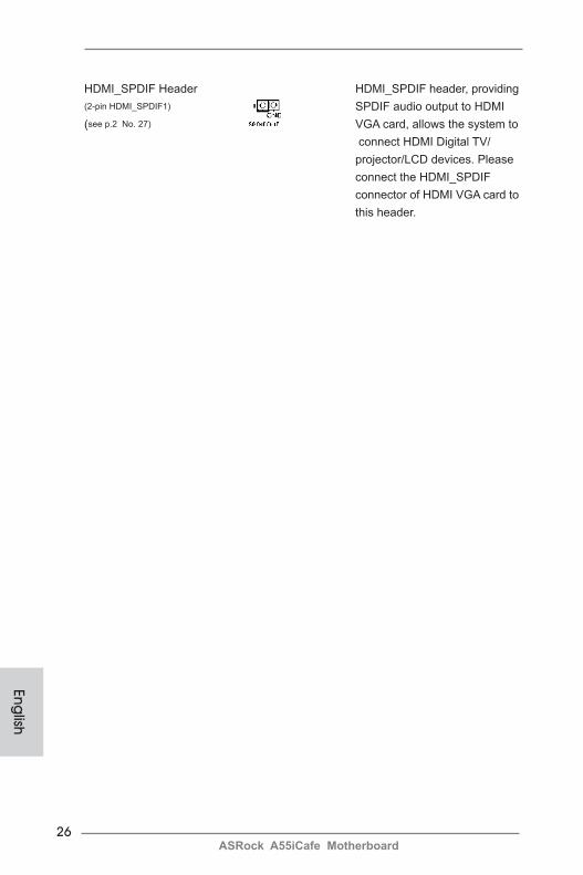
HDMI_SPDIF Header HDMI_SPDIF header, providing (2-pin HDMI_SPDIF1) SPDIF audio output to HDMI(see p.2 No. 27) VGA card, allows the system to connect HDMI Digital TV/ projector/LCD devices. Please connect the HDMI_SPDIF connector of HDMI VGA card to this header.
27ASRock A55iCafe Motherboard
2.10 Driver Installation GuideTo install the drivers to your system, please insert the support CD to your optical drive first. Then, the drivers compatible to your system can be auto-detected and listed on the support CD driver page. Please follow the order from up to bottom side to install those required drivers. Therefore, the drivers you install can work properly.
2.11 Installing Windows® 7 / 7 64-bit / VistaTM / VistaTM 64-bit / XP /
XP 64-bit With RAID FunctionsIf you want to install Windows® 7 / 7 64-bit / VistaTM / VistaTM 64-bit / XP / XP 64-bit on your SATA / SATAII HDDs with RAID functions, please refer to the document at the following path in the Support CD for detailed procedures:..\ RAID Installation Guide
Eng
lish
Using SATA / SATAII HDDs without NCQ and Hot Plug functions (IDE mode)
STEP 1: Set up UEFI.A. Enter UEFI SETUP UTILITY Advanced screen Storage Configuration.B. Set the “SATA Mode” option to [IDE]. STEP 2: Install Windows® XP / XP 64-bit OS on your system.
2.12 Installing Windows® 7 / 7 64-bit / VistaTM / VistaTM 64-bit / XP /
XP 64-bit Without RAID FunctionsIf you want to install Windows® 7 / 7 64-bit / VistaTM / VistaTM 64-bit / XP / XP 64-bit OS on your SATA / SATAII HDDs without RAID functions, please follow below procedures according to the OS you install.
2.12.1 Installing Windows® XP / XP 64-bit Without RAID FunctionsIf you want to install Windows® XP / XP 64-bit on your SATA / SATAII HDDs without RAID functions, please follow below steps.
28ASRock A55iCafe Motherboard
English
STEP 1: Set up UEFI.A. Enter UEFI SETUP UTILITY Advanced screen Storage Configuration.B. Set the “SATA Mode” option to [IDE]. STEP 2: Install Windows® 7 / 7 64-bit / VistaTM / VistaTM 64-bit OS on your system.
Using SATA / SATAII HDDs without NCQ and Hot Plug functions (IDE mode)
2.12.2 Installing Windows® 7 / 7 64-bit / VistaTM / VistaTM 64-bit
Without RAID FunctionsIf you want to install Windows® 7 / 7 64-bit / VistaTM / VistaTM 64-bit on your SATA / SATAII HDDs without RAID functions, please follow below steps.
Using SATA / SATAII HDDs with NCQ and Hot Plug functions (AHCI mode)
STEP 1: Set up UEFI.A. Enter UEFI SETUP UTILITY Advanced screen Storage Configuration.B. Set the “SATA Mode” option to [AHCI]. STEP 2: Install Windows® 7 / 7 64-bit / VistaTM / VistaTM 64-bit OS on your system.
29ASRock A55iCafe Motherboard
Eng
lish
3. BIOS InformationThe Flash Memory on the motherboard stores BIOS Setup Utility. When you start up the computer, please press <F2> or <Del> during the Power-On-Self-Test (POST) to enter BIOS Setup utility; otherwise, POST continues with its test routines. If you wish to enter BIOS Setup after POST, please restart the system by pressing <Ctl> + <Alt> + <Delete>, or pressing the reset button on the system chassis. The BIOS Setup program is designed to be user-friendly. It is a menu-driven program, which allows you to scroll through its various sub-menus and to select among the prede-termined choices. For the detailed information about BIOS Setup, please refer to the User Manual (PDF file) contained in the Support CD.
4. Software Support CD informationThis motherboard supports various Microsoft® Windows® operating systems: 7 / 7 64-bit / VistaTM / VistaTM 64-bit / XP SP3 / XP 64-bit. The Support CD that came with the motherboard contains necessary drivers and useful utilities that will enhance motherboard features. To begin using the Support CD, insert the CD into your CD-ROM drive. It will display the Main Menu automatically if “AUTORUN” is enabled in your computer. If the Main Menu does not appear automatically, locate and double-click on the file “ASSETUP.EXE” from the BIN folder in the Support CD to display the menus.
30ASRock A55iCafe Motherboard
1. EinführungWir danken Ihnen für den Kauf des ASRock A55iCafe Motherboard, ein zuverlässig-es Produkt, welches unter den ständigen, strengen Qualitätskontrollen von ASRock gefertigt wurde. Es bietet Ihnen exzellente Leistung und robustes Design, gemäß der Verpflichtung von ASRock zu Qualität und Halbarkeit. Diese Schnellinstalla-tionsanleitung führt in das Motherboard und die schrittweise Installation ein. Details über das Motherboard finden Sie in der Bedienungsanleitung auf der Support-CD.
Da sich Motherboard-Spezifikationen und BIOS-Software verändern können, kann der Inhalt dieses Handbuches ebenfalls jederzeit geändert werden. Für den Fall, dass sich Änderungen an diesem Handbuch ergeben, wird eine neue Version auf der ASRock-Website, ohne weitere Ankündigung, verfügbar sein. Die neuesten Grafikkarten und unterstützten CPUs sind auch auf der ASRock-Website aufgelistet. ASRock-Website: http://www.asrock.com Wenn Sie technische Unterstützung zu Ihrem Motherboard oder spezifische Informationen zu Ihrem Modell benötigen, besuchen Sie bitte unsere Webseite: www.asrock.com/support/index.asp
1.1 KartoninhaltASRock A55iCafe Motherboard (ATX-Formfaktor: 30.5 cm x 20.3 cm; 12.0 Zoll x 8.0 Zoll)ASRock A55iCafe SchnellinstallationsanleitungASRock A55iCafe Support-CD Zwei Serial ATA (SATA) -Datenkabel (optional)Ein I/O Shield
ASRock erinnert...Zur besseren Leistung unter Windows® 7 / 7, 64 Bit / VistaTM / VistaTM 64 Bit empfehlen wir, die Speicherkonfiguration im BIOS auf den AHCI-Modus einzustellen. Hinweise zu den BIOS-Einstellungen finden Sie in der Bedienungsanleitung auf der mitgelieferten CD.
De
utsch
31ASRock A55iCafe Motherboard
1.2 Spezifikationen
Plattform - ATX-Formfaktor: 30.5 cm x 20.3 cm; 12.0 Zoll x 8.0 Zoll - Alle Feste Kondensatordesign CPU - Unterstützt Sockel-FM1-100-W-Prozessoren - V4 + 1-Stromphasendesign - Unterstützt Cool ‘n’ QuietTM-Technologie von AMD - UMI-Link-GEN2 Chipsatz - AMD A55 FCH (Hudson-D2) Speicher - Unterstützung von Dual-Kanal-Speichertechnologie (siehe VORSICHT 1) - 4 x Steckplätze für DDR3 - Unterstützt DDR3 2400+(OC)/1866/1600/1333/ 1066/800 non-ECC, ungepufferter Speicher (siehe VORSICHT 2) - Max. Kapazität des Systemspeichers: 32GB (siehe VORSICHT 3) Erweiterungs- - 1 x PCI-Express-2.0-x16-Steckplätze steckplätze (PCIE3 für x16-Modus) - 2 x PCI Express 2.0 x1-Steckplätze - 2 x PCI -Steckplätze - Unterstützt AMD duale Grafikkarten Onboard-VGA - AMD Radeon HD 65XX/64XX-Grafik - DirectX 11, Pixel Shader 5.0 - Maximal gemeinsam genutzter Speicher 512MB (siehe VORSICHT 4) - Doppel-VGA Ausgabe: unterstützt D-Sub und DVI-D Ports durch unabhängige Bildschirmanzeige Kontrolleure - Unterstützt DVI mit einer maximalen Auflösung von 1920 x 1200 bei 75 Hz - Unterstützt D-Sub mit einer maximalen Auflösung von 1920 x 1600 bei 60 Hz - Unterstützt AMD Steady VideoTM: Neuartige Funktion der Videonachbearbeitung für automatische Reduzierung von Bildschwankungen bei Heim-/Online-Videos - Unterstützt HDCP-Funktion mit DVI-Port - Unterstutzt 1080p Blu-ray (BD) / HD-DVD-Wiedergabe mit DVI-Port Audio - 5.1 CH HD Audio (Realtek ALC662 Audio Codec) - Premium Blu-ray-Audio-Unterstützung - Unterstützt THX TruStudioTM
De
utsc
h
32ASRock A55iCafe Motherboard
De
utsch
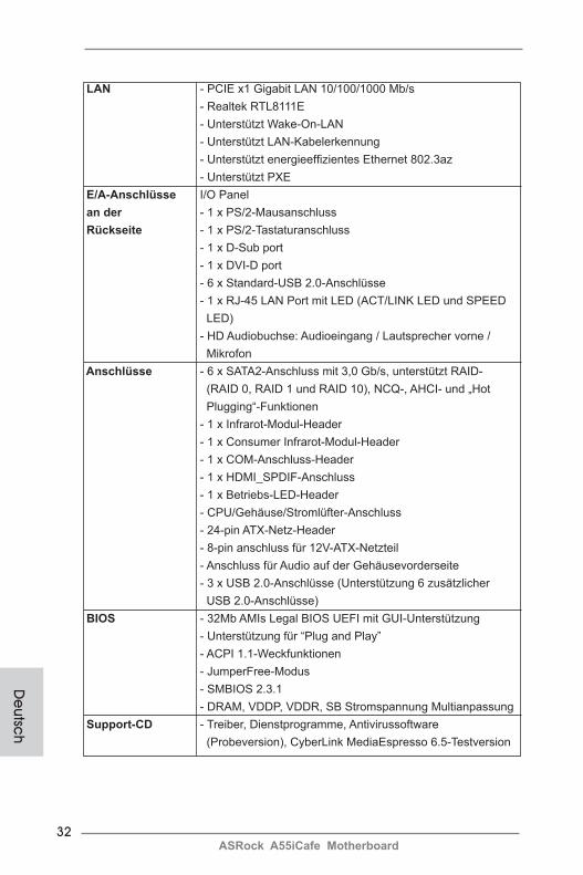
LAN - PCIE x1 Gigabit LAN 10/100/1000 Mb/s - Realtek RTL8111E - Unterstützt Wake-On-LAN - Unterstützt LAN-Kabelerkennung - Unterstützt energieeffizientes Ethernet 802.3az - Unterstützt PXE E/A-Anschlüsse I/O Panel an der - 1 x PS/2-Mausanschluss Rückseite - 1 x PS/2-Tastaturanschluss - 1 x D-Sub port - 1 x DVI-D port - 6 x Standard-USB 2.0-Anschlüsse - 1 x RJ-45 LAN Port mit LED (ACT/LINK LED und SPEED LED) - HD Audiobuchse: Audioeingang / Lautsprecher vorne / Mikrofon Anschlüsse - 6 x SATA2-Anschluss mit 3,0 Gb/s, unterstützt RAID- (RAID 0, RAID 1 und RAID 10), NCQ-, AHCI- und „Hot Plugging“-Funktionen - 1 x Infrarot-Modul-Header - 1 x Consumer Infrarot-Modul-Header - 1 x COM-Anschluss-Header - 1 x HDMI_SPDIF-Anschluss - 1 x Betriebs-LED-Header - CPU/Gehäuse/Stromlüfter-Anschluss - 24-pin ATX-Netz-Header - 8-pin anschluss für 12V-ATX-Netzteil - Anschluss für Audio auf der Gehäusevorderseite - 3 x USB 2.0-Anschlüsse (Unterstützung 6 zusätzlicher USB 2.0-Anschlüsse) BIOS - 32Mb AMIs Legal BIOS UEFI mit GUI-Unterstützung - Unterstützung für “Plug and Play” - ACPI 1.1-Weckfunktionen - JumperFree-Modus - SMBIOS 2.3.1 - DRAM, VDDP, VDDR, SB Stromspannung Multianpassung Support-CD - Treiber, Dienstprogramme, Antivirussoftware (Probeversion), CyberLink MediaEspresso 6.5-Testversion
33ASRock A55iCafe Motherboard
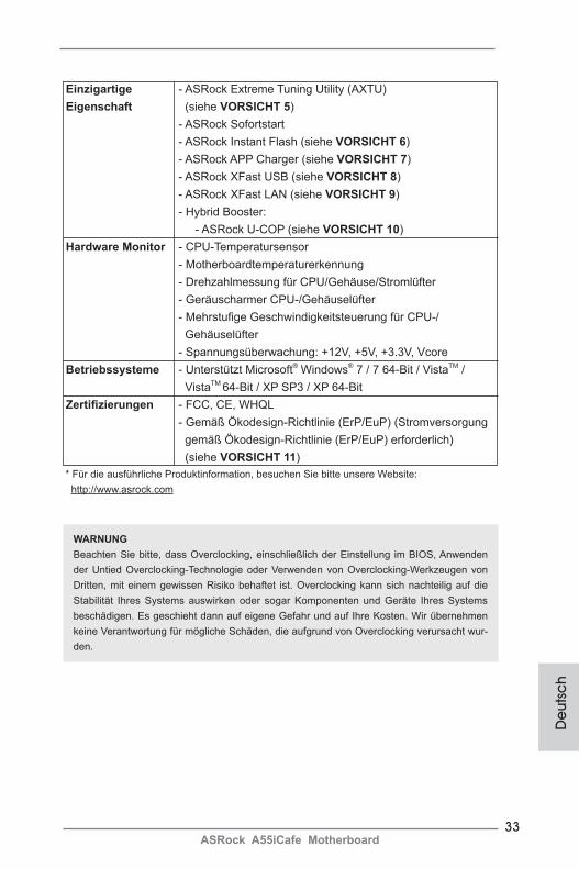
Einzigartige - ASRock Extreme Tuning Utility (AXTU) Eigenschaft (siehe VORSICHT 5) - ASRock Sofortstart - ASRock Instant Flash (siehe VORSICHT 6) - ASRock APP Charger (siehe VORSICHT 7) - ASRock XFast USB (siehe VORSICHT 8) - ASRock XFast LAN (siehe VORSICHT 9) - Hybrid Booster: - ASRock U-COP (siehe VORSICHT 10) Hardware Monitor - CPU-Temperatursensor - Motherboardtemperaturerkennung - Drehzahlmessung für CPU/Gehäuse/Stromlüfter - Geräuscharmer CPU-/Gehäuselüfter - Mehrstufige Geschwindigkeitsteuerung für CPU-/ Gehäuselüfter - Spannungsüberwachung: +12V, +5V, +3.3V, Vcore Betriebssysteme - Unterstützt Microsoft® Windows® 7 / 7 64-Bit / VistaTM / VistaTM 64-Bit / XP SP3 / XP 64-Bit Zertifizierungen - FCC, CE, WHQL - Gemäß Ökodesign-Richtlinie (ErP/EuP) (Stromversorgung gemäß Ökodesign-Richtlinie (ErP/EuP) erforderlich) (siehe VORSICHT 11) * Für die ausführliche Produktinformation, besuchen Sie bitte unsere Website: http://www.asrock.com
De
utsc
h
WARNUNGBeachten Sie bitte, dass Overclocking, einschließlich der Einstellung im BIOS, Anwenden der Untied Overclocking-Technologie oder Verwenden von Overclocking-Werkzeugen von Dritten, mit einem gewissen Risiko behaftet ist. Overclocking kann sich nachteilig auf die Stabilität Ihres Systems auswirken oder sogar Komponenten und Geräte Ihres Systems beschädigen. Es geschieht dann auf eigene Gefahr und auf Ihre Kosten. Wir übernehmen keine Verantwortung für mögliche Schäden, die aufgrund von Overclocking verursacht wur-den.
34ASRock A55iCafe Motherboard
De
utsch
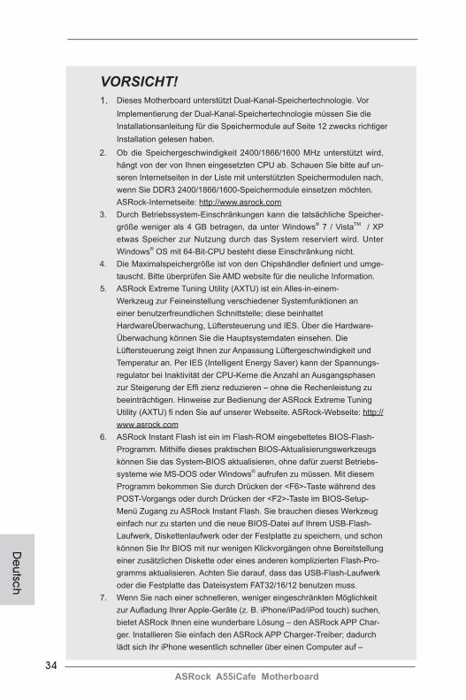
VORSICHT!1. Dieses Motherboard unterstützt Dual-Kanal-Speichertechnologie. Vor
Implementierung der Dual-Kanal-Speichertechnologie müssen Sie die Installationsanleitung für die Speichermodule auf Seite 12 zwecks richtiger Installation gelesen haben.
2. Ob die Speichergeschwindigkeit 2400/1866/1600 MHz unterstützt wird, hängt von der von Ihnen eingesetzten CPU ab. Schauen Sie bitte auf un-seren Internetseiten in der Liste mit unterstützten Speichermodulen nach, wenn Sie DDR3 2400/1866/1600-Speichermodule einsetzen möchten.
ASRock-Internetseite: http://www.asrock.com3. Durch Betriebssystem-Einschränkungen kann die tatsächliche Speicher-
größe weniger als 4 GB betragen, da unter Windows® 7 / VistaTM / XP etwas Speicher zur Nutzung durch das System reserviert wird. Unter Windows® OS mit 64-Bit-CPU besteht diese Einschränkung nicht.
4. Die Maximalspeichergröße ist von den Chipshändler definiert und umge-tauscht. Bitte überprüfen Sie AMD website für die neuliche Information.
5. ASRock Extreme Tuning Utility (AXTU) ist ein Alles-in-einem- Werkzeug zur Feineinstellung verschiedener Systemfunktionen an einer benutzerfreundlichen Schnittstelle; diese beinhaltet HardwareÜberwachung, Lüftersteuerung und IES. Über die Hardware-
Überwachung können Sie die Hauptsystemdaten einsehen. Die Lüftersteuerung zeigt Ihnen zur Anpassung Lüftergeschwindigkeit und Temperatur an. Per IES (Intelligent Energy Saver) kann der Spannungs-regulator bei Inaktivität der CPU-Kerne die Anzahl an Ausgangsphasen zur Steigerung der Effi zienz reduzieren – ohne die Rechenleistung zu beeinträchtigen. Hinweise zur Bedienung der ASRock Extreme Tuning Utility (AXTU) fi nden Sie auf unserer Webseite. ASRock-Webseite: http://www.asrock.com
6. ASRock Instant Flash ist ein im Flash-ROM eingebettetes BIOS-Flash-Programm. Mithilfe dieses praktischen BIOS-Aktualisierungswerkzeugs können Sie das System-BIOS aktualisieren, ohne dafür zuerst Betriebs-systeme wie MS-DOS oder Windows® aufrufen zu müssen. Mit diesem Programm bekommen Sie durch Drücken der <F6>-Taste während des POST-Vorgangs oder durch Drücken der <F2>-Taste im BIOS-Setup-Menü Zugang zu ASRock Instant Flash. Sie brauchen dieses Werkzeug einfach nur zu starten und die neue BIOS-Datei auf Ihrem USB-Flash-Laufwerk, Diskettenlaufwerk oder der Festplatte zu speichern, und schon können Sie Ihr BIOS mit nur wenigen Klickvorgängen ohne Bereitstellung einer zusätzlichen Diskette oder eines anderen komplizierten Flash-Pro-gramms aktualisieren. Achten Sie darauf, dass das USB-Flash-Laufwerk oder die Festplatte das Dateisystem FAT32/16/12 benutzen muss.
7. Wenn Sie nach einer schnelleren, weniger eingeschränkten Möglichkeit zur Aufladung Ihrer Apple-Geräte (z. B. iPhone/iPad/iPod touch) suchen, bietet ASRock Ihnen eine wunderbare Lösung – den ASRock APP Char-ger. Installieren Sie einfach den ASRock APP Charger-Treiber; dadurch
lädt sich Ihr iPhone wesentlich schneller über einen Computer auf –
35ASRock A55iCafe Motherboard
De
utsc
h
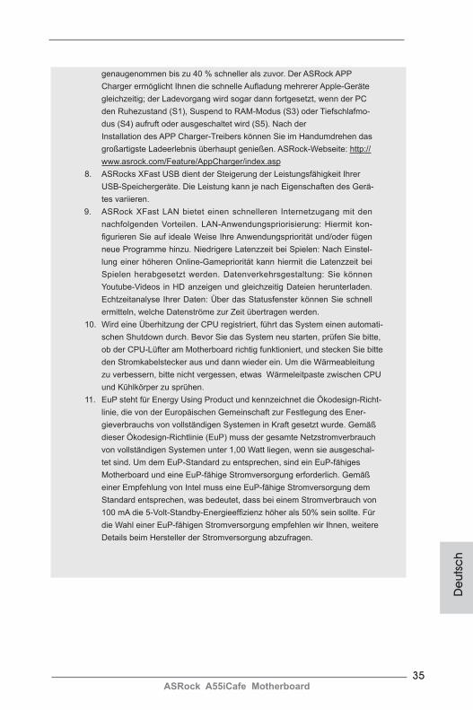
genaugenommen bis zu 40 % schneller als zuvor. Der ASRock APP Charger ermöglicht Ihnen die schnelle Aufladung mehrerer Apple-Geräte
gleichzeitig; der Ladevorgang wird sogar dann fortgesetzt, wenn der PC den Ruhezustand (S1), Suspend to RAM-Modus (S3) oder Tiefschlafmo-dus (S4) aufruft oder ausgeschaltet wird (S5). Nach der
Installation des APP Charger-Treibers können Sie im Handumdrehen das großartigste Ladeerlebnis überhaupt genießen. ASRock-Webseite: http://www.asrock.com/Feature/AppCharger/index.asp
8. ASRocks XFast USB dient der Steigerung der Leistungsfähigkeit Ihrer USB-Speichergeräte. Die Leistung kann je nach Eigenschaften des Gerä-tes variieren.
9. ASRock XFast LAN bietet einen schnelleren Internetzugang mit den nachfolgenden Vorteilen. LAN-Anwendungspriorisierung: Hiermit kon-figurieren Sie auf ideale Weise Ihre Anwendungspriorität und/oder fügen neue Programme hinzu. Niedrigere Latenzzeit bei Spielen: Nach Einstel-lung einer höheren Online-Gamepriorität kann hiermit die Latenzzeit bei Spielen herabgesetzt werden. Datenverkehrsgestaltung: Sie können Youtube-Videos in HD anzeigen und gleichzeitig Dateien herunterladen. Echtzeitanalyse Ihrer Daten: Über das Statusfenster können Sie schnell ermitteln, welche Datenströme zur Zeit übertragen werden.
10. Wird eine Überhitzung der CPU registriert, führt das System einen automati-schen Shutdown durch. Bevor Sie das System neu starten, prüfen Sie bitte, ob der CPU-Lüfter am Motherboard richtig funktioniert, und stecken Sie bitte den Stromkabelstecker aus und dann wieder ein. Um die Wärmeableitung zu verbessern, bitte nicht vergessen, etwas Wärmeleitpaste zwischen CPU und Kühlkörper zu sprühen.
11. EuP steht für Energy Using Product und kennzeichnet die Ökodesign-Richt-linie, die von der Europäischen Gemeinschaft zur Festlegung des Ener-gieverbrauchs von vollständigen Systemen in Kraft gesetzt wurde. Gemäß dieser Ökodesign-Richtlinie (EuP) muss der gesamte Netzstromverbrauch von vollständigen Systemen unter 1,00 Watt liegen, wenn sie ausgeschal-tet sind. Um dem EuP-Standard zu entsprechen, sind ein EuP-fähiges Motherboard und eine EuP-fähige Stromversorgung erforderlich. Gemäß einer Empfehlung von Intel muss eine EuP-fähige Stromversorgung dem Standard entsprechen, was bedeutet, dass bei einem Stromverbrauch von 100 mA die 5-Volt-Standby-Energieeffizienz höher als 50% sein sollte. Für die Wahl einer EuP-fähigen Stromversorgung empfehlen wir Ihnen, weitere Details beim Hersteller der Stromversorgung abzufragen.

36ASRock A55iCafe Motherboard
De
utsch
1.3 Einstellung der JumperDie Abbildung verdeutlicht, wie Jumper gesetzt werden. Werden Pins durch Jumperkappen verdeckt, ist der Jumper “Gebrückt”. Werden keine Pins durch Jumperkappen verdeckt, ist der Jumper “Offen”. Die Abbildung zeigt einen 3-Pin Jumper dessen Pin1 und Pin2 “Ge-brückt” sind, bzw. es befindet sich eine Jumper-Kappe auf diesen beiden Pins.
Jumper Einstellun Beschreibung
CMOS löschen(CLRCMOS1, 3-Pin jumper)(siehe S.2, No. 28)
Hinweis: CLRCMOS1 ermöglicht Ihnen die Löschung der Daten im CMOS. Zum Löschen und Zurücksetzen der Systemparameter auf die Standardeinrichtung schalten Sie den Computer bitte aus und trennen das Netzkabel von der Stromversorgung. Warten Sie 15 Sekunden, schließen Sie dann Pin2 und Pin3 am CLRCMOS1 über einen Jumper fünf Sekunden lang kurz. Sie sollten das CMOS allerdings nicht direkt nach der BIOS-Aktualisierung löschen. Wenn Sie das CMOS nach Abschluss der BIOS-Aktualisierung löschen müssen, fahren Sie zuerst das System hoch. Fahren Sie es dann vor der CMOS-Löschung herunter. Bitte beachten Sie, dass Kennwort, Datum, Uhrzeit, benutzerdefiniertes Profil, 1394 GUID und MAC-Adresse
nur gelöscht werden, wenn die CMOS-Batterie entfernt wird.
CMOS löschen
Default-Einstellung
37ASRock A55iCafe Motherboard
De
utsc
h
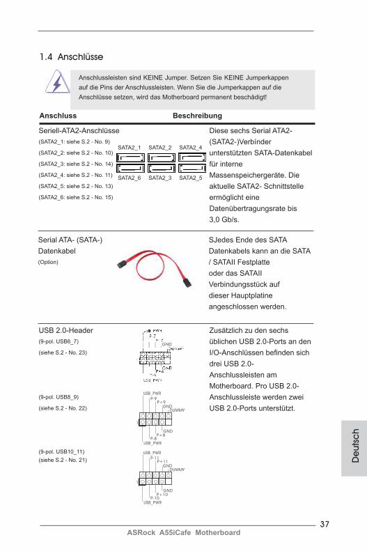
USB 2.0-Header Zusätzlich zu den sechs (9-pol. USB6_7) üblichen USB 2.0-Ports an den (siehe S.2 - No. 23) I/O-Anschlüssen befinden sich drei USB 2.0- Anschlussleisten am Motherboard. Pro USB 2.0- (9-pol. USB8_9) Anschlussleiste werden zwei (siehe S.2 - No. 22) USB 2.0-Ports unterstützt.
(9-pol. USB10_11)(siehe S.2 - No. 21)
Seriell-ATA2-Anschlüsse Diese sechs Serial ATA2- (SATA2_1: siehe S.2 - No. 9) (SATA2-)Verbínder (SATA2_2: siehe S.2 - No. 10) unterstützten SATA-Datenkabel (SATA2_3: siehe S.2 - No. 14) für interne (SATA2_4: siehe S.2 - No. 11) Massenspeichergeräte. Die (SATA2_5: siehe S.2 - No. 13) aktuelle SATA2- Schnittstelle (SATA2_6: siehe S.2 - No. 15) ermöglicht eine Datenübertragungsrate bis 3,0 Gb/s.
1.4 Anschlüsse
Anschlussleisten sind KEINE Jumper. Setzen Sie KEINE Jumperkappen auf die Pins der Anschlussleisten. Wenn Sie die Jumperkappen auf die Anschlüsse setzen, wird das Motherboard permanent beschädigt!
Anschluss Beschreibung
SATA2_6 SATA2_3 SATA2_5
SATA2_1 SATA2_2 SATA2_4
Serial ATA- (SATA-) SJedes Ende des SATA Datenkabel Datenkabels kann an die SATA (Option) / SATAII Festplatte oder das SATAII Verbindungsstück auf dieser Hauptplatine angeschlossen werden.
1
USB_PWRP-8
GND
DUMMY
USB_PWR
P+8
GND
P-9P+9
1
USB_PWRP-10
GND
DUMMY
USB_PWR
P+10
GND
P-11P+11
38ASRock A55iCafe Motherboard
De
utsch
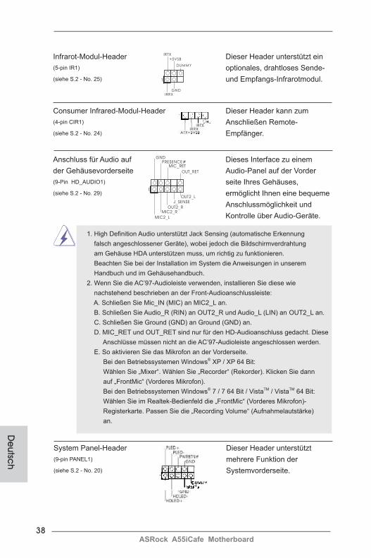
Infrarot-Modul-Header Dieser Header unterstützt ein (5-pin IR1) optionales, drahtloses Sende- (siehe S.2 - No. 25) und Empfangs-Infrarotmodul.
Anschluss für Audio auf Dieses Interface zu einem der Gehäusevorderseite Audio-Panel auf der Vorder (9-Pin HD_AUDIO1) seite Ihres Gehäuses, (siehe S.2 - No. 29) ermöglicht Ihnen eine bequeme Anschlussmöglichkeit und Kontrolle über Audio-Geräte.
Consumer Infrared-Modul-Header Dieser Header kann zum (4-pin CIR1) Anschließen Remote-(siehe S.2 - No. 24) Empfänger.
1
IRTX
+5VSB
DUMMY
IRRXGND
J_SENSE
OUT2_L
1
MIC_RETPRESENCE#
GND
OUT2_RMIC2_R
MIC2_L
OUT_RET
1. High Definition Audio unterstützt Jack Sensing (automatische Erkennung falsch angeschlossener Geräte), wobei jedoch die Bildschirmverdrahtung am Gehäuse HDA unterstützen muss, um richtig zu funktionieren. Beachten Sie bei der Installation im System die Anweisungen in unserem Handbuch und im Gehäusehandbuch. 2. Wenn Sie die AC’97-Audioleiste verwenden, installieren Sie diese wie nachstehend beschrieben an der Front-Audioanschlussleiste: A. Schließen Sie Mic_IN (MIC) an MIC2_L an. B. Schließen Sie Audio_R (RIN) an OUT2_R und Audio_L (LIN) an OUT2_L an. C. Schließen Sie Ground (GND) an Ground (GND) an.
D. MIC_RET und OUT_RET sind nur für den HD-Audioanschluss gedacht. Diese Anschlüsse müssen nicht an die AC’97-Audioleiste angeschlossen werden.
E. So aktivieren Sie das Mikrofon an der Vorderseite. Bei den Betriebssystemen Windows® XP / XP 64 Bit:
Wählen Sie „Mixer“. Wählen Sie „Recorder“ (Rekorder). Klicken Sie dann auf „FrontMic“ (Vorderes Mikrofon). Bei den Betriebssystemen Windows® 7 / 7 64 Bit / VistaTM / VistaTM 64 Bit: Wählen Sie im Realtek-Bedienfeld die „FrontMic“ (Vorderes Mikrofon)- Registerkarte. Passen Sie die „Recording Volume“ (Aufnahmelautstärke) an.
System Panel-Header Dieser Header unterstützt (9-pin PANEL1) mehrere Funktion der (siehe S.2 - No. 20) Systemvorderseite.
39ASRock A55iCafe Motherboard
De
utsc
h
Schließen Sie die Ein-/Austaste, die Reset-Taste und die Systemstatusanzeige am Gehäuse an diesen Header an; befolgen Sie dabei die nachstehenden Hinweise zur Pinbelegung. Beachten Sie die positiven und negativen Pins, bevor Sie die Kabel anschließen.
PWRBTN (Ein-/Ausschalter): Zum Anschließen des Ein-/Ausschalters an der Frontblende des Gehäu ses. Sie können konfigurieren, wie das System mit Hilfe des Ein-/Ausschalters ausgeschaltet werden können soll.
RESET (Reset-Taste): Zum Anschließen der Reset-Taste an der Frontblende des Gehäuses. Mit der Reset-Taste können Sie den Computer im Falle eines Absturzes neu starten.
PLED (Systembetriebs-LED): Zum Anschließen der Betriebsstatusanzeige an der Frontblende des Gehäuses. Die LED leuchtet, wenn das System in Betrieb ist. Die LED blinkt, wenn sich das System im Ruhezustand S1 befindet. Die LED schaltet sich aus, wenn sich das System in den Modi S3/S4 befindet oder ausgeschaltet ist (S5).
HDLED (Festplattenaktivitäts-LED): Zum Anschließen der Festplattenaktivitäts-LED an der Frontblende des Gehäuses. Die LED leuchtet, wenn die Festplatte Daten liest oder schreibt.
Das Design der Frontblende kann je nach Gehäuse variiere. Ein Frontblendenmodul besteht hauptsächlich aus einer Ein-/Austaste, einer Reset-Taste, einer Betriebs-LED, einer Festplattenaktivitäts-LED, Lautsprechern, etc. Stellen Sie beim Anschließen des Frontblendenmoduls Ihres Gehäuses an diesem Header sicher, dass die Kabel- und Pinbelegung korrekt übereinstimmen.
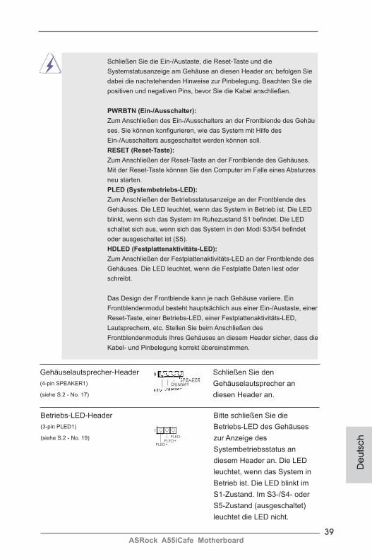
Gehäuselautsprecher-Header Schließen Sie den (4-pin SPEAKER1) Gehäuselautsprecher an (siehe S.2 - No. 17) diesen Header an.
1
PLED+PLED+
PLED-
Betriebs-LED-Header Bitte schließen Sie die (3-pin PLED1) Betriebs-LED des Gehäuses(siehe S.2 - No. 19) zur Anzeige des Systembetriebsstatus an diesem Header an. Die LED leuchtet, wenn das System in Betrieb ist. Die LED blinkt im S1-Zustand. Im S3-/S4- oder S5-Zustand (ausgeschaltet) leuchtet die LED nicht.
40ASRock A55iCafe Motherboard
De
utsch
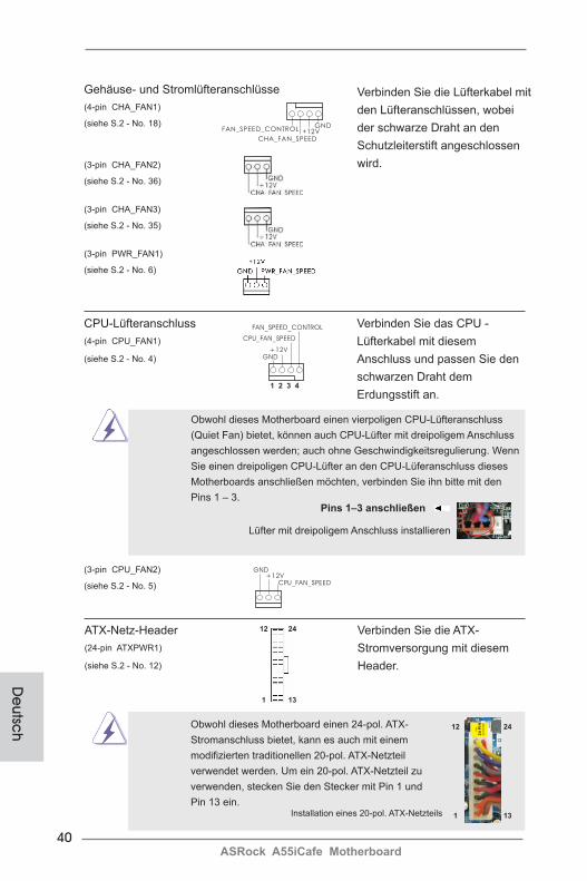
Gehäuse- und Stromlüfteranschlüsse(4-pin CHA_FAN1) (siehe S.2 - No. 18)
(3-pin CHA_FAN2) (siehe S.2 - No. 36)
(3-pin CHA_FAN3) (siehe S.2 - No. 35)
(3-pin PWR_FAN1) (siehe S.2 - No. 6)
Verbinden Sie die Lüfterkabel mit den Lüfteranschlüssen, wobei der schwarze Draht an den Schutzleiterstift angeschlossen wird.
CPU-Lüfteranschluss Verbinden Sie das CPU - (4-pin CPU_FAN1) Lüfterkabel mit diesem (siehe S.2 - No. 4) Anschluss und passen Sie den schwarzen Draht dem Erdungsstift an.
Pins 1–3 anschließen
Lüfter mit dreipoligem Anschluss installieren
Obwohl dieses Motherboard einen vierpoligen CPU-Lüfteranschluss (Quiet Fan) bietet, können auch CPU-Lüfter mit dreipoligem Anschluss angeschlossen werden; auch ohne Geschwindigkeitsregulierung. Wenn Sie einen dreipoligen CPU-Lüfter an den CPU-Lüferanschluss dieses Motherboards anschließen möchten, verbinden Sie ihn bitte mit den Pins 1 – 3.
GND+12V
CPU_FAN_SPEED
FAN_SPEED_CONTROL
1 2 3 4
GND+12V
CPU_FAN_SPEED
(3-pin CPU_FAN2) (siehe S.2 - No. 5)
GND+12V
CHA_FAN_SPEED
FAN_SPEED_CONTROL
ATX-Netz-Header Verbinden Sie die ATX- (24-pin ATXPWR1) Stromversorgung mit diesem (siehe S.2 - No. 12) Header.
Installation eines 20-pol. ATX-Netzteils
Obwohl dieses Motherboard einen 24-pol. ATX- Stromanschluss bietet, kann es auch mit einem modifizierten traditionellen 20-pol. ATX-Netzteil verwendet werden. Um ein 20-pol. ATX-Netzteil zu verwenden, stecken Sie den Stecker mit Pin 1 und Pin 13 ein.
12
1
24
13
12
1
24
13
41ASRock A55iCafe Motherboard
De
utsc
h
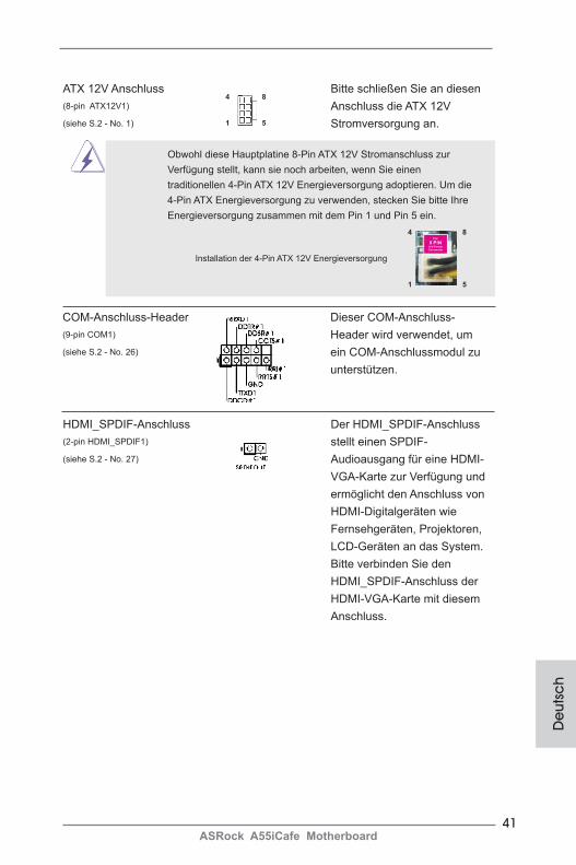
Installation der 4-Pin ATX 12V Energieversorgung
Obwohl diese Hauptplatine 8-Pin ATX 12V Stromanschluss zur Verfügung stellt, kann sie noch arbeiten, wenn Sie einen traditionellen 4-Pin ATX 12V Energieversorgung adoptieren. Um die 4-Pin ATX Energieversorgung zu verwenden, stecken Sie bitte Ihre Energieversorgung zusammen mit dem Pin 1 und Pin 5 ein.
COM-Anschluss-Header Dieser COM-Anschluss- (9-pin COM1) Header wird verwendet, um (siehe S.2 - No. 26) ein COM-Anschlussmodul zu unterstützen.
ATX 12V Anschluss Bitte schließen Sie an diesen (8-pin ATX12V1) Anschluss die ATX 12V (siehe S.2 - No. 1) Stromversorgung an.
4 8
1 5
4 8
1 5
HDMI_SPDIF-Anschluss Der HDMI_SPDIF-Anschluss (2-pin HDMI_SPDIF1) stellt einen SPDIF- (siehe S.2 - No. 27) Audioausgang für eine HDMI- VGA-Karte zur Verfügung und ermöglicht den Anschluss von HDMI-Digitalgeräten wie Fernsehgeräten, Projektoren, LCD-Geräten an das System. Bitte verbinden Sie den HDMI_SPDIF-Anschluss der HDMI-VGA-Karte mit diesem Anschluss.
42ASRock A55iCafe Motherboard
De
utsch
2. BIOS-InformationDas Flash Memory dieses Motherboards speichert das Setup-Utility. Drücken Sie <F2> oder <Del> während des POST (Power-On-Self-Test) um ins Setup zu gelan-gen, ansonsten werden die Testroutinen weiter abgearbeitet. Wenn Sie ins Setup gelangen wollen, nachdem der POST durchgeführt wurde, müssen Sie das System über die Tastenkombination <Ctrl> + <Alt> + <Delete> oder den Reset-Knopf auf der Gehäusevorderseite, neu starten. Natürlich können Sie einen Neustart auch durchführen, indem Sie das System kurz ab- und danach wieder anschalten.Das Setup-Programm ist für eine bequeme Bedienung entwickelt worden. Es ist ein menügesteuertes Programm, in dem Sie durch unterschiedliche Untermenüs scrol-len und die vorab festgelegten Optionen auswählen können. Für detaillierte Infor-mationen zum BIOS-Setup, siehe bitte das Benutzerhandbuch (PDF Datei) auf der Support CD.
3. Software Support CD informationDieses Motherboard unterstützt eine Reiche von Microsoft® Windows® Betriebs-systemen: 7 / 7 64-Bit / VistaTM / VistaTM 64-Bit / XP SP3 / XP 64-Bit. Die Ihrem Motherboard beigefügte Support-CD enthält hilfreiche Software, Treiber und Hilf-sprogramme, mit denen Sie die Funktionen Ihres Motherboards verbessern können Legen Sie die Support-CD zunächst in Ihr CD-ROM-Laufwerk ein. Der Willkom-mensbildschirm mit den Installationsmenüs der CD wird automatisch aufgerufen, wenn Sie die “Autorun”-Funktion Ihres Systems aktiviert haben.Erscheint der Wilkommensbildschirm nicht, so “doppelklicken” Sie bitte auf das File ASSETUP.EXE im BIN-Verzeichnis der Support-CD, um die Menüs aufzurufen.Das Setup-Programm soll es Ihnen so leicht wie möglich machen. Es ist menüges-teuert, d.h. Sie können in den verschiedenen Untermenüs Ihre Auswahl treffen und die Programme werden dann automatisch installiert.
43ASRock A55iCafe Motherboard
1. IntroductionMerci pour votre achat d’une carte mère ASRock A55iCafe, une carte mère très fiable produite selon les critères de qualité rigoureux de ASRock. Elle offre des per-formances excellentes et une conception robuste conformément à l’engagement d’ASRock sur la qualité et la fiabilité au long terme.Ce Guide d’installation rapide présente la carte mère et constitue un guide d’installation pas à pas. Des informations plus détaillées concernant la carte mère pourront être trouvées dans le manuel l’utilisateur qui se trouve sur le CD d’assistance.
Les spécifications de la carte mère et le BIOS ayant pu être mis à jour, le contenu de ce manuel est sujet à des changements sans notification. Au cas où n’importe qu’elle modification intervenait sur ce manuel, la version mise à jour serait disponible sur le site web ASRock sans nouvel avis. Vous trouverez les listes de prise en charge des cartes VGA et CPU également sur le site Web ASRock. Site web ASRock, http://www.asrock.com Si vous avez besoin de support technique en relation avec cette carte mère, veuillez consulter notre site Web pour de plus amples informations particulières au modèle que vous utilisez. www.asrock.com/support/index.asp
1.1 Contenu du paquetCarte mère ASRock A55iCafe (Facteur de forme ATX: 12.0 pouces x 8.0 pouces, 30.5 cm x 20.3 cm)Guide d’installation rapide ASRock A55iCafeCD de soutien ASRock A55iCafeDeux câbles de données de série ATA (SATA) (en option)Un I/O Panel Shield
ASRock vous rappelle...Pour bénéficier des meilleures performances sous Windows® 7 / 7 64 bits / VistaTM / VistaTM 64 bits, il est recommandé de paramétrer l'option BIOS dans Configuration de stockage en mode AHCI. Pour plus de détails sur l'installation BIOS, référez-vous au "Mode d'emploi" sur votre CD de sup-port.
Fra
nça
is
44ASRock A55iCafe Motherboard
Franç
ais
1.2 Spécifications
Format - Facteur de forme ATX: 12.0 pouces x 8.0 pouces, 30.5 cm x 20.3 cm - Accessoires de Carte mère CPU - Support des unités centrales Socket FM1 100W - Conception V4 + 1 Power Phase - Supporte la technologie Cool ‘n’ QuietTM d’AMD - UMI-Link GEN2 Chipsets - AMD A55 FCH (Hudson-D2) Mémoire - Compatible avec la Technologie de Mémoire à Canal Double (voir ATTENTION 1) - 4 x slots DIMM DDR3 - Supporter DDR3 2400+(OC)/1866/1600/1333/ 1066/800 non-ECC, sans amortissement mémoire (voir ATTENTION 2) - Capacité maxi de mémoire système: 32GB (voir ATTENTION 3) Slot d’extension - 1 x slot PCI Express 2.0 x16 (PCIE3 @ mode x16) - 2 x slot PCI Express 2.0 x1 - 2 x slot PCI - Prend en charge AMD Dual Graphics VGA sur carte - Graphiques à l’AMD Radeon HD 65XX/64XX - DirectX 11, nuanceur de pixels 5.0 - mémoire partagée max 512MB (voir ATTENTION 4) - Output de VGA Duel: supporter D-Sub et DVI-D ports par les controleurs de display independents - Prend en charge le DVI avec une résolution maximale jusqu’à 1920x1200 @ 75Hz - Prend en charge le D-Sub avec une résolution maximale jusqu’à 1920x1600 @ 60Hz - Supporte AMD Steady VideoTM: Nouvelle fonctionnalité de traitement post-vidéo pour réduction automatique des tremblements dans les clips vidéo en ligne/maison - Prise en charge de la fonction HDCP avec port DVI - Supporter 1080p Blu-ray(BD)/ lecteur de HD-DVD avec port DVI Audio - 5,1 CH HD Audio (Realtek ALC662 Audio Codec) - Prise en charge de l’audio Premium Blu-ray - Prend en charge THX TruStudioTM
45ASRock A55iCafe Motherboard
LAN - PCIE x1 Gigabit LAN 10/100/1000 Mb/s - Realtek RTL8111E - Supporte du Wake-On-LAN - Prise en charge de la détection de câble LAN - Prend en charge la norme Energy Efficient Ethernet (Ethernet à efficacité énergétique) 802.3az - Supporte PXE Panneau arrière I/O Panel - 1 x port souris PS/2 - 1 x port clavier PS/2 - 1 x port D-Sub - 1 x port DVI-D - 6 x ports USB 2.0 par défaut - 1 x port LAN RJ-45 avec LED (ACT/LED CLIGNOTANTE et LED VITESSE) - Prise HD Audio: Entrée Ligne / Haut-parleur frontal / Microphone Connecteurs - 6 x connecteurs 3,0 Gb/s SATA2, prise en charge des fonctions RAID (RAID 0, RAID 1 et RAID 10), NCQ, AHCI et « Connexion à chaud » - 1 x En-tête du module infrarouge - 1 x Barrette pour module à infrarouges grand public - 1 x En-tête de port COM - 1 x Connecteur HDMI_SPDIF - 1 x Connecteur de LED d’alimentation - Connecteur pour ventilateur de CPU/Châssis/Ventilateur - br. 24 connecteur d’alimentation ATX - br. 8 connecteur d’alimentation 12V ATX - Connecteur audio panneau avant - 3 x En-tête USB 2.0 (prendre en charge 6 ports USB 2.0 supplémentaires) BIOS - 32Mb AMI UEFI Legal BIOS avec support GUI - Support du “Plug and Play” - Compatible pour événements de réveil ACPI 1.1 - Gestion jumperless - Support SMBIOS 2.3.1 - DRAM, VDDP, VDDR, SB Tension Multi-ajustement CD d’assistance - Pilotes, utilitaires, logiciel anti-virus (Version d’essai), CyberLink MediaEspresso 6.5 Trial
Fra
nça
is
46ASRock A55iCafe Motherboard
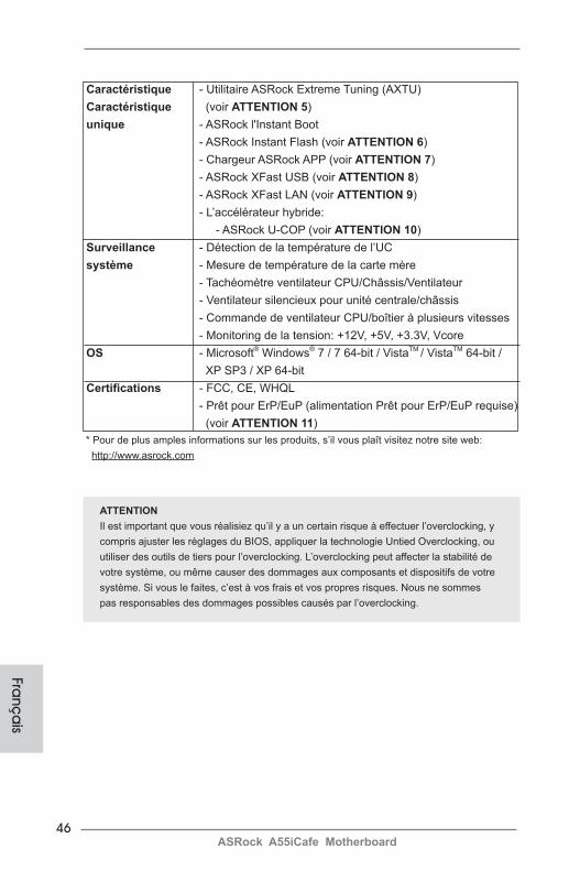
Caractéristique - Utilitaire ASRock Extreme Tuning (AXTU) Caractéristique (voir ATTENTION 5) unique - ASRock l'Instant Boot - ASRock Instant Flash (voir ATTENTION 6) - Chargeur ASRock APP (voir ATTENTION 7) - ASRock XFast USB (voir ATTENTION 8) - ASRock XFast LAN (voir ATTENTION 9) - L’accélérateur hybride: - ASRock U-COP (voir ATTENTION 10) Surveillance - Détection de la température de l’UC système - Mesure de température de la carte mère - Tachéomètre ventilateur CPU/Châssis/Ventilateur - Ventilateur silencieux pour unité centrale/châssis - Commande de ventilateur CPU/boîtier à plusieurs vitesses - Monitoring de la tension: +12V, +5V, +3.3V, Vcore OS - Microsoft® Windows® 7 / 7 64-bit / VistaTM / VistaTM 64-bit / XP SP3 / XP 64-bit Certifications - FCC, CE, WHQL - Prêt pour ErP/EuP (alimentation Prêt pour ErP/EuP requise) (voir ATTENTION 11) * Pour de plus amples informations sur les produits, s’il vous plaît visitez notre site web: http://www.asrock.com
Franç
ais
ATTENTIONIl est important que vous réalisiez qu’il y a un certain risque à effectuer l’overclocking, y compris ajuster les réglages du BIOS, appliquer la technologie Untied Overclocking, ou utiliser des outils de tiers pour l’overclocking. L’overclocking peut affecter la stabilité de votre système, ou même causer des dommages aux composants et dispositifs de votre système. Si vous le faites, c’est à vos frais et vos propres risques. Nous ne sommes pas responsables des dommages possibles causés par l’overclocking.
47ASRock A55iCafe Motherboard
ATTENTION! 1. Cette carte mère supporte la Technologie de Mémoire à Canal Double.
Avant d’intégrer la Technologie de Mémoire à Canal Double, assurez- vous de bien lire le guide d’installation des modules mémoire en page 12 pour réaliser une installation correcte.
2. La prise en charge de fréquences de mémoire de 2400/1866/1600MHz dépend du CPU que vous choisissez. Si vous choisissez des barrettes de mémoire DDR3 2400/1866/1600 sur cette carte mère, veuillez vous référer à la liste des mémoires prises en charge sur notre site Web pour connaître barrettes de mémoire compatibles.
Site Web ASRock http://www.asrock.com3. Du fait des limites du système d’exploitation, la taille mémoire réelle
réservée au système pourra être inférieure à 4 Go sous Windows® 7 /VistaTM / XP. Avec Windows® OS avec CPU 64 bits, il n’y a pas ce genre de limitation.
4. La dimension maximum du memoire partage est definie par le vendeur de jeu de puces et est sujet de changer. Veuillez verifier la AMD website pour les informations recentes SVP.
5. ASRock Extreme Tuning Utility (AXTU) est un utilitaire tout-en-un qui permet de régler précisément différentes fonctions du système, via une
interface facile à utiliser, incluant Moniteur de périphériques, Contrôle du ventilateur et IES. Dans Moniteur de périphériques, il affi che les valeurs principales de votre système. Dans Contrôle du ventilateur, il affi che la vitesse du ventilateur et la température, que vous pouvez ajuster. Dans IES (Intelligent Energy Saver – Fonction intelligente d’économie d’énergie), le contrôleur de la tension peut réduire le nombre de phases de sortie pour améliorer le fonctionnement lorsque les cores du CPU ne sont pas utilisées, sans diminuer les performances de l’ordinateur. Veuillez visiter notre site Web pour plus d’informations sur l’utilisation des fonctions de l’utilitaire ASRock Extreme Tuning Utility (AXTU). Site Web de ASRock : http://www.asrock.com
6. O ASRock Instant Flash é um utilitário de flash do BIOS incorporado na memória Flash ROM. Esta prática ferramenta de actualização do BIOS permite-lhe actualizar o BIOS do sistema sem necessitar de entrar nos sistemas operativos, como o MS-DOS ou o Windows®. Com este
utilitário, poderá premir a tecla <F6> durante o teste de arranque POST ou premir a tecla <F2> para exibir o menu de configuração do BIOS para aceder ao ASRock Instant Flash. Execute esta ferramenta para guardar o novo ficheiro de BIOS numa unidade flash USB, numa disquete ou num disco rígido, em seguida, poderá actualizar o BIOS com apenas alguns cliques sem ter de utilizar outra disquete ou outro complicado
utilitário de flash. Note que a unidade flash USB ou a unidade de disco rígido devem utilizar o sistema de ficheiros FAT32/16/12.
Fra
nça
is

48ASRock A55iCafe Motherboard
Franç
ais
7. Si vous désirez un moyen plus rapide et moins contraignant de recharger vos appareils Apple tels que iPhone/iPod/iPad Touch, ASRock a préparé pour vous la solution idéale - le chargeur ASRock APP. Il suffit d’installer le pilote du chargeur APP, et vous pourrez recharger rapidement votre iPhone à partir de votre ordinateur, jusqu’à 40% plus vite qu’avant. Le chargeur ASRock APP vous permet de charger rapidement et simulta-nément plusieurs appareils Apple, et le chargement continu est même pris en charge lorsque le PC passe en mode Veille (S1), Suspension à la RAM (S3), hibernation (S4) ou hors tension (S5). Lorsque le pilote du chargeur APP est installé, vous découvrez un mode de mise en charge tout à fait inédit.
Site web ASRock : http://www.asrock.com/Feature/AppCharger/index.asp8. ASRock XFast USB permet d’améliorer les performances de votre péri-
phérique de stockage USB. Les performances réelles dépendent des propriétés du périphérique.
9. ASRock XFast LAN fournit un accès Internet plus rapide, avec les avan-tages suivants. Priorisation d’application LAN : Vous pouvez configurer votre priorité d’application idéalement et/ou ajouter des nouveaux pro-grammes. Latence plus basse dans les jeux : Après avoir réglé la priorité de jeux en ligne plus haute, cela peut réduire la latence dans les jeux. Forme du trafic : Vous pouvez regarder des vidéos HD YouTube et té-lécharger simultanément des fichiers. Analyse en temps réel de vos don-nées : Avec la fenêtre d’état, vous pouvez facilement reconnaître les flux de données que vous êtes en train de transférer.
10. Lorsqu’une surchauffe du CPU est détectée, le système s’arrête automatiquement. Avant de redémarrer le système, veuillez vérifier que le ventilateur d’UC sur la carte mère fonctionne correctement et
débranchez le cordon d’alimentation, puis rebranchez-le. Pour améliorer la dissipation de la chaleur, n’oubliez pas de mettre de la pâte thermique entre le CPU le dissipateur lors de l’installation du PC.
11. EuP, qui signifie Energy Using Product (Produit Utilisant de l’Energie), est une disposition établie par l’Union Européenne pour définir la con-sommation de courant pour le système entier. Conformément à la norme EuP, le courant CA total du système entier doit être inférieur à 1 W en mode d’arrêt. Pour être conforme à la norme EuP, une carte mère EuP et une alimentation EuP sont requises. Selon les suggestions d’Intel’, l’alimentation électrique EuP doit correspondre à la norme, qui est que
l’efficacité électrique de 5v en mode de veille doit être supérieure à 50% pour 100 mA de consommation de courant. Pour choisir une alimentation électrique conforme à la norme EuP, nous vous recommandons de con-sulter votre fournisseur de courant pour plus de détails.
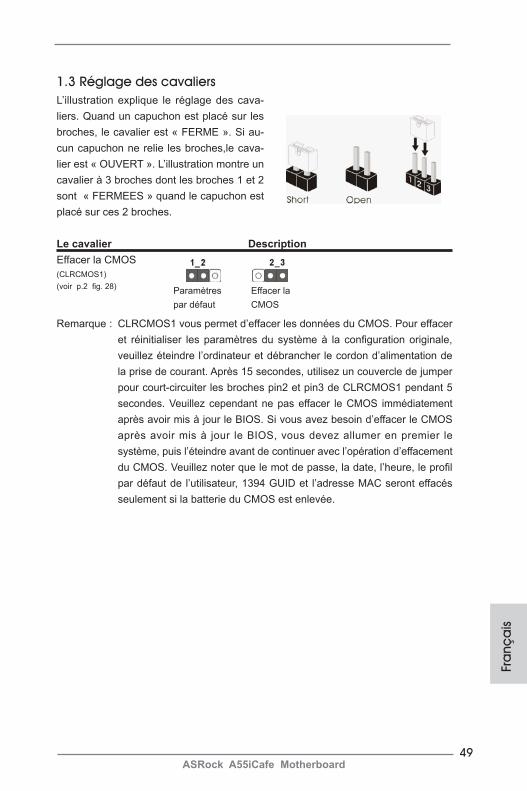
49ASRock A55iCafe Motherboard
Fra
nça
is
1.3 Réglage des cavaliersL’illustration explique le réglage des cava-liers. Quand un capuchon est placé sur les broches, le cavalier est « FERME ». Si au-cun capuchon ne relie les broches,le cava-lier est « OUVERT ». L’illustration montre un cavalier à 3 broches dont les broches 1 et 2 sont « FERMEES » quand le capuchon est placé sur ces 2 broches.
Le cavalier DescriptionEffacer la CMOS(CLRCMOS1)(voir p.2 fig. 28)
Remarque : CLRCMOS1 vous permet d’effacer les données du CMOS. Pour effacer et réinitialiser les paramètres du système à la configuration originale, veuillez éteindre l’ordinateur et débrancher le cordon d’alimentation de la prise de courant. Après 15 secondes, utilisez un couvercle de jumper pour court-circuiter les broches pin2 et pin3 de CLRCMOS1 pendant 5 secondes. Veuillez cependant ne pas effacer le CMOS immédiatement après avoir mis à jour le BIOS. Si vous avez besoin d’effacer le CMOS après avoir mis à jour le BIOS, vous devez allumer en premier le système, puis l’éteindre avant de continuer avec l’opération d’effacement du CMOS. Veuillez noter que le mot de passe, la date, l’heure, le profil par défaut de l’utilisateur, 1394 GUID et l’adresse MAC seront effacés seulement si la batterie du CMOS est enlevée.
Effacer la CMOS
Paramètres par défaut

50ASRock A55iCafe Motherboard
Franç
ais
En-tête USB 2.0 A côté des six ports USB (USB6_7 br.9) 2.0 par défaut sur le panneau (voir p.2 No. 23) E/S, il y a trois embases USB 2.0 sur cette carte mère. Chaque embase USB 2.0 peut prendre en charge 2 ports USB (USB8_9 br.9) 2.0.(voir p.2 No. 22)
(USB10_11 br.9)(voir p.2 No. 21)
Connecteurs Série ATA2 Ces six connecteurs Série (SATA2_1: voir p.2 No. 9) ATA2 (SATA2) prennent en (SATA2_2: voir p.2 No. 10) charge les câbles SATA pour (SATA2_3 voir p.2 No. 14) les périphériques de stockage (SATA2_4 voir p.2 No. 11) internes. L’interface SATA2(SATA2_5 voir p.2 No. 13) actuelle permet des taux (SATA2_6 voir p.2 No. 15) transferts de données pouvant aller jusqu’à 3,0 Gb/s.
1.4 En-têtes et Connecteurs sur Carte
Les en-têtes et connecteurs sur carte NE SONT PAS des cavaliers. NE PAS placer les capuchons de cavalier sur ces en-têtes et con-necteurs. Le fait de placer les capuchons de cavalier sur les en-têtes et connecteurs causera à la carte mère des dommages irré-versibles!
SATA2_6 SATA2_3 SATA2_5
SATA2_1 SATA2_2 SATA2_4
Câble de données Toute cote du cable de data Série ATA (SATA) SATA peut etre connecte au (en option) disque dur SATA / SATAII / ou au connecteur SATAII sur la carte mere.
1
USB_PWRP-8
GND
DUMMY
USB_PWR
P+8
GND
P-9P+9
1
USB_PWRP-10
GND
DUMMY
USB_PWR
P+10
GND
P-11P+11
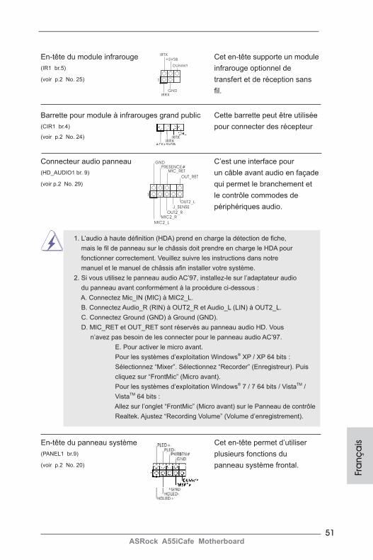
51ASRock A55iCafe Motherboard
Fra
nça
is
En-tête du module infrarouge Cet en-tête supporte un module (IR1 br.5) infrarouge optionnel de (voir p.2 No. 25) transfert et de réception sans fil.
Connecteur audio panneau C’est une interface pour (HD_AUDIO1 br. 9) un câble avant audio en façade (voir p.2 No. 29) qui permet le branchement et le contrôle commodes de périphériques audio.
Barrette pour module à infrarouges grand public Cette barrette peut être utilisée (CIR1 br.4) pour connecter des récepteur (voir p.2 No. 24)
1
IRTX
+5VSB
DUMMY
IRRXGND
J_SENSE
OUT2_L
1
MIC_RETPRESENCE#
GND
OUT2_RMIC2_R
MIC2_L
OUT_RET
1. L’audio à haute définition (HDA) prend en charge la détection de fiche, mais le fil de panneau sur le châssis doit prendre en charge le HDA pour fonctionner correctement. Veuillez suivre les instructions dans notre manuel et le manuel de châssis afin installer votre système. 2. Si vous utilisez le panneau audio AC’97, installez-le sur l’adaptateur audio du panneau avant conformément à la procédure ci-dessous : A. Connectez Mic_IN (MIC) à MIC2_L. B. Connectez Audio_R (RIN) à OUT2_R et Audio_L (LIN) à OUT2_L. C. Connectez Ground (GND) à Ground (GND). D. MIC_RET et OUT_RET sont réservés au panneau audio HD. Vous n’avez pas besoin de les connecter pour le panneau audio AC’97. E. Pour activer le micro avant. Pour les systèmes d’exploitation Windows® XP / XP 64 bits : Sélectionnez “Mixer”. Sélectionnez “Recorder” (Enregistreur). Puis cliquez sur “FrontMic” (Micro avant). Pour les systèmes d’exploitation Windows® 7 / 7 64 bits / VistaTM / VistaTM 64 bits : Allez sur l’onglet “FrontMic” (Micro avant) sur le Panneau de contrôle Realtek. Ajustez “Recording Volume” (Volume d’enregistrement).
En-tête du panneau système Cet en-tête permet d’utiliser (PANEL1 br.9) plusieurs fonctions du (voir p.2 No. 20) panneau système frontal.
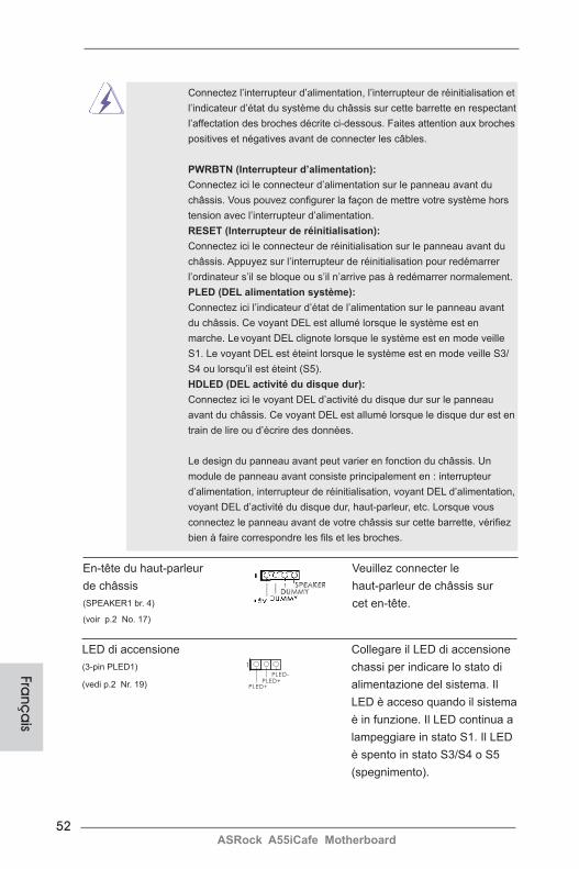
52ASRock A55iCafe Motherboard
Franç
ais
Connectez l’interrupteur d’alimentation, l’interrupteur de réinitialisation et l’indicateur d’état du système du châssis sur cette barrette en respectant l’affectation des broches décrite ci-dessous. Faites attention aux broches positives et négatives avant de connecter les câbles.
PWRBTN (Interrupteur d’alimentation): Connectez ici le connecteur d’alimentation sur le panneau avant du châssis. Vous pouvez configurer la façon de mettre votre système hors tension avec l’interrupteur d’alimentation.
RESET (Interrupteur de réinitialisation): Connectez ici le connecteur de réinitialisation sur le panneau avant du châssis. Appuyez sur l’interrupteur de réinitialisation pour redémarrer l’ordinateur s’il se bloque ou s’il n’arrive pas à redémarrer normalement.
PLED (DEL alimentation système): Connectez ici l’indicateur d’état de l’alimentation sur le panneau avant du châssis. Ce voyant DEL est allumé lorsque le système est en marche. Le voyant DEL clignote lorsque le système est en mode veille S1. Le voyant DEL est éteint lorsque le système est en mode veille S3/ S4 ou lorsqu’il est éteint (S5).
HDLED (DEL activité du disque dur): Connectez ici le voyant DEL d’activité du disque dur sur le panneau avant du châssis. Ce voyant DEL est allumé lorsque le disque dur est en train de lire ou d’écrire des données.
Le design du panneau avant peut varier en fonction du châssis. Un module de panneau avant consiste principalement en : interrupteur d’alimentation, interrupteur de réinitialisation, voyant DEL d’alimentation, voyant DEL d’activité du disque dur, haut-parleur, etc. Lorsque vous connectez le panneau avant de votre châssis sur cette barrette, vérifiez bien à faire correspondre les fils et les broches.
En-tête du haut-parleur Veuillez connecter le de châssis haut-parleur de châssis sur (SPEAKER1 br. 4) cet en-tête.(voir p.2 No. 17)
LED di accensione Collegare il LED di accensione (3-pin PLED1) chassi per indicare lo stato di (vedi p.2 Nr. 19) alimentazione del sistema. Il LED è acceso quando il sistema è in funzione. Il LED continua a lampeggiare in stato S1. Il LED è spento in stato S3/S4 o S5 (spegnimento).
1
PLED+PLED+
PLED-
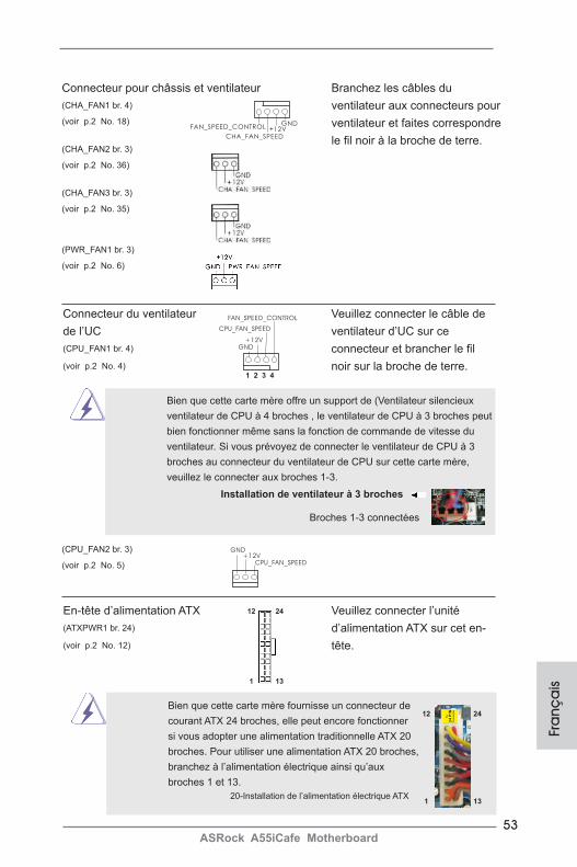
53ASRock A55iCafe Motherboard
Fra
nça
is
Connecteur du ventilateur Veuillez connecter le câble de de l’UC ventilateur d’UC sur ce (CPU_FAN1 br. 4) connecteur et brancher le fil (voir p.2 No. 4) noir sur la broche de terre.
GND+12V
CPU_FAN_SPEED
FAN_SPEED_CONTROL
1 2 3 4
Bien que cette carte mère offre un support de (Ventilateur silencieux ventilateur de CPU à 4 broches , le ventilateur de CPU à 3 broches peut bien fonctionner même sans la fonction de commande de vitesse du ventilateur. Si vous prévoyez de connecter le ventilateur de CPU à 3 broches au connecteur du ventilateur de CPU sur cette carte mère, veuillez le connecter aux broches 1-3.
Installation de ventilateur à 3 broches
Broches 1-3 connectées
Connecteur pour châssis et ventilateur(CHA_FAN1 br. 4) (voir p.2 No. 18)
(CHA_FAN2 br. 3) (voir p.2 No. 36)
(CHA_FAN3 br. 3) (voir p.2 No. 35)
(PWR_FAN1 br. 3) (voir p.2 No. 6)
Branchez les câbles du ventilateur aux connecteurs pour ventilateur et faites correspondre le fil noir à la broche de terre.
GND+12V
CPU_FAN_SPEED
(CPU_FAN2 br. 3) (voir p.2 No. 5)
GND+12V
CHA_FAN_SPEED
FAN_SPEED_CONTROL
En-tête d’alimentation ATX Veuillez connecter l’unité (ATXPWR1 br. 24) d’alimentation ATX sur cet en- (voir p.2 No. 12) tête.
Bien que cette carte mère fournisse un connecteur de courant ATX 24 broches, elle peut encore fonctionner si vous adopter une alimentation traditionnelle ATX 20 broches. Pour utiliser une alimentation ATX 20 broches, branchez à l’alimentation électrique ainsi qu’aux broches 1 et 13.
20-Installation de l’alimentation électrique ATX
12
1
24
13
12
1
24
13
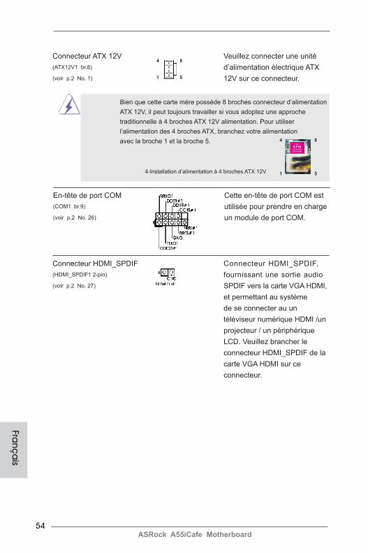
54ASRock A55iCafe Motherboard
Franç
ais
Connecteur ATX 12V Veuillez connecter une unité (ATX12V1 br.8) d’alimentation électrique ATX (voir p.2 No. 1) 12V sur ce connecteur.
4 8
1 5
Bien que cette carte mère possède 8 broches connecteur d’alimentation ATX 12V, il peut toujours travailler si vous adoptez une approche traditionnelle à 4 broches ATX 12V alimentation. Pour utiliser l’alimentation des 4 broches ATX, branchez votre alimentation avec la broche 1 et la broche 5.
4-Installation d’alimentation à 4 broches ATX 12V
En-tête de port COM Cette en-tête de port COM est (COM1 br.9) utilisée pour prendre en charge (voir p.2 No. 26) un module de port COM.
4 8
1 5
Connecteur HDMI_SPDIF Connecteur HDMI_SPDIF, (HDMI_SPDIF1 2-pin) fournissant une sortie audio (voir p.2 No. 27) SPDIF vers la carte VGA HDMI, et permettant au système de se connecter au un téléviseur numérique HDMI /un projecteur / un périphérique LCD. Veuillez brancher le connecteur HDMI_SPDIF de la carte VGA HDMI sur ce connecteur.
55ASRock A55iCafe Motherboard
2. Informations sur le BIOSLa puce Flash Memory sur la carte mère stocke le Setup du BIOS. Lorsque vous démarrez l’ordinateur, veuillez presser <F2> ou <Del> pendant le POST (Power-On-Self-Test) pour entrer dans le BIOS; sinon, le POST continue ses tests de routine. Si vous désirez entrer dans le BIOS après le POST, veuillez redémarrer le système en pressant <Ctl> + <Alt> + <Suppr>, ou en pressant le bouton de reset sur le boîtier du système. Vous pouvez également redémarrer en éteignant le système et en le rallumant. L’utilitaire d’installation du BIOS est conçu pour être convivial. C’est un programme piloté par menu, qui vous permet de faire défiler par ses divers sous-menus et de choisir parmi les choix prédéterminés. Pour des informations détaillées sur le BIOS, veuillez consulter le Guide de l’utilisateur (fichier PDF) dans le CD technique.
3. Informations sur le CD de supportCette carte mère supporte divers systèmes d’exploitation Microsoft® Windows®: 7 / 7 64 bits / VistaTM / VistaTM 64 bits / XP SP3 / XP 64 bits. Le CD technique livré avec cette carte mère contient les pilotes et les utilitaires nécessaires pour amélio-rer les fonctions de la carte mère. Pour utiliser le CD technique, insérez-le dans le lecteur de CD-ROM. Le Menu principal s’affiche automatiquement si “AUTORUN” est activé dans votre ordinateur. Si le Menu principal n’apparaît pas automatique-ment, localisez dans le CD technique le fichier “ASSETUP.EXE” dans le dossier BIN et double-cliquez dessus pour afficher les menus.
Fra
nça
is
56ASRock A55iCafe Motherboard
1. IntroduzioneGrazie per aver scelto una scheda madre ASRock A55iCafe, una scheda madre af-fidabile prodotta secondo i severi criteri di qualità ASRock. Le prestazioni eccellenti e il design robusto si conformano all’impegno di ASRock nella ricerca della qualità e della resistenza. Questa Guida Rapida all’Installazione contiene l’introduzione alla motherboard e la guida passo-passo all’installazione. Informazioni più dettagliate sulla motherboard si possono trovare nel manuale per l’utente presente nel CD di supporto.
Le specifiche della scheda madre e il software del BIOS possono essere aggiornati, pertanto il contenuto di questo manuale può subire variazioni senza preavviso. Nel caso in cui questo manuale sia modificato, la versione aggiornata sarà disponibile sul sito di ASRock senza altro avviso. Sul sito ASRock si possono anche trovare le più recenti schede VGA e gli elenchi di CPU supportate. ASRock website http://www.asrock.com Se si necessita dell’assistenza tecnica per questa scheda madre, visitare il nostro sito per informazioni specifiche sul modello che si sta usando. www.asrock.com/support/index.asp
1.1 Contenuto della confezioneScheda madre ASRock A55iCafe (ATX Form Factor: 12.0-in x 8.0-in, 30.5 cm x 20.3 cm)Guida di installazione rapida ASRock A55iCafeCD di supporto ASRock A55iCafeDue cavi dati Serial ATA (SATA) (opzionali)Un I/O Shield
ASRock vi ricorda...Per ottenere migliori prestazioni in Windows® 7 / 7 64-bit / VistaTM / VistaTM 64-bit, si consiglia di impostare l'opzione BIOS in Storage Configuration (Configurazione di archiviazione) sulla modalità AHCI. Per l'impostazione BIOS, fare riferimento a “User Manual” (Manuale dell'utente) nel CD di supporto per dettagli.Ita
liano
57ASRock A55iCafe Motherboard
Italia
no
1.2 Specifiche
Piattaforma - ATX Form Factor: 12.0-in x 8.0-in, 30.5 cm x 20.3 cm - Design condensatore compatto Processore - Supporto per processori socket FM1 100W - Struttura di fase con alimentazione V4 + 1 - Supporto tecnologia AMD Cool ‘n’ QuietTM
- UMI-Link GEN2 Chipset - AMD A55 FCH (Hudson-D2) Memoria - Supporto tecnologia Dual Channel Memory (vedi ATTENZIONE 1) - 4 x slot DDR3 DIMM - Supporto DDR3 2400+(OC)/1866/1600/1333/1066 /800 non-ECC, momoria senza buffer (vedi ATTENZIONE 2) - Capacità massima della memoria di sistema: 32GB (vedi ATTENZIONE 3) Slot di - 1 x slot PCI Express 2.0 x16 (PCIE3 a modalità x16) espansione - 2 x slot PCI Express 2.0 x1 - 2 x slot PCI - Supporto di AMD Dual Graphics VGA su scheda - Grafica AMD Radeon HD 65XX/64XX - DirectX 11, Pixel Shader 5.0 - Memoria massima condivisa 512MB (vedi ATTENZIONE 4) - Uscita VGA Doppia: supporto porte D-Sub e DVI-D tramite verificatore display indipendente - Supporta DVI con risoluzione massima fino a 1920x1200 @ 75Hz - Supporta D-Sub con risoluzione massima fino a 1920x1600 @ 60Hz - Supporta AMD Steady VideoTM: Nuova capacità di post-elab orazione video per la riduzione automatica delle vibrazioni nei video a casa/on-line - Supporto della funzione HDCP con le porte DVI - Supporto 1080p Blu-ray (BD) / HD-DVD riproduzione con le porte DVI Audio - 5.1 CH HD Audio (Realtek ALC662 Audio Codec) - Supporto audio Blu-ray Premium - Supporto THX TruStudioTM
LAN - PCIE x1 Gigabit LAN 10/100/1000 Mb/s - Realtek RTL8111E - Supporta Wake-On-LAN

58ASRock A55iCafe Motherboard
- Supporta il rilevamento cavo LAN - Supporto di Energy Efficient Ethernet 802.3az - Supporta PXE Pannello I/O Panel posteriore I/O - 1 x porta PS/2 per mouse - 1 x porta PS/2 per tastiera - 1 x Porta D-Sub - 1 x Porta DVI-D - 6 x porte USB 2.0 già integrate - 1 x porte LAN RJ-45 con LED (LED azione/collegamento e LED velocità) - Connettore HD Audio: ingresso linea / cassa frontale / microfono Connettori - 6 x connettori SATA2 3,0 Gb/s, supporto di RAID (RAID 0, RAID 1 e RAID 10) e delle funzioni NCQ, AHCI e “Hot Plug” - 1 x Collettore modulo infrarossi - 1 x Connettore modulo infrarosso consumer - 1 x collettore porta COM - 1 x connettore HDMI_SPDIF - 1 x LED di accensione - Connettore CPU/Chassis/Alimentazione ventola - 24-pin collettore alimentazione ATX - 8-pin connettore ATX 12V - Connettore audio sul pannello frontale - 3 x Collettore USB 2.0 (supporta 6 porte USB 2.0) BIOS - 32Mb AMI UEFI Legal BIOS con interfaccia di supporto - Supporta “Plug and Play” - Compatibile con ACPI 1.1 wake up events - Supporta jumperfree - Supporta SMBIOS 2.3.1 - Regolazione multi-voltaggio DRAM, VDDP, VDDR, SB CD di - Driver, utilità, software antivirus (Versione dimostrativa), supporto CyberLink MediaEspresso 6.5 Trial Caratteristi- - ASRock Extreme Tuning Utility (AXTU) ca speciale (vedi ATTENZIONE 5) - ASRock Instant Boot - ASRock Instant Flash (vedi ATTENZIONE 6) - Caricatore ASRock APP Charger (vedi ATTENZIONE 7) - ASRock XFast USB (vedi ATTENZIONE 8)
Italia
no

59ASRock A55iCafe Motherboard
Italia
no
- ASRock XFast LAN (vedi ATTENZIONE 9) - Booster ibrido: - ASRock U-COP (vedi ATTENZIONE 10) Monitoraggio - Sensore per la temperatura del processore Hardware - Sensore temperatura scheda madre - Indicatore di velocita per la ventola del CPU/Chassis/ Alimentazione - Ventola CPU/Chassis silenziosa - Ventola CPU/chassis con controllo di varie velocità - Voltaggio: +12V, +5V, +3.3V, Vcore Compatibi- - Microsoft® Windows® 7 / 7 64 bit / VistaTM / VistaTM 64 bit lità SO / XP SP3 / XP 64 bit Certificazioni - FCC, CE, WHQL - Predisposto ErP/EuP (è necessaria l’alimentazione predis posta per il sistema ErP/EuP) (vedi ATTENZIONE 11) * Per ulteriori informazioni, prego visitare il nostro sito internet: http://www.asrock.com
AVVISOSi prega di prendere atto che la procedura di overclocking implica dei rischi, come anche la regolazione delle impostazioni del BIOS, l’applicazione della tecnologia Untied Over-clocking Technology, oppure l’uso di strumenti di overclocking forniti da terzi. L’overclocking può influenzare la stabilità del sistema, ed anche provocare danni ai componenti ed alle periferiche del sistema. La procedura è eseguita a proprio rischio ed a proprie spese. Noi non possiamo essere ritenuti responsabili per possibili danni provocati dall’overclocking.
60ASRock A55iCafe Motherboard
ATTENZIONE! 1. Questa scheda madre supporta la tecnologia Dual Channel Memory. Prima
di implementare la tecnologia Dual Channel Memory, assicurarsi di leggere la guida all’installazione dei moduli di memoria, a pagina 12, per seguire un’installazione appropriata.
2. Il fatto che la velocità della memoria da 2400/1866/1600MHz sia supporta-ta o meno, dipende dagli CPU utilizzati. Se si desidera adottare il modulo di memoria DDR3 2400/1866/1600 su questa scheda madre, fare riferimento all’elenco delle memorie supportate nel nostro sito web per scoprire quali sono i moduli compatibili.
Sito web ASRock http://www.asrock.com3. A causa delle limitazioni del sistema operativo, le dimensioni effettive della
memoria possono essere inferiori a 4GB per l’accantonamento riservato all’uso del sistema sotto Windows® 7 / VistaTM / XP. Per Windows® OS con CPU 64-bit, non c’è tale limitazione.
4. La dimensione massima della memoria condivisa viene stabilita dal ven-ditore del chipset ed e‘ soggetta a modificazioni. Prego fare riferimento al sito internet AMD per le ultime informazioni.
5. L’utilità AXTU (ASRock Extreme Tuning Utility) è uno strumento tutto in uno per regolare varie funzioni del sistema in un’interfaccia facile da usare che include monitoraggio hardware, controllo ventola ed IES. Hardware Monitor (Monitoraggio hardware) mostra le letture principa-li del sistema. Fan Control (Controllo ventola) mostra la velocità e la temperatura che possono essere regolate. Il regolatore di tensione di IES (Intelligent Energy Saver) può ridurre il numero di fasi d’uscita per migliorare l’effi cienza quando i core CPU sono inattivi senza sacrifi care le prestazioni di computazione. Vistare il nostro per informazioni sulle procedure operative dell’utilità AXT (ASRock Extreme Tuning Utility).
Sito ASRock: http://www.asrock.com6. ASRock Instant Flash è una utilità Flash BIOS integrata nella Flash ROM.
Questo comodo strumento d’aggiornamento del BIOS permette di aggior-nare il sistema BIOS senza accedere a sistemi operativi come MS-DOS or Windows®. Con questa utilità, si può premere il tasto <F6> durante il POST, oppure il tasto <F2> nel menu BIOS per accedere ad ASRock In-stant Flash. Avviare questo strumento e salvare il nuovo file BIOS nell’unità Flash USB, dischetto (disco floppy) o disco rigido; poi si può aggiornare il BIOS con pochi clic, senza preparare altri dischetti (dischi floppy) o altre complicate utilità Flash. Si prega di notare che l’unità Flash USB o il disco rigido devono usare il File System FAT32/16/12.
7. Se vuoi un modo rapido e indipendente per caricare i dispositivi Apple, come iPhone/iPod/iPad Touch, ASRock ha preparato una soluzione mera-vigliosa: ASRock APP Charger. Basta installare il driver APP Charger per caricare l’iPhone più rapidamente rispetto al computer, con una velocità maggiore del 40%. ASRock APP Charger permette di caricare
simultaneamente molti dispositivi Apple in modo rapido e supporta anche il
Italia
no

61ASRock A55iCafe Motherboard
Italia
no
caricamento continuato quando il PC accede alla modalità di Standby (S1), Sospensione su RAM (S3), Ibernazione (S4) o Spegnimento (S5). Una
volta installato il driver APP Charger si otterranno prodigi e comodità mai avuti prima.
Sito ASRock: http://www.asrock.com/Feature/AppCharger/index.asp8. ASRock XFast USB può accelerare le prestazioni del dispositivo d’archi-
viazione USB. Le prestazioni dipendono dalle proprietà del dispositivo.9. ASRock XFast LAN offre un accesso a Internet più veloce, che compren-
de i seguenti benefici. Priorità alle applicazioni LAN: è possibile configu-rare la priorità assegnata alle applicazioni in modo ideale e/o aggiungere nuovi programmi. Minore latenza nei giochi: dopo avere impostato la priorità dei giochi su un livello più alto, la latenza dei giochi può essere minore. Configurazione del traffico: è possibile seguire video HD su Youtube e scaricare file contemporaneamente. Analisi in tempo reale dei dati: grazie alla finestra di stato, è possibile riconoscere con facilità quali dati si stanno trasferendo in streaming.
10. Se il processore si surriscalda, il sistema si chiude automaticamente. Prima di riavviare il sistema, assicurarsi che la ventolina CPU della scheda madre funzioni correttamente; scollegare e ricollegare il cavo d’alimentazione. Per migliorare la dissipazione del calore, ricordare di applicare l’apposita pasta siliconica tra il processore e il dissipatore quando si installa il sistema.
11. EuP, che sta per Energy Using Product (Prodotto che consuma energia) , era una normativa emanata dall’Unione Europea che definiva il consumo energetico del sistema completo. In base all’EuP, l’alimentazione totale del sistema completo deve essere inferiore a 1,00 W quando è spento. Per soddisfare la norma EuP sono necessari un alimentatore e una sche-da elettrica predisposti EuP. In base ai suggerimenti Intel l’alimentatore predisposto EuP deve soddisfare lo standard secondo cui l’efficienza energetica in standby di 5 v è più alta del 50% con un consumo di corren-te di 100 mA. Per la scelta di un’alimentatore predisposto EuP consiglia-mo di verificare ulteriori dettagli con il produttore.
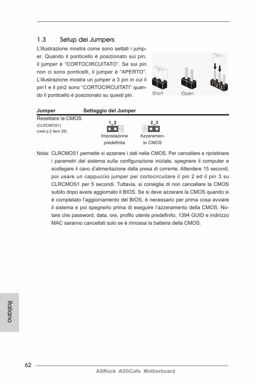
62ASRock A55iCafe Motherboard
Italia
no
1.3 Setup dei Jumpers L’illustrazione mostra come sono settati i jump-er. Quando il ponticello è posizionato sui pin, il jumper è “CORTOCIRCUITATO”. Se sui pin non ci sono ponticelli, il jumper è “APERTO”. L’illustrazione mostra un jumper a 3 pin in cui il pin1 e il pin2 sono “CORTOCIRCUITATI” quan-do il ponticello è posizionato su questi pin.
Jumper Settaggio del JumperResettare la CMOS (CLRCMOS1)(vedi p.2 item 28)
Nota: CLRCMOS1 permette si azzerare i dati nella CMOS. Per cancellare e ripristinare i parametri del sistema sulla configurazione iniziale, spegnere il computer e scollegare il cavo d’alimentazione dalla presa di corrente. Attendere 15 secondi, poi usare un cappuccio jumper per cortocircuitare il pin 2 ed il pin 3 su CLRCMOS1 per 5 secondi. Tuttavia, si consiglia di non cancellare la CMOS subito dopo avere aggiornato il BIOS. Se si deve azzerare la CMOS quando si è completato l’aggiornamento del BIOS, è necessario per prima cosa avviare il sistema e poi spegnerlo prima di eseguire l’azzeramento della CMOS. No-tare che password, data, ore, profilo utente predefinito, 1394 GUID e indirizzo MAC saranno cancellati solo se è rimossa la batteria della CMOS.
Azzeramen-to CMOS
Impostazione predefinita
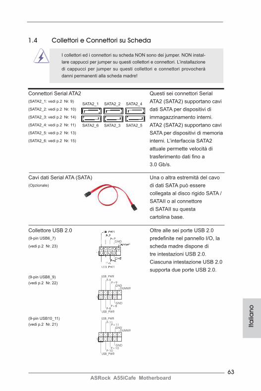
63ASRock A55iCafe Motherboard
Italia
no
Connettori Serial ATA2 Questi sei connettori Serial (SATA2_1: vedi p.2 Nr. 9) ATA2 (SATA2) supportano cavi (SATA2_2: vedi p.2 Nr. 10) dati SATA per dispositivi di (SATA2_3: vedi p.2 Nr. 14) immagazzinamento interni. (SATA2_4: vedi p.2 Nr. 11) ATA2 (SATA2) supportano cavi (SATA2_5: vedi p.2 Nr. 13) SATA per dispositivi di memoria (SATA2_6: vedi p.2 Nr. 15) interni. L’interfaccia SATA2 attuale permette velocità di trasferimento dati fino a 3.0 Gb/s.
Collettore USB 2.0 Oltre alle sei porte USB 2.0(9-pin USB6_7) predefinite nel pannello I/O, la (vedi p.2 Nr. 23) scheda madre dispone di tre intestazioni USB 2.0. Ciascuna intestazione USB 2.0 supporta due porte USB 2.0.(9-pin USB8_9)(vedi p.2 Nr. 22)
(9-pin USB10_11)(vedi p.2 Nr. 21)
1.4 Collettori e Connettori su Scheda
I collettori ed i connettori su scheda NON sono dei jumper. NON instal-lare cappucci per jumper su questi collettori e connettori. L’installazione di cappucci per jumper su questi collettori e connettori provocherà danni permanenti alla scheda madre!
SATA2_6 SATA2_3 SATA2_5
SATA2_1 SATA2_2 SATA2_4
Cavi dati Serial ATA (SATA) Una o altra estremità del cavo (Opzionale) di dati SATA può essere collegata al disco rigido SATA / SATAII o al connettore di SATAII su questa cartolina base.
1
USB_PWRP-8
GND
DUMMY
USB_PWR
P+8
GND
P-9P+9
1
USB_PWRP-10
GND
DUMMY
USB_PWR
P+10
GND
P-11P+11
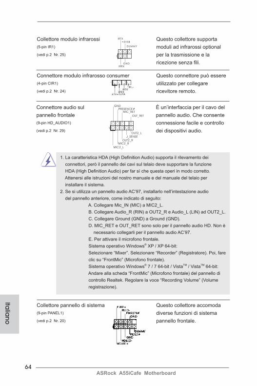
64ASRock A55iCafe Motherboard
Italia
no
Connettore audio sul È un’interfaccia per il cavo del pannello frontale pannello audio. Che consente (9-pin HD_AUDIO1) connessione facile e controllo (vedi p.2 Nr. 29) dei dispositivi audio.
J_SENSE
OUT2_L
1
MIC_RETPRESENCE#
GND
OUT2_RMIC2_R
MIC2_L
OUT_RET
Connettore modulo infrarosso consumer Questo connettore può essere (4-pin CIR1) utilizzato per collegare (vedi p.2 Nr. 24) ricevitore remoto.
Collettore modulo infrarossi Questo collettore supporta (5-pin IR1) moduli ad infrarossi optional (vedi p.2 Nr. 25) per la trasmissione e la ricezione senza fili.
1
IRTX
+5VSB
DUMMY
IRRXGND
1. La caratteristica HDA (High Definition Audio) supporta il rilevamento dei connettori, però il pannello dei cavi sul telaio deve supportare la funzione HDA (High Definition Audio) per far sì che questa operi in modo corretto. Attenersi alle istruzioni del nostro manuale e del manuale del telaio per installare il sistema. 2. Se si utilizza un pannello audio AC’97, installarlo nell’intestazione audio del pannello anteriore, come indicato di seguito:
A. Collegare Mic_IN (MIC) a MIC2_L. B. Collegare Audio_R (RIN) a OUT2_R e Audio_L (LIN) ad OUT2_L. C. Collegare Ground (GND) a Ground (GND).
D. MIC_RET e OUT_RET sono solo per il pannello audio HD. Non è necessario collegarli per il pannello audio AC’97.
E. Per attivare il microfono frontale. Sistema operativo Windows® XP / XP 64-bit: Selezionare “Mixer”. Selezionare “Recorder” (Registratore). Poi, fare clic su “FrontMic” (Microfono frontale). Sistema operativo Windows® 7 / 7 64-bit / VistaTM / VistaTM 64-bit: Andare alla scheda “FrontMic” (Microfono frontale) del pannello di controllo Realtek. Regolare la voce “Recording Volume” (Volume registrazione).
Collettore pannello di sistema Questo collettore accomoda (9-pin PANEL1) diverse funzioni di sistema (vedi p.2 Nr. 20) pannello frontale.
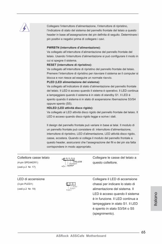
65ASRock A55iCafe Motherboard
Italia
no
Collegare l’interruttore d’alimentazione, l’interruttore di ripristino, l’indicatore di stato del sistema del pannello frontale del telaio a questo header in base all’assegnazione dei pin definita di seguito. Determinare i pin positivi e negativi prima di collegare i cavi.
PWRBTN (interruttore d’alimentazione): Va collegato all’interruttore d’alimentazione del pannello frontale del telaio. Usando l’interruttore d’alimentazione si può configurare il modo in cui si spegne il sistema.
RESET (interruttore di ripristino): Va collegato all’interruttore di ripristino del pannello frontale del telaio. Premere l’interruttore di ripristino per riavviare il sistema se il computer si blocca e non riesce ad eseguire un normale riavvio.
PLED (LED alimentazione del sistema): Va collegato all’indicatore di stato d’alimentazione del pannello frontale del telaio. Il LED è acceso quando il sistema è operativo. Il LED continua a lampeggiare quando il sistema è in stato di standby S1. Il LED è spento quando il sistema è in stato di sospensione /ibernazione S3/S4 oppure spento (S5).
HDLED (LED attività disco rigido): Va collegato al LED attività disco rigido del pannello frontale del telaio. Il LED è acceso quando disco rigido legge e scrive i dati.
Il design del pannello frontale può variare in base ai telai. Il modulo di un pannello frontale può consistere di: interruttore d’alimentazione, interruttore di ripristino, LED d’alimentazione, LED attività disco rigido, casse, eccetera. Quando si collega il modulo del pannello frontale a questo header, assicurarsi che l’assegnazione dei fili e dei pin sia fatta corrispondere in modo appropriato.
Collettore casse telaio Collegare le casse del telaio a (4-pin SPEAKER1) questo collettore.(vedi p.2 Nr. 17)
LED di accensione Collegare il LED di accensione (3-pin PLED1) chassi per indicare lo stato di (vedi p.2 Nr. 19) alimentazione del sistema. Il LED è acceso quando il sistema è in funzione. Il LED continua a lampeggiare in stato S1. Il LED è spento in stato S3/S4 o S5 (spegnimento).
1
PLED+PLED+
PLED-
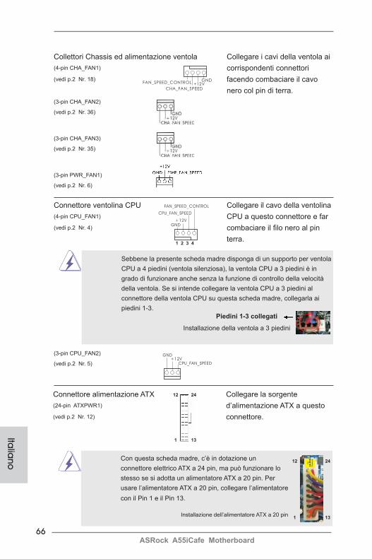
66ASRock A55iCafe Motherboard
Italia
no
Collettori Chassis ed alimentazione ventola Collegare i cavi della ventola ai (4-pin CHA_FAN1) corrispondenti connettori (vedi p.2 Nr. 18) facendo combaciare il cavo nero col pin di terra.(3-pin CHA_FAN2) (vedi p.2 Nr. 36)
(3-pin CHA_FAN3) (vedi p.2 Nr. 35)
(3-pin PWR_FAN1) (vedi p.2 Nr. 6)
Connettore ventolina CPU Collegare il cavo della ventolina (4-pin CPU_FAN1) CPU a questo connettore e far (vedi p.2 Nr. 4) combaciare il filo nero al pin terra.
Sebbene la presente scheda madre disponga di un supporto per ventola CPU a 4 piedini (ventola silenziosa), la ventola CPU a 3 piedini è in grado di funzionare anche senza la funzione di controllo della velocità della ventola. Se si intende collegare la ventola CPU a 3 piedini al connettore della ventola CPU su questa scheda madre, collegarla ai piedini 1-3.
Piedini 1-3 collegati
Installazione della ventola a 3 piedini
GND+12V
CPU_FAN_SPEED
FAN_SPEED_CONTROL
1 2 3 4
GND+12V
CPU_FAN_SPEED
(3-pin CPU_FAN2) (vedi p.2 Nr. 5)
GND+12V
CHA_FAN_SPEED
FAN_SPEED_CONTROL
Installazione dell’alimentatore ATX a 20 pin
Con questa scheda madre, c’è in dotazione un connettore elettrico ATX a 24 pin, ma può funzionare lo stesso se si adotta un alimentatore ATX a 20 pin. Per usare l’alimentatore ATX a 20 pin, collegare l’alimentatore con il Pin 1 e il Pin 13.
Connettore alimentazione ATX Collegare la sorgente (24-pin ATXPWR1) d’alimentazione ATX a questo (vedi p.2 Nr. 12) connettore.
12
1
24
13
12
1
24
13
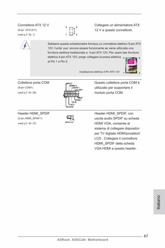
67ASRock A55iCafe Motherboard
Italia
no
Connettore ATX 12 V Collegare un alimentatore ATX (8-pin ATX12V1) 12 V a questo connettore.(vedi p.2 Nr. 1)
4 8
1 5
Sebbene questa schedamadre fornisca un connettore elettrico 8-pin ATX 12V, l‘unita‘ puo‘ ancora essere funzionante se viene utilizzata una fornitura elettrica tradizionale a 4-pin ATX 12V. Per usare tale fornitura elettrica 4-pin ATX 12V, prego collegare la presa elettrica al Pin 1 e Pin 5.
Installazione elettrica 4-Pin ATX 12V
Collettore porta COM Questo collettore porta COM è (9-pin COM1) utilizzato per supportare il (vedi p.2 Nr. 26) modulo porta COM.
4 8
1 5
Header HDMI_SPDIF Header HDMI_SPDIF, con (2-pin HDMI_SPDIF1) uscita audio SPDIF su scheda (vedi p.2 Nr. 27) HDMI VGA, consente al sistema di collegare dispositivi per TV digitale HDMI/proiettori/ LCD . Collegare il connettore HDMI_SPDIF della scheda VGA HDMI a questo header.
68ASRock A55iCafe Motherboard
Italia
no
2. Informazioni sul BIOS La Flash Memory sulla scheda madre contiene le Setup Utility. Quando si avvia il computer, premi <F2> o <Del> durante il Power-On-Self-Test (POST) della Setup utility del BIOS; altrimenti, POST continua con i suoi test di routine. Per entrare il BIOS Setup dopo il POST, riavvia il sistema premendo <Ctl> + <Alt> + <Delete>, o premi il tasto di reset sullo chassis del sistema. Per informazioni più dettagliate circa il Setup del BIOS, fare riferimento al Manuale dell’Utente (PDF file) contenuto nel cd di supporto.
3. Software di supporto e informazioni su
CDQuesta scheda madre supporta vari sistemi operativi Microsoft® Windows®: 7 / 7 64-bit / VistaTM / VistaTM 64-bit / XP SP3 / XP 64-bit. Il CD di supporto a corredo della scheda madre contiene i driver e utilità necessari a potenziare le caratteris-tiche della scheda.Inserire il CD di supporto nel lettore CD-ROM. Se la funzione “AUTORUN” è attivata nel computer, apparirà automaticamente il Menù principale. Se il Menù principale non appare automaticamente, posizionarsi sul file “ASSETUP.EXE” nel CESTINO del CD di supporto e cliccare due volte per visualizzare i menù.
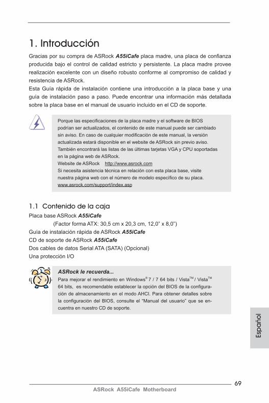
69ASRock A55iCafe Motherboard
Esp
año
l
1. IntroducciónGracias por su compra de ASRock A55iCafe placa madre, una placa de confianza producida bajo el control de calidad estricto y persistente. La placa madre provee realización excelente con un diseño robusto conforme al compromiso de calidad y resistencia de ASRock. Esta Guía rápida de instalación contiene una introducción a la placa base y una guía de instalación paso a paso. Puede encontrar una información más detallada sobre la placa base en el manual de usuario incluido en el CD de soporte.
Porque las especificaciones de la placa madre y el software de BIOS podrían ser actualizados, el contenido de este manual puede ser cambiado sin aviso. En caso de cualquier modificación de este manual, la versión actualizada estará disponible en el website de ASRock sin previo aviso. También encontrará las listas de las últimas tarjetas VGA y CPU soportadas en la página web de ASRock. Website de ASRock http://www.asrock.com Si necesita asistencia técnica en relación con esta placa base, visite nuestra página web con el número de modelo específico de su placa. www.asrock.com/support/index.asp
1.1 Contenido de la cajaPlaca base ASRock A55iCafe (Factor forma ATX: 30,5 cm x 20,3 cm, 12,0” x 8,0”)Guía de instalación rápida de ASRock A55iCafeCD de soporte de ASRock A55iCafeDos cables de datos Serial ATA (SATA) (Opcional)Una protección I/O
ASRock le recuerda...Para mejorar el rendimiento en Windows® 7 / 7 64 bits / VistaTM / VistaTM 64 bits, es recomendable establecer la opción del BIOS de la configura-ción de almacenamiento en el modo AHCI. Para obtener detalles sobre la configuración del BIOS, consulte el “Manual del usuario” que se en-cuentra en nuestro CD de soporte.
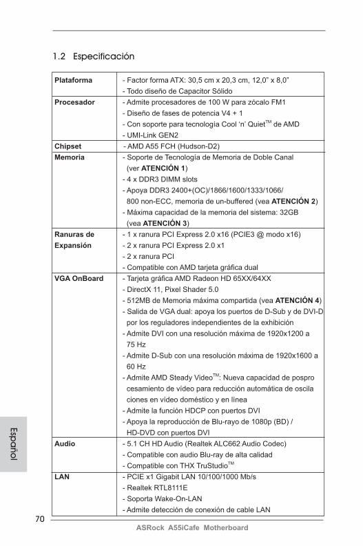
70ASRock A55iCafe Motherboard
Espa
ñol
1.2 Especificación Plataforma - Factor forma ATX: 30,5 cm x 20,3 cm, 12,0” x 8,0” - Todo diseño de Capacitor Sólido Procesador - Admite procesadores de 100 W para zócalo FM1 - Diseño de fases de potencia V4 + 1 - Con soporte para tecnología Cool ‘n’ QuietTM de AMD - UMI-Link GEN2 Chipset - AMD A55 FCH (Hudson-D2) Memoria - Soporte de Tecnología de Memoria de Doble Canal (ver ATENCIÓN 1) - 4 x DDR3 DIMM slots - Apoya DDR3 2400+(OC)/1866/1600/1333/1066/ 800 non-ECC, memoria de un-buffered (vea ATENCIÓN 2) - Máxima capacidad de la memoria del sistema: 32GB (vea ATENCIÓN 3) Ranuras de - 1 x ranura PCI Express 2.0 x16 (PCIE3 @ modo x16) Expansión - 2 x ranura PCI Express 2.0 x1 - 2 x ranura PCI - Compatible con AMD tarjeta gráfica dual VGA OnBoard - Tarjeta gráfica AMD Radeon HD 65XX/64XX - DirectX 11, Pixel Shader 5.0 - 512MB de Memoria máxima compartida (vea ATENCIÓN 4) - Salida de VGA dual: apoya los puertos de D-Sub y de DVI-D por los reguladores independientes de la exhibición - Admite DVI con una resolución máxima de 1920x1200 a 75 Hz - Admite D-Sub con una resolución máxima de 1920x1600 a 60 Hz - Admite AMD Steady VideoTM: Nueva capacidad de pospro cesamiento de vídeo para reducción automática de oscila ciones en vídeo doméstico y en línea - Admite la función HDCP con puertos DVI - Apoya la reproducción de Blu-rayo de 1080p (BD) / HD-DVD con puertos DVI Audio - 5.1 CH HD Audio (Realtek ALC662 Audio Codec) - Compatible con audio Blu-ray de alta calidad - Compatible con THX TruStudioTM LAN - PCIE x1 Gigabit LAN 10/100/1000 Mb/s - Realtek RTL8111E - Soporta Wake-On-LAN - Admite detección de conexión de cable LAN
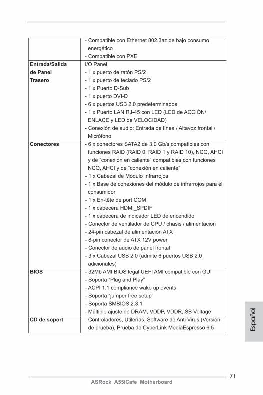
71ASRock A55iCafe Motherboard
Esp
año
l
- Compatible con Ethernet 802.3az de bajo consumo energético - Compatible con PXE Entrada/Salida I/O Panel de Panel - 1 x puerto de ratón PS/2 Trasero - 1 x puerto de teclado PS/2 - 1 x Puerto D-Sub - 1 x puerto DVI-D - 6 x puertos USB 2.0 predeterminados - 1 x Puerto LAN RJ-45 con LED (LED de ACCIÓN/ ENLACE y LED de VELOCIDAD) - Conexión de audio: Entrada de línea / Altavoz frontal / Micrófono Conectores - 6 x conectores SATA2 de 3,0 Gb/s compatibles con funciones RAID (RAID 0, RAID 1 y RAID 10), NCQ, AHCI y de “conexión en caliente” compatibles con funciones NCQ, AHCI y de “conexión en caliente” - 1 x Cabezal de Módulo Infrarrojos - 1 x Base de conexiones del módulo de infrarrojos para el consumidor - 1 x En-tête de port COM - 1 x cabecera HDMI_SPDIF - 1 x cabecera de indicador LED de encendido - Conector de ventilador de CPU / chasis / alimentacion - 24-pin cabezal de alimentación ATX - 8-pin conector de ATX 12V power - Conector de audio de panel frontal - 3 x Cabezal USB 2.0 (admite 6 puertos USB 2.0 adicionales) BIOS - 32Mb AMI BIOS legal UEFI AMI compatible con GUI - Soporta “Plug and Play” - ACPI 1.1 compliance wake up events - Soporta “jumper free setup” - Soporta SMBIOS 2.3.1 - Múltiple ajuste de DRAM, VDDP, VDDR, SB Voltage CD de soport - Controladores, Utilerías, Software de Anti Virus (Versión de prueba), Prueba de CyberLink MediaEspresso 6.5
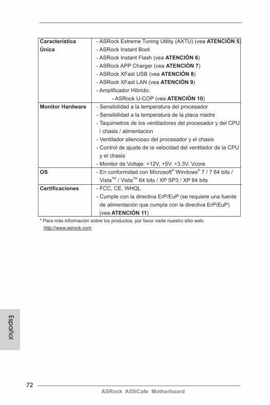
72ASRock A55iCafe Motherboard
Espa
ñol
Característica - ASRock Extreme Tuning Utility (AXTU) (vea ATENCIÓN 5) Única - ASRock Instant Boot - ASRock Instant Flash (vea ATENCIÓN 6) - ASRock APP Charger (vea ATENCIÓN 7) - ASRock XFast USB (vea ATENCIÓN 8) - ASRock XFast LAN (vea ATENCIÓN 9) - Amplificador Híbrido: - ASRock U-COP (vea ATENCIÓN 10) Monitor Hardware - Sensibilidad a la temperatura del procesador - Sensibilidad a la temperatura de la placa madre - Taquimetros de los ventiladores del procesador y del CPU / chasis / alimentacion - Ventilador silencioso del procesador y el chasis - Control de ajuste de la velocidad del ventilador de la CPU y el chasis - Monitor de Voltaje: +12V, +5V, +3.3V, Vcore OS - En conformidad con Microsoft® Windows® 7 / 7 64 bits / VistaTM / VistaTM 64 bits / XP SP3 / XP 64 bits Certificaciones - FCC, CE, WHQL - Cumple con la directiva ErP/EuP (se requiere una fuente de alimentación que cumpla con la directiva ErP/EuP) (vea ATENCIÓN 11) * Para más información sobre los productos, por favor visite nuestro sitio web: http://www.asrock.com
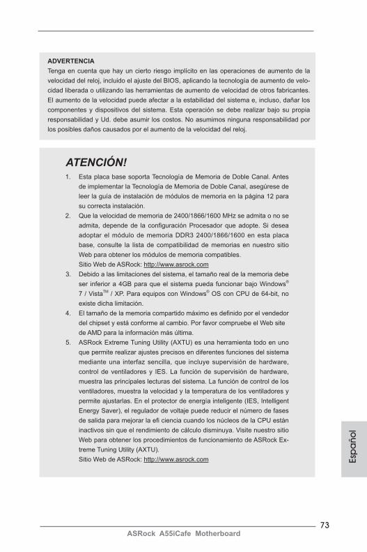
73ASRock A55iCafe Motherboard
Esp
año
l
ATENCIÓN!1. Esta placa base soporta Tecnología de Memoria de Doble Canal. Antes
de implementar la Tecnología de Memoria de Doble Canal, asegúrese de leer la guía de instalación de módulos de memoria en la página 12 para su correcta instalación.
2. Que la velocidad de memoria de 2400/1866/1600 MHz se admita o no se admita, depende de la configuración Procesador que adopte. Si desea adoptar el módulo de memoria DDR3 2400/1866/1600 en esta placa base, consulte la lista de compatibilidad de memorias en nuestro sitio Web para obtener los módulos de memoria compatibles.
Sitio Web de ASRock: http://www.asrock.com3. Debido a las limitaciones del sistema, el tamaño real de la memoria debe
ser inferior a 4GB para que el sistema pueda funcionar bajo Windows® 7 / VistaTM / XP. Para equipos con Windows® OS con CPU de 64-bit, no existe dicha limitación.
4. El tamaño de la memoria compartido máximo es definido por el vendedor del chipset y está conforme al cambio. Por favor compruebe el Web site de AMD para la información más última.
5. ASRock Extreme Tuning Utility (AXTU) es una herramienta todo en uno que permite realizar ajustes precisos en diferentes funciones del sistema mediante una interfaz sencilla, que incluye supervisión de hardware, control de ventiladores y IES. La función de supervisión de hardware, muestra las principales lecturas del sistema. La función de control de los ventiladores, muestra la velocidad y la temperatura de los ventiladores y permite ajustarlas. En el protector de energía inteligente (IES, Intelligent Energy Saver), el regulador de voltaje puede reducir el número de fases de salida para mejorar la efi ciencia cuando los núcleos de la CPU están inactivos sin que el rendimiento de cálculo disminuya. Visite nuestro sitio Web para obtener los procedimientos de funcionamiento de ASRock Ex-treme Tuning Utility (AXTU).
Sitio Web de ASRock: http://www.asrock.com
ADVERTENCIATenga en cuenta que hay un cierto riesgo implícito en las operaciones de aumento de la velocidad del reloj, incluido el ajuste del BIOS, aplicando la tecnología de aumento de velo-cidad liberada o utilizando las herramientas de aumento de velocidad de otros fabricantes. El aumento de la velocidad puede afectar a la estabilidad del sistema e, incluso, dañar los componentes y dispositivos del sistema. Esta operación se debe realizar bajo su propia responsabilidad y Ud. debe asumir los costos. No asumimos ninguna responsabilidad por los posibles daños causados por el aumento de la velocidad del reloj.
74ASRock A55iCafe Motherboard
6. ASRock Instant Flash es una utilidad de programación del BIOS que se encuentra almacenada en la memoria Flash ROM. Esta sencilla her-ramienta de actualización de BIOS le permitirá actualizar el BIOS del sistema sin necesidad de acceder a ningún sistema operativo, como MS-DOS o Windows®. Gracias a esta utilidad, sólo necesitará pulsar <F6> durante la fase POST o pulsar <F2> para acceder al menú de configu-ración del BIOS y a la utilidad ASRock Instant Flash. Ejecute esta herra-mienta y guarde el archivo correspondiente al sistema BIOS nuevo en su unidad flash USB, unidad de disco flexible o disco duro para poder
actualizar el BIOS con sólo pulsar un par de botones, sin necesidad de preparar un disco flexible adicional ni utilizar complicadas utilidades de
programación. Recuerde que la unidad flash USB o disco duro utilizado debe disponer del sistema de archivos FAT32/16/12.
7. Si desea una forma más rápida y menos limitada de cargar sus disposi-tivos de Apple; como por ejemplo iPhone, iPod o iPad Touch, ASRock ha creado una fantástica solución para usted: ASRock APP Charger. Simplemente mediante la instalación del controlador de APP Charger, podrá cargar su iPhone de forma mucho más rápida que antes, hasta un 40%, desde su equipo. ASRock APP Charger le permite cargar de forma rápida muchos dispositivos de Apple simultáneamente e incluso podrá continuar la carga cuando su PC entre en modo de espera (S1), suspen-dido en RAM (S3), modo de hibernación (S4) o se apague (S5). Una vez instalado el controlador de APP Charger, podrá disfrutar fácilmente de una fantástica carga sin precedentes. Sitio web de ASRock: http://www.asrock.com/Feature/AppCharger/index.asp
8. ASRock XFast USB puede aumentar el rendimiento de los dispositivos de almacenamiento USB. El rendimiento depende de las propiedades del dispositivo.
9. ASRock XFast LAN proporciona un acceso a Internet más rápido, que incluye las ventajas que se indican a continuación. Priorización de aplicaciones LAN: Puede configurar la prioridad de las aplicaciones de forma ideal y/o agregar nuevos programas. Menor latencia en los juegos: Después de aumentar la prioridad de los juegos en línea, se puede reducir la latencia en los mismos. Gestionar el tráfico: Puede ver vídeo en alta definición de Youtube y descargar archivos simultáneamente. Análisis de sus datos en tiempo real: Con la ventana de estado, puede reconocer fácilmente qué transmisiones en secuencias se están trans-firiendo actualmente.
10. Cuando la temperatura de CPU está sobre-elevada, el sistema va a apagarse automaticamente. Antes de reanudar el sistema, compruebe
si el ventilador de la CPU de la placa base funciona apropiadamente y desconecte el cable de alimentación, a continuación, vuelva a conec-tarlo. Para mejorar la disipación de calor, acuérdese de aplicar thermal grease entre el procesador y el disipador de calor cuando usted instala el sistema de PC.
Espa
ñol

75ASRock A55iCafe Motherboard
Esp
año
l
11. EuP, siglas de Energy Using Product (Producto que Utiliza Energía), es una disposición regulada por la Unión Europea para establecer el consumo total de energía de un sistema. Según la disposición EuP, la alimentación de CA total para el sistema completo ha de ser inferior a
1,00W en modo apagado. Para cumplir con el estándar EuP, se requi-eren una placa base y una fuente de alimentación que cumplan con la directiva EuP. Según las directrices de Intel, una fuente de alimentación que cumpla con la directiva EuP debe satisfacer el estándar, es decir, la eficiencia de energía de 5v en modo de espera debería ser mayor del 50% con un consumo de corriente de 100mA. Para seleccionar una fuente de alimentación que cumpla la directiva EuP, le recomendamos que consulte con el fabricante de la fuente de alimentación para obtener más detalles.
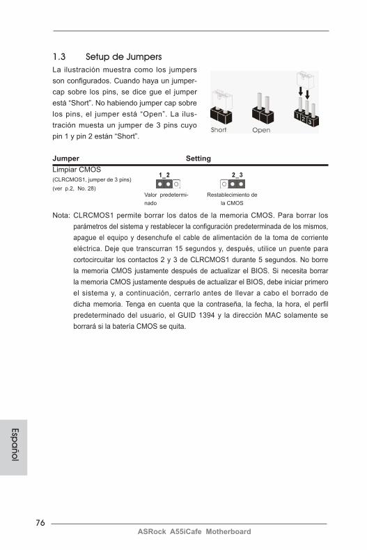
76ASRock A55iCafe Motherboard
Espa
ñol
1.3 Setup de Jumpers La ilustración muestra como los jumpers son configurados. Cuando haya un jumper-cap sobre los pins, se dice gue el jumper está “Short”. No habiendo jumper cap sobre los pins, el jumper está “Open”. La ilus-tración muesta un jumper de 3 pins cuyo pin 1 y pin 2 están “Short”.
Jumper SettingLimpiar CMOS (CLRCMOS1, jumper de 3 pins) (ver p.2, No. 28)
Nota: CLRCMOS1 permite borrar los datos de la memoria CMOS. Para borrar los parámetros del sistema y restablecer la configuración predeterminada de los mismos, apague el equipo y desenchufe el cable de alimentación de la toma de corriente eléctrica. Deje que transcurran 15 segundos y, después, utilice un puente para cortocircuitar los contactos 2 y 3 de CLRCMOS1 durante 5 segundos. No borre la memoria CMOS justamente después de actualizar el BIOS. Si necesita borrar la memoria CMOS justamente después de actualizar el BIOS, debe iniciar primero el sistema y, a continuación, cerrarlo antes de llevar a cabo el borrado de dicha memoria. Tenga en cuenta que la contraseña, la fecha, la hora, el perfil predeterminado del usuario, el GUID 1394 y la dirección MAC solamente se borrará si la batería CMOS se quita.
Valor predetermi-nado
Restablecimiento de la CMOS

77ASRock A55iCafe Motherboard
Esp
año
l
Cabezal USB 2.0 Además de seis puertos(9-pin USB6_7) USB 2.0 predeterminados en el (vea p.2, N. 23) panel de E/S, hay tres bases de conexiones USB 2.0 en esta placa base. Cada una de estas bases de conexiones admite dos puertos USB 2.0.(9-pin USB8_9)(vea p.2, N. 22)
(9-pin USB10_11)(vea p.2, N. 21)
Conexiones de serie ATA2 Estas seis conexiones de (SATA2_1: vea p.2, N. 9) serie ATA2 (SATA2) admiten (SATA2_2: vea p.2, N. 10) cables SATA para dispositivos (SATA2_3: vea p.2, N. 14) de almacenamiento internos. La (SATA2_4: vea p.2, N. 11) interfaz SATA2 actual permite (SATA2_5: vea p.2, N. 13) una velocidad de transferencia (SATA2_6: vea p.2, N. 15) de 3.0 Gb/s.
1.4 Cabezales y Conectores en Placas
Los conectores y cabezales en placa NO son puentes. NO coloque las cubiertas de los puentes sobre estos cabezales y conectores. El colocar cubiertas de puentes sobre los conectores y cabezales provo-cará un daño permanente en la placa base.
1
USB_PWRP-8
GND
DUMMY
USB_PWR
P+8
GND
P-9P+9
1
USB_PWRP-10
GND
DUMMY
USB_PWR
P+10
GND
P-11P+11
SATA2_6 SATA2_3 SATA2_5
SATA2_1 SATA2_2 SATA2_4
Cable de datos de Cualquier extremo del cable de serie ATA (SATA) los datos de SATA puede ser (Opcional) conectado con el disco duro de SATA / SATAII o el conectador de SATAII en esta placa base.
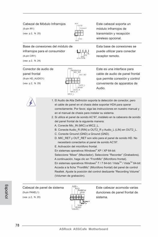
78ASRock A55iCafe Motherboard
Espa
ñol
Cabezal de Módulo Infrarrojos Este cabezal soporta un (5-pin IR1) módulo infrarrojos de (vea p.2, N. 25) transmisión y recepción wireless opcional.
Conector de audio de Este es una interface para panel frontal cable de audio de panel frontal (9-pin HD_AUDIO1) que permite conexión y control (vea p.2, N. 29) conveniente de apparatos de Audio.
Base de conexiones del módulo de Esta base de conexiones se infrarrojos para el consumidor puede utilizar para conectar (4-pin CIR1) receptor remoto. (vea p.2, N. 24)
1. El Audio de Alta Definición soporta la detección de conector, pero el cable de panel en el chasis debe soportar HDA para operar correctamente. Por favor, siga las instrucciones en nuestro manual y en el manual de chasis para instalar su sistema. 2. Si utiliza el panel de sonido AC’97, instálelo en la cabecera de sonido del panel frontal de la siguiente manera: A. Conecte Mic_IN (MIC) a MIC2_L. B. Conecte Audio_R (RIN) a OUT2_R y Audio_L (LIN) en OUT2_L. C. Conecte Ground (GND) a Ground (GND).
D. MIC_RET y OUT_RET son sólo para el panel de sonido HD. No necesitará conectarlos al panel de sonido AC’97.
E. Activación del micrófono frontal. En sistemas operativos Windows® XP / XP 64-bit: Seleccione “Mixer” (Mezclador). Seleccione “Recorder” (Grabadora). A continuación, haga clic en “FrontMic” (Micrófono frontal). En sistemas operativos Windows® 7 / 7 64-bit / VistaTM / VistaTM 64-bit: Acceda a la ficha “FrontMic” (Micrófono frontal) del panel de control Realtek. Ajuste la posición del control deslizante “Recording Volume” (Volumen de grabación).
1
IRTX
+5VSB
DUMMY
IRRXGND
J_SENSE
OUT2_L
1
MIC_RETPRESENCE#
GND
OUT2_RMIC2_R
MIC2_L
OUT_RET
Cabezal de panel de sistema Este cabezar acomoda varias (9-pin PANEL1) dunciones de panel frontal de (vea p.2, N. 20) sistema.
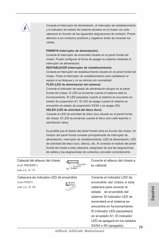
79ASRock A55iCafe Motherboard
Esp
año
l
Conecte el interruptor de alimentación, el interruptor de restablecimiento y el indicador de estado del sistema situados en el chasis con esta cabecera en función de las siguientes asignaciones de contacto. Preste atención a los contactos positivos y negativos antes de conectar los cables.
PWRBTN (interruptor de alimentación): Conecte el interruptor de encendido situado en el panel frontal del chasis. Puede configurar la forma de apagar su sistema mediante el interruptor de alimentación.
RESTABLECER (interruptor de restablecimiento): Conecte el interruptor de restablecimiento situado en el panel frontal del chasis. Pulse el interruptor de restablecimiento para restablecer el equipo si se bloquea y no se reinicia con normalidad.
PLED (LED de alimentación del sistema): Conecte el indicador de estado de alimentación situado en el panel frontal del chasis. El LED se enciende cuando el sistema esté en funcionamiento. El LED parpadea cuando el sistema se encuentre en estado de suspensión S1. El LED se apaga cuando el sistema se encuentre en estado de suspensión S3/S4 o se apaga (S5).
HDLED (LED de actividad del disco duro): Conecte el LED de actividad de disco duro situado en el panel frontal del chasis. El LED se enciende cuando el disco duro esté leyendo o escribiendo datos.
Es posible que el diseño del panel frontal varíe en función del chasis. Un módulo del panel frontal consiste principalmente de interruptor de alimentación, interruptor de restablecimiento, LED de alimentación, LED de actividad del disco duro, altavoz, etc. Al conectar el módulo del panel frontal del chasis a esta cabecera, asegúrese de que las asignaciones de cables y las asignaciones de contactos coincidan correctamente.
Cabezal del altavoz del chasis Conecte el altavoz del chasis a (4-pin SPEAKER1) su cabezal.(vea p.2, N. 17)
Cabecera de indicador LED de encendido Conecte el indicador LED de (3-pin PLED1) encendido del chasis a esta (vea p.2, N. 19) cabecera para conocer el estado de encendido del sistema. El indicador LED se encenderá si el sistema se encuentra en funcionamiento. El indicador LED parpadeará en el estado S1. El indicador LED se apagará en los estados S3/S4 o S5 (apagado).
1
PLED+PLED+
PLED-
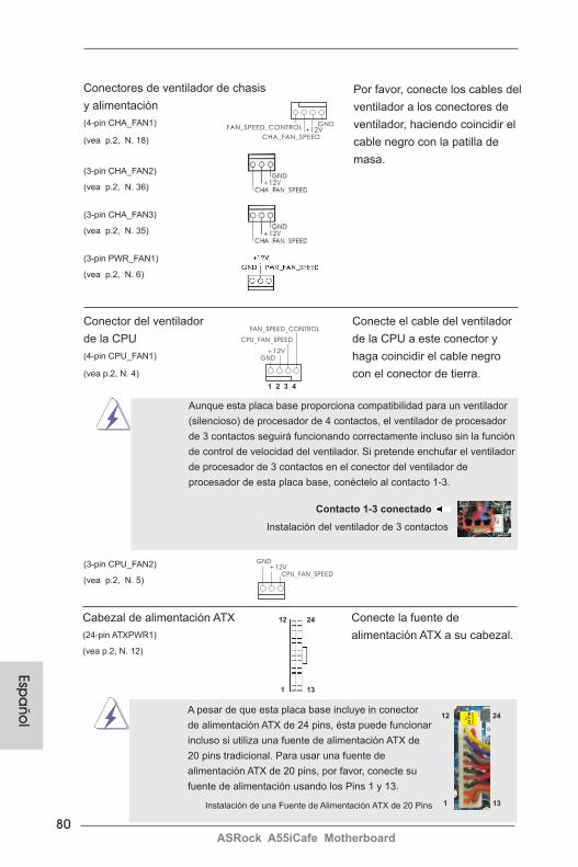
80ASRock A55iCafe Motherboard
Espa
ñol
Conectores de ventilador de chasis y alimentación(4-pin CHA_FAN1) (vea p.2, N. 18)
(3-pin CHA_FAN2) (vea p.2, N. 36)
(3-pin CHA_FAN3) (vea p.2, N. 35)
(3-pin PWR_FAN1) (vea p.2, N. 6)
Por favor, conecte los cables del ventilador a los conectores de ventilador, haciendo coincidir el cable negro con la patilla de masa.
Aunque esta placa base proporciona compatibilidad para un ventilador (silencioso) de procesador de 4 contactos, el ventilador de procesador de 3 contactos seguirá funcionando correctamente incluso sin la función de control de velocidad del ventilador. Si pretende enchufar el ventilador de procesador de 3 contactos en el conector del ventilador de procesador de esta placa base, conéctelo al contacto 1-3.
Contacto 1-3 conectado
Instalación del ventilador de 3 contactos
Conector del ventilador Conecte el cable del ventilador de la CPU de la CPU a este conector y (4-pin CPU_FAN1) haga coincidir el cable negro (vea p.2, N. 4) con el conector de tierra.
GND+12V
CPU_FAN_SPEED
FAN_SPEED_CONTROL
1 2 3 4
GND+12V
CPU_FAN_SPEED
(3-pin CPU_FAN2) (vea p.2, N. 5)
GND+12V
CHA_FAN_SPEED
FAN_SPEED_CONTROL
Instalación de una Fuente de Alimentación ATX de 20 Pins
A pesar de que esta placa base incluye in conector de alimentación ATX de 24 pins, ésta puede funcionar incluso si utiliza una fuente de alimentación ATX de 20 pins tradicional. Para usar una fuente de alimentación ATX de 20 pins, por favor, conecte su fuente de alimentación usando los Pins 1 y 13.
Cabezal de alimentación ATX Conecte la fuente de (24-pin ATXPWR1) alimentación ATX a su cabezal.(vea p.2, N. 12)
12
1
24
13
12
1
24
13

81ASRock A55iCafe Motherboard
Esp
año
l
Aunque esta placa base proporciona un conector de energía de 8-pin ATX 12V, puede todavía trabajar si usted adopta un fuente tradicional de energía de 4-pin ATX 12V. Para usar el fuente de energía de 4-pin ATX 12V, por favor conecte su fuente de energía junto con Pin 1 y Pin 5.
Instalación de Fuente de Energía de 4-Pin ATX 12V
Conector de ATX 12V power Tenga en cuenta que es (8-pin ATX12V1) necesario conectar este (vea p.2, N. 1) conector a una toma de corriente con el enchufe ATX 12V, de modo que proporcione suficiente electricidad. De lo contrario no se podrá encender.
Cabezal del puerto COM Este cabezal del puerto COM (9-pin COM1) se utiliza para admitir un (vea p.2, N. 26) módulo de puerto COM.
4 8
1 5
4 8
1 5
Cabecera HDMI_SPDIF Cabecera HDMI_SPDIF. Ofrece (HDMI_SPDIF1 de 2 pin) una salida SPDIF la tarjeta (vea p.2, N. 27) VGA HDMI, permite al sistema conectarse a dispositivos de TV Digital HDMI / proyectores / Dispositivos LCD. Conecte el conector HDMI_SPDIF de la tarjeta VGA HDMI a esta cabecera.
82ASRock A55iCafe Motherboard
2. BIOS InformaciónEl Flash Memory de la placa madre deposita SETUP Utility. Durante el Power-Up (POST) apriete <F2> o <Del> para entrar en la BIOS. Sí usted no oprime ninguna tecla, el POST continúa con sus rutinas de prueba. Si usted desea entrar en la BIOS después del POST, por favor reinicie el sistema apretando <Ctl> + <Alt> + <Borrar>, o apretando el botón Reset en el panel del ordenador. Para información detallada sobre como configurar la BIOS, por favor refiérase al Manual del Usuario (archivo PDF) contenido en el CD.
3. Información de Software Support CDEsta placa-base soporta diversos tipos de sistema operativo Windows®: 7 / 7 64 bits / VistaTM / VistaTM 64 bits / XP SP3 / XP 64 bits. El CD de instalación que acompaña la placa-base trae todos los drivers y programas utilitarios para instalar y configurar la placa-base. Para iniciar la instalación, ponga el CD en el lector de CD y se des-plegará el Menú Principal automáticamente si «AUTORUN» está habilitado en su computadora.Si el Menú Principal no aparece automáticamente, localice y doble-pulse en el ar-chivo “ASSETUP.EXE” para iniciar la instalación.
Espa
ñol
83ASRock A55iCafe Motherboard
1. ВведениеБлагодарим вас за покупку материнской платы ASRock A55iCafe надежной материнской платы, изготовленной в соответствии с постоянно предъявляемыми ASRock жесткими требованиями к качеству. Она обеспечивает превосходную производительность и отличается отличной конструкцией, которые отражают приверженность ASRock качеству и долговечности.Данное руководство по быстрой установке включает вводную информацию о материнской плате и пошаговые инструкции по ее установке. Более подробные сведения о плате можно найти в руководстве пользователя на компакт-диске поддержки.
Спецификации материнской платы и программное обеспечение BIOS иногда изменяются, поэтому содержание этого руководства может обновляться без уведомления. В случае любых модификаций руководства его новая версия будет размещена на веб-сайте ASRock без специального уведомления. Кроме того, самые свежие списки поддерживаемых модулей памяти и процессоров можно найти на сайте ASRock. Адрес веб-сайта ASRock http://www.asrock.com При необходимости технической поддержки по вопросам данной материнской платы посетите наш веб-сайт для получения информации об используемой модели. www.asrock.com/support/index.asp
1.1 КомплектностьМатеринская плата ASRock A55iCafe (форм-фактор ATX: 12,0 x 8,0 дюйма / 30,5 x 20,3 см)Руководство по быстрой установке ASRock A55iCafeКомпакт-диск поддержки ASRock A55iCafe2 x кабель данных Serial ATA (SATA) (дополнительно)1 x I/O Щит Группы ввода / вывода
Русс
кий
ASRock напоминает...Для обеспечения максимальной производительности ОС Windows®
7 / 7 64-bit / VistaTM / VistaTM 64-bit рекомендуется в BIOS выбрать для параметра Storage Configuration (Конфигурация запоминающего устройства) режим AHCI. Подробные сведения о настройке BIOS см. в руководстве пользователя на прилагаемом компакт-диске.
84ASRock A55iCafe Motherboard
1.2 Спецификации
Платформа - форм-фактор ATX: 12,0 x 8,0 дюйма / 30,5 x 20,3 см - Весь Твердый Конденсаторный проект Процессор - Поддерживаются процессоры для гнезда Socket FM1 с потребляемой мощностью до 100 Вт - Технология V4 + 1 Power Phase Design - Поддержка технологии AMD Cool ‘n’ QuietTM
- UMI-Link GEN2 Набор микросхем - AMD A55 FCH (Hudson-D2) Память - Поддержка технологии Dual Channel DDR3 Memory Technology (см. ОСТОРОЖНО, пункт 1) - 4 x гнезда DDR3 DIMM - Поддержите DDR3 2400+(OC)/1866/1600/1333/1066/800 не- ECC, безбуферная память (см. ОСТОРОЖНО, пункт 2) - Mакс. 32 Гб (см. ОСТОРОЖНО, пункт 3) Гнезда - 1 x гнезда PCI Express 2.0 x16 (PCIE3 в режиме x16) расширения - 2 x гнезда PCI Express 2.0 x1 - 2 x гнезда PCI - поддержка AMD двойные видеокарты Графика - Видеоадаптер AMD Radeon HD 65XX/64XX - Поддержка DirectX 11, Pixel Shader 5.0 - Макс. объем разделяемой памяти 512Мб (см. ОСТОРОЖНО, пункт 4) - Двойственное VGA выходное устройство: поддерживает D-Sub и DVI-D порты через независимый контроллер дисплея - Поддержка DVI с максимальным разрешением до 1920х1200 @ 75 Гц - Поддержка D-Sub с максимальным разрешением до 1920х1600 @ 60 Гц - Поддержка технологии AMD Steady VideoTM: новая функция постобработки видеоизображения для автоматического устранения дрожания при просмотре домашних и онлайновых видеозаписей - Поддержка функции HDCP через разъемы DVI - Подержат Blu-луч 1080p (КОММУТАЦИОННАЯ ДОСКА) / воспроизведение HD-DVD через разъемы DVI Аудиосистема - 5.1 CH HD Аудио (Кодер-декодер Аудио Realtek ALC662) - Поддержка Premium Blu-ray audio - Поддержка технологии THX TruStudioTM
ЛВС - PCIE x 1 Gigabit LAN 10/100/1000 Mb/s - Realtek RTL8111E - поддержка Wake-On-LAN - Поддержка определения кабеля ЛВС - Поддержка энергосберегающего интерфейса Ethernet 802.3az - Поддержка PXE
Русский

85ASRock A55iCafe Motherboard
Русс
кий
Разъемы ввода- I/O Panel вывода на задней - 1 x порт мыши PS/2 панели - 1 x порт клавиатуры PS/2 - 1 x D-Sub порт - 1 x DVI-D порт - 6 x порта USB 2.0 на задней панели в стандартной конфигурации - Разъем 1 x RJ-45 LAN с светодиодным индикатором (индикатор ACT/LINK и индикатор SPEED) - Соединитель звуковой подсистемы: линейный вход / передняя колонка / микрофон Колодки и - 6 x разъема SATA2 3,0 Гбит/с, поддержка функций RAID (RAID 0, плате RAID 1 и RAID 10), NCQ, AHCI и «горячего подключения» - 1 x Колодка инфракрасного модуля - 1 x Датчик пользовательского инфракрасного модуля - 1 x Колодка COM - 1 x Колодка HDMI_SPDIF - 1 x разъем Power LED - соединитель: CPU/Chassis/Power FAN - 24-контактный Колодка питания ATX - 8-контактный Разъем ATX 12 В - Аудиоразъем передней панели - 3 x Колодка USB 2.0 (одна колодка для поддержки 6 дополнительных портов USB 2.0 BIOS - 32Mb AMI UEFI Legal BIOS с поддержкой rpaфичеckoro интеpфeйca поль зователя - поддержка “Plug and Play” - ACPI 1.1, включение по событиям - поддержка режима настройки без перемычек - поддержка SMBIOS 2.3.1 - Регулировка напряжений DRAM, VDDP, VDDR, SB Компактдиск - Драйверы, Утилиты, Антивирус (пробная версия), Пробная версия поддержки программы CyberLink MediaEspresso 6.5 Уникальная - ASRock Extreme Tuning Utility (AXTU) (см. ОСТОРОЖНО, пункт 5) Особенность - ASRock Instant Boot - ASRock Instant Flash (см. ОСТОРОЖНО, пункт 6) - ASRock APP Charger (см. ОСТОРОЖНО, пункт 7) - ASRock XFast USB (см. ОСТОРОЖНО, пункт 8) - ASRock XFast LAN (см. ОСТОРОЖНО, пункт 9) - Hybrid Booster: - ASRock U-COP (см. ОСТОРОЖНО, пункт 10) Контроль - Датчики температуры процессора оборудо- - Датчики температуры корпуса вания - Тахометры вентиляторов CPU/Chassis/Power FAN
86ASRock A55iCafe Motherboard
- Бесшумный вентилятор ЦП/системного блока - Мультиконтроль скорости вентилятора ЦП/Шасси - Контроль напряжения: +12V, +5V, +3.3V, Vcore Операцион - Совместимость с Microsoft® Windows® 7 / 7 64-bit / VistaTM
/ Поддержка 64-разрядной версии VistaTM / XP SP3 / XP 64-bit ные - FCC, CE, WHQL системы - Совместимость с ErP/EuP Ready (требуется блок питания Сертифика- совместимый с ErP/EuP) (см. ОСТОРОЖНО, пункт 11) ты * Для детальной информации продукта, пожалуйста посетите наш вебсайт: http://www.asrock.com
Русский
ВНИМАНИЕСледует понимать, что с оверклокингом связан определенный риск во всех случаях, включая изменение установок BIOS, применение технологии Untied Overclocking или использование инструментов оверклокинга сторонних производителей. Оверклокинг может повлиять на стабильность работы системы и даже вызвать повреждение входящих в нее компонентов и устройств. Приступая к оверклокингу, вы полностью берете на себя все связанные с ним риски и расходы. Мы не будем нести ответственность за любые возможные повреждения в результате оверклокинга.
87ASRock A55iCafe Motherboard
Русс
кий
ОСТОРОЖНО! 1. Данная материнская плата поддерживает технологию двухканальной
памяти Dual Channel Memory Technology. Перед ее использованием не забудьте прочитать инструкции по правильной установке модулей памяти в руководстве по установке (стр. 12).
2. Поддержка частоты памяти 2400/1866/1600 МГц зависит от используемого процессора с разъемом. Для использования модуля памяти DDR3 2400/1866/1600 на этой материнской плате ознакомьтесь со списком поддерживаемых модулей памяти на нашем веб-сайте, чтобы выбрать совместимые модули памяти.
Веб-сайт ASRock http://www.asrock.com3. В силу ограничения операционной системы фактическая емкость
памяти может быть меньше 4Гб для обеспечения резервного места для использования системой Windows® 7 / VistaTM / XP. Таких ограничений нет для Windows® OS с 64-bit центральным процессором.
4. Максимальная совместная емкость памяти определена продавцем микропроцессорного набора и может измениться. Входите в AMD веб-сайт за последние информации, пожалуйста.
5. Служебная программа ASRock Extreme Tuning Utility (AXTU) – это универсальное средство тонкой настройки различных функций системы с удобным и понятным интерфейсом, включающая разделы Hardware Monitor (Наблюдение за оборудованием), Fan Control (Управление вентилятором) and IES (Автоматическое энергосбережение). В разделе Hardware Monitor (Наблюдение за оборудованием) отображаются
основные характеристики аппаратных средств системы. В разделе Fan Control (Управление вентилятором) отображается скорость вентилятора и температура, которые можно регулировать. В разделе IES (Автоматическое энергосбережение) можно настроить регулятор напряжения так, что он будет уменьшать количество работающих линий питания, чтобы поднять КПД системы без ущерба для ее производительности во время простоя ядер ЦПУ. Чтобы узнать, как
работать с программой ASRock Extreme Tuning Utility (AXTU), посетите наш сайт в Интернете. Адрес сайта ASRock: http://www.asrock.com
6. ASRock Instant Flash – программа для прошивки BIOS, встроенная в Flash ROM. Данное средство для обновления BIOS умеет работать без входа в операционные системы, вроде MS-DOS или Windows®. Чтобы запустить программу достаточно нажать <F6> во время самотестирования системы (POST) или войти в BIOS при помощи кнопки <F2> и выбрать пункт ASRock Instant Flash через меню. Запустите программу и сохраните новый BIOS на USB-флэшку,
дискету или жесткий диск. После этого вы сможете оперативно обновить BIOS, без необходимости подготовки дополнительной
дискеты, без установки программы прошивки. Имейте в виду, что USB-флэшка или винчестер должны использовать файловую систему FAT32/16/12.
88ASRock A55iCafe Motherboard
Русский
7. Если вы хотите быстрее и без ограничений заряжать свои устройства Apple, например iPhone, iPod и iPad Touch, компания ASRock приготовила отличное решение для вас – ASRock APP Charger. Просто установив драйвер APP Charger, вы сможете заряжать iPhone от компьютера намного быстрее, ускорение составит до 40%. ASRock APP Charger позволяет быстро заряжать несколько устройств Apple одновременно и даже поддерживает непрерывную зарядку, когда компьютер переходит в режим ожидания (S1), режим ожидания с сохранением данных в ОЗУ (S3), режим гибернации (S4) или режим выключения (S5). Установив драйвер APP Charger, вы испытаете небывалое удобство зарядки.
Веб-сайт ASRock: http://www.asrock.com/Feature/AppCharger/index.asp8. Функция ASRock XFast USB увеличивает скорость работы устройств
USB. Рост скорости зависит от устройства.9. ASRock XFast LAN обеспечивает более быстрый доступ к сети Интернет,
который даст описанные далее преимущества. Установка приоритетов приложений ЛВС: можно задать оптимальный приоритет для своего приложения и/или добавить новые программы. Более низкая латентность в игре: после установки более высокого приоритета игре в режиме
онлайн, может снизиться латентность в игре. Формирование трафика: можно одновременно просматривать видео высокого разрешения на
Youtube и загружать файлы. Анализ данных в реальном времени: в окне состояния можно легко определить, какие потоки данных передаются в данный момент времени.
10. При обнаружении перегрева процессора работа системы автоматически завершается. Прежде чем возобновить работу системы, убедитесь в нормальной работе вентилятора процессора на материнской плате и отсоедините шнур питания, а затем снова подключите его. Чтобы улучшить отвод тепла, не забудьте при сборке компьютера нанести термопасту между процессором и радиатором.
11. EuP расшифровывается как Energy Using Product. Стандарт был разработан Европейским Союзом для определения энергопотребления готовых систем. По требованию EuP система в выключенном состоянии должна потреблять менее 1 Вт энергии. Для соответствия стандарту EuP нужны соответствующие материнская плата и блок питания. Компания
Intel предложила, что совместимый с EuP блок питания должен обеспечивать 50% эффективность линии питания 5V при потреблении 100 мА (в режиме ожидания). Сверьтесь с информацией производителей блоков питания, чтобы выбрать модель с поддержкой EuP.

89ASRock A55iCafe Motherboard
Русс
кий
1.3 Установка перемычекКонфигурация перемычек иллюстрируется на рисунке. Когда перемычка надета на контакты, они называются “замкнутыми” (short). Если на контактах перемычки нет, то они называются “разомкнутыми” (open). На иллюстрации показана 3-контактная перемычка, у которой контакты 1 и 2 замкнуты.
Перемычка Установка ОписаниеОчистка CMOS(CLRCMOS1,3-контактная перемычка)(см. стр. 2, п. 28)
Примечание. Контактная колодка CLRCMOS1 позволяет очистить данные CMOS. Для очистки данных и восстановления заводских системных параметров сначала выключите компьютер и отсоедините сетевую вилку кабеля питания от электророзетки. Выждите не менее 15 секунд и колпачковой перемычкой на 5 секунд перемкните штырьки 2 и 3 контактной колодки CLRCMOS1. Однако не производите очистку CMOS непосредственно после обновления BIOS. Если необходимо очистить CMOS сразу же после окончания обновления BIOS, то, перед очисткой CMOS, необходимо сначала выполнить загрузку системы, а затем завершить ее работу. Примите во внимание, что пароль, дата, время, профиль пользователя по умолчанию, идентификатор 1394 GUID и MAC-адрес будут очищены только тогда, когда будет извлечена из своего гнезда батарейка CMOS.
Стандартные Очистка CMOS
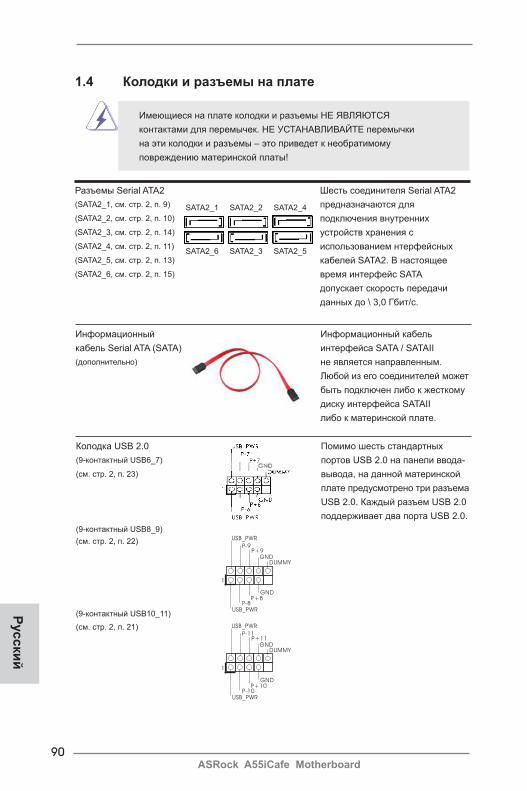
90ASRock A55iCafe Motherboard
Русский
Колодка USB 2.0 Помимо шесть стандартных (9-контактный USB6_7) портов USB 2.0 на панели ввода- (см. стр. 2, п. 23) вывода, на данной материнской плате предусмотрено три разъема USB 2.0. Каждый разъем USB 2.0 поддерживает два порта USB 2.0.(9-контактный USB8_9)(см. стр. 2, п. 22)
(9-контактный USB10_11) (см. стр. 2, п. 21)
Разъемы Serial ATA2 Шесть соединителя Serial ATA2 (SATA2_1, см. стр. 2, п. 9) предназначаются для (SATA2_2, см. стр. 2, п. 10) подключения внутренних (SATA2_3, см. стр. 2, п. 14) устройств хранения с (SATA2_4, см. стр. 2, п. 11) использованием нтерфейсных (SATA2_5, см. стр. 2, п. 13) кабелей SATA2. В настоящее (SATA2_6, см. стр. 2, п. 15) время интерфейс SATA допускает скорость передачи данных до \ 3,0 Гбит/с.
1.4 Колодки и разъемы на плате
Имеющиеся на плате колодки и разъемы НЕ ЯВЛЯЮТСЯ контактами для перемычек. НЕ УСТАНАВЛИВАЙТЕ перемычки на эти колодки и разъемы – это приведет к необратимому повреждению материнской платы!
1
USB_PWRP-8
GND
DUMMY
USB_PWR
P+8
GND
P-9P+9
SATA2_6 SATA2_3 SATA2_5
SATA2_1 SATA2_2 SATA2_4
Информационный Информационный кабель кабель Serial ATA (SATA) интерфейса SATA / SATAII (дополнительно) не является направленным. Любой из его соединителей может быть подключен либо к жесткому диску интерфейса SATAII либо к материнской плате.
1
USB_PWRP-10
GND
DUMMY
USB_PWR
P+10
GND
P-11P+11
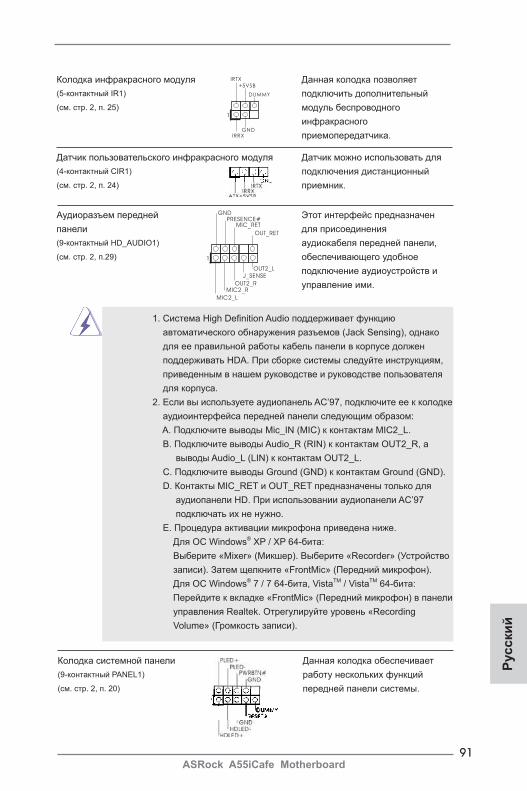
91ASRock A55iCafe Motherboard
Русс
кий
Колодка инфракрасного модуля Данная колодка позволяет (5-контактный IR1) подключить дополнительный (см. стр. 2, п. 25) модуль беспроводного инфракрасного приемопередатчика.
Аудиоразъем передней Этот интерфейс предназначенпанели для присоединения (9-контактный HD_AUDIO1) аудиокабеля передней панели, (см. cтр. 2, п.29) обеспечивающего удобное подключение аудиоустройств и управление ими.
Датчик пользовательского инфракрасного модуля Датчик можно использовать для (4-контактный CIR1) подключения дистанционный (см. стр. 2, п. 24) приемник.
1. Система High Definition Audio поддерживает функцию автоматического обнаружения разъемов (Jack Sensing), однако для ее правильной pаботы кабель панели в корпусе должен поддерживать HDA. При сборке системы следуйте инструкциям, приведенным в нашем руководстве и руководстве пользователя для корпуса. 2. Если вы используете аудиопанель AC’97, подключите ее к колодке аудиоинтерфейса передней панели следующим образом: A. Подключите выводы Mic_IN (MIC) к контактам MIC2_L. B. Подключите выводы Audio_R (RIN) к контактам OUT2_R, а выводы Audio_L (LIN) к контактам OUT2_L. C. Подключите выводы Ground (GND) к контактам Ground (GND).
D. Контакты MIC_RET и OUT_RET предназначены только для аудиопанели HD. При использовании аудиопанели AC’97
подключать их не нужно. E. Процедура активации микрофона приведена ниже.
Для ОС Windows® XP / XP 64-бита: Выберите «Mixer» (Микшер). Выберите «Recorder» (Устройство записи). Затем щелкните «FrontMic» (Передний микрофон). Для ОС Windows® 7 / 7 64-бита, VistaTM / VistaTM 64-бита: Перейдите к вкладке «FrontMic» (Передний микрофон) в панели управления Realtek. Отрегулируйте уровень «Recording Volume» (Громкость записи).
1
IRTX
+5VSB
DUMMY
IRRXGND
J_SENSE
OUT2_L
1
MIC_RETPRESENCE#
GND
OUT2_RMIC2_R
MIC2_L
OUT_RET
Колодка системной панели Данная колодка обеспечивает (9-контактный PANEL1) работу нескольких функций (см. стр. 2, п. 20) передней панели системы.
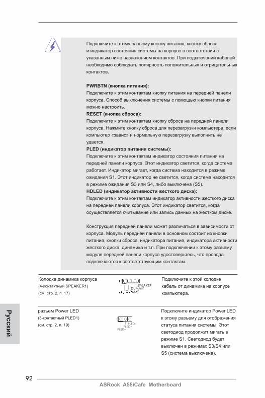
92ASRock A55iCafe Motherboard
Русский
Подключите к этому разъему кнопку питания, кнопку сброса и индикатор состояния системы на корпусе в соответствии с указанным ниже назначением контактов. При подключении кабелей необходимо соблюдать полярность положительных и отрицательных контактов.
PWRBTN (кнопка питания): Подключите к этим контактам кнопку питания на передней панели корпуса. Способ выключения системы с помощью кнопки питания можно настроить.
RESET (кнопка сброса): Подключите к этим контактам кнопку сброса на передней панели корпуса. Нажмите кнопку сброса для перезагрузки компьютера, если компьютер «завис» и нормальную перезагрузку выполнить не удается.
PLED (индикатор питания системы): Подключите к этим контактам индикатор состояния питания на передней панели корпуса. Этот индикатор светится, когда система работает. Индикатор мигает, когда система находится в режиме ожидания S1. Этот индикатор не светится, когда система находится в режиме ожидания S3 или S4, либо выключена (S5).
HDLED (индикатор активности жесткого диска): Подключите к этим контактам индикатор активности жесткого диска на передней панели корпуса. Этот индикатор светится, когда осуществляется считывание или запись данных на жестком диске.
Конструкция передней панели может различаться в зависимости от корпуса. Модуль передней панели в основном состоит из кнопки питания, кнопки сброса, индикатора питания, индикатора активности жесткого диска, динамика и т.п. При подключении к этому разъему модуля передней панели корпуса удостоверьтесь, что провода подключаются к соответствующим контактам.
Колодка динамика корпуса Подключите к этой колодке (4-контактный SPEAKER1) кабель от динамика на корпусе (см. стр. 2, п. 17) компьютера.
разъем Power LED Подключите индикатор Power LED (3-контактный PLED1) к этому разъему для отображения (см. стр. 2, п. 19) статуса питания системы. Этот светодиод продолжит мигать в режиме S1. Светодиод будет выключен в режимах S3/S4 или S5 (система выключена).
1
PLED+PLED+
PLED-
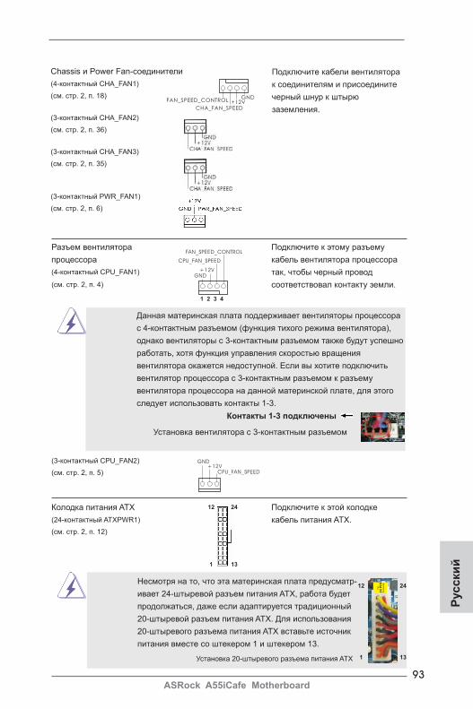
93ASRock A55iCafe Motherboard
Русс
кий
Разъем вентилятора Подключите к этому разъему процессора кабель вентилятора процессора (4-контактный CPU_FAN1) так, чтобы черный провод (см. стр. 2, п. 4) соответствовал контакту земли.
GND+12V
CPU_FAN_SPEED
FAN_SPEED_CONTROL
1 2 3 4
Данная материнская плата поддерживает вентиляторы процессора с 4-контактным разъемом (функция тихого режима вентилятора), однако вентиляторы с 3-контактным разъемом также будут успешно работать, хотя функция управления скоростью вращения вентилятора окажется недоступной. Если вы хотите подключить вентилятор процессора с 3-контактным разъемом к разъему вентилятора процессора на данной материнской плате, для этого следует использовать контакты 1-3.
Установка вентилятора с 3-контактным разъемом
Контакты 1-3 подключены
Подключите кабели вентилятора к соединителям и присоедините черный шнур к штырю заземления.
Chassis и Power Fan-соединители (4-контактный CHA_FAN1) (см. стр. 2, п. 18)
(3-контактный CHA_FAN2) (см. стр. 2, п. 36)
(3-контактный CHA_FAN3) (см. стр. 2, п. 35)
(3-контактный PWR_FAN1) (см. стр. 2, п. 6)
GND+12V
CPU_FAN_SPEED
(3-контактный CPU_FAN2) (см. стр. 2, п. 5)
GND+12V
CHA_FAN_SPEED
FAN_SPEED_CONTROL
Колодка питания ATX Подключите к этой колодке (24-контактный ATXPWR1) кабель питания ATX. (см. стр. 2, п. 12)
Несмотря на то, что эта материнская плата предусматр- ивает 24-штыревой разъем питания ATX, работа будет продолжаться, даже если адаптируется традиционный 20-штыревой разъем питания ATX. Для использования 20-штыревого разъема питания ATX вставьте источник питания вместе со штекером 1 и штекером 13.
Установка 20-штыревого разъема питания ATX
12
1
24
13
12
1
24
13
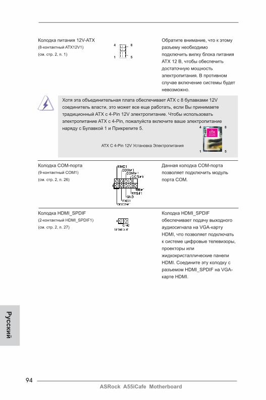
94ASRock A55iCafe Motherboard
Русский
Колодка питания 12V-ATX Обратите внимание, что к этому (8-контактный ATX12V1) разъему необходимо (см. стр. 2, п. 1) подключить вилку блока питания ATX 12 В, чтобы обеспечить достаточную мощность электропитания. В противном случае включение системы будет невозможно.
4 8
1 5
Хотя эта объединительная плата обеспечивает ATX с 8 булавками 12V соединитель власти, это может все еще работать, если Вы принимаете традиционный ATX с 4-Pin 12V электропитание. Чтобы использовать электропитание ATX с 4-Pin, пожалуйста включите ваше электропитание наряду с Булавкой 1 и Прикрепите 5.
ATX С 4-Pin 12V Установка Электропитания
Колодка COM-порта Данная колодка COM-порта (9-контактный COM1) позволяет подключить модуль (см. стр. 2, п. 26) порта COM.
4 8
1 5
Колодка HDMI_SPDIF Колодка HDMI_SPDIF (2-контактный HDMI_SPDIF1) обеспечивает подачу выходного(см. стр. 2, п. 27) аудиосигнала на VGA-карту HDMI, что позволяет подключать к системе цифровые телевизоры, проекторы или жидкокристаллические панели HDMI. Соедините эту колодку с разъемом HDMI_SPDIF на VGA- карте HDMI.
95ASRock A55iCafe Motherboard
Русс
кий
2. Информация о BIOSУтилита настройки BIOS (BIOS Setup) хранится во флэш-памяти на материнской плате. Чтобы войти в программу настройки BIOS Setup, при запуске компьютера нажмите <F2> или <Del> во время самопроверки при включении питания (Power-On-Self-Test – POST). Если этого не сделать, то процедуры тестирования POST будут продолжаться обычным образом. Если вы захотите вызвать BIOS Setup уже после POST, перезапустите систему с помощью клавиш <Ctrl> + <Alt> + <Delete> или нажатия кнопки сброса на корпусе системы. Подробную информацию о программе BIOS Setup вы найдете в Руководстве пользователя (в формате PDF) на компакт-диске поддержки.
3. Информация о компакт-диске поддержки с программным обеспечениемДанная материнская плата поддерживает различные операционные системы Microsoft
®
Windows®: 7 / 7 64-bit / VistaTM / VistaTM 64-bit / XP SP3 / XP 64-bit. Поставляемый вместе
с ней компакт-диск поддержки содержит необходимые драйверы и полезные утилиты, которые расширяют возможности материнской платы.Чтобы начать работу с компакт-диском поддержки, вставьте его в дисковод CD-ROM. Если в вашем компьютере включена функция автозапуска (AUTORUN), то на экране автоматически появится главное меню компакт-диска (Main Menu). Если этого не произошло, найдите в папке BIN на компакт-диске поддержки файл ASSETUP.EXE и дважды щелкните на нем, чтобы открыть меню.

96ASRock A55iCafe Motherboard
1. Giriş ASRock’ın kesintisiz titiz kalite denetimi altında üretilen güvenilir bir anakart olan ASRock A55iCafe anakartını satın aldığınız için teşekkür ederiz. ASRock’ın kalite ve dayanıklılık konusundaki kararlılığına uygun güçlü tasarımıyla mükemmel bir performans sunar.
Bu Hızlı Takma Kılavuzu anakarta giriş ve adım adım takma kılavuzu içerir. Anakart hakkında daha ayrıntılı bilgiyi Destek CD’sinde sunulan kullanıcı kılavuzunda bula-bilirsiniz.
Anakart özellikleri ve BIOS yazılımı güncelleştirilebileceğinden bu kılavuzun içeriği önceden haber verilmeksizin değişebilir. Bu belgede değişiklik yapılması durumun -da, güncelleştirilmiş sürüm ayrıca haber verilmeksizin ASRock web sitesinde sunulur. En son VGA kartlarını ve CPU destek listelerini de ASRock web sitesinde bulabilirsiniz. ASRock web sitesi http://www.asrock.com
Bu anakartla ilgili teknik desteğe ihtiyacınız olursa, kullandığınız modele özel bilgiler için lütfen web sitemizi ziyaret edin. www.asrock.com/support/index.asp
1.1 Paket İçindekiler
ASRock A55iCafe Anakart (ATX Form Faktörü: 12,0-inç x 8,0-inç, 30,5 cm x 20,3 cm)ASRock A55iCafe Hızlı Takma KılavuzuASRock A55iCafe Destek CD’si2 x Seri ATA (SATA) Veri Kablosu (İsteğe Bağlı)1 x G/Ç Panel Kalkanı
ASRock Size Şunu Hatırlatır...Windows® 7 / 7 64-bit / VistaTM / VistaTM 64-bit ile daha iyi performans elde etmek için, Depolama Konfigürasyonundaki BIOS seçeneğini AHCI moduna ayarlamanız tavsiye edilir. BIOS ayarı için, ayrıntıları öğrenmek üzere lütfen destek CD'mizdeki "Kullanıcı Kılavuzu"na bakın.
Türkçe
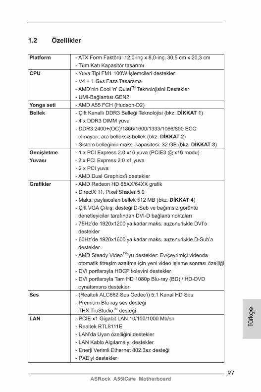
97ASRock A55iCafe Motherboard
Türk
çe
1.2 Özellikler
Platform - ATX Form Faktörü: 12,0-inç x 8,0-inç, 30,5 cm x 20,3 cm - Tüm Katı Kapasitör tasarımı CPU - Yuva Tipi FM1 100W İşlemcileri destekler - V4 + 1 Gьз Fazэ Tasarэmэ - AMD’nin Cool ‘n’ QuietTM Teknolojisini Destekler - UMI-Bağlantısı GEN2 Yonga seti - AMD A55 FCH (Hudson-D2) Bellek - Çift Kanallı DDR3 Belleği Teknolojisi (bkz. DİKKAT 1) - 4 x DDR3 DIMM yuva - DDR3 2400+(OC)/1866/1600/1333/1066/800 ECC olmayan, ara belleksiz bellek (bkz. DİKKAT 2) - Sistem belleğinin maks. kapasitesi: 32 GB (bkz. DİKKAT 3) Genişletme - 1 x PCI Express 2.0 x16 yuva (PCIE3 @ x16 modu) Yuvası - 2 x PCI Express 2.0 x1 yuva - 2 x PCI yuva - AMD Dual Graphics’i destekler Grafikler - AMD Radeon HD 65XX/64XX grafik - DirectX 11, Pixel Shader 5.0 - Maks. paylaюэlan bellek 512 MB (bkz. DİKKAT 4) - Çift VGA Çıkış: desteği D-Sub ve bağımsız görüntü denetleyiciler tarafından DVI-D bağlantı noktaları - 75Hz’de 1920x1200’ya kadar maks. зцzьnьrlьkle DVI’э destekler - 60Hz’de 1920x1600’ya kadar maks. зцzьnьrlьkle D-Sub’э destekler - AMD Steady VideoTM’yu destekler: Ev/çevrimiçi videoda otomatik titreşim azaltma için yeni video işleme sonrası özelliği - DVI portlarэyla HDCP iюlevini destekler - DVI portlarэyla Tam HD 1080p Blu-ray (BD) / HD-DVD oynatэmэnэ destekler Ses - (Realtek ALC662 Ses Codec’i) 5,1 Kanal HD Ses - Premium Blu-ray ses desteği - THX TruStudioTM desteği LAN - PCIE x1 Gigabit LAN 10/100/1000 Mb/sn - Realtek RTL8111E - LAN’da Uyan özelliğini destekler - LAN Kablo Algılama’yı destekler - Enerji Verimli Ethernet 802.3az desteği - PXE’yi destekler
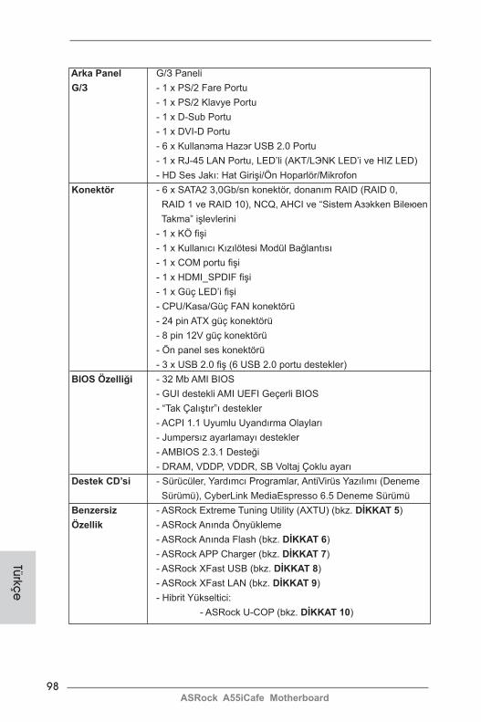
98ASRock A55iCafe Motherboard
Türkçe
Arka Panel G/З Paneli G/З - 1 x PS/2 Fare Portu - 1 x PS/2 Klavye Portu - 1 x D-Sub Portu - 1 x DVI-D Portu - 6 x Kullanэma Hazэr USB 2.0 Portu - 1 x RJ-45 LAN Portu, LED’li (AKT/LЭNK LED’i ve HIZ LED) - HD Ses Jakı: Hat Girişi/Ön Hoparlör/Mikrofon Konektör - 6 x SATA2 3,0Gb/sn konektör, donanım RAID (RAID 0, RAID 1 ve RAID 10), NCQ, AHCI ve “Sistem Aзэkken Bileюen Takma” işlevlerini - 1 x KÖ fişi - 1 x Kullanıcı Kızılötesi Modül Bağlantısı - 1 x COM portu fişi - 1 x HDMI_SPDIF fişi - 1 x Güç LED’i fişi - CPU/Kasa/Güç FAN konektörü - 24 pin ATX güç konektörü - 8 pin 12V güç konektörü - Ön panel ses konektörü - 3 x USB 2.0 fiş (6 USB 2.0 portu destekler) BIOS Özelliği - 32 Mb AMI BIOS - GUI destekli AMI UEFI Geçerli BIOS - “Tak Çalıştır”ı destekler - ACPI 1.1 Uyumlu Uyandırma Olayları - Jumpersız ayarlamayı destekler - AMBIOS 2.3.1 Desteği - DRAM, VDDP, VDDR, SB Voltaj Çoklu ayarı Destek CD’si - Sürücüler, Yardımcı Programlar, AntiVirüs Yazılımı (Deneme Sürümü), CyberLink MediaEspresso 6.5 Deneme Sürümü Benzersiz - ASRock Extreme Tuning Utility (AXTU) (bkz. DİKKAT 5) Özellik - ASRock Anında Önyükleme - ASRock Anında Flash (bkz. DİKKAT 6) - ASRock APP Charger (bkz. DİKKAT 7) - ASRock XFast USB (bkz. DİKKAT 8) - ASRock XFast LAN (bkz. DİKKAT 9) - Hibrit Yükseltici: - ASRock U-COP (bkz. DİKKAT 10)
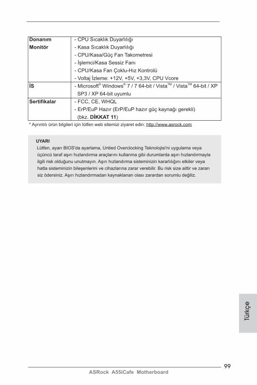
99ASRock A55iCafe Motherboard
Türk
çe
Donanım - CPU Sıcaklık Duyarlılığı Monitör - Kasa Sıcaklık Duyarlılığı - CPU/Kasa/Güç Fan Takometresi - İşlemci/Kasa Sessiz Fanı - CPU/Kasa Fan Çoklu-Hız Kontrolü - Voltaj İzleme: +12V, +5V, +3,3V, CPU Vcore İS - Microsoft® Windows® 7 / 7 64-bit / VistaTM / VistaTM 64-bit / XP SP3 / XP 64-bit uyumlu Sertifikalar - FCC, CE, WHQL - ErP/EuP Hazır (ErP/EuP hazır güç kaynağı gerekli) (bkz. DİKKAT 11) * Ayrıntılı ürün bilgileri için lütfen web sitemizi ziyaret edin: http://www.asrock.com
UYARILütfen, ayarı BIOS'da ayarlama, Untied Overclocking Teknolojisi'ni uygulama veya üçüncü taraf aşırı hızlandırma araçlarını kullanma gibi durumlarda aşırı hızlandırmayla ilgili risk olduğunu unutmayın. Aşırı hızlandırma sisteminizin kararlılığını etkiler veya hatta sisteminizin bileşenlerini ve cihazlarına zarar verebilir. Bu risk size aittir ve zararı siz ödersiniz. Aşırı hızlandırmadan kaynaklanan olası zarardan sorumlu değiliz.
100ASRock A55iCafe Motherboard
Türkçe
DİKKAT!1. Bu anakart Çift Kanallı Bellek Teknolojisi'ni destekler. Çift Kanallı Bellek
Teknolojisi'ni uygulamadan önce, uygun yükleme hakkında sayfa 12'deki bellek modüllerinin yükleme kılavuzunu okuduğunuzdan emin olun.
2. 2400/1866/1600MHz bellek hızı çalıştığınız CPU'ya göre desteklenir. DDR3 2400/1866/1600 bellek modülünü bu anakartta çalıştırmak istiyorsanız, uyumlu bellek modülleri için lütfen web sitemizdeki bellek destek listesine bakın. ASRock web sitesi: http://www.asrock.com
3. İşletim sistemi kısıtlaması nedeniyle, Windows® 7 / VistaTM / XP altında sistem kullanımı için ayırmak için gerçek bellek boyutu 4 GB'den az olabilir. 64-bit CPU'lu Windows® OS için bu tür bir sınırlama yoktur.
4. Maksimum paylaюэlan bellek boyutu yonga seti satэcэsэ tarafэndan tanэmlanэr ve deрiюebilir. Lьtfen en son bilgileri iзin AMD web sitesini kontrol edin.
5. ASRock Extreme Tuning Utility (AXTU) hepsi bir arada bir araç olup kullanıcı ile dost bir arayüzde farklı sistem i.levlerinin ince ayarını yapmak için kullanılmakta olup buna Donanım Monitörü, Fan Kontrolü ve IES da-hildir. Donanım Monitöründe sisteminizde okunan önemli de.erleri gösterir. Fan Kontrolünde ayarlamanız için fan hızını ve sıcaklı.ını gösterir. IES’de (Akıllı Enerji Tasarrufu), CPU çekirdekleri bo.ta oldu.unda bilgisayarın performansından ödün vermeden gerilim düzenleyicisi çıkı. fazlarının sayısını dü.ürerek verimlili.i iyile.tirir. ASRock Extreme Tuning Utility (AXTU)’nun çalı.ma prosedürleri için lütfen web sitemizi ziyaret ediniz. ASRock web sitesi: http://www.asrock.com
6. ASRock Anında Flash, Flash ROM’a katıştırılmış bir BIOS flash yardımcı programıdır. Bu kullanışlı BIOS güncelleme aracı, sistem BIOS’unu MS-DOS veya Windows® gibi ilk önce işletim sistemine girmeden
güncellemenizi sağlar. Bu yardımcı programla, POST sırasında <F6> tuşuna basabilirsiniz veya BIOS ayarları menüsünün ASRock Anında Flash’a erişmesi için <F2> tuşuna basabilirsiniz. Bu aracı başlatın ve yeni BIOS dosyasını USB flash sürücünüze, diskete veya sabit sürücüye kayde-din, sonra BIOS’unuzu yalnızca birkaç tıklatma ile ek bir disket veya diğer karmaşık flash yardımcı programlarını hazırlamadan güncelleyebilirsiniz. Lütfen USB flash sürücünün veya sabit diskin FAT32/16/12 dosya sistemi kullanması gerektiğini unutmayın.
7. iPhone/iPod/iPad Touch gibi Apple cihazlarınızı şarj etmek için daha hızlı ve daha özgür bir biçimde şarj etmek istiyorsanız, ASRock sizin için mükemmel bir çözüm hazırladı - ASRock APP Charger. Sadece APP Charger sürücünü kurarak, iPhone’unuzu bilgisayarınızdan daha çabuk ve eskisinden 40% daha hızlı şekilde şarj edebilirsiniz. ASRock APP Charger birçok Apple cihazını aynı anda ve hızlı bir biçimde şarj etmenize olanak tanır ve hatta bilgisayarınız Bekleme modunda (S1), RAM’de Askıya Al modunda (S3), uyku modunda (S4) veya kapalı(S5) iken sürekli şarj
etmeyi destekler. APP Charger sürücüsü kurulu iken kolaylıkla şimdiye hiç olmadığı kadar harika bir şarj deneyimi yaşayabilirsiniz.
101ASRock A55iCafe Motherboard
Türk
çe
ASRock internet sitesi: http://www.asrock.com/Feature/AppCharger/index.asp
8. ASRock XFast USB, USB bellek aygıtı performansını arttırabilir. Perfor-mans aygtının özelliğine göre değişiklik gösterebilir.
9. ASRock XFast LAN hızlı internet erişimi sağlarken aşağıdaki avantajlara da sahiptir. LAN uygulaması Önceliklendirmesi: Uygulama önceliğinizi ideal şekilde yapılandırabilir ve/veya yeni programlar ekleyebilirsiniz. Oyunda Daha Az Gecikme Zamanı: Çevrimiçi oyun önceliğini daha yükseğe ayarladığınızda, oyundaki gecikmeler azalabilir. Trafik Şekillendirme: You-tube HD video izleyebilir ve aynı anda dosyaları indirebilirsiniz. Verilerinizin Gerçek Zamanlı Analizi: Durum penceresi ile, şu anda aktardığınız hangi verilerin akışının yapıldığını kolaylıkla yapılandırabilirsiniz.
10. CPU aşırı ısınması algılandığında, sistem otomatik olarak kapatılır. Sistemi devam ettirmeden önce, lütfen anakarttaki CPU fanının düzgün çalıştığını kontrol edin ve güç kablosunu çıkarın, sonra geri takın. Isı geçişini artırmak için, PC sistemini yüklediğinizde CPU ile ısı emici arasına ısı macunu sürmeyi unutmayın.
11. Enerji Kullanan Ürün anlamına gelen EuP, tamamlanmış sistemler için güç tüketimini tanımlamak için Avrupa Birliği tarafından düzenlenen bir gerekli-liktir. EuP’a göre, kapalı mod durumunda tamamlanmış sistemin toplam AC gücü 1,00W altında olmalıdır. EuP standardını karşılamak için, EuP hazır anakart ve EuP hazır güç kaynağı gerekir. Intel’in önerisine göre, EuP hazır güç kaynağının 100 mA akım tüketiminde 5v beklemede güç etkinliği %50’den yüksektir standardını karşılaması gerekir. EuP hazır güç kaynağı seçimi için, daha fazla ayrıntı için güç kaynağı üreticisine başvurmanızı öneririz.
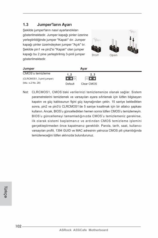
102ASRock A55iCafe Motherboard
1.3 Jumper'ların AyarıŞekilde jumper'ların nasıl ayarlandıkları gösterilmektedir. Jumper kapağı pinler üzerine yerleştirildiğinde jumper "Kapalı" dır. Jumper kapağı pinler üzerindeyken jumper "Açık" tır. Şekilde pin1 ve pin2'si "Kapalı" olan jumper kapağı bu 2 pine yerleştirilmiş 3-pinli jumper gösterilmektedir.
Jumper AyarCMOS’u temizleme(CLRCMOS1, 3-pinli jumper)
(bkz. s.2 No. 28)
Not: CLRCMOS1, CMOS’daki verilerinizi temizlemenize olanak sağlar. Sistem parametrelerini temizlemek ve varsayılan ayara sıfırlamak için lütfen bilgisayarı kapatın ve güç kablosunun fişini güç kaynağından çekin. 15 saniye bekledikten sonra, pin2 ve pin3‘ü CLRCMOS1’de 5 saniye kısaltmak için bir atlatıcı şapkası kullanın. Ancak, BIOS’u güncelledikten hemen sonra lütfen CMOS’u temizlemeyin. BIOS’u güncellemeyi tamamladığınızda CMOS’u temizlemeniz gerekirse, i lk olarak sistemi başlatmanız ve ardından CMOS temizleme işlemini gerçekleştirmeden önce kapatmanız gereklidir. Parola, tarih, saat, kullanıcı varsayılan profili, 1394 GUID ve MAC adresinin yalnızca CMOS pili çıkarıldığında temizleneceğini lütfen aklınızda bulundurunuz.
Clear CMOSDefault
Türkçe
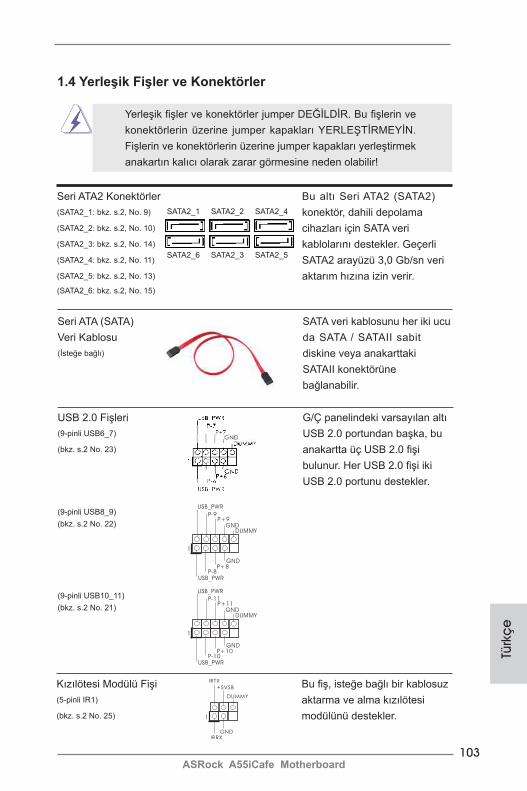
103ASRock A55iCafe Motherboard
Türk
çe
USB 2.0 Fişleri G/Ç panelindeki varsayılan altı (9-pinli USB6_7) USB 2.0 portundan başka, bu (bkz. s.2 No. 23) anakartta üç USB 2.0 fişi bulunur. Her USB 2.0 fişi iki USB 2.0 portunu destekler.
(9-pinli USB8_9)(bkz. s.2 No. 22)
(9-pinli USB10_11)(bkz. s.2 No. 21)
Seri ATA2 Konektörler Bu altı Seri ATA2 (SATA2) (SATA2_1: bkz. s.2, No. 9) konektör, dahili depolama (SATA2_2: bkz. s.2, No. 10) cihazları için SATA veri (SATA2_3: bkz. s.2, No. 14) kablolarını destekler. Geçerli (SATA2_4: bkz. s.2, No. 11) SATA2 arayüzü 3,0 Gb/sn veri (SATA2_5: bkz. s.2, No. 13) aktarım hızına izin verir.(SATA2_6: bkz. s.2, No. 15)
1
USB_PWRP-8
GND
DUMMY
USB_PWR
P+8
GND
P-9P+9
1.4 Yerleşik Fişler ve Konektörler
Yerleşik fişler ve konektörler jumper DEĞİLDİR. Bu fişlerin ve konektörlerin üzerine jumper kapakları YERLEŞTİRMEYİN. Fişlerin ve konektörlerin üzerine jumper kapakları yerleştirmek anakartın kalıcı olarak zarar görmesine neden olabilir!
SATA2_6 SATA2_3 SATA2_5
SATA2_1 SATA2_2 SATA2_4
Seri ATA (SATA) SATA veri kablosunu her iki ucu Veri Kablosu da SATA / SATAII sabit (İsteğe bağlı) diskine veya anakarttaki SATAII konektörüne bağlanabilir.
1
USB_PWRP-10
GND
DUMMY
USB_PWR
P+10
GND
P-11P+11
Kızılötesi Modülü Fişi Bu fiş, isteğe bağlı bir kablosuz (5-pinli IR1) aktarma ve alma kızılötesi (bkz. s.2 No. 25) modülünü destekler.1
IRTX
+5VSB
DUMMY
IRRXGND
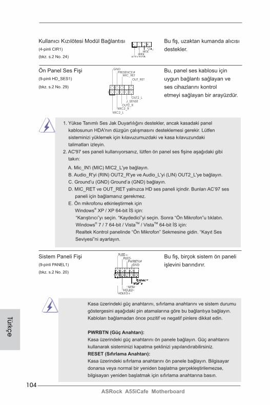
104ASRock A55iCafe Motherboard
Ön Panel Ses Fişi Bu, panel ses kablosu için (9-pinli HD_SES1) uygun bağlantı sağlayan ve (bkz. s.2 No. 29) ses cihazlarını kontrol etmeyi sağlayan bir arayüzdür.
Kullanıcı Kızılötesi Modül Bağlantısı Bu fiş, uzaktan kumanda alıcısı(4-pinli CIR1) destekler. (bkz. s.2 No. 24)
J_SENSE
OUT2_L
1
MIC_RETPRESENCE#
GND
OUT2_RMIC2_R
MIC2_L
OUT_RET
1. Yükse Tanımlı Ses Jak Duyarlılığını destekler, ancak kasadaki panel kablosunun HDA'nın düzgün çalışmasını desteklemesi gerekir. Lütfen sisteminizi yüklemek için kılavuzumuzdaki ve kasa kılavuzundaki talimatları izleyin.
2. AC'97 ses paneli kullanıyorsanız, lütfen ön panel ses fişine aşağıdaki gibi takın:
A. Mic_IN'i (MIC) MIC2_L'ye bağlayın. B. Audio_R'yi (RIN) OUT2_R'ye ve Audio_L'yi (LIN) OUT2_L'ye bağlayın. C. Ground’u (GND) Ground’a (GND) bağlayın. D. MIC_RET ve OUT_RET yalnızca HD ses paneli içindir. Bunları AC’97 ses
paneli için bağlamanız gerekmez. E. Ön mikrofonu etkinleştirmek için Windows® XP / XP 64-bit İS için:
“Karıştırıcı”yı seçin. “Kaydedici”yi seçin. Sonra “Ön Mikrofon”u tıklatın.Windows® 7 / 7 64-bit / VistaTM / VistaTM 64-bit İS için:Realtek Kontrol panelinde “Ön Mikrofon” Sekmesine gidin. “Kayıt Ses Seviyesi”ni ayarlayın.
Türkçe
Sistem Paneli Fişi Bu fiş, birçok sistem ön paneli (9-pinli PANEL1) işlevini barındırır.(bkz. s.2 No. 20)
Kasa üzerindeki güç anahtarını, sıfırlama anahtarını ve sistem durumu göstergesini aşağıdaki pin atamalarına göre bu bağlantıya bağlayın. Kabloları bağlamadan önce pozitif ve negatif pinlere dikkat edin.
PWRBTN (Güç Anahtarı): Kasa üzerindeki güç anahtarını ön panele bağlayın. Güç anahtarını kullanarak sisteminizi kapatma şeklinizi yapılandırabilirsiniz.
RESET (Sıfırlama Anahtarı): Kasa üzerindeki sıfırlama anahtarını ön panele bağlayın. Bilgisayar donarsa veya normal bir yeniden başlatma gerçekleştirilemezse, bilgisayarı yeniden başlatmak için sıfırlama anahtarına basın.
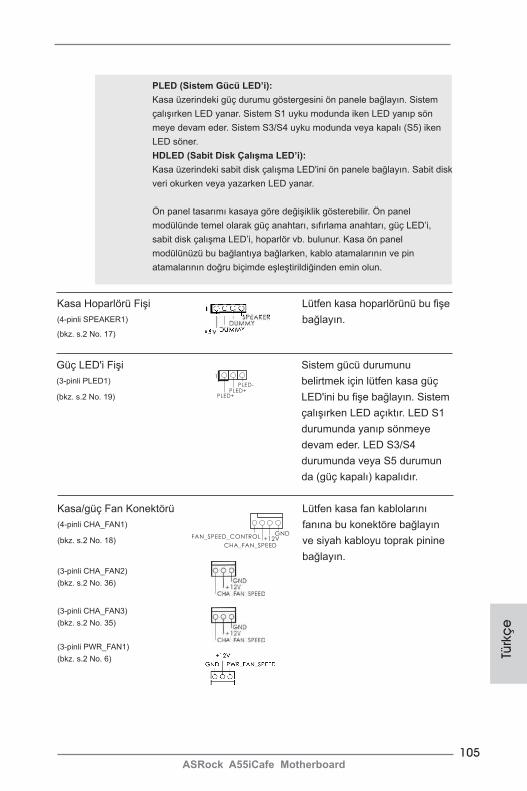
105ASRock A55iCafe Motherboard
Türk
çe
PLED (Sistem Gücü LED’i): Kasa üzerindeki güç durumu göstergesini ön panele bağlayın. Sistem çalışırken LED yanar. Sistem S1 uyku modunda iken LED yanıp sön meye devam eder. Sistem S3/S4 uyku modunda veya kapalı (S5) iken LED söner.
HDLED (Sabit Disk Çalışma LED’i): Kasa üzerindeki sabit disk çalışma LED'ini ön panele bağlayın. Sabit disk veri okurken veya yazarken LED yanar.
Ön panel tasarımı kasaya göre değişiklik gösterebilir. Ön panel modülünde temel olarak güç anahtarı, sıfırlama anahtarı, güç LED’i, sabit disk çalışma LED’i, hoparlör vb. bulunur. Kasa ön panel modülünüzü bu bağlantıya bağlarken, kablo atamalarının ve pin atamalarının doğru biçimde eşleştirildiğinden emin olun.
Kasa Hoparlörü Fişi Lütfen kasa hoparlörünü bu fişe (4-pinli SPEAKER1) bağlayın.(bkz. s.2 No. 17)
Güç LED'i Fişi Sistem gücü durumunu (3-pinli PLED1) belirtmek için lütfen kasa güç (bkz. s.2 No. 19) LED'ini bu fişe bağlayın. Sistem çalışırken LED açıktır. LED S1 durumunda yanıp sönmeye devam eder. LED S3/S4 durumunda veya S5 durumun da (güç kapalı) kapalıdır.
1
PLED+PLED+
PLED-
Kasa/güç Fan Konektörü Lütfen kasa fan kablolarını (4-pinli CHA_FAN1) fanına bu konektöre bağlayın (bkz. s.2 No. 18) ve siyah kabloyu toprak pinine bağlayın.(3-pinli CHA_FAN2)(bkz. s.2 No. 36)
(3-pinli CHA_FAN3)(bkz. s.2 No. 35)
(3-pinli PWR_FAN1)(bkz. s.2 No. 6)
GND+12V
CHA_FAN_SPEED
FAN_SPEED_CONTROL

106ASRock A55iCafe Motherboard
3-Pinli Fanı Takma
Bu anakart 4-Pinli CPU fan (Sessiz Fan) desteği sağlasa da, 3-Pinli CPU fan hızı kontrol işlevi olmadan bile hala başarılı bir şekilde çalışabilir. 3-Pinli CPU fanı bu konektördeki CPU fan konektörüne bağlamayı planlıyorsanız, lütfen Pin 1-3'e bağlayın.
Pin 1-3 Bağlı
Türkçe
ATX Güç Konektörü Lütfen bir ATX güç kaynağını (24-pinli ATXPWR1) bu konektöre bağlayın.(bkz. s.2 No. 12)
Bu anakart 24-pinli ATX güç konektörü sağlasa da geleneksel bir 20-pinli ATX güç kaynağı bağlarsanız da çalışabilir. 20-pinli ATX güç kaynağını kullanmak için, lütfen güç kaynağınızı Pin 1 ve Pin 13'le birlikte takın.
20-Pinli ATX Güç Kaynağını Takma
12
1
24
13
12
1
24
13
GND+12V
CPU_FAN_SPEED
(3-pinli CPU_FAN2)(bkz. s.2 No. 5)
CPU Fan Konektörü Lütfen fan kablolarını CPU (4-pinli CPU_FAN1) fanına bu konektöre bağlayın (bkz. s.2 No. 4) ve siyah kabloyu toprak pinine bağlayın.
GND+12V
CPU_FAN_SPEED
FAN_SPEED_CONTROL
1 2 3 4
ATX 12V Güç Konektörü Lütfen bir ATX 12V güç (8-pinli ATX12V1) kaynağını bu konektöre (bkz. s.2 No. 1) bağlayın.
Bu anakart 8-pinli ATX 12V güç konektörü sağlasa da geleneksel bir 4-pinli ATX 12V güç kaynağı bağlarsanız da çalışabilir. 4-pinli ATX güç kaynağını kullanmak için, lütfen güç kaynağınızı Pin 1 ve Pin 5'le birlikte takın.
4-Pinli ATX 12V Güç Kaynağını Takma
4 8
1 5
4 8
1 5

107ASRock A55iCafe Motherboard
Türk
çe
Seri port Fişi Bu COM1 fişi bir seri port (9-pinli COM1) modülünü destekler.(bkz. s.2 No. 26)
HDMI_SPDIF Fişi HDMI_SPDIF fişi, SPDIF ses (2-pinli HDMI_SPDIF1) çıkışını HDMI VGA kartına (bkz. s.2 No. 27) sağlar, sistemin HDMI Dijital TV/projektör/LCD cihazlarını bağlamasına izin verir. Lütfen HDMI VGA kartının HDMI_SPDIF konektörünü bu fişe bağlayın.
108ASRock A55iCafe Motherboard
2. BIOS Bilgileri
Anakarttaki Flash Bellek BIOS Ayarları Yardımcı Programını içerir. Bilgisayarı başlattığınızda, lütfen Otomatik Güç Sınaması (POST) sırasında BIOS Ayarları yardımcı programına girmek için <F2> veya <Del> tuşuna basın; aksi halde, POST test rutinlerine devam eder. BIOS Ayarlarına POST'tan sonra girmek istiyorsanız, lütfen <Ctl> + <Alt> + <Delete> tuşlarına basarak veya sistem kasasındaki sıfırlama düğmesine basarak sistemi yeniden başlatın. BIOS Ayarları programı kullanıcı dostu olacak şekilde tasarlanmıştır. Çeşitli alt menüler arasında dolaşmanıza ve önceden belirlenen seçenekler arasından seçim yapmanıza izin veren menü tabanlı bir programdır. BIOS Ayarları hakkında ayrıntılı bilgi için, lütfen Destek CD'sinde bulunan Kullanıcı Kılavuzu'na (PDF dosyası) başvurun.
3. Yazılım Destek CD’si bilgileriBu anakart çeşitli Microsoft® Windows® işletim sistemleri destekler: 7 / 7 64-bit / VistaTM / VistaTM 64-bit / XP SP3 / XP 64-bit. Anakartla birlikte gelen Destek CD'si anakart özelliklerini genişleten gerekli sürücüleri ve kullanışlı yardımcı programları içerir. Destek CD'sini kullanmaya başlamak için, CD'yi CDROM sürücünüze takın. Bilgisayarınızda "OTOMATİK KULLAN" özelliği etkinleştirilmişse, Ana Menüyü otomatik olarak görüntüler. Ana Menü otomatik olarak görüntülenmezse, menüleri görüntülemek için Destek CD'sinin “BIN” klasöründeki "ASSETUP.EXE" dosyasını bulun ve çift tıklatın.
Türkçe
109ASRock A55iCafe Motherboard
Eng
lish
Installing OS on a HDD Larger Than 2TB in AHCI ModeThis motherboard is adopting UEFI BIOS that allows Windows® OS to be installed on a large size HDD (>2TB). Please follow below procedure to install the operating system.
1. Please make sure to use Windows® VistaTM 64-bit (with SP1 or above) or Windows® 7 64-bit. 2. Press <F2> or <Delete> at system POST. Set AHCI Mode in UEFI Setup Utility > Advanced > Storage Configuration > SATA Mode. 3. Choose the item “UEFI:xxx“ to boot in UEFI Setup Utility > Boot > Boot Option #1. (“xxx” is the device which contains your Windows® installation files. Normally it is an optical drive.) You can also press <F11> to launch boot menu at system POST and choose the item “UEFI:xxx“ to boot. 4. Start Windows® installation.
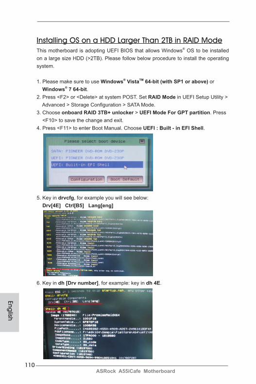
110ASRock A55iCafe Motherboard
Installing OS on a HDD Larger Than 2TB in RAID ModeThis motherboard is adopting UEFI BIOS that allows Windows® OS to be installed on a large size HDD (>2TB). Please follow below procedure to install the operating system.
1. Please make sure to use Windows® VistaTM 64-bit (with SP1 or above) or Windows® 7 64-bit. 2. Press <F2> or <Delete> at system POST. Set RAID Mode in UEFI Setup Utility > Advanced > Storage Configuration > SATA Mode. 3. Choose onboard RAID 3TB+ unlocker > UEFI Mode For GPT partition. Press <F10> to save the change and exit. 4. Press <F11> to enter Boot Manual. Choose UEFI : Built - in EFI Shell.
5. Key in drvcfg, for example you will see below: Drv[4E] Ctrl[B5] Lang[eng]
6. Key in dh [Drv number], for example: key in dh 4E.
English
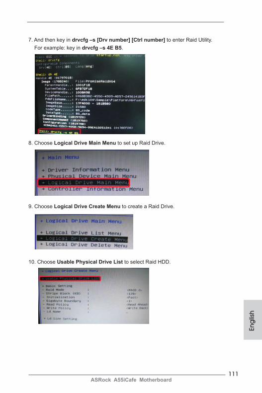
111ASRock A55iCafe Motherboard
Eng
lish
7. And then key in drvcfg –s [Drv number] [Ctrl number] to enter Raid Utility. For example: key in drvcfg –s 4E B5.
8. Choose Logical Drive Main Menu to set up Raid Drive.
9. Choose Logical Drive Create Menu to create a Raid Drive.
10. Choose Usable Physical Drive List to select Raid HDD.
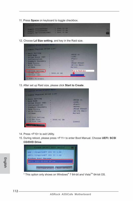
112ASRock A55iCafe Motherboard
11. Press Space on keyboard to toggle checkbox.
12. Choose Ld Size setting, and key in the Raid size.
13. After set up Raid size, please click Start to Create.
14. Press <F10> to exit Utility.15. During reboot, please press <F11> to enter Boot Manual. Choose UEFI: SCSI CD/DVD Drive.
* This option only shows on Windows® 7 64-bit and VistaTM 64-bit OS.
English
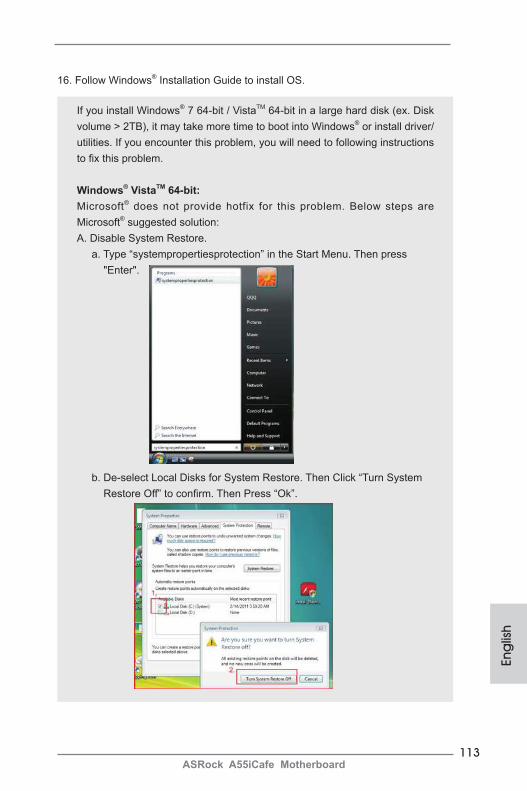
113ASRock A55iCafe Motherboard
16. Follow Windows® Installation Guide to install OS.
If you install Windows® 7 64-bit / VistaTM 64-bit in a large hard disk (ex. Disk volume > 2TB), it may take more time to boot into Windows® or install driver/utilities. If you encounter this problem, you will need to following instructions to fix this problem.
Windows® VistaTM 64-bit:Microsoft® does not provide hotfix for this problem. Below steps are Microsoft® suggested solution:A. Disable System Restore. a. Type “systempropertiesprotection” in the Start Menu. Then press "Enter".
b. De-select Local Disks for System Restore. Then Click “Turn System Restore Off” to confirm. Then Press “Ok”.
Eng
lish
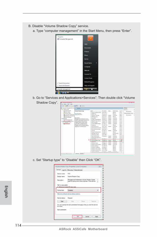
114ASRock A55iCafe Motherboard
B. Disable “Volume Shadow Copy” service. a. Type “computer management” in the Start Menu, then press “Enter”.
b. Go to “Services and Applications>Services”; Then double click “Volume Shadow Copy”.
c. Set “Startup type” to “Disable” then Click “OK”.
English
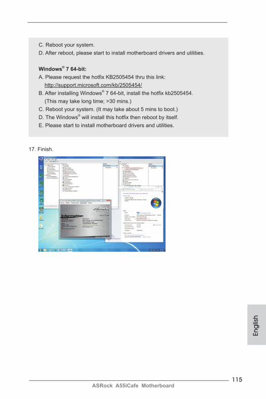
115ASRock A55iCafe Motherboard
17. Finish.
C. Reboot your system.D. After reboot, please start to install motherboard drivers and utilities.
Windows® 7 64-bit:A. Please request the hotfix KB2505454 thru this link: http://support.microsoft.com/kb/2505454/B. After installing Windows® 7 64-bit, install the hotfix kb2505454. (This may take long time; >30 mins.)C. Reboot your system. (It may take about 5 mins to boot.)D. The Windows® will install this hotfix then reboot by itself.E. Please start to install motherboard drivers and utilities.
Eng
lish


