Embed Size (px)
Citation preview
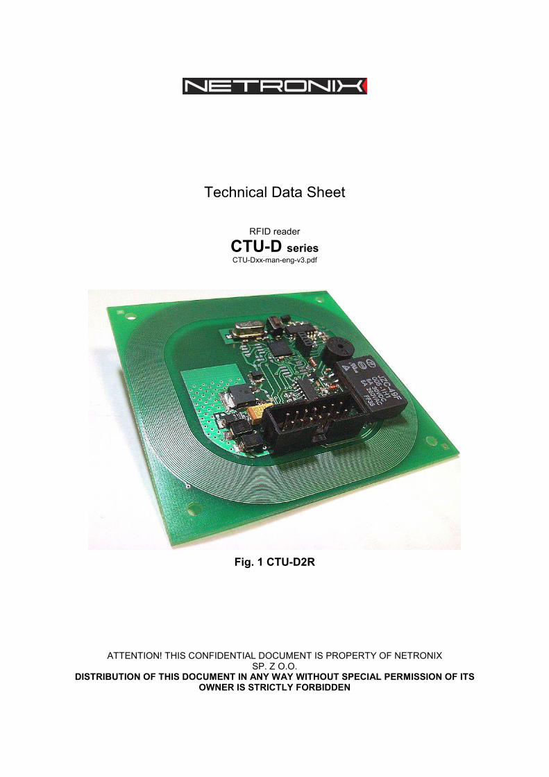
Technical Data Sheet
RFID reader
CTU-D series CTU-Dxx-man-eng-v3.pdf
Fig. 1 CTU-D2R
ATTENTION! THIS CONFIDENTIAL DOCUMENT IS PROPERTY OF NETRONIX SP. Z O.O.
DISTRIBUTION OF THIS DOCUMENT IN ANY WAY WITHOUT SPECIAL PERMISSION OF ITS OWNER IS STRICTLY FORBIDDEN

1. INTRODUCTION ............................................................................................. 4
2. GENERAL SPECIFICATION........................................................................... 5
3. DIMENSION, TERMINAL DESCRIPTION....................................................... 6
4. MODULE SETTINGS BY ON-BOARD SWITCH............................................. 7
5. TRANSMISSION PROTOCOLS...................................................................... 7
5.1. RS-232/485 TRANSMISSION PROTOCOL ................................................ 7
5.2. Protocol for I2C transmission............................................................................. 7
5.2.1. Data exchange algorithm ............................................................................... 7
5.2.2. Timings .............................................................................................................. 9
5.3. Protocol for 1WIRE (Dallas) bus...................................................................... 10
5.4. Wiegand protocol ................................................................................................ 11
6. COMMUNICATION PROTOCOL COMMANDS............................................ 11
6.1. Commands for communication with transponders ................................... 11
6.1.1. Selecting the transponder type.................................................................... 12
6.1.2. On/off switching of reader field .................................................................... 12
6.1.3. Reading the ID card unique number .......................................................... 12
6.2. Commands for communication with Q5 transponders............................. 13
6.2.1. Writing the ID-Unique number to Q5 transponder.................................... 13
6.2.2. Reading the sector of Q5 transponder ....................................................... 13
6.2.3. Writing the sector of Q5 transponder ......................................................... 14
6.3. Commands for communication with HITAG transponders...................... 14
6.3.1. Reading the page of HITAG transponder .................................................. 14
6.3.2. Writing the page to HITAG transponder..................................................... 15
6.4. Reader inputs and outputs ............................................................................... 15
6.4.1. Writing the output state................................................................................. 15
6.4.2. Reading the input state................................................................................. 15
6.4.3. Writing the settings to any port .................................................................... 16
6.4.4. Reading-out the configuration of freely selected port .............................. 18
6.5. Access password ................................................................................................ 19
6.5.1. Logging to reader........................................................................................... 19
6.5.2. Changing the password ................................................................................ 19
6.5.3. Logging out of the reader ............................................................................. 20
6.6. Operating the transponder internal memory ............................................... 20
6.6.1. Reading-out the transponder number from memory................................ 20
6.6.2. Writing the transponder name to memory ................................................. 21
6.7. Operating the built-in access control ............................................................ 21
6.7.1. Writing the configuration of access control................................................ 21
6.7.2. Reading-out the configuration of access control ...................................... 21
6.7.3. Writing the “automatic read” configuration................................................. 22
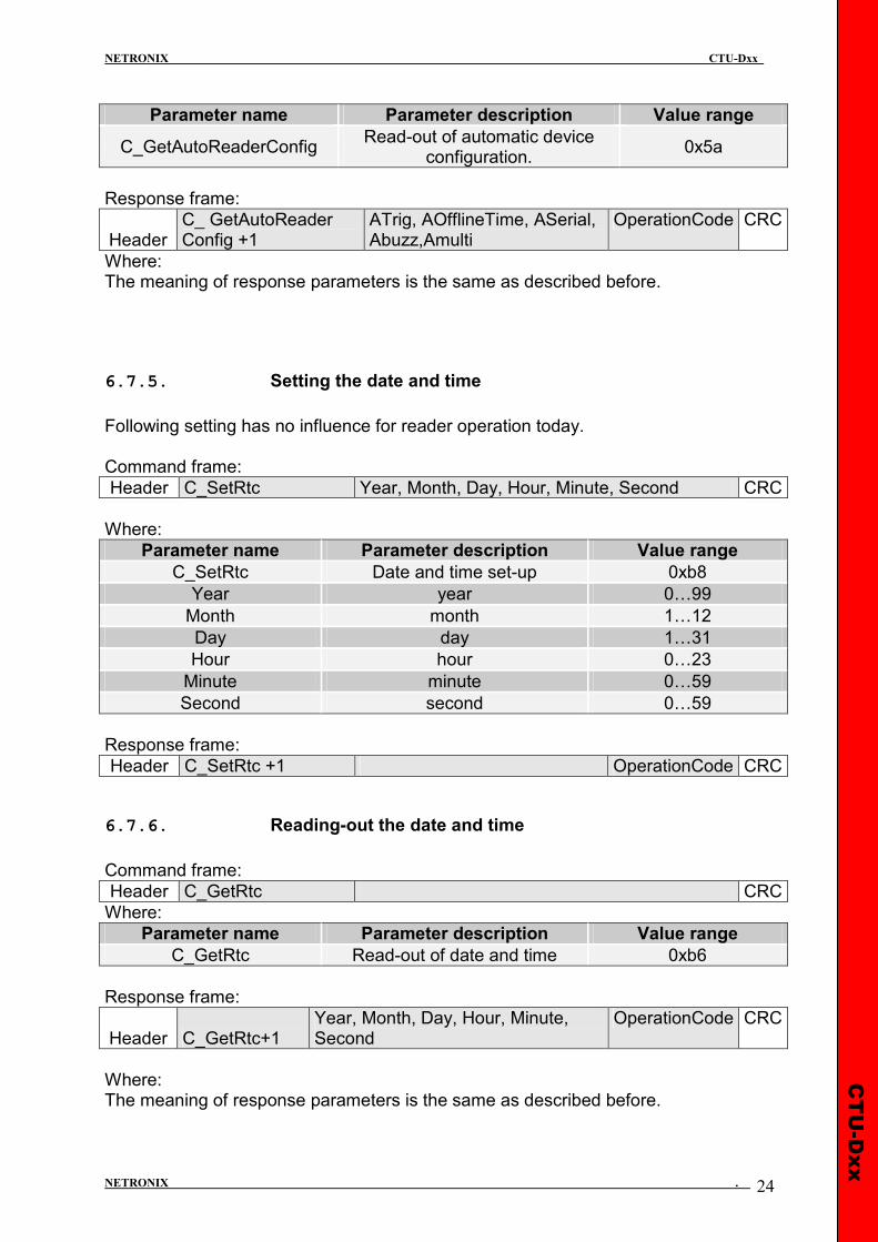
6.7.4. Reading-out the configuration of automatic device .................................. 23
6.7.5. Setting the date and time ............................................................................. 24
6.7.6. Reading-out the date and time .................................................................... 24
6.8. Configuring the UART serial interface........................................................... 25
6.8.1. Writing the configuration of serial port........................................................ 25
6.8.2. Reading the configuration of serial interface............................................. 25
6.9. Managing the events .......................................................................................... 26
6.9.1. Setting the event recorder ............................................................................ 26
6.9.2. Reading the event recorder ......................................................................... 27
6.9.3. Reading the counters related to event memory. ...................................... 27
6.9.4. Reading the events ....................................................................................... 28
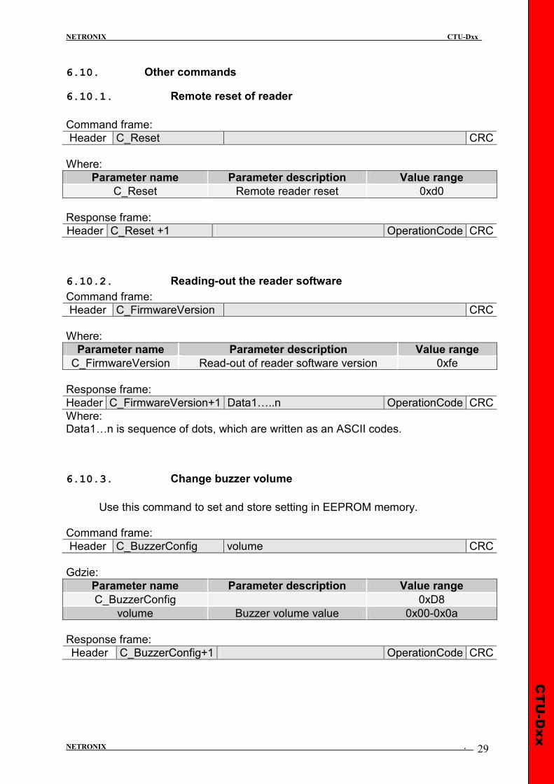
6.10. Other commands ............................................................................................. 29
6.10.1. Remote reset of reader............................................................................. 29
6.10.2. Reading-out the reader software............................................................. 29
6.10.3. Change buzzer volume............................................................................. 29
6.11. Code meanings in response frames .......................................................... 30
7. MECHANISM OF MASTER ID ...................................................................... 31
8. RESET TO DEFAULT SETTINGS ................................................................ 32

CTU-Dxx
NETRONIX CTU-Dxx
NETRONIX . 4
1. Introduction
CTU-D device series is OEM miniature RFID card reader operating at frequency of 125 kHz. Main features:
• Support of Unique, Q5, Hitag-1, Hitag-S or HID transponders, • built-in antenna • card memory with build-in lock driver, • lots of communication interfaces type, depend on version (see table below) • Built-in relay and buzzer • Built-in push-button for reset to default settings • 2 configurable inputs/outputs • Two-state outputs control • Read-out of two-state input • changeable format of sending ID • Data password protected • Software update via RS-232 interface using NEFIR program
CTU-D reader series
INTERFACES
Module type
GPIO
Card memory
Event memory
Relay
Power supply
RS-232
RS-485
RS-232TTL
SPI
I2C
WIEGAND
1WIRE
CTU-D2R* ���� 40 ���� ���� 7-16 ����
CTU-D4R � 40 � � 7-16 �
CTU-D5N* ���� 40 ���� ���� 5 ���� ���� ���� ���� ����
CTU-D5R � 40 � � 5 � � � � �
CTU-D2RM � 1000 4000 � 7-16 �
* - standard version, rest of version for special order
CTU-Dxx
NETRONIX CTU-Dxx
NETRONIX . 5
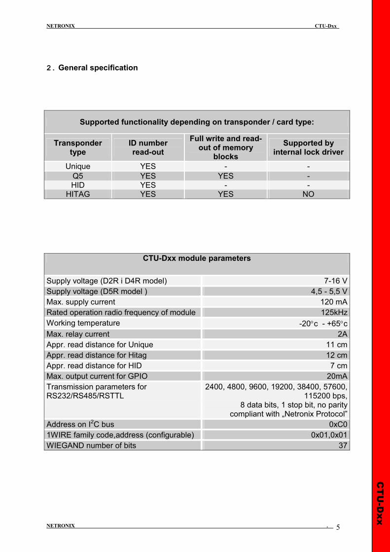
2. General specification
Supported functionality depending on transponder / card type:
Transponder type
ID number read-out
Full write and read-out of memory
blocks
Supported by internal lock driver
Unique YES - -
Q5 YES YES - HID YES - - HITAG YES YES NO
CTU-Dxx module parameters
Supply voltage (D2R i D4R model) 7-16 V
Supply voltage (D5R model ) 4,5 - 5,5 V
Max. supply current 120 mA
Rated operation radio frequency of module 125kHz
Working temperature -20°c - +65°c Max. relay current 2A
Appr. read distance for Unique 11 cm
Appr. read distance for Hitag 12 cm
Appr. read distance for HID 7 cm
Max. output current for GPIO 20mA
Transmission parameters for RS232/RS485/RSTTL
2400, 4800, 9600, 19200, 38400, 57600, 115200 bps,
8 data bits, 1 stop bit, no parity compliant with „Netronix Protocol”
Address on I2C bus 0xC0
1WIRE family code,address (configurable) 0x01,0x01
WIEGAND number of bits 37
CTU-Dxx
NETRONIX CTU-Dxx
NETRONIX . 6
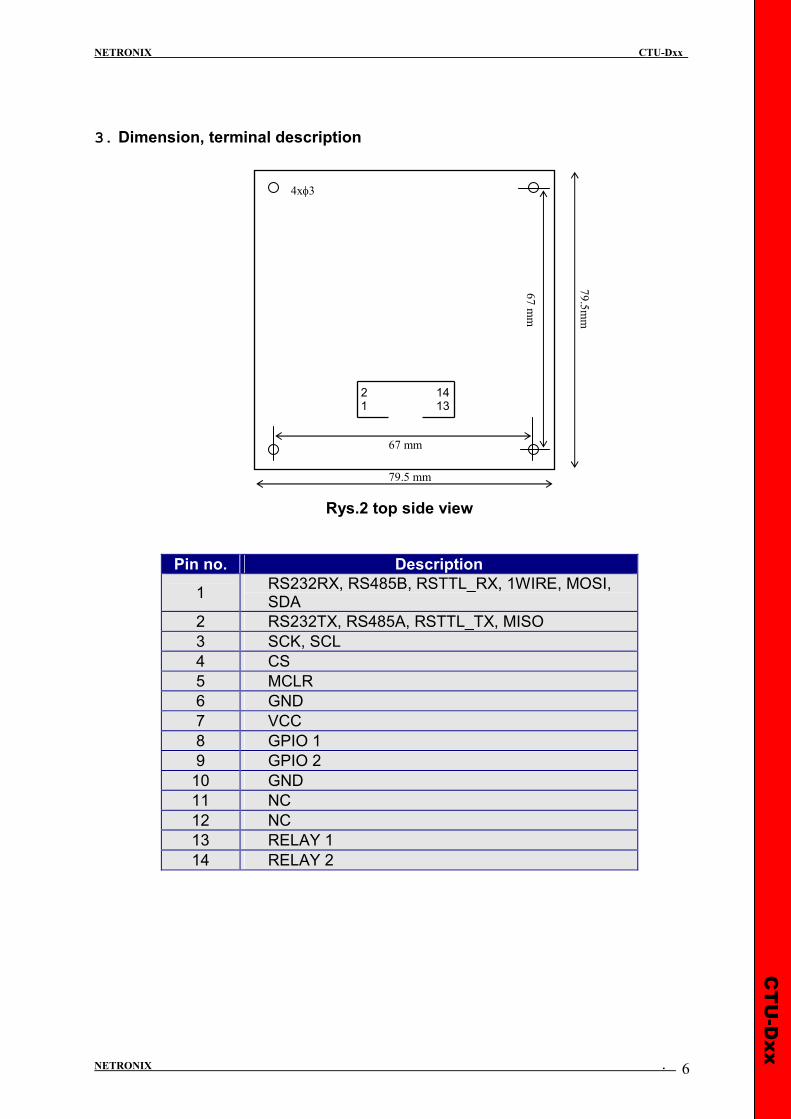
3. Dimension, terminal description
Rys.2 top side view
Pin no. Description
1 RS232RX, RS485B, RSTTL_RX, 1WIRE, MOSI, SDA
2 RS232TX, RS485A, RSTTL_TX, MISO
3 SCK, SCL
4 CS
5 MCLR
6 GND
7 VCC
8 GPIO 1
9 GPIO 2
10 GND
11 NC
12 NC
13 RELAY 1
14 RELAY 2
4xφ3
67 mm
67 m
m
79.5 mm
79.5mm
2 14 1 13
CTU-Dxx
NETRONIX CTU-Dxx
NETRONIX . 7
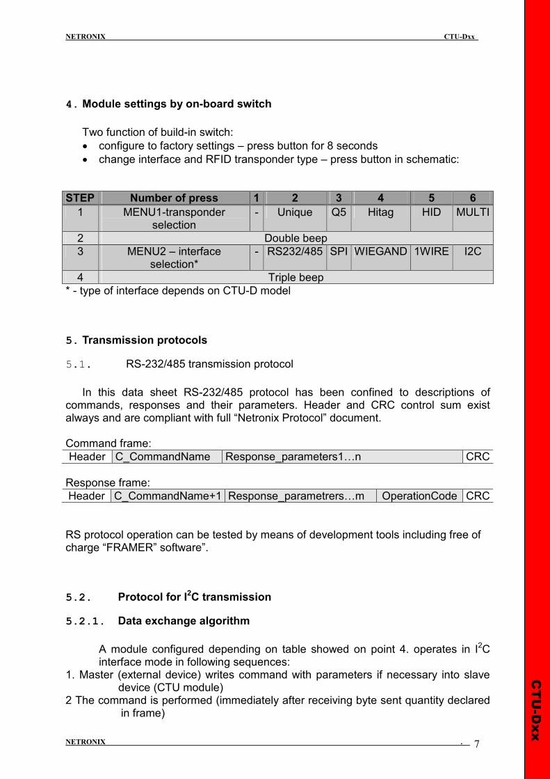
4. Module settings by on-board switch
Two function of build-in switch:
• configure to factory settings – press button for 8 seconds • change interface and RFID transponder type – press button in schematic:
STEP Number of press 1 2 3 4 5 6
1 MENU1-transponder selection
- Unique Q5 Hitag HID MULTI
2 Double beep
3 MENU2 – interface selection*
- RS232/485 SPI WIEGAND 1WIRE I2C
4 Triple beep
* - type of interface depends on CTU-D model
5. Transmission protocols
5.1. RS-232/485 transmission protocol
In this data sheet RS-232/485 protocol has been confined to descriptions of
commands, responses and their parameters. Header and CRC control sum exist always and are compliant with full “Netronix Protocol” document. Command frame:
Header C_CommandName Response_parameters1…n CRC
Response frame:
Header C_CommandName+1 Response_parametrers…m OperationCode CRC
RS protocol operation can be tested by means of development tools including free of charge “FRAMER” software”.
5.2. Protocol for I2C transmission
5.2.1. Data exchange algorithm
A module configured depending on table showed on point 4. operates in I2C interface mode in following sequences:
1. Master (external device) writes command with parameters if necessary into slave device (CTU module)
2 The command is performed (immediately after receiving byte sent quantity declared in frame)

CTU-Dxx
NETRONIX CTU-Dxx
NETRONIX . 8
3. Master device reads response, its parameters and operation code. In case of receiving busy byte 0xCB, repeat attempt to read the response after ca. 1 ms (commands connected with write to/and read from transponders can last up to 100 ms). We write inquiry-command to CTU module: The „number of bytes” field must contain information on byte quantity sent directly “command” fields and “parameters”. We have then:
START
NUMBER OF BYTES(1B) SLAVE ADDRESS (1B) 0 COMMAND (1B)
PARAMETERS (0...n B)
START
Number of bytes N or 0xCB SLAVE ADDRESS (1B) 1 PARAMETERS + OPERATION CODE (N bytes)
STOP
I2C SEND START
I2C SEND:
0b110000a0
Wait for ACK
I2C SEND:
Number of bytes,command,[data]
I2C SEND:
0b110000a1
Wait for ACK
Wait 1ms
I2C START
I2C READ 1 byte:N
N= 0xCB ?
Receive N bytes
I2C SEND STOP
TAK
NIE
CTU-Dxx
NETRONIX CTU-Dxx
NETRONIX . 9
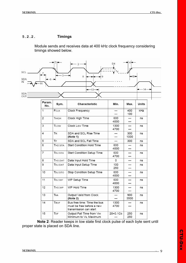
5.2.2. Timings
Module sends and receives data at 400 kHz clock frequency considering timings showed below.
Note 2: Reader keeps in low state first clock pulse of each byte sent until proper state is placed on SDA line.
CTU-Dxx
NETRONIX CTU-Dxx
NETRONIX . 10
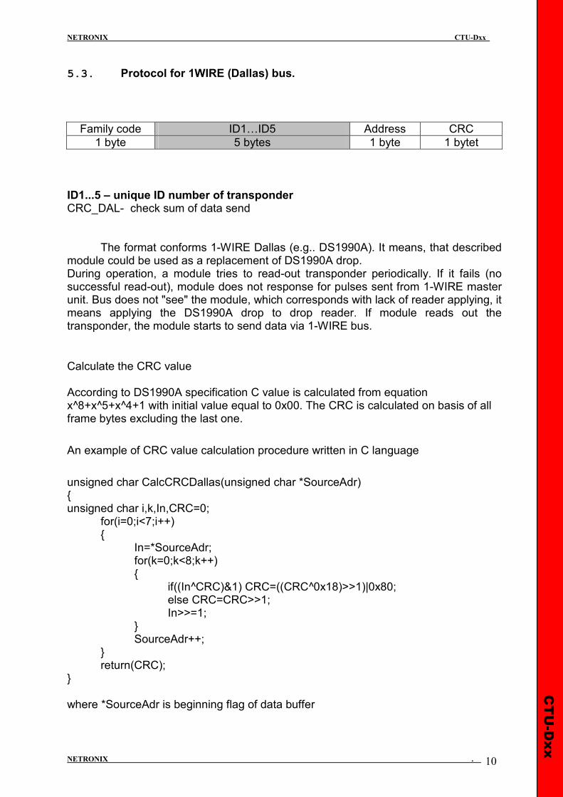
5.3. Protocol for 1WIRE (Dallas) bus.
Family code ID1…ID5 Address CRC
1 byte 5 bytes 1 byte 1 bytet
ID1...5 – unique ID number of transponder CRC_DAL- check sum of data send
The format conforms 1-WIRE Dallas (e.g.. DS1990A). It means, that described module could be used as a replacement of DS1990A drop. During operation, a module tries to read-out transponder periodically. If it fails (no successful read-out), module does not response for pulses sent from 1-WIRE master unit. Bus does not "see" the module, which corresponds with lack of reader applying, it means applying the DS1990A drop to drop reader. If module reads out the transponder, the module starts to send data via 1-WIRE bus.
Calculate the CRC value According to DS1990A specification C value is calculated from equation x^8+x^5+x^4+1 with initial value equal to 0x00. The CRC is calculated on basis of all frame bytes excluding the last one.
An example of CRC value calculation procedure written in C language
unsigned char CalcCRCDallas(unsigned char *SourceAdr) { unsigned char i,k,In,CRC=0; for(i=0;i<7;i++) { In=*SourceAdr; for(k=0;k<8;k++) { if((In^CRC)&1) CRC=((CRC^0x18)>>1)|0x80; else CRC=CRC>>1; In>>=1; } SourceAdr++; } return(CRC); } where *SourceAdr is beginning flag of data buffer
CTU-Dxx
NETRONIX CTU-Dxx
NETRONIX . 11
5.4. Wiegand protocol
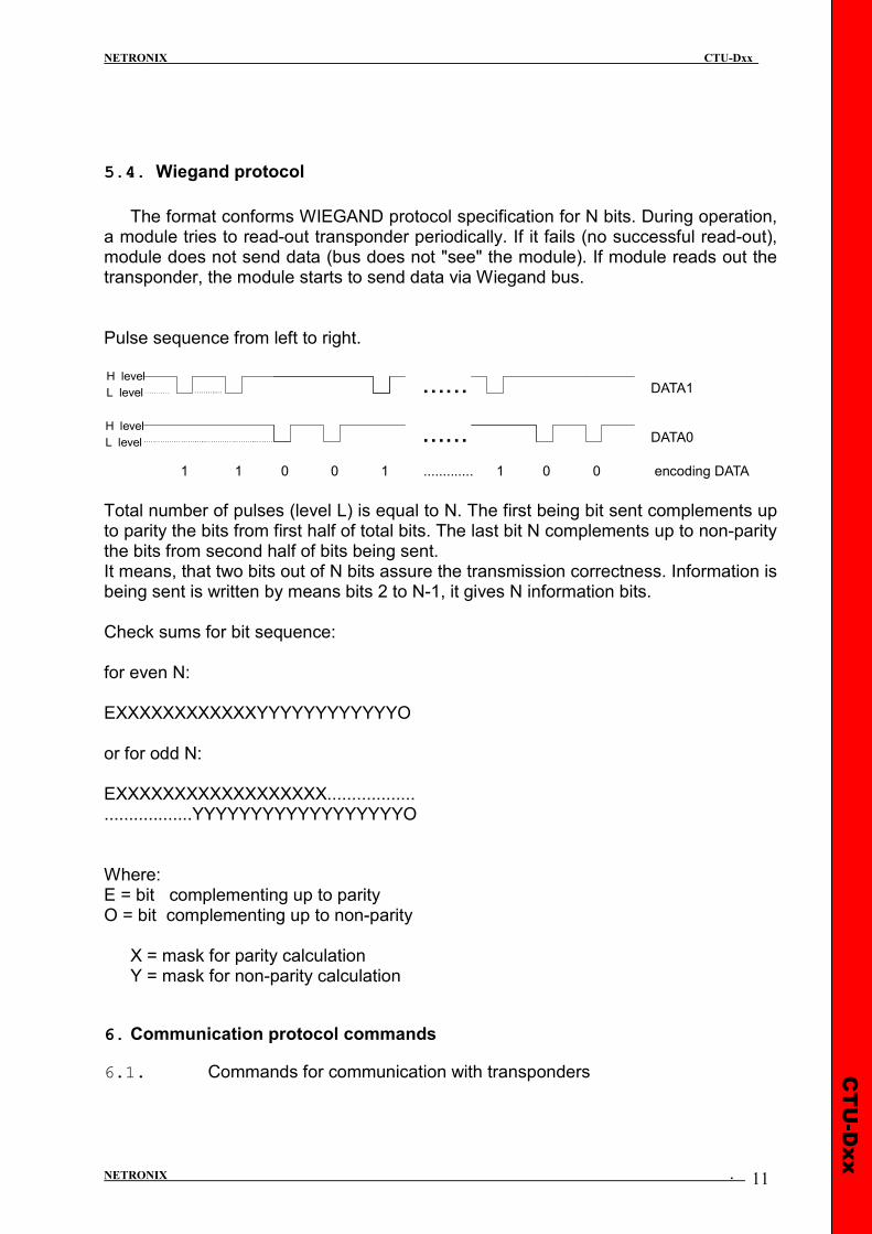
The format conforms WIEGAND protocol specification for N bits. During operation,
a module tries to read-out transponder periodically. If it fails (no successful read-out), module does not send data (bus does not "see" the module). If module reads out the transponder, the module starts to send data via Wiegand bus. Pulse sequence from left to right.
Total number of pulses (level L) is equal to N. The first being bit sent complements up to parity the bits from first half of total bits. The last bit N complements up to non-parity the bits from second half of bits being sent. It means, that two bits out of N bits assure the transmission correctness. Information is being sent is written by means bits 2 to N-1, it gives N information bits. Check sums for bit sequence: for even N: EXXXXXXXXXXXXYYYYYYYYYYYYO or for odd N: EXXXXXXXXXXXXXXXXXX.................. ..................YYYYYYYYYYYYYYYYYYO Where: E = bit complementing up to parity O = bit complementing up to non-parity X = mask for parity calculation Y = mask for non-parity calculation
6. Communication protocol commands
6.1. Commands for communication with transponders
......
......
DATA1
DATA0
1 1 0 0 1 ............. 1 0 0 encoding DATA
H level
H level
L level
L level
CTU-Dxx
NETRONIX CTU-Dxx
NETRONIX . 12
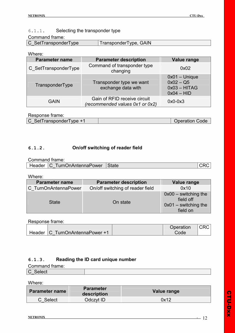
6.1.1. Selecting the transponder type
Command frame:
C_SetTransponderType TransponderType, GAIN
Where:
Parameter name Parameter description Value range
C_SetTransponderType Command of transponder type
changing 0x02
TransponderType Transponder type we want
exchange data with
0x01 – Unique 0x02 – Q5 0x03 – HITAG 0x04 – HID
GAIN Gain of RFID receive circuit
(recommended values 0x1 or 0x2) 0x0-0x3
Response frame:
C_SetTransponderType +1 Operation Code
6.1.2. On/off switching of reader field
Command frame:
Header C_TurnOnAntennaPower State CRC
Where:
Parameter name Parameter description Value range
C_TurnOnAntennaPower On/off switching of reader field 0x10
State On state
0x00 – switching the field off
0x01 – switching the field on
Response frame:
Header C_TurnOnAntennaPower +1 Operation
Code CRC
6.1.3. Reading the ID card unique number
Command frame:
C_Select
Where:
Parameter name Parameter description
Value range
C_Select Odczyt ID 0x12

CTU-Dxx
NETRONIX CTU-Dxx
NETRONIX . 13
Response frame:
C_Select +1 Coll, TType, ID1…….IDn Operation Code
Where:
Parameter name Parameter description Meaning
Coll Information on collision (HITAG transponders
only)
0 – no collision 1 – collision of two or more transponders
TType Information on transponder type, to whom the
red ID number concerns
1 - Unique,Q5 3 - HITAG 4 - HID
ID1…IDn Unique number of transponder ID1 – LSB, IDn – MSB
6.2. Commands for communication with Q5 transponders
After selecting the type Q5 transponder with C_SetTransponderType command, we have new commands at disposal, which will be used for two-way communication.
6.2.1. Writing the ID-Unique number to Q5 transponder
Command frame:
C_UniqueWrite Unique1..5, lock
Where:
Parameter name Parameter description Value range
C_UniqueWrite Command of id-unique write 0x08
Unique1..5 5 bytes of ID number 0x00-0xff
lock ID programming with rewrite lock 0 – without lock 1- with lock
Response frame:
C_UniqueWrite +1 Operation Code
Note: The Q5 type transponders do not have verification function of correct ID number write. Getting proper code of operation does not guarantee correct assign of ID number. Make sure, that ID number has been assigned correctly reading the number with C_Select command.
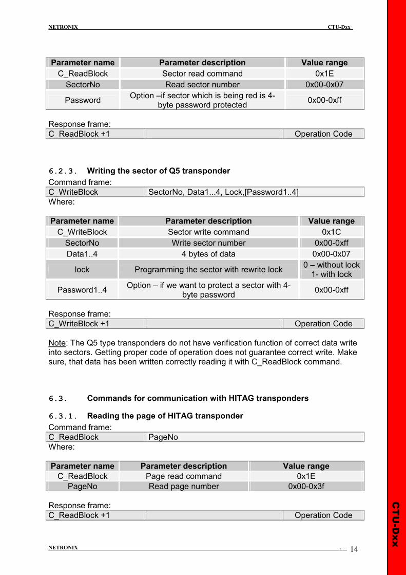
6.2.2. Reading the sector of Q5 transponder
Command frame:
C_ReadBlock SectorNo,[Password1..4]
Where:
CTU-Dxx
NETRONIX CTU-Dxx
NETRONIX . 14
Parameter name Parameter description Value range
C_ReadBlock Sector read command 0x1E
SectorNo Read sector number 0x00-0x07
Password Option –if sector which is being red is 4-
byte password protected 0x00-0xff
Response frame:
C_ReadBlock +1 Operation Code
6.2.3. Writing the sector of Q5 transponder
Command frame:
C_WriteBlock SectorNo, Data1...4, Lock,[Password1..4]
Where:
Parameter name Parameter description Value range
C_WriteBlock Sector write command 0x1C
SectorNo Write sector number 0x00-0xff
Data1..4 4 bytes of data 0x00-0x07
lock Programming the sector with rewrite lock 0 – without lock 1- with lock
Password1..4 Option – if we want to protect a sector with 4-
byte password 0x00-0xff
Response frame:
C_WriteBlock +1 Operation Code
Note: The Q5 type transponders do not have verification function of correct data write into sectors. Getting proper code of operation does not guarantee correct write. Make sure, that data has been written correctly reading it with C_ReadBlock command.
6.3. Commands for communication with HITAG transponders
6.3.1. Reading the page of HITAG transponder
Command frame:
C_ReadBlock PageNo
Where:
Parameter name Parameter description Value range
C_ReadBlock Page read command 0x1E
PageNo Read page number 0x00-0x3f
Response frame:
C_ReadBlock +1 Operation Code

CTU-Dxx
NETRONIX CTU-Dxx
NETRONIX . 15
6.3.2. Writing the page to HITAG transponder
Command frame:
C_WriteBlock PageNo, Data1...4
Where:
Parameter name Parameter description Value range
C_WriteBlock Sector read command 0x1C
PageNo Read page number 0x00-0x3f
Data1..4 4 bytes of data which is being red 0x00-0xff
Response frame:
C_WriteBlock +1 Operation Code
6.4. Reader inputs and outputs
Reader has inputs and outputs which are configurable. Inputs are controlled directly from microcontroller outputs. Output load current is up to 20 mA.
6.4.1. Writing the output state
Command frame:
C_WriteOutputs IONo, State
Where:
Parameter name Parameter description Value range
C_WriteOutputs Output state write 0x70
IONo I/O port number. The port should be configured as an output
0x1..0x7 for UW-U4R 0x1..0xC for UW-U4G
State Requested output state 0x00 or 0x01
Response frame:
C_WriteOutputs +1 Operation Code
6.4.2. Reading the input state
Command frame:
C_ReadInputs IONo
Where:
Parameter name Parameter description Value range
C_ReadInputs Input state reed-out 0x72
IONo I/O port number.
Should be configured as an input. 0x0..0x7 dla UW-U4R 0x0..0xC dla UW-U4G

CTU-Dxx
NETRONIX CTU-Dxx
NETRONIX . 16
Response frame:
C_ReadInputs +1 State,[COUNTER] Operation Code
Where:
Parameter name Parameter description Value range
State Input state which has been red
Counter Counter state for counter type
input.
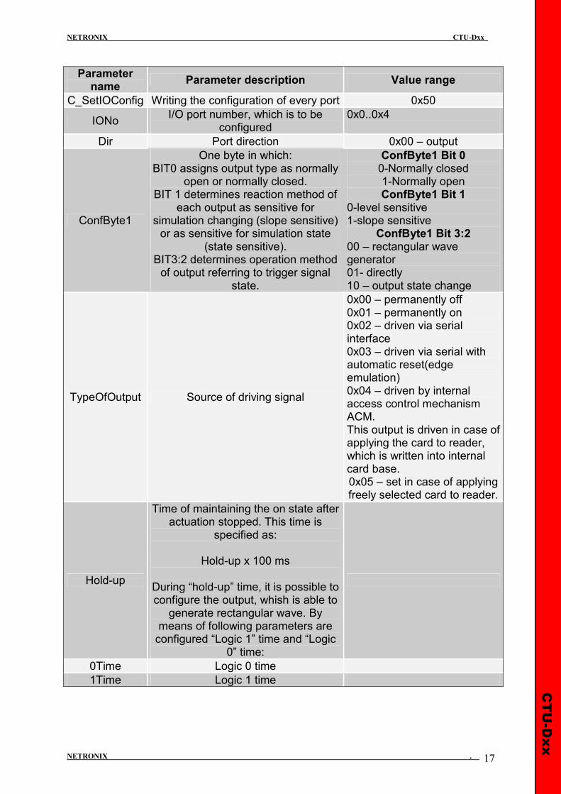
6.4.3. Writing the settings to any port
Command frame:
Header C_SetIOConfig IONo, IOConfigData1…n CRC
If we set a port as output, IOConfigData1…n parameters are as below: Dir, ConfByte1, TypeOfOutput, Hold-up, 0Time, 1Time Where:
„0”
„1”
INTERF ↓
INTERF
Base card
Each card
0
1
2
3
4
5
TypeOfOutput
1
0
ConfByte1 - BIT 1
t2 t0
t1
IOn
0
1
ConfByte1 - BIT 0
t2=Hold-UP x 100ms
tn=nTime x 100ms
t2
t0 t1
00
ConfByte1 - BIT 3:2
01
TOGGLE 10
CTU-Dxx
NETRONIX CTU-Dxx
NETRONIX . 17
Parameter name
Parameter description Value range
C_SetIOConfig Writing the configuration of every port 0x50
IONo I/O port number, which is to be
configured 0x0..0x4
Dir Port direction 0x00 – output
ConfByte1
One byte in which: BIT0 assigns output type as normally
open or normally closed. BIT 1 determines reaction method of
each output as sensitive for simulation changing (slope sensitive) or as sensitive for simulation state
(state sensitive). BIT3:2 determines operation method of output referring to trigger signal
state.
ConfByte1 Bit 0 0-Normally closed 1-Normally open ConfByte1 Bit 1
0-level sensitive 1-slope sensitive
ConfByte1 Bit 3:2 00 – rectangular wave generator 01- directly 10 – output state change
TypeOfOutput Source of driving signal
0x00 – permanently off 0x01 – permanently on 0x02 – driven via serial interface 0x03 – driven via serial with automatic reset(edge emulation) 0x04 – driven by internal access control mechanism ACM. This output is driven in case of applying the card to reader, which is written into internal card base. 0x05 – set in case of applying freely selected card to reader.
Hold-up
Time of maintaining the on state after actuation stopped. This time is
specified as:
Hold-up x 100 ms
During “hold-up” time, it is possible to configure the output, whish is able to generate rectangular wave. By
means of following parameters are configured “Logic 1” time and “Logic
0” time:
0Time Logic 0 time
1Time Logic 1 time

CTU-Dxx
NETRONIX CTU-Dxx
NETRONIX . 18
If we set a port as a input, IOConfigData1…n parameters would be as below: Dir, Triger, TypeOfInput, Delay, Where:
Parameter name Parameter description Value range
C_SetIOConfig Writing the configuration of freely selected
port. 0x50
IONo I/O port number, which is to be configured. 0x00,0x01,0x07
Dir Port direction 0x01 – input
TypeOfInput Input type 0x03
Delay Delay 0x00
6.4.4. Reading-out the configuration of freely selected port
Command frame:
Header C_GetIOConfig IONo CRC
Where:
Parameter name Parameter description Value range
C_GetIOConfig Reading-out the configuration of freely selected
port. 0x52
IONo I/O port number, which configuration is to be
red-out. 0x00…0x05
Response frame:
Header C_GetIOConfig +1 IOConfigData1…n OperationCode CRC
Where:
Parameter name Parameter description Value range
IOConfigData1…n This is the same, as in case of configuration
write.
Some I/O of CTU-D reader has no possibility to toggle port direction. To accomplish proper configuration, input proper direction option to given port.
LIST OF EXISTING PORTS, WHICH CAN BE DRIVEN IN UW-M4R
Port number Direction Description
0 input/output GPIO1
1 input/output GPIO 2
2 output RELAY
3 output BUZZER
CTU-Dxx
NETRONIX CTU-Dxx
NETRONIX . 19
Response frame:
Header C_SetIOConfig +1 OperationCode CRC
6.5. Access password
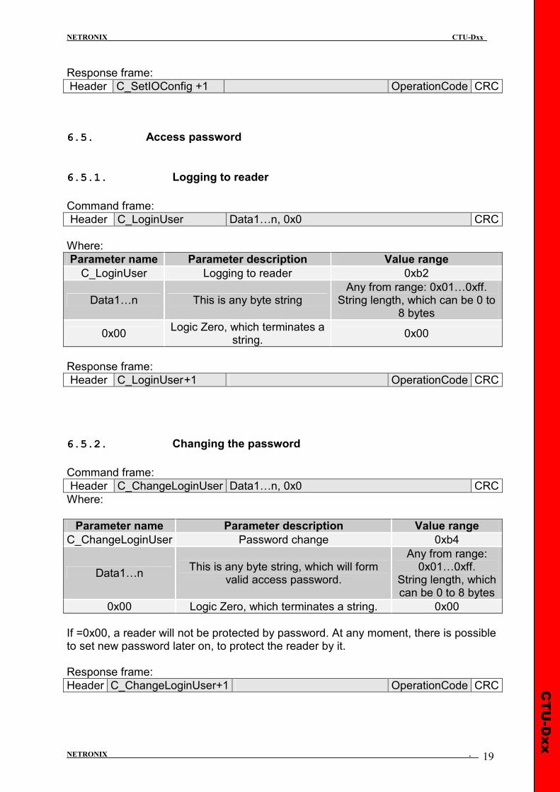
6.5.1. Logging to reader
Command frame:
Header C_LoginUser Data1…n, 0x0 CRC
Where:
Parameter name Parameter description Value range
C_LoginUser Logging to reader 0xb2
Data1…n This is any byte string Any from range: 0x01…0xff. String length, which can be 0 to
8 bytes
0x00 Logic Zero, which terminates a
string. 0x00
Response frame:
Header C_LoginUser +1 OperationCode CRC
6.5.2. Changing the password
Command frame:
Header C_ChangeLoginUser Data1…n, 0x0 CRC
Where:
Parameter name Parameter description Value range
C_ChangeLoginUser Password change 0xb4
Data1…n This is any byte string, which will form
valid access password.
Any from range: 0x01…0xff.
String length, which can be 0 to 8 bytes
0x00 Logic Zero, which terminates a string. 0x00
If =0x00, a reader will not be protected by password. At any moment, there is possible to set new password later on, to protect the reader by it. Response frame:
Header C_ChangeLoginUser+1 OperationCode CRC
CTU-Dxx
NETRONIX CTU-Dxx
NETRONIX . 20
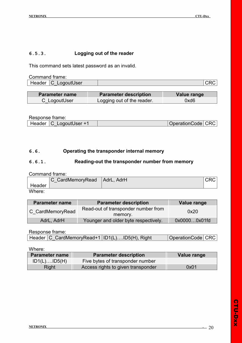
6.5.3. Logging out of the reader
This command sets latest password as an invalid. Command frame:
Header C_LogoutUser CRC
Parameter name Parameter description Value range
C_LogoutUser Logging out of the reader. 0xd6
Response frame:
Header C_LogoutUser +1 OperationCode CRC
6.6. Operating the transponder internal memory
6.6.1. Reading-out the transponder number from memory
Command frame:
Header C_CardMemoryRead
AdrL, AdrH CRC
Where:
Parameter name Parameter description Value range
C_CardMemoryRead Read-out of transponder number from
memory. 0x20
AdrL, AdrH Younger and older byte respectively. 0x0000…0x01fd
Response frame:
Header C_CardMemoryRead+1 ID1(L)….ID5(H), Right OperationCode CRC
Where:
Parameter name Parameter description Value range
ID1(L)….ID5(H) Five bytes of transponder number
Right Access rights to given transponder 0x01
CTU-Dxx
NETRONIX CTU-Dxx
NETRONIX . 21
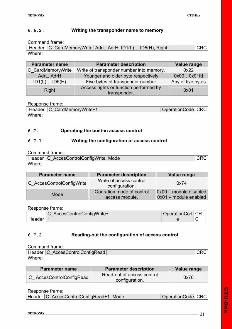
6.6.2. Writing the transponder name to memory
Command frame:
Header C_CardMemoryWrite AdrL, AdrH, ID1(L)….ID5(H), Right CRC
Where:
Parameter name Parameter description Value range
C_CardMemoryWrite Write of transponder number into memory. 0x22
AdrL, AdrH Younger and older byte respectively 0x00…0x01fd
ID1(L)….ID5(H) Five bytes of transponder number Any of five bytes
Right Access rights or function performed by
transponder. 0x01
Response frame:
Header C_CardMemoryWrite+1 OperationCode CRC
Where:
6.7. Operating the built-in access control
6.7.1. Writing the configuration of access control
Command frame:
Header C_AccesControlConfigWrite Mode CRC
Where:
Parameter name Parameter description Value range
C_AccesControlConfigWrite Write of access control
configuration. 0x74
Mode Operation mode of control
access module. 0x00 – module disabled 0x01 – module enabled
Response frame:
Header C_AccesControlConfigWrite+1
OperationCode
CRC
6.7.2. Reading-out the configuration of access control
Command frame:
Header C_AccesControlConfigRead CRC
Where:
Parameter name Parameter description Value range
C_ AccesControlConfigRead Read-out of access control
configuration. 0x76
Response frame:
Header C_AccesControlConfigRead+1 Mode OperationCode CRC
CTU-Dxx
NETRONIX CTU-Dxx
NETRONIX . 22
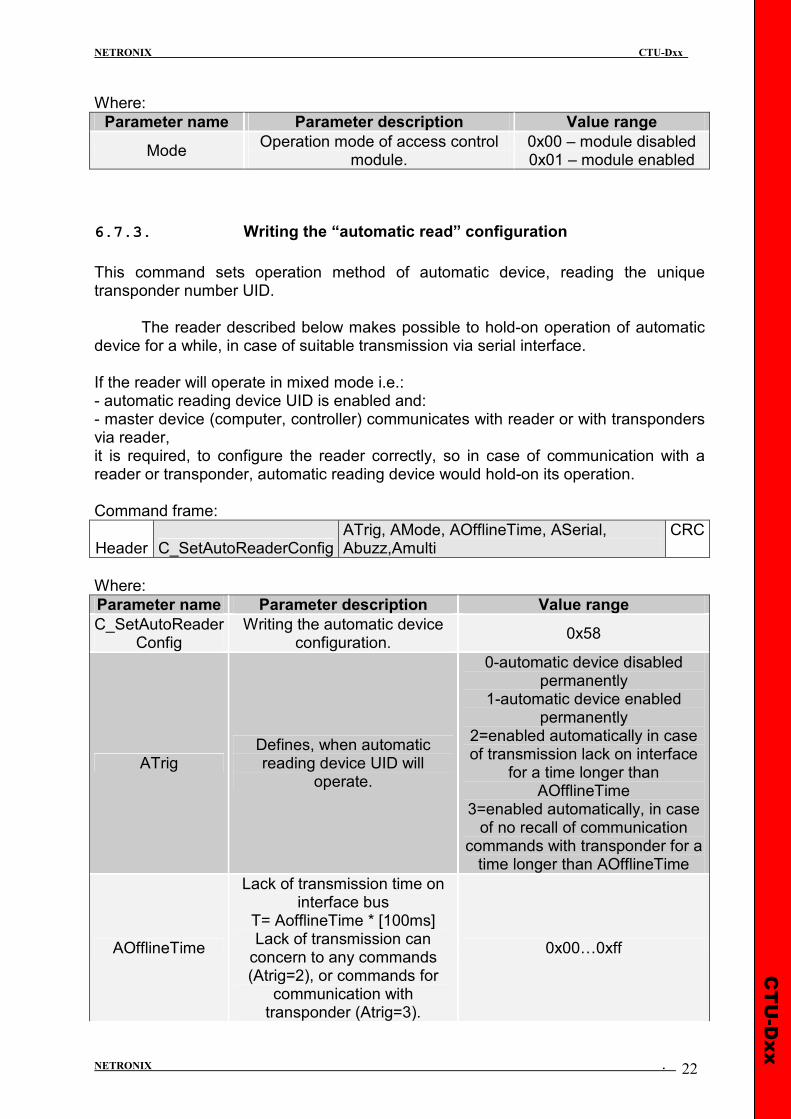
Where:
Parameter name Parameter description Value range
Mode Operation mode of access control
module. 0x00 – module disabled 0x01 – module enabled
6.7.3. Writing the “automatic read” configuration
This command sets operation method of automatic device, reading the unique transponder number UID.
The reader described below makes possible to hold-on operation of automatic device for a while, in case of suitable transmission via serial interface. If the reader will operate in mixed mode i.e.: - automatic reading device UID is enabled and: - master device (computer, controller) communicates with reader or with transponders via reader, it is required, to configure the reader correctly, so in case of communication with a reader or transponder, automatic reading device would hold-on its operation. Command frame:
Header C_SetAutoReaderConfig ATrig, AMode, AOfflineTime, ASerial, Abuzz,Amulti
CRC
Where:
Parameter name Parameter description Value range
C_SetAutoReader Config
Writing the automatic device configuration.
0x58
ATrig Defines, when automatic reading device UID will
operate.
0-automatic device disabled permanently
1-automatic device enabled permanently
2=enabled automatically in case of transmission lack on interface
for a time longer than AOfflineTime
3=enabled automatically, in case of no recall of communication
commands with transponder for a time longer than AOfflineTime
AOfflineTime
Lack of transmission time on interface bus
T= AofflineTime * [100ms] Lack of transmission can concern to any commands (Atrig=2), or commands for
communication with transponder (Atrig=3).
0x00…0xff
CTU-Dxx
NETRONIX CTU-Dxx
NETRONIX . 23
Commands for communication
with transponder: C_TurnOnAntennaPower
C_Select
ASerial
Automatic sending the UID transponder number, after reading it automatically from
transponder.
0-never 1-for the first applying the
transponder only 2-sends all
R Reserved, always 0
CR=1 Number which is ended with line end mark CR+LF
Selection the format of sending number
8 bits:
MSB LSB
R R H CR R E I A
E=1 information extended with cards umber in filed and card type
I=1 Number in reversed order
A=1 H=0
Number sent in ASCII format
AMode
A=0 H=0
Number sent in Nertonix format
A=0 H=1
Number sent in binary format
ABuzz
Automatic indication of reading by means of buzzer, after automatic UID read-out from
transponder.
0-never 1-for the first applying the
transponder only 2-indicates all
AMulti Multi type of transponders read
mode
0 – read a only selected by CSetTransponderType command
trnasponder type 0xff – read all known transponder
types
Response frame:
Header C_ SetAutoReaderConfig +1 OperationCode CRC
6.7.4. Reading-out the configuration of automatic device
Command frame:
Header C_ GetAutoReaderConfig CRC
Where:
CTU-Dxx
NETRONIX CTU-Dxx
NETRONIX . 24
Parameter name Parameter description Value range
C_GetAutoReaderConfig Read-out of automatic device
configuration. 0x5a
Response frame:
Header C_ GetAutoReader Config +1
ATrig, AOfflineTime, ASerial, Abuzz,Amulti
OperationCode CRC
Where: The meaning of response parameters is the same as described before.
6.7.5. Setting the date and time
Following setting has no influence for reader operation today. Command frame:
Header C_SetRtc Year, Month, Day, Hour, Minute, Second CRC
Where:
Parameter name Parameter description Value range
C_SetRtc Date and time set-up 0xb8
Year year 0…99
Month month 1…12
Day day 1…31
Hour hour 0…23
Minute minute 0…59
Second second 0…59
Response frame:
Header C_SetRtc +1 OperationCode CRC
6.7.6. Reading-out the date and time
Command frame:
Header C_GetRtc CRC
Where:
Parameter name Parameter description Value range
C_GetRtc Read-out of date and time 0xb6
Response frame:
Header C_GetRtc+1 Year, Month, Day, Hour, Minute, Second
OperationCode CRC
Where: The meaning of response parameters is the same as described before.
CTU-Dxx
NETRONIX CTU-Dxx
NETRONIX . 25
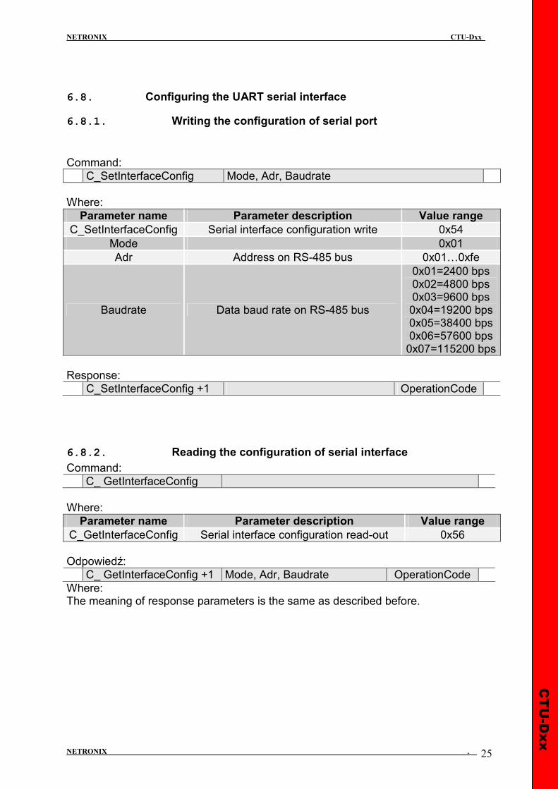
6.8. Configuring the UART serial interface
6.8.1. Writing the configuration of serial port
Command:
C_SetInterfaceConfig Mode, Adr, Baudrate
Where:
Parameter name Parameter description Value range
C_SetInterfaceConfig Serial interface configuration write 0x54
Mode 0x01
Adr Address on RS-485 bus 0x01…0xfe
Baudrate Data baud rate on RS-485 bus
0x01=2400 bps 0x02=4800 bps 0x03=9600 bps 0x04=19200 bps 0x05=38400 bps 0x06=57600 bps 0x07=115200 bps
Response:
C_SetInterfaceConfig +1 OperationCode
6.8.2. Reading the configuration of serial interface
Command:
C_ GetInterfaceConfig
Where:
Parameter name Parameter description Value range
C_GetInterfaceConfig Serial interface configuration read-out 0x56
Odpowiedź:
C_ GetInterfaceConfig +1 Mode, Adr, Baudrate OperationCode
Where: The meaning of response parameters is the same as described before.
CTU-Dxx
NETRONIX CTU-Dxx
NETRONIX . 26
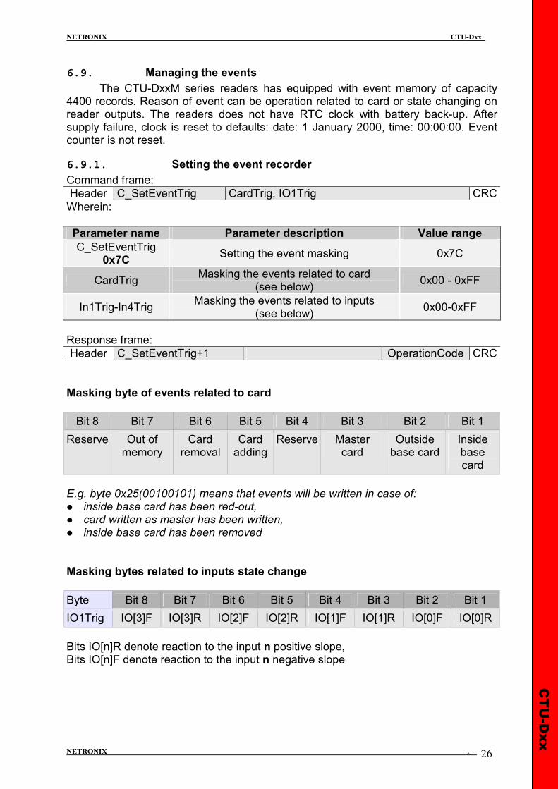
6.9. Managing the events
The CTU-DxxM series readers has equipped with event memory of capacity 4400 records. Reason of event can be operation related to card or state changing on reader outputs. The readers does not have RTC clock with battery back-up. After supply failure, clock is reset to defaults: date: 1 January 2000, time: 00:00:00. Event counter is not reset.
6.9.1. Setting the event recorder
Command frame:
Header C_SetEventTrig CardTrig, IO1Trig CRC
Wherein:
Parameter name Parameter description Value range
C_SetEventTrig 0x7C
Setting the event masking 0x7C
CardTrig Masking the events related to card
(see below) 0x00 - 0xFF
In1Trig-In4Trig Masking the events related to inputs
(see below) 0x00-0xFF
Response frame:
Header C_SetEventTrig+1 OperationCode CRC
Masking byte of events related to card
Bit 8 Bit 7 Bit 6 Bit 5 Bit 4 Bit 3 Bit 2 Bit 1
Reserve Out of memory
Card removal
Card adding
Reserve Master card
Outside base card
Inside base card
E.g. byte 0x25(00100101) means that events will be written in case of: � inside base card has been red-out, � card written as master has been written, � inside base card has been removed Masking bytes related to inputs state change
Byte Bit 8 Bit 7 Bit 6 Bit 5 Bit 4 Bit 3 Bit 2 Bit 1
IO1Trig IO[3]F IO[3]R IO[2]F IO[2]R IO[1]F IO[1]R IO[0]F IO[0]R
Bits IO[n]R denote reaction to the input n positive slope, Bits IO[n]F denote reaction to the input n negative slope

CTU-Dxx
NETRONIX CTU-Dxx
NETRONIX . 27
E.g. In4Trig-In1Trig configuration byte sequence: 0x00,0x31,0x40,0x08, causes, that events will be written in case of: − Any state change of input with index 10 occurs − Positive slope appears on input with index 8 − Positive slope appears on input with index 7 − Negative slope appears on input with index 1 During configuring the event triggers, decide which port is configured as an input. Do not configure events for those I/O’s, which are outputs. To guarantee correctness of event write process, time between two subsequent triggers must be longer than 20 ms.
6.9.2. Reading the event recorder
Command frame:
Header C_GetEventTrig CRC
Wherein:
Parameter name Parameter description Value range
C_GetEventTrig 0x7E
Reading the configuration of event recorder 0x7E
Response frame:
Header C_GetEventTrig+1 CardTrig, In1Trig OperationCode CRC
6.9.3. Reading the counters related to event memory.
Command frame:
Header C_GetEventParam CRC
Wherein:
Parameter name Parameter description Value range
C_GetEventParam 0x78
Reading the configuration of event recorder 0x78
Response frame:
Header C_GetEvent Param+1
CapL, CapH, PointerL, PointerH,TotB3,TotB2,TotB1,TotB0
OperationCode CRC
CapH:CapL – two-byte value, which defines event memory capacity. PointerH:PointerL – two-byte value, which marks from first free event. TotB3:TotB2:TotB1:TotB0 – four-byte value, which defines number of events recorded from the moment of counter reset. Events are recorded in sequence from index 0 up to Cap-1. In the moment memory gets full, the counter is being “overturned”, and older inputs are overwritten.
CTU-Dxx
NETRONIX CTU-Dxx
NETRONIX . 28
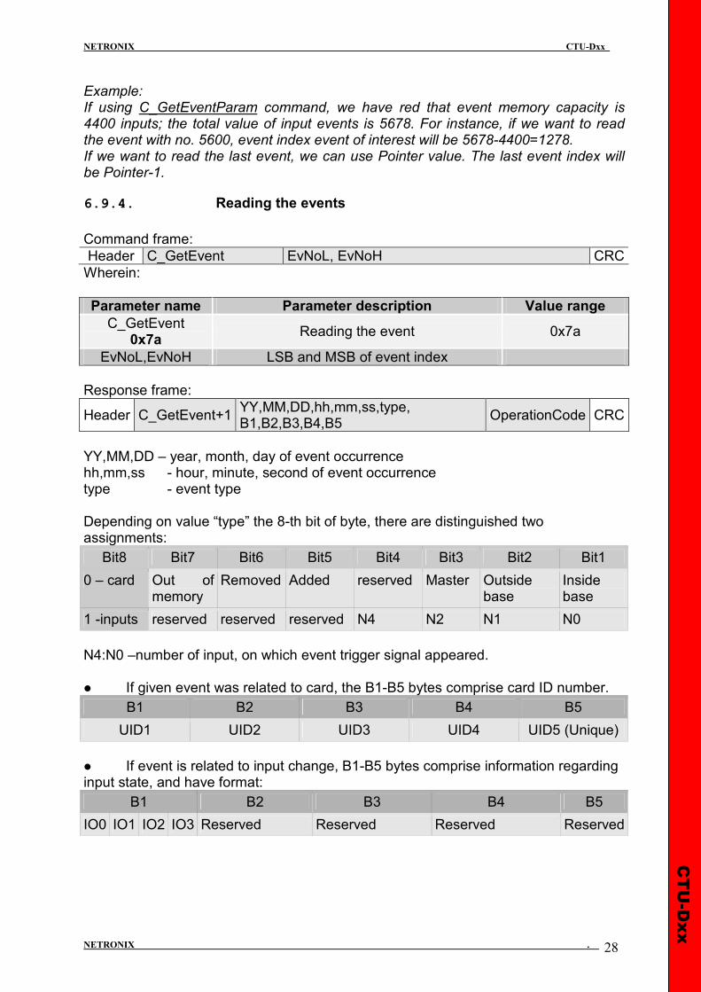
Example: If using C_GetEventParam command, we have red that event memory capacity is 4400 inputs; the total value of input events is 5678. For instance, if we want to read the event with no. 5600, event index event of interest will be 5678-4400=1278. If we want to read the last event, we can use Pointer value. The last event index will be Pointer-1.
6.9.4. Reading the events
Command frame:
Header C_GetEvent EvNoL, EvNoH CRC
Wherein:
Parameter name Parameter description Value range
C_GetEvent 0x7a
Reading the event 0x7a
EvNoL,EvNoH LSB and MSB of event index
Response frame:
Header C_GetEvent+1 YY,MM,DD,hh,mm,ss,type, B1,B2,B3,B4,B5
OperationCode CRC
YY,MM,DD – year, month, day of event occurrence hh,mm,ss - hour, minute, second of event occurrence type - event type Depending on value “type” the 8-th bit of byte, there are distinguished two assignments:
Bit8 Bit7 Bit6 Bit5 Bit4 Bit3 Bit2 Bit1
0 – card Out of memory
Removed Added reserved Master Outside base
Inside base
1 -inputs reserved reserved reserved N4 N2 N1 N0
N4:N0 –number of input, on which event trigger signal appeared. � If given event was related to card, the B1-B5 bytes comprise card ID number.
B1 B2 B3 B4 B5
UID1 UID2 UID3 UID4 UID5 (Unique)
� If event is related to input change, B1-B5 bytes comprise information regarding input state, and have format:
B1 B2 B3 B4 B5
IO0 IO1 IO2 IO3 Reserved Reserved Reserved Reserved
CTU-Dxx
NETRONIX CTU-Dxx
NETRONIX . 29
6.10. Other commands
6.10.1. Remote reset of reader
Command frame:
Header C_Reset CRC
Where:
Parameter name Parameter description Value range
C_Reset Remote reader reset 0xd0
Response frame:
Header C_Reset +1 OperationCode CRC
6.10.2. Reading-out the reader software
Command frame:
Header C_FirmwareVersion CRC
Where:
Parameter name Parameter description Value range
C_FirmwareVersion Read-out of reader software version 0xfe
Response frame:
Header C_FirmwareVersion+1 Data1…..n OperationCode CRC
Where: Data1…n is sequence of dots, which are written as an ASCII codes.
6.10.3. Change buzzer volume
Use this command to set and store setting in EEPROM memory.
Command frame:
Header C_BuzzerConfig volume CRC
Gdzie:
Parameter name Parameter description Value range
C_BuzzerConfig 0xD8
volume Buzzer volume value 0x00-0x0a
Response frame:
Header C_BuzzerConfig+1 OperationCode CRC
CTU-Dxx
NETRONIX CTU-Dxx
NETRONIX . 30
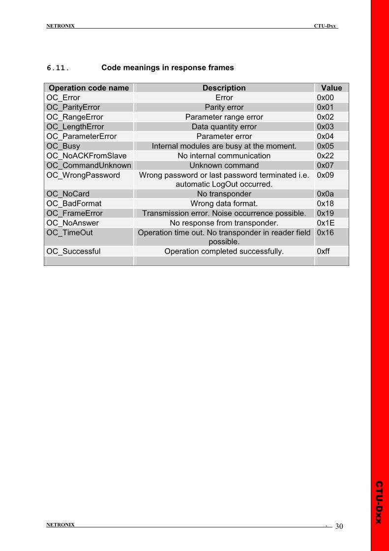
6.11. Code meanings in response frames
Operation code name Description Value
OC_Error Error 0x00
OC_ParityError Parity error 0x01
OC_RangeError Parameter range error 0x02
OC_LengthError Data quantity error 0x03
OC_ParameterError Parameter error 0x04
OC_Busy Internal modules are busy at the moment. 0x05
OC_NoACKFromSlave No internal communication 0x22
OC_CommandUnknown Unknown command 0x07
OC_WrongPassword Wrong password or last password terminated i.e. automatic LogOut occurred.
0x09
OC_NoCard No transponder 0x0a
OC_BadFormat Wrong data format. 0x18
OC_FrameError Transmission error. Noise occurrence possible. 0x19
OC_NoAnswer No response from transponder. 0x1E
OC_TimeOut Operation time out. No transponder in reader field possible.
0x16
OC_Successful Operation completed successfully. 0xff
CTU-Dxx
NETRONIX CTU-Dxx
NETRONIX . 31
7. Mechanism of Master ID
Master ID mechanism is based on principle the quick adding/removing of user card to/out of reader memory by means of „master card”. If you want to register a card as a „master card”, it is required to clear card memory first by means of reset function to factory defaults. After clearing the memory, apply selected card to module, whenever you like. This moment, the card becomes “master card”. It is impossible to remove or add the master card by means of other card. If you want to register a card as a “user card”, apply “master card” to reader first, and next during five seconds, apply registered card. If you want to remove “user card” from memory, apply “master card” to reader first, and next during five seconds apply card which is being removed. After applying to a reader the “user card”, the reader enables electric output, which has been programmed as a controlled by internal access control mechanism.
CTU-Dxx
NETRONIX CTU-Dxx
NETRONIX . 32
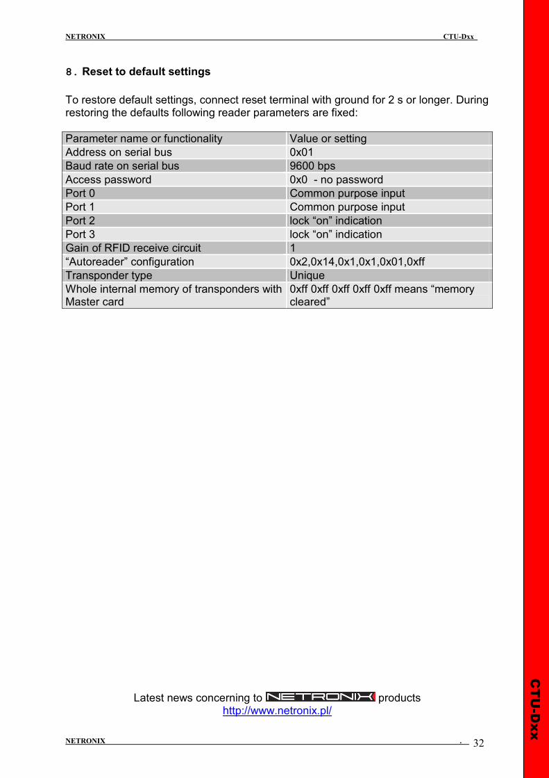
8. Reset to default settings
To restore default settings, connect reset terminal with ground for 2 s or longer. During restoring the defaults following reader parameters are fixed:
Parameter name or functionality Value or setting
Address on serial bus 0x01
Baud rate on serial bus 9600 bps
Access password 0x0 - no password
Port 0 Common purpose input
Port 1 Common purpose input
Port 2 lock “on” indication
Port 3 lock “on” indication
Gain of RFID receive circuit 1
“Autoreader” configuration 0x2,0x14,0x1,0x1,0x01,0xff
Transponder type Unique
Whole internal memory of transponders with Master card
0xff 0xff 0xff 0xff 0xff means “memory cleared”
Latest news concerning to products http://www.netronix.pl/