Embed Size (px)
Citation preview
Structural Engineering and Mechanics, Vol. 54, No. 6 (2015) 1267-1281
DOI: http://dx.doi.org/10.12989/sem.2015.54.6.1267 1267
Copyright © 2015 Techno-Press, Ltd. http://www.techno-press.org/?journal=sem&subpage=8 ISSN: 1225-4568 (Print), 1598-6217 (Online)
Shear response of lean duplex stainless steel plate girders
Salam R. Armoosh1, A.R. Khalim1a and Akram Sh. Mahmood2b
1Department of Civil and Structural Engineering, Universiti Kebangsaan Malaysia, Bangi, Selangor, Malaysia
2Department of Civil Engineering, University of Al-Anbar, Ramadi, Anbar, Iraq
(Received September 12, 2013, Revised February 18, 2015, Accepted May 15, 2015)
Abstract. Carbon steel plate girders have been used on a large scale in the building industry. Nowadays,
Lean Duplex Stainless Steel (LDSS) plate girders are gaining popularity as they possess greater strength and
are more impervious to corrosion than those that are constructed from carbon steel. Regardless of their
popularity, there is very limited information with regards to their shear behavior. In this paper, the non-linear
finite element analysis was employed to investigate the shear behavior of LDSS plate girders. Parameters
considered were the web thickness, the flange width, and the girders aspect ratio. The analysis revealed that
although the shear behavior of the LDSS girders was no different from that of carbon steel plate girders, it
had obviously been affected by the non-linearity of the material. Furthermore, the selected parameters were
found to pronounce effect on the shear capacity of the LDSS girders. That is, the shear capacity increased
considerably with web thickness, and increased slightly with flange width. However, it was reduced as the
aspect ratio increased. Comparisons between the finite element analysis failure loads and those predicted by
the current European Code of Practice revealed that the latter underestimated the shear strength of the LDSS
plate girders.
Keywords: lean duplex stainless steel (LDSS); shear response; ultimate shear capacity; finite element
analysis; Welded I-sections
1. Introduction
The modern duplex stainless steel, which is produced from cast alloys, has been a common
engineering material since its appearance in the early 1980s. It is popular because it possesses an
appealing combination of properties, such as durability and a tremendous resistance to corrosion
cracking under chloride stress. Since then, various grades of duplex have been developed and there
has been an increase in its production. However, duplex stainless steels are recognized as a
possible substitute for various other types of stainless steel and nickel based alloys. This rapid
growth in production has led to an increase in researches into the subject (Gunn 1997).
Generally, the construction industry focuses primarily on the austenitic grades. EN
1.4301/1.4307 and EN 1.4401/1.4404, which contain roughly 8-11% of nickel, are the most
Corresponding author, Master Student, E-mail: [email protected] aAssociate Professor bLecturer
Salam R. Armoosh, A.R. Khalim and Akram Sh. Mahmood
frequently used grades of austenitic stainless steel. As nickel balances the austenitic
microstructure, it adds to the related positive features such as formability, weldability, toughness,
and high temperature attributes. However, much of the cost of austenitic stainless steel is mainly
due to the presence of nickel. Therefore, due to the recent high prices of nickel, there has been a
greater demand for lean duplexes with low nickel content (around 1.5%), such as EN 1.4162 grade
(Gardner 2005).
The design of stainless steel parts is more complex than that of carbon steels because of the
differences between their mechanical behaviors. The stress-strain curves of stainless steels have a
gradual yield with fairly low proportional limits. Osgood and Ramberg (1943) proposed a simple
formula for describing the stress-strain curve by using three parameters: namely, Young‟s modulus
and two secant yield strengths.
Unosson and Olsson (2003) carried out experimental and theoretical study to investigate the
resistance of welded I-girders made of stainless subjected to concentrated force and shear. They
concluded that ENV 1993-1-5:1997 is in better agreement with the results from this study than
ENV 1993-1-1:1992, and can be used for predicting the resistance to concentrated loads or shear.
Rasmussen (2003) developed an expression for the stress-strain curves for stainless steel alloys,
which can be applied over the full range of strains. The expression can be used for the design and
numerical modeling of stainless steel parts and elements which undergo stresses beyond the 0.2%
proof stress in their final limit state. In this stress range, the current stress-strain curves, which are
based on the Ramberg-Osgood expression, become extremely inaccurate mainly because these
curve extrapolations are meant for stresses lower than the 0.2% proof stress. The extrapolations
become markedly inaccurate for alloys with obvious strain hardening. Using his experimental data
and data from previous researchers, Rasmussen was able to ascertain the full range of the stress-
strain curve, which is employed in the numerical part of this paper.
In designing lean steel plated structures, one of the most vital load issues to be taken into
consideration is resistance to shear. However, very little research has been carried out with regard
to this issue in stainless steel structures and this material has only recently made its appearance in
the construction industry. An experimental and numerical study was conducted in the Laboratory
of Structural Technology of the Department of Construction Engineering in UPC by Real et al.
(2007) to investigate the effect of shear load on stainless steel plated girders at approximate service
conditions and what happens to the girders until failure occurs. The results of the experiment were
compared to those obtained from the application of ENV 1993-1-4 and those provided by the
numerical model.
In 2007, experiments were conducted at UPC by Estrada et al. (2007 a, b) as part of a wide
ranging study on the shear behavior of stainless steel girders aimed at understanding how stainless
steel plate girders react to shear loads. Theofanous and Gardner (2010) focused their research on
lean duplex stainless steel hollow sections by performing an FE analysis. Since 2010, the study of
stainless steel plate girders has become more widespread because of the increasing importance of
stainless steel within the building industry. Hassanein (2010) performed a study on the features of
the shear failure mechanism in stainless steel plate girders.
Hassanein (2011) recently introduced a theoretical set of models to examine the shear failure of
the lean duplex stainless steel Grade EN 1.4162 plate girders. Longshithung Patton and Singh
(2012) conducted tests on the use of LDSS (lean duplex stainless steel) in hollow columns of
varying cross-sectional shapes under pure axial compression.
Saliba and Gardner (2013) conducted an experimental and numerical study at the Imperial
College, London to examine the structural behavior of lean duplex stainless steel welded I-sections
1268
Shear response of lean duplex stainless steel plate girders
as well as the shear response of lean duplex stainless steel plate girders. The modes of failure that
were obtained from the outcomes of both the experiments and the FE simulations were discussed
and the shear design provisions of EN 1993-1-4 were evaluated. However, the FE validation in this
paper has been compared with the experimental data obtained from the study by Saliba and
Gardner (2013).
Saliba et al. (2014) reviewed the previous researched conducted to investigate the behavior and
design of stainless steel plate girders loaded in shear. They found that the current EN 1993-1-4
shear design expressions are conservative and better results can be achieved by using the proposed
design expressions of Estrada et al. (2007 a, b) and EN 1993-1-5.
The finite element method (FEM) was employed in this study to examine the shear behavior of
LDSS girders. The following factors were taken into consideration: the web thickness, the flange
width, and the girders aspect ratio. Therefore, the current study presents a set of models to explore
the shear response and strength of lean duplex stainless steel grade EN 1.4162 rigid end stiffeners.
As such, the impact of various factors such as flange width to web depth ratio (bf/hw), flange to
web thickness ratio (tf/tw), as well as web height to web thickness ratio (hw/tw) have been taken into
account.
2. Finite element model
2.1 General
In order to examine the shear response of the nonlinear lean duplex stainless steel (LDSS) plate
girders, a numerical analysis was carried out on the actual plate girders. The current model using
the finite element program was based on the experimental program that presented by Saliba and
Gardner (2013) for lean duplex stainless steel plate girders with square web panels. In total, 24
plate girder models were analyzed throughout the numerical investigation by employing the
LUSAS V14.3. The following features were investigated: web thickness, flange width, and aspect
ratio. The performances of these variables were also calculated according to the following
parameters:
1. Flange to web thickness ratio (tf/tw); (2, 2.4, 3 and 4),
2. Flange width to web depth ratio (bf/hw); (0.25, 0.33 and 0.41),
3. Web plate slenderness (hw/tw); (100, 120, 150, and 200).
For all the finite element models in this study, the web depth of the plate girders was fixed at
600 mm, while the span of the plate girders for the aspect ratio=1 and aspect ratio=2 were 1200
and 2400, respectively. The particulars of the parametric studies with both aspect ratios are shown
in Table 1. The numerical investigation was divided into three groups according to the flange
width (bf). The first group had a flange width of 150 mm, the second group had a flange width of
200 mm, and the third group had a flange width of 250 mm. The web thickness for each group
varied between 3 to 6 mm. The same details above apply to both aspect ratios 1 and 2.
The finite element analysis program comprised three groups. The lean duplex stainless steel
plate girders (LDSS) were labeled in such a way that the aspect ratio number could be recognized
from the label. The group was represented by the letter G and this was followed by the group
number and by numbers in parentheses, which gave the thickness of the flange and the web in
millimeters separated by a dash. For example, the label „„LDSS1G1 (12−4)‟‟ would describe a Table 1 Finite element program
1269
Salam R. Armoosh, A.R. Khalim and Akram Sh. Mahmood
Group bf (mm) 𝑏𝑓 ℎ𝑤∗ tw (mm) hw/tw tf (mm) tf/tw
LDSSG1 150 0.25 3, 4,5, 6 200, 150, 120, 100 12 4, 3,2.4, 2
LDSSG2 200 0.33 3, 4,5, 6 200, 150, 120, 100 12 4, 3,2.4, 2
LDSSG3 250 0.41 3, 4,5, 6 200, 150, 120, 100 12 4, 3,2.4, 2
*hw=600 mm
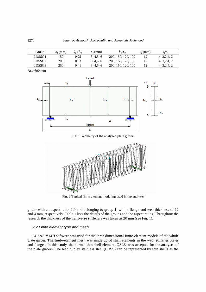
Fig. 1 Geometry of the analyzed plate girders
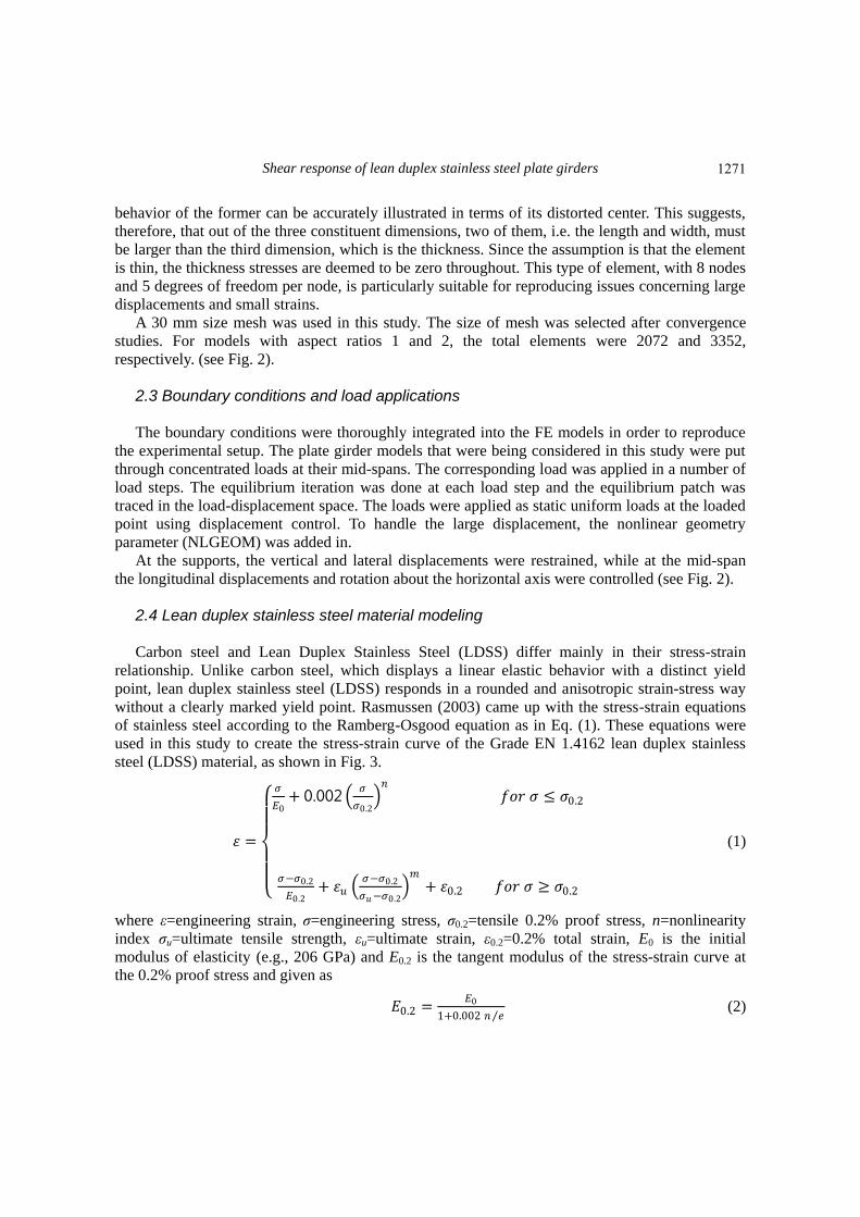
Fig. 2 Typical finite element modeling used in the analyses
girder with an aspect ratio=1.0 and belonging to group 1, with a flange and web thickness of 12
and 4 mm, respectively. Table 1 lists the details of the groups and the aspect ratios. Throughout the
research the thickness of the transverse stiffeners was taken as 20 mm (see Fig. 1).
2.2 Finite element type and mesh
LUSAS V14.3 software was used for the three dimensional finite-element models of the whole
plate girder. The finite-element mesh was made up of shell elements in the web, stiffener plates
and flanges. In this study, the normal thin shell element, QSL8, was accepted for the analyses of
the plate girders. The lean duplex stainless steel (LDSS) can be represented by thin shells as the
1270
Shear response of lean duplex stainless steel plate girders
behavior of the former can be accurately illustrated in terms of its distorted center. This suggests,
therefore, that out of the three constituent dimensions, two of them, i.e. the length and width, must
be larger than the third dimension, which is the thickness. Since the assumption is that the element
is thin, the thickness stresses are deemed to be zero throughout. This type of element, with 8 nodes
and 5 degrees of freedom per node, is particularly suitable for reproducing issues concerning large
displacements and small strains.
A 30 mm size mesh was used in this study. The size of mesh was selected after convergence
studies. For models with aspect ratios 1 and 2, the total elements were 2072 and 3352,
respectively. (see Fig. 2).
2.3 Boundary conditions and load applications
The boundary conditions were thoroughly integrated into the FE models in order to reproduce
the experimental setup. The plate girder models that were being considered in this study were put
through concentrated loads at their mid-spans. The corresponding load was applied in a number of
load steps. The equilibrium iteration was done at each load step and the equilibrium patch was
traced in the load-displacement space. The loads were applied as static uniform loads at the loaded
point using displacement control. To handle the large displacement, the nonlinear geometry
parameter (NLGEOM) was added in.
At the supports, the vertical and lateral displacements were restrained, while at the mid-span
the longitudinal displacements and rotation about the horizontal axis were controlled (see Fig. 2).
2.4 Lean duplex stainless steel material modeling
Carbon steel and Lean Duplex Stainless Steel (LDSS) differ mainly in their stress-strain
relationship. Unlike carbon steel, which displays a linear elastic behavior with a distinct yield
point, lean duplex stainless steel (LDSS) responds in a rounded and anisotropic strain-stress way
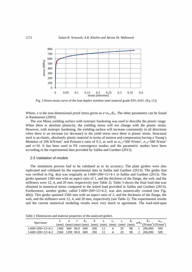
without a clearly marked yield point. Rasmussen (2003) came up with the stress-strain equations
of stainless steel according to the Ramberg-Osgood equation as in Eq. (1). These equations were
used in this study to create the stress-strain curve of the Grade EN 1.4162 lean duplex stainless
steel (LDSS) material, as shown in Fig. 3.
𝜀 =
𝜎
𝐸0+ 0.002
𝜎
𝜎0.2 𝑛
𝑓𝑜𝑟 𝜎 ≤ 𝜎0.2
𝜎−𝜎0.2
𝐸0.2+ 𝜀𝑢
𝜎−𝜎0.2
𝜎𝑢−𝜎0.2 𝑚
+ 𝜀0.2 𝑓𝑜𝑟 𝜎 ≥ 𝜎0.2
(1)
where ε=engineering strain, σ=engineering stress, σ0.2=tensile 0.2% proof stress, n=nonlinearity
index σu=ultimate tensile strength, εu=ultimate strain, ε0.2=0.2% total strain, E0 is the initial
modulus of elasticity (e.g., 206 GPa) and E0.2 is the tangent modulus of the stress-strain curve at
the 0.2% proof stress and given as
𝐸0.2 =𝐸0
1+0.002 𝑛 𝑒 (2)
1271
Salam R. Armoosh, A.R. Khalim and Akram Sh. Mahmood
0
100
200
300
400
500
600
700
800
0 0.05 0.1 0.15 0.2 0.25 0.3 0.35 0.4
stre
ss (
MP
a)
strain (mm/mm)
Fig. 3 Stress-strain curve of the lean duplex stainless steel material grade EN1.4162. (Eq. (1))
Where, e is the non-dimensional proof stress given as e=σ0.2/E0. The other parameters can be found
in Rasmussen (2003).
The von Mises yielding surface with isotropic hardening was used to describe the plastic range.
When there is absolute plasticity, the yielding stress will not change with the plastic strain.
However, with isotropic hardening, the yielding surface will increase consistently in all directions
when there is an increase (or decrease) in the yield stress once there is plastic strain. Structural
steel is an elastic, absolutely plastic material in terms of tension and compression having a Young‟s
Modulus of 206 KN/mm2 and Poisson‟s ratio of 0.3, as well as σ0.2=500 N/mm2, σ1.0=580 N/mm2
and n=10. It has been used in FE convergence studies and the parametric studies have been
according to the experimental data provided by Saliba and Gardner (2013).
2.5 Validation of models
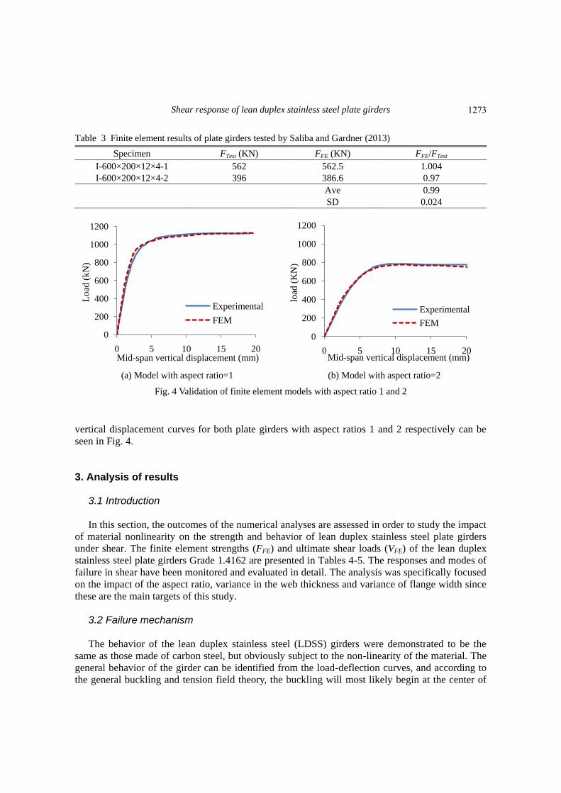
The simulation process had to be validated as to its accuracy. The plate girders were also
replicated and validated by the experimental data in Saliba and Gardner (2013). The girder that
was verified in Fig. 4(a) was originally as I-600×200×12×4-1 in Saliba and Gardner (2013). The
girder spanned 1360 mm with an aspect ratio of 1, and the thickness of the flange, the web, and the
stiffeners were 12, 4, and 20 mm, respectively (see Table 2). Table 3 shows the final load that was
obtained in numerical terms compared to the tested load provided in Saliba and Gardner (2013).
Furthermore, another girder, called I-600×200×12×4-2, was also numerically created (see Fig.
4(b)). This girder spanned 2560 mm with an aspect ratio of 2, and the thickness of the flange, the
web, and the stiffeners were 12, 4, and 20 mm, respectively (see Table 2). The experimental results
and the current numerical modeling results were very much in agreement. The load-mid-span
Table 2 Dimensions and material properties of the analyzed girders
Specimen L
(mm)
a
(mm)
e
(mm)
hw
(mm)
b
(mm) tf
(mm)
tw
(mm) ts
(mm)
bs
(mm) a/hw
E0
(N/mm2)
σ0.2
(N/mm2)
I-600×200×12×4-1 1360 600 80.0 600 200 12 4 20 98 1 206,000 500
I-600×200×12×4-2 2560 1200 80.0 600 200 12 4 20 98 2 206,000 500
1272
Shear response of lean duplex stainless steel plate girders
Table 3 Finite element results of plate girders tested by Saliba and Gardner (2013)
Specimen FTest (KN) FFE (KN) FFE/FTest
I-600×200×12×4-1 562 562.5 1.004
I-600×200×12×4-2 396 386.6 0.97
Ave 0.99
SD 0.024
(a) Model with aspect ratio=1 (b) Model with aspect ratio=2
Fig. 4 Validation of finite element models with aspect ratio 1 and 2
vertical displacement curves for both plate girders with aspect ratios 1 and 2 respectively can be
seen in Fig. 4.
3. Analysis of results 3.1 Introduction In this section, the outcomes of the numerical analyses are assessed in order to study the impact
of material nonlinearity on the strength and behavior of lean duplex stainless steel plate girders
under shear. The finite element strengths (FFE) and ultimate shear loads (VFE) of the lean duplex
stainless steel plate girders Grade 1.4162 are presented in Tables 4-5. The responses and modes of
failure in shear have been monitored and evaluated in detail. The analysis was specifically focused
on the impact of the aspect ratio, variance in the web thickness and variance of flange width since
these are the main targets of this study.
3.2 Failure mechanism
The behavior of the lean duplex stainless steel (LDSS) girders were demonstrated to be the
same as those made of carbon steel, but obviously subject to the non-linearity of the material. The
general behavior of the girder can be identified from the load-deflection curves, and according to
the general buckling and tension field theory, the buckling will most likely begin at the center of
0
200
400
600
800
1000
1200
0 5 10 15 20
Lo
ad (
kN
)
Mid-span vertical displacement (mm)
Experimental
FEM
0
200
400
600
800
1000
1200
0 5 10 15 20
load
(K
N)
Mid-span vertical displacement (mm)
Experimental
FEM
1273
Salam R. Armoosh, A.R. Khalim and Akram Sh. Mahmood
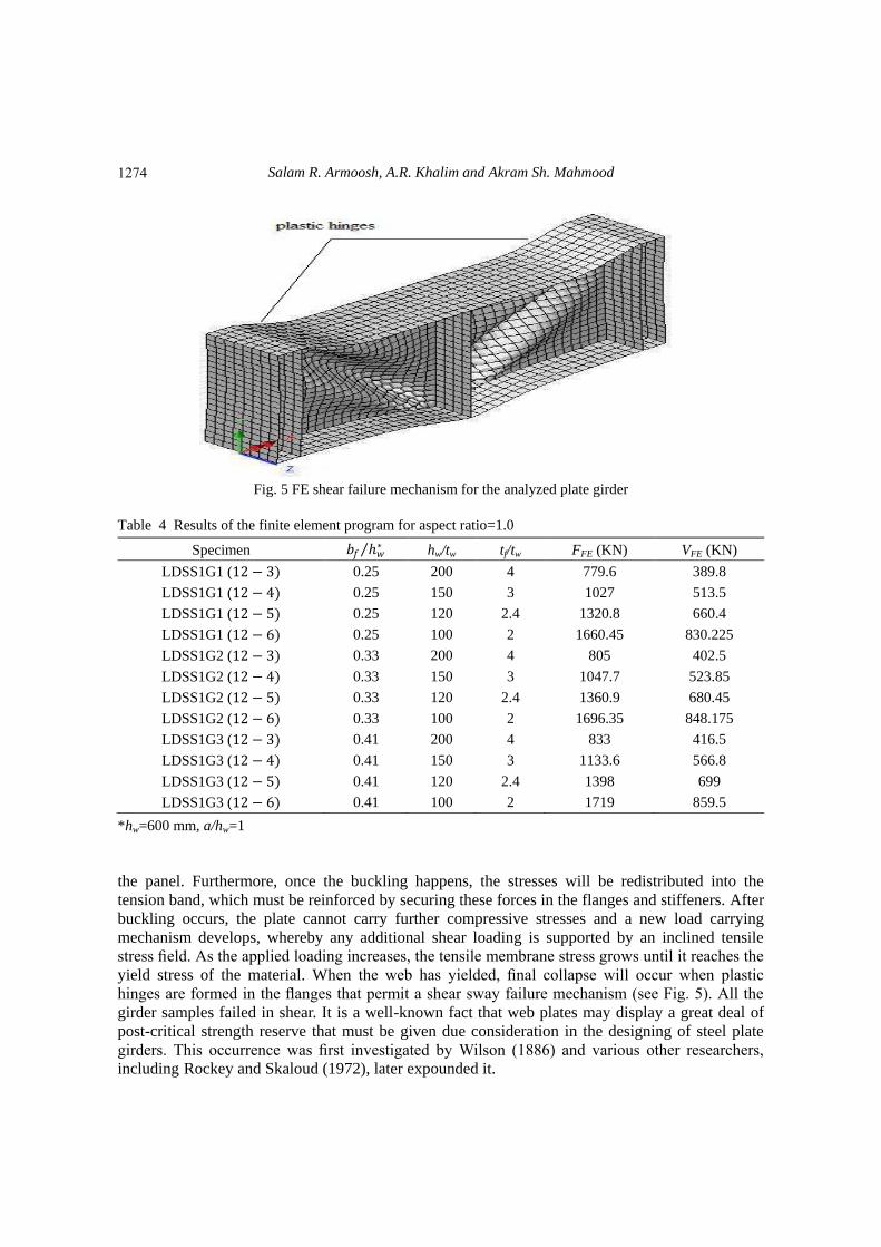
Fig. 5 FE shear failure mechanism for the analyzed plate girder
Table 4 Results of the finite element program for aspect ratio=1.0
Specimen 𝑏𝑓 ℎ𝑤∗ hw/tw tf/tw FFE (KN) VFE (KN)
LDSS1G1 (12 − 3) 0.25 200 4 779.6 389.8
LDSS1G1 (12 − 4) 0.25 150 3 1027 513.5
LDSS1G1 (12 − 5) 0.25 120 2.4 1320.8 660.4
LDSS1G1 (12 − 6) 0.25 100 2 1660.45 830.225
LDSS1G2 (12 − 3) 0.33 200 4 805 402.5
LDSS1G2 (12 − 4) 0.33 150 3 1047.7 523.85
LDSS1G2 (12 − 5) 0.33 120 2.4 1360.9 680.45
LDSS1G2 (12 − 6) 0.33 100 2 1696.35 848.175
LDSS1G3 (12 − 3) 0.41 200 4 833 416.5
LDSS1G3 (12 − 4) 0.41 150 3 1133.6 566.8
LDSS1G3 (12 − 5) 0.41 120 2.4 1398 699
LDSS1G3 (12 − 6) 0.41 100 2 1719 859.5
*hw=600 mm, a/hw=1
the panel. Furthermore, once the buckling happens, the stresses will be redistributed into the
tension band, which must be reinforced by securing these forces in the flanges and stiffeners. After
buckling occurs, the plate cannot carry further compressive stresses and a new load carrying
mechanism develops, whereby any additional shear loading is supported by an inclined tensile
stress field. As the applied loading increases, the tensile membrane stress grows until it reaches the
yield stress of the material. When the web has yielded, final collapse will occur when plastic
hinges are formed in the flanges that permit a shear sway failure mechanism (see Fig. 5). All the
girder samples failed in shear. It is a well-known fact that web plates may display a great deal of
post-critical strength reserve that must be given due consideration in the designing of steel plate
girders. This occurrence was first investigated by Wilson (1886) and various other researchers,
including Rockey and Skaloud (1972), later expounded it.
1274
Shear response of lean duplex stainless steel plate girders
Table 5 Results of the finite element program for aspect ratio=2.0
Specimen 𝑏𝑓 ℎ𝑤∗ hw/tw tf/tw FFE (KN) VFE (KN)
LDSS2G1 (12 − 3) 0.25 200 4 517 258.5
LDSS2G1 (12 − 4) 0.25 150 3 727.4 363.7
LDSS2G1 (12 − 5) 0.25 120 2.4 1044 522
LDSS2G1 (12 − 6) 0.25 100 2 1309 654.5
LDSS2G2 (12 − 3) 0.33 200 4 536 268
LDSS2G2 (12 − 4) 0.33 150 3 773 386.5
LDSS2G2 (12 − 5) 0.33 120 2.4 1075.7 537.85
LDSS2G2 (12 − 6) 0.33 100 2 1408.77 704.4
LDSS2G3 (12 − 3) 0.41 200 4 540 270
LDSS2G3 (12 − 4) 0.41 150 3 785 392.5
LDSS2G3 (12 − 5) 0.41 120 2.4 1083.7 541.85
LDSS2G3 (12 − 6) 0.41 100 2 1430.8 715.4
*hw=600 mm, a/hw=2.0
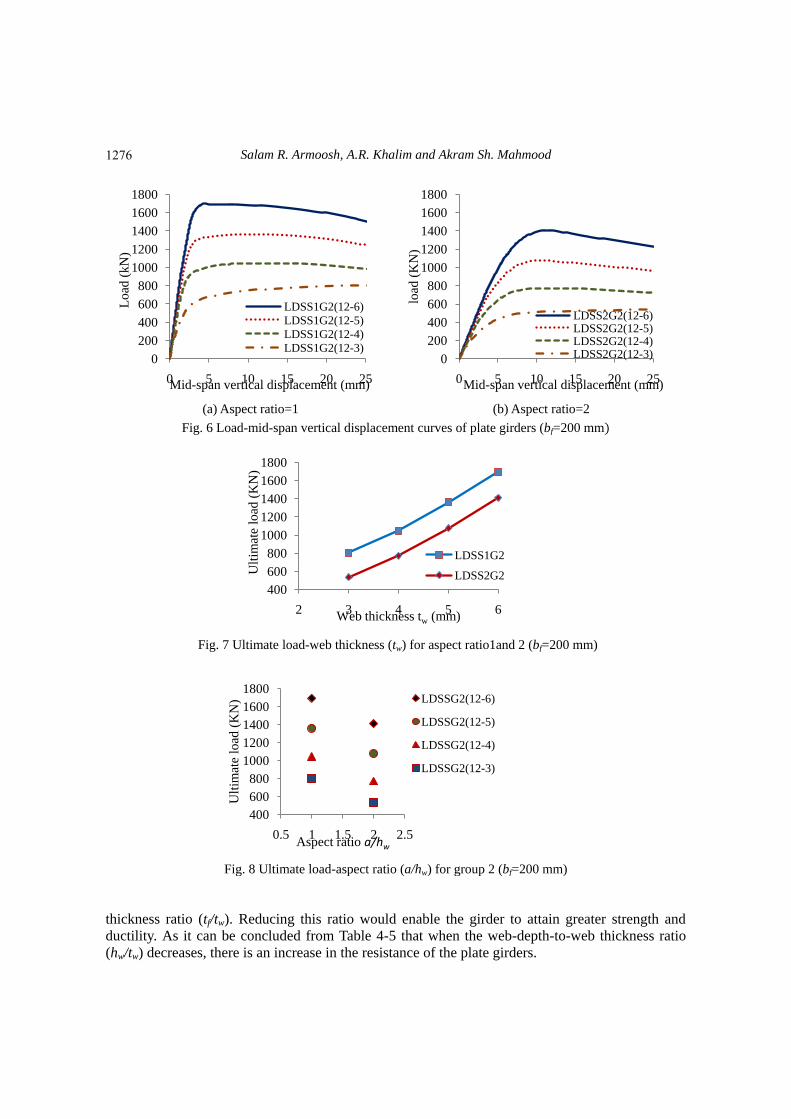
3.3 Load-displacement relationship of the plate girders
In order to investigate the structural behavior of lean duplex stainless steel (LDSS) plate
girders, parametric studies must be carried out on the relationship between the load and the mid-
span vertical displacement, together with the aspect ratios 1 and 2 (see Figs. 6(a)-(b)). From these
curves, it is possible to detect the main changes in the behavior of the girder from the variations in
the parameters such as web thickness, flange width-to-depth ratio (bf/hw), web slenderness (hw/tw),
flange-to-web thickness ratio (tf/tw) as well as the aspect ratio. The results indicate that the flange
width-to-web depth ratio (bf/hw) has an effect on the failure modes of the duplex stainless steel
plate girders. When the flange width-to-web depth ratio (bf/hw) is 0.25 and the flange-to-web
thickness ratio (tf/tw) for both aspect ratios is more than 2, then the failure mode is always in shear.
However, when the flange width-to-web depth ratio (bf/hw) is 0.30 or 0.41, regardless of the
slenderness of the web plate (hw/tw), and when the flange-to-web thickness ratio (tf/tw) for both
aspect ratios is more than 2, the failure mode is always in shear. It should be noted that the models
in Fig. 6 have a flange width of (bf=200 mm).
3.4 Effect of chosen parameters
Once the obtained numerical results were in good general agreement with the experimental
results, a sequence of chosen parameters was introduced to evaluate the general behavior of the
lean duplex stainless steel plate girders.
3.4.1 Web thickness (tw) Fig. 7 shows the effect of web thickness on the ultimate shear loads of lean duplex stainless
steel (LDSS) plate girders. It can be observed that any increase in the thickness of the web led to
an increase in the ultimate load shear as well.
However, since the flange thickness for all the FE models was fixed at 12 mm, the structural
behavior of the lean duplex stainless (LDSS) plate girders was influenced by the flange-to-web
1275
Salam R. Armoosh, A.R. Khalim and Akram Sh. Mahmood
0
200
400
600
800
1000
1200
1400
1600
1800
0 5 10 15 20 25
Lo
ad (
kN
)
Mid-span vertical displacement (mm)
LDSS1G2(12-6)
LDSS1G2(12-5)
LDSS1G2(12-4)
LDSS1G2(12-3)0
200
400
600
800
1000
1200
1400
1600
1800
0 5 10 15 20 25
load
(K
N)
Mid-span vertical displacement (mm)
LDSS2G2(12-6)LDSS2G2(12-5)LDSS2G2(12-4)LDSS2G2(12-3)
400
600
800
1000
1200
1400
1600
1800
2 3 4 5 6
Ult
imat
e lo
ad (
KN
)
Web thickness tw (mm)
LDSS1G2
LDSS2G2
400
600
800
1000
1200
1400
1600
1800
0.5 1 1.5 2 2.5
Ult
imat
e lo
ad (
KN
)
Aspect ratio a/hw
LDSSG2(12-6)
LDSSG2(12-5)
LDSSG2(12-4)
LDSSG2(12-3)
(a) Aspect ratio=1 (b) Aspect ratio=2
Fig. 6 Load-mid-span vertical displacement curves of plate girders (bf=200 mm)
Fig. 7 Ultimate load-web thickness (tw) for aspect ratio1and 2 (bf=200 mm)
Fig. 8 Ultimate load-aspect ratio (a/hw) for group 2 (bf=200 mm)
thickness ratio (tf/tw). Reducing this ratio would enable the girder to attain greater strength and
ductility. As it can be concluded from Table 4-5 that when the web-depth-to-web thickness ratio
(hw/tw) decreases, there is an increase in the resistance of the plate girders.
1276
Shear response of lean duplex stainless steel plate girders
3.4.2 Flange width (bf) The rotated stress field method, based on Hoglund‟s theory (1997) was proposed for the EN
1993-1-5. The design terms included the flange contribution (Vbf,Rd) in the resistant mechanism that
allowed a secured tension field to be created so as to raise the shear capacity.
The effect of flange contribution has been examined in the current study and it was observed
that the flange contribution can affect and raise the ultimate shear loads. Since this study is only
focused on changes to the flange width, therefore the flange contribution has only a slight effect on
variations in the flange width (150, 200 and 250 mm). The results also illustrate that with the web
depth fixed at 600 mm, an increase in the flange width-to-web depth (bf/hw) leads to an increase in
the resistance of the plate girders, as seen in Tables 4-5.
3.4.3 Aspect ratio (a/hw) It is crucial that the effect of the aspect ratio of the plate girders has been investigated as the
aspect ratio of the web panel has a great effect on the shear failure of lean duplex stainless steel
(LDSS) plate girders. This work has been carried out and both aspect ratios 1 and 2 have been
discussed.
One interesting observation is that those panels with equal values of web slenderness (hw/tw) but
different aspect ratios displayed different strengths according to the web contribution. In fact, the
higher aspect ratio values contributed less of the web panel (χw) to the whole resistance mechanism
(see Fig. 8).
It was noted that for the slender lean duplex stainless steel (LDSS) plate girders (LDSS2G1, 2,
3 (12-3)), shear buckling almost occurred along the linear path. Hence, geometrical nonlinearity
was the cause of the failure because the plastic shear resistance for that plate girder was less than
the maximum elastic applied load (623 KN) at which the web is still under pure shear for the web
thickness of 3 mm, which is calculated according to the following equation:
𝜏 =𝐹 2
ℎ𝑤 𝑡𝑤 (3)
The von Mises stress (𝜎𝑣𝑚 = 𝜏 3) may be taken to be equal to σ0.01=300 MPa. In that girder,
the impact of the material non-linearity occurred later during the creation of the tension field in the
post-critical range.
In the somewhat sturdy and thick girders, buckling happened in the nonlinear range of the
duplex stainless steel material. The material nonlinearity effect occurred because the final loads
that were applied to these girders were greater than the maximum elastic load (623 KN) that was
applied.
3.5 Comparison with design code (EN 1993-1-4)
This comparison involved the EN 1.4162 lean duplex stainless steel (LDSS) girders depicted by
shear failure. As shown in Table 6, the EN 1993-1-4 was used to make a comparison between the
finite element ultimate shear force and the factored design shear resistance.
The design shear resistance, Vc,Rd, was assumed to be the lesser of the shear buckling resistance,
Vb,Rd, , based on Clause 5.2(1) of EN 1993-1-5 modified by (3) and (4) and the plastic resistance,
Vpl,Rd, based on Clause 6.2.6.of EN 1993-1-1. Nevertheless, the rotated stress field method, which
is based on Hoglund‟s theory (1997), was suggested in EN 1993-1-4. The design terms included
the flange contribution (Vbf,Rd) in the resistant mechanism that allowed the creation of a secured
tension field that raised the shear capacity.
1277
Salam R. Armoosh, A.R. Khalim and Akram Sh. Mahmood
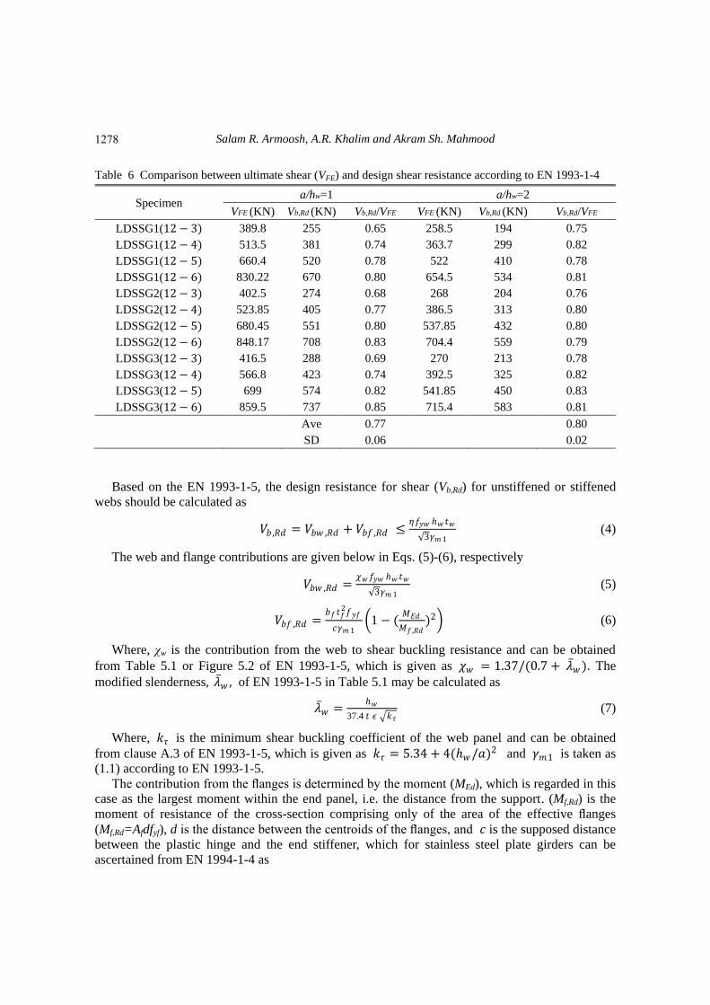
Table 6 Comparison between ultimate shear (VFE) and design shear resistance according to EN 1993-1-4
Specimen a/hw=1 a/hw=2
VFE (KN) Vb,Rd (KN) Vb,Rd/VFE VFE (KN) Vb,Rd (KN) Vb,Rd/VFE
LDSSG1(12 − 3) 389.8 255 0.65 258.5 194 0.75
LDSSG1(12 − 4) 513.5 381 0.74 363.7 299 0.82
LDSSG1(12 − 5) 660.4 520 0.78 522 410 0.78
LDSSG1(12 − 6) 830.22 670 0.80 654.5 534 0.81
LDSSG2(12 − 3) 402.5 274 0.68 268 204 0.76
LDSSG2(12 − 4) 523.85 405 0.77 386.5 313 0.80
LDSSG2(12 − 5) 680.45 551 0.80 537.85 432 0.80
LDSSG2(12 − 6) 848.17 708 0.83 704.4 559 0.79
LDSSG3(12 − 3) 416.5 288 0.69 270 213 0.78
LDSSG3(12 − 4) 566.8 423 0.74 392.5 325 0.82
LDSSG3(12 − 5) 699 574 0.82 541.85 450 0.83
LDSSG3(12 − 6) 859.5 737 0.85 715.4 583 0.81
Ave 0.77 0.80
SD 0.06 0.02
Based on the EN 1993-1-5, the design resistance for shear (Vb,Rd) for unstiffened or stiffened
webs should be calculated as
𝑉𝑏 ,𝑅𝑑 = 𝑉𝑏𝑤 ,𝑅𝑑 + 𝑉𝑏𝑓 ,𝑅𝑑 ≤𝜂𝑓𝑦𝑤 ℎ𝑤 𝑡𝑤
3𝛾𝑚 1 (4)
The web and flange contributions are given below in Eqs. (5)-(6), respectively
𝑉𝑏𝑤 ,𝑅𝑑 =𝜒𝑤𝑓𝑦𝑤 ℎ𝑤 𝑡𝑤
3𝛾𝑚 1 (5)
𝑉𝑏𝑓 ,𝑅𝑑 =𝑏𝑓𝑡𝑓
2𝑓𝑦𝑓
𝑐𝛾𝑚 1 1 − (
𝑀𝐸𝑑
𝑀𝑓 ,𝑅𝑑)2 (6)
Where, χw is the contribution from the web to shear buckling resistance and can be obtained
from Table 5.1 or Figure 5.2 of EN 1993-1-5, which is given as 𝜒𝑤 = 1.37/(0.7 + 𝜆 𝑤). The
modified slenderness, 𝜆 𝑤 , of EN 1993-1-5 in Table 5.1 may be calculated as
𝜆 𝑤 =ℎ𝑤
37.4 𝑡 𝜖 𝑘𝜏 (7)
Where, 𝑘𝜏 is the minimum shear buckling coefficient of the web panel and can be obtained
from clause A.3 of EN 1993-1-5, which is given as 𝑘𝜏 = 5.34 + 4(ℎ𝑤/𝑎)2 and 𝛾𝑚1 is taken as
(1.1) according to EN 1993-1-5.
The contribution from the flanges is determined by the moment (MEd), which is regarded in this
case as the largest moment within the end panel, i.e. the distance from the support. (Mf,Rd) is the
moment of resistance of the cross-section comprising only of the area of the effective flanges
(Mf,Rd=Afdfyf), d is the distance between the centroids of the flanges, and 𝑐 is the supposed distance
between the plastic hinge and the end stiffener, which for stainless steel plate girders can be
ascertained from EN 1994-1-4 as
1278
Shear response of lean duplex stainless steel plate girders
𝑐 = 0.17 +3.5 .𝑏𝑓𝑡𝑓
2𝑓𝑦𝑓
𝑡𝑤𝑑2𝑓𝑦𝑓 .𝑎. (8)
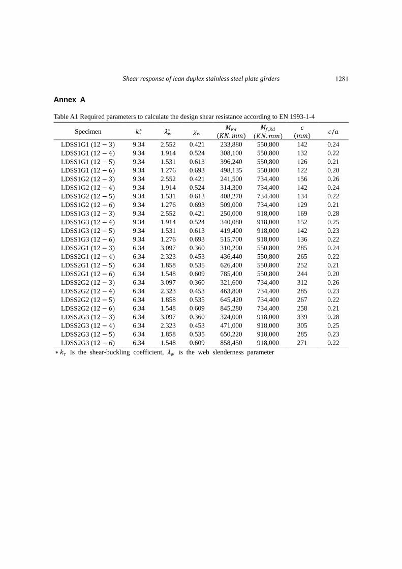
Annex A, Table A1 gives a sample of the key factors that are employed in the calculations. As
can be seen, there is good agreement between the finite element strengths with the design
specifications of EN 1993-1-4, and the shear strength has been overestimated a bit based on the
EN 1993-1-4 of the LDSS plate girders.
4. Conclusions
The following conclusions are drawn from the numerical studies conducted herein:
• By comparing the numerical analysis that was carried out in this study and the experimental
results that were stated in the literature, it can be shown that the numerical results that were
obtained were in good general agreement with the experimental results.
• The web thickness was found to have a noticeable effect on the shear capacity of lean duplex
stainless steel (LDSS) plate girders. When compared with sample (I-600×200×12×4-1), which had
a web thickness of 4 mm, the ultimate shear capacity of the samples increased by 23% and 21%
when the web thickness increased to 5 mm and 6 mm, respectively.
• The effect of the ratio of the flange thickness to the web thickness, tf/tw on the shear behavior
of lean duplex stainless (LDSS) plate girders was examined. The results indicated that when the
flange thickness, tf was maintained as a constant, the ratio negatively affected the shear strength of
the LDSS plate girders.
• It was learned that when the web depth was maintained at a constant value, the shear strength
increased as the web depth-to-web thickness ratio (hw/tw) decreased.
• According to the results of the FEM analysis, when the web depth was maintained at a
constant value, the shear resistance of the LDSS plate girders increased with an increase in the
ratio of the flange width-to-web depth (bf/hw).
• Panels with equal values of web slenderness (hw/tw) and having different aspect ratios were
observed to possess differing strengths provided by the web contribution. In fact, the higher the
values of the aspect ratio, the lesser the contribution of the web panel (χw) to the overall resistant
mechanism.
• It was noticed that the shear buckling of the LDSS plate girders almost took place during the
linear path. According to the geometrical characteristics of the plate girders, the failure in the thin
girders was caused by the geometrical nonlinearity, while the failure in the thick girders was
attributed to the material nonlinearity.
• A comparison of the failure loads acquired from the FEM analysis with the approximate
strengths of the present European Code of Practice, EN 1993-1-4, indicated that the shear strength
of the LDSS plate girders had been slightly underestimated by the latter.
References EN 1993-1-4 (2006), Eurocode 3, Design of Steel Structures Part 1-4, General rules; Supplementary rules
for stainless steel, CEN.
EN 1993-1-5 (2007), Eurocode 3, Design of steel structures Part 1-5, Plated Structural Elements, CEN.
ENV 1993-1-1 (1992), Eurocode 3, Design of steel structures Part 1-1, General rules and rules for buildings,
1279

Salam R. Armoosh, A.R. Khalim and Akram Sh. Mahmood
CEN.
ENV 1993-1-5 (1997), Eurocode 3, Design of steel structures Part 1-5, General rules; Supplementary rules
for planar plated structures without transverse loading, CEN.
Estrada, I., Real, E. and Mirambell, E. (2007a), “General behaviour and effect of rigid and non-rigidend post
in stainless steel plate girders loaded in shear. part I: experimental study”, J. Construct. Steel Res., 63(7),
970-984.
Estrada, I., Real, E. and Mirambell, E. (2007b), “General behaviour and effect of rigid and non-rigidend post
in stainless steel plate girders loaded in shear. part II: extended numerical study and design proposal”, J.
Construct. Steel Res., 63(7), 985-996.
LUSAS V14.3 (2006).
Gardner, L. (2005), “The use of stainless steel in structures”, Prog. Struct. Eng. Mater., 7(2), 45-55.
Gunn, R.N. (1997), Duplex Stainless Steels: Microstructure, Properties and Applications, TWI Ltd,
London, UK.
Hassanein, M. (2010), “Imperfection analysis of austenitic stainless steel plate girders failing by shear”, Eng.
Struct., 32(3), 704-713.
Hassanein, M. (2011), “Finite element investigation of shear failure of lean duplex stainless steel plate
girders”, Thin Wall. Struct., 49(8), 964-973.
Höglund, T. (1997), “Shear buckling resistance of steel and aluminum plate girders”, Thin Wall. Struct.,
29(1), 13-30.
Longshithung Patton, M. and Singh, K.D. (2012), “Numerical modelling of lean duplex stainless steel
hollow columns of square, L-, T-, and+-shaped cross sections under pure axial compression”, Thin Wall.
Struct., 53, 1-8.
Osgood, W. and Ramberg, W. (1943), “Description of stress-strain curves by three parameters”, Tech. Notes
Nat. Adv. Comm. Aeronaut, 902(13), Document ID: 19930081614.
Rasmussen, K.J. (2003), “Full-range stress–strain curves for stainless steel alloys”, J. Construct. Steel Res.,
59(1), 47-61.
Real, E., Mirambell, E. and Estrada, I. (2007), “Shear response of stainless steel plate girders”, Eng. Struct.,
29(7), 1626-1640.
Rockey, K.C. and Skaloud, M. (1972), “The ultimate load behaviour of plated girders loaded in shear”,
Struct. Eng., 50(1), 29-47.
Saliba, N. and Gardner, L. (2013), “Experimental study of the shear response of lean duplex stainless steel
plate girders”, Eng. Struct., 46, 375-391.
Saliba, N. and Gardner, L. (2013), “Cross-section stability of lean duplex stainless steel welded I-sections”,
J. Construct. Steel Res., 80, 1-14.
Saliba, N., Real, E., Gardner, L. (2014), “Shear design recommendations for stainless steel plate girders”,
Eng. Struct., 59, 220-228.
Theofanous, M. and Gardner, L. (2010), “Experimental and numerical studies of lean duplex stainless steel
beams”, J. Construct. Steel Res., 66(6), 816-825.
Unosson, E. and Olsson, A. (2003), “Stainless steel girders-resistance to concentrated loads and shear”,
Proceedings of The Stainless Steel in Structures: International Experts Seminar, Ascot, UK, May.
Wilson, J.M. (1886), “On specifications for strength of iron bridges”, Tran. Am. Soc. Civil Eng., 15(1), 389-
414.
CC
1280
Shear response of lean duplex stainless steel plate girders
Annex A
Table A1 Required parameters to calculate the design shear resistance according to EN 1993-1-4
Specimen 𝑘𝜏∗ 𝜆𝑤
∗ 𝜒𝑤 𝑀𝐸𝑑
(𝐾𝑁.𝑚𝑚)
𝑀𝑓 ,𝑅𝑑
(𝐾𝑁.𝑚𝑚)
𝑐
(𝑚𝑚) 𝑐/𝑎
LDSS1G1 (12 − 3) 9.34 2.552 0.421 233,880 550,800 142 0.24
LDSS1G1 (12 − 4) 9.34 1.914 0.524 308,100 550,800 132 0.22
LDSS1G1 (12 − 5) 9.34 1.531 0.613 396,240 550,800 126 0.21
LDSS1G1 (12 − 6) 9.34 1.276 0.693 498,135 550,800 122 0.20
LDSS1G2 (12 − 3) 9.34 2.552 0.421 241,500 734,400 156 0.26
LDSS1G2 (12 − 4) 9.34 1.914 0.524 314,300 734,400 142 0.24
LDSS1G2 (12 − 5) 9.34 1.531 0.613 408,270 734,400 134 0.22
LDSS1G2 (12 − 6) 9.34 1.276 0.693 509,000 734,400 129 0.21
LDSS1G3 (12 − 3) 9.34 2.552 0.421 250,000 918,000 169 0.28
LDSS1G3 (12 − 4) 9.34 1.914 0.524 340,080 918,000 152 0.25
LDSS1G3 (12 − 5) 9.34 1.531 0.613 419,400 918,000 142 0.23
LDSS1G3 (12 − 6) 9.34 1.276 0.693 515,700 918,000 136 0.22
LDSS2G1 (12 − 3) 6.34 3.097 0.360 310,200 550,800 285 0.24
LDSS2G1 (12 − 4) 6.34 2.323 0.453 436,440 550,800 265 0.22
LDSS2G1 (12 − 5) 6.34 1.858 0.535 626,400 550,800 252 0.21
LDSS2G1 (12 − 6) 6.34 1.548 0.609 785,400 550,800 244 0.20
LDSS2G2 (12 − 3) 6.34 3.097 0.360 321,600 734,400 312 0.26
LDSS2G2 (12 − 4) 6.34 2.323 0.453 463,800 734,400 285 0.23
LDSS2G2 (12 − 5) 6.34 1.858 0.535 645,420 734,400 267 0.22
LDSS2G2 (12 − 6) 6.34 1.548 0.609 845,280 734,400 258 0.21
LDSS2G3 (12 − 3) 6.34 3.097 0.360 324,000 918,000 339 0.28
LDSS2G3 (12 − 4) 6.34 2.323 0.453 471,000 918,000 305 0.25
LDSS2G3 (12 − 5) 6.34 1.858 0.535 650,220 918,000 285 0.23
LDSS2G3 (12 − 6) 6.34 1.548 0.609 858,450 918,000 271 0.22
∗ 𝑘𝜏 Is the shear-buckling coefficient, 𝜆𝑤 is the web slenderness parameter
1281