Embed Size (px)
Citation preview
PROCEEDINGS OF THE IEEE 1
Full-Duplex Wireless Communications:Challenges, Solutions and Future Research
DirectionsZhongshan Zhang,Senior Member, IEEE,Keping Long,Senior Member, IEEE,Athanasios V. Vasilakos,Senior Member, IEEEand Lajos Hanzo*,Fellow, IEEE
Abstract—The family of conventional half-duplex (HD)wireless systems relied on transmitting and receiving indifferent time-slots or frequency sub-bands. Hence thewireless research community aspires to conceive full-duplex(FD) operation for supporting concurrent transmission andreception in a single time/frequency channel, which wouldimprove the attainable spectral efficiency by a factor oftwo. The main challenge encountered in implementing anFD wireless device is the large power difference betweenthe self-interference (SI) imposed by the device’s own trans-missions and the signal of interest received from a remotesource. In this survey, we present a comprehensive list ofthe potential FD techniques and highlight their pros andcons. We classify the SI cancellation techniques into threecategories, namely passive suppression, analog cancellationand digital cancellation, with the advantages and disadvan-tages of each technique compared. Specifically, we analyzethe main impairments (e.g. phase noise, power amplifiernonlinearity as well as in-phase and quadrature-phase (I/Q)imbalance, etc.) that degrading the SI cancellation. We thendiscuss the FD based Media Access Control (MAC)-layerprotocol design for the sake of addressing some of thecritical issues, such as the problem of hidden terminals,the resultant end-to-end delay and the high packet lossratio (PLR) due to network congestion. After elaboratingon a variety of physical/MAC-layer techniques, we discusspotential solutions conceived for meeting the challengesimposed by the aforementioned techniques. Furthermore,we also discuss a range of critical issues related to the im-
Zhongshan Zhang and Keping Long are with Beijing Engineeringand Technology Center for Convergence Networks and UbiquitousServices, University of Science and Technology Beijing (USTB), No.30, Xueyuan Road, Haidian District, Beijing, China 100083 (e-mail:zhangzs,[email protected]).
Athanasios V. Vasilakos is with the Dept of Computer Science,Elec-trical and Space Engineering 97187, Lulea University of Technology,Lulea, Sweden (e-mail: [email protected]).
Lajos Hanzo is with the School of Electronics and ComputerScience, University of Southampton, Southampton, SO17 1BJ, UK (e-mail: [email protected]).
This work was supported by the key project of the NationalNatural Science Foundation of China (No. 61431001), Program forNew Century Excellent Talents in University (NECT-12-0774) and theFoundation of Beijing Engineering and Technology ResearchCenterfor Convergence Networks. The financial support of the EPSRC, UKunder the poject EP/N004558/1 and of the ERC’s Advanced FellowGrant is gratefully acknowledged.
plementation, performance enhancement and optimizationof FD systems, including important topics such as hybridFD/HD scheme, optimal relay selection and optimal powerallocation, etc. Finally, a variety of new directions and openproblems associated with FD technology are pointed out.Our hope is that this treatise will stimulate future researchefforts in the emerging field of FD communications.
Index Terms—Full-Duplex, Self-Interference, PassiveSuppression, Analog Cancellation, Digital Cancellation,Phase Noise, Power Amplifier Nonlinearity, TransmitI/Q Imbalance, Relay, Amplify-and-Forward, Decode-and-Forward, Optimal Power Allocation, Optimal Relay Selec-tion, Cognitive Radio.
I. INTRODUCTION
SINCE communication networks are expected to de-liver ever-increasing data rates, the spectral effi-
ciency of the networks has to be further improved.Although some advanced techniques, such as Multi-Input Multi-Output (MIMO) [1], [2] and OrthogonalFrequency Division Multiplexing (OFDM) [3] have beenidentified as promising solutions for beneficially increas-ing the network’s spectral efficiency, the currently oper-ational wireless communication systems are still unableto sufficiently satisfy the above-mentioned requirements,because today’s systems usually employ devices thatuse either a time-division or frequency-division duplexfor the signals’ transmission and reception. Hence inpractice only half-duplex (HD) operations have beenemployed, leading to an erosion of the resource uti-lization (i.e. the half-duplex-induced factor two capacitydegradation cannot be avoided) [4], [5].
In order to compensate for the shortcomings of theHD systems, the promise of radical full-duplex (FD)operation [6], on the other hand, improves the achievablespectral efficiency of wireless communication systemsby avoiding the utilization of two independent channelsfor bi-directional end-to-end transmission that is inherentin the conventional HD operations. Many of the currentresearch achievements have already demonstrated the
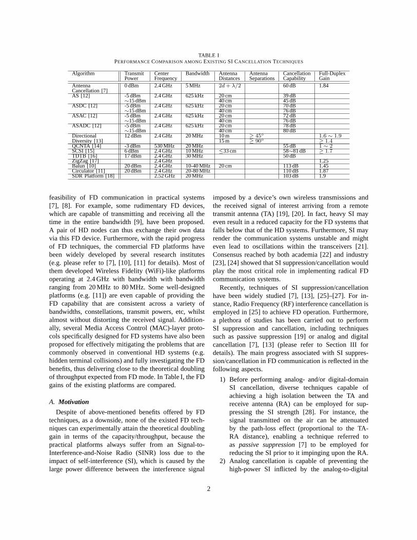
TABLE IPERFORMANCECOMPARISON AMONGEXISTING SI CANCELLATION TECHNIQUES
Algorithm Transmit Center Bandwidth Antenna Antenna Cancellation Full-DuplexPower Frequency Distances Separations Capability Gain
Antenna 0 dBm 2.4 GHz 5 MHz 2d+ λ/2 60 dB 1.84Cancellation [7]AS [12] -5 dBm 2.4 GHz 625 kHz 20 cm 39 dB
∼15 dBm 40 cm 45 dBASDC [12] -5 dBm 2.4 GHz 625 kHz 20 cm 70 dB
∼15 dBm 40 cm 76 dBASAC [12] -5 dBm 2.4 GHz 625 kHz 20 cm 72 dB
∼15 dBm 40 cm 76 dBASADC [12] -5 dBm 2.4 GHz 625 kHz 20 cm 78 dB
∼15 dBm 40 cm 80 dBDirectional 12 dBm 2.4 GHz 20 MHz 10 m ≥ 45 1.6 ∼ 1.9Diversity [13] 15 m ≥ 90 ≥ 1.4QCNTA [14] -3 dBm 530 MHz 20 MHz 55 dB 1 ∼ 2SCSI [15] 6 dBm 2.4 GHz 10 MHz ≤33 cm 58∼81 dB ≥ 1.7TDTB [16] 17 dBm 2.4 GHz 30 MHz 50 dBZigZag [17] 2.4 GHz 1.25Balun [10] 20 dBm 2.4 GHz 10-40 MHz 20 cm 113 dB 1.45Circulator [11] 20 dBm 2.4 GHz 20-80 MHz 110 dB 1.87SDR Platform [18] 2.52 GHz 20 MHz 103 dB 1.9
feasibility of FD communication in practical systems[7], [8]. For example, some rudimentary FD devices,which are capable of transmitting and receiving all thetime in the entire bandwidth [9], have been proposed.A pair of HD nodes can thus exchange their own datavia this FD device. Furthermore, with the rapid progressof FD techniques, the commercial FD platforms havebeen widely developed by several research institutes(e.g. please refer to [7], [10], [11] for details). Most ofthem developed Wireless Fidelity (WiFi)-like platformsoperating at 2.4 GHz with bandwidth with bandwidthranging from 20 MHz to 80 MHz. Some well-designedplatforms (e.g. [11]) are even capable of providing theFD capability that are consistent across a variety ofbandwidths, constellations, transmit powers, etc, whilstalmost without distorting the received signal. Addition-ally, several Media Access Control (MAC)-layer proto-cols specifically designed for FD systems have also beenproposed for effectively mitigating the problems that arecommonly observed in conventional HD systems (e.g.hidden terminal collisions) and fully investigating the FDbenefits, thus delivering close to the theoretical doublingof throughput expected from FD mode. In Table I, the FDgains of the existing platforms are compared.
A. Motivation
Despite of above-mentioned benefits offered by FDtechniques, as a downside, none of the existed FD tech-niques can experimentally attain the theoretical doublinggain in terms of the capacity/throughput, because thepractical platforms always suffer from an Signal-to-Interference-and-Noise Radio (SINR) loss due to theimpact of self-interference (SI), which is caused by thelarge power difference between the interference signal
imposed by a device’s own wireless transmissions andthe received signal of interest arriving from a remotetransmit antenna (TA) [19], [20]. In fact, heavy SI mayeven result in a reduced capacity for the FD systems thatfalls below that of the HD systems. Furthermore, SI mayrender the communication systems unstable and mighteven lead to oscillations within the transceivers [21].Consensus reached by both academia [22] and industry[23], [24] showed that SI suppression/cancellation wouldplay the most critical role in implementing radical FDcommunication systems.
Recently, techniques of SI suppression/cancellationhave been widely studied [7], [13], [25]–[27]. For in-stance, Radio Frequency (RF) interference cancellation isemployed in [25] to achieve FD operation. Furthermore,a plethora of studies has been carried out to performSI suppression and cancellation, including techniquessuch as passive suppression [19] or analog and digitalcancellation [7], [13] (please refer to Section III fordetails). The main progress associated with SI suppres-sion/cancellation in FD communication is reflected in thefollowing aspects.
1) Before performing analog- and/or digital-domainSI cancellation, diverse techniques capable ofachieving a high isolation between the TA andreceive antenna (RA) can be employed for sup-pressing the SI strength [28]. For instance, thesignal transmitted on the air can be attenuatedby the path-loss effect (proportional to the TA-RA distance), enabling a technique referred toas passive suppression[7] to be employed forreducing the SI prior to it impinging upon the RA.
2) Analog cancellation is capable of preventing thehigh-power SI inflicted by the analog-to-digital
2
converter (ADC), which would desensitize theautomatic gain control (AGC) owing to signalleakages. Either training sequence-based methods[12] or adaptive interference cancellation [7] maybe used for performing analog cancellation.
3) In light of the fact that even after performinganalog cancellation the residual SI encountered inpractical systems remains the rate-limiting bottle-neck, additional digital cancellation is required formitigating the interference effects in the baseband[12]. Since both the linear and nonlinear residualSI components should be subtracted in the digitaldomain [11], the FD receiver is required to esti-mate both the delay and phase shift between thetransmitted and the received signals relying on SIchannel estimates.
4) Note that no stand-alone analog or digital tech-nique is capable of achieving a high enoughcancellation capability to satisfy the decoding re-quirement. It was reported in [7], [12] that theinterference rejection ratio of analog-only methodsonly ranges from 20 to 45 dB, making the residualSI may still be several-dB above the thermal noisefloor even with the help of passive suppression[4]. Therefore, a combination of analog and digitalcancellations may be promising to offer a suffi-ciently high SI cancellation capability.
However, the hardware imperfections encountered inpractical FD realizations, such as nonlinear distortions,non-ideal frequency response of circuits, the phase noise,etc., may impose significant performance limitations onthe SI cancellation, thus resulting in a high residual SI[11], [29]. It was shown in [29] that the phase noisemay gravely limit the combined analog and digital SIcancellation. If the residual SI is uncorrelated with theSI signal, the phase noise will dominate the residual SI(i.e. after performing analog cancellation) and preventthe concatenated digital canceller from further cancellingthe residual SI. Apart from the aforementioned issues,the conception of FD MAC-layer protocols requiressubstantial further research for exploiting the FD benefitspotentially offered by the physical-layer techniques [15].Some of the most challenging problems in wirelessnetworks, such as the presence of hidden terminals,loss of throughput due to congestion and large end-to-end delays, etc. have to be mitigated by carefullydesigned FD MAC-layer protocols [7]. Furthermore, theexisting studies indicated that FD schemes may notalways outperform their HD counterparts, hence hybridschemes switching between the HD mode and FD modehave to be developed for adaptively exploiting the radio
resources, while at the same time maximizing both theinstantaneous and the average spectral efficiency [22].
To sum up, one of the fundamental motivations of thispaper is to survey and analyze the critical techniques thatenable the wireless devices to operate in FD mode. Sincethe FD mode allows wireless devices to concurrentlytransmit and receive in a single time/frequency-slot, itsignificantly improves both the attainable spectral effi-ciency and the resource utilization. We will survey andcompare different FD techniques and introduce variousSI suppression/cancellation schemes. Some existing SIcancellation techniques such as passive suppression, aswell as both analog and digital cancellations will bediscussed, with their advantages, drawbacks and opendesign challenges being analyzed. Specifically, the hard-ware limitations encountered in practical FD systemdesign, including the phase noise, the frequency non-ideal response, the power amplifier nonlinearity, as wellas the transmit in-phase and quadrature-phase (I/Q)imbalance have to be investigated. Furthermore, somecritical issues related to the MAC-layer protocols arealso studied. Finally, advanced practical implementationsand commercial realizations of hybrid FD/HD scheme,optimal relay selection, and optimal power allocation arediscussed, followed by a variety of new directions andopen problems.
B. Main Contributions
In this paper, we review the state of the art in FD wire-less communication system design and investigate thecritical techniques such as SI suppression/cancellationand MAC-layer protocols, while highlighting the distor-tions imposed by hardware imperfections encountered inpractical systems. The main contributions of this surveyinclude
1) Outlining the potential benefits offered by FDtechniques.
2) Surveying the critical issues related to FD trans-missions from a physical-layer perspective relyingon SI suppression/cancellation, whilst giving cog-nizance to the MAC-layer protocols.
3) Investigating the main hardware imperfections,such as the phase noise, non-flat frequency re-sponse of circuits, power amplifier nonlinearity,and transmit I/Q imbalance, etc., which may im-pose limitations on the attainable SI cancellationcapability.
4) Discussing the advantages, drawbacks, as well asdesign challenges of practical FD systems, whilstidentifying their new directions and applications.
3
The remainder of this paper is organized as follows.The main benefits brought about by employing FDtechniques will be listed in Section II. Then a range of SIcancellation techniques, including passive suppression,analog and digital cancellations, will be introduced inSection III. Specifically, the impacts of hardware limita-tions (e.g. phase noise, power amplifier nonlinearity andtransmit I/Q imbalance) on SI cancellation are elabo-rated in Section III-E. Typical FD MAC-layer protocols,such as theBusytone-aided MAC Protocol [10] and theFD-MAC technique [15] are then discussed in SectionIV, followed by a range of critical issues related tothe associated practical implementation and commercialrealizations in Section V. Finally, our conclusions as wellas future research directions are provided in Section VI.
II. BENEFITS OF EMPLOYING FULL-DUPLEXOPERATIONS
Recent advances in FD communications have in-creased both the attainable throughput and diversityorders of systems communicating over wireless channels.The main driving force behind the advances in FD com-munications is the promise of nearly doubled channelcapacity compared to the conventional HD communi-cations, while meeting a range of contradicting designchallenges. For example, it is possible to both enhancethe SI cancellation and simultaneously to reduce theBit Error Ratio (BER), provided that an increased com-plexity may be tolerated to facilitate more sophisticatedsignal processing. Similarly, the packet loss ratio (PLR)may also be further reduced, if a larger buffer size maybe provided by the FD devices. In a nutshell, the FDmode exhibits advantages over the HD mode in terms ofeither having an increased throughput or reduced outageprobability (OP) [30], [31] albeit this is achieved atthe cost of increased complexity (i.e. for performing SIcancellation).
Nonetheless, at the time of writing HD rather thanFD regimes may be preferred owing to the followingreasons:
• Although in theory the FD mode may be capableof doubling the capacity of the HD mode, the latterbecomes a more attractive choice in the presenceof excessive SI, which prevents high-integrity com-munication in the FD mode [30].
• HD modes may be more attractive from the perspec-tive of low-complexity practical implementation[32].
Again, an FD scheme may not always outperform itsHD counterpart in all scenarios, hence a hybrid HD/FDscheme may be proposed to gain an advantage over
either of the individual schemes. In a word, the attain-able performance benefits depend not only on the SI-cancellation capability, but also on a range of practicalimplementation issues, although the former acts as thedominant factor.
Recently, a range of theoretical and practical aspectsof FD communications have been investigated [22], [33]by quantifying the performance of FD modes. In thissection, we investigate the advantages/disadvantages ofFD technology, with a range of further plausible tradeoffsidentified. A comparison of the HD modes and FDmodes will be carried out from a capacity, OP, and BERperspective. It is worth noting that the conclusions drawnin this section are applicable not only to cooperativerelays, although representative performance comparisonsbetween HD and FD modes may be readily carriedout in cooperative relaying scenarios. For example, theFD benefits of relaying systems quantified in terms ofcapacity/throughput improvements over the HD modecan also be readily gleaned in device-to-device (D2D)-like scenarios [10], [11], where a pair of FD nodessimultaneously send packets to each other. For thereader’s convenience, we have summarized the majorcontributions on the subject of performance comparisonsin Table II.
A. Capacity Comparison of HD and FD Modes
The achievable capacity/throughput in FD systems hasbeen widely analyzed in the existing studies (e.g., [7],[10], [11], [15]). In theory, FD techniques may doublethe capacity of the HD techniques due to the potentialcapability of simultaneously transmitting and receivingusing the same channel in the former. Although SI maysubstantially degrade the integrity of the FD mode, insome scenarios this might be tolerable [36]. In the fol-lowing parts, capacity of FD systems in either Amplify-and-Forward (AF) or Decode-and-Forward (DF) modewill be investigated.
1) AF Mode: In the infrastructure-based AF relayingmode relying on flat-fading wireless links, the end-to-endchannel capacities of the FD/HD modes were derived in[30], leading to the following conclusions:
• If the power of SI can be reduced below the noiselevel, the FD mode always outperforms the HDmode, regardless of the channel signal-to-noise ratio(SNR).
• The HD mode outperforms the FD mode only in thescenario when the SNR of the source→relay link israther low and the relay’s input SINR is dominatedby the SI.
4
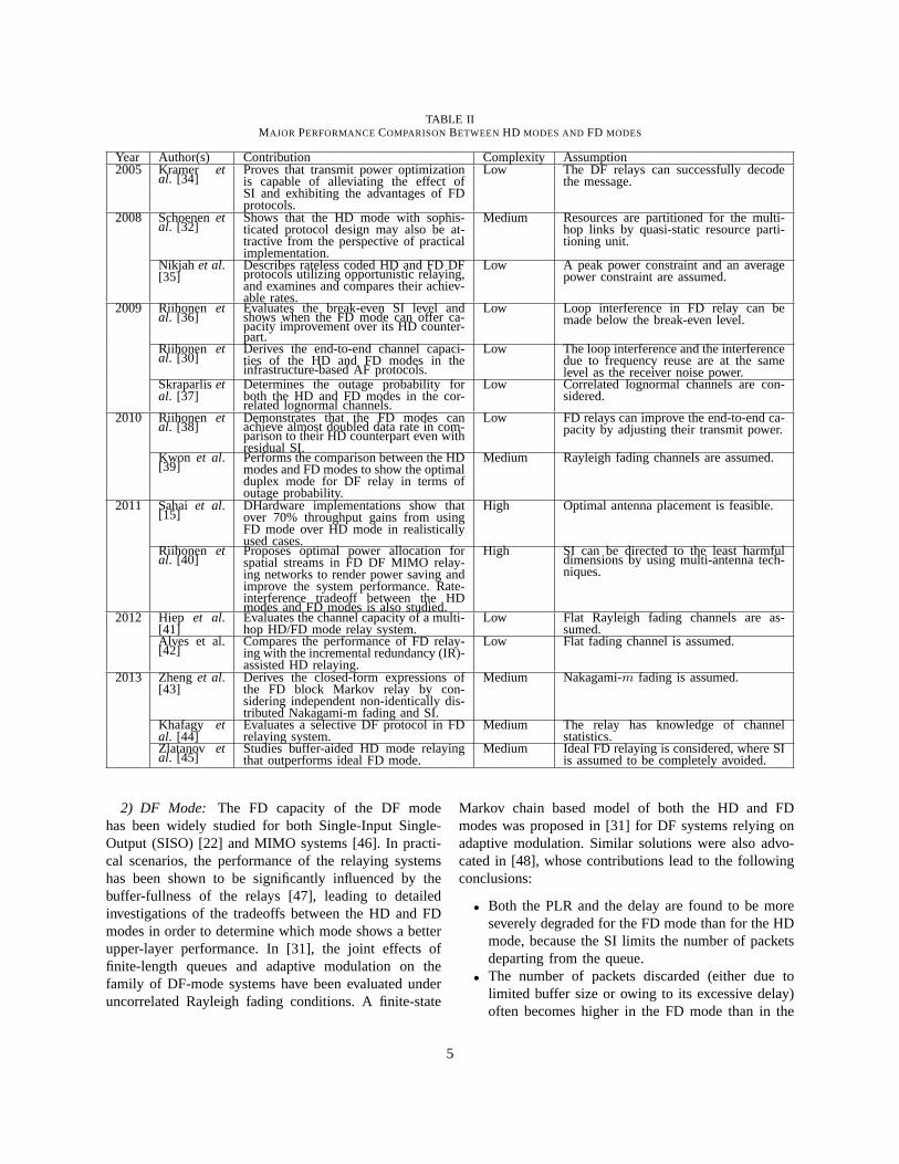
TABLE IIMAJOR PERFORMANCECOMPARISONBETWEEN HD MODES AND FD MODES
Year Author(s) Contribution Complexity Assumption2005 Kramer et
al. [34]Proves that transmit power optimizationis capable of alleviating the effect ofSI and exhibiting the advantages of FDprotocols.
Low The DF relays can successfully decodethe message.
2008 Schoenenetal. [32]
Shows that the HD mode with sophis-ticated protocol design may also be at-tractive from the perspective of practicalimplementation.
Medium Resources are partitioned for the multi-hop links by quasi-static resource parti-tioning unit.
Nikjah et al.[35]
Describes rateless coded HD and FD DFprotocols utilizing opportunistic relaying,and examines and compares their achiev-able rates.
Low A peak power constraint and an averagepower constraint are assumed.
2009 Riihonen etal. [36]
Evaluates the break-even SI level andshows when the FD mode can offer ca-pacity improvement over its HD counter-part.
Low Loop interference in FD relay can bemade below the break-even level.
Riihonen etal. [30]
Derives the end-to-end channel capaci-ties of the HD and FD modes in theinfrastructure-based AF protocols.
Low The loop interference and the interferencedue to frequency reuse are at the samelevel as the receiver noise power.
Skraparlisetal. [37]
Determines the outage probability forboth the HD and FD modes in the cor-related lognormal channels.
Low Correlated lognormal channels are con-sidered.
2010 Riihonen etal. [38]
Demonstrates that the FD modes canachieve almost doubled data rate in com-parison to their HD counterpart even withresidual SI.
Low FD relays can improve the end-to-end ca-pacity by adjusting their transmit power.
Kwon et al.[39]
Performs the comparison between the HDmodes and FD modes to show the optimalduplex mode for DF relay in terms ofoutage probability.
Medium Rayleigh fading channels are assumed.
2011 Sahai et al.[15]
DHardware implementations show thatover 70% throughput gains from usingFD mode over HD mode in realisticallyused cases.
High Optimal antenna placement is feasible.
Riihonen etal. [40]
Proposes optimal power allocation forspatial streams in FD DF MIMO relay-ing networks to render power saving andimprove the system performance. Rate-interference tradeoff between the HDmodes and FD modes is also studied.
High SI can be directed to the least harmfuldimensions by using multi-antenna tech-niques.
2012 Hiep et al.[41]
Evaluates the channel capacity of a multi-hop HD/FD mode relay system.
Low Flat Rayleigh fading channels are as-sumed.
Alves et al.[42]
Compares the performance of FD relay-ing with the incremental redundancy (IR)-assisted HD relaying.
Low Flat fading channel is assumed.
2013 Zhenget al.[43]
Derives the closed-form expressions ofthe FD block Markov relay by con-sidering independent non-identically dis-tributed Nakagami-m fading and SI.
Medium Nakagami-m fading is assumed.
Khafagy etal. [44]
Evaluates a selective DF protocol in FDrelaying system.
Medium The relay has knowledge of channelstatistics.
Zlatanov etal. [45]
Studies buffer-aided HD mode relayingthat outperforms ideal FD mode.
Medium Ideal FD relaying is considered, where SIis assumed to be completely avoided.
2) DF Mode: The FD capacity of the DF modehas been widely studied for both Single-Input Single-Output (SISO) [22] and MIMO systems [46]. In practi-cal scenarios, the performance of the relaying systemshas been shown to be significantly influenced by thebuffer-fullness of the relays [47], leading to detailedinvestigations of the tradeoffs between the HD and FDmodes in order to determine which mode shows a betterupper-layer performance. In [31], the joint effects offinite-length queues and adaptive modulation on thefamily of DF-mode systems have been evaluated underuncorrelated Rayleigh fading conditions. A finite-state
Markov chain based model of both the HD and FDmodes was proposed in [31] for DF systems relying onadaptive modulation. Similar solutions were also advo-cated in [48], whose contributions lead to the followingconclusions:
• Both the PLR and the delay are found to be moreseverely degraded for the FD mode than for the HDmode, because the SI limits the number of packetsdeparting from the queue.
• The number of packets discarded (either due tolimited buffer size or owing to its excessive delay)often becomes higher in the FD mode than in the
5
HD mode in the presence of SI. However, the FDmode may become superior to the HD mode if thesize of the queue’s buffer is sufficiently high. Unlessthe number of packets arriving from the upper layerbecomes so high that it hinders the reliable packettransmission, increasing the buffer size generallybenefits the FD mode more drastically than HDmode.
B. Comparison of the HD and FD Modes in Terms ofOutage Probability
Apart from capacity, the OP of wireless links alsoconstitutes one of the most important reliability metricsin a fading channel. In order to optimize the FD systemsin terms of OP performance, the fundamental tradeoffbetween the attainable resource efficiency and SI tol-erance must be carefully investigated. In the followingparts, the performance comparison between the FD andHD modes in terms of OP performance will be carriedout.
1) OP of the AF Relaying Mode:In [49], the outageperformance of an FD based wireless AF relay link isstudied in the presence of realistic non-ideal feedbackinformation. A new relay protocol is proposed for co-phasing the direct and relaying paths to enhance boththe end-to-end SNR as well as the outage capacity.It has been shown that the FD mode is capable ofoffering performance improvements over both classicdirect transmission and HD relaying, even if the feedbackchannel is of relatively low quality due to using a limitednumber of feedback bits. Furthermore, the followingconclusions may be inferred:
• In the presence of an adequate directsource→destination link but in the absence ofresidual SI, FD AF relaying is expected tooutperform HD AF relaying, even if the SNRis low. By contrast, as the SNR increases, theemployment of HD relaying becomes preferablefrom the perspective of the attainable OP, becausethe FD relaying will suffer from distortions eitherdue to the increased residual SI or due to its noiseamplification, which in fact degrades a strongdirect link.
• Mitigating the residual SI by using classic minimummean square error (MMSE) criterion eased decisionfeedback equalization at the destination is indeedcapable of achieving better outage performance thanHD relaying [50].
2) OP of the DF Relaying Mode:In a multihop FDrelaying system, where multiple DF mode relays arecascaded, the ability of the relays to isolate transmission
from reception may be quantified by defining a newparameter referred to as the Path-Loss-to-InterferenceRatio (PLIR), which represents the ratio of the receiveddesired signal power to the received interference power,when the transmit power is the same for the usefuland interfering signals [51]. For a given PLIR, theoptimal number of FD relays should be determined byminimizing the OP of a multihop network, whilst relyingon an appropriately designed protocol, such as selectiveDF [44]. The specific design-dilemma in this context iswhether to use a lower number of less-reliable long hops,or a higher number of more reliable hops to minimizethe OP.
Considering the DF relaying, the conditions to besatisfied for achieving superiority of FD mode over HDmode in terms of the OP can be summarized for a simplethree-node cooperative network as follows:
• FD relaying is superior to conventional HD modein terms of the OP when the Signal-to-InterferenceRatio (SIR) is low (i.e. corresponding to a low SIstrength) for transmission over Nakagami-m wire-less channels [52]. As the SIR increases, FD modetends to exhibit a lower OP than HD mode.
• When the SNR is low, the OP decreases uponincreasing the number of relays in a multihopnetwork, while this trend becomes reversed, as theSNR increases owing to the increased interferenceamong the relays.
• For sufficiently high values of PLIR, the FD modehas been shown to outperform the HD mode interms of the OP in a multihop relaying system.
C. Comparison of HD modes and FD Modes in Termsof BER
The BER performance of FD systems has been lav-ishly documented. For instance, in [53], the BER of aMIMO-aided FD system has been evaluated with theassistance of beamforming for the sake of improvingthe effective SNR. Note that beamforming has beenshown to be especially beneficial for AF relaying, whichis prone to the performance-limitation imposed by theaccumulated interference/noise [53].
1) BER of the AF Relaying Mode:In [54], the perfor-mance comparison of the AF relaying aided HD modeand FD mode was carried out in terms of the achievableBER, with the assistance of multiple antennas at eachnode. The source→destination beamforming vectors arejointly optimized in [54] based on the MMSE objectivefunction subject to the transmit power constraints of boththe source and the relays. Furthermore, a pre-nulling
6
algorithm1 is employed by the FD relays to facilitateSI suppression, provided that perfect channel state in-formation (CSI) is available at each node. Naturally, theprovision of accurate CSI for all nodes remains an openchallenge at the time of writing. It has been demonstratedin [54] that the FD mode is capable of outperformingthe HD mode in terms of its BER, when the SNR of therelay→destination link is lower than 5 dB due to the factthat the noise effect of the latter is twice as high as thatof the former, but the situation is reversed, if the SNR ofthe relay→destination link becomes higher than 15 dB.
2) BER of the DF Relaying Mode:In [33], the BERanalysis of FD cooperative system employing a singleDF relay is carried out in conjunction with binaryphase shift keying (BPSK). Without loss of generality,the SI channel is assumed to suffer from Rayleigh orNakagami-m fading. In contrast to the results obtainedfor AF relaying (e.g. in [54]), the closed-form BERexpression derived for DF relaying demonstrates aninferior performance of the FD mode compared to thatof the HD mode even for a low level of residual SI atboth the relay and destination [33].
D. Advantages/Disadvantages of the FD Mode
Based on the aforementioned comparisons, the FDmode has shown several attractive advantages, but alsoexposed weaknesses in contrast to the HD mode. Forexample, since an FD node has to process twice asmany packets as a HD node due to its simultaneoustransmission and reception, both the PLR as well as thedelay may become more severe for FD mode than for HDmode. Increasing their buffer’s queue-length generallybenefits FD mode more than HD mode. Nevertheless,striking the most appropriate buffer-size versus PLRtradeoff constitutes promising study-item. Both advan-tages and disadvantages of FD techniques are detailedbelow.
1) Advantages of the Full-Duplex Mode:
• Throughput Gain : As compared to the HD mode,the FD mode nearly doubles the throughput of asingle-hop wireless link in the physical-layer.
• Collision Avoidance: In the traditional CarrierSense Multiple Access with Collision Avoidance(CSMA/CA) protocol, each HD node is requiredto check the channel’s quality before using it. TheFD mode, however, only requires the first node thatinitiates transmissions to sense the channel, which is
1In MIMO-aided FD systems, the pre-nulling approach performstransmit pre-processing for the sake of minimizing SI imposed ontherelay’s TAs [55]. Pre-nulling algorithms will be specifically detailed inSection III-D.
necessary for avoiding collisions at those FD nodesthat do not perform carrier sensing.
• Solving the Hidden Terminal Problem: The prob-lem of hidden terminals can be solved using FDtechniques. Let us consider a scenario of multiplenodes having data in their buffer for direct transmis-sion to and reception from a common access point(AP). If a node starts transmitting its data to theAP and the AP simultaneously starts transmittingdata back to this node, the other nodes will hearthe transmissions from the AP and delay theirtransmissions to avoid collisions. Even if the APhas no data to send back to the first node, it stillrepeats an “ACK” for that node so as to prevent theother nodes from transmitting.
• Reducing Congestion with the Aid of MACScheduling: The potential throughput loss imposedby congestion can be circumvented by enabling FDoperation in congested nodes. For instance, in a gen-eral star topology associated with(2n + 1) nodes,nodes 1 ton may attempt to transmit their data tonodes(n+ 1) to 2n respectively via node 0. Thenthe aggregate network throughput becomes as lowas 1/n even if conventional HD MAC schedulingis performed. With the aid of FD operation, on theother hand, node 0 is capable of both transmittingand receiving simultaneously, hence the aggregatenetwork throughput might approach the single-linkcapacity, whilst simultaneously benefitting from thespatial diversity gain.
• Reducing the End-to-End Delay: An FD node iscapable of commencing the forwarding of a hithertoonly partially received packet so as to significantlyreduce the end-to-end delay of packet deliverythrough a multihop network, as compared to theconventional store-and-forward technique employedin HD mode, which would make the end-to-enddelay a linearly increasing function of the numberof hops.
• Enhancing the Primary User’s Detection Qual-ity in Cognitive Radio (CR) Environment : Thereliable detection of the primary user is not aneasy task to perform in CR environments [56]. Thiswould, however, become an even more challengingoperation, if the primary receivers were to operateonly in a HD mode. As a benefit, the FD modeenables the secondary user to scan for any primaryusers, while it is actively occupying the spectrum.The primary receivers may transmit at the sametime, so as to ease the secondary users’ scanningand detection operation.
7
2) Disadvantages of the Full-Duplex Mode:
• Performance Constrained by SI: In an FD de-vice, the RA’s input signal of interest is usuallyseveral orders of magnitude lower in power thanthe received SI signal imposed by the device’s TAoutput. Hence, the interference imposed by the TAupon the RA will consequently drown out the weakinput signal and degrade the FD gains.
• Degraded Link Reliability : The FD mode suffersfrom a reduced link reliability, regardless of theSNR. As indicated in [7], a state-of-the-art off-the-shelf radio is capable of achieving 88% of the linkreliability2 compared to its HD mode counterpart.Furthermore, without invoking digital interferencecancellation, an even lower reliability of say 67%may be attainable for the FD mode.
• Suffers From Higher PLR: As compared to theHD devices, an FD node has to process twicethe number of packets due to its simultaneoustransmission and reception, thus leading to a higherPLR than the HD mode.
• A Higher Buffer Size Requirement: To reduce thePLR of the FD mode, a sufficiently large buffer isrequired for enabling the packets to be forwarded(that would otherwise have been discarded due toqueue overflow). Since the effects of packet-losslevel are more severe in the FD mode, a largerbuffer size is required than for the HD mode.
A rudimentary performance comparison between theHD and FD modes is given in Table III. In practicalimplementations, the decision as to whether adopting theFD mode or the HD mode depends on several factors,such as the system throughput required, the SI cancel-lation capability, and the affordable hardware/softwarecomplexity, etc. Among the aforementioned factors, theSI signal significantly constrains the advantages of theFD techniques and would be the key limiting factor indeveloping FD systems. We will touch upon the innercore of this stylized illustration in the following twosections.
III. SELF-INTERFERENCE CANCELLATION
The goal of FD radio is to simultaneously transmit andreceive within the same frequency band, in which casean FD node receives not only the signal of interest, butalso the signal it is transmitting, which constitutes theSI imposed upon the RAs. Since the strength of the SIsignal observed in FD devices may be 50-100 dB higher
2Link reliability may be described as the specific fraction of timeduring which a link between two adjacent nodes remains connected[57].
than that of the signal of interest, the strong SI signal willgovern the gain control settings of the AGC, which scalesthe input signal prior to digitization to the normalizedrange of [-1, 1]. If the SI power is high, it constrains theweak signal of interest to occupy a range much smallerthan [-1, 1], hence invoking a high quantization noise onthe signal of interest as well as a significantly erodingthe SINR in the digital baseband [29].
To resolve the above-mentioned problem as well as toexploit the potential FD gains, we have to be capable ofsufficiently reducing the SI strength before decoding thesignal of interest [30]. For example, in a scenario relyingon a FD radio having a transmit power of 0 dBm and anoise floor of approximately -90 dBm, the RAs have tobe capable of reducing the SI by nearly 95 dB so asto ensure that the FD node’s own transmissions do notunduly contaminate its reception [10]. As indicated in[20], the goal of SI cancellation is to predict and modelthe distortions in order to compensate for them at theRAs. However, SI cancellation is by no means a simplelinear operation, because the conventional assumptionthat “the radio signal preserves its original basebandrepresentation except for power scaling and frequencyshifting” turns out to be partially incorrect [11]. Toelaborate, in practical systems, the FD radios may distortthe transmitted signal’s digital baseband representation.Explicitly, both linear distortions (induced by signalattenuations and reflections from the environment, etc),as well as non-linear distortions (induced by circuitpower leakage, non-flat hardware frequency response,higher-order signal harmonics, etc), the noise3 imposedby the imperfect transmit power amplifiers and phasenoise4 generated by local oscillators [11] are imposed.For example, in a typical WiFi radio using 80 MHzbandwidth and a receiver noise floor of -90 dBm as wellas the transmit power of 20 dBm, the SI signal comprisesthe following typical components [11]:
• The linear (main) componentof 20 dBm strength,corresponding to 110 dB above the noise floor;
• The non-linear componentof -10 dBm strength,corresponding to 80 dB above the noise floor;
• The transmitter noiseof -40 dBm strength, corre-sponding to 50 dB above the noise floor,
as graphically illustrated in Fig. 1.In order to suppress the SI power to a level below
the noise floor, the above-mentioned distortions must beadequately mitigated, whilst simultaneously consideringthe impact both of random transmitter noise and that of
3It was experimentally observed to be around the level of -50 dBm,i.e. 40 dB higher than the receiver noise floor level of -90 dBm[58].
4It is typically of the order of -40 dBm [11].
8
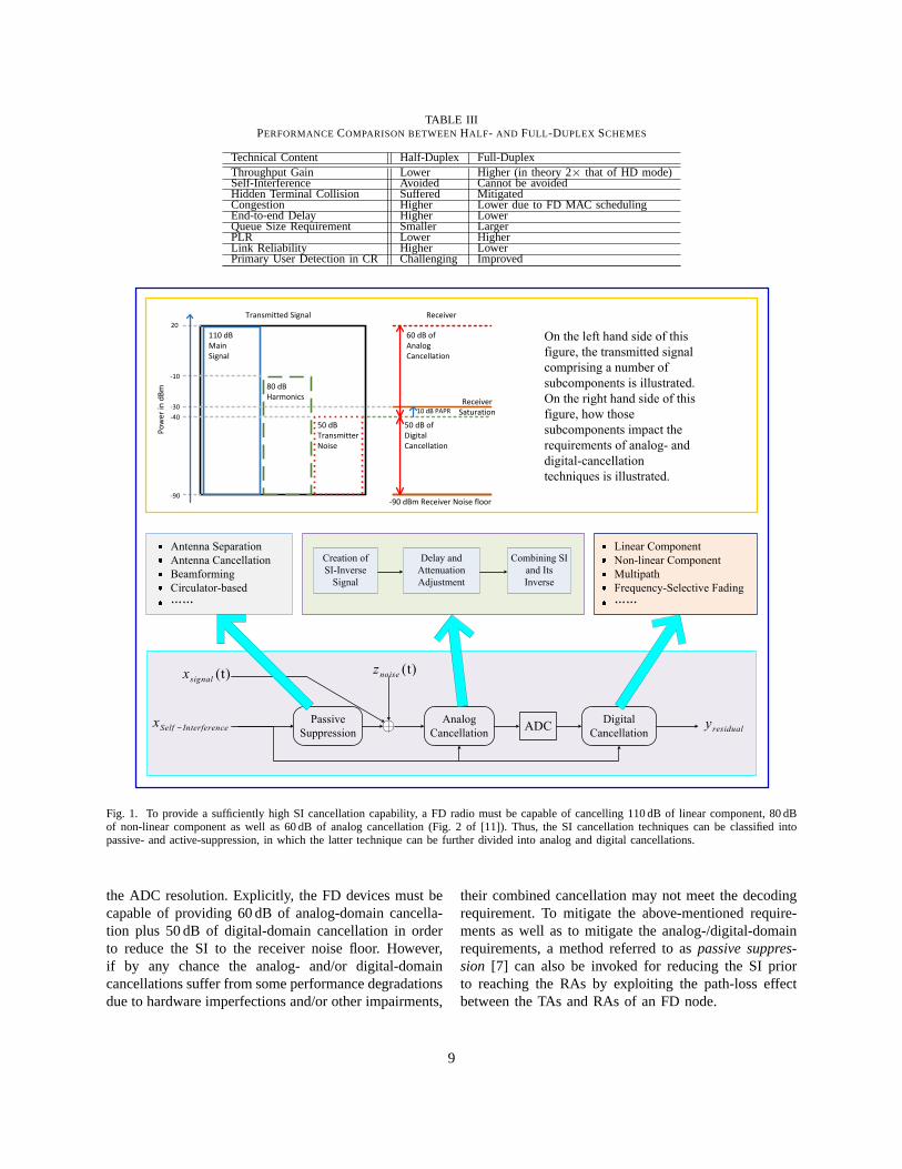
TABLE IIIPERFORMANCECOMPARISON BETWEENHALF- AND FULL -DUPLEX SCHEMES
Technical Content Half-Duplex Full-DuplexThroughput Gain Lower Higher (in theory 2× that of HD mode)Self-Interference Avoided Cannot be avoidedHidden Terminal Collision Suffered MitigatedCongestion Higher Lower due to FD MAC schedulingEnd-to-end Delay Higher LowerQueue Size Requirement Smaller LargerPLR Lower HigherLink Reliability Higher LowerPrimary User Detection in CR Challenging Improved
Passive
Suppression
Analog
Cancellation
Digital
CancellationADC
(t)signalx
Self Interferencex −
(t)noisez
residualy
Antenna Separation
Antenna Cancellation
Beamforming
Circulator-based
……
Creation of
SI-Inverse
Signal
Delay and
Attenuation
Adjustment
Combining SI
and Its
Inverse
Linear Component
Non-linear Component
Multipath
Frequency-Selective Fading
……
20
-10
-30
-40
-90
Po
we
r in
dB
m
Transmitted Signal Receiver
Receiver
Saturation10 dB PAPR
50 dB of
Digital
Cancellation
-90 dBm Receiver Noise floor
110 dB
Main
Signal
80 dB
Harmonics
50 dB
Transmitter
Noise
60 dB of
Analog
Cancellation
On the left hand side of this
figure, the transmitted signal
comprising a number of
subcomponents is illustrated.
On the right hand side of this
figure, how those
subcomponents impact the
requirements of analog- and
digital-cancellation
techniques is illustrated.
Fig. 1. To provide a sufficiently high SI cancellation capability, a FD radio must be capable of cancelling 110 dB of linear component, 80 dBof non-linear component as well as 60 dB of analog cancellation (Fig. 2 of [11]). Thus, the SI cancellation techniques can be classified intopassive- and active-suppression, in which the latter technique can be further divided into analog and digital cancellations.
the ADC resolution. Explicitly, the FD devices must becapable of providing 60 dB of analog-domain cancella-tion plus 50 dB of digital-domain cancellation in orderto reduce the SI to the receiver noise floor. However,if by any chance the analog- and/or digital-domaincancellations suffer from some performance degradationsdue to hardware imperfections and/or other impairments,
their combined cancellation may not meet the decodingrequirement. To mitigate the above-mentioned require-ments as well as to mitigate the analog-/digital-domainrequirements, a method referred to aspassive suppres-sion [7] can also be invoked for reducing the SI priorto reaching the RAs by exploiting the path-loss effectbetween the TAs and RAs of an FD node.
9
Self-Interference Suppression/Cancellation
Active Cancellation
Analog
Cancellation
SI-Inversion Based
Analog CancellationDynamic Adaptation Against
Changing Environment
Frequency-
Domain Solution
Time-Domain
Solution
Digital
Cancellation
Estimation of
the Non-Linear
SI Components
Estimation of
the Linear SI
Components
Impairments Imposed
on SI Cancellation
Power Amplifier
NonlinearityPhase
Noise
Transmit I/Q
Imbalance
MIMO Aided Aggregate Analog
and Digital Cancellation
Natural
Isolation
Time-Domain
Cancellation
Spatial
Suppression
MMSE
Filtering
Antenna Subset
SelectionMaximum
SIR
Optimal
Eigenbeamforming
Null-Space
ProjectionPre-Coding
& Decoding
Passive Suppression
Antenna
CancellationDirectional Passive
Suppression
Antenna
Separation
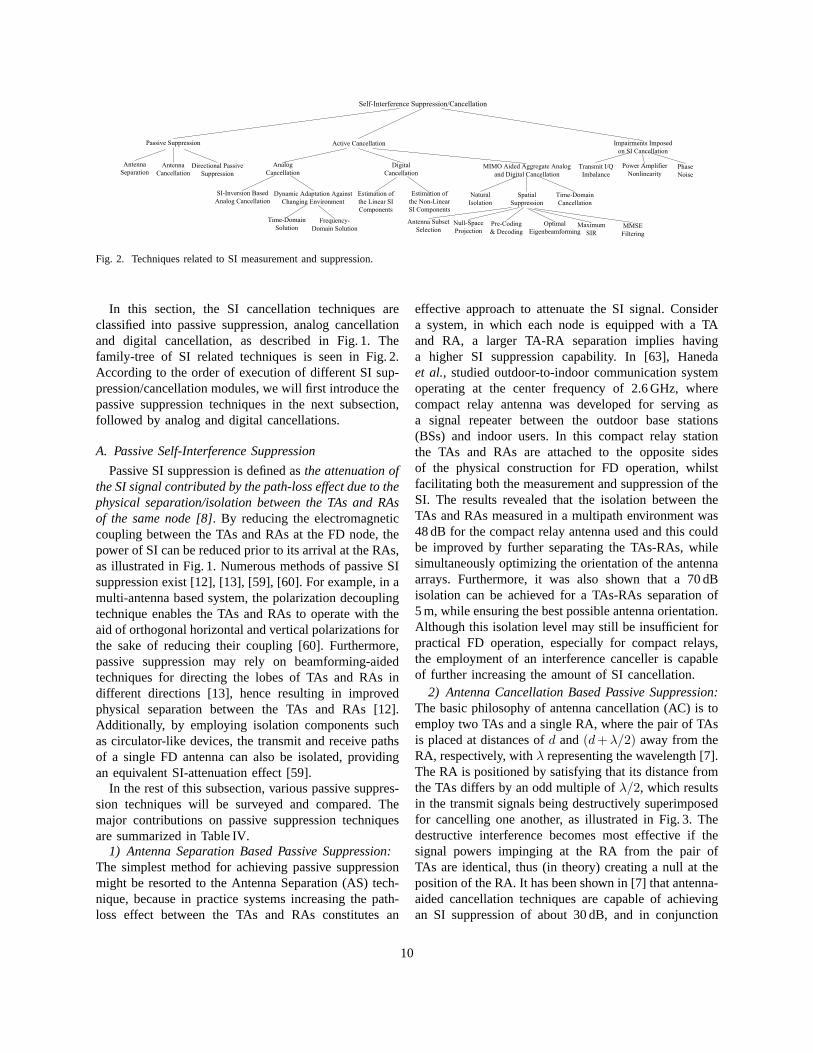
Fig. 2. Techniques related to SI measurement and suppression.
In this section, the SI cancellation techniques areclassified into passive suppression, analog cancellationand digital cancellation, as described in Fig. 1. Thefamily-tree of SI related techniques is seen in Fig. 2.According to the order of execution of different SI sup-pression/cancellation modules, we will first introduce thepassive suppression techniques in the next subsection,followed by analog and digital cancellations.
A. Passive Self-Interference Suppression
Passive SI suppression is defined asthe attenuation ofthe SI signal contributed by the path-loss effect due to thephysical separation/isolation between the TAs and RAsof the same node [8]. By reducing the electromagneticcoupling between the TAs and RAs at the FD node, thepower of SI can be reduced prior to its arrival at the RAs,as illustrated in Fig. 1. Numerous methods of passive SIsuppression exist [12], [13], [59], [60]. For example, in amulti-antenna based system, the polarization decouplingtechnique enables the TAs and RAs to operate with theaid of orthogonal horizontal and vertical polarizations forthe sake of reducing their coupling [60]. Furthermore,passive suppression may rely on beamforming-aidedtechniques for directing the lobes of TAs and RAs indifferent directions [13], hence resulting in improvedphysical separation between the TAs and RAs [12].Additionally, by employing isolation components suchas circulator-like devices, the transmit and receive pathsof a single FD antenna can also be isolated, providingan equivalent SI-attenuation effect [59].
In the rest of this subsection, various passive suppres-sion techniques will be surveyed and compared. Themajor contributions on passive suppression techniquesare summarized in Table IV.
1) Antenna Separation Based Passive Suppression:The simplest method for achieving passive suppressionmight be resorted to the Antenna Separation (AS) tech-nique, because in practice systems increasing the path-loss effect between the TAs and RAs constitutes an
effective approach to attenuate the SI signal. Considera system, in which each node is equipped with a TAand RA, a larger TA-RA separation implies havinga higher SI suppression capability. In [63], Hanedaet al., studied outdoor-to-indoor communication systemoperating at the center frequency of 2.6 GHz, wherecompact relay antenna was developed for serving asa signal repeater between the outdoor base stations(BSs) and indoor users. In this compact relay stationthe TAs and RAs are attached to the opposite sidesof the physical construction for FD operation, whilstfacilitating both the measurement and suppression of theSI. The results revealed that the isolation between theTAs and RAs measured in a multipath environment was48 dB for the compact relay antenna used and this couldbe improved by further separating the TAs-RAs, whilesimultaneously optimizing the orientation of the antennaarrays. Furthermore, it was also shown that a 70 dBisolation can be achieved for a TAs-RAs separation of5 m, while ensuring the best possible antenna orientation.Although this isolation level may still be insufficient forpractical FD operation, especially for compact relays,the employment of an interference canceller is capableof further increasing the amount of SI cancellation.
2) Antenna Cancellation Based Passive Suppression:The basic philosophy of antenna cancellation (AC) is toemploy two TAs and a single RA, where the pair of TAsis placed at distances ofd and(d+λ/2) away from theRA, respectively, withλ representing the wavelength [7].The RA is positioned by satisfying that its distance fromthe TAs differs by an odd multiple ofλ/2, which resultsin the transmit signals being destructively superimposedfor cancelling one another, as illustrated in Fig. 3. Thedestructive interference becomes most effective if thesignal powers impinging at the RA from the pair ofTAs are identical, thus (in theory) creating a null at theposition of the RA. It has been shown in [7] that antenna-aided cancellation techniques are capable of achievingan SI suppression of about 30 dB, and in conjunction
10
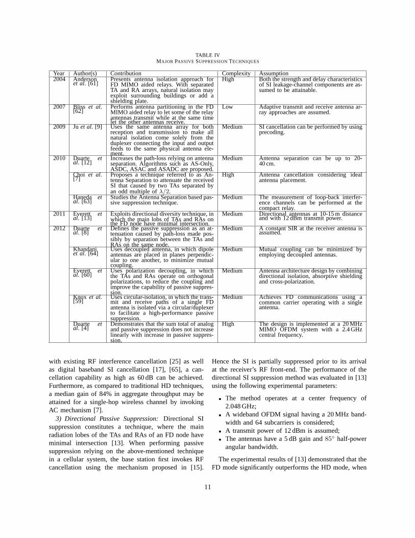
TABLE IVMAJOR PASSIVE SUPPRESSIONTECHNIQUES
Year Author(s) Contribution Complexity Assumption2004 Anderson
et al. [61]Presents antenna isolation approach forFD MIMO aided relays. With separatedTA and RA arrays, natural isolation mayexploit surrounding buildings or add ashielding plate.
High Both the strength and delay characteristicsof SI leakage-channel components are as-sumed to be attainable.
2007 Bliss et al.[62]
Performs antenna partitioning in the FDMIMO aided relay to let some of the relayantennas transmit while at the same timelet the other antennas receive.
Low Adaptive transmit and receive antenna ar-ray approaches are assumed.
2009 Ju et al. [9] Uses the same antenna array for bothreception and transmission to make allnatural isolation come solely from theduplexer connecting the input and outputfeeds to the same physical antenna ele-ment.
Medium SI cancellation can be performed by usingprecoding.
2010 Duarte etal. [12]
Increases the path-loss relying on antennaseparation. Algorithms such as AS-Only,ASDC, ASAC and ASADC are proposed.
Medium Antenna separation can be up to 20-40 cm.
Choi et al.[7]
Proposes a technique referred to as An-tenna Separation to attenuate the receivedSI that caused by two TAs separated byan odd multiple ofλ/2.
High Antenna cancellation considering idealantenna placement.
Haneda etal. [63]
Studies the Antenna Separation based pas-sive suppression technique.
Medium The measurement of loop-back interfer-ence channels can be performed at thecompact relay.
2011 Everett etal. [13]
Exploits directional diversity technique, inwhich the main lobs of TAs and RAs onthe FD node have minimal intersection.
Medium Directional antennas at 10-15 m distanceand with 12 dBm transmit power.
2012 Duarte etal. [8]
Defines the passive suppression as an at-tenuation caused by path-loss made pos-sibly by separation between the TAs andRAs on the same node.
Medium A constant SIR at the receiver antenna isassumed.
Khandaniet al. [64]
Uses decoupled antenna, in which dipoleantennas are placed in planes perpendic-ular to one another, to minimize mutualcoupling.
Medium Mutual coupling can be minimized byemploying decoupled antennas.
Everett etal. [60]
Uses polarization decoupling, in whichthe TAs and RAs operate on orthogonalpolarizations, to reduce the coupling andimprove the capability of passive suppres-sion.
Medium Antenna architecture design by combiningdirectional isolation, absorptive shieldingand cross-polarization.
Knox et al.[59]
Uses circular-isolation, in which the trans-mit and receive paths of a single FDantenna is isolated via a circular/duplexerto facilitate a high-performance passivesuppression.
Medium Achieves FD communications using acommon carrier operating with a singleantenna.
Duarte etal. [4]
Demonstrates that the sum total of analogand passive suppression does not increaselinearly with increase in passive suppres-sion.
High The design is implemented at a 20 MHzMIMO OFDM system with a 2.4 GHzcentral frequency.
with existing RF interference cancellation [25] as wellas digital baseband SI cancellation [17], [65], a can-cellation capability as high as 60 dB can be achieved.Furthermore, as compared to traditional HD techniques,a median gain of 84% in aggregate throughput may beattained for a single-hop wireless channel by invokingAC mechanism [7].
3) Directional Passive Suppression:Directional SIsuppression constitutes a technique, where the mainradiation lobes of the TAs and RAs of an FD node haveminimal intersection [13]. When performing passivesuppression relying on the above-mentioned techniquein a cellular system, the base station first invokes RFcancellation using the mechanism proposed in [15].
Hence the SI is partially suppressed prior to its arrivalat the receiver’s RF front-end. The performance of thedirectional SI suppression method was evaluated in [13]using the following experimental parameters:
• The method operates at a center frequency of2.048 GHz;
• A wideband OFDM signal having a 20 MHz band-width and 64 subcarriers is considered;
• A transmit power of 12 dBm is assumed;• The antennas have a 5 dB gain and85 half-power
angular bandwidth.
The experimental results of [13] demonstrated that theFD mode significantly outperforms the HD mode, when
11
dTX1
d+λ/2
RF Analog
RF→BasebandADC
Digital
Interference
Cancellation
Decoder
RF Interference Cancellation
Input
Output
Encoder
DAC
Baseband→RF
RF Analog
Antenna Cancellation
TX2RX
TX Signal Path RX Signal Path
RF Interference
Reference
QHx220
Digital Interference Reference
Power
Splitter
Fig. 3. Block diagram of antenna cancellation for a wirelessFD SI cancellation. The power splitters introduce a 6 dB reduction in signal, thuspower from TX1 is 6 dB lower compared to power from TX2, withoutthe need for an additional attenuator to compensate for the amplitudemismatch (Fig. 2 of [7]).
relying on passive SI suppression combined with activeSI cancellation. In a scenario, where the TA-RA distanceis assumed to be 10 m and the antennas are separated byan angle of45 or more, the FD gain5 over the HD modemay range from 60% to 90%. This gain becomes 50%or more for an antenna distance of 15 m and for an angleranging from90 to 150.
4) Open Research Issues in Passive Suppression:Although passive SI suppression techniques are capableof attenuating the SI signal in proportion to the path-loss, a larger TA-RA separation usually requires a higherdevice size, which may not be always feasible in practi-cal systems. There are still multiple open challenges inimplementing passive suppression, mainly reflected inthe following aspects:
• The amount of SI reduction offered by the pas-sive suppression technique itself is insufficient forflawless decoding. For instance, in the experimentsperformed in [12], antenna distances of 20 cm and40 cm are considered. These separations are feasiblefor devices such as personal computers, but areactually insufficient for attenuating the interfering
5The FD gain as compared to the HD mode can be evaluated in termsof data rate, capacity, BER, and outage probability improvement, etc.
power to a level below the power of the signal ofinterest;
• The SI-reduction capability of some passive sup-pression techniques (e.g. directional SI suppressionand beamforming) may rely heavily on the multiple-antenna configurations of the FD devices, prevent-ing the size-limited receivers from sufficiently sup-pressing the SI power;
• Increasing the TA-RA separation may not alwaysbenefit the FD operation due to the following rea-sons:
– Increasing the TA-RA separation will degradethe estimate of the wireless channel betweenthe TA and RA, consequently eroding boththe SI channel’s estimate and the resultantsuppression;
– For some of the separation-sensitive tech-niques, a separation beyond the optimum dis-tance (e.g. an odd multiple ofλ/2 specified inAC based suppression [7]) may even deterio-rate the attainable cancellation;
• Furthermore, some passive suppression techniquesmay be band-limited, thus substantially eroding thecancellation performance of a wideband system. For
12
example, it was found that the bandwidth of thetransmitted signal imposes a fundamental constrainton the performance of AC based techniques [7].Basically, the AC based technique only ensures atthe central frequency that the signal is perfectlyphase-inverted and cancelled. However, the perfectantenna positions derived for a specific frequencyare no longer perfect for the other frequencies.Hence the AC based technique fails to provideperfect phase inversion at the RA position across theentire bandwidth. Specifically, in wideband OFDMsystems, the SI cancellation may fail on a persubcarrier basis due to the channel’s frequencyselectivity.
In brief, the best antenna configuration in terms ofthe attainable SI suppression relies on installing the TAsand RAs at the opposite sides of the device in orderto create the highest possible separation [15]. However,optimizing the antenna configuration of compact devicesremains challenging. Hence, we have to resort to a com-bination of passive and active suppression/cancellationtechniques for facilitating a better SI reduction in prac-tically FD systems.
B. Analog Self-Interference Cancellation
Based on the above-mentioned discussion, we supposethat the amount of SI reduction relying on the purepassive suppression technique is insufficient for sup-porting high-integrity FD reception6. In order to reducethe SI below the noise level, we have to additionallyinvoke active cancellation techniques for further reducingthe residual SI after passive suppression. Hence, theobjective of the additional SI cancellation modules isto minimize the SI either within the RF [7] or in theanalog/digital baseband stage.
In theory, the employment of the RF/analog cancella-tion module is not mandatory, if the FD radio is capableof performing a perfect SI leakage-path estimation atthe RAs, the reconstructed digital samples of the SIsignal may be readily subtracted from the low-powerreceived samples, for example by using techniques suchas ZigZag decoding [17]. Unfortunately, a strong SI sig-nal would saturate the AGC, which is hence desensitizedfor the reception of a weak desired signal compressedto a range much smaller than[−1, 1]. In this case,the ADC that becomes impact of the extremely strong
6The signal received at the RAs will be first amplified by anAGC and then down-converted to the baseband/intermidiate frequency,followed by filtering and sampling before the ADC to create thedigitalsamples.
SI power. More explicitly, the quantization noise con-taminating the desired signal might become excessive,hence resulting in a negative effective SINR that wouldbecome inadequate for recovering the desired signal inthe digital baseband [10]. As indicated by [66], thelimitations of the ADC, such as its estimated dynamicrange and quantization resolution constitute the mainobstacle in improving the achievable SI-isolation levelsby employing digital cancellation.
Therefore, it is critical to further reduce the powerof the SI signal prior to the digitization7 of the desiredreceived signal. Specifically, a mechanism referred to asanalog cancellationhas to be invoked for mitigating theSI contaminating the analog signal before it is digitized.After performing analog cancellation, the decontami-nated received digital samples will exhibit a sufficientlyhigh resolution of the desired received signal, thus fa-cilitating efficient digital SI cancellation [7], as depictedin Fig. 1. In this subsection, a range of beneficial analogcancellation techniques will be surveyed and compared,followed by the family of digital cancellation techniques.For the reader’s convenience, we have summarized theseminal contributions on the subject of analog/digitalcancellation techniques in Table V.
1) Analog Cancellation for Reducing the Linear SIComponent:In this section, we focus our attention onthe fundamentals of analog cancellation by elaboratingon the reduction of the linear SI component, whichconstitutes the majority of the SI power, leaving thedynamic adaptation based solutions guarding againstthe non-linear components encountered in time-variantenvironments for further study in the next part.
The principle of analog cancellation can be simplysummarized as follows:In order to sufficiently reducethe SI power, an FD radio is required for creating areference signal corresponding to a perfect replica of theSI signal at all instances. Combining this replica and theSI signals is in theory capable of facilitating perfect SIcancellation [10].Basically, the analog cancellation canbe performed either at the RF or at the analog basebandstage [29]. However, most of the existing analog cancel-lation (e.g. [7], [10], [12]) techniques operate at the RF.Furthermore, by identifying whether the perfect replica-based SI cancelling signal is generated by processing theSI prior to or after up-conversion, the RF-based analogcancellation arrangements may be further classified aspre-mixer (e.g. [12]) orpost-mixerschemes (e.g. [10]).The baseband analog canceller, on the other hand, isdefined as the canceller, in which the perfect replica-
7Before performing digitization, the AGC scales the input to thenormalized range of[−1, 1].
13
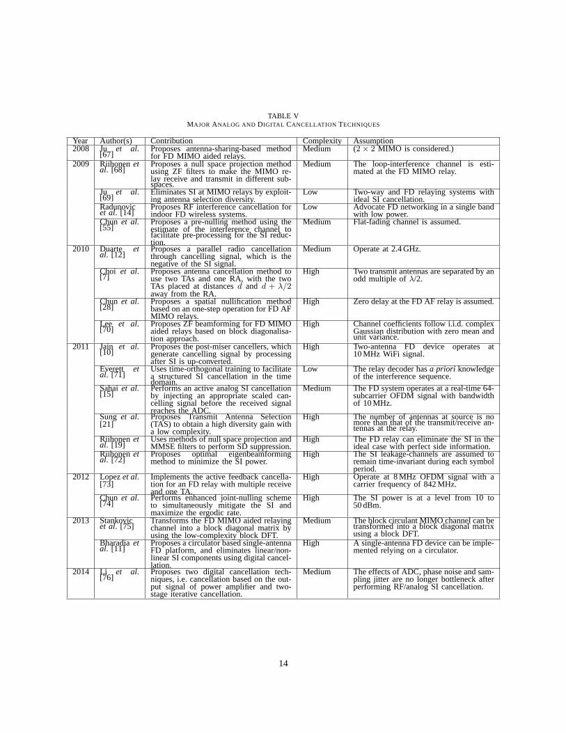
TABLE VMAJOR ANALOG AND DIGITAL CANCELLATION TECHNIQUES
Year Author(s) Contribution Complexity Assumption2008 Ju et al.
[67]Proposes antenna-sharing-based methodfor FD MIMO aided relays.
Medium (2× 2 MIMO is considered.)
2009 Riihonenetal. [68]
Proposes a null space projection methodusing ZF filters to make the MIMO re-lay receive and transmit in different sub-spaces.
Medium The loop-interference channel is esti-mated at the FD MIMO relay.
Ju et al.[69]
Eliminates SI at MIMO relays by exploit-ing antenna selection diversity.
Low Two-way and FD relaying systems withideal SI cancellation.
Radunovicet al. [14]
Proposes RF interference cancellation forindoor FD wireless systems.
Low Advocate FD networking in a single bandwith low power.
Chun et al.[55]
Proposes a pre-nulling method using theestimate of the interference channel tofacilitate pre-processing for the SI reduc-tion.
Medium Flat-fading channel is assumed.
2010 Duarte etal. [12]
Proposes a parallel radio cancellationthrough cancelling signal, which is thenegative of the SI signal.
Medium Operate at 2.4 GHz.
Choi et al.[7]
Proposes antenna cancellation method touse two TAs and one RA, with the twoTAs placed at distancesd and d + λ/2away from the RA.
High Two transmit antennas are separated by anodd multiple ofλ/2.
Chun et al.[28]
Proposes a spatial nullification methodbased on an one-step operation for FD AFMIMO relays.
High Zero delay at the FD AF relay is assumed.
Lee et al.[70]
Proposes ZF beamforming for FD MIMOaided relays based on block diagonalisa-tion approach.
High Channel coefficients follow i.i.d. complexGaussian distribution with zero mean andunit variance.
2011 Jain et al.[10]
Proposes the post-miser cancellers, whichgenerate cancelling signal by processingafter SI is up-converted.
High Two-antenna FD device operates at10 MHz WiFi signal.
Everett etal. [71]
Uses time-orthogonal training to facilitatea structured SI cancellation in the timedomain.
Low The relay decoder hasa priori knowledgeof the interference sequence.
Sahaiet al.[15]
Performs an active analog SI cancellationby injecting an appropriate scaled can-celling signal before the received signalreaches the ADC.
Medium The FD system operates at a real-time 64-subcarrier OFDM signal with bandwidthof 10 MHz.
Sung et al.[21]
Proposes Transmit Antenna Selection(TAS) to obtain a high diversity gain witha low complexity.
High The number of antennas at source is nomore than that of the transmit/receive an-tennas at the relay.
Riihonenetal. [19]
Uses methods of null space projection andMMSE filters to perform SD suppression.
High The FD relay can eliminate the SI in theideal case with perfect side information.
Riihonenetal. [72]
Proposes optimal eigenbeamformingmethod to minimize the SI power.
High The SI leakage-channels are assumed toremain time-invariant during each symbolperiod.
2012 Lopezet al.[73]
Implements the active feedback cancella-tion for an FD relay with multiple receiveand one TA.
High Operate at 8 MHz OFDM signal with acarrier frequency of 842 MHz.
Chun et al.[74]
Performs enhanced joint-nulling schemeto simultaneously mitigate the SI andmaximize the ergodic rate.
High The SI power is at a level from 10 to50 dBm.
2013 Stankovicet al. [75]
Transforms the FD MIMO aided relayingchannel into a block diagonal matrix byusing the low-complexity block DFT.
Medium The block circulant MIMO channel can betransformed into a block diagonal matrixusing a block DFT.
Bharadiaetal. [11]
Proposes a circulator based single-antennaFD platform, and eliminates linear/non-linear SI components using digital cancel-lation.
High A single-antenna FD device can be imple-mented relying on a circulator.
2014 Li et al.[76]
Proposes two digital cancellation tech-niques, i.e. cancellation based on the out-put signal of power amplifier and two-stage iterative cancellation.
Medium The effects of ADC, phase noise and sam-pling jitter are no longer bottleneck afterperforming RF/analog SI cancellation.
14
based cancelling signal is generated in the baseband andthe cancellation occurs in the analog baseband [29].
Based on the above-mentioned principle, the operationof analog cancellation can be realized by executing thefollowing three steps, including:
• Creation of SI-Inverse Signal: Basically, SI inver-sion can be implemented by an FD radio upon sim-ply inverting a signal by inverting its phase. How-ever, this phase adjustment may only be feasibleacross a limited bandwidth, which hence limits itsmaximum cancellation capability. In other words, aperfect signal inversion can be attained at the centralfrequency, but the inverted signals will deviate atboth sides of the central frequency from180,hence suffering from a significant phase-distortion.To address the above-mentioned problem, we haveto resort to sophisticated hardware/circuit designrelying on
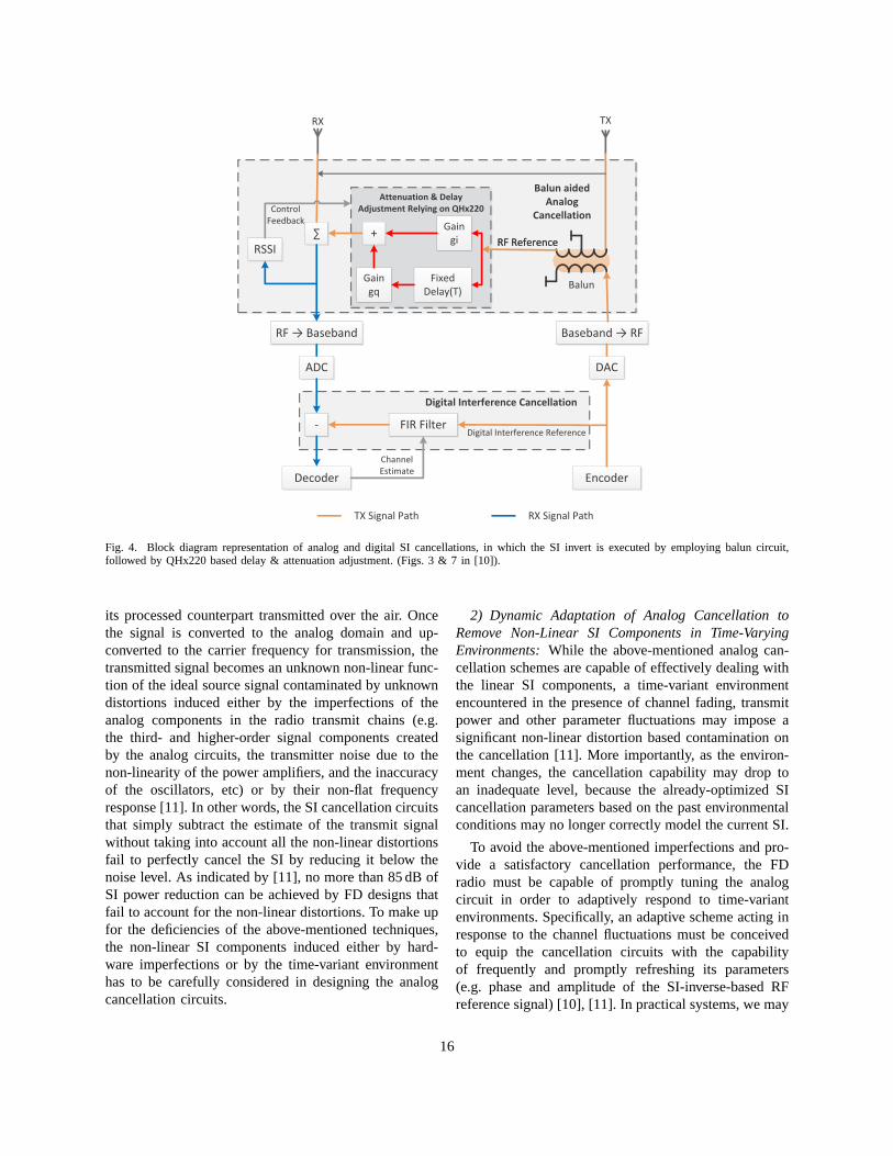
– A balanced/unbalanced (balun) transformer,which is a common component in RF, audioand video circuits, can be utilized for perfectly(in theory) converting back and forth betweenan input signal and its inverse at all instances[10]. As illustrated in Fig. 4, the TA is assumedto transmit the positive signal. The balun out-put of RF reference, which is subject to anadjustment on the delay and attenuation of thereference signal, highly matches the SI signalat the RA, thus offering a reliable SI nullingby combining the received SI signal with itsnegative version.
– Apart from that, another method of generatingthe RF reference signal is to view the SIcancellation as a sampling and interpolationproblem, which can be resolved relying onthe delay-line based analog circuit [11]. Bypicking up the phase and amplitude of theSI signal (e.g. relying on Nyquist samplingtheorem [77]), we can always reconstruct theSI signal at any instant as a weighted linearcombination of samples taken before and afterthe recreation instant, with the weights of thelinear combination determined by using the socalledsince interpolationalgorithm. Of course,a fundamental tradeoff between the hardwarecomplexity (i.e. in terms of the number of delaylines) and the cancellation capability must betreated.
• Delay and Attenuation Adjustment: Since the signaltransmitted over the ether experiences both attenua-tion and delay in all practical scenarios, an identical
attenuation and delay has to be applied to the in-verted SI. The QHx220 noise cancellation chip [78],separates the SI-inversion-based RF reference signalinto its in-phase and quadrature components (i.e.giandgq), can be invoked for imposing an adaptivelycontrollable delay on the aggregated output signalby carefully controlling the attenuation of thosecomponents. It is shown in [10] that the balun-aidedcancellation is capable of achieving an impressiveSI reduction across a wide bandwidth, provided thatboth the phase and the amplitude of the inverted SIsignal are set appropriately.
• Creating a SI-Null by Combining the SI and ItsInverse: The SI-inverse signal will then be com-bined with the SI signal at the RA. Without loss ofgenerality, the Received Signal Strength Indicator(RSSI) values can be employed for representing theresidual SI energy remaining after combining, asillustrated in Fig. 4. In theory, a perfect SI-inversesignal will result in zero SI value at the output of theRSSI. However, the realistic practical engineeringimperfections of the hardware components, such aspower leakage or a non-flat8 frequency response atbalun, will always result in a residual SI power9
after signal combining, which can be minimized bycarefully adapting the attenuations (gi andgq) usingself-tuning algorithms [10].
The existing studies have demonstrated that analogcancellation techniques are capable of reducing the SIstrength by dozens of dBs [7], [10], [11]. For example,in order to facilitate FD communication at the transmitpowers typical of WiFi devices [13], it was shownexperimentally [61] that the SI-induced contaminationimposed on a modulated constellation point can besignificantly reduced by using an interference cancelleraccomodated within the RF stage. Furthermore, as indi-cated in [10], the SI-inverse technique alone is capableof reducing the SI by no less than 45 dB across a 40 MHzbandwidth.
Nonetheless, subtracting the SI from the receivedsignal by simply relying on the above-mentioned SI-inversion technique remains a challenge in practicalsystems, because the FD radio only knows the “clean”digital representation of the baseband signal, rather than
8For example, the balun circuit is not frequency flat and invertsdifferent parts of the bands with different amplitudes, thusapplying asingle attenuation and delay factor to invert the SI signal will neverachieve a perfect cancellation [10]. Furthermore, the QHx220 modulemay also suffer from a non-linear distortion, resulting in imperfect SIcancellation for typical wireless input powers (0-30 dBm) [10].
9In practical designs, the combining-output energy can be further re-duced in the digital-domain relying on digital cancellationtechniques.
15
∑
RSSI
RF → Baseband
ADC
-
Decoder
FIR Filter
DAC
Encoder
Baseband → RF
RF Reference
Balun
Control
Feedback
Digital Interference Cancellation
Digital Interference Reference
RX TX
TX Signal Path RX Signal Path
RF Reference
Attenuation & Delay
Adjustment Relying on QHx220
+Gain
gi
Gain
gq
Fixed
Delay(T)
Balun aided
Analog
Cancellation
Channel
Estimate
Fig. 4. Block diagram representation of analog and digital SI cancellations, in which the SI invert is executed by employing balun circuit,followed by QHx220 based delay & attenuation adjustment. (Figs. 3 & 7 in [10]).
its processed counterpart transmitted over the air. Oncethe signal is converted to the analog domain and up-converted to the carrier frequency for transmission, thetransmitted signal becomes an unknown non-linear func-tion of the ideal source signal contaminated by unknowndistortions induced either by the imperfections of theanalog components in the radio transmit chains (e.g.the third- and higher-order signal components createdby the analog circuits, the transmitter noise due to thenon-linearity of the power amplifiers, and the inaccuracyof the oscillators, etc) or by their non-flat frequencyresponse [11]. In other words, the SI cancellation circuitsthat simply subtract the estimate of the transmit signalwithout taking into account all the non-linear distortionsfail to perfectly cancel the SI by reducing it below thenoise level. As indicated by [11], no more than 85 dB ofSI power reduction can be achieved by FD designs thatfail to account for the non-linear distortions. To make upfor the deficiencies of the above-mentioned techniques,the non-linear SI components induced either by hard-ware imperfections or by the time-variant environmenthas to be carefully considered in designing the analogcancellation circuits.
2) Dynamic Adaptation of Analog Cancellation toRemove Non-Linear SI Components in Time-VaryingEnvironments:While the above-mentioned analog can-cellation schemes are capable of effectively dealing withthe linear SI components, a time-variant environmentencountered in the presence of channel fading, transmitpower and other parameter fluctuations may impose asignificant non-linear distortion based contamination onthe cancellation [11]. More importantly, as the environ-ment changes, the cancellation capability may drop toan inadequate level, because the already-optimized SIcancellation parameters based on the past environmentalconditions may no longer correctly model the current SI.
To avoid the above-mentioned imperfections and pro-vide a satisfactory cancellation performance, the FDradio must be capable of promptly tuning the analogcircuit in order to adaptively respond to time-variantenvironments. Specifically, an adaptive scheme acting inresponse to the channel fluctuations must be conceivedto equip the cancellation circuits with the capabilityof frequently and promptly refreshing its parameters(e.g. phase and amplitude of the SI-inverse-based RFreference signal) [10], [11]. In practical systems, we may
16
invoke both the time- and frequency-domain solutions inorder to combat the non-linear SI components in time-varying environment.
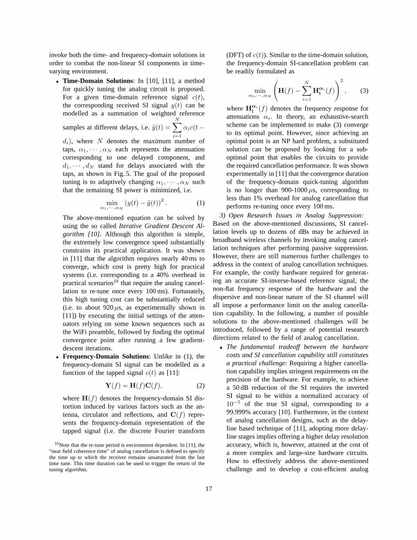
• Time-Domain Solutions: In [10], [11], a methodfor quickly tuning the analog circuit is proposed.For a given time-domain reference signalc(t),the corresponding received SI signaly(t) can bemodelled as a summation of weighted reference
samples at different delays, i.e.y(t) =N∑
i=1
αic(t−
di), where N denotes the maximum number oftaps, α1, · · · , αN each represents the attenuationcorresponding to one delayed component, andd1, · · · , dN stand for delays associated with thetaps, as shown in Fig. 5. The goal of the proposedtuning is to adaptively changingα1, · · · , αN suchthat the remaining SI power is minimized, i.e.
minα1,··· ,αN
(y(t)− y(t))2. (1)
The above-mentioned equation can be solved byusing the so calledIterative Gradient Descent Al-gorithm [10]. Although this algorithm is simple,the extremely low convergence speed substantiallyconstrains its practical application. It was shownin [11] that the algorithm requires nearly 40 ms toconverge, which cost is pretty high for practicalsystems (i.e. corresponding to a 40% overhead inpractical scenarios10 that require the analog cancel-lation to re-tune once every 100 ms). Fortunately,this high tuning cost can be substantially reduced(i.e. to about 920µs, as experimentally shown in[11]) by executing the initial settings of the atten-uators relying on some known sequences such asthe WiFi preamble, followed by finding the optimalconvergence point after running a few gradient-descent iterations.
• Frequency-Domain Solutions: Unlike in (1), thefrequency-domain SI signal can be modelled as afunction of the tapped signalc(t) as [11]:
Y(f) = H(f)C(f), (2)
whereH(f) denotes the frequency-domain SI dis-tortion induced by various factors such as the an-tenna, circulator and reflections, andC(f) repre-sents the frequency-domain representation of thetapped signal (i.e. the discrete Fourier transform
10Note that the re-tune period is environment dependent. In [11], the“near field coherence time” of analog cancellation is defined to specifythe time up to which the receiver remains unsaturated from the lasttime tune. This time duration can be used to trigger the return of thetuning algorithm.
(DFT) of c(t)). Similar to the time-domain solution,the frequency-domain SI-cancellation problem canbe readily formulated as
minα1,··· ,αN
(
H(f)−N∑
i=1
Hαi
i(f)
)2
, (3)
whereHαi
i(f) denotes the frequency response for
attenuationsαi. In theory, an exhaustive-searchscheme can be implemented to make (3) convergeto its optimal point. However, since achieving anoptimal point is an NP hard problem, a substitutedsolution can be proposed by looking for a sub-optimal point that enables the circuits to providethe required cancellation performance. It was shownexperimentally in [11] that the convergence durationof the frequency-domain quick-tuning algorithmis no longer than 900-1000µs, corresponding toless than 1% overhead for analog cancellation thatperforms re-tuning once every 100 ms.
3) Open Research Issues in Analog Suppression:Based on the above-mentioned discussions, SI cancel-lation levels up to dozens of dBs may be achieved inbroadband wireless channels by invoking analog cancel-lation techniques after performing passive suppression.However, there are still numerous further challenges toaddress in the context of analog cancellation techniques.For example, the costly hardware required for generat-ing an accurate SI-inverse-based reference signal, thenon-flat frequency response of the hardware and thedispersive and non-linear nature of the SI channel willall impose a performance limit on the analog cancella-tion capability. In the following, a number of possiblesolutions to the above-mentioned challenges will beintroduced, followed by a range of potential researchdirections related to the field of analog cancellation.
• The fundamental tradeoff between the hardwarecosts and SI cancellation capability still constitutesa practical challenge: Requiring a higher cancella-tion capability implies stringent requirements on theprecision of the hardware. For example, to achievea 50 dB reduction of the SI requires the invertedSI signal to be within a normalized accuracy of10−5 of the true SI signal, corresponding to a99.999% accuracy [10]. Furthermore, in the contextof analog cancellation designs, such as the delay-line based technique of [11], adopting more delay-line stages implies offering a higher delay resolutionaccuracy, which is, however, attained at the cost ofa more complex and large-size hardware circuits.How to effectively address the above-mentionedchallenge and to develop a cost-efficient analog
17
d1 a1d1
dN aN
fixed
delaysvariable
attenuators
Control
algorithm
aN
Analog Cancellation Circuit
×
LNA
R+iT
RX
R
PA
××
ADCDAC
RX
TX
Digital CancellationEliminates all linear and
non-linear distortion
1
2
3
Circulator
C
T R+aT
Tb
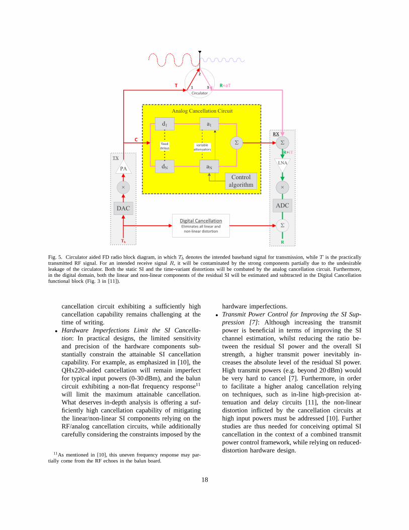
Fig. 5. Circulator aided FD radio block diagram, in whichTb denotes the intended baseband signal for transmission, while T is the practicallytransmitted RF signal. For an intended receive signalR, it will be contaminated by the strong components partially due to the undesirableleakage of the circulator. Both the static SI and the time-variant distortions will be combated by the analog cancellationcircuit. Furthermore,in the digital domain, both the linear and non-linear components of the residual SI will be estimated and subtracted in the Digital Cancellationfunctional block (Fig. 3 in [11]).
cancellation circuit exhibiting a sufficiently highcancellation capability remains challenging at thetime of writing.
• Hardware Imperfections Limit the SI Cancella-tion: In practical designs, the limited sensitivityand precision of the hardware components sub-stantially constrain the attainable SI cancellationcapability. For example, as emphasized in [10], theQHx220-aided cancellation will remain imperfectfor typical input powers (0-30 dBm), and the baluncircuit exhibiting a non-flat frequency response11
will limit the maximum attainable cancellation.What deserves in-depth analysis is offering a suf-ficiently high cancellation capability of mitigatingthe linear/non-linear SI components relying on theRF/analog cancellation circuits, while additionallycarefully considering the constraints imposed by the
11As mentioned in [10], this uneven frequency response may par-tially come from the RF echoes in the balun board.
hardware imperfections.• Transmit Power Control for Improving the SI Sup-
pression [7]: Although increasing the transmitpower is beneficial in terms of improving the SIchannel estimation, whilst reducing the ratio be-tween the residual SI power and the overall SIstrength, a higher transmit power inevitably in-creases the absolute level of the residual SI power.High transmit powers (e.g. beyond 20 dBm) wouldbe very hard to cancel [7]. Furthermore, in orderto facilitate a higher analog cancellation relyingon techniques, such as in-line high-precision at-tenuation and delay circuits [11], the non-lineardistortion inflicted by the cancellation circuits athigh input powers must be addressed [10]. Furtherstudies are thus needed for conceiving optimal SIcancellation in the context of a combined transmitpower control framework, while relying on reduced-distortion hardware design.
18
In summary, the achievable SI cancellation capabilitymay remain limited and in fact insufficient for high-integrity detection, when relying on stand-alone analogcancellation. To offer a sufficiently high cancellationcapability (i.e. to make the resultant SINR high enoughfor high-integrity detection), digital-domain cancellationcombined with analog cancellation must be employed forfurther mitigating the residual SI in the digital baseband.
C. Digital Self-Interference Cancellation
As indicated by [10], although an industry-grade baluncircuit is capable of reducing the SI by as much as 45 dBfor a 40 MHz wide SI signal, the remaining SI powermay remain by up to 45 dB higher than the noise floor (inthe absence of employing passive suppression). This stillexcessively interferes with the desired signal, either be-cause of the residual multipath SI echoes contaminatingthe desired signal or because of the SI leakage imposedby the imperfections of the hardware circuits. Evidently,the residual SI after analog cancellation must be furtherreduced in the digital domain.
Digital cancellation constitutes an active SI-mitigationmechanism that by definition operates in the digitaldomain and exploits the knowledge of the interferingsignal in order to cancel it after the received signal hasbeen quantized by the ADC [29], [79]. To achieve this,the receiver first extracts the SI and then remodulatesit and subtracts it from the received SI contaminatedsignal. Coherent SI-detection can also be employed forrecovering the SI by correlating the received signal withthe clean hypothesized regenerated SI-inversion basedreference signal, which is available at the output ofthe co-located FD transmitter [7]. This technique thenrequires the receiver to estimate both the delay and phaseshift between the transmitted and the received signalsrelying on techniques, such as the correlation peak basedalgorithm for subtracting the SI signal.
1) Fundamentals of Digital Cancellation:Digitalcancellation can be regarded as an excellent, safety-netsolution for diverse scenarios, when analog cancellationachieves a poor suppression [7], [12]. However, sincethe transmitted packet are different from the generatedreference signal due to a number of factors such asthe hardware limitations and the multipath fading, sub-tracting the estimated signal rather than the clean signalwould be capable of substantially improving the capabil-ity of digital cancellation. In practice, digital cancellationfundamentally comprises two main components, i.e.esti-mating the SI channel, and using the channel estimationon the known transmit signal to generate digital samplesfor subtracting the SI from the received signal [10].
In order to implement the digital cancellation to elim-inate the residual SI power after analog cancellation, theSI channel components comprising both the leakage overthrough the analog cancellation circuit and the delayedreflections of the SI signal from the environment mustbe estimated [11]. Basically, the residual SI can besub-divided into linear and non-linear components. Theformer constitutes the majority of the SI power and canbe estimated by existing algorithms, such as the familyof least-square and MMSE [80] based techniques, whilethe latter is induced by the non-linear distortions ofthe imperfect analog cancellation circuits. For example,the QHx220 hardware [10] employed in the balun-based analog cancellation scheme may cause non-lineardistortions, particularly for high input powers beyondsay -40 dBm [10]. Consequently, the non-linearity ofthe SI leakage channel must be accurately characterizedfor the sake of high-rejection SI cancellation in thedigital domain. In practical designs, we may rely on thefollowing techniques for estimating the linear and non-linear components [11]:
2) Estimation of the Linear Component of the SILeakage-Channel:By modelling the linear componentsof the SI as a non-causal linear function of the transmit-ted digital signalx[n], which is known in advance, thereceived sampley[n] at any instant can be modelled asa linear combination of up tok samples ofx[n] beforeand after the instantn, wherek > 0 is a function of theSI leakage channel memory:
y[n] =k∑
z=1−k
x[n− z]h[z] + w[n], (4)
where h[n] and w[n] represent the SI channel atten-uation and the additive noise component at instantn, respectively. By definingy = [y[0], · · · , y[n]]T ,h = [h[−k], · · · , h[0], · · · , h[k − 1]]T , and w =[w[0], · · · , w[n]]T , wherexT denotes the transpose ofvectorx, the SI channel vectorh can be estimated asfollows [11]:
h =(
AHA)−1
AHy, (5)
where we have A =
x[−k] . . . x[0] . . . x[k − 1]...
. . ....
. .....
x[n− k] . . . x[n] . . . x[n+ k − 1]
, and
AH denotes the Hermitian transpose of the matrixA. Since the training matrixA can be pre-computed,the computational complexity of the above-mentionedalgorithm can be substantially reduced.
19
3) Estimation of the Non-Linear Components of theSI Leakage-Channel:After estimating and eliminatingthe linear components of the SI signal, the residual non-linear components can be further reduced. As indicatedby [11], the power of the residual non-linear componentsis about 20 dB higher than the noise level. Since theexact non-linear function that an FD radio applies tothe baseband transmitted signal is hard to estimate, ageneral model relying on Taylor series expansion can beemployed for approximating the non-linear function inthe digital baseband domain [11]:
y[n] =∑
m∈odd terms,n=−k,··· ,k
x[n] (|x[n]|)m−1 · hm[n],
(6)in which only the odd-order terms correspond to non-zero energy in the frequency band of interest, as revealedin [11]. Evidently, the first term is the linear componentcorresponding to the majority of the SI power, which canbe estimated and cancelled using the algorithm proposedin (5). Furthermore, it was found in [11] that in practicethe higher order terms of (6) constitute a correspond-ingly lower power, because those terms are created bythe mixing of multiple lower-order terms, where eachmixing operation reduces the combined power. Henceonly a limited number of terms have to be considered inimplementing practical SI leakage-channel estimation.
4) Open Research Issues in Digital Cancellation:Once the SI signal can be sufficiently suppressed byperforming both RF/analog and digital cancellation, theSI-contaminated signals can be successfully detected bythe FD receiver. In contrast to analog cancellation, whichis unable to adaptively combat the time-variant effectsof the radio environment, digital cancellation is capableof dynamically adapting to these, because it estimatesthe SI leakage-channel on a short-term per-packet basis.Hence robust digital cancellation provides the necessaryresidual SI power reduction below the noise floor. Itis shown in [11] that in a typical indoor deploymentoperating in the 2.4 GHz Industrial Scientific Medical(ISM) band over a 80 MHz bandwidth, a hybrid FDsystem is capable of reducing both the distortions as wellas the effects of environmental changes by up to 110 dBin a dense indoor office environment. Furthermore, amedian throughput gain of 87% can be achieved bypractical WiFi radios, corresponding to almost twice thethroughput of the conventional HD system. Nonetheless,a range of practical issues still have to be addressed,including:
• The Tradeoff between Analog and Digital Cancel-lations: Despite of the capability in cancelling thelinear/non-linear SI components in digital cancella-
tion, it is still noteworthy that digital cancellationoperating in isolation without analog cancellationfails to provide a sufficiently high SI suppression[8]. To offer a high enough SI cancellation, a hybridanalog-digital design is required to successfullysubtract all the linear and non-linear components.However, there exists a fundamental tradeoff be-tween the capacities of analog- and digital-domaintechniques. To elaborate a little further, the achiev-able SI-rejection of digital cancellation dependson the efficiency of the attainable suppression ofthe preceding analog cancellation when they arecascaded, with the capability of the former typicallydecreasing as that of the latter increases. In ascenario, where analog cancellation might achievea sufficiently high suppression, digital cancellationmay even become unnecessary. It would be veryimportant to effectively balance the roles of theanalog- and digital-domain functions in the over-all cancellation and to carefully reveal the overallbenefits of combined analog/digital cancellation.
• Performance Limitations Imposed by Practical Im-perfections: Despite the promising capabilities of-fered by concatenated analog-digital cancellations,the joint benefits of analog-plus-digital cancellationmay still remain limited by various practical factors,such as the phase noise issues elaborated on inSection III-E and the leakage-channel estimationerrors. Specifically, the amount of attainable com-bined analog and concatenated digital suppressionis limited by the phase noise imposed by the localoscillators [29]. If the analog canceller achievesa higher suppression, the residual SI has a dom-inant phase-noise-induced contribution. Otherwisethe residual SI exhibits a higher correlation withthe SI signal and thus the SI may be efficientlyreduced by the digital canceller. Therefore, it israther critical to substantially improve the aggre-gated performance of concatenated analog-digitalcancellation by carefully combating the impact ofpractical distortions.
In summary, to carefully tackle the above-mentionedchallenges and improve the aggregated capability ofthe concatenated analog-digital cancellation, we haveto address several critical problems. On one hand, wemust effectively balance the tradeoff between analog anddigital cancellations so as to attain the best possibleaggregated cancellation in the overall solution. On theother hand, the cancellation capability of any individualtechnique (e.g. passive suppression, analog or digitalcancellation) should be further improved. To achieve
20
this ambitious goal, we may resort to sophisticatedalgorithms, such as the SI model relying on Taylor seriesexpansion [11] for mitigating both linear and non-linearSI components in the analog- and/or digital-domain.Furthermore, in contrast to the existing FD solutionsrelying on a single antenna [11] or a pair of antennasconstituted by a TA and RA [10], the spatial diversitygain offered by multiple antennas can also be readilyexploited for further improving the SI suppression capa-bility, as elaborated on in the following subsection.
D. MIMO Aided SI Cancellation Techniques by Exploit-ing the Spatial Diversity Gain
The exploration of SISO based FD techniques moti-vated the development of SI mitigation techniques con-ceived for MIMO devices [81]. Three main approacheshave been proposed, namely natural isolation (i.e. con-stituted by spatially separating the transmit and receiveantenna arrays) [12], time-domain (TD) cancellation [10]and spatial-domain (SD) suppression [72], [74], [82],all of which are applicable to FD MIMO devices forimproving the SI mitigation capability [19].
1) Natural Isolation: Unlike passive suppressiontechniques discussed in Section III-A, in which the SIstrength is attenuated relying on path-loss effect, naturalisolation in MIMO based FD systems can be achievedby employing some signal processing techniques (e.g.beamforming) to provide an additional man-made isola-tion [19]. For example, with separated receive and trans-mit antenna arrays, a rational antenna-array installationcan guarantee obstacles in between the array to blockthe line-of-sight (LOS) SI component. Furthermore, di-rectional antenna elements can be separated by pointingat opposite directions [61], thus substantially reducingthe SI strength imposed on RAs.
2) Time-Domain Cancellation:Classic TD trainingcan be beneficially utilized for estimating the leakagepath of the SI and thus for facilitating a reliable can-cellation, provided that the FD system knows its owntransmitted signal (or at least approximately) [15], [19],[71]. If the SI channel can be reliably estimated, theSI signal may be effectively replicated and removedfrom the received signal. Time-orthogonal training basedalgorithms [15], [83] can be employed for satisfying theabove-mentioned requirement. In contrast to methodsusing time-orthogonal training, the structured SI can-cellation technique of [71] allows for the FD device toestimate the TA-RA leakage path of the SI by observingits own transmit signal during instances, when the sourcenode is inactive. Hence, the FD device becomes capableof suppressing any SI imposed on the signal transmitted
from the source node to it after estimating the TA-RASI leakage, provided that the FD device’s decoder hasa priori knowledge of the SI. It was shown in [71] thatthe structured cancellation technique is capable of out-performing the time-orthogonal training based schemesof in terms of the achievable rate.
Despite of that, the main drawback of TD cancellationmay be reflected in its blindness to the SD characteristicsof the SI channel, such as a low-rank channel matrixthat is not expected in creating a high isolation. Further-more, the TD based schemes are sensitive to both thechannel estimation errors and the transmit signal noise,corresponding to a new signal imposed on the FD inputthat may actually degrade the natural isolation as wellas SI cancellation performance. The above-mentionedchallenges may be addressed in spatial suppression tech-niques by employing the SD based techniques, whichare found to be better than the TD based cancellationwhenever a sufficient number of antennas compared tothat of spatial streams is provided in the former [19].Diverse SD solutions, such as precoding/decoding [9]and pre-nulling [55] have been proposed for rejectingthe SI based on the idealized simplifying assumption ofhaving perfect SI channel information.
3) Spatial Suppression:Spatial suppression can beachieved by employing schemes such as antenna subsetselection, null-space projection (i.e. making the receivingand transmitting subspaces orthogonal by relying onprecoding/beamforming techniques), and joint transmitand receive beam selection, which is capable of sup-porting more spatial streams by choosing the minimumeigenmodes for overlapping subspaces. Furthermore, al-gorithms such as zero-forcing (ZF) and MMSE canbe employed for maintaining the desired signal qualityas well as improving SI cancellations [19]. Instead ofproviding an exhaustive survey, we just introduce anumber of typical schemes below.
• Antenna Subset Selection [84]: As revealed in [85],the simplified receive antenna selection scheme mayinspire us to formulate SI suppression relying ongeneralized antenna subset selection using respec-tive receive and transmit filters. In theory, the opti-mal filters can be found by calculating the Frobe-nius norm for all the TA-RA subset combinationsand choosing the one corresponding to the lowestresidual SI strength. However, deriving the optimalsolution will become infeasible as the number ofTAs and/or RAs becomes large. Instead, we mayrefer to some sub-optimal technique for facilitatinga cost-efficient spatial suppression. In [21], [84], theso-called transmit antenna selection (TAS) scheme
21
was proposed for achieving a high diversity gain at alow complexity. The main philosophy of TAS is thatinstead of the best subset antennas, a sub-optimalsub-set is selected for relay-aided transmission. Asa benefit, the dimension of the SI leakage-channelmatrix is reduced to(NR × Nk), whereNR andNk denote the number of RAs and the numberof selected TAs, respectively. Consequently, thegoal of TAS becomes to choose the specific subsetof TAs that minimizes the effective SNR of theSI leakage-channel [21], with the following fourcriteria beneficially employed:
– Minimum Frobenius Norm SNR [21], whichchooses the specific SI channel of the smallestFrobenius Norm from all the candidate selec-tions;
– Minimum Post-Processing SNR [21], whichchooses the subset of TAs with the minimumpost-processing SNR for the sake of optimizingthe BER performance;
– Minimum Singular Value [21], which choosesthe specific antennas having the minimum sin-gular values among all the SI channels;
– Minimum Capacity [21], which chooses thelowest-capacity SI leakage-channel after select-ing the TA subset.
• Null-Space Projection [68]: In [68], a techniquereferred to as “Null-Space Projection” is proposed,in which the pre-coding and decoding matricesobtained from the singular value decomposition(SVD) of the SI channel are selected for ensuringthat the FD device is capable of receiving andtransmitting in different subspaces, i.e. the transmitbeam-patterns are projected to the null-space of theSI channel combined with the receive filter andviceversa. The ZF filter provides an efficient solution,if the SI is dominant [68]. Furthermore, three filter-design paradigms, i.e.independent design, whichallows one of the filters to be designed withoutany knowledge of the other filter,separate design,which allows one of the filters to be designed giventhe other design, andjoint design, in which bothfilters are designed together, can be implemented.If the pre-coding and decoding filters are jointlydesigned, several spatial input and output streamscan be supported simultaneously by the FD devicefor outperforming the HD systems in terms ofcapacity [86].
• Pre-coding and Decoding [87]: If the transmit andreceive filters can be jointly designed in a MIMObased FD device, an SI cancellation technique
can be conceived by satisfying the condition ofDH
RHRPR = 0, where PR and DR describethe pre-coder’s and the decoder’s action, respec-tively. Note that the pre-coding problem at handcorresponds to converting a MIMO channel matrixinto matrices having a lower triangular structure(e.g. for AF relaying) or a diagonal matrix (e.g.for DF relaying) [87]. By invoking the SVD ofHR as HR = URΣRV
HR , efficient SI can-
cellation can be achieved, provided that the pre-coder and decoder matrices are designed asPR =α[vR,j 6=k · · ·vR,j 6=k] and DR = [uR,k · · ·uR,k],with uR,k and vR,k representing the k-th columnvector of the matricesUR and V R, respectively,and withα denoting the power normalization factor.
• Optimal Eigenbeamforming [72]: In a MIMO basedFD device, SD aided SI suppression can be per-formed using optimal eigenbeamforming, whichminimizes the power of the residual SI signal bypointing the transmit and receive beams to theminimum eigenmodes of the SI channel [72]. Theoptimal eigenbeamforming is capable of increasingboth the attainable communication rate and thecoverage area [88]. Apart from frequency-domainbeamforming, a TD transmit beamforming (TDTB)method may also be invoked at the RF front-end ofthe receivers in broadband FD mode MIMO radios.A cancellation capability of 50 dB is achievablein TDTB over a reasonably wide bandwidth of30 MHz [16]. Furthermore, distributed beamform-ing can also be employed for multiuser MIMO-assisted FD systems in order to suppress the SIat the FD device (e.g. base station) as well as tomitigate the multiuser interference at the mobilestations [89].
• SI Suppression with Maximum SIR [90]: In thisscheme, the FD device employs both transmit andreceive filters for suppressing the SI signal, hencemaximizing the ratio between the power of theuseful signal and the SI power [90]. The SIR maybe readily maximized either at the input or theoutput of the device. By defining the receive andtransmit suppression matrices asGrx and Gtx,respectively, a two-step approach can be employedfor optimizing the SIR:
– Step 1: By designing the receive suppressionmatrix Grx and neglecting for the moment thetransmit suppression matrixGtx, the specificGrx matrix that is optimal in terms of SIRmaximization at the FD device’s receiver has
22
to obey [90]Grx,opt = argmaxGrx
‖GrxH1‖2F‖GrxH0‖2F
,
where ‖A‖2F denotes the Frobenius norm ofthe matrixA, while the matricesH0 andH1
represent the SI leakage-channel matrix and thedevice’s receive channel matrix, respectively.
– Step 2: Given Grx, Gtx is optimizedby maximizing the SIR at the FD de-vice’s transmit side, yieldingGtx,opt =
argmaxGtx
‖H2Gtx‖2F‖Grx,optH0Gtx‖2F
, whereH2 rep-
resents the device’s transmit channel matrix[90]. SI suppression with maximum SIR wasshown to outperform the ZF nulling techniquein terms of its channel capacity, regardlesswhether the SI channel is of full-rank ornot [90]. Furthermore, enhanced joint-nullingschemes may also be conceived for MIMO-aided FD devices for mitigating the SI andfor maximizing the ergodic rate simultaneously[74].
• MMSE Filtering [68]: The degree of freedom (DoF)in the spatial domain allows for more sophisticatedapproaches to be conceived for improving the usefulsignal power. Suffice to say that the family of SDsuppression schemes is capable of minimizing theeffects of SI at the cost of partially affecting the use-ful signal. An MMSE cost-function based schemecan be developed for reducing the aforementionedcost. This is, because in contrast to ZF, the MMSEscheme can suppress not only the SI signal, but alsothe additive Gaussian noise [68], hence typicallyleading to a better BER than ZF. Furthermore,a multiple-filter based scheme can also be devel-oped for achieving a substantial inter-antenna/multi-stream interference suppression as well as SI can-cellation [91]. The total mean squared error of thesignal received at the mobile stations can thus beminimized by using this filter. As compared to theconventional scheme [92], which designs the inter-antenna/multi-stream interference suppression andSI cancellation independently, the joint multiple-filter based scheme is capable of achieving a su-perior performance in terms of the average BER.
From the above-mentioned discussions, while both TDand FD techniques having their respective advantages,each technique has exposed its drawbacks. For example,TD cancellation suffers from a higher residual SI inducedby the channel estimation errors and transmit signalnoise, while SD suppression requires extra antennas andhence suffers from a high computational complexity. To
elaborate a little further, many of the existing SD sup-pression methods rely on complex matrix computations,which may significantly erode the benefits of FD tech-niques owing to their cost [82]. Carefully designed low-complexity algorithms conceived for high-dimensionalMIMO SI channels are thus capable of dramaticallyreducing the hardware/software cost in FD signal pro-cessing, hence facilitating realistic FD communication.Furthermore, the combination of TD cancellation andSD suppression may be potentially capable of providinga high isolation level for a moderate number of antennaseven at a low SNR and may perform better than any ofthese techniques operating in isolation [19]. In [19], thecombination of TD and SD cancellations is found to beespecially beneficial if there exists a significant amountof transmit signal noise. Combining these schemes re-sults in a residual SI leakage-channel expressed in theform of HR = GrxHRGtx + C, with GrxHRGtx
representing the SD suppression andC denoting the TDcancellation. The corresponding filter design can thus beperformed for one of the schemes first, followed by theother scheme based on the residual SI leakage-channelof the first scheme [68].
E. IMPAIRMENTS IMPOSED ON SELF-INTERFERENCE CANCELLATION
Despite the successful implementations of FD tech-niques in the context of short-range communications,extending their applications to the long-range commu-nication scenarios remains a challenge, again, owing tothe impact of SI [29]. As indicated in [4], the attain-able aggregate SI cancellation does not increase linearlywith the achievable analog cancellation. Furthermore,the amount of attainable digital cancellation depends onthe amount of the analog cancellation, when they arecascaded. In other words, when the analog cancellationreduces the SI to a lesser extent, the digital cancellerbecomes capable of mitigating more substantially andvice versa. More specifically, the reasons of “what limitsthe amount of analog cancellation in a FD system andhow does the amount of cancellations by analog anddigital cancellers depend on each other in cascadedsystems” are still unclear [29].
To find the reasons for the above-mentioned limi-tations, a number of factors, including the transmit-ter/receiver phase noise [29], I/Q imbalance [76], poweramplifier nonlinearity [76] and ADC quantization noise[66], etc., all of which impose impairments on the TA-RA link of FD systems, must be taken into consideration[29]. Furthermore, we may resort to the following meth-ods for mitigating the above-mentioned impairments:
23
• The quantization noise level can be reduced belowthe thermal noise level relying on a high-resolutionADC [12]. Hence the FD radio is capable of strikingoff the quantization noise from the list of SI-cancellation bottlenecks. For instance, as indicatedin [66], an ADC with 16 bit quantization shouldbe exploited in order to handle SIR in the range of-40 dB to -20 dB relying on digital cancellation;
• The I/Q imbalance can be readily mitigated as longas it does not significantly vary with time [29].This distortion as well as the power amplifier’snonlinearity can be compensated with an aid ofdigital pre-distortion in the transmitter [93];
• If the FD model operates in the linear region of thepower amplifier, the SI cancellation will no longersuffer significantly from the power amplifier’s non-linearity [29].
Given the above-mentioned prerequisite, the phasenoise [94] inflicted by the jitter in the local oscilla-tors, turns out to constitute a major bottleneck in FDsystems, since it substantially limits the amount of SIcancellation. However, depending on the specific systemparameters, such as the power amplifier linearity, ADCresolution, precision of the RF/analog cancellation andthe SI leakage-channel estimation accuracy, the majorfactors leading to performance limitations may varysubstantially. As revealed in [76], provided that theeffects of quantization/phase noise can be mitigated, thenonlinearity of the power amplifier and the transmitI/Q imbalance will dominate the precision of digitalcancellation, if the most dominant leakage-channel com-ponent’s SI contribution can be subtracted from theSI signal during the RF/analog cancellation phase. Toelaborate a little further, let us consider a system with atransmit power of 10 dBm and a bandwidth of 20 MHz(corresponding to a noise floor of -101 dBm). In thisscenario the radio is required to suppress the effectsof both quantization/phase noise and sampling jitter byabout 40 dB to mitigate the SI below the noise floor,whereas the distortions induced by the power amplifiernonlinearity and transmit I/Q imbalance must be sup-pressed by about 80 dB [76].
In the following, we will analyze the impact of theabove-mentioned impairments on SI cancellation in con-sideration of variant scenarios.
1) The Impact of Phase Noise on the Self-InterferenceCancellation: In this section, the impact of phase noiseon the SI cancellation is analyzed, with all the above-mentioned impairments (including I/Q imbalance, poweramplifier nonlinearity, etc) but channel estimation errorsassumed to be mitigated. In order to model the phase
noise imposed on the SI signal, let us first consider thebaseband signalx(t) that is up-converted to a carrier fre-quency ofωc. The up-converted signal can be expressedas:
xup(t) = x(t)e[ωc+φ(t)], (7)
where φ(t) represents the phase noise. The down-converted phase noise can be similarly defined. Thevariance and autocorrelation of the phase noise canthus be defined asσ2
φ = E|φ(t)|2 and Rφ(τ) =Eφ(t)φ(t− τ), respectively.
As quantified in [29], the strength of the residual SIcan be represented as
E|yresidual,d[iT ]|2 = |hSI |2σ2φ(1−Rφ(dT )) + 2σ2
noise,(8)
whereyresidual,d[iT ] denotes the residual SI for a givendelay d between the SI and the SI-inverse-based can-celling reference signals,hSI stands for the attenuationof the SI signal,T represents the sampling period andσ2
noise is the variance of the thermal noise. Once the delayd is sufficiently high, the residual SI power will dependonly on the variances of the phase noise and of thethermal noise.
In order to evaluate the impact of phase noise onthe SI cancellation, let us define the phase noise andits corresponding variance in the SI signal as wellas the cancelling signal by the pairs(φsi(t), σ
2si) and
(φcancel(t), σ2cancel), respectively. Furthermore, let us de-
note the phase noise at the receiver and its varianceby the pair[φdown(t), σ
2down]. Without loss of generality,
we assume thatφsi(t) and φcancel(t) are independentof φdown(t). As compared to the family of narrowbandsystems, a wideband system suffers from a relativelyhigh thermal noise level, but the phase noise floorremains similar [29].
• The impact of phase noise on analog cancella-tion: In [29], the authors analyzed the impact ofphase noise on the residual SI strength. Consideringan imperfect SI leakage-channel estimation in theanalog domain, the strength of the residual SIin each canceller stage (including the pre-mixer,post-mixer and baseband canceller) comprises twocomponents, namely the SI-dependent componentand the phase noise-dependent component. As in-dicated in [29], the SI-dependent component canbe further reduced by employing a digital canceller.The phase-noise-dependent residual SI, on the otherhand, scales linearly in strength with the SI power,implying that the phase noise will dominate theresidual SI after analog cancellation in the pres-ence of a high received SI power level. Both the
24
theoretical analysis and the experimental results of[29] showed that the amount of analog cancellationattained is inversely proportional to the phase noisevariance. Specifically, the amount of pre-mixer can-cellation is limited by the inverse of the phase noisevariance, but the amount of cancellation can beincreased by carefully matching the local oscillatorsto the SI and cancelling signals. Unlike the pre-mixer cancellers, in which the delay determines theamount of residual SI, the post-mixer cancellers arecapable of reducing the residual SI by improving theSI channel estimation accuracy. In baseband analogcancellers, on the other hand, the residual SI isfound to be proportional to the sum of the phasenoise variances at both the TA and RA.
• The impact of phase noise on the relationshipbetween the passive suppression and the analogcancellation: In [29], the authors evaluated the re-lationship between the passive suppression and theanalog cancellation under the impact of phase noise,showing that a higher cascaded passive suppressionand analog cancellation can be provided by increas-ing the passive suppression capability. Specifically,the total cancellation can be maximized, if thepassive suppression is maximized. However, theaggregate SI cancellation does not linearly increasewith the attainable passive suppression, becausethe amount of analog cancellation in a pre-mixercanceller is dependent on the amount of passivesuppression. Explicitly, the former reduces, as thelatter increases.
• The impact of phase noise on the cascaded SIcancellation: In a cascaded SI cancellation scheme,both analog and digital cancellations will sufferfrom a performance degradation induced by theeffects of phase noise [29]. When analog cancel-lation is performed in conjunction with idealizedperfect SI leakage-channel estimation, the digitalcancellation fails to further reduce the residual SI,when any one of the following conditions is met:
– φsi(t) and φcancel(t) are identically distributedin the pre-/post-mixer cancellers, andφsi(t)and φdown(t) are identically distributed in thebaseband analog cancellers;
– φsi(t) andφcancel(t) are not independently dis-
tributed, and
σ2si ≪ 1
σ2cancel≪ 1
σ2down ≪ 1
is satisfied;
If, on the other hand, realistic imperfect SI leakage-channel estimation is considered in the context ofanalog cancellation, the cascaded digital cancel-
lation becomes capable of subtracting (only) theresidual SI component, provided that it is correlatedwith the SI signal. However, the total amount ofthe cascaded cancellations still remains limited byboth the phase noise properties and the errors ofthe SI leakage-channel estimation executed withinthe analog cancellation stage. Specifically, a pooranalog cancellation leads to degraded overall can-cellation, even if digital cancellation benefits foridealized perfect SI leakage-channel estimation.
2) The Impact of Power Amplifier Nonlinearity andof Transmit I/Q Imbalance on the Digital Cancellation:As revealed in [29], [76], a number of impairmentssuch as quantization/phase noise and power amplifiernonlinearity will impose a limit on the attainable grade ofSI cancellation. In order to combat the above-mentionedimpairments, the authors of [76] focused their attentionon the design of digital cancellation by decomposing theSI signal into its non-delayed contribution and the non-line-of-sight (NLOS) components. They used digital-domain cancellation to supplement the RF/analog can-cellation. After cancelling the LOS component relyingon RF techniques, the quantization/phase noise (due tothe impact of RF/analog impairments) can be reduced toa level that no longer limits the performance of the FDsystem. Instead, the nonlinearity of the power amplifierand the transmit I/Q imbalance become the most promi-nent factors12 limiting the precision of SI cancellation, inwhich case the NLOS components should be eliminatedby using a digital cancellation scheme. Taking the above-mentioned impairments into consideration, the followingalgorithms can be employed [76]:
• The power-amplifier-output based algorithm of[76] can be invoked by using the output signalof the power amplifier, which can be obtained byattaching a coupler to the TA. The coupled signalwill then be converted to its digital samples by usinganother RF front-end. In this case the SI channelcan be estimated using the classical LS algorithmof [11].The numerical results of [76] show that theSI components caused both by the power amplifiernonlinearity and by the transmit I/Q imbalance canbe substantially reduced, thus achieving a higherdigital cancellation capability.
• The two-stage iterative algorithm of [76] em-ployed for mitigating the limitations of the SI
12In consideration of the fact that the effects of quantization error,phase noise and sampling jitter can be made low enough by adjustingthe TA-RA isolation, the impairments associated with the poweramplifier nonlinearity and transmit I/Q imbalance will then dominatethe distortion of digital cancellation [76].
25
leakage-channel estimation. Since the SI leakage-channel estimation process is contaminated byinterference (in this scenario the interference iscontributed by the desired signal), the SI cannotbe completely eliminated. Although in theory theleakage-channel estimation accuracy can be im-proved by increasing the training sequence length,the time-variant channel variation (when the chan-nel can no longer be treated as static one withina longer training sequence period) will erode theaccuracy of leakage-channel estimation. In orderto address the above-mentioned issues, the far-end(desired) signal can be removed from the aggregatereceived signal for the sake of improving the SIleakage-channel estimation accuracy and hence theattainable SI cancellation. In the first stage of thisalgorithm, the SI cancellation can be carried outby implementing classic channel estimators, such asthe LS algorithm of [11] and the decision-feedbackalgorithm [95], followed by detecting and regener-ating the desired transmit signal in the second stage.Following the current-round of SI cancellation, thefar-end signal can be detected again, followed byemploying this re-detected signal in a new iterationof SI leakage-channel estimation and cancellation.The above-mentioned procedure can be repeated,until a satisfactory cancellation is achieved, result-ing in the output SINR level required.
As compared to the power-amplifier-output based al-gorithm, the two-stage iterative algorithm is capable ofsubstantially suppressing the impairments imposed bythe NLOS components. However, the detection errorsof the desired signal in the current iteration will impactthe SI leakage-channel estimation in the next iteration,resulting in a phenomenon known as “error propagation”.To improve the system’s resilience to error propagation,the technique of soft decision [95] instead of harddecisions is preferred. However, the hard decision canstill be employed for effectively improving the system’sperformance, as long as the initial detection error ismoderate [76].
F. Comparison of Variant SI Suppression Techniques
Although numerous sophisticated techniques havebeen proposed for SI cancellation in FD radios, thereare advantages and disadvantages in the context ofeach approach. For instance, antenna-aided cancella-tion constitutes a promising active SI suppression tech-nique, which has an up to 60 dB cancellation capa-bility in combination with both noise reduction anddigital cancellation, but some basic limitations are also
observed, such as a radically degraded performanceupon increasing the bandwidth, a stringently specifiedinter-antenna distance, etc [7]. Furthermore, despite ofpromising cancellation capability provided by existingsolutions (e.g. up to 110 dB cancellation capability of-fered by the circulator-aided cancellation scheme [11]),the complexity-capability tradeoff must be addressed.For example, the delay-line based cancellation circuitcomplicated the hardware design, and most of the SDsuppression methods suffer from a higher computationalcomplexity than their TD cancellation based counterpartowing to the requirement of complex matrix compu-tations in the former. More importantly, in practicalsystems, the hardware imperfections, such as the non-flatfrequency response of analog technique, the phase noise,power amplifier nonlinearity, and I/Q imbalance, etc. willall impose constraints on the SI cancellation. Finally, thefamily of passive suppression techniques, on the otherhand, can provide a substantial SI rejection by exploit-ing the associated path-loss, but may impose physicalconstraints on the size of the devices. In summary, eachmechanism has its own advantages and disadvantages,as briefly summarized in Table VI. To sufficiently exploitthe (theoretically) promising FD benefits, we may resortto the properly designed MAC/higher-layer protocolsfor making up for the shortcomings of the physical-layer techniques as well as effectively mitigating theperformance degradations due to the problems such aslong end-to-end delay, high PLR, and hidden terminaldistortions.
IV. MAC-LAYER PROTOCOL DESIGN FORFULL-DUPLEX SYSTEMS
Although the sophistically designed SI cancellationmethods executed in the physical layer are capableof providing a promising performance gain in termsof throughput, the most interesting FD benefits mayoccur at the higher-layer protocols such as MAC-layerprotocols [10], [15], which may be capable of mitigatingthe end-to-end delay, the network congestion and thehidden terminal problems [7]. For instance, a bottle-neck may occur at the Wireless Local Area Networks(WLAN) AP, which serves multiple clients with thesame channel access opportunity as a client. The above-mentioned bottleneck can be removed by employing anFD mode AP, which is capable of transmitting wheneverclients send packets to it. Furthermore, in CSMA/CAprotocol, the hidden terminal problem, which occurs dueto the fact that the HD mode receiver cannot informthe other nodes of an ongoing reception, is naturallymitigated in FD systems due to the receiver’s capability
26
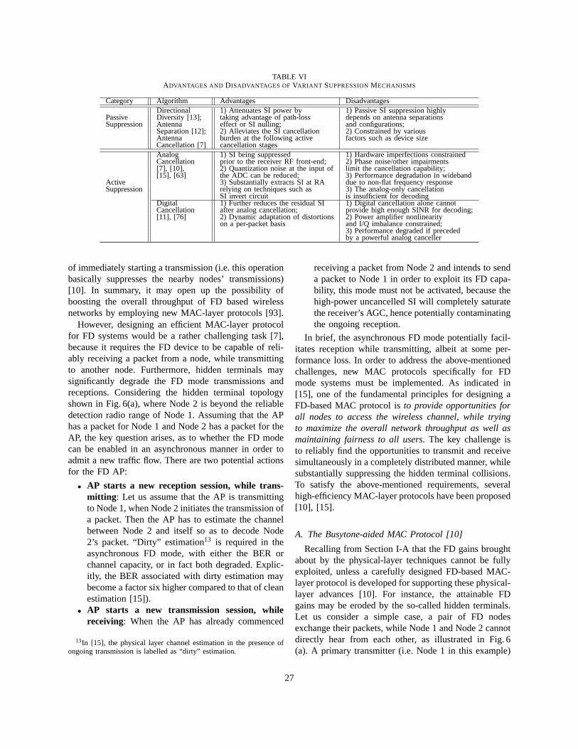
TABLE VIADVANTAGES AND DISADVANTAGES OF VARIANT SUPPRESSIONMECHANISMS
Category Algorithm Advantages DisadvantagesDirectional 1) Attenuates SI power by 1) Passive SI suppression highly
Passive Diversity [13]; taking advantage of path-loss depends on antenna separationsSuppression Antenna effect or SI nulling; and configurations;
Separation [12]; 2) Alleviates the SI cancellation 2) Constrained by variousAntenna burden at the following active factors such as device sizeCancellation [7] cancellation stagesAnalog 1) SI being suppressed 1) Hardware imperfections constrainedCancellation prior to the receiver RF front-end; 2) Phase noise/other impairments[7], [10], 2) Quantization noise at the input of limit the cancellation capability;[15], [63] the ADC can be reduced; 3) Performance degradation in wideband
Active 3) Substantially extracts SI at RA due to non-flat frequency responseSuppression relying on techniques such as 3) The analog-only cancellation
SI invert circuit is insufficient for decodingDigital 1) Further reduces the residual SI 1) Digital cancellation alone cannotCancellation after analog cancellation; provide high enough SINR for decoding;[11], [76] 2) Dynamic adaptation of distortions 2) Power amplifier nonlinearity
on a per-packet basis and I/Q imbalance constrained;3) Performance degraded if precededby a powerful analog canceller
of immediately starting a transmission (i.e. this operationbasically suppresses the nearby nodes’ transmissions)[10]. In summary, it may open up the possibility ofboosting the overall throughput of FD based wirelessnetworks by employing new MAC-layer protocols [93].
However, designing an efficient MAC-layer protocolfor FD systems would be a rather challenging task [7],because it requires the FD device to be capable of reli-ably receiving a packet from a node, while transmittingto another node. Furthermore, hidden terminals maysignificantly degrade the FD mode transmissions andreceptions. Considering the hidden terminal topologyshown in Fig. 6(a), where Node 2 is beyond the reliabledetection radio range of Node 1. Assuming that the APhas a packet for Node 1 and Node 2 has a packet for theAP, the key question arises, as to whether the FD modecan be enabled in an asynchronous manner in order toadmit a new traffic flow. There are two potential actionsfor the FD AP:
• AP starts a new reception session, while trans-mitting : Let us assume that the AP is transmittingto Node 1, when Node 2 initiates the transmission ofa packet. Then the AP has to estimate the channelbetween Node 2 and itself so as to decode Node2’s packet. “Dirty” estimation13 is required in theasynchronous FD mode, with either the BER orchannel capacity, or in fact both degraded. Explic-itly, the BER associated with dirty estimation maybecome a factor six higher compared to that of cleanestimation [15]).
• AP starts a new transmission session, whilereceiving: When the AP has already commenced
13In [15], the physical layer channel estimation in the presence ofongoing transmission is labelled as “dirty” estimation.
receiving a packet from Node 2 and intends to senda packet to Node 1 in order to exploit its FD capa-bility, this mode must not be activated, because thehigh-power uncancelled SI will completely saturatethe receiver’s AGC, hence potentially contaminatingthe ongoing reception.
In brief, the asynchronous FD mode potentially facil-itates reception while transmitting, albeit at some per-formance loss. In order to address the above-mentionedchallenges, new MAC protocols specifically for FDmode systems must be implemented. As indicated in[15], one of the fundamental principles for designing aFD-based MAC protocol isto provide opportunities forall nodes to access the wireless channel, while tryingto maximize the overall network throughput as well asmaintaining fairness to all users. The key challenge isto reliably find the opportunities to transmit and receivesimultaneously in a completely distributed manner, whilesubstantially suppressing the hidden terminal collisions.To satisfy the above-mentioned requirements, severalhigh-efficiency MAC-layer protocols have been proposed[10], [15].
A. The Busytone-aided MAC Protocol [10]
Recalling from Section I-A that the FD gains broughtabout by the physical-layer techniques cannot be fullyexploited, unless a carefully designed FD-based MAC-layer protocol is developed for supporting these physical-layer advances [10]. For instance, the attainable FDgains may be eroded by the so-called hidden terminals.Let us consider a simple case, a pair of FD nodesexchange their packets, while Node 1 and Node 2 cannotdirectly hear from each other, as illustrated in Fig. 6(a). A primary transmitter (i.e. Node 1 in this example)
27
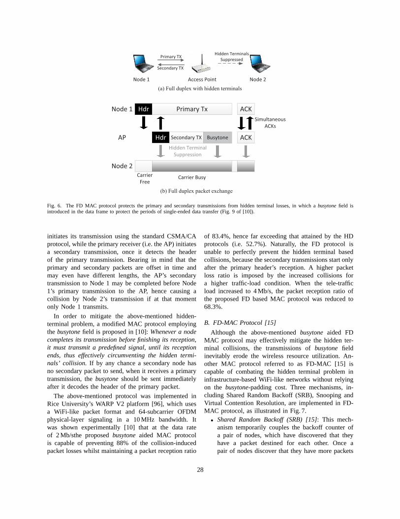
Primary TX
Secondary TX
Hidden Terminals
Suppressed
Node 1 Access Point Node 2
(a) Full duplex with hidden terminals
Hdr Primary Tx ACK
ACKHdr Secondary TX Busytone
Node 1
AP
Node 2
Carrier
FreeCarrier Busy
Simultaneous
ACKs
Hidden Terminal
Suppression
(b) Full duplex packet exchange
Fig. 6. The FD MAC protocol protects the primary and secondarytransmissions from hidden terminal losses, in which abusytonefield isintroduced in the data frame to protect the periods of single-ended data transfer (Fig. 9 of [10]).
initiates its transmission using the standard CSMA/CAprotocol, while the primary receiver (i.e. the AP) initiatesa secondary transmission, once it detects the headerof the primary transmission. Bearing in mind that theprimary and secondary packets are offset in time andmay even have different lengths, the AP’s secondarytransmission to Node 1 may be completed before Node1’s primary transmission to the AP, hence causing acollision by Node 2’s transmission if at that momentonly Node 1 transmits.
In order to mitigate the above-mentioned hidden-terminal problem, a modified MAC protocol employingthe busytonefield is proposed in [10]:Whenever a nodecompletes its transmission before finishing its reception,it must transmit a predefined signal, until its receptionends, thus effectively circumventing the hidden termi-nals’ collision. If by any chance a secondary node hasno secondary packet to send, when it receives a primarytransmission, thebusytoneshould be sent immediatelyafter it decodes the header of the primary packet.
The above-mentioned protocol was implemented inRice University’s WARP V2 platform [96], which usesa WiFi-like packet format and 64-subcarrier OFDMphysical-layer signaling in a 10 MHz bandwidth. Itwas shown experimentally [10] that at the data rateof 2 Mb/sthe proposedbusytoneaided MAC protocolis capable of preventing 88% of the collision-inducedpacket losses whilst maintaining a packet reception ratio
of 83.4%, hence far exceeding that attained by the HDprotocols (i.e. 52.7%). Naturally, the FD protocol isunable to perfectly prevent the hidden terminal basedcollisions, because the secondary transmissions start onlyafter the primary header’s reception. A higher packetloss ratio is imposed by the increased collisions fora higher traffic-load condition. When the tele-trafficload increased to 4 Mb/s, the packet reception ratio ofthe proposed FD based MAC protocol was reduced to68.3%.
B. FD-MAC Protocol [15]
Although the above-mentionedbusytoneaided FDMAC protocol may effectively mitigate the hidden ter-minal collisions, the transmissions ofbusytonefieldinevitably erode the wireless resource utilization. An-other MAC protocol referred to as FD-MAC [15] iscapable of combating the hidden terminal problem ininfrastructure-based WiFi-like networks without relyingon the busytone-padding cost. Three mechanisms, in-cluding Shared Random Backoff (SRB), Snooping andVirtual Contention Resolution, are implemented in FD-MAC protocol, as illustrated in Fig. 7.
• Shared Random Backoff (SRB) [15]: This mech-anism temporarily couples the backoff counter ofa pair of nodes, which have discovered that theyhave a packet destined for each other. Once apair of nodes discover that they have more packets
28
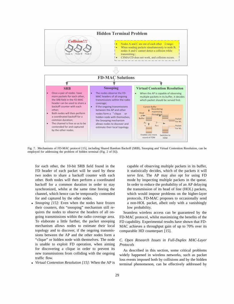
FD-MAC Solutions
SRB
· Once a pair of nodes have
more packets for each other,
the SRB field in the FD-MAC
header can be used to share a
backoff counter with each
other;
· Both nodes will then perform
a coordinated backoff for a
common duration;
· The channel is free so as to be
contended for and captured
by the other nodes.
Snooping
· The nodes observe the FD-
MAC headers of all ongoing
transmissions within the radio
coverage;
· If the ongoing transmissions
between the AP and other
nodes form a clique or
hidden node with themselves,
the Snooping mechanism
allows nodes to discover and
estimate their local topology.
Virtual Contention Resolution
· When the AP is capable of observing
multiple packets in its buffer, it decides
which packet should be served first.
Hidden Terminal Problem
· Nodes A and C are out of each other s range;
· When sending packets simultaneously to node B,
nodes A and C cannot detect a collision while
transmitting ;
· CSMA/CD does not work, and collision occurs.
Node A Node B Node C
Collision!!!
Current Buffer
Head
of
Buffer
f
ppi
ck
Recordering
maximizing
throughputp
1-
ppick
Enables one more
round of FDMSwitches to
HDM
Packet
For M1
Packet
For M2
Fig. 7. Mechanisms of FD-MAC protocol [15], including SharedRandom Backoff (SRB), Snooping and Virtual Contention Resolution, can beemployed for addressing the problem of hidden terminal (Fig. 2of [6]).
for each other, the 10-bit SRB field found in theFD header of each packet will be used by thesetwo nodes to share a backoff counter with eachother. Both nodes will then perform a coordinatedbackoff for a common duration in order to staysynchronized, whilst at the same time freeing thechannel, which hence can be temporarily contendedfor and captured by the other nodes.
• Snooping [15]: Even when the nodes have frozentheir counters, this “snooping” mechanism still re-quires the nodes to observe the headers of all on-going transmissions within the radio coverage area.To elaborate a little further, the packet snoopingmechanism allows nodes to estimate their localtopology and to discover, if the ongoing transmis-sions between the AP and the other nodes form a“clique” or hidden node with themselves. The nodeis unable to exploit FD operation, when aimingfor discovering a clique in order to prevent itsnew transmissions from colliding with the ongoingtraffic flow.
• Virtual Contention Resolution [15]: When the AP is
capable of observing multiple packets in its buffer,it statistically decides, which of the packets it willserve first. The AP may also opt for using FDmode by inspecting multiple packets in the queue.In order to reduce the probability of an AP delayingthe transmission of its head of line (HOL) packets,which would impose problems on the higher-layerprotocols, FD-MAC proposes to occasionally senda non-HOL packet, albeit only with a vanishinglylow probability.
Seamless wireless access can be guaranteed by theFD-MAC protocol, whilst maximizing the benefits of theFD capability. Experimental results have shown that FD-MAC achieves a throughput gain of up to 70% over itscomparable HD counterpart [15].
C. Open Research Issues in Full-Duplex MAC-LayerProtocols
As described in this section, some critical problemswidely happened in wireless networks, such as packetloss events imposed both by collisions and by the hiddenterminal phenomenon, can be effectively addressed by
29
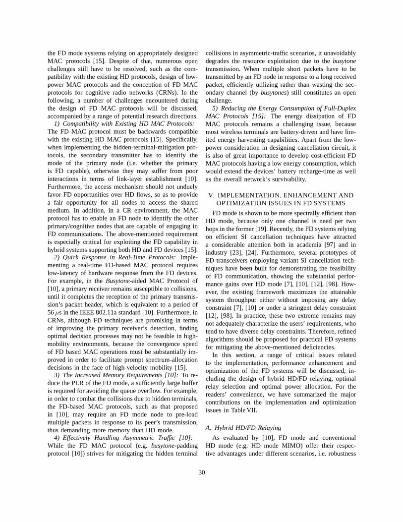
the FD mode systems relying on appropriately designedMAC protocols [15]. Despite of that, numerous openchallenges still have to be resolved, such as the com-patibility with the existing HD protocols, design of low-power MAC protocols and the conception of FD MACprotocols for cognitive radio networks (CRNs). In thefollowing, a number of challenges encountered duringthe design of FD MAC protocols will be discussed,accompanied by a range of potential research directions.
1) Compatibility with Existing HD MAC Protocols:The FD MAC protocol must be backwards compatiblewith the existing HD MAC protocols [15]. Specifically,when implementing the hidden-terminal-mitigation pro-tocols, the secondary transmitter has to identify themode of the primary node (i.e. whether the primaryis FD capable), otherwise they may suffer from poorinteractions in terms of link-layer establishment [10].Furthermore, the access mechanism should not unduelyfavor FD opportunities over HD flows, so as to providea fair opportunity for all nodes to access the sharedmedium. In addition, in a CR environment, the MACprotocol has to enable an FD node to identify the otherprimary/cognitive nodes that are capable of engaging inFD communications. The above-mentioned requirementis especially critical for exploiting the FD capability inhybrid systems supporting both HD and FD devices [15].
2) Quick Response in Real-Time Protocols:Imple-menting a real-time FD-based MAC protocol requireslow-latency of hardware response from the FD devices.For example, in theBusytone-aided MAC Protocol of[10], a primary receiver remains susceptible to collisions,until it completes the reception of the primary transmis-sion’s packet header, which is equivalent to a period of56µs in the IEEE 802.11a standard [10]. Furthermore, inCRNs, although FD techniques are promising in termsof improving the primary receiver’s detection, findingoptimal decision processes may not be feasible in high-mobility environments, because the convergence speedof FD based MAC operations must be substantially im-proved in order to facilitate prompt spectrum-allocationdecisions in the face of high-velocity mobility [15].
3) The Increased Memory Requirements [10]:To re-duce the PLR of the FD mode, a sufficiently large bufferis required for avoiding the queue overflow. For example,in order to combat the collisions due to hidden terminals,the FD-based MAC protocols, such as that proposedin [10], may require an FD mode node to pre-loadmultiple packets in response to its peer’s transmission,thus demanding more memory than HD mode.
4) Effectively Handling Asymmetric Traffic [10]:While the FD MAC protocol (e.g.busytone-paddingprotocol [10]) strives for mitigating the hidden terminal
collisions in asymmetric-traffic scenarios, it unavoidablydegrades the resource exploitation due to thebusytonetransmission. When multiple short packets have to betransmitted by an FD node in response to a long receivedpacket, efficiently utilizing rather than wasting the sec-ondary channel (bybusytones) still constitutes an openchallenge.
5) Reducing the Energy Consumption of Full-DuplexMAC Protocols [15]: The energy dissipation of FDMAC protocols remains a challenging issue, becausemost wireless terminals are battery-driven and have lim-ited energy harvesting capabilities. Apart from the low-power consideration in designing cancellation circuit, itis also of great importance to develop cost-efficient FDMAC protocols having a low energy consumption, whichwould extend the devices’ battery recharge-time as wellas the overall network’s survivability.
V. IMPLEMENTATION, ENHANCEMENT ANDOPTIMIZATION ISSUES IN FD SYSTEMS
FD mode is shown to be more spectrally efficient thanHD mode, because only one channel is need per twohops in the former [19]. Recently, the FD systems relyingon efficient SI cancellation techniques have attracteda considerable attention both in academia [97] and inindustry [23], [24]. Furthermore, several prototypes ofFD transceivers employing variant SI cancellation tech-niques have been built for demonstrating the feasibilityof FD communication, showing the substantial perfor-mance gains over HD mode [7], [10], [12], [98]. How-ever, the existing framework maximizes the attainablesystem throughput either without imposing any delayconstraint [7], [10] or under a stringent delay constraint[12], [98]. In practice, these two extreme remains maynot adequately characterize the users’ requirements, whotend to have diverse delay constraints. Therefore, refinedalgorithms should be proposed for practical FD systemsfor mitigating the above-mentioned deficiencies.
In this section, a range of critical issues relatedto the implementation, performance enhancement andoptimization of the FD systems will be discussed, in-cluding the design of hybrid HD/FD relaying, optimalrelay selection and optimal power allocation. For thereaders’ convenience, we have summarized the majorcontributions on the implementation and optimizationissues in Table VII.
A. Hybrid HD/FD Relaying
As evaluated by [10], FD mode and conventionalHD mode (e.g. HD mode MIMO) offer their respec-tive advantages under different scenarios, i.e. robustness
30
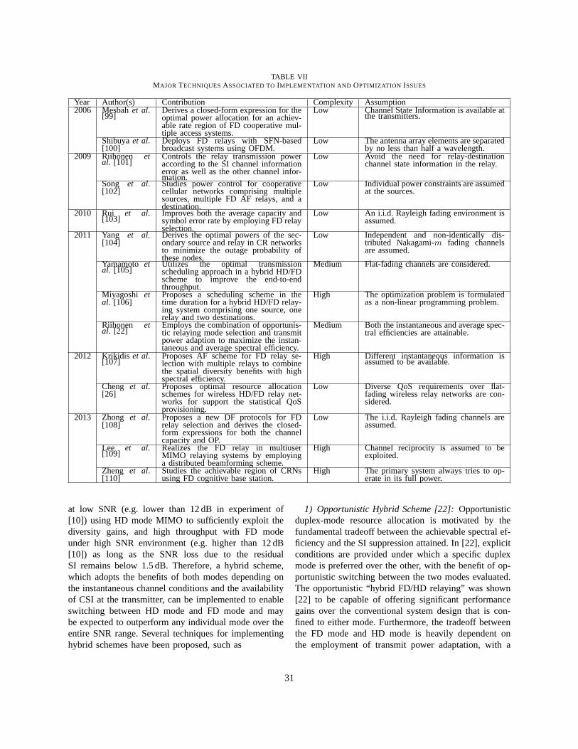
TABLE VIIMAJOR TECHNIQUESASSOCIATED TOIMPLEMENTATION AND OPTIMIZATION ISSUES
Year Author(s) Contribution Complexity Assumption2006 Mesbahet al.
[99]Derives a closed-form expression for theoptimal power allocation for an achiev-able rate region of FD cooperative mul-tiple access systems.
Low Channel State Information is available atthe transmitters.
Shibuyaet al.[100]
Deploys FD relays with SFN-basedbroadcast systems using OFDM.
Low The antenna array elements are separatedby no less than half a wavelength.
2009 Riihonen etal. [101]
Controls the relay transmission poweraccording to the SI channel informationerror as well as the other channel infor-mation.
Low Avoid the need for relay-destinationchannel state information in the relay.
Song et al.[102]
Studies power control for cooperativecellular networks comprising multiplesources, multiple FD AF relays, and adestination.
Low Individual power constraints are assumedat the sources.
2010 Rui et al.[103]
Improves both the average capacity andsymbol error rate by employing FD relayselection.
Low An i.i.d. Rayleigh fading environment isassumed.
2011 Yang et al.[104]
Derives the optimal powers of the sec-ondary source and relay in CR networksto minimize the outage probability ofthese nodes.
Low Independent and non-identically dis-tributed Nakagami-m fading channelsare assumed.
Yamamoto etal. [105]
Utilizes the optimal transmissionscheduling approach in a hybrid HD/FDscheme to improve the end-to-endthroughput.
Medium Flat-fading channels are considered.
Miyagoshi etal. [106]
Proposes a scheduling scheme in thetime duration for a hybrid HD/FD relay-ing system comprising one source, onerelay and two destinations.
High The optimization problem is formulatedas a non-linear programming problem.
Riihonen etal. [22]
Employs the combination of opportunis-tic relaying mode selection and transmitpower adaption to maximize the instan-taneous and average spectral efficiency.
Medium Both the instantaneous and average spec-tral efficiencies are attainable.
2012 Krikidis et al.[107]
Proposes AF scheme for FD relay se-lection with multiple relays to combinethe spatial diversity benefits with highspectral efficiency.
High Different instantaneous information isassumed to be available.
Cheng et al.[26]
Proposes optimal resource allocationschemes for wireless HD/FD relay net-works for support the statistical QoSprovisioning.
Low Diverse QoS requirements over flat-fading wireless relay networks are con-sidered.
2013 Zhong et al.[108]
Proposes a new DF protocols for FDrelay selection and derives the closed-form expressions for both the channelcapacity and OP.
Low The i.i.d. Rayleigh fading channels areassumed.
Lee et al.[109]
Realizes the FD relay in multiuserMIMO relaying systems by employinga distributed beamforming scheme.
High Channel reciprocity is assumed to beexploited.
Zheng et al.[110]
Studies the achievable region of CRNsusing FD cognitive base station.
High The primary system always tries to op-erate in its full power.
at low SNR (e.g. lower than 12 dB in experiment of[10]) using HD mode MIMO to sufficiently exploit thediversity gains, and high throughput with FD modeunder high SNR environment (e.g. higher than 12 dB[10]) as long as the SNR loss due to the residualSI remains below 1.5 dB. Therefore, a hybrid scheme,which adopts the benefits of both modes depending onthe instantaneous channel conditions and the availabilityof CSI at the transmitter, can be implemented to enableswitching between HD mode and FD mode and maybe expected to outperform any individual mode over theentire SNR range. Several techniques for implementinghybrid schemes have been proposed, such as
1) Opportunistic Hybrid Scheme [22]:Opportunisticduplex-mode resource allocation is motivated by thefundamental tradeoff between the achievable spectral ef-ficiency and the SI suppression attained. In [22], explicitconditions are provided under which a specific duplexmode is preferred over the other, with the benefit of op-portunistic switching between the two modes evaluated.The opportunistic “hybrid FD/HD relaying” was shown[22] to be capable of offering significant performancegains over the conventional system design that is con-fined to either mode. Furthermore, the tradeoff betweenthe FD mode and HD mode is heavily dependent onthe employment of transmit power adaptation, with a
31
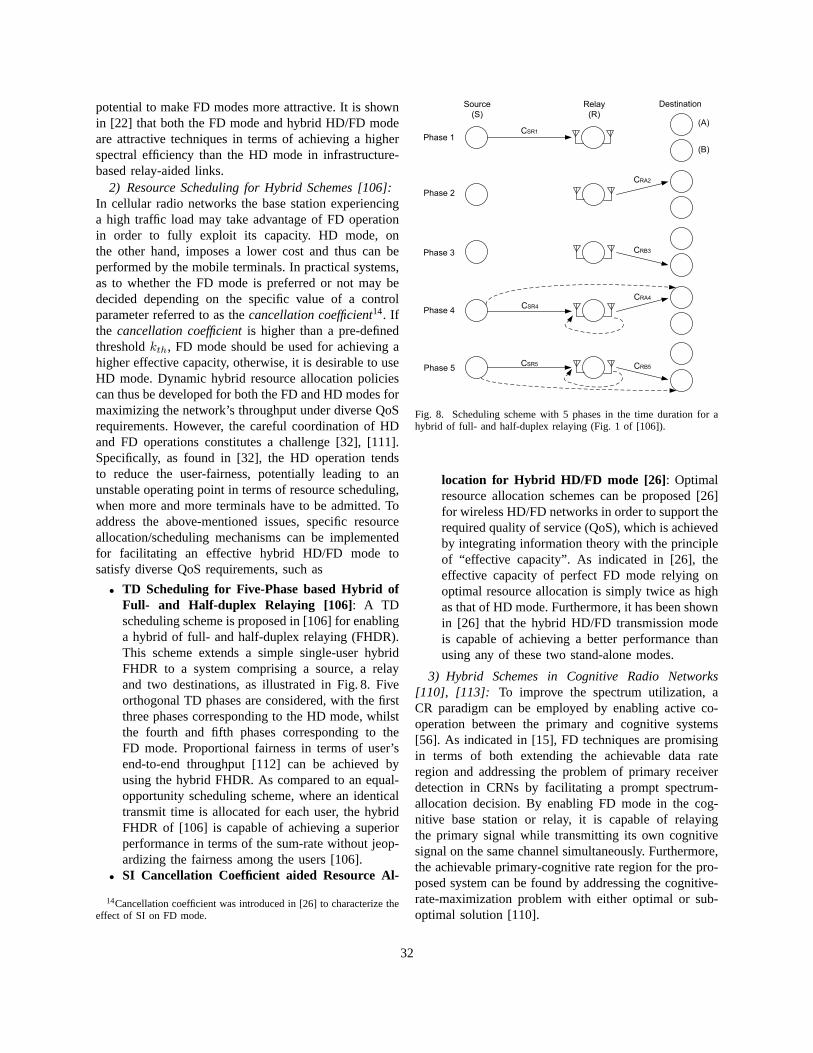
potential to make FD modes more attractive. It is shownin [22] that both the FD mode and hybrid HD/FD modeare attractive techniques in terms of achieving a higherspectral efficiency than the HD mode in infrastructure-based relay-aided links.
2) Resource Scheduling for Hybrid Schemes [106]:In cellular radio networks the base station experiencinga high traffic load may take advantage of FD operationin order to fully exploit its capacity. HD mode, onthe other hand, imposes a lower cost and thus can beperformed by the mobile terminals. In practical systems,as to whether the FD mode is preferred or not may bedecided depending on the specific value of a controlparameter referred to as thecancellation coefficient14. Ifthe cancellation coefficientis higher than a pre-definedthresholdkth, FD mode should be used for achieving ahigher effective capacity, otherwise, it is desirable to useHD mode. Dynamic hybrid resource allocation policiescan thus be developed for both the FD and HD modes formaximizing the network’s throughput under diverse QoSrequirements. However, the careful coordination of HDand FD operations constitutes a challenge [32], [111].Specifically, as found in [32], the HD operation tendsto reduce the user-fairness, potentially leading to anunstable operating point in terms of resource scheduling,when more and more terminals have to be admitted. Toaddress the above-mentioned issues, specific resourceallocation/scheduling mechanisms can be implementedfor facilitating an effective hybrid HD/FD mode tosatisfy diverse QoS requirements, such as
• TD Scheduling for Five-Phase based Hybrid ofFull- and Half-duplex Relaying [106]: A TDscheduling scheme is proposed in [106] for enablinga hybrid of full- and half-duplex relaying (FHDR).This scheme extends a simple single-user hybridFHDR to a system comprising a source, a relayand two destinations, as illustrated in Fig. 8. Fiveorthogonal TD phases are considered, with the firstthree phases corresponding to the HD mode, whilstthe fourth and fifth phases corresponding to theFD mode. Proportional fairness in terms of user’send-to-end throughput [112] can be achieved byusing the hybrid FHDR. As compared to an equal-opportunity scheduling scheme, where an identicaltransmit time is allocated for each user, the hybridFHDR of [106] is capable of achieving a superiorperformance in terms of the sum-rate without jeop-ardizing the fairness among the users [106].
• SI Cancellation Coefficient aided Resource Al-
14Cancellation coefficient was introduced in [26] to characterize theeffect of SI on FD mode.
Phase 1
Phase 5
Phase 4
Phase 3
Phase 2
CSR1
CSR4
CSR5
Source
(S)
Relay
(R)
Destination
(A)
(B)
CRA2
CRB3
CRA4
CRB5
Fig. 8. Scheduling scheme with 5 phases in the time duration forahybrid of full- and half-duplex relaying (Fig. 1 of [106]).
location for Hybrid HD/FD mode [26] : Optimalresource allocation schemes can be proposed [26]for wireless HD/FD networks in order to support therequired quality of service (QoS), which is achievedby integrating information theory with the principleof “effective capacity”. As indicated in [26], theeffective capacity of perfect FD mode relying onoptimal resource allocation is simply twice as highas that of HD mode. Furthermore, it has been shownin [26] that the hybrid HD/FD transmission modeis capable of achieving a better performance thanusing any of these two stand-alone modes.
3) Hybrid Schemes in Cognitive Radio Networks[110], [113]: To improve the spectrum utilization, aCR paradigm can be employed by enabling active co-operation between the primary and cognitive systems[56]. As indicated in [15], FD techniques are promisingin terms of both extending the achievable data rateregion and addressing the problem of primary receiverdetection in CRNs by facilitating a prompt spectrum-allocation decision. By enabling FD mode in the cog-nitive base station or relay, it is capable of relayingthe primary signal while transmitting its own cognitivesignal on the same channel simultaneously. Furthermore,the achievable primary-cognitive rate region for the pro-posed system can be found by addressing the cognitive-rate-maximization problem with either optimal or sub-optimal solution [110].
32
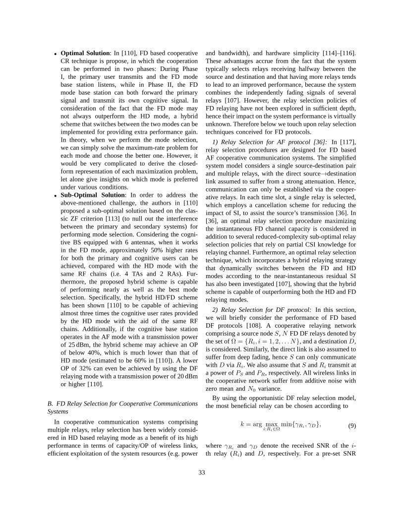
• Optimal Solution: In [110], FD based cooperativeCR technique is propose, in which the cooperationcan be performed in two phases: During PhaseI, the primary user transmits and the FD modebase station listens, while in Phase II, the FDmode base station can both forward the primarysignal and transmit its own cognitive signal. Inconsideration of the fact that the FD mode maynot always outperform the HD mode, a hybridscheme that switches between the two modes can beimplemented for providing extra performance gain.In theory, when we perform the mode selection,we can simply solve the maximum-rate problem foreach mode and choose the better one. However, itwould be very complicated to derive the closed-form representation of each maximization problem,let alone give insights on which mode is preferredunder various conditions.
• Sub-Optimal Solution: In order to address theabove-mentioned challenge, the authors in [110]proposed a sub-optimal solution based on the clas-sic ZF criterion [113] (to null out the interferencebetween the primary and secondary systems) forperforming mode selection. Considering the cogni-tive BS equipped with 6 antennas, when it worksin the FD mode, approximately 50% higher ratesfor both the primary and cognitive users can beachieved, compared with the HD mode with thesame RF chains (i.e. 4 TAs and 2 RAs). Fur-thermore, the proposed hybrid scheme is capableof performing nearly as well as the best modeselection. Specifically, the hybrid HD/FD schemehas been shown [110] to be capable of achievingalmost three times the cognitive user rates providedby the HD mode with the aid of the same RFchains. Additionally, if the cognitive base stationoperates in the AF mode with a transmission powerof 25 dBm, the hybrid scheme may achieve an OPof below 40%, which is much lower than that ofHD mode (estimated to be 60% in [110]). A lowerOP of 32% can even be achieved by using the DFrelaying mode with a transmission power of 20 dBmor higher [110].
B. FD Relay Selection for Cooperative CommunicationsSystems
In cooperative communication systems comprisingmultiple relays, relay selection has been widely consid-ered in HD based relaying mode as a benefit of its highperformance in terms of capacity/OP of wireless links,efficient exploitation of the system resources (e.g. power
and bandwidth), and hardware simplicity [114]–[116].These advantages accrue from the fact that the systemtypically selects relays receiving halfway between thesource and destination and that having more relays tendsto lead to an improved performance, because the systemcombines the independently fading signals of severalrelays [107]. However, the relay selection policies ofFD relaying have not been explored in sufficient depth,hence their impact on the system performance is virtuallyunknown. Therefore below we touch upon relay selectiontechniques conceived for FD protocols.
1) Relay Selection for AF protocol [36]:In [117],relay selection procedures are designed for FD basedAF cooperative communication systems. The simplifiedsystem model considers a single source-destination pairand multiple relays, with the direct source→destinationlink assumed to suffer from a strong attenuation. Hence,communication can only be established via the cooper-ative relays. In each time slot, a single relay is selected,which employs a cancellation scheme for reducing theimpact of SI, to assist the source’s transmission [36]. In[36], an optimal relay selection procedure maximizingthe instantaneous FD channel capacity is considered inaddition to several reduced-complexity sub-optimal relayselection policies that rely on partial CSI knowledge forrelaying channel. Furthermore, an optimal relay selectiontechnique, which incorporates a hybrid relaying strategythat dynamically switches between the FD and HDmodes according to the near-instantaneous residual SIhas also been investigated [107], showing that the hybridscheme is capable of outperforming both the HD and FDrelaying modes.
2) Relay Selection for DF protocol:In this section,we will briefly consider the performance of FD basedDF protocols [108]. A cooperative relaying networkcomprising a source nodeS, N FD DF relays denoted bythe set ofΩ = Ri, i = 1, 2, . . . N, and a destinationD,is considered. Similarly, the direct link is also assumed tosuffer from deep fading, henceS can only communicatewith D via Ri. We also assume thatS andRi transmit ata power ofPS andPR, respectively. All wireless links inthe cooperative network suffer from additive noise withzero mean andN0 variance.
By using the opportunistic DF relay selection model,the most beneficial relay can be chosen according to
k = arg maxi:Ri∈Ω
minγRi, γD, (9)
where γRiand γD denote the received SNR of thei-
th relay (Ri) and D, respectively. For a pre-set SNR
33
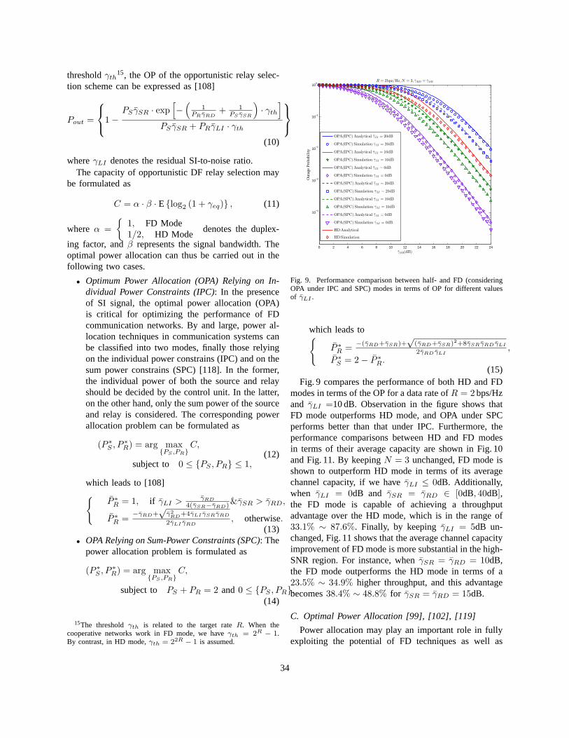
thresholdγth15, the OP of the opportunistic relay selec-tion scheme can be expressed as [108]
Pout =
1−PS γSR · exp
[
−(
1PRγRD
+ 1PS γSR
)
· γth]
PS γSR + PRγLI · γth
N
,
(10)
whereγLI denotes the residual SI-to-noise ratio.The capacity of opportunistic DF relay selection may
be formulated as
C = α · β · Elog2 (1 + γeq) , (11)
whereα =
1, FD Mode1/2, HD Mode
denotes the duplex-
ing factor, andβ represents the signal bandwidth. Theoptimal power allocation can thus be carried out in thefollowing two cases.
• Optimum Power Allocation (OPA) Relying on In-dividual Power Constraints (IPC): In the presenceof SI signal, the optimal power allocation (OPA)is critical for optimizing the performance of FDcommunication networks. By and large, power al-location techniques in communication systems canbe classified into two modes, finally those relyingon the individual power constrains (IPC) and on thesum power constrains (SPC) [118]. In the former,the individual power of both the source and relayshould be decided by the control unit. In the latter,on the other hand, only the sum power of the sourceand relay is considered. The corresponding powerallocation problem can be formulated as
(P ∗S , P
∗R) = arg max
PS ,PRC,
subject to 0 ≤ PS , PR ≤ 1,(12)
which leads to [108]
P ∗R = 1, if γLI > γRD
4(γSR−γRD)&γSR > γRD,
P ∗R =
−γRD+√
γ2
RD+4γLI γSRγRD
2γLI γRD, otherwise.
(13)• OPA Relying on Sum-Power Constraints (SPC): The
power allocation problem is formulated as
(P ∗S , P
∗R) = arg max
PS ,PRC,
subject to PS + PR = 2 and0 ≤ PS , PR,(14)
15The thresholdγth is related to the target rateR. When thecooperative networks work in FD mode, we haveγth = 2R − 1.By contrast, in HD mode,γth = 22R − 1 is assumed.
0 2 4 6 8 10 12 14 16 18 20 22 24
10−4
10−3
10−2
10−1
100
γSR(dB)
Out
age
Pro
babi
lity
R = 2bps/Hz,N = 3, γRD = γSR
OPA(IPC)Analytical γLI = 20dB
OPA(IPC)Simulation γLI = 20dB
OPA(IPC)Analytical γLI = 10dB
OPA(IPC)Simulation γLI = 10dB
OPA(IPC)Analytical γLI = 0dB
OPA(IPC)Simulation γLI = 0dB
OPA(SPC)Analytical γLI = 20dB
OPA(SPC)Simulation γLI = 20dB
OPA(SPC)Analytical γLI = 10dB
OPA(SPC)Simulation γLI = 10dB
OPA(SPC)Analytical γLI = 0dB
OPA(SPC)Simulation γLI = 0dB
HDAnalytical
HDSimulation
Fig. 9. Performance comparison between half- and FD (consideringOPA under IPC and SPC) modes in terms of OP for different valuesof γLI .
which leads to
P ∗R =
−(γRD+γSR)+√
(γRD+γSR)2+8γSRγRD γLI
2γRD γLI,
P ∗S = 2− P ∗
R.(15)
Fig. 9 compares the performance of both HD and FDmodes in terms of the OP for a data rate ofR = 2bps/Hzand γLI =10 dB. Observation in the figure shows thatFD mode outperforms HD mode, and OPA under SPCperforms better than that under IPC. Furthermore, theperformance comparisons between HD and FD modesin terms of their average capacity are shown in Fig. 10and Fig. 11. By keepingN = 3 unchanged, FD mode isshown to outperform HD mode in terms of its averagechannel capacity, if we haveγLI ≤ 0dB. Additionally,when γLI = 0dB and γSR = γRD ∈ [0dB, 40dB],the FD mode is capable of achieving a throughputadvantage over the HD mode, which is in the range of33.1% ∼ 87.6%. Finally, by keepingγLI = 5dB un-changed, Fig. 11 shows that the average channel capacityimprovement of FD mode is more substantial in the high-SNR region. For instance, whenγSR = γRD = 10dB,the FD mode outperforms the HD mode in terms of a23.5% ∼ 34.9% higher throughput, and this advantagebecomes38.4% ∼ 48.8% for γSR = γRD = 15dB.
C. Optimal Power Allocation [99], [102], [119]
Power allocation may play an important role in fullyexploiting the potential of FD techniques as well as
34
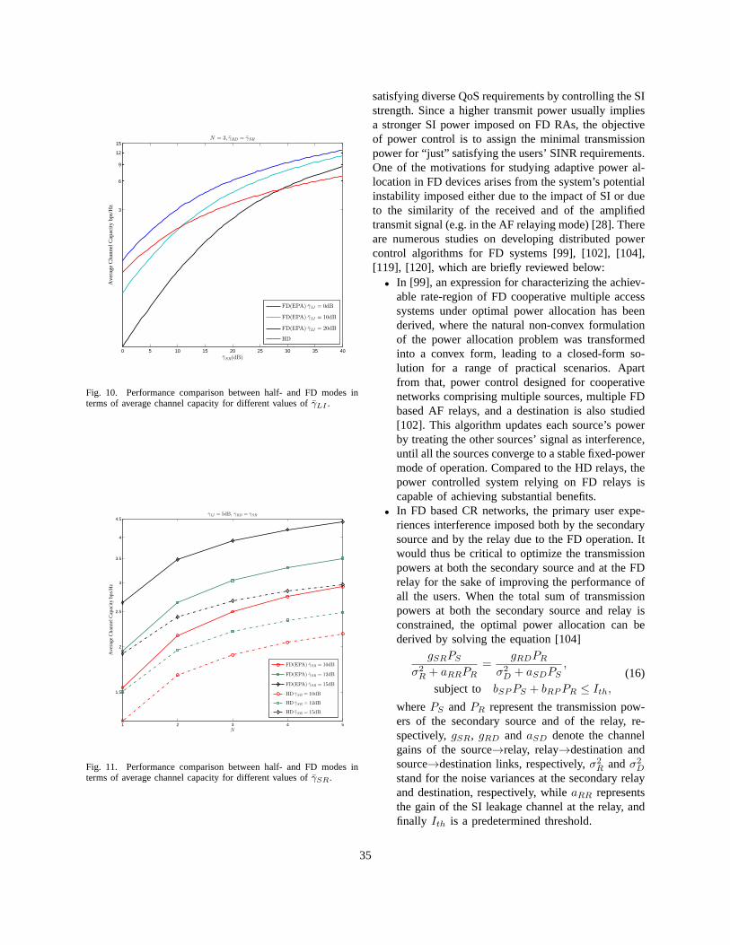
0 5 10 15 20 25 30 35 40
3
6
9
12
15
γSR(dB)
Ave
rage
Cha
nnel
Cap
acity
bps
/Hz
N = 3, γRD = γSR
FD(EPA) γLI = 0dB
FD(EPA) γLI = 10dB
FD(EPA) γLI = 20dB
HD
Fig. 10. Performance comparison between half- and FD modes interms of average channel capacity for different values ofγLI .
1 2 3 4 5
1.5
2
2.5
3
3.5
4
4.5
N
Ave
rage
Cha
nnel
Cap
acity
bps
/Hz
γLI = 5dB, γRD = γSR
FD(EPA) γSR = 10dB
FD(EPA) γSR = 12dB
FD(EPA) γSR = 15dB
HD γSR = 10dB
HD γSR = 12dB
HD γSR = 15dB
Fig. 11. Performance comparison between half- and FD modes interms of average channel capacity for different values ofγSR.
satisfying diverse QoS requirements by controlling the SIstrength. Since a higher transmit power usually impliesa stronger SI power imposed on FD RAs, the objectiveof power control is to assign the minimal transmissionpower for “just” satisfying the users’ SINR requirements.One of the motivations for studying adaptive power al-location in FD devices arises from the system’s potentialinstability imposed either due to the impact of SI or dueto the similarity of the received and of the amplifiedtransmit signal (e.g. in the AF relaying mode) [28]. Thereare numerous studies on developing distributed powercontrol algorithms for FD systems [99], [102], [104],[119], [120], which are briefly reviewed below:
• In [99], an expression for characterizing the achiev-able rate-region of FD cooperative multiple accesssystems under optimal power allocation has beenderived, where the natural non-convex formulationof the power allocation problem was transformedinto a convex form, leading to a closed-form so-lution for a range of practical scenarios. Apartfrom that, power control designed for cooperativenetworks comprising multiple sources, multiple FDbased AF relays, and a destination is also studied[102]. This algorithm updates each source’s powerby treating the other sources’ signal as interference,until all the sources converge to a stable fixed-powermode of operation. Compared to the HD relays, thepower controlled system relying on FD relays iscapable of achieving substantial benefits.
• In FD based CR networks, the primary user expe-riences interference imposed both by the secondarysource and by the relay due to the FD operation. Itwould thus be critical to optimize the transmissionpowers at both the secondary source and at the FDrelay for the sake of improving the performance ofall the users. When the total sum of transmissionpowers at both the secondary source and relay isconstrained, the optimal power allocation can bederived by solving the equation [104]
gSRPS
σ2R + aRRPR
=gRDPR
σ2D + aSDPS
,
subject to bSPPS + bRPPR ≤ Ith,
(16)
wherePS andPR represent the transmission pow-ers of the secondary source and of the relay, re-spectively,gSR, gRD and aSD denote the channelgains of the source→relay, relay→destination andsource→destination links, respectively,σ2
R andσ2D
stand for the noise variances at the secondary relayand destination, respectively, whileaRR representsthe gain of the SI leakage channel at the relay, andfinally Ith is a predetermined threshold.
35
• In [119], an outage-constrained power allocationscheme is proposed for CRNs. Unlike [104], theknowledge of the instantaneous CSI for the linkbetween the primary and secondary users is not re-quired in this scheme. However, the secondary useris allowed for sharing the spectrum of the primaryuser, provided that the primary user’s maximumtolerable OP is satisfied [120]. Numerical resultsshowed that the proposed optimal power allocationschemes are robust to the effects of the outdatedCSI and achieve performance advantages over theEqual Power Allocation (EPA) scheme in terms ofthe OP of the secondary user.
VI. CONCLUSIONS AND POTENTIAL FUTURERESEARCH
A. Conclusions
The available radio spectrum is limited, hence beforenew commercially implementable spectral resources areexploited, the ever increasing throughput requirementscannot be readily satisfied without increasing the achiev-able spectral efficiency expressed in bits/s/Hertz. Themain driving force behind FD techniques is the promiseof nearly doubling the data rate in comparison to theirHD counterpart, while striking an attractive trade-offamongst the design challenges. Those challenges specif-ically pertain to FD communications, potentially facil-itating simultaneous transmission and reception withinthe same frequency band. One of the most challengingfactors is that the family of SI suppression/cancellationsolutions is typically based on complex and/or costlyhardware designs. Hence it is of crucial importanceto closely examine cost-efficient algorithms associatedwith tolerable hardware/software complexity. More im-portantly, the most dominant hardware imperfections,such as the phase noise, non-flat frequency response ofthe circuits, power amplifier nonlinearity and transmitI/Q imbalance, etc. may all impose limitations on the at-tainable SI cancellation capability and must be carefullymitigated. Furthermore, the effect of the MAC and otherhigher-layer protocols on the practical implementationof FD systems constitutes another key issue to be morevigorously investigated. Against the aforementioned re-quirements and challenges, there is an urging demand forhigh-performance, low-complexity FD protocols. In thissection, we offer a few general design guidelines for FDwireless communication systems based on the solutionsdiscussed throughout this treatise.
1) FD techniques may significantly improve both theachievable spectral efficiency and the associatednetwork throughput compared to the classic HD
approach, provided that the SI encountered at theFD nodes can be significantly reduced. Since anyindividual SI component (either linear or non-linear) of insufficiently low level may becomethe limiting factor of the ultimate SI cancella-tion and may hence dominate the FD-gain degra-dations, each component should be substantiallyreduced by employing an appropriate technique(e.g. analog and/or digital cancellation). Althoughemploying costly high-precision hardware can leadto a high SI cancellation capability, impairmentssuch as the non-flat frequency response of thehardware and the dispersion of the SI leakage-channel may still impose a performance limit onthe attainable RF/analog cancellation. Therefore,the performance of SI cancellation techniquesin practical systems has to be further improvedwith the aid of better SI-cancellation techniquesconceived for a higher transmit power and fora wider bandwidth. Furthermore, the other im-pairments, including phase noise, power amplifiernonlinearity and transmit I/Q imbalance, will alsosubstantially degrade the performance of digitalcancellation. To sufficiently reduce both the linearand non-linear SI components, the constraints im-posed by above-mentioned impairments also haveto be mitigated.
2) Digital cancellation exploits the knowledge of theinterfering signal in order to cancel it after the con-taminated received signal has been quantized by anADC, thus improving the jointly designed analog-and-digital cancellation capability. It is noteworthythat the maximum attainable SI suppression ofdigital cancellation decreases as that of the preced-ing analog cancellation increases in a concatenatedregime. Hence the fundamental tradeoff betweenthe capacities of the analog- and digital-domaintechniques have to be addressed in order to ef-fectively balance their roles achieving the highestpossible overall benefits for the combined scheme.However, again, the joint benefits of cascadedanalog/digital cancellation may be constrained bythe various sources of distortions, such as the phasenoise, power amplifier nonlinearity and transmitI/Q imbalance. It was experimentally shown in[29] that the phase noise imposes a limit on theamount of cascaded analog and digital cancella-tion. Specifically, the phase noise will dominatethe residual SI after performing analog cancel-lation, hence preventing the concatenated digitalcanceller from further reducing the residual SI
36
(if it is uncorrelated with the SI signal). Further-more, the change of system parameters, such asthe power amplifier linearity characteristics, ADCresolution, precision of the RF/analog cancellationand the SI leakage-channel estimation accuracy,etc. may change the major factors that dominatethe attainable performance. To further improve theaggregated performance of concatenated analog-digital cancellation in practical FD systems, itis rather critical to combat the above-mentionedimpairments and to adaptively accommodate thetime-variant environment.
3) Since the passive suppression relying on path-losseffect is capable of identically (or in other words,non-selectively) suppressing all the SI components(i.e. including the linear/non-linear componentsas well as transmitter noise), the analog/digitalcancellation techniques should be combined withpassive suppression techniques for sufficiently at-tenuating the SI power as much as possible whilewithout violating the device-size constraints.
4) In light of the fact that predominantly multi-antenna aided FD techniques will be utilized inwireless systems in the foreseeable future, theincreased DoF offered by the antenna arrays opensup a range of new solutions for SI cancellation.Advanced techniques, such as natural isolation andSD suppression can be specifically developed forFD based MIMO devices in order to facilitatehigh-performance SI suppression. However, com-plex matrix computations are required by manyof the existing SD suppression methods, such asthose involved in pre-coding/decoding and MMSEfiltering, etc. This complexity-burden significantlyhampers the realizability of FD systems. Hencemore cost-efficient algorithms have to be designedby relying on sophisticated yet low-complexitysignal processing techniques, especially for high-dimensional MIMO channels, in order to facilitatethe practical implementation of FD based systems.
5) Apart from the above-mentioned physical-layersolutions, FD research efforts have to be dedicatedto the design of cost-effective MAC-layer proto-cols for multi-node networks. Some of the mostchallenging problems met in wireless networks,such as the problems imposed by hidden terminals,the throughput erosion due to network congestionand their high end-to-end delay may be mitigatedby efficient FD MAC-layer protocols. However,a number of open challenges encountered duringthe design of FD MAC protocols have to be
tackled. On one hand, the FD based MAC-layerprotocols must be backwards compatible with theexisting HD MAC protocols. Specifically, a practi-cally implemented FD system must be capable ofproviding a fair opportunity for all HD/FD nodesto access the shared medium, whilst equippingthe FD devices with the capability of identifyingthe duplex mode of the other devices. On theother hand, the efficiency degradation encounteredin handling asymmetric traffic must be mitigatedin FD MAC-layer protocols, otherwise the FDgains potentially offered by physical-layer tech-niques may be eroded by an inefficient MAC-layer protocol. Furthermore, in light of the factthat the FD mode may not always be capable ofoutperforming its HD counterpart, hybrid schemesswitching between the HD and FD modes shouldbe supported by the FD protocols for adaptivelyexploiting the radio resources and hence for max-imizing the attainable spectral efficiency.
6) Although the existing studies showed that theFD mode is capable of providing a promisingperformance gain over its HD counterpart in termsof its physical-layer throughput in bidirectionalcommunication scenarios, most existing studiesevaluate the FD gains by considering the simpleidealized communication scenarios of bidirectionallinks supporting symmetric traffic [10], withoutinvestigating the FD gains, when handling the non-ideal scenarios of asymmetric traffic. For exam-ple, it was shown in [10] that the balun-basedFD system provides a higher capacity than theconventional HD mode for a(2 × 2) MIMO linkin its high-SNR regime (e.g. higher than 12 dB),provided that the SI-induced SNR loss remainsbelow 1.5 dB. However, without invoking the FDprotocols in a more realistic real-life environmentsubjected to much more severe interference andto realistic traffic characteristics, the attainable FDgains across the whole network require furtherinvestigations.
B. Future Research
Apart from the above-mentioned challenges, it is alsoworth pointing out that the approaches presented in thispaper may be further developed, as detailed below.
1) Although the existing FD techniques are capableof offering an SI cancellation gain that makesthe ultimate SINR high enough for high-integritydetection at the receiver, the current analog cancel-lation circuits are still too bulky on the order of 100
37
square centimeters [11]. Thus hampers their em-ployment in cell phones or other portable devices.To operate the SI cancellation modules on suchsmall devices, further miniaturization of the corecircuits is required. For example, as speculated in[11], the delay-line circuit could be realized in asufficiently small radio frequency integrated circuit(RFIC) as compact as 20-30 square millimeters forestimating the true time delays.
2) Despite their substantial research-advances, thecurrent FD designs still under-utilize the spatialdiversity order potential offered by multiple an-tennas, because the state-of-the-art antennas areusually partitioned intotransmit and receivesub-sets in order to enable simultaneous transmissionand reception on a single FD mode terminal. Anew FD architecture allowing each antenna tosupport simultaneous transmission and receptionon the same channel is thus highly desirable,otherwise the attainable FD gains will be essen-tially eliminated by the loss of spatial diversitygain. To achieve the above-mentioned objectives,the SI cancellation circuit must be capable ofcancelling both the SI induced by each antenna’sown transmissions and that imposed by cross-talk amongst the different antennas [11]. Naturally,designing such a powerful, yet compact circuitwill impose new challenges, because the SI can-cellation will become a multi-parameter-resolutionproblem, forcing both the hardware complexity aswell as the circuit size to increase significantly, asthe number of interference sources increases.
3) Sophisticated SI leakage-channel estimators haveto be implemented at the FD mode receiver forsuccessfully extracting the CSI of interest fromits SI-contaminated counterpart, followed by CSIfeedback to the transmitter [10]. However, theexisting periodic-sounding based CSI-estimationsmechanisms may fail to track the CSI changes indynamic environment, although they might be ad-equate for networks experimenting relatively staticchannel conditions. Specifically, in CRNs the FDradio environment becomes even more challengingthan that of HD transmissions, because FD devicessuffer from a heavier interference imposed by thesecondary nodes than in the HD mode. Therefore,designing robust algorithms relying on much moredynamic CSI estimators for adaptively tracking thechannel states (e.g. on a per-packet basis [10]) andfor mitigating the SI/noise power in a dynamicmanner is critical for FD communications invoked
in CR environments.4) The attainable performance gains of the FD mode
may be impacted by several issues, includingthe SI power, the system’s traffic load and thesymmetrical characteristics of the traffic streams.For instance, the FD mode outperforms the con-ventional HD mode of MIMO systems in termsof their throughput, if communications is bidirec-tional, while the latter performs better if all com-munications are in one direction [10]. A hybridscheme facilitating dynamic switching betweenthe HD and FD modes can be implemented tocombine both of its constituent modes. However,the hybrid nodes have to be capable of identifyingthe environment changes in terms of the CSI, thetraffic characteristics as well as communicationdirections and of promptly switching between theFD and HD modes. Furthermore, in the absence ofa centralized controller, a sophisticated distributedapproach relying on self-organization [56], [121],[122] should also be employed by each node forimplementing a cost-efficient hybrid protocol.
5) The power efficiency of the FD mode must besignificantly improved either with the aid of circuitarchitecture optimization or by relying on theenhancement of MAC/higher-layer protocols. Ascompared to the HD mode, which employs onlyhalf of the total resources (i.e. time resources inTime Division Duplexing (TDD) or frequency re-sources in Frequency Division Duplexing (FDD))for signal transmissions, a higher power consump-tion is encountered by the FD devices, whichsimultaneously perform both transmission and re-ception by exploiting all the spectral resources,if a sufficiently high tele-traffic load is assumed.Furthermore, the SI-cancellation circuits of the FDdevices employed for eliminating the linear/non-linear SI components from the static/changing en-vironment also impose an extra energy consump-tion over that of the HD systems. Therefore, sys-tematically solving the high-power-consumptionproblems encountered in FD networks relying onsophisticated techniques ranging from the circuitlevel to the protocol level would facilitate power-efficient FD solutions.
6) Numerous critical issues, such as the problemsof hidden terminals and multiple access collisionscannot be readily addressed in distributed net-works in the context of FD based MAC protocoldesign. Specifically, the design of an automaticresource allocation technique capable of adapting
38
to time-variant traffic load conditions as well asto diverse QoS requirements in non-infrastructure-based networks constitutes a new challenge. Un-like infrastructure-based networks, the family ofnon-infrastructure-based networks usually performtheir networking functions in a self-organized man-ner without relying on centralized control [56],[121]. Thus an appropriate MAC protocol con-ceived for fully exploiting the FD benefits whilstsuccessfully addressing a range of challengingissues such as the adaptivity, both to diverseQoS requirements and to complex interferenceenvironments, whilst simultaneously maintainingbackward-compatibility with the existing MACprotocols in non-infrastructure-based networks isdefinitely worthy of further study.
7) FD based small cell BSs may provide a promisingway towards addressing the complicated backhaulproblems encountered in heterogeneous networks,in which the typical backhaul solutions relying onout-of-band resources (e.g. fiber, microwave radio,etc.) become challenging either due to the cost-prohibitive fiber connecting or due to the LOSrequirement of microwave based backhaul [20]. Toleverage the same spectrum for both user accessand backhaul, the FD based small-cell BSs canreceive from the macrocells while simultaneouslytransmit to the UEs in the downlink. In the uplink,on the other hand, the FD based small-cell BSs willreceive from the UEs while simultaneously trans-mit to the macrocells. In this manner, the FD basedsmall-cell BSs can effectively backhaul itself with-out requiring a separate backhaul frequency band,thus substantially reducing the cost and complex-ity of implementing heterogeneous networks. Theexisted studies show [20] that the self-backhauledsmall cells may even perform nearly as well asa fiber-backhauled small cells. Furthermore, byvirtue of the larger form factor, the self-backhauledsmall-cell BSs may achieve much higher spectralefficiencies than the size-constrained FD devices.However, to provide an improved FD gain in theself-backhauled BS with a larger form factor, ahigher ordered MIMO comprising much largerdirectional backhaul antennas are usually required,thus substantially increasing the burden of FDreceiver from the perspective of complicated SIcancellation as well as the other signal process-ing functionalities. Therefore, proposing a feasibleFD based self-backhaul solution enabling a moreefficient utilization of the macrocell spectral re-
sources, whilst simultaneously facilitating a cost-efficient high-ordered MIMO based SI cancellationconstitutes a promising study-item.
Given that FD communication has become a feasibledesign option, the research community is turning itsattention to more cost-effective system design principles,where the attainable spectral efficiency may be signif-icantly improved by creating high-reliability, reduced-complexity, reduced-cost, power-efficient FD devices. Weexpect a substantial throughput increase upon simulta-neously enabling the reliable transmission and receptionof data by a single device, as facilitated by high-performance SI cancellation, adaptive power allocation,and hybrid HD/FD schemes combined with a CR-aidednetworking. In a nutshell, an exciting era for a growingresearch-community!
39
NOMENCLATURE
ADC analog-to-digital converterAF amplify-and-forwardAGC automatic gain controlAP access pointAS antenna separationASAC Antenna Separation and Analog Cancel-
lationASADC Antenna Separation, Analog and Digital
CancellationASDC Antenna Separation and Digital Cancella-
tionBER Bit Error RatioBPSK binary phase shift keyingBS base stationCR cognitive radioCRN cognitive radio networkCSI channel state informationCSMA Carrier Sense Multiple AccessDF decode-and-forwardDFT discrete Fourier transformDL downlinkDoF Degrees of FreedomEPA Equal Power AllocationFD full-duplexFDD Frequency Division DuplexingFHDR full- and half-duplex relayingHD half-duplexHOL head of lineIPC individual power constrainsISM Industrial Scientific MedicalLOS line-of-sightMAC Media Access ControlMIMO Multi-Input Multi-OutputMMSE minimum mean square errorMRC maximum ratio combiningNAV network allocation vectorsNC network codingNLOS non-line-of-sightOFDM orthogonal frequency division multiplexingOFDMA orthogonal frequency division multiple
accessOP outage probabilityOPA optimal power allocationPLIR path-loss-to-interference ratioPLR Packet Loss RatioQAM Quadrature Amplitude ModulationQCNTA Quellan Canceller with Nulling Transmit
AntennaQoS quality of serviceRA Receive Antenna
RF Radio FrequencyRFIC radio frequency integrated circuitRSSI Received Signal Strength IndicatorSCSI Scaled Cancelling Signal InjectionSD spatial-domainSFN single frequency networkSI self-interferenceSIC successive interference cancellationSIR Signal-to-Interference RatioSISO Single-Input Single-OutputSINR Signal-to-Interference-and-Noise RadioSNR Signal-to-Noise RatioSPC sum power constrainsSRB Shared Random BackoffSVD singular value decompositionTA Transmit AntennaTAS Transmit Antenna SelectionTD time-domainTDD Time Division DuplexingTDTB time-domain transmit beamformingWiFi Wireless FidelityWLAN wireless local area networksZF Zero Forcing
REFERENCES
[1] A. J. Paulraj, D. A. GORE, R. U. Nabar, and H. Bolcskei, “Anoverview of MIMO communications - a key to gigabit wireless,”Proc. IEEE, vol. 92, no. 2, pp. 198–218, July 2004.
[2] Z. Zhang, X. Wang, K. Long, A. V. Vasilakos, and L. Hanzo,“Large-Scale MIMO Based Wireless Backhaul in 5G Net-works,” IEEE Wireless Commun. Mag., Oct. 2015.
[3] R. van Nee and R. Prasad,OFDM for Wireless MultimediaCommunications. Artech House, 2000.
[4] M. Duarte, Full-duplex wireless: Design, implementation andcharacterization. PhD Dissertation, Rice University, 2012.
[5] Z. Zhang, W. Zhang, and C. Tellambura, “Cooperative OFDMchannel estimation in the presence of frequency offsets,”IEEETrans. Veh. Technol., vol. 58, no. 7, pp. 3447–3459, Sept. 2009.
[6] Z. Zhang, X. Chai, K. Long, A. V. Vasilakos, and L. Hanzo,“Full Duplex Techniques for 5G Networks: Self-InterferenceCancellation, Protocol Design, and Relay Selection,”IEEECommun. Mag., vol. 53, no. 5, pp. 128–137, May 2015.
[7] J. I. Choi, M. Jain, K. Srinivasan, P. Levis, and S. Katti,“Achieving single channe, full duplex wireless communication,”in Proceedings of ACM MobiCom’10, Chicago, Illinois, USA,2010.
[8] M. Duarte, C. Dick, and A. Sabharwal, “Experiment-DrivenCharacterization of Full-Duplex Wireless Systems,”IEEE Trans.Wireless Commun., vol. 11, no. 12, pp. 4296–4307, Dec. 2012.
[9] H. Ju, E. Oh, and D. Hong, “Improving efficiency of resourceusage in two-hop full duplex relay systems based on resourcesharing and interference cancellation,”IEEE Trans. WirelessCommun., vol. 8, no. 8, pp. 3933–3938, Aug. 2009.
[10] M. Jain, J. I. Choi, T. Kim, D. Bharadia, S. Seth, K. Srinivasan,P. Levis, S. Katti, and P. Sinha, “Practical, real-time, fullduplexwireless,” inProceedings of ACM MobiCom’11, Sept. 2011, pp.301–312.
[11] D. Bharadia, E. Mcmilin, and S. Katti, “Full duplex radios,” inProc. ACM SIGCOMM, Hong Kong, 2013, pp. 375–386.
40
[12] M. Duarte and A. Sabharwal, “Full-duplex wireless communi-cations using off-the-shelf radios: Feasibility and first results,”in Proc. 2010 Asilomar Conference on Signals and Systems,2010.
[13] E. Everett, M. Duarte, C. Dick, and A. Sabharwal, “Empoweringfull-duplex wireless communication by exploiting directionaldiversity,” in Asilomar Conference on Signals, Systems andComputers, 2011, pp. 2002–2006.
[14] B. Radunovic, D. Gunawardena, P. Key, A. Proutiere, N. Singh,V. Balan, and G. Dejean, “Rethinking Indoor Wireless MeshDesign: Low Power, Low Frequency, Full-Duplex,” inWirelessMesh Networks (WIMESH 2010), 2010 Fifth IEEE Workshopon, 2010, pp. 1–6.
[15] A. Sahai, G. Patel, and A. Sabharwal, “Pushing the limitsoffull-duplex: Design and real-time implementation,”[Online].Available: arXiv:1107.0607, 2011.
[16] Y. Hua, P. Liang, Y. Ma, A. C. Cirik, and Q. Gao, “A method forbroadband full-duplex MIMO radio,”IEEE Signal ProcessingLett., vol. 19, no. 12, pp. 793–796, Dec. 2012.
[17] S. Gollakota and D. Katabi, “ZigZag decoding: combatinghid-den terminals in wireless networks,” inProc. ACM SIGCOMM,New York, NY, USA, 2008, pp. 159–170.
[18] M. Chung, M. S. Sim, J. Kim, D. K. Kim, and C.-B. Chae,“Prototyping Real-Time Full Duplex Radios,” 2015. [Online].Available: http://arxiv.org/abs/1503.03013v2
[19] T. Riihonen, S. Werner, and R. Wichman, “Mitigation of loop-back self-interference in full-duplex MIMO relays,”IEEE Trans.Signal Processing, vol. 59, no. 12, pp. 5983–5993, Dec. 2011.
[20] S. Hong, J. Brand, J. I. Choi, M. Jain, J. Mehlman, S. Katti, andP. Levis, “Applications of Self-Interference Cancellation in 5Gand Beyond,”IEEE Commun. Mag., vol. 52, no. 2, pp. 114–121,Feb. 2014.
[21] Y. Sung, J. Ahn, B. V. Nguyen, and K. Kim, “Loop-interferencesuppression strategies using antenna selection in full-duplexMIMO relays,” in Intelligent Signal Processing and Commu-nications Systems (ISPACS), 2011 International Symposiumon,2011, pp. 1–4.
[22] T. Riihonen, S. Werner, and R. Wichman, “Hybrid Full-Duplex/Half-Duplex Relaying with Transmit Power Adapta-tion,” IEEE Trans. Wireless Commun., vol. 10, no. 9, pp. 3074–3085, Sept. 2011.
[23] 3GPP, “Full duplex configuration of Un and Uu subframes fortype I relay,” 3GPP TSG RAN WG1 R1-100139, Tech. Rep.,Jan. 2010.
[24] ——, “Text proposal on inband full duplex relay for TR36.814,” 3GPP TSG RAN WG1 R1-101659, Tech. Rep., Feb.2010.
[25] B. Radunovic, D. Gunawardena, P. Key, A. Proutiere, N. Singh,H. V. Balan, and G. Dejean, “Rethinking indoor wireless: Lowpower, low frequency, full-duplex,” inTechnical Report MSR-TR-2009-148, Microsoft Research, 2009.
[26] W. Cheng, X. Zhang, and H. Zhang, “Full/half duplex basedresource allocations for statistical quality of service provisioningin wireless relay networks,” inINFOCOM, 2012 ProceedingsIEEE, Mar. 2012, pp. 864–872.
[27] T. Riihonen, S. Werner, and R. Wichman, “Comparison offull-duplex and half-duplex modes with a fixed amplify-and-forward relay,” in IEEE Wireless Commun. and NetworkingConf. (WCNC), Budapest, Hungary, Apr. 2009, pp. 1–5.
[28] B. Chun and Y. H. Lee, “A spatial self-interference nullificationmethod for full duplex amplify-and-forward MIMO relays,” inIEEE Wireless Commun. and Networking Conf. (WCNC), Apr.2010, pp. 1–6.
[29] A. Sahai, G. Patel, C. Dick, and A. Sabharwal, “On the Impactof Phase Noise on Active Cancelation in Wireless Full-Duplex,”IEEE Trans. Veh. Technol., vol. 62, no. 9, pp. 4494–4510, Nov.2013.
[30] T. Riihonen, S. Werner, R. Wichman, and J. Hamalainen,“Outage probabilities in infrastructure-based single-frequencyrelay links,” in IEEE Wireless Commun. and Networking Conf.(WCNC), Budapest, Hungary, Apr. 2009.
[31] T. Kwon, Y. Lim, and D. Hong, “Comparison of FDR and HDRUnder Adaptive Modulation With Finite-Length Queues,”IEEETrans. Veh. Technol., vol. 61, no. 2, pp. 838–843, Feb. 2012.
[32] R. Schoenen, A. Otyakmaz, and B. H. Walke, “Concurrentoperation of half-and full-duplex terminals in future multi-hop FDD based cellular networks,” inInt. Conf. on WirelessCommun., Networking and Mobile Computing (WiCom), Oct.2008, pp. 1–7.
[33] D. Michalopoulos, J. Schlenker, J. Cheng, and R. Schober, “Er-ror rate analysis of full-duplex relaying,” inWaveform Diversityand Design Conference (WDD), 2010 International, Aug. 2010,pp. 165–168.
[34] G. Kramer, M. Gastpar, and P. Gupta, “Cooperative Strategiesand Capacity Theorems for Relay Networks,”IEEE Trans.Inform. Theory, vol. 51, no. 9, pp. 3037–3063, Sept. 2005.
[35] R. Nikjah and N. C. Beaulieu, “Achievable Rates and Fairnessin Rateless Coded Decode-and-Forward Half-Duplex and Full-Duplex Opportunistic Relaying,” inProc. IEEE Int. Conf. Com-munications (ICC), May 2008, pp. 3701–3707.
[36] T. Riihonen, S. Werner, R. Wichman, and E. Z. B., “On thefeasibility of full-duplex relaying in the presence of loopinter-ference,” inProc. 10th IEEE Workshop on Signal ProcessingAdvances in Wireless Communications, June 2009.
[37] D. Skraparlis, V. K. Sakarellos, A. D. Panagopoulos, and J. D.Kanellopoulos, “Outage performance analysis of cooperativediversity with MRC and SC in correlated lognormal channels,”EURASIP J. Wireless Commun. Networking, vol. 2009, pp. 1–7,2009.
[38] T. Riihonen, S. Werner, and R. Wichman, “Rate-interferencetrade-off between duplex modes in decode-and-forward relay-ing,” in IEEE Int. Symposium on Personal, Indoor and MobileRadio Commun. (PIMRC), Sept. 2010.
[39] T. Kwon, S. Lim, S. Choi, and D. Hong, “Optimal duplex modefor DF relay in terms of the outage probability,”IEEE Trans.Veh. Technol., vol. 59, no. 7, pp. 3628–3634, Sept. 2010.
[40] T. Riihonen, S. Werner, and R. Wichman, “Transmit poweroptimization for multiantenna decode-and-forward relays withloopback self-interference from full-duplex operation,”in Sig-nals, Systems and Computers (ASILOMAR), 2011 ConferenceRecord of the Forty Fifth Asilomar Conference on, Nov. 2011,pp. 1408–1412.
[41] P. T. Hiep and R. Kohno, “Capacity bound for full-duplexmultiple-hop MIMO relays system in rayleigh fading,” inWire-less Telecommunications Symposium (WTS), 2012, Apr. 2012,pp. 1–6.
[42] H. Alves, G. Fraidenraich, R. D. Souza, M. Bennis, andM. Latva-aho, “Performance Analysis of Full Duplex and Selec-tive and Incremental Half Duplex Relaying Schemes,” inIEEEWireless Commun. and Networking Conf. (WCNC), 2012, pp.771–775.
[43] Y. R. Zheng and C. Xiao, “Performance of Block-Markov FullDuplex Relaying with Self Interference in Nakagami-m Fading,”IEEE Wireless Commun. Lett., vol. 2, no. 3, pp. 311–314, June2013.
[44] M. Khafagy, A. Ismail, M.-S. Alouini, and S. Aissa, “Onthe Outage Performance of Full-Duplex Selective Decode-and-Forward Relaying,”IEEE Commun. Lett., vol. 17, no. 6, pp.1180–1183, 2013.
[45] N. Zlatanov and R. Schober, “Buffer-Aided Half-DuplexRe-laying Can Outperform Ideal Full-Duplex Relaying,”IEEECommun. Lett., vol. 17, no. 3, pp. 479–482, Mar. 2013.
[46] B. P. Day, A. R. Margetts, D. W. Bliss, and P. Schniter,“Full-Duplex MIMO Relaying: Achievable Rates Under Limited
41
Dynamic Range,”IEEE J. Select. Areas Commun., vol. 30, no. 8,pp. 1541–1553, Sept. 2012.
[47] P. Cheng, G. Yu, Z. Zhang, H. Jia, H. H. Chen, and P. Qiu,“Cross-layer performance analysis of two-hop wireless linkswith adaptive modulation,” inProc. IEEE Int. Symp. Pers.,Indoor, Mobile Radio Commun., Sept. 2006, pp. 1–5.
[48] A. Muller and H. C. Yang, “Dual-hop adaptive packet trans-mission with regenerative relaying for wireless TDD systems,”in IEEE Global Telecommn. Conf. (GLOBECOM), Nov. 2009,pp. 552–557.
[49] T. Riihonen, R. Wichman, and J. Hamalainen, “Co-phasingfull-duplex relay link with non-ideal feedback information,”in Wireless Communication Systems. 2008 (ISWCS’08). IEEEInternational Symposium on, Oct. 2008, pp. 263–267.
[50] J. Cioffi, G. Dudevoir, M. V. Eyuboglu, and G. J. Forney,“Bypassing orthogonal relaying transmissions via spatial signalseparation,”IEEE Trans. Commun., vol. 43, no. 10, pp. 2582–2594, Oct. 1995.
[51] T. K. Baranwal, D. S. Michalopoulos, and R. Schober, “OutageAnalysis of Multihop Full Duplex Relaying,”IEEE Commun.Lett., vol. 17, no. 1, pp. 63–66, Jan. 2013.
[52] P. K. Sharma and P. Garg, “Outage analysis of full duplexdecode and forward relaying over Nakagami-m channels,” inCommunications (NCC), 2013 National Conference on, Feb.2013, pp. 1–5.
[53] K. Lee, H. M. Kwon, M. Jo, H. Park, and Y. H. Lee, “MMSE-Based Optimal Design of Full-Duplex Relay System,” inProc.IEEE Vehicular Technology Conf. (VTC), Sept. 2012, pp. 1–5.
[54] J. Joung and A. Sayed, “Design of half- and full-duplex relaysystems based on the MMSE formulation,” inProc. of IEEE/SPSSP’09, Sept. 2009, pp. 281–284.
[55] B. Chun, E. Jeong, J. Joung, Y. Oh, and Y. H. Lee, “Pre-nullingfor self-interference suppression in full-duplex relays,” in ProcAsia-Pacific Signal and Information Processing AssociationAnnual Summit Conference (APSIPA ASC), Sapporo, Oct. 2009.
[56] Z. Zhang, K. Long, and J. Wang, “Self-Organization Paradigmsand Optimization Approaches for Cognitive Radio Technolo-gies: A Survey,”IEEE Wireless Commun. Mag., vol. 20, no. 2,pp. 36–42, Apr. 2013.
[57] J. W. Tantra, C. H. Foh, and D. Qiu, “On link reliability inwireless mobile ad hoc networks,” inVehicular TechnologyConference, 2006. VTC-2006 Fall. 2006 IEEE 64th, 2006, pp.1–5.
[58] T. Lee, The Design of CMOS Radio-Frequency IntegratedCircuits. Cambridge University Press, 2004.
[59] M. E. Knox, “Single antenna full duplex communications usinga common carrier,” inWireless and Microwave TechnologyConference (WAMICON), 2012 IEEE 13th Annual. IEEE, 2012,pp. 1–6.
[60] E. Everett,Full-duplex Infrastructure Nodes: Achieving LongRange with Half-duplex Mobiles. Master’s thesis, Rice Uni-versity, 2012.
[61] C. R. Anderson, S. Krishnamoorthy, C. G. Ranson, T. J.Lemon, W. G. Newhall, T. Kummetz, and J. H. Reed, “Antennaisolation, wideband multipath propagation measurements, andinterference mitigation for on-frequency repeaters,” inProc.SoutheastCon, Greensboro, NC, Mar. 2004, pp. 110–114.
[62] D. Bliss, P. Parker, and A. Margetts, “Simultaneous transmissionand reception for improved wireless network performance,” inProc IEEE Statistical Signal Processing, 2007, pp. 478–482.
[63] K. Haneda, E. Kahra, S. Wyne, C. Icheln, and P. Vainikainen,“Measurement of loop-back interference channels for outdoor-to-indoor full-duplex radio relays,” inProc. The 4th EuropeanConf Ant. Prop., Apr. 2010, pp. 1–5.
[64] A. Khandani, “Shaping the Future of Wireless: Two-Way Connectivity.” [Online]. Available: http://www.nortel-institute.uwaterloo.ca/content/Shaping Future of Wireless Two-way Connectivity18June2012.pdf
[65] D. Halperin, T. Anderson, and D. Wetherall, “Taking thestingout of carrier sense: interference cancellation for wireless lans,”in Proceedings of the 14th ACM international conference onMobile computing and networking (MobiCom’08), New York,NY, USA, 2008, pp. 339–350.
[66] M. A. A. Khojastepour and S. Rangarajan, “Wideband DigitalCancellation for Full-Duplex Communications,” inSignals, Sys-tems and Computers (ASILOMAR), 2012 Conference Record ofthe Forty Sixth Asilomar Conference on, Nov. 2012, pp. 1300–1304.
[67] H. Ju, S. Lee, K. Kwak, E. Oh, and D. Hong, “A new duplexwithout loss of data rate and utilizing selection diversity,” inProc. IEEE Vehicular Technology Conf. (VTC), May 2008, pp.1519–1523.
[68] T. Riihonen, S. Werner, and R. Wichman, “Spatial loop in-terference suppression in full-duplex MIMO relays,” inProc.43rd Asilomar Conf. Signals, Systems, Computers (ACSSC’09),Pacific Grove, CA, Nov. 2009.
[69] H. Ju, E. Oh, and D. Hong, “Catching resource-devouringworms in next-generation wireless relay systems: Two-way relayand full-duplex relay,”IEEE Commun. Mag., vol. 47, no. 9, pp.58–65, Sept. 2009.
[70] J.-H. Lee and O.-S. Shin, “Full-duplex relay based on blockdiagonalisation in multiple-input multiple-output relay systems,”IET Commun., vol. 4, no. 15, pp. 1817–1826, 2010.
[71] E. Everett, D. Dash, C. Dick, and A. Sabharwal, “Self-interference cancellation in multi-hop full-duplex networks viastructured signaling,” inAllerton Conference on Commun.,Control, and Comput., 2011, pp. 1619–1626.
[72] T. Riihonen, A. Balakrishnan, K. Haneda, S. Wyne, S. Werner,and R. Wichman, “Optimal eigenbeamforming for suppressingself-interference in full-duplex MIMO relays,” inInformationSciences and Systems (CISS), 2011 45th Annual Conference on,2011, pp. 1–6.
[73] R. Lopez-Valcarce, E. Antonio-Rodriguez, C. Mosquera, andF. Perez-Gonzalez, “An Adaptive Feedback Canceller for Full-Duplex Relays Based on Spectrum Shaping,”IEEE J. Select.Areas Commun., vol. 30, no. 8, pp. 1566–1577, Sept. 2012.
[74] B. Chun and H. Park, “A Spatial-Domain Joint-Nulling Methodof Self-Interference in Full-Duplex Relays,”IEEE Commun.Lett., vol. 16, no. 4, pp. 436–438, Apr. 2012.
[75] V. Stankovic and P. Spalevic, “Cooperative relaying with blockDFT processing and full-duplex relays,”IEE Elect. Lett., vol. 49,no. 4, pp. 300–302, Feb. 2013.
[76] S. Li and R. D. Murch, “An Investigation Into BasebandTechniques for Single-Channel Full-Duplex Wireless Communi-cation Systems,”IEEE Trans. Wireless Commun., vol. 13, no. 9,pp. 4794–4806, Sept. 2014.
[77] A. V. Oppenheim, R. W. Schafer, and J. R. Buck,Discrete-timesignal processing (2nd ed.). Prentice-Hall, Inc., Upper SaddleRiver, NJ, USA, 1999.
[78] Q. Inc., “Qhx220 narrowband noise canceller ic.” [Online].Available: http://www.quellan.com/products/qhx220ic.php
[79] T. Riihonen and R. Wichman, “Analog and digital self-interference cancellation in full-duplex MIMO-OFDMtransceivers with limited resolution in A/D conversion,”in Signals, Systems and Computers (ASILOMAR), 2012Conference Record of the Forty Sixth Asilomar Conference on,2012, pp. 45–49.
[80] L. L. Scharf, Statistical Signal Processing: Detection, Esti-mation, and Time Series Analysis. ADDISON-WESLEYPublishing Company, 1991.
[81] D. Senaratne and C. Tellambura, “Beamforming for spacedivision duplexing,” inProc. IEEE Int. Conf. Communications(ICC), Kyoto, Japan, June 2011, pp. 1–5.
[82] T. Riihonen, S. Werner, and R. Wichman, “Residual self-interference in full-duplex MIMO relays after null-space projec-
42
tion and cancellation,” inProc. IEEE Asilomar Conf. Signals,Syst. Comput., Nov. 2010, pp. 653–657.
[83] A. Thangaraj, R. Ganti, and S. Bhashyam, “Self-interferencecancellation models for full-duplex wireless communications,”in Signal Processing and Communications (SPCOM), 2012International Conference on, 2012, pp. 1–5.
[84] D. A. Gore and A. . Paulraj, “MIMO Antenna Subset SelectionWith Space-Time Coding,”IEEE Trans. Signal Processing,vol. 50, no. 10, pp. 2580–2588, Oct. 2002.
[85] A. Hazmi, J. Rinne, and M. Renfors, “Diversity based DVB-T in-door repeater in slowly mobile loop interference environ-ment,” in in Proc. 10th Int. OFDM-Workshop, 2005.
[86] T. Taniguchi and Y. Karasawa, “Design and analysis of MIMOmultiuser system using full-duplex multiple relay nodes,” inWireless Days (WD), 2012 IFIP, Nov. 2012, pp. 1–8.
[87] I. Krikidis, H. A. Suraweera, S. Yang, and K. Berberidis,“Full-Duplex Relaying over Block Fading Channel: A DiversityPerspective,”IEEE Trans. Wireless Commun., vol. 11, no. 12,pp. 4524–4535, Dec. 2012.
[88] P. Larsson and M. Prytz, “MIMO On-Frequency Repeater withSelf-Interference Cancellation and Mitigation,” inProc. IEEEVehicular Technology Conf. (VTC), Apr. 2009, pp. 1–5.
[89] J.-H. Lee and O.-S. Shin, “Distributed beamforming approachto full-duplex relay in multiuser MIMO transmission,” inIEEEWireless Commun. and Networking Conf. (WCNC), Apr. 2012,pp. 278–282.
[90] P. Lioliou, M. Viberg, M. Coldrey, and F. Athley, “Self-interference suppression in full-duplex MIMO relays,” inSig-nals, Systems and Computers (ASILOMAR), 2010 ConferenceRecord of the Forty Fourth Asilomar Conference on, 2010, pp.658–662.
[91] J. Sangiamwong, T. Asai, J. Hagiwara, Y. Okumura, andT. Ohya, “Joint Multi-Filter Design for Full-Duplex MU-MIMORelaying,” in Proc. IEEE Vehicular Technology Conf. (VTC),Apr. 2009, pp. 1–5.
[92] C.-B. Chae, T. Tang, R. W. Heath, and S. Cho, “MIMO RelayingWith Linear Processing for Multiuser Transmission in FixedRelay Networks,”IEEE Trans. Signal Processing, vol. 56, no. 2,pp. 727–738, Feb. 2008.
[93] S. Li and R. D. Murch, “Full-Duplex Wireless Communicationusing Transmitter Output Based Echo Cancellation,” inIEEEGlobal Telecommn. Conf. (GLOBECOM), Houston, TX, Dec.2011, pp. 1–5.
[94] P. Smith,Little known characteristics of phase noise. AnalogDevices, Inc., Application Note AN-741., Aug. 2004.
[95] C. Luschi, M. Sandell, P. Strauch, J.-J. Wu, C. Ilas, P.-W. Ong, R. Baeriswyl, F. Battaglia, S. Karageorgis, and R.-H. Yan, “Advanced signal-processing algorithms for energy-efficient wireless communications,”Proc. IEEE, vol. 88, no. 10,pp. 1633–1650, Oct. 2000.
[96] T. U. Rice Univ., Houston, “WARP project.” [Online].Available: warp.rice.edu
[97] D. W. K. Ng and R. Schober, “Dynamic Resource Allocationin OFDMA Systems with Full-Duplex and Hybrid Relaying,”in Proc. IEEE Int. Conf. Communications (ICC), Kyoto, Japan,June 2011, pp. 1–6.
[98] M. A. Khojastepour, K. Sundaresan, S. Rangarajan, X. Zhang,and S. Barghi, “The case for antenna cancellation for scalablefull duplex wireless communications,” inProc. 2011 ACMWorkshop Hot Topics Netw., 2011.
[99] W. Mesbah and T. N. Davidson, “Optimal Power Allocationfor Full-Duplex Cooperative Multiple Access,” inProc. IEEEInt. Conf. Acoustics, Speech, and Signal Processing (ICASSP),vol. 4, May 2006, pp. 689–692.
[100] K. Shibuya, “Broadcast-wave relay technology for digital ter-restrial television broadcasting,”Proc. IEEE, vol. 94, no. 1, pp.269–273, 2006.
[101] T. Riihonen, S. Werner, and R. Wichman, “Optimized gaincontrol for single-frequency relaying with loop interference,”IEEE Trans. Wireless Commun., vol. 8, no. 6, pp. 2801–2806,June 2009.
[102] Y.-K. Song and D. Kim, “Convergence of distributed powercontrol with full-duplex amplify-and-forward relays,” inWire-less Communications Signal Processing, 2009. WCSP 2009.International Conference on, Nov. 2009, pp. 1–5.
[103] X. Rui, J. Hou, and L. Zhou, “On the performance of full-duplexrelaying with relay selection,”IEE Elect. Lett., vol. 46, no. 25,pp. 1674–1676, Dec. 2010.
[104] Y. Yang, J. Ge, and Y. Gao, “Power Allocation for Two-WayOpportunistic Amplify-and-Forward Relaying over Nakagami-m Channels,”IEEE Trans. Wireless Commun., vol. 10, no. 7,pp. 2063–2068, July 2011.
[105] K. Yamamoto, K. Haneda, H. Murata, and S. Yoshida, “OptimalTransmission Scheduling for a Hybrid of Full- and Half-DuplexRelaying,” IEEE Commun. Lett., vol. 15, no. 3, pp. 305–307,Mar. 2011.
[106] M. Miyagoshi, K. Yamamoto, K. Haneda, H. Murata, andS. Yoshida, “Multi-user transmission scheduling for a hybrid offull-and half-duplex relaying,” inInformation, Communicationsand Signal Processing (ICICS) 2011 8th International Confer-ence on, 2011, pp. 1–5.
[107] I. Krikidis, H. A. Suraweera, P. J. Smith, and C. Yuen, “Full-Duplex Relay Selection for Amplify-and-Forward CooperativeNetworks,” IEEE Trans. Wireless Commun., vol. 11, no. 12, pp.4381–4393, Dec. 2012.
[108] B. Zhong, D. Zhang, Z. Zhang, Z. Pan, K. Long, and A. V. Vasi-lakos, “Opportunistic Full-Duplex Relay Selection for Decode-and-Forward Cooperative Networks over Rayleigh Fading Chan-nels,” in Proc. IEEE Int. Conf. Communications (ICC), Sydney,Australia, June 2014, pp. 1–6.
[109] J.-H. Lee and O.-S. Shin, “Full-Duplex Relay Based on Dis-tributed Beamforming in Multiuser MIMO Systems,”IEEETrans. Veh. Technol., vol. 62, no. 4, pp. 1855–1860, May 2013.
[110] G. Zheng, I. Krikidis, and B. Ottersten, “Full-DuplexCoopera-tive Cognitive Radio with Transmit Imperfections,”IEEE Trans.Wireless Commun., vol. 12, no. 5, pp. 2498–2511, 2013.
[111] A. Otyakmaz, R. Schoenen, and B. Walke, “Parallel Operationof Halfand Full-Duplex FDD in Future Multi-Hop Mobile RadioNetworks,” in European Wireless Conference, Prague, June2008, pp. 1–7.
[112] F. Kelly, “Charging and rate control for elastic traffic,” Euro.Trans. Telecommun., vol. 8, pp. 33–37, Jan.-Feb. 1997.
[113] K.-K. Wong, “Maximizing the Sum-Rate and Minimizing theSum-Power of a Broadcast 2-User 2-Input Multiple-OutputAntenna System Using a Generalized Zeroforcing Approach,”IEEE Trans. Wireless Commun., vol. 5, no. 12, pp. 3406–3412,Dec. 2006.
[114] D. B. da Costa and S. Aissa, “Performance analysis of relayselection techniques with clustered fixed-gain relays,”IEEESignal Processing Lett., vol. 17, pp. 201–204, Feb. 2010.
[115] Z. Zhang, C. Tellambura, and R. Schober, “Improved OFDMAuplink transmission via cooperative relaying in the presenceof frequency offsetsłpart I: ergodic information rate analysis,”Euro. Trans. Telecommun., vol. 21, no. 3, pp. 224–240, Apr.2010.
[116] ——, “Improved OFDMA uplink transmission via cooperativerelaying in the presence of frequency offsets - part II: Outageinformation rate analysis,”Euro. Trans. Telecommun., vol. 21,no. 3, pp. 241–250, Apr. 2010.
[117] I. Krikidis, H. A. Suraweera, and C. Yuen, “Amplify-and-Forward with full-duplex relay selection,” inProc. IEEE Int.Conf. Communications (ICC), June 2012, pp. 1–6.
[118] T. Riihonen, S. Werner, and R. Wichman, “Hybrid Full-Duplex/Half-Duplex Relaying with Transmit Power Adapta-
43
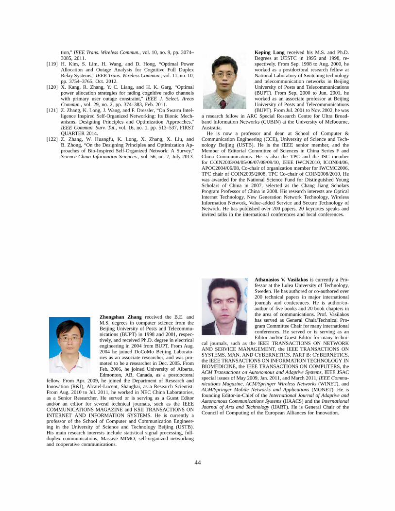
tion,” IEEE Trans. Wireless Commun., vol. 10, no. 9, pp. 3074–3085, 2011.
[119] H. Kim, S. Lim, H. Wang, and D. Hong, “Optimal PowerAllocation and Outage Analysis for Cognitive Full DuplexRelay Systems,”IEEE Trans. Wireless Commun., vol. 11, no. 10,pp. 3754–3765, Oct. 2012.
[120] X. Kang, R. Zhang, Y. C. Liang, and H. K. Garg, “Optimalpower allocation strategies for fading cognitive radio channelswith primary user outage constraint,”IEEE J. Select. AreasCommun., vol. 29, no. 2, pp. 374–383, Feb. 2011.
[121] Z. Zhang, K. Long, J. Wang, and F. Dressler, “On Swarm Intel-ligence Inspired Self-Organized Networking: Its Bionic Mech-anisms, Designing Principles and Optimization Approaches,”IEEE Commun. Surv. Tut., vol. 16, no. 1, pp. 513–537, FIRSTQUARTER 2014.
[122] Z. Zhang, W. Huangfu, K. Long, X. Zhang, X. Liu, andB. Zhong, “On the Designing Principles and Optimization Ap-proaches of Bio-Inspired Self-Organized Network: A Survey,”Science China Information Sciences., vol. 56, no. 7, July 2013.
Zhongshan Zhang received the B.E. andM.S. degrees in computer science from theBeijing University of Posts and Telecommu-nications (BUPT) in 1998 and 2001, respec-tively, and received Ph.D. degree in electricalengineering in 2004 from BUPT. From Aug.2004 he joined DoCoMo Beijing Laborato-ries as an associate researcher, and was pro-moted to be a researcher in Dec. 2005. FromFeb. 2006, he joined University of Alberta,Edmonton, AB, Canada, as a postdoctoral
fellow. From Apr. 2009, he joined the Department of Research andInnovation (R&I), Alcatel-Lucent, Shanghai, as a Research Scientist.From Aug. 2010 to Jul. 2011, he worked in NEC China Laboratories,as a Senior Researcher. He served or is serving as a Guest Editorand/or an editor for several technical journals, such as theIEEECOMMUNICATIONS MAGAZINE and KSII TRANSACTIONS ONINTERNET AND INFORMATION SYSTEMS. He is currently aprofessor of the School of Computer and Communication Engineer-ing in the University of Science and Technology Beijing (USTB).His main research interests include statistical signal processing, full-duplex communications, Massive MIMO, self-organized networkingand cooperative communications.
Keping Long received his M.S. and Ph.D.Degrees at UESTC in 1995 and 1998, re-spectively. From Sep. 1998 to Aug. 2000, heworked as a postdoctoral research fellow atNational Laboratory of Switching technologyand telecommunication networks in BeijingUniversity of Posts and Telecommunications(BUPT). From Sep. 2000 to Jun. 2001, heworked as an associate professor at BeijingUniversity of Posts and Telecommunications(BUPT). From Jul. 2001 to Nov. 2002, he was
a research fellow in ARC Special Research Centre for Ultra Broad-band Information Networks (CUBIN) at the University of Melbourne,Australia.
He is now a professor and dean at School of Computer &Communication Engineering (CCE), University of Science and Tech-nology Beijing (USTB). He is the IEEE senior member, and theMember of Editorial Committee of Sciences in China Series F andChina Communications. He is also the TPC and the ISC memberfor COIN2003/04/05/06/07/08/09/10, IEEE IWCN2010, ICON04/06,APOC2004/06/08, Co-chair of organization member for IWCMC2006,TPC chair of COIN2005/2008, TPC Co-chair of COIN2008/2010,Hewas awarded for the National Science Fund for DistinguishedYoungScholars of China in 2007, selected as the Chang Jiang ScholarsProgram Professor of China in 2008. His research interests are OpticalInternet Technology, New Generation Network Technology, WirelessInformation Network, Value-added Service and Secure Technology ofNetwork. He has published over 200 papers, 20 keynotes speaks andinvited talks in the international conferences and local conferences.
Athanasios V. Vasilakosis currently a Pro-fessor at the Lulea University of Technology,Sweden. He has authored or co-authored over200 technical papers in major internationaljournals and conferences. He is author/co-author of five books and 20 book chapters inthe area of communications. Prof. Vasilakoshas served as General Chair/Technical Pro-gram Committee Chair for many internationalconferences. He served or is serving as anEditor and/or Guest Editor for many techni-
cal journals, such as the IEEE TRANSACTIONS ON NETWORKAND SERVICE MANAGEMENT, the IEEE TRANSACTIONS ONSYSTEMS, MAN, AND CYBERNETICS, PART B: CYBERNETICS,the IEEE TRANSACTIONS ON INFORMATION TECHNOLOGY INBIOMEDICINE, the IEEE TRANSACTIONS ON COMPUTERS, theACM Transactions on Autonomous and Adaptive Systems, IEEE JSACspecial issues of May 2009, Jan. 2011, and March 2011,IEEE Commu-nications Magazine, ACM/Springer Wireless Networks(WINET), andACM/Springer Mobile Networks and Applications(MONET). He isfounding Editor-in-Chief of theInternational Journal of Adaptive andAutonomous Communications Systems(IJAACS) and theInternationalJournal of Arts and Technology(IJART). He is General Chair of theCouncil of Computing of the European Alliances for Innovation.
44
Lajos Hanzo (http://www-mobile.ecs.soton.ac.uk) FREng, FIEEE,FIET, Fellow of EURASIP, DSc receivedhis degree in electronics in 1976 and hisdoctorate in 1983. In 2009 he was awardedan honorary doctorate by the TechnicalUniversity of Budapest, while in 2015 bythe University of Edinburgh. During his38-year career in telecommunications he hasheld various research and academic postsin Hungary, Germany and the UK. Since
1986 he has been with the School of Electronics and ComputerScience, University of Southampton, UK, where he holds the chairin telecommunications. He has successfully supervised about100PhD students, co-authored 20 John Wiley/IEEE Press books onmobile radio communications totalling in excess of 10 000 pages,published 1500+ research entries at IEEE Xplore, acted bothasTPC and General Chair of IEEE conferences, presented keynotelectures and has been awarded a number of distinctions. Currentlyhe is directing a 60-strong academic research team, working ona range of research projects in the field of wireless multimediacommunications sponsored by industry, the Engineering and PhysicalSciences Research Council (EPSRC) UK, the European ResearchCouncil’s Advanced Fellow Grant and the Royal Society’s WolfsonResearch Merit Award. He is an enthusiastic supporter of industrialand academic liaison and he offers a range of industrial courses.He is also a Governor of the IEEE VTS. During 2008 - 2012 hewas the Editor-in-Chief of the IEEE Press and a Chaired Professoralso at Tsinghua University, Beijing. His research is funded by theEuropean Research Council’s Senior Research Fellow Grant.Forfurther information on research in progress and associated publicationsplease refer to http://www-mobile.ecs.soton.ac.uk Lajos has 23 000+citations.
45