Embed Size (px)
Citation preview
Defence Science Journal, Vol 43, No 1, January 1993, pp 43-51@ 1993, DESIDOC
Submarine Communications
H.B. Singh and Rajendra Pal
Defence Electronics Applications Laboratory, Dehradun-24800/
ABSTRACT
Submarines operating i]1 deep water are virtually cut off from the outer world. It becomes veryimportant and essential to convey survivable and critical informations to the submarine during thetime it operates under water. Conventional means of radio communication do not serve any usefulpurpose as the higher frequencies get attenuated very sharply in sea water. At VLF band, which ispresently being used by most of the world Navies, signal can penetrate only upto 8-10 m of depth.This depth is not sufficient under hostile environment. ELF is another band where listening depthis around 100 m but data rate is very low.
This paper summarises the various means of communication used to send messages to submarinewhile cruising at various depths. It seems that in the near future blue-green laser is going to be thevital means of sending large information to a submarine operating much deeper {500-700 m) withunrestricted speed.
I. INTRODUCTION
Submarines, now-a-days, are very important and
vital arm of any defence force. Most of the world Navies
today have tactical attack submarines which in the time
of war can be used to attack enemy submarines and
surface ships. The nuclear powered submarines are
capable of launchtng missiles that can destroy inland
enemy targets, thousands of miles away. In this way
they act as mobile launching pads whose position can
be safely kept hidden from the enemy. To perform this
role submarines have to operate for continuous stretchof time spanning over many months away from shores
and in the deep sea water. In order, to perform their
mission successfullJ submarines must be able to receive
communication from their base stations without
exposing themselves to the danger of detection.
operating very far away from the shore and VHF/UHF
when it was within the line-of-sight distance. Most of
the time submarines would be operating deep inside
the water but at preassigned time schedule, they would
ascend up to the periscopic depth and raise their
antennae. above the surface of water in order to
comMunicate with the outer world.
Raising' antenna above the surface of water could
endanger the submarine to its detection by the hostile
forces. The raised antenna could be detected by enemy
radars or airborne observers. Also, the enemy satellite
could locate the submarine by picking up radio signals
transmitted from it.
3. PRESENT DA y COMMUNICA TION
TECHNIQUES
In order to minimise the risk of detection, a
submarine must have the capability to receive
communicaticm while remaining submerged at
operational depths. This could be possible only by using
those radio waves which could penetrate water to a
considerable depth.
2. SUBMARINE COMMUNICA TION OF EARL Y
DAYS
Not so very long ago, radio communication to
submarines was carried out mainly in HF, VHF and
UHF radio bands; HF when the submarine was
Received 17 Decemher 1992
43
DEF SCI J, VOL 43, NO 1, JANUARY 1993
1000 , NON-ABSORBEO
n:1, II : 0.3
I NIGHT TIMEI In = j+2,I
,-.,,1DAY TIMEn = 1, d = 0.2 dB
'.,\ ,
'..,
\\\
GROUND WAVE'SEAWATER \\
\
100
E"..~
1/1Xa:
NOTE " j
DAY Tt1E -FIRST ORDER '-,
WAVEGUIDE MODENIGHT TIME -FIRST AND SECOND
ORDER MODES
INVERSEDISTANCE10
1
100 1000 10000MILES
It is well known that penetration of radio waves in
water is directly proportional to its wavelength (i.e. ,
inversely proportional to its frequency). Thus, longer
waves could be used for the purpose stated above, but
these waves have their own problems. Their mode of
propagation is such that they travel along the ground
bounded by two planes, i.e, the earth and ionosphere.
This waveguide mode of propagation supports only
vertical polarization. Longer the wave length, smaller
is the electrical length of the vertical antenna radiator .
This reduces radiation efficiency and restricts its
bandwidth. At the antenna site, a lot of copper buried
in the ground is needed to increase the ;round
conductivity, to reduce the ground losses and thus to
improve the antenna performance.
4. VLF BAND FOR SUBMARINE COMMUNI-
CATIONS
A radio band consisting of frequencies between 10
and 30 kHz, known as VLF band, works out to be the
best compromise, considering the above two conflicting
requirements. Even at these frequencies antenna
structure becomes very huge. Tower height around 300
m are not very uncommon for such stations. Even after
costly preparation of ground b~ burying lot of copper
in the fore-ground antenna efficiency greater than 50
per cent is not easier to achieve.
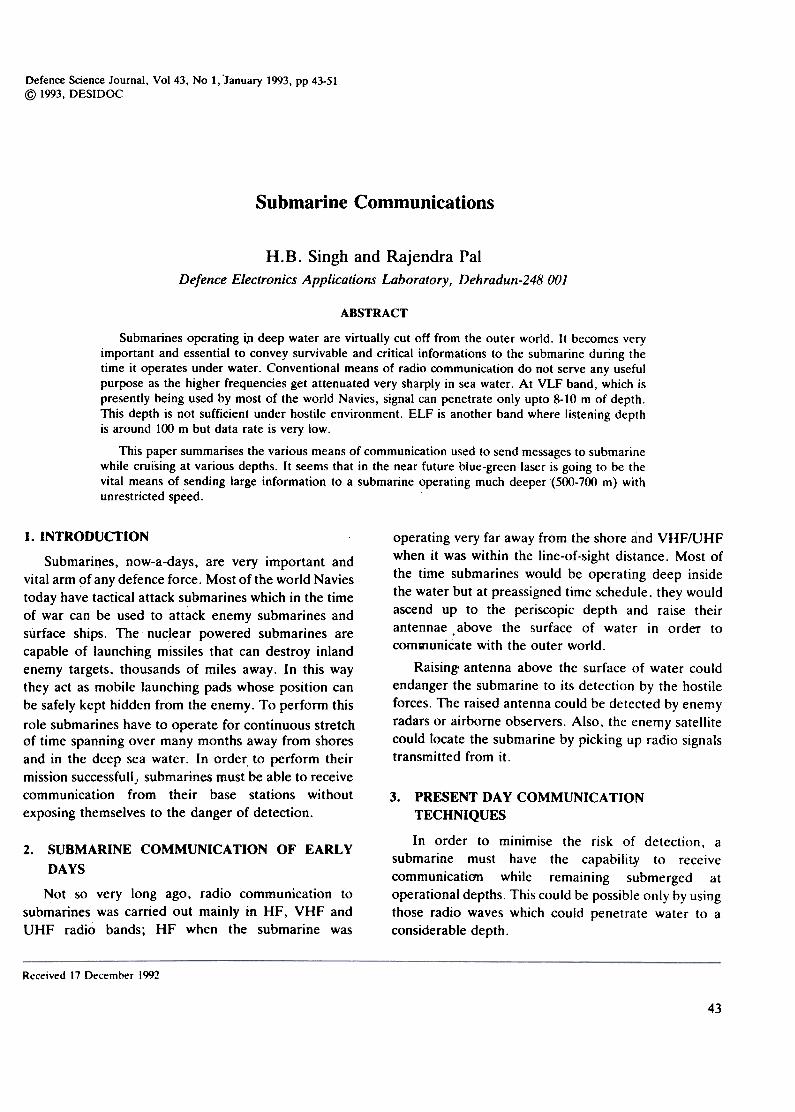
Fixure I. Field strength at various distances.
4.1 Propagation of VLF Band
As mentioned earlier, these waves travel along the
ground guided by ionosphere and the earth, with
E-vector as vertical. The field strength at various
distances is as given in Fig. 1. Atmospheric noise at
these frequencies is very high I. The limit to distance
from the transmitter up to which the VLF signal can
be picked up is reached when signal field strength getsreduced to a value which is only 10 dB higher than the
field strength of atmospheric noise.
As the signal now penetrates in the water to the
submarine located below. both signals as well as noise
are attenuated alike maintaining constant
signal-to-noise ratio till both get reduced so much that
receiver thermal noise also becomes an important
factor. This is a limiting depth. Only up to this depth
the signal can be properly demodulated a~ received.
With the present day state-of-the-art receivers and hull
mounted antennae this depth is of the order of 8-10 m .
4.2 New Techniques in Receiving Antennas to Further
Increase the Listening Depth
The depth of 10 m is the capability of present day
state-of-art receiver system which is not considered safe
for the submaraines. There is a need of some kind of
break through so that submarines could listen VLF while
operating at safer depths of the order of 100 m.
As mentioned earlier, the E-vector of the VLF wave
is not exactly vertical but has a slight tilt, the exact
amo4nt of which d.epends upon the conductivity of the
ground plane2 .The horizontal component denotes the
fraction of energy which leaks into the ground plane,
be it earth or sea water. It also denotes that only
horizontally polarized wave travels into the sea water .
As a result only two types of antennae which can be
used to pick these signals are possible, i.e., horizontal
wire antenna and the loop aerial. Actually both are
used by mounting them on hull, i.e. , on the outer surface
of the submarine.
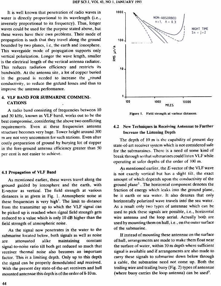
If instead of mounting these antennae on the surface
of hull , arrangements are made to make them float near
the surface of water, within 10 m depth where sufficient
signal is available and if arrangements are also made to
carry these signals to submarine down below through
a cable, the submarine need not come up. Both the
trailing wire and trailing buoy (Fig. 2) types of antennae
(where buoy carries the loop antenna) can be used3.
44
SINGH & PAL: SUBMARINE COMMUNICA TIONS
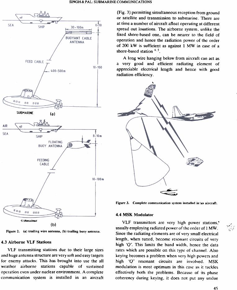
(Fig. 3) permitting simultaneous reception from groundor satellite and transmission to submarine. There are
at time a number of aircraft afloat operating at different
spread out loGations. The airborne system, unlike the
fixed shore-based one, can be nearer to the field of
operation and hence the radiation power of the order
of 200 kW is sufficient as against 1 MW in case of ashore-based station 4, 5.
A long wire hanging below from aircraft can act as
a very good and efficient radiating element of
appreciable electrical length and hence with good
radiation efficiency.
,
SUBMARINE (a)
~
Figure 3. Complete communication system installed in 'an aircraft,
SUBHARINE
4.4 MSK Modulator
VLF transmitters are very high power stations,"
usually employing radiated power of the order of I MW.
Since the radiating elements are of very small electrical
length, when tuned, become resonant circuits of very
high '0'. This limits the band width, hence the data
rates which are possible on this type of channel. Also
keying becomes a problem when very high powers and
high '0' resonant circuits are involved. MSK
modulation is most optimum in this case as it tackles
effectively both the problems. Because of its phase
coherency during keying, it does not put any undue
.
,..~;:!:
(b)
Figure 2. (a) trailing wire antenna, (b) trailing buoy antenna.
4.3 Airborne VLF Stations
VLF transmitting stations due to their large sizes
and huge antenna structure are very soft and easy targets
for enemy attacks. This has brought into use the all
weather airborne stations capable of sustained
operation even under nuclear environment. A complete
communication system is installed in an aircraft
45
DEF SCI J, VOI. 43, NO 1, JANUARY 1993
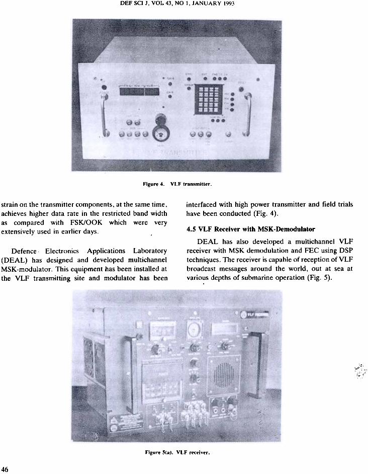
Figure 4. VLF transmitter .
interfaced with high power transmitter and field trialshave been conducted (Fig. 4).
strain on the transmitter components, at the same time,
achieves higher data rate in the restricted band width
as compared with FSK/OOK which were very
extensively used in earlier days. 4.5 VLF Receiver with MSK-Demodulator
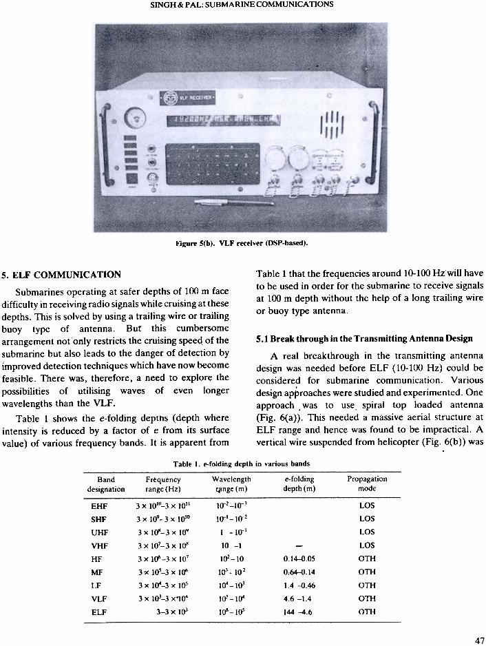
DEAL has also developed a multichannel VLFreceiver with MSK demodulation and FEC using DSPtechniques. The receiver is capable of reception of VLFbroadcast messages around the world, out at sea atvarious depths of submarine operation (Fig. 5).
Defence Electronics Applications Laboratory(DEAL) has designed and developed multichannel
MSK-modulator. This equipment has been installed at
the VLF transmitting site and modulator has been
'~f::;c
Figure 5(a). VLF receiver .
46
SINGH & PAL: SUBMARINE COMMUNICA TIONS
Figure S(b). VLF receiver (DSP-based).
Table 1 that the frequencies around 10-100 Hz.will have
to be used in order for the submarine to receive signalsat 100 m depth without the help of a long trailing wire
or buoy type antenna.
5.1 Break through in the Transmitting Antenna Design
A real breakthrough in the transmitting antenna
design was needed before ELF (10-100 Hz) could be
considered for submarine communication. Various
design approaches were studied and experimented. One
approach .was to use. spiral top loaded antenna
(Fig. 6(a». This needed a massive aerial structure at
ELF range and hence was found to be impractical. A
vertical wire suspended from helicopter (Fig. 6(b» was
5. ELF COMMUNICATION
Submarines operating at safer depths of 100 m face
difficulty in receiving radio signals while cruising at these
depths. This is solved by using a trailing wire or trailing
buoy type of antenna. But this cumbersome
arrangement not only restricts the cruising speed of the
submarine but also leads to the danger of detection by
improved detection techniques which have now become
feasible. There was, therefore. a need to explore the
possibilities of utilising waves of even longer
wavelengths than the VLF .
Table 1 shows the e-folding depths ( depth where
intensity is reduced by a factor of e from its surface
value) of various frequency bands. It is apparent from
Table I. e-folding depth in various bands
e-folding
depth (m)
Band
designationFrequency
range (Hz)
Wavelengthr4lnge (m)
Propagationmode
!q-2-
tq-l-
! -
3 x 10¹⁰-3 X 10¹¹
3 x 10⁹-3 x tol°
3 x lQi1-3 x to''
3 x 10⁷-3 X tQil
3 x tff'-3 x tO7
3 ?< tOS-3 x tff'
3 x t~-3 x tOS
3 x to)-3 x,~
3-3 x loJ
LOS
LOS
LOS
LOS
OTH
OTH
OTH
OTH
OTH
EHF
SHF
UHF
VHF
HF
MF
LF
VLF
ELF
10 -1
IOZ-10
loJ-IO2
1~ -loJ
10-' -1~
lOS-lo-'
0.14-0.05
0.64-0.14
1.4 -{1.46
4.6 -1.4
144 -4.6
47
-10-J
-10-2
-10-1
DEF SCI J, VOL 43, NO 1, JANUARY 1993
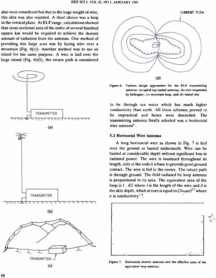
also once considered but due to the huge weight of wire,this idea was also rejected. A third choice was a loopin the vertical plane. At ELF range, calculations showedthat cross-sectional area of the order of several hundredsquare km would be required to achieve the desiredamount of radiation from the antenna. One method ofproviding this large al ea was by laying wire over amountain (Fig. 6( c ) ) .Another method was to use anisland for the same purpose. A wire is laid over thelarge island (Fig. 6(d)), the return path is considered
CURRENT FLOW
(d)
Figure 6. Various design approaches for the ELF transmittingantenna: (a) spiral top loaded antenna, (b) wire suspendedby helicopter, (c) mountain loop, and (d) island slol.
to be through sea water which has much higher
conductivity than earth. All these schemes proved to
be impractical and hence were discarded. The
transmitting antenna finally selected was a horizontal
wire antenna6 .(a)
(b)"
';~ ","",
.:-,'
--
5.2 Horizontal Wire Antenna
A long horizontal wire as shown in Fig. 7 is laid
over the ground or buried underneath. Wire can be
buried at considerable depth without significant loss in
radiated power. The wire is insulated throughout its
lengt~, only at the ends it is bare to provide good ground
contact. The wire is fed in the centre. The return path
is thro.ugh ground. The field radiated by loop antenna
is proportional to its area. The equivalent area of the
loop is 1 .<512 where 1 is the length of the wire and <5 is
the skin depth, which in turn is equal to (2Iw,u0" )0-5 where0" is conductivity7.8. .
-.-: :..,-:: ::;:0.: :..:.:.: ';..::.;.,;:.: :...,.
-.-,-, ~.:.,:'.:.:..':.-.)DtJZ~TAlElfCTRIC::::', ,--'./ ,.".-AHTEJ8CA--'...:...: : ,. ,.:..::~:,"::.:.,.:, :':.::;;..:I
.~~~: c; , ~-:r ~:':\!;~ ; ~i.~iJ:::1; r ::-:~~ :~--~ :;:-:-~,:::;:
'. I.I,...~ ,.,.,I.' , '-.~ :::.:..: ..:.:i .~.~.~~-~:~~ r' .:i~:;li.~.~ .::, .:.: ',~; ;~:::::...~~-~..;:~':~~~::~- ~; :
..-EFFECTIVE AREA ' -, '..'..' ~.,-.., , ' : .
.':OFEa.UIVAlENT ,... :. ,, .'- ...lOOPANTENNA.: :.- , :.,:'.
.,. ., .;..:..::. : :'~'..,;- .: :.,. ..:,' -.~:.:...
Figure 7. HoriwntaJ electric antenna and the effective ana or the
equivalent loop antenna.
48
!t
j-;r::-":}:-:!:::-
TRANSMITTER .
(c)
SINGH & PAL: SUBMARINE COMMUNICATIONS
propagate in the case of VLF. Hence, though the
wavelength is launched by a horizontal wire radiator ,
the wave polarization gets changed into vertical
polarization as the wave propagates (Fig. 9).
Skin depth is inversely proportional to the earth
conductivity. Hence land of poor conductivity is
preferred as it will result in larger area. Better
conductivity is needed only near the ends. To increase
J we can lay a number of wires in parallel. The effective
length will be the sum of all the lengths. To keep voltages
and current uniform along the length, distributed
feeding is used. This loop antenna is directional. To
make it omnidirectional, similar array of antenna
lengths perpendicular to it are used. The final shape is
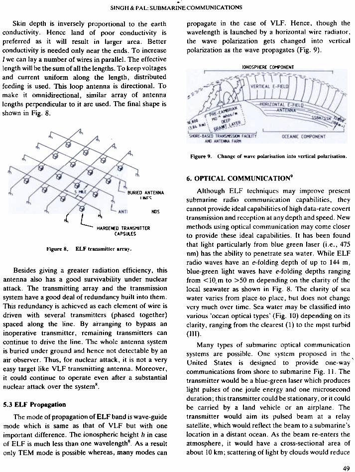
shown in Fig. 8.
IONOSPHERE COMPONENT
Figure 9. Change of wave polarisation into vertical polarisation.
-BURIED ANTENNALINES
ANTENNA GROUNOS
if'
L HAROENEO TRANSMITTER
CAPSULES
ELF transmitter array.Figure 8.
Besides giving a greater radiation efficiency, this
antenna also has a good survivability under nuclear
attack. The transmitting array and the transmission
system have a good deal of redundancy built into them.
This redundancy is achieved as each element of wire is
driven with several transmitters (phased together)
spaced along the line. By arranging to bypass an
inoperative transmitter, remaining transmitters can
continue to drive the line. The whole antenna system
is buried under ground and hence not detectable by an
air observer. Thus, for nuclear attack, it is not a very
easy target like VLF transmitting antenna. Moreover ,
it could continue to operate even after a substantial
nuclear attack over the systems.
6. OPTICAL COMMUNICA TION'
Although ELF techniques may improve present
submarine radio communication capabilities, they
cannot provide ideal capabilities of high data-rate covert
transmission and reception at any depth and speed. New
methods using optical communication may come closer
to provide these ideal capabilities. It has been found
that light particularly from blue green laser (i.e. , 475
nm) has the ability to penetrate sea water. While ELF
radio waves have an e-folding depth of up to 144 m,
blue-green light waves have e-folding depths ranging
from <10. m to >50 m depending on the clarity of the
local seawater as shown in Fig. 8. The clarity of sea
water varies from place .to place, but does not change
very much over time. Sea water may be classified into
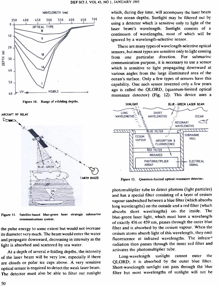
various 'ocean optical types' (Fig. 10) depending on its
clarity, ranging from the clearest ( 1) to the m9st turbid
(III).
Many types of submarine optical communication
systems are possible. One system proposed in the
United States is designed to provide one-way
communications from shore to submarine Fig. II. The
transmitter would be a blue-green laser which produces
light pulses of one joule energy and one microsecond
duration; this transmitter could be stationary, or it could
be carried by a land vehicle or an airplane. The
transmitter would aim its pulsed beam at a relay
satellite, which would reflect the beam to a submarine's
location in a distant ocean. As the beam re-enters the
atmosphere, it would have a cross-sectionat area of
about 10 km; scattering of light by clouds would reduce
5.3 ELF Propagation
The mode of propagation of ELF band is wave-guide
mode which is same as that of VLF but with one
important difference. The ionospheric height h in case
of ELF is much less than one wavelengths. As a result
only TEM mode is possible whereas, many modes can
49
DEF SCI J, VOL 43, NO I, JANUARY 1993
which, during day time, will accompany the laser beam
to the ocean depths. Sunlight may be filtered out byusing a detector which is sensitive only to light of the
laser beam's wavelength. Sunlight consists of a
continuum of wavelengths, most of which will be
ignored by a wavelength-selective sensor .
There are many types of wavelength-selective optical
sensors, but most types are sensitive only to light coming
from one particular direction. For submarine
communication purpose, it is necessary to use a sensor
which is sensitive to light propagating downward at
various angles from the large illuminated area of the
ocean's surface. Only a few types of sensors have this
capability. One such sensor invented only a few years
ago is called the QLORD, (quantum-Iimited opticalresonance detector) (Fig. 12). This device uses a
Figure 10. Range of e-foldin~ depths.SUNliGHT BLUE-GREEN LASER BEAM
--;:-.;;;;---t~WAVELENGTHS -,~ OCEAN
'~'RESONANT ~
,-~ WAVELENGTHS
AIRCRAFT RF RELAY
~,~
HULL
ELECTRICALSIGNAL...
~EARTH BASED Figure 12. Quantum-limited optical resonance detector .
Figure II. Satellite-based blue-green laser strategic submarine
communications system.
the pulse energy to some extent but would not increase
its diameter very much. The beam would enter the water
and propagate downward, decreasing in intensity as the
light is absorbed and scattered by sea water .
At a depth of several e-folding depths, the intensityof the laser beam will be very low. especially if there
are clouds or polar ice caps above. A very sensitiveoptical sensor is required to detect the weak laser beam.
The detector must also be able to filter out sunlight
photomultiplier tube to detect photons (light particles)and has a special filter consisting of a layer of cesium
vapour sandwiched between a blue filter '(which absorbs
long wavelengths) on the outside and a red filter (whichabsorbs short wavelengths) on, the inside. The
blue-green laser light, which must have a wavel6ngth
of exactly 456 or 459 nm, passes through the outer blue
filter and is absorbed by the cesium vapour. When the
cesium atoms absorb light of this wavelength, they emit
fluorescence at infrared wavelengths. The infrareA
radiation then passes through the inner red filter and
activates the photomultiplier tube.
Long-wavelength sunlight cannot eAter the
QLORD; it is absorbed by the outer blue filter .
Short-wavelength sunlight can pass through the blue
filter but most wavelengths of sunlight will not be
50
SINGH & r AL: SUBMARINECOMMUNICA TIONS
absorbed by the cesium vapour. Instead the short-
wavelength sunlight will pass through the cesium vapourand will be absorbed by the inner red filter. This does
not produce fluorescence, and so it does not activate
the photomultiplier tube.
QLORD sensors could be mounted on the hull of
a submarine. With these sensors, the submarine could
receive laser signals at a depth of about 700 m in optical
type-1 water on a clear day or night, or about 570 m on
a cloudy day or night. Operation beneath the polar
icecap would be more limited. These depths compare
very favourably to the antenna depths at which VLF
and ELF signals can be received. ~nother advantage
of optical communication is the higher data rate.
Moreover, optical communications can be received
while cruising at any speed.
submarines can receive VLF broadcast messages
operating thousands of km from shore stations and
completely hidden under water at around 1 ()() m depthIn open sea. -
The much promising means i.e. , the optical
communication using blue-green laser is yet another
possible approach which can be comfortably handled
at DEAL, Dehradun.
ACKNOWLEDGEMENTS
Authors are thankful to Shri VP Sandlas, Director ,
DEAL, Dehradun for his keen interest and
encouragement, and to Shri PC Gupta for healthy
suggestions. Thanks are also due to Smt Prem Lata for
secretarial assistance .
7. ACOUSTICAL COMMUNICA TION
In addition .to radio and optical techniques, several
other methods of submarine communication are
possible. For example, submarines can communicate
using acoustical techniques. Sound waves can be
transmitted for thousands of miles under water .
especially if the sound is generated and received in .a
layer of water known as the deep sound channel which
lies about 1200 to 1800 m deep. However. multipath
interference (self-interference of the transmitted signai
with its echoes from the ocean floor, the ocean surface.
and refractivity gradients) limits the data rate
achievable at long ranges. Moreover, sound waves
which propagate at about 1500 m/s would require an
hour or more to reach distant submarines. and
long-range acoustical communications are vulnerable to
jamming. The propagation delay can be reduced by
using arrays of acoustical transmitters on underwater
buoys connected by cable to the mainland; however .
these could be located by the enemy in peace time and
destroyed quickly in war time. Acoustical methods
are presently used for submarine-to-ship and
submarine-to-submarine communications II.
~
REFERENCES
1. Watt, A.D. VLF radio engineering. Pergamon
Press, New York, 1967.
2. Moore, R.K. Radio Communication on sea. IEEE
Spectrum, 1981, 1625.
3. Fessenden, C. T. Development of trailing wire
E-field submarine antenna for extremely low
frequency (ELF) receiption. I EEE Trans.
Commun. 1974, COM- 22, 428-37.
4. Black, K.M. & Andrew, G. TACAMO Military
electronics/ counter-measures. 1980. p. 56.
5. .Star,key, R.J. Jr. The renoissance in submarine
communications. ME/C Part III, 1981 7(1), and
Part .IV, 1981 7(2l.
6. Keiser, B .E .Early development of the project
sanguine radiating system. IEEE" Trans. Commun.
1974, COM-22(4), 364-71.
7. Hansen. R.C. Radiating and reception with buried
and submerged antenna. IEEE Trans. Antenna
and Propagation, 1963, 207-14.
8. Michael-Burrows, L. ELF communication
antennas. Peter Peregrinus Ltd, England, 1978.
9. Starkey, R.J. Jr. The renaissance in submarine
communications. ME/C, Part V, 19~1, 7(3).
10. Singh, H.B. & Pal, Rajendra. Nuclear hardened
radio communication to suhmarrine- a review.
IEEE Technical Review, 19H6, 3(5).205-10.
II. Collaham, M. B. Submarine communications.
IEEE Communication Magazine, 1981, 19(6),
16-25.
8. CONCLUSION
The various approaches for sending messages tosubmarines operating under water have their own merits
and demerits. Since our naval VLF transmitting station
is operational, there is a need to equip all submarines
with multichannel MSK-receivers along with trailing
wire/trailing buoy types of antennae so that our
51