Embed Size (px)
Citation preview
EK-CMIV5-RM-005
Networks. Communications
Communications Options Minireference Manual
Volume 5 Ethernet Devices (Part 1)
DIGITAL INTERNAL USE ONLY
Digital Equipment Corporation
1 st Edition, December 1981 2nd Edition, August 1984 3rd Edition, August 1986 4th Edition, August 1987 5th Edition, August 1988
© Digital Equipment Corporation 1981,1984,1986,1987, 1988 All Rights Reserved
The information in this document is subject to change without notice and should not be construed as a commitment by Digital Equipment Corporation. Digital Equipment Corporation assumes no responsibility for any errors that may appear in this document.
Printed in U.S.A.
This document was set on a DIGITAL DECset Integrated Publishing System.
• Class A Computing Devices:
Notice: This equipment generates, uses, and may emit radio frequency energy. The equipment has been type tested and found to comply with the limits for a Class A computing device pursuant to SubpartJ of Part 15 of FCC Rules, which are designed to provide reasonable protection against such radio frequency interference when operated in a commercial environment. Operation of this equipment in a residential area may cause interference in which case the user at his own expense may be required to take measures to correct the interference.
The following are trademarks of Digital Equipment Corporation:
mamaD!DlM DEC DECmate DECset DECsystem-l0 DECSYSTEM-20
DECUS DECwriter DIBOL MASSBUS PDP PIOS Professional Rainbow
RSTS RSX Scholar ULTRIX UNIBUS VAX VMS VT Work Processor
CONTENTS
Page
CHAPTER 1 INTRODUCTION
CHAPTER 2 ETHERNET DEVICES
2.1 INTRODUCTION .................................................................................................... 2-1 DEBNA/DEBNK ETHERNET VAXBI CONTROLLER .......... DEBNA/DEBNK-l
General Description .................................................................... DEBNA/DEBNK-l Product Configuration ................................................................ DEBNA/DEBNK-l Product Differences .................................................................... DEBNA/DEBNK-2 Reference Documentation .......................................................... DEBNA/DEBNK-2 Hardware Components ............................................................... DEBNA/DEBNK-2 Software Components ................................................................. DEBNA/DEBNK-4 Environmental Considerations .................................................... DEBNA/DEBNK-4 Power Requirements ................................................................... DEBNA/DEBNK-4 Installation Flow Diagram .......................................................... DEBNA/DEBNK-5 Cables ......................................................................................... DEBNA/DEBNK-9 Self-Test Diagnostics ................................................................ DEBNA/DEBNK-Il Self-Tests .................................................................................. DEBNA/DEBNK-l1 Self-Test Results ...................................................................... DEBNA/DEBNK-l1 Self-Test Interpretation ............................................................ DEBNA/DEBNK-13 ROM-Based Diagnostics (RBDs) ............................................. DEBNA/DEBNK-14
DO - DEBNx Self-Test ....................................................... DEBNA/DEBNK-14 DI - Network Interconnect Diagnostic ............................... DEBNA/DEBNK-16 D2 - Tape Drive Diagnostic ................................................ DEBNA/DEBNK-18
Software Diagnostics ................................................................ DEBNA/DEBNK-19 Error Types .............................................................................. DEBNA/DEBNK-20 Error Description ..................................................................... DEBNA/DEBNK-20 Troubleshooting ........................................................................ DEBNA/DEBNK-21 Running ROM Diagnostics from the Console .......................... DEBNA/DEBNK-29 ROM Diagnostic Console Commands ...................................... DEBNA/DEBNK-30 EXECUTE Commands (DO, DI, D2) .................................... DEBNA/DEBNK-30 Error Reports ........................................................................... DEBNA/DEBNK-32 Status Reporting ...................................................................... DEBNA/DEBNK-36
DECmux II STATISTICAL MULTIPLEXER ............................................... DMXII-l General Description .................................................................................. DMXII-I Product Configuration ............................................................................... DMXII-2
Configuration Number I .................................................................. DMXII-2 Configuration Number 2 .................................................................. DMXII-3
DECmux II Versions ................................................................................. DMXII-4 Reference Documentation ......................................................................... DMXII-4 Component List ......................................................................................... DMXII-4 Equipment Placement ............................................................................... DMXII-5 Environmental Requirements .................................................................... DMXII-5 Physical Description .................................................................................. DMXII-5 Power Requirements .................................................................................. DMXII-5 Installation Flow Diagram ......................................................................... DMXII-6
iii
CONTENTS (Coot)
Page
Cabling .................................................................................................... DMXII-ll Diagnostics .............................................................................................. DMXII-12 DECmux II Diagnostic Summary .......................................................... DMXII-13
Off-line Test 1 ................................................................................ DMXII-I3 Off-line Test 2 ................................................................................ DMXII-I3 Off-line Test 3 ................................................................................ DMXII-I3 Off-line Test 4 ................................................................................ DMXII-I4 Off-line Test 5 ................................................................................ DMXII-I4 Off-line Test 6/0ff-line Test 7 ...................................................... DMXII-I4 Off-line Test 8 ................................................................................ DMXII-I4
Identifying Problems with the DECmux II ............................................ DMXII-I5 Identifying Problems with the Composite Link ...................................... DMXII-I6 Resetting the DECmux II Unit to Factory Settings ............................... DMXII-I7
DECNA ETHERNET COMMUNICATIONS CONTROLLER ................ DECNA-I General Description ................................................................................ DECNA-I Features ................................................................................................... DECNA-I Reference Documentation ....................................................................... DECNA-l Hardware Components ............................................................................ DECN A-I Software Component ............................................................................... DECNA-2 Installation Flow Diagram ....................................................................... DECNA-3 Cabling ............................................................................... , .................... DECNA-8 Power-Up Self-Test ................................................................................. DECNA-9 Maintenance Services Program ............................................................. DECNA-I 0
Installing the DECNA Diagnostic ............................................... DECNA-II Running the Maintenance Services Program ............................... DECNA-II
Testing the Network ............................................................................. DECNA-I2 Test Procedure .............................................................................. DECNA-14
DECOM BROADBAND ETHERNET TRANSCEIVER ........................... DECOM-I General Description ................................................................................ DECOM-l DECOM Versions ................................................................................... DECOM-l Components ............................................................................................. DECOM-2 Country Kits ........................................................................................... DECOM-2 Reference Documentation ....................................................................... DECOM-3 Device Placement .................................................................................... DECOM-4 Power Requirements ................................................................................ DECOM-5 Preinstallation Steps ................................................................................ DECOM-5 Installation Flow Diagram ....................................................................... DECOM-6 Cable Length Restrictions ..................................................................... DECOM-18 Cable Connections ................................................................................. DECOM-19 Diagnostics ............................................................................................ DECOM-20 DECOM Troubleshooting Table ............................................................ DECOM-2I Precheck ............................................................................................... DECOM-22 Ethernet Controller Self-Test ................................................................ DECOM-22 Network Troubleshooting Table ............................................................ DECOM-23 DECOM-AX Checkout Flow Diagram ................................................ DECOM-24 DECOM-BX Checkout Flow Diagram ................................................. DECOM-3I
iv
CONTENTS (Coot)
Page
DECrouter 200 ASYNCHRONOUS ROUTER .............................................. DR200-1 General Description ................................................................................... DR200-1 DECrouter 200 Versions ............................................................................ DR200-1 Reference Documentation .......................................................................... DR200-2 Hardware Components ............................................................................... DR200-2 Software Components ................................................................................. DR200-2 Equipment Placement ................................................................................ DR200-2 Environmental Requirements ..................................................................... DR200-2 Physical Description ................................................................................... DR200-2 Power Requirements ................................................................................... DR200-3 Installation Flow Diagram .......................................................................... DR200-3 Cabling ....................................................................................................... DR200-6 Basic Configuration Rules .......................................................................... DR200-6 Connecting Port Devices to the DECrouter 200 ....................................... DR200-7 Diagnostics ................................................................................................. DR200-8 DECrouter 200 Fault Conditions ............................................................... DR200-9
Dl LED OFF .................................................................................... DR200-9 D2 LED OFF .................................................................................... DR200-9 D2 LED Blinking ............................................................................ DR200-1 0 D3 LED Blinking ............................................................................ DR200-12
DECSA COMMUNICATIONS SERVER ..................................................... DECSA-l General Description ................................................................................. DECSA-l Reference Documentation ........................................................................ DECSA-l DECSA Communications Server Hardware Components ........................ DECSA-l DECSA Communications Server Software Components ......................... DECSA-2 System Placement .................................................................................... DECSA-3 Power Requirements ................................................................................. DECSA-3 Installation Flow Diagram ........................................................................ DECSA-4 Initial Test Indications ............................................................................. DECSA-9 Ethernet Address Display ...................................................................... DECSA-IO DECSA Cabling .................................................................................... DECSA-ll DECSA Diagnostics .............................................................................. DECSA-13 Diagnostic Descriptions .......................................................................... DECSA-13 Running Initial Tests and Diagnostics ................................................... DECSA-14 Running DECSA Diagnostics from a Remote Host. ............................. DECSA-14 Diagnostic Results .................................................................................. DECSA-16 Successful Initial Test Indications .......................................................... DECSA-17 Successful LDI Indications ..................................................................... DECSA-18 Fault Indications .................................................................................... DECSA-19
Initial Test Fault Indications ......................................................... DECSA-19 LDI Fault Indications .................................................................... DECSA-20 Logic Module Slot Numbers ......................................................... DECSA-21
Required Equipment .............................................................................. DECSA-22 Troubleshooting ...................................................................................... DECSA-23 Module Replacement and Upgrades ....................................................... DECSA-28
M7133 PDP-l 1/24 CPU Module Replacement ........................... DECSA-28
v
CONTENTS (Cont)
Page
M7792 DEUNA Port Module Replacement.. ............................... DECSA-29 M7793 DEUNA Link Module Replacement.. .............................. DECSA-30 M8743-xA Memory Module Replacement .................................... DECSA-30
System Upgrade ..................................................................................... DECSA-30 Backplane Terminal Strip Wiring .......................................................... DECSA-36 Secondary Power Supply Cabling .......................................................... DECSA-37 DECSA Tech Tips/FCO Index ............................................................. DECSA-38
DECserver 100 TERMINAL SERVER ....................................................... DS100-1 General Description ................................................................................... DS100-1 Product Configurations ............................................................................. DS 1 00-2 DECserver 100 Versions ........................................................................... DS100-2 Hardware Components .............................................................................. DS 1 00-3 Software Components ................................................................................ DS100-3
DECserver 100 Software ..................................................................... DSI00-3 Host Software ...................................................................................... DSI00-3 Server Software Operation ................................................................... DS 1 00-3
Terminal Connector Pin Assignments ....................................................... DS100-4 Application Modes .................................................................................... DS100-5 Terminals .................................................................................................. DS100-5 Reference Documentation ......................................................................... DS100-6 Device Placement ...................................................................................... DS 1 00-6 Installation Flow Diagram ......................................................................... DS100-7 Power Cord Length ................................................................................. DS 1 00-16 Ethernet Transceiver Cable Length ........................................................ DS100-16 Diagnostic Maintenance Features ............................................................ DS 1 00-17 Diagnostic Description ............................................................................ DSI00-17 Executing Diagnostic ............................................................................... DS 1 00-17 Error Indications/Symptoms .. ................................................................. DS 1 00-18 Status and Error Message Types ............................................................ DS 100-19 Fatal Bugcheck Error Message ............................................................... DS 100-19 Troubleshooting Flow Diagram ............................................................... DS 1 00-21
DECserver 200 TERMINAL SERVER ....................................................... DS200-1 General Description ..... .............................................................................. DS200-1 DECserver 200 Versions ........................................................................... DS200-2 Product Configuration ............................................................................... DS200-2 Reference Documentation ......................................................................... DS200-4 Software Components .. .............................................................................. DS200-4 Preinstallation Checklist.. .......................................................................... DS200-5 Arranging for Software Installation .......................................................... DS200-5 Installation Flow Diagram ... ...................................................................... DS200-7 Verifying Operation ................................................................................... DS200-8 Maximum Cable Length ........................................................................... DS200-9 DECserver 200/MC ............................................................................... DS200-1 0 DECserver 200/DL ................................................................................ DS200-11 Diagnostics ................................................................. ; ............................ DS200-13
vi
CONTENTS (Cont)
Page
DECserver 200 Fault Conditions ............................................................... DS200-14 D 1 LED OFF ..... .................................................................................. DS200-14 D2 LED OFF ....................................................................................... DS200-15 D2 LED Blinking ................................................................................. DS200-15 D3 LED Blinking ................................................................................. DS200-17 900-999 Console Messages ................................................................... DS200-18 DECserver 200 Crash Code List.. ........................................................ DS200-20
DECserver 500 TERMINAL SERVER .......................................................... DS500-1 General Description ... ................................................................................... DS500-1 DECserver 500 Versions .............................................................................. DS500-1 Network Configuration ................................................................................ DS500-4 Modular Hardware Description .................................................................... DS500-5 Line-Card Vectors/Addresses ....................................................................... DS500-6 DECserver 500 Software Installation Requirements .................................... DS500-8 Reference Documentation ............................................................................ DS500-9 Installation Flow Diagram ...... .................................................................... DS500-1 0 Devices ....................................................................................................... DS500-11 Device Placement ....................................................................................... DS500-12 Ethernet Connections ................................................................................. DS500-13 Port Device Connections ............................................................................ DS500-13 Diagnostic Self-Test Program .................................................................... DS500-22 Switch-Selected Diagnostic Boot Modes .................................................... DS500-23
Boot Mode 0 ..... .................................................................................... DS500-24 Boot Mode 1 ..... .................................................................................... DS500-24 Boot Mode 2 ..... .................................................................................... DS500-24 Boot Mode 3 ......................................................................................... DS500-25 Boot Mode 7 ......................................................................................... DS500-29
Status and Error Codes LED Display ....................................................... DS500-29 Diagnostic Status and Error Codes ....................................................... DS500-29 Server Software Status and Error Codes .............................................. DS500-29
Module Self-Test LEDs ............................................................................. DS500-32 CPU Module .............................................................................................. DS500-32 Ethernet Controller Module ....................................................................... DS500-32 CXA16, CXB16, and CXY08 Line Cards ............................................... DS500-32 Server Local Console Ports ........................................................................ DS500-32 Local Console Terminal ............................................................................. DS500-33 Spares ......................................................................................................... DS500-33 FRU Removal and Replacement Procedures ............................................. DS500-34 Cover Removal and Replacement.. ............................................................. DS500-35
Front Cover ........................................................................................... DS500-35 Rear Cover ............................................................................................ DS500-37
Module Removal ........................................................................................ DS500-38 Power Supply Removal and Installation ..................................................... DS500-40 AC Switch Assembly Removal and Installation ........................................ DS500-42 AC Line Filter Removal and Installation ... ............................................... DS500-44 Fan Removal and Installation .................................................................... DS500-47
vii
CONTENTS (Coot) Page
CPU Module Installation Procedure ............ ..... , '" ...... , .............................. DSSOO-49 Module Installation ..................................... , ......................................... DSSOO-49 Testing ................................................................................................... DSSOO-SO
Ethernet Controller Module Installation Procedure .................................... DSSOO-Sl Module Preparation ............................................................................... DSSOO-Sl Module Installation ............................................................................... DSSOO-S4 Testing ................................................................................................... DSSOO-SS
Line-Card Installation Procedure ............................................................... DSSOO-S7 Module Preparation ............................................................................... DSSOO-S7 Module Installation .. ............................................................................. DSSOO-61 Testing ........................................... ........................................................ DSSOO-62
Connecting a Local Console Terminal ....................................................... DSSOO-63
viii
QUICK REFERENCE CHECK
Use this quick reference as a resource to identify the major sections in the 7 volumes ofthe Communications Options Minire/erence Manual
VOLUME 1 COMMUNICATIONS OPTIONS
Float-Address Vectors Cables Test Connectors Special Test Programs Special Tools and Equipment EINCCITT Data Vendor Modem Products Data Communication Troubleshooting Communication Devices
DHII DHB32 DHQll DHUll DHVII DMB32 DMCll DMF32
VOLUME 2 COMMUNICATIONS OPTIONS (CONT)
DMPII DMRII DMVII DMZ32 DPVll DSB32 DSVII DUPII DUVII DZII DZ32 DZQll DZVll KMVIA/KMVIA-S
VOLUME 3 DIGITAL MODEMS (PART I)
EINCCITT Data Vendor Modem Products Modems
DF02/DF03 DF112 DF124 DF124+ DF126 DF127 DF129 DF212-CA DF224 DF242-CA DFAOI Command Summary
VOLUME 4 DIGITAL MODEMS (PART 2)
Enclosures DFMDevices
DFM Statistical Multiplexer DFM X.25 PAD
Test Procedures Modem Option Dictionary Modem Theory Autodialer Command/Response
VOLUME 5 ETHERNET DEVICES (PART 1)
Ethernet Devices DEBNA/DEBNK DECmux II DECNA DECOM DECrouter 200 DECSA DEC server 100 DEC server 200 DEC server 500
VOLUME 6 ETHERNET DEVICES (PART 2)
Ethernet Devices (Cont) DEFTR DELNI DELUA DEMPR DEMWA DEPCA DEQNA DE REP DESNC DESPR DESTA
VOLUME 7 ETHERNET DEVICES (PART 3)
Ethernet Devices (Cont) DEUNA H4000 H400S LAN Bridge 100 MUXserver 100 TPENET
Cables Special Tools and Test Equipment Network Troubleshooting Ethernet Configuration
CHAPTER 1 INTRODUCTION
The Communications Options Minireference series of manuals provide Field Service personnel (trained in Digital Equipment Corporation's communications options, DEC modem products, and Ethernet products) with easy-to-use references that focus on essential installation and maintenance procedures.
This series of manuals is a replacement for and supersedes the Communications Options Minireference Manual (EK-CMINI-RM). All of the information contained in the Communications Options Minireference Manual is included. Information concerning most of Digital Equipment Corporation's new communication options, modem products, and Ethernet products has also been included. These manuals will be updated as new communications options, modem products, and Ethernet products are produced.
To effectively use these reference manuals and to quickly locate the desired information, it is important that the user be aware of the organization and content of the various manuals.
• Volume 1 contains generic communications information such as: cables, test connectors and terminators, special test programs, and special tools and equipment Volume 1 also contains information concerning installation and maintenance of some of the communications options.
• Volume 2 contains only communications options. Communications options are presented in alphanumerical order beginning in Volume 1 and continuing into Volume 2.
• Volumes 3 and 4 contain information concerning Digital Equipment Corporation's modem products.
• Volumes 5,6, and 7 contain information concerning installation and maintenance of Ethernet products. Chapters include EthernetDevices, Cables, Special Tools and Test Equipment, Network Troubleshooting, and Ethernet Configuration. Provisions are made for adding information as it becomes available.
Option-specific data is located alphanumerically by option designation.
1-1

..
2.1 INTRODUCTION
CHAPTER 2 ETHERNET DEVICES
This chapter contains all information needed to configure, install, and test a variety of Digital Equipment Corporation's Ethernet devices.
The purpose of this chapter is to provide Field Service personnel (trained in servicing Ethernet devices) with a quick reference guide, highlighting important factors concerning installation and maintenance. The information contained in these sections is, therefore, short and to the point. If more detailed information is needed, reference should be made to microfiche, the technical manual, or other reference material concerning that particular device.
Each specific section contained in this chapter is organized in alphanumeric order.
2-1

DEBNA/DEBNK INSTALLATION
DEBNA/DEBNK ETHERNET VAXBI CONTROLLER
General Description The DEBNx model number describes a family of intelligent I/O controllers for the VAXBI bus.
• DEBNA is an IEEE 802.3-compatible, standard Ethernet interface for VAX 8000-series systems.
• DEBNK is identical to DEBNA, but has an on-board TK50 streaming tape-drive controller. DEBNK is an option for OEM applications.
DEBNA and DEBNK are both T1034 (41OF) modules and the modules can be distinguished by their VAXBI device type (Bile bb + 0).
Specific TK50 information for DEBNK and operational support for DEBNA can be found in the VAX Systems and Options Catalog.
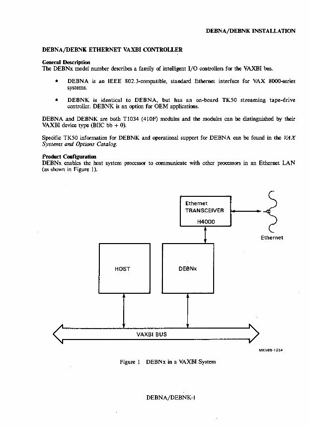
Product Configuration DEBNx enables the host system processor to communicate with other processors in an Ethernet LAN (as shown in Figure 1).
Ethernet TRANSCEIVER
H4000
! Ethernet
HOST DEBNx
.A
VAXBI BUS y
MKV88-12S4
Figure 1 DEBNx in a VAXBI System
DEBNA/DEBNK-l
DEBNA/DEBNK INSTALLATION
Product Differences The only DEBNK-exc1usive feature is that it supports tape. Both DEBNA and DEBNK have the following basic components.
• VAXBI corner (interface): BIlC and BCI3 chips
• Central processor and memory: MicroVAX processor chip and associated logic MicroVAX RAM, patch RAM, and ROM
• Tape controller: . 80186 processor chip and associated logic
80816 RAM, patch RAM, and ROM MPSC (DIGITAL proprietary tape protocol) chip AD16 bus for 80816 and 80816 memory
• Ethernet/802.3 controller: LANCE and SIA (Ethernet) chips
• 1116 bus to provide access to the MicroVAX processor and MicroVAX memory for tape controller and Ethernet controller
• 1132 bus to connect MicroVAX processor and VAXBI corner
• IEEE 802.3 compatibility
• MicroVAX buffer RAM of 128 Kbytes
Reference Documentation The following related documentation is available to support servicing.
DEBNA/ DEBNK Installation Guide EK-DEBNX-IN
DEBNA/ DEBNK Technical Manual EK-DEBNX-TM
VAXBI Options Handbook EB':27271-46
TK50D, TK50R Tape Drive Subsystem Owner's Manual EK-LOP05-0M
Ethernet Installation Guide EK-ETHER-IN
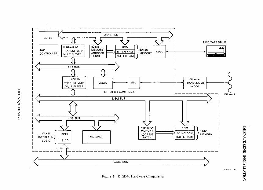
Hardware Components DEBNx is made up of the following component groups (see Figure 2).
• MicroVAX processor and associated control . logic • MicroVAX memory and patch hardware • MEM bus • 1132 bus • VAXBI interface logic • Ethernet controller • Tape controller
DEBNA/DEBNK-2
V tTl 0:;
Z ;l>
.......... V tTl 0:;
Z ~ w
-------1 -- " I
I I : ~
I .~
80186
TAPE TRANSCEIVER/ MULTIPLEXER
TK50 TAPE DRIVE
MPSC CONTROLLER
1116/MEM TRANSCEIVER/ MULTIPLEXER
;<
II 32 BUS
VAXBI {~C13 INTERFACE
LOGIC B11 C
ADDRESS LATCH
I l:J I Eth,m,t I ~ LANCE' • SIA' ! · TRA~:~~~VER ..
ETHERNET CONTROLLER L --------,,-, Ethernet
MEM BUS
MicroVAX ROM } 1132 MEMORY "'" PATCH RAM MEMORY ADDRESS .-- BUFFER RAM
LATCH _ MicroVAX
L ______ _ ----------------------------------------~
VAXBI BUS
MKV88-1255
Figure 2 DEBNx Hardware Components
o ~ = Z > , o ~ = Z ~
Z rJ'J.
~ r r ~ ~
DEBNA/DEBNK INSTALLATION
Software Components Where DEBNA has only a network interconnect (NI) port, DEBNK is a multi port adapter. The NI port is the controller's interface to Ethernet. DEBNK has both an NI port and a tape/storage port.
The two ports are controlled by logically-distinct port drivers on the host. Port status will not affect one another except in the following situations.
• A hardware failure or several logical failures in DEBNx.
• DEBNx receives a VAXBI command that forces both ports to the "Stopped" state.
• A BVP (BIVAX Port) RESTART command forces both ports to the "Undefined" state.
• A VAXBI node reset to the DEBNx forces both ports to the "Undefined" state.
For more information on DEBNx software compoments, refer to the DEBNA/ DEBNK Technical Manual.
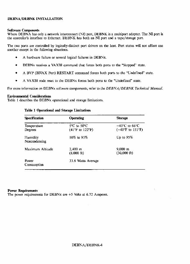
Environmental Considerations Table 1 describes the DEBNx operational and storage limitations.
Table 1 Operational and Storage Limitations
Specification
Temperature Degrees
Humidity Noncondensing
Maximum Altitude
Power Consumption
Power Requirements
Operating
5°C to 50°C (41°F to 122°F)
10% to 95%
2,400 m (8,000 ft)
33.6 Watts Average
The power requirements for DEBNx are +5 Volts at 6.72 Amperes.
DEBNA/DEBNK-4
Storage
-40°C to 66°C (-40°F to 151°F)
Up to 95%
9,000 m (30,000 ft)
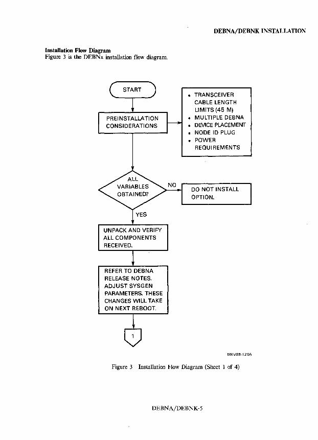
Installation Flow Diagram Figure 3 is the DEBNx installation flow diagram.
PREINSTALLATION CONSIDERATIONS
UNPACK AND VERIFY ALL COMPONENTS RECEIVED.
REFER TO DEBNA RELEASE NOTES. ADJUST SYSGEN PARAMETERS. THESE CHANGES WILL TAKE ON NEXT REBOOT.
DEBNA/DEBNKINSTALLATION
• TRANSCEIVER CABLE LENGTH LIMITS (45 M)
• MULTIPLE DEBNA • DEVICE PLACEMENT • NODE ID PLUG
• POWER REQUIREMENTS
DO NOT INSTALL
OPTION.
MKV88·1256
Figure 3 Installation Flow Diagram (Sheet 1 of 4)
DEBNA/DEBNK-5
DEBNA/DEBNKINSTALLATION
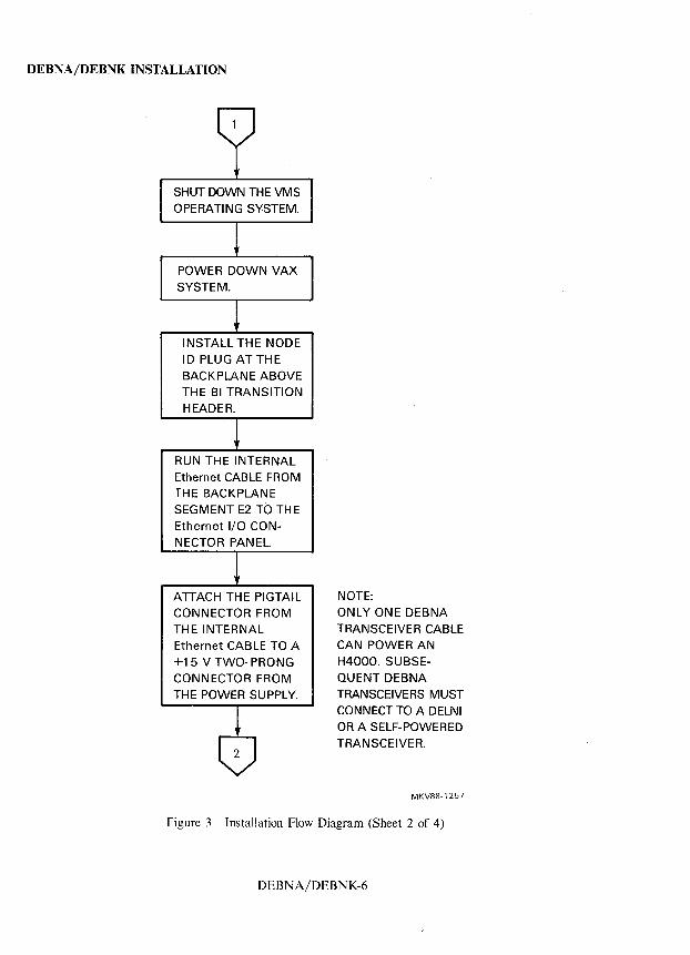
SHUT DOWN THE VMS OPERATING SYSTEM.
POWER DOWN VAX SYSTEM.
INSTALL THE NODE ID PLUG AT THE BACKPLANE ABOVE THE BI TRANSITION HEADER.
RUN THE INTERNAL Ethernet CABLE FROM THE BACKPLANE SEGMENT E2 TO TH E Ethernet I/O CONNECTOR PANEL.
ATTACH THE PIGTAIL CONNECTOR FROM THE INTERNAL Ethernet CABLE TO A +15 V TWO- PRONG CONNECTOR FROM THE POWER SUPPLY.
NOTE: ONLY ONE DEBNA TRANSCEIVER CABLE CAN POWER AN H4000. SUBSEQUENT DEBNA TRANSCEIVERS MUST CONNECT TO A DELNI OR A SELF-POWERED TRANSCEIVER.
MKV88-1257
Figure 3 Installation Flow Diagram (Sheet 2 of 4)
DEBNA/DEBNK-6
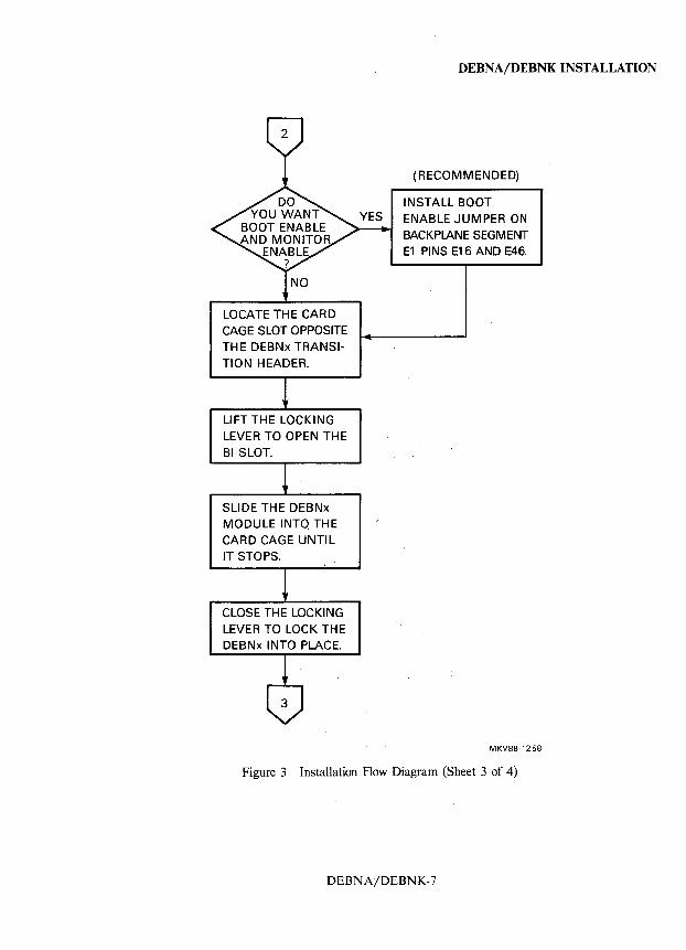
LOCATE THE CARD CAGE SLOT OPPOSITE THE DEBNx TRANSITION HEADER.
LIFT THE LOCKING LEVER TO OPEN THE BI SLOT.
SLIDE THE DEBNx MODULE INTO THE CARD CAGE UNTIL IT STOPS.
CLOSE THE LOCKING LEVER TO LOCK THE DEBNx INTO PLACE.
DEBNA/DEBNKINSTALLATION
(RECOMMENDED)
INSTALL BOOT ENABLE JUMPER ON BACKPLANE SEGMENT E1 PINS E16 AND E46.
MKV88-1258
Figure 3 Installation Flow Diagram (Sheet 3 of 4)
DEBN A/DEBNK-7
DEBNA/DEBNK INSTALLATION
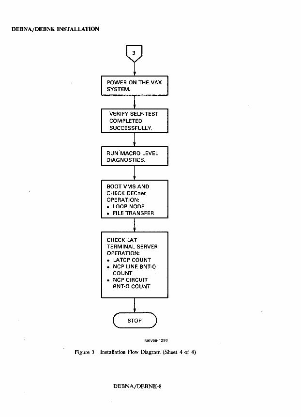
POWER ON THE VAX SYSTEM.
VERIFY SELF-TEST COMPLETED SUCCESSFULLY.
RUN MACRO LEVEL DIAGNOSTICS.
BOOT VMS AND CH ECK DECnet OPERATION: • LOOP NODE • FILE TRANSFER
CHECK LAT TERMINAL SERVER OPERATION: • LATCP COUNT • NCP LINE BNT-O
COUNT • NCP CIRCUIT
BNT-O COUNT
MKV88-1259
Figure 3 Installation Flow Diagram (Sheet 4 of 4)
DEBNA/DEBNK-8
DEBNA/DEBNK CABLING
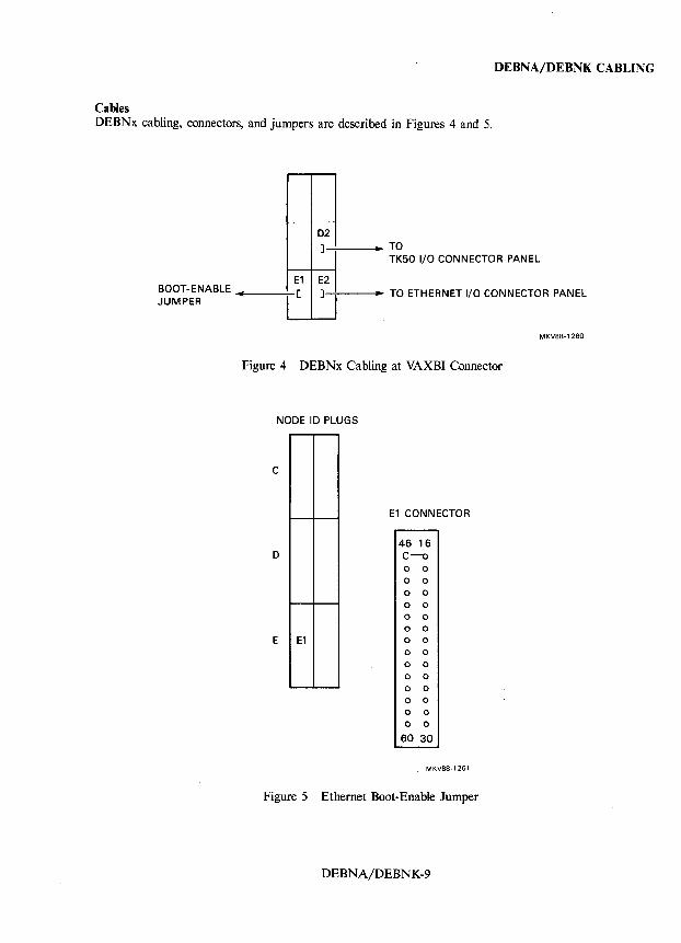
Cables DEBNx cabling, connectors, and jumpers are described in Figures 4 and 5.
BOOT-ENABLE JUMPER
02
] • TO TK50 I/O CONNECTOR PANEL
E1 E2 .. [ ] • TO ETHERNET I/O CONNECTOR PANEL
MKV88·1260
Figure 4 DEBNx Cabling at VAXBI Connector
NODE ID PLUGS
C
o
E E1
E1 CONNECTOR
46 16 C-o o 0 o 0
o 0
o 0
o 0 o 0
o 0 o 0
o 0
o 0 o 0
o 0 o 0
o 0
60 30
MKV88-1261
Figure 5 Ethernet Boot-Enable Jumper
DEBNA/DEBNK-9
DEBNAjDEBNK CABLING
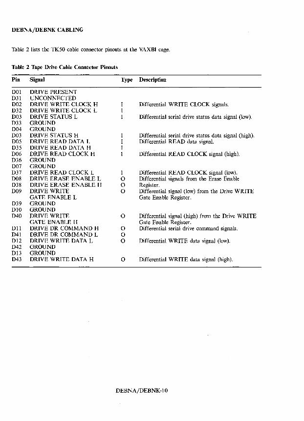
Table 2 lists the TK50 cable connector pinouts at the VAXBI cage.
Table 2 Tape Drive Cable Connector Pinouts
Pin Signal Type Description
DOl DRIVE PRESENT D3l UNCONNECTED D02 DRIVE WRITE CLOCK H I Differential WRITE CLOCK signals. D32 DRIVE WRITE CLOCK L I D03 DRIVE STATUS L I Differential serial drive status data signal (low). D33 GROUND D04 GROUND D03 DRIVE STATUS H I Differential serial drive status data signal (high). D05 DRIVE READ DATA L I Differential READ data signal. D35 DRIVE READ DATA H I D06 DRIVE READ CLOCK H I Differential READ CLOCK signal (high). D36 GROUND D07 GROUND D37 DRIVE READ CLOCK L I Differential READ CLOCK signal (low). D08 DRIVE ERASE ENABLE L 0 Differential signals from the Erase Enable D38 DRIVE ERASE ENABLE H 0 Register. D09 DRIVE WRITE 0 Differential signal (low) from the Drive WRITE
GATE ENABLE L Gate Enable Register. D39 GROUND DlO GROUND D40 DRIVE WRITE 0 Differential signal (high) from the Drive WRITE
GATE ENABLE H Gate Enable Register. Dll DRIVE DR COMMAND H 0 Differential serial drive command signals. D4l DRIVE DR COMMAND L 0 D12 DRIVE WRITE DATA L 0 Differential WRITE data signal (low). D42 GROUND D13 GROUND D43 DRIVE WRITE DATA H 0 Differential WRITE data signal (high).
DEBNAjDEBNK-lO
DEBNA/DEBNK DIAGNOSTICS
Self-Test Diagnostics
Self-Tests DEBNx power-up self-tests are standalone ROM-based diagnostic routines that run automatically,
• When the host is powered up. • When the host system is reset.
Self-testing can also be run from a VAX 8200/8300-series console using the DO tests. Example, where DEBNx is on Node 5:
<CTRL/P> »> Z 5
T/R RBD5> DO (tests run and results are displayed) RBD5> QUIT <CTRL/P> »>
BIle performs its own self-test on power-up. The BIIC:
• Sets Broke, Initialization, and Self-Test status bits in its VAXBICSR.
• Sets STS bit to indicate that BIIC passed its internal self-test.
• Disables VAXBI bus drivers if self-test fails.
Self-Test Results Pass/fail self-test results are reported in four ways:
• Node status (as a whole) is reported on the VAXBI bus:
BI BAD asserted = failure
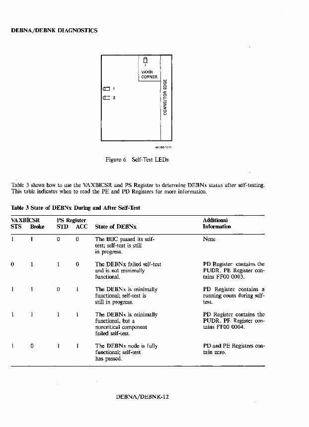
• Status is reported on the module LEDs. Figure 6 shows the LED locations:
One yellow DEBNx OK indicator; ON = OK One Tape OK indicator; green = tape present
• Status is shown by registers during testing:
VAXBICSR Port Status (PS) Register
• Status is shown after testing:
Port Error (PE) Register contains an error message. Port Data (PD) Register contains a copy of the Power-up Diagnostic Register (PUDR) which provides additional information.
DEBNA/DEBNK-ll
DEBNA/DEBNK DIAGNOSTICS
B 1
VAXBI CORNER
w C!l
a::::J 1 c w a:
CD 2 0 l-V w Z Z 0 U
MKV88-'262
Figure 6 Self-Test LEOs
Table 3 shows how to use the VAXBICSR and PS Register to determine OEBNx status after self-testing. This table indicates when to read the PE and PO Registers for more information.
Table 3 State of DEBNx During and After Self-Test
VAXBICSR STS Broke
o
o
PS Register STD ACC State of DEBNx
o o
o
o
The BIIC passed its selftest; self-test is still in progress.
The DEBNx failed self-test and is not minimally functional.
The DEBNx is minimally functional; self-test is still in progress.
The DEBNx is minimally functional. but a noncritical component failed self-test.
The DEBNx node is fully functional; self-test has passed.
OEBNA/OEBNK-12
Additional Information
None
PO Register contains the PUDR. PE Register contains FFOO 0003.
PD Register contains a running count during selftest.
PD Register contains the PUDR. PE Register contains FFOO 0004.
PD and PE Registers contain zero.
Self-test checks the following components.
DEBNx module components:
• MicroVAX
ROM RAM Patch hardware
• BIIC and BC 13 chips • LANCE chip • MicroVAX 80186 communications
DEBNx tape controller chips:
• Multiprotocol serial controller • 80186 microprocessor • 80186 gap-detection hardware • 80186 patch registers • 80186 patch PAL • 80186 buffer and patch RAM • 80186 ROM • 80186 tape-control registers
Self-Test Interpretation
DEBNA/DEBNK DIAGNOSTICS
After most self-test failures, system software can examine the VAXBICSR, PS, PE, and PD Registers to determine which components are usable. Based on this information, the system can decide that the node is still usable for certain tasks. If the BIIC chip fails its self-test, however, it disables its VAXBI drives. This puts the entire node off-line making the BVP registers inaccessible.
If the PD Register indicates that all the components have failed, the problem is probably the BIIC, MicroVAX, or MicroVAX ROM. If one of these components fails, the self-test routine stops, and the MicroVAX enters a WAIT state.
DEBNA/DEBNK-13
DEBNA/DEBNK DIAGNOSTICS
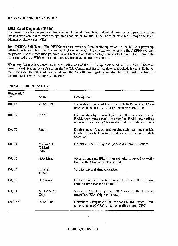
ROM-Based Diagnostics (RBDs) The tests in each category are described in Tables 4 through 6. Individual tests, or test groups, can be invoked with commands from the operator's console or, for the Dl or D2 tests, executed through the VAX Diagnostic Supervisor (VDS).
DO - DEBNx Self-Test - The DEBNx self-test, which is functionally equivalent to the DEBNx power-up self-test, performs a basic confidence check of the module. Table 4 describes the tests in the DEBNx self-test diagnostic. The test execution parameters and method of fault reporting can be selected with the appropriate run-time switches. With no test number, DO executes all tests by default.
When any DO test is selected, an internal self-check of the BIIC chip is executed. After a 250-millisecond delay, the self-test status (STS) bit in the VAXBI Control and Status Register is checked. If the BIIC failed the self-check, the STS bit is cleared and the VAXBI bus registers are disabled. This inhibits further communication with the DEBNx module.
Table 4 DO DEBNx Self-Test
Diagnostic/ Test
DO/Tl
DO/T2
DO/T3
DO/T4
DO/T5
DO/T6
DO/T7
DO/T8
DO/T9*
Name
ROMCRC
RAM
Patch
MicroVAX Critical Path
IRQ Lines
Interval Timer
BI Corner
NI LANCE Chip
ROMCRC
Description
Calculates a longword CRC for each ROM section. Compares calculated CRC to corresponding stored CRe.
First verifies byte mask logic, then the nonstack area of RAM, then moves stack into verified RAM and verifies untested stack area. (Also verifies data and address lines.)
Disables patch function and toggles each patch register bit. Enables patch function and executes single patch operation.
Checks critical timing and principal microinstructions.
Steps through all IPLs (interrupt priority levels) to verify that no IRQ line is stuck asserted.
Verifies interval time operation.
Performs seven subtests to verify BIIC and BC13 chips. Exits to next test if test fails.
Verifies LANCE chip and CRC logic in the Ethernet controller. (SIA chip not tested.)
Calculates a longword CRC for each ROM section. Compares calculated CRC to corresponding stored CRC.
DEBN A/DEBNK-14
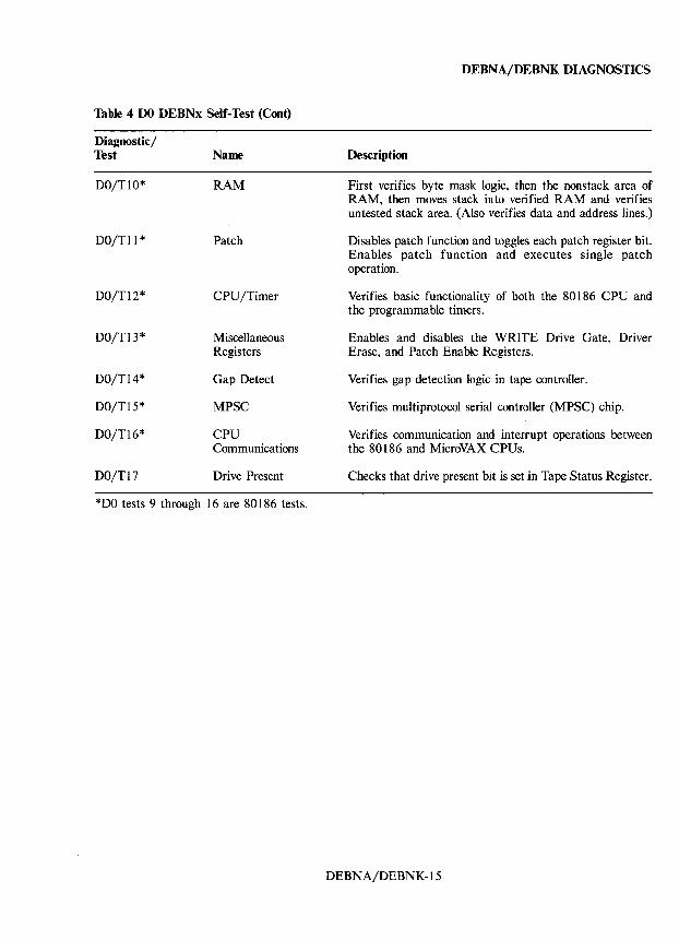
Table 4 DO DEBNx Self-Test (Cont)
Diagnostic/ Test Name
DO/T10* RAM
DO/TIl * Patch
DO/T12* CPU/Timer
DO/T13* Miscellaneous Registers
DO/T14* Gap Detect
DO/T15* MPSC
DO/T16* CPU Communications
DO/T17 Drive Present
*DO tests 9 through 16 are 80186 tests.
DEBNA/DEBNK DIAGNOSTICS
Description
First verifies byte mask logic, then the nons tack area of RAM, then moves stack in to verified RAM and verifies untested stack area. (Also verifies data and address lines.)
Disables patch function and toggles each patch register bit. Enables patch function and executes single patch operation.
Verifies basic functionality of both the 80186 CPU and the programmable timers.
Enables and disables the WRITE Drive Gate, Driver Erase, and Patch Enable Registers.
Verifies gap detection logic in tape controller.
Verifies multiprotocol serial controller (MPSC) chip.
Verifies communication and interrupt operations between the 80186 and MicroVAX CPUs.
Checks that drive present bit is set in Tape Status Register.
DEBNA/DEBNK-15
DEBNA/DEBNK DIAGNOSTICS
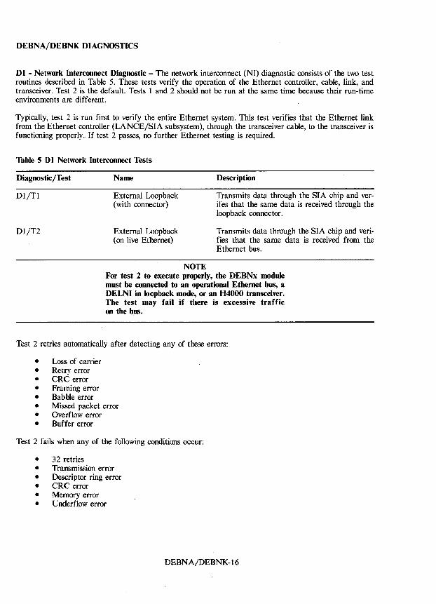
Dl - Network Interconnect Diagnostic - The network interconnect (NI) diagnostic consists of the two test routines described in Table 5. These tests verify the operation of the Ethernet controller, cable, link, and transceiver. Test 2 is the default. Tests 1 and 2 should not be run at the same time because their run-time environments are different.
Typically, test 2 is run first to verify the entire Ethernet system. This test verifies that the Ethernet link from the Ethernet controller (LANCE/SIA subsystem), through the transceiver cable, to the transceiver is functioning properly., If test 2 passes, no further Ethernet testing is required.
Table 5 Dl Network Interconnect Tests
Diagnostic/Test Name Description
Dl/Tl
Dl/T2
External Loopback (with connector)
External Loopback (on live Ethernet)
NOTE
Transmits data through the SIA chip and verifes that the same data is received through the loopback connector.
Transmits data through the SIA chip and verifies that the same data is received from the Ethernet bus.
For test 2 to execute properly, the DEBNx module must be connected to an operational Ethernet bus, a DELNI in loopback mode, or an H4000 transceiver. The test may fail if there is excessive traffic on the bus.
Test 2 retries automatically after detecting any of these errors:
• Loss of carrier • Retry error • CRC error • Framing error • Babble error • Missed packet error • Overflow error • Buffer error
Test 2 fails when any of the following conditions occur:
• 32 retries • Transmission error • Descriptor ring error • CRC error • Memory error • Underflow error
DEBNA/DEBNK-16
DEBNA/DEBNK DIAGNOSTICS
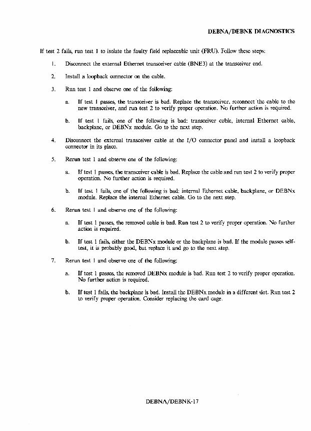
If test 2 fails, run test 1 to isolate the faulty field replaceable unit (FRU). Follow these steps:
1. Disconnect the external Ethernet transceiver cable (BNE3) at the transceiver end.
2. Install a loop back connector on the cable.
3. Run test 1 and observe one of the following:
a. If test 1 passes, the transceiver is bad. Replace the transceiver, reconnect'the cable to the new transceiver, and run test 2 to verify proper operation. No further action is required.
b. If test 1 fails, one of the following is bad: transceiver cable, internal Ethernet cable, backplane, or DEBNx module. Go to the next step.
4. Disconnect the external transceiver cable at the I/O connector panel and install a loopback connector in its place.
5. Rerun test 1 and observe one of the following:
a. If test 1 passes, the transceiver cable is bad. Replace the cable and run test 2 to verify proper operation. No further action is required.
b. If test 1 fails, one of the following is bad: internal Ethernet cable, backplane, or DEBNx module. Replace the internal Ethernet cable. Go to the next step.
6. Rerun test 1 and observe one of the following:
a. If test 1 passes, the removed cable is bad. Run test 2 to verify proper operation. No further action is required.
b. If test 1 fails, either the DEBNx module or the backplane is bad. If the module passes selftest, it is probably good, but replace it and go to the next step.
7. Rerun test 1 and observe one of the following:
a. If test 1 passes, the removed DEBNx module is bad. Run test 2 to verify proper operation. No further action is required.
b. If test 1 fails, the backplane is bad. Install the DEBNx module in a different slot. Run test 2 to verify proper operation. Consider replacing the card cage.
DEBNA/DEBNK-17
DEBNA/DEBNK DIAGNOSTICS
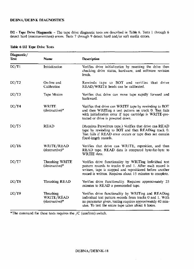
D2 - Tape Drive Diagnostic - The tape drive diagnostic tests are described in Table 6. Tests 1 through 6 detect hard (nonintermittent) errors. Tests 7 through 9 detect hard and/or soft media errors.
Table 6 D2 Tape Drive Tests
Diagnostic/ Test
D2/Tl
D2/T2
D2/T3
D2/T4
D2/T5
D2/T6
D2/T7
D2/T8
D2/T9
Name
Initialization
On-line and Calibration
Tape Motion
WRITE (destructive) *
READ
WRITE/READ (destructive )*
Thrashing WRITE (destructive) *
Thrashing READ
Thrashing WRITE/READ ( destructive) *
Description
Verifies drive initialization by resetting the drive then checking drive status, hardware, and software revision levels.
Rewinds tape to BOT and verifies that drive READ/WRITE heads can be calibrated.
Verifies that drive can move tape rapidly forward and backward.
Verifies that drive can WRITE tape by rewinding to BOT and then WRITing a test pattern on track O. Test fails with initialization error if tape cartridge is WRITE-protected or drive is powered down.
(Requires Prewritten tape.) Verifies that drive can READ tape by rewinding to BOT and then READing track O. Test fails if READ error occurs or tape does not contain fixed-length records.
Verifies that drive can WRITE, reposition, and then READ tape. READ data is compared byte-for-byte to WRITE data.
Verifies drive functionality by WRITing individual test pattern records to tracks 0 and 1. After each record is written, tape is stopped and repositioned before another record is written. Requires about 15 minutes to complete.
Verifies drive functionality. Requires approximately 25 minutes to READ a prerecorded tape.
Verifies drive functionality by WRITing and READing individual test pattern records from tracks 0 and 1. With no parameter given, testing requires approximately 40 minutes. To test the entire tape takes about 8 hours.
*The command for these tests requires the /C (confirm) switch.
DEBNA/DEBNK-18
DEBNA/DEBNK DIAGNOSTICS
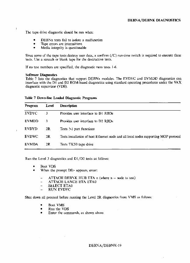
The tape drive diagnostic should be run when:
• DEBNx tests fail to isolate a malfunction • Tape errors are intermittent • Media integrity is questionable
Since some of the tape tests destroy user data, a confirm (lC) run-time switch is required to execute these tests. Use a scratch or blank tape for the destructive tests.
If no test numbers are specified, the diagnostic runs tests 1-6.
Software Diagnostics Table 7 lists the diagnostics that support DEBNx modules. The EVDYC and EVMDD diagnostics can interface with the DI and D2 ROM-based diagnostics using standard operating procedures under the VAX diagnostic supervisor (VDS).
Table 7 Down-line Loaded Diagnostic Programs
Program Level Description
EVDYC 3 Provides user interface to D 1 RBDs
EVMDD 3 Provides user interface to D2 RBDs
EVDYD 2R Tests NI port functions
EVDWC 2R Tests installation of host Ethernet node and all local nodes supporting MOP protocol
EVMDA 2R Tests TK50 tape drive
Run the Level 3 diagnostics and DI/D2 tests as follows:
• Boot VDS • When the prompt DS> appears, enter:
ATTACH DEBNK HUB ETA n (where n = node to test) ATTACH LANCE ETA ETAO SELECT ETAO RUN EVDYC
Shut down all protocol before running the Level 2R diagnostics from VMS as follows:
• Boot VMS • Run the VDS • Enter the commands, as shown above
DEBNA/DEBNK-19
DEBNA/DEBNK DIAGNOSTICS
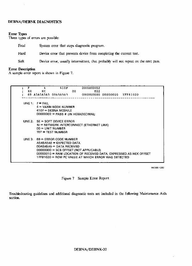
Error Types Three types of errors are possible:
Fatal System error that stops diagnostic program.
Hard Device error that prevents device from completing the current test.
Soft Device error, usually intermittent, that probably will not repeat on the next pass.
Error Description A sample error report is shown in Figure 7.
F 4 410F SE NI 00 69 ASASASAS OOASASAS
LINE 1: F= FAIL 4 = VAXBI NODE NUMBER 41 OF = DEBNA MODULE
000000002 T02
000000000 00000010 1FF81020
00000002 = PASS 41= (IN HEXADECIMAL)
LINE 2: SE = SOFT DEVICE ERROR NI = NETWORK INTERCONNECT (ETHERNET LINK) 00 = UNIT NUMBER T02 = TEST NUMBER
LINE 3: 69 = ERROR CODE NUMBER A5A5A5A5 = EXPECTED DATA 00A5A5A5 = DATA RECEIVED 00000000 = SCB OFFSET (NOT APPLICABLE) 00000010= RAM LOCATION OF RECEIVED DATA, EXPRESSED AS HEX OFFSET 1 FF81 020 = ROM PC VALUE AT WHICH ERROR WAS DETECTED
Figure 7 Sample Error Report
MKV88-1263
Troubleshooting guidelines and additional diagnostic tests are included in the following Maintenance Aids section.
DEBNA/DEBNK-20
DEBNA/DEBNK MAINTENANCE AIDS
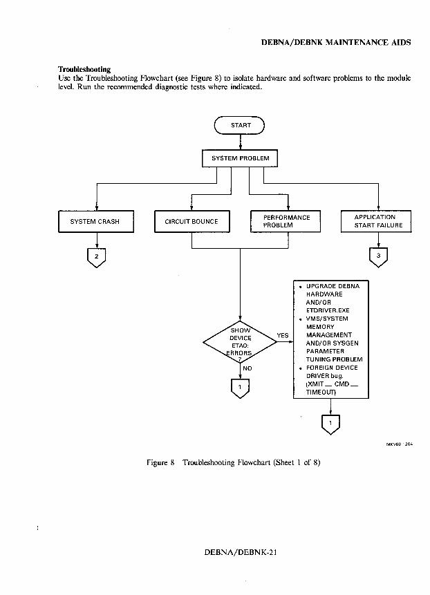
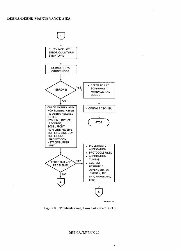
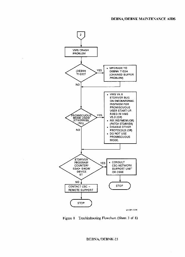
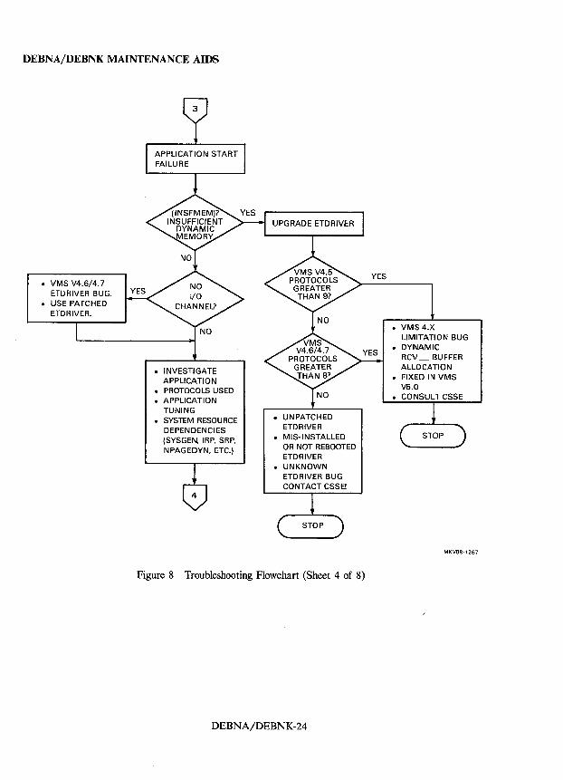
Troubleshooting Use the Troubleshooting Flowchart (see Figure 8) to isolate hardware and software problems to the module level. Run the recommended diagnostic tests where indicated.
SYSTEM CRASH
• UPGRADE DEBNA HARDWARE AND/OR ETDRIVER. EXE
• VMS/SYSTEM MEMORY MANAGEMENT AND/OR SYSGEN PARAMETER TUNING PROBLEM
• FOREIGN DEVICE DRIVER bug. (XMIT_CMD_ TIMEOUT)
Figure 8 Troubleshooting Flowchart (Sheet 1 of 8)
DEBNA/DEBNK-21
MKV88-1264
DEBNA/DEBNK MAINTENANCE AIDS
CHECK NCP LINE ERROR COUNTERS/ SYMPTOMS
CHECK SYSGEN AND NCP TUNING. REFER TO DEBNA RELEASE NOTES. SYSGEN: LRPSIZE, LRPCOUNT, SCSBUFFCNT NCP: LINE RECEIVE BUFFERS, LINE DEV BUFFER SIZE LOADNET.COM: NETACP/BUFFER LIMIT • INVESTIGATE
APPLICATION
• PROTOCOLS USED • APPLICATION
TUNING
• SYSTEM RESOURCE DEPENDENCIES (SYSGEN, IRP, SRP, NPAGEDYN, ETC.)
MKV88-'265
Figure 8 Troubleshooting Flowchart (Sheet 2 of 8)
DEBNA/DEBNK-22
NO
NO
DEBNA/DEBNK MAINTENANCE AIDS
• UPGRADE TO DEBNA T1034 (CHAINED BUFFER PROBLEM)
• VMS V4.X ETDRIVER BUG ON ENCOUNTERING INSFMEM FOR PROMISCUOUS USER START-UP. FIXED IN VMS V5.0 (OR)
• FIX INSFMEM (OR) (PATCH ETDRIVER)
• DISABLE OTHER PROTOCOLS (OR)
• DO NOT USE PROMISCUOUS MODE.
CONSULT CSC-NETWORK SUPPORT UNIT OR CSSE
MKV8B-1266
Figure 8 Troubleshooting Flowchart (Sheet 3 of 8)
DEBNA/DEBNK-23
DEBNA/DEBNK MAINTENANCE AIDS
• VMS V4.6/4.7 ETDRIVER BUG .
• USE PATCHED ETDRIVER.
• INVESTIGATE APPLICATION
• PROTOCOLS USED • APPLICATION
TUNING • SYSTEM RESOURCE
DEPENDENCIES (SYSGEN, IRP, SRP, NPAGEDYN, ETC.)
• UNPATCHED ETDRIVER
• MIS-INSTALLED OR NOT REBOOTED ETDRIVER
• UNKNOWN ETDRIVER BUG CONTACT CSSE!
Figure 8 Troubleshooting Flowchart (Sheet 4 of 8)
DEBNA/DEBNK-24
YES
• VMS 4.X LIMITATION BUG
• DYNAMIC RCV _ BUFFER ALLOCATION
• FIXED IN VMS V5.0
• CONSULT CSSE
MKV88·1267
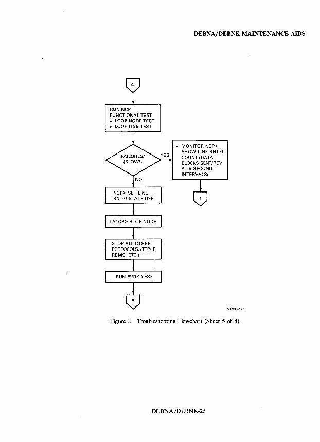
RUN NCP FUNCTIONAL TEST • LOOP NODE TEST • LOOP LINE TEST
STOP ALL OTHER PROTOCOLS. (TIP/IP, RBMS, ETC.)
DEBNAjDEBNK MAINTENANCE AIDS
• MONITOR NCP> SHOW LINE BNT-O COUNT (DATABLOCKS SENT/RCV AT 5 SECOND INTERVALS)
MKV88-1268
Figure 8 Troubleshooting Flowchart (Sheet 5 of 8)
DEBNA/DEBNK-25
DEBNAjDEBNK MAINTENANCE AIDS
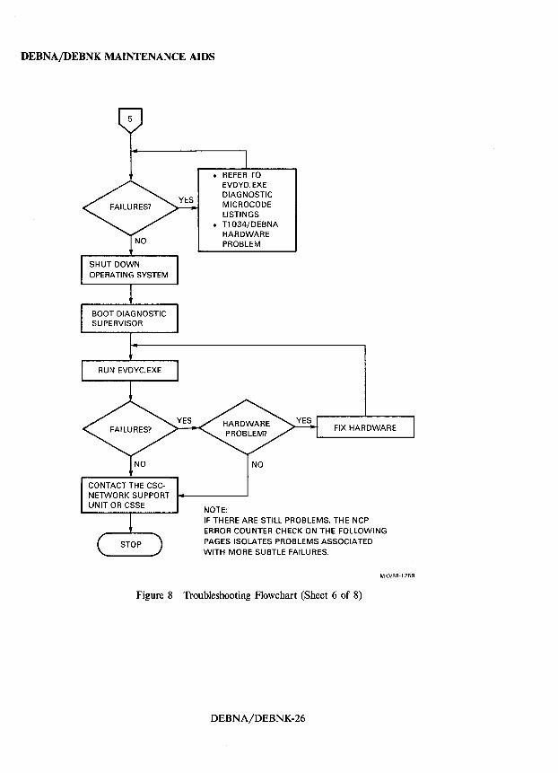
CONTACT THE CSCNETWORK SUPPORT UNIT OR CSSE
• REFER TO EVDYD.EXE DIAGNOSTIC MICROCODE LISTINGS
• T1034/DEBNA HARDWARE PROBLEM
NOTE:
FIX HARDWARE
IF THERE ARE STILL PROBLEMS, THE NCP ERROR COUNTER CHECK ON THE FOLLOWING PAGES ISOLATES PROBLEMS ASSOCIATED WITH MORE SUBTLE FAILURES.
MKV88·1269
Figure 8 Troubleshooting Flowchart (Sheet 6 of 8)
DEBNA/DEBNK-26
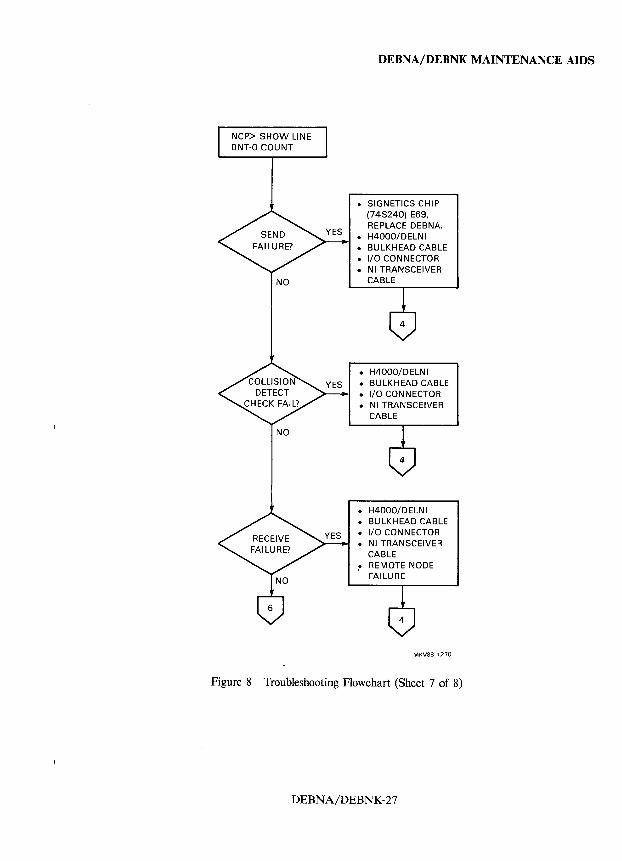
NCP> SHOW LINE BNT-O COUNT
NO
NO
DEBNA/DEBNK MAINTENANCE AIDS
• SIGNETICS CHIP (74S240) E69. REPLACE DEBNA.
• H4000/DELNI • BULKHEAD CABLE • I/O CONNECTOR • NI TRANSCEIVER
CABLE
• H4000/DELNI • BULKHEAD CABLE • I/O CONNECTOR • NI TRANSCEIVER
CABLE
• H4000/DELNI • BULKHEAD CABLE • I/O CONNECTOR • NI TRANSCEIVER
CABLE ,. REMOTE NODE
FAILURE
MKV88-1270
Figure 8 Troubleshooting Flowchart (Sheet 7 of 8)
DEBNA/DEBNK-27
DEBNA/DEBNK MAINTENANCE AIDS
NO
NO
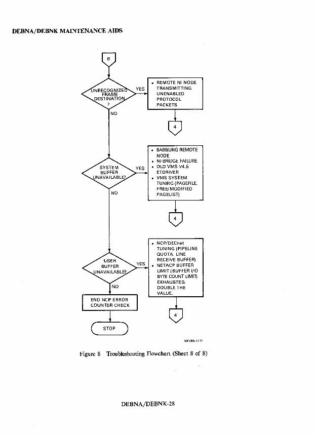
• REMOTE NI NODE TRANSMITTING UN ENABLED PROTOCOL PACKETS
• BABBLING REMOTE NODE
• NI BRIDGE FAILURE • OLD VMS V4.5
ETDRIVER • VMS SYSTEM
TUNING (PAGEFILE, FREE/MODI FI ED PAGELlST)
• NCP/DECnet TUNING (PIPELINE QUOTA, LINE RECEIVE BUFFER)
• NETACP BUFFER LIMIT (BUFFER I/O BYTE COUNT LIMIT) EXHAUSTED. DOUBLE THE VALUE.
MKV88·1271
Figure 8 Troubleshooting Flowchart (Sheet 8 of 8)
DEBNA/DEBNK-28
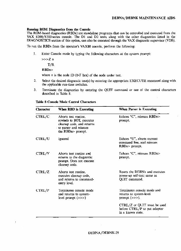
DEBNA/DEBNK MAINTENANCE AIDS
Running ROM Diagnostics from the Console The ROM-based diagnostics (RBDs) are standalone programs that can be controlled and executed from the VAX 8200/8300-series console. The Dl and D2 tests, along with the other diagnostics listed in the DIAGNOSTICS section of this option, can also be executed through the VAX diagnostic supervisor (VDS).
To run the RBDs from the operator's VAXBI console, perform the following:
1. Enter Console mode by typing the following characters at the system prompt:
»>Zn
T/R
RBDn>
where n is the node ID (O-F hex) of the node under test.
2. Select the desired diagnostic testes) by entering the appropriate EXECUTE command along with the applicable run-time switches.
3. Terminate the diagnostics by entering the QUIT command or one of the control characters described in Table 8.
Table 8 Console Mode Control Characters
Character
CTRL/C
CTRL/U
CTRL/Y
CTRL/Z
CTRL/P
When RBD is Executing
Aborts test routine, rewinds to BOT, executes cleanup code, and returns to parser and reissues the RBDn> prompt.
Ignored
Aborts test routine and returns to the diagnostic prompt. Does not execute cleanup code.
Aborts test routine, executes cleanup code, and returns to commandentry level.
Terminates console mode and returns to systemlevel prompt (> > > )
DEBNA/DEBNK-29
When Parser is Executing
Echoes "C", reissues RBDn> prompt.
Echoes "U", aborts current command line, and reissues RBDn> prompt.
Echoes "C", reissues RBDn> prompt.
Resets the DEBNx and executes power-up self-test; same as QUIT command.
Terminates .console mode and returns to system-level prompt (»».
CTRL/Z or QUIT must be used before CTRL/P to put adapter in a known state.
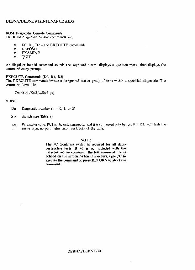
DEBNA/DEBNK MAINTENANCE AIDS
ROM Diagnostic Console Commands The ROM diagnostic console commands are:
• DO, D 1, D2 - the EXECUTE commands • DEPOSIT • EXAMINE • QUIT
An illegal or invalid command sounds the keyboard alarm, displays a question mark, then displays the command-entry prompt.
EXECUTE Commands (DO, Dt, D2) The EXECUTE commands invoke a designated test or group of tests within a specified diagnostic. The command format is:
Dn[jSwl/Sw2/ ... Sw9 pc]
where:
Dn Diagnostic number (n = 0, 1, or 2)
Sw Switch (see Table 9)
pc Parameter code. PC 1 is the only parameter and it is supported only by test 9 of D2. PC 1 tests the entire tape; no parameter tests two tracks of the tape.
NOTE The IC (confirm) switch is required for all datadestructive tests. If IC is not included with the data-destructive command, the last command line is echoed on the screen. When this occurs, type I C to execute the command or press RETURN to abort the command.
DEBNA/DEBNK-30
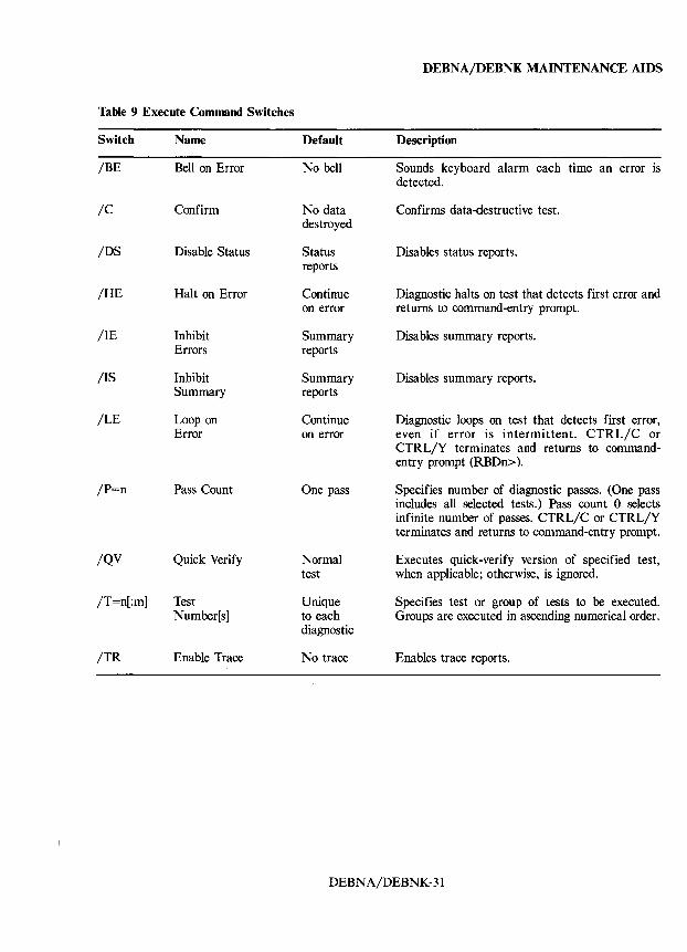
Table 9 Execute Command Switches
Switch
/BE
/C
/DS
/HE
/IE
/IS
/LE
/P=n
/QV
/T=n[:m]
/TR
Name
Bell on Error
Confirm
Disable Status
Halt on Error
Inhibit Errors
Inhibit Summary
Loop on Error
Pass Count
Quick Verify
Test Number[s]
Enable Trace
Default
No bell
No data destroyed
Status reports
Continue on error
Summary reports
Summary reports
Continue on error
One pass
Normal test
Unique to each diagnostic
No trace
DEBNA/DEBNK MAINTENANCE AIDS
Description
Sounds keyboard alarm each time an error is detected.
Confirms data-destructive test.
Disables status reports.
Diagnostic halts on test that detects first error and returns to command-entry prompt.
Disables summary reports.
Disables summary reports.
Diagnostic loops on test that detects first error, even if error is intermittent. CTRL/C or CTRL/Y terminates and returns to commandentry prompt (RBDn».
Specifies number of diagnostic passes. (One pass includes all selected tests.) Pass count 0 selects infinite number of passes. CTRL/C or CTRL/Y terminates and returns to command-entry prompt.
Executes quick-verify version of specified test, when applicable; otherwise, is ignored.
Specifies test or group of tests to be executed. Groups are executed in ascending numerical order.
Enables trace reports.
DEBNA/DEBNK-31
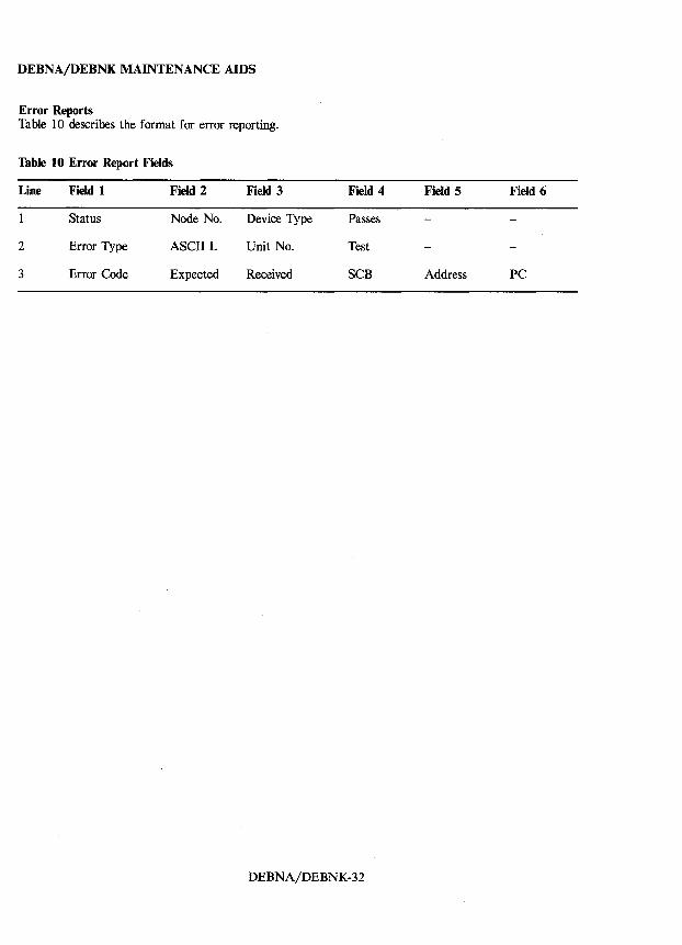
DEBNA/DEBNK MAINTENANCE AIDS
Error Reports Table 10 describes the format for error reporting.
Table 10 Error Report Fields
Line Field 1 Field 2 Field 3 Field 4 Field 5 Field 6
Status Node No. Device Type Passes
2 Error Type ASCII L Unit No. Test
3 Error Code Expected Received SCB Address PC
DEBNA/DEBNK-32
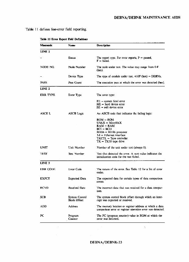
Table 11 defines line-error field reporting.
Table 11 Error Report Field Definitions
Mnemonic
LINE 1
NODE NO.
PASS
LINE 2
ERR TYPE
ASCII L
UNIT
TEST
LINE 3
ERR CODE
EXPCT
RCVD
SCB
ADD
PC
Name
Status
Node Number
Device Type
Pass Count
Error Type
ASCII Logic
Unit Number
Test Number
Error Code
Expected Data
Received Data
System Control Block Offset
Address
Program Counter
DEBNA/DEBNK MAINTENANCE AIDS
Description
The report type. For error reports, P = passed, F = failed.
The node under test. The value may range from O-F (hex).
The type of module under test. 410F (hex) = DEBNx.
The execution pass at which the error was detected (hex).
The error type:
FE = system fatal error HE = hard device error SE = soft device error
An ASCII code that indicates the failing logic:
ROM = ROM UVAX = MicroVAX RAM = RAM BCI = BCB 80186 = 80186 processor NI = Ethernet interface TKCTL = Tape controller TK = TK50 tape drive
Number of the unit under test (always 0).
Test that detected the error. A zero value indicates the initialization code for the test failed.
The nature of the error. See Table 12 for a list of error codes.
The expected data for certain types of data comparison errors.
The incorrect data that was received for a data comparison.
The system control block offset through which an interrupt was expected or received.
The memory location or register address at which a data comparison error or register operation error was detected.
The PC (program counter) value in ROM at which the error was detected.
DEBNA/DEBNK-33
DEBNA/DEBNKMAINTENANCE AIDS
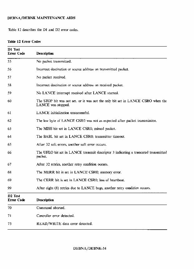
Table 12 describes the D 1 and D2 error codes.
Table 12 Error Codes
Dl Test Error Code
55
56
57
58
59
60
61
62
63
64
65
66
67
68
69
99
D2 Test Error Code
70
71
73
Description
No packet transmitted.
Incorrect destination or source address on transmitted packet.
No packet received.
Incorrect destination or source address on received packet.
No LANCE interrupt received after LANCE started.
The STOP bit was not set, or it was not the only bit set in LANCE CSRO when the LANCE was stopped.
LANCE initialization unsuccessful.
The low byte of LANCE CSRO was not as expected after packet transmission.
The MISS bit set in LANCE CSRO; missed packet.
The BABL bit set in LANCE CSRO; transmitter timeout.
After 32 soft errors, another soft error occurs.
The UFLO bit set in LANCE transmit descriptor 3 indicating a truncated transmitted packet.
After 32 retries, another retry condition occurs.
The MERR bit is set in LANCE CSRO; memory error.
The CERR bit is set in LANCE CSRO; loss of heartbeat.
After eight (8) retries due to LANCE bugs, another retry condition occurs.
Description
Command aborted.
Controller error detected.
READ/WRITE data error detected.
DEBNA/DEBNK-34
DEBNA/DEBNK MAINTENANCE AIDS
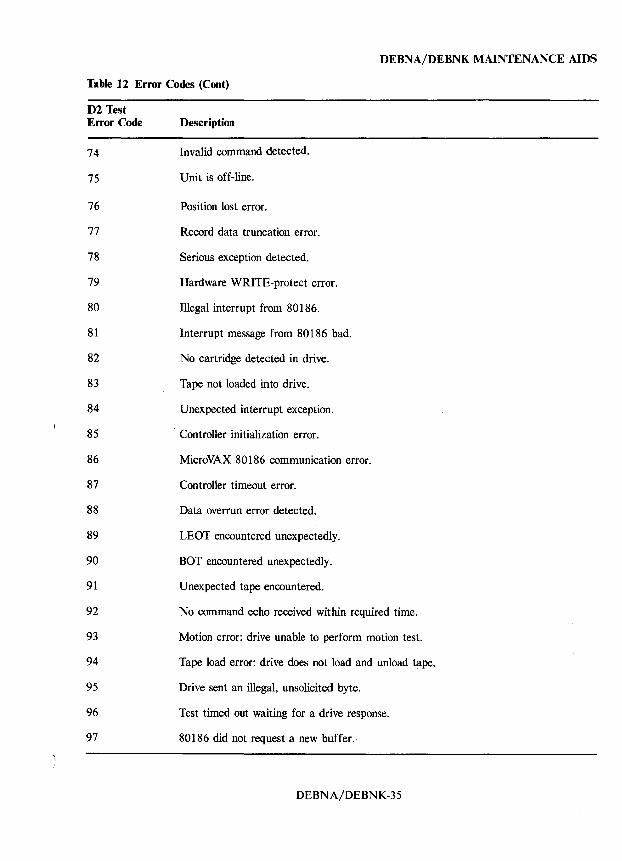
Table 12 Error Codes (Coot)
D2 Test Error Code
74
75
76
77
78
79
80
81
82
83
84
85
86
87
88
89
90
91
92
93
94
95
96
97
Description
Invalid command detected.
Unit is off-line.
Position lost error.
Record data truncation error.
Serious exception detected.
Hardware WRITE-protect error.
Illegal interrupt from 80186.
Interrupt message from 80186 bad.
No cartridge detected in drive.
Tape not loaded into drive.
Unexpected interrupt exception.
, Controller initialization error.
MicroVAX 80186 communication error.
Controller timeout error.
Data overrun error detected.
LEOT encountered unexpectedly.
BOT encountered unexpectedly.
Unexpected tape encountered.
No command echo received within required time.
Motion error: drive unable to perform motion test.
Tape load error: drive does not load and unload tape.
Drive sent an illegal, unsolicited byte.
Test timed out waiting for a drive response.
80186 did not request a new buffer.
DEBNA/DEBNK-35
DEBNA/DEBNK MAINTENANCE AIDS
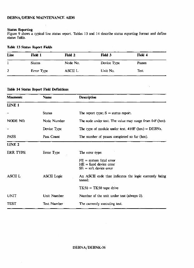
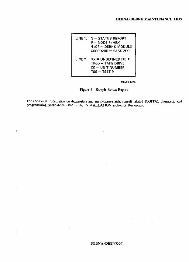
Status Reporting Figure 9 shows a typical line status report. Tables 13 and 14 describe status reporting format and define status fields.
Table 13 Status Report Fields
Line Field 1 Field 2 Field 3 Field 4
Status Node No. Device Type Passes
2 Error Type ASCII L Unit No. Test
Table 14 Status Report Field Definitions
Mnemonic
LINE 1
NODE NQ
PASS
LINE 2
ERR TYPE
ASCII L
UNIT
TEST
Name
Status
Node Number
Device Type
Pass Count
Error Type
ASCII Logic
Unit Number
Test Number
Description
The report type; S = status report.
The node under test. The value may range from O-F (hex).
The type of module under test. 410F (hex) = DEBNx.
The number of passes completed so far (hex).
The error type:
FE = system fatal error HE = hard device error SE = soft device error
An ASCII code that indicates the logic currently being tested:
TK50 = TK50 tape drive
Number of the unit under test (always 0).
The currently executing test.
DEBNA/DEBNK-36
DEBNA/DEBNK MAINTENANCE AIDS
LINE 1: S = STATUS REPORT F = NODE F (HEX) 41 OF = DEBNK MODULE 00000200 = PASS 200
LINE 2: XX = UNDEFINED FIELD TK50 = TAPE DRIVE 00 = UNIT NUMBER T09 = TEST 9
MKV88-1272
Figure 9 Sample Status Report
For additional information on diagnostics and maintenance aids, consult related DIGITAL diagnostic and programming publications listed in the INSTALLATION section of this option.
DEBNA/DEBNK-37

DEClancontroller 200 INSTALLATION
DEClancontroller 200 NETWORK ADAPTER
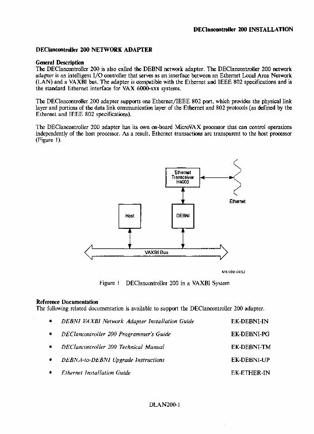
General Description The DEClancontroller 200 is also called the DEBNI networ~ adapter. The DEClancontroller 200 network adapter is an intelligent I/O controller that serves as an interface between an Ethernet Local Area Network (LAN) and a VAXBI bus. The adapter is compatible with the Ethernet and IEEE 802 specifications and is the standard Ethernet interface for VAX 6000-xxx systems.
The DEClancontroller 200 adapter supports one Ethernet/IEEE 802 port, which provides the physical link layer and portions of the data link communication layer of the Ethernet and 802 protocols (as defined by the Ethernet and IEEE 802 specifications).
The DEClancontroller 200 adapter has its own on-board MicroVAX processor that can control operations independently of the host processor. As a result, Ethernet transactions are transparent to the host processor (Figure 1).
Host
VAXBI Bus
Ethernet Transceiver
H4000
DEBNI
Ethernet
MKV89·0452
Figure 1 DEClancontroller 200 in a VAXBI System
Reference Documentation The following related documentation is available to support the DEClancontroller 200 adapter.
• DEBNI VAXBI Network Adapter Installation Guide
• DEClancontroller 200 Programmer's Guide
• DEClancontroller 200 Technical Manual
• DEBNA-to-DEBNI Upgrade Instructions
• Ethernet Installation Guide
DLAN200-1
EK-DEBNI-IN
EK-DEBNI-PG
EK-DEBNI-TM
EK-DEBNI-UP
EK-ETHER-IN
DEClancontroller 200 INSTALLATION
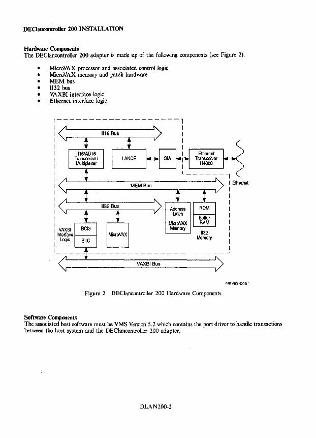
Hardware Components The DEClancontroller 200 adapter is made up of the following components (see Figure 2).
• MicroVAX processor and associated control logic • MicroVAX memory and patch hardware • MEM bus • 1132 bus • VAXBI interface logic • Ethernet interface logic
r-------------------1
1116/AD16 Transceiver/ Multiplexer
1116 Bus
LANCE
I
Ethernet Transceiver
H4000
I I I I I I I I I I
I 1
I 1
I I
L ______ j
1 VAXBI I Interface r----I I Logic 1
BIIC
BCI3
1 ___ -
MEM Bus
MicroVAX
VAXBI Bus
MicroVAX Memory
Buffer RAM
1132 Memory
Figure 2 DEClancontroller 200 Hardware Components
Software Components
1 Ethernet 1
1
1
1
1
1
1
1
1
I
MKV89·0451
The associated host software must be VMS Version 5.2 which contains the port driver to handle transactions between the host system and the DEClancontroller 200 adapter.
DLAN200-2
DEClancontroiler 200 INSTALLATION
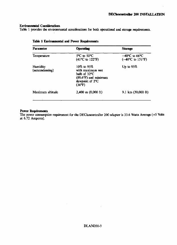
Enl'ironmental Considerations Table 1 provides the environmental considerations for both operational and storage requirements.
Table 1 Enl'ironmental and Power Requirements
Parameter
Temperature
Humidity (noncondensing)
Maximum altitude
Power Requirements
Operating
5°C to 50°C (41°C to 122°F)
10% to 95% with maximum wet bulb of 32°C (89.6°F) and minimum dewpoint of 2°C (36°F)
2,400 m (8,000 ft)
Storage
-40°C to 66°C (-40°C to 151°F)
Up to 95%
9.1 km (30,000 ft)
The power consumption requirement for the DEClancontroller 200 adapter is 33.6 Watts Average (+5 Volts at 6.72 Amperes).
DLAN200-3
DEClancontroller 200 INSTALLATION
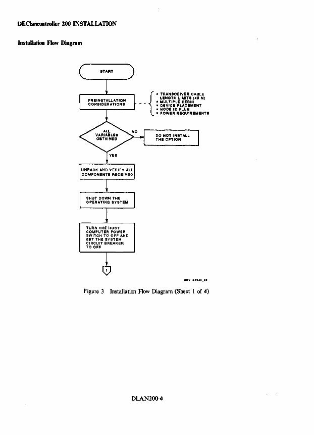
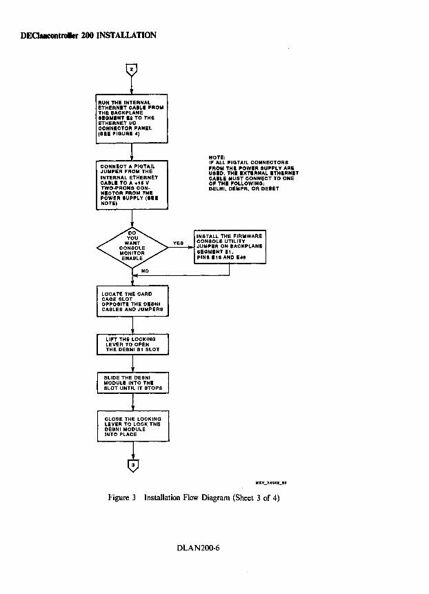
Installation Flow Diagram
TURN THE HOST COMPUTER POWER SWITCH TO OFF AND SET THE SYSTEM CIRCUIT BREAKER TO OFF
{
• TRANSCEIVER CABLE LENGTH LIMITS (45 M)
_ _ • MULTIPLE DEBNI • DEVICE PLACEMENT • NODE ID PLUG • POWER REQUIREMENTS
DO NOT INSTALL THE OPTION
Figure 3 Installation Flow Diagram (Sheet I of 4)
DLAN200-4
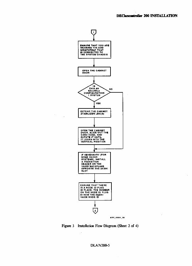
EN8URE THAT YOU ARE WEARING THE ESD WRI8T8TRAP THAT IS CONNECTED TO THE SYSTEM CHASSIS
OPEN THE CABINET DOOR. SLIDE OUT THE CARD CAGE. AND ROTATE IT UNTIL IT LOCKS INTO THE VERTICAL POSITION
IF NECESSARY (FOR SOME OLDER SYSTEMS), INSTALL A TRANSITION HEADER ON THE VAXBIBACKPLANE OPPOSITE THE DEBNI SLOT
ENSURE THAT THERE IS A NODE 10 PLUG IN PLACE. THE NUMBER ON THE NODE 10 PLUG IS NOW THE DEBNI VAXBINODE 10
DEClancoatroller 100 INSTALLATION
Figure 3 Installation Flow Diagram (Sheet 2 of 4)
DLAN200-5
DECIancontroUer 200 INSTALLATION
RUN THE INTERNAL ETHERNET CABLE FROM THE BACKPLANE SEGMENT E2 TO THE ETHERNET 110 CONNECTOR PANEL (SEE FIGURE 4)
CONNECT A PIGTAIL JUMPER FROM THE INTERNAL ETHERNET CABLE TO A +115 V TWO-PRONG CONNECTOR FROM THE POWER SUPPLY (8EE NOTE)
NOTE: IF ALL PIGTAIL CONNECTORS FROM THE POWER SUPPLY ARE USED, THE EXTERNAL ETHERNET CABLE MUST CONNECT TO OHE OF THE FOLLOWING: DELHI, DEMPR, OR DEBET
INSTALL THE FIRMWARE
>-_Y_E_S-"~I ~~::~~'o~TJ~IJ~PLANE
LOCA TE THE CARD CAGE SLOT OPPOSITE THE DEBNI CABLES AND JUMPERS
CLOSE THE LOCKING LEVER TO LOCK THE DEBNI MODULE INTO PLACE
SEGMENT E1, PINS E 18 AND 148
Figure 3 Installation Flow Diagram (Sheet 3 of 4)
DLAN200-6
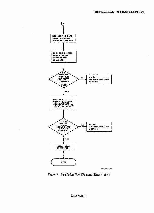
TURN THE SYSTEM POWER ON AND 08SERVE THE
DEBNILED.
BOOT THE OPERATING SYSTEM, CONFIGURE THE NETWORK DATABASE, AND START DECna'
NO
DECJancontroller 200 INSTALLATION
GO TO TROUBLE8HOOTING SECTION
GO TO TROUBLESHOOTING
SECTION
Figure 3 Installation Flow Diagram (Sheet 4 of 4)
DLAN200-7
DEClancontroiler 200 CABLING
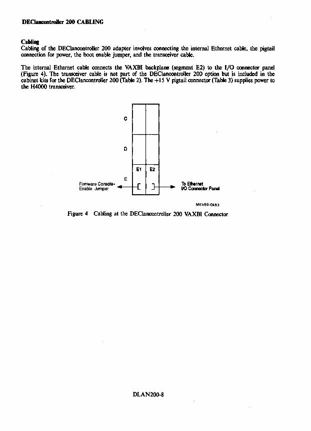
Cabling Cabling of the DEClancontroller 200 adapter involves connecting the internal Ethernet cable, the pigtail connection for power, the boot enable jumper, and the transceiver cable.
The internal Ethernet cable connects the VAXBI backplane (segment E2) to the I/O connector panel (Figure 4). The transceiver cable is not part of the DEClancontroller 200 option but is included in the cabinet kits for the DEClancontroller 200 (Table 2). The +15 V pigtail connector (Table 3) supplies power to the H4000 transceiver.
Firmware ConsoleEnable Jumper ---
c
0
E1
E
E2
-"'" p
To Ethernet 00 Connector Panel
MKV89·0453
Figure 4 Cabling at the DEClancontroller 200 VAXBI Connector
DLAN200-8
DEClancontroller 200 CABLING
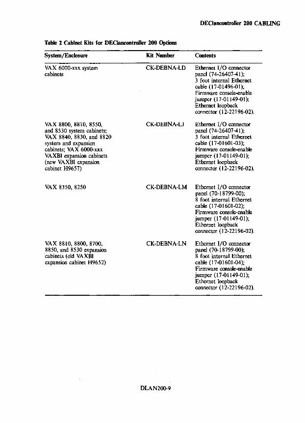
Table 2 Cabinet Kits for DEClancontroller 200 Options
System/Enclosure
VAX 6000-xxx system cabinets
VAX 8800, 8810, 8550, and 8530 system cabinets; VAX 8840, 8830, and 8820 system and expansion cabinets; VAX 6000-xxx VAXBI expansion cabinets (new VAXBI expansion cabinet H9657)
VAX 8350, 8250
VAX 8810, 8800, 8700, 8850, and 8530 expansion cabinets (old VAXBI expansion cabinet H9652)
Kit Number Contents
CK-DEBNA-LD Ethernet I/O connector panel (74-26407-41); 3 foot internal Ethernet cable (17-01496-01); Firmware console-enable jumper (17-01149-01); Ethernet loopback connector (12-22196-02).
CK-DEBNA-LJ Ethernet I/O connector panel (74-26407-41); 3 foot internal Ethernet cable (17-01601-03); Firmware console-enable jumper (17-01149-01); Ethernet loopback connector (12-22196-02).
CK-DEBNA-LM Ethernet I/O connector panel (70-18799-00); 8 foot internal Ethernet cable (17-01601-02); Firmware console-enable jumper (17-01149-01); Ethernet loopback connector (12-22196-02).
CK-DEBNA-LN Ethernet I/O connector panel (70-18799-00);
DLAN200-9
8 foot internal Ethernet cable (17-01601-04); Firmware console-enable jumper (17-01149-01); Ethernet loopback connector (12-22196-02).
DEClanoontroiler 200 CABLING
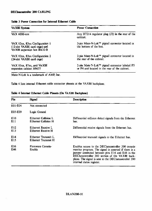
Table 3 Power Connection for Internal Ethernet Cable
VAXBI System
VAX 6000-xxx
VAX 82xx, 83xx Configuration 1 (12-slot VAXBI card cage) and VAXBI expansion box BA32-B
VAX 82xx, 83xx Configuration 2 (24-slot VAXBI card cage)
VAX 85xx, 87xx, and VAXBI expansion cabinet H9657
Mate-N-Lok is a trademark of AMp, Inc.
Power Coonectioo
Any H7214 regulator plug (J2) in the rear of the cabinet.
2-pin Mate-N-Lok™ pigtail connector located in the bottom of the box.
2-pin Mate-N-Lok™ pigtail connector located in the rear of the cabinet.
2-pin Mate-N-Lok™ pigtail connector labeled P3 or P4 and located in the rear of the cabinet.
Table 4 lists internal Ethernet cable connector pinouts at the VAXBI backplane.
Table 4 Internal Ethernet Cable Pinouts (On VAXBI Backplane)
Pin Signal
EOl-E04 Not connected
E05-E09 Logic Ground
ElO Ethernet Collision L Ell Ethernet Collision H
E12 Ethernet Receive L El3 Ethernet Receive H
E14 Ethernet Transmit L E15 Ethernet Transmit H
E16 Firmware Console-E46 Enable
Description
Differential collision detect signals from the Ethernet bus.
Differential receive signals from the Ethernet bus.
Differential transmit signals to the Ethernet bus.
Enables access to the DEClancontroller 200 console moni tor program. The signal is asserted if there is a jumper connected between pins E 16 and E46 in the DEClancontroller 200 section of the VAXBI backplane. The signal is sent to the DEClancontroller 200 internal status register.
DLAN200-10
DEClancontroUer 200 DIAGNOSTICS
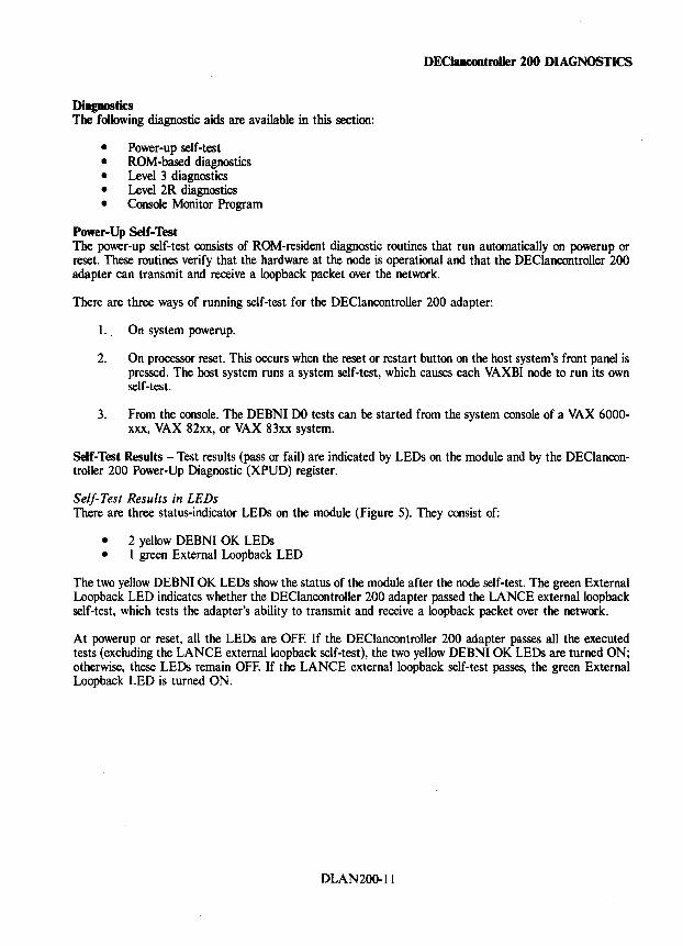
Diagnostics The following diagnostic aids are available in this section:
• Power-up self-test • ROM-based diagnostics • Level 3 diagnostics • Level 2R diagnostics • Console Monitor Program
Power-Up Self-Test The power-up self-test consists of ROM-resident diagnostic routines that run automatically on powerup or reset. These routines verify that the hardware at the node is operational and that the DEClancontroller 200 adapter can transmit and receive a loopback packet over the network.
There are three ways of running self-test for the DEClancontroller 200 adapter:
I. On system powerup.
2. On processor reset. This occurs when the reset or restart button on the host system's front panel is pressed. The host system runs a system self-test, which causes each VAXBI node to run its own self-test.
3. From the console. The DEBNI DO tests can be started from the system console of a VAX 6000-xxx, VAX 82xx, or VAX 83xx system.·
Self-Test Results - Test results (pass or fail) are indicated by LEDs on the module and by the DEClancontroller 200 Power-Up Diagnostic (XPUD) register.
Self-Test Results in LEDs There are three status-indicator LEDs on the module (Figure 5). They consist of:
• 2 yellow DEBNI OK LEDs • 1 green External Loopback LED
The two yellow DEBNI OK LEDs show the status of the module after the node self-test. The green External Loopback LED indicates whether the DEClancontroller 200 adapter passed the LANCE externalloopback self-test, which tests the adapter's ability to transmit and receive a loopback packet over the network.
At powerup or reset, all the LEDs are OFF. If the DEClancontroller 200 adapter passes all the executed tests (excluding the LANCE externalloopback self-test), the two yellow DEBNI OK LEDs are turned ON; otherwise, these LEDs remain OFF. If the LANCE externalloopback self-test passes, the green External Loopback LED is turned ON.
DLAN200-11
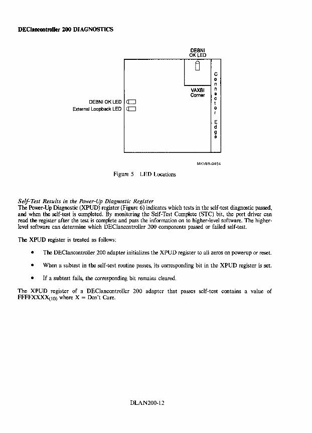
DEClancontroiler 200 DIAGNOSTICS
DEBNIOKLED External Loopback LED
a=J a=J
Figure 5 LED Locations
Self-Test Results in the Power-Up Diagnostic Register
DEBNI OK LED
~
VAXBI Corner
C 0 n n e c t 0 r
E d 9 e
MKV89·0454
The Power-Up Diagnostic (XPUD) register (Figure 6) indicates which tests in the self-test diagnostic passed, and when the self-test is completed. By monitoring the Self-Test Complete (STC) bit, the port driver can read the register after the test is complete and pass the information on to higher-level software. The higherlevel software can determine which DEClancontroller 200 components passed or failed self-test.
The XPUD register is treated as follows:
• The DEClancontroller 200 adapter initializes the XPUD register to all zeros on powerup or reset.
• When a subtest in the self-test routine passes, its corresponding bit in the XPUD register is set.
• If a subtest fails, the corresponding bit remains cleared.
The XPUD register of a DEClancontroller 200 adapter that passes self-test contains a value of FFFFXXXX(lo) where X = Don't Care.
DLAN200-12
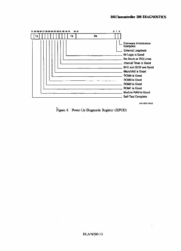
DEClancontroller 200 DIAGNOSTICS
31 30 29 28 27 28 25 24 23 22 21 20 19 18 18 15 2 1 0
1 11S 1 1 I 1 I I I I II I 1s Os I II
I L ___ ~ Firmware Initialization Complete
External Loopback NI Logic is Good
1...-______________ No Stuck-at IRQ Lines
1...-_______________ Interval Timer is Good 1...-________________ BIIC and BCI3 are Good
1...-________________ MicroVAX is Good 1...-_________________ ROM4 is Good
L-__________________ ROM3 is Good 1...-___________________ ROM2 is Good
'--___________________ ROM1 is Good
1...-____________________ Module RAM is Good '--______________________ Self-Test Complete
MKV89-0455
,. Figure 6 Power-Up Diagnostic Register (XPUD)
DLAN200-13
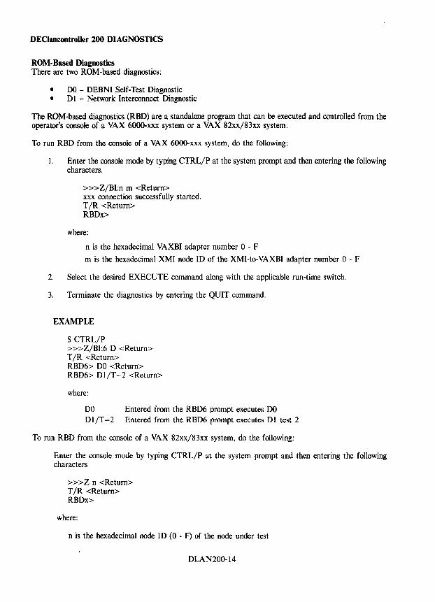
DEClancontroller 200 DIAGNOSTICS
ROM-Based Diagnostics There are two ROM-based diagnostics:
• DO - DEBNI Self-Test Diagnostic • D I - Network Interconnect Diagnostic
The ROM-based diagnostics (RBD) are a standalone program that can be executed and controlled from the operator's console of a VAX 6000-xxx system or a VAX 82xx/83xx system.
To run RBD from the console of a VAX 6000-xxx system, do the following:
I. Enter the console mode by typing CTRL/P at the system prompt and then entering the following characters.
»>Z/BI:n m <Return> xxx connection successfully started. T /R <Return> RBDx>
where:
n is the hexadecimal VAXBI adapter number 0 - F
m is the hexadecimal XMI node ID of the XMI-to-VAXBI adapter number 0 - F
2. Select the desired EXECUTE command along with the applicable run-time switch.
3. Terminate the diagnostics by entering the QUIT command.
EXAMPLE
$ CTRL/P »>Z/BI:6 D <Return> T /R <Return> RBD6> DO <Return> RBD6> DI/T=2 <Return>
where:
DO DI/T=2
Entered from the RBD6 prompt executes DO Entered from the RBD6 prompt executes DI test 2
To run RBD from the console of a VAX 82xx/83xx system, do the following:
Enter the console mode by typing CTRL/P at the system prompt and then entering the following characters
»>Z n <Return> T /R <Return> RBDx>
where:
n is the hexadecimal node ID (0 - F) of the node under test
DLAN200-14
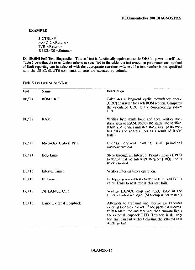
EXAMPLE
$ CTRL/P »>Z 2 <Return> T IR <Return> RBD2>DO <Return>
DEClancootroller 200 DIAGNOSTICS
DO DEBNI Self-Test Diagnostic - This self-test is functionally equivalent to the DEBNI power-up self-test. Table 5 describes the tests. Unless otherwise specified in the table, the test execution parameters and method of fault reporting can be selected with the appropriate run-time switches. If a test number is not specified with the DO EXECUTE command, all tests are executed by default.
Table 5 DO DEBNI Self-Test
Test Name
DO/Tl ROMCRC
DO/T2 RAM
DO/T3 MicroVAX Critical Path
DO/T4 IRQ Lines
DO/T5 Interval Timer
DO/T6 BI Corner
DO/T7 NI LANCE Chip
DO/T8 Lance External Loopback
Description
Calculates a longword cyclic redundancy check (CRC) character for each ROM section. Compares the calculated CRC to the corresponding stored CRC.
Verifies byte mask logic and then verifies nonstack area of RAM. Moves the stack into verified RAM and verifies untested stack area. (Also verifies data and address lines as a result of RAM tests.)
Checks critical timing and principal microinstructions.
Steps through all Interrupt Priority Levels (IPLs) to verify that no Interrupt Request (IRQ) line is stuck asserted.
Verifies interval timer operation.
Performs seven subtests to verify BIIC and BC13 chips. Exits to next test if this test fails.
Verifies LANCE chip and CRC logic in the Ethernet interface logic. (SIA chip is not tested.)
Attempts to transmit and receive an Ethernet externalloopback packet. If one packet is successfully transmitted and received, the firmware lights the external loopback LED. This test is the only test that can fail without causing the self-test as a whole to fail.
DLAN200-15
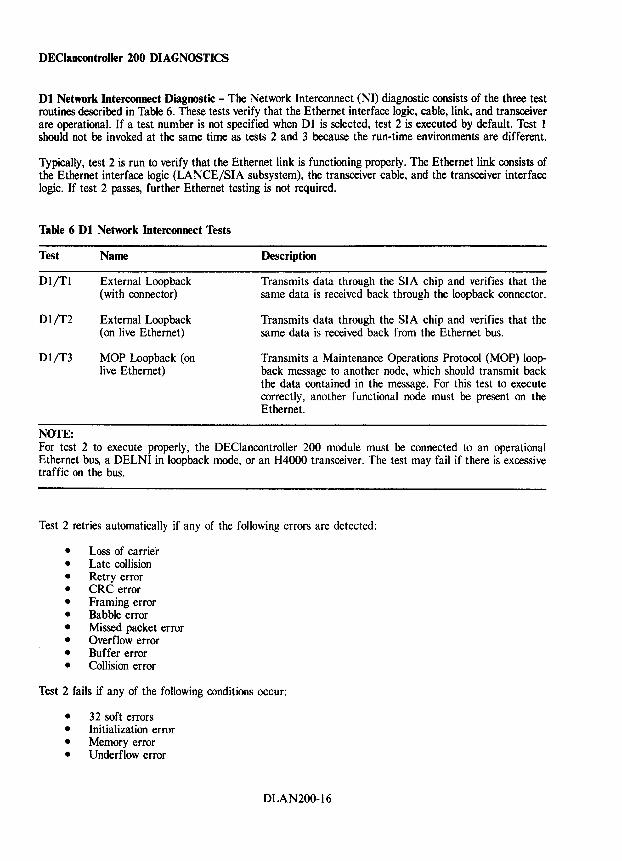
DEClancontroller 200 DIAGNOSTICS
Dl Network Interconnect Diagnostic - The Network Interconnect (NI) diagnostic consists of the three test routines described in Table 6. These tests verify that the Ethernet interface logic, cable, link, and transceiver are operational. If a test number is not specified when D 1 is selected, test 2 is executed by default. Test 1 should not be invoked at the same time as tests 2 and 3 because the run-time environments are different.
Typically, test 2 is run to verify that the Ethernet link is functioning properly. The Ethernet link consists of the Ethernet interface logic (LANCEjSIA subsystem), the transceiver cable, and the transceiver interface logic. If test 2 passes, further Ethernet testing is not required.
Table 6 Dl Network Interconnect Tests
Test Name
DI/Tl External Loopback (with connector)
DI/T2 External Loopback (on live Ethernet)
Dl/T3 MOP Loopback (on live Ethernet)
NOTE:
Description
Transmits data through the SIA chip and verifies that the same data is received back through the loopback connector.
Transmits data through the SIA chip and verifies that the same data is received back from the Ethernet bus.
Transmits a Maintenance Operations Protocol (MOP) loopback message to another node, which should transmit back the data contained in the message. For this test to execute correctly, another functional node must be present on the Ethernet.
For test 2 to execute properly, the DEClancontroller 200 module must be connected to an operational Ethernet bus, a DELNI in loopback mode, or an H4000 transceiver. The test may fail if there is excessive traffic on the bus.
Test 2 retries automatically if any of the following errors are detected:
• Loss of carrie"r • Late collision • Retry error • CRC error • Framing error • Babble error • Missed packet error • Overflow error • Buffer error • Collision error
Test 2 fails if any of the following conditions occur:
• 32 soft errors • Initialization error • Memory error • Underflow error
DLAN200-16
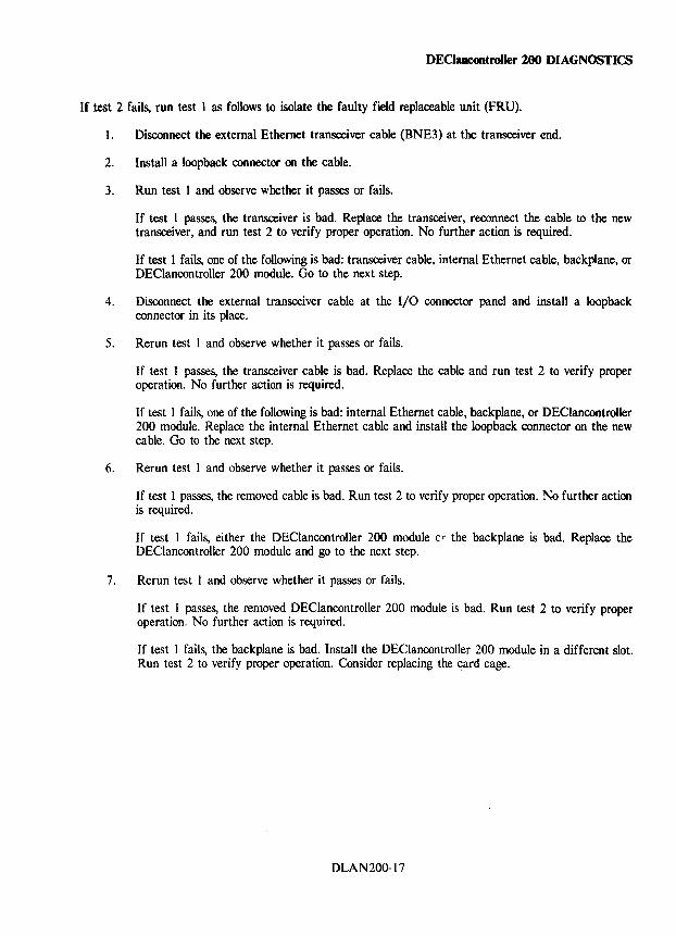
DEClancontroller 200 DIAGNOSTICS
If test 2 fails, run test 1 as follows to isolate the faulty field replaceable unit (FRU).
1. Disconnect the external Ethernet transceiver cable (BNE3) at the transceiver end.
2. Install a loopback connector on the cable.
3. Run test 1 and observe whether it passes or fails.
If test 1 passes, the transceiver is bad. Replace the transceiver, reconnect the cable to the new transceiver, and run test 2 to verify proper operation. No further action is required.
If test 1 fails, one of the following is bad: transceiver cable, internal Ethernet cable, backplane, or DEClancontroller 200 module. Go to the next step.
4. Disconnect the external transceiver cable at the I/O connector panel and install a loopback connector in its place.
5. Rerun test 1 and observe whether it passes or fails.
If test 1 passes, the transceiver cable is bad. Replace the cable and run test 2 to verify proper operation. No further action is required.
If test 1 fails, one of the following is bad: internal Ethernet cable, backplane, or DEClancontroller 200 module. Replace the internal Ethernet cable and install the loopback connector on the new cable. Go to the next step.
6. Rerun test 1 and observe whether it passes or fails.
If test 1 passes, the removed cable is bad. Run test 2 to verify proper operation. No further action is required.
If test 1 fails, either the DEClancontroller 200 module (r the backplane is bad. Replace the DEClancontroller 200 module and go to the next step.
7. Rerun test 1 and observe whether it passes or fails.
If test 1 passes, the removed DEClancontroller 200 module is bad. Run test 2 to verify proper operation. No further action is required.
If test 1 fails, the backplane is bad. Install the DEClancontroller 200 module in a different slot. Run test 2 to verify proper operation. Consider replacing the card cage.
DLAN200-17
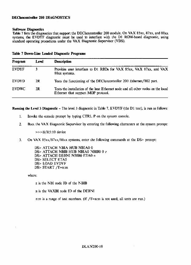
DEClancontroller 200 DIAGNOSTICS
Software Diagnostics Table 7 lists the diagnostics that support the DEClancontroller 200 module. On VAX 85xx, 87xx, and 88xx systems, the EVDYF diagnostic must be used to interface with the DI ROM-based diagnostic, using standard operating procedures under the VAX Diagnostic Supervisor (VDS).
Table 7 Down-Line Loaded Diagnostic Programs
Program
EVDYF
EVDYD
EVDWC
Level
3
2R
2R
Description
Provides user interface to D I RBDs for VAX 85xx, VAX 87xx, and VAX 88xx systems.
Tests the functioning of the DEClancontroller 200 Ethernet/802 port.
Tests the installation of the host Ethernet node and all other nodes on the local Ethernet that support MOP protocol.
Running the Level 3 Diagnostic - The level 3 diagnostic in Table 7, EVDYF (the DI test), is run as follows:
I. Invoke the console prompt by typing CTRL P on the system console.
2. Boot the VAX Diagnostic Supervisor by entering the following characters at the system prompt:
»>B/R5:10 device
3. On VAX 85xx/87xx/88xx systems, enter the following commands at the DS> prompt:
DS> ATTACH NBIA HUB NBIAO 0 DS> ATTACH NBIB HUB NBIAO NBIBO 0 z DS> ATTACH DEBNI NBIBO ETAO n DS> SELECT ETAO DS> LOAD EVDYF DS> START /T=n:m
where:
z is the NBI node ID of the NBIB
n is the VAXBI node ID of the DEBNI
n:m is a range of test numbers. (If IT =n:m is not used, all tests are run.)
DLAN200-18
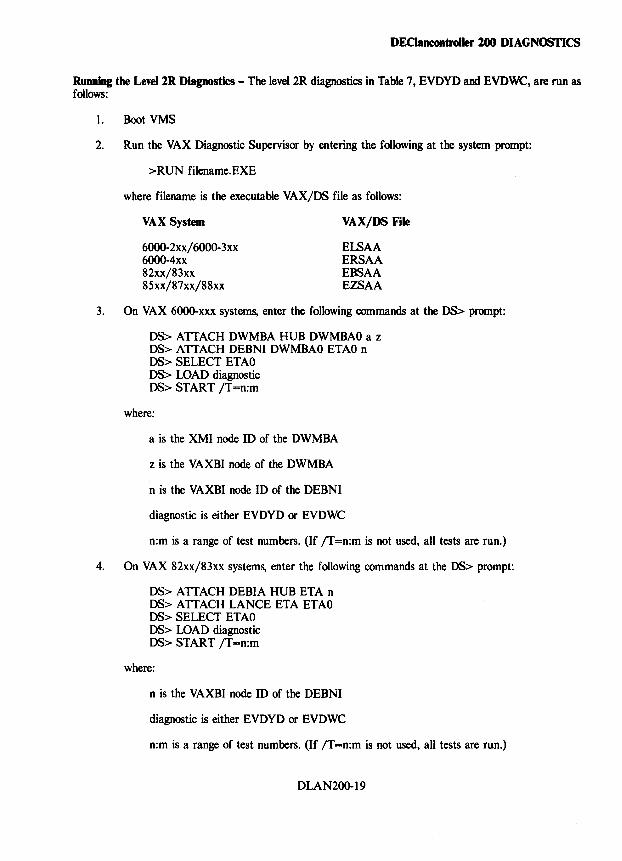
DEClancontroller 200 DIAGNOSTICS
Running the Level 2R Diagnostics - The level 2R diagnostics in Table 7, EVDYD and EVDWC, are run as follows:
1. Boot VMS
2. Run the VAX Diagnostic Supervisor by entering the following at the system prompt:
>RUN filename.EXE
where filename is the executable VAX/DS file as follows:
VAX System
6000-2xx/ 6000-3xx 6000-4xx 82xx/83xx 85xx/87xx/88xx
VAX/DS File
ELSAA ERSAA EBSAA EZSAA
3. On VAX 6000-xxx systems, enter the following commands at the DS> prompt:
DS> ATTACH DWMBA HUB OWMBAO a z DS> ATTACH DEBNI DWMBAO ETAO n OS> SELECT ETAO OS> WAD diagnostic OS> START /T=n:m
where:
a is the XMI node 10 of the DWMBA
z is the VAXBI node of the OWMBA
n is the VAXBI node ID of the DEBNI
diagnostic is either EVDYD or EVDWC
n:m is a range of test numbers. (If /T=n:m is not used, all tests are run.)
4. On VAX 82xx/83xx systems, enter the following commands at the DS> prompt:
DS> ATTACH DEBIA HUB ETA n DS> ATTACH LANCE ETA ETAO OS> SELECT ETAO DS> LOAD diagnostic DS> START /T=n:m
where:
n is the VAXBI node ID of the DEBNI
diagnostic is either EVOYD or EVOWC
n:m is a range of test numbers. (If /T=n:m is not used, all tests are run.)
DLAN200-19
DEClancontroiler 200 DIAGNOSTICS
5. On VAX 85xx/87xx/88xx systems, enter the following commands at the DS> prompt:
DS> ATIACH NBIA HUB NBIAO 0 DS> ATIACH NBIB HUB NBIAO NBIBO 0 z DS> ATIACH DEBNI NBIBO ETAO n DS> SELECT ETAO DS> LOAD diagnostic DS> START /T=n:m
where:
z is the NBI node ID of the NBIB
n is the VAXBI node ID of the DEBNI
diagnostic is either EVDYD or EVDWC
n:m is a range of test numbers. (If /T=n:m is not used, all tests are run.)
DLAN200-20
DEClancontroller 200 DIAGNOSTICS
Console Monitor Program The DEClancontroller 200 firmware includes a Console Monitor Program (CMP) that allows any user to monitor the DEClancontroller 200 operation. The CMP .is accessible only if the DEClancontroller 200 firmware console monitor jumper is installed on the backplane (at segment E I, connect pins E 16 and E46).
Console Monitor Remote Node Connect -
$MCR NCP NCP> SET NODE node-Ilame HARDWARE ADDRESS address NCP> DEFINE NODE node-Ilame HARDWARE ADDRESS address NCP> SET NODE node-Ilame SERVICE PASSWORD 424E4942F415244 NCP> DEFINE NODE node-Ilame SERVICE PASSWORD 424E4942F415244 NCP> SET NODE node-Ilame SERVICE CIRCUIT circuit--I1ame NCP> DEFINE NODE node-Ilame SERVICE CIRCUIT circuit--I1ame
where:
node-Ilame is the name assigned to the DEClancontroller 200 Ethernet node. address is the DEClancontroller 200 Ethernet default physical address. circuit--I1ame is the Ethernet circuit for the system from which you are sending the commands.
Console Monitor Remote Node Connect Example -
$MCR NCP NCP> SET NODE NODE_B HARDWARE ADDRESS 08-00-3C-4F-22-22 NCP> DEFINE NODE NODE_B HARDWARE ADDRESS 08-00-3C-4F-22-22 NCP> SET NODE NODE_B SERVICE PASSWORD 424E4942F415244 NCP> DEFINE NODE NODE_B SERVICE PASSWORD 424E4942F415244 NCP> SET NODE NODE_B SERVICE CIRCUIT BNA-O NCP> DEFINE NODE NODE_B SERVICE CIRCUIT BNA-O
Console Monitor Local Node Connect - If the DEClancontrolier 200 to be connected is local, the user must first create a node name and assign it a valid DECnet address. That DECnet node name and address must be distinct from the other DECnet node names and addresses already defined to that system. Once a DECnet node name and address has been established, use the remote node connect procedure described in the above example. This is done because the NCP CONNECT command does not allow a node to connect to itself.
Invoking the Console - After entering the DEClancontrolier 200 into the DECnet data base, (as a remote node) it can be remotely connected using NCp, as follows:
$MCR NCP NCP> CONNECT NODE node-Ilame Console connected (press CTRL/D when finished) BNI>
where:
node-Ilame is the logical name you asigned to the DEClancontroller 200 Ethernet node.
Exiting the Console Monitor - To exit the console monitor type CTRL D
DLAN200-21
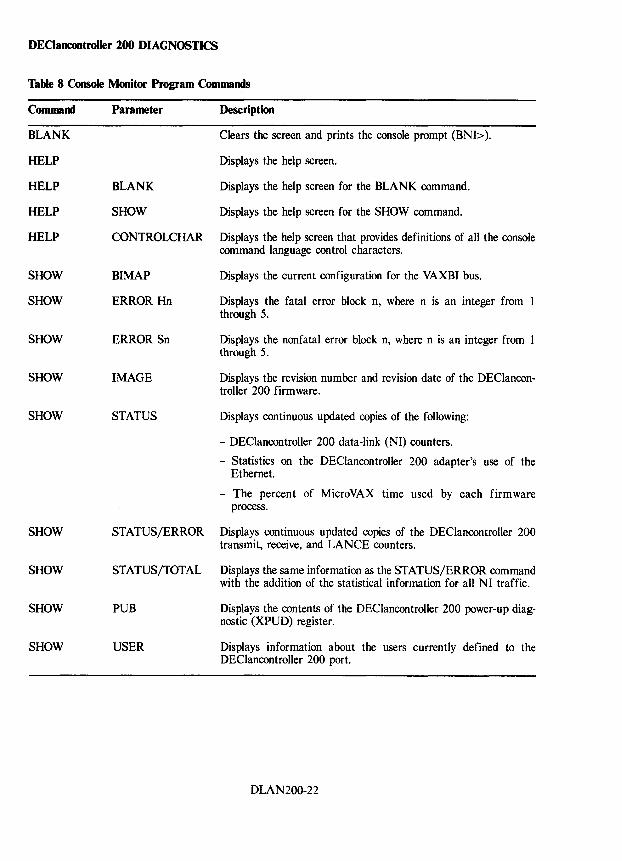
DEClancontroller 200 DIAGNOSTICS
Table 8 Console Monitor Program Commands
Command
BLANK
HELP
HELP
HELP
HELP
SHOW
SHOW
SHOW
SHOW
SHOW
SHOW
SHOW
SHOW
SHOW
Parameter Description
Clears the screen and prints the console prompt (BNI».
Displays t.he help screen.
BLANK Displays the help screen for the BLANK command.
SHOW Displays the help screen for the SHOW command.
CONTROLCHAR Displays the help screen that provides definitions of all the console command language control characters.
BIMAP Displays the current configuration for the VAXBI bus.
ERROR Hn Displays the fatal error block n, where n is an integer from through 5.
ERROR Sn Displays the nonfatal error block n, where n is an integer from 1 through 5.
IMAGE Displays the revision number and revision date of the DEClancontroller 200 firmware.
STATUS Displays continuous updated copies of the following:
- DEClancontroller 200 data-link (NI) counters.
- Statistics on the DEClancontroller 200 adapter's use of the Ethernet.
- The percent of MicroVAX time used by each firmware process.
STATUS/ERROR Displays continuous updated copies of the DEClancontroller 200 transmit, receive, and LANCE counters.
STATUS/TOTAL Displays the same information as the STATUS/ERROR command with the addition of the statistical information for all NI traffic.
PUB Displays the contents of the DEClancontroller 200 power-up diagnostic (XPUD) register.
USER Displays information about the users currently defined to the DEClancontroller 200 port.
DLAN200-22
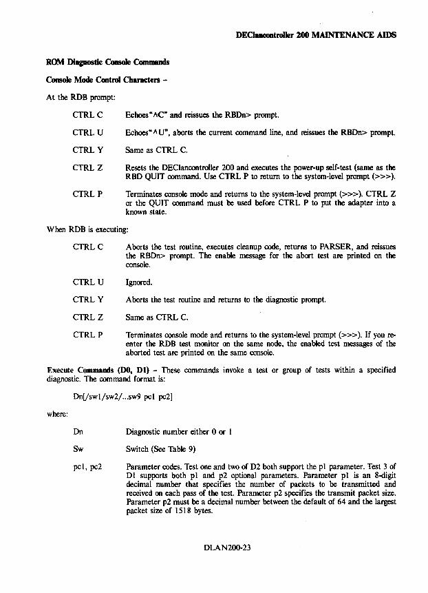
DEClaneantroiler 100 MAINTENANCE AIDS
ROM Diagnostic Console Com __
Console Mode Control Characters -
At the RDB prompt:
CTRLC
CTRLU
CTRLY
CTRLZ
CTRLP
Echoes" "C'" and reissues the RBDn> prompt.
Echoes" " U"', aborts the current command line, and reissues the RBDn> prompt.
Same as CTRL C.
Resets the DEClancontroller 200 and executes the power-up self-test (same as the RBD QUIT command. Use CTRL P to return to the system-level prompt (»».
Terminates console mode and returns to the system-level prompt (»». CTRL Z or the QUIT command must be used before CTRL P to put the adapter into a known state.
When RDB is executing:
CTRLC
CTRL U
CTRLY
CTRLZ
CTRLP
Aborts the test routine, executes cleanup code, returns to PARSER, and reissues the RBDn> prompt. The enable message for the abort test are printed on the console.
Ignored.
Aborts the test routine and returns to the diagnostic prompt.
Same as CTRL C.
Terminates console mode and returns to the system-level prompt (»». If you reenter the RDB test monitor on the same node, the enabled test messages of the aborted test are printed on the same console.
Execute Commands (DO, Dl) - These commands invoke a test or group of tests within a specified diagnostic. The command format is:
where:
Dn[!swl/sw2/ ... sw9 pel pe2]
Dn
Sw
pel, pe2
Diagnostic number either 0 or 1
Switch (See Table 9)
Parameter codes. Test one and two of D2 both support the pI parameter. Test 3 of Dl supports both pI and p2 optional parameters. Parameter pI is an 8-digit decimal number that specifies the number of packets to be transmitted and received on each pass of the test. Parameter p2 specifies the transmit packet size. Parameter p2 must be a decimal number between the default of 64 and the largest packet size of 1518 bytes.
DLAN200-23
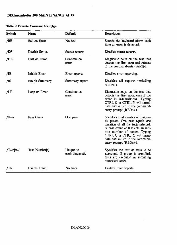
DEClancontroUer 100 MAINTENANCE AIDS
Table 9 Execute Command Switches
Switch Name Default Description
IBE Bell on Error No bell Sounds the keyboard alarm each time an error is detected.
IDS Disable Status Status reports Disables status reports.
IHE Halt on Error Continue on Diagnostic halts on the test that error detects the first error and returns
to the command-entry prompt.
lIE Inhibit Error Error reports Disables error reporting.
lIS Inhibit Summary Summary report Disables all reports including summary.
ILE Loop on Error Continue on Diagnostic loops on the test that error detects the first error, even if the
error is intermittent. Typing CTRL C or CTRL Y will termi-nate and return to the command-entry prompt (RBDn».
IP=n Pass Count One pass Specifies total number of diagnos-tic passes. One pass equals one iteration of all the tests selected. A pass count of 0 selects an infi-nite number of passes. Typing CTRL C or CTRL Y will termi-nate and return to the command-entry prompt (RBDn».
IT=n[:m] Test Number[s] Unique to Specifies the test or tests to be each diagnostic executed. If group is specified,
tests are executed in ascending numerical order.
ITR Enable Trace No trace Enables trace reports.
DLAN200-24
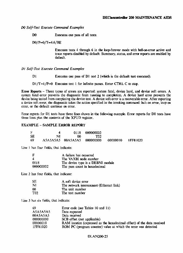
DEClaneontroUer 200 MAINTENANCE AIDS
DO Self-Test Execute Command Examples
DO Executes one pass of all tests.
DO/P=0/T=4:6/BE
Executes tests 4 through 6 in the loop-forever mode with bell-on-error active and trace reports disabled by default. Summary, status, and error reports are enabled by default.
D 1 Self-Test Execute Command Examples
DI Executes one pass of DI test 2 (which is the default test executed).
DI/T=I/P=O Executes test I for infinite passes. Enter CTRL C to stop.
Error Reports - Three types of errors are reported: system fatal, device hard, and device soft errors. A system fatal error prevents the diagnostic from running to completion. A device hard error prevents the device being tested from completing the device test. A device soft error is a recoverable error. After reporting a device soft error, the diagnostic takes the action specified in the invoking command: halt on error, loop on error, or the default continue on error.
Error reports for DI tests have three lines shown in the following example. Error reports for DO tests have three lines plus the contents of the XPUD register.
EXAMPLE - SAMPLE ERROR REPORT
4 0118 NI 00
F SE 69 ASASASAS 00A5ASAS
000000002 T02
000000000 00000010
Line 1 has four fields, that indicate:
F 4 0118 000000002
A failure has occurred The VAXBI node number The device type is a DEBNI module The pass count in hexadecimal
Line 2 has four fields, that indicate:
SE NI 00 T02
A soft device error The network interconnect (Ethernet link) The unit number The test number
Line 3 has six fields, that indicate:
Error code (see Tables 10 and 11) Data expected Data received SCB offset (not applicable)
IFF81020
69 A5A5A5A5 00A5ASAS 000000000 00000010 IFF81020
RAM location (expressed as the hexadecimal offset) of the data received ROM PC (program counter) value at which the error was detected
DLAN200-2S
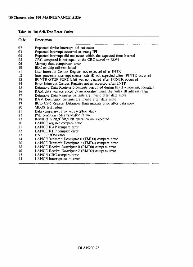
DEClancontroller 200 MAINTENANCE AIDS
Table 10 DO Self-Test Error Codes
Code Description
02 Expected device interrupt did not occur 03 Expected interrupt occurred at wrong IPL 04 Expected interrupt did not occur within the expected time interval 05 CRC computed is not equal to the CRC stored in ROM 06 Memory data comparison error 10 BIIC on-chip self-test failed I I User Interrupt Control Register not expected after INTR 12 Inter-processor interrupt source node ID not expected after IPINTR occurred 13 IPINTR/STOP FORCE bit was not cleared after IPINTR occurred 14 Error Interrupt Control Register not as expected after INTR I 5 Datamove Data Register 0 contents corrupted during BI/I1 windowing operation 16 RAM data was corrupted by an operation using the node's BI address range 17 Datamove Data Register contents are invalid after data move 18 RAM Destination contents are invalid after data move 19 BCI3 CSR Register Datamove flags indicate error after data move 20 MBOX test failure 21 Data comparison error on exception stack 22 PSL condition codes validation failure 23 Result of GPR/CSR/IPR operation not expected 30 LANCE register compare error 31 LANCE RAP compare error 32 LANCE RDP compare error 33 ENET PROM error 34 LANCE Transmit Descriptor 0 (TMDO) compare error 36 LANCE Transmit Descriptor 2 (TMD2) compare error 38 LANCE Receive Descriptor 0 (RMDO) compare error 40 LANCE Receive Descriptor 2 (RMD2) compare error 43 LANCE CRC compare error 44 LANCE interrupt count error
DLAN200-26
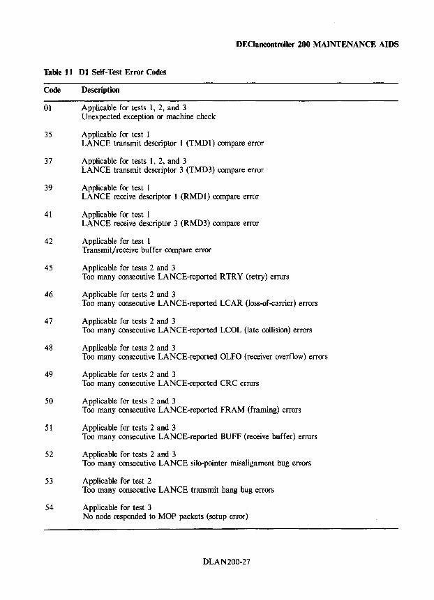
Table 11 Dl Self-Test Error Codes
Code Description
01 Applicable for tests 1, 2, and 3 Unexpected exception or machine check
35 Applicable for test 1
DEClancontroller 200 MAINTENANCE AIDS
LANCE transmit descriptor 1 (TMD1) compare error
37 Applicable for tests 1, 2, and 3 LANCE transmit descriptor 3 (TMD3) compare error
39 Applicable for test 1 LANCE receive descriptor 1 (RMDl) compare error
41 Applicable for test 1 LANCE receive descriptor 3 (RMD3) compare error
42 Applicable for test 1 Transmit/receive buffer compare error
45 Applicable for tests 2 and 3 Too many consecutive LANCE-reported RTRY (retry) errors
46 Applicable for tests 2 and 3 Too many consecutive LANCE-reported LCAR (loss-of-carrier) errors
47 Applicable for tests 2 and 3 Too many consecutive LANCE-reported LCOL (late collision) errors
48 Applicable for tests 2 and 3 Too many consecutive LANCE-reported OLFO (receiver overflow) errors
49 Applicable for tests 2 and 3 Too many consecutive LANCE-reported CRC errors
50 Applicable for tests 2 and 3 Too many consecutive LANCE-reported FRAM (framing) errors
51 Applicable for tests 2 and 3 Too many consecutive LANCE-reported BUFF (receive buffer) errors
52 Applicable for tests 2 and 3 Too many consecutive LANCE silo-pointer misalignment bug errors
53 Applicable for test 2 Too many consecutive LANCE transmit hang bug errors
54 Applicable for test 3 No node responded to MOP packets (setup error)
DLAN200-27
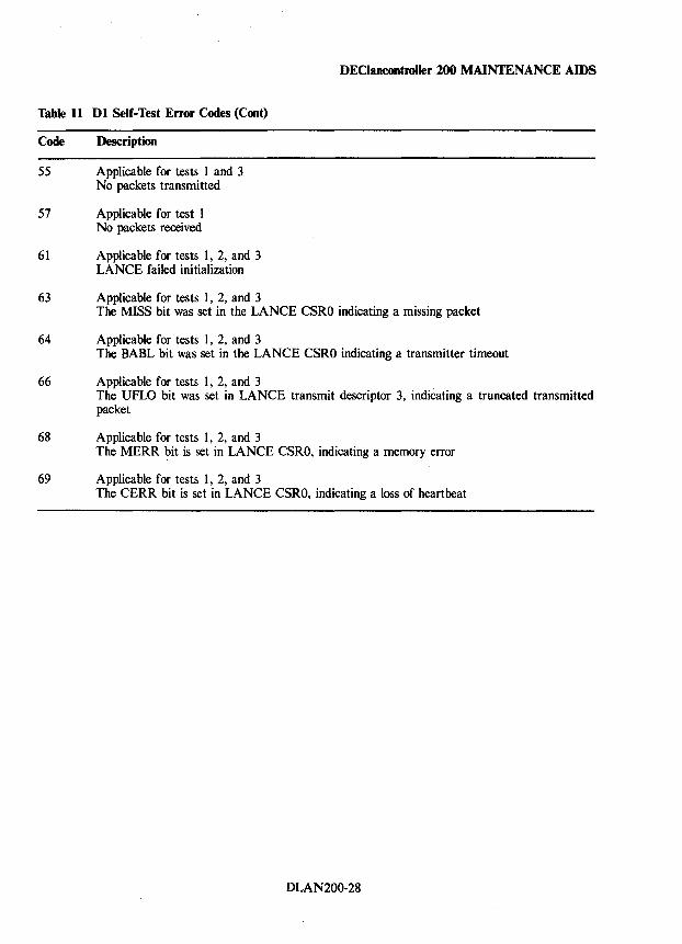
Table 11 Dl Self-Test Error Codes (Coot)
Code Description
55 Applicable for tests 1 and 3 No packets transmitted
57 Applicable for test 1 No packets received
61 Applicable for tests 1, 2, and 3 LANCE failed initialization
63 Applicable for tests 1, 2, and 3
DEClaocootroller 200 MAINTENANCE AIDS
The MISS bit was set in the LANCE CSRO indicating a missing packet
64 Applicable for tests 1, 2, and 3 The BABL bit was set in the LANCE CSRO indicating a transmitter timeout
66 Applicable for tests 1, 2, and 3 The UFLO bit was set in LANCE transmit descriptor 3, indicating a truncated transmitted packet
68 Applicable for tests 1, 2, and 3 The MERR ?it is set in LANCE CSRO, indicating a memory error
69 Applicable for tests 1, 2, and 3 The CERR bit is set in LANCE CSRO, indicating a loss of heartbeat
DLAN200-28
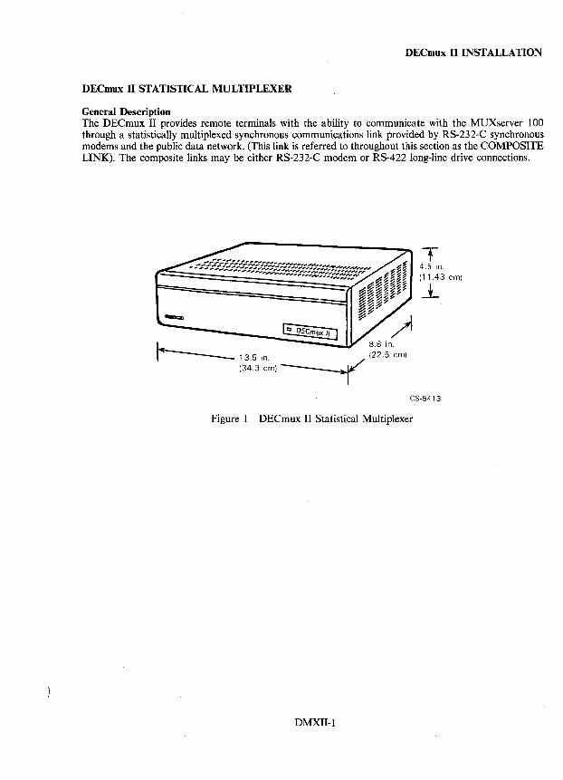
DECmux II INSTALLATION
DECmux II STATISTICAL MULTIPLEXER
General Description The DECmux II provides remote terminals with the ability to communicate with the MUXserver 100 through a statistically multiplexed synchronous communications link provided by RS-232-C synchronous modems and the public data network. (This link is referred to throughout this section as the COMPOSITE LINK). The composite links may be either RS-232-C modem or RS-422 long-line drive connections.
- 13.5 in. (34.3 em)-
8.8 in .
.( (22.5 oml
T 4.5 in. (11.43 em)
--.L
CS-5413
Figure 1 DECmux II Statistical Multiplexer
DMXII-1
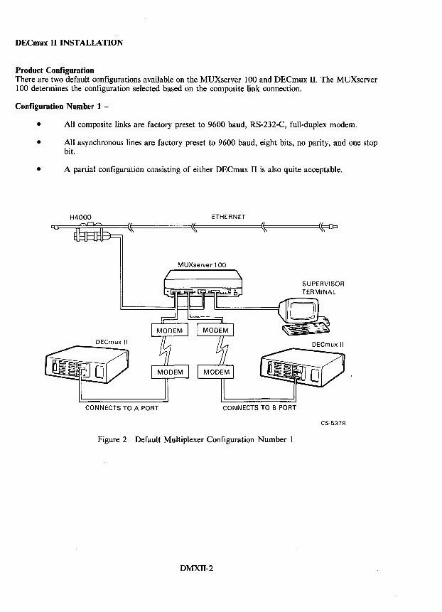
DECmux II INSTALLATION
Product Configuration There are two default configurations available on the MUXserver 100 and DECmux II. The MUXserver 100 determines the configuration selected based on the composite link connection.
Configuration Number 1 -
• All composite links are factory preset to 9600 baud, RS-232-C, full-duplex modem.
• All asynchronous lines are factory preset to 9600 baud, eight bits, no parity, and one stop bit.
• A partial configuration consisting of either DECmux II is also quite acceptable.
H4000 ETHERNET
MUXserver 1 00
DECmux II
CONNECTS TO A PORT CONNECTS TO B PORT
Figure 2 Default Multiplexer Configuration Number 1
DMXII-2
SUPERVISOR TERMINAL
DECmux II
CS-5378
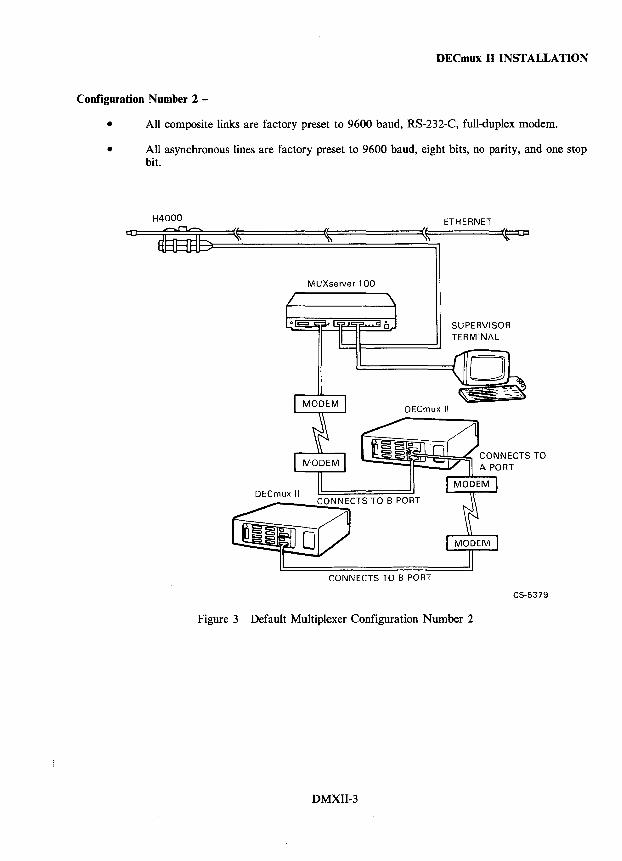
DECmux II INSTALLATION
Configuration Number 2 -
• All composite links are factory preset to 9600 baud, RS-232-C, full-duplex modem.
• All asynchronous lines are factory preset to 9600 baud, eight bits, no parity, and one stop bit.
H4000
MUXserver 100
CONNECTS TO B PORT
ETHERNET
SUPERVISOR TERMINAL
Figure 3 Default Multiplexer Configuration Number 2
DMXII-3
C5-5379
DECmux II INSTALLATION
DECmux II Versions The DECmux II is available in two versions (DFMZA-BA and DFMZA-BB). Each version has different power requirements.
Model
DFMZA-BA DFMZA-BB
Reference Documentation
Input V oItage
100 - 120 Vac 220 - 240 Vac
Refer to the following documents for more information on the DECmux II statistical multiplexer.
• MUXserver 100 Remote Terminal Server Software AA-JC20A-TE Installation Guide (VMS/MicroVMSj
• MUXserver 100 Remote Terminal Server Software AA-JC19A-TC Installation Guide (RSX-11 M-PLUSj
• MUXserver 100 Remote Terminal Server Software AA-JS34A-TY Installation Guide (Micro/ RSXj
• MUXserver 100 Remote Terminal Server Software AA-JQ09A-TE Installation Guide (ULTRIX-32/32mj
• MUXserver 100 Network Reference Manual EK-DSRZA-RM
• MUXserver 100 Network Installation Manual EK-DSRZA-IN
• MUXserver 100 User's Pocket Guide EK-DSRZA-PG
• MUXserver 100 Network Identification Card EK-DSRZA-ID
• LAT Network Manager's Guide AA-DJ18A-TK
Component List The following parts are supplied with each DECmux II statistical multiplexer.
• One DECmux II statistical multiplexer • Eight MUXserver 100 user's pocket guide • One MUXserver 100 network reference manual • One MUXserver 100 network installation manual • Power cord set (DFMZA-BA only) • One RS-422 test cable (P /N 70-20984-01)
DMXII-4
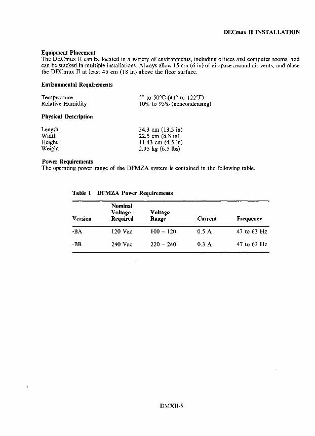
DECmux II INSTALLATION
Equipment Placement The DECmux II can be located in a variety of environments, including offices and computer rooms, and can be stacked in mUltiple installations. Always allow 15 em (6 in) of airspace around air vents, and place the DECmux II at least 45 cm (18 in) above the floor surface.
Environmental Requirements
Temperature Relative Humidity
Physical Description
Length Width Height Weight
Power Requirements
5° to 50°C (41° to 122°F) 10% to 95% (nonconden~ing)
34.3 em (13.5 in) 22.5 em (8.8 in) 11.43 cm (4.5 in) 2.95 kg (6.5 lbs)
The operating power range of the DFMZA system is contained in the following table.
Table 1 DFMZA Power Requirements
Nominal Voltage Voltage
Version Required Range Current Frequency
-BA 120 Vac 100 - 120 0.5 A 47 to 63 Hz
-BB 240 Vac 220 - 240 0.3 A 47 to 63 Hz
DMXII-5
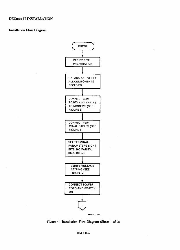
DECmux II INSTALLATION
Installation Flow Diagram
UNPACK AND VERIFY ALL COMPONENTS RECEIVED
CONNECT COMPOSITE LINK CABLES TO MODEMS (SEE FIGURE 5)
CONNECT TERMINAL CABLES (SEE FIGURE 6)
SET TERMINAL PARAMETERS EIGHT BITS, NO PARITY,
9600 BITS/S
VERIFY VOLTAGE SETTING (SEE
FIGURE 7)
CONNECT POWER CORD AND SWITCH ON
MKV87-1224
Figure 4 Installation Flow Diagram (Sheet 1 of 2)
DMXII-6
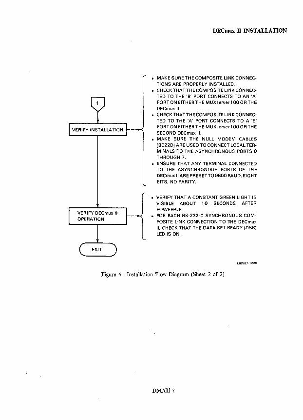
VERIFY DECmux II OPERATION
DECmux II INSTALLATION
• MAKE SURE THE COMPOSITE LINK CONNECTIONS ARE PROPERLY INSTALLED.
• CHECKTHATTHECOMPOSITE LlNKCONNECTED TO THE 'B' PORT CONNECTS TO AN 'A' PORT ON EITHER THE MUXserver 1 00 OR THE DECmux II.
• CHECKTHATTHECOMPOSITE LlNKCONNECTED TO THE 'A' PORT CONNECTS TO A 'B' PORT ON EITHER THE MUXserver 1 00 OR THE SECOND DECmux II.
• MAKE SURE THE NULL MODEM CABLES (BC22D) ARE USED TO CONNECT LOCAL TERMINALS TO THE ASYNCHRONOUS PORTS 0 THROUGH 7.
• ENSURE THAT ANY TERMINAL CONNECTED TO THE ASYNCHRONOUS PORTS OF THE DECmux II ARE PRESETTO 9600 BAUD, EIGHT BITS, NO PARITY.
• VERIFY THAT A CONSTANT GREEN LIGHT IS VISIBLE ABOUT 10 SECONDS AFTER POWER-UP.
• FOR EACH RS-232-C SYNCHRONOUS COMPOSITE LINK CONNECTION TO THE DECmux II, CHECK THAT THE DATA SET READY (DSR) LED IS ON.
MKV87-1225
Figure 4 Installation Flow Diagram (Sheet 2 of 2)
DMXII-7
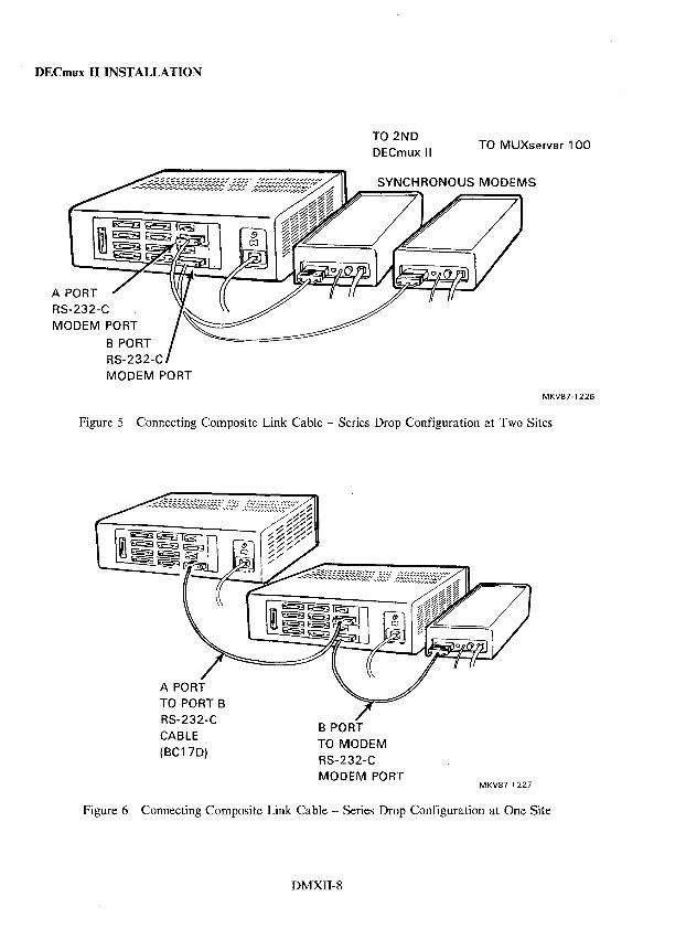
DECmux II INSTALLATION
A PORT RS-232-C
MODEM PORT
B PORT RS-232-C
MODEM PORT
TO 2ND DECmux II
TO MUXserver 100
MKV87-1226
Figure 5 Connecting Composite Link Cable - Series Drop Configuration at Two Sites
TO PORT B RS-232-C
CABLE
(BC17D)
B PORT TO MODEM
RS-232-C
MODEM PORT MKV87-1227
Figure 6 Connecting Composite Link Cable - Series Drop Configuration at One Site
DMXII-8
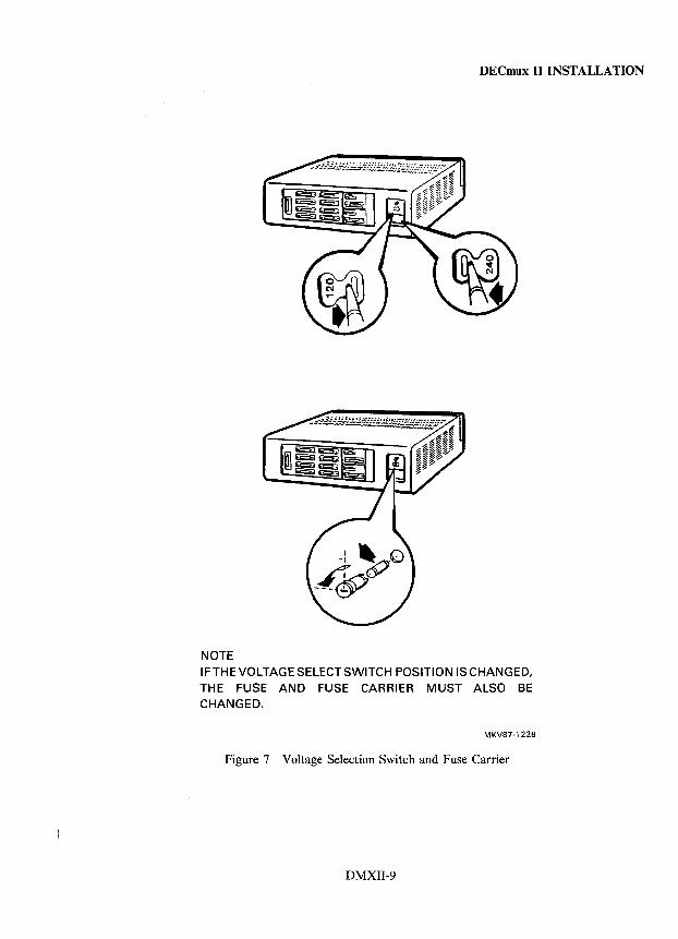
DECmux II INSTALLATION
NOTE IFTHEVOLTAGESELECTSWITCH POSITION IS CHANGED, THE FUSE AND FUSE CARRIER MUST ALSO BE CHANGED.
MKV87·1228
Figure 7 Voltage Selection Switch and Fuse Carrier
DMXII-9
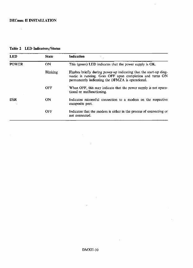
DECmux II INSTALLATION
Table 2 LED Indicators/Status
LED State
POWER ON
Blinking
OFF
DSR ON
OFF
Indication
This (green) LED indicates that the power supply is OK.
Flashes briefly during power-up indicating that the start-up diagnostic is running. Goes OFF upon completion and turns ON permanently indicating the DFMZA is operational.
When OFF, this may indicate that the power supply is not operational or malfunctioning.
Indicates successful connection to a modem on the respective composite port.
Indicates that the modem is either in the process of connecting or not connected.
DMXII-IO
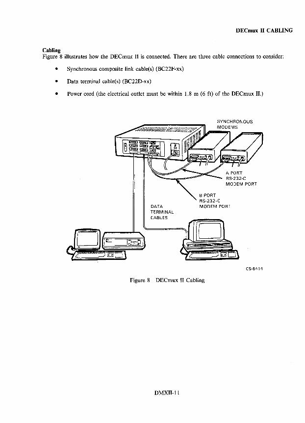
DECmux II CABLING
Cabling Figure 8 illustrates how the DECmux II is connected. There are three cable connections to consider:
• Synchronous composite link cable(s) (BC22F-xx)
• Data terminal cable(s) (BC22D-xx)
• Power cord (the electrical outlet must be within 1.8 m (6 ft) of the DECmux II.)
DATA TERMINAL CABLES
B PORT RS-232-C MODEM PORT
Figure 8 DECmux II Cabling
DMXII-ll
CS-5414

DECmux II DIAGNOSTICS
Diagnostics There are no loadable diagnostics designed specifically for the DECmux II. There are extensive internal tests designed to check the operation of the DECmux II unit, the synchronous links, and the asynchronous line terminals.
The phases of testing are:
• Self-test of the DECmux II unit executed at power-up.
• Local loop back testing using turnaround connectors.
• Remote loopback testing using a DECmux II unit or MUXserver 100 (see Figure 9).
DECmux II
LOCAL MODEM
REMOTE MODEM
MUXserver 1000R2ND DECmux II
DECmux LOOPBACK TEST (Use loopback connector H325)
f MODEM CABLE TEST
ANALOG LOOPBACK TEST
REMOTE DIGITAL LOOPBACK TEST
Figure 9 DECmux II Loopback Points
DMXII-12
MUXserver LOOPBACK TEST
CS-5372
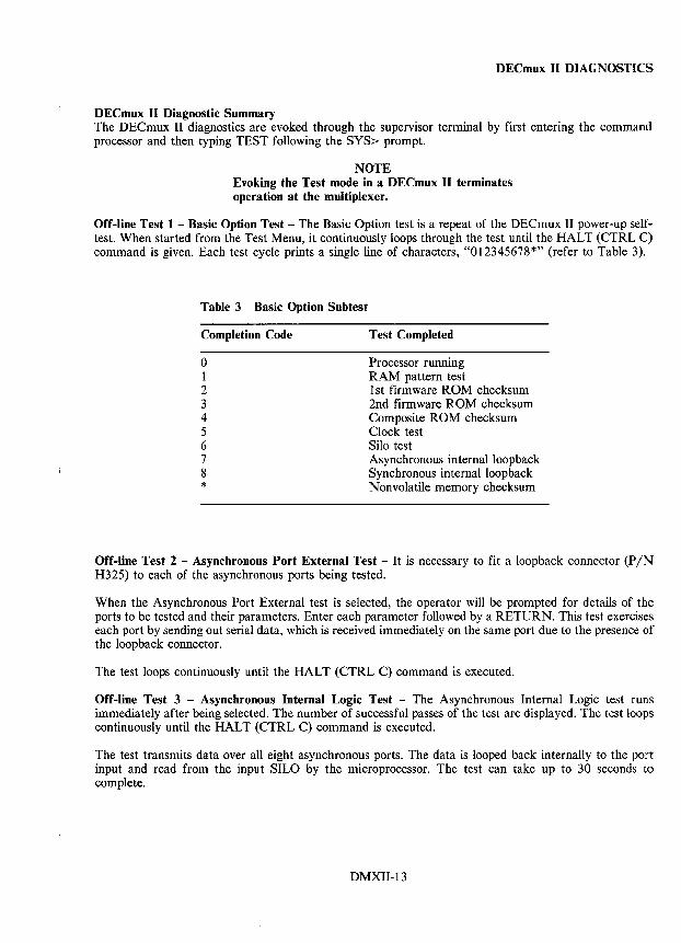
DECmux II DIAGNOSTICS
DECmux II Diagnostic Summary The DECmux II diagnostics are evoked through the supervisor terminal by first entering the command processor and then typing TEST following the SYS> prompt.
NOTE Evoking the Test mode in a DECmux II terminates operation at the multiplexer.
Off-line Test 1 - Basic Option Test - The Basic Option test is a repeat of the DECmux II power-up selftest. When started from the Test Menu, it continuously loops through the test until the HALT (CTRL C) command is given. Each test cycle prints a single line of characters, "012345678*" (refer to Table 3).
Table 3 Basic Option Subtest
Completion Code
o 1 2 3 4 5 6 7 8 *
Test Completed
Processor running RAM pattern test 1st firmware ROM checksum 2nd firmware ROM checksum Composite ROM checksum Clock test Silo test Asynchronous internal loop back Synchronous internal loop back Nonvolatile memory checksum
Off-line Test 2 - Asynchronous Port External Test - It is necessary to fit a loopback connector (PIN H325) to each of the asynchronous ports being tested.
When the Asynchronous Port External test is selected, the operator will be prompted for details of the ports to be tested and their parameters. Enter each parameter followed by a RETURN. This test exercises each port by sending out serial data, which is received immediately on the same port due to the presence of the loopback connector.
The test loops continuously until the HALT (CTRL C) command is executed.
Off-line Test 3 - Asynchronous Internal Logic Test - The Asynchronous Internal Logic test runs immediately after being selected. The number of successful passes of the test are displayed. The test loops continuously until the HALT (CTRL C) command is executed.
The test transmits data over all eight asynchronous ports. The data is looped back internally to the port input and read from the input SILO by the microprocessor. The test can take up to 30 seconds to complete.
DMXII-13
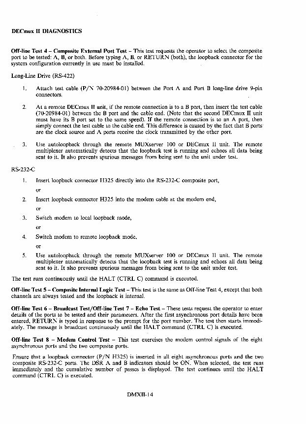
DECmux II DIAGNOSTICS
Off-line Test 4 - Composite External Port Test - This test requests the operator to select the composite port to be tested: A, B, or both. Before typing A, B, or RETURN (both), the loopback connector for the system configuration currently in use must be installed.
Long-Line Drive (RS-422)
1. Attach test cable (P/N 70-20984-01) between the Port A and Port B long-line drive 9-pin connectors.
2. At a remote DECmux II unit, if the remote connection is to a B port, then insert the test cable (70-20984-01) between the B port and the cable end. (Note that the second DECmux II unit must have its B port set to the same speed). If the remote connection is to an A port, then simply connect the test cable to the cable end. This difference is caused by the fact that B ports are the clock source and A ports receive the clock transmitted by the other port.
3. Use autoloopback through the remote MUXserver 100 or DECmux II unit. The remote multiplexer automatically detects that the loopback test is running and echoes all data being sent to it. It also prevents spurious messages from being sent to the unit under test.
RS-232-C
I. Insert loopback connector H325 directly into the RS-232-C composite port,
or
2. Insert loopback connector H325 into the modem cable at the modem end,
or
3. Switch modem to local loopback mode,
or
4. Switch modem to remote loopback mode,
or
5. Use autoloopback through the remote MUXserver 100 or DECmux II unit. The remote multiplexer automatically detects that the loopback test is running and echoes all data being sent to it. It also prevents spurious messages from being sent to the unit under test.
The test runs continuously until the HALT (CTRL C) command is executed.
Off-line Test 5 - Composite Internal Logic Test - This test is the same as Off-line Test 4, except that both channels are always tested and the loopback is internal.
Off-line Test 6 - Broadcast Test/Off-line Test 7 - Echo Test - These tests request the operator to enter details of the ports to be tested and their parameters. After the first asynchronous port details have been entered, RETURN is typed in response to the prompt for the port number. The test then starts immediately. The message is broadcast continuously until the HALT command (CTRL C) is executed.
Off-line Test 8 - Modem Control Test - This test exercises the modem control signals of the eight asynchronous ports and the two composite ports.
Ensure that a loopback connector (PIN H325) is inserted in all eight asynchronous ports and the two composite RS-232-C ports. The DSR A and B indicators should be ON. When selected, the test runs immediately and the cumulative number of passes is displayed. The test continues until the HALT command (CTRL C) is executed.
DMXII-14
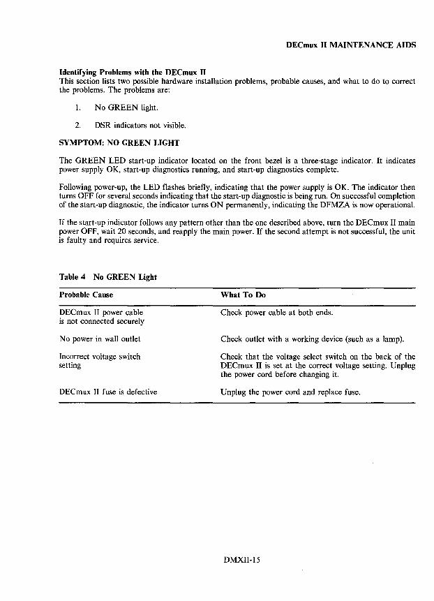
DECmux II MAINTENANCE AIDS
Identifying Problems with the DECmux II This section lists two possible hardware installation problems, probable causes, and what to do to correct the problems. The problems are:
1. No GREEN light.
2. DSR indicators not visible.
SYMPTOM: NO GREEN LIGHT
The GREEN LED start-up indicator located on the front bezel is a three-stage indicator. It indicates power supply OK, start-up diagnostics running, and start-up diagnostics complete.
Following power-up, the LED flashes briefly, indicating that the power supply is OK. The indicator then turns OFF for several seconds indicating that the start-up diagnostic is being run. On successful completion of the start-up diagnostic, the indicator turns ON permanently, indicating the DFMZA is now operational.
If the start-up indicator follows any pattern other than the one described above, turn the DECmux II main power OFF, wait 20 seconds, and reapply the main power. If the second attempt is not successful, the unit is faulty and requires service.
Table 4 No GREEN Light
Probable Cause
DECmux II power cable is not connected securely
No power in wall outlet
Incorrect voltage switch setting
DECmux II fuse is defective
What To Do
Check power cable at both ends.
Check outlet with a working device (such as a lamp).
Check that the voltage select switch on the back of the DECmux II is set at the correct voltage setting. Unplug the power cord before changing it.
Unplug the power cord and replace fuse.
DMXII-15
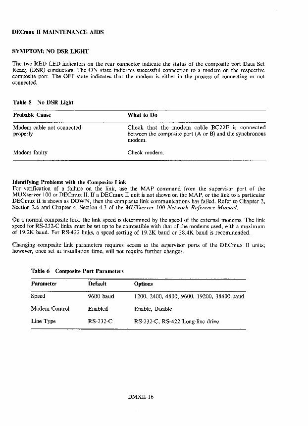
DECmux II MAINTENANCE AIDS
SYMPTOM: NO DSR LIGHT
The two RED LED indicators on the rear connector indicate the status of the composite port Data Set Ready (DSR) conductors. The ON state indicates successful connection to a modem on the respective composite port. The OFF state indicates that the modem is either in the process of connecting or not connected.
Table 5 No DSR Light
Probable Cause
Modem cable not connected properly
Modem faulty
Identifying Problems with the Composite Link
What to Do
Check that the modem cable BC22F is connected between the composite port (A or B) and the synchronous modem.
Check modem.
For verification of a failure on the link, use the MAP command from the supervisor port of the MUXserver 100 or DECmux II. If a DECmux II unit is not shown on the MAP, or the link to a particular DECmux II is shown as DOWN, then the composite link communications has failed. Refer to Chapter 2, Section 2.6 and Chapter 4, Section 4.3 of the MUXserver 100 Network Reference Manual.
On a normal composite link, the link speed is determined by the speed of the external modems. The link speed for RS-232-C links must be set up to be compatible with that of the modems used, with a maximum of 19.2K baud. For RS-422 links, a speed setting of 19.2K baud or 38.4K baud is recommended.
Changing composite link parameters requires access to the supervisor ports of the DECmux II units; however, once set at installation time, will not require further changes.
Table 6 Composite Port Parameters
Parameter Default Options
Speed 9600 baud 1200, 2400, 4800, 9600, 19200, 38400 baud
Modem Control Enabled Enable, Disable
Line Type RS-232-C RS-232-C, RS-422 Long-line drive
DMXII-16
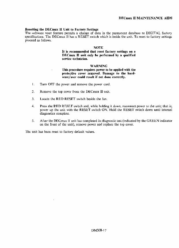
DECmux II MAINTENANCE AIDS
Resetting the DECmux II Unit to Factory Settings The software reset feature permits a change of data in the permanent database to DIGITAL factory specifications. The DECmux II has a RESET switch which is inside the unit. To reset to factory settings proceed as follows.
NOTE It is recommended that reset factory settings on a DECmux II unit only be performed by a qualified service technician.
WARNING This procedure requires power to be applied with the protective cover removed. Damage to the hardware/user could result if not done correctly.
1. Turn OFF the power and remove the power cord.
2. Remove the top cover from the DECmux II unit.
3. Locate the RED RESET switch beside the fan.
4. Press the RED RESET switch and, while holding it down, reconnect power to the unit; that is, power up the unit with the RESET switch ON. Hold the RESET switch down until internal diagnostics complete.
5. After the DECmux II unit has completed its diagnostic test (indicated by the GREEN indicator on the front of the unit), remove power and replace the top cover.
The unit has been reset to factory default values.
DMXII-17

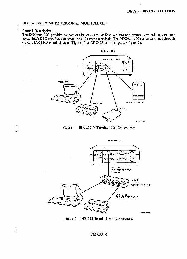
)
DECmux 300 INSTALLATION
DECmux 300 REMOTE TERMINAL MULTIPLEXER
General Description The DECmux 300 provides connections between the MUXserver 300 and remote terminals or computer ports. Each DECmux 300 can serve up to 32 remote terminals. The DECmux 300 serves terminals through either EIA-232-D terminal ports (Figure I) or DEC423 terminal ports (Figure 2).
DECmux 300
Figure I EIA-232-D Terminal Port Connections
DECmux 300
Figure 2 DEC423 Terminal Port Connections
DMX300-1
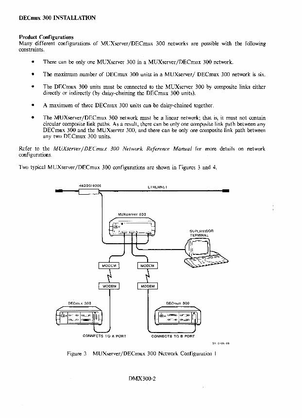
DECmux 300 INSTALLATION
Product Configurations Many different configurations of MUXserver/DECmux 300 networks are possible with the following constraints.
• There can be only one MUXserver 300 in a MUXserver/DECmux 300 network.
• The maximum number of DECmux 300 units in a MUXserver/ DECmux 300 network is six.
• The DECmux 300 units must be connected to the MUXserver 300 by composite links either directly or indirectly (by daisy-chaining the DECmux 300 units).
• A maximum of three DECmux 300 units can be daisy-chained together.
• The MUXserver /DECmux 300 network must be a linear network; that is, it must not contain circular composite link paths. As a result, there can be only one composite link path between any DECmux 300 and the MUXserver 300, and there can be only one composite link path between any two DECmux 300 units.
Refer to the MUXserver/DECmux 300 Network Reference Manual for more details on network configurations.
Two typical MUXserver/DECmux 300 configurations are shown in Figures 3 and 4.
H4000/4005
MUXserver 300
DECmux 300
CONNECTS TO A PORT
ETHERNET
DECmux 300
SUPERVISOR TERMINAL
CONNECTS TO B PORT
SN-OI86-88
Figure 3 MUXserver /DECmux 300 Network Configuration 1
DMX300-2
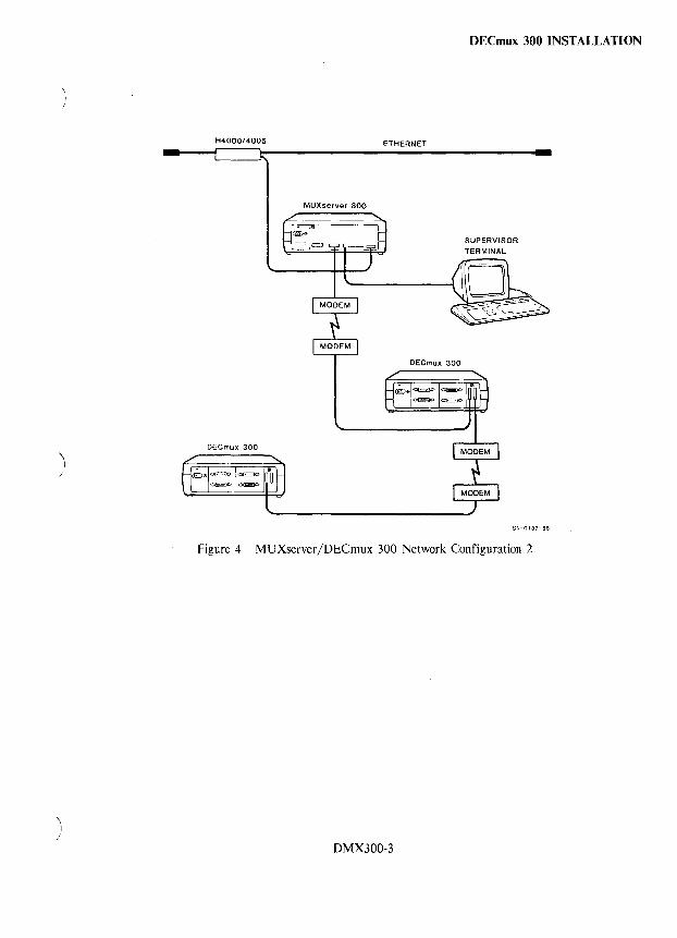
)
)
H4000/4005 ETHERNET
MUXserver 300
DECmux 300
DECmux 300
DECmux 300 INSTALLATION
SUPERVISOR TERMINAL
SN-0187-88
Figure 4 MUXserver/DECmux 300 Network Configuration 2
DMX300-3
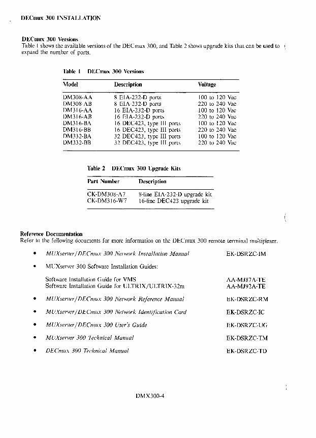
DECmux 300 INSTALLATION
DECmux 300 Versions Table 1 shows the available versions of the DECmux 300, and Table 2 shows upgrade kits that can be used to expand the number of ports.
Table 1 DECmux 300 Versions
Model
DM308-AA DM308-AB DM316-AA DM316-AB DM316-BA DM316-BB DM332-BA DM332-BB
Description
8 EIA-232-D ports 8 EIA-232-D ports 16 EIA-232-D ports 16 EIA-232-D ports 16 DEC423, type III ports 16 DEC423, type III ports 32 DEC423, type III ports 32 DEC423, type III ports
Table 2 DECmux 300 Upgrade Kits
Part Number Description
Voltage
100 to 120 Vac 220 to 240 Vac 100 to 120 Vac 220 to 240 Vac 100 to 120 Vac 220 to 240 Vac 100 to 120 Vac 220 to 240 Vac
CK-DM308-A 7 CK-DM316-W7
8-line EIA-232-D upgrade kit 16-line DEC423 upgrade kit
Reference Documentation Refer to the following documents for more information on the DECmux 300 remote terminal multiplexer.
• MUXserver / DECmux 300 Network Installation Manual
• MUXserver 300 Software Installation Guides:
Software Installation Guide for VMS Software Installation Guide for ULTRIX/ULTRIX-32m
• MUXserver / DECmux 300 Network Reference Manual
• MUXserver / DECmux 300 Network Identification Card
• MUXserver / DECmux 300 User's Guide
• MUXserver 300 Technical Manual
• DECmux 300 Technical Manual
DMX300-4
EK-DSRZC-IM
AA-MJ87 A-TE AA-MJ92A-TE
EK-DSRZC-RM
EK-DSRZC-IC
EK-DSRZC-UG
EK-DSRZC-TM
EK-DSRZC-TD
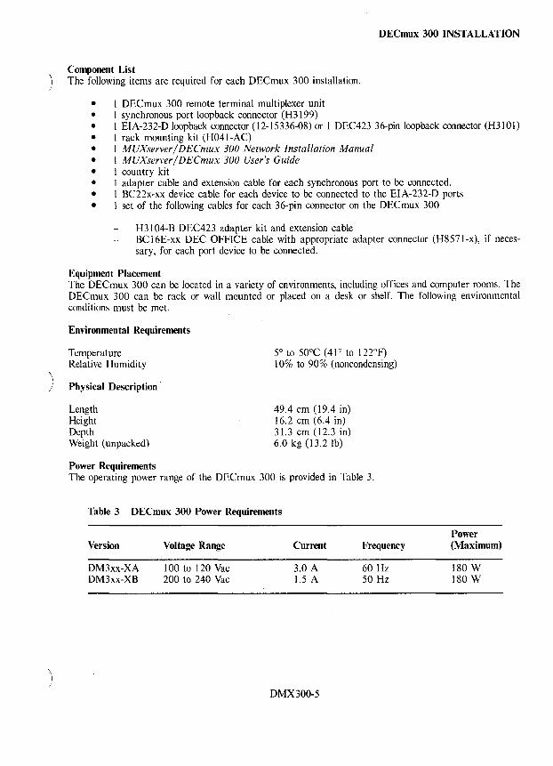
)
~ )
DECmux 300 INSTALLATION
Component List The following items are required for each DECmux 300 installation.
• 1 DECmux 300 remote terminal multiplexer unit • 1 synchronous port loopback connector (H3199) • 1 EIA-232-D loopback connector (12-15336-08) or 1 DEC423 36-pin loopback connector (H31Ol) • 1 rack mounting kit (H041-AC) • 1 MUXserver/ DECmux 300 Network Installation Manual • 1 MUXserver / DECmux 300 User's Guide • I country kit • 1 adapter cable and extension cable for each synchronous port to be connected. • 1 BC22x-xx device cable for each device to be connected to the EIA-232-D ports • I set of the following cables for each 36-pin connector on the DECmux 300
H3104-B DEC423 adapter kit and extension cable BC 16E-xx DEC OFFICE cable with appropriate adapter connector (H8571-x), if necessary, for each port device to be connected.
Equipment Placement The DECmux 300 can be located in a variety of environments, including offices and computer rooms. The DECmux 300 can be rack or wall mounted or placed on a desk or shelf. The following environmental conditions must be met.
Environmental Requirements
Temperature Relative Humidity
Physical Description
Length Height Depth Weight (unpacked)
Power Requirements
5° to 50°C (41 ° to 122°F) 10% to 90% (noncondensing)
49.4 cm (19.4 in) 16.2 cm (6.4 in) 31.3 cm (12.3 in) 6.0 kg (13.2 lb)
The operating power range of the DECmux 300 is provided in Table 3.
Table 3 DECmux 300 Power Requirements
Version Voltage Range Current Frequency
DM3xx-XA 100 to 120 Vac 3.0 A 60 Hz DM3xx-XB 200 to 240 Vac 1.5 A 50 Hz
DMX300-5
Power (Maximum)
180 W 180 W
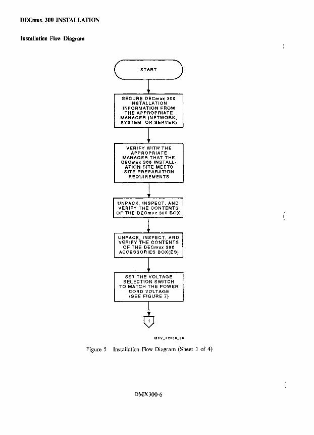
DECmux 300 INSTALLATION
Installation Flow Diagram
C ____ START-)
1 SECURE DECmux 300
INSTALLATION INFORMATION FROM THE APPROPRIATE
MANAGER (NETWORK, SYSTEM, OR SERVER)
VERIFY WITH THE APPROPRIATE
MANAGER THAT THE DECmux 300 INSTALL
ATION SITE MEETS SITE PREPARATION
REQUIREMENTS
UNPACK, INSPECT, AND VERIFY THE CONTENTS
OF THE DECmux 300 BOX
UNPACK, INSPECT, AND VERIFY THE CONTENTS
OF THE DECmux 300 ACCESSORIES BOX(ES)
SET THE VOLTAGE SELECTION SWITCH
TO MATCH THE POWER CORD VOLTAGE (SEE FIGURE 7)
Figure 5 Installation Flow Diagram (Sheet 1 of 4)
DMX300-6
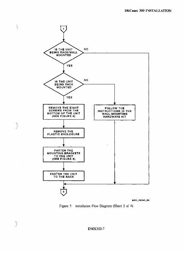
)
REMOVE THE EIGHT SCREWS FROM THE
BOTTOM OF THE UNIT (SEE FIGURE 6)
FASTEN THE MOUNTING BRACKETS
TO THE UNIT (SEE FIGURE 6)
NO
NO
DECmux 300 INSTALLATION
FOLLOW THE INSTRUCTIONS IN THE
WALL-MOUNTING HARDWARE KIT
Figure 5 Installation Flow Diagram (Sheet 2 of 4)
DMX300-7
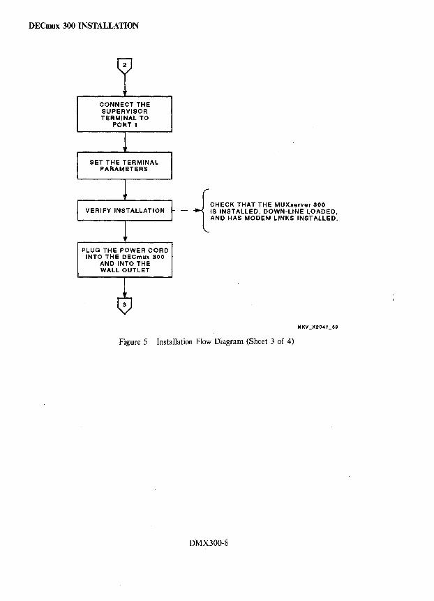
DECmux 300 INSTALLATION
CONNECT THE SUPERVISOR TERMINAL TO
PORT 1
SET THE TERMINAL PARAMETERS
PLUG THE POWER CORD INTO THE DECmux 300
AND INTO THE WALL OUTLET
{
CHECK THAT THE MUXserver 300 - IS INSTALLED. DOWN-LINE LOADED.
AND HAS MODEM LINKS INSTALLED.
Figure 5 Installation Flow Diagram (Sheet 3 of 4)
DMX300-8

)
\, )
VERIFY DECmux 300 OPERATION
(SEE FIGURE 8)
INSTALL THE SYNCHRONOUS LINE
CABLES AND CHECK OUT THE MUXserverl
DECmux 300 NETWORK
C __ STOP_)
DECmux 300 INSTALLATION
• VERIFY THAT THE GREEN LED IS LIT ON THE REAR OF THE DECmux 300.
• THE TERMINAL ON THE SUPERVISOR PORT SHOULD DISPLAY A MESSAGE 20 SECONDS AFTER POWER-UP.
• PRESS THE RETURN KEY SEVERAL TIMES. THE "DM300_CONSOLE>" PROMPT SHOULD APPEAR. •
• REFER TO THE TROUBLESHOOTING SECTION IF THE ABOVE MESSAGE WAS NOT DISPLAYED.
• IF THE DECmux 300 IS NOT ATTACHED TO A WORKING SYNCHRONOUS PORT, OR THE MUXserver 300 IS DOWN, THE DECmux 300 WILL DISPLAY THE DM300 CONSOLE> PROMPT. IF THE NETWORK DOES COME Up, THE LOCAL> PROMPT IS DISPLAYED.
Figure 5 Installation Flow Diagram (Sheet 4 of 4)
DMX300-9
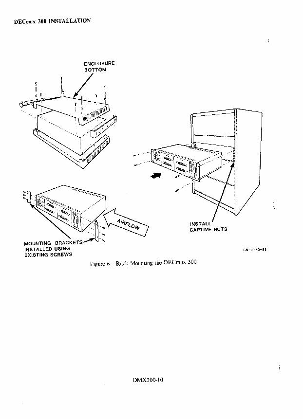
DECrnux 300 INSTALLATION
INSTALLED USING EXISTING SCREWS
INSTALL CAPTIVE NUTS
Figure 6 Rack Mounting the DECmux 300
DMX300-10
SN-0170-88
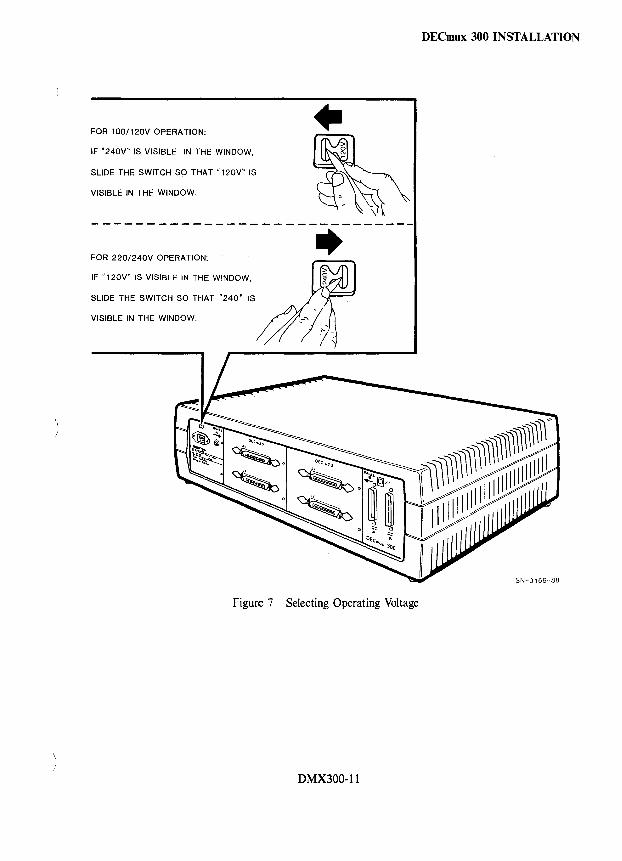
FOR 100/120V OPERATION:
IF "240V" IS VISIBLE IN THE WINDOW,
SLIDE THE SWITCH SO THAT "120V" IS
VISIBLE IN THE WINDOW.
• -------------- ---------------
FOR 220/240V OPERATION:
IF "120V" IS VISIBLE IN THE WINDOW,
SLIDE THE SWITCH SO THAT "240' IS
VISIBLE IN THE WINDOW.
..
Figure 7 Selecting Operating Voltage
DMX300-11
DECmux 300 INSTALLATION
SN-Q 169-88
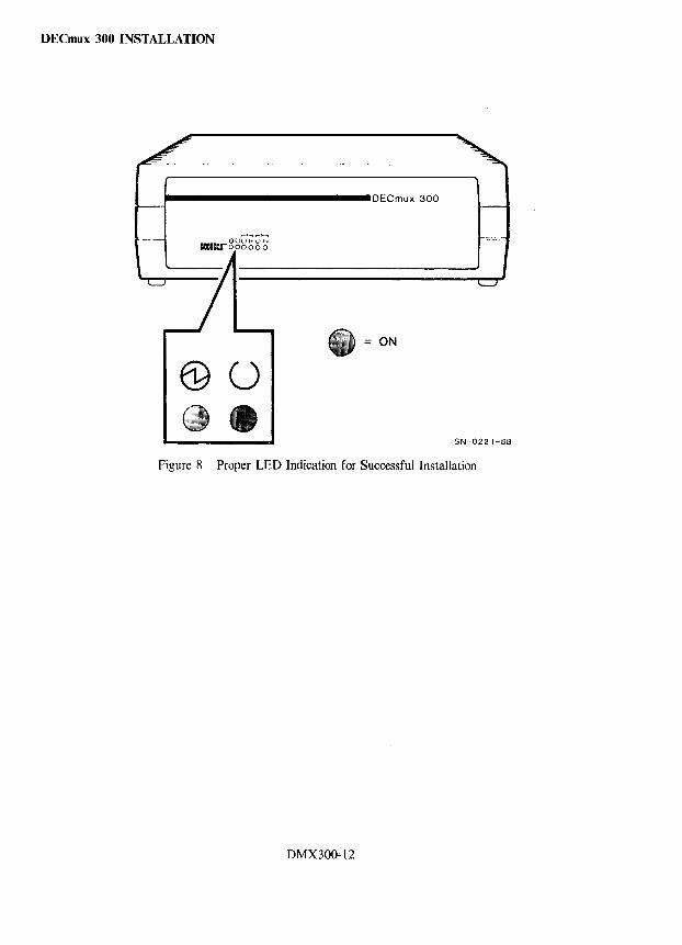
DECmux 300 INSTALLATION
........................... OECmux 300
ON
@o SN-0221-88
Figure 8 Proper LED Indication for Successful Installation
DMX300~12
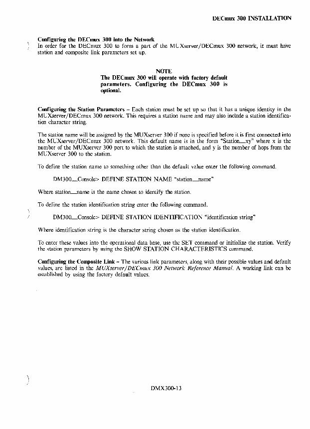
)
\
DECmux 300 INSTALLATION
Configuring the DECmux 300 into the Network In order for the DECmux 300 to form a part of the MUXserver/DECmux 300 network, it must have station and composite link parameters set up.
NOTE The DECmux 300 will operate with factory default parameters. Configuring the DECmux 300 is optional.
Configuring the Station Parameters - Each station must be set up so that it has a unique identity in the MUXserver /DECmux 300 network. This requires a station name and may also include a station identification character string.
The station name will be assigned by the MUXserver 300 if none is specified before it is first connected into the MUXserver/DECmux 300 network. This default name is in the form "Station_xy" where x is the number of the MUXserver 300 port to which the station is attached, and y is the number of hops from the MUXserver 300 to the station.
To define the station name to something other than the default value enter the following command.
DM300_Console> DEFINE STATION NAME "station_name"
Where station_name is the name chosen to identify the station.
To define the station identification string enter the following command.
DM300_Console> DEFINE STATION IDENTIFICATION "identification string"
Where identification string is the character string chosen as the station identification.
To enter these values into the operational data base, use the SET command or initialize the station. Verify the station parameters by using the SHOW STATION CHARACTERISTICS command.
Configuring the Composite Link - The various link parameters, along with their possible values and default values, are listed in the MUXserver / DECmux 300 Network Reference Manual. A working link can be established by using the factory default values.
DMX300-13
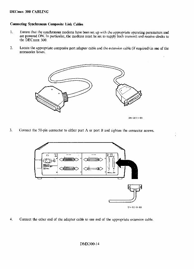
DECmux 300 CABLING
Connecting Synchronous Composite Link Cables
1. Ensure that the synchronous modems have been set up with the appropriate operating parameters and are powered ON. In particular, the modems must be set to supply both transmit and receive clocks to the DECmux 300.
2. Locate the appropriate composite port adapter cable and the extension cable (if required) in one of the accessories boxes.
SN-0211-88
3. Connect the 50-pin connector to either port A or port B and tighten the connector screws.
SN-0219-88
4. Connect the other end of the adapter cable to one end of the appropriate extension cable.
DMX300-14
DECmux 300 CABLING
5. Connect the other end of the extension cable or the adapter cable to the synchronous modem.
The yellow Composite Link Ready LEDs for each composite port will illuminate if that port is connected to a synchronous modem and the modem is powered ON and functioning correctly.
6. Repeat steps 1 through 5 for the other composite port if required.
NOTE If using the RS-422-A null-modem cable (BC19Y-IO) to connect the DECmux 300 with a local DECmux 300 or MUXserver 300, connect one end of the cable to the composite port on the DECmux 300 and the other end of the cable to the composite port on the DECmux 300 or MUXserver 300.
For mterface specific guidelines refer to the MUXserver / DECmux 300 Network Installation Manual.
DMX300-15
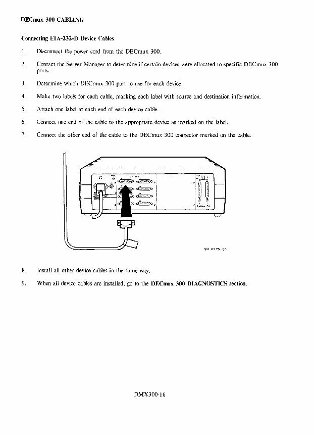
DECmux 300 CABLING
Connecting EIA-232-D Device Cables
1. Disconnect the power cord from the DECmux 300.
2. Contact the Server Manager to determine if certain devices were allocated to specific DECmux 300 ports.
3. Determine which DECmux 300 port to use for each device.
4. Make two labels for each cable, marking each label with source and destination information.
5. Attach one label at each end of each device cable.
6. Connect one end of the cable to the appropriate device as marked on the label.
7. Connect the other end of the cable to the DECmux 300 connector marked on the cable.
8. Install all other device cables in the same way.
9. When all device cables are installed, go to the DECmux 300 DIAGNOSTICS section.
DMX300-16
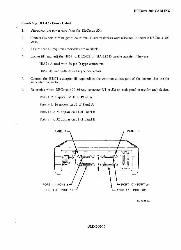
DECmux 300 CABLING
Connecting DEC423 Device Cables
I. Disconnect the power cord from the DECmux 300.
2. Contact the Server Manager to determine if certain devices were allocated to specific DECmux 300 ports.
3. Ensure that all required accessories are available.
4. Locate (if required) the H8571-x DEC423 to EIA-232-D passive adapter. They are:
H8571-A used with 25-pin D-type connectors
H8571-B used with 9-pin D-type connectors
5. Connect the H8571-x adapter (if required) to the communications port of the devices that use the associated connector.
6. Determine which DECmux 300 36-way connector (11 or J2) on each panel to use for each device.
Ports 1 to 8 appear on J 1 of Panel A
Ports 9 to 16 appear on 12 of Panel A
Ports 17 to 24 appear on J 1 of Panel B
Ports 25 to 32 appear on J2 of Panel B
PORT 1 - PORT 8 PORT 17 - PORT 24
SN-0226-88
DMX300-17
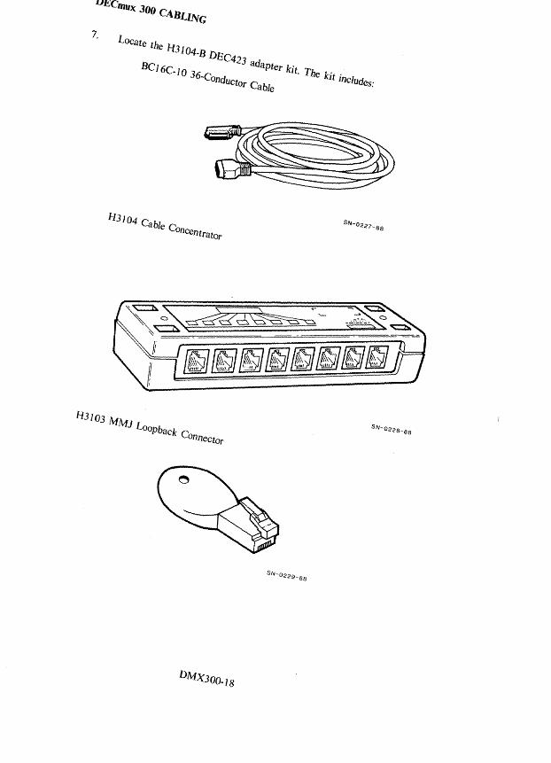
LOcate th e 1-010 4-BDE
BC C423 ad 16C-IO 36 apter kit. Th .
-Conductor Cable e kIt includes:
1-13104 Cable C onCCntra.tor
~~~
fI3103 i'v[i'v[J
---- --
l&§J[§Eifjif!jJfjJfEjJl§j
LooPback C onnector
Dl\fX300_18
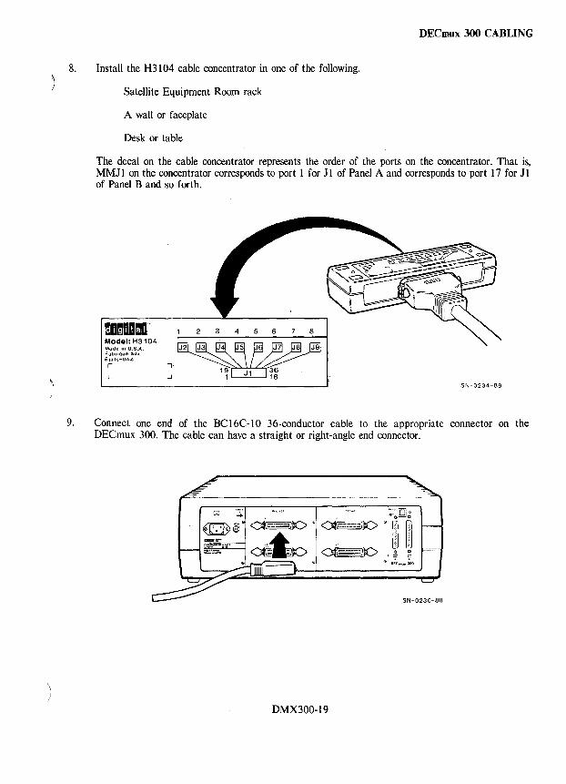
DECmux 300 CABLING
8. Install the H3104 cable concentrator in one of the following.
Satellite Equipment Room rack
A wall or faceplate
Desk or table
The decal on the cable concentrator represents the order of the ports on the concentrator. That is, MM11 on the concentrator corresponds to port 1 for 11 of Panel A and corresponds to port 17 for 11 of Panel B and so forth.
momODmo" Model: H3104 Made in U.S.A. Fabrique aUl(
Etats-Unis r ..,
L
9. Connect one end of the BC16C-IO 36-conductor cable to the appropriate connector on the DECmux 300. The cable can have a straight or right-angle end connector.
-+ ~'IQ'"
:.t:;l~ 0' <€=:JlO · 04i< DlC> • ~ ~ io'=-" ~~ O((;:-:=:iilO ~ ~
@ DEC"' .... lOO
SN-0230-88
DMX300-19
DECmux 300 CABLING
10. Lock the cable plug to the connector using the spring latches provided on the DECmux 300 connector.
11. Connect the other end of the BCI6C-I0 36-conductor cable to connector Jl on the H3104 cable concentrator.
12. Lock the cable plug to connector Jl with the spring latches provided on the Jl connector.
13. Determine which DECmux 300 port to use for each device.
14. Locate the BCI6E-xx 6-conductor cable (DEC OFFICE cable).
15. Make two labels for each cable, marking each label with source and destination information.
16. Attach one label to each end of each BCI6E-xx cable.
17. Connect one end of the cable to the cable concentrator MMJ that corresponds to the DECmux 300 port marked on the label.
18. Connect the other end of the cable to the H8571-x adapter, or to the appropriate device connector, as marked on the label.
19. Repeat steps 14 through 18 for each device to be connected to the same 36-way connector.
20. Repeat steps 6 through 13 to connect cable concentrators to each 36-way connector on the DECmux 300.
21. When all device cables are installed, go to the DECmux 300 DIAGNOSTICS section.
DMX300-20
DECmux 300 DIAGNOSTICS
Self-Test Diagnostics The DECmux 300 self-test can run in one of the following modes.
• Normal mode • Manufacturing mode • Fatal Error mode
Normal Mode - This is the mode under which the self-test diagnostic typically runs. If no errors are detected in Normal mode, the test runs for about 33 seconds, lights the Ready LED, and transfers control to the DECmux 300 firmware. If a fatal error is detected, self-test enters the Fatal Error mode.
Manufacturing Mode - Self-test runs in this mode when the manufacturing mode jumper is connected. In this mode, the self-test program loops continually through all the individual tests.
NOTE The READY LED flashes at the completion of each test. If a fatal error is detected, the READY LED is ON permanently. When a complete cycle of tests is completed, the yellow LEDs and the Ready LED flash together.
Manufacturing mode tests dynamic memory more extensively and runs for about 55 seconds. All errors are fatal and cause the Ready LED to light and halt the test.
To terminate the Manufacturing mode, remove the jumper and recycle power.
) Fatal Error Mode - Self-test enters the Fatal Error mode when a fatal error is detected. All errors are fatal in Manufacturing mode.
The error routine WRITEs the name of the test that failed to a byte in the EEPROM.
In Manufacturing mode, a test restart is disabled until the error code in EEPROM is cleared by the power-up reset procedure.
Self-Test Program Tests There are two groups of tests that are run during the self-test program; the asynchronous side tests and the synchronous side tests. Refer to the DECmux 300 Technical Manual for details.
DMX300-21
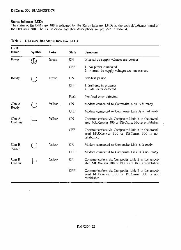
DECmux 300 DIAGNOSTICS
Status Indicator LEDs The status of the DECmux 300 is indicated by the Status Indicator LEDs on the control/indicator panel of the DECmux 300. The six indicators and their descriptions are provided in Table 4.
Table 4 DECmux 300 Status Indicator LEDs
LED Name Symbol Color State Symptom
Power G1 Green ON Internal dc supply voltages are correct
OFF 1. No power connected 2. Internal dc supply voltages are not correct
Ready U Green ON Self-test passed
OFF 1. Self-test in progress 2. Fatal error detected
Flash Nonfatal error detected
Chn A U Yellow ON Modem connected to Composite Link A is ready Ready
OFF Modem connected to Composite Link A is not ready
Chn A Yellow ON Communications via Composite Link A to the associ-On-Line ated MUXserver 300 or DECmux 300 is established
OFF Communications via Composite Link A to the associ-ated MUXserver 300 or DECmux 300 is not established
Chn B U Yellow ON Modem connected to Composite Link B is ready Ready
OFF Modem connected to Composite Link B is not ready
Chn B Yellow ON Communications via Composite Link B to the associ-On-Line ated MUXserver 300 or DECmux 300 is established
OFF Communications via Composite Link B to the associ-ated MUXserver 300 or DECmux 300 is not established
DMX300-22
)
~ )
DECrnux 300 DIAGNOSTICS
The meaning of the Ready LED is expanded as follows.
• Normal mode
Ready LED ON - Self-test has completed without detecting any errors.
Ready LED blinking (250 ms ON/250 ms OFF) - Indicates a nonfatal hardware error and an error message is displayed on the console terminal. Refer to the MUXserver / DECmux 300 Network Reference Manual for a complete description of the diagnostic error messages.
• Manufacturing mode
Ready LED ON - A fatal hardware error was detected.
Ready LED ON (for 25 ms periodically) - Self test is executing successfully.
Ready LED blinking (250 ms ON/250 ms OFF) - The EEPROM error byte is not cleared.
DMX300-23
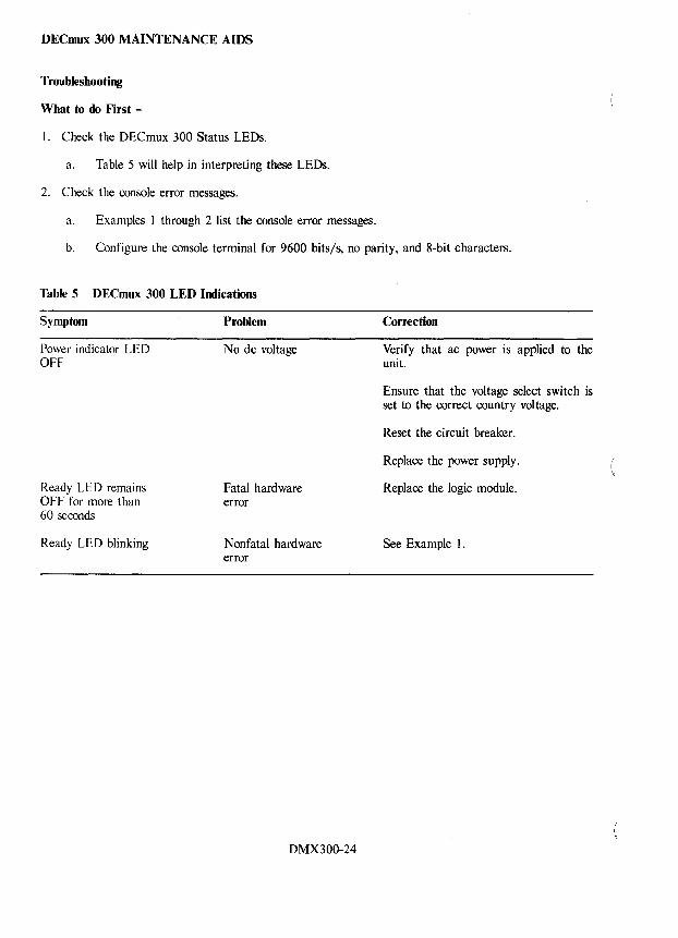
DECmux 300 MAINTENANCE AIDS
Troubleshooting
What to do First -
I. Check the DECmux 300 Status LEDs.
a. Table 5 will help in interpreting these LEDs.
2. Check the console error messages.
a. Examples 1 through 2 list the console error messages.
b. Configure the console terminal for 9600 bits/s, no parity, and 8-bit characters.
Table 5 DECmux 300 LED Indications
Symptom
Power indicator LED OFF
Ready LED remains OFF for more than 60 seconds
Ready LED blinking
Problem
No dc voltage
Fatal hardware error
Nonfatal hardware error
DMX300-24
Correction
Verify that ac power is applied to the unit.
Ensure that the voltage select switch is set to the correct country voltage.
Reset the circuit breaker.
Replace the power supply.
Replace the logic module.
See Example 1.
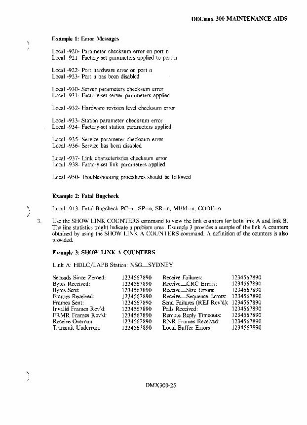
) 3.
) I
DECmux 300 MAINTENANCE AIDS
Example 1: Error Messages
Local -920- Parameter checksum error on port n Local -921- Factory-set parameters applied to port n
Local -922- Port hardware error on port n Local -923- Port n has been disabled
Local -930- Server parameters checksum error Local -931- Factory-set server parameters applied
Local -932- Hardware revision level checksum error
Local -933- Station parameter checksum error Local -934- Factory-set station parameters applied
Local -935- Service parameter checksum error Local -936- Service has been disabled
Local -937- Link characteristics checksum error Local -938- Factory-set link parameters applied
Local -950- Troubleshooting procedures should be followed
Example 2: Fatal Bugcheck
Local -913- Fatal Bugcheck PC=n, SP=on, SR=n, MEM=n, CODE=n
Use the SHOW LINK COUNTERS command to view the link counters for both link A and link B. The line statistics might indicate a problem area. Example 3 provides a sample of the link A counters obtained by using the SHOW LINK A COUNTERS command. A definition of the counters is also provided.
Example 3: SHOW LINK A COUNTERS
Link A: HDLC/LAPB Station: NSG_SYDNEY
Seconds Since Zeroed: Bytes Received: Bytes Sent: Frames Received: Frames Sent: Invalid Frames Rcv'd: FRMR Frames Rcv'd: Recei ve Overrun: Transmit Underrun:
1234567890 1234567890 1234567890 1234567890 1234567890 1234567890 1234567890 1234567890 1234567890
Receive Failures: Receive_CRC Errors: Receive~ize Errors: Receive~equence Errors: Send Failures (REJ Rcv'd): Polls Received: Remote Reply Timeouts: RNR Frames Received: Local Buffer Errors:
DMX300-25
1234567890 1234567890 1234567890 1234567890 1234567890 1234567890 1234567890 1234567890 1234567890
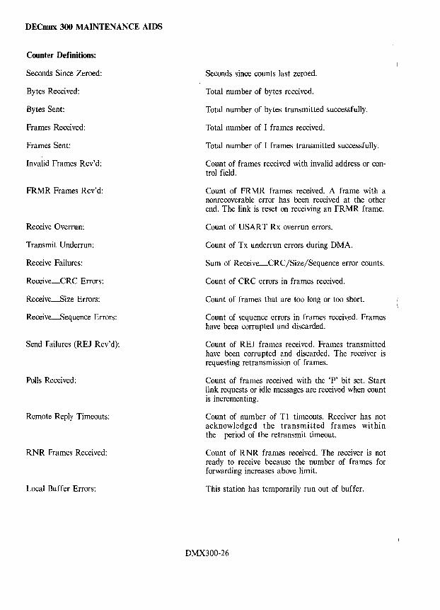
DECmux 300 MAINTENANCE AIDS
Counter Definitions:
Seconds Since Zeroed:
Bytes Received:
Bytes Sent:
Frames Received:
Frames Sent:
Invalid Frames Rcv'd:
FRMR Frames Rcv'd:
Receive Overrun:
Transmit Underrun:
Receive Failures:
Receive_CRC Errors:
Receive~ize Errors:
Receive~equence Errors:
Send Failures (REJ Rcv'd):
Polls Received:
Remote Reply Timeouts:
RNR Frames Received:
Local Buffer Errors:
Seconds since counts last zeroed.
Total number of bytes received.
Total number of bytes transmitted successfully.
Total number of I frames received.
Total number of I frames transmitted successfully.
Count of frames received with invalid address or control field.
Count of FRMR frames received. A frame with a nonrecoverable error has been received at the other end. The link is reset on receiving an FRMR frame.
Count of USAR T Rx overrun errors.
Count of Tx underrun errors during DMA.
Sum of Receive_CRC/Size/Sequence error counts.
Count of CRC errors in frames received.
Count of frames that are too long or too short.
Count of sequence errors in frames receiv:ed. Frames have been corrupted and discarded.
Count of REJ frames received. Frames transmitted have been corrupted and discarded. The receiver is requesting retransmission of frames.
Count of frames received with the 'P' bit set. Start link requests or idle messages are received when count is incrementing.
Count of number of Tl timeouts. Receiver has not acknowledged the transmitted frames within the period of the retransmit timeout.
Count of RNR frames received. The receiver is not ready to receive because the number of frames for forwarding increases above limit.
This station has temporarily run out of buffer.
DMX300-26
\, )
DECmux 300 MAINTENANCE AIDS
Problems with the Composite Link - Use the following procedure when troubleshooting the composite link from either the MUXserver 300 or DECmux 300.
1. Connect a console terminal to the local unit.
2. Press the <RETURN> key a few times and log into the Local mode. If the DECmux 300 has not established communications with the MUXserver 300, the Standalone mode will be entered instead of the Normal mode. Under the Standalone mode, only the following commands are allowed.
SET/DEFINE/SHOW /LIST [LINK I PORT I STATION] TEST [LINK I PORT] SET/DEFINE PRIVILEGED PASSWORD SET PRIVILEGED
3. Use the SET PRIVILEGED command, then continue with the next step.
4. Enable broadcast on the console port by using the SET PORT BROADCAST ENABLED command. It may be necessary to reset the unit parameters to the factory defaults. If so, press and hold the Reset button while removing and reinserting the ac power cord.
After verifying the power and interface connections to the MUXserver 300, DECmux 300, and modems, proceed with Table 6.
DMX300-27
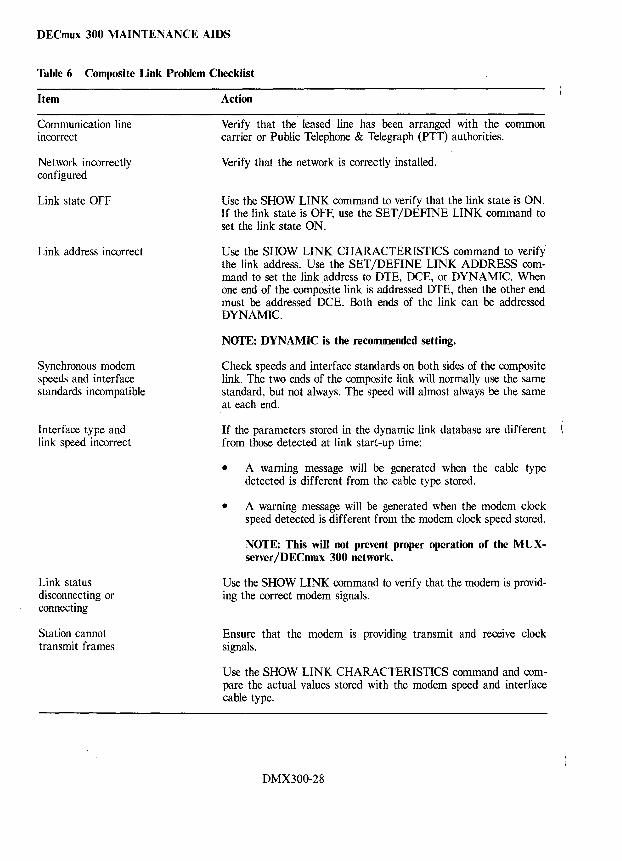
DECmux 300 MAINTENANCE AIDS
Table 6 Composite Link Problem Checklist
Item
Communication line incorrect
Network incorrectly configured
Link state OFF
Link address incorrect
Synchronous modem speeds and interface standards incompatible
Interface type and link speed incorrect
Link status disconnecting or connecting
Station cannot transmit frames
Action
Verify that the leased line has been arranged with the common carrier or Public Telephone & Telegraph (PIT) authorities.
Verify that the network is correctly installed.
Use the SHOW LINK command to verify that the link state is ON. If the link state is OFF, use the SET jDEFlNE LINK command to set the link state ON.
Use the SHOW LINK CHARACTERISTICS command to verify the link address. Use the SET jDEFlNE LINK ADDRESS command to set the link address to DTE, DCE, or DYNAMIC. When one end of the composite link is addressed DTE, then the other end must be addressed DCE. Both ends of the link can be addressed DYNAMIC.
NOTE: DYNAMIC is the recommended setting.
Check speeds and interface standards on both sides of the composite link. The two ends of the composite link will normally use the same standard, but not always. The speed will almost always be the same at each end.
If the parameters stored in the dynamic link database are different from those detected at link start-up time:
• A warning message will be generated when the cable type detected is different from the cable type stored.
• A warning message will be generated when the modem clock speed detected is different from the modem clock speed stored.
NOTE: This will not prevent proper operation of the MUXserver/DECmux 300 network.
Use the SHOW LINK command to verify that the modem is providing the correct modem signals.
Ensure that the modem is providing transmit and receive clock signals.
Use the SHOW LINK CHARACTERISTICS command and compare the actual values stored with the modem speed and interface cable type.
DMX300-28
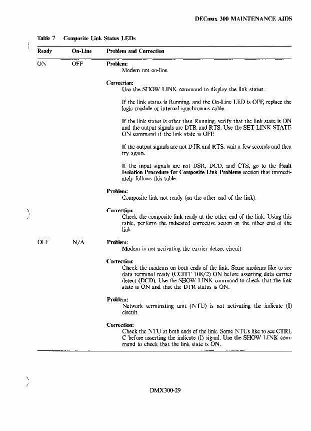
)
)
DECmux 300 MAINTENANCE AIDS
Table 7 Composite Link Status LEDs
Ready On-Line
ON OFF
OFF N/A
Problem and Correction
Problem: Modem not on-line
Correction: Use the SHOW LINK command to display the link status.
If the link status is Running, and the On-Line LED is OFF, replace the logic module or internal synchronous cable.
If the link status is other then Running, verify that the link state is ON and the output signals are DTR and RTS. Use the SET LINK STATE ON command if the link state is OFE
If the output signals are not DTR and RTS, wait a few seconds and then try again.
If the input signals are not DSR, DCD, and CTS, go to the Fault Isolation Procedure for Composite Link Problems section that immediately follows this table.
Problem: Composite link not ready (on the other end of the link).
Correction: Check the composite link ready at the other end of the link. Using this table, perform the indicated corrective action on the other end of the link.
Problem: Modem is not activating the carrier detect circuit
Correction: Check the modems on both ends of the link. Some modems like to see data terminal ready (CCITT 108/2) ON before asserting data carrier detect (DCD). Use the SHOW LINK command to check that the link state is ON and that the DTR status is ON.
Problem: Network terminating unit (NTU) is not activating the indicate (I) circuit.
Correction: Check the NTU at both ends of the link. Some NTUs like to see CTRL C before asserting the indicate (I) signal. Use the SHOW LINK com~ mand to check that the link state is ON.
DMX300-29
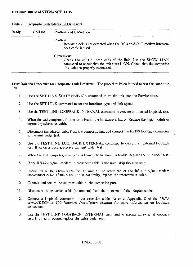
DECmux 300 MAINTENANCE AIDS
Table 7 Composite Link Status LEDs (Cont)
Ready On-Line Problem and Correction
Problem: Receive clock is not detected when the RS-422-A/null-modem interconnect cable is used.
Correction: Check the units at both ends of the link. Use the SHOW LINK command to check that the link state is ON. Check that the composite link cable is properly connected.
Fault Isolation Procedure for Composite Link Problems - The procedure below is used to test the composite link.
1. Use the SET LINK STATE SERVICE command to set the link into the Service state.
2. Use the SET LINK command to set the interface type and link speed.
3. Use the TEST LINK LOOPBACK INTERNAL command to execute an internalloopback test.
4. When the test completes, if an error is found, the hardware is faulty. Replace the logic module or internal synchronous cable.
5. Disconnect the adapter cable from the composite link and connect the H3199100pback connector to the unit under test.
6. Use the TEST LINK LOOPBACK EXTERNAL command to execute an externalloopback test. If an error occurs, replace the unit under test.
7. When the test completes, if an error is found, the hardware is faulty. Replace the unit under test.
8. If the RS-422-A/null-modem interconnect cable is not used, skip the next step.
9. Repeat all of the above steps for the unit at the other end of the RS-422-A/null-modem interconnect cable. If the other unit is not faulty, replace the interconnect cable.
10. Connect and secure the adapter cable to the composite port.
11. Disconnect the extension cable (or modem) from the other end of the adapter cable.
12. Connect a loopback connector to the extension cable. Refer to Appendix D of the MUXserver / DECmux 300 Network Installation Manual for more information on loopback connectors.
13. Use the TEST LINK LOOPBACK EXTERNAL command to execute an externalloopback test. If an error occurs, replace the cable under test.
DMX300-30
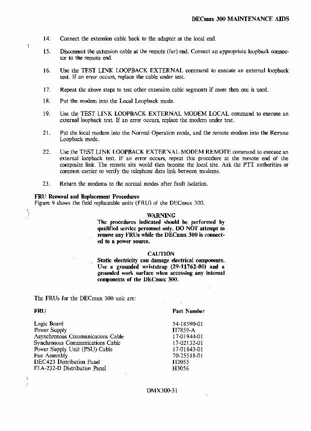
1 /
DECmux 300 MAINTENANCE AIDS
14. Connect the extension cable back to the adapter at the local end.
15. Disconnect the extension cable at the remote (far) end. Connect an appropriate loopback connector to the remote end.
16. Use the TEST LINK LOOPBACK EXTERNAL command to execute an externalloopback test. If an error occurs, replace the cable under test.
17. Repeat the above steps to test other extension cable segments if more then one is used.
18. Put the modem into the Local Loopback mode.
19. Use the TEST LINK LOOPBACK EXTERNAL MODEM LOCAL command to execute an external loopback test. If an error occurs, replace the modem under test.
21. Put the local modem into the Normal Operation mode, and the remote modem into the Remote Loopback mode.
22. Use the TEST LINK LOOPBACK EXTERNAL MODEM REMOTE command to execute an external loopback test. If an error occurs, repeat this procedure at the remote end of the composite link. The remote site would then become the local site. Ask the PTT authorities or common carrier to verify the telephone data link between modems.
23. Return the modems to the normal modes after fault isolation.
FRU Removal and Replacement Procedures Figure 9 shows the field replaceable units (FRU) of the DECmux 300.
WARNING The procedures indicated should be performed by qualified service personnel only. DO NOT attempt to remove any FRUs while the DECmux 300 is connected to a power source.
CAUTION Static electricity can damage electrical components. Use a grounded wrists trap (29-11762-00) and a grounded work surface when accessing any internal components ~f the DECmux 300.
The FRUs for the DECmux 300 unit are:
FRU
Logic Board Power Supply Asynchronous Communications Cable Synchronous Communications Cable Power Supply Unit (PSU) Cable Fan Assembly DEC423 Distribution Panel EIA-232-D Distribution Panel
Part Number
54-18590-01 H7859-A 17-01944-01 17-02132-01 17-01843-01 70-25518-01 H3055 H3056
DMX300-31
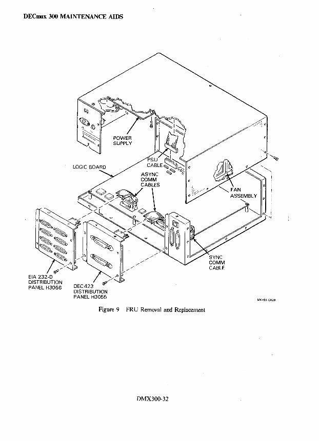
DECmux 300 MAINTENANCE AIDS
Figure 9 FRU Removal and Replacement
DMX300-32
DECNA INSTALLATION
DECNA ETHERNET COMMUNICATIONS CONTROLLER
General Description The DECNA (DIGITAL Ethernet CTI Bus Network Adapter) module is the Ethernet communications controller for the Professional 300 series computer. The DECNA controller allows the computer to:
• Exchange data with other computers and workstations on a local area network that has PRO/DECnet, and
• Exchange data with other network software that use the Ethernet communications systems.
The DECNA controller module is installed in the card cage inside the Professional computer. The computer is connected to the Ethernet network by the transceiver cable that comes with the DECNA controller.
Features
• Data transfer rate of 10M bits/so
• Performs Direct Memory Access (DMA) transfers to and from CPU memory.
• Contains a built-in test program that tests the controller when the Professional computer is first turned on.
• Performs internal and external loopback of data and can assist with the loopback of data from other stations.
Reference Documentation
• PRO/DECnet User's Guide
• Introduction to Local Area Networks
• DELNI Installation/Owner's Manual
• Ethernet Installation Guide
• The Professional 300 Series Communications Handbook
• Professional 300 Series Owner's Manual
• Professional 300 Series Pocket Service Guide
Hardware Components (Figure I)
• DECNA option module (P/N 54-15987-01)
• PVC transceiver cable 5 m (16.4 ft) (PIN 17-00612-01)
• Loopback connector (P /N 12-22196-01)
DECNA-I
AA-V445A-TH
EB-22714-18
EK-DELNI-IN
EK-ETHER-IN
EB-26165-55
AZ-N597A-TH
EK-PC350-PS
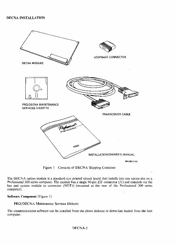
DECNAINSTALLATION
DECNA MODULE
PRO/DECNA MAINTENANCE SERVICES DISKETTE
LOOPBACK CONNECTOR
TRANSCEIVER CABLE
INSTALLATION/OWNER'S MANUAL
MKV85·1133
Figure I Contents of DECNA Shipping Container
The DECNA option module is a standard size printed circuit board that installs into one option slot on a Professional 300 series computer. The module has a single 90-pin ZIF connector (J I) and connects via the bus and system module to connector (NETI) (mounted at the rear of the Professional 300 series computer).
Software Component (Figure I)
PRO/DECNA Maintenance Services Diskette
The communications software can be installed from the above diskette or down-line loaded from the host computer.
DECNA-2
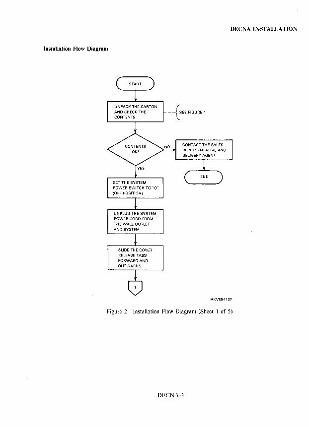
Installation Flow Diagram
UNPACK THE CARTON
AND CHECK THE CONTENTS
SET THE SYSTEM
POWER SWITCH TO "0"
(OFF POSITION)
UNPLUG THE SYSTEM
POWER CORD FROM THE WALL OUTLET
AND SYSTEM
SLIDE THE COVER RELEASE TABS
FORWARD AND
OUTWARDS
-{SEE FIGURE 1
CONTACT THE SALES
REPRESENTATIVE AND
DELIVERY AGENT
DEeNA INSTALLATION
MKV85-113i
Figure 2 Installation Flow Diagram (Sheet I of 5)
DECNA-3
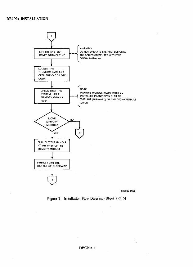
DEeNA INSTALLATION
LOOSEN THE THUMBSCREWS AND OPEN THE CARD CAGE DOOR
CHECK THAT THE SYSTEM HAS A MEMORY MODULE (0034)
PULL OUT THE HANDLE AT THE BASE OF THE MEMORY MODULE
_ DO NOT OPERATE THE PROFESSIONAL
{
WARNING
300 SERIES COMPUTER WITH THE COVER REMOVED
MEMORY MODULE (0034) MUST BE
{
NOTE
- INSTALLED IN ANY OPEN SLOT TO THE LEFT (FORWARD) OF THE -DECNA MODULE (0042)
MKV85-1138
Figure 2 Installation Flow Diagram (Sheet 2 of 5)
DECNA-4
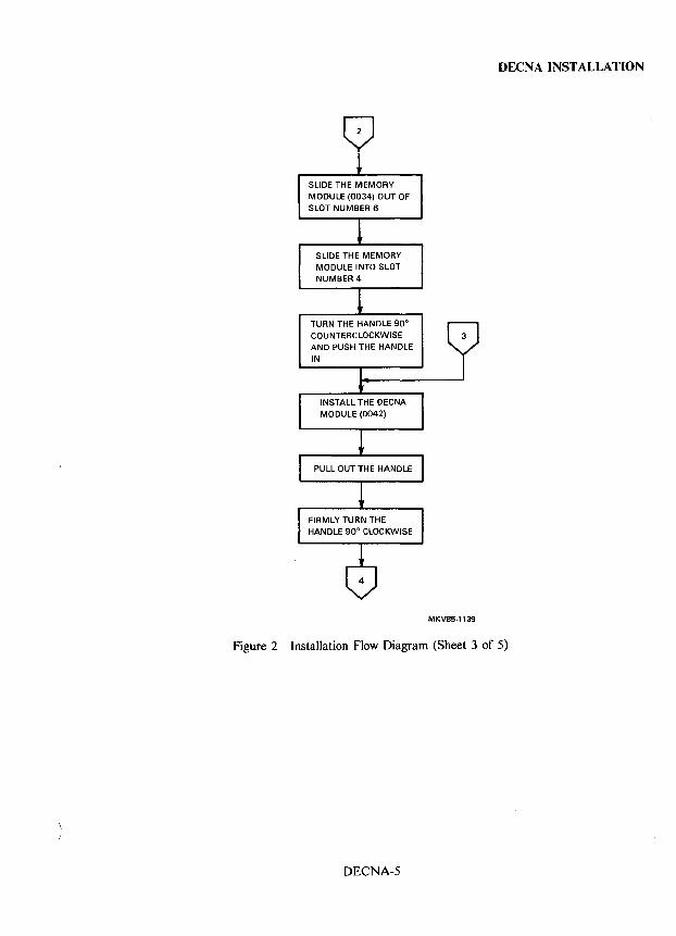
SLIDE THE MEMORY MODULE (0034) OUT OF SLOT NUMBER 6
SLIDE THE MEMORY MODULE INTO SLOT NUMBER 4
TURN THE HANDLE 90° COUNTERCLOCKWISE AND PUSH THE HANDLE
IN
DEeNA INSTALLATION
MKV85-1139
Figure 2 Installation Flow Diagram (Sheet 3 of 5)
DECNA-5
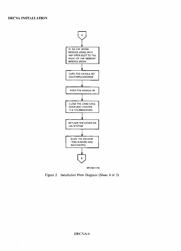
DECNAINSTALLATION
SLIDE THE DECNA MODULE (0042) INTO
ANY OPEN SLOT TO THE
RIGHT OF THE MEMORY MODULE (0034)
CLOSE THE CARD CAGE
DOOR AND TIGHTEN THE THUMBSCREWS
SLIDE THE RELEASE TABS INWARD AND
BACKWARDS
MKV85·1140
Figure 2 Installation Flow Diagram (Sheet 4 of 5)
DECNA-6
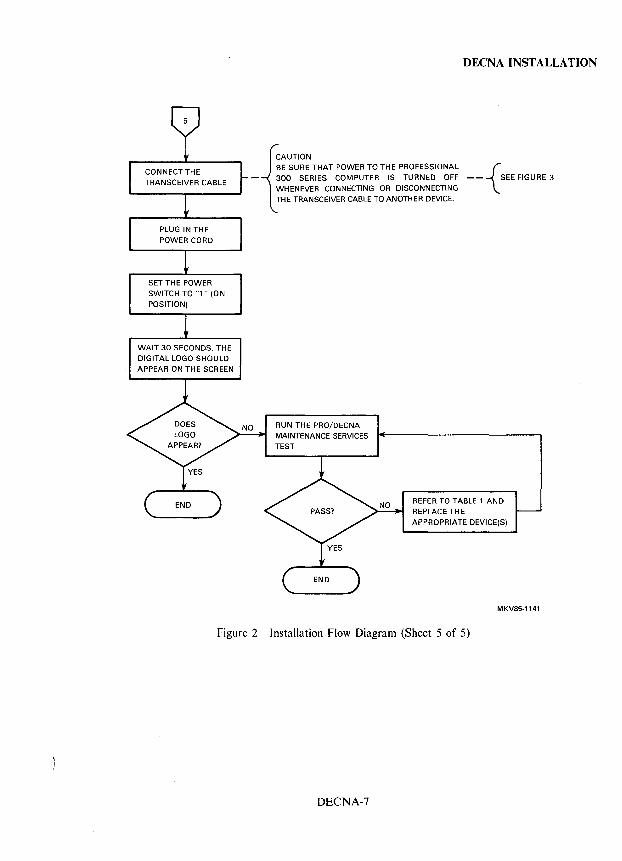
SET THE POWER SWITCH TO '" ., (ON
POSITION)
WAIT 30 SECONDS. THE
DIGITAL LOGO SHOULD APPEAR ON THE SCREEN
DEeNA INSTALLATION
BE SURE THAT POWER TO THE PROFESSIONAL
- 300 SERIES COMPUTER IS TURNED OFF -- {SEE FIGURE 3
{
AUTION
WHENEVER CONNECTING OR DISCONNECTING THE TRANSCEIVER CABLE TO ANOTHER DEVICE.
RUN THE PRO/DECNA MAINTENANCE SERVICES TEST
REFER TO TABLE 1 AND REPLACE THE
APPROPRIATE DEVICE(S)
MKV85·1141
Figure 2 Installation Flow Diagram (Sheet 5 of 5)
DECNA-7
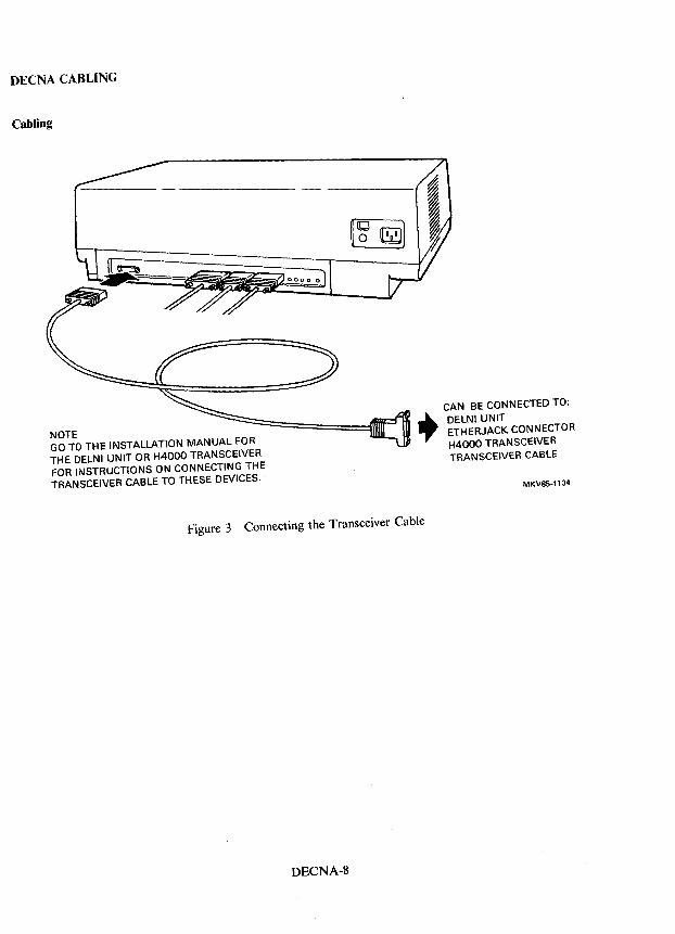
DEeNA CABLING
Cabling
NOTE GO TO THE INSTALLATION MANUAL FOR THE DELNI UNIT OR H4000 TRANSCEIVER FOR INSTRUCTIONS ON CONNECTING THE TRANSCEIVER CABLE TO THESE DEVICES.
CAN BE CONNECTED TO:
~ DELNI UNIT ." ETHERJACK CONNECTOR
H4000 TRANSCEIVER TRANSCEIVER CABLE
MKV85-1134
Figure 3 Connecting the Transceiver Cable
DECNA-8
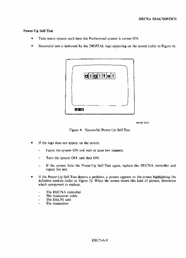
DECNA DIAGNOSTICS
Power-Up Self-Test
• Tests entire system each time the Professional system is turned ON.
• Successful test is indicated by the DIGITAL logo appearing on the screen (refer to Figure 4).
(
~BmDDmD
MKV84-2353
Figure 4 Successful Power-Up Self-Test
• If the logo does not appear on the screen:
Leave the system ON and wait at least two minutes.
Turn the system OFF and then ON.
If the system fails the Power-Up Self-Test again, replace the DECNA controller and repeat the test.
• If the Power-Up Self-Test detects a problem, a picture appears on the screen highlighting the defective module (refer to Figure 5). When the screen shows this kind of picture, determine which component to replace.
The DECNA controller The transceiver cable The DELNI unit The transceiver
DECNA-9
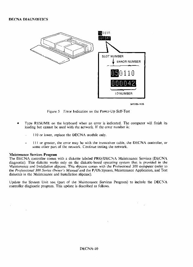
DECNA DIAGNOSTICS
110110 .. SLOT NUMBER
t ERROR NUMBER ~
.0110 PU""m
I 0 NUMBER
MKV85-1135
Figure 5 Error Indication on the Power-Up Self-Test
• Type RESUME on the keyboard when an error is indicated. The computer will finish its loading but cannot be used with the network. If the error number is:
110 or lower, replace the DECNA module only.
111 or greater, the error may be with the transceiver cable, the DECNA controller, or some other part of the network. Continue testing the network.
Maintenance Services Program The DEeNA controller comes with a diskette labeled PRO/DECNA Maintenance Services (DECNA diagnostic). This diskette works only on the diskette-based operating system that is provided in the Maintenance and Installation slipcase. This slipcase comes with the Professional 300 computer (refer to the Professional 300 Series Owner's Manual and the P lOS System, Maintenance Application, and Test diskettes in the Maintenance and Installation slipcase).
Update the System Unit test (part of the Maintenance Services Program) to include the DECNA controller diagnostic program. This update is described as follows.
DECNA-lO
DEeNA DIAGNOSTICS
Installing the DECNA Diagnostic - This procedure installs the DEeNA diagnostic test on the Maintenance Application diskette for maintenance and testing. Perform this procedure after successfully installing the DEeNA controller.
1. Turn the computer OFF.
2. Insert the P lOS system diskette in drive 1 and dose the diskette drive door.
3. Once the P lOS system diskette has been successfully loaded, a message appears on the screen. Now, remove the P lOS diskette and insert the Maintenance Application diskette in drive 1. Press RESUME.
4. Select the Update Program. Press DO.
5. When prompted, insert the PROIDEeNA Maintenance Services diskette in drive 2. Press RESUME.
6. When finished, remove both diskettes from the drives and return them to the Maintenance and Installation slipcase.
Running the Maintenance Services Program - The Power-Up Self-Test runs each time the Professional computer is turned ON. Run the Maintenance Services test along with the other system tests from the Maintenance Services Menu when the system test is selected.
To run the test for the DEeNA controller, follow the instructions in the Professional 300 Series Owner's Manual (Maintenance Application Test Programs section). These instructions are summarized as follows:
1. Place the P lOS diskette in drive 1 and close the diskette drive door.
2. Turn the system power OFF and then ON.
3. Follow the instructions that appear on the monitor.
a. Remove the P lOS diskette.
b. Place the Maintenance Application diskette in drive 1 and close the diskette drive door.
c. Place test diskette in drive 2 and close the diskette drive door.
d. Press RESUME on the keyboard.
4. Select the desired test.
The DEeNA diagnostic test runs as part of the System Unit test. If the test detects an error, the test places a system unit test summary on the screen. Press the HELP key for information and corrective action.
See the Professional 300 Series Pocket Service Guide for information on running the individual option tests in the field service mode.
DEeNA-II
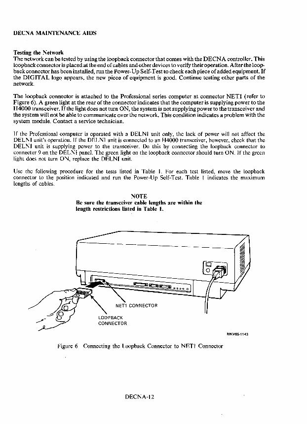
DECNA MAINTENANCE AIDS
Testing the Network The network can be tested by using the loopback connector that comes with the DECNA controller. This loopback connector is placed at the end of cables and other devices to verify their operation. After the loopback connector has been installed, run the Power -Up Self-Test to check each piece of added equipment. If the DIGITAL logo appears, the new piece of equipment is good. Continue testing other parts of the network.
The loopback connector is attached to the Professional series computer at connector NET! (refer to Figure 6). A green light at the rear of the connector indicates that the computer is supplying power to the H 4000 transceiver. If the light does not turn ON, the system is not supplying power to the transceiver and the system will not be able to communicate over the network. This condition indicates a problem with the system module. Contact a service technician.
If the Professional computer is operated with a DELNI unit only, the lack of power will not affect the DELNI unit's operation. If the DELNI unit is connected to an H4000 transceiver, however, check that the DELNI unit is supplying power to the transceiver. Do this by connecting the loopback connector to connector 9 on the DELNI panel. The green light on the loopback connector should turn ON. If the green light does not turn ON, replace the DELNI unit.
Use the following procedure for the tests listed in Table 1. For each test listed, move the loopback connector to the position indicated and run the Power-Up Self-Test. Table I indicates the maximum lengths of cables.
NOTE Be sure the transceiver cable lengths are within the length restrictions listed in Table 1.
Figure 6 Connecting the Loopback Connector to NET I Connector
DECNA-12
MKV85-1143
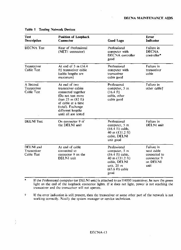
DECNA MAINTENANCE AIDS
Table t Testing Network Devices
Test Position of Loopback Error Description Connector Good Logo Indicator
DEeNA Test Rear of Professional Professional Failure in (NET) connector) computer with DEeNA
DEeNA controller controller* good
Transceiver At end of 5 m (16.4 Professional Failure in Cable Test ft) transceiver cable computer with transceiver
(cable lengths are transceiver cable maximum) cable good
A Second At end of two Professonal Failure in Transceiver transceiver cables computer, 5 m other cablet Cable Test connected together (16.4 ft)
(Do not test more cable, other than 25 m (82 ft) cable good of cable at a time (total). Exchange different lengths until all are tested
DELNI Test On connector 9 of Professional Failure in the DELNI unit computer, 5 m DELNI unit
(16.4 ft) cable, 40m(l3\.2ft) cable, DELNI unit good
DELNI and At end of cable Professional Failure in Transceiver connected to computer, 5 m next cable Cable Test connector 9 on the ()6.4 ft) cable, connected to
DELNI unit 40 m (l3\'2 ft) connector 9 cable, DELNI on DELNI unit, 20 m unit (65.6 ft) cable good
* If the Professional computer (or DELNI unit) is attached to an H4000 transceiver, be sure the green light on the end of the loopback connector lights. If it does not light, power is not reaching the transceiver and the transceiver will not operate.
t If the error indication is still present, then the transceiver or some other part of the network is not working correctly. Notify the system manager or service technician.
DEeNA-I 3
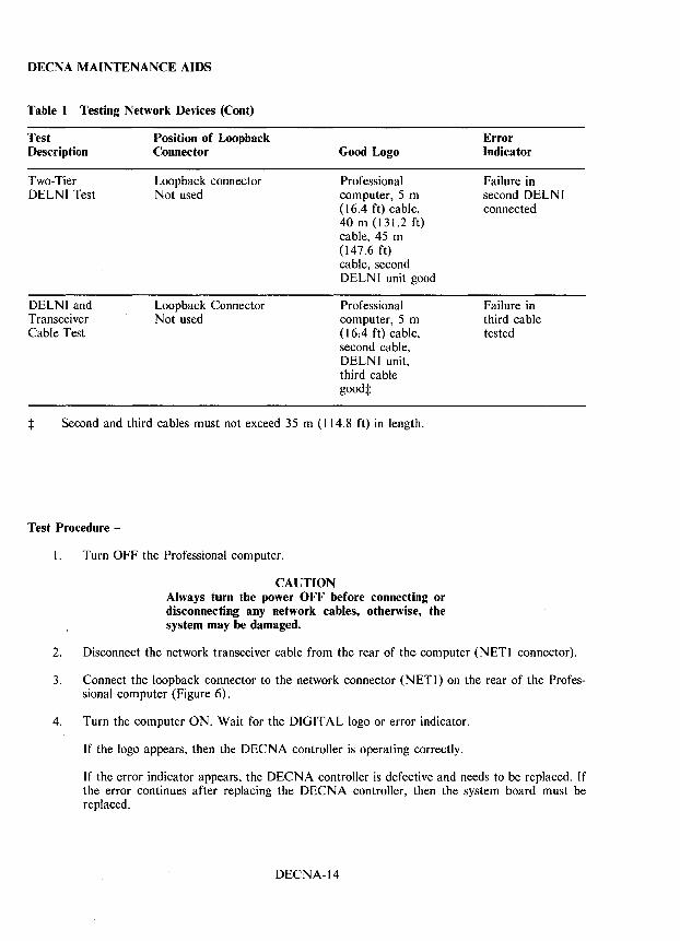
DECNA MAINTENANCE AIDS
Table 1 Testing Network Devices (Cont)
Test Description
Two-Tier DELNI Test
DELNI and Transceiver Cable Test
Position of Loopback Connector
Loopback connector Not used
Loopback Connector Not used
Good Logo
Professional computer, 5 m (16.4 ft) cable, 40 m (131.2 ft) cable, 45 m (147.6 ft) cable, second DELN I unit good
Professional computer, 5 m (16.4 ft) cable, second cable, DELNI unit, third cable goodt
t Second and third cables must not exceed 35 m (I 14.8 ft) in length.
Test Procedure -
I. Turn OFF the Professional computer.
CAUTION Always turn the power OFF before connecting or disconnecting any network cables, otherwise, the system may be damaged.
Error Indicator
Failure in second DELNI connected
Failure in third cable tested
2. Disconnect the network transceiver cable from the rear of the computer (NETI connector).
3. Connect the loopback connector to the network connector (N ET I) on the rear of the Professional computer (Figure 6).
4. Turn the computer ON. Wait for the DIGITAL logo or error indicator.
If the logo appears, then the DECNA controller is operating correctly.
If the error indicator appears, the DECNA controller is defective and needs to be replaced. If the error continues after replacing the DECNA controller, then the system board must be replaced.
DECNA-14
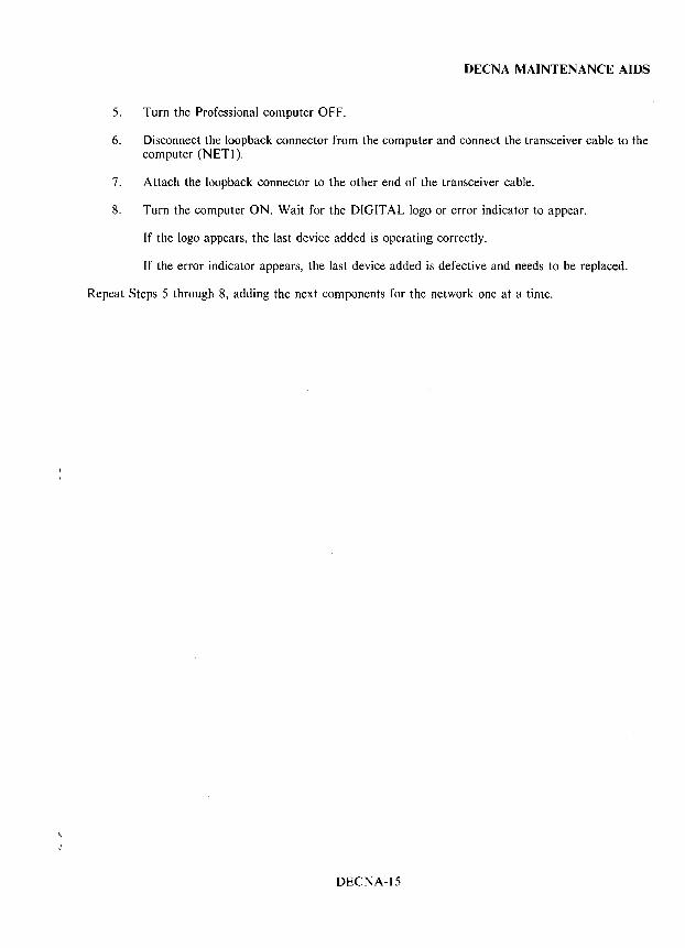
DECNA MAINTENANCE AIDS
5. Turn the Professional computer OFF.
6. Disconnect the loopback connector from the computer and connect the transceiver cable to the computer (NET]).
7. A ttach the loopback connector to the other end of the transceiver cable.
8. Turn the computer ON. Wait for the DIGITAL logo or error indicator to appear.
If the logo appears, the last device added is operating correctly.
If the error indicator appears, the last device added is defective and needs to be replaced.
Repeat Steps 5 through 8, adding the next components for the network one at a time.
DECNA-15

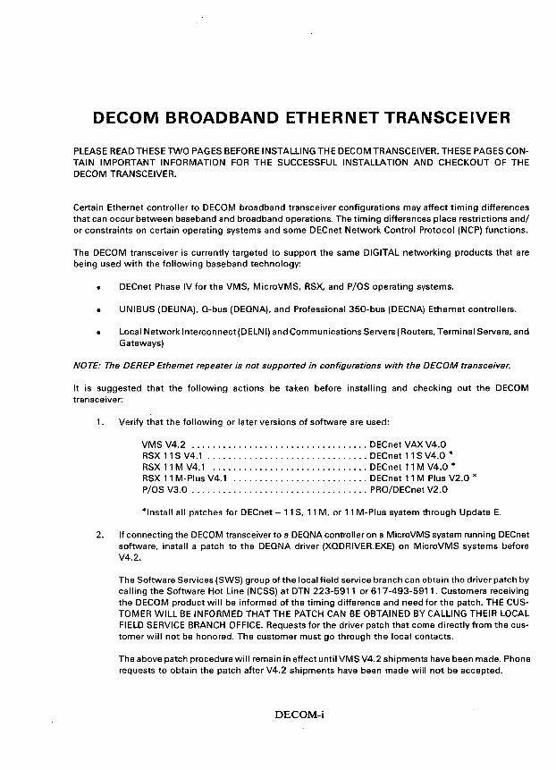
DECOM BROADBAND ETHERNET TRANSCEIVE'R
PLEASE READ THESE TWO PAGES BEFORE INSTALLING THE DECOM TRANSCEIVER. THESE PAGES CONTAIN IMPORTANT INFORMATION FOR THE SUCCESSFUL INSTALLATION AND CHECKOUT OF THE DECOM TRANSCEIVER.
Certain Ethernet controller to DECOM broadband transceiver configurations may affect timing differences that can occur between baseband and broadband operations. The timing differences place restrictions and/ or constraints on certain operating systems and some DECnet Network Control Protocol (NCP) functions.
The DECOM transceiver is currently targeted to support the same DIGITAL networking products that are being used with the following baseband technology:
• DECnet Phase IV for the VMS, MicroVMS, RSX, and P/OS operating systems.
• UNIBUS (DEUNA), Q-bus (DEQNA), and Professional 350-bus (DECNA) Ethernet controllers.
• Local Network Interconnect(DELNI) and Communications Servers (Routers, Terminal Servers, and Gateways)
NOTE: The DEREP Ethernet repeater is not supported in configurations with the DECOM transceiver.
It is suggested that the following actions be taken before installing and checking out the DECOM transceiver:
1. Verify that the following or later versions of software are used:
VMS V4.2 .................................. DECnet VAX V4.0 RSX 11 S V4.1 ............................... DECnet 11 S V4.0 * RSX 11 M V4.1 .............................. DECnet 11 M V4.0 * RSX 11 M-Plus V4.1 .......................... DECnet 11 M Plus V2.0 * P/OS V3.0 .................................. PRO/DECnet V2.0
*Install all patches for DECnet - 11 S, 11 M, or 11 M-Plus system through Update E.
2. If connecting the DECOM transceiver to a DEQNA controller on a MicroVMS system running DECnet software, install a patch to the DEQNA driver (XQDRIVER.EXE) on MicroVMS systems before V4.2.
The Software Services (SWS) group of the local field service branch can obtain the driver patch by calling the Software Hot Line (NCSS) at DTN 223-5911 or 617-493-5911. Customers receiving the DECOM product will be informed of the timing difference and need for the patch. THE CUSTOMER WILL BE INFORMED THAT THE PATCH CAN BE OBTAINED BY CALLING THEIR LOCAL FIELD SERVICE BRANCH OFFICE. Requests for the driver patch that come directly from the customer will not be honored. The customer must go through the local contacts.
The above patch procedure will remain in effect until VMS V4.2 shipments have been made. Phone requests to obtain the patch after V4.2 shipments have been made will not be accepted.
DECOM-i
3. If using the DECOM transceiver with a DEONA controller on an RSX-11 system running DECnet software, issue the following NCP command or commands from a privileged terminal/account.
NCP> CLEAR LOGGING CONSOLE EVENT 5.14 NCP> CLEAR LOGGING FILE EVENT 5.14 NCP> CLEAR LOGGING MONITOR EVENT 5.14
Page DECOM-22 contains a reference to an "Ethernet Controller Self-Test" as "NI Exerciser". This reference is not true in all cases. When the DECOM transceiver is to be tested in a network environment, use the "NI Exerciser" when the flow diagram reads "Run Ethernet Controller Self-Test". This test is called for on pages DECOM-24, -28, -29, -31, -35, and -36.
When the DECOM transceiver is to be tested in a standalone loopback configuration ("RF Loopback" with the variable attenuator or "Digital Loopback" using the DECOM loopback switch), use the "Controller's Functional Diagnostic" when the flow diagram reads "Run Ethernet Controller Self-Test". This occurs on pages DECOM-25, -26, -27, -32, -33, and -37.
NOTE: In all cases of "Run Ethernet Controller Self- Test" using the H4000- T Ethernet transceiver tester, its testing functions may be substituted for a station with an Ethernet controller utilizing NI Exerciser or functional diagnostics.
DECOM-ii
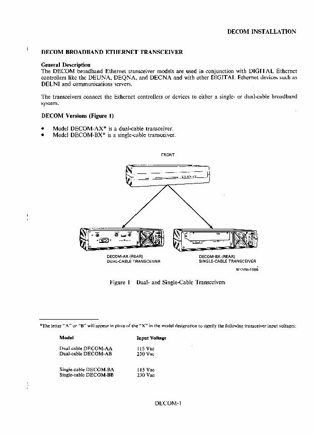
DECOM INSTALLATION
DECOM BROADBAND ETHERNET TRANSCEIVER
General Description The DECOM broadband Ethernet transceiver models are used in conjunction with DIGITAL Ethernet controllers like the DEUNA, DEQNA, and DECNA and with other DIGITAL Ethernet devices such as DELNI and communications servers.
The transceivers connect the Ethernet controllers or devices to either a single- or dual-cable broadband system.
DECOM Versions (Figure t)
• Model DECOM-AX* is a dual-cable transceiver. • Model DECOM-8X* is a single-cable transceiver.
DECOM-AX (REAR) DUAL-CABLE TRANSCEIVER
FRONT
DECOM-BX (REAR) SINGLE-CABLE TRANSCEIVER
MKV85-1086
Figure I Dual- and Single-Cable Transceivers
*The letter "A" or "8" will appear in place of the "X" in the model designation to signify the following transceiver input voltages:
Model
Dual-cable DECOM-AA Dual-cable DECOM-AB
Single-cable DECOM-BA Single-cable DECOM-BB
Input Voltage
115 Vac 230 Vac
115 Vac 230 Vac
DECOM-l
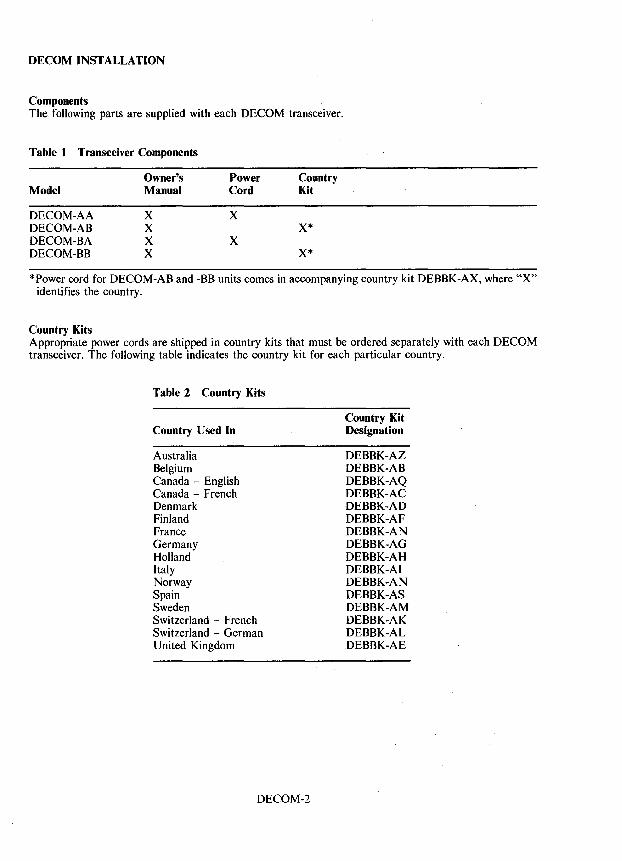
DECOM INSTALLATION
Components The following parts are supplied with each DECOM transceiver.
Table 1 Transceiver Components
Owner's Power Country Model Manual Cord Kit
DECOM-AA X X DECOM-AB X X* DECOM-BA X X DECOM-BB X X*
*Power cord for DECOM-AB and -BB units comes in accompanying country kit DEBBK-AX, where "X" identifies the country.
Country Kits Appropriate power cords are shipped in country kits that must be ordered separately with each DECOM transceiver. The following table indicates the country kit for each particular country.
Table 2 Country Kits
Country Used In
Australia Belgium Canada - English Canada - French Denmark Finland France Germany Holland Italy Norway Spain Sweden Switzerland - French Switzerland - German United Kingdom
DECOM-2
Country Kit Designation
DEBBK-AZ DEBBK-AB DEBBK-AQ DEBBK-AC DEBBK-AD DEBBK-AF DEBBK-AN DEBBK-AG DEBBK-AH DEBBK-AI DEBBK-AN DEBBK-AS DEBBK-AM DEBBK-AK DEBBK-AL DEBBK-AE
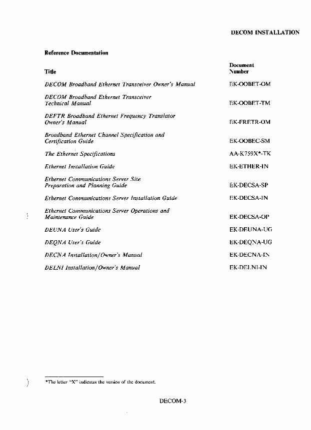
Reference Documentation
Title
DECOM Broadband Ethernet Transceiver Owner's Manual
DECOM Broadband Ethernet Transceiver Technical Manual
DEFTR Broadband Ethernet Frequency Translator Owner's Manual
Broadband Ethernet Channel Specification and Certification Guide
The Ethernet Specifications
Ethernet Installation Guide
Ethernet Communications Server Site Preparation and Planning Guide
Ethernet Communications Server Installation Guide
Ethernet Communications Server Operations and Maintenance Guide
DE UNA User's Guide
DEQNA User's Guide
DECNA Installation/Owner's Manual
DELNI Installation/Owner's Manual
*The letter "X" indicates the version of the document.
DECOM-3
DECOM INSTALLATION
Document Number
EK-OOBET-OM
EK-OOBET-TM
EK-FRETR-OM
EK-OOBEC-SM
AA-K759X*-TK
EK-ETHER-IN
EK-DECSA-SP
EK-DECSA-IN
EK-DECSA-OP
EK-DEUNA-UG
EK-DEQNA-UG
EK-DECNA-IN
EK-DELNI-IN
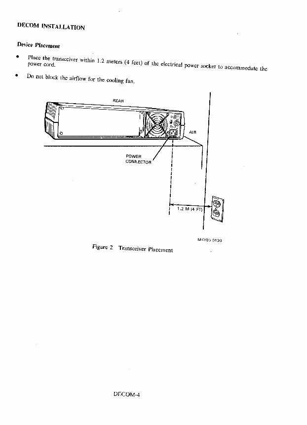
DECOM INSTALLATION
Device Placement
• Place the transceiver within 1.2 meters (4 feet) of the electrical power socket to accommodate the power cord.
• Do not block the airflow for the cooling fan.
REAR
POWER CONNECTOR
Figure 2 Transceiver Placement
DECOM-4
1.2 M (4 FT)
MKV85-0130
DECOM INSTALLATION
Power Requirements AC input power is switch selectable.
liS Vac, 60 Hz, 0.8 A, 90 W
or
230 Vac, 50 Hz, 0.4 A, 90 W
Preinstallation Steps
I. Check that the network in which the transceiver is being installed has been certified according to the Broadband Ethernet Channel Specification and Certification Guide (EK-OOBEC-SM).
2. Check that all Ethernet controllers or devices are operating correctly. Refer to the manuals that come with the devices for their checkout procedures.
3. Make sure that the other end of the transceiver cable is connected to the controller and that the RF drop cable(s) is connected to the appropriate coaxial wall outlet(s) or tap(s).
4. For the dual-cable system, mark the receive and transmit RF drop cables and coaxial wall outlets or taps RECEIVE and TRANSMIT, respectively. (If the cables are reversed during installation, no damage will be caused to the equipment; however, the DECOM unit will not work.)
DECOM-5
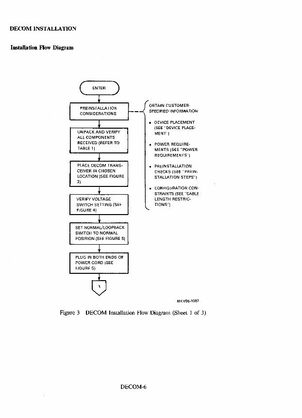
DECOM INSTALLATION
Installation Flow Diagram
UNPACK AND VERIFY ALL COMPONENTS
RECEIVED (REFER TO
TABLE 1)
PLACE DECOM TRANS
CEIVER IN CHOSEN LOCATION (SEE FIGURE
2)
VERIFY VOLTAGE
SWITCH SETTING (SEE FIGURE 4)
SET NORMAL!LOOPBACK
SWITCH TO NORMAL
POSITION (SEE FIGURE 5)
PLUG IN BOTH ENDS OF
POWER CORD (SEE
FIGURE 5)
OBTAIN CUSTOMER
SPECIFIED INFORMATION:
• DEVICE PLACEMENT (SEE "DEVICE PLACE
MENT')
• POWER REQUIREMENTS (SEE "POWER
REQUIREMENTS")
• PREINSTALLATION CHECKS (SEE "PREIN
STALLATION STEPS")
• CONFIGURATION CONSTRAINTS (SEE "CABLE
LENGTH RESTRIC
TIONS")
MKV85·1087
Figure 3 DECOM Installation Flow Diagram (Sheet I of 3)
DECOM-6
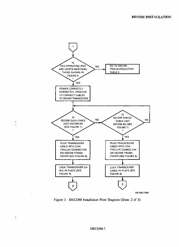
POWER CORRECTLY
CONNECTED. PROCEED TO CONNECT CABLES TO DECOM TRANSCEIVER.
PLUG TRANSCEIVER
CABLE INTO CONTROLLER CONNECTOR ON DECOM TRANS
CEIVER (SEE FIGURE 8)
LOCK TRANSCEIVER CABLE IN PLACE (SEE
FIGURE 9)
DECOM INSTALLATION
GO TO DECOM TROUBLESHOOTING
TABLE 5
PLUG TRANSCEIVER CABLE INTO CONTROLLER CONNECTOR
ON DECOM TRANSCEIVER (SEE FIGURE 8)
LOCK TRANSCEIVER CABLE IN PLACE (SEE
FIGURE 9)
MKV85-1088
Figure 3 DECOM Installation Flow Diagram (Sheet 2 of 3)
DECOM-7
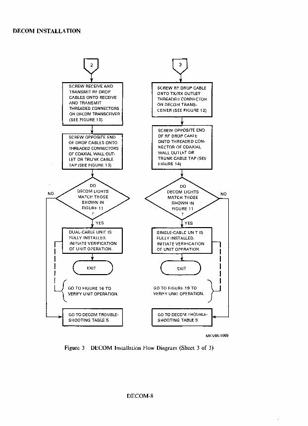
DECOM INSTALLATION
SCREW RECEIVE AND SCREW RF DROP CABLE TRANSMIT RF DROP ONTO TX/RX OUTLET CABLES ONTO RECEIVE THREADED CONNECTOR AND TRANSMIT ON DECOM TRANS-THREADED CONNECTORS CEIVER (SEE FIGURE 12) ON DECOM TRANSCEIVER
(SEE FIGURE 10)
SCREW OPPOSITE END
SCREW OPPOSITE END OF RF DROP CABLE
OF DROP CABLES ONTO ONTO THREADED CON-
THREADED CONNECTORS NECTOR OF COAXIAL
OF COAXIAL WALL OUT- WALL OUTLET OR
LET OR TRUNK CABLE TRUNK CABLE TAP (SEE
TAP (SEE FIGURE 13) FIGURE 14)
DUAL-CABLE UNIT IS SINGLE-CABLE UNIT IS FULLY INSTALLED. FULLY INSTALLED. INITIATE VERIFICATION INITIATE VERIFICATION OF UNIT OPERATION. OF UNIT OPERATION. I
I I I
L{ }J GO TO FIGURE 16 TO GO TO FIGURE 19 TO
VERIFY UNIT OPERATION. VERIFY UNIT OPERATION.
GO TO DECOM TROUBLE- GO TO DECOM TROUBLE-SHOOTING TAB'LE 5 SHOOTING TABLE 5
MKV85-1089
Figure 3 DECOM Installation Flow Diagram (Sheet 3 of 3)
DECOM-8
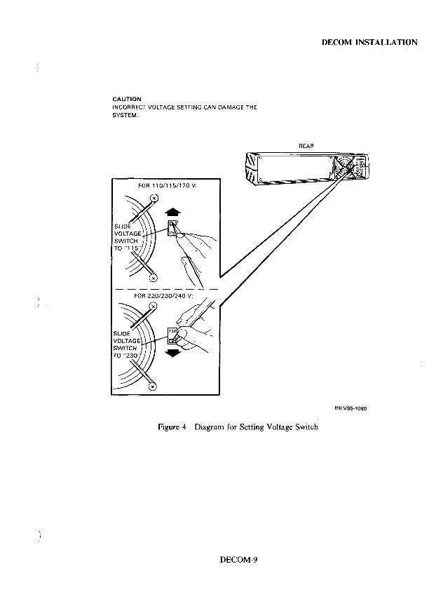
CAUTION INCORRECT VOLTAGE SETTING CAN DAMAGE THE SYSTEM.
REAR
Figure 4 Diagram for Setting Voltage Switch
DECOM-9
DECOM INSTALLATION
MKV85-1090
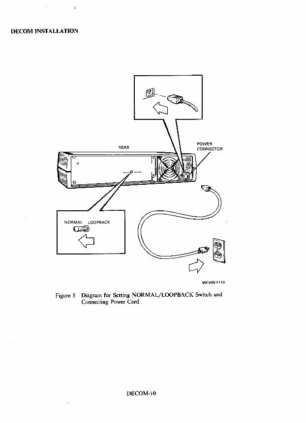
DECOM INSTALLATION
o
NORMAL LOOPBACK
~
"," ~~". @)"
Q" Y
MKV85·1110
Figure 5 Diagram for Setting NORMAL/LOOPBACK Switch and Connecting Power Cord
DECOM-IO
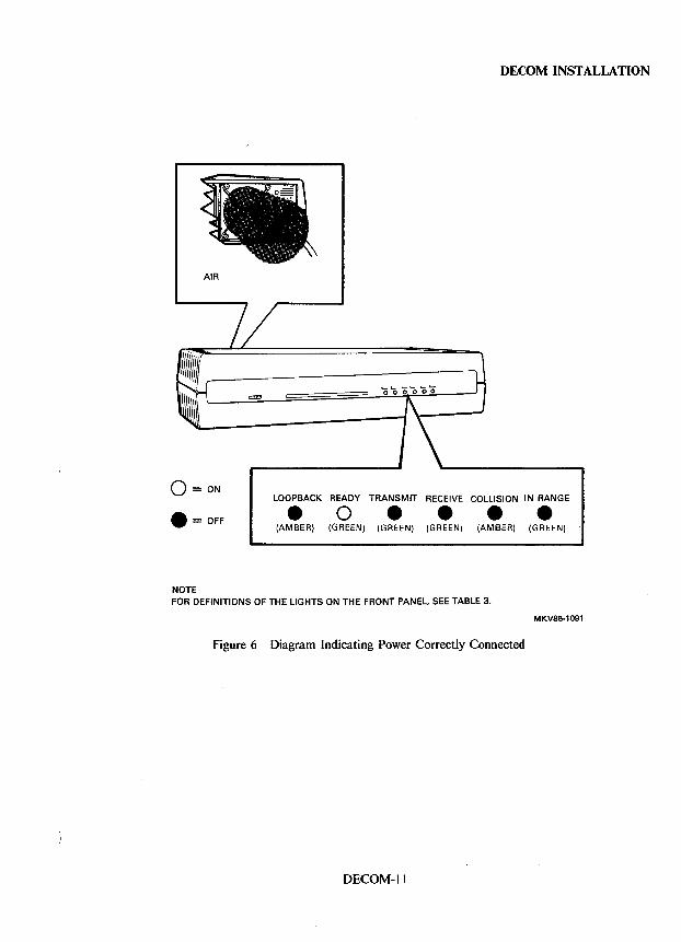
AIR
o =ON
• = OFF
NOTE
DECOM INSTALLATION
LOOPBACK READY TRANSMIT RECEIVE COLLISION IN RANGE
• 0 • • • • (AMBER) (GREEN) (GREEN) (GREEN) (AMBER) (GREEN)
FOR DEFINITIONS OF THE LIGHTS ON THE FRONT PANEL, SEE TABLE 3.
M KV85-1 091
Figure 6 Diagram Indicating Power Correctly Connected
DECOM-ll
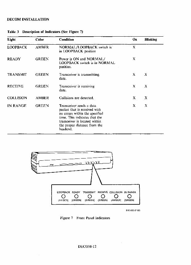
DECOM INSTALLATION
Table 3 Description of Indicators (See Figure 7)
Light Color Condition On Blinking
LOOPBACK AMBER NORMAL/LOOPBACK switch is X in LOOPBACK position
READY GREEN Power is ON and NORMAL/ X LOOPBACK switch is in NORMAL position.
TRANSMIT GREEN Transceiver is transmitting X X data.
RECEIVE GREEN Transceiver is receiving X X data.
COLLISION AMBER Collisions are detected. X X
IN RANGE GREEN Transceiver sends a data X X packet that is received with no errors within the specified time. This indicates that the transceiver is located within the proper distance from the headend.
=
LOOPBACK READY TRANSMIT RECEIVE COLLISION IN RANGE
o 0 0 000 (AMBER) (GREEN) (GREEN) (GREEN) (AMBER) (GREEN)
MKV85·0163
Figure 7 Front Panel Indicators
DECOM-12
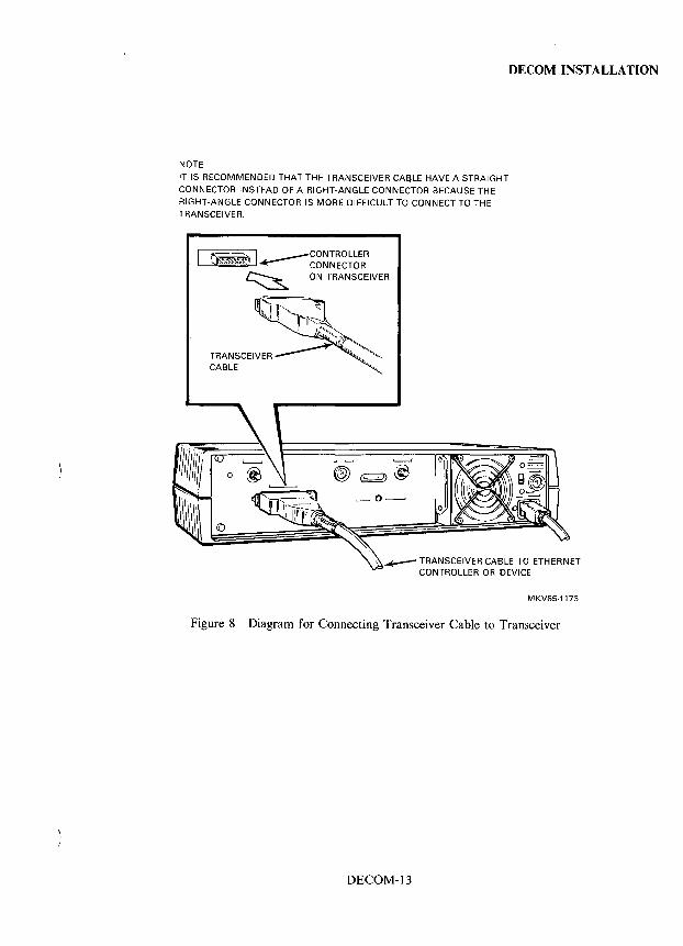
NOTE
IT IS RECOMMENDED THAT THE TRANSCEIVER CA~LE HAVE A STRAIGHT CONNECTOR INSTEAD OF A RIGHT-ANGLE CONNECTOR BECAUSE THE RIGHT-ANGLE CONNECTOR IS MORE DIFFICULT TO CONNECT TO THE TRANSCEIVER.
f"'~ I . .---CONTROLLER J~~ CONNECTOR
~ ON TRANSCEIVER
DECOM INSTALLATION
....-- TRANSCEIVER CABLE TO ETHERNET CONTROLLER OR DEVICE
MKV85-1173
Figure 8 Diagram for Connecting Transceiver Cable to Transceiver
DECOM-13
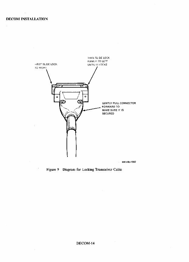
DECOM INSTALLATION
THEN SLIDE LOCK FIRMLY TO LEFT
FIRST SLIDE LOCK UNTIL IT LOCKS
TORIGHT\~. __ ~/
GENTLY PULL CONNECTOR
FORWARD TO MAKE SURE IT IS
SECURED
MKV85·1092
Figure 9 Diagram for Locking Transceiver Cable
DECOM-14
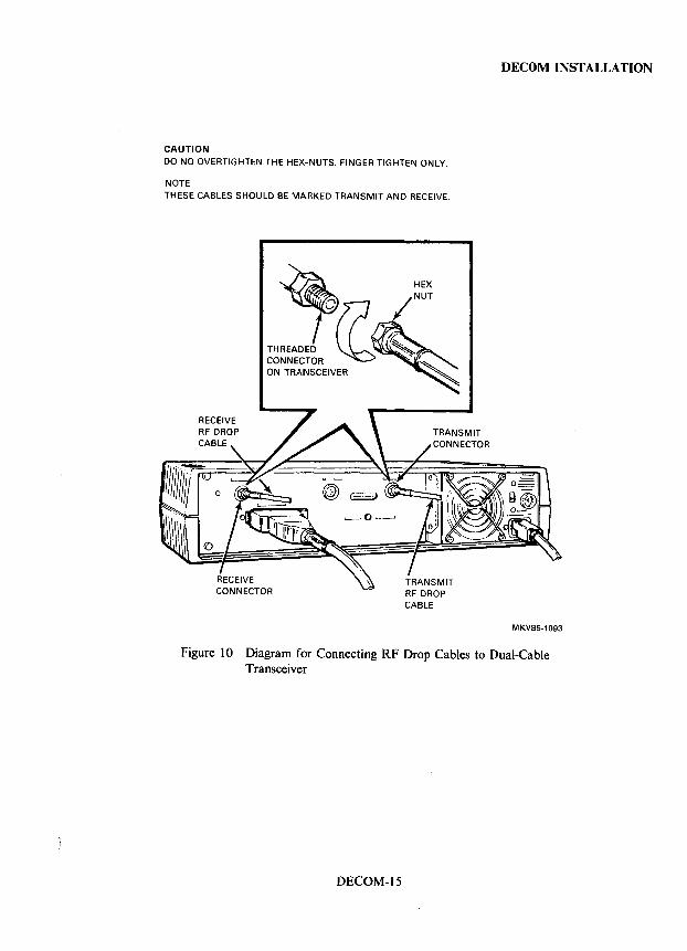
DECOM INSTALLATION
CAUTION
DO NO OVERTIGHTEN THE HEX-NUTS. FINGER TIGHTEN ONLY.
NOTE THESE CABLES SHOULD BE MARKED TRANSMIT AND RECEIVE.
MKV85-1093
Figure 10 Diagram for Connecting RF Drop Cables to Dual-Cable Transceiver
DECOM-15
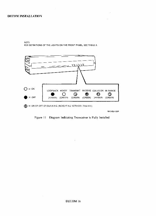
DECOM INSTALLATION
NOTE FOR DEFINITIONS OF THE LIGHTS ON THE FRONT PANEL, SEE TABLE 3.
0= ON LOOPBACK READY TRANSMIT RECEIVE COLLISION IN RANGE
• = OFF • 0 • • • • (AMBER) (GREEN) (GREEN) (GREEN) (AMBER) (GREEN)
• = ON OR OFF OR BLINKING (INDICATING NETWORK TRAFFIC)
MKV85·1094
Figure II Diagram Indicating Transceiver is Fully Installed
DECOM-16
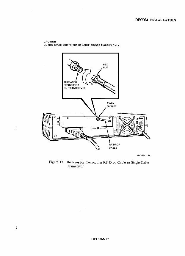
DECOM INSTALLATION
CAUTION DO NOT OVERTIGHTEN THE HEX-NUT. FINGER TIGHTEN ONLY.
MKV85-1174
Figure 12 Diagram for Connecting RF Drop Cable to Single-Cable Transceiver
DECOM-17
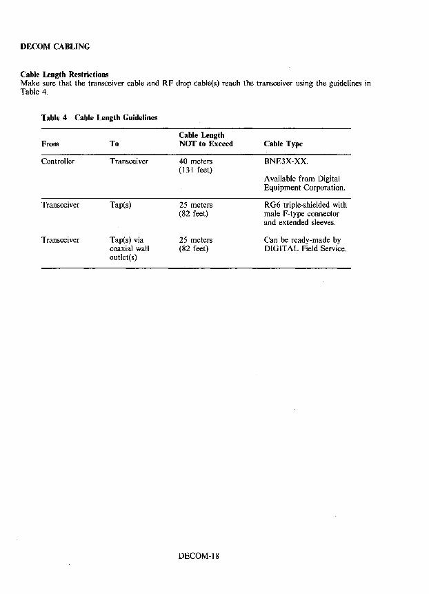
DECOM CABLING
Cable Length Restrictions Make sure that the transceiver cable and RF drop cable(s) reach the transceiver using the guidelines in Table 4.
Table 4 Cable Length Guidelines
From
Controller
Transceiver
Transceiver
To
Transceiver
Tap(s)
Tap(s) via coaxial wall outlet(s)
Cable Length NOT to Exceed
40 meters (131 feet)
25 meters (82 feet)
25 meters (82 feet)
DECOM-18
Cable Type
BNE3X-XX.
A vailable from Digital Equipment Corporation.
RG6 triple-shielded with male F-type connector and extended sleeves.
Can be ready-made by DIGITAL Field Service.
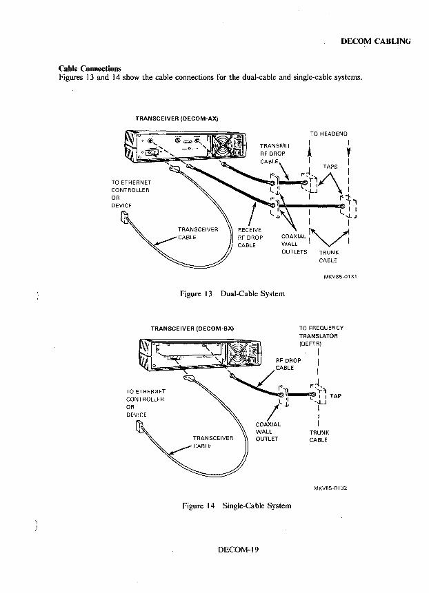
DECOM CABLING
Cable Connections Figures 13 and 14 show the cable connections for the dual-cable and single-cable systems.
TRANSCEIVER (DECOM-AX)
TO HEADEND
I I
A Y I I
TRANSMIT
...... _:I'ftIs'r~ I r:J ~TA?S I
l 'l I.. 1·1 I J,. ',LJ ,.. ... :1, I st.,
II l... I I -IJ ~J
I
COAXIAL ~ ~ WALL I "'/' I OUTLETS TRUNK
CABLE
MKV85-0131
Figure 13 Dual-Cable System
TRANSCEIVER (DECOM-BX) TO FREQUENCY
TRANSLATOR (DEFTR)
I I I
r:~~ "'-_IElI..~~ I I TAP
'~J I
Figure 14 Single-Cable System
DECOM-19
I I
TRUNK CABLE
MKV85-0132
DECOM DIAGNOSTICS
Diagnostics There are no diagnostics designed specifically for the DECOM transceiver. The NIE (Network Exerciser) diagnostic, however, can be helpful in isolating faults to the transceiver as discussed in the Maintenance Aids section.
DECOM-20
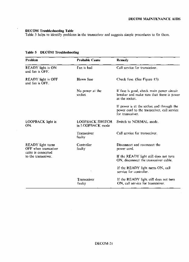
DECOM MAINTENANCE AIDS
DECOM Troubleshooting Table Table 5 helps to identify problems in the transceiver and suggests simple procedures to fix them.
Table 5 DECOM Troubleshooting
Problem
READY light is ON and fan is OFF.
READY light is OFF and fan is OFF.
LOOPBACK light is ON.
READY light turns OFF when transceiver cable is connected to the transceiver.
Probable Cause
Fan is bad
Blown fuse
No power at the socket
Remedy
Call service for transceiver.
Check fuse. (See Figure 15).
If fuse is good, check main power circuit breaker and make sure that there is power at the socket.
If power is at the socket and through the power cord to the transceiver, call service for transceiver.
LOOPBACK SWITCH Switch to NORMAL mode. in LOOPBACK mode
Transceiver faulty
Controller faulty
Transceiver faulty
DECOM-21
Call service for transceiver.
Disconnect and reconnect the power cord.
If the READY light still does not turn ON, disconnect the transceiver cable.
If the READY light turns ON, call service for controller.
If the READY light still does not turn ON, call service for transceiver.
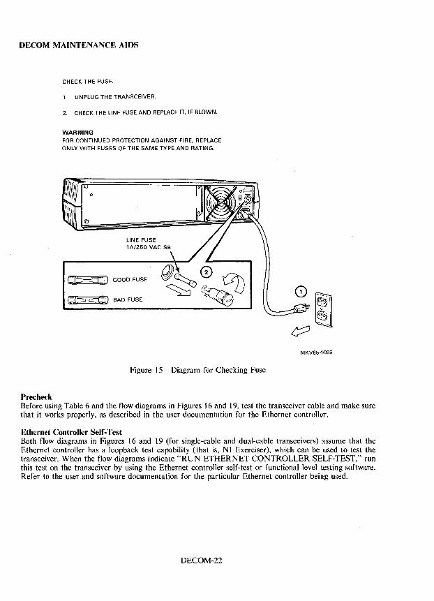
DECOM MAINTENANCE AIDS
Precheck
CHECK THE FUSE.
1. UNPLUG THE TRANSCEIVER.
2. CHECK THE LINE FUSE AND REPLACE IT. IF BLOWN.
WARNING FOR CONTINUED PROTECTION AGAINST FIRE. REPLACE ONLY WITH FUSES OF THE SAME TYPE AND RATING.
o
LINE FUSE 1 A/2S0 VAC SB
~::v GOOD FUSE
be> <t:D BAD FUSE
Figure 15, Diagram for Checking Fuse
MKV85-1095
Before using Table 6 and the flow diagrams in Figures 16 and 19, test the transceiver cable and make sure that it works properly, as described in the user documentation for the Ethernet controller.
Ethernet Controller Self-Test Both flow diagrams in Figures 16 and 19 (for single-cable and dual-cable transceivers) assume that the Ethernet controller has a loopback test capability (that is, NI Exerciser), which can be used to test the transceiver. When the flow diagrams indicate "RUN ETHERNET CONTROLLER SELF-TEST," run this test on the transceiver by using the Ethernet controller self-test or functional level testing software. Refer to the user and software documentation for the particular Ethernet controller being used.
DECOM-22
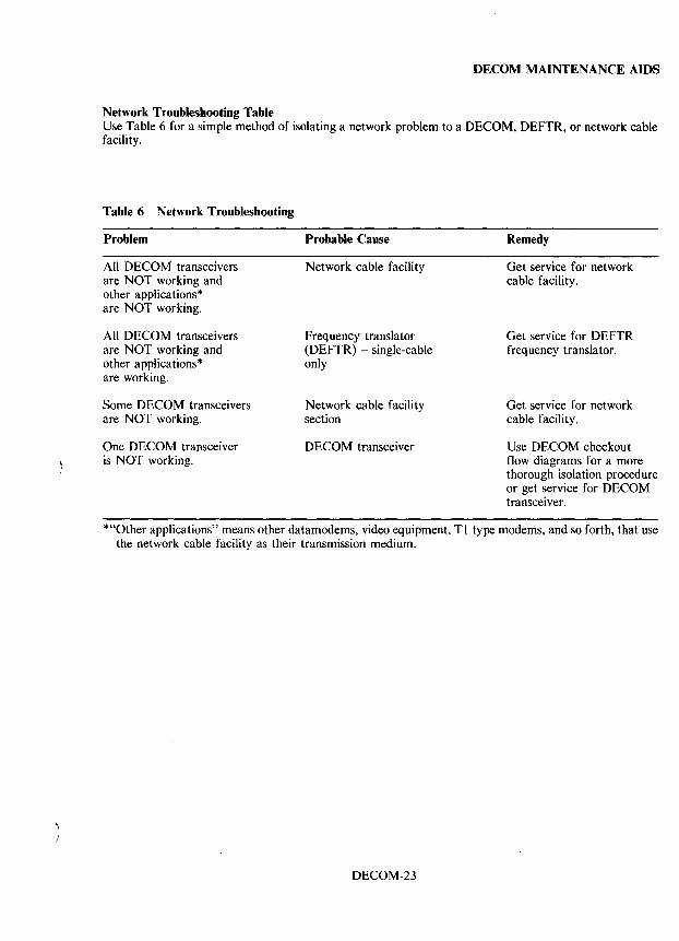
DECOM MAINTENANCE AIDS
Network Troubleshooting Table Use Table 6 for a simple method of isolating a network problem to a DECOM, DEFTR, or network cable facility.
Table 6 Network Troubleshooting
Problem
All DECOM transceivers are NOT working and other applications* are NOT working.
All DECOM transceivers are NOT working and other applications* are working.
Some DECOM transceivers are NOT working.
One DECOM transceiver is NOT working.
Probable Cause
Network cable facility
Frequency translator (DEFTR) - single-cable only
Network cable facility section
DECOM transceiver
Remedy
Get service for network cable facility.
Get service for DEFTR frequency translator.
Get service for network cable facility.
Use DECOM checkout flow diagrams for a more thorough isolation procedure or get service for DECOM transceiver.
*"Other applications" means other data modems, video equipment, TI type modems, and so forth, that use the network cable facility as their transmission medium.
DECOM-23
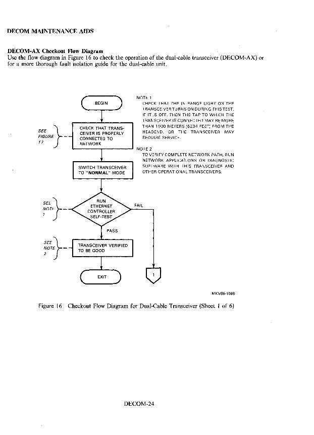
DECOM MAINTENANCE AIDS
DECOM-AX Checkout Flow Diagram Use the flow diagram in Figure 16 to check the operation of the dual-cable transceiver (DECOM-AX) or for a more thorough fault isolation guide for the dual-cable unit.
SEE} FIGURE -17
SEE~ ~OT)-
SEE~ ~OTj-
CHECK THAT TRANSCEIVER IS PROPERLY CONNECTED TO NETWORK
NOTE 1
CHECK THAT THE IN RANGE LIGHT ON THE
TRANSCEIVER TURNS ON DURING THIS TEST.
IF IT IS OFF, THEN THE TAP TO WHICH THE
TRANSCEIVER IS CONNECTED MAY BE MORE
THAN 1900 METERS (6234 FEET) FROM THE
HEADEND, OR THE TRANSCEIVER MAY
REQUIRE SERVICE.
NOTE 2 TO VERIFY COMPLETE NETWORK PATH, RUN
NETWORK APPLICATIONS OR DIAGNOSTIC
SOFTWARE WITH THIS TRANSCEIVER AND
OTHER OPERATIONAL TRANSCEIVERS.
FAIL
MKV85-1096
Figure 16 Checkout Flow Diagram for Dual-Cable Transceiver (Sheet 1 of 6)
DECOM-24
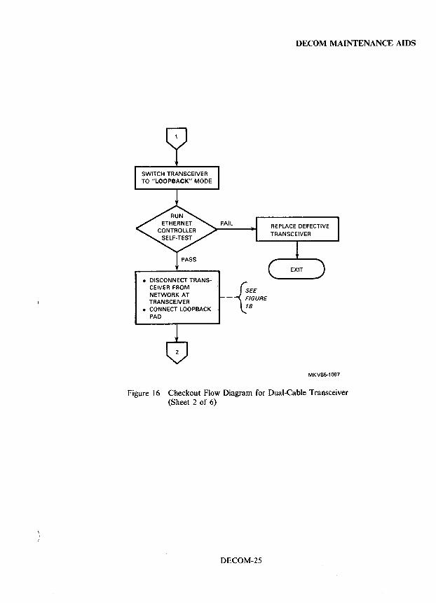
• DISCONNECT TRANSCEIVER FROM NETWORK AT TRANSCEIVER
• CONNECT LOOPBACK PAD
{
SEE - FIGURE
18
DECOM MAINTENANCE AIDS
REPLACE DEFECTIVE
MKV85-1097
Figure 16 Checkout Flow Diagram for Dual-Cable Transceiver (Sheet 2 of 6)
DECOM-25
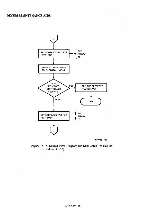
DECOM MAINTENANCE AIDS
{
SEE - FIGURE
18
REPLACE DEFECTIVE
{
SEE
- FIGURE 18
MKV85-1098
Figure 16 Checkout Flow Diagram for Dual;.Cable Transceiver (Sheet 3 of 6)
DECOM-26
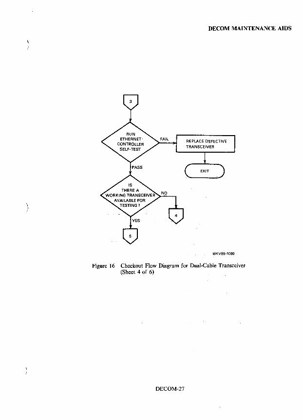
DECOM MAINTENANCE AIDS
)
REPLACE DEFECTIVE
MKV85·1099
Figure 16 Checkout Flow Diagram for Dual-Cable Transceiver (Sheet 4 of 6) ,
DECOM-27
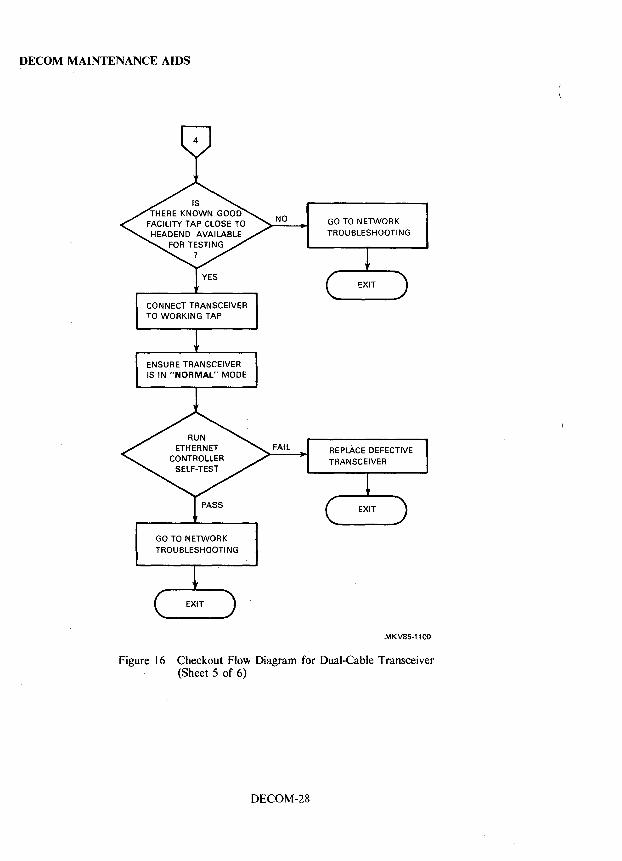
DECOM MAINTENANCE AIDS
GO TO NETWORK TROUBLESHOOTING
GO TO NETWORK TROUBLESHOOTING
REPLACE DEFECTIVE
MKV85-1100
Figure 16 Checkout Flow Diagram for DuaJ-Cable Transceiver (Sheet 5 of 6)
DECOM-28
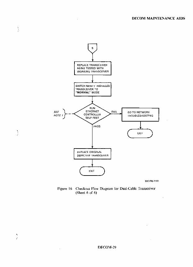
SEE} NOTE 1 -
REPLACE TRANSCEIVER BEING TESTED WITH WORKING TRANSCEIVER
SWITCH NEWLY INSTALLED TRANSCEIVER TO "NORMAL" MODE
PASS
REPLACE ORIGINAL
FAIL
DECOM MAINTENANCE AIDS
GO TO NETWORK TROUBLESHOOTING
MKV85·1101
Figure 16 Checkout Flow Diagram for Dual-Cable Transceiver (Sheet 6 of 6)
DECOM-29
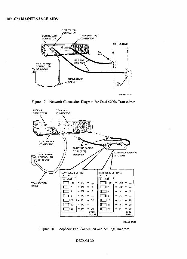
DECOM MAINTENANCE AIDS
TO ETHERNET CONTROLLER OR DEVICE
TO HEADEND
I TX A TAP~ I
I"'-k .. -...... __ .:$.)-'1
I.lJ I
I Y I I I I
r:-::;.~
~"----------------/~~~· t~ RX I TAP I
MKV85-0142
Figure 17 Network Connection Diagram for Dual-Cable Transceiver
RECEIVE TRANSMIT CONNECTOR CONNECTOR
IN OUT IN OUT
TRANSCEIVER CJIII1 dB = OUT = c:::JIII 1 dB = OUT = CABLE -=:J 2 IN 2 c:J1112 OUT =
-=:J 3 IN 3 EJ3 IN 3
CJl6 OUT = CJ116 OUT =
IC:::J 10 = IN 10 £::=J 10 IN 10
CJII 20 = OUT = IIII:::J 20 IN 20
C]20 = IN .1Q IL::J 20 IN 20 35dB 53dB TOTAL TOTAL
MKV85-1102
Figure I 8 Loopback Pad Connection and Settings Diagram
DECOM-30
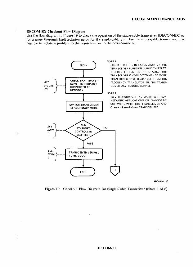
DECOM MAINTENANCE AIDS
, DECOM-8X Checkout Flow Diagram Use the flow diagram in Figure 19 to check the operation of the single-cable transceiver (DECOM-BX) or for a more thorough fault isolation guide for the single-cable unit. For the single-cable transceiver, it is possible to isolate a problem to the transceiver or to the downconverter.
SEE} FIGURE -
20
SEE~ ~OT)-
SEE~ ;OTj-
CHECK THAT TRANSCEIVER IS PROPERLY CONNECTED TO NETWORK
NOTE 1 CHECK THAT THE IN RANGE LIGHT ON THE
TRANSCEIVER TURNS ON DURING THIS TEST.
IF IT IS OFF, THEN THE TAP TO WHICH THE
TRANSCEIVER IS CONNECTED MAY BE MORE
THAN 1900 METERS (6234 FEET) FROM THE
FREQUENCY TRANSLATOR, OR THE TRANS
CEIVER MAY REQUIRE SERVICE.
NOTE 2
FAIL
TO VERIFY COMPLETE NETWORK PATH, RUN
NETWORK APPLICATIONS OR DIAGNOSTIC
SOFTWARE WITH THIS TRANSCEIVER AND
OTHER OPERATIONAL TRANSCEIVERS.
MKV85-1103
Figure 19 Checkout Flow Diagram for Single-Cable Transceiver (Sheet 1 of 6)
DECOM-31
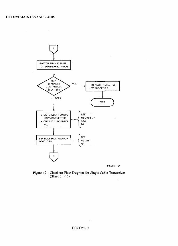
DECOM MAINTENANCE AIDS
• CAREFULLY REMOVE
DOWNCONVERTER
• CONNECT LOOPBACK
PAD.
REPLACE DEFECTIVE
{
SEE .
_ FIGURES 21
AND 18
{
SEE - FIGURE
18
MKV85-1104
Figure 19 Checkout Flow Diagram for Single-Cable Transceiver (Sheet 2 of 6)
DECOM-32
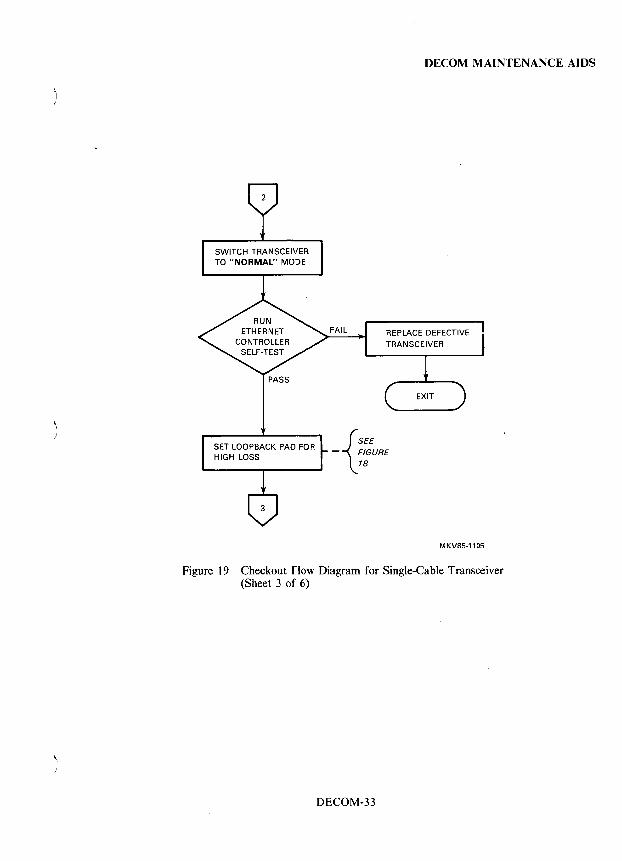
DECOM MAINTENANCE, AIDS
{
SEE - FIGURE
18
MKV85-1105
Figure 19 Checkout Flow Diagram for Single-Cable Transceiver (Sheet 3 of 6)
DECOM-33
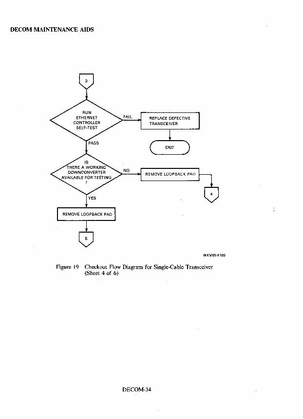
DECOM MAINTENANCE AIDS
REPLACE DEFECTIVE
REMOVE LOOPBACK PAD
MKV85-1106
Figure 19 Checkout Flow Diagram for Single-Cable Transceiver (Sheet 4 of 6)
DECOM-34
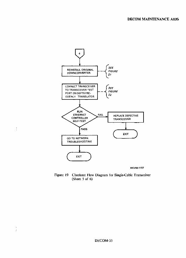
CONNECT TRANSCEIVER
TO TRANSCEIVER TEST
PORT ON DEFTR FRE
QUENCY TRANSLATOR
{
SEE
- FIGURE 21
{
SEE
- FIGURE 22
DECOM MAINTENANCE AIDS
REPLACE DEFECTIVE
MKV85-1107
Figure 19 Checkout Flow Diagram for Single-Cable Transceiver (Sheet 5 of 6)
DECOM-35
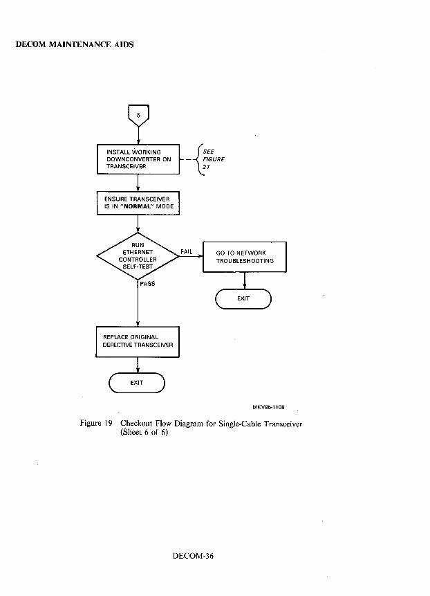
DECOM MAINTENANCE AIDS
INSTALL WORKING DOWN CONVERTER ON TRANSCEIVER
PASS
REPLACE ORIGINAL DEFECTIVE TRANSCEIVER
{
SEE
- FIGURE 21
FAIL GO TO NETWORK
TROUBLESHOOTING
MKV85-1108
Figure 19 Checkout Flow Diagram for Single-Cable Transceiver (Sheet 6 of 6)
DECOM-36
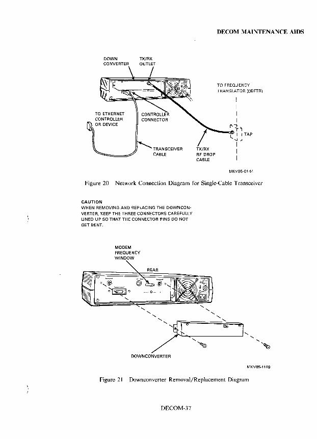
DOWN CONVERTER
TO ETHERNET CONTROLLER OR DEVICE
TX/RX OUTLET
TRANSCEIVER CABLE
DECOM MAINTENANCE AIDS
TO FREQU ENCY TRANSLATOR (DEFTR)
I I I I
1"1"1 ----'" TX/RX RF DROP CABLE
l... I I TAP --.LJ
I I I
MKV85-0144
Figure 20 Network Connection Diagram for Single-Cable Transceiver
CAUTION WHEN REMOVING AND REPLACING THE DOWNCON
VERTER, KEEP THE THREE CONNECTORS CAREFULLY LINED UP SO THAT THE CONNECTOR PINS DO NOT GET BENT_
MODEM FREQUENCY WINDOW
DOWNCONVERTER
MKV85-1109
Figure 21 Downconverter Removal/Replacement Diagram
DECOM-37
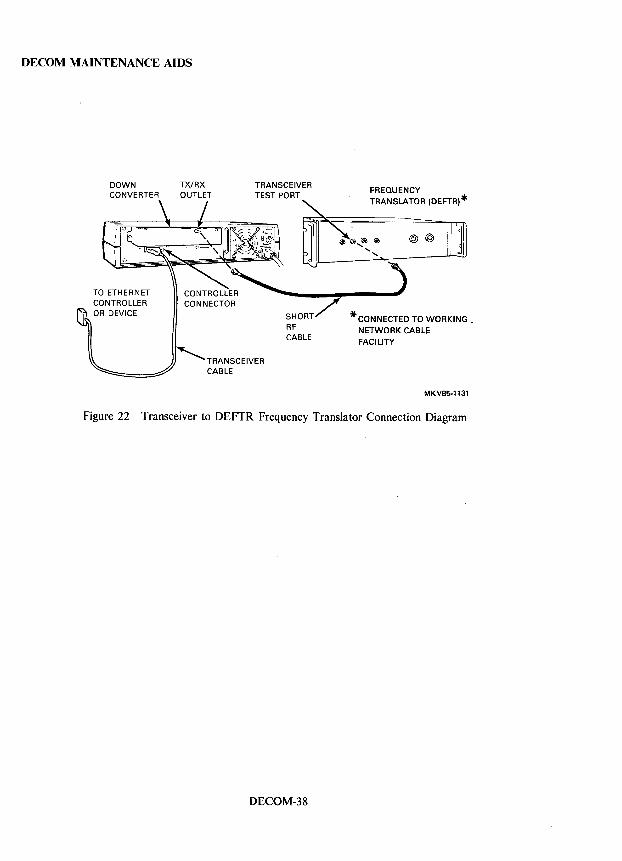
DECOM MAINTENANCE AIDS
DOWN CONVERTER
TX/RX OUTLET
TRANSCEIVER TEST PORT
FREQUENCY TRANSLATOR (DEFTR)*
@ @ Ii)] )
* CONNECTED TO WORKING. NETWORK CABLE FACILITY
MKV85·1131
Figure 22 Transceiver to DEFTR Frequency Translator Connection Diagram
DECOM-38
DECrepeater 200 INSTALLATION
DECrepeater 200 ETHERNET REPEATER ) The DECrepeater 200 retimes, reshapes, and repeats all signals it receives from one segment of a Local Area
-Network (LAN) and passes these signals to the next segment. This has the effect of extending the network beyond the limit of a single cable segment.
)
'\ )
The DECrepeater 200 is designed to comply with the IEEE 802.3 specification and is compatible with the Ethernet V2.0 specification.
DECrepeater 200 Versions There are two versions of the DECrepeater 200. They are:
• DEREN-A A/ AB, local repeater - Used to connect two standard Thickwire Ethernet, or two IEEE 802.3 lObase5 coaxial cable LAN segments.
• DEREN-RC/RD, remote repeater - Used to connect two remote Ethernet or IEEE 802.3 LAN segments. This repeater connects to a coaxial cable on one side and a fiber optic cable on the other side. The coaxial cable connects to a standard Ethernet or IEEE 802.3 LAN segment, and the fiber optic cable can connect to another repeater or to a bridge. The fiber optic cable is an IEEE 802.3 fiber optic interrepeater link (FOIRL) cable.
The two versions of the repeater are shown in Figure 1.
DRPT200-1
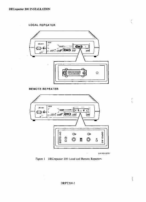
DECrepeater 200 INSTALLATION
LOCAL REPEATER
REMOTE REPEATER
o 1 ~ CD W 0 o
1:7 m
" o [] >-
o
MKV89-0039
Figure 1 DECrepeater 200 Local and Remote Repeaters
DRPT200-2
'\ I
)
\ I
)
DECrepeater 200 INSTALLATION
DECrepeater 200 Configuration Considerations In a 1Obase5 to 1Obase5 configuration, the repeater has two Attachment Unit Interface (AUI) ports. The AUI port is Ethernet compatible and is designed to comply with IEEE 802.3. DECrepeater 200 units can connect 10base5 LAN segments with a maximum of 500 m (1640 ft) per segment.
In a 10base5 to FOIRL configuration, the repeater has two different interface ports. Port A is an AUI port and port B is a fiber optic interface port. The fiber optic interface is compatible with the IEEE 802.3 FOIRL specification and offers multifiber support.
A maximum of four DECrepeater 200 units can be used to connect five segments of a LAN. Of the five segments, a maximum of three can be 10baseS coaxial segments. This rule applies to both local and remote repeaters.
Basic Configuration Rules
1. If the repeater connects to an IEEE 802.3 transceiver, such as the H4005, the transceiver cable must be an IEEE 802.3 compliant transceiver cable (BNE3H/K/L/M or BNE4C/D). If an H4005 is used, it must have heartbeat disabled.
2. If the repeater connects to an Ethernet transceiver, such as the H4000, the transceiver cable can be either Ethernet or IEEE 802.3 compliant.
3. IEEE 802.3 transceiver cables and Ethernet transceiver cables cannot be interconnected.
4. Maximum length for the transceiver cable cannot exceed 50 m (164 ft).
5. Remote (fiber optic) repeaters can be used in one of two ways:
a. Repeater-to-repeater application: Two remote repeaters are joined by a fiber optic link. Each repeater is connected to a separate standard baseband Ethernet segment via a transceiver and a transceiver cable.
b. Bridge-to-repeater application: One remote repeater is connected to a LAN Bridge by a fiber optic link. The repeater and the bridge are connected to separate standard Ethernet segments via a transceiver and a transceiver cable. The maximum length of a single fiber optic link between the bridge and repeater is 1.5 kilometers.
6. The attenuating spacer provided must be used on the transmitter ST connector when 100/140 micron cable is used if:
a. The measured loss of the 100/140 fiber optic cable is less than 4 dB, or
b. The 100/140 micron cable length of less than 1 kilometer is used.
DRPT200-3
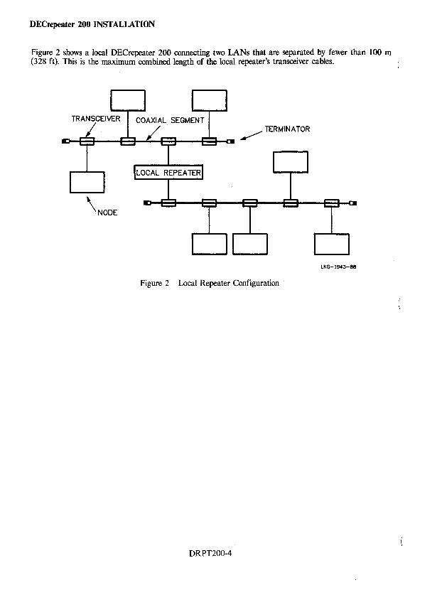
DECrepeater 200 INSTALLATION
Figure 2 shows a local DECrepeater 200 connecting two LANs that are separated by fewer than 100 m (328 ft). This is the maximum combined length of the local repeater's transceiver cables.
TRANSCEIVER ~ TERMINATOR
\NODE
LKG-1943-88
Figure 2 Local Repeater Configuration
DRPT200-4
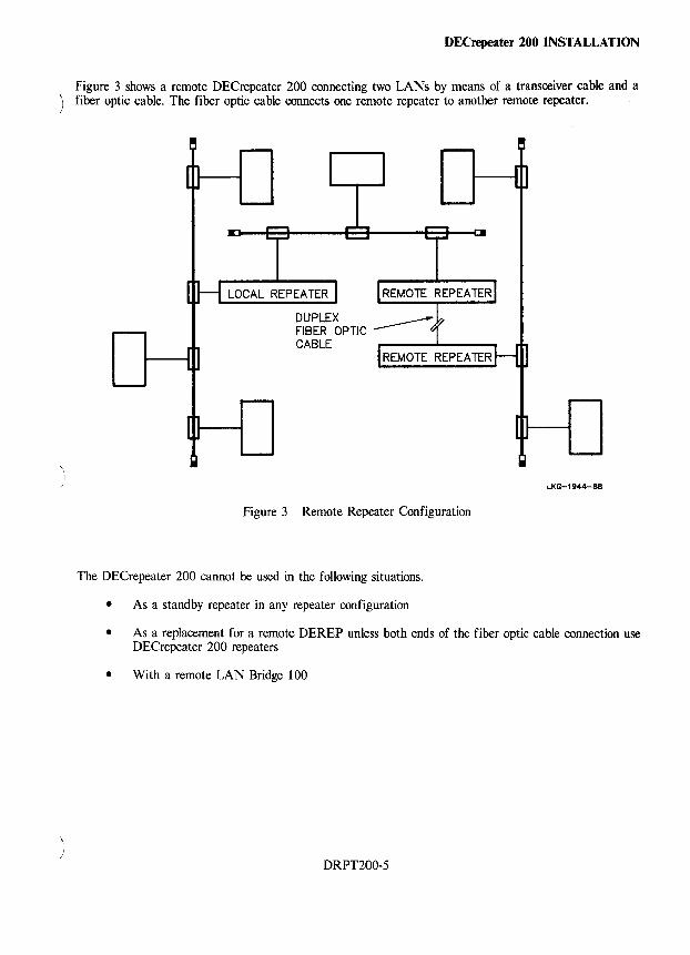
)
DECrepeater 200 INSTALLATION
Figure 3 shows a remote DECrepeater 200 connecting two LANs by means of a transceiver cable and a fiber optic cable. The fiber optic cable connects one remote repeater to another remote repeater.
LOCAL REPEATER REMOTE REPEATER
LKG-1944-88
Figure 3 Remote Repeater Configuration
The DECrepeater 200 cannot be used in the following situations.
• As a standby repeater in any repeater configuration
• As a replacement for a remote DEREP unless both ends of the fiber optic cable connection use DECrepeater 200 repeaters
• With a remote LAN Bridge 100
DRPT200-5
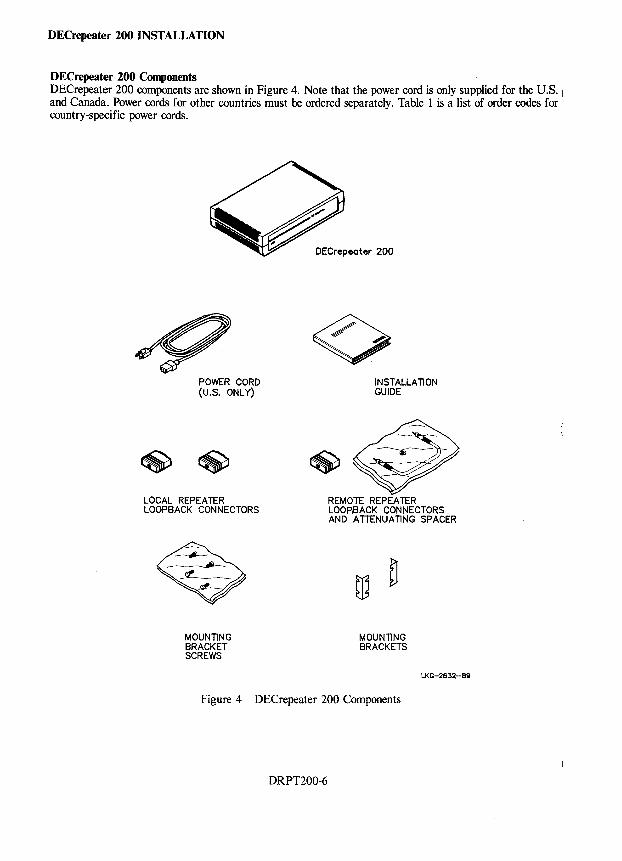
DECrepeater 200 INSTALLATION
DECrepeater 200 Components DECrepeater 200 components are shown in Figure 4. Note that the power cord is only supplied for the U.S. I
and Canada. Power cords for other countries must be ordered separately. Table 1 is a list of order codes for country-specific power cords.
POWER CORD (u.s. ONLY)
LOCAL REPEATER LOOPBACK CONNECTORS
MOUNTING BRACKET SCREWS
DECrepeoter 200
INSTALLATION GUIDE
~~ REMOTE REPEATER LOOPIBACK CONNECTORS AND ATTENUATING SPACER
MOUNTING BRACKETS
LKG-2632-89
Figure 4 DECrepeater 200 Components
DRPT200-6
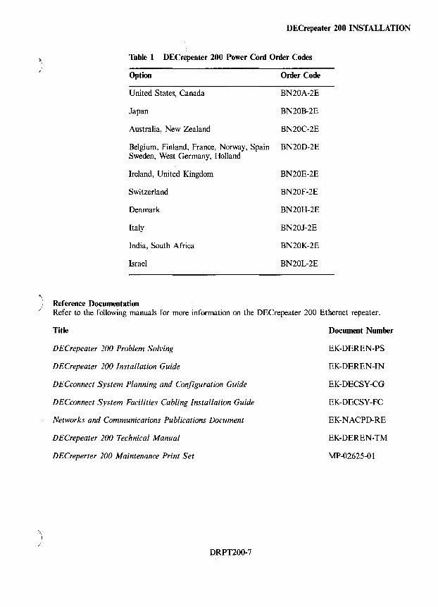
DECrepeater 200 INSTALLATION
Table 1 DEC repeater 200 Power Cord Order Codes
Option Order Code
United States, Canada BN20A-2E
Japan BN20B-2E
Australia, New Zealand BN20C-2E
Belgium, Finland, France, Norway, Spain BN20D-2E Sweden, West Germany, Holland
Ireland, United Kingdom BN20E-2E
Switzerland BN20F-2E
Denmark BN20H-2E
Italy BN20J-2E
India, South Africa BN20K-2E
Israel BN20L-2E
) Reference Documentation Refer to the following manuals for more information on the DECrepeater 200 Ethernet repeater.
Title
DECrepeater 200 Problem Solving
DECrepeater 200 Installation Guide
DECconnect System Planning and Configuration Guide
DECconnect System Facilities Cabling Installation Guide
Networks and Communications Publications Document
DECrepeater 200 Technical Manual
DECreperter 200 Maintenance Print Set
DRPT200-7
Document Number
EK-DEREN-PS
EK-DEREN-IN
EK-DECSY-CG
EK-DECSY-FC
EK-NACPD-RE
EK-DEREN-TM
MP-02625-0 1
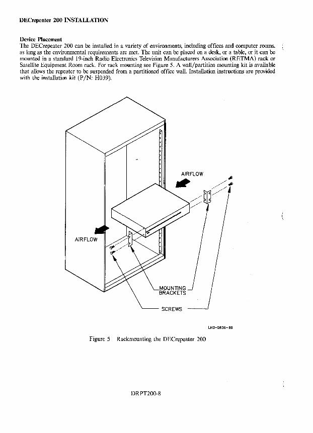
DECrepeater 200 INSTALLATION
Device Placement The DECrepeater 200 can be installed in a variety of environments, including offices and computer rooms, as long as the environmental requirements are met. The unit can be placed on a desk, or a table, or it can be mounted in a standard 19-inch Radio Electronics Television Manufacturers Association (RETMA) rack or Satellite Equipment Room rack. For rack mounting see Figure 5. A wall/partition mounting kit is available that allows the repeater to be suspended from a partitioned office wall. Installation instructions are provided with the installation kit (P /N: H039).
LKG-2636-89
Figure 5 Rackmounting the DECrepeater 200
DRPT200-8
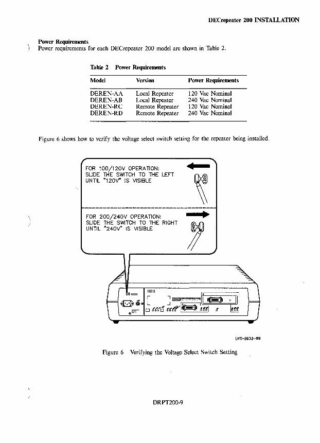
\
DECrepeater 200 INSTALLATION
Power Requirements Power requirements for each DECrepeater 200 model are shown in Table 2.
Table 2 Power Requirements
Model
DEREN-AA DEREN-AB DEREN-RC DEREN-RD
Version
Local Repeater Local Repeater Remote Repeater Remote Repeater
Power Requirements
120 Vac Nominal 240 Vac Nominal 120 Vac Nominal 240 Vac Nominal
Figure 6 shows how to verify the voltage select switch setting for the repeater being installed .
FOR 100/120V OPERATION: SLIDE THE SWITCH TO THE LEFT UNTIL "120V" IS VISIBLE
FOR 200/240V OPERATION: SLIDE THE SWITCH TO THE RIGHT UNTIL "240V" IS VISIBLE
•
•
LKG-2633-89
Figure 6 Verifying the Voltage Select Switch Setting.
DRPT200-9
DECrepeater 200 INSTALLATION
Preinstallation Steps Before installing the DECrepeater 200, use the following checklist to ensure that site preparation is complete.
I. Verify access to ac power.
2. Ensure that the appropriate baseband network interface is installed; that is, the H4005 and the required transceiver cabling is in place, tested, and tagged.
3. Ensure that the fiber optic cables (if required) are installed, certified, and tagged.
4. Ensure that the wall/partition mounting bracket kit is installed (if required).
5. Ensure that the power outlet matches the power requirements of the repeater and is within 1. 8 m (6 ft) of the installation location.
6. Ensure that the environmental requirements are met.
7. Ensure that there is adequate space for ventilation and for maintenance access.
DRPT200-10
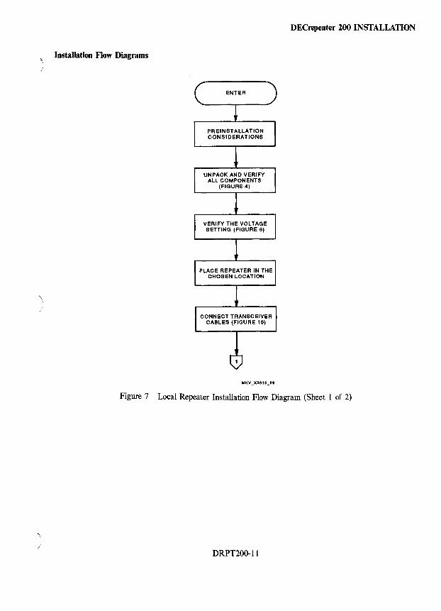
DECrepeater 200 INSTALLATION
Installation Flow Diagrams
ENTER
'\ I
Figure 7 Local Repeater Installation Flow Diagram (Sheet 1 of 2)
/ DRPT200-11
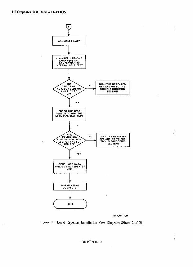
DECrepeater 200 INSTALLATION
OBSERVE 2 SECOND LAMP TEST AND COMPLETION OF
INTERNAL SELF-TEST
PRESS THE TEST SWITCH TO RUN THE
EXTERNAL SELF-TEST
SEND USER DATA ACROSS THE REPEATER
LINK
TURN THE REPEATER OFF AND GO TO THE TROUBLESHOOTING
SECTION
NO TURN THE REPEATER OFF AND GO TO THE TROUBLESHOOTING
SECTION
Figure 7 Local Repeater Installation Flow Diagram (Sheet 2 of 2)
DRPT200-12
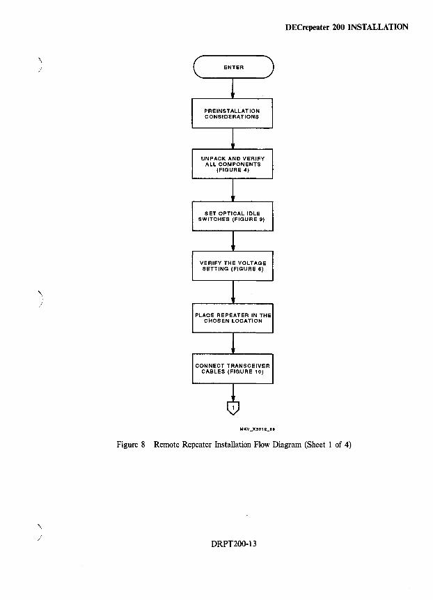
1 )
)
Figure 8
~ )
PRE INSTALLATION CONSIDERATIONS
UNPACK AND VERIFY ALL COMPONENTS
(FIGURE 4)
SET OPTICAL IDLE SWITCHES (FIGURE 9)
VERIFY THE VOLTAGE SETTING (FIGURE 6)
PLACE REPEATER IN THE CHOSEN LOCATION
CONNECT TRANSCEIVER CABLES (FIGURE 10)
DEC repeater 200 INSTALLATION
Remote Repeater Installation Flow Diagram (Sheet 1 of 4)
DRPT200-13
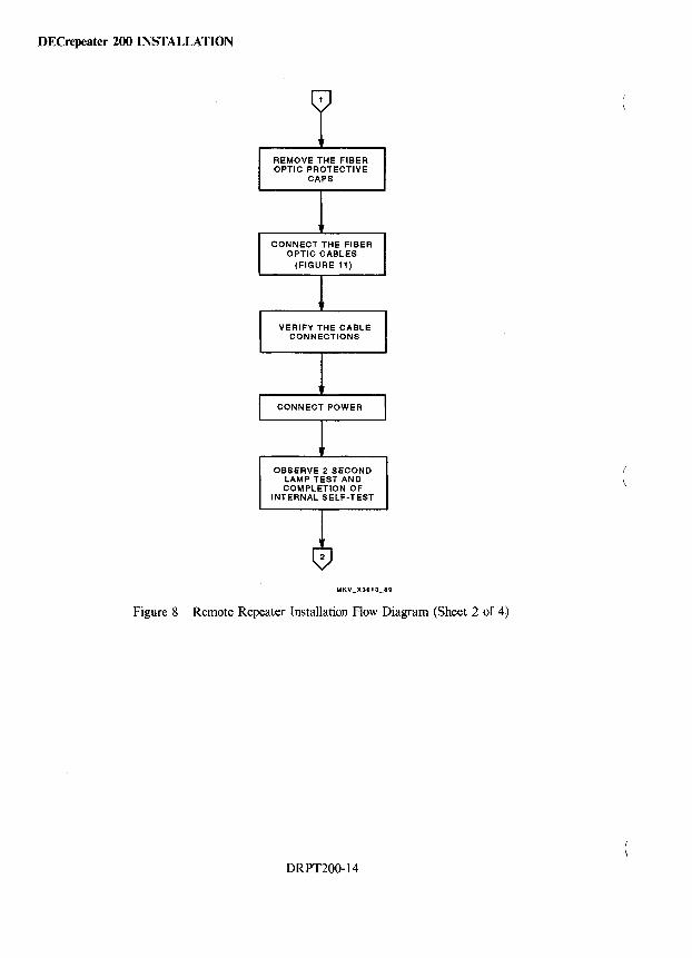
DECrepeater 200 INSTALLATION
REMOVE THE FIBER OPTIC PROTECTIVE
CAPS
CONNECT THE FIBER OPTIC CABLES
(FIGURE 11)
VERIFY THE CABLE CONNECTIONS
OBSERVE 2 SECOND LAMP TEST AND COMPLETION OF
INTERNAL SELF-TEST
Figure 8 Remote Repeater Installation Flow Diagram (Sheet 2 of 4)
DRPT200-14
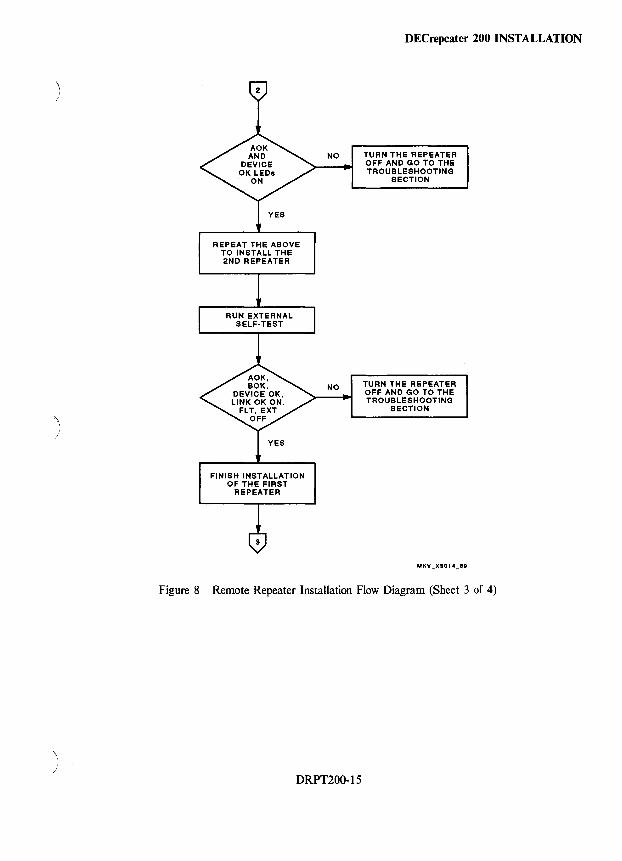
) I
)
\ )
DECrepeater 200 INSTALLATION
NO TURN THE REPEATER
REPEAT THE ABOVE TO INSTALL THE 2ND REPEATER
FINISH INSTALLATION OF THE FIRST
REPEATER
NO
OFF AND GO TO THE TROUBLESHOOTING
SECTION
TURN THE REPEATER OFF AND GO TO THE TROUBLESHOOTING
SECTION
Figure 8 Remote Repeater Installation Flow Diagram (Sheet 3 of 4)
DRPT200~15
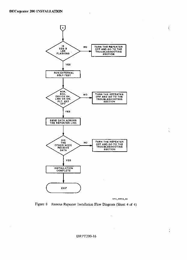
DECrepeater 200 INSTALLATION
NO
NO
NO
TURN THE REPEATER OFF AND GO TO THE TROUBLESHOOTING
SECTION
TURN THE REPEATER OFF AND GO TO THE TROUBLESHOOTING
SECTION
TURN THE REPEATER OFF AND GO TO THE TROUBLESHOOTING
SECTION
Figure 8 Remote Repeater Installation Flow Diagram (Sheet 4 of 4)
DRPT200-16
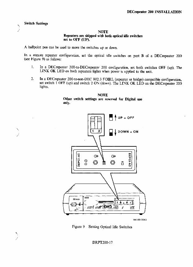
"', \ )
Switch Settings
DECrepeater 200 INSTALLATION
NOTE Repeaters are shipped with both optical idle switches set to OFF (UP).
A ballpoint pen can be used to move the switches up or down.
In a remote repeater configuration, set the optical idle switches on port B of a DEC repeater 200 (see Figure 9) as follows:
1. In a DECrepeater 200-to-DECrepeater 200 configuration, set both switches OFF (up). The LINK OK LED on both repeaters lights when power is applied to the unit.
2. In a DECrepeater 200-to-non-DEC 802.3 FOIRL (repeater or bridge) compatible configuration, set switch 1 OFF (up) and switch 2 ON (down). The LINK OK LED on the DECrepeater 200 lights.
NOTE Other switch settings are reserved for Digital use only.
o ~ o Q.
W o
~ t UP - OFF
~ + DOWN - ON
OK
o
o m
" 2 ). ()
MKV89-0040
Figure 9 Setting Optical Idle Switches
DRPT200-17
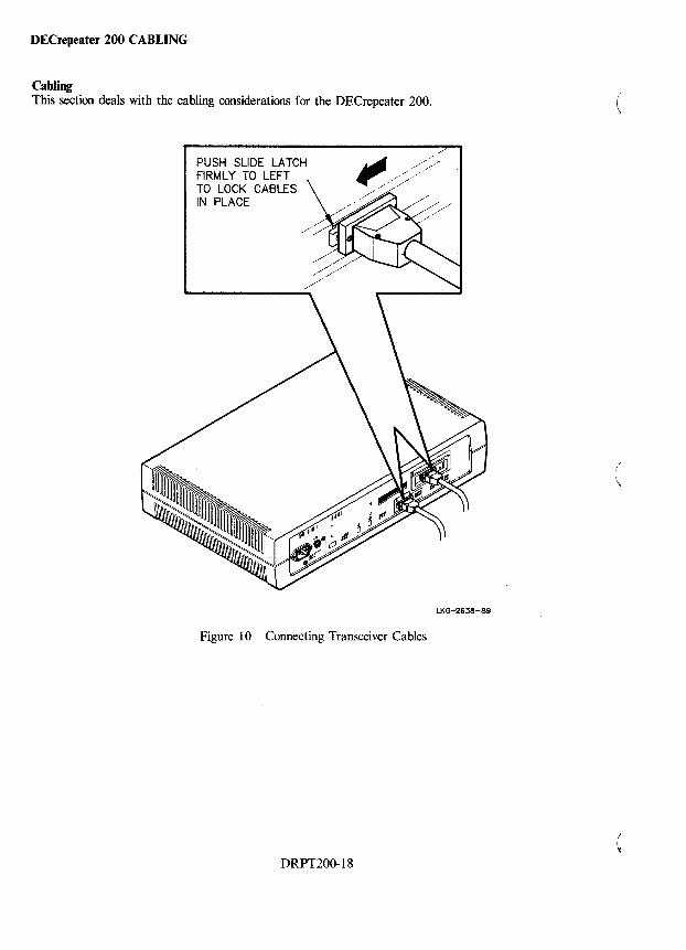
DECrepeater 200 CABLING
Cabling This section deals with the cabling considerations for the DECrepeater 200.
PUSH SLIDE LATCH FIRML Y TO LEFT TO LOCK CABLES IN PLACE
Figure 10 Connecting Transceiver Cables
DRPT200-18
!
\
LKG-2S38-89
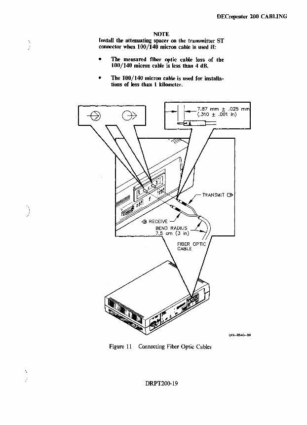
)
)
\
DECrepeater 200 CABLING
NOTE Install the attenuating spacer on the transmitter ST connector when 100/140 micron cable is used if:
• The measured fiber optic cable loss of the 100/140 micron cable is less than 4 dB.
• The 100/140 micron cable is used for installations of less than 1 kilometer.
___ 11 __ 7.87 mm ± .025 mm (.310 ± .001 in)
c::€ ~ i
LKG-2640-89
Figure 11 Connecting Fiber Optic Cables
DRPT200-19
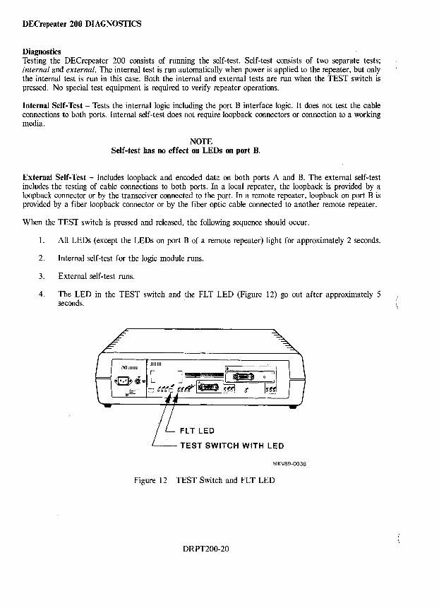
DECrepeater 200 DIAGNOSTICS
Diagnostics Testing the OECrepeater 200 consists of running the self-test. Self-test consists of two separate tests; internal and external. The internal test is run automatically when power is applied to the repeater, but only the internal test is run in this case. Both the internal and external tests are run when the TEST switch is pressed. No special test equipment is required to verify repeater operations.
Internal Self-Test - Tests the internal logic including the port B interface logic. It does not test the cable connections to both ports. Internal self-test does not require loopback connectors or connection to a working media.
NOTE Self-test has no effect on LEDs on port B.
External Self-Test - Includes loopback and encoded data on both ports A and B. The external self-test includes the testing of cable connections to both ports. In a local repeater, the loopback is provided by a loopback connector or by the transceiver connected to the port. In a remote repeater, loopback on port B is provided by a fiber loopback connector or by the fiber optic cable connected to another remote repeater.
When the TEST switch is pressed and released, the following sequence should occur.
1. All LEOs (except the LEOs on port B of a remote repeater) light for approximately 2 seconds.
2. Internal self-test for the logic module runs.
3. External self-test runs.
4. The LED in the TEST switch and the FLT LED (Figure 12) go out after approximately 5 seconds.
TEST SWITCH WITH LED
MKV89-0038
Figure 12 TEST Switch and FLT LED
ORPT200-20
)
)
DECrepeater 200 DIAGNOSTICS
If a fault is detected, the FLT LED lights, the TEST LED remains ON, and the repeater does not go online. If either of these LEOs remain ON, go to the Troubleshooting section.
NOTE Remote repeaters do not pass external self-test unless both repeaters are fully connected and operating. The self-test must be performed individually on each unit.
DRPT200-21
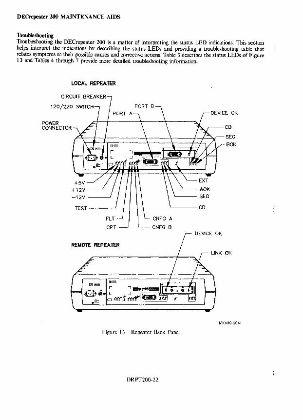
DECrepeater 200 MAINTENANCE AIDS
Troubleshooting Troubleshooting the DECrepeater 200 is a matter of interpreting the status LED indications. This section helps interpret the indications by describing the status LEDs and providing a troubleshooting table that relates symptoms to their possible causes and corrective actions. Table 3 describes the status LEDs of Figure 13 and Tables 4 through 7 provide more detailed troubleshooting information.
POWER CONNECTOR
LOCAL REPEA 1ER
CPT
REMOTE REPEATER
CNFG B
Figure 13 Repeater Back Panel
DRPT200-22
CD
SEG BOK
LINK OK
MKV89·0041
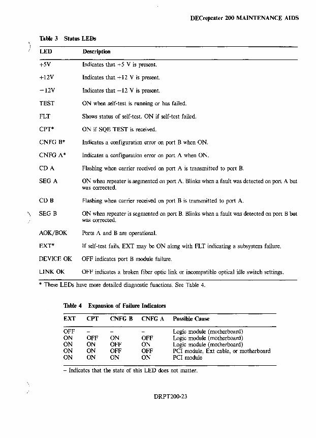
~ )
~ /
DECrepeater 200 MAINTENANCE AIDS
Table 3 Status LEDs
LED
+5V
+12V
-12V
TEST
FLT
CPT*
CNFG B*
CNFG A*
CDA
SEGA
COB
SEG B
AOK/BOK
EXT*
DEVICE OK
LINK OK
Description
Indicates that +5 V is present.
Indicates that + 12 V is present.
Indicates that -12 V is present.
ON when self-test is running or has failed.
Shows status of self-test. ON if self-test failed.
ON if SQE TEST is received.
Indicates a configuration error on port B when ON.
Indicates a configuration error on port A when ON.
Flashing when carrier received on port A is transmitted to port B.
ON when repeater is segmented on port A. Blinks when a fault was detected on port A but was corrected.
Flashing when carrier received on port B is transmitted to port A.
ON when repeater is segmented on port B. Blinks when a fault was detected on port B but was corrected.
Ports A and B are operational.
If self-test fails, EXT may be ON along with FLT indicating a subsystem failure.
OFF indicates port B module failure.
OFF indicates a broken fiber optic link or incompatible optical idle switch settings.
* These LEOs have more detailed diagnostic functions. See Table 4.
Table 4 Expansion of Failure Indicators
EXT CPT CNFGB CNFGA Possible Cause
OFF Logic module (motherboard) ON OFF ON OFF Logic module (motherboard) ON ON OFF ON Logic module (motherboard) ON ON OFF OFF PCI module, Ext cable, or motherboard ON ON ON ON PCI module
- Indicates that the state of this LED does not matter.
DRPT200-23
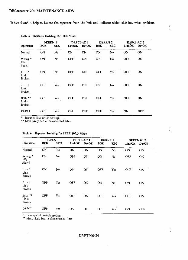
DECrepeater 200 MAINTENANCE AIDS
Tables 5 and 6 help to isolate the repeater from the link and indicate which side has what problem.
Table 5 Repeater Isolating for DEC Mode
DEREN 1 DEPCI-AC 1 DEREN 2 DEPCI-AC 2 Operation BOK SEG LinkOK DevOK BOK SEG LinkOK DevOK
Normal ON No ON ON ON No ON ON
Wrong * ON No OFF ON ON No OFF ON Idle Signal
1-->2 ON No OFF ON OFF Yes OFF ON Link Broken
2-->1 OFF Yes OFF ON ON No OFF ON Link Broken
Both ** OFF Yes OFF ON OFF Yes OFF ON Links Broken
DEPCI OFF Yes ON OFF OFF Yes ON OFF
* Incompatible switch settings * * Most likely bad or disconnected fiber
Table 6 Repeater Isolating for IEEE 802.3 Mode
DEREN 1 DEPCI-AC 1 DEREN 2 DEPCI-AC 2 Operation BOK SEG LinkOK DevOK BOK SEG LinkOK DevOK
Normal ON No ON ON ON No ON ON
Wrong * ON No OFF ON ON No OFF ON Idle Signal
1-->2 ON No ON ON OFF Yes OFF ON Link Broken
2--» OFF Yes OFF ON ON No ON ON Link Broken
Both ** OFF Yes OFF ON OFF Yes OFF ON Links Broken
DEPCI OFF Yes ON OFF OFF Yes ON OFF
* Incompatible switch settings ** Most likely bad or disconnected fiber
DRPT200-24
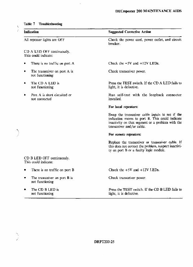
/
Table 7 Troubleshooting
Indication
All repeater lights are OFF
CD A LED OFF continuously. This could indicate:
• There is no traffic on port A
• The transceiver on port A is not functioning
• The CD A LED is not functioning
• Port A is short circuited or not connected
CD B LED OFF continuously. This could indicate:
• There is no traffic on port B
• The transceiver on port B is not functioning
• The CD B LED is not functioning
DEC repeater 200 MAINTENANCE AIDS
Suggested Corrective Action
Check the power cord, power outlet, and circuit breaker.
Check the +5V and +12V LEOs.
Check transceiver power.
Press the TEST switch. If the CD A LED fails to light, it is defective.
Run self-test with the loopback connector installed.
For local repeaters:
Swap the transceiver cable inputs to see if the indication moves to port B. This could indicate inactivity on that segment or a problem with the transceiver and/or cable.
For remote repeaters:
Replace the transceiver or transceiver cable. If this does not correct the problem, suspect inactivity on port B or a faulty logic module.
Check the +5V and +12V LEOs.
Check transceiver power.
Press the TEST switch. If the CD B LED fails to light, it is defective;
DRPT200·25
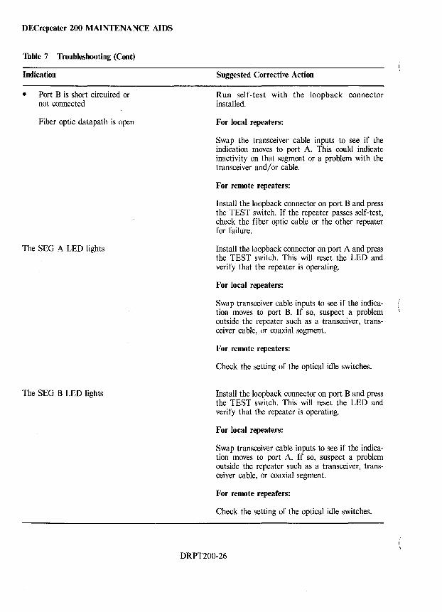
DECrepeater 200 MAINTENANCE AIDS
Table 7 Troubleshooting (Cont)
Indication
• Port B is short circuited or not connected
Fiber optic data path is open
The SEG A LED lights
The SEG B LED lights
Suggested Corrective Action
Run self-test with the loopback connector installed.
For local repeaters:
Swap the transceiver cable inputs to see if the indication moves to port A. This could indicate inactivity on that segment or a problem with the transceiver and/or cable.
For remote repeaters:
Install the loopback connector on port B and press the TEST switch. If the repeater passes self-test, check the fiber optic cable or the other repeater for failure.
Install the loopback connector on port A and press the TEST switch. This will reset the LED and verify that the repeater is operating.
For local repeaters:
Swap transceiver cable inputs to see if the indication moves to port B. If so, suspect a problem outside the repeater such as a transceiver, transceiver cable, or coaxial segment.
For remote repeaters:
Check the setting of the optical idle switches.
Install the loopback connector on port B and press the TEST switch. This will reset the LED and verify that the repeater is operating.
For local repeaters:
Swap transceiver cable inputs to see if the indication moves to port A. If so, suspect a problem outside the repeater such as a transceiver, transceiver cable, or coaxial segment.
For remote repeaters:
Check the setting of the optical idle switches.
DRPT200-26
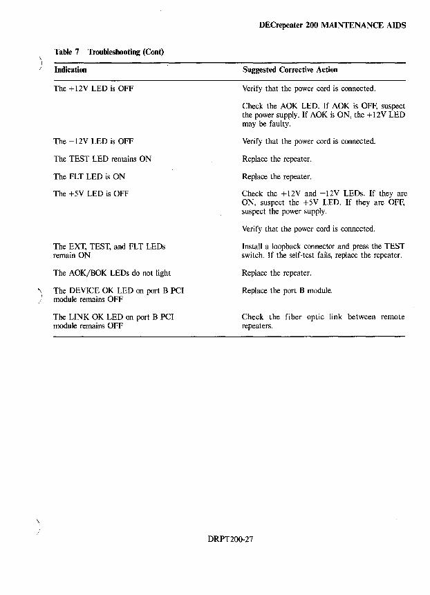
Table 7 Troubleshooting (Cont) ) / Indication
) ;
"-I
/
The + 12V LED is OFF
The -12V LED is OFF
The TEST LED remains ON
The FLT LED is ON
The +5V LED is OFF
The EXT, TEST, and FLT LEOs remain ON
The AOK/BOK LEOs do not light
The DEVICE OK LED on port B PCI module remains OFF
The LINK OK LED on port B PCI module remains OFF
DECrepeater200 MAINTENANCE AIDS
Suggested Corrective Action
Verify that the power cord is connected.
Check the AOK LED. If AOK is OFF, suspect the power supply. If AOK is ON, the +12V LED may be faulty.
Verify that the power cord is connected.
Replace the repeater.
Replace the repeater.
Check the + 12V and -12V LEOs. If they are ON, suspect the +5V LED. If they are OFF, suspect the power supply.
Verify that the power cord is connected.
Install a loopback connector and press the TEST switch. If the self-test fails, replace the repeater.
Replace the repeater.
Replace the port B module.
Check the fiber optic link between remote repeaters.
DRPT200-27
DECrepeater 200 MAINTENANCE AIDS
FRU Removal and Replacement Procedures Figure 14 shows the FRUs for the DECrepeater 200. The FRUs and their part numbers are listed below.
FRU
Logic Module Power Supply Fan Assembly
Part Number
Port Connector Interface (PCI) Module (Local) Port Connector Interface (PCI) Module (Remote)
54-18363-01 30-27484-01 70-23165-01 54-18359-01 54-1837.7-01
WARNING The procedures described should be performed by qualified service personnel only. DO NOT attempt to remove any FRUs while the DECrepeater 200 is connected to a power source.
CAUTION Static electricity can damage electrical components. Use a grounded wrists trap (29-11762-00) and a grounded work surface when accessing any internal components of the DECrepeater 200.
DRPT200-28
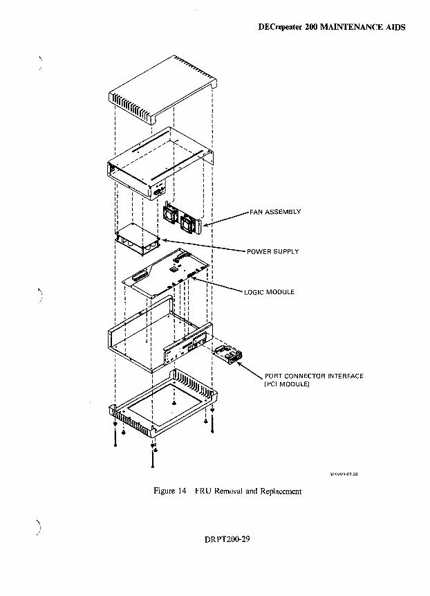
\ I
I
)
" I /
DEC repeater 200 MAINTENANCE AIDS
MKV89-0128
Figure 14 FRU Removal and Replacement
DRPT200-29

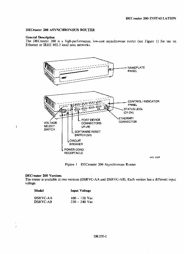
DEC router 200 INSTALLATION
DECrouter 200 ASYNCHRONOUS ROUTER
General Description The DEC router 200 is a high-performance, low-cost asynchronous router (see Figure 1) for use on Ethernet or IEEE 802.3 local area networks.
DECrouter 200 Versions
SOFTWARE RESET SWITCH (S1)
CIRCUIT BREAKER
POWER CORD RECEPTACLE
11-..-1---- NAMEPLATE PANEL
4..~--- CONTROLI INDICATOR PANEL
STATUS LEDs (D1-D4)
LKG-0326
Figure 1 DECrouter 200 Asynchronous Router
The router is available in two versions (DSRVC-AA and DSRVC-AB). Each version has a different input voltage.
Model
DSRVC-AA DSRVC-AB
Input Voltage
100 - 120 Vac 220 - 240 Vac
DR200-1
DECrouter 200 INSTALLATION
Reference Documentation Refer to the following documents for more information on the DECrouter 200 asynchronous router:
• DECrouter 200 Hardware Installation/Owner's Guide
• DECrouter 200 Technical Manual
• DECrouter 200 Management Guide
• DECrouter 200 Identification Card
• DECrouter 200 Software Installation Guide (VMS/MicroVMSj
• DECrouter 200 ULTRIX-32/32m Installation Guide
• DECrouter 200 RSX-JJ M-Plus Installation Guide
Hardware Components The DECrouter 200 package consists of:
• DEC router 200 hardware unit - DSRVC-AA or DSR VC-AB
• Country kit - Correct power cord and hardware installation/owner's guide
• Software - DECrouter 200 software and software installation guide
Terminal cables for the DECrouter 200 are ordered separately.
Software Components The basic software that is required for the installation and operation of the DECrouter 200 includes:
• DECrouter 200 distribution software (installed on each DECrouter 200 load host)
• DECnet Phase IV software (installed on each DECrouter 200 load host - not required for ULTRIX systems)
Equipment Placement The router can be placed in various locations, including offices and computer rooms, as long as the environmental requirements are met.
Environmental Requirements
Temperature Relative Humidity
Physical Description
Length Width Height Weight
5° to 50°C (41 ° to 122°F) 10% to 95% (noncondensing)
31.2 cm (12.3 in) 49.3 cm (19.4 in) 11.7 cm (4.6 in) 5.9 kg (13.0 Ib)
DR200-2
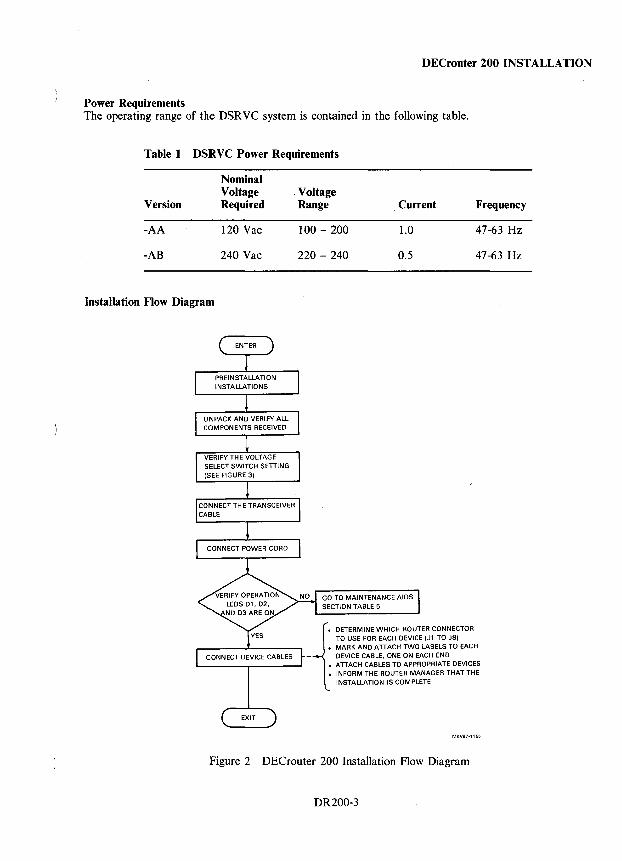
DEC router 200 INSTALLATION
Power Requirements The operating range of the DSRVC system is contained in the following table.
Table I DSRVC Power Requirements
Version
-AA
-AB
Installation Flow Diagram
Nominal Voltage Required
120 Vac
240 Vac
, Voltage Range
100 - 200
220 - 240
Current
1.0
0.5
GO TO MAINTENANCE AIDS SECTION TABLE 5
Frequency
47-63 Hz
47-63 Hz
• MARK AND ATTACH TWO LABELS TO EACH i DETERMINE WHICH ROUTER CONNECTOR TO USE FOR EACH DEVICE (Jl TO JB)
- DEVICE CABLE. ONE ON EACH END • ATTACH CABLES TO APPROPRIATE DEVICES • INFORM THE ROUTER MANAGER THAT THE
INSTALLATION IS COMPLETE
Figure 2 DECrouter 200 Installation Flow Diagram
DR200-3
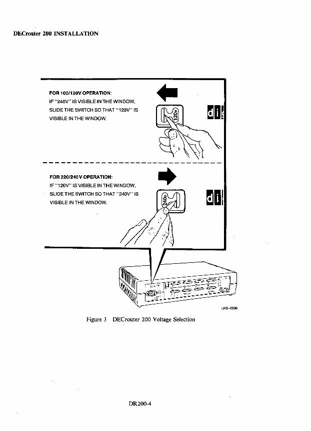
DECrouter 200 INSTALLATION
FOR 100/120VOPERATION:
IF "240V" IS VISIBLE IN THE WINDOW,
SLIDE THE SWITCH SO THAT" 120V" IS
VISIBLE IN THE WINDOW.
II)
/_b~ -------------------------------
FOR 220/240 V OPERATION:
IF "120V" IS VISIBLE IN THE WINDOW,
SLIDE THE SWITCH SO THAT "240V" IS
VISIBLE IN THE WINDOW.
-+
Figure 3 DECrouter 200 Voltage Selection
DR200-4
mOl
LKG-0336
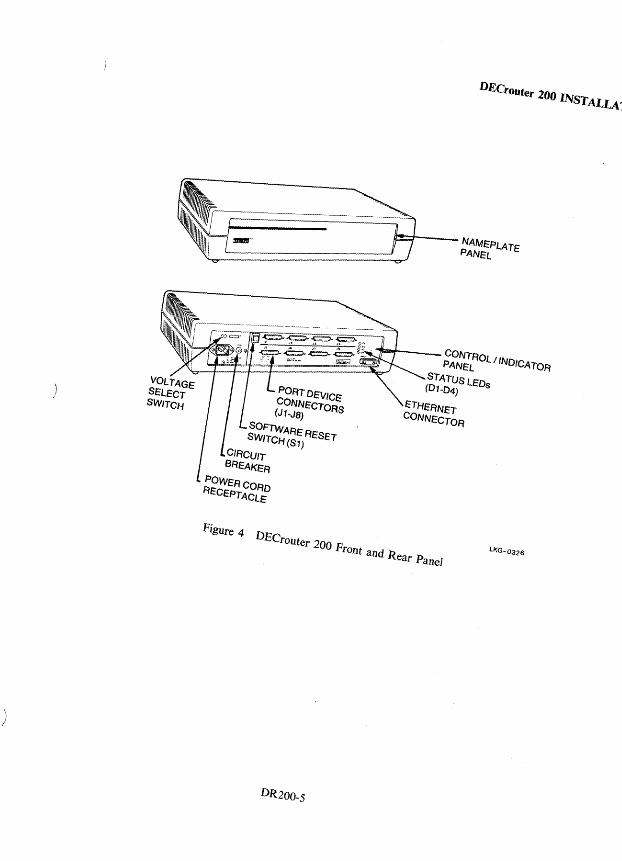
\ /
)
SOFTWARE RESET SWITCH (Sl)
CIRCUIT BREAKER
POWERCORO RECEPTACL/=
u...--I-___ NAMEPLATE PANEL
.... !!I!!ti--___ CONTROL / INDICATOR PANEL
STATUS LEOs (01-04)
ETHERNET CONNECTOR
Figure 4 DECrouter 200 Front and Rear Panel
DR200_S
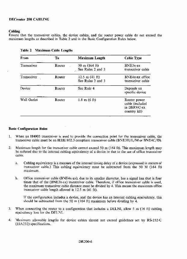
DECrouter 200 CABLING
Cabling Ensure that the transceiver cables, the device cables, and the router power cable do not exceed the maximum lengths as described in Table 2 and in the Basic Configuration Rules below.
Table 2 Maximum Cable Lengths
From To Maximum Length Cable Type
Transceiver Router 50 m (164 ft) BNE3x-xx See Rules 2 and 3 transceiver cable
Transceiver Router 12.5 m (41 ft) BNE4x-xx office See Rules 2 and 3 transceiver cable
Device Router See Rule 4 Depends on specific device
Wall Outlet Router 1.8 m (6 ft) Router power cable (included in DSRVC-xx country kit)
Basic Configuration Rules
1. When an H4005 transceiver is used to provide the connection point for the transceiver cable, the transceiver cable must be an IEEE 802.3 compliant transceiver cable (BNE3H/L/M or BNE4C/D).
2. Maximum length for the transceiver cable cannot exceed 50 m (164 ft). This maximum length may be reduced due to the internal cabling equivalency of a device or due to the use of office transceiver cable.
a. Cabling equivalency is a measure of the internal timing delay of a device (expressed in meters of transceiver cable.) This cabling equivalency must be subtracted from the 50 M (164 ft) maximum.
b. Office transceiver cable (BNE4x-xx), due to its smaller diameter, has a signal loss that is four times that of the (BNE3x-xx) transceiver cable. Therefore, if office transceiver cable is used, the maximum transceiver cable distance must be divided by 4. This means the maximum office transceiver cable length allowed is 12.5 m (41 ft).
If the configuration includes a device, and the device has an internal cabling equivalency, this should be subtracted from the 50 m (164 ft) maximum before dividing by 4.
3. When connecting the router to a configuration that includes a DELNI, allow 5 m (16 ft) cabling equivalency loss for the DELNI.
4. Maximum allowable lengths for device cables should not exceed guidelines set by RS-232-C (EIA232) specifications.
. DR200-6
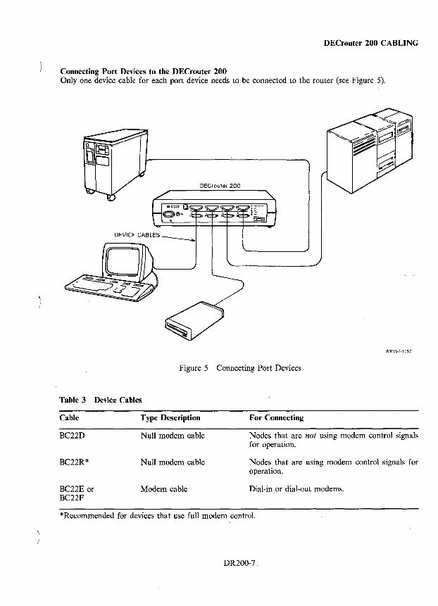
DEC router 200 CABLING
Connecting Port Devices to the DECrouter 200 Only one device cable for each port device needs to be connected to the router (see Figure 5).
DEC router 200
MKV87-1156
Figure 5 Connecting Port Devices
Table 3 Device Cables
Cable
BC22D
BC22R*
BC22E or BC22F
Type Description
Null modem cable
Null modem cable
Modem cable
For Connecting
Nodes that are not using modem control signals for operation.
Nodes that are using modem control signals for operation.
Dial-in or dial-out modems.
*Recommended for devices that use full modem control.
DR200-7
DECrouter 200 DIAGNOSTICS
Diagnostics The OECrouter 200 provides the following maintenance features.
• Hardware self-test
• Loopback tests
• Up-line crash dumps
The four status LEOs, located on the router's control/indicator panel, indicate the status of the router and are also used for diagnosing router problems. Compare the state of the status LEOs on the router with those shown in Table 5, then go to the section that follows.
NOTE All four LEDs illuminate for 1 second when the power is first applied to the router. After powering up the router, allow up to 2 minutes to elapse before determining the state of the status LEDs.
Table 4 Problem Analysis Tools
Tool
Hardware self-test
Circuit-level loopback test
Node-level loopback test
Up-line crash dump
Problems
Suspected problems in hardware.
The OECrouter and a node on the same Ethernet are not communicating properly.
The OECrouter and an adjacent node on one of the asynchronous circuits are not communicating properly.
Higher-level problems and logical link problems between two nonadjacent nodes or between two adjacent nodes on Ethernet.
System crashes.
DR200-8
Components Tested
All hardware components including Ethernet connections.
Ethernet cable and components. Checks physical links between components.
Asynchronous circuits. Checks physical links between hardware components.
Logical link capabiliti4s (network software).
None
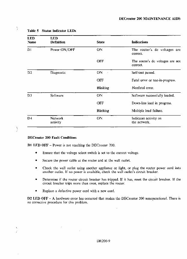
DECrouter 200 MAINTENANCE AIDS
Table 5 Status Indicator LEDs
LED Name
LED Definition State Indications
Dl
D2
D3
D4
Power ON/OFF
Diagnostic
Software
Network activity
ON
OFF
ON
OFF
Blinking
ON
OFF
Blinking
ON
The router's dc voltages are correct.
The router's dc voltages are not correct.
Self-test passed.
Fatal error or test-in-progress.
Nonfatal error.
Software successfully loaded.
Down-line load in progress.
Multiple load failure.
Indicates activity on the network.
DEC router 200 Fault Conditions
Dl LED OFF - Power is not reaching the DECrouter 200.
• Ensure that the voltage select switch is set to the correct voltage.
• Secure the power cable at the router and at the wall outlet.
• Check the wall outlet using another appliance or light, or plug the router power cord into another outlet. If no power is available, check the wall outlet's circuit breaker.
• Determine if the router circuit breaker has tripped. If it has, reset the circuit breaker. If the circuit breaker trips more than once, replace the router.
• Replace a defective power cord with a new cord.
D2 LED OFF - A hardware error has occurred that makes the DECrouter 200 nonoperational. There is no corrective procedure for this problem.
DR200-9
DECrouter 200 MAINTENANCE AIDS
D2 LED Blinking - If the D2 LED is blinking after power-up, it indicates that the router has a nonfatal problem during self-test. To isolate the problem, connect a console terminal to port (J1) of the router. The primary problem indicator in this case is the error message that appears on the console terminal.
To isolate and diagnose the problem, perform the following:
• Connect a console terminal to Port 1 (11) of the router, then power up the terminal.
• Configure the terminal to operate at a speed of 9600 bits/s with a character size of 8 bits with no parity (refer to the specific terminal user's guide for help in setting up the terminal parameters).
• Unplug the router power cord at the wall outlet, then reinsert it.
• Read the error message that appears on the terminal display (if no message appears on the terminal display, refer to the No Message~ on Console Terminal section that follows).
The following sections list the error messages that occur in conjunction with the D2 LED blinking on your display.
Error Messages 922 and 923
Local -922- port hardware error on port n Local -923- port n has been disabled
These messages indicate a port hardware error. There is no corrective procedure for this problem.
Error Message 932
Local -932- hardware revision level checksum error
The router's nonvolatile memory is faulty. There is no corrective procedure for this problem.
Error Messages 941, 942, and 950
Local -941- transceiver loopback error Local -942- image load not attempted Local -950- troubleshooting procedures should be followed
There is a fault in the transceiver cabling between the router and the coaxial cable.
1. Check the transceiver cable that runs from the router to the transceiver, to the DELNI, or to the Etherjack. Be sure the connection is secure at both ends. Check the cable for any signs of damage. If the cable appears damaged, replace it.
2. If the above action does not correct the problem:
a. Disconnect the transceiver cable from the router.
b. Plug the Ethernet turnaround connector into the Ethernet connector on the router.
c. Initialize the router by pressing <CTRL/P> on the console terminal, or by unplugging and then reinserting the router's power cord.
DR200-10
DEC router 200 MAINTENANCE AIDS
d. Wait 20 seconds for the diagnostic test to complete, then observe the status of the D2 LED:
(1) If the D2 LED continues to blink and the error messages reappear after the self-test (within 10 or 15 seconds), the router is faulty and must be replaced.
(2) If the D2 LED glows steadily, proceed to the next step to isolate and determine , the faulty unit.
NOTE When using the Ethernet loop back connector to troubleshoot the DECrouter 200, note that if the results cause the D2 LED to glow steadily, the router attempts to down-line load the router image. Since the router is disconnected from the network, the down-line load fails and the router responds by causing the D3 LED to blink and issues messages 902 and 912 to the console terminal.
e. Unplug the Ethernet turnaround connector from the Ethernet connector on the router.
f. Reconnect the transceiver cable to the Ethernet connector on the router.
g. Disconnect the other end of the transceiver cable from the DELNI, from the Etherjack, or from the transceiver on the Ethernet coaxial cable.
h. Plug the Ethernet turnaround connector into the transceiver cable.
i. Initialize the router by pressing <CTRL/P> on the console terminal, or by unplugging and then reinserting the router's power cord.
(1) If the D2 LED continues to blink, the transceiver cable is faulty and must be replaced.
(2) If the D2 LED glows steadily, the faulty unit is the device the transceiver cable was connected to (the DELNI, the Etherjack extension, or the transceiver).
No Messages on Console Terminal
• The port to which the console terminal is physically connected is not defined as the console port.
• The console terminal is faulty.
• The internal characteristics for the console terminal are not set up correctly.
DR200-11
DECrouter 200 MAINTENANCE AIDS
D3 LED Blinking - If the 03 LED is blinking after power-up, it indicates the router has a down-line loading problem.
To isolate and diagnose the problem, perform the following:
• Connect a console terminal to Port 1 (11) of the router, then power up the terminal.
• Configure the terminal to operate at a speed of 9600 bits/s with a character size of 8 bits with no parity (refer to the· specific terminal user's guide for help in setting up the terminal parameters).
• Press <CTRL/P> on the console terminal keyboard. (Pressing <CTRL/P> restarts the router self-test and starts the down-line loading of the router image from a load host.)
• Read the message that appears on the terminal display.
NOTE If the down-line load succeeds, the terminal displays a message indicating the load is complete, followed by a series of coded alphabetic characters. This is normal. The characters represent DDCMP protocol messages from Port 1 of the DECrouter 200.
Down-Line Load Starts and Then Fails
The following messages appear on the console terminal at various intervals:
Local -902- waiting for image to load Local -903- loading from host host-address Local -912- load failure, timeout
The host system (address in error message) fails to complete the down-line load to the OECrouter 200.
Copy the error message exactly as it appears on the console terminal display and notify the router manager.
Down-Line Load Does Not Start
The following messages appear on the console terminal at various intervals:
Local -902- waiting for image to load Local -912- load failure, timeout
The load host system is not responding to the router's down-line load request within the allotted timeout period.
Copy the error message exactly as it appears on the console terminal display and notify the router manager.
OR200-12
DECrouter 250 INSTALLATION
DECroutei' 250 SYNCHRONOUS/ASYNCHRONOUS ROUTER
General Description The DECrouter 250 is an Ethernet communications routing server. It can connect any combination of up to eight DECnet devices to each other, to the local area network (LAN), and to larger DECnet networks. The DECrouter 250 has ten ports: one Ethernet port, one console port, two 50-pin device ports, and six 25-pin (EIA-232-D) device ports. All eight device ports can be for either synchronous or asynchronous devices that use DEC net Phase III, Phase IV, or Phase V protocols with Digital Data Communications Message Protocol (DDCMP). The DECrouter 250 supports the following standards:
• EIA-232-D/Y.24/Y.28 • RS-449, RS-423-A/Y.1O • RS-449, RS-422-A/Y.I0 • Y.35 • Y.36
DECrouter 250 Versions The DECrouter 250 is available in two versions with each having a different input voltage. The versions and input voltages are listed below.
Model
DSRVR-AA DSRVR-AB DSRVR-A3 (see NOTE)
Input Voltage
100-120 Vac 220-240 Vac 220-240 Vac
NOTE This is a field service spare that is shipped without a country kit or manuals. It is set to 240 Vac but can be reset to 120 Vac.
Reference Documentation Refer to the following documentation for more information on the DEC router 250 synchronous/asynchronous router.
• DECrouter 250 Hardware Installation Manual EK-A0460-IN
• DECrouter 250 VMS Software Installation Guide AA-PAX6A-TE
• DECrouter 250 ULTRIX Software Installation Guide AA-PAX8A-TE
• DECrouter 250 MS-DOS Software Installation Guide AA-PAX7 A-TE
• DECrouter 250 Management Guide Volume I AA-PAX4A-TE
• DECrouter 250 ~Management Guide Volume II AA-PAX5A-TE
• DECrouter 250 Maintenance Card AV-PAX9A-TE
DR250-1
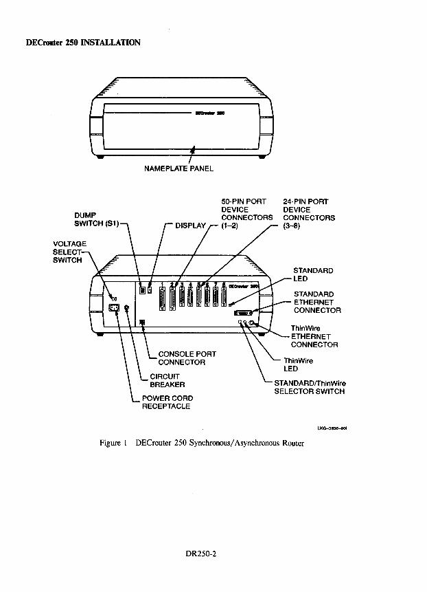
DECrouter 250 INSTALLATION
fo---------......,.
DUMP SWITCH (S1)
VOLTAGE SELECT SWITCH
NAMEPLATE PANEL
CONSOLE PORT CONNECTOR
POWER CORD RECEPTACLE
50-PIN PORT DEVICE CONNECTORS (1-2)
24-PIN PORT DEVICE CONNECTORS (3-8)
STANDARD LED
STANDARD ETHERNET CONNECTOR
ThlnWlre ETHERNET CONNECTOR
STANDARDfThinWire SELECTOR SWITCH
LKG-3836-eOI
Figure 1 DECrouter 250 Synchronous/ Asynchronous Router
DR250-2
DECrouter 250 INSTALLATION
Hardware Components The DECrouter 250 package consists of:
• DECrouter 250 hardware unit - DSRVR-AA or DSRVR-AB • Country Kit - Powef cord 'and hardware installation manual • Software - DECrouter software and installation manual
Software Components The following software is required for the DECserver 250 installation and operation.
• DECrouter 250 distribution software (installed on each load host)
• DECnet Phase IV software (i"~talled on each load host)
Equipment Placement The DECrouter 250 can be placed in various locations, including offices and computer rooms, as long as the environmental requirements are met.
Environmental Requirements
Temperature Relative Humidity
Physical Dimensions
Width Height Depth Weight
Power Requirements
Model Version
DSRVR-AA DSRVR-AB
S° to 50°C (41° to 122°F) 10% to 90% (noncondensing)
49.3 em (19.4 in.) 16.1 em (6.3 in.) 31.2 em (12.3 in.) 8.1 kg (17.1 lbs)
Input Voltage
100-120 Vac 220-240 Vac
DR2S0-3
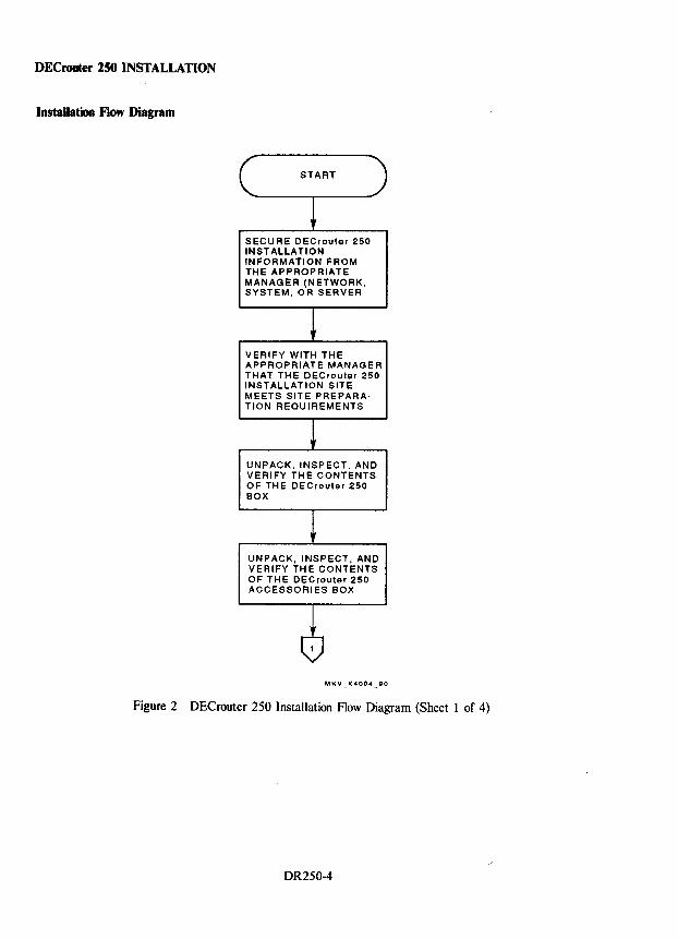
DECrouter 250 INSTALLATION
Installation Flow Diagram
SECURE DeCrouter 250 INSTALLATION INFORMATION FROM THE APPROPRIATE MANAGER (NETWORK, SYSTEM, OR SERVER
VERIFY WITH THE APPROPRIATE MANAGER THAT THE OECrouter 250 INSTALLATION SITE MEETS SITE PREPARATION REQUIREMENTS
UNPACK, INSPECT. AND VERIFY THE CONTENTS OF THE DECrouter 250 BOX
UNPACK, INSPECT, AND VERIFY TH E CONTENTS OF THE DECrouter 250 ACCESSORIES BOX
Figure 2 DECrouter 250 Installation Flow Diagram (Sheet 1 of 4)
DR250-4
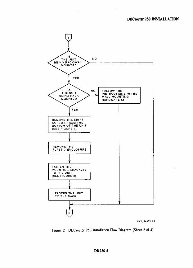
REMOVE THE EIGHT SCREWS FROM THE BOTTOM OF THE UNIT (SEE FIGURE 3)
REMOVE THE PLASTIC ENCLOSURE
FASTEN THE MOUNTING BRACKETS TO THE UNIT (SEE FIGURE 3)
FASTEN THE UNIT TO THE RACK
DECrouter 2S0 INSTALLATION
FOLLOW THE INSTRUCTIONS IN THE WALL-MOUNTING HARDWARE KIT
Figure 2 DECrouter 250 Installation Flow Diagram (Sheet 2 of 4)
DR250-5
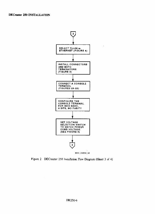
DECrouter 250 INSTALLATION
SELECT ThlnWire ETHERNET (FIGURE 4)
INSTALL CONNECTORS AND BOTH TERMINATORS (FIGURE 5)
CONNECT A CONSOLE TERMINAL (FIGURES 20-22)
CONFIGURE THE CONSOLE TERMINAL FOR 9600 BAUD. 8 BITS. NO PARITY
SET VOLTAGE SELECTION SWITCH TO MATCH POWER CORD VOLTAGE (SEE FIGURE 6)
Figure 2 DECrouter 250 Installation Flow Diagram (Sheet 3 of 4)
DR250-6
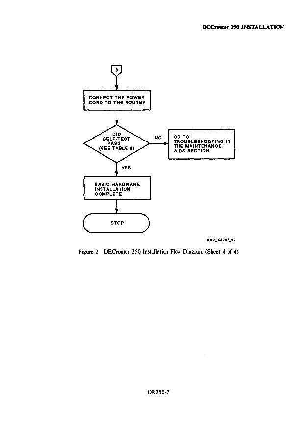
CONNECT THE POWER COR D TO THE ROUTER
BASIC HARDWARE INSTALLATION COMPLETE
DECrouter 250 INSTALLATION
NO GO TO TROUBLESHOOTING IN THE MAINTENANCE AIDS SECTION
Figure 2 DECrouter 250 Installation Flow Diagram (Sheet 4 of 4)
DR250-7
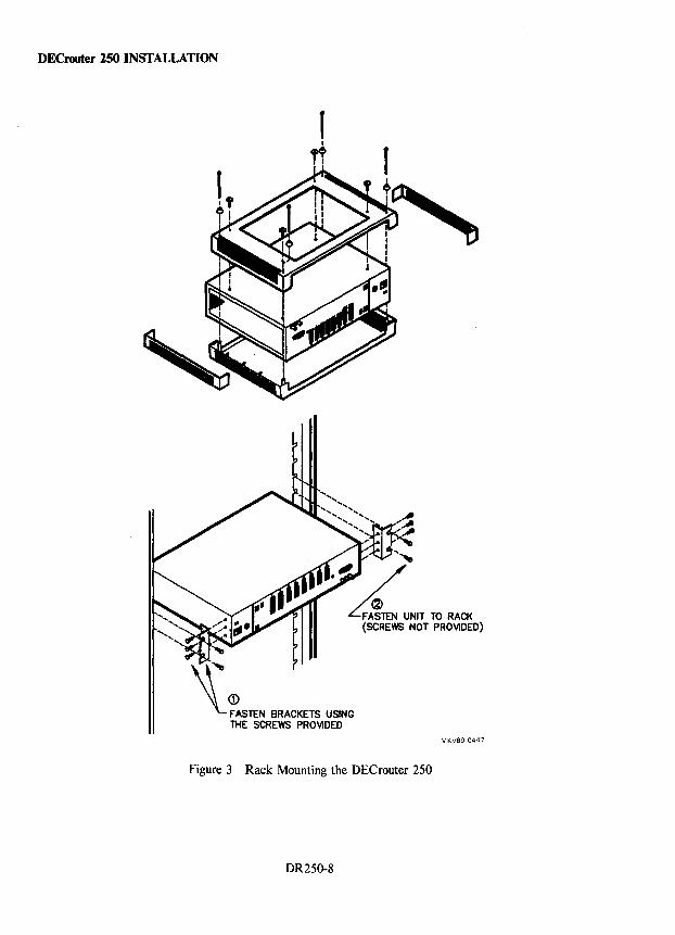
DECrooter 250 INSTALLATION
1
MKV89-0447
Figure 3 Rack Mounting the DEC router 250
DR250-8
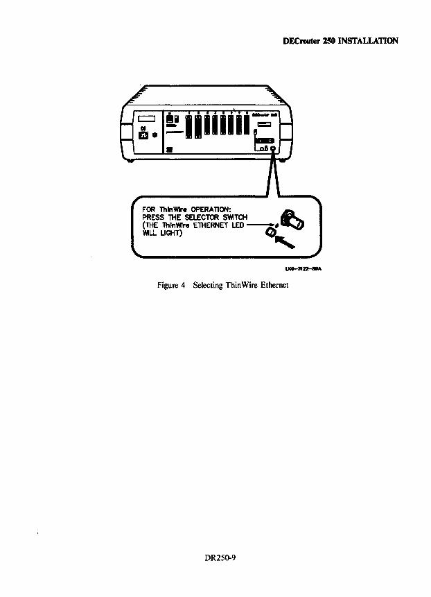
DECrouter 250 INSTALLATION
FOR ThlnWlre OPERATION: ~ PRESS n-tE SELECTOR SWTCH (THE ThlnWlre ETHERNET LED--q; WILL LIGHT) ,
Figure 4 Selecting Thin Wire Ethernet
DR250-9
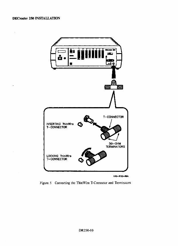
DECrouter 250 INSTALLATION
INSERTING lhlnWlre Cb T-CONNECTOR
LOCKING lhlnWlre T -CONNECTOR
50-OHM TERMINATORS
Figure 5 Connecting the Thin Wire T-Connector and Terminators
DR250-10
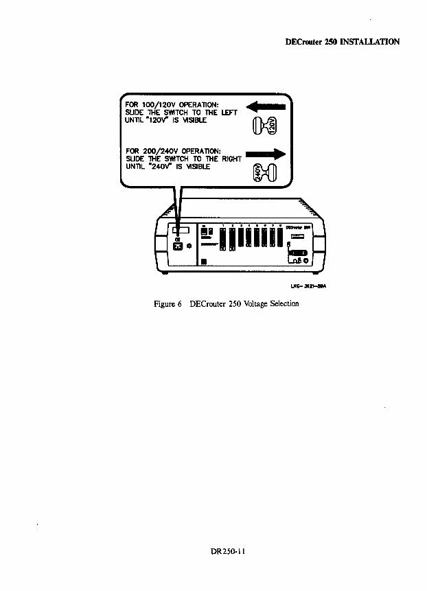
FOR 100/120V OPERATI~: SUDE lHE SWITCH TO THE LEFT UNllL -120'1' IS VISIBLE
FOR 200/240V OPERATION: SUDE lHE SWITCH TO THE RIGHT UNTIL -240'1' IS VISIBLE
DECrouter 250 INSTALLATION
~iiiiiiir=• 1= LJ(Q- 312t-11A
Figure 6 DEC router 250 Voltage Selection
DR250-11
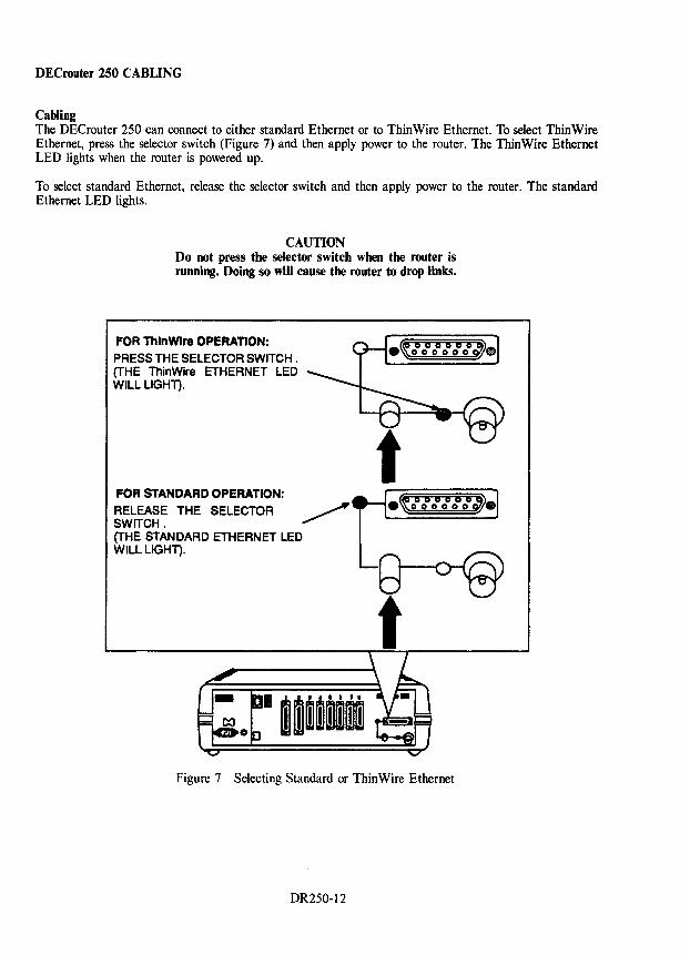
DECrouter 250 CABLING
Cabling The DECrouter 250 can connect to either standard Ethernet or to ThinWire Ethernet. To select ThinWire Ethernet, press the selector switch (Figure 7) and then apply power to the router. The ThinWire Ethernet LED lights when the router is powered up.
To select standard Ethernet, release the selector switch and then apply power to the router. The standard Ethernet LED lights.
CAUTION Do not press the selector switch when the router is running. Doing so will cause the router to drop links.
FOR ThlnWlre OPERAnON:
PRESS THE SELECTOR SWITCH. (THE ThinWire ETHERNET LED WILL LIGHT).
FOR STANDARD OPERATION:
RELEASE THE SELECTOR SWITCH. (THE STANDARD ETHERNET LED WILL LIGHT).
•~ 0 0 b Obo~. 000000
Figure 7 Selecting Standard or Thin Wire Ethernet
DR250-12
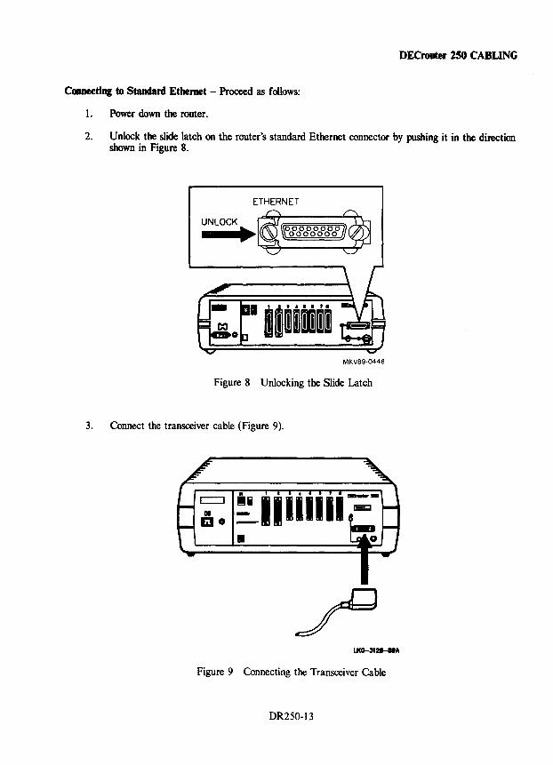
DECrouter 150 CABLING
Coaaecting to Standard Ethernet - Proceed as follows:
1. Power down the router.
2. Unlock the slide latch on the router's standard Ethernet connector by pushing it in the direction shown in Figure 8.
ETHERNET
UNLOCK
-
MKV89-0446
Figure 8 Unlocking the Slide Latch
3. Connect the transceiver cable (Figure 9).
Figure 9 Connecting the Transceiver Cable
DR250-13
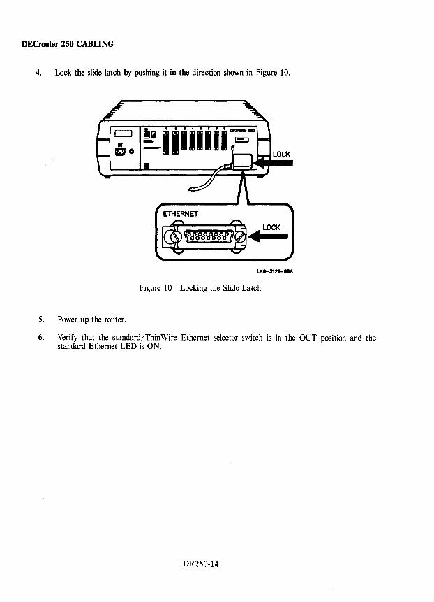
DECrouter 250 CABLING
4. Lock the slide latch by pushing it in the direction shown in Figure 10.
LOCK
Figure 10 Locking the Slide Latch
5. Power up the router.
6. Verify that the standard/Thin Wire Ethernet selector switch is in the OUT position and the standard Ethernet LED is ON.
DR250-14
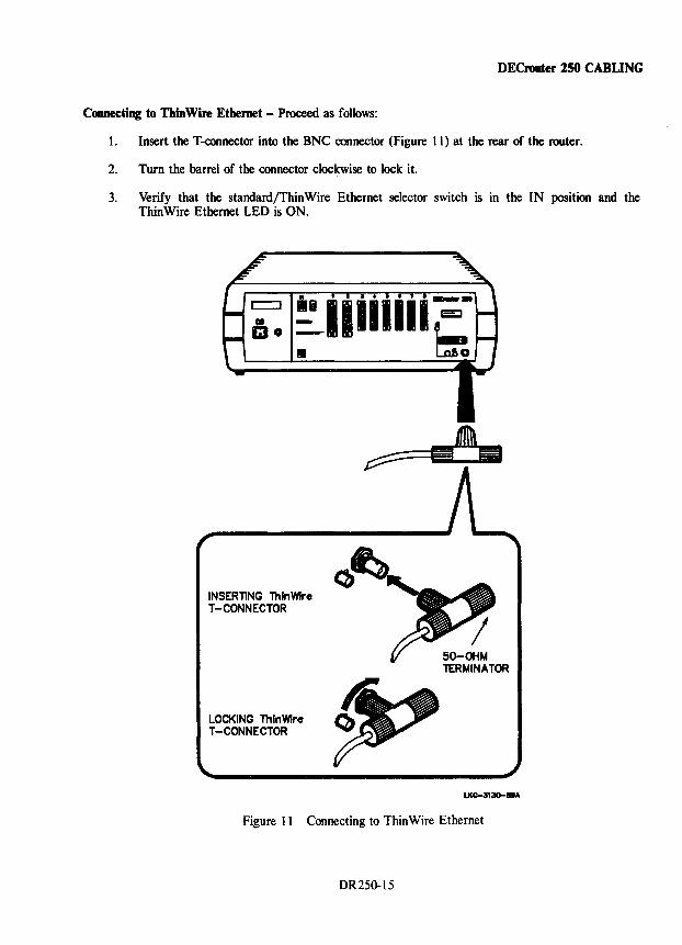
DECrouter 250 CABLING
Connecting to ThinWire Ethernet - Proceed as follows:
1. Insert the T-connector into the BNC connector (Figure 11) at the rear of the router.
2. Tum the barrel of the connector clockwise to lock it.
3. Verify that the standard/Thin Wire Ethernet selector switch is in the IN position and the ThinWire Ethernet LED is ON.
INSERTING ThlnWlre T-CONNECTOR
LOCKING ThlnWlre T-CONNECTOR
50-OHM TERMINATOR
Figure 11 Connecting to ThinWire Ethernet
DR250-15
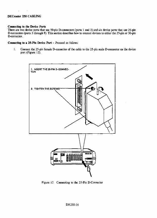
DECrouter 250 CABLING
Coonecting to the Device Ports There are two device ports that use 50-pin D-connectors (ports 1 and 2) and six device ports that use 25-pin D-connectors (ports 3 through 8). This section describes how to connect devices to either the 25-pin or 50-pin D-connector.
Coone~ting to a 25-Pin Device Port - Proceed as follows:
1. Connect the 25-pin female D-connector of the cable to the 25-pin male D-connector on the device port (Figure 12).
Figure 12 Connecting to the 25-Pin D-Connector
DR250-16
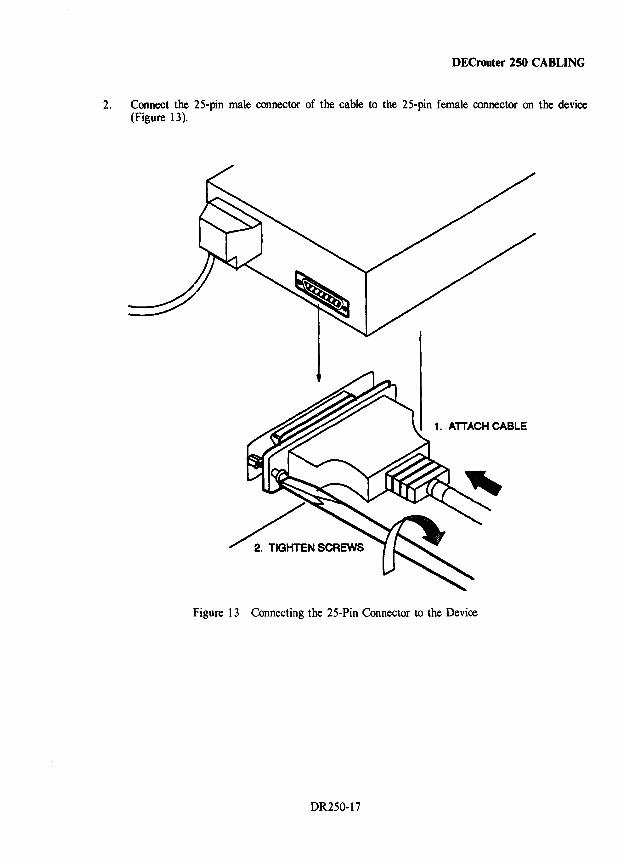
DECrouter 250 CABLING
2. Connect the 25-pin male connector of the cable to the 25-pin female connector on the device (Figure 13).
1. ATTACH CABLE
~NSCREWS Figure 13 Connecting the 25-Pin Connector to the Device
DR250-17
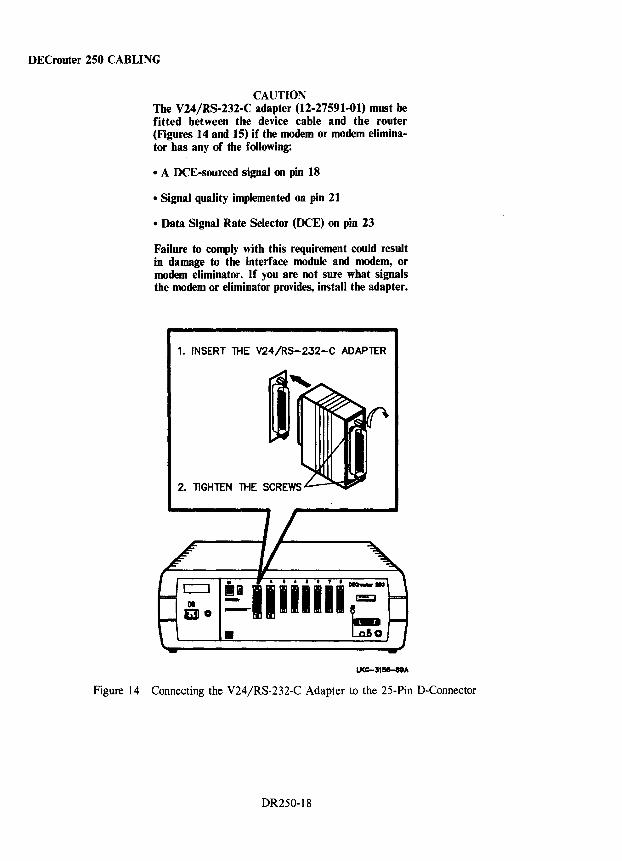
DECrouter 250 CABLING
CAUTION The V24/RS-232-C adapter (12-27591-01) must be fitted between the device cable and the router (Figures 14 and 15) if the modem or modem eliminator has any of the following:
• A DCE-sourced signal on pin 18
• Signal quality implemented on pin 21
• Data Signal Rate Selector (DCE) on pin 23
Failure to comply with this requirement could result in damage to the interface module and modem, or modem eliminator. If you are not sure what signals the modem or eliminator provides, install the adapter.
1. INSERT THE V24/RS-232-C ADAPTER
Figure 14 Connecting the V24/RS-232-C Adapter to the 25-Pin D-Connector
DR250-18
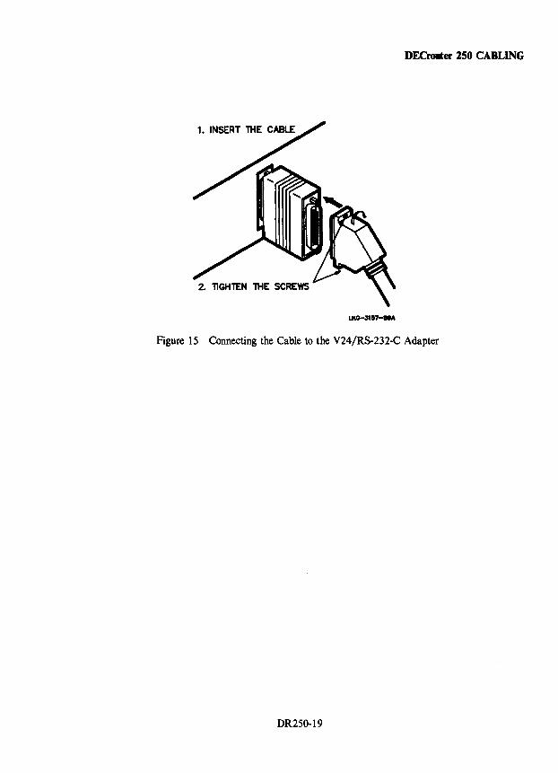
DECrouter 150 CABLING
Figure 15 Connecting the Cable to the V24/RS-232-C Adapter
DR250-19
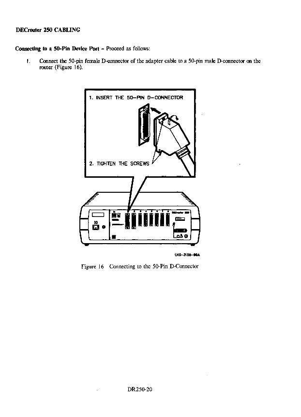
DECrouter 250 CABLING
Connecting to a SO-Pin Device Port - Proceed as follows:
1. Connect the 50-pin female D-connector of the adapter cable to a 50-pin male D-connector on the router (Figure 16).
1. INSERT THE 50-PIN D-CONNECTOR
2. TIGHTEN 'THE SCREWS
Figure 16 Connecting to the 50-Pin D-Connector
DR250-20
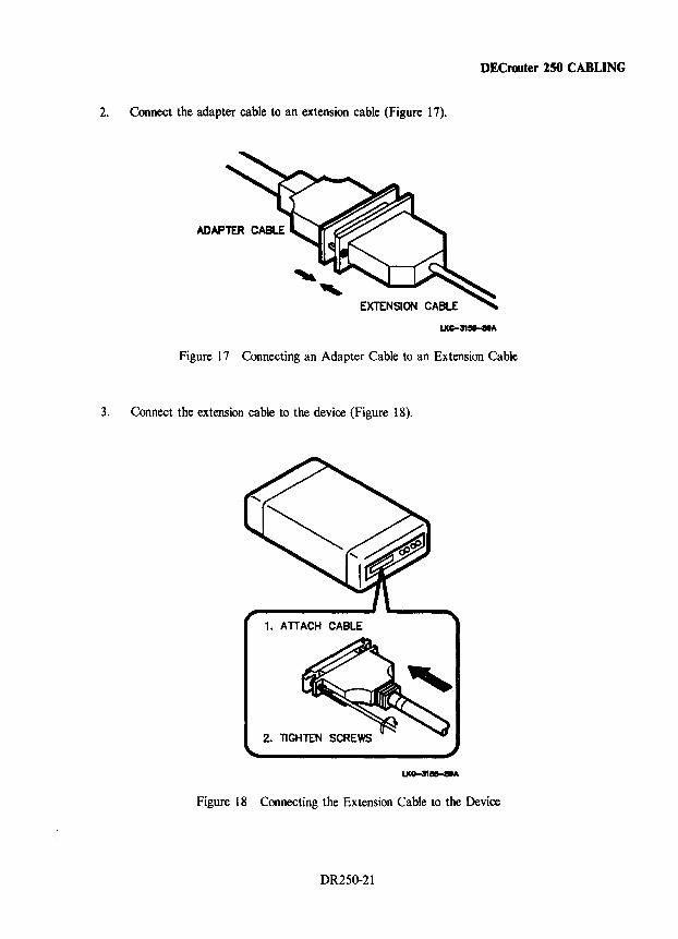
DECrouter lSO CABLING
2. Connect the adapter cable to an extension cable (Figure 17).
EXTENSION CABLE
LKG-31 .... A
Figure 17 Connecting an Adapter Cable to an Extension Cable
3. Connect the extension cable to the device (Figure 18).
Figure 18 Connecting the Extension Cable to the Device
DR250-21
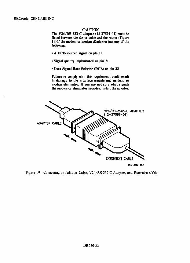
DEC router 250 CABLING
CAUTION The V24/RS-232-C adapter (12-27591-01) must be fitted between the device cable and the router (Figure 19) if the modem or modem eliminator has any of the following:
• A DCE-sourced signal on pin 18
• Signal quality implemented on pin 21
• Data Signal Rate Selector (DCE) on pin 23
Failure to comply with this requirement could result in damage to the interface module and modem, or modem eliminator. If you are not sure what signals the modem or eliminator provides, install the adapter.
V24/RS-232-C ADAPlER (12-27591-01)
EXTENSION CABLE
LKo-31eo-eII"
Figure 19 Connecting an Adapter Cable, V24/RS-232-C Adapter, and Extension Cable
DR250-22
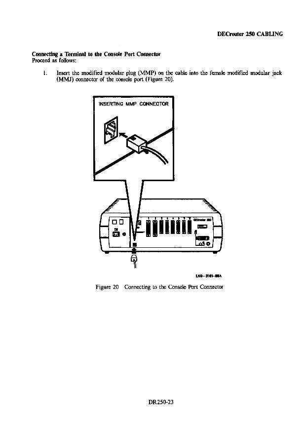
Connecting a Terminal to the Console Port Connector Proceed as follows:
DECrouter 250 CABLING
1. Insert the modified modular plug (MMP) on the cable into the female modified modular jack (MMJ) connector of the console port (Figure 20).
INSERTING MMP CONNECTOR
Figure 20 Connecting to the Console Port Connector
DR250-23
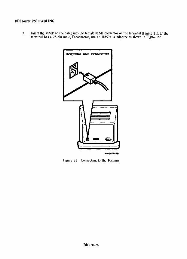
DECrouter 250 CABLING
2. Insert the MMP on the cable into the female MMJ connector on the terminal (Figure 21). If the terminal has a 25-pin male, D-connector, use an H8571-A adapter as shown in Figure 22.
INSERTING MMP CONNECTOR
Figure 21 Connecting to the Terminal
DR250-24
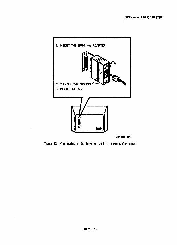
DECrouter 250 CABLING
1. INSERT THE H8571-A ADAPlER
3. INSERT THE MMP
~.A
Figure 22 Connecting to the Terminal with a 25-Pin D-Connector
DR250-25
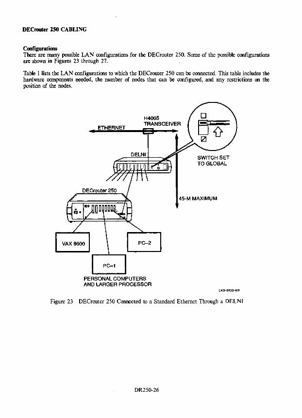
DECrooter ZSO CABLING
Configurations There are many possible LAN configurations for the DECrouter 250. Some of the possible configurations are shown in Figures 23 through 27.
Table 1 lists the LAN configurations to which the DECrouter 250 can be connected. This table includes the hardware components needed, the number of nodes that can be configured, and any restrictions on the position of the nodes.
ETHERNET
VAX 8600 PC-2
PC-1
PERSONAL COMPUTERS AND LARGER PROCESSOR
45-M MAXIMUM
LK~832-801
Figure 23 DECrouter 250 Connected to a Standard Ethernet Through a DELNI
DR250-26
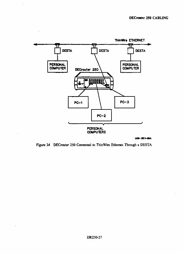
DESTA
PERSONAL. COMPUTER
\
PC-1
PC-2
T
PERSONAL COMPUlERS
DECrouter 250 CABLING
lhlnWire EniERNET
DESTA
PERSONAL COMPUTER
PC-3
I
Figure 24 DECrouter 250 Connected to Thin Wire Ethernet Through a DESTA
DR2S0-27
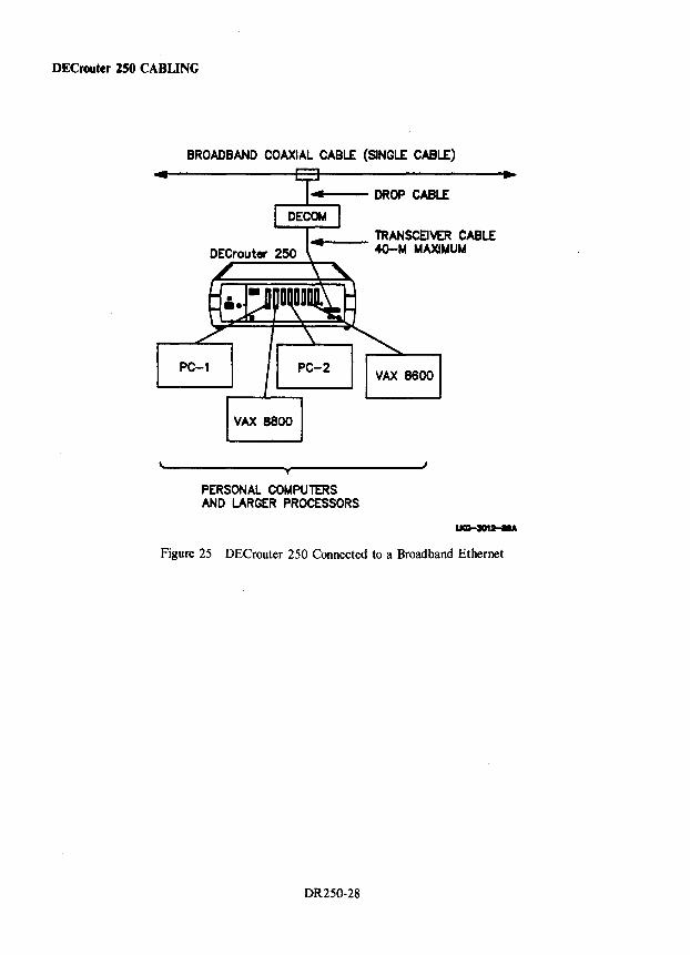
DECrouter 250 CABLING
BROADBAND COAXIAL CABLE (SINGLE CABLE)
4--- DROP CABLE
4--- TRANSCEIVER CABLE 4O-M MAXIMUM
PC-1 PC-2
VAX 8800
T
PERSONAL COMPUTERS AND LARGER PROCESSORS
VAX 8600
I
Figure 25 DECrouter 250 Connected to a Broadband Ethernet
DR250-28
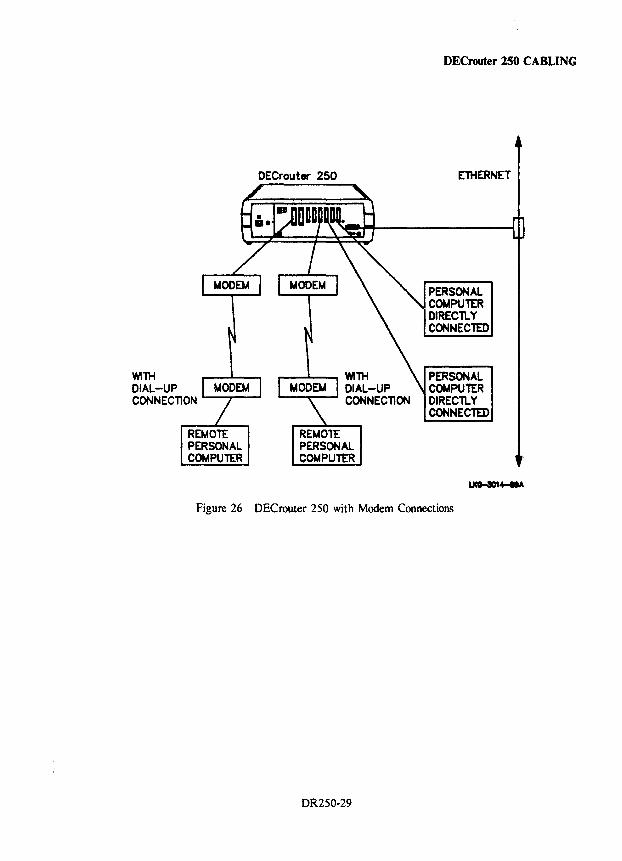
WITH DIAL-UP CONNEC110N
REMOTE PERSONAL COMPUTER
DECrouter 250
REMon: PERSONAL COMPUTER
DECrouter 250 CABLING
ElliERNET
PERSONAL COMPUTER DlRECllY CONNECTED
PERSONAL COMPUTER DIRECllY CONNECTED
Figure 26 DECrouter 250 with Modem Connections
DR250-29
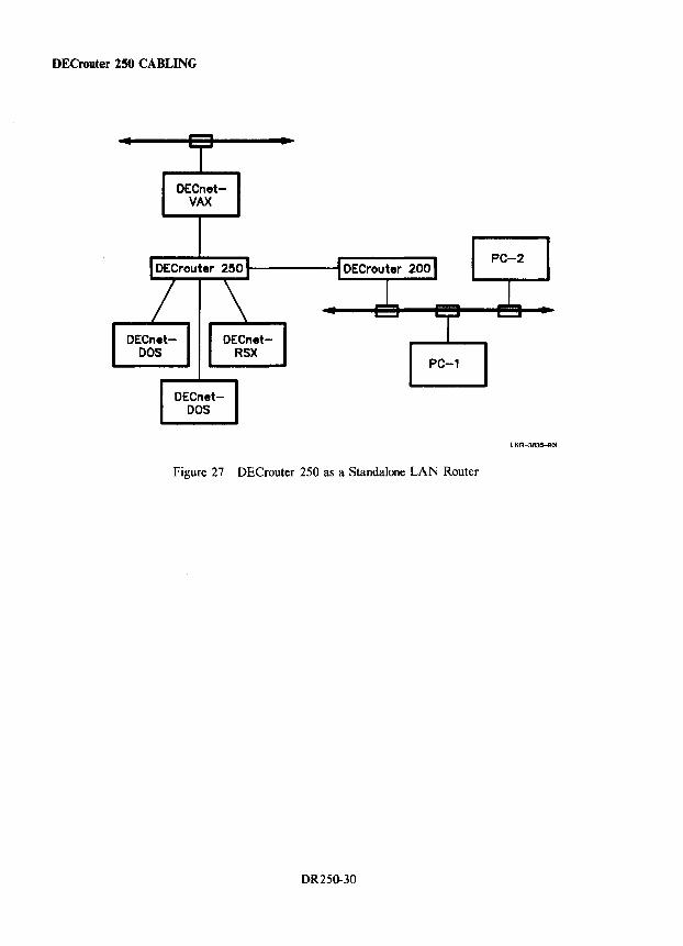
DECrouter 250 CABLING
DECnetDOS
DECnetVAX
DECnetRSX
DECnetDOS
PC-1
Figure 27 DECrouter 250 as a Standalone LAN Router
DR250-30
LKG--3835-901
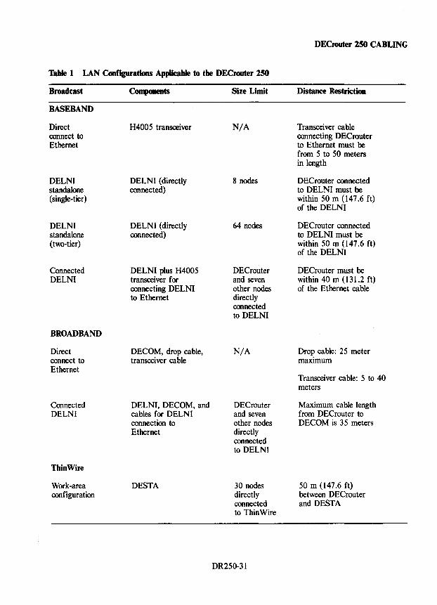
DECrouter 150 CABLING
Table 1 LAN Configurations Applicable to the DECrouter 250
Broadcast Components Size Limit Distance Restriction
BASEBAND
Direct H4005 transceiver N/A Transceiver cable connect to connecting DEC router Ethernet to Ethernet must be
from 5 to 50 meters in length
DELNI DELNI (directly 8 nodes DECrouter connected standalone connected) to DELNI must be (single-tier) within 50 m (147.6 ft)
of the DELNI
DELNI DELNI (directly 64 nodes DECrouter connected standalone connected) to DELNI must be (two-tier) within 50 m (147.6 ft)
of the DELNI
Connected DELNI plus H4005 DECrouter DECrouter must be DELNI transceiver for and seven within 40 m (131.2 ft)
connecting DELNI other nodes of the Ethernet cable to Ethernet directly
connected to DELNI
BROADBAND
Direct DECOM, drop cable, N/A Drop cable: 25 meter connect to transceiver cable maximum Ethernet
Transceiver cable: 5 to 40 meters
Connected DELNI, DECOM, and DEC router Maximum cable length DELNI cables for DELNI and seven from DECrouter to
connection to other nodes DECOM is 35 meters Ethernet directly
connected to DELNI
ThinWire
Work-area DESTA 30 nodes 50 m (147.6 ft) configuration directly between DECrouter
connected and DESTA to ThinWire
DR250-31
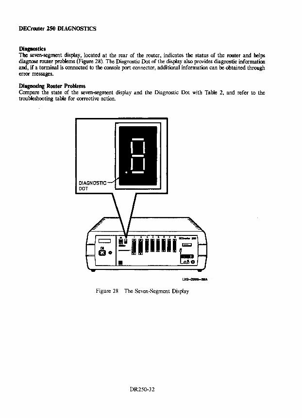
DECrouter 150 DIAGNOSTICS
Diagnostics The seven-segment display, located at the rear of the router, indicates the status of the router and helps diagnose router problems (Figure 28). The Diagnostic Dot of the display also provides diagnostic information and, if a terminal is connected to the console port connector, additional information can be obtained through error messages.
Diagnosing Router Problems Compare the state of the seven-segment display and the Diagnostic Dot with Table 2, and refer to the troubleshooting table for corrective action.
DIAGNOSllC DOT
Figure 28 The Seven-Segment Display
DR250-32
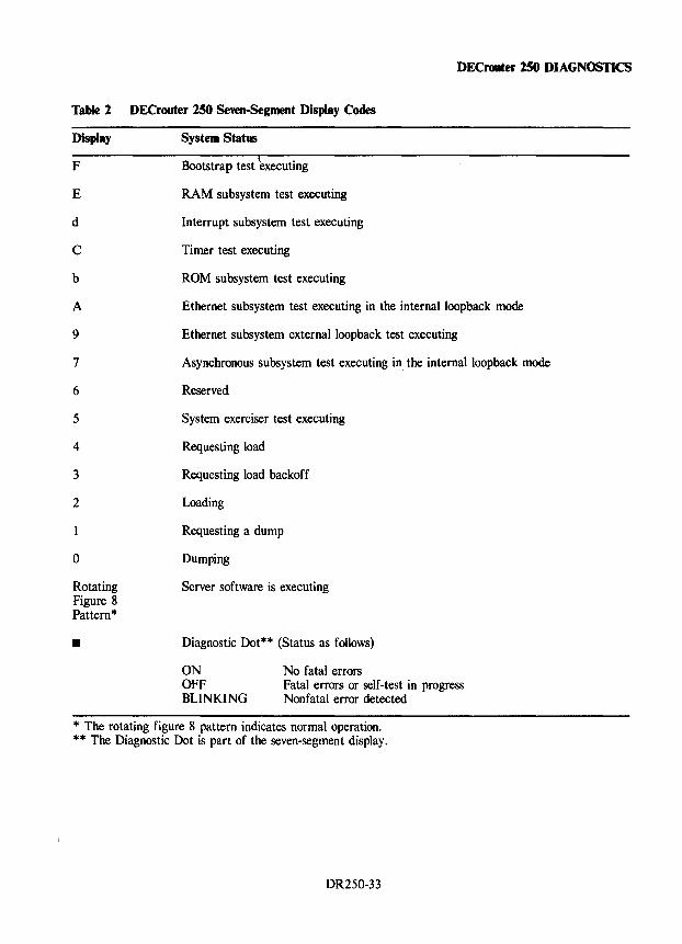
DECrouter 250 DIAGNOSTICS
Table 2 DECrouter 250 Seven-Segment Display Codes
Display System Status
F Bootstrap test 'executing
E RAM subsystem test executing
d Interrupt subsystem test executing
C Timer test executing
b ROM subsystem test executing
A Ethernet subsystem test executing in the internal loopback mode
9 Ethernet subsystem externalloopback test executing
7 Asynchronous subsystem test executing in the internal loopback mode
6 Reserved
5 System exerciser test executing
4 Requesting load
3 Requesting load backoff
2 Loading
o
Rotating Figure 8 Pattern *
•
Requesting a dump
Dumping
Server software is executing
Diagnostic Dot** (Status as follows)
ON OFF BLINKING
No fatal errors Fatal errors or self-test in progress Nonfatal error detected
* The rotating figure 8 pattern indicates normal operation. ** The Diagnostic Dot is part of the seven-segment display.
DR250-33
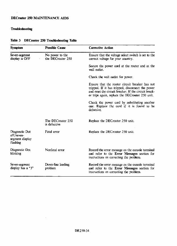
DEC router 250 MAINTENANCE AIDS
Troubleshooting
Table 3 DECrouter 250 Troubleshooting Table
Symptom
Seven-segment display is OFF
Diagnostic Dot off/sevensegment display flashing
Diagnostic Dot blinking
Seven-segment display has a "3"
Possible Cause
No power to the the DECrouter 250
The DECrouter 250 is defective
Fatal error
Nonfatal error
Down-line loading problem
Corrective Action
Ensure that the voltage select switch is set to the correct voltage for your country.
Secure the power cord at the router and at the wall outlet.
Check the wall outlet for power.
Ensure that the router circuit breaker has not tripped. If it has tripped, disconnect the power and reset the circuit breaker. If the circuit breaker trips again, replace the DECrouter 250 unit.
Check the power cord by substituting another one. Replace the cord if it is found to be defective.
Replace the DECrouter 250 unit.
Replace the DEC router 250 unit.
Record the error message on the console terminal and refer to the Error Messages section for instructions on correcting the problem.
Record the error message on the console terminal and refer to the Error Messages section for instructions on correcting the problem.
DR250-34
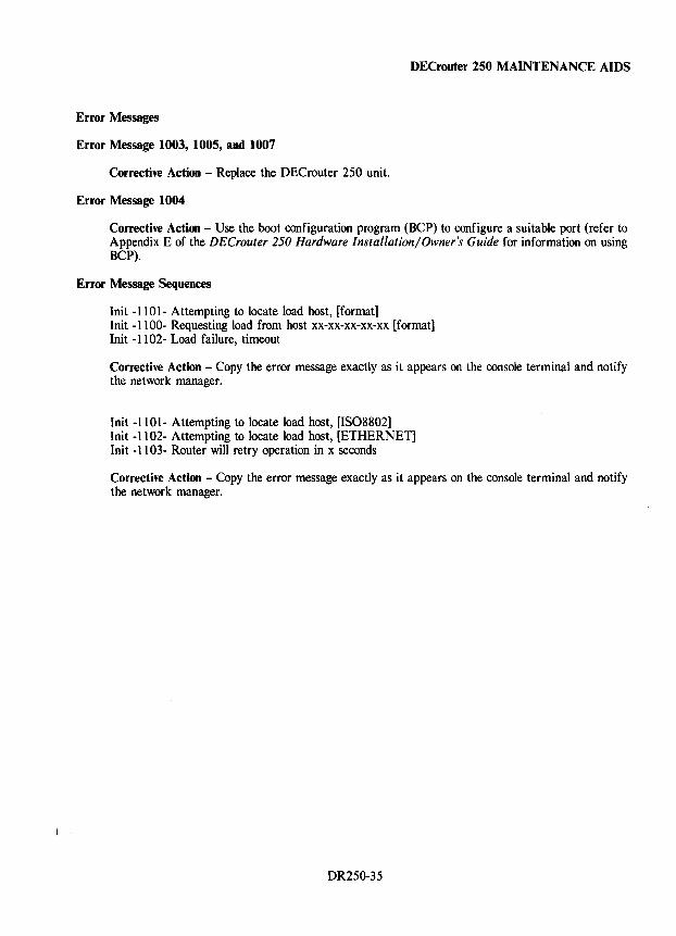
DEC router 250 MAINTENANCE AIDS
Error Messages
Error Message 1003, 1005, and 1007
Corrective Action - Replace the DECrouter 250 unit.
Error Message 1004
Corrective Action - Use the boot configuration program (BCP) to configure a suitable port (refer to Appendix E of the DECrouter 250 Hardware Installation/Owner's Guide for information on using BCP).
Error Message Sequences
Init -1101- Attempting to locate load host, [format] Init -1100- Requesting load from host xx-xx-xx-xx-xx [format] Init -1102- Load failure, timeout
Corrective Action - Copy the error message exactly as it appears on the console terminal and notify the network manager.
Init -1101- Attempting to locate load host, [1S08802] Init -1102- Attempting to locate load host, [ETHERNET] Init -1103- Router will retry operation in x seconds
Corrective Action - Copy the error message exactly as it appears on the console terminal and notify the network manager.
DR250-35

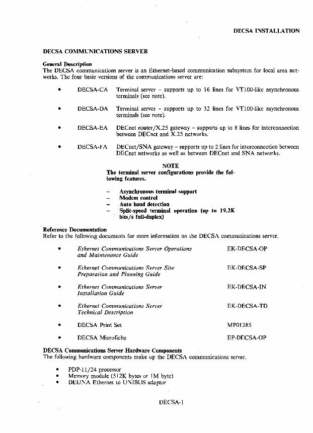
DECSA INSTALLATION
DECSA COMMUNICATIONS SERVER
General Description The DECSA communications server is an Ethernet-based communication subsystem for local area networks. The four basic versions of the communications server are:
• DECSA-CA Terminal server - supports up to 16 lines for VT100-like asynchronous terminals (see note).
• DECSA-DA Terminal server - supports up to 32 lines for VT100-like asynchronous terminals (see note).
• DECSA-EA DECnet router/X.25 gateway - supports up to 8 lines for interconnection between DECnet and X.25 networks.
• DECSA-FA DECnet/SNA gateway - supports up to 2 lines for interconnection between DECnet networks as well as between DECnet and SNA networks.
NOTE The terminal server configurations provide the following features.
Asynchronous terminal support Modem control Auto baud detection Split-speed terminal operation (up to 19.2K bits/s full-duplex)
Reference Documentation Refer to the following documents for more information on the DEC SA communications server.
• Ethernet Communications Server Operations EK-DECSA-OP and Maintenance Guide
• Ethernet Communications Server Site EK-DECSA-SP Preparation and Planning Guide
• Ethernet Communications Server EK-DECSA-IN Installation Guide
• Ethernet Communications Server EK-DECSA-TD Technical Description
• DECSA Print Set MP01385
• DECSA Microfiche EP-DECSA-OP
DECSA Communications Server Hardware Components The following hardware components make up the DECSA communications server.
• PDP-ll/24 processor • Memory module (512K bytes or 1 M byte) • DEUNA Ethernet to UNIBUS adaptor
DECSA-l
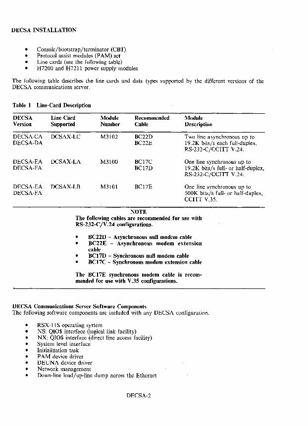
DECSAINSTALLATION
• Console/bootstrap/terminator (CBT) • Protocol assist modules (PAM) set • Line cards (see the following table) • H7200 and H7211 power supply modules
The following table describes the line cards and data types supported by the different versions of the DECSA communications server.
Table 1 Line-Card Description
DECSA Line Card Version Supported
DECSA-CA DCSAX-LC DECSA-DA
DECSA-EA DCSAX-LA DECSA-FA
DECSA-EA DCSAX-LB DECSA-FA
Module Number
M3102
M3100
M3101
Recommended Cable
BC22D BC22E
BC17C BC17D
BC17E
NOTE
Module Description
Two line asynchronous up to 19.2K bits/s each full-duplex, RS-232-C/CCITT V.24.
One line synchronous up to 19.2K bits/s full- or half-duplex, RS-232-C/CCITT V.24.
One line synchronous up to SOaK bits/s full- or half-duplex, CCITT V.3S.
The following cables are recommended for use with RS-232-C/V.24 configurations.
• BC22D - Asynchronous null modem cable • BC22E - Asynchronous modem extension
cable • BC17D - Synchronous null modem cable • BC17C - Synchronous modem extension cable
The BC17E synchronous modem cable is recommended for use with V.35 configurations.
DECSA Communications Server Software Components The following software components are included with any DECSA configuration.
• RSX-llS operating system • NS: QIO$ interface (logical link facility) • NX: QIO$ interface (direct line access facility) • System level interface • Initialization task • PAM device driver • DEUNA device driver • Network management • Down-line load/up-line dump across the Ethernet
DECSA-2
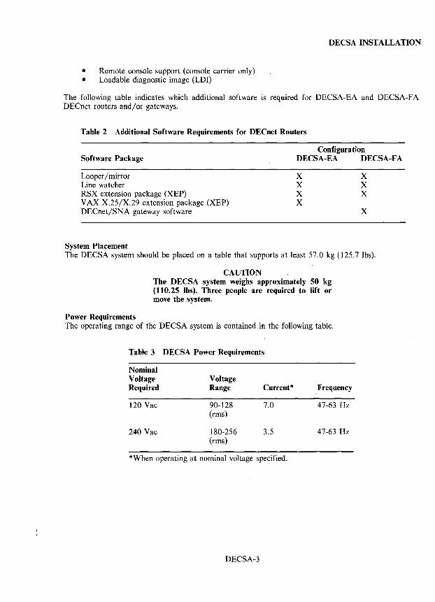
DECSA INSTALLATION
• Remote console support (console carrier only) • Loadable diagnostic image (LDI)
The following table indicates which additional software is required for DECSA-EA and DECSA-FA DECnet routers and/or gateways.
Table 2 Additional Software Requirements for DEC net Routers
Configura tion Software Package DECSA-EA DECSA-F A
Looper / mirror Line watcher RSX extension package (XEP) VAX X.25/X.29 extension package (XEP) DECnet/SNA gateway software
System Placement
X X X X
X X X
X
The DECSA system should be placed on a table that' supports at least 57.0 kg (125.7 lbs).
CAUTION The DECSA system weighs approximately 50 kg (110.25 lbs). Three people are required to lift or move the system.
Power Requirements The operating range of the DECSA system is contained in the following table.
Table 3 DECSA Power Requirements
Nominal Voltage Voltage Required Range Current * Frequency
120 Vac 90-128 7.0 47-63 Hz (rms)
240 Vac 180-256 3.5 47-63 Hz (rms)
*When operating at nominal voltage specified.
DECSA-3
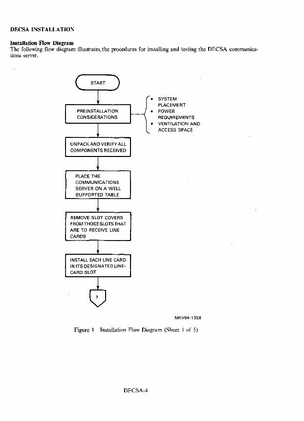
DECSA INSTALLATION
Installation Flow Diagram The following flow diagram illustrates. the procedures for installing and testing the DECSA communications server.
PREINSTALLATION CONSI DERATI ONS
UNPACKANDVERIFYALL
COMPONENTS RECEIVED
PLACE THE
COMMUNICATIONS
SERVER ON A WELL
SUPPORTED TABLE
REMOVE SLOT COVERS FROM THOSE SLOTS THAT ARE TO RECEIVE LINE
CARDS
INSTALL EACH LINE CARD IN ITS DESIGNATED LlNE
CARD SLOT
-{: SYSTEM PLACEMENT
POWER REQUIREMENTS
VENTILATION AND
ACCESS SPACE
MKV84-1328
Figure 1 Installation Flow Diagram (Sheet 1 of 5)
DECSA-4
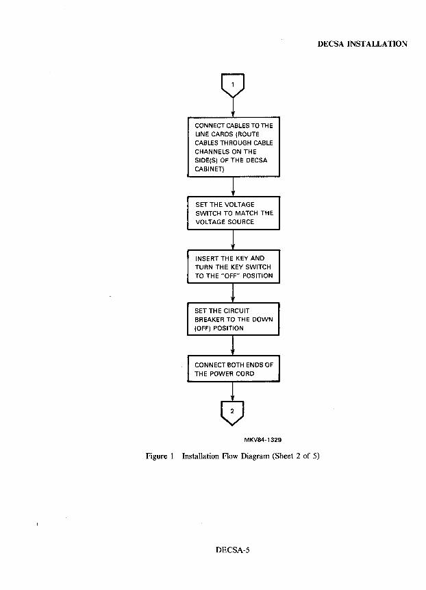
CONNECT CABLES TO THE
LINE CARDS (ROUTE CABLES THROUGH CABLE
CHANNELS ON THE SIDE(S) OF THE DECSA CABINET)
SET THE VOLTAGE SWITCH TO MATCH THE VOLTAGE SOURCE
INSERT THE KEY AND TURN THE KEY SWITCH TO THE "OFF" POSITION
SET THE CIRCUIT BREAKER TO THE DOWN
(OFF) POSITION
CONNECT BOTH ENDS OF THE POWER CORD
MKV84-1329
DECSA INSTALLATION
Figure 1 Installation Flow Diagram (Sheet 2 of 5)
DECSA-5
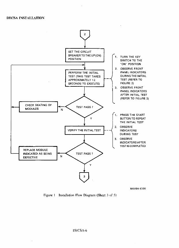
, DECSA INSTALLATION
CHECK SEATING OF MODULES
REPLACE MODULE INDICATED AS BEING
DEFECTIVE
SET THE CIRCUIT BREAKERTOTHE UP(ON) POSITION
PERFORM THE INITIAL
TEST (THIS TEST TAKES APPROXIMATELY 12
SECONDS TO EXECUTE)
1.
2.
3.
1.
2.
3.
Figure 1 Installation Flow Diagram (Sheet 3 of 5)
DECSA-6
TURN THE KEY SWITCH TO THE "ON" POSITION
OBSERVE FRONT PANEL INDICATORS DURING THE INITIAL TEST (REFER TO FIGURE 2)
OBSERVE FRONT PANEL INDICATORS AFTER INITIAL TEST (REFER TO FIGURE 2)
PRESS THE START BUTTON TO REPEAT TH E INITIAL TEST
OBSERVE
INDICATORS DURING TEST
OBSERVE INDICATORS AFTER TEST IS COM PLETED
MKV84-1330
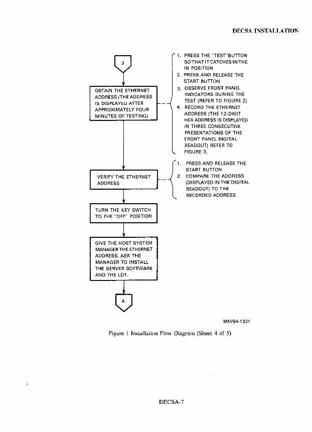
OBTAIN THE ETHERNET
ADDRESS (THE ADDRESS IS DISPLAYED AFTER APPROXIMATELY FOUR MINUTES OF TESTING)
VERIFY THE ETHERNET ADDRESS
TURN THE KEY SWITCH TO THE "OFF" POSITION
GIVE THE HOST SYSTEM MANAGER THE ETHERNET ADDRESS. ASK THE MANAGER TO INSTALL THE SERVER SOFTWARE
AND THE LD1.
DECSA INSTALLATION
1. PRESS THE "TEST"BUTTON SO THAT IT CATCHES INTHE IN POSITION
2. PRESS AND RELEASE THE START BUnON
3. OBSERVE FRONT PANEL INDICATORS DURING THE TEST (REFER TO FIGURE 2)
4. RECORD THE ETHERNET ADDRESS (THE 12-DIGIT HEX ADDRESS IS DISPLAYED IN THREE CONSECUTIVE PRESENTATIONS OF THE FRONT PANEL DIGITAL READOUT) REFER TO FIGURE 3.
2.
{
1. PRESS AND RELEASE THE START BUnON COMPARE THE ADDRESS (DISPLAYED IN THE DIGITAL
READOUT) TO THE RECORDED ADDRESS
MKV84-1331
Figure 1 Installation Flow Diagram (Sheet 4 of 5)
DECSA-7
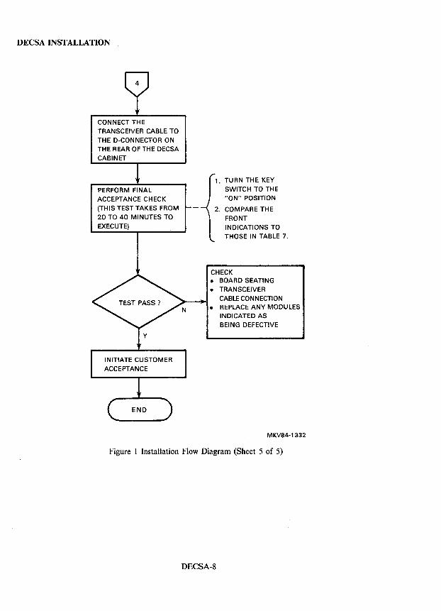
DECSA INSTALLATION
CONNECT THE TRANSCEIVER CABLE TO THE D-CONNECTOR ON THE REAR OF THE DECSA CABINET
PERFORM FINAL ACCEPTANCE CHECK (THIS TEST TAKES FROM 20 TO 40 MINUTES TO
EXECUTE)
INITIATE CUSTOMER ACCEPTANCE
1. TURN THE KEY SWITCH TO THE "ON" POSITION
2. COMPARE THE FRONT INDICATIONS TO THOSE IN TABLE 7.
CHECK • BOARD SEATING
• TRANSCEIVER CABLE CONNECTION
• REPLACE ANY MODULES INDICATED AS BEING DEFECTIVE
MKV84-1332
Figure 1 Installation Flow Diagram (Sheet 5 of 5)
DECSA-8
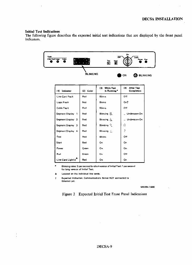
DECSA INSTALLATION
Initial Test Indications The following figure describes the expected initial test indications that are displayed by the front panel indicators.
FlUlt
Line c..d Logic Coble -• • • BLINKING • BLINKING
(3) While Test (4) After Test (1) Indicator (2) Color Is Running* Completion
Line Card Fault Red Blinks Off
Logic Fault Red Blinks Ont
Cable Fault Red Blinks Off
Segment Display 1 Red Blinking ,-,
Underscore On o. -Segment Display 2 Red Blinking :::. _ Underscore On
Segment Display 3 Red Blinking :3. G
Segment Display 4 Red Blinking :3. I:' Test Red Blinks Off
Start Red On On
Power Green On On
Run Green On Off
Line Card Light(s)· Red On On
Blinking rates: 3 per second for short version of Initial Test; 1 per second for long version of Initial Test.
A Located on the individual line cards.
Expected indication: Communications Server NOT connected to Ethernet yet.
MKV84-1600
Figure 2 Expected Initial Test Front Panel Indications
DECSA-9
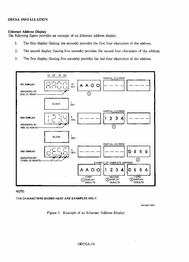
DECSAINSTALLATION
Ethernet Address Display The following figure provides an example of an Ethernet address display.
1. The first display (lasting ten seconds) provides the first four characters of the address.
2. The second display (lasting five seconds) provides the second four characters of the address.
3. The first display (lasting five seconds) provides the last four characters of the address.
Dl D2 D3 D4 PARTIAL ADDRESS
1ST DISPLAY ~~c·1 '----A A---"O 011 -11- ---I o INDICATED BY
ONE (1) POINT-------'
BlANK I ~EC. 2ND DISPLAY
INDICATED BY TWO (2) POINTS------L.--
BLANK
3RD DISPLAY
INDICATED BY THREE (3) POINTS----L-'---'
NOTE:
5 SEC.
1 SEC.
PARTIAL ADDRESS
1----1 B 1----1 o
PARTIAL ADDRESS
;EC 1----II II D E 5 6
o EXAMPLE OF COMPLETE ADDRESS
IAAoolBB FIRST SECOND THIRD o DISPLAY 0DISPLAY (3) DISPLAY RESULTS RESULTS RESULTS
THE CHARACTERS SHOWN HERE ARE EXAMPLES ONLY.
MKV84-1601
Figure 3 Example of an Ethernet Address Display
DECSA-IO
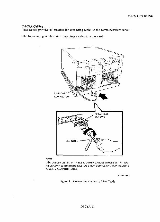
DECSA CABLING
DECSA Cabling This section provides information for connecting cables to the communications server.
The following figure illustrates connecting a cable to a line card.
NOTE: USE CABLES LISTED IN TABLE 1. OTHER CABLES (THOSE WITH TWOPIECE CONNECTOR HOUSINGS) USE MORE SPACE AND MAY REQUIRE A BCl 7L ADAPTOR CABLE.
MKV84-1602
Figure 4 Connecting Cables to Line Cards
DECSA-ll
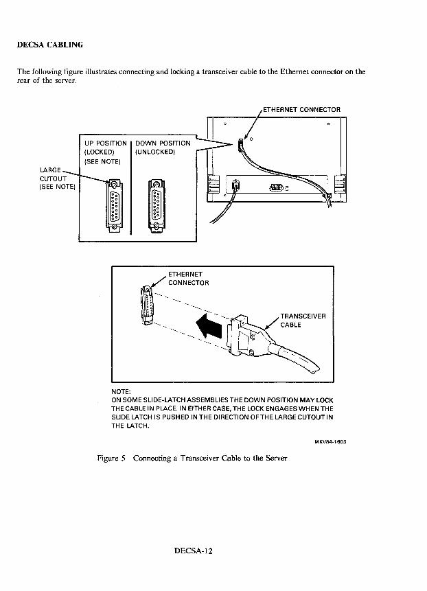
DECSA CABLING
The following figure illustrates connecting and locking a transceiver cable to the Ethernet connector on the rear of the server.
LARGE CUTOUT (SEE NOTE)
UP POSITION (LOCKED)
(SEE NOTE)
NOTE:
DOWN POSITION (UNLOCKED)
ETHERNET CONNECTOR
ON SOME SLIDE-LATCH ASSEMBLIES THE DOWN POSITION MAY LOCK THE CABLE IN PLACE. IN EITHER CASE. THE LOCK ENGAGES WHEN THE SLIDE LATCH IS PUSHED IN THE DIRECTION OFTHE LARGE CUTOUT IN THE LATCH.
MKV84-1603
Figure 5 Connecting a Transceiver Cable to the Server
DECSA-12
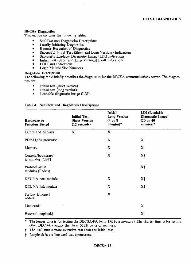
DECSA DIAGNOSTICS
DECSA Diagnostics This section contains the following tables.
• Self-Test and Diagnostics Descriptions • Locally Initiating Diagnostics • Remote Execution of Diagnostics • Successful Initial Test (Short and Long Versions) Indications • Successful Loadable Diagnostic Image (LDI) Indications • Initial Test (Short and Long Versions) Fault Indications • LDI Fault Indications • Logic Module Slot Numbers
Diagnostic Descriptions The following table briefly describes the diagnostics for the DECSA communications server. The diagnostics are:
• Initial test (short version) • Initial test (long version) • Loadable diagnostic image (LDI)
Table 4 Self-Test and Diagnostics Descriptions
Hardware or Function Tested
Lamps and displays
PDP-I 1/24 processor
Memory
Console/bootstrap/ terminator (CBT)
Protocol assist modules (P AMs)
DEUNA port module
DEUNA link module
Display Ethernet address
Line cards
External loopback:t:
Initial Test Short Version (12 seconds)
x
Initial Long Version (4 or 8 minutes) *
x
x
x
x
x
x
x
LDI (Loadable Diagnostic Image) (20 or 40 minutes) *
x
x
Xt
xt
xt
xt
x
x
* The longer time is for testing the DECSA-FA (with 1M byte memory). The shorter time is for testing other DECSA versions that have SI2K bytes of memory.
t The LDI runs a more extensive test than the initial test. :t: Loopback is via line-card test connectors.
DECSA-13
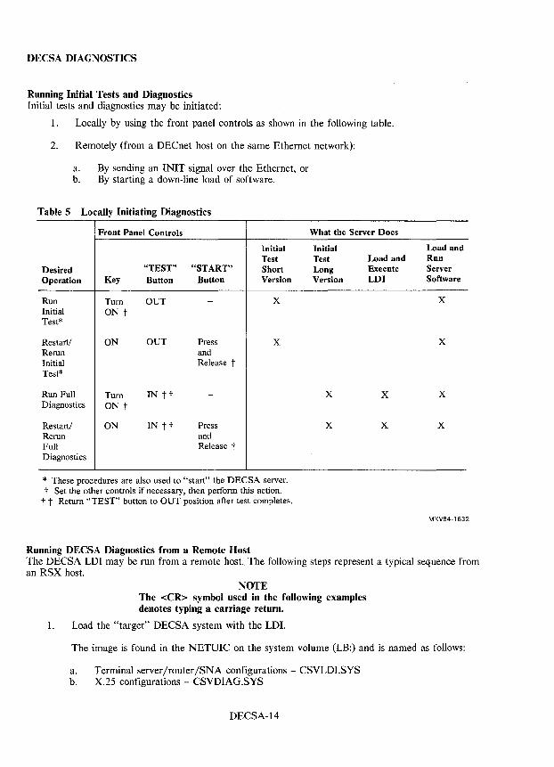
DECSA DIAGNOSTICS
Running Initial Tests and Diagnostics Initial tests and diagnostics may be initiated:
1. Locally by using the front panel controls as shown in the following table.
2. Remotely (from a DEC net host on the same Ethernet network):
a. By sending an INIT signal over the Ethernet, or b. By starting a down-line load of software.
Table 5 Locally Initiating Diagnostics
Front Panel Controls
Initial Test
Desired "TEST" "START" Short Operation Key Button Button Version
Run Tum OUT - X Initial ON t Test*
Restart/ ON OUT Press X Rerun and Initial Release t Test*
Run Full Tum IN tt -Diagnostics ON t
Restart/ ON IN t t Press Rerun and Full Release t Diagnostics
* These procedures are also used to "start" the DECSA server. t Set the other controls if necessary, then perform this action. t t Return "TEST" button to OUT position after test completes.
Running DECSA Diagnostics from a Remote Host
What the Server Does
Initial Test Load and Long Execute Version LDI
X X
X X
Load and Run Server Software
X
X
X
X
MKV84-1632
The DECSA LDI may be run from a remote host. The following steps represent a typical sequence from an RSX host.
NOTE The <CR> symbol used in the following examples denotes typing a carriage return.
1. Load the "target" DECSA system with the LDI.
The image is found in the NETUIC on the system volume (LB:) and is named as follows:
a. Terminal server/router/SNA configurations - CSVLDI.SYS b. X.25 configurations - CSVDIAG.SYS
DECSA-14
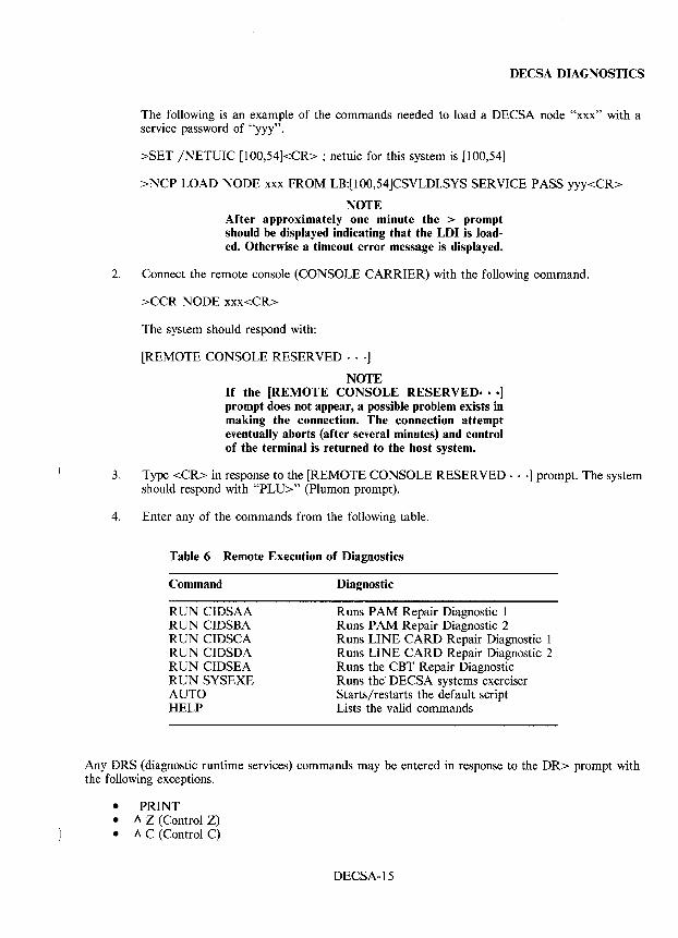
DECSA DIAGNOSTICS
The following is an example of the commands needed to load a DECSA node "xxx" with a service password of "yyy".
>SET /NETUIC [100,54]<CR> ; netuic for this system is [100,54]
>NCP LOAD NODE xxx FROM LB:[100,54]CSVLDI.SYS SERVICE PASS yyy<CR>
NOTE After approximately one minute the > prompt should be displayed indicating that the LDI is loaded. Otherwise a timeout error message is displayed.
2. Connect the remote console (CONSOLE CARRIER) with the following command.
>CCR NODE xxx<CR>
The system should respond with:
[REMOTE CONSOLE RESERVED·· .]
NOTE If the [REMOTE CONSOLE RESERVED· •• J prompt does not appear, a possible problem exists in making the connection. The connection attempt eventually aborts (after several minutes) and control of the terminal is returned to the host system.
3. Type <CR> in response to the [REMOTE CONSOLE RESERVED· .. ] prompt. The system should respond with "PLU>" (Plumon prompt).
4. Enter any of the commands from the following table.
Table 6 Remote Execution of Diagnostics
Command
RUN CIDSAA RUN CIDSBA RUN CIDSCA RUN CIDSDA RUN CIDSEA RUN SYSEXE AUTO HELP
Diagnostic
Runs PAM Repair Diagnostic 1 Runs PAM Repair Diagnostic 2 Runs LINE CARD Repair Diagnostic 1 Runs LINE CARD Repair Diagnostic 2 Runs the CBT Repair Diagnostic Runs the'DECSA systems exerciser Starts/restarts the default script Lists the valid commands
Any DRS (diagnostic runtime services) commands may be entered in response to the DR> prompt with the following exceptions.
• PRINT • A Z (Control Z) • A C (Control C)
DECSA-15
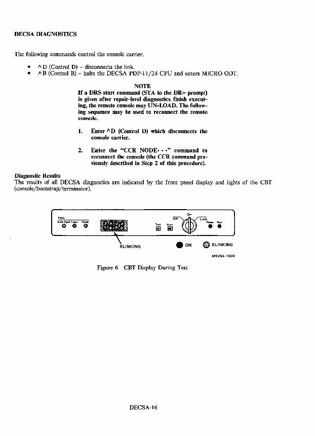
DECSA DIAGNOSTICS
The following commands control the console carrier.
• 1\ D (Control D) - disconnects the link. • AB (Control B) - halts the DECSA PDP-ll/24 CPU and enters MICRO ODT.
Diagnostic Results
NOTE If a DRS start command (STA to the DR> prompt) is given after repair-level diagnostics finish executing, the remote console may UN-LOAD. The following sequence may be used to reconnect the remote console.
1. Enter 1\ D (Control D) which disconnects the console carrier.
2. Enter the "CCR NODE· •• " command to reconnect the console (the CCR command previously described in Step 2 of this procedure).
The results of all DECSA diagnostics are indicated by the front panel display and lights of the CBT (console/bootstrap/terminator).
Fault
line Card logic Cable ••• BLINKING .. BLINKING
MKV84-1604
Figure 6 CBT Display During Test
DECSA-16
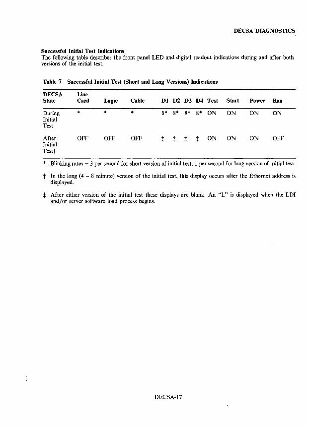
DECSA DIAGNOSTICS
Successful Initial Test Indications The following table describes the front panel LED and digital readout indications during and after both versions of the initial test.
Table 7 Successful Initial Test (Short and Long Versions) Indications
DECSA Line State Card Logic Cable Dl D2 D3 D4 Test Start Power Run
During * * * 8* 8* 8* 8* ON ON ON ON Initial Test
After OFF OFF OFF :j: :j: :j: :j: ON ON ON OFF Initial Testt
* Blinking rates = 3 per second for short version of initial test; 1 per second for long version of initial test.
t In the long (4 - 8 minute) version of the initial test, this display occurs after the Ethernet address is displayed.
:j: After either version of the initial test these displays are blank. An "L" is displayed when the LDI and/or server software load process begins.
DECSA-17
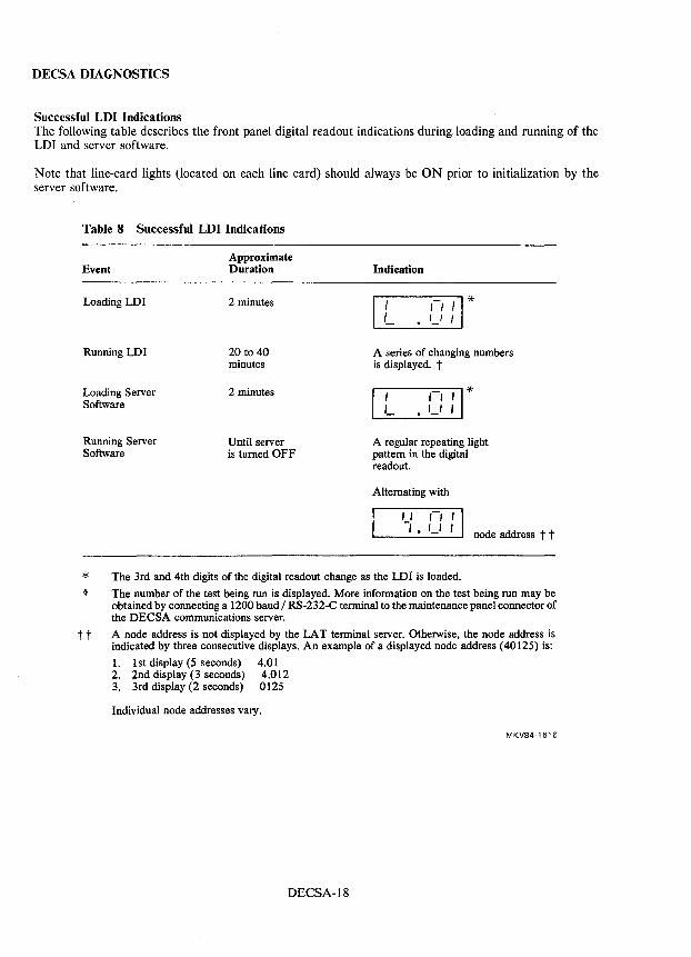
DECSA DIAGNOSTICS
Successful LDI Indications The following table describes the front panel digital readout indications during loading and running of the LDI and server software.
Note that line-card lights (located on each line card) should always be ON prior to initialization by the server software.
Table 8 Successful LDI Indications
Approximate Event Duration
Loading LDI 2 minutes
Running LDI 20 to 40 minutes
Loading Server 2 minutes Software
Running Server Until server Software is turned OFF
Indication
IL I I 'I * . '-' , A series of changing numbers is displayed. t
It , , , 1* • '-' I
A regular repeating light pattern in the digital readout.
Alternating with
" I" -, • '_I I node address t t
* The 3rd and 4th digits of the digital readout change as the LDI is loaded.
t The number of the test being run is displayed. More information on the test being run may be obtained by connecting a 1200 baud I RS-232-C terminal to the maintenance panel connector of the DECSA communications server.
t t A node address is not displayed by the LA T terminal server. Otherwise, the node address is indicated by three consecutive displays. An example of a displayed node address (40125) is:
1. 1st display (5 seconds) 4.01 2. 2nd display (3 seconds) 4.012 3. 3rd display (2 seconds) 0125
Individual node addresses vary.
MKV84-1616
DECSA-18
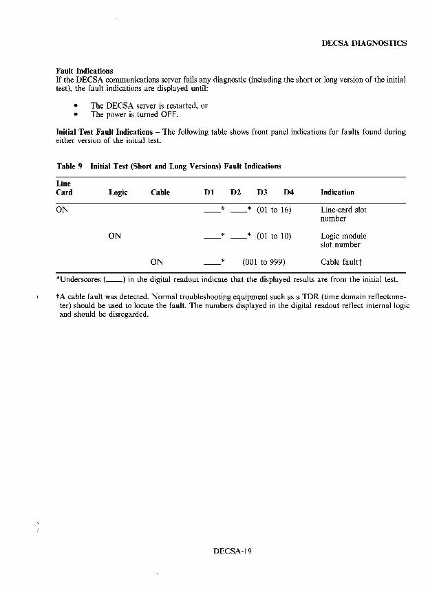
DECSA DIAGNOSTICS
Fault Indications If the DECSA communications server fails any diagnostic (including the short or long version of the initial test), the fault indications are displayed until:
• The DECSA server is restarted, or • The power is turned OFF.
Initial Test Fault Indications - The following table shows front panel indications for faults found during either version of the initial test.
Table 9 Initial Test (Short and Long Versions) Fault Indications
Line Card Logic Cable Dl D2 D3 D4 Indication
ON * * (01 to 16) Line-card slot number
ON * * (01 to 10) Logic module slot number
ON * (001 to 999) Cable faultt
*Underscores ( __ ) in the digital readout indicate that the displayed results are from the initial test.
tA cable fault was detected. Normal troubleshooting equipment such as a TDR (time domain reflectometer) should be used to locate the fault. The numbers displayed in the digital readout reflect internal logic and should be disregarded.
DECSA-19
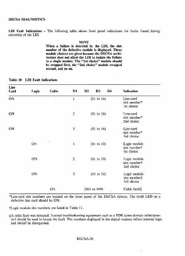
DECSA DIAGNOSTICS
LDI Fault Indications - The following table shows front panel indications for faults found during execution of the LDI.
NOTE When a failure is detected by the LDI, the slot number of the defective module is displayed. Three module choices are given because the DECSA architecture does not allow the LDI to isolate the failure to a single module. The "1st choice" module should be swapped first, the "2nd choice" module swapped second, and so on.
Table 10 LDI Fault Indications
Line Card Logic Cable Dl D2 D3 D4
ON (01 to 16)
ON 2 (01 to 16)
ON 3 (01 to 16)
ON (01 to 10)
ON 2 (01 to 10)
ON 3 (01 to 10)
ON (001 to 999)
Indication
Line-card slot number* 1st choice
Line-card slot number* 2nd choice
Line-card slot number* 3rd choice
Logic module slot numbert 1st choice
Logic module slot numbert 2nd choice
Logic module slot numbert 3rd choice
Cable fault:j:
*Line-card slot numbers are located on the front panel of the DECSA system. The (red) LED on a defective line card should be ON.
tLogic module slot numbers are listed in Table 11.
:j:A cable fault was detected. Normal troubleshooting equipment such as a TDR (time domain reflectometer) should be used to locate the fault. The numbers displayed in the digital readout reflect internal logic and should be disregarded.
DECSA-20
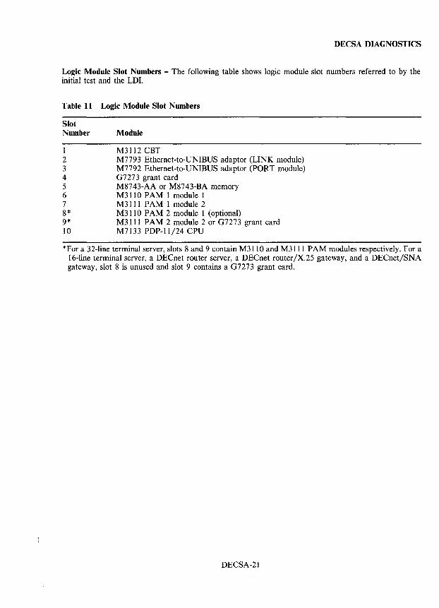
DECSA DIAGNOSTICS
Logic Module Slot Numbers - The following table shows logic module slot numbers referred to by the initial test and the LDI.
Table 11 Logic Module Slot Numbers
Slot Number
1 2 3 4 5 6 7 8* 9* 10
Module
M3112 CBT M7793 Ethernet-to-UNIBUS adaptor (LINK module) M7792 Ethernet-to-UNIBUS adaptor (PORT module) 07273 grant card M8743-AA or M8743-BA memory M3110 PAM 1 module 1 M3111 PAM 1 module 2 M311 0 PAM 2 module 1 (optional) M3111 PAM 2 module 2 or 07273 grant card M7133 PDP-ll/24 CPU
*For a 32-line terminal server, slots 8 and 9 contain M3110 and M3111 PAM modules respectively. For a 16-line terminal server, a DECnet router server, a DECnet router/X.25 gateway, and a DECnet/SNA gateway, slot 8 is unused and slot 9 contains a 07273 grant card.
DECSA-21
DECSA MAINTENANCE AIDS
Required Equipment The following extender modules may be required to perform some maintenance procedures described in this manual.
• W900 - Dual-height extender module • W987 - Quad-height extender module • W904 - Hex-height extender module
The DECSA controlled distribution (CD) repair kit contains only those modules that are unique to the DECSA server. Those modules include:
• Line cards • PAM modules • CBT modules • SI2K byte memory modules
The following modules are not included in the DECSA CD repair kit. However, these modules should be available at the DIGITAL Field Service Office.
• DEUNA modules • CPU module • 1 M byte memory module • +5 V regulator • ± 15 V regulator
DECSA-22
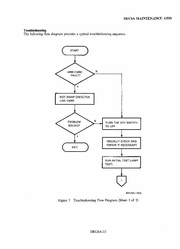
DECSA MAINTENANCE AIDS
Troubleshooting The following flow diagram provides a typical troubleshooting sequence.
HOT SWAP DEFECTIVE LINE CARD
N
TURN THE KEY SWITCH TO OFF
VISUALLY CHECK AND REPAIR IF NECESSARY
RUN INITIAL TEST (LAMP TEST)
MKV84-1605
Figure 7 Troubleshooting Flow Diagram (Sheet 1 of 5)
DECSA-23

DECSA MAINTENANCE AIDS
TURN THE KEY SWITCH TO OFF
REPLACE FRU (C8T MODULE)
REPLACE DEFECTIVE FRU
RUN LDI *
* LDI INDICATES FULL DIAGNOSTIC PROCEDURE
MKV84-1606
Figure 7 Troubleshooting Flow Diagram (Sheet 2 of 5)
DECSA-24
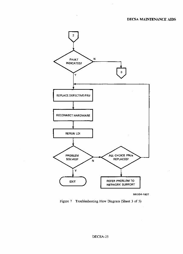
DECSA MAINTENANCE AIDS
N
y
REPLACE DEFECTIVE FRU
RECONNECT HARDWARE
MKV84-1607
Figure 7 Troubleshooting Flow Diagram (Sheet 3 of 5)
DECSA-25
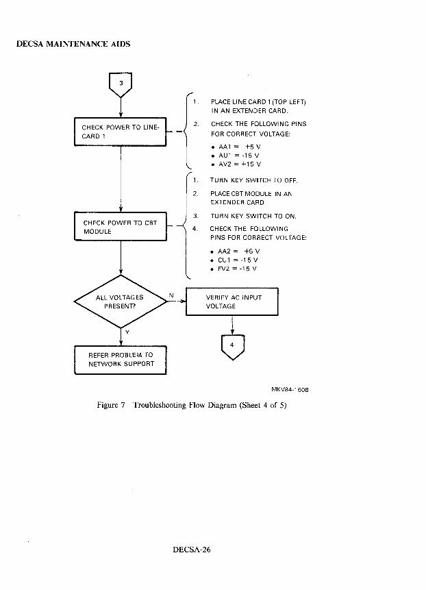
DECSA MAINTENANCE AIDS
CHECK POWER TO L1NE
CARD 1
CHECK POWER TO CBT
MODULE
REFER PROBLEM TO
NETWORK SUPPORT
1. PLACE LINE CARD 1 (TOP LEFT)
IN AN EXTENDER CARD.
2. CHECK THE FOLLOWING PINS
FOR CORRECT VOLTAGE:
11.
2.
3.
4.
• AA1 = +5 V • AU1 = -15 V
• AV2 = +15 V
TURN KEY SWITCH TO OFF.
PLACE CBT MODULE IN AN
EXTENDER CARD.
TURN KEY SWITCH TO ON.
CHECK THE FOLLOWING
PINS FOR CORRECT VOLTAGE:
• AA2 = +5V
• CU1 = -15 V • FV2 = -15 V
VERIFY AC INPUT
VOLTAGE
MKV84-1608
Figure 7 Troubleshooting Flow Diagram (Sheet 4 of 5)
DECSA-26
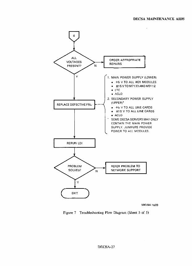
Y
REPLACE DEFECTIVE FRU
N
DECSA MAINTENANCE AIDS
ORDER APPROPRIATE REPAIRS
1. MAIN POWER SUPPLY (LOWER)
• +5 V TO ALL HEX MODULES • ±15VTO M7133ANDM3112
• LTC • ACLO
2. SECONDARY POWER SUPPLY (UPPER)*
• +5 V TO ALL LINE CARDS • ±15 V TO ALL LINE CARDS
• ACLO * SOME DECSA SERVERS MAY ONLY
CONTAIN THE MAIN POWER SUPPLY. JUMPERS PROVIDE POWER TO ALL MODULES.
REFER PROBLEM TO NETWORK SUPPORT
MKV84-1609
Figure 7 Troubleshooting Flow Diagram (Sheet 5 of 5)
DECSA-27
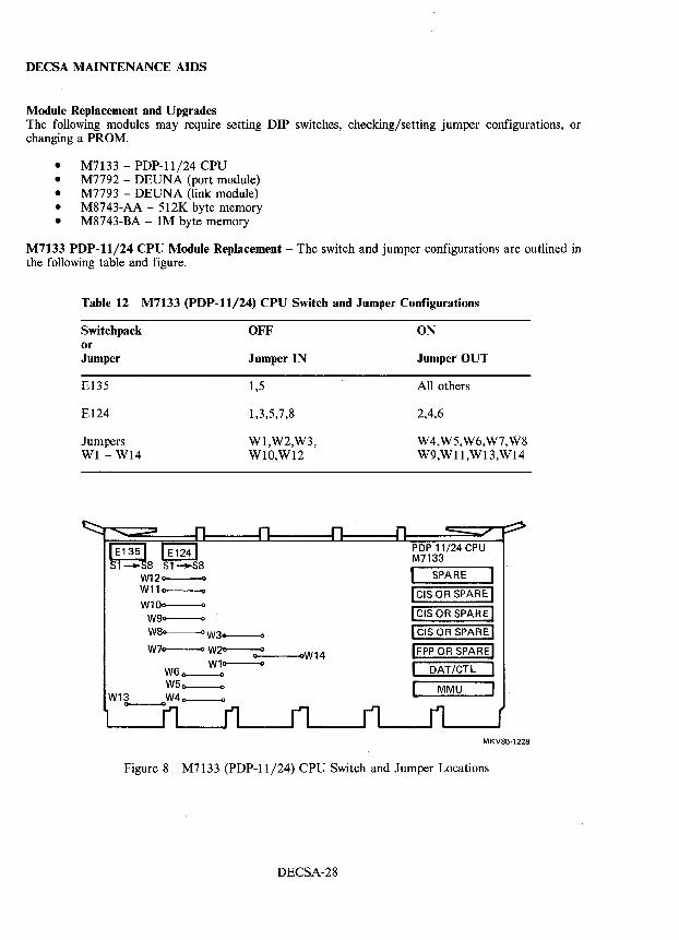
DECSA MAINTENANCE AIDS
Module Replacement and Upgrades The following modules may require setting DIP switches, checking/setting jumper configurations, or changing a PROM.
• M7133 - PDP-ll/24 CPU • M7792 - DEUNA (port module) • M7793 - DEUNA (link module) • M8743-AA - 512K byte memory • M8743-BA - 1M byte memory
M7133 PDP-ll/24 CPU Module Replacement - The switch and jumper configurations are outlined in the following table and figure.
Table 12 M7133 (PDP-ll/24) CPU Switch and Jumper Configurations
Switchpack or Jumper
E135
E124
Jumpers WI - W14
W12-W11~
W100-----0 W90
OFF
Jumper IN
1,5
1,3,5,7,8
Wl,W2,W3, WlO,WI2·
W8~W3~
W7- W2--Q-o ---ooW14 W1a----o
W6_ W50-------0
W1L-W4 0-----0
ON
Jumper OUT
All others
2,4,6
W4,W5,W6,W7,W8 W9,Wll,WI3,WI4
PDP 11/24 CPU M7133
I SPARE
I CIS OR SPARE: I ICIS OR SPARE I I CIS OR SPARE I IFPP OR SPARE!
I DAT/CTL I I MMU I
MKV85·1228
Figure 8 M7133 (PDP-ll/24) CPU Switch and Jumper Locations
DECSA-28
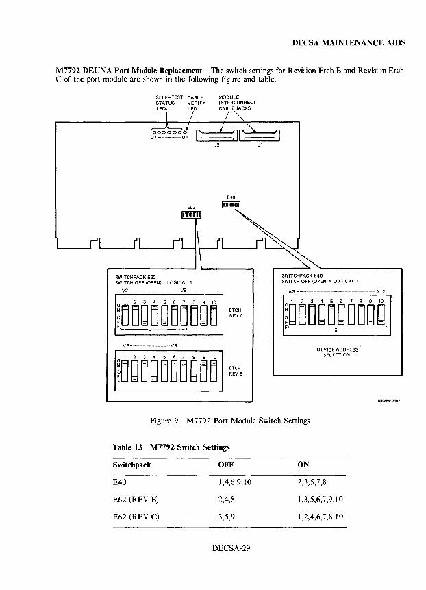
DECSA MAINTENANCE AIDS
M7792 DEUNA Port Module Replacement - The switch settings for Revision Etch B and Revision Etch C of the port module are shown in the following figure and table.
SELF-TEST CABLE STATUS VERIFY LEDs LED
SWITCH PACK E62 SWITCH OFF (OPEN) = LOGICAL 1
V2-------------------- VB
V3--------------VB
MODULE I NTE RCONNECT CABLE JACKS
J2
E40
100001011001
ETCH REV C
ETCH REV B
Jl
SWITCHPACK E40 SWITCH OFF (OPEN) = LOGICAL 1
A3-----------------------A12
I DEVICE ADDRESS
SELECTION
MKV84-0562
Figure 9 M7792 Port Module Switch Settings
Table 13 M7792 Switch Settings
Switchpack
E40
E62 (REV B)
E62 (REV C)
OFF
1,4,6,9,10
2,4,8
3,5,9
DECSA-29
ON
2,3,5,7,8
1,3,5,6,7,9,10
1,2,4,6,7,8,10
DECSA MAINTENANCE AIDS
M7793 DEUNA Link Module Replacement - The PROM in the M7793 link module contains the Ethernet address. When replacing a DEUNA link module adhere to the following conditions:
1. If possible, move the PROM from the defective module to the new module being installed.
2. If the PROM must be changed, report the new Ethernet address to the system or network manager.
M8743-xA Memory Module Replacement - All address switches on a replacement M8743 module must be set to ON.
Verify the following jumper configuration.
IN: OUT:
Wl,W2,W3,W4 W5
System Upgrade When it is necessary to upgrade a terminal server from 16 to 32 lines, an additional (secondary) power supply and PAM set is required.
DECSA-30
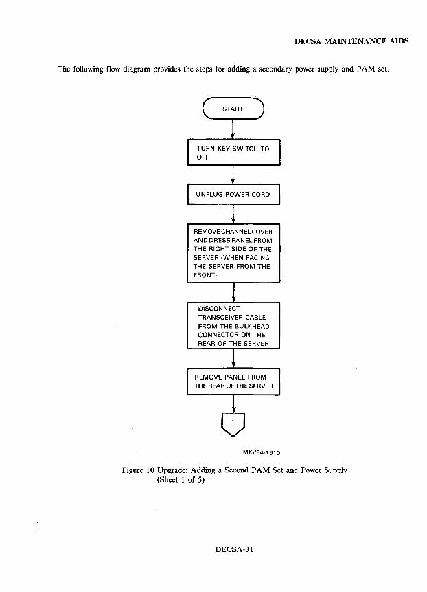
DECSA MAINTENANCE AIDS
The following flow diagram provides the steps for adding a secondary power supply and PAM set.
TURN KEY SWITCH TO OFF
REMOVE CHANNEL COVER AND DRESS PANEL FROM
THE RIGHT SIDE OF THE
SERVER (WHEN FACING
THE SERVER FROM THE
FRONT)
DISCONNECT TRANSCEIVER CABLE
FROM THE BULKHEAD
CONNECTOR ON THE REAR OF THE SERVER
REMOVE PANEL FROM
THE REAR OFTHE SERVER
MKV84-1610
Figure 10 Upgrade: Adding a Second PAM Set and Power Supply (Sheet 1 of 5)
DECSA-31
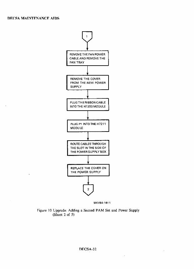
DECSA MAINTENANCE AIDS
REMOVE THE FAN POWER
CABLE AND REMOVE THE
FAN TRAY
REMOVE THE COVER
FROM THE NEW POWER SUPPLY
PLUG THE RIBBON CABLE
INTO THE H7200 MODULE
PLUG P1 INTO THE H7211
MODULE
ROUTE CABLES THROUGH
THE SLOT IN THE SIDE OF
TH E POWER SU PPL Y BOX
REPLACE THE COVER ON
THE POWER SUPPLY
MKV84-1611
Figure 10 Upgrade: Adding a Second PAM Set and Power Supply (Sheet 2 of 5)
DECSA-32
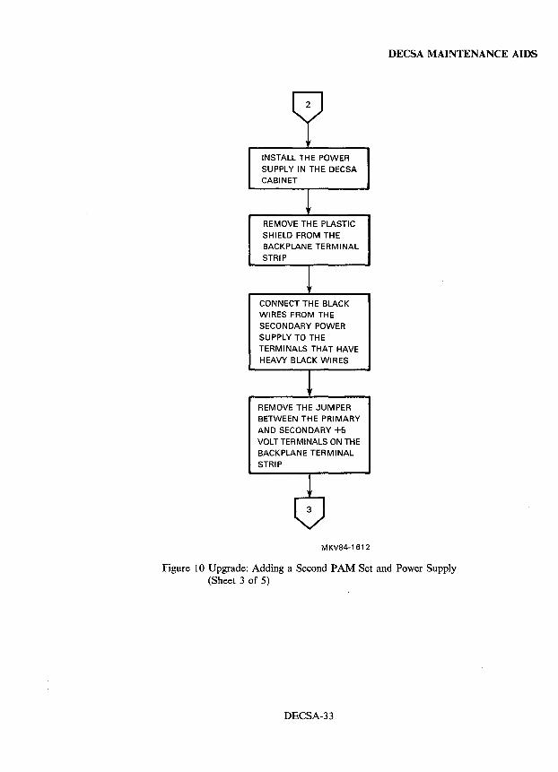
INSTALL THE POWER SUPPLY IN THE DECSA CABINET
REMOVE TH E PLASTIC SHIELD FROM THE BACKPLANE TERMINAL
STRIP
CONNECT THE BLACK WIRES FROM THE SECONDARY POWER SUPPLY TO THE
TERMINALS THAT HAVE HEAVY BLACK WIRES
REMOVE THE JUMPER BETWEEN THE PRIMARY
AND SECONDARY +5 VOLT TERMINALS ON THE BACKPLANE TERMINAL STRIP
MKV84-1612
DECSA MAINTENANCE AIDS
Figure 10 Upgrade: Adding a Second PAM Set and Power Supply (Sheet 3 of 5)
DECSA-33
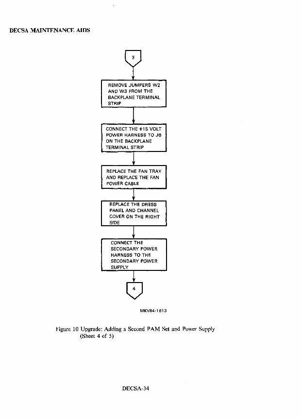
DECSA MAINTENANCE AIDS
REMOVE JUMPERS W2 AND W3 FROM THE BACKPLANE TERMINAL STRIP
CONNECT THE +15 VOLT POWER HARNESS TO J6 ON THE BACKPLANE TERMINAL STRIP
REPLACE TH E FAN TRAY AND REPLACE THE FAN POWER CABLE
REPLACE THE DRESS PANEL AND CHANNEL COVER ON THE RIGHT SIDE
CONNECT THE SECONDARY POWER HARNESS TO THE SECONDARY POWER
MKV84-1613
Figure 10 Upgrade: Adding a Second PAM Set and Power Supply (Sheet 4 of 5)
DECSA-34
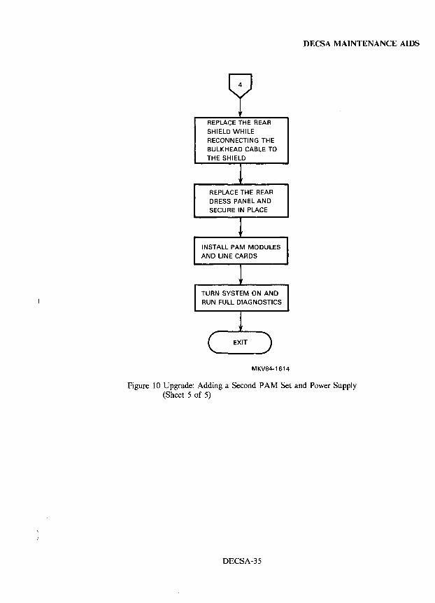
REPLACE THE REAR SHIELD WHILE RECONNECTING THE BULKHEAD CABLE TO THE SHIELD
REPLACE THE REAR DRESS PANEL AND SECURE IN PLACE
INSTALL PAM MODULES AND LINE CARDS
TURN SYSTEM ON AND RUN FULL DIAGNOSTICS
MKV84-1614
DEC SA MAINTENANCE AIDS
Figure 10 Upgrade: Adding a Second PAM Set and Power Supply (Sheet 5 of 5)
DECSA-35
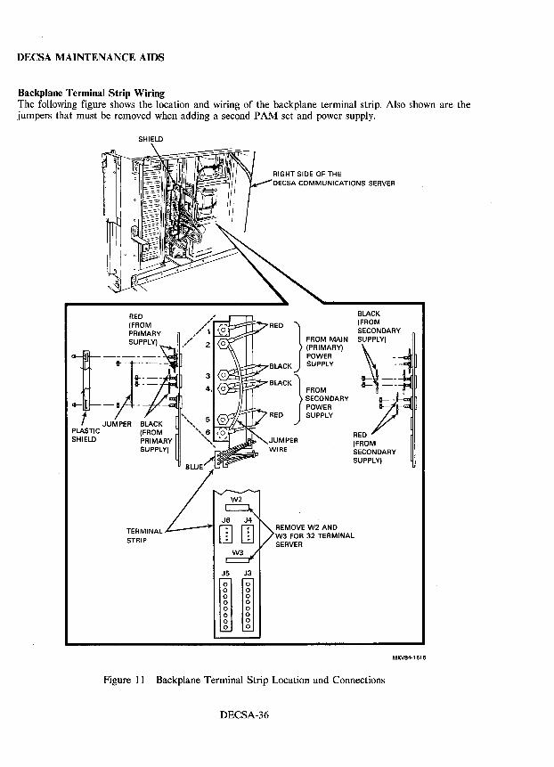
DECSA MAINTENANCE AIDS
Backplane Terminal Strip Wiring The following figure shows the location and wiring of the backplane terminal strip. Also shown are the jumpers that must be removed when adding a second PAM set and power supply.
SHIELD
RED (FROM PRIMARY SUPPLY)
)-.~=~-. .. ---
-B --
JUMPER BLACK PLASTIC (FROM SHIELD PRIMARY
SUPPLY)
TERMINAL STRIP
DECSA COMMUNICATIONS SERVER
FROM MAIN (PRIMARY) POWER
RED }
BLACK SUPPLY
BLACK} ~~g~NDARY POWER
RED SUPPLY
JUMPER WIRE
BLACK (FROM SECONDARY
SSl~~_ t:~--
RED (FROM SECONDARY SUPPLY)
MKV84·1615
Figure 11 Backplane Terminal Strip Location and Connections
DECSA-36
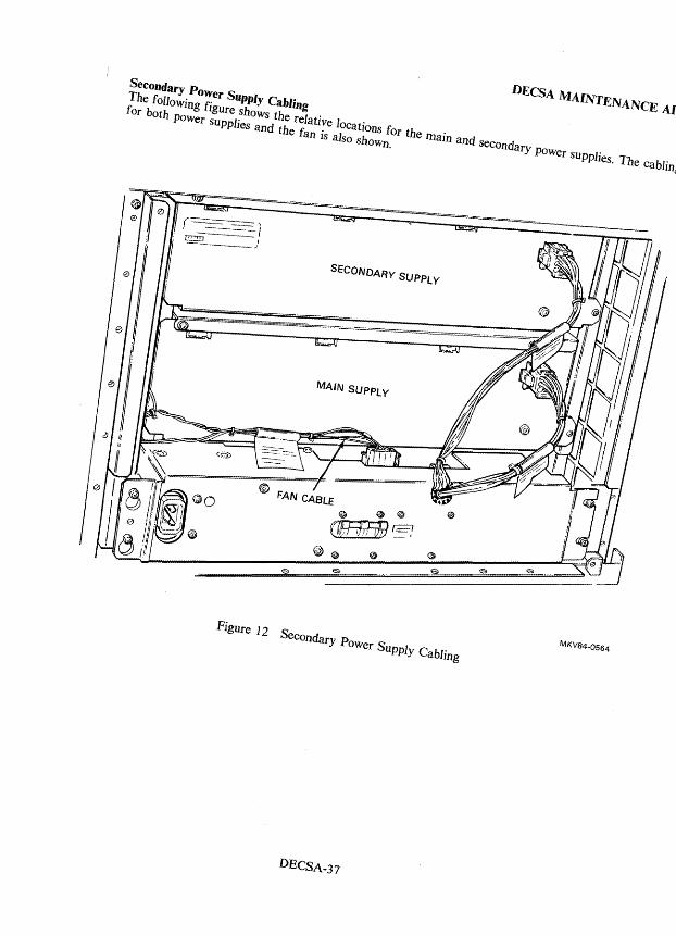
Secondary PO ... r Supply Cabling
ror bolh POwer supplies and Ihe fan is also shown. The fOl/owing figure shows Ihe relalive locations for the Illain and secondary JlOwer sUPplies. The cabling
o SECONDARY SUPPLY
MAIN SUPPLY
Figure 12 Secondary Power SUPply Cabling MKV84-0564
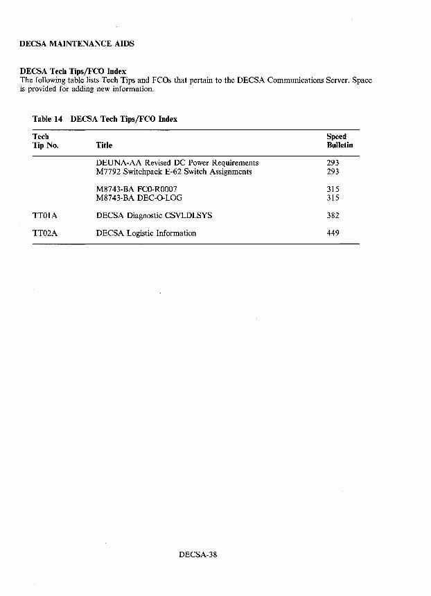
DECSA MAINTENANCE AIDS
DECSA Tech Tips/FCO Index The following table lists Tech Tips and FCOs that pertain to the DECSA Communications Server. Space is provided for adding new information.
Table 14 DECSA Tech Tips/FCO Index
Tech Speed Tip No. Title Bulletin
DEUNA-AA Revised DC Power Requirements 293 M7792 Switchpack E-62 Switch Assignments 293
M8743-BA FCO-ROOO7 315 M8743-BA DEC-O-LOG 315
TT01A DECSA Diagnostic CSVLDI.SYS 382
TT02A DECSA Logistic Information 449
DECSA-38
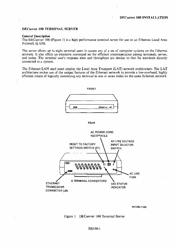
DECserver 100 INSTALLATION
DECserver 100 TERMINAL SERVER
General Description The DECserver 100 (Figure 1) is a high performance terminal server for use on an Ethernet Local Area Network (LAN).
The server allows up to eight terminal users to access any of a set of computer systems on the Ethernet network. It also offers an extensive command set for efficient communication among terminals, server, and nodes. The terminal user's response time and throughput are similar to that for terminals directly connected to a system.
The Ethernet LAN used must employ the Local Area Transport (LAT) network architecture. The LAT architecture makes use of the unique features of the Ethernet network to provide a low-overhead, highly efficient means of logically connecting any terminal to one or more nodes on the same Ethernet network.
ETHERNET TRANSCEIVER
CONNECTOR (J9)
FRONT
IIIIIIII
REAR
AC POWER CORD RECEPTACLE
RESET TO FACTORY SETTINGS SWITCH (S1)
AC LINE VOLTAGE INPUT SELECTOR
INDICATOR
MKV85-1196
Figure 1 DECserver 100 Terminal Server
DSI00-l
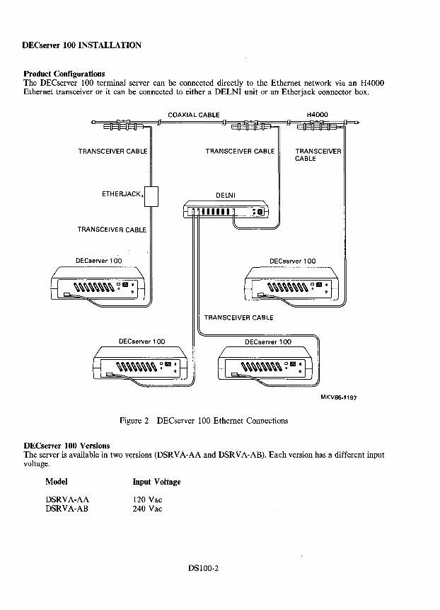
DECserver 100 INSTALLATION
Product Configurations The DECserver 100 terminal server can be connected directly to the Ethernet network via an H4000 Ethernet transceiver or it can be connected to either a DELNI unit or an Etherjack connector box.
COAXIAL CABLE H4000
~~~~~F======~l~~~~J~~~~~
TRANSCEIVER CABLE
ETHERJACK,
TRANSCEIVER CABLE
DECserver 100
DECserver 100
TRANSCEIVER CABLE
DELNI
TRANSCEIVER CABLE
DECserver 100
TRANSCEIVER CABLE
DECserver 1 00
MKV85-1197
Figure 2 DECserver 100 Ethernet Connections
DECserver 100 Versions The server is available in two versions (DSRVA-AA and DSRVA-AB). Each version has a different input voltage.
Model
DSRVA-AA DSRVA-AB
Input Voltage
120 Vac 240 Vac
DS100-2
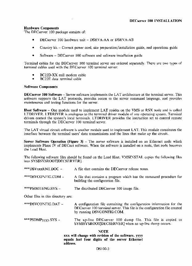
DECserver 100 INSTALLATION
Hardware Components The DECserver 100 package consists of:
• DEC server 100 hardware unit - DSRVA-AA or DSRVA-AB
• Country kit - Correct power cord, site preparation/installation guide, and operations guide
• Software - OECserver 100 software and software installation guide
Terminal cables for the DECserver 100 terminal server are ordered separately. There are two types of terminal cables used with the DECserver 100 terminal server:
• BC220-XX null modem cable • BC22E data terminal cable
Software Components
DECserver 100 Software - Server software implements the LAT architecture at the terminal server. This software supports the LA T protocols, provides access to the server command language, and provides maintenance and testing functions for the server.
Host Software - One module used to implement LAT resides on the VMS or RSX node and is called LTDRIVER. LTDRIVER is analogous to the terminal driver module of any operating system. Terminal drivers control the system's local terminals. L TDRIVER provides the instruction set to control remote terminals through the OECserver 100 terminal server.
The LAT virtual circuit software is another module used to implement LAT. This module constitutes the interface between the terminal users' data transmissions and the lines that make up the circuit.
Server Software Operation (Figure 3) - The server software is installed on an Ethernet node which implements Phase IV of DEC net software. When the software is installed on a node, that node becomes the Load Host.
The following software files should be found on the Load Host. VMSINSTAL copies the following files into SYS$SYSROOT[OECSERVER).
***DSVxxxRNT.DOC - A file that contains the DEC server release notes.
***DSVCONFIG.COM - A file that contains a program which has the command procedure for building the configuration file.
***PS0801ENG.SYS - The distributed DEC server 100 image file.
Other files in this directory are:
***DSVCONFIG.DAT -
***PSDMPyyyy.SYS -
A configuration file containing the configuration information for the DECserver 100 terminal server. This file is the configuration file created by running DSVCONFIG.COM.
The up-line DECserver 100 dump file. This file is copied to SYS$SYSROOT[DECSERVER] when an up-line dump occurs.
NOTE xxx will change with revision of the software. yyyy equals last four digits of the server Ethernet address.
DS100-3
DECserver 100 INSTALLATION
When the server (DSRVA-XX) is powered on or given the Initialize command, it runs its internal self-test. If the self-test passes, the server then broadcasts a "Request for Down-Line Load" message on the Ethernet network. The Load Host receives the broadcast message and down-line loads the server software to the DEC server 100 terminal server.
Once the server software is loaded, terminal users are able to access other nodes on the Ethernet network. The users are not restricted to the Load Host. Any node that implements the LTDRIVER software is available to the users.
-
DEC
HOST
----
I I T
DEC LOAD
HOST
-- ---,.. ,..-
DSRVA-XX
I 1 .......... 8 T
DEC
HOST
-... --
ETHERNET _ . -r-
I DSRVA-XX
I T 1 .......... 8
I I T
--
MKV85-1198
Figure 3 DEC server 100 Topology
Terminal Connector Pin Assignments Table 1 lists the pin assignments for each of the 25-pin D-subminiature (D-SUB) terminal connectors on the back of the terminal server.
Table 1 Terminal Connector Pin Assignments
Pin No. Signal Function
7 Ground Signal Ground 2 PJL TX L Transmit Data 3 PJL RX H Receive Data
DS100-4
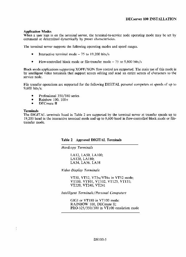
DEC server 100 INSTALLATION
Application Modes When a user logs in on the terminal server, the terminal-to-service node operating mode may be set by command or determined dynamically by preset characteristics.
The terminal server supports the following operating modes and speed ranges.
• Interactive terminal mode - 75 to 19,200 bits/s
• Flow-controlled block mode or file-transfer mode - 75 to 9,600 bits/s
Block mode applications supporting XOFF /XON flow control are supported. The main use of this mode is by intelligent video terminals that support screen editing and send an entire screen of characters to the service node.
File transfer operations are supported for the following DIGITAL personal computers at speeds of up to 9,600 bits/s:
• Professional 350/380 series • Rainbow 100, 100+ • DEC mate II
Terminals The DIGITAL terminals listed in Table 2 are supported by the terminal server at transfer speeds up to 19,200 baud in the interactive terminal mode and up to 9,600 baud in flow-controlled block mode or filetransfer mode.
Table 2 Approved DIGITAL Terminals
Hardcopy Terminals
LA 12, LA50, LA 1 00; LA120, LA180; LA34, LA36, LA38
Video Display Terminals
VT50, VT52, VT5x/VT6x in VT52 mode; VT100, VT101, VT102, VT125, VT131; VT220, VT240, VT241
Intelligent Terminals/Personal Computers
GIGIor VT180 in VT100 mode; RAINBOW 100, DECmate II; PRO-325/350/380 in VT100 emulation mode
DSIOO-5
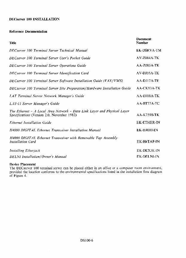
DECserver 100 INSTALLATION
Reference Documentation
Title
DECserver ]00 Terminal Server Technical Manual
DECserver ] 00 Terminal Server User's Pocket Guide
DECserver ] 00 Terminal Server Operations Guide
DECserver ]00 Terminal Server Identification Card
DECserver ]00 Terminal Server Software Installation Guide (VAX/VMS)
DECserver 100 Terminal Server Site Preparation/Hardware Installation Guide
LAT Terminal Server Network Manager's Guide
LA T-]] Server Manager's Guide
The Ethernet - A Local Area Network - Data Link Layer and Physical Layer Specifications (Version 2.0, November 1982)
Ethernet Installation Guide
H4000 DIGITAL Ethernet Transceiver Installation Manual
H4000 DIGITAL Ethernet Transceiver with Removable Tap Assembly Installation Card
Installing Etherjack
DELNI Installation/Owner's Manual
Device Placement
Document Number
EK-DSRVA-TM
AV-Z084A-TK
AA-Z085A-TK
A V-DJ35A-TK
AA-D117 A-TE
AA-CK93A-TK
AA-D118A-TK
AA-BT77 A-TC
AA-K759B-TK
EK-ETHER-IN
EK-H4000-IN
EK-H4TAP-IN
EK-DEXJK-IN
EK-DELNI-IN
The DECserver 100 terminal server can be placed either in an office or a computer room environment, provided the location conforms to the environmental specifications listed in the installation flow diagram of Figure 4.
DSIOO-6
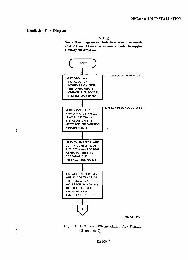
DECserver 100 INSTALLATION
Installation Flow Diagram
NOTE Some flow diagram symbols have roman numerals next to them. These roman numerals refer to supplementary information.
GET DECserver INSTALLATION INFORMATION FROM THE APPROPRIATE MANAGER (NETWORK. SYSTEM, OR SERVER)
I. (SEE FOLLOWING PAGE)
_---.....1-----..... II. (SEE FOLLOWING PAGES) VERIFY WITH THE APPROPRIATE MANAGER THAT TH E DEC server INSTALLATION SITE MEETS SITE PREPARATION REQUIREMENTS
UNPACK. INSPECT, AND VERIFY CONTENTS OF THE DECserver 100 BOX. REFER TO THE SITE PREPARATION/ INSTALLATION GUIDE
UNPACK. INSPECT, AND VERIFY CONTENTS OF THE DECserver 100 ACCESSORIES BOX(ES). REFER TO THE SITE PREPARATION/ INSTALLATION GUIDE
MKV85-1199
Figure 4 DECserver 100 Installation Flow Diagram (Sheet 1 of 9)
DS100-7
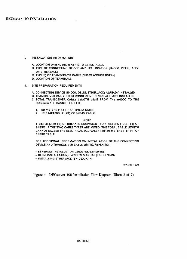
DECserver 100 INSTALLATION
I. INSTALLATION INFORMATION
A. LOCATION WHERE DECserver IS TO BE INSTALLED B. TYPE OF CONNECTING DEVICE AND ITS LOCATION (H4000. DELNI. AND/
OR ETHERJACK) C. TYPE(S) OF TRANSCEIVER CABLE (BNE3X AND/OR BNE4X) D. LOCATION OF TERMINALS
II. SITE PREPARATION REQUIREMENTS
A. CONNECTING DEVICE (H4000. DELNI. ETHERJACK) ALREADY INSTALLED B. TRANSCEIVER CABLE FROM CONNECTING DEVICE ALREADY INSTALLED C. TOTAL TRANSCEIVER CABLE LENGTH LIMIT FROM THE H4000 TO THE
DECserver 100 CANNOT EXCEED:
1. 50 METERS (164 FT) OF BNE3X CABLE 2. 12.5 METERS (41 FT) OF BNE4X CABLE
NOTE 1 METER (3.28 FT) OF BNE4X IS EQUIVALENT TO 4 METERS (13.21 FT) OF BNE3X. IF THE TWO CABLE TYPES ARE MIXED. THE TOTAL CABLE LENGTH CANNOT EXCEED THE ELECTRICAL EQUIVALENT OF 50 METERS (164 FT) OF BNE3X CABLE.
FOR ADDITIONAL INFORMATION ON INSTALLATION OF THE CONNECTING DEVICE AND TRANSCEIVER CABLE LIMITS. REFER TO:
- ETHERNET INSTALLATION GUIDE (EK-ETHER-IN) - DELNIINSTALLATION/OWNER'S MANUAL (EK-DELNI-IN) -INSTALLING ETHERJACK (EK-DEXJK-IN)
MKV85-1200
Figure 4 DECserver 100 Installation Flow Diagram (Sheet 2 of 9)
DSlOO-8
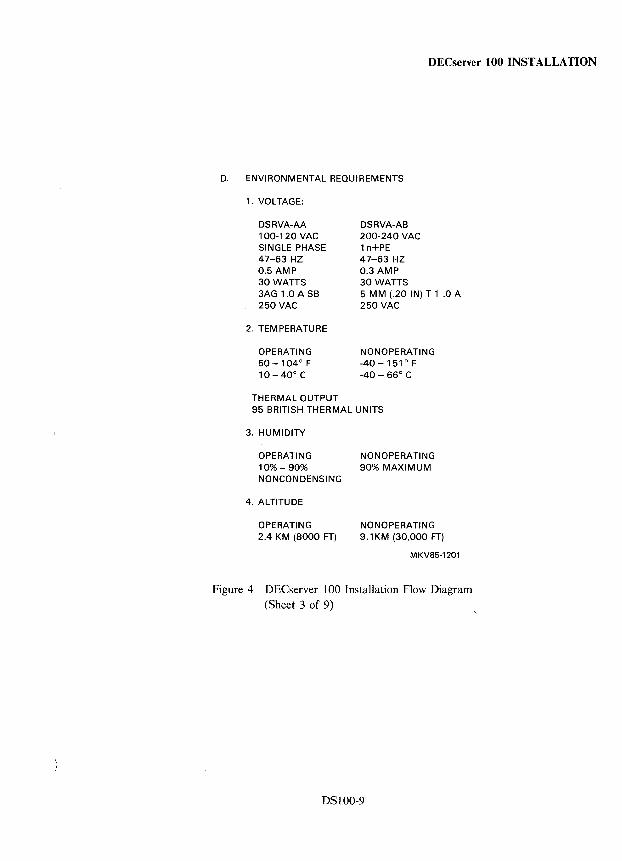
DECserver 100 INSTALLATION
D. ENVIRONMENTAL REQUIREMENTS
1. VOLTAGE:
DSRVA-AA 100-120 VAC SINGLE PHASE 47-63 HZ 0.5 AMP 30 WATTS 3AG 1.0 A SB 250 VAC
2. TEMPERATURE
OPERATING 50 -104° F 10 - 40 0 C
THERMAL OUTPUT
DSRVA-AB 200-240 VAC 1 n+PE 47-63 HZ 0.3 AMP 30 WATTS 5 MM (.20 IN) T 1 .0 A 250 VAC
NONOPERATING -40 -151 0 F -40- 66° C
95 BRITISH THERMAL UNITS
3. HUMIDITY
OPERATING NONOPERATING 10% - 90% 90% MAXIMUM NONCONDENSING
4. ALTITUDE
OPERATING 2.4 KM (8000 FT)
NONOPERATING 9.1 KM (30,000 FT)
MKV85-1201
Figure 4 DECserver 100 Installation Flow Diagram (Sheet 3 of 9)
DSIOO-9
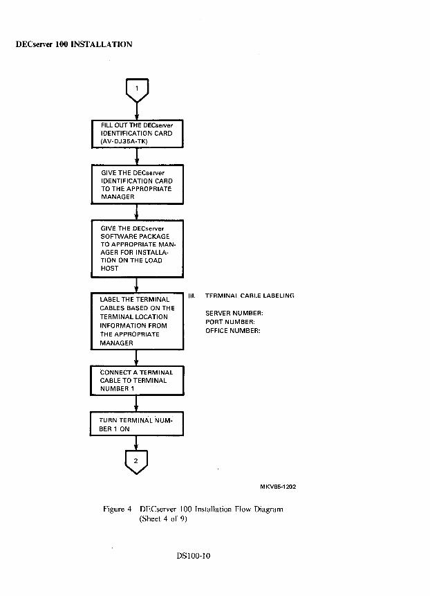
DECserver 100 INSTALLATION
FILL OUT THE DECserver IDENTIFICATION CARD (AV-DJ35A-TK)
GIVE THE DECserver IDENTIFICATION CARD TO THE APPROPRIATE MANAGER
GIVE THE DECserver SOFTWARE PACKAGE TO APPROPRIATE MANAGER FOR INSTALLATION ON THE LOAD HOST
'--LA-B-E-L-T-H-E..JTIo.E-R-M-IN-A-L--' III. TERM I NAL CABLE LABEll NG
CABLES BASED ON TH E TERMINAL LOCATION INFORMATION FROM THE APPROPRIATE MANAGER
CONNECT A TERMINAL CABLE TO TERMINAL NUMBER 1
SERVER NUMBER: PORT NUMBER: OFFICE NUMBER:
MKV85-1202
Figure 4 DECserver 100 Installation Flow Diagram (Sheet 4 of 9)
DSIOO-IO
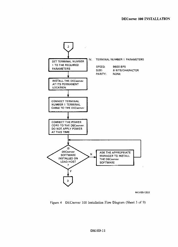
DECserver 100 INSTALLATION
..... ----..... ---..... IV. TERMINAL NUMBER 1 PARAMETERS SET TERMINAL NUMBER 1 TO THE REQUIRED PARAMETERS
INSTALL THE DECserver AT ITS PERMANENT LOCATION
CONNECT TERMINAL NUMBER 1 TERMINAL CABLE TO THE DECserver
CONNECT THE POWER CORD TO THE DECserver. DO NOT APPLY POWER ATTHIS TIME
SPEED: 9600 BPS SIZE: 8 BITS/CHARACTER PARITY: NONE
ASK THE APPROPRIATE MANAGER TO INSTALL TH E DECserver SOFTWARE
MKV85·1203
Figure 4 DECserver 100 Installation Flow Diagram (Sheet 5 of 9)
DSI00-ll
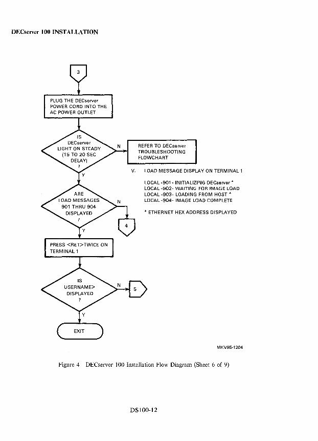
DECserver 100 INSTALLATION
PLUG TH E DECserver POWER CORD INTO THE AC POWER OUTLET
REFER TO DECserver TROUBLESHOOTING FLOWCHART
v. LOAD MESSAGE DISPLAY ON TERMINAL 1
LOCAL -901- INITIALIZING DECserver * LOCAL -902- WAITING FOR IMAGE LOAD LOCAL -903- LOADING FROM HOST * LOCAL -904- IMAGE LOAD COMPLETE
* ETHERNET HEX ADDRESS DISPLAYED
MKV85-1204
Figure 4 DECserver 100 Installation Flow Diagram (Sheet 6 of 9)
DSIOO-12
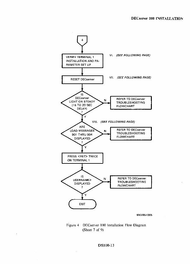
VERIFY TERMINAL 1 INSTALLATION AND PARAMETER SET UP
DECserver 100 INSTALLATION
VI. (SEE FOLLOWING PAGE)
VII. (SEE FOLLOWING PAGE)
REFER TO DECserver TROUBLESHOOTING FLOWCHART
(SEE FOLLOWING PAGE)
REFER TO DECserver TROUBLESHOOTING FLOWCHART
REFER TO DECserver TROUBLESHOOTING FLOWCHART
MKV85·1205
Figure 4 DECserver 100 Installation Flow Diagram (Sheet 7 of 9)
DSIOO-13
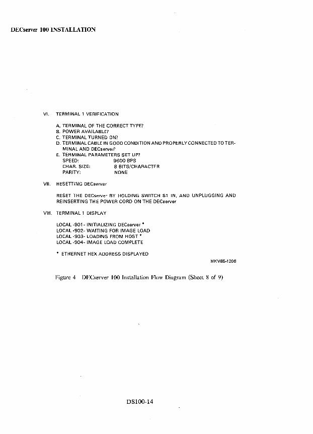
DECserver 100 INSTALLATION
VI. TERMINAL 1 VERIFICATION
A. TERMINAL OF THE CORRECT TYPE? B. POWER AVAILABLE? C. TERMINAL TURNED ON? D. TERMINAL CABLE IN GOOD CONDITION AND PROPERLY CONNECTED TO TER
MINAL AND DECserver? E. TERMINAL PARAMETERS SET UP?
SPEED: 9600 BPS CHAR. SIZE: B BITS/CHARACTER PARITY: NONE
VII. RESETTING DECserver
RESET THE DECserver BY HOLDING SWITCH S1 IN, AND UNPLUGGING AND REINSERTING THE POWER CORD ON THE DECserver
VIII. TERMINAL 1 DISPLAY
LOCAL -901- INITIALIZING DECserver * LOCAL -902- WAITING FOR IMAGE LOAD LOCAL -903- LOADING FROM HOST * LOCAL -904- IMAGE LOAD COMPLETE
* ETHERNET HEX ADDRESS DISPLAYED
MKV85-1206
Figure 4 DECserver 100 Installation Flow Diagram (Sheet 8 of 9)
DSlOO-14
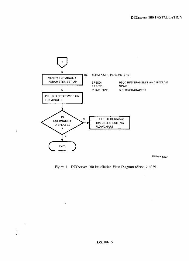
DEC server 100 INSTALLATION
TERMINAL 1 PARAMETERS
SPEED: PARITY:
9600 BPS TRANSMIT AND RECEIVE
NONE CHAR. SIZE: 8 BITS/CHARACTER
REFER TO DECserver
TROUBLESHOOTING FLOWCHART
MKV84-1207
Figure 4 DECserver 100 Installation Flow Diagram (Sheet 9 of 9)
DSIOO-15
DECserver 100 CABLING
Power Cord Length The length of the power cord for the DECserver 100 terminal server is 1.8 m (6 ft).
Ethernet Transceiver Cable Length The maximum transceiver cable length, as measured from the H4000 transceiver to the server (this includes lengths of transceiver cable connecting the server to either a DELNI unit or Etherjack connector box), cannot exceed the following limits.
• 50.0 m (164 ft) when using BNE3X-XX transceiver cable • 12.5 m (41 ft) when using BNE4X-XX transceiver cable
The BNE4X transceiver cable (also referred to as Office Cable) has an attenuation ratio of 1:4 when compared to BNE3X transceiver cable. In other words, 1 m (3.3 ft) of BNE4X transceiver cable is equivalent to 4 m (13.1 ft) of BNE3X transceiver cable.
If a combination of the two cable types is used, the total physical cable length cannot exceed the electrical equivalent of 50 m (164 ft) of BNE3X transceiver cable.
DSlOO-16
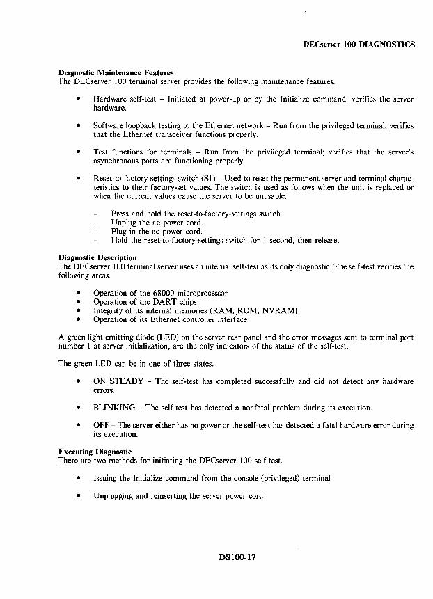
DECserver 100 DIAGNOSTICS
Diagnostic Maintenance Features The DECserver 100 terminal server provides the following maintenance features.
• Hardware self-test - Initiated at power-up or by the Initialize command; verifies the server hardware.
• Software loopback testing to the Ethernet network - Run from the privileged terminal; verifies that the Ethernet transceiver functions properly.
• Test functions for terminals - Run from the privileged terminal; verifies that the server's asynchronous ports are functioning properly.
• Reset-to-factory-settings switch (S1) - Used to reset the permanent server and terminal characteristics to their factory-set values. The switch is used as follows when the unit is replaced or when the current values cause the server to be unusable.
Press and hold the reset-to-factory-settings switch. Unplug the ac power cord. Plug in the ac power cord. Hold the reset-to-factory-settings switch for 1 second, then release.
Diagnostic Description The DECserver 100 terminal server uses an internal self-test as its only diagnostic. The self-test verifies the following areas.
• Operation of the 68000 microprocessor • Operation of the DART chips • Integrity of its internal memories (RAM, ROM, NVRAM) • Operation of its Ethernet controller interface
A green light emitting diode (LED) on the server rear panel and the error messages sent to terminal port number 1 at server initialization, are the only indicators of the status of the self-test.
The green LED can be in one of three states.
• ON STEADY - The self-test has completed successfully and did not detect any hardware errors.
• BLINKING - The self-test has detected a nonfatal problem during its execution.
• OFF - The server either has no power or the self-test has detected a fatal hardware error during its execution.
Executing Diagnostic There are two methods for initiating the DECserver 100 self-test.
• Issuing the Initialize command from the console (privileged) terminal
• Unplugging and reinserting the server power cord
DSlOO-17
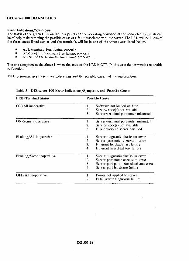
DECserver 100 DIAGNOSTICS
Error Indications/Symptoms The status of the green LED on the rear panel and the operating condition of the connected terminals can be of help in determining the possible cause of a fault associated with the server. The LED will be in one of the three states listed earlier and the terminals will be in one of the three states listed below.
• ALL terminals functioning properly • SOME of the terminals functioning properly • NONE of the terminals functioning properly
The one exception to the above is when the state of the LED is OFF. In this case the terminals are unable to function.
Table 3 summarizes these error indications and the possible causes of the malfunction.
Table 3 DECserver 100 Error Indications/Symptoms and Possible Causes
LED/Terminal Status
ON/All inoperative
ON/Some inoperative
Blinking/ All inoperative
Blinking/Some inoperative
OFF/All inoperative
Possible Cause
1. 2. 3.
1. 2. 3.
1. 2. 3. 4.
1. 2. 3. 4.
1. 2.
DSIOO-18
Software not loaded on host Service node(s) not available Server/terminal parameter mismatch
Server/terminal parameter mismatch Service node(s) not available EIA drivers on server port bad
Server diagnostic checksum error Server parameter checksum error Ethernet loopback test failure Ethernet heartbeat test failure
Server diagnostic checksum error Server parameter checksum error Server port parameter checksum error Server port hardware failure
Power not applied to server Fatal server diagnostic failure
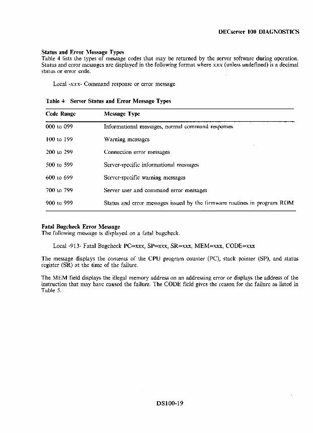
DECserver 100 DIAGNOSTICS
Status and Error Message Types Table 4 lists the types of message codes that may be returned by the server software during operation. Status and error messages are displayed in the following format where xxx (unless undefined) is a decimal status or error code.
Local -xxx- Command response or error message
Table 4 Server Status and Error Message Types
Code Range Message Type
000 to 099 Informational messages, normal command responses
100 to 199 Warning messages
200 to 299 Connection error messages
500 to 599 Server-specific informational messages
600 to 699 Server-specific warning messages
700 to 799 Server user and command error messages
900 to 999 Status and error messages issued by the firmware routines in program ROM
Fatal Bugcheck Error Message The following message is displayed on a fatal bugcheck.
Local -913- Fatal Bugcheck PC=xxx, SP=xxx, SR=xxx, MEM=xxx, CODE=xxx
The message displays the contents of the CPU program counter (PC), stack pointer (SP), and status register (SR) at the time of the failure.
The MEM field displays the illegal memory address on an addressing error or displays the address of the instruction that may have caused the failure. The CODE field gives the reason for the failure as listed in Table 5.
DSIOO-19
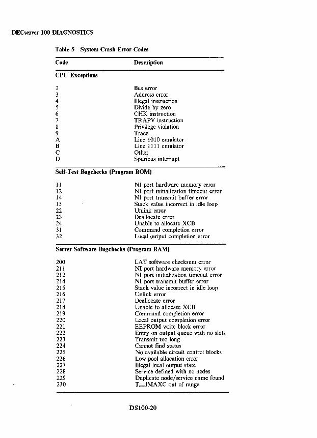
DECserver 100 DIAGNOSTICS
Table 5 System Crash Error Codes
Code
CPU Exceptions
2 3 4 5 6 7 8 9 A B C D
Description
Bus error Address error Illegal instruction Divide by zero CHK instruction TRAPV instruction Privilege violation Trace Line 1010 emulator Line 1111 emulator Other Spurious interrupt
Self-Test Bugchecks (Program ROM)
11 12 14 15 22 23 24 31 32
NI port hardware memory error NI port initialization timeout error NI port transmit buffer error Stack value incorrect in idle loop Unlink error Deallocate error Unable to allocate XCB Command completion error Local output completion error
Server Software Bugchecks (Program RAM)
200 211 212 214 215 216 217 218 219 220 221 222 223 224 225 226 227 228 229 230
LAT software checksum error NI port hardware memory error NI port initialization timeout error NI port transmit buffer error Stack value incorrect in idle loop Unlink error Deallocate error Unable to allocate XCB Command completion error Local output completion error EEPROM write block error Entry on output queue with no slots Transmit too long Cannot find status No available circuit control blocks Low pool allocation error Illegal local output state Service defined with no nodes Duplicate node/service name found T-IMAXC out of range
DSIOO-20
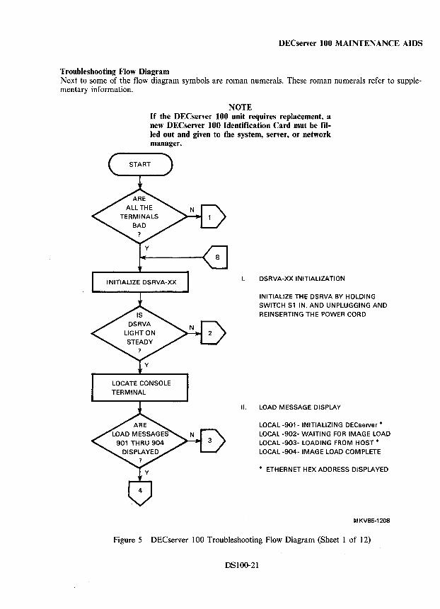
DECserver 100 MAINTENANCE AIDS
Troubleshooting Flow Diagram Next to some of the flow diagram symbols are roman numerals. These roman numerals refer to supplementary information.
NOTE If the DECserver 100 unit requires replacement, a new DECserver 100 Identification Card mut be filled out and given to the system, server, or network manager.
LOCATE CONSOLE TERMINAL
I. DSRVA-XX INITIALIZATION
INITIALIZE THE DSRVA BY HOLDING SWITCH S1 IN, AND UNPLUGGING AND REINSERTING THE POWER CORD
II. LOAD MESSAGE DISPLAY
LOCAL -901- INITIALIZING DECserver * LOCAL -902- WAITING FOR IMAGE LOAD LOCAL -903- LOADING FROM HOST * LOCAL -904- IMAGE LOAD COMPLETE
* ETHERNET HEX ADDRESS DISPLAYED
MKV85-1208
Figure 5 DECserver 100 Troubleshooting Flow Diagram (Sheet 1 of 12)
DSI00-21
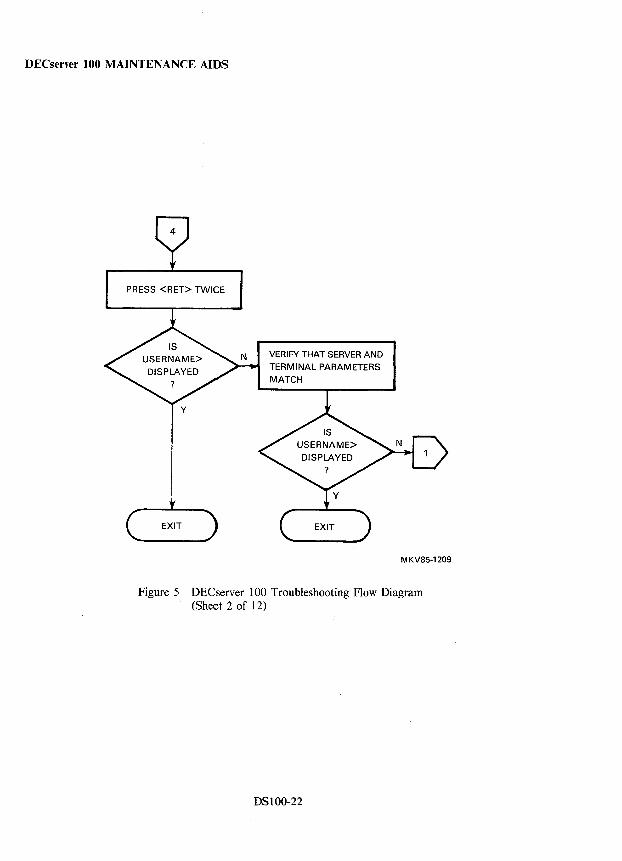
DECserver 100 MAINTENANCE AIDS
PRESS <RET> TWICE
y
VERIFY THAT SERVER AND
TERMINAL PARAMETERS
MATCH
MKV85·1209
Figure 5 DEC server 100 Troubleshooting Flow Diagram (Sheet 2 of 12)
DSIOO-22
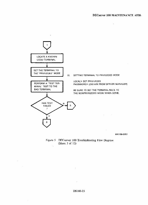
LOCATE A KNOWN
GOOD TERMINAL
SET THE TERMINAL TO
THE "PRIVILEGED" MODE
PERFORM A "TEST TER
MINAL" TEST TO THE BAD TERMINAL
DECserver 100 MAINTENANCE AIDS
III. SETTING TERMINAL TO PRIVILEGED MODE
LOCAL> SET PRIVILEGED PASSWORD> (OBTAIN FROM SERVER MANAGER)
BE SURE TO SET THE TERMINAL BACK TO
THE NONPRIVILEGED MODE WHEN DONE.
MKV86-0553
Figure 5 DECserver 100 Troubleshooting Flow Diagram (Sheet 3 of 12)
DSIOO-23
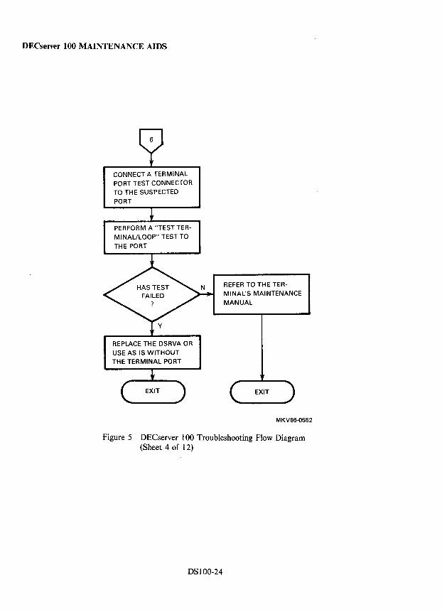
DECserver 100 MAINTENANCE AIDS
CONNECT A TERMINAL PORT TEST CONNECTOR TO THE SUSPECTED
PORT
PERFORM A "TEST TERMI NAL/LOOP" TEST TO
THE PORT
REPLACE THE DSRVA OR
USE AS IS WITHOUT THE TERMINAL PORT
REFER TO THE TERMINAL'S MAINTENANCE
MANUAL
MKV86·0552
Figure 5 DECserver 100 Troubleshooting Flow Diagram (Sheet 4 of 12)
DSI00-24
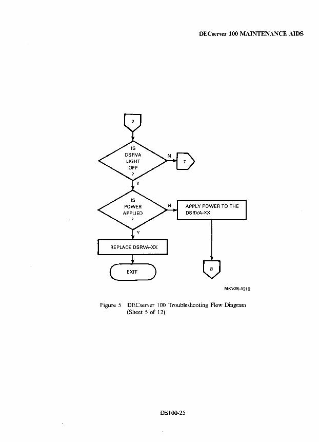
DECserver 100 MAINTENANCE ·AIDS
APPLY POWER TO THE
DSRVA-XX
MKV85-1212
Figure 5 DECserver 100 Troubleshooting Flow Diagram (Sheet 5 of 12)
DSlOO-25
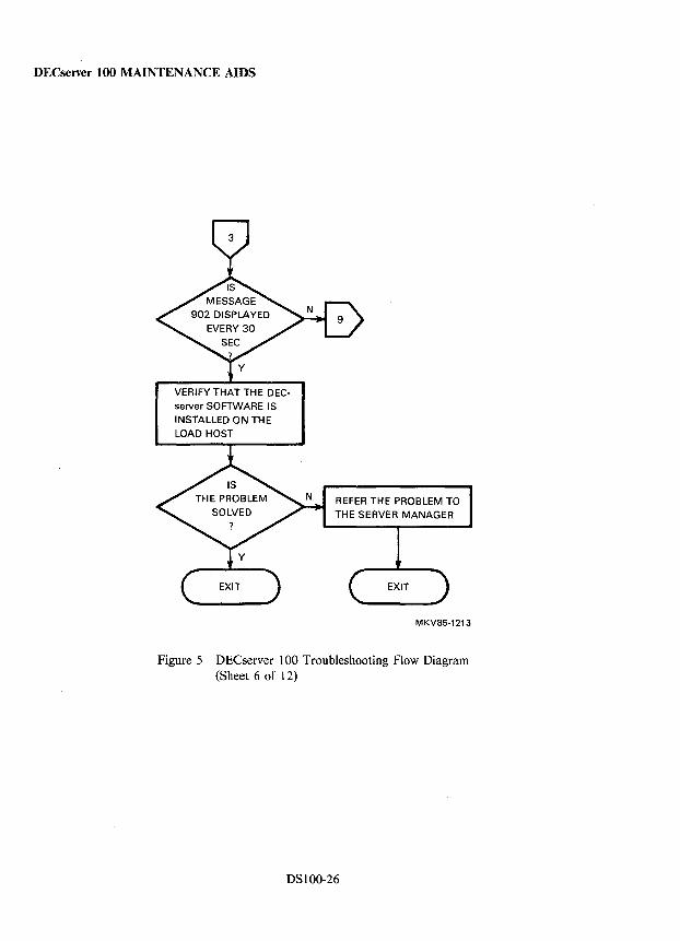
DECserver 100 MAINTENANCE AIDS
VERIFY THAT THE DECserver SOFTWARE IS INSTALLED ON THE LOAD HOST
REFER THE PROBLEM TO THE SERVER MANAGER
MKV85-1213
Figure 5 DEC server 100 Troubleshooting Flow Diagram (Sheet 6 of 12)
DSIOO-26
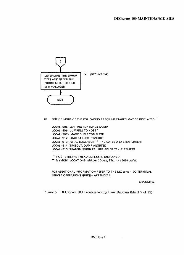
DECserver 100 MAINTENANCE AIDS
DETERMINE THE ERROR TYPE AND REFER THE PROBLEM TO THE SERVER MANAGER
IV. (SEE BELOW)
IV. ONE OR MORE OF THE FOLLOWING ERROR MESSAGES MAY BE DISPLAYED:
LOCAL -905- WAITING FOR IMAGE DUMP LOCAL -906- DUMPING TO HOST * LOCAL -907- IMAGE DUMP COMPLETE LOCAL -912- LOAD FAILURE, TIMEOUT LOCAL -913- FATAL BUGCHECK ** (INDICATES A SYSTEM CRASH) LOCAL -914- TIMEOUT, DUMP ABORTED LOCAL -915- TRANSMISSION FAILURE AFTER TEN ATTEMPTS
* HOST ETHERNET HEX ADDRESS IS DISPLAYED MEMORY LOCATIONS, ERROR CODES, ETC. ARE DISPLAYED
FOR ADDITIONAL INFORMATION REFER TO THE DECserver 100 TERMINAL SERVER OPERATIONS GUIDE - APPENDIX A
MKV85-1214
Figure 5 DECserver 100 Troubleshooting Flow Diagram (Sheet 7 of 12)
DSlOO-27

DECserver 100 MAINTENANCE AIDS
V. (SEE FOLLOWING PAGE)
THE ETHERNET TRANS
CEIVER.lS AT FAULT.
REFER THIS TO THE SERVER MANAGER
A PROBLEM WITH THE ETHERNET EXISTS.
REFER THIS TO THE SERVER MANAGER
EXIT
MKV85-1215
Figure 5 DEC server 100 Troubleshooting Flow Diagram (Sheet 8 of 12)
DSIOO-28
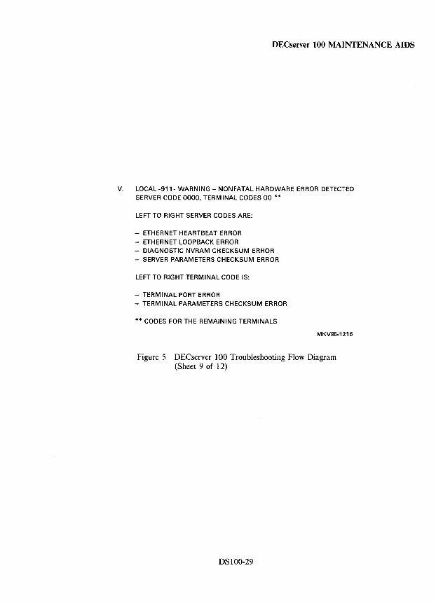
DECserver tOO MAINTENANCE AIDS
V. LOCAL -911- WARNING - NONFATAL HARDWARE ERROR DETECTED SERVER CODE 0000, TERMINAL CODES 00 **
LEFT TO RIGHT SERVER CODES ARE:
- ETHERNET HEARTBEAT ERROR
- ETHERNET LOOPBACK ERROR - DIAGNOSTIC NVRAM CHECKSUM ERROR - SERVER PARAMETERS CHECKSUM ERROR
LEFT TO RIGHT TERMINAL CODE IS:
- TERMINAL PORT ERROR
- TERMINAL PARAMETERS CHECKSUM ERROR
** CODES FOR THE REMAINING TERMINALS
MKV85-1216
Figure 5 DECserver 100 Troubleshooting Flow Diagram (Sheet 9 of 12)
DSIOO-29
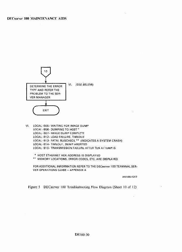
DECserver 100 MAINTENANCE AIDS
DETERMINE THE ERROR TYPE AND REFER THE
PROBLEM TO THE SERVER MANAGER
VI. (SEE BELOW)
VI. LOCAL -905- WAITING FOR IMAGE DUMP
LOCAL -906- DUMPING TO HOST * LOCAL -907- IMAGE DUMP COMPLETE LOCAL -912- LOAD FAILURE, TIMEOUT
LOCAL -913- FATAL BUGCHECK ** (INDICATES A SYSTEM CRASH) LOCAL -914- TIMEOUT, DUMP ABORTED LOCAL -915- TRANSMISSION FAILURE AFTER TEN ATTEMPTS
* HOST ETHERNET HEX ADDRESS IS DISPLAYED MEMORY LOCATIONS, ERROR CODES, ETC. ARE DISPLAYED
FOR ADDITIONAL INFORMATION REFER TO THE DECserver 1 00 TERMINAL SERVER OPERATIONS GUIDE - APPENDIX A
MKV85-1217
Figure 5 DECserver 100 Troubleshooting Flow Diagram (Sheet 10 of 12)
DSI00-30
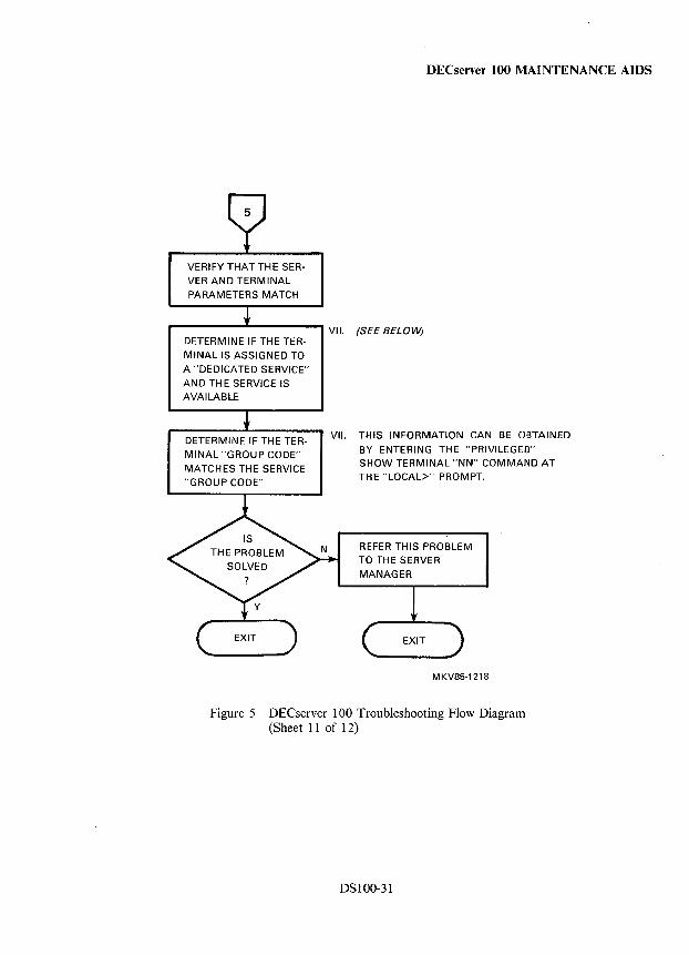
VERIFY THAT THE SERVER AND TERMINAL PARAMETERS MATCH
DETERMINE IF THE TERMINAL IS ASSIGNED TO A "DEDICATED SERVICE" AND THE SERVICE IS AVAILABLE
DETERMINE IF THE TERMINAL "GROUP CODE" MATCHES THE SERVICE "GROUP CODE"
DECserver 100 MAINTENANCE AIDS
VII. (SEE BELOW)
VII. THIS INFORMATION CAN BE OBTAINED BY ENTERING THE "PRIVILEGED" SHOW TERMINAL "NN" COMMAND AT THE "LOCAL>" PROMPT.
REFER THIS PROBLEM TO THE SERVER MANAGER
MKV85-1218
Figure 5 DECserver 100 Troubleshooting Flow Diagram (Sheet 11 of 12)
DSI00-31
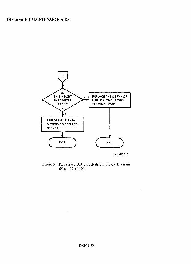
DECserver 100 MAINTENANCE AIDS
USE DEFAULT PARA
METERS OR REPLACE
SERVER
REPLACE THE DSRVA OR
USE IT WITHOUT THIS
TERMINAL PORT
EXIT
MKV85-1219
Figure 5 DECserver 100 Troubleshooting Flow Diagram (Sheet 12 of 12)
DSIOO-32
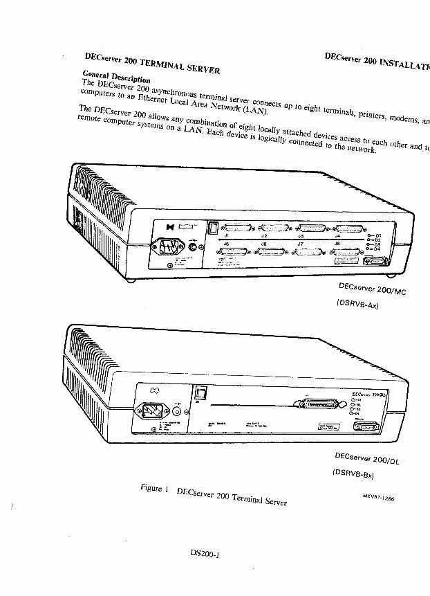
DECserver 200 TERMINAL SERVER DECserver 200 INSTALLATION
General Description
The DECserver 200 asYnchronoUs terminal server connects up to eight terminals, printers, modems, and computers to an Ethernet Loeal Area Network (LAN).
The DECserver 200 allows any combination of eight locally attached devices access to each other and to remote computer systems on a LAN. Each device is lOgically connected to the network.
(OSRVB-Ax)
----- DfC,.,yC( 200lDL JI O-Of lQ Q#I7~g:E " -------
OECserver 200/0L
(OSRVB-Bx)
Figure I DECserver 200 Terminal Server MKV87- 1266
D8200-1
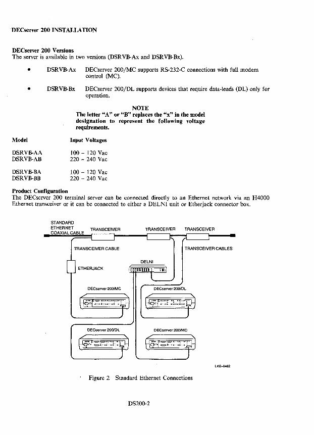
DECserver 200 INSTALLATION
DECserver 200 Versions The server is available in two versions (DSRVB-Ax and DSRVB-Bx).
• DSRVB-Ax DECserver 200/MC supports RS-232-C connections with full modem control (MC).
• DSRVB-Bx DECserver 200/DL supports devices that require data-leads (DL) only for operation.
Model
DSRVB-AA DSRVB-AB
DSRVB-BA DSRVB-BB
NOTE The letter "A" or "B" replaces the "x" in the model designation to represent the following voltage requirements.
Input Voltages
100 - 120 Vac 220 - 240 Vac
100 - 120 Vac 220 - 240 Vac
Product Configuration The DECserver 200 terminal server can be connected directly to an Ethernet network via an H4000 Ethernet transceiver or it can be connected to either a DELNI unit or Etherjack connector box.
STANDARD ETHERNET COAXIAL CABLE
TRANSCEIVER
TRANSCEIVER CABLE
DECserver 200/DL
TRANSCEIVER TRANSCEIVER
TRANSCEIVER CABLES
DECserver 200/Me
lKG-0482
Figure 2 Standard Ethernet Connections
DS200-2
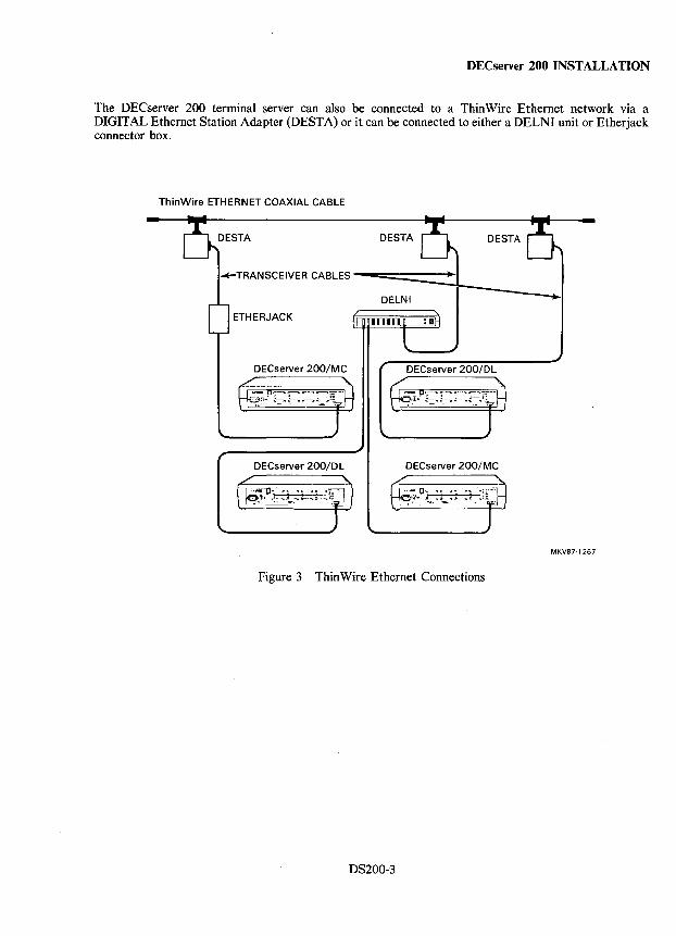
DECserver 200 INSTALLATION
The DECserver 200 terminal server can also be connected to a Thin Wire Ethernet network via a DIGITAL Ethernet Station Adapter (DESTA) or it can be connected to either a DELNI unit or Etherjack connector box.
ThinWire ETHERNET COAXIAL CABLE
DESTA
-+-TRANSCEIVER CABLES --===::====-+-I
DELNI
ETHERJACK
DECserver 200/DL
DECserver 200/DL DECserver 200/MC
MKV87·1267
Figure 3 Thin Wire Ethernet Connections
DS200-3
DECserver 200 INSTALLATION
Reference Documentation Refer to the following documents for more information on the DECserver 200 terminal server:
• DECserver 200 Technical Manual
• DECserver 200 Software Installation Manual
• DECserver 200 Management Guide
• DECserver 200 User's Guide
• DECserver 200 User's Reference Card
• DECserver 200 Identification Card
• Terminal Server Commands and Messages Guide
• LATplus/VMS Service Node Management Guide
Software Components The basic software that is required for the installation and operation of the DECserver 200 includes:
• DECserver 200 distribution software to be installed on each load host.
• DEC net Phase IV software to be installed on each load host (not required for ULTRIX systems).
• LA T service node software to be installed on all LA T service nodes that communicate with the DECserver 200 devices.
The distribution software must be installed on a load host that runs DECnet Phase IV software. The distribution includes an image file that is down-line loaded to the DECserver 200.
LAT (Local Area Transport) software must be installed on each node using devices connected to the DECserver 200.
LAT software packaging is as (operating system) dependent.
• V AX/VMS or Micro VMS OS Version 4.2 or later - LA Tplus/VMS is contained in the DECserver 200 software kit.
• ULTRIX-32/32M OS - LAT service node software included in the OS.
• RSX-ll-PLUS or Micro/RSX OS - LAT software included with DECnet-RSX software.
• TOPS-tO or TOPS-20 OS - LAT software included with as.
DS200-4
DECserver 200 INSTALLATION
Preinstallation Checklist Verify that the following items are installed or ready to be installed:
Hardware
• The appropriate network interface (that is; Ethernet junction box, DELNI, DESTA, or Ethernet transceiver, and so on). See Product Configuration section.
• Transceiver cabling (installed, tested, and tagged). See Cabling section.
• All devices and cables that connect to the DECserver 200. A terminal or personal computer (in the terminal emulation mode) is available for installation verification as per the DECserver 200 Software Installation Guide. See Cabling section.
• The H039 wall/partition mounting bracket kit or H041-AA rack mount kit if required.
Software
• DECserver 200 ID card complete and given to the system/network manager. See Arranging for Software Installation section.
• Distribution software installed on the load host(s). See Software Components section.
• DECnet Phase 4 software installed as required.
• LA T service node software installed as required.
Environment
• Verify that power requirements and DECserver 200 voltage select switch setting is correct (100 - 120 Vac or 220 - 240 Vac).
• Verify that operating temperature 5° to 50°C (41° to 122°F); humidity 10% to 95%; and altitude 2.4 km (8000 ft) requirements are met.
Service
• Optional service contracts are in place if requested.
Arranging for Software Installation
• Fill out the DECserver 200 Terminal Server Identification Card - Order Number EK-D200T-ID-001 (see Figure 4).
• Give the ID card and any software to the appropriate manager (systems/network manager).
• Label the terminal cables based on the location information from the appropriate manager.
• Connect and power-up a terminal to port number one. Configure the console terminal for 9600 bits/s, no parity, and 8-bit characters.
DS200-5
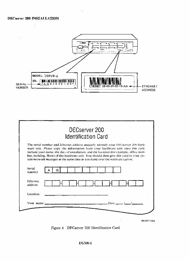
DECserver 200 INSTALLATION
MODEL: DSRYB-A
SN: 111111111111111111111111111111111111111111111111111111111111 SERIAL * A G 6 2 0 00 1 9 9 * NUMBER
DECserver 200 Identification Card
The serial number ami Ethernet address uniqucly identify your DECs(:ryer 200 hardware unit. Pkase cop)' the information from your hardware: unit onto this card. Include your name:, the dat:: of installation. and the location (for l'xampk'. office nUIllher, building. floor) of the: hardware unit. You should then give: this card to );our system/network m:lI1:lger at the same time as you hand ove:r the software: cartoll.
Serial number
Ethe:rne:t address
Location
Your name _' __ --------------Date __ 1 __ / __ _
MKV87-1269
Figure 4 DECserver 200 Identification Card
DS200-6
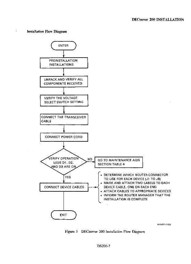
Installation Flow Diagram
PREINSTALLATION INSTALLATIONS
UNPACK AND VERIFY ALL COMPONENTS RECEIVED
VERIFY THE VOLTAGE SELECT SWITCH SETTING
CONNECT THE TRANSCEIVER CABLE
CONNECT POWER CORD
CONNECT DEVICE CABLES
DECserver 200 INSTALLATION
GO TO MAINTENANCE AIDS SECTION TABLE 4
• DETERMINE WHICH ROUTER CONNECTOR TO USE FOR EACH DEVICE (Jl TO J8)
• MARK AND ATTACH TWO LABELS TO EACH DEVICE CABLE, ONE ON EACH END
• ATTACH CABLES TO APPROPRIATE DEVICES • INFORM THE ROUTER MANAGER THAT THE
INSTALLATION IS COMPLETE
MKV87-1155
Figure 5 DECserver 200 Installation Flow Diagram
D8200-7
DECserver 200 INSTALLATION
Verifying Operation Proper operation of the server is verified by the status of the four LEDs on the server's control/indicator panel.
Whenever power is applied to the unit, the server performs diagnostic self-test and indicates a request for a down-line load of the server image from the load host. The server self-test normally takes about 20 seconds to complete, but the down-line loading of the server image could take longer if the network is busy. Allow up to two minutes for the self-test and down-line loading of the server image to complete. The D2 status LED will be ON indicating successful completion of self-test. Refer to the Diagnostic and Maintenance Aids sections for more information.
DS200-8
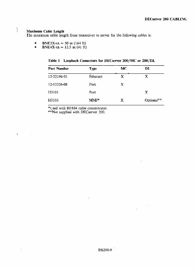
DECserver 200 CABLING
Maximum Cable Length The maximum cable length from transceiver to server for the following cables is:
• BNE3X-xx = 50 m (164 ft) • BNE4X-xx = 12.5 m (41 ft)
Table 1 Loopback Connectors for DECserver 200/MC or 200/DL
Part Number Type MC DL
12-22196-01 Ethernet X X
12-15336-08 Port X
H3101 Port X
H3103 MMJ* X Optional * *
*Used with H3104 cable concentrator. **Not supplied with DECserver 200.
DS200-9
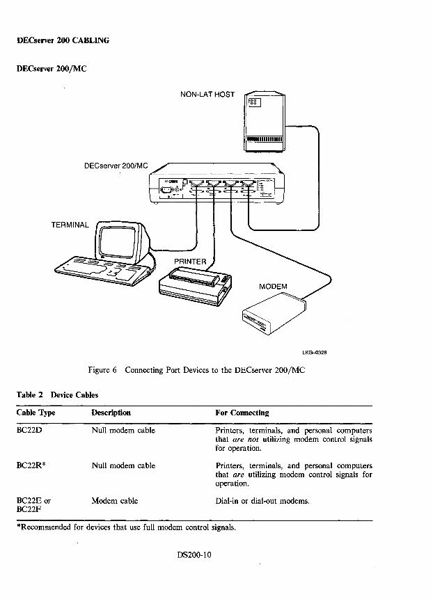
DECserver 200 CABLING
DECserver 200/MC
DECserver 200/MC
TERMINAL
NON-LAT HOST IOciI E-.l
11111111111111111
LKG-0328
Figure 6 Connecting Port Devices to the DECserver 200 fMC
Table 2 Device Cables
Cable Type
BC22D
BC22R*
BC22E or BC22F
Description
Null modem cable
Null modem cable
Modem cable
For Connecting
Printers, terminals, and personal computers that are not utilizing modem control signals for operation.
Printers, terminals, and personal computers that are utilizing modem control signals for operation.
Dial-in or dial-out modems.
*Recommended for devices that use full modem control signals.
DS200-10
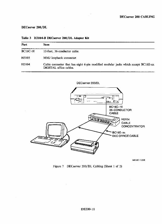
DECserver 200 CABLING
DECserver 200/DL
Table 3 H3104-B DECserver 200/DL Adapter Kit
Part
BC16C-I0
H3103
H3104
Item
10-foot, 36-conductor cable.
MMJ loopback connector.
Cable connector that has eight 6-pin modified modular jacks which accept BC 16E-xx DIGITAL office cables.
DECserver 200/DL
CONCENTRATOR
BC16E-xx DEC OFFICE CABLE
MKV87-1268
Figure 7 DECserver 200/DL Cabling (Sheet 1 of 2)
DS200-11
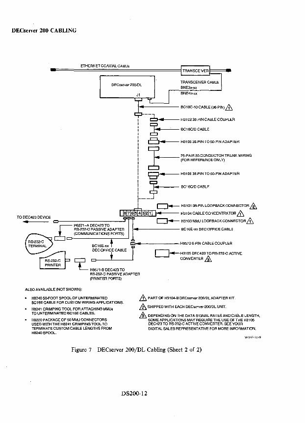
DECserver 200 CABLING
ETHERNET COAXIAL CABLE
DECserver 200/DL
~f------- BC16C-10 CABLE (36-PIN) Le:.
--cbr-..... -- H3102 36-PIN CABLE COUPLER
~ BC16CID CABLE
a~ H3106 36-PIN TO 50-PIN ADAPTER
~ 25-PAIR 50-CONDUCTOR TRUNK WIRING 6 (FOR REFERENCE ONLY)
gfool ... __ -- H3106 36-PIN TO 50-PIN ADAPTER
I ~"""--- BC16CID CABLE
t-_..J I ~ H310136-PINLOOPBACKCONNECTOR&
IIal71sm312111 1111 H3104CABLECONCENTRATOR&
.... CI 9 c::::J.-....- H3103MMJ LOOPBACKCONNECTORLe:. TO DEC423 DEVICE I
RS-232-C PASSIVE ADAPTER MIll BC16E-xx DEC OFFICE CABLE £ H8571-A DEC423 TO
(COMMUNICATIONS PORTS)
ClIII
L H8571-B DEC423 TO RS-232-C PASSIVE ADAPTER (PRINTER PORTS)
ALSO AVAILABLE (NOT SHOWN):
H8572 6-PIN CABLE COUPLER
~H3105 DEC423 TO RS-232-C ACTIVE
CONVERTER &
• H8240 50-FOOT SPOOL OF UNTERMINATED BC16E CABLE FOR CUSTOM WIRING APPLICATIONS.
.& PART OF H3104-B DECserver 200/DL ADAPTER KIT.
.& SHIPPED WITH EACH DECserver 200/DL UNIT. • H8241 CRIMPING TOOL FOR ATTACHING MMJs
TO UNTERMINATED BC16E CABLES.
• H8220 PACKAGE OF 50 MMJ CONNECTORS USED WITH THE H8241 CRIMPING TOOL TO TERMINATE CUSTOM CABLE LENGTHS FROM H8240 SPOOL.
& DEPENDING ON THE DATA SIGNAL RATES AND CABLE LENGTH, SOME APPLICATIONS MAY REQUIRE THE USE OFTHE H3105 DEC423 TO RS-232-C ACTIVE CONVERTER. SEE YOUR DIGITAL SALES REPRESENTATIVE FOR MORE INFORMATION.
MKV87·1278
Figure 7 DECserver 200/DL Cabling (Sheet 2 of 2)
D8200-12
DECserver 200 DIAGNOSTICS
Diagnostics The DEC server 200 diagnostic self-test performs a number of DECserver 200 hardware tests. The self-test executes (and a down-line load occurs) whenever the DECserver initializes. The DECserver can be initialized in a number of ways:
• By powering up the server,
• By executing the INITIALIZE command,
• By executing a NCP LOAD command on a DEC net load host, and
• By pressing <CTRL/P> if there was an error that prevented down-line loading during the most recent self-test.
The 02 status LED on the control/indicator panel displays the results of the self-test.
• If it remains OFF after the self-test, there is a fatal error.
• If it blinks, there is a nonfatal error. For nonfatal hardware errors, an error message appears on a terminal attached to the console port.
• If it glows, the self-test detected no hardware errors.
DS200-13
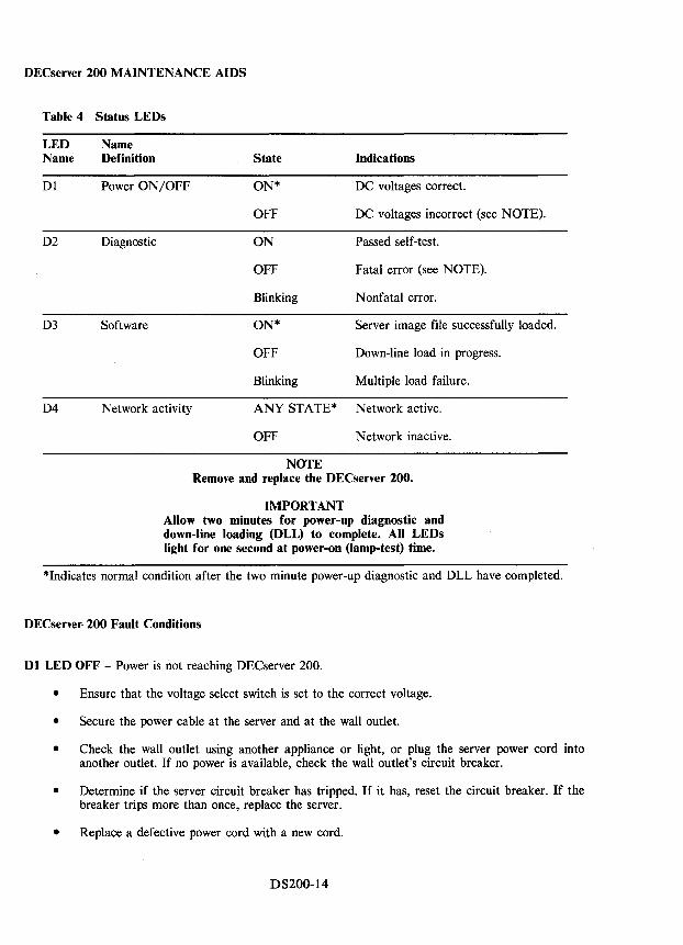
DECserver 200 MAINTENANCE AIDS
Table 4 Status LEDs
LED Name Name Definition State Indications
Dl Power ON/OFF ON* DC voltages correct.
OFF DC voltages incorrect (see NOTE).
D2 Diagnostic ON Passed self-test.
OFF Fatal error (see NOTE).
Blinking Nonfatal error.
D3 Software ON* Server image file successfully loaded.
OFF Down-line load in progress.
Blinking Multiple load failure.
D4 Network activity ANY STATE* Network active.
OFF Network inactive.
NOTE Remove and replace the DECserver 200.
IMPORTANT Allow two minutes for power-up diagnostic and down-line loading (DLL) to complete. All LEDs light for one second at power-on (lamp-test) time.
*Indicates normal condition after the two minute power-up diagnostic and DLL have completed.
DECserver· 200 Fault Conditions
Dl LED OFF - Power is not reaching DECserver 200.
• Ensure that the voltage select switch is set to the correct voltage.
• Secure the power cable at the server and at the wall outlet.
• Check the wall outlet using another appliance or light, or plug the server power cord into another outlet. If no power is available, check the wall outlet's circuit breaker.
• Determine if the server circuit breaker has tripped. If it has, reset the circuit breaker. If the breaker trips more than once, replace the server.
• Replace a defective power cord with a new cord.
DS200-14
DECserver 200 MAINTENANCE AIDS
D2 LED OFF - Fatal error or test is in progress. If 02 remains OFF for more than 20 seconds after the DI LED goes ON, there is a fatal hardware error. There is no corrective procedure for this problem.
D2 LED Blinking - If the D2 LED is blinking after power-up, the server has detected a nonfatal hardware error during self-test. The following sections list the errors that occur in conjunction with the D2 LED blinking on your display.
Error Messages 920 and 921
Local -920- parameter checksum error on port n Local -921- factory-set parameters applied to port n
These messages indicate a port checksum error. The permanent characteristics for the indicated port do not pass the internal checksum test. The factory-set defaults are in effect.
I. Enter the DEFINE PORT command to reset the port characteristics to values of your choice. Then reinitialize the server using the INITIALIZE command, or
2. Reset the server characteristics using the software Reset Switch CSl) on the back of the server. Press and hold the switch IN while removing and reinserting the server power cord.
Error Messages 922 and 923
Local -922- port hardware error on port n Local -923- port n has been disabled
These messages indicate a port hardware error. There is no corrective procedure for this problem.
Error Messages 930 and 931
Local -930- server parameters checksum error Local -931- factory-set server parameters applied
The server characteristics in the permanent data base are not operational. The factory-set defaults are operating.
1. Enter the DEFINE SERVER command to reset the port characteristics to values of your choice. Then reinitialize the server using the INITIALIZE command, or
2. Reset the server characteristics using the software Reset Switch (1) on the back of the server. Press and hold the switch IN while removing and reinserting the server power cord. If this action fails to correct the problem, the memory used to store the characteristics is faulty. The server must be replaced.
Error Message 932
Local -932- hardware revision level checksum error
The server's nonvolatile memory is faulty. There is no corrective procedure for this problem. The server must be replaced.
DS200-15
DECserver 200 MAINTENANCE AIDS
Error Messages 935 and 936
Local -935- service characteristics checksum error Local -936- service has been disabled
The service characteristics in the permanent data base are not operational. The factory-set defaults are operating.
1. Enter the DEFINE SERVER command to reset the port characteristics to values of your choice. Then reinitialize the server using the INITIALIZE command, or
2. Reset the server characteristics using the software Reset Switch (1) on the back of the server. Press and hold the switch IN while removing and reinserting the server power cord. If this action fails to correct the problem, the memory used to store the characteristics is faulty. The server must be replaced.
Error Messages 941,942, and 950
Local -941- transceiver loopback error Local -942- image load not attempted Local -950- troubleshooting procedures should be followed
These messages indicate that there is a fault between the server and the coaxial cable.
1. Check the transceiver cable that runs from the server to the transceiver, to the DELNI, or to the Etherjack. Ensure that there is a secure connection at both ends of the cable. Check the cable for damage. If damaged, replace the cable.
2. If the above action does not correct the problem:
a. Disconnect the transceiver cable from the server.
b. Plug the Ethernet loopback connector into the Ethernet connector on the server.
c. Initialize the server by pressing <CTRL/P> on the console terminal, or by unplugging and reinserting the server's power cord.
d. Wait 20 seconds for the diagnostic test to complete, then observe the status of the D2 LED:
(1) If the D2 LED continues to blink and the error messages reappear after the self-test, the server is faulty and must be replaced.
(2) If the D2 LED stays ON, proceed to the next step to isolate and determine the faulty unit.
e. Unplug the Ethernet loopback connector from the Ethernet connector on the server.
f. Reconnect the transceiver cable to the Ethernet connector on the server.
g. Disconnect the other end of the transceiver cable from the DELNI, from the Etherjack, or from the transceiver on the Ethernet coaxial cable.
h. Plug the Ethernet loopback connector into the transceiver cable.
DS200-16
DECserver 200 MAINTENANCE AIDS
i. Initialize the server by pressing <CTRL/P> on the console terminal, or by unplugging and reinserting the server's power cord. Wait 20 seconds for the self-test to complete.
(1) If the D2 LED continues to blink, the transceiver is faulty and must be replaced.
(2) If the D2 LED stays ON, the faulty unit is the device the transceiver cable was connected to (the DELNI, the Etherjack extension, the transceiver, or the Ethernet tap for the transceiver).
If the above procedures do not correct the problem, the transceiver unit or transceiver Ethernet tap is faulty. Remove and reinstall the transceiver in a new location. Initialize by pressing <CTRL/P> on the console terminal, or by unplugging and reinserting the server's power cord. If the D2 LED stays ON, the new Ethernet tap is working and the DECserver 200 will function properly. If the error messages persist, the transceiver is probably faulty. Replace the transceiver.
Error Messages 943 and 944
Local -943- transceiver heartbeat error Local -944- check transceiver type for heartbeat support
These messages indicate that a heartbeat signal was not detected by self-test. This does not cause the D2 LED to blink.
1. The transceiver is an 802.3 compatible transceiver or a non-DIGITAL transceiver that was made to conform to the Ethernet Version 1.0 specification. The signal is used in all DIGITAL Ethernet transceivers. If this condition occurs on a DIGITAL transceiver or a DELNI, there may be a problem with the transceiver.
2. If a non-DIGITAL (or 802.3) transceiver is being used, disable the server heartbeat detection ability by defining the server characteristic (HEAR TBEA T) as DISABLED>. Enter the DEFINE/ST SERVER HEARTBEAT DISABLED commands.
If the above procedures do not correct the problem, there is a transceiver or transceiver cable problem.
No Messages on Console Terminal
• The port to which the terminal is physically connected is not defined as the console port.
• The console terminal is faulty.
• The internal characteristics for the console terminal are not set up correctly.
D3 LED Blinking - Perform the following steps before proceeding with problem analysis:
• Connect a terminal to port one.
• Configure the terminal for 9600 bits/s, 8-bit character size, and no parity.
• Press <CTRL/P> on the terminal. <CTRL/P> restarts the DECserver 200 self-test and DLL.
• Terminal will display messages.
DS200-17
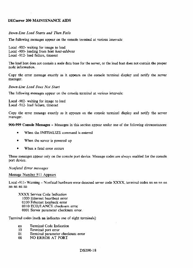
DECserver 200 MAINTENANCE AIDS
Down-Line Load Starts and Then Fails
The following messages appear on the console terminal at various intervals:
Local -902- waiting for image to load Local -903- loading from host host-address Local-912- load failure, timeout
The load host does not contain a node data base for the server, or the load host does not contain the proper node information.
Copy the error message exactly as it appears on the console terminal display and notify the server manager.
Down-Line Load Does Not Start
The following messages appear on the console terminal at various intervals:
Local -902- waiting for image to load Local -912- load failure, timeout
Copy the error message exactly as it appears on the console terminal display and notify the server manager.
900-999 Console Messages - Messages in this section appear under one of the following circumstances:
• When the INITIALIZE command is entered
• When the server is powered up
• When a fatal error occurs
These messages appear only on the console port device. Message codes are always enabled for the console port device.
Nonfatal Error messages
Message Number 911 Appears
Local-911- Warning - Nonfatal hardware error detected server code XXXX, terminal codes nn nn nn nn nn nn nn nn
XXXX Service Code Indication 1000 Ethernet heartbeat error 0100 Ethernet loopback error 0010 ECO /LANCE checksum error 0001 Server parameter checksum error.
Terminal codes [each nn indicates one of eight terminals]:
nn Terminal Code Indication 10 Terminal port error 01 Terminal parameter checksum error 00 NO ERROR AT PORT
DS200-18
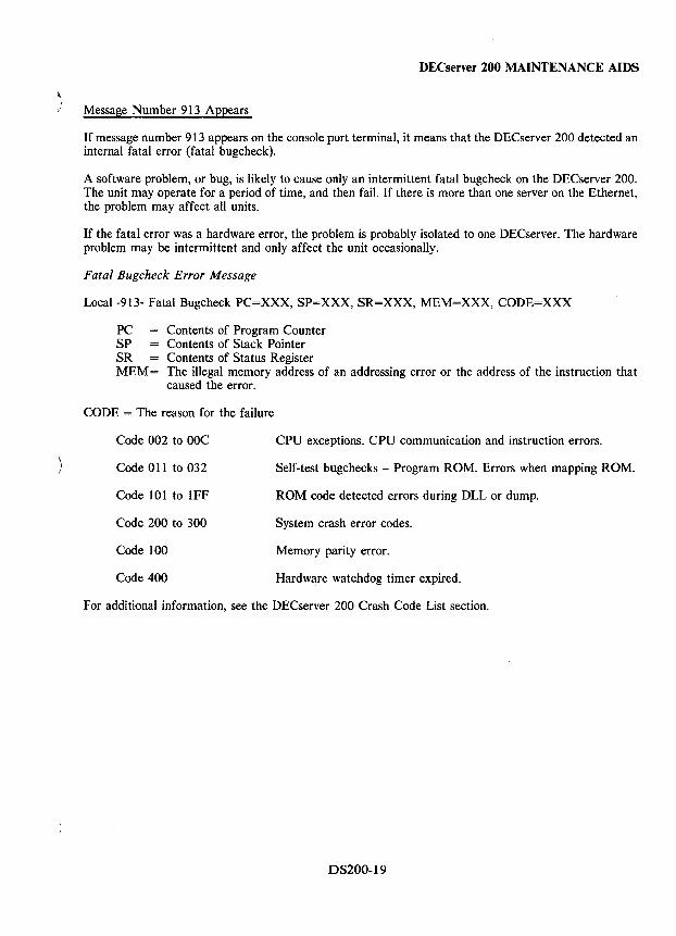
DECserver 200 MAINTENANCE AIDS
Message Number 913 Appears
If message number 913 appears on the console port terminal, it means that the DECserver 200 detected an internal fatal error (fatal bugcheck).
A software problem, or bug, is likely to cause only an intermittent fatal bugcheck on the DECserver 200. The unit may operate for a period of time, and then fail. If there is more than one server on the Ethernet, the problem may affect all units.
If the fatal error was a hardware error, the problem is probably isolated to one DECserver. The hardware problem may be intermittent and only affect the unit occasionally.
Fatal Bugcheck Error Message
Local-913- Fatal Bugcheck PC=XXX, SP=XXX, SR=XXX, MEM=XXX, CODE=XXX
PC SP SR MEM=
Contents of Program Counter Contents of Stack Pointer Contents of Status Register The illegal memory address of an addressing error or the address of the instruction that caused the error.
CODE = The reason for the failure
Code 002 to OOC CPU exceptions. CPU communication and instruction errors.
Code 011 to 032 Self-test bugchecks - Program ROM. Errors when mapping ROM.
Code 101 to IFF ROM code detected errors during DLL or dump.
Code 200 to 300 System crash error codes.
Code 100 Memory parity error.
Code 400 Hardware watchdog timer expired.
For additional information, see the DECserver 200 Crash Code List section.
DS200-19
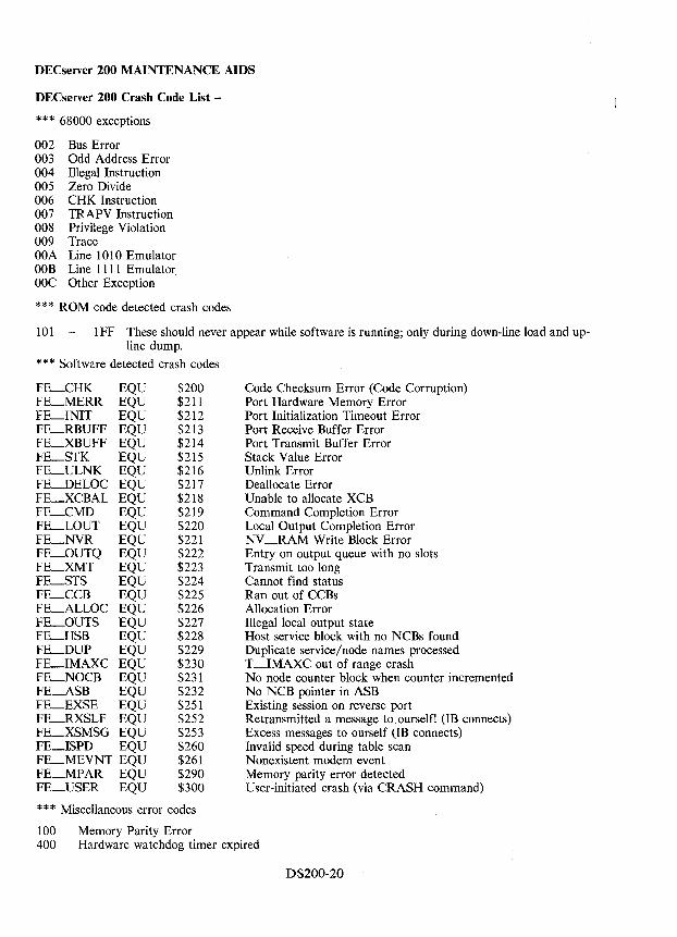
DECserver 200 MAINTENANCE AIDS
DECserver 200 Crash Code List -
*** 68000 exceptions
002 Bus Error 003 Odd Address Error 004 Illegal Instruction 005 Zero Divide 006 CHK Instruction 007 TRAPV Instruction 008 Privilege Violation 009 Trace OOA Line 1010 Emulator OOB Line 1111 Emulator OOC Other Exception
*** ROM code detected crash codes
101 - IFF These should never appear while software is running; only during down-line load and upline dump.
* * * Software detected crash codes
FE_CHK EQU FE_MERR EQU FE_INIT EQU FE_RBUFF EQU FE_XBUFF EQU FE_STK EQU FE_ULNK EQU FE_DELOC EQU FE_XCBAL EQU FE_CMD EQU FE_LOUT EQU FE_NVR EQU FE_OUTQ EQU FE_XMT EQU FE~TS EQU FE_CCB EQU FE_ALLOC EQU FE_OUTS EQU FE_HSB EQU FE_DUP EQU FE_IMAXC EQU FE_NOCB EQU FE_ASB EQU FE_EXSE EQU FE_RXSLF EQU FE-XSMSG EQU FE_ISPD EQU FE_MEV NT EQU FE_MPAR EQU FE_USER EQU
$200 . $211
$212 $213 $214 $215 $216 $217 $218 $219 $220 $221 $222 $223 $224 $225 $226 $227 $228 $229 $230 $231 $232 $251 $252 $253 $260 $261 $290 $300
* * * Miscellaneous error codes
100 Memory Parity Error
Code Checksum Error (Code Corruption) Port Hardware Memory Error Port Initialization Timeout Error Port Receive Buffer Error Port Transmit Buffer Error Stack Value Error Unlink Error Deallocate Error Unable to allocate XCB Command Completion Error Local Output Completion Error NV-RAM Write Block Error Entry on output queue with no slots Transmit too long Cannot find status Ran out of CCBs Allocation Error Illegal local output state Host service block with no NCBs found Duplicate service/node names processed T--IMAXC out of range crash No node counter block when counter incremented No NCB pointer in ASB Existing session on reverse port Retransmitted a message to ourself! (lB connects) Excess messages to ourself (IB connects) Invalid speed during table scan Nonexistent modem event Memory parity error detected User-initiated crash (via CRASH command)
400 Hardware watchdog timer expired
DS200-20
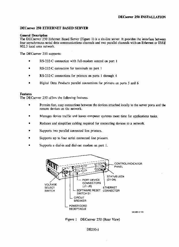
DECserver 250 INSTALLATION
DECserver 250 ETHERNET BASED SERVER
General Description The DECserver 250 Ethernet Based Server (Figure 1) is a six-line server. It provides the interface between four asynchronous serial data communications channels and two parallel channels with an Ethernet or IEEE 802.3 local area network.
The DECserver 250 supports:
• RS-232-C connection with full-modem control on port I
• RS-232-C connection for terminals on port 1
• RS-232-C connections for printers on ports 1 through 4
• Digital Data Products parallel connections for printers on ports 5 and 6
Features The DECserver 250 offers the following features.
• Permits fast, easy connections between the devices attached locally to the server ports and the remote devices on the network.
• Manages device traffic and leaves computer systems more time for applications tasks.
• Reduces and simplifies cabling required for connecting devices to a network.
• Supports two parallel connected line printers.
• Supports up to four serial connected line printers.
• Supports a dial-in and dial-out modem on port 1.
CONTROL/INDICATOR PANEL
VOLTAGE SELECT SWITCH
ETHERNET SOFTWARE RESET CONNECTOR SWITCH 81
CIRCUIT BREAKER
POWER CORD RECEPTACLE
Figure 1 DECserver 250 (Rear View)
DS250-1
MKV89-0199
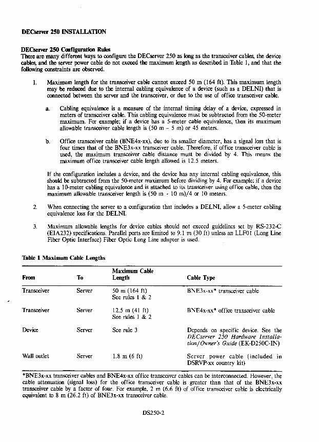
DECserver 250 INSTALLATION
DECserver 250 Configuration Rules There are many different ways to configure the DECserver 250 as long as the transceiver cables, the device cables, and the server power cable do not exceed the maximum length as described in Table 1, and that the following constraints are observed.
1. Maximum length for the transceiver cable cannot exceed 50 m (164 ft). This maximum length may be reduced due to the internal cabling equivalence of a device (such as a DELNI) that is connected between the server and the transceiver, or due to the use of office transceiver cable.
a. Cabling equivalence is a measure of the internal timing delay of a device, expressed in meters of transceiver cable. This cabling equivalence must be subtracted from the 50-meter maximum. For example; if a device has a 5-meter cable equivalence, then its maximum allowable transceiver cable length is (50 m - 5 m) or 45 meters.
b. Office transceiver cable (BNE4x-xx), due to its smaller diameter, has a signal loss that is four times that of the BNE3x-xx transceiver cable. Therefore, if office transceiver cable is used, the maximum transceiver cable distance must be divided by 4. This means the maximum office transceiver cable length allowed is 12.5 meters.
If the configuration includes a device, and the device has any internal cabling equivalence, this should be subtracted from the 50-meter maximum before dividing by 4. For example; if a device has a 10-meter cabling equivalence and is attached to its transceiver using office cable, then the maximum allowable transceiver length is (50 m - 10 m)/4 or 10 meters.
2. When connecting the server to a configuration that includes a DELNI, allow a 5-meter cabling equivalence loss for the DELNI.
3. Maximum allowable lengths for device cables should not exceed guidelines set by RS-232-C (EIA232) specifications. Parallel ports are limited to 9.1 m (30 ft) unless an LLFOI (Long Line Fiber Optic Interface) Fiber Optic Long Line adapter is used.
Table 1 Maximum Cable Lengths
From To
Transceiver Server
Transceiver Server
Device Server
Wall outlet Server
Maximum Cable Length
50 m (164 ft) See rules 1 & 2
12.5 m (41 ft) See rules 1 & 2
See rule 3
1.8 m (6 ft)
Cable Type
BNE3x-xx* transceiver cable
BNE4x-xx* office transceiver cable
Depends on specific device. See the DECserver 250 Hardware Installation/ Owner's Guide (EK-D250C-IN)
Server power cable (included in DSRVP-xx country kit)
*BNE3x-xx transceiver cables and BNE4x-xx office transceiver cables can be interconnected. However, the cable attenuation (signal loss) for the office transceiver cable is greater than that of the BNE3x-xx transceiver cable by a factor of four. For example, 2 m (6.6 ft) of office transceiver cable is electrically equivalent to 8 m (26.2 ft) of BNE3x-xx transceiver cable.
DS250-2
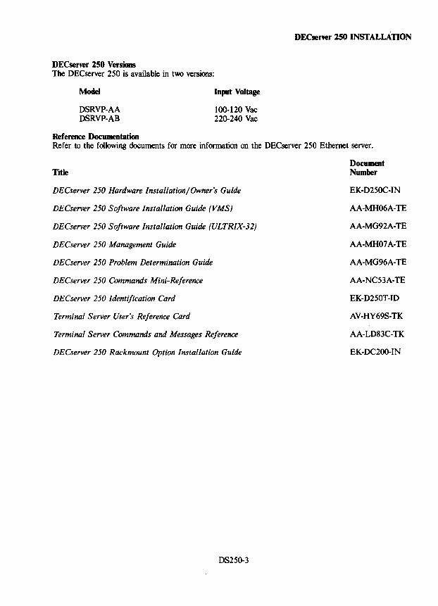
DECserver 250 Versions The DECserver 250 is available in two versions:
Model
DSRVP-AA DSRVP-AB
Reference Documentation
Input Voltage
100-120 Vac 220-240 Vac
DECse"er 250 INSTALLATION
Refer to the following documents for more information on the DECserver 250 Ethernet server.
Title
DECserver 250 Hardware Installation/Owner's Guide
DECserver 250 Software Installation Guide (VMS)
DECserver 250 Software Installation Guide (ULTRIX-32)
DECserver 250 Management Guide
DECserver 250 Problem Determination Guide
DECserver 250 Commands Mini-Reference
DECserver 250 Identification Card
Terminal Server User's Reference Card
Terminal Server Commands and Messages Reference
DECserver 250 Rackmount Option Installation Guide
DS250-3
Document Number
EK-D250C-IN
AA-MH06A-TE
AA-MG92A-TE
AA-MH07 A-TE
AA-MG96A-TE
AA-NC53A-TE
EK-D250T-ID
AV-HY69S-TK
AA-LD83C-TK
EK-DC200-IN
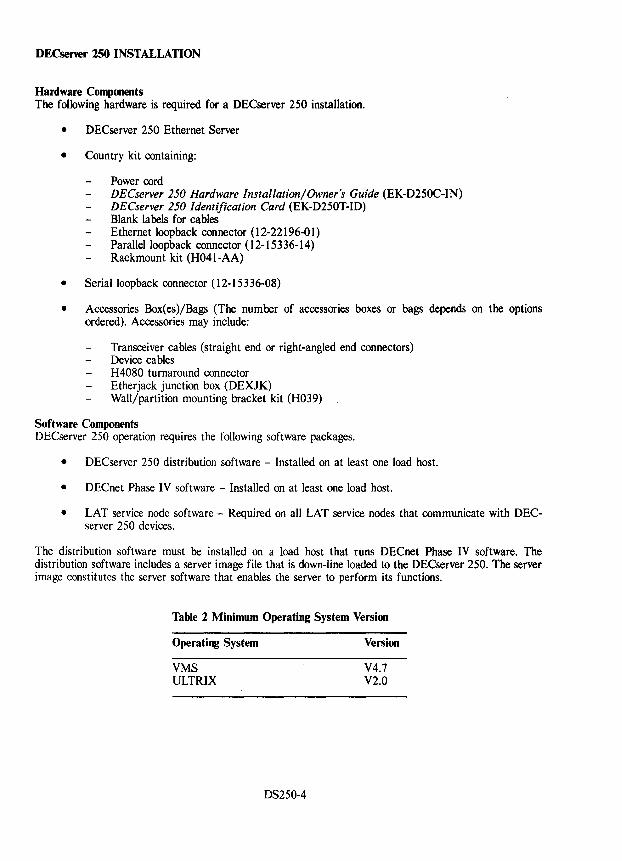
DECservel' 250 INSTALLATION
Hardware Components The following hardware is required for a DECserver 250 installation.
• DECserver 250 Ethernet Server
• Country kit containing:
Power cord DECserver 250 Hardware Installation/Owner's Guide (EK-D250C-IN) DECserver 250 Identification Card (EK-D250T-ID) Blank labels for cables Ethernet loop back connector (12-22196-01) Parallel loopback connector (12-15336-14) Rackmount kit (H041-AA)
• Serialloopback connector (12-15336-08)
• Accessories Box(es)/Bags (The number of accessories boxes or bags depends on the options ordered). Accessories may include:
Transceiver cables (straight end or right-angled end connectors) Device cables H4080 turnaround connector Etherjack junction box (DEXJK) Wall/partition mounting bracket kit (H039)
Software Components DECserver 250 operation requires the following software packages.
• DECserver 250 distribution software - Installed on at least one load host.
• DECnet Phase IV software - Installed on at least one load host.
• LAT service node software - Required on all LAT service nodes that communicate with DECserver 250 devices.
The distribution software must be installed on a load host that runs DECnet Phase IV software. The distribution software includes a server image file that is down-line loaded to the DECserver 250. The server image constitutes the server software that enables the server to perform its functions.
Table 2 Minimum Operating System Version
Operating System
VMS ULTRIX
DS250-4
Version
V4.7 V2.0
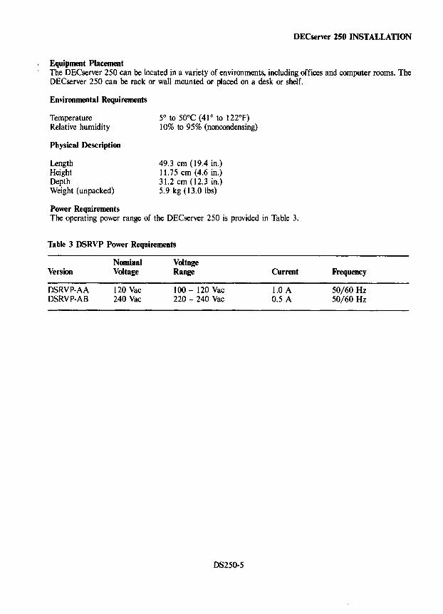
DECserver 250 INSTALLATION
Equipment Placement The DECserver 250 can be located in a variety of environments, including offices and computer rooms. The DECserver 250 can be rack or wall mounted or placed on a desk or shelf.
Enviroomental Requirements
Temperature Relative humidity
Physical Descriptioo
Length Height Depth Weight (unpacked)
Power Requirements
5° to 50°C (41 ° to 122°F) 10% to 95% (noncondensing)
49.3 em (19.4 in.) 11.75 cm (4.6 in.) 3l.2 cm (12.3 in.) 5.9 kg (13.0 lbs)
The operating power range of the DECserver 250 is provided in Table 3.
Table 3 DSRVP Power Requirements
Version
DSRVP-AA DSRVP-AB
Nominal Voltage
120 Vac 240 Vac
Voltage Range
100 - 120 Vac 220 - 240 Vac
DS250-5
Current
1.0 A 0.5 A
Frequency
50/60 Hz 50/60 Hz
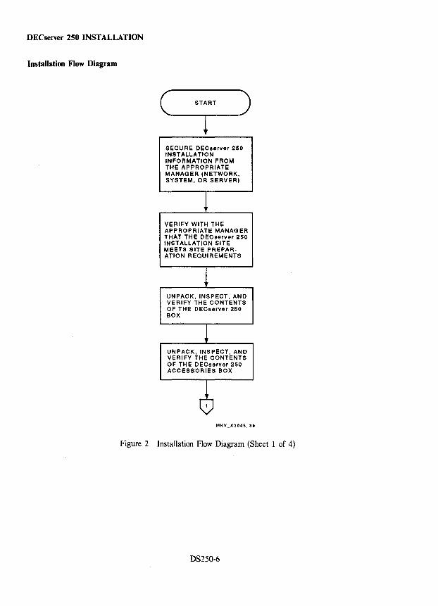
DECserver 250 INSTALLATION
Installation Flow Diagram
SECURE DECserver 250 INSTALLATION INFORMATION FROM THE APPROPRIATE MANAGER (NETWORK, SYSTEM, OR SERVER)
VERIFY WITH THE APPROPRIATE MANAGER THAT THE DECserver 250 INSTALLATION SITE MEETS SITE PREPARATION REQUIREMENTS
UNPACK, INSPECT, AND VERIFY THE CONTENTS OF THE DECserver 250 BOX
UNPACK, INSPECT, AND VERIFY THE CONTENTS OF THE DECserver 250 ACCESSORIES BOX
Figure 2 Installation Flow Diagram (Sheet 1 of 4)
DS250-6
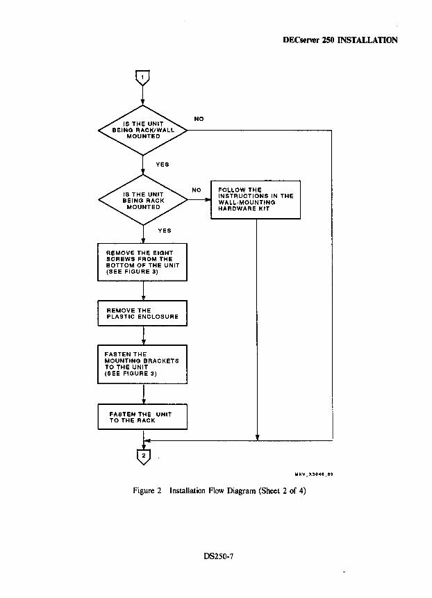
REMOVE THE EIGHT SCREWS FROM THE BOTTOM OF THE UNIT (SEE FIGURE 3)
FASTEN THE MOUNTING BRACKETS TO THE UNIT (SEE FIGURE 3)
DECserver 250 INSTALLATION
NO
NO FOLLOW THE INSTRUCTIONS IN THE WALL·MOUNTING HARDWARE KIT
Figure 2 Installation Flow Diagram (Sheet 2 of 4)
DS250-7
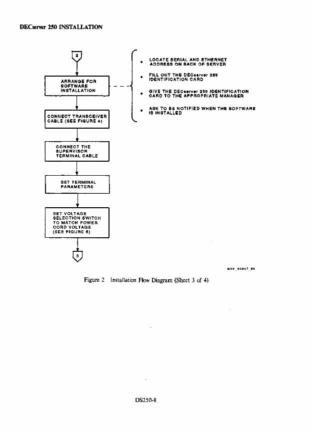
DECsener 250 INSTALLATION
ARRANGE FOR SOFTWARE INSTALLATION
CONNECT THE SUPERVISOR TERMINAL CABLE
SET VOLTAGE SELECTION SWITCH TO MATCH POWER CORD VOLTAGE (SEE FIGURE 5)
•
•
LOCATE SERIAL AND ETHERNET ADDRESS ON BACK OF SERVER
FILL OUT THE DECserver 250 IDENTIFICATION CARD
• GIVE THE DEC •• rver 250 IDENTIFICATION CARD TO THE APPROPRIATE MANAGER
• ASK TO BE NOTIFIED WHEN THE SOFTWARE IS INSTALLED
Figure 2 Installation Flow Diagram (Sheet 3 of 4)
DS250-8
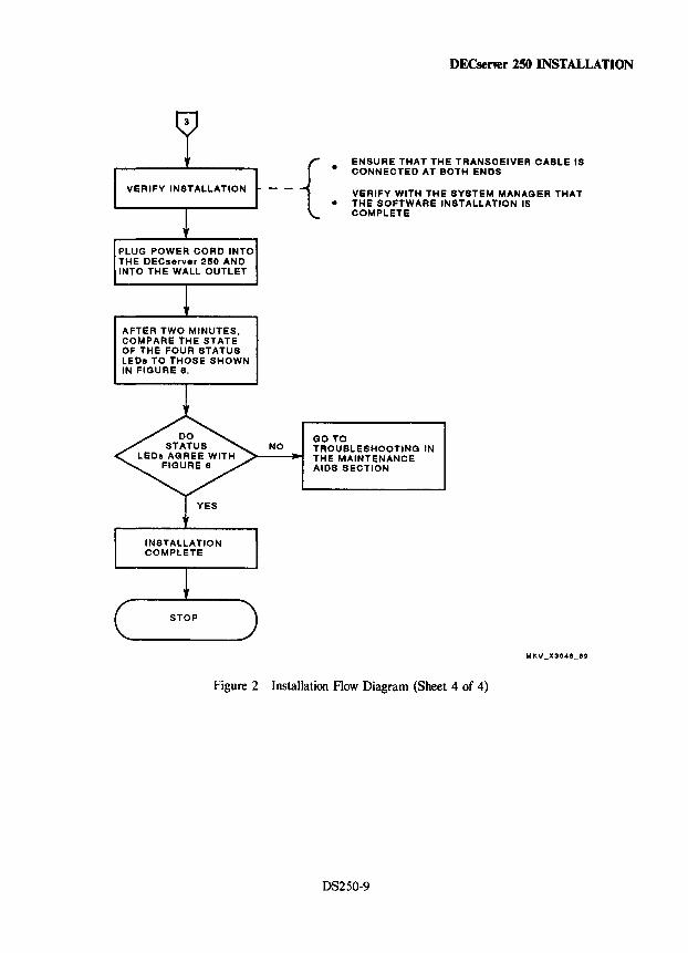
PLUG POWER CORD INTO THE DECserver 250 AND INTO THE WALL OUTLET
AFTER TWO MINUTES, COMPARE THE STATE OF THE FOUR STATUS LEOs TO THOSE SHOWN IN FIGURE 6.
--{ :
GOTO
DECserver 250 INSTALLATION
ENSURE THAT THE TRANSCEIVER CABLE IS CONNECTED AT BOTH ENDS
VERIFY WITH THE SYSTEM MANAGER THAT THE SOFTWARE INSTALLATION IS COMPLETE
NO TROUBLESHOOTING IN THE MAINTENANCE AIDS SECTION
Figure 2 Installation Flow Diagram (Sheet 4 of 4)
DS250-9
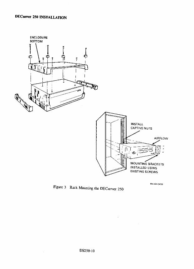
DECserver 250 INSTALLATION
ENCLOSURE BonOM
I .a
Figure 3 Rack Mounting the OECserver 250
OS250-10
INSTALL
MOUNTING BRACKETS INSTALLED USING EXISTING SCREWS
MKV89·0458
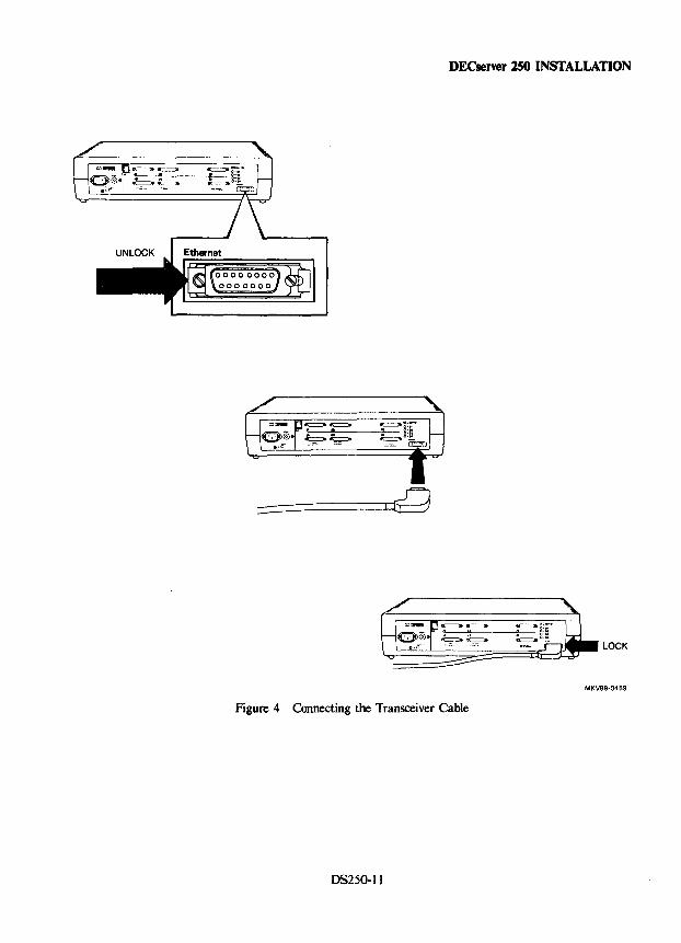
DECsener lSO INSTALLATION
=============:=Ij~
MKV89-0459
Figure 4 Connecting the Transceiver Cable
DS250-11
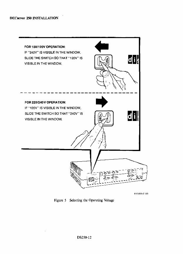
DECserver 250 INSTALLATION
FOR 1 OO/120V OPERATION:
IF "240V" IS VISIBLE IN THE WINDOW,
SLIDE THE SWITCH SO THAT "'120V" IS
VISIBLE IN THE WINDOW.
.. \1)
-O,b ~ -------------------------------
FOR 220/240V OPERATION:
IF "120V" IS VISIBLE IN THE WINDOW,
SLIDE THE SWITCH SO THAT "240V" IS
VISIBLE IN THE WINDOW.
..
Figure 5 Selecting the Operating Voltage
D8250-12
~DI
MKV89·0183
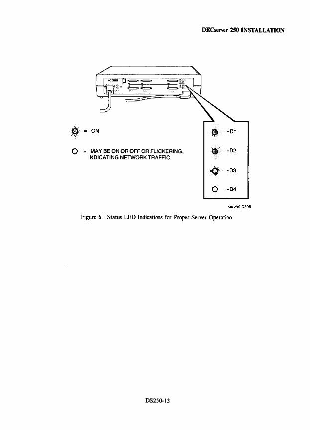
ON
o = MAY BE ON OR OFF OR FLICKERING, INOICATING NETWORK TRAFFIC.
DECserver 250 INSTALLATION
··,t",·,··· -01
.:,:;, .. -02
.,.",:j,"' .. -03
o -04
MKV89·0205
Figure 6 Status LED Indications for Proper Server Operation
DS250-13
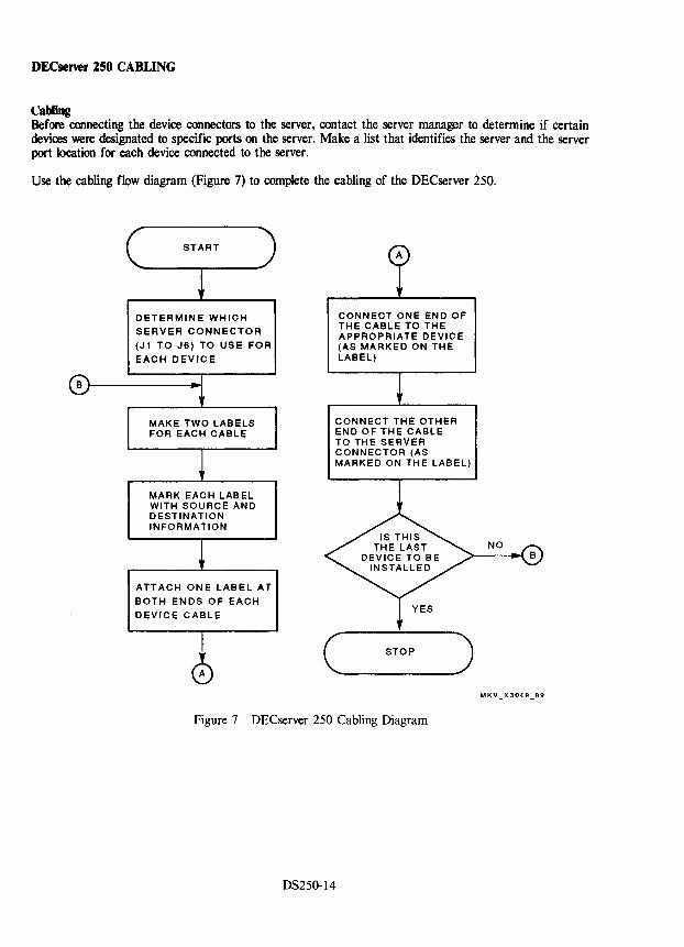
DECserver 250 CABLING
t:abling Before connecting the device connectors to the server, contact the server manager to determine if certain devices were designated to specific ports on the server. Make a list that identifies the server and the server port location for each device connected to the server.
Use the cabling flow diagram (Figure 7) to complete the cabling of the DECserver 250.
DETERMINE WHICH SERVER CONNECTOR
(J 1 TO J6) TO USE FOR
EACH DEVICE
B J-----------I~
MAKE TWO LABELS FOR EACH CABLE
MARK EACH LABEL WITH SOURCE AND DESTINATION INFORMATION
ATTACH ONE LABEL AT
BOTH ENDS OF EACH
DEVICE CABLE
CONNECT ONE END OF THE CABLE TO THE APPROPRIATE DEVICE (AS MARKED ON THE LABEL)
CONNECT THE OTHER END OF THE CABLE TO THE SERVER CONNECTOR (AS MARKED ON THE LABEL)
C __ STOP_)
Figure 7 DECserver 250 Cabling Diagram
DS250-14
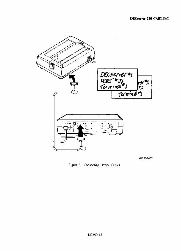
DECserver 150 CABLING
Dec7ervt/Jtt POR:1 ~ ~ ~:It.t 7e("mi~/·t J.
--(v",il1' .JIj
MKV89-0457
Figure 8 Connecting Device Cables
DS250-15
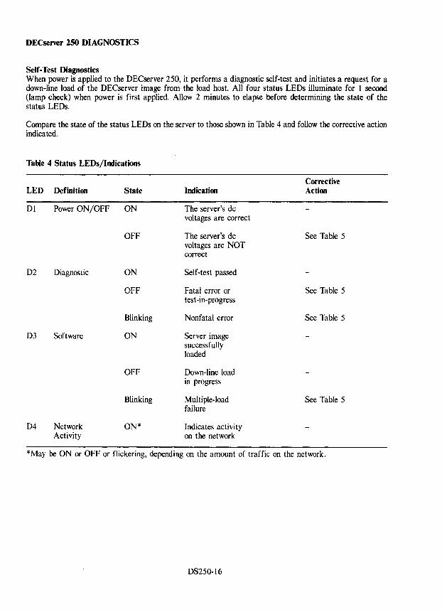
DECserver 250 DIAGNOSTICS
Self-Test Diagnostics When power is applied to the DECserver 250, it performs a diagnostic self-test and initiates a request for a down-line load of the DECserver image from the load host. All four status LEOs illuminate for 1 second (lamp check) when power is first applied. Allow 2 minutes to elapse before determining the state of the status LEOs.
Compare the state of the status LEDs on the server to those shown in Table 4 and follow the corrective action indicated.
Table 4 Status LEDs/Indications
Corrective LED Definition State Indication Action
01 Power ON/OFF ON The server's dc vol tages are correct
OFF The server's dc See Table 5 voltages are NOT correct
02 Diagnostic ON Self-test passed
OFF Fatal error or See Table 5 test -in-progress
Blinking Nonfatal error See Table 5
D3 Software ON Server image successfully loaded
OFF Down-line load in progress
Blinking Multiple-load See Table 5 failure
04 Network ON* Indicates activity Activity on the network
*May be ON or OFF or flickering, depending on the amount of traffic on the network.
DS250-16
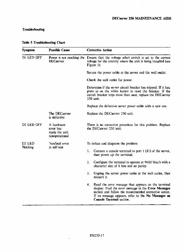
DECserver 250 MAINTENANCE AIDS
Troubleshooting
Table 5 Troubleshooting Chart
Symptom
DI LED OFF
D2 LED OFF
D2 LED Blinking
Possible Cause Corrective Action
Power is not reaching the Ensure that the voltage select switch is set to the correct DECserver voltage for the country where the unit is being installed (see
Figure 5).
The DECserver is defective
A hardware error has made the unit nonoperational
Nonfatal error in self-test
Secure the power cable at the server and the wall outlet.
Check the wall outlet for power.
Determine if the server circuit breaker has tripped. If it has, press in on the white button to reset the breaker. If the circuit breaker trips more than once, replace the DECserver 250 unit.
Replace the defective server power cable with a new one.
Replace the DECserver 250 unit.
There is no corrective procedure for this problem. Replace the DECserver 250 unit.
To isolate and diagnose the problem:
I. Connect a console terminal to port 1 (J I) of the server, then power up the terminal.
2. Configure the terminal to operate at 9600 bits/s with a character size of 8 bits and no parity.
3. Unplug the server power cable at the wall outlet, then reinsert it.
4. Read the error message that appears on the terminal display. Find the error message in the Error Messages section and follow the recommended corrective action. If no message appears, refer to the No Messages on Console Terminal section.
DS250-17
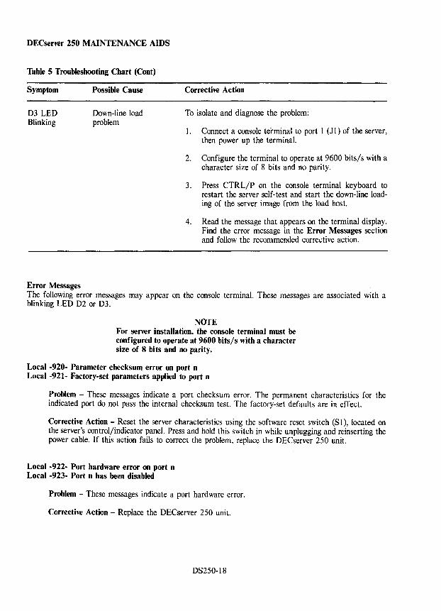
DECserver 250 MAINTENANCE AIDS
Table 5 Troubleshooting Chart (Cont)
Symptom
D3 LED Blinking
Error Messages
Possible Cause
Down-line load problem
Corrective Action
To isolate and diagnose the problem:
1. Connect a console terminal to port 1 (Jl) of the server, then power up the terminal.
2. Configure the terminal to operate at 9600 bits/s with a character size of 8 bits and no parity.
3. Press CTRL/P on the console terminal keyboard to restart the server self-test and start the down-line loading of the server image from the load host.
4. Read the message that appears on the terminal display. Find the error message in the Error Messages section and follow the recommended corrective action.
The following error messages may appear on the console terminal. These messages are associated with a blinking LED D2 or D3.
NOTE For server installation, the console terminal must be configured to operate at 9600 bits/s with a character size of 8 bits and no parity.
Local -920- Parameter checksum error on port n Local -921- Factory-set parameters applied to port n
Problem - These messages indicate a port checksum error. The permanent characteristics for the indicated port do not pass the internal checksum test. The factory-set defaults are in effect.
Corrective Action - Reset the server characteristics using the software reset switch (S I), located on the server's control/indicator panel. Press and hold this switch in while unplugging and reinserting the power cable. If this action fails to correct the problem, replace the DECserver 250 unit.
Local -922- Port hardware error on port n Local -923- Port n has been disabled
Problem - These messages indicate a port hardware error.
Corrective Action - Replace the DECserver 250 unit.
DS250-18
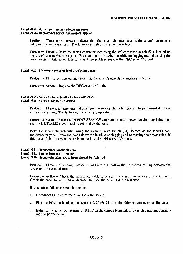
Local -930- Server parameters checksum error Local -931- Factory-set server parameters applied
DECserver 150 MAINTENANCE AIDS
Problem - These error messages indicate that the server characteristics in the server's permanent database are not operational. The factory-set defaults are now in effect.
Corrective Action - Reset the server characteristics using the software reset switch (81), located on the server's control/indicator panel. Press and hold this switch in while unplugging and reinserting the power cable. If this action fails to correct the problem, replace the DECserver 250 unit.
Local -932- Hardware revision level checksum error
Problem - This error message indicates that the server's nonvolatile memory is faulty.
Corrective Action - Replace the DECserver 250 unit.
Local -935- Service characteristics checksum error Local -936- Service has been disabled
Problem - These error messages indicate that the service characteristics in the permanent database are not operational. The factory-set defaults are operating.
Corrective Action - Enter the DEFINE SERVICE command to reset the service characteristics, then use the INITIALIZE command to reinitialize the server.
Reset the server characteristics using the software reset switch (S 1), located on the server's control/indicator panel. Press and hold this switch in while unplugging and reinserting the power cable. If this action fails to correct the problem, replace the DECserver 250 unit.
Local -941- Transceiver loopback error Local -942- Image load not attempted Local -950- Troubleshooting procedures should be followed
Problem - These error messages indicate that there is a fault in the transceiver cabling between the server and the coaxial cable.
Corrective Action - Check the transceiver cable to be sure the connection is secure at both ends. Check the cable for any sign of damage. Replace the cable if it is questioned.
If this action fails to correct the problem:
l. Disconnect the transceiver cable from the server.
2. Plug the Ethernet loopback connector (12-22196-01) into the Ethernet connector on the server.
3. Initialize the server by pressing CTRL/P on the console terminal, or by unplugging and reinserting the power cable.
D8250-19
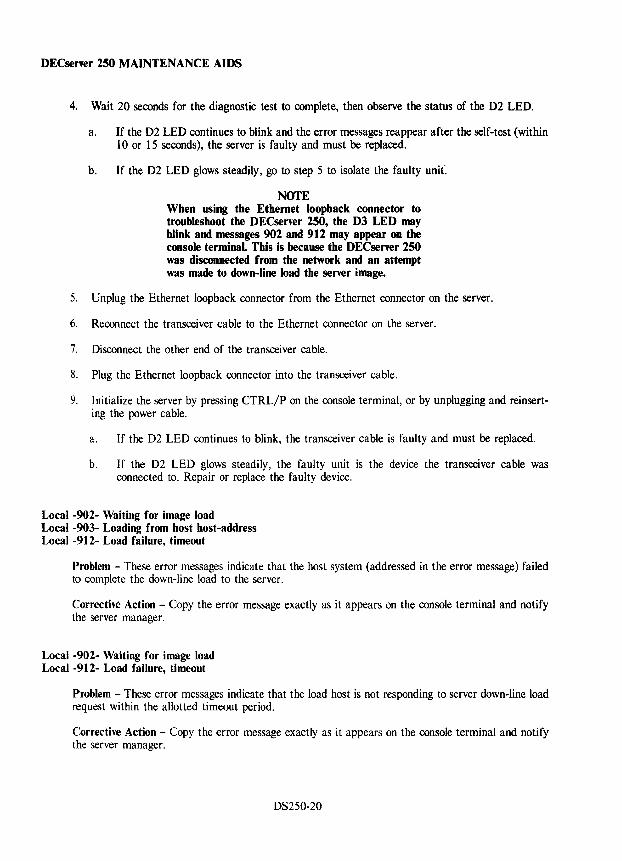
DECsener 250 MAINTENANCE AIDS
4. Wait 20 seconds for the diagnostic test to complete, then observe the status of the D2 LED.
a. If the D2 LED continues to blink and the error messages reappear after the self-test (within 10 or 15 seconds), the server is faulty and must be replaced.
b. If the D2 LED glows steadily, go to step 5 to isolate the faulty unit:
NOfE When using the Ethernet loopback connector to troubleshoot the DECserver 250, the D3 LED may blink and messages 902 and 912 may appear on the console terminal. This is because the DECserver 250 was disconnected from the network and an attempt was made to down-line load the server image.
5. Unplug the Ethernet loopback connector from the Ethernet connector on the server.
6. Reconnect the transceiver cable to the Ethernet connector on the server.
7. Disconnect the other end of the transceiver cable.
8. Plug the Ethernet loopback connector into the transceiver cable.
9. Initialize the server by pressing CTRLjP on the console terminal, or by unplugging and reinserting the power cable.
a. If the D2 LED continues to blink, the transceiver cable is faulty and must be replaced.
b. If the D2 LED glows steadily, the faulty unit is the device the transceiver cable was connected to. Repair or replace the faulty device.
Local -902- Waiting for image load Local -903- Loading from host host-address Local -912- Load failure, timeout
Problem - These error messages indicate that the host system (addressed in the error message) failed to complete the down-line load to the server.
Corrective Action - Copy the error message exactly as it appears on the console terminal and notify the server manager.
Local -902- Waiting for image load Local -912- Load failure, timeout
Problem - These error messages indicate that the load host is not responding to server down-line load request within the allotted timeout period.
Corrective Action - Copy the error message exactly as it appears on the console terminal and notify the server manager.
DS250-20
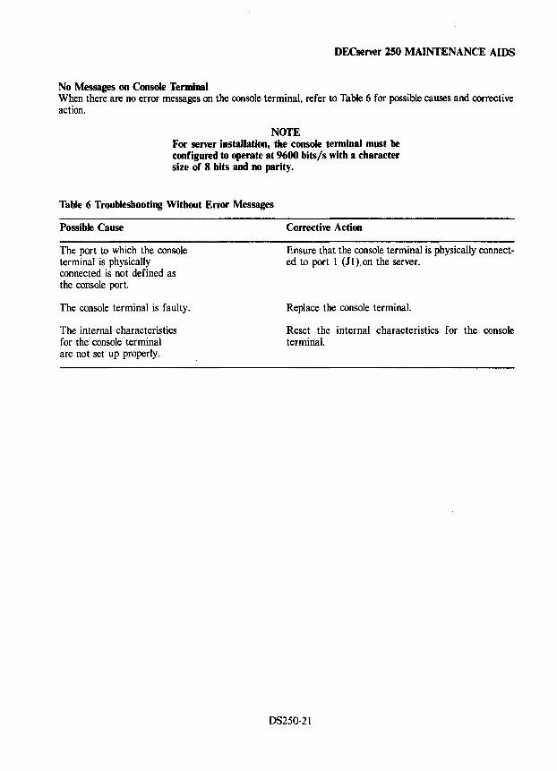
DECserver 250 MAINTENANCE AIDS
No Messages on Console Terminal When there are no error messages on the console terminal, refer to Table 6 for possible causes and corrective action.
NOTE For server installation, the console terminal must be configured to operate at 9600 bits/s with a character size of 8 bits and no parity.
Table 6 Troubleshooting Without Error Messages
Possible Cause
The port to which the console terminal is physically connected is not defined as the console port.
The console terminal is faulty.
The internal characteristics for the console terminal are not set up properly.
Corrective Action
Ensure that the console terminal is physically connected to port I (J1).on the server.
Replace the console terminal.
Reset the internal characteristics for the console terminal.
DS250-21

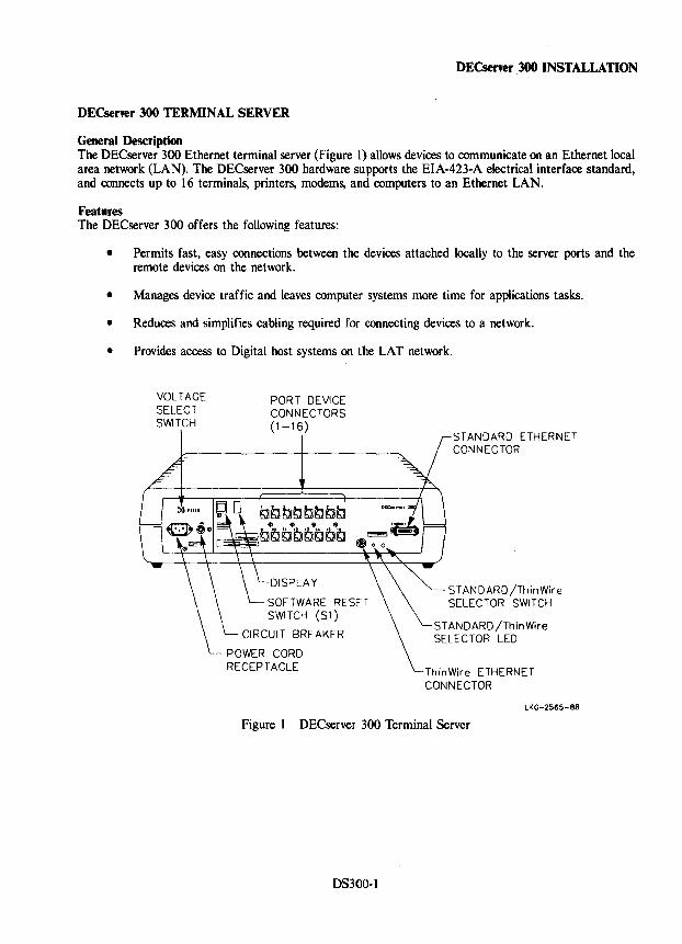
DECserver 300 INSTALLATION
DECserver 300 TERMINAL SERVER
General Description The DECserver 300 Ethernet terminal server (Figure 1) allows devices to communicate on an Ethernet local area network (LAN). The DECserver 300 hardware supports the EIA-423-A electrical interface standard, and connects up to 16 terminals, printers, modems, and computers to an Ethernet LAN.
Features The DECserver 300 offers the following features:
• Permits fast, easy connections between the devices attached locally to the server ports and the remote devices on the network.
• Manages device traffic and leaves computer systems more time for applications tasks.
• Reduces and simplifies cabling required for connecting devices to a network.
• Provides access to Digital host systems on the LAT network.
VOLTAGE SELECT SWITCH
PORT DEVICE CONNECTORS (1-16)
DISPLAY
SOFTWARE RESET SWITCH (S1)
CIRCUIT BREAKER
POWER CORD RECEPTACLE
STANDARD ETHERNET CONNECTOR
STANDARD/ThinWire SELECTOR SWITCH
ST ANDARD jThinWire SELECTOR LED
ThinWire ETHERNET CONNECTOR
LKC-2S65-88
Figure 1 DECserver 300 Terminal Server
DS300-1
DECserver 300 INSTALLATION
DECserver 300 Configuration Rules There are many different ways to configure the OECserver 300 as long as the transceiver cables, the device cables, and the server power cable do not exceed the maximum length as described in Table 1, and that the following constraints are observed.
1. Maximum length for the transceiver cable cannot exceed 50 m (164 ft). This maximum length may be reduced due to the internal cabling equivalence of a device (such as a OELNI) that is connected between the server and the transceiver, or due to the use of office transceiver cable.
a. Cabling equivalence is a measure of the internal timing delay of a device, expressed .in meters of transceiver cable. This cabling equivalence must be subtracted from the 50-meter maximum. For example, if a device has a 5-meter cable equivalence, then its maximum allowable transceiver cable length is (50 m - 5 m) or 45 meters.
b. Office transceiver cable (BNE4x-xx), due to its smaller diameter, has a signal loss that is four times that of the BNE3x-xx transceiver cable. Therefore, if office transceiver cable is used, the maximum transceiver cable distance must be divided by 4. This means the maximum office transceiver cable length allowed is 12.5 meters.
If the configuration includes a device, and the device has any internal cabling equivalence, this should be subtracted from the 50-meter maximum before dividing by 4. For example, if a device has a 10-meter cabling equivalence and is attached to its transceiver using office cable, then the maximum allowable transceiver length is (50 m - 10 m)/4 or 10 meters.
2. When connecting the server to a configuration that includes a DELNI, allow a 5-meter cabling equivalence loss for the OELNI.
OS300-2
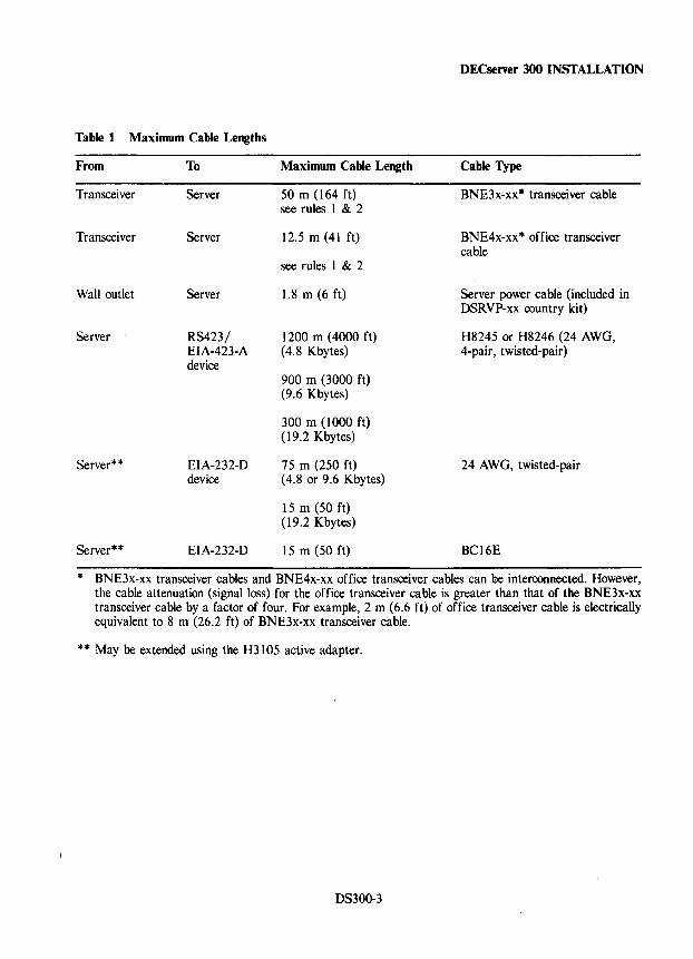
Table 1 Maximum Cable Lengths
From To
Transceiver Server
Transceiver Server
Wall outlet Server
Server RS423/ EIA-423-A device
Server * * EIA-232-D device
Server * * EIA-232-D
Maximum Cable Length
50 m (164 ft) see rules 1 & 2
12.5 m (41 ft)
see rules 1 & 2
1.8 m (6 ft)
1200 m (4000 ft) (4.8 Kbytes)
900 m (3000 ft) (9.6 Kbytes)
300 m (1000 ft) (19.2 Kbytes)
75 m (250 ft) (4.8 or 9.6 Kbytes)
15 m (50 ft) (19.2 Kbytes)
15 m (50 ft)
DECserver 300 INSTALLATION
Cable Type
BNE3x-xx· transceiver cable
BNE4x-xx* office transceiver cable
Server power cable (included in DSRVP-xx country kit)
H8245 or H8246 (24 AWG, 4-pair, twisted-pair)
24 AWG, twisted-pair
BC16E
* BNE3x-xx transceiver cables and BNE4x-xx office transceiver cables can be interconnected. However, the cable attenuation (signal loss) for the office transceiver cable is greater than that of the BNE3x-xx transceiver cable by a factor of four. For example, 2 m (6.6 ft) of office transceiver cable is electrically equivalent to 8 m (26.2 ft) of BNE3x-xx transceiver cable.
** May be extended using the H3105 active adapter.
DS300-3
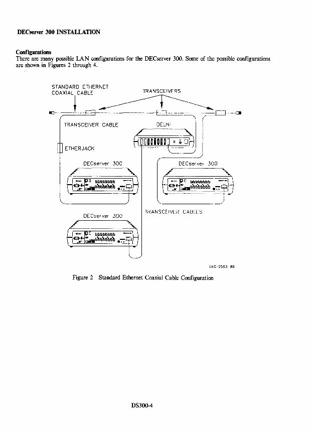
DECserver 300 INSTALLATION
Configurations There are many possible LAN configurations for the DECserver 300. Some of the possible configurations are shown in Figures 2 through 4.
STANDARD ETHERNET
COAXIAL~ CABLE ____
TRANSCEIVER CABLE
ETHERJACK
DEC server 300
DECserver 300
TRANSCEIVERS
TRANSCEIVER CABLES
LKG-259"-B9
Figure 2 Standard Ethernet Coaxial Cable Configuration
DS300-4
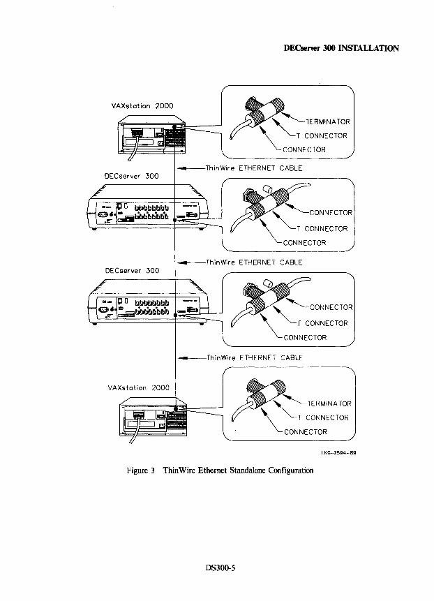
DECserver 300
VAXstation 2000
DECserver 300 INSTALLATION
~~TERMINATOR ~~T CONNECTOR
\..-CONNECTOR
ETHERNET CABLE
~ ~CONNECTOR " ~T CONNECTOR
\..-CONNECTOR
____ ThinWire ETHERNET CABLE
~ CONNECTOR
" ~T CONNECTOR
\..- CONNECTOR
____ ThinWire ETHERNET CABLE
~ ~TERMINATOR " ~T CONNECTOR
~CONNECTOR lKG-25Q4-SQ
Figure 3 ThinWire Ethernet Standalone Configuration
DS300-5
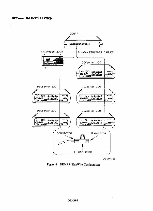
DECserver 300 INSTALLATION
DEMPR
VAXstotion 2000 ThinWire ETHERNET CABLES
DECserver 300
DECserver 300
CONN~ ~ TERMINATOR
~ G ~/ t
T CONNECTOR
LKG-2595-89
Figure 4 DEMPR ThinWire Configuration
DS300-6
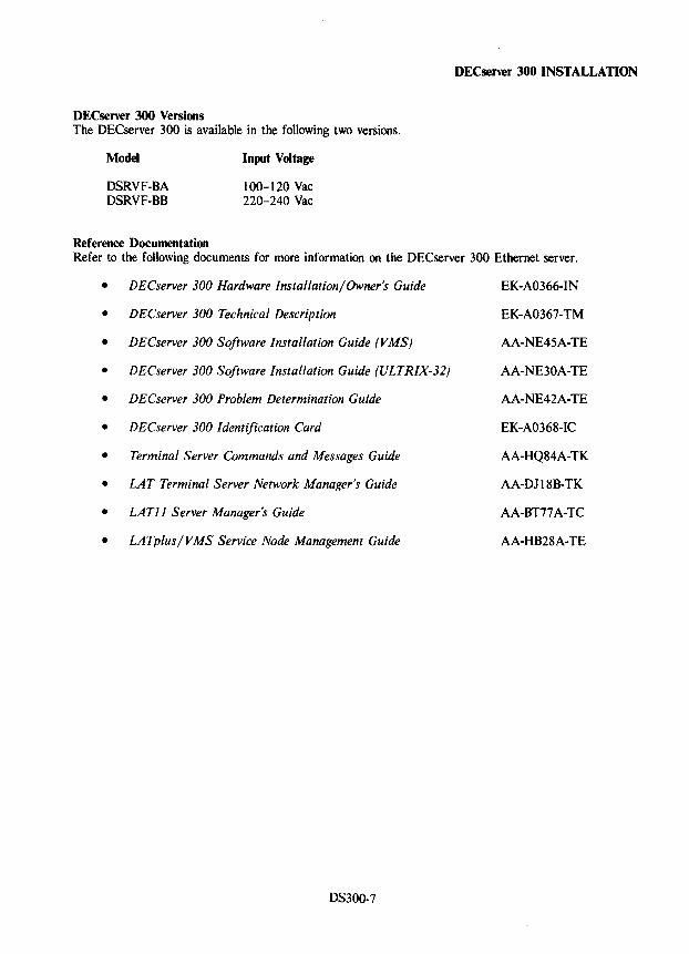
DECserver 300 Versions The OECserver 300 is available in the following two versions.
Model
DSRVF-BA OSRVF-BB
Reference Documentation
Input Voltage
100-120 Vac 220-240 Vac
DECserver 300 INSTALLATION
Refer to the following documents for more information on the OECserver 300 Ethernet server.
• DECserver 300 Hardware Installation/Owner's Guide EK-A0366-IN
• DECserver 300 Technical Description EK-A0367-TM
• DECserver 300 Software Installation Guide (VMS) AA-NE45A-TE
• DECserver 300 Software Installation Guide (ULTRIX-32) AA-NE30A-TE
• DECserver 300 Problem Determination Guide AA-NE42A-TE
• DECserver 300 Identification Card EK-A0368-IC
• Terminal Server Commands and Messages Guide AA-HQ84A-TK
• LAT Terminal Server Network Manager's Guide AA-DJI8B-TK
• LAT]] Server Manager's Guide AA-BT77 A-TC
• LATpius/VMS Service Node Management Guide AA-HB28A-TE
OS300-7
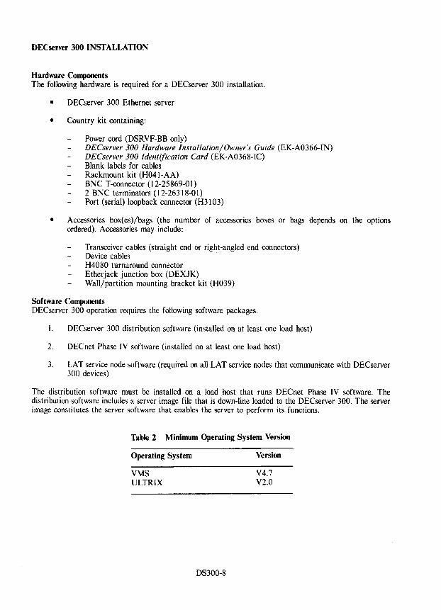
DECserver 300 INSTALLATION
Hardware Components The following hardware is required for a DECserver 300 installation.
• DECserver 300 Ethernet server
• Country kit containing:
Power cord (DSRVF-BB only) DECserver 300 Hardware Installation/Owner's Guide (EK-A0366-IN) DECserver 300 Identification Card (EK-A0368-IC) Blank labels for cables Rackmount kit (H041-AA) BNC T-connector (12-25869-01) 2 BNC terminators (12-26318-01) Port (serial) loopback connector (H3103)
• Accessories box(es)/bags (the number of accessories boxes or bags depends on the options ordered). Accessories may include:
Transceiver cables (straight end or right-angled end connectors) Device cables H4080 turnaround connector Etherjack junction box (DEXJK) Wall/partition mounting bracket kit (H039)
Software Components DECserver 300 operation requires the following software packages.
1. DECserver 300 distribution software (installed on at least one load host)
2. DECnet Phase IV software (installed on at least one load host)
3. LAT service node software (required on all LAT service nodes that communicate with DECserver 300 devices)
The distribution software must be installed on a load host that runs DECnet Phase IV software. The distribution software includes a server image file that is down-line loaded to the DECserver 300. The server image constitutes the server software that enables the server to perform its functions.
Table 2 Minimum Operating System Version
Operating System
VMS ULTRIX
OS300-8
Version
V4.7 V2.0
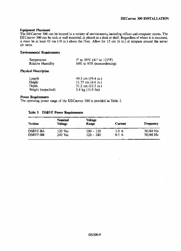
DECserver 300 INSTALLATION
Equipment Placement The DECserver 300 can be located in a variety of environments, including offices and computer rooms. The DECserver 300 can be rack or wall mounted, or placed on a desk or shelf. Regardless of where it is mounted, it must be at least 45 cm (18 in.) above the floor. Allow for 15 cm (6 in.) of airspace around the server air vents.
Environmental Requirements
Temperature Relative Humidity
Physical Description
Length Height Depth Weight (unpacked)
Power Requirements
5° to 50°C (41 ° to 122°F) 10% to 95% (noncondensing)
49.3 cm (19.4 in.) 11.75 cm (4.6 in.) 31.2 cm (12.3 in.) 5.4 kg (11.9 lbs)
The operating power range of the DEC server 300 is provided in Table 3.
Table 3 DSRVF Power Requirements
Nominal Voltage Version Voltage Range Current
DSRVF-BA 120 Vac 100 - l20 1.0 A DSRVF-BB 240 Vac 220 - 240 0.5 A
DS300-9
Frequency
50/60 Hz 50/60 Hz
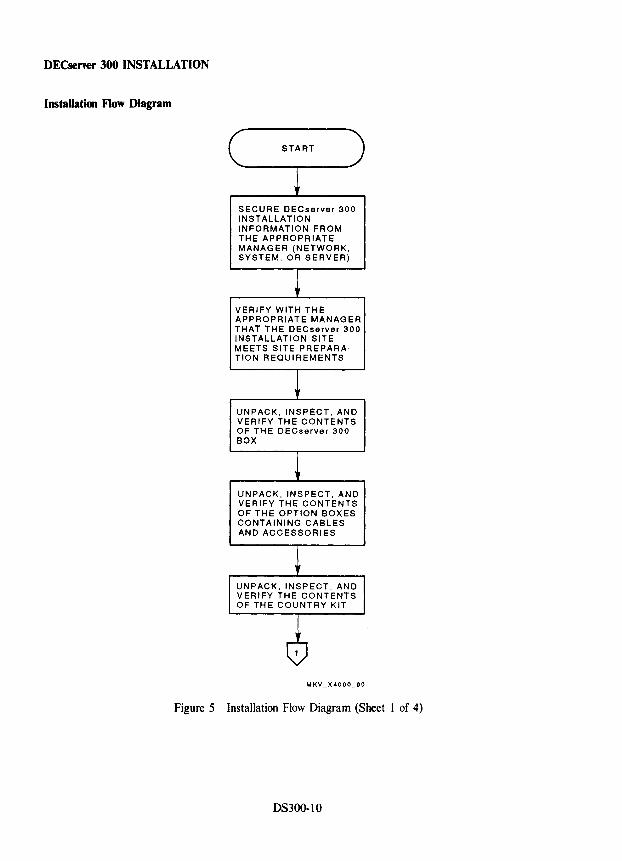
DECserver 300 INSTALLATION
Installation Flow Diagram
SECURE DECserver 300 INSTALLATION INFORMATION FROM THE APPROPR lATE MANAGER (NETWORK, SYSTEM, OR SERVER)
VERIFY WITH THE APPROPRIATE MANAGER THAT THE DECserver 300 INSTALLATION SITE MEETS SITE PREPARATION REQUIREMENTS
UNPACK, INSPECT, AND VERIFY THE CONTENTS OF THE DECserver 300 BOX
UNPACK, INSPECT, AND VERIFY THE CONTENTS OF THE OPTION BOXES CONTAINING CABLES AND ACCESSORIES
UNPACK, INSPECT, AND VERIFY THE CONTENTS OF THE COUNTRY KIT
Figure 5 Installation Flow Diagram (Sheet 1 of 4)
DS300-1O
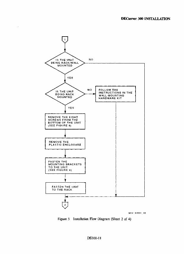
REMOVE THE EIGHT SCREWS FROM THE BOTTOM OF THE UNIT (SEE FIGURE 6)
FASTEN THE MOUNTING BRACKETS TO THE UNIT (SEE FIGURE 6)
FASTEN THE UNIT TO THE RACK
DECserver 300 INSTALLATION
NO
NO FOLLOW THE INSTRUCTIONS IN THE WALL-MOUNTING HARDWARE KIT
MKV X4001 90
Figure 5 Installation Flow Diagram (Sheet 2 of 4)
DS300-11
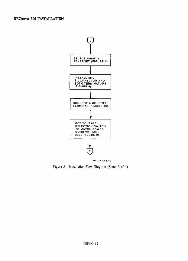
DECserver 300 INSTALLATION
SELECT ThinWire ETHERNET (FIGURE 7)
INSTALL BNC T-CONNECTOR AND BOTH TERMINATORS (FIGURE 8)
CONNECT A CONSOLE TERMINAL (FIGURE 15)
SET VOLTAGE SELECTION SWITCH TO MATCH POWER CORD VOLTAGE (SEE FIGURE 9)
Figure 5 Installation Flow Diagram (Sheet 3 of 4)
DS300-12
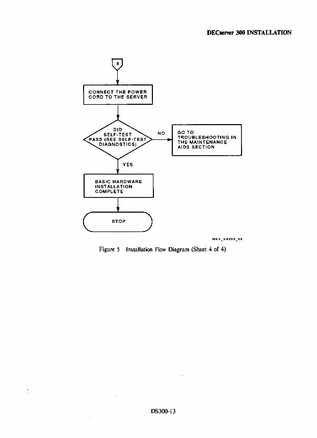
CONNECT THE POWER CORD TO THE SERVER
BASIC HARDWARE INSTALLATION COMPLETE
DECsener 300 INSTALLATION
NO GO TO TROUBLESHOOTING IN THE MAINTENANCE AIDS SECTION
Figure 5 Installation Flow Diagram (Sheet 4 of 4)
DS300-13
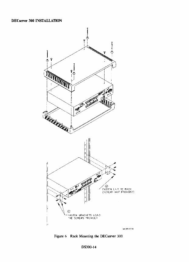
DECserver 300 INSTALLATION
, r? I I I
",,' ;, \,~
'"
, ¢
I I I
"'::::m:; / Jdj.~
:~'! L'~TEN UNIT TO RACK
(SCREWS NOT PROVIDED)
'-CD FASTEN BRACKETS USING THE SCREWS PROVIDED
MKV89·0338
Figure 6 Rack Mounting the DECserver 300
DS300-14
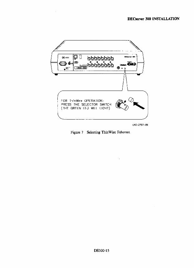
DECserver 300 INSTALLATION
FOR ThinWire OPERATION: ~CO, PRESS THE SELECTOR SWITCH (THE GREEN LEO WILL LIGHT)
LKC-2757-89
Figure 7 Selecting Thin Wire Ethernet
DS300-15
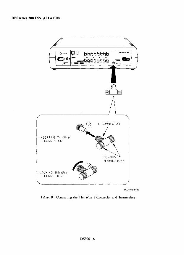
DECserver 300 INSTALLATION
INSERTING ThinWire T-CONNECTOR
LOCKING ThinWire T -CONNECTOR
~ CO T-CONNECTOR
'~ ~ ~
TERMINA TORS
LKG-2758-89
Figure 8 Connecting the Thin Wire T-Connector and Terminators
DS300-16
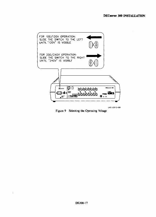
FOR 100!120V OPERATION: SLIDE THE SWITCH TO THE LEFT UNTIL "120V" IS VISIBLE
FOR 200!240V OPERATION: SLIDE THE SWITCH TO THE RIGHT UNTIL "240V" IS VISIBLE
DECsener 300 INSTALLATION
LKG-2573-89
Figure 9 Selecting the Operating Voltage
DS300-17
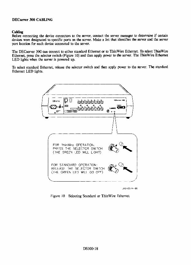
DECserver 300 CABLING
Cabling Before connecting the device connectors to the server, contact the server manager to determine if certain devices were designated to specific ports on the server. Make a list that identifies the server and the server port location for each device connected to the server.
The DECserver 300 can connect to either standard Ethernet or to ThinWire Ethernet. To select ThinWire Ethernet, press the selector switch (Figure 10) and then apply power to the server. The ThinWire Ethernet LED lights when the server is powered up.
To select standard Ethernet, release the selector switch and then apply power to the server. The standard Ethernet LED lights.
FOR ThinWire OPERA TION: ~CO .... PRESS THE SELECTOR S~TCH . ~ (THE GREEN LED WILL LIGHT)
FOR STANDARD OPERATION: ~r>.. o "-0, RELEASE THE SELECTOR SWITCH (THE GREEN LED WILL GO OFF)
LKG-2574-89
Figure 10 Selecting Standard or ThinWire Ethernet
DS300-18
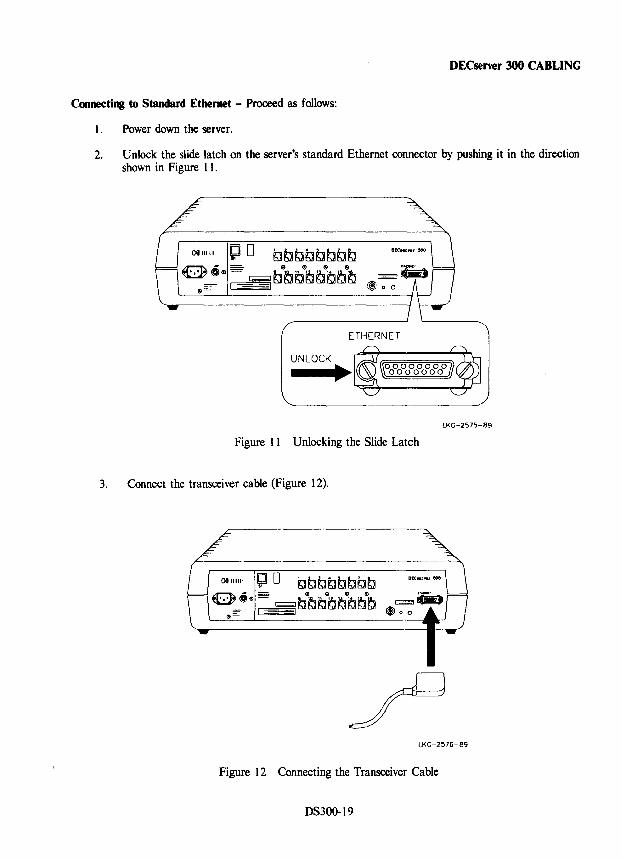
DECserver 300 CABLING
Connecting to Standard Ethernet - Proceed as follows:
1. Power down the server.
2. Unlock the slide latch on the server's standard Ethernet connector by pushing it in the direction shown in Figure 11.
LKG-2575-89
Figure 11 Unlocking the Slide Latch
3. Connect the transceiver cable (Figure 12).
LKG-2576-89
Figure 12 Connecting the Transceiver Cable
DS300-19
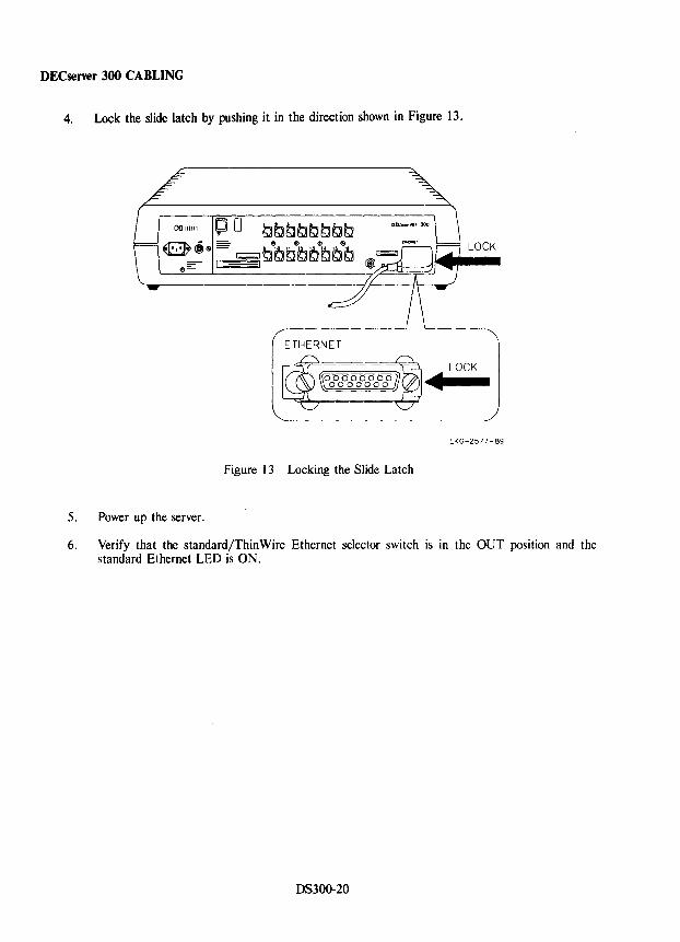
DECserver 300 CABLING
4. Lock the slide latch by pushing it in the direction shown in Figure 13.
LOCK
ETHERNET
LOCK
-LKG-2577-89
Figure 13 Locking the Slide Latch
5. Power up the server.
6. Verify that the standard/Thin Wire Ethernet selector switch is in the OUT position and the standard Ethernet LED is ON.
DS300-20
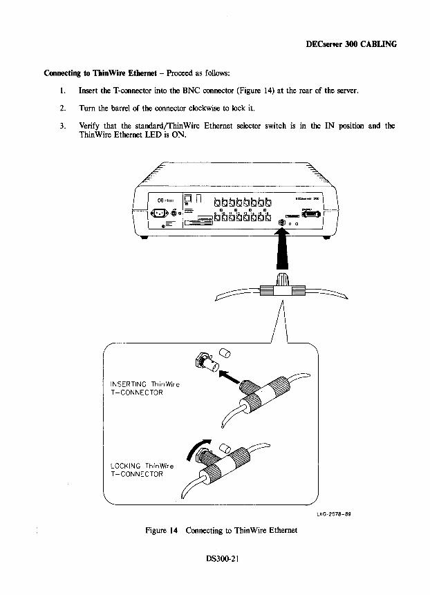
DECser\'er 300 CABLING
Connecting to ThinWire Ethernet - Proceed as follows:
1. Insert the T-connector into the BNC connector (Figure 14) at the rear of the server.
2. Turn the barrel of the connector clockwise to lock it.
3. Verify that the standard/ThinWire Ethernet selector switch is in the IN position and the ThinWire Ethernet LED is ON.
INSERTING ThinWire T -CONNECTOR
LOCKING ThinWire T -CONNECTOR
Figure 14 Connecting to ThinWire Ethernet
DS300-21
LKG-2578-89
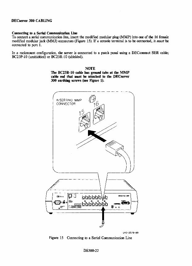
DECserver 300 CABLING
Connecting to a Serial Communication Line To connect a serial communication line, insert the modified modular plug (MMP) into one of the 16 female modified modular jack (MMJ) connectors (Figure 15). If a console terminal is to be connected, it must be connected to port 1.
In a rackmount configuration, the server is connected to a patch panel using a OECconnect SER cable; BC23P-1O (unshielded) or BC23R-1O (shielded).
NOTE The BC23R-IO cable has ground tabs at the MMP cable end that must be attached to the DECserver 300 earthing screws (see Figure I).
INSERTING MMP CONNECTOR
)) LKG-2579-89
Figure 15 Connecting to a Serial Communication Line
OS300-22
DECserver 300 DIAGNOSTICS
setf-Test Diagnostics When power is applied to the DECserver 300, it performs a diagnostic self-test and initiates a request for a down-line load of the DECserver image from the load host.
NOfE For self-test to successfully complete, the DECsener 300 must be connected to one of the following:
• An operational Ethernet segment
• ThinWire Ethernet port selected and fitted with BNC T -connector and two terminators (supplied with country kit)
• Standard Ethernet port selected and fitted with optional Ethernet loopback connector (12-22196-02)
Before power is applied to the DECserver 300, perform the following steps:
1. Connect a console terminal to port number 1.
2. Configure the terminal for 9600 bits/So 8-bit character size, and no parity.
3. Remove and reinsert the server ac power plug.
4. Observe the seven-segment display (Figure 16).
When the server power cord is plugged in, the seven-segment display shows an "8", and the Diagnostic Dot is on for approximately 0.5 seconds as a DISPLAY CHECK. The display then counts down from F to 5 as the self-test diagnostics are run. If the self-test diagnostics are successful, the server attempts a down-line load of software from the host. If the server is not connected to an Ethernet segment at this time, the display alternates between "4" and "3" and the Diagnostic Dot remains ON (see Table 4).
NOfE An alternating 4-3 display without an Ethernet connected, indicates successful completion of self-test.
If a fatal error is detected, the count stops and the code of the test that failed flashes. If a nonfatal error is detected, the count continues and the Diagnostic Dot blinks. See Troubleshooting in the MAINTENANCE AIDS section for more information.
NOfE There is one exception to this sequence. If the sener fails the Ethernet subsystem external loopback test, the display stops at "9" and the Diagnostic Dot blinks. The "9" on the display does not blink.
OS300-23
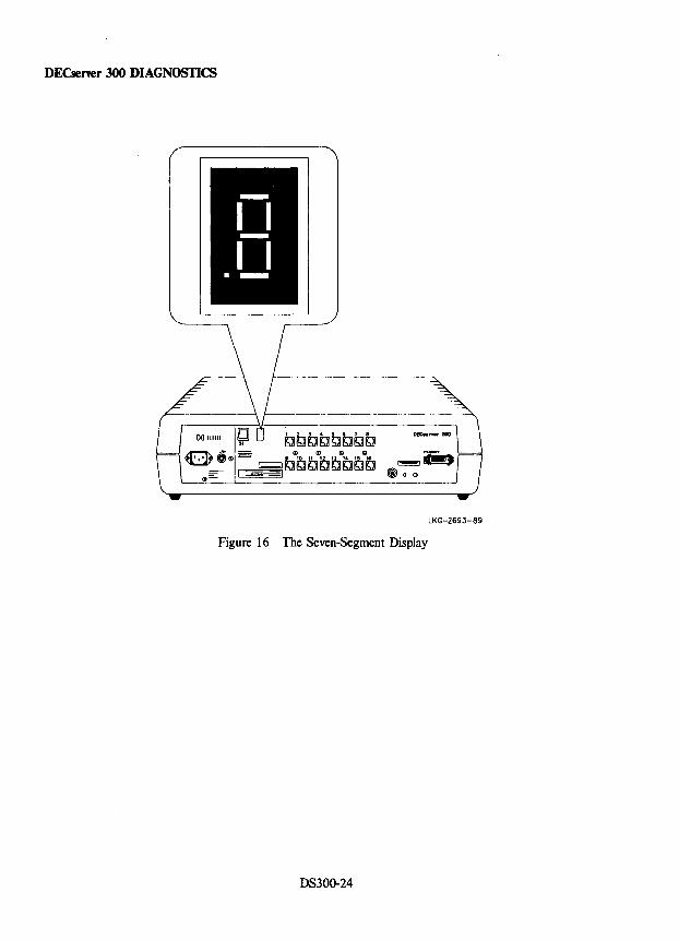
DECsener 300 DIAGNOSTICS
LKG-269J-89
Figure 16 The Seven-Segment Display
DS300-24
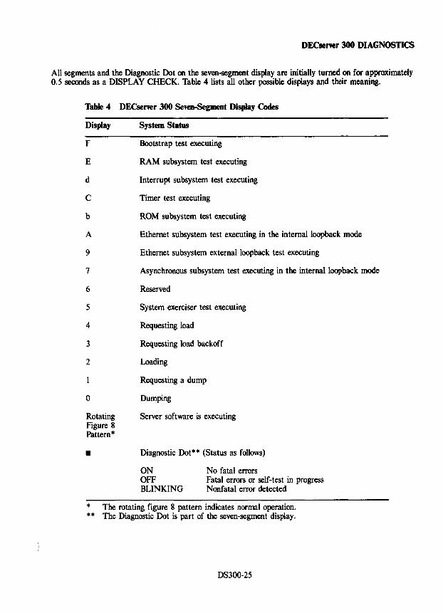
DECserver 300 DIAGNOSTICS
All segments and the Diagnostic Dot on the seven~segment display are initially turned on for approximately 0.5 seconds as a DISPLAY CHECK. Table 4 lists all other possible displays and their meaning.
Table 4 DECserver 300 Seven-Segment Display Codes
Display
F
E
d
C
b
A
9
7
6
5
4
3
2
o
Rotating Figure 8 Pattern·
•
System Status
Bootstrap test executing
RAM subsystem test executing
Interrupt subsystem test executing
Timer test executing
ROM subsystem test executing
Ethernet subsystem test executing in the internalloopback mode
Ethernet subsystem externalloopback test executing
Asynchronous subsystem test executing in the internal loopback mode
Reserved
System exerciser test executing
Requesting load
Requesting load backoff
Loading
Requesting a dump
Dumping
Server software is executing
Diagnostic Dot** (Status as follows)
ON OFF BLINKING
No fatal errors Fatal errors or self-test in progress Nonfatal error detected
• The rotating figure 8 pattern indicates normal operation . ** The Diagnostic Dot is part of the seven-segment display.
DS300-25
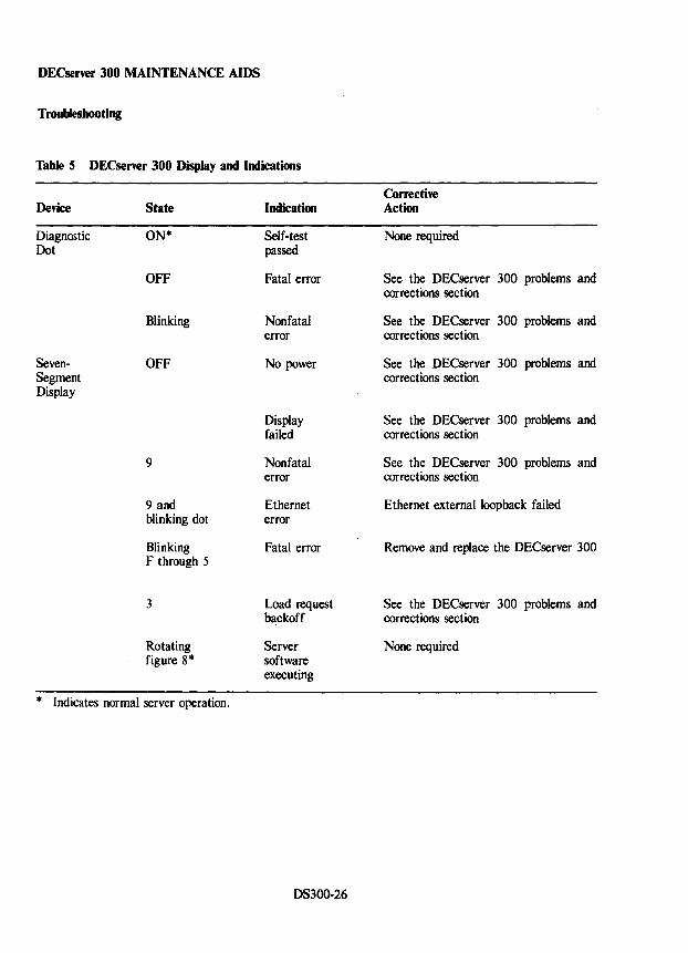
DECsener 300 MAINTENANCE AIDS
Troubleshooting
Table 5 DECserver 300 Display and Indications
Device
Diagnostic Dot
SevenSegment Display
State
ON*
OFF
Blinking
OFF
9
9 and blinking dot
Blinking F through 5
3
Rotating figure 8*
* Indicates normal server operation.
Indication
Self-test passed
Fatal error
Nonfatal error
No power
Display failed
Nonfatal error
Ethernet error
Fatal error
Load request b~ckoff
Server software executing
DS300-26
Corrective Action
None required
See the DECserver 300 problems and corrections section
See the DECserver 300 problems and corrections section
See the DECserver 300 problems and corrections section
See the DECserver 300 problems and corrections section
See the DECserver 300 problems and corrections section
Ethernet externalloopback failed
Remove and replace the DECserver 300
See the DECserver 300 problems and corrections section
None required
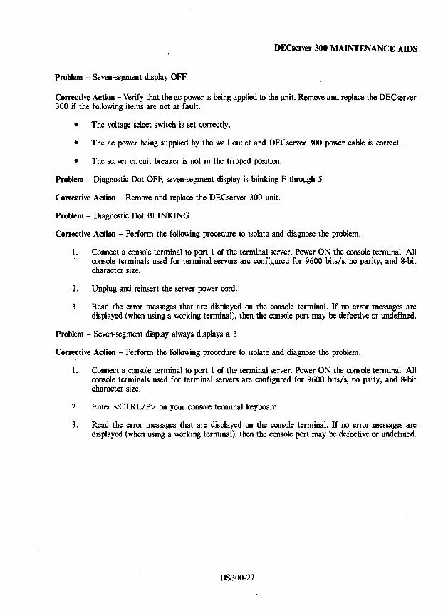
DECserver 300 MAINTENANCE AIDS
Problem - Seven-segment display OFF
Corrective Actioo - Verify that the ac power is being applied to the unit. Remove and replace the DECserver 300 if the following items are not at fault.
• The voltage select switch is set correctly.
• The ac power being supplied by the wall outlet and DECserver 300 power cable is correct.
• The server circuit breaker is not in the tripped position.
Problem - Diagnostic Dot OFF, seven-segment display is blinking F through 5
Corrective Action - Remove and replace the DECserver 300 unit.
Problem - Diagnostic Dot BLINKING
Corrective Action - Perform the following procedure to isolate and diagnose the problem.
1. Connect a console terminal to port 1 of the terminal server. Power ON the console terminal. All console terminals used for terminal servers are configured for 9600 bits/s, no parity, and 8-bit character size.
2. Unplug and reinsert the server power cord.
3. Read the error messages that are displayed on the console terminal. If no error messages are displayed (when using a working terminal), then the console port may be defective or undefined.
Problem - Seven-segment display always displays a 3
Corrective Actioo - Perform the following procedure to isolate and diagnose the problem.
1. Connect a console terminal to port 1 of the terminal server. Power ON the console terminal. All console terminals used for terminal servers are configured for 9600 bits/s, no paity, and 8·bit character size.
2. Enter <CTRL/P> on your console terminal keyboard.
3. Read the error messages that are displayed on the console terminal. If no error messages are displayed (when using a working terminal), then the console port may be defective or undefined.
DS300-27
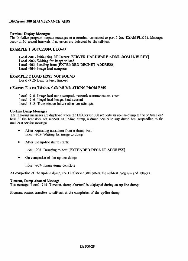
DECserver 300 MAINTENANCE AIDS
Terminal Display Messages The Initialize program outputs messages to a terminal connected to port 1 (see EXAMPLE 1). Messages occur at 30 second intervals if no errors are detected by the self-test.
EXAMPLE 1 SUCCESSFUL LOAD
Local -901- Initializing DECserver [SERVER HARDWARE ADDR.-ROM-H/W REV] Local -902- Waiting for image to load Local -903- Loading from [EXTENDED DECNET ADDRESS] Local -904- Image load complete
EXAMPLE 2 LOAD HOST NOT FOUND Local -912- Load failure, timeout
EXAMPLE 3 NETWORK COMMUNICATIONS PROBLEMS
Local -910- Image load not attempted, network communication error Local -916- Illegal load image, load aborted Local -915- Transmission failure after ten attempts
Up-Line Dump Messages The following messages are displayed when the DECserver 300 requests an up-line dump to the original load host. If the host does not support an up-line dump, a dump occurs to any dump host responding to the multicast service message.
• After requesting assistance from a dump host: Local -905- Waiting for image to dump
• After the up-line dump starts:
Local -906- Dumping to host [EXTENDED DECNET ADDRESS]
• On completion of the up-line dump:
Local -907- Image dump complete
At completion of the up-line dump, the DEC server 300 enters the self-test program and reboots.
Timeout, Dump Aborted Message The message "Local -914- Timeout, dump aborted" is displayed during an up-line dump.
Program control transfers to self-test at the completion of the up-line dump.
DS300-28
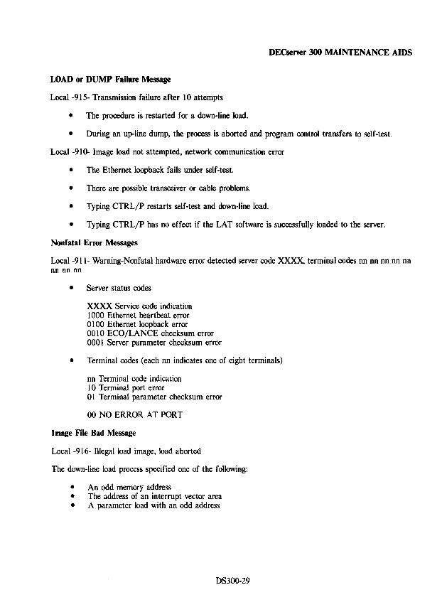
DECsener 300 MAINTENANCE AIDS
LOAD or DUMP Failure Message
Local -915- Transmission failure after 10 attempts
• The procedure is restarted for a down-line load.
• During an up-line dump, the process is aborted and program control transfers to self-test.
Local -910- Image load not attempted, network communication error
• The Ethernet loopback fails under self-test.
• There are possible transceiver or cable problems.
• Typing CTRL/P restarts self-test and down-line load.
• Typing CTRL/P has no effect if the LAT software is successfully loaded to the server.
Nonfatal Error Messages
Local-911- Warning-Nonfatal hardware error detected server code XXXx, terminal codes nn nn nn nn nn nn nn nn
• Server status codes
XXXX Service code indication 1000 Ethernet heartbeat error 01 00 Ethernet loopback error 0010 ECO/LANCE checksum error 0001 Server parameter checksum error
• Terminal codes (each nn indicates one of eight terminals)
nn Terminal code indication 10 Terminal port error 01 Terminal parameter checksum error
00 NO ERROR AT PORT
Image File Bad Message
Local -916- Illegal load image, load aborted
The down-line load process specified one of the following:
• An odd memory address • The address of an interrupt vector area • A parameter load with an odd address
DS300-29
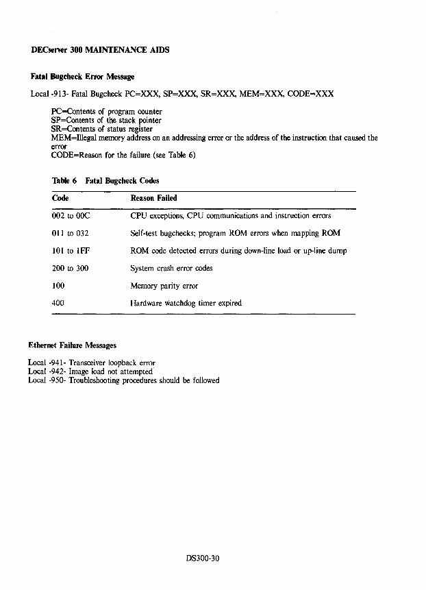
DECserver 300 MAINTENANCE AIDS
Fatal Bugcheck Error Message
Local -913- Fatal Bugcheck PC=XXx, SP=XXx, SR=XXX, MEM=XXX, CODE=XXX
PC=Contents of program counter SP=Contents of the stack pointer SR=Contents of status register MEM=Illegal memory address on an addressing error or the address of the instruction that caused the error CODE=Reason for the failure (see Table 6)
Table 6 Fatal Bugcheck Codes
Code
002 to OOC
011 to 032
101 to IFF
200 to 300
100
400
Ethernet Failure Messages
Reason Failed
CPU exceptions, CPU communications and instruction errors
Self-test bugchecks; program ROM errors when mapping ROM
ROM code detected errors during down-line load or up-line dump
System crash error codes
Memory parity error
Hardware watchdog timer expired
Local -941- Transceiver loopback error Local -942- Image load not attempted Local -950- Troubleshooting procedures should be followed
DS300-30
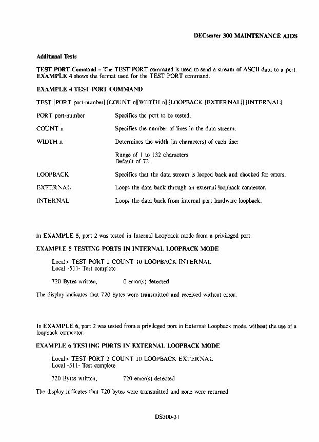
DECserver 300 MAINTENANCE AIDS
Additional Tests
TEST PORT Command - The TEST'· PORT command is used to send a stream of ASCII data to a port. EXAMPLE 4 shows the format used for the TEST PORT command.
EXAMPLE 4 TEST PORT COMMAND
TEST [PORT port-number] [COUNT n][WIDTH n] [LOOPBACK {EXTERNAL}] {INTERNAL}
PORT port-number
COUNT n
WIDTH n
LOOPBACK
EXTERNAL
INTERNAL
Specifies the port to be tested.
Specifies the number of lines in the data stream.
Determines the width (in characters) of each line:
Range of 1 to 132 characters Default of 72
Specifies that the data stream is looped back and checked for errors.
Loops the data back through an external loopback connector.
Loops the data back from internal port hardware loopback.
In EXAMPLE 5, port 2 was tested in Internal Loopback mode from a privileged port.
EXAMPLE 5 TESTING PORTS IN INTERNAL LOOPBACK MODE
Local> TEST PORT 2 COUNT 10 LOOPBACK INTERNAL Local -511- Test complete
720 Bytes written, o error(s) detected
The display indicates that 720 bytes were transmitted and received without error.
In EXAMPLE 6, port 2 was tested from a privileged port in External Loopback mode, without the use of a loopback connector.
EXAMPLE 6 TESTING PORTS IN EXTERNAL LOOPBACK MODE
Local> TEST PORT 2 COUNT 10 LOOPBACK EXTERNAL Local -511- Test complete
720 Bytes written, 720 error(s) detected
The display indicates that 720 bytes were transmitted and none were returned.
DS300-31
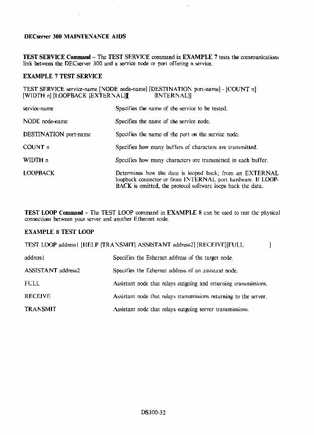
DECserver 300 MAINTENANCE AIDS
TEST SERVICE Command - The TEST SERVICE command in EXAMPLE 7 tests the communications link between the DECserver 300 and a service node or port offering a service.
EXAMPLE 7 TEST SERVICE
TEST SERVICE service-name [NODE node-name] [DESTINATION port-name] - [COUNT nJ [WIDTH n] [LOOPBACK {EXTERNAL}][ {INTERNAL}]
service-name
NODE node-name
DESTINATION port-name
COUNT n
WIDTH n
LOOPBACK
Specifies the name of the service to be tested.
Specifies the name of the service node.
Specifies the name of the port on the service node.
Specifies how many buffers of characters are transmitted.
Specifies how many characters are transmitted in each buffer.
Determines how the data is looped back; from an EXTERNAL loopback connector or from INTERNAL port hardware. If LOOPBACK is omitted, the protocol software loops back the data.
TEST LOOP Command - The TEST LOOP command in EXAMPLE 8 can be used to test the physical connections between your server and another Ethernet node.
EXAMPLE 8 TEST LOOP
TEST LOOP address! [HELP {TRANSMIT} ASSISTANT address2] {RECEIVEHFULL
addressl
ASSISTANT address2
FULL
RECEIVE
TRANSMIT
Specifies the Ethernet address of the target node.
Specifies the Ethernet address of an assistant node.
Assistant node that relays outgoing and returning transmissions.
Assistant node that relays transmissions returning to the server.
Assistant node that relays outgoing server transmissions.
DS300-32
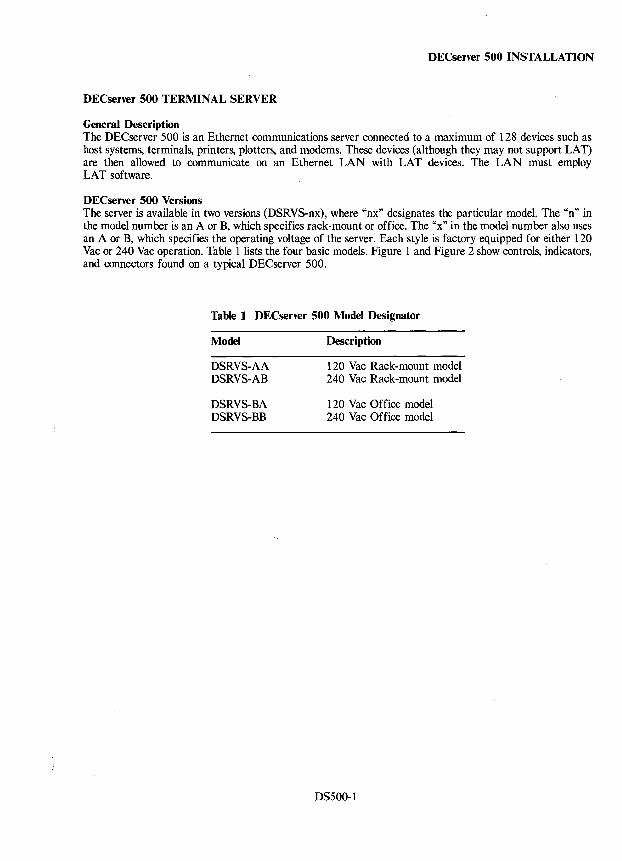
DECserver 500 INSTALLATION
DECserver 500 TERMINAL SERVER
General Description The DECserver 500 is an Ethernet communications server connected to a maximum of 128 devices such as host systems, terminals, printers, plotters, and modems. These devices (although they may not support LAT) are then allowed to communicate on an Ethernet LAN with LAT devices. The LAN must employ LAT software.
DECserver 500 Versions The server is available in two versions (DSRVS-nx), where "nx" designates the particular model. The "n" in the model number is an A or B, which specifies rack-mount or office. The "x" in the model number also uses an A or B, which specifies the operating voltage of the server. Each style is factory equipped for either 120 Vac or 240 Vac operation. Table 1 lists the four basic models. Figure 1 and Figure 2 show controls, indicators, and connectors found on a typical DECserver 500.
Table 1 DECserver 500 Model Designator
Model
DSRVS-AA DSRVS-AB
DSRVS-BA DSRVS-BB
Description
120 Vac Rack-mount model 240 Vac Rack-mount model
120 Vac Office model 240 Vac Office model
DS500-1
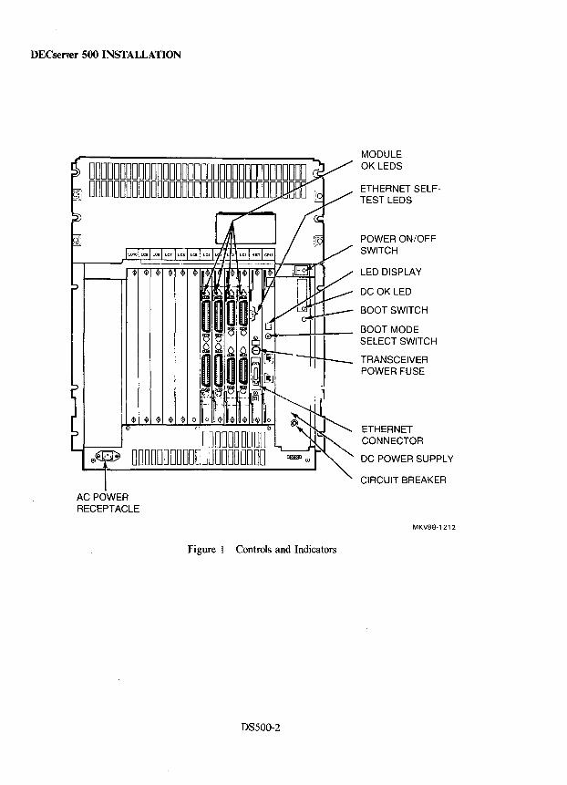
DECserver 500 INSTALLATION
00000000000000000000000000000000000 DDDDDDDDDDDDDDDDDDDDDDDODDODDD~uuD !P
rmOODOOOO $e~e DODDDDDDDD[;~JDDO~ODOO
AC POWER RECEPTACLE
Figure 1 Controls and Indicators
DS500-2
MODULE OK LEOS
ETHERNET SELFTEST LEOS
POWER ON/OFF SWITCH
LED DISPLAY
MKV88-1212
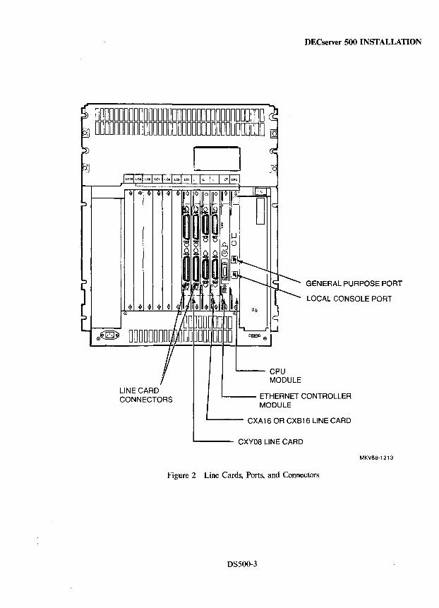
DECserver 500 INSTALLATION
00000000000000000000000000000000000 -I DOODDDDDDDOOODDDDDDDDODDDDDDUOOOOOO 0
LINE CARD CONNECTORS
o
GENERAL PURPOSE PORT
LOCAL CONSOLE PORT
'---- CPU MODULE
!---- ETHERNET CONTROLLER MODULE
L......-_ CXA 16 OR CXB16 LINE CARD
"----- CXY08 LINE CARD
MKV88-1213
Figure 2 Line Cards, Ports, and Connectors
DS500-3
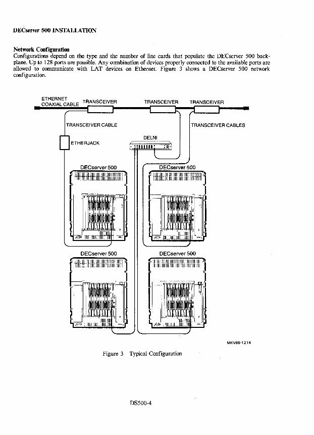
DECserver 500 INSTALLATION
Network Configuration Configurations depend on the type and the number of line cards that populate the DECserver 500 backplane. Up to 128 ports are possible. Any combination of devices properly connected to the available ports are allowed to communicate with LAT devices on Ethernet. Figure 3 shows a DECserver 500 network configuration.
ETHERNET COAXIAL CABLE TRANSCEIVER
TRANSCEIVER CABLE
ETHERJACK
DECserver 500 UODOODDDDDDDODDDODODODOOODODDDDDDDD nDOODCDDDOOOODDOOOODDOOOOrnOODDDDDD
DECserver 500
TRANSCEIVER TRANSCEIVER
TRANSCEIVER CABLES
DELNI
DECserver 500
MKV88·1214
Figure 3 Typical Configuration
DS500-4
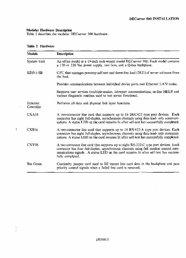
DECserver 500 INSTALLATION
Modular Hardware Description Table 2 describes the modular DECserver 500 hardware.
Table 2 Hardware
Module
System Unit
KDJ11-SB
Ethernet Controller
CXA16
CXB16
CXY08
Bus Grant
Description
An office model or a 19-inch rack-mount model DECserver 500. Each model contains a 120 or 220 Vac power supply, two fans, and a Q-bus backplane.
CPU that manages powerup self-test and down-line load (DLL) of server software from the host.
Provides communications between individual device ports and Ethernet LAN nodes.
Supports user services (multiple-session, intraport communications, on-line HELP, and various diagnostic routines used to test server functions).
Performs all data and physical link layer functions.
A two-connector line card that supports up to 16 DEC423 type port devices. Each connector has eight full-duplex, asynchronous channels using data-Iead- only communications. A status LED on the card remains lit after self-test has successfully completed.
A two-connector line card that supports up to 16 RS-422-A type port devices. Each connector has eight full-duplex, asynchronous channels using data-lead- only communications. A status LED on the card remains lit after self-test has successfully completed.
A two-connector line card that supports up to eight RS-232-C type port devices. Each connector has four full-duplex, asynchronous channels using full modem control communications signals. A status LED on the card remains lit after self-test has successfully completed.
Continuity jumper card used to fill vacant line card slots in the backplane and pass priority control signals when a failed line card is removed.
DSSOO-5
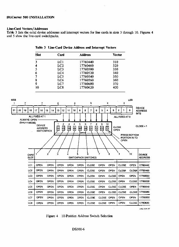
DECserver 500 INSTALLATION
Line-Card Vectors/ Addresses Table 3 lists the octal device addresses and interrupt vectors for line cards in slots 3 through 10. Figures 4 and 5 show the line-card switchpacks.
MSB 7
Table 3 Line-Card Device Address and Interrupt Vectors
Slot
3 4 5 6 7 8 9 10
7
Card
LCI LC2 LC3 LC4 LC5 LC6 LC7 LC8
6 &
0 .. &
Address Vector
17760440 310 17760460 320 17760500 330 17760520 340 17760540 350 17760560 360 17760600 370 17760620 400
X X .. &
II .. ..
LSB 0 ,
13112 111 110 1 9 1 8 1 7 1 6 1 5 1 4 1 3 1 2 11 1 0 1 DEVICE ADDRESS BITS
121 1 20 119 118 117 116 115 114
1 1 1 1 1 1 J l' . , ALL FIXED AT 0 ALL FIXED AT 1
ALWAYSOPEN--------~~~--JL-J~~-l--i--1--i--1~ (DHU11 MODE)
DEVICE ADDRESS SWITCH PACK
CLOSE = 1
CARD 1/ 2/ ! f I ~ \ \8 "'9 "10 SLOT SWITCHPACK SWITCHES
LC1 OPEN OPEN OPEN OPEN OPEN CLOSE OPEN OPEN CLOSE OPEN
LC2 OPEN OPEN OPEN OPEN OPEN CLOSE OPEN OPEN CLOSE CLOSE
LC3 OPEN OPEN OPEN OPEN OPEN CLOSE OPEN CLOSE OPEN OPEN
LC4 OPEN OPEN OPEN OPEN OPEN CLOSE OPEN CLOSE OPEN CLOSE
LC5 OPEN OPEN OPEN OPEN OPEN CLOSE OPEN CLOSE CLOSE OPEN
LC6 OPEN OPEN OPEN OPEN OPEN CLOSE OPEN CLOSE CLOSE CLOSE
LC7 OPEN OPEN OPEN OPEN OPEN CLOSE CLOSE OPEN OPEN OPEN
LC8 OPEN OPEN OPEN OPEN OPEN CLOSE CLOSE OPEN OPEN CLOSE
Figure 4 10-Position Address Switch Selection
DS500-6
DEVICE ADDRESS
17760440
17760460
17760500
17760520
17760540
17760560
17760600
17760620
LKG-l074-87
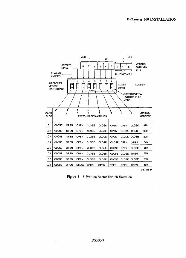
DECserver 500 INSTALLATION
MSB X
LSB X 0
ALWAYS VECTOR OPEN ADDRESS
BITS ALWAYS CLOSED
4 6 7 INTERRUPT CLOSE CLOSE = 1 VECTOR SWITCH PACK
CARD 1 4 5 a VECTOR SLOT SWITCHPACK SWITCHES ADDRESS
LC1 CLOSE OPEN OPEN CLOSE CLOSE OPEN OPEN CLOSE 310
LC2 CLOSE OPEN OPEN CLOSE CLOSE OPEN CLOSE OPEN 320
LC3 CLOSE OPEN OPEN CLOSE CLOSE OPEN CLOSE CLOSE 330
LC4 CLOSE OPEN OPEN CLOSE CLOSE CLOSE OPEN OPEN 340
LC5 CLOSE OPEN OPEN CLOSE CLOSE CLOSE OPEN CLOSE 350
LC6 CLOSE OPEN OPEN CLOSE CLOSE CLOSE CLOSE OPEN 360
LC7 CLOSE OPEN OPEN CLOSE CLOSE CLOSE CLOSE CLOSE 370
Lca CLOSE OPEN CLOSE OPEN OPEN OPEN OPEN OPEN 400
LKG-l073-87
Figure 5 8-Position Vector Switch Selection
DS500-7
DECserver 500 INSTALLATION
DECserver 500 Software Installation Requirements
The requirements are:
• DECserver 500 distribution software must be installed on the identified load host(s).
• DECnet Phase IV software must be installed on the identified load host(s) (supports DLL, dumps, and remote console operation).
• LAT service node software must be installed on all LAT (Local Area Transport) service nodes that communicate with the DECserver 500 over the Ethernet LAN.
Once identified, system hosts become load hosts only after the distribution software is installed and the systems are running DEC net Phase IV software. The distribution includes an image file that is down-line loaded to the DECserver 500.
LAT software must be installed on each service node using devices connected to the DECserver 500.
LAT software packaging is operating-system dependent as follows.
• VAX/VMS or MicroVMS Version 4.2 or later - LATplus/VMS is contained in the DECserver 500 software kit.
• RSX-IIM-PLUS or Micro/RSX - LAT software included with DECnet-RSX software.
• TOPS-IO or TOPS-20 - LAT software included with operational software.
All service-node software on the LAN should be installed and running before the server becomes operational. For more information see the DECserver 500 Software Product Description.
DS500-8
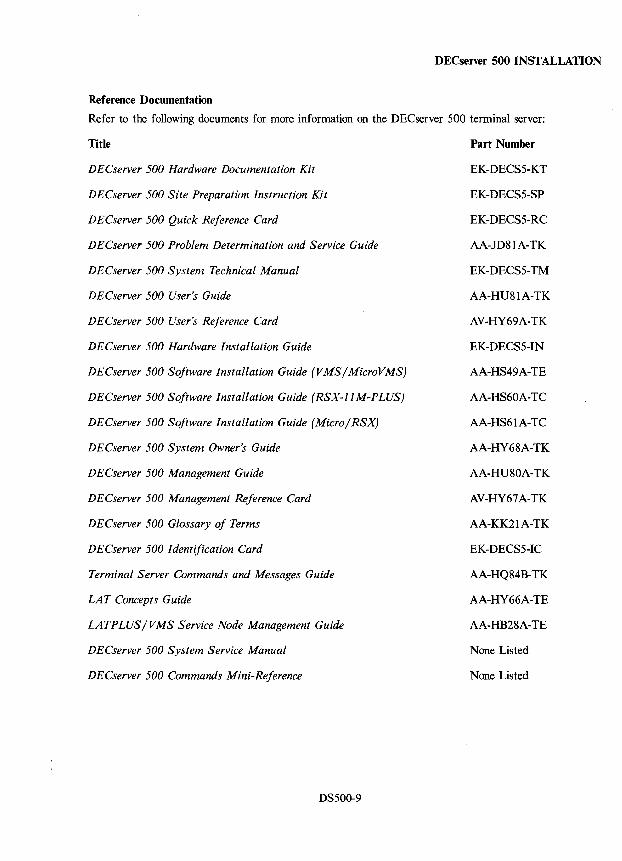
DECserver 500 INSTALLATION
Reference Documentation
Refer to the following documents for more information on the DECserver 500 terminal server:
Title
DECserver 500 Hardware Documentation Kit
DECserver 500 Site Preparation Instruction Kit
DECserver 500 Quick Reference Card
DECserver 500 Problem Determination and Service Guide
DECserver 500 System Technical Manual
DECserver 500 User's Guide
DECserver 500 User's Reference Card
DECserver 500 Hardware Installation Guide
DECserver 500 Software Installation Guide (VMS / MicroVMSj
DECserver 500 Software Installation Guide (RSX-JJ M-PLUSj
DECserver 500 Software Installation Guide (Micro/ RSXj
DECserver 500 System Owner's Guide
DECserver 500 Management Guide
DECserver 500 Management Reference Card
DECserver 500 Glossary of Terms
DECserver 500 Identification Card
Terminal Server Commands and Messages Guide
LAT Concepts Guide
LATPLUS/VMS Service Node Management Guide
DECserver 500 System Service Manual
DECserver 500 Commands Mini-Reference
DS500-9
Part Number
EK-DECS5-KT
EK-DECS5-SP
EK-DECS5-RC
AA-JD81A-TK
EK-DECS5-TM
AA-HU81A-TK
AV-HY69A-TK
EK-DECS5-IN
AA-HS49A-TE
AA-HS60A-TC
AA-HS61A-TC
AA-HY68A-TK
AA-HU8 OA-TK
AV-HY67A-TK
AA-KK21A-TK
EK-DECS5-IC
AA-HQ84B-TK
AA-HY66A-TE
AA-HB28A-TE
None Listed
None Listed
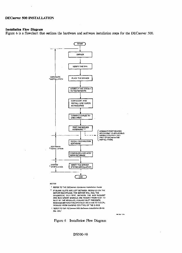
DECserver 500 INSTALLATION
Installation Flow Diagram Figure 6 is a flowchart that outlines the hardware and software installation steps for the DECserver 500.
HARDWARE • INSTALLATION
SOFTWARE t INSTALLATION
SYSTEM t VERIFICATION
l
NOTES
• REFER TO THE DECserver Hardware Instal/ation Guide
•• IF BLANK SLOTS ARE LEFT BETWEEN MODULES ON THE SERVER BACKPLANE, THE SERVER WILL FAIL THE DIAGNOSTIC SELF-TEST. BECAUSE THE BUS-REQUEST AND BUS-GRANT SIGNALS ARE PASSED FROM SLOT TO SLOT BY THE MODULES, A BLANK SLOT PREVENTS MODULES BEYOND THE OPEN SLOT RELATIVETO THE CPU MODULE FROM GAINING CONTROL OF THE Q-BIJS.
t REFER TO THE DECserver500 Software Instal/ation Guide fop. Sys.j
Figure 6 Installation Flow Diagram
DS500-10
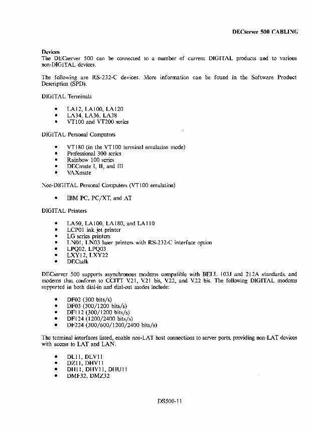
DECserver 500 CABLING
Devices The DECserver 500 can be connected to a number of current DIGITAL products and to various non-DIGITAL devices.
The following are RS-232-C devices. More information can be found in the Software Product Description (SPD).
DIGITAL Terminals
• LAI2, LAI00, LA120 • LA34, LA36, LA38 • VT 100 and VT200 series
DIGITAL Personal Computers
• VT 180 (in the VT 1 00 terminal emulation mode) • Professional 300 series • Rainbow 100 series • DEC mate I, II, and III • VAXmate
Non-DIGITAL Personal Computers (VT100 emulation)
• IBM PC, PC/XT, and AT
DIGITAL Printers
• LA50, LAlOO, LA180, and LA110 • LCPO 1 ink jet printer • LG series printers • LN01, LN03 laser printers with RS-232-C interface option • LPQ02, LPQ03 • LXY12, LXY22 • DECtaik
DECserver 500 supports asynchronous modems compatible with BELL 103J and 212A standards, and modems that conform to CCITT Y.21, Y.21 bis, Y.22, and Y.22 bis. The following DIGITAL modems supported in both dial-in and dial-out modes include:
• DF02 (300 bits/s) • DF03 (300/1200 bits/s) • DFl12 (300/1200 bits/s) • DF124 (1200/2400 bits/s) • DF224 (300/600/1200/2400 bits/s)
The terminal interfaces listed, enable non-LAT host connections to server ports, providing non-LAT devices with access to LAT and LAN.
• DLl1, DLV11 • DZ11, DHVll • DHll, DHVll, DHUll • DMF32, DMZ32
DS500-11
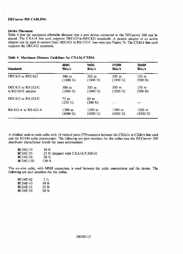
DECserver 500 CABLING
Device Placement Table 4 lists the maximum allowable distance that a port device connected to the DECserver 500 can be placed. The CXA16 line card supports DEC423-to-DEC423 standards. A passive adapter or an active adapter can be used to convert from DEC423 to RS-232-C four-wire (see Figure 7). The CXB16 line card supports the DEC422 standards.
Table 4 Maximum Distance Guidelines for CXAI6/CXBI6
4800 9600 Standards Bits/s Bits/s
DEC423 to DEC423 300 m 300 m (1000 ft) (1000 ft)
DEC423 to RS-232-C 300 m 300 m w/H3105A adapter (1000 ft) (1000 ft)
DEC423 to RS-232-C 75 m 60 m (250 ft) (200 ft)
RS-422-A to RS-422-A 1200 m 1200 m (4000 ft) (4000 ft)
19200 Bits/s
300 m (1000 ft)
300 m (1000 ft)
1200 m (4000 ft)
38400 Bits/s
150 m (500 ft)
150 m (500 ft)
1200 m (4000 ft)
A shielded male-to-male cable with 18 twisted pairs (TP) connects between the CXA16 or CXB16 line card and the H3104 cable concentrator. The following are part numbers for the cables (see the DECserver 500 Hardware Installation Guide for more information).
10 ft BC16C-I0 BC16C-25 BC16C-50 BC16C-150
25 ft (shipped with CXAI6/CXB16) 50 ft
150 ft
The six-wire cable, with MMJ connectors, is used between the cable concentrator and the device. The following are part numbers for the cables.
BC16E-02 2 ft BC16E-I0 10 ft BC16E-25 25 ft BC16E-50 50 ft
DS500-12
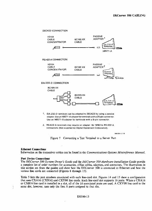
DECserver 500 CABLING
DEC423 CONNECTION
H3104 PASSIVE
CABLE BC16E-XX ADAPTER 1
CONCENTRATOR CABLE
~ [J c c:::J
H8571-A
RS-422-A CONNECTION
H3104 PASSIVE CABLE BC16E-XX ADAPTER 2
CONCENTRATOR CABLE
~ 0 0 CJ
EIA-232-D CONNECTION
BC19N-XX CABLE
~ BC22D·XX CABLE
0 0
1. EIA-232-D terminals can be adapted to DEC423 by using a passive adapter. Use an H8571-A adapterforterminals with a 25-pin connector. Use an H8571-B adapter for terminals with a 9-pin connector.
2. RS-422-A terminals may require an adapter for MMJ to RS-422-A connectors. (Not supplied by Digital Equipment Corporation).
~
~
e::s
MKV88·1216
Figure 7 Connecting a Test Terminal to a Server Port
Ethernet Connections Information on the transceiver cables can be found in the Communications Options Minireference Manual.
Port Device Connections The DECserver 500 System Owner's Guide and the DECserver 500 Hardware Installation Guide provide a complete list of order numbers for accessories, office cables, adapters, and connectors. The illustrations in this section are from the guides and show how the DECserver 500 is connected to Ethernet and how the various line cards are connected (Figures 8 through 15).
Table 5 lists the port numbers associated with each line-card slot. Figures 14 and 15 show a configuration that uses CXA16 (CXBI6) and CXY08 line cards. Each line-card slot supports 16 ports. When a CXA16 or CXB 16 line card is installed in a slot, all of the 16 associated ports are used. A CXY08 line card in the same slot, however, uses only the first 8 ports assigned to that slot.
DS500-13
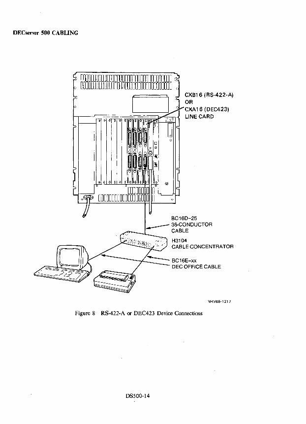
DECserver 500 CABLING
DODDDDDODDODDDDDDDDDDDDDDDUDDDDDDDD ODODDDDDDDDDDODDODOOODDDDODDDDDDDDO 0
CJo o
ODOODD D 0 ~~ I
e DDOOODODDDDDOODDO 0 0 I------J
CXB16 (RS-422-A) OR CXA16 (DEC423) LINE CARD
BC16D-25 ~ 36-CONDUCTOR
CABLE
/c',<' H3104 ~,/ CABLE CONCENTRATOR
MKV88-1217
Figure 8 RS-422-A or DEC423 Device Connections
DS500-14
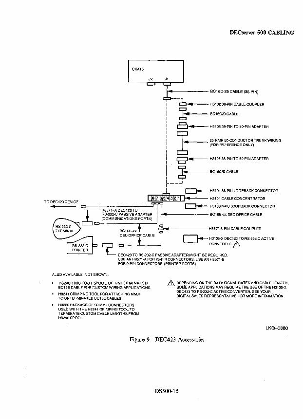
DECserver 500 CABLING
CXA16
J2 J1
~------ BC16D-25 CABLE (36-PIN)
--~"'4 __ -- H3102 36-PIN CABLE COUPLER
~ BC16C/DCABLE
c::::J~ H3106 36-PIN TO 50-PIN ADAPTER
~ 25-PAIR 50-CONDUCTOR TRUNK WIRING c:b" (FOR REFERENCE ONLY)
9 ... 4----- H3106 36-PIN TO 50-PIN ADAPTER
~ BC16C/D CABLE
r--.J I ~ H310136-PINLOOPBACKCONNECTOR
1/8/7/61514J3/2/11 I.. H3104 CABLE CONCENTRATOR TO DEC423 DEVICE
• CJ 7' I ~ H3103MMJLOOPBACKCONNECTOR
& H8571-A DEC423 TO RS-232-C PASSIVE ADAPTER MIll BC16E-xx DEC OFFICE CABLE (COMMUNICATIONS PORTS)
c:::J .. H8572 6-PIN CABLE COUPLER
0..- H31 05-X DEC423 TO R8-232-C ACTIVE
Q CONVERTER & L DEC423 TO RS-232-C PASSIVE ADAPTER MIGHT BE REQUIRED.
USE AN H8571-A FOR 25-PIN CONNECTORS; USE AN H8571-B FOR 9-PIN CONNECTORS. (PRINTER PORTS)
ALSO AVAILABLE (NOT SHOWN):
• H8240 lOOO-FOOT SPOOL OF UNTERMINATED BC16E CABLE FOR CUSTOM WIRING APPLICATIONS.
• H8241 CRIMPING TOOL FOR ATTACHING MMJs TO UNTERMINATED BC16E CABLES.
• H8220 PACKAGE OF 50 MMJ CONNECTORS USED WITH THE H8241 CRIMPING TOOL TO TERMINATE CUSTOM CABLE LENGTHS FROM H8240 SPOOL.
& DEPENDING ON THE DATA SIGNAL RATES AND CABLE LENGTH, SOME APPLICATIONS MAY REQUIRE THE USE OF THE H3105-X DEC423 TO RS-232-C ACTIVE CONVERTER. SEE YOUR DIGITAL SALES REPRESENTATIVE FOR MORE INFORMATION.
LKG-0880
Figure 9 DEC423 Accessories
DS500-15
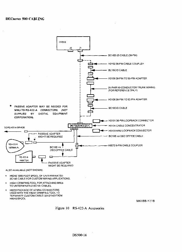
DECserver 500 CABLING
CXB16
J2 J1
* PASSIVE ADAPTER MAY BE NEEDED FOR
MMJ-TO-RS-422-A CONNECTORS. (NOT
SUPPLIED BY DIGITAL EQUIPMENT
CORPORATION).
..... f-------- BC16D-25 CABLE (36-PIN)
---,
Ofool4.--- H3102 36-PIN CABLE COUPLER
~ BC16C/D CABLE
81 ... -4---- H31 06 36-PIN TO 50-PIN ADAPTER
~ 25-PAIR 50-CONDUCTOR TRUNK WIRING 6 (FOR REFERENCE ONLY)
8""' ....... -- H31 06 36-PIN TO 50-PIN ADAPTER
$ BC16C/D CABLE
r---.J I ~ H3101 36-PIN LOOPBACK CONNECTOR
TO RS-422-A DEVICE I 181716\5141312111 I... H3104 CABLE CONCENTRATOR
r- PASSIVE ADAPTER Clr--------------J9 1 ~ H3103 MMJ LOOPBACK CONNECTOR
~ * MIGHT BE REQUIRED 4l1li BC16E -xx DEC OFFICE CABLE
Cl ... H8572 6-PIN CABLE COUPLER
~ PASSIVE ADAPTER MIGHT BE REQUIRED
ALSO AVAILABLE (NOT SHOWN):
• H8240 1000-FOOT SPOOL OF UNTERMINATED BC16E CABLE FOR CUSTOM WIRING APPLICATIONS.
• H8241 CRIMPING TOOL FOR ATTACHING MMJs TO UNTERMINATED BC16E CABLES.
• H8220 PACKAGE OF 50 MMJ CONt-JECTORS USED WITH THE H8241 CRIMPING TOOL TO TERMINATE CUSTOM CABLE LENGTHS FROM H8240 SPOOL.
Figure 10 RS-422-A Accessories
DS500-16
MKV88-1218
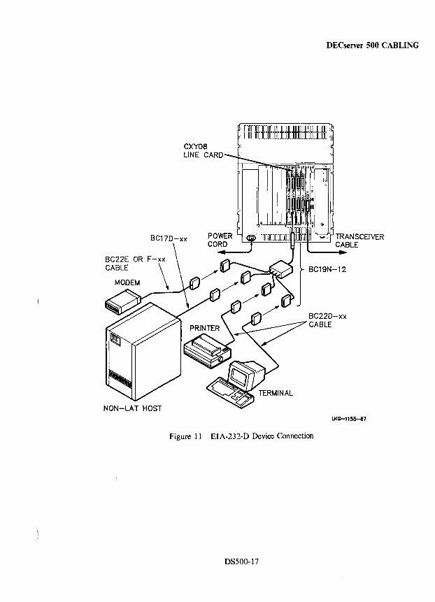
DECserver 500 CABLING
'''"'0 ·TRANSCEIVER L.....::::I~==~Fl~::::-----I CABLE
BC19N-12
U<G-1155-87
Figure 11 EIA-232-D Device Connection
DS500-17
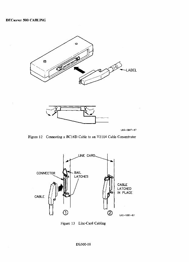
DECserver 500 CABLING
lKG-0847-87
Figure 12 Connecting a BC 16D Cable to an H3104 Cable Concentrator
LINE CARD
CABLE
CD Figure 13 Line-Card Cabling
DS500-18
CABLE LATCHED IN PLACE
LKG-l061-87
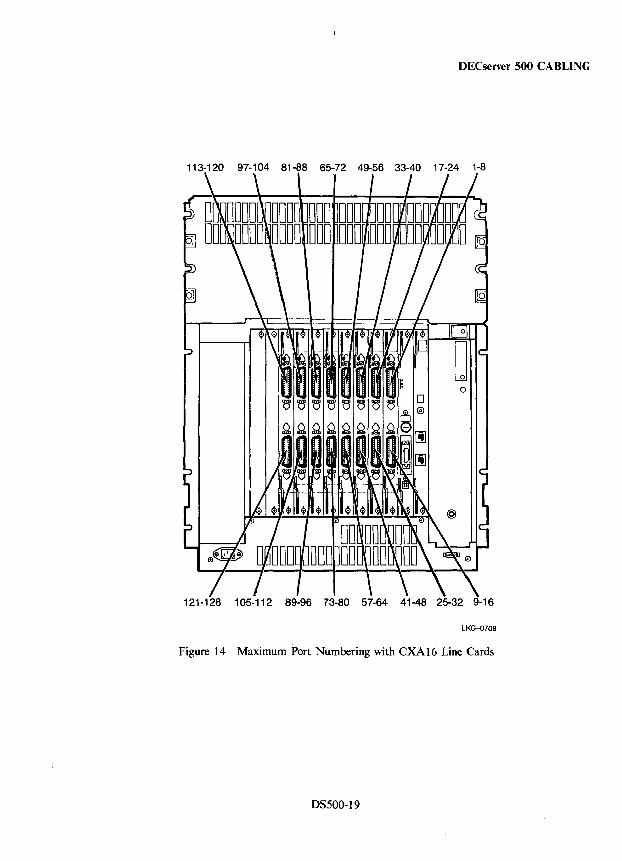
DECserver 500 CABLING
113-120 97-10481-8865-7249-5633-4017-24 1-8
121-128 105-112 89-9673-8057-6441-4825-329-16
LKG-0708
Figure 14 Maximum Port Numbering with CXA16 Line Cards
DS500-19
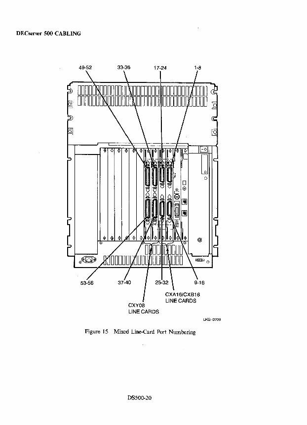
DECserver 500 CABLING
33-36 17-24 1-8
CXY08 LINE CARDS
LKG-0709
Figure 15 Mixed Line-Card Port Numbering
DS500-20
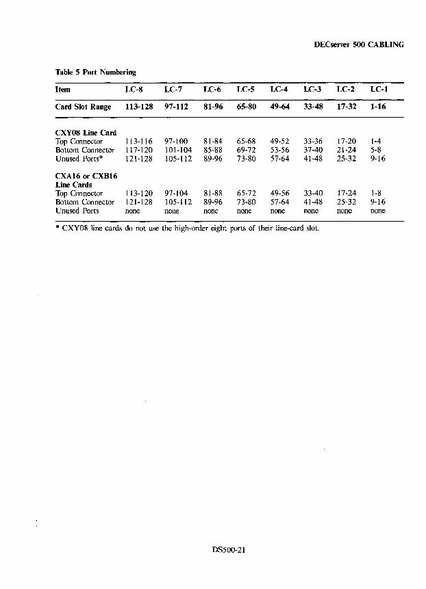
DECserver 500 CABLING
Table 5 Port Numbering
Item LC-8 LC-7 LC-6 LC-5 LC-4 LC-3 LC-2 LC-l
Card Slot Range 113-128 97-112 81-96 65-80 49-64 33-48 17-32 1-16
CXY08 Line Card Top Connector 113-116 97-100 81-84 65-68 49-52 33-36 17-20 1-4 Bottom Connector 117-120 101-104 85-88 69-72 53-56 37-40 21-24 5-8 Unused Ports* 121-128 105-112 89-96 73-80 57-64 41-48 25-32 9-16
CXA16 or CXB16 Line Cards Top Connector 113-120 97-104 81-88 65-72 49-56 33-40 17-24 1-8 Bottom Connector 121-128 105-112 89-96 73-80 57-64 41-48 25-32 9-16 Unused Ports none none none none none none none none
* CXY08 line cards do not use the high-order eight ports of their line-card slot.
DS500-21
DECserver 500 DIAGNOSTICS
Diagnostic Self-Test Program The server diagnostic self-test program performs two primary functions:
• Tests the server hardware for failures
• Initiates a down-line load of the server from a host computer if no hardware failures are detected
Additionally, the program supports the following functions:
• A boot mode that allows the server software to be loaded when nonfatal hardware errors are detected by the diagnostics. Nonfatal errors are errors that affect only the line cards.
• The use of a local console terminal that enables users to interact with the diagnostic tests to control the testing of specific server modules.
• Maintenance Qperations Protocol (MOP) functions that enable the use of a remote console to test server hardware, to load the server software, and to execute an up-line dump of the contents of server memory to a designated host computer.
• The continuous self-testing of the server to support manufacturing testing requirements.
• A System Configuration Verification Program that automatically checks for a valid server hardware configuration each time the server is powered ON or the BOOT switch is pressed.
• An interactive System Configuration Assistance Program that helps the user verify that server modules are properly addressed and installed in the correct slots in the server backplane.
DS500-22
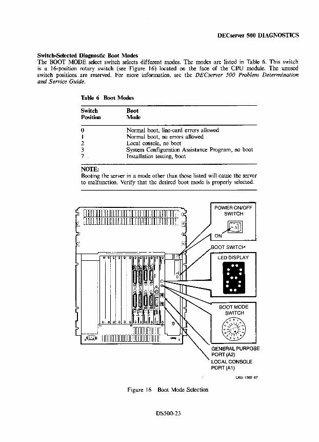
DECserver 500 DIAGNOSTICS
Switch-Selected Diagnostic Boot Modes The BOOT MODE select switch selects different modes. The modes are listed in Table 6. This switch is a 16-position rotary switch (see Figure 16) located on the face of the CBU module. The unused switch positions are reserved. For more information, see the DECserver 500 Problem Determination and Service Guide.
Table 6 Boot Modes
Switch Position
Boot Mode
o 1 2 3 7
Normal boot, line-card errors allowed Normal boot, no errors allowed Local console, no boot System Configuration Assistance Program, no boot Installation testing, boot
NOTE: Booting the server in a mode other than those listed will cause the server to malfunction. Verify that the desired boot mode is properly selected.
00000000000000000000000000000000000 :j DODDDDOOODDDOODOODDOOOOOODDOOODDDDD 10
0000000000 0~ 000000000000000000000
POWER ON/OFF SWITCH
n ON
LED DISPLAY
II " GENERAL PURPOSE '\ PORT(A2)
LOCAL CONSOLE PORT (A1)
LKG-l080-87
Figure 16 Boot Mode Selection
DS500-23
DECserver 500 DIAGNOSTICS
To select and execute a boot mode, refer to Figure 16 and perform the following steps:
CAUTION Use a small screwdriver to position the BOOT MODE select switch; otherwise damage to the switch will occur.
1. Using a small screwdriver, turn the BOOT MODE select switch to the number that corresponds to the desired boot mode. Table 6 lists the different boot modes.
2. Boot the server by pressing the BOOT switch.
3. Observe that the selected boot mode is displayed in the LED display for five (5) seconds and then the server proceeds to execute the selected boot mode.
NOTE The five-second delay allows time to select a different boot mode.
Boot the server in Mode 0 or 1 for normal operation. These modes can be used for troubleshooting.
Each time the server is booted in one of these modes, the diagnostic self-test program executes the following tests before requesting a down-line load of the server software.
• System Kernel Test • Ethernet Citizenship Test • Board-Level Line-Card Test • System Configuration Verification Program
Boot Mode 0 - In Boot Mode 0, line-card faults are nonfatal and are ignored.
Boot Mode 1 - In Boot Mode 1, any hardware fault is considered fatal. When fatal faults are detected, the server displays an error code in the LED display and does not request down-line load of the server software. If the diagnostics detect fatal hardware faults in either Mode 0 or 1, the server displays an error code in the LED display and does not request a down-line load.
Boot Mode 2 - Boot Mode 2 (Local Console), places the server under the control of the server firmware and activates the server Console Commands Interface. Select this mode only when a local console terminal is connected and when there is a need to control system testing for an extended period of time.
When booting the server in Boot Mode 2, the server executes the following tests automatically:
• System Kernel Test • Ethernet Citizenship Test • Board-Level Line-Card Test • System Configuration Verification Program
If these tests complete successfully, the Console Commands Interface activates, the local console prompt (Console» is displayed at the local console terminal, and control of the server is passed directly to the local console port. The local console terminal can then be used to run more extensive diagnostic tests using the Console Commands Interface commands.
DS500-24
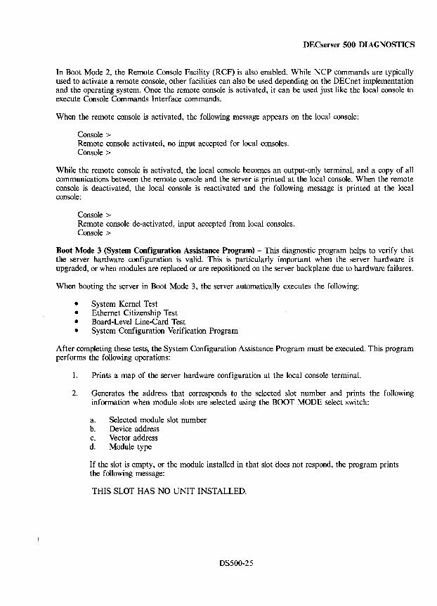
DECserver 500 DIAGNOSTICS
In Boot Mode 2, the Remote Console Facility (RCF) is also enabled. While NCP commands are typically used to activate a remote console, other facilities can also be used depending on the DECnet implementation and the operating system. Once the remote console is activated, it can be used just like the local console to execute Console Commands Interface commands.
When the remote console is activated, the following message appears on the local console:
Console> Remote console activated, no input accepted for local consoles. Console>
While the remote console is activated, the local console becomes an output-only terminal, and a copy of all communications between the remote console and the server is printed at the local console. When the remote console is deactivated, the local console is reactivated and the following message is printed at the local console:
Console> Remote console de-activated, input accepted from local consoles. Console>
Boot Mode 3 (System Configuration Assistance Program) - This diagnostic program helps to verify that the server hardware configuration is valid. This is particularly important when the server hardware is upgraded, or when modules are replaced or are repositioned on the server backplane due to hardware failures.
When booting the server in Boot Mode 3, the server automatically executes the following:
• System Kernel Test • Ethernet Citizenship Test • Board-Level Line-Card Test • System Configuration Verification Program
After completing these tests, the System Configuration Assistance Program must be executed. This program performs the following operations:
1. Prints a map of the server hardware configuration at the local console terminal.
2. Generates the address that corresponds to the selected slot number and prints the following information when module slots are selected using the BOOT MODE select switch:
a. Selected module slot number b. Device address c. Vector address d. Module type
If the slot is empty, or the module installed in that slot does not respond, the program prints the following message:
THIS SLOT HAS NO UNIT INSTALLED.
DS500-25
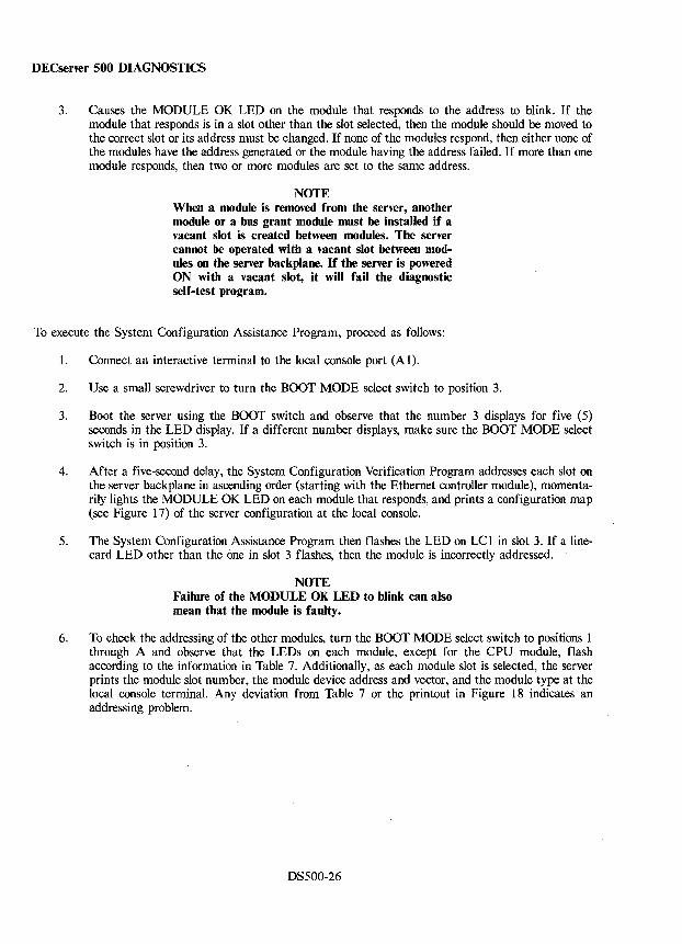
DECserver 500 DIAGNOSTICS
3. Causes the MODULE OK LED on the module that responds to the address to blink. If the module that responds is in a slot other than the slot selected, then the module should be moved to the correct slot or its address must be changed. If none of the modules respond, then either none of the modules have the address generated or the module having the address failed. If more than one module responds, then two or more modules are set to the same address.
NOTE When a module is removed from the server, another module or a bus grant module must be installed if a vacant slot is created between modules. The server cannot be operated with a vacant slot between modules on the server backplane. If the server is powered ON with a vacant slot, it will fail the diagnostic self-test program.
To execute the System Configuration Assistance Program, proceed as follows:
1. Connect an interactive terminal to the local console port (A 1).
2. Use a small screwdriver to turn the BOOT MODE select switch to position 3.
3. Boot the server using the BOOT switch and observe that the number 3 displays for five (5) seconds in the LED display. If a different number displays, make sure the BOOT MODE select switch is in position 3.
4. After a five-second delay, the System Configuration Verification Program addresses each slot on the server backplane in ascending order (starting with the Ethernet controller module), momentarily lights the MODULE OK LED on each module that responds, and prints a configuration map (see Figure 17) of the server configuration at the local console.
5. The System Configuration Assistance Program then flashes the LED on LCI in slot 3. If a linecard LED other than the one in slot 3 flashes, then the module is incorrectly addressed.
NOTE Failure of the MODULE OK LED to blink can also mean that the module is faulty.
6. To check the addressing of the other modules, turn the BOOT MODE select switch to positions 1 through A and observe that the LEDs on each module, except for the CPU module, flash according to the information in Table 7. Additionally, as each module slot is selected, the server prints the module slot number, the module device address and vector, and the module type at the local console terminal. Any deviation from Table 7 or the printout in Figure 18 indicates an addressing problem.
DS500-26
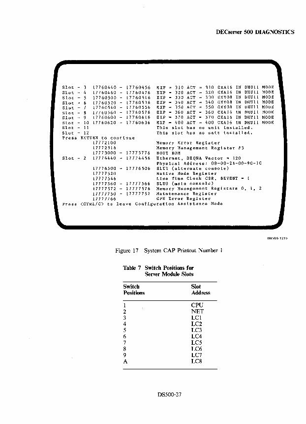
DECserver 500 DIAGNOSTICS
r Slot - 3 Slot - 4 Slot - 5 Slot - 6 Slot - 7 S10 t - 8 Slot - 9 Slot - 10 Slot - 11 Slot - 12
177 60440 - 17760456 EXP '" 17760460 - 17760476 EXP '" 177 60500 - 17760516 EXP .. 17760520 - 17760536 EXP '" 17760540 - 17760556 EXP '" 17760560 - 17760576 EXP '" 17760600 - 17760616 EXP '" 17760620 - 17760636 EXP =
This This
310 ACT '" 310 CXA 16 IN DHUll 320 ACT = 320 CXA16 IN DHUll 330 ACT '" 330 CXY08 IN DHUll 340 ACT '" 340 CXY08 IN DHUll 350 ACT '" 350 CXY08 IN DHUll 360 ACT '" 360 CXA16 IN DHUll 370 ACT '" 370 CXA16 IN DHU 11 400 ACT '" 400 CXA16 IN DHUll
slot has no unit installed. slot has no unit installed.
Press RETURN to continue 17772100 17772516
Memory Error Register Memory Management Register #3 BOOT ROM 17773000 - 17773776
Slot - 2 17774440 - 17774456 Ethernet, DEQNA Vector" 120 Physical Address: 08-00-2B-00-9C-IC
Press
l
17776500 - 17776506 SLUl (alternate console) 17777520 Native Mode Register 17777546 Line Time Clock CSR, BEVENT '" 1 17777560 - 17777566 SLUO (main console) 17777572 - 17777576 Memory Management Registers 0, 1, 2 17777750 - 17777752 Maintenance Register 17777766 CPU Error Register
<CTRL/C) to leave Configuration Assistance Mode
Figure 17 System CAP Printout Number I
Table 7 Switch Positions for Server Module Slots
Switch Slot Positions Address
I CPU 2 NET 3 LCI 4 LC2 5 LC3 6 LC4 7 LC5 8 LC6 9 LC7 A LC8
DS500-27
1 MODE MODE MODE MODE MODE MODE MODE MODE
MKV88-1219
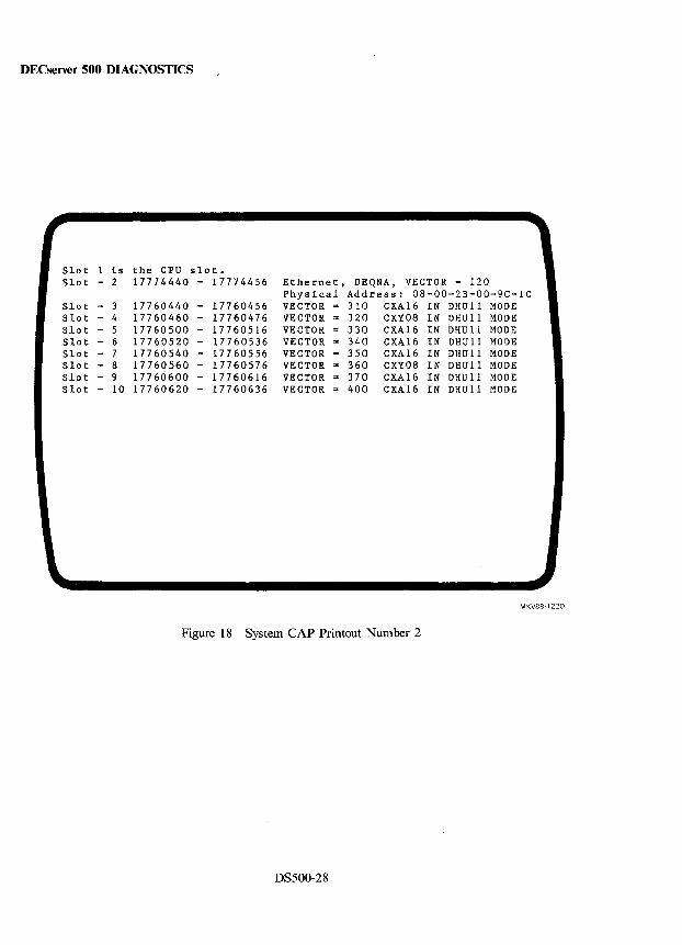
DECserver 500 DIAGNOSTICS
r- 1 Slot is the CPU slot. Slot - 2 17774440 - 17774456 Ethernet, DEQNA, VECTOR = 120
Physical Address: 08-00-2B-00-9C-1C Slot - 3 17760440 - 17760456 VECTOR = 310 CXA16 IN DHUll MODE Slot - 4 17760460 - 17760476 VECTOR = 320 CXY08 IN DHUll MODE Slot - 5 17760500 - 17760516 VECTOR 330 CXA16 IN DHUll MODE Slot - 6 17760520 - 17760536 VECTOR ... 340 CXA16 IN DHUll MODE Slot - 7 177 60540 - 17760556 VECTOR = 350 CXA16 IN DHUll MODE Slot - 8 17760560 - 17760576 VECTOR ... 360 CXY08 IN DHUll MODE Slot - 9 177 60600 - 17760616 VECTOR = 370 CXA16 IN DHU 11 MODE Slot - 10 17760620 - 17760636 VECTOR ... 400 CXA16 IN DHUll MODE
MKV88-1220
Figure 18 System CAP Printout Number 2
DS500-28
DECserver 500 DIAGNOSTICS
Boot Mode 7 (Installation Testing) - This mode is intended for initial installation of the server hardware and software. This mode is also used for troubleshooting. When the server is booted in this mode, the following tests are automatically executed:
• System Kernel Test • Ethernet Citizenship Test • Board-Level Line-Card Test • System Configuration Verification Program • Extended Ethernet Interface Test • Extended Line-Card Test • System Exerciser Test • Internal Loopback Test
On successful completion of the above tests, the server automatically initiates the loading of server software by sending out an MOP Request Program message over the Ethernet LAN using the MOP dump/load multicast address.
NOTE Boot Mode 7 should not be used for normal operation. Because additional testing is done in this mode, the server takes longer to boot. Therefore, to expedite booting the server for normal operation, use either Boot Mode 0 or Boot Mode 1. Boot Mode 0 is recommended because it allows a remote console to be used for troubleshooting when a line card fails.
Status and Error Codes LED Display The LED display provides a visual indication of server status. It displays status and error codes that indicate whether the server is operating properly or whether it has failed. In case of failures, the error code assists in isolating the fault.
The codes displayed by the LED display fall into two general categories:
• Diagnostic Status and Error Codes - These codes are displayed while the server self-test diagnostics are running.
• Software Status and Error Codes - These codes are displayed after successful completion of server diagnostics and initiation of the down-line load request for server software.
Diagnostic Status and Error Codes - Status and error codes are displayed in the LED display (refer back to Figure 16) while the server diagnostic self-test program is running. The codes indicate which test is currently executing or has failed. Refer to Table 8 for an explanation of each diagnostic status and error code.
Server Software Status and Error Codes - The server software status and error codes are not displayed until after the successful completion of the diagnostics and the initiation of a down-line load request for server software. While the software is being loaded, the LED display indicates the load status. For example, the LED display alternately flashes the letter B and the number 3 to indicate that a load host has responded to the server's request for a down-line load and that the server software is about to be loaded.
After the software is successfully loaded, the LED display indicates that the software is running by alternately flashing the numbers 0 and 8. If the software does not load successfully or fails after it has been loaded, the LED display indicates the type of failure.
Refer to Table 9 for an explanation of each software status and error code.
DS500-29
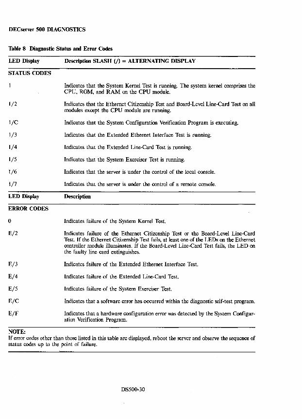
DECserver 500 DIAGNOSTICS
Table 8 Diagnostic Status and Error Codes
LED Display
STATUS CODES
1/2
l/C
1/3
1/4
1/5
1/6
1/7
LED Display
ERROR CODES
o
E/2
E/3
E/4
E/5
E/C
E/F
NOTE:
Description SLASH (/) = ALTERNATING DISPLAY
Indicates that the System Kernel Test is running. The system kernel comprises the CPU, ROM, and RAM on the CPU module.
Indicates that the Ethernet Citizenship Test and Board-Level Line-Card Test on all modules except the CPU module are running.
Indicates that the System Configuration Verification Program is executing.
Indicates that the Extended Ethernet Interface Test is running.
Indicates that the Extended Line-Card Test is running.
Indicates that the System Exerciser Test is running.
Indicates that the server is under the control of the local console.
Indicates that the server is under the control of a remote console.
Description
Indicates failure of the System Kernel Test.
Indicates failure of the Ethernet Citizenship Test or the Board-Level Line-Card Test. If the Ethernet Citizenship Test fails, at least one of the LEDs on the Ethernet controller module illuminates. If the Board-Level Line-Card Test fails, the LED on the faulty line card extinguishes.
Indicates failure of the Extended Ethernet Interface Test.
Indicates failure of the Extended Line-Card Test.
Indicates failure of the System Exerciser Test.
Indicates that a software error has occurred within the diagnostic self-test program.
Indicates that a hardware configuration error was detected by the System Configuration Verification Program.
If error codes other than those listed in this table are displayed, reboot the server and observe the sequence of status codes up to the point of failure.
DS500-30
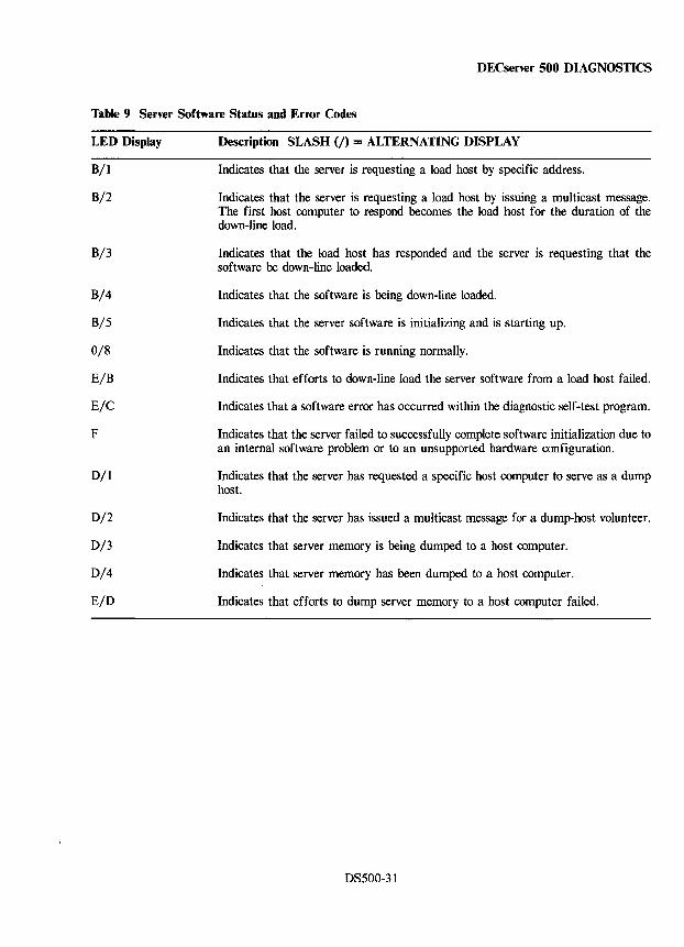
DECserver 500 DIAGNOSTICS
Table 9 Server Software Status and Error Codes
LED Display
B/l
B/2
B/3
B/4
B/5
0/8
E/B
E/C
F
D/l
D/2
D/3
D/4
E/D
Description SLASH (J) = ALTERNATING DISPLAY
Indicates that the server is requesting a load host by specific address.
Indicates that the server is requesting a load host by issuing a multicast message. The first host computer to respond becomes the load host for the duration of the down-line load.
Indicates that the load host has responded and the server is requesting that the software be down-line loaded.
Indicates that the software is being down-line loaded.
Indicates that the server software is initializing and is starting up.
Indicates that the software is running normally.
Indicates that efforts to down-line load the server software from a load host failed.
Indicates that a software error has occurred within the diagnostic self-test program.
Indicates that the server failed to successfully complete software initialization due to an internal software problem or to an unsupported hardware configuration.
Indicates that the server has requested a specific host computer to serve as a dump host.
Indicates that the server has issued a multicast message for a dump-host volunteer.
Indicates that server memory is being dumped to a host computer.
Indicates that server memory has been dumped to a host computer.
Indicates that efforts to dump server memory to a host computer failed.
DS500-31
DECserver 500 DIAGNOSTICS
Module Self-Test LEDs All of the modules have LEDs that indicate whether the Board-Level Line-Card Test executes successfully.
CPU Module The CPU module board-level test checks the system kernel, that is; the CPU, ROM, and RAM. If a failure is detected, the number 0 displays in the LED display.
Ethernet Controller Module DEQNA, the Ethernet controller module, has three LEDs that are all turned ON when the server is powered up or when the BOOT switch is pressed. The Ethernet Citizenship Test then turns OFF the LEDs one at a time to indicate that the following events have occurred:
1. The first LED turns OFF when the test starts running.
2. The second LED turns OFF after the module's internalloopback test executes successfully.
3. The third LED turns OFF after the module's externalloopback test executes successfully.
If one or more of the LEDs remain ON, it means that the Ethernet controller module has failed the test.
NOTE If the Ethernet Citizenship Test fails, the server displays error code E/2 in the LED display on the CPU module.
CXA16, CXB16, and CXY08 Line Cards Each line card has a MODULE OK LED. The LED turns ON to indicate that the module Board-Level Line-Card Test has executed successfully.
The effect that failing the Board-Level Line-Card Test has on the server depends on the boot mode. In Boot Mode 0 (line-card errors allowed), the diagnostic self-test program issues a request for a down-line load of the server software. In Boot Mode I (no errors allowed), the diagnostic self-test program does not issue the down-line load request, but displays error code E/2 in the LED display on the CPU module.
Server Local Console Ports The server is equipped with two local ports (refer to Figure 16).
• The Local Console Port - An input/output port used to connect the local console. This port is provided primarily for use during installation, maintenance, and reconfiguration of the server. The server software considers this port to be port O.
• The General Purpose Port - Operational only when the diagnostic firmware is running on the server, but not when the server software is running. It is a backup port during diagnostic testing. If the local console port fails, this port can be used for the same purpose.
DS500-32
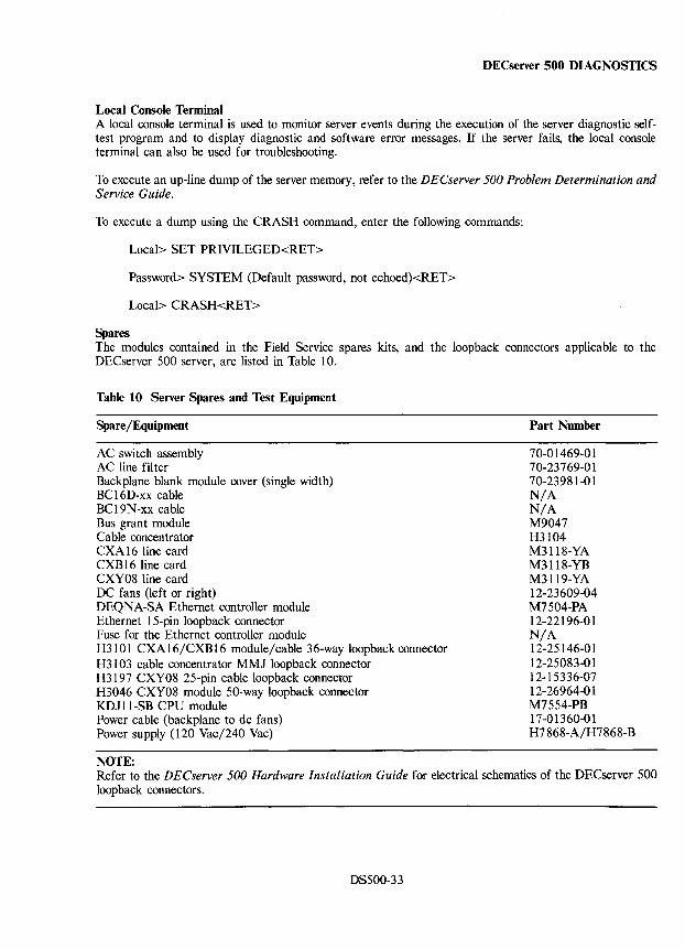
DECserver 500 DIAGNOSTICS
Local Console Terminal A local console terminal is used to monitor server events during the execution of the server diagnostic selftest program and to display diagnostic and software error messages. If the server fails, the local console terminal can also be used for troubleshooting.
To execute an up-line dump of the server memory, refer to the DECserver 500 Problem Determination and Service Guide.
To execute a dump using the CRASH command, enter the following commands:
Local> SET PRIVILEGED<RET>
Password> SYSTEM (Default password, not echoed)<RET>
Local> CRASH<RET>
Spares The modules contained in the Field Service spares kits, and the loopback connectors applicable to the DECserver 500 server, are listed in Table 10.
Table 10 Server Spares and Test Equipment
Spare/Equipment
AC switch assembly AC line filter Backplane blank module cover (single width) BCI6D-xx cable BCI9N-xx cable Bus grant module Cable concentrator CXA 16 line card CXB 16 line card CXY08 line card DC fans (left or right) DEQNA-SA Ethernet controller module Ethernet 15-pin loopback connector Fuse for the Ethernet controller module H3101 CXAI6/CXB16 module/cable 36-way loopback connector H3103 cable concentrator MMJ loopback connector H3197 CXY08 25-pin cable loopback connector H3046 CXY08 module 50-way loopback connector KDJ 11-SB CPU module Power cable (backplane to dc fans) Power supply (120 Vac/240 Vac)
NOTE:
Part Number
70-01469-01 70-23769-01 70-23981-01 N/A N/A M9047 H3104 M3118-YA M3118-YB M3119-YA 12-23609-04 M7504-PA 12-22196-01 N/A 12-25146-01 12-25083-01 12-15336-07 12-26964-01 M7554-PB 17-01360-01 H7868-A/H7868-B
Refer to the DECserver 500 Hardware Installation Guide for electrical schematics of the DECserver 500 loopback connectors.
DS500-33
DECserver 500 MAINTENANCE AIDS
FRU Removal and Replacement Procedures This section describes how to remove and how to install the server field replaceable units (FRU). In cases where the installation procedure is different from the removal procedure, a separate installation procedure is provided.
WARNINGS The procedures described should be performed by qualified service personnel only. DO NOT attempt to remove any FRUs while server power is turned ON.
SAFETY REGULATIONS REQUIREMENT: Do not apply power to the server unless all modules and blank module covers are installed. The server must not be operated with uncovered module slots.
CAUTION Static electricity can damage system components. Use a grounded wrist strap (29-11762-00) and grounded work surface when accessing any internal part of the system.
DS500-34
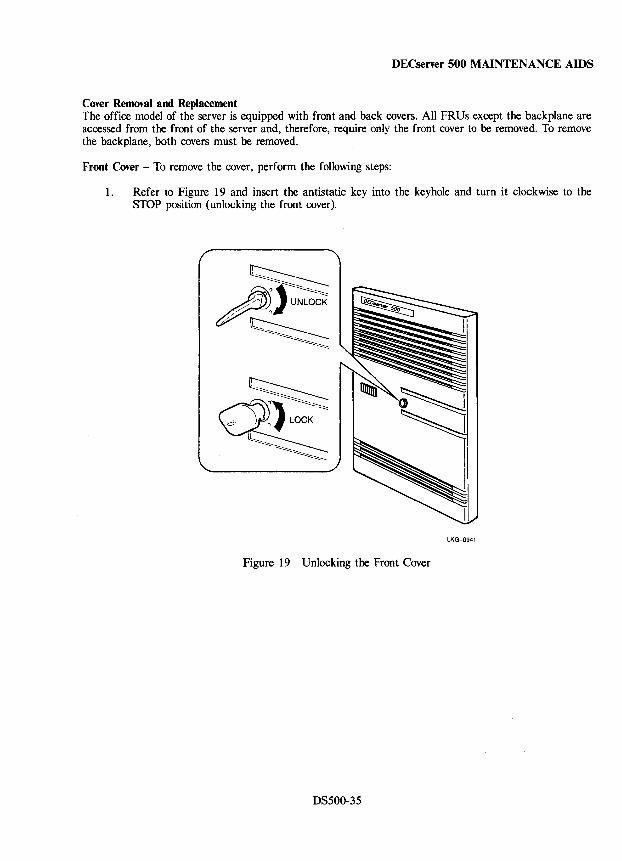
DECserver 500 MAINTENANCE AIDS
Cover Removal and Replacement The office model of the server is equipped with front and back covers. All FRUs except the backplane are accessed from the front of the server and, therefore, require only the front cover to be removed. To remove the backplane, both covers must be removed.
Front Cover - To remove the cover, perform the following steps:
1. Refer to Figure 19 and insert the antistatic key into the keyhole and turn it clockwise to the STOP position (unlocking the front cover).
LKG-0941
Figure 19 Unlocking the Front Cover
DS500-35
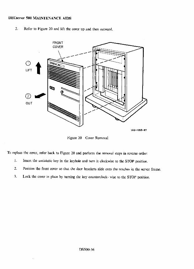
DECserver 500 MAINTENANCE AIDS
2. Refer to Figure 20 and lift the cover up and then outward.
CD LIFT t (?), OUT
LKG-1055-87
Figure 20 Cover Removal
To replace the cover, refer back to Figure 20 and perform the removal steps in reverse order:
1. Insert the antistatic key in the keyhole and turn it clockwise to the STOP position.
2. Position the front cover so that the door brackets slide onto the notches in the server frame.
3. Lock the cover in place by turning the key counterclock- wise to the STOP position.
DS500-36
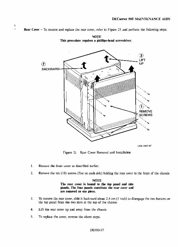
DECserver 500 MAINTENANCE AIDS
Rear Cover - To remove and replace the rear cover, refer to Figure 21 and perform the following steps:
NOTE This procedure requires a phillips-head screwdriver.
® BACKWARD~~~~~
, , , ", ':::'''''G
" ''''-''Q
" CD'''''''Q REMOVE ,~CREWS
--------- :-"~ ",
LKG-1057-87
Figure 21 Rear Cover Removal and Installation
1. Remove the front cover as described earlier.
2. Remove the ten (10) screws (five on each side) holding the rear cover to the front of the chassis.
NOTE The rear cover is bound to the top panel and side panels. The four panels constitute the rear cover and are removed as one piece.
3. To remove the rear cover, slide it backward about 2.4 cm (1 inch) to disengage the two buttons on the top panel from the two slots at the top of the chassis.
4. Lift the rear cover up and away from the chassis.
5. To replace the cover, reverse the above steps.
DS500-37
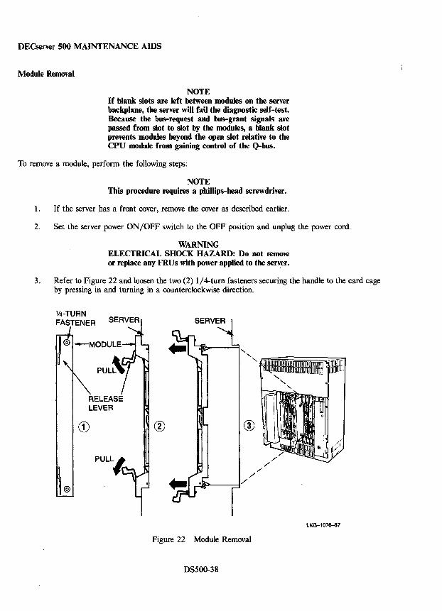
DECserver 500 MAINTENANCE AIDS
Module Removal
NOTE If blank slots are left between modules on the server backplane, the server will fail the diagnostic self-test. Because the bus-request and bus-grant signals are passed from slot to slot by the modules, a blank slot prevents modules beyond the open slot relative to the CPU module from gaining control of the Q-bus.
To remove a module, perform the following steps:
NOTE This procedure requires a phillips-head screwdriver.
1. If the server has a front cover, remove the cover as described earlier.
2. Set the server power ON/OFF switch to the OFF position and unplug the power cord.
WARNING ELECTRICAL SHOCK HAZARD: Do not remove or replace any FRUs with power applied to the server.
3. Refer to Figure 22 and loosen the two (2) lj4-turn fasteners securing the handle to the card cage by pressing in and turning in a counterclockwise direction.
V4-TURN FASTENER
RELEASE LEVER
®
"-" "
®
Figure 22 Module Removal
OS500-38
LKG-1076-87
DECserver 500 MAINTENANCE AIDS
4. Simultaneously pull the upper and lower release levers outward to disengage the module from the backplane. Gently slide the module outward and remove it from the server.
5. Put the module in a safe place.
6. If the module is to be returned to Digital Equipment Corporation, it must be properly packed for shipping.
NOTE If the module is to be replaced by a new module, use the shipping container and packing material from the new module to pack and ship this module.
DS500-39
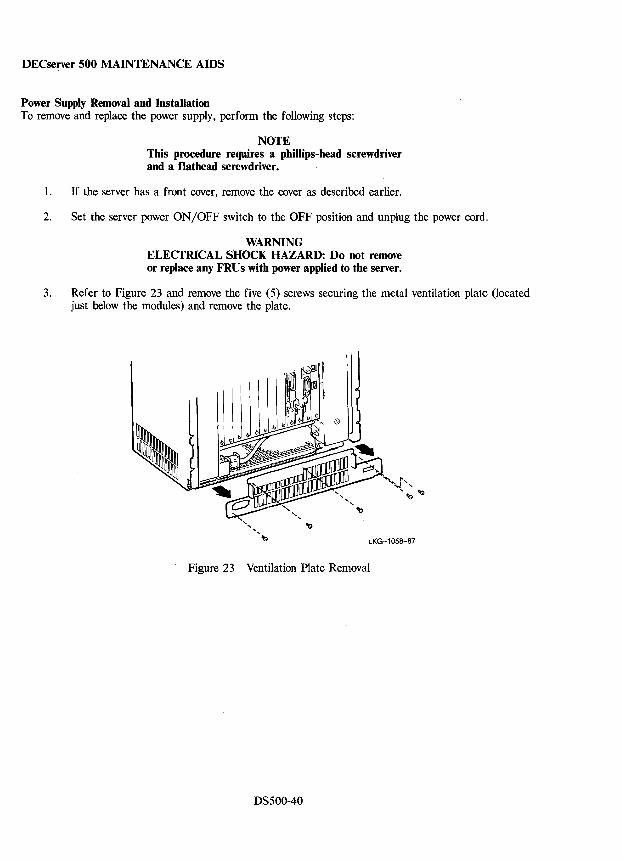
DECserver 500 MAINTENANCE AIDS
Power Supply Removal and Installation To remove and replace the power supply, perform the following steps:
NOTE This procedure requires a phillips-head screwdriver and a flathead screwdriver.
1. If the server has a front cover, remove the cover as described earlier.
2. Set the server power ON/OFF switch to the OFF position and unplug the power cord.
WARNING ELECTRICAL SHOCK HAZARD: Do not remove or replace any FRUs with power applied to the server.
3. Refer to Figure 23 and remove the five (5) screws securing the metal ventilation plate (located just below the modules) and remove the plate.
< Figure 23 Ventilation Plate Removal
DS500-40
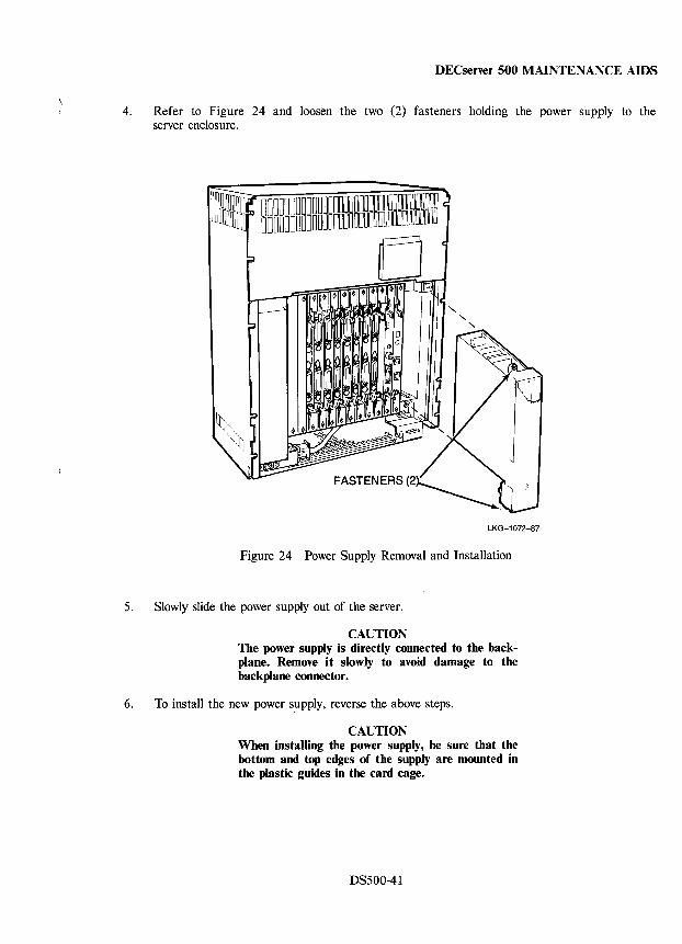
DECserver 500 MAINTENANCE AIDS
4. Refer to Figure 24 and loosen the two (2) fasteners holding the power supply to the server enclosure.
LKG-1072-87
Figure 24 Power Supply Removal and Installation
5. Slowly slide the power supply out of the server.
CAUTION The power supply is directly connected to the backplane. Remove it slowly to avoid damage to the backplane connector.
6. To install the new power supply, reverse the above steps.
CAUTION When installing the power supply, be sure that the bottom and top edges of the supply are mounted in the plastic guides in the card cage.
DS500-41
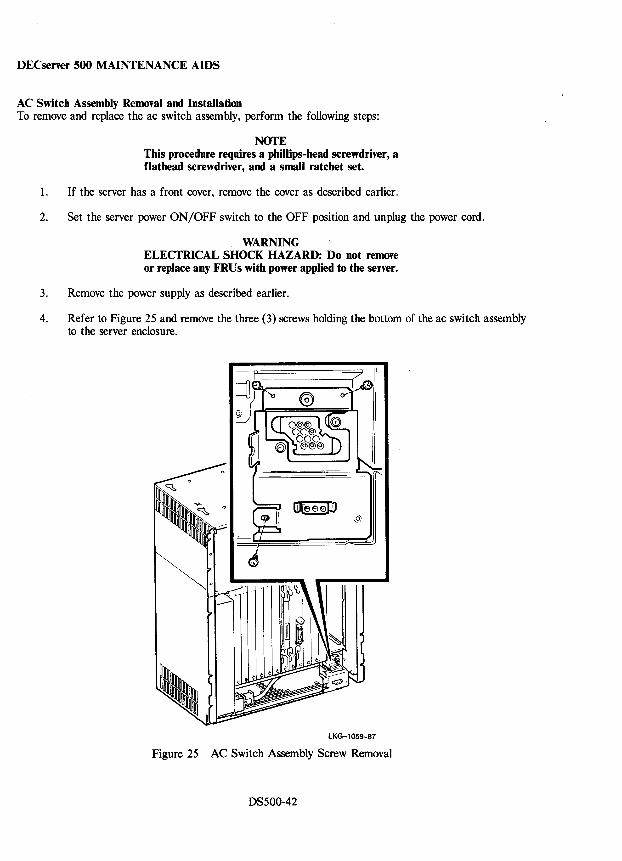
DECserver 500 MAINTENANCE AIDS
AC Switch Assembly Removal and Installation To remove and replace the ac switch assembly, perform the following steps:
NOTE This procedure requires a phillips-head screwdriver, a flathead screwdriver, and a small ratchet set.
1. If the server has a front cover, remove the cover as described earlier.
2. Set the server power ON/OFF switch to the OFF position and unplug the power cord.
WARNING ELECTRICAL SHOCK HAZARD: Do not remove or replace any FRUs with power applied to the server.
3. Remove the power supply as described earlier.
4. Refer to Figure 25 and remove the three (3) screws holding the bottom of the ac switch assembly to the server enclosure.
LKG-1059-87
Figure 25 AC Switch Assembly Screw Removal
DS500-42
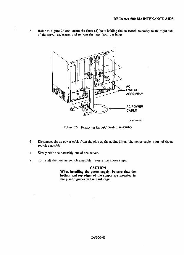
DECserver 500 MAINTENANCE AIDS
5. Refer to Figure 26 and locate the three (3) bolts holding the ac switch assembly to the right side of the server enclosure, and remove the nuts from the bolts.
AC ~~~~~--";~SWITCH
ASSEMBLY
\..-___ AC POWER CABLE
LKG-1070-87
Figure 26 Removing the AC Switch Assembly
6. Disconnect the ac power cable from the plug on the ac line filter. The power cable is part of the ac switch assembly.
7. Slowly slide the assembly out of the server.
8. To install the new ac switch assembly, reverse the above steps.
CAUTION When installing the power supply, be sure that the bottom and top edges of the supply are mounted in the plastic guides in the card cage.
DS500-43
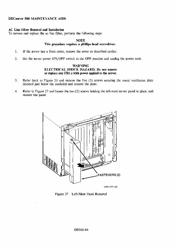
DECserver 500 MAINTENANCE AIDS
AC Line Filter Removal and Installation To remove and replace the ac line filter, perform the following steps:
NOTE This procedure requires a phillips-head screwdriver.
1. If the server has a front cover, remove the cover as described earlier.
2. Set the server power ON/OFF switch to the OFF position and unplug the power cord.
WARNING ELECTRICAL SHOCK HAZARD: Do not remove or replace any FRUs with power applied to the server.
3. Refer back to Figure 23 and remove the five (5) screws securing the metal ventilation plate (located just below the modules) and remove the plate.
4. Refer to Figure 27 and loosen the two (2) screws holding the left-most server panel in place, and remove the panel.
~FASTENERS (2)
LKG-1071-87
Figure 27 Left-Most Panel Removal
DS500-44
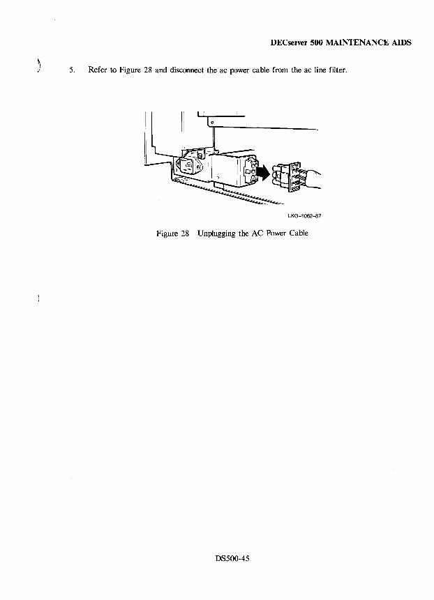
DECserver 500 MAINTENANCE AIDS
5. Refer to Figure 28 and disconnect the ac power cable from the ac line filter.
LKG-1062-87
Figure 28 Unplugging the AC Power Cable
DS500-45
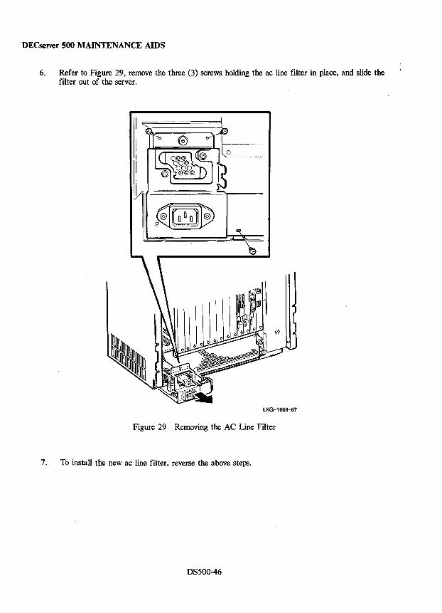
DECserver 500 MAINTENANCE AIDS
6. Refer to Figure 29, remove the three (3) screws holding the ac line filter in place, and slide the filter out of the server.
LKG-1068-87
Figure 29 Removing the AC Line Filter
7. To install the new ac line filter, reverse the above steps.
DS500-46
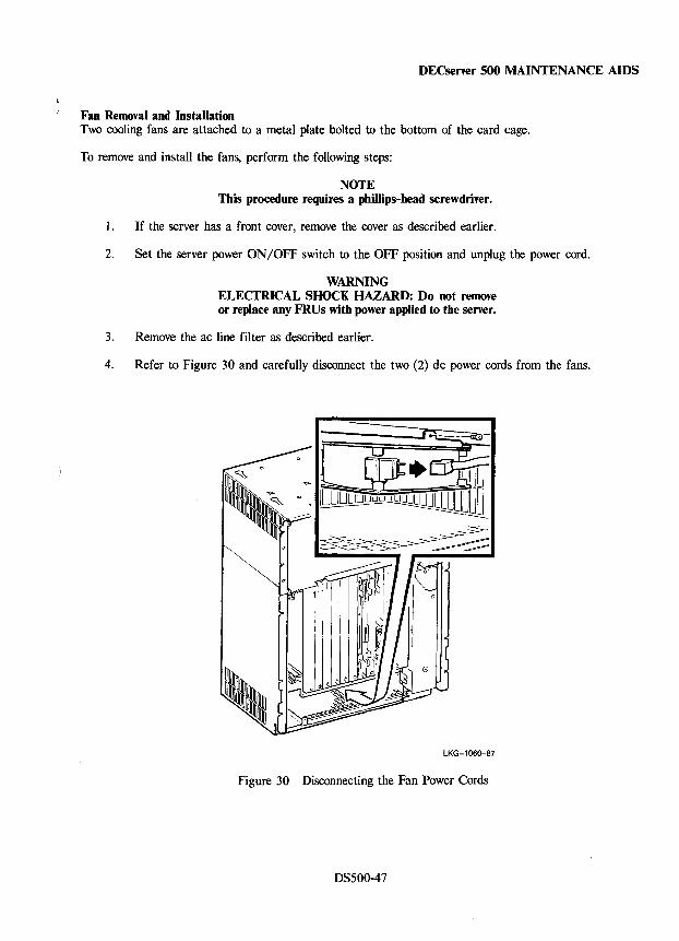
DECserver 500 MAINTENANCE AIDS
Fan Removal and Installation Two cooling fans are attached to a metal plate bolted to the bottom of the card cage.
To remove and install the fans, perform the following steps:
NOTE This procedure requires a phillips-head screwdriver.
1. If the server has a front cover, remove the cover as described earlier.
2. Set the server power ON/OFF switch to the OFF position and unplug the power cord.
WARNING ELECTRICAL SHOCK HAZARD: Do not remove or replace any FRUs with power applied to the server.
3. Remove the ac line filter as described earlier.
4. Refer to Figure 30 and carefully disconnect the two (2) dc power cords from the fans.
[ 9t!.~ J
LKG-1060-87
Figure 30 Disconnecting the Fan Power Cords
DS500-47
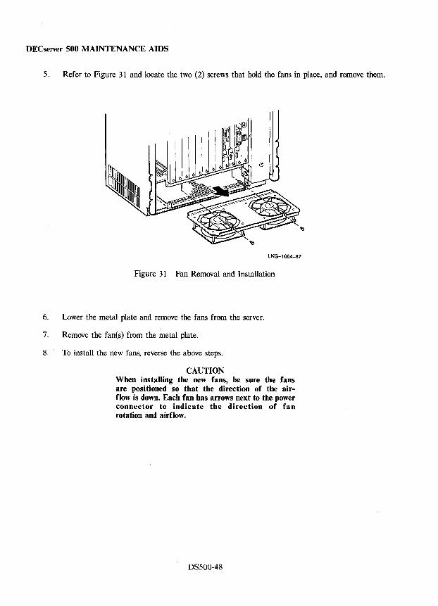
DECserver 500 MAINTENANCE AIDS
5. Refer to Figure 31 and locate the two (2) screws that hold the fans in place, and remove them.
LKG-l064-87
Figure 31 Fan Removal and Installation
6. Lower the metal plate and remove the fans from the server.
7. Remove the fan(s) from the metal plate.
8. To install the new fans, reverse the above steps.
CAUTION When installing the new fans, be sure the fans are positioned so that the direction of the airflow is down. Each fan has arrows next to the power connector to indicate the direction of fan rotation and airflow.
DS500-48
DECserver 500 MAINTENANCE AIDS
~ v CPU Module Installation Procedure
The CPU module installation procedure is made up of the following steps:
• Module installation • Testing
Module Installation - Perform the following steps:
NOTE This procedure requires a phillips-head screwdriver.
1. Ensure that the server power ON/OFF switch is OFF and the power cord is unpluged.
WARNING ELECTRICAL SHOCK HAZARD: Do not remove or replace any FRUs with power applied to the server.
2. Hold the module up to the CPU module slot with the component side facing the power supply.
3. Align the module with the card cage guides and slide it into the slot until it engages the backplane. The module handle should be about a 1/4-inch from being flush with the Ethernet controller module handle when it engages the backplane.
4. Simultaneously pull the upper release lever down and the lower release lever up to fully seat the module. The module handle should now be flush with the Ethernet controller module handle.
5. Carefully press in on the 1/4-turn fasteners and turn them clockwise to secure the module.
DS500-49
DECserver 500 MAINTENANCE AIDS
Testing - To test the CPU module to ensure that it is working properly, proceed as follows:
1. Refer to the "Connecting A Local Console Terminal" section and connect an interactive terminal to local console port AI.
2. Plug in the server power cord and set the server power ON/OFF switch to ON.
3. Observe that the CPU light emitting diode (LED) display illuminates.
4. Use a small screwdriver to set the BOOT MODE select switch to position 2 (Local Console mode). The server allows five (5) seconds for a boot mode to be selected when the power ON/OFF is turned ON; otherwise, simply press the BOOT switch after selecting Boot Mode 2.
5. Observe that the server executes the diagnostic self-test program and then alternately displays the numbers 1 and 6 in the LED display to indicate that the local console terminal is activated.
6. Type the following commands at the local console prompt:
Console > Desel/test:all<RET> Console >Sel/test:Sys<RET> Console >Start/EOP: 1 <RET>
NOTE While the System Exerciser Test is executing, the LED display alternately displays the numbers 1 and 5.
7. Observe the local console for error information. If the test passes, the message: "End of Pass I" is displayed. If the test fails, the message: "n errors" is displayed (n equals the number of errors detected).
DS500-50
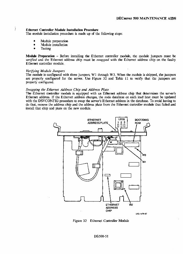
DECserver 500 MAINTENANCE AIDS
Ethernet Controller Module Installation Procedure The module installation procedure is made up of the following steps:
• Module preparation • Module installation • Testing
Module Preparation - Before installing the Ethernet controller module, the module jumpers must be verified and the Ethernet address chip must be swapped with the Ethernet address chip on the faulty Ethernet controller module.
Verifying Module Jumpers The module is configured with three jumpers, WI through W3. When the module is shipped, the jumpers are properly configured for the server. Use Figure 32 and Table 11 to verify that the jumpers are properly configured.
Swapping the Ethernet Address Chip and Address Plate The Ethernet controller module is equipped with an Ethernet address chip that determines the server's Ethernet address. If the Ethernet address changes, the node database on each load host must be updated with the DSVCONFIG procedure to swap the server's Ethernet address in the database. To avoid having to do that, remove the address chip and the address plate from the Ethernet controller module that failed and install that chip and plate on the new module.
ETHERNET W2 ADDRESS CHIP
LKG-l079-87
Figure 32 Ethernet Controller Module
DS500-5I
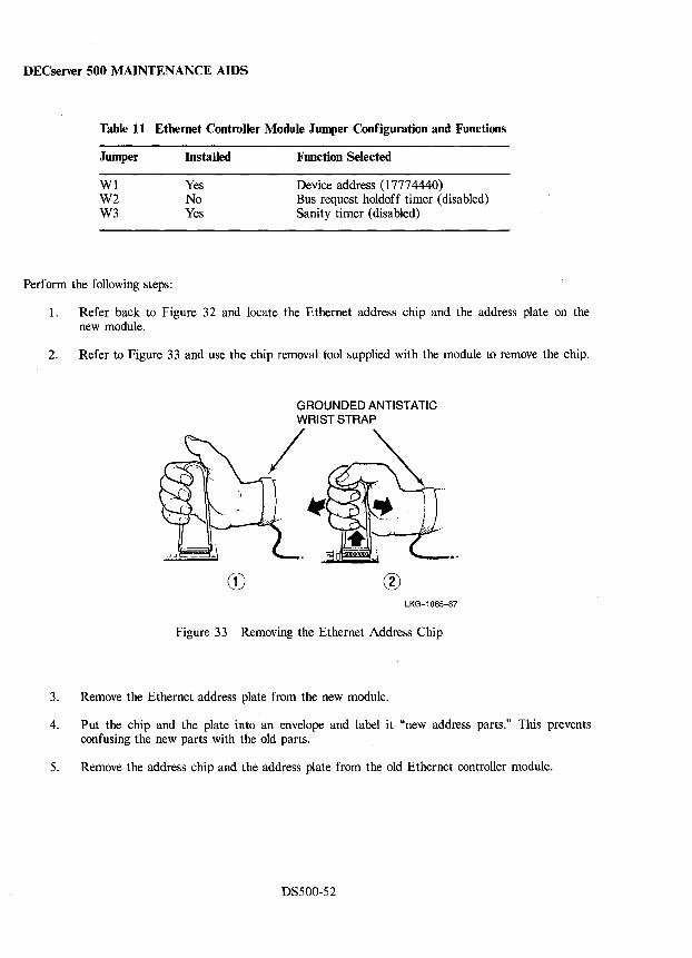
DECserver 500 MAINTENANCE AIDS
Table 11 Ethernet Controller Module Jumper Configuration and Functions
Jumper
WI W2 W3
Perform the following steps:
Installed
Yes No Yes
Function Selected
Device address (17774440) Bus request holdoff timer (disabled) Sanity timer (disabled)
1. Refer back to Figure 32 and locate the Ethernet address chip and the address plate on the new module.
2. Refer to Figure 33 and use the chip removal tool supplied with the module to remove the chip.
® LKG-1065-87
Figure 33 Removing the Ethernet Address Chip
3. Remove the Ethernet address plate from the new module.
4. Put the chip and the plate into an envelope and label it "new address parts." This prevents confusing the new parts with the old parts.
5. Remove the address chip and the address plate from the old Ethernet controller module.
DS500-52
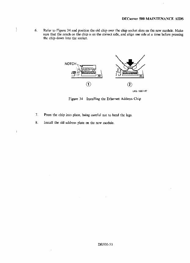
DECserver 500 MAINTENANCE AIDS
6. Refer to Figure 34 and position the old chip over the chip socket slots on the new module. Make sure that the notch on the chip is on the correct side, and align one side at a time before pressing the chip down into the socket.
CD ® LKG-1067-87
Figure 34 Installing the Ethernet Address Chip
7. Press the chip into place, being careful not to bend the legs.
8. Install the old address plate on the new module.
DS500-53
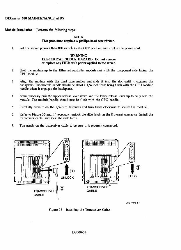
DECserver 500 MAINTENANCE AIDS
Module Installation - Perform the following steps:
NOTE This procedure requires a phillips-head screwdriver.
1. Set the server power ON/OFF switch to the OFF position and unplug the power cord.
WARNING ELECTRICAL SHOCK HAZARD: Do not remove or replace any FRUs with power applied to the server.
2. Hold the module up to the Ethernet controller module slot with the component side facing the CPU module.
3. Align the module with the card cage guides and slide it into the slot until it engages the backplane. The module handle should be about a 1/4-inch from being flush with the CPU module handle when it engages the backplane.
4. Simultaneously pull the upper release lever down and the lower release lever up to fully seat the module. The module handle should now be flush with the CPU handle.
5. Carefully press in on the 1/4-turn fasteners and turn them clockwise to secure the module.
6. Refer to Figure 35 and, if necessary, unlock the slide latch on the Ethernet connector, install the transceiver cable, and lock the slide latch.
7. Tug gently on the transceiver cable to be sure it is securely connected.
TRANSCEIVER CABLE
®
Figure 35 Installing the Transceiver Cable
DS500-S4
LKG-1075-87
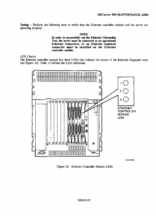
DECserver 500 MAINTENANCE AIDS
Testing - Perform the following tests to verify that the Ethernet controller module and the server are operating properly.
LED Checks
NOTE In order to successfully run the Ethernet Citizenship Test, the server must be connected to an operational Ethernet transceiver, or an Ethernet loopback connector must be installed on the Ethernet controller module.
The Ethernet controller module has three LEDs that indicate the results of the Ethernet diagnostic tests (see Figure 36). Table 12 defines the LED indications.
00000000000000000000000000000000000 00000000000000000000000000000000000
o
0000000000 0~ 000000000000000000000 DBJ 0
Figure 36 Ethernet Controller Module LEDs
DS500-55
ETHERNET CONTROLLER MODULE LEOs
LKG-0550
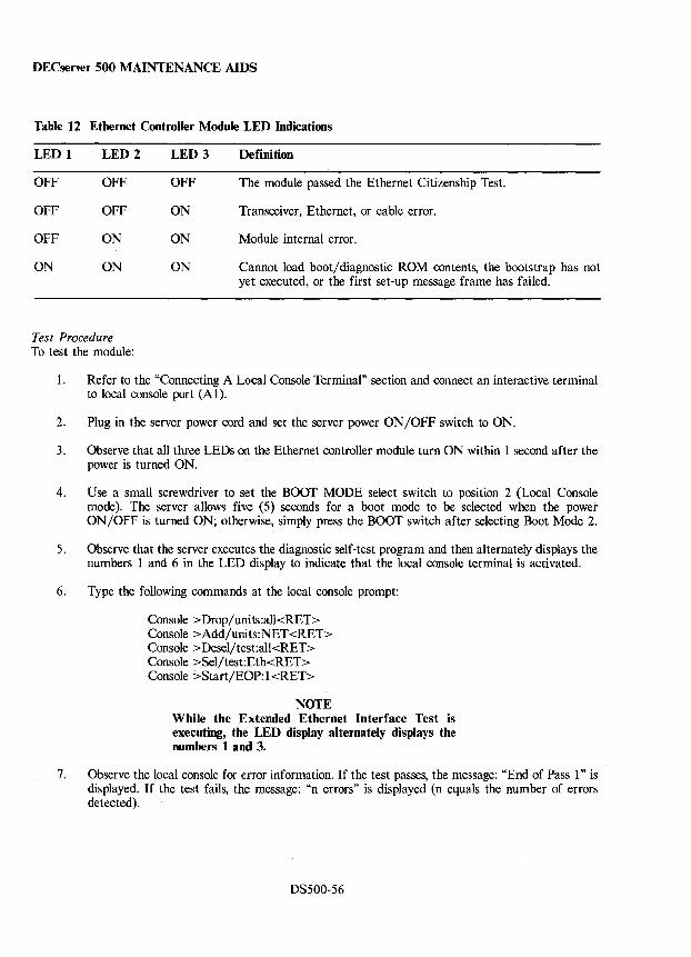
DECserver 500 MAINTENANCE AIDS
Table 12 Ethernet Controller Module LED Indications
LED 1 LED 2 LED 3 Definition
OFF OFF OFF The module passed the Ethernet Citizenship Test.
OFF OFF ON Transceiver, Ethernet, or cable error.
OFF ON ON Module internal error.
ON ON ON Cannot load boot/diagnostic ROM contents, the bootstrap has not yet executed, or the first set-up message frame has failed.
Test Procedure To test the module:
1. Refer to the "Connecting A Local Console Terminal" section and connect an interactive terminal to local console port (Al).
2. Plug in the server power cord and set the server power ON/OFF switch to ON.
3. Observe that all three LEOs on the Ethernet controller module turn ON within 1 second after the power is turned ON.
4. Use a small screwdriver to set the BOOT MODE select switch to position 2 (Local Console mode). The server allows five (5) seconds for a boot mode to be selected when the power ON/OFF is turned ON; otherwise, simply press the BOOT switch after selecting Boot Mode 2.
5. Observe that the server executes the diagnostic self-test program and then alternately displays the numbers 1 and 6 in the LED display to indicate that the local console terminal is activated.
6. Type the following commands at the local console prompt:
Console >Drop/units:all<RET> Console >Add/units:NET <RET> Console > Desel/test:all<RET> Console >Sel/test:Eth<RET> Console >Start/EOP: 1 <RET>
NOTE While the Extended Ethernet Interface Test is executing, the LED display alternately displays the numbers 1 and 3.
7. Observe the local console for error information. If the test passes, the message: "End of Pass 1" is displayed. If the test fails, the message: "n errors" is displayed (n equals the number of errors detected).
DS500-56
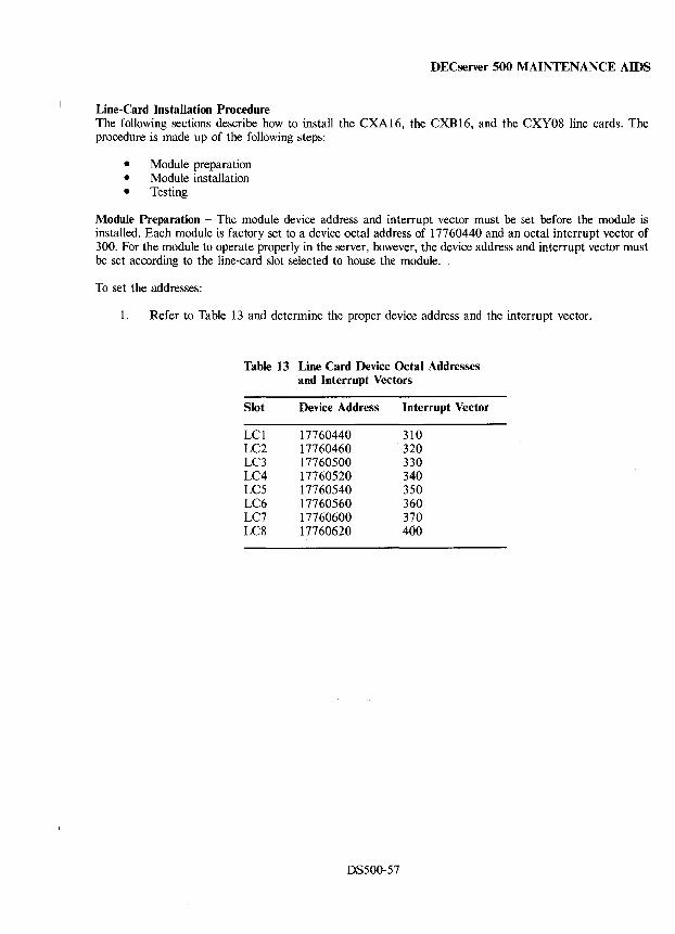
DECserver 500 MAINTENANCE AIDS
Line-Card Installation Procedure The following sections describe how to install the CXAI6, the CXBI6, and the CXY08 line cards. The procedure is made up of the following steps:
• Module preparation • Module installation • Testing
Module Preparation - The module device address and interrupt vector must be set before the module is installed. Each module is factory set to a device octal address of 17760440 and an octal interrupt vector of 300. For the module to operate properly in the server, however, the device address and interrupt vector must be set according to the line-card slot selected to house the module.
To set the addresses:
1. Refer to Table 13 and determine the proper device address and the interrupt vector.
Table 13 Line Card Device Octal Addresses and Interrupt Vectors
Slot Device Address Interrupt Vector
LCI 17760440 310 LC2 17760460 320 LC3 17760500 330 LC4 17760520 340 LC5 17760540 350 LC6 17760560 360 LC7 17760600 370 LC8 17760620 400
DS500-57
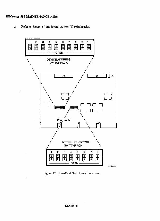
DECserver 500 MAINTENANCE AIDS
2. Refer to Figure 37 and locate the two (2) switchpacks.
1 2 3 4 5 6 7 8 9 10
mmm~~m~mm~ -------OPEN -------
\ \
\ \
\
DEVICE ADDRESS SWITCHPACK
I I
I I
I
\ , J2 / I
/
"",,,-__ J_, _ ....... 1 0 LED
\
\ I \ /
\ / \ / \ r., /
, L-1/ r~ I
LJ, " r --, r "I IIffIIEHD mmm / ',L ..J L --I
I \ II \
Wr::::sl C=W \ \
\
INTERRUPT VECTOR SWITCHPACK
\ \
\ \
\
2345678
\ \
mmmmmmmm ----- OPEN -----
Figure 37 Line-Card Switch pack Locations
DS500-58
r-, L...J
LKG-0551
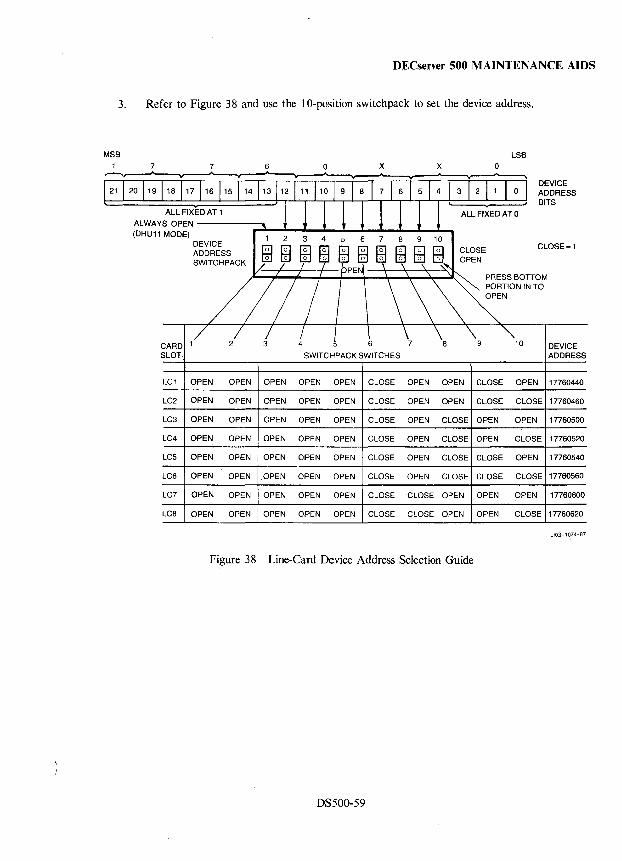
DECserver 500 MAINTENANCE AIDS
3. Refer to Figure 38 and use the lO-position switchpack to set the device address.
MSB LSB
7 7 6 o x x o
121 1 20 119118 117116 115 114 13112 111 110 1 9 1 8 1 7 1 6 1 5 1 4 1 3 DEVICE ADDRESS BITS
ALWAYSA~~~I~E_D_A_T_1 ___ .... , ! 1 l! J J 1 1 \ (DHU11 MODE)
CARD SLOT
DEVICE ADDRESS SWITCH PACK
SWITCHPACK SWITCHES
ALL FIXED AT 0
CLOSE=1
DEVICE ADDRESS
LC1 OPEN OPEN OPEN OPEN OPEN CLOSE OPEN OPEN CLOSE OPEN 17760440
LC2 OPEN OPEN OPEN OPEN OPEN CLOSE OPEN OPEN CLOSE CLOSE 17760460
LC3 OPEN OPEN OPEN OPEN OPEN CLOSE OPEN CLOSE OPEN OPEN 17760500
LC4 OPEN OPEN OPEN OPEN OPEN CLOSE OPEN CLOSE OPEN CLOSE 17760520
LC5 OPEN OPEN OPEN OPEN OPEN CLOSE OPEN CLOSE CLOSE OPEN 17760540
LC6 OPEN OPEN OPEN OPEN OPEN CLOSE OPEN CLOSE CLOSE CLOSE 17760560
LC7 OPEN OPEN OPEN OPEN OPEN CLOSE CLOSE OPEN OPEN OPEN 17760600
LC8 OPEN OPEN OPEN OPEN OPEN CLOSE CLOSE OPEN OPEN CLOSE 17760620
LKG-1 074-87
Figure 38 Line-Card Device Address Selection Guide
DS500-59
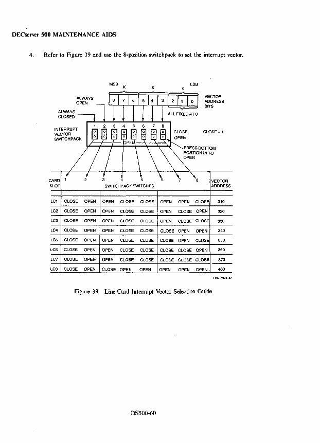
DECserver 500 MAINTENANCE AIDS
4. Refer to Figure 39 and use the 8-position switchpack to set the interrupt vector.
MSB LSB X X 0
ALWAYS VECTOR OPEN ADDRESS
BITS ALWAYS CLOSED
4 6 7 INTERRUPT CLOSE CLOSE = 1 VECTOR SWITCH PACK
CARD 1 4 a VECTOR SLOT SWITCH PACK SWITCHES ADDRESS
LC1 CLOSE OPEN OPEN CLOSE CLOSE OPEN OPEN CLOSE 310
LC2 CLOSE OPEN OPEN CLOSE CLOSE OPEN CLOSE OPEN 320
LC3 CLOSE OPEN OPEN CLOSE CLOSE OPEN CLOSE CLOSE 330
LC4 CLOSE OPEN OPEN CLOSE CLOSE CLOSE OPEN OPEN 340
LC5 CLOSE OPEN OPEN CLOSE CLOSE CLOSE OPEN CLOSE 350
LC6 CLOSE OPEN OPEN CLOSE CLOSE CLOSE CLOSE OPEN 360
LC7 CLOSE OPEN OPEN CLOSE CLOSE CLOSE CLOSE CLOSE 370
Lca CLOSE OPEN CLOSE OPEN OPEN OPEN OPEN OPEN 400
LKG-l073-87
Figure 39 Line-Card Interrupt Vector Selection Guide
DS500-60
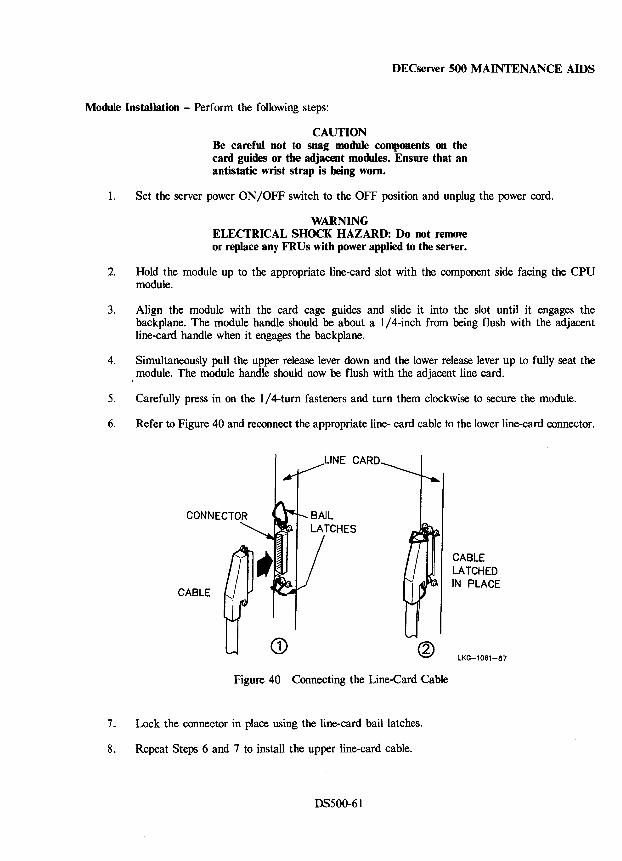
DECserver 500 MAINTENANCE AIDS
Module Installation - Perform the following steps:
CAUTION Be careful not to snag module components on the card guides or the adjacent modules. Ensure that an antistatic wrist strap is being worn.
1. Set the server power ON/OFF switch to the OFF position and unplug the power cord.
WARNING ELECTRICAL SHOCK HAZARD: Do not remove or replace any FRUs with power applied to the server.
2. Hold the module up to the appropriate line-card slot with the component side facing the CPU module.
3. Align the module with the card cage guides and slide it into the slot until it engages the backplane. The module handle should be about a 1/ 4-inch from being flush with the adjacent line-card handle when it engages the backplane.
4. Simultaneously pull the upper release lever down and the lower release lever up to fully seat the I module. The module handle should now be flush with the adjacent line card.
5. Carefully press in on the 1/ 4-turn fasteners and turn them clockwise to secure the module.
6. Refer to Figure 40 and reconnect the appropriate line- card cable to the lower line-card connector.
LINE CARD
CABLE
CD Figure 40 Connecting the Line-Card Cable
7. Lock the connector in place using the line-card bail latches.
8. Repeat Steps 6 and 7 to install the upper line-card cable.
DS500-61
CABLE LATCHED IN PLACE
LKG-l061-87
DECserver 500 MAINTENANCE AIDS
Testing - To test the line card to ensure that it is working properly, proceed as follows:
1. Refer to the "Connecting A Local Console Terminal" section and connect a console terminal to the server local console port (AI).
2. Plug in the server power cord and set the server power ON/OFF switch to ON.
3. Use a small screwdriver to set the BOOT MODE select switch to position 3 (System Configuration Assistance Program). The server allows five (5) seconds for a boot mode to be selected when the power ON/OFF is turned ON; otherwise, simply press the BOOT switch after selecting Boot Mode 3.
4. Observe that the server executes the diagnostic self-test program, that the LED display constantly displays the number 3, and that a configuration map is printed out at the local console terminal.
5. Check the configuration map to ensure that the line card's device address and interrupt vector are set correctly.
6. Use a small screwdriver to set the BOOT MODE select switch to position 2 (Local Console mode) and press the BOOT switch.
7. Observe that the server executes the diagnostic self-test program and then alternately displays the numbers 1 and 6 in the LED display to indicate that the local console terminal is activated.
8. Type the following commands at the local console prompt:
Console >Drop/units:all<RET> Console >Add/units:LCn<RET> Console >Desel/test:all<RET> Console >Sel/test:Asy<RET> Console >Start/EOP: 1 <RET>
NOTE The "n" in LCn represents the line-card slot number. While the Asynchronous Test is executing, the LED display alternately displays numbers 1 and 4.
9. Observe the local console for error information. If the test passes, the message: "End of Pass 1" is displayed. If the test fails, the message: "n errors" is displayed (n equals the number of errors detected).
DS500-62
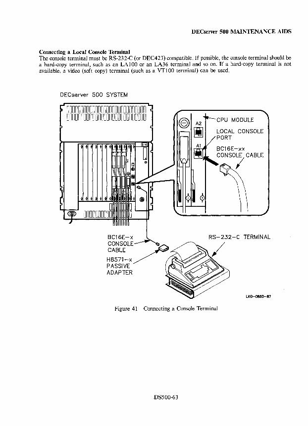
DECserver 500 MAINTENANCE AIDS
Connecting a Local Console Terminal The console terminal must be RS-232-C (or DEC423) compatible. If possible, the console terminal should be a hard-copy terminal, such as an LA 1 00 or an LA36 terminal and so on. If a hard-copy terminal is not available, a video (soft copy) terminal (such as a VT100 terminal) can be used.
DECserver 500 SYSTEM
0000000000000000000000000000 0000000000000000000000000000 CPU MODULE
LOCAL CONSOLE PORT
BC16E-xx CONSOLE CABLE
I
LKG-085o-S7
Figure 41 Connecting a Console Terminal
DS500-63
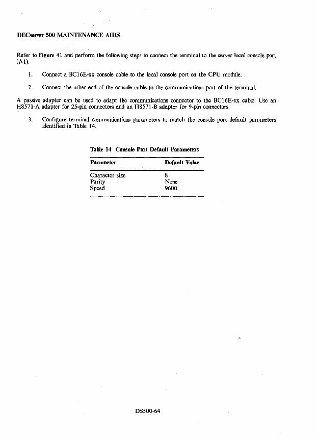
DECserver 500 MAINTENANCE AIDS
Refer to Figure 41 and perform the following steps to comlect the terminal to the server local console port (Al).
1. Connect a BCI6E-xx console cable to the local console port on the CPU module.
2. Connect the other end of the console cable to the communications port of the terminal.
A passive adapter can be used to adapt the communications connector to the BCI6E-xx cable. Use an H8571-A adapter for 25-pin connectors and an H8571-B adapter for 9-pin connectors.
3. Configure terminal communications parameters to match the console port default parameters identified in Table 14.
Table 14 Console Port Default Parameters
Parameter
Character size Parity Speed
DS500-64
Default Value
8 None 9600
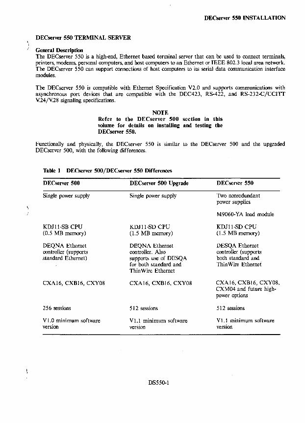
DECserver 550 INSTALLATION
DECserver 550 TERMINAL SERVER
General Description The DECserver 550 is a high-end, Ethernet based terminal server that can be used to connect terminals, printers, modems, personal computers, and host computers to an Ethernet or IEEE 802.3 local area network. The DECserver 550 can support connections of host computers to its serial data communication interface modules.
The DEC server 550 is compatible with Ethernet Specification V2.0 and supports communications with asynchronous port devices that are compatible with the DEC423, RS-422, and RS-232-CjCCITT V.24jY.28 signaling specifications.
NOTE Refer to the DECserver 500 section in this volume for details on installing and testing the DECserver 550.
Functionally and physically, the DECserver 550 is similar to the DECserver 500 and the upgraded DECserver 500, with the following differences.
Table 1 DECserver 500jDECserver 550 Differences
DECserver 500
Single power supply
KDJ II-SB CPU (0.5 MB memory)
DEQNA Ethernet controller (supports standard Ethernet)
CXA16, CXB16, CXY08
256 sessions
Vl.O minimum software version
DECserver 500 Upgrade
Single power supply
KDJ II.,SD CPU (1.5 MB memory)
DEQNA Ethernet controller. Also supports use of DESQA for both standard and Thin Wire Ethernet
CXA16, CXB16, CXY08
512 sessions
V 1.1 minimum software version
DS550-1
DECserver 550
Two nonredundant power supplies
M9060-YA load module
KDJ II-SD CPU (1.5 MB memory)
DESQA Ethernet controller (supports both standard and Thin Wire Ethernet
CXA 16, CXB 16, CXY08, CXM04 and future highpower options
512 sessions
V 1.1 minimum software version
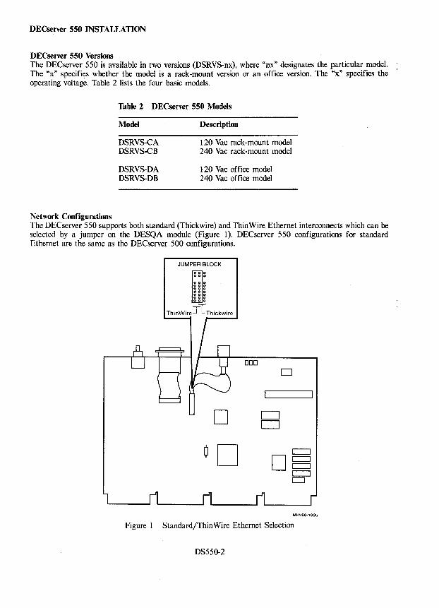
DECserver 550 INSTALLATION
DECserver 550 Versions The DECserver 550 is available in two versions (DSRVS-nx), where "nx" designates the particular model. The "n" specifies whether the model is a rack-mount version or an office version. The "x." specifies the operating voltage. Table 2 lists the four basic models.
Network Configurations
Table 2 DECserver 550 Models
Model
DSRVS-CA DSRVS-CB
DSRVS-OA DSRVS-OB
Description
120 Vac rack-mount model 240 Vac rack-mount model
120 Vac office model 240 Vac office model
The DECserver 550 supports both standard (Thickwire) and ThinWire Ethernet interconnects which can be selected by a jumper on the DESQA module (Figure 1). DECserver 550 configurations for standard Ethernet are the same as the DECserver 500 configurations.
JUMPER BLOCK
000 000
ggg 000 000 000 000
'-r-''-r-'
ThinWire-.J L Thickwire
D
DOD D
D
MKV88·1835
Figure 1 Standard/ThinWire Ethernet Selection
OS550-2
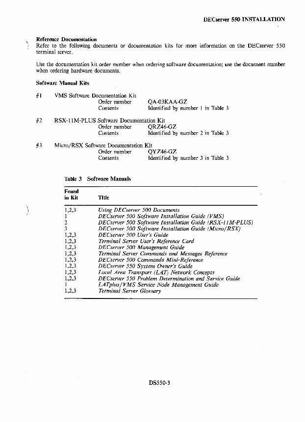
)
DECserver 550 INSTALLATION
Reference Documentation Refer to the following documents or documentation kits for more information on the DECserver 550 terminal server.
Use the documentation kit order number when ordering software documentation; use the document number when ordering hardware documents.
Software Manual Kits
#1 VMS Software Documentation Kit Order number Contents
QA-03KAA-GZ Identified by number 1 in Table 3
#2 RSX-I1M-PLUS Software Documentation Kit Order number QRZ46-GZ Contents Identified by number 2 in Table 3
#3 Micro/RSX Software Documentation Kit Order number QYZ46-GZ Contents Identified by number 3 in Table 3
Table 3 Software Manuals
Found in Kit Title
1,2,3 1 2 3 1,2,3 1,2,3 1,2,3 1,2,3 1,2,3 1,2,3 1,2,3 1,2,3 1 1,2,3
Using DECserver 500 Documents DECserver 500 Software Installation Guide (VMS) DECserver 500 Software Installation Guide (RSX-ll M-PLUS) DECserver 500 Software Installation Guide (Micro/RSX) DECserver 500 User's Guide Terminal Server User's Reference Card DECserver 500 Management Guide Terminal Server Commands and Messages Reference DECserver 500 Commands Mini-Reference DECserver 550 System Owner's Guide Local Area Transport (LAT) Network Concepts DECserver 550 Problem Determination and Service Guide LATplus/VMS Service Node Management Guide Terminal Server Glossary
DS550-3
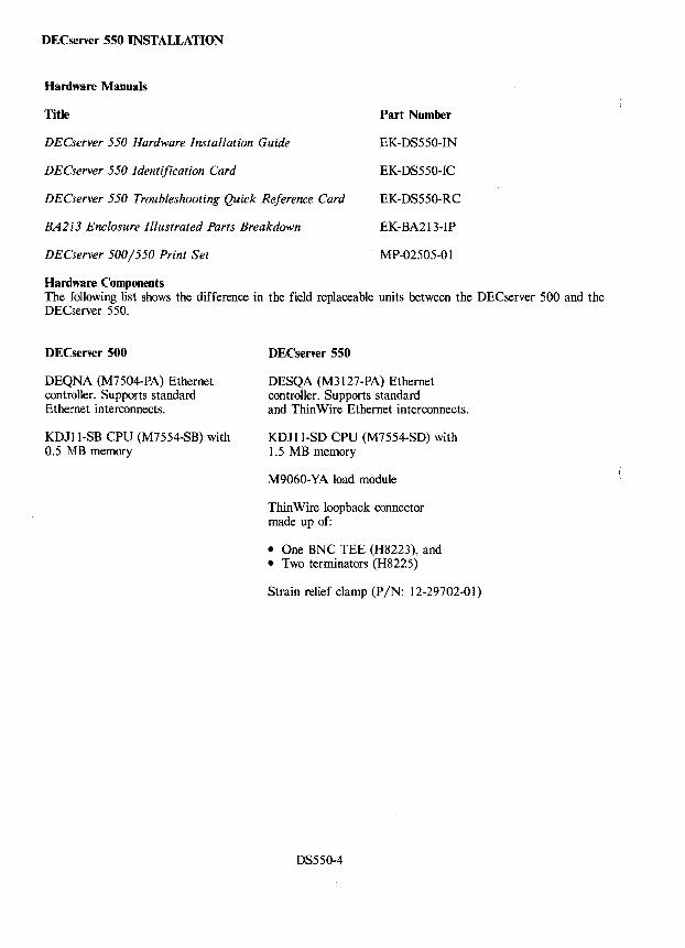
DECserver 550 INSTALLATION
Hardware Manuals
Title Part Number
DECserver 550 Hardware Installation Guide EK-DS550-IN
DECserver 550 Identification Card
DECserver 550 Troubleshooting Quick Reference Card
EK-DS550-IC
EK-DS550-RC
BA2l3 Enclosure Illustrated Parts Breakdown EK-BA213-IP
DECserver 500/550 Print Set MP-02505-0 1
Hardware Components The following list shows the difference in the field replaceable units between the DECserver 500 and the DECserver 550.
DECserver 500
DEQNA (M7504-PA) Ethernet controller. Supports standard Ethernet interconnects.
KDJ11-SB CPU (M7554-SB) with 0.5 MB memory
DECserver 550
DESQA (M3127-PA) Ethernet controller. Supports standard and Thin Wire Ethernet interconnects.
KDJI1-SD CPU (M7554-SD) with 1.5 MB memory
M9060-YA load module
Thin Wire loop back connector made up of:
• One BNC TEE (H8223), and • Two terminators (H8225)
Strain relief clamp (PIN: 12-29702-01)
DS550-4
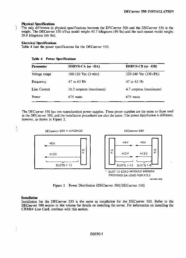
DECserver 550 INSTALLATION
Physical Specifications The only difference in physical specifications between the DECserver 500 and the DECserver 550 is the weight. The DECserver 550 office model weighs 40.7 kilograms (90 lbs) and the rack-mount model weighs 29.9 kilograms (66 lbs).
Electrical Specifications Table 4 lists the power specifications for the DECserver 550.
Table 4 Power Specifications
Parameter DSRVS-CA (or -DA) DSRVS-CB (or -DB)
Voltage range 100-120 Vac (3-wire) 220-240 Vac (IN+PE)
Frequency 47 to 63 Hz 47 to 63 Hz
Line Current 10.2 amperes (maximum) 4.7 amperes (maximum)
Power 675 watts 675 watts
The DECserver 550 has two nonredundant power supplies. These power supplies are the same as those used in the DECserver 500, and the installation procedures are also the same. The power distribution is different, however, as shown in Figure 2.
Installation
DECserver 500 + UPGRADE
.. +5V
+12V
y
vi a.:
SLOTS 1-12 ---
DECserver 550
- r--+5V +5V
vi en a.: +12V +12V a.:
'------v-----/ '----v--' - SLOTS 7-12 SLOTS 1-6 '--
* SLOT 12 LOAD MODULE M9060A PROVIDES 5A LOAD FOR P.S.2
MKV88·1836
Figure 2 Power Distribution (DECserver 500jDECserver 550)
Installation for the DECserver 550 is the same as installation for the DECserver 500. Refer to the DECserver 500 section in this volume for details on installing the server. For information on installing the CXM04 Line Card, continue with this section.
DS550·5
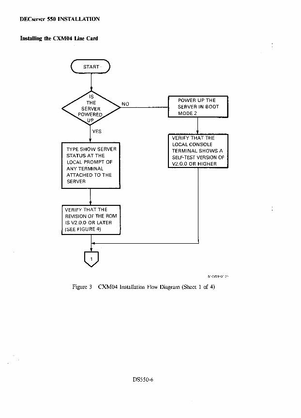
DEC~r~r550INSTALLATION
Installing the CXM04 Line Card
YES
TYPE SHOW SERVER STATUS AT THE LOCAL PROMPT OF ANY TERMINAL ATTACHED TO THE
SERVER
VERIFY THAT THE REVISION OF THE ROM IS V2.0.0 OR LATER
(SEE FIGURE 4-)
NO POWER UP THE SERVER IN BOOT MODE2
VERIFY THAT THE LOCAL CONSOLE TERMINAL SHOWS A SELF-TEST VERSION OF V2.0.0 OR HIGHER
MKV89-0134
Figure 3 CXM04 Installation Flow Diagram (Sheet 1 of 4)
OS550-6
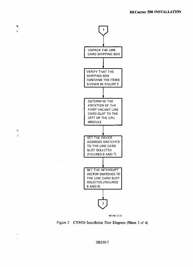
VERIFY THAT THE SHIPPING BOX CONTAINS THE ITEMS SHOWN IN FIGURE 5
DETERMINE THE LOCATION OF THE FIRST VACANT LINE CARD SLOT TO THE LEFT OF THE CPU MODULE
ADDRESS SWITCHES TO THE LINE CARD SLOT SELECTED (FIGURES 6 AND 7)
SET THE INTERRUPT VECTOR SWITCHES TO THE LINE CARD SLOT SELECTED (FIGURES 6 AND 8)
MKV89·0135
DECserver 550 INSTALLATION
Figure 3 CXM04 Installation Flow Diagram (Sheet 2 of 4)
DS550-7
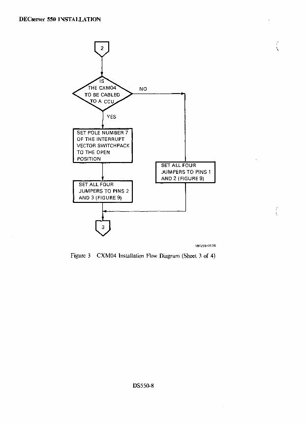
DECserver 550 INSTALLATION
YES
SET POLE NUMBER 7 OF THE INTERRUPT VECTOR SWITCHPACK TO THE OPEN POSITION
SET ALL FOUR JUMPERS TO PINS 2 AND 3 (FIGURE 9)
NO
SET ALL FOUR JUMPERS TO PINS 1 AND 2 (FIGURE 9)
MKV89-0136
Figure 3 CXM04 Installation Flow Diagram (Sheet 3 of 4)
DS550-8
(
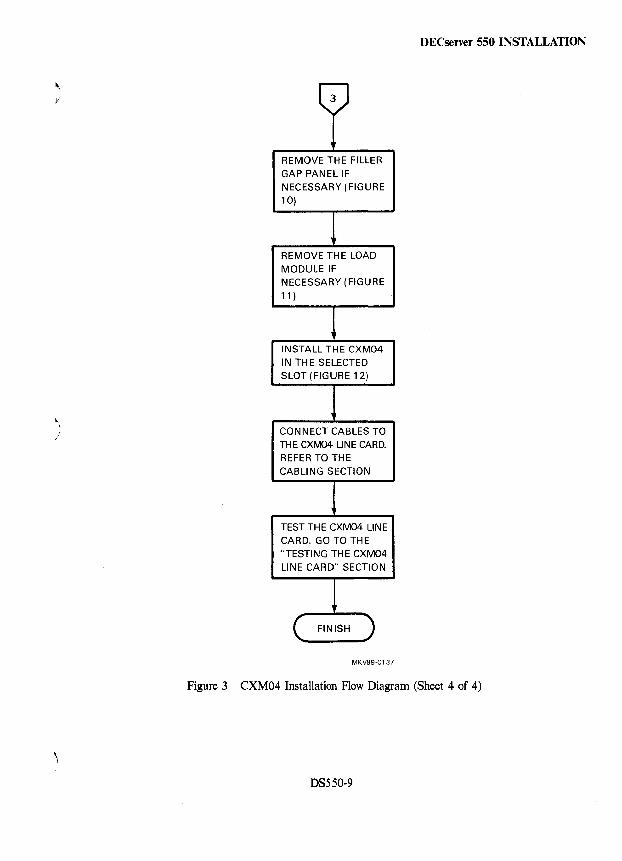
~\
Ii
)
3
REMOVE THE FILLER GAP PANEL IF NECESSARY (FIGURE 10)
REMOVE THE LOAD MODULE IF NECESSARY (FIGURE 11 )
INSTALL THE CXM04 IN THE SELECTED SLOT (FIGURE 12)
CONNECT CABLES TO THE CXM04 LINE CARD. REFER TO THE CABLING SECTION
TEST THE CXM04 LINE CARD. GO TO THE "TESTING THE CXM04 LINE CARD" SECTION
MKVB9·0137
DECserver 550 INSTALLATION
Figure 3 CXM04 Installation Flow Diagram (Sheet 4 of 4)
DS550-9

DECserver 550 INSTALLATION
Local> SHOW SERVER STATUS
DECserver 500 V2.1.1 LAT V5.1 ROM V2.0.2 Uptime: 0 1:10:40
Address: 08-00-2B-08-D2-28 Name: C212 Number: o Cur High Max
Active Ports: 1 1 33 Minutes to Shutdown: 0 Active Users: 1 1 33 DisCARDd Nodes: 0 Queue Entries: 0 0 8 Resource Errors: 0
Available Services: 18 18 N/A Port Framing Errors: 0 Local Services: 0 0 255 Port Parity Errors: 0 Reachable Nodes: 18 18 100 Port Overrun Errors: 0
Active Circuits: 0 0 64 Primary Host: JOANY Connected Nodes: 0 0 64 Load Address: AA-00-04-00-35-04 Connected Sessions: 0 0 256 Dump Address: None Available % CPU Used: 1 41 100 % Memory Used: 5 5 100
MKV89-0162
Figure 4 Example of A SHOW SERVER STATUS Command
DS550-10
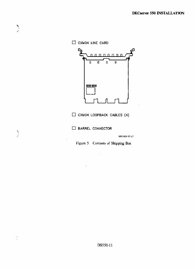
DECserver 550 INSTALLATION
~I J
o CXM04 LINE CARD
[] [] [] []
IIIIIIIIIIIIIIIIIIIII
D
o CXM04 LOOPBACK CABLES (4)
o BARREL CONNECTOR
) MKV89-0157
Figure 5 Contents of Shipping Box
DS550-11
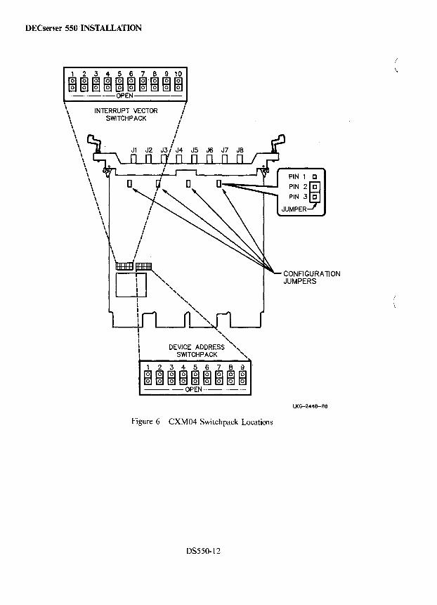
DECserver 550 INSTALLATION
1 2 3 4 5 6 7 8 9 10
mmm~m~mmlmlml -----OPEN-----
\ \ INTERRUPT VECTOR
SWiTCHPACK \ \ \ \ \ \ \ \ \ \ \ \ \ \ \ \ \ \ \ \ \ \ \ \ \
, "
DEVICE ADDRESS '" SWiTCHPACK "
1 2 3 4 5 6 7 8 9
m1mml~~~~~~ -----OPEN------
Figure 6 CXM04 Switch pack Locations
DS550-12
PIN 1 C
PIN 2~ PIN 3 C
JUMPER
CONFIGURA TI ON JUMPERS
LKG-2448-88
(
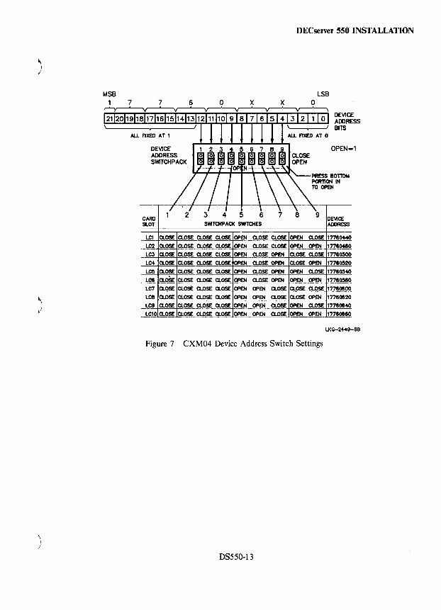
MSB 7
)
\ /
7
DEVICE ADDRESS SWITCH PACK
CARD SLOT
2
6 o x
3 4 5 6 SWlTCHPAQ( SWITCHES
x
7
DECserver 550 INSTALLATION
8
LSB o
DEVICE ADDRESS BITS
OPEN=1
9 DEVICE ADDRESS
LC1 CLOSE CLOSE CLOSE CLOSE OPEN . CLOSE CLOSE OPEN CLOSE 177604-40
LC2 CLOSE CLOSE CLOSE CLOSE OPEN CLOSE CLOSE OPEN OPEN 177604e0
LeJ CLOSE CLOSE CLOSE CLOSE OPEN CLOSE OPEN CLOSE CLOSE 17760500
LC4 CLOSE CLOSE CLOSE CLOSE ClOSE OPEN ClOSE OPEN 1776~20
L~ ClOSE ClOSE CLOSE CLOSE OPEN ClOSE OPEN OPEN ClOSE 1776~
LCS CLoSE CLOSE ClOSE CLOSE OPEN ClOSE OPEN OPEN OPEN 1776~0 LC7 ClOSE ClOSE CLOSE ClOSE OPEN OPEN ClOSE ClOSE ClOSE 17760600
LCS ClOSE ClOSE ClOSE ClOSE OPEN OPEN CLOSE ClOSE OPEN 17760620
LC9 CLOSE CLOSE CLOSE CLOSE OPEN OPEN CLOSE OPEN ClOSE 17760640
LC10 ClOSE ClOSE ClOSE ClOSE OPEN OPEN CLOSE OPEN OPEN 17760660
LKG-2449-88
Figure 7 CXM04 Device Address Switch Settings
DS550-13
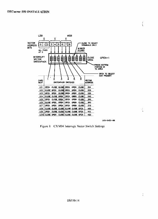
DECserver 550 INSTALLATION
VECTOR ADDRESS BITS
INTERRUPT VECTOR SWiTCHPACK
MSB
OPEN=1
RESS BOTIOM PORTION IN TO OPEN
'------ OPEN TO SELECT -.--+---r---+---+--~--~--T C~ P~T
CARD SLOT
LC1
LC2
LC3
LC4
LC5
LC8
LC7
LC8
LC9
Figure 8
SWlTCHPACI( SWITCHES
OPEN OPEN a.OSE
OPEN OPEN a.OSE
OPEN OPEN a.OSE
OPEN OIIEN a.OSE
OPEN OPEN a.OSE
OPEN OPEN a.OSE
OPEN OPEN a.OSE
a.OSE a.OSE OPEN
CLOSE CLOSE OPEN
CLOSE CLOSE OPEN
VECTOR ADDRESS
310
320
330
340
350
360
370
~ 410
420
LKG-2450-88
CXM04 Interrupt Vector Switch Settings
DS550-14
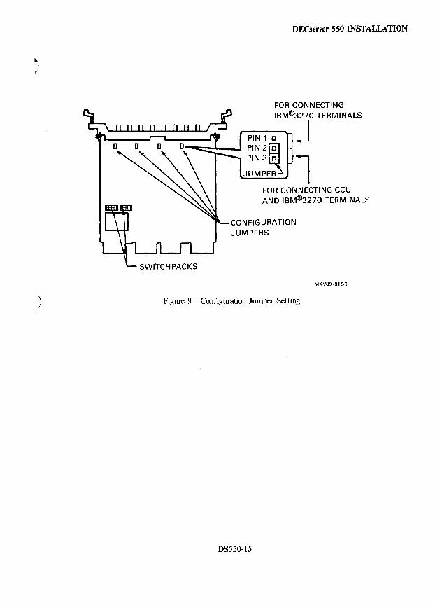
\ )
DECserver 550 INSTALLATION
FOR CONNECTING IBM@3270 TERMINALS
---J PIN 1 c ...... ~~--J PIN2~
PIN3 C l JUMPER
FOR CONNECTING CCU AND IBM@3270 TERMINALS
CONFIGURATION JUMPERS
Figure 9 Configuration Jumper Setting
DS550-15
MKV89-0158
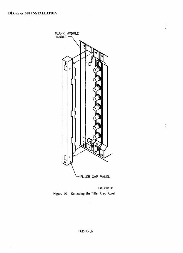
DECseiver 550 INSTALLATION
BLANK MODULE HANDLE
FILLER GAP PANEL
LKG- 2451-88
Figure 10 Removing the Filler Gap Panel
DS550-16
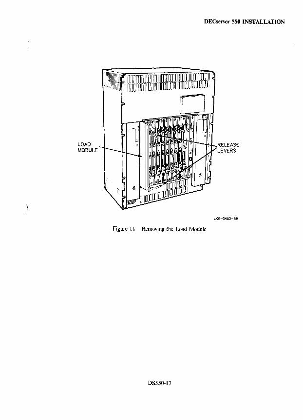
LOAD MODULE
DECserver 550 INSTALLATION
Figure 11 Removing the Load Module
DS550-17
RELEASE LEVERS
LKG-2452-89
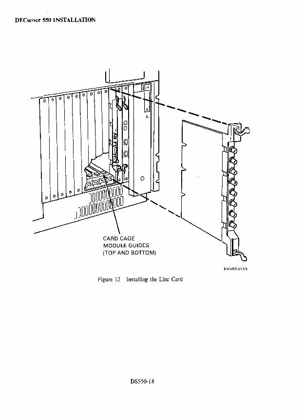
DECserver 550 INSTALLATION
CARD CAGE MODULE GUIDES (TOP AND BOTTOM)
Figure 12 Installing the Line Card
DS550-18
MKV89-0159
DECserver 550 CABLING
\ Cabling ) Cabling for the DECserver 550 is the same as cabling for the DECserver 500 except for the cabling of the
CXM04 Line Card. This section covers cabling for the CXM04. Refer to the DECserver 500 section in this volume for details on cabling the DECserver 550.
)
The CXM04 Line Card can be used in one of two configurations.
• A single line card can support up to four IBM® 3270 terminals with associated connections to a single IBM® 3x74 or equivalent cluster controller unit (CCU). Figure 13 is an example of this configuration.
• A single line card can support up to eight IBM® 3270 terminals with no connections to a CCU. Figure 14 is an example of this configuration.
Each CXM04 Line Card supports up to eight coaxial cables and/or twisted-pair cables with baluns. Whenever twisted-pair cabling is used, baluns must be used at the CXM04 Line Card connector and at the terminal (or CCU) connector.
NOTE The coaxial cable must be RG62A/U or equivalent.
Table 5 shows the maximum cable lengths and the cabling procedure is provided in the flow diagrams of Figures 15 and 16.
IBM is a registered trademark of International Business Machines Corporation.
DS550-19
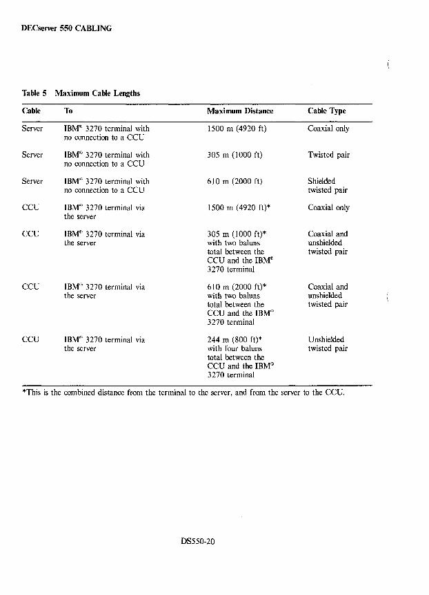
DECserver 550 CABLING
Table 5 Maximum Cable Lengths
Cable To Maximum Distance Cable Type
Server IBM(1i) 3270 terminal with 1500 m (4920 ft) Coaxial only no connection to a CCU
Server IBM® 3270 terminal with 305 m (1000 ft) Twisted pair no connection to a CCU
Server IBMCii) 3270 terminal with 610 m (2000 ft) Shielded no connection to a CCU twisted pair
CCU IBM® 3270 terminal via 1500 m (4920 ft)* Coaxial only the server
CCU IBM(iI) 3270 terminal via 305 m (1000 ft)* Coaxial and the server with two baluns unshielded
total between the twisted pair CCU and the IBM® 3270 terminal
CCU IBM@ 3270 terminal via 610 m (2000 ft)* Coaxial and the server with two baluns unshielded
total between the twisted pair CCU and the IBM® 3270 terminal
CCU IBM(tO 3270 terminal via 244 m (800 ft)* Unshielded the server with four baluns twisted pair
total between the CCU and the IBM® 3270 terminal
*This is the combined distance from the terminal to the server, and from the server to the CCU.
DS550-20
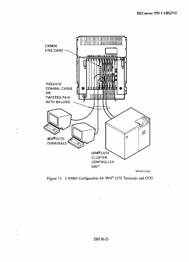
CXM04
RG62A/U COAXIAL CABLE OR TWISTED PAl R WITH BALUNS
TERMINALS
CONTROLLER UNIT
DECserver 550 CABLING
MKV89-0160
Figure 13 CXM04 Configuration for IBM® 3270 Terminals and CCU
DS550-21
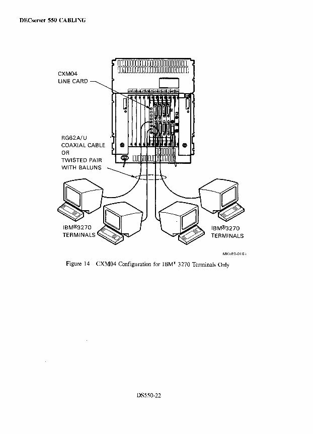
DECserver 550 CABLING
CXM04
RG62A/U COAXIAL CABLE OR TWISTED PAIR WITH BALUNS
0000000000000000000000000000 0000000000000000000000000000
D
MKV89-0161
Figure 14 CXM04 Configuration for IBM® 3270 Terminals Only
DS550-22
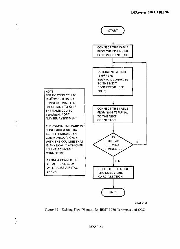
'1 )
NOTE FOR EXISTING CCU TO IBM@3270 TERMINAL CONNECTIONS, IT IS IMPORTANT TO KEEP THE SAME CCU TO TERMINAL PORT NUMBER ASSIGNMENT
THE CXM04 LINE CARD IS CONFIGURED SO THAT EACH TERMINAL CAN COMMUNICATE ONLY WITH THE CCU LINE THAT IS PHYSICALLY ATTACHED TO TH E ADJACENT CONNECTOR.
A CXM04 CONNECTED TO MULTIPLE CCUs WILL CAUSE A FATAL
ERROR.
CONNECT THE CABLE FROM THE CCU TO THE BOTTOM CONNECTOR
DETERMINE WHICH IBM@3270
TERMINAL CONNECTS TO THE NEXT CONNECTOR. (SEE NOTE)
CONNECT THE CABLE FROM THIS TERMINAL TO THE NEXT CONNECTOR
GO TO THE "TESTING THE CXM04 LINE
DECserver 550 CABLING
NO
MKV89-0151
Figure 15 Cabling Flow Diagram for IBM® 3270 Terminals and CCU
OS550-23
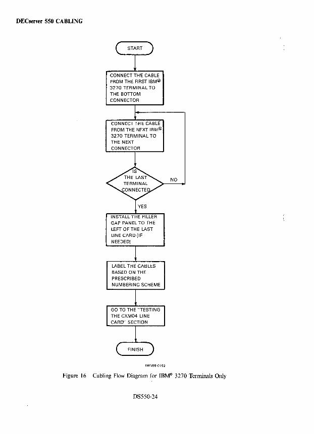
DECserver 550 CABLING
CONNECT THE CABLE FROM THE FIRST IBM® 3270 TERMINAL TO THE BOTTOM CONNECTOR
CONNECT THE CABLE FROM THE NEXT IBM® 3270 TERMINAL TO
INSTALL THE FILLER GAP PANEL TO THE LEFT 0 F TH E LAST LINE CARD (IF NEEDED)
LABEL THE CABLES BASED ON THE PRESCRIBED NUMBERING SCHEME
GO TO THE "TESTING THE CXM04 LINE CARD" SECTION
MKV89-0152
NO
Figure 16 Cabling Flow Diagram for IBM® 3270 Terminals Only
DS550-24
) /
DECserver 550 DIAGNOSTICS
Diagnostics Diagnostics for the DECserver 550 are the same as diagnostics for the DECserver 500. Refer to the DECserver 500 section in this volume for details on diagnostics. Continue with this section for information on testing the CXM04 Line Card.
DS550-25
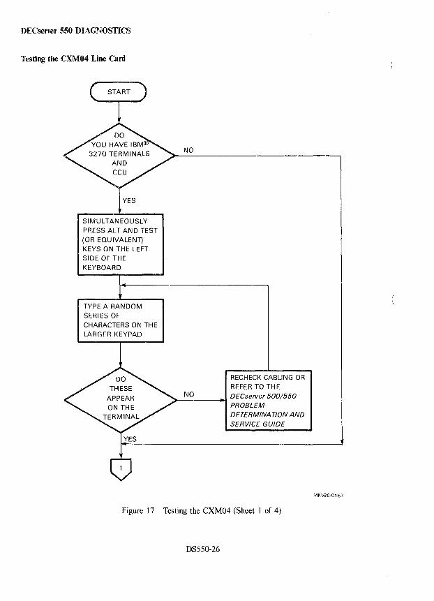
DECserver 550 DIAGNOSTICS
Testing the CXM04 Line Card
YES
SIMULTANEOUSLY PRESS ALT AND TEST
(OR EQUIVALENT) KEYS ON THE LEFT
SIDE OFTHE KEYBOARD
TYPE A RANDOM
SERIES OF
CHARACTERS ON THE
LARGER KEYPAD
NO
RECHECK CABLING OR
REFER TO THE NO DECserver 500/550
PROBLEM DETERMINA TION AND SERVICE GUIDE
Figure 17 Testing the CXM04 (Sheet 1 of 4)
DS550-26
MKV89·0153
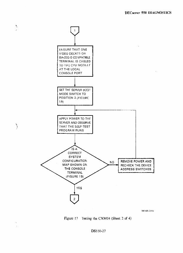
)
ENSURE THAT ONE
VIDEO DEC423 OR
EIA-232-D COMPATIBLE
TERMINAL IS CABLED
TO THE CPU MODULE
AT THE LOCAL
CONSOLE PORT
SET THE SERVER BOOT
MODE SWITCH TO
POSITION 3 (FIGURE
18)
APPLY POWER TO THE
SERVER AND OBSERVE
THAT THE SELF-TEST
PROGRAM RUNS
DECserver 550 DIAGNOSTICS
NO REMOVE POWER AND RECHECK THE DEVICE
ADDRESS SWITCHES
MKV89-0154
Figure 17 Testing the CXM04 (Sheet 2 of 4)
DS550-27
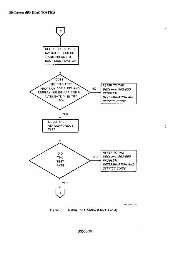
DECserver 550 DIAGNOSTICS
2
SET THE BOOT MODE SWITCH TO POSITION 2 AND PRESS THE BOOT MODE SWITCH
START THE ASYNCHRONOUS TEST
REFER TO THE NO DECserver 500/550
PROBLEM DETERMINA TlON AND SERVICE GUIDE
REFER TO THE NO DECserver 500/550
~----. PROBLEM DETERMINA TION AND SERVICE GUIDE
MKV89-0155
Figure 17 Testing the CXM04 (Sheet 3 of 4)
DS550-28
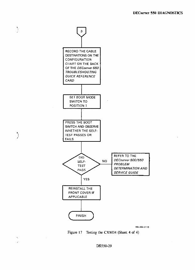
RECORD THE CABLE
DESTINATIONS ON THE CONFIGURATION
CHART ON TH E BACK OF TH E DECseNer 550 TROUBLESHOOTING QUICK REFERENCE CARD
SET BOOT MODE
SWITCH TO POSITION 1
PRESS THE BOOT
SWITCH AND OBSERVE WHETHER THE SELF
TEST PASSES 0 R
FAILS
DECserver 550 DIAGNOSTICS
REFER TO THE
NO DECseNer 500/550
REINSTALL THE
FRONT COVER IF APPLICABLE
>---1 PROBLEM DETERMINA TlON AND SERVICE GUIDE
MKV89·0156
Figure 17 Testing the CXM04 (Sheet 4 of 4)
DS550-29
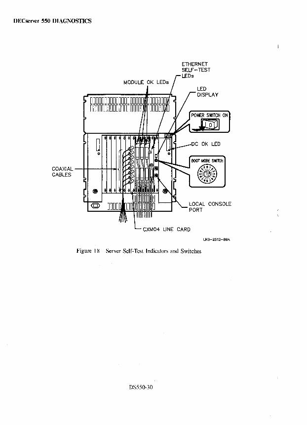
DECserver 550 DIAGNOSTICS
COAXIAL -H--I-+-+-I-~ CABLES
MODULE OK LEOs
ETHERNET SELF-TEST LEOs
POWER SWITCH ON
..s
LOCAL CONSOLE PORT
CXM04 LINE CARD
LKG-2512-89.4.
Figure 18 Server Self-Test Indicators and Switches
DS550-30
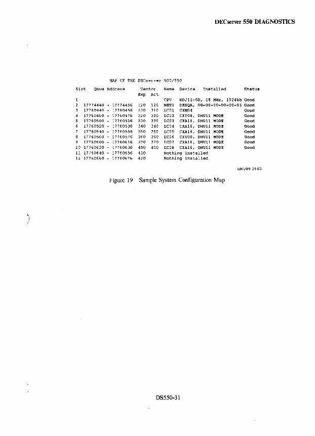
DECserver 550 DIAGNOSTICS
MAP OF THE DECserver 500/550
Slot Qbus Address Vector Name Device Installed Status Exp Act
CPU KDJ11-SD, 18 MHz, 1024kb Good 17774440 - 17774456 120 120 NETO DI!!SQA, 08-00-00-00-00-01 Good 17760440 - 17760456 310 310 LC01 CXM04 Good 17760460 - 17760476 320 320 LC02 CXY08, DHUll MODE Good
5 17760500 - 17760516 330 330 LC03 CXA16, DHUll MODE Good 6 17760520 - 17760536 340 340 LC04 CXA16, DHU11 MODI!! Good
17760540 - 17760556 350 350 LCOS CXA16, DHU11 MODE Good 17760560 - 17760576 360 360 LC06 CXY08, DHU11 MODI!! Good 17760600 - 17760616 370 370 LC07 CXA16, DHU11 MODE Good
10 17760620 - 17760636 400 400 LC08 CXA16, DHU11 MODI!! Good 11 17760640 - 17760656 410 Nothing installed 12 17760660 - 17760676 420 Nothing installed
MKV89-0163
Figure 19 Sample System Configuration Map
)
DS550-31
DECserver 550 MAINTENANCE AIDS
Maintenance Aids Maintenance aids for the DECserver 550 are the same as the maintenance aids for the DECserver 500, except those concerning the DESQA Ethernet controller. Refer to the DESQA section in Volume 6 for DESQA maintenance aids. Refer to the DECserver 500 section in this volume for details on the DECserver 500 maintenance aids
DS550-32
~\
Communications Options Minireference Manual Volume 5 Ethernet Devices (Part 1) EK-CMIV5-RM-005
READER'S COMMENTS
Your comments and suggestions will help us in our efforts to improve the quality of our publications.
1. How did you use this manual? (Circle your response.)
(a) Installation (c) Maintenance (e) Training (b) Operation/use (d) Programming (f) Other (Please specify.) _______ _
2. Did the manual meet your needs? Yes 0 No 0 Why?
3. Please rate the manual on the following ca.egories. (Circle your response.)
Excellent Good Fair Poor Unacceptable Accuracy 5 4 3 2 1 Clarity 5 4 3 2 Completeness 5 4 3 2 Table of Contents, Index 5 4 3 2 Illustrations, examples 5 4 3 2 Overall ease of use 5 4 3 2
4. What things did you like most about this manual?
5. What things did you like least about this manual? __________________ _
6. Please list and describe any errors you found in the manual.
Page Description/Location of Error
Name ____ ~------------ Job Title ___________________ _
Street _________________ _ Company _______________________ _
City _________________ _ Department _________________________ _
State/Country _________________ _ Telephone Number _________________ _
Postal (ZI P) Code Date
THANK YOU FOR YOUR COMMENTS AND SUGGESTIONS.
Please do not use this form to order manuals. Contact your representative at Digital Equipment Corporation or (in the USA) call our DECdirectTl
.. department at this toll-free number: 800-258-1710.
<Cl 1988 by Digital Equipment Corporation. MKO
FOLD HERE AND TAPE. DO NOT STAPLE.
BUSINESS REPLY MAIL FIRST CLASS PERMIT NO. 33 MAYNARD, MA
POSTAGE WILL BE PAID BY ADDRESSEE
DIGITAL EQUIPMENT CORPORATION Educational Services/Quality Assurance 12 Crosby Drive BUO/E08 Bedford, MA 01730-1493 USA
1111111111111111111111111111111111111111111111111111
FOLD HERE AND TAPE. DO NOT STAPLE.
No Postage Necessary
if Mailed in the United States