Embed Size (px)
Citation preview

Mobile Netw Appl (2012) 17:267–280DOI 10.1007/s11036-011-0337-z
A Practical Approach to Energy Efficient Communicationsin Mobile Wireless Networks
Panayiotis Kolios · Vasilis Friderikos ·Katerina Papadaki
Published online: 22 July 2011© Springer Science+Business Media, LLC 2011
Abstract Energy efficiency and capacity maximizationare two of the most challenging issues to be addressedby current and future cellular networks. Significantresearch effort has been placed recently in reducing thetotal energy consumption while maintaining or improv-ing capacity either by introducing more efficient hard-ware components or by developing innovative softwaretechniques. In this paper we investigate a novel net-working paradigm to address the aforementioned prob-lems. By capitalizing on the inherent delay tolerance ofInternet type services, we argue that significant energysavings can be achieved by postponing the communi-cation of information for a later time instance withbetter networking conditions. We device decentralizedalgorithms for the proposed postponement schemesand show the superior performance of implementingsuch schemes over the traditional cellular operation.
Keywords cellular networks · wireless routing ·green networking · energy efficiency ·store carry and forward relaying
P. Kolios (B) · V. FriderikosCenter for Telecommunications Research,King’s College London, London, WC2R 2LS, UKe-mail: [email protected]
V. Friderikose-mail: [email protected]
K. PapadakiOperational Research Group, Department of Management,London School of Economics, London, WC2A 2AE, UKe-mail: [email protected]
1 Introduction
While figures on the number of voice subscribers incellular networks continue to grow, the current expo-nential rate of adoption of Internet type services on thego has exceeded all previous expectations. Already in[1] its argued that data traffic has surpassed voice inmany places. However, mobile Internet access requiresapproximately 10–100× more capacity over voice ser-vices, generating a serious thread in network operationperformance. Clearly there is a need in building upmore capacity to support the increasing demand; atthe same time however the increasing energy consump-tion cost to support these services in current networkdeployments becomes intolerably expensive. From themobile terminals perspective, the increase in cost on thetransmission link significantly degrades the user experi-ence. At the infrastructure side improving efficiency isnecessitated in order to bring cost down and allow forthe healthy proliferation of services.
Due to the aforementioned challenges of supportingthe increased data traffic and increasing concerns onthe carbon footprint of telecommunications equipment,energy efficiency in cellular networks has gained a lotof research attention recently. The key challenge isto achieve system-wide energy gains while maintainingand/or improving system performance. Considerablework in the literature has previously addressed theproblem of energy efficiency on the transmission link,consider for example the work in [2–4]. More recentlyit has been realized that infrastructure nodes (deployedto provide ubiquitous connectivity) contribute the high-est energy consumption at the network access side. In[5] the authors detail the energy consumption of theaccess network entities, detailing a 50% contribution to

268 Mobile Netw Appl (2012) 17:267–280
the BaseStation (BS) nodes. A breakdown of the BScomponents show that improving the efficiency of thehardware components is necessitated. To strengthenthat argument, the work in [6] comment that a shiftfrom no load to high load at a BS contributes only toa mere 2–3% increase in the total power consumption.
In light of these findings, the work in [7] and [8] con-sider how switching off low utilization BSs can provideenergy savings at the network access side. The silentassumption is that neighboring cells need to provide thenecessary coverage while user terminals in the area ofthe BSs that have been switched off need to transmitover longer distances. Antenna tilting and shrinkingcell size deployments have also been proposed in [9]while femtocells (with low power components) havealso emerged recently as an alternative approach toprovide connectivity to indoor users. However the in-herent complexity of evaluating these approaches in aholistic way proves to be a very challenging task.
An alternative (and also complementary to the pre-vious proposals) approach that we have been investi-gating recently is to allow for mobile terminals to post-pone message requests for delay tolerant traffic andrefrain communication only at the favorable channellocations within the cell. It is interesting to note thatwhile data traffic significantly increases the load burdenin the system, a significant portion of the requestedtraffic is delay insensitive information (an example ofsuch services include email clients, file downloadingand exchange services, News feeds etc). The key benefitis that while communication can take place at any timeand at any location within the cell coverage area, a mo-bile user can deliberately delay communication to reacha target location to achieve some performance gain.Clearly delaying transmissions while a user approachesthe serving BS reduces considerably the required trans-mit power for successful communication allowing forpotential energy efficiency gains. At the same timereducing the output transmit power automatically re-duces the inter-cell interference caused to neighboringcells. Moreover, message requests can effortlessly bedeferred for a later time when a user reaches a targetBS, allowing in that respect system wide optimizationsfor energy efficiency by switching off under-utilizedBSs or to achieve load balancing across the network.
It is worth noting here that the proposed scheme cap-italized on the broad range of message deliver delays ofdifferent Internet services and benefits from the actualmobility of the nodes to postpone communication atthe best locations within the cell. Other studies haveconsidered the benefits in energy efficiency from theinherent delay flexibility of different traffic flows inthe past (see for example [3, 4]). However the latter
contributions optimize the transmission durations toachieve the minimum downlink data rate; in effectminimizing the instantaneous transmit power levels. Onthe contrary here we consider the case where decisionsare made on the best time instances a terminal shallengage in communication to achieve energy efficienttransmissions. Hence the novelty of the proposed mes-sage forwarding paradigm is that the actual mobilityis used to provide energy efficiency gains in cellularnetworks.
In our previous work centralized approaches havebeen studied for the various problems discussed aboveand a theoretical framework has been developed forevaluating the optimal forwarding decision policies toservice a batch of user requests. The work in [10]details the energy efficiency gains within a single cellwhile the work in [11] deals with the multicell scenario.It has been shown that significant performance gainscan be realized while the proposed mathematical pro-gramming problems derived were shown to be com-putationally efficient to be used in practice. However,such schemes assume global information about the net-work dynamics and thus require considerable signallingand location information exchange. Instead here, wepropose novel decentralized algorithms that take intoaccount only local information available at the mobileterminals to compute the best forwarding paths. Suchimplementations, as we discuss in the sequel, are verysimple to implement and can be adopted today.
In the following section (Section 2) we present amotivating example for the delay tolerant networkingparadigm that we are proposing in this paper. Section 3details a simple algorithm that can be implemented dis-tributively at each mobile terminal for energy efficientcommunication and Section 4 presents a case study andthe potential performance gains are derived. Further,in Section 5 we reason the additional benefits that canbe realized by the proposed strategy via relaying. Thestore-carry and forwarding paradigm within the cell isintroduced and the potential gains are quantified inSection 6. Section 7 details the overhead requirementsof the proposed networking paradigm and Section 8concludes the paper.
2 Motivation
Consider the map shown in Fig. 1 of the area nearKing’s College London. We recorded the received sig-nal strength from each serving BS at different loca-tions along the Strand road as shown in the figure. Allvalues are in negative dBm units. As shown, there isconsiderable improvement in the signal strength values

Mobile Netw Appl (2012) 17:267–280 269
75
BS locationApproximate coverage
observed along the roadRSS reading
1
2
3
4
5
6
7
8
9
73
51
63
92
50
64
43
100
Fig. 1 The figures shows the received signal strength observedat different location along the Strand. The approximate coveragearea of each base stations is also illustrated
when the mobile terminals are closer to the serving BScompare to the values near the cell edge. For examplethe signal strength value from point 1 to 2 changesfrom −100 dBm to −73 dBm in just a few tens ofmeters while at point 3 which is right next to the serv-ing BS the signal becomes very strong (as expected).The important point however is that even small dis-placements of the mobile terminals cause the channelquality to vary greatly. Obviously the same patternrepeats for the adjacent serving BSs. Therefore, evenfor small traveling speeds as experienced by pedes-trian users, changes in the channel gains are observedwithin small time scales. In addition to that, while thechanges in the signal strength values within each cellare approximately the same—consider points 3, 6 and8 in Fig. 1, switching between serving BSs allows for agreater potential to realize system wide optimizations.As mentioned above, an immediate advantage is toachieve load balancing by targeting low loaded cells,improving system performance. In an effort to reducethe network energy consumption data traffic can beshifted to target BSs such that specific cell sites canbe switched off for longer periods of time. Clearly forsufficient delay tolerance, a mobile terminal can reachthe favorable transmit locations at the target cells be-fore communicating and thus achieving the same min-imum communication energy consumption. In effectsuch a strategy maximizes the energy efficiency gains ofboth the mobile terminals and the supporting networkat no expense to the perceivable user experience (forexample it would not matter if synchronizing the Newsfeeds on a smartphone application is done every 1 orevery 5 min).
A further benefit is that operating the wireless chan-nel at the good locations within the cell improves
considerably the instantaneous spectral efficiency. Ineffect this reduces the amount of resources required tosupport the requested load (i.e. the minimum amountof physical resource blocks are occupied) allowing cellsites to support more requests. In the subsequent sec-tions we aim to quantify the possible gains of such anetworking operation.
3 Mathematical model formulation
We consider a set of user requests s ∈ Q = {1, . . . , Q}generated from each terminal in the set m ∈ M ={1, . . . , M} and serviced by a single BS in the set k ∈Cm = {1, . . . , C} of candidate cells that it can have ac-cess from. Note that set Cm is a subset of the totalnumber of BSs a terminal can listen to. As we willexplain in the sequel specific BSs might get overloadedand thus user terminals might be forced to handoverto another cell (a feature already implemented by cur-rent technologies). In addition, underload BS might becandidates to switch off to save energy and thus datatraffic might be shifted to neighboring cells as well. Weconsider that the following data is easily obtained orcalculated:
1. Mobile terminals are equipped with a GPS and/oran accelerometer and a digital compass sensors.Note that while GPS readings are sufficient for pro-ducing location information and estimating the ter-minal’s velocity vm, the work in [12] details how theaccelerometer and a digital compass sensor (usedto provide speed and direction of the terminal, re-spectively) can be employed to obtain the requiredinformation at a lower power consumption costwhile achieving the same accuracy. Alternatively,the work in [13, 14] show how accurate enoughlocation information can be obtained via triangula-tion techniques from cellular signalling. Note thatin contrast to location-based services, for the pur-poses of our work exact location information is notrequired. In Section 7 we will detail the overheadrequirements for a number of different solutions.
2. Each terminal maintains a neighboring cell list(NCL) of all the BSs it can listen to and knowsthe positions of those BSs (including other char-acteristics if needed such as transmit power andsectorization). Such information can be obtaineddynamically for a specific tracking area or pre-loaded into the mobile terminals memory. Alsoeach terminal can obtain a good estimate of thelocation specific channel losses Lpm(t)(k), m ∈ Mand k ∈ Cm, using for example a pathloss model,

270 Mobile Netw Appl (2012) 17:267–280
shadowing maps and antenna gains for all BSs inthe NCL and the serving BS (sBS).
3. Here we assume that each terminal can obtain loadinformation from each BS, defined as lk through thebroadcast of master/system information blocks.
4. Finally for each service request (either for uplinkor downlink) terminals maintain a time to live(TTLsm, s ∈ Q, m ∈ M) counter of the remain-ing time before the request’s delivery deadline isreached.
In 1), we assume that three sensors are present. Suchan assumption is valid for the broad class of terminalsthat are able to access the Internet and provide datatraffic services. More details on the possibilities of suchbuild-in sensors can be found in [15]. Moreover, in[16] it has been shown that human mobility patternsare 93% predictable and thus preloading base stationinformation as suggested in 2) would seem very rea-sonable. Knowledge of the delay sensitivity is a naturalassumption and default values can be used. For exam-ple periodic synchronization of email clients or updatesof News feeds can be set up within a preference list.For more interactive services including downloadingof files, a user could designate the acceptable delaytolerance at run time based on urgency and cost.
3.1 Decision process
Having obtained the current position pm(0) and veloc-ity vm, m ∈ M, each terminal extrapolates the positionspm it can reach towards the sBS and neighboring BSsit can currently listen to. It then decides on the targetlocation to opt for before sending a message requestswhich maximizes a utility function given the deliverydelay constraints and system imposed accessibility con-straints. The utility function can be simply a maximiza-tion of the channel gains such that the communicationcost (in terms of energy consumption) is reduced, or itcan be any other function that achieves a system wideperformance gain.
Here we consider a simplified function, where eachterminal opts for the minimum channel losses from allcandidate BSs it can have access from (i.e. in the setCm). Moreover, all BSs in set Cm have a lower and anupper load threshold Thresholdlow, Thresholdhigh. Theformer defines the minimum load below which a cellcould possibly enter a sleep period to save energy, whileThresholdhigh defines the maximum load below whichthe call blocking and dropping probabilities are sat-isfied. Both of these parameters are system depended.
The problem is then to find the target transmit posi-tions that attain the minimum channel losses within the
delay constraints. Therefore, for each service request sand mobile terminal m we require,
f (s, m, k) = mintk
{Lpm(t)(k)|t ≤ TT Lsm, k ∈ Cm
}(1)
The greedy decision process is described by Algo-rithm 1.
Algorithm 1 Local decision processEnsure: Repeat every period τm {Period τm determines
the accuracy of the decisions; depends on speedof the mobile nodes and the use case scenariosconsidered.}
Require: Each user locally senses/computes/derivesthe following information:a) Current position pm(0) of user mb) Speed and direction (i.e velocity vm) obtained forexample from accelerometer and digital compasssensorsc) NCL ∪ {sBS} with BS locations and load infor-mation lm
d) Service request list with TTLsm, ∀s ∈ Q, m ∈ M1: for j = 1 to |NCL| do2: if Thresholdlow < lNCL{ j} < Thresholdhigh then3: Cm ∪ NCL{ j}4: end if5: end for6: if Cm �= Ø then7: ∀s: Find f (s, m, k) as defined by Eq. 1 {Deter-
mines target position for service request s for ter-minal m in direction of motion based on currentspeed.}
8: else9: System outage occurs
10: end if11: return f (s, m, k) or request reject error
Note that the process described by Algorithm 1 istriggered with the arrival of a new request and atperiodic time intervals τm. The complexity of the abovealgorithm is simply O(QClogC).
4 System model
In accordance to the study in Section 2, we considerthe area near King’s College London as a toy example.Mobile nodes are considered to be user terminals insidevehicles. The map layout, as shown in Fig. 2, is importedfrom Open Street Maps (OSM1) into SUMO2 mobility
1http://www.openstreetmap.org/2http://sumo.sourceforge.net/

Mobile Netw Appl (2012) 17:267–280 271
Fig. 2 Network topology under investigation (showing themarked route of the mobile terminals and the position of in-frastructure nodes). Bidirectional vehicular traffic is considered
simulator where realistic mobility traffic was generated.The actual BS positions from a single operator in theUK were retrieved from sitefinder.3 The BSs alongthe roadside (triangle shaped locations) as shown inFig. 2 are possible serving BSs to the users along theStrand road. The first-tier BSs (shapes in squares) areconsidered as interfering nodes to the serving BSs.
4.1 Communications model
Without loss of generality, we consider here the down-link of information from the infrastructure nodes tothe mobile terminals. All BSs transmit with a con-stant output power that is equally distributed along allphysical resource blocks (PRBs). Therefore, the powerconsumed per resource block is Pk, k ∈ Cm and the totalnumber of PRBs for each site is ηt PRB. Similar tothe recommendations in [17] for a macro-BS urbanscenario in an LTE system, the channel losses can becharacterized as follows:
PLBS = 128.1 + 37.6log10(d) (2)
where the communication distance d is measured inkilometers. In addition to the path loss, shadowing canbe added to the model, however due to the absenceof shadowing maps of the area under investigation wedo not consider the shadowing effects for the loca-tion specific channel gains. Nevertheless, in additionto the path loss, the antenna gain pattern (which isalso location specific) is incorporated into the model asrecommended. For a horizontal angle θ , the pattern is
3http://www.sitef\/inder.ofcom.org.uk/
defined as follows (details can be found in [17]),
A(θ) = − min
[
12(
θ
θ3dB
)2
, Am
]
(3)
Usual values of θ3dB and Am are 65 degrees and−20 dB, respectively.
With the transmit power per PRB and the channellosses as defined by Eqs. 2 and 3, the SINR values forvector pm, m ∈ M can be computed as follows:
SINRpm = PkLpm(k)
N0 + ∑i �=k, i∈Cm∪Im
li Pi Lpm(i)(4)
where N0 is the noise power per PRB and L is thelocation depended signal attenuation. Set I is the set ofinterfering BSs. Using Shannon’s formula, the achievespectral efficiency can then be computed as follows:
R(SINRpm
) = log2
(1 + SINRpm
)(5)
To better approximate to the actual performanceof the network, this function is scaled by a factor of0.6 while the maximum achievable spectral efficiencyis bounded to 4.4 bps/Hz and a minimum SINR of−6.5 dB is required as described in [17]. Note also thatthe same setup has been used previously in [18].
Furthermore, given a requested data rate serviceBsm, the number of physical resource blocks allocatedto user m for service s is:
ηPRBsm = Bsm
R(SINRpm
) · BW(6)
where BW is the bandwidth of a single PRB (in the caseof LTE it is 180 KHz). Finally, the energy consumed intransmission is simply the number of resource blocksused in transmission multiplied by the power per re-source block and the time required to send a messageof F bits at the requested data rate B. This is expressedas follows:
Esmk = {nPRBsm| f (s, m, k)} × Pk × Fsm
Bsm(7)
where Esmk and nPRBsm are vectors and Pk, Fsm andBsm are scalar values.
4.2 Experimental results
To get a meaningful inside on the performance ofthe proposed networking paradigm we assume that all

272 Mobile Netw Appl (2012) 17:267–280
0 50 100 150 200 250 300 350 400 4500
50
100
150
200
250
300
350
400
450
Message Deliver Delay (sec)
Co
mm
un
atio
n d
ista
nce
(m
)
HD, Route 1: 2.6158 m/sHD, Route 2: 0.7256 m/sND, Route 1: 4.6735 m/sND, Route 2: 4.6899 m/sLD, Route 1: 5.4107 m/sLD, Route 2: 5.3278 m/s
Fig. 3 The minimum distance achieved from a serving BS is givenfor various delay deadline constraints
terminals require a message of size F = 500 KB and therequested data rate is B = 512 Kbps while the messagedelivery deadline (MDD) varies. An LTE system isconsidered with 6 candidate serving BSs and 6 first-tiercells. A 10 MHz system bandwidth is assumed and thenoise power is −174 dBm/Hz. All cells are 30% loadedunless otherwise stated.
We consider the flow of vehicles in both directionof the marked route in Fig. 2 and average values arepresented in the results below. The legend in all figuresincludes the average speed experienced through theroute. In Fig. 3 the minimum transmission distancefor various traffic flows is shown. In one extreme, lowdensity (LD) is considered (vehicles are emitted fromeach vertex at a rate of one every 20 s i.e., λ = 1/20)and vehicles travel at their desired speed unless forcedto stop by traffic lights. At the other extreme of highdensity (HD)—with rate λ = 1/5, backlogged trafficalways exists at junctions. At normal densities (ND)—with rate λ = 1/10, vehicle interaction takes place alongthe roads and queues are formed at traffic lights. How-ever queues do not grow over large time periods inthis case.
Looking into the distance covered towards theinfrastructure nodes, its clear that increased speedachieves faster convergence to the minimum commu-nication distance at given delay constraints. However,the tradeoff of considering increasingly high speeds isthat terminals may stay at good location within the cellcoverage only for short times reducing the potentialperformance benefits. Nevertheless, the traveling speedas shown in the figure considerably affects the achiev-able displacements within the cell and parameters such
0 50 100 150 200 250 300 350 400 45010
−2
10−1
100
Message Deliver Delay (sec)
No
rmal
ised
En
erg
y C
on
sum
pti
on
ND, Route 1: 4.6735 m/sND, Route 2: 4.6899 m/s
Fig. 4 The average energy consumption within different MDDvalues is shown for both routes considered
as the evaluation period τi in Algorithm 1 must beadjusted accordingly.
4.3 Energy efficiency gains
Figure 4 shows the normalized energy consumptionwithin different delay constraints. While the trackingoverhead for the location of the terminal is not factoredin the cost, the energy savings are significant even forsmall delay constraints. For both flows, an approximatedelivery delay of several tens of seconds achieves morethan 25× reduction in the communication energy con-sumption. As we will show later, the incurred overhead
0 50 100 150 200 250 300 350 400 4501
1.5
2
2.5
3
3.5
4
4.5
5
5.5
6
Message Deliver Delay (sec)
Nu
mb
er o
f se
rvin
g B
Ss
ND, Route 1: 4.6735 m/sND, Route 2: 4.6899 m/s
Fig. 5 The figures shows the accumulated number of serving BSsa terminal connects to within increasing MDDs

Mobile Netw Appl (2012) 17:267–280 273
reduces these gains by only a small factor. In addition,in the above results a minimum SINR of −6.5 dB wasrequired for a minimum achieved data rate. In Fig. 4those values that have not met that goal were notincluded. Therefore, further gains are expected underthose circumstances where retransmissions are necessi-tated.
Its worth noting also that even though the minimumcommunication cost is achieved within a small delay,allowing increased delay tolerance allows terminals toforward requests at target BSs that are not the currentsBS. Figure 5 shows the accumulated number of servingBSs that a terminal can connect to while in transit.Figure 6 shows the minimum distance away from thefurthest base station that a terminal can listen to thathas the strongest received signal. In the figure, thesawtooth pattern is an indication of the threshold delaysrequired for a mobile terminal to move into regions ofbetter channel signal strength. It is interesting to notefor small delays the serving BS (and thus the distanceto that BS) can change abruptly. Hence, investing onthe delay flexibility of the message requests allows forthe possibility to implement informed routing decisionsto increase system performance without a sacrifice inthe communication cost.
We also consider the case where terminals are re-stricted access to several BS during periods of lowutilization such that the operator can gradually turn offthose nodes. To examine the potential impact of such ascenario, 3 out of 6 BSs are randomly made unavailablealong the route considered in Fig. 2. Figure 7 shows theenergy consumption values obtained for different delayconstraints. Clearly, cell switch-off increases the aver-
0 50 100 150 200 250 300 350 400 4500
50
100
150
200
250
300
350
400
450
Elapsed time (sec)
Min
imu
m d
ista
nce
of
serv
ing
BS
ND, Route 1: 4.6735 m/sND, Route 2: 4.6899 m/s
Fig. 6 The transmission distance against the message delivery de-lay for the furthest BS node reached by the terminal is illustrated
0 50 100 150 200 250 300 350 400 45010
−2
10−1
100
Message Deliver Delay (sec)
No
rmal
ised
En
erg
y C
on
sum
pti
on
ND, Route 1: 4.6735 m/sND, Route 2: 4.6899 m/s
Fig. 7 The link energy consumption at different delay constraintsis plotted when half the BSs are switched off
age transmission distance which results in an increase inthe communication energy consumption for the tradi-tional cellular operation. Nevertheless, for delay insen-sitive services, the same energy efficiency gains can beachieved via the proposed postponement scheme whileat the same time only half of the BSs are operating.
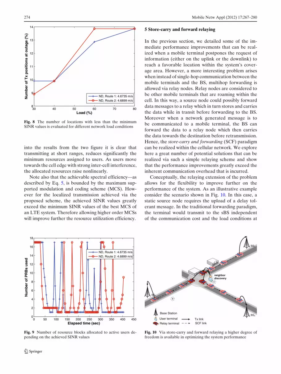
As expected, the rise in the interference in suchdensely populated urban scenario from increasinglyloaded cells also impacts the link energy consumption.Figure 8 shows the ratio of positions within the net-work coverage area that experience SINR values below−6.5 dB against increasing load conditions.4
4.4 Resource efficiency gains
Equation 6 determines the number of physical resourceblocks required to satisfy a data rate requirement ata given SINRpi(t) value a user i experiences at timet. Clearly, improving the SINR values increases thespectral efficiency of the utilized resource block andminimizes the number of PRBs assigned to a user.Figure 9 shows the number of resource blocks assignedto active users along the two routes depending onthe instantaneous channel losses. Evidently, localizedtransmissions around the cell center improve consid-erably the resource consumption efficiency, droppingfrom a total of 17 PRBs to just 1. The results illustratedin this figure can be interpreted with the help of theplot in Fig. 6 where the distance away from the BSwith the strongest signal strength is illustrated. Looking
4Details on the load variations in the course of a day can be foundin [1].
274 Mobile Netw Appl (2012) 17:267–280
30 40 50 60 70 808
9
10
11
12
13
14
Load (%)
Nu
mb
er o
f T
x p
osi
tio
ns
at o
uta
ge
(%)
ND, Route 1: 4.6735 m/sND, Route 2: 4.6899 m/s
Fig. 8 The number of locations with less than the minimumSINR values is evaluated for different network load conditions
into the results from the two figure it is clear thattransmitting at short ranges, reduces significantly theminimum resources assigned to users. As users movetowards the cell edge with strong inter-cell interference,the allocated resources raise nonlinearly.
Note also that the achievable spectral efficiency—asdescribed by Eq. 5, is bounded by the maximum sup-ported modulation and coding scheme (MCS). How-ever for the localized transmission achieved via theproposed scheme, the achieved SINR values greatlyexceed the minimum SINR values of the best MCS ofan LTE system. Therefore allowing higher order MCSswill improve further the resource utilization efficiency.
0 50 100 150 200 250 300 350 400 4500
2
4
6
8
10
12
14
16
18
Elapsed time (sec)
Nu
mb
er o
f P
RB
s u
sed
ND, Route 1: 4.6735 m/sND, Route 2: 4.6899 m/s
Fig. 9 Number of resource blocks allocated to active users de-pending on the achieved SINR values
5 Store-carry and forward relaying
In the previous section, we detailed some of the im-mediate performance improvements that can be real-ized when a mobile terminal postpones the request ofinformation (either on the uplink or the downlink) toreach a favorable location within the system’s cover-age area. However, a more interesting problem ariseswhen instead of single-hop communication between themobile terminals and the BS, multihop forwarding isallowed via relay nodes. Relay nodes are considered tobe other mobile terminals that are roaming within thecell. In this way, a source node could possibly forwarddata messages to a relay which in turn stores and carriesthe data while in transit before forwarding to the BS.Moreover when a network generated message is tobe communicated to a mobile terminal, the BS canforward the data to a relay node which then carriesthe data towards the destination before retransmission.Hence, the store-carry and forwarding (SCF) paradigmcan be realized within the cellular network. We explorehere a great number of potential solutions that can berealized via such a simple relaying scheme and showthat the performance improvements greatly exceed theinherent communication overhead that is incurred.
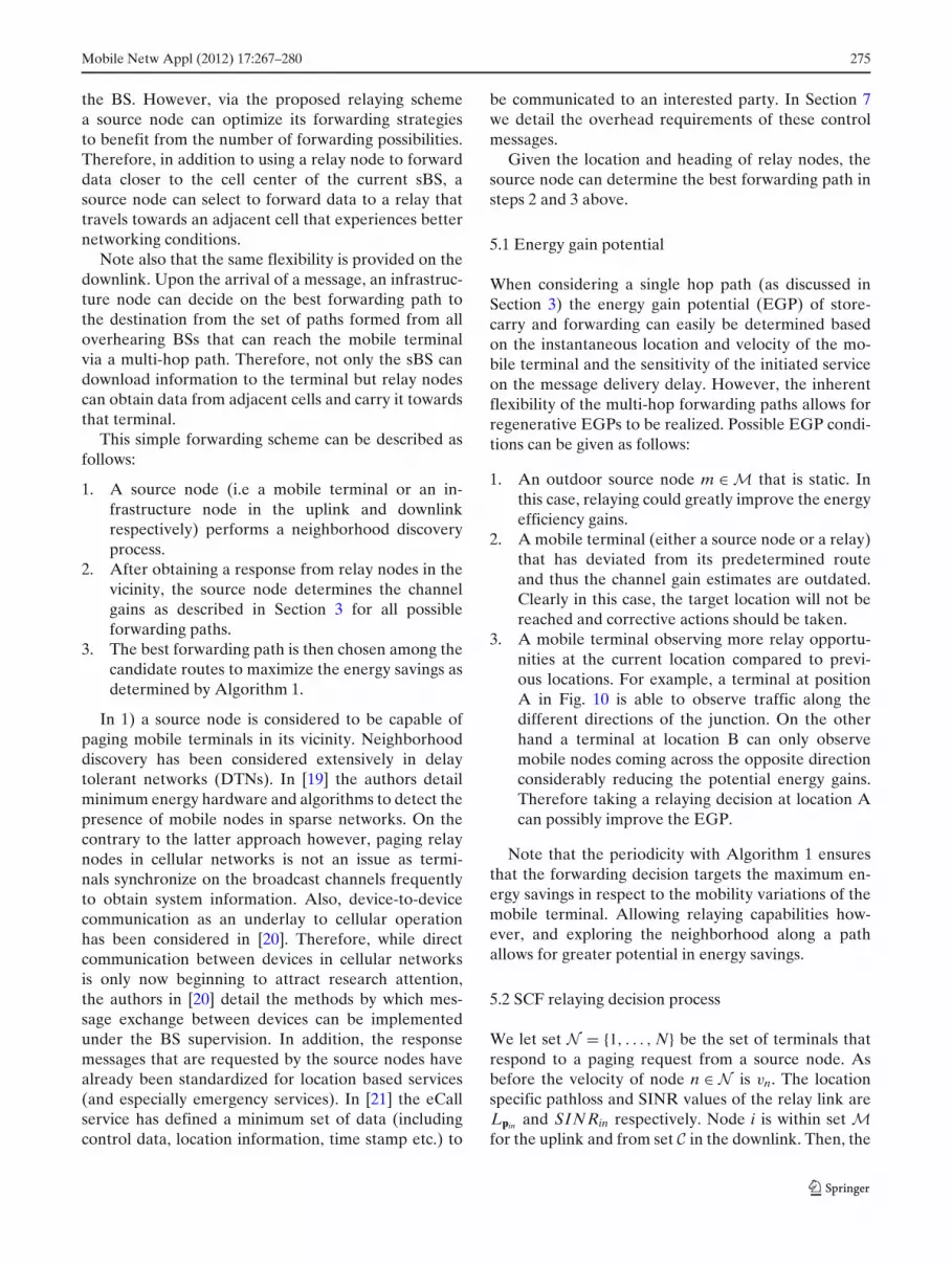
Conceptually, the relaying extension of the problemallows for the flexibility to improve further on theperformance of the system. As an illustrative exampleconsider the scenario shown in Fig. 10. In this case, astatic source node requires the upload of a delay tol-erant message. In the traditional forwarding paradigm,the terminal would transmit to the sBS independentof the communication cost and the load conditions at
BS1
BS3Base Station
User terminal
Relay terminal
neighbor discovery
Tx linkSCF link
BS2
A
B
Fig. 10 Via store-carry and forward relaying a higher degree offreedom is available in optimizing the system performance
Mobile Netw Appl (2012) 17:267–280 275
the BS. However, via the proposed relaying schemea source node can optimize its forwarding strategiesto benefit from the number of forwarding possibilities.Therefore, in addition to using a relay node to forwarddata closer to the cell center of the current sBS, asource node can select to forward data to a relay thattravels towards an adjacent cell that experiences betternetworking conditions.
Note also that the same flexibility is provided on thedownlink. Upon the arrival of a message, an infrastruc-ture node can decide on the best forwarding path tothe destination from the set of paths formed from alloverhearing BSs that can reach the mobile terminalvia a multi-hop path. Therefore, not only the sBS candownload information to the terminal but relay nodescan obtain data from adjacent cells and carry it towardsthat terminal.
This simple forwarding scheme can be described asfollows:
1. A source node (i.e a mobile terminal or an in-frastructure node in the uplink and downlinkrespectively) performs a neighborhood discoveryprocess.
2. After obtaining a response from relay nodes in thevicinity, the source node determines the channelgains as described in Section 3 for all possibleforwarding paths.
3. The best forwarding path is then chosen among thecandidate routes to maximize the energy savings asdetermined by Algorithm 1.
In 1) a source node is considered to be capable ofpaging mobile terminals in its vicinity. Neighborhooddiscovery has been considered extensively in delaytolerant networks (DTNs). In [19] the authors detailminimum energy hardware and algorithms to detect thepresence of mobile nodes in sparse networks. On thecontrary to the latter approach however, paging relaynodes in cellular networks is not an issue as termi-nals synchronize on the broadcast channels frequentlyto obtain system information. Also, device-to-devicecommunication as an underlay to cellular operationhas been considered in [20]. Therefore, while directcommunication between devices in cellular networksis only now beginning to attract research attention,the authors in [20] detail the methods by which mes-sage exchange between devices can be implementedunder the BS supervision. In addition, the responsemessages that are requested by the source nodes havealready been standardized for location based services(and especially emergency services). In [21] the eCallservice has defined a minimum set of data (includingcontrol data, location information, time stamp etc.) to
be communicated to an interested party. In Section 7we detail the overhead requirements of these controlmessages.
Given the location and heading of relay nodes, thesource node can determine the best forwarding path insteps 2 and 3 above.
5.1 Energy gain potential
When considering a single hop path (as discussed inSection 3) the energy gain potential (EGP) of store-carry and forwarding can easily be determined basedon the instantaneous location and velocity of the mo-bile terminal and the sensitivity of the initiated serviceon the message delivery delay. However, the inherentflexibility of the multi-hop forwarding paths allows forregenerative EGPs to be realized. Possible EGP condi-tions can be given as follows:
1. An outdoor source node m ∈ M that is static. Inthis case, relaying could greatly improve the energyefficiency gains.
2. A mobile terminal (either a source node or a relay)that has deviated from its predetermined routeand thus the channel gain estimates are outdated.Clearly in this case, the target location will not bereached and corrective actions should be taken.
3. A mobile terminal observing more relay opportu-nities at the current location compared to previ-ous locations. For example, a terminal at positionA in Fig. 10 is able to observe traffic along thedifferent directions of the junction. On the otherhand a terminal at location B can only observemobile nodes coming across the opposite directionconsiderably reducing the potential energy gains.Therefore taking a relaying decision at location Acan possibly improve the EGP.
Note that the periodicity with Algorithm 1 ensuresthat the forwarding decision targets the maximum en-ergy savings in respect to the mobility variations of themobile terminal. Allowing relaying capabilities how-ever, and exploring the neighborhood along a pathallows for greater potential in energy savings.
5.2 SCF relaying decision process
We let set N = {1, . . . , N} be the set of terminals thatrespond to a paging request from a source node. Asbefore the velocity of node n ∈ N is vn. The locationspecific pathloss and SINR values of the relay link areLpin and SINRin respectively. Node i is within set Mfor the uplink and from set C in the downlink. Then, the

276 Mobile Netw Appl (2012) 17:267–280
energy consumption of the relay path can be expressedas follows:
Esinj(t) = Ein(0 → τ) + Enj(τ → t), τ ≤ t ≤ TTLsm
(8)
where {i ∈ M, j ∈ Ci} for the uplink and {i ∈ C j, j ∈ Mfor the downlink. The minimum energy consumptionof the relay path is simply, Esr(s, m, n, k) = min Esinj
and the minimum energy path from both the direct andrelay links is,
Emin(s, m, n, k) = min (Esmk, Esr) (9)
The best forwarding policy under the delay con-straints TTLsm, s ∈ Q, m ∈ M is,
g(s, m, n, k) = minmntk
{Emin(s, m, n, k)|t ≤ TTLsm} (10)
It can easily be shown that problem (10) has a short-est path complexity. The local decision process can thenbe defined by Algorithm 2.
Algorithm 2 SCF relaying decision processEnsure: Repeat every τu{Terminal u posses a message}Require: pu(0), vu, NCL with location and load infor-
mation lk and TTLsm, ∀s ∈ Q, m ∈ M1: {Neighboring decision process}2: if u = m AND vu=0 then3: Send paging request4: N ⇐= Respond mobile terminals5: end if6: {Forwarding decision process}7: for j = 1 to |NCL| do8: if Thresholdlow < lNCL{ j} < Thresholdhigh then9: C ∪ NCL{ j}
10: end if11: end for12: if C �= Ø then13: ∀s: Find g(s, m, n, k) as defined by Eq. 1014: else15: System outage occurs16: end if17: return g(s, m, n, k) or request reject error
The neighboring decision process as derived in lines1–5 of the algorithm reflect the conditions of 1) inthe previous subsection. Equivalently other conditionson the neighborhood discovery can be implemented.As detailed in the above process, if n �= ø then thesource node m forwards the message to relay n thatcarries it while in transit to the target location pn(t∗)before forwarding; forming in that respect a simple2-hop path. On the other hand, the mobile terminal
moves to the target location before communicatingwith the BS in a single hop SCF fashion as describedin Section 3. Note that in this algorithm, a mobileterminal (engaging either on the uplink or downlinkof information) will communicate instantaneously withthe BS if a relay node is not discovered. Alternatively,the terminal might refrain its transmission and resenda paging request at a later time (and within the delayconstraints) if it is anticipated that a relaying node willbe available.
6 SCF relaying numerical evaluation
Similar to Section 4, we consider the downlink of infor-mation to active users within the cell, however in thiscase all the destination nodes are static. Upon arrivalof downlink data, an infrastructure node performs theneighbor discovery of relay nodes from all BSs thatthe terminal reports within its NCL. The infrastructurenode then assesses the EGP of the different forwardingpaths and decides on the best route via Algorithm 2.For the BS transmission link, the location dependedpathloss model and antenna gain pattern defined byEqs. 2 and 3 is used. In relaying information from themobile terminal to the static user the following pathlossmodel is used,
PLRN = 103.8 + 20.9log10(d) (11)
while the antenna gain for all terminal nodes is 0 dBiand their transmit power is 23 dBm. All other para-meters are as defined in Section 4 for the traditionalcellular system scenario.
6.1 2-hop relaying performance evaluation
For the evaluation of the 2-hop SCF scheme we con-sider the two cases where the BSs can forward in-formation to relay nodes (RS) within a transmissiondistance of 200 m and 50 m. The first case considers thegeneral scenario where a BS can forward data to anyrelay within its coverage which can then offload it tothe destination. The second scenario considers the casewhere the BS communicates with the relays within itsvicinity. For both cases, transmitting from the relays tothe user terminals (UTs) is restricted to 50 m.
In Fig. 11 the energy consumption efficiency gains ofthe proposed 2-hop scheme are illustrated. The directlink energy consumption is shown for comparison. Ev-idently, it would be very beneficial for delay tolerantdata traffic to be forwarded to static users via thepotential relaying paths. The energy efficiency gains (asshown in the figure) greatly exceed 15× compared to

Mobile Netw Appl (2012) 17:267–280 277
0 20 40 60 80 10010
−2
10−1
100
Message Delivery Delay (sec)
No
rmal
ised
En
erg
y C
on
sum
pti
on
Direct link2−hop relaying: BS−RS 200m, RS−UT 50m2−hop relaying: BS−RS 50m, RS−UT 50m
Fig. 11 Energy consumption gains of the proposed 2-hop schemecompared to the direct link
the direct link. As before it is important to note thatbad channel conditions (with SINR < −6.5 dB) whereretransmissions are inevitable, are not considered here.Furthermore, the experienced SINR values within thevicinity of the communicating nodes are far better thanthe minimum SINR values required to achieve themaximum spectral efficiency of 4.4 bps/Hz consideredby the system setup. Therefore such gains can only beconsidered as a lower bound on the potential energygains.
It is also important to note that via relaying themessage delivery delay to achieve the maximum gainsis reduced considerably compared to the single-hop ap-
0 20 40 60 80 1002
4
6
8
10
12
14
16
18
Message Delivery Delay (sec)
Nu
mb
er o
f P
RB
s u
sed
Direct link2−hop relaying: BS−RS 200m, RS−UT 50m2−hop relaying: BS−RS 50m, RS−UT 50m
Fig. 12 Resource consumption efficiency of both the direct linkand the proposed 2-hop SCF scheme
0 50 100 150 200 250 300 350 4000
5
10
15
20
25
30
35
Message Delivery Delay (sec)
Can
did
ate
forw
ard
ing
no
des
2−hop relaying: BS−RS 200m, RS−UT 50m2−hop relaying: BS−RS 50m, R−SUT 50m
Fig. 13 Accumulated number of relay nodes that can form feasi-ble paths for message forwarding
proach. The gains here—in delivery delay, come fromthe flexibility of the infrastructure node to select amongthe overhearing BSs the forwarding path that reducesboth the energy consumption and the delivery delay.
Further, Fig. 12 plots the number of PRBs consumedin transmission. As expected, the possibility of thesecond transmission link increases the total number ofPRBs used. However for sufficient delay tolerance, theresource efficiency reduces by only 6% compared to thesingle hop SCF scheme (i.e. only 1 extra PRB is used intransmission).
Figure 13 plots the number of relay nodes that cancommunicated with both the destination terminal and aBS when restricting the communication distance of thefirst hop to 200 m and 50 m respectively (the second hoptransmission range is kept to 50 m). For the first case wesee that a significant number of relay nodes can be con-sidered as potential candidates for message forwarding.It is interesting to note also, that even for small delaysof few tens of seconds, an average of 3 relays (whichactually pass by the vicinity of 3 BSs) can be possiblecandidates as shown for the second case. Clearly forlarger delays, this diversity gain increases considerably.Further, by restricting communication within the vicin-ity of the end nodes, reduces considerably the inter-cellcochannel interference. We aim to quantify such gainsat a later time.
7 Overhead considerations
Based on the awareness of the instantaneous positionand velocity of users within the cell, the proposed

278 Mobile Netw Appl (2012) 17:267–280
scheme opts for the best target locations for sendinga user request to optimize some performance met-ric. Such apriori information can be obtained fromdifferent sources (including GPS, A-GPS, triangulationetc) at different communication cost. When the fre-quency of obtaining this information is factored into thecommunication cost, the total overhead of implement-ing such a scheme is derived. However it is importantto note that such location information might alreadybe available at the source node for numerous otheroperations (including application specific requirementsfor location based services or lower layer necessities foroptimizing the cellular network operation).
Nevertheless we consider here the case where suchlocation information is absent. The baseline communi-cation cost of a A-GPS sensor is approximately 400 mWand the average acquisition time is 13 s [12]. Whilethis is prohibitively expensive as a standalone mech-anism, the use of the accelerometer and digital com-pass sensors on the terminals can be used to formdirectional trails following the terminals displacement(i.e dead reckoning). Both of these sensors consumeapproximately 100 mW while the acquisition time isapproximately 10 ms. Interrogating these sensors onceevery τi, i ∈ M ∪ N seconds provides an estimate of theinstantaneous position of terminals.5
We consider a simple example, where each terminalacquires a sample of its location every 4 s while theinitial position is obtained via A-GPS. The energy con-sumption of the A-GPS receiver is approximately 5.2 Jwhile for each of the direction and speed sensors theenergy is approximately 1 mJ. Clearly this values areorders of magnitude smaller than the energy savingsthat can be achieved by the system as discussed above.This is especially true when the proposed SCF schemesare employed during low utilization periods where viathe use of store, carry and forwarding target BSs cango to sleep sooner. Also note that the energy efficiencygains per user increase proportionally to the requesteddownload volume at each terminal. That is to say thatas each user requests more data traffic, the overheadcost in location information is shared among the ser-vice requests and thus the energy savings increase.In addition, for scenarios where more uniform trafficflow is considered (i.e. highways and onboard trains)the frequency of acquiring location information cansignificantly reduce. A further important observationis that accurate location information (provided by A-GPS) is not a must for the envisioned schemes. The au-
5To compensate for cumulative errors, a new A-GPS signal canbe obtained periodically as discussed in [12].
thors in [14] comment that via triangulation the locationof mobile terminals can be estimated with an deviationerror of less than 25 m. In such a case, the locationinformation overhead is eliminated. Considering onlythe overhead is monitoring the onboard sensors forspeed and direction the energy efficiency gains improveto 98%.
7.1 Relaying location information
Efficient mechanisms for location information ex-change between mobile terminals and infrastructurenodes has been considered in the past while actualimplementations have been a requirement especiallyfor emergency and safety applications in a number ofcountries. Within the EU, the eCall service [21] hasdefined a minimum set of data to be exchanged. Table 1details the mandatory data fields for location informa-tion exchange. Further, an optional 106 Bytes field canbe included detailing the triggering event. However,such additional information needs not be exchanged forthe envisioned purposes we study here.
For the neighborhood discovery process detailed byAlgorithm 2 the total of 38 Bytes can be consideredthe overhead per node replying to a paging request.Clearly for the close vicinity around the source terminalthe total number of nodes replying at any instance issmall and thus this overhead is also minimum. Figure 14shows the total number of mobile terminals replying toa paging request within a 50 m range from an arbitrarylocation along the roadways in Fig. 2.
While the actual number of nodes that respond topaging requests may vary depending on the traffic, theaverage number on nodes under normal traffic flowconditions is not more that two. Thus, the location ex-change overhead is considerably lower (much less than1%) compared to the potential energy gains achievedby the SCF relaying scheme. To reduce even further thetotal overhead, the authors in [22] consider how pagingcan be performed based on prerequisite conditions toreduce the number of candidate relay nodes that replyduring the neighborhood discovery process.
Table 1 Location information exchange
Name Size Description
Control 1 Byte Purpose flagsIdentification 20 Bytes Identification numberTime stamp 4 Bytes Request trigger timeLocation 9 Bytes Lat, lon and directionService provider 4 Bytes IP address

Mobile Netw Appl (2012) 17:267–280 279
−50 0 50 100 150 200 250 300 350 400 4500
2
4
6
8
10
12
Elapsed time (sec)
# o
f re
spo
nd
no
des
Respond nodesAverage # of respond nodes
Fig. 14 The number of responde nodes at arbitrary locationsacross the stretch of mark routes consider in Fig. 2 is illustratedover the considered time interval
Finally, sharing the cost of location information incellular systems has been discussed in detail in [23].The authors discuss how performance improvementsthroughout the different layers of the protocol stackcan be realized when in possession of such information.Also the importance of knowing the instantaneous lo-cation of users is becoming more apparent as we shifttowards self-organizing networks where the differentparameters of the system have to be adjusted online.An example of this can found in [24] and [25] wherethe authors require location information to assess thehandover possibility.
8 Conclusions
Decentralized postponement algorithms have been de-rived in this paper that can be effective mechanismsfor improving significantly system performance. For thesingle-hop case, by delaying data transmissions, mobileusers can achieve more than 33× reductions in thecommunication energy consumption compared to thetraditional instantaneous transmission. Further, and atthe expense of increased delay in the end-to-end path,cell switch-off can reduce the access network energyconsumption at no expense on the communication linkefficiency.
Via relaying, we showed that simple store-carry andforwarding schemes can provide additional benefits tothe system allowing greater flexibility in finding the bestforwarding policies to achieve a target system perfor-mance improvement. In this paper the focus was in de-veloping a simple 2-hop scf relaying scheme that is easy
(in terms of complexity) to implement. The observedenergy gains exceed 15× the energy consumption ofthe current network operation. For both the single-hop and multi-hop cases we showed that the overheadrequirements for implementing postponement schemeshave only fractional costs to the total gains. Interestingfuture avenues of research are real world implemen-tations/testbeds of the proposed relaying schemes to-gether with a detailed energy consumption breakdownbased on current and emerging data traffic mix ofmobile networks.
Acknowledgements The work reported in this paper hasformed part of the Green Radio Core 5 Research Programme ofthe Virtual Centre of Excellence in Mobile & Personal Commu-nications, Mobile VCE, www.mobilevce.com. This research hasbeen funded by EPSRC and by the Industrial Companies whoare Members of Mobile VCE.
References
1. Holma H, Toskala (2009) A LTE for UMTS-OFDMA andSC-FDMA based radio access, 1st edn. Wiley, 2 pp
2. Rodoplu V, Meng TH (1999) Minimum energy mobile wire-less networks. IEEE J Sel Areas Commun 17(8):278–283
3. Kim H, de Veciana G (2010) Leveraging dynamic spare ca-pacity in wireless systems to conserve mobile terminals en-ergy. IEEE/ACM Trans Netw 18(3):802–815
4. Uysal-Biyikoglu E, Prabhakar B, El Gamal A (2002) Aenergy-efficient packet transmission over a wireless link.IEEE/ACM Trans Netw 10(4):487–499
5. Vadgama S (2009) Trends in green wireless access. Fujitsu SciTech J 45(4):404–408
6. Arnold O, Richter F, Fettweis G, Blume O (2010) Powerconsumption modeling of different base station types in het-erogeneous cellular networks. In: CT MobileSummit
7. Marsan MA, Chiaraviglio L, Ciullo D, Meo M (2009) Op-timal energy savings in cellular access networks. In: IEEEinternational conference on communications workshops,pp 1–5
8. Zhouy S, Gongy J, Yangy Z, Niuy Z, Yang P (2009) Greenmobile access network with dynamic base station energy sav-ing. In: ACM MobiCom’09
9. Badic B, O’Farrrell T, Loskot P, He J (2009) Energy efficientradio access architectures for green radio: large versus smallcell size deployment. In: IEEE vehicular technology confer-ence
10. Kolios P, Friderikos V, Papadaki KP (2010) Look-aheadstrategies based on store-carry and forward relaying for en-ergy efficient cellular communications. In: Future internet SI:network vs. application based solutions for NGN, vol 2(4), pp587–602
11. Kolios P, Friderikos V, Papadaki KP (2010) Load balancingvia store-carry and forward relaying in cellular networks. In:IEEE global telecommunications conference
12. Constandache I, Choudhury RR, Rhee I (2010) Towardsmobile phone localization without war-driving. In: IEEEINFOCOM
13. Thiagarajan A, Ravindranath L, Balakrishnan H, Madden S,Girod L (2011) Accurate, low-energy trajectory mapping formobile devices. NSDI

280 Mobile Netw Appl (2012) 17:267–280
14. Jooyoung K et al (2009) A novel location finding sys-tem for 3GPP LTE. In: IEEE international symposium onpersonal, indoor and mobile radio communications, pp 3213–3217
15. Lane ND et al (2010) A survey of mobile phone sensing.IEEE Commun Mag 48(9):140–150
16. Song C, Qu Z, Blumm N, Barabasi AL (2010) Limits ofpredictability in human mobility. Science 327(5968):1018–1021
17. 3GPP, LTE (2010) Evolved universal terrestrial radio access(E-UTRA), Radio frequency (RF) system scenarios. 3GPPTR 36.942 version 9.0.1 Release 9
18. Viering I, Dottling M, Lobinger A (2009) A mathematicalperspective of self-optimizing wireless networks. In: IEEEinternational conference on communications
19. Banerjee N, Corner MD, Levine BN (2007) An energy-efficient architecture for DTN throwboxes. In: IEEE interna-tional conference on computer communications, pp 776–784
20. Doppler K, Rinne M, Wijting C, Ribeiro CB, Hugl K (2009)Device-to-device communication as an underlay to LTE-advanced networks. IEEE Commun Mag 47(12):42–49
21. Werner M et al (2009) Cellular in-band modem solution foreCall emergency data transmission. In: IEEE vehicular tech-nology conference
22. Mustafa H, Zhang Y (2009) Vehicular networks: techniques,standards, and applications. CRC Press, Boca Raton, pp 156–163
23. Lequerica I, Ruiz PM, Cabrera V (2010) Improvement ofvehicular communications by using 3G capabilities to dissem-inate control information. IEEE Netw 24(1):32–38
24. Jansen T et al (2009) Handover parameter optimization inLTE self-organizing networks. In: IEEE vehicular technol-ogy conference
25. Glisic S, Lorenzo B (2009) Advanced wireless networks: cog-nitive, cooperative & opportunistic 4G technology, 2nd edn.Wiley, New York, p 669


