Embed Size (px)
Citation preview

M
IEEECOMMUNICATIONSAGAZINE
A Publication of the IEEE Communications Societywww.comsoc.org
•LTE-Advanced Pro•Radio Communications•Automotive Networking
•Bio-Inspired Cyber Security•Consumer Communications
June 2016, Vol. 54, No. 6

it will work here.
Soon it will be reality. A world connected as never before. Always available. Low latency. Ultra reliable. That’s the promise of 5G. New spectrum. New waveforms. Millimeter- waves. More. Keysight offers the world’s rst 5G simulation, design and test environment able to emulate your real-world 5G wireless thesis. With deep expertise to help you navigate 5G risk and complexity. So you can go from 5G ideas to 5G reality faster.
Autonomous vehicles navigating through traf c. Hands free.
HARDWARE + SOFTWARE + PEOPLE = 5G INSIGHTS
If your 5G idea works here...
© Keysight Technologies, Inc. 2016
US A: 800 829 4444 CAN: 877 894 4414
5G Get the latest app notes,white papers and tutorials www.keysight.com/find/5G-Insight
IENYCM3512.indd 1IENYCM3512.indd 1 19/03/16 5:56 PM19/03/16 5:56 PM

1
Director of MagazinesRaouf Boutaba, University of Waterloo (Canada)
Editor-in-ChiefOsman S. Gebizlioglu, Huawei Tech. Co., Ltd. (USA)
Associate Editor-in-ChiefZoran Zvonar, MediaTek (USA)
Senior Technical EditorsNim Cheung, ASTRI (China)
Nelson Fonseca, State Univ. of Campinas (Brazil)Steve Gorshe, PMC-Sierra, Inc (USA)
Sean Moore, Centripetal Networks (USA)Peter T. S. Yum, The Chinese U. Hong Kong (China)
Technical EditorsMohammed Atiquzzaman, Univ. of Oklahoma (USA)Guillermo Atkin, Illinois Institute of Technology (USA)
Mischa Dohler, King’s College London (UK)Frank Effenberger, Huawei Technologies Co.,Ltd. (USA)
Tarek El-Bawab, Jackson State University (USA)Xiaoming Fu, Univ. of Goettingen (Germany)
Stefano Galli, ASSIA, Inc. (USA)Admela Jukan, Tech. Univ. Carolo-Wilhelmina zu
Braunschweig (Germany)Vimal Kumar Khanna, mCalibre Technologies (India)
Yoichi Maeda, Telecommun. Tech. Committee (Japan)Nader F. Mir, San Jose State Univ. (USA)
Seshradi Mohan, University of Arkansas (USA)Mohamed Moustafa, Egyptian Russian Univ. (Egypt)
Tom Oh, Rochester Institute of Tech. (USA)Glenn Parsons, Ericsson Canada (Canada)
Joel Rodrigues, Univ. of Beira Interior (Portugal)Jungwoo Ryoo, The Penn. State Univ.-Altoona (USA)
Antonio Sánchez Esguevillas, Telefonica (Spain)Mostafa Hashem Sherif, AT&T (USA)
Tom Starr, AT&T (USA)Ravi Subrahmanyan, InVisage (USA)
Danny Tsang, Hong Kong U. of Sci. & Tech. (China)Hsiao-Chun Wu, Louisiana State University (USA)
Alexander M. Wyglinski, Worcester Poly. Institute (USA)Jun Zheng, Nat’l. Mobile Commun. Research Lab (China)
Series EditorsAd Hoc and Sensor Networks
Edoardo Biagioni, U. of Hawaii, Manoa (USA)Silvia Giordano, Univ. of App. Sci. (Switzerland)
Automotive Networking and ApplicationsWai Chen, Telcordia Technologies, Inc (USA)
Luca Delgrossi, Mercedes-Benz R&D N.A. (USA)Timo Kosch, BMW Group (Germany)
Tadao Saito, University of Tokyo (Japan)Consumer Communicatons and Networking
Ali Begen, Cisco (Canada)Mario Kolberg, University of Sterling (UK)
Madjid Merabti, Liverpool John Moores U. (UK)Design & Implementation
Vijay K. Gurbani, Bell Labs/Alcatel Lucent (USA)Salvatore Loreto, Ericsson Research (Finland)
Ravi Subrahmanyan, Invisage (USA)Green Communicatons and Computing Networks
Song Guo, University of Aizu (Japan)John Thompson, Univ. of Edinburgh (UK)
RangaRao V. Prasad, Delft Univ. of Tech. (The Netherlands)Jinsong Wu, Alcatel-Lucent (China)
Honggang Zhang, Zhejiang Univ. (China)Integrated Circuits for CommunicationsCharles Chien, CreoNex Systems (USA)
Zhiwei Xu, SST Communication Inc. (USA)Network and Service Management
George Pavlou, U. College London (UK)Juergen Schoenwaelder, Jacobs University (Germany)
Networking Testing and AnalyticsYing-Dar Lin, National Chiao Tung University (Taiwan)
Erica Johnson, University of New Hampshire (USA)Irena Atov, InCluesive Technologies (USA)
Optical CommunicationsAdmela Jukan, Tech. Univ. Braunschweig, Germany (USA)
Xiang Lu, Futurewei Technologies, Inc. (USA)Radio Communications
Thomas Alexander, Ixia Inc. (USA)Amitabh Mishra, Johns Hopkins Univ. (USA)
ColumnsBook Reviews
Piotr Cholda, AGH U. of Sci. & Tech. (Poland)History of Communications
Steve Weinsten (USA)Regulatory and Policy Issues
J. Scott Marcus, WIK (Germany)Jon M. Peha, Carnegie Mellon U. (USA)
Technology Leaders’ ForumSteve Weinstein (USA)Very Large Projects
Ken Young, Telcordia Technologies (USA)
Publications StaffJoseph Milizzo, Assistant Publisher
Susan Lange, Online Prod uction ManagerJennifer Porcello, Production Specialist
Catherine Kemelmacher, Associate Editor
IEEE Communications Magazine • June 2016
June 2016, vol. 54, no. 6www.comsoc.org/commag
LTE-AdvAncEd Pro: PArT 2Guest editors: robert W. HeatH Jr., MicHael HoniG, satosHi naGata, stefan Parkvall,
and antHony c. k. soonG
Guest editorial
an overview of 3GPP enhancements on machine to machine communications
Alberto Rico-Alvariño, Madhavan Vajapeyam, Hao Xu, Xiaofeng Wang, Yufei Blankenship, Johan Bergman, Tuomas Tirronen, and Emre Yavuz
lte evolution for vehicle-to-everythinG services
Hanbyul Seo, Ki-Dong Lee, Shinpei Yasukawa, Ying Peng, and Philippe Sartori
advances and challenGes toward a scalable cloud radio access network
Congmin Fan, Ying Jun (Angela) Zhang, and Xiaojun Yuan
wireless communication for factory automation: an oPPortunity for lte and 5G systems
Bernd Holfeld, Dennis Wieruch, Thomas Wirth, Lars Thiele, Shehzad Ali Ashraf, Jörg Huschke, Ismet Aktas, and Junaid Ansari
lte release 14 outlook
Christian Hoymann, David Astely, Magnus Stattin, Gustav Wikström, Jung-Fu (Thomas) Cheng, Andreas Höglund, Mattias Frenne, Ricardo Blasco, Joerg Huschke, and Fredrik Gunnarsson
licensed-assisted access lte: coexistence with ieee 802.11 and the evolution toward 5GAmitav Mukherjee, Jung-Fu Cheng, Sorour Falahati, Havish Koorapaty, Du Ho Kang, Reem Karaki, Laetitia Falconetti, and Daniel Larsson
Bio-insPirEd cyBEr sEcuriTy for communicATions And nETworking
Guest editors: WoJciecH Mazurczyk, sean Moore, errin W. fulP, HirosHi Wada, and kenJi leibnitz
Guest editorial
hive oversiGht for network intrusion early warninG usinG diamond: a bee-insPired method for fully distributed cyber defense
Maciej Korczynski, Ali Hamieh, Jun Ho Huh, Henrik Holm, S. Raj Rajagopalan, and Nina H. Fefferman
bio-insPired cybersecurity for wireless sensor networks
Salim Bitam, Sherali Zeadally, and Abdelhamid Mellouk
decaPitation via diGital ePidemics: a bio-insPired transmissive attack
Pin-Yu Chen, Ching-Chao Lin, Shin-Ming Cheng, Hsu-Chun Hsiao, and Chun-Ying Huang
bio-insPired rf steGanoGraPhy via linear chirP radar siGnals
Zhiping Zhang, Michael J. Nowak, Michael Wicks, and Zhiqiang Wu
the President’s PaGe
conference calendar
Global communications newsletter
advertisers’ index
12
M
IEEECOMMUNICATIONSAGAZINE
4
6
7
160
14
22
44
50
58
60
68
29
36
75
82

IEEE Communications Magazine • June 20162
2016 IEEE Communications Society Elected OfficersHarvey A. Freeman, President
Luigi Fratta, VP–Technical ActivitiesGuoliang Xue, VP–Conferences
Stefano Bregni, VP–Member RelationsNelson Fonseca, VP–PublicationsRob Fish, VP-Standards ActivitiesSergio Benedetto, Past President
Members-at-Large
Class of 2016Sonia Aissa, Hsiao Hwa Chen
Nei Kato, Xuemin Shen
Class of 2017Gerhard Fettweis, Araceli Garciá Gómez
Steve Gorshe, James Hong
Class of 2018Leonard J. Cimini, Tom HouRobert Schober, Qian Zhang
2016 IEEE OfficersBarry L. Shoop, President
Karen Bartleson, President-ElectParviz Famouri, SecretaryJerry L. Hudgins, Treasurer
Howard E. Michel, Past-PresidentE. James Prendergast, Executive Director
Celia Desmond, Director, Division III
IEEE COMMUNICATIONS MAGAZINE (ISSN 0163-6804) is published monthly by The Institute of Electrical and Electronics Engineers, Inc. Headquarters address: IEEE, 3 Park Avenue, 17th Floor, New York, NY 10016-5997, USA; tel: +1 (212) 705-8900; http://www.comsoc.org/commag. Responsibility for the contents rests upon authors of signed articles and not the IEEE or its members. Unless otherwise specified, the IEEE neither endorses nor sanctions any positions or actions espoused in IEEE Communications Magazine.
ANNUAL SUBSCRIPTION: $27 per year print subscrip-tion. $16 per year digital subscription. Non-member print subscription: $400. Single copy price is $25.
EDITORIAL CORRESPONDENCE: Address to: Editor-in-Chief, Osman S. Gebizlioglu, Huawei Technologies, 400 Crossing Blvd., 2nd Floor, Bridgewater, NJ 08807, USA; tel: +1 (908) 541-3591, e-mail: [email protected].
COPYRIGHT AND REPRINT PERMISSIONS: Abstracting is permitted with credit to the source. Libraries are permitted to photocopy beyond the limits of U.S. Copyright law for private use of patrons: those post-1977 articles that carry a code on the bottom of the first page provided the per copy fee indicated in the code is paid through the Copyright Clearance Center, 222 Rosewood Drive, Danvers, MA 01923. For other copying, reprint, or republication permission, write to Director, Publishing Services, at IEEE Headquarters. All rights reserved. Copyright © 2016 by The Institute of Electrical and Electronics Engineers, Inc.
POSTMASTER: Send address changes to IEEE Communications Magazine, IEEE, 445 Hoes Lane, Piscataway, NJ 08855-1331. GST Registration No. 125634188. Printed in USA. Periodicals postage paid at New York, NY and at additional mailing offic-es. Canadian Post International Publications Mail (Canadian Distribution) Sales Agreement No. 40030962. Return undeliv-erable Canadian addresses to: Frontier, PO Box 1051, 1031 Helena Street, Fort Eire, ON L2A 6C7.
SUBSCRIPTIONS: Orders, address changes — IEEE Service Center, 445 Hoes Lane, Piscataway, NJ 08855-1331, USA; tel: +1 (732) 981-0060; e-mail: [email protected].
ADVERTISING: Advertising is accepted at the discretion of the publisher. Address correspondence to: Advertising Manager, IEEE Communications Magazine, 3 Park Avenue, 17th Floor, New York, NY 10016.
SUBMISSIONS: The magazine welcomes tutorial or survey articles that span the breadth of communications. Submissions will normally be approximately 4500 words, with few mathematical formulas, accompanied by up to six figures and/or tables, with up to 10 carefully selected references. Electronic submissions are preferred, and should be sumitted through Manuscript Central: http://mc.manuscriptcentral.com/commag-ieee. Submission instructions can be found at the following: http://www.comsoc.org/commag/paper-submis-sion-guidelines. For further information contact Zoran Zvonar, Associate Editor-in-Chief ([email protected]). All submissions will be peer reviewed.
consumEr communicATions And nETworkingseries editors: ali c. beGen, Mario kolberG, and MadJid Merabti
series editorial
on the resource trade-off of flow uPdate in software-defined networks
Yujie Liu, Yong Li, Yue Wang, Ying Zhang, and Jian Yuan
cdn interconnection service trial: imPlementation and analysis
Yonghwan Bang, June-Koo Kevin Rhee, KyungSoo Park, Kyongchun Lim, Giyoung Nam, John D. Shinn, Jongmin Lee, Sungmin Jo, Ja-Ryeong Koo, Jonggyu Sung, Young-il Seo, Taesang Choi, Hong-Ik Kim, Junyoung Park, and Chang Hee Yun
comPutinG for rural emPowerment: enabled by last-mile telecommunications
Somen Nandi, Saigopal Thota, Avishek Nag, Sw. Divyasukhananda, Partha Goswami, Ashwin Aravindakshan, Raymond Rodriguez, and Biswanath Mukherjee
suPPortinG consumer services in a deterministic industrial internet core network
Ted H. Szymanski
AuTomoTivE nETworking And APPLicATionsseries editors: Wai cHen, luca delGrossi, tiMo koscH, and tadao saito
series editorial
a self-orGanizinG network aPProach to Priority manaGement at intersections
Ozan K. Tonguz and Wantanee Viriyasitavat
hiGh sPeed can transmission scheme suPPortinG data rate of over 100 mb/s
Suwon Kang, Sungmin Han, Seungik Cho, Donghyuk Jang, Hyuk Choi, and Ji-Woong Choi
rAdio communicATions: comPonEnTs, sysTEms, And nETworks
series editors: aMitabH MisHra and toM alexander
series editorial
dual connectivity for lte small cell evolution: functionality and Performance asPects
Claudio Rosa, Klaus Pedersen, Hua Wang, Per-Henrik Michaelsen, Simone Barbera, Esa Malkamäki, Tero Henttonen, and Benoist Sébire
radio ProPaGation modelinG for 5G mobile and wireless communications
Jonas Medbo, Pekka Kyösti, Katsutoshi Kusume, Leszek Raschkowski, Katsuyuki Haneda, Tommi Jamsa, Vuokko Nurmela, Antti Roivainen, and Juha Meinilä
AccEPTEd from oPEn cALLPhysical-layer authentication for wireless security enhancement: current challenGes and future develoPments
Xianbin Wang, Peng Hao, and Lajos Hanzo
87
102
110
118
119
128
136
88
94
137
144
152
currently scheduled toPics
toPic issue date manuscriPt due date
internet of tHinGs (iot) deceMber 2016 June 15, 2016
PeoPle-centric internet-of-tHinGs february 2017 June 30, 2016
sustainable incentive MecHanisMs for Mobile croWdsensinG MarcH 2017 July 15, 2016
foG coMPutinG and netWorkinG aPril 2017 sePteMber 1, 2016
netWork slicinG in 5G systeMs May 2017 sePteMber 15, 2016
www.comsoc.org/commag/call-for-papers

Higher. Wider. Faster.Test solutions for 5G.The next major step beyond LTE/LTE-Advanced (4G) sets challenging requirements. Rohde & Schwarz is a world leader in all areas of RF and microwave test and measure- ment equipment. As a technology expert, we have been actively involved in mobile communications since the rst generation. We are committed to supporting the wireless communications industry with the solutions needed to investigate, develop and standardize 5G.
Check out our test solutions at www.rohde-schwarz.com/ad/5G
IENYCM3529.indd 1IENYCM3529.indd 1 19/05/16 4:09 PM19/05/16 4:09 PM

IEEE Communications Magazine • June 20164
The PresidenT’s Page
Over the past decade, moving com-puting, control, and data stor-age into the Cloud has been the
trend. However, today Cloud computing is encountering growing challenges in meet-ing many new requirements in the emerging Internet of Things (IoT). Such challenges include:
Latency Constraints: The stringent latency and delay requirements of many IoT systems fall far outside what mainstream Cloud services can support. For example, industrial control systems often demand end-to-end latencies to be within a few mil-liseconds. Many connected vehicle, virtual reality, gaming, and real-time financial trad-ing applications may require latencies to stay below a few tens of milliseconds.
Network Bandwidth Constraints: The vast and rapidly growing number of con-nected things is creating data at an expo-nential rate. Sending all data to the Cloud will demand prohibitively high network bandwidth. This is often unnecessary. Sometimes, it is prohibited due to regula-tions and data privacy concerns.
Resource-Constrained Devices: IoT will support a vast number and variety of resource-constrained devices. Many such devices will not be able to rely solely on their own resources to fulfill all their com-puting needs. Requiring all of them to rely on Cloud services will be unrealistic and cost-prohibitive as well, because interacting with the Cloud often requires heavy processing and com-plex protocols. For example, the multitude of microcom-puters on a car need firmware updates, but requiring each of these resource-constrained devices to perform the heavy cryptographic processing and run the complex procedures and protocols required for direct contact with the Cloud can be cost-prohibitive and also result in a system that is excessively difficult to manage.
Uninterrupted Services without Internet Access: Many IoT devices and systems, such as vehicles, drones, and oil rigs, may have intermittent network connectivity to the Cloud, but will require non-interrupted services.
New Security Challenges in IoT: Cloud and host com-puting alone have difficulty meeting many new security challenges in IoT. Such challenges include, for example, keeping the security credentials and software on the vast number and variety of resource-constrained devices up to date, authenticating and protecting these devices from secu-rity attacks, and assessing the security status of large distrib-uted systems in a trustworthy manner.
Filling these and many additional gaps in today’s com-puting models will require a new computing and networking
paradigm. This new paradigm is Fog, which distributes computing, control, storage, and networking services closer to end users. Fog is a natural extension of the Cloud, bridging the Cloud and the endpoints to make com-puting possible anywhere along the contin-uum from the Cloud down to the end users. A Fog computing platform will allow the same application to run anywhere, reducing the need for specialized applications dedi-cated just for the Cloud or just for the edge devices. It will enable applications from dif-ferent suppliers to run on the same physi-cal platform without mutual interference. It will provide a common lifecycle management framework for all applications, offering capa-bilities for composing, configuring, dispatch-ing, activating and deactivating, adding and removing, and updating applications. It will further provide a secure execution environ-ment for Fog services and applications. This emerging Fog computing and networking era will represent a fundamental advancement in the state-of-the-art of computing and net-working.
Fog provides effective ways to overcome many limitations of the existing Cloud and host computing models. Table 1 shows, for illustration, how Fog can help address the challenges we discussed at the beginning of this column.
Fog will also enable new and potentially highly disruptive business models for comput-ing and networking. With Fog computing and
networking, routers, switches, and application servers will con-verge into Fog nodes. Such a transformation can significantly reshape the landscape of the networking, server, and software industries. Fog-as-a-service will enable new models to deliver services to customers. Unlike Clouds that are mostly operated by large companies who can afford to build and operate huge data centers, Fog-as-a-service will enable companies, big and small, to deliver computing, storage, and control services at dif-ferent scales to meet the needs of a wide variety of customers.
Proof-of-Concept (POC) trials are demonstrating the business value and technology necessity of Fog computing. For example, Cisco recently conducted a successful POC in Barcelona, where Fog computing made smart city appli-cations more cost-effective and manageable. Barcelona envisions deploying thousands of roadside cabinets through-out the city to optimize traffic management, energy man-agement, and water and waste management. Before they could turn this vision into reality, the city faced two major challenges. First, the traditional approach of adding new applications by adding dedicated new gateways and serv-ers in every roadside cabinet is no longer feasible due to limited cabinet space. Second, the siloed applications have
Harvey Freeman
The emerging era of fog CompuTing and neTworking
Tao Zhang

IEEE Communications Magazine • June 2016 5
The PresidenT’s Page
been using siloed application management systems, which made the system excessively expensive to deploy and oper-ate. Fog computing provided a solution. A single Fog node provided a common platform at each cabinet for all services and allowed applications from different suppliers to coexist without mutual interference. It provided a unified platform to support networking, security, and lifecycle management for all applications, reducing the system costs and allowing application providers to focus on developing applications rather than dedicated hardware and software for hosting and managing their applications.
On the journey to realize the full promise of Fog com-puting and networking, we will encounter many new chal-lenges. For instance:• What will Fog architectures look like?• What new networking capabilities will Fog enable?
• How should the Fog interact with the Cloud?• How to support the development and lifecycle manage-
ment of Fog networks, services and applications?• How to enable scalable and manageable Fog systems
and networks?•How to secure Fog computing and networking?• How to enable users to control their Fog services?
Addressing these challenges necessitates rethinking of the end-to-end computing and networking paradigm, and will provide a fertile ground for innovation and disruption.
To that end, major industry movers and leading academic institutions joined forces to found a global Open Fog Con-sortium (OpenFog) in November 2015. The objective is to develop an open Fog reference architecture and to accelerate market adoption of Fog solutions. Championed by ComSoc, IEEE has entered into a strategic affiliation with OpenFog. We will co-create and co-promote Fog computing and net-working concepts and architectures. We plan to jointly spon-sor an annual Fog industry event. We will also co-sponsor events, journals and their special issues on Fog. Furthermore, we will jointly identify needs for new standards required to enable Fog computing and networking, and be ready to take leadership in developing these crucial standards.
At this historic moment, as we witness the emergence of the Fog computing and networking era, please join our efforts to enable and shape this new trend. The work and fun have just begun.
BiographyDr. Tao Zhang, an IEEE Fellow, is a distinguished engineer/senior director of Cisco’s Corporate Strategic Innovation Group. He joined Cisco in 2012 as the chief scientist for smart connected vehi-cles. Since then, he has also been leading initiatives to create strategies, architectures, technology, and eco-systems for the Internet of Things (IoT) and Fog Computing. Prior to Cisco, he was chief scientist and director of Mobile and Vehicular Networking at Telcordia Technologies (formerly Bell Communications Research or Bellcore). For more than 25 years he has been in various technical and executive positions, directing research and product development for vehicular, mobile, and broadband networking. He is a co-founder and a Board director of the Open Fog Consortium, the CIO of the IEEE Communications Society (2016-17), and a founding Board director of the Connect-ed Vehicle Trade Association (CVTA). He holds more than 50 U.S. patents and has co-authored two books: Vehicle Safety Communications: Protocols, Security, and Privacy (2012) and IP-Based Next Generation Wireless Networks (2004), both published by John Wiley & Sons.
Table 1. Fog provides capabilities to address IoT challenges.
IoT challenges How Fog can help
Latency constraintsStore and process data, carry out control and other time-sensitive tasks near end users.
Network bandwidth constraints
Enable hierarchical data processing along the endpoint-to-Cloud continuum, hence reducing the amount of data that needs to be sent to the Cloud.
Resource-constrained devices
Perform resource-intensive tasks on behalf of resource-constrained devices when such tasks cannot be moved to the Cloud due to any reason.
Uninterrupted service with intermittent Internet access
A local Fog system can function autonomously to ensure non-interrupted services even with intermittent network connectivity to the Cloud.
New security challenges in IoT
Provide services to, for example: 1) manage and update security credentials and software on resource-constrained devices; and 2) protect devices that cannot adequately protect themselves.
ComSoc 2016 ElectionTake Time to Vote
Ballots were e-mailed and/or postal mailed 27 May 2016 to all ComSoc members (excluding Student Members, Associate Members, and Affiliates) whose memberships were effective prior to 1 May 2016. You must have an e-ballot or paper ballot
before you can vote.
VOTE NOW using the URL below. You will need your IEEE account user name/password to access the ballot. If you do not remember your password, you may retrieve it on the voter login page.
https://eballot4.votenet.com/IEEE
If you have questions about the IEEE ComSoc voting process or would like to request a paper ballot, please contact [email protected] or +1 732 562 3904.
If you do not receive a ballot by 30 June, but you feel your membership was valid before 1 May 2016, you may e-mail [email protected] or call +1 732 562 3904 to check your member status. (Provide your member number, full name,
and address.)
Please note IEEE Policy (Section 14.1) that IEEE mailing lists should not be used for “electioneering” in connection with any office within the IEEE.
Voting for this election closes 22 July 2016 at 4:00 p.m. EDT! Please vote!

IEEE Communications Magazine • June 20166
ConferenCe Calendar
–Communications Society portfolio events appear in bold colored print. –Communications Society technically co-sponsored conferences appear in black italic print. –Individuals with information about upcoming conferences, Calls for Papers, meeting announcements, and meeting reports should send this information to: IEEE Communications Society, 3 Park Avenue, 17th Floor, New York, NY 10016; e-mail: [email protected]; fax: + (212) 705-8996. Items submitted for publication will be included on a space-available basis.
2016J U L Y
OECC/PS 2016 —Optoelectronics and Communications Conference/Int’l. Con-ference on Photonics in Switching, 3–7 JulyNiigata, Japanhttp://www.oecc-ps2016.org/
ICUFN 2016 — Int’l. Conference on Ubiquitous and Future Networks, 5–8 JulyVienna, Austriahttp://icufn.org/main/
CITS 2016 — Int’l Conference on Com-puter, Information and Telecommunica-tion Systems6–8 JulyKunming, Chinahttp://atc.udg.edu/CITS2016/
IEEE ICME 2016 — IEEE Int’l. Conference on Multimedia and Expo, 11–15 JulySeattle, WAhttp://www.icme2016.org/
SPLITECH 2016 — Int’l. Multidisciplinary Conference on Computer and Energy Sci-ence, 13–15 JulySplit, Croatiahttp://splitech2016.fesb.hr/
SPECTS 2016 — Int’l. Symposium on Performance Evaluation of Computer and Telecommunication Systems, 24–27 JulyMontreal, Canadahttp://atc.udg.edu/SPECTS2016/
TEMU 2016 — Int’l. Conference on Tele-communications and Multimedia, 25–27 JulyHeraklion, Greecehttp://www.temu.gr/
IEEE/CIC ICCC — Int’l. Conference on Communications in China, 27–29 JulyChengdu, Chinahttp://iccc2016.ieee-iccc.org/
ICCE 2016 — IEEE Int’l. Conference on Communications and Electronics, 27–29 JulyHa Long, Vietnamhttp://www.icce-2016.org
A U G U S TICCCN 2016 — Int’l. Conference on Computer Communication and Net-works, 1–4 Aug.Waikoloa, HIhttp://icccn.org/icccn16/
ISMW-FRUCT 2016 — Int’l. FRUCT Con-ference on Intelligence, Social Media and Web, 28 Aug.–4 Sept.St. Petersburg, Russiahttp://ismw-fruct.spbu.ru/#general
S E P T E M B E RIEEE PIMRC 2016 — IEEE Int’l. Sympo-sium on Personal, Mobile, and Indoor Radio Communications, 4–7 Sept.Valencia, Spainhttp://www.ieee-pimrc.org/
IEEE EDOC 2016 — IEEE Int’l. Enterprise Distributed Object Computing Confer-ence, 5–9 Sept.Vienna, Austrialhttp://edoc2016.univie.ac.at/
ASMS/SPSC 2016 — Advanced Satellite Multimedia Systems Conference and the Signal Processing for Space Communica-tions Workshop, 5–7 Sept.Palma De Mallorca, Spainhttp://www.asmsconference.org/
ITC28 2016 — Int’l. Teletraffic Congress, 12–16 Sept.Würzburg, Germanyhttp://itc28.org/
IEEE HEALTHCOM 2016 — IEEE Int’l. Conference on e-Health Networking, Application & ServicesMunich, Germanyhttp://ieeehealthcom2016.com/call-for-submission
IEEE SARNOFF SYMPOSIUM 2016 — IEEE 37th Sarnoff Symposium 2016, 19–21 Sept.Newark, NJhttp://sites.ieee.org/sarnoff2016/
ISWCS — Int’l. Symposium on Wireless Communication Systems, 20–23 Sept.Poznan, Polandhttp://iswcs2016.org/
ICACCI 2016 — Int’l. Conference on Advances in Computing, Communica-tions and Informatics, 21–24 Sept.Jaipur, Indiahttp://icacci-conference.org/2016/home
SOFTCOM 2016 — Int’l. Conference on Software, Telecommunications and Com-puter Networks, 22–24 Sept.Split, Croatiahttp://marjan.fesb.hr/SoftCOM/2016/cfp.html
NETWORKS 2016 — Int’l. Network Strategy and Planning Symposium, 26–28 Sept.Montreal, Canadahttp://networks2016.etsmtl.ca
IEEE WISEE 2016 — IEEE Int’l. Confer-ence on Wireless for Space and Extreme Environments, 26–29 Sept.Aachen, Germanyhttp://www.ti.rwth-aachen.de/WiSEE2016
O C T O B E R
IEEE CLOUDNET 2016 — IEEE Int’l. Conference on Cloud Networking, 3–6 Oct.Pisa, Italyhttp://cloudnet2016.ieee-cloudnet.org
ICMU 2016 — International Conference on Mobile Computing and Ubiquitous Networking, 4–6 Oct.Kaiserslautern, Germanyhttp://www.icmu.org/icmu2016/
APNOMS 2016 — Asia-Pacific Network Operations and Management Sympo-sium, 5–7 Oct.Kanazawam, Japanhttp://www.ieice.org/~icm/apnoms/2016/
ATC 2016 — Int’l. Conference on Advanced Technologies for Communica-tions, 12–14 Oct.Hanoi, Vietnamhttp://rev-conf.org
WCSP 2016 — Int’l. Conference on Wire-less Communications & Signal Process-ing, 13–15 Oct.Yangzhou, Chinahttp://ic-wcsp.org
–Communications Society portfolio events appear in bold colored print. –Communications Society technically co-sponsored conferences appear in black italic print. –Individuals with information about upcoming conferences, Calls for Papers, meeting announcements, and meeting reports should send this information to: IEEE Communications Society, 3 Park Avenue, 17th Floor, New York, NY 10016; e-mail: [email protected]; fax: + (212) 705-8996. Items submitted for publication will be included on a space-available basis.
Updated on the CommUniCations soCiety’s Web sitewww.comsoc.org/conferences

June 2016 Global Communications Newsletter 1
GLOBALCOMMUNICATIONSNEWSLETTER
As everyone knows, the Mobile World Congress (MWC) is the world’s biggest and most influential mobile event. This year the conference was held February 22–25 in Barcelona (Spain). This edition of MWC was the 10th time that it has been held in Barcelona. Until 2005 the Congress was held in Cannes (France) under the name of 3GSM World. In 2006 it was moved to Barce-lona and since then it has become one of the biggest technology events. This relationship will continue until at least 2023, thanks to the agreement that was reached recently.
The event consists of three main blocks. The first block is the conferences, all related to mobile technologies; the second is the exhibition zone, where companies show their novelties; the third block consists of a dozen parallel events. The presence of up to 95,000 attendees and approximately 2,000 companies that have participated in the exhibition zone are both clear indicators of the success of MWC-16.
MWC is mainly focused on mobile devices. In past years, there have been huge announcements of devices at MWC. However, this year MWC was also focused on other issues, like vehicular technology, new mobile payment methods, new trends in ISP (Internet service providers) mobile products and services, and finally virtual reality, whose scale of presence was the biggest sur-prise. The most relevant companies in the cellular market showed their new mobile designs that incorporate a virtual reality (VR) headset. The image of conference attendees looking in all direc-tions with their virtual reality headsets has become the snapshot that best summarizes MWC-16. Now it is time to see if the appli-cations supporting this new technology actually attract consumers.
On the other hand, the new mobile payment services and related technologies presented at MWC-16 also attracted great attention. One of the most promising was the Paypal Here read-er, based on NFC (near field communication) technology. This reader is able to understand any type of payment method. In the same business line, another important novelty was the mobile banking service called imaginBank, presented by La Caixa. With imaginBank, you can do what you usually do in a traditional bank, but also much more, thanks to the inherent benefits of IT tech-nologies. In imaginBank, all the banking services are online; the users manage their own financial resources by themselves, with the help of a set mobile app and social networks. The final touch was led by MasterCard, who presented an authentication tech-nology based on selfies called selfie-pay. This app enables con-sumers to validate their transactions with a simple selfie. It is clear that all these pieces must be put to work together in order to provide value added on-line banking and shopping services to the community.
Regarding mobile devices, the most relevant premiere was
a modular phone design that lets you attach accessories direct-ly to it. The device can be prepared in any way the consumer likes it. Another interesting issue was the internal water circuits to keep the processor cool, keeping it from overheating. Howev-er, it remains to be seen if consumers continue to opt for high-end devices, or as recently noted in data sales, these types of high-performance mobile devices are passed over in favor of an increasingly compelling midrange in features and prices.
The next generation of mobile communications (5G) was on many MWC-16 minds. The focus on 5G has been all about connecting things to the Internet, when in fact much of the world does not even have access to the basics. Facebook Chief Execu-tive Mark Zuckerberg pointed out that while a small section of the connected world is racing to embrace next-generation technology, the majority of people, including large swaths of Europe and the USA, are still using 2G, a technology that is 25 years old. Zucker-berg cautioned that the gap between the small wealthy majority and everyone else is only going to widen if we keep going the way we are.
Finally, another remarkable event at MWC-16 was the Mobile Premier Awards (MPA). The MPA is an organization that was born in Barcelona, and it is completely independent of MWC. However, this year they presented the award at MWC-16. It is an acknowledgement of the best app developed by startup compa-
June 2016ISSN 2374-1082
(Continued on Newsletter page 4)
Barcelona Mobile World Congress 2016By Juan Pedro Muñoz-Gea, Josemaría Malgosa-Sanahuja, and Pilar Manzanares-López, Universidad Politécnica de Cartagena, Spain
The MWC-2016 was held in Barcelona, in one of the most beautiful exhibitions called Fira de Barcelona.
The image of conference attendees looking at all directions with their virtual reality headsets has become the snapshot that best summarizes MWC-16.
CONFERENCE REPORT

2 Global Communications Newsletter June 2016
Telekom Romania, the former Romtelecom and Cosmote Romania, is facing network challenges in one of the most com-petitive markets in the EU. In the fixed line business, the former Romtelecom is competing with RCS&RDS, UPC Romania, and telcos with larger optical fiber networks, while in the mobile business, the main competitors are Orange and Vodafone, celcos with better national coverage of LTE networks and providing higher speed access. In September 2014 Romtelecom and Cosmote were rebranded under the Telekom logo, while the merger process started in 2013. On January 1, 2016, Miroslav Majoros, an executive with a telecom engineering background and with an MBA from the prestigious Harvard Business School and Stanford Graduate School of Business, came from Slovakia to turn arround Telekom Romania.
One of the main problems behind the Telekom evolution in the last few years was financing. How do you intend to raise funds to develop the busi-ness, mobile mainly, to reduce the gap?
The overall investment plans for 2016 amount to over €180 million. Most of the investments will be directed toward optical fiber networks and mobile networks, based on 3G and 4G technologies. The increase in the investments planned, by more than 35 percent compared to the previous year, was more than necessary, given that the local market is extremely competitive, and without putting money in the infrastructure it is impossible to succeed in the long term.
Telekom Mobile lags behind its main competitors from the
point of view of LTE networks. What is your strategy to rapidly reduce the gap (with Orange, Vodafone)?
We will continue to develop our LTE infrastructure, as it is one of our strategic objectives. The agreement with Orange represents an immediate support for our plans, but in the medium and long term it is natural to continue developing our own infrastructure.
Telekom Mobile aquired only one 2x5 MHz bloc in the 800 MHz band, while Orange and Vodafone aquired two blocks. What are your intentions to keep pace with your competitors?
Depending on the evolution of the 4G mobile telecommu-nications market and on the future development of our own network, we might consider acquiring a supplementary block for this bandwidth.
Recently, Deutsche Telekom’s top managers declared that the fiber network is a top priority for Telekom Romania. Why not the LTE network, hav-ing in mind that mobile business accounts for two thirds of Romanian telecommunications revenues?
It is not a fixed versus mobile business strategy. We started to operate having in mind an integrat-ed approach, therefore both segments are equally relevant. We will focus on expanding both the fiber and LTE networks, on re-launching the portfolio of fixed-mobile services, and on improving the quality of services for customers.
Telekom–Orange wholesale and national roaming agreements respectively mean giving access to the Telekom fixed network, a strate-gic asset Orange never could have, and to the Orange LTE network, an asset Telekom already
has. How do you comment?This agreement is a good opportunity for us to provide
improved services to our customers. Our main focus is represent-ed by the fixed-mobile convergent packages, under the Magen-taONE proposition. Extended coverage for both fixed and mobile networks will help us significantly increase the areas where we can offer our services to customers. Therefore, the national roam-
(Continued on Newsletter page 4)
June 2016 Global Communications Newsletter 3
Telekom Romania: A New Beginning? An Interview with Miroslav Majoros, CEO, Telekom RomaniaBy Nicolae Oaca, Romania
On February 25, 2016, AT&T for the first time in México opened its data center during the AT&T High Tech Day, when ComSoc student members and student branch members from Universidad Autonoma de la Ciudad de México, with students from other universities, visited the center. AT&T opened some of
its data centers that same day. Students had the chance to com-municate using video conferencing with students in other cities where AT&T has data centers, such as San Juan, Puerto Rico; Texas, New Jersey and Florida in the U.S.; and Tlalnepantla in Mexico State, near Mexico City.
Until December 2014, the mobile market in México had the following distribution: TELCEL-AMERICA MOBILE (from Mexico) was the largest with 70.4 million users; second was MOVIS-TAR-TELEFONICA (from Spain) with 20.5 million users; IUSACELL-was third with 8.5 million users; and NEXTEL was fourth with 2.8 million users. In January 2015 AT&T (from the U.S.) re-entered the market in México, buying IUSACELL and NEXTEL. Now AT&T is the third largest competitor measured by number of users, 11.4
millions, but second in revenues and coverage with 90 percent, behind TELCEL, which covers 94 percent, and ahead of MOVISTAR, which cov-ers 80 percent of Mexico. Students had the chance to visit the AT&T data center and its NOC (network opera-tions center).
In the U.S., the purpose of AT&T High Tech Day was to get high school students excited about careers in the fields of science, technology, engi-neering, and mathematics (STEM). This event has occurred since 1998;
IEEE ComSoc Student Members Visit AT&T Data Center in Tlalnepantla, MexicoBy Jose-Ignacio Castillo-Velazquez, UACM, Mexico
(Continued on Newsletter page 4)
Miroslav Majoros
In a picture at AT&T facilities are Fabricio Astorga Martínez, Luis Carlos Revilla Melo, Daniel Javier Serrano Martinez, Fernando Trueba, Adrian Martinez, Alonso Delgado, and Violeta Perez from UACM, with students from other universities in Mexico City.
REGIONAL REPORT
CHAPTER REPORT

2 Global Communications Newsletter June 2016
VITEL 2015, the 31st workshop on telecommunications, took place at the Congress Centre Brdo pri Kranju in Slove-nia 11–12 May 2015. A Program Committee, chaired by Bost-jan Tavcar, selected ‘Critical Infrastructure and ICT’ as a theme for the workshop. An event was organized by the Slovenian Electronic Communications Society, a member of the Electro-technical Association of Slovenia, and sister society of the IEEE Communications Society. A group of 35 authors and co-authors prepared 22 papers, and more than 130 participants attended the workshop. A round table, chaired by Nikolaj Simic, president of the organizing committee, was dedicated to security threats in critical infrastructure and their consequences on state security. Members of the round table discussed facilities and services crucial for the country.
At the VITEL 2015 workshop, several lecturers pointed out a significant impact of discontinuity of ICT activities and oper-ation on national security, the economy, and critical societal functions, including health, safety, personal security, and social welfare.
The European Union Council Directive on the identifica-tion and designation of European Critical Infrastructures (ECI) and the assessment of the need to improve their protection 114/2008/EC requires implementation of relevant legal mea-sures from the member states. Regarding the action priorities or direct impact on other sectors of critical infrastructure in the EU, critical infrastructure was classified according to priority order, where information and communication support was listed as the second priority.
Thus, the VITEL 2015 workshop focused on ICT systems as important tools for the protection of critical infrastructure. Bostjan Tavcar, who in addition to serving as president of the workshop program committee also is the head of the Administration of the Republic of Slovenia for civil protection and disaster relief, opened the workshop with his introductory speech. Then the attendees were honored with the remarkable opening speech of academic professor Tadej Bajd, president of the Slovenian Academy of Sci-ences and Arts.
In the two days of the VITEL 2015 workshop lecturers from public institutions, research institutes, universities, and private companies, the following topics were addressed:
•A critical infrastructure for providing IT and telecommunica-tions services and relevant solutions.
•Determination of cyber threats and vulnerabilities of critical infrastructure.
•Provision of telecommunications and information services in natural disasters and other emergency sit-uations. An audience heard about actual experiences from infra-structure operators, e.g. telecoms, broadcasters, the electric power industry, and a National protection and rescue directorate from Croatia in major natural and other disasters. Cases included sleet (freezing rain) in Slovenia in February 2014 and floods in the Northern Balkans in May and June 2014.
•The role of the State and civil protection service in providing mini-mal functions of public telecommuni-cations networks in natural and other disasters. Lecturers and the audience had a fruitful discussion on the question of how the Administration for Civil Protection and Disaster Relief of the Republic of Slovenia and local civil protection organizations could assist in providing telecommu-nications and information services in such accidents.
•Levels of reliability, availability, and security provided by new technologies.
•Functioning of the emergency call service (112) and critical infrastructure in major natural and other disasters.
•The choice of LTE as the telecommunications platform for professional radio communications.
•Development of radio networks (e.g. DMR) for the critical communications.
•The role of the national regulator in assuring non-disturbed provision of ICT services in the event of natural and other disasters. A lecturer from the Agency for Communication Net-works and Services from the Republic of Slovenia focused on the question whether the Electronic Communications Act needs to be reworded or changed in relation to critical infra-structure.
•DNS as critical infrastructure. A lecturer from the Academic and Research Network of Slovenia showed how DNS (domain name server) has been involved in national critical infrastructure and what approach and measures should be taken for risk man-agement of DNS at the national ccTLD Registry.
In addition to the aforementioned topics attendees heard sev-eral lectures related to the private software and hardware solu-tions used for critical infrastructure management.
Attendees finished the two days of very interesting and fruitful discussions with the conclusion that a proper function-ing of the ICT in case of critical situations is the basis for all other industries, and should be given more value in the future.
After the great success of the 31st workshop on telecommunications, we are looking forward to the 32nd work-shop, which will be held from 16–17 May, 2016 at the Brdo Congress Cen-tre, Brdo pri Kranju, Slovenia. The title of the next workshop is ‘Smart Net-works of the Information Society’. You are kindly invited!
VITEL 2015: 31st Workshop on Telecommunications Critical Infrastructure and ICTBy Tomi Mlinar and Marko Jagodic, Slovenian Electronic Communications Society, Slovenia
Round table with Nikolaj Simic, chairman (left) and other members (B. Tavcar, M. Mrzel-Ljubic, F. Dolenc, M. Turk, B. Ivanc, and V. Podlogar).
June 2016 Global Communications Newsletter 3
The 31st VITEL workshop participants in front of the Brdo Congress Centre, Slovenia.
Academic Prof. Tadej Bajd, President of the Slovenian Academy of Aciences and Arts.
CONFERENCE REPORT

4 Global Communications Newsletter June 2016
GLOBALCOMMUNICATIONSNEWSLETTER
Stefano BregniEditor
Politecnico di Milano — Dept. of Electronics and InformationPiazza Leonardo da Vinci 32, 20133 MILANO MI, ItalyTel: +39-02-2399.3503 — Fax: +39-02-2399.3413
Email: [email protected], [email protected]
ieee CommuniCationS SoCiety
Stefano Bregni, Vice-PreSident for MeMBer and gloBal actiVitieScarloS andreS lozano garzon, director of la region
Scott atkinSon, director of na regionandrzej jajSzczyk, director of eMea region
takaya yaMazato, director of aP regioncurtiS Siller, director of SiSter and related SocietieS
ieee CommuniCationS SoCiety
Marko jagodic ([email protected])nicolae oaca ([email protected])
joSeMaria MalgoSa Sanahuja ([email protected])
ing agreement with Orange for access to its 4G and 4G+ net-works will enable us to also win new customers who will thus benefit from extended 4G coverage and higher quality of 4G and 4G+ services, in addition to the fixed broadband and best-in-class TV services within Telekom’s integrated bundles. We estimate that we will be able to launch the first commercial packages based on this agreement in May 2016.
How about repositioning Telekom in the Romanian market?This is a process that started almost two years ago with the
rebranding, when Telekom announced a new vision and strategy to further differentiate in a market mainly driven by price. The launch of the integrated fixed-mobile packages was the first step in this process, bringing customers an integrated communications proposition in the market and a new customer experience, with simple, transparent services and convenience — one invoice, one call center, one MyAccount.
We will continue to build on this strategy. We have a strong integrated fixed-mobile proposition, a complete service portfolio for B2B, and a very good TV offer. It is now time to focus more on the next steps of the process and our strategy for how to do this is very clear: by delivering an excellent customer experience and great value for the money to our customers. In the coming period we will therefore focus on expanding our networks, for both fixed and mobile technologies, as the base for innovative, interactive, and converged services, on consolidating our conver-gent service portfolio, and on improving the customer experience.
The essence of our strategy is to offer great value for our customers through bringing more benefits and competitive, simplified, and innovative services, along with providing a great customer experience through all touchpoints. The lowest price and the cheapest services are not the vision we share for a sus-tainable industry and for creating value to customers.
Is it part of the strategy to merge DT operations in Romania?We are heading in this direction. The two companies are
aligned operationally and are working in sync to offer an integrat-ed customer experience and to ensure commercial consistency. However, a complete merger is a more subtle process that goes beyond procedures, functions, and structures, up to mentalities and organization culture. At this point there is still work to do in terms of harmonizing the two cultures. This is a process that takes time, no matter what actions you take and how much effort you put in.
Last but not least, the legal merger is a very complex process
teleCom romania/Continued from page 2
BarCelona/Continued from page 1
nies around the world. There were 16 apps competing for the award (http://mobilepremierawards.com/finalists-2016), which in the end was won by Jordi Llonch, CEO and founder of Sharing Academy, S.L. The application puts in students in contact with senior students, who act as teachers. The app was born out of Jordi’s personal experience, and it receives approximately 6,000 visits every day.
It can be concluded that the most recent edition of Barcelona MWC did not strictly follow the tradition of focusing on mobile devices. On the contrary, it expanded to other very prominent fields of the mobile world. In this way, Barcelona MWC has defi-nitely become the principal reference of the mobile technology.
Student memBerS ViSit at&t/Continued from page 2this year was the first time it occurred in Mexico due to the recent AT&T acquisition. Because of confidentiality reasons, students could not take pictures inside the data center and NOC facilities. Students received snacks and flash memories from AT&T as sou-venirs.
At the end of the visit, the students had the chance to talk with the AT&T data center´s CTO (Chief Technology Officer). Now those students have a better idea how a real data center and NOC work, and they have also expanded their career opportuni-ties to consider when they will graduate.
and is subject to different regulations and various approvals, and not only from the shareholders.
Could RomTelekom have an IPO this year?It is a shareholders’ matter to decide on what is the best solu-
tion for privatization and the proper timing. What I can tell you regarding the status of this process is that for the moment we are waiting for a decision from the Ministry upon the solution that the State will opt for, direct negotiation or IPO. In the meantime, we can only reiterate that Telekom Romania is part of the OTE and DT Groups, which are fully committed to their presence in Romania and the country’s prospects. The recent rebranding and our continuous investments in the local market are evidence of this commitment.
www.comsoc.org/gcnISSN 2374-1082
OMBUDSMANComSoc Bylaws Article 3.8.10
“The Ombudsman shall be the first point of contact for reporting a dispute or complaint related to Society activities and/or volunteers. The Ombudsman will investigate, provide
direction to the appropriate IEEE resources if necessary, and/or otherwise help settle these disputes at an appropriate level
within the Society.”
IEEE Communications Society Ombudsmanc/o Executive Director
3 Park Avenue 17 Floor
New York, NY 10017, [email protected]
[email protected] “About Us” (bottom of page)

IENYCM3482.indd 1IENYCM3482.indd 1 25/08/15 4:27 PM25/08/15 4:27 PM

IEEE Communications Magazine • June 201612
Guest editorial
Our society is undergoing an unprecedented transfor-mation as more and more devices are being inter-connected over the wide area network. This will
profoundly change our productivity and human interac-tion. The Internet of Things (IoT) has been one of the most successful growth segments in cellular-based applications in recent years, with an annual growth rate in the range of 30 percent. It is anticipated that the ratio of connected things to people will rise sharply over the next 5–10 years, to around 7:1 or even higher, which means that there would be 50 billion or even more connected things. The GSM Associ-ation believes the number could grow to 24 billion by 2020 [1], while Gartner forecasts that number to be 35 billion [2]. Applications include smart building, smart metering, smart city, ehealth, smart environment, consumer electronics, and telematics/vehicle to everything (V2X). Consequently, this part of the Feature Topic will focus on technologies for Long Term Evolution (LTE) that will enhance the support of IoT.
Mobile networks can embrace machine-to-machine (M2M) communication services with wide-area coverage, low cost, low latency, and massive number of connections. LTE-Advanced Pro can surpass the limits of legacy fourth generation (4G) networks, which were not specifically designed for the particular requirements of some M2M scenarios (e.g., very long terminal battery life of up to sev-eral years). Such benefits make it possible for operators to generate revenue from vertical markets, especially in smart metering, vehicle communication, and wearable devices.
Industry applications such as smart metering require good coverage, up to 20 dB more than current LTE net-works, and low terminal-side power consumption, up to 10 years of battery lifetime. The existing cellular network is mainly designed for capacity enhancement and is to a lesser extent focused on reaching a massive scale of connectivity, which motivates further evolution.
There are three candidate technologies, including eMTC, EC-GSM-IoT, and NB-IoT, which are being discussed and standardized in Third Generation Partnership Project (3GPP) Release 13. The first article of this part of the Fea-
ture Topic gives an overview of Release 13 for M2M com-munication. It elucidates physical layer as well as medium access control (MAC) and higher layer signaling features.
The second article specifically addresses the LTE evo-lution for V2X services. The article presents the use cases and addresses the main challenges of high mobility and densely populated vehicle environments. The main goal of this evolution is to enable the vehicles to communicate with other vehicles, pedestrians, and infrastructure in order to exchange messages for aiding in road safety (e.g., collision avoidance messages), controlling traffic flow, and providing various traffic notifications. It will no doubt alter the way that we interact with our automobiles in the future.
This third article discusses enhancements needed in LTE-Advanced Pro to enable a scalable cloud radio access network (C-RAN). The article focuses on collaborative sig-nal processing, resource management, and a green architec-ture for C-RAN systems. It discusses how to take advantage of the near sparsity of the channel matrix to significantly reduce the channel estimation overhead and computational complexity as well as the BBU management, the RRH on/off problem, and problems caused by finite capacity of the transport network.
The fourth article in this Feature Topic discusses the wireless factory automation use case for LTE. The article classifies these requirements and identifies the opportunities that the current LTE air interface has for factory automa-tion applications. It goes on to discuss the features that will be needed in its evolution to support this application for increasing factory productivity.
The fifth article gives an overview of the technical features of LTE-Advanced Pro in Release 14. It discusses the support for reduced latency, enhancements to LTE in unlicensed spectrum, a high-data-rate and low-energy carrier, enhance-ments to M2M communication, further enhancements for using multiple antennas, support for intelligent transportation systems, and enhanced support for broadcast and multicast services.
The final article elucidates a new feature in LTE-Ad-vanced Pro that makes use of the unlicensed spectrum,
LTE-AdvAncEd Pro: PArT 2
Robert W. Heath Jr. Michael Honig Satoshi Nagata Stefan Parkvall Anthony C. K. Soong

IEEE Communications Magazine • June 2016 13
Guest editorial
known as licensed assisted access (LAA). Under LAA, licensed carriers will be able to opportunistically use unli-censed carriers to enhance the downlink performance for the user. The article discusses the built-in technologies in this new feature that will allow it to coexist with WiFi, the impact of unlicensed spectrum operation on the LTE physi-cal layer architecture, and the scope of additional enhance-ments beyond LTE Release 13.
Please look forward to the next part of this Feature Topic as we characterize other evolutions envisioned for LTE.
RefeRences
[1] GSMA, “Europe Response to the European Commission Public Consultation on the Internet of Things.,” http://www.gsma.com/gsmaeurope/wp-content/uploads/2012/07/GSMA-Europe-Re-sponse-EC-Consultation-IoT-10072012.pdf, July 2012.
[2] Gartner Report, “Top Strategic Predictions for 2016 and Beyond: The Future Is a Digital Thing,” www.gartner.com, Oct. 2015.
BiogRaphies
RobeRt W. HeatH JR. is a Cullen Trust Endowed Professor in the Department of Electrical and Com-puter Engineering at the University of Texas at Austin and a member of the Wireless Networking and Communications Group. He received his Ph.D. in electrical engineering from Stanford University. He is a co-author of the book Millieter Wave Wireless. His current research interests include millime-
ter-wave for 5G, cellular system analysis, communication with low-resolution ADCs, and vehicle-to-X systems.
MicHael Honig ([email protected]) is a professor in the Department of Electrical Engi-neering and Computer Science at Northwestern University. He received his B.S. degree in electrical engineering from Stanford University in 1977, and his Ph.D. degree in electrical engineering from the University of California, Berkeley, in 1981. Prior to joining Northwestern he worked at Bellcore in the Systems Principles Research Division. His recent research has focused on resource allocation for wireless networks and spectrum markets.
SatoSHi nagata received his B.E. and M.E. degrees from Tokyo Institute of Technology, Japan. He joined NTT DoCoMo, Inc., and worked on the research and development of wireless access technol-ogies for LTE and LTE-Advanced. He is currently working for 5G and 3GPP standardization. He has contributed to 3GPP for many years, and contributed to 3GPP TSG-RAN WG1 as a Vice Chairman. He has been the Chairman of 3GPP TSG-RAN WG1 since 2013.
Stefan PaRkvall [S’92, M’96, SM’05] is a principal researcher at Ericsson Research, active in the area of 5G research and 3GPP standardization. He received his Ph.D. degree from the Royal Institute of Technology in 1996, served as an IEEE Distinguished Lecturer 2011–2012, and co-authored several popular books such as 4G-LTE/LTE-Advanced for Mobile Broadband. He received the Ericsson Inventor of the Year award and the Swedish government’s Major Technical Award for contributions to HSPA, and was nominated for the European Inventor Award for contributions to LTE.
antHony c. k. Soong [S’88, M’91, SM’02, F’14] ([email protected]) is the chief scientist for Wireless Research and Standards at Huawei Technologies Co. Ltd., in the United States. His research group is active in the research, development, and standardization of the next generation cellular system. He has published numerous scientific papers and has over 90 patents granted or pending. He received his Ph.D. from the University of Alberta, and 2013 IEEE Signal Processing Society Best Paper Award and 3GPP2 2005 Award of Merit.
IENYNT001.indd 1 17/05/16 2:43 PM

IEEE Communications Magazine • June 201614 0163-6804/16/$25.00 © 2016 IEEE
AbstrAct
The broad connection of devices to the Inter-net, known as the IoT or M2M, requires low-cost power-efficient global connectivity services. New physical layer solutions, MAC procedures, and network architectures are needed to evolve the current LTE cellular systems to meet the demands of IoT services. Several steps have been taken under the 3GPP to accomplish these objec-tives and are included in the upcoming 3GPP LTE standards release (3GPP Release 13). In this tutorial article, we present an overview of several features included in 3GPP to accom-modate the needs of M2M communications, including changes in the physical layer such as enhanced machine type communications, and new MAC and higher-layer procedures provided by extended discontinuous reception. We also briefly discuss the narrowband IoT, which is in the development stage with a target completion date of June 2016.
IntroductIonIn a largely connected world, the amount of devices that access the Internet is increasing year by year. During the last decade, the increase in mobile traffic has mainly been caused by the global adoption of smartphones and the corre-sponding applications, which have caused the cellular networks to move from voice-centered to data-centered services. These applications require high data rate, global access to the Inter-net, and seamless mobility, which have been the main driver of cellular standards in the past.
In many cases, the development of smart devices and services, such as smart grid, smart cities, sensor networks, wearable devices, con-nected homes, and connected cars, pose a new set of requirements not currently supported or optimized by Long Term Evolution (LTE) cel-lular systems, which has the primary focus of mobile broadband (MBB) communications. The support of machine-to-machine (M2M) commu-nications is one of the major requirements for next-generation networks [1]. Some of the key requirements of M2M communications are listed below.
Cost Reduction: In the current smartphone market, the price of the communication unit
(e.g., the cellular modem) is only a small part of the overall device, which makes cost reduction much less important than other aspects, such as high peak data rate and spectral efficiency. For M2M, the cost of the communication unit has to be drastically reduced to be integrated within other types of devices, such as wearable devices (e.g., activity trackers, heart rate sensors), utility meters (water, gas, or electric), alarms, and other types of sensors. Various cost reduction tech-niques have been considered by the Third Gen-eration Partnership Project (3GPP), including reduced computational complexity (e.g., reducing the bandwidth of the device or the supported transmission modes), reduced data rate, single antenna support, and half duplex operations.
Reduced Power Consumption: In many meter-ing or sensor network applications, it is desir-able to deploy battery operated devices targeting years of operation. For example, a utility com-pany may want to collect metering information from their clients by installing a cellular modem in the metering device and having this informa-tion transmitted to a central server periodically with a duty cycle of several hours or days. Once deployed, it is expected to operate these devic-es over many years without the need to change batteries or redeployment. Similarly, it is critical to reduce power consumption for wearable and other tracking devices.
Enhanced Coverage: Many devices targeting M2M applications may experience poor signal reception conditions. For example, metering or alarm devices may be deployed in basements or concrete structures, which significantly increas-es the path loss between the transmitter and receiver. In order to reach these kinds of devices, M2M communications may require a 15–20 dB coverage enhancement with respect to regular cellular services.
There are several proprietary technologies in the so-called low-power wide-area (LPWA) fami-ly targeting Internet of Things (IoT) applications with extremely low throughput and operating in unlicensed spectrum [2]. In 3GPP, there has been an effort to enable IoT services by standardized solutions in cellular networks and to reuse the existing infrastructure as much as possible. LTE Release 12 introduced some initial features to meet the requirements driven by IoT applica-
An Overview of 3GPP Enhancements on Machine to Machine Communications
Alberto Rico-Alvariño, Madhavan Vajapeyam, Hao Xu, Xiaofeng Wang, Yufei Blankenship, Johan Bergman, Tuomas Tirronen, and Emre Yavuz
LtE-AdvAncEd Pro
The authors present an overview of several fea-tures included in 3GPP to accommodate the needs of M2M communications, including changes in the physical layer such as enhanced machine type communications, and new MAC and higher-lay-er procedures provided by extended discontinu-ous reception.
Alberto Rico-Alvariño, Madhavan Vajapeyam, Hao Xu, and Xiaofeng Wang are with Qualcomm Inc.; Yufei Blankenship, Johan Bergman, Tuomas Tirronen, and Emre Yavuz are with Ericsson.

IEEE Communications Magazine • June 2016 15
tions. A new user equipment (UE) category (Category 0) [3] with reduced peak data rate, half duplex operation with relaxed RF require-ments, and a single receive antenna was defined to reduce the baseband and RF complexity of the UE. From the higher-layer perspective, power saving mode (PSM) [4] was adopted to allow a UE to drastically reduce power consumption for applications with delay-tolerant mobile-orig-inated (MO) traffic in order to achieve years of battery life. In Release 13, additional improve-ments were introduced to drive down the cost and power consumption further. In this article we provide a high-level overview of the physi-cal layer enhancements introduced in enhanced machine-type communications (eMTC), and the medium access control (MAC) and higher-layer improvements brought by extended discontinu-ous reception (eDRX). In addition, we also brief-ly summarize the work on the narrowband IoT (NB-IoT), which started in September 2015 with a target completion date of June 2016.
The remainder of this article is structured as follows. The next section describes the set of physical layer features introduced under eMTC. Then we briefly summarize high-level features of NB-IoT. Following that we present the high-er-layer changes to support reduced power consumption under eDRX. The final section presents the conclusions.
EnhAncEd MAchInE-tyPE coMMunIcAtIons
eMTC introduces a set of physical layer features aiming to reduce the cost and power consumption of UEs and extending coverage, while at the same time reusing most of the LTE physical layer pro-cedures [5]. An eMTC UE can be deployed in any LTE evolved Node B (eNB) configured to sup-port eMTC and can be served together with other LTE UEs by the same eNB. This allows eMTC deployment with the existing infrastructure just by applying a software update. The main features introduced by eMTC are as follows.
Narrowband Operation: The support of a wideband RF front-end and higher sampling fre-quencies increase the cost and power consump-tion of a UE. An eMTC UE follows narrowband operation for the transmission and reception of physical channels and signals, and the maximum channel bandwidth is reduced to 1.08 MHz, or 6 LTE resource blocks (RBs). This bandwidth is selected to allow the eMTC UE to follow the same cell search and random access procedures as legacy UEs, which use the channels and signals that occupy six RBs: the primary synchroniza-tion signal (PSS), the secondary synchronization signal (SSS), the physical broadcast channel (PBCH), and the physical random access channel (PRACH). The eMTC UE can be served by a cell with much larger bandwidth (e.g., 10 MHz), but the physical channels and signals transmitted or received by the eMTC UE are always con-tained in 1.08 MHz. A new frequency unit, called a narrowband, was defined in LTE Release 13 to accommodate this operation. A narrowband is a predefined set of six contiguous RBs in which an eMTC UE can operate. In the case of a 10 MHz channel (50 RBs), for example, 8 non-overlap-
ping narrowbands are defined in the specifica-tion. Most of the channels of Release 12 LTE can be reused just by constraining the resource allocation to be within a narrowband. This nar-rowband operation is shown in Fig. 1a.
Low Cost and Simplified Operation: Many features introduced for Category 0 UEs are maintained for eMTC UEs, such as a sin-gle receive antenna, reduced soft buffer size, reduced peak data rate (1 Mb/s), and half duplex operation with relaxed switching time. New fea-tures are introduced to further reduce the cost of eMTC UEs, such as reduced transmission mode support (only transmission modes 1, 2, 6, and 9 are supported), reduced number of blind decod-ings for control channel, no simultaneous recep-tion (a UE is not required to decode unicast and broadcast data simultaneously), and the afore-mentioned narrowband operation.
Transmission of Downlink Control Infor-mation: The legacy physical downlink control channel (PDCCH) is wideband and uses the first orthogonal frequency-division multiplexing (OFDM) symbols in a subframe, that is, control and data are multiplexed in the time domain within the same subframe. A similar structure is adopted for other control channels like the phys-ical control format indicator channel (PCFICH) and physical hybrid automatic repeat request (HARQ) indicator channel (PHICH). A narrow-band UE is not able to monitor these channels, so their functionality is replaced by new mecha-nisms introduced in Release 13 eMTC:
•New control channel: Instead of the legacycontrol channel (PDCCH), a new control chan-nel called MPDCCH is introduced. This new control channel spans up to six RBs in the fre-quency domain and one subframe in the time domain. The MPDCCH is similar to enhanced PDCCH (EPDCCH), with the additional support of common search space for paging and random access.
•Handling legacy control region: In legacyLTE, the size of the control region (in number of OFDM symbols) is indicated in the PCFICH and can potentially change every subframe. In eMTC this information is semi-statically signaled in the system information block (SIB), so eMTC devic-es do not need to decode PCFICH.
Figure 1. a) Narrowband operation; b) repetition with RF retuning.
(b)1 subframe
Center 6 RBsused for
cell acquisition(PSS, SSS, PBCH)
Narrowband of 6 RBsused for
eMTC dataand control
Widebandcell
(a)
PDSCHLegacy control
region
Initial datain narrowband 1
CRSSymbols lost dueto RF retuning
RF returning

IEEE Communications Magazine • June 201616
•HARQ feedback for uplink transmissions: In legacy LTE this information is contained in PHICH, and retransmissions can be non-adap-tive (use the same resources as the previous transmission) and are synchronous (the timing of retransmissions is fixed). In eMTC, there is no support of the PHICH, and retransmissions are adaptive, asynchronous, and based on new scheduling assignment received in an MPDCCH.
Extended Coverage: The presence of devices in extreme coverage conditions (e.g., a meter in a basement) requires the UEs to operate with much lower signal-to-noise ratio (SNR). eMTC targets 15 dB coverage enhancement with respect to Release 12 LTE, which results in 155.7 dB maximum coupling loss between transmitter and receiver. This enhanced coverage is obtained by repeating in time almost every channel beyond one subframe (1 ms) to accumulate enough ener-gy to decode [6]. This feature is similar to uplink transmission time interval (TTI) bundling intro-duced in Release 8 to improve the uplink cover-age for voice over IP (VoIP). The TTI bundling length, which can span 4 subframes (TTI of 4 ms) in Release 8, is extended up to 2048 subframes for the data channels in Release 13 eMTC. The following channels support repetition in eMTC: the physical downlink shared channel (PDSCH), physical uplink shared channel (PUSCH), MPD-CCH, PRACH, physical uplink control channel (PUCCH), and PBCH. Two modes of operation are introduced to support coverage enhance-ment (CE). CE mode A is defined for small coverage enhancements, for which full mobility and channel state information (CSI) feedback are supported; CE mode B is defi ned for UE in extremely poor coverage conditions, for which no CSI feedback and limited mobility are supported.
Frequency Diversity by RF Retuning: Due to the narrowband RF, single antenna, and limited mobility, eMTC UEs experience limited frequen-cy, spatial, and time diversity. In order to reduce the effect of fading and outages, frequency hop-ping is introduced among different narrowbands
by RF retuning. This hopping is applied to the different uplink and downlink physical channels when repetition is enabled. For example, if 32 subframes are used for transmission of PDSCH, the 16 first subframes may be transmitted over the first narrowband; then the RF front-end is retuned to a different narrowband, and the remaining 16 subframes are transmitted over the second narrowband. With the assumption of a single local oscillator (LO) in the device, up to two OFDM symbols are assumed for this retun-ing. This narrowband operation is depicted in Fig. 1b for PDSCH repetition, where the first two OFDM symbols in the subframe after retun-ing are lost. Since these symbols are used for leg-acy control channels, the impact is limited to the loss of cell-specific reference signals (CRS) in this symbol.
In the following section we present the chang-es in UE operation with these new features. More precisely, we first present the new proce-dure for cell acquisition/initial random access and further details on data communications.
cELL sEArch And InItIAL AccEss
For cell search and initial access, eMTC UEs use the same signals and channels as a legacy LTE UE. The UE searches for the PSS/SSS in the center 6 RBs to obtain the cell ID, subframe tim-ing information, duplexing mode (time-division, TDD, or frequency-division, FDD), and cyclic prefi x (CP) length. There are no enhancements to PSS/SSS with the assumption that the eNB can power boost these signals to decrease the search time and power consumption of eMTC UEs in poor coverage conditions. The next step is to decode PBCH, which carries the master infor-mation block (MIB). The legacy PBCH is trans-mitted in the second slot of subframe 0, and for eMTC this channel is repeated in the fi rst slot of subframe 0 and in another subframe (subframe 9 for FDD and subframe 5 for TDD). The PBCH repetition is performed by repeating the exact same constellation points in different OFDM
Figure 2. a) Cell search; b) system information acquisition.
(b)1 SFSIB1-BR
(a)
1 narrowband
Phase differentialfor frequency error estimation
Reserved forlegacy control
PBCH symbol 0
PSS/SSS/PBCHin center 6 RBs
PDSCH carryingSIB1-BR
PBCH symbol 1PBCH symbol 2PBCH symbol 3PSS/SSSCRS
PSS/SSS Legacy PBCH
Two modes of operation
are introduced to sup-
port coverage enhance-
ment (CE). CE Mode A
is defi ned for small cov-
erage enhancements,
for which full mobility
and channel state infor-
mation (CSI) feedback
are supported; CE
Mode B is defi ned for
UE in extremely poor
coverage conditions, for
which no CSI feedback
and limited mobility
are supported.

IEEE Communications Magazine • June 2016 17
symbols so that they can be used for initial fre-quency error estimation even before attempting PBCH decoding. In Fig. 2a we show the repeti-tion pattern for subframe 0 in FDD, normal CP, and how the repeated symbols can be used for frequency error estimation. The information in the MIB is shared between eMTC UE and legacy UE, with system bandwidth, system frame num-ber, and number of CRS antenna ports signaled to both types of UEs.
Additionally, five reserved bits in the MIB are used in eMTC to convey scheduling information about a new system information block for band-width reduced devices(SIB1-BR), including time and frequency location, and transport block size. SIB-BR is transmitted over PDSCH directly, without any control channel associated with it. SIB-BR remains unchanged for 512 radio frames (5120 ms) to allow a large number of subframes to be combined. In Fig. 2b we show an example of transmission of SIB-BR over the wideband LTE channel.
SIB-BR carries the basic information needed by the UE to access the system, including valid downlink and uplink subframes, maximum sup-port of coverage enhancement, and scheduling information for other SIBs. After decoding all the necessary SIBs, the UE is able to access the cell by starting a random access procedure.
For random access, the signaling of differ-ent PRACH resources and different coverage enhancement levels is supported. This provides some control of the near-far effect for a PRACH by grouping together UEs that experience similar path loss. Up to four different PRACH resources can be signaled, each one with a reference signal received power (RSRP) threshold. The UE esti-mates the RSRP using the downlink CRS, and based on the measurement result selects one of the resources for random access. Each of these four resources has an associated number of rep-etitions for a PRACH and number of repetitions for the random access response (RAR). Thus, UE in bad coverage would need a larger number of repetitions to be successfully detected by the eNB and need to receive the RAR with the cor-responding number of repetitions to meet their coverage level. The search spaces for RAR and contention resolution messages are also defined in the system information, separately for each coverage level. Note that the PRACH waveform used in eMTC is the same as in legacy LTE (i.e., based on OFDM and Zadoff-Chu sequences). Further enhancements to the PRACH waveform (e.g., [7]) may be considered in future releases if needed.
After the random access procedure is suc-cessfully completed, the UE can establish ara-dio resource control (RRC) connection with the eNB. The UE can be configured to be in either CE mode A or CE mode B with a UE-specific search space to receive uplink and downlink data assignments.
dAtA coMMunIcAtIons
Once the RRC connection is established, the UE blindly decodes the MPDCCH in the configured search space to obtain uplink and downlink data assignments. MPDCCH is a new control channel introduced in Release 13 based on the Release
11 EPDCCH channel. An MPDCCH can be repeated in the time domain and can also use frequency hopping to improve the performance in fading channels. Unlike a legacy PDCCH, an MPDCCH uses all the available OFDM symbols in a subframe to transmit the downlink control information (DCI), so time-domain multiplexing between control and data in the same subframe is not possible. Instead, a cross-subframe sched-uling rule is followed in eMTC: An MPDCCH with a last repetition in subframe N schedules a PDSCH assignment in subframe N + 2. DCI carried by the MPDCCH provides information on how many times the MPDCCH is repeated so that the UE knows when PDSCH transmission starts. The PDSCH assignment can be in a differ-ent narrowband, so the UE might need to retune before decoding it. For uplink data transmission, scheduling follows the same timing as legacy LTE, where an MPDCCH ending in subframe N schedules a PUSCH transmission starting in subframe N + 4.
In Fig. 3 the difference in scheduling between eMTC UEs and legacy UEs is shown: legacy assignments are scheduled using the PDCCH, which uses the first OFDM symbols in each sub-frame. The PDSCH is scheduled in the same subframe in which the PDCCH is received. The eMTC PDSCH is cross-subframe scheduled, and a subframe is introduced between the MPDCCH and PDSCH to allow for MPDCCH decoding and RF retuning. As shown in the figure, the eNB scheduler can multiplex regular UE and eMTC UE in the same subframe just by assign-ing different resources and avoiding collision of the MPDCCH with the legacy PDSCH. Also, eMTC control and data channels can be repeated for a large number of subframes to be decodable in extreme coverage conditions, with a maximum number of repetitions of 256 subframes for the MPDCCH and 2048 subframes for the PDSCH.
Downlink HARQ feedback is realized by a similar mechanism as legacy LTE: a PDSCH
Figure 3. Scheduling timing for eMTC and legacy LTE PDSCH.
PDCCH
Frequencyhopping
RF retuning
LegacyPDSCH
assignment
1 SF
PDSCH for legacy UE
MPDCCH
PDSCH for eMTC UE
Frequencyhopping

IEEE Communications Magazine • June 201618
transmission ending in subframe N triggers a PUCCH transmission starting in subframe N + 4. Uplink HARQ is different from Release 12 LTE, as the time between retransmissions of the same HARQ process is no longer constant due to the dynamic bundling operation (bundling of a PUSCH can change in every assignment, whereas Release 8 TTI bundling is semi-statically configured by RRC signaling). HARQ retrans-missions are directly triggered by receiving a new assignment over the MPDCCH. In this sense, the uplink operation in eMTC is asynchronous, fol-lowing a similar procedure as downlink HARQ in previous LTE releases.
In general, eMTC introduces a wide range of features to enable cost savings and enhanced coverage while keeping great commonality with LTE, such as the reuse of most uplink and down-link physical channels. In the next section we briefly describe another technology introduced in 3GPP Release 13, which allows further band-width reduction to 180 kHz.
nArrowbAnd IntErnEt of thIngsSimilar to eMTC in reducing complexity and increasing coverage of cellular services, a sepa-rate work item, NB-IoT, was introduced in 3GPP for late inclusion in Release 13. Since the target completion date is June 2016, here we only pro-vide a brief summary of what has been agreed so far for NB-IoT.
NB-IoT further decreases the bandwidth requirements compared to eMTC to 180 kHz. This narrowband bandwidth allows the device complexity to be further reduced at the expense of decreased peak data rate (around 50 kb/s for uplink and 30 kb/s for downlink). Furthermore, NB-IoT UEs only support lim-ited mobility procedures. Thus, NB-IoT tar-gets use cases with reduced mobility and very low data rate (e.g., metering devices) with the possibility of reusing GSM or LTE spec-trum, while eMTC can cover applications with higher data rate and mobility requirements (e.g., wearables). For Release 13, both TDD
and FDD are supported by eMTC, while only FDD is supported by NB-IoT (compatible with future TDD inclusion).
Unlike eMTC, which is always operated with-in an LTE spectrum, NB-IoT is designed to sup-port three different deployment scenarios.
In-Band Operation: Similar to eMTC, NB-IoT can be deployed within an LTE wideband sys-tem. In this case, the narrowband comprises 1 resource block (180 kHz). For in-band operation the transmit power at the eNB is shared between wideband LTE and NB-IoT.
Standalone Operation: NB-IoT can also be deployed in a standalone 200 kHz of spectrum, for example, by refarming one or more GSM carriers. In standalone operation all the trans-mit power at the base station can be used for NB-IoT, thus increasing the coverage of these cells with respect to in-band deployment.
Guard-Band Operation: In this case, an NB-IoT cell is co-located with an LTE cell (e.g., they are served by the same eNB), but the NB-IoT channel is placed in a guard band of an LTE channel. In guard-band operation, the NB-IoT downlink can share the same power amplifier (PA) as the LTE channel, thus effec-tively also sharing the transmitted power.
In Fig. 4 we show a diagram of the different deployment modes of NB-IoT.
Due to the reduced bandwidth of NB-IoT, new physical channels are introduced for syn-chronization, broadcast information, and random access, as well as new downlink reference signals for channel estimation, tracking, and demodula-tion. The main NB-IoT features and differences in respect to eMTC are as follows.
Acquisition Process: eMTC and legacy LTE share the same cell search process, which includes detecting legacy PSS/SSS/PBCH. NB-IoT introduces a new set of broadcast chan-nels and synchronization signals that use a band-width of 180 kHz.
Uplink Waveform: The uplink waveform of NB-IoT takes the single-carrier frequency-divi-sion multiple access (SC-FDMA) LTE uplink as a baseline, but adds some modifications on top to be more efficient in extreme coverage cases and also support lower-complexity UEs. The first change is that the minimum resource allo-cation is reduced from one RB to one subcarrier, thus leading to a single-tone modulation uplink transmission. In this single-tone modulation, the time-domain waveform during a symbol dura-tion is a constant envelope sinusoid, which allows more efficient PA usage. Also, the narrower bandwidth of the uplink signals enables the mul-tiplexing of a larger amount of UE in the same bandwidth. This increased level of multiplexing of UEs is especially useful in the case where these UEs are power limited and therefore do not benefit from being allocated a larger amount of bandwidth. Moreover, two different subcarrier spacings are allowed in NB-IoT uplink: 15 kHz (the same as legacy LTE) and 3.75 kHz (4 times lower than legacy LTE). The 3.75 kHz spacing allows for additional protection against timing errors due to the longer CP.
Downlink Transmission Schemes: A single transmission scheme based on space frequency block coding (SFBC) is supported for all physical
Figure 4. Different deployment modes of NB-IoT.
180 kHz
In-band
Standalone
Guard band
Wideband LTE channel (e.g., 10 MHz)
NB-IoT cell 1 NB-IoT cell 2 NB-IoT cell 3
LTE channel 2LTE channel 1

IEEE Communications Magazine • June 2016 19
downlink channels, unlike eMTC, which supports both precoder and SFBC-based transmission schemes. One of the major changes in NB-IoT is the introduction of a new control channel based on SFBC that spans the entire subframe. A new downlink reference signal is introduced for demodulation and time/frequency tracking. Additionally, legacy LTE CRS can be used to enhance channel estimation when NB-IoT is deployed in-band.
Random Access: Unlike legacy LTE, which uses a PRACH based on Zadoff-Chu sequenc-es, NB-IoT uses a PRACH based on single-tone transmission with hopping. A single-tone signal is used to increase the multiplexing capacity of PRACH while using a constant envelope signal, and the hopped transmission allows the eNB to estimate the round-trip delay to issue a timing advance command.
Both eMTC and NB-IoT introduce changes in the physical layer that enable reduced device complexity and enhanced coverage, which are two of the main features required by M2M ser-vices. Although this reduced complexity also reduces the power consumption of UEs, addi-tional modifications in the higher-layer proce-dures are introduced to further increase the battery life of eMTC and NB-IoT UEs, which we describe next.
EXtEndEd dIscontInuous rEcEPtIonThe main feature to reduce power consump-tion from the radio perspective is discontinuous reception (DRX). A UE confi gured with a DRX cycle can avoid monitoring the control channel continuously, enabling the UE to switch off parts of the circuitry to reduce power consumption. DRX is supported in Release 12 LTE with cycles up to 2.56 s. In order to effi ciently support M2M communications with low duty cycle, however, the maximum DRX cycle should be increased to several minutes or even hours. A longer DRX-based mechanism for power savings enhance-ments has the following key advantages over PSM:
• DRX is well suited for unscheduled mobile terminated (MT) data with some require-ment on delay tolerance; PSM, on the other hand, would require the UE to negotiate a periodic tracking area update (TAU) timer equal to (or slightly shorter than) the maxi-mum allowed delay tolerance.
• A UE in DRX does not generate unneces-sary signaling (resulting in power ineffi cien-cy) during periods of time when there is no data for the UE; in contrast, PSM performs TAU procedures at every TAU timer expiry, regardless of the data availability for the UE.Extended DRX cycles are introduced in
Release 13 for both idle and connected modes, thus enabling further UE power savings when the UE is not required to be reachable as fre-quently. For idle mode, the maximum possible DRX cycle length is extended to 43.69 min, while for connected mode the maximum DRX cycle is extended up to 10.24 s.
Since the system frame number (SFN) in LTE wraps around every 1024 radio frames (10.24 s), eDRX introduces Hyper-SFN (H-SFN) cycles to enable an extended common time reference to be used for paging coordination between the UE and the network. The H-SFN is broadcast by the cell and increments by one when the SFN wraps around (i.e., every 10.24 s). The maximum eDRX cycle corresponds to 256 hyper-frames.
A UE confi gured with an eDRX cycle in idle mode monitors the control channel for paging during a paging transmission window (PTW). The PTW is periodic with starting time defi ned by a paging hyper-frame (PH), which is based on a formula that is known by the mobility manag-ing entity (MME), UE, and eNB as a function of the eDRX cycle and UE identity. During the PTW, the UE monitors paging according to the legacy DRX cycle (TDRX) for the duration of the PTW or until a paging message is received for the UE, whichever is earlier. The eDRX cycle and corresponding UE power consumption levels are illustrated in Fig. 5. Note that during the idle time outside of the PTW, the UE power
Figure 5. eDRX cycle in idle mode and resulting UE power levels.
Extended DRX cycle
Legacy DRX
•••
TDRX
(a)
(b)
Prx
TDRX
TeDRX TeDRX
Tprepare TpreparePTW
Legacy DRX
PTW PTW
•••Psleep
Pdeep_sleep
Both eMTC and NB-IoT
introduce changes
in the physical layer
that enable reduced
device complexity and
enhanced coverage,
which are two of the
main features required
by M2M services.
Although this reduced
complexity also reduces
the power consumption
of UEs, additional mod-
ifi cations in the higher
layer procedures are
introduced to further
increase the battery
life of eMTC and
NB-IoT UEs.

IEEE Communications Magazine • June 201620
(Pdeep_sleep) will typically be much lower than the sleep power within the PTW (Psleep). The transition to the deep-sleep state is not instan-taneous and requires some preparation time for the UE to load or save the context into non-vol-atile memory. Hence, in order to take full advan-tage of power savings in deep-sleep state, the eDRX cycle (TeDRX) should be sufficiently long and the PTW as small as possible.
Figure 6 compares the battery consumption performance of devices configured with eDRX and PSM for various eDRX/TAU cycles based on the model parameters given below. The per-formance measure is provided as battery life gain (percent) that a device configured with eDRX can achieve over a device configured with PSM when eDRX/TAU cycles are on par. The devices are assumed to perform two MT transactions per day, and otherwise stay in deep sleep when not in PTW (if configured with eDRX) or performing TAU followed by an “active time” (if configured with PSM). It can be observed that significant power savings of up to 43 percent can be achieved when using eDRX, especially for a small PTW. When the eDRX cycle is increased, the delay tolerance also increases, and the gap between eDRX and PSM becomes smaller as expected.
concLusIons And futurE studyThe support of M2M communication in cellu-lar networks requires the introduction of new features to enable low cost, low power, and
enhanced coverage. In Releases 12 and 13, sev-eral new features have been added to LTE, such as physical layer changes to reduce the UE com-plexity and increase coverage, and higher-layer procedures to reduce the power consumption of devices. In this article we have provided a high-level overview of the new features intro-duced in 3GPP Release 13: eMTC, NB-IoT, and eDRX.
Future evolution of 3GPP standardization activities related to M2M technologies may include system capacity and user throughput improvements, congestion and overload control in connected mode, position location, as well as broadcast/multicast support.
AcknowLEdgMEnts
The authors would like to acknowledge Peter Gaal, Wanshi Chen, Miguel Griot, Ali Fakoo-rian, Onkar Dabeer, Yongbin Wei, and Durga Malladi for their valuable contributions and tech-nical discussions.
rEfErEncEs
[1] F. Boccardi et al., “Five Disruptive Technology Directions for 5G,” IEEE Commun. Mag., vol. 52, no. 2, Feb. 2014, pp. 74–80.
[2] ETSI GS LTN 003, “Low Throughput Networks (LTN); Protocols and Inter-faces v. 1.1.1 (2014-09).”
[3] 3GPP TS 36.306, “E-UTRA, UE Radio Access Capabilities (Release 12, v. 12.7.0),” 2015.
[4] 3GPP TS 23.682, “Architecture Enhancements to Facilitate Communi-cations with Packet Data Networks and Applications (Release 12, v. 12.4.0),” 2015.
[5] 3GPP, “TR 36.888 Study on Provision of Low-Cost MTC UE Based on LTE, v. 12.0.0,” 2013.
[6] R. Ratasuk, N. Mangalvedhe and A. Ghosh, “Extending LTE Coverage for Machine Type Communications,” Proc. IEEE 2nd World Forum on Inter-net of Things, Milan, Italy, 2015.
[7] M. Kasparick et al., “Bi-Orthogonal Waveforms for 5G Random Access with Short Message Support,” Proc. 20th Euro. Wireless Conf., Barcelona, Spain, 2014.
bIogrAPhIEs
Alberto rico-AlvAriño received his Ph.D. degree in electrical engineering from the Universidade de Vigo, Spain, in 2014. He joined Qualcomm Inc.’s (San Diego, California) Corporate R&D division in 2014 to work in standardization and development related to LTE-Advanced. He is actively involved in the stan-dardization of eMTC and NB-IoT in LTE Release 13, among other topics.
MAdhAvAn vAjApeyAM received his B.S. degree in electrical engineering from the Universidade Federal da Paraiba, Campina Grande, Brazil, in 2000, and his M.S. and Ph.D. degrees in electrical engineering from the University of Southern California, Los Angeles, in 2002 and 2007, respectively. He joined the Corporate R&D division of Qualcomm in 2007, and has since been active-ly involved in the development and standardization of 3GPP LTE and LTE-Ad-vanced technologies. His research interests include MAC and upper layer protocols for heterogeneous networks and machine-type communications.
hAo Xu received his B.S and M.S. from Moscow Power Engineering Institute and Technical University, Russia, in 1994 and 1996, respectively. He received his Ph.D. from Virginia Tech in 2000. During his Ph.D. research, he pioneered the millimeter-wave propagation research at 38 GHz and 60 GHz with Professor Theodore Rappaport. He received the IEEE Communications Society Steve Rice Award in 1999 with Dr. G. Durgin and Dr. T. Rappaport. From 2000 to 2003, he worked at Bell Labs’ Wireless Communication Research Lab, where the first MIMO system (BLAST) was invented. His research led to one of the first outdoor MIMO channel capacity evaluations, and the joint 3GPP/3GPP2 spatial channel model (SCM). In 2003, he received the Bell-Labs President Gold Metal Award. Since 2003, he has being working at Qualcomm R&D, where his main research focus is on wireless communications system design. He has led various research and prototyping efforts, as well as 3GPP physical layer design topics. He is currently leading eMTC/NB-IoT research and standardization activities. He has numerous journal publications and patents, and also served a few years as an Associate Editor for IEEE Transactions on Wireless Communications.
XiAofeng WAng received his B.S. degree in electronics from Wuhan Universi-ty, China, in 1991, his M.E. degree in telecommunications engineering from Beijing University of Posts and Telecommunications, China, in 1994, and his Ph.D. degree from the University of Victoria, Canada, in 2002. Since 2000, he has worked in both industry and academia. He was with PMC-Sierra Inc. as a systems engineer from 2000 to 2002, with the Department of Electrical and
Figure 6. eDRX idle mode battery life savings gain relative to PSM.
DRX cycle (min)
UE power consumption model parameters
Parameter Value Comments
Prx 1 unit/ms
eDRX battery life gain relative to PSM
50
20
15
Batte
ry li
fe g
ain (%
)
25
30
35
40
45
10 15 20 25 30
eDRX, PTW = 2.56 seDRX, PTW = 5.12 seDRX, PTW = 10.24 s
Power consumed for RX
Ptx 2 unit/ms Power consumed for TX
Psleep0.01-0.02unit/ms Power consumed during legacy DRX sleep mode
Pdeep_sleep0.0002unit/ms Optimized sleep state
Tprepare 500 ms Time to transition between deep sleep and sleep statesTeDRX 1 min–30 min Extended DRX cycleTDRX 2.56 s Legacy DRX cycle

IEEE Communications Magazine • June 2016 21
Computer Engineering, Concordia University, Montreal, Canada, as an assistant professor from 2002 to 2007, with Wavesat Inc., Montreal, Canada, as the lead of the system group from 2008 to 2010, and with PMC-Sierra Inc., as a DSP lead from 2011 and 2012. Since 2012, he has been with Qualcomm Technolo-gies Inc. as a senior staff engineer. His research interests lie in communication theory and systems. Recently, he has been mostly involved in the development of several new communications standards such as IEEE 802.3bp 1000 BASE-T1 and 3GPP NB-IoT. He is a co-rapporteur of 3GPP NB-IoT work item.
yufei blAnkenship received her Ph.D. degree in electrical engineering from Vir-ginia Tech in 2000. From 2000 tp 2007, she was with Motorola Labs, working on physical layer standardization with an emphasis on channel coding. She is currently a standards researcher with Ericsson. For 3GPP LTE Release 13, her focus was in the areas of MTC and NB-IoT.
johAn bergMAn received an M.S. degree in engineering physics from Chalm-ers University of Technology, Gteborg, Sweden in 1997. He joined Ericsson in 1997 to work on baseband algorithm design for WCDMA. Since 2005, he has worked on physical layer standardization and RAN system design for WCDMA/LTE. Currently he is involved in standardization of MTC and NB-IoT in LTE Release 13.
tuoMAs tirronen is a senior researcher at Ericsson Research, which he joined in 2012 to do Internet of Things related research. He received his D.Sc. in communications engineering in 2010 from Aalto University. His current research interests in addition to IoT include 4G and 5G wireless access tech-nologies, performance evaluation, and radio protocols and resources. He has been supporting standardization work for machine type communications in LTE Release 13.
eMre A. yAvuz received his B.Sc. and M.Sc. degrees in electrical and elec-tronics engineering from METU, Ankara, Turkey in 1995 and 1998, respec-tively. He was a software engineer with Alcatel in Toronto developing safety-critical real-time microprocessor firmware for embedded command, control, and communication applications in automated train systems from 1999 to 2001. He received his Ph.D. degree in electrical and computer engineering from the University of British Columbia in Vancouver in 2007. He worked as a technical consultant from 2007 to 2009 prior to joining the School of Electrical Engineering at KTH, Stockholm, Sweden, as a postdoctoral fellow. He is now a researcher at Ericsson AB, Stock-holm, working with L2/L3 standardization and RAN system design. He is currently involved in the standardization of machine type communication in LTE Release 13.

IEEE Communications Magazine • June 201622 0163-6804/16/$25.00 © 2016 IEEE
AbstrAct
Wireless communication has become a key technology for competitiveness of next genera-tion vehicles. Recently, the 3GPP has initiated standardization activities for LTE-based V2X services composed of vehicle-to-vehicle, vehi-cle-to-pedestrian, and vehicle-to-infrastructure/network. The goal of these 3GPP activities is to enhance LTE systems to enable vehicles to communicate with other vehicles, pedestrians, and infrastructure in order to exchange messages for aiding in road safety, controlling traffic flow, and providing various traffic notifications. In this article, we provide an overview of the service flow and requirements of the V2X services LTE systems are targeting. This article also discusses the scenarios suitable for operating LTE-based V2X services, and addresses the main challenges of high mobility and densely populated vehicle environments in designing technical solutions to fulfill the requirements of V2X services. Leverag-ing the spectral-efficient air interface, the cost-ef-fective network deployment, and the versatile nature of supporting different communication types, LTE systems along with proper enhance-ments can be the key enabler of V2X services.
IntroductIonThe concept of the “connected car” has emerged recently, in which the ability to provide a new dimension of services for drivers via wireless communications is considered as one of the most distinctive designs of next generation vehicles. Vehicles wirelessly connected to other vehicles and pedestrians within proximity can identify the possibility of collisions by exchanging informa-tion such as speed and direction at their location. Also, vehicles connected to network infrastruc-ture can communicate with an entity in charge of traffic control so that they can be informed of unknown deterministic hazards on the road or guidance on the speed and route for traffic flow optimization. Numerous activities, including research projects and field tests, to enable con-nected cars are ongoing in many countries.
Widely deployed Long Term Evolution (LTE) networks and user devices can provide a means to realize this many new services for connected cars with limited cost for functional upgrade. LTE has potential to support various
vehicle-to-everything (V2X) services (Fig. 1) suc-cessfully because it has an air interface of high spectral efficiency and is able to support different types of communications from one-to-one to one-to-many transmissions, and from conventional uplink and downlink cellular communications to device-to-device (D2D) direct over-the-air com-munications. In order to respond to this evolving market potential, the Third Generation Partner-ship Project (3GPP) recently started developing specifications for LTE-based V2X services with a target completion by 2016~2017.
In this article, we begin with a discussion on the significance of V2X services, and then intro-duce up-to-date LTE standardization activities for V2X, including the scope, use cases, and ser-vice requirements work in 3GPP. We also discuss some operating scenarios under which LTE-based V2X services are expected, and address the main challenges, such as high mobility and densely populated vehicle environments, togeth-er with technical design considerations.
V2X-relAted ActIVItIes outsIde 3GPPIn standardization, the intelligent transportation system (ITS), which is based on V2X commu-nication, can be utilized for safety, non-safety, and infotainment purposes. The European Tele-communications Standards Institute (ETSI) has defined safety messages [1], which are divided into two types: cooperative awareness messag-es (CAMs) [2] and decentralized environmental notification messages (DENMs) [3]. CAMs are periodic messages with, for example, a frequency of 10 Hz and maximum latency of 100 ms trans-mitted to interchange vehicle status among vehi-cles in close vicinity. It is noted that in spite of the periodic nature of CAMs, the size of each message can change in time because a relatively stable information component such as the device certificate can be transmitted less frequently. DENMs are used for road hazard warnings to warn road users of dangerous events. Dedicated short-range communications (DSRC) has been developed as a standard for V2X communica-tion, which relies on the physical and medium access layer technologies of IEEE 802.11 such as carrier sense multiple access with collision avoid-ance [4, 5].
In the automotive industry, automakers estab-lished the Crash Avoidance Metrics Partner-
LTE Evolution for Vehicle-to-Everything Services
Hanbyul Seo, Ki-Dong Lee, Shinpei Yasukawa, Ying Peng, and Philippe Sartori
lte-AdVAnced Pro
The authors provide an overview of the service flow and requirements of the V2X services LTE sys-tems are targeting. They also discuss the scenarios suitable for operating LTE-based V2X services, and address the main challenges of high mobili-ty and densely populated vehicle environments in designing technical solu-tions to fulfill the require-ments of V2X services.
Hanbyul Seo and Ki-Dong Lee are with LG Electronics; Shinpei Yasukawa is with NTT DoCoMo; Ying Peng is with CATT; Philippe Sartori is with Huawei.

IEEE Communications Magazine • June 2016 23
ship (CAMP) Consortium in 2001, focused on addressing the technical challenges with vehi-cle-to-vehicle (V2V) and vehicle-to-infrastruc-ture (V2I). Several projects have been conducted in CAMP, such as Vehicle Safety Communica-tions (VSC) [6], automated vehicle research, and the Vehicle Infrastructure Integration Consor-tium (VIIC). In Europe, the Car 2 Car Commu-nication Consortium (C2C-CC) was established in 2007 [7]. C2C-CC is dedicated to increasing road traffic safety and efficiency by means of cooperative ITS (C-ITS). C2C-CC supports the creation of European standards for communicat-ing vehicles spanning all brands.
In the government and regulatory bodies, there has been growing involvement over the past years to advance ITS. The U.S. Department of Transportation’s National Highway Traffic Safety Administration (NHTSA), a federal agen-cy authorized to oversee motor vehicle safety, together with the automotive industry and aca-demic institutions have been researching V2V for more than a decade. In August 2014, NHTSA published an Advance Notice of Proposed Rulemaking and a supporting research report on V2V readiness that explore technical, legal, and policy issues for V2V applications. From 2012 to 2014, a safety pilot involving approximately 2800 cars, trucks, and buses from different vendors was conducted as a joint effort involving govern-ment, industry, and academia.
stAndArdIzAtIon for V2X serVIces In 3GPP
The aforementioned V2X-related activities made outside 3GPP have played an essential role in motivating V2X study and normative work in 3GPP since 2014. Those activities mostly include sensor/actuator and application-layer V2X mes-sage design; however, one of the most critical problems to make the associated technology fea-sible in the market is how to communicate better over a wide geographic area in a more cost-ef-fective manner; that is, the capital/operational expenditures (CAPEX/OPEX) for deployment/operation of infrastructure equipment. This is how 3GPP can provide a means for better com-munication (e.g., more reliable, with low latency) to make V2X more useful and cost-effective in reality. Under the ongoing standardization work, 3GPP is liaising with the other organizations to inform the outcome of the 3GPP activity as well as to solicit input [e.g., 8].
Since its first standardization, Release 8 in 2008, LTE has continued to evolve over several releases. Such evolution not only includes uplink and downlink enhancements to one-to-one com-munications between user equipment (UE) and base stations (also known as evolved NodeBs, or eNodeBs), but also covers other types of wire-less communications. LTE supports one-to-many communications via downlink transmissions from a single cell by using single-cell point-to-multi-point (SC-PTM) transmission or from multiple cells by using multimedia broadcast multicast services (MBMS). Additionally, LTE provides a communication link called a sidelink, also known as D2D direct communications, whereby a UE directly transmits data, including data for one-
to-many communications, to other UEs in its proximity without routing via an eNodeB. The one-to-many communication mechanisms in LTE are useful building blocks for V2X services, espe-cially for safety-related services where the same message needs to be sent to multiple UEs.
In response to the increasing demand for vehicular communications, 3GPP has started standardization activities for LTE-based V2X services. As a first step, Technical Specification Group (TSG) Services and System Aspects (SA) Working Group 1 (WG1), which is responsi-ble for defining use cases and requirements for new services and features, recently completed a study item on LTE support for V2X [9] and has started the corresponding specification work. In accordance with this outcome, TSG Radio Access Network (RAN) is conducting a study on the feasibility and identification of necessary enhancements to the LTE air interface and pro-tocol [10]. TSG SA WG2, responsible for the overall architecture, also recently launched a study on the main functions, entities, and net-work interconnections required to support V2X services [11]. The 3GPP activities include V2V, vehicle-to-pedestrian (V2P), and V2I/N as tar-get services, and cover all uplink, downlink, and sidelink communications. After the studies and corresponding specification work are finalized in 2017 as part of Release 14, a full set of technical enablers, from the air interface and protocols to the service requirement and management func-tionalities, will be available to support V2X ser-vices in LTE.
3GPP also recently started studies on new ser-vices that will be enabled by the new generation radio communication technology, so called fifth generation (5G), targeting specifications beyond Release 14 [12]. In this study, enhanced V2X is one of the five service categories, and the follow-ing use cases are under initial consideration:• Autonomous driving use cases, which
require very rigorous reliability (nearly 100percent), very low end-to-end latency (e.g.,a few milliseconds), and very high data rates
Figure 1. Types of V2X services.
V2V
V2I/N
V2P
Pedestrian
Othervehicle
Vehicle
Infrastructure/network

IEEE Communications Magazine • June 201624
(e.g., tens of megabits per second), even when the density of vehicles is very high such as in multi-lane and multi-layer road scenarios
• High Mobility Mobile Broadband use cases, ensuring V2X services are available with high priority when appropriate for safety, and making mobile broadband communica-tion seamlessly available whenever possible
• Infotainment use cases
V2X use cAses And serVIce requIrements In 3GPP releAse14The study in 3GPP SA WG1 forms the basis of transport-layer-specific service and system requirements that will allow V2X-type applica-tions (based on standards developed by other standards development organizations such as ETSI) to operate on LTE technology. The study covers three types of V2X services to be specified in 3GPP Release 14 [9]:• V2V: covering LTE-based communication
between UEs using V2V applications.• V2P: covering LTE-based communication
between UEs supporting V2P applications, where P represents vulnerable road users including pedestrians, motorcyclists, bikers, roller skaters, and so on.
• V2I/N: covering LTE-based communication between a UE and a roadside unit (RSU), both using V2I applications. An RSU is a transportation infrastructure entity (e.g., an entity transmitting speed notifications), which is implemented in an eNodeB or a stationary UE. V2N (e.g., for traffic signal control) is also included.Both safety and non-safety use cases are pos-
sible with each type of V2X service:• Safety-related use cases: critical-event warn-
ing (e.g., collision warning, emergency stop warning)
• Non-safety-related use cases: supplemen-tal services that can help drivers/passengers reap the benefits of using advanced V2X services (e.g., automated parking assistance, traffic route information support)The Technical Report [9] being produced by
the feasibility study includes a wide range of cat-egories characterizing the service requirements:• Authentication (how to authenticate the
V2X users/UEs)• Capacity• Charging (how mobile operators should
charge for the use of V2X service)• Communication range (measured in
response time; e.g., 4 s)• Control• Energy consumption (communication ener-
gy efficiency due to frequent message trans-fer)
• Frequency of message transmissions (e.g., 10 times per second)
• Inter-operator/country (when multiple mobile operators are involved in V2X ser-vice)
• Latency (e.g., 100 ms)• Location (sharing of location information
with an improved accuracy)• Message size (e.g., up to a maximum of 1200
bytes, excluding security overhead)• Message transfer (timely transfer of V2X-re-
lated messages)• Reliability• Security (anonymity/integrity protection)• Speed (e.g., absolute: 160 km/h; relative: 280
km/h)Table 1 presents the key performance param-
eters with the suggested values for 3GPP Release 14 V2X services. The parameter effective distance is greater than the range required to support time to collision of 4 s at the maximum relative speed. This allows multiple V2X transmissions in order to increase the cumulative transmission reliability. Minimum radio layer message recep-tion reliability denotes the probability that the recipient gets a V2X message in the effective dis-tance and within the maximum tolerable latency. The parameter cumulative transmission reliability denotes the probability that the application at the recipient receives the required information, assuming the application layer can operate with one received V2X message during a certain time window (e.g., a 200 ms window as shown in the example; 1 – (1 – p)2, where p is minimum radio layer message reception reliability). Also, LTE-
Table 1. Example parameters for V2X services in 3GPP Release 14.
Parameters
Scenarios Effective distance
Absolute speed of a UE
Relative speed between 2 UEs
Maximum tolerable latency
Minimum radio layer message reception reliability
(Example) cumulative transmission reliability
#1 suburban/major road 200 m 50 km/h 100 km/h 100 ms 90% 99%
#2 freeway/motorway 320 m 160 km/h 280 km/h 100 ms 80% 96%
#3 autobahn 320 m 280 km/h 280 km/h 100 ms 80% 96%
#4 NLOS/urban 150 m 50 km/h 100 km/h 100 ms 90% 99%
#5 urban intersection 50 m 50 km/h 100 km/h 100 ms 95% —
#6 campus/ shopping area 50 m 30 km/h 30 km/h 100 ms 90% 99%
#7 imminent crash 20 m 80 km/h 160 km/h 20 ms 95% —

IEEE Communications Magazine • June 2016 25
based V2X is working on targeting a maximum relative speed of 500 km/h for one possible sce-nario, although it is not listed in Table 1.
oPerAtIon scenArIos beInG consIdered for lte-bAsed V2X serVIces
On the operation of LTE-based V2X, two air interfaces (cellular interface based on uplink/downlink and D2D interface using sidelink) will be jointly operated and selected according to the requirement of each V2X service. The cellular communication and D2D communication, which are part of LTE-based V2X, will introduce signif-icant operational benefit and efficient utilization of the spectrum. This subsection briefly describes the operational scenarios of LTE-based V2X together with the spectrum aspect, which is cru-cial in order to operate the two air interfaces and exploit conventional LTE network infrastructure.
In general, ITS consists of four types of entity; vehicles equipped with an onboard unit (OBU), vulnerable road users like pedestrians and bicy-cle riders, RSUs, and central ITS servers. All the entities can communicate with each other by means of cellular-based communication or D2D-based communication. D2D-based V2X will provide low latency and short-range commu-nication even for out-of-network coverage, while cellular-based communication is for wide-area communication with high capacity. Examples of V2X deployment and transport options are shown in Fig. 2. A major difference from DSRC and ETSI ITS [4, 13] is direct network connectiv-ity and network controllability by means of LTE infrastructure.
The RSU is a transportation infrastructure entity that could be implemented in an eNodeB or a stationary user terminal. The RSU provides several services based on the knowledge of local topology obtained from neighboring vulnerable users, sensors (e.g., cameras, induction loops), and the central ITS server. When a limited number of vehicles are equipped with OBUs, for example, at the initial stage of V2X service launch, the RSU provides local topology infor-mation obtained by roadside sensors instead of V2V communication. If an existing eNodeB can work as an RSU, rapid growth of the V2X mar-ket might be expected. Even in the mature stage, an RSU can provide wider topology information with high reliability.
A central ITS server provides centralized control for other entities as well as traffic, road, and service information. The central ITS serv-er could be deployed outside of the LTE net-work by the transportation industry (e.g., a road management authority and government bodies like the Department of Transportation). Ongo-ing study on mobile edge computing [14] may enable deployment within the core network, that is, Evolved Packet Core (EPC), in the future in order to reduce latency.
Figure 3 shows several scenarios of spectrum usage for LTE-based V2X. It is noted that each spectrum allocated to either cellular or D2D in the figure may include multiple carriers in order to cope with high capacity requirements for future V2X services. For cellular-based V2X, existing LTE spectrum and infrastructure can be
reused to offer sufficient capacity, and existing LTE networks are operated by several operators with multiple LTE carriers in a specific region. This corresponds to scenario A in Fig. 3, and as each UE uses spectrum of its own operator for both cellular and D2D links, the same spec-trum can be used for both links. In this case, it is important to consider how to provide the required quality of service (QoS) for the V2X communications across UEs belonging to differ-ent operators where tight coordination and fast data transfer may not always be assumed.
Depending on the frequency allocation policy, it is possible that a new dedicated spectrum is allocated to D2D-based V2X. An LTE carrier for D2D operation is not necessarily licensed to an operator. In such a case, all the D2D opera-tion for V2X takes place in the dedicated D2D spectrum as in scenario B, and the issue of inter-operator operation is limited to the cellu-lar link. In this case, the operator may use the cellular link for V2X services posing relatively low latency in order to account for the latency caused by the inter-operator operation, while using a D2D link for services requiring short latency and short coverage. It is noteworthy that even for D2D-based V2X, operator operation is considered for centralized control. Network control will be utilized for radio parameter opti-mization, radio resource allocation, congestion control, authentication and security, and so on. If no LTE coverage is provided for some areas, D2D links will be used for V2X without having such network control as in scenario D. All the parameters that would be controlled by the net-work can be set to predefined ones, and this may lead to relatively non-optimized operation.
If mission-critical services are supported by cellular-based V2X, dedicated spectrum for the entire V2X can have advantages in terms of capacity and QoS control. In this case, a single operator per specific area (i.e., a non-overlap-ping operator area) and RAN sharing operation among operators are considered as operational options with low deployment cost. As a result, the operation scenario will be in the form of sce-nario C in Fig. 3.
Figure 2. Examples of V2X deployment and transport options.
D2D-basedV2X
EPC
Camera
Induction loop
To EPC or eNodeB
Central ITS server
eNodeB type RSUor normal eNodeB
eNB type RSUor UE type RSU
Vehicle user
Vulnerable road user
Cellular-based V2X

IEEE Communications Magazine • June 201626
tecHnIcAl cHAllenGes And desIGn consIderAtIons
There are mainly two technical challenges in ful-fi lling the V2X service requirements: high vehi-cle speed and high UE density. It is noteworthy that UE capability may be different for vehicles and pedestrians. Higher capability and virtual-ly unlimited battery may be assumed for UEs installed within vehicles, but the same assump-tion is not generally valid for pedestrian UEs (e.g., those installed within smartphones). Thus, consideration needs to be given to this difference in designing technical solutions.
The physical layer (PHY) design of the exist-ing LTE system supports about 300 km/h of UE velocity at 2 GHz carrier frequency. However, PHY design for V2X faces the design objective of supporting up to 6 GHz to support a wider frequency allocation range. Also, in the D2D-based V2V scenario, the transmitter and receiver may be driven at very high velocity in opposite directions, which reaches a very high relative velocity. With such high carrier frequency and relative velocity, Doppler effects, including fre-quency error and inter-carrier interference, and insufficient channel estimation due to shorter coherence time, become much more serious, and current PHY design may not satisfy all scenarios.
One instance is that in the existing PHY design, two reference signals are separated by a 0.5 ms gap as shown in Fig. 4. With 500 km/h relative speed at 6 GHz spectrum, the coherence time becomes about 0.15 ms, which is smaller than the current time interval of reference sig-nals. Consequently, the demodulation per-formance of the data will fall sharply because
reference signals with that separation are unable to track such fast channel variations. The corre-sponding consideration of enhancement in the 3GPP PHY includes improving the ability to track the channel variation. Figure 4 also illus-trates an example of enhanced reference signal structure where four reference signal symbols are uniformly located within a 1 ms subframe to reduce the time interval between reference sig-nals [10]. In addition, several techniques are also under consideration by comparing the phase of the fi rst and second half of each reference signal so that very high frequency offset can be estimat-ed even within a single reference signal symbol.
Furthermore, high vehicle speed leads to fre-quent change in communication topology, which includes uplink and downlink between eNodeB and UE as well as sidelink between two UEs. Handover (i.e., change of the serving cell) is a representative example of the topology change in LTE systems, and a UE takes the new serving cell as the new reference in terms of synchro-nization and other communication configura-tions. Such change generally causes interruption in communication for some time duration. As V2X services pose tight latency and reliability requirements, V2X communications should be robust to this frequent topology change. As an example for synchronization, signals transmitted from satellites (e.g., by using GPS) can be used as the reference for sidelink, thereby allowing a reference independent of the cell change.
Compared to traditional cellular communi-cations, V2X services are unique in terms of deployment scenarios and traffi c characteristics. Vehicle density can be high, with most vehicles concentrated on a few arteries, as seen in Fig. 5.
Figure 3. Spectrum options for V2X operation in a given area.
CoverageScenario B: Multiple operators share
spectrum for D2D.
Scenario D: No cellular coverageis provided.
Scenario A: Multiple operators manage differentspectrum.
Scenario C: A single operator manages V2X ina given area.
Spec
trum
Spectrum for cellular(operator 1)
Spectrum for cellular(operator 2)
Spectrum for D2D(operator 1&2)
Spectrum for cellular(operator 1)
Spectrum for cellular(operator 2)
Can be the samespectrum
Can be the samespectrum
Spectrum for D2D
Spectrum for D2D(operator 1)
Spectrum for D2D(operator 2)
Coverage
Can be the samespectrum
Spec
trum
Spectrum for cellular(operator 1)
Spectrum for D2D(operator 1)
Coverage
Spec
trum
There are mainly two
technical challenges in
fulfi lling the V2X service
requirements: high vehi-
cle speed and high UE
density. It is noteworthy
that UE capability may
be different for vehicles
and pedestrians. Higher
capability and virtually
unlimited battery may
be assumed for UEs
installed within vehicles,
but the same assump-
tion is not generally
valid for pedestrian UEs.

IEEE Communications Magazine • June 2016 27
Similarly, pedestrians are concentrated in streets. In order to provide reliable safety services, it is imperative that all V2X actors transmit relatively frequently, typically every 0.1 to 1 s, using small payload sizes (less than a few hundred bytes). These traffic characteristics are very different from typical cellular communications, where a relatively small number of users are active at the same time. 3GPP is looking at several techniques in the two air interfaces to meet the demands of this challenging deployment.
The D2D interface of LTE was developed in part for public safety communications. The primary application traffic was voice, and the number of concurrent transmissions was low (tens of users in a cell area). 3GPP is investigating improvements to the D2D interface to accommodate V2X traffic. Some of the improvements being discussed include advanced resource allocation procedures to lever-age the V2X traffic characteristics; for instance, most V2X traffic is periodic with a relatively pre-dictable size. Using semi-persistent resource alloca-tion techniques is a means to enable a large number of actors to all transmit in an efficient manner with limited signaling cost. In addition, traditional tech-niques such as detecting other UEs’ transmission can improve the overall system performance. Given the dense environment, collision avoidance will need to be deployed. Several such techniques are currently being studied, like interference coordi-nation, either fully autonomous between actors or with base station guidance.
Improvements for the cellular interface are also under consideration. At least for V2I/N, com-munication from the network needs to be consid-ered. The transmission range typically needs to be larger than for V2V/V2P communication, and the communication is by nature point-to-multipoint. In order to accommodate this traffic demand, broadcast mechanisms are being considered with the possibility of further enhancement for the spectral efficiency and latency performance. Multi-cell broadcast based on MBMS has the ben-efit of reinforcing the signal strength of the mes-
sage as signals from neighboring cells also act as useful ones. Single-cell broadcast using SC-PTM is beneficial in that the resource reusability of the cellular network can be exploited, and V2X mes-sages can be efficiently multiplexed with unicast transmissions for other services.
The possibility of using LTE for V2X and the expected pros and cons have been studied in sev-eral papers [e.g., 15]. Although the design for LTE-based V2X is not completed yet, its poten-tial benefit over the existing DSRC can be sum-marized below.
Figure 4. Illustration of existing LTE uplink and sidelink channel structure and possible enhancement to track fast channel variation.
D D D RS D D D D D D RS D D D
D D RS
aReference signalsequence b c d e f g
Phase rotation estimationto track channel variation
within an RS symbol
h i j k l
D D RS D D RS D D RS D D
Slowchannel
Estimatedchannel phase
Phase of actualchannel
Fastchannel
Existing LTEuplink/sidelink
structure
An example ofthe enhanced
structure
0.5 ms
1 ms
Figure 5. An example of street deployed in the city (Seoul, Korea).

IEEE Communications Magazine • June 201628
Cost-Effective V2I/N: The existing LTE infra-structure, including eNBs and the core networks, can be reused with some upgrading in order to provide V2I/N services. A V2I/N service provider can save the cost of deploying new RSUs and con-necting them to the network (e.g., the ITS server).
Better Coverage: LTE can provide better performance when the received signal power is weak. The receiver sensitivity is lower than that of DSRC, which means that LTE UEs can receive weak signals that are not detectable by DSRC receivers. In addition, the use of turbo code can provide better channel coding gain when compared to the convolutional code used in DSRC. Use of MBMS can be a good solution, if available, to enlarge V2X coverage.
Higher Multiplexing Capacity: LTE supports the frequency domain multiplexing of multiple UE transmissions, in contrast to DSRC, where only one device can transmit at a time in a given channel. As a result, LTE can multiplex more UEs within limited resources without compromising each transmission’s coverage, which is especially advantageous when the vehicle density is high.
Robustness to Congestion: An eNodeB can allocate non-overlapping resources to different UEs in order to prevent resource collision, which is unavoidable in DSRC in a congested area. This eNodeB-based scheduling can be used for both uplink and sidelink transmissions whenever the transmitting UE is inside the network cov-erage. When eNodeB-based scheduling is not used, a UE can try to avoid resource collision by detecting other UEs’ transmission as mentioned above, and use of semi-static allocation can be helpful in the sense that a UE can be aware of other UEs’ future behavior.
conclusIonsIn this article, we have discussed how LTE sys-tems are evolving in order to support V2X ser-vices. Basic safety services such as collision warning as well as convenience services such as traffi c fl ow optimization are identifi ed as the fi rst step of LTE-based V2X services. Those services can be provided in multiple operation scenarios using the D2D interface, the cellular interface, or their combination. The main challenges identifi ed in supporting V2X services are high mobility and dense population of UEs, and LTE systems need to be enhanced so that the service requirements can be fulfi lled in such a vehicular communication environment. Leveraging the spectrally efficient air interface, cost-effective network deployment, and the versatile nature of supporting different communication types, LTE systems along with proper enhancements can be a cost-effective enabler of V2X services. Furthermore, 3GPP has also started to discuss more advanced services of connected cars as the second step, and the relat-ed specifi cation work is expected to continue for further LTE evolution and the new air interface design for 5G communications.
references
[1] ETSI TR Std 101 607, “Intelligent Transport Systems; Cooperative ITS; Release 1, v. 1.1.1, 2013; http://www.etsi.org/deliver/etsi_tr/101600_101699/101607/01.01.01_60/tr_101607v010101p.pdf.
[2] ETSI EN Std 302 637-2, “Intelligent Transport Systems; Vehicular Com-munications; Basic Set of Applications; Part 2: Specification of Coop-erative Awareness Basic Service,” v. 1.3.0, Aug. 2013; http://www.etsi.org/deliver/etsi_en/302600_302699/30263702/01.03.00_20/en_30263702v010300a.pdf.
[3] ETSI EN Std 302 637-3, “Intelligent Transport Systems; Vehicular Commu-nications; Basic Set of Applications; Part 3: Specifi cation of Decentralized Environmental Notification Basic Service,” v. 1.2.0, Aug. 2013; http://www.etsi.org/deliver/etsi_en/302600_302699/30263703/01.02.00_20/en_30263703v010200a.pdf).
[4] ASTM E2213-03, “Standard Specification for Telecommunications and Information Exchange Between Roadside and Vehicle Systems 5 GHz Band Dedicated Short Range Communications (DSRC) Medium Access Control (MAC) and Physical Layer (PHY) Specifications,” July 2003; http://www.astm.org/Standards/E2213.htm).
[5] Y. L. Morgan, “Notes on DSRC & WAVE Standards Suite: Its Architecture, Design, and Characteristics,” IEEE Commun. Surveys & Tutorials, vol. 12, no. 4, 2010, pp. 504–18.
[6] NHTSA and CAMP, “Vehicle Safety Communications Applications (VSC-A) Final Report,” 2011.
[7] CoCar Consortium, “CoCarX — ITS Services and Communication Architec-ture,” CoCarX Deliverable D3, Oct. 2011.
[8] 3GPP, SP-150839, “LS on LTE Support for V2X Services,” TSG-SA Meeting #70, Dec. 2015; http://www.3gpp.org/ftp/tsg_sa/TSG_SA/TSGS_70/Docs/SP-150839.zip).
[9] 3GPP, TR 22.885 v14.0.0, “Study on LTE Support for V2X Services”; http://www.3gpp.org/DynaReport/22885.htm.
[10] 3GPP, TR 36.885 v1.0.0, “Study on LTE-Based V2X Services”; http://www.3gpp.org/DynaReport/36885.htm).
[11] 3GPP S2-153532, “New SID on Architecture Enhancements for LTE Support of V2X Services,” SA WG2 Meeting #111, Oct. 2015; http://www.3gpp.org/ftp/tsg_sa/WG2_Arch/TSGS2_111_Chengdu/Docs/S2-153532.zip).
[12] 3GPP, TR 22.891 v. 2.0.0, “Feasibility Study on New Services and Markets Technology Enablers”; http://www.3gpp.org/DynaReport/22891.htm)
[13] ETSI EN 302 665 v. 1.1.1 “Intelligent Transport Systems (ITS); Communi-cations Architecture,” Sept. 2010; http://www.etsi.org/deliver/etsi_en/302600_302699/302665/01.01.01_60/en_302665v010101p.pdf).
[14] ETSI GS MEC-IEG 005 V1.1.1, “Mobile-Edge Computing (MEC); Proof of Concept Framework,” Aug. 2015; http://www.etsi.org/deliver/etsi_gs percent5CMEC-IEG percent5C001_099 percent5C005 per-cent5C01.01.01_60 percent5Cgs_MEC-IEG005v010101p.pdf).
[15] G. Araniti et al., “LTE for Vehicular Networking: A Survey,” IEEE Commun. Mag., vol. 51, no. 5, 2013, pp. 148–57.
bIoGrAPHIes
HANBYUL SEO received his B.S., M.E., and Ph.D. degrees in electrical engi-neering from Seoul National University, Korea, in 2001, 2003, and 2008, respectively. He joined LG Electronics in 2008 and has been working on 3GPP LTE standardization including the areas of wireless relay, CoMP, and D2D. He is Rapporteur of 3GPP V2X standard items in TSG RAN.
KI-DONG LEE [SM ‘07] received his degrees in OR/industrial and systems engi-neering from Korea Advanced Insitute of Science and Technology (KAIST). As an author of a book, book chapters, and many journal publications, he has professional experience in probability models, scheduling, protocols, and cryptography in satellite/wireless networks. He has served as a co-Guest Edi-tor for IEEE Wireless Communications and as Rapporteur of 3GPP V2X, and received awards from IEEE ComSoc, IFORS/APORS, Korea Math Society, and SK Telecom. He is an elected Vice Chairman of 3GPP SA1.
SHINPEI YASUKAWA received his M.E. degree from Doshisha University, Japan, in 2009. He joined NTT DoCoMo in 2009 and has been engaged in research and development of uplink MIMO in LTE. Since 2013, he has been engaged in 3GPP LTE standardization including the area of machine-type communica-tions and device-to-device communication. He was a recipient of the IEICE Young Engineer Award and the Active Research Award in radio communica-tion systems from the IEICE in 2011.
YING PENG received her M.Sc and Ph.D. degrees from the University of Bristol, United Kingdom, in 2002 and 2006, respectively, and joined CATT in 2008. She has been working on 3GPP LTE/LTE-A standardization including 4G self-evaluation, HetNet, eICIC, CoMP and D2D, and ITU-R WP5D, including 4G/5G technique evaluations since 2008. She is currently co-Rapporteur of the V2X study item and V2V work item in 3GPP RAN and co-Chairman of the 5G evaluation group in ITU-R WP5D.
PHILIPPE SARTORI is with Huawei Technologies and received his engineering degrees from ENST, France, and Ecole Polytechnique, France. He has been actively involved in the standardization of LTE since 2008. He has focused on nearly all aspects of physical design and has recently been working on device-to-device technology. He is currently co-Rapporteur of the V2V work item in 3GPP RAN. He is currently focusing on connected/autonomous vehicles and their implications on wireless communication
LTE supports the fre-
quency domain multi-
plexing of multiple UE
transmissions in contrast
to DSRC, where only
one device can transmit
at a time in a given
channel. As a result, LTE
can multiplex more UEs
within limited resources
without compromising
each transmission’s
coverage, which is
especially advantageous
when the vehicle
density is high.

IEEE Communications Magazine • June 2016 290163-6804/16/$25.00 © 2016 IEEE
AbstrAct
With centralized processing, cooperative radio, real-time cloud computing, and clean infra-structure, C-RAN is a “future-proof” solution to sustain the mobile data explosion in future wireless networks. The technology holds great potential in enhancing LTE with the necessary capability to accommodate the unprecedented traffic volume that today’s wireless cellular sys-tem is facing. However, the high density of RRHs in C-RANs leads to severe scalability issues in terms of computational and implementation complexities. This article discusses the challeng-es and recent developments in the technologies that potentially address the scalability issues of C-RANs. In particular, we focus on the collab-orative signal processing, resource management, and green architecture of C-RAN systems. This article is a humble attempt to draw the atten-tion of the research community to the following important question: how to leverage the revolu-tionary architecture of C-RAN to attain unprece-dented system capacity at an affordable cost and complexity.
IntroductIonThe dramatic increase of smart mobile devic-es and wireless applications has led to an explo-sive growth in wireless data traffic. To meet the increasing traffic demand, a revolutionary wire-less cellular architecture, referred to as the cloud radio access network (C-RAN), has emerged as a promising solution. A C-RAN consists of three key components:• Distributed remote radio heads (RRHs) at
remote sites of cells• A pool of baseband units (BBUs) in a data
center cloud• A high-bandwidth low-latency optical trans-
port network connecting the BBUs and RRHs
The key distinction of C-RANs from traditional base station (BS) systems is that the radio func-tion units (the RRHs) are separated from the baseband processing units, and the latter are migrated to a centralized data center. This keeps RRHs lightweight, thereby allowing them to be deployed in large numbers of small cells at low cost. Meanwhile, centralized processing opens up new possibilities for significant system capacity enhancement and cost reduction through flex-
ible interference management, dynamic spec-trum reuse, collaborative radio technology, and so on. As such, the C-RAN has been recognized as a “future-proof” architecture that enables the implementation of the key features of Long Term Evolution (LTE) and LTE-Advanced, such as carrier aggregation and coordinated multi-point (CoMP).
In a C-RAN, the virtual BSs work togeth-er in a large physical BBU pool, and thus are allowed to easily share the signaling, traffic data, and channel state information (CSI) of active users in the system. On one hand, this enables tight BS coordination, including joint signal pro-cessing, scheduling, radio resource management, and load balancing, so as to greatly enhance the system capacity. On the other hand, the com-plexity and cost of tight coordination of all BSs may increase substantially when the network size becomes large. Indeed, the preliminary C-RAN technology can already support around 10 km separation between the BBU pool and RRHs, covering 10–1000 RRH sites. It is not hard to imagine that the size of the network will grow even larger with the advances of radio over fiber (RoF) and data center technology. With such a large network size, the computational and oper-ational complexity of current distributed anten-na systems (DASs) and multi-cell coordination schemes will become prohibitively high. Thus, it is of utmost importance to design scalable coop-erative schemes for C-RANs, where scalable means:• The computational and implementation
complexity grows at the the same rate (i.e., linearly) with the network size.
• The performance is not substantially degrad-ed compared to that of the full-scale coop-eration.In this article, we discuss the scalabili-
ty issues in C-RANs from the following three aspects: signal processing, resource management, and problems related to the C-RAN architec-ture. Specifically, coordinated signal processing requires the knowledge and processing of large channel matrices. This leads to high channel esti-mation overhead to estimate the channel matrix, and high computational complexity to process the channel matrix. In this article, we introduce several recently proposed schemes for scalable signal processing. In particular, we explore the near sparsity of the channel matrix to signifi-
Advances and Challenges toward a Scalable Cloud Radio Access Network
Congmin Fan, Ying Jun (Angela) Zhang, and Xiaojun Yuan
LtE-AdvAncEd Pro
The authors discuss the challenges and recent developments in the
technologies that poten-tially address the scal-
ability issues of C-RANs. In particular, they focus on collaborative signal
processing, resource management, and green
architecture of C-RAN systems. They attempt
to draw attention of the research community to the following important
question: how to leverage the revolutionary archi-
tecture of C-RAN to attain unprecedented system
capacity at an affordable cost and complexity.
Congmin Fan and Ying Jun (Angela) Zhang are with the Chinese University of Hong Kong; Xiaojun Yuan is with Shanghai Tech University.

IEEE Communications Magazine • June 201630
cantly reduce the channel estimation overhead and computational complexity. For example, as shown in [1], by exploiting the near sparsity, the complexity of the optimal linear detection can be reduced from cubic to no more than quadrat-ic with the number of RRHs. The complexity is further reduced to linear in [2]. The scalabil-ity issue of resource management in C-RANs mainly comes from the high computational complexity of solving combinatorial optimiza-tion problems. In this article, we show that game theory, graph theory, and matching theory are potential solutions for scalable resource manage-ment in C-RANs. Last but not least, we discuss the scalability issues that are closely related to the special architecture of C-RANs. Specifical-ly, we discuss the BBU management, RRH on/off problem, and problems caused by the finite capacity of the transport network.
The purpose of this article is to draw the attention of the research community to the scal-ability issues in C-RANs and, in general, large-scale collaborative wireless cellular systems. It is a humble attempt to spur new research activities in this regard.
chAnnEL EstImAtIon AndsIgnAL ProcEssIng
Due to centralized baseband processing, RRHs in a C-RAN can be viewed as a large-scale dis-tributed antenna system. It is widely believed that the highest system performance of a multi-an-tenna system is reached when all antennas are involved in cooperative transmission and recep-tion. The fully coordinated signal processing, however, is extremely costly in a large C-RAN due to the following two reasons: (i) high chan-nel estimation overhead to estimate the entire channel matrix, and (ii) high computational com-plexity to process the large-scale channel matrix. A straightforward way to decrease the high complexity on estimation and computation is to decompose the network into small clusters and limit the cooperation inside the clusters instead of over the whole network. However, due to the inter-cluster interference, clustering would inevitably degrade the benefits of full-scale cooperation, which in turn leads to a noticeable performance loss compared to full-scale cooper-ation. In this section, we discuss some potential solutions that decrease the estimation overhead and computational complexity without causing signifi cant performance loss.
chAnnEL EstImAtIon
Full-scale RRH coordination requires knowl-edge of the CSI of all users to all RRHs, which results in very high channel estimation overhead. As shown in [3], the benefit of full cooperation between transmitters is fundamentally limited by the overhead of pilot-assisted channel estima-tion. Thus, it is of critical importance to develop effi cient estimation algorithms that can estimate the C-RAN channel with minimum channel esti-mation overhead and high estimation accuracy. Indeed, this problem has drawn much attention for years in multiple antenna systems, especial-ly in large-scale multiple-input multiple-out-put (MIMO) systems. For example, in [4], the
authors derived the optimal design of training pilots for MIMO systems. However, the result cannot be extended directly to C-RAN for the following reason. In traditional MIMO systems, the transmit antennas are co-located, and so are the receiving antennas. Thus, the path loss coeffi -cients are the same for all antennas. In C-RANs, however, both the RRHs and users are randomly located in the network area. As a result, the path loss coeffi cients are signifi cantly different among different RRH-user pairs, resulting in a severe near-far problem. As such, the design of training pilots in C-RANs is much more complicated than that in large-scale MIMO systems.
Reference [5]1 considered the near-far effect and derived the optimal pilot design for a mul-tiuser MIMO system, where the transmit anten-nas are co-located, but the receive antennas (or mobile users) are randomly distributed in an area. Interestingly, it proved that instead of estimating all the channel coefficients from all users, there is an optimal subset of channel coef-ficients that should be estimated. The optimal subset is chosen based on the path loss coeffi-cients to balance the system capacity and channel estimation overhead. This result sheds light on the design of training pilots in C-RANs. Notice that an RRH can only receive reasonably strong signals from a small number of nearby users, and vice versa, because of the random distribution of RRHs and users over a large area. This implies that the channel matrix is a near-sparse matrix, in the sense that a majority of entries have very small magnitudes. Thus, estimating the large channel entries only, rather than the full channel matrix, can signifi cantly simplify the channel esti-mation without a noticeable capacity loss. How-ever, the unique architecture of C-RAN gives rise to a number of fundamental issues for future research, including how to select the optimal subset of channel entries for estimation, how to design the training pilots for the estimation of all the selected channel entries with minimum over-head, and, more importantly, how to make the channel estimation complexity grow at the same rate (i.e., linearly) with the size of a C-RAN.
One potential approach to estimating a near-sparse channel matrix is the well-known tech-nique of compressed sensing. For example, [6] proposed to use compressed sensing to handle the angular sparsity in direction of arrival in a conventional MIMO channel. Recall that the channel matrix in a C-RAN can be approximat-ed as a sparse matrix by only selecting a subset of channel entries for estimation. In this way, even though the angular sparsity does not exist in C-RANs, compressed sensing can still be applied in C-RANs. However, the structure of the approximated sparse matrix is not random, but closely related to the selection policy of channel entries and the architecture of C-RAN. How to use compressed sensing to estimate the sparse matrix with a special structure is still a challeng-ing open problem.
uPLInk sIgnAL dEtEctIon
Besides improving the effi ciency of channel esti-mation, the near-far effect in C-RAN channels is also a useful characteristic to improve the com-putational complexity scalability of uplink signal
The structure of the
approximated sparse
matrix is not random,
but closely related to
the selection policy of
channel entries and the
architecture of C-RAN.
How to use compressed
sensing to estimate
the sparse matrix with
a special structure is
still a challenging open
problem.
1 An extended version of [5] can be downloaded from http://arxiv.org/abs/1511.08977.

IEEE Communications Magazine • June 2016 31
processing. This has been explored in our recent work [1, 2]. In particular, [1] established a unified theoretical framework for dynamic clustering, consisting of the following two steps: • Channel sparsification based on a link-dis-
tance threshold• A detection algorithm based on dynamic
nested clustering (DNC), which decompos-es the centralized detection problem into problems with smaller sizesIn the first step, the channel matrix is sparsi-
fied by discarding the matrix entries if the cor-responding link length (or large-scale fading in general) exceeds a certain threshold. The thresh-old is rigorously calculated in [1] based on the tolerance of signal-to-interference-plus-noise ratio (SINR) loss, and the location distribution of users and RRHs. Moreover, it has been prov-en that given a certain SINR requirement, the distance threshold does not increase with the number of RRHs/users. This means the num-ber of non-zero channel coefficients per RRH/user does not scale with the network size. Table 1 lists the percentage of non-zero entries in the sparsified channel matrix for different SINR requirements. In the simulation, 4000 RRHs and 3000 users are uniformly located in a circular area with radius 10 km. The transmitting power allocated to each user is 80 dB beyond the noise power. We see that the non-zero entries in the channel matrix can be reduced to a very low per-centage, say 0.19 percent, by compromising only 10 percent of SINR. The percentage is expected to be even lower when the network size becomes larger.
Due to the channel sparsification in the first step, the service region of each RRH is a cir-cle centered around itself with the radius being the distance threshold. Subsequently, the sec-ond step of the algorithm divides the whole network area into multiple center clusters and a single boundary cluster (Fig. 1a). As long as the minimum distance between different center clusters is more than twice the distance thresh-old, there is no overlap between the service
regions of RRHs from different center clusters. In this way, the center clusters can be processed independently, and they affect each other only through their interactions with the boundary cluster. As such, the signal detection complexity can be significantly reduced as it is dominated by the sizes of the clusters instead of all of the C-RAN networks. Take optimal linear detection, that is, minimum mean square error (MMSE) detection, as an example. As shown in [1], the optimal linear detection can be transformed to solving a system of linear equations defined by a doubly bordered block diagonal (DBBD) matrix (Fig. 2) based on the DNC algorithm. The diag-onal blocks (except the last one) correspond to the center clusters, the cut node (i.e., the last block on the main diagonal) corresponds to the boundary cluster, and the borders capture the interaction between the center clusters and the boundary cluster. As the linear equations can be solved by processing the diagonal blocks and borders instead of manipulating the full matrix, the complexity of MMSE detection is reduced from O(N3) to O(Na), where N is the number of RRHs and a ≤ 2. In this way, the computational complexity grows much more slowly with the net-work size.
To further improve the scalability of compu-tational complexity for uplink signal detection, [2]2 designed a randomized Gaussian message passing (RGMP) algorithm, the complexity of which grows linearly with the size of the network. In other words, the computational complexity
Table 1. Percentage of non-zero entries in sparsi-fied channel matrix with different SINR loss requirements.
Percentage of SINR loss (%) 1 4 7 10
Distance threshold (m) 1613 760 547 439
Percentage of non-zero entries 2.60 0.58 0.30 0.19
Figure 1. C-RAN architecture: a) dynamic nested clustering in a C-RAN; b) BBUs in the centralized data center.
Boundary cluster
Centercluster
Center cluster
Centercluster
(a) (b)
Center cluster
Centralized processor
Parallelprocessor
Parallelprocessor
Parallelprocessor
Parallelprocessor
2 The extended version of [2] can be downloaded from http://arxiv.org/abs/1511.09024.

IEEE Communications Magazine • June 201632
per RRH or user remains constant regardless of the network size, and thus perfect scalability is achieved. It can be proved that the RGMP algo-rithm has much better convergence than the par-allel and sequential message passing algorithms. Compared to other iterative algorithms, such as the preconditioned conjugate gradient (PCG) method, the generalized approximate message passing (GAMP) algorithm, and the alternat-ing direction method of multipliers (ADMM), the proposed RGMP algorithm has a much fast-er rate of convergence. As shown in Fig. 3, the number of iterations needed for convergence grows roughly linearly with the number of RRHs in both the PCG and RAMP algorithms, whereas the convergence time remains almost constant in the proposed RGMP algorithm. Moreover, Fig. 4 shows that it takes the ADMM algorithm more than 300 iterations to reduce the error to 0.01 even for a small C-RAN with only 40 RRHs, whereas the proposed RGMP algorithm converg-es rapidly in a few iterations.
The successful algorithms proposed in [1, 2] show the possibility of designing scalable signal processing for C-RAN. Future extensions can be envisioned, such as extension to nonlinear signal detection, joint channel estimation and signal detection, and so on.
downLInk bEAmformIng
Unlike the uplink case, the beamforming design in downlink involves transmit power constraints of individual RRHs. This makes the downlink beamforming more complicated. To deal with the high complexity, researchers have proposed sev-eral efficient algorithms, among which ADMM is particularly outstanding due to its distributed and parallelizable implementation. In [7], a two-stage framework based on ADMM is presented
to solve large-scale convex optimization prob-lems, such as downlink beamforming problems. In the first stage, the original problem is trans-formed into a standard cone programming form via matrix stuffing. In the second stage, ADMM is adopted to solve the problem in a standard form. Since ADMM can solve the problem in parallel, the computational time is significantly reduced.
Reference [8] showed that the dual of a multi-antenna downlink channel with per-anten-na power constraints is an uplink channel with noises that has an uncertain diagonal covariance matrix. Then the original downlink problem can be solved by iteratively updating the noise covari-ance matrix and the dual uplink detection matrix. Thanks to the similarity between channel models of C-RANs and traditional multi-antenna sys-tems, the downlink-uplink duality given in [8] also holds for C-RANs. This indicates that the downlink beamforming problem in C-RANs may be solved by existing efficient uplink algorithms, such as those proposed in [1, 2].
Considering the satisfactory performance of message passing in uplink, it is reasonable to treat message passing as one promising solution to downlink beamforming. Sohn et al. presented a message passing algorithm for downlink beam-forming to maximize the sum throughput in a cooperative MIMO network [9]. The algorithm has a polynomial-time computational complex-ity and is amenable to parallel implementation. Although this work only considered small coop-erative networks, it sheds light on the possibility of designing beamforming algorithms based on message passing.
Another promising scheme to reduce the complexity of beamforming design is clustering, which limits the cooperation inside each cluster. As mentioned before, since cluster-edge users suffer from severe inter-cluster interference, clustering leads to inevitable performance loss. A recent work by Ratnam et al. [10] proposed an interlaced clustering algorithm as a solution to the edge user problem. In interlaced clustering, multiple cluster patterns are spatially shifted rep-licas of each other, and operate simultaneously. Thus, an edge user on one cluster pattern is in the interior of a cluster on another cluster pat-tern with high probability, which ensures good throughput for each user. A number of future extensions can be envisioned, such as designing cluster patterns to improve the system perfor-mance, deriving the optimal cluster size and the optimal number of cluster patterns, reducing the complexity of beamforming inside each cluster, and so on.
rEsourcE mAnAgEmEntBesides coordinated signal processing, coordi-nated resource management, including dynamic frequency reuse, coordinated scheduling, and RRH association, now becomes possible because of the centralized C-RAN architecture. However, the optimal frequency, time, and RRH allocation problem is a combinatorial optimization prob-lem. The computational complexity of solving such a problem is prohibitively high, especially in a large-scale C-RAN. In this section, we present some promising schemes that may be used to
Figure 2. A doubly bordered block diagonal matrix based on the clustering given in Fig. 1a.
0 1000 2000 3000 4000
0
500
1000
1500
2000
2500
3000
3500
4000

IEEE Communications Magazine • June 2016 33
avoid the combinatorial computational complexi-ty in resource allocation problems.
Game theory has attracted much attention in wireless networks, as resource allocation prob-lems can easily be transformed to games. In a game, RRHs/users are treated as players that aim to maximize their own utility or the overall network efficiency by choosing when, on which channel, and to whom to transmit. For exam-ple, a recent work by Bethanabhotla et al. [11] proposed decentralized association schemes to solve the user-cell association problem in massive MIMO based on game theory. In the article, an association game is formulated by defining the users as players and the users’ throughputs as payoff functions. In the game, each user makes its own association decisions to BSs based on its own user-centric utility function. As shown in [11], such a decentralized association scheme achieved good performance with low complexity.
Another promising technique for resource allocation in C-RANs is graph theory. In [12], a graph-theoretical-based approach is proposed to solve the coordinated scheduling problem in C-RANs. A scheduling graph is constructed by setting a vertex as an association between user, BSs, and time/frequency resource block. Some vertices in the scheduling graph are connected to represent practical constraints in the origi-nal problem. For example, two users cannot be served by the same time/frequency block, or a user cannot be connected to multiple BSs. In this way, the original scheduling problem is refor-mulated as a maximum weight clique problem, where the weight of each vertex is the benefit of the association represented by that vertex. As shown in [12], such a maximum weight clique problem can be solved easily by efficient algo-rithms in graph theory.
Recently, motivated by the tractable solutions and efficient algorithmic implementations of matching theory for combinatorial problems, Gu et al. gave a tutorial on the use of matching the-ory for resource allocation in wireless networks [13]. To illustrate the concepts of matching the-ory, the tutorial proposed a wireless-oriented classification of matching theory. Based on the players’ quotas, there are three classical types of matching: one-to-one matching, many-to-one matching, and many-to-many matching. More-over, to capture the wireless resource allocation features, three novel classes are proposed: canon-ical matching, matching with externalities, and matching with dynamics. Specifically, in canon-ical matching, the preference of each resource/user is independent of other resources’/users’ choices. In matching with externalities, the pref-erence of each resource/user varies with other resources’/users’ choices due to “peer effects,” such as interference. Matching with dynamics is more complicated, in which the matching pro-cesses are sensitive to dynamics of the environ-ment, inc;luding fast fading, mobility, and so on. With the detailed classification of matching, it is easy to transfer a resource allocation problem to a matching problem. For example, we consider a C-RAN frequency reuse problem, in which each user is assigned to one channel, and different users can transmit over the same channel. Obvi-ously, this problem is a many-to-one matching.
Since the users occupying the same channel will cause interference to each other, the problem belongs to matching with externalities. With existing techniques in matching theory, it is very likely to solve the above-mentioned matching problem with efficient algorithms.
So far, we have only discussed some prospec-tive techniques for efficient resource allocation but have not considered the near sparsity of the C-RAN channel matrices. The near sparsity of channel matrices can significantly simplify the above-mentioned techniques. For example, we consider the user-cell association problem pre-sented in [11] for C-RANs instead of massive MIMO. The association lists of users can be shortened since in C-RANs, including an RRH in the association list of a far-off user is meaning-less. The system capacity would not be noticeably increased by allowing RRHs to serve a far-off user since the corresponding channel coefficients are very small.
grEEn ArchItEcturEThe special features of C-RANs lead to some unique architecture problems, such as those below.
BBU Management: The C-RAN architecture allows the data center to dynamically adjust the workload among BBUs. Efficient algorithms for computational power allocation and workload scheduling become a necessity. Moreover, notice that the wireless traffic load is highly dynamic in time and space. Thus, when the amount of work-load is small, it is energy-efficient to consolidate all workload to a subset of BBUs and turn off the idle BBUs. However, once in off state, a BBU cannot be restarted instantaneously. This would incur a service delay if the active BBUs cannot satisfy all the incoming workload. Dynamic BBU management mechanisms are needed to balance the trade-off between energy efficiency and ser-vice delay.
Limited Capacity of Transport Network: To guarantee seamless cooperation among
Figure 3. Convergence rate against the number of RRHs.
Number of RRHs
0100 200 300 400 500 600 700 800
40
60
80
100
120
140
160
180
200
Num
ber o
f ite
ratio
ns
RGMPGAMPPCG
20

IEEE Communications Magazine • June 201634
RRHs, data of RRHs transmit to the central-ized data center from time to time. Even though high-bandwidth low-latency optical transport links are employed in C-RANs, the capac-ity of the transport network is still finite. This limits the amount of information that can be exchanged between the BBUs and RRHs, which implies that the cooperation among RRHs is lim-ited. Moreover, the virtually centralized BBUs in the data center are geographically separated in general. Thus, the BBUs also need to share data over the transport network. How to fully utilize the limited backhaul capacity to maximize the cooperation and thereby optimize the system capacity is a critical problem in C-RANs.
RRH On/Off Problem: Thanks to the high density of RRHs and fluctuation of wireless traf-fic load, not all the RRHs need to be active all the time. For example, on weekends, it is essen-tial to turn off some RRHs in office and indus-trial zones to decrease the power consumption in C-RANs. The corresponding power consump-tion of the transport network connected to these RRHs can also be reduced. The RRH on/off scheme is undoubtedly one of the key techniques to improve the energy efficiency in C-RANs.
It is clear that all the above-mentioned prob-lems are highly related to the signal processing and resource management schemes. Thus, as shown in our later discussions, these problems are often jointly solved with detection, beam-forming, scheduling, and so on.
In [1], a computational power allocation scheme associated with the DNC algorithm was proposed for the parallel implementation of signal processing. As shown in Fig. 1b, the operations corresponding to the boundary clus-ter are performed by the centralized processor, and those corresponding to the center clusters are performed by the parallel processors. The interactions between the boundary cluster and the center clusters are captured by exchanging
messages between the centralized processor and the parallel processors (denoted by lighting sym-bols in Fig. 1b). By adjusting the cluster sizes in C-RANs, the amount of workload allocated to each processor can easily be changed. This com-putational power allocation scheme is amena-ble to different architectures of the BBU pool. Moreover, in this scheme, the number of mes-sages to be shared is very small. For example, [1] showed that for MMSE detection, messages only need to be exchanged twice among different pro-cessors. This will decrease the traffic load of the transport network among processors.
Zhou and Yu studied the uplink of a C-RAN with limited backhaul capacity in [14]. Instead of directly sending the received signals to the BBU pool as in [1], [14] quantized the received sig-nals before sending them to the BBU pool. This compress-and-forward scheme can significantly reduce the amount of data to be transmitted over the transport network, but also inevitably intro-duces quantization noises. Thus, an optimization approach was proposed in [14] to optimize the sum-rate by minimizing the quantization noise level under a backhaul capacity constraint. This work presented an efficient backhaul capacity allocation algorithm in C-RANs.
A work by Shi et al. formulated a power min-imization problem by jointly considering RRH selection and beamforming vector design [15]. Notice that when an RRH is turned off, all the corresponding entries in the beamforming vector are set to zero. Thus, the beamforming vector is in a group sparsity structure. In this way, the prob-lem is simplified to a group sparse beamforming problem. Efficient algorithms were designed by applying the l1/lp-norm to induce group sparsity. Reference [15] is a successful attempt to solve the RRH selection problem by group sparsity, and has motivated several follow-up works, which consid-ered joint beamforming and RRH selection prob-lems with backhaul capacity constraints, imperfect CSI, or some other constraints.
The above three works presented some initial ideas to improve the architectural efficiency in C-RANs. Future work on architecture problems is expected to construct a green and environ-ment-friendly C-RAN.
concLusIonsFeaturing centralized baseband processing, coop-erative radio, and real-time cloud infrastructure, C-RAN has great potential to be a predominant wireless cellular architecture in next-generation wireless systems. By introducing the challeng-es and some potential solutions to enhance the scalability of C-RAN algorithms, this article aims to attract research efforts on designing efficient schemes for scalable signal processing, resource management, BBU management, and so on. These schemes, if successfully developed, will greatly advance the key technologies of C-RANs, and consequently contribute to the paradigm shift to LTE and LTE-Advanced in wireless networks.
AcknowLEdgmEnts
This work was supported in part by the National Basic Research Program (973 Program number 2013CB336701), the National Natural Science Foundation of China (Project numbers 61471241,
Figure 4. Relative error vs. number of iterations when there are 40 RRHs and 32 users in a C-RAN.
Number of iterations
10 0 50 100 150 200 250 300 350 400 450 500-14
10-12
10-10
10-8
10-6
10-4
10-2
10 0Re
lative
erro
r
RGMPADMM

IEEE Communications Magazine • June 2016 35
61201262), and two grants from the Research Grants Council of Hong Kong under General Research Funding (Project numbers 2150828 and 2150876).
rEfErEncEs
[1] C. Fan, Y. J. Zhang, and X. Yuan, “Dynamic Nested Clustering for Parallel PHY-Layer Processing in C-RANs,” IEEE Trans. Wireless Commun., vol. 15, no. 3, Mar. 2016, pp. 1881–94.
[2] C. Fan, X. Yuan, and Y. J. Zhang, “Randomized Gaussian Message Passing for Scalable Uplink Signal Processing in C-RANs,” Proc. IEEE ICC, Kuala Lumpur, Malaysia, 2016.
[3] A. Lozano, R. Heath, and J. Andrews, “Fundamental Limits of Coopera-tion,” IEEE Trans. Info. Theory, vol. 59, no. 9, Sept. 2013, pp. 5213–26.
[4] B. Hassibi and B. M. Hochwald, “How Much Training Is Needed in Multi-ple-Antenna Wireless Links?” IEEE. Trans. Info. Theory, vol. 49, Apr. 2003, pp. 951–63.
[5] C. Fan, X. Yuan, and Y. J. Zhang, “Throughput Bounds for Training-Based Multiuser MIMO Systems,” Proc. IEEE ICCCN, Waikoloa, HI, 2016.
[6] W. U. Bajwa et al., “Compressed Channel Sensing: A New Approach to Estimating Sparse Multipath Channels,” Proc. IEEE, vol. 98, no. 6, June 2010, pp. 1058–76.
[7] Y. Shi et al., “Large-Scale Convex Optimization for Dense Wireless Coop-erative Networks,” IEEE Trans. Signal Processing, vol. 63, no. 18, Sept. 2015, pp. 4729–43.
[8] W. Yu and T. Lan, “Transmitter Optimization for the Multi-Antenna Down-link with Per-Antenna Power Constraints,” IEEE Trans. Signal Processing, vol. 55, no. 6, June 2007, pp. 2646–60.
[9] I. Sohn, S. H. Lee, and J. G. Andrews, “Belief Propagation for Distributed Downlink Beamforming in Cooperative MIMO Cellular Networks,” IEEE Trans. Wireless Commun., vol. 10, no. 12, Dec. 2011, pp. 4140–49.
[10] V. V. Ratnam, G. Caire, and A. F. Molisch, “Capacity Analysis of Interlaced Clustering in a Distributed Antenna System,” Proc. IEEE ICC, London, U.K., 2015.
[11] D. Bethanabhotla et al., “Optimal User-Cell Association for Massive MIMO Wireless Networks,” IEEE Trans. Wireless Commun., vol. 15, no. 3, 2015, pp. 1835–50.
[12] A. Douik et al., “Coordinated Scheduling for the Downlink of Cloud Radio-Access Networks,” Proc. IEEE ICC, London, U.K., 2015.
[13] Y. Gu et al., “Matching Theory for Future Wireless Networks: Fundamen-tals and Applications,” IEEE Commun. Mag., vol. 53, no. 5, May 2015, pp. 52–59.
[14] Y. Zhou and W. Yu, “Optimized Backhaul Compression for Uplink Cloud Radio Access Network,” IEEE JSAC, vol. 32, no. 6, June 2014, pp. 1295–1307.
[15] Y. Shi, J. Zhang, and K. B. Letaief, “Group Sparse Beamforming for Green Cloud-RAN,” IEEE Trans. Wireless Commun., vol. 13, no. 5, May 2014, pp. 2809–23.
bIogrAPhIEs
CONGMIN FAN [S’14] ([email protected]) received her B.Eng. degree with fi rst class honors in information engineering from the Chinese University of Hong Kong in 2012. She is currently pursuing her Ph.D degree at the same
university. Her research interests are 5G wireless communication networks, cloud radio access networks, and optimization theory, with current emphasis on signal processing, resource allocation, and channel estimation.
YING JUN (Angela) Zhang [S’00, M’05, SM’11] ([email protected]) received her B.Eng. degree in electronic engineering from Fudan University, Shanghai, China, in 2000, and her Ph.D. degree in electrical and electron-ic engineering from Hong Kong University of Science and Technology in 2004. Since 2005, she has been with the Department of Information Engineering, Chinese University of Hong Kong, where she is currently an associate professor. During the summers of 2007 and 2009, she was with the Wireless Communications and Network Science Laboratory at Massachusetts Institute of Technology (MIT). Her current research interests are mainly focused on wireless communications systems and smart power systems, in particular optimization techniques for such systems. She is an Executive Editor of IEEE Transactions on Wireless Communications. She is also an Associate Editor of IEEE Transactions on Communications. Previ-ously, she served many years as an Associate Editor of IEEE Transactions on Wireless Communications and Security and Communications Networks (Wiley), and a Guest Editor of a Feature Topic in IEEE Communications Magazine. She has served as a Workshop Chair of IEEE ICCC 2014 and 2013, TPC Vice Chair of Wireless Networks and Security Track of IEEE VTC 2014, TPC Vice-Chair of Wireless Communications Track of IEEE CCNC 2013, TPC Co-Chair of Wireless Communications Symposium of IEEE GLO-BECOM 2012, Publication Chair of IEEE TTM 2011, TPC Co-Chair of the Communication Theory Symposium of IEEE ICC 2009, Track Chair of ICCCN 2007, and Publicity Chair of IEEE MASS 2007. She was a Co-Chair of the IEEE ComSoc Multimedia Communications Technical Committee and the IEEE Communication Society GOLD Coordinator. She is a co-recipient of the 2014 IEEE ComSoc APB Outstanding Paper Award, 2013 IEEE Smart-gridComm Best Paper Award, and 2011 IEEE Marconi Prize Paper Award on Wireless Communications. She received the Young Researcher Award from the Chinese University of Hong Kong in 2011. As the only winner from Engineering Science, she won the Hong Kong Young Scientist Award 2006, conferred by the Hong Kong Institution of Science.
XIAOJUN YUAN [S’04, M’09] ([email protected]) received his B.S. degree in electronic and information systems from Shanghai Jiaotong Uni-versity, his M.S. degree in circuit and systems from Fudan University, and his Ph.D. degree in electrical engineering from the City University of Hong Kong in 2008. From 2009 to 2011, he was a research fellow at the Department of Electronic Engineering, City University of Hong Kong. He was a visiting scholar at the Department of Electrical Engineering, University of Hawaii at Manoa in spring and summer 2009, as well as in the same period of 2010. From 2011 to 2014, he was a research assistant professor at the Institute of Network Coding, Chinese University of Hong Kong. He is now an assistant professor at the School of Information Science and Technology, ShanghaiTech University. His research interests cover a broad range of wireless communications, signal processing, and information theory including MIMO techniques, physical-layer network coding, cooperative communications, compressed sensing, and so on. He has published over 80 peer-reviewed research papers in leading inter-national journals and conferences, and has served on a number of technical program committees for international conferences. He was a co-recipient of the Best Paper Award of the IEEE International Conference on Communica-tions, Sydney, Australia, in 2014.
It is essential to turn
off some of RRHs in
the offi ce and industrial
zones to decrease the
power consumption
in C-RANs. The cor-
responding power
consumption of the
transport network that
are connected to these
RRHs can also be
reduced. The RRH on/
off scheme is undoubt-
edly one of the key
techniques to improve
the energy effi ciency
in C-RANs.
IEEE Communications Magazine • June 201636 0163-6804/16/$25.00 © 2016 IEEE
AbstrAct
The evolution of wireless communication from 4G toward 5G is driven by application demands and business models envisioned for 2020 and beyond. This requires network support for novel use cases in addition to classical mobile broadband services. Wireless factory auto mation is an application area with highly demanding communica tion requirements. We classify these requirements and identify the opportunities for the current LTE air interface for factory auto-mation applications. Moreover, we give an out-look on the relevant design considerations to be addressed by 5G commu nication systems.
IntroductIon
In the Next Generation Mobile Network (NGMN) consortium and the Third Genera-tion Partnership Project (3GPP), the use case of machine type communication (MTC) is divided into two main groups as massive MTC (M-MTC) and mission-critical MTC (C-MTC) [1]. While M-MTC involves a large number of low-cost devices such as sensors or meters with high requirements on coverage and energy efficiency, C-MTC targets scenarios with very low latency and high reliability requirements such as process automation, intelligent transportation systems, and smart grid, as well as factory automation.
In this article, we focus on the highly chal-lenging factory automation applications with strict demands on latency and reliability. In this context, reliability refers to guaranteed message delivery within the required latency bound. It is typically quantified as the residual block error rate (BLER) at the physical layer (PHY) or the packet error rate (PER) at higher layers of the protocol stack. Latency is considered end-to-end (e2e) in factory automation, where one end is formed by sensors measuring data and provid-ing it to the process logic controller (PLC). The PLC comprises the essential logic to process the collected sensor data and instructs the actuators forming the other communication end.
In recent years, using wireless technologies for factory applications has received significant attention from the automation and communi-
cation industry. This is mainly attributed to the following. First, installation and maintenance cost for cables are high as they often experience wear and tear, need additional protection and housing, and limit mobility due to interleaving. Therefore, from time to time cables have to be replaced manually, which requires intervention of trained personnel and interruption of produc-tion processes. In contrast, wireless technologies have very low installation and maintenance costs. Second, wireless technologies offer a high degree of deployment flexibility, which enables rapid realization of different production deployments, even with mobility. Finally, the shared nature of the wireless medium allows communication flex-ibility, where any device can communicate with any other device in its communication range.
In the scope of the KoI project [2] funded by the German Federal Ministry of Education and Research (BMBF), seven partners from indus-try and academia are investigating the wireless factory automation scenario. The novel commu-nication architecture proposed in the KoI project is based on two-tier radio resource coordina-tion as illustrated in Fig. 1. The two-tier archi-tecture is chosen to realize a logical separation of mission-critical functionalities from generic functionalities. Note that in practical implemen-tations, these functionalities could potentially be integrated within a single entity. On the first tier, the global radio coordinator uses Long Term Evolution (LTE) as the baseline technology to realize authentication and admission control, resource coordination, and interference man-agement among different communication cells (generic functionalities). It operates in a larger coverage area (e.g., a factory hall) and handles functionalities requiring longer timescales. On the second tier, local radio coordinators operate in a smaller area and on a much more granular timescale, that is, enabling the required low-la-tency and high-reliability transmissions (mis-sion-critical functionalities). Local coordinators can operate in two modes: a “centralized” mode, where both the user and control plane messages are transmitted via the local coordinators, and an “assisted device-to-device (D2D)” mode, where user and control planes are separated. The latter allows the direct exchange of user data between
Wireless Communication for Factory Automation:
An Opportunity for LTE and 5G SystemsBernd Holfeld, Dennis Wieruch, Thomas Wirth, Lars Thiele, Shehzad Ali Ashraf, Jörg Huschke, Ismet Aktas, and Junaid Ansari
LtE-AdvAncEd Pro
Wireless factory automation is an application area with highly demanding communication requirements. The authors classify these requirements and identify the opportunities for the current LTE air interface for factory automation applications. Moreover, they give an outlook on the relevant design considerations to be addressed by 5G communication systems.
Bernd Holfeld, Dennis Wieruch, Thomas Wirth, and Lars Thiele are with Fraunhofer Heinrich Hertz Institute; Shehzad Ali Ashraf, Jörg Huschke, Ismet Aktas, and Junaid Ansari are with Ericsson Research.

IEEE Communications Magazine • June 2016 37
devices (e.g., sensors and actuators) while control information routes via local coordinators. For critical factory applications, the assisted D2D mode may provide advantages over the central-ized mode with respect to latency, thanks to the gains due to proximity of devices and a reduced number of communication hops.
In the following sections, we outline our major findings in relevance to the KoI project. We focus here on the air interface design of the local radio coordinator requiring reliable low-latency transmissions. We start with a discussion about the state-of-the-art technologies used in factory environments and their limitations in achieving the low-latency and high-reliability requirements. Furthermore, we describe the proposed medi-um access control (MAC) and PHY schemes for this specific use case in the context of 3GPP technologies. In particular, we discuss whether wireless communication for factory automation can be provided as an evolution of LTE; that is, it benefits from a backward-compatible mobile standard, or will require more substantial modi-fications toward a non-backward-compatible fifth generation (5G) system. Here, backward com-patibility means that the legacy and 5G devices could share the same frequency carrier.
rEquIrEmEnts In FActory AutomAtIonIn the context of the KoI project, we have con-ducted a detailed questionnaire-based survey to gather first-hand information from notable industrial players involved in a broad range of factory automation processes. Table 1 summa-rizes the key findings from the survey in terms of the communication requirements. Depending on the specific application scenario, these require-ments may differ within the shown ranges. To exemplify, we particularly provide the require-ments of two factory applications being targeted by the wireless community in the table.
Although wireless communication offers sev-eral advantages over wired networks, it is not adequately leveraged in factory automation sce-narios. Among others, this can be attributed to the fact that the currently available wireless technologies do not fulfill the ultra-high reliabil-ity requirements of 1 – 10–9 with very low (e2e) latency bounds down to 1 ms needed by facto-ry automation applications. As a comparison, current cellular systems, such as LTE, are opti-mized for mobile broadband (MBB) traffic and target a BLER of 10–1 before retransmission with (e2e) latency bounds of several milliseconds. In addition, the factory automation use case is not only different due to the reliability and laten-cy requirements, but also due to very different propagation conditions as discussed below, traffic characteristics (e.g., periodic and sporadic), and deployment peculiarities.
stAtE-oF-thE-Art-tEchnoLogIEs And thEIr LImItAtIons
Currently, factory automation applications are heavily dominated by wired technologies such as PROFIBUS/ PROFINET, SERCOS, HART, and CAN [3]. However, in wireless domain, the most commonly used factory communication solutions rely on customized radio stacks based
on IEEE layer 1 (L1) and layer 2 (L2) technol-ogies, as listed in Table 2. These IEEE-based standards operate in the unlicensed bands (below 6 GHz) and hence suffer from potential interfer-ence from other collocated networks sharing the same wireless spectrum.
Spectrum availability in unlicensed frequency spectrum inhibits guaranteed medium access and limits the scalability of the deployed solutions. This is associated with the regulatory policies for unlicensed spectrum that mandate features such as listen-before-talk (LBT), restriction of radio duty cycles, and transmit power limitation in order to facilitate coexistence. Under these pol-icies, the stringent timing and reliability require-ments of the C-MTC use case cannot be fulfilled. While wireless technologies operating in the licensed frequencies seem highly promising, these have still not surfaced for several C-MTC use cases, especially for factory automation applica-tions. Operation in the licensed spectrum permits high transmit power levels and does not suffer from the drawbacks of mandatory coexistence regulations. Hence, it enables the implementa-tion of deterministic medium access schemes. 3GPP’s licensing-based LTE standard brings inherent advantages to fulfill the requirements of C-MTC applications. It allows deterministic multi-user scheduling by utilizing frequency mul-tiplexing per time instance, support for quality of service, and flexible interference management for multiple cells. Therefore, by putting a focus on C-MTC besides the IoT-driven M-MTC market, 3GPP can deliver a favorable air interface for wireless factory automation and could certain-ly provide a single flexible solution for various requirements in this application area. In the fol-lowing, we compare LTE to the currently used wireless standards for factory automation.
In Table 2, we highlight several layer 1/2 (L1/L2) features of the current LTE Release 12 and IEEE-based wireless technologies for factory automation. While LTE was initially designed for cellular macro networks with inter-site dis-tances in the kilometer range, including support of up to 100 km coverage nowadays, other wire-less technologies were specifically adjusted for
Figure 1. A communication architecture for wireless factory automation as envisioned in the project KoI [2].
Global radiocoordinator
PLC
Sensor
Actuator
Local radiocoordinator
PLC
Sensor
Actuator
Local radiocoordinator
Zone AZone B
LTE linkLow-latency link zone ALow-latency link zone B

IEEE Communications Magazine • June 201638
short- to medium-range communications below 200 m. Consequently, the symbol duration of IEEE-based technologies is much smaller, which in turn affects the (e2e) latency. However, to achieve a fair comparison of the latency impact between LTE and IEEE-based standards, we need to consider more than the pure time sym-bol duration. First, in IEEE-based standards the channel occupation time for a single transmitter is governed by additional symbols for synchro-nization preambles, control signaling, and LBT backoff, while LTE allows spreading data and control information over the frequency domain within the time symbol duration. Second, only LTE exploits multi-user access by frequency and space multiplexing, whereas IEEE-based stan-dards predominantly rely on user multiplexing over time. Therefore, increasing the number of nodes has a significant impact on (e2e) latency for these standards. With increasing number of nodes, the LBT-based non-deterministic medium access schemes, for example, carrier sense medi-um access with collision avoidance (CSMA/CA), start to be inefficient. Even if the deterministic slotted medium access mode is used instead of CSMA/CA, the IEEE technologies can only sup-port limited numbers of users to meet the latency requirements. In short, when comparing both technologies, we identify LTE as the choice for latency-critical factory applications.
Besides latency, factory automation also demands ultra-reliable transmission, as mentioned previously. Reliability is ensured by the use of for-ward error correction (FEC) schemes and exploit-ing the diversity gains. However, as specifi ed in [9], LTE transmission is typically confi gured to oper-ate for the target BLER of 10–1 before retransmis-sion, which is considered to be a good trade-off between latency and system capacity for MBB ser-vices. In addition, it is to be noted that the turbo codes chosen for LTE have an error floor. For small packet size and code rate, the fl oor is below BLER of 10–5. The coding efficiency decreases with the number of decoding iterations that can be executed within the tight latency requirement typical in C-MTC. Low-complexity convolution-al codes that do not experience error floors and show similar performance for user data with small packet sizes are promising candidates. We study changes in coding and other L1/L2 modifi cations that are needed to enable mission-critical services using LTE later.
kEy dEsIgn FEAturEs
The key design targets for C-MTC include low latency and ultra-high reliability. This requires exploiting certain design features at both layer 1 and layer 2 of the communication system, which are briefly described in the following. Please note that these design principles hold for C-MTC in general and factory automation in particular.
EnAbLIng uLtrA-Low LAtEncy
For a communication system, delays at various protocol layers contribute to the (e2e) latency. The major contributors to the latency include protocol stacks, signal processing, medium access, transmission, and propagation delays. Processing delays are governed by the encoding and decoding complexity of the data at trans-mitter and receiver side, respectively. The phys-ical layer and medium access mecha nisms are major contributors to end-to-end latency from the radio communication perspective. Therefore, it is important to design lower layer protocols impart ing as little latency as possible for mission-crit ical applications while fulfi lling the reliability requirements.
EnAbLIng uLtrA-hIgh rELIAbILIty
Diversity is one of the most significant tech-niques of the PHY layer for achieving highly reliable communication in a fading channel. As shown in [10], Fig. 2 illustrates that with-out diversity gains, a 90 dB margin is needed for guaranteeing lower than 10–9 probability of fading-induced outage. With diversity orders 8 and 16, the needed margin reduces to 18 dB and 9 dB, respectively. Time, frequency, and/or space are the three dimensions of achieving such high diversity gains. However, time diver-sity is not considered to be a suitable option for applications with strict latency bounds. It is also shown in [10] that hybrid automatic repeat request (HARQ) gains are not signifi-cant with such low latency requirements. Nev-ertheless, frequency diversity can be exploited on top of spatial diversity for C-MTC. Since D2D transmission cannot exploit high diversity gains only via spatial diversity, frequency diver-sity is of particular importance for the assisted D2D mode. Further details on diversity are described later.
Table 1. Communication requirements for wireless factory automation gathered within the KoI project.
e2e latency Reliability Data size Communication range between devices
No. of devices per factory hall
Machine mobility (indoors)
Summarized results
1 to 50 ms 1 – 10–6 to 1– 10–9 10 to 300 bytes 2 to 100 m 10 to 1000 0 to 10 m/s
Application scenario: Manufacturing processes
< 10 ms 1 – 10–9 < 50 bytes < 100 m < 1000 ~ 1 m/s
Application scenario: Automated guided vehicles
10 to 50 ms 1 – 10–6 to 1 – 10–9 < 300 bytes ~ 2 m < 1000 < 10 m/s
The physical layer
and medium access
mecha nisms are major
contributors to endto
end latency from the
radio communication
perspective. Therefore,
it is important to design
lower layer protocols
impart ing as little
latency as possible for
missioncrit ical applica
tions while fulfi lling the
reliability requirements.

IEEE Communications Magazine • June 2016 39
rAdIo chAnnELs In FActory EnvIronmEnts
In factory automation, the communication sys-tem needs to be adapted for indoor radio prop-agation. Here, this means the building structure, that is, the existence of metallic ceilings and open metallic joists, as well as close-by production cells comprising active machine tools and industrial robots alter the scattering and reflection charac-teristics of the radio channel. Therefore, when proposing L1/L2 modifications for an LTE-based C-MTC air interface, the time dispersion of the
multi-path channel and the evolution of the wire-less signal over time are of high relevance. These parameters deliver design constraints on the min-imum symbol length needed for the transmis-sion without inter-symbol interference (ISI) and improved link adaptation.
Motivated by existing technologies in unlicensed spectrum, the use of spectrum below 6 GHz is the current choice for the automation industry. To gain insight into typical channel characteristics, we performed a wideband channel measurement campaign within the KoI project, recording the channel delay statistics in a representative factory
Table 2. Layer 1 and 2 features of relevant wireless standards retrieved from standardization documents of IEEE 802.11n 2009 [4], IEEE 802.11ac 2013 [5], IEEE 802.15.1 2005 [6], IEEE 802.15.4 2011 [7], Bluetooth core v4.2 [8], and LTE 3GPP Rel-12 [9].
L1/L2 technology
IEEE 802.11n (WLAN)
IEEE 802.11ac (WLAN)
IEEE 802.15.1 (WPAN)
Bluetooth 4.2 (WPAN)
IEEE 802.15.4 (WPAN)
3GPP LTE Rel-12 (4G cellular)
Industrial solution/standard IWLAN Bluetooth 1.2, WISA Bluetooth ZigBee, ISA100.11a,
WirelessHART
Spec. release 2009 2013 2005 2014 2011 2015
Range < 200 m < 200 m < 100 m < 100 m < 10 m < 100 km
Licensing Unlicensed Unlicensed Unlicensed Unlicensed Unlicensed Licensed
User multiplexing Time Time, space Time Time Time Time, space, frequency
Antenna support 4 8 1 1 1 8
Target error rate PER: 0.1 PER: 0.1 BER: 0.001 BER: 0.0002 0.001 PER: 0.01 BLER: 0.1
FEC Convolutional code, LDPC, STBC
Convolutional code, LDPC, STBC
No FEC, repetition code, Hamming code
No FEC, repetition code, Hamming code
No FEC, convolutional code, RSC Turbo code, STBC
Frequency band 2.4 GHz, 5 GHz 5 GHz 2.4 GHz 2.4 GHz780 MHz, 868 MHz, 915 MHz, 950 MHz, 2.45 GHz
400 MHz–4GHz
Bandwidth 20 MHz–40 MHz 20 MHz–160 MHz 1 MHz 1 MHz 200 kHz–5 MHz; 1.4 MHz–100 MHz
Time symbol duration 3.6 ms 3.6 ms 1 ms 1 ms > 6 ms 71.4 ms
Theoretical peak data rate < 600 Mb/s < 6.93 Gb/s 1 Mb/s 24 Mb/s < 1 Mb/s DL:
< 4 Gb/sUL: < 1.5 Gb/s
Signaling OFDM OFDM Single carrier with spread spectrum
Single carrier with spread spectrum
Single carrier with spread spectrum
DL: OFDMA
UL: SCFDMA
Modulation Up to 64QAM Up to 256QAM GFSK PSK, GFSK ChirpSK/FSK/PSK/ASK DL: up to 256QAM
UL: up to 64QAM
Channel access scheme
CSMA/CA and slotted
CSMA/CA and slotted Slotted Slotted CSMA/CA and slotted Scheduled
LDPC: Lowdensity parity check STBC: Spacetime block coding RSC: ReedSolomon code

IEEE Communications Magazine • June 201640
automation cell at 5.8 GHz [11]. This carrier fre-quency was chosen due to its availability without licensing and complements other measurements performed for industrial applications at 2.4 GHz. Although the measurements were performed in unlicensed frequency bands of 5.8 GHz, the results could also be extended for neighboring frequency bands under a licensed regime. The addressed application scenario was the wireless control of industrial robots that repeatedly per-formed a pick-and-place process on a predefined trajectory at almost constant speed. The com-munication link was observed between a robot control unit placed within the automation cell and an antenna installed at the gripper of the moving robot arm. The 90th-percentile excess delay for non-line-of-sight (NLOS) transmis-sion was 202 ns, but in a few cases of this setup the channel excess delays reached up to 350 ns (Fig. 3). To evolve LTE for communication in factory halls, the cyclic prefix (CP) length could be adapted based on these lower excess delays. Furthermore, the results also give a baseline for the D2D waveform design. Figure 3 exemplifies the power-delay profile of a measurement snap-shot in which we estimated the set of dominant multipath components from the recorded chan-nel impulse response (CIR). Also, we observed from the measurement data a high correlation between channel snapshots at the same positions of the repeated manufacturing process over time. The knowledge of the future position combined with the prediction of the link quality by previ-ous channel estimates offers advantages in the design of feedback mechanisms and control data aspects. Channel quality indicator (CQI) feed-back could be reduced while preserving high reliability and performance of the communica-tion link. Hence, precise channel forecasts facil-itate improved but simplified link adaptation in terms of pre-selection of modulation and coding schemes and optimized scheduling decisions. As a consequence, the L1/L2 processing of the air interface can be optimized for low-latency and
reliable radio access for short-range industrial radios.
L1/L2 modIFIcAtIons wIthIn LtETaking into account the aforementioned require-ments, design principles, and channel peculiar-ities for the factory automation use case, this section outlines the key modifications required and/or being considered in LTE systems from the layer 1 and layer 2 perspectives.
trAnsmIssIon tImE IntErvAL shortEnIng
The total latency between the time when data arrives in the transmission buffer and the time when a packet is delivered at the receiver is typ-ically several times larger than 1 transmission time interval (TTI). For instance, in the case of uplink transmission, the device may also first send a scheduling request (SR) and wait for the uplink resource allocation from the base station. Hence, in order to achieve the requirement of 1 ms laten-cy with an LTE system, the TTI should be rede-signed to be significantly smaller.
LTE Release 13 is currently investigating the concept of TTI shortening for latency reduction. A TTI can be defined as the duration of an inde-pendent decodable transmission. Since in LTE systems the processing times are based on the TTI, a shorter TTI results in faster processing times. Therefore, TTI shortening leads to mul-tiple benefits including lower transmission time, faster HARQ retransmissions, and lower process-ing time. Hence, in factory automation scenari-os with typically small data size, TTI shortening would help in achieving lower latency. Moreover, TTI shortening allows scheduling flexibility as more user equipment (UE) can be scheduled in the same subframe using the same frequency resource. While current LTE systems use a TTI of 1 ms, LTE Release 13 is considering a TTI of duration 0.5 ms, and even the minimum possible duration consisting of only 1 OFDM symbol (i.e., 71.4 ms including the cyclic prefix). We believe that by shortening the TTI to 1 OFDM symbol, the minimum required e2e latency of 1 ms in fac-tory automation can be fulfilled. Nevertheless, the cyclic prefix in LTE is optimized for macro scenarios operating at traditional LTE frequen-cies, which is not an efficient design regarding the factory deployments described above. We give further details on design complexities with respect to TTI shortening later.
InstAnt uPLInk AccEss
Primarily, the LTE link layer is not designed to address latency-critical communication require-ments. In an LTE system, the channel access and radio resource management are centrally coordi-nated by the LTE base station, or eNodeB. While the eNodeB is able to efficiently handle downlink transmissions, uplink transmissions involve high signaling overhead leading to undesired commu-nication latency. For an uplink transmission, the device first needs to send a scheduling request (SR). Corresponding to the SR, the eNodeB sends the scheduling grant (SG) to the device, thereby indicating the schedule and the resources to be used. Finally, the user can transmit its data only after receiving the SG. Hence, the cycle of SR-SG-data induces a high degree of latency (at
Figure 2. Outage probability of Rayleigh fading channels or different diversity orders [10].
Fading gain (dB)-100 -80 -60 -40 -20 0
Out
age
prob
abilit
y of
chan
nel
10 -10
10 -8
10 -6
10 -4
10 -2
100
Div order = 1Div order = 2Div order = 4Div order = 8Div order = 16

IEEE Communications Magazine • June 2016 41
best this can be on average 9.5 ms with 1 ms TTI size). In order to deal with the uplink dynam-ic scheduling, the concept of so-called instant uplink access (IUA) is being investigated in LTE Release 13, where the SR-SG overhead is pro-posed to be eliminated. The eNodeB reserves prior uplink resources for a given device, and when the data arrives, it is directly sent out with-out any SR. While blocking some uplink resourc-es in every subframe results in lower resource utilization when there is no uplink traffic, this scheme helps in substantially reducing the uplink latency. Besides latency reduction, system-level simulation results indicate that IUA also allows lower energy consumption for the device [12].
It is to be noted that the IUA concept is com-plementary to TTI shortening. These two con-cepts can lead to minimizing (e2e) latency of the existing LTE system, and thus are very well suit-ed to the requirements of a wide range of factory automation applications.
moduLAtIon And codIng schEmEs
Modulation and coding selection impacts both the required received signal power and the required bandwidth [13]. In general, higher mod-ulation order and code rate require additional signal power, but reduce the needed bandwidth. When it comes to modulation, there are practi-cal limitations, such as transmitter and receiver impairments, which typically limit the highest modulation order. Considering LTE, the avail-able modulation levels are quadrature phase shift keying (QPSK), 16-quadrature amplitude modu-lation (QAM), 64-QAM, and 256-QAM.
Although many modern communication sys-tems such as LTE and IEEE 802.11ac use turbo or LDPC codes as FEC for data (Table 1), it is preferred to use convolutional codes in the low-latency and high-reliability C-MTC use cases such as factory automation. Convolutional codes have similar performance as turbo and LDPC codes for small block lengths that are typical for this use case (e.g., up to a few hundred bits). In contrast to convolutional codes, turbo and LDPC codes have an error floor, which makes these codes less efficient when the BLER reaches very low levels (e.g., 10–9). Considering latency, decoding convolutional codes imparts shorter delay compared to the iterative decoders typi-cally used for turbo and LDPC decoding. This is due to lower decoding complexity, and the prop-erty of convolutional codes that the decoder can process the code block while it is being received, thereby obtaining the decoded bits with very lit-tle delay. This requires that interleaving is only performed over frequency and not over time. However, for control channels that have block lengths smaller than 10 bits, block codes are pre-ferred due to better performance and manage-able decoding complexity [14].
dIvErsIty
Another important use of coding is to harvest diversity. As discussed previously, diversity is a powerful tool for achieving high reliability, and to achieve spatial and frequency diversity in an OFDM system, it is essential to spread the coded bits over different diversity channels. Ideally, if the correct and erroneous code words differ in d
positions, it is desired that these d positions are mapped to independent frequency bins or trans-mit antennas. If a deployment has M diversity channels, the code rate needs to be low enough to have free distance (convolutional codes) or minimum Hamming distance (block codes) suffi-ciently larger than M.
In order to enable multi-cell factory deploy-ments to work with a small frequency reuse fac-tor, not only is the SNR of importance, but the system also has to work reliably at a low average SINR. A BLER of 10–9 at low average SINR of 3–10 dB can only be achieved with a very high diversity order of 16 (e.g., 8 × 2 or 2 × 8 anten-nas), unless transmitter-side channel state infor-mation is available. This can be seen in Fig. 4, assuming for simplicity that the SNR and SINR requirements for the same BLER are equal. We consider here up to 8 transmit antennas and a code rate of 1/2 with a free distance of 10 com-bined with Alamouti code, which can exploit the transmit-side diversity order to a large extent. However, there is a diversity loss associated with the use of Alamouti code for more than two transmit antennas. For example, with BLER of 10–9, the required SNR for 8 transmit antennas (using binary PSK, BPSK, and a code rate of 1/2) is approximately 2.3 dB higher compared to when maximum diversity gains can be exploited, (i.e., ideal full diversity).
An 8 × 2 configuration is possible for com-munication where one endpoint is a base station that typically has the deployment space and com-plexity constraints allowing for a high number of antennas. For D2D, where only a few antennas can be accommodated, such high diversity order might not be achieved even after exploiting gains from frequency diversity.
Performance degradation due to antenna cor-relation is also shown in Fig. 4. We illustrate the effect of receive antenna correlation for an 8 × 2 antenna configuration as well as the effect of transmit antenna correlation for a 2 × 8 antenna configuration. We see that with antenna correla-tion of 0.5, the BLER slope is approximately the same as when there is no antenna correlation, although there is a small SNR penalty at lower BLER. This indicates that the diversity order is very well preserved. With antenna correlation
Figure 3. Typical power-delay profile obtained during the KoI channel mea-surement campaign in a factory automation setup at 5.8GHz [11].
0 100 200 300 400 500 600−110
−100
−90
−80
−70
−60
−50
Path delay (ns)
Path
gain
(dB)
Dominant multipath componentsRecorded CIR

IEEE Communications Magazine • June 201642
as high as 0.7, there is a more noticeable effect on the BLER slope. However, even in this case, the SNR penalty at 10–9 BLER is approximately 2 dB.
5g outLook: bEyond thE LtE EvoLutIonFor factory automation, we target the TTI to be on the order of 100 ms to satisfy the most strin-gent use cases. If the LTE TTI is reduced to 1 OFDM symbol of 71.4 ms, this target could be met. However, having just a single OFDM sym-bol per TTI comes with the drawback of a small number of resource elements. Given that the amount of control signaling and reference sym-bols has to stay approximately constant regard-less of the TTI duration, the overhead percentage increases accordingly. Furthermore, in factory environments, the delay spread and excess delay are much lower than those for which the LTE OFDM symbol duration was originally designed. Therefore, a scaled version of LTE numerology is more suitable for latency-critical systems in the factory environment (e.g., using a scaling factor of 5). Thus, the new scaled numerology being considered for 5G has a subcarrier spacing of 75 kHz and OFDM symbol duration of 13.3 ms excluding the cyclic prefix (CP). Moreover, early decoding is considered to be an important aspect for delay sensitive communication. Hence, the control signaling and reference symbols need to be placed at the start of the subframe to allow early decoding of the received data [14].
Although orthogonal waveforms such as LTE’s OFDM have many advantages, some limitations could be addressed by a novel wave-form in 5G [15]. OFDM is well suited for cellu-lar systems. However, for D2D communication, it suffers from the stringent synchronization requirements. For cellular systems, multiple access interference within a cell is avoided in the downlink by inherently synchronized trans-mission. In the uplink, synchronized reception of the signals from multiple devices is achieved
by adjusting the timing advance for each device accordingly. For D2D communication, if multiple D2D links are concurrently active and in inter-ference range of each other, the timing advance of multiple transmitting devices can in general not be controlled in such a way that synchronous reception at all receiving devices is achieved.
Here, D2D systems could benefit from multi-carrier waveforms with improved fre-quency localization and relaxed synchroniza-tion requirements. Filtering the transmit signal achieves lower spectral side-lobes. In order to deal with the interference between asynchronous receptions on adjacent sub-bands that emerges in OFDM, the filtering could be done separate-ly on each transmitted sub-band, using filtered OFDM. Alternatively, filtering each resource block separately as in universal filtered multi-carrier (UFMC) has the benefit of not requir-ing allocation-dependent filters. Furthermore, filter bank multi-carrier (FBMC) could be used. This generalization of multi-carrier modulation introduces a well designed poly-phase proto-type filter shape onto the modulated signal on each subcarrier. FBMC systems benefit from cyclic-prefix-free transmission, saving addition-al resources. Nevertheless, the drawback of the FBMC approach is degraded time-localization behavior. In particular, multiple symbols overlap in the time domain and increase the effective symbol duration. Therefore, it first needs to be analyzed if the FBMC waveform can meet the low-latency requirements of the indoor facto-ry automation applications with short channel impulse responses. In conclusion, going with a filtered OFDM design is currently the best and most mature choice for 5G factory communi-cation systems because of the time localization specifics of FBMC.
summAryThis article discusses the use of wireless com-munication in a factory automation scenario and presents the challenging communication requirements. While current wireless solutions for such applications are dominated by propri-etary implementations and are mostly applied in isolated scenarios, a worldwide wireless stan-dard could leverage the advantages of going wireless in a global market. Licensed opera-tion naturally brings advantages in meeting the latency and reliability requirements by exclud-ing the need to handle coexisting systems. By fulfilling the requirements of mission-critical applications, wireless technologies based on LTE will certainly enable new services in factory automation. For this, the current LTE design needs to undergo some modifications, which are partially being considered in 3GPP already and discussed in this article. While the proposed design modifications could address a broad range of factory automation services, a few mis-sion-critical applications require revolutionary (non-backward-compatible) changes in the com-munication system as highlighted above. Either way, whether it be LTE’s evolution or 5G that makes it to the market of factory automation, in both cases it opens up new business oppor-tunities for vendors and operators using 3GPP technologies.
Figure 4. Impact of antenna correlation on link performance for the 8 × 2 and 2 × 8 antenna configurations with QPSK and rate 1/2 coding [10].
Block error rate 10 -9 10 -8 10 -7 10 -6 10 -5 10 -4 10 -3
Requ
ired
S/N
(dB)
-4
-2
0
2
4
6
8
10
1228, antenna correlation = 0.028, antenna correlation = 0.528, antenna correlation = 0.782, antenna correlation = 0.082, antenna correlation = 0.582, antenna correlation = 0.7
IEEE Communications Magazine • June 2016 43
AcknowLEdgmEnt
This work is part of the research project Koor-dinierte Industriekommunikation (KoI) under grant support of the Federal Ministry of Edu-cation and Research (BMBF) of Germany. Partners involved in the project are Ericsson, Fraunhofer Heinrich Hertz Institute, RWTH Aachen University, the University of Paderborn, WiseSense GmbH, and WeissRobotics GmbH & Co. KG.
rEFErEncEs
[1] E. Dahlmann et al., “5G Wireless Access: Requirements and Realization,” IEEE Commun. Mag., vol. 52, no. 12, Dec. 2014, pp. 42–47.
[2] Research project Koordinierte Industriekommunikation (KoI) supported by the Federal Ministry of Education and Research (BMBF) of Germany, Duration: 01/2015–06/2017; http://www.koiprojekt.de
[3] J.P. Thomesse, “Fieldbus Technology in Industrial Automation,” Proc. IEEE, vol. 93, no. 6, June 2005, pp. 1073–1101.
[4] IEEE Std 802.11n, “Part 11: Wireless LAN Medium Access Control (MAC) and Physical Layer (PHY) Specifi cations; Amendment 5: Enhancements for Higher Throughput,” Sept. 2009; http://standards.ieee.org
[5] IEEE Std 802.11ac, “Part 11: Wireless LAN Medium Access Control (MAC) and Physical Layer (PHY) Specifi cations; Amendment 4: Enhancements for Very High Throughput for Operation in Bands below 6 GHz,” Dec. 2013; http://standards.ieee.org.
[6] IEEE Std 802.15.1, “Part 15.1: Wireless Medium Access Control (MAC) and Physical Layer (PHY) Specifi cations for Wireless Personal Area Networks (WPANs),” June 2005; http://standards.ieee.org.
[7] IEEE Std 802.15.4, “Part 15.4: LowRate Wireless Personal Area Networks (LRWPANs),” Sept. 2011; http://standards.ieee.org.
[8] Bluetooth Special Interest Group, “Covered Core Package Version: 4.2,” Bluetooth System Spec., Dec. 2014.
[9] 3GPP TS 36.201 (v12.2.0), “Evolved Universal Terrestrial Radio Access (EUTRA); LTE Physical Layer; General Description (Release 12),” Mar. 2015.
[10] N. A. Johansson et al., “Radio Access for Ultrareliable and LowLatency 5G Communications,” Proc. IEEE ICC Wksp. 5G & Beyond — Enabling Technologies and Applications, London, U.K., June 2015.
[11] B. Holfeld et al., “Radio Channel Characterization at 5.85 GHz for Wireless M2M Communication of Industrial Robots,” Proc. IEEE Wireless Commun. and Networking Conf., Doha, Qatar, Apr. 2016.
[12] 3GPP TR 36.881 (v0.5.0), “Evolved Universal Terrestrial Radio Access (EUTRA); Study on Latency Reduction Techniques for LTE (Release 13),” Nov. 2015.
[13] O. N. C. Yilmaz et al., “Analysis of UltraReliable and LowLatency 5G Communication for a Factory Automation Use Case,” Proc. IEEE ICC Wksp. 5G & Beyond Enabling Technologies and Applications, London, U.K., June 2015.
[14] S. A. Ashraf et al., “Control Channel Design Tradeoffs for UltraReliable and LowLatency Communication System,” Proc. IEEE GLOBECOM Wksp. Ultra-Low Latency and Ultra-High Reliability in Wireless Communication, San Diego, CA, Dec. 2015.
[15] G. Wunder et al., “5GNOW: NonOrthogonal, Asynchronous Waveforms for Future Mobile Applications,” IEEE Commun. Mag., vol. 52, no. 2, Feb. 2014, pp. 97–105.
bIogrAPhIEs
BERND HOLFELD ([email protected]) joined the Fraunhofer Heinrich Hertz Institute, Berlin, Germany, in 2012 after completing his Dipl.
Ing. (M.Sc.) degree in electrical engineering at Technische Universität Dresden, Germany, the same year. In 2010, he was a visiting student researcher at the Institute for Telecommunications Research at UniSA, Adelaide, Australia. He has been involved in several research projects on 4G and 5G radio access. His current focus is on machinetomachine communication for industrial wireless systems.
DENNIS WIERUCH ([email protected]) received his Dipl.Ing. (M.Sc.) degree in computer engineering from Technische Universität Berlin, Germany, in 2009. In March 2009, he joined the Fraunhofer Heinrich Hertz Institute, Germany, as a research associate, where he is currently pursuing a Ph.D. degree. His research interests include wireless communications with a focus on cognitive radio, compressed sensing, software defi ned radio, and digital signal processing. He has participated in several European Union and German government funded research projects.
THOMAS WIRTH ([email protected]) received his Dipl.Inform. (M.Sc.) degree in computer science from the Universität Würzburg, Germany, in 2004. He joined the Fraunhofer Heinrich Hertz Institute in 2006, working as a senior researcher on LTE and LTEAdvanced technologies. Since 2011, he has headed the Software Defi ned Radio group with a focus on PHY and MAC algorithms and realtime implementation for future wireless networks, including industrial radio applications and 5G prototypes.
LARS THIELE ([email protected]) is currently associated with the Fraunhofer Heinrich Hertz Institute, where he leads the System Level Innovation group. He received his Dipl.Ing. (M.Sc.) degree in electrical engineering from Technische Universität Berlin in 2005 and his Dr.Ing. (Ph.D.) degree from Technische Universität München in 2013. He has co/authored more than 50 papers and several book chapters in the fi elds of radio propagation modeling, largescale systemlevel simulations, CoMP transmission, and massive MIMO.
SHEHZAD ALI ASHRAF ([email protected]) is an experienced researcher at Ericsson Research, which he joined in 2013. He holds an M.Sc. in electrical engineering from RWTH Aachen University. Since joining Ericsson, he has been deeply involved in European Union and German government funded research projects related to the development of 5G concepts. Currently, he is also involved in 3GPP standardization. His research interests include 4G and 5G radio access technologies, and machinetype communications.
JÖRG HUSCHKE ([email protected]) is a master researcher in radio research at Ericsson Research. He has been working toward 3GPP standardization of MBMS for LTE and its performance evaluation. In 2016, he began leading the radio interface team in the German research project KoI on evolved LTE and 5Gbased wireless communication in factory automation. He received his diploma degree in electrical engineering from GeorgSimonOhm University of Applied Sciences, Nuremberg, Germany, in 1993.
ISMET AKTAS ([email protected]) works at Ericsson Research on concept development and evaluation for 5G. In this context, he is looking into critical machine type communication in general and wireless factory automation in particular. He obtained his Ph.D. and Diploma degrees from RWTH Aachen University. Currently, he is leading the KoI project. His research interests include crosslayer design, jamming detection, machine type communication, and industrial automation.
JUNAID ANSARI ([email protected]) is currently associated with Ericsson Research. Previously, he worked as a postdoctoral researcher and research assistant at the Institute for Networked Systems at RWTH Aachen University. He received his Ph.D. (2012) and M.Sc. (2006) degrees from RWTH Aachen University. He has worked on several collaborative European Union and German government funded research projects. His research interests include cognitive radios, embedded intelligence, and system architecture design for next generation wireless networks.
By fulfi lling the require
ments of missioncrit ical
applications, wireless
technologies based on
LTE will certainly enable
new services in factory
automation. For this,
the current LTE system
needs to undergo some
design modifi cations,
which are partially being
considered in 3GPP
already and discussed
in this article.

IEEE Communications Magazine • June 201644 0163-6804/16/$25.00 © 2016 IEEE
AbstrAct
Today’s 4G LTE systems bring unprecedent-ed mobile broadband performance to over a bil-lion of users across the globe. Recently, work on a 5G mobile communication system has begun, and next to a new 5G air interface, LTE will be an essential component. The evolution of LTE will therefore strive to meet 5G requirements and to address 5G use cases. In this article, we provide an overview of foreseen key technolo-gy areas and components for LTE Release 14, including latency reductions, enhancements for machine-type communication, operation in unli-censed spectrum, massive multi-antenna systems, broadcasting, positioning, and support for intelli-gent transportation systems.
IntroductIonThe first release of the Long Term Evolution (LTE) specifications, Release 8, was complet-ed in 2008, and commercial network operation already began in December 2009. This was soon followed by deployments on a global scale, and since then there has been unprecedented adop-tion worldwide. In the first six years of commer-cial availability, more than 440 LTE networks have been launched in over 145 countries, and at the end of 2015, the number of LTE subscrip-tions reached one billion [1].
Ever since the first release, the LTE specifi-cations have been regularly updated in Releas-es 9 through 13, introducing enhancements and new features to improve efficiency, and to boost both user and system performance. This includes carrier aggregation for spectrum flexibil-ity, advanced antenna techniques and advanced receivers to increase spectral efficiency, small cell enhancements to address densification, as well as WiFi interworking and licensed-assisted access to exploit unlicensed spectrum. At the same time, support for voice calls, public warning systems, positioning, and multimedia broadcast multicast services have been added in addition to enhance-ments for the Internet of Things (IoT) with opti-mizations for machine-type communications and support for public safety with device-to-device communication.
In short, LTE is continuously evolving, addressing not only mobile broadband, but also new areas and use cases. In light of the advance-ments, Release 13 and onwards is also referred to as “LTE-Advanced Pro.” The work on Release
14 has started with the target of being finalized in March 2017.
At the same time, the work on the future fifth generation (5G) radio access is ongoing in industry and academia as well as in fora such as the International Telecommunication Union (ITU) and Third Generation Partnership Proj-ect (3GPP) [2–4]. Since LTE is an essential part of the future radio access, 3GPP has decided to continue strong evolution of LTE in parallel with the development of a new radio interface and also to submit the two to IMT-2020. Hence, the evolution of LTE in Release 14 and beyond will strive to meet and address corresponding 5G requirements and use cases, respectively.
In the present article, we review the require-ments for future 5G radio access to identify some main technology areas and components for LTE evolution in Release 14 and beyond. These include:• Latency reduction• Enhanced operation in unlicensed spectrum• Machine-type communication• Massive multi-antenna systems• Intelligent transportation systems (ITS)• Enhanced multimedia broadcasting• Enhanced positioningThe different areas are then discussed, followed by a conclusion in the final section. Note that the above list is not exclusive and that additional areas may become part of LTE Release 14 as work progresses.
requIrements for future rAdIo AccessThere is an industry consensus that the most important use cases for radio access in 2020 and beyond can be categorized in three families [3], which is also reflected in the ongoing 3GPP work on 5G requirements [4]:• Enhanced mobile broadband (eMBB)• Massive machine-type communication
(mMTC)• Ultra-reliable and low-latency communica-
tion (URLLC)eMBB will require massive system capacity to meet the predicted future traffic growth. At the same time, future systems will not only offer higher peak rates up to 20 Gb/s, but more impor-tantly offer much higher data rates in real-life deployments, for example, 10 Mb/s everywhere, several 100 Mb/s in dense urban environments, and even higher in hotspot environments. Den-sification with more network nodes, use of more
LTE Release 14 OutlookChristian Hoymann, David Astely, Magnus Stattin, Gustav Wikström, Jung-Fu (Thomas) Cheng, Andreas Höglund, Mattias Frenne, Ricardo Blasco,
Joerg Huschke, and Fredrik Gunnarsson
Lte-AdvAnced Pro
The authors provide an overview of foreseen key technology areas and components for LTE Release 14, includ-ing latency reductions, enhancements for machine-type communi-cation, operation in unli-censed spectrum, massive multi-antenna systems, broadcasting, positioning, and support for intelligent transportation systems.
The authors are with Ericsson Research.

IEEE Communications Magazine • June 2016 45
spectrum, both licensed and unlicensed, as well as spectral efficiency enhancements are needed.
This motivates further evolution of licensed-as-sisted access (LAA) and massive multiple anten-na systems as described below. With eight-layer multiple-input multiple-output (MIMO) transmis-sion defined in Release 10 and carrier aggregation of up to 32 carriers introduced in Release 13, the LTE peak data rate can already go up to ~25 Gb/s. However, very high data rates will also call for latency reductions due to the properties of Internet protocols as outlined below. Furthermore, media content streaming constitutes a major part of the future traffic volumes, and this motivates further evolution of eMBMS as described below.
mMTC addresses applications with a very large number of sensors, actuators, and simi-lar devices typically associated with little traf-fic as well as requirements on low device cost and very long battery life. Together with network enhancements, such as improved coverage and signaling reductions, they enable the vision of a networked society with billions of connected things. Challenges in terms of coverage, device cost, and battery life have been addressed in previous standard releases as described below, where further evolution is also outlined.
URLLC implies fulfilling very tough require-ments on reliability, availability, and latency in order to offer connectivity that is essential-ly always available. Examples include health applications, traffic safety and control, control of critical infrastructures, and connectivity for industrial processes. More specifically, in Release 14, an intelligent transportation system based on LTE will be developed as described below. We also note that latency reduction will enable even more low-latency applications.
Furthermore, positioning enhancements will not only add value to all the above mentioned use cases but also be needed for emergency calls. We outline enhancements for positioning below.
Already today, LTE offers support for many diverse use cases, and from the above it is clear that LTE capabilities will be significantly extend-ed, allowing LTE to address even more challeng-ing use cases in the future.
LAtency reductIonWhile much attention has been paid to improv-ing LTE data rates, little effort has been spent on reducing packet latency. However, the per-ceived throughput will be affected by both aspects; especially for smaller packets does the impact of latency become visible. For TCP traf-fic, reduced latency is essential since, particular-ly during the TCP slow start phase, the rate of TCP acknowledgments determines the achiev-able data rate. Furthermore, low latency is of key importance to enable URLLC use cases with tight delay requirements. Latency reduction tech-niques are currently being considered in 3GPP in the form of an extension of semi-persistent scheduling for faster uplink access, reduction of handover interruption time, as well as shorter transmission intervals and processing times [5]. For time-division duplexing (TDD) operation, latency can be further reduced by increasing the number of uplink-downlink (UL-DL) switches, which currently is at most one per 5 ms.
In the UL, the medium access is based on scheduling requests (SRs) that are sent by the terminal to request resources if data needs to be sent. This introduces delay since the terminal must wait for an SR opportunity as well as the extra round-trip time needed to grant the trans-mission. By instead configuring a terminal with a periodic UL grant (e.g., with a 1 ms periodicity), referred to as a Fast UL grant [5], the terminal is allowed to transmit without the SR related delay. The existing SR-based UL access as well as UL access using a Fast UL grant are depicted in Fig. 1. To avoid unnecessary battery consumption and interference, the terminal should only use the UL resources if it has data to send. Additional-ly, to avoid resources being underutilized, they could be overbooked and assigned to multiple terminals with different reference signal settings to allow the network to distinguish them.
On the physical layer, the introduction of a shorter transmission time interval (TTI) reduces the data transmission and processing delays. It is essential, though, to reduce the period of con-trol signaling in both UL and DL for scheduling commands and hybrid automatic repeat request (HARQ) feedback, and also consider reference signals for demodulation. TTI durations down to a single orthogonal frequency-division multi-plexing (OFDM) symbol are being considered. However, since the control and reference signal overhead grows with decreasing TTI, the final design needs to find a good trade-off. It should also be noted that the solution is backward com-patible in the sense that legacy terminals can be served on the same carrier.
The above enhancements have the potential to significantly reduce user plane latency. With Fast UL, the latency for a sporadic UL trans-mission can be reduced from ~12.5 ms down to ~7.5 ms for the current 1 ms TTI duration.
Figure 1. Conventional scheduling-request-based access (top) and access with a Fast UL grant (bottom).
Inactive
UL data
Active SR-basedaccessDA
TASR
UL grant
Inactive
UL data
Active Fast ULaccessDA
TA
Fast UL grant

IEEE Communications Magazine • June 201646
With a reduction of the TTI length down to, for example, 2 OFDM symbols, the one-way latency reduces to ~1 ms.
LIcensed-AssIsted AccessExisting and new licensed spectrum will remain fundamental for providing seamless wide-area coverage, achieving the highest spectral effi-ciency, and ensuring reliability of cellular net-works. To meet the ever increasing data traffic demand, more spectrum will be needed. Given the large amount of spectrum available in the unlicensed bands, it is therefore of interest to use it as a complement to licensed spectrum. After careful study [6], 3GPP introduced LAA in Release 13 to enable LTE DL transmissions in secondary cells operated in unlicensed spectrum. These transmissions are controlled and coordi-nated from primary cells operating in licensed spectrum using the carrier aggregation frame-work (Fig. 2). This approach enables operators to enhance the seamless coverage in the LTE network with additional bandwidth and capaci-ty. To achieve coexistence with other technolo-gies operating in the same band, such as IEEE 802.11, listen-before-talk (LBT) procedures and discontinuous transmission with limited maxi-mum channel occupancy time were introduced.
To further enhance the capabilities of LAA operations, UL channel access will be added in Release 14. Due to LBT procedures, several protocol enhancements may be introduced to improve LAA UL operation efficiency. Enabling one DL subframe to send grants for several UL subframes can reduce the overhead and sig-nificantly increase the throughput of LAA UL
transmissions. Due to the uncertainty in channel access opportunities on carriers in unlicensed spectrum, it is more efficient for LAA UL HARQ to follow an asynchronous protocol, sim-ilar to LAA DL HARQ. The UL retransmission can be scheduled by a UL grant and occur at any time relative to the initial transmission.
On the physical layer side, 256-quadrature amplitude modulation (QAM) support will be introduced to bring LTE UL capability on par with other small cell technologies. Another potential enhancement to consider is the dual connectivity framework wherein the terminal may also simultaneously receive and transmit to a master and a secondary base station when the two base stations are connected via non-ideal backhaul. The combination of dual connectivity and LAA will extend unlicensed band LTE oper-ations to even more deployment scenarios.
LTE-WLAN aggregation, introduced in Release 13, is another area where protocols will be enhanced in Release 14. Release 13 supports LTE-WLAN aggregation for the DL. Release 14 will allow aggregation for the UL as well. Addi-tional information collection and feedback (e.g., better estimation of available WLAN capacity) as well as automatic neighbor relation procedures are to be introduced to improve performance.
Due to the discontinuous transmission with limited maximum channel occupancy time, LAA carriers can support very dynamic muting of otherwise persistent signals, such as cell-specific reference signals. Such lean operations can lead to reduced inter-cell interference and enhanced energy efficiency. It is therefore noted that such designs and benefits can also be extended to car-riers in the licensed spectrum with significant user throughput improvements, especially in combination with higher order modulation such as 256-QAM.
mAchIne-tyPe communIcAtIon And the Internet of thIngs
Significant enhancements to LTE have been intro-duced to efficiently address the mMTC use case, that is, to allow very simple devices to be con-nected in a power-efficient manner. In Release 13, the existing track of MTC improvements [7] has been further evolved by reducing the device bandwidth to 1.4 MHz and the output power to 20 dBm, achieving even lower device cost. Fur-thermore, coverage enhancements up to 15–20 dB were introduced. These devices will still operate in all existing LTE system bandwidths.
Also in Release 13, another LTE-based track called narrowband IoT (NB-IoT) was stan-dardized, with similar targets when it comes to coverage, power consumption, and device com-plexity. The smaller device bandwidth of 200 kHz reduces data rates and increases latency, but also offers greater deployment flexibility, as shown in Fig. 3. Such devices can be supported using one resource block inside an LTE carrier, in a stand-alone system with 200 kHz bandwidth, for exam-ple, on a re-farmed GSM carrier, or alternatively in the guard band of another (LTE) system.
The evolution of LTE will include enhance-ments common to both the MTC and NB-IoT solutions. More specifically:
Figure 2. LAA enabling transmissions on secondary cell(s) operated in unli-censed spectrum controlled from a primary cell operating in licensed spec-trum using carrier aggregation.
LTE small cell
LTE macro
Unlicensed spectrum
Licensed spectrum
LAA secondary cell
• Opportunistic capacity boost
LTE primary cell• Reliable control signaling• Seamless coverage and mobility• Robust/real-time user data with LTE QoS
Figure 3. NB-IoT deployment modes.
Standalone- 200 kHz allocation, e.g. re-farmedGSM carrier at 850/900 MHz
Guard band- Operation in LTE “guard band”,directly adjacent to LTE (i.e. no guard)
In-band- Operation within wider LTE carrier- Allows time-sharing of PRB betweenNB-IoT and LTE LTE
NB-IoTGSM

IEEE Communications Magazine • June 2016 47
• Point-to-multipoint transmissions enable, for example, efficient software / firmware updates or addressing of many actuators (e.g., light switches) for thousands of devic-es simultaneously.
• Positioning brings benefits to many different mMTC use cases. There is already support for positioning in Release13, but improv-ing the positioning accuracy is desirable by introducing dedicated signals, procedures, and requirements for enhanced positioning performance in Release 14.
• Cost-efficient and easily deployable relays can reduce the transmission times, espe-cially in challenging coverage conditions, and improve battery life, increase capaci-ty, reduce latency, and enhance coverage simultaneously. Besides connecting sen-sor-type devices, relaying is also interesting for smart wearables and is considered in Release 14.Furthermore, higher-layer enhancements for
signaling reductions and extended DRX cycles introduced in Release 13 improve battery life for devices and improve network capacity. Lon-ger DRX cycles in connected mode make it pos-sible to keep terminals with high requirements on DL reachability in connected mode, but also put new requirements on, for example, mobility handling and congestion control in connected state. Work in Release 14 is foreseen to address these aspects, and to further reduce the radio and network interfaces signaling overhead, fur-ther extend battery life, and reduce the access latency for all types of devices.
Another potential Release 14 addition is NB-IoT operation in unpaired (TDD) spectrum, currently supported for the MTC track but not for NB-IoT.
As a final remark, due to the deployment flexibility, NB-IoT may be well suited for the migration into 5G, complementing the new radio access with the ability to support massive amounts of low-cost devices.
mAssIve muLtI-AntennA systemsIn Release 13, a study of MIMO enhance-ments to extend the current support of 8 up to 64 transmit antennas was conducted, thus tar-geting a massive number of controllable anten-na elements at the base station [8]. The study considered simultaneous horizontal and vertical adaptive transmission, utilizing two-dimensional antenna arrays with both closed loop and open loop (beamforming) operation modes. Significant performance improvement for both single-user and multi-user MIMO was found, which led to standard enhancements for up to 16 antennas in Release 13. This included feedback and small cell sounding enhancements for both closed and open loop operation in addition to an extension of the number of co-scheduled terminals to 8 for multi-user MIMO.
The closed loop mode is suitable for both FDD and TDD. It uses measurement channel state information reference signals (CSI-RS) per antenna and a precoder matrix codebook for terminal feedback (Fig. 4). A large num-ber of terminals can be served in a cell without increasing the CSI-RS overhead as the CSI-RSs
are cell-specific. However, for an increased num-ber of antennas, the increasing CSI-RS over-head will at some point neutralize any possible massive MIMO gain. Open loop beamforming, where the beamforming direction is determined without explicit feedback from the terminal, has increased efficiency for large numbers of trans-mit antennas, since the CSI-RS are terminal-spe-cific and beamformed (Fig. 5). However, when the number of served terminals becomes large, the overhead is problematic. Hence, the closed loop and open loop modes are complementary, and further enhancements to both of them will increase coverage and capacity further.
In Release 14, the MIMO evolution will continue, targeting up to 32 transmit antennas. Currently, both single- and multi-user MIMO performance is seen to be limited by the quality of the channel knowledge at the transmitter, and this motivates investigating new feedback meth-odologies for high-resolution feedback in addi-tion to the existing precoding codebook-based scheme. The challenge is how to ensure suffi-ciently good transmitter channel knowledge for frequency-division duplexing (FDD) and TDD when full reciprocity is not available, for instance when the terminal has fewer transmit antennas than receive antennas.
For open loop operation, further beamform-ing enhancements are envisioned, introducing dynamic CSI-RS allocation, allowing for effi-
Figure 4. Closed loop MIMO where the terminal controls the precoders W1 and W2 for robust operation.
One beamformedstream per polarization
Polarizationprecoding
Beamformingper polarization
Basic idea for 1–2 streams
wbf
w1
wbf
wpol
w2
Figure 5. Open loop beamforming, where the terminal selects one out of K beams formed by the standard transparent precoders Vk, which are deter-mined without explicit terminal feedback.
Symbolstream
•••
•••
•••
•••
•••
•••P1 V1
Vk
Standardtransparent
CSI-RS 1
•••
•••
•••PK VKCSI-RS K
K CSI-RSresources
CSI-RS resourceselector

IEEE Communications Magazine • June 201648
cient pooling of RS resources. This would then both manage the reference signal overhead with beamforming with a larger number of simultane-ous terminals as well as provide robustness for the open loop mode.
Finally, studies on further enhanced DL coor-dinated multipoint operation, including beam-forming coordination between multiple base stations using massive MIMO, are also foreseen.
InteLLIgent trAnsPortAtIon systemsRadio communications are instrumental in enabling the deployment of ITS, which have been identified as a way of improving traffic safety and efficiency. To support these as well as many other applications, 3GPP is developing an ITS solution based on LTE targeting different vehicle-to-any-thing (V2X) connectivity scenarios, including vehicle-to-vehicle (V2V), vehicle-to-roadside infrastructure (V2I), vehicle-to-pedestrian (V2P), and vehicle-to-network (V2N) (Fig. 6). LTE V2X intends to reuse the higher layers and services specified by the European Telecommunications Standards Institute (ETSI), and hence specify only the lower layers. An LTE solution will ben-efit from the existence of an already deployed network infrastructure to support many of the use cases and provide an increased level of security over distributed systems.
The standardization started in Release 13 by identifying the uses cases of V2X services along with their requirements. This is followed by enhancing the existing interfaces that are neces-sary to support the connectivity scenarios [9].
The direct device-to-device interface used, for example, in V2V and V2P needs to support increased terminal mobility. At typical vehicle speeds, the transmitted signals are significantly degraded, especially at high carrier frequencies where, for example, the coherence time of the channel is much shorter than in traditional cel-lular communications. Thus, it is necessary to introduce a new LTE subframe structure with increased pilot-symbol density that allows for accurate channel estimation. Similarly, the cel-lular methods for obtaining frequency synchro-nization do not perform well in these scenarios. One possibility to overcome this problem is to derive synchronization from an absolute time ref-erence obtained from positioning satellites. An enhanced pilot structure may also allow resolving larger frequency misalignments between trans-mitter and receiver.
Other enhancements are motivated by the
high vehicle densities typical in urban envi-ronments. For example, improvements to the resource allocation algorithms are necessary to improve system capacity. Sensing-based distrib-uted resource allocation may alleviate congestion in scenarios with moderate loads, whereas cen-tralized resource allocation may be necessary in the most challenging cases such as in traffic jams. Location information may be used to improve spatial reuse of radio resources.
For the cellular interface (e.g., used for V2N), the motivations are similar. For example, in sce-narios with high densities of vehicles, multicast transmission with local distribution of the traf-fic may be used to alleviate network congestion. This can be realized by performing a local break-out of the traffic before it reaches the core net-work and redistributing the packets locally. In this way latency is minimized, which is critical for safety applications. Similarly, optimizations of scheduling protocols are necessary to reduce overhead and enable low-latency transmissions. Enhancements to the signaling protocols are also necessary to provide support for high mobility. For example, in urban scenarios, service con-tinuity needs to be ensured for terminals that change the serving cell frequently. Other gen-eral enhancements for ITS include higher-layer protocol optimizations and security solutions for V2X.
muLtImedIA broAdcAst And muLtIcAst servIces
Evolved multimedia broadcast multicast service (eMBMS) provides an efficient way to deliver download as well as streaming content to mul-tiple users. Specifically, mobile video streaming will generate a major volume of network data traffic in the future. Commercial deployments of eMBMS or “LTE broadcast” are generating increasing interest, and to meet the industry and operators’ demand, it is important to enhance eMBMS further, especially with a focus on use cases including linear TV, live, video on demand, smart TV, and over-the-top content.
eMBMS uses the MBMS single frequency network (MBSFN) transmission mode, where all cells in an area transmit the broadcast signal syn-chronously. Interference does not occur from any cell in the area where the signal arrives with a delay shorter than the cyclic prefix (CP). The CP available today for eMBMS is 16.7 ms, but this is not large enough to offer higher spectral efficien-cy of 2 b/s/Hz in relevant deployment scenarios such as the lower 700 and 800 MHz frequency bands and rural scenarios with smaller indoor losses or outdoor rooftop antennas for TV recep-tion. This motivates the introduction of a longer CP, up to about 200 ms. In order to keep the rel-ative overhead of the CP constant, the OFDM symbol length and thereby the number of subcar-riers need to be increased proportionally.
Furthermore, currently only 6 subframes out of the 10 of a radio frame can be allocated to MBSFN. By extending this number, the broad-cast capacity can be increased, for example, when eMBMS is deployed on a supplemental down-link (SDL) carrier. A further broadcast capacity enhancement is support for MBSFN subframes
Figure 6. Illustration of the different ITS connectivity scenarios and the differ-ent LTE interfaces.
V2I over enhanced LTEdevice-to-device interface
V2P over optimized LTEcellular interface
V2N over LTE cellular interface withenhanced multi-cast for local distribution
V2V/V2P over enhanced LTEdevice-to-device interface

IEEE Communications Magazine • June 2016 49
without any unicast control region. This is because with almost all subframes allocated to eMBMS, there is hardly any use for the unicast control region.
The above mentioned enhancements are being addressed in Release 14, and may ulti-mately lead to an LTE carrier that is dedicated to eMBMS.
PosItIonIng enhAncementsRecently, the FCC introduced new positioning requirements with dedicated focus on indoor users [10]. It has been concluded that the base-line positioning functionalities introduced in Release 9 meet the horizontal accuracy require-ments in adequately densely deployed networks [11]. The exact metric for evaluating vertical accuracy is still under discussion. Some solution components for vertical positioning were intro-duced in Release 13 such as terminal reporting of WiFi and Bluetooth nodes, and uncompen-sated barometric pressure, which will be further addressed with network assistance aspects in Release 14.
In addition, Release 14 enhancements include more general means to generate positioning refer-ence signals (PRSs). This is motivated by the need to generate different PRSs from different remote radio heads associated with the same cell, as well as to enable better interference suppression. Moreover, the focus will also be on terrestrial beacon systems with PRS beacons on a dedicated carrier to support positioning. Furthermore, the reporting format and requirements of observed time difference of arrival measurements will be revisited to enable finer granularity reporting. Terminal receivers have become more accurate since the requirements were specified, and finer reporting prevents the positioning performance from being limited by the report quantization.
summAry And concLusIonThis article has provided a high-level overview of the major technology areas considered for the evolution of LTE in Release 14, including support for reduced latency, enhancements to LTE in unlicensed spectrum, enhancements to machine-type communication, further enhance-ments for using multiple antennas, support for intelligent transportation systems, and enhanced support for TV services.
With the above enhancements, the LTE evo-lution will strive to meet the 5G requirements and address 5G use cases. As a complement to the new 5G air interface, LTE will remain an essential component of any future wireless access network.
references[1] Ericsson Mobility Report, Nov 2015, www.ericsson.com/mobility-report.[2] A. Osseiran et al., “Scenarios for 5G Mobile Wireless Communications:
The Vision of the METIS Project,” IEEE Commun. Mag., vol. 52, no. 5, May 2014, pp. 26–35.
[3] ITU-R Rec. M.2083-0, “IMT Vision Framework and Overall Objectives of the Future Development of IMT for 2020 and Beyond,” Sept. 2015.
[4] 3GPP TR 38.913, “Study on Scenarios and Requirements for Next Genera-tion Access Technologies.”
[5] 3GPP TR 36.881, “Study on Latency Reduction Techniques for LTE.”[6] 3GPP TR 36.889, “Study on Licensed-Assisted Access to Unlicensed Spec-
trum.”
[7] 3GPP TR 36.888, “Study on Provision of Low-Cost Machine-Type Commu-nication (MTC) User equipment (UE).”
[8] 3GPP TR 36.897, “Study on Elevation Beamforming/Full-Dimension (FD) Multiple Input Multiple Output (MIMO) for LTE (Release 13).”
[9] 3GPP TR 36.885, “Study on LTE-Based V2X services.”[10] FCC 15-9 “Wireless E911 Location Accuracy Requirements, Fourth Report
and Order,” Feb. 2015.[11] 3GPP TR 37.857, “Study on Indoor Positioning Enhancements for UTRA
and LTE.”
bIogrAPhIes
CHRISTIAN HOYMANN received his diploma and doctoral degree in electrical engineering from RWTH Aachen University in 2002 and 2008, respectively. Since 2007 he has worked at Ericsson Research. As a principal researcher he drives the 3GPP LTE evolution, in both research and standardization. Recently, he also got involved in the development and standardization of the next gen-eration radio access. He is currently head of Ericsson’s 3GPP RAN delegation.
DAVID ASTELY received his Ph.D. degree in electrical engineering from the Royal Institute of Technology, Stockholm, Sweden, in 1999. From 1999 to 2001, he was with Nokia Networks, and since 2001, he has been with Erics-son, where he has held positions in both research and development. He is currently a principal researcher at Ericsson Research working on research and standardization of future radio access.
MAGNUS STATTIN has graduated and received his Ph.D. degree in radio com-munication systems from the Royal Institute of Technology in 2005. He joined Ericsson Research in Stockholm, Sweden, in June 2005. At Ericsson Research he has been working on research in the areas of radio resource management and radio protocols of various wireless technologies. He is active in concept development and 3GPP standardization of LTE, LTE-Advanced, and future wireless technologies.
GUSTAV WIKSTRÖM received his Ph.D. in particle physics from Stockholm Uni-versity in 2009. After holding a postdoctoral position at the University of Geneva, he joined Ericsson Research in 2011, where he is currently leading work to reduce user plane latency in LTE.
JUNG-FU (THOMAS) CHENG is with Ericsson Silicon Valley, where he leads research and development of advanced wireless communication technolo-gies. Since joining Ericsson in 1999, he has driven a wide range of projects evolving cellular wireless PHY and MAC layer technologies from 2.5G EDGE, 3G HSPA, 4G LTE, and 5G technologies. He holds over 100 granted U.S. patents and was named Ericsson Inventor of the Year in 2012. He was a co-recipient of the 1999 IEEE Communications Society Leonard G. Abraham Prize Paper Award in the Field of Communications Systems.
ANDREAS HÖGLUND has a Master’s degree in engineering physics and a Ph.D. in condensed matter theory, and started working in telecom in 2008 when he joined Ericsson Research. Since then he has been working on capacity studies, MBB traffi c models for simulators, WDCMA heterogeneous networks, and power consumption reduction features and SI for MTC; has been the horizontal topic driver for massive machine-type communications (MMC) in the EU PPT research project METIS; and is currently working on standardiza-tion of eMTC and NB-IoT.
MATTIAS FRENNE joined Ericsson in 2011 and is a senior specialist in the area of multi-antenna signal processing. He has contributed to concepts and standardization of LTE, and his current focus is on concept development and standardization of the new radio access technology in 5G. He holds an M.Sc. (1996) and Ph.D. (2002) in engineering physics and signal processing, respectively, both from Uppsala University, Sweden.
RICARDO BLASCO SERRANO holds M.Sc. (2007) and PhD (2013) degrees in tele-communications from the Technical University of Catalonia (UPC), Spain, and the Royal Institute of Technology, respectively. Since 2014 he has been with Ericsson Research, Kista, Sweden, working on device-to-device and vehicular communications, and as a standardization delegate in 3GPP RAN WG1.
JÖRG HUSCHKE is a master researcher in radio research at Ericsson GmbH, Germany. Since 2008, he has been working toward 3GPP standardization of MBMS for LTE and on its performance evaluation. He is active in the EBU Strategic Program Cooperating Terrestrial Networks (mobile subgroup). In 2016 he has become rapporteur for the eMBMS work item in 3GPP. He received his diploma degree in electrical engineering from Georg-Simon-Ohm University of Applied Sciences, Nuremberg, Germany in 1993.
FREDRIK GUNNARSSON [SM] received his M.Sc. and Ph.D. degrees in electrical engineering from Linkping University, Sweden, in 1996 and 2000, respective-ly. In 2001 he joined Ericsson and is now an expert in RAN Automation and Positioning at Ericsson Research as well as an associate professor at Linköping University. He is an Associate Editor of IEEE Transactions on Vehicular Tech-nology. He works on concepts for positioning, as well as signal processing and control aspects of radio resource and network management.
Release 14 enhance-
ments include more
general means to
generate positioning
reference signals (PRSs).
This is motivated by the
need to generate differ-
ent PRSs from different
remote radio heads
associated to the same
cell, as well as to enable
better interference
suppression.

IEEE Communications Magazine • June 201650 0163-6804/16/$25.00 © 2016 IEEE
AbstrAct
LAA is a new operation mode of LTE in the unlicensed spectrum, which will be featured in LTE Release 13. Under LAA, licensed carriers will be aggregated with unlicensed carriers in order to opportunistically enhance downlink user throughput while still offering seamless mobility support. In order to coexist with WiFi, some of the new functionalities required of LAA LTE include a mechanism for channel sensing based on listen-before-talk, discontinuous transmission on a carrier with limited maximum transmission duration, and multicarrier transmission across multiple unlicensed channels. This article pres-ents a detailed overview of the design agreements for LAA, the impact of unlicensed spectrum operation on the LTE physical layer architec-ture, and the scope of additional enhancements beyond LTE Release 13. A range of simulations for indoor and multicarrier scenarios show that fair coexistence between LAA and WiFi can be achieved, and that deployment of LAA can pro-vide a boost in WiFi performance.
IntroductIonThe proliferation of Third-Generation Part-nership Project (3GPP) Long-Term Evolution (LTE) in different regions of the world demon-strates that both demand for wireless broadband data is increasing, and that LTE is an extremely successful platform to meet that demand. Exist-ing and new spectrum licensed for use by Inter-national Mobile Telecommunications (IMT) technologies will remain fundamental for pro-viding seamless wide-area coverage, achieving the highest spectral efficiency, and ensuring the highest reliability of cellular networks. To meet ever increasing data traffic demand (e.g., video streaming) from users and, in particular, in con-centrated high traffic buildings or hotspots, more mobile broadband bandwidth will be needed. Given the large amount of spectrum available in the unlicensed bands around the globe, unli-censed spectrum is being increasingly considered by cellular operators as a complementary tool to augment their service offering. Coordinat-ed transmission across licensed and unlicensed spectrum is also perceived to be a key feature
of upcoming fifth generation (5G) radio access networks [1].
As part of this evolution, a new initia-tive of LTE Release 13 is the specification of licensed-assisted access (LAA) operation in the unlicensed spectrum [2, 3]. Based on the princi-ple of carrier aggregation (CA), LAA secondary cells (SCells) carry data transmissions in the unli-censed spectrum with assistance from a primary cell (PCell) in the licensed spectrum. The PCell retains the exchange of essential control mes-sages and also provides always available robust spectrum for real-time or delay-sensitive traffic. It enables operators to enhance the existing or planned universal seamless coverage in the LTE network with additional bandwidth and capaci-ty. LTE Release 13 includes the specification of DL-only LAA operation as the most relevant initial use case, while uplink (UL) LAA is being incorporated into Release 14.
A key objective of the LAA feature is that the LAA design should target a fair coexistence mechanism with existing WiFi networks so as to not impact WiFi services more than another WiFi network on the same carrier would, with respect to metrics such as throughput and laten-cy. The usage of LTE in unlicensed spectrum is a fundamental paradigm shift, since LTE physical channels have largely been designed on the basis of uninterrupted operation on licensed carriers (although Release 12 LTE added a new ON/OFF operations mode of SCells in the licensed bands).
In addition, different geographical regions have distinct regulatory requirements in terms of power spectral density for transmission in the unlicensed spectrum [2]. Therefore, Release 13 LAA targets a single global framework for LAA, with functionalities that meet regulatory require-ments in different regions and bands. Further-more, LAA design should provide sufficient configurability to enable efficient operation in different geographical regions. The LAA design should also target fair coexistence among LAA networks deployed by different operators so that the LAA networks can achieve comparable per-formance.
Some of the new functionalities required of LAA from a coexistence perspective include a mechanism for clear channel assessment based
Licensed-Assisted Access LTE: Coexistence with IEEE 802.11 and the
Evolution toward 5GAmitav Mukherjee, Jung-Fu Cheng, Sorour Falahati, Havish Koorapaty, Du Ho Kang, Reem Karaki, Laetitia Falconetti, and Daniel Larsson
LtE-AdvAncEd Pro
The authors present a detailed overview of the design agreements for LAA, the impact of unli-censed spectrum opera-tion on the LTE physical layer architecture, and the scope of additional enhancements beyond LTE Release 13. A range of simulations for indoor and multicarrier scenarios show that fair coexistence between LAA and WiFi can be achieved, and that deployment of LAA can provide a boost in WiFi performance.
Amitav Mukherjee, Jung-Fu Cheng, and Havish Koorapaty are with Ericsson Research, San Jose, California; Sorour Falahati, Du Ho Kang, and Daniel Larsson are with Ericsson Research, Stockholm, Sweden; Reem Karaki and Laetitia Falconetti are with Ericsson Research, Aachen, Germany.

IEEE Communications Magazine • June 2016 51
on listen-before-talk (LBT), discontinuous transmission (DTX) on a carrier with limited maximum transmission duration, and dynamic frequency selection (DFS) for radar avoidance in certain bands. The DTX and LBT functional-ities will have a major impact on various aspects of LTE ranging from downlink physical chan-nel design, channel state information (CSI) esti-mation and reporting, hybrid authomatic repeat request (HARQ) operation, to radio resource management (RRM). Prior to the LAA initiative, the coexistence of LBT-based LTE and WiFi was not evaluated in detail, with most works featur-ing semi-static coexistence mechanisms such as LTE almost blank subframes or time-division duplexing [4–8]. Preliminary LAA designs and coexistence evaluations corresponding to the 3GPP LAA Study Item phase were presented in [9, 10], while a Markov-chain-based analysis of LTE-WiFi coexistence with simplifi ed LBT and no random backoff was performed in [11].
This article presents an overview of the impact of unlicensed spectrum operation and the introduction of coexistence mechanisms on the LTE physical layer framework. The LAA system architecture for downlink operation is described in detail, covering aspects such as coexistence with WiFi via channel selection and LBT, phys-ical channel design, multicarrier operation, and RRM. Enhanced LBT algorithms are presented that further improve coexistence over the base-line LAA LBT schemes. A range of simulations for indoor and multicarrier scenarios show that fair coexistence between LAA and WiFi can be achieved, and that deployment of LAA can pro-vide a boost in WiFi performance.
LAA chAnnEL AccEsscArrIEr sELEctIon And dfs
Carrier Selection: In Japan, Europe, and the United States, between 455 and 555 MHz of unlicensed spectrum is currently available for use in the 5 GHz band. The unlicensed band can be divided into multiple carriers of 20 MHz bandwidth each. The judicious selection of one or more 20 MHz carriers with low ambient inter-ference for operation is therefore the first step for LAA nodes to achieve good coexistence with other unlicensed spectrum deployments. Howev-er, in dense deployments with a large number of nodes, interference avoidance cannot be guaran-teed through channel selection, and sharing of unlicensed carriers between different technolo-gies is inevitable.
Carrier selection can be performed peri-odically in a semi-static manner since average interference levels may change in the long run due to varying numbers of neighboring nodes and traffic loads. These carriers are then con-figured and activated as SCells for the LAA user equipments (UEs). Carrier selection can be implemented autonomously without any speci-fication impact by an LAA eNB by computing average received interference power estimates on candidate carriers. Additionally, UE received signal strength indicator (RSSI) measurements with confi gurable measurement granularity and time instances of the reports were introduced in Rel-13 LAA, and they can be a valuable tool for
the assessment of hidden nodes by the evolved NodeB (eNB) near specific UEs. For example, UE measurement reports that show a high RSSI when the serving cell is inactive due to LBT can imply the presence of hidden nodes, and can be taken into account for channel (re)selection.
Dynamic Frequency Selection: DFS is a reg-ulatory requirement for certain frequency bands in various regions, for example, to detect inter-ference from radar systems and to avoid co-chan-nel operation with these systems by selecting a different carrier on a relatively slow timescale. The corresponding timescales for DFS are on the order of seconds and can therefore be considered to be on an even slower timescale than carrier selection. It has been agreed in 3GPP that this functionality is an implementation issue and will not have an impact on the LTE specifi cations [2].
bAsELInE Lbt frAmEwork for A sIngLE cArrIEr
The LBT procedure is defined as a mecha-nism by which a device performs one or more clear channel assessment (CCA) checks prior to transmitting on the channel. It is the LAA counterpart of the distributed coordination func-tion (DCF) and enhanced distributed channel access (EDCA) medium access control (MAC) protocols in WiFi. Japanese and European reg-ulations currently require the usage of LBT in the 5 GHz unlicensed bands, and also limit the maximum channel occupancy time for a partic-ular transmission (e.g., 4 ms channel occupancy limit in Japan). Hence, LBT is considered to be a required functionality for fair and friendly oper-ation in the unlicensed spectrum under a single global framework.
A straightforward approach to fair coexis-tence would be to make the LAA LBT procedure for both data and discovery reference signals (DRS) as similar as possible to the DCF/EDCA protocols of WiFi. This is the guiding principle behind the LAA LBT mechanism as depicted in Fig. 1, which has the following major features when energy detection (ED) is used to detect the presence of WiFi:
•Before data transmission, an LAA nodemust sense the medium to be idle for a random backoff phase comprising N CCA slots, where each CCA slot is of 9 ms duration. N is a counter drawn randomly within a dynamic contention window (CW), that is, 0 ≤ N ≤ CW. The N idle slots do not need to be contiguous in time, and the backoff counter can be decremented after each idle CCA slot.
•If the energy in a CCA slot is sensed to beabove the ED threshold during random backoff, the backoff process is suspended and the counter is frozen. The backoff process is resumed, and the counter can be decremented once the medi-um has been idle for the duration of a defer peri-od. A defer period consists of a 16 ms silent period followed by multiple CCA slots. For example, an LAA defer period of 43 ms (16 + 3 9 ms) is well aligned with the arbitration inter-frame space (AIFS) of EDCA best effort traffi c. The backoff counter may be decremented by one after defer-ring is completed.
•If HARQ feedback from UEs indicates thatthe fi rst subframe of the most recent DL trans-mission burst had 80 percent or more decoding
To support coexistence
with other technolo-
gies in the unlicensed
spectrum, LAA adopts
dynamic carrier mea-
surement/selection,
listen-before-talk proto-
col, and discontinuous
transmission with limit-
ed maximum duration.

IEEE Communications Magazine • June 201652
errors (negative acknowledgments, NACKs), then the CW is doubled for the next LBT (up to a pre-defined maximum value such as 63 for eNBs with best-effort traffic). The CW is reset to the minimum value otherwise.
•Once the random backoff and subse-quent DL transmission have been completed, a post-transmission random backoff is performed wherein a new random backoff counter is drawn and counted down before trying to transmit another DL burst, as seen in Fig. 1.
•A single short CCA period of 25 ms can be used to transmit control information without accompanying data, such as DRS.
•Four sets of minimum and maximum CW sizes, maximum channel occupancy times (MCOTs), and defer period CCA slots have been defined, corresponding to four LBT priority classes as in EDCA. For LBT class 3, CW 15, 31, 63, and MCOT is up to 10 ms [12].
coExIstEncE EnhAncEmEnts for LAA LbtCoexistence with WiFi is greatly enhanced by restricting the LAA CCA starting points to LAA subframe boundaries and enforcing “freeze peri-ods” where the backoff procedure and CCA sensing are completely suspended [13], as shown in Fig. 1. The notion of a freeze period is not a part of the LAA LBT specification, but is an implementation enhancement that can further improve coexistence. Configuring freeze periods during the LBT procedure reduces the overhead due to the possible transmission of any initial sig-nals, since it may not be feasible to immediately start LTE data transmission at an arbitrary time instance due to the alignment of LAA SCell and PCell subframe boundaries.
As an example, the eNB may voluntarily decide to not contend for the channel for up to 11 out of the 14 orthogonal frequency-division multiplexing (OFDM) symbols (OSs) in a 1 ms period if transmission of partial subframes short-er than 11 symbols is eschewed. When coexisting with WiFi nodes that may access the channel and start transmissions at any time, the LAA eNB then essentially forfeits the channel to the WiFi nodes 78.6 percent of the time.
This is verified in Fig. 2, which shows the coex-istence performance in terms of average per user
throughput and outage probability of WiFi VoIP users when the LAA eNB can adapt the degree of freeze period it uses based on the observed buffer occupancy in the LAA network. The buf-fer occupancy metric quantifies the fraction of time there is data waiting in the eNB buffer to be served to its UEs [2]. The scenario consid-ered here is an in-building deployment with four co-located WiFi access points (APs) and eNBs per building, along with 20 FTP users and two VoIP users per carrier per building. The perfor-mance metrics are obtained using an event-driv-en system simulator implemented in MATLAB with a total of 45 buildings in the simulation. For each trial (set of user drops), the simulation run-time is set to the average time needed to serve 15 files per user, and 15 such trials are conducted per traffic load point. The FTP traffic generation is based on a Poisson process model for the file arrivals, where each file is 0.5 MB in size. The maximum LAA LBT freeze period implement-ed here can be as large as 11 out of 14 OFDM symbols.
Figure 2 shows both per-user FTP throughput (user throughput is the average of all of its per-file throughputs) and VoIP outage metrics as a function of the total served traffic, which increas-es as the file arrival rate per user is increased. Here, VoIP users with 98th percentile laten-cy greater than 50 ms are considered to be in outage (out of a total of 90 VoIP users in the simulation). The figures clearly show that good coexistence with WiFi is possible in the indoor scenario, even when a conservative ED threshold of –62 dBm is used by LAA. For example, the mean per user throughput in the WiFi network of operator A is increased by around 40 percent in both DL and UL when coexisting with LAA for the same served traffic level of 8 Mb/s.
muLtIcArrIEr LbtSimultaneous operation on multiple unlicensed channels or carriers is a key technique for max-imizing the data delivered during a transmission opportunity. As an example, IEEE 802.11ac sup-ports transmission bandwidths of up to 160 MHz, which would span eight contiguous 20 MHz unli-censed channels in the 5 GHz band. The design of a multicarrier operation mode for LAA with concurrent transmission on multiple unlicensed SCells should continue to adhere to the principle of fair coexistence with WiFi, while being able to quickly detect transmission opportunities across multiple channels.
With regard to coexistence, a brief overview of the multicarrier LBT procedure in WiFi is provided next. WiFi adopts a hierarchical chan-nel bonding scheme by combining contiguous 20 MHz sub-channels in a non-overlapping manner. One of these contiguous sub-channels is designated as a primary channel on which a complete random backoff cycle is performed, while the others are designated as secondary channels. Counting down of the random backoff counter is based only on the outcome of clear channel assessments on the primary channel. On the secondary channels, only a quick CCA check is performed for point coordination func-tion interframe space (PIFS) duration (generally 25 ms) before the potential start of transmission,
Figure 1. LAA DL transmissions with LBT CW updates based on HARQ ACK/NACK feedback. A post-transmission backoff is applied between DL bursts to prevent monopolizing the unlicensed channel. The UE provides HARQ ACK/NACK feedback and CSI reports on the licensed carrier.
DL SCell
Idle channel
Defer
Busy SF 0DRS
Short CCA
UL PCell
Draw counter 0≤N≤ CW
N idle CCA slots
SF 1 SF 2 SF 3
Update CW based on latest HARQ feedback
ACK/NACK
ACK /NACK
End of burst, update CWPost-txbackoff
CCA slot SF x LAA DLsubframe
UL subframeon PCell
CSIreport
DRS Discovery referencesignal
CSIreport
Freezeperiod

IEEE Communications Magazine • June 2016 53
to determine which of the secondary channels are also available in addition to the primary. The final transmission therefore always includes the primary channel. Upon expiration of the back-off counter, the overall transmission bandwidth (20 MHz, 40 MHz, 80 MHz, or 160 MHz) is determined by the results of the secondary CCA checks. The signal and energy detection thresh-olds for secondary channels are generally higher than those for the primary channel, and scale up with increasing channel bandwidth.
Thus, two main alternatives for LAA multi-carrier LBT are apparent.• Alt. 1: Single Random Backoff Channel:
Similar to WiFi, only one full-fledged ran-dom backoff (as defined above) needs to be completed on any one carrier, along with quick CCA checks on the other channels, before transmission occurs.
• Alt. 2: Parallel Random Backoff Channels: Multiple SCells need to each have individu-
ally completed full-fledged random backoffs before transmitting simultaneously.Both alt. 1 and alt. 2 are supported in Release
13 LAA. Representative examples of these mul-ticarrier LBT alternatives are compared in Fig. 3 for a scenario with three LAA SCells that are assigned a common random backoff counter. In the case of alt. 1, SCell 1 finishes counting down first and is designated as the channel with the full-fledged random backoff procedure. To deter-mine whether any other channels are eligible for transmission, the most recent slots of the ran-dom backoff procedure corresponding to these channels are examined, and the channels that are found to have been idle for the duration of a PIFS are also used for transmission, which is SCell 3 in Fig. 3. In the case of alt. 2, all SCells that finish their countdown before a predefined wait limit (defined in terms of CCA slots) trans-mit simultaneously.
A performance evaluation for multi-car-
Figure 2. 3GPP indoor single-carrier deployment showing the improvement in Wi-Fi FTP and VoIP performance when LAA LBT employs freeze periods together with an ED threshold of –62 dBm per CCA slot. Blue lines indicate Wi-Fi-LAA coexistence, while black lines indicate WiFi-WiFi coexistence scenarios. LAA does not utilize the licensed carrier for data. Operator A’s net-work has only DL traffic, and operator B network has both DL and UL FTP traffic with 80/20 split, along with 20 FTP users and two VoIP users per carrier per building. For both WiFi and LAA, transmit bursts are of 4 ms duration, 256-quadrature modula-tion (QAM) is supported, and antenna configuration is 2 Tx–2 Rx [2].
Total served traffic per operator per AP (Mb/s)
Mea
n ob
ject
data
rate
per
use
r (M
b/s)
03 4 5 6 7 8 9 10
10
20
30
40
50
60
70
80
90
100DL throughput
Op.A LAA, Freeze Per.Op.B WiFi DLOp.A WiFi DLOp.B WiFi DL
Total served traffic per operator per AP (Mb/s)
Ratio
of V
oIP
user
s in
outa
ge (9
8% d
elay
> 5
0 m
s)
04 5 6 7 8 9
0.1
0.2
0.3
0.4
0.5
0.6
0.7
0.8
0.9
1DL VoIP outage
Op.B WiFi coexisting with LAAOp.B WiFi coexisting with WiFi
Total served traffic per operator per AP (Mb/s)
Mea
n ob
ject
data
rate
per
use
r (M
b/s)
03 4 5 6 7 8 9 10
10
20
30
40
50
60
70
80
90
100UL throughput
Op.B WiFi UL coexisting with LAAOp.B WiFi UL coexisting with WiFi
Total served traffic per operator per AP (Mb/s)
Ratio
of V
oIP
user
s in
outa
ge (9
8% d
elay
> 5
0 m
s)
04 5 6 7 8 9
0.1
0.2
0.3
0.4
0.5
0.6
0.7
0.8
0.9
1UL VoIP outage
Op.B WiFi coexisting with LAAOp.B WiFi coexisting with WiFi

IEEE Communications Magazine • June 201654
rier LBT over 80 MHz is shown in Fig. 4. The overall system performance results clearly show that from the coexistence point of view and the impact on the non-replaced WiFi network, both classes of multi-channel LAA LBT schemes are viable and can increase the performance of a multi-carrier WiFi network compared to when it is coexisting with another WiFi network. Also, alt. 1 with a single random backoff channel offers better coexistence due to the more agile random backoff channel selection and better alignment with the WiFi procedure.
downLInk LAA frAmEworkPhysIcAL chAnnELs And PArtIAL subfrAmEs
A summary of the major differences in phys-ical channel and RS design between Release 13 LAA and Release 12 LTE is shown in Table 1. The design of the data-bearing physical downlink shared channel (PDSCH) was one of the major focus areas of Release 13 LAA. One of the main issues regarded the usage of partial subframes that occupy fewer than 14 OFDM symbols (a 1 ms TTI) at the beginning or end of DL bursts. At the start of a burst, a partial subframe can be useful since the starting point for data transmission varies due to the random completion time of LBT. Fur-thermore, the end of a DL burst may have to be truncated into a partial subframe due to regulatory restrictions on maximum channel occupancy.
In practice, it is difficult to implement a large number of different starting symbol positions at the beginning of a DL burst. This is because of the multiple steps involved in preparation of a data subframe, ranging from scheduling, layer 2 control processing, encoding, scrambling and modulation, and transport of digital samples to
remote radio heads. Furthermore, preemptively preparing different subframe versions for differ-ent possible starting points raises costs due to increased memory requirements. Ultimately, it was agreed to support up to two starting points (either the first or eighth OFDM symbol) at the start of a DL burst, and multiple partial sub-frame lengths (from 3 to 12 OFDM symbols) for the last subframe of a burst. The LBT scheme with freeze periods described earlier has a nat-ural synergy with limiting the starting positions at the initiation of a burst: if LBT does not suc-ceed until the first/eighth symbol, the next CCA is deferred until the end of that subframe/slot. If the LAA eNB is unable to start PDSCH trans-mission immediately after clearing LBT, a short initial signal, for example, comprising primary and secondary synchronization sequences, may optionally be transmitted before PDSCH trans-mission begins.
The length of a partial subframe at the end of a DL burst will be indicated both in the par-tial and previous subframes using cell-specific physical downlink control channel (PDCCH) sig-naling. PDSCH in LAA will support most of the single-codeword and dual-codeword transmis-sion schemes in LTE Release 12, with the excep-tion of multi-user multiple-input multiple-output (MIMO), closed-loop unit-rank spatial multi-plexing, and single antenna port beamforming (transmission modes 5, 6, and 7). Since the moti-vation is to use LAA as a throughput booster, it is reasonable to focus on the MIMO transmis-sion modes with the highest spectral efficiency, such as modes 9 and 10. To facilitate detection of bursts and fine synchronization, every DL sub-frame will carry at least one symbol of cell-specif-ic reference signals (CRSs).
With a single starting position at subframe boundaries together with LBT with freeze peri-ods described above, there is no impact on UE-specific demodulation reference signals (DMRSs) and channel state information ref-erence signals (CSI-RSs) in the first subframe of a burst since they are located after the fifth OS within a subframe. For the same reasons, no changes are required for control channel design when DL bursts start from the first OS, with regard to PDCCH and the enhanced PDCCH (EPDCCH). If a 7-symbol partial subframe is used at the start of a burst, the PDCCH and PDSCH resource mapping is the same as in the first slot of a regular full-length subframe, while the start symbol of the EPDCCH is offset by 7 OFDM symbols. For the partial subframe of var-ious lengths at the end of a burst, the reference signal mappings are based on existing mappings defined for the downlink pilot time slot (DwPTS) used in TDD special subframes.
Finally, the physical multicast channel (PMCH) and physical broadcast channel are not included in Release 13 LAA, since single-fre-quency operation and transmission without a licensed carrier are not in the scope of the fea-ture.
controL sIgnALIng
In Release 10 CA, an SCell may carry schedul-ing grants for UEs served on that same SCell (referred to as self-scheduling), or UEs on a par-
Figure 3. Comparison of LAA multicarrier LBT access schemes: alt. 1, with a single random backoff channel, and alt. 2, with multiple random backoff channels. In the alt. 2 example, a static prespecified wait limit is defined; SCells that have completed backoff before the wait limit defer transmis-sion accordingly.
SCell 1
End of burst
Post-TXbackoff
Backoff complete, quickcheck on other SCells
SCell 2
SCell 3
SCell 1
SCell 2
SCell 3
Alt. 1 LBT
Alt. 2 LBT
Interferer
Interferer
PIFS
New DL burst
New DL burst
LBT deferred
Interferer
Interferer
New DL burst
New DL burst
Backoff complete, waituntil wait limit
End of burst
Post-TXbackoff
New DL burst
Wait limit
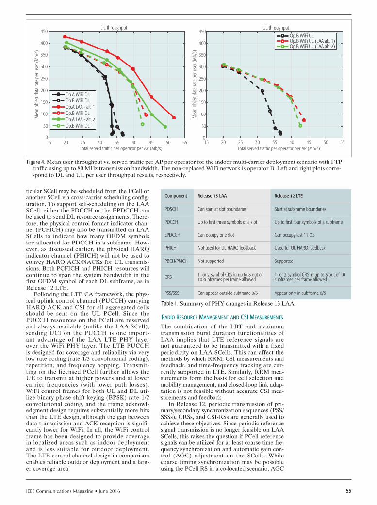
IEEE Communications Magazine • June 2016 55
ticular SCell may be scheduled from the PCell or another SCell via cross-carrier scheduling config-uration. To support self-scheduling on the LAA SCell, either the PDCCH or the EPDCCH can be used to send DL resource assignments. There-fore, the physical control format indicator chan-nel (PCFICH) may also be transmitted on LAA SCells to indicate how many OFDM symbols are allocated for PDCCH in a subframe. How-ever, as discussed earlier, the physical HARQ indicator channel (PHICH) will not be used to convey HARQ ACK/NACKs for UL transmis-sions. Both PCFICH and PHICH resources will continue to span the system bandwidth in the first OFDM symbol of each DL subframe, as in Release 12 LTE.
Following the LTE CA framework, the phys-ical uplink control channel (PUCCH) carrying HARQ-ACK and CSI for all aggregated cells should be sent on the UL PCell. Since the PUCCH resources on the PCell are reserved and always available (unlike the LAA SCell), sending UCI on the PUCCH is one import-ant advantage of the LAA LTE PHY layer over the WiFi PHY layer. The LTE PUCCH is designed for coverage and reliability via very low rate coding (rate-1/3 convolutional coding), repetition, and frequency hopping. Transmit-ting on the licensed PCell further allows the UE to transmit at higher powers and at lower carrier frequencies (with lower path losses). WiFi control frames for both UL and DL uti-lize binary phase shift keying (BPSK) rate-1/2 convolutional coding, and the frame acknowl-edgment design requires substantially more bits than the LTE design, although the gap between data transmission and ACK reception is signifi-cantly lower for WiFi. In all, the WiFi control frame has been designed to provide coverage in localized areas such as indoor deployment and is less suitable for outdoor deployment. The LTE control channel design in comparison enables reliable outdoor deployment and a larg-er coverage area.
rAdIo rEsourcE mAnAgEmEnt And csI mEAsurEmEnts
The combination of the LBT and maximum transmission burst duration functionalities of LAA implies that LTE reference signals are not guaranteed to be transmitted with a fixed periodicity on LAA SCells. This can affect the methods by which RRM, CSI measurements and feedback, and time-frequency tracking are cur-rently supported in LTE. Similarly, RRM mea-surements form the basis for cell selection and mobility management, and closed-loop link adap-tation is not feasible without accurate CSI mea-surements and feedback.
In Release 12, periodic transmission of pri-mary/secondary synchronization sequences (PSS/SSSs), CRSs, and CSI-RSs are generally used to achieve these objectives. Since periodic reference signal transmission is no longer feasible on LAA SCells, this raises the question if PCell reference signals can be utilized for at least coarse time-fre-quency synchronization and automatic gain con-trol (AGC) adjustment on the SCells. While coarse timing synchronization may be possible using the PCell RS in a co-located scenario, AGC
Figure 4. Mean user throughput vs. served traffic per AP per operator for the indoor multi-carrier deployment scenario with FTP traffic using up to 80 MHz transmission bandwidth. The non-replaced WiFi network is operator B. Left and right plots corre-spond to DL and UL per user throughput results, respectively.
Total served traffic per operator per AP (Mb/s)
Mea
n ob
ject
data
rate
per
use
r (M
b/s)
15 20 25 30 35 40 45 50 55
50
0
100
150
200
250
300
350
400
450DL throughput
Op.A WiFi DLOp.B WiFi DLOp.A LAA - alt. 1Op.B WiFi DLOp.A LAA - alt. 2Op.B WiFi DL
Total served traffic per operator per AP (Mb/s)
Mea
n ob
ject
data
rate
per
use
r (M
b/s)
0
50
100
150
200
250
300
350
400
450UL throughput
Op.B WiFi ULOp.B WiFi UL (LAA alt. 1)Op.B WiFi UL (LAA alt. 2)
15 20 25 30 35 40 45 50 55
Table 1. Summary of PHY changes in Release 13 LAA.
Component Release 13 LAA Release 12 LTE
PDSCH Can start at slot boundaries Start at subframe boundaries
PDCCH Up to first three symbols of a slot Up to first four symbols of a subframe
EPDCCH Can occupy one slot Can occupy last 11 OS
PHICH Not used for UL HARQ feedback Used for UL HARQ feedback
PBCH/PMCH Not supported Supported
CRS 1- or 2-symbol CRS in up to 8 out of 10 subframes per frame allowed
1- or 2-symbol CRS in up to 6 out of 10 subframes per frame allowed
PSS/SSS Can appear outside subframe 0/5 Appear only in subframe 0/5

IEEE Communications Magazine • June 201656
adjustment would not be feasible due to the PCell potentially operating on a carrier (e.g., 2 GHz) that has substantially different characteristics and path loss compared to LAA SCells in the 5 GHz band. This difference in long-term channel prop-erties also rules out using PCell RS for channel estimation fi lter adjustment on LAA SCells.
Based on the above discussion, the Release 13 solution is to transmit constant-power discovery reference signals (DRSs) on the LAA SCells, subject to a single CCA duration of 25 ms with-out random backoff. The signals comprising the LAA DRSs are the same as symbols 0–11 of the Release 12 DRS, which comprised PSS/SSS/CRS and was designed for small cell PHY enhance-ments. The transmission burst containing LAA DRSs cannot exceed 1 ms in duration, and will be attempted to be sent periodically every 40 ms or so. UEs will be configured with a discovery measurement timing configuration (DMTC) of six subframes, within which they can attempt to detect and measure DRSs of serving and adja-cent LAA cells.
Moreover; CSI-RSs together with CSI-IMs (or other known unused resource elements) can be used to derive CSI reports from the UE when they are available. Due to the unpredictable availability of the unlicensed carrier, the most practical approach would be to rely only on ape-riodic CSI reports for the LAA SCell, as opposed to periodic CSI reports. Furthermore, the CRS and CSI-RS power will be the same within a burst but may be varied across transmission bursts; therefore, UEs should not average CRS/CSI-RS measurements across bursts.
EvoLutIon bEyond rELEAsE 13The initial DL-only LAA framework developed in Release 13 is amenable to several potential enhancements in future releases in order to cre-ate a full-fl edged LAA design with both DL and UL transmissions and support for aggregation of a large number of unlicensed channels.
uPLInk LAASeveral aspects of UL LAA, such as HARQ and UL LBT, were discussed during Release 13. It was agreed that UL HARQ should follow an asynchronous protocol, similar to LAA DL HARQ. In other words, UL retransmissions are explicitly rescheduled by the eNB, as opposed to automatic retransmission 4 ms after an eNB NACK as in Release 12.
With regard to the framework of UL LBT, it was recognized that UL LBT imposes an additional LBT step for UL transmissions that were scheduled by an LAA SCell (self-sched-uling), since the UL grant itself requires a DL LBT by the eNB. Therefore, Release 13 LAA recommended that the UL LBT for self-sched-uling should use either a single CCA duration of at least 25 ms (similar to DL DRS) or a ran-dom backoff scheme with a defer period of 25 ms including a defer duration of 16 ms followed by one CCA slot, and a maximum contention win-dow size between three and seven.
The exact specification of UL LBT and enhancements to UL scheduling, PUCCH design, and data transmission are expected to be fi nalized in a Release 14 work item.
LAA wIth 32 cArrIErs
Wideband transmissions are a key feature for enabling high user data rates, and this is espe-cially true as we evolve toward 5G. As discussed earlier, IEEE 802.11ac currently supports trans-mission bandwidths of up to 160 MHz, and fur-ther improvements may be made in 802.11ax. In contrast, Release 13 LAA can aggregate up to 100 MHz on the downlink by aggregating fi ve DL carriers. Therefore, LAA should be enhanced to support system bandwidths similar to 802.11ac in unlicensed spectrum. In Release 13, a sepa-rate 3GPP work item specified aggregation of up to 16 or 32 carriers, which is a natural candi-date for application to LAA. With 32 aggregat-ed carriers, LAA will then be able to support a transmission bandwidth of 640 MHz to a single UE. This would impact a number of PHY-layer aspects, such as the need to support PUCCH on LAA SCells to reduce control overhead on the PCell, and enhancements in scheduling with such a large number of available carriers.
duAL connEctIvIty suPPort
To allow additional deployment scenarios for LTE that utilize unlicensed spectrum, it is important to extend the applicable deployment scenarios beyond those enabled by carrier aggre-gation with licensed spectrum and the associat-ed stringent time synchronization requirements. It is therefore proposed to extend the design to also allow for dual connectivity (DC) oper-ation between LTE in licensed and unlicensed spectrum with non-ideal backhaul in Release 14, which would have much looser synchronization requirements compared to CA. Supporting DC would necessitate the introduction of PUCCH and random access channels on the LAA UL, in addition to changes in radio link monitoring of the unlicensed secondary carriers.
concLusIonsThis article presents an overview of licensed assisted access in Release 13 LTE for operation in unlicensed spectrum. It is shown how the intro-duction of new functionalities such as DTX and LBT necessitates numerous changes in the DL physical channels, HARQ feedback procedures, scheduling, RRM mechanisms, and CSI acquisi-tion. Detailed system-level simulation results are presented to show that fair coexistence between LAA and WiFi can be achieved in a range of sin-gle-carrier and multi-carrier scenarios. Finally, an overview of desirable enhancements for LAA in future LTE releases was presented.
rEfErEncEs[1] E. Dahlman et al., “5G Wireless Access: Requirements and Realization,”
IEEE Commun. Mag., vol. 52, no. 12, Dec. 2014, pp. 42–47.[2] 3GPP TR 36.889 v13.0.0, “Feasibility Sudy on Licensed-Assisted Access to
Unlicensed Spectrum,” July 2015; www.3gpp.org[3] RP-151045, “New Work Item on Licensed-Assisted Access to Unlicensed
Spectrum,” 2015; www.3gpp.org[4] F. Liu et al., “Small Cell Traffi c Balancing over Licensed and Unlicensed
Band,” IEEE Trans. Vehic. Tech., vol. 64, no. 12, Dec. 2015, pp. 5850–65.[5] E. P. L. Almeida et al., “Enabling LTE/WiFi Coexistence by LTE Blank Sub-
frame Allocation,” Proc. IEEE ICC, 2013.[6] A. M. Cavalcante et al., “Performance Evaluation of LTE and WiFi Coexis-
tence in Unlicensed Bands,” Proc. IEEE VTC-Spring, 2013.[7] N. Rupasinghe and I. Guvenc, “Licensed-Assisted Access for WiFi-LTE
Coexistence in the Unlicensed Spectrum,” Proc. IEEE GLOBECOM Wksp. Emerging Tech. for 5G, Austin, TX, Dec. 2014.
To allow additional
deployment scenarios
for LTE that utilize
unlicensed spectrum, it
is important to extend
the applicable deploy-
ment scenarios beyond
those enabled by
carrier aggregation with
licensed spectrum and
the associated stringent
time synchronization
requirements.

IEEE Communications Magazine • June 2016 57
[8] H. Zhang et al., “Coexistence of WiFi and Heterogeneous Small Cell Net-works Sharing Unlicensed Spectrum,” IEEE Commun. Mag., vol. 53, no. 3, Mar. 2015, pp. 158–64.
[9] A. Mukherjee et al., “System Architecture and Coexistence Evaluation of Licensed-Assisted Access LTE with IEEE 802.11,” Proc. IEEE ICC Wksp. LTE-U, London, U.K., June 2015.
[10] J. Jeon et al., “LTE with Listen-Before-Talk in Unlicensed Spectrum,” Proc. IEEE ICC Wksp. LTE-U, London, U.K., June 2015.
[11] C. Chen, R. Ratasuk, and A. Ghosh, “Downlink Performance Analysis of LTE and WiFi Coexistence in Unlicensed Bands with aSimple Listen-Be-fore-Talk Scheme,” Proc. IEEE VTC-Spring, Glasgow, Scotland, May 2015.
[12] 3GPP TS 36.300, 2016; www.3gpp.orgR1-151131, “Further Details on LBT Design for DL,” Ericsson, Mar. 2015;
www.3gpp.org.
bIogrAPhIEs
AmitAv mukherjee received his B.S. degree from the University of Kansas, Law-rence, in 2005, his M.S. degree from Wichita State University, Kansas, in 2007, both in electrical engineering, and his Ph.D. degree in electrical and computer engineering from the University of California, Irvine, in 2012. He is currently a research engineer at Ericsson Research, San Jose, California, where he is involved with the standardization of LTE in unlicensed spectrum. From 2012 to 2014, he was a 3GPP RAN1 delegate at Hitachi America Ltd., Santa Clara, California. His research interests encompass statistical signal processing and wireless communications, with over 65 refereed publications and 50 pending/issued patents in these areas.
jung-Fu (thomAs) Cheng is with Ericsson Silicon Valley where he leads research and development of advanced wireless communication technolo-gies. Since joining Ericsson in 1999, he has driven a wide range of projects evolving cellular wireless PHY and MAC layer technologies from 2.5G EDGE, 3G HSPA, 4G LTE, to 5G technologies. His research interests include iterative processing, coding, and signal processing algorithms for wireless communi-cations. He was the principal contributor to the LTE turbo and convolutional coding and rate matching procedures. He is responsible for driving Ericsson’s global strategy, research, and standardization of small and heterogeneous cell operations using LTE technologies. He holds over 100 granted U.S. patents and was named Ericsson Inventor of the Year in 2012. He was a co-recipient of the 1999 IEEE Communications Society Leonard G. Abraham Prize Paper Award in the Field of Communications Systems. He received his B.S. and M.S. degrees in electrical engineering from National Taiwan University, Taipei. He received his Ph.D. degree in electrical Engineering from California Institute of Technology, Pasadena.
sorour FAlAhAti received her B.S. degree in electrical engineering from Sharif University of Technology, Tehran, Iran, in 1994, and both her M.Sc. and Ph.D degrees from Chalmers University of Technology, Gteborg, Sweden, in 1996 and 2002, respectively. From January 2003 until October 2005, she worked in the Signals and Systems Group, Uppsala University, Sweden. Since November 2005 she has been with Ericsson Research in Stockholm, Sweden, and has
worked on a range of topics including signal processing for communication systems, control channel design, wireless backhaul systems, and spectrum sharing in unlicensed bands. Currently, she is involved in standardization efforts in 3GPP for evolution of LTE, including operation of LTE in unlicensed spectrum, and in ETSI BRAN for development of a harmonized standard for operation in unlicensed spectrum at 5 GHz.
hAvish koorApAty ([email protected]) received his B.S., M.S., and Ph.D. degrees in electrical and computer engineering from North Caro-lina State University in 1991, 1993, and 1996, respectively. He has been with Ericsson Research since 1996, where he has worked in the general area of wireless communications systems including cellular and satellite systems. His work spans a wide range of topics including error control coding, location determination and tracking, mobile phone systems engineering, broadband wireless system design, wireless backhaul solutions, energy efficiency, spec-trum sharing, and small cells. He has over 100 technical papers and patents in these areas. Recently, he has worked on LTE evolution and has been involved in standardization efforts in 3GPP for LTE including serving as Rap-porteur for the licensed-assisted access study and work items. He received the 3GPP Excellence award for his contributions to 3GPP in 2015.
Du ho kAng ([email protected]) received his M.S. degree from Seoul National University, Korea, in 2010 and obtained his Ph.D. degree in 2014 in the area of radio communication systems from KTH Royal Institute of Technology, Sweden. He joined Ericsson Research as an experienced researcher and has been engaged in the standardization and regulation of LTE evolution and 5G. He is also serving as the Ericsson delegate of METIS-II, the EU 5G flagship project. His general interests include spectrum technolo-gies and regulations for future wireless access networks.
reem kArAki is a research engineer in Radio Protocols at Ericsson Germany. Her research interests include LTE licensed assisted access (LAA), LTE/WiFi aggregation, and dual connectivity. She received an M.Sc. in communications engineering from RWTH, Germany, in 2014.
lAetitiA FAlConetti holds an M.Sc. from Karlsruhe University and a Ph.D. from RWTH). She joined Ericsson Research in 2008 and is a senior researcher in the Radio Network Algorithms Group at Ericsson Research, Kista, Sweden. Her research interests include radio resource management, energy-efficient mobile communications, and, more generally, LTE evolution with features such as LAA and latency reduction.
DAniel lArsson received his M.Sc.E.E. from the Royal Institute of Technology in 2006. He joined Ericsson in 2007, and has been working on the devel-opment and standardization of mobile broadband technologies since 2008. His research has included work in the areas of carrier aggregation, mobility, positioning, broadcast techniques (eMBMS), TDD technologies, and interfer-ence mitigation techniques. He is currently working on operation of LTE in unlicensed spectrum and latency reduction in LTE. He is also head of the delegation at Ericsson in 3GPP RAN WG1 for 4G and 5G technologies. He received the Ericsson Inventor of the Year award in 2015.

IEEE Communications Magazine • June 201658
Guest editorial
Nature is Earth’s most amazing invention machine for solving problems and adapting to significant envi-ronmental changes. Its ability to address complex,
large-scale problems with robust, adaptable, and efficient solutions results from many years of selection, genetic drift, and mutations. Thus, it is not surprising that inventors and researchers often look to natural systems for inspiration and methods to solve problems in human-created artifi-cial environments. This has resulted in the development of evolutionary algorithms including genetic algorithms and swarm algorithms, and of classifier and pattern detection algorithms, such as neural networks, for addressing hard computational problems.
A natural evolutionary driver is to survive long enough to create a next generation of descendants and ensure the survival of the species. One factor in survival is an organ-ism’s ability to defend against attackers, both predators and parasites, and against rapid changes in environmental conditions. Analogously, networks and communications sys-tems use cyber security to ensure the survival of their assets against cyber criminals, hostile organizations, hackers, activ-ists, and sudden changes in the network environment. Many of the defense methods used by natural organisms may be mapped to cyber space to implement effective cyber securi-ty. Some examples include immune systems, invader detec-tion, friend vs. foe, camouflage, and mimicry. Many cyber security technologies and systems in common use today have their roots in bio-inspired methods, including anti-vi-rus, intrusion detection, threat behavior analysis, attribu-tion, honeypots, counterattack, and the like. As the threats evolve to evade current cyber security technologies, similar-ly bio-inspired security and defense technologies evolve to counter the threat.
An objective of this Feature Topic was to survey current work in the area of bio-inspired cyber security for commu-nications and networking. Hopefully this Feature Topic provides the ComSoc community a better understanding of the current evolutionary state of cyber threats, defenses, and intelligence, and helps the community plan for future transitions of this research into practical implementations.
In this Feature Topic, we are delighted to present a
selection of four articles that contribute to the enhancement of knowledge in bio-inspired cyber security for communica-tions and networking. The collection of these high-quality articles provides a view on the latest research advances in this field.
The first article, “Hive Oversight for Network Intrusion Early-Warning Using DIAMoND (HONIED): A Bee-In-spired Method for Fully Distributed Cyber Defense” by Korczynski et al., describes an interesting concept of a self-organized anomaly detection system. This bio-in-spired approach is derived from the social interactions of honey bees observed in nature. In honey bee foraging, sys-tem participants do not define the search target a priori; instead, participants identify anomalies (resources) as they encounter them. The foraging methods may be mapped to computer system networks in order to detect and mitigate distributed attacks in an automated fashion.
In the second article, “Bio-Inspired Cybersecurity for Wireless Sensor Networks,” Bitam et al. first carefully review existing bio-inspired techniques developed for improving cyber security of cyber-physical systems using wireless sen-sor networks. The authors propose a generic bio-inspired machine-learning model called Swarm Intelligence for WSN Cybersecurity (SIWC) that addresses drawbacks of prior bio-inspired solutions. SIWC is a neural network system trained by swarm intelligence optimization to automatically and efficiently determine the optimal critical parameters used to detect cyber-attacks.
In the next article “Decapitation via Digital Epidemics: A Bio-Inspired Transmissive Attack,” Chen et al. address an emerging attack pattern called transmissive attack in which an attacker leverages diverse communication paths to approach the target and performs malicious activities. The authors provide an overview of commonly used epidemic models for communication systems and then relate trans-missive attacks to these epidemic models. Simulations and experiments in mobile social networks demonstrate the util-ity of epidemic models for assessing the trade-off between the transmissive attacks’ success rate vs. the risk of exposure (detection).
Finally, in “Bio-Inspired RF Steganography via Linear
Bio-inspired CyBer seCurity for CommuniCations and networking
Wojciech Mazurczyk Sean Moore Errin W. Fulp Hiroshi Wada Kenji Leibnitz

IEEE Communications Magazine • June 2016 59
Guest editorial
Chirp Radar Signals,” Zhang et al. propose RF steganogra-phy for concealing communication information in a linear chirp radar signal. The main idea of the described approach is inspired by the chirping sound made by birds. Some bird calls and bird songs can convey messages that are only par-tially understood by other species, and some information will only be picked up by birds of the same species or even between only a few individuals.
We hope readers enjoy this Feature Topic and find the articles interesting. In addition, we also hope that the pre-sented results stimulate further research in these important areas of information and network security.
We would also like to express our thanks for the support and help of Osman S. Gebizlioglu, Editor-in-Chief of IEEE Communications Magazine, Joseph Milizzo from the Com-munications Society staff, the leading researchers contrib-uting to the Feature Topic, and the excellent reviewers for their great help and support that made this Feature Topic possible.
BiographiesWojciech Mazurczyk [M’11, SM’13] ([email protected]) received his M.Sc., Ph.D. (Hons.), and D.Sc. (habilitation) degrees in telecommunications from the Warsaw University of Technology (WUT), Poland, in 2004, 2009, and 2014, respectively. He is currently an associate pro-
fessor with the Institute of Telecommunications at WUT. His research interests include bioinspired cybersecurity and networking, information hiding, and network security. Since 2013, he has been an Associate Technical Editor of IEEE Communications Magazine.
Sean Moore [M’01, SM’03] is the chief technology officer and vice president of research for Cen-tripetal Networks. In the past, he was a chief scientist and chief architect at Avaya, chief scientist at Cetacean Networks, and senior director of R&D at MadeToOrder.com. He is a former Editor-in-Chief of IEEE Communications Magazine. He received a B.S. degree in electrical engineering from Tulane University in 1983, an M.S. in mathematics from the University of New Orleans in 1990, and M.S. and Ph.D. degrees in computer science from Dartmouth College in 1993 and 1994, respectively.
errin W. Fulp holds an M.Sc. (1994) in computer science and a Ph.D. (1999) in computer engineer-ing from North Carolina State Universit, and is a full professor at Wake Forest University. He is an author of over 55 publications, 3 patents, and 20 invited talks on computer security and networks. He was involved in one startup company. His main research interests are moving target system defenses, agent-based (swarm intelligence) network security and management, and bio-inspired security methods for the smart grid.
hiroShi Wada holds a Ph.D. (2009) in computer science from the University of Massachusetts Boston. He is a staff engineer with Unitrends Australia, and leads research and development. Before joining Unitrends he was a senior researcher with NICTA and a VP research at Yuruware, which was a startup incubated in NICTA subsequently acquired by Unitrends in 2014. His research interests include distributed computing, dependable system operation, performance engineering, and search-based software engineering. In these areas he has published over 30 refereed papers.
kenji leibnitz received M.Sc. and Ph.D. degrees in information science from the University of Würz-burg, Germany. Since 2010 he has been a senior researcher at the National Institute of Information and Communications Technology and a guest associate professor at Osaka University; since 2013 he has been with the Center of Information and Neural Networks. His research interests include mod-eling and performance analysis of communication networks, especially the application of biologically and brain inspired mechanisms to self-organization in future networks.
IENYCM3524.indd 1 22/04/16 2:59 PM

IEEE Communications Magazine • June 201660 0163-6804/16/$25.00 © 2016 IEEE
AbstrAct
Social insect colonies have survived over evolutionary time in part due to the success of their collaborative methods: using local informa-tion and distributed decision making algorithms to detect and exploit critical resources in their environment. These methods have the unusu-al and useful ability to detect anomalies rapid-ly, with very little memory, and using only very local information. Our research investigates the potential for a self-organizing anomaly detection system inspired by those observed naturally in colonies of honey bees. We provide a summary of findings from a recently presented algorithm for a nonparametric, fully distributed coordination framework that translates the biological success of these methods into analogous operations for use in cyber defense and discuss the features that inspired this translation. We explore the impacts on detection performance of the defined range of distributed communication for each node and of involving only a small percentage of total nodes in the network in the distributed detection com-munication. We evaluate our algorithm using a software-based testing implementation, and demonstrate up to 20 percent improvement in detection capability over parallel isolated anom-aly detectors.
IntroductIonOver the past years, cyber-attackers have taken advantage of the massive acceleration in the adoption of virtualization and cloud computing, the Internet of Things (IoT), and mobile devices as an increase in potential targets and expanding attack surface. Motivations are the major char-acteristics that differentiate malicious actors. Organized crime is interested in economic gain, nation-states are mostly interested in cyber-es-pionage, whereas hacktivists can be motivated politically or ideologically.1 Cyber-attack strat-egies have also evolved significantly: modern malicious activities are spread stealthily over a large number of malicious machines. Those can be compromised or rented from so-called bul-
letproof hosting providers that ignore all abuse notifications [1]. This increases the chance of cyber-criminal success, either decreasing the probability the attack will be noticed or launch-ing a distributed denial of service (DDoS) attack as a smokescreen to cover virus or malware installation, and/or financial or data theft.2
To address these more challenging types of cyber-attacks, recent defenses have introduced the idea of sharing information across organi-zational boundaries, allowing collaboration to achieve rapid detection and mitigation for a vari-ety of cyber-attacks, especially those for which prior knowledge is scant or nonexistent. Indeed, an entire new infrastructure is being created with new sharing protocols, cyber threat “exchanges,” and government backing. Automated cyber data processing and sharing is already being promoted as the new defensive strategy against smart and highly distributed adversaries. However, there are some fundamental challenges to address before this paradigm can become reality, such as: • Policy issues that prevent sensitive data from
being shared between organizations• System scalability• Semantics of the data being exchanged• Alert correlationAs cyber-attacks are evolving rapidly, the data captured in one particular environment may be incomparable to data from another, vitiating any gains from sharing. Any form of detection that relies on comparison of semantically rich data is thus in jeopardy if the data comes from sensors in different domains. Even if direct comparison is possible, it is not guaranteed that the existing alert correlation techniques will be able to recon-struct novel, complex attack scenarios.
Honey bees As An evolved AnomAly detectIon mAcHIne
Colonies of honey bees rely on foraging work-ers to discover and share locations of flowering plants from which to gather the pollen and nectar used for food. The colony operates under many time-varying constraints: different plants flower at different times of year and/or day, other ani-
Hive Oversight for Network Intrusion Early Warning Using DIAMoND:
A Bee-Inspired Method for Fully Distributed Cyber DefenseMaciej Korczynski, Ali Hamieh, Jun Ho Huh, Henrik Holm, S. Raj Rajagopalan, and Nina H. Fefferman
bIo-InspIred cyber securIty for communIcAtIons And networkIng
The authors investigate the potential for a self-or-ganizing anomaly detec-tion system inspired by those observed naturally in colonies of honey bees. They provide a summary of findings from a recently presented algorithm for a nonparametric, fully distributed coordination framework that translates the biological success of these methods into analo-gous operations for use in cyber defense and discuss the features that inspired this translation.
Maciej Korczynski is with Delft University of Technology; Ali Hamieh and Nina H. Fefferman are with Rutgers University; Jun Ho Huh and S. Raj Rajagopalan are with Honeywell ACS Labs; Henrik Holm is with Forest Glen Research, LLC.
1 http://www.mcafee.com/mx/resources/reports/rp-quarter-ly-threats-aug-2015.pdf 2 https://www.neustar.biz/resources/whitepapers/ddos-pro-tection/2014-annual-ddos-at-tacks-and-impact-report.pdf

IEEE Communications Magazine • June 2016 61
mals also eat the plants/flowers, or the nectar and pollen are depleted by both direct competi-tion with other insects/bees and by their own col-ony mates having already gathered the resources, making additional trips redundant. Each of these challenges must be met efficiently since the rate of resource acquisition determines the probabil-ity of colony growth, reproduction, and survival through the winter [2]. Meeting these challeng-es requires the colony (using only the relatively simple cognition and communication available to bees) to identify locations richest in resources, communicate their location to comrades, exploit them quickly, and abandon depleted locations rapidly in favor of alternate sources. Honey bees manage to meet these challenges with startling efficiency by a very simple method: each for-ager evaluates each site they visit; if a forager is excited by the resource richness of the site, she returns and tells a subset of her comrades the location of the resource and her own rela-tive level of excitement (via mathematical dance language). Bees who receive her signal decides whether or not she was excited enough to merit their own trip to the site. If they go, they either return just as excited to recruit others, or else disagree, decide the site was not exciting enough, and search for a new site themselves or wait for another comrade to recruit. This system fulfills many desirable features: excitement waxes and wanes endogenously with site quality, sites are exploited while also searching for new sites, indi-viduals identify new sites that do not fit the cur-rent predominant interest, and attention accrues very rapidly at any site consensus deems worth-while without the need for bees to agree a priori on any single definition of “exciting.”
puttIng bees to work In cyber-defense
In this article we define HONIED: Hive Over-sight for Network Intrusion Early Warning using DIAMoND — a bee-inspired method for fully distributed cyber defense. Our research is the first to investigate the potential for a self-orga-nizing anomaly detection system inspired by the distributed algorithms colonies of honey bees use to forage efficiently to provide appropriate, dynamic detection thresholds for anomalous event patterns on computer system networks to improve early detection and mitigation methods to counter malicious threats.
Our approach addresses some of the main challenges of distributed defense strategies. The proposed system allows for cooperation between sensors in an arbitrary virtual topolo-gy and does not rely on sharing the particulars of the underlying event, but only the pattern of “excitation” seen in the sensors. By its nature this data does not contain any individually sensi-tive information, or even any information about the specific attack. We expect that overcoming organizational hurdles that may prevent sharing of such data would be far easier. For the same reason, our scheme easily addresses the third and fourth challenges; because the data shared is very simple (not even individual values for detection thresholds are shared), there is no question of creating semantic equivalence or complex cor-relation techniques. Finally, the scheme enables sensors to self-tune their individual detection
threshold values using a feedback mechanism. When new attack patterns appear, the sensors learn by cooperation to sense them — it takes some time, but there is no prior modeling that has to be applied to the sensors. That makes our scheme especially appealing for detecting novel network attacks assuming that some controls (e.g., local intrusion detection systems) are able to detect their symptoms.
relAted workThere have been several proposals for fully dis-tributed systems [3–7]. Locasto et al. proposed a fully distributed peer-to-peer (P2P) intrusion detection system (IDS) called Worminator [4]. The system creates and shares between the federations of nodes compact watchlists of IP addresses encoded in Bloom filters. Another P2P approach for collaborative intrusion detection is proposed by Zhou et al. [5]. It implements a distributed hash table (DHT) system to share detection information. Each peer submits its blacklist to a fully distributed P2P overlay. The participating nodes are notified if other peers are attacked by the same source. However, both methods use a single traffic feature, which might be too restrictive for detecting some important characteristics of large-scale intrusions.
In a distributed IDS proposed by Dash et al. [6], local detectors use a binary classifier to ana-lyze incoming/outgoing host traffic and raise an alarm if a threshold value is crossed. Through their information sharing system (ISS), those alarms are sent to a random set of global detec-tors that generate a global view of security sta-tus of the system being monitored. DefCOM [7], which is a distributed system for DDoS mitiga-tion, consists of three types of nodes: core, classi-fier, and alert generator nodes. It implements an overlay communication protocol between source, victim, and core networks to detect and block the attack at the source. One of the main drawbacks of both systems, however, is the separation of
Figure 1. Literature in bio-inspired algorithms.
1996
1998 20
0020
0220
0420
0620
0820
1020
1220
140
500
1000
1500
2000
2500
3000
3500
634
1108
1619
2048
2421
2703
3025
3285Cumulative sum of papers onIEEE Xplore matching "bio-inspired"

IEEE Communications Magazine • June 201662
different types of nodes and the need for the sys-tems to coordinate messages between them.
While bio-inspired (cf. Fig. 1, e.g., [8]), and honey-bee-based algorithms in particular, are not new [9, 10], our approach is among the first to apply them to distributed-decision-driven cyber-security systems.
Honey bee-InspIred detectIon system
formIng tHe AnAlogIes wItH Honey bee forAgIng
In honey bee foraging [2], system participants do not define the search target a priori, instead let-ting participants identify anomalies (resources) as they encounter them. This feature is one of the most important benefits we anticipate from adopting this bio-inspired perspective, particu-larly when detecting complex network attacks that might coincide with each other (in which there are no known patterns for which to look). In honey bee foragers, if enough participants identify a location as a valuable target (i.e., an anomaly), it becomes an anomaly by definition. Furthermore, as an anomaly is handled (i.e., resources are exploited), participants gradually lose interest, ceasing to identify the location as anomalous.
Another important feature of the system is that foragers who act as early scouts return to recruit additional foragers to help exploit identi-
fied anomalies (i.e., resources). They communi-cate not only the location, but also their “relative excitement” about the quality of the discovered resources to all other bees within range, called the foraging dance floor. This is functionally equivalent to a nonparametric description of per-ceived importance of the identified target, allow-ing very rapid and low-overhead communication and census-taking for collaborative decision mak-ing. This real-time collaborative definition of anomalies makes the system uniquely suited to discover novel targets by eliminating the need to employ any form of uniform template for com-parison or recognition. We critically also adopt these features in our algorithm design.
Basing our algorithm on this system, instead of traditional distributed network anomaly detec-tion (in which we must have a list of known patterns that indicate attacks and/or legitimate traffic), we instead allow emergent consensus to draw attention to patterns, even if some partic-ipants would not have identified the pattern as indicating an attack if assessed only independent-ly.
system bAsIcs
We use Distributed Intrusion/Anomaly Monitor-ing for Nonparametric Detection (DIAMoND): a nonparametric, fully distributed coordination framework that decouples local intrusion detec-tion functions from network wide coordination. DIAMoND first builds coordination overlay net-works on top of physical networks. DIAMoND then dynamically combines direct observations of traditional localized/centralized network IDS (NIDS) with knowledge exchanged with other coordinating nodes called neighbors to dynam-ically detect anomalies of underlying physi-cal systems. Specifically, coordinating nodes in DIAMoND, analogous to honey bees, exchange generic nonparametric levels of concern between neighbors that reflect the observed probabili-ty of network attacks without elaborating any further details on the attacks themselves. As a result, the coordination layer of the DIAMoND framework can readily be coupled with any local detection schemes without the need for increas-ing the detection feature sets. The coordination network layer is also decoupled from the under-lying physical network layer to facilitate flexible coordination strategies based on, for example, previously observed correlated behaviors, instead of being artificially limited to direct connectivity or geographical proximity. Interactions inside DIAMoND are limited to local neighborhood (e.g., one- or two-hop neighbors) in the overlay network, thus ensuring system scalability linear to the coordination network density instead of network size. While in general there can still be potential risks for recovery of sensitive infor-mation from the sharing of only nonparametric descriptors, in this case, since there is no need for/assumption of a uniform individual detec-tion algorithm for local determination of level of excitement/concern across participating nodes, or even for a single node over time, no inference can be made simply from the nonparametric information shared about more sensitive fea-tures. The overall architecture of DIAMoND thus allows preservation of potentially sensitive
Figure 2. DIAMoND architecture.
DIAMoND node
DU CU
Concernlevel
Threatlevel
Concernlevels
Direct observation
To peers From peers
Physical networkCoordination overlaynetwork

IEEE Communications Magazine • June 2016 63
information of individual participating parties, which eases deployment of DIAMoND across political and administrative boundaries.
system desIgnArcHItecture overvIew
DIAMoND is deployed over multiple nodes (switches, middleboxes) in a fully distributed architecture (Fig. 2). We define a node’s neigh-borhood as a subset of all nodes with which it directly exchanges nonparametric alert-related information. Neighborhoods are dynamic and can change over time based on, for example, previously observed correlated behaviors or changes in the network topology. Two collabo-rating nodes enjoy a symbioti, mutual relation-ship, meaning both must authenticate each other and agree to join each other’s neighborhoods. Furthermore, each node is equipped with two functional units: a detection unit (DU) and a coordination unit (CU). The former is respon-sible for the data-driven individual assessment of the so-called threat level — the level of likeli-hood that an intrusion is occurring based on the direct observation reported by local NIDS and/or firewall implementation. The latter calculates the concern level, which is a function of its own threat level and the concern levels of its neighbors (Fig. 2).
detectIon unIt
Any detection or security intelligence such as NIDS or firewalls can be implemented in a DU as long as there is an appropriate plug-in to a CU to translate the output of the DU to the nonparametric threat level. Additionally, there must be an incorporated appropriate response by the DU to different levels of concerns of its neighbors (e.g., tuning of sensitivity thresholds). To foster interoperability, we do not require the extraction and provision of any potentially sensi-tive and/or incomparable attack details. In fact, a node may choose any local anomaly detection method independent from any other node(s), thereby making it difficult for an attacker to manipulate the local anomaly detection’s influ-ence on the CU network by making it harder to predict what types of traffic may trigger an indi-vidual, local intrusion warning. These features greatly increase the potential of such a system to be able to detect diverse characteristics of large-scale network attacks, depending on a variety
of local detection algorithms adapted to DIA-MoND.
coordInAtIon unIt
Each of the participating nodes has an inter-nal set of sensitivity thresholds corresponding to their “native” detection algorithms. These sen-sitivity thresholds are updated dynamically over time, and there is no a priori assumption of their uniformity across nodes. Since each node may employ its own local anomaly detector, these thresholds are also completely independent of each other. The sensitivity threshold is a func-tion of the observed threat level and the level of concern of each node’s neighborhood. Note that even if the sensitivity threshold is dynamic, it can be updated within a certain predefined range to prevent malicious tuning.
At each time instance, each node computes a function of the observed threat level, which is the individual data-driven assessed level of the likeli-hood that an anomaly is occurring.
We assign values low, med, high to the threat level for each node in each time instant based on the traffic observed in the local intrusion detec-tion on that node. Values are defined such that low indicates a completely normal classification, med indicates that traffic patterns have exceeded some fixed numbers of standard deviations from normal but have not yet exceeded the rate lim-iting threshold to be considered an attack, and high indicates classification of a current attack by the local anomaly detector.
Each node has a level of concern at every time instant, which is a function of both the previous-ly assessed threat level and of the total impact of the concerns of all nodes within its neighbor-hood computed by our naïve excitation algorithm that takes discrete values low, med, high. Values are defined such that low indicates a consensus between a node’s neighbors and normal network state, med indicates that traffic patterns observed within a neighborhood have deviated from nor-mal traffic distributions but have not yet exceed-ed some thresholds to be considered an attack, and high indicates classification by the node’s neighborhood of a current attack.
Finally, each node determines the strength of influence of the levels of concern from its neighbors. This strength allows a node to tune preference between sensitivity and specificity provided by the collaborative network. We here
Figure 3. Neighborhood strategies: a) hop limit TTL = 1; b) hop limit TTL = 2; c) correlated attacks neighborhood.
TTL = 1 TTL = 1
TTL = 1
TTL = 2
TTL = 2TTL = 2
TTL = 2 TTL = 2
TTL = 2
TTL = 2
TTL = 2
TTL = 1
TTL = 1 TTL = 1
TTL = 1TTL = 1
TTL = 1
TTL = 1
TTL = 3
TTL = 1TTL = 1
TTL = 1A A A
(a) (b) (c)
TTL = 1

IEEE Communications Magazine • June 201664
present the full results for a moderate strength of influence, but results from other choices may be found in [11].
neIgHborHood strAtegIes
Honey bees incorporate the influence of other nodes into their decision on whether or not to reinforce the signal as discussed earlier. We define and investigate two different strategies for creating the “areas” or neighborhoods to max-imize the flow of meaningful information while minimizing the number of connections.
The first strategy is based on a hop limit that reflects the geographical or administrative dis-tance between neighbors. In the simplest but very effective form, we define a neighborhood of a node by direct physical or logical connection. We also attempt to empirically verify the appli-
cation of the extended neighborhoods by increas-ing the time to live (TTL) value (Figs. 3a and 3b). Another strategy, depicted in Fig. 3c, con-sists of correlating previously observed attacks and constructing neighborhoods based on the assumption that malicious activity may reoccur and be launched from the same set of compro-mised machines and/or against the same victims (networks, servers).
evAluAtIon testbedWe have developed our prototype communi-cation protocol as an OpenFlow controller in the POX environment3 and evaluated it using the Mininet 2.0 network emulator.4 Our initial software system deployment consists of 20 nodes due to computational constraints and up to 20 end-user machines connected to each node. The full specification together with the communica-tion protocol is available to the public.5
In this article, we test the performance of the algorithm on an “extended star” physical topol-ogy that represents a tree of 19 links which is generated by initiating the graph with a “root” node and then attaching each subsequently creat-ed node to one of the already existing nodes in a uniform fashion.
In our experimental evaluation, we use traf-fic captured from the trans-Pacific line (sam-plepoint-F, 150 Mb/s).6 The traffic is labeled by the MAWI working group as anomalous or normal using an advanced graph-based meth-od that combines responses from independent anomaly detectors built on principal compo-nent analysis (PCA), the gamma distribution, the Kullback-Leibler divergence, and the Hough transform [12]. Then we develop our method based on an X-means algorithm. Finally, we filter all traffic labeled as anomalous by each classifica-tion method and use the remaining traffic in our benchmark traffic generator.
Each node has been equipped with a sampling detection algorithm for detecting SYN flooding attacks and TCP portscan activity [13]. The meth-od considers TCP connections as legitimate if it samples one of multiple acknowledgment (ACK) segments (with disabled SYN flag) coming from the server. It defines two traffic features: a num-ber of outgoing SYN segments to correspond-ing incoming ACK segments per source and per destination IP address. The method is combined with a rate limiting scheme — if the traffic rate is less than or equal to a predefined rate for a given IP address, it is allowed to pass the filter, whereas traffic that exceeds the rate is dropped. For the purpose of this study, we refer to the above-described algorithm as benchmark local intrusion detector (BLID). To meet the needs of our system, we extend the proposed algorithm and define the range of sensitivity rate limiting thresholds as well as the plug-in that translates the output of the algorithm to the nonparametric thread level.
We evaluate the capability of our system using two predominant attacks exploiting TCP protocol: network-wide SYN stealth scans and SYN flooding attacks that are launched from a selected percentage of the network nodes, which are considered compromised and take part in a coordinated distributed attack. For more details
3 https://openflow.stanford.edu 4 http://mininet.org 5 http://mkorczynski.com/diamond.html 6 http://mawi.wide.ad.jp/mawi
Figure 4. Comparison of DIAMoND vs. BLID for network-wide stealth scans (top) and DDoS attacks (bottom). We also explored the impact of either strengthening (strong) or weakening (weak) the influence of network neighbors to show the robustness of effect and test system sensitivity to individual-node-level detection accuracy.
0 0.01 0.02 0.03 0.040.5
0.55
0.6
0.65
0.7
0.75
0.8
0.85BLID vs. DIAMoND: Stealth scan, TTL = 1
Sens
itivit
y
1 − specificity
Weak: BLID
Weak: DIAMoND
Moderate: BLID
Moderate: DIAMoND
Strong: BLID
Strong: DIAMoND
0 0.01 0.02 0.03 0.040.9
0.91
0.92
0.93
0.94
0.95
0.96
0.97
0.98BLID vs. DIAMoND: DDoS attack, TTL = 1
Sens
itivit
y
1 − specificity

IEEE Communications Magazine • June 2016 65
on the tesbed, we refer the reader to our previ-ous work [11].
emulAtIon resultscrIterIA of detectIon evAluAtIon
To assess the performance of DIAMoND, we consider three meaningful metrics: sensitivity, specifi city, and overall system accuracy. Sensitiv-ity measures the proportion of malicious packets that are correctly identifi ed as such, and specifi city measures the proportion of legitimate packets that are correctly identifi ed as such, whereas accuracy measures the proportion of packets correctly iden-tifi ed malicious and legitimate to all the packets.
Also, we quantify the additional information that is gained by deploying our system on top of BLIDs. In other words, we ask by how much, if at all, the inclusion of the DIAMoND collab-oration among nodes improves their accuracy relative to their use of only the local detection algorithms in isolation. In order to evaluate the information gain we use an information theoretic approach, Kullback-Leibler (K-L) divergence.
It is important to recall that the potential for improvement in accuracy is scaled by the per-cent of malicious packets. Since in the case of network-wide stealth scans malicious packets constitute a smaller percentage of all network traffi c, the increase in accuracy is strictly bound-ed, meaning that, for example, 0.045 represents a substantial improvement relative to the range possible for improvement.
detectIon performAnce
Figure 4 shows a sensitivity as a function of 1 – specificity for network-wide stealth scans (top) and DDoS attacks (bottom) in an overlay net-work where neighborhoods are created on the basis of direct physical connections (TTL = 1). We present results that reflect participating nodes assigning a moderate level of influence from the concern levels of their neighbors to their own decision, but then also present results from both weakening and strengthening that
infl uence for comparison. The results for stealth scans indicate that the more influence nodes assign to their neighbors’ concern, the greater their improvement in sensitivity, without com-promising specifi city in comparison to BLID sys-tems operating independently. The fact that 1 – specificity does not exceed 3.5 percent (in the worst case) comes from two reasons: • Precise calibration of the rate limiting sensitiv-
ity thresholds. For example, the consensus of level of concerns of neighbors cannot reduce the sensitivity threshold of a chosen node below some pre-calibrated minimal value.
• The level of concern of a node signals the anomaly, while the decision about the assigning particular flows to legitimate or malicious classes remains with the DU.
As with the sensitivity improvements, the overall information gain of DIAMoND calculated over the accuracy of BLID increases as participating nodes increase the influence of the input from their neighbors (approximately twice as large for moderate and strong as for weak; Table 1).
In the evaluated attack scenarios, we observe no major distinction in the detection accuracy and information gain regardless of the neighbor-hood strategies (Table 1).
Finally, our results show less significant improvement in sensitivity of our system over BLID systems operating independently for DDoS attacks: between 1.6 and 4.5 percent (Fig. 4 and Table 1). We also observe that the infor-mation gain of the overlay detection system is lower (although always positive) in comparison with low-rate malicious activity, but the system can react close to the source of the attack more effectively and thereby reduce the collateral damage to a minimum.
mInImAl And mArgInAl deployment gAIn
Deployment of networked services across admin-istrative boundaries usually has to take place progressively. In this section, we try to under-stand the minimal deployment percentage
Table 1. Sensitivity, 1 – specifi city, accuracy of BLID and DIAMoND, and the accuracy gain of DIA-MoND over BLID. Performance at low TTL demonstrates signifi cant benefi t without increased com-munication overhead costs associated with higher TTLs.
Sensitivity 1 – specifi city Accuracy
BLID DIAMoND BLID DIAMoND BLID DIAMoND Gain
Stealth scan, TTL = 1 neighborhood
0.58 (±0.02) 0.8 (±0.015) 6.2e–4 (±1,5e–4) 0.017 (±0.003) 0.889 0.935 0.047
Stealth scan, TTL = 2 neighborhood
0.557 (±0.021) 0.787 (±0.021) 7.5e–4 (±5.2e–4) 0.019 (±0.003) 0.889 0.932 0.045
Stealth scan, TTL = 3 neighborhood
0.568 (±0.029) 0.793 (±0.029) 6.1e–4(±1.7e–4) 0.02 (±0.003) 0.887 0.932 0.045
Stealth scan, attack correlation neighborhood
0.528 (±0.027) 0.752 (±0.027) 5.55e–4 (±1.3e–4) 0.02 (±0.003) 0.891 0.931 0.041
DDoS attack, TTL = 1 neighborhood
0.923 (±0.012) 0.962 (±0.01) 0.005 (±7.3e–4) 0.032 (±0.004) 0.95 0.964 0.014
Sensitivity measures the
proportion of malicious
packets that are correct-
ly identifi ed as such,
specifi city measures the
proportion of legitimate
packets that are correct-
ly identifi ed as such,
whereas accuracy mea-
sures the proportion
of correctly identifi ed
malicious and legitimate
to all the packets.

IEEE Communications Magazine • June 201666
needed for DIAMoND to have significant per-formance impact and marginal performance gain with additional deployment.
To quantitatively evaluate deployment gain, we adapt a calculation of “offline marginal util-ity,” originally proposed to analyze the impact of additional metrics, to instead compute the incremental information gain for each additional node (relative to the information achieved with BLID). We refer the reader to some relevant literature for more details [11].
Figure 5 provides an example analysis of the deployment gain for a 20-node network under network-wide port scan probing. This figure shows a point of diminishing return such that, after 30 percent of the nodes participate in DIA-MoND, the information gain is close to that achieved when all nodes are participating, and the marginal deployment gain from increasing participation is insignificant. On the other side, even when there are only 10 percent nodes par-ticipating, the information gain is already over 0.01. When 20 percent nodes are participating, the information gain reached a significant 0.03. We thus concluded that, in this case:• Minimal effective deployment is 10 percent
of the network nodes participating.• Marginal gain is maximized at 20 percent
deployment.DIAMoND plateaus after 30 percent deploy-ment, with minimal value gained by having addi-tional nodes participating.
As our immediate next step we plan to explore the scalability of DIAMoND coordination proto-col, and apply it to a broad set of deployment scenarios and real-network topologies.
conclusIonsIn this article we investigate the potential for a self-organizing, nonparametric distributed coor-dination framework inspired by those observed naturally in colonies of honey bees to provide dynamic individual detection thresholds for anomalous event pattern detection on networks.
To illustrate its application, we couple DIA-MoND with local anomaly detection schemes for network-wide stealthy port scan and SYN-flood-ing-based DDoS and evaluate its performance on an emulation testbed. DIAMoND demonstrated up to 20 percent enhancement in sensitivity with-out sacrificing specificity. In this article, we also systematically investigate several automated coor-dination neighborhood construction strategies and find that DIAMoND exhibits stable performance gain over different neighborhood strategies. This leads us to conclude that DIAMoND is robust to neighborhood size. Deployment impact shows that DIAMoND quickly reaches an information gain plateau after 30 percent of network nodes participate in coordination, which enhances the deployability of DIAMoND. It allows multiple entities, which may be functionally and/or legally prohibited from sharing cyber data, to leverage each other’s insight and increase their effective-ness in cyber defense. Furthermore, DIAMoND enables real-time adaptation, eliminating the identification-designed-response delay inherent in defenses that react to known and predefined threats, and allowing active defense for emerging novel network attacks.
Acknowledgments
The U.S. Department of Homeland Securi-ty sponsored this research under the Air Force Research Laboratory (AFRL) agreement num-ber FA8750-12-2-0232. The U.S. Government is authorized to reproduce and distribute reprints for governmental purposes. This work represents the views of the authors and does not repre-sent official policies or endorsements, either expressed or implied, of AFRL or the U.S. Gov-ernment.
references
[1] A. Noroozian et al., “Developing Security Reputation Metrics for Hosting Providers,” Proc. USENIX CSET, 2015, pp. 1–8.
[2] M. L. Winston, The Biology of the Honey Bee, Harvard Univ. Press, 1991.[3] C. V. Zhou, C. Leckie, and S. Karunasekera, “A Survey of Coordinated
Attacks and Collaborative Intrusion Detection,” Computers & Security, vol. 29, no. 1, 2010, pp. 124–40.
[4] M. Locasto et al., “Towards Collaborative Security and P2P Intrusion Detec-tion,” Proc. IEEE IAW, 2005, pp. 333–39.
[5] C. V. Zhou, S. Karunasekera, and C. Leckie, “A Peer-to-Peer Collaborative Intrusion Detection System,” Proc. IEEE ICON, vol. 1, 2005.
[6] D. Dash et al., “When Gossip Is Good: Distributed Probabilistic Inference for Detection of Slow Network Intrusions,” Proc. Nat’l. Conf. AI, vol. 2. AAAI Press, 2006, pp. 1115–22.
[7] M. Robinson et al., “DefCOM: Defensive Cooperative Overlay Mesh,” Proc. DARPA Info. Survivability Conf. and Expo., vol. 2, 2003, pp. 101–02.
[8] W. Mazurczyk and E. Rzeszutko, “Security — A Perpetual War: Lessons from Nature,” IT Professional, vol. 17, no. 1, 2015, pp. 16–22.
[9] D. Karaboga and B. Akay, “A Survey: Algorithms Simulating Bee Swarm Intel-ligence,” Artificial Intelligence Review, vol. 31, no. 1–4, 2009, pp. 61–85.
[10] G. A. Fink et al., “Defense on the Move: Ant-Based Cyber Defense,” IEEE S&P, vol. 12, no. 2, 2014, pp. 36–43.
[11] M. Korczynski et al., “DIAMoND: Distributed Intrusion/Anomaly Moni-toring for Nonparametric Detection,” Proc. IEEE ICCCN, 2015, pp. 1–8.
[12] R. Fontugne et al., “MAWILab: Combining Diverse Anomaly Detectors for Automated Anomaly Labeling and Performance Benchmarking,” Proc. ACM CoNEXT, 2010, pp 1–12.
[13] M. Korczy’nski, L. Janowski, and A. Duda, “An Accurate Sampling Scheme for Detecting SYN Flooding Attacks and Portscans,” Proc. IEEE ICC, 2011, pp. 1–5.
bIogrApHIes
Maciej Korczy’nsKi ([email protected]) is a postdoctoral scientist in the cybersecurity research group at Delft University of Technology. He received his Ph.D. degree in computer science from Grenoble University of Technology, France, in 2012. Previously, he was a postdoctoral research asso-ciate at Rutgers University, New Jersey (2013–2014). His research interests include encrypted traffic classification, security of the TLS and DNS protocols,
Figure 5. Information gain of DIAMoND over BLID.
0 0.2 0.4 0.6 0.8 10
0.01
0.02
0.03
0.04
0.05BLID vs. DIAMoND: Stealth scan, TTL = 1 neighborhood
Info
rmat
ion
gain
Deployment

IEEE Communications Magazine • June 2016 67
passive and active Internet security measurements, incident data analysis, economics of cybersecurity, anomaly and attack detection, and bio-inspired cybersecurity.
ali HaMieH ([email protected]) is a research scientist at Rutgers Univer-sity. He received a Ph.D. degree from the University of Versailles in France for his thesis, Security in Wireless Ad Hoc Networks: The Cases of Jamming Attacks and Greedy Behaviors. His research interests include network design and security.
jun Ho HuH ([email protected]) is a research scientist at Honeywell ACS Labs. He received his Ph.D. in the field of cybersecurity and trustworthy computing from the University of Oxford. Since joining Honeywell, he has been involved in numerous intrusion detection projects for embedded sys-tems, developing specification- and outlier analysis-based intrusion detection sensors for smart meters and flight controllers. His research interests also include designing intuitive cybersecurity dashboards and usable authentica-tion solutions for control systems.
HenriK HolM [M] ([email protected]) is an independent consul-tant with Forest Glen Research, LLC. He received his Ph.D. from NTNU, Nor-
way, in 2002. He previously worked as a postdoctoral researcher and lecturer with the University of Minnesota, and at Honeywell ACS Labs. His current interests include medical and embedded device security, signal processing, and machine learning.
s. raj rajagopalan ([email protected]) is a research scientist at Honeywell ACS Labs. He received a Ph.D. in the field of theoretical com-puter science from Boston University. Since joining Honeywell in 2011, he has been leading the effort at ACS Labs of incorporating the fruits of the latest cybersecurity research into the vast portfolio of control systems in Honeywell ACS. His research interests also include using techniques from socio-cultural anthropology to address cybersecurity problems, and the study of the interac-tions between security and safety in modern buildings.
nina H. FeFFerMan ([email protected]) is an associate professor in both DEENR and DIMACS at Rutgers University. She received her Ph.D. in biology from Tufts University in 2004, and her M.S. and A.B. in mathematics from Rutgers University in 2001 and Princeton University in 1999, respective-ly. Her research explores evolutionary biology, epidemiology (in humans and wildlife), cybersecurity, and any other complex systems where the success of individuals involves the success of the group to which they belong.

IEEE Communications Magazine • June 201668 0163-6804/16/$25.00 © 2016 IEEE
AbstrActRapid advances in information and commu-
nication technologies have led to the emergence of cyber-physical systems (CPSs). Wireless sensor networks (WSNs) play a pivotal role in CPSs, particularly for operations such as surveillance and monitoring. However, these WSNs are sub-ject to various types of cyberattacks that can cause damage, theft, or destruction of sensitive data, in addition to disruption of services pro-vided by CPSs. To strengthen cybersecurity in WSN-enabled CPSs, various researchers have proposed a new category of efficient algorithms, inspired by biological phenomena. We present a careful review of different bio-inspired tech-niques developed for improving cybersecurity of CPSs using WSNs. Additionally, we propose a generic bio-inspired model called Swarm Intelligence for WSN Cybersecurity (SIWC) that addresses drawbacks of prior bio-inspired approaches.
IntroductIonThe widespread deployment of information technology (IT) in various cyber-physical sys-tems (CPSs) such as smart grids, healthcare platforms, and computer networks has made them vulnerable to various types of security attacks known as cyberattacks. Such attacks are becoming increasingly sophisticated and danger-ous, attempting to gain unauthorized access to a service or data, or trying to compromise a com-putational system’s confidentiality, availability, or integrity. The last few years have brought a tremendous increase in the number of cyberat-tacks, along with the emergence of various types of cybercriminals who constantly develop new attack techniques.
According to the Ponemon Institute [1], the average consolidated total cost of a data breach, based on a recent 2015 study of 350 companies spanning 11 countries, is $3.8 million worldwide, up from $3.5 million a year ago. The same study found that the cost of a data breach is $154 per stolen record containing sensitive information, up from $145 in 2014. Due to the increasing cost of cyberattacks and our heavy reliance on com-puter systems and technologies, cybersecurity has emerged as an important research field to control and prevent such access.
trends In cybersecurIty wIth wIreless sensor networks (wsns)
CPSs adopt and deploy technologies extensive-ly, such as wireless sensor networks (WSNs) for many application domains. In particular, WSNs contribute to ensure the cybersecurity of CPSs, where sensors may dynamically collect physical information through a cooperative process that helps detect and mitigate potential future cyber-attacks (as shown in Fig. 1).
In the literature, WSNs have been heavily used to support various surveillance and security functions. For example, sensor networks have been deployed to support surveillance capabil-ities such as threat-presence detection within security-sensitive and hostile regions such as a militarized area, border protection, etc. To sup-port surveillance, a WSN has been proposed in [2] to detect and determine the direction of movement of intruding personnel and vehicles (i.e. target tracking) in the sensitive zone. For many of the surveillance functions, deployed sensors cooperate with each other to detect an imminent approaching mobile threat and are able to self-organize to provide a relevant, time-ly, and concise net-centric view of the surveil-lance field. This information helps to enhance decision-making abilities for command and control, intelligence, surveillance, and recon-naissance tactical mission planning. To enhance these decision-making abilities, sensor nodes should be able to forward threat information to a gateway node called the sink node. In such an environment, sensor nodes may be compromised by intruders to disrupt sensed and transmitted data by injecting false data reports.
Medical monitoring can also be cited as a healthcare service provided by wearable and implantable body sensors connected in the well-known body sensor network (BSN). A typical BSN is composed of a number of miniature, lightweight, low-power sensing devices and wireless transceivers. These sensor networks are used to capture large amounts of data con-taining information about the patient’s health status, which is then stored in some database. Health status data commonly includes informa-tion such as blood pressure, heart rate, distance traveled through walking/running, playing activ-
Bio-Inspired Cybersecurity for Wireless Sensor Networks
Salim Bitam, Sherali Zeadally, and Abdelhamid Mellouk
bIo-InspIred cyber securIty for communIcAtIons And networkIng
The authors present a careful review of different bio-inspired techniques developed for improving cybersecurity of CPS using WSNs. Additionally, they propose a generic bio-inspired model called Swarm Intelligence for WSN Cybersecurity (SIWC) that addresses drawbacks of prior bio-in-spired approaches.
Salim Bitam is with the University of Biskra, Algeria; Sherali Zeadally is with the University of Kentucky; Abdelhamid Mellouk is with the University of Paris-Est.

IEEE Communications Magazine • June 2016 69
ities, and surroundings (e.g. room temperature). This collected information helps the early detec-tion of emergency conditions, diseases in at-risk patients, as well as the monitoring of chronic dis-ease, elderly people, postoperative rehabilitation patients, and persons with special disabilities [4]. However, in this case a BSN may be exposed to a malicious party who can exploit various serious security threats to compromise the healthcare service and prevent patients from reaching avail-able healthcare facilities.
Earlier discussions about the application domains (surveillance of sensitive regions and healthcare) demonstrate that WSNs are critical to provide vital solutions and cybersecurity that protect countries’, organizations’, and individ-uals’ digital equipment resources and services from unintended or unauthorized access/change, disruption, or destruction. Attacks on WSNs can potentially affect the infrastructure’s/applica-tion’s entire operation (along with data confi-dentiality, integrity, and availability) given the integral role they currently play.
motIVAtIons for usIng bIo-InspIred ApproAches for cybersecurIty
In the literature, several traditional approaches were proposed [3] to cope with WSNs’ cyberse-curity. However, these traditional security algo-rithms are not very effective for WSNs for the following reasons:• In previously proposed traditional security
approaches, compromised nodes are hardto detect because these algorithms typicallyconsider one centralized node (i.e. a basestation) responsible for detecting cyberat-tacks for large-scale networks. This situa-tion leads to a heavyweight security processperformed by the base station, which couldpotentially miss several attacks.
• Conventional security solutions do not scalewell with the rapid increase in informationor processing required by the massive infl uxof large amounts of data. Furthermore, thecomputational complexity of cyberattacksrequires security solutions that are morescalable, robust, and fl exible than traditionalsecurity methods can offer [5].
Therefore, recently a new category of meth-ods has emerged that is inspired by biological phenomena such as biological evolution, bio-logical immune system, and swarm intelligence. Bio-inspired techniques for WSN cybersecurity are initially motivated by the successful adaptive defense process of insects, such as ants against threats where they can ramp up their defense rapidly, and then resume routine behavior quickly after an intruder has been stopped. Bio-inspired approaches are highly scalable, use lightweight architectures, and are less resource-constrained compared to traditional security solutions.
bIo-InspIred methods AndtheIr ApplIcAtIon to cybersecurIty
Here, we briefly review three bio-inspired approaches aimed at improving cybersecurity (although not specifi cally for WSNs).
genetIc AlgorIthm (gA)GA was proposed in [7] to create a moving target defense where the computer configura-tions (operating system and/or applications) are directly manipulated to fi nd diverse, secure con-figurations that are placed in service at vary-ing periods of time. The motivation behind this idea is that alternative confi gurations found by GA can disrupt the attacker’s knowledge about the system. Therefore, the attacker acts on false or constantly changing information that may expend more resources, thereby increasing the risk of detection. This study encodes computer system confi gurations as chromosomes, and the security associated with each configuration is considered as its fitness. A series of selection, crossover, and mutation processes are per-formed to discover secure configurations. The fitness is decayed based on the period of time it was made active. Hence, less recently used configurations will be considered less secure, which will potentially pave the way for newly discovered confi gurations.
Ant colony optImIZAtIon (Aco)The authors of [8] proposed an ant-based model (called AraTRM) to address the problem of trust and reputation management and ensure the security of data forwarding in networks. In contrast to traditional approaches, the ant-based model is considered an effective way to detect an adversary node that exists in the selected path leading to the service provider. As in nature, when ants move, they leave a secreted phero-mone substance to inform their nest mates of possible food discovery. Similarly, if the consum-er is satisfi ed, he increases a score from source to destination (i.e. pheromone) on the global path from its location to the service provider, there-by rewarding this path as secured so that other consumers might use this path. On the other hand, pheromone values along the path to the malicious service provider will be punished by a victim client. As a result, the malicious service provider would be less likely to be selected as the next nodes by other consumers, because the incremented digital value (i.e. pheromone) on the edges linked to the malicious service provider is relatively small.
Bio-inspired techniques
for WSN cybersecurity
are initially motivated by
the successful adaptive
defense process of
insects, such as ants
against threats where
they can ramp up their
defense rapidly, and
then resume routine
behavior quickly after
an intruder has been
stopped.Figure 1. WSN-enabled cyber-physical systems.
Physical process
Wireless modules Sensors
Wireless sensor network
Processing unit Storage
Controller
Cyberspace
Physical space

IEEE Communications Magazine • June 201670
ArtIfIcIAl Immune system (AIs)The authors of [9] used artificial immune sys-tem (AIS) modeling to study distributed system security issues such as identifi cation, access level, authentication, and authorization in grid com-puting infrastructures. These grid systems aim to provide a safe and secure environment for any-one using recorded logs (i.e. all operations that occurred in the grid system). These logs, though, cannot ensure secure communications within the grids. To deal with this defi ciency, four different groups of AIS agents were proposed: presenter, helper, memory, and killer agents. The present-er agent plays the role of an antigen that moves randomly between the network’s nodes and is responsible for fi nding (auditing) faults, failures, or defected nodes caused by a cyberattack. If a defect occurs, the presenter agent solicits a help-er agent to determine a specifi c killer agent for eliminating the defect’s causes. The elimination operation follows a learning pattern generated and communicated to the killer by the memo-ry agent, playing the role of lymphocytes that are known as natural killer cells (a type of white blood cells).
Next we present various WSN cyberattacks, followed by a discussion of different cybersecu-rity bio-inspired methods that can be applied to cope with these attacks.
wsn cyberAttAcksThere are fi ve types of well-known cyberattacks against a WSN (as shown in Fig. 2).
Passive Attack (or Eavesdropping Attack): Here, an attacker compromises and intercepts an aggregator node in the network, inspects it, listens, and reads useful data in it, trying to learn which nodes have more value within the topol-ogy (e.g. sink node or base station). Under the attacker’s control, the new compromised node can be used to launch new malicious attacks. To protect nodes, WSNs should be able to conceal messages from unauthorized access (confi denti-ality).
Active Attack: In this scenario, an attacker intends to disrupt the network’s functionality (availability). The active attacks jam communica-tions by making changes to data already stored in
the WSN in addition to modifying confi guration parameters of the WSN’s components (i.e. sen-sors). Thus, the sensors become unavailable and the expected WSN services are suspended.
Impersonation (or Sybil) Attack: In this attack, an adversary can directly replace a node’s media access control (MAC) or IP address. The victim node is masqueraded as another node, which receives false data packets and compro-mises the trustworthiness of the information relayed.
Modifi cation/Fabrication Attack: This attack involves unauthorized access to the WSN to modify the transmitted data packets or generate bogus data (affecting the integrity of the infor-mation) that is forwarded to the network nodes and to the base station. A sinkhole (blackhole) attack is a type of modifi cation/fabrication attack that occurs when a malicious node attracts data packets sent by a sensor to a base station. A wormhole attack is another modification/fabri-cation attack in which the attacker records the packets at one location in the network and tun-nels them to another location.
Denial-of-Service (DoS) Attack: This involves stopping the aggregation and forwarding of data in the network produced by the uninten-tional failure of nodes or as a result of malicious actions. DoS attacks prevent the base station from getting information from several sensors and nodes in the network.
Any of the aforementioned attacks that can potentially disrupt or destroy a network, or diminish a network’s capability to provide a ser-vice, are considered a DoS attack.
bIo-InspIredcybersecurIty solutIons for wsns
Now we review bio-inspired methods proposed for WSN cybersecurity. We classify these meth-ods according to their biological inspiration.
Ant colony systems for wsn cybersecurIty
McKinnon et al. [6] proposed a complex-adap-tive control system as a scalable approach inspired by ants’ communication behavior to deal with the security risks associated with the large-scale deployments of smart grids. As with any complex system, this approach is based on inter-agent communication and the collective application of simple rules. Similar to ants, these lightweight agents move in the network and communicate using digital pheromones to alert each other about possible cybersecurity attacks. Both communication and coordination are local and decentralized, thereby allowing the framework to scale across the large num-ber of devices that exist in the smart grid envi-ronment. This solution employs the digital ants framework (DAF), which applies lessons learned from ant foraging behaviors to address distributed cybersecurity problems. The DAF utilizes lightweight agents that use stigmergic (pheromone-based) communications to create useful emergent colony behaviors that ensure the protected enclave’s security. Application of the DAF to energy delivery systems incorpo-rates data from both information technology and energy delivery systems.
Figure 2. The fi ve types of well-known WSN cyber-attacks.
Passiveattacks
WSNcyberattacks
Activeattacks
Denial-of-serviceattacks
Modification/fabrication
attacks
Impersonationattacks
The DAF utilizes light-
weight agents that use
stigmergic (phero-
mone-based) communi-
cations to create useful
emergent colony behav-
iors that ensure the pro-
tected enclave’s security.
Application of the DAF
to energy delivery sys-
tems incorporates data
from both information
technology and energy
delivery systems.

IEEE Communications Magazine • June 2016 71
Marmol and Perez [10] proposed a bio-in-spired trust and reputation model called Bio-inspired Trust and Reputation Model for WSNs (BTRM-WSN). This proposal is based on ant colony systems that select the most trustworthy node through the most reputa-ble path, offering a certain WSN service. In particular, ants build paths fulfilling certain conditions in a graph. These ants leave some pheromone traces that help the next ants fi nd and follow those routes.
eVolutIonAry AlgorIthms for wsn cybersecurIty
There are a few studies on WSN cybersecuri-ty that use evolutionary algorithms because of their tradeoffs between required functional (such as accuracy) and non-functional (such as power usage and bandwidth) properties of any security solution. One such study is the reduced-complex-ity genetic algorithm for intrusion detection in sensor networks [11]. In this study, the authors proposed an evaluation process for sensor node attributes by measuring the perceived threat and its suitability to host the local monitoring node (LMN) that acts as a trusted proxy agent for the sink and is capable of securely monitoring its neighbors. These security attributes, in con-junction with a genetic algorithm, optimize the placement of LMNs by dynamically evaluating a node’s fi tness based on network integrity, residu-al battery power, and coverage. As a supervisor node, the sink is responsible for detecting vari-ous network misbehaviors, determining the list of sensor nodes affected, and then estimating the attack regions. This research effort [11] has shown a rapid detection of compromised nodes (with an improvement of almost 50 percent) due to the optimal placement of LMNs. Moreover, the accurate analysis of perceived threats by the sink has led to a substantial reduction in false positives and false negatives. Nevertheless, the major drawback of this genetic algorithm is its exponential computation cost for large-scale deployment of WSNs.
pArtIcle swArm optImIZAtIon for wsn cybersecurIty
In [12] the authors proposed a Secure Reputa-tion Update Target Localization (SRUTL) algo-rithm based on PSO that addresses malicious node attacks such as Sybil attacks using target localization. SRUTL uses three phases. First, the sensor network is constructed following a uni-form distribution where nodes are placed in a regular manner in the studied area, and then a stability factor (an inter-device noise) is verifi ed at each node. This prevents malicious attacks at the node level; these nodes are considered as cluster members. A local voting scheme is per-formed at each node’s neighborhood to elect cluster decoders (CDs) after verifying its identity. The CD with the highest reputation is selected as the cluster head (CH). Finally, a PSO algo-rithm is run at the CH level to detect malicious nodes in the cluster. To do that, the CH esti-mates the target’s location and then sends an update packet to the cluster members. Once the update packet is received, each node (includ-ing the CH) computes its reputation based on its contribution for the target’s location estima-tion and increases a local score using the signal
strength at every node, as well as environmental and inter-device noise. During the next packet forwarding, the CH verifi es its score with those of its cluster members. If a mismatch is found, the CH deduces that this member is a malicious node that should be ignored in any further repu-tation computation in the network. We note that this scheme did not address the special cases of nodes failing at the CH level, which could affect WSN security.
ArtIfIcIAl Immune systems for wsn cybersecurIty
An artificial immune system called a coop-erative-based fuzzy artificial immune system (Co-FAIS) was proposed in [13] to mitigate WSN DoS attacks. It is a modular-based defense system that consists of a set of agents working together to calculate the abnormality of sensor behavior or to detect the attackers. A sniffer module adapts to the sink node to audit data by analyzing the packet contents and sending the log file to the next layer called the fuzzy mis-use detector module (FMDM), responsible for detecting misused nodes. The FMDM works with a danger detector module to identify danger sig-nals’ sources. The infected sources are transmit-ted to the fuzzy Q-learning vaccination module (FQVM) used to identify attack behavior fol-lowing a reinforcement learning capability. The cooperative decision-making module (Co-DMM) incorporates the danger detector module with the FQVM to produce optimum defense strate-gies. An evaluation of the proposed system has shown that it improves attack-detection accuracy and yields a successful defense-rate performance against attacks after comparisons with attack-detec-tion techniques based on a fuzzy logic controller, a fuzzy Q-learning system, and an AIS. However, a major drawback of Co-FAIS is that it needs more training time than traditional methods.
neurAl networks for wsn cybersecurIty
To detect DoS attacks at the media access con-trol (MAC) layer of a WSN when monitoring real-time systems, the authors of [14] focus on a neural network (NN) considered as a low stor-age and computational time security scheme. To detect DoS attacks caused by adversaries that fl ood the network with packets, thereby causing collisions, two parameters were defi ned: the col-lision rate (Rc), which is the number of collisions per second detected by a node; and the arrival rate (Rr), which is the number of ready-to-send packets per second that are successfully received by a node forwarded as MAC control packets to start a data transmission. Rc and Rr are used to detect the probability of a DoS attack. Both Rc and Rr are used as inputs to the NN, and the corresponding probability of attack is represent-ed as the targets to the multilayer perceptron (MLP). At each node, the MLP is implement-ed with pre-defined weights and biases, which are obtained from a trained phase. Every period, each node passes its computed values of Rc and Rr to its MLP, which produces an output that is the calculated probability of attack at that par-ticular node. If the MLP’s output (the calculated probability of attack at that particular node) is greater than a preset threshold value STH, then the node temporarily shuts itself down, and reac-
The accurate analysis
of perceived threats by
the sink has led to a
substantial reduction in
false positives and false
negatives. Nevertheless,
the major drawback
of this genetic algo-
rithm is its exponential
computation cost for
large-scale deployment
of WSNs.

IEEE Communications Magazine • June 201672
tivates subsequently when the attack is over. The choice of STH value is chosen depending on the extent of traffic variation in the normal operation of the WSN. Despite the good results given by this scheme in terms of the power saving due to shutting down the attacked nodes, this security mechanism might trigger a false alarm and cause the node to shut down in normal conditions with-out any attacks.
dIscussIon of bIo-InspIred methods for wsn cybersecurIty
As Table 1 shows, the majority of the bio-in-spired methods proposed for WSN cybersecurity require that the user input explicitly different parameters and variables (such as the population size for GA or pheromone value for ant systems) used by the method. In this case, because the user can choose inappropriate values, an auto-mated process for choosing the parameter values is preferred. Moreover, some of these bio-in-spired methods are of high computational com-plexity to be executed, especially in the case of a dense WSN. To address these major drawbacks, we propose a machine learning-based model to determine the optimal parameters for detect-ing more attacks without user involvement. To reduce computational complexity, this model is trained with a swarm intelligence algorithm, as we explain next.
our proposed model: sIwcWe propose here a unified cybersecurity model called Swarm Intelligence for WSN Cybersecu-rity (SIWC). Considered as a machine learn-ing-based approach, SIWC is an NN system trained by a swarm intelligence algorithm such as a genetic algorithm, ant colony system, par-ticle swarm system, or some other algorithm. In contrast to traditional neural networks where general rules are given explicitly as learning rules to discover a prospective attack, SIWC is trained automatically by the swarm intelligence algorithm without requiring an explicit training process. Specifically, based on its interaction with its dynamic environment (i.e. several sourc-es of information about prior cyberattacks), the swarm intelligence trainer can discover, formu-late, and inform the NN about certain future cyberattacks. Various types of cyberattacks could be detected including active attack, pas-sive attack, sybil attack, or DoS attack, where each one is expressed in a specific objective function established by swarm intelligence. Moreover, our approach makes use of an auto-matic lightweight security process (with reduced computation complexity and resource require-ments) that is executed by cooperative agents. It is worth noting that the combination of swarm intelligence with neural networks has been used in the literature to solve other problems in dif-ferent contexts such as data classification [15]. The architecture and functions of SIWC are explained in the following section.
sIwc ArchItecture
As Fig. 3 shows, SIWC consists of three lay-ers: the sensor layer, the security layer, and the decision layer. The sensor layer is formed by different sensors (s11, …, s1x, s21, …, s2y, …, sn1, …, snz) that are responsible for sensing and collecting data transmitted to the security layer (i.e. the second layer). The security layer is a set of protector nodes (p1, p2, …, pn) responsible for detecting abnormal security behaviors and attacks of a cluster of sensors. The protector node represents the head of a cluster of sensors previously formed. For example, the protector node pn is responsible for detecting misbehav-iors of its cluster composed by sensors (sn1, …, snz). In order to estimate the model parameters, the Maximum-Likelihood Estimation (MLE) approach is proposed. MLE is implemented on each protector node to ensure the cybersecurity of the protector node cluster. When a threat is detected, it is sent to the decision layer, which is the WSN base station, in order to take a relevant decision, such as mitigating the attack or switch-ing off the attacked node.
sIwc functIonAlIty
As mentioned earlier, each sensor node period-ically calculates a set of critical parameters (xi) (e.g. collision rate or arrival rate) in its sensing range. These critical parameters are forwarded as control packets to the corresponding protector node (the cluster head) to calculate the prob-ability of an attack (as shown in Fig. 4). These parameters are weighted according to the impor-tance of each parameter used to define an attack
Figure 3. Our swarm intelligence for WSN cybersecurity (SIWC) model.
Sensor nodeS11
S12
S1xS21
S22 S23
S2y Sn1
Sn2 Sn3Snz
S13
Decisionlayer
Protectornode
Basestation
Sensorlayer
P2P1 PnSecuritylayer
SSSSSS SSSSSSSSSSSSSSSSSSSSSSS
SSS
Table 1. Comparison between bio-inspired methods for WSN cybersecurity.
Study InspirationExplicit introduction of
user parametersHigh
complexity
[6] Ant colony Yes —
[10] (BTRM-WSN)
Ant colony Yes —
[11] (LMN)
Genetic system Yes Yes
[12] (PSO-BASED)
Swarm intelligence Yes Yes
[13] (CO-FAIS)
Immune system — Yes
[14] Neural network — Yes

IEEE Communications Magazine • June 2016 73
among the sum of all parameters (e.g. the weight xi for parameter xi).
Each protector node possesses its own MLE trained using a swarm intelligence optimization algorithm after introducing the weighted param-eters received from the corresponding sensors. The MLE method is trained to find the best val-ues, which promote the highest probability of cyberattack detection. The found probabilistic value is compared to a prefixed threshold, which represents the cyberattack risk and which is determined by the swarm intelligence approach, based on previously detected attacks. Hence, the protector node informs the base station to take the appropriate action, such as shutting down a malicious node.
AnAlytIcAl dIscussIon of sIwc model In this section, an analytical discussion of our proposed model is given. To ensure the cyberse-curity of wireless sensor networks that are often deployed to control cyber physical systems, we defined a set of requirements. We discuss below how our proposed model deals with each of these requirements to provide an efficient and secure solution.
Decentralized Authentication and Integration Mechanisms: Cybersecurity solutions should use lightweight, secure authentication mechanisms and key management schemes. Key management operations must be automated. A sensor node frequently needs to communicate with its base station to report data. As a result, secure com-munication protocols that preserve the integrity of the data should be used to detect any unau-thorized access or modification to the data with-out any centralized coordination.
Our proposed SIWC model is a neural net-work-based technique that aims to ensure authentication and integration at a local level without any centralized administration. In fact, each cluster is independently protected by its own protector node that is responsible for its management. This protector node handles all cryptographic operations such as the generation of public and private keys, digital signatures, and cryptographic hash functions.
As for authentication, the protector node locally checks all connections among WSN nodes to detect any unauthorized intrusion. To achieve this, a maximum likelihood neural network is devoted to constantly monitor the network con-nections. This neural network is trained by a swarm intelligence algorithm in order to obtain sufficient learning experience to detect unusual variations when an attack occurs.
Automated Connection Lock: Cybersecurity for WSNs requires the timely processing of the transmitted messages so that they are received within a pre-defined time window, otherwise anomalous delays will be logged. Also, long net-work delays will cause termination of the net-work connection automatically after a predefined period of inactivity, as well as locking a connec-tion session after a predefined number of consec-utive invalid attempts. Based on the MLE, the proposed SIWC can estimate with high accura-cy different delay parameters to detect various abnormal transmissions involving various delays, inactivity periods, etc. Indeed, the MLE gives the
average value of the estimated parameter (taken from several random samples) which is theoret-ically exactly equal or close to the population value.
Distinction between Failure Situations and Cyberattacks: WSN devices are subject to even-tual failures. In order to provide safe and secure operation, the cybersecurity system should dis-tinguish between usual failure detection and unexpected cyberattacks by performing efficient local self-scan and self-test during the occur-rence of any suspected event. To achieve this goal, the swarm intelligence algorithm defines a specific objective function that evaluates differ-ent nodes’ states in order to distinguish a node under attack from a node failing or malfunction-ing. Consequently, a set of parameters describing an attacked node is sent to the neural network, which can trigger periodically and automatically a test and scan routine to detect any attacked node.
Minimizing Computational Complexity of Cybersecurity Solutions: Another important requirement is to minimize the computational complexity of cybersecurity solutions. Consid-ered as a biologically-inspired approach, swarm intelligence optimization is the most promising approach that reduces computational complexity because biological metaphors are an essential part of cyber concepts such as viruses, worms, etc. Bio-inspired approaches can detect a cyber-attack in the WSN with very low complexity due to the probabilistic (none-exhaustive) tracking process that intelligently explores the network, and due to the best configuration (i.e. best val-ues of neural network parameters) suggested by the swarm intelligence algorithm, which helps to quickly and efficiently detect any cyberattack.
conclusIonCyberattacks continue to become more sophis-ticated and occur with greater frequency. In this work, we focused on WSN cybersecurity, which is an integral part of many CPSs. In reviewing vari-ous bio-inspired approaches to enhance the cyber-security of CPSs, we found that there is a need to address several of the drawbacks of recently proposed bio-inspired methods. These methods suffer from high computational complexity and require users to choose various input parameters. To address these drawbacks, we proposed SIWC, a generic bio-inspired model that uses a machine learning-based approach. SIWC is an NN sys-
Figure 4. SIWC functionality.
Decision layer(base station)
Security layer(protector node)
Local layer(sensor node)
Swarm intelligenceoptimization
Output
(decision)Activationfunction
Artificial neural network
Thresholdwnxn
w3x3
w2x2
w1x1
WeightsInputs
Transferfunction

IEEE Communications Magazine • June 201674
tem trained by swarm intelligence optimization to automatically determine the optimal critical parameters used to detect cyberattacks.
Acknowledgments
We thank the anonymous reviewers for their valu-able suggestions and comments, which helped improve the quality and presentation of this article.
references
[1] C. Biener, M. Eling, and J. H. Wirfs, “Insurability of Cyber Risk: An Empirical Analysis,” The Geneva Papers on Risk and Insurance–Issues and Prac-tice, vol. 40, no. 1, 2015, pp. 131–58.
[2] D. S. Ghataoura, J. E. Mitchell, and G. E. Matich, “Networking and Appli-cation Interface Technology for Wireless Sensor Network Surveillance and Monitoring,” IEEE Commun. Mag., vol. 49, no. 10, 2011, pp. 90–97.
[3] A. Oracevic et al., “Secure Target Detection and Tracking in Mission Critical Wireless Sensor Networks,” Proc. IEEE Int’l. Conf. in Anti-Counterfeiting, Security, and Identifi cation, 2014, pp. 1–5.
[4] A. Darwish and A. E. Hassanien, “Wearable and Implantable Wireless Sensor Network Solutions for Healthcare Monitoring,” Sensors, vol. 11, no. 6, 2011, pp. 5561–95.
[5] D. J. John et al., “Evolutionary Based Moving Target Cyber Defense,” Proc. ACM Conf. Genetic and Evolutionary Computation Conf. (GECCO), Wksp. Genetic and Evolutionary Computation in Defense, Security and risk management (SecDef), 2014, pp. 1261–68.
[6] S. R. Thompson et al., “Bio-Inspired Cyber Security for Smart Grid Deploy-ments,” Proc. IEEE Innovative Smart Grid Technologies, 2013, pp. 1–6.
[7] E. W. Fulp et al., “An Evolutionary Strategy for Resilient Cyber Defense,” Proc. IEEE Globecom, 2015, pp. 1–6.
[8] W. Hao and Z. Yuqing, “AraTRM: Attack Resistible Ant-based Trust and Reputation Model,” Proc. IEEE Int’l. Conf. Computer and Information Technology, 2014, pp. 652–57.
[9] E. B. Noeparast and T. Banirostam, “A Cognitive Model of Immune System for Increasing Security in Distributed Systems,” Proc. IEEE Int’l. Conf. Comput. Modelling and Simulation, 2012, pp. 181–86.
[10] F. G Mármol and G. M. Pérez, “Providing Trust in Wireless Sensor Net-works Using a Bio-Inspired Technique,” Telecommunication Systems, vol. 46, no. 2, 2011, pp. 163–80.
[11] R. Khanna, H. Liu, and H. H. Chen, “Reduced Complexity Intrusion Detec-tion in Sensor Networks Using Genetic Algorithm,” Proc. IEEE ICC, 2009, pp. 1–5.
[12] R. Tanuja et al., “Secure Reputation Update for Target Localization in Wireless Sensor Networks,” Wireless Networks and Computational Intel-ligence, Springer, 2012, pp. 109–18.
[13] S. Shamshirband et al., “Co-FAIS: Cooperative Fuzzy Artifi cial Immune System for Detecting Intrusion in Wireless Sensor Networks,” J. Network and Computer Applications, vol. 42, 2014, pp. 102–17.
[14] R. V. Kulkarni and G. K. Venayagamoorthy, “Neural Network based Secure Media Access Control Protocol for Wireless Sensor Networks,” Proc. IEEE Int’l. Joint Conf. Neural Networks, 2009, pp. 1680–87.
[15] W. A. H. Ghanem and A. Jantan, “Swarm Intelligence and Neural Net-work for Data Classifi cation,” Proc. IEEE Int’l. Conf. Control System, Com-puting and Engineering, 2014, pp. 196-201.
bIogrAphIes
SALIM BITAM ([email protected]) is an associate professor in the Com-puter Science Department at the University of Biskra, Algeria, as well as a senior member of the LESIA Laboratory at the University of Biskra, and an associate member of the LiSSi Laboratory at the University of Paris-Est Créteil VdM (UPEC), France. He received an Engineer degree in comput-er science from the University of Constantine, Algeria, his Master’s and Ph.D. in computer science from the University of Biskra, and a Doctorate of Sciences (Habilitation) diploma from the Higher School of Computer Science — ESI, Algiers, Algeria. His main research interests are vehicular ad hoc networks, cloud computing, and bio-inspired methods for routing and optimization. He has to his credit more than 30 publications in journals, books, and conferences, for which he has received two best paper awards. He has served as an editorial board member and a reviewer of several jour-nals for IEEE, Elsevier, Wiley, and Springer, and on the technical program committees of several international conferences (IEEE GLOBECOM, IEEE ICC, IEEE/RSJ IROS, and others).
SHERALI ZEADALLY ([email protected]) is an associate professor in the College of Communication and Information at the University of Kentucky. He received his Bachelor degree in computer science from the University of Cambridge, England, and his doctoral degree in computer science from the University of Buckingham, England. His research interests focus on computer networks, including wired/wireless networks; network/system/cyber-security; mobile computing; energy-effi cient networking; multimedia; and performance evalua-tion of systems and networks. He is a Fellow of the British Computer Society and the Institution of Engineering Technology, England.
ABDELHAMID MELLOUK ([email protected]) is a full professor at the University of Paris-Est Créteil VdM (Paris-12 University UPEC), Networks & Telecom-munications Department and LiSSi Laboratory, IUT Creteil/Vitry, France. He graduated in computer network engineering from the Computer Science High Engineering School, University Oran-EsSenia, Algeria, and the University of Paris Sud Orsay (Paris-11 University). He received his Ph.D. in computer science from the same university, and a Doctorate of Sciences (Habilitation) diploma from UPEC. He is the founder of the Network Control Research activity with extensive international academic and industrial collaborations. His general area of research focus is on computer networks, including adaptive real-time bio-inspired control mechanisms for high-speed new generation dynamic wired/wireless networking in order to maintain acceptable quality of service/experience for added value services. He has held several national and international offi ces, including leadership positions in IEEE Communications Society Technical Committees.
These methods suffer
from high computa-
tional complexity and
require users to choose
various input parame-
ters. To address these
drawbacks, we pro-
posed SIWC, a generic
bio-inspired model that
uses a machine learn-
ing-based approach.
SIWC is an NN system
trained by swarm intel-
ligence optimization to
automatically determine
the optimal critical
parameters used to
detect cyberattacks.

IEEE Communications Magazine • June 2016 750163-6804/16/$25.00 © 2016 IEEE
AbstrAct
The evolution of communication technology and the proliferation of electronic devices have rendered adversaries powerful means for target-ed attacks via all sorts of accessible resources. In particular, due to the intrinsic interdependence and ubiquitous connectivity of modern commu-nication systems, adversaries can devise malware that propagates through intermediate hosts to approach the target, to which we refer as trans-missive attacks. Inspired by biology, the trans-mission pattern of such an attack in the digital space much resembles the spread of an epidemic in real life. This article describes transmissive attacks, summarizes the utility of epidemic mod-els in communication systems, and draws connec-tions between transmissive attacks and epidemic models. Simulations, experiments, and ongoing research challenges on transmissive attacks are also addressed.
IntroductIonIn recent years, researchers have successfully borrowed several biological mechanisms from nature for devising efficient protocols and under-standing their performance via the associated mathematical models, especially for cyber secu-rity in communication systems [1, 2]. Inspired by epidemiology, this article investigates an emerg-ing attack pattern, transmissive attack, featuring heterogeneous propagation paths and specific targets. Analogous to the spread of epidemics in nature, malicious codes act as viruses that are capable of infecting hosts (i.e., electronic devices) via various communication resources, and they can be stealthily transported by inter-mediate hosts to reach the primary hosts (i.e., targets), which is similar to the biological mecha-nism known as host specificity.
Inevitably, the proliferation of electronic devic-es equipped with communication capabilities and the penetration of the Internet of Things have created ever increasing security threats that we call digital epidemics, which may be even more vital than actual transmissive diseases like Dengue fever, ebola, and SARS due to their cyber trans-mission and dormant operation nature, and their induced loss in properties and privacy. It is worth mentioning that although the fragility of modern
communication systems may seem to be shock-ing news to the world, the severe consequences caused by digital epidemics have been foreseen by researchers [3–5]. In the past two decades various advanced communication technologies, such as cellular systems and wired and wireless networks, and tremendous user activities, such as online social networking and mobile applications, have constituted a heterogeneous but ubiquitous net-work among users and devices around the globe, which is known to be a complex communication network [6] or a generalized social network [5]. Malicious codes are able to exploit these hetero-geneous communication paths and intrinsic sys-tem interconnectivity for propagation, and thereby compromise more devices.
By investigating recently discovered attack cases and system vulnerabilities, we present an emerging attack pattern named transmissive attack, where an adversary can leverage diverse communication paths and common communi-cation protocols (e.g., the Internet of Things) to indirectly compromise a target (or a set of targets) that cannot be directly accessed by the adversary.
Furthermore, in order to increase the possi-bility of reaching the target, transmissive attacks may camouflage their activities to elude detec-tion rather than indiscriminately infesting as many hosts as possible. The specificity to tar-geted attacks and heterogeneity in propagation paths distinguish transmissive attacks from well-known Internet worms such as Code Red, which only exploits a single propagation resource (the Internet) and features indiscriminate attacks.
Figure 1 illustrates several possible means for the adversary to access the target.1 Consider the target to be a personal computer in an enterprise that is granted access to private employee/cus-tomer databases or confidential corporate files, and all external networking connections to the target are prohibited. If the target is connected to other internal machines that connect to the outside world, the adversary can eventually reach the target by successive propagation. Pessimisti-cally, even if all connections from other internal machines to the target are prohibited, the adver-sary can still manage to approach the target by compromising the authorized user’s electronic devices, such as portable storage devices, wearable
Decapitation via Digital Epidemics: A Bio-Inspired Transmissive Attack
Pin-Yu Chen, Ching-Chao Lin, Shin-Ming Cheng, Hsu-Chun Hsiao, and Chun-Ying Huang
bIo-InspIred cyber securIty for communIcAtIons And networkIng
This article describes transmissive attacks,
summarizes the utility of epidemic models in
communication systems, and draws connections
between transmissive attacks and epidemic models. Simulations,
experiments, and ongoing research challenges on transmissive attacks are
also addressed.
Pin-Yu Chen is with the University of Michigan; Ching-Chao Lin and Shin-Ming Cheng are with National Taiwan University of Science and Technology; Hsu-Chun Hsiao is with National Taiwan University and CTTI, Academia Sinica; Chun-Ying Huang is with National Chiao Tung University.
1 A detailed attack scenario is provided in the supplementary file, http://arxiv.org/abs/1603.00588

IEEE Communications Magazine • June 201676
devices, or health devices embedded in a human body equipped with communication capabili-ties. In practice, all the adversary needs to do to launch a transmissive attack is simply release a malicious code (e.g., a Trojan virus), and then sit back and wait for the code to propagate among hosts (potential victims), via either cyber connec-tion (e.g., phishing from the Internet) or human carrier (e.g., Bluetooth or WiFi direct reception from proximity), to create an indirect (i.e., multi-hop) communication path for accessing the target. Moreover, after successful intrusion the adversary can erase its traces from the communication path (e.g., implementing a global timer for self-deacti-vation) to reduce the risk of being uncovered.
Inspired by biology, we use epidemic models to evaluate the consequences of a transmissive attack from a macroscopic system-level perspective. Analogous to disease transmission assessment, epidemic models categorize the hosts in a system into a few states to analyze the collective behavior of a system with parametric mathematical models (e.g., coupled state difference equations or Mar-kov chains) for the purposes of status tracking, outbreak prediction, and further actions. As a first step toward analyzing transmissive attacks, we use epidemic models to investigate the probability of successfully compromising the target and quantify the risk of exposure with respect to time. We show that the trade-offs in time between the probabil-ity of successful intrusion to the target and the associated risk can be characterized by epidemic models, thereby enabling security analysis.2
trAnsmIssIve AttAcks In prActIceAs illustrated in Fig. 1, one typical scenario of transmissive attack is that an adversary aims to approach a target by propagating through inter-
mediate hosts via all possible communication resources in a complex communication system. The purpose of such indirect propagation can be that direct access from the adversary to the target is unavailable, or the adversary attempts to hide his/her true identity by manipulating compromised machines to launch an attack, such as the exploitation of mobile devices as botnets [11]. It is worth noting that a transmis-sive attack can be more insidious due to inher-ent configurability of electronic devices carried by a user (e.g., programmable in-body health devices or wearable mobile devices), which enables malware propagation even when typical communication devices such as cell phones and laptops are prohibited.
In addition to hidden identity, another appealing advantage of the transmissive attack is that the adversary need not know the com-plete network topology to accomplish the attack. All the adversary needs to do is release a trans-missive malicious code and then wait for the malicious code to propagate to the target due to its transmissive nature. In practice a trans-missive attack can be accomplished simply by devising a Trojan virus designed to be operated in the stealthy transmissive mode during prop-agation and activated when reaching the target. Advanced transmissive attacks can camouflage normal user/network activities to elude intrusion detection or system monitoring, thereby incur-ring severe threats to security and privacy.
One of the most notable targeted attacks is the Stuxnet attack discovered in 2010. Stuxnet is designed to target a specific version of indus-trial control systems in a surreptitious manner, whereas traditional worms often aim to infest as many hosts as possible in a short time period. Stuxnet thus exhibits several distinguishing char-acteristics compared to traditional worms: each Stuxnet worm only replicates itself for at most three times; it is programmed to self-destruct on a day in 2012; it can stealthy propagate via car-riers (i.e., vulnerable Windows computers) with-out showing any symptoms, and only unpack its malicious payload when reaching a target; mul-tiple zero-day vulnerabilities are used. Although performing a targeted attack may be expensive, and indeed Stuxnet is believed to be state-spon-sored malware due to its unprecedented level of sophistication, more and more Stuxnet succes-sors (e.g., dudu and Flame) demonstrate how far an adversary is willing to go for high-value targets.
Stuxnet is one kind of advanced persistent threat (APT), which can be seen as one specific case of transmissive attack. An APT possesses the feature of specificity in targets. Although the feature of heterogeneity in community paths is not mandatory for an APT, it would shorten the process to approach the targets if heterogeneous community paths are considered. In 2013, Man-diant3 summarized the attack life cycle of APT:1. Initial compromise2. Establish foothold3. Escalate privileges4. Internal reconnaissance5. Move laterally6. Maintain presence7. Complete mission
Figure 1. Illustration of transmissive attacks and their propagation paths. Transmissive attacks exploit various communication resources for propa-gation in order to reach the target. This diagram shows some examples of propagation paths that lead to the target.
Adversary
Internal(enterprise)
networkTarget
Alice
Internet
Alice
Botnet
Propogation path
Phone contacts
MMSPhishing
Alice’snotebook
Wearabledevice
Programmablehealth device
Mobile device
Portablestoragedevice
Wirelesstransmission
Trojan virusInternet worm
2 Although in recent years epidem-ic-like information propagation has been well studied in the commu-nications society in the context of “epidemic routing,” where packets are transmitted in a store-and-for-ward fashion in intermittently con-nected networks, little is known on how to apply these well developed analysis tools [7–10] to model transmissive attacks and beyond. 3 APT1: Exposing One of China’s Cyber Espionage Units, http://intelreport.mandiant.com/

IEEE Communications Magazine • June 2016 77
An APT attack often loops through steps 3 to 6 until it reaches the specific target. These steps are also applicable to transmissive attacks.
To launch a successful transmissive attack, an attacker would also like to increase heterogene-ity in community paths (e.g., by exploiting diverse vulnerabilities). The statistics of recently report-ed vulnerabilities (Table 1) shows the numbers are consistently increasing for most platforms and applications, even for modern mobile and wearable devices. Consequently, various activities and media, including web downloads, document reading, e-mail reading, short messages deliv-ery, Wi-Fi access, Bluetooth access, and NFC contacts, can be used together to deliver mali-cious payloads and approach targets. By lever-aging these existing vulnerabilities, an attacker can even launch transmissive attacks in the back-ground and be invisible to a user.
For example, in July 2015, an unprecedented vulnerability in the Android system called Stage-fright was revealed by the cyber security firm Zimperium.4 Stagefright leverages the vulnerabil-ity of the media library to access users’ Android devices through a simple multimedia message service (MMS) without users’ awareness.5,6,7 As approximately 80 percent of mobile devices use Android systems, nearly 1 billion devices are potential victims.3,4,5 By viewing mobile users using different operating systems as hosts with different levels of immunity to a virus, the Stage-fright vulnerability behaves like host specifi city in epidemiology, as it can compromise users using Android systems.
overvIew of epIdemIc modelsHere we provide an overview of classical epi-demic models that have been applied to com-munication systems, particularly for modeling information dissemination, malware propagation, and developing the associated control methods.8
Following terminologies from biology and epidemiology, each device in a communication system can be categorized into a few states rep-resenting its status. The main utility of such an abstraction is that one can leverage epidem-
ic models to simplify complicated interactions among individuals and extract collective informa-tion for large-scale analysis and prediction, for example, tracking pandemic spread patterns and predicting their outbreaks in terms of the infect-ed population. A popular analogy is that each device is either in the susceptible (S), infected (I), or recovered (R) state, known as the SIR model.
For epidemic modeling of normal informa-tion dissemination dynamics, including routing in communication networks, rumor, news spread in social networks, and so on, an infected indi-vidual means he/she carries a certain message (e.g., a data packet) to be delivered, a suscepti-ble individual means he/she does not carry that message but can potentially be infected, and a recovered individual means he/she is immune to the message and hence ignores the message upon reception; for example, in a cooperative relay-assisted network a device in the recovered state will refuse to receive or forward the packet.
For epidemic modeling of malicious codes propagation dynamics, such as privilege escala-tion or system vulnerability leakage, an infect-ed individual means he/she is compromised by a malicious code and is being leveraged as a warm bed for further propagation or attack (e.g., a bot-net). A susceptible individual means he/she is not compromised, but is still vulnerable to the mali-cious code. A recovered individual means he/she is free of the threats incurred from the malicious code (e.g., securing one’s devices via frequent security patch updates).
The following paragraphs introduce three basic epidemic models and relevant control tech-niques.
sI model
The SI model assumes each individual is either in the susceptible or infected state. It can be used to estimate the reception performance of a broadcasting protocol or the dynamics of a mali-cious code. In [4], the authors show that infor-mation dissemination in a fully mixed network of dynamic topology and opportunistic links, such as a mobile contact-based network that possesses time-varying traces due to mobility and temporal connections due to opportunistic contacts, can be captured by an SI model. In [12], the authors show that the trends of self-propagating Internet worms such as Code Red and Slammer can be successfully predicted by SI models. In [5], the authors use the SI model to formulate malware propagation in a hybrid network composed of a social network and a proximal network, where malware can leverage delocalized links (e.g., through MMS) and localized links (e.g., through Bluetooth) for propagation.
sIs model
Similar to the SI model, the SIS model also assumes that each individual is in either the sus-ceptible or the infected state. The difference is that an SIS model allows an individual to tran-sition from the infected state to the susceptible state. SIS models can be well mapped to the formulation of a typical two-state Markov chain where the steady-state behavior of the entire sys-tem is used for analysis. The utility of SIS models can be found in formulating recurrent network
4 https://www.zimperium.com/
5 http://fortune.com/2015/07/27/stagefright-android-vulnerabili-ty-text/
6 http://www.forbes.com/sites/thomasbrewster/2015/07/27/android-text-attacks/
7 As quoted from Zimperium chief technology offi cer Zuk Avraham, “These vulnerabilities are extremely dangerous because they do not require that the victim take any action to be exploited. Unlike spear-phishing, where the victim needs to open a PDF fi le or a link sent by the attacker, this vulnerability can be triggered while you sleep. Before you wake up, the attacker will remove any signs of the device being compromised and you will continue your day as usual — with a trojaned phone.” Source: http://venturebeat.com/2015/07/27/research-ers-fi nd-vulnerability-that-af-fects-95-of-android-devices
8 Due to reference count limita-tions only a subset of related works are introduced in this section. Interested readers can refer to [7–10, references therein] for more details.
Table 1. Statistics of vulnerabilities identifi ed on popular applications and platforms.
Number of vulnerabilities
Application platforms 2013 2014 2015
Adobe Acrobat Reader 66 44 129
Apple iPhone OS 90 120 375
Apple Mac OS X 65 135 384
Apple WatchOS — — 53
Google Android 7 11 130
Microsoft Internet Explorer 129 243 231
Microsoft Offi ce 17 10 40
Microsoft Windows 7 100 36 147
Linux Kernel 189 133 77
SIS models can be
well mapped to the
formulation of a typical
two-state Markov chain
where the steady-state
behavior of the entire
system is used for anal-
ysis. The utility of SIS
models can be found
in formulating recurrent
network behaviors,
such as the trends of
receiving spam mails, or
information dissemina-
tion in an evolving envi-
ronment with system
reconfi guration factors.

IEEE Communications Magazine • June 201678
behaviors, such as the trends of receiving spam mails, or information dissemination in an evolv-ing environment with system reconfi guration fac-tors. In [13], the authors integrate the SIS model with queueing theory to study malware propaga-tion dynamics in a dynamic network.
sIr model
The SIR model is a widely used model in ener-gy-constrained systems (e.g., a wireless sensor network) or communication systems with control capabilities over information delivery (e.g., a con-fi gurable routing protocol). An infected individ-ual can transition from the infected state to the recovered state when certain events occur; for example, a sensor stops forwarding packets due to battery drain. A susceptible node can transition to the recovered state when certain mechanisms are activated; for example, a computer is no lon-ger vulnerable to a malicious code after installing the corresponding security patch or upgrading its operating system. In [14], the SIR model is used to study the vulnerability of broadcast pro-tocols in wireless sensor networks. In [7, 8], the SIR model is used to analyze the performance of several protocols for epidemic routing.
control technIQues
One major advantage of using epidemic mod-els for modeling dynamics of information deliv-ery or malware propagation lies in the fact that their analytical expressions closely resemble cou-pled state equations appearing in control theo-ry, which allows one to quantify a cost function of interest and evaluate the performance of a control strategy. A commonly used cost function rooted in various applications is the accumulated infected population within a time interval. For instance, in store-and-forward routing schemes such as epidemic routing, the accumulated infected population from the time when a source releases a packet to the time when the packet is no longer carried by any individual is considered as a cost function for data transmission. It can be interpreted as the system-wise buffer occupancy for data transmission since all infected devices need to keep the packet in their own buffer until the destination successfully receives the packet.
Notably, although epidemic routing enables communications in intermittently connected net-works, its spreading nature inevitably induces additional system burden, especially for buffer occupancy. In [7], the authors propose two strat-egies for controlling buffer occupancy, which we call the global timeout scheme and the antipack-et dissemination scheme. In the global timeout scheme, each infected individual drops the pack-et in its buffer when the global timer expires. In the antipacket dissemination scheme, as motivat-ed by vaccination from immunology, upon packet reception the destination releases an antipacket as an indicator of acknowledgment (ACK) and asks every encountered individual to forward the antipacket so that infected nodes can erase the obsolete packet from its buffer, and suscep-tible nodes can be prevented from receiving the already delivered packet, and hence achieve buf-fer occupancy reduction.
In [9], the authors consider time-dependent control capability of SIR models in hybrid net-
works, where the control ability is proportional to the elapsed time; that is, the ability to restrain malware propagation increases with the time spent in reverse-engineering its operations. An optimal control strategy based on dynamic pro-gramming is proposed for solving the optimal time to implement the control strategy (analo-gously releasing the antidotes) in order to bal-ance the trade-offs between effectiveness and consequences.
connectIng the dots:evAluAtIng trAnsmIssIve AttAcks vIA
epIdemIc modelsAlthough transmissive attacks can be a serious threat to cyber security, they are often accom-panied by an additional price compared to tra-ditional attack schemes. Notably, their spreading nature and self-propagating patterns enhance the risk of exposure, and hence the attacks may be more likely to be detected. Generally speaking, while an attacker can accelerate the processes of reaching the target by compromising additional hosts, such an increased level of malicious activi-ties becomes easily identifi ed, thereby jeopardiz-ing the purpose of the attack. To this end, there is a trade-off between the probability of a suc-cessful attack and the risk of being detected due to excessive exposure.
To quantify this trade-off between attack suc-cess and risk of exposure for transmissive attacks, we propose to use epidemic models for analysis. The risk of exposure is the accumulated infected population (i.e., accumulated number of com-promised hosts) from time 0 when the adversary launches a transmissive attack to time T when the target is comprised, or the time when the adversary decides to abort the attack, as the lon-ger the duration of a host being compromised renders an attack more prone to detection. The attack success at a time instance t is defined as the probability of successfully accessing the tar-get between time intervals 0 and t.
For further illustration, we consider the scenar-io where the adversary adopts the global timeout scheme for transmissive attacks as his/her control technique to reduce the risk of exposure. A glob-al timer is set since the attacker launches a trans-missive attack, and upon global timer expiration all malware residing in the compromised hosts will erase their traces via complete self-deletion, whether the attack is successful or not, so as to allow the adversary to constrain malware propa-gation and alleviate exposure.
Under the global timeout scheme, an interest-ing question that naturally arises is: what is the optimal global timeout value TG such that the attack success at time TG is no less than a certain value (e.g., 80 percent) while the risk of expo-sure can be minimized? Partial answers to this question have been given in the contexts of min-imizing the system buffer occupancy while simul-taneously guaranteeing end-to-end data delivery reliability between a source-destination pair for epidemic routing [15], where the data delivery reliability and buffer occupancy are proven to be associated with the accumulated infected popula-tion under the SIR model [8].
In particular, if the mobility pattern follows a
Although transmissive
attacks can be a serious
threat to cyber security,
they are often accom-
panied by an additional
price compared to tra-
ditional attack schemes.
Notably, their spreading
nature and self-propa-
gating patterns enhance
the risk of exposure,
and hence the attacks
may be more likely to
be detected.

IEEE Communications Magazine • June 2016 79
homogeneous mixing mobility assumption, such as the random waypoint model or the random direction model, a closed-form expression of optimal global timeout value is provided in [15] in which, given a data delivery reliability guaran-tee, the optimal global timeout value that min-imizes the system buffer occupancy depends on the initially infected population and the pairwise meeting rate. This suggests that if mobile bot-nets (i.e., several initially compromised hosts) are utilized to launch a transmissive attack, the global timer should be set smaller than that of a single seed to minimize the risk of exposure. Similarly, the global timer should decrease when the pairwise meeting rate is higher due to more frequent encounters facilitating malware propa-gation. Moreover, an interesting finding in [15] is that the optimal buffer occupancy grows expo-nentially with the data delivery reliability. Anal-ogously, for transmissive attacks the exponential growth rate suggests that the risk of exposure can be significantly amplified if an adversary desires higher attack success.
It is also proven in [15] that when adopting the optimal global timer, the per-user buffer occupancy does not depend on the total popula-tion for epidemic routing. This suggests that for transmissive attacks, the risk of exposure for a single host can be controlled to a certain extent such that its local risk does not increase with the total host number.
experIments And sImulAtIonsIn this section we conduct several simulations and experiments as a first step toward the anal-ysis of transmissive attacks using epidemic mod-els. In particular, we investigate the trade-offs between the attack success and risk of expo-sure by simulating global-timeout-value-enabled transmissive attacks in mobile networks with two widely adopted mobility models: the random waypoint (RWP) mobility model and the random direction (RD) mobility model. We also evalu-ate the effect of propagation path diversity of a mobile social network on transmissive attacks based on mobile and social interaction patterns extracted from real-life datasets.
sImulAtIon of trAnsmIssIve AttAcks In mobIle networks
We simulate the traces of a mobile network of N mobile users moving around in a wrap-around L L square area. Any pair of users can exchange information for communication when they are within distance r of each other. For the RWP mobility model each user selects a destination at random and travels to the des-tination at a constant speed v. Similarly, for the RD mobility model each user selects a direc-tion at random and travels at a constant speed v. For both models the speed v is randomly and uniformly drawn from the interval [vmin, vmax]. Initially (at time 0), one user is compromised to launch a transmissive attack, and the target is selected at random.
Figures 2 and 3 display the attack success and the risk of exposure with respect to the global timeout value TG, respectively. Given TG, the attack success is defined as the fraction of sim-ulated transmissive attacks that successfully
approach the target prior to time TG among all trials, and the risk of exposure is defined as the accumulated compromised population divided by the total population N. The SIR epidemic model proposed in [15] is used for performance com-parison. The successful rate is the probability of infecting a particular host, and the risk of expo-sure is evaluated using the accumulated infected population.
It can be observed that the global timeout value TG indeed governs the performance of both attack success and risk of exposure. The simulation results also validate the trade-offs between these two metrics as the enhancement of attack vulnerability often leads to an increased
Figure 2. Successful rate for transmissive attacks with respect to varying global timeout value TG in mobile networks simulated by RD and RWP mobility models. The system parameters are N = 100 mobile users, r = 0.1 km, L = 2.5352 km, vmin = 4 km/h, vmax = 10 km/h, and pairwise meeting rate = 0.37043. The results are averaged over 10,000 trials.
0 10 20 30 40 500
10
20
30
40
50
60
70
80
90
100
Global timer TG
Succ
essfu
l rat
e (%
)
Epidemic modelSimulation (RWP)Simulation (RD)
Figure 3. Risk metric corresponding to Fig. 2. Epidemic models are capable of predicting both the attack success and risk of exposure.
0 10 20 30 40 50101
102
103
104
Global timer TG
Risk
Epidemic modelSimulation (RWP)Simulation (RD)

IEEE Communications Magazine • June 201680
risk of exposure, and vice versa. For example, to enhance the attack success from 30 percent (TG = 10) to 90 percent (TG = 20), the risk of expo-sure needs to be amplified 10 times. Notably, the predicted results from the epidemic model can successfully capture the trends of these two met-rics. An immediate utility is that an adversary can use the epidemic model to determine the optimal global timeout value that guarantees the attack success while simultaneously minimizing the risk of exposure (e.g., selecting TG = 25 such that the attack success is no less than 95 percent). Moreover, a defender can also utilize the epi-demic model to evaluate a system’s vulnerability without conducting time-consuming simulations.
experIment of trAnsmIssIve AttAcks In mobIle socIAl networks
To investigate the impact of propagation path diversity on transmissive attacks, we use the CRAWDAD mobile-social interaction traces9 to simulate a transmissive attack. The purpose of this experiment is to study the consequences of transmissive attacks that are capable of propa-gating through social contacts (e.g., via MMS) or proximity contacts (e.g., via Bluetooth). In such a mobile social network the malware can propa-gate from one compromised user to another user with probability of success ps via the social prop-agation path if these two users are social contacts (i.e., there is an edge between these two users in the corresponding social graph). Similarly, the malware can propagate from one compromised user to another user with probability of success pl via the proximity propagation path if these two users are within a physical contact distance.
Figures 4 and 5 display the attack success and risk of exposure for transmissive attacks in the mobile social network, respectively. It can be observed that the inclusion of social propagation paths can sig-nificantly enhance the attack success. For example, after 30 hours since launching a transmissive attack, the attack success in utilizing both social and mobile propagation paths can be doubled compared to the attack success of only exploiting mobile propaga-tion paths. However, the induced risk metric is also amplified, as shown in Fig. 5.
Additional experiments of different parame-ter configurations show similar trends in attack success and risk of exposure, which are discussed in the supplementary file.1 These results suggest that propagation path diversity can facilitate transmissive attacks at the price of potentially amplified exposure. In addition, how current epi-demic models can be improved to model trans-missive attacks in such a heterogeneous network is an active research area.
some ongoIng chAllenges And open reseArch QuestIons
Here we discuss several ongoing challenges and open research questions related to transmissive attacks.
Lateral movement detection and prevention: Unlike disruption attacks (e.g., denial of service), which often cause distinguishable anomalous activities, lateral movement attacks (e.g., privilege escalation that insidiously acquires user creden-tials) are difficult to detect. Transmissive attacks fall into one category of lateral movement attacks due to their stealthy transmissive nature. If detect-ing lateral movement is implausible, one may shift attention to designing a resilient cyber system that can constrain the damage induced by such attacks.
Transmissive attacks in a network of networks: A network of networks (NoNs) is an intuitive expla-nation of modern communication systems with intrinsic layered structures and heterogeneous net-works. The layers of the Internet architecture can be operated by different protocols, and a device can have multiple communication resources (e.g., cellular, WiFi, and Bluetooth modules).
As horizontal malware propagations within a single layer/system can be straightforward by lever-
Figure 4. Successful rate for transmissive attacks in a mobile social network: exploiting both social and mobile propagation paths can significantly improve the possibility of approaching the target. The propagation param-eters ps = pl = 0.05, and the results are averaged over 10,000 trials.
0 10 20 30 40 50 600
10
20
30
40
50
60
70
80
90
100
Time (h)
Succ
essfu
l rat
e (%
)
Social+mobile propagationMobile propagation
Figure 5. Risk metric corresponding to Fig. 4: the accumulated infected population with respect to time. The results show clear trade-offs between attack success and risk of exposure.
0 10 20 30 40 50 600
0.5
1
1.5
2
2.5
3x 10
8
Time (h)
Risk
Social+mobile propagationMobile propagation
9 CRAWDAD dataset thlab/sigcomm2009 (v. 2012-07-15); http://crawdad.org/thlab/sig-comm2009/20120715

IEEE Communications Magazine • June 2016 81
aging similar vulnerabilities, vertical malware prop-agations traversing different layers/systems can be more difficult due to lack of common vulner-abilities or implementation of additional security rules. In terms of bio-inspired attacks, transmissive attacks that are self-evolving and adaptive to the NoN environment can be a vital threat.
Data-driven inference for attack and defense: In a data-rich era, our cyber footage is every-where and easy to track. Both attackers and defenders should make use of available data collected from different sources to infer vul-nerabilities in a system. Notably, modern tech-nology enables an adversary to optimize his/her attack strategy based on the inference results from collected data prior to launching a trans-missive attack, known as the inference attacks. For instance, personal trace information such as GPS signals or locations revealed by online social networking activities can be directly observed or indirectly inferred from user-centric data.
Evolutionary resilience of dynamic systems: In many cases the underlying communication sys-tem where a transmissive attack takes place is an ever changing system due to variations in time, traffic flows, evolution of communication tech-nology, and so on. Therefore, a general notion of resilience for such a dynamic system is necessary to quantify network stability that can vary with time, which we call evolutionary resilience. Notably, biology models such as ecological systems, pred-ator-prey models, and evolutionary game theory that target evolutionary stability in time-varying coupled systems may be well mapped to analyze transmissive attacks in dynamic systems.
conclusIonThis article introduces an emerging attack pattern called transmissive attack that leverages diverse communication paths to approach a target and accomplish its task. Inspired by biology, we pro-vide an overview of commonly used epidemic models for communication systems, and connect the dots between transmissive attacks and epidem-ic models. We perform simulations via two widely used mobility models and conduct experiments in mobile social networks to demonstrate the utility of epidemic models for assessing attack success and risk of exposure, and we also discuss some ongoing research challenges and open research questions related to transmissive attacks.
Acknowledgment
This work was supported in part by Taiwan Infor-mation Security Center (TWISC), Academia Sinica, and Ministry of Science and Technology, Taiwan, under the grant MOST 103-2221-E-009-230-MY2, 104-2218-E-001-002, 104-2923-E-011-006-MY2, and 104-2221-E-009-200-MY3. The first author would like to thank Mr. Ming-Yann Lee (M.D.) at the Department of Medical Imagine, National Taiwan University Hospital, for his help in clarifying termi-nologies in biology and epidemiology.
references
[1] W. Mazurczyk and E. Rzeszutko, “Security — A Perpetual War: Lessons from Nature,” IEEE IT Professional, vol. 17, no. 1, Jan. 2015, pp. 16–22.
[2] S.-M. Cheng and P.-Y. Chen, “Ecology-Based DoS Attack in Cognitive Radio Networks,” 2016, arXiv:1603.01315.
[3] P. Wang et al., “Understanding the Spreading Patterns of Mobile Phone Viruses,” Science, vol. 324, May 2009, pp. 1071–75.
[4] P.-Y. Chen and K.-C. Chen, “Information Epidemics in Complex Networks with Opportunistic Links and Dynamic Topology,” Proc. IEEE GLOBE-COM, Dec. 2010.
[5] S.-M. Cheng et al., “On Modeling Malware Propagation in Generalized Social Networks,” IEEE Commun. Lett., vol. 15, no. 1, Jan. 2011, pp. 25–27.
[6] S.-M. Cheng et al., “Diffusion Models for Information Dissemination Dynamics in Wireless Complex Communication Networks,” J. Complex Systems, 2013.
[7] Z. J. Haas and T. Small, “A New Networking Model for Biological Applica-tions of Ad Hoc Sensor Networks,” IEEE/ACM Trans. Net., vol. 14, no. 1, Feb. 2006, pp. 27–40.
[8] X. Zhang et al., “Performance Modeling of Epidemic Routing,” Comp. Net., vol. 51, no. 8, July 2007, pp. 2867–91.
[9] P.-Y. Chen, S.-M. Cheng, and K.-C. Chen, “Optimal Control of Epidemic Information Dissemination Over Networks,” IEEE Trans. Cybernetics, vol. 44, no. 12, Dec. 2014, pp. 2316–28.
[10] S. Peng, S. Yu, and A. Yang, “Smartphone Malware and Its Propagation Modeling: A Survey,” IEEE Commun. Surveys & Tutorials, vol. 16, no. 2, 2014, pp. 925–41.
[11] A. Mtibaa, K. Harras, and H. Alnuweiri, “From Botnets to Mobibots: A Novel Malicious Communication Paradigm for Mobile Botnets,” IEEE Commun. Mag., vol. 53, no. 8, Aug. 2015, pp. 61–67.
[12] C. C. Zou et al., “The Monitoring and Early Detection of Internet Worm,” IEEE/ACM Trans. Net., vol. 13, no. 5, Oct. 2005, pp. 961–74.
[13] V. Karyotis and S. Papavassiliou, “Macroscopic Malware Propagation Dynamics for Complex Networks with Churn,” IEEE Commun. Lett., vol. 19, no. 4, Apr. 2015, pp. 577–80.
[14] P. De, Y. Liu, and S. Das, “An Epidemic Theoretic Framework for Vulner-ability Analysis of Broadcast Protocols in Wireless Sensor Networks,” IEEE Trans. Mobile Comp., vol. 8, no. 3, Mar. 2009 , pp. 413–25.
[15] P.-Y. Chen, M.-H. Sung, and S.-M. Cheng, “Buffer Occupancy and Deliv-ery Reliability Tradeoffs for Epidemic Routing,” 2016, arXiv:1601.06345.
bIogrAphIes
PIN-YU CHEN [S’10] ([email protected]) received his B.S. degree in electrical engineering and computer science (undergraduate honors program) from National Chiao Tung University, Taiwan, in 2009, and his M.S. degree in communication engineering from National Taiwan University in 2011. He is currently working toward his Ph.D. degree in electrical engineering and computer science at the University of Michigan, Ann Arbor. His research interests include network science, interdisciplinary network analysis, graph clustering and community detection, statistical graph signal processing, cyber security, and their applications to data analysis and communication systems. He is a member of the Tau Beta Pi Honor Society and the Phi Kappa Phi Honor Society, and was the recipient of the Chia-Lun Lo Fellowship. He was also the recipient of the IEEE GLOBECOM 2010 GOLD Best Paper Award, an IEEE ICASSP 2014 NSF travel grant, and an IEEE ICASSP 2015 SPS travel grant.
CHING-CHAO LIN ([email protected]) received his B.S. degree in computer science and information engineering from National Taiwan University of Science and Technology, Taipei, in 2015. He is currently working toward his M.S. degree in computer science and information engineering at National Taiwan University of Science and Technology. His research interests include cyber security and wireless networks.
SHIN-MING CHENG [S’05, M’07] ([email protected]) received his B.S. and Ph.D. degrees in computer science and information engineering from National Taiwan University in 2000 and 2007, respectively. He was a postdoc-toral research fellow at the Graduate Institute of Communication Engineering, National Taiwan University, from 2007 to 2012. Since 2012, he has been with the Department of Computer Science and Information Engineering, National Taiwan University of Science and Technology as an assistant professor. His current research interests include mobile networks, wireless communication, cyber security, and complex networks. He was a recipient of the IEEE PIMRC 2013 Best Paper Award and the 2014 ACM Taipei/Taiwan Chapter K. T. Li Young Researcher Award.
HSU-CHUN HSIAO ([email protected]) is an assistant professor in the Department of Computer Science and Information Engineering and Grad-uate Institute of Networking and Multimedia at National Taiwan University. She also holds an adjunct assistant researcher position at Academia Sinica. She completed her B.S. (2006) and M.S. (2008) in electrical engineering at National Taiwan University, and her Ph.D. at Carnegie Mellon University (2014). Her research interests include network security, anonymity and priva-cy, and applied cryptography.
CHUN-YING HUANG [S’03, M’08] ([email protected]) is an associate professor in the Department of Computer Science, National Chiao Tung University. He leads the security and systems laboratory at National Chiao Tung University. From 2008 to 2013, he was an assistant professor in the Department of Computer Science and Engineering, National Taiwan Ocean University, and was an associate professor in the same deparment from 2013 to 2016. He received his Ph.D in electrical engineering from National Taiwan University in 2007. His research interests include system security, multime-dia networking, and mobile computing. He is a member of ACM and IEEE. He was a recipient of the 2014 ACM Taipei/Taiwan Chapter K. T. Li Young Researcher Award.
In many cases the
underlying communi-
cation system where a
transmissive attack takes
place is an ever-chang-
ing system due to
variations in time, traffi c
fl ows, evolution of com-
munication technology,
and so on. Therefore, a
general notion of resil-
ience for such a dynam-
ic system is necessary
to quantify network
stability that can vary
with time, which we call
evolutionary resilience.

IEEE Communications Magazine • June 201682 0163-6804/16/$25.00 © 2016 IEEE
AbstrAct
The chirp signal is one of the first bio-in-spired signals commonly used in RF applications where the term chirp is a reference to the chirp-ing sound made by birds. It has since been rec-ognized that birds communicate through such chirping sounds to attract other birds of the same species, to transmit an alarm for specific threats, and so on. However, birds of a different species, or sometime even birds in a different social group within a species, are unable to connect a specif-ic meaning to certain calls — they will simply hear a bird chirping. Inspired by such, this article provides a tutorial on a novel RF steganography scheme to conceal digital communication in lin-ear chirp radar signals. We first provide a review of the linear chirp signal and existing communi-cation systems using chirp waveforms. Next we discuss how to implement the RF steganogra-phy and hide digitally modulated communication information inside a linear chirp radar signal to prevent an enemy from detecting the existence of such hidden information. A new modulation called reduced phase shift keying is employed to make the modulated chirp waveform almost iden-tical to the unmodulated chirp signal. Further-more, variable symbol durations are employed to eliminate cyclostationary features that might otherwise be exploited by an enemy to detect the existence of the hidden information.
IntroductIonThe chirp signal is among the first bio-inspired signals commonly used in our RF applications: the name chirp is a reference to the chirping sound made by birds. Using chirps, birds conduct sophisticated communication through their bird calls and bird songs. They transmit various mes-sages to engage in courtship, to convey alarm, or even to advertise territories. Interestingly, some bird calls and bird songs can convey messages that are only partially understood by other spe-cies, but more detailed information will only be picked up by birds of the same species, some-times even between only a few individuals [1]. In other words, bird calls and bird songs may con-tain multiple “layers” of information simultane-ously, encoded by employing subtle variations of chirping. Such minor variations can be consid-ered a type of embedded modulation that carries
a secure message only understood by its intended receiver. To the unintended receiver, the signal appears to be a regular chirp. Inspired by this, we discuss a novel RF steganography method using linear chirp signals in this article.
In military operations and other covert oper-ations, it is highly desirable to prevent an enemy and other parties from detecting the existence of RF communication. A great deal of research has been done to develop low probability of detec-tion (LPD) RF waveforms by ensuring that the power spectral density is lower than the noise floor through spread spectrum technologies such as direct-sequence spreading spectrum or fre-quency hopping [2], by exploiting noise-like sig-nals such as chaotic signals to carry information [3], or both [4].
However, there is another interesting and under-investigated approach to camouflage com-munication. The idea is not to hide the waveform itself through LPD designs, but to hide the com-munication in another form of RF transmission. We call this RF steganography. In this article, we discuss a novel RF steganography scheme to obscure a communication signal within a linear chirp radar signal. This newly designed chirp sig-nal will serve two purposes simultaneously: it is still an effective radar signal providing range and Doppler measurement to its original radar oper-ators, and it carries secure digital communication information intended for designated receivers. We first provide a tutorial on the linear chirp signal and conventional chirp communication waveforms. Then we discuss how to use new modulation and system designs to make the lin-ear chirp signal with its embedded communica-tion information almost identical to the original radar signal without any indication of the embed-ded digital modulation. This will enable the radar operator to maintain the same performance such as auto-correlation function and ambiguity func-tion, while also ensuring that the enemy is unable to detect the existence of the hidden communica-tion signal embedded in the radar signal.
The rest of the article is organized as follows. First, we review the linear chirp radar signal and conventional chirp modulation and communica-tion schemes. We then discuss the RF stegan-ography scheme, which uses reduced phase shift keying modulation. Next, we further enhance the security of the scheme by introducing variable
Bio-Inspired RF Steganography via Linear Chirp Radar Signals
Zhiping Zhang, Michael J. Nowak, Michael Wicks, and Zhiqiang Wu
bIo-InspIred cyber securIty for communIcAtIons And networkIng
The authors provide a tutorial on a novel RF steganography scheme to conceal digital communi-cation in linear chirp radar signals. They provide a review of the linear chirp signal and existing com-munication systems using chirp waveforms. They discuss how to implement the RF steganography and hide digitally modulated communication informa-tion inside a linear chirp radar signal to prevent an enemy from detecting the existence of such hidden information.
Zhiping Zhang and Zhiqiang Wu are with Wright State University; Michael J. Nowak is with the Air Force Research Laboratory; Michael Wicks is with the University of Dayton.

IEEE Communications Magazine • June 2016 83
symbol duration and modulation design. The conclusion follows.
LIneAr chIrp for rAdAr And communIcAtIon
Linear chirp signals are widely used today in sonar and radar systems [5]. It is a signal in which the frequency linearly increases (“up-chirp”) or decreases (“down-chirp”) with time. In a linear chirp signal, the instantaneous frequency f(t) var-ies linearly with time: f(t) = f0 + kt, where f0 is the starting frequency, and k is the rate of fre-quency increase or chirp rate. When k is larger than 0, the signal is an up-chirp; when k is less than 0, the signal is a down-chirp.
Since the chirp signal spans a very wide band-width, it is resistant to narrowband interference. This inherent capability of interference rejec-tion makes the chirp signal very attractive to spread spectrum communication systems as well, where a significant advantage is the low Doppler sensitivity [6]. Thus, it is no surprise that many researchers have conducted research on the use of chirp signals for communication purposes.
The first communication scheme employing chirp signals is called chirp modulation. Chirp modulation was patented by Sidney Darlington in 1954 [7] with significant later work performed by Winkler in 1962 [8]. The idea of chirp modu-lation is very simple: binary data is transmitted by mapping the bits into up-chirps and down-chirps. For instance, over one bit period 1 is assigned a chirp with positive rate a and 0 to a chirp with negative rate –a.
Figure 1 illustrates the concept of chirp mod-ulation by transmitting 3 bits: 1 0 1. Information bit 1 is represented by an up-chirp waveform, and information bit 0 is represented by a down-chirp waveform.
In chirp modulation, a single bit is transmit-ted on each chirp signal. To increase the data rate and transmit multiple bits on a single chirp, it is natural to use a shorter symbol duration and to modulate multiple information bits sequential-ly onto the chirp signal [9]. Figure 2 illustrates an example of such a combination of digital binary phase shift keying (BPSK) and chirp modulation. Figure 2a shows the unmodulated chirp signal, Fig. 2b shows the baseband 2-phase amplitude modulated (2PAM) signal where 3 binary bits (1 0 1) are represented by antipodal amplitudes (+1 or –1), and Fig. 2c shows the modulated chirp signal. The modulation can be performed by simply multiplying the baseband 2PAM signal (Fig. 2b) with the original chirp signal. This is equivalent to introducing a 0 or π phase offset to the unmodulated chirp signal at different data symbols. As can be seen in Fig. 2c, phase reversal occurs when two adjacent data bits are different. As a direct result, the BPSK modulated chirp sig-nal is very different from the unmodulated chirp signal. Therefore, the enemy may easily recog-nize that there is digital modulation in the signal.
To enhance the communication perfor-mance, combining pseudo-noise spreading with chirp modulation was proposed. This scheme was first suggested by Baier et al. [10] and Kow-atsh et al. [6, 11] and termed pseudo-noise-chirp (PN-chirp). The idea is also quite straightfor-
ward: a pseudo-noise spreading code with N chirps is used to represent one data symbol in a chirp modulated signal. This way, the processing gain N of the spread spectrum is exploited, which offers a significant performance gain to the chirp modulated communication system.
At the receiver side, a matched filter can be utilized to obtain excellent bit error rate (BER) performance for these chirp modulated com-munication signals. However, these signals were developed purely for communication purposes, not for hiding information. As can be seen from the various versions of modulated chirp signals, it is apparent that digital modulation has taken place and that the signal is significantly different
Figure 1. Chirp modulation signal: a) digital data; b) chirp modulation.
0 0.5 1 1.5 2 2.5 3−1.5
−1
−0.5
0
0.5
1
1.5
(a)
0 0.5 1 1.5 2 2.5 3−1.5
−1
−0.5
0
0.5
1
1.5
(b)
Figure 2. BPSK modulated chirp signal: a) unmodulated chirp signal; b) bina-ry data; c) binary modulated chirp signal.
0 0.5 1 1.5 2 2.5 3
−1
0
1
(a)
0 0.5 1 1.5 2 2.5 3
−1
0
1
(b)
0 0.5 1 1.5 2 2.5 3
−1
0
1
(c)

IEEE Communications Magazine • June 201684
from an unmodulated chirp signal. Take chirp modulation as an example: a simple spectrogram analysis of the signal will exhibit an up and down frequency change, indicating that the signal is digitally modulated. The BPSK modulated chirp signal and PN-chirp signal exhibit a 180° phase change when two adjacent bits or adjacent chips are different, again revealing the embedded dig-ital modulation.
rf stegAnogrAphy vIA LIneAr chIrp rAdAr sIgnAL
We now explain RF steganography exploiting a linear chirp radar signal. Pulsed linear chirp sig-nals have been used widely in radar. Specifically, the same linear chirp signal is transmitted from the radar system periodically with a pulse repe-tition interval larger than the pulse width of the linear chirp signal. In the silent period between two signals, the radar receives the reflections of the previously transmitted signal to perform
radar functions such as range detection and Dop-pler estimation of objects.
Now, instead of designing and transmitting a low probability of detection communication waveform and hoping to avoid detection by the enemy, we embed the communication sig-nal inside the linear chirp radar signal. The joint radar/communication signal is then trans-mitted from the radar transmitter and reaches the intended communication receiver and also reflects from objects that the radar is designed to detect. The radar signal must complete a round-trip to perform its function, which creates a sig-nificant reduction in signal strength. Hence, most radar transmitters emit signals at very high power compared to normal communication transmit-ters. On the other hand, the embedded commu-nication signal must only make a one-way trip to its target. Therefore, the signal enjoys a very high signal-to-noise ratio (SNR).
This enables us to adopt a different phase shift keying modulation which is suitable for our purposes in this scenario. Instead of using phases 0 and π in the signal constellation to represent our binary data as in regular BPSK, we use two constellation points with a much smaller phase difference (Fig. 3). Specifically, we use phase φ and phase –φ to represent the binary data. We call this new modulation scheme reduced phase shift keying (reduced PSK, or RPSK). As such, the conventional BPSK is a special case of the binary RPSK with φ = 90°.
Because the RPSK modulation uses a smaller phase difference, the constellation points have much smaller separation (dmin). As a direct result, this new modulation scheme has poor-er BER performance compared to the original BPSK. The BER of the original BPSK in an additive white Gaussian noise (AWGN) channel is determined by
Q dmin / 2σ
⎛⎝⎜
⎞⎠⎟=Q A
σ⎛⎝⎜
⎞⎠⎟=Q 2Eb
N0
⎛
⎝⎜
⎞
⎠⎟ ,
where A = Eb, N0/2 is the power spectral density of the additive white Gaussian noise, and Eb is the bit energy. On the other hand, the BER of binary reduced PSK is
Q dmin / 2σ
⎛⎝⎜
⎞⎠⎟=Q Asin2(φ)
σ⎛
⎝⎜
⎞
⎠⎟ =Q
2Eb sin2(φ)
N0
⎛
⎝⎜⎜
⎞
⎠⎟⎟.
For example, when φ = 15°, sin2(φ) = 0.0670, which corresponds to –11.74 dB. Hence, such a binary RPSK requires 11.74 dB additional SNR to achieve the same BER performance of the original BPSK. However, because of the very high SNR of the linear chirp radar signal, this performance loss is quite tolerable. Figure 4 shows the BER vs. Eb/N0 curves of binary RPSK modulations with different phase φ. As shown in Fig. 4, there is an 11.74 dB difference between the BER of a binary reduced PSK and that of a conventional BPSK (where φ = 90°).
Additionally, the reduced PSK modulation can be coupled with pseudo-noise code spread-ing spectrum. A pseudo-noise code with code length N larger than 15 (11.76 dB) will be suffi-cient to compensate for the performance loss of an RPSK modulation with φ of 15°.
Figure 3. Reduced phase shift keying modulation.
dmin
Q
I
A
φ
-φ
Figure 4. BER of binary reduced phase shift keying.
0 2 4 6 8 10 12 14 16 1810−6
10−5
10−4
10−3
10−2
10−1
100 BER vs. Eb/N0 with different
Eb/N0
BER
φ = 15°
φ = 30°
φ = 45°
φ = 60°BPSK

IEEE Communications Magazine • June 2016 85
It is important and interesting to note that when we project the binary RPSK constellation to the in-phase component and quadrature component, it is evident that only the quadrature component con-tains the digital data. Hence, the optimum receiver can be implemented easily by a matched filter with only the quadrature component.
It is also worth mentioning that if a higher data rate is required for the covert communication, we can employ higher M-ary PSK modulations in the RPSK setting by assigning M constellation points with phase difference 2φ. For example, a quadra-ture RPSK (QRPSK) constellation consists of four phases: φ, 3 φ, –φ, and –3 φ.
With the new RPSK modulation, the linear chirp signal with embedded communication much more closely resembles the original unmodulated linear chirp signal. Figure 5 shows the same example of a chirp modulated signal with 3 bits modulated using binary RPSK with φ = 15°. Compared to Fig. 2, it is clear that the phase reversal between adjacent sym-bols in the original BPSK modulated chirp signal is now replaced by a much smaller phase change, leading to a signal almost identical to the original unmodulated chirp signal. It is evident that the smaller the φ is, the less difference there is between the modulated chirp signal and the original chirp sig-nal. When RPSK modulation with small φ is applied, neither time domain analysis (e.g., zero crossing rate) nor spectrum analysis (e.g., spectrogram) will indicate that there is a digitally modulated signal hidden in the linear chirp signal.
enhAnced rf stegAnogrAphy vIA vArIAbLe symboL durAtIon
Despite the improvements already discussed, the chirp signal with RPSK modulation itself is not enough to yield the RF steganography capabil-ity we desire. Although the signal does exhibit almost identical time and frequency behavior as an unmodulated linear chirp, it has a cyclosta-tionary feature that is exploitable by an enemy to discover the existence of digital modulation embedded in the radar signal.
Cylostationary analysis has been recognized as an important tool for performing signal detection, RF parameter estimation, and signal classification [12]. A man-made signal such as a communication signal often exhibits cyclosta-tionarity due to the inherent modulation of the communication signal. The second-order spec-tral moment, also called the spectral correlation function (SCF), will reveal features of the inher-ent modulation and its parameters in the cyclic frequency domain. For example, the SCF of a BPSK signal will exhibit peaks in the cyclic fre-quency domain at twice the carrier frequency fc and at the symbol rate 1/Tb [12].
The linear chirp signal with embedded RPSK modulation that we have discussed so far uses a fixed symbol duration Tb to transmit one bit (or one chip). Therefore, cyclostationary analysis of such a signal will exhibit a peak at the symbol rate 1/Tb in the cyclic frequency domain (and at multiples of symbol rate m/Tb where m is an integer). Hence, although time domain analysis and frequency domain analysis do not give our enemy any indication of the exis-tence of embedded digital modulation, a cyclosta-tionary analysis will reveal its existence.
To address this, we now propose to use a vari-able symbol duration scheme for our modulated linear chip transmission. Specifically, we inten-tionally assign a unique symbol duration Tbi for the ith data symbol. Each symbol has a differ-ent duration, and one symbol’s duration is not a multiple of another symbol’s. This way, we no longer have a fixed symbol rate, and we eliminate the cyclostationarity associated with the symbol rate. Therefore, there will be no cyclostation-ary feature exploitable by the enemy to discover the existence of our hidden digital modulation. At our intended receiver, on the other hand, because the unique symbol durations are known, there is no difficulty demodulating the data.
However, the variable symbol duration leads to variable symbol energy (Eb) for different data symbols. Since the linear chirp signal is a con-stant envelope signal, the symbol energy for the ith symbol is simply Ac
2/2 ⋅ Tbi where Ac is the amplitude of the chirp signal. Therefore, the data symbols with longer symbol duration will have higher symbol energy and correspondingly better BER performance. This is obviously not desir-able.
Fortunately, we have an elegant and simple solution for this problem. By adjusting the phase difference parameter φ in the RPSK modulation, we can compensate for the shorter symbol dura-tion with larger φ and ensure that the BER stays the same. For example, if the first data symbol has a symbol duration Tb1 and a binary RPSKwith φ1, and the second data symbol has a sym-bol duration Tb2 and φ2, as long as we make surethat Tb1 sin2(φ1) = Tb2 sin2(φ2), the BER perfor-mance does not change.
Figure 6 illustrates such an RPSK modulated chirp signal with variable symbol duration. As shown in Fig. 6b, three different symbol dura-tions are used to carry three binary bits. The first symbol duration Tb1 = 1, and the associat-ed phase difference φ = 15°. The second sym-
Figure 5. a) Unmodulated chirp signal; b) binary data; c) binary RPSK modu-lated chirp signal.
0 0.5 1 1.5 2 2.5 3
−1
0
1
(a)
0 0.5 1 1.5 2 2.5 3
−1
0
1
(b)
0 0.5 1 1.5 2 2.5 3
−1
0
1
(c)

IEEE Communications Magazine • June 201686
bol duration Tb2 = 0.83, and the associated φ =16.5°. The third symbol duration Tb3 = 1.37, andφ3 = 12.8°. It is evident that the longer the sym-bol duration, the smaller the associated φ.
concLusIonIn this article, we provide a tutorial on RF steg-anography by concealing communication informa-tion in a linear chirp radar signal. By exploiting a new reduced phase shift keying modulation, the modulated chirp signal becomes very similar to an unmodulated chirp signal. Moreover, by adopting variable symbol durations, we further enhance the security of the hidden communication signal by eliminating the cyclostationary feature. The resulting reduced PSK modulated chirp signal then serves a hybrid radar/communication pur-pose, while the enemy cannot detect the existence of the modulation embedded in the chirp signal.
AcknowLedgmentThis material is based on work supported by the National Science Foundation under Grant No. 1323240 and the Air Force Research Laboratory. Any opinions, findings, conclusions, or recom-mendations expressed in this material are those of the authors and do not necessarily reflect the views of the funding agencies.
references
[1] D. E. Kroodsma, Acoustic Communication in Birds: Volume 1: Production,Perception, and Design Features of Sounds, Nature Academic Press,1982.
[2] R. Schoolcraft, “Low Probability of Detection Communications-LPD Wave-form Design and Detection Techniques,” IEEE MILCOM, 1991.
[3] F. C. Lau and C. K. Tse, Chaos-Based Digital Communication Systems:Operating Principles, Analysis Methods, and Performance Evaluation, Springer, 2003
[4] H. Lu et al., “High-Security Chaotic Cognitive Radio System with Sub-carrier Shifting,” IEEE Commun. Letters, vol. 19, no. 10, Oct. 2015, pp.1726–29.
[5] N. Levanon and E. Mozeson, Radar Signals, Wiley, 2004.[6] M. Kowatsh and J. T. Laferal, “A Spread-Spectrum Concept Combining
Chirp Modulation and Pseudonoise Coding,” IEEE Trans. Commun., vol.com-31, no. 10, Oct. 1983, pp. 1133–42.
[7] S. Darlington, U.S. Patent 2,678,997, Pulse Transmission (chirp).[8] M. R. Winker, “Chirp Signals for Communications,” IEEE WESCon Conv.
Rec., 1962.[9] C. E. Cook, “Linear FM Signal Formats for Beacon and Communication
Systems,” IEEE Trans. Aerospace Electronic Systems, vol. AES 10, July1974, pp. 471–78.
[10] P. W. Baier, R. Simons, and H. Waibel, “Chirp-PN-PSK-Signale alsSpread-Spectrum-Signalformen geringer Dopplerempfindlichkeit undgrober Signalformvielfalt, NTZ Archiv, vol. 3, Feb. 1981, pp. 29–33.
[11] M. Kowatsch, F. J. Seifert, and J. Lafferl, “Comments on TransmissionSystem Using Pseudonoise Modulations of Linear Chirps,” IEEE Trans.Aerospace Electronic Systems, vol. AES-17, Mar. 1981, pp. 300–03.
[12] W. A. Gardner, W. A. Brown, and C.-K. Chen, “Spectral Correlation ofModulated Signals: Part II — Digital Modulation,” IEEE Trans. Commun., vol. 35, no. 6, 1987, pp. 595–601.
bIogrAphIesZhiping Zhang [M’16] received his B.S. degree in electrical engineering from Nankai University, Tianjin, China, in 2001, and his M.S. and Ph.D. degrees in intelligence science from Peking University, Beijing, China, in 2004 and 2011, respectively. From 2011 to 2013, he was a postdoctoral research fellow at the Department of Computer Science and Technology, Peking University. Since 2013, he has served as a research faculty member and co-director of the Broadband, Mobile and Wireless Networking Laboratory at the Department of Electrical Engineering of Wright State University.
Michael J. nowak [M’16] received his B.S. in astronautical engineering from the United States Air Force Academy in 1979, his M.S. in aerospace engi-neering from the University of Texas at Austin in 1992, and his Ph.D. in engineering from Wright State University in 2016. Currently he serves as a technical advisor of the Spectral Warfare Division of Sensors Directorate, Air Force Research Laboratory.
Michael wicks [S’81, M’89, SM’90, F’98] ) received his B.Sc. degree in elec-trical engineering from Rensselaer Polytechnic Institute, Troy, New York, in 1981, and his M.Sc. and Ph.D. degrees in electrical engineering from Syracuse University, New York, in 1985 and 1995, respectively. He was the U.S. Air Force Senior Scientist for Sensors Signal Processing, specializing in the science and technology needed for superior air and space systems for intelligence, surveillance, reconnaissance (ISR), precision engagement, and electronic warfare. He Joined the University of Dayton in 2011 where he serves as a full professor and Endowed Chair, Ohio Scholar for Sensor Exploitation and Fusion, and Distinguished Research Scientist. He was the recipient of the 2013 IEEE Picard Medal for Radar Technologies and Applications
Zhiqiang wu [M’02] ([email protected]) received his B.S. degree from Beijing University of Posts and Telecommunications, China, in 1993, his M.S. degree from Peking University, Beijing, in 1996, and his Ph.D. degree from Colorado State University, Fort Collins, in 2002, all in electrical engineering. He worked as an assistant professor in the Department of Electrical Engineer-ing of West Virginia University Institute of Technology from 2003 to 2005. He joined the Department of Electrical Engineering, Wright State University in 2005, where he currently serves as a full professor.
Figure 6. Binary reduced PSK modulated chirp signal with variable symbol duration: a) unmodulated chirp signal; b) binary data; c) binary RPSK modulated chirp signal.
0 0.5 1 1.5 2 2.5 3
−1
0
1
(a)
0 0.5 1 1.5 2 2.5 3
−1
0
1
(b)
0 0.5 1 1.5 2 2.5 3
−1
0
1
(c)

IEEE Communications Magazine • June 2016 87
SerieS editorial
This theme is strongly reflected in the four articles we have selected for this edition of the Consumer Communications and Networking series. The theme
includes the enhancement of network features as well as network extensions to cover an even larger area and to reach more people. Articles in this edition cover network topics including flow updates in software defined networks, interconnecting ISP content delivery networks, providing connectivity to rural communities, and supporting consumer services on industrial deterministic networks.
More specifically, the first article in this edition, by Yujie Liu et al., focuses on the resource trade-off of flow updates in software defined networks. It discusses how dynamic rule updates affect traffic flow and what additional resources are required to handle the flow update. The article provides both qualitative analysis and quantitative simulation results of the trade-off between bandwidth and flow table size.
The second article, by Yonghwan Bang et al., presents an approach to interconnecting Internet service provid-er (ISP) content delivery networks (CDNs) based on the Internet Engineering Task Force (IETF) CDN interconnec-tion model. They enhance the IETF work by introducing a CDN interconnection gateway model that overcomes the issue of platform independence between different ISPs. The article reports on a trial carried out between three ISPs in South Korea as the first successful IETF standard-compliant attempt to interconnect ISP CDNs.
The third article, by Saigopal Thota et al., looks at pro-viding connectivity to rural and remote regions. The authors focus on different aspects providing last mile telecommuni-cation connectivity including interfering factors, technology options, and deployment trends. This article serves as a guide to choose, deploy, and operate suitable telecommu-nications technology depending on the characteristics and features of the area.
The final article in this issue, by Ted Szymanski, focus-es on the convergence of industrial networks that pro-
vide a deterministic service and the Internet of Things network that provides a best effort service for consum-ers. The article explores a future Industrial Internet of Things, which is capable of offering both deterministic and best effort services. The article investigates the posi-tive impact of such a network on the delivery of consum-er services, large-scale video distribution, e-commerce, and cloud computing.
In closing, we would like to remind you that January is again IEEE CCNC time. The Consumer Communications and Networking Conference will be running for the 14th time between January 8–11, 2017 in Las Vegas, Nevada. IEEE CCNC 2017 will provide a forum to discuss consumer communications issues mentioned in this edition and many more. See http://www.ieee-ccnc.org for details. As in past years, CCNC will run around the same time as the Consum-er Electronics Show (CES), giving you two opportunities to learn more about and see consumer communications in action. We hope to see you in Las Vegas in January!
Biographies
Ali C. Begen [SM] ([email protected]) joined MediaMelon, Inc. as the principal architect for streaming technologies in February 2016, where he is currently heading the development efforts for MediaMelon’s content-aware streaming solutions. He holds a Ph.D. degree in electrical and computer engineering from Georgia Tech. In January 2016, he was elected a Distinguished Lecturer by the IEEE Communications Society. Visit http://ali.begen.net for further information on his projects, publications, keynotes, tutorials, and teaching, standards, and professional activities.
MArio KolBerg [SM] ([email protected]) is a senior lecturer of Computing Science at the Uni-versity of Stirling. His research interests include P2P overlay networks and home automation. He is on the Board of the Springer Journal of Peer-to-Peer Networking and Applications and has a long standing involvement with the IEEE CCNC conference series. He served as its TPC Chair in 2011. He also chaired the Human Centric Computing track at IEEE GLOBECOM 2014. He holds a Ph.D. from the University of Strathclyde, United Kingdom.
MAdjid MerABti [SM] ([email protected]) is a professor of networked systems and Dean of the College of Sciences, University of Sharjah, United Arab Emirates. He holds a Ph.D. from Lancaster University, United Kingdom. He has over 25 years’ experience in conducting research in the areas of computer networks, mobile computing, and computer network security. He has over 200 publications in these areas and helped in the inception of the IEEE CCNC conference series. He sits on the Editorial Boards of Wiley Security and Communications Networks Journal and Computer Communications Journal.
Consumer CommuniCations and networking
Ali C. Begen Mario Kolberg Madjid Merabti
IEEE Communications Magazine • June 201688 0163-6804/16/$25.00 © 2016 IEEE
AbstrAct
In software-defined networks, packet forward-ing is performed by installing rules on the switches’ flow tables. After the rules are installed, the con-troller needs to dynamically update the rules during runtime for a variety of reasons including traffic engineering, policy changes, network maintenance, and so on. A single forwarding policy update often consists of rule modifications on multiple switches simultaneously. Since the update process requires moving flows to different paths in a consistent and correct manner, multiple steps are usually involved. Thus, additional resources are needed to handle the flow update to ensure correctness and perfor-mance, such as extra bandwidth and flow table entries. In this work, we analyze different existing mechanisms of flow update from their resource utilization perspectives. Specifically, we study the impact of bandwidth and flow table size on the per-formance of flow update, and their interactions. We provide both qualitative analysis of the trade-off between these two kinds of resources, and the quantitative simulation results of this trade-off under different realistic network topologies. Our observation is important to the problems related to flow update, based on which we further illustrate its usefulness with three applications.
IntroductIonWith significant momentum in growth, software-de-fined networking (SDN) has demonstrated efficient control and simplified network management, thanks to the separation of the control and data planes. The SDN controller can centrally and directly configure the forwarding paths of the data plane [1, 2]. While the rules can be installed by the controller proactive-ly in advance, in a production SDN environment, they are updated dynamically and continuously in order to meet the volatile traffic demand, perform scheduled maintenance, and react to emergency situations. A flow update is defined as installing a set of rules on multiple switches to realize a new network policy and to replace an old policy, which is implemented by the controller to replace old for-warding rules with new ones.
Flow update has been studied in a number of existing works lately [3, 4]. We summarize that a good flow update mechanism should complete the update process fast and consistently with low overhead. First of all, due to the dynamic network environment, flow update needs to be carried out
frequently, which typically involves the transi-tion of a large number of flows. Thus, during the update, in order to adapt to new situations quickly and reduce the possible network congestion, it is important to complete the update process as fast as possible. Second, the update needs to be consistent, which means that all packets should be processed under either the old policy or the new policy completely. If the packets are pro-cessed by a mixture of the two policies, they may be delivered incorrectly or even dropped. Finally, the update process should introduce low over-head to the network, that is, the utilization of net-work resources cannot exceed the resource limits. For example, an update may accidentally move a large amount of traffic to a loaded link temporar-ily, which incurs significant overhead. However, if some of the original flows passing through the link are moved first, the overhead may be reduced.
In practice, how to schedule the update of multiple flows to satisfy the above properties is a challenging problem. To complete the flow update fast, many solutions require configuring multiple switches simultaneously. To guarantee consistency, one would need to move the flows from the current state to temporary intermediate states. To reduce overhead, we need to optimize the flows’ update sequence to utilize the network resources efficiently. In particular, there are mainly two types of resourc-es. To handle the flows in the intermediate states, network bandwidth is a major constraint [5]. In order to keep the network congestion-free, the link load should not exceed its capacity limit. We assume that the flows’ traffic does not change during the update process. However, the update operations could introduce bandwidth overhead. For example, if we migrate a number of new flows into a link before moving its old flows away, the link utilization could get significantly higher than that in the initial and final states. Thus, without careful coordination, the update will result in unfair network bandwidth usage, and even lead to severe traffic congestion and packet loss. On the other hand, from the perspective of forwarding nodes, flow table capacity is anoth-er important constraint [6]. It is very limited, since the commonly used flow table, especially ternary content addressable memory (TCAM), is expensive and power hungry. The analysis in [7] demonstrates that in order to use 15-shortest path, up to 20,000 flow entries are required, which is beyond the flow table capacity of even next generation SDN switch-es. However, to implement a consistent update, the
On the Resource Trade-off of Flow Update in Software-Defined Networks
Yujie Liu, Yong Li, Yue Wang, Ying Zhang, and Jian Yuan
consumer communIcAtIons And networkIng
The authors analyze different existing mech-anisms of flow update from their resource utilization perspectives. They study the impact of bandwidth and flow table size on the performance of flow update, and their interactions. They provide both qualitative analysis of the trade-off between these two kinds of resources, and the quan-titative simulation results of this trade-off under different realistic network topologies.
Yujie Liu, Yong Li, Yue Wang, and Jian Yuan are with Tsinghua University; Ying Zhang is with Ericsson Research Silicon Valley Lab.

IEEE Communications Magazine • June 2016 89
switches have to carry both the new and old rules in the intermediate states [6]. Thus, in the worst case the flow table space is doubled, which may exceed the capacity of some key switches belonging to multiple routing paths. Once the flow table is fully occupied, the switch may refuse to install other flow entries or even drop the rules silently, which leads to network forwarding errors.
Furthermore, these two constraints of link bandwidth and flow table are closely coupled and should be jointly considered, since rescheduling the traffic load during the flow update has a direct impact on both link utilization and flow table usage concurrently. For instance, transmitting the packets through a path requires sparing the band-width of the links as well as adding flow entries into the switches. Besides, splitting the traffic into multiple paths has been used to avoid congestion in the literature [8, 13], but at the cost of more flow entries required in the switches. Therefore, revealing the interactions between these two kinds of resources could provide important hints on the characteristics of network performance during the update, and open up a new avenue for the design of flow update schemes.
In this work, we aim to investigate how the resources of link bandwidth and flow table memory influence the update process, and fur-ther analyze how they interact with each other. Through qualitative analysis, we provide a pro-found understanding of the trade-off between these two resources. By quantitative assessment, we conduct simulations under real network set-tings to numerically depict the resource trade-off in the flow update. Based on these observations, we further discuss how to solve some related problems in SDN from this new perspective, including update feasibility analysis, heuristic algorithm design and network provisioning in the cloud. Thus, our study provides new insight and ideas for future work in this area.
Flow updAte And exIstIng solutIonsAs described above, in the flow update process we should ensure that the link bandwidth and flow table memory limits are not violated. If directly moving a large flow to its new path leads to severe congestion on the bottleneck link, a viable solution is to split the flow into multiple subflows and move the subflows step by step to complete the update [6, 7]. In this way, the link utilization is reduced and the update is carried out successfully, but at the cost of extra flow entries added in the switches. Conversely, if flow table capacity is strictly limited and there is not enough space to configure the rules for flow splitting, we should move the entire flow to reduce the number of extra flow entries. As a result, the traffic load will be unbalanced, or some links will even be overloaded. Thus, link bandwidth and flow table memory are two close-ly correlated resources, and there is a trade-off between them in the flow update process.
To the best of our knowledge, this trade-off has not been investigated before. However, some recent works [5–10] have studied a part of this problem. We divide these works into three groups, including those focusing on reducing flow table overhead, ensuring a congestion-free update, and jointly considering these two con-
straints. Based on the classification, we further discuss how the flow update is performed in these works to meet the constraints.
We first present a survey of existing flow update mechanisms in Table 1. We compare existing works according to four perspectives:• Congestion freedom: without violating the
link bandwidth requirement at any time• Flow table overhead: without violating the
maximum size of flow tables• Generality: working with general network
topologies and traffic demand• Resource trade-off: considering the trade-
off between bandwidth and table sizeWe discuss the details of each work below.
Peresíni et al. [9] designed ESPRES, a runtime mechanism that arranges updates to fully utilize the flow tables of switches without overloading them. They propose to reduce rule overhead in the switches by preferring update operations that remove rules first. Katta et al. [6] present an algo-rithm for incremental consistent network update that divides a global policy into a set of slices and updates one slice at a time. They reduce the rule space overhead by increasing the number of slices. However, since the variable link utiliza-tion has an ignorable effect on the update pro-cess, it is essential to take the link constraint into account, which is not included in these works.
Some other studies have focused on ensuring a congestion-free update. Ghorbani et al. [10] pro-pose a heuristic approach for the flow update plan-ning problem in virtual machine (VM) migration. They study how to guarantee that no link capacity is violated at any time during the update process. Liu et al. [5] introduce zUpdate to perform con-gestion-free network-wide traffic migration during data center network updates. They notice that switch table size limit restricts the network update and propose to handle the critical flows specially to cut down the number of added flow entries. How-ever, the interaction of these two constraints is not analyzed, and zUpdate works only for hierarchi-cal network topologies such as FatTree [12]. Hong et al. [7] present a novel technique that leverages a small amount of scratch link capacity to apply congestion-free updates. They compute a multi-step transition plan using a linear programming (LP)-based algorithm, and further post-process the output of the LP to fit into the number of rules available. This work focuses on achieving high link
Table 1. Comparison of the works focusing on network update schemes in SDN.
Work Congestion- freedom
Flow table overhead Generality Resource
tradeoff
ESPRES [9] ü
Incremental [6] ü ü
VM migration [10] ü
zUpdate [5] ü ü
SWAN [7] ü ü ü
Dynamic [11] ü ü ü
Optimal [8] ü ü ü

IEEE Communications Magazine • June 201690
utilization in inter-data-center networks, and the intermediate configurations are neither the new nor the old policy in their scenario. Jin et al. [11] propose a system for fast and consistent network updates that adapts to runtime conditions. They prove that in the presence of both link capacity and switch memory constraints, finding a feasible update schedule is NP-complete.1 These works all deal with these two resource constraints separately and do not reveal the interaction between them. Thus, it is important to investigate how to imple-ment flow update by considering this interaction, which will help improve the performance and effi -ciency of the update algorithm.
The correlation between link bandwidth and flow table capacity has been noticed by several works. Hong et al. [7] discuss the fact that switch hardware supports a limited number of forward-ing rules, which makes it hard to fully use network capacity. Jain et al. [13] fi nd that adding more paths and using fine-grained traffic splitting both give more fl exibility to traffi c engineering but consume additional hardware table resources. However, this work focuses on centralized traffic engineering, which allocates bandwidth among competing ser-vices. In addition, neither of them give a funda-mental analysis on the trade-off between these two resources. Liu et al. [8] investigate how to carry out a fast update of multiple flows, while this article investigates a different problem of revealing the trade-off between link bandwidth and flow table resource during the update. In [8], both link band-width and fl ow table size constraints are considered in formulating the multi-fl ow update problem, but the trade-off between these two resources is not taken into account in their proposed flow update algorithms. It analyzes how the flow table size impacts the number of update steps and update success rate, but it does not provide analysis about how many fl ow entries should be added given the available link bandwidth. Therefore, it is essential to enhance understanding of this resource trade-off by quantitative assessment.
QuAlItAtIve InsIgHtTo better explain the resource trade-off in the flow update, we first illustrate it by an example shown in Fig. 1. The packets of three fl ows, F1, F2, and F3, are sent from S3, S1, and S2 to the same destination D, and their traffi c rates are 0.6, 0.7, and 0.8 units, respectively. The initial network state is presented in Fig. 1a. When a new phys-
ical link is up between S3 and S4, the controller needs to change the forwarding rules to improve routing efficiency, and the new paths are shown in Fig. 1c. If the link capacity is 1 unit, the traffi c has to be split to ensure the link utilization is not beyond the capacity limit during the update, which is shown in Fig. 1b. Note that since the number of fl ow entries installed on each switch increases with the number of fl ows transmitted through it, large fl ow table overhead is incurred in the inter-mediate state. For example, S4 has to store twice as many fl ow entries than in the initial state. How-ever, if the link capacity is 2 units, two strategies can be used to implement the update. One is to migrate the entire flow in only one step, which reduces the fl ow table overhead by half but leads to signifi cantly higher link utilization (75 percent on the link between S2 and D) and therefore may cause transient congestion. The other is to split the traffi c and separate the update into two steps (similar to Fig. 1b), which results in doubling of flow table space compared to the first solution, but reduces the max link utilization to 50 percent.
In conclusion, flow updates face a trade-off between link and flow table resources. Specifi-cally, if the link bandwidth is limited, more fl ow table resources are needed to achieve a conges-tion-free update. On the contrary, if the flow table memory is insufficient, more link band-width is required to carry out the updates.
QuAntItAtIve evAluAtIonTo quantitatively evaluate the trade-off between the resource utilization of link bandwidth and fl ow table memory in the update process, we investigate their relationship by employing the solution presented in our earlier work [8] as a case study. The optimal solution solves the fl ow update problem with a mul-tistep strategy. Given the initial and final network configuration, it computes a series of intermedi-ate states to complete the transition by deciding in which step the path of a flow should be updated. Within each step, the two-phase update method [3] is utilized to update the fl ow table in order to keep per-packet consistency. This mechanism seeks the optimal solution for the flow update problem and aims to minimize the number of update steps, which jointly considers the constraints of flow table and link bandwidth. In the solution, traffic splitting is enabled when moving an entire flow leads to con-gestion. The mathematical formulation and specifi c procedures of the algorithm can be found in [8].
Figure 1. The illustration of the interaction between link capacity and fl ow table overhead during fl ow update when link capacity c = 1: a) the initial network state; b) the intermediate state; c) the fi nal state. If c = 2, the network state can directly transform from a) to c) without splitting traffi c, and the fl ow table overhead is reduced by half compared to b).
(c)
S4
F1: 0.6F3: 0.8F2: 0.7
S2
S3S3
S1
DLinkcapacity: 1
(b)
3
1
2
S4
F1:0.6
F1:0.6
F3:0.7
F3:0.1
F2:0.4
F2:0.3
S2S1
DLinkcapacity: 1
S3(a)
S4
F1: 0.6 F3: 0.8F2: 0.7
S2S1
DLinkcapacity: 1
Flow updates face
a trade-off between
link and fl ow table
resources. Specifi cally,
if the link bandwidth is
limited, more fl ow table
resources are needed
to achieve a conges-
tion-free update. On
the contrary, if the fl ow
table memory is insuf-
fi cient, more link band-
width is required to
carry out the updates.
1 NP is the set of problems with solutions that can be verifi ed in polynomial time. A problem p is NP-complete if p is in NP, and every problem in NP is reducible to p in polynomial time. Polynomial time algorithms do not exist for NP-complete problems, unless P = NP, which is still an unsolved question in com-puter science [14].
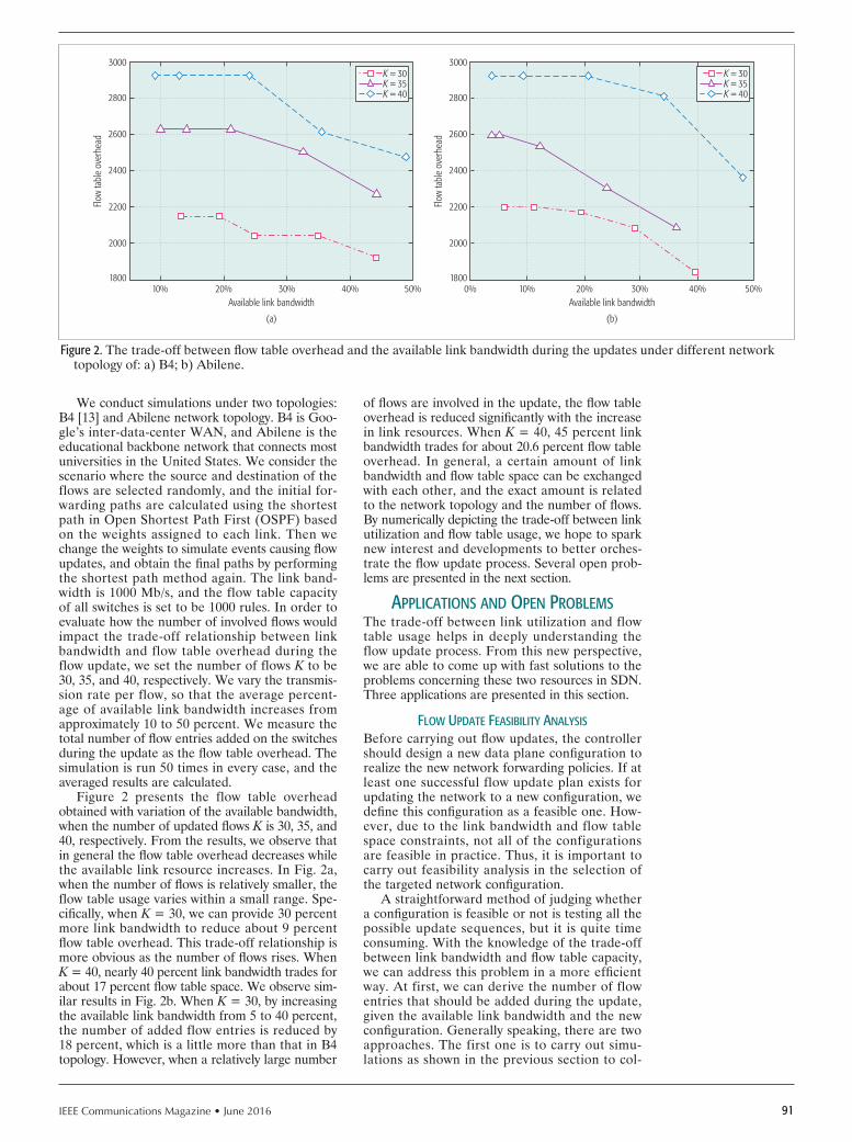
IEEE Communications Magazine • June 2016 91
We conduct simulations under two topologies: B4 [13] and Abilene network topology. B4 is Goo-gle’s inter-data-center WAN, and Abilene is the educational backbone network that connects most universities in the United States. We consider the scenario where the source and destination of the flows are selected randomly, and the initial for-warding paths are calculated using the shortest path in Open Shortest Path First (OSPF) based on the weights assigned to each link. Then we change the weights to simulate events causing flow updates, and obtain the final paths by performing the shortest path method again. The link band-width is 1000 Mb/s, and the flow table capacity of all switches is set to be 1000 rules. In order to evaluate how the number of involved flows would impact the trade-off relationship between link bandwidth and flow table overhead during the flow update, we set the number of flows K to be 30, 35, and 40, respectively. We vary the transmis-sion rate per flow, so that the average percent-age of available link bandwidth increases from approximately 10 to 50 percent. We measure the total number of flow entries added on the switches during the update as the flow table overhead. The simulation is run 50 times in every case, and the averaged results are calculated.
Figure 2 presents the flow table overhead obtained with variation of the available bandwidth, when the number of updated flows K is 30, 35, and 40, respectively. From the results, we observe that in general the flow table overhead decreases while the available link resource increases. In Fig. 2a, when the number of flows is relatively smaller, the flow table usage varies within a small range. Spe-cifically, when K = 30, we can provide 30 percent more link bandwidth to reduce about 9 percent flow table overhead. This trade-off relationship is more obvious as the number of flows rises. When K = 40, nearly 40 percent link bandwidth trades for about 17 percent flow table space. We observe sim-ilar results in Fig. 2b. When K = 30, by increasing the available link bandwidth from 5 to 40 percent, the number of added flow entries is reduced by 18 percent, which is a little more than that in B4 topology. However, when a relatively large number
of flows are involved in the update, the flow table overhead is reduced significantly with the increase in link resources. When K = 40, 45 percent link bandwidth trades for about 20.6 percent flow table overhead. In general, a certain amount of link bandwidth and flow table space can be exchanged with each other, and the exact amount is related to the network topology and the number of flows. By numerically depicting the trade-off between link utilization and flow table usage, we hope to spark new interest and developments to better orches-trate the flow update process. Several open prob-lems are presented in the next section.
ApplIcAtIons And open problemsThe trade-off between link utilization and flow table usage helps in deeply understanding the flow update process. From this new perspective, we are able to come up with fast solutions to the problems concerning these two resources in SDN. Three applications are presented in this section.
Flow updAte FeAsIbIlIty AnAlysIs
Before carrying out flow updates, the controller should design a new data plane configuration to realize the new network forwarding policies. If at least one successful flow update plan exists for updating the network to a new configuration, we define this configuration as a feasible one. How-ever, due to the link bandwidth and flow table space constraints, not all of the configurations are feasible in practice. Thus, it is important to carry out feasibility analysis in the selection of the targeted network configuration.
A straightforward method of judging whether a configuration is feasible or not is testing all the possible update sequences, but it is quite time consuming. With the knowledge of the trade-off between link bandwidth and flow table capacity, we can address this problem in a more efficient way. At first, we can derive the number of flow entries that should be added during the update, given the available link bandwidth and the new configuration. Generally speaking, there are two approaches. The first one is to carry out simu-lations as shown in the previous section to col-
Figure 2. The trade-off between flow table overhead and the available link bandwidth during the updates under different network topology of: a) B4; b) Abilene.
Available link bandwidth
(a)
10%
2000
1800
Flow
tabl
e ov
erhe
ad
2200
2400
2600
2800
3000
20% 30% 40% 50%Available link bandwidth
(b)
10%0%
2000
1800
Flow
tabl
e ov
erhe
ad
2200
2400
2600
2800
3000
20% 30% 40% 50%
K = 30K = 35K = 40
K = 30K = 35K = 40

IEEE Communications Magazine • June 201692
lect data about how many flow entries need to be added based on available link bandwidth. Then these data are fit into curves and the experimen-tal formula is deduced, based on which we can estimate the flow table memory required by the specific flow update scenario. The second one is to build a mathematical model to describe the relationship between the two resources during an update and calculate the number of flow entries to be added based on the formulated model. Since how to build a realistic model and formu-late the problem is still an open question that deserves future study, we currently suggest adopt-ing the first approach in practice. If the current flow table memory in the network cannot meet the derived resource requirement, the network configuration is infeasible. As shown in Fig. 3, the top and bottom curves show the resource trade-off when updating the network state to con-figuration A and B, respectively. To guarantee that updating to configuration A is feasible, the current available network resource should be in the feasible region of A, which is represented by the red cross hatched area above the top curve. When the available link bandwidth is the same, updating to configuration B incurs less flow table space overhead. Thus, the feasible region of B is larger than that of A, which includes both the red cross hatched area and the blue backslash hatched area. In this case, assuming the existing resource is denoted by the triangle in Fig. 3, we can conclude that the feasible new configura-tion is B rather than A. In conclusion, instead of checking all possible update solutions, the meth-od utilizing the trade-off between link and switch resources improves the efficiency of feasibility analysis in network configuration selection.
HeurIstIc AlgorItHm desIgn
Understanding the relationship between link uti-lization and flow table usage paves the way for developing efficient flow update algorithms. For example, the problem of finding the fastest update
solution of multiple flows without violating the con-straints of link bandwidth and flow table is NP-com-plete [11], because the hardness stems from the fact that flow table constraints involve integers, and flow table space cannot be allocated fractionally. Since polynomial time algorithms do not exist for NP-complete problems (unless P = NP), heuristic algorithms are required for an efficient solution. With the hope of sparking new interest in this area, we discuss how to design an efficient update meth-od of this problem based on the trade-off between the two resources as an example.
At first, we can utilize the derived numeri-cal results regarding the resource trade-off as a benchmark to measure the resource status of the network, which provides the information about which resource is relatively scarce. Then we can decide when and how to schedule the flow update based on the resource status. From the perspec-tive of links, if a link is already in high utilization, an existing flow must be removed before moving a new flow to it. Thus, in deciding the update sequence of the flows, if the link bandwidth is more limited compared to flow table memory, we can give high priority to the update of the critical flows that go through busy links. Otherwise, to ensure that there is enough flow table space to configure the rules for new flows, high priori-ty can be given to updating the flows with paths that include the key switches which have little available flow table memory. When deciding how to update the flows, if the link bandwidth is lim-ited in comparison to flow table space, we may split the flows into multiple subflows and update one subflow to the new path in each step; other-wise, we should update each flow as a whole. In addition, to guarantee consistency, we can adopt existing consistent update mechanisms [3, 4] to update the flow tables. To ensure a fast solution, we update as many flows as possible in one step.
In addition to inspiring heuristic algorithms, understanding the resource trade-off is also important in the formulation of the flow update problem. If we deduce the formula on the numeri-cal relationship of these two resources for the sce-nario that has typical topologies and specific traffic distribution, the two constraints will be combined. In this situation, the updating solution can be calculated more easily. In conclusion, the idea of considering the resource trade-off opens a new perspective on designing flow update schemes.
network provIsIonIng In tHe cloud
SDN has attracted increasing attention as a plat-form for cloud providers. In general, a cloud provider hosts multiple data centers located in different regions. In order to meet users’ ever changing requirements, the cloud provider must maintain enough resources to enable necessary flow updates caused by events such as VM migra-tion or traffic engineering. Thus, a fundamen-tal problem for cloud providers is to decide how much link bandwidth and flow table memory need to be provisioned, given the unit price of the resources and the network update requirements.
Now we introduce how to minimize the expenditure of network resources by taking the trade-off between link bandwidth and flow table capacity into account as an example. As shown in Fig. 4, we can derive the numerical relationship
Figure 3. How to utilize the resource trade-off to carry out feasibility analysis of flow updates.
Available link bandwidth0.20
350
300
Flow
tabl
e ov
erhe
ad
400
450
500
550
600
0.4 0.6
Configuration A
Configuration B
Existingresource
0.8 1

IEEE Communications Magazine • June 2016 93
of these two resources during the flow update and the feasibility area using the approaches shown in the previous section. If the average flow table memory and link bandwidth of the network is denoted by s and b, respectively, the resource trade-off function is represented by s = h(b), which reveals how much flow table memory should be provided at least under the variation of available link bandwidth. Our goal is to minimize the total cost of network resources, which is rep-resented by c = f(b, s). By reforming this func-tion into ~s = g(b, c) and combining the trade-off function, the problem is converted to finding the tangent point P = [b*, s*] of s and ~s. If ~s = g(b, c) is linear, such as functions S1 and S3 in Fig. 4, P will be one of the two endpoints; otherwise (e.g., S2), P is somewhere between the endpoints, and should be calculated case by case. In sum-mary, a profound understanding of the trade-off between link and flow table resources will help cloud providers to efficiently decide how many resources should be provisioned in order to reduce the construction cost of data centers.
conclusIonWe have qualitatively analyzed how the resourc-es of link bandwidth and flow table influence the update process, and how they interact with each other. Moreover, we quantitatively evaluate the resource trade-off in the real network update sce-narios. Based on these observations, we further discuss how to solve the problems related to flow updates from this new perspective. The analysis results indicate that the efficiency of carrying out feasibility analysis of flow update and performing network provisioning in the cloud can be improved by considering the trade-off, and it also opens up a new avenue for designing heuristic flow update schemes. Thus, our study provides new perspectives and insight for future work in this area.
AcknowledgmentThis work is supported by the National Basic Research Program of China (973 Program) under grant 2013CB329105, and the National Nature Science Foundation of China (Grant No. 61273214). This work is also supported by the National Nature Science Foundation of China (No. 61301080) and the Research Fund of Tsing-hua University (No. 20161080099).
reFerences
[1] N. McKeown et al., “OpenFlow: Enabling Innovation in Campus Net-works,” SIGCOMM Comp. Commun. Rev., vol. 38, no. 2, Apr. 2008, pp. 69–74.
[2] H. Kim and N. Feamster, “Improving Network Management with Software Defined Networking,” IEEE Commun. Mag., vol. 51, no. 2, Feb. 2013, pp. 114–19.
[3] M. Reitblatt et al., “Abstractions for Network Update,” Proc. ACM SIG-COMM 2012, Helsinki, Finland, Aug. 13–17, 2012, pp. 323–34.
[4] R. McGeer, “A Safe, Efficient Update Protocol for Openflow Networks,” Proc. ACM HotSDN 2012, Helsinki, Finland, Aug. 13–17, 2012, pp. 61–66.
[5] H. H. Liu et al., “zUpdate: Updating Data Center Networks with Zero Loss,” Proc. ACM SIGCOMM 2013, Hong Kong, China, Aug. 12–16, 2013, pp. 411–22.
[6] N. P. Katta, J. Rexford, and D. Walker, “Incremental Consistent Updates,” Proc. ACM HotSDN 2013, Hong Kong, China, Aug. 16, 2013, pp. 49–54.
[7] C. Y. Hong et al., “Achieving High Utilization with Software-Driven WAN,” Proc. ACM SIGCOMM 2013, (Hong Kong, China), Aug. 12–16, 2013, pp. 15–26.
[8] Y. Liu et al., “Achieving Efficient and Fast Update for Multiple Flows in Software-Defined Networks,” Proc. ACM DCC 2014, Chicago, IL, Aug. 18, 2014, pp. 77–82.
[9] P. Peresíni et al., “ESPRES: Transparent SDN Update Scheduling,” Proc. ACM HotSDN 2014, Chicago, IL, Aug. 22, 2014, pp. 73–78.
[10] S. Ghorbani and M. Caesar, “Walk the Line: Consistent Network Updates with Bandwidth Guarantees,” Proc. ACM HotSDN 2012, Helsinki, Finland, Aug. 13–17, 2012, pp. 67–72.
[11] X. Jin et al., “Dynamic Scheduling of Network Updates,” Proc. ACM SIG-COMM 2014, Chicago, IL, Aug. 17–21, 2014, pp. 539–50.
[12] C. E. Leiserson, “Fat-trees: Universal Networks for Hardware-Efficient Supercomputing,” IEEE Trans. Computers, vol. C-34, no. 10, Oct. 1985, pp. 892–901.
[13] S. Jain et al. , “B4: Experience with A Globally-Deployed Software Defined WAN,” Proc. ACM SIGCOMM 2013, Hong Kong, China, Aug. 12–16, 2013, pp. 3–14.
[14] C. S. Calude, E. Calude, and M. S. Queen, “Inductive Complexity of the p Versus np Problem,” Parallel Processing Letters, vol. 23, no. 1, 2013, pp. 1–16.
bIogrApHIesYujie Liu received her B. S. degree from the Department of Electronic Engi-neering, Tsinghua University, China, in 2011. Now she is pursuing her Ph.D. degree at the same university. Her research fields include future Internet architecture, software defined networks, and network functions virtualization.
Yong Li [M’09] received his B.S. and Ph.D degrees from Huazhong Univer-sity of Science and Technology and Tsinghua University in 2007 and 2012, respectively. During 2012 and 2013 he was a visiting research associate with Telekom Innovation Laboratories and Hong Kong University of Science and Technology, respectively. From 2013 to 2014 he was a visiting scientist at the University of Miami. He is currently a faculty member in the Depart-ment of Electronic Engineering, Tsinghua University. His research interests are in the areas of mobile computing and social networks, urban comput-ing and vehicular networks, and network science and future Internet. He has served as General Chair, Technical Program Committee (TPC) chair, and TPC member for several international workshops and conferences. He is currently an Associate Editor of the Journal of Communications and Networking and EURASIP Journal of Wireless Communications and Net-working.
Yue Wang received his B.S. and PhD degrees from the Electronic Engineering Department of Tsinghua University in 1999 and 2005, respectively. He is now an assistant professor at Tsinghua University. His research interests include computer networks, data fusion, and complex networks.
Ying Zhang received her Ph.D. degree from the Electrical Engineering and Computer Science Department, University of Michigan, Ann Arbor, in 2009. She is a researcher at the IP and Transport Research Group, Ericsson Research Silicon Valley, San Jose, California. Her research interests include networking and systems, including software-defined networking, cloud, Internet, and cel-lular network management, Internet routing, and measurement and network security.
jian Yuan received his Ph.D. degree in electrical engineering from the Univer-sity of Electronic Science and Technology of China in 1998. He is currently a professor in the Department of Electronic Engineering at Tsinghua University. His main research interest is in complex dynamics of networked systems.
Figure 4. How to utilize the resource trade-off to help cloud providers make informed decisions on resource provisioning.
Available link bandwidth0.20
450
400
Flow
tabl
e ov
erhe
ad
500
550
600
0.4
Costfunction
S1
S2
S3
0.6
Feasibilityarea
0.8 1

IEEE Communications Magazine • June 201694 0163-6804/16/$25.00 © 2016 IEEE
AbstrAct
Content delivery service has become a major traffic load on today’s Internet, and this has trig-gered the interest of ISPs in operating their own content delivery networks (CDNs) to optimize Internet traffic considering both content delivery caching and user-network proximity. ISPs, howev-er, are typically regionally bound or network-do-main-wise isolated; hence, their CDN gain is somewhat limited. In order to enhance the gain of ISP CDN services to the level of incumbent global CDNs, a CDN interconnection (CDNI) model is introduced by IETF, where local ISP CDN ser-vices can be extended among heterogeneous CDNs across network domains. However, despite the mul-tiple benefits of a CDNI system, it is difficult to apply a CDNI service to the current CDN mar-ket due to the platform independence. Hence, we introduced a CDNI gateway model that is stan-dard-capable and platform-independent. With the CDNI gateway model, we design and implement a complete CDNI system and conduct a CDNI ser-vice trial with three major ISPs in South Korea. To the best of our knowledge, this is the first CDNI service trial complying with the IETF standard achieved by a multi-ISP collaboration. According to the analysis of experimental results from the service trial, we observe that CDNI can reduce content traffic by about 40 percent at the Internet exchange link compared to a legacy CDN system.
IntroductIonInternet contents, such as multimedia, web pages, and application updates, has become a dominant traffic source on today’s Internet. Since the growth of the content traffic volume is increasing over time, the link investment cost is increasing as well. A content delivery network (CDN) is commonly used to reduce traffic on the Internet and improve user service experience [1, 2]. In the incumbent CDN service, a CDN operator, who is indepen-dent of an Internet service provider (ISP), places CDN servers and surrogates over the world. In this model, end users receive CDN services from surrogates based on a certain level of proximi-ty on the Internet. However, CDN servers and surrogates are typically distributed unevenly over
different ISP domains. On the other hand, ISP operators are becoming interested in operating their own CDN services as they see opportuni-ties for further improvements on the user expe-rience and traffic control because of ownership of the networks. In turn, ISP-operated CDNs are expected to reduce a large portion of traffic in the network as more than 60 percent of the Internet traffic consists of content delivery. However, an ISP is typically regionally bound or network-do-main-wise isolated, so its CDN gain is limited because its access users might receive contents from other CDNs. In order to compete against incumbent global CDNs and increase the gain of ISP CDN services, an ISP should extend local ISP CDN services across the network domains, there-by requiring interconnection between CDNs [3]. In 2011, British Telecom (BT) launched whole-sale content connect (WCC), which delivers mul-timedia content to broadband end users from content servers situated within the BT network. A content service provider’s (CSP’s) content is delivered to any Internet connected end user in the United Kingdom from caches held within the BT wholesale network. ISP CDN interconnection between FT-Orange and Poland Telecom (PT) with heterogeneous solutions was tried in 2011 as well. For this, Cisco’s CDS solution and Coblitz’s CDN solution were used for FT-Orange and PT, respectively. Meanwhile, Cisco began a three-phase exploration into the feasibility of CDN federations, a CDN federation pilot (CFP) for testing technology interworking issues and busi-ness models [4]. Cisco defines CDN federations as multi-footprint open CDN capabilities built and shared by autonomous members. Since 2011, the Internet Engineering Task Force (IETF) has been studying how CDNs can operate in an inter-connected manner under a Working Group on CDN interconnection (CDNI), envisioning a large federation of local ISPs to reduce CDN traffic between ISPs [5, 6]. IETF summarizes the three major use cases of CDNI as follows.
Footprint Extension Use Cases: This is consid-ered a major use case. CDNI enables CDN pro-viders who have a geographically limited footprint to provide their services beyond their own foot-prints. It includes use cases of geographic exten-
CDN Interconnection Service Trial: Implementation and Analysis
Yonghwan Bang, June-Koo Kevin Rhee, KyungSoo Park, Kyongchun Lim, Giyoung Nam, John D. Shinn, Jongmin Lee, Sungmin Jo, Ja-Ryeong Koo, Jonggyu Sung, Young-il Seo, Taesang Choi, Hong-Ik Kim, Junyoung Park, and Chang Hee Yun
consumer communIcAtIons And networkIng
The authors describe a CDNI gateway model that is standard-capable and platform-independent. With the CDNI gateway model, they design and implement a complete CDNI system and conduct a CDNI service trial with three major ISPs in South Korea. According to the analysis of experimental results from the service trial, they observe that CDNI can reduce content traffic by about 40 percent at the Internet exchange (IX) link compared to a legacy CDN system.
Yonghwan Bang, June-Koo Kevin Rhee, KyungSoo Park, Kyongchun Lim, and Giyoung Nam are with KAIST; John D. Shinn is with Solbox; Jongmin Lee and Sung-min Jo are with SK Telecom; Ja-Ryeong Koo is with LG UPLUS; Jonggyu Sung and Young-il Seo are with the Institute of Convergence Technology, KT; Taesang
Choi is with ETRI; Hong-Ik Kim is with CJ HelloVision; Junyoung Park is with T-Broad Inc.; Chang Hee Yun is with the National Information-Society Agency.

IEEE Communications Magazine • June 2016 95
sion, inter-affi liates interconnection, ISP handling of third party contents, and nomadic users.
Offload Use Cases: Unexpected heavy traf-fic may introduce overload beyond the capabili-ty of a CDN. In this case, CDNI can offload the overloaded traffi c to another CDN (downstream CDN, dCDN). Moreover, when a partial failure occurs, CDNI can redirect traffi c to another CDN.
CDN Capability Use Cases: In this use case, the CDN provider may have an appropriate geographic footprint, but may wish to extend the supported range of devices and users or the supported range of delivery technologies. In this case, a CDN pro-vider may interconnect with a CDN that offers ser-vices the CDN provider is not willing to provide, or its own CDN is not able to support.
By enabling these use cases, we can obtain many-fold benefi ts. Importantly, CDNI can solve ineffi ciencies in the current CDN server infrastruc-ture. The number of CDN providers is increas-ing, and their server infrastructure is necessarily deployed redundantly. From the point of view of a network infrastructure provider, these ineffi cien-cies can be eliminated by CDNI, and moreover it can improve the user’s quality of experience. On the other hand, CDNI can save capital expen-diture (CAPEX) and operational expenditure (OPEX) costs on the network infrastructure by reducing redundant content traffic especially on the Internet exchange (IX) link, for which major investment with overprovisioning is required to avoid congestion [8]. In a CDNI-enabled network, every user’s content request is serviced within the user’s ISP network independent from CDN con-tracts in order to avoid inter-ISP traffi c. To reap all these benefits by interconnection to the level of those of an incumbent CDN system, we can consider the following requirements:• First, CDNI must interconnect CDN request
routers that are operated by different pro-viders to achieve effective content requestredirection across CDNs.
• Each CDN participating in CDNI serviceshould exchange content distribution meta-data through CDNI interfaces so that CSPdistribution policies can be enforced consis-tently across CDNs.
• CDNI must provide a control protocolacross CDNs so that important actions canbe triggered across CDNs.
• Lastly, CDNI is required to support exchangeof logging/reporting information so thatessential applications such as accounting andbilling, reporting, and analytics can be per-formed over a CDN federation.
To realize all of these system requirements, we design and implement a CDNI system based on a CDNI gateway model that is standard-capable and platform-independent. With our CDNI system developed at Korea Advanced Institute of Science and Technology (KAIST), we conducted a CDNI trial service consisting of three major nation-wide ISPs, a cable network provider, and a CSP. Three major ISPs and a cable network provider collab-orated to build four CDNs, and a CSP took the role of publisher of the trial service. Through the CDNI service trial, we verified that CDNI can reduce content traffic by more than 40 percent compared to legacy CDN systems. The rest of this article is organized as follows. First, we introduce
the concept and architecture of a CDNI gateway. Second, the operations for a CDNI system with the CDNI gateway model are explained. Third, the CDNI trial service is described and analyzed. Finally, we conclude with a discussion.
ArchItecture of cdnI gAtewAyA CDNI gateway with minimum platform depen-dence is designed and developed with interfaces toward standalone CDNs, which requires min-imum modification of a legacy CDN system. This gateway model can provide CDNI standard compliance as well as immediate legacy CDN interworking. From a technical point of view, a CDNI gateway is designed with two parts: a CDNI module and a CDN adaptation interface. A CDNI module includes a CDNI interface and a CDNI database. The CDN adaptation interface provides communication between a CDNI mod-ule and legacy CDN systems. The CDNI data-base manages required information for CDNI between CDNs. To optimize our CDNI system, we implement our own HTTP server and DNS server that perform parallel processing for user content requests cooperating with the CDNI sys-tem. The detailed role of each is as follows.
A CDNI Interface is an IETF standard-com-pliant CDNI interface application programming interface (API) to communicate with other CDN platforms for interconnection. It provides the principal functions of CDNI bootstrapping, request routing, log data acquisition, and deploy-ment of metadata or footprint information. The CDNI interface is designed as a simple HTTP-based representational state transfer-ful (REST-ful) interface. In terms of functional architecture, a CDNI interface consists of control, request routing, metadata, and logging interfaces. Each interface communicates with HTTP POST messages. Payload data is formatted in JavaS-cript Object Notification (JSON) [9] style. The detailed role of each interface is as follows:• Control interface: It provides the CDNI
bootstrapping process and managementfunctions that manage the information ofCDNI contracts.
• Request routing interface: If a user requestis generated, a CDNI gateway HTTP serv-er asks a request routing interface to get anappropriate dCDN based on footprint andcapability information. It initializes itself withfootprint information, which is provided bylegacy CDN administration through a CDNIadaptation interface. It also provides a setof management functions for footprint andcapability information of a CDNI network.
• Metadata interface: It provides initializationand management functions; the initializa-tion function shares footprint and capabilityinformation at bootstrapping time with otherCDNI entities, and the management func-tions provide ADD, DELETE, UPDATE,and other related operations of metadata.
• Logging interface: Every time each contentrequest is serviced or routed, a CDNI log issaved through logging interfaces. It provides aGET method to get logging information fromdedicated dCDNs or an uplink CDN (uCDN).A CDNI database retains the information
for a CDNI service: capability information of
From a technical
point of view, a CDNI
gateway is designed
with two parts: a CDNI
module and a CDN
adaptation interface. A
CDNI module includes
a CDNI interface and
a CDNI database. The
CDN adaptation inter-
face provides communi-
cation between a CDNI
module and legacy
CDN systems.

IEEE Communications Magazine • June 201696
each CDN surrogate server and footprint that describes the service scope (the allowed client IP subnet or country code, etc.). Content distri-bution metadata describe an authorized service timeframe or service type for each content. A CDNI service log and CDNI contract informa-tion are saved to the CDNI database as well. All information of the CDNI databases is created, updated, deleted by the CDNI interface API, and written in the JSON format.
A CDNI gateway HTTP or DNS server per-forms parallel processing for user HTTP requests using event queues with multi-thread processing. It accepts user HTTP/DNS requests and redi-rects them to final HTTP/DNS targets by asking an HTTP/DNS request routing interface of the CDNI interface. Each server can support a max-imum of eight cores for which working threads are evenly scheduled. We conduct performance assessment showing that each server can process more than 20,000 content requests per second under a laboratory stress test environment.
An adaptation interface is implemented for communication between a CDNI gateway and a legacy CDN request router to minimize platform dependence. It provides API functions of the CDNI database configuration and administration to a legacy CDN. Table 1 provides detailed design information of the CDNI adaptation interface. It has three functional categories, and each catego-ry consists of HTTP method functions. A CDN administrator can boot up and stop a CDNI gate-way with administration functions. Data config-uration functions support database management of a CDNI gateway. When the legacy CDN needs other CDNs’ information such as content distri-bution metadata or log data, the corresponding get-information functions can provide it.
operAtIons for A cdn InterconnectIon wIth A cdnI gAtewAy
In a CDNI system, the content delivery service is operated through a uCDN and a dCDN. When a content request is generated, a uCDN accepts the user request, and chooses an appropriate dCDN and redirects the request. The dCDN pro-vides the content delivery service to the user on behalf of the uCDN. Since a uCDN can select itself as a dCDN, a CDNI should be dCDN-ca-pable as well as uCDN-capable. Each CDN in
a network of a CDNI system communicates only with its own CDNI gateway, and the CDNI gateway processes all CDNI-related operations. This supports CDN platform independence in a CDNI system with heterogeneous CDNs. Fig-ure 1 shows how a CDNI system works with a CDNI gateway in detail. In a CDNI system, a CSP makes a contract of a content delivery ser-vice with a uCDN, which in turn makes another contract of CDN interconnection with multiple dCDNs. When a user requests a CSP’s content service, the CDNI gateway of the uCDN accepts this request on behalf of a CDN request router, and checks the corresponding footprint infor-mation from the CDNI database to determine the appropriate dCDN among the contracted dCDNs and allow the user request redirection to the dCDN. The dCDN receives this redirect-ed user request and performs the same process that the uCDN did, and if it finally determines there is no better dCDN than itself, it redirects the request to its CDN request router to let the CDN deliver the content to the user. The poli-cy to determine the best dCDN must take into account various parameters including the prox-imity of surrogates and the user, the CDN server and surrogate loads, network bandwidth usage, and so on. In our CDNI design, we use a prox-imity-first policy where every content request is redirected to a dCDN that is deployed on the same carrier network with the user. This policy can reduce the IX link traffic dramatically since content delivery in a IX link only occurs when the first acquisition is acquired by the uCDN for each content service. Due to these aspects of the CDNI system, each surrogate of all CDNI partic-ipating CDNs should store a greater amount of content than a legacy CDN system. The impact of this is discussed later in this article.
In a CDNI system, a user request can traverse multiple dCDNs. Hence, the CDNI system can cause looping or flooding of request redirection messages, which can result in a service failure. It is critical to prevent looping and flooding to provide a reliable CDNI service. Looping and flooding prevention can be provided by utilizing combined information of a CDN provider ID (CPI) list and a maximum number of allowed redirection hop count (MaxNumRedHops). With this information, we implemented a loop-ing/flooding prevention mechanism into a CDNI gateway.1. When a CDNI gateway receives a content
request or a request redirection message, it determines the next appropriate dCDN, adds its CPI information to the CPI list in the request redirection message and checks whether there are the same CPIs. If so, it is considered as a loop and chooses the sec-ond best dCDN, and so on. If there is no possible option, the request is dropped.
2. For flooding prevention, we add a NumRed-Hops field into the redirection message. Every time a request message is redirected, each CDNI gateway increases the value of this field by one. If NumRedHops exceeds MaxNumRedHops, which is a predefined value, the corresponding redirection mes-sage is dropped, as appears in an IETF CDNI WG draft [10].
Table 1. Functions of the CDNI adaptation interface in a CDNI gateway.
Category Function Description
Administration
RUN Request to CDNI gateway to run CDNI module
INIT Send CDN information to CDNI gateway and request to initialize
STOP Request to CDNI gateway to stop CDNI service
Database configuration
ADD Request to CDNI gateway to add information
UPDATE Request to CDNI gateway to update information
REMOVE Request to CDNI gateway to remove information
Get information
GET_CDmD Request to CDNI gateway to get content distribution metadata
GET_LOG Request to CDNI gateway to get other CDN’s (dCDN)’s CDNI log data

IEEE Communications Magazine • June 2016 97
cdnI trIAl serVIce
From a technical point of view, we are interest-ed in observing the practical performance of a CDNI system in terms of traffic reduction and user experience. In particular, an IX link requires the most investment with overprovisioning to avoid traffi c congestion due to large capacities of broadband core and access networks [8].
Our major concern is to verify IX link traffic reduction by application of CDNI. For this purpose, we planned a CDNI trial service and established the KAIST CDNI Consortium, which consists of three major ISPs, a cable network provider, a con-tent service provider, and KAIST in Korea. The three major ISPs and the cable network provider collaborated to build four CDNs, and the CSP took the role of publisher in our trial service. Offered contents were provided by all CDN providers and the publisher. Each CDN interconnects with CDNI gateways, and a policy of redirection is set to prox-imity-first to eliminate the traffic among ISP net-work domains. The proximity-fi rst policy redirects a content request to a dCDN that is located on the same carrier network as that of the user. As afore-mentioned, the CDNI gateway is capable of both DNS and HTTP redirection methods. We choose DNS request redirection for our service trial since it is faster than HTTP redirection.
To determine the traffic reduction due to CDNI, it is necessary to monitor and analyze an IX link. However, direct monitoring of a com-mercial IX link brings technical and organiza-tional difficulties, especially for ISPs. Hence, we employed the the Korea Advanced Research Network (KOREN) to take the role of an IX link instead of using an actual commercial IX link. All service traffi c generated by surrogates is delivered
over an actual commercial network, while the inter-CDN traffi c that corresponds to IX link traf-fic is delivered through KOREN links. The trial service was offered to 170 users, where approxi-mately 100 users actively participated. A total of 121 contents with a total volume of 9.6 GB were in place for service. For a 6-day service period, 2612 content requests were generated, and a total volume of 50.5 GB of content services was deliv-ered. The caching policy of each surrogate follows the CDN’s own policy. The corresponding content and provider information is described in Fig. 2b. As shown in the figure, each content provider’s number of contents and its volume varied broadly and biasedly. TBroad provides 78 percent of the total volume of contents, while SKT only provides 4 percent. This biased content service reflects a realistic content service environment.
The CDN interconnection network diagram of the CDNI trail service is presented in Fig. 2a. A trial service site that provides content download services was temporally placed. All the CDN pro-viders collected their subscribers who volunteered for the CDNI trial service. This figure indicates that each subscriber downloaded content only from their corresponding CDN surrogates regard-less of the CSP under the CDNI system.
results And AnAlysIsIn order to quantify the impact of CDNI on IX link traffi c reduction, we analyzed the CDNI and HTTP log information in addition to a service traffi c monitoring tool that monitors content ser-vice traffi c at each network interface of all CDN surrogates and a publisher content server. Fig-ure 3a shows the content popularity distribution acquired during the CDNI trial service. As shown in this fi gure, it closely follows a power-law distri-
Figure 1. Service scenario of a CDNI system.
CDNI gatewayCDNI gateway
HTTP/DNS contentrequest
Content delivery
End user
Web/application content retrieve
CDN
I interfaceCI
MI
RIFCI
LI
CDN
I int
erfa
ceLI
FCI
RIM
ICI
Adaptation interfaceAdaptation interface
Request router
Surrogate Surrogate
Legacy CDN
•••
dCDN nuCDN
HTTPserver
CDNI controlmodule
DNSserverCDNI DB
(JSON)CDNI DB(JSON)
HTTPserver
DNSserver
CDNI controlmodule
Request router
Surrogate Surrogate
Legacy CDN
Acquisition
Acquisition
CSP
Origin contents
CDN
I int
erfa
ce
It is critical to prevent
looping and fl ooding to
provide a reliable CDNI
service. Looping and
fl ooding prevention can
be provided by utilizing
combined information
of a CDN provider
ID (CPI) list and a
maximum number of
allowed redirection
hop count.

IEEE Communications Magazine • June 201698
bution with an exponential cutoff, similar to an actual service distribution (e.g., the YouTube video popularity distribution) [11], even though the counts of offered contents and users are rel-atively small. Since the content popularity distri-bution drives the service traffic pattern, and its distribution in our trial was quite close to those observed from large-scale CDN network stud-ies, the analysis of our trial service could rep-resent a valid observation to some extent. In a practical Internet environment, this result should be investigated more accurately under the pres-ence of service traffic other than that of CDN. Prior to discussing the traffic reduction effect due to CDNI, we first investigated the cache-hit ratios in cases of CDNs and fully interconnected CDNIs, respectively.
As presented in Fig. 3b, the average hit ratio of the CDNI system is less than those of CDNs. Note that the CDNI system allows CDN surro-gates to pull more content from the other CDN
caches without increasing the storage size. In this analysis, we exclude the cache hit when the content service is delivered by a CDN surro-gate located in another domain. The hit ratio of a CDNI system is degraded not because of the fewer hits but because of the more accepted con-tent requests destined to other CDN domains. Different from others, only TBroad’s CDNI hit ratio is higher than that of the CDN case since it has significantly more contents and relatively fewer domain users. Since the CDNI hit ratios of Fig. 3b include the cache hits across other net-work domains, we need to analyze the amount of total generated IX link traffic over a network to ascertain the impact of CDNI on IX link traffic reduction. Figure 4 represents the IX link traf-fic analysis results for each case of non-CDN, CDN-only, and CDNI system, respectively.
Since we analyzed service results of a real environment, the same experiment cannot be reproduced in other system models of non-CDN or CDN-only. Hence, we remanipulate CDNI service log data and create a service log for the non-CDN and CDN-only cases. Figure 4a shows the service traffic volume of each CSP content and the total of the IX link traffic. In this case, since all content requests are resolved by the CSP origin server that is located at its own net-work, all service traffic crosses through the IX link. This means that the total sum of the ser-vice traffic equals the total of the IX link traf-fic. The three plots in Fig. 4b correspond to the service-local, service-IX, and cache-IX traffic for the CDN-only system. The service-local traffic means the volume of service traffic requested by users located at the same ISP network as the uCDN. The service-IX traffic represents that of user requests from outside of the uCDN ISP domain. Finally, the cache-IX traffic is the traffic caused by content acquisition of each CDN sur-rogate from the origin server. For the CDN-on-ly case, we can easily see that the total IX link traffic volume is the sum of service-IX and cache-IX volumes for each CDN. In the case of CDNI, there is no service-IX traffic since all user requests are redirected within their own local domains. Hence, the total volume of the IX link traffic of the CDNI case equals the total volume of cache-IX traffic at each CDN. Figure 4c shows the analysis results of the CDNI case. In sum-mary, as shown in Fig. 4d, the CDN-only system
Figure 2. a) KAIST CDNI trail service network; b) content information.
Testbed
CJ Hellovision
LG U+
User CDNI gateway Surrogate Publisher Router
KT
T-BroadSKT
KOREN
(a)
(b)
No. of contentsVolume of
contents (GB)
KT
7
0.5
LG U+
25
0.7
SKT
15
0.4
CJHV
17
0.5
TBroad
57
7.5
Total
121
9.6
Figure 3. a) Content popularity distribution from the CDNI trial service; b) cache hit ratio at each CDN testbed.
Video rank(a) (b)
1.E+011.E+00
1.E+01
1.E+00
View
s
1.E+02
1.E+03
1.E+02 1.E+03KT
20%
0%
Hit r
atio
40%
60%
80%
100%
LG U+ SKT TBroad Average
CDN CDNI

IEEE Communications Magazine • June 2016 99
saves IX link traffic by 44 percent compared to the non-CDN case; the CDNI system achieves a 43 percent traffic reduction compared to the CDN-only case, which is an overall 68 percent traffic reduction compared with the non-CDN case. As reviewed previously, although the CDNI system shows a lower local cache hit ratio, it eliminates much more redundant content service traffic on the IX link. This implies that the IX link traffic reduction is more important than ser-vice traffic reduction in access networks.
In addition to the observation of traffic reduc-tion by CDNI in a wired access Internet service, we present another case study for a cellular net-work environment. Figure 5 shows the service throughput enhancement due to CDNI on com-mercial Long Term Evolution-Advanced (LTE-A) cellular networks, where two CDNs in the cellular network domains of SKT and KT are intercon-nected. The data show the throughput perfor-mance when SKT LTE-A mobile users request KT CDN’s contents with or without CDNI. We assess the minimum, maximum, and average through-puts from 10 trials for each case. As shown in the figure, the throughput is almost doubled when CDNI is enabled. This indicates that CDNI ser-vice is not limited by IX link capacity, as expected. This result implies possible quality of experience (QoE) improvement by the measure of first-byte-play lead time through employing CDNI.
conclusIons And dIscussIon
In this article, we introduce and demonstrate a CDNI gateway model that provides IETF stan-dard-compatible CDNI operations with minimum dependence on legacy CDN platforms. We ver-ified actual traffic reduction by employment of CDNI, especially at the IX link, in a practical CDNI service trial involving three major nation-wide ISPs and CSPs in Korea. From our trial results, we observe that CDNI services can reduce up to 43 percent of the content traffic volume at the IX link compared to legacy CDN systems. We proved that CDNI, especially with a gateway implementation model, is one of the most feasible practical solutions to enhance the capability of current Internet services. However, for commer-cial adoption of CDNI, further studies on security, billing, and business models should be carried out.
AcknowledgmentThis work was supported by the ICT R&D pro-gram of MSIP/IITP, Republic of Korea [12-911-05-003, 14-911-05-001].
references
[1] B. Li et al., “On the Optimal Placement of Web Proxies in the Internet,” Proc. IEEE INFOCOM, vol. 3, Mar. 1999, pp. 1282–90.
[2] L. Qiu et al., “On the Placement of Web Server Replicas,” Proc. IEEE INFO-COM, vol. 3, Apr. 2001, pp. 1587–96.
Figure 4. Traffic generation analysis results for: a) non-CDN case: service traffic volumes for CSP contents and the total volume of IX link traffic; b) CDN-only case: service traffic volumes of CDNs and the total volume of IX link traffic; c) CDNI case: service traffic volumes of CDNs and the total volume of IX link traffic; d) IX link traffic reduction ratio of CDN and CDNI systems compared to a non-CDN system.
(a) (b)KT
10
0
Traf
fic v
olum
e (G
B)
LG U+ SKT Tbroad Total IX
20
30
40
50
60
KT LG U+ SKT TB Total IX
10
0
Traf
fic v
olum
e (G
B)
20
30
40
50
60
(c) (d)
KT
10
0
Traf
fic v
olum
e (G
B)
LG U+ SKT TB Total IX
20
30
40
50
60
Non-CDN CDN-only CDNI
68%
43%
44%
10
0
Tota
l IXP
traf
fic (G
B)20
30
40
50
60
Service-localService-IXCache-IX
Service-localService-IXCache-IX

IEEE Communications Magazine • June 2016100
[3] G. Haßlinger and F. Hartleb. “Content Delivery and Caching from a Net-work Provider’s Perspective,” Computer Networks, vol. 55.18, Sept. 2011, pp. 3991–4006.
[4] M. Latouche et al., “The CDN Federation: Solutions for ISPs and Content Providers to Scale A Great Customer Experience,” Cisco Internet Business Solutions Group (IBSG), 2012.
[5] B. Niven-Jenkins, F. Le Faucheur, and N. Bitar, “RFC 6707: Content Distri-bution Network Interconnection (CDNI) Problem Statement,” IETF CDNI WG, Sept. 2012.
[6] Y. Lee and K. Leung. “Rfc 7337: Content Distribution Network Interconnec-tion (CDNI) Requirements,” IETF CDNI WG, Aug. 2014.
[7] V. Jesus and R. L. Aguiar. “Figures of Merit for the Placement (in) Efficiency of Interconnected CDNs,” IEEE Symp. Computers and Commun., July 2012, pp. 277–82.
[8] C. Labovitz et al., “Internet Inter-Domain Traffic,” ACM SIGCOMM Comp. Commun. Rev., vol 40.4., Oct. 2010, pp 75–86.
[9] T. Bray, Ed. “Rfc 7159: The JavaScript Object Notation (JSON) Data Inter-change Format,” IETF, Mar. 2014.
[10] T. Choi et al., “Method of Request Routing Re-Direction with Loop Detec-tion and Prevention,” U.S. Patent No. 20,140,156,822. 5 June 2014.
[11] M. Cha et al., “I Tube, You Tube, Everybody Tubes: Analyzing the World’s Largest User Generated Content Video System,” Proc. 7th ACM SIG-COMM Conf. Internet Measurement, Oct. 2007, pp. 1–14.
bIogrAphIesYonghwan Bang received an M.Sc. in electrical engineering from KAIST, Korea, in 2011 and his B.S. in computer science from Chungname National University, Korea, in 2007. He is currently a Ph.D. candidate at the Depart-ment of Electrical Engineering, KAIST. His research interests and experiences include WiFi networking, CDN networking, and system engineering. His cur-rent research interests are focused on device-to-device content delivery on 5G cellular networks.
June-Koo Kevin Rhee received a Ph.D. in electrical engineering from the Uni-versity of Michigan, Ann Arbor, in 1995, and his B.S. and M.Sc. in electrical engineering from Seoul National University, Korea, in 1988 and 1990, respec-tively. He is currently a professor at the School of Electrical Engineering, KAIST. He has made broad contributions in the areas of optical and wireless networking, CDN networking, and optical communications with more than 120 technical journal and conference papers as author or coauthor. He has been granted more than 20 patents as inventor and co-inventor. Recently, he was awarded the Ministry Certificate of Commendation from the Korean Ministry of Science, ICT and Planning.
KYoungSoo PaRK is an associate professor in the Electrical Engineering Department at KAIST. He received his B.S. degree in computer science from Seoul National University in 1997, and his M.A. (in 2004) and Ph.D. (in 2007) degrees in computer science from Princeton University. After his Ph.D., he worked as an associate research scholar at Princeton University from 2007 to 2008 and worked as an assistant professor in the Computer Science Depart-ment at the University of Pittsburgh in 2009. In 2007, he co-founded CoBlitz, Inc. (acquired by Verivue, Inc. in 2010, and later acquired by Akamai,Inc. in 2012), which provides highly scalable and reliable content distribution services to ISPs and telcos.
KYongchun Lim received his B.E. degree in electronic and electrical engi-neering from Sungkyunkwan University, Seoul, Korea, in 2012, and his M.S. degree in electrical engineering from KAIST in 2014, where he is currently working toward his Ph.D. degree. His current research interests include quan-tum key distribution and quantum information.
giYoung nam received his M.S. in electrical engineering from KAIST in Feb-ruary 2014. Previously, he received his B.S. in electrical engineering from KAIST in February 2012. He is currently at Kakao Corp. His research interests and experiences include networked computer systems, multimedia systems, network security system architecture, and network middleboxes.
John D. Shinn currently serves as a director at Solbox, a managed CDN solu-tion provider in Korea. He has more than 16 years of platform architecture development and technical consultant experience in this industry. He has been leading the development and implementation of cloud storage plat-forms, cloud IaaS platforms, CDN platforms, and government IT projects in Solbox. He earned a B.S. in computer science from Yonsei University, Korea.
Jong min Lee received his Ph.D. from KAIST in 2010. Since 2007, he has been working as an Editor of ITU-T SG13 Q3, Q8, and Q9. In 2010, he joined SK Telecom. His research area includes wired/wireless contents streaming, contents delivery optimization, and management. In 2012, he joined NGMN as an MCDO project leader and is also involved in MPEG as a WG Chair and Editor. He has over a decade’s experience in information and telecommunica-tion over fixed and mobile IP streaming technology.
Sungmin Jo received his B.S. and M.S. degrees in electrical engineering from Kookmin University, Seoul, Korea, in 1994 and 1996, respectively. Since 1996, he has been with Network Technology R&D center, SK Telecom. His research areas of interest include wired/wireless convergence networks, optical and RF relay stations, wireless LAN networks, and CDNs. He was the recipient of the Best Practice in Multimedia Innovation at the IEEE International Conference on Multimedia and Expo 2015.
Ja-RYeong Koo received an M.Sc. in computer science from Texas A&M Uni-versity at College Station in 2008 and a B.S. in computer engineering from Kyung-Hee University, Korea, in 2003. He is currently a deputy manager at LG UPLUS. He has been working on the CDN platform and networking for IPTV broadcasting, including mobile IPTV, particularly the video portal.
JonggYu Sung received B.S. and M.S. degrees in electronic engineering from the KyungPook National University, Korea, in 1994 and 1996, respectively. He is currently a principal research engineer at Infra Lab, Institute of Convergence Technology, KT. He has made contributions in the areas of network manage-ment and contents delivery networking with technical journal and conference papers as author or coauthor. His current research interests include network virtual functions, software defined networks, cloud computing, and next gen-eration operations support platforms.
Young-iL Seo has more than 20 years’ extensive experiences as an IP network engineer at KT Network R&D Laboratory. As a key accomplishment, he suc-cessfully deployed KT NGN and implemented KT TPS, including IPTV over KT NGN. He is responsible for design, deployment, and engineering of KT’s IP network. He was the Editor of ITU-T IPTV FG and is now active in the IETF P2P related WG. He is focusing on next generation content delivery technology, P2P issues, and IETF application-layer traffic optimization technology.
TaeSang choi is a principal member of engineering staff in ETRI, having joined the Institute in 1996 after doing R&D on network and service man-agement of telecommunications during his Ph.D. studies at the University of Missouri at Kansas City. He has successfully managed a number of projects in the area of networking, especially in Internet traffic engineering, measurement and analysis, QoS, SDN, and NFV management. Currently, he is managing the OPEN-TAM subproject in the ONOS SDN Open Source consortium, and is involved in a Korean government supported project, “Smart Networking Core Technology Development,” which addresses SDN/T-SDN/NFV control and management for carrier-grade networks.
hong-iK Kim received his B.S. degree from the Department of Electronics at Hankuk Aviation University, Gyeonggi, Korea, in 1996 and his M.S. and Ph.D. degrees from the Department of Electrical and Communication Engineering at Hanyang University, Seoul, Korea, in 2003 and 2007, respectively. Currently, he is a principal researcher at CJ HelloVision. His current research interests include pattern recognition, multimedia on-demand systems, platform conver-gence, broadband communication, and data broadcasting.
JunYoung PaRK received an M.S. in telecommunication engineering from the University of Yeungnam in 1996. He has 15 years’ work experience in broadcast and telecommunication engineering in the cableTV industry. He is currently a team leader of the technology strategy team in T-Broad Inc., South Korea.
chang hee Yun earned an Honors Bachelor of Management Information Sys-tems dein DanKook Yniversity, Korea, and graduated at the top of his Master’s class at the university in 1999. He has also completed the Master’s course at the University for Peace in 2014 as well. He is currently working as a director at the National Information-Society Agency, Korea. He has worked as a project manager in building for network infrastructure of the ITU Plenipotentiary 2014, Busan, Korea. At that time, he planned and coordinated the wireless and wired network mobile application to operate during the whole conference, which was successful, resulting in paperless operation for the entire conference. He earned an Achievement Award in 2015 for successfully hosting ITU Plenary 2014 from the Ministry of Science, ICT, and Future Planning.
Figure 5. CDNI system performance for LTE-A cellular networks.
Trial
Min: 15.6
Min: 33.3Max: 23.1
Max: 47.1
2
20
0
Thro
ughp
ut (M
b/s)
40
60
80
1 3 4 5 6 7 8 9 10
CDNICDN-only
Avg: 40.4
Avg: 18.9

Call for PaPers
Ieee CommunICatIons magazIne
Internet of thIngs (Iot)
BaCkgroundInternet of Things is seen as a set of vertical application domains that share a limited number of common basic functionalities (such as communications and networking protocols and operating systems APIs). In this view, consumer centric solutions, platforms, data management, and business models have to be developed and consolidated in order to deploy effective solutions in the specific fields. The availability of low cost general purpose processing and storage systems with sensing/actuation capabilities (now available also to prosumers) coupled with communication capabilities are broadening the possibilities of IoT leading to open systems that will be high-ly programmable, virtualized and will support large numbers of APIs. Internet of Things emerges as a set of integrated technologies new exciting solutions and services that are set to change the way people live, produce goods. Internet of Things is rewarded by many as a fruitful technological sector in order to generate revenues. IoT covers a large wealth of consumer centric technologies (from sen-sors to communications up to software platforms) and it is applicable to an even larger set of application domains (from manufactur-ing to e-health, from logistics to automotive). Innovation will be nurtured and driven by the possibilities offered by the combination of increased technological capabilities, new business models and the rise of new ecosystems.
This proposed Feature Topic (FT) issue will gather articles from a wide range of perspectives in different industrial and research com-munities of IoT. The primary FT goals are to advance the understanding of the challenges faced in IoT communications, networking, distributed processing, new signal processing capabilities, software platforms and end – users devices over the next decade, and pro-vide further awareness in the IoT research communities on these challenges, thus fostering future investigation. In addition a perspec-tive on the business possibilities of IoT are of interest in order to enable and deploy the foreseen technical solutions. Original research papers are to be solicited in topics including, but not limited to, the following themes:
•Existing and future communication architectures and technologies for large IoT systems•Existing and future use cases and deployment of large IoT systems•Design and evaluation of large IoT test beds, prototypes, and platforms for consumer centric IoT application development and deployment•Identification of viable business models and related ecosystems•Solution and services supported by consumer devices•Security, Privacy and interworking issues for cooperative IoT operations•Interfaces, cross-platform communication and programmability for IoT systems•Autonomics mechanisms for QoS and performance evaluation for IoT solutions•Game-theoretic and control-theoretic mechanisms for IoT resource allocation and management•Integrating 4G and 5G wireless technologies into IoT communications and Platforms•Integration of cognitive techniques with IoT systems•Energy-efficient communications considering opportunistic policies for large IoT systems•Big data and data analytics solutions for IoT systems•Comparison and improvement of IoT communication protocols•Novel distributed techniques (e.g., Edge/Fog computing)•New sensing and actuation capabilities and devices and their applicability
suBmIssIonsArticles should be tutorial in nature, with the intended audience being all members of the IoT research community. They should be written in a style comprehensible to readers outside the specialty of the article. Mathematical equations should not be used (in justi-fied cases up to three simple equations are allowed). Articles should not exceed 4500 words (from introduction through conclusions). Figures and tables should be limited to a combined total of six. The number of references is recommended not to exceed 15. In some rare cases, more mathematical equations, figures, and tables may be allowed if well justified. In general, however, mathematics should be avoided; instead, references to papers containing the relevant mathematics should be provided. Complete guidelines for preparation of the manuscripts are posted at http://www.comsoc.org/commag/paper-submission-guidelines. Please send a pdf (pre-ferred) or MSWORD formatted paper via Manuscript Central (http://mc.manuscriptcentral.com/commag-ieee). Register or log in, and go to Author Center. Follow the instructions there. Select “December 2016/IoT” as the Feature Topic category for your submission.
ImPortant dates•Submission Deadline: June 15, 2016•Notification Due Date: August 15, 2016•Final Version Due Date: September 15, 2016•Feature Topic Publication Date: December, 2016
guest edItorsRoberto Minerva Mohsen Guizani Christos Verikoukis Hausi MullerTIM Lab, Italy University of Idaho, USA CTTC, Spain University of Victoria, [email protected] [email protected] [email protected] [email protected]
Soumya Kanti Datta Yen-Kuang ChenEURECOM, France INTEL, [email protected] [email protected]

IEEE Communications Magazine • June 2016102 0163-6804/16/$25.00 © 2016 IEEE
AbstrAct
Increasing economic and educational exposure, and promotion of global health and wellness can be achieved through the power of sharing knowl-edge, technology, and resources. ICT can play a key role in disseminating such knowledge across the world. But a digital divide exists between urban and rural/remote areas, which results in economic and social disparities across regions. Developing last-mile telecommunication technol-ogies for rural/remote areas is a crucial aspect in providing computing and ICT services that can integrate millions of stakeholders in rural/remote areas globally into the digital age, particularly with the advent of cloud computing. This article focus-es on the different aspects of providing last-mile rural telecommunication access such as interfer-ing factors, technology options, and deployment trends. This article aims to guide service provid-ers, industry practitioners, and local entrepreneurs with a technology-and-deployment-trend analysis to choose, deploy, and operate suitable telecom-munication networks depending on the unique features of the rural/remote area. Our goal is to bring attention to accessible and affordable tech-nologies with practical considerations.
IntroductIon
computIng for rurAl EmpowErmEnt
It has been well studied that increasing global eco-nomic citizenship and educational exposure, and promotion of global health and wellness, can be achieved through the power of sharing knowledge, technology, and resources. Computing and infor-mation and communication technology (ICT) ser-vices can play an important role in disseminating such knowledge around the world. Computing tech-nologies and services can potentially reach large populations faster in emerging economies. Espe-cially with the advent of the cloud-computing par-adigm, there is new scope for rural users to exploit today’s technologies such as cloud computing and cloud storage, where the resources required and the charges at the user site to access these services are minimal using devices such as smartphones. Combining the power of cloud computing along with existing or emerging web services will pave the
way for bridging the digital gap and can bootstrap rural economy and the quality of life [1].
Our goal is to bring attention to accessible and affordable technologies with practical con-siderations. In this article, we discuss various technology options, deployment trends, and best practices in leveraging the power of ICT, partic-ularly for rural empowerment. The interfering factors with possible resources integration [2] to utilize the existing infrastructures for last-mile communications in rural areas are also discussed.
lAst-mIlE rurAl tElEcommunIcAtIon nEtworks
Telecommunication networks play a crucial role in connecting rural users to the cloud and the rest of the Internet [3]. However, rural/remote areas are characteristically influenced by factors such as scat-tered user base, resistance to adopt new technolo-gy, and affordability. These factors result in limited or nonexistent last-mile connectivity infrastructure. They also create a digital divide between urban and rural/remote locations, which results in lack of access to computing infrastructure, and leads to economic and social disparities across regions. Revolutionary technologies and appropriate imple-mentation plans need to be explored for rural tele-communication networks, which should be robust, flexible, scalable, affordable, and easy to use. We also believe that isolated efforts and investments in one area without integration among multiple areas will likely be unsuccessful.
Typically, a telecommunication network con-sists of three major infrastructure categories:• Access network• Metropolitan area network• Core network (Fig. 1)The access network enables end users (businesses and residential customers) to connect to the rest of the network, and it typically spans a few kilometers. The network that connects the access network to the rest of the network is generally referred to as a backhaul/backbone/backend network. It consists of the metropolitan and core networks. The metropol-itan network spans a metropolitan region, covering distances of a few tens to a few hundreds of kilo-meters. A metro-core aggregation ring, as the name suggests, aggregates traffic from multiple metropol-itan access networks using aggregation switches and routes the traffic to the core network. The core net-
Computing for Rural Empowerment: Enabled by Last-Mile Telecommunications
Somen Nandi, Saigopal Thota, Avishek Nag, Sw. Divyasukhananda, Partha Goswami, Ashwin Aravindakshan, Raymond Rodriguez, and Biswanath Mukherjee
consumEr communIcAtIons And nEtworkIng
The authors aim to guide service providers, industry practitioners, and local entrepreneurs with a technology-and-deploy-ment-trend analysis to choose, deploy, and operate suitable tele-communication networks depending on the unique features of the rural/remote area. Their goal is to bring attention to accessible and affordable technologies with practi-cal considerations.
Somen Nandi, Saigopal Thota, Avishek Nag, Ashwin Aravindakshan, Raymond Rodriguez, and Biswanath Mukherjee are with the University of California, Davis; Sw. Divyasukhananda is with Ramakrishna Mission Vivekananda University; Partha Goswami is with the Indian Institute of Technology, Kharagpur.

IEEE Communications Magazine • June 2016 103
work provides global connectivity with the help of core routers and switches, and spans long distanc-es such as a few hundred to a few thousand kilo-meters. Network operators, service providers, and researchers continue to address challenging issues to accommodate higher bandwidth requirements with increasing traffi c. But an important challenge yet to be addressed is how to provide cost-effective last-mile connectivity to rural areas for enabling computing services.
Our detailed economic analysis on cell phone and Internet penetration with respect to income levels of 50 nations [4] shows that the Internet penetration today is tightly correlated to average income levels, with only 31 percent penetration in developing nations. Cell phone penetration, on the other hand, is widely observed throughout the world with 96 percent global penetration (89 per-cent in developing nations). This is a strong exam-ple showing how a technology penetrates into a society, and people will adopt it, irrespective of their economic status, if it is made affordable and easy to use with compelling applications. Smart-phones can play a major role in this context as they provide both cellular and Internet connectivity. Even though smartphones are not yet used widely in rural areas, their penetration will increase in the next few years similar to cell phones, especially with their prices going down [5].
IntEgrAtEd ApproAch
Most previous works on last-mile rural computing and communication were reported before the recent cloud computing and smartphone era. In this article, we present an integrated approach from technolog-ical, business, and sustainability perspectives — as well as available resources — for providing comput-ing services with support from telecommunications to improve rural living standards.
In this article, we discuss constraints and interfering factors for developing computing ser-vices and telecommunication networks in rural areas and technology options. Then we provide a comprehensive review of relevant research activ-ities during the recent past to help researchers, stakeholders, and industry:• To gain knowledge about existing solutions
around the world
• To further improve the state of the art inrural telecommunications research
• To integrate technologies and network solu-tions for deployment in diverse regions ofthe world
Our goal in this article is not only to provide a comprehensive review of multiple technologies and deployment trends around the world, but also to elucidate the sustainability of services in a rural setting that needs a multidisciplinary inte-grated approach.
IntErfErIng fActorsSeveral factors are crucial in determining a via-ble technology solution for last-mile connectivity in rural scenarios, as reviewed below.
gEogrAphIc locAtIon
The geographic location determines the terrain and hence the challenges associated with its char-acteristics (i.e., fl at land, hilly areas, dense forest areas, etc.). A hilly and densely forested area may have more fading (i.e., reduced signal intensity due to the propagation of a signal over multiple paths and interference) and signal power loss compared to a relatively flat area with less tree canopy [6]. Location governs the cost associated with the infrastructure development and transpor-tation of telecommunication equipment, trouble-shooting, and maintenance of the network.
EconomIc condItIons
Affordability of a service to end users is the ulti-mate driving force for developing a financially sustainable solution. Therefore, low-cost network solutions are required for rural areas. Customer density and economic conditions of users deter-mine the selection of a technology. For exam-ple, WiFi operates on unlicensed industrial, scientifi c, and medical (ISM) spectrum, which is open for usage without a regulatory fee, where-as WiMAX and Long Term Evolution (LTE) require licensed spectrum (which comes with a spectrum-usage license fee that will be billed to users indirectly). Therefore, a suitable net-work solution needs to be selected based on the affordability of users with appropriate return on investment (RoI) to the service provider.
Affordability of a service
by end-users is the ulti-
mate driving force for
developing a fi nancially
sustainable solution.
Therefore, low-cost
network solutions are
required for rural areas.
Customer density and
economic conditions of
users determine
the selection of a
technology.
Figure 1. Major infrastructure categories in a telecommunication network.
MetroaccessPassive optical
network
Wireless accesspointFTTH
Aggregationswitch
Core router
Core networkMetro-coreaggregation
ring
Access network
Last-milenetwork
Last-milebackend
Cellular base stationNodeB
Metro network
OLT

IEEE Communications Magazine • June 2016104
motIvAtIon/IncEntIvEs And AdoptAbIlIty
In developing economies, there are many remote but populated regions with barriers to develop-ment such as lack of transportation infrastructure that contribute to economic and knowledge dis-parities, resulting in lack of entrepreneurship and social innovation. Insufficient knowledge among these bottom-of-the-pyramid customers may lead to ignoring and underestimating the benefit and power of ICT. Community-based participatory research (CBPR) is essential to understand and motivate end users to become integral partners in this multi-stakeholder value chain. It is import-ant to study and analyze cultural and behavioral incentives in rural areas to improve adoption of technology and make people act in a certain way, customized to the prevailing culture. In order to have an effective CBPR in developing or rural regions, it is unavoidable to implement any pro-gram without the direct engagement of the local political and cultural (and often religious) lead-ers. Thus, any multi-faceted project should always consider involving both political and cultural con-straints along with other interfering factors.
A single “one size fits all” solution does not exist for telecommunication in rural areas. Based on different interfering factors presented here, a network solution needs to be selected for a par-ticular scenario.
sustAInAblE busInEss frAmEwork
Rural areas are typically characterized by lack of skilled personnel, sparse population distribution, difficult terrains for transporting equipment, and so on. A common observation in rural computing projects is that they are not managed/maintained after the group who set up the project leaves the site. Sometimes, projects are discontinued due to lack of funds to run the infrastructure.
Therefore, community-based network con-nectivity projects for rural computing need to be designed to be autonomous and remotely man-ageable, and require minimal human interven-tion. The cost of operation should be low with minimal dependence on external resources such as electricity supplied from distant power sta-tions. The fewer the dependencies, the easier the deployment, and the higher the sustainability of the project.
Strong business models make a project/invest-ment profitable and sustainable. A recent study concluded that new technology adoptions and diffusion models are needed for rapidly evolving mobile technologies [7]. Self-sustaining business models are needed so that the infrastructures are owned and managed by local entrepreneurs besides service providers (see [8]).
tEchnology optIonsTechnology options for last-mile rural access along with their advantages and limitations are summarized in Table 1 and described below. For details, please see [5].
wIrEd
Wired technologies include copper or fiber-based telecommunication technologies. They provide higher data rates, and, unlike wireless technologies, they are less susceptible to exter-nal factors such as interference, signal loss, and line-of-sight (LOS) requirements. Depend-ing on whether there is a wired infrastructure nearby, deploying last-mile connectivity using digital subscriber line (xDSL) technologies or a passive optical network (PON) with fiber to the home/curb (FTTH/C) is a viable option. In FTTH/C, access network connectivity is pro-vided using optical fibers to the home or curb, respectively.
Table 1. Deployment trends based on different network technologies: pros and cons in the context of last-mile rural connectivity.
Deployment trend/technology
Cost Coverage/penetration
Lic./unlic.
NLOS*Data rate
PowerDeterioration/interference
Remarks Infra. Oper.
Long-reach WiFi Low Low Low Unlic. No Low Low High Uses off-the-shelf equipment, hence low cost
WiMAX-based High High High Lic. Yes High High LowUser devices do not have WiMAX interfaces, need WiFi last hop
Delay-tolerant net-works
Low Low High Unlic. Yes Low Low LowDelayed response time, not suitable for real-time applications
Hybrid wired and wireless
High Med. Med. Unlic. Yes High Low Med. Low cost and flexible connectivity
Cellular High High High Lic. Yes Med. High Med.Provides both voice and data communication; rapidly penetrating technology
Cognitive radio High Low High Lic. Yes High Low High Can exploit unused licensed spectrum
Power line communications
Med. Low High Unlic. Yes High Low High High penetration of power lines is an advantage
MIMO wireless High Low High Both Yes High Low Low Expensive
Alternative telecom networks
Low Low High Both Yes High Low N/ALeverage existing infrastructure, not widely available
*NLOS: non-line of sight; Lic.: licensed; Unlic.: unlicensed.
IEEE Communications Magazine • June 2016 105
fIXEd wIrElEss
Fixed wireless broadband refers to technologies where customer premises equipment (CPE) at a user’s site connects to a wireless network. They include very small aperture terminal (VSAT), IEEE 802.11 (WiFi), and IEEE 802.16 (WiMAX) technologies. In VSAT, a small satellite transmit-ter and receiver communicate with VSAT access satellites. VSAT could be a good candidate for setting up broadband links in remote locations. WiFi provides short-range communication with speeds of up to 54 Mb/s today and throughputs of around 500 Mb/s using emerging standards, such as IEEE 802.11ac.
For providing last-mile broadband access in rural areas, most deployments observed today are based on wireless technologies due to their cost effectiveness, fl exibility, and ease of installa-tion, especially in challenging terrains. However, the backhaul connection from the wireless ter-minal to the core network generally uses wired (fi ber or copper) connectivity.
dEploymEnt trEndsA viable deployment trend with an appropriate business model is necessary for sustainability. A study has shown multiple benefits of improving mobile access and smartphone use; for example, Safaricom in Kenya developed a mobile payment platform named M-Pesa, where airtime can be used as currency. An Android-based mHealth system, implemented in Kenya to monitor and perform clinical care (for about two million people) during home visits in resource-constrained environments, turned out to be a viable and cost-effective solution at scale to collect electronic data during household visits [14]. We have summarized multiple deploy-ment trends (based on technology options) for last-mile connectivity in Table 2; these are described below. Due to limitations on space and number of references, further information can be found in our detailed technical report [5], including citations to work not cited directly in Table 2.
long-rEAch wIfI
Research and deployment in setting up long-reach WiFi networks is quite mature due to the commercialization of WiFi, availability of low-cost off-the-shelf equipment, and WiFi’s opera-tion in unlicensed frequency spectrum.
Deploying WiFi-based long-distance networks has been explored with links as long as 50–100 km. Real-world deployments give poor end-to-end per-formance as the IEEE 802.11 medium access con-trol (MAC) protocol is developed for short-range communication. To overcome the shortcomings of WiFi over long distances, essential changes are proposed such as an adaptive loss recovery mech-anism, showing 2–5-fold improvement in Trans-mission Control Protocol (TCP)/User Datagram Protocol (UDP) throughput, and time-division multiple access (TDMA) on frequency bands with high signal loss during transmission.
In a different work, a testbed is evaluated on two links in Africa — Merida to El Baul (279 km) and El Aguila to Platillon (382 km) [6] — to mea-sure the performance of very-long-distance single WiFi links. For such extremely long distances, an unobstructed line of sight and at least 60 percent
of the first Fresnel zone are required. The data rates were around 65 kb/s with unmodifi ed IEEE 802.11 protocol. By modifying the 802.11 MAC protocol to TDMA, the throughput increased to 600 kb/s, allowing video transmissions.
In [9], a long-range WiFi network is proposed with relay nodes between the end-user termi-nal and a rural telecenter. WiFi relay points are solar-powered self-sustainable units with their own omnidirectional antenna module. The nature of power consumption of the equipment was opti-mized to suit the solar power supply system.
cEllulAr nEtworks
Cellular penetration and tele-density in rural areas is signifi cant in most countries; hence, cel-lular networks can be an efficient last-mile solu-tion for rural areas. They have the advantage of providing voice as well as data connectivity, which can enable multiple services, particularly with the advent of cloud computing and smartphones.
The lack of infrastructure is pronounced in sub-Saharan Africa, making today’s cellular approaches challenging to deploy. Unlike the majority of African villages, Macha and Dwesa host local wireless networks through satellite gateways. Cell phones are more prevalent and easier to use than PCs; therefore, a low-cost GSM system called VillageCell is developed to provide localized cellular coverage integrating voice over IP (VoIP) in a cost-effective manner [5]. The work presents a software-defi ned-radio (SDR)-controlled software implementation of the GSM stack, called OpenBTS, where core cel-lular services are provided for a fraction of the cost of a commercial base station, offering local cellular coverage and standard phone connec-tions to callers using off-the-shelf equipment.
Another solution for cellular connectivity in sparse rural areas is to use a small low-power cellu-lar base station, called a femtocell, which connects to a broadband network and provides cellular connec-tivity within its coverage range. Femtocells can sup-port 16–64 simultaneous calls covering a radius of 1.5 km. Providing cellular connectivity using femto-cell reduces the cost from $200,000 (for a macrocell, i.e., a traditional cellular base station) to $100 (for a femtocell). In [10], an analysis of a long-reach WiFi backhaul to support femtocells shows that a large number of simultaneous high-quality voice calls can be supported with the solution, and the number var-ies w.r.t. remoteness of the femtocell.
wImAX And ltEWiMAX-based solutions are important for last-mile connectivity in rural areas as WiMAX has greater coverage and supports broadband appli-cations in LOS and non-LOS (NLOS) scenar-ios. Where no infrastructure exists, WiMAX is cheaper and faster in getting a large area cov-ered, so it is a potential “greenfield” solution. We proposed and deployed a network infrastruc-ture to provide education and healthcare services in India where WiMAX base stations provide blanket network coverage in rural areas, and outdoor CPE is used to connect to the WiMAX base station (Fig. 2) [1]. We observed that video conferencing and related applications can be provided in rural areas for low cost with band-widths as low as 301 kb/s.
Cellular penetration
and tele-density in rural
areas is signifi cant in
most countries and
hence cellular networks
can be an effi cient last-
mile solution for rural
areas. They have the
advantage of providing
voice as well as data
connectivity which can
enable multiple services,
particularly with the
advent of cloud
computing and
smartphones.

IEEE Communications Magazine • June 2016106
A local-loop WiMAX access network is deployed in the Siyakhula Living Laboratory, a joint venture between Rhodes University and the University of Fort Hare, for introducing ICT in rural areas that are home for 42.5 percent of the total population of South Africa, while fixed-line density in some rural areas is less than 5 percent. Reference [5] reviews a work that configures local distributed access nodes (DANs) (client systems running Ubuntu) placed in schools. Wireless access points (APs) at DANs provide access to users. Alvarion BreezeMAX technology is used for WiMAX deployment. A WiMAX micro base station is housed at the highest point in a school. DANs connect to the Internet through the base station over a VSAT connection provided by Tel-kom, a telecommunications provider in South Africa. The work presents a real deployment of a distributed architecture using low-cost equipment.
Long Term Evolution (LTE) is a fourth gen-eration (4G) cellular technology, which is com-patible with previous mobile technologies GSM, GPRS, UMTS, EDGE, CDMA2000, and so on. LTE allows very high user mobility (up to 450 km/h) and can extend the battery life of mobile terminals. But deployment of a WiMAX network is much cheaper than deployment of an LTE net-work, so it is a great choice for private mobile broadband wireless networks, as the above exam-ples indicate.
dElAy-tolErAnt nEtworks
Low-cost connectivity alternatives such as store-and-forward networking are suitable for rural areas with minimum or no existing infrastructure and where basic data communication is more important than time sensitivity. Applications such as browsing can be delay-tolerant, where the response to a data request/query (e.g., informa-tion, documents, videos, email) will be received in a few hours after the query is submitted.
One such delay-tolerant networking (DTN) solution is deployed in a rural area with about 1000 customers where WiFi APs are set up, and the other end of the WiFi connection is in moving public transport vehicles that frequently shuttle between an urban area and a rural area. WiFi APs cache data requests (queries) made by users, and these vehicles collect queries from
APs within the range of the traveled routes. The queries are sent to and relevant content is down-loaded from the Internet when the vehicles are within range of Internet-enabled hotspots (which are coverage areas of wireless APs with Internet connectivity) in the urban area. This technology is inexpensive with approximate costs of $0.03 per capita, and it has been successfully tested for rural connectivity in Cambodia and India [5]. But these networks may incur a large response time (between query submission and reception of response) dictated by the frequency of the mov-ing vehicles.
cognItIvE usAgE of unutIlIzEd tElEvIsIon spEctrum
Cognitive radio technology enables utilization of unused licensed spectrum by sensing the envi-ronment and adapting accordingly. The IEEE 802.22 wireless regional area network (WRAN) standard is based on opportunistic usage of very-high-frequency/ultra-high-frequency (VHF/UHF) TV bands, called TV white space (TVWS).
Techniques and deployment scenarios are presented in a work (reviewed in [5]) with cog-nitive usage of TVWS as a possible solution for last-mile rural connectivity. They can provide wireless broadband access to rural and suburban areas with an average coverage radius of 33 km (and up to 100 km). Large network coverage and availability of white space in the spectrum make this technology particularly suitable for rural deployment. The cost-demand mismatch in rural areas is solved due to free usage of licensed spec-trum and large coverage.
A wireless broadband access network, called Hopscotch, was deployed on the west coast of Scotland where point-to-point (P2P) links and blanket coverage similar to WiFi, but using white spaces in UHF, are used to provide network cov-erage [12]. The advantages of using UHF are wider coverage and non-LOS links. P2P links are used for backhaul, and point-to-multipoint (P2MP) links are used for providing blanket coverage. WiFi in 5 GHz is used in conjunction to serve subscribers in close vicinity. Substantial reduction in path loss and improved throughput are observed at UHF frequencies compared to 5 GHz, especially in longer NLOS links [12].
powEr lInE communIcAtIon
Power line communication (PLC) is another solution for broadband access. It enables utility companies to deploy communication networks and transmit data signals over existing power line infrastructure. Electromagnetic waves car-rying information-bearing signals propagate via the medium voltage (MV) and low voltage (LV) lines, together with electric power. High-speed transmission of data, voice, video, and so on via power cables would be invaluable for rural areas as the electricity infrastructure generally reaches most rural areas, thereby reducing the telecom-munication capital expenditure. A PLC model for broadband over power lines with MV or LV nodes converting IP-based communication signal to other suitable signal for transmission through power lines is proposed in [13]. The work gives a detailed account on the components required for a PLC system.
A company called Xeline conducted trials
Figure 2. The education and healthcare center equipped with our WiMAX-based last-mile telecommunication solution. The figure on the right shows the mast used to host the WiMAX CPE, and the inset shows the WiMAX CPE that connects to the base station [1].

IEEE Communications Magazine • June 2016 107
with a Korean electricity company with data rates of 2 Mb/s. In the access segment, PLC uses LV distribution lines to provide access to houses or offices, connecting backhaul to a customer and
in-building home wiring network to distribute the signal. Another field test provided throughput of 45 Mb/s (27 downstream and 18 upstream) over a distance of 600 m using repeaters.
Table 2. Summary of deployment trends with case studies and on last-mile telecommunication in rural areas*.
Last-mile technology
Access backend Article Antenna Remarks
WiFi WiFi
B. Raman et al.
R. Patra et al.
R. Flickinger et al. [6]
K. Ab-Hamid [9]
Directional
Directional
Directional
Directional
Long-distance multihop WiFi links as backhaul for connecting multiple villages
Long-distance WiFi links with adaptive loss-recovery mechanism showing improvements in TCP/UDP throughput and TDMA.Very-long-distance links tested with endpoints on hilly areas for LOS. Link distances of up to 382 km.Multihop network with relays powered by solar, making network self-sustainable in hilly terrain.
Cellular Satellite A. Anand et al.OpenBTS implementation for GSM
VoIP-based calling as using cell phones is easier than PCs in hilly areas.
Cellular WiFiA. Dhanunjay et al.
J. Fitzpatrick [10]
OpenBTS-based GSM micro-cells and wireless meshFemtocells
Providing Internet and cellular voice services using solar-powered low-power microcells.
In case of low user density, femtocells are a good alternative to provide cellular connec-tivity with a long-distance WiFi backhaul.
Cellular Any F. Simba et al. 3G omnidirectionalDiscusses advantages of UMTS 900 MHz for lower path loss and higher coverage at the expense of lower bandwidth.
WiMAX Satellite I. Siebrger et al. WiMAX local loopWiMAX local loop created using Alvarion BreezeMAX technology and connected to the Internet using VSAT.
WiFi WiMAXP. Goswami et al. [1]
D. Chieng et al.
Omnidirectional WiMAX base stationOmnidirectional WiMAX base station
WiMAX base station provides blanket coverage, and outdoor CPE is used to connect to the base station and WiFi for local access. Multi-tier multihop WiMAX and WiFi backhaul and WiFi access tiers with a WiMAX base station serving multiple hexagonal cells with WiFi routers.
WiFiMoving vehicles
A. A. Hasson
S. Issacman et al.
Mobile access points
Mobile access points
Requests queried are stored and forwarded using public transport vehicles. Data trans-ferred from an area with Internet connectivity through vehicles. Similar to above, but uses low-bandwidth cellular data for sending user queries to reduce response time.
WiFiOptical fiber
S. Sarkar et al. [11] Omnidirectional meshCombines the high-speed connectivity of fiber and the flexibility and cost effectiveness of wireless.
TVWS Cellular A. AchtzehnCellular omnidirectional antenna
Uses TVWS for greater cellular bandwidth on existing cellular towers.
TVWS Any C. McGuire et al. [12] Omnidirectional Leverages greater coverage area of spectrum in TVWS to provide blanket coverage.
Power linesPower lines
A. M. M. Altrad et al. [13]
Not applicableUses existing power line distribution infrastructure to homes to provide network con-nectivity.
Wireless (WiFi)
Power lines
D. Fink et al.
A. M. Sarafi et al.
I. K. Vlachos
WiFi access points
Data communication over power lines to users’ homes.
Wireless-broadband over power lines (W-BPL) use medium voltage power lines as backhaul and wireless antennas for user access.Proposed system shows performance of raw 200 Mb/s after management data require-ments such as smart grid applications.
MU-MIMO CellularI. Latif
N. L. Ratnayake
Sectorial
Sectorial
Presents testbed LTE measurements with 800 MHz using multiple antennas to improve throughput and minimize interference.TV analog spectrum in Australia for sparsely populated areas leveraging spatial multi-plexing gain.
*Due to the restriction on the number of references in this article, not all the works mentioned here are cited, and citations to these works and more details can be found in our technical report [5].

IEEE Communications Magazine • June 2016108
A hybrid architecture using MV lines and wireless (to replace LV in the access) is pro-posed where the MV lines act as backhaul links, and the last link of the network distribution uses WiFi/WiMAX wireless APs. A scheme of using such hybrid PLC for offering broadband access along a 107 km MV power grid in Larissa, a rural area in Greece, is described [5]. This technology is called hybrid wireless-broadband over power lines (W-BPL), and is based on the ubiquitous power grid and WiFi technology, with high potential for scalability and installation with data rates of 75–100 Mb/s. This study describes dif-ferent quality of service (QoS) priority levels for applications such as smart grid, remote device management, and different network applications.
multIplE-Input multIplE-output
wIrElEss nEtworks
Spectral effi ciency of standard technologies such as wireless local area network (WLAN), wireless local loop (WLL), and WRAN is quite limited. To achieve better spectral efficiency, a broad frequency spectrum or multi-user multiple-in-put multiple-output (MU-MIMO) technology is required. For APs equipped with multiple anten-nas, spectral efficiency and hence the capacity improves linearly as a function of the number of antennas without increasing total transmission power (spatial multiplexing gain).
Providing wireless broadband connectivity to Australia’s rural areas is challenging due to a scattered population (2.7 persons/km2). A novel approach is proposed to use analog TV spectrum with MIMO to leverage the spatial multiplexing gain (reviewed in [5]). These systems incur low interference and increased range due to beam forcing (a signal processing technique to reduce signal attenuation with distance) gain at the base station. In this work, the channel is modeled for varying weather conditions so that the transmit-ter array can adjust its properties to improve the spectral efficiency and the quality of the trans-mitted signal. This work also showcases the chan-nel deployment steps.
usE of AltErnAtE InfrAstructurE
In many countries, there is a substantial amount of alternative telecommunication infrastructures. For example, in India, Indian Rail (RailTel), the Gas Association of India Ltd. (GAILTel), and the national electricity distribution network (PowerGrid) have their own telecommunication networks. These alternative telecommunications networks (ATNs) operate their own in-house telecommunications systems, which have sub-stantial built-in available capacity. Thus, while deploying a last-mile connectivity in rural areas, some of these ATNs’ infrastructure can poten-tially be used in coalition with low-cost wireless solutions. There have been deployments using alternative networks in India [5].
othEr mEthods
In addition to these deployment trends, there are other technologies suitable for last-mile rural network connectivity such as free space aptics (FSO) and Zigbee (IEEE 802.15.4). More details on deployment trends based on these technolo-gies are described in our technical report [5].
dIscussIon
Provisioning last-mile connectivity in rural areas has many practical challenges that need attention from the R&D community, as summarized below.
smArtphonEs As computIng And nEtwork dEvIcEs
The fast market adoption of cell phones needs to be leveraged to provide appropriate com-puting and telecommunication services in rural areas. Like cell phones, smartphone technology will penetrate more in rural areas soon. A smart-phone with data connectivity and basic features can deliver useful services, including a suitable interface for cloud computing and fi eld-data col-lection and transfer. Smartphone applications suitable for rural users need to be developed to improve their knowledge, health, and business opportunities. R&D is required to provide blan-ket network coverage in rural areas to utilize smartphones and their applications.
lEvErAgIng EXIstIng InfrAstructurE And tEchnologIEs
Any existing infrastructure needs to be explored to provide telecommunication in rural areas from solutions utilizing telephone/electricity poles to mount WiFi/WiMAX or other antennas to act as relays/APs, to using solutions such as PLC. Sometimes, an optical fi ber network connecting two cities can be used to provide connectivity between villages with the help of multiplexers and gateways. Methods to efficiently tap band-width from existing networks without jeopar-dizing the primary connections to connect rural areas need to be explored.
Also, while rural areas face problems that are significantly different from those of more developed areas, one can also exploit the ben-efits of the decreasing costs of standards-based mass-produced technology; for example, prolif-eration of inexpensive Android smartphones can help connect to the Internet. Some underserved rural areas could be served by hybrid methods that combine commercial and non-traditional approaches.
rElIAblE connEctIvIty
Just providing infrastructure for end-to-end connectivity in rural areas is insuffi cient. Mech-anisms are also needed to make the network connection reliable and fault-resilient, especially for delay-intolerant services such as e-learning and emergency services.
EXploItIng EmErgIng trEnds: opEn sourcE And softwArE-dEfInEd control
The emerging “open source” trend in telecom is a threat to many existing service providers and equipment vendors as it can make the deploy-ment and operation of any network less expen-sive. Consider the example where multiple base stations are connected through the local wireless network, and calls are routed via private branch exchange (PBX) servers implemented in an open source framework, called Asterisk (www.asterisk.org). This system allows free calls within the local network and standard connections to outside call-ers using the satellite link. VillageCell in Africa uses free, open source solutions and off-the-shelf
Sometimes, an optical
fi ber network connect-
ing two cities can be
used to provide con-
nectivity to the villages
between them with the
help of multiplexers and
gateways. Methods to
effi ciently tap bandwidth
from existing networks
without jeopardizing the
primary connections
to connect rural areas
need to be explored.

IEEE Communications Magazine • June 2016 109
hardware, and hence the total deployment cost is minimal and the solution is scalable. Similar to the deployment discussed above, the voice and data from users are forwarded to the open source Asterisk PBX system, and the users use their existing cell phones for communication [15].
Also, many constraints that community-based networks impose on their design and operation can lead to novel research challenges and cre-ate new opportunities for service providers and equipment vendors. For example, the emerging trends of software-defined networking (SDN) and network functions virtualization (NFV) can be exploited to reduce the human intervention in these networks. The topic of autonomic net-working during the last decade may now be more applicable here.
concludIng rEmArksThe economic, social, and political life in the 21st century is increasingly becoming digital. It is important to provide computing and network services to underserved/remote communities to create sustainable growth and provide improved quality of life. We present how computing tech-nologies can be used for various applications for rural empowerment. We identify several factors that significantly affect the design and imple-mentation of last-mile telecommunication net-works for rural areas. Deployment trends and case studies from different parts of the world show that “one size does not fit all.” We out-line possible R&D topics to develop innovative technology and sustainable business models that can improve computing and telecommunication capacity in rural areas.
Some important take-away messages follow. Choice of technology is crucial in setting up a network solution, and any existing infrastructure needs to be leveraged. Network solutions should provide reliable connectivity to grow a healthy and sustainable customer base. User density analysis needs to be conducted to identify loca-tions of potential customers to motivate service providers to provide network services. Network solutions and business models need to be auton-omous — operationally and fi nancially self-suffi -cient — for rapid penetration in rural areas, and long-term sustenance. Besides telecommunica-tion solutions, compelling applications suitable for rural communities need to be developed that can exploit the compute and data resources of today’s cloud computing and networking para-digms such as SDN to motivate users to adopt and utilize available services.
rEfErEncEs
[1] P. Goswami, P. Mahapatra, and Sw. Divyasukananda, “Bridging the Digital Gap in Rural India VIVEKDISHA: A Novel Experience,” Proc. Nat’l. Conf. Commun., 2013.
[2] A. Davis, A. Tall, and D. Guntuku, “Reaching the Last Mile: Best Practices in Leveraging the Power of ICTs to Communicate Climate Services to Farm-ers at Scale,” CGIAR Research Program on Climate Change, Agriculture and Food Security, working paper no. 70, 2014, pp. 1–35.
[3] S. Surana et al., “Deploying a Rural Wireless Telemedicine System: Experiences in Sustainability,” IEEE Computer, vol. 41, no. 6, June 2008, pp. 48–56.
[4] A. Nandi, Global Adoption of Mobile Phones — Trends and Interfering Factors, M.S. thesis, Comp. Sci., UC Davis, Mar. 2014.
[5] S. Thota et al., “Computing for Rural Empowerment: Enabled by Last-Mile Telecommunications (Extended Version),” tech. rep., UC Davis, http://networks.cs.ucdavis.edu/LastMile/LastMile_TechReport.pdf.
[6] R. Flickenger et al., “Very Long Distance Wi-Fi Networks,” Proc., 2nd ACM SIGCOMM Wksp. Networked Systems for Developing Regions, 2008.
[7] T. B. Chiyangwa and P. M. Alexander, “Rapidly Co-Evolving Technology Adoption and Diffusion Models,” Elsevier Telematics & Informatics, vol. 33, no. 1, Feb. 2016 , pp. 56–76.
[8] D. Soman et al., “Beyond Great Ideas: A Framework for Scaling Local Inno-vations,” Harward Business Rev., http://hbr.org/product/beyond-great-ideas-a-framework-for-scaling-local-i/an/ROT180-PDF-ENG, Sept. 2012.
[9] K. Ab-Hamid, C. E. Tan, and S. P. Lau, “Self-Sustainable Energy Effi cient Long Range WiFi Network for Rural Communities,” Proc. IEEE GLOBE-COM, 2011, pp. 1050–55.
[10] J. Fitzpatrick, “Voice Call Capacity Analysis of Long Range WiFi as a Femto Back-haul Solution,” Computer Networks, vol. 56, no. 5, Mar. 2012, pp. 1538–53.
[11] S. Sarkar, S. Dixit, and B. Mukherjee, “Hybrid Wireless-Optical Broad-band-Access Network (WOBAN): A Review of Relevant Challenges,” IEEE/OSA J. Lightwave Tech., vol. 25, no. 11, Nov. 2007, pp. 3329–40.
[12] C. McGuire, M. R. Brew, F. Darbari, S. Weiss, and R. W. Stewart, “Enabling Rural Broadband via TV White Space,” Proc. 5th Int’l. Symp. Commun. Control and Signal Processing, 2012.
[13] A. M. M. Altrad, W. R. S. Osman, and K. Nisar, “Modelling of Remote Area Broadband Technology over Low Voltage Power Line Channel,” Int’l. J. Computer Networks and Commun., vol. 4, no. 5, Sept. 2012.
[14] Z. A. Rajput et al., “Evaluation of an Android-Based mHealth System for Population Surveillance in Developing Countries,” J. Amer. Med. Infor-matics Assn., vol. 19, no. 4, Feb. 2012, pp. 655–59.
[15] A. Anand et al., “Villagecell: Cost Effective Cellular Connectivity in Rural Areas,” Proc. 5th Int’l. Conf. Info. and Commun. Technologies and Development, 2012, pp. 180–89.
bIogrAphIEs
SOMEN NANDI ([email protected]) is the managing director and co-founder of Global HealthShare initiative (GHS) at the University of California, Davis. Before GHS, he spent 12 years in the biotechnology industry as a senior scientist and director, and developed several products that are currently in the market. He enjoys working with multidisciplinary and collaborative projects that enable him to appreciate the importance of multifaceted programs in diverse settings. He received his Ph.D. from the University of Calcutta (Bose Institute), India.
SAIGOPAL THOTA ([email protected]) currently works as a software engineer at Cablevision Corporation. His research interests include last-mile networks, cloud-based service architectures for heterogeneous multi-device collaboration, and hybrid optical access networks. He received his Ph.D. in computer science from the University of California, Davis, in 2014, and his B.Tech. from Dhirubhai Ambani Institute of Information and Communication Technology, India, in 2009.
AVISHEK NAG ([email protected]) is a research associate at CONNECT, Ire-land’s National Research Centre for Future Networks and Communications. His research interests include cross-layer optimization in wired and wireless networks, network reliability, mathematics of networks, network virtualization, and software-defi ned networks. He received his B.E. (honors) from Jadavpur University, Kolkata, India, in 2005, his M.Tech. from the Indian Institute of Technology (IIT), Kharagpur, in 2007, and his Ph.D. from the University of California, Davis, in 2012.
SW. DIVYASUKHANANDA ([email protected]) is the coordinator, VIVEKDI-SHA, an ICT-based network of Ramakrishna Mission Vivekananda University, India. His mission is to spread quality education at the high school level and beyond, and to break the digital divide between urban and rural areas by conducting online classes and providing telemedicine services.
PARTHA GOSWAMI ([email protected]) is a senior networking engi-neer at IIT Kharagpur. He has worked for 21 years in the area of computer networking. He received his B.Sc. in physics (Honors) and B.Tech. in radio physics and Electronics from the University of Calcutta in 1991 and 1994, respectively. He completed his M.Tech. (2006) from the School of Informa-tion Technology and Ph.D. (2016) from the Department of Electronics and Electrical Communication Engineering at IIT, Kharagpur.
ASHWIN ARAVINDAKSHAN ([email protected]) is an associate professor of marketing at the University of California, Davis. His research focuses on the analytics of consumer behavior and the optimization of marketing actions. His work has appeared in Operations Research, Management Science, the Journal of Marketing Research, and Marketing Science, among others. He received a B.Tech. in aerospace engineering from IIT, Madras, and a Ph.D. in marketing from the University of Maryland, College Park.
RAYMOND L. RODRIGUEZ ([email protected]) is a professor of molecular and cellular biology and Executive Director of the GHS initiative at the Univer-sity of California, Davis. His research interests include complex biological sys-tems from environment x genome interactions to global health and disease.
BISWANATH MUKHERJEE [F] ([email protected]) is Distinguished Profes-sor of Computer Science at the University of California, Davis. He received his B.Tech. degree from IIT, Kharagpur (1980) and his Ph.D. from the University of Washington, Seattle (1987). He was General Co-Chair of IEEE/OSA OFC ’11, Technical Program Co-Chair of OFC ’2009, and Technical Program Chair of IEEE INFOCOM ’96. He is Editor of Springer’s Optical Networks Book Series.
Besides telecommunica-
tion solutions, compel-
ling applications suitable
for rural communities
need to be developed
that can exploit the
compute and data
resources of today’s
cloud computing and
networking paradigms
such as software-de-
fi ned networking (SDN)
to motivate users to
adopt and utilize avail-
able services.

IEEE Communications Magazine • June 2016110 0163-6804/16/$25.00 © 2016 IEEE
AbstrAct
A convergence is occurring in the network-ing world. Industrial networks currently provide deterministic services in robotic factories and aircraft, while the best effort Internet of Things provides best effort services for consumers. We argue that a convergence should occur, and that a future converged Industrial Internet of Things (IIoT) should support both best effort and deter-ministic services, with very low latency and jitter. This article presents the design of a determin-istic IIoT core network consisting of many sim-ple deterministic packet switches configured by an SDN control plane. The use of deterministic communications can reduce router buffer sizes by a factor of ≥ 1000, and can reduce end-to-end latencies to the speed of light in fiber. A speed-of-light deterministic core network can have a profound impact on virtually all consumer ser-vices such as multimedia distribution, e-Com-merce, and cloud computing or gaming systems. Highly aggregated video streams can be deliv-ered over a deterministic virtual network with very high link utilization (≤ 100 percent), very low packet jitter (≤ 10 ms), and zero congestion. In addition to improving consumer services, a converged deterministic IIoT core network can save billions of dollars per year as a result of sig-nificantly improved network utilization and ener-gy efficiency.
IntroductIonThe existing best effort Internet of Things (BE-IoT) suffers from congestion and provides inefficient best effort service for consumers. It provides no guarantees for the bandwidth, delay, or jitter of a consumer’s Internet connection(s), and it is typically overprovisioned to operate at light loads, to reduce delay, jitter, and packet loss rate. This over-provisioning costs service providers several billions of dollars per year in excess capital costs and energy costs, and large delays still occur frequently during times of con-gestion. As a result of congestion, the BE-IoT cannot support the demanding machine-to-ma-chine (M2M) communications required in robot-ic factories, airplanes, and space craft. We argue that the future converged industrial Internet of Things (IIoT) should support both best effort services for consumers and deterministic services for M2M communications, where the end-to-end
delay, jitter, and packet loss rate can be deter-ministically bounded.
General Electric (GE) coined the term Indus-trial Internet to acknowledge the growing impor-tance of connecting industrial machines rather than humans. Industrial automation will use the IIoT to enable a new wave of robotic manufac-turing, by interconnecting industrial sensors, control systems, and robots. GE envisions that the transformation to industrial automation may impact the world on the same scale as the indus-trial revolution of the 19th century. It estimates that industrial automation may increase world-wide GDP by $15 trillion by 2030 by reducing costs and waste, and improving manufacturing processes. GE also estimates that the IIoT may control about $82 trillion of industrial GDP by 2030, representing about half of the world’s GDP. In March 2014, five companies (GE, Cisco, AT&T, IBM, and Intel) formed the Industrial Internet Consortium to advance the technolo-gies, and in June 2015 the Consortium included 160 companies, indicating strong industrial sup-port.
Reduction of the large Internet latencies has received significant attention lately. In 2013, the Association of Computer Manufacturers (ACM) and the Internet Society held a workshop on reducing Internet latencies, which concluded that unnecessary delays should be removed from every layer of the protocol stack [1]. A recent ACM paper, “The Internet at the Speed of Light,” shows that Internet latencies are typically 10 to 100 larger than the minimum delays due to the speed of light in fiber [2]. They argue that a speed-of-light Internet would be a “technologi-cal leap” forward that could fundamentally trans-form computing. For example, a speed-of-light Internet could transform cloud computing or gaming systems, both multi-billion-dollar indus-tries, by dramatically increasing the size of the reachable population (of machines or people) given a fixed latency. In 2014, the Internation-al Telecommunication Union (ITU) began to explore the impact of a Tactile Internet network, with a goal to reduce end-to-end latencies to 1 ms. They argue that the Tactile Internet would add a new dimension to human-machine interac-tion and revolutionize M2M interaction [3].
Large Internet latencies lead to very high costs in the e-Commerce industry. In 2014, global e-Commerce revenue was about US$1.2 trillion.
Supporting Consumer Services in a Deterministic Industrial Internet Core Network
Ted H. Szymanski
consumer communIcAtIons And networkIng
A convergence is occur-ring in the networking world. Industrial networks currently provide deter-ministic services in robotic factories and aircraft, while the best effort Inter-net of Things provides best effort services for consumers. The author argues that a convergence should occur, and that a future converged industri-al Internet of Things (IIoT) should support both best effort and deterministic services, with very low latency and jitter.
The author is with McMaster University.

IEEE Communications Magazine • June 2016 111
A 100 ms latency penalty can reduce sales for Amazon by 1 percent, and similar figures have been reported for Bing and Google [2]. Ama-zon’s sales revenues were US$89 billion in 2014, and a 1 percent loss represents over US$1 billion in 2015. According to Akamai, a quick page load time is a key factor in a consumer’s loyalty to an e-Commerce site, as 40 percent will wait no lon-ger than 3 s before abandoning the site.
Large Internet latencies also lead to very high costs in the financial services industry. A 1 ms increase in latency can reduce revenue by US$100 million per year for firms performing high frequency automated stock trading. Internet latencies can be reduced by deploying new fiber, but the cost is prohibitive. For example, the cost of deploying new fiber under the Arctic Circle to reduce the London-to-Tokyo latency by 60 ms is US$1.5 billion.
According to Sandvine Networks, large-scale video distribution from services such as YouTube and NetFlix currently consumes about 50 percent of the continental U.S. core bandwidth at peak times. This figure is expected to rise to potential-ly 90 percent in the future.
We believe that a convergence of the best effort and deterministic communications par-adigms into a single unified network should occur. This article first presents the design of a deterministic IIoT core network based on a network of simple deterministic packet switch-es controlled by a software defined networking (SDN) control plane [4]. The packet switches can operate at layer 2 or 3, as shown in Fig. 1. Our SDN control plane can program thousands of deterministic virtual networks (VNs) into the IIoT core to distribute highly aggregated video streams, as shown in Fig. 2. Our deterministic IIoT design has three unique features:• It can provably operate all Internet links at
100 percent loads.• It can simultaneously reduce end-to-end
transport delays to the speed of light in fiber.
• The complexity of scheduling traffic through the switches with low jitter is not NP-Hard [4].
We show that the ability to operate the future deterministic core network at 100 percent capac-ity can lead to potential capital cost savings of US$37 billion per year.
This article is organized as follows. We dis-cuss the evolution to a converged IIoT network. We present the design of a deterministic packet switch for layer 2 or 3. We present a determin-istic U.S. core network and its performance. We explore the distribution of aggregated video over the converged IIoT. We conclude the article.1
the evolutIon to determInIstIc servIcesThe existing BE-IoT poses several challenges for industrial automation and the consumer services industry. The BE-IoT suffers from congestion, which causes:• Excessively high end-to-end delays poten-
tially as large as 50–500 ms• Potentially high packet loss rates of 5–50
percent, unless the network is significantly overprovisioned [4]
The Internet Engineering Task Force (IETF)
acknowledges that overprovisioning lowers the utilization of the BE-IoT infrastructure to typi-cally below 50 percent [5, 6]. The IETF has ruled out overprovisioning as a means to achieve deter-ministic services, and aims to achieve at least 50 percent link utilizations for deterministic traffic flows in the future Internet.
Current BE-IoT routers typically use a band-width-delay product buffer sizing rule, which provides buffers for about 250 ms of data per IO port to provide congestion control for worst case scenarios [4, 7]. A router with 400 Gb/s links has buffers for about 100 Gbits of data per IO port (in the worst case), equivalent to about 8.3 million maximum-size IP packets. Referring to Fig. 2 and assuming 400 Gb/s links, the BE-IoT router in Chicago will have buffers for about 32 million IP packets. These large buffers increase BE-IoT router complexity, costs, power con-sumption, and failure rates, and play a key role in the BE-IoTs excessive delays during times of congestion.
Atm And mPls-te core networks
A deterministic traffic flow is immune to conges-tion and interference from all other traffic flows, and can also be called a guaranteed rate (GR) or constant bit rate (CBR) flow. In the 1990s the international community developed the asyn-chronous transfer mode (ATM) standard with CBR service (in principle). Unfortunately, the problem of scheduling CBR traffic flows through an input-queued packet switch with minimum delay and jitter is a well-known NP-Hard prob-lem; see [4, 8–10]. The ATM standard did not solve the NP-Hard switch scheduling problem and could not provide a true deterministic ser-vice [4]
The ATM standard was eventually aban-doned. Multiprotocol label switching with traffic engineering (MPLS-TE) was developed shortly thereafter to offer improved service. However, the MPLS-TE standard also did not solve the NP-Hard switch scheduling problem and could not provide a true deterministic service [4].
MPLS-TE exists today, but it does not pro-vide a true deterministic service for industrial automation, robotic manufacturing, and mis-sion-critical M2M communications [4].
Figure 1. A layer 3 network of IP routers, with a layer 2 optical transport network (OTN) underlay. “Deterministic transport connections” (virtual links) can be embedded into each layer.
OpticaltransportNetwork
IP layer Layer 3 deterministic transport connection (virtual link)
Layer 2 deterministic transport connection (virtual link)
OTNOTN
OTN OTN OTN
OTNOTNOTN
1 A related video, “A Speed of Light Deterministic Industrial Internet of Things,” can be found at https://youtu.be/cXA0HEjKRPY

IEEE Communications Magazine • June 2016112
exIstIng IndustrIAl networks
Proprietary industrial networks offering low-la-tency deterministic M2M services have existed for years in industrial automation and the avi-onics industry. However, the proprietary nature of these networks has increased costs and limit-ed wide-scale deployment. For example, Airbus developed the patented Avionics Full-Duplex Switched Ethernet (AFDX) network for the Airbus 380. The A380 requires over 500,000 m of control wires. Unfortunately, in 2006 wiring problems (the wires were a few inches too short) delayed the A380 project, leading to cost over-runs of e2 billion. The proprietary nature of the control wires meant that low-cost replacements were not readily available. In 2014, wiring prob-lems delayed the new U.S. Air Force KC-46 refu-eling tanker project leading to cost overruns of US$1.5 billion. The IEEE recently developed the deterministic Ethernet standard to provide an open low-cost standard to support both best effort and deterministic M2M services, to avoid similar problems recurring.
the determInIstIc ethernet Access network
To address the need for deterministic M2M ser-vices in factories, vehicles, trains, planes, and audio/video applications, the IEEE developed the 802.1Q standard for Deterministic Ethernet to provide both deterministic and best effort ser-vices on a single Ethernet link [11]. The standard requires that a packet must be delivered within a deterministic time bound, but for flexibility it does not specify any scheduling algorithms. Typ-ically, an application will explicitly reserve times for data transmissions on the Ethernet broadcast medium to achieve a deterministic delay bound. The IEEE standard requires that all applica-tions on the broadcast medium are synchronized,
potentially to within nanoseconds or microsec-onds of accuracy, to avoid packet collisions. The IEEE also added 3 bytes to the basic Ethernet packet size to allow for the identification of 16 million virtual networks.
Layer 2 networks are usually small, and are typically interconnected with service provider bridges and backbone bridges. Traditionally, a layer 3 IP core network interconnects “islands” of smaller layer 2 networks. The IEEE is cur-rently looking at the requirements for providing deterministic services in larger layer 2 networks, such as bridged and switched Ethernet networks and rings, to support real-time M2M services. However, the introduction of switches signifi-cantly complicates the provisioning of determin-istic services, since the problem of scheduling deterministic traffic flows through one switch with minimum delay and jitter is NP-Hard in general [10]. Our scheduling algorithms can also be used to program deterministic layer 2 bridges.
In Fig. 1, our layer 2 OTN can span a con-tinent, where each simple deterministic packet switch can ideally fit on a field programmable gate array (FPGA). The layer 2 switches must obey strict deterministic packet forwarding schedules and could use any transport-orient-ed packet format, for example, the Determinis-tic Ethernet or carrier Ethernet packet formats. Hence, the network in Fig. 1 can be viewed as IP-over-Carrier-Ethernet-over-dense wave-length-division multiplexing (DWDM).
the wIreless tsch Access network
The IETF has created a Working Group, 6TiSCH, to incorporate IEEE’s time synchronized chan-nel hopping (TSCH) wireless standard into the IP infrastructure [12]. The standard will provide deter-ministic real-time M2M services for “last-mile” wireless access networks supporting IPv6. The TSCH standard allows a wireless node to explic-itly reserve time slots for transmission on several frequency-based channels. The transmissions of a traffic flow will typically experience extensive fre-quency hopping to mitigate the effects of wireless fading and interference in any one frequency. How-ever, for flexibility the standard does not specify the scheduling algorithms to be used.
IetF ActIvItIes In determInIstIc networks
In October 2015, the IETF approved the Deter-ministic Networking Group to explore the feasi-bility of adding deterministic services to the BE Internet network (as a work in progress). The IETF has published a draft Deterministic Net-working Problem Statement [5] and a Deter-ministic Forwarding Per Hop Behavior (PHB) [6] draft for use with the differentiated services (DiffServ) service model. These drafts specify an abstract model rather than a detailed technical solution. The drafts require that the packets in a deterministic flow must receive deterministic service in each Internet router, but for flexibility they do not specify the router architecture or any routing/scheduling algorithms. The IETF drafts require that all routers are synchronized, to with-in 10 ns–10 ms of accuracy. This tight synchroni-zation is a potential problem for a deterministic network that spans a continent as shown in Fig. 2 (our approach solves this problem).
Figure 2. A deterministic U.S. IIoT core network with virtual links originating at six cities (Seattle, Los Angeles, Denver, Chicago, Boston, and Miami). A virtual network supporting video distribution from Chicago is highlight-ed (in red).
NY
Wash.DC
Virtuallinks
(DTCs)
Miami
New Orleans
Houston
LA
LVSF
DenverSLC
Seattle Physical edges(fiber)
Minneapolis
CHIBoston
Dallas

IEEE Communications Magazine • June 2016 113
The IETF has proposed several use cases for deterministic communications, including:• Professional audio over the Internet• Deterministic radio access networks• Deterministic mobile networks• Deterministic control for utilities such as the
smart power gridThe existing power grid distributes vast
amounts of power over a network of high-volt-age transmission lines. The ability to increase transmission line utilizations by 10 percent can lead to potential capital cost savings of several billion dollars [13]. However, the future smart power grid will require a very fast control sys-tem. According to the IETF, jitter of less than 250 μs and end-to-end delays of less than 4–10 ms are needed [13]. The deterministic U.S. IIoT network shown in Fig. 2 can meet a 10 ms delay constraint over distances of about 2000 km, and the jitter is less than 10 μs.
the IndustrIAl Internet And
tActIle Internet ProJects
In late 2015, the Industrial Internet Consortium published a draft Industrial Internet Reference Architecture. The first draft identifies the most important architectural issues and is broad rather than deep. The architecture does not mention deterministic communications or time synchro-nization requirements, but it does discuss the use of prioritization to achieve better service for M2M fl ows. In this article, we argue that deter-ministic communications offers several benefi ts over best effort communications using priori-tization, and present a deterministic Industrial Internet core network.
In 2014, the ITU began a project on the Tac-tile Internet to describe a future Internet net-work with exceptionally low end-to-end latency, and high availability, reliability and security, for applications including industrial automation and
smart transportation systems. This project does not mention deterministic communications or time synchronization requirements. The Tactile Internet project has the same goals as the Indus-trial Internet project.
A determInIstIc PAcket swItchPacket switches use several types of queueing, including input queueing (IQ), output queueing (OQ), and combined input and output queue-ing (CIOQ). An N N OQ switch can achieve 100 percent throughput with minimum delay; however, it requires an internal speedup of N to remove all contention for output ports, which increases costs and power use. Large OQ switch-es are intractable and are rarely used [4].
An IQ or CIOQ switch can achieve 100 percent throughput with no internal speedup, or with a small Internet speedup of typically 2 or 4. However, complex scheduling algorithms are needed to schedule the packets through the switch with 100 percent throughput and with-out contention [8, 9]. The problem of sched-uling deterministic traffic flows through an IQ or CIOQ switch with no speedup, 100 percent throughput, and minimum delay and jitter is NP-Hard; see [4, 10].
Figure 3 illustrates a simple packet switch that supports deterministic traffi cs fl ows with 100 percent throughput, and deterministic delay and jitter guarantees [14]. The switch adds crosspoint queues (XQs) to the basic CIOQ switch, yielding a combined input, crosspoint, and output queue-ing (CIXOQ) switch. The majority of buffering occurs at the input ports (IPs) and output ports (OPs); the XQs are very small, and exist only to simplify the scheduling algorithms. Variable-size Internet packets arrive at the IPs, and are typi-cally fragmented into fi xed sized cells (with 64 or 128 bytes) for transmission through the switch. The variable-size Internet packets are reassem-
In late 2015, the Indus-
trial Internet Consortium
published a draft Indus-
trial Internet Reference
Architecture. The fi rst
draft identifi es the most
important architectural
issues and it is “broad
rather than deep.” The
architecture does not
mention deterministic
communications or
time-synchronization
requirements, but it
does discuss the use of
prioritization to achieve
better service for
M2M fl ows.
Figure 3. Basic deterministic switch with combined input, crosspoint and output queueing (CIXOQ).
IF
IF
Reassembly queues
XQ switch
Virtual output queues (VOQs)VOQ(0,0)
VOQ(0,N-1)
TX-schedule
RX-schedule
IP-class-schedule
Input ports
OP-class-schedule
Output ports
Best effort class
Deterministic class

IEEE Communications Magazine • June 2016114
bled at the output side of the switch. In an N N switch, each IP has N virtual output queues (VOQs), where VOQ(i,j) stores data which arrives at IP(i) and is going to OP(j). Each VOQ in Fig. 3 supports two prioritized traffic classes, the deterministic and best effort classes.
However, a VOQ can be partitioned to sup-port many prioritized traffic classes, including the three existing DiffServ traffic classes, expedited forwarding (EF), assured forwarding (AF), and DE), and a new deterministic class. Another new traffic class can also be created to handle short TCP/IP control packets (i.e., TCP acknowledg-ment [ACK] packets and socket open/close con-nection packets) with expedited guaranteed rate (GR) service.
Let each N N CIOQ or CIXOQ switch have an N N matrix of guaranteed traffic rates to be supported between the input and output ports. Reference [4] presents a very fast recursive scheduling algorithm, which can schedule the transmission of packets through a CIOQ switch with near-minimal delay and jitter. The algo-rithm mathematically recursively decomposes the N N matrix of guaranteed traffic rates to achieve a very low-jitter transmission schedule with 100 percent throughput.
When the XQs are added to the CIOQ switch, as shown in Fig. 3, the scheduling algo-rithm is simplified. Each row of the N N traffic matrix can be processed in isolation to compute a TX-Schedule for each IP. (Each row of the N N matrix is a 1 N vector, which can be pro-cessed using the recursive scheduling algorithms in [4, 14].) At each IP, the TX-Schedule iden-tifies a VOQ to be serviced for each time slot of a scheduling frame. The TX-Schedule pro-vides each IP with a guaranteed rate of trans-mission, from the VOQs into the XQs of the switch. Each column of the N N traffic matrix can also be processed to compute an RX-Sched-ule for each OP. The RX-Schedule specifies the XQ to be serviced in each column of the XQ switch for each time slot of a scheduling frame. The RX-Schedule provides each OP with a guar-anteed rate of reception from the XQs into the OQs of the switch. When an IP receives service
in a time slot, an Input-Class-Schedule can spec-ify the traffic class or traffic flow to be serviced. At the OPs, once packets are reassembled, an optional Output-Class-Schedule can specify the traffic class or traffic flow to be serviced.
the determInIstIc schedules
The switch in Fig. 3 can reserve time slots for the transmissions of every deterministic traffic flow in a scheduling frame with F time slots. A scheduling frame length of F = 1024 can allo-cate bandwidth in increments of 0.1 percent of the line rate. Using a 400 Gb/s line rate and F = 1024, each time slot reservation will reserve 400 Mb/s. Given a traffic rate matrix, the schedules can be computed in microseconds. The traffic demands for deterministic flows change relative-ly slowly, over seconds or minutes, and hence the schedules can be computed once and stored in lookup tables and reused until the traffic demands change. The shaded boxes in Fig. 3 rep-resent lookup tables. The routers do not need to be synchronized to microseconds of accuracy, as these schedules can be circularly rotated by arbi-trary amounts and still retain the deterministic delay and jitter bounds. This ability to circularly rotate schedules is very important, since all the routers or switches in the U.S. core network in Fig. 2 need not be synchronized.
A determInIstIc u.s. IIotFigure 2 illustrates a deterministic U.S. IIoT core network, with 26 nodes (cities) and 86 edges. The bold lines represent optical fiber links between cities. The dotted lines represent congestion-free deterministic transport connections (DTCs) between cities.
Our SDN control plane can program many virtual networks (VNs) into layer 3, as shown in Fig. 2. A VN is composed of many virtual links (VLs), where each VL represents a DTC, which passes through many routers. A router views a DTC as a congestion-free one-hop VL between remote cities, as shown by the dotted lines in Fig. 2. Our SDN control plane can configure the deterministic connections in layer 3 by con-figuring each router with several deterministic
Figure 4. a) End-to-end queueing delay CDF for selected flows in the USA backbone; b) jitter distribution for all flows in the U.S. backbone.
Time (s)
(a)
20
0.2
0
Prob
abilit
y
0.4
0.6
0.8
1
4 6 8 10 12Time (s)
(b)
-5
0.05
0
Prob
abilit
y
0.1
0.15
0.2
0 5
Seattle, LASeattle, HoustonLA, MiamiNY, MiamiBoston, AtlantaMiami, SF

IEEE Communications Magazine • June 2016 115
forwarding schedules. Packets of a DTC will be forwarded along a fixed path of Internet rout-ers using these deterministic forwarding sched-ules, resulting in near-minimal buffer sizes and queueing latencies. Our SDN control plane uses a Max-Flow Min-Cost routing algorithm [15], without relying on sub-optimal best effort IP routing algorithms. It can create single-path or multi-path DTCs, with redundancy for improved reliability.
Our SDN control plane can also embed many VNs and VLs into an optional layer 2 underlay network of simple packet switches called the optical transport network (OTN), as shown in the bottom part of Fig. 1. Each VL in layer 2 can bypass several IP routers in layer 3, which will significantly improve energy efficiency. Current IP routers consume between 5 and 10 nJoules per bit transmitted, while state-of-the-art layer 2 packet switches consume about 250 pJoules per bit, resulting in an energy savings of a factor of about 30. The use of deterministic connections in layers 2 and 3 can help meet the aggressive ener-gy effi ciency targets specifi ed by the Greentouch consortium (www.greentouch.org).
In Fig. 2, our SDN control plane programmed 300 VLs into the IIoT. Six cities selected at ran-dom (Seattle, Los Angeles, Denver, Chicago, Boston, and Miami) each have 50 VLs, with 25 VLs going to/from the other cities. Each of these six cities can reach any other city over a one-hop VL. (In Fig. 2, it is straightforward to embed a fully connected network where every pair of cit-ies is interconnected with two VLs.) An IP router can also use VLs in its Open Shortest Path First (OSPF) and Border Gateway Protocol (BGP) routing algorithms to support best effort traf-fi c. These routing algorithms often minimize the number of hops, and they can be modifi ed to use the VLs, which are viewed as one-hop logical connections between cities.
exPerImentAl results wIth 92 Percent loAds
In our tests, a scheduling frame with 1024 time slots was used. Each time slot was sufficient to transmit a maximum-size IP packet over an edge. Assuming 400 Gb/s edges and 1500-byte IP pack-ets, a time slot consists of 30 ns. (A 400 Gb/s edge may consist of 4 parallel 100 Gb/s channels, in which case a time slot consists of 120 ns).
The IIoT network performance is determin-istic, and was determined using three methods, which were all in agreement;1. Reference [4] presents theoretical bounds
on the end-to-end latencies and jitter.2. A software simulator was developed to sim-
ulate the deterministic system.3. An FPGA hardware testbed was developed
where 26 simple routers were synthesized onto an Altera FPGA, and the performance was measured in hardware.
The hardware testbed can transmit packets at a rate exceeding 400 million packets/s. The hard-ware testbed and software simulator yield identi-cal deterministic results.
Figure 4a illustrates the cumulative distribu-tion function (CDF) of the end-to-end queueing delay between several cities, expressed in time slots. This fi gure does not include the fi ber laten-cy. The queueing delays in Fig. 4a are all less
than 10 μs. Using standard single-mode fiber, the speed of light is about 200 km/ms. Consider the VLs between Los Angeles and Miami. The length of the fi ber between these cities is at least 3800 km, depending on the physical path. The fi ber latency is therefore 19 ms. The end-to-end queueing delay along the VL (≤ 10 μs) is over 1000 times smaller than the end-to-end fiber delay (≥ 19 ms).
Figure 4b illustrates the probability distri-bution of the jitter of the packets leaving a VL (averaged over all VLs in the U.S. network). The jitter is defined as the time difference of two consecutive departing packets in a given VL minus the ideal time between packets in the VL. According to Fig. 4b, most packets are delivered with a jitter ≤ 1 μs. According to theory, given a VL with a provisioned rate of 10 Gb/s and maximum-size IP packets, the maximum jitter is about 1.2 μs [4]. These jitter times, measured in microseconds, are exceptionally small when com-pared to the end-to-end fi ber delays in the U.S. backbone network, measured in milliseconds.
According to our testbed the switch at Chi-cago buffers less than 50 packets, even at 93 percent average link loads. A BE-IoT router at Chicago with 400 Gb/s links would have a worst case buffer size of about 32 million packets [4, 7]. The use of deterministic packet switching, com-bined with our very low-jitter scheduling algo-rithm, has reduced the worst case buffer sizes by a factor exceeding 100,000 times.
lArge-scAle vIdeo dIstrIbutIonIn this section, we explore large-scale video dis-tribution over the future deterministic IIoT using simulations. Assume a Netfl ix data center in Chi-cago distributes video to several cities. Our SDN control plane can program a VN into the IIoT to support video distribution, with VLs from Chica-go, to all other cities, as shown in Fig. 2. Netfl ix has about 35 million subscribers in the United States, and alone accounts for about 33 percent of the U.S. download bandwidth in peak hours. Each VL will typically carry between 1000 and 100,000 video streams, depending on the time of day. The provisioned rate of the VLs can be updated by an autonomic controller in the SDN control plane every 15 minutes (or as needed).
Video encoders typically use the standard three-level group of pictures (GOP) format. Each GOP consists of a large independent (I) frame, followed by several optional smaller pre-dictive (P) frames, where several small bi-predic-tive (B) frames may exist between the P frames.
Figure 5a explores the aggregation of multiple low-bit-rate single-layer scalable video coding (SVC) video streams for mobile devices (i.e., tab-lets and smartphones). No buffering to smooth the traffic is assumed in Fig. 5. A single-layer SVC video stream called “Gandhi” is used, with a G16B15 GOP format. The G16B15 GOP for-mat has one independent I frame followed by 15 smaller B frames. It has 53,968 frames, with a screen size of 352 × 288 pixels, a rate of 7.5 frames/s, with an average bit rate of 18.5 kb/s. To generate multiple video streams for aggregation, the same video stream was circularly rotated by a random amount before aggregation. Referring to the top row in Fig. 5a, the single video stream
Netfl ix has about 35
million subscribers in
the USA, and alone
accounts for about 33
percent of the USA
download bandwidth
in peak hours. Each
VL will typically carry
between 1,000 and
100,000 video streams,
depending upon the
time of day. The provi-
sioned rate of the VLs
can be updated by an
autonomic controller in
the SDN control-plane
every 15 minutes
(or as needed).
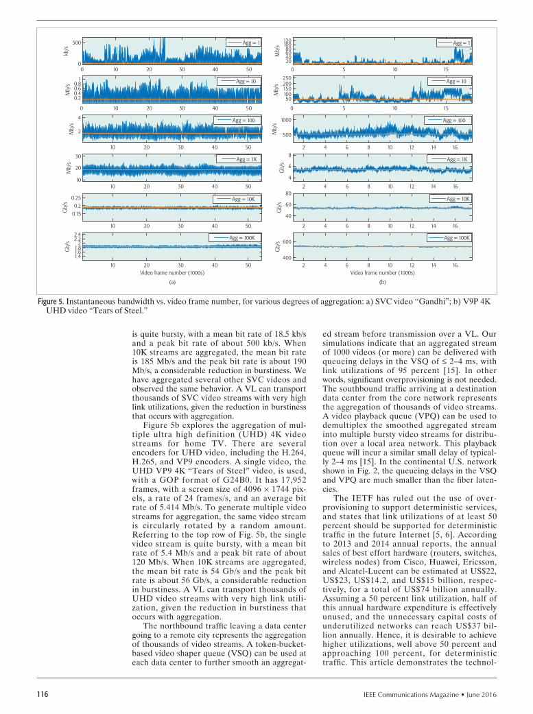
IEEE Communications Magazine • June 2016116
is quite bursty, with a mean bit rate of 18.5 kb/s and a peak bit rate of about 500 kb/s. When 10K streams are aggregated, the mean bit rate is 185 Mb/s and the peak bit rate is about 190 Mb/s, a considerable reduction in burstiness. We have aggregated several other SVC videos and observed the same behavior. A VL can transport thousands of SVC video streams with very high link utilizations, given the reduction in burstiness that occurs with aggregation.
Figure 5b explores the aggregation of mul-tiple ultra high definition (UHD) 4K video streams for home TV. There are several encoders for UHD video, including the H.264, H.265, and VP9 encoders. A single video, the UHD VP9 4K “Tears of Steel” video, is used, with a GOP format of G24B0. It has 17,952 frames, with a screen size of 4096 × 1744 pix-els, a rate of 24 frames/s, and an average bit rate of 5.414 Mb/s. To generate multiple video streams for aggregation, the same video stream is circularly rotated by a random amount. Referring to the top row of Fig. 5b, the single video stream is quite bursty, with a mean bit rate of 5.4 Mb/s and a peak bit rate of about 120 Mb/s. When 10K streams are aggregated, the mean bit rate is 54 Gb/s and the peak bit rate is about 56 Gb/s, a considerable reduction in burstiness. A VL can transport thousands of UHD video streams with very high link utili-zation, given the reduction in burstiness that occurs with aggregation.
The northbound traffic leaving a data center going to a remote city represents the aggregation of thousands of video streams. A token-bucket-based video shaper queue (VSQ) can be used at each data center to further smooth an aggregat-
ed stream before transmission over a VL. Our simulations indicate that an aggregated stream of 1000 videos (or more) can be delivered with queueing delays in the VSQ of ≤ 2–4 ms, with link utilizations of 95 percent [15]. In other words, significant overprovisioning is not needed. The southbound traffic arriving at a destination data center from the core network represents the aggregation of thousands of video streams. A video playback queue (VPQ) can be used to demultiplex the smoothed aggregated stream into multiple bursty video streams for distribu-tion over a local area network. This playback queue will incur a similar small delay of typical-ly 2–4 ms [15]. In the continental U.S. network shown in Fig. 2, the queueing delays in the VSQ and VPQ are much smaller than the fiber laten-cies.
The IETF has ruled out the use of over-provisioning to support deterministic services, and states that link utilizations of at least 50 percent should be supported for deterministic traffic in the future Internet [5, 6]. According to 2013 and 2014 annual reports, the annual sales of best effort hardware (routers, switches, wireless nodes) from Cisco, Huawei, Ericsson, and Alcatel-Lucent can be estimated at US$22, US$23, US$14.2, and US$15 billion, respec-tively, for a total of US$74 billion annually. Assuming a 50 percent link utilization, half of this annual hardware expenditure is effectively unused, and the unnecessary capital costs of underutilized networks can reach US$37 bil-lion annually. Hence, it is desirable to achieve higher utilizations, well above 50 percent and approaching 100 percent, for deterministic traffic. This article demonstrates the technol-
Figure 5. Instantaneous bandwidth vs. video frame number, for various degrees of aggregation: a) SVC video “Gandhi”; b) V9P 4K UHD video “Tears of Steel.”
Video frame number (1000s)
(a)
10
2.4
Gb/
s 2.22
1.81.61.4
20 30 40 50
10
Gb/
s
0.150.2
0.25
20 30 40 50
10
Mb/
s
10
20
30
20 30 40 50
10
Mb/
s
2
4
20 30 40 50
100
Mb/
s
0.20.40.60.8
1
20 30 40 50
100kb
/s
500
020 30 40 50
Video frame number (1000s)
(b)
2
Gb/
s
400
600
4 6 8 10 12 14 16
2
Gb/
s
40
60
80
4 6 8 10 12 14 16
2
Gb/
s
4
6
8
4 6 8 10 12 14 16
2
Mb/
s
500
1000
4 6 8 10 12 14 16
50
Mb/
s
25020015010050
10 15
50
Mb/
s
12010080604020
10 15
Agg = 1
Agg = 10
Agg = 1K
Agg = 10K
Agg = 100K
Agg = 100
Agg = 1
Agg = 10
Agg = 100
Agg = 1K
Agg = 10K
Agg = 100K
IEEE Communications Magazine • June 2016 117
ogies to achieve up to 100 percent utilization for deterministic traffic flows, using simple low-cost CIOQ or CIXOQ switches, which can lower the excess capital costs and energy costs of a future deterministic core network signifi -cantly.
conclusIonThe Internet network has used an ineffi cient best effort communications paradigm for the last 40 years, incurring excessive delays, capital costs, and energy costs. This article proposes a determin-istic Industrial Internet of Things core network consisting of many simple deterministic packet switches controlled by an SDN control plane. Our SDN control plane can program thousands of deterministic virtual networks into the core network to provide each consumer service with its own dedicated congestion-free VN with excep-tionally low latency and jitter. Highly aggregated video streams can be delivered over the conti-nental United States with very low end-to-end latency determined by the speed of light in fi ber, with jitters less than 10 ms, and with up to 100 percent link utilizations. By achieving 100 per-cent link utilizations rather than the 50 percent targeted by the IETF, the proposed determinis-tic network can save potentially US$37 billion in capital costs annually. A speed-of-light determin-istic core network can have a profound impact on virtually all consumer services such as multimedia distribution, e-Commerce, and cloud comput-ing or gaming. It can also pay for itself quickly, due to its significantly improved utilization and energy effi ciency. The deterministic technologies proposed in this article can also provide deter-ministic services in metro area networks, data center networks, and supercomputer networks. We believe that a future converged deterministic Internet of Things that combines the best effort and deterministic communications paradigms can fundamentally transform computing and consum-er services in the 21st century.
reFerences
[1] M. Ford, “Workshop Report: Reducing Internet Latency 2013,” ACM SIG-COMM CCR, vol. 44, no. 2, Apr. 2014, pp. 80–86.
[2] A. Singla et al., “The Internet at The Speed of Light,” ACM Hotnets 2014, Oct. 2014, Los Angeles, CA, pp. 1–7.
[3] G. Fettweis et al., “The Tactile Internet,” ITU-T Technology Watch Report, Aug. 2014, pp. 1–24.
[4] T.H. Szymanski, “An Ultra Low Latency Guaranteed-Rate Internet for Cloud Services,” IEEE Trans. Networking, vol. 24, no. 1, Feb. 2016, pp. 123–36.
[5] N. Finn and P. Thubert, “Deterministic Networking Problem Statement (04),” IETF Internet Draft, Standards Track, Oct. 19, 2015, pp. 1–17.
[6] S. Shah and P. Thubert, “Deterministic Forwarding PHB (04),” IETF Internet Draft, Aug. 30, 2015, pp. 1–8.
[7] S. Iyer, R. R. Kompella, and N. Mckeown, “Designing Packet Buffers for Router Linecards,” IEEE Trans. Networking, vol. 16, no. 3, June 2008, pp. 705–17.
[8] V. Anantharam et al., “Achieving 100% Throughput in an Input Queued Switch,” IEEE Trans. Commun., vol. 47, no. 8, 1999, pp. 1260–67.
[9] W.J. Chen, C-S. Chang, and H-Y. Huang, “Birkhoff-von Neumann Input Buffered Crossbar Switches for Guaranteed-Rate Services,” IEEE Trans. Commun., vol. 49, no. 7, July 2001, pp. 1145–47.
[10] I. Keslassy et al., “On Guaranteed Smooth Scheduling for Input-Queued Switches,” IEEE/ACM Trans. Networking, vol. 13, no. 6, Dec. 2005, pp. 1364–75.
[11] IEEE 802 Tutorial, “Deterministic Ethernet: 802.1 Standards for Real-Time Process Control, Industrial Automation, and Vehicular Networks,” Nov. 12, 2012, pp. 1–72.
[12] D. Dujovne et al., “6TiSCH: Deterministic IP-Enabled Industrial Internet (of Things),” IEEE Commun. Mag., vol. 52, no. 12, Dec. 2014, pp. 36–41.
[13] P. Wetterwald and J. Raymond, “Deterministic Networking Utilities Requirements,” IETF Internet Draft, June 30, 2015, pp. 1–26.
[14] T. H. Szymanski, “Crossbar Switch and Recursive Scheduling,” U.S. Patent 9042380B2, issued May 26, 2015, pp. 1–36.
[15] T. H. Szymanski, “Max-Flow Min-Cost Routing in a Future Internet with Improved QoS Guarantees,” IEEE Trans. Commun., vol. 61, no. 4, Apr. 2013, pp. 1485–97.
bIogrAPhY
TED H. SZYMANSKI ([email protected]) completed his Ph.D. degree at the University of Toronto. From 2001 to 2011, he held the Bell Canada Chair in Data Communications at McMaster University. Previously, he was a professor at Columbia University and its Center for Telecommunications Research, and McGill University and the Canadian Institute for Telecommunications Research. He participated in a 10-year research program within the Networks of Centers of Excellence of Canada, which demonstrated a free-space intelli-gent optical backplane using photonic packet-switches with about 1000 opti-cal channels. Contributors included Nortel Networks (Ericsson), Newbridge Networks (Alcatel), Lockheed-Martin/Sanders, and McGill, McMaster, Toronto, and Heriot-Watt Universities. His group also demonstrated the fi rst FPGA with optical IO, using the U.S. DARPA/Lucent/Coop smart-pixel foundry service. His interests include security, energy effi ciency, deterministic communications, and the industrial Internet of Things.
A speed-of-light deter-
ministic core network
can have a profound
impact on virtually all
consumer services such
as multimedia distri-
bution, e-Commerce,
and cloud computing
or gaming. It can also
pay for itself quickly,
due to its signifi cantly
improved utilization and
energy effi ciency.

IEEE Communications Magazine • June 2016118
SerieS editorial
In this 17th issue of the Automotive Networking and Appli-cations Series, we are pleased to present two articles that address:
• Enhancing a current in-car networking technology to meet the rapidly rising needs of the onboard electronic compo-nents
• A biologically inspired self-organizing traffic control scheme, based on vehicle-to-vehicle (V2V) communica-tions, that expedites emergency vehicles (EVs) through urban traffic intersectionsAn important urban safety issue is how to support emergen-
cy vehicles (EVs), such as ambulances or fire trucks, to expedite the EVs through the urban traffic to reach their destinations as fast as possible. This support of EVs becomes an especially interesting challenge when vehicles use vehicle-to-vehicle com-munications to self-organize themselves to pass through traffic intersections. The first article, “A Self-Organizing Network Approach to Priority Management at Intersections” by O.K. Tonguz and W. Viriyasitavat, proposes a biologically inspired self-organizing traffic control scheme that expedites the EVs through traffic intersections in urban areas. In the article, the authors first outline their motivation of creating a “green-wave” effect for the EVs and then give an overview of the self-orga-nized traffic control paradigm. The article then describes in detail the proposed algorithm for enabling prioritized intersec-tion control, where vehicles communicate among themselves using V2V communications to resolve potential conflicts at the intersections and assign (high) priority to EVs. The authors then present extensive simulation results to demonstrate the efficacy of their proposed scheme in reducing the travel time of EVs through urban traffic while exacting only a negligible adverse effect on non-emergency vehicles. The article also dis-cusses some open challenges related to the priority manage-ment of EVs.
As the number and type of electronic components in cars increase, the need for ever higher data transmissions among these components within the cars also rises rapidly. The con-troller area network (CAN) is the most widely deployed in-car networking technology, which is characterized by its simplicity and robust performance, albeit at somewhat low data rates (e.g., up to 1 Mb/s for CAN 2.0, or up to 16 Mb/s for CAN-FD) that cannot match other networking technologies such as Ethernet or optical fibers. Therefore, how to expand the appli-cations of the CAN standard beyond its wide adoption in con-trol components to various in-car electronic components that
require higher data rates has become an interesting and timely challenge. The second article, “High-Speed CAN Transmission Scheme Supporting Data Rate over 100 Mb/s” by S. Kang et al., proposes a new scheme to increase the data rate of the CAN network to over 100 Mb/s, while remaining seamlessly compat-ible with the existing CAN network protocol. In their article, the authors first review major in-car network standards includ-ing LIN, CAN/CAN-FD, FlexRay, Automotive Ethernet, and MOST. The authors then discuss the CAN network in greater detail, and propose and describe in detail their new scheme for the high-speed CAN network. Through their simulation analy-sis, the authors show that their proposed scheme can provide higher data rate while keeping backward compatibility with the existing CAN standard. The authors conclude with a discussion of some open challenges related to further enchantments to CAN.
We thank all contributors who submitted manuscripts for this Series, as well as all the reviewers who helped with thoughtful and timely reviews. We thank Dr. Osman Gebizlio-glu, Editor-in-Chief, for his support, guidance, and suggestions throughout the process of putting together this issue. We also thank the IEEE publication staff, particularly Ms. Peggy Kang and Ms. Jennifer Porcello, for their assistance and diligence in preparing the issue for publication.
Biographies
Wai Chen ([email protected]) received his B.S. degree from Zhejiang University, and M.S., M.Phil., and Ph.D. degrees from Columbia University, New York. He is chief scientist of the China Mobile Research Institute and general manager of the China Mobile Internet-of-Things Research Institute. Previously he was VPGD of ASTRI, Hong Kong, and chief scientist and director at Telcordia (formerly known as Bellcore), New Jersey.
LuCa DeLgrossi is manager of the Vehicle-Centric Communications Group at Mercedes-Benz Research & Development North America Inc., Palo Alto, California. He received his Ph.D. in comput-er science from the Technical University of Berlin, Germany. He served for many years as professor and associate director of the Centre for Research on the Applications of Telematics to Organizations and Society (CRATOS) of the Catholic University at Milan, Italy.
Timo KosCh is a team manager for BMW Group Research and Technology where he is responsible for projects on distributed information systems, including cooperative systems for active safety and automotive IT security. He studied computer science and economics at Darmstadt University of Technology and the University of British Columbia in Vancouver. He received his Ph.D. from the computer science faculty of the Munich University of Technology.
TaDao saiTo [LF] received his Ph.D. degree in electronics from the University of Tokyo. He is a pro-fessor emeritus at the University of Tokyo. He was chief scientist and CTO of Toyota InfoTechnology Center. He is chairman of the Ubiquitous Networking Forum of Japan and chairman of the Next Generation IP Network Promotion Forum of Japan. He has published eight books on electronics, computers, and digital communications. He is a Fellow of IEICE of Japan.
Automotive NetworkiNg ANd ApplicAtioNs
Wai Chen Luca Delgrossi Timo Kosch Tadao Saito

IEEE Communications Magazine • June 2016 1190163-6804/16/$25.00 © 2016 IEEE
AbstrAct
Prior work has shown that a biologically inspired approach can solve some of the fun-damental transportation problems in urban areas. As one instance of this approach, it was shown that vehicles equipped with dedicated short-range communications (DSRC) radios can manage traffic in urban areas in a completely self-organized manner similar to self-organiz-ing biological systems (e.g., ants, birds, and fish). This scheme is known as virtual traffic lights, and its success is enabled by the design of local rules which allow vehicles approaching an intersec-tion to resolve the ensuing conflict in a seamless and self-organized manner without the need for any infrastructure. One important safety issue in urban traffic is how to manage the presence of emergency vehicles such as ambulances and fire trucks. In this article, it is shown that by design-ing a different set of local rules, one can give pri-ority to emergency vehicles at every intersection, thus expediting their response times.
IntroductIonAmong the different safety applications of vehic-ular ad hoc networks (VANETs), all except the post crash notification (PCN) application are designed to prevent accidents; the PCN application is a passive safety application which aims at dis-seminating safety information to intended drivers so that they are informed about an accident in a timely manner and make rerouting decisions when necessary. Therefore, the main objective of this application is to direct normal traffic around an accident area, but not to assist an emergency response team to reach the scene of an accident.
Using the self-organized traffic control par-adigm first proposed in [1], we propose the use of dedicated short-range communications (DSRC) and VANET technologies to enable an active and post-incident safety application that aims at facilitating and prioritizing the motion of emergency vehicles (EVs) through traffic in urban areas. While law enforcement to facilitate such EV motion is already in place (i.e., vehicles move over to give way to approaching EVs), fur-ther improvement in emergency response time is extremely critical, especially in fire and health-re-lated incidents. To put things into perspective, Fig. 1 depicts the generalized flashover curve for
residential constructions. A flashover occurs at the stage of an ensuing fire at which all surfaces and objects within a space have been heated to their ignition temperature, and flame breaks out almost at once over the surface of all objects in the space; hence, it is the most dangerous part of a fire for firefighters. As shown in the figure, a reduction in response time (i.e., the time that lapses after the fire is detected and reported until the time the firefighters arrive at the scene) is crucial. Similarly, in the case of health-related incidents, it has been shown that the chance of survival drops by roughly 10 percent for every minute a patient stays in cardiac arrest (see, e.g., http://www.americanheart.org).
Reducing the emergency response time by minutes or even seconds is therefore crucial in an emergency situation. The design of the pro-posed system is based on a concept similar to what is currently being used today; that is, assign-ing highest priority to EVs. However, instead of allowing the EVs to pass through intersections without obeying traffic lights, our system aims to provide a “green-wave” effect for the EVs. Green wave phenomena occur when a series of traffic lights are synchronized so that the number of times a car needs to stop at intersections is minimized. This allows continuous traffic flow and significantly improves traffic flows for EVs at intersections. By having always-green sig-nals displayed to the EVs, the proposed system allows the EVs to move at a faster speed and also avoids EV-involved accidents (e.g., each year in the United States, 80 EV crashes occur that involve fatalities [2], and, on average, the EV travel time can be reduced by at least 26 per-cent [3]). In addition, it is reported in [4] that a major portion of EV crashes take place at inter-sections, and among these, more than 25 percent have been found to occur at signalized intersec-tions — vehicles approaching a green signal can-not see an EV approaching from the intersecting roadway because of line-of-sight problems due to nearby buildings, vegetation, or hills [2]. By presenting green and red signals to the EV and other non-EV vehicles, respectively, these EV crashes at intersections could be avoided.
In addition, it is worth pointing out that since the proposed scheme enables traffic control (if necessary) at every intersection, the EV-in-volved accidents that have been found to occur
A Self-Organizing Network Approach to Priority Management at Intersections
Ozan K. Tonguz and Wantanee Viriyasitavat
AutomotIve networkIng And ApplIcAtIons
One important safety issue in urban traffic
is how to manage the presence of emergency vehicles such as ambu-
lances and fire trucks. The authors show that
by designing a different set of local rules, one can
give priority to emergency vehicles at every intersec-tion, thus expediting their
response times.
Ozan K. Tonguz is with Carnegie Mellon University; Wantanee Viriyasitavat is with Mahidol University and Norwegian University of Science and Technology.

IEEE Communications Magazine • June 2016120
at non-signalized intersections could also be prevented. As a result, benefits of the proposed scheme are ubiquitous: at signalized and non-sig-nalized intersections.
self-orgAnIzed trAffIc controlThe premise of the priority management scheme proposed in this article is the self-organized traffic control paradigm first proposed in [1]. It was shown later that this self-organized traffic control paradigm is an instance or example of biologically inspired solutions to several funda-mental transportation problems [5]. In the pro-posed self-organized traffic control paradigm, vehicles communicate among themselves (i.e., in an ad hoc manner without any help from infra-structure) to resolve conflicts at intersections and determine who should cross the intersections first (i.e., they establish the right of way). Unlike other self-organized traffic control schemes, which rely on some centralized infrastructure [6], the proposed scheme operates in a distrib-uted manner under the assumption that each vehicle periodically broadcasts hello messages to announce its presence, current position, and velocity to other nearby vehicles. A vehicle can therefore construct a local map and determine if there is an ensuing conflict at the intersection it is about to approach. In situations where a con-flict is detected, vehicles involved in the conflict perform the following three steps:• Leader election process• Generation of traffic light information• HandoverBased on the beaconing mechanism of DSRC technology, cluster leaders approaching an inter-section can communicate and choose one cluster leader to serve as a “virtual traffic light” (VTL). The leader election process is based on safety considerations as well as other considerations. In general, the cluster leader (among the four
cluster leaders) farthest from the intersection is chosen as the VTL. Upon acknowledgment of the VTL by the other cluster leaders, the VTL broad-casts a red light to its approach and a green light to the orthogonal direction. After a fixed duration (e.g., 45 s) and/or possibly based on other criteria (e.g., the number of vehicles in each approach), the VTL responsibility can be handed over to a cluster leader in the orthogonal direction. More details about the principle of operation of the VTL scheme can be found in [1].
It has been shown by extensive simulations that the aforementioned traffic control scheme (i.e., the VTL system) could provide up to 60 percent improvement in traffic flow [1]. Such a significant improvement is due to two reasons: i) VTL can render traffic control truly ubiquitous compared to only 20 percent of intersections that are currently equipped with traffic lights; and ii) VTL reduces the “dead period” of intersections (i.e., unnecessary red lights when a green light is given to a road with no vehicles).
It should be noted that the above VTL system operates based on the following assumptions [1]:• All vehicles are equipped with DSRC radi-
os.• All vehicles share the same digital map and
positioning system device that has lane-level accuracy.
• The RF propagation problems such as obstructions due to buildings at the corners of intersections do not disrupt the necessary vehicle-to-vehicle communication for elect-ing a leader that will serve as a VTL [7].
• Other communications problems due to col-lision of transmitted packets or beacon mes-sages by vehicles are not severe.
proposed AlgorIthm for enAblIng prIorIty IntersectIon control
It has been shown in several previous studies that VTL is a biologically inspired self-organizing net-work approach to urban traffic control, and this scheme ultimately depends on designing local rules at intersections for deciding the right of way between competing flows. By obeying these local rules, the flow rate can be increased by 30–60 percent, which is a significant improve-ment in mitigating traffic congestion and reduc-ing the commute time during rush hours. In this article, we show that by designing new local rules for intersections, it is possible to perform yet another important functionality: giving priority to emergency vehicles including ambulances, fire trucks, and so on. This expedites the movement of emergency vehicles, which, in turn, can save many lives.
It is well known that the local rules used by self-organizing biological systems in nature for different functionalities are different. While a certain set of local rules might be used for for-aging, a different set of local rules might be used by social insect colonies for protecting them-selves against predators, and yet another set of rules might be used to cope with drastic changes in the environment (e.g., in terms of tempera-ture). Depending on the nature of the function to be performed, these local rules might neces-sitate using priority rules. As an example, it is
Figure 1. The flashover curve and the evolution of fire with time in a building. Chance of survival is substantially decreased after the flashover point (pic-ture taken from http://firesprinklerassoc.com/wp-content/uploads/2014/02/newflashoverchart-1024x791.jpg).
DETECTIONOF FIRE
REPORTOF FIRE
RESPONSE TO FIRE SETUPFIGHTING FIRE
DISPATCH
PRO
DUC
TS O
F CO
MBU
STIO
N
ACTIONSBEFORE FIRE1)TEST SMOKE ALARMS2)CONDUCT FIRE ESCAPE DRILLS
TIME (in minutes)Based upon national averages
TIME vs. PRODUCTS of COMBUSTION
0 1 2 3 4 5 6 7 8 9 10
TIME VARIES TIME DIRECTLY MANAGEABLE BY FIRE DEPARTMENT
SMOKEALARM
ACTIVATES
of smoke alarmsdidn’t work in homesthat had fires*
*U.S. Experience With Smoke Alarms and Other Fire Alarms. NFPA. September 2001.
NOTE: See NFPA Fire Protection Handbook for time and temperature information.
RESIDENTIALSPRINKLERACTIVATES
FIREFIGHTERS OPENHOSE NOZZLES
No one survives flashover
FIRE GROWTHRESTRICTED
FIRE GROWTHRESTRICTED
FIRE GROWTHUNRESTRICTED
FLASHOVER
30% of fire deaths occured in home fires in which smoke alarms sounded*
25%
NORTHERN ILLINOISFIRE INSPECTORS
ASSOCIATION
COMMERCIALSPRINKLERACTIVATES
Without fire sprinklers, odds of escaping decrease significantly

IEEE Communications Magazine • June 2016 121
interesting to note that priority rules (which are functions of factors such as size, direction of movement, and whether or not they carry a load) have been used in a number of ant species for deciding the right of way [8, 9]. For instance, in the leaf-cutting ant Atta columbica, higher pri-ority is given to the inbound laden ants as the outbound ants give way to inbound laden ants in 80 percent of their encounters, possibly due to the fact that the inbound ants are carrying leaves or food for the colony. Inspired by such observa-tions, we propose a self-organizing network solu-tion to one of the major problems in emergency response management [5]; that is, facilitating and expediting the motion of EVs (or high-pri-ority vehicles) through traffi c and/or congestion in urban areas. By detecting the presence of an EV, the proposed scheme, VTL with priority intersection control (VTL-PIC), assigns priority (i.e., gives right of way) to the road or approach on which the EV travels. To enable the priori-ty scheme at intersections, two new mechanisms (i.e., local rules) are designed [10].
Detection of an EV When It Approaches and Leaves an Intersection: It is clear that detection of an EV is a critical component of the pro-posed VTL-PIC scheme. In our proposed solu-tion, upon approaching an intersection, the EV periodically broadcasts a PIC request message to announce its presence and demand priori-ty until it receives a PIC grant message from a vehicle that is leading the intersection (i.e., the intersection leader). Note that in addition to the PIC request message, the intersection leader can detect the presence of the EV when it receives a hello message generated by the EV.
Besides PIC request messages, the EV is also required to inform the intersection leader upon leaving the intersection so that the intersection can now resume its normal operation for normal traffi c management. A PIC clear message is used to handle such detection. When the EV crosses the conflict point (intersection), it periodical-ly broadcasts a PIC clear message for a certain period of time. In the case when PIC clear mes-sages are lost, the intersection leader can also detect the departure of the EV when it does not receive hello messages from the EV for a certain period of time.
Priority Assignment Scheme: Once the pres-ence of an EV is detected, phase layout confi g-uration of the traffic signals of the intersection needs to be recomputed and broadcast to vehi-cles involved in the conflict at the intersection. While there are a number of algorithms that could be used for priority assignment, a simple scheme (i.e., the cluster in which the EV is trav-eling always gets the green signal) is used in our protocol to illustrate how priority intersection control could be used in conjunction with the VTL system.
Since the proposed scheme is an overlay scheme on top of VTL, the VTL-PIC will also share the same benefi ts as the VTL scheme. The benefits of the VTL-PIC protocol on the travel time of emergency vehicles are as follows.
Less Severe Traffic Congestion for EVs: Given the same amount of traffi c, an EV in the VTL-PIC scheme encounters less severe traffic congestion compared to that found in typical sce-
narios with physical traffic lights. Our previous work has shown that because of more efficient use of intersections as a resource and the fact that the VTL renders traffi c control ubiquitous (i.e., traffi c control at every intersection), during rush hours traffic congestion takes place at a much later stage (i.e., more vehicles can enter the net-work before traffic congestion happens) com-pared to typical scenarios with physical traffic lights and identical traffi c generation rate. As a result, vehicles and especially an EV reach their destination locations within a much shorter time duration when the VTL scheme is employed. Furthermore, when traffi c congestion is inevita-ble (i.e., generated traffi c exceeds the capacity of the road network), the VTL scheme can resolve the congestion situation much more quickly; hence, the travel time of the EV is substantially reduced.
Lower Travel Time for EVs: Creation of a green wave effect allows EVs to travel at high-er speeds such that they do not need to slow down when approaching intersections. Since the VTL-PIC scheme always assigns green signals to the road on which the EVs are traveling, the EVs will encounter green-wave phenomena as they pass through intersections (i.e., consecutive traffic lights are coordinated and present pro-gressive green displays to the EVs). This results in a higher traveling speed of EVs compared to conventional operation where EVs have to slow down significantly as they see red signals when approaching intersections. By assigning higher priority to the roads on which EVs travel, VTL-PIC could clear up an EV’s route by also giving higher priority to vehicles that travel in front of the EV to pass the intersections.
Potential Prevention of Crashes: The pro-posed scheme can prevent potential EV crashes or accidents that take place at intersections. By presenting a green signal in the EV’s direction (approach), other vehicles that approach from different directions are presented with red sig-nals, and hence are prepared to stop and give right of way to the EV. Note that because of ubiquitous traffi c control rendered by the VTL-PIC scheme, it is expected that the proposed protocol could prevent a significant number of EV crashes (i.e., more than 25 percent [2]), thus making both signalized and non-signalized inter-sections safer for both emergency and regular (non-emergency) vehicles.
prIncIple of operAtIon
According to the scheme described above, a vehi-cle at an intersection must belong to one of three different categories: an EV, a non-EV vehicle that is leading the intersection, and a non-EV vehicle that is not leading the intersection. Fig-ures 2a and 2b depict the flow diagrams of the algorithms used by an EV and a non-EV vehicle upon approaching an intersection, respectively.
Upon approaching an intersection, an EV determines if there is already a VTL set up for the intersection by passively listening to the VTL message broadcast by the leader. In the case when no VTL exists and no conflict is detect-ed at the intersection, the EV can pass through the intersection with no additional communica-tion. In the case where a conflict is detected or
When the EV crosses
the confl ict point (inter-
section), it periodically
broadcasts a PIC clear
message for a certain
period of time. In the
case when PIC clear
messages are lost, the
intersection leader can
also detect the depar-
ture of the EV when it
does not receive hello
messages from the
EV for a certain
period of time.
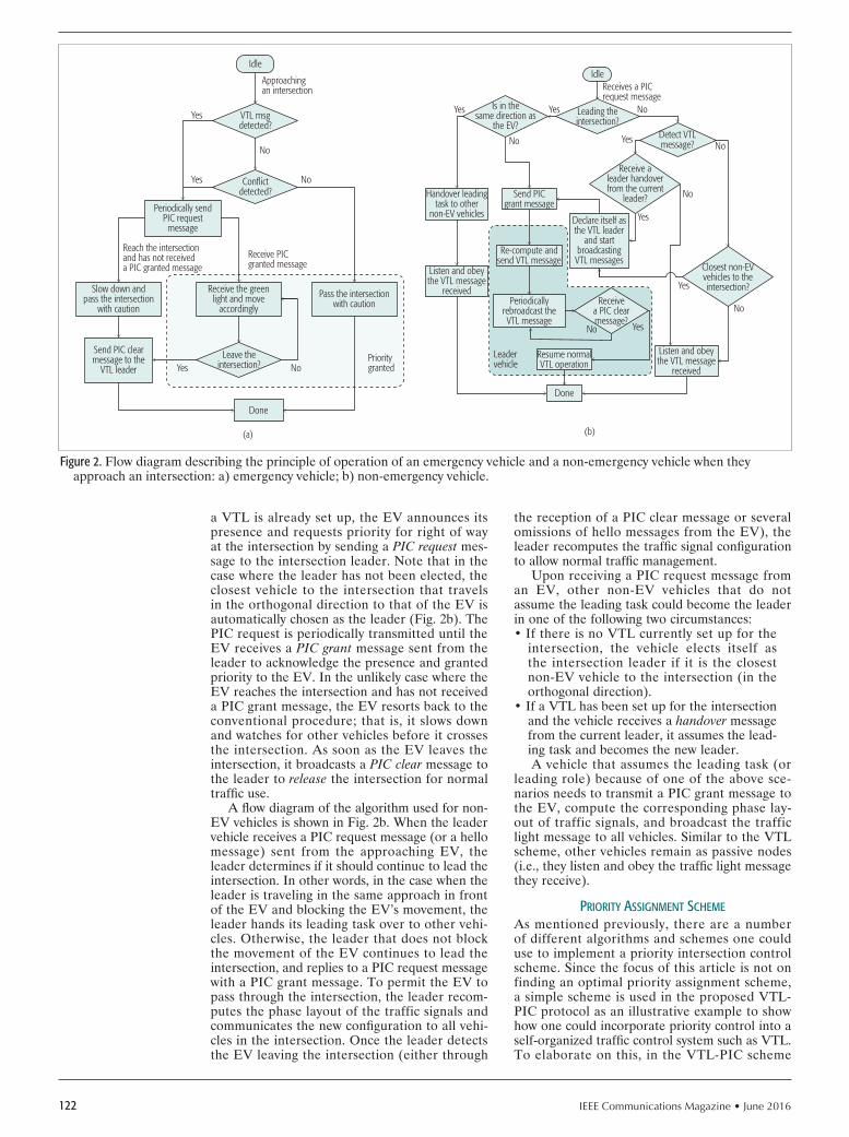
IEEE Communications Magazine • June 2016122
a VTL is already set up, the EV announces its presence and requests priority for right of way at the intersection by sending a PIC request mes-sage to the intersection leader. Note that in the case where the leader has not been elected, the closest vehicle to the intersection that travels in the orthogonal direction to that of the EV is automatically chosen as the leader (Fig. 2b). The PIC request is periodically transmitted until the EV receives a PIC grant message sent from the leader to acknowledge the presence and granted priority to the EV. In the unlikely case where the EV reaches the intersection and has not received a PIC grant message, the EV resorts back to the conventional procedure; that is, it slows down and watches for other vehicles before it crosses the intersection. As soon as the EV leaves the intersection, it broadcasts a PIC clear message to the leader to release the intersection for normal traffic use.
A flow diagram of the algorithm used for non-EV vehicles is shown in Fig. 2b. When the leader vehicle receives a PIC request message (or a hello message) sent from the approaching EV, the leader determines if it should continue to lead the intersection. In other words, in the case when the leader is traveling in the same approach in front of the EV and blocking the EV’s movement, the leader hands its leading task over to other vehi-cles. Otherwise, the leader that does not block the movement of the EV continues to lead the intersection, and replies to a PIC request message with a PIC grant message. To permit the EV to pass through the intersection, the leader recom-putes the phase layout of the traffic signals and communicates the new configuration to all vehi-cles in the intersection. Once the leader detects the EV leaving the intersection (either through
the reception of a PIC clear message or several omissions of hello messages from the EV), the leader recomputes the traffic signal configuration to allow normal traffic management.
Upon receiving a PIC request message from an EV, other non-EV vehicles that do not assume the leading task could become the leader in one of the following two circumstances:• If there is no VTL currently set up for the
intersection, the vehicle elects itself asthe intersection leader if it is the closestnon-EV vehicle to the intersection (in theorthogonal direction).
• If a VTL has been set up for the intersectionand the vehicle receives a handover messagefrom the current leader, it assumes the lead-ing task and becomes the new leader.A vehicle that assumes the leading task (or
leading role) because of one of the above sce-narios needs to transmit a PIC grant message to the EV, compute the corresponding phase lay-out of traffic signals, and broadcast the traffic light message to all vehicles. Similar to the VTL scheme, other vehicles remain as passive nodes (i.e., they listen and obey the traffic light message they receive).
prIorIty AssIgnment scheme
As mentioned previously, there are a number of different algorithms and schemes one could use to implement a priority intersection control scheme. Since the focus of this article is not on finding an optimal priority assignment scheme, a simple scheme is used in the proposed VTL-PIC protocol as an illustrative example to show how one could incorporate priority control into a self-organized traffic control system such as VTL. To elaborate on this, in the VTL-PIC scheme
Figure 2. Flow diagram describing the principle of operation of an emergency vehicle and a non-emergency vehicle when they approach an intersection: a) emergency vehicle; b) non-emergency vehicle.
Periodicallyrebroadcast theVTL message
IdleIdle
(b)(a)
Leadervehicle
Prioritygranted
Yes
Yes
Yes
YesYesYes
Yes
Yes
No
No
NoNo
No
No
No
Yes
No
No
Declare itself asthe VTL leader
and startbroadcastingVTL messages
Send PICgrant message
Re-compute andsend VTL message
Resume normalVTL operation
Done
Done
Handover leadingtask to other
non-EV vehicles
Listen and obeythe VTL message
received
Listen and obeythe VTL message
received
Leading theintersection?
VTL msgdetected?
Conflictdetected?
Leave theintersection?
Periodically sendPIC request
message
Receive PICgranted message
Reach the intersectionand has not receiveda PIC granted message
Slow down andpass the intersection
with caution
Receive the greenlight and move
accordingly
Pass the intersectionwith caution
Detect VTLmessage?
Is in thesame direction as
the EV?
Receivea PIC clearmessage?
Receive aleader handoverfrom the current
leader?
Receives a PICrequest message
Approachingan intersection
Closest non-EVvehicles to theintersection?
Send PIC clearmessage to the
VTL leader

IEEE Communications Magazine • June 2016 123
described in this article, an intersection leader always gives right of way (i.e., green light) to the road on which an EV is traveling. “Always-green” configuration continues until the EV has left the intersection, and normal operation of the VTL-PIC is then resumed. It is an interesting subject for future study to determine the optimal priority scheme for priority vehicles.
sImulAtIon settIng And results
sImulAtIon settIng
In order to evaluate the proposed VTL-PIC pro-tocol, we resort to the SUMO traffic mobility simulator, an open source microscopic simula-tor developed by the Institute of Transportation Systems at the German Aerospace Center [11]. A 10 10 Manhattan grid network topology is assumed in the simulations with 125-m block length.
The traffic generation pattern used in the sim-ulations is depicted in Fig. 3b where the traffic generation rate (e.g., R1 and R2 [veh/h]) varies based on different time windows during rush hour, number of total vehicles injected into the simulations, N. The step function shown in Fig. 3b is used to capture the traffic behavior during rush hour; there is a first wave of commuters who try to enter/leave the city sooner to avoid traffic jams, followed by the period when most com-muters enter/leave; and finally, another wave of the remaining vehicles. Hence, in this article the relationship between these three parameters is assumed to be
= = =R N R R N3
, 2 231 2 1
One EV is artificially added into the simula-tion at t = 5400 s (i.e., 90 min after the simula-tion starts). The EV starts from the center of the
source area to its destination in the top right of the network. All vehicles including the EV are assumed to be equipped with a GPS system and DSRC radios with a transmission range of 200 m. We assume that there is no packet loss in thenetwork; that is, all packets sent are correctlyreceived at the receiver(s). Travel time of theEV and non-EV vehicles are collected from thesimulations conducted and reported in the nextsubsection.
Three different traffic control schemes are implemented and evaluated:• A baseline scheme where only physical traf-
fic lights (TLs) are used at intersections,and an EV does not receive any priority atintersections. In this scheme, an EV is treat-ed as a non-EV vehicle. This assumption isvalid in a heavily congested urban scenario;vehicles cannot move to the side to give wayto the EV.
• A VTL scheme where the VTL paradigmis used as the traffic control mechanism atintersections; however, it does not give pri-ority to the EV.
• A VTL-PIC scheme where both the VTLand the priority scheme are implemented.
sImulAtIon results
Rush Hour Scenario: To simulate the traffic pat-tern during rush hours, vehicles in the simula-tor are assumed to start from their origination location (source area) in the 3 10 source area located at the bottom of Fig. 3a to their destina-tion area in the topmost portion of the network.
Figures 4a and 4b show the simulation results in terms of travel time of the EV and non-EV vehicles as a function of total number of vehicles generated, respectively. Observe that the travel time of both types of vehicles decreases when the VTL system is in place, and the proposed VTL-
Figure 3. Left: A 10 × 10 Manhattan grid topology with 125-m block length is used in the simulations. The bottom 3 × 10 area is the source area where vehicles are injected into the network in the simulations. Small red dots represent vehicles. Right: Traffic gen-eration pattern used in the simulations. While the black dotted line shows the realistic traffic generation rate, the staircase in red color shows the approximation used in the simulations: a) network topology; b) traffic generation patterns.
!"
Destinationarea
Source area(for rush-hourscenario only
(a) (b)
0 30 60 90 1200
R1
R2=2 x R1
Traf
fic g
ener
atio
n ra
te
Time after simulation starts (in minutes)

IEEE Communications Magazine • June 2016124
PIC protocol further decreases the travel time of the EV vehicle. Figure 4a, for example, shows that with the new VTL-PIC scheme, the travel time of an EV can be reduced from 430 s (in the case with the TL scheme) to a range of 180–250 s, which is quite significant as such a 3- or 4-min reduction in travel time could save many lives in emergency response applications. It is worth pointing out that despite the enforced EV priori-ty, VTL-PIC has little or no adverse effect on the travel time of non-EV vehicles (Fig. 4b).
Figure 5 presents in detail the travel time of the EV for each intersection it crosses. Note that based on the pre-specified route depicted in Fig. 3a, the EV passes three intersections before it leaves the source area and 12 more intersections outside the source area before it reaches its des-tination. As a result, the EV always encounters conflicts as it arrives at the first three intersec-tions, but not afterward. This is because traffic density outside the source area is very low; thus, it is unlikely to encounter conflicts at the inter-sections outside the source area. The reduction in the travel time of the EV is therefore gained from the first three intersections. Furthermore, the advantage of the VTL-PIC scheme becomes more pronounced as the number of vehicles increases (Fig. 5, bottom). This confirms our intuition: VTL-PIC outperforms VTL only at the always conflicting intersections and when there are larger numbers of vehicles in the simulations, thus leading to a higher level of conflicts at inter-sections. It is important to note that the VTL-PIC protocol creates the green wave phenomena for the EV; that is, the time it takes for the EV to cross the intersection(s) is minimal, as shown in Fig. 5. As shown later, when the traffic pattern of non-EVs is uniformly distributed (instead of the dominant northbound traffic), the benefits of VTL-PIC will be more pronounced.
Lunchtime Scenario: In contrast to the 3 10 source area used in obtaining the previous results to simulate the traffic pattern during rush hour, the entire 10 10 network shown in Fig. 3a is
used as the source area for lunchtime scenarios. All non-EVs have random start and end loca-tions. Similar to the previous case, an EV starts from the center of the 3 10 area in the bottom part of the network to a destination in the top-right portion of the network (Fig. 3a).
Figures 6a and 6b depict the average trav-el time of the EVs and non-EVs, respective-ly. Observe that, compared to the physical TL scheme currently used, the average travel time of EVs can be reduced by up to 5 min with the VTL/VTL-PIC scheme, which is quite significant. Furthermore, compared to the VTL scheme, up to 45 s of travel time for the EV can be saved with the proposed VTL-PIC scheme. It is worth pointing out that given the same number of vehi-cles in simulations, benefits of VTL-PIC over VTL become more obvious (i.e, in a scenario with 7000 vehicles, the VTL-PIC scheme could save an additional 45 s of an EV’s travel time vs. less than 5 s additional saving time obtained in the rush hour scenario). This larger benefit is due to the fact that the EV experiences conflicts at all of the 16 intersections it crosses in this scenario (as opposed to only 3 intersections observed in the rush hour scenarios). Note that the benefit in terms of travel time of an EV largely depends on the number of congested intersections; hence, the expected benefit will increase considerably when a larger urban area is considered.
dIscussIonSince the proposed priority management scheme uses the existing VTL system described in [1] as its premise, a number of issues related to wide adoption of the VTL system are also relevant for the VTL-PIC scheme. More specifically, the pro-posed priority management scheme in this article assumes the full adoption of the VTL scheme by all the vehicles in an urban area. While such a fundamental paradigm shift can be brought about by the Departments of Transportation (DoTs) of different countries based on new legislation, our ongoing work shows that it might be possi-
Figure 4. Average travel time of emergency and non-emergency vehicles in a scenario where an emergency vehicle is inserted into the network at t = 90 min after the onset of rush hour. The results are plotted with 95 percent confidence interval. Note that the confidence interval for the non-emergency vehicles is very small. Observe that in b) the results for VTL and VTL-PIC are almost the same: a) emergency vehicle; b) non-emergency vehicle.
0
(a) (b)
2 3 4 5
x 104
100
200
300
400
500
600
Number of cars
Aver
age
trave
l tim
e (s
econ
ds)
Travel time of the EV vehicle
VTL-PICPhysical traffic lightVTL
0 1 2 3 4 5
x 104
100
200
300
400
500
600
700
800
900
Number of cars
Aver
age
trave
l tim
e (s
econ
ds)
Travel time of the non−emergency vehicle
Physical traffic lightsVTL-PICVTL

IEEE Communications Magazine • June 2016 125
ble to deploy VTL partially on designated routes only; for example, during rush hours using an approach similar to the high occupancy vehicle (HOV) concept [12]. In this HOV-like concept, several streets are exclusively reserved for VTL vehicles and intersections on these streets adopt VTL as the intersection control management [12]. Only VTL vehicles are allowed to travel on these streets while non-VTL vehicles can still utilize other streets. This concept thus allows the coexistence of VTL and non-VTL vehicles in the same road network, and also implies that the proposed priority management scheme might be applicable on those routes where VTL is enforced by local DoTs. The same scheme can also be applied to the VTL-PIC scheme pro-posed in this article in scenarios where the tech-nology penetration rate is less than 100 percent. Similar to the results shown in [12], depending on the route that needs to be taken by an EV, the benefit of the proposed VTL-PIC scheme might signifi cantly degrade when the penetration rate is less than 100 percent.
In addition, the successful operation of the proposed scheme also assumes the right driver interface, which involves some kind of display unit on the dashboard of every vehicle that will interface with the DSRC unit. The fault-tolerant and security aspects of the proposed scheme are also major considerations for ensuring that, even in the worst case scenarios (e.g., in the event of high packet loss and inaccurate GPS informa-tion), the proposed scheme does not lead to acci-dents. Such provably fail-safe operation must be guaranteed [13]. Finally, the proposed scheme has to have the capability of dealing with pedes-trians and cyclists who might not be equipped with DSRC radios. An external representation for the VTL on the outside of the vehicle has been proposed to display traffi c light information
to non-equipped cars, pedestrians, and cyclists [14]. Note that this might be less of a problem, though, given that most pedestrians or cyclists will give way to the EVs once they hear an emer-gency siren.
It is also worth mentioning that the priori-ty assignment scheme introduced in this article is only a proof-of-concept type of example that illustrates how the powerful biologically inspired self-organized traffic control paradigm could be used to facilitate a safety-critical operation. As future work, it would be interesting to extend the proposed priority management scheme where sev-eral (instead of a single) consecutive intersections are coordinated to further increase the traffic efficiency. In addition, the same priority scheme could also be used to prioritize mass transit vehi-cles at intersections (buses, etc.) during rush hours, which, in turn, could reduce the commute time of urban workers during rush hours [15].
relAted workExisting approaches to priority management at intersections for emergency, municipal, and mass transit buses are usually known as EV preemp-tion (EVP) systems, and can be categorized into two main categories:
centrAlIzed control systems
The most straightforward way of implementing an EVP mechanism is to employ a centralized control system. Examples of such systems include Global Traffi c Technologies (GTT)’s Opticom™ Central Management Software (http://www.gtt.com) and GERTRUDE (http://www.gertrude.fr). In GTT’s commercial product, arrival of EVs at an intersection is recognized by the traffi c signal controller through light, sound, or radio waves. Once detected, the centralized urban traffi c con-trol software decides if signal preemption is war-
Figure 5. Average travel time of an EV as it passes through 15 intersections before it reaches its destina-tion, 3 of which are intersections in the source area and always have confl icts. Note that the results presented here are extracted from one of many simulation runs; the negligible discrepancy observed in the top fi gure (i.e., the EV crossing time at intersections 7 and 15 are slightly higher in the VTL-PIC scheme) is the result of simulation artifacts.
1 2 3 4 5 6 7 8 9 10 11 12 13 14 15Intersection # in order which EV vehicle passes
0
5
10
15
20
Tim
e th
e EV
take
s to
cros
s an
inte
rsec
tion
(s)
Number of vehicles in the simulation = 8000
VTLVTL-PIC
1 2 3 4 5 6 7 8 9 10 11 12 13 14 15Intersection # in order which EV vehicle passes
050
100150200250300350
Tim
e th
e EV
take
s to
cros
s an
inte
rsec
tion
(s)
Number of vehicles in the simulation = 40,000
VTLVTL-PIC
Only VTL vehicles are
allowed to travel on
these streets while non-
VTL vehicles can still
utilize other streets. This
concept thus allows the
co-existence of VTL and
non-VTL vehicles in the
same road network and
also implies that the
proposed priority man-
agement scheme might
be applicable on those
routes where
VTL is enforced
by the local DoT’s.

IEEE Communications Magazine • June 2016126
ranted and, if necessary, interrupts the normal green-yellow-and-red cycle to change the light to green for the EV. GTT’s Optimal Product has been implemented in Olathe, Kansas, and Savannah, Georgia, and it has been shown that it creates efficiency in motion for the EVP, which allows first responders to arrive at an emergency scene faster.
IntersectIon-bAsed systems
These systems can operate without a backbone network connecting all intersections to a central control center; hence, they offer a more scalable solution than the centralized system. Disadvan-tages of this approach are:• Higher installation, operation, and mainte-
nance cost per intersection• Lower efficiency in EVP due to lack of coor-
dination between consecutive intersectionsSimilar to the above approach, as an EV approaches a traffic signal, a light-, radio-, or sound-based detection mechanism triggers the traffic signal controller installed at the signal pole and/or arm to adjust the traffic light pattern. EMTRAC systems (http://www.emtracsystems.com) and E-ViEWs Safety Systems are the two most prevalent solutions. In EMTRAC, a 30–60 s reduction in travel time has been reported when the system is used in the mass transportation system in Santa Clara, California. However, the EVs and the intersections need special equip-ment that cost $3000 per vehicle and $10,000 per intersection.
E-ViEWs Safety Systems, partnered withNASA’s Jet Propulsion Laboratory, has launched several technologies for emergency intelligent transportation systems (http://eviewsinc.com). Based on the wireless communications among EVs, dynamic message signs (DMSs), and inter-section traffic controllers, road users are notified of approaching EV vehicles at signalized intersec-tions; hence, the system provides faster emergency response times and greater safety on the roads.
While these systems have been shown to reduce response time of EVs, all of these schemes rely on some kind of infrastructure and require additional costly equipment to be installed; hence, coverage and benefits of such systems are fundamentally limited by the number of equipped intersections.
conclusIonWe have proposed a biologically inspired self-or-ganized traffic control scheme that expedites emergency response operations (i.e., facilitates and expedites the movement of emergency vehicles through traffic in urban areas). In the proposed priority management scheme, vehi-cles communicate among themselves using vehicle-to-vehicle communications to resolve potential conflicts at intersections and determine a priority scheme that assigns the priority to a specific road or approach. The proposed prior-ity scheme is based on local rules for vehicles approaching intersections, corresponding to the detection of the presence (and absence) of an emergency vehicle and rules that assign prior-ity to emergency vehicles. Results of extensive simulations have shown that, with the proposed scheme, even in a relatively small topology (e.g., 10 10 Manhattan grid), an emergency vehicle is able to arrive at the scene of an accident up to 5 min earlier compared to a conventional phys-ical traffic light system. Clearly, for emergency response operations this is quite significant. For bigger or denser cities, the reduction in travel time of emergency vehicles will be even larger. In addition, results also show that the proposed VTL-PIC protocol has a negligible adverse effect on the travel time of non-emergency vehicles.
Acknowledgment
This research has been supported in part by the T-SET University Transportation Center spon-sored by the U.S. Department of Transportationunder Grant No. DTRT12-G-UTC11.
Figure 6. Average travel time (in seconds) of the emergency and non-emergency vehicles in the lunchtime scenario as a function of number of vehicles in the network where the emergency vehicle is inserted into the network at t = 90 min. The results are plot-ted with 95 percent confidence interval. Note that the confidence interval for the non-emergency vehicles is very small. Again, observe that the results of VTL and VTL-PIC are almost the same in Fig. 6b: a) emergency vehicle; b) non-emergency vehicle.
1000 2000
(a) (b)
3000 4000 5000 6000 7000150
200
250
300
350
400
450
500
Number of cars
Aver
age
trave
l tim
e (s
)
Travel time of the emergency vehicle
Physical traffic lightsVTLVTL−PIC
1000 2000 3000 4000 5000 6000 7000150
200
250
300
350
400
450
500
Number of cars
Aver
age
trave
l tim
e (s
)
Travel time of the non-emergency vehicle
Physical traffic lightsVTL-PICVTL

IEEE Communications Magazine • June 2016 127
references
[1] M. Ferreira et al., “Self-Organized Traffi c Control,” Proc. ACM Int’l. Wksp.Vehicular Internetworking, 2010, pp. 85–90.
[2] U.S. DOT (2003), “Fatality Analysis Reporting System (FARS) Web-Based Encyclopedia Queries for Emergency Use Crash Statistics,” http://www-fars.nhtsa.dot.gov
[3] L. Faubion, “Emergency Vehicle Priority (EVP) Systems Reduce Response Time, Collision Avoidance, Fire Engineering,” http://community.fi reengi-neering.com/forum/topic/show?id=1219672 percent3ATopic percen-t3A317613, Apr. 2011.
[4] ITS, U.S. DoT, “Traffic Signal Preemption for Emergency Vehicles: ACross-Cutting Study, Putting the ‘First’ in ‘First Response,’ “ http://ntl.bts.gov/lib/jpodocs/repts_te/14097_fi les/14097.pdf, 2006.
[5] O. K. Tonguz, “Biologically Inspired Solutions to Fundamental Transporta-tion Problems,” Keynote, IEEE VNC, Jersey City, NJ, Dec. 2010.
[6] A. Leich, “Cooperative Self-Organizing System for Low CarbonMobility at Low Penetration Rates,” tech. rep., COLOMBO Project,Nov. 2015.
[7] T. Neudecker et al., “Feasibility of Virtual Traffic Lights in Non-Line-Of-Sight Environments,” Proc. 7th ACM Int’l. Wksp. Vehicular Internetwork-ing, 2012, pp. 103–06.
[8] A. Dussutour et al., “Priority Rules Govern the Organization of Traffi c on Foraging Trails under Crowding Conditions in the Leaf-Cutting Ant AttaColombica,” J. Experimental Biology, vol. 212, Feb. 2008, pp. 499–505.
[9] P. Casacci L et al., “Ant Pupae Employ Acoustics to Communicate SocialStatus in Their Colony’s Hierarchy,” Current Biology, vol. 23, Feb. 2013, pp. 323–27.
[10] W. Viriyasitavat and O. K. Tonguz, “Priority Management of EmergencyVehicles at Intersections Using Self-Organized Traffi c Control,” Proc. IEEEVTC-Fall, 2012, pp. 1–4.
[11] M. Behrisch et al., “Sumo - Simulation of Urban Mobility: An Overview,” Int’l. Conf. Advances in System Simulation, Oct. 2011, pp. 63–68.
[12] O. K. Tonguz, W. Viriyasitavat, and J. Roldan, “Implementing Virtual Traf-fi c Lights with Partial Penetration: A Game-Theoretical Approach,” IEEECommun. Mag., vol. 52, no. 12, Dec. 2014, pp. 173–85.
[13] J. Yapp and A. Kornecki, “Safety Analysis of Virtual Traffi c Lights,” Proc. Int’l. Conf. Methods and Models in Automation and Robotics, Aug. 2015, pp. 505–10.
[14] H. Conceicao, M. Ferreira, and P. Steenkiste, “Virtual Traffic Lights inPartial Deployment Scenarios,” Proc. IEEE Intelligent Vehicles Symp., June 2013, pp. 988–93.
[15] O. K. Tonguz and W. Viriyasitavat, “Methods and Software for Managing Vehicle Priority in a Self-Organizing Traffi c Control System,” U.S. Patent Application 14/214,885, 2014.
bIogrAphIesOZAN K. TONGUZ ([email protected]) is a tenured full professor in the Electrical and Computer Engineering Department of Carnegie Mellon Uni-versity (CMU). He currently leads substantial research efforts at CMU in the broad areas of telecommunications and networking. He has published about 300 papers in IEEE journals and conference proceedings in the areas of wireless networking, optical communications, and computer networks. He is the author (with G. Ferrari) of Ad Hoc Wireless Networks: A Communi-cation-Theoretic Perspective (Wiley, 2006). In December 2010, he founded the CMU startup known as Virtual Traffic Lights, LLC, which specializes in providing solutions to acute transportation problems using vehicle-to-vehicle and vehicle-to-infrastructure communications paradigms. His current research interests include vehicular networks, wireless networks, sensor networks, self-organizing networks, smart grid, bioinformatics, and security. He currently serves or has served as a consultant or expert for several companies, major law fi rms, and government agencies in the United States, Europe, and Asia.
WANTANEE VIRIYASITAVAT ([email protected]) is a lecturer in the Faculty of Information and Communication Technology at Mahidol University, Bang-kok, Thailand, and is also a faculty member in the Department of Telematics, Norwegian Univeristy of Science and Technology, Norway. During 2012–2013, she was a research scientist in the Department of Electrical and Computer Engi-neering at CMU. She received her B.S./M.S. and Ph.D. degrees in electrical and computer engineering from CMU in 2006 and 2012, respectively. From 2007 to 2012, she was a research assistant at CMU, where she was a member of the General Motors Collaborative Research Laboratory (CRL) working on the design of a routing framework for safety and non-safety applications of vehicular ad hoc wireless networks. She has published more than 30 conference and journal publications, and received numerous awards such as the Dissertation award from the National Research Council of Thailand. Her research interests include traffi c mobility modeling, network analysis, and protocol design for ITS.
Results of extensive
simulations have shown
that, with the proposed
scheme, even in a
relatively small topology
an emergency vehicle
is able to arrive at the
scene of an accident up
to fi ve minutes earlier
as compared to a con-
ventional physical traffi c
lights system. Clearly,
for emergency response
operations this is quite
signifi cant.

IEEE Communications Magazine • June 2016128 0163-6804/16/$25.00 © 2016 IEEE
AbstrActAs the number of electronic components in
the car increases, the requirement for the higher data transmission scheme among them is on the sharp rise. The control area network (CAN) has been widely adopted to support the in-car com-munications needs but the data rate is far below what other schemes such as Ethernet and optical fibers can offer. A new scheme for enhancing the speed of CANs has been proposed, where a carrier modulated signal is introduced on top of the existing CAN signal, whereby the data rate can be enhanced over 100 Mb/s. The proposed scheme is compatible with the existing CAN net-work and accordingly enables seamless upgrade of the existing network to support high-speed demand using CAN protocol.
IntroductIonWith the exploding interest in connected cars and smart cars, the need for efficient data trans-mission links within the car is rapidly growing. In past decades, there have been many standards developed to address the requirements for fast and robust links between devices within cars. Table 1 shows a comparison of popular in-car network standards. Among them, the local inter-connect network (LIN), control area network (CAN), and FlexRay were developed to support the requirement for connection and control of various in-car devices [1]. LIN is a one-wire com-munication system developed to meet the need for simple networking of sensor-actuator control requiring low bandwidth.
CAN is the most widely used standard in-car networking technology, featuring simplicity and robust performance. CAN is based on bus topol-ogy for simple wiring of individual nodes, and a signal is transmitted and received on a dif-ferential pair of unshielded twisted pair (UTP) for robust performance against interference. This robust performance and priority-based fast scheduling has enabled its widespread use in time-critical applications such as engine and power train control. Notwithstanding its dom-inant adoption across the automotive industry, the current standard of CAN, denoted by CAN 2.0, only supports a maximum data rate of 1 Mb/s [2]. In response to the demand for higher data rates, Bosch recently launched CAN-FD (flexible data rate) supporting data rates of up
to 16 Mb/s in an attempt to support the need for higher bandwidth based on widespread adoption of CAN [3]. In addition to increasing the data rate, there have been efforts to analyze and opti-mize the packet transmission delays in the CAN bus, where many nodes send and receive packets independently [4, 5].
FlexRay was developed to support the requirement for reliable and fast response in applications such as steering, braking, and other safety-critical systems. FlexRay makes use of time slots and cycles instead of random access. Each node is assigned certain time slots in every cycle where it can send packets without any com-petition or delay. In addition to the above con-trol application, there has been growing demand to connect devices that require much higher bandwidth with the introduction of cameras and entertainment systems in cars.
In order to meet the high data rate demand, automotive Ethernet and media oriented systems transport (MOST) have been developed. Auto-motive Ethernet is actively being promoted based on its huge success in data networks, both wired and wireless [6]. In order to apply Ethernet to cars, there had to be some modification of stan-dards due to cabling limitations and strict elec-tromagnetic interference (EMI) requirements. As a result, a new Ethernet physical layer stan-dard was developed to support 100 Mb/s over a single pair of copper wires with reduced signaling rates [7]. Unlike data networks, which are less sensitive to packet transmission delay, commu-nication within cars is mostly very time-sensitive. To meet the requirement for real-time communi-cation within cars, the IEEE 802.3br Task Group is working on standards where high-priority pack-ets can interrupt ongoing packet transmission for express delivery [8]. To support in-car infotain-ment systems, the task of developing efficient multimedia distribution in terms of latency and supported bandwidth is undertaken by the IEEE 802.1 Time Sensitive Networking Task Group. Another Task Group, IEEE 802.3bp, is work-ing to define a standard for 1 Gb/s over a single twisted pair for links up to 15 m, especially for the automotive market [9]. MOST was initially developed to support the need for audio appli-cations [10]. To meet strict EMC requirements, MOST started by using optical fibers as physical media and is based on ring topology to intercon-
High Speed CAN Transmission Scheme Supporting Data Rate of over 100 Mb/s
Suwon Kang, Sungmin Han, Seungik Cho, Donghyuk Jang, Hyuk Choi, and Ji-Woong Choi
AutomotIve networkIng And ApplIcAtIons
A new scheme for enhancing the speed of control area networks has been proposed, where a carrier modulated signal is introduced on top of the existing control area network signal, whereby the data rate can be enhanced over 100 Mb/s
Suwon Kang is with GCT Semiconductor Inc.; Sungmin Han, Seungik Cho, and Ji-Woong Choi are with Daegu Gyeongbuk Institute of Science and Technology; Donghyuk Jang is with the Agency for Defense Development, Korea; Hyuk Choi is with the University of Seoul. Ji-Woong Choi is the corresponding author.

IEEE Communications Magazine • June 2016 129
nect up to 64 nodes. MOST 25 was first intro-duced by BMW in 2001, and Toyota introduced MOST 50 in 2007 using unshielded twisted pair (UTP). MOST 150 supports 150 Mb/s using opti-cal cable.
Given that CAN is the most widely deployed of the above standards, this article discusses increasing its data rate significantly to support the requirements for connected cars and smart cars. The following section introduces the CAN standard and protocol. After that, we describe a proposed high-speed CAN signal transmission scheme, and present a transmitter and receiv-er to implement the scheme. Following that we provide the simulation results for the proposed scheme. Further enhancement of the proposed scheme is then discussed. The final section con-cludes the article.
controller AreA network system A conventional CAN system is based on a bus configuration as in Fig. 1. All the nodes share a bus for communication, and each node can transfer data to any node on the bus. Each node comprises a controller and a transceiver. The controller performs bit transmission/recep-tion and timing control. The CAN transceiver is responsible for signal conversion to and from the bus. In the typical application, the two lines on the bus denoted by CAN_H and CAN_L swing from 2.5 V in opposite directions with offset of 1 V, producing a differential signal when trans-mitting a dominant bit equal to 0. When trans-mitting a recessive bit equal to 1, the transceiver stops driving the bus, and the levels of the two lines return back to 2.5 V. The resulting CAN signal is transferred on the CAN bus in the form of a differential signal to reduce the interference from other noise sources. The bus is terminated on both ends to prevent signal reflection from degrading the quality of the received signal on each node. On the receiving node, a CAN receiv-er detects the voltage level difference between CAN_H and CAN_L to determine bits that are being transferred.
Data in the CAN system is transferred in the form of a frame, as shown in Fig. 2. Let the dom-inant bit and recessive bit be denoted by D and R, respectively. In an idle period, the bus stays at R with no node driving the bus. The transmitting node attempts to send the frame by transmitting D when the bus is confirmed to be in the state of
R. The initial transmission of D is called start-of-frame (SOF). Then an arbitration field made up of 12 bits follows SOF. The arbitration field contains a 12-bit field that represents a unique identifier indicating the type of message it wants to send. In the case when two nodes are starting an SOF and transmitting identifiers at the same time, the scheduling is performed based on the priority of the identifiers, using so-called carri-er sense multiple access with bitwise arbitration (CSMA/BA). The node with the smaller iden-tifier value prevails and wins the exclusive right to continue to drive the bus. The losing nodes stops transmission and switches to listening state, waiting for the next chance. This unique and fast resolution of contention is one of the greatest benefits that CAN provides compared to other standards such as Ethernet, where conflict of transmission is resolved by each node transmit-ting after random periods with none of the nodes getting its message transmitted immediately.
The control field contains control bits and bits indicating the number of data following it. In the data field, up to 8 bytes or 64 bits can be trans-ferred in CAN 2.0. In this case, a CAN frame consists of 110 bits for the standard format. The CAN standard specifies that every five consec-utive transmissions of the same bits, either Ds or Rs, should be followed by transmission of a different bit, which is inserted at the transmit-ter, transmitted on the CAN bus, and removed from the receiver. Hence, the actual number of bits transmitted on the CAN bus could be larg-er than 110 bits due to this dummy bit insertion and removal. In CAN-FD, the duration of the
Table 1. Comparison of in-car network standards.
LIN CAN/CAN-FD FlexRay Automotive Ethernet MOST
Physical media One wire UTP Two or four wires UTP Optical fiber, coaxial cable, UTP
Multiple access Master-slave and scheduling Priority-based messages Time-division multiple
access (TDMA)Point-to-point link Priority-based TDMA
Topology Bus Bus Star, bus Star Ring
Maximum date rate 19.2 kb/s 1 Mb/s (CAN), 16 Mb/s
(CAN-FD) 10 Mb/s 100 Mb/s 150 Mb/s
Target applicationActuator and sensor control such as electronic seat, mirror, and tailgate
ABS, power train, engine control
Steering, braking, and other safety-critical systems.
Infotainment and cameras Media player and infotainment
Figure 1. CAN bus configuration.
124 ohm 124 ohm
CAN_H
CAN_L
CANcontroller
Node #n
CHOI499/1.23
CANtransceiver
CANcontroller
Node #2
CANtransceiver
CANcontroller
Node #1
CANtransceiver

IEEE Communications Magazine • June 2016130
data field can be increased over 64-bit periods specified in CAN 2.0. The cyclic redundancy check (CRC) field is used to check data integ-rity. Receiving nodes calculate the CRC of the frame and compare it against the received CRC. The ACK field is used to inform the transmitter of the receipt of the frame. In the case of error, receiving nodes can start transmission of an error frame to report the error. Following ACK are the end-of-frame (EOF) of 7 bits and inter-frame space (IFS) of 3 bits. After IFS, any node can start transmission by sending an SOF.
With many electronic control units (ECUs) and passive nodes connected on the same bus, the priority-based fast contention resolution of the CAN standard is best suited for safety-critical applications. On the flip side, however, nodes with lower-priority messages can suffer from very long delays before getting a chance to transmit, when the bus is mostly occupied by higher-pri-ority nodes. As a solution to this delay issue, a modified CAN standard called time triggered CAN (TTCAN) was proposed and standardized in ISO 11898-4, which is a higher-layer proto-col operating on top of a CAN [11]. In TTCAN, there are windows in the time domain during which only one node is allowed to transmit. In addition, there are other windows during which all nodes can compete for transmission. Hence, nodes with lower-priority messages can use win-dows dedicated to them for data transmission without suffering severe delay.
Another aspect of improvement on the CAN system is related to the improvement of its trans-mission rate. Most widely adopted CAN systems now support maximum data rates up to 1 Mb/s. As one of the most obvious improvements, over-clocking of the CAN signal has been proposed to increase the data rate to over 1 Mb/s [12,
13]. In [12], overclocking of the data field has been proposed, by which the data field in a CAN frame can be transmitted at a higher clock rate, reducing the time spent on data field transmis-sion. However, the overall data rate improve-ment quickly reaches a certain limit because the maximum of bits in a data field is limited to 64 bits. CAN-FD has been proposed as an upgrade to CAN 2.0 where both overclocking and exten-sion of data field are introduced for higher data rate. The data rate is increased by sending bits in a data field at a higher clocking rate for a longer data field length. However, due to the overclock-ing during the data field transmission, CAN-FD is not compatible with existing CAN standard devices, which can observe bit transitions within a CAN bit period, subsequently reporting errors. As a solution to avoid this unwanted error report-ing during the CAN bit period, partial overclock-ing within the bit period has been proposed and shown to support higher data transmission up to 16 Mb/s [13]. Even with these improvements, the data rate is still lower than what other standards support to meet the increasing demand for high-er data rate.
the proposed hIgh-speed cAn system The primary cause of the data rate limitation of the CAN system comes from three factors. One is the constraint of the bus characteristics, which limits the minimum clock pulse width, which then limits maximum clock rate. Second, due to the attenuation at higher frequency, higher clock pulse suffers from severe edge degradation that could render received waveform hard to detect properly. Finally, only binary signaling is allowed in the standard with very low bandwidth utiliza-tion.
The proposed scheme overcomes these limita-tions by adding carrier modulation to the CAN frame along with higher bandwidth utilization. One of the biggest advantages of using carrier modulation for data transmission is that the pro-posed system is no longer dependent on edge detection using bit transitions. It also enables the use of higher bandwidth modulation sending multiple bits for each transmit symbol, providing higher data rate without transmission bandwidth increase.
IntroductIon of the cArrIer modulAted sIgnAl The proposed scheme applies a carrier modu-lated signal on top of the standard CAN signal when dominant bits are transmitted by a trans-mitting node. Figure 3a shows the case for the proposed scheme when there are three nodes connected on the bus. The proposed CAN node transmits on the bus while two nodes are receiv-ing from the bus, one being a standard CAN node and the other being a high-speed CAN node. The proposed high-speed CAN transmitter is designed such that the transmitted high-speed CAN signal does not cause any error condition to the existing standard CAN receiver. On the other hand, a high-speed CAN receiver conform-ing to the proposed scheme can recognize the carrier modulated signal and perform required demodulation. The proposed high-speed CAN controller sends both high-speed CAN transmit bits and standard CAN transmit bits to the trans-
Figure 2. CAN frame.
Start of frame(1 bit)
Arbitration field(12 bits)
Control field(6 bits)
Data field(up to 64 bits)
CRC field(16 bits)
ACK field(1 bit)
End of frame(EOF)7 bits
Inter-frame-space(IFS)3 bits
CHOI499/2.23
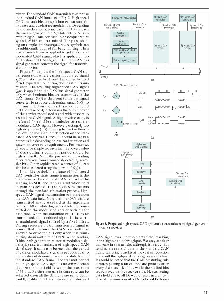
IEEE Communications Magazine • June 2016 131
mitter. The standard CAN transmit bits comprise the standard CAN frame as in Fig. 2. High-speed CAN transmit bits are split into two streams for in-phase and quadrature modulation. Depending on the modulation scheme used, the bits in each stream are grouped into N/2 bits, where N is an even integer. Thus, for each in-phase/quadrature symbol, N bits are transmitted. The pulse shap-ing on complex in-phase/quadrature symbols can be additionally applied for band limiting. Then carrier modulation is applied to get the carrier modulated CAN signal, which is applied on top of the standard CAN signal. Then the CAN bus signal generator converts the signal for transmis-sion on the bus.
Figure 3b depicts the high-speed CAN sig-nal generator, where carrier modulated signal Sp(t) is first scaled by Ap and then shifted by fixed offset, typically 1 V, during dominant bit trans-mission. The resulting high-speed CAN signal Qs(t) is applied to the CAN bus signal generator only when dominant bits are transmitted in the CAN frame. Qs(t) is then sent to the bus signal converter to produce differential signal Qd(t) to be transmitted on the bus. It should be noted that the value of Ap determines the output power of the carrier modulated signal with respect to a standard CAN signal. A higher value of Ap is preferred for reliable transmission of a carrier modulated CAN signal. However, setting Ap too high may cause Qs(t) to swing below the thresh-old level of dominant bit detection on the stan-dard CAN receiver. Hence, Ap should be set to a proper value depending on bus configuration and system bit error rate requirements. For instance, Ap could be simply set such that the lowest value of Qs(t) during a dominant period should be higher than 0.5 V for the purpose of preventing other receivers from erroneously detecting reces-sive bits. Other sophisticated schemes of Ap can also be considered using the power of Qs(t).
In an idle period, the proposed high-speed CAN controller starts frame transmission in the same way as the standard CAN controller by sending an SOF and then an arbitration field to gain bus access. If the node wins the bus through the standard arbitration process, high-speed CAN signal transmission can start from the CAN data field. Note that the CAN bits are transmitted as the standard at the maximum rate of 1 Mb/s, while high-speed bits are trans-mitted on the modulated carrier with higher data rate. When the dominant bit, D, is to be transmitted, the combined signal is the carri-er modulated signal shifted by a fixed offset. During recessive bit transmission no signal is transmitted, because the CAN transmitter is allowed to drive the bus only when it is trans-mitting dominant bits of CAN. When sending R bits, both generation of carrier modulated sig-nal Sp(t) and transmission of high-speed CAN signal stop. It can easily be seen that the period of carrier modulated signal is proportional to the number of dominant bits in the data field of the standard CAN frame. The transmit period of a high-speed CAN signal is maximized when the size the data field is set to the maximum of 64 bits. Further increase in data rate can be achieved when all the data bits are set to domi-nant 0, enabling the transmission of a high-speed
CAN signal over the whole data field, resulting in the highest data throughput. We only consider this case in this article, although it is true that sending meaningful data in the standard CAN frame can bring benefits at the cost of reduction in overall throughput depending on application. It should be noted that the CAN bit stuffing rule dictates putting a bit of opposite polarity after every 5 consecutive bits, while the stuffed bits are removed on the receiver side. Hence, setting data field bits to all Ds would result in a bit pat-tern of transmission of 5 Ds followed by trans-
Figure 3. Proposed high-speed CAN system: a) transmitter; b) signal genera-tion; c) receiver.
High-speed CAN signalgenerator
CAN bus signal generator
CAN_H
CAN_L
High-speedCAN controller
1 V
D D DR R RCAN bits
Sp(t)
Qs(t)
Qd(t) 2.5 V3.5 V
Ap
Sp(t)
Qs(t)
Ap
(a)
(b)
(c)
High-speed CANcontroller
High-speed CANreceive bits
High-speed CANtransmit bits
High-speed CANreceiver
Standard CANcontroller
Standard CANreceive bits
Standard CANtransmit bits
Standard CANreceiver
Symbolgeneration
Carriermodulation
High-speed CAN controller
1 V
Closes for D bit
Standard CAN bits
1.5 V
Slicer
Equalizer
Downconverter
Bandpass
Standard CANbit detector
Standard CANreceive bits
Signalconverter
High-speedCAN receive
bits

IEEE Communications Magazine • June 2016132
mission of one R, which repeats itself during the data field transmission, that is, repetition of the pattern (D-D-D-D-D-R).
IntroductIon of A multI-level modulAtIon scheme In contrast to the binary signaling of the CAN system, the use of multi-level modulation is con-sidered to increase the throughput. High-speed CAN transmit bits are used to form a complex symbol to be modulated and transmitted on the bus. The complex symbol can be constructed using any modulation scheme, including quadra-ture phase shift keying (QPSK), 16-quadrature amplitude modulation (QAM,) 64-QAM, and so on. Higher order modulation is preferred to get higher data rate. However, the choice of mod-ulation scheme is related to the signal-to-noise ratio, frequency attenuation characteristics of the channel, and receiver complexity.
receIver Figure 3c shows the proposed receiver. The differential signal received from the bus is con-verted to a single-ended signal using a differen-tial-to-single conversion device, which is applied to the standard CAN bit detector and band-pass filter, respectively, for high-speed signal demodu-lation. The standard CAN detector monitors the bus and detects the start of recessive-to-domi-nant bit transition during a data field and enables the high-speed CAN demodulator operation to run for a period of 5 D bits. The bandpass fil-ter in the high-speed CAN receiver removes the interference from the standard CAN signal as well as out-of-band noise, providing input to the demodulator and equalizer of the proposed scheme. The down converter removes the carrier to generate a baseband signal providing in-phase and quadrature components. The output of the demodulator is applied to the equalizer for channel compensation. A slicer performs hard decision of equalizer output and generates high-speed CAN received bits.
sImulAtIon results Computer simulation is used to verify the perfor-mance of the proposed scheme. The simulator models the transmitter and receiver of the pro-posed scheme, and the output of the transmitter passes through a channel model of the CAN bus before being processed in the receiver.
For ease of explanation, we start with a description of the channel. A CAN bus of 100 m length made of CAT-3 cables is considered, and the transmitter and receiver are placed on each end of the bus with termination. Most of the CAN buses in commercial vehicles are short-er than this, so the length can be considered as the longest case in commercial vehicles. For sim-plicity, this channel without intermediate nodes is called channel A. In reality, along the bus line, there are many CAN nodes accessing the bus through short feed lines. Starting with the first node 10 m away from the transmitter, a total of 9 CAN nodes are placed 10 m apart, with input impedance of 20 k-ohm. For the length of feed lines, we consider the cases of 0.3 m (channel B) and 0.15 m (channel C) to see their effects on the performance. To obtain the transfer function from transmitter to receiver, we use an ABCD parameter model of transmission lines [15]. The ABCD parameter of each node is found, and the total ABCD parameter from transmitter to receiver is obtained by multiplication of all the ABCD matrices. The transfer function in terms of input voltage to output voltage is obtained and plotted in Fig. 4. Channel A shows monotonically increasing attenuation as frequency increases due to the resistance of the copper lines. Following the overall attenuation trends, channels B and C show additional drops in frequency response due to the reflections from intermediate tap lines. It can be seen that longer tap lines in channel B cause larger drops in the frequency response, rendering equalization in the receiver more chal-lenging. Since there is more attenuation in the high frequency region, it is beneficial to place a high-speed CAN signal in the lower frequency region when high-speed CAN symbol rates are the same. However, placing the signal closer to DC can cause more interference from the stan-dard CAN signal. Hence, trade-offs should be made based on the bus characteristics, carrier frequency, and symbol rate of the high-speed CAN signal. In addition to the distortion from the bus, additive white Gaussian noise (AWGN) is generated and added to channel output.
On the transmitter side, a standard CAN frame with data field bits set to all Ds is gener-ated, and random bit generators are used to gen-erate bits to be carried in a carrier modulated signal. QPSK, 16-QAM, and 64-QAM with nor-malized rectangular constellations and Gray bit encoding are considered for modulation schemes, and a square root raised cosine filter with roll-off factor of 0.1 is used for the pulse shaping filter. Considering the frequency response of channels in Fig. 4, carrier frequency and symbol rate of high-speed CAN signal Sp(t) are set to 24 MHz and 36 MHz, respectively. The modulated signal is scaled by setting Ap = 0.3 and then shifted by 1 V as in Fig. 3b before being applied to the chan-nel input.
Figure 4. Frequency response of a CAN bus.
Frequency (MHz)100
-50
-60
Out
put/i
nput
(dB)
-40
-30
-20
-10
0
20 30 40 50 60 70 80 90 100
ABC

IEEE Communications Magazine • June 2016 133
On the receiver side, the channel output is applied to the band-pass filter to remove the CAN signal as well as wide-band noise. A linear band-pass filter is designed to have 3 dB band-width of 40 MHz centered at carrier frequen-cy with 64 taps. The output is down-converted to baseband, sampled at the symbol rate of the high-speed CAN signal, filtered with the same square root raised cosine filter as the transmit-ter, and applied to the adaptive equalizer. It is assumed that the timing and carrier synchroni-zation are established for simplicity. An a adap-tive decision feedback equalizer is employed to compensate the distortion from the channel. The feed-forward filter and feedback filter employ 24 taps and 8 taps, respectively. For equalizer training, QPSK training symbols generated from random bits are sent for the period of the first 15 D bits out of 64 bits in the data field for each CAN frame. The conventional least mean square (LMS) training method is employed to train equalizer tap coefficients with center tap initial-ized [14]. Once training is completed, demodu-lation starts for corresponding data modulation, and the equalizer performs fine adjustment of the equalizer coefficients using slicer output as reference data until the end of the data field. The process repeats itself for each CAN frame.
The bit error rate (BER) performance of the proposed scheme for QPSK, 16-QAM, and 64-QAM are evaluated by varying the signal-to-noise ratio (SNR) of the high-speed CAN signal for channels A, B, and C. SNR is defined to the power of the carrier modulated high-speed CAN signal to the noise power within the bandwidth occupied by the modulated signal. For compar-ison, a channel with no distortion, denoted by channel R, is considered as a reference. The results are shown in Fig. 5 along with ideal BER performance of each modulation scheme after 100,000 CAN frames are transmitted. Compared to ideal performance, the proposed receiver in the case of channel R shows SNR loss of about 0.9 dB, 1.5 dB, and 1.8 dB for QPSK, 16-QAM, and 64-QAM, respectively, at BER = 10–5. The loss results from non-ideal adaptive equalizer operation and interference from an existing CAN signal. It can be seen that the proposed scheme operates well with reasonable loss in the presence of standard CAN signal interference. Results for channel A show that the loss of the copper lines incurs loss of 3.1 dB, 4.0 dB, and 4.9 dB for QPSK, 16-QAM, and 64-QAM, respectively, at BER = 10–5. It can also be seen that intermedi-ate taps in channels B and C bring about addi-tional loss compared to channel A. This is due to the fact that higher modulation requires higher SNR, and the equalizer cannot fully compen-sate the larger frequency distortion in channels B and C. The imperfect compensation of distortion results in residual inter-symbol interference (ISI) that degrades SNR at symbol detection. Com-paring the results for channels B and C shows higher SNR is required for the case of longer tap lines to achieve the same BER performance. For channel B, the use of QPSK, 16-QAM, and 64-QAM gives loss of about 4.6 dB, 5.9 dB, and 8.0 dB at BER = 10–5 compared to ideal perfor-mance, while channel C with shorter feed lines shows smaller loss. In a real implementation, the
loss can become larger due to impairments such as phase noises of oscillators degrading synchro-nization performance. To reduce the overall loss, the use of more sophisticated equalizer training needs to be considered to set equalizer coeffi-cients more accurately based on the relatively short period of training symbols. In addition, the use of channel coding such as trellis coded mod-ulation can be considered to lower the required SNR.
The net data rate of a CAN system is lower than the gross data rate during the data field due to overhead bits in CAN frames such as arbi-tration field, control field, stuffed recessive bits in the data field, and CRC field. In the CAN standard, the maximum data field is limited to 64 bits, and CAN-FD allows for extension of the data field up to 512 bits. Since the proposed scheme uses the interval of a data field for higher data transmission, net throughput increases as the length of the data field increases. To see the effect of data field length and SNR on the net data rate, throughput from transmitter to receiv-er in the case of channel B is measured by send-ing 100,000 CAN frames based on the following assumptions. The transmitter and receiver exclu-sively make use of the CAN bus, and there is no gap between consecutive frames. Any bit error of the high-speed CAN signal during the data field results in the loss of the entire frame. The receiv-er counts the number of successfully received bits in received frames and calculates net throughput in terms of bits per second.
Figure 6 shows the net throughput according to the length of the data field and SNR condi-tions for each modulation scheme. For the pro-posed scheme, data field lengths of 64 bits and 512 bits are considered. The net throughput of the CAN with a 64-bit data field and CAN-FD with a 512-bit data field is also evaluated for comparison. CAN and CAN-FD show constant throughput of 0.4 and 12.0 Mb/s, respectively, because their robust binary signaling scheme
Figure 5. Bit error rate performance of the proposed scheme.
SNR (dB)105
1.0E-06
1.0E-07
Bit e
rror r
ate
1.0E-05
1.0E-04
1.0E-03
1.0E-02
1.0E-01
15 20 25 30 35 40
QPSK(R)16-QAM (R)64-QAM (R)QPSK(Ideal)
QPSK(A)16-QAM (A)64-QAM (A)16-QAM (Ideal)
QPSK(B)16-QAM (B)64-QAM (B)64-QAM (Ideal)
QPSK(C)16-QAM (C)64-QAM (C)

IEEE Communications Magazine • June 2016134
generates no error frames over the range of SNR under consideration. For QPSK, the pro-posed scheme with data fields of 64 bits and 512 bits shows higher throughput than CAN-FD when SNR is higher than 15.2 dB and 16.3 dB, respectively. Let us define the SNR that gives the same throughput as CAN-FD as cut-off SNR for each modulation scheme for data field length of 512 bits. It can be said that the use of the proposed scheme provides through-put enhancement compared to CAN-FD when the receiver operates above the cut-off SNR for each modulation scheme. We note that 16-QAM and 64-QAM show cut-off SNR of about 24.0 dB and 31.9 dB, respectively. Hence, for example, the use of 16-QAM is recommended when SNR is in the range of 24 to 31.9 dB. It can be seen that the use of a longer data field requires higher SNR to provide the same throughput because a longer frame is more prone to errors than a short-er frame. However, a longer frame can provide higher peak throughput in high SNR conditions. In the current simulation, QPSK with 64 bits and 512 bits provide the maximum throughput of 28.5 and 54.1 Mb/s, respectively, without any bit errors. To provide even higher throughput, 16-QAM and 64-QAM can be employed in higher SNR con-dition. Note that the maximum net throughput of 107.8 Mb/s and 161.8 Mb/s is achieved for 16-QAM and 64-QAM, respectively, for data field length of 512 bits. If the proposed scheme is to be employed in an existing CAN bus system support-ing only 64 bits, the maximum throughput of 56.9 Mb/s and 85.3 Mb/s can be achieved for 16-QAM and 64-QAM, respectively. For each CAN bus in a particular vehicle, the net throughput can be evaluated based on channel characteristics and
SNR in order to provide a guideline on the selec-tion of modulation schemes and data field length.
further works While the proposed scheme used simple LMS training with long training sequence, a more effi-cient equalizer initialization scheme can be used to reduce the length of training bits in the data field to achieve higher throughput, especially for a short CAN frame. Although the frequency and timing of the transmitter and receiver were assumed to be synchronized perfectly for simplici-ty, the introduction of an appropriate synchroniza-tion scheme is required for real implementation. The use of an additional coding scheme can be considered to obtain coding gain and protection against other artifacts such as impulsive noises.
conclusIons A new scheme for improving the data rate of a CAN system has been proposed by introduc-ing carrier modulation on top of the existing CAN signal. The performance of the scheme in the CAN bus environment has been evaluated in terms of BER and net throughput to show that the proposed scheme can provide higher data rate while keeping backward compatibil-ity with the CAN standard. With the use of a longer frame supported by CAN-FD, the net throughput can be increased to 161.8 Mb/s. The proposed scheme can easily be applied to the existing CAN network without additional deploy-ment of cabling to support the need for high data rate links between devices, resulting in significant reduction of the cost and weight of the vehicle. With the proposed scheme, the CAN standard will be able to expand its application to versa-tile in-vehicle devices requiring higher data rate beyond its wide adoption to control devices.
Acknowledgments This work was partly supported by the Institute for Information & Communications Technology Promotion (IITP) grant funded by the Korean government (MSIP) (No. B0101-15-0557, Resil-ient Cyber-Physical Systems Research) and the Basic Science Research Program through the National Research Foundation of Korea (NRF) funded by the Ministry of Science, ICT & Future Planning (NRF-2015R1A2A2A01008218).
references [1] S. C. Talbot and S. Ren, “Comparison of FieldBus Systems CAN, TTCAN,
FlexRay and LIN in Passenger Vehicles,” Proc. 29th IEEE Int’l. Conf. Dis-tributed Computing Systems Wsps., 2009, pp. 26–31.
[2] R. Bosch GmbH, “Controller Area Network (CAN) Specification,” v. 2.0., 1991.
[3] R. Bosch GmbH, “CAN with Flexible Data-Rate,” v. 1.0, 2012. [4] K. Tindell and A. Burns, “Guaranteed Message Latencies for Distributed
Safety Critical Hard Real-Time Networks,” Dept. Comp. Sci., Univ. of York, tech. rep. YCS 229, 1994.
[5] A. Davare, Q. Zhu, and M. D. Natale, “Period Optimization for Hard Real-Time Distributed Automotive Systems,” Proc. 44th IEEE/ACM Design Automation Conf., 2007, pp. 278–83.
[6] K. Matheus and T. Königseder, Automotive Ethernet, Cambridge Univ. Press, 2014.
[7] K. Matheus, “OPEN Alliance — Stepping Stone to Standardized Automotive Ethernet,” Proc. 2nd Ethernet&IP@Automotive Technology Day, Regens-burg, Germany, 2012.
[8] IEEE 802.3br “Interspersing Express Traffic (IET), 802.3,” Nov. 2013. [9] IEEE 802.3, “Reduced Twisted Pair Gigabit Ethernet Call for Interest,” Mar.
2012. [10] MOST Corp., “MOST150 Inauguration in Audi A3,” MOST Informative,
no. 8, Oct. 2012, pp. 2.
Figure 6. Net throughput of the proposed scheme.
SNR (dB)1510
1
0.1
Net t
hrou
ghpu
t (M
b/s) 10
100
20 25 30 35 40
0.40
12.0
QPSK, 64 bits16-QAM, 512 bitsCAN, 64 bits
QPSK, 512 bits64-QAM, 64 bitsCAN-FD, 512 bits
16-QAM, 64 bits64-QAM, 512 bits
161.8
85.3107.8
56.954.1
28.5

IEEE Communications Magazine • June 2016 135
[11] ISO 898-4, “Controller Area Network (CAN) — Part 4: Time-Triggered Communication,” 2004.
[12] G. Cena and A. Valenzano, “Overclocking of Controller Area Networks,” Electronics Letters, vol. 35, no. 22, Oct. 1999, pp. 1923–25.
[13] T. Ziermann, S. Wildermann, and J. Teich, “CAN+: A New Backward-Com-patible Controller Area Network (CAN) Protocol with Up to 16x Higher Data Rates,” Proc. Conf. Design, Automation and Test in Europe, 2009, pp. 1088–93.
[14] D. Jang et al., “Communication Channel Modeling of Controller Area Network (CAN),” Proc. Int’l. Conf. Ubiquitous and Future Networks, Aug. 2015, pp. 86–88.
[15] Bernard Sklar, Digital Communications: Fundamentals and Applications, 2nd ed., Prentice Hall, 2001.
bIogrAphIes
Suwon Kang received his B.S., M.S., and Ph.D. degrees in electrical engi-neering from Seoul National University (SNU), Seoul, Korea, in 1993, 1995, and 2001, respectively. Since 2001, he has been with GCT Semiconductor Inc., California, where he is currently vice president of advanced technology. His research interests are wireless and wire-line communication systems and signal processing.
Sungmin Han received his B.S. degree in electronics engineering from Korea University of Technology and Education, Cheonan, in 2012. Currently, he is working toward his Ph.D. degree in the Department of Information and Communication Engineering (ICE), Daegu Gyeongbuk Institute of Science and Technology (DGIST), Korea. His research areas are communication theory and communication networks.
SeungiK CHo received his B.S. degree in information and communication engineering from Chungbuk National University (CBNU), Cheongju, Korea, in 2014. Since 2014, he has been studying in the Department of ICE, DGIST, as a Master’s student. His research area is advanced communications and RF energy harvesting.
DongHyuK Jang received his B.S. degree in electronics engineering from Kyungpook National University (KNU), Daegu, Korea, in 2013 and his M.S. degree in ICE from DGIST, Korea, in 2015. He is currently a researcher with the Agency for Defense Development (ADD), Korea. His research interests are channel modeling and analysis of communication systems..
HyuK CHoi received his B.S., M.S., and Ph.D. degrees in electrical engineering from SNU in 1994, 1996, and 2002, respectively. In 2003, he joined the faculty at the University of Seoul, where he is currently a professor in the School of Computer Science. His research interests are in information security and signal processing.
Ji-woong CHoi [SM’09] ([email protected]) received B.S., M.S., and Ph.D. degrees in electrical engineering from SNU in 1998, 2000, and 2004, respec-tively. From 2005 to 2007, he was at Stanford University, California, as a postdoctoral researcher. From 2007 to 2010, he worked for Marvell Semicon-ductor, United States, as a staff systems engineer for WiMAX and LTE system design. In 2010, he joined DGIST, where he is currently an associate pro-fessor. His research areas are communication theory and signal processing.

IEEE Communications Magazine • June 2016136
SerieS editorial
The quality of a mobile channel is severely affected by obstructions such as tall buildings, mountains, and foliage, which in turn limit the performance
of wireless communication systems. A transmitted signal propagates toward a receiver generally following standard electromagnetic reflection, diffraction, and scattering mech-anisms, which attenuate the strength of the signal, such attenuation being commonly known as propagation loss. There are a number of propagation models with which many of you may be familiar, such as COST 231, Long-ley-Rice, Okumura, and Hata, to name a few; these have been developed to predict path loss for variable separation distances on the order of hundreds to thousands of meters between transmitters and receivers, and are known as large-scale propagation models. Such models are extensively used in estimating the coverage areas of cellular base stations. Besides the large-scale propagation models, there is a family of small-scale models (also known as fading models) that characterize the signal strength variations for much smaller separation distances, on the order of a few wavelengths to a few tens of meters between transmitters and receivers.
Today’s third generation (3G) and 4G cellular and Wi-Fi (IEEE 802.11) carrier frequencies mostly lie between 600–5000 MHz. However, 5G communications systems are envisioned to use 38–60 GHz frequencies, which have wave-lengths on the order of millimeters, and are hence denoted as millimeter-wave (mmWave) frequencies. At mmWave frequencies, most objects in the physical environment appear very large relative to the wavelength, thus causing pronounced shadowing losses to the transmitted signal in addition to varying degrees of loss due to reflections, refrac-tions, and diffraction. Because of the smaller wavelengths at mmWave frequencies, the signal is also much more subject to atmospheric attenuation due to rain, snow and hail, oxy-gen absorption, path depolarization, and other impairments.
A great deal of work is being done today to define what 5G ought be and to identify which technological break-throughs are fundamental to its successful realization. Driv-ing this revolution are many recently emerged data-hungry applications, such as live streaming video over cellular net-
works, intra- and inter-vehicular communications, and the IoT (Internet of Things), that require larger bandwidth than what is currently available today. Efforts to shape the 5G landscape are already at work in wireless personal area networks (WPANs, IEEE802.15.3) and wireless local area networks (WLANs, IEEE802.11ad, ah, ax) technology development and standards areas. Due to the widely held view that 5G communications must utilize mmWave fre-quencies to support the targeted applications, propagation modeling for mmWave communication for large and small separation distances between transmitters and receivers is a very active area of research at the present time in both academia and industry around the globe.
Our first article in this issue of the Radio Communica-tions Series is “Dual Connectivity for LTE Small Cell Evo-lution: Functionality and Performance Aspects.” This article presents the benefits of a user being connected to two base stations at the same time — a macrocell and a small cell — but on two different carriers. In this article, the authors include simulation results showing 50 percent increase in per user throughput and 50 percent reduction in handover failure ratio for mobile users as a result of dual connectivity.
We have also included a second article in this issue, “Radio Propagation Models for 5G Mobile and Wireless Communications,” which identifies requirements for 5G radio propagation models depending on use cases and technology trends. This article surveys recent propaga-tion models proposed for mmWave communications, and identifies their strengths and weaknesses. It then presents a map-based propagation model that not only meets the requirements, but also offers extensions to existing stochas-tic models.
We thank our authors for submitting their cutting edge research contributions to the Radio Communications Series, our reviewers for providing objective and timely reviews to help us select the two articles that are part of this issue, and the readership for their time and attention. In future issues of the Series, we look forward to bringing you similar timely articles from our community of authors covering emerging trends in wireless communications R&D.
Radio CommuniCations: Components, systems, and netwoRks
Amitabh Mishra Tom Alexander

IEEE Communications Magazine • June 2016 1370163-6804/16/$25.00 © 2016 IEEE
AbstrAct
DC is one of the most important features introduced in Release 12 of the 3GPP specifi-cations. DC aims at increasing the per-user throughput by improving the utilization of radio resources across two base stations connected via non-ideal backhaul (X2) and operating on dif-ferent carrier frequencies. By making it possible to maintain the connection to the primary cell located in the macro base station while access-ing the extra capacity provided by the small cell layer, DC can also improve the mobility perfor-mance in small cell deployments. This article gives an overview of the DC feature as standard-ized in Release 12. We summarize the support-ed scenarios and the DC functionality, and also demonstrate by means of detailed system-lev-el simulations how DC can improve end-user throughput and mobility performance.
IntroductIonTo meet the capacity requirements caused by the continuous increase of mobile broadband traffic, network operators have three main possibilities: bring more spectrum into use, enhance spectral efficiency, and increase cell densification. But with the limited availability of new spectrum and the spectral efficiency of radio access tech-nologies now approaching Shannon’s limit [1], increased cell densification through the introduc-tion of small cells is the most promising enabler for increasing the capacity of radio networks. The cost performance ratio of small cells is known to be minimized by having them tightly integrat-ed with the macro layer. Integration of macro and small cells comes in many forms depend-ing on the radio frequency deployment, the type of small cells, and the corresponding inter-node connectivity architecture. Examples of macro and small cell integration options are outlined in [2], corresponding small cell enhancements are dis-cussed in [3], while related multi-cell coopera-tion techniques are reported in [4]. In general, the tightest integration of small cells is achieved with remote radio heads (RRHs), which utilize joint centralized baseband processing for macro and small cells, assuming high-speed fiber-based fronthaul connections between the nodes. An
example of the latter is so-called inter-site car-rier aggregation (CA) [4], where a user can be simultaneously connected to a macrocell and a small cell RRH, assuming that those cells use non-overlapping carriers. This form of CA offers promising gains in terms of improved end-us-er throughput and mobility robustness [4]. The cost of inter-site CA is the need for high-speed, low-latency, fiber-based connections between the RRHs and their corresponding macro site host.
For Third Generation Partnership Project (3GPP) Long Term Evolution (LTE), the macro and small cell integration options are further extended in Release 12 with the introduction of dual connectivity (DC). DC allows users to be simultaneously served by a macro and a small cell operating at different carriers, while the corresponding serving evolved Node-Bs (eNBs) are interconnected with traditional X2-based backhaul connections. These types of backhaul connections are cheaper but characterized by lower capacity and higher latency compared to the high-speed fiber-based fronthaul connections assumed with inter-site CA. Therefore, X2-based backhauls are also referred to as non-ideal back-hauls in the remaining of this article. In sum-mary, DC aims to bring some of the benefits of inter-site CA to small cell deployments without fiber-based connection between macro and small cell base stations. The main drawback is repre-sented by the potential impacts on the transport and eNB processing requirements, as we further detail later. The Release 12 DC solution builds on the basics of the CA functionality introduced in Release 10 of the 3GPP specifications [5], as well as on the findings from two earlier LTE Release 12 study items as reported in [6, 7]. The Release 12 DC solution is backward compatible in the sense that a macro and a small cell base station can simultaneously serve Release 12 ter-minals configured with DC and pre-Release 12 terminals individually without DC.
This article offers a detailed description of the standardized DC feature and related research challenges, focusing on both the over-all functionality and performance aspects. This includes describing the deployment scenarios for DC, the functionality and details of the user (U-) and control (C-) plane protocol architectures,
Dual Connectivity for LTE Small Cell Evolution:
Functionality and Performance AspectsClaudio Rosa, Klaus Pedersen, Hua Wang, Per-Henrik Michaelsen, Simone Barbera, Esa Malkamäki, Tero Henttonen, and Benoist Sébire
rAdIo communIcAtIons
The authors present an overview of the DC
feature as standardized in Release 12. They
summarize the supported scenarios and the DC functionality, and also
demonstrate by means of detailed system-level
simulations how DC can improve
end-user throughput and mobility
performance.
Claudio Rosa, Klaus Pedersen, Per-Henrik Michaelsen, Esa Malkamäki, Tero Henttonen, and Benoist Sébire are with Nokia-Bell Labs; Hua Wang is with Keysight Technologies; Simone Barbera is with Telenor A/S.

IEEE Communications Magazine • June 2016138
as well as the rationales leading to the various design choices. Mobility and cell management procedures with DC are outlined as well. A set of system-level performance results is presented to demonstrate the benefits of DC. Throughout the article, guidance on how to best use and operate the many options that come with the introduction of DC are presented. Finally, concluding remarks and an outlook toward future research and DC enhancements in upcoming 3GPP releases are presented.
deployment scenArIoA deployment scenario for DC is depicted in Fig. 1. It corresponds to a dedicated carrier small cell deployment where different carrier frequencies are used by the macro (F1) and small cells (F2), the macro and small cells being interconnect-ed via non-ideal X2 backhauls. Although this is the typical deployment scenario for DC, the use of DC is not necessarily restricted between a macro and a small cell eNB, but can in principle be applied between any pair of eNBs that are interconnected via X2 and operate on at least two different carrier frequencies. DC is designed to work for backhaul latencies of up to 60 ms [8], although its applicability in scenarios with larger latencies is not precluded.
DC deployment scenarios cover both time-synchronized and time-asynchronous net-works, and cases with frequency- and time-di-vision duplex (FDD and TDD), and also allow the use of CA at each layer. Multiple carriers can be deployed at both macro and small cell layers, although the aggregated bandwidth per user equipment (UE) cannot exceed either 100 MHz or 5 component carriers as per Release 10 CA assumptions [5]. Without loss of gener-ality, in this article we focus on outdoor small cell deployments with synchronized operation
of macro and small cell base stations, assuming FDD for both macro and small cell layers, and only two component carriers configured (one in the macro layer and one in the small cell layer).
duAl connectIvIty solutIonWhen configured with DC a UE is simultane-ously connected to two eNBs: a master eNB (MeNB) and a secondary eNB (SeNB). The MeNB and SeNB are connected via an X2 inter-face. In LTE, UEs can be in either of two modes: radio resource control (RRC) connected mode and idle mode. When in RRC connected mode, the UE has a radio connection with the net-work, and can transmit and receive U-plane data. When in idle mode, the UE can only be paged and/or initiate communication with the network via a random access procedure. In any case, an idle mode UE needs to initiate a radio connec-tion with the network and switch to RRC con-nected mode before it can transmit and receive U-plane data. DC is only applicable to UEs in RRC connected mode. The U-plane and C-plane alternatives to support DC are summarized in the remaining part of this section.
user plAne
From a user plane perspective, 3GPP has stan-dardized two types of DC solutions: one with split of U-plane data in the core network (CN), and another one with split of U-plane data in the MeNB (Fig. 2). With data split in the CN, each eNB involved in DC has its own user plane connection toward the serving gateway (S-GW). Thus, the MeNB and SeNB serve separate radio bearers. In other words, when a radio bearer is configured to carry data from one or several applications, the corresponding data can only be transmitted from and toward one of the eNBs involved in the DC configuration (unless a radio bearer reconfiguration is performed). Quite dif-ferently, with data split in the MeNB, only the MeNB has a user plane connection toward the S-GW, and data from one radio bearer can be transmitted via both the MeNB and SeNB.
Advantages and Drawbacks of DC Solutions: The main advantage of splitting U-plane data in the MeNB is the higher flexibility in simul-taneously using the spectrum available in the macro and small cell layers. However, this typ-ically comes at the cost of increased transport and processing capacity in the MeNB since all data transmitted toward the UE always has to traverse the MeNB. Moreover, due to X2 latency, such option requires distributed radio resource management (RRM), as well as flow control of U-plane data between the MeNBs and the SeNBs. Some of these challenges are better exemplified in the remainder of this sec-tion, while the performance impacts of distrib-uted RRM and X2 latency are illustrated below. In contrast, splitting user plane data in the CN can achieve some of the offloading gains, but cannot fully exploit the peak data rate and fast inter-layer load balancing gains offered by DC with U-plane data split in the MeNB. This is due to the limit imposed by the one-to-one mapping between radio bearers and eNBs involved in the DC configuration.
The two DC solutions are in practice realized
Figure 1. Main deployment scenario of interest for small cell enhancements in general (and DC in particular).
Macro layer (F1)
Small cell layer (F2)
Non-ideal backhaul (X2)
Figure 2. Dual connectivity architecture and U-plane options.
Radiobearer #2
Radiobearer #1
S-GW
eNB
UE
Single connectivity (legacy) Dual connectivity withU-plane split in CN
Dual connectivity withU-plane split in MeNB
Radiobearer #2Radio
bearer #1
S-GW
MeNB SeNB
UE
Radiobearer #2
Radiobearer #1
S-GW
MeNB SeNB
UE

IEEE Communications Magazine • June 2016 139
by the standardization of three different types of radio bearers: radio bearers that are served by the MeNB alone, called master cell group (MCG) bearers; radio bearers that are served by the SeNB alone, called secondary cell group (SCG) bearers; and radio bearers that are served by both the MeNB and SeNB, called split bear-ers. Since the two DC solutions require different transport and processing capabilities, the Rel-12 specifications do not support simultaneous configuration of SCG and split bearers for the same UE. Figure 3 illustrates the user plane protocol stack at the MeNB, SeNB and at the UE in case the UE is configured with one MCG and one SCG bearer (Fig. 3a), or one MCG and one split bearer (Figs. 3b and 3c). The solid and dashed arrows illustrate the flow of U-plane data in downlink and uplink, respectively. It can be observed from the two rightmost configurations of Fig. 3 that Release 12 specifications do not support splitting U-plane data in the uplink, in which case only routing is supported; that is, for a split bearer the UE is configured in terms of whether it should transmit U-plane data in uplink toward the MeNB (Fig. 3b) or toward the SeNB (Fig. 3c).
Apart from that, the DC solutions are designed to maintain as much as possible the general structure of the LTE link layer design [9]. The packet data convergence protocol (PDCP) is mainly responsible for ciphering (security) and header compression. The main functions provided by the radio link control (RLC) layer are segmentation, concatenation, and in-order delivery of packet data units to higher layers. The medium access control (MAC) is essential-ly responsible for scheduling, multiplexing, and retransmission of packet data, while the physical layer (PHY) is primarily accountable for trans-mitting the packet data over the air interface.
Upper Layer 2 Protocol Stack: With the split bearer option of DC (Figs. 3b and 3c), the PDCP functionality in the UE needs to be updated to be able to perform reordering of packet data units delivered via two independent RLC enti-ties. This is done using a reordering window con-trolled by a reordering timer running at the UE. The reordering function of PDCP is designed to work within the backhaul latency requirements specified in [8].
Lower Layer 2 Protocol Stack: Two separate MAC entities (one per eNB) are introduced for UEs configured with DC: one handling the scheduling of transmissions in the MGC and one handling the scheduling of transmissions in the SGC. In LTE, discontinuous reception (DRX) allows the UE to decrease its power consumption in connected mode. DRX operation is tightly coupled to scheduling decisions, and with two MAC entities corresponding to two schedulers separately located in the MeNB and SeNB, a common DRX is not possible. Although some coordination between the eNBs for DRX config-uration is seen as beneficial from the UE power consumption perspective, how to achieve the coordination is not specified but rather left for network implementation.
Buffer Status Reporting and Power Head-room Reporting: Buffer status reporting and power headroom reporting were introduced in
LTE Release 8 with the scope to assist and con-trol scheduling of uplink data transmissions in the eNB. With dual connectivity, power headroom reports transmitted toward one eNB include power headroom information on all the activated cells in the UE, that is, the activated cells served by the other eNB involved in the DC configura-tion as well. For non-split bearers, buffer status reports of MCG bearers are transmitted toward the MeNB, while buffer status reports of SCG bearers are transmitted toward the SeNB. For split bearers, the data in the PDCP buffer is only considered for buffer status reporting toward the eNB configured for U-plane data transmission in the UL.
In order to clarify the UE behavior, let us consider a UE configured with DC and having one cell configured in the MeNB and one cell configured in the SeNB. Moreover, the UE is configured with one MCG and one split bear-er. When reporting power headroom informa-tion, the UE considers the allocated transmission power on each cell and compares it to the maxi-mum allowed transmission power. The difference between the maximum and the allocated power is the power headroom. The UE reports the power headroom measured on all activated cells to both the MeNB and SeNB. The UE also reports the amount of data belonging to the MCG bearer to the MeNB, while the amount of data belonging to the split bearer is reported to either the SeNB or the MeNB, depending on toward which node the UE is configured to transmit UL user plane data.
Random Access: In order to maintain the PHY connection to both eNBs involved in DC, independent (and parallel) random access pro-cedures are supported in the MeNB and SeNB. For example, a UE that has lost synchroniza-tion to the SeNB (e.g., due to expiration of the advanced timer) can initiate a random access
Figure 3. Dual connectivity DL/UL U-plane protocol stacks at eNB and UE with a few example configurations: a) MCG bearer + SCG bearer + split bearer, with UL configured in either b) MCG or c) SCG.
PDCP
MCGbearer
(c)
RLC
RLC
PDCP
RLC
PDCP
PDCP
Splitbearer
RLC RLC
DL U-plane data UL U-plane data
MAC
PHY
MAC
RLC
MAC
PHY
MAC
PHYCC#1
CC#1 CC#2
PHYCC#2
MAC
RLC
PDCP
PHYCC#2
MAC
RLC
PDCP
PHYCC#1
RLC
MAC
PHY
PDCP
RLC
MAC
PHY
PDCP
MeNB
UE
SeNB
PDCP
MCGbearer
(b)
RLC
RLC
PDCP
RLC
PDCP
PDCP
Splitbearer
MCGbearer
(a)
SCGbearer
RLC RLC
MAC
PHY
MAC
RLC
MAC
PHY
MAC
PHYCC#1
CC#1 CC#2CC#1 CC#2
PHYCC#2
MeNBMeNB
UEUE
SeNBSeNB

IEEE Communications Magazine • June 2016140
procedure toward the SeNB without affecting data transmission and reception with the MeNB.
Uplink Power Control: With simultaneous UL transmissions toward multiple eNBs in DC, UL power control becomes more challenging. The possibility of semi-statically confi guring separate maximum transmission powers for UL transmis-sion toward the MeNB and SeNB is therefore introduced. In this way, a minimum amount of power can be guaranteed for UL transmissions toward one eNB even if (due to uncoordinated scheduling) the other eNB is already trying to fully utilize the maximum UE power capabilities. The power control mechanism for DC still allows using the full transmission power for UL trans-mission toward one eNB if there are no simulta-neous UL transmissions toward the other eNB.
X2 Enhancements: DC also imposes enhance-ments for the X2 specifi cations [10]. First, each PDCP transmitting entity in DL needs to get from lower layers regular indication of successful delivery of PDCP packets. In LTE this service is provided by the RLC layer. However, in the case of split bearers, the RLC entity responsible for reliable data transmission via the SeNB and the PDCP entity are located in separate eNBs (Figs. 3b and 3c). Therefore, with a split bearer the SeNB regularly provides the MeNB (over X2) with information on the last in-sequence success-fully delivered PDCP packet among the ones it has received from the MeNB. Also, the MeNB needs to decide which data is to be transmitted via its own cells, and which data is to be forward-ed to the SeNB over X2. Since the MeNB does not necessarily know the conditions (channel, interference, load, etc.) in the SeNB, X2 flow control is necessary in order to avoid data over-fl ow and underfl ow in the SeNB. Therefore, the X2 specifications are enhanced, enabling the SeNB to send radio bearer level information on its available buffer size to the MeNB. This standardized signaling can be used to implement request-based flow control mechanisms such as the one presented in [11], which for X2 latencies up to 20 ms is shown to provide acceptable per-formance with respect to small cell deployments, which require high-speed and low-latency inter-faces with the macro eNB.
control plAne
When a UE is configured with DC, the MeNB maintains the RRC connection, and the control plane connection toward the mobility manage-ment entity (MME) is always terminated in the MeNB. This means that there is no impact of
DC on the MME and on the CN in the case of a split bearer, and only minor impact in the case of an SCG bearer due to U-plane and C-plane con-nections of the same UE terminating at different eNBs. The MeNB controls the DC confi guration: it generates and sends all the RRC messages to the UE. Transmission of RRC messages via the SeNB is not supported. However, the SeNB can request the MeNB to change or release its own part of the RRC configuration via an X2 mes-sage.
Radio link monitoring (RLM) is one import-ant procedure in LTE. It is used to monitor the radio link conditions so that appropriate actions can be taken if a radio link failure (RLF) occurs. With DC, a UE only performs RLM on two cells: one in the MeNB (the primary cell, PCell) and one in the SeNB (the primary secondary cell, PSCell). The difference between RLM in the MeNB and SeNB is that upon detection of an RLF in the SeNB, the UE does not trigger the RRC connection re-establishment procedure because the RRC connection toward the MeNB can still be maintained even if the radio link to the SeNB fails.
mobIlIty And cell mAnAgementIn line with the basic principles of LTE, net-work-controlled UE-assisted mobility and cell management also applies to DC. Since the RRC always resides in the MeNB, the MeNB also maintains the UE RRM measurement con-figuration and acts according to the received measurement reports. As in CA, the UE can be configured to perform measurements from its serving and surrounding cells. For addition-al details and background information on the RRM measurement events for mobility and sec-ondary cell (SCell) management, see [12, 13]. RRM measurements with DC are largely unaf-fected compared to CA, except for modifica-tions to RRM measurement events A3 (neighbor becomes offset better than PCell) and A5 (PCell becomes worse than threshold #1 and neighbor becomes better than threshold #2). With DC, the PSCell can also be used instead of the PCell for those events.
To exemplify the procedures involved in DC operation, Fig. 4 shows a UE confi gured with DC moving along the picture trajectory (UE path). When the UE enters the coverage area of small cell eNB #1, the SeNB addition procedure is first used to configure the UE with DC. Based on RRM measurements reported by the UE, the MeNB can then decide to initiate the SeNB
In line with the basic
principles of LTE,
net work-controlled
UE-assisted mobility and
cell management also
applies to DC. Since the
RRC always resides in
the MeNB, the MeNB
also maintains the UE
RRM measurement
con fi guration and
acts according to the
received measurement
reports.
Figure 4. UE moving in macrocell coverage area with several small cells.
MacroeNB #1 Small cell
eNB #1Small celleNB #2
UE path
Small celleNB #3
SeNBaddition
SeNBchange
SeNBrelease Handover SeNB
additionSeNB
release
F1
MacroeNB #2
F2

IEEE Communications Magazine • June 2016 141
change procedure to change the SeNB for the UE from small cell eNB #1 to small cell eNB #2, involving the release of the current SeNB and the addition of a new SeNB. If the radio link to the SeNB deteriorates due to the UE moving out of the corresponding small cell, the MeNB can finally decide to initiate the SeNB release procedure. Upon or before doing a handover the SeNB must be (temporarily) released. If the data connection with the previously confi gured SeNB (or alternatively with another small cell eNB) is still possible after the handover, DC can be restored using the SeNB addition procedure.
As an example of the signaling involved with the DC (re)configuration procedures, Fig. 5 shows the signaling fl ow chart for the SeNB addi-tion procedure as follows:• Upon requesting the SeNB to allocate radio
resources for a specific UE/radio bearer (1), the MeNB also indicates to the SeNB the bearer characteristics. In addition, the MeNB indicates to the SeNB the configu-ration of the cells under MeNB control and the UE capabilities, from which the SeNB can infer the amount of radio resources it is allowed to use. The MeNB can also pro-vide the latest measurement reports for the cell(s) requested to be added in the SeNB.
• The SeNB may reject the request. Howev-er, if the RRM entity in the SeNB is able to admit the resource request, it allocates respective radio and transport network resources. The SeNB provides the new radio resource configuration of the cells under its control to the MeNB (2).
• The MeNB then sends an RRC reconfig-uration message to the UE (3) including the new radio resource confi guration of the cells under control of the SeNB.
• The UE applies the new configuration and replies to the MeNB with an RRC reconfi g-uration complete message (4).
• The MeNB informs the SeNB that the UE has completed the reconfiguration proce-dure successfully (5). The UE performs synchronization with the primary cell of the SeNB, that is, the PSCell (6). Note that the random access procedure toward the SeNB and the indication of RRC reconfi guration completion/failure toward the MeNB are performed independently.
• The MeNB may take action to minimize ser-vice interruption due to activation of DC by initiating data forwarding toward the SeNB (7, 8).
• Finally, for SCG bearers only, the user plane path toward the CN also needs to be updat-ed (9–12).
perFormAnce resultsThe performance benefi ts of using DC with a split bearer are illustrated in the following for 3GPP Release 12 scenario 2a as defi ned in [7], by means of extensive system-level simulations. The results also show the performance of DC vs. that of inter-site CA with high-speed fi ber-based fronthaul con-nections between an MeNB and small cell nodes. The network topology consists of a standard hex-agonal grid of three-sector MeNBs complement-ed by a set of outdoor small cells. The small cells are randomly deployed in condensed clusters with four small cells per macro sector area. The sim-ulator follows the LTE specifications, including detailed modeling of major RRM functionalities. A dynamic birth-death traffi c model is applied to generate user calls, where call arrival is according to a Poisson process with arrival rate per macro cell area. Each call has a fi nite payload size of B = 4 Mb. Thus, the average offered load per macro-cell area equals B Mb/s. Channel-aware joint proportional fair scheduling is assumed [14]. The X2 fl ow control algorithm is a simple request-and-forward-based scheme, which aims to keep the transmission buffer depth in the SeNB to a pre-
Figure 5. SeNB addition procedure.
MMES-GWSeNB
1. SeNB addition request
2. SeNB addition request acknowledge
5. SeNB reconfiguration complete
6. Random access procedure
4. RRC connection reconfiguration complete
3. RRC connection reconfiguration
7. SN status transfer
9. E-RAB modification indication
12. E-RAB modification confirmation
10. Bearer modification
8. Data forwarding
11. End marker packet
MeNBUESG
G m
odifi
catio
n pr
oced
ure
Path
upd
ate
proc
edur
e
If the radio link to the
SeNB deteriorates due
to the UE moving out of
the corresponding small
cell, the MeNB can fi nal-
ly decide to initiate the
SeNB release procedure.
Upon or before doing
a handover the SeNB
must be (temporarily)
released. If the data
connection with the pre-
viously confi gured SeNB
(or alternatively with
another small cell eNB)
is still possible after the
handover, DC can be
restored using the SeNB
addition procedure.

IEEE Communications Magazine • June 2016142
defi ned target level [11]. Requests from the SeNB to the MeNB are sent periodically every 5 ms on a per-user basis. Received data from the MeNB are buffered in the SeNB until they have been suc-cessfully transmitted to the UE. The X2 latency is assumed to equal 5 ms. More detailed system level simulation parameters can be found in [11].
Figure 6a shows the 5th percentile and 50th percentile end-user throughput as a function of the offered traffi c per equivalent macrocell area. The 5th and 50th percentile user throughput denote the throughput experienced by at least 95 and 50 percent of the end users, respectively. Due to the possibility of performing radio aggregation across two eNBs, the user throughput perfor-mance with DC is signifi cantly higher than without DC, but still relatively close to the performance of inter-site CA with fi ber-based fronthaul connec-tions between macro and small cell eNBs. If hav-ing a target to serve, for example, 95 percent of the users with at least 4 Mb/s, it is observed from Fig. 6a that the maximum tolerable offered load increases from 30 Mb/s (without DC) to approxi-mately 45 Mb/s for cases with DC, corresponding to a capacity gain of about 50 percent. At the same time, the performance degradation of DC compared to inter-site CA is almost negligible. Additional DC performance results can be found in [11, 14].
DC also offers improved mobility robustness. Figure 6b shows the handover failure (HOF) ratio for cases with and without DC. In this con-text, a HOF event is declared if a radio link fail-ure for the MeNB occurs after the time to trigger expires, which means during the handover prepa-ration or execution time, as defined in [15]. A radio link failure is declared when the downlink signal-to-interference-plus-noise ratio (SINR) for the UE on the primary cell has been below –8 dB and stayed below –6 dB for the duration of a pre-defi ned timer, here assumed to be 1 s. It can be generally observed that the HOF percentage is signifi cantly lower with DC enabled, thus demon-strating that the use of DC also offers benefits in terms of mobility robustness. The improved HOF performance from using DC comes from always having the PCell at the macro layer, while utilizing the small cells whenever possible for the user. Keeping the PCell at the macro layer
essentially means that the HOF probability cor-responds to the macro-only scenario, and there-fore is not affected by the small cells.
concludIng remArKsIn this article we have described the DC con-cept for LTE-Advanced. The DC feature brings carrier aggregation gains to small cell deploy-ments with non-ideal X2 backhaul connection. System-level simulation results carried out in representative small cell deployment scenar-ios show a capacity increase from DC with a split bearer on the order of 50 percent, while 95 percent of users can still experience user throughput of at least 4 Mb/s. At the same time, the mobility robustness performance can be improved by signifi cantly reducing the handover failure ratio due to the UE always being con-nected to the macro layer even when utilizing the radio resources in the small cell layer. Fur-ther evolution of DC includes improvement of the mobility and small cell management proce-dures (handover while retaining the DC confi g-uration and handover with SeNB addition), as well as support of uplink bearer split and local breakout solutions for DC. These enhance-ments have already been included in Release 13 of the LTE specifications. Future research activities should target reducing the impact on the transport and processing requirements of DC, while maintaining the advantages of radio aggregation across eNBs. Also, future research may consider the applicability of DC to cloud network architectures, as well as the extension of DC to inter-radio-access-technology deploy-ments such as DC between LTE and 5G.
reFerences
[1] C. E. Shannon, “Communication in the Presence of Noise,” Proc. Inst. Radio Engineers, vol. 37, no. 1, 1949, pp. 10–21.
[2] Y. Kishiyama et al., “Future Steps on LTE-A: Evolution toward Integration of Local Area and Wide Area Systems,” IEEE Wireless Commun., vol. 20, no. 1, Feb. 2013, pp. 12–18.
[3] T. Nakamura et al., “Trends in Small Cell Enhancements in LTE-Advanced,” IEEE Commun. Mag., vol. 51, no. 2, Feb. 2013, pp. 99–105.
[4] B. Soret et al., “Multicell Cooperation for LTE-Advanced Heterogeneous Network Scenarios,” IEEE Wireless Commun., vol. 20, no. 1, Feb. 2013, pp. 27–34.
[5] K. I. Pedersen et al., “Carrier Aggregation for LTE-Advanced: Functionality and Performance Aspects,” IEEE Commun. Mag., vol. 46, no. 6, June 2011, pp. 89–95.
Figure 6. Downlink user a) throughput; b) mobility performance with and without DC.
Offered traffic per macrocell area (Mb/s)10
5
User
thro
ughp
ut (M
b/s)
0
10
15
20
25
30
35
(a)
20 30 40 50UE speed
0.2%
Hand
over
failu
re ra
tio
0.0%
0.6%
0.4%
0.8%
1.0%
1.2%
1.4%
1.6%
(b)
3 km/h
w/o CA/DC (5%-ile)CA (5%-ile)DC (5%-ile)
w/o CA/DC (50%-ile)CA (50%-ile)DC (50%-ile)
Case without DC Case with DC
30 km/h 60 km/h
0.79%
1.25%1.34%
0.50%
0.30%
0.53%
Due to the possibility of
performing radio aggre-
gation across two eNBs,
the user throughput
perfor mance with DC is
signifi cantly higher than
with out DC, but still
relatively close to the
performance of inter-
site CA with fi ber-based
fronthaul connec tions
between macro and
small cell eNBs.

IEEE Communications Magazine • June 2016 143
[6] 3GPP TR36.842, “Study on Small Cell Enhancements for E-UTRA and E-UTRAN — Higher Layer Aspects,” v. 12.0.0, Dec. 2013.
[7] 3GPP TR36.872, “Small Cell Enhancements for E-UTRA and E-UTRAN — Physical Layer Aspects,” v. 12.1.0, Dec. 2013.
[8] 3GPP TR36.932, “Scenarios and Requirements for Small Cell Enhance-ments for E-UTRA and E-UTRAN,” v. 12.1.0, Dec. 2013.
[9] A. Larmo et al., “The LTE Link-Layer Design,” IEEE Commun. Mag., vol. 47, no. 4, Apr. 2009, pp. 52–59.
[10] 3GPP TS36.300, “Evolved Universal Terrestrial Radio Access (E-UTRA) and Evolved Universal Terrestrial Radio Access Network (E-UTRAN); Overall Description; Stage 2 (Release 12),” v. 12.4.0, Dec. 2014.
[11] H. Wang et al., “Inter-eNB Flow Control for Heterogeneous Networks with Dual Connectivity,” Proc. 2015 IEEE 81st VTC, Glasgow, U.K., 11–14 May 2015, pp. 1–5.
[12] K. I. Pedersen et al., “Mobility Enhancements for LTE-Advanced Multilayer Networks with Inter-Site Carrier Aggregation,” IEEE Commun. Mag., vol. 51, no. 5, May 2013, pp. 64–71.
[13] S. Barbera et al., “Mobility Analysis for Inter-Site Carrier Aggregation in LTE Heterogeneous Networks,” Proc. 2013 IEEE 78th VTC, Las Vegas, NV, 2–5 Sept. 2013, pp. 1–5.
[14] H. Wang et al., “Dedicated Carrier Deployment in Heterogeneous Net-works with Inter-Site Carrier Aggregation,” Proc. IEEE WCNC, Shanghai, China, 7–10 Apr. 2013, pp. 756–60.
[15] 3GPP TR36.839, “Evolved Universal Terrestrial Radio Access (E-UTRA); Mobility Enhancements in Heterogeneous Networks,” v. 11.1.0, Jan. 2013.
bIogrAphIes
Claudio Rosa ([email protected]) received his M.Sc.E.E. and Ph.D. degrees in 2000 and 2005, respectively, from Aalborg University. In 2003 he also received an M.Sc.E.E. degree in telecommunication engineering from Politecnico di Milano, Italy. He is currently with Nokia-Bell Labs, Aalborg, Denmark, where he works as a senior wireless network specialist. At pres-ent his research activities are mainly focused on 3GPP standardization of LTE-Advanced, more specifically on small cell enhancements and unlicensed spectrum opportunities for cellular deployments.
Klaus i. PedeRsen ([email protected]) received his M.Sc. degree in electrical engineering and Ph.D. degree from Aalborg University in 1996 and 2000, respectively. He is currently a senior wireless network specialist at Nokia-Bell Labs, and a part-time professor at Aalborg University in the Wire-less Communications Network (WCN) section. He is the author/co-author of more than 100 peer-reviewed publications on a wide range of topics, as well as an inventor on several patents. His current work is related to 5G air inter-face design, including radio resource management aspects and system-level performance assessment. He is also currently contributing to the EU funded research project FANTASTIC-5G focused on development of a new multi-ser-vice 5G air interface for below 6 GHz operation.
Hua Wang received his Bachelor’s degree from Zhejiang University, China, in 2003, and his M.Sc. and Ph.D. degrees from the Technical University of Den-mark, Copenhagen, in 2005 and 2009, respectively. From 2008 to 2009 he was a visiting scholar at the University of Texas at Austin. In 2009 he joined Aalborg University as a postdoctoral researcher and became an associate pro-fessor in 2013. In 2016 he joined Keysight Technologies, Aalborg, as a senior researcher. His main research interests are in the area of radio resource management and performance analysis for 4G/5G systems.
PeR-HenRiK MiCHaelsen ([email protected]) received his M.Sc. degree in electrical engineering from Aalborg University in 1982. He is currently a wireless networks specialist at Nokia-Bell Labs. He is the author/co-author of more than 25 peer-reviewed publications on a wide range of topics, as well as an inventor on several patents. His current work is related to low data rate access for the Internet of Things, in particular narrowband IoT for LTE with focus on indoor coverage, low cost, long battery life, and large number of devices.
siMone BaRBeRa received his M.Sc.E.E. from the University of Messina, Italy, in January 2006, and his Ph.D. in telecommunications and microelectronics from the University of Rome (Tor Vergata), Italy, in April 2011. He was employed as a hardware engineer at Elital Srl, a company located in L’Aquila, Italy. Later he was employed as a postdoctoral researcher at Aalborg University, working in collaboration with Nokia. His work was mainly related to the standard-ization of LTE-Advanced, with particular focus on mobility in heterogeneous networks. His main expertise is in hardware design, cellular networks, and global navigation satellite systems. Starting in February 2016, he is working at Telenor A/S, Aalborg, Denmark.
esa MalKaMäKi ([email protected]) received M.Sc.(Tech), Lic.Sc.(Tech), and D.Sc.(Tech) degrees, all in electrical and communications engineering, from Helsinki University of Technology in 1989, 1992, and 1998, respectively. He worked for the Communications Laboratory of Hel-sinki University of Technology participating in the RACE Mobile project start-ing in 1988. He joined Nokia Research Center in 1992 working first in the RACE ATDMA project. Since 1998 he has been working with standardization research, first with ETSI (EGPRS) and since 1999 with 3GPP (WCDMA, HSPA, LTE, LTE-A), working first on physical layer and recently on higher layer pro-tocols (MAC, RLC, PDCP, RRC) with carrier aggregation, dual connectivity, license assisted access, and latency reduction. He is currently a senior special-ist, radio research at Nokia-Bell Labs and participates in 3GPP RAN2 meetings as a standards delegate.
TeRo HenTTonen ([email protected]) received his M.Sc. in applied mathematics from Helsinki University in 2001. He joined Nokia in 2000, first working on standardization research in UMTS/HSDPA/HSUPA and later on LTE in areas of simulation modeling, system simulations, higher layer protocols (MAC, RLC, PDCP, RRC), and mobility. He joined Renesas Mobile Networks at the end of 2010 and worked there as RAN2 standardization delegate for LTE control plane, RRC, dual connectivity, eICIC/feICIC, and small cells aspects. In October 2013 he joined Nokia Networks as a RAN2 delegate for control plane, ASN.1, RRC, dual connectivity, license-assisted access, and carrier aggregation. He is currently a senior specialist, 3GPP standardization at Nokia-Bell Labs and participates in 3GPP RAN2 meetings as a standards delegate.
BenoisT séBiRe ([email protected]) received his Master’s degree in electronics and computer engineering with honors from the École Nationale Supérieure des Sciences Appliquées et de Technologie, France. He is currently a chief architect at Nokia-Bell Labs, Tokyo. He has been an active delegate for the past 16 years in 3GPP: first in TSG GERAN for EDGE, and since 2004 in TSG RAN for HSUPA and LTE. His work is relat-ed to radio protocol design, and he is the author/co-author of more than 180 patents. He has held numerous positions in 3GPP: as vice-chairman in RAN2 and as specification and work item rapporteur, notably for the LTE Stage 2, since 2006.

IEEE Communications Magazine • June 2016144 0163-6804/16/$25.00 © 2016 IEEE
AbstrAct
This article first identifies requirements of 5G radio propagation models for relevant propagation scenarios and link types derived from the analysis of recently discussed 5G visions and respective 5G technology trends. A literature survey reveals that none of the state-of-the-art propagation models such as WINNER/IMT-Advanced, COST 2100, and IEEE 802.11 fully satisfies the model require-ments without significant extensions, and therefore there is room for a new framework of propagation models. We then present a novel map-based propa-gation model that satisfies the model requirements, and also introduce new extensions to existing sto-chastic models. Several open issues are finally iden-tified that require further studies in 5G propagation modeling.
IntroductIonRecently, there have been various international activities to discuss what the next generation sys-tem, that is, fifth generation (5G), will be around 2020 and beyond (e.g., [1, 2]). It is generally predicted that areas of mobile services will be significantly expanded by a wide variety of use cases with challenging and diverse requirements in terms of data rate, number of connections, latency, and energy consumption, among other relevant metrics.
A 5G concept, along with relevant technol-ogy components, is being developed to address those future requirements (e.g., [1, 3]). These aspects are also translated to 5G propagation modeling requirements. To achieve higher data rates, radio frequencies above 6 GHz have been attracting attention as one of the promising solu-tions because of their potential to allow wider bandwidths than legacy radio systems operating below 6 GHz. In particular, ultra-dense networks (UDNs) using small cells can take advantage of the propagation properties of the high frequen-cies, showing higher path loss in the surrounding environment for improving multi-user and multi-cell interference management over space. Mas-sive multiple-input multiple-output (M-MIMO) is another future technology that uses hundreds of antenna elements to efficiently steer signals
to dedicated terminals. M-MIMO is a promis-ing technology at both legacy below-6-GHz and higher frequency bands. In contrast to the exist-ing mobile wireless standards, which have mainly targeted human-centric services, a tremendous amount of data traffic is expected to originate from machine-type communication services lead-ing to massive machine communications (MMC) in the 5G system. Direct device-to-device (D2D) communication is seen as an enabler for MMC and also for cellular traffic offloading, coverage extension (e.g., emergency communications), as well as for latency-critical applications (e.g., remote driving, industry automation, tele-pro-tection, and mission-critical controls). Vehi-cle-to-vehicle (V2V) communication is one specific example of the D2D communications.
As radio channel models are commonly used to evaluate wireless system performance, especial-ly for new technology components, it is essential to have model frameworks that reproduce radio channel responses as close to reality as possible. Given the 5G context, all the mentioned techni-cal aspects set new requirements for modeling. One of the main contributions of this article is to present these key requirements and propagation phenomena that are needed for the evaluation of 5G systems. Furthermore, an overview of current-ly existing channel models and their shortcomings is given. We then present a new channel model approach and extensions of the existing ones that resulted from the measurement-based channel modeling work within the METIS project.
5G ProPAGAtIon Model requIreMentsAs discussed in the previous section, diverse use cases and requirements are foreseen for 5G, which lead to a wide range of relevant propa-gation scenarios and link types that have to be modeled. The propagation scenarios include environments such as dense urban, urban, indoor office, shopping mall, rural, highway, and sta-dium, while different link topologies like out-door-to-outdoor (O2O), outdoor-to-indoor (O2I), and indoor-to-indoor (I2I) are possible. The link types include cellular access, point-to-point such as backhaul, and peer-to-peer links represented by D2D, MMC, and V2V commu-
Radio Propagation Modeling for 5G Mobile and Wireless Communications
Jonas Medbo, Pekka Kyösti, Katsutoshi Kusume, Leszek Raschkowski, Katsuyuki Haneda, Tommi Jamsa, Vuokko Nurmela, Antti Roivainen, and Juha Meinilä
rAdIo coMMunIcAtIons
The authors identify requirements of 5G radio propagation models for relevant propagation scenarios and link types derived from the analysis of recently discussed 5G visions and respective 5G technology trends. They also present a novel map-based propagation model that satisfies the model requirements, and introduce new extensions to existing stochastic models.
Jonas Medbo is with Ericsson Research; Pekka Kyösti is with Anite Telecoms and the University of Oulu; Katsutoshi Kusume is with DoCoMo Euro-Labs; Leszek Raschkowski is with Fraunhofer Heinrich Hertz Institute; Katsuyuki Haneda is with Aalto University; Tommi Jamsa is with Tommi Jämsä Consulting and
Huawei Technologies; Vuokko Nurmela is with Nokia Bell Labs; Antti Roivainen and Juha Meinilä are with the University of Oulu.

IEEE Communications Magazine • June 2016 145
nications. The diverse propagation scenarios and link types set the following requirements of the 5G propagation models in addition to the chal-lenges in their implementation in practice.
APPlIcAbIlItY to duAl-MobIlItY cHAnnels
Involvement of device mobility at two link ends as represented in D2D and V2V communica-tions, which we call dual mobility in this article, incurs unique challenges in the propagation mod-eling (i.e., making the model spatially consistent). This is equivalent to temporal consistency when a device moves over space as time elapses. The propagation model is spatially consistent if two closely located devices in space see similar radio channel profi les in the angular, delay, power, and polarization domains. The consistency therefore ensures that the channels evolve smoothly with-out discontinuities when devices move or turn around. The lack of spatial consistency potential-ly leads to significant errors in evaluating radio networks involving device mobility, including wrong handover decisions, unrealistic multihop scenarios, and so on. Spatially consistent mod-eling is also crucial in MMC and cellular access links such as the UDN, as the density of links is expected to increase and the devices are spatially close to each other.
APPlIcAbIlItY to FrequencY-AGIle cHAnnels
Design of 5G cellular access links requires the propagation model to cover a wide frequency range from 0.5 to 100 GHz. This range is extreme-ly wide compared to the spectrum discussed, for example, in 2G, 3G, and 4G. Although the propagation characteristics, especially diffraction, scattering, and penetration, show signifi cant dif-ferences in attenuation at 100 GHz compared to those at 1 GHz, the propagation model should be consistent and applicable across the whole range.
APPlIcAbIlItY to MAssIVe-AntennA cHAnnels
5G cellular communication systems aggres-sively exploit multiple antenna transmission tech-niques such as spatial multiplexing and spatial division multiple access. Many of these techniques, like M-MIMO and pencil beamforming, will uti-lize highly resolved spatial properties of the radio channel. Particularly for high carrier frequencies, in the millimeter-wave (mmWave) range, narrow beams are required in order to compensate for the smaller omni-antenna aperture and also link blockage losses in diffraction at building corners and blocking by human bodies, moving objects, and vegetation. Furthermore, if the array antenna is large in respect to the wavelength, radio signals emanating from nearby wireless devices or scatter-ers cannot be approximated as plane waves, but have to be treated as spherical waves, which can possibly have an impact on beamforming meth-ods. The knowledge of high-frequency radio chan-nels along with the support of M-MIMO is very relevant in cellular UDNs.
dIVersItY to AccoMModAte
dIFFerent sIMulAtIon needs
Finally, on a practical side, the wide range of propagation scenarios and link types sets a chal-lenge of having a single scalable framework of the propagation model applicable to all the pos-
sible envisaged scenarios and link types. A model framework for long-range backhaul links may not be used to characterize indoor D2D channels. Furthermore, requirements of the model vary significantly for different link types. A massive sensor network in the form of D2D links may, for example, be based on very simple transceiver units with one antenna each that would not need an angular-dependent propagation model. On the contrary, when looking at cellular access links exploiting M-MIMO, the angular information is crucial, as described earlier. The more require-ments imposed on the model, the more complex the implementation and computation. Therefore, it is important to use the right model framework that satisfi es the model requirements with min-imal complexity. It may be inevitable to have multiple propagation model frameworks with varying levels of requirements addressed, and hence varying complexity, to serve for different propagation scenarios and link types effi ciently.
5G ProPAGAtIon ModelInG APProAcHeseXIstInG Models coMPAred to MetIs Models
This section reviews the existing models in the literature to see if the 5G propagation model requirements identified in the previous section are addressed.
WINNER-Family Channel Models: The fam-ily of geometry-based stochastic channel models (GSCM) includes WINNER [4], IMT-Advanced [5], and Third Generation Partnership Project (3GPP) stochastic channel model (SCM) and D2D model. Although they were originally designed for 2D propagation, further develop-ment has led to 3D extensions like WINNER+ [6], QuaDRiGa [7], and 3GPP-3D [8]. They are versatile models for frequencies below 6 GHz supported by a vast amount of channel measure-ment campaigns. System-level evaluations are supported by the so-called drop concept, which produces non-correlated channel realizations and also correlated large-scale parameters, like shadowing, and angular and delay spreads, for moving user terminals. Model parameters have been missing for frequencies higher than 6 GHz, which is a problem that is partially addressed by METIS 60 GHz measurements (e.g., [9]).
The GSCM framework has major chal-lenges in satisfying the 5G propagation model requirements. For instance, the widely used WINNER-type channel models do not provide correlated channel realizations even if two user terminals are defined close to each other spa-tially, and hence, the spatial consistency is not supported. This exaggerates the performance of spatial techniques as in reality, the angular sep-arability of the two links is limited because same clusters1 are visible to both links, resulting in the small-scale channel characteristics of those links being similar. Moreover, the WINNER family models lack realistic amplitude representation of highly resolved sub-paths, resulting in overes-timated performance in the case of M-MIMO. This is illustrated in Fig. 1, where the WINNER type of modeling is compared to a measured channel [10]. The singular value distribution of the WINNER modeling method results in a nearly ideal MIMO channel for the large anten-
5G cellular communi-
cation systems aggres-
sively exploit multiple
antenna transmission
techniques such as
spatial multiplexing
and spatial division
multiple access. Many
of these techniques, like
M-MIMO and pencil
beamforming, will utilize
highly resolved spatial
properties of the radio
channel.
1 Clusters are defi ned as groups of radio wave scatterers pro-ducing multipath echoes to the receiver.

IEEE Communications Magazine • June 2016146
na array (an even distribution is optimal as the MIMO singular values correspond to the sig-nal-to-noise ratio, SNR, values of the possible MIMO data transmission streams), whereas the measured channel performs much worse. In order to provide a solid basis for the optimiza-tion of M-MIMO transmission techniques for 5G, the corresponding channel modeling needs substantial improvement.
COST 2100 Channel Model: The COST 2100 channel model is better suited for spatially con-sistent modeling of propagation channels. In con-trast to the earlier mentioned model family, the COST 2100 model defines clusters on a coordi-nate system of the environment simultaneously for all user terminals including those in proximity to each other. Each cluster has a visibility region stretching over a spatial area in the environ-ment and determining whether a user terminal “sees” the cluster. Thus, closely located users experience similar propagation environments. Also, spherical waves and smooth time evolu-tion of the channel are supported because of the coordinate-system-based cluster definition. Still, and similar to the WINNER family models, the COST 2100 model is not applicable to dual-mo-bility channels since it is designed for conditions where one link end, that is, a base station (BS), is fixed. Moreover, the COST 2100 model has only limited support for propagation scenarios and carrier frequencies below 6 GHz.
IEEE802.11ad Channel Model: The IEEE 802.11ad channel model, for very high data rate WLAN, was developed for frequencies around 60 GHz. The model supports spatio-tempo-
ral-polarimetric propagation characteristics of non-stationary channels. Line-of-sight, and first- and second-order reflections are modeled based on accurate environment layouts. Intra-cluster properties associated with each reflection are characterized for 60 GHz and for three indoor scenarios only. The model has limited applica-bility to dual-mobility channel simulations since the cluster properties changes significantly after major motion of WLAN devices. Moreover, clus-ter coordinates are not utilized, which prevents spherical wave modeling.
Table 1 summarizes the main features of a set of existing models and the two METIS model alternatives that are introduced in the next sec-tions. The comparison reveals that none of the existing channel models fulfills all the listed fea-tures and hence satisfies the 5G model require-ments.
MetIs Model (I): MAP-bAsed Model
As reviewed above, it is a considerable challenge to fulfill all the 5G requirements by extending the existing stochastic GSCM-family models with new features and parameters. Stochastic distri-butions of the necessary parameters (about 30 in [4], more than 40 in [10]) for all 5G frequen-cy band and environment combinations must be determined such that the resulting model param-eters would be consistent across frequency. In order to provide a reliable model parametriza-tion of such a channel model, a large number of extensive channel measurements correspond-ing to all the modeled environments would be required, which might not be a viable way for-
Table 1. Comparison of existing models with METIS models [10].
Features 3GPP SCM
WINNER II/ WINNER+
IMT- Advanced 3GPP D2D 3GPP
3DCOST 2100
IEEE 802.11ad
METIS models
Stochastic Map-based
Frequency range (GHz) 1–3 1–6 0.45–6 1–4 1–4 1–6 60–66 0.45–6, 60–70 Up to 100
Bandwidth (MHz) 5 100 100 100 100 200 2000 100 below 6 GHz, 1000 @ 60 GHz
10% of the center freq.
Support M-MIMO No Limited No No No Yes Yes Limited Yes
Support spherical waves No No No No No Yes No No1 Yes
Support extremely large arrays beyond consistency interval3 No No No No No Partly No No Yes
Support dual mobility No No No Limited No No No Limited2 Yes
Support mesh networks No No No No No No No No Yes
Support 3D (elevation) No Yes No No Yes Partly Yes Yes Yes
Support mmWave No No No No No No Yes Partly Yes
Dynamic modeling No Very limited No No No Yes Limited No1 Yes
Spatial consistency No No No No No Yes No Shadow fading only Yes
1 Possible, if the location of the physical scattering object is fixed. 2 Spatially consistent shadowing, azimuth angle of arrival (AOA)/azimuth angle of departure (AOD)/Doppler. 3 Consistency interval means the maximum distance that, within the large-scale parameters, can be approximated to be constant.

IEEE Communications Magazine • June 2016 147
ward. For this reason METIS provides an alter-native modeling approach referred to as the “map-based” model [10].
The map-based model is based on simpli-fied standard ray-tracing techniques with added important features and a coarse geometrical description of the environment. An example of such an environment description is the Madrid grid, depicted in Fig. 2 (also [11]), which has been specified for the METIS test cases. The map-based model inherently addresses all the critical 5G channel modeling challenges as it is based on physical principles using only a limit-ed number of parameters corresponding to the relevant physical properties. In the following a brief overview of the METIS map-based channel model is provided. A detailed description includ-ing model parameters is provided in [10]. Notice that the model does not require specific optimi-zation of parameters from measurements for all environment, frequency band, and deployment combinations.
Model Specification: A block diagram of the channel model is illustrated in Fig. 3 with numbered steps of the procedure to generate radio channel realizations. On a higher level the procedure is divided into four main operations:
creation of the environment, determination of propagation pathways, determination of propa-gation channel matrices for path segments, and composition of the radio channel transfer func-tion. In the following we describe the main oper-ations briefly.
Steps 1–4: In the first four steps the 3D prop-agation environment is specified. The map con-tains coordinate points of wall corners (e.g., Point 1 in Fig. 2) where for simplicity walls are modeled as rectangular surfaces. Second, a set of random scattering/shadowing objects, repre-senting humans, vehicles, and so on, is drawn on the map with a given scenario-dependent density. Third, rough surfaces (e.g., brick walls) are divid-ed into tiles with certain tile center coordinate points, which act as point sources of diffuse scat-tering. In Step 4 transceiver locations or trajec-tories are defined. It is also possible to draw the transceiver locations randomly, which is analo-gous to drop simulations of GSCMs.
Steps 5–6: The next operation is to determine propagation pathways from the transmitter to the receiver. Coordinates of interaction points for parameter vectors are determined utilizing mathematical tools of analytical geometry. The principles of this part are simple and obvious to
Figure 1. Cluster angle distribution of a real measured urban macro channel and the WINNER model (left) and sorted power distri-bution of corresponding 40 GHz MIMO channel (20 20 elements) singular values for different antenna array lengths of 10 and 100 cm (right).
Azimuth angle (º)-10-15
-15
-20
Relat
ive p
ower
(dB)
-10
-5
0
5
10
15
-5 0 5 10 15Sorted MIMO singular value number
-35
-40
Relat
ive p
ower
(dB)
-30
-25
-20
-15
-10
-5
0
5 10 15 20
Measured 10 cmWINNER 10 cmMeasured 100 cmWINNER 100 cm
WINNERMeasurements
Figure 2. Madrid grid and an illustration of path gains in decibel units. One diffraction point (1) and one specular reflection point (2) are indicated in the left graph.
X (m)1000
50
0
Y (m
)
100
150
200
250
300
350
400
450
500
550
200 300
TX
RX
2
1
400X (m)
-100
50
0
Relative power (dB)
100
150
200
250
300
350
400
450
500
550
-60
-50
-70
-80
-90
-100
-110
-120
-1300 100 200 300 400 500
TX

IEEE Communications Magazine • June 2016148
the human eye, although writing an algorithmic description of the step is complicated.
Starting from the TX and RX locations (Fig. 2), all possible second nodes visible to the TX/RX node either with a line-of-sight (LOS) path or via a single specular refl ection are identifi ed. Possible second nodes are diffraction points like corners, scattering objects, or diffuse scattering point sources. Specular images are also con-sidered as second nodes in this step. Then the coordinates and interaction types of interaction points (diffraction nodes and specular refl ection points e.g., Points 1 and 2 in Fig. 2) are deter-mined. Possible pathways are identifi ed by check-ing whether any wall is blocking the direct or single order refl ected paths. For specular image nodes, blocking also occurs if the path does not intersect the corresponding reflection surface. This procedure may be repeated to achieve any number of diffraction and specular reflection interactions. When repeated, the nodes of previ-ous steps act as TX/RX of the fi rst step.
After the pathways are determined, the cor-responding path lengths and arrival and depar-ture directions are calculated. The mentioned directions are utilized in the very last step as arguments to radiation patterns of TX and RX antennas.
Steps 7–11: In Step 7 the shadowing due to objects (e.g., humans and vehicles) obstructing or blocking paths is modeled. The blocking effect may be substantial, particularly for higher fre-quencies in the mmWave range. This effect is accounted for using a simplifi ed blocking model [10]. Each blocking object is approximated by a rectangular screen, as illustrated in Fig. 4. The screen is vertical and, to avoid using multiple screens for each object, perpendicularly orient-ed with respect to the line connecting the two nodes of the link in the projection from above as shown in Fig. 4. This means that as either node is moving, the screen turns around a vertical line through the center of the screen so that it is always perpendicular to the line connecting TX and RX. Furthermore, each object also scat-ters the radio waves of nearby paths. The effect of such scatterers is significant when they are located close to either end of the link (TX or RX antennas). It is also signifi cant for scatterers that are in LOS relative to two nodes of a pathway segment, which in turn are in non-LOS relative
to each other. For this scattering a simple model of the radar cross-section of a conducting sphere is used [4]. The area A of the screen and the radius of the sphere R are related by A = R2.
For each path segment, propagation matri-ces are determined for corresponding interac-tions as indicated in Steps 8–11. The output of these steps is a set of complex 2 2 matrices describing gains of polarization components. For example, for the LOS path the matrix is a diag-onal matrix with phases and amplitudes based on path length, wavelength, and free space loss. With specular refl ection the matrix is determined based on well-known Fresnel reflection coeffi-cients.
The map-based model provides two options for modeling of diffraction. The first option is based on the uniform theory of diffraction (UTD) and provides accurate modeling. A drawback of the UTD approach, however, is that it brings high complexity. For this reason a substantially simpler approach, based on the Berg recursive model [12], is provided as the baseline alterna-tive. The Berg recursive model is semi-empirical and designed for signal strength prediction along streets in an urban environment. It is semi-em-pirical in the sense that it refl ects physical prop-agation mechanisms without being strictly based on electromagnetics theory. It is based on the assumption that a street corner appears like a source of its own when a propagating radio wave turns around it. The corners of buildings and the antennas represent nodes.
Step 12: The last operation is to compose the radio channel transfer functions by embedding antenna radiation patterns to shadowing losses (from Step 7) and composite propagation matri-ces. For a single path the complex gain is calcu-lated as a product of the polarimetric antenna radiation pattern vectors, element-wise product of propagation matrices of each path segment of the path, and the total shadowing loss. The result contains all modeled antenna and propagation effects in the given environment for the specifi ed RX and TX antenna locations.
Outdoor to Indoor and Indoor Modeling: For indoor propagation the same ray tracing tech-nique as for outdoors is used with the exception that wall penetration is allowed. There are two complexity levels of determining the indoor pen-etration loss. For low complexity the loss is mod-
Figure 3. A block diagram of the METIS map-based model. Pol: polarization.
Determination of propagation pathways:Creation of the environment:
Determination of propagation channel matrices for path segments:
Determine pathways:interaction types and
coordinate points
Define Tx andRx location
Draw randomobjects
Define map
Determineshadowing lossdue to objects
Determine pol.matrix for
segments withdirect LOS
8.Determine pol.
matrix forsegments with
reflection
Determine pol.matrix for
segments withdiffraction
Determine pol.matrix for
segments withscattering
Embed antennasand calculate
composite radiochannel IR
Compose radio channeltransfer function:
Define pointsource distribution
for diffusescattering
Calculate pathlengths and arrival &departure directions
1.
7.
2. 3. 4. 5. 6.
9. 10. 11. 12.
For specular image
nodes, blocking occurs
also if the path does
not intersect the cor-
responding refl ection
surface. This procedure
may be repeated to
achieve any number of
diffraction and specular
refl ection interactions.
When repeated, the
nodes of previous steps
act as TX/RX of the
fi rst step.

IEEE Communications Magazine • June 2016 149
eled as a constant per unit indoor propagation length (typically in the range 0.3–1 dB/m). For higher complexity a specific loss is assigned to each penetrated indoor wall and/or floor.
For outdoor to indoor propagation a sim-plified principle is used. The reasoning for the simplification is to keep complexity as low as possible and avoid defining any detailed exterior wall structures such as windows. The model is divided into two cases depending on the level of available detail:• There is no indoor layout.• The indoor layout is specified.
In both cases the paths are determined assum-ing that the building where the user is located does not exist. In other words, the exterior walls are fully transparent in the outdoor-to-indoor direction in the phase of determining propaga-tion paths. When the paths have been identified the building is reintroduced, and the correspond-ing attenuations for each path due to exterior wall penetration and indoor penetration, as spec-ified above, are determined. To keep the model simple, paths diffracted by, for example, window frames are neglected.
Validation by Measurements: Comparisons
with measurement data are crucial to provide val-idation and reliability of any model. The METIS map-based model has been compared to selected measurement data for this purpose. One exam-ple is D2D propagation, which is simulated with the layout of Fig. 5 (left). For this scenario the modeling of scattering and blocking by objects has been successfully validated using two sets of measurement data. The Doppler characteristics, caused by objects along the route of the UE in an urban street, are validated by measurements in [13]. Path loss and shadowing characteristics of the LOS links are shown in Fig. 5 (right) for both the simulation scenario and corresponding measurements in the city of Oulu, which were conducted by University of Oulu and are report-ed in [10, 14]. The antenna heights are 2.5 and 1.6 m at the different link ends. The frequency is 5.25 GHz. In the model all random objects have the same height of 1.5 m. Thus, no object is fully blocking the direct path. In the measurement higher vehicles were occasionally present, which might have temporarily obstructed the LOS. The spike in measurement results at 40 m is caused by a double-decker bus which blocks the LOS. For this scenario the agreement between mea-
Figure 4. Illustrations of the shadow modeling (left) and scattering modeling (right) of objects of the propagation environment.
RX
RXTX
TX
R1R2
R
Figure 5. Layout with TX locations denoted by blue stars and RX locations denoted by green dots (left). Comparison of modeled and measured V2V LOS path loss data measured by Oulu University at 5.25 GHz (right).
x-coords (m)1000
50
0
y-co
ords
(m)
100
150
200
250
300
350
400
450
500
550
200 300 400Tx-Rx distance (m)
fc = 5.25 GHz
101100
50
40
Path
loss
(dB)
60
70
80
90
100
110
120
130
102 103
Meas
Model
PLfree

IEEE Communications Magazine • June 2016150
surements and model is evident in spite of the slightly different antenna and obstruction heights in the measurements compared to the model.
The advantage with the map-based model is that it does not need to be validated for all think-able propagation scenarios. What is important is to validate each model component corresponding to each specifi c physical propagation mechanism. This validation was only partly performed within the framework of the METIS project. However, it is straightforward to utilize publicly available measurement results to complete the validation of the METIS map-based model.
MetIs cHAnnel Model (II):stocHAstIc Model eXtensIon
As detailed previously in this article, the stochas-tic model refers to models based on the GSCM approach, in which scenario-specific parameter distributions are extracted from channel mea-surements. Model parameter extraction for new scenarios (e.g., moving networks, stadium, UDN, and new frequencies above 6 GHz) is a crucial aspect of fulfi lling the requirements of the chan-nel model for 5G simulations. Thus, the METIS stochastic model extension especially focuses on modeling three-dimensional spatial channels in urban microcellular environments, dense urban small cell scenarios, and short-range indoor and outdoor 60 GHz channels (e.g., [9, 10, 15, 16]). The extension includes the following [10] (also see Table 1):• New frequency agile path loss model for
UMi street canyon scenarios covering a fre-quency from 0.8 to 60.4 GHz
• Model parametrization at 60 GHz in shop-ping mall [9] and open square scenarios
• Generation of large-scale parameters based on the sum-of-sinusoids method in order to support spatial consistency in the case of moving transmitters and receivers
• Direct sampling of the Laplacian shaped angular spectrum in order to support very large array antennas
• Explicit placing of scattering clusters between TX and RX locations in order to allow for spherical wave modeling to be usedEach of these features was established and
supported based on the evidence obtained through extensive channel measurements; the details of the measurements and evidence can be found in [10].
suMMArY And Future WorKThis article introduces a new set of 5G propaga-tion models that are applicable to propagation scenarios and link types derived from recent dis-cussions on 5G visions and respective 5G tech-nology trends. Through the literature survey it is concluded that none of the existing channel models is fully applicable to 5G link design and that consequently new channel models are need-ed. We present a new map-based model that accounts for all the requirements of 5G propa-gation model. A brief overview of the new exten-sions for stochastic models is also provided.
As future work, the model should be vali-dated and reinforced for an even wider range of frequency bands, environments, and network
deployment scenarios. Industrial environments for MMC are one of the important scenarios that have been scarcely covered. The literature sur-vey indicated that radio channel measurement results between 6 and 60, and above 70 GHz are far from comprehensive in general. Additionally, most channel sounding has been performed at a single frequency band at different measurement sites. Open questions still remain on a frequency dependent model of diffuse scattering, material absorption, cluster properties, and so on. Finally, it is also intriguing to consider a hybrid approach of the map-based and stochastic models to take advantage of the strength of both models. For example, detailed behaviors of channels (e.g., polarization) are modeled in a physically mean-ingful manner in the map-based model, but with-out much comparison with measurements. The stochastic model, on the other hand, is based fully on empirical analysis, while its physical basis is justified only intuitively. One of the possible hybrid approaches of these two models is to add measurement evidence into the physically sound map-based model.
AcKnoWledGMents
The authors would like to thank all our col-leagues in METIS, although the opinions expressed herein are those of the authors.
reFerences
[1] METIS, Mobile and Wireless Communications Enablers for the Twen-ty-twenty Information Society, EU 7th Framework Programme project, http://www.metis2020.com.
[2] NGMN Alliance, “NGMN 5G White Paper,” Feb. 2015.[3] ICT-317669 METIS Project, “Final Report on Architecture,” deliverable
D6.4, Jan. 2015.[4] WINNER II D1.1.2, “Channel Models,” v. 1.2, 2008.[5] ITU-R M.2135-1, “Guidelines for Evaluation of Radio Interface Technolo-
gies for IMT-Advanced,” tech. rep., Dec. 2009.[6] WINNER+ D5.3, “Final Channel Models,” v. 1.0, CELTIC CP5-026 WIN-
NER+ project, http://projects.celtic-initiative.org/winner+/deliverables_winnerplus.html, 2010.
[7] S. Jaeckel et al., “QuaDRiGa: A 3-D Multicell Channel Model with Time Evolution for Enabling Virtual Field Trials,” IEEE Trans. Antennas and Propagation, 2014.
[8] 3GPP TR 36.873, “Study on 3D Channel Model for LTE,” v. 12.2.0, June 2015.
[9] A. Karttunen et al., “Radio Propagation Measurements and WINNER II Parametrization for a Shopping Mall at 61–65 GHz,” Proc. VTC 2015-Spring, May 2015.
[10] ICT-317669 METIS Project, “METIS Channel Models,” deliverable D1.4 v. 3, June 2015.
[11] ICT-317669 METIS Project, “Simulation Guidelines,” deliverable D6.1, Nov. 2013.
[12] J.-E. Berg, “A Recursive Method for Street Microcell Pathloss Calcula-tions,” Proc. IEEE PIMRC ’95, vol. 1, 1995.
[13] ICT-317669 METIS Project, “Initial Channel Models Based on Measure-ments,” deliverable D1.2, Apr. 2014.
[14] A. Roivainen et al., “Vehicle-to-Vehicle Radio Channel Characterization in Urban Environment at 2.3 GHz and 5.25 GHz,” Proc. IEEE PIMRC, Washington, DC, Sept. 2014.
[15] J. Medbo et al., “Channel Modeling for the Fifth Generation Mobile Communications,” Proc. EuCAP ’15, April 2015.
[16] A. Roivainen et al., “Elevation Analysis for Urban Microcell Outdoor Measurements at 2.3 GHz,” Proc. 1st Int’l. Conf. 5G for Ubiquitous Con-nectivity, 2014.
AddItIonAl reAdInG[1] K. Haneda et al., “Frequency-Agile Pathloss Models for Urban Street Can-
yons,” IEEE Trans. Antennas and Propagation, in press.
bIoGrAPHIesJonas medBo is currently holding a position as senior specialist in applied propagation at Ericsson Research, Sweden. He received his Ph.D. degree in particle physics from Uppsala University, Sweden, in 1997. Since 1997 he has been with Ericsson Research focusing on propagation research. He has contributed to widely used channel models like Hiperlan/2 and 3GPP SCM,
What is important is
to validate each model
component correspond-
ing to each specifi c
physical propagation
mechanism. This vali-
dation was only partly
performed within the
framework of the METIS
project. However, it
is straightforward to
utilize publicly available
measurement results to
complete the validation
of the METIS map-
based model.
IEEE Communications Magazine • June 2016 151
and is currently focusing on 5G channel measurements in the range 0.5 to 100 GHz and modeling for 3GPP and ITU.
Pekka kyösti received his M.Sc. in mathematics from Oulu University, Finland. From 1998 to 2002 he was with Nokia Networks working in the field of transceiver baseband algorithms. From 2002 to 2013 he was with Elektrobit and since that with Anite in Oulu. Since 2002 he has been working on radio channel measurements, estimation, and modeling. He has participated in the channel modeling work in the European METIS 2020 and IST-WINNER projects since 2004.
katsutoshi kusume received his M.Sc. and Dr.-Ing. degrees from Munich University of Technology in 2001 and 2010, respectively. In 2002 he joined DoCoMo Euro-Labs and is currently manager of the Wireless Research Group. He led the work package in the METIS project on scenarios/ requirements, channel modeling, and testbed from 2013 to 2015. He received the Best Paper Award at IEEE GLOBECOM ’09. His research interests include multiple antennas, iterative processing, and waveform designs.
Leszek Raschkowski received his Dipl.-Ing. (M.S.) degree in electrical engi-neering in 2012 from Technische Universität Berlin, Germany. Currently, he is employed as a research associate at Fraunhofer Heinrich Hertz Institute, Berlin. His research interests include measuring, modeling, and simulating radio propagation channels, as well as performance analysis of wireless com-munication systems.
katsuyuki haneda is an assistant professor at Aalto University, Finland. He was the recipient of Best Paper Awards in VTC 2013-Spring and EuCAP 2013. He serves as an Associate Editor of IEEE Transactions on Antennas and Propa-gation and an Editor of IEEE Transactions on Wireless Communications. His research focuses on high-frequency radios, wireless for medical and post-di-
saster scenarios, radio wave propagation modeling, and in-band full-duplex radio technologies.
tommi Jamsa graduated from Oulu University in 1995. During his career at Elektrobit (EB) and Anite Telecoms (1993–2015), his responsibilities have been product management, radio channel research, and standardization. He has contributed channel models and test methodologies to several interna-tional fora and projects such as COST, WiMAX, 3GPP, ITU-R, WINNER, and METIS. Currently he is a consultant in Tommi Jamsa Consulting, and acts as a senior expert on channel modeling at Huawei Technologies, Sweden.
Vuokko nuRmeLa received her M.Sc. in physics from the University of Helsinki, Finland, in 1998. She has been working for Nokia since 1997. Her profession-al interests include radio propagation measurements and modeling. She has also been working on development and simulations in 2G, 3G, 4G, and 5G systems. She is currently working in Bell Labs Espoo, Finland.
antti RoiVainen received his M.Sc. degree in electrical engineering from the University of Oulu in 2007. He is currently working toward his Dr.Sc. (Tech.) degree at the Centre for Wireless Communications (CWC), University of Oulu. He has been involved in several radio channel measurement and modeling activities including modeling of terrestrial and satellite radio channels. His research interests include radio channel measurements and modeling as well as performance analysis of hybrid satellite-terrestrial systems.
Juha meiniLä received his M.S. degree in electrical engineering from the Tech-nical University of Helsinki in 1979. He has worked at the Radio Department of the Finnish PTT and in the Research Center of Finland (VTT). From 1998 to 2015 he worked at Elektrobit, where he focused mainly on development and research. At Elektrobit he participated in the METIS project phase I (2012–2015). In METIS he has participated mainly in channel modeling.

IEEE Communications Magazine • June 2016152 0163-6804/16/$25.00 © 2016 IEEE
AbstrAct
While the open nature of radio propaga-tion enables convenient “anywhere” wireless access, it becomes the root of security vulner-abilities in wireless communications. In light of this, physical-layer authentication, which is based on exploitation of the dynamics of phys-ical layer attributes, is emerging as an effective approach to enhancing wireless security. In this article, we first review the existing physical-layer authentication techniques and identify their cur-rent limitations, ranging from low authentication reliability to the difficulties of integrating these techniques with the existing wireless infrastruc-ture and applying them in complex future net-works. We then present three promising research areas in addressing these challenges. Specifi-cally, we propose the use of the multi-attribute multi-observation technique for enhancing the authentication reliability. In order to apply point-to-point physical-layer authentication techniques into existing wireless networks, we propose a cross-layer authentication approach relying on a composite security key that can seamlessly inte-grate physical-layer and upper-layer authentica-tion schemes. We also discuss possible ways of invoking physical-layer authentication to reduce both the complexity and latency of the security processes in complex heterogeneous networks with the aid of the proposed physical security context sharing.
IntroductIonAuthentication of a wireless device is convention-ally handled above the physical layer using key-based cryptography. Although the effectiveness of such techniques has been proven, the security key distribution and management over dynam-ic wireless networks face a range of emerging problems. The timely sharing of security keys in highly complex networks supporting a large number of mobile and heterogeneous devices is becoming a new challenge. On one hand, the high computational cost of key generation/detec-tion may result in excessive latencies in large-scale networks, which may become intolerable for delay-sensitive communications. On the other hand, the promise that the digital key cannot be computationally broken still remains mathemat-
ically unproven [1]. With the rapid growth of processing power, the time spent on cracking a digital security key could be remarkably short-ened. Most importantly, attackers using unau-thorized security keys cannot easily be detected when the physical-layer attributes are disregard-ed, because user identification and access rights are only validated through digital keys.
In contrast to the existing upper-layer secu-rity schemes, wireless transmitters can also be validated at the physical layer by verifying the dynamic characteristics of the associated physical communication links and devices [2–6], that is, through physical-layer authentication. The recip-rocal channel properties and some of the ana-log front-end (AFE) imperfections of wireless transceivers primarily constitute two categories of physical-layer attributes for device authentica-tion [2]. Compared to digital key-based authen-tication, the specific physical-layer attributes are directly related to the communicating devices and the corresponding environment, which are extremely difficult to impersonate. Furthermore, both the channel and device imperfection esti-mation and compensation techniques constitute inherent functions of communications receivers exploited to improve reception performance. As a benefit of this, physical-layer authentication can be accomplished without incurring additional security overhead.
In this article, we first identify the techni-cal challenges of physical-layer authentication in terms of reliability and integration with the existing network infrastructure and protocols. Three promising directions in overcoming these challenges are discussed. Specifically, we pro-pose to enhance the reliability of physical-layer authentication with the aid of a novel multi-attri-bute multi-observation (MAMO) technique. Fur-thermore, we explore the inherent link attributes for physical-layer key generation in enabling the concept of the composite security key (CSK). In doing so, physical-layer authentication can be efficiently integrated with existing cryp-tography-based infrastructures and protocols. Additionally, the authentication procedure of the future fifth generation (5G) heterogeneous networks may be simplified and enhanced by the proposed predicted physical security context sharing (PSCS).
Physical-Layer Authentication for Wireless Security Enhancement:
Current Challenges and Future DevelopmentsXianbin Wang, Peng Hao, and Lajos Hanzo
Accepted from open cAll
The authors review the existing physical-layer authentication techniques and identify their current limitations, ranging from low authentication reli-ability to the difficulties of integrating these tech-niques with the existing wireless infrastructure and applying them in complex future networks. They then present three promising research areas in addressing these chal-lenges. Specifically, they propose the use of the multi-attributes multi-ob-servation technique for enhancing authentication reliability.
Xianbin Wang and Peng Hao are with Western University; Lajos Hanzo is with the University of Southampton.

IEEE Communications Magazine • June 2016 153
chAllenges In physIcAl-lAyer AuthentIcAtIon
Disregarding the extensive research attention it has drawn, physical-layer authentication is still far from practical deployment due to sev-eral challenges. In this section, three challenges in physical-layer authentication are discussed in detail.
low relIAbIlIty of physIcAl-lAyer AuthentIcAtIon
In general, physical-layer authentication tech-niques can be classified as channel-based and AFE-imperfection-based approaches, as shown in Fig. 1. Channel-based physical-layer authen-tication exploits the environment-dependent radiometric features of a specific transceiver pair, such as channel state information (CSI) [3] and the received signal strength indicator (RSSI) [7]. These channel characteristics can be used to dif-ferentiate signals arriving from an authorized transmitter and those from spoofing transmit-ters. However, extensive channel monitoring and frequent adaptation of the authentication rules are required when the channel is non-stationary. This may become a challenge in highly dynamic environments (e.g., vehicle-to-vehicle commu-nications) and sleep-mode-aided networks (e.g., IEEE 802.15.4 networks).
On the other hand, the attributes of the AFE may also be explored for authentication due to its relatively stable nature. These AFE imper-fections are inevitable variations introduced to different devices during the fabrication of analog components. Several device-specific characteris-tics, including the in-phase/quadrature imbalance (IQI) [4], the digital-to-analog converter and the power amplifier characteristics [5], as well as the carrier frequency offset (CFO) [6], have been explored for authentication. In practice, the difference of the selected hardware attributes between different devices is usually small, and its observation is further corrupted by both noise and interference, which reduces the accuracy of estimating these attributes for authentication purposes.
IntegrAtIon wIth the exIstIng network InfrAstructure And AuthentIcAtIon protocols
Given the significant advantages of physical-layer authentication, it is straightforward to consid-er the integrated exploitation of physical-layer authentication as a complement to the upper-lay-er authentication schemes.
One of the most challenging tasks in cross-layer authentication is the integration of physical-layer authentication with the existing infrastructure and protocols. In [2], an overview of cross-layer authentication by using lower-/physical-layer characteristics is provided. Some of the existing cross-layer schemes are imple-mented through quantization of physical-layer characteristics for upper-layer verification [8]. Although the authentication is realized at an upper layer, the principles of this kind of meth-od and of classic cryptography are rather differ-ent. Hence, using it directly in a cryptosystem will impose additional cost, and it is also likely to produce challenges.
Another related challenge is how to extend
device-to-device physical-layer authentication to the more general scenarios of end-to-end authentication. In [9], a physical-layer key gen-eration scheme exploiting the channel reciprocity of the directly connected transmitter and receiver is discussed. However, in large-scale wireless net-works, authentication and key exchange usually take place between devices that are not directly linked. In contrast, most current physical-layer authentication procedures are limited to device-to-device authentication, since they rely on the characteristics gleaned by analyzing the direct communication links between the transmitter and receiver. As a result, it is critical to develop an authentication process that is not restricted to the physical layer of two directly communicating devices.
AuthentIcAtIon In complex heterogeneous networks
It is anticipated that the operational wireless infra-structure will evolve into the 5G by supporting the dramatically increased tele-traffic. Given the significantly increased network complexity, mobile users will have to frequently switch between differ-ent base stations or access points, which results in frequent authentication handover. This situation becomes even more challenging in heterogeneous networks (HetNets). The authentication hando-ver is traditionally based on a cryptographic key and on multiple handshakes, as proposed by the Third Generation Partnership Project (3GPP) in [10]. To seamlessly hand over the entire con-text, the handover has to involve multiple enti-ties including users, access points (APs), base stations (BSs), and servers. Sophisticated back-haul processing and multiple handshakes have to be involved for information or pairwise key exchanges between these entities. In practice, all of these contribute to unwanted latency. This procedure could take up to hundreds of millisec-onds, which is far beyond the latency tolerance of 5G services [11].
future development of physIcAl-lAyer securIty
In this section, we present three possible solu-tions to address the identified challenges.
Figure 1. Comparison of existing channel-based and AFE-imperfection-based physical-layer authentication techniques.
Channel betweendevice A and B
Channel-basedphysical-layer authentication
AFE-imperfection-basedphysical-layer authentication
I/Q imbalance of device D(modulation domain)
Signal transient of device C(waveform domain)
Device A
Device B
Device C
Device D

IEEE Communications Magazine • June 2016154
relIAbIlIty enhAncement by multI-AttrIbute multI-observAtIon AuthentIcAtIon technIques
As discussed earlier, the performance of physi-cal-layer authentication is often degraded by the instability of the rapidly time-varying channel. Additionally, the performance of AFE-imperfec-tion-based authentication techniques is limited by the low reliability of AFE imperfection esti-mation.
We propose to enhance the reliability of physical-layer authentication using MAMO techniques by the exploitation of as many of the physical-layer attributes as possible for improv-ing the authentication reliability. Indeed, vari-ous channel-based and AFE-imperfection-based physical-layer characteristics may readily be com-bined for the environment-based characteristics and CSI, as well as some attributes like the RSSI and round-trip time (RRT). As for hardware-im-perfection-based characteristics, I/Q amplitude mismatch and phase shift error, the CFO, the clock skew, and so on may be exploited.
The reliability of each physical-layer attribute has to be taken into consideration for multi-at-tribute-based authentication. The choice of using selected attributes for authentication depends on the specific application scenarios. For instance, the time-invariant AFE imperfections constitute beneficial choices in mobile communications; the channel-based characteristics are expected to work well in stationary indoor scenarios. To elaborate further, we may consider the combi-nation of multiple channel-based and AFE-im-perfection-based characteristics for improved authentication performance since it is extremely unlikely for an attacker to occasionally experi-ence the same communication channel and its own nearly identical AFE imperfections as a legitimate transmitter. For example as studied in [12], optimal weights can be set for each of the
selected attributes according to their reliability; the authenticity decision can be made either sep-arately or totally based on all the selected char-acteristics.
The proposed multi-observation technique constitutes another approach to enhancing the characteristic estimation accuracy. Receiver diversity is an effective means of combating wire-less fading, which improves the channel capacity by increasing the signal-to-noise ratio (SNR). Given the fact that the estimated characteristics predetermine the attainable authentication reli-ability, it is plausible that the proposed multi-ob-servation technique improves the authentication reliability. In a cooperative communication sys-tem, the source usually relies on multiple relays and optimal relay selection, which facilitates col-laborative authentication strategy. For instance, many relays may receive an authentication request from the same source due to the broad-cast nature of the wireless medium. Thus, the relays may rely on cooperative observations to jointly authenticate the transmitter for achieving improved authentication reliability.
seAmless IntegrAtIon wIth exIstIng networks And protocol usIng composIte securIty key
To achieve effective integration of physical-layer authentication and existing network and proto-cols, two key issues should be considered. First is the proper choice of the physical-layer character-istics that can be extracted for upper-layer secu-rity mechanisms. Due to the end-to-end nature of upper-layer authentication, the duration of such a procedure may be significant. Thus, only stable characteristics that are stationary during the authentication process can be exploited. Sec-ond, how to process the selected characteristics is another critical concern. The utilization of phys-ical-layer characteristics in widely used symmet-ric/asymmetric key generation algorithms is an important area for further investigation.
In this subsection, we aim to address the prob-lems in seamlessly integrating the physical-layer and existing upper-layer authentication schemes. We assume that device B needs to authenticate the claimed identity of device A, while devices A and B are in an end-to-end communication scenario, as shown in Fig. 2. Device C, which can be a collaborative access point in practice, is a trusted third party of device B that shares the direct link with A.
The physical layer of our design, which is at the bottom of the protocol stack, plays the crit-ical role of providing characteristics including IQI, CFO, and even antenna-specific characteris-tics to the upper layers.
The proposed authentication framework is summarized as follows. As a benefit of direct communication with device A, device C becomes capable of evaluating the physical-layer charac-teristics of A by analyzing its received signals. Therefore, the device-A-specific characteristics can be quantized and hashed at device C for gen-erating specific digital numbers (i.e., PHY-key), which are shared with both devices A and B for further authentication-related processing. Spe-cifically, these PHY-characteristic-related num-bers of device A can then be used for generating an asymmetric key for authentication purposes
Figure 2. Cross-layer design for end-to-end authentication.
Transport layer(end-to-end)
Network layer(routing)
Physical layer(IQI, CFO, etc.)
Data link layer(MAC, point-to-point)
Application layer(authentication algorithm)
.
.
.
Authentication andcontrol data flow
Device C Device B
Device A
PHY
char
acte
ristic
s extr
actio
n
OSI model
OSI model
Application layer(authentication algorithm)
.
.
.
Transport layer(end-to-end)
Network layer(routing)
Data link layer(MAC, point-to-point)
Physical layer(IQI, CFO, etc.)

IEEE Communications Magazine • June 2016 155
in this article. The PHY-key related to device A can be utilized in the existing key generation algorithm at device A to generate an enhanced asymmetric key pair. The input from the physical layer, actually the PHY-key via device C, can be used as partial input to the private key selection in the existing key generator, thus leading to a physical-layer-dependent composite public and private key pair. On the other hand, the PHY-key can also be directly combined with the orig-inal public key from the existing key generator. This will lead to a composite public key capable of preventing unauthorized decryption and crypt-analysis. In this case, additional decryption steps will be required to remove the effect of PHY-key. After generating the composite security keys, the public key can be shared with B with the aid of the existing protocol, while the associated pri-vate key is only stored in device A without being shared with any other devices. Basically, device A uses its private key to encrypt plaintext and generate the corresponding ciphertext. Device B attempts to decrypt the ciphertext using the public key, while the authenticity of A is verified only if B is capable of decrypting the readable digest, since only A owns the private key. It is worth noting that PHY-key generation exploiting the hardware-imperfection-related attributes is typically more stable than those gleaned from the wireless channels as argued in [9]. The input from the physical layer expressed in terms of the total number of bits used in the CSK can be adjusted according to the robustness of the phys-ical-layer attributes. In addition, mutual authen-tication may also be realized through utilization of the shared secret key between A and B with the aid of collaborative devices (e.g., device C for device A).
There are two main benefits of using the pro-posed PHY-key and composite security key. On one hand, the proposed method could be more efficient. Existing approaches directly using these physical-layer characteristics as an authentication tag will impose additional payload at each layer’s data encapsulation, and cost additional band-width and power in delivering them to device B. Comparatively, using these characteristics as a securing key can eliminate this overhead. On the other hand, the robustness of the authentica-tion process is enhanced. Similar to the two-fac-tor authentication strategy in which the physical possession factor and virtual password factor are checked together as a double insurance, the PHY-key and CSK are also secured by the intrin-sically unforgeable feature of physical-layer char-acteristics and the computational intractability of asymmetric encryptions.
AuthentIcAtIon hAndover sImplIfIcAtIon usIng physIcAl securIty context shArIng
In this subsection, we focus on simplifying the authentication procedure in the complex 5G HetNet. The prediction and sharing of physi-cal-layer attributes as security context are the two key aspects of our solution. As illustrated in Fig. 3, we assume a user is moving between cells.
Security Context Prediction: The variation trend of attributes such as direction of arrival (DOA), RSS, RTT, and CSI can be used for phys-ical security context, which can be further predict-
ed based on their previous observations and play an important role in simplifying authentication handover. For example, with the predicted DOA, the authentication-oriented beams of a BS or an AP can accurately point to the antenna array of the intended user, which actively prevents an impersonation attacker from the highly direction-al communication link between the user and BS/AP. Besides, these attributes can also be used to monitor and track the real-time moving direction and position of the user. The next cell that the user will enter can consequently be predicted. The authentication server thereby is able to prepare the authentication-related information (e.g., the PHY-key information) and send it to the serv-ing AP of the next cell in advance. Once the user enters the new cell, the authentication and asso-ciation request can be sent back immediately by the serving AP. It is noteworthy that the emerg-ing software defined networking (SDN) can be utilized to efficiently manage the network-wide authentication information as proposed in [13].
Security Context Sharing: With increased network complexity and operating frequency, more physical characteristics and security con-text can be observed and shared for authenti-cation purposes. The authentication handover may not happen in a completely new context, implying that much of the already known infor-mation of the stable and predictable character-istics can be reused. For example, the PHY-key has high potential to be used as a network-wide unique and unforgeable key because we involve physical-layer factors in key generation. In this case, some repetitive steps such as the frequent-ly repeated pairwise key generation in the sole-ly cryptographic authentication schemes can be reduced.
cAse study And performAnce evAluAtIon
cAse study I: relAy AuthentIcAtIon usIng the multI-chArActerIstIc And dIversIty technIque
In the first case study, we consider the authen-tication of amplify-and-forward (AF) relay as a special case. AF relays, also known as ana-
Figure 3. Simplification of authentication handover with physical security con-text prediction and sharing.
Server
User
Femtocell
Picocell
Macrocell
Relay
Movingpath
Movingpath
Authenticationhandover
engine
Security context
collection
Secu
rity co
ntext
shari
ng
Advancedauthentication
preparation

IEEE Communications Magazine • June 2016156
log repeaters, only work at the physical layer and thus cannot adopt most of the upper-layer authentication schemes. We here apply and eval-uate only the physical-layer authentication reli-ability enhancement using the proposed MAMO technique.
The combination of channel-based RSSI and AFE-imperfection-based IQI may readily be con-sidered as a benefit of their availability in most wireless receivers. The RSSI is representative of the level of the received radio signals and can be directly accessed at the physical layer [7, 14]. Regarding the IQI, we use the same model as in [4], where the AF relay involves one receiv-ing IQI component and one transmission IQI component. For simplicity, we denote the four characteristics of IQI as [ar, qr, at, qt], where a and q represent the amplitude and phase shift imbalances, while the subscripts r and t denote
reception and transmission. Our objective is to authenticate AF relay nodes by the joint verifica-tion of their RSSI and IQI.
The proposed authentication procedure is evaluated using MATLAB simulations. We con-sider four legitimate AF relays and an illegiti-mate AF relay with a and q randomly chosen from –0.05~0.05 and –5°~5°, respectively. The RSSI readings of each AF relay are obtained from the experiments using Atheros WiFi devic-es [14]. We randomly choose one AF relay in each round of simulations, and estimate the corresponding IQI and RSSI of this relay. The generalized likelihood ratio test and hypothesis testing is applied first to determine the relay’s authenticity based on the IQI and RSSI sepa-rately. Eventually, we combine the two attributes for the final authentication decision. Specifically, we claim to have a legitimate relay only when both the IQI- and RSSI-based tests claim the same legitimate relay nodes. Additionally, three antennas are assumed at the receiver to demon-strate the benefits of multi-observation-based authentication enhancement by using maximal ratio combining (MRC) of multiple received sig-nals. The probability of correct authentication vs. false alarm rate is shown in Fig. 4, where the probability of correct authentication is defined as the percentage of successful authentication trials in the total number of authentication tests. It becomes explicit that the probability of cor-rect authentication is significantly improved by using multiple characteristics (i.e., RSSI and IQI) and MRC-based hypothesis testing. To be specific, the proposed MAMO technique pro-vides on average a 9.28 and 50.48 percent higher correct authentication probability than conven-tional authentication techniques when only IQI is used in isolation with and without MRC, respec-tively. This is because the combined character-istics are more reliable and distinguishable than a single characteristic. Additionally, the accura-cy of multi-characteristic estimating is further enhanced by combining multiple observations through MRC.
cAse study II: cross-lAyer AuthentIcAtIon usIng phy-key
In this case study, our proposed cross-layer authentication is evaluated in terms of correct authentication probability and delay reduction.
We first apply the proposed PHY-key into the existing one-way hash digital signature authen-tication scheme. The block diagram is shown in Fig. 5. For simplicity, we also use IQI to gener-ate the PHY-key in this case study. Without loss of generality, we consider a general transmitter rather than AF relay so that the IQI is modeled as [at, qt]. As shown in this figure, message-digest 5 (MD5) is used as the hash function to process the quantized IQI and generate the 128-bit hash value; the Rivest, Shamir, and Adleman (RSA) algorithm is used to process the outputs of the compositing procedure in order to generate the public and private keys as presented previously. The MRC relying on multiple antennas is also considered at the receiver to increase the IQI estimate-to-noise ratio.
Additionally, we also simulated the proposed authentication simplification in a handover sce-
Figure 4. Authentication performance using multiple physical layer attributes.
10−1 1000.1
0.2
0.3
0.4
0.5
0.6
0.7
0.8
0.9
1
False alarm rate
Corre
ct au
then
ticat
ion
prob
abilit
y
IQI & RSSI, MRCIQI, MRCIQI, non-MRC
Figure 5. One-way hash digital signature using PHY-key generation.
Originaldata
x
Hashfunction
Digesty1
Compositeprivate key Signature
Originaldata
x
Signature
Hashfunction
H1
Digesty1
IQIestimation Quantization PHY-key
generation
Composite public key
Decryptedy2
ComparisonAuthenticityand integrityverification
IQI distortedsignal
Composite security key generation
Existingencryption

IEEE Communications Magazine • June 2016 157
nario using the PHY-key. For description sim-plicity, we assume user U moves to a new cell covered by B from the cell covered by A, while A and B are served by server S. The identity of U has been authenticated by A, that is, A has the knowledge of U’s identity as either a legiti-mate user or an impersonation attacker. We also assume an authorized devices list AUTH and an attackers list ATTK kept at A, B, and S as (AUTH, ATTK)A, (AUTH, ATTK)B, and (AUTH, ATTK)S, respectively. The lists contain the infor-mation of identity, PHY-key, and some predict-ed directions and positions of different users. Our handover procedure with the prediction and reuse of these lists is presented in Algorithm 1.
The simulation results on authentication probability vs. SNR and handover delay are shown in Fig. 6. We can see that the probabil-ity of correct authentication of our cross-layer authentication increases with the SNR and can be further improved using MRC. It can also be observed that the correct authentication prob-ability is higher than 97 percent even when the SNR is as low as 10 dB, which is representative of a relatively poor wireless communication sce-nario. For characterizing handover latency, we simulate our handover simplification method and compare it to the traditional handover scheme. The traditional handover scheme of [13] relying on [10] proposed by 3GPP is used in this investi-gation. In traditional handover, a highly authen-tication-induced processing delay is imposed by the handover-related request, response, and handshake procedures. In this figure, it can be
seen that the delay of both methods increases when network utilization rate (NUR) becomes higher, where NUR is defined as the ratio of actual network traffic to the maximum traffic that the network can handle. We can observe that the handover delay for both methods stays low if NUR is below 60 percent. When the net-work load becomes high, our method shows its superiority in reducing the delay. Compared to the traditional method, the delay is reduced as we pre-share the (AUTH, s) of a user by relying
Algorithm 1. Authentication handover using PHY-key.
1) Start of the authentication handover procedure.
2) A shares the (AUTH, ATTK)A about U to B directly or via S. B updates (AUTH, ATTK)B.
3) U sends B the association request with claimed identity and signature using the above-mentioned one-way hash method.
4) B first checks AUTHB. If U is in AUTHB, B uses the corresponding public-key to decrypt the received signature. If it can decrypt correctly, go to step 7); if it is incorrect, go to step 5). If U is not in AUTHB, go to step 5).
5) B generates PHY-key of U and checks (ATTK)B. If U is in (ATTK)B, go to step 7). If U is not in (AUTH, ATTK)B, B sends S the PHY-key of U, then go to step 6).
6) If S decides to grant U the access, go to 7); otherwise, go to 8).
7) B grants U the access in the response, and go to 9).
8) B rejects U in the response.
9) B shares the updated (AUTH, ATTK)B about U to the next possible cell based on the prediction.
10) End of authentication handover.
Figure 6. Probability of correct authentication using PHY-key and handover delay.
0 5 10 15 20 25 300.55
0.6
0.65
0.7
0.75
0.8
0.85
0.9
0.95
1
SNR (dB)
Corr
ect a
uthe
ntica
tion
prob
abili
ty
PHY−key, MRCPHY−key, non−MRC
0 0.2 0.4 0.6 0.8 10
2
4
6
8
10
12
Network utilization rate
Auth
entic
atio
n ha
ndov
er d
elay
(ms)
Traditional handoverSimplified handover

IEEE Communications Magazine • June 2016158
on the prediction at step 2 and reuse the shared information at step 4.
conclusIonsThis article focuses on the current challenges and future development of physical-layer authentication techniques. We identify three main challenges of physical-layer authentication development in terms of the relatively low authentication reliability, seam-less integration with existing upper-layer authenti-cation protocols, and the increased authentication complexity problem in 5G. We then propose three solutions to deal with these problems. Specifi cally, we propose MAMO techniques to enhance the reliabil-ity of physical-layer authentication. Also, we propose the cross-layer-aided architecture as well as PHY-key and composite security key generation to achieve seamless integration of physical-layer authentication and cryptography schemes. It is noteworthy that the brute-force search attack, which is the weakness of traditional cryptography, can be alleviated effectively by using the PHY-key. In addition, the upcoming 5G will have fundamental impact on current physical-lay-er authentication due to increased network complex-ity. New security approaches including the proposed physical-layer security context prediction and sharing have been studied in simplifying authentication han-dover in 5G.
references[1] A. Mukherjee et al., “Principles of Physical Layer Security in Multiuser
Wireless Networks: A Survey,” IEEE Commun. Surveys & Tutorials, vol. 16, no. 3, 2014, pp. 1550–73.
[2] K. Zeng, K. Govindan, and P. Mohapatra, “Non-Cryptographic Authentica-tion and Identifi cation in Wireless Networks,” IEEE Wireless Commun., vol. 17, no. 5, Oct. 2010, pp. 56–62.
[3] L. Xiao et al., “Using the Physical Layer for Wireless Authentication in Time-Variant Channels,” IEEE Trans. Wireless Commun., vol. 7, no. 7, 2008, pp. 2571–79.
[4] P. Hao, X. Wang, and A. Behnad, “Relay Authentication by Exploiting I/Q Imbalance in Amplify-and-Forward System,” Proc. IEEE GLOBECOM, Dec. 2014, pp. 613–18.
[5] A. C. Polak, S. Dolatshahi, and D. L. Goeckel, “Identifying Wireless Users via Transmitter Imperfections,” IEEE JSAC, vol. 29, no. 7, 2011, pp. 1469–79.
[6] W. Hou et al., “Physical Layer Authentication for Mobile Systems with Time-Varying Carrier Frequency Offsets,” IEEE Trans. Commun., vol. 62, no. 5, 2014, pp. 1658–67.
[7] Y. Chen et al., “Detecting and Localizing Identity-Based Attacks in Wireless and Sensor Networks,” IEEE Trans. Vehic. Tech., vol. 59, no. 5, 2010, pp. 2418–34.
[8] B. Vladimir et al., “Wireless Device Identifi cation with Radiometric Signa-tures,” Proc. ACM Int’l. Conf. Mobile Computing and Networking, 2008, pp. 116–27.
[9] K. Zeng, “Physical Layer Key Generation in Wireless Networks: Challenges and Opportunities,” IEEE Commun. Mag., vol. 53, no. 6, June 2015, pp. 33–39.
[10] 3GPP TS 33.401 V11.5.0 Tech. Spec. Group Service and System Aspects, “3GPP System Architecture Evolution (SAE); Security Architecture (Release 11),” 2012.
[11] D. He et al., “Secure and Efficient Handover Authentication Based on Bilinear Pairing Functions,” IEEE Trans. Wireless Commun., vol. 11, no. 1, 2012, pp. 48–53.
[12] X. Duan and X. Wang, “Authentication Handover and Privacy Protection in 5G HetNet using Software-Defi ned Networking,” IEEE Commun. Mag., vol. 53, no. 4, Apr. 2015, pp. 28–35.
[13] P. Hao, X. Wang, and A. Refaey, “An Enhanced Cross-Layer Authentica-tion Mechanism for Wireless Communications based on PER and RSSI,” Proc. IEEE Canadian Wksp. Info. Theory, June 2013, pp. 44–48.
[14] P. Hao and X. Wang, “Performance Enhanced Wireless Device Authen-tication Using Multiple Weighted Device-Specifi c Characteristics,” Proc. IEEE China Summit & Intl. Conf. Signal and Info. Procesing, July 2015, pp. 438–42.
AddItIonAl reAdIng
[1] J.G. Andrews et al., “What Will 5G Be?” IEEE JSAC, vol. 32, no. 6, 2014, pp. 1065–82.
bIogrAphIes
XIANBIN WANG [SM] ([email protected]) is a professor and Canada Research Chair at Western University, London, Ontario, Canada. He received his Ph.D. degree in electrical and computer engineering from the National University of Singapore in 2001. Prior to joining Western, he was with Com-munications Research Centre Canada (CRC) as a research scientist/senior research scientist between July 2002 and December 2007. From January 2001 to July 2002, he was a system designer at STMicroelectronics, where he was responsible for system design for DSL and Gigabit Ethernet chipsets. His current research interests include 5G networks, communications security, adaptive wireless systems, and locationing technologies. He has over 250 peer-reviewed journal and conference papers, in addition to 24 granted and pending patents and several standard contributions. He is an IEEE Distin-guished Lecturer. He has received many awards and recognition, including the Canada Research Chair, CRC President’s Excellence Award, Canadian Fed-eral Government Public Service Award, Ontario Early Researcher Award, and three IEEE Best Paper Awards. He currently serves as an Editor/Associate Edi-tor of IEEE Wireless Communications Letters, IEEE Transactions on Vehicular Technology, and IEEE Transactions on Broadcasting. He was also an Editor of IEEE Transactions on Wireless Communications between 2007 and 2011. He has been involved in a number of IEEE conferences including GLOBECOM, ICC, VTC, PIMRC, WCNC, and CWIT, in different roles such as Symposium Chair, tutorial instructor, Track Chair, Session Chair, and TPC Chair.
PENG HAO [S] ([email protected]) received his B.E.Sc. from Qingdao University, China, in 2008, his M.E.Sc. degree from Shandong University, Jinan, China, in 2011, and his Ph.D. degree from Western University in 2015, respectively. He is currently a postdoctoral fellow with the Department of Electrical and Computer Engineering, Western University. His recent research interests are focused on wireless security, particularly physical-layer authentication using device fi ngerprint.
LAJOS HANZO [F] ([email protected]) (FREng, Fellow of IET, Fellow of EUR-ASIP) received his degree in electronics in 1976 and his D.Sc. in 1983. In 2009 he was awarded an honorary doctorate by the Technical University of Budapest and in 2015 by the University of Edinburgh. In 2016 he was admitted to the Hungarian Academy of Science. During his 40-year career in telecommunications he has held various research and academic posts in Hungary, Germany, and the United Kingdom. Since 1986 he has been with the School of Electronics and Computer Science, University of Southampton, United Kingdom, where he holds the Chair in telecommunications. He has successfully supervised about 100 Ph.D. students, co-authored 20 John Wiley/IEEE Press books on mobile radio communications totalling in excess of 10,000 pages, published 1500+ research entries at IEEE Xplore, acted as both TPC and General Chair of IEEE conferences, and presented keynote lectures, and has been awarded a number of distinctions. Currently he is directing a 60-strong academic research team, working on a range of research projects in the fi eld of wireless multimedia communications sponsored by industry, the Engineering and Physical Sciences Research Council UK, the European Research Council’s Advanced Fellow Grant, and the Royal Society’s Wolfson Research Merit Award. He is an enthusiastic supporter of industrial and aca-demic liaison and offers a range of industrial courses. He is also a Governor of the IEEE Vehicular Technology Society. During 2008–2012 he was the Editor-in-Chief of IEEE Press and a Chaired Professor at Tsinghua University, Beijing. His research is funded by the European Research Council’s Senior Research Fellow Grant. For further information on research in progress and associated publications please refer to http://www-mobile.ecs.soton.ac.uk. He has 24,000 citations.
The upcoming 5G will
bring fundamental
impacts to current phys-
ical-layer authentication
due to increased net-
work complexity. New
security approaches
including the proposed
physical layer security
context predication
and sharing has been
studied in simplifying
authentication
handover in 5G.

Call for PaPers
Ieee CommunICatIons magazIne
PeoPle-CentrIC Internet of thIngs
BaCkground
Internet of Things (IoT) is designed to operate in conjunction with and in service of people. Therefore, people can be viewed as an
integral part of the IoT ecosystem. Although considerable work has been done in the recent past regarding IoT, many challenges have
remained. In fact, most technologies and solutions for accessing real-world information are either closed, platform-specific, or appli-
cation-specific. Recent efforts to define IoT reference architectures, such as IoT-A, OpenIoT, SENSEI, or FI-WARE, are important steps
in the right direction, but they still lack features that are important for people-centric applications, such as adaptability, intuitiveness,
and integration capabilities. So, on one hand, there is need to define an IoT architecture that goes beyond vertical solutions by inte-
grating all required technologies and components into a common, open and multi-application platform. On the other hand, there is
need to develop a set of common building blocks, middleware and services that can be used to construct people-oriented applications
in an open, dynamic and more effective way into smart environments including but not restricted to smart cities, businesses, educa-
tion and e-health.
This Feature Topic solicits technical papers describing original, previously unpublished research, not currently under review by another
conference or journal, pertaining to People-Centric Internet of Things, including architectural aspects, middleware, and applications. It
provides a forum for a broad range of unsolicited high quality scientific research papers that meet the criteria of originality, presenta-
tion quality and topic relevance. Submissions should clearly identify how they relate to topics under consideration in this special issue.
Contributions describing an overall working system and reporting real world deployment experiences are particularly of interest.
This Feature Topic will focus on several topics such as:
•People-IoT Interactions
•Social Network Applications to Mobile Computing
•Context-Aware Applications and Services
•Human in the Loop
•Big Data Analysis in People-centric IoT
•Cloud-based People-centric IoT Applications and Environments
•Security and Privacy
•Prototypes, Field Experiments, Testbeds
suBmIssIons
Articles should be tutorial in nature and written in a style comprehensible to readers outside the specialty of the article. Authors
must follow the IEEE Communications Magazine’s guidelines for preparation of the manuscript. Complete guidelines for prospec-
tive authors can be found athttp://www.comsoc.org/commag/paper-submission-guidelines. It is very important to note that the IEEE
Communications Magazine strongly limits mathematical content, and the combined number of figures and tables to six. Manuscript
length (introduction through conclusions, excluding figures, tables and captions) should not exceed 4500 words. Manuscripts should
be submitted through Manuscript Central at http://mc.manuscriptcentral.com/commag-ieee/ by the manuscript submission deadline.
Please select “February 2017/People-Centric IoT” in the drop down menu. For further details, please refer to ‘Information for Authors’
on theIEEE Communications Magazine web site at http://www.comsoc.org/pubs/commag/sub_guidelines.html.
ImPortant dates
•Manuscript Submission: June 30, 2016
•Decision Notification: September 15, 2016
•Final Manuscripts Due: November 15, 2016
•Publication Date: February 2017
guest edItors
Jorge Sá Silva Pei Zhang Trevor Pering Fernando Boavida
University of Coimbra, Portugal Carnegie Mellon University, USA Google, USA University of Coimbra, Portugal
[email protected] [email protected] [email protected] [email protected]
Takahiro Hara Nicolas C. Liebau
Osaka University, Japan SAP AG, Germany

IEEE Communications Magazine • June 2016160
Advertisers’ index
NATIONAL SALES OFFICEJames A. Vick
Sr. Director Advertising Business, IEEE MediaEmAIL: [email protected]
Marion DelaneySales Director, IEEE Media
EmAIL: [email protected]
Mark DavidSr. Manager Advertising & Business Development
EmAIL: [email protected]
Mindy BelferAdvertising Sales Coordinator
EmAIL: [email protected]
NORTHERN CALIFORNIAGeorge Roman
TEL: (702) 515-7247FAx: (702) 515-7248
EmAIL: [email protected]
SOUTHERN CALIFORNIAMarshall Rubin
TEL: (818) 888 2407FAx: (818) 888-4907
EmAIL: [email protected]
mID-ATLANTICDawn Becker
TEL: (732) 772-0160FAx: (732) 772-0164
EmAIL: [email protected]
NORTHEASTMerrie Lynch
TEL: (617) 357-8190FAx: (617) 357-8194
EmAIL: [email protected]
Jody EstabrookTEL: (77) 283-4528
FAx:: (774) 283-4527EmAIL: [email protected]
SOUTHEASTScott Rickles
TEL: (770) 664-4567FAx: (770) 740-1399
EmAIL: [email protected]
MIDWEST/CENTRAL CANADADave Jones
TEL: (708) 442-5633FAx: (708) 442-7620
EmAIL: [email protected]
MIDWEST/ONTARIO, CANADAWill Hamilton
TEL: (269) 381-2156FAx: (269) 381-2556
EmAIL: [email protected]
TEXASBen Skidmore
TEL: (972) 587-9064FAx: (972) 692-8138
EmAIL: [email protected]
EUROPEChristian Hoelscher
TEL: +49 (0) 89 95002778FAx: +49 (0) 89 95002779
EmAIL: [email protected]
ADVERTISING SALES OFFICESClosing date for space reservation: 15th of the month
prior to date of issue
COMPANY ............................................................................................PAGE
Keysight ............................................................................................ Cover 2
National Instruments ........................................................................ Cover 4
Rohde & Schwarz ........................................................................................3
Tutorial ............................................................................................. Cover 3
Wiley ........................................................................................................11
CURRENTLY SCHEDULED TOPICS
TOPIC ISSUE DaTE MaNUSCRIPT DUE DaTE
Internet of thIngs (Iot) December 2016 June 15, 2016
PeoPle-centrIc Internet-of-thIngs february 2017 June 30, 2016
sustaInable IncentIve mechanIsms for mobIle crowDsensIng march 2017 July 15, 2016
fog comPutIng anD networkIng aPrIl 2017 sePtember 1, 2016
network slIcIng In 5g systems may 2017 sePtember 15, 2016
www.comsoc.org/commag/call-for-papers

For this and other sponsor opportunities contact Mark David // 732-465-6473 // [email protected]
JUNE
201
6
Sponsor content provided by:
Emerging Concepts and Technologies Towards 5G Wireless Networks
Despite the recent advances in wireless technologies, the wireless community faces the challenge of enabling a further traffic increase of up to 1,000 times in the next 10 years or so, while no customer is willing to pay more for the wireless pipe itself: the so called “traffic-revenue decoupling.” Moreover, many experts warn that the low-hanging fruits in wireless research (in information theory, communi-cations theory, and signal processing) have already been collected. Topics in this tutorial will cover:
Fundamental dynamics of cellular communications 3GPP operation Key technologies in LTE and LTE-Advanced Emerging challenges and opportunities in beyond-2020 wireless networks Bottleneck problems in beyond-2020 wireless networks
In addition, the potential research directions towards coping with the bottleneck problems, especially in the context of radio access network (RAN) will be discussed and the underlying mathematical tools will also be highlighted. Areas to be addressed will include:
Interference-robust PHY Non-coherent communications Steerable beam forming Uplink distributed multi-channel multiple-access Inter-cell load coordination (ICLC) for
non-uniform traffic Interdisciplinary approaches + RRM Robust algorithms and protocols Layer 8 – User-in-the-loop
IEEE ComSoc content sponsored by:
Limited Time Only at >> www.comsoc.org
Rumble in the IoT Jungle: Emerging Standards Take On Proprietary Solutions
We know the vision – as the IoT industry grows our “things” will become more intelligent and make our lives more efficient by connecting everything from health monitoring devices to traffic lights. In addition to end user benefits, the opportunity to create new revenue streams through monetized data and new applications makes the IoT space attractive for businesses and services. But what connectivity will underpin the IoT?
The mobile industry is characterized by global standards, and various solutions are being pushed by organizations like 3GPP, ETSI and most emphatically oneM2M. But proprietary solutions aren’t waiting, and are driving into the market with connectivity solutions that are ready and available now, and could emerge to be a de facto standard if adoption is rapid enough. Who’ll win this battle?
The fourth webinar in InterDigital’s Creating the Living Network™ webinar series will bring togeth-er two IoT experts to debate proprietary solutions vs. global standards in IoT.
InterDigital’s Creating the Living Network ™ Webinar Series
Now available on-demand!
For this and other sponsor opportunities contact Mark David // 732-465-6473 // [email protected]
Limited Time Only at >> www.comsoc.org
IENYCM3528.indd 1IENYCM3528.indd 1 19/05/16 4:05 PM19/05/16 4:05 PM

©2016 National Instruments. All rights reserved. LabVIEW, National Instruments, NI, ni.com, and USRP are trademarks of National Instruments. Other product and company names listed are trademarks or trade names of their respective companies. 24480
In the race to design next-generation wireless technologies, research teams must rely
on platforms and tools that accelerate their productivity. Using the NI software defined
radio platform and LabVIEW Communications, leading researchers are innovating faster
and building 5G proof-of-concept systems to demonstrate new technologies first.
Accelerate your innovation at ni.com/5g
INNOVATE FASTERWITH FIELD-DEPLOYED 5G PROOF-OF-CONCEPT SYSTEMS
LabVIEW Communications System Design Software, USRP-2943R SDR Hardware
IENYCM3522.indd 1IENYCM3522.indd 1 18/04/16 10:09 PM18/04/16 10:09 PM