Embed Size (px)
Citation preview

UM-S-iSG18GFP-4.5.06.1-EN.docx 1
iSG18GFP User Manual, Secure, Section S
iSG18GFP
Intelligent 18 Port Compact Service Aware Ethernet Switch IEC 61850-3 and IEEE 1613 Compliant
Version 4.5.06.1, Apr 2020
© 2020 iS5 Communications Inc. All rights reserved.

ISG18GFP USER MANUAL, SECURE, SECTION S
UM-S-iSG18GFP-4.5.06.1-EN.docx 2 © 2020 IS5 COMMUNICATIONS INC. ALL RIGHTS RESERVED
COPYRIGHT NOTICE © 2020 iS5 Communications Inc. All rights reserved.
No part of this publication may be reproduced in any form without the prior written consent of iS5 Communications Inc. (iS5).
TRADEMARKS iS5Com is a registered trademark of iS5. All other trademarks belong to their respective owners.
REGULATORY COMPLIANCE STATEMENT Product(s) associated with this publication complies/comply with all applicable regulations. For more details, refer to the Technical Specifications.
WARRANTY iS5 warrants that all products are free from defects in material and workmanship for a specified warranty period from the invoice date (5 years for most products). iS5 will repair or replace products found to be defective within this warranty period including shipping costs. This warranty does not cover product modifications or repairs done by persons other than iS5-approved personnel, and this warranty does not apply to products that are misused, abused, improperly installed, or damaged by accident. Refer to the Technical Specifications for the actual warranty period(s) of the product(s) associated with this publication.
DISCLAIMER Information in this publication is intended to be accurate. iS5 shall not be responsible for its use or infringements on third-parties because of the use of this publication. There may occasionally be unintentional errors on this publication. iS5 reserves the right to revise the contents of this publication without notice.
CONTACT INFORMATION iS5 Communications Inc #1-1815 Meyerside Dr., Mississauga, Ontario, L5T 1G3 Tel: 1+ 905-670-0004 // Fax: 1+ 289-401-5206 Website: http://www.is5com.com/ Technical Support E-mail: [email protected] Sales Contact E-mail: [email protected]
ISG18GFP USER MANUAL, SECURE, SECTION S
UM-S-iSG18GFP-4.5.06.1-EN.docx i
Table of Contents
CHAPTER 1: ABOUT THE DOCUMENT .......................................................................................... 1
1.1 iSG18GFP Overview ..................................................................................... 1 1.2 Using this Document .................................................................................... 2 1.2.1 Documentation Purpose ................................................................................. 2 1.2.2 Intended Audience .......................................................................................... 2 1.2.3 Documentation Suite ...................................................................................... 2 1.2.4 Conventions Used........................................................................................... 3 1.3 List of Abbreviations .................................................................................... 4 1.4 References ..................................................................................................... 5
CHAPTER 2: NAT .............................................................................................................................. 7
2.1 Networking ..................................................................................................... 7 2.1.1 Static NAT only ............................................................................................... 7 2.1.2 Dynamic NAT only .......................................................................................... 7 2.1.3 Dynamic and Static NAT together .................................................................. 7 2.2 NAT Commands Hierarchy .......................................................................... 8 2.3 NAT Commands Descriptions ..................................................................... 8 2.4 Example of Fixed Network ........................................................................... 9 2.5 Example of Cellular Network ..................................................................... 11
CHAPTER 3: RIP ............................................................................................................................. 14
3.1 GCE RIP Commands Hierarchy ................................................................. 14 3.2 GCE RIP Commands Descriptions ............................................................ 15 3.3 ACE RIP Commands Hierarchy ................................................................. 16 3.5 ACE RIP Commands Descriptions ............................................................ 17 3.6 Example ....................................................................................................... 18
CHAPTER 4: OSPF ......................................................................................................................... 22
4.1 OSPF GCE Commands Hierarchy ............................................................. 23 4.2 OSPF GCE Commands Descriptions ........................................................ 26 4.3 OSPF ACE Commands Hierarchy ............................................................. 35 4.4 OSPF ACE Commands Descriptions ........................................................ 36 4.5 OSPF Setup Example ................................................................................. 36
CHAPTER 5: VRRP ......................................................................................................................... 42 5.1 VRRP Commands Hierarchy ...................................................................... 42 5.2 VRRP Commands Descriptions ................................................................. 43 5.3 Example 1 .................................................................................................... 44 5.3.1 Setup Drawing .............................................................................................. 44 5.3.2 Configuration ................................................................................................. 44 5.4 Example 2 .................................................................................................... 50 5.4.1 Configuration ................................................................................................. 50
CHAPTER 6: SERIAL PORTS AND SERVICES ............................................................................ 53 6.1 Serial Interfaces .......................................................................................... 53 6.2 Serial Ports and Services Configuration Structure ................................. 53 6.3 Serial Services Commands Hierarchy ...................................................... 54 6.4 Serial Ports and Services Commands Descriptions ............................... 55 6.5 Declaration of Serial Ports ......................................................................... 59 6.6 Default State of Serial Ports ....................................................................... 59
ISG18GFP USER MANUAL, SECURE, SECTION S
UM-S-iSG18GFP-4.5.06.1-EN.docx ii © 2020 IS5 COMMUNICATIONS INC. ALL RIGHTS RESERVED
6.7 System Default VLAN 4093 ........................................................................ 59 6.8 Serial Default VLAN 4092 ........................................................................... 59 6.9 RS- 232 Port Pin Assignment .................................................................... 60 6.10 RS-232 Serial Cable .................................................................................... 60 6.11 Serial Ports LED States .............................................................................. 61 6.12 ACE QoS ...................................................................................................... 61 6.13 ACE QoS Commands Hierarchy ................................................................ 61 6.14 ACE QoS Commands Descriptions........................................................... 62 6.15 Example of QoS for Serial Tunneling ....................................................... 62
CHAPTER 7: TRANSPARENT SERIAL TUNNELING ................................................................... 65
7.1 Concept of Operation ................................................................................. 65 7.2 Supported Network Topologies................................................................. 65 7.2.1 Point-to-Point ................................................................................................ 66 7.2.2 Point-to-multipoint point ................................................................................ 66 7.2.3 Multipoint-to-multipoint point ......................................................................... 67 7.3 Modes of Operation .................................................................................... 67 7.3.1 Port Mode of Operation ................................................................................ 67 7.3.1.1 Transparent Tunneling ........................................................................... 67 7.3.1.2 Bitstream ................................................................................................ 67 7.3.2 Service Buffer Mode ..................................................................................... 68 7.3.2.1 Byte Mode .............................................................................................. 68 7.3.2.2 Frame Mode ........................................................................................... 68 7.3.3 Service Connection Mode ............................................................................. 68 7.3.3.1 UDP ........................................................................................................ 68 7.3.3.2 TCP ........................................................................................................ 68 7.3.3.3 Service Port Number .............................................................................. 68 7.4 Addressing Aware Modes .......................................................................... 69 7.4.1 Non Aware Mode .......................................................................................... 69 7.4.2 Aware Mode .................................................................................................. 69 7.5 Serial Traffic Flow Diagram ........................................................................ 69 7.6 Serial Traffic Direction ................................................................................ 70 7.6.1 Serial Ports Counters .................................................................................... 70 7.6.1.1 Rx Counters ............................................................................................ 70 7.6.1.2 Tx Counters ............................................................................................ 70 7.7 Allowed Latency .......................................................................................... 70 7.8 Tx Delay ....................................................................................................... 70 7.9 Bus Idle Time ............................................................................................... 70 7.9.1 Byte Mode ..................................................................................................... 71 7.9.2 Frame Mode .................................................................................................. 71 7.10 Bits-for-sync ................................................................................................ 71 7.10.1 Bits-for-sync1 ................................................................................................ 71 7.10.2 Bits-for-sync2 ................................................................................................ 71 7.11 RS-232 Control Lines .................................................................................. 71 7.11.1 Modes of Operation ...................................................................................... 72 7.11.1.1 PPP Remote Service, CTS/RTS ............................................................ 72 7.11.1.2 PPP Remote Service, DTR/DSR ............................................................ 73 7.11.1.3 PPP Local Service, CTS/RTS ................................................................ 74 7.11.1.4 PPP Local Service, DTR/DSR ................................................................ 74 7.12 Example of Serial Tunneling ...................................................................... 75
CHAPTER 8: TERMINAL SERVER ................................................................................................ 76 8.1 Terminal Server Service ............................................................................. 76 8.2 Service Buffer Mode ................................................................................... 77 8.2.1 Byte Mode ..................................................................................................... 77 8.2.2 Frame Mode .................................................................................................. 77
CHAPTER: ABOUT THE DOCUMENT, SECTION: ISG18GFP OVERVIEW
UM-S-iSG18GFP-4.5.06.1-EN.docx iii © 2020 IS5 COMMUNICATIONS Inc. ALL RIGHTS RESERVED
8.2.3 Service Operation Mode ............................................................................... 77 8.2.4 Service Connection Mode ............................................................................. 78 8.2.4.1 UDP ........................................................................................................ 78 8.2.4.2 TCP ........................................................................................................ 78 8.2.4.3 Service Port Number .............................................................................. 78 8.3 Terminal Server Commands Hierarchy .................................................... 78 8.4 Terminal Server Commands Descriptions ............................................... 80 8.5 Example of Local Service by Terminal Server ......................................... 85 8.6 Example of Networking .............................................................................. 87
CHAPTER 9: MODBUS GATEWAY ............................................................................................... 89
9.1 Implementation............................................................................................ 89 9.2 Modbus Gateway Commands Hierarchy .................................................. 89 9.3 Modbus Gateway Commands Descriptions ............................................. 92 9.4 Example ....................................................................................................... 93
CHAPTER 10: DNP3 GATEWAY ...................................................................................................... 96 10.1 Example of DNP3 Gateway Configuration ................................................ 96
CHAPTER 11: PROTOCOL GATEWAY IEC 101 TO IEC 104 ......................................................... 98 11.1 Modes of Operation .................................................................................... 99 11.2 IEC101/104 Gateway Properties IEC 101 ................................................ 100 11.3 IEC101/104 Gateway Configuration......................................................... 100 11.4 Gateway 101/104 Configuration Flow ..................................................... 101 11.5 Gateway 101/104 Commands Hierarchy ................................................. 103 11.6 Gateway 101/104 Commands Descriptions ............................................ 104 11.7 Example of Gateway 101/104 ................................................................... 106
CHAPTER 12: VPN.......................................................................................................................... 110 12.1 Background ............................................................................................... 110 12.2 Supported Modes ...................................................................................... 110 12.2.1 L2 VPN ........................................................................................................ 110 12.2.1.1 Supported Topologies and Guidelines ................................................. 111 12.2.1.2 Guidelines ............................................................................................. 111 12.2.1.3 Main Advantages .................................................................................. 111 12.2.2 DM-VPN ...................................................................................................... 112 12.2.2.1 Supported Topologies .......................................................................... 112 12.2.2.2 Guidelines ............................................................................................. 112 12.2.2.3 Main Advantages .................................................................................. 113 12.2.3 IPSec-VPN .................................................................................................. 113 12.2.3.1 Transport Mode (Route based) ............................................................ 113 12.2.3.2 Tunnel Mode (Policy-Based) ................................................................ 113 12.2.3.3 Topologies Supported and Guidelines ................................................. 114 12.2.3.4 Main Advantages .................................................................................. 114 12.3 L2-VPN Commands Hierarchy ................................................................. 114 12.4 L2-VPN Commands Descriptions ............................................................ 116 12.5 DM-VPN Commands Hierarchy ................................................................ 116 12.6 DM-VPN Commands Descriptions .......................................................... 118 12.7 IPsec-VPN Transport Mode Commands Hierarchy ............................... 120 12.8 IPsec-VPN Transport Mode Commands Descriptions .......................... 120 12.9 IPsec-VPN Tunnel mode Commands Hierarchy .................................... 120
CHAPTER 13: IPSEC ...................................................................................................................... 121 13.1 Applications ............................................................................................... 121 13.2 Authentication Header .............................................................................. 121
ISG18GFP USER MANUAL, SECURE, SECTION S
UM-S-iSG18GFP-4.5.06.1-EN.docx iv © 2020 IS5 COMMUNICATIONS INC. ALL RIGHTS RESERVED
13.3 Encapsulating Security Payload ............................................................. 121 13.4 Security Associations .............................................................................. 121 13.5 ISAKMP ...................................................................................................... 122 13.6 IKE .............................................................................................................. 122 13.6.1 ISAKMP Phase 1 ........................................................................................ 122 13.6.1.1 Diffie and Hellman Key Exchange ........................................................ 122 13.6.1.2 Authentication ....................................................................................... 123 13.6.1.2.1 PSK ..................................................................................................... 123 13.6.1.2.2 RSA Signatures (X.509) ...................................................................... 125 13.6.1.3 Exchange Modes .................................................................................. 126 13.6.1.3.1 Main..................................................................................................... 126 13.6.1.3.2 Aggressive .......................................................................................... 127 13.6.1.4 Settings Structure ................................................................................. 127 13.6.2 ISAKMP Phase 2 ........................................................................................ 127 13.6.2.1 Modes ................................................................................................... 127 13.6.2.2 Perfect Forward Secrecy ...................................................................... 127 13.6.2.3 Settings structure.................................................................................. 128 13.7 IPsec Command Association ................................................................... 128 13.8 IPsec Commands Hierarchy .................................................................... 130 13.9 IPsec X.509 Commands Hierarchy .......................................................... 131 13.10 IPsec Commands Descriptions ............................................................... 131 13.10.1 IPSec Defaults ............................................................................................ 137
CHAPTER 14: CELLULAR MODEM ............................................................................................... 138
14.1 LTE Modem ................................................................................................ 138 14.2 Hardware .................................................................................................... 139 14.2.1 Cellular Modem as a USB Device .............................................................. 139 14.2.1.1 Cellular Commands Hierarchy ............................................................. 139 14.2.1.2 Cellular Commands Description ........................................................... 139 14.3 Interface Name .......................................................................................... 139 14.4 Method of operation ................................................................................. 139 14.4.1 L3 IPsec VPN .............................................................................................. 140 14.4.2 SIM Card State ........................................................................................... 140 14.4.2.1 SIM State Example ............................................................................... 141 14.4.3 Backup and Redundancy ............................................................................ 142 14.4.3.1 Backup between ISP (SIM cards watchdog) ........................................ 142 14.4.3.2 Backup between Interfaces (Cellular or Physical) ................................ 143 14.4.3.3 Modem Conditional Reload .................................................................. 143 14.5 Cellular Commands Hierarchy ................................................................. 144 14.6 Cellular Commands Descriptions ........................................................... 145 14.7 Default State .............................................................................................. 147 14.8 LED States ................................................................................................. 148 14.9 Example for Retrieving IMEI .................................................................... 148 14.10 Example: SIM Status ................................................................................. 148 14.11 Example: Cellular Watch Dog .................................................................. 149
CHAPTER 15: VPN SETUP EXAMPLES........................................................................................ 153
15.1 L2 VPN over L3 Cloud .............................................................................. 153 15.1.1 Network Drawing, Part A ............................................................................ 154 15.1.2 Configuration ............................................................................................... 154 15.1.2.1 Hub ....................................................................................................... 154 15.1.2.2 Spoke ................................................................................................... 156 15.1.2.3 Testing the Setup (Shown at the Hub) ................................................. 158 15.1.3 Network Drawing, part B ............................................................................. 159 15.1.4 Configuration ............................................................................................... 159 15.1.4.1 Hub ....................................................................................................... 159 15.1.4.2 Spoke ................................................................................................... 159
CHAPTER: ABOUT THE DOCUMENT, SECTION: ISG18GFP OVERVIEW
UM-S-iSG18GFP-4.5.06.1-EN.docx v © 2020 IS5 COMMUNICATIONS Inc. ALL RIGHTS RESERVED
15.1.4.3 Testing the Setup (Shown at the hub) .................................................. 160 15.2 IPsec VPN over L3 Cloud ......................................................................... 162 15.2.1 Network Drawing ......................................................................................... 162 15.2.2 Configuration ............................................................................................... 162 15.3 L2 VPN over Cellular Setup ...................................................................... 168 15.3.1.1 Network Drawing .................................................................................. 168 15.3.1.2 Spoke ................................................................................................... 169 15.3.1.3 Hub ....................................................................................................... 170 15.3.1.4 Testing the Setup ................................................................................. 173 15.3.2 Adding Terminal Server Service ................................................................. 175 15.3.2.1 Spoke ................................................................................................... 175 15.3.2.2 Testing the setup .................................................................................. 175 15.3.3 Adding an IEC 101/104 service .................................................................. 175 15.3.3.1 Spoke ................................................................................................... 175 15.3.3.2 Testing the setup .................................................................................. 176 15.3.4 Adding Serial Tunneling Service ................................................................. 177 15.3.4.1 Hub ....................................................................................................... 177 15.3.4.2 Spoke ................................................................................................... 177 15.3.4.3 Testing the Setup ................................................................................. 177 15.4 DMVPN over Cellular Setup ..................................................................... 178 15.4.1 Network Drawing ......................................................................................... 179 15.4.2 Configuration ............................................................................................... 179 15.4.2.1 Spoke ................................................................................................... 179 15.4.2.2 Hub ....................................................................................................... 181 15.4.3 Testing the Setup ........................................................................................ 183 15.4.4 Adding a Terminal Server Service .............................................................. 183 15.4.5 Adding a Transparent Serial Tunneling Service ......................................... 184
Table of Tables Table 1 - Documentation Suite Details ................................................................................................................. 2 Table 2 - Acronyms Used in this Document ......................................................................................................... 4 Table 3 - NAT Commands Descriptions ............................................................................................................... 8 Table 4 - GCE RIP Commands Descriptions ..................................................................................................... 15 Table 5 - ACE RIP Commands Description ........................................................................................................ 17 Table 6 -OSPF GCE Commands Descriptions................................................................................................... 26 Table 7 - OSPF ACE Commands Description .................................................................................................... 36 Table 8 - VRRP Commands Descriptions .......................................................................................................... 43 Table 9 - Serial Ports and Services Command Descriptions ............................................................................. 55 Table 10 - RS-232 Port Pin Assignments ........................................................................................................... 60 Table 11 - RS-232 Serial Cable .......................................................................................................................... 61 Table 12 - Serial Ports LED States ..................................................................................................................... 61 Table 13 - ACE QoS Commands Descriptions................................................................................................... 62 Table 14 - Modbus Gateway Commands Descriptions ...................................................................................... 92 Table 15 - Gateway 101/104 Commands ......................................................................................................... 104 Table 16 - L2-VPN Commands Descriptions .................................................................................................... 116 Table 17 - DM-VPN Commands Descriptions .................................................................................................. 118 Table 18 - IPsec-VPN Transport Mode Commands Descriptions .................................................................... 120 Table 19 - IPsec Commands Descriptions ....................................................................................................... 131 Table 20 - Cellular Commands Description ...................................................................................................... 139 Table 21 - Cellular Commands Descriptions .................................................................................................... 145 Table 22 - SIM Cards LED states ..................................................................................................................... 148
ISG18GFP USER MANUAL, SECURE, SECTION S
UM-S-iSG18GFP-4.5.06.1-EN.docx vi © 2020 IS5 COMMUNICATIONS INC. ALL RIGHTS RESERVED
Table of FIGURES Figure 1 - NAT Networking ................................................................................................................................... 7 Figure 2 - Fixed Network Architecture .................................................................................................................. 9 Figure 3 - Cellular Network Architecture ............................................................................................................. 11 Figure 7 – Configuring iSG18GFP as Router Using RIP .................................................................................... 18 Figure 4 - OSPF Setup Example ........................................................................................................................ 36 Figure 5 - Configuration Example of a VRRP Together with RIP ....................................................................... 44 Figure 6 - Configuration Example of VRRP Multiple Instance Setup ................................................................. 50 Figure 8 - Example of QoS for Serial Tunneling ................................................................................................. 62 Figure 9 - PPP Local Service.............................................................................................................................. 66 Figure 10 - PPP Remote Service ....................................................................................................................... 66 Figure 11 - P2MP Local Service ......................................................................................................................... 66 Figure 12 - P2MP Remote Service ..................................................................................................................... 66 Figure 13 - MP2MP Mixed Service ..................................................................................................................... 67 Figure 14 - Serial Traffic Flow Diagram .............................................................................................................. 69 Figure 15 - PPP Remote Service, CTS/RTS ...................................................................................................... 72 Figure 16 - PPP Remote Service, DTR/DSR ..................................................................................................... 73 Figure 17 - PPP Local Service, CTS/RTS .......................................................................................................... 74 Figure 18 - PPP Local Service, DTR/DSR ......................................................................................................... 74 Figure 19 - PPP Topology of Transparent Serial Tunneling ............................................................................... 75 Figure 20 - Terminal Server Service ................................................................................................................... 76 Figure 21 - Transparent Serial Tunneling Service .............................................................................................. 76 Figure 22 - Terminal Server Commands ............................................................................................................ 80 Figure 23 - Example of Local Service by a Terminal Server .............................................................................. 85 Figure 24 - Networking Example ........................................................................................................................ 87 Figure 25 - Modbus Gateway Configuration ....................................................................................................... 93 Figure 26 - Example of DNP3 Gateway Configuration ....................................................................................... 96 Figure 27 - Balanced Mode Topology ................................................................................................................ 99 Figure 28 - Unbalanced Mode Topology ............................................................................................................ 99 Figure 29 - Gateway Service Configuration in iSIM ......................................................................................... 101 Figure 30 - Example of Gateway 101/104 ........................................................................................................ 106 Figure 31 - IPSec Encrypted Link Topology ..................................................................................................... 110 Figure 32 - GRE Tunnel Established Between 2 Routers Interfaces ............................................................... 111 Figure 33 - DM-VPN Topology ......................................................................................................................... 112 Figure 34 - Route Based IPSec-VPN ............................................................................................................... 113 Figure 35 – Policy-Based IPSec-VPN .............................................................................................................. 114 Figure 36 - Certificate and Key Files ................................................................................................................ 125 Figure 37 - L3 VPN Topology ........................................................................................................................... 140 Figure 38 - Primary Active SIM Card ................................................................................................................ 142 Figure 39 - L2 Protection .................................................................................................................................. 143 Figure 40 - L3 Protection Resilient Networking Between VPN Paths .............................................................. 143 Figure 41 – Network Drawing, Part A ............................................................................................................... 154 Figure 42 - Network Drawing, Part B ................................................................................................................ 159 Figure 43 - IPsec VPN over L3 Cloud .............................................................................................................. 162 Figure 44 - L2 VPN, iSG18GFP Cellular Spoke - iSG18GFP hub ................................................................... 168 Figure 45 - L3 DMVPN, cellular spoke – iSG18GFP hub ................................................................................. 179
ISG18GFP USER MANUAL, SECURE, SECTION S
UM-S-iSG18GFP-4.5.06.1-EN.docx 1
About the Document
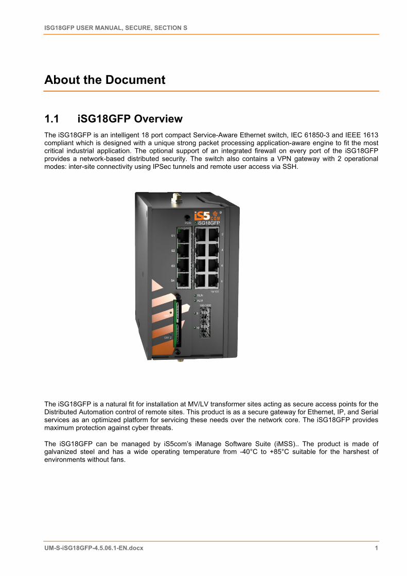
1.1 iSG18GFP Overview The iSG18GFP is an intelligent 18 port compact Service-Aware Ethernet switch, IEC 61850-3 and IEEE 1613 compliant which is designed with a unique strong packet processing application-aware engine to fit the most critical industrial application. The optional support of an integrated firewall on every port of the iSG18GFP provides a network-based distributed security. The switch also contains a VPN gateway with 2 operational modes: inter-site connectivity using IPSec tunnels and remote user access via SSH.
The iSG18GFP is a natural fit for installation at MV/LV transformer sites acting as secure access points for the Distributed Automation control of remote sites. This product is as a secure gateway for Ethernet, IP, and Serial services as an optimized platform for servicing these needs over the network core. The iSG18GFP provides maximum protection against cyber threats.
The iSG18GFP can be managed by iS5com’s iManage Software Suite (iMSS).. The product is made of galvanized steel and has a wide operating temperature from -40°C to +85°C suitable for the harshest of environments without fans.
ISG18GFP USER MANUAL, SECURE, SECTION S
UM-S-iSG18GFP-4.5.06.1-EN.docx 2 © 2020 IS5 COMMUNICATIONS INC. ALL RIGHTS RESERVED
1.2 Using this Document
1.2.1 Documentation Purpose
This user guide describes the features available in the Secure product configuration of the iSG18GFP Ethernet switch only. This document contains Section S of the iSG18GFP user manual.
It includes chapters about NAT, OSPF, VRRP, RIPv2, Serial Ports and Services, Transparent Serial Tunneling, Terminal server, Modbus gateway, DNP3 gateway, VPN, IPsec, Cellular modem, and VPN Setup Examples.
This part of the document describes the security features of the product.
• For basic networking features, refer to Section B, iSG18GFP User Manual, Basic, Section B, UM-B-iSG18GFP-4.5.06.01-EN.docx
• For general structure and features of the product, refer to iSG18GFP User Manual, General, Section G, UM-G-iSG18GFP-4.5.06.01-EN.docx
• For enhanced security features, refer to iSG18GFP User Manual, Enhanced Security, Section E, UM-E-iSG18GFP-4.5.06.01-EN.docx
1.2.2 Intended Audience
This user guide is intended for network administrators responsible for installing and configuring network equipment. Users must be familiar with the concepts and terminology of Ethernet and local area networking (LAN) to use this user guide.
1.2.3 Documentation Suite
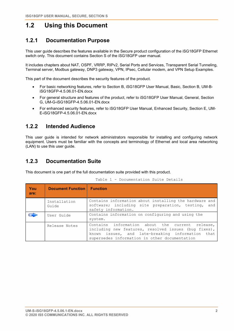
This document is one part of the full documentation suite provided with this product.
Table 1 - Documentation Suite Details
You are:
Document Function Function
Installation Guide
Contains information about installing the hardware and software; including site preparation, testing, and safety information.
User Guide Contains information on configuring and using the system.
Release Notes Contains information about the current release, including new features, resolved issues (bug fixes), known issues, and late-breaking information that supersedes information in other documentation
CHAPTER: ABOUT THE DOCUMENT, SECTION: USING THIS DOCUMENT
UM-S-iSG18GFP-4.5.06.1-EN.docx 3 © 2020 IS5 COMMUNICATIONS Inc. ALL RIGHTS RESERVED
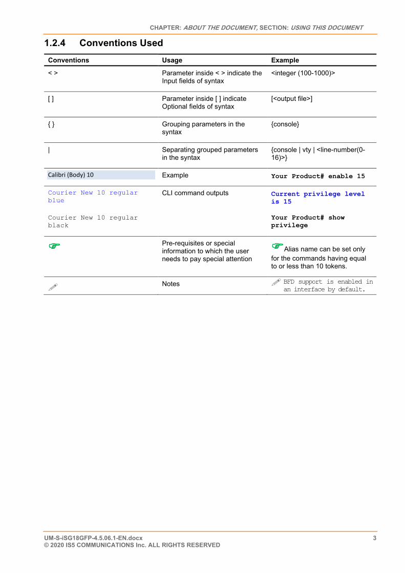
1.2.4 Conventions Used Conventions Usage Example
< > Parameter inside < > indicate the Input fields of syntax
<integer (100-1000)>
[ ] Parameter inside [ ] indicate Optional fields of syntax
[<output file>]
{ } Grouping parameters in the syntax
{console}
| Separating grouped parameters in the syntax
{console | vty | <line-number(0-16)>}
Calibri (Body) 10 Example Your Product# enable 15
Courier New 10 regular blue
Courier New 10 regular black
CLI command outputs Current privilege level is 15
Your Product# show privilege
Pre-requisites or special information to which the user needs to pay special attention
Alias name can be set only for the commands having equal to or less than 10 tokens.
Notes BFD support is enabled in an interface by default.
ISG18GFP USER MANUAL, SECURE, SECTION S
UM-S-iSG18GFP-4.5.06.1-EN.docx 4 © 2020 IS5 COMMUNICATIONS INC. ALL RIGHTS RESERVED
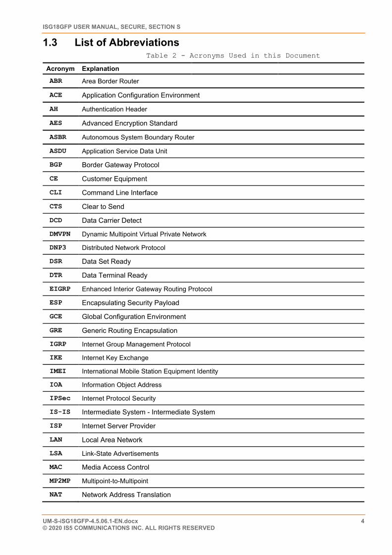
1.3 List of Abbreviations Table 2 - Acronyms Used in this Document
Acronym Explanation
ABR Area Border Router
ACE Application Configuration Environment
AH Authentication Header
AES Advanced Encryption Standard
ASBR Autonomous System Boundary Router
ASDU Application Service Data Unit
BGP Border Gateway Protocol
CE Customer Equipment
CLI Command Line Interface
CTS Clear to Send
DCD Data Carrier Detect
DMVPN Dynamic Multipoint Virtual Private Network
DNP3 Distributed Network Protocol
DSR Data Set Ready
DTR Data Terminal Ready
EIGRP Enhanced Interior Gateway Routing Protocol
ESP Encapsulating Security Payload
GCE Global Configuration Environment
GRE Generic Routing Encapsulation
IGRP Internet Group Management Protocol
IKE Internet Key Exchange
IMEI International Mobile Station Equipment Identity
IOA Information Object Address
IPSec Internet Protocol Security
IS-IS Intermediate System - Intermediate System
ISP Internet Server Provider
LAN Local Area Network
LSA Link-State Advertisements
MAC Media Access Control
MP2MP Multipoint-to-Multipoint
NAT Network Address Translation
CHAPTER: ABOUT THE DOCUMENT, SECTION: REFERENCES
UM-S-iSG18GFP-4.5.06.1-EN.docx 5 © 2020 IS5 COMMUNICATIONS Inc. ALL RIGHTS RESERVED
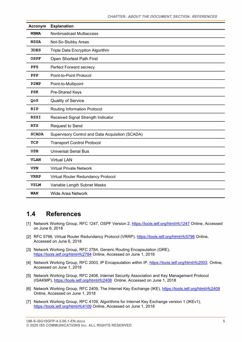
Acronym Explanation NBMA Nonbroadcast Multiaccess
NSSA Not-So-Stubby Areas
3DES Triple Data Encryption Algorithm
OSPF Open Shortest Path First
PFS Perfect Forward secrecy
PPP Point-to-Point Protocol
P2MP Point-to-Multipoint
PSK Pre-Shared Keys
QoS Quality of Service
RIP Routing Information Protocol
RSSI Received Signal Strength Indicator
RTS Request to Send
SCADA Supervisory Control and Data Acquisition (SCADA)
TCP Transport Control Protocol
USB Universal Serial Bus
VLAN Virtual LAN
VPN Virtual Private Network
VRRP Virtual Router Redundancy Protocol
VSLM Variable Length Subnet Masks
WAN Wide Area Network
1.4 References [1] Network Working Group, RFC 1247, OSPF Version 2, https://tools.ietf.org/html/rfc1247 Online, Accessed
on June 6, 2018
[2] RFC 5798, Virtual Router Redundancy Protocol (VRRP), https://tools.ietf.org/html/rfc5798 Online, Accessed on June 6, 2018
[3] Network Working Group, RFC 2784, Generic Routing Encapsulation (GRE), https://tools.ietf.org/html/rfc2784 Online, Accessed on June 1, 2018
[4] Network Working Group, RFC 2003, IP Encapsulation within IP, https://tools.ietf.org/html/rfc2003 Online, Accessed on June 1, 2018
[5] Network Working Group, RFC 2408, Internet Security Association and Key Management Protocol (ISAKMP), https://tools.ietf.org/html/rfc2408 Online, Accessed on June 1, 2018
[6] Network Working Group, RFC 2409, The Internet Key Exchange (IKE), https://tools.ietf.org/html/rfc2409 Online, Accessed on June 1, 2018
[7] Network Working Group, RFC 4109, Algorithms for Internet Key Exchange version 1 (IKEv1), https://tools.ietf.org/html/rfc4109 Online, Accessed on June 1, 2018

ISG18GFP USER MANUAL, SECURE, SECTION S
UM-S-iSG18GFP-4.5.06.1-EN.docx 6 © 2020 IS5 COMMUNICATIONS INC. ALL RIGHTS RESERVED
[8] Network Working Group, RFC 2631, Diffie-Hellman Key Agreement Method, https://www.ietf.org/rfc/rfc2631.txt Online, Accessed on June 1, 2018
[9] Network Working Group, RFC 5114, Additional Diffie-Hellman Groups, https://tools.ietf.org/html/rfc5114 Online, Accessed on June 4, 2018
[10] iS5Com, iSG18GFP User Manual, Enhanced, Section E, UM-E-iSG18GFP-4.4-2-EN
[11] Cisco, OSPF Design Guide, https://www.cisco.com/c/en/us/support/docs/ip/open-shortest-path-first-ospf/7039-1.html#intro
[12] TechLibrary, Junos OS, OSPF Feature Guide, https://www.juniper.net/documentation/en_US/junos/topics/concept/ospf-routing-understanding-ospf-areas-overview.html
[13] Network Working Group, RFC 1058, Routing Informational Protocol, https://tools.ietf.org/html/rfc1058
[14] Network Working Group, RFC 1583, OSPF Version 2, https://tools.ietf.org/html/rfc1583
CHAPTER: NAT, SECTION: NETWORKING
UM-S-iSG18GFP-4.5.06.1-EN.docx 7 © 2020 IS5 COMMUNICATIONS Inc. ALL RIGHTS RESERVED
NAT
The iSG18GFP supports static and dynamic settings of Network Address Translation (NAT).
Dynamic NAT settings allow LAN members to initiate sessions with targets located at the Wide Area Network (WAN). The iSG18GFP will use its WAN IP interface as a new source IP of the session request, hiding the original private IP of the initiating LAN device. The iSG18GFP can use a single WAN IP interface to traverse multiple private IP addresses of its LAN, thus limiting the required public IP addresses to a single one.
Static NAT settings direct incoming WAN traffic to a particular target LAN client. As WAN stations usually will not have a route to a private LAN but only to a WAN IP address of the router, the static NAT settings are mandatory to allow them to initiate sessions towards LAN targets.
The iSG18GFP provides both a routing function and security layer, allowing WAN traffic access to the LAN.
The NAT functionality is supported at the Application Configuration Environment (ACE).
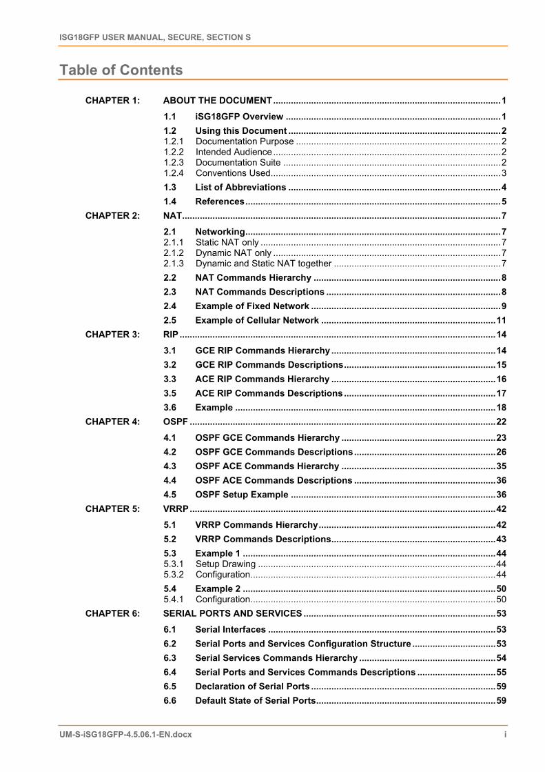
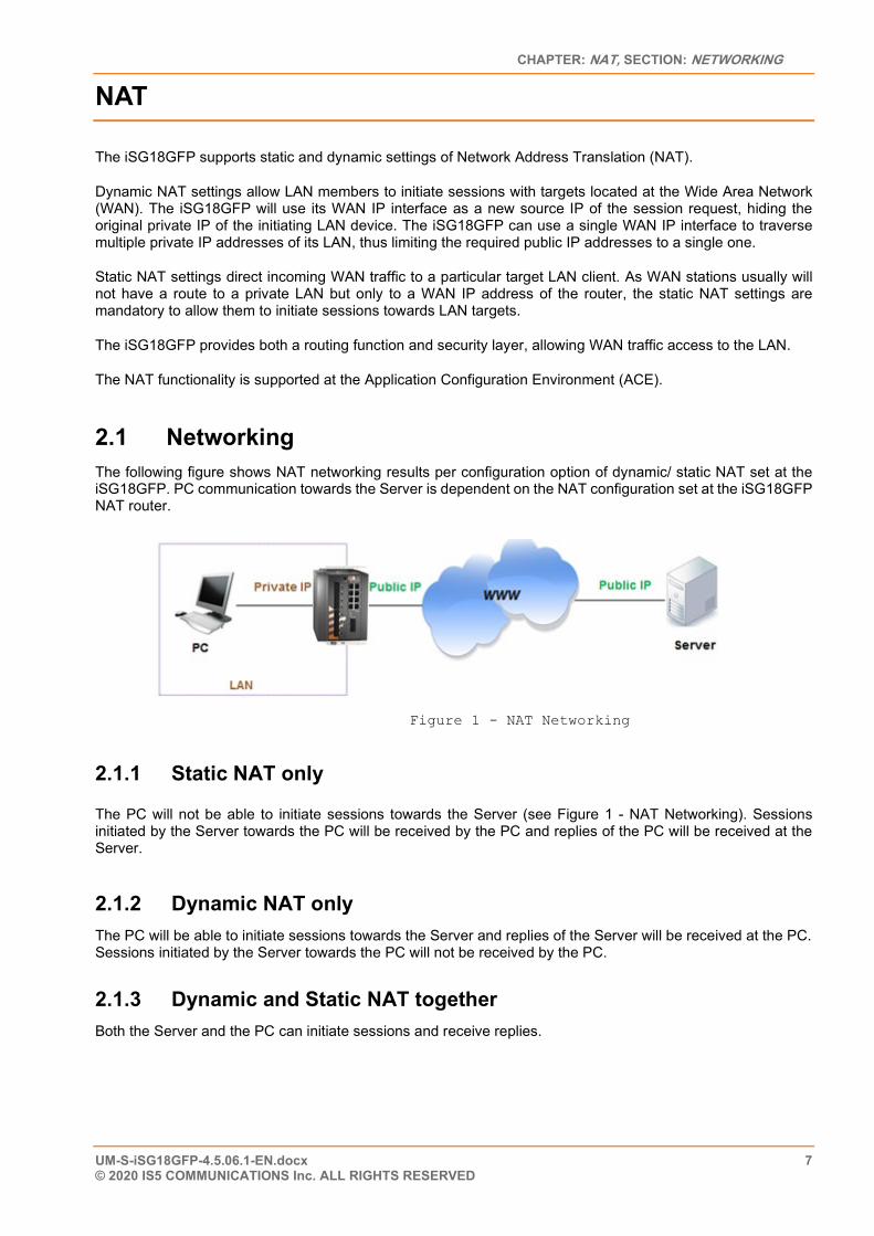
2.1 Networking The following figure shows NAT networking results per configuration option of dynamic/ static NAT set at the iSG18GFP. PC communication towards the Server is dependent on the NAT configuration set at the iSG18GFP NAT router.
Figure 1 - NAT Networking
2.1.1 Static NAT only
The PC will not be able to initiate sessions towards the Server (see Figure 1 - NAT Networking). Sessions initiated by the Server towards the PC will be received by the PC and replies of the PC will be received at the Server.
2.1.2 Dynamic NAT only The PC will be able to initiate sessions towards the Server and replies of the Server will be received at the PC. Sessions initiated by the Server towards the PC will not be received by the PC.
2.1.3 Dynamic and Static NAT together Both the Server and the PC can initiate sessions and receive replies.
ISG18GFP USER MANUAL, SECURE, SECTION S
UM-S-iSG18GFP-4.5.06.1-EN.docx 8 © 2020 IS5 COMMUNICATIONS INC. ALL RIGHTS RESERVED
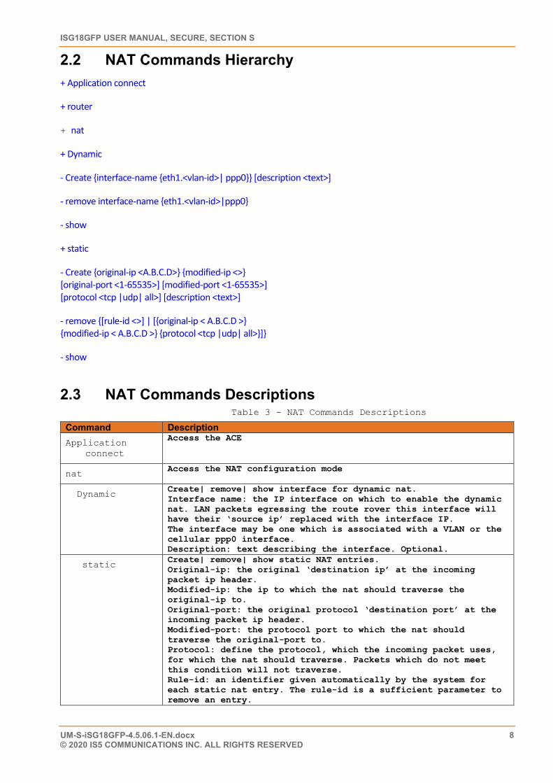
2.2 NAT Commands Hierarchy + Application connect
+ router
+ nat
+ Dynamic
- Create {interface-name {eth1.<vlan-id>| ppp0}} [description <text>]
- remove interface-name {eth1.<vlan-id>|ppp0}
- show
+ static
- Create {original-ip <A.B.C.D>} {modified-ip <>} [original-port <1-65535>] [modified-port <1-65535>] [protocol <tcp |udp| all>] [description <text>]
- remove {[rule-id <>] | [{original-ip < A.B.C.D >} {modified-ip < A.B.C.D >} {protocol <tcp |udp| all>}]}
- show
2.3 NAT Commands Descriptions Table 3 - NAT Commands Descriptions
Command Description Application
connect
Access the ACE
nat Access the NAT configuration mode
Dynamic Create| remove| show interface for dynamic nat. Interface name: the IP interface on which to enable the dynamic nat. LAN packets egressing the route rover this interface will have their ‘source ip’ replaced with the interface IP. The interface may be one which is associated with a VLAN or the cellular ppp0 interface. Description: text describing the interface. Optional.
static Create| remove| show static NAT entries. Original-ip: the original ‘destination ip’ at the incoming packet ip header. Modified-ip: the ip to which the nat should traverse the original-ip to. Original-port: the original protocol ‘destination port’ at the incoming packet ip header. Modified-port: the protocol port to which the nat should traverse the original-port to. Protocol: define the protocol, which the incoming packet uses, for which the nat should traverse. Packets which do not meet this condition will not traverse. Rule-id: an identifier given automatically by the system for each static nat entry. The rule-id is a sufficient parameter to remove an entry.
CHAPTER: NAT, SECTION: EXAMPLE OF FIXED NETWORK
UM-S-iSG18GFP-4.5.06.1-EN.docx 9 © 2020 IS5 COMMUNICATIONS Inc. ALL RIGHTS RESERVED
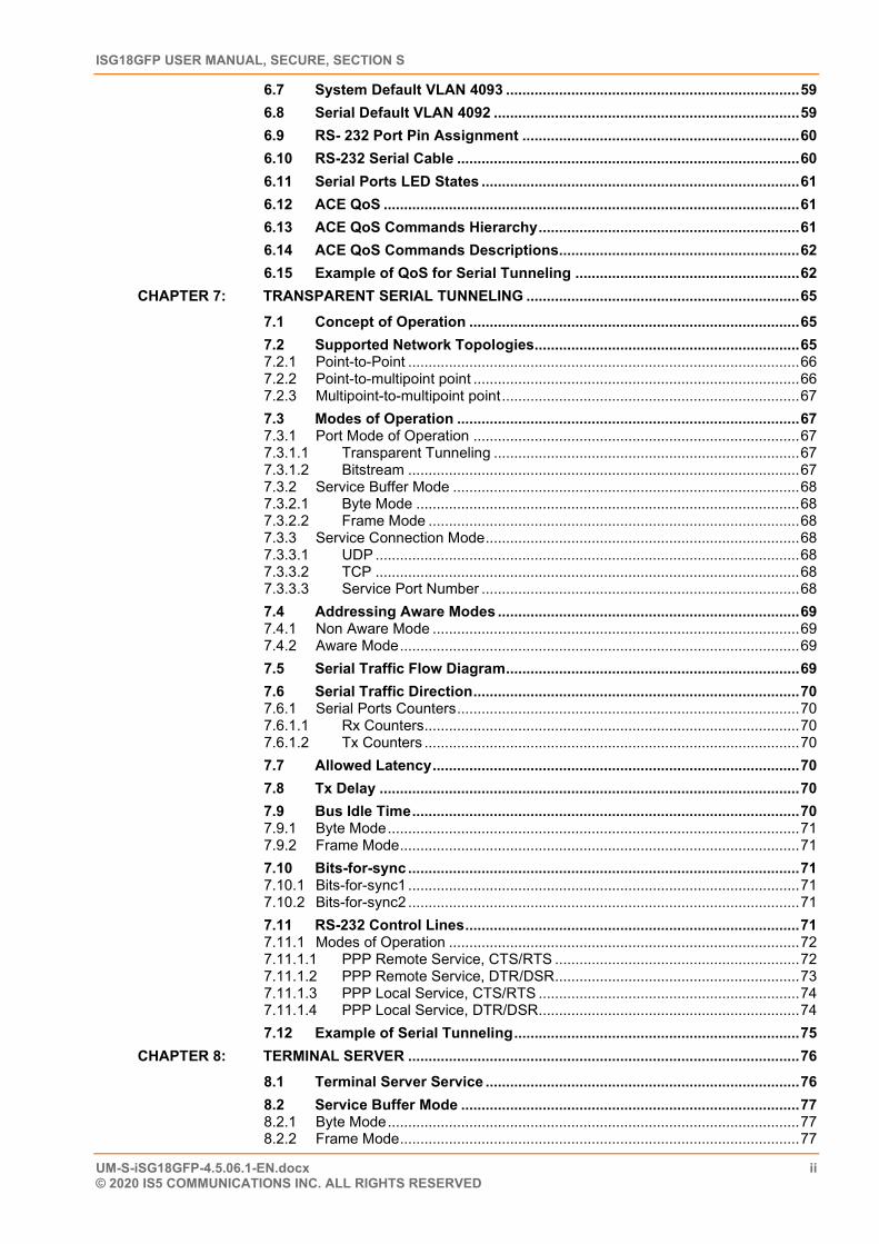
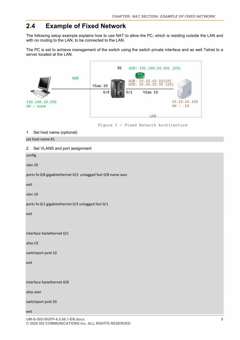
2.4 Example of Fixed Network The following setup example explains how to use NAT to allow the PC, which is residing outside the LAN and with no routing to the LAN, to be connected to the LAN.
The PC is set to achieve management of the switch using the switch private interface and as well Telnet to a server located at the LAN.
Figure 2 - Fixed Network Architecture
1. Set host name (optional) set host-name R1
2. Set VLANS and port assignment config
vlan 20
ports fa 0/8 gigabitethernet 0/3 untagged fast 0/8 name wan
exit
vlan 10
ports fa 0/1 gigabitethernet 0/3 untagged fast 0/1
exit
interface fastethernet 0/1
alias CE
switchport pvid 10
exit
interface fastethernet 0/8
alias wan
switchport pvid 20
exit
ISG18GFP USER MANUAL, SECURE, SECTION S
UM-S-iSG18GFP-4.5.06.1-EN.docx 10 © 2020 IS5 COMMUNICATIONS INC. ALL RIGHTS RESERVED
3. Set a GCE interface for management. Add static route to the ACE NAT interface interface vlan 10
ip address 10.10.10.50 255.255.255.0
no shut
exit
ip route 0.0.0.0 0.0.0.0 10.10.10.10
exit
write startup-cfg
4. Set ACE interfaces. Interface eth1.20 will be the NAT interface, eth1.10 will be used to route towards the LAN
application connect
router interface create address-prefix 192.168.20.201/24 vlan 20 purpose application-host description wan
router interface create address-prefix 10.10.10.10/24 vlan 10 purpose general description lan
5. Set Static NAT settings, directing WAN traffic targeted to 192.168.20.201 with port SSH (22) towards the GCE interface 10.10.10.50. This will allow the PC to achieve management of the iSG18GFP.
router nat static create original-ip 192.168.20.201 modified-ip 10.10.10.50 original-port 22 modified-port 22 protocol tcp
6. Set Static NAT settings, directing WAN traffic targeted to 192.168.20.201 towards 10.10.10.100 with port 20000 (DNP3). This will allow the PC to establish DNP3 session with the server.
router nat static create original-ip 192.168.20.201 modified-ip 10.10.10.100 original-port 20000 modified-port 20000 protocol tcp
7. Set dynamic NAT settings, allowing LAN devices to initiate connection to the PC residing at the WAN 8. Perform the task. exit
Write startup-cfg
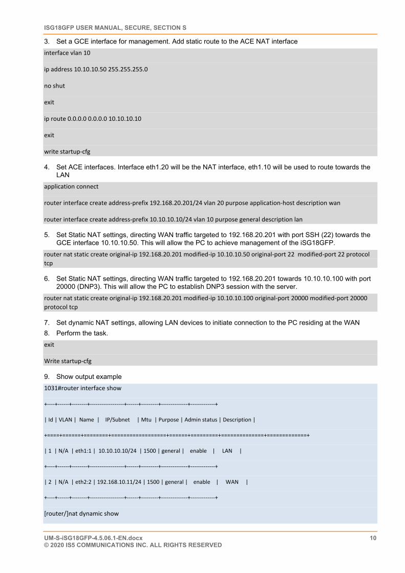
9. Show output example 1031#router interface show
+----+------+--------+------------------+------+---------+--------------+-------------+
| Id | VLAN | Name | IP/Subnet | Mtu | Purpose | Admin status | Description |
+====+======+========+==================+======+=========+==============+=============+
| 1 | N/A | eth1:1 | 10.10.10.10/24 | 1500 | general | enable | LAN |
+----+------+--------+------------------+------+---------+--------------+-------------+
| 2 | N/A | eth2:2 | 192.168.10.11/24 | 1500 | general | enable | WAN |
+----+------+--------+------------------+------+---------+--------------+-------------+
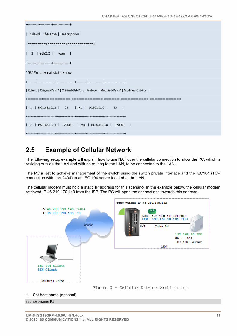
[router/]nat dynamic show
CHAPTER: NAT, SECTION: EXAMPLE OF CELLULAR NETWORK
UM-S-iSG18GFP-4.5.06.1-EN.docx 11 © 2020 IS5 COMMUNICATIONS Inc. ALL RIGHTS RESERVED
+---------+---------+-------------+
| Rule-Id | If-Name | Description |
+=========+=========+=============+
| 1 | eth2:2 | wan |
+---------+---------+-------------+
1031#router nat static show
+---------+-----------------+-------------------+----------+-----------------+-------------------+
| Rule-Id | Original-Dst-IP | Original-Dst-Port | Protocol | Modified-Dst-IP | Modified-Dst-Port |
+=========+=================+===================+==========+=================+===================+
| 1 | 192.168.10.11 | 23 | tcp | 10.10.10.10 | 23 |
+---------+-----------------+-------------------+----------+-----------------+-------------------+
| 2 | 192.168.10.11 | 20000 | tcp | 10.10.10.100 | 20000 |
+---------+-----------------+-------------------+----------+-----------------+-------------------+
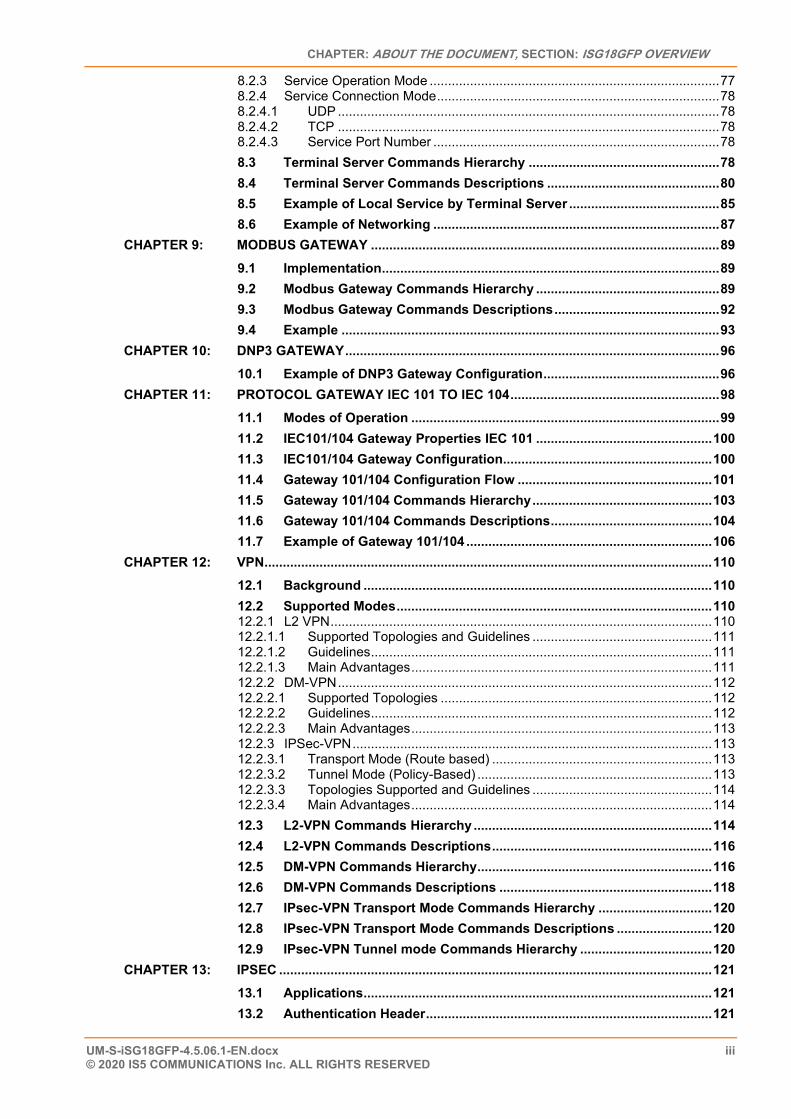
2.5 Example of Cellular Network The following setup example will explain how to use NAT over the cellular connection to allow the PC, which is residing outside the LAN and with no routing to the LAN, to be connected to the LAN.
The PC is set to achieve management of the switch using the switch private interface and the IEC104 (TCP connection with port 2404) to an IEC 104 server located at the LAN.
The cellular modem must hold a static IP address for this scenario. In the example below, the cellular modem retrieved IP 46.210.170.143 from the ISP. The PC will open the connections towards this address.
Figure 3 - Cellular Network Architecture
1. Set host name (optional) set host-name R1
ISG18GFP USER MANUAL, SECURE, SECTION S
UM-S-iSG18GFP-4.5.06.1-EN.docx 12 © 2020 IS5 COMMUNICATIONS INC. ALL RIGHTS RESERVED
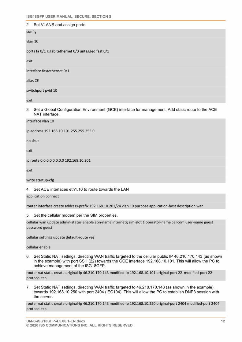
2. Set VLANS and assign ports config
vlan 10
ports fa 0/1 gigabitethernet 0/3 untagged fast 0/1
exit
interface fastethernet 0/1
alias CE
switchport pvid 10
exit
3. Set a Global Configuration Environment (GCE) interface for management. Add static route to the ACE NAT interface.
interface vlan 10
ip address 192.168.10.101 255.255.255.0
no shut
exit
ip route 0.0.0.0 0.0.0.0 192.168.10.201
exit
write startup-cfg
4. Set ACE interfaces eth1.10 to route towards the LAN application connect
router interface create address-prefix 192.168.10.201/24 vlan 10 purpose application-host description wan
5. Set the cellular modem per the SIM properties. cellular wan update admin-status enable apn-name internetg sim-slot 1 operator-name cellcom user-name guest password guest
cellular settings update default-route yes
cellular enable
6. Set Static NAT settings, directing WAN traffic targeted to the cellular public IP 46.210.170.143 (as shown in the example) with port SSH (22) towards the GCE interface 192.168.10.101. This will allow the PC to achieve management of the iSG18GFP.
router nat static create original-ip 46.210.170.143 modified-ip 192.168.10.101 original-port 22 modified-port 22 protocol tcp
7. Set Static NAT settings, directing WAN traffic targeted to 46.210.170.143 (as shown in the example) towards 192.168.10.250 with port 2404 (IEC104). This will allow the PC to establish DNP3 session with the server.
router nat static create original-ip 46.210.170.143 modified-ip 192.168.10.250 original-port 2404 modified-port 2404 protocol tcp

CHAPTER: NAT, SECTION: EXAMPLE OF CELLULAR NETWORK
UM-S-iSG18GFP-4.5.06.1-EN.docx 13 © 2020 IS5 COMMUNICATIONS Inc. ALL RIGHTS RESERVED
8. Set dynamic NAT settings, allowing LAN devices to initiate connection to the PC residing at the WAN router nat dynamic create interface-name ppp0 description wan
9. Commit exit
Write startup-cfg
ISG18GFP USER MANUAL, SECURE, SECTION S
UM-S-iSG18GFP-4.5.06.1-EN.docx 14 © 2020 IS5 COMMUNICATIONS INC. ALL RIGHTS RESERVED
RIP
RIP (Routing Information Protocol) is a distance-vector routing protocol that employs the hop count as a routing metric. RIP routing and configuration is available at both Global Configuration Environment (GCE) mode and Application Configuration Environment (ACE) modes.
The protocol is limited to networks whose longest path involves 15 hops. [13] Another drawback of RIP is the amount of time that it takes for all routers on an internetwork to become aware (converge ) of a failure. It would taka around three to four minutes before all the routes are removed from the routing tables. In comparison, Open Shortest Path First (OSPF) would have detected the error and converged in a minute or less.
RIP’s typical operation uses two types of packets: request packets and response packets. When a RIP-enabled router is first started, the router sends request packets out all RIP interfaces to the broadcast address 255.255.255.255. All RIP packets, whether they are request or response packets, use UDP (port 520) as the Transport layer protocol. All RIP-enabled routers will respond to the request packets by sending response packets.
If you plan to use network IDs across your network and deploy Variable Length Subnet Masks (VSLM) to conserve addresses on your network, RIP does not support VSLM, so RIPv2 must be used. RIPv2 is supported in the application layer of the iSG18GFP, and as such the configuration is available in the ACE mode and related to IP interfaces configured in the application.
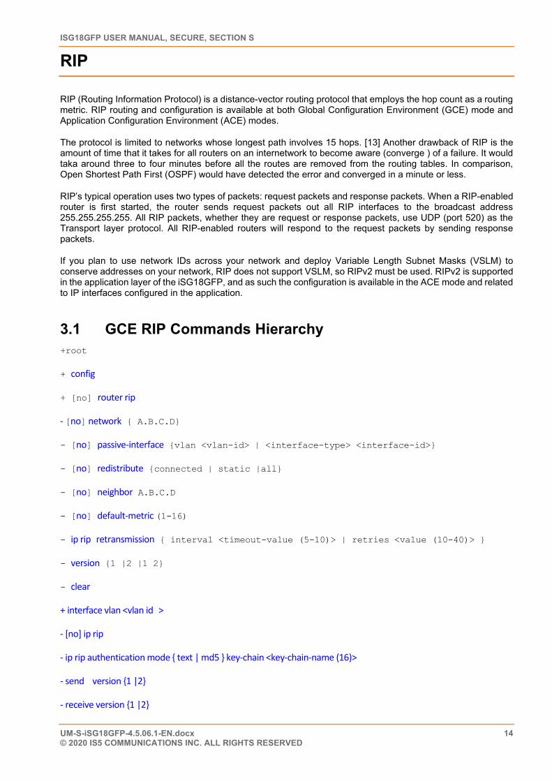
3.1 GCE RIP Commands Hierarchy +root
+ config
+ [no] router rip
- [no] network { A.B.C.D}
- [no] passive-interface {vlan <vlan-id> | <interface-type> <interface-id>}
- [no] redistribute {connected | static |all}
- [no] neighbor A.B.C.D
- [no] default-metric (1-16)
- ip rip retransmission { interval <timeout-value (5-10)> | retries <value (10-40)> }
- version {1 |2 |1 2}
- clear
+ interface vlan <vlan id >
- [no] ip rip
- ip rip authentication mode { text | md5 } key-chain <key-chain-name (16)>
- send version {1 |2}
- receive version {1 |2}
CHAPTER: RIP, SECTION: GCE RIP COMMANDS DESCRIPTIONS
UM-S-iSG18GFP-4.5.06.1-EN.docx 15 © 2020 IS5 COMMUNICATIONS Inc. ALL RIGHTS RESERVED
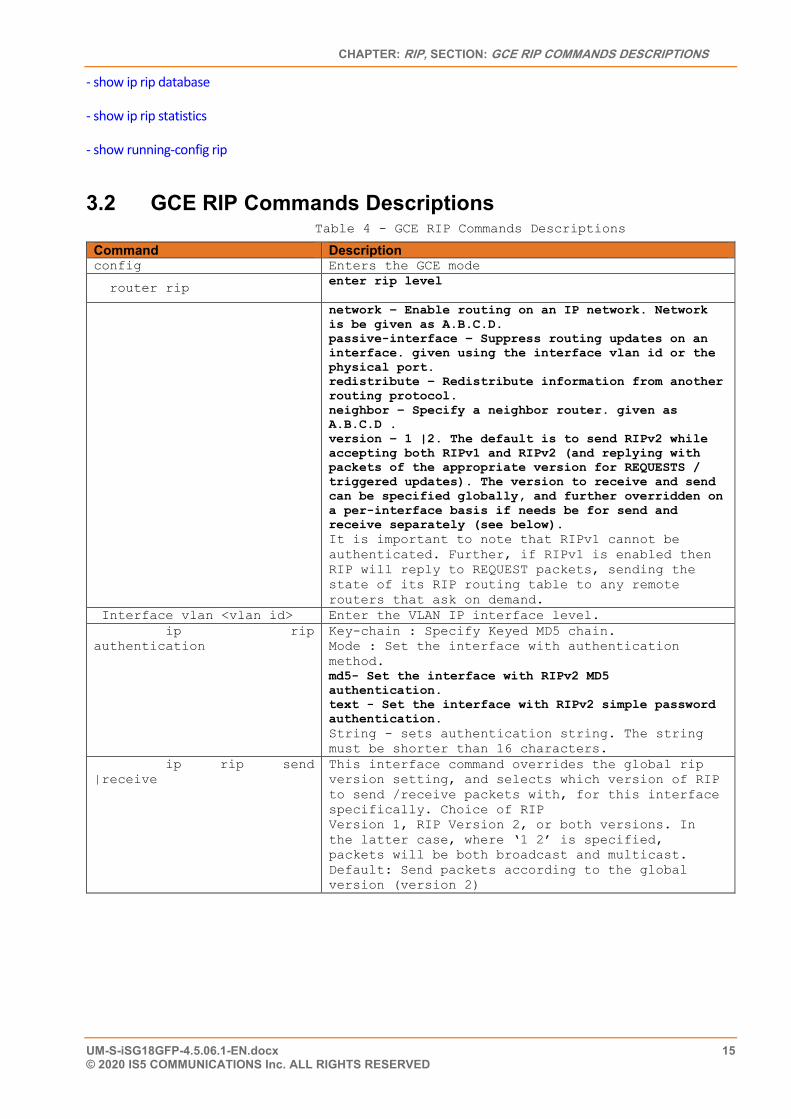
- show ip rip database
- show ip rip statistics
- show running-config rip
3.2 GCE RIP Commands Descriptions Table 4 - GCE RIP Commands Descriptions
Command Description config Enters the GCE mode
router rip enter rip level
network – Enable routing on an IP network. Network is be given as A.B.C.D. passive-interface – Suppress routing updates on an interface. given using the interface vlan id or the physical port. redistribute – Redistribute information from another routing protocol. neighbor – Specify a neighbor router. given as A.B.C.D . version – 1 |2. The default is to send RIPv2 while accepting both RIPv1 and RIPv2 (and replying with packets of the appropriate version for REQUESTS / triggered updates). The version to receive and send can be specified globally, and further overridden on a per-interface basis if needs be for send and receive separately (see below). It is important to note that RIPv1 cannot be authenticated. Further, if RIPv1 is enabled then RIP will reply to REQUEST packets, sending the state of its RIP routing table to any remote routers that ask on demand.
Interface vlan <vlan id> Enter the VLAN IP interface level. ip rip authentication
Key-chain : Specify Keyed MD5 chain. Mode : Set the interface with authentication method. md5- Set the interface with RIPv2 MD5 authentication. text - Set the interface with RIPv2 simple password authentication. String - sets authentication string. The string must be shorter than 16 characters.
ip rip send |receive
This interface command overrides the global rip version setting, and selects which version of RIP to send /receive packets with, for this interface specifically. Choice of RIP Version 1, RIP Version 2, or both versions. In the latter case, where ‘1 2’ is specified, packets will be both broadcast and multicast. Default: Send packets according to the global version (version 2)
ISG18GFP USER MANUAL, SECURE, SECTION S
UM-S-iSG18GFP-4.5.06.1-EN.docx 16 © 2020 IS5 COMMUNICATIONS INC. ALL RIGHTS RESERVED
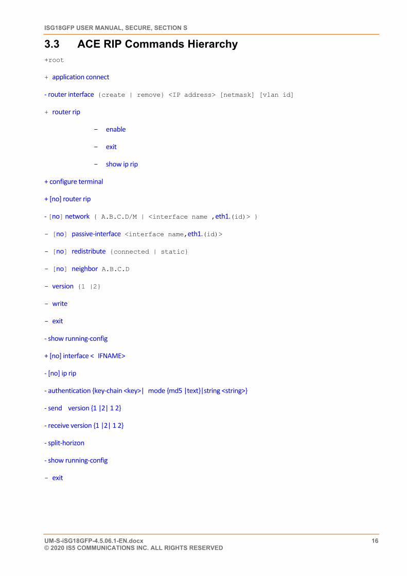
3.3 ACE RIP Commands Hierarchy +root
+ application connect
- router interface {create | remove} <IP address> [netmask] [vlan id]
+ router rip
- enable
- exit
- show ip rip
+ configure terminal
+ [no] router rip
- [no] network { A.B.C.D/M | <interface name ,eth1.(id)> }
- [no] passive-interface <interface name,eth1.(id)>
- [no] redistribute {connected | static}
- [no] neighbor A.B.C.D
- version {1 |2}
- write
- exit
- show running-config
+ [no] interface < IFNAME>
- [no] ip rip
- authentication {key-chain <key>| mode {md5 |text}|string <string>}
- send version {1 |2| 1 2}
- receive version {1 |2| 1 2}
- split-horizon
- show running-config
- exit
CHAPTER: RIP, SECTION: ACE RIP COMMANDS DESCRIPTIONS
UM-S-iSG18GFP-4.5.06.1-EN.docx 17 © 2020 IS5 COMMUNICATIONS Inc. ALL RIGHTS RESERVED
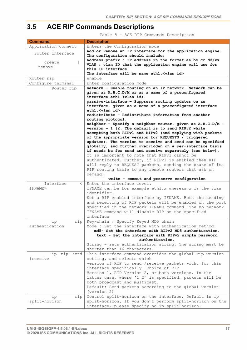
3.5 ACE RIP Commands Descriptions Table 5 - ACE RIP Commands Description
Command Description Application connect Enters the Configuration mode
router interface
create | remove
Add or Remove an IP interface for the application engine. The configuration should include: Address-prefix : IP address in the format aa.bb.cc.dd/xx VLAN : vlan ID that the application engine will use for this IP interface The interface will be name eth1.<vlan id>
Router rip enable Configure terminal Enter configuration mode Router rip network – Enable routing on an IP network. Network can be
given as A.B.C.D/M or as a name of a preconfigured interface eth1.<vlan id>. passive-interface – Suppress routing updates on an interface. given as a name of a preconfigured interface eth1.<vlan id>. redistribute – Redistribute information from another routing protocol. neighbor – Specify a neighbor router. given as A.B.C.D/M . version – 1 |2. The default is to send RIPv2 while accepting both RIPv1 and RIPv2 (and replying with packets of the appropriate version for REQUESTS / triggered updates). The version to receive and send can be specified globally, and further overridden on a per-interface basis if needs be for send and receive separately (see below). It is important to note that RIPv1 cannot be authenticated. Further, if RIPv1 is enabled then RIP will reply to REQUEST packets, sending the state of its RIP routing table to any remote routers that ask on demand.
write – commit and preserve configuration Interface < IFNAME>
Enter the interface level. IFNAME can be for example eth1.x whereas x is the vlan identifier. Set a RIP enabled interface by IFNAME. Both the sending and receiving of RIP packets will be enabled on the port specified in the network IFNAME command. The no network IFNAME command will disable RIP on the specified interface
ip rip authentication
Key-chain : Specify Keyed MD5 chain Mode : Set the interface with authentication method.
md5- Set the interface with RIPv2 MD5 authentication. text - Set the interface with RIPv2 simple password
authentication. String - sets authentication string. The string must be shorter than 16 characters.
ip rip send |receive
This interface command overrides the global rip version setting, and selects which version of RIP to send /receive packets with, for this interface specifically. Choice of RIP Version 1, RIP Version 2, or both versions. In the latter case, where ‘1 2’ is specified, packets will be both broadcast and multicast. Default: Send packets according to the global version (version 2)
ip rip split-horizon
Control split-horizon on the interface. Default is ip split-horizon. If you don’t perform split-horizon on the interface, please specify no ip split-horizon.
ISG18GFP USER MANUAL, SECURE, SECTION S
UM-S-iSG18GFP-4.5.06.1-EN.docx 18 © 2020 IS5 COMMUNICATIONS INC. ALL RIGHTS RESERVED
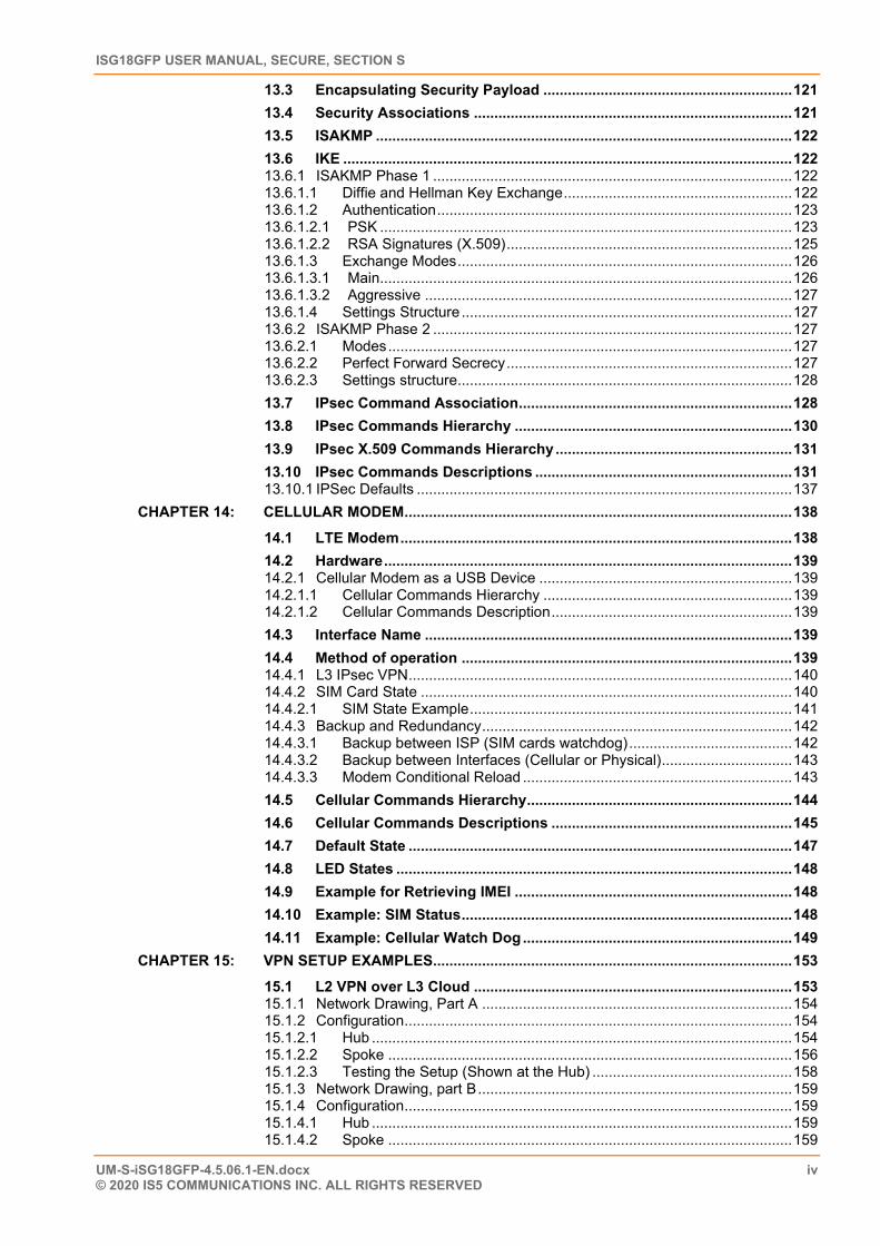
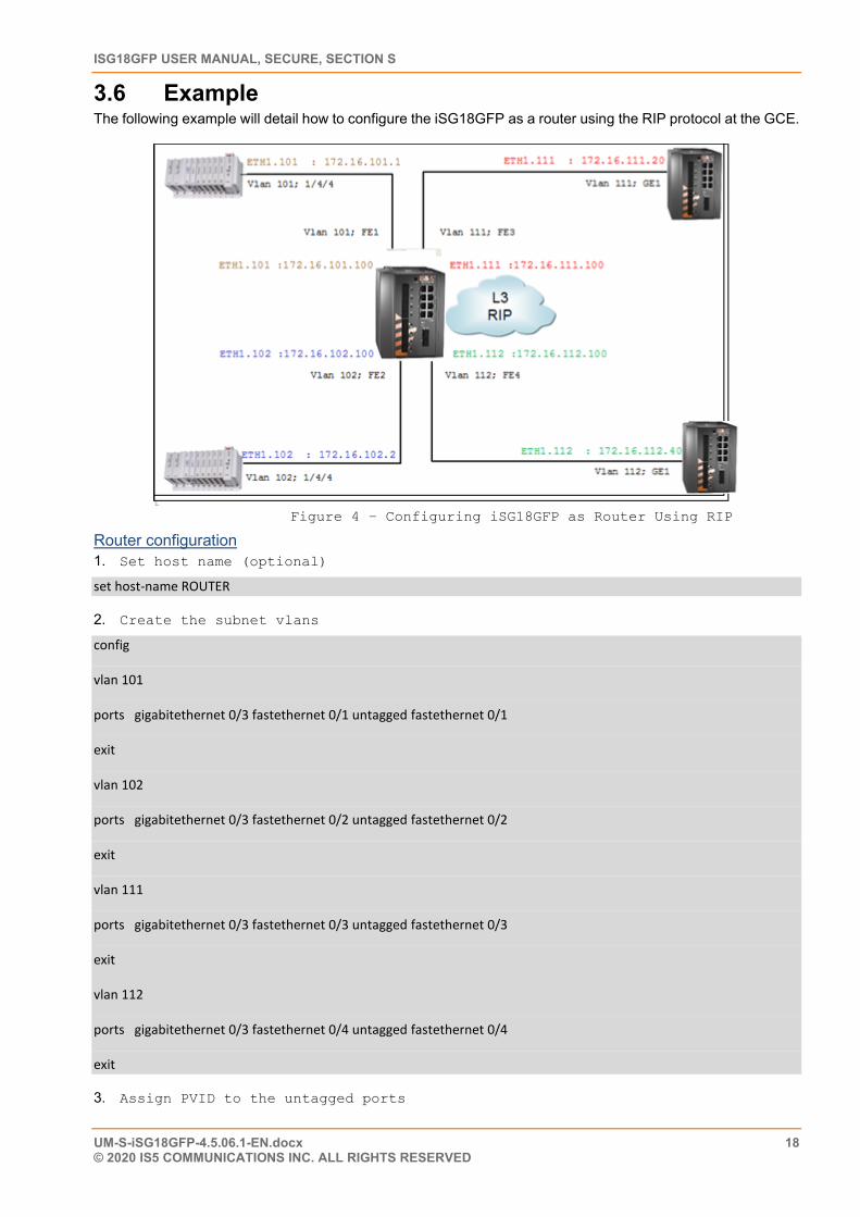
3.6 Example The following example will detail how to configure the iSG18GFP as a router using the RIP protocol at the GCE.
Figure 4 – Configuring iSG18GFP as Router Using RIP
Router configuration 1. Set host name (optional)
set host-name ROUTER
2. Create the subnet vlans
config
vlan 101
ports gigabitethernet 0/3 fastethernet 0/1 untagged fastethernet 0/1
exit
vlan 102
ports gigabitethernet 0/3 fastethernet 0/2 untagged fastethernet 0/2
exit
vlan 111
ports gigabitethernet 0/3 fastethernet 0/3 untagged fastethernet 0/3
exit
vlan 112
ports gigabitethernet 0/3 fastethernet 0/4 untagged fastethernet 0/4
exit
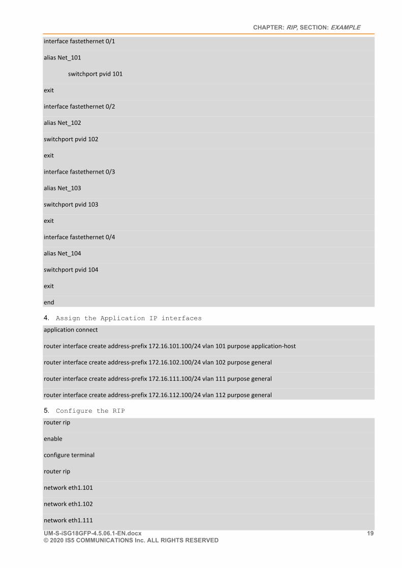
3. Assign PVID to the untagged ports
CHAPTER: RIP, SECTION: EXAMPLE
UM-S-iSG18GFP-4.5.06.1-EN.docx 19 © 2020 IS5 COMMUNICATIONS Inc. ALL RIGHTS RESERVED
interface fastethernet 0/1
alias Net_101
switchport pvid 101
exit
interface fastethernet 0/2
alias Net_102
switchport pvid 102
exit
interface fastethernet 0/3
alias Net_103
switchport pvid 103
exit
interface fastethernet 0/4
alias Net_104
switchport pvid 104
exit
end
4. Assign the Application IP interfaces
application connect
router interface create address-prefix 172.16.101.100/24 vlan 101 purpose application-host
router interface create address-prefix 172.16.102.100/24 vlan 102 purpose general
router interface create address-prefix 172.16.111.100/24 vlan 111 purpose general
router interface create address-prefix 172.16.112.100/24 vlan 112 purpose general
5. Configure the RIP
router rip
enable
configure terminal
router rip
network eth1.101
network eth1.102
network eth1.111
ISG18GFP USER MANUAL, SECURE, SECTION S
UM-S-iSG18GFP-4.5.06.1-EN.docx 20 © 2020 IS5 COMMUNICATIONS INC. ALL RIGHTS RESERVED
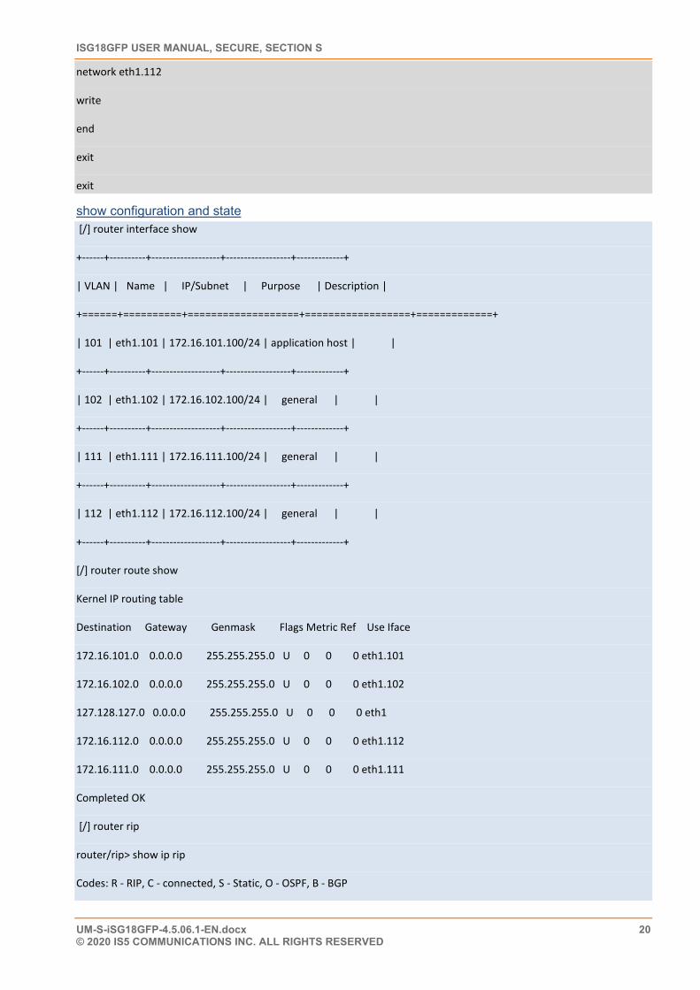
network eth1.112
write
end
exit
exit
show configuration and state [/] router interface show
+------+----------+-------------------+------------------+-------------+
| VLAN | Name | IP/Subnet | Purpose | Description |
+======+==========+===================+==================+=============+
| 101 | eth1.101 | 172.16.101.100/24 | application host | |
+------+----------+-------------------+------------------+-------------+
| 102 | eth1.102 | 172.16.102.100/24 | general | |
+------+----------+-------------------+------------------+-------------+
| 111 | eth1.111 | 172.16.111.100/24 | general | |
+------+----------+-------------------+------------------+-------------+
| 112 | eth1.112 | 172.16.112.100/24 | general | |
+------+----------+-------------------+------------------+-------------+
[/] router route show
Kernel IP routing table
Destination Gateway Genmask Flags Metric Ref Use Iface
172.16.101.0 0.0.0.0 255.255.255.0 U 0 0 0 eth1.101
172.16.102.0 0.0.0.0 255.255.255.0 U 0 0 0 eth1.102
127.128.127.0 0.0.0.0 255.255.255.0 U 0 0 0 eth1
172.16.112.0 0.0.0.0 255.255.255.0 U 0 0 0 eth1.112
172.16.111.0 0.0.0.0 255.255.255.0 U 0 0 0 eth1.111
Completed OK
[/] router rip
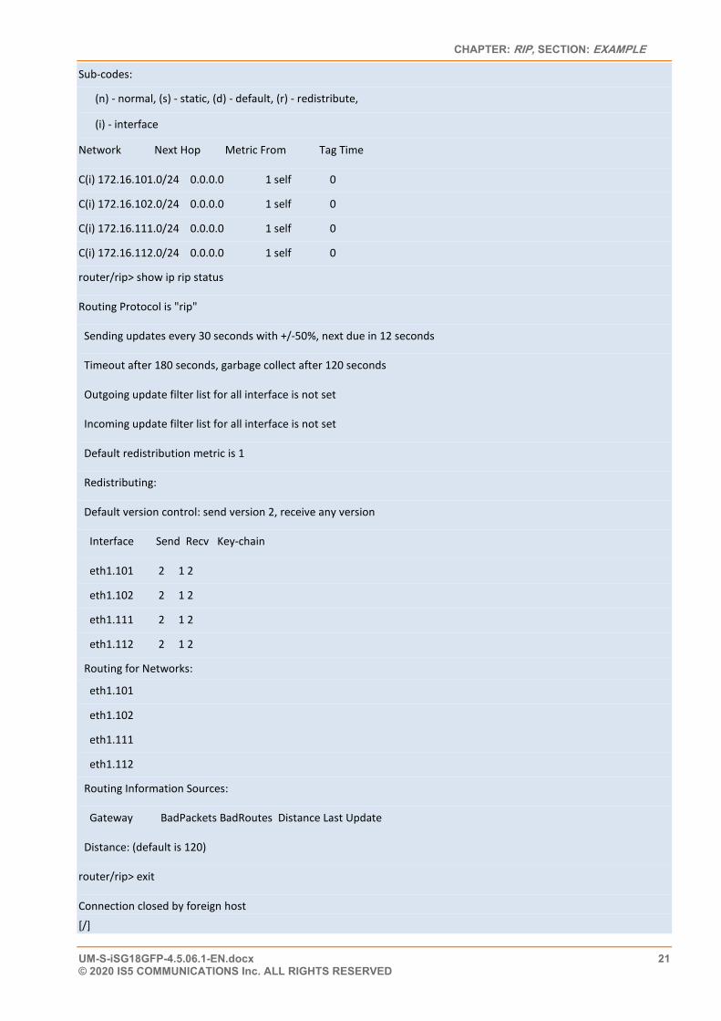
router/rip> show ip rip
Codes: R - RIP, C - connected, S - Static, O - OSPF, B - BGP
CHAPTER: RIP, SECTION: EXAMPLE
UM-S-iSG18GFP-4.5.06.1-EN.docx 21 © 2020 IS5 COMMUNICATIONS Inc. ALL RIGHTS RESERVED
Sub-codes:
(n) - normal, (s) - static, (d) - default, (r) - redistribute,
(i) - interface
Network Next Hop Metric From Tag Time
C(i) 172.16.101.0/24 0.0.0.0 1 self 0
C(i) 172.16.102.0/24 0.0.0.0 1 self 0
C(i) 172.16.111.0/24 0.0.0.0 1 self 0
C(i) 172.16.112.0/24 0.0.0.0 1 self 0
router/rip> show ip rip status
Routing Protocol is "rip"
Sending updates every 30 seconds with +/-50%, next due in 12 seconds
Timeout after 180 seconds, garbage collect after 120 seconds
Outgoing update filter list for all interface is not set
Incoming update filter list for all interface is not set
Default redistribution metric is 1
Redistributing:
Default version control: send version 2, receive any version
Interface Send Recv Key-chain
eth1.101 2 1 2
eth1.102 2 1 2
eth1.111 2 1 2
eth1.112 2 1 2
Routing for Networks:
eth1.101
eth1.102
eth1.111
eth1.112
Routing Information Sources:
Gateway BadPackets BadRoutes Distance Last Update
Distance: (default is 120)
router/rip> exit
Connection closed by foreign host
[/]
ISG18GFP USER MANUAL, SECURE, SECTION S
UM-S-iSG18GFP-4.5.06.1-EN.docx 22 © 2020 IS5 COMMUNICATIONS INC. ALL RIGHTS RESERVED
OSPF
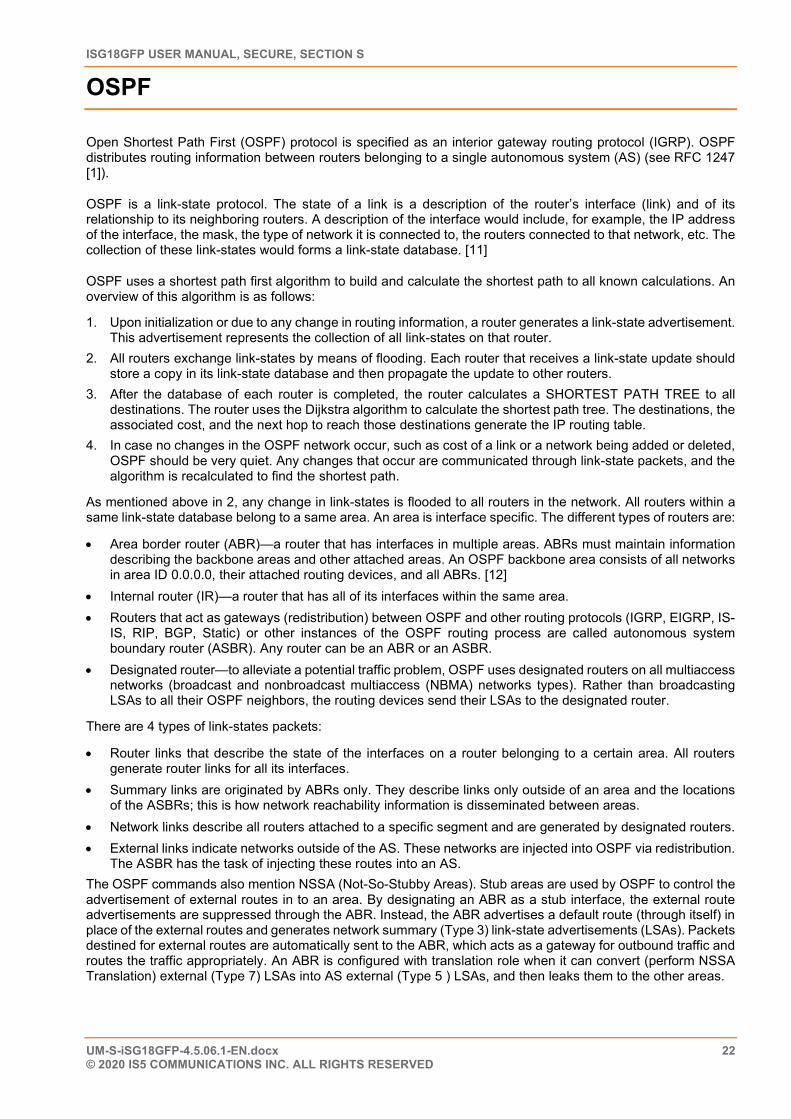
Open Shortest Path First (OSPF) protocol is specified as an interior gateway routing protocol (IGRP). OSPF distributes routing information between routers belonging to a single autonomous system (AS) (see RFC 1247 [1]).
OSPF is a link-state protocol. The state of a link is a description of the router’s interface (link) and of its relationship to its neighboring routers. A description of the interface would include, for example, the IP address of the interface, the mask, the type of network it is connected to, the routers connected to that network, etc. The collection of these link-states would forms a link-state database. [11]
OSPF uses a shortest path first algorithm to build and calculate the shortest path to all known calculations. An overview of this algorithm is as follows:
1. Upon initialization or due to any change in routing information, a router generates a link-state advertisement. This advertisement represents the collection of all link-states on that router.
2. All routers exchange link-states by means of flooding. Each router that receives a link-state update should store a copy in its link-state database and then propagate the update to other routers.
3. After the database of each router is completed, the router calculates a SHORTEST PATH TREE to all destinations. The router uses the Dijkstra algorithm to calculate the shortest path tree. The destinations, the associated cost, and the next hop to reach those destinations generate the IP routing table.
4. In case no changes in the OSPF network occur, such as cost of a link or a network being added or deleted, OSPF should be very quiet. Any changes that occur are communicated through link-state packets, and the algorithm is recalculated to find the shortest path.
As mentioned above in 2, any change in link-states is flooded to all routers in the network. All routers within a same link-state database belong to a same area. An area is interface specific. The different types of routers are:
• Area border router (ABR)—a router that has interfaces in multiple areas. ABRs must maintain information describing the backbone areas and other attached areas. An OSPF backbone area consists of all networks in area ID 0.0.0.0, their attached routing devices, and all ABRs. [12]
• Internal router (IR)—a router that has all of its interfaces within the same area. • Routers that act as gateways (redistribution) between OSPF and other routing protocols (IGRP, EIGRP, IS-
IS, RIP, BGP, Static) or other instances of the OSPF routing process are called autonomous system boundary router (ASBR). Any router can be an ABR or an ASBR.
• Designated router—to alleviate a potential traffic problem, OSPF uses designated routers on all multiaccess networks (broadcast and nonbroadcast multiaccess (NBMA) networks types). Rather than broadcasting LSAs to all their OSPF neighbors, the routing devices send their LSAs to the designated router.
There are 4 types of link-states packets:
• Router links that describe the state of the interfaces on a router belonging to a certain area. All routers generate router links for all its interfaces.
• Summary links are originated by ABRs only. They describe links only outside of an area and the locations of the ASBRs; this is how network reachability information is disseminated between areas.
• Network links describe all routers attached to a specific segment and are generated by designated routers. • External links indicate networks outside of the AS. These networks are injected into OSPF via redistribution.
The ASBR has the task of injecting these routes into an AS. The OSPF commands also mention NSSA (Not-So-Stubby Areas). Stub areas are used by OSPF to control the advertisement of external routes in to an area. By designating an ABR as a stub interface, the external route advertisements are suppressed through the ABR. Instead, the ABR advertises a default route (through itself) in place of the external routes and generates network summary (Type 3) link-state advertisements (LSAs). Packets destined for external routes are automatically sent to the ABR, which acts as a gateway for outbound traffic and routes the traffic appropriately. An ABR is configured with translation role when it can convert (perform NSSA Translation) external (Type 7) LSAs into AS external (Type 5 ) LSAs, and then leaks them to the other areas.
CHAPTER: OSPF, SECTION: OSPF GCE COMMANDS HIERARCHY
UM-S-iSG18GFP-4.5.06.1-EN.docx 23 © 2020 IS5 COMMUNICATIONS Inc. ALL RIGHTS RESERVED
The advantage of shortest path first algorithms is that they result in smaller more frequent update everywhere. They converge quickly, thus preventing such problems as routing loops and Count-to-Infinity (when routers continuously increment the hop count to a particular network). This makes for a stable network.
OSPF is available both in the central switch unit and in the ACE layer. Configuration is thus available in both GCE and ACE modes. Routing of VPNs can be done only in the application layer.
Total limit of 64 subnets is supported at the routing table. Customer static and dynamic entries in total should not exceed a total of 60 entries. A syslog message with severity ERROR will indicate exceeding this limit "Number of routes [%d] exceeded max of 60!"
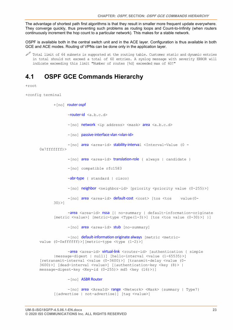
4.1 OSPF GCE Commands Hierarchy +root
+config terminal
+[no] router ospf
-router-id <a.b.c.d>
-[no] network <ip address> <mask> area <a.b.c.d>
-[no] passive-interface vlan <vlan-id>
-[no] area <area-id> stability-interval <Interval-Value (0 - 0x7fffffff)>
-[no] area <area-id> translation-role { always | candidate }
-[no] compatible rfc1583
-abr-type { standard | cisco}
-[no] neighbor <neighbor-id> [priority <priority value (0-255)>]
-[no] area <area-id> default-cost <cost> [tos <tos value(0- 30)>]
-area <area-id> nssa [{ no-summary | default-information-originate [metric <value>] [metric-type <Type(1-3)>] [tos <tos value (0-30)>] }]
-[no] area <area-id> stub [no-summary]
-[no] default-information originate always [metric <metric- value (0-0xffffff)>][metric-type <type (1-2)>]
-area <area-id> virtual-link <router-id> [authentication { simple |message-digest | null}] [hello-interval <value (1-65535)>] [retransmit-interval <value (0-3600)>] [transmit-delay <value (0- 3600)>] [dead-interval <value>] [{authentication-key <key (8)> | message-digest-key <Key-id (0-255)> md5 <key (16)>}]
-[no] ASBR Router
-[no] area <AreaId> range <Network> <Mask> {summary | Type7} [{advertise | not-advertise}] [tag <value>]
ISG18GFP USER MANUAL, SECURE, SECTION S
UM-S-iSG18GFP-4.5.06.1-EN.docx 24 © 2020 IS5 COMMUNICATIONS INC. ALL RIGHTS RESERVED
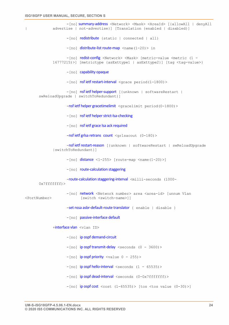
-[no] summary-address <Network> <Mask> <AreaId> [{allowAll | denyAll | advertise | not-advertise}] [Translation {enabled | disabled}]
-[no] redistribute {static | connected | all}
-[no] distribute-list route-map <name(1-20)> in
-[no] redist-config <Network> <Mask> [metric-value <metric (1 - 16777215)>] [metrictype {asExttype1 | asExttype2}] [tag <tag-value>}
-[no] capability opaque
-[no] nsf ietf restart-interval <grace period(1-1800)>
-[no] nsf ietf helper-support [{unknown | softwareRestart | swReloadUpgrade | switchToRedundant}]
-nsf ietf helper gracetimelimit <gracelimit period(0-1800)>
-[no] nsf ietf helper strict-lsa-checking
-[no] nsf ietf grace lsa ack required
-nsf ietf grlsa retrans count <grlsacout (0-180)>
-nsf ietf restart-reason [{unknown | softwareRestart | swReloadUpgrade |switchToRedundant}]
-[no] distance <1-255> [route-map <name(1-20)>]
-[no] route-calculation staggering
-route-calculation staggering-interval <milli-seconds (1000- 0x7fffffff)>
-[no] network <Network number> area <area-id> [unnum Vlan <PortNumber> [switch <switch-name>]]
-set nssa asbr-default-route translator { enable | disable }
-[no] passive-interface default
+interface vlan <vlan ID>
-[no] ip ospf demand-circuit
-[no] ip ospf transmit-delay <seconds (0 - 3600)>
-[no] ip ospf priority <value 0 - 255)>
-[no] ip ospf hello-interval <seconds (1 - 65535)>
-[no] ip ospf dead-interval <seconds (0-0x7fffffff)>
-[no] ip ospf cost <cost (1-65535)> [tos <tos value (0-30)>]
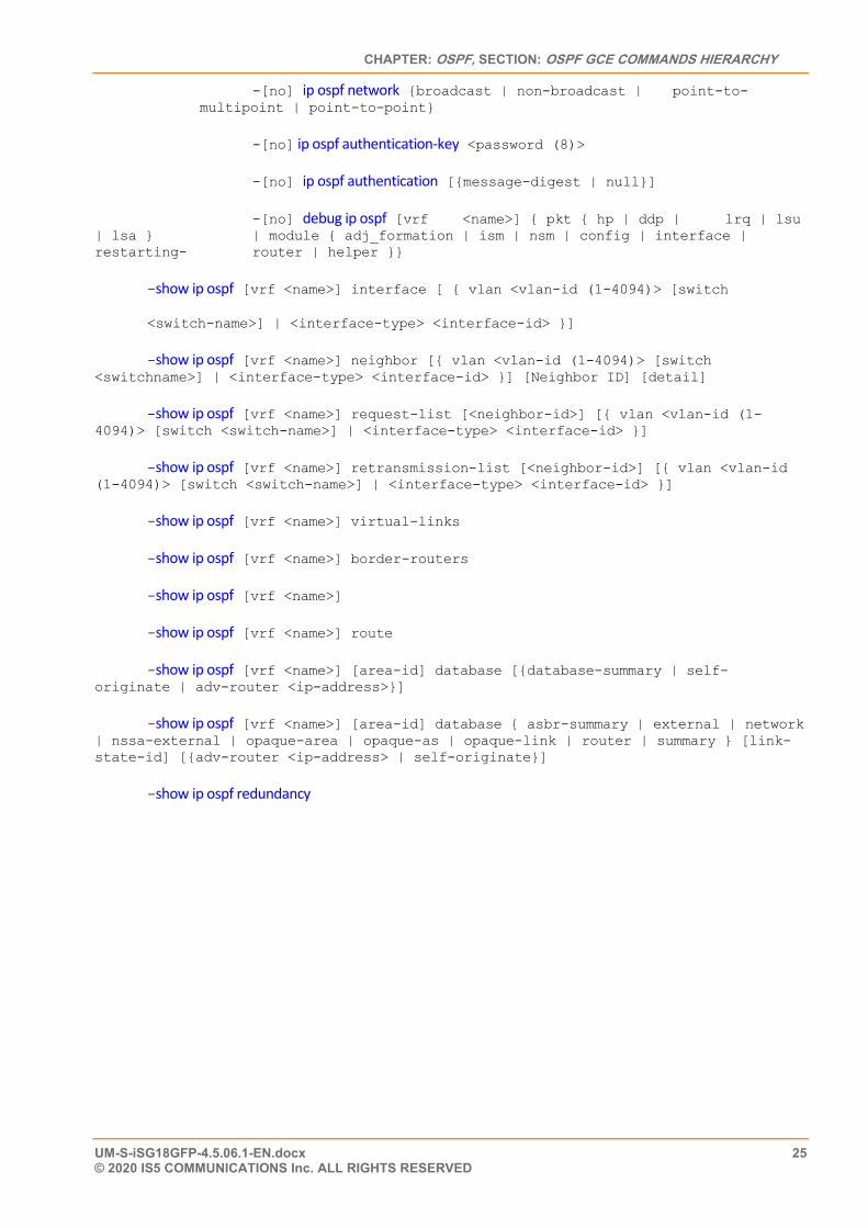
CHAPTER: OSPF, SECTION: OSPF GCE COMMANDS HIERARCHY
UM-S-iSG18GFP-4.5.06.1-EN.docx 25 © 2020 IS5 COMMUNICATIONS Inc. ALL RIGHTS RESERVED
-[no] ip ospf network {broadcast | non-broadcast | point-to- multipoint | point-to-point}
-[no] ip ospf authentication-key <password (8)>
-[no] ip ospf authentication [{message-digest | null}]
-[no] debug ip ospf [vrf <name>] { pkt { hp | ddp | lrq | lsu | lsa } | module { adj_formation | ism | nsm | config | interface | restarting- router | helper }}
-show ip ospf [vrf <name>] interface [ { vlan <vlan-id (1-4094)> [switch
<switch-name>] | <interface-type> <interface-id> }]
-show ip ospf [vrf <name>] neighbor [{ vlan <vlan-id (1-4094)> [switch <switchname>] | <interface-type> <interface-id> }] [Neighbor ID] [detail]
-show ip ospf [vrf <name>] request-list [<neighbor-id>] [{ vlan <vlan-id (1- 4094)> [switch <switch-name>] | <interface-type> <interface-id> }]
-show ip ospf [vrf <name>] retransmission-list [<neighbor-id>] [{ vlan <vlan-id (1-4094)> [switch <switch-name>] | <interface-type> <interface-id> }]
-show ip ospf [vrf <name>] virtual-links
-show ip ospf [vrf <name>] border-routers
-show ip ospf [vrf <name>]
-show ip ospf [vrf <name>] route
-show ip ospf [vrf <name>] [area-id] database [{database-summary | self- originate | adv-router <ip-address>}]
-show ip ospf [vrf <name>] [area-id] database { asbr-summary | external | network | nssa-external | opaque-area | opaque-as | opaque-link | router | summary } [link-state-id] [{adv-router <ip-address> | self-originate}]
-show ip ospf redundancy
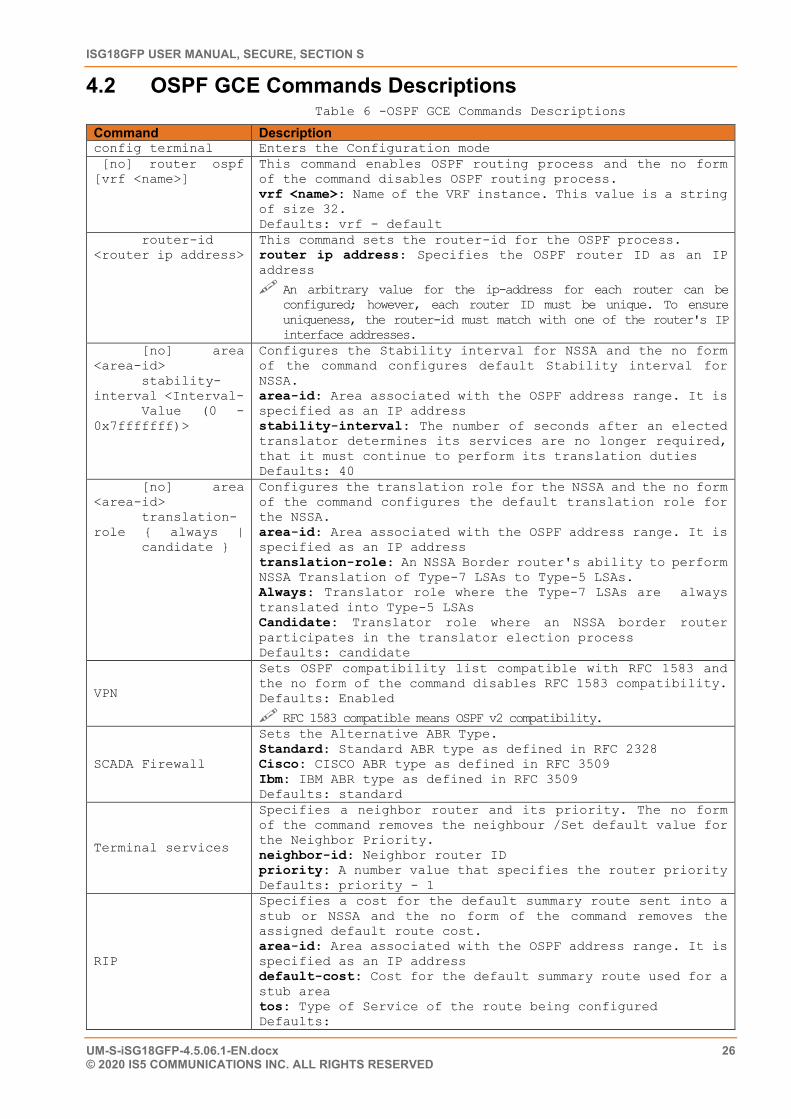
ISG18GFP USER MANUAL, SECURE, SECTION S
UM-S-iSG18GFP-4.5.06.1-EN.docx 26 © 2020 IS5 COMMUNICATIONS INC. ALL RIGHTS RESERVED
4.2 OSPF GCE Commands Descriptions Table 6 -OSPF GCE Commands Descriptions
Command Description config terminal Enters the Configuration mode [no] router ospf [vrf <name>]
This command enables OSPF routing process and the no form of the command disables OSPF routing process. vrf <name>: Name of the VRF instance. This value is a string of size 32. Defaults: vrf - default
router-id <router ip address>
This command sets the router-id for the OSPF process. router ip address: Specifies the OSPF router ID as an IP address
An arbitrary value for the ip-address for each router can be configured; however, each router ID must be unique. To ensure uniqueness, the router-id must match with one of the router's IP interface addresses.
[no] area <area-id> stability-interval <Interval- Value (0 - 0x7fffffff)>
Configures the Stability interval for NSSA and the no form of the command configures default Stability interval for NSSA. area-id: Area associated with the OSPF address range. It is specified as an IP address stability-interval: The number of seconds after an elected translator determines its services are no longer required, that it must continue to perform its translation duties Defaults: 40
[no] area <area-id> translation-role { always | candidate }
Configures the translation role for the NSSA and the no form of the command configures the default translation role for the NSSA. area-id: Area associated with the OSPF address range. It is specified as an IP address translation-role: An NSSA Border router's ability to perform NSSA Translation of Type-7 LSAs to Type-5 LSAs. Always: Translator role where the Type-7 LSAs are always translated into Type-5 LSAs Candidate: Translator role where an NSSA border router participates in the translator election process Defaults: candidate
VPN
Sets OSPF compatibility list compatible with RFC 1583 and the no form of the command disables RFC 1583 compatibility. Defaults: Enabled
RFC 1583 compatible means OSPF v2 compatibility.
SCADA Firewall
Sets the Alternative ABR Type. Standard: Standard ABR type as defined in RFC 2328 Cisco: CISCO ABR type as defined in RFC 3509 Ibm: IBM ABR type as defined in RFC 3509 Defaults: standard
Terminal services
Specifies a neighbor router and its priority. The no form of the command removes the neighbour /Set default value for the Neighbor Priority. neighbor-id: Neighbor router ID priority: A number value that specifies the router priority Defaults: priority - 1
RIP
Specifies a cost for the default summary route sent into a stub or NSSA and the no form of the command removes the assigned default route cost. area-id: Area associated with the OSPF address range. It is specified as an IP address default-cost: Cost for the default summary route used for a stub area tos: Type of Service of the route being configured Defaults:
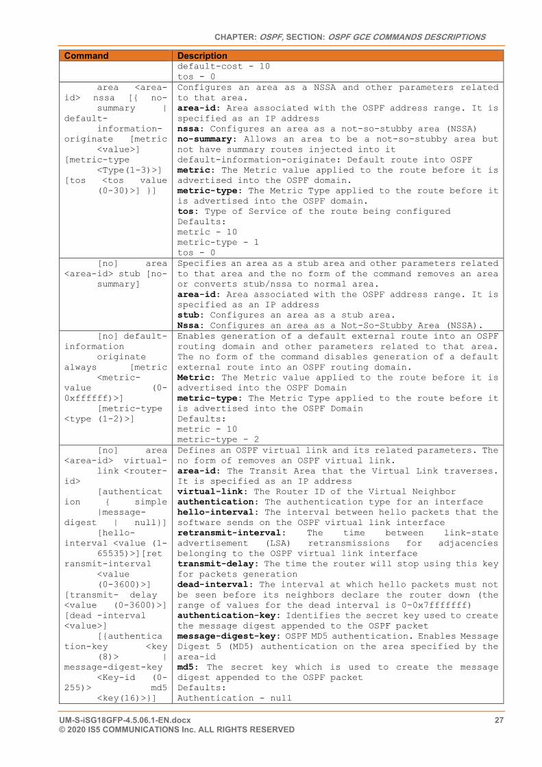
CHAPTER: OSPF, SECTION: OSPF GCE COMMANDS DESCRIPTIONS
UM-S-iSG18GFP-4.5.06.1-EN.docx 27 © 2020 IS5 COMMUNICATIONS Inc. ALL RIGHTS RESERVED
Command Description default-cost - 10 tos - 0
area <area-id> nssa [{ no- summary | default- information-originate [metric <value>] [metric-type <Type(1-3)>] [tos <tos value (0-30)>] }]
Configures an area as a NSSA and other parameters related to that area. area-id: Area associated with the OSPF address range. It is specified as an IP address nssa: Configures an area as a not-so-stubby area (NSSA) no-summary: Allows an area to be a not-so-stubby area but not have summary routes injected into it default-information-originate: Default route into OSPF metric: The Metric value applied to the route before it is advertised into the OSPF domain. metric-type: The Metric Type applied to the route before it is advertised into the OSPF domain. tos: Type of Service of the route being configured Defaults: metric - 10 metric-type - 1 tos - 0
[no] area <area-id> stub [no- summary]
Specifies an area as a stub area and other parameters related to that area and the no form of the command removes an area or converts stub/nssa to normal area. area-id: Area associated with the OSPF address range. It is specified as an IP address stub: Configures an area as a stub area. Nssa: Configures an area as a Not-So-Stubby Area (NSSA).
[no] default-information originate always [metric <metric-value (0-0xffffff)>] [metric-type <type (1-2)>]
Enables generation of a default external route into an OSPF routing domain and other parameters related to that area. The no form of the command disables generation of a default external route into an OSPF routing domain. Metric: The Metric value applied to the route before it is advertised into the OSPF Domain metric-type: The Metric Type applied to the route before it is advertised into the OSPF Domain Defaults: metric - 10 metric-type - 2
[no] area <area-id> virtual- link <router-id> [authentication { simple |message-digest | null}] [hello-interval <value (1- 65535)>][retransmit-interval <value (0-3600)>] [transmit- delay <value (0-3600)>] [dead -interval <value>] [{authentication-key <key (8)> | message-digest-key <Key-id (0-255)> md5 <key(16)>}]
Defines an OSPF virtual link and its related parameters. The no form of removes an OSPF virtual link. area-id: The Transit Area that the Virtual Link traverses. It is specified as an IP address virtual-link: The Router ID of the Virtual Neighbor authentication: The authentication type for an interface hello-interval: The interval between hello packets that the software sends on the OSPF virtual link interface retransmit-interval: The time between link-state advertisement (LSA) retransmissions for adjacencies belonging to the OSPF virtual link interface transmit-delay: The time the router will stop using this key for packets generation dead-interval: The interval at which hello packets must not be seen before its neighbors declare the router down (the range of values for the dead interval is 0–0x7fffffff) authentication-key: Identifies the secret key used to create the message digest appended to the OSPF packet message-digest-key: OSPF MD5 authentication. Enables Message Digest 5 (MD5) authentication on the area specified by the area-id md5: The secret key which is used to create the message digest appended to the OSPF packet Defaults: Authentication - null
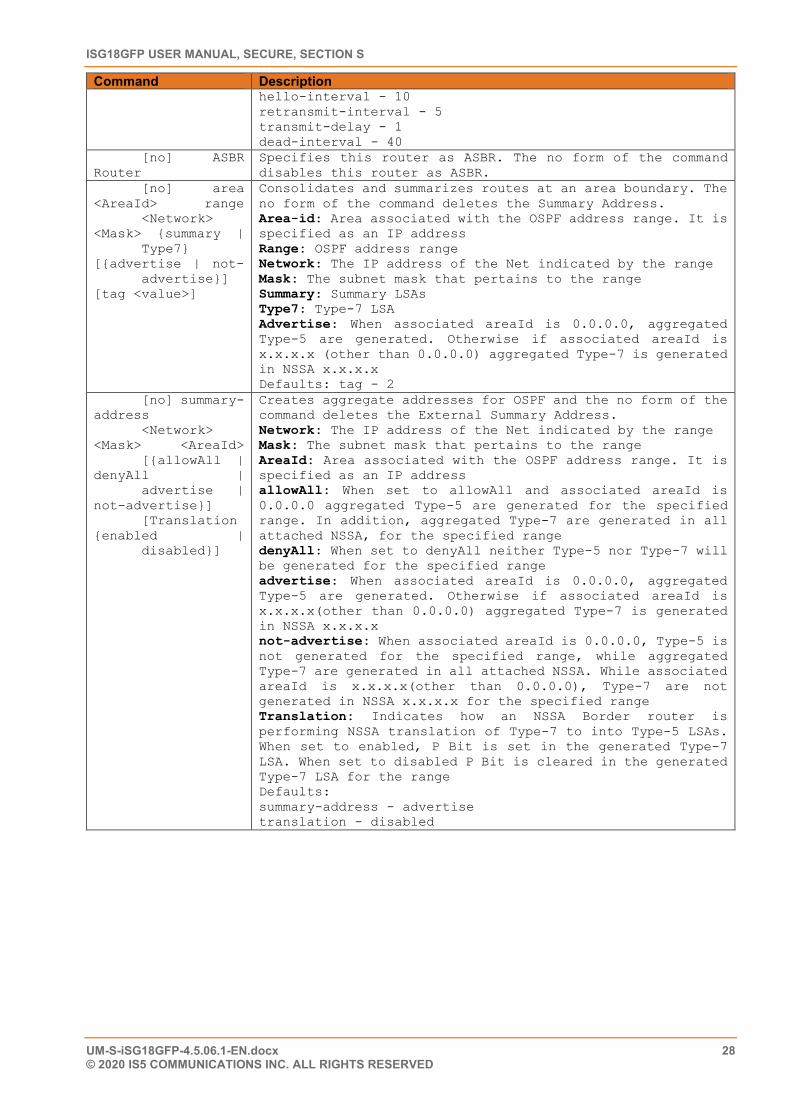
ISG18GFP USER MANUAL, SECURE, SECTION S
UM-S-iSG18GFP-4.5.06.1-EN.docx 28 © 2020 IS5 COMMUNICATIONS INC. ALL RIGHTS RESERVED
Command Description hello-interval - 10 retransmit-interval - 5 transmit-delay - 1 dead-interval - 40
[no] ASBR Router
Specifies this router as ASBR. The no form of the command disables this router as ASBR.
[no] area <AreaId> range <Network> <Mask> {summary | Type7} [{advertise | not- advertise}] [tag <value>]
Consolidates and summarizes routes at an area boundary. The no form of the command deletes the Summary Address. Area-id: Area associated with the OSPF address range. It is specified as an IP address Range: OSPF address range Network: The IP address of the Net indicated by the range Mask: The subnet mask that pertains to the range Summary: Summary LSAs Type7: Type-7 LSA Advertise: When associated areaId is 0.0.0.0, aggregated Type-5 are generated. Otherwise if associated areaId is x.x.x.x (other than 0.0.0.0) aggregated Type-7 is generated in NSSA x.x.x.x Defaults: tag - 2
[no] summary-address <Network> <Mask> <AreaId> [{allowAll | denyAll | advertise | not-advertise}] [Translation {enabled | disabled}]
Creates aggregate addresses for OSPF and the no form of the command deletes the External Summary Address. Network: The IP address of the Net indicated by the range Mask: The subnet mask that pertains to the range AreaId: Area associated with the OSPF address range. It is specified as an IP address allowAll: When set to allowAll and associated areaId is 0.0.0.0 aggregated Type-5 are generated for the specified range. In addition, aggregated Type-7 are generated in all attached NSSA, for the specified range denyAll: When set to denyAll neither Type-5 nor Type-7 will be generated for the specified range advertise: When associated areaId is 0.0.0.0, aggregated Type-5 are generated. Otherwise if associated areaId is x.x.x.x(other than 0.0.0.0) aggregated Type-7 is generated in NSSA x.x.x.x not-advertise: When associated areaId is 0.0.0.0, Type-5 is not generated for the specified range, while aggregated Type-7 are generated in all attached NSSA. While associated areaId is x.x.x.x(other than 0.0.0.0), Type-7 are not generated in NSSA x.x.x.x for the specified range Translation: Indicates how an NSSA Border router is performing NSSA translation of Type-7 to into Type-5 LSAs. When set to enabled, P Bit is set in the generated Type-7 LSA. When set to disabled P Bit is cleared in the generated Type-7 LSA for the range Defaults: summary-address - advertise translation - disabled
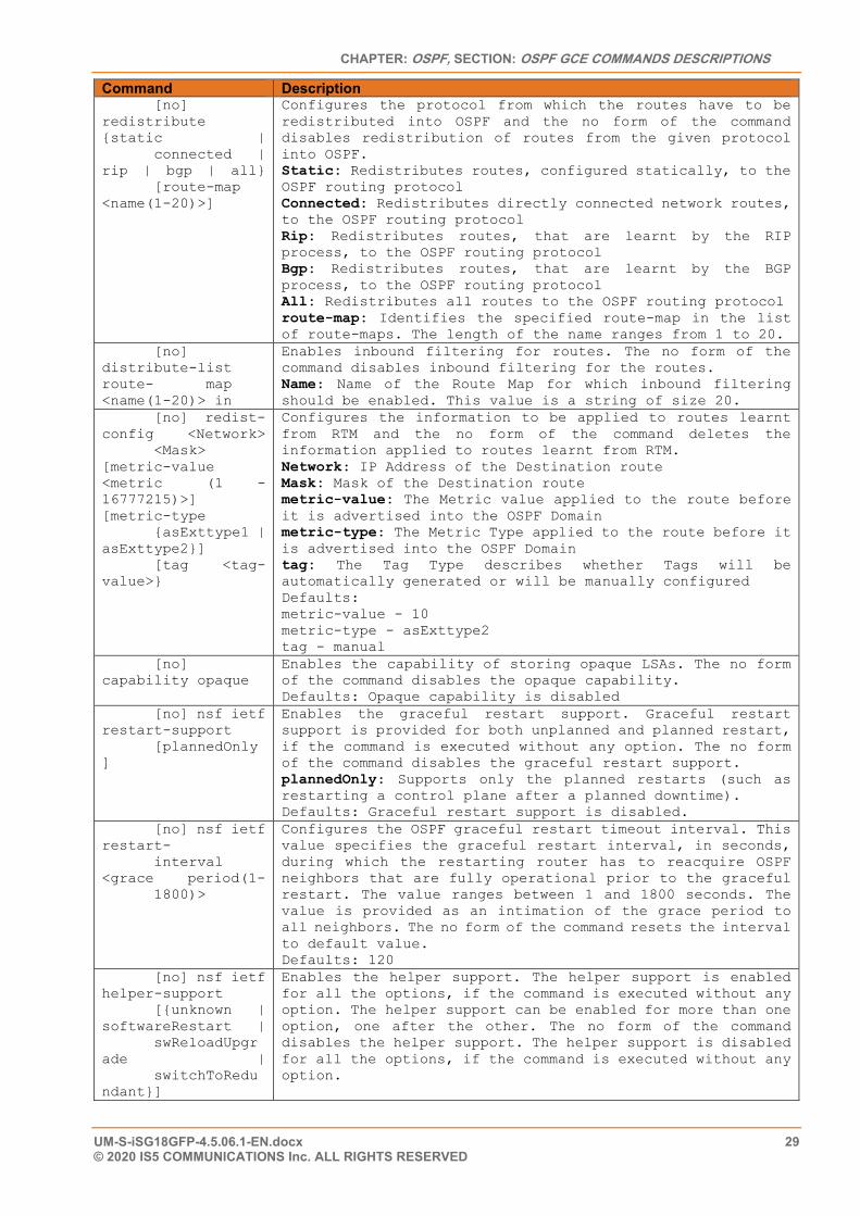
CHAPTER: OSPF, SECTION: OSPF GCE COMMANDS DESCRIPTIONS
UM-S-iSG18GFP-4.5.06.1-EN.docx 29 © 2020 IS5 COMMUNICATIONS Inc. ALL RIGHTS RESERVED
Command Description [no] redistribute {static | connected | rip | bgp | all} [route-map <name(1-20)>]
Configures the protocol from which the routes have to be redistributed into OSPF and the no form of the command disables redistribution of routes from the given protocol into OSPF. Static: Redistributes routes, configured statically, to the OSPF routing protocol Connected: Redistributes directly connected network routes, to the OSPF routing protocol Rip: Redistributes routes, that are learnt by the RIP process, to the OSPF routing protocol Bgp: Redistributes routes, that are learnt by the BGP process, to the OSPF routing protocol All: Redistributes all routes to the OSPF routing protocol route-map: Identifies the specified route-map in the list of route-maps. The length of the name ranges from 1 to 20.
[no] distribute-list route- map <name(1-20)> in
Enables inbound filtering for routes. The no form of the command disables inbound filtering for the routes. Name: Name of the Route Map for which inbound filtering should be enabled. This value is a string of size 20.
[no] redist-config <Network> <Mask> [metric-value <metric (1 - 16777215)>] [metric-type {asExttype1 | asExttype2}] [tag <tag-value>}
Configures the information to be applied to routes learnt from RTM and the no form of the command deletes the information applied to routes learnt from RTM. Network: IP Address of the Destination route Mask: Mask of the Destination route metric-value: The Metric value applied to the route before it is advertised into the OSPF Domain metric-type: The Metric Type applied to the route before it is advertised into the OSPF Domain tag: The Tag Type describes whether Tags will be automatically generated or will be manually configured Defaults: metric-value - 10 metric-type - asExttype2 tag - manual
[no] capability opaque
Enables the capability of storing opaque LSAs. The no form of the command disables the opaque capability. Defaults: Opaque capability is disabled
[no] nsf ietf restart-support [plannedOnly]
Enables the graceful restart support. Graceful restart support is provided for both unplanned and planned restart, if the command is executed without any option. The no form of the command disables the graceful restart support. plannedOnly: Supports only the planned restarts (such as restarting a control plane after a planned downtime). Defaults: Graceful restart support is disabled.
[no] nsf ietf restart- interval <grace period(1- 1800)>
Configures the OSPF graceful restart timeout interval. This value specifies the graceful restart interval, in seconds, during which the restarting router has to reacquire OSPF neighbors that are fully operational prior to the graceful restart. The value ranges between 1 and 1800 seconds. The value is provided as an intimation of the grace period to all neighbors. The no form of the command resets the interval to default value. Defaults: 120
[no] nsf ietf helper-support [{unknown | softwareRestart | swReloadUpgrade | switchToRedundant}]
Enables the helper support. The helper support is enabled for all the options, if the command is executed without any option. The helper support can be enabled for more than one option, one after the other. The no form of the command disables the helper support. The helper support is disabled for all the options, if the command is executed without any option.
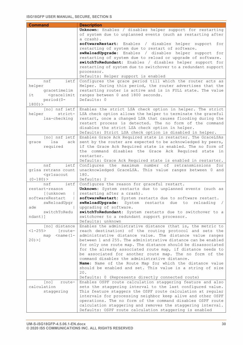
ISG18GFP USER MANUAL, SECURE, SECTION S
UM-S-iSG18GFP-4.5.06.1-EN.docx 30 © 2020 IS5 COMMUNICATIONS INC. ALL RIGHTS RESERVED
Command Description Unknown: Enables / disables helper support for restarting of system due to unplanned events (such as restarting after a crash). softwareRestart: Enables / disables helper support for restarting of system due to restart of software. swReloadUpgrade: Enables / disables helper support for restarting of system due to reload or upgrade of software. switchToRedundant: Enables / disables helper support for restarting of system due to switchover to a redundant support processor. Defaults: Helper support is enabled
nsf ietf helper gracetimelimit <gracelimit period(0-1800)>
Configures the grace period till which the router acts as Helper. During this period, the router advertises that the restarting router is active and is in FULL state. The value ranges between 0 and 1800 seconds. Defaults: 0
[no] nsf ietf helper strict- lsa-checking
Enables the strict LSA check option in helper. The strict LSA check option allows the helper to terminate the graceful restart, once a changed LSA that causes flooding during the restart process is detected. The no form of the command disables the strict LSA check option in helper. Defaults: Strict LSA check option is disabled in helper.
[no] nsf ietf grace lsa ack required
Enables Grace Ack Required state in restarter. The GraceLSAs sent by the router are expected to be acknowledged by peers, if the Grace Ack Required state is enabled. The no form of the command disables the Grace Ack Required state in restarter. Defaults: Grace Ack Required state is enabled in restarter.
nsf ietf grlsa retrans count <grlsacout (0-180)>
Configures the maximum number of retransmissions for unacknowledged GraceLSA. This value ranges between 0 and 180. Defaults: 2
nsf ietf restart-reason [{unknown | softwareRestart | swReloadUpgrade | switchToRedundant}]
Configures the reason for graceful restart. Unknown: System restarts due to unplanned events (such as restarting after a crash). softwareRestart: System restarts due to software restart. swReloadUpgrade: System restarts due to reloading / upgrading of software. switchToRedundant: System restarts due to switchover to a switchover to a redundant support processor. Defaults: unknown
[no] distance <1-255> [route- map <name(1-20)>]
Enables the administrative distance (that is, the metric to reach destination) of the routing protocol and sets the administrative distance value. The distance value ranges between 1 and 255. The administrative distance can be enabled for only one route map. The distance should be disassociated for the already associated route map, if distance needs to be associated for another route map. The no form of the command disables the administrative distance. Name: Name of the Route Map for which the distance value should be enabled and set. This value is a string of size 20. Defaults: 0 (Represents directly connected route)
[no] route-calculation staggering
Enables OSPF route calculation staggering feature and also sets the staggering interval to the last configured value. This feature staggers the OSPF route calculation at regular intervals for processing neighbor keep alive and other OSPF operations. The no form of the command disables OSPF route calculation staggering and removes the staggering interval. Defaults: OSPF route calculation staggering is enabled
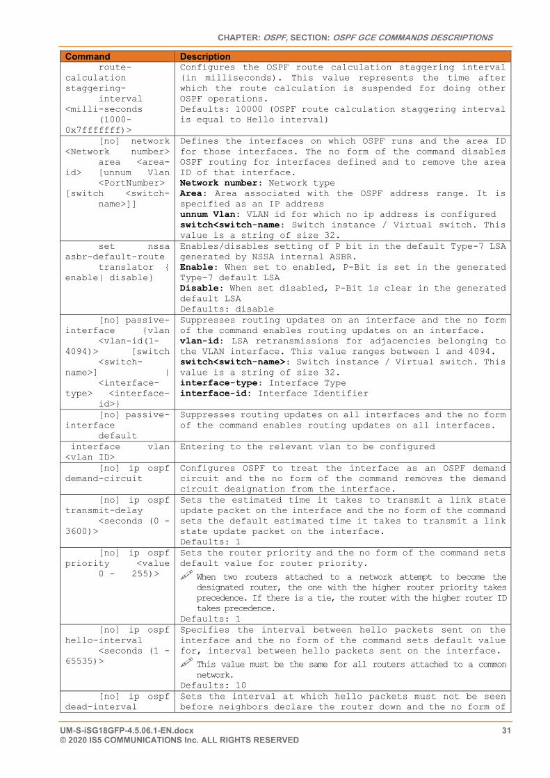
CHAPTER: OSPF, SECTION: OSPF GCE COMMANDS DESCRIPTIONS
UM-S-iSG18GFP-4.5.06.1-EN.docx 31 © 2020 IS5 COMMUNICATIONS Inc. ALL RIGHTS RESERVED
Command Description route-calculation staggering- interval <milli-seconds (1000-0x7fffffff)>
Configures the OSPF route calculation staggering interval (in milliseconds). This value represents the time after which the route calculation is suspended for doing other OSPF operations. Defaults: 10000 (OSPF route calculation staggering interval is equal to Hello interval)
[no] network <Network number> area <area-id> [unnum Vlan <PortNumber> [switch <switch- name>]]
Defines the interfaces on which OSPF runs and the area ID for those interfaces. The no form of the command disables OSPF routing for interfaces defined and to remove the area ID of that interface. Network number: Network type Area: Area associated with the OSPF address range. It is specified as an IP address unnum Vlan: VLAN id for which no ip address is configured switch<switch-name: Switch instance / Virtual switch. This value is a string of size 32.
set nssa asbr-default-route translator { enable| disable}
Enables/disables setting of P bit in the default Type-7 LSA generated by NSSA internal ASBR. Enable: When set to enabled, P-Bit is set in the generated Type-7 default LSA Disable: When set disabled, P-Bit is clear in the generated default LSA Defaults: disable
[no] passive-interface {vlan <vlan-id(1-4094)> [switch <switch-name>] | <interface-type> <interface- id>}
Suppresses routing updates on an interface and the no form of the command enables routing updates on an interface. vlan-id: LSA retransmissions for adjacencies belonging to the VLAN interface. This value ranges between 1 and 4094. switch<switch-name>: Switch instance / Virtual switch. This value is a string of size 32. interface-type: Interface Type interface-id: Interface Identifier
[no] passive-interface default
Suppresses routing updates on all interfaces and the no form of the command enables routing updates on all interfaces.
interface vlan <vlan ID>
Entering to the relevant vlan to be configured
[no] ip ospf demand-circuit
Configures OSPF to treat the interface as an OSPF demand circuit and the no form of the command removes the demand circuit designation from the interface.
[no] ip ospf transmit-delay <seconds (0 - 3600)>
Sets the estimated time it takes to transmit a link state update packet on the interface and the no form of the command sets the default estimated time it takes to transmit a link state update packet on the interface. Defaults: 1
[no] ip ospf priority <value 0 - 255)>
Sets the router priority and the no form of the command sets default value for router priority.
When two routers attached to a network attempt to become the designated router, the one with the higher router priority takes precedence. If there is a tie, the router with the higher router ID takes precedence.
Defaults: 1 [no] ip ospf hello-interval <seconds (1 - 65535)>
Specifies the interval between hello packets sent on the interface and the no form of the command sets default value for, interval between hello packets sent on the interface.
This value must be the same for all routers attached to a common network.
Defaults: 10 [no] ip ospf dead-interval
Sets the interval at which hello packets must not be seen before neighbors declare the router down and the no form of
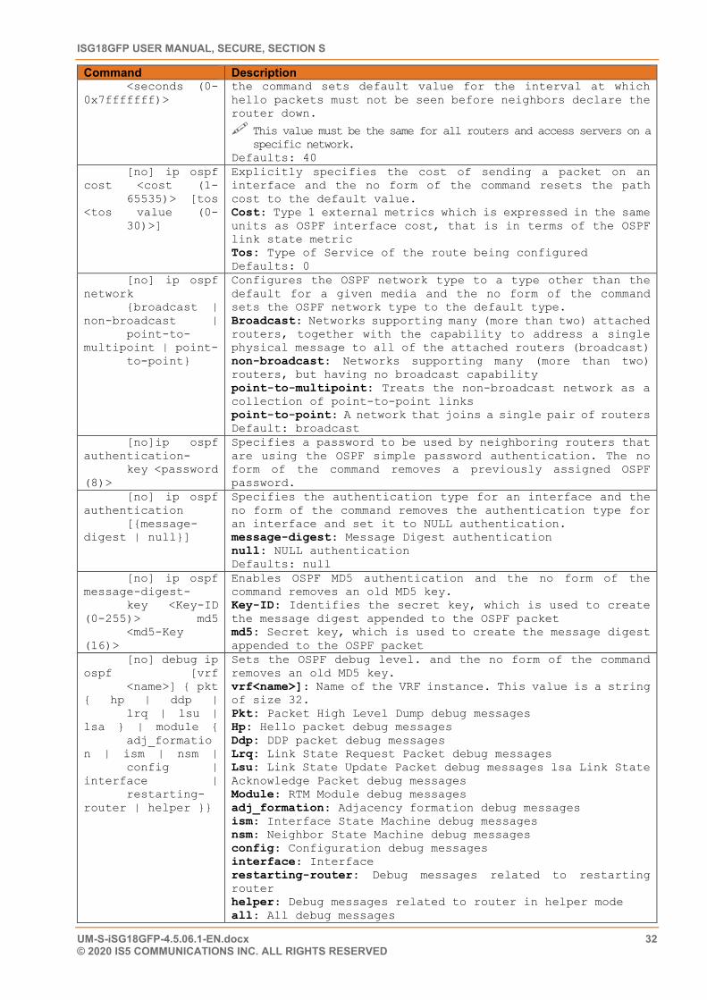
ISG18GFP USER MANUAL, SECURE, SECTION S
UM-S-iSG18GFP-4.5.06.1-EN.docx 32 © 2020 IS5 COMMUNICATIONS INC. ALL RIGHTS RESERVED
Command Description <seconds (0-0x7fffffff)>
the command sets default value for the interval at which hello packets must not be seen before neighbors declare the router down.
This value must be the same for all routers and access servers on a specific network.
Defaults: 40 [no] ip ospf cost <cost (1- 65535)> [tos <tos value (0- 30)>]
Explicitly specifies the cost of sending a packet on an interface and the no form of the command resets the path cost to the default value. Cost: Type 1 external metrics which is expressed in the same units as OSPF interface cost, that is in terms of the OSPF link state metric Tos: Type of Service of the route being configured Defaults: 0
[no] ip ospf network {broadcast | non-broadcast | point-to-multipoint | point- to-point}
Configures the OSPF network type to a type other than the default for a given media and the no form of the command sets the OSPF network type to the default type. Broadcast: Networks supporting many (more than two) attached routers, together with the capability to address a single physical message to all of the attached routers (broadcast) non-broadcast: Networks supporting many (more than two) routers, but having no broadcast capability point-to-multipoint: Treats the non-broadcast network as a collection of point-to-point links point-to-point: A network that joins a single pair of routers Default: broadcast
[no]ip ospf authentication- key <password (8)>
Specifies a password to be used by neighboring routers that are using the OSPF simple password authentication. The no form of the command removes a previously assigned OSPF password.
[no] ip ospf authentication [{message-digest | null}]
Specifies the authentication type for an interface and the no form of the command removes the authentication type for an interface and set it to NULL authentication. message-digest: Message Digest authentication null: NULL authentication Defaults: null
[no] ip ospf message-digest- key <Key-ID (0-255)> md5 <md5-Key (16)>
Enables OSPF MD5 authentication and the no form of the command removes an old MD5 key. Key-ID: Identifies the secret key, which is used to create the message digest appended to the OSPF packet md5: Secret key, which is used to create the message digest appended to the OSPF packet
[no] debug ip ospf [vrf <name>] { pkt { hp | ddp | lrq | lsu | lsa } | module { adj_formation | ism | nsm | config | interface | restarting-router | helper }}
Sets the OSPF debug level. and the no form of the command removes an old MD5 key. vrf<name>]: Name of the VRF instance. This value is a string of size 32. Pkt: Packet High Level Dump debug messages Hp: Hello packet debug messages Ddp: DDP packet debug messages Lrq: Link State Request Packet debug messages Lsu: Link State Update Packet debug messages lsa Link State Acknowledge Packet debug messages Module: RTM Module debug messages adj_formation: Adjacency formation debug messages ism: Interface State Machine debug messages nsm: Neighbor State Machine debug messages config: Configuration debug messages interface: Interface restarting-router: Debug messages related to restarting router helper: Debug messages related to router in helper mode all: All debug messages
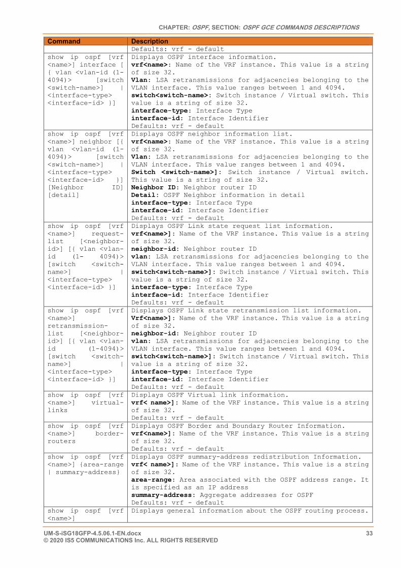
CHAPTER: OSPF, SECTION: OSPF GCE COMMANDS DESCRIPTIONS
UM-S-iSG18GFP-4.5.06.1-EN.docx 33 © 2020 IS5 COMMUNICATIONS Inc. ALL RIGHTS RESERVED
Command Description Defaults: vrf - default
show ip ospf [vrf <name>] interface [ { vlan <vlan-id (1-4094)> [switch <switch-name>] | <interface-type> <interface-id> }]
Displays OSPF interface information. vrf<name>: Name of the VRF instance. This value is a string of size 32. Vlan: LSA retransmissions for adjacencies belonging to the VLAN interface. This value ranges between 1 and 4094. switch<switch-name>: Switch instance / Virtual switch. This value is a string of size 32. interface-type: Interface Type interface-id: Interface Identifier Defaults: vrf - default
show ip ospf [vrf <name>] neighbor [{ vlan <vlan-id (1-4094)> [switch <switch-name>] | <interface-type> <interface-id> }] [Neighbor ID] [detail]
Displays OSPF neighbor information list. vrf<name>: Name of the VRF instance. This value is a string of size 32. Vlan: LSA retransmissions for adjacencies belonging to the VLAN interface. This value ranges between 1 and 4094. Switch <switch-name>]: Switch instance / Virtual switch. This value is a string of size 32. Neighbor ID: Neighbor router ID Detail: OSPF Neighbor information in detail interface-type: Interface Type interface-id: Interface Identifier Defaults: vrf - default
show ip ospf [vrf <name>] request-list [<neighbor-id>] [{ vlan <vlan-id (1- 4094)> [switch <switch-name>] | <interface-type> <interface-id> }]
Displays OSPF Link state request list information. vrf<name>]: Name of the VRF instance. This value is a string of size 32. neighbor-id: Neighbor router ID vlan: LSA retransmissions for adjacencies belonging to the VLAN interface. This value ranges between 1 and 4094. switch<switch-name>]: Switch instance / Virtual switch. This value is a string of size 32. interface-type: Interface Type interface-id: Interface Identifier Defaults: vrf - default
show ip ospf [vrf <name>] retransmission-list [<neighbor-id>] [{ vlan <vlan-id (1-4094)> [switch <switch-name>] | <interface-type> <interface-id> }]
Displays OSPF Link state retransmission list information. Vrf<name>]: Name of the VRF instance. This value is a string of size 32. neighbor-id: Neighbor router ID vlan: LSA retransmissions for adjacencies belonging to the VLAN interface. This value ranges between 1 and 4094. switch<switch-name>]: Switch instance / Virtual switch. This value is a string of size 32. interface-type: Interface Type interface-id: Interface Identifier Defaults: vrf - default
show ip ospf [vrf <name>] virtual-links
Displays OSPF Virtual link information. vrf< name>]: Name of the VRF instance. This value is a string of size 32. Defaults: vrf - default
show ip ospf [vrf <name>] border-routers
Displays OSPF Border and Boundary Router Information. vrf<name>]: Name of the VRF instance. This value is a string of size 32. Defaults: vrf - default
show ip ospf [vrf <name>] {area-range | summary-address}
Displays OSPF summary-address redistribution Information. vrf< name>]: Name of the VRF instance. This value is a string of size 32. area-range: Area associated with the OSPF address range. It is specified as an IP address summary-address: Aggregate addresses for OSPF Defaults: vrf - default
show ip ospf [vrf <name>]
Displays general information about the OSPF routing process.
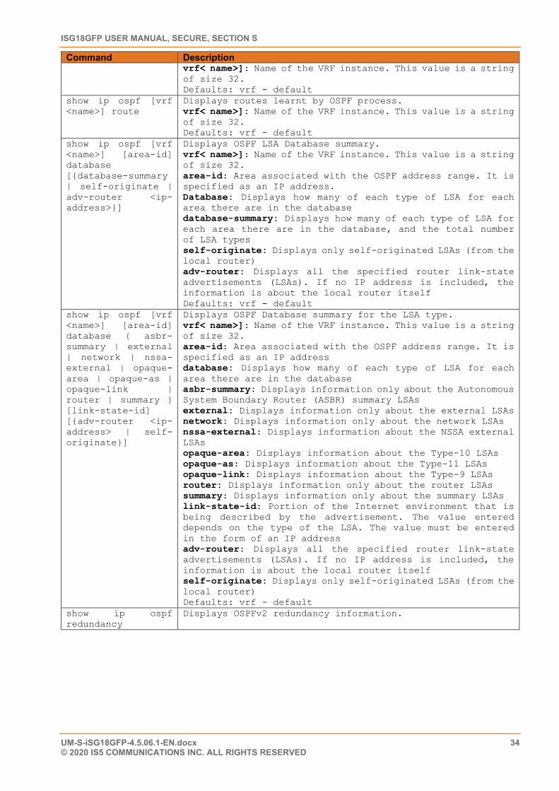
ISG18GFP USER MANUAL, SECURE, SECTION S
UM-S-iSG18GFP-4.5.06.1-EN.docx 34 © 2020 IS5 COMMUNICATIONS INC. ALL RIGHTS RESERVED
Command Description vrf< name>]: Name of the VRF instance. This value is a string of size 32. Defaults: vrf - default
show ip ospf [vrf <name>] route
Displays routes learnt by OSPF process. vrf< name>]: Name of the VRF instance. This value is a string of size 32. Defaults: vrf - default
show ip ospf [vrf <name>] [area-id] database [{database-summary | self-originate | adv-router <ip-address>}]
Displays OSPF LSA Database summary. vrf< name>]: Name of the VRF instance. This value is a string of size 32. area-id: Area associated with the OSPF address range. It is specified as an IP address. Database: Displays how many of each type of LSA for each area there are in the database database-summary: Displays how many of each type of LSA for each area there are in the database, and the total number of LSA types self-originate: Displays only self-originated LSAs (from the local router) adv-router: Displays all the specified router link-state advertisements (LSAs). If no IP address is included, the information is about the local router itself Defaults: vrf - default
show ip ospf [vrf <name>] [area-id] database { asbr-summary | external | network | nssa-external | opaque-area | opaque-as | opaque-link | router | summary } [link-state-id] [{adv-router <ip-address> | self-originate}]
Displays OSPF Database summary for the LSA type. vrf< name>]: Name of the VRF instance. This value is a string of size 32. area-id: Area associated with the OSPF address range. It is specified as an IP address database: Displays how many of each type of LSA for each area there are in the database asbr-summary: Displays information only about the Autonomous System Boundary Router (ASBR) summary LSAs external: Displays information only about the external LSAs network: Displays information only about the network LSAs nssa-external: Displays information about the NSSA external LSAs opaque-area: Displays information about the Type-10 LSAs opaque-as: Displays information about the Type-11 LSAs opaque-link: Displays information about the Type-9 LSAs router: Displays information only about the router LSAs summary: Displays information only about the summary LSAs link-state-id: Portion of the Internet environment that is being described by the advertisement. The value entered depends on the type of the LSA. The value must be entered in the form of an IP address adv-router: Displays all the specified router link-state advertisements (LSAs). If no IP address is included, the information is about the local router itself self-originate: Displays only self-originated LSAs (from the local router) Defaults: vrf - default
show ip ospf redundancy
Displays OSPFv2 redundancy information.
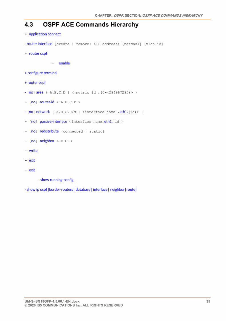
CHAPTER: OSPF, SECTION: OSPF ACE COMMANDS HIERARCHY
UM-S-iSG18GFP-4.5.06.1-EN.docx 35 © 2020 IS5 COMMUNICATIONS Inc. ALL RIGHTS RESERVED
4.3 OSPF ACE Commands Hierarchy + application connect
- router interface {create | remove} <IP address> [netmask] [vlan id]
+ router ospf
- enable
+ configure terminal
+ router ospf
- [no] area { A.B.C.D | < metric id ,(0-4294967295)> }
- [no] router-id < A.B.C.D >
- [no] network { A.B.C.D/M | <interface name ,eth1.(id)> }
- [no] passive-interface <interface name,eth1.(id)>
- [no] redistribute {connected | static}
- [no] neighbor A.B.C.D
- write
- exit
- exit
- show running-config
- show ip ospf [border-routers| database| interface| neighbor|route]
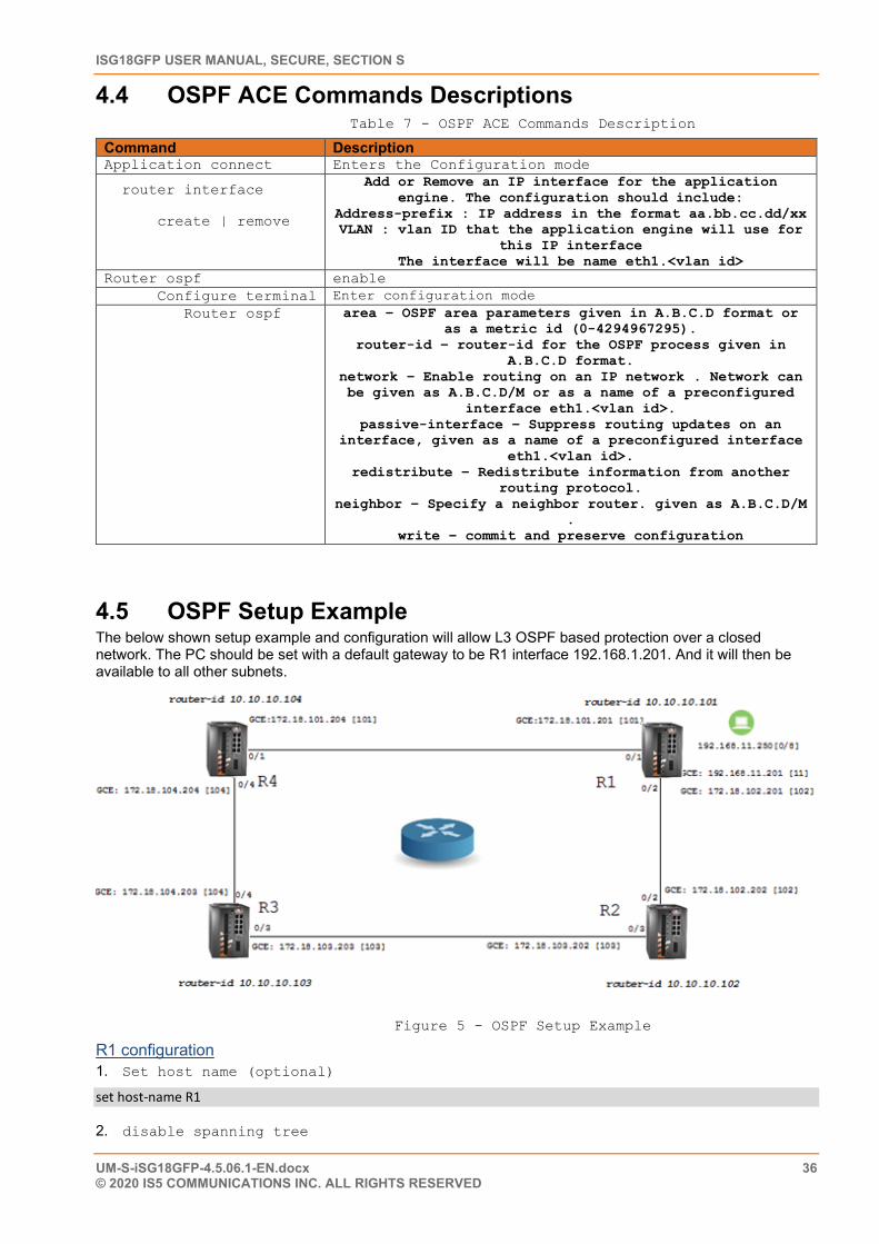
ISG18GFP USER MANUAL, SECURE, SECTION S
UM-S-iSG18GFP-4.5.06.1-EN.docx 36 © 2020 IS5 COMMUNICATIONS INC. ALL RIGHTS RESERVED
4.4 OSPF ACE Commands Descriptions Table 7 - OSPF ACE Commands Description
Command Description Application connect Enters the Configuration mode
router interface
create | remove
Add or Remove an IP interface for the application engine. The configuration should include:
Address-prefix : IP address in the format aa.bb.cc.dd/xx VLAN : vlan ID that the application engine will use for
this IP interface The interface will be name eth1.<vlan id>
Router ospf enable Configure terminal Enter configuration mode Router ospf area – OSPF area parameters given in A.B.C.D format or
as a metric id (0-4294967295). router-id – router-id for the OSPF process given in
A.B.C.D format. network – Enable routing on an IP network . Network can be given as A.B.C.D/M or as a name of a preconfigured
interface eth1.<vlan id>. passive-interface – Suppress routing updates on an
interface, given as a name of a preconfigured interface eth1.<vlan id>.
redistribute – Redistribute information from another routing protocol.
neighbor – Specify a neighbor router. given as A.B.C.D/M .
write – commit and preserve configuration
4.5 OSPF Setup Example The below shown setup example and configuration will allow L3 OSPF based protection over a closed network. The PC should be set with a default gateway to be R1 interface 192.168.1.201. And it will then be available to all other subnets.
Figure 5 - OSPF Setup Example
R1 configuration 1. Set host name (optional)
set host-name R1
2. disable spanning tree
CHAPTER: OSPF, SECTION: OSPF SETUP EXAMPLE
UM-S-iSG18GFP-4.5.06.1-EN.docx 37 © 2020 IS5 COMMUNICATIONS Inc. ALL RIGHTS RESERVED
config
no spanning-tree
exit
3. remove network ports from default vlan 1
vlan 1
no ports fa 0/1-2 untagged fa 0/1-2
exit
4. assign VLANS and corresponding IP interfaces
vlan 101
ports fastethernet 0/1
exit
vlan 102
ports fastethernet 0/2
exit
vlan 11
port fastethernet 0/8 untagged fastethernet 0/8 name lan
exit
interface vlan 101
shutdown
ip address 172.18.101.201 255.255.255.0
no shutdown
exit
interface vlan 102
shutdown
ip address 172.18.102.201 255.255.255.0
no shutdown
exit
interface vlan 11
shutdown
ip address 192.168.11.201 255.255.255.0
no shutdown
ISG18GFP USER MANUAL, SECURE, SECTION S
UM-S-iSG18GFP-4.5.06.1-EN.docx 38 © 2020 IS5 COMMUNICATIONS INC. ALL RIGHTS RESERVED
exit
5. Set PVID to the LAN PC (untagged access device)
interface fastethernet 0/8
switchport pvid 11
exit
6. configure OSPF
router ospf
router-id 10.10.10.101
network 172.18.101.201 255.255.255.0 area 0.0.0.0
network 172.18.102.201 255.255.255.0 area 0.0.0.0
network 192.168.11.201 255.255.255.0 area 0.0.0.0
passive-interface vlan 11
end
write startup-cfg
R2 configuration 1. Set host name (optional)
set host-name R2 2. disable spanning tree
config
no spanning-tree
exit
3. remove network ports from default vlan 1
config
vlan 1
no ports fa 0/2,0/3 untagged fa 0/2-3
exit
4. assign VLANS and corresponding IP interfaces
vlan 102
ports fastethernet 0/2
exit
vlan 103
ports fastethernet 0/3
exit
CHAPTER: OSPF, SECTION: OSPF SETUP EXAMPLE
UM-S-iSG18GFP-4.5.06.1-EN.docx 39 © 2020 IS5 COMMUNICATIONS Inc. ALL RIGHTS RESERVED
interface vlan 102
shutdown
ip address 172.18.102.202 255.255.255.0
no shutdown
exit
interface vlan 103
shutdown
ip address 172.18.103.202 255.255.255.0
no shutdown
exit
5. configure OSPF
router ospf
router-id 10.10.10.102
network 172.18.102.202 255.255.255.0 area 0.0.0.0
network 172.18.103.202 255.255.255.0 area 0.0.0.0
end
write startup-cfg
R3 configuration 1. Set host name (optional
set host-name R3 2. disable spanning tree
config
no spanning-tree
exit
3. remove network ports from default vlan 1
config
vlan 1
no ports fa 0/4,0/3 untagged fa 0/3-4
exit
4. assign VLANS and corresponding IP interfaces
vlan 103
ports fastethernet 0/3
exit
ISG18GFP USER MANUAL, SECURE, SECTION S
UM-S-iSG18GFP-4.5.06.1-EN.docx 40 © 2020 IS5 COMMUNICATIONS INC. ALL RIGHTS RESERVED
vlan 104
ports fastethernet 0/4
exit
interface vlan 103
shutdown
ip address 172.18.103.203 255.255.255.0
no shutdown
exit
interface vlan 104
shutdown
ip address 172.18.104.203 255.255.255.0
no shutdown
exit
5. configure OSPF
router ospf
router-id 10.10.10.103
network 172.18.104.203 255.255.255.0 area 0.0.0.0
network 172.18.103.203 255.255.255.0 area 0.0.0.0
end
write startup-cfg
R4 configuration 1. Set host name (optional)
set host-name R4 2. disable spanning tree
config
no spanning-tree
exit
3. remove network ports from default vlan 1
config
vlan 1
no ports fa 0/4,0/1 untagged fa 0/1,0/4
exit
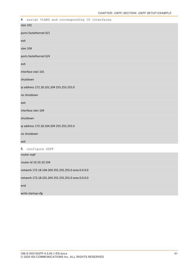
CHAPTER: OSPF, SECTION: OSPF SETUP EXAMPLE
UM-S-iSG18GFP-4.5.06.1-EN.docx 41 © 2020 IS5 COMMUNICATIONS Inc. ALL RIGHTS RESERVED
4. assign VLANS and corresponding IP interfaces
vlan 101
ports fastethernet 0/1
exit
vlan 104
ports fastethernet 0/4
exit
interface vlan 101
shutdown
ip address 172.18.101.204 255.255.255.0
no shutdown
exit
interface vlan 104
shutdown
ip address 172.18.104.204 255.255.255.0
no shutdown
exit
5. configure OSPF
router ospf
router-id 10.10.10.104
network 172.18.104.204 255.255.255.0 area 0.0.0.0
network 172.18.101.204 255.255.255.0 area 0.0.0.0
end
write startup-cfg
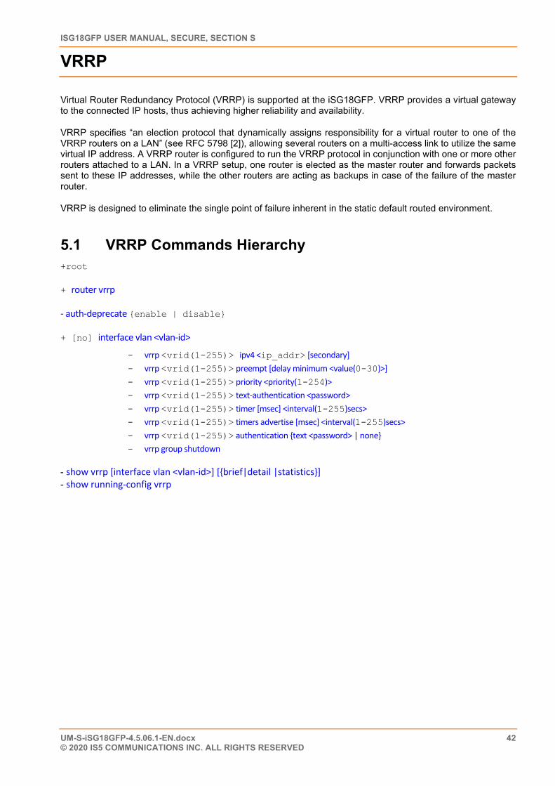
ISG18GFP USER MANUAL, SECURE, SECTION S
UM-S-iSG18GFP-4.5.06.1-EN.docx 42 © 2020 IS5 COMMUNICATIONS INC. ALL RIGHTS RESERVED
VRRP
Virtual Router Redundancy Protocol (VRRP) is supported at the iSG18GFP. VRRP provides a virtual gateway to the connected IP hosts, thus achieving higher reliability and availability.
VRRP specifies “an election protocol that dynamically assigns responsibility for a virtual router to one of the VRRP routers on a LAN” (see RFC 5798 [2]), allowing several routers on a multi-access link to utilize the same virtual IP address. A VRRP router is configured to run the VRRP protocol in conjunction with one or more other routers attached to a LAN. In a VRRP setup, one router is elected as the master router and forwards packets sent to these IP addresses, while the other routers are acting as backups in case of the failure of the master router.
VRRP is designed to eliminate the single point of failure inherent in the static default routed environment.
5.1 VRRP Commands Hierarchy +root
+ router vrrp
- auth-deprecate {enable | disable}
+ [no] interface vlan <vlan-id>
- vrrp <vrid(1-255)> ipv4 <ip_addr> [secondary] - vrrp <vrid(1-255)> preempt [delay minimum <value(0-30)>] - vrrp <vrid(1-255)> priority <priority(1-254)> - vrrp <vrid(1-255)> text-authentication <password> - vrrp <vrid(1-255)> timer [msec] <interval(1-255)secs> - vrrp <vrid(1-255)> timers advertise [msec] <interval(1-255)secs> - vrrp <vrid(1-255)> authentication {text <password> | none} - vrrp group shutdown
- show vrrp [interface vlan <vlan-id>] [{brief|detail |statistics}] - show running-config vrrp
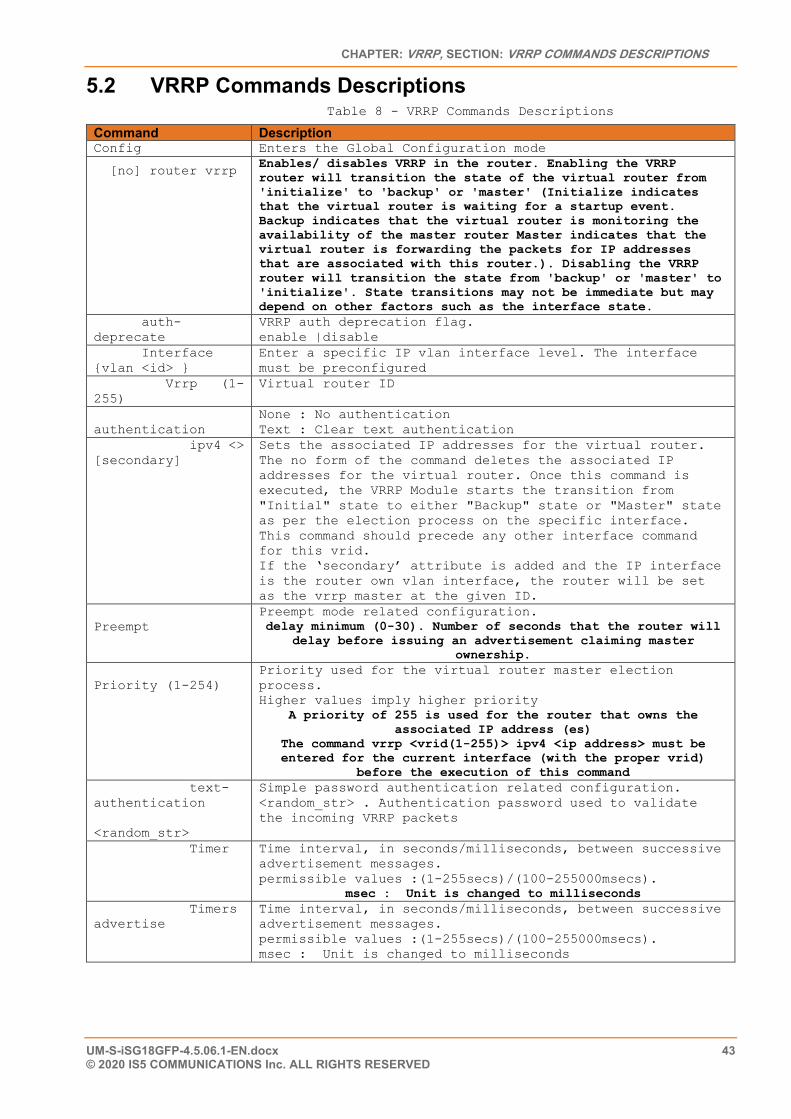
CHAPTER: VRRP, SECTION: VRRP COMMANDS DESCRIPTIONS
UM-S-iSG18GFP-4.5.06.1-EN.docx 43 © 2020 IS5 COMMUNICATIONS Inc. ALL RIGHTS RESERVED
5.2 VRRP Commands Descriptions Table 8 - VRRP Commands Descriptions
Command Description Config Enters the Global Configuration mode
[no] router vrrp Enables/ disables VRRP in the router. Enabling the VRRP router will transition the state of the virtual router from 'initialize' to 'backup' or 'master' (Initialize indicates that the virtual router is waiting for a startup event. Backup indicates that the virtual router is monitoring the availability of the master router Master indicates that the virtual router is forwarding the packets for IP addresses that are associated with this router.). Disabling the VRRP router will transition the state from 'backup' or 'master' to 'initialize'. State transitions may not be immediate but may depend on other factors such as the interface state.
auth-deprecate
VRRP auth deprecation flag. enable |disable
Interface {vlan <id> }
Enter a specific IP vlan interface level. The interface must be preconfigured
Vrrp (1-255)
Virtual router ID
authentication
None : No authentication Text : Clear text authentication
ipv4 <> [secondary]
Sets the associated IP addresses for the virtual router. The no form of the command deletes the associated IP addresses for the virtual router. Once this command is executed, the VRRP Module starts the transition from "Initial" state to either "Backup" state or "Master" state as per the election process on the specific interface. This command should precede any other interface command for this vrid. If the ‘secondary’ attribute is added and the IP interface is the router own vlan interface, the router will be set as the vrrp master at the given ID.
Preempt
Preempt mode related configuration. delay minimum (0-30). Number of seconds that the router will
delay before issuing an advertisement claiming master ownership.
Priority (1-254)
Priority used for the virtual router master election process. Higher values imply higher priority
A priority of 255 is used for the router that owns the associated IP address (es)
The command vrrp <vrid(1-255)> ipv4 <ip address> must be entered for the current interface (with the proper vrid)
before the execution of this command text-authentication <random_str>
Simple password authentication related configuration. <random_str> . Authentication password used to validate the incoming VRRP packets
Timer Time interval, in seconds/milliseconds, between successive advertisement messages. permissible values :(1-255secs)/(100-255000msecs).
msec : Unit is changed to milliseconds Timers advertise
Time interval, in seconds/milliseconds, between successive advertisement messages. permissible values :(1-255secs)/(100-255000msecs). msec : Unit is changed to milliseconds
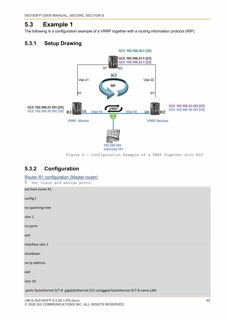
ISG18GFP USER MANUAL, SECURE, SECTION S
UM-S-iSG18GFP-4.5.06.1-EN.docx 44 © 2020 IS5 COMMUNICATIONS INC. ALL RIGHTS RESERVED
5.3 Example 1 The following is a configuration example of a VRRP together with a routing information protocol (RIP).
5.3.1 Setup Drawing
Figure 6 - Configuration Example of a VRRP Together with RIP
5.3.2 Configuration Router R1 configuration (Master router) 1. Set vlans and assign ports
set host-name R1
config t
no spanning-tree
vlan 1
no ports
exit
interface vlan 1
shutdown
no ip address
exit
vlan 10
ports fastethernet 0/7-8 gigabitethernet 0/3 untagged fastethernet 0/7-8 name LAN
CHAPTER: VRRP, SECTION: EXAMPLE 1
UM-S-iSG18GFP-4.5.06.1-EN.docx 45 © 2020 IS5 COMMUNICATIONS Inc. ALL RIGHTS RESERVED
exit
vlan 21
ports fastethernet 0/1 name RIP
exit
interface fastethernet 0/1
alias NNI
switchport pvid 21
exit
interface fastethernet 0/7
alias VRRP
switchport pvid 10
exit
interface fastethernet 0/8
alias UNI
switchport pvid 10
exit 2. Set ip interfaces and rip
interface vlan 11
interface vlan 10
ip address 192.168.10.101 255.255.255.0
no shut
exit
interface vlan 21
ip address 192.168.21.101 255.255.255.0
no shut
exit
router rip
network 192.168.21.101
network 192.168.10.101
passive-interface vlan 10
exit
ISG18GFP USER MANUAL, SECURE, SECTION S
UM-S-iSG18GFP-4.5.06.1-EN.docx 46 © 2020 IS5 COMMUNICATIONS INC. ALL RIGHTS RESERVED
3. set vrrp instance (master router)
router vrrp
interface vlan 10
vrrp 1 ipv4 192.168.10.101
vrrp 1 ipv4 192.168.10.101 secondary
exit
write startup-cfg
Router R2 configuration 1. Set vlans and assign ports
set host-name R2
config t
no spanning-tree
vlan 1
no ports
exit
interface vlan 1
shutdown
no ip address
exit
vlan 10
ports fastethernet 0/7-8 gigabitethernet 0/3 untagged fastethernet 0/7-8 name LAN
exit
vlan 22
ports fastethernet 0/1 name RIP
exit
interface fastethernet 0/1
alias NNI
switchport pvid 22
exit
interface fastethernet 0/7
alias VRRP
CHAPTER: VRRP, SECTION: EXAMPLE 1
UM-S-iSG18GFP-4.5.06.1-EN.docx 47 © 2020 IS5 COMMUNICATIONS Inc. ALL RIGHTS RESERVED
switchport pvid 10
exit
interface fastethernet 0/8
alias UNI
switchport pvid 10
exit
2. Set ip interfaces
interface vlan 11
interface vlan 10
ip address 192.168.10.102 255.255.255.0
no shut
exit
interface vlan 22
ip address 192.168.22.102 255.255.255.0
no shut
exit
router rip
network 192.168.22.102
network 192.168.10.102
passive-interface vlan 10
exit
3. set vrrp instance
router vrrp
interface vlan 10
vrrp 1 ipv4 192.168.10.102
vrrp 1 ipv4 192.168.10.101 secondary
exit
write startup-cfg
ISG18GFP USER MANUAL, SECURE, SECTION S
UM-S-iSG18GFP-4.5.06.1-EN.docx 48 © 2020 IS5 COMMUNICATIONS INC. ALL RIGHTS RESERVED
Router R3 configuration set host-name R3
config t
no spanning-tree
vlan 1
no ports
exit
interface vlan 1
shutdown
no ip address
exit
vlan 21
ports fastethernet 0/1
exit
vlan 22
ports fastethernet 0/2
exit
vlan 30
ports fastethernet 0/8 gigabit 0/3 untagged fastethernet 0/8
exit
interface fastethernet 0/1
alias NNI
switchport pvid 21
exit
interface fastethernet 0/2
alias NNI
switchport pvid 22
exit
interface vlan 21
ip address 192.168.21.1 255.255.255.0
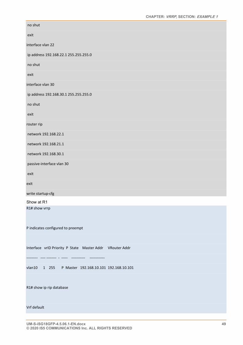
CHAPTER: VRRP, SECTION: EXAMPLE 1
UM-S-iSG18GFP-4.5.06.1-EN.docx 49 © 2020 IS5 COMMUNICATIONS Inc. ALL RIGHTS RESERVED
no shut
exit
interface vlan 22
ip address 192.168.22.1 255.255.255.0
no shut
exit
interface vlan 30
ip address 192.168.30.1 255.255.255.0
no shut
exit
router rip
network 192.168.22.1
network 192.168.21.1
network 192.168.30.1
passive-interface vlan 30
exit
exit
write startup-cfg
Show at R1 R1# show vrrp
P indicates configured to preempt
Interface vrID Priority P State Master Addr VRouter Addr
--------- ---- -------- - ----- ----------- ------------
vlan10 1 255 P Master 192.168.10.101 192.168.10.101
R1# show ip rip database
Vrf default
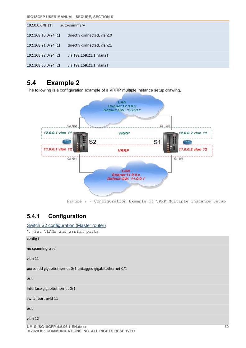
ISG18GFP USER MANUAL, SECURE, SECTION S
UM-S-iSG18GFP-4.5.06.1-EN.docx 50 © 2020 IS5 COMMUNICATIONS INC. ALL RIGHTS RESERVED
192.0.0.0/8 [1] auto-summary
192.168.10.0/24 [1] directly connected, vlan10
192.168.21.0/24 [1] directly connected, vlan21
192.168.22.0/24 [2] via 192.168.21.1, vlan21
192.168.30.0/24 [2] via 192.168.21.1, vlan21
5.4 Example 2 The following is a configuration example of a VRRP multiple instance setup drawing.
Figure 7 - Configuration Example of VRRP Multiple Instance Setup
5.4.1 Configuration Switch S2 configuration (Master router) 1. Set VLANs and assign ports
config t
no spanning-tree
vlan 11
ports add gigabitethernet 0/1 untagged gigabitethernet 0/1
exit
interface gigabitethernet 0/1
switchport pvid 11
exit
vlan 12
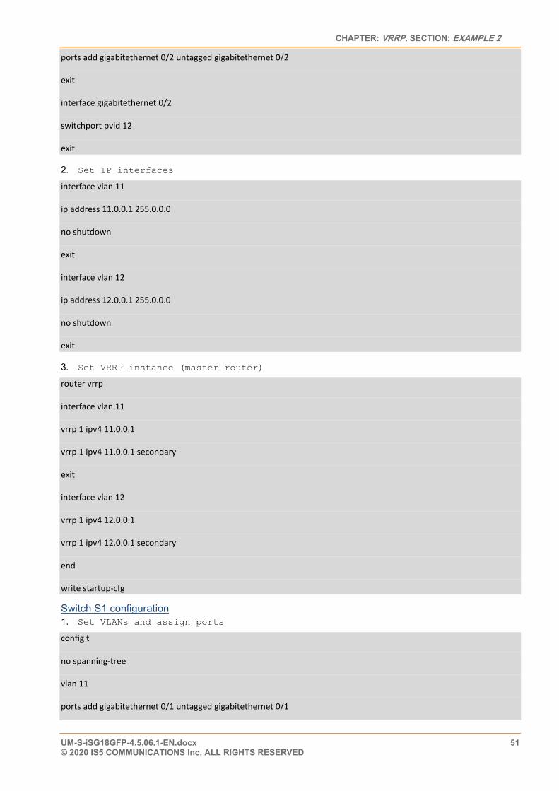
CHAPTER: VRRP, SECTION: EXAMPLE 2
UM-S-iSG18GFP-4.5.06.1-EN.docx 51 © 2020 IS5 COMMUNICATIONS Inc. ALL RIGHTS RESERVED
ports add gigabitethernet 0/2 untagged gigabitethernet 0/2
exit
interface gigabitethernet 0/2
switchport pvid 12
exit
2. Set IP interfaces
interface vlan 11
ip address 11.0.0.1 255.0.0.0
no shutdown
exit
interface vlan 12
ip address 12.0.0.1 255.0.0.0
no shutdown
exit
3. Set VRRP instance (master router)
router vrrp
interface vlan 11
vrrp 1 ipv4 11.0.0.1
vrrp 1 ipv4 11.0.0.1 secondary
exit
interface vlan 12
vrrp 1 ipv4 12.0.0.1
vrrp 1 ipv4 12.0.0.1 secondary
end
write startup-cfg
Switch S1 configuration 1. Set VLANs and assign ports
config t
no spanning-tree
vlan 11
ports add gigabitethernet 0/1 untagged gigabitethernet 0/1
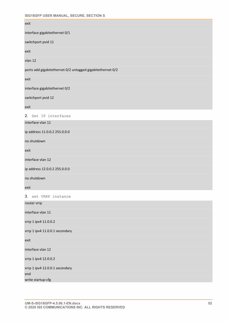
ISG18GFP USER MANUAL, SECURE, SECTION S
UM-S-iSG18GFP-4.5.06.1-EN.docx 52 © 2020 IS5 COMMUNICATIONS INC. ALL RIGHTS RESERVED
exit
interface gigabitethernet 0/1
switchport pvid 11
exit
vlan 12
ports add gigabitethernet 0/2 untagged gigabitethernet 0/2
exit
interface gigabitethernet 0/2
switchport pvid 12
exit
2. Set IP interfaces
interface vlan 11
ip address 11.0.0.2 255.0.0.0
no shutdown
exit
interface vlan 12
ip address 12.0.0.2 255.0.0.0
no shutdown
exit
3. set VRRP instance
router vrrp
interface vlan 11
vrrp 1 ipv4 11.0.0.2
vrrp 1 ipv4 11.0.0.1 secondary
exit
interface vlan 12
vrrp 1 ipv4 12.0.0.2
vrrp 1 ipv4 12.0.0.1 secondary end write startup-cfg
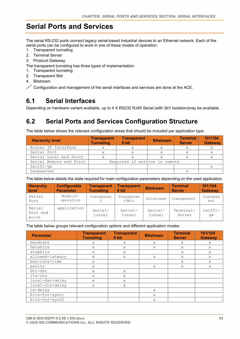
CHAPTER: SERIAL PORTS AND SERVICES, SECTION: SERIAL INTERFACES
UM-S-iSG18GFP-4.5.06.1-EN.docx 53 © 2020 IS5 COMMUNICATIONS Inc. ALL RIGHTS RESERVED
Serial Ports and Services
The serial RS-232 ports connect legacy serial-based industrial devices to an Ethernet network. Each of the serial ports can be configured to work in one of these modes of operation: 1. Transparent tunneling 2. Terminal Server 3. Protocol Gateway The transparent tunneling has three types of implementation: 1. Transparent tunneling 2. Transparent 9bit 4. Bitstream Configuration and management of the serial interfaces and services are done at the ACE.
6.1 Serial Interfaces Depending on hardware variant available, up to 4 X RS232 RJ45 Serial (with 2kV Isolation)may be available.
6.2 Serial Ports and Services Configuration Structure The table below shows the relevant configuration areas that should be included per application type.
Hierarchy level Transparent Tunneling
Transparent 9 bit Bitstream Terminal
Server 101/104 Gateway
Router IP Interface x x x x x Serial Port x x x x x Serial Local end Point x x x x x Serial Remote end Point Required if service is remote Iec101-gw x termserver x
The table below details the state required for main configuration parameters depending on the used application.
Hierarchy level
Configurable Parameter
Transparent Tunneling
Transparent 9 bit Bitstream Terminal
Server 101/104 Gateway
Serial Port
Mode-of-operation
transparent
Transparent9bit
bitstream transparent transparent
Serial Port end point
application Serial- tunnel
Serial- tunnel
Serial- tunnel
Terminal-Server
iec101-gw
The table below groups relevant configuration options and different application modes.
Parameter Transparent Tunneling
Transparent 9 bit Bitstream Terminal
Server 101/104 Gateway
baudrate x x x x x databits x x x x x stopbits x x x x allowed-latency x x x x x bus-idle-time x x x parity x x x x dtr-dsr x x rts-cts x x local-dsr-delay x x local-cts-delay x x tx-delay x bits-for-sync1 x bits-for-sync2 x
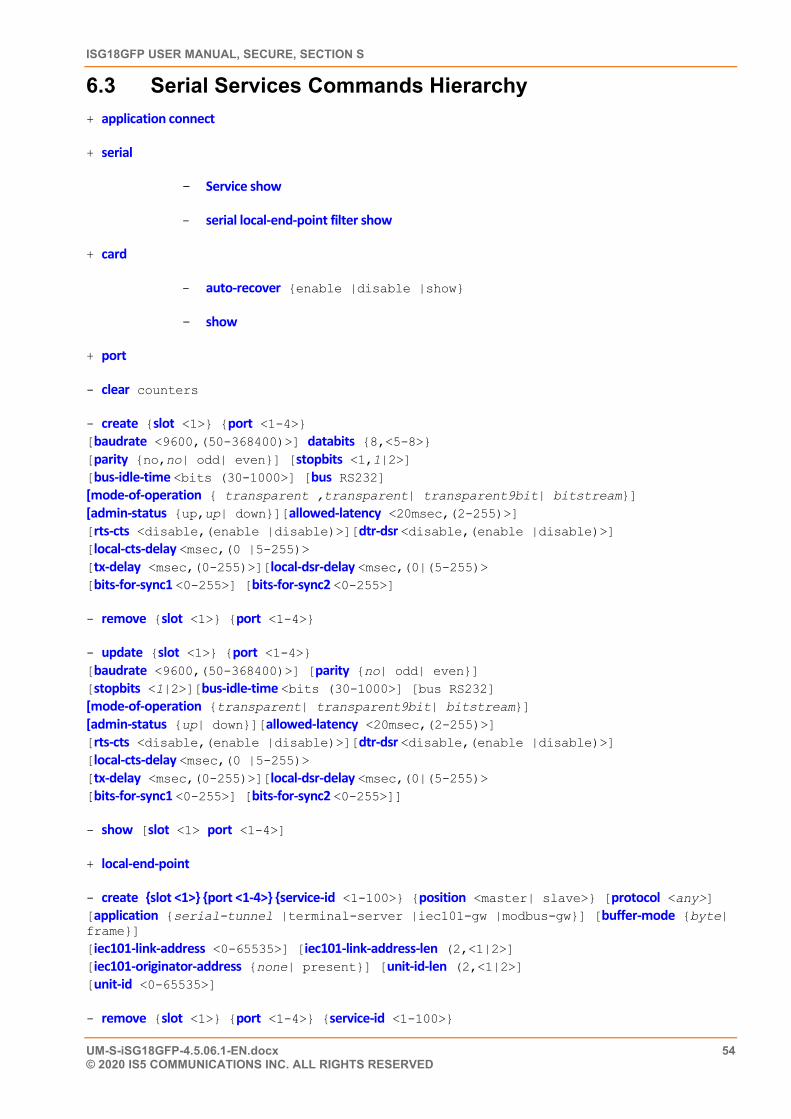
ISG18GFP USER MANUAL, SECURE, SECTION S
UM-S-iSG18GFP-4.5.06.1-EN.docx 54 © 2020 IS5 COMMUNICATIONS INC. ALL RIGHTS RESERVED
6.3 Serial Services Commands Hierarchy + application connect
+ serial
- Service show
- serial local-end-point filter show
+ card
- auto-recover {enable |disable |show}
- show
+ port
- clear counters
- create {slot <1>} {port <1-4>} [baudrate <9600,(50-368400)>] databits {8,<5-8>} [parity {no,no| odd| even}] [stopbits <1,1|2>] [bus-idle-time <bits (30-1000>] [bus RS232] [mode-of-operation { transparent ,transparent| transparent9bit| bitstream}] [admin-status {up,up| down}][allowed-latency <20msec,(2-255)>] [rts-cts <disable,(enable |disable)>][dtr-dsr <disable,(enable |disable)>] [local-cts-delay <msec,(0 |5-255)> [tx-delay <msec,(0-255)>][local-dsr-delay <msec,(0|(5-255)> [bits-for-sync1 <0-255>] [bits-for-sync2 <0-255>]
- remove {slot <1>} {port <1-4>}
- update {slot <1>} {port <1-4>} [baudrate <9600,(50-368400)>] [parity {no| odd| even}] [stopbits <1|2>][bus-idle-time <bits (30-1000>] [bus RS232] [mode-of-operation {transparent| transparent9bit| bitstream}] [admin-status {up| down}][allowed-latency <20msec,(2-255)>] [rts-cts <disable,(enable |disable)>][dtr-dsr <disable,(enable |disable)>] [local-cts-delay <msec,(0 |5-255)> [tx-delay <msec,(0-255)>][local-dsr-delay <msec,(0|(5-255)> [bits-for-sync1 <0-255>] [bits-for-sync2 <0-255>]]
- show [slot <1> port <1-4>]
+ local-end-point
- create {slot <1>} {port <1-4>} {service-id <1-100>} {position <master| slave>} [protocol <any>] [application {serial-tunnel |terminal-server |iec101-gw |modbus-gw}] [buffer-mode {byte| frame}] [iec101-link-address <0-65535>] [iec101-link-address-len (2,<1|2>] [iec101-originator-address {none| present}] [unit-id-len (2,<1|2>] [unit-id <0-65535>]
- remove {slot <1>} {port <1-4>} {service-id <1-100>}
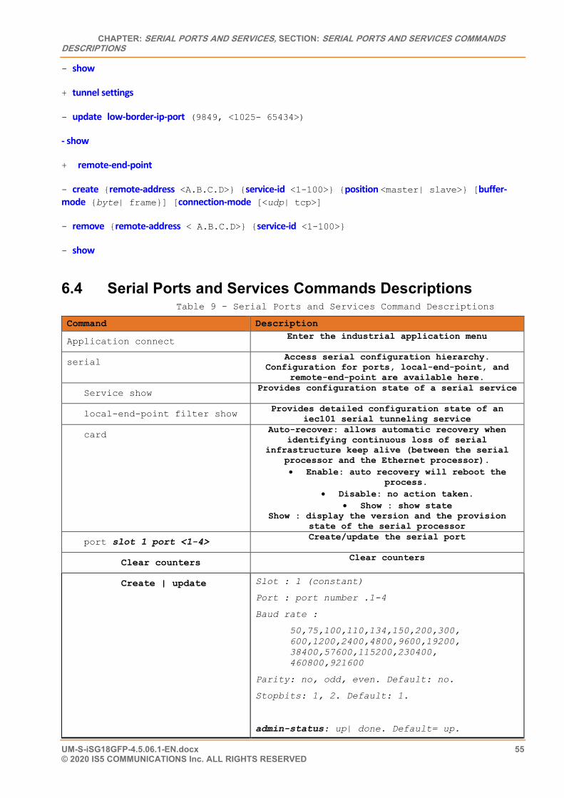
CHAPTER: SERIAL PORTS AND SERVICES, SECTION: SERIAL PORTS AND SERVICES COMMANDS DESCRIPTIONS
UM-S-iSG18GFP-4.5.06.1-EN.docx 55 © 2020 IS5 COMMUNICATIONS Inc. ALL RIGHTS RESERVED
- show
+ tunnel settings
- update low-border-ip-port (9849, <1025- 65434>)
- show
+ remote-end-point
- create {remote-address <A.B.C.D>} {service-id <1-100>} {position <master| slave>} [buffer-mode {byte| frame}] [connection-mode [<udp| tcp>]
- remove {remote-address < A.B.C.D>} {service-id <1-100>}
- show
6.4 Serial Ports and Services Commands Descriptions Table 9 - Serial Ports and Services Command Descriptions
Command Description
Application connect Enter the industrial application menu
serial Access serial configuration hierarchy. Configuration for ports, local-end-point, and
remote-end-point are available here.
Service show Provides configuration state of a serial service
local-end-point filter show Provides detailed configuration state of an iec101 serial tunneling service
card Auto-recover: allows automatic recovery when identifying continuous loss of serial
infrastructure keep alive (between the serial processor and the Ethernet processor). • Enable: auto recovery will reboot the
process. • Disable: no action taken.
• Show : show state Show : display the version and the provision
state of the serial processor
port slot 1 port <1-4> Create/update the serial port
Clear counters Clear counters
Create | update Slot : 1 (constant)
Port : port number .1-4
Baud rate :
50,75,100,110,134,150,200,300, 600,1200,2400,4800,9600,19200, 38400,57600,115200,230400, 460800,921600
Parity: no, odd, even. Default: no.
Stopbits: 1, 2. Default: 1.
admin-status: up| done. Default= up.
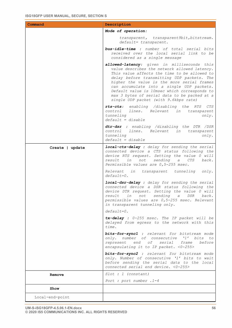
ISG18GFP USER MANUAL, SECURE, SECTION S
UM-S-iSG18GFP-4.5.06.1-EN.docx 56 © 2020 IS5 COMMUNICATIONS INC. ALL RIGHTS RESERVED
Command Description
Mode of operation:
transparent, transparent9bit,bitstream. default= transparent.
bus-idle-time : number of total serial bits received over the local serial link to be considered as a single message
allowed-latency: given in milliseconds this value describes the network allowed latency. This value affects the time to be allowed to delay before transmitting UDP packets. The higher the value is the more serial frames can accumulate into a single UDP packets. Default value is 10msec which corresponds to max 3 bytes of serial data to be packed at a single UDP packet (with 9.6kbps rate)
rts-cts: enabling /disabling the RTS CTS control lines. Relevant in transparent tunneling only. default = disable
dtr-dsr : enabling /disabling the DTR /DSR control lines. Relevant in transparent tunneling only. default = disable
Create | update local-cts-delay : delay for sending the serial connected device a CTS status following the device RTS request. Setting the value 0 will result in not sending a CTS back. Permissible values are 0,5-255 msec.
Relevant in transparent tunneling only. default=0.
local-dsr-delay : delay for sending the serial connected device a DSR status following the device DTR request. Setting the value 0 will result in not sending a DSR back. permissible values are 0,5-255 msec. Relevant in transparent tunneling only.
default=0.
tx-delay : 0-255 msec. The IP packet will be delayed from egress to the network with this time.
bits-for-sync1 : relevant for bitstream mode only. number of consecutive ‘1’ bits to represent end of serial frame before encapsulating it to IP packet. <0-255>
bits-for-sync2 : relevant for bitstream mode only. Number of consecutive ‘1’ bits to wait before sending the serial data to the local connected serial end device. <0-255>
Remove Slot : 1 (constant)
Port : port number .1-4
Show
Local-end-point
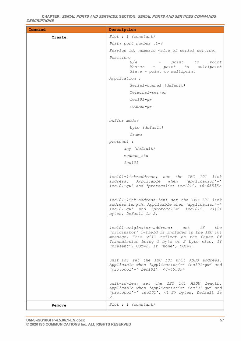
CHAPTER: SERIAL PORTS AND SERVICES, SECTION: SERIAL PORTS AND SERVICES COMMANDS DESCRIPTIONS
UM-S-iSG18GFP-4.5.06.1-EN.docx 57 © 2020 IS5 COMMUNICATIONS Inc. ALL RIGHTS RESERVED
Command Description
Create Slot : 1 (constant)
Port: port number .1-4
Service id: numeric value of serial service.
Position: N/A - point to point Master – point to multipoint Slave – point to multipoint
Application :
Serial-tunnel (default)
Terminal-server
iec101-gw
modbus-gw
buffer mode:
byte (default)
frame
protocol :
any (default)
modbus_rtu
iec101
iec101-link-address: set the IEC 101 link address. Applicable when ‘application’=’ iec101-gw’ and ‘protocol’=’ iec101’. <0-65535>
iec101-link-address-len: set the IEC 101 link address length. Applicable when ‘application’=’ iec101-gw’ and ‘protocol’=’ iec101’. <1|2> bytes. Default is 2.
iec101-originator-address: set if the ‘originator’ i=field is included in the IEC 101 message. This will reflect on the Cause Of Transmission being 1 byte or 2 byte size. If ‘present’, COT=2. If ‘none’, COT=1.
unit-id: set the IEC 101 unit ASDU address. Applicable when ‘application’=’ iec101-gw’ and ‘protocol’=’ iec101’. <0-65535>
unit-id-len: set the IEC 101 ASDU length. Applicable when ‘application’=’ iec101-gw’ and ‘protocol’=’ iec101’. <1|2> bytes. Default is 2.
Remove Slot : 1 (constant)
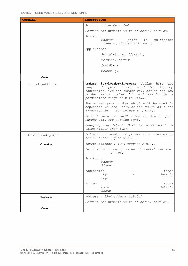
ISG18GFP USER MANUAL, SECURE, SECTION S
UM-S-iSG18GFP-4.5.06.1-EN.docx 58 © 2020 IS5 COMMUNICATIONS INC. ALL RIGHTS RESERVED
Command Description
Port : port number .1-4
Service id: numeric value of serial service.
Position: Master – point to multipoint Slave – point to multipoint
Application :
Serial-tunnel (default)
Terminal-server
iec101-gw
modbus-gw
show
tunnel settings update low-border-ip-port: define here the range of port number used for tcp/udp connection. The set number will define the low border range value ‘x’ and result in a permissible range of x to x+100.
The actual port number which will be used is dependent on the ‘service-id’ value as such: [‘service-id’+ ‘low-border-ip-port’].
Default value is 9849 which results in port number 9850 for service-id=1.
Changing the default 9849 is permitted to a value higher than 1024.
Remote-end-point Defines the remote end points in a transparent serial tunneling service.
Create remote-address : IPv4 address A.B.C.D
Service id: numeric value of serial service. <1-100.
Position: Master Slave
connection mode: udp – default tcp
Buffer mode: byte – default frame
Remove address : IPv4 address A.B.C.D
Service id: numeric value of serial service.
show
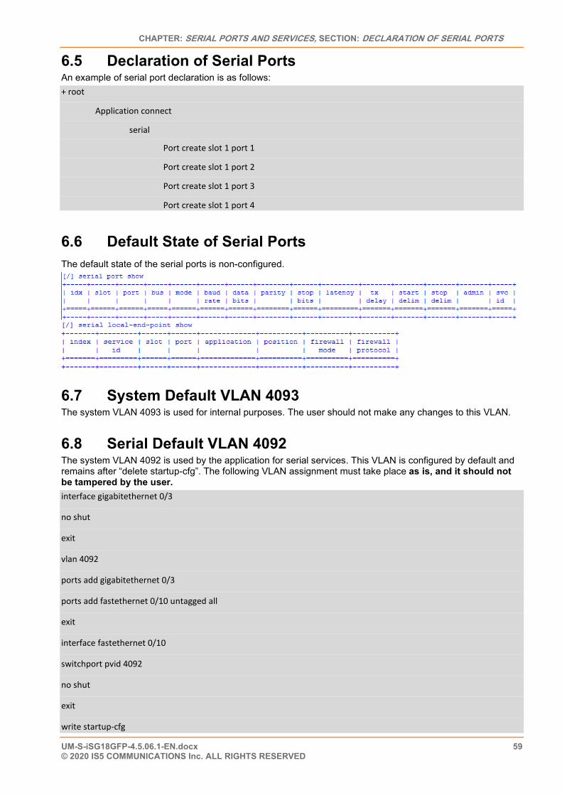
CHAPTER: SERIAL PORTS AND SERVICES, SECTION: DECLARATION OF SERIAL PORTS
UM-S-iSG18GFP-4.5.06.1-EN.docx 59 © 2020 IS5 COMMUNICATIONS Inc. ALL RIGHTS RESERVED
6.5 Declaration of Serial Ports An example of serial port declaration is as follows: + root
Application connect
serial
Port create slot 1 port 1
Port create slot 1 port 2
Port create slot 1 port 3
Port create slot 1 port 4
6.6 Default State of Serial Ports The default state of the serial ports is non-configured.
6.7 System Default VLAN 4093 The system VLAN 4093 is used for internal purposes. The user should not make any changes to this VLAN.
6.8 Serial Default VLAN 4092 The system VLAN 4092 is used by the application for serial services. This VLAN is configured by default and remains after “delete startup-cfg”. The following VLAN assignment must take place as is, and it should not be tampered by the user. interface gigabitethernet 0/3
no shut
exit
vlan 4092
ports add gigabitethernet 0/3
ports add fastethernet 0/10 untagged all
exit
interface fastethernet 0/10
switchport pvid 4092
no shut
exit
write startup-cfg
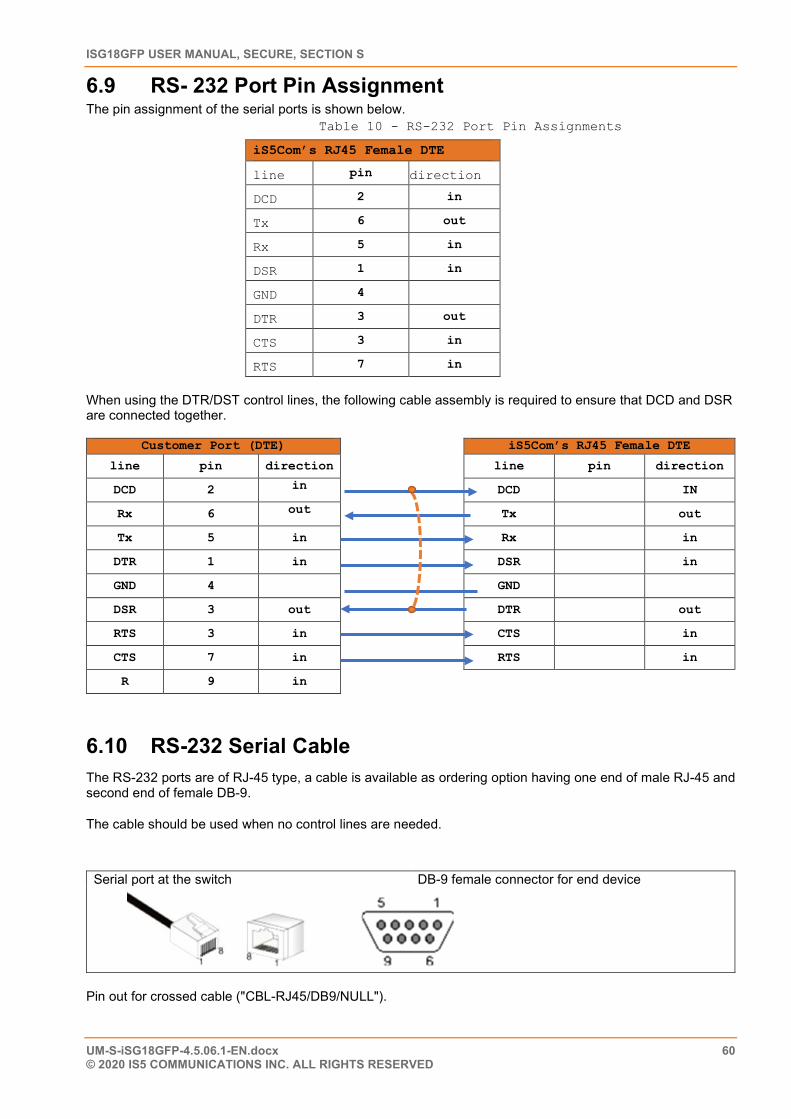
ISG18GFP USER MANUAL, SECURE, SECTION S
UM-S-iSG18GFP-4.5.06.1-EN.docx 60 © 2020 IS5 COMMUNICATIONS INC. ALL RIGHTS RESERVED
6.9 RS- 232 Port Pin Assignment The pin assignment of the serial ports is shown below.
Table 10 - RS-232 Port Pin Assignments
iS5Com’s RJ45 Female DTE
line pin direction
DCD 2 in
Tx 6 out
Rx 5 in
DSR 1 in
GND 4
DTR 3 out
CTS 3 in
RTS 7 in
When using the DTR/DST control lines, the following cable assembly is required to ensure that DCD and DSR are connected together.
Customer Port (DTE) iS5Com’s RJ45 Female DTE
line pin direction line pin direction
DCD 2 in DCD IN
Rx 6 out Tx out
Tx 5 in Rx in
DTR 1 in DSR in
GND 4 GND
DSR 3 out DTR out
RTS 3 in CTS in
CTS 7 in RTS in
R 9 in
6.10 RS-232 Serial Cable The RS-232 ports are of RJ-45 type, a cable is available as ordering option having one end of male RJ-45 and second end of female DB-9.
The cable should be used when no control lines are needed.
Serial port at the switch DB-9 female connector for end device
Pin out for crossed cable ("CBL-RJ45/DB9/NULL").
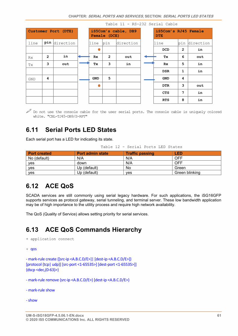
CHAPTER: SERIAL PORTS AND SERVICES, SECTION: SERIAL PORTS LED STATES
UM-S-iSG18GFP-4.5.06.1-EN.docx 61 © 2020 IS5 COMMUNICATIONS Inc. ALL RIGHTS RESERVED
Table 11 - RS-232 Serial Cable
Customer Port (DTE) iS5Com’s cable, DB9 Female (DCE)
iS5Com’s RJ45 Female DTE
line pin direction line pin direction line pin direction
DCD 2 in
Rx 2 in Rx 2 out Tx 6 out
Tx 3 out Tx 3 in Rx 5 in
DSR 1 in
GND 4 GND 5 GND 4
DTR 3 out
CTS 7 in
RTS 8 in
Do not use the console cable for the user serial ports. The console cable is uniquely colored
white. "CBL-TJ45-DB9/S-RPT"
6.11 Serial Ports LED States Each serial port has a LED for indicating its state.
Table 12 - Serial Ports LED States
Port created Port admin state Traffic passing LED No (default) N/A N/A OFF yes down N/A OFF yes Up (default) No Green yes Up (default) yes Green blinking
6.12 ACE QoS SCADA services are still commonly using serial legacy hardware. For such applications, the iSG16GFP supports services as protocol gateway, serial tunneling, and terminal server. These low bandwidth application may be of high importance to the utility process and require high network availability.
The QoS (Quality of Service) allows setting priority for serial services.
6.13 ACE QoS Commands Hierarchy + application connect
+ qos
- mark-rule create {[src-ip <A.B.C.D/E>]| [dest-ip <A.B.C.D/E>]} [protocol {tcp| udp}] [src-port <1-65535>] [dest-port <1-65535>]] {dscp <dec,(0-63)>}
- mark-rule remove {src-ip <A.B.C.D/E>} [dest-ip <A.B.C.D/E>}
- mark-rule show
- show
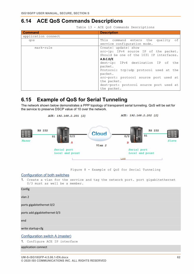
ISG18GFP USER MANUAL, SECURE, SECTION S
UM-S-iSG18GFP-4.5.06.1-EN.docx 62 © 2020 IS5 COMMUNICATIONS INC. ALL RIGHTS RESERVED
6.14 ACE QoS Commands Descriptions Table 13 - ACE QoS Commands Descriptions
Command Description application connect qos This command enters the quality of
service configuration mode. mark-rule Create| update| show
src-ip: IPv4 source IP of the packet. Should be one of the 1031 IP interfaces. A.B.C.D/E dest-ip: IPv4 destination IP of the packet. Protocol: tcp|udp protocol used at the packet. src-port: protocol source port used at the packet. dest-port: protocol source port used at the packet.
6.15 Example of QoS for Serial Tunneling The network shown below demonstrates a PPP topology of transparent serial tunneling. QoS will be set for the service to preserve DSCP value of 10 over the network.
Figure 8 - Example of QoS for Serial Tunneling
Configuration of both switches 1. Create a vlan for the service and tag the network port. port gigabitethernet
0/3 must as well be a member.
Config
vlan 2
ports gigabitethernet 0/2
ports add gigabitethernet 0/3
end
write startup-cfg
Configuration switch A (master) 1. Configure ACE IP interface
application connect
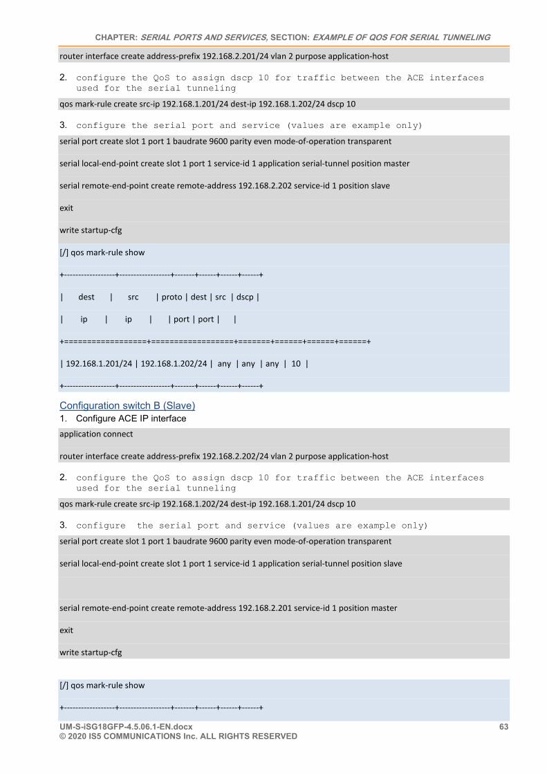
CHAPTER: SERIAL PORTS AND SERVICES, SECTION: EXAMPLE OF QOS FOR SERIAL TUNNELING
UM-S-iSG18GFP-4.5.06.1-EN.docx 63 © 2020 IS5 COMMUNICATIONS Inc. ALL RIGHTS RESERVED
router interface create address-prefix 192.168.2.201/24 vlan 2 purpose application-host
2. configure the QoS to assign dscp 10 for traffic between the ACE interfaces used for the serial tunneling
qos mark-rule create src-ip 192.168.1.201/24 dest-ip 192.168.1.202/24 dscp 10
3. configure the serial port and service (values are example only)
serial port create slot 1 port 1 baudrate 9600 parity even mode-of-operation transparent
serial local-end-point create slot 1 port 1 service-id 1 application serial-tunnel position master
serial remote-end-point create remote-address 192.168.2.202 service-id 1 position slave
exit
write startup-cfg
[/] qos mark-rule show
+------------------+------------------+-------+------+------+------+
| dest | src | proto | dest | src | dscp |
| ip | ip | | port | port | |
+==================+==================+=======+======+======+======+
| 192.168.1.201/24 | 192.168.1.202/24 | any | any | any | 10 |
+------------------+------------------+-------+------+------+------+
Configuration switch B (Slave) 1. Configure ACE IP interface application connect
router interface create address-prefix 192.168.2.202/24 vlan 2 purpose application-host
2. configure the QoS to assign dscp 10 for traffic between the ACE interfaces used for the serial tunneling
qos mark-rule create src-ip 192.168.1.202/24 dest-ip 192.168.1.201/24 dscp 10
3. configure the serial port and service (values are example only)
serial port create slot 1 port 1 baudrate 9600 parity even mode-of-operation transparent
serial local-end-point create slot 1 port 1 service-id 1 application serial-tunnel position slave
serial remote-end-point create remote-address 192.168.2.201 service-id 1 position master
exit
write startup-cfg
[/] qos mark-rule show
+------------------+------------------+-------+------+------+------+

ISG18GFP USER MANUAL, SECURE, SECTION S
UM-S-iSG18GFP-4.5.06.1-EN.docx 64 © 2020 IS5 COMMUNICATIONS INC. ALL RIGHTS RESERVED
| dest | src | proto | dest | src | dscp |
| ip | ip | | port | port | |
+==================+==================+=======+======+======+======+
| 192.168.1.202/24 | 192.168.1.201/24 | any | any | any | 11 |
+------------------+------------------+-------+------+------+------+
CHAPTER: TRANSPARENT SERIAL TUNNELING, SECTION: CONCEPT OF OPERATION
UM-S-iSG18GFP-4.5.06.1-EN.docx 65 © 2020 IS5 COMMUNICATIONS Inc. ALL RIGHTS RESERVED
Transparent Serial Tunneling
In transparent serial tunneling mode, the routerh encapsulates the serial frames into UDP packets. The UDP packet is sourced with a local IP interface configured in the application layer of the iSG18GFP. Topologies supported are PPP, P2MP and MP2MP, over a single switch or an IP network.
Control line signals are also supported in this mode.
The condition for transparent serial tunneling is having an iS5Com’s switch at both ends of the network, connecting the devices.
The transparent tunneling has three types of implementations: 1. Transparent tunneling: encapsulation of standard serial frames is supported. The serial frames are
structured with start, stop, data, and parity bits. 2. Transparent 9bit: in this special mode the parity bit is regarded as an additional data bit. 3. Bitstream: this is an oversampling mode in which no start, stop bits are available for the frames. The
number of data bits is usually higher the “standard” 5-8 data bits. The following chapter will explain key serial properties and modes of operation.
7.1 Concept of Operation The benefit of transparent serial tunneling is its simplicity.
Serial traffic received from the customer serial device at the switch serial port is encapsulated as UDP or TCP Ethernet packets by the switch.
An ACE IP interface is configured to route the packets over the Ethernet network. The Ethernet cloud may be Layer 2 based or Layer 3 routing based, and it may involve any type of networking including cellular connectivity and VPN between the switches.
The serial devices must all be connected to iSG18GFP switches.
The switch serial port is configurable with a full set of serial properties. A service-id is attached to each serial port. The service-id groups serial devices in a network in a logic communication segment at which members can communicate with each other.
At each service-id group, there must be at least one device which is set as a master and at least one device set as a slave.
The communication rules that are maintained between service-id group members are as follow:
1. Traffic sent from a master will be received at all slaves 2. Traffic sent from a slave will be received at all masters 3. Traffic between masters is blocked 4. Traffic between slaves is blocked
7.2 Supported Network Topologies Transparent serial tunneling supports the following topologies:
• Point-to-point • Point-to-multipoint point • Multi Point to multipoint point
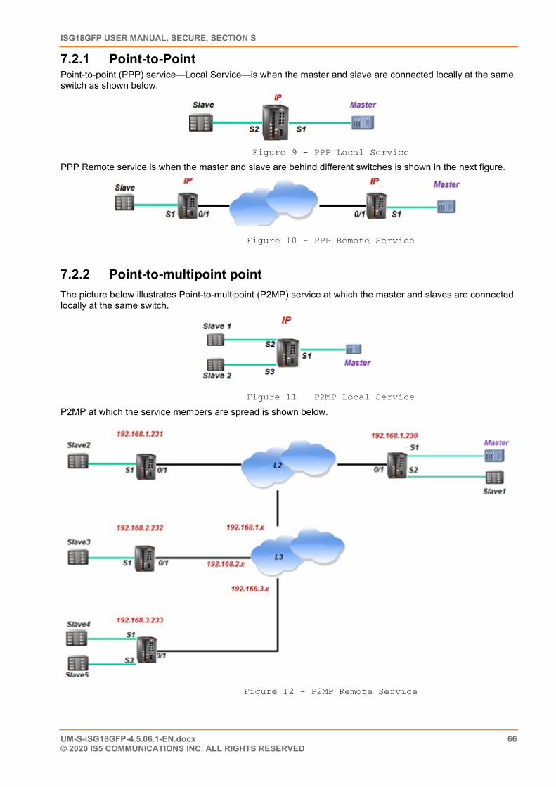
ISG18GFP USER MANUAL, SECURE, SECTION S
UM-S-iSG18GFP-4.5.06.1-EN.docx 66 © 2020 IS5 COMMUNICATIONS INC. ALL RIGHTS RESERVED
7.2.1 Point-to-Point Point-to-point (PPP) service—Local Service—is when the master and slave are connected locally at the same switch as shown below.
Figure 9 - PPP Local Service
PPP Remote service is when the master and slave are behind different switches is shown in the next figure.
Figure 10 - PPP Remote Service
7.2.2 Point-to-multipoint point The picture below illustrates Point-to-multipoint (P2MP) service at which the master and slaves are connected locally at the same switch.
Figure 11 - P2MP Local Service
P2MP at which the service members are spread is shown below.
Figure 12 - P2MP Remote Service
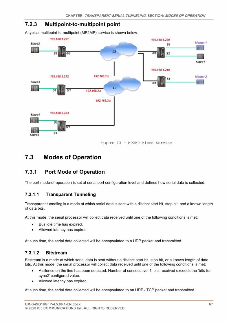
CHAPTER: TRANSPARENT SERIAL TUNNELING, SECTION: MODES OF OPERATION
UM-S-iSG18GFP-4.5.06.1-EN.docx 67 © 2020 IS5 COMMUNICATIONS Inc. ALL RIGHTS RESERVED
7.2.3 Multipoint-to-multipoint point A typical multipoint-to-multipoint (MP2MP) service is shown below.
Figure 13 - MP2MP Mixed Service
7.3 Modes of Operation
7.3.1 Port Mode of Operation
The port mode-of-operation is set at serial port configuration level and defines how serial data is collected.
7.3.1.1 Transparent Tunneling
Transparent tunneling is a mode at which serial data is sent with a distinct start bit, stop bit, and a known length of data bits.
At this mode, the serial processor will collect data received until one of the following conditions is met:
• Bus idle time has expired. • Allowed latency has expired.
At such time, the serial data collected will be encapsulated to a UDP packet and transmitted.
7.3.1.2 Bitstream Bitstream is a mode at which serial data is sent without a distinct start bit, stop bit, or a known length of data bits. At this mode, the serial processor will collect data received until one of the following conditions is met:
• A silence on the line has been detected. Number of consecutive ‘1’ bits received exceeds the ‘bits-for-sync2’ configured value.
• Allowed latency has expired.
At such time, the serial data collected will be encapsulated to an UDP / TCP packet and transmitted.
ISG18GFP USER MANUAL, SECURE, SECTION S
UM-S-iSG18GFP-4.5.06.1-EN.docx 68 © 2020 IS5 COMMUNICATIONS INC. ALL RIGHTS RESERVED
7.3.2 Service Buffer Mode The service buffer mode is set at local-end-point configuration level and defines the buffer operational mode for the service-id.
The default state is ‘byte’ mode. If the user keeps this field as default state but configures the service ‘connection-mode’ to ‘tcp’, the buffer mode will be changed to ‘frame’ automatically. If the user explicitly sets the buffer mode to either ‘byte’ or ‘frame’, the configuration will take effect for any connection-mode setting (tcp | udp).
7.3.2.1 Byte Mode
A byte is structured as start-bit, data-bits, parity-bit, stop-bits whereas the number of data-bits may be 5 to 8.
At this mode, the serial-processor collects bytes and encapsulates the data at a UDP/TCP Ethernet frame.
The number of bytes collected to a single Ethernet packet is determined by the following factors:
• Allowed latency • Bus idle time
7.3.2.2 Frame Mode
A frame is a group of bytes sent by the customer equipment (CE) as a complete message.
When using frame mode, the serial-processor will use the bus-idle-time to distinguish between frames. Each frame will be encapsulated as an individual UDP packet.
7.3.3 Service Connection Mode The service connection-mode is set at remote-end-point configuration level and defines the protocol option to be used for the service-id.
7.3.3.1 UDP
1. Serial data will be encapsulated as UDP/IP frames. This is the default option for a serial service.
2. UDP connection mode will use by default Byte Mode for Service Buffer Mode. That is unless ‘buffer-mode’ was explicitly set to ‘frame’ by the user.
7.3.3.2 TCP
1. Serial data will be encapsulated as TCP/IP frames.
2. This mode allows higher availability for the end-to-end connection and traffic validation.
3. TCP connection mode will use by default frame mode for the service buffer mode. That is unless ‘buffer-mode’ was explicitly set to ‘byte’ by the user.
4. At TCP mode, the iSG18GFP router at which the serial configuration determines the serial port to be the ‘master’ at the service, will act as the tcp client and will initiate the tcp session towards the remote iSG18GFP routers holding the serial ‘slaves’ at the serial tunneling service.
7.3.3.3 Service Port Number The TCP/UDP port number used at a serial tunneling connection is defined by the values of ‘service-id’ and the ‘low-border-ip-port’ set at the ‘serial’ ‘settings’.
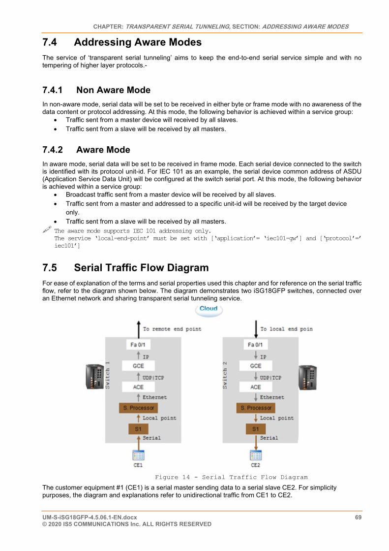
CHAPTER: TRANSPARENT SERIAL TUNNELING, SECTION: ADDRESSING AWARE MODES
UM-S-iSG18GFP-4.5.06.1-EN.docx 69 © 2020 IS5 COMMUNICATIONS Inc. ALL RIGHTS RESERVED
7.4 Addressing Aware Modes The service of ‘transparent serial tunneling’ aims to keep the end-to-end serial service simple and with no tempering of higher layer protocols.-
7.4.1 Non Aware Mode In non-aware mode, serial data will be set to be received in either byte or frame mode with no awareness of the data content or protocol addressing. At this mode, the following behavior is achieved within a service group:
• Traffic sent from a master device will received by all slaves. • Traffic sent from a slave will be received by all masters.
7.4.2 Aware Mode In aware mode, serial data will be set to be received in frame mode. Each serial device connected to the switch is identified with its protocol unit-id. For IEC 101 as an example, the serial device common address of ASDU (Application Service Data Unit) will be configured at the switch serial port. At this mode, the following behavior is achieved within a service group:
• Broadcast traffic sent from a master device will be received by all slaves. • Traffic sent from a master and addressed to a specific unit-id will be received by the target device
only. • Traffic sent from a slave will be received by all masters.
The aware mode supports IEC 101 addressing only. The service ‘local-end-point’ must be set with [‘application’= ‘iec101-gw’] and [‘protocol’=’ iec101’]
7.5 Serial Traffic Flow Diagram For ease of explanation of the terms and serial properties used this chapter and for reference on the serial traffic flow, refer to the diagram shown below. The diagram demonstrates two iSG18GFP switches, connected over an Ethernet network and sharing transparent serial tunneling service.
Figure 14 - Serial Traffic Flow Diagram
The customer equipment #1 (CE1) is a serial master sending data to a serial slave CE2. For simplicity purposes, the diagram and explanations refer to unidirectional traffic from CE1 to CE2.
ISG18GFP USER MANUAL, SECURE, SECTION S
UM-S-iSG18GFP-4.5.06.1-EN.docx 70 © 2020 IS5 COMMUNICATIONS INC. ALL RIGHTS RESERVED
7.6 Serial Traffic Direction Transmit direction represents the serial processor traffic towards the CE, over the serial port. Receive direction represents the traffic received at the serial processor from the CE, over the serial port.
7.6.1 Serial Ports Counters The Tx and Rx counters of the serial ports are controlled by the serial processor.
7.6.1.1 Rx Counters • Switch 1—counters will increase when CE1 transmits. Data is received at the serial processor via S1
and updates the counters. • Switch 2—counters are not updated.
7.6.1.2 Tx Counters • Switch 1—counters are not updated. • Switch 2—CE1 Data is received over the Ethernet network to switch 2 and to the serial processor.
The serial processor transmits the data to CE2 over S1 and increases the Tx counters.
7.7 Allowed Latency Allowed latency is the maximum time allowed for the serial-processor to collect serial data from CE1 transmission, before closing an Ethernet packet and sending it over the cloud.
This parameter refers to round-trip in milliseconds units. It reflects only the time for the serial processor to collect data; it does not consider the network self-latency.
Allowed latency is applicable in byte mode only.
• Switch 1—as CE1 transmits data to serial processor over S1, the allowed-latency properties are applicable. For a configured value x at allowed-latency, the serial processor will collect serial data for up to x/2 milliseconds time and then close the collected data as an Ethernet packet.
• Switch2—as CE2 is only receiving, the allowed-latency is not of influence.
7.8 Tx Delay Tx-delay is set in bits. It determines a delay to take place by the serial processor before transmitting serial data to the port. Depending on the baud rate chosen, and the number of bits, a time is calculated for Tx-delay.
• Switch1—as the serial processor only receives serial data, the tx-delay is of no affect. • Switch2—the Ethernet encapsulated data is received at switch 2 and to its serial-processor. It is then
transmitted to CE2 via S1 following a time elapse of the tx-delay. The serial-processor will delay transmitting the first serial byte to CE2. Following data bytes are sent without delay.
7.9 Bus Idle Time This parameter determines a silence on the serial line to identify frame end. The configurable value for it is given in number of bits. Depending on the baud rate chosen, and the number of bits, a time is calculated for bus-idle-time.
CHAPTER: TRANSPARENT SERIAL TUNNELING, SECTION: BITS-FOR-SYNC
UM-S-iSG18GFP-4.5.06.1-EN.docx 71 © 2020 IS5 COMMUNICATIONS Inc. ALL RIGHTS RESERVED
7.9.1 Byte Mode When using byte mode, end of byte is determined by stop bits. Bus idle time is not applicable at this mode.
7.9.2 Frame Mode • Switch1- the serial-processor will collect serial data transmitted from CE1 until a silence is identified
on the line for a time period equal or above the bus-idle-time. • Switch2- the serial-processor transmits the serial frames to CE2 while maintaining a gap between
frames. The gap is the bus-idle-time.
7.10 Bits-for-sync The parameters ‘bits-for-sync1’ and ‘bits-for-sync2’ are applicable for bitstream mode only.
7.10.1 Bits-for-sync1 Bits-for-sync1 is similar in purpose to Tx-delay. When transmitting, the serial processor will add number of consecutive ‘1’ bits before the data. The number of consecutive ‘1’ bits is determined by ‘bits-for-sync1’.
7.10.2 Bits-for-sync2 Similar in purpose to ‘bus-idle-time’. When receiving, the serial-processor looks for a silence on the line in order to identify end of message and encapsulate to a UDP packet. The silence on the line is identified as a number of consecutive ‘1’ bits received. The number of consecutive ‘1’ bits is determined by ‘bits-for-sync2’.
7.11 RS-232 Control Lines The iSG18GFP supports the use of the RS-232 control lines for the transparent serial tunneling service.
By default, the control lines are disabled, making active the lines at the ports Tx and Rx only.
The control lines are applicable for point-to-point serial services only.
The control lines are:
• RTS (Request to Send) • CTS (Clear to Send) • DCD (Data Carrier Detect). Applicable only when DTR/DSR lines are disabled. • DTR (Data Terminal Ready). Applicable only when RTS/CTS lines are disabled. • DSR (Data Set Ready). Applicable only when RTS/CTS lines are disabled.
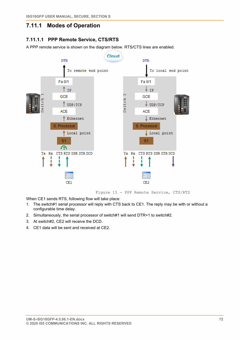
ISG18GFP USER MANUAL, SECURE, SECTION S
UM-S-iSG18GFP-4.5.06.1-EN.docx 72 © 2020 IS5 COMMUNICATIONS INC. ALL RIGHTS RESERVED
7.11.1 Modes of Operation
7.11.1.1 PPP Remote Service, CTS/RTS A PPP remote service is shown on the diagram below. RTS/CTS lines are enabled.
Figure 15 - PPP Remote Service, CTS/RTS
When CE1 sends RTS, following flow will take place: 1. The switch#1 serial processor will reply with CTS back to CE1. The reply may be with or without a
configurable time delay. 2. Simultaneously, the serial processor of switch#1 will send DTR=1 to switch#2. 3. At switch#2, CE2 will receive the DCD. 4. CE1 data will be sent and received at CE2.
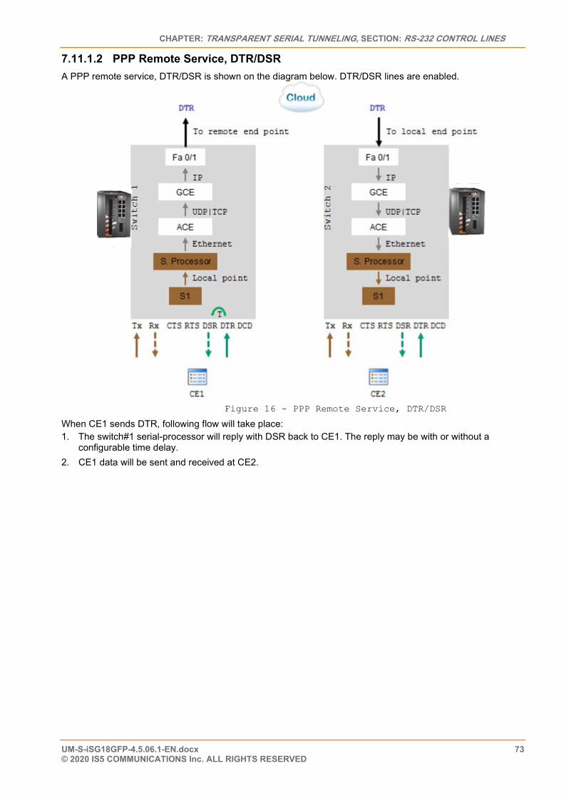
CHAPTER: TRANSPARENT SERIAL TUNNELING, SECTION: RS-232 CONTROL LINES
UM-S-iSG18GFP-4.5.06.1-EN.docx 73 © 2020 IS5 COMMUNICATIONS Inc. ALL RIGHTS RESERVED
7.11.1.2 PPP Remote Service, DTR/DSR A PPP remote service, DTR/DSR is shown on the diagram below. DTR/DSR lines are enabled.
Figure 16 - PPP Remote Service, DTR/DSR
When CE1 sends DTR, following flow will take place: 1. The switch#1 serial-processor will reply with DSR back to CE1. The reply may be with or without a
configurable time delay. 2. CE1 data will be sent and received at CE2.
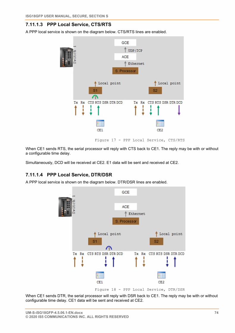
ISG18GFP USER MANUAL, SECURE, SECTION S
UM-S-iSG18GFP-4.5.06.1-EN.docx 74 © 2020 IS5 COMMUNICATIONS INC. ALL RIGHTS RESERVED
7.11.1.3 PPP Local Service, CTS/RTS A PPP local service is shown on the diagram below. CTS/RTS lines are enabled.
Figure 17 - PPP Local Service, CTS/RTS
When CE1 sends RTS, the serial processor will reply with CTS back to CE1. The reply may be with or without a configurable time delay.
Simultaneously, DCD will be received at CE2. E1 data will be sent and received at CE2.
7.11.1.4 PPP Local Service, DTR/DSR A PPP local service is shown on the diagram below. DTR/DSR lines are enabled.
Figure 18 - PPP Local Service, DTR/DSR
When CE1 sends DTR, the serial processor will reply with DSR back to CE1. The reply may be with or without configurable time delay. CE1 data will be sent and received at CE2.
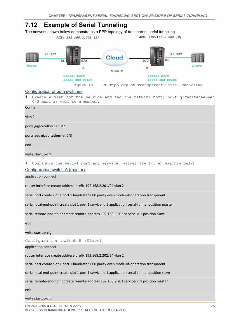
CHAPTER: TRANSPARENT SERIAL TUNNELING, SECTION: EXAMPLE OF SERIAL TUNNELING
UM-S-iSG18GFP-4.5.06.1-EN.docx 75 © 2020 IS5 COMMUNICATIONS Inc. ALL RIGHTS RESERVED
7.12 Example of Serial Tunneling The network shown below demonstrates a PPP topology of transparent serial tunneling.
Figure 19 - PPP Topology of Transparent Serial Tunneling
Configuration of both switches 1. Create a vlan for the service and tag the network port; port gigabitethernet
0/3 must as well be a member.
Config
vlan 2
ports gigabitethernet 0/2
ports add gigabitethernet 0/3
end
write startup-cfg
1. Configure the serial port and service (values are for an example only)
Configuration switch A (master) application connect
router interface create address-prefix 192.168.2.201/24 vlan 2
serial port create slot 1 port 1 baudrate 9600 parity even mode-of-operation transparent
serial local-end-point create slot 1 port 1 service-id 1 application serial-tunnel position master
serial remote-end-point create remote-address 192.168.2.202 service-id 1 position slave
exit
write startup-cfg
Configuration switch B (Slave)
application connect
router interface create address-prefix 192.168.2.202/24 vlan 2
serial port create slot 1 port 1 baudrate 9600 parity even mode-of-operation transparent
serial local-end-point create slot 1 port 1 service-id 1 application serial-tunnel position slave
serial remote-end-point create remote-address 192.168.2.201 service-id 1 position master
exit
write startup-cfg
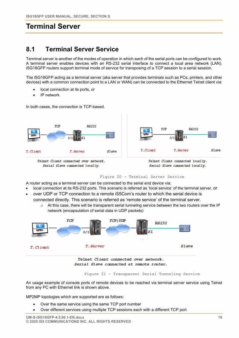
ISG18GFP USER MANUAL, SECURE, SECTION S
UM-S-iSG18GFP-4.5.06.1-EN.docx 76 © 2020 IS5 COMMUNICATIONS INC. ALL RIGHTS RESERVED
Terminal Server
8.1 Terminal Server Service Terminal server is another of the modes of operation in which each of the serial ports can be configured to work. A terminal server enables devices with an RS-232 serial interface to connect a local area network (LAN). iSG18GFP routers support terminal mode of service for transposing of a TCP session to a serial session.
The iSG18GFP acting as a terminal server (aka server that provides terminals such as PCs, printers, and other devices) with a common connection point to a LAN or WAN) can be connected to the Ethernet Telnet client via:
• local connection at its ports, or • IP network.
In both cases, the connection is TCP-based.
Figure 20 - Terminal Server Service
A router acting as a terminal server can be connected to the serial end device via: • local connection at its RS-232 ports. This scenario is referred as ‘local service’ of the terminal server, or • over UDP or TCP connection to a remote iS5Com’s router to which the serial device is
connected directly. This scenario is referred as ‘remote service’ of the terminal server. o At this case, there will be transparent serial tunneling service between the two routers over the IP
network (encapsulation of serial data in UDP packets)
Figure 21 - Transparent Serial Tunneling Service
An usage example of console ports of remote devices to be reached via terminal server service using Telnet from any PC with Ethernet link is shown above.
MP2MP topologies which are supported are as follows:
• Over the same service using the same TCP port number • Over different services using multiple TCP sessions each with a different TCP port
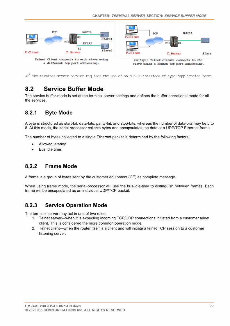
CHAPTER: TERMINAL SERVER, SECTION: SERVICE BUFFER MODE
UM-S-iSG18GFP-4.5.06.1-EN.docx 77 © 2020 IS5 COMMUNICATIONS Inc. ALL RIGHTS RESERVED
The terminal server service requires the use of an ACE IP interface of type ‘application-host’.
8.2 Service Buffer Mode
The service buffer-mode is set at the terminal server settings and defines the buffer operational mode for all the services.
8.2.1 Byte Mode
A byte is structured as start-bit, data-bits, parity-bit, and stop-bits, whereas the number of data-bits may be 5 to 8. At this mode, the serial processor collects bytes and encapsulates the data at a UDP/TCP Ethernet frame.
The number of bytes collected to a single Ethernet packet is determined by the following factors:
• Allowed latency • Bus idle time
8.2.2 Frame Mode
A frame is a group of bytes sent by the customer equipment (CE) as complete message.
When using frame mode, the serial-processor will use the bus-idle-time to distinguish between frames. Each frame will be encapsulated as an individual UDP/TCP packet.
8.2.3 Service Operation Mode The terminal server may act in one of two roles:
1. Telnet server—when it is expecting incoming TCP/UDP connections initiated from a customer telnet client. This is considered the more common operation mode.
2. Telnet client—when the router itself is a client and will initiate a telnet TCP session to a customer listening server.
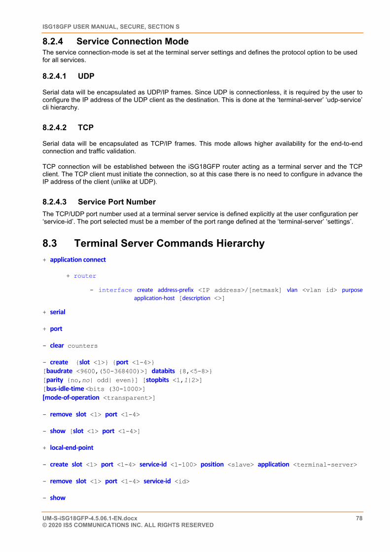
ISG18GFP USER MANUAL, SECURE, SECTION S
UM-S-iSG18GFP-4.5.06.1-EN.docx 78 © 2020 IS5 COMMUNICATIONS INC. ALL RIGHTS RESERVED
8.2.4 Service Connection Mode The service connection-mode is set at the terminal server settings and defines the protocol option to be used for all services.
8.2.4.1 UDP
Serial data will be encapsulated as UDP/IP frames. Since UDP is connectionless, it is required by the user to configure the IP address of the UDP client as the destination. This is done at the ‘terminal-server’ ‘udp-service’ cli hierarchy.
8.2.4.2 TCP
Serial data will be encapsulated as TCP/IP frames. This mode allows higher availability for the end-to-end connection and traffic validation.
TCP connection will be established between the iSG18GFP router acting as a terminal server and the TCP client. The TCP client must initiate the connection, so at this case there is no need to configure in advance the IP address of the client (unlike at UDP).
8.2.4.3 Service Port Number The TCP/UDP port number used at a terminal server service is defined explicitly at the user configuration per ‘service-id’. The port selected must be a member of the port range defined at the ‘terminal-server’ ‘settings’.
8.3 Terminal Server Commands Hierarchy + application connect
+ router
- interface create address-prefix <IP address>/[netmask] vlan <vlan id> purpose application-host [description <>]
+ serial
+ port
- clear counters
- create {slot <1>} {port <1-4>} [baudrate <9600,(50-368400)>] databits {8,<5-8>} [parity {no,no| odd| even}] [stopbits <1,1|2>] [bus-idle-time <bits (30-1000>] [mode-of-operation <transparent>]
- remove slot <1> port <1-4>
- show [slot <1> port <1-4>]
+ local-end-point
- create slot <1> port <1-4> service-id <1-100> position <slave> application <terminal-server>
- remove slot <1> port <1-4> service-id <id>
- show
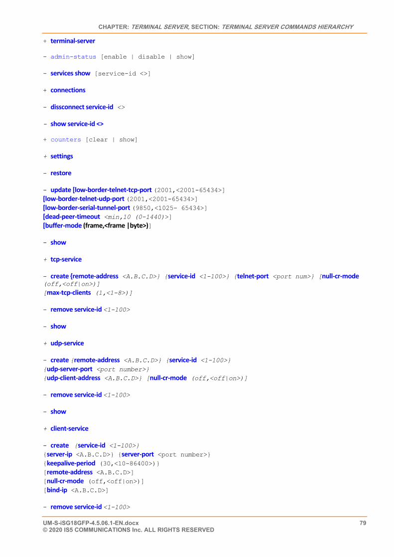
CHAPTER: TERMINAL SERVER, SECTION: TERMINAL SERVER COMMANDS HIERARCHY
UM-S-iSG18GFP-4.5.06.1-EN.docx 79 © 2020 IS5 COMMUNICATIONS Inc. ALL RIGHTS RESERVED
+ terminal-server
- admin-status [enable | disable | show]
- services show [service-id <>]
+ connections
- dissconnect service-id <>
- show service-id <>
+ counters [clear | show]
+ settings
- restore
- update [low-border-telnet-tcp-port (2001,<2001-65434>] [low-border-telnet-udp-port (2001,<2001-65434>] [low-border-serial-tunnel-port (9850,<1025- 65434>] [dead-peer-timeout <min,10 (0-1440)>] [buffer-mode (frame,<frame |byte>)]
- show
+ tcp-service
- create {remote-address <A.B.C.D>} {service-id <1-100>} {telnet-port <port num>} [null-cr-mode (off,<off|on>)] [max-tcp-clients (1,<1-8>)]
- remove service-id <1-100>
- show
+ udp-service
- create {remote-address <A.B.C.D>} {service-id <1-100>} {udp-server-port <port number>} {udp-client-address <A.B.C.D>} [null-cr-mode (off,<off|on>)]
- remove service-id <1-100>
- show
+ client-service
- create {service-id <1-100>} {server-ip <A.B.C.D>} {server-port <port number>} {keepalive-period (30,<10-86400>)} [remote-address <A.B.C.D>] [null-cr-mode (off,<off|on>)] [bind-ip <A.B.C.D>]
- remove service-id <1-100>
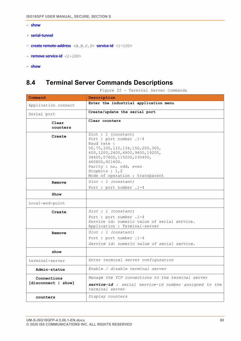
ISG18GFP USER MANUAL, SECURE, SECTION S
UM-S-iSG18GFP-4.5.06.1-EN.docx 80 © 2020 IS5 COMMUNICATIONS INC. ALL RIGHTS RESERVED
- show
+ serial-tunnel
- create remote-address <A.B.C.D> service-id <1-100>
- remove service-id <1-100>
- show
8.4 Terminal Server Commands Descriptions Figure 22 - Terminal Server Commands
Command Description
Application connect Enter the industrial application menu
Serial port Create/update the serial port
Clear counters
Clear counters
Create Slot : 1 (constant) Port : port number .1-4 Baud rate : 50,75,100,110,134,150,200,300, 600,1200,2400,4800,9600,19200, 38400,57600,115200,230400, 460800,921600. Parity : no, odd, even Stopbits : 1,2 Mode of operation : transparent
Remove Slot : 1 (constant)
Port : port number .1-4
Show
Local-end-point
Create Slot : 1 (constant)
Port : port number .1-4 Service id: numeric value of serial service. Application : Terminal-server
Remove Slot : 1 (constant)
Port : port number .1-4
Service id: numeric value of serial service.
show
terminal-server Enter terminal server configuration
Admin-status Enable / disable terminal server
Connections [disconnect | show]
Manage the TCP connections to the terminal server
service-id : serial service-id number assigned to the terminal server
counters Display counters
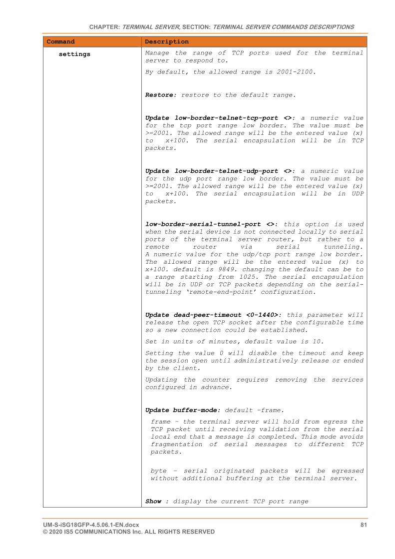
CHAPTER: TERMINAL SERVER, SECTION: TERMINAL SERVER COMMANDS DESCRIPTIONS
UM-S-iSG18GFP-4.5.06.1-EN.docx 81 © 2020 IS5 COMMUNICATIONS Inc. ALL RIGHTS RESERVED
Command Description
settings Manage the range of TCP ports used for the terminal server to respond to.
By default, the allowed range is 2001-2100.
Restore: restore to the default range.
Update low-border-telnet-tcp-port <>: a numeric value for the tcp port range low border. The value must be >=2001. The allowed range will be the entered value (x) to x+100. The serial encapsulation will be in TCP packets.
Update low-border-telnet-udp-port <>: a numeric value for the udp port range low border. The value must be >=2001. The allowed range will be the entered value (x) to x+100. The serial encapsulation will be in UDP packets.
low-border-serial-tunnel-port <>: this option is used when the serial device is not connected locally to serial ports of the terminal server router, but rather to a remote router via serial tunneling. A numeric value for the udp/tcp port range low border. The allowed range will be the entered value (x) to x+100. default is 9849. changing the default can be to a range starting from 1025. The serial encapsulation will be in UDP or TCP packets depending on the serial-tunneling ‘remote-end-point’ configuration.
Update dead-peer-timeout <0-1440>: this parameter will release the open TCP socket after the configurable time so a new connection could be established.
Set in units of minutes, default value is 10.
Setting the value 0 will disable the timeout and keep the session open until administratively release or ended by the client.
Updating the counter requires removing the services configured in advance.
Update buffer-mode: default –frame.
frame – the terminal server will hold from egress the TCP packet until receiving validation from the serial local end that a message is completed. This mode avoids fragmentation of serial messages to different TCP packets.
byte – serial originated packets will be egressed without additional buffering at the terminal server.
Show : display the current TCP port range
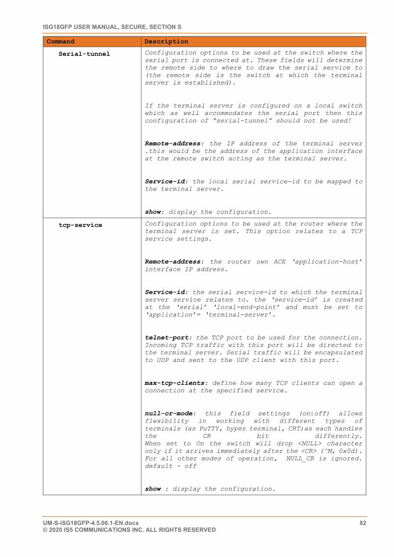
ISG18GFP USER MANUAL, SECURE, SECTION S
UM-S-iSG18GFP-4.5.06.1-EN.docx 82 © 2020 IS5 COMMUNICATIONS INC. ALL RIGHTS RESERVED
Command Description
Serial-tunnel Configuration options to be used at the switch where the serial port is connected at. These fields will determine the remote side to where to draw the serial service to (the remote side is the switch at which the terminal server is established).
If the terminal server is configured on a local switch which as well accommodates the serial port then this configuration of “serial-tunnel” should not be used!
Remote-address: the IP address of the terminal server .this would be the address of the application interface at the remote switch acting as the terminal server.
Service-id: the local serial service-id to be mapped to the terminal server.
show: display the configuration.
tcp-service Configuration options to be used at the router where the terminal server is set. This option relates to a TCP service settings.
Remote-address: the router own ACE ‘application-host’ interface IP address.
Service-id: the serial service-id to which the terminal server service relates to. the ‘service-id’ is created at the ‘serial’ ‘local-end-point’ and must be set to ‘application’= ‘terminal-server’.
telnet-port: the TCP port to be used for the connection. Incoming TCP traffic with this port will be directed to the terminal server. Serial traffic will be encapsulated to UDP and sent to the UDP client with this port.
max-tcp-clients: define how many TCP clients can open a connection at the specified service.
null-cr-mode: this field settings (on|off) allows flexibility in working with different types of terminals (as PuTTY, hyper terminal, CRT)as each handles the CR bit differently. When set to On the switch will drop <NULL> character only if it arrives immediately after the <CR> (^M, 0x0d). For all other modes of operation, NULL_CR is ignored. default - off
show : display the configuration.
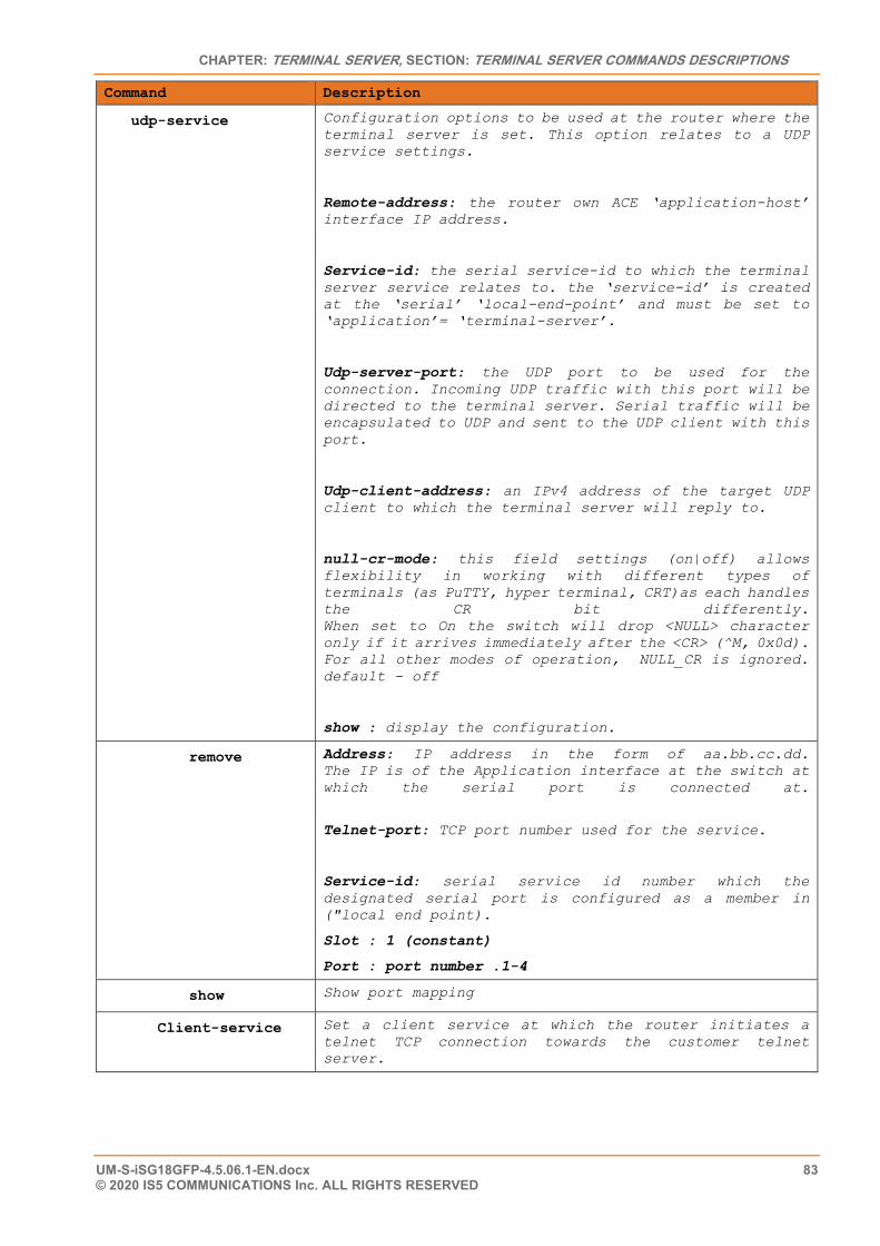
CHAPTER: TERMINAL SERVER, SECTION: TERMINAL SERVER COMMANDS DESCRIPTIONS
UM-S-iSG18GFP-4.5.06.1-EN.docx 83 © 2020 IS5 COMMUNICATIONS Inc. ALL RIGHTS RESERVED
Command Description
udp-service Configuration options to be used at the router where the terminal server is set. This option relates to a UDP service settings.
Remote-address: the router own ACE ‘application-host’ interface IP address.
Service-id: the serial service-id to which the terminal server service relates to. the ‘service-id’ is created at the ‘serial’ ‘local-end-point’ and must be set to ‘application’= ‘terminal-server’.
Udp-server-port: the UDP port to be used for the connection. Incoming UDP traffic with this port will be directed to the terminal server. Serial traffic will be encapsulated to UDP and sent to the UDP client with this port.
Udp-client-address: an IPv4 address of the target UDP client to which the terminal server will reply to.
null-cr-mode: this field settings (on|off) allows flexibility in working with different types of terminals (as PuTTY, hyper terminal, CRT)as each handles the CR bit differently. When set to On the switch will drop <NULL> character only if it arrives immediately after the <CR> (^M, 0x0d). For all other modes of operation, NULL_CR is ignored. default - off
show : display the configuration.
remove Address: IP address in the form of aa.bb.cc.dd. The IP is of the Application interface at the switch at which the serial port is connected at.
Telnet-port: TCP port number used for the service.
Service-id: serial service id number which the designated serial port is configured as a member in ("local end point).
Slot : 1 (constant)
Port : port number .1-4
show Show port mapping
Client-service Set a client service at which the router initiates a telnet TCP connection towards the customer telnet server.
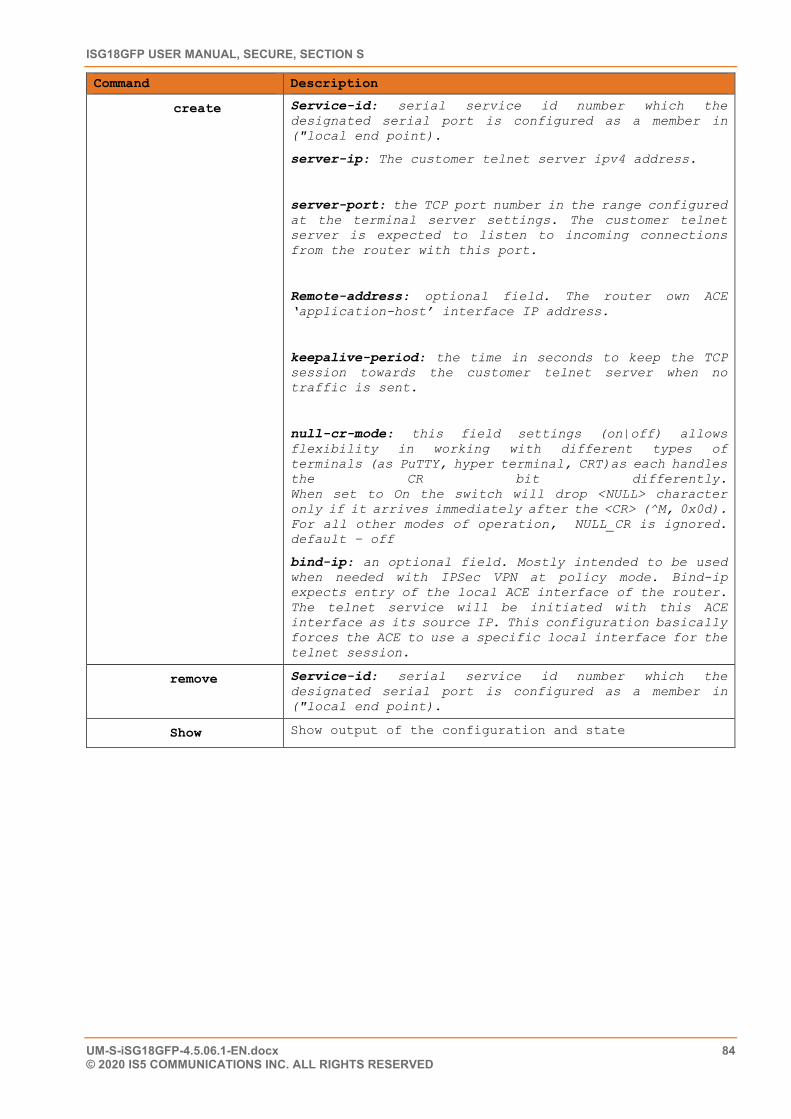
ISG18GFP USER MANUAL, SECURE, SECTION S
UM-S-iSG18GFP-4.5.06.1-EN.docx 84 © 2020 IS5 COMMUNICATIONS INC. ALL RIGHTS RESERVED
Command Description
create Service-id: serial service id number which the designated serial port is configured as a member in ("local end point).
server-ip: The customer telnet server ipv4 address.
server-port: the TCP port number in the range configured at the terminal server settings. The customer telnet server is expected to listen to incoming connections from the router with this port.
Remote-address: optional field. The router own ACE ‘application-host’ interface IP address.
keepalive-period: the time in seconds to keep the TCP session towards the customer telnet server when no traffic is sent.
null-cr-mode: this field settings (on|off) allows flexibility in working with different types of terminals (as PuTTY, hyper terminal, CRT)as each handles the CR bit differently. When set to On the switch will drop <NULL> character only if it arrives immediately after the <CR> (^M, 0x0d). For all other modes of operation, NULL_CR is ignored. default – off
bind-ip: an optional field. Mostly intended to be used when needed with IPSec VPN at policy mode. Bind-ip expects entry of the local ACE interface of the router. The telnet service will be initiated with this ACE interface as its source IP. This configuration basically forces the ACE to use a specific local interface for the telnet session.
remove Service-id: serial service id number which the designated serial port is configured as a member in ("local end point).
Show Show output of the configuration and state
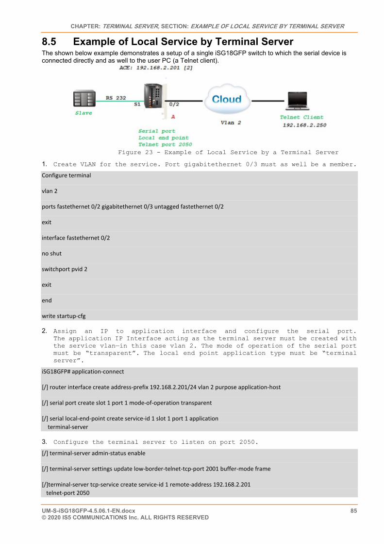
CHAPTER: TERMINAL SERVER, SECTION: EXAMPLE OF LOCAL SERVICE BY TERMINAL SERVER
UM-S-iSG18GFP-4.5.06.1-EN.docx 85 © 2020 IS5 COMMUNICATIONS Inc. ALL RIGHTS RESERVED
8.5 Example of Local Service by Terminal Server The shown below example demonstrates a setup of a single iSG18GFP switch to which the serial device is connected directly and as well to the user PC (a Telnet client).
Figure 23 - Example of Local Service by a Terminal Server
1. Create VLAN for the service. Port gigabitethernet 0/3 must as well be a member.
Configure terminal
vlan 2
ports fastethernet 0/2 gigabitethernet 0/3 untagged fastethernet 0/2
exit
interface fastethernet 0/2
no shut
switchport pvid 2
exit
end
write startup-cfg
2. Assign an IP to application interface and configure the serial port. The application IP Interface acting as the terminal server must be created with the service vlan—in this case vlan 2. The mode of operation of the serial port must be “transparent”. The local end point application type must be “terminal server”.
iSG18GFP# application-connect
[/] router interface create address-prefix 192.168.2.201/24 vlan 2 purpose application-host
[/] serial port create slot 1 port 1 mode-of-operation transparent
[/] serial local-end-point create service-id 1 slot 1 port 1 application terminal-server
3. Configure the terminal server to listen on port 2050.
[/] terminal-server admin-status enable
[/] terminal-server settings update low-border-telnet-tcp-port 2001 buffer-mode frame
[/]terminal-server tcp-service create service-id 1 remote-address 192.168.2.201 telnet-port 2050
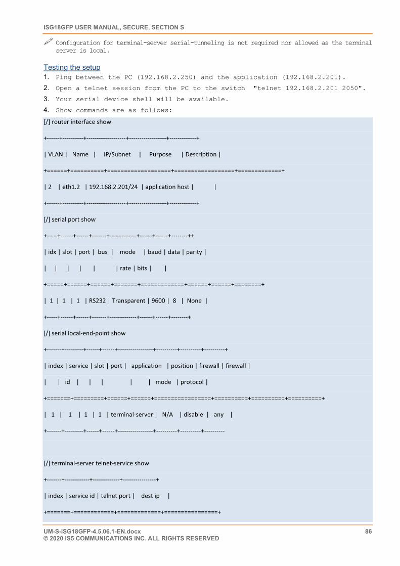
ISG18GFP USER MANUAL, SECURE, SECTION S
UM-S-iSG18GFP-4.5.06.1-EN.docx 86 © 2020 IS5 COMMUNICATIONS INC. ALL RIGHTS RESERVED
Configuration for terminal-server serial-tunneling is not required nor allowed as the terminal server is local.
Testing the setup 1. Ping between the PC (192.168.2.250) and the application (192.168.2.201).
2. Open a telnet session from the PC to the switch "telnet 192.168.2.201 2050".
3. Your serial device shell will be available.
4. Show commands are as follows:
[/] router interface show
+------+----------+-------------------+------------------+-------------+
| VLAN | Name | IP/Subnet | Purpose | Description |
+======+==========+===================+==================+=============+
| 2 | eth1.2 | 192.168.2.201/24 | application host | |
+------+----------+-------------------+------------------+-------------+
[/] serial port show
+-----+------+------+-------+-------------+------+------+--------++
| idx | slot | port | bus | mode | baud | data | parity |
| | | | | | rate | bits | |
+=====+======+======+=======+=============+======+======+========+
| 1 | 1 | 1 | RS232 | Transparent | 9600 | 8 | None |
+-----+------+------+-------+-------------+------+------+--------+
[/] serial local-end-point show
+-------+---------+------+------+-----------------+----------+----------+----------+
| index | service | slot | port | application | position | firewall | firewall |
| | id | | | | | mode | protocol |
+=======+=========+======+======+=================+==========+==========+==========+
| 1 | 1 | 1 | 1 | terminal-server | N/A | disable | any |
+-------+---------+------+------+-----------------+----------+----------+----------
[/] terminal-server telnet-service show
+-------+------------+-------------+----------------+
| index | service id | telnet port | dest ip |
+=======+============+=============+================+
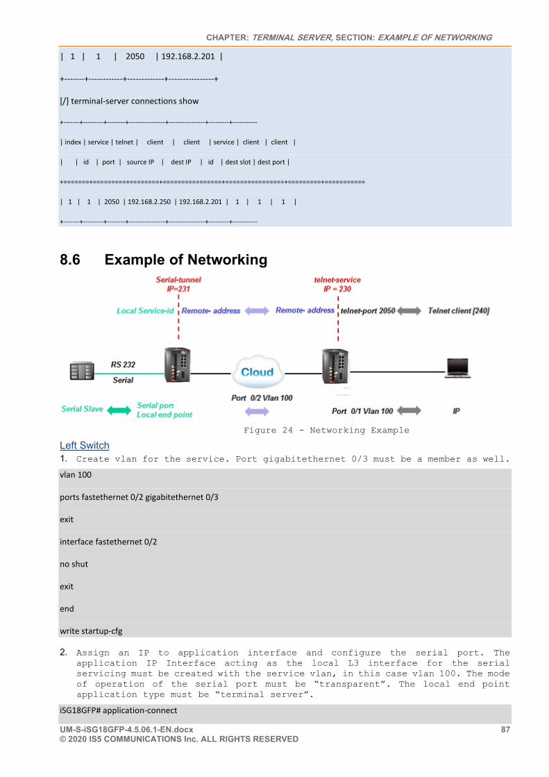
CHAPTER: TERMINAL SERVER, SECTION: EXAMPLE OF NETWORKING
UM-S-iSG18GFP-4.5.06.1-EN.docx 87 © 2020 IS5 COMMUNICATIONS Inc. ALL RIGHTS RESERVED
| 1 | 1 | 2050 | 192.168.2.201 |
+-------+------------+-------------+----------------+
[/] terminal-server connections show
+-------+---------+--------+----------------+----------------+---------+-----------
| index | service | telnet | client | client | service | client | client |
| | id | port | source IP | dest IP | id | dest slot | dest port |
+=======+=========+========+================+================+=========+===========
| 1 | 1 | 2050 | 192.168.2.250 | 192.168.2.201 | 1 | 1 | 1 |
+-------+---------+--------+----------------+----------------+---------+-----------
8.6 Example of Networking
Figure 24 - Networking Example
Left Switch 1. Create vlan for the service. Port gigabitethernet 0/3 must be a member as well.
vlan 100
ports fastethernet 0/2 gigabitethernet 0/3
exit
interface fastethernet 0/2
no shut
exit
end
write startup-cfg
2. Assign an IP to application interface and configure the serial port. The application IP Interface acting as the local L3 interface for the serial servicing must be created with the service vlan, in this case vlan 100. The mode of operation of the serial port must be “transparent”. The local end point application type must be “terminal server”.
iSG18GFP# application-connect
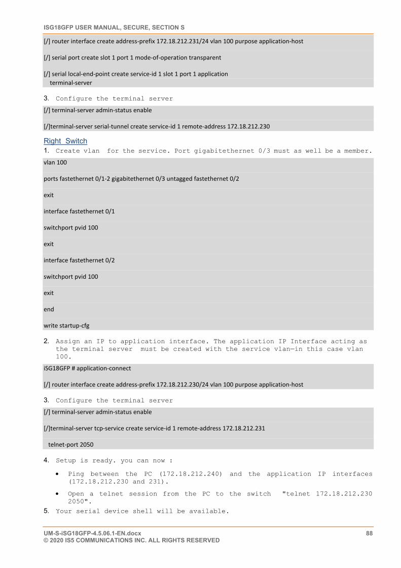
ISG18GFP USER MANUAL, SECURE, SECTION S
UM-S-iSG18GFP-4.5.06.1-EN.docx 88 © 2020 IS5 COMMUNICATIONS INC. ALL RIGHTS RESERVED
[/] router interface create address-prefix 172.18.212.231/24 vlan 100 purpose application-host
[/] serial port create slot 1 port 1 mode-of-operation transparent
[/] serial local-end-point create service-id 1 slot 1 port 1 application terminal-server
3. Configure the terminal server
[/] terminal-server admin-status enable
[/]terminal-server serial-tunnel create service-id 1 remote-address 172.18.212.230
Right Switch 1. Create vlan for the service. Port gigabitethernet 0/3 must as well be a member.
vlan 100
ports fastethernet 0/1-2 gigabitethernet 0/3 untagged fastethernet 0/2
exit
interface fastethernet 0/1
switchport pvid 100
exit
interface fastethernet 0/2
switchport pvid 100
exit
end
write startup-cfg
2. Assign an IP to application interface. The application IP Interface acting as the terminal server must be created with the service vlan—in this case vlan 100.
iSG18GFP # application-connect
[/] router interface create address-prefix 172.18.212.230/24 vlan 100 purpose application-host
3. Configure the terminal server
[/] terminal-server admin-status enable
[/]terminal-server tcp-service create service-id 1 remote-address 172.18.212.231
telnet-port 2050
4. Setup is ready. you can now :
• Ping between the PC (172.18.212.240) and the application IP interfaces (172.18.212.230 and 231).
• Open a telnet session from the PC to the switch "telnet 172.18.212.230 2050".
5. Your serial device shell will be available.
CHAPTER: MODBUS GATEWAY, SECTION: IMPLEMENTATION
UM-S-iSG18GFP-4.5.06.1-EN.docx 89 © 2020 IS5 COMMUNICATIONS Inc. ALL RIGHTS RESERVED
Modbus Gateway
The serial communication protocol Modbus enables communication among many devices connected to the same network. Each device intended to communicate using Modbus is given a unique address. In serial and MB+ networks, only the node assigned as a Master may initiate a command. On Ethernet, any device can send out a Modbus command, although usually only one master device does so. A Modbus command contains the Modbus address of the device it is intended for (1 to 247). Only the intended device will act on the command, even though other devices might receive it (an exception is specific broadcastable commands sent to node 0, which are acted on but not acknowledged). All Modbus commands contain checksum information to allow the recipient to detect transmission errors. The basic Modbus commands can instruct an RTU to change the value in one of its registers, control or read an I/O port, and command the device to send back one or more values contained in its registers.
Some of the Modbus versions are:
• Modbus RTU is used in serial communication and makes use of a compact, binary representation of the data for protocol communication and is the most common implementation available for Modbus. A Modbus RTU message must be transmitted continuously without inter-character hesitations. Modbus messages are framed (separated) by idle (silent) periods
• Modbus TCP/IP or Modbus TCP is a Modbus variant used for communications over TCP/IP networks, connecting over port 502
The iS5Com’s capability of gateway Modbus RTU to Modbus TCP is another benefit to industrial area applications.
The iSG18GFP allows connecting an RS232 Modbus RTU and gateway to a remote Modbus TCP client (SCADA) over the Ethernet. The Modbus RTU slave is connected at the switch local serial port, over an RS232 link. The Modbus TCP Client (SCADA) may be connected directly to the switch Ethernet port or via an IP cloud. The switch gateway will encapsulate the Modbus RTU to a TCP packet with port 502.
The switch Modbus gateway is assigned with the stations ID of the Modbus RTU devices connected to it. The gateway is set to use a ACE IP interface as its TCP traffic source. Packet sent from Modbus TCP Client will carry the gateway IP interface and the Modbus RTU station ID as its target. The gateway will listen to incoming packets and forward the message in a serial uniform to relevant Modbus RTU using the station id as identifier.
Up to 5 instances of a gateway can coexist. Each must use a different ACE IP interface and have a unique gateway-id.
A serial port that is connecting a Modbus RTU device can be associated with a single gateway instance. A Modbus RTU device must have at least one Modbus ID. Each Modbus ID must be unique behind the gateway.
9.1 Implementation The Modbus gateway is supported between a Modbus TCP and a Modbus RTU. Modbus TCP gateway to Modbus ASCII is not implemented.
The gateway translates Modbus frames of same structure, meaning is it a prerequisite to have the Modbus TCP device use the same frame structure as the Modbus RTU device.
The terminal server service requires the use of an ACE IP interface type ‘application-host’
9.2 Modbus Gateway Commands Hierarchy + root
+ application connect

ISG18GFP USER MANUAL, SECURE, SECTION S
UM-S-iSG18GFP-4.5.06.1-EN.docx 90 © 2020 IS5 COMMUNICATIONS INC. ALL RIGHTS RESERVED
+ router
- interface create address-prefix <IP address>/[netmask] vlan <vlan id> purpose application-host [description <>]
+ serial
+ port
- create {slot <1>} {port <1-4>} {mode-of-operation <transparent>} [baudrate <>][parity <>][stopbits <>]
- show
+ local-end-point
- create create {slot <1>} {port <1-4>} {application <modbus-gw>}{service-id<>} [position <>] [protocol <>]
- show
+ modbus-gw
- show-gw-list
- connection [clear | show]
- counters
- clear-id {gw-id <1-5>} {unit-id <1-255>}
- clear-port {slot 1 port <1-4>}
- show-by-id gw-id <1-5>} {unit-id <1-255>}
- show-by-port {slot 1 port <1-4>}
+ debug
- map-units-on-bus-show slot 1 port <1-4>
- map-units-on-bus-start slot 1 port <1-4>
- show-serial-points slot 1 port <1-4>
- show-server-points slot 1 port <1-4>
- show-tcp-points
+ history
- clear {gw-id <1-5>}
- show {gw-id <1-5>}
+ mapping

CHAPTER: MODBUS GATEWAY, SECTION: MODBUS GATEWAY COMMANDS HIERARCHY
UM-S-iSG18GFP-4.5.06.1-EN.docx 91 © 2020 IS5 COMMUNICATIONS Inc. ALL RIGHTS RESERVED
- add-gw {address-prefix <a.b.c.d/e>} {admin-status (enable| diable} {gw-id <1-5>} [timeout-period <500-100,000>]
- add-id {slot 1 port <1-4>} {gw-id <1-5>} {unit-id <1-255>}
- remove-gw {gw-id <1-5>}
- show-ids [gw-id <1-5>]
+ update [admin-status (enable| diable} | timeout {gw-id <1-5> timeout-period <500-100,000>} ]
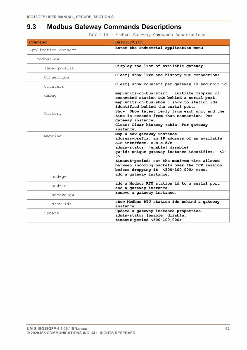
ISG18GFP USER MANUAL, SECURE, SECTION S
UM-S-iSG18GFP-4.5.06.1-EN.docx 92 © 2020 IS5 COMMUNICATIONS INC. ALL RIGHTS RESERVED
9.3 Modbus Gateway Commands Descriptions Table 14 - Modbus Gateway Commands Descriptions
Command Description
Application connect Enter the industrial application menu
modbus-gw
show-gw-list Display the list of available gateway
Connection Clear| show live and history TCP connections
counters Clear| show counters per gateway id and unit id
debug map-units-on-bus-start : initiate mapping of connected station ids behind a serial port. map-units-on-bus-show : show to station ids identified behind the serial port.
History Show: Show latest reply from each unit and the time in seconds from that connection. Per gateway instance. Clear: Clear history table. Per gateway instance.
Mapping Map a new gateway instance address-prefix: an IP address of an available ACE interface. A.b.c.d/e admin-status: (enable| disable) gw-id: unique gateway instance identifier. <1-5> timeout-period: set the maximum time allowed between incoming packets over the TCP session before dropping it <500-100,000> msec.
add-gw add a gateway instance.
add-id add a Modbus RTU station id to a serial port and a gateway instance.
Remove-gw remove a gateway instance.
show-ids show Modbus RTU station ids behind a gateway instance.
update Update a gateway instance properties. admin-status (enable| disable. timeout-period <500-100,000>
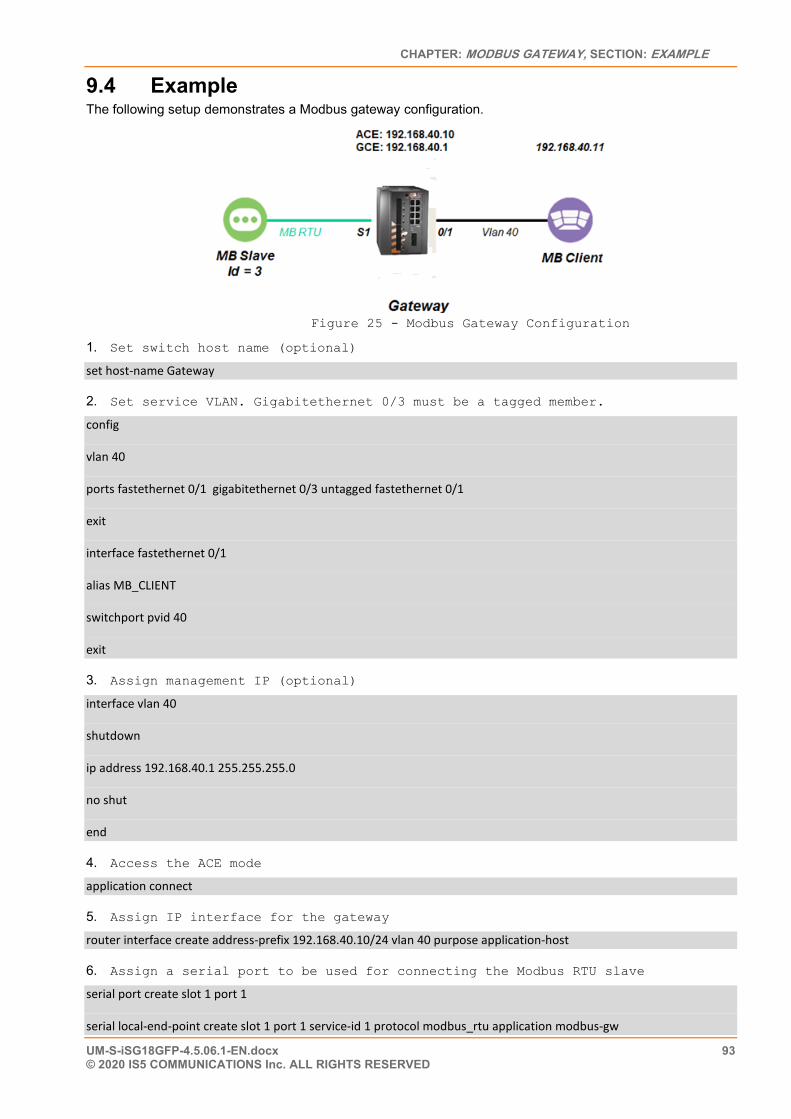
CHAPTER: MODBUS GATEWAY, SECTION: EXAMPLE
UM-S-iSG18GFP-4.5.06.1-EN.docx 93 © 2020 IS5 COMMUNICATIONS Inc. ALL RIGHTS RESERVED
9.4 Example The following setup demonstrates a Modbus gateway configuration.
Figure 25 - Modbus Gateway Configuration
1. Set switch host name (optional)
set host-name Gateway
2. Set service VLAN. Gigabitethernet 0/3 must be a tagged member.
config
vlan 40
ports fastethernet 0/1 gigabitethernet 0/3 untagged fastethernet 0/1
exit
interface fastethernet 0/1
alias MB_CLIENT
switchport pvid 40
exit
3. Assign management IP (optional)
interface vlan 40
shutdown
ip address 192.168.40.1 255.255.255.0
no shut
end
4. Access the ACE mode
application connect
5. Assign IP interface for the gateway
router interface create address-prefix 192.168.40.10/24 vlan 40 purpose application-host
6. Assign a serial port to be used for connecting the Modbus RTU slave
serial port create slot 1 port 1
serial local-end-point create slot 1 port 1 service-id 1 protocol modbus_rtu application modbus-gw
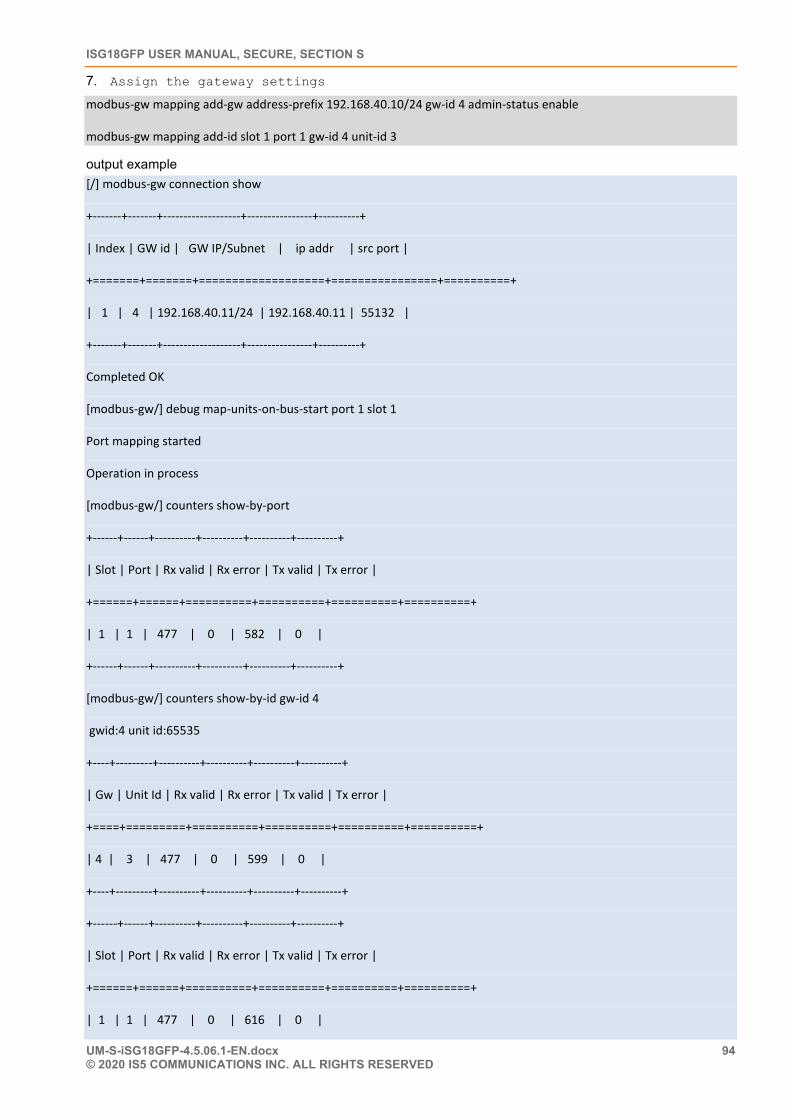
ISG18GFP USER MANUAL, SECURE, SECTION S
UM-S-iSG18GFP-4.5.06.1-EN.docx 94 © 2020 IS5 COMMUNICATIONS INC. ALL RIGHTS RESERVED
7. Assign the gateway settings
modbus-gw mapping add-gw address-prefix 192.168.40.10/24 gw-id 4 admin-status enable
modbus-gw mapping add-id slot 1 port 1 gw-id 4 unit-id 3
output example [/] modbus-gw connection show
+-------+-------+-------------------+----------------+----------+
| Index | GW id | GW IP/Subnet | ip addr | src port |
+=======+=======+===================+================+==========+
| 1 | 4 | 192.168.40.11/24 | 192.168.40.11 | 55132 |
+-------+-------+-------------------+----------------+----------+
Completed OK
[modbus-gw/] debug map-units-on-bus-start port 1 slot 1
Port mapping started
Operation in process
[modbus-gw/] counters show-by-port
+------+------+----------+----------+----------+----------+
| Slot | Port | Rx valid | Rx error | Tx valid | Tx error |
+======+======+==========+==========+==========+==========+
| 1 | 1 | 477 | 0 | 582 | 0 |
+------+------+----------+----------+----------+----------+
[modbus-gw/] counters show-by-id gw-id 4
gwid:4 unit id:65535
+----+---------+----------+----------+----------+----------+
| Gw | Unit Id | Rx valid | Rx error | Tx valid | Tx error |
+====+=========+==========+==========+==========+==========+
| 4 | 3 | 477 | 0 | 599 | 0 |
+----+---------+----------+----------+----------+----------+
+------+------+----------+----------+----------+----------+
| Slot | Port | Rx valid | Rx error | Tx valid | Tx error |
+======+======+==========+==========+==========+==========+
| 1 | 1 | 477 | 0 | 616 | 0 |
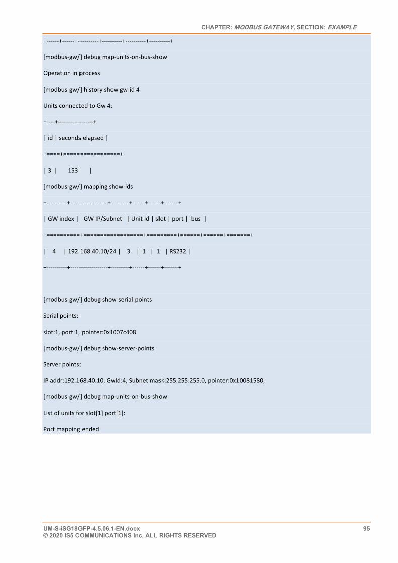
CHAPTER: MODBUS GATEWAY, SECTION: EXAMPLE
UM-S-iSG18GFP-4.5.06.1-EN.docx 95 © 2020 IS5 COMMUNICATIONS Inc. ALL RIGHTS RESERVED
+------+------+----------+----------+----------+----------+
[modbus-gw/] debug map-units-on-bus-show
Operation in process
[modbus-gw/] history show gw-id 4
Units connected to Gw 4:
+----+-----------------+
| id | seconds elapsed |
+====+=================+
| 3 | 153 |
[modbus-gw/] mapping show-ids
+----------+------------------+---------+------+------+-------+
| GW index | GW IP/Subnet | Unit Id | slot | port | bus |
+==========+==================+=========+======+======+=======+
| 4 | 192.168.40.10/24 | 3 | 1 | 1 | RS232 |
+----------+------------------+---------+------+------+-------+
[modbus-gw/] debug show-serial-points
Serial points:
slot:1, port:1, pointer:0x1007c408
[modbus-gw/] debug show-server-points
Server points:
IP addr:192.168.40.10, GwId:4, Subnet mask:255.255.255.0, pointer:0x10081580,
[modbus-gw/] debug map-units-on-bus-show
List of units for slot[1] port[1]:
Port mapping ended
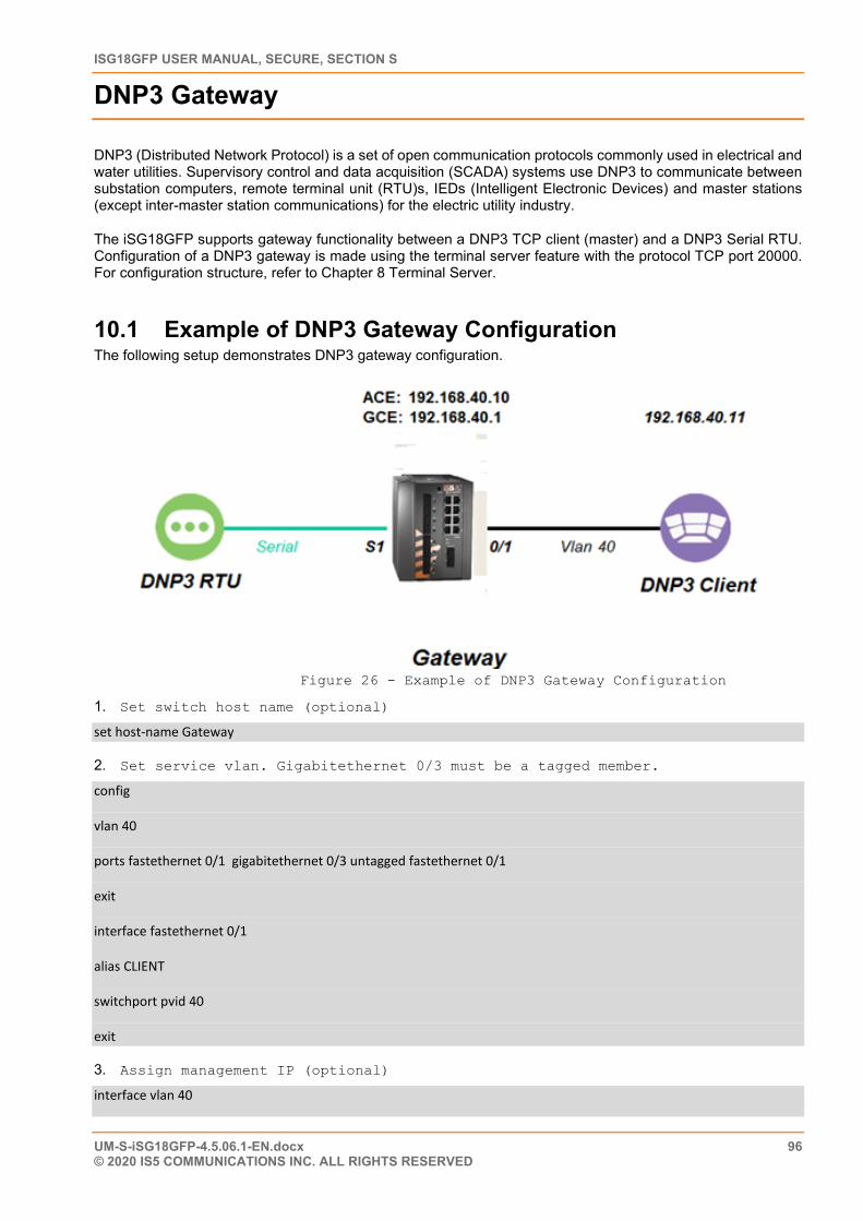
ISG18GFP USER MANUAL, SECURE, SECTION S
UM-S-iSG18GFP-4.5.06.1-EN.docx 96 © 2020 IS5 COMMUNICATIONS INC. ALL RIGHTS RESERVED
DNP3 Gateway
DNP3 (Distributed Network Protocol) is a set of open communication protocols commonly used in electrical and water utilities. Supervisory control and data acquisition (SCADA) systems use DNP3 to communicate between substation computers, remote terminal unit (RTU)s, IEDs (Intelligent Electronic Devices) and master stations (except inter-master station communications) for the electric utility industry.
The iSG18GFP supports gateway functionality between a DNP3 TCP client (master) and a DNP3 Serial RTU. Configuration of a DNP3 gateway is made using the terminal server feature with the protocol TCP port 20000. For configuration structure, refer to Chapter 8 Terminal Server.
10.1 Example of DNP3 Gateway Configuration The following setup demonstrates DNP3 gateway configuration.
Figure 26 - Example of DNP3 Gateway Configuration
1. Set switch host name (optional)
set host-name Gateway
2. Set service vlan. Gigabitethernet 0/3 must be a tagged member.
config
vlan 40
ports fastethernet 0/1 gigabitethernet 0/3 untagged fastethernet 0/1
exit
interface fastethernet 0/1
alias CLIENT
switchport pvid 40
exit
3. Assign management IP (optional)
interface vlan 40
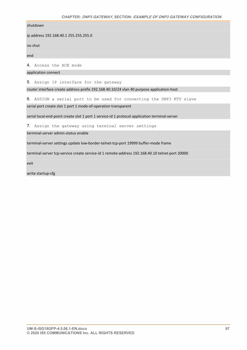
CHAPTER: DNP3 GATEWAY, SECTION: EXAMPLE OF DNP3 GATEWAY CONFIGURATION
UM-S-iSG18GFP-4.5.06.1-EN.docx 97 © 2020 IS5 COMMUNICATIONS Inc. ALL RIGHTS RESERVED
shutdown
ip address 192.168.40.1 255.255.255.0
no shut
end
4. Access the ACE mode
application connect
5. Assign IP interface for the gateway
router interface create address-prefix 192.168.40.10/24 vlan 40 purpose application-host
6. ASSIGN a serial port to be used for connecting the DNP3 RTU slave
serial port create slot 1 port 1 mode-of-operation transparent
serial local-end-point create slot 1 port 1 service-id 1 protocol application terminal-server
7. Assign the gateway using terminal server settings
terminal-server admin-status enable
terminal-server settings update low-border-telnet-tcp-port 19999 buffer-mode frame
terminal-server tcp-service create service-id 1 remote-address 192.168.40.10 telnet-port 20000
exit
write startup-cfg
ISG18GFP USER MANUAL, SECURE, SECTION S
UM-S-iSG18GFP-4.5.06.1-EN.docx 98 © 2020 IS5 COMMUNICATIONS INC. ALL RIGHTS RESERVED
Protocol Gateway IEC 101 to IEC 104
IEC 60870-5 is one of the IEC 60870 set of standards which define systems used for telecontrol (supervisory control and data acquisition (SCADA)). The IEC Technical Committee 57 has also generated companion standards. This document will refer to 2 of them:
• IEC 60870-5-101 (“IEC101”) Transmission Protocol operates over serial connection (“IEC101 serial devices” or “IEC101 devices”)
• IEC 60870-5-104 (“IEC104”). Transmission Protocols for Network access for IEC 60870-5-101 using standard transport profiles It operates over IP interfaces (“IEC104 IP protocol”).
Protocol Gateway is another mode of operation in which each of the serial ports can be configured to work. The iSG18GFP, when is using its application module, implements the gateway for IEC101 serial devices to the IEC104 IP protocol. The IEC101 and IEC104 protocols are fully integrated in its application module, thus allowing the IEC101 slave devices to be represented as a IEC104 server in the IP network and to be addressed as such by IEC104 clients located anywhere in the network.
The gateway implementation consists of 3 functions:
• IEC104 Server—the application module will act as an IEC104 server to any IEC104 clients that connect to it over the Ethernet network. This function includes the full implementation of the state-machine of the IEC104 server, response to keep-alive test frames and listening of TCP port 2404 for any client requests.
• IEC60870 message router—the application module will act as an application router translating the requests received by the IEC104 server to commands issued by the IEC101 master with the proper IEC101 address and sending the responses vice versa.
• IEC101 Master—the application module will act as an IEC101 master to the IEC101 server devices connected to the assigned serial interfaces in the switch. This function includes the full implementation of the state-machine of the IEC101 master, initialization, and arbitration of the IEC101 bus and issuing commands to the appropriate IEC101 slave to provide the response to the requests which arrive from the message router.
The IEC101 devices will be configured with their serial link properties, device address, and ASDU (Application service Data Unit) address to be uniquely identified behind the gateway.
Overall the IEC101 devices will be addressed from the IEC104 remote client using the following hierarchical addressing scheme:
• IP address of the ACE module in which the IEC101/104 gateway is implemented, • IEC101 device address, • ASDU address, and • IOA (Information Object Address)
IOA is the index (address) of a data item or the actual address of the discrete inputs mapped at the IEC101 RTU.
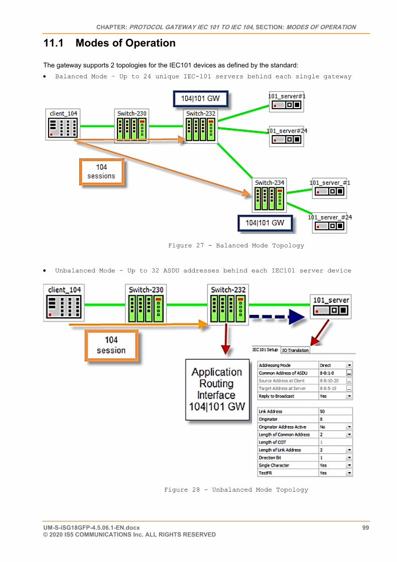
CHAPTER: PROTOCOL GATEWAY IEC 101 TO IEC 104, SECTION: MODES OF OPERATION
UM-S-iSG18GFP-4.5.06.1-EN.docx 99 © 2020 IS5 COMMUNICATIONS Inc. ALL RIGHTS RESERVED
11.1 Modes of Operation The gateway supports 2 topologies for the IEC101 devices as defined by the standard: • Balanced Mode – Up to 24 unique IEC-101 servers behind each single gateway
Figure 27 - Balanced Mode Topology
• Unbalanced Mode – Up to 32 ASDU addresses behind each IEC101 server device
Figure 28 - Unbalanced Mode Topology
ISG18GFP USER MANUAL, SECURE, SECTION S
UM-S-iSG18GFP-4.5.06.1-EN.docx 100 © 2020 IS5 COMMUNICATIONS INC. ALL RIGHTS RESERVED
11.2 IEC101/104 Gateway Properties IEC 101 • System role : Controlling station definition (Master) • Network configuration :
o PPP o Multiple point-to-point o Multipoint-party line (planned)
• Physical layer o Transmission speed in monitor & control direction: 300 – 38400bps
• Link layer o Link transmission procedure
Balanced transmission Unbalanced transmission
o Address field of the link Not present (balanced transmission only) One octet Two octets Structured values translation Unstructured
• Application layer o Common address of ASDU
One octet Two octets
o Information object address Two octets Three octets Structured Unstructured
o Cause of transmission One octet Two octets (with originator address)
11.3 IEC101/104 Gateway Configuration A gateway setup configuration should include the following parameters:
• ACE IP address—ACE IP interface is mandatory to be set, and it should be associated with a VLAN for the uplink traffic. This application IP interface acts as the IEC104 server in the Ethernet network and represents all the IEC101 devices connected locally to the switch towards the IEC104 clients.
• Optional remote IP addresses—when configuring the IEC104 service-group, you should also provide the IP addresses of the IEC104 clients so the proper service-aware firewall rules can be defined.
• IEC101 device parameters—for the serial interfaces, the physical link properties should be configured (baud-rate, parity, stop bits). Furthermore, the IEC101 addressing information should be provided and the devices should be assigned to the IEC104/101 gateway.
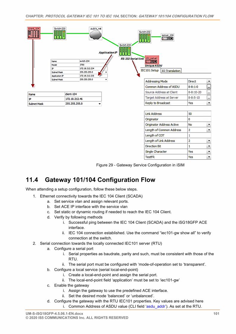
CHAPTER: PROTOCOL GATEWAY IEC 101 TO IEC 104, SECTION: GATEWAY 101/104 CONFIGURATION FLOW
UM-S-iSG18GFP-4.5.06.1-EN.docx 101 © 2020 IS5 COMMUNICATIONS Inc. ALL RIGHTS RESERVED
Figure 29 - Gateway Service Configuration in iSIM
11.4 Gateway 101/104 Configuration Flow When attending a setup configuration, follow these below steps.
1. Ethernet connectivity towards the IEC 104 Client (SCADA) a. Set service vlan and assign relevant ports. b. Set ACE IP interface with the service vlan c. Set static or dynamic routing if needed to reach the IEC 104 Client. d. Verify by following methods
i. Successful ping between the IEC 104 Client (SCADA) and the iSG18GFP ACE interface.
ii. IEC 104 connection established. Use the command “iec101-gw show all” to verify connection at the switch.
2. Serial connection towards the locally connected IEC101 server (RTU) a. Configure a serial port
i. Serial properties as baudrate, parity and such, must be consistent with those of the RTU.
ii. The serial port must be configured with ‘mode-of-operation set to ‘transparent’. b. Configure a local service (serial local-end-point)
i. Create a local-end-point and assign the serial port. ii. The local-end-point field ‘application’ must be set to ‘iec101-gw’
c. Enable the gateway i. Assign the gateway to use the predefined ACE interface. ii. Set the desired mode ‘balanced’ or ‘unbalanced’.
d. Configure the gateway with the RTU IEC101 properties. Key values are advised here i. Common Address of ASDU value (CLI field ‘asdu_addr’). As set at the RTU.
ISG18GFP USER MANUAL, SECURE, SECTION S
UM-S-iSG18GFP-4.5.06.1-EN.docx 102 © 2020 IS5 COMMUNICATIONS INC. ALL RIGHTS RESERVED
ii. Common Address of ASDU length in bytes (CLI field ‘common_address_field_length’). As set at the RTU.
iii. Link Address (CLI field ‘link_addr’). As set at the RTU. iv. Link Address length in bytes (CLI field ‘link_address_field_length’). As set at the RTU. v. Cause of Transmission length in bytes, determined by the usage of the originator
address field in the protocol. (CLI field ‘orig_addr_participate’) vi. Connect the IEC101 server (RTU) to the serial port with a proper serial cable. Pin-out
of the RS232 RJ45 port of the switch is given in this manual. Control lines are not supported for the gateway application. Usage of Tx, Rx and GND lines are allowed.
e. Verify by following methods i. Use the command “iec101-gw show all” to verify the operational status (‘OP ST’) is
UP. ii. Follow serial port and gateway counters to check if serial traffic is received and
transmitted at the serial port. Show commands “serial port show slot 1 port <x>” and “iec101-gw cnt show” are available.
3. Trouble shooting a. Most trouble shooting is usually at the IEC101 connection to the locally connected RTU. The
IEC 104 connection between the gateway and the client (SCADA) is based on straightforward Ethernet connectivity which is easy to establish and diagnose.
b. If the IEC101 (‘OP ST’) is in any other state other then ‘UP’, try the following i. Verify your serial physical connection. ii. Verify the RTU is on and properly configured. iii. Follow the serial port counters to verify traffic is received and transmitted at the serial
port. If only Rx counters are progressing, check again the serial properties of both the gateway and the RTU (baudrate, parity and such).
iv. Verify the IEC properties are consistent between the gateway and the RTU (CA, LA, CA length, LA length, COT)
The terminal server service requires the use of an ACE IP interface type ‘application-host’.
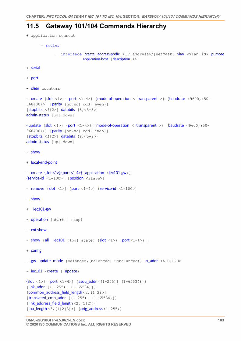
CHAPTER: PROTOCOL GATEWAY IEC 101 TO IEC 104, SECTION: GATEWAY 101/104 COMMANDS HIERARCHY
UM-S-iSG18GFP-4.5.06.1-EN.docx 103 © 2020 IS5 COMMUNICATIONS Inc. ALL RIGHTS RESERVED
11.5 Gateway 101/104 Commands Hierarchy + application connect
+ router
- interface create address-prefix <IP address>/[netmask] vlan <vlan id> purpose application-host [description <>]
+ serial
+ port
- clear counters
- create {slot <1>} {port <1-4>} {mode-of-operation < transparent >} [baudrate <9600,(50-368400)>] [parity {no,no| odd| even}] [stopbits <1|2>] databits {8,<5-8>} admin-status [up| down]
- update {slot <1>} {port <1-4>} {mode-of-operation < transparent >} [baudrate <9600,(50-368400)>] [parity {no,no| odd| even}] [stopbits <1|2>] databits {8,<5-8>} admin-status [up| down]
- show
+ local-end-point
- create {slot <1>} {port <1-4>} {application <iec101-gw>} {service-id <1-100>} [position <slave>]
- remove {slot <1>} {port <1-4>} {service-id <1-100>}
- show
+ iec101-gw
- operation {start | stop}
- cnt show
- show {all| iec101 {log| state} {slot <1>} {port <1-4>} }
+ config
- gw update mode {balanced,(balanced| unbalanced)} ip_addr <A.B.C.D>
- iec101 {create | update}
{slot <1>} {port <1-4>} {asdu_addr {(1-255)| (1-65534)}} {link_addr {(1-255)| (1-65534)}} [common_address_field_length <2,(1|2)>] [translated_cmn_addr {(1-255)| (1-65534)}] [link_address_field_length <2,(1|2)>] [ioa_length <3,(1|2|3)>] [orig_address <1-255>]
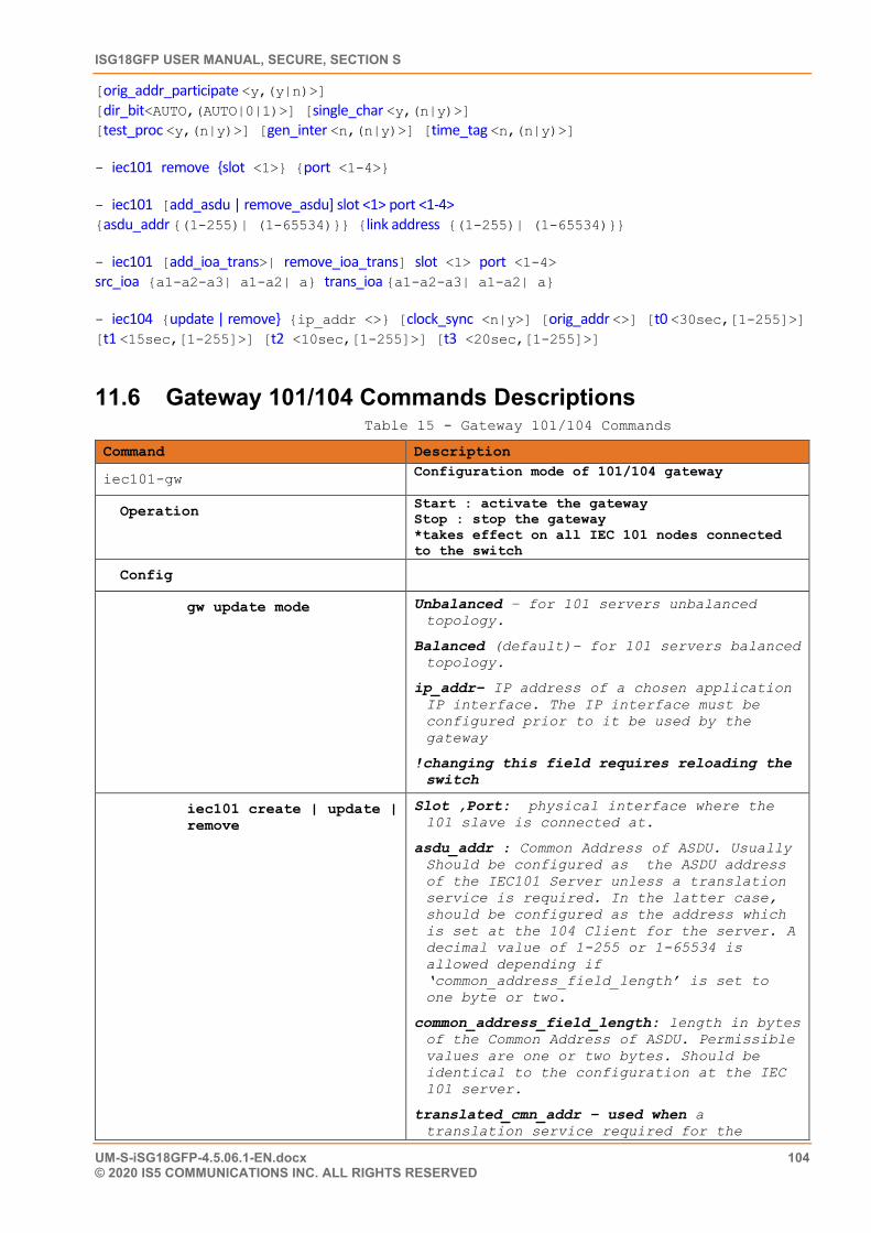
ISG18GFP USER MANUAL, SECURE, SECTION S
UM-S-iSG18GFP-4.5.06.1-EN.docx 104 © 2020 IS5 COMMUNICATIONS INC. ALL RIGHTS RESERVED
[orig_addr_participate <y,(y|n)>] [dir_bit<AUTO,(AUTO|0|1)>] [single_char <y,(n|y)>] [test_proc <y,(n|y)>] [gen_inter <n,(n|y)>] [time_tag <n,(n|y)>]
- iec101 remove {slot <1>} {port <1-4>}
- iec101 [add_asdu | remove_asdu] slot <1> port <1-4> {asdu_addr {(1-255)| (1-65534)}} {link address {(1-255)| (1-65534)}}
- iec101 [add_ioa_trans>| remove_ioa_trans] slot <1> port <1-4> src_ioa {a1-a2-a3| a1-a2| a} trans_ioa {a1-a2-a3| a1-a2| a}
- iec104 {update | remove} {ip_addr <>} [clock_sync <n|y>] [orig_addr <>] [t0 <30sec,[1-255]>] [t1 <15sec,[1-255]>] [t2 <10sec,[1-255]>] [t3 <20sec,[1-255]>]
11.6 Gateway 101/104 Commands Descriptions Table 15 - Gateway 101/104 Commands
Command Description
iec101-gw Configuration mode of 101/104 gateway
Operation Start : activate the gateway Stop : stop the gateway *takes effect on all IEC 101 nodes connected to the switch
Config
gw update mode Unbalanced – for 101 servers unbalanced topology.
Balanced (default)– for 101 servers balanced topology.
ip_addr– IP address of a chosen application IP interface. The IP interface must be configured prior to it be used by the gateway
!changing this field requires reloading the switch
iec101 create | update | remove
Slot ,Port: physical interface where the 101 slave is connected at.
asdu_addr : Common Address of ASDU. Usually Should be configured as the ASDU address of the IEC101 Server unless a translation service is required. In the latter case, should be configured as the address which is set at the 104 Client for the server. A decimal value of 1-255 or 1-65534 is allowed depending if ‘common_address_field_length’ is set to one byte or two.
common_address_field_length: length in bytes of the Common Address of ASDU. Permissible values are one or two bytes. Should be identical to the configuration at the IEC 101 server.
translated_cmn_addr – used when a translation service required for the
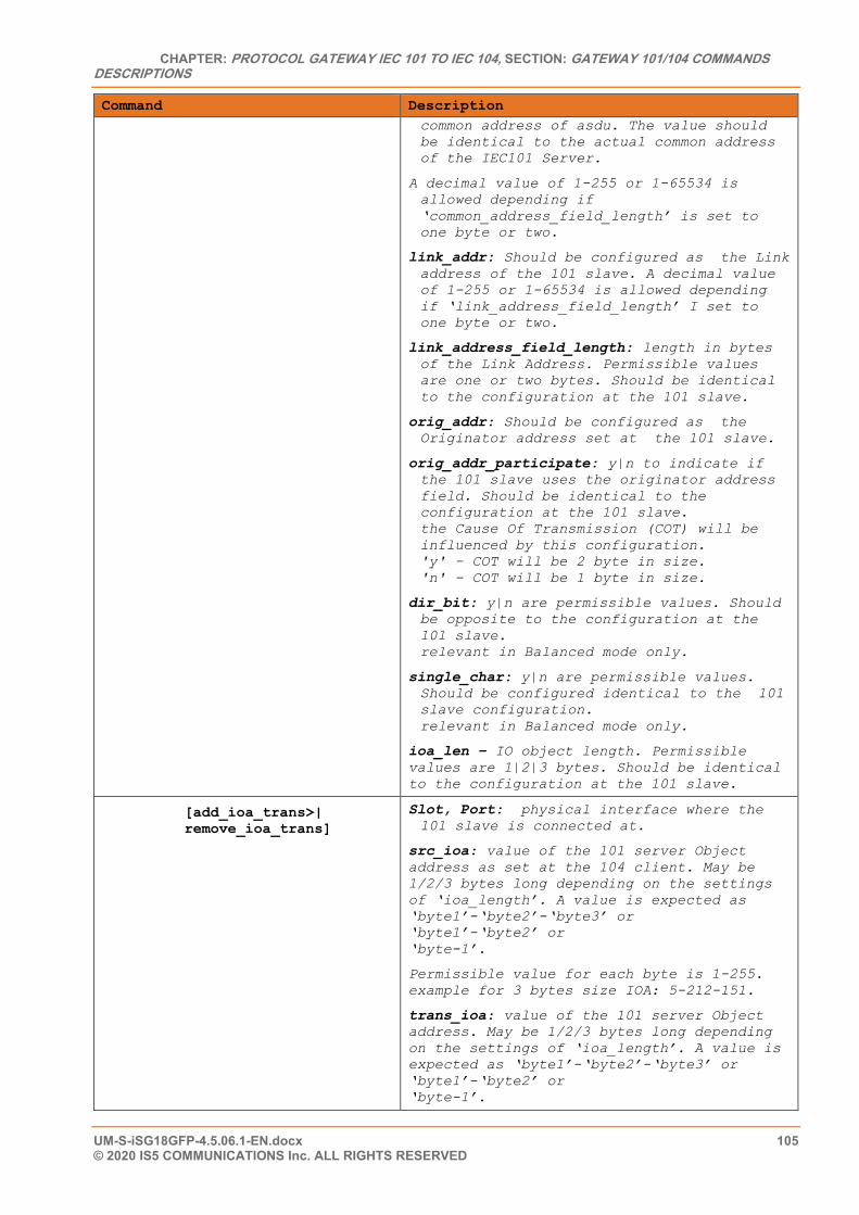
CHAPTER: PROTOCOL GATEWAY IEC 101 TO IEC 104, SECTION: GATEWAY 101/104 COMMANDS DESCRIPTIONS
UM-S-iSG18GFP-4.5.06.1-EN.docx 105 © 2020 IS5 COMMUNICATIONS Inc. ALL RIGHTS RESERVED
Command Description common address of asdu. The value should be identical to the actual common address of the IEC101 Server.
A decimal value of 1-255 or 1-65534 is allowed depending if ‘common_address_field_length’ is set to one byte or two.
link_addr: Should be configured as the Link address of the 101 slave. A decimal value of 1-255 or 1-65534 is allowed depending if ‘link_address_field_length’ I set to one byte or two.
link_address_field_length: length in bytes of the Link Address. Permissible values are one or two bytes. Should be identical to the configuration at the 101 slave.
orig_addr: Should be configured as the Originator address set at the 101 slave.
orig_addr_participate: y|n to indicate if the 101 slave uses the originator address field. Should be identical to the configuration at the 101 slave. the Cause Of Transmission (COT) will be influenced by this configuration. 'y' – COT will be 2 byte in size. 'n' - COT will be 1 byte in size.
dir_bit: y|n are permissible values. Should be opposite to the configuration at the 101 slave. relevant in Balanced mode only.
single_char: y|n are permissible values. Should be configured identical to the 101 slave configuration. relevant in Balanced mode only.
ioa_len – IO object length. Permissible values are 1|2|3 bytes. Should be identical to the configuration at the 101 slave.
[add_ioa_trans>| remove_ioa_trans]
Slot, Port: physical interface where the 101 slave is connected at.
src_ioa: value of the 101 server Object address as set at the 104 client. May be 1/2/3 bytes long depending on the settings of ‘ioa_length’. A value is expected as ‘byte1’-‘byte2’-‘byte3’ or ‘byte1’-‘byte2’ or ‘byte-1’.
Permissible value for each byte is 1-255. example for 3 bytes size IOA: 5-212-151.
trans_ioa: value of the 101 server Object address. May be 1/2/3 bytes long depending on the settings of ‘ioa_length’. A value is expected as ‘byte1’-‘byte2’-‘byte3’ or ‘byte1’-‘byte2’ or ‘byte-1’.
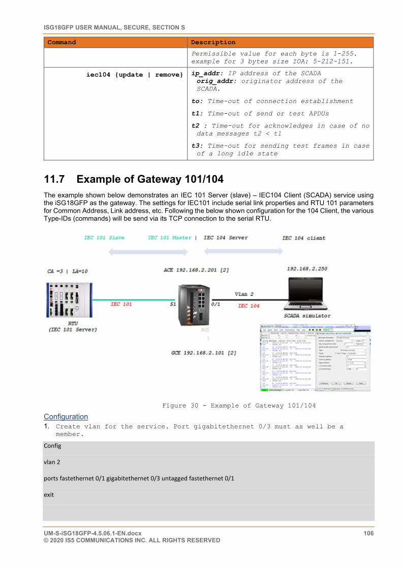
ISG18GFP USER MANUAL, SECURE, SECTION S
UM-S-iSG18GFP-4.5.06.1-EN.docx 106 © 2020 IS5 COMMUNICATIONS INC. ALL RIGHTS RESERVED
Command Description
Permissible value for each byte is 1-255. example for 3 bytes size IOA: 5-212-151.
iec104 {update | remove} ip_addr: IP address of the SCADA orig_addr: originator address of the SCADA.
to: Time-out of connection establishment
t1: Time-out of send or test APDUs
t2 : Time-out for acknowledges in case of no data messages t2 < t1
t3: Time-out for sending test frames in case of a long idle state
11.7 Example of Gateway 101/104 The example shown below demonstrates an IEC 101 Server (slave) – IEC104 Client (SCADA) service using the iSG18GFP as the gateway. The settings for IEC101 include serial link properties and RTU 101 parameters for Common Address, Link address, etc. Following the below shown configuration for the 104 Client, the various Type-IDs (commands) will be send via its TCP connection to the serial RTU.
Figure 30 - Example of Gateway 101/104
Configuration 1. Create vlan for the service. Port gigabitethernet 0/3 must as well be a
member.
Config
vlan 2
ports fastethernet 0/1 gigabitethernet 0/3 untagged fastethernet 0/1
exit
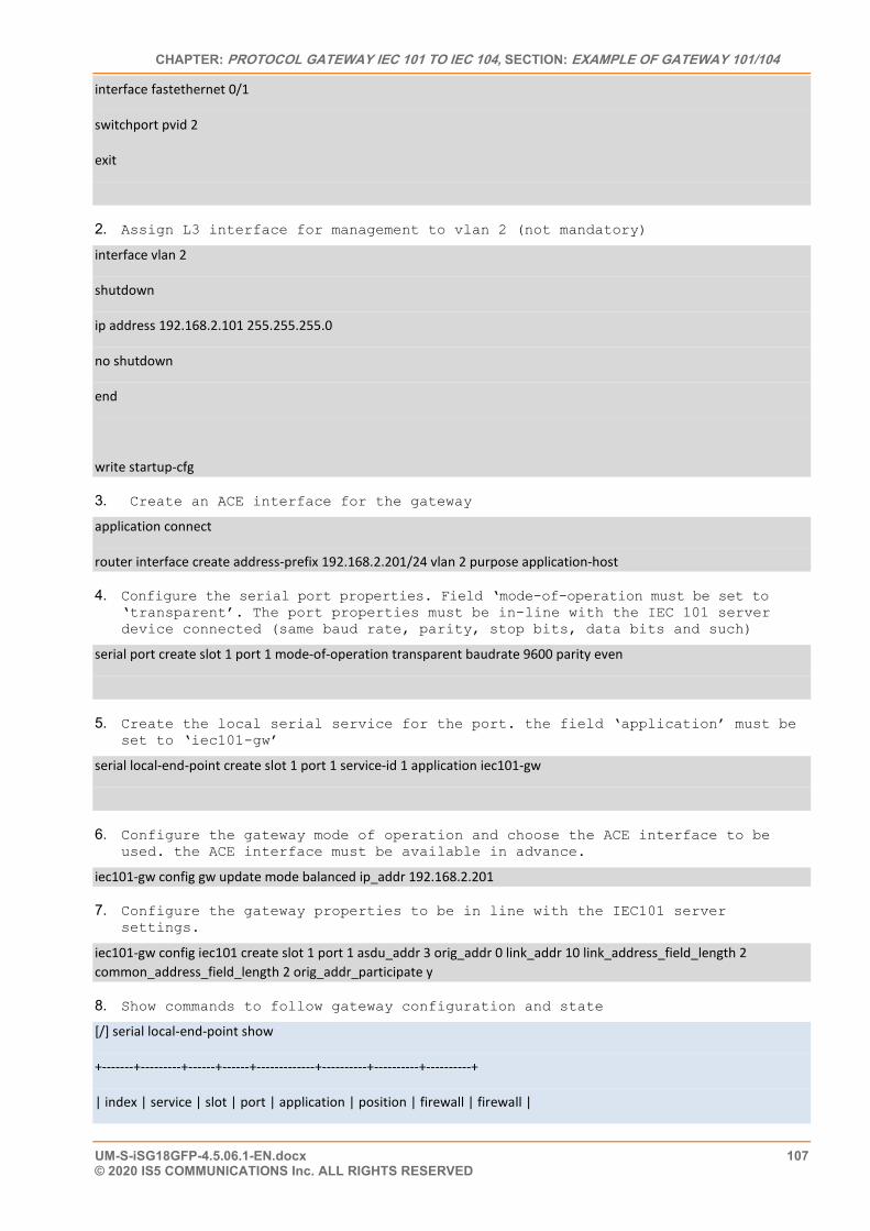
CHAPTER: PROTOCOL GATEWAY IEC 101 TO IEC 104, SECTION: EXAMPLE OF GATEWAY 101/104
UM-S-iSG18GFP-4.5.06.1-EN.docx 107 © 2020 IS5 COMMUNICATIONS Inc. ALL RIGHTS RESERVED
interface fastethernet 0/1
switchport pvid 2
exit
2. Assign L3 interface for management to vlan 2 (not mandatory)
interface vlan 2
shutdown
ip address 192.168.2.101 255.255.255.0
no shutdown
end
write startup-cfg
3. Create an ACE interface for the gateway
application connect
router interface create address-prefix 192.168.2.201/24 vlan 2 purpose application-host
4. Configure the serial port properties. Field ‘mode-of-operation must be set to ‘transparent’. The port properties must be in-line with the IEC 101 server device connected (same baud rate, parity, stop bits, data bits and such)
serial port create slot 1 port 1 mode-of-operation transparent baudrate 9600 parity even
5. Create the local serial service for the port. the field ‘application’ must be set to ‘iec101-gw’
serial local-end-point create slot 1 port 1 service-id 1 application iec101-gw
6. Configure the gateway mode of operation and choose the ACE interface to be used. the ACE interface must be available in advance.
iec101-gw config gw update mode balanced ip_addr 192.168.2.201
7. Configure the gateway properties to be in line with the IEC101 server settings.
iec101-gw config iec101 create slot 1 port 1 asdu_addr 3 orig_addr 0 link_addr 10 link_address_field_length 2 common_address_field_length 2 orig_addr_participate y
8. Show commands to follow gateway configuration and state
[/] serial local-end-point show
+-------+---------+------+------+-------------+----------+----------+----------+
| index | service | slot | port | application | position | firewall | firewall |
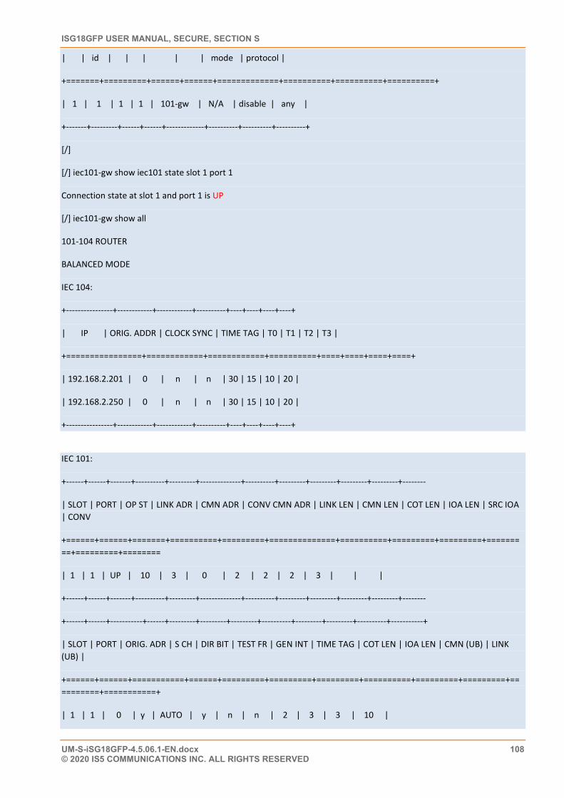
ISG18GFP USER MANUAL, SECURE, SECTION S
UM-S-iSG18GFP-4.5.06.1-EN.docx 108 © 2020 IS5 COMMUNICATIONS INC. ALL RIGHTS RESERVED
| | id | | | | | mode | protocol |
+=======+=========+======+======+=============+==========+==========+==========+
| 1 | 1 | 1 | 1 | 101-gw | N/A | disable | any |
+-------+---------+------+------+-------------+----------+----------+----------+
[/]
[/] iec101-gw show iec101 state slot 1 port 1
Connection state at slot 1 and port 1 is UP
[/] iec101-gw show all
101-104 ROUTER
BALANCED MODE
IEC 104:
+----------------+------------+------------+----------+----+----+----+----+
| IP | ORIG. ADDR | CLOCK SYNC | TIME TAG | T0 | T1 | T2 | T3 |
+================+============+============+==========+====+====+====+====+
| 192.168.2.201 | 0 | n | n | 30 | 15 | 10 | 20 |
| 192.168.2.250 | 0 | n | n | 30 | 15 | 10 | 20 |
+----------------+------------+------------+----------+----+----+----+----+
IEC 101:
+------+------+-------+----------+---------+--------------+----------+---------+---------+---------+---------+--------
| SLOT | PORT | OP ST | LINK ADR | CMN ADR | CONV CMN ADR | LINK LEN | CMN LEN | COT LEN | IOA LEN | SRC IOA | CONV
+======+======+=======+==========+=========+==============+==========+=========+=========+=========+=========+========
| 1 | 1 | UP | 10 | 3 | 0 | 2 | 2 | 2 | 3 | | |
+------+------+-------+----------+---------+--------------+----------+---------+---------+---------+---------+--------
+------+------+-----------+------+---------+---------+---------+----------+---------+---------+----------+-----------+
| SLOT | PORT | ORIG. ADR | S CH | DIR BIT | TEST FR | GEN INT | TIME TAG | COT LEN | IOA LEN | CMN (UB) | LINK (UB) |
+======+======+===========+======+=========+=========+=========+==========+=========+=========+==========+===========+
| 1 | 1 | 0 | y | AUTO | y | n | n | 2 | 3 | 3 | 10 |
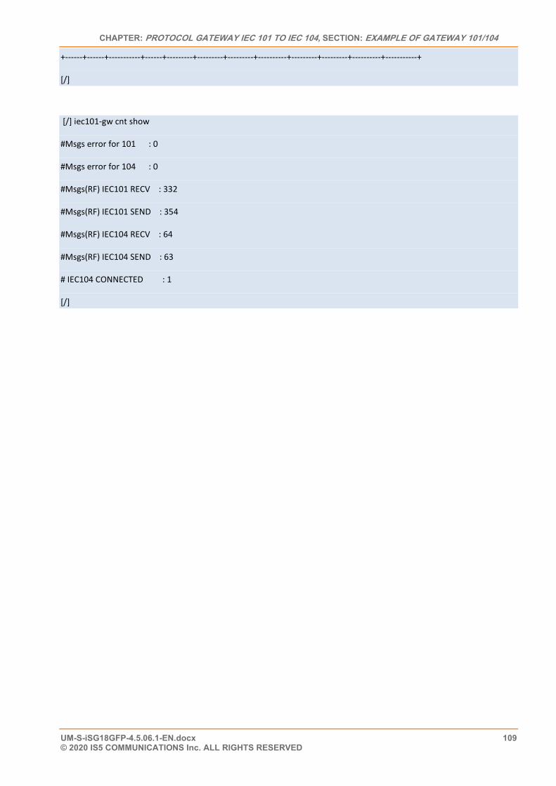
CHAPTER: PROTOCOL GATEWAY IEC 101 TO IEC 104, SECTION: EXAMPLE OF GATEWAY 101/104
UM-S-iSG18GFP-4.5.06.1-EN.docx 109 © 2020 IS5 COMMUNICATIONS Inc. ALL RIGHTS RESERVED
+------+------+-----------+------+---------+---------+---------+----------+---------+---------+----------+-----------+
[/]
[/] iec101-gw cnt show
#Msgs error for 101 : 0
#Msgs error for 104 : 0
#Msgs(RF) IEC101 RECV : 332
#Msgs(RF) IEC101 SEND : 354
#Msgs(RF) IEC104 RECV : 64
#Msgs(RF) IEC104 SEND : 63
# IEC104 CONNECTED : 1
[/]
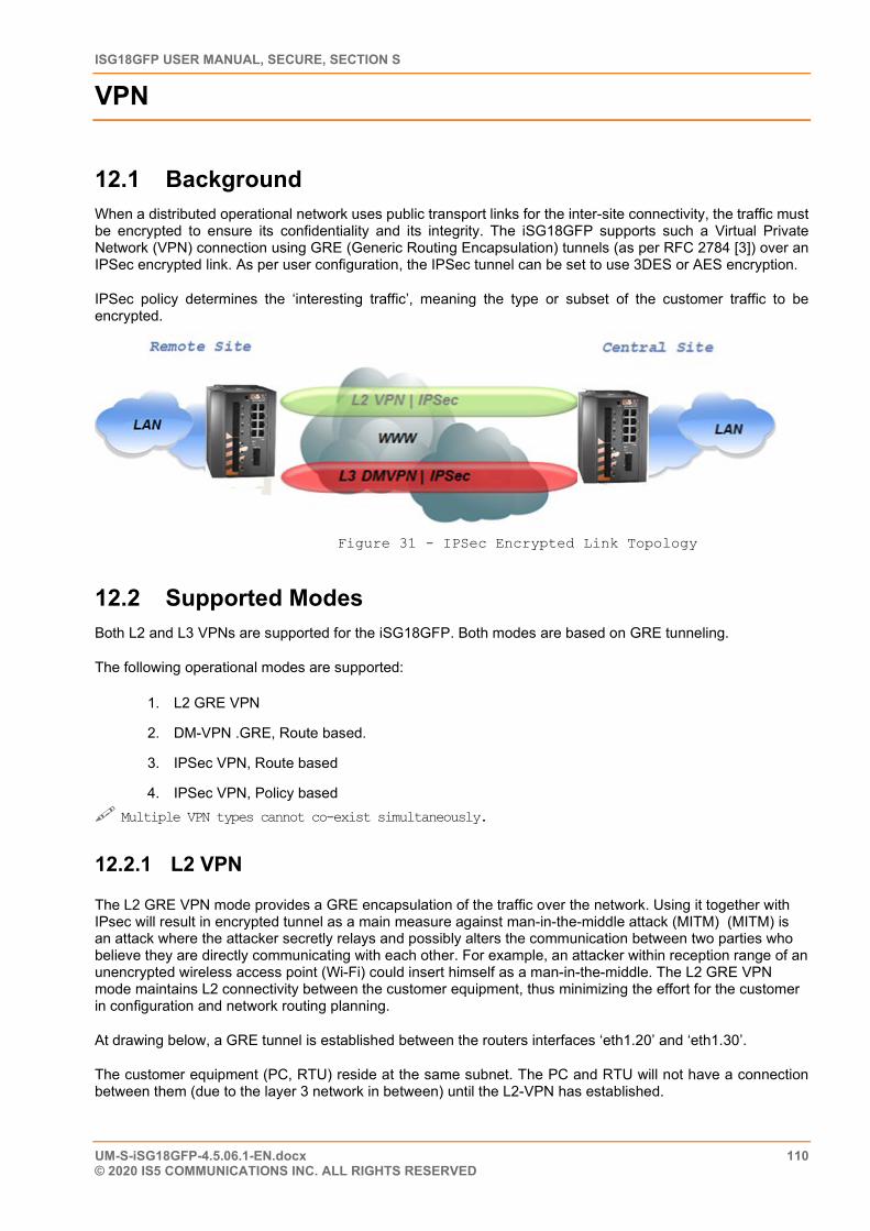
ISG18GFP USER MANUAL, SECURE, SECTION S
UM-S-iSG18GFP-4.5.06.1-EN.docx 110 © 2020 IS5 COMMUNICATIONS INC. ALL RIGHTS RESERVED
VPN
12.1 Background When a distributed operational network uses public transport links for the inter-site connectivity, the traffic must be encrypted to ensure its confidentiality and its integrity. The iSG18GFP supports such a Virtual Private Network (VPN) connection using GRE (Generic Routing Encapsulation) tunnels (as per RFC 2784 [3]) over an IPSec encrypted link. As per user configuration, the IPSec tunnel can be set to use 3DES or AES encryption.
IPSec policy determines the ‘interesting traffic’, meaning the type or subset of the customer traffic to be encrypted.
Figure 31 - IPSec Encrypted Link Topology
12.2 Supported Modes Both L2 and L3 VPNs are supported for the iSG18GFP. Both modes are based on GRE tunneling.
The following operational modes are supported:
1. L2 GRE VPN
2. DM-VPN .GRE, Route based.
3. IPSec VPN, Route based
4. IPSec VPN, Policy based Multiple VPN types cannot co-exist simultaneously.
12.2.1 L2 VPN
The L2 GRE VPN mode provides a GRE encapsulation of the traffic over the network. Using it together with IPsec will result in encrypted tunnel as a main measure against man-in-the-middle attack (MITM) (MITM) is an attack where the attacker secretly relays and possibly alters the communication between two parties who believe they are directly communicating with each other. For example, an attacker within reception range of an unencrypted wireless access point (Wi-Fi) could insert himself as a man-in-the-middle. The L2 GRE VPN mode maintains L2 connectivity between the customer equipment, thus minimizing the effort for the customer in configuration and network routing planning.
At drawing below, a GRE tunnel is established between the routers interfaces ‘eth1.20’ and ‘eth1.30’.
The customer equipment (PC, RTU) reside at the same subnet. The PC and RTU will not have a connection between them (due to the layer 3 network in between) until the L2-VPN has established.
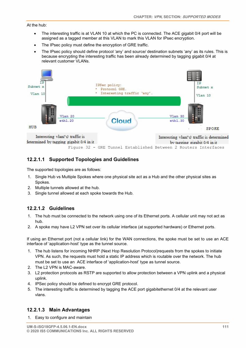
CHAPTER: VPN, SECTION: SUPPORTED MODES
UM-S-iSG18GFP-4.5.06.1-EN.docx 111 © 2020 IS5 COMMUNICATIONS Inc. ALL RIGHTS RESERVED
At the hub:
• The interesting traffic is at VLAN 10 at which the PC is connected. The ACE gigabit 0/4 port will be assigned as a tagged member at this VLAN to mark this VLAN for IPsec encryption.
• The IPsec policy must define the encryption of GRE traffic. • The IPsec policy should define protocol ‘any’ and source/ destination subnets ‘any’ as its rules. This is
because encrypting the interesting traffic has been already determined by tagging gigabit 0/4 at relevant customer VLANs.
Figure 32 - GRE Tunnel Established Between 2 Routers Interfaces
12.2.1.1 Supported Topologies and Guidelines
The supported topologies are as follows:
1. Single Hub vs Multiple Spokes where one physical site act as a Hub and the other physical sites as Spokes.
2. Multiple tunnels allowed at the hub. 3. Single tunnel allowed at each spoke towards the Hub.
12.2.1.2 Guidelines 1. The hub must be connected to the network using one of its Ethernet ports. A cellular unit may not act as
hub. 2. A spoke may have L2 VPN set over its cellular interface (at supported hardware) or Ethernet ports.
If using an Ethernet port (not a cellular link) for the WAN connections, the spoke must be set to use an ACE interface of ‘application-host’ type as the tunnel source.
1. The hub listens for incoming NHRP (Next Hop Resolution Protocol)requests from the spokes to initiate VPN. As such, the requests must hold a static IP address which is routable over the network. The hub must be set to use an ACE interface of ‘application-host’ type as tunnel source.
2. The L2 VPN is MAC-aware. 3. L2 protection protocols as RSTP are supported to allow protection between a VPN uplink and a physical
uplink. 4. IPSec policy should be defined to encrypt GRE protocol. 5. The interesting traffic is determined by tagging the ACE port gigabitethernet 0/4 at the relevant user
vlans.
12.2.1.3 Main Advantages 1. Easy to configure and maintain
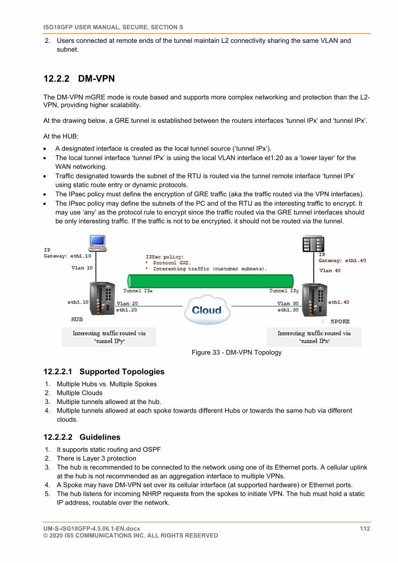
ISG18GFP USER MANUAL, SECURE, SECTION S
UM-S-iSG18GFP-4.5.06.1-EN.docx 112 © 2020 IS5 COMMUNICATIONS INC. ALL RIGHTS RESERVED
2. Users connected at remote ends of the tunnel maintain L2 connectivity sharing the same VLAN and subnet.
12.2.2 DM-VPN
The DM-VPN mGRE mode is route based and supports more complex networking and protection than the L2-VPN, providing higher scalability.
At the drawing below, a GRE tunnel is established between the routers interfaces ‘tunnel IPx’ and ‘tunnel IPx’.
At the HUB:
• A designated interface is created as the local tunnel source (‘tunnel IPx’). • The local tunnel interface ‘tunnel IPx’ is using the local VLAN interface et1.20 as a ‘lower layer’ for the
WAN networking. • Traffic designated towards the subnet of the RTU is routed via the tunnel remote interface ‘tunnel IPx’
using static route entry or dynamic protocols. • The IPsec policy must define the encryption of GRE traffic (aka the traffic routed via the VPN interfaces). • The IPsec policy may define the subnets of the PC and of the RTU as the interesting traffic to encrypt. It
may use ‘any’ as the protocol rule to encrypt since the traffic routed via the GRE tunnel interfaces should be only interesting traffic. If the traffic is not to be encrypted, it should not be routed via the tunnel.
Figure 33 - DM-VPN Topology
12.2.2.1 Supported Topologies 1. Multiple Hubs vs. Multiple Spokes 2. Multiple Clouds 3. Multiple tunnels allowed at the hub. 4. Multiple tunnels allowed at each spoke towards different Hubs or towards the same hub via different
clouds.
12.2.2.2 Guidelines 1. It supports static routing and OSPF 2. There is Layer 3 protection 3. The hub is recommended to be connected to the network using one of its Ethernet ports. A cellular uplink
at the hub is not recommended as an aggregation interface to multiple VPNs. 4. A Spoke may have DM-VPN set over its cellular interface (at supported hardware) or Ethernet ports. 5. The hub listens for incoming NHRP requests from the spokes to initiate VPN. The hub must hold a static
IP address, routable over the network.
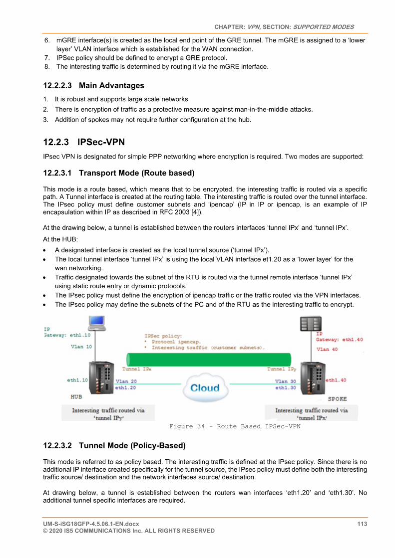
CHAPTER: VPN, SECTION: SUPPORTED MODES
UM-S-iSG18GFP-4.5.06.1-EN.docx 113 © 2020 IS5 COMMUNICATIONS Inc. ALL RIGHTS RESERVED
6. mGRE interface(s) is created as the local end point of the GRE tunnel. The mGRE is assigned to a ‘lower layer’ VLAN interface which is established for the WAN connection.
7. IPSec policy should be defined to encrypt a GRE protocol. 8. The interesting traffic is determined by routing it via the mGRE interface.
12.2.2.3 Main Advantages 1. It is robust and supports large scale networks 2. There is encryption of traffic as a protective measure against man-in-the-middle attacks. 3. Addition of spokes may not require further configuration at the hub.
12.2.3 IPSec-VPN IPsec VPN is designated for simple PPP networking where encryption is required. Two modes are supported:
12.2.3.1 Transport Mode (Route based)
This mode is a route based, which means that to be encrypted, the interesting traffic is routed via a specific path. A Tunnel interface is created at the routing table. The interesting traffic is routed over the tunnel interface. The IPsec policy must define customer subnets and ‘ipencap’ (IP in IP or ipencap, is an example of IP encapsulation within IP as described in RFC 2003 [4]).
At the drawing below, a tunnel is established between the routers interfaces ‘tunnel IPx’ and ‘tunnel IPx’.
At the HUB: • A designated interface is created as the local tunnel source (‘tunnel IPx’). • The local tunnel interface ‘tunnel IPx’ is using the local VLAN interface et1.20 as a ‘lower layer’ for the
wan networking. • Traffic designated towards the subnet of the RTU is routed via the tunnel remote interface ‘tunnel IPx’
using static route entry or dynamic protocols. • The IPsec policy must define the encryption of ipencap traffic or the traffic routed via the VPN interfaces. • The IPsec policy may define the subnets of the PC and of the RTU as the interesting traffic to encrypt.
Figure 34 - Route Based IPSec-VPN
12.2.3.2 Tunnel Mode (Policy-Based)
This mode is referred to as policy based. The interesting traffic is defined at the IPsec policy. Since there is no additional IP interface created specifically for the tunnel source, the IPsec policy must define both the interesting traffic source/ destination and the network interfaces source/ destination.
At drawing below, a tunnel is established between the routers wan interfaces ‘eth1.20’ and ‘eth1.30’. No additional tunnel specific interfaces are required.
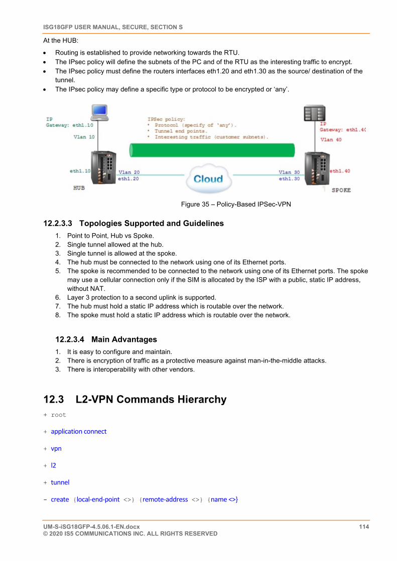
ISG18GFP USER MANUAL, SECURE, SECTION S
UM-S-iSG18GFP-4.5.06.1-EN.docx 114 © 2020 IS5 COMMUNICATIONS INC. ALL RIGHTS RESERVED
At the HUB:
• Routing is established to provide networking towards the RTU. • The IPsec policy will define the subnets of the PC and of the RTU as the interesting traffic to encrypt. • The IPsec policy must define the routers interfaces eth1.20 and eth1.30 as the source/ destination of the
tunnel. • The IPsec policy may define a specific type or protocol to be encrypted or ‘any’.
Figure 35 – Policy-Based IPSec-VPN
12.2.3.3 Topologies Supported and Guidelines 1. Point to Point, Hub vs Spoke. 2. Single tunnel allowed at the hub. 3. Single tunnel is allowed at the spoke. 4. The hub must be connected to the network using one of its Ethernet ports. 5. The spoke is recommended to be connected to the network using one of its Ethernet ports. The spoke
may use a cellular connection only if the SIM is allocated by the ISP with a public, static IP address, without NAT.
6. Layer 3 protection to a second uplink is supported. 7. The hub must hold a static IP address which is routable over the network. 8. The spoke must hold a static IP address which is routable over the network.
12.2.3.4 Main Advantages 1. It is easy to configure and maintain. 2. There is encryption of traffic as a protective measure against man-in-the-middle attacks. 3. There is interoperability with other vendors.
12.3 L2-VPN Commands Hierarchy + root
+ application connect
+ vpn
+ l2
+ tunnel
- create {local-end-point <>} {remote-address <>} {name <>}
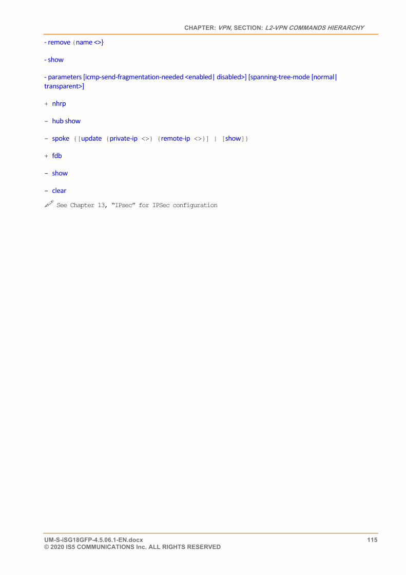
CHAPTER: VPN, SECTION: L2-VPN COMMANDS HIERARCHY
UM-S-iSG18GFP-4.5.06.1-EN.docx 115 © 2020 IS5 COMMUNICATIONS Inc. ALL RIGHTS RESERVED
- remove {name <>}
- show
- parameters [icmp-send-fragmentation-needed <enabled| disabled>] [spanning-tree-mode [normal| transparent>]
+ nhrp
- hub show
- spoke {[update {private-ip <>} {remote-ip <>}] | [show]}
+ fdb
- show
- clear
See Chapter 13, “IPsec” for IPSec configuration
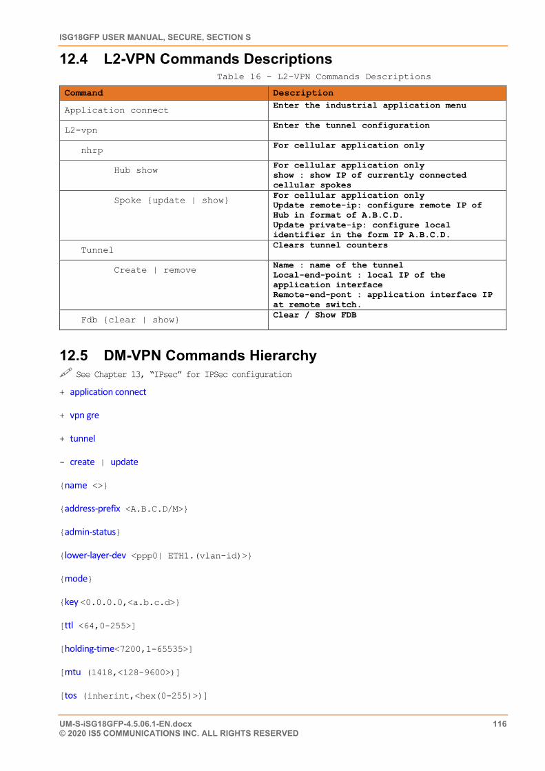
ISG18GFP USER MANUAL, SECURE, SECTION S
UM-S-iSG18GFP-4.5.06.1-EN.docx 116 © 2020 IS5 COMMUNICATIONS INC. ALL RIGHTS RESERVED
12.4 L2-VPN Commands Descriptions Table 16 - L2-VPN Commands Descriptions
Command Description
Application connect Enter the industrial application menu
L2-vpn Enter the tunnel configuration
nhrp For cellular application only
Hub show For cellular application only show : show IP of currently connected cellular spokes
Spoke {update | show} For cellular application only Update remote-ip: configure remote IP of Hub in format of A.B.C.D. Update private-ip: configure local identifier in the form IP A.B.C.D.
Tunnel Clears tunnel counters
Create | remove Name : name of the tunnel Local-end-point : local IP of the application interface Remote-end-pont : application interface IP at remote switch.
Fdb {clear | show} Clear / Show FDB
12.5 DM-VPN Commands Hierarchy See Chapter 13, “IPsec” for IPSec configuration + application connect
+ vpn gre
+ tunnel
- create | update
{name <>}
{address-prefix <A.B.C.D/M>}
{admin-status}
{lower-layer-dev <ppp0| ETH1.(vlan-id)>}
{mode}
{key <0.0.0.0,<a.b.c.d>}
[ttl <64,0-255>]
[holding-time<7200,1-65535>]
[mtu (1418,<128-9600>)]
[tos (inherint,<hex(0-255)>)]
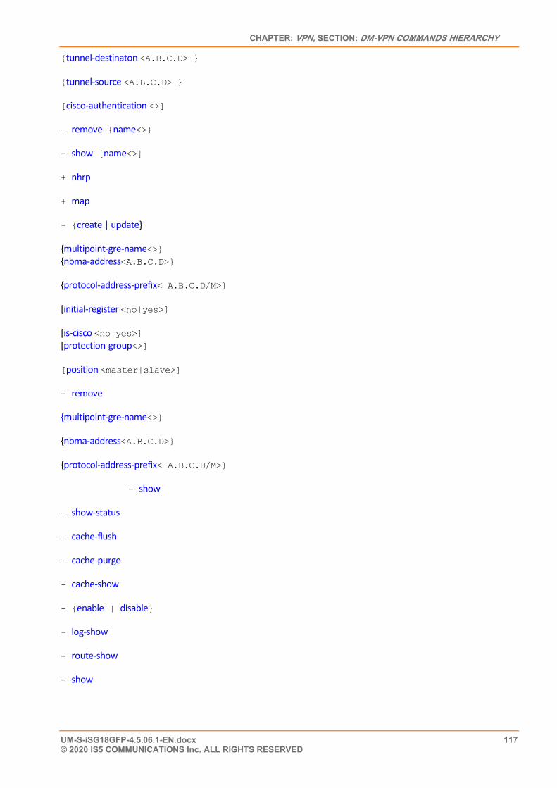
CHAPTER: VPN, SECTION: DM-VPN COMMANDS HIERARCHY
UM-S-iSG18GFP-4.5.06.1-EN.docx 117 © 2020 IS5 COMMUNICATIONS Inc. ALL RIGHTS RESERVED
{tunnel-destinaton <A.B.C.D> }
{tunnel-source <A.B.C.D> }
[cisco-authentication <>]
- remove {name<>}
- show [name<>]
+ nhrp
+ map
- {create | update}
{multipoint-gre-name<>} {nbma-address<A.B.C.D>}
{protocol-address-prefix< A.B.C.D/M>}
[initial-register <no|yes>]
[is-cisco <no|yes>] [protection-group<>]
[position <master|slave>]
- remove
{multipoint-gre-name<>}
{nbma-address<A.B.C.D>}
{protocol-address-prefix< A.B.C.D/M>}
- show
- show-status
- cache-flush
- cache-purge
- cache-show
- {enable | disable}
- log-show
- route-show
- show
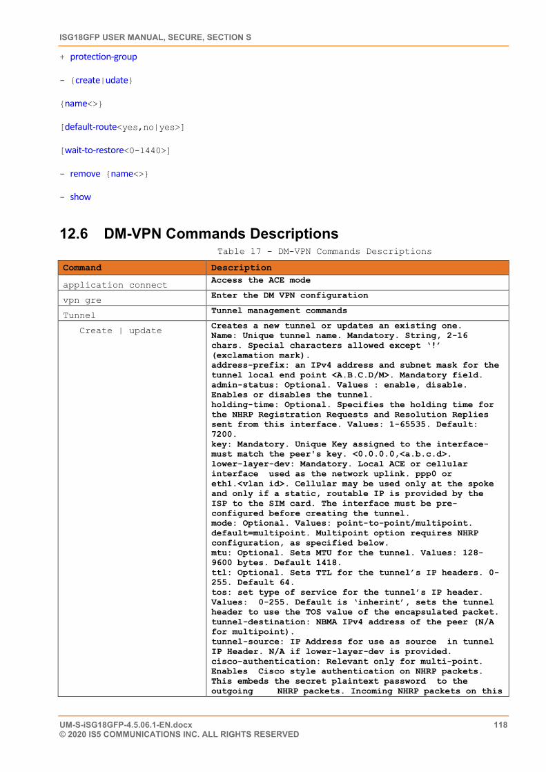
ISG18GFP USER MANUAL, SECURE, SECTION S
UM-S-iSG18GFP-4.5.06.1-EN.docx 118 © 2020 IS5 COMMUNICATIONS INC. ALL RIGHTS RESERVED
+ protection-group
- {create|udate}
{name<>}
[default-route<yes,no|yes>]
[wait-to-restore<0-1440>]
- remove {name<>}
- show
12.6 DM-VPN Commands Descriptions Table 17 - DM-VPN Commands Descriptions
Command Description
application connect Access the ACE mode
vpn gre Enter the DM VPN configuration
Tunnel Tunnel management commands
Create | update Creates a new tunnel or updates an existing one. Name: Unique tunnel name. Mandatory. String, 2-16 chars. Special characters allowed except ‘!’ (exclamation mark). address-prefix: an IPv4 address and subnet mask for the tunnel local end point <A.B.C.D/M>. Mandatory field. admin-status: Optional. Values : enable, disable. Enables or disables the tunnel. holding-time: Optional. Specifies the holding time for the NHRP Registration Requests and Resolution Replies sent from this interface. Values: 1-65535. Default: 7200. key: Mandatory. Unique Key assigned to the interface- must match the peer's key. <0.0.0.0,<a.b.c.d>. lower-layer-dev: Mandatory. Local ACE or cellular interface used as the network uplink. ppp0 or eth1.<vlan id>. Cellular may be used only at the spoke and only if a static, routable IP is provided by the ISP to the SIM card. The interface must be pre-configured before creating the tunnel. mode: Optional. Values: point-to-point/multipoint. default=multipoint. Multipoint option requires NHRP configuration, as specified below. mtu: Optional. Sets MTU for the tunnel. Values: 128-9600 bytes. Default 1418. ttl: Optional. Sets TTL for the tunnel’s IP headers. 0-255. Default 64. tos: set type of service for the tunnel’s IP header. Values: 0-255. Default is ‘inherint’, sets the tunnel header to use the TOS value of the encapsulated packet. tunnel-destination: NBMA IPv4 address of the peer (N/A for multipoint). tunnel-source: IP Address for use as source in tunnel IP Header. N/A if lower-layer-dev is provided. cisco-authentication: Relevant only for multi-point. Enables Cisco style authentication on NHRP packets. This embeds the secret plaintext password to the outgoing NHRP packets. Incoming NHRP packets on this
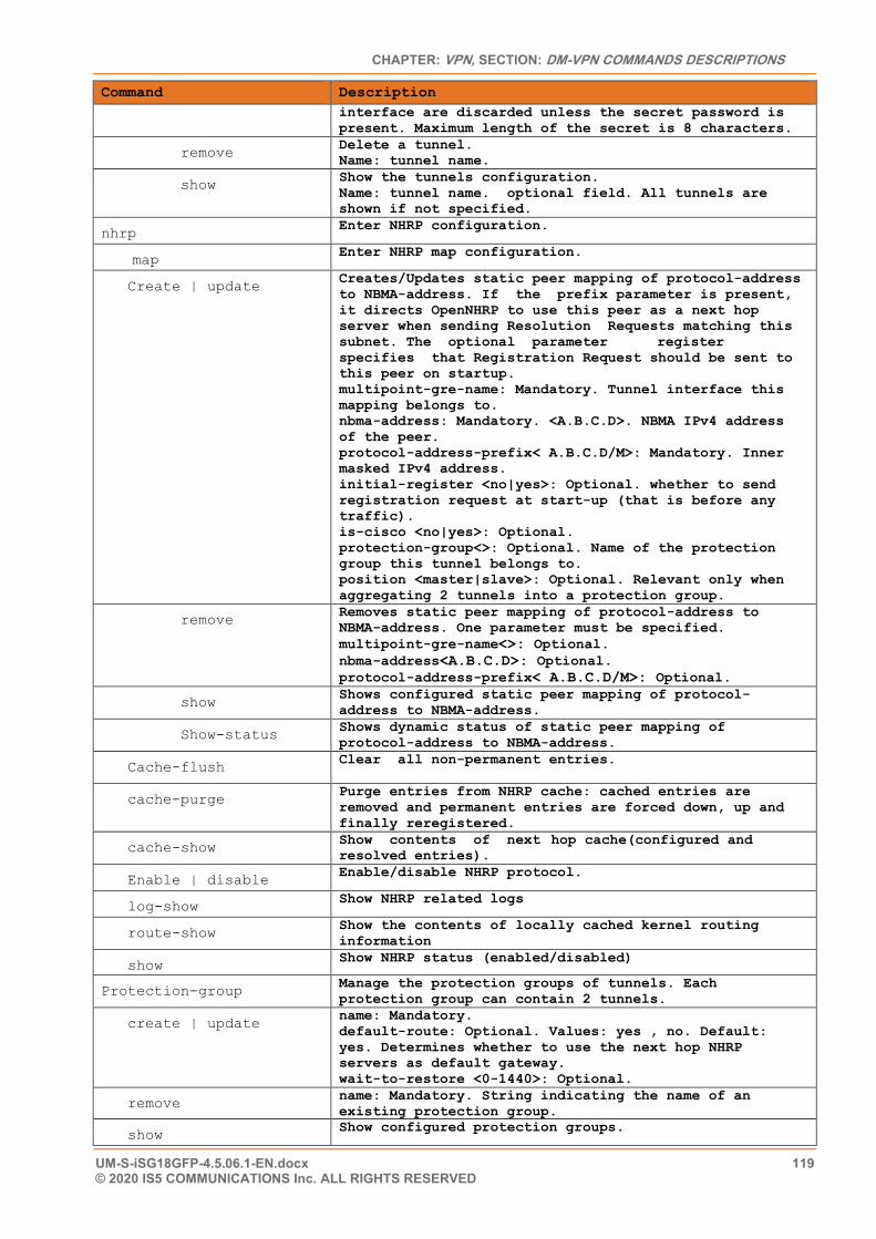
CHAPTER: VPN, SECTION: DM-VPN COMMANDS DESCRIPTIONS
UM-S-iSG18GFP-4.5.06.1-EN.docx 119 © 2020 IS5 COMMUNICATIONS Inc. ALL RIGHTS RESERVED
Command Description interface are discarded unless the secret password is present. Maximum length of the secret is 8 characters.
remove Delete a tunnel. Name: tunnel name.
show Show the tunnels configuration. Name: tunnel name. optional field. All tunnels are shown if not specified.
nhrp Enter NHRP configuration.
map Enter NHRP map configuration.
Create | update Creates/Updates static peer mapping of protocol-address to NBMA-address. If the prefix parameter is present, it directs OpenNHRP to use this peer as a next hop server when sending Resolution Requests matching this subnet. The optional parameter register specifies that Registration Request should be sent to this peer on startup. multipoint-gre-name: Mandatory. Tunnel interface this mapping belongs to. nbma-address: Mandatory. <A.B.C.D>. NBMA IPv4 address of the peer. protocol-address-prefix< A.B.C.D/M>: Mandatory. Inner masked IPv4 address. initial-register <no|yes>: Optional. whether to send registration request at start-up (that is before any traffic). is-cisco <no|yes>: Optional. protection-group<>: Optional. Name of the protection group this tunnel belongs to. position <master|slave>: Optional. Relevant only when aggregating 2 tunnels into a protection group.
remove Removes static peer mapping of protocol-address to NBMA-address. One parameter must be specified. multipoint-gre-name<>: Optional. nbma-address<A.B.C.D>: Optional. protocol-address-prefix< A.B.C.D/M>: Optional.
show Shows configured static peer mapping of protocol-address to NBMA-address.
Show-status Shows dynamic status of static peer mapping of protocol-address to NBMA-address.
Cache-flush Clear all non-permanent entries.
cache-purge Purge entries from NHRP cache: cached entries are removed and permanent entries are forced down, up and finally reregistered.
cache-show Show contents of next hop cache(configured and resolved entries).
Enable | disable Enable/disable NHRP protocol.
log-show Show NHRP related logs
route-show Show the contents of locally cached kernel routing information
show Show NHRP status (enabled/disabled)
Protection-group Manage the protection groups of tunnels. Each protection group can contain 2 tunnels.
create | update name: Mandatory. default-route: Optional. Values: yes , no. Default: yes. Determines whether to use the next hop NHRP servers as default gateway. wait-to-restore <0-1440>: Optional.
remove name: Mandatory. String indicating the name of an existing protection group.
show Show configured protection groups.
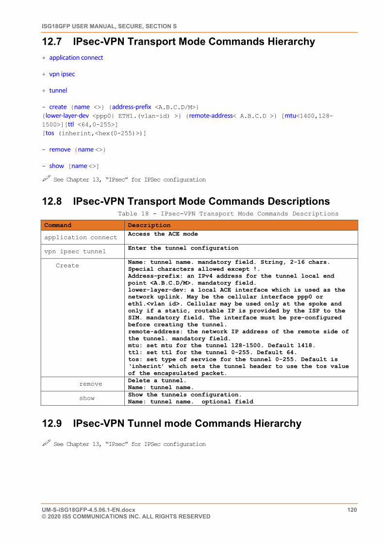
ISG18GFP USER MANUAL, SECURE, SECTION S
UM-S-iSG18GFP-4.5.06.1-EN.docx 120 © 2020 IS5 COMMUNICATIONS INC. ALL RIGHTS RESERVED
12.7 IPsec-VPN Transport Mode Commands Hierarchy + application connect
+ vpn ipsec
+ tunnel
- create {name <>} {address-prefix <A.B.C.D/M>} {lower-layer-dev <ppp0| ETH1.(vlan-id) >} {remote-address< A.B.C.D >} [mtu<1400,128-1500>][ttl <64,0-255>] [tos (inherint,<hex(0-255)>)]
- remove {name <>}
- show [name <>]
See Chapter 13, “IPsec” for IPSec configuration
12.8 IPsec-VPN Transport Mode Commands Descriptions Table 18 - IPsec-VPN Transport Mode Commands Descriptions
Command Description
application connect Access the ACE mode
vpn ipsec tunnel Enter the tunnel configuration
Create Name: tunnel name. mandatory field. String, 2-16 chars. Special characters allowed except !. Address-prefix: an IPv4 address for the tunnel local end point <A.B.C.D/M>. mandatory field. lower-layer-dev: a local ACE interface which is used as the network uplink. May be the cellular interface ppp0 or eth1.<vlan id>. Cellular may be used only at the spoke and only if a static, routable IP is provided by the ISP to the SIM. mandatory field. The interface must be pre-configured before creating the tunnel. remote-address: the network IP address of the remote side of the tunnel. mandatory field. mtu: set mtu for the tunnel 128-1500. Default 1418. ttl: set ttl for the tunnel 0-255. Default 64. tos: set type of service for the tunnel 0-255. Default is ‘inherint’ which sets the tunnel header to use the tos value of the encapsulated packet.
remove Delete a tunnel. Name: tunnel name.
show Show the tunnels configuration. Name: tunnel name. optional field
12.9 IPsec-VPN Tunnel mode Commands Hierarchy See Chapter 13, “IPsec” for IPSec configuration
CHAPTER: IPSEC, SECTION: APPLICATIONS
UM-S-iSG18GFP-4.5.06.1-EN.docx 121 © 2020 IS5 COMMUNICATIONS Inc. ALL RIGHTS RESERVED
IPsec
Internet Protocol Security (IPsec) is a protocol suite for securing Internet Protocol (IP) communications by authenticating and/or encrypting each IP packet of a communication session. The IPsec protocol suite includes the modules described in this chapter.
13.1 Applications IPSec should be configured as follows when a VPN is used :
1. DM-VPN: IPSec is mandatory. 2. IPSec-VPN: IPSec is mandatory. 3. L2-VPN: IPSec is mandatory when the VPN is established over the public network and /or when security
is required.
13.2 Authentication Header The IP Authentication Header (AH) is used to provide connectionless integrity and data origin authentication for IP datagrams. • Supported mode per IKE phase 2 (transport ,tunnel) • No specific configuration is available for AH. Authentication and encryption are implemented for ESP
13.3 Encapsulating Security Payload Encapsulating Security Payload (ESP) provides origin authenticity, integrity, and confidentiality protection of IP packets.
• Supported exchange mode per IKE phase 1. (main ,aggressive) • Supported mode per IKE phase 2. (transport ,tunnel) • Origin Authentication supported by IKE phase 1 and phase 2 HASH Cryptographic. • Encryption supported by IKE phase 1 and phase 2 algorithms.
13.4 Security Associations A security association (SA) is a relationship between two or more entities that describes how the entities will utilize security services to communicate securely. [5] Such entities are the VPN Hubs and Spokes.
This relationship is represented by a set of information that can be considered a contract between the entities. The information must be agreed upon and shared between all the entities.
Internet Security Association and Key Management Protocol (ISAKMP) “defines the procedures for authenticating a communicating peer, creation and management of Security Associations, key generation techniques, and threat mitigation (e.g. denial of service and replay attacks)”. For more details, refer to RFC 2408 [5]
ISG18GFP USER MANUAL, SECURE, SECTION S
UM-S-iSG18GFP-4.5.06.1-EN.docx 122 © 2020 IS5 COMMUNICATIONS INC. ALL RIGHTS RESERVED
13.5 ISAKMP ISAKMP provides a framework for agreeing to the format of SA attributes, and for negotiating, modifying, and deleting SAs.
First, an initial protocol exchange allows a basic set of security attributes to be agreed upon. This basic set provides protection for subsequent ISAKMP exchanges. It also indicates the authentication method and key exchange that will be performed as a part of the ISAKMP protocol. After the basic set of security attributes has been agreed upon, initial identity authenticated, and required keys generated, the established SA can be used for the protection of the VPN tunnels.
ISAKMP implementation guards against denial of service, replay / reflection, and man-in-the-middle. This is important because these are the types of attacks that are targeted against protocols.
The ISAKMP SA is “the shared policy and key used by the negotiating peers in this protocol to protect their communication”. For more details, refer to RFC 2409 [6]
ISAKMP uses the Internet Key Exchange (IKEv1) for authentication and encryption establishment. See RFC 4109 [7].
13.6 IKE IKE negotiates the IPsec SAs. This process requires that the IPsec systems first authenticate themselves to each other and establish ISAKMP (IKE) shared keys (Phase 1). Phase 2 is where SAs are negotiated on behalf of VPN GRE services.
13.6.1 ISAKMP Phase 1
Phase 1 is where the two ISAKMP VPN peers establish a secure, authenticated channel within which they communicate. This is called the ISAKMP SA or IKE SA. The authentication is supported with pre-shared keys (PSK) or digital signatures (X.509)
13.6.1.1 Diffie and Hellman Key Exchange
Diffie and Hellman (D-H) describe a method for two parties to agree upon a shared secret number, called ZZ, in such a way that the secret will be unavailable to eavesdroppers. This method requires that both the sender and recipient of a message have key pairs (private and public). By combining one's private key and the other party's public key, both parties can compute the same shared secret number ZZ.
Generation of ZZ
For example, let’s identify the communicating parties as party A and party B. Prior to their communication, the parties agree between them on a large prime number p, and a generator (or base) g (where 0 < g < p).
Party A chooses a secret integer xa (her private key) and then calculates ya = g ^ xa mod p (which is her public key). Party B chooses a private key xb, and calculates his public key in the same way as yb = g ^ xb mod p.
Both parties then send each other their public keys. Both parties know their public keys but not their private keys because calculating them is a hard mathematical problem (known as the discrete logarithm problem). However, they can calculate:
ZZ = g ^ (xb * xa) mod p = (yb ^ xa) mod p = (ya ^ xb) mod p, where ZZ is their shared secret as defined by X9.42. For more details, refer to RFC 2631 [8]
Any eavesdropper who was listening in on the communication knows p, g, and both parties public keys ya and yb. But the eavesdropper will be unable to calculate the shared secret from these values.
CHAPTER: IPSEC, SECTION: IKE
UM-S-iSG18GFP-4.5.06.1-EN.docx 123 © 2020 IS5 COMMUNICATIONS Inc. ALL RIGHTS RESERVED
This secret number can then be converted into cryptographic keying material (KM). The KM is typically used as a key-encryption key (KEK) to encrypt (wrap) a content-encryption key (CEK) which is in turn used to encrypt the message data (the VPN GRE traffic).This key is kept secret and never exchanged over the insecure channel.
The D-H groups are identified by the length of the keys in bits. The larger the key (higher group id) the higher is the security but as well the resources required are higher and the user should consider performance degradation. Some common key encryption algorithms have KEKs of the following lengths.
• 3-key 3DES 192 bits
• RC2-128 128 bits
• RC2-40 40 bits [8]
The D-H exchange can be authenticated with pre-shared keys (PSK)s or Rivest-Shamir-Adleman (RSA) signatures.
At the Phase 1, there are two basic methods used to establish an authenticated key exchange: Main Mode and Aggressive Mode. For more on key exchange modes, refer to Chapter 5, iSG18GFP User Manual, E section, UM-E-iSG18GFP-4.4-1-EN [10]
13.6.1.2 Authentication
13.6.1.2.1 PSK
The encryption, hash, and authentication algorithm for use with a PSK are a part of the state information distributed with the key itself.
Each VPN end point (Hubs, Spokes) must have a unique ID and a common shared key known to the remote VPN partner. Together, these form the station PSK.
When a pre-shared key is used to generate an authentication payload, the certification authority is "None", the Authentication Type is "preshared", and the payload contains the ID, encoded as two 64-bit quantities, and the result of applying the pseudorandom hash function to the message body with the KEY is forming the key for the function.
The PSK can be set as one of two forms: 1. IP address form A.B.C.D.
a. Allowed in both Main and Aggressive IKE modes b. The PSK of all members should be taken as their VPN network IP address.
2. Fully qualified domain name (FQDN). a. Allowed only when Aggressive IKE mode is used.
Below is an example of PSK configuration 1. Detail the pre-shared IDs of the VPN members and specify the id of local unit
iSG18GFP #application connect
ipsec isakmp update authentication-method pre_shared_key
ipsec preshared create id SA.iS5Com.com key secretkey
ipsec preshared create id SB. iS5Com.com key secretkey
ipsec isakmp update my-id SA. iS5Com.com
ipsec policy create protocol gre
ipsec enable
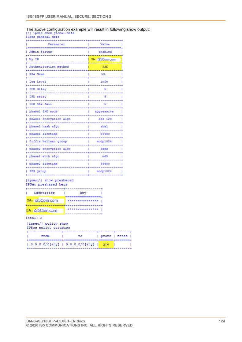
ISG18GFP USER MANUAL, SECURE, SECTION S
UM-S-iSG18GFP-4.5.06.1-EN.docx 124 © 2020 IS5 COMMUNICATIONS INC. ALL RIGHTS RESERVED
The above configuration example will result in following show output:
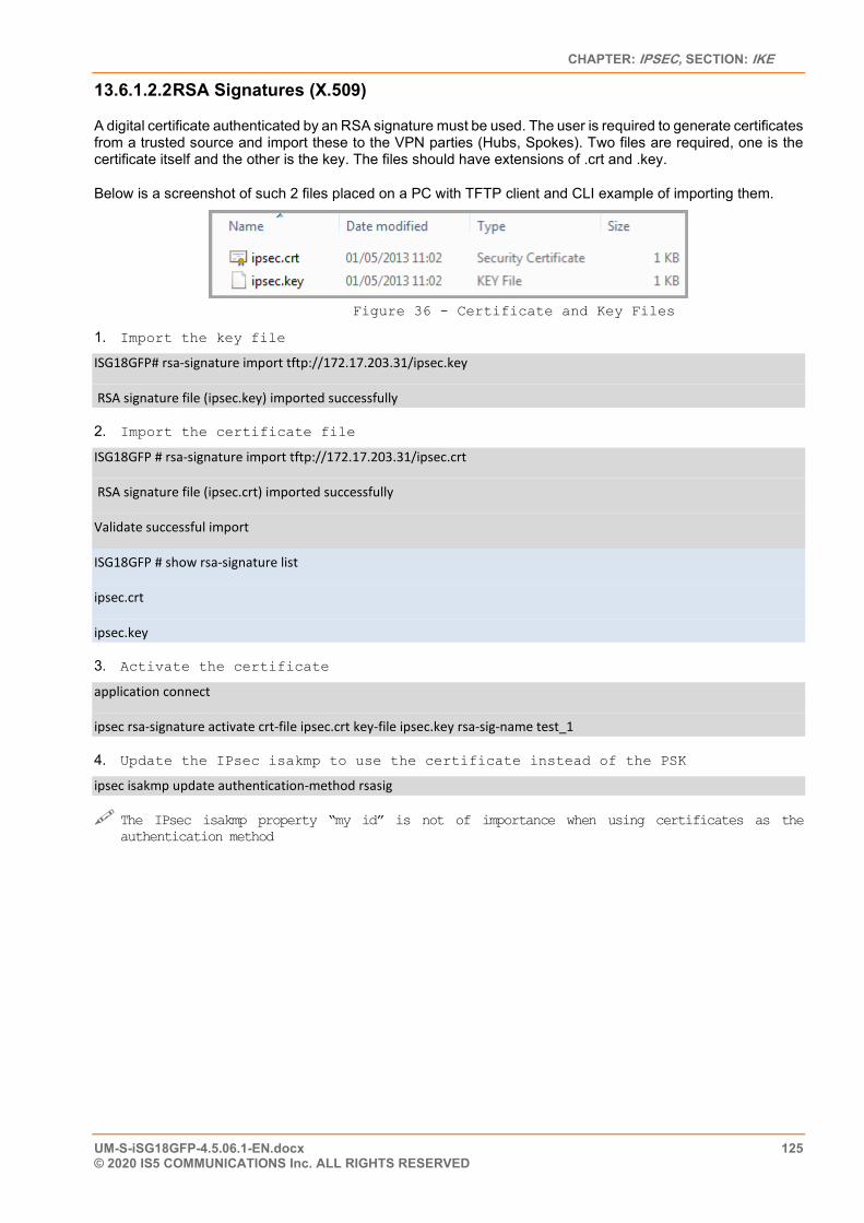
CHAPTER: IPSEC, SECTION: IKE
UM-S-iSG18GFP-4.5.06.1-EN.docx 125 © 2020 IS5 COMMUNICATIONS Inc. ALL RIGHTS RESERVED
13.6.1.2.2 RSA Signatures (X.509)
A digital certificate authenticated by an RSA signature must be used. The user is required to generate certificates from a trusted source and import these to the VPN parties (Hubs, Spokes). Two files are required, one is the certificate itself and the other is the key. The files should have extensions of .crt and .key.
Below is a screenshot of such 2 files placed on a PC with TFTP client and CLI example of importing them.
Figure 36 - Certificate and Key Files
1. Import the key file
ISG18GFP# rsa-signature import tftp://172.17.203.31/ipsec.key
RSA signature file (ipsec.key) imported successfully
2. Import the certificate file
ISG18GFP # rsa-signature import tftp://172.17.203.31/ipsec.crt
RSA signature file (ipsec.crt) imported successfully
Validate successful import
ISG18GFP # show rsa-signature list
ipsec.crt
ipsec.key
3. Activate the certificate
application connect
ipsec rsa-signature activate crt-file ipsec.crt key-file ipsec.key rsa-sig-name test_1
4. Update the IPsec isakmp to use the certificate instead of the PSK
ipsec isakmp update authentication-method rsasig
The IPsec isakmp property “my id” is not of importance when using certificates as the authentication method
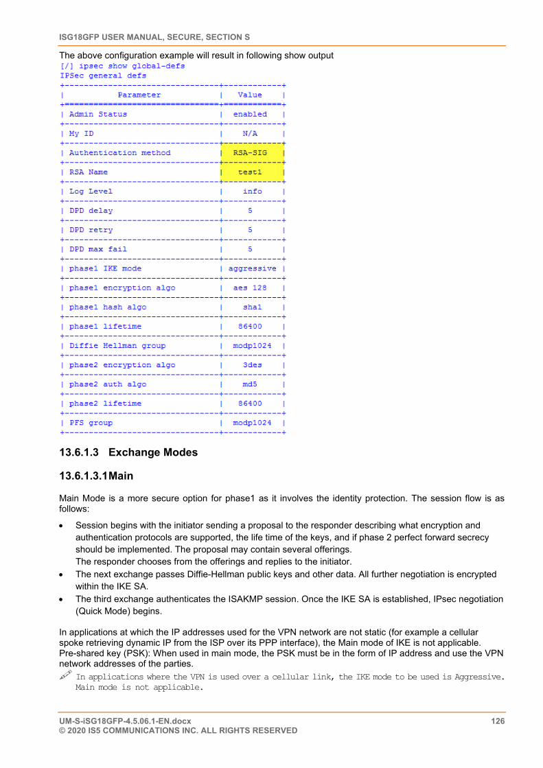
ISG18GFP USER MANUAL, SECURE, SECTION S
UM-S-iSG18GFP-4.5.06.1-EN.docx 126 © 2020 IS5 COMMUNICATIONS INC. ALL RIGHTS RESERVED
The above configuration example will result in following show output
13.6.1.3 Exchange Modes
13.6.1.3.1 Main
Main Mode is a more secure option for phase1 as it involves the identity protection. The session flow is as follows:
• Session begins with the initiator sending a proposal to the responder describing what encryption and authentication protocols are supported, the life time of the keys, and if phase 2 perfect forward secrecy should be implemented. The proposal may contain several offerings. The responder chooses from the offerings and replies to the initiator.
• The next exchange passes Diffie-Hellman public keys and other data. All further negotiation is encrypted within the IKE SA.
• The third exchange authenticates the ISAKMP session. Once the IKE SA is established, IPsec negotiation (Quick Mode) begins.
In applications at which the IP addresses used for the VPN network are not static (for example a cellular spoke retrieving dynamic IP from the ISP over its PPP interface), the Main mode of IKE is not applicable. Pre-shared key (PSK): When used in main mode, the PSK must be in the form of IP address and use the VPN network addresses of the parties. In applications where the VPN is used over a cellular link, the IKE mode to be used is Aggressive.
Main mode is not applicable.
CHAPTER: IPSEC, SECTION: IKE
UM-S-iSG18GFP-4.5.06.1-EN.docx 127 © 2020 IS5 COMMUNICATIONS Inc. ALL RIGHTS RESERVED
13.6.1.3.2 Aggressive
In this mode, the negotiation is quicker as the session is completed in only 3 messages. The disadvantage is in that the identity of the peers is not protected.
The first two messages negotiate policy, exchange Diffie-Hellman public values and ancillary data necessary for the exchange, and identities. In addition, the second message authenticates the responder. The third message authenticates the initiator and provides a proof of participation in the exchange.
• The initiator send a request with all required SA information. • The responder replies with authentication and its ID. • The initiator authenticates the session in the follow-up message.
PSK When used in Aggressive mode, the PSK may be either in the form of IP address or fully qualified domain name (FQDN). The PSK doesn’t have to be the actual IP addresses of the VPN network interfaces as it considers the enter value as text (in the format of IP) and not as a valid IP address.
In Applications where the VPN is used over a cellular link, the IKE mode to be used is Aggressive. The PSK may be of IP format or fqdn
13.6.1.4 Settings Structure • Authentication method (PSK,X.509) • Diffie–Hellman key exchange group (a.k.a. Oakley groups – see RFC 5114 [9]) • IKE exchange mode
o Main o Aggressive
• Encryption algorithm o Advanced Encryption Standard (AES)
128 and 256 key size options symmetric algorithm
o Triple Data Encryption Algorithm (3DES) comprises of three DES keys, K1, K2 and K3, each of 56 bits
• Authentications HASH algorithms o Secure Hash Algorithm SHA-1 (160 bit) o Secure Hash Algorithm SHA-2 (256 |512 bit) o Message Digest (MD5) (128 bit)
• Life time and Dead Peer Discovery settings
13.6.2 ISAKMP Phase 2 At this phase, the negotiation of SA to secure the VPN GRE data using IPsec is made.
13.6.2.1 Modes The mode supported by iS5Com to be used between end stations supporting IPsec (the VPN parties) is Transport Mode.
13.6.2.2 Perfect Forward Secrecy
Perfect forward secrecy (PFS) is a part of the key agreement session and has a purpose to ensure that a session key derived from a set of long-term public and private keys will not be compromised if one of the (long-term) private keys is compromised in the future. The VPN (GRE, IPSEC) sessions can negotiate new keys for every communication, and if a key is compromised, only the specific session it protected will be revealed.
The PFS uses as well the D-H groups but independently from phase 1.
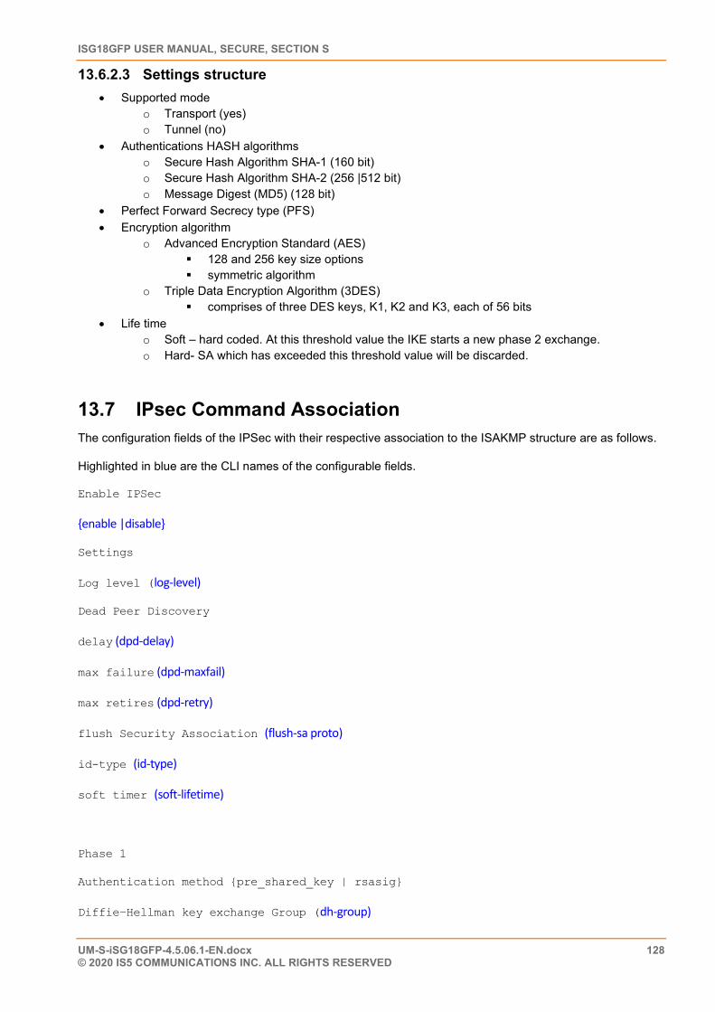
ISG18GFP USER MANUAL, SECURE, SECTION S
UM-S-iSG18GFP-4.5.06.1-EN.docx 128 © 2020 IS5 COMMUNICATIONS INC. ALL RIGHTS RESERVED
13.6.2.3 Settings structure • Supported mode
o Transport (yes) o Tunnel (no)
• Authentications HASH algorithms o Secure Hash Algorithm SHA-1 (160 bit) o Secure Hash Algorithm SHA-2 (256 |512 bit) o Message Digest (MD5) (128 bit)
• Perfect Forward Secrecy type (PFS) • Encryption algorithm
o Advanced Encryption Standard (AES) 128 and 256 key size options symmetric algorithm
o Triple Data Encryption Algorithm (3DES) comprises of three DES keys, K1, K2 and K3, each of 56 bits
• Life time o Soft – hard coded. At this threshold value the IKE starts a new phase 2 exchange. o Hard- SA which has exceeded this threshold value will be discarded.
13.7 IPsec Command Association The configuration fields of the IPSec with their respective association to the ISAKMP structure are as follows.
Highlighted in blue are the CLI names of the configurable fields.
Enable IPSec
{enable |disable}
Settings
Log level (log-level)
Dead Peer Discovery
delay (dpd-delay)
max failure (dpd-maxfail)
max retires (dpd-retry)
flush Security Association (flush-sa proto)
id-type (id-type)
soft timer (soft-lifetime)
Phase 1
Authentication method {pre_shared_key | rsasig}
Diffie–Hellman key exchange Group (dh-group)
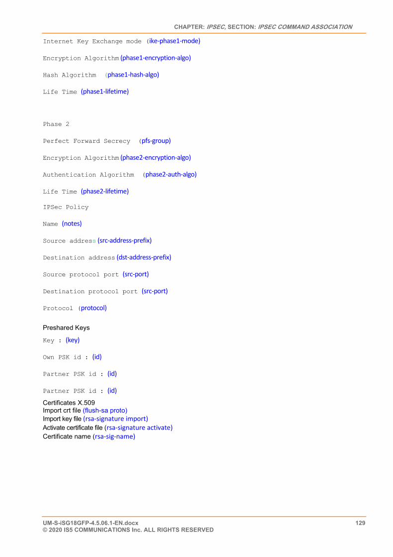
CHAPTER: IPSEC, SECTION: IPSEC COMMAND ASSOCIATION
UM-S-iSG18GFP-4.5.06.1-EN.docx 129 © 2020 IS5 COMMUNICATIONS Inc. ALL RIGHTS RESERVED
Internet Key Exchange mode (ike-phase1-mode)
Encryption Algorithm (phase1-encryption-algo)
Hash Algorithm (phase1-hash-algo)
Life Time (phase1-lifetime)
Phase 2
Perfect Forward Secrecy (pfs-group)
Encryption Algorithm (phase2-encryption-algo)
Authentication Algorithm (phase2-auth-algo)
Life Time (phase2-lifetime)
IPSec Policy
Name (notes)
Source address (src-address-prefix)
Destination address (dst-address-prefix)
Source protocol port (src-port)
Destination protocol port (src-port)
Protocol (protocol)
Preshared Keys
Key : (key)
Own PSK id : (id)
Partner PSK id : (id)
Partner PSK id : (id)
Certificates X.509 Import crt file (flush-sa proto) Import key file (rsa-signature import) Activate certificate file (rsa-signature activate) Certificate name (rsa-sig-name)
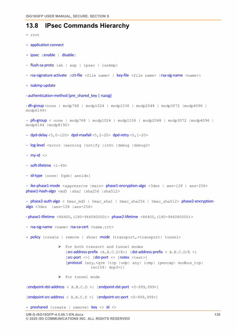
ISG18GFP USER MANUAL, SECURE, SECTION S
UM-S-iSG18GFP-4.5.06.1-EN.docx 130 © 2020 IS5 COMMUNICATIONS INC. ALL RIGHTS RESERVED
13.8 IPsec Commands Hierarchy + root
+ application connect
+ ipsec {enable | disable}
- flush-sa proto {ah | esp | ipsec | isakmp}
- rsa-signature activate {crt-file <file name> | key-file <file name> |rsa-sig-name <name>}
+ isakmp update
- authentication-method {pre_shared_key | rsasig}
- dh-group <none | modp768 | modp1024 | modp1536 | modp2048 | modp3072 |modp4096 | modp6144>
- pfs-group < none | modp768 | modp1024 | modp1536 | modp2048 | modp3072 |modp4096 | modp6144 |modp8192>
- dpd-delay <5,0-120> dpd-maxfail <5,2-20> dpd-retry <5,1-20>
- log-level <error |warning |notify |info |debug |debug2>
- my-id <>
- soft-lifetime <1-99>
- id-type {none| fqdn| asn1dn}
- ike-phase1-mode <aggressive |main> phase1-encryption-algo <3des | aes-128 | aes-256> phase1-hash-algo <md5 |sha1 |sha256 |sha512>
- phase2-auth-algo < hmac_md5 | hmac_sha1 | hmac_sha256 | hmac_sha512> phase2-encryption-algo <3des |aes-128 |aes-256>
- phase1-lifetime <86400,(180-946080000)> phase2-lifetime <86400,(180-946080000)>
- rsa-sig-name <name> rsa-ca-cert <name.crt>
+ policy {create | remove | show} mode (transport,<transport| tunnel>
For both transort and tunnel modes {src-address-prefix <A.B.C.D/E>} {dst-address-prefix < A.B.C.D/E >} [src-port <>] [dst-port <> [notes <text>] [protocol (any,<gre |tcp |udp| any| icmp| ipencap| modbus_tcp| iec104| dnp3>)]
For tunnel mode
{endpoint-dst-address < A.B.C.D >} [endpoint-dst-port <0-999,999>]
[endpoint-src-address < A.B.C.D >] [endpoint-src-port <0-999,999>]
+ preshared {create | remove} key <> id <>
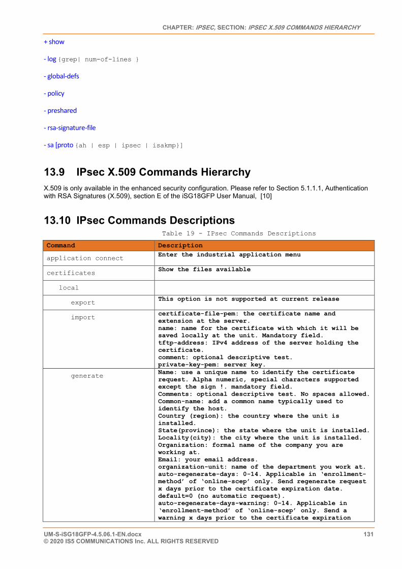
CHAPTER: IPSEC, SECTION: IPSEC X.509 COMMANDS HIERARCHY
UM-S-iSG18GFP-4.5.06.1-EN.docx 131 © 2020 IS5 COMMUNICATIONS Inc. ALL RIGHTS RESERVED
+ show
- log {grep| num-of-lines }
- global-defs
- policy
- preshared
- rsa-signature-file
- sa [proto {ah | esp | ipsec | isakmp}]
13.9 IPsec X.509 Commands Hierarchy X.509 is only available in the enhanced security configuration. Please refer to Section 5.1.1.1, Authentication with RSA Signatures (X.509), section E of the iSG18GFP User Manual, [10]
13.10 IPsec Commands Descriptions Table 19 - IPsec Commands Descriptions
Command Description
application connect Enter the industrial application menu
certificates Show the files available
local
export This option is not supported at current release
import certificate-file-pem: the certificate name and extension at the server. name: name for the certificate with which it will be saved locally at the unit. Mandatory field. tftp-address: IPv4 address of the server holding the certificate. comment: optional descriptive test. private-key-pem: server key.
generate Name: use a unique name to identify the certificate request. Alpha numeric, special characters supported except the sign !. mandatory field. Comments: optional descriptive test. No spaces allowed. Common-name: add a common name typically used to identify the host. Country (region): the country where the unit is installed. State(province): the state where the unit is installed. Locality(city): the city where the unit is installed. Organization: formal name of the company you are working at. Email: your email address. organization-unit: name of the department you work at. auto-regenerate-days: 0-14. Applicable in ‘enrollment-method’ of ‘online-scep’ only. Send regenerate request x days prior to the certificate expiration date. default=0 (no automatic request). auto-regenerate-days-warning: 0-14. Applicable in ‘enrollment-method’ of ‘online-scep’ only. Send a warning x days prior to the certificate expiration
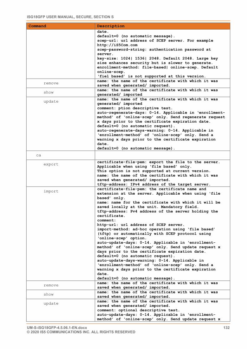
ISG18GFP USER MANUAL, SECURE, SECTION S
UM-S-iSG18GFP-4.5.06.1-EN.docx 132 © 2020 IS5 COMMUNICATIONS INC. ALL RIGHTS RESERVED
Command Description date. default=0 (no automatic message). scep-url: url address of SCEP server. For example http://iS5Com.com scep-password-string: authentication password at server. key-size: 1024| 1536| 2048. Default 2048. Large key size enhances security but is slower to generate. enrollment-method: file-based| online-scep. Default online-scep. ‘fiel based’ is not supported at this version.
remove name: the name of the certificate with which it was saved when generated/ imported.
show name: the name of the certificate with which it was generated/ imported
update name: the name of the certificate with which it was generated/ imported comment: ption descriptive test. auto-regenerate-days: 0-14. Applicable in ‘enrollment-method’ of ‘online-scep’ only. Send regenerate request x days prior to the certificate expiration date. default=0 (no automatic request). auto-regenerate-days-warning: 0-14. Applicable in ‘enrollment-method’ of ‘online-scep’ only. Send a warning x days prior to the certificate expiration date. default=0 (no automatic message).
ca
export certificate-file-pem: export the file to the server. Applicable when using ‘file based’ only. This option is not supported at current version. name: the name of the certificate with which it was saved when generated/ imported. tftp-address: IPv4 address of the target server.
import certificate-file-pem: the certificate name and extension at the server. Applicable when using ‘file based’ only. name: name for the certificate with which it will be saved locally at the unit. Mandatory field. tftp-address: Pv4 address of the server holding the certificate. comment: http-url: url address of SCEP server. import-method: ad-hoc operation using ‘file based’ (tftp) or automatically with SCEP protocol using ‘online-scep’ option. auto-update-days: 0-14. Applicable in ‘enrollment-method’ of ‘online-scep’ only. Send update request x days prior to the certificate expiration date. default=0 (no automatic request). auto-update-days-warning: 0-14. Applicable in ‘enrollment-method’ of ‘online-scep’ only. Send a warning x days prior to the certificate expiration date. default=0 (no automatic message).
remove name: the name of the certificate with which it was saved when generated/ imported.
show name: the name of the certificate with which it was saved when generated/ imported.
update name: the name of the certificate with which it was saved when generated/ imported. comment: optional descriptive test. auto-update-days: 0-14. Applicable in ‘enrollment-method’ of ‘online-scep’ only. Send update request x
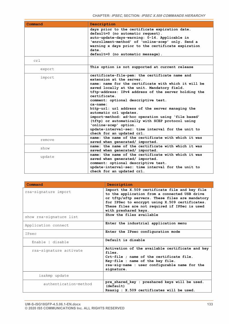
CHAPTER: IPSEC, SECTION: IPSEC X.509 COMMANDS HIERARCHY
UM-S-iSG18GFP-4.5.06.1-EN.docx 133 © 2020 IS5 COMMUNICATIONS Inc. ALL RIGHTS RESERVED
Command Description days prior to the certificate expiration date. default=0 (no automatic request). auto-update-days-warning: 0-14. Applicable in ‘enrollment-method’ of ‘online-scep’ only. Send a warning x days prior to the certificate expiration date. default=0 (no automatic message).
crl
export This option is not supported at current release
import certificate-file-pem: the certificate name and extension at the server. name: name for the certificate with which it will be saved locally at the unit. Mandatory field. tftp-address: IPv4 address of the server holding the certificate. comment: optional descriptive test. ca-name: http-url: url address of the server managing the automatic crl updates. import-method: ad-hoc operation using ‘file based’ (tftp) or automatically with SCEP protocol using ‘online-scep’ option. update-interval-sec: time interval for the unit to check for an updated crl.
remove name: the name of the certificate with which it was saved when generated/ imported.
show name: the name of the certificate with which it was saved when generated/ imported.
update name: the name of the certificate with which it was saved when generated/ imported. comment: optional descriptive test. update-interval-sec: time interval for the unit to check for an updated crl.
Command Description
rsa-signature import Import the X.509 certificate file and key file to the application from a connected USB drive or tftp/sftp servers. These files are mandatory for IPSec to encrypt using X.509 certificates. These files are not required if IPSec is used with preshared keys.
show rsa-signature list Show the files available
Application connect Enter the industrial application menu
IPsec Enter the IPsec configuration mode
Enable | disable Default is disable
rsa-signature activate Activation of the available certificate and key files. Crt-file ; name of the certificate file. Key-file : name of the key file. rsa-sig-name : user configurable name for the signature.
isakmp update
authentication-method pre_shared_key : preshared keys will be used. (default) Rsasig : X.509 certificates will be used.
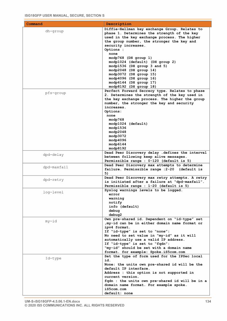
ISG18GFP USER MANUAL, SECURE, SECTION S
UM-S-iSG18GFP-4.5.06.1-EN.docx 134 © 2020 IS5 COMMUNICATIONS INC. ALL RIGHTS RESERVED
Command Description
dh-group Diffie–Hellman key exchange Group. Relates to phase 1. Determines the strength of the key used in the key exchange process. The higher the group number, the stronger the key and security increases. Options : none modp768 (DH group 1) modp1024 (default) (DH group 2) modp1536 (DH group 3 and 5) modp2048 (DH group 14) modp3072 (DH group 15) modp4096 (DH group 16) modp6144 (DH group 17) modp8192 (DH group 18)
pfs-group Perfect Forward Secrecy type. Relates to phase 2. Determines the strength of the key used in the key exchange process. The higher the group number, the stronger the key and security increases. Options: none modp768 modp1024 (default) modp1536 modp2048 modp3072 modp4096 modp6144 modp8192
dpd-delay Dead Peer Discovery delay .defines the interval between following keep alive messages. Permissible range : 0-120 (default is 5)
dpd-maxfail Dead Peer Discovery max attempts to determine failure. Permissible range :2-20 (default is 5)
dpd-retry Dead Peer Discovery max retry attempts. A retry is initiated after a failure at “dpd-maxfail”. Permissible range : 1-20 (default is 5)
log-level Syslog warnings levels to be logged. error warning notify info (default) debug debug2
my-id Own pre-shared id. Dependent on “id-type” set ,my-id can be in either domain name format or ipv4 format. If “id-type” is set to “none”: No need to set value in “my-id” as it will automatically use a valid IP address. If “id-type” is set to “fqdn”: “my-id” should be set with a domain name format. for example: Spoke.iS5com.com
Id-type Set the type of form used for the IPSec local id. None: the units own pre-shared id will be the default IP interface. Address : this option is not supported in current version. fqdn : the units own pre-shared id will be in a domain name format. For example spoke. iS5com.com default: none
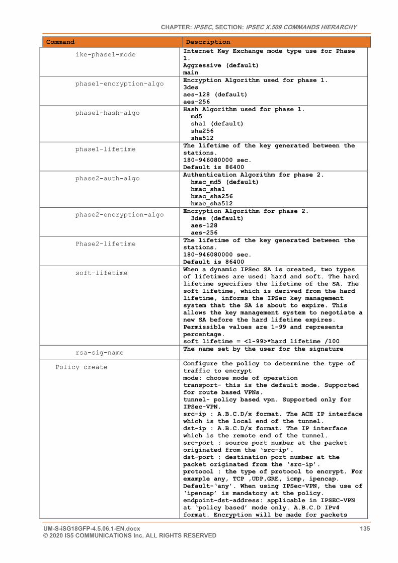
CHAPTER: IPSEC, SECTION: IPSEC X.509 COMMANDS HIERARCHY
UM-S-iSG18GFP-4.5.06.1-EN.docx 135 © 2020 IS5 COMMUNICATIONS Inc. ALL RIGHTS RESERVED
Command Description
ike-phase1-mode Internet Key Exchange mode type use for Phase 1. Aggressive (default) main
phase1-encryption-algo Encryption Algorithm used for phase 1. 3des aes-128 (default) aes-256
phase1-hash-algo Hash Algorithm used for phase 1. md5 sha1 (default) sha256 sha512
phase1-lifetime The lifetime of the key generated between the stations. 180-946080000 sec. Default is 86400
phase2-auth-algo Authentication Algorithm for phase 2. hmac_md5 (default) hmac_sha1 hmac_sha256 hmac_sha512
phase2-encryption-algo Encryption Algorithm for phase 2. 3des (default) aes-128 aes-256
Phase2-lifetime The lifetime of the key generated between the stations. 180-946080000 sec. Default is 86400
soft-lifetime When a dynamic IPSec SA is created, two types of lifetimes are used: hard and soft. The hard lifetime specifies the lifetime of the SA. The soft lifetime, which is derived from the hard lifetime, informs the IPSec key management system that the SA is about to expire. This allows the key management system to negotiate a new SA before the hard lifetime expires. Permissible values are 1-99 and represents percentage. soft lifetime = <1-99>*hard lifetime /100
rsa-sig-name The name set by the user for the signature
Policy create Configure the policy to determine the type of traffic to encrypt mode: choose mode of operation transport- this is the default mode. Supported for route based VPNs. tunnel- policy based vpn. Supported only for IPSec-VPN. src-ip : A.B.C.D/x format. The ACE IP interface which is the local end of the tunnel. dst-ip : A.B.C.D/x format. The IP interface which is the remote end of the tunnel. src-port : source port number at the packet originated from the ‘src-ip’. dst-port : destination port number at the packet originated from the ‘src-ip’. protocol : the type of protocol to encrypt. For example any, TCP ,UDP,GRE, icmp, ipencap. Default-‘any’. When using IPSec-VPN, the use of ‘ipencap’ is mandatory at the policy. endpoint-dst-address: applicable in IPSEC-VPN at ‘policy based’ mode only. A.B.C.D IPv4 format. Encryption will be made for packets
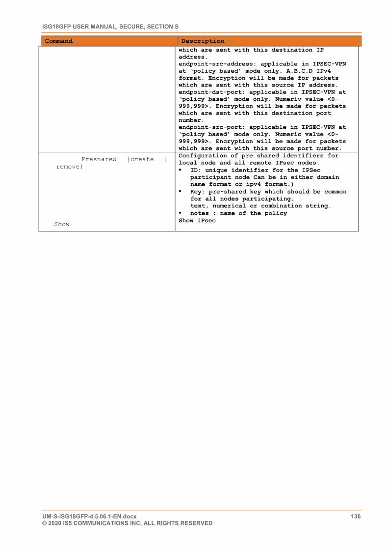
ISG18GFP USER MANUAL, SECURE, SECTION S
UM-S-iSG18GFP-4.5.06.1-EN.docx 136 © 2020 IS5 COMMUNICATIONS INC. ALL RIGHTS RESERVED
Command Description which are sent with this destination IP address. endpoint-src-address: applicable in IPSEC-VPN at ‘policy based’ mode only. A.B.C.D IPv4 format. Encryption will be made for packets which are sent with this source IP address. endpoint-dst-port: applicable in IPSEC-VPN at ‘policy based’ mode only. Numeriv value <0-999,999>. Encryption will be made for packets which are sent with this destination port number. endpoint-src-port: applicable in IPSEC-VPN at ‘policy based’ mode only. Numeric value <0-999,999>. Encryption will be made for packets which are sent with this source port number.
Preshared {create | remove}
Configuration of pre shared identifiers for local node and all remote IPsec nodes. ID: unique identifier for the IPSec
participant node Can be in either domain name format or ipv4 format.)
Key: pre-shared key which should be common for all nodes participating. text, numerical or combination string.
notes : name of the policy
Show Show IPsec
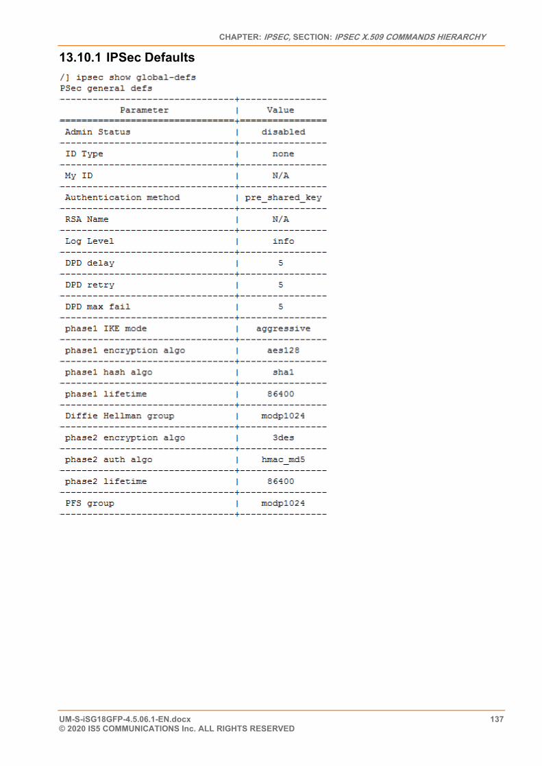
CHAPTER: IPSEC, SECTION: IPSEC X.509 COMMANDS HIERARCHY
UM-S-iSG18GFP-4.5.06.1-EN.docx 137 © 2020 IS5 COMMUNICATIONS Inc. ALL RIGHTS RESERVED
13.10.1 IPSec Defaults
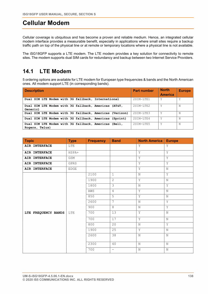
ISG18GFP USER MANUAL, SECURE, SECTION S
UM-S-iSG18GFP-4.5.06.1-EN.docx 138 © 2020 IS5 COMMUNICATIONS INC. ALL RIGHTS RESERVED
Cellular Modem
Cellular coverage is ubiquitous and has become a proven and reliable medium. Hence, an integrated cellular modem interface provides a measurable benefit, especially in applications where small sites require a backup traffic path on top of the physical line or at remote or temporary locations where a physical line is not available.
The iSG18GFP supports a LTE modem. The LTE modem provides a key solution for connectivity to remote sites. The modem supports dual SIM cards for redundancy and backup between two Internet Service Providers.
14.1 LTE Modem 5 ordering options are available for LTE modem for European type frequencies & bands and the North American ones. All modem support LTE (in corresponding bands).
Description Part number North America
Europe
Dual SIM LTE Modem with 3G fallback, International 2SIM-LTE1 Y Y
Dual SIM LTE Modem with 3G fallback, Americas (AT&T, Generic)
2SIM-LTE2 Y N
Dual SIM LTE Modem with 3G fallback, Americas (Verizon) 2SIM-LTE3 Y N
Dual SIM LTE Modem with 3G fallback, Americas (Sprint) 2SIM-LTE4 Y N
Dual SIM LTE Modem with 3G fallback, Americas (Bell, Rogers, Telus)
2SIM-LTE5 Y N
Topic Type Frequency Band North America Europe AIR INTERFACE LTE Y Y
AIR INTERFACE HSPA+ Y Y
AIR INTERFACE GSM Y Y
AIR INTERFACE GPRS Y Y
AIR INTERFACE EDGE Y N
LTE FREQUENCY BANDS LTE
2100 1 N Y
1900 2 Y N
1800 3 N Y
AWS 4 Y N
850 5 Y N
2600 7 N Y
900 8 N Y
700 13 Y N
700 17 Y N
800 20 N Y
1900 25 Y N
2600 38 N N
2300 40 N N
700 - N N
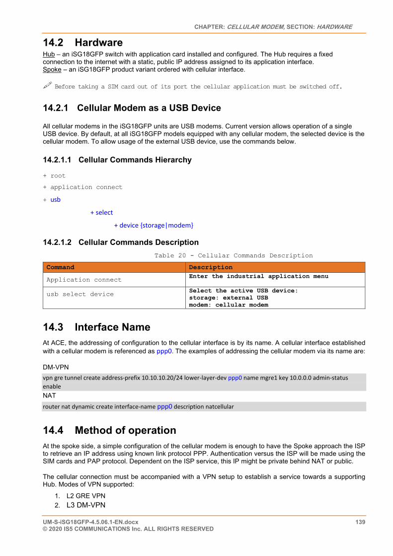
CHAPTER: CELLULAR MODEM, SECTION: HARDWARE
UM-S-iSG18GFP-4.5.06.1-EN.docx 139 © 2020 IS5 COMMUNICATIONS Inc. ALL RIGHTS RESERVED
14.2 Hardware Hub – an iSG18GFP switch with application card installed and configured. The Hub requires a fixed connection to the internet with a static, public IP address assigned to its application interface. Spoke – an iSG18GFP product variant ordered with cellular interface. Before taking a SIM card out of its port the cellular application must be switched off.
14.2.1 Cellular Modem as a USB Device
All cellular modems in the iSG18GFP units are USB modems. Current version allows operation of a single USB device. By default, at all iSG18GFP models equipped with any cellular modem, the selected device is the cellular modem. To allow usage of the external USB device, use the commands below.
14.2.1.1 Cellular Commands Hierarchy
+ root
+ application connect
+ usb
+ select
+ device {storage|modem}
14.2.1.2 Cellular Commands Description Table 20 - Cellular Commands Description
Command Description
Application connect Enter the industrial application menu
usb select device Select the active USB device: storage: external USB modem: cellular modem
14.3 Interface Name At ACE, the addressing of configuration to the cellular interface is by its name. A cellular interface established with a cellular modem is referenced as ppp0. The examples of addressing the cellular modem via its name are:
DM-VPN vpn gre tunnel create address-prefix 10.10.10.20/24 lower-layer-dev ppp0 name mgre1 key 10.0.0.0 admin-status enable NAT router nat dynamic create interface-name ppp0 description natcellular
14.4 Method of operation At the spoke side, a simple configuration of the cellular modem is enough to have the Spoke approach the ISP to retrieve an IP address using known link protocol PPP. Authentication versus the ISP will be made using the SIM cards and PAP protocol. Dependent on the ISP service, this IP might be private behind NAT or public.
The cellular connection must be accompanied with a VPN setup to establish a service towards a supporting Hub. Modes of VPN supported:
1. L2 GRE VPN 2. L3 DM-VPN
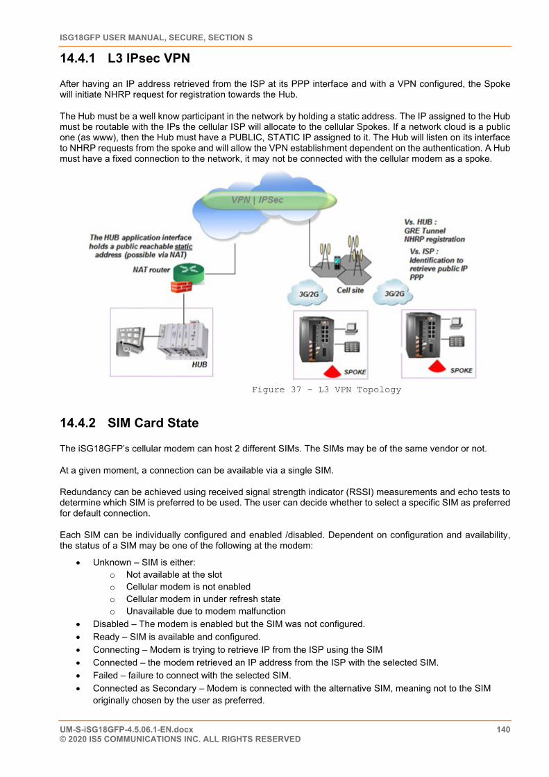
ISG18GFP USER MANUAL, SECURE, SECTION S
UM-S-iSG18GFP-4.5.06.1-EN.docx 140 © 2020 IS5 COMMUNICATIONS INC. ALL RIGHTS RESERVED
14.4.1 L3 IPsec VPN
After having an IP address retrieved from the ISP at its PPP interface and with a VPN configured, the Spoke will initiate NHRP request for registration towards the Hub.
The Hub must be a well know participant in the network by holding a static address. The IP assigned to the Hub must be routable with the IPs the cellular ISP will allocate to the cellular Spokes. If a network cloud is a public one (as www), then the Hub must have a PUBLIC, STATIC IP assigned to it. The Hub will listen on its interface to NHRP requests from the spoke and will allow the VPN establishment dependent on the authentication. A Hub must have a fixed connection to the network, it may not be connected with the cellular modem as a spoke.
Figure 37 - L3 VPN Topology
14.4.2 SIM Card State
The iSG18GFP’s cellular modem can host 2 different SIMs. The SIMs may be of the same vendor or not.
At a given moment, a connection can be available via a single SIM.
Redundancy can be achieved using received signal strength indicator (RSSI) measurements and echo tests to determine which SIM is preferred to be used. The user can decide whether to select a specific SIM as preferred for default connection.
Each SIM can be individually configured and enabled /disabled. Dependent on configuration and availability, the status of a SIM may be one of the following at the modem:
• Unknown – SIM is either: o Not available at the slot o Cellular modem is not enabled o Cellular modem in under refresh state o Unavailable due to modem malfunction
• Disabled – The modem is enabled but the SIM was not configured. • Ready – SIM is available and configured. • Connecting – Modem is trying to retrieve IP from the ISP using the SIM • Connected – the modem retrieved an IP address from the ISP with the selected SIM. • Failed – failure to connect with the selected SIM. • Connected as Secondary – Modem is connected with the alternative SIM, meaning not to the SIM
originally chosen by the user as preferred.
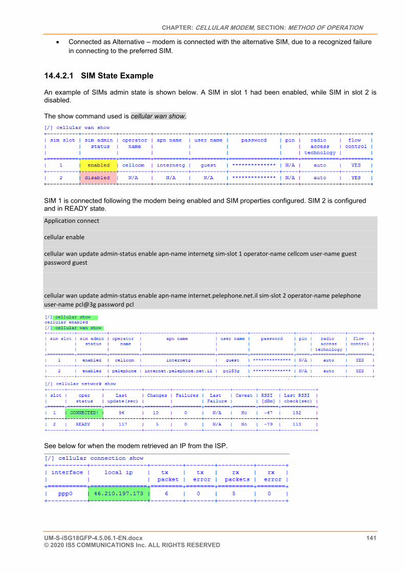
CHAPTER: CELLULAR MODEM, SECTION: METHOD OF OPERATION
UM-S-iSG18GFP-4.5.06.1-EN.docx 141 © 2020 IS5 COMMUNICATIONS Inc. ALL RIGHTS RESERVED
• Connected as Alternative – modem is connected with the alternative SIM, due to a recognized failure in connecting to the preferred SIM.
14.4.2.1 SIM State Example
An example of SIMs admin state is shown below. A SIM in slot 1 had been enabled, while SIM in slot 2 is disabled.
The show command used is cellular wan show.
SIM 1 is connected following the modem being enabled and SIM properties configured. SIM 2 is configured and in READY state.
Application connect
cellular enable
cellular wan update admin-status enable apn-name internetg sim-slot 1 operator-name cellcom user-name guest password guest
cellular wan update admin-status enable apn-name internet.pelephone.net.il sim-slot 2 operator-name pelephone user-name pcl@3g password pcl
See below for when the modem retrieved an IP from the ISP.
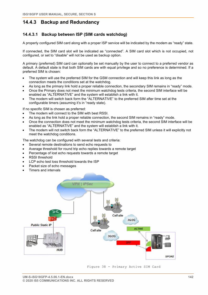
ISG18GFP USER MANUAL, SECURE, SECTION S
UM-S-iSG18GFP-4.5.06.1-EN.docx 142 © 2020 IS5 COMMUNICATIONS INC. ALL RIGHTS RESERVED
14.4.3 Backup and Redundancy
14.4.3.1 Backup between ISP (SIM cards watchdog)
A properly configured SIM card along with a proper ISP service will be indicated by the modem as “ready” state.
If connected, the SIM card slot will be indicated as “connected”. A SIM card slot which is not occupied, not configured, or set to “disable” will not be used as backup option.
A primary (preferred) SIM card can optionally be set manually by the user to connect to a preferred vendor as default. A default state is that both SIM cards are with equal privilege and so no preference is determined. If a preferred SIM is chosen:
• The system will use the preferred SIM for the GSM connection and will keep this link as long as the connection meets the conditions set at the watchdog.
• As long as the primary link hold a proper reliable connection, the secondary SIM remains in “ready” mode. • Once the Primary does not meet the minimum watchdog tests criteria, the second SIM interface will be
enabled as “ALTERNATIVE” and the system will establish a link with it. • The modem will switch back form the “ALTERNATIVE” to the preferred SIM after time set at the
configurable timers (assuming it’s in “ready state).
If no specific SIM is chosen as preferred: • The modem will connect to the SIM with best RSSI. • As long as the link hold a proper reliable connection, the second SIM remains in “ready” mode. • Once the connection does not meet the minimum watchdog tests criteria, the second SIM interface will be
enabled as “ALTERNATIVE” and the system will establish a link with it. • The modem will not switch back form the “ALTERNATIVE” to the preferred SIM unless it will explicitly not
meet the watchdog conditions.
The watchdog can be configured with several tests and criteria: • Several remote destinations to send echo requests to • Average threshold for round trip echo replies towards a remote target • Percentage of lost echo requests towards a remote target • RSSI threshold • LCP echo test loss threshold towards the ISP • Packet size of echo messages • Timers and intervals
Figure 38 - Primary Active SIM Card
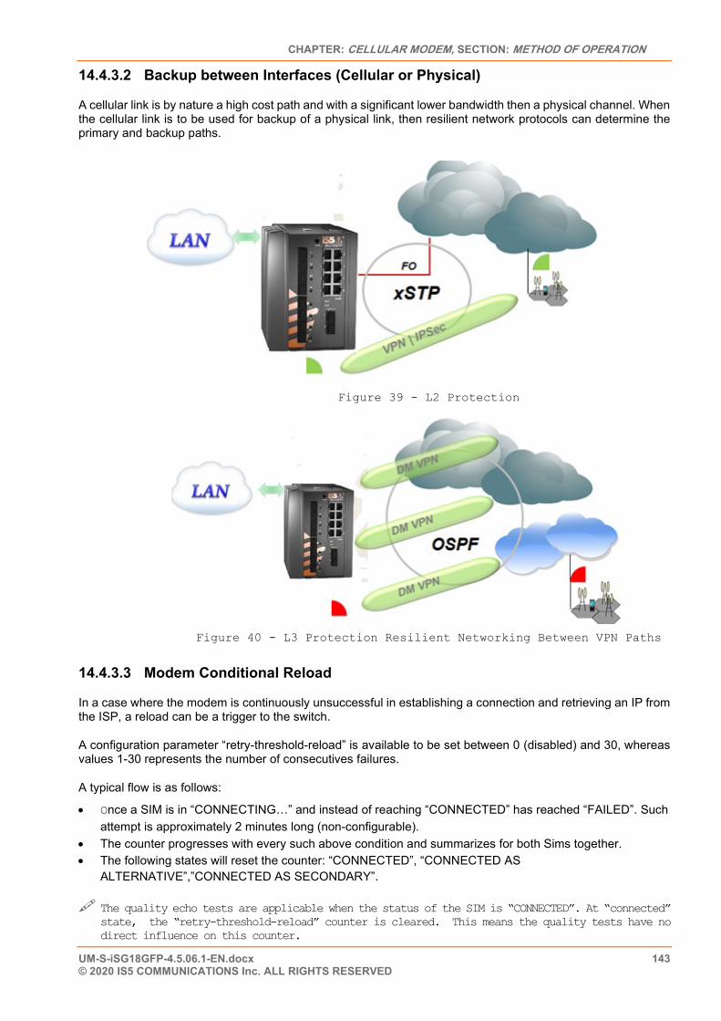
CHAPTER: CELLULAR MODEM, SECTION: METHOD OF OPERATION
UM-S-iSG18GFP-4.5.06.1-EN.docx 143 © 2020 IS5 COMMUNICATIONS Inc. ALL RIGHTS RESERVED
14.4.3.2 Backup between Interfaces (Cellular or Physical)
A cellular link is by nature a high cost path and with a significant lower bandwidth then a physical channel. When the cellular link is to be used for backup of a physical link, then resilient network protocols can determine the primary and backup paths.
Figure 39 - L2 Protection
Figure 40 - L3 Protection Resilient Networking Between VPN Paths
14.4.3.3 Modem Conditional Reload
In a case where the modem is continuously unsuccessful in establishing a connection and retrieving an IP from the ISP, a reload can be a trigger to the switch.
A configuration parameter “retry-threshold-reload” is available to be set between 0 (disabled) and 30, whereas values 1-30 represents the number of consecutives failures.
A typical flow is as follows:
• Once a SIM is in “CONNECTING…” and instead of reaching “CONNECTED” has reached “FAILED”. Such attempt is approximately 2 minutes long (non-configurable).
• The counter progresses with every such above condition and summarizes for both Sims together. • The following states will reset the counter: “CONNECTED”, “CONNECTED AS
ALTERNATIVE”,”CONNECTED AS SECONDARY”.
The quality echo tests are applicable when the status of the SIM is “CONNECTED”. At “connected” state, the “retry-threshold-reload” counter is cleared. This means the quality tests have no direct influence on this counter.
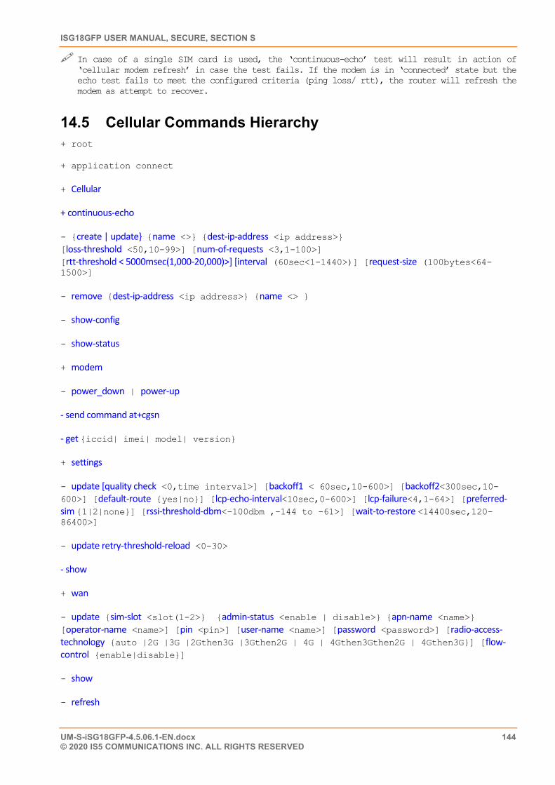
ISG18GFP USER MANUAL, SECURE, SECTION S
UM-S-iSG18GFP-4.5.06.1-EN.docx 144 © 2020 IS5 COMMUNICATIONS INC. ALL RIGHTS RESERVED
In case of a single SIM card is used, the ‘continuous-echo’ test will result in action of ‘cellular modem refresh’ in case the test fails. If the modem is in ‘connected’ state but the echo test fails to meet the configured criteria (ping loss/ rtt), the router will refresh the modem as attempt to recover.
14.5 Cellular Commands Hierarchy + root
+ application connect
+ Cellular
+ continuous-echo
- {create | update} {name <>} {dest-ip-address <ip address>} [loss-threshold <50,10-99>] [num-of-requests <3,1-100>] [rtt-threshold < 5000msec(1,000-20,000)>] [interval (60sec<1-1440>)] [request-size (100bytes<64-1500>]
- remove {dest-ip-address <ip address>} {name <> }
- show-config
- show-status
+ modem
- power_down | power-up
- send command at+cgsn
- get {iccid| imei| model| version}
+ settings
- update [quality check <0,time interval>] [backoff1 < 60sec,10-600>] [backoff2<300sec,10-600>] [default-route {yes|no}] [lcp-echo-interval<10sec,0-600>] [lcp-failure<4,1-64>] [preferred-sim {1|2|none}] [rssi-threshold-dbm<-100dbm ,-144 to -61>] [wait-to-restore <14400sec,120-86400>]
- update retry-threshold-reload <0-30>
- show
+ wan
- update {sim-slot <slot(1-2>} {admin-status <enable | disable>} {apn-name <name>} [operator-name <name>] [pin <pin>] [user-name <name>] [password <password>] [radio-access-technology {auto |2G |3G |2Gthen3G |3Gthen2G | 4G | 4Gthen3Gthen2G | 4Gthen3G}] [flow-control {enable|disable}]
- show
- refresh
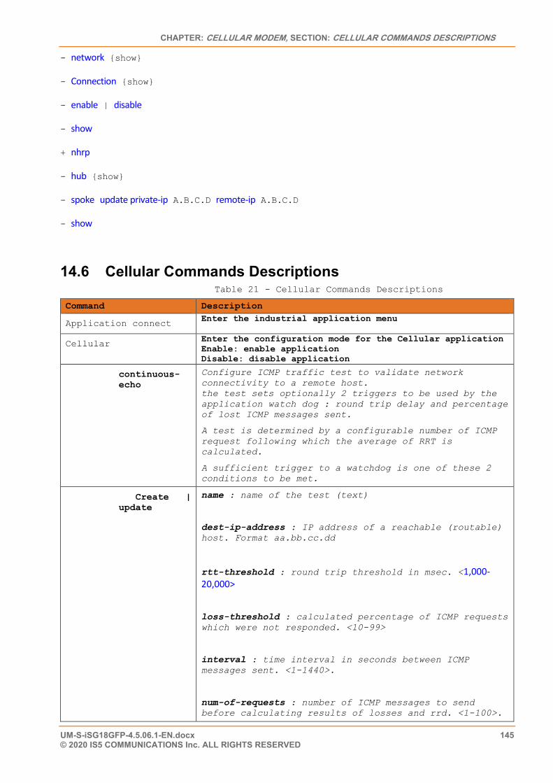
CHAPTER: CELLULAR MODEM, SECTION: CELLULAR COMMANDS DESCRIPTIONS
UM-S-iSG18GFP-4.5.06.1-EN.docx 145 © 2020 IS5 COMMUNICATIONS Inc. ALL RIGHTS RESERVED
- network {show}
- Connection {show}
- enable | disable
- show
+ nhrp
- hub {show}
- spoke update private-ip A.B.C.D remote-ip A.B.C.D
- show
14.6 Cellular Commands Descriptions Table 21 - Cellular Commands Descriptions
Command Description
Application connect Enter the industrial application menu
Cellular Enter the configuration mode for the Cellular application Enable: enable application Disable: disable application
continuous-echo
Configure ICMP traffic test to validate network connectivity to a remote host. the test sets optionally 2 triggers to be used by the application watch dog : round trip delay and percentage of lost ICMP messages sent.
A test is determined by a configurable number of ICMP request following which the average of RRT is calculated.
A sufficient trigger to a watchdog is one of these 2 conditions to be met.
Create | update
name : name of the test (text)
dest-ip-address : IP address of a reachable (routable) host. Format aa.bb.cc.dd
rtt-threshold : round trip threshold in msec. <1,000-20,000>
loss-threshold : calculated percentage of ICMP requests which were not responded. <10-99>
interval : time interval in seconds between ICMP messages sent. <1-1440>.
num-of-requests : number of ICMP messages to send before calculating results of losses and rrd. <1-100>.
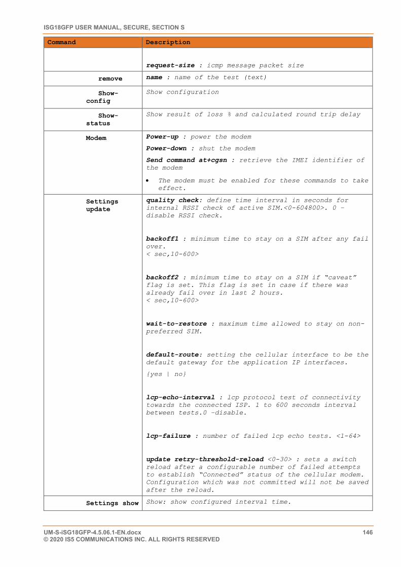
ISG18GFP USER MANUAL, SECURE, SECTION S
UM-S-iSG18GFP-4.5.06.1-EN.docx 146 © 2020 IS5 COMMUNICATIONS INC. ALL RIGHTS RESERVED
Command Description
request-size : icmp message packet size
remove name : name of the test (text)
Show-config
Show configuration
Show-status
Show result of loss % and calculated round trip delay
Modem Power-up : power the modem
Power-down : shut the modem
Send command at+cgsn : retrieve the IMEI identifier of the modem
• The modem must be enabled for these commands to take effect.
Settings update
quality check: define time interval in seconds for internal RSSI check of active SIM.<0-604800>. 0 –disable RSSI check.
backoff1 : minimum time to stay on a SIM after any fail over. < sec,10-600>
backoff2 : minimum time to stay on a SIM if “caveat” flag is set. This flag is set in case if there was already fail over in last 2 hours. < sec,10-600>
wait-to-restore : maximum time allowed to stay on non-preferred SIM.
default-route: setting the cellular interface to be the default gateway for the application IP interfaces.
{yes | no}
lcp-echo-interval : lcp protocol test of connectivity towards the connected ISP. 1 to 600 seconds interval between tests.0 –disable.
lcp-failure : number of failed lcp echo tests. <1-64>
update retry-threshold-reload <0-30> : sets a switch reload after a configurable number of failed attempts to establish “Connected” status of the cellular modem. Configuration which was not committed will not be saved after the reload.
Settings show Show: show configured interval time.
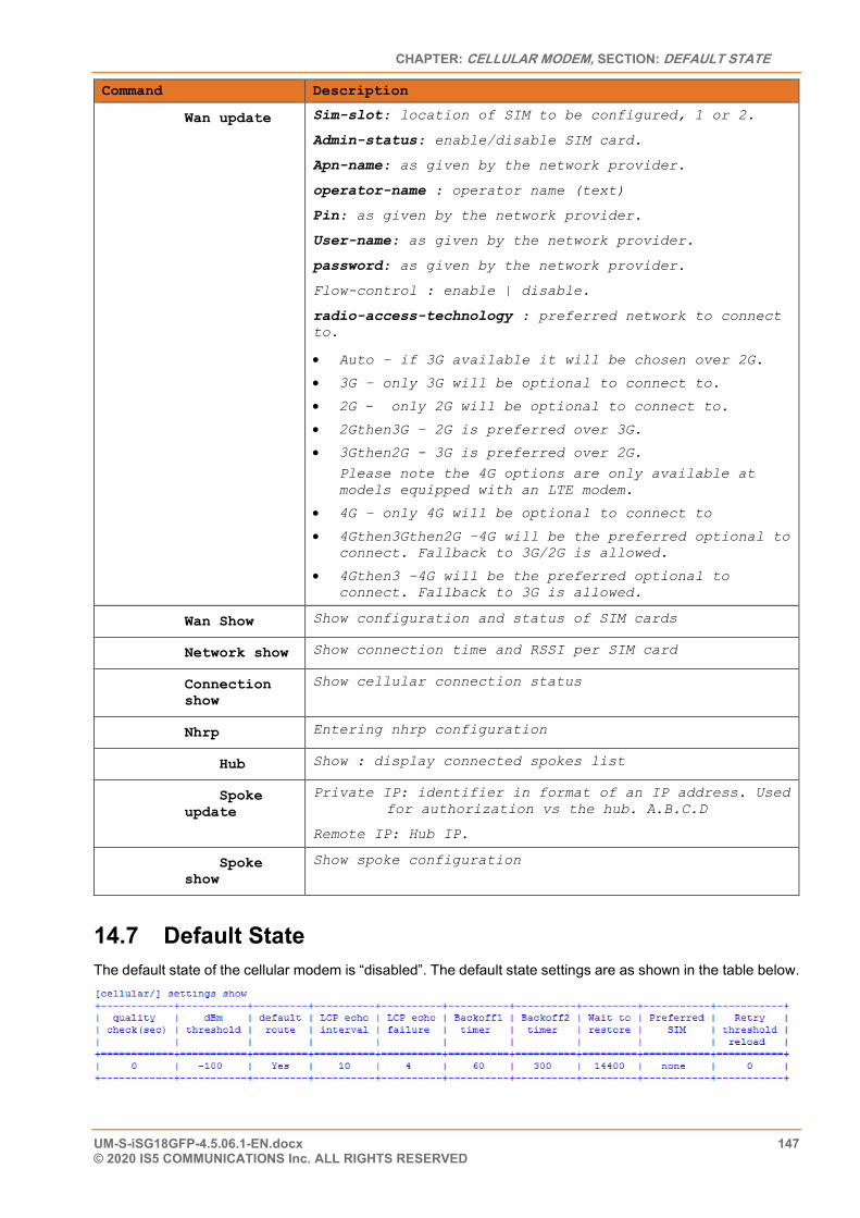
CHAPTER: CELLULAR MODEM, SECTION: DEFAULT STATE
UM-S-iSG18GFP-4.5.06.1-EN.docx 147 © 2020 IS5 COMMUNICATIONS Inc. ALL RIGHTS RESERVED
Command Description
Wan update Sim-slot: location of SIM to be configured, 1 or 2.
Admin-status: enable/disable SIM card.
Apn-name: as given by the network provider.
operator-name : operator name (text)
Pin: as given by the network provider.
User-name: as given by the network provider.
password: as given by the network provider.
Flow-control : enable | disable.
radio-access-technology : preferred network to connect to.
• Auto – if 3G available it will be chosen over 2G.
• 3G – only 3G will be optional to connect to.
• 2G - only 2G will be optional to connect to.
• 2Gthen3G – 2G is preferred over 3G.
• 3Gthen2G - 3G is preferred over 2G.
Please note the 4G options are only available at models equipped with an LTE modem.
• 4G – only 4G will be optional to connect to
• 4Gthen3Gthen2G –4G will be the preferred optional to connect. Fallback to 3G/2G is allowed.
• 4Gthen3 –4G will be the preferred optional to connect. Fallback to 3G is allowed.
Wan Show Show configuration and status of SIM cards
Network show Show connection time and RSSI per SIM card
Connection show
Show cellular connection status
Nhrp Entering nhrp configuration
Hub Show : display connected spokes list
Spoke update
Private IP: identifier in format of an IP address. Used for authorization vs the hub. A.B.C.D
Remote IP: Hub IP.
Spoke show
Show spoke configuration
14.7 Default State The default state of the cellular modem is “disabled”. The default state settings are as shown in the table below.
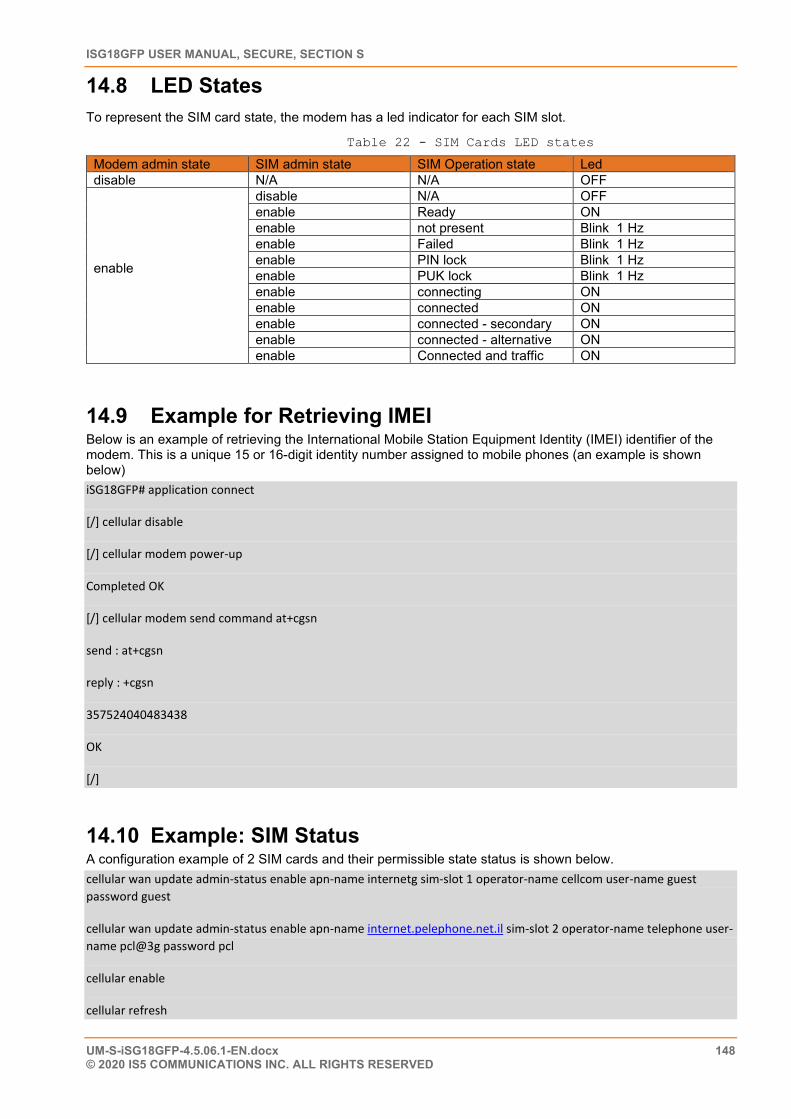
ISG18GFP USER MANUAL, SECURE, SECTION S
UM-S-iSG18GFP-4.5.06.1-EN.docx 148 © 2020 IS5 COMMUNICATIONS INC. ALL RIGHTS RESERVED
14.8 LED States To represent the SIM card state, the modem has a led indicator for each SIM slot.
Table 22 - SIM Cards LED states
Modem admin state SIM admin state SIM Operation state Led disable N/A N/A OFF
enable
disable N/A OFF enable Ready ON enable not present Blink 1 Hz enable Failed Blink 1 Hz enable PIN lock Blink 1 Hz enable PUK lock Blink 1 Hz enable connecting ON enable connected ON enable connected - secondary ON enable connected - alternative ON enable Connected and traffic ON
14.9 Example for Retrieving IMEI Below is an example of retrieving the International Mobile Station Equipment Identity (IMEI) identifier of the modem. This is a unique 15 or 16-digit identity number assigned to mobile phones (an example is shown below) iSG18GFP# application connect
[/] cellular disable
[/] cellular modem power-up
Completed OK
[/] cellular modem send command at+cgsn
send : at+cgsn
reply : +cgsn
357524040483438
OK
[/]
14.10 Example: SIM Status A configuration example of 2 SIM cards and their permissible state status is shown below. cellular wan update admin-status enable apn-name internetg sim-slot 1 operator-name cellcom user-name guest password guest
cellular wan update admin-status enable apn-name internet.pelephone.net.il sim-slot 2 operator-name telephone user-name pcl@3g password pcl
cellular enable
cellular refresh
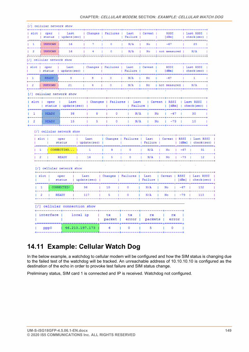
CHAPTER: CELLULAR MODEM, SECTION: EXAMPLE: CELLULAR WATCH DOG
UM-S-iSG18GFP-4.5.06.1-EN.docx 149 © 2020 IS5 COMMUNICATIONS Inc. ALL RIGHTS RESERVED
14.11 Example: Cellular Watch Dog In the below example, a watchdog to cellular modem will be configured and how the SIM status is changing due to the failed test of the watchdog will be tracked. An unreachable address of 10.10.10.10 is configured as the destination of the echo in order to provoke test failure and SIM status change.
Preliminary status, SIM card 1 is connected and IP is received. Watchdog not configured.
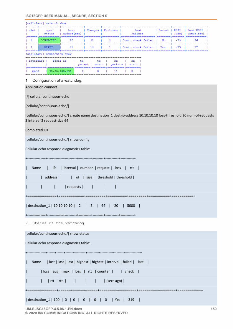
ISG18GFP USER MANUAL, SECURE, SECTION S
UM-S-iSG18GFP-4.5.06.1-EN.docx 150 © 2020 IS5 COMMUNICATIONS INC. ALL RIGHTS RESERVED
1. Configuration of a watchdog. Application connect
[/] cellular continuous-echo
[cellular/continuous-echo/]
[cellular/continuous-echo/] create name destination_1 dest-ip-address 10.10.10.10 loss-threshold 20 num-of-requests 3 interval 2 request-size 64
Completed OK
[cellular/continuous-echo/] show-config
Cellular echo response diagnostics table:
+---------------+-------------+----------+----------+---------+-----------+-----------+
| Name | IP | interval | number | request | loss | rtt |
| | address | | of | size | threshold | threshold |
| | | | requests | | | |
+===============+=============+==========+==========+=========+===========+===========+
| destination_1 | 10.10.10.10 | 2 | 3 | 64 | 20 | 5000 |
+---------------+-------------+----------+----------+---------+-----------+-----------+
2. Status of the watchdog
[cellular/continuous-echo/] show-status
Cellular echo response diagnostics table:
+---------------+------+------+------+---------+---------+----------+--------+------------+
| Name | last | last | last | highest | highest | interval | failed | last |
| | loss | avg | max | loss | rtt | counter | | check |
| | | rtt | rtt | | | | | (secs ago) |
+===============+======+======+======+=========+=========+==========+========+============+
| destination_1 | 100 | 0 | 0 | 0 | 0 | 0 | Yes | 319 |
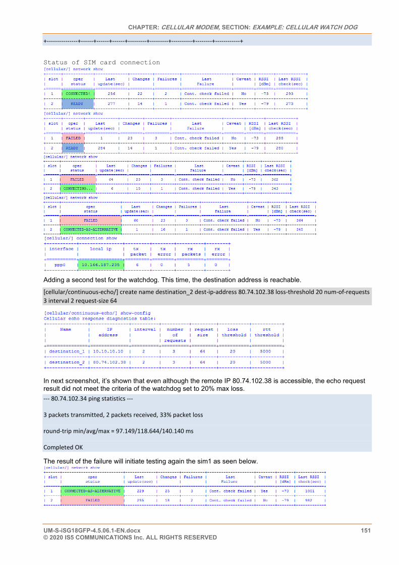
CHAPTER: CELLULAR MODEM, SECTION: EXAMPLE: CELLULAR WATCH DOG
UM-S-iSG18GFP-4.5.06.1-EN.docx 151 © 2020 IS5 COMMUNICATIONS Inc. ALL RIGHTS RESERVED
+---------------+------+------+------+---------+---------+----------+--------+------------+
Status of SIM card connection
Adding a second test for the watchdog. This time, the destination address is reachable.
[cellular/continuous-echo/] create name destination_2 dest-ip-address 80.74.102.38 loss-threshold 20 num-of-requests 3 interval 2 request-size 64
In next screenshot, it’s shown that even although the remote IP 80.74.102.38 is accessible, the echo request result did not meet the criteria of the watchdog set to 20% max loss. --- 80.74.102.34 ping statistics ---
3 packets transmitted, 2 packets received, 33% packet loss
round-trip min/avg/max = 97.149/118.644/140.140 ms
Completed OK
The result of the failure will initiate testing again the sim1 as seen below.
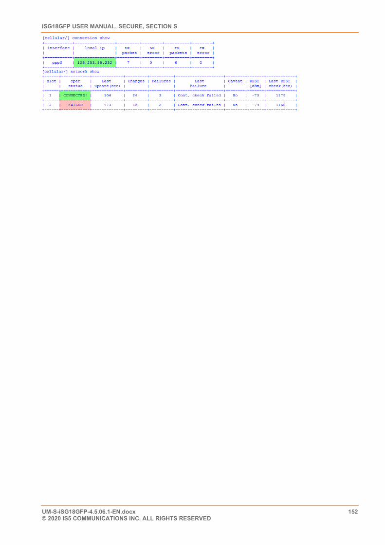
ISG18GFP USER MANUAL, SECURE, SECTION S
UM-S-iSG18GFP-4.5.06.1-EN.docx 152 © 2020 IS5 COMMUNICATIONS INC. ALL RIGHTS RESERVED
CHAPTER: VPN SETUP EXAMPLES, SECTION: L2 VPN OVER L3 CLOUD
UM-S-iSG18GFP-4.5.06.1-EN.docx 153 © 2020 IS5 COMMUNICATIONS Inc. ALL RIGHTS RESERVED
VPN Setup Examples
15.1 L2 VPN over L3 Cloud The following example will demonstrate proper configuration of L2 VPN over Layer 3 cloud.
The concept is as follows:
• Maintaining virtual LAN & Layer 2 connectivity between two remote sites connected over layer 3 cloud.
• The 2 PCs on the map are holding IP addresses with the same subnet. Following configuration will allow traffic between them to pass over the GRE tunnel as if they were connected at the same LAN.
• Switch B will be configured so that the computer on side A will be able to manage it via SSH through the tunnel.
• The Spoke is set as terminal server to serve a locally connected serial slave. The PC (192.168.10.250) will be able to open a secure Telnet connection to the Spoke (over the encrypted tunnel) to control the remote slave.
• The spoke is set as an IEC101/104 gateway to serve a locally connected IEC101 slave. The PC (192.168.10.250) will be able to open an IEC 104 connection to the spoke gateway (over the encrypted tunnel) to control the remote IEC 101 slave.
• A serial tunneling service set between a master and slave. This service traffic is encrypted over the tunnel.
The configuration guidelines are follows:
• The proper usage of the ACE ports is of importance; port gigabitethernet 0/4 is to be added as tagged member to the customer service VLANs (VLAN 10 at following example). By assigning this port, all traffic at the specified VLAN will be send over the VPN.
• At both the Hub and Spoke, an ACE IP interface must be assigned as an ‘application-host’ type. This interface is used as the tunnel end point. Port gigabitethernet 0/3 is to be set as a tagged member at this ACE interface vlan (VLAN 20 and 30 at the following example).
• An additional ACE interface (type ‘general’) is set at the Spoke to support the serial services: serial-tunneling, terminal-server, 101/104 gateway.
• An additional ACE interface (type ‘general’) is set at the HUB to support the serial-tunneling service. • Port gigabitethernet 0/4 has a default state of disable mac-learning. When used in L2 VPN, this state must
be changed to allow mac-learning.
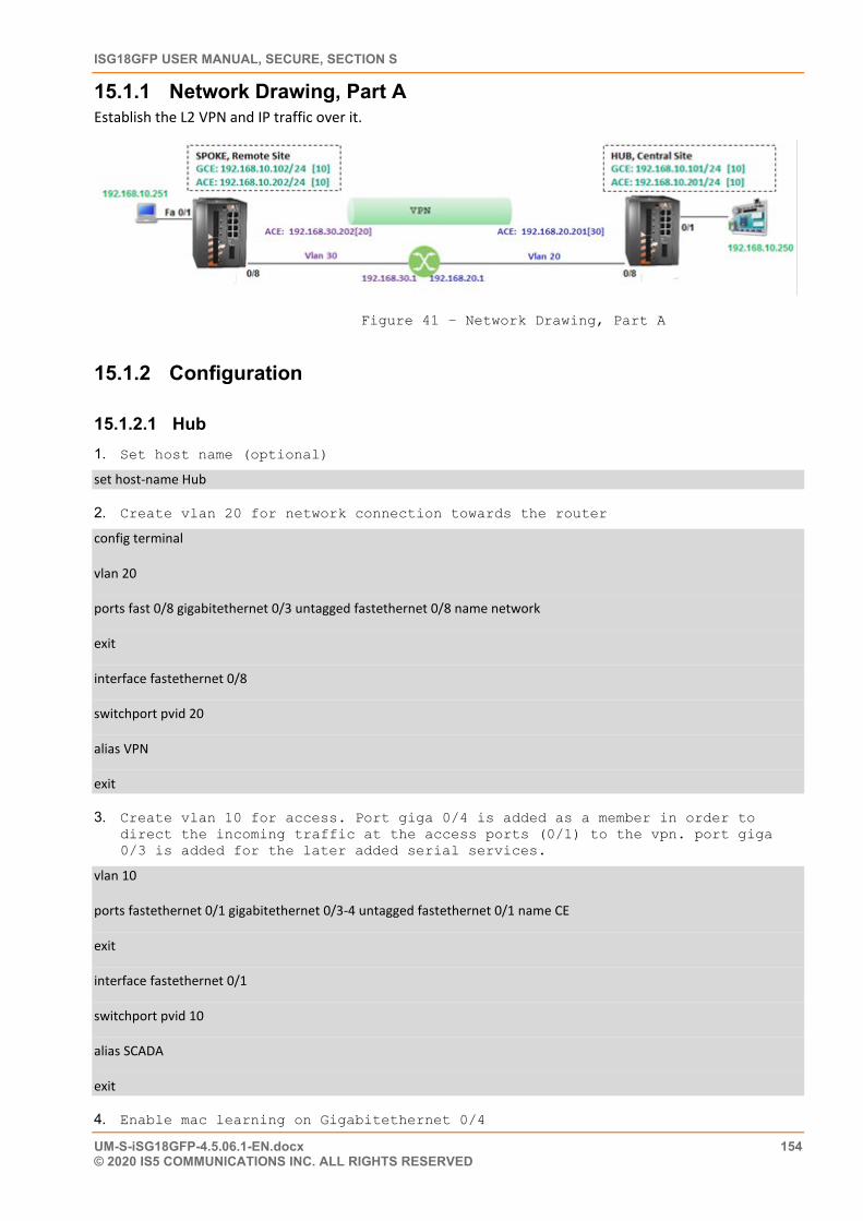
ISG18GFP USER MANUAL, SECURE, SECTION S
UM-S-iSG18GFP-4.5.06.1-EN.docx 154 © 2020 IS5 COMMUNICATIONS INC. ALL RIGHTS RESERVED
15.1.1 Network Drawing, Part A Establish the L2 VPN and IP traffic over it.
Figure 41 – Network Drawing, Part A
15.1.2 Configuration
15.1.2.1 Hub 1. Set host name (optional)
set host-name Hub
2. Create vlan 20 for network connection towards the router
config terminal
vlan 20
ports fast 0/8 gigabitethernet 0/3 untagged fastethernet 0/8 name network
exit
interface fastethernet 0/8
switchport pvid 20
alias VPN
exit
3. Create vlan 10 for access. Port giga 0/4 is added as a member in order to direct the incoming traffic at the access ports (0/1) to the vpn. port giga 0/3 is added for the later added serial services.
vlan 10
ports fastethernet 0/1 gigabitethernet 0/3-4 untagged fastethernet 0/1 name CE
exit
interface fastethernet 0/1
switchport pvid 10
alias SCADA
exit
4. Enable mac learning on Gigabitethernet 0/4
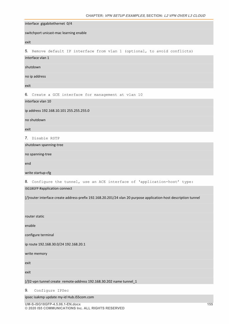
CHAPTER: VPN SETUP EXAMPLES, SECTION: L2 VPN OVER L3 CLOUD
UM-S-iSG18GFP-4.5.06.1-EN.docx 155 © 2020 IS5 COMMUNICATIONS Inc. ALL RIGHTS RESERVED
interface gigabitethernet 0/4
switchport unicast-mac learning enable
exit
5. Remove default IP interface from vlan 1 (optional, to avoid conflicts)
interface vlan 1
shutdown
no ip address
exit
6. Create a GCE interface for management at vlan 10
interface vlan 10
ip address 192.168.10.101 255.255.255.0
no shutdown
exit
7. Disable RSTP
shutdown spanning-tree
no spanning-tree
end
write startup-cfg
8. Configure the tunnel, use an ACE interface of ‘application-host’ type:
iSG18GFP #application connect
[/]router interface create address-prefix 192.168.20.201/24 vlan 20 purpose application-host description tunnel
router static
enable
configure terminal
ip route 192.168.30.0/24 192.168.20.1
write memory
exit
exit
[/]l2-vpn tunnel create remote-address 192.168.30.202 name tunnel_1
9. Configure IPSec
ipsec isakmp update my-id Hub.iS5com.com
ISG18GFP USER MANUAL, SECURE, SECTION S
UM-S-iSG18GFP-4.5.06.1-EN.docx 156 © 2020 IS5 COMMUNICATIONS INC. ALL RIGHTS RESERVED
ipsec preshared create id Spoke1.iS5com.com key secretkey
ipsec preshared create id Hub.iS5com.com key secretkey
ipsec policy create protocol gre
ipsec isakmp update id-type fqdn
ipsec disable
ipsec enable
exit
write startup-cfg
15.1.2.2 Spoke 1. Set host name (optional)
set host-name Spoke
2. Create vlan 30 for network connection towards the router
config terminal
vlan 30
ports fast 0/8 gigabitethernet 0/3 untagged fastethernet 0/8 name network
exit
interface fastethernet 0/8
switchport pvid 30
alias VPN
exit
3. Create vlan 10 for access. Port gigabitethernet 0/4 is added as a member in order to direct the incoming traffic at the access ports (0/1) to the vpn. port gigabitethernet 0/3 is added for the later added serial services.
vlan 10
ports fastethernet 0/1 gigabitethernet 0/3-4 untagged fastethernet 0/1 name CE
exit
interface fastethernet 0/1
switchport pvid 10
alias SCADA
exit
4. Enable mac learning on Gigabitethernet 0/4
interface gigabitethernet 0/4
CHAPTER: VPN SETUP EXAMPLES, SECTION: L2 VPN OVER L3 CLOUD
UM-S-iSG18GFP-4.5.06.1-EN.docx 157 © 2020 IS5 COMMUNICATIONS Inc. ALL RIGHTS RESERVED
switchport unicast-mac learning enable
exit
5. Remove default IP interface from vlan 1 (optional, to avoid conflicts)
interface vlan 1
shutdown
no ip address
exit
6. Create a GCE interface for management at vlan 10
interface vlan 10
ip address 192.168.10.102 255.255.255.0
no shutdown
exit
7. Disable RSTP
shutdown spanning-tree
no spanning-tree
end
write startup-cfg
8. Configure the tunnel, use an ACE interface of ‘application-host’ type:
iSG18GFP #application connect
[/]router interface create address-prefix 192.168.30.202/24 vlan 30 purpose application-host description tunnel
router static
enable
configure terminal
ip route 192.168.20.0/24 192.168.30.1
write memory
exit
exit
vpn l2 tunnel create remote-address 192.168.20.201 name tunnel_1
vpn l2 nhrp spoke update private-ip 192.168.30.202 remote-ip 192.168.20.201
[/]
9. Configure IPSec
ipsec isakmp update my-id Spoke1.iS5com.com
ISG18GFP USER MANUAL, SECURE, SECTION S
UM-S-iSG18GFP-4.5.06.1-EN.docx 158 © 2020 IS5 COMMUNICATIONS INC. ALL RIGHTS RESERVED
ipsec preshared create id Spoke1.iS5com.com key secretkey
ipsec preshared create id Hub.iS5com.com key secretkey
ipsec policy create protocol gre
ipsec isakmp update id-type fqdn
ipsec disable
ipsec enable
exit
write startup-cfg
15.1.2.3 Testing the Setup (Shown at the Hub) 1. Verify by pinging from ACE to ACE
[/] ping 192.168.30.202
PING 192.168.30.202 (192.168.30.202): 56 data bytes
64 bytes from 192.168.30.202: seq=0 ttl=63 time=0.460 ms
64 bytes from 192.168.30.202: seq=1 ttl=63 time=0.363 ms
2. Verify that IPSec SA is established
[/] ipsec show log
…
2015-05-04 17:49:05: INFO: IPsec-SA established: ESP/Transport 192.168.20.201[500]->192.168.30.202[500] spi=152943490(0x91dbb82)
2015-05-04 17:49:05: INFO: IPsec-SA established: ESP/Transport 192.168.20.201[500]->192.168.30.202[500] spi=167249243(0x9f8055b)
3. Verify by pinging from GCE to GCE
Hub# ping 192.168.10.102
Reply Received From :192.168.10.102, TimeTaken : 10 msecs
Reply Received From :192.168.10.102, TimeTaken : 3 msecs
Reply Received From :192.168.10.102, TimeTaken : 3 msecs
1. Verify ping between the PCs
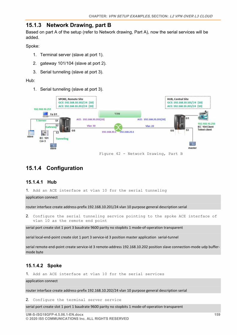
CHAPTER: VPN SETUP EXAMPLES, SECTION: L2 VPN OVER L3 CLOUD
UM-S-iSG18GFP-4.5.06.1-EN.docx 159 © 2020 IS5 COMMUNICATIONS Inc. ALL RIGHTS RESERVED
15.1.3 Network Drawing, part B Based on part A of the setup (refer to Network drawing, Part A), now the serial services will be added.
Spoke:
1. Terminal server (slave at port 1).
2. gateway 101/104 (slave at port 2).
3. Serial tunneling (slave at port 3).
Hub:
1. Serial tunneling (slave at port 3).
Figure 42 - Network Drawing, Part B
15.1.4 Configuration
15.1.4.1 Hub 1. Add an ACE interface at vlan 10 for the serial tunneling
application connect
router interface create address-prefix 192.168.10.201/24 vlan 10 purpose general description serial
2. Configure the serial tunneling service pointing to the spoke ACE interface of vlan 10 as the remote end point
serial port create slot 1 port 3 baudrate 9600 parity no stopbits 1 mode-of-operation transparent
serial local-end-point create slot 1 port 3 service-id 3 position master application serial-tunnel
serial remote-end-point create service-id 3 remote-address 192.168.10.202 position slave connection-mode udp buffer-mode byte
15.1.4.2 Spoke 1. Add an ACE interface at vlan 10 for the serial services
application connect
router interface create address-prefix 192.168.10.202/24 vlan 10 purpose general description serial
2. Configure the terminal server service
serial port create slot 1 port 1 baudrate 9600 parity no stopbits 1 mode-of-operation transparent
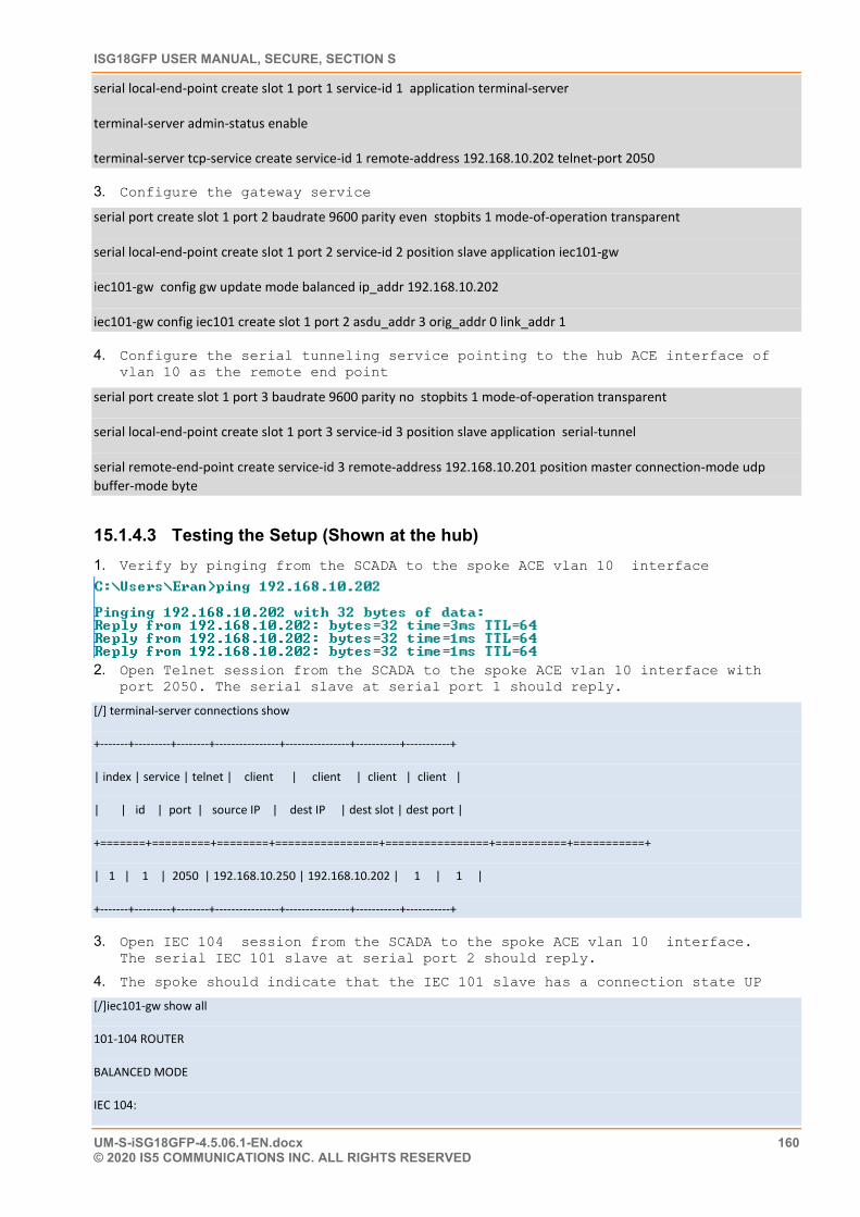
ISG18GFP USER MANUAL, SECURE, SECTION S
UM-S-iSG18GFP-4.5.06.1-EN.docx 160 © 2020 IS5 COMMUNICATIONS INC. ALL RIGHTS RESERVED
serial local-end-point create slot 1 port 1 service-id 1 application terminal-server
terminal-server admin-status enable
terminal-server tcp-service create service-id 1 remote-address 192.168.10.202 telnet-port 2050
3. Configure the gateway service
serial port create slot 1 port 2 baudrate 9600 parity even stopbits 1 mode-of-operation transparent
serial local-end-point create slot 1 port 2 service-id 2 position slave application iec101-gw
iec101-gw config gw update mode balanced ip_addr 192.168.10.202
iec101-gw config iec101 create slot 1 port 2 asdu_addr 3 orig_addr 0 link_addr 1
4. Configure the serial tunneling service pointing to the hub ACE interface of vlan 10 as the remote end point
serial port create slot 1 port 3 baudrate 9600 parity no stopbits 1 mode-of-operation transparent
serial local-end-point create slot 1 port 3 service-id 3 position slave application serial-tunnel
serial remote-end-point create service-id 3 remote-address 192.168.10.201 position master connection-mode udp buffer-mode byte
15.1.4.3 Testing the Setup (Shown at the hub) 1. Verify by pinging from the SCADA to the spoke ACE vlan 10 interface
2. Open Telnet session from the SCADA to the spoke ACE vlan 10 interface with
port 2050. The serial slave at serial port 1 should reply.
[/] terminal-server connections show
+-------+---------+--------+----------------+----------------+-----------+-----------+
| index | service | telnet | client | client | client | client |
| | id | port | source IP | dest IP | dest slot | dest port |
+=======+=========+========+================+================+===========+===========+
| 1 | 1 | 2050 | 192.168.10.250 | 192.168.10.202 | 1 | 1 |
+-------+---------+--------+----------------+----------------+-----------+-----------+
3. Open IEC 104 session from the SCADA to the spoke ACE vlan 10 interface. The serial IEC 101 slave at serial port 2 should reply.
4. The spoke should indicate that the IEC 101 slave has a connection state UP
[/]iec101-gw show all
101-104 ROUTER
BALANCED MODE
IEC 104:
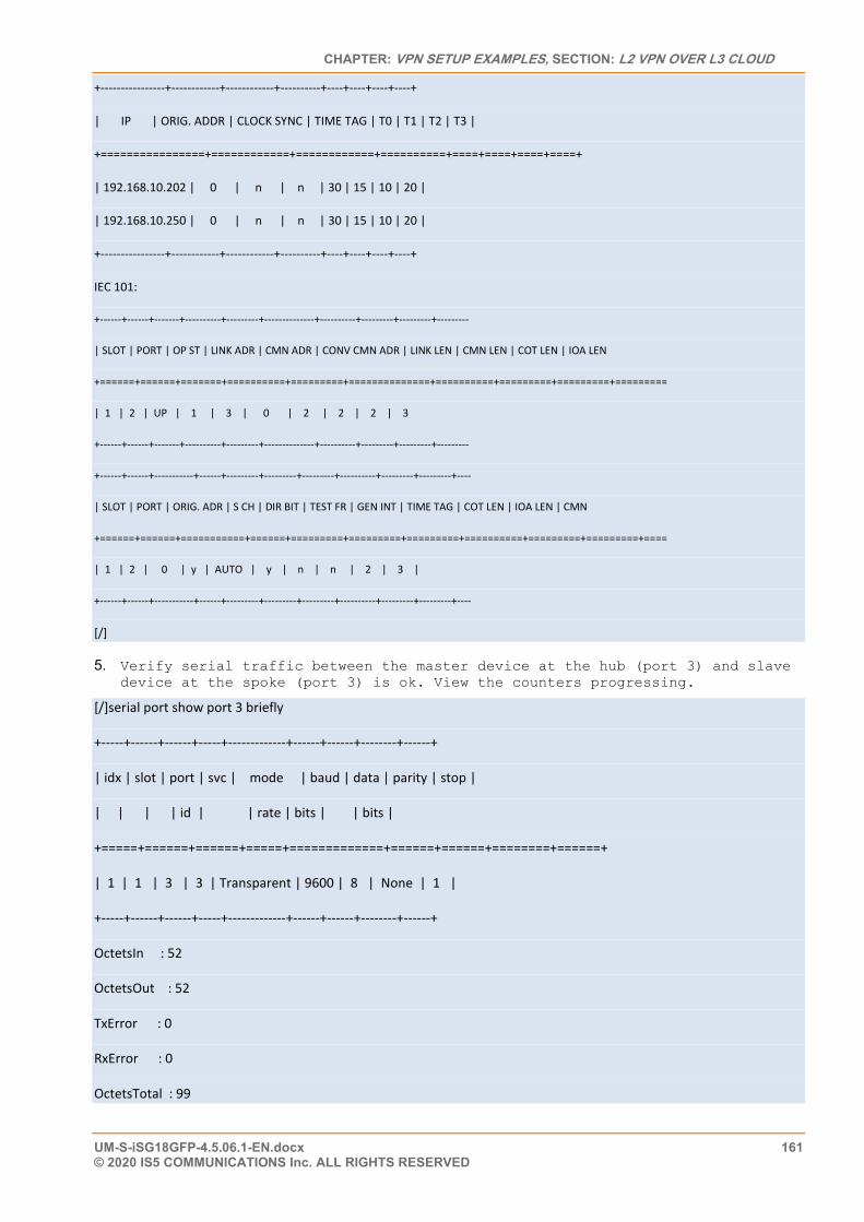
CHAPTER: VPN SETUP EXAMPLES, SECTION: L2 VPN OVER L3 CLOUD
UM-S-iSG18GFP-4.5.06.1-EN.docx 161 © 2020 IS5 COMMUNICATIONS Inc. ALL RIGHTS RESERVED
+----------------+------------+------------+----------+----+----+----+----+
| IP | ORIG. ADDR | CLOCK SYNC | TIME TAG | T0 | T1 | T2 | T3 |
+================+============+============+==========+====+====+====+====+
| 192.168.10.202 | 0 | n | n | 30 | 15 | 10 | 20 |
| 192.168.10.250 | 0 | n | n | 30 | 15 | 10 | 20 |
+----------------+------------+------------+----------+----+----+----+----+
IEC 101:
+------+------+-------+----------+---------+--------------+----------+---------+---------+---------
| SLOT | PORT | OP ST | LINK ADR | CMN ADR | CONV CMN ADR | LINK LEN | CMN LEN | COT LEN | IOA LEN
+======+======+=======+==========+=========+==============+==========+=========+=========+=========
| 1 | 2 | UP | 1 | 3 | 0 | 2 | 2 | 2 | 3
+------+------+-------+----------+---------+--------------+----------+---------+---------+---------
+------+------+-----------+------+---------+---------+---------+----------+---------+---------+----
| SLOT | PORT | ORIG. ADR | S CH | DIR BIT | TEST FR | GEN INT | TIME TAG | COT LEN | IOA LEN | CMN
+======+======+===========+======+=========+=========+=========+==========+=========+=========+====
| 1 | 2 | 0 | y | AUTO | y | n | n | 2 | 3 |
+------+------+-----------+------+---------+---------+---------+----------+---------+---------+----
[/]
5. Verify serial traffic between the master device at the hub (port 3) and slave device at the spoke (port 3) is ok. View the counters progressing.
[/]serial port show port 3 briefly
+-----+------+------+-----+-------------+------+------+--------+------+
| idx | slot | port | svc | mode | baud | data | parity | stop |
| | | | id | | rate | bits | | bits |
+=====+======+======+=====+=============+======+======+========+======+
| 1 | 1 | 3 | 3 | Transparent | 9600 | 8 | None | 1 |
+-----+------+------+-----+-------------+------+------+--------+------+
OctetsIn : 52
OctetsOut : 52
TxError : 0
RxError : 0
OctetsTotal : 99
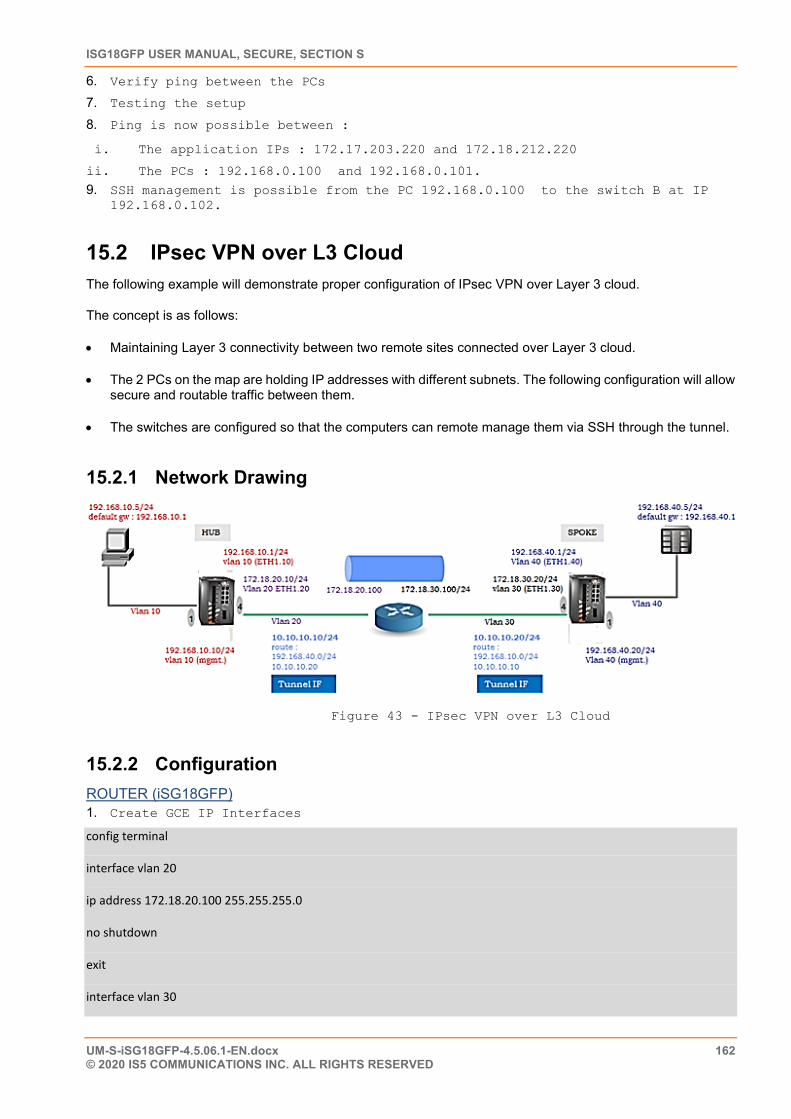
ISG18GFP USER MANUAL, SECURE, SECTION S
UM-S-iSG18GFP-4.5.06.1-EN.docx 162 © 2020 IS5 COMMUNICATIONS INC. ALL RIGHTS RESERVED
6. Verify ping between the PCs
7. Testing the setup
8. Ping is now possible between :
i. The application IPs : 172.17.203.220 and 172.18.212.220
ii. The PCs : 192.168.0.100 and 192.168.0.101.
9. SSH management is possible from the PC 192.168.0.100 to the switch B at IP 192.168.0.102.
15.2 IPsec VPN over L3 Cloud The following example will demonstrate proper configuration of IPsec VPN over Layer 3 cloud.
The concept is as follows:
• Maintaining Layer 3 connectivity between two remote sites connected over Layer 3 cloud.
• The 2 PCs on the map are holding IP addresses with different subnets. The following configuration will allow secure and routable traffic between them.
• The switches are configured so that the computers can remote manage them via SSH through the tunnel.
15.2.1 Network Drawing
Figure 43 - IPsec VPN over L3 Cloud
15.2.2 Configuration ROUTER (iSG18GFP) 1. Create GCE IP Interfaces
config terminal
interface vlan 20
ip address 172.18.20.100 255.255.255.0
no shutdown
exit
interface vlan 30
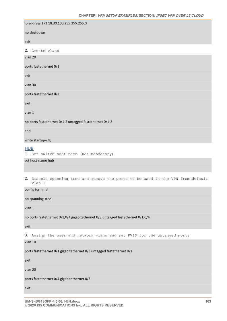
CHAPTER: VPN SETUP EXAMPLES, SECTION: IPSEC VPN OVER L3 CLOUD
UM-S-iSG18GFP-4.5.06.1-EN.docx 163 © 2020 IS5 COMMUNICATIONS Inc. ALL RIGHTS RESERVED
ip address 172.18.30.100 255.255.255.0
no shutdown
exit
2. Create vlans
vlan 20
ports fastethernet 0/1
exit
vlan 30
ports fastethernet 0/2
exit
vlan 1
no ports fastethernet 0/1-2 untagged fastethernet 0/1-2
end
write startup-cfg
HUB 1. Set switch host name (not mandatory)
set host-name hub
2. Disable spanning tree and remove the ports to be used in the VPN from default vlan 1
config terminal
no spanning-tree
vlan 1
no ports fastethernet 0/1,0/4 gigabitethernet 0/3 untagged fastethernet 0/1,0/4
exit
3. Assign the user and network vlans and set PVID for the untagged ports
vlan 10
ports fastethernet 0/1 gigabitethernet 0/3 untagged fastethernet 0/1
exit
vlan 20
ports fastethernet 0/4 gigabitethernet 0/3
exit
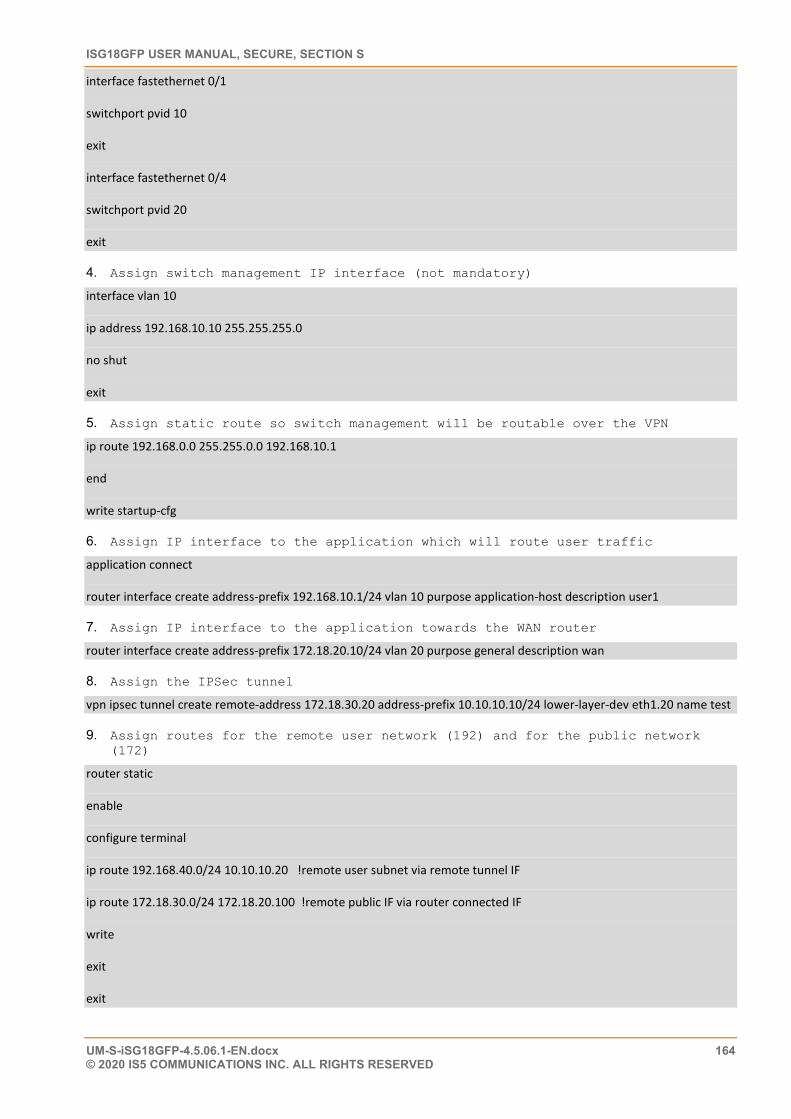
ISG18GFP USER MANUAL, SECURE, SECTION S
UM-S-iSG18GFP-4.5.06.1-EN.docx 164 © 2020 IS5 COMMUNICATIONS INC. ALL RIGHTS RESERVED
interface fastethernet 0/1
switchport pvid 10
exit
interface fastethernet 0/4
switchport pvid 20
exit
4. Assign switch management IP interface (not mandatory)
interface vlan 10
ip address 192.168.10.10 255.255.255.0
no shut
exit
5. Assign static route so switch management will be routable over the VPN
ip route 192.168.0.0 255.255.0.0 192.168.10.1
end
write startup-cfg
6. Assign IP interface to the application which will route user traffic
application connect
router interface create address-prefix 192.168.10.1/24 vlan 10 purpose application-host description user1
7. Assign IP interface to the application towards the WAN router
router interface create address-prefix 172.18.20.10/24 vlan 20 purpose general description wan
8. Assign the IPSec tunnel
vpn ipsec tunnel create remote-address 172.18.30.20 address-prefix 10.10.10.10/24 lower-layer-dev eth1.20 name test
9. Assign routes for the remote user network (192) and for the public network (172)
router static
enable
configure terminal
ip route 192.168.40.0/24 10.10.10.20 !remote user subnet via remote tunnel IF
ip route 172.18.30.0/24 172.18.20.100 !remote public IF via router connected IF
write
exit
exit
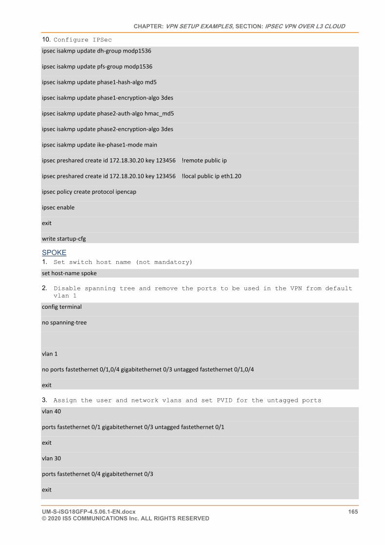
CHAPTER: VPN SETUP EXAMPLES, SECTION: IPSEC VPN OVER L3 CLOUD
UM-S-iSG18GFP-4.5.06.1-EN.docx 165 © 2020 IS5 COMMUNICATIONS Inc. ALL RIGHTS RESERVED
10. Configure IPSec
ipsec isakmp update dh-group modp1536
ipsec isakmp update pfs-group modp1536
ipsec isakmp update phase1-hash-algo md5
ipsec isakmp update phase1-encryption-algo 3des
ipsec isakmp update phase2-auth-algo hmac_md5
ipsec isakmp update phase2-encryption-algo 3des
ipsec isakmp update ike-phase1-mode main
ipsec preshared create id 172.18.30.20 key 123456 !remote public ip
ipsec preshared create id 172.18.20.10 key 123456 !local public ip eth1.20
ipsec policy create protocol ipencap
ipsec enable
exit
write startup-cfg
SPOKE 1. Set switch host name (not mandatory)
set host-name spoke
2. Disable spanning tree and remove the ports to be used in the VPN from default vlan 1
config terminal
no spanning-tree
vlan 1
no ports fastethernet 0/1,0/4 gigabitethernet 0/3 untagged fastethernet 0/1,0/4
exit
3. Assign the user and network vlans and set PVID for the untagged ports
vlan 40
ports fastethernet 0/1 gigabitethernet 0/3 untagged fastethernet 0/1
exit
vlan 30
ports fastethernet 0/4 gigabitethernet 0/3
exit
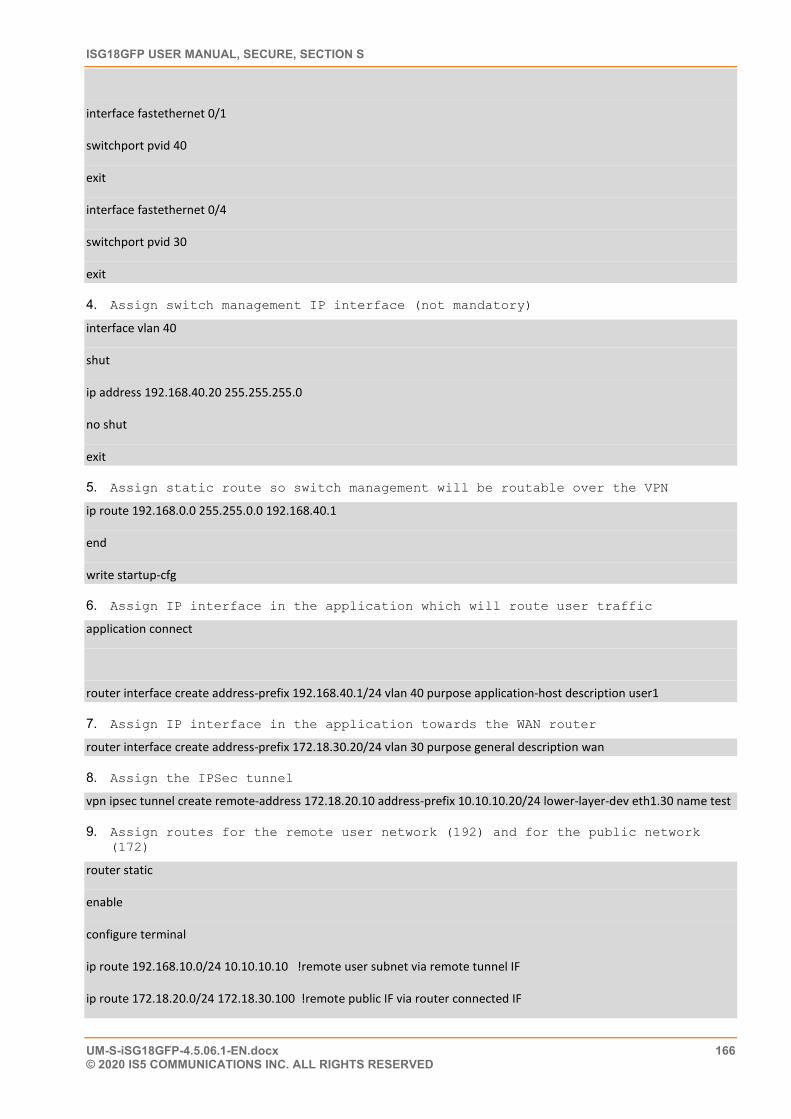
ISG18GFP USER MANUAL, SECURE, SECTION S
UM-S-iSG18GFP-4.5.06.1-EN.docx 166 © 2020 IS5 COMMUNICATIONS INC. ALL RIGHTS RESERVED
interface fastethernet 0/1
switchport pvid 40
exit
interface fastethernet 0/4
switchport pvid 30
exit
4. Assign switch management IP interface (not mandatory)
interface vlan 40
shut
ip address 192.168.40.20 255.255.255.0
no shut
exit
5. Assign static route so switch management will be routable over the VPN
ip route 192.168.0.0 255.255.0.0 192.168.40.1
end
write startup-cfg
6. Assign IP interface in the application which will route user traffic
application connect
router interface create address-prefix 192.168.40.1/24 vlan 40 purpose application-host description user1
7. Assign IP interface in the application towards the WAN router
router interface create address-prefix 172.18.30.20/24 vlan 30 purpose general description wan
8. Assign the IPSec tunnel
vpn ipsec tunnel create remote-address 172.18.20.10 address-prefix 10.10.10.20/24 lower-layer-dev eth1.30 name test
9. Assign routes for the remote user network (192) and for the public network (172)
router static
enable
configure terminal
ip route 192.168.10.0/24 10.10.10.10 !remote user subnet via remote tunnel IF
ip route 172.18.20.0/24 172.18.30.100 !remote public IF via router connected IF
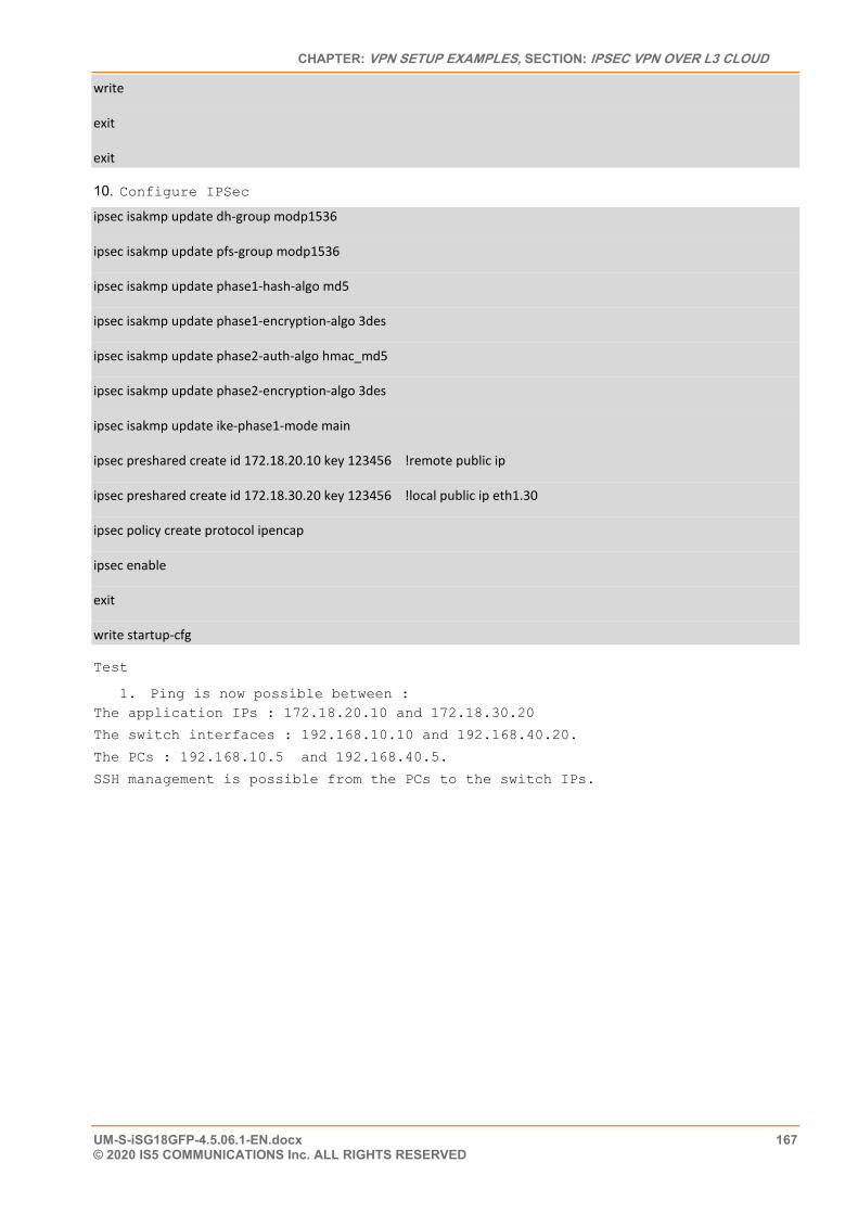
CHAPTER: VPN SETUP EXAMPLES, SECTION: IPSEC VPN OVER L3 CLOUD
UM-S-iSG18GFP-4.5.06.1-EN.docx 167 © 2020 IS5 COMMUNICATIONS Inc. ALL RIGHTS RESERVED
write
exit
exit
10. Configure IPSec
ipsec isakmp update dh-group modp1536
ipsec isakmp update pfs-group modp1536
ipsec isakmp update phase1-hash-algo md5
ipsec isakmp update phase1-encryption-algo 3des
ipsec isakmp update phase2-auth-algo hmac_md5
ipsec isakmp update phase2-encryption-algo 3des
ipsec isakmp update ike-phase1-mode main
ipsec preshared create id 172.18.20.10 key 123456 !remote public ip
ipsec preshared create id 172.18.30.20 key 123456 !local public ip eth1.30
ipsec policy create protocol ipencap
ipsec enable
exit
write startup-cfg
Test
1. Ping is now possible between : The application IPs : 172.18.20.10 and 172.18.30.20
The switch interfaces : 192.168.10.10 and 192.168.40.20.
The PCs : 192.168.10.5 and 192.168.40.5.
SSH management is possible from the PCs to the switch IPs.
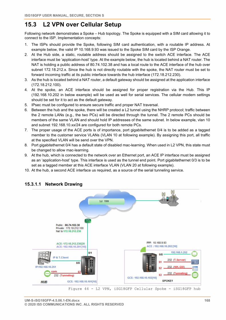
ISG18GFP USER MANUAL, SECURE, SECTION S
UM-S-iSG18GFP-4.5.06.1-EN.docx 168 © 2020 IS5 COMMUNICATIONS INC. ALL RIGHTS RESERVED
15.3 L2 VPN over Cellular Setup Following network demonstrates a Spoke – Hub topology. The Spoke is equipped with a SIM card allowing it to connect to the ISP. Implementation concepts:
1. The ISPs should provide the Spoke, following SIM card authentication, with a routable IP address. At example below, the valid IP 10.168.9.93 was issued to the Spoke SIM card by the ISP Orange.
2. At the Hub side, a static, routable address should be assigned to the switch ACE interface. The ACE interface must be ‘application-host’ type. At the example below, the hub is located behind a NAT router. The NAT is holding a public address of 80.74.102.38 and has a local route to the ACE interface of the hub over subnet 172.18.212.x. Since the hub is not directly routable with the spoke, the NAT router must be set to forward incoming traffic at its public interface towards the hub interface (172.18.212.230).
3. As the hub is located behind a NAT router, a default gateway should be assigned at the application interface (172.18.212.100).
4. At the spoke, an ACE interface should be assigned for proper registration via the Hub. This IP (192.168.10.202 in below example) will be used as well for serial services. The cellular modem settings should be set for it to act as the default gateway.
5. IPsec must be configured to ensure secure traffic and proper NAT traversal. 6. Between the hub and the spoke, there will be created a L2 tunnel using the NHRP protocol; traffic between
the 2 remote LANs (e.g., the two PCs) will be directed through the tunnel. The 2 remote PCs should be members of the same VLAN and should hold IP addresses of the same subnet. In below example, vlan 10 and subnet 192.168.10.xx/24 are configured for both remote PCs.
7. The proper usage of the ACE ports is of importance, port gigabitethernet 0/4 is to be added as a tagged member to the customer service VLANs (VLAN 10 at following example). By assigning this port, all traffic at the specified VLAN will be send over the VPN.
8. Port gigabitethernet 0/4 has a default state of disabled mac-learning. When used in L2 VPN, this state must be changed to allow mac-learning.
9. At the hub, which is connected to the network over an Ethernet port, an ACE IP interface must be assigned as an ‘application-host’ type. This interface is used as the tunnel end point. Port gigabitethernet 0/3 is to be set as a tagged member at this ACE interface VLAN (VLAN 20 at following example).
10. At the hub, a second ACE interface us required, as a source of the serial tunneling service.
15.3.1.1 Network Drawing
Figure 44 - L2 VPN, iSG18GFP Cellular Spoke - iSG18GFP hub
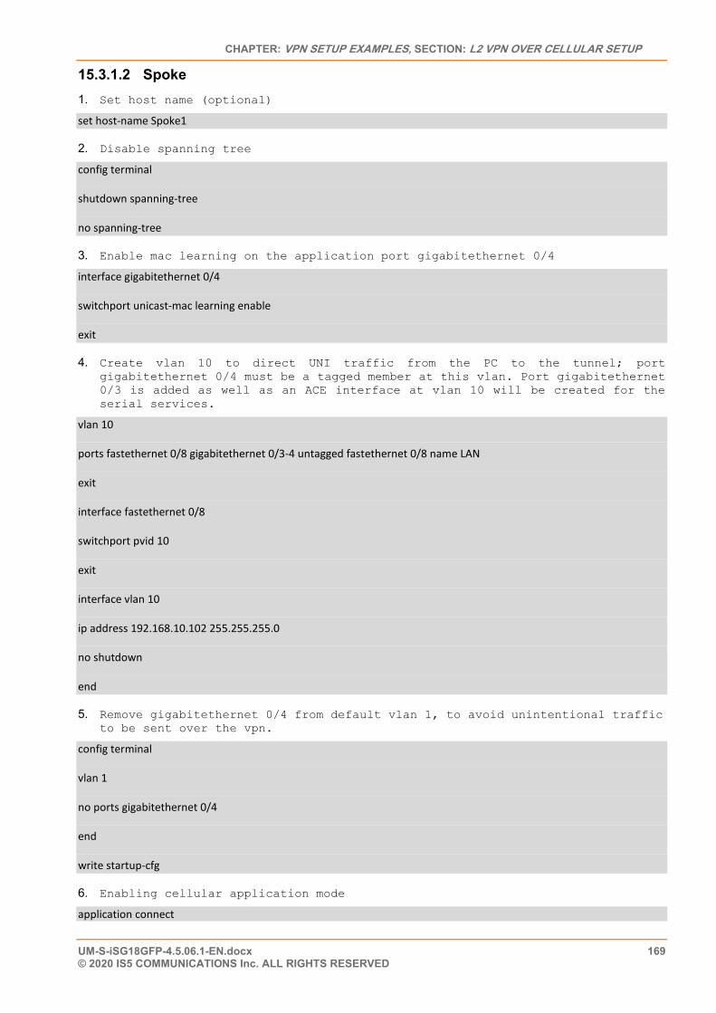
CHAPTER: VPN SETUP EXAMPLES, SECTION: L2 VPN OVER CELLULAR SETUP
UM-S-iSG18GFP-4.5.06.1-EN.docx 169 © 2020 IS5 COMMUNICATIONS Inc. ALL RIGHTS RESERVED
15.3.1.2 Spoke 1. Set host name (optional)
set host-name Spoke1
2. Disable spanning tree
config terminal
shutdown spanning-tree
no spanning-tree
3. Enable mac learning on the application port gigabitethernet 0/4
interface gigabitethernet 0/4
switchport unicast-mac learning enable
exit
4. Create vlan 10 to direct UNI traffic from the PC to the tunnel; port gigabitethernet 0/4 must be a tagged member at this vlan. Port gigabitethernet 0/3 is added as well as an ACE interface at vlan 10 will be created for the serial services.
vlan 10
ports fastethernet 0/8 gigabitethernet 0/3-4 untagged fastethernet 0/8 name LAN
exit
interface fastethernet 0/8
switchport pvid 10
exit
interface vlan 10
ip address 192.168.10.102 255.255.255.0
no shutdown
end
5. Remove gigabitethernet 0/4 from default vlan 1, to avoid unintentional traffic to be sent over the vpn.
config terminal
vlan 1
no ports gigabitethernet 0/4
end
write startup-cfg
6. Enabling cellular application mode
application connect
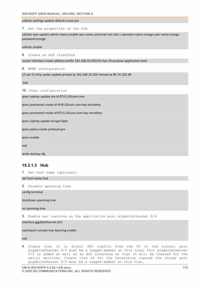
ISG18GFP USER MANUAL, SECURE, SECTION S
UM-S-iSG18GFP-4.5.06.1-EN.docx 170 © 2020 IS5 COMMUNICATIONS INC. ALL RIGHTS RESERVED
cellular settings update default-route yes
7. Set the properties of the SIM
cellular wan update admin-status enable apn-name uinternet sim-slot 1 operator-name orange user-name orange password orange
cellular enable
8. Create an ACE interface
router interface create address-prefix 192.168.10.202/24 vlan 10 purpose application-host
9. NHRP configuration
[/] vpn l2 nhrp spoke update private-ip 192.168.10.202 remote-ip 80.74.102.38
exit
10. IPSec configuration
ipsec isakmp update my-id RTU1.iS5com.com
ipsec preshared create id HUB.iS5com.com key secretkey
ipsec preshared create id RTU1.iS5com.com key secretkey
ipsec isakmp update id-type fqdn
ipsec policy create protocol gre
ipsec enable
exit
write startup-cfg
15.3.1.3 Hub 1. Set host name (optional)
set host-name Hub
2. Disable spanning tree
config terminal
shutdown spanning-tree
no spanning-tree
3. Enable mac learning on the application port gigabitethernet 0/4
interface gigabitethernet 0/4
switchport unicast-mac learning enable
exit
4. Create vlan 10 to direct UNI traffic from the PC to the tunnel; port gigabitethernet 0/4 must be a tagged member at this vlan; Port gigabitethernet 0/3 is added as well as an ACE interface at vlan 10 will be created for the serial services. Create vlan 20 for the networking towards the cloud; port gigabitethernet 0/3 must be a tagged member at this vlan.
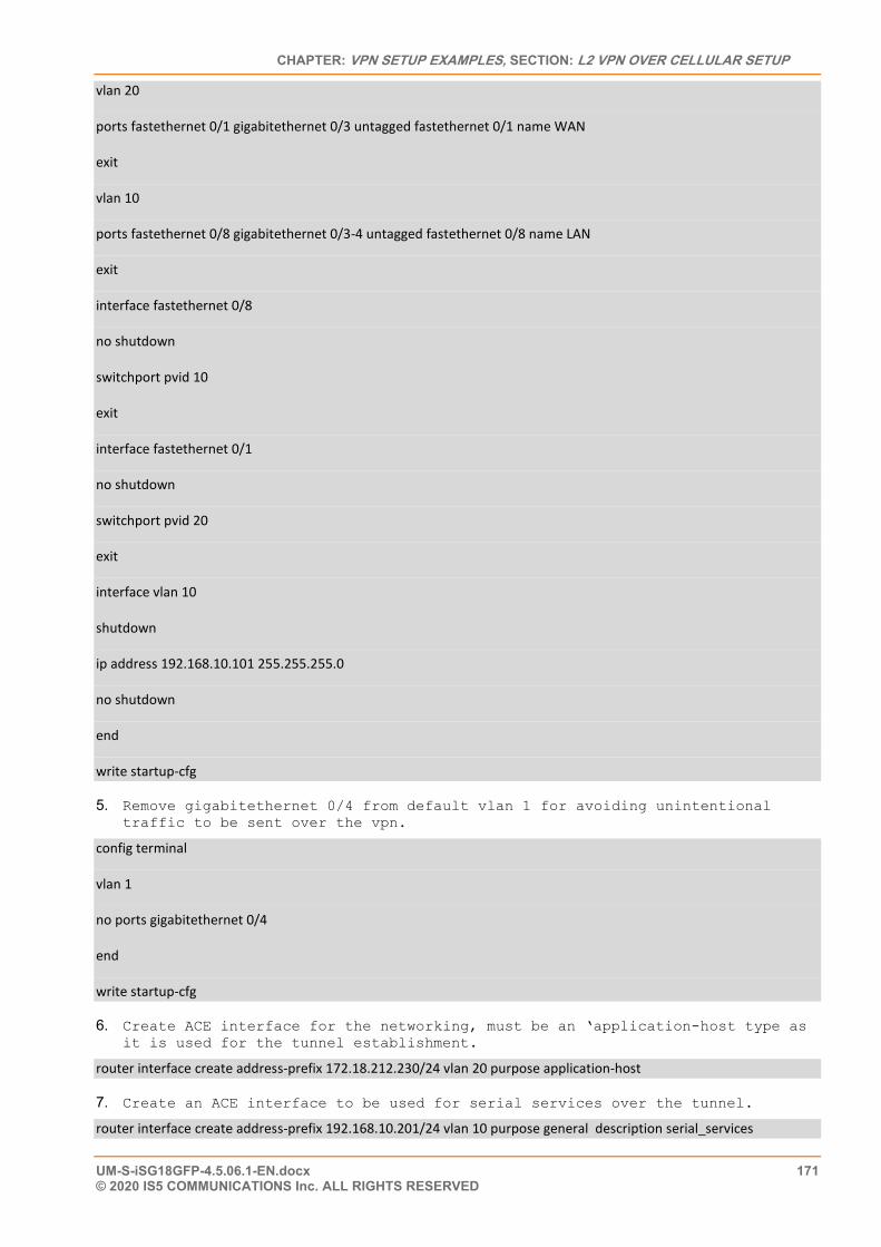
CHAPTER: VPN SETUP EXAMPLES, SECTION: L2 VPN OVER CELLULAR SETUP
UM-S-iSG18GFP-4.5.06.1-EN.docx 171 © 2020 IS5 COMMUNICATIONS Inc. ALL RIGHTS RESERVED
vlan 20
ports fastethernet 0/1 gigabitethernet 0/3 untagged fastethernet 0/1 name WAN
exit
vlan 10
ports fastethernet 0/8 gigabitethernet 0/3-4 untagged fastethernet 0/8 name LAN
exit
interface fastethernet 0/8
no shutdown
switchport pvid 10
exit
interface fastethernet 0/1
no shutdown
switchport pvid 20
exit
interface vlan 10
shutdown
ip address 192.168.10.101 255.255.255.0
no shutdown
end
write startup-cfg
5. Remove gigabitethernet 0/4 from default vlan 1 for avoiding unintentional traffic to be sent over the vpn.
config terminal
vlan 1
no ports gigabitethernet 0/4
end
write startup-cfg
6. Create ACE interface for the networking, must be an ‘application-host type as it is used for the tunnel establishment.
router interface create address-prefix 172.18.212.230/24 vlan 20 purpose application-host
7. Create an ACE interface to be used for serial services over the tunnel.
router interface create address-prefix 192.168.10.201/24 vlan 10 purpose general description serial_services
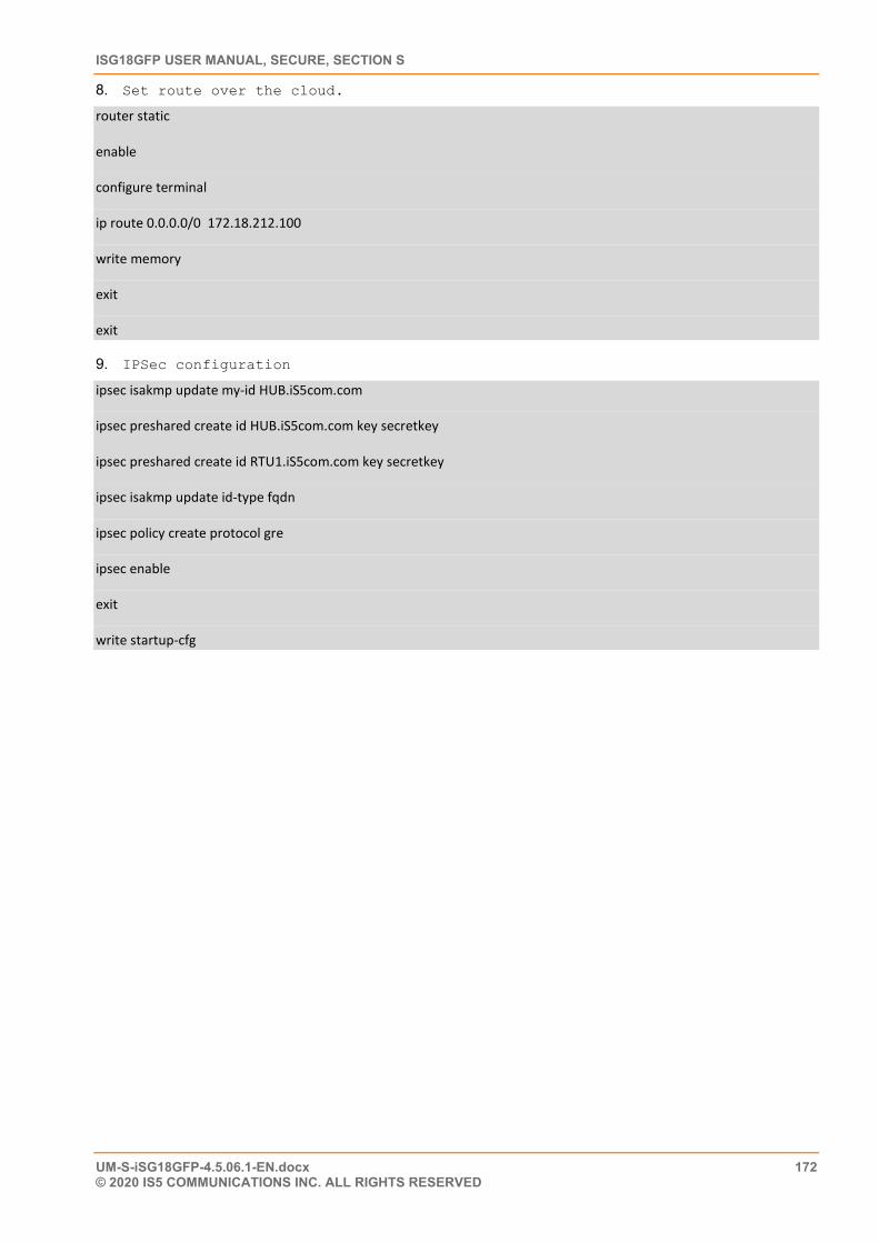
ISG18GFP USER MANUAL, SECURE, SECTION S
UM-S-iSG18GFP-4.5.06.1-EN.docx 172 © 2020 IS5 COMMUNICATIONS INC. ALL RIGHTS RESERVED
8. Set route over the cloud.
router static
enable
configure terminal
ip route 0.0.0.0/0 172.18.212.100
write memory
exit
exit
9. IPSec configuration
ipsec isakmp update my-id HUB.iS5com.com
ipsec preshared create id HUB.iS5com.com key secretkey
ipsec preshared create id RTU1.iS5com.com key secretkey
ipsec isakmp update id-type fqdn
ipsec policy create protocol gre
ipsec enable
exit
write startup-cfg
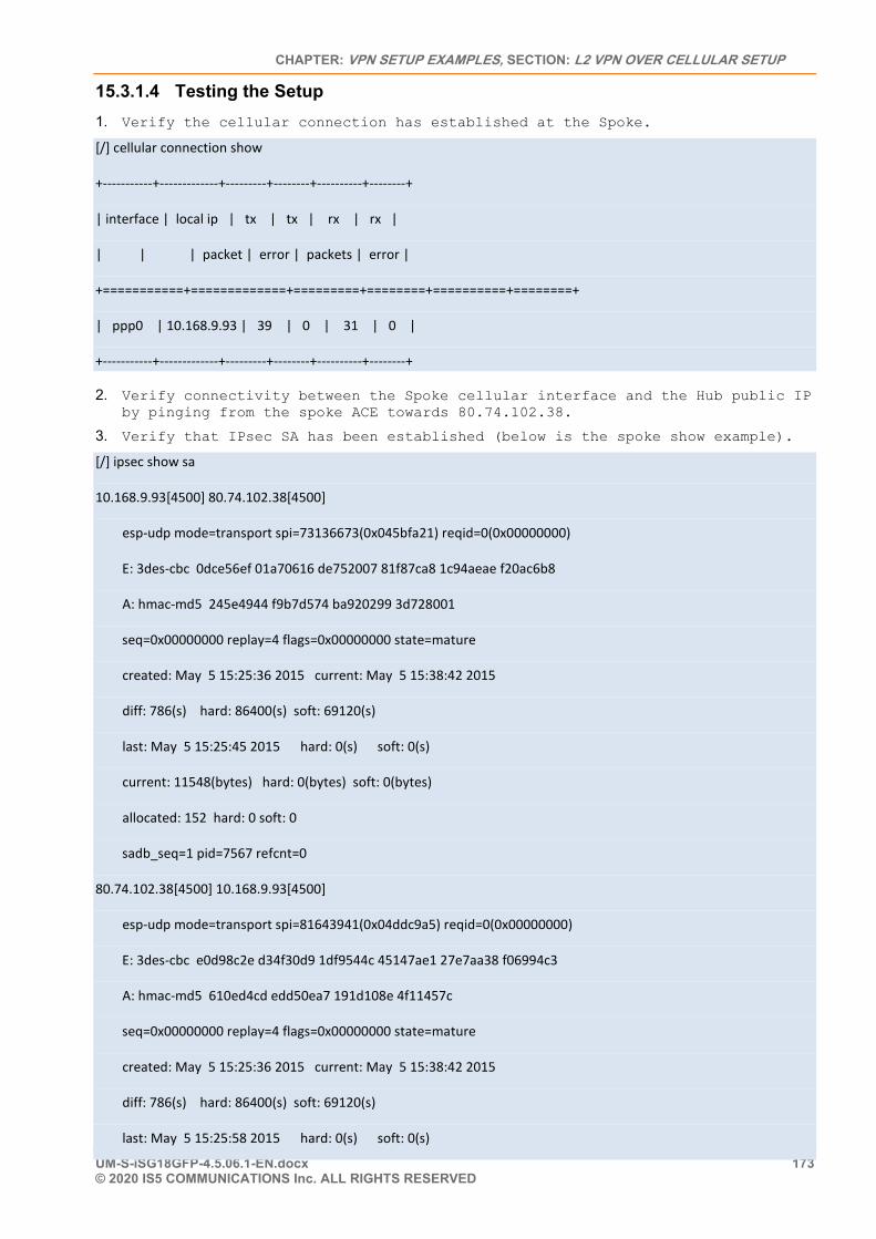
CHAPTER: VPN SETUP EXAMPLES, SECTION: L2 VPN OVER CELLULAR SETUP
UM-S-iSG18GFP-4.5.06.1-EN.docx 173 © 2020 IS5 COMMUNICATIONS Inc. ALL RIGHTS RESERVED
15.3.1.4 Testing the Setup 1. Verify the cellular connection has established at the Spoke.
[/] cellular connection show
+-----------+-------------+---------+--------+----------+--------+
| interface | local ip | tx | tx | rx | rx |
| | | packet | error | packets | error |
+===========+=============+=========+========+==========+========+
| ppp0 | 10.168.9.93 | 39 | 0 | 31 | 0 |
+-----------+-------------+---------+--------+----------+--------+
2. Verify connectivity between the Spoke cellular interface and the Hub public IP by pinging from the spoke ACE towards 80.74.102.38.
3. Verify that IPsec SA has been established (below is the spoke show example).
[/] ipsec show sa
10.168.9.93[4500] 80.74.102.38[4500]
esp-udp mode=transport spi=73136673(0x045bfa21) reqid=0(0x00000000)
E: 3des-cbc 0dce56ef 01a70616 de752007 81f87ca8 1c94aeae f20ac6b8
A: hmac-md5 245e4944 f9b7d574 ba920299 3d728001
seq=0x00000000 replay=4 flags=0x00000000 state=mature
created: May 5 15:25:36 2015 current: May 5 15:38:42 2015
diff: 786(s) hard: 86400(s) soft: 69120(s)
last: May 5 15:25:45 2015 hard: 0(s) soft: 0(s)
current: 11548(bytes) hard: 0(bytes) soft: 0(bytes)
allocated: 152 hard: 0 soft: 0
sadb_seq=1 pid=7567 refcnt=0
80.74.102.38[4500] 10.168.9.93[4500]
esp-udp mode=transport spi=81643941(0x04ddc9a5) reqid=0(0x00000000)
E: 3des-cbc e0d98c2e d34f30d9 1df9544c 45147ae1 27e7aa38 f06994c3
A: hmac-md5 610ed4cd edd50ea7 191d108e 4f11457c
seq=0x00000000 replay=4 flags=0x00000000 state=mature
created: May 5 15:25:36 2015 current: May 5 15:38:42 2015
diff: 786(s) hard: 86400(s) soft: 69120(s)
last: May 5 15:25:58 2015 hard: 0(s) soft: 0(s)
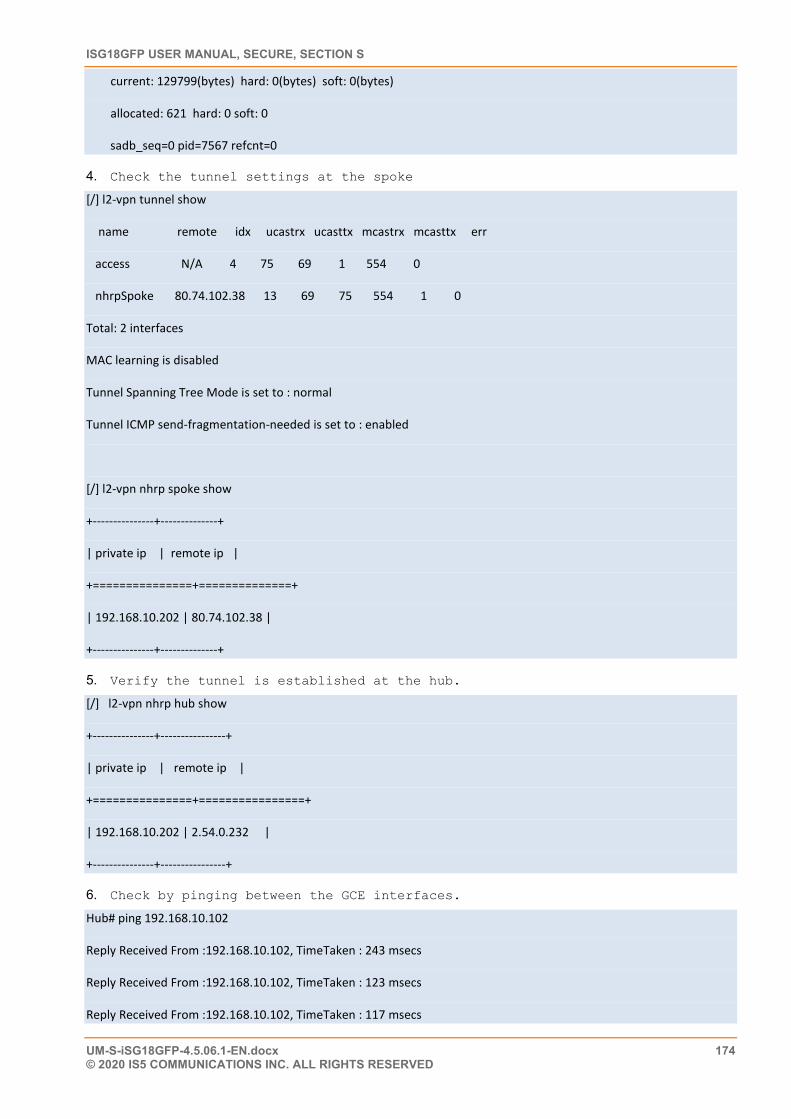
ISG18GFP USER MANUAL, SECURE, SECTION S
UM-S-iSG18GFP-4.5.06.1-EN.docx 174 © 2020 IS5 COMMUNICATIONS INC. ALL RIGHTS RESERVED
current: 129799(bytes) hard: 0(bytes) soft: 0(bytes)
allocated: 621 hard: 0 soft: 0
sadb_seq=0 pid=7567 refcnt=0
4. Check the tunnel settings at the spoke
[/] l2-vpn tunnel show
name remote idx ucastrx ucasttx mcastrx mcasttx err
access N/A 4 75 69 1 554 0
nhrpSpoke 80.74.102.38 13 69 75 554 1 0
Total: 2 interfaces
MAC learning is disabled
Tunnel Spanning Tree Mode is set to : normal
Tunnel ICMP send-fragmentation-needed is set to : enabled
[/] l2-vpn nhrp spoke show
+---------------+--------------+
| private ip | remote ip |
+===============+==============+
| 192.168.10.202 | 80.74.102.38 |
+---------------+--------------+
5. Verify the tunnel is established at the hub.
[/] l2-vpn nhrp hub show
+---------------+----------------+
| private ip | remote ip |
+===============+================+
| 192.168.10.202 | 2.54.0.232 |
+---------------+----------------+
6. Check by pinging between the GCE interfaces.
Hub# ping 192.168.10.102
Reply Received From :192.168.10.102, TimeTaken : 243 msecs
Reply Received From :192.168.10.102, TimeTaken : 123 msecs
Reply Received From :192.168.10.102, TimeTaken : 117 msecs
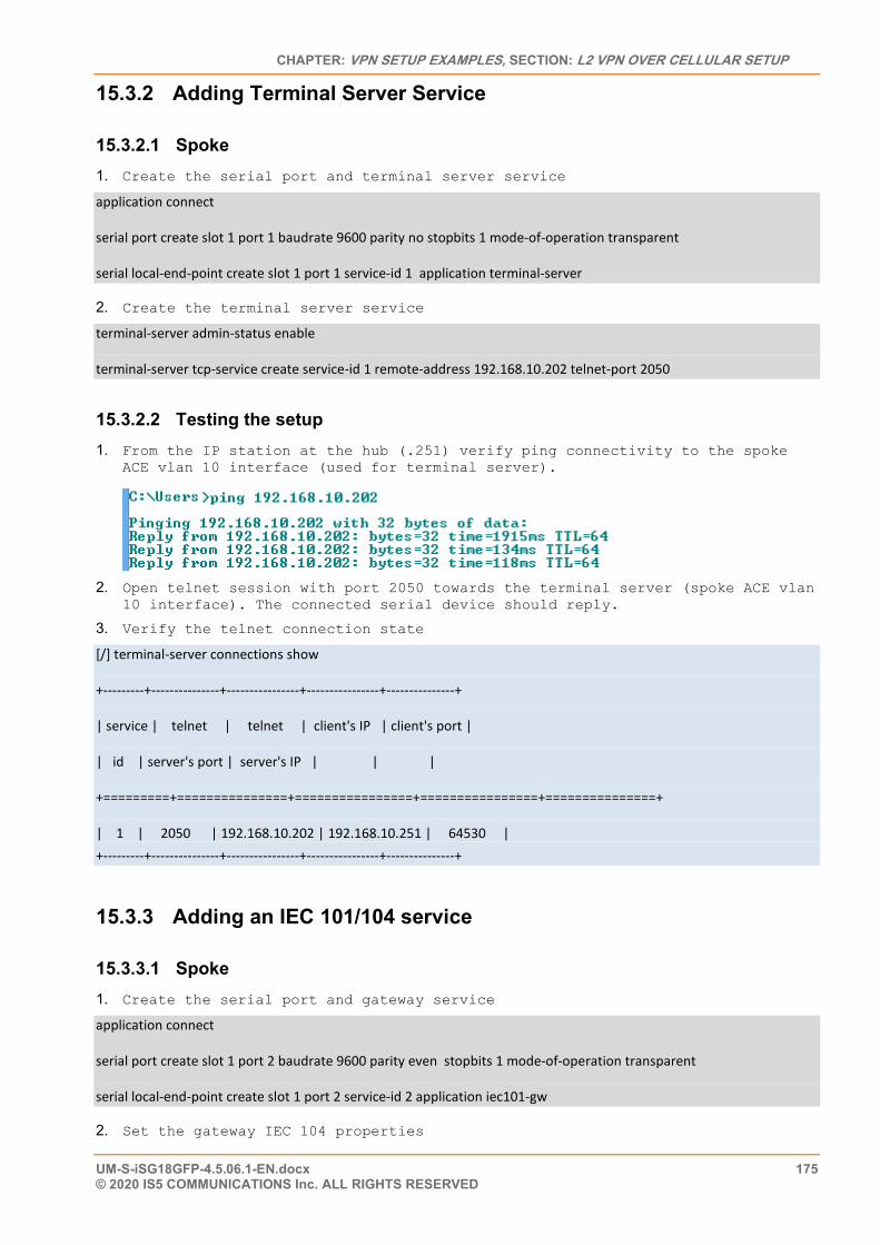
CHAPTER: VPN SETUP EXAMPLES, SECTION: L2 VPN OVER CELLULAR SETUP
UM-S-iSG18GFP-4.5.06.1-EN.docx 175 © 2020 IS5 COMMUNICATIONS Inc. ALL RIGHTS RESERVED
15.3.2 Adding Terminal Server Service
15.3.2.1 Spoke 1. Create the serial port and terminal server service
application connect
serial port create slot 1 port 1 baudrate 9600 parity no stopbits 1 mode-of-operation transparent
serial local-end-point create slot 1 port 1 service-id 1 application terminal-server
2. Create the terminal server service
terminal-server admin-status enable
terminal-server tcp-service create service-id 1 remote-address 192.168.10.202 telnet-port 2050
15.3.2.2 Testing the setup 1. From the IP station at the hub (.251) verify ping connectivity to the spoke
ACE vlan 10 interface (used for terminal server).
2. Open telnet session with port 2050 towards the terminal server (spoke ACE vlan
10 interface). The connected serial device should reply.
3. Verify the telnet connection state
[/] terminal-server connections show
+---------+---------------+----------------+----------------+---------------+
| service | telnet | telnet | client's IP | client's port |
| id | server's port | server's IP | | |
+=========+===============+================+================+===============+
| 1 | 2050 | 192.168.10.202 | 192.168.10.251 | 64530 | +---------+---------------+----------------+----------------+---------------+
15.3.3 Adding an IEC 101/104 service
15.3.3.1 Spoke 1. Create the serial port and gateway service
application connect
serial port create slot 1 port 2 baudrate 9600 parity even stopbits 1 mode-of-operation transparent
serial local-end-point create slot 1 port 2 service-id 2 application iec101-gw
2. Set the gateway IEC 104 properties
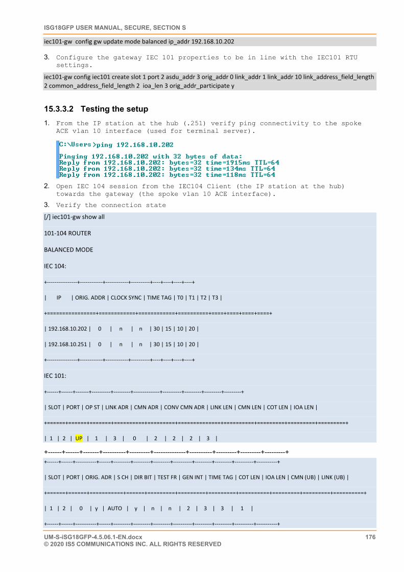
ISG18GFP USER MANUAL, SECURE, SECTION S
UM-S-iSG18GFP-4.5.06.1-EN.docx 176 © 2020 IS5 COMMUNICATIONS INC. ALL RIGHTS RESERVED
iec101-gw config gw update mode balanced ip_addr 192.168.10.202
3. Configure the gateway IEC 101 properties to be in line with the IEC101 RTU settings.
iec101-gw config iec101 create slot 1 port 2 asdu_addr 3 orig_addr 0 link_addr 1 link_addr 10 link_address_field_length 2 common_address_field_length 2 ioa_len 3 orig_addr_participate y
15.3.3.2 Testing the setup 1. From the IP station at the hub (.251) verify ping connectivity to the spoke
ACE vlan 10 interface (used for terminal server).
2. Open IEC 104 session from the IEC104 Client (the IP station at the hub)
towards the gateway (the spoke vlan 10 ACE interface).
3. Verify the connection state
[/] iec101-gw show all
101-104 ROUTER
BALANCED MODE
IEC 104:
+----------------+------------+------------+----------+----+----+----+----+
| IP | ORIG. ADDR | CLOCK SYNC | TIME TAG | T0 | T1 | T2 | T3 |
+================+============+============+==========+====+====+====+====+
| 192.168.10.202 | 0 | n | n | 30 | 15 | 10 | 20 |
| 192.168.10.251 | 0 | n | n | 30 | 15 | 10 | 20 |
+----------------+------------+------------+----------+----+----+----+----+
IEC 101:
+------+------+-------+----------+---------+--------------+----------+---------+---------+---------+
| SLOT | PORT | OP ST | LINK ADR | CMN ADR | CONV CMN ADR | LINK LEN | CMN LEN | COT LEN | IOA LEN |
+======+======+=======+==========+=========+==============+==========+=========+=========+=========+
| 1 | 2 | UP | 1 | 3 | 0 | 2 | 2 | 2 | 3 |
+------+------+-------+----------+---------+--------------+----------+---------+---------+---------+ +------+------+-----------+------+---------+---------+---------+----------+---------+---------+----------+-----------+
| SLOT | PORT | ORIG. ADR | S CH | DIR BIT | TEST FR | GEN INT | TIME TAG | COT LEN | IOA LEN | CMN (UB) | LINK (UB) |
+======+======+===========+======+=========+=========+=========+==========+=========+=========+==========+
| 1 | 2 | 0 | y | AUTO | y | n | n | 2 | 3 | 3 | 1 |
+------+------+-----------+------+---------+---------+---------+----------+---------+---------+----------+-----------+
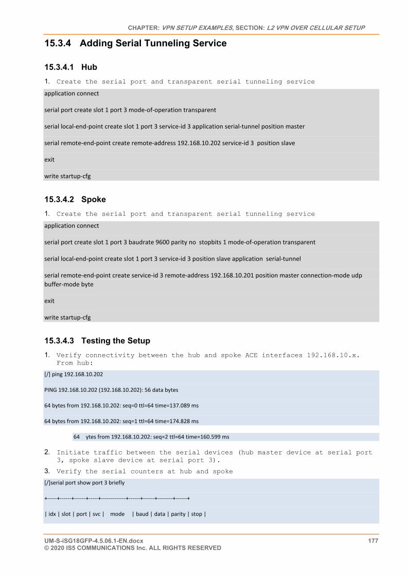
CHAPTER: VPN SETUP EXAMPLES, SECTION: L2 VPN OVER CELLULAR SETUP
UM-S-iSG18GFP-4.5.06.1-EN.docx 177 © 2020 IS5 COMMUNICATIONS Inc. ALL RIGHTS RESERVED
15.3.4 Adding Serial Tunneling Service
15.3.4.1 Hub 1. Create the serial port and transparent serial tunneling service
application connect
serial port create slot 1 port 3 mode-of-operation transparent
serial local-end-point create slot 1 port 3 service-id 3 application serial-tunnel position master
serial remote-end-point create remote-address 192.168.10.202 service-id 3 position slave
exit
write startup-cfg
15.3.4.2 Spoke 1. Create the serial port and transparent serial tunneling service
application connect
serial port create slot 1 port 3 baudrate 9600 parity no stopbits 1 mode-of-operation transparent
serial local-end-point create slot 1 port 3 service-id 3 position slave application serial-tunnel
serial remote-end-point create service-id 3 remote-address 192.168.10.201 position master connection-mode udp buffer-mode byte
exit
write startup-cfg
15.3.4.3 Testing the Setup 1. Verify connectivity between the hub and spoke ACE interfaces 192.168.10.x.
From hub:
[/] ping 192.168.10.202
PING 192.168.10.202 (192.168.10.202): 56 data bytes
64 bytes from 192.168.10.202: seq=0 ttl=64 time=137.089 ms
64 bytes from 192.168.10.202: seq=1 ttl=64 time=174.828 ms
64 ytes from 192.168.10.202: seq=2 ttl=64 time=160.599 ms
2. Initiate traffic between the serial devices (hub master device at serial port 3, spoke slave device at serial port 3).
3. Verify the serial counters at hub and spoke
[/]serial port show port 3 briefly
+-----+------+------+-----+-------------+------+------+--------+------+
| idx | slot | port | svc | mode | baud | data | parity | stop |
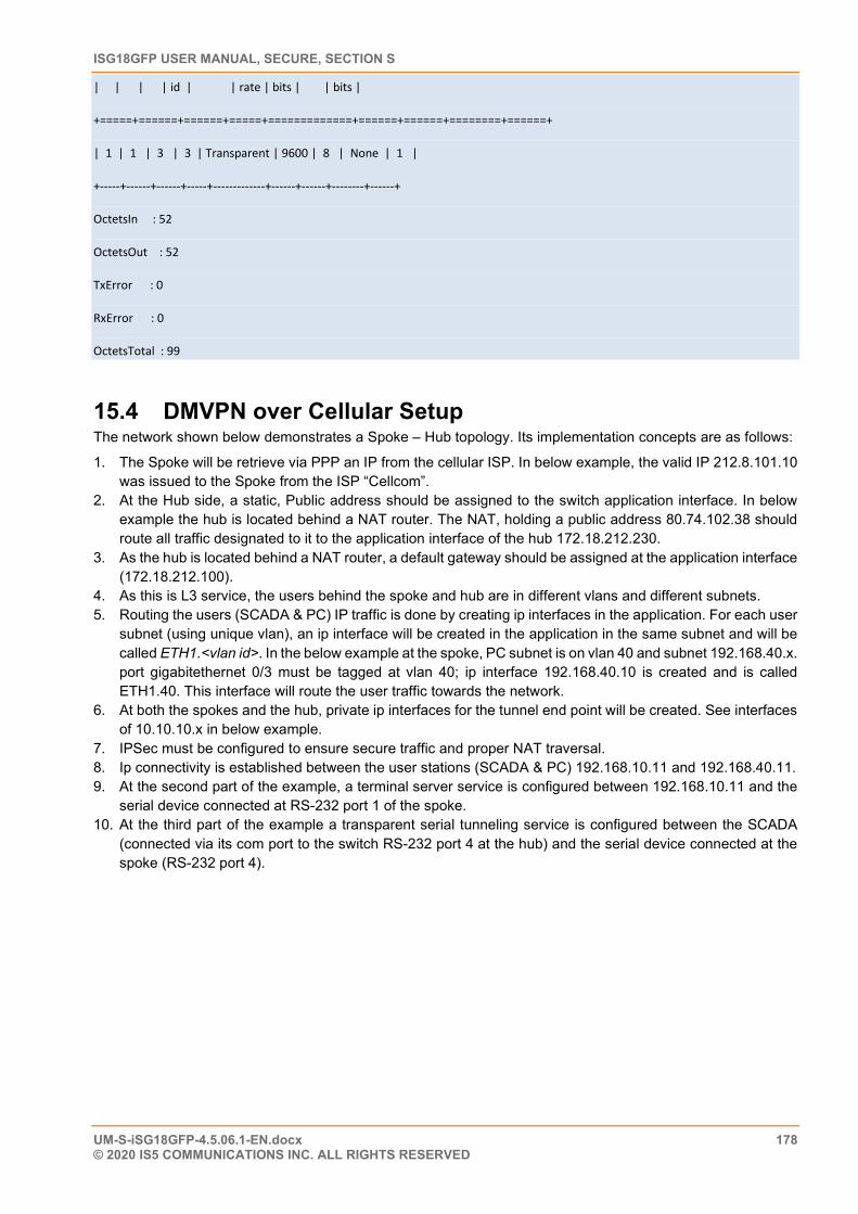
ISG18GFP USER MANUAL, SECURE, SECTION S
UM-S-iSG18GFP-4.5.06.1-EN.docx 178 © 2020 IS5 COMMUNICATIONS INC. ALL RIGHTS RESERVED
| | | | id | | rate | bits | | bits |
+=====+======+======+=====+=============+======+======+========+======+
| 1 | 1 | 3 | 3 | Transparent | 9600 | 8 | None | 1 |
+-----+------+------+-----+-------------+------+------+--------+------+
OctetsIn : 52
OctetsOut : 52
TxError : 0
RxError : 0
OctetsTotal : 99
15.4 DMVPN over Cellular Setup The network shown below demonstrates a Spoke – Hub topology. Its implementation concepts are as follows:
1. The Spoke will be retrieve via PPP an IP from the cellular ISP. In below example, the valid IP 212.8.101.10 was issued to the Spoke from the ISP “Cellcom”.
2. At the Hub side, a static, Public address should be assigned to the switch application interface. In below example the hub is located behind a NAT router. The NAT, holding a public address 80.74.102.38 should route all traffic designated to it to the application interface of the hub 172.18.212.230.
3. As the hub is located behind a NAT router, a default gateway should be assigned at the application interface (172.18.212.100).
4. As this is L3 service, the users behind the spoke and hub are in different vlans and different subnets. 5. Routing the users (SCADA & PC) IP traffic is done by creating ip interfaces in the application. For each user
subnet (using unique vlan), an ip interface will be created in the application in the same subnet and will be called ETH1.<vlan id>. In the below example at the spoke, PC subnet is on vlan 40 and subnet 192.168.40.x. port gigabitethernet 0/3 must be tagged at vlan 40; ip interface 192.168.40.10 is created and is called ETH1.40. This interface will route the user traffic towards the network.
6. At both the spokes and the hub, private ip interfaces for the tunnel end point will be created. See interfaces of 10.10.10.x in below example.
7. IPSec must be configured to ensure secure traffic and proper NAT traversal. 8. Ip connectivity is established between the user stations (SCADA & PC) 192.168.10.11 and 192.168.40.11. 9. At the second part of the example, a terminal server service is configured between 192.168.10.11 and the
serial device connected at RS-232 port 1 of the spoke. 10. At the third part of the example a transparent serial tunneling service is configured between the SCADA
(connected via its com port to the switch RS-232 port 4 at the hub) and the serial device connected at the spoke (RS-232 port 4).
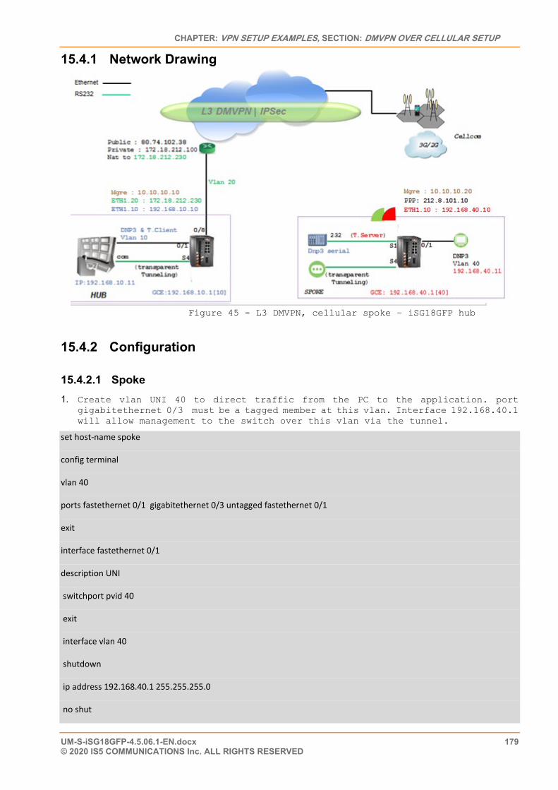
CHAPTER: VPN SETUP EXAMPLES, SECTION: DMVPN OVER CELLULAR SETUP
UM-S-iSG18GFP-4.5.06.1-EN.docx 179 © 2020 IS5 COMMUNICATIONS Inc. ALL RIGHTS RESERVED
15.4.1 Network Drawing
Figure 45 - L3 DMVPN, cellular spoke – iSG18GFP hub
15.4.2 Configuration
15.4.2.1 Spoke 1. Create vlan UNI 40 to direct traffic from the PC to the application. port
gigabitethernet 0/3 must be a tagged member at this vlan. Interface 192.168.40.1 will allow management to the switch over this vlan via the tunnel.
set host-name spoke
config terminal
vlan 40
ports fastethernet 0/1 gigabitethernet 0/3 untagged fastethernet 0/1
exit
interface fastethernet 0/1
description UNI
switchport pvid 40
exit
interface vlan 40
shutdown
ip address 192.168.40.1 255.255.255.0
no shut
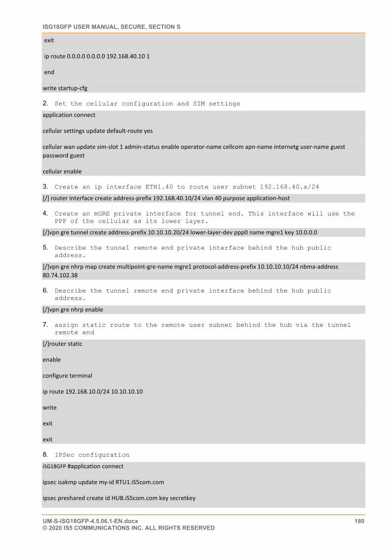
ISG18GFP USER MANUAL, SECURE, SECTION S
UM-S-iSG18GFP-4.5.06.1-EN.docx 180 © 2020 IS5 COMMUNICATIONS INC. ALL RIGHTS RESERVED
exit
ip route 0.0.0.0 0.0.0.0 192.168.40.10 1
end
write startup-cfg
2. Set the cellular configuration and SIM settings
application connect
cellular settings update default-route yes
cellular wan update sim-slot 1 admin-status enable operator-name cellcom apn-name internetg user-name guest password guest
cellular enable
3. Create an ip interface ETH1.40 to route user subnet 192.168.40.x/24
[/] router interface create address-prefix 192.168.40.10/24 vlan 40 purpose application-host
4. Create an mGRE private interface for tunnel end. This interface will use the PPP of the cellular as its lower layer.
[/]vpn gre tunnel create address-prefix 10.10.10.20/24 lower-layer-dev ppp0 name mgre1 key 10.0.0.0
5. Describe the tunnel remote end private interface behind the hub public address.
[/]vpn gre nhrp map create multipoint-gre-name mgre1 protocol-address-prefix 10.10.10.10/24 nbma-address 80.74.102.38
6. Describe the tunnel remote end private interface behind the hub public address.
[/]vpn gre nhrp enable
7. assign static route to the remote user subnet behind the hub via the tunnel remote end
[/]router static
enable
configure terminal
ip route 192.168.10.0/24 10.10.10.10
write
exit
exit
8. IPSec configuration
iSG18GFP #application connect
ipsec isakmp update my-id RTU1.iS5com.com
ipsec preshared create id HUB.iS5com.com key secretkey
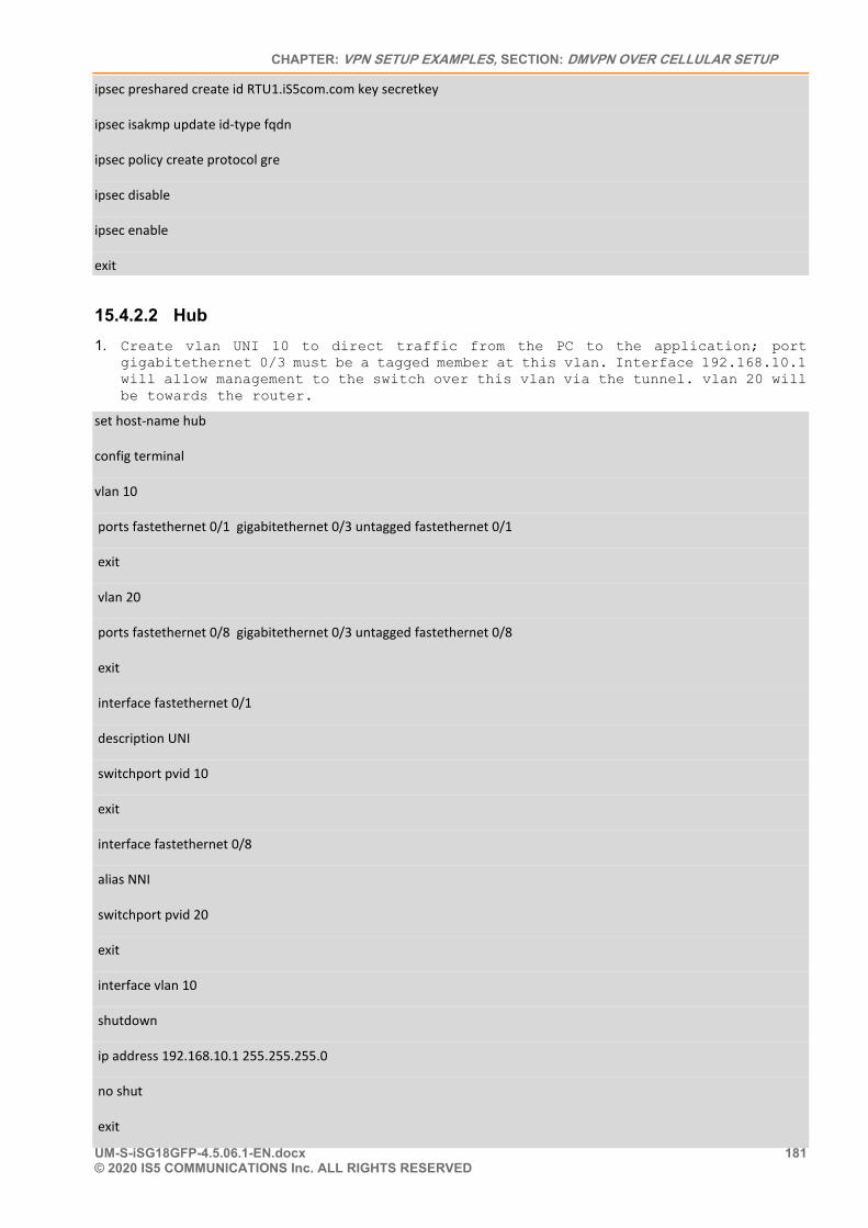
CHAPTER: VPN SETUP EXAMPLES, SECTION: DMVPN OVER CELLULAR SETUP
UM-S-iSG18GFP-4.5.06.1-EN.docx 181 © 2020 IS5 COMMUNICATIONS Inc. ALL RIGHTS RESERVED
ipsec preshared create id RTU1.iS5com.com key secretkey
ipsec isakmp update id-type fqdn
ipsec policy create protocol gre
ipsec disable
ipsec enable
exit
15.4.2.2 Hub 1. Create vlan UNI 10 to direct traffic from the PC to the application; port
gigabitethernet 0/3 must be a tagged member at this vlan. Interface 192.168.10.1 will allow management to the switch over this vlan via the tunnel. vlan 20 will be towards the router.
set host-name hub
config terminal
vlan 10
ports fastethernet 0/1 gigabitethernet 0/3 untagged fastethernet 0/1
exit
vlan 20
ports fastethernet 0/8 gigabitethernet 0/3 untagged fastethernet 0/8
exit
interface fastethernet 0/1
description UNI
switchport pvid 10
exit
interface fastethernet 0/8
alias NNI
switchport pvid 20
exit
interface vlan 10
shutdown
ip address 192.168.10.1 255.255.255.0
no shut
exit
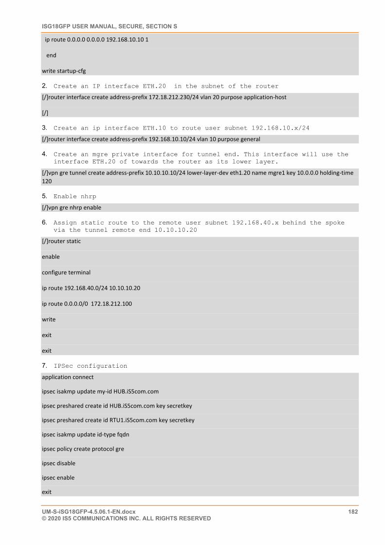
ISG18GFP USER MANUAL, SECURE, SECTION S
UM-S-iSG18GFP-4.5.06.1-EN.docx 182 © 2020 IS5 COMMUNICATIONS INC. ALL RIGHTS RESERVED
ip route 0.0.0.0 0.0.0.0 192.168.10.10 1
end
write startup-cfg
2. Create an IP interface ETH.20 in the subnet of the router
[/]router interface create address-prefix 172.18.212.230/24 vlan 20 purpose application-host
[/]
3. Create an ip interface ETH.10 to route user subnet 192.168.10.x/24
[/]router interface create address-prefix 192.168.10.10/24 vlan 10 purpose general
4. Create an mgre private interface for tunnel end. This interface will use the interface ETH.20 of towards the router as its lower layer.
[/]vpn gre tunnel create address-prefix 10.10.10.10/24 lower-layer-dev eth1.20 name mgre1 key 10.0.0.0 holding-time 120
5. Enable nhrp
[/]vpn gre nhrp enable
6. Assign static route to the remote user subnet 192.168.40.x behind the spoke via the tunnel remote end 10.10.10.20
[/]router static
enable
configure terminal
ip route 192.168.40.0/24 10.10.10.20
ip route 0.0.0.0/0 172.18.212.100
write
exit
exit
7. IPSec configuration
application connect
ipsec isakmp update my-id HUB.iS5com.com
ipsec preshared create id HUB.iS5com.com key secretkey
ipsec preshared create id RTU1.iS5com.com key secretkey
ipsec isakmp update id-type fqdn
ipsec policy create protocol gre
ipsec disable
ipsec enable
exit
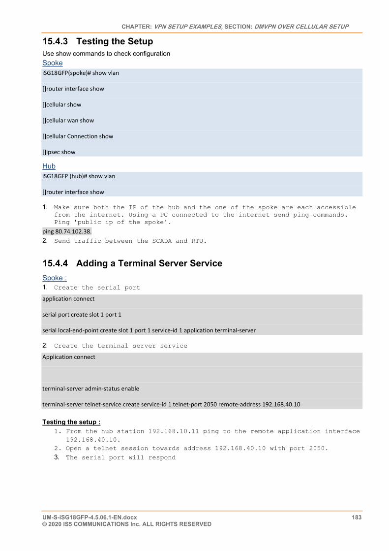
CHAPTER: VPN SETUP EXAMPLES, SECTION: DMVPN OVER CELLULAR SETUP
UM-S-iSG18GFP-4.5.06.1-EN.docx 183 © 2020 IS5 COMMUNICATIONS Inc. ALL RIGHTS RESERVED
15.4.3 Testing the Setup Use show commands to check configuration Spoke iSG18GFP(spoke)# show vlan
[]router interface show
[]cellular show
[]cellular wan show
[]cellular Connection show
[]ipsec show
Hub iSG18GFP (hub)# show vlan
[]router interface show
1. Make sure both the IP of the hub and the one of the spoke are each accessible from the internet. Using a PC connected to the internet send ping commands. Ping 'public ip of the spoke'.
ping 80.74.102.38. 2. Send traffic between the SCADA and RTU.
15.4.4 Adding a Terminal Server Service Spoke : 1. Create the serial port
application connect
serial port create slot 1 port 1
serial local-end-point create slot 1 port 1 service-id 1 application terminal-server
2. Create the terminal server service
Application connect
terminal-server admin-status enable
terminal-server telnet-service create service-id 1 telnet-port 2050 remote-address 192.168.40.10
Testing the setup : 1. From the hub station 192.168.10.11 ping to the remote application interface
192.168.40.10. 2. Open a telnet session towards address 192.168.40.10 with port 2050. 3. The serial port will respond
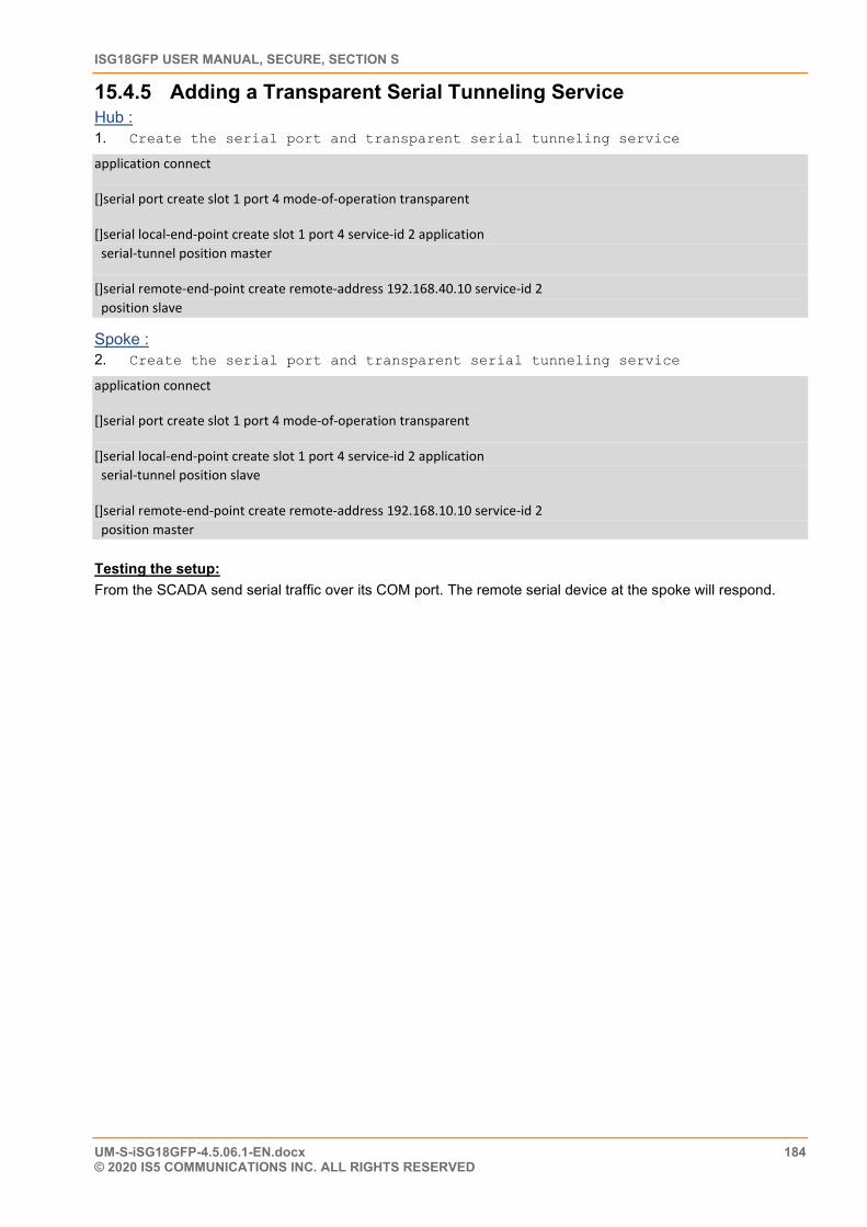
ISG18GFP USER MANUAL, SECURE, SECTION S
UM-S-iSG18GFP-4.5.06.1-EN.docx 184 © 2020 IS5 COMMUNICATIONS INC. ALL RIGHTS RESERVED
15.4.5 Adding a Transparent Serial Tunneling Service Hub : 1. Create the serial port and transparent serial tunneling service
application connect
[]serial port create slot 1 port 4 mode-of-operation transparent
[]serial local-end-point create slot 1 port 4 service-id 2 application serial-tunnel position master
[]serial remote-end-point create remote-address 192.168.40.10 service-id 2 position slave
Spoke : 2. Create the serial port and transparent serial tunneling service
application connect
[]serial port create slot 1 port 4 mode-of-operation transparent
[]serial local-end-point create slot 1 port 4 service-id 2 application serial-tunnel position slave
[]serial remote-end-point create remote-address 192.168.10.10 service-id 2 position master
Testing the setup: From the SCADA send serial traffic over its COM port. The remote serial device at the spoke will respond.