Embed Size (px)
Citation preview

Gateway Designation for Timely Communications in Instant Mesh Networks
Bo Xing, Mayur Deshpande, Sharad Mehrotra and Nalini Venkatasubramanian School of Information and Computer Sciences
University of California, Irvine {bxing, mayur, sharad, nalini}@ics.uci.edu
Abstract-In this paper, we explore how to effectively create and use "instant mesh networks", i.e., wireless mesh networks that are dynamically deployed in temporary circumstances (e.g., emergency responses) - in addition to enabling coverage for internal onsite communications, such a network will support information flow into and out of the deployment site through its gateway (i.e., the mesh router that connects to the external backhaul). We study optimizing the performance of communications (specifically in terms of latency) in an instant mesh network by intelligently selecting the gateway. We demonstrate that designating the proper gateway significantly enhances the timeliness of communications with the external backhaul. We mathematically model the "gateway designation problem" using the notion of centrality from graph theory. We propose a distributed algorithm, FACE (Fast Approximate Center Exploration), for locating the optimal gateway. FACE is an approximate algorithm that works in an efficient manner without compromising the optimality of solutions. A thorough performance evaluation shows that the gateways designated by FACE reduce latencies by up to 92 % for various types of communications, and that FACE saves transmission cost and execution time by up to 71 % in finding the gateways.
Keywords-mesh network; gateway; centrality; approximation.
I. INTRODUCTION
Today, mesh networking technologies are widely employed to support the wireless communication needs of communities, enterprises and large metropolitan areas. Given their ease of deployment, wireless mesh networks are increasingly being considered as feasible technologies that can be used to create temporary network infrastructures in situations where regular infrastructures are spotty, disrupted or non-existent. Instant mesh networks are such mesh networks that are dynamically deployed to enable robust communications. They are useful in many situations, including at crisis/incident sites, venues of conferences, entertainment and sporting events [1]. Instant mesh networks offer a cost-efficient way of rendering scalable, flexible and easily manageable communication services.
Our compelling motivation for studying instant mesh networks stems from our rich experience with building IT infrastructure testbeds for emergency response [2]. In emergency response scenarios, the ability to instantly create networking support for the rapid access to digital information is greatly desired. For instance, off-site rescue personnel create site maps (often accessing external GIS databases) and annotate them with commands that must be instantaneously disseminated to on-site first responders carrying mobile devices (i.e., data dissemination). Additionally, first responders carrying on-board sensors may communicate streams of multi-modal information (images, speech, other sensor data) to the off-site specialists who can further analyze the information to create better situational awareness of the disaster scene (i.e., data collection). In such mission-critical applications, timeliness and reliability of data delivery is of paramount importance. Due to the lack of reliable infrastructures at rescue sites, these communications
BaCkbontatency
Mesh Backbone
Clientatency .'
Mobile Clients
-----;=
Fig. I. Architecture of a Hierarchical Instant Mesh Network
are typically carried out wirelessly using variants of the 802.11 protocol at the licensed 4.9GHz public safety frequency band. Instant mesh networks come into play in situations where external information or expanded coverage is needed.
A hierarchical network architecture (illustrated in Fig. 1) is set up by introducing a group of mesh routers that blanket a region with communication capabilities. At the mesh backbone layer, the mesh routers form a multi-hop network; one or more of them serve as "gateways", connected directly to the external backhaul (via ethernet, satellite, or EVDO, etc.). Such tactical mesh routers (e.g., CoCo [3]) typically are battery-powered, and employ reactive routing protocols (e.g., SafeMesh [4]) to save on routing/energy cost. At the lowest layer, mobile clients connect to the network by talking to nearby mesh routers; further, the clients themselves can form a multi-hop network with some of them connected to a mesh router.
Operationally, the construction of a mesh backbone in an
instant mesh network is comprised of two phases - first, mesh routers are placed in such a way that they form a connected network while covering the region of interest (taking into account the constraints imposed by the physical environment); second, it is determined which router(s) should serve as gateway(s), and they are connected to the external backhaul. Given (a) the need for rapid deployment, (b) the realization that each gateway comes with a deployment cost (e.g., wiring or installing EVDO cards) and (c) that the number of deployed mesh routers is typically not very large (determined by the size/terrain of individual sites), tactical instant mesh networks often employ a single gateway so as to minimize deployment time and cost.
In this paper, we explore optimizing the performance of communications in an instant mesh network to/from the external backhaul. In our target domain, the communications do not place a heavy load on the network (hence throughput is not a major concern); however, they have stringent requirements on reliability and timeliness. Our prior work [5] partly addresses reliability issues; here, we focus on enhancing the timeliness of communications, i.e., minimizing latency. This latency is the sum of two parts - (i) Backbone Latency: the time it takes for data to flow between the gateway and the mesh routers, and (ii) Client Latency: the time it takes for data to flow between
978-1-4244-5328-3/10/$26.00 ©2010 IEEE 564
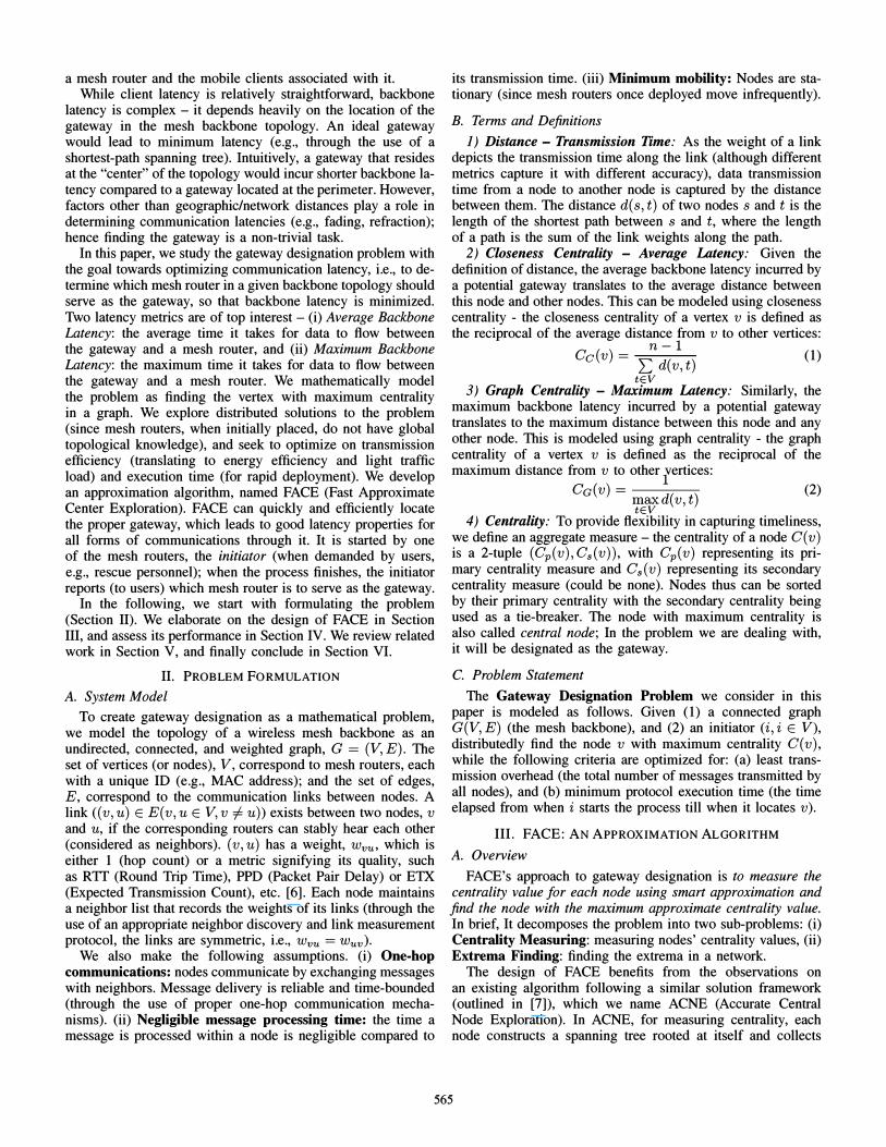
a mesh router and the mobile clients associated with it. While client latency is relatively straightforward, backbone
latency is complex - it depends heavily on the location of the gateway in the mesh backbone topology. An ideal gateway would lead to minimum latency (e.g., through the use of a shortest-path spanning tree). Intuitively, a gateway that resides at the "center" of the topology would incur shorter backbone latency compared to a gateway located at the perimeter. However, factors other than geographic/network distances play a role in determining communication latencies (e.g., fading, refraction); hence finding the gateway is a non-trivial task.
In this paper, we study the gateway designation problem with the goal towards optimizing communication latency, i.e., to determine which mesh router in a given backbone topology should serve as the gateway, so that backbone latency is minimized. Two latency metrics are of top interest - (i) Average Backbone Latency: the average time it takes for data to flow between the gateway and a mesh router, and (ii) Maximum Backbone Latency: the maximum time it takes for data to flow between the gateway and a mesh router. We mathematically model the problem as finding the vertex with maximum centrality in a graph. We explore distributed solutions to the problem (since mesh routers, when initially placed, do not have global topological knowledge), and seek to optimize on transmission efficiency (translating to energy efficiency and light traffic load) and execution time (for rapid deployment). We develop an approximation algorithm, named FACE (Fast Approximate Center Exploration). FACE can quickly and efficiently locate the proper gateway, which leads to good latency properties for all forms of communications through it. It is started by one of the mesh routers, the initiator (when demanded by users, e.g., rescue personnel); when the process finishes, the initiator reports (to users) which mesh router is to serve as the gateway.
In the following, we start with formulating the problem (Section II). We elaborate on the design of FACE in Section III, and assess its performance in Section IV. We review related work in Section V, and finally conclude in Section VI.
II. PROBLEM FORMULATION
A. System Model
To create gateway designation as a mathematical problem, we model the topology of a wireless mesh backbone as an undirected, connected, and weighted graph, G = (V, E). The set of vertices (or nodes), V , correspond to mesh routers, each with a unique ID (e.g., MAC address); and the set of edges, E, correspond to the communication links between nodes. A link «(v,u) E E(v,u E V,v =I u)) exists between two nodes, v and u, if the corresponding routers can stably hear each other (considered as neighbors). (v, u) has a weight, Wvu, which is either 1 (hop count) or a metric signifying its quality, such as RTT (Round Trip Time), PPD (Packet Pair Delay) or ETX (Expected Transmission Count), etc. [6]. Each node maintains a neighbor list that records the weights of its links (through the use of an appropriate neighbor discovery and link measurement protocol, the links are symmetric, i.e., Wvu = wuv) .
We also make the following assumptions. (i) One-hop communications: nodes communicate by exchanging messages with neighbors. Message delivery is reliable and time-bounded (through the use of proper one-hop communication mechanisms). (ii) Negligible message processing time: the time a message is processed within a node is negligible compared to
its transmission time. (iii) Minimum mobility: Nodes are stationary (since mesh routers once deployed move infrequently).
B. Terms and Definitions
1) Distance - Transmission Time: As the weight of a link depicts the transmission time along the link (although different metrics capture it with different accuracy), data transmission time from a node to another node is captured by the distance between them. The distance d(s, t) of two nodes sand t is the length of the shortest path between s and t, where the length of a path is the sum of the link weights along the path.
2) Closeness Centrality - Average Latency: Given the definition of distance, the average backbone latency incurred by a potential gateway translates to the average distance between this node and other nodes. This can be modeled using closeness centrality - the closeness centrality of a vertex v is defined as the reciprocal of the average distance from v to other vertices:
n-l Cc(v) = L d(v, t) (1) tEV
3) Graph Centrality - Maximum Latency: Similarly, the maximum backbone latency incurred by a potential gateway translates to the maximum distance between this node and any other node. This is modeled using graph centrality - the graph centrality of a vertex v is defined as the reciprocal of the maximum distance from v to other lertices:
Ca(v) = (2) maxd(v, t) tEV
4) Centrality: To provide flexibility in capturing timeliness, we define an aggregate measure - the centrality of a node C ( v ) is a 2-tuple (Cp(v),Cs(v)), with Cp(v) representing its primary centrality measure and Cs(v) representing its secondary centrality measure (could be none). Nodes thus can be sorted by their primary centrality with the secondary centrality being used as a tie-breaker. The node with maximum centrality is also called central node; In the problem we are dealing with, it will be designated as the gateway.
C. Problem Statement
The Gateway Designation Problem we consider in this paper is modeled as follows. Given (1) a connected graph G(V, E) (the mesh backbone), and (2) an initiator (i, i E V ), distributedly find the node v with maximum centrality C(v), while the following criteria are optimized for: (a) least transmission overhead (the total number of messages transmitted by all nodes), and (b) minimum protocol execution time (the time elapsed from when i starts the process till when it locates v).
III. FACE: AN ApPROXIMATION ALGORIT HM
A. Overview
FACE's approach to gateway designation is to measure the centrality value for each node using smart approximation and find the node with the maximum approximate centrality value. In brief, It decomposes the problem into two sub-problems: (i) Centrality Measuring: measuring nodes' centrality values, (ii) Extrema Finding: finding the extrema in a network.
The design of FACE benefits from the observations on an existing algorithm following a similar solution framework (outlined in [7]), which we name ACNE (Accurate Central Node Exploration). In ACNE, for measuring centrality, each node constructs a spanning tree rooted at itself and collects
565
its distances to other nodes along the spanning tree. This is essentially similar to a proactive link state routing protocol (where link information is propagated to all nodes). Although solving the problem, ACNE incurs high overhead (because of the large number of spanning trees constructed). In order to lower the cost, FACE makes several optimizations. In the following, we first elaborate on the comprising pieces of FACE.
R. Algorithm Anatomy
FACE makes uses of two types of shortest-path spanning trees. A spanning tree rooted at the initiator is called a Primary Spanning Tree (PST), which is used mainly for finding the extrema and reporting it to the initiator; a spanning tree rooted at a non-initiator node is a Secondary Spanning Tree (SST), used primarily for centrality measuring.
FACE employs an Efficient Spanning Tree Construction (ESTC) mechanism. The root (R) sends, say, ST messages to all its neighbors, which in turn propagate them to their other neighbors. An ST message carries a dist field, indicating the distance from its sender to R. A node N, upon first receiving an ST message, marks the sender of the message (P) as its parent. Before further propagating it, N adds WNP (the weight of the link between N and P) to the dist field (thus all nodes record their distances to R). Node N infers that a neighbor is its child if N never receives ST messages from it; N infers that it itself is a leaf node if it receives ST messages from all its neighbors. This mechanism avoids the use of ACK messages or timers. It works because N cannot be the parent of a node from which it receives ST messages. In implementation, N initializes its children list by replicating its neighbor list; every time it hears an ST message, N removes the sender from its children list.
1) Spanning-Tree-Based Extrema Finding: FACE uses an extrema finding scheme to find the node with maximum centrality, once each node knows its own centrality value (it will be described shortly how). The extrema is found on basis of the PST (similar to a leader election process [8]), starting at the PST leaves, each reporting its centrality value to its parent. A non-leaf node, upon receiving the reports from all its children, compares its own centrality with the maximum centralities in its children's subtrees, and sends the largest to its parent. This process is analogous to a maximin heap operation where the maximin node becomes the root of the whole heap. Thus, when the initiator (the PST root) hears from all its children, it can determine which node has the maximum centrality.
2) Centrality Approximation: An intuitive way of distributedly measuring the centrality of a node is to collect the distance from it to every other node based on a spanning tree rooted at it. However, for the central node to be found, this would involve constructing spanning trees for all nodes, which is a costly operation. Furthermore, it can be overkill, especially because, in our case, the goal is not to get the precise measure of nodes' centralities, but rather to obtain the relative ranking of their centralities. Hence, an alternative that can lower the cost by approximating centrality would be appealing.
As proposed by Eppstein [9], centrality can be estimated by taking a subset of the nodes as sample points - the centrality of a node is computed using its distances to only these sample points. While this significantly reduces computation workload, the resulting centrality value differs from the accurate by an additive error (depending on the number of sample points), making this approach even more attractive. However, this
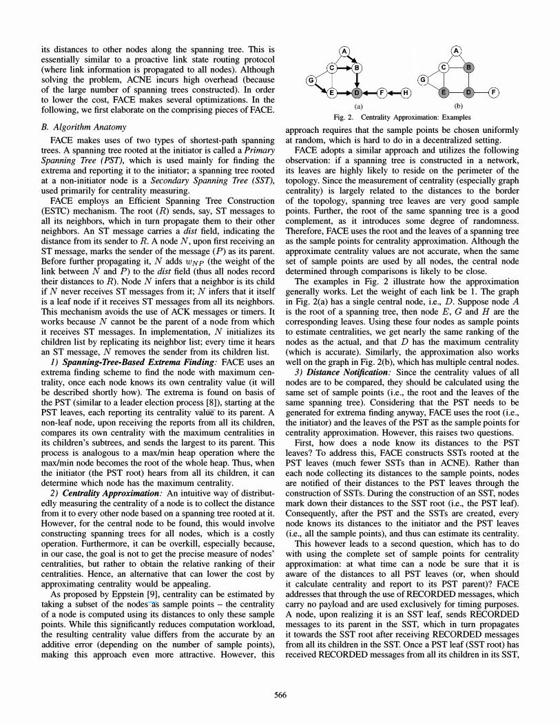
(a) (b) Fig. 2. Centrality Approximation: Examples
approach requires that the sample points be chosen uniformly at random, which is hard to do in a decentralized setting.
FACE adopts a similar approach and utilizes the following observation: if a spanning tree is constructed in a network, its leaves are highly likely to reside on the perimeter of the topology. Since the measurement of centrality (especially graph centrality) is largely related to the distances to the border of the topology, spanning tree leaves are very good sample points. Further, the root of the same spanning tree is a good complement, as it introduces some degree of randomness. Therefore, FACE uses the root and the leaves of a spanning tree as the sample points for centrality approximation. Although the approximate centrality values are not accurate, when the same set of sample points are used by all nodes, the central node determined through comparisons is likely to be close.
The examples in Fig. 2 illustrate how the approximation generally works. Let the weight of each link be 1. The graph in Fig. 2(a) has a single central node, i.e., D. Suppose node A is the root of a spanning tree, then node E, G and H are the corresponding leaves. Using these four nodes as sample points to estimate centralities, we get nearly the same ranking of the nodes as the actual, and that D has the maximum centrality (which is accurate). Similarly, the approximation also works well on the graph in Fig. 2(b), which has multiple central nodes.
3) Distance Notification: Since the centrality values of all nodes are to be compared, they should be calculated using the same set of sample points (i.e., the root and the leaves of the same spanning tree). Considering that the PST needs to be generated for extrema finding anyway, FACE uses the root (i.e., the initiator) and the leaves of the PST as the sample points for centrality approximation. However, this raises two questions.
First, how does a node know its distances to the PST leaves? To address this, FACE constructs SSTs rooted at the PST leaves (much fewer SSTs than in ACNE). Rather than each node collecting its distances to the sample points, nodes are notified of their distances to the PST leaves through the construction of SSTs. During the construction of an SST, nodes mark down their distances to the SST root (i.e., the PST leaf). Consequently, after the PST and the SSTs are created, every node knows its distances to the initiator and the PST leaves (i.e., all the sample points), and thus can estimate its centrality.
This however leads to a second question, which has to do with using the complete set of sample points for centrality approximation: at what time can a node be sure that it is aware of the distances to all PST leaves (or, when should it calculate centrality and report to its PST parent)? FACE addresses that through the use of RECORDED messages, which carry no payload and are used exclusively for timing purposes. A node, upon realizing it is an SST leaf, sends RECORDED messages to its parent in the SST, which in turn propagates it towards the SST root after receiving RECORDED messages from all its children in the SST. Once a PST leaf (SST root) has received RECORDED messages from all its children in its SST,
566
Pseudo-Code 1 FACE Algorithm Outline 1: The initiator constructs the PST. 2: Each PST leaf node constructs an SST to notify the
distances from it to other nodes. 3: Each node estimates its own centrality (based on its dis
tances to the initiator and the PST leaves). 4: Node with maximum centrality is found using the PST.
it calculates its centrality and reports to its parent. Similarly, a non-PST-Ieaf node calculates and reports its centrality once it has received REPORT messages from all its children in the PST. By doing this, FACE guarantees that every node estimates its centrality using all the PST leaves and the initiator, as sample points. This is because of the following theorems.
Theorem 1 A PST leaf receives DISTANCE messages from all other PST leaves no later than it receives RECORDED messages from all its children in its SST. Theorem 2 A nonPST-leaf node receives DISTANCE messages from all PST leaves no later than it receives REPORT messages from all its children in the PST. The proofs of the theorems (please refer to [10]) are based on the assumption that the travel time of a message along a path is proportional to the length of the path. Although in reality they are not strictly proportional, as will be shown (next section), in our experiments, the theorems still hold, and nearly all nodes calculate their centrality values based on the complete set of sample points. C. Algorithm Description
A full description of the FACE algorithm is now in order (an outline of the algorithm is presented using Pseudo-Code 1).
1. The initiator, I, sends REQUEST messages and starts constructing the PST. Other nodes record their distances to I.
2. Once a node, L, realizes that it is a PST leaf, it starts constructing an SST rooted at itself, SST(L), by sending DISTANCE messages. When a node, P, realizes it is a leaf of SST(L), it sends a RECORDED message to its parent in SST(L), say Q. Q, in turn, sends a RECORDED message to its parent once it hears from all its children. Finally, L gets RECORDED messages from all its children.
3. When L has received RECORDED messages from all its children in SST(L), it is sure that it has also received DISTANCE messages from all other PST leaves (proof provided in the next subsection). L calculates its (approximate) centrality using its distances to I and to those PST leaves, and reports it to L's parent in the PST using a REPORT message.
4. When a non-PST-Ieaf node, N, receives REPORT messages from all its children in the PST, it is sure that it has received DISTANCE messages from all PST leaves (proof provided in the next subsection). N then calculates its (approximate) centrality and compares it with the centralities it received from its children; the largest is propagated up the PST.
5. Finally I receives REPORT messages from all its children, calculates its own centrality based on its distances to all PST leaves, and determines which node has the maximum centrality.
For an example of FACE in action, please refer to [10]. IV. PERFORMANCE EVALUATION
A. Experiment Methodology
1) Experiment Framework: We use QualNet v4.0 [11] as the simulation platform. In the experiments, a mesh backbone is simulated by a group of static nodes that are uniformly
placed in a rectangular area (mimicking mesh routers each being calibrated to cover a certain region). The number of nodes varies from 10, 20 to 70, while the simulation area changes from 300m x 300m, 424m x 424m to 794m x 794m accordingly. As a result, they always form a connected multihop network, with constant node density. Nodes transmit at the same frequency (2.4GHz) with uniform bandwidth (2Mbps) and transmission range (120m by default). IEEE 802. lIb is used as the MAC protocol. Nodes run a neighbor discovery protocol, which constructs neighbor lists on the nodes (by periodically MAC-broadcasting HELLO beacons) and makes sure that the perceived neighborhood and link weights are symmetric and stable. No routing protocol is present; all communications are between neighboring nodes, using TCP as the transport protocol for ensuring reliable message exchanges.
For a given set of nodes, each simulation is run with a specific node serving as the initiator, and lasts sufficiently long for the traffic to completely vanish. Every result reported in this section is averaged over simulation runs with all possible initiators in 5 different topologies (e.g., a result for a 50-node backbone is an average from 250 simulation runs). Due to space limitation, we present only the results of the experiments that consider graph centrality as the primary centrality measure, and use hop count as the link quality metric. We observe that the results of other experiments demonstrate similar patterns.
2) Experiment Design: In the first set of experiments, we examine FACE's impact on communication performance. The goal is to discover the importance of such a gateway designation mechanism. We experiment with communications through all gateway candidates, and compare the latencies incurred by FACE-designated gateways and those of others. We particularly test two types of communications: (i) reliable dissemination from a potential gateway along the spanning tree rooted at it (inbound traffic), (ii) reliable FTP transfer from a mesh router to a potential gateway (outbound traffic).
Here, we measure (i) average backbone latency and (ii) maximum backbone latency as defined in Section I. Specifically, for inbound disseminations, average latency is the average time elapsed before a recipient receives the data, whereas maximum latency is the time elapsed before all recipients receive the data.
Our second set of experiments compare the performance of FACE against other gateway designation techniques. The comparison techniques are (i) ACNE and (ii) E-ACNE (ACNE employing ESTC as the spanning tree construction scheme). In our implementation, ACNE starts by the initiator constructing a PST (using a traditional scheme). When a node gets involved in the construction of the PST, it constructs an SST rooted at itself. Its distances to other nodes are measured based on the SST and are collected; it then calculates its centrality. Finally, the maximum centrality is found by popping the extrema along the PST to the initiator. E-ACNE is an algorithm that we make up for showing the impact of ESTC on performance improvement.
Here, we assess the efficiency of the techniques by measuring (i) transmission overhead: the average number of messages sent by each node during the process, and (ii) execution time: the time from when the initiator starts the process till when it locates the gateway. In addition, we compare their efficacy in locating the appropriate gateway using (iii) solution optimality; it is defined as the average number of hops from the designated gateway to the mesh router with maximum centrality in theory.
567

1 00' 1r-+-==: F:7AC:::;E:====1�1 :e 80 +Random-Average 1;' -&-Random-Worst ij 60 :§ :g, 40 � � 2
qo 20 30 40 50 60 70 Number of Nodes
� 1201 1r-+-==: F:7AC:::;E:====1�
-;: 100 + Random-Average g -&-Random-Worst .; 80 -' E " E .� �
20 30 40 50 60 70 Number of Nodes
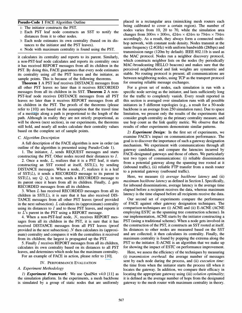
(a) Average Latency (32KB) (b) Maximum Latency (32KB)
Fig. 3. Experiment Results: Impact of FACE on Inbound Dissemination Traffic
B. Experiment Results
1) Impact of FACE on Communication Latenci�s: yve start by examining the benefit of having a gateway designatl.on mechanism (in particular, FACE). We compare the latenc!es of communications through all possible gateways. In plottmg the experiment results, we use "FACE" to indicate �he latency of communications through the mesh gateway desIgnated by FACE; we use "Random - Average" to represent the average latency of communications through a randomly selected gateway; finally, "Random - Worst" indicates the longest latency of communications through a randomly selected gateway.
First we test disseminations started from a gateway to all other �esh routers through a spanning tree rooted at it (using UDP-based ACKIretransmission mechanisms for reliable onehop communications). Large-size data, when being di.sseminated, is fragmented into 2000B chunks; the chunks are dIffused sequentially at a short interval (1 second). The results are plotted in Fig. 3. Second, we test FTP-based file transfers fr?m other mesh routers to a gateway (AODV is used as the routmg protocol). In both scenarios, we experiment �it� �56� data (mimicking text data) as well as 32KB data (mImIcking Image data), but present only the results with 32KB data, in Fig. 4. �he latencies in the FTP case are relatively long because connectIOn setup and maintenance leads to additional overheads. . .
It is shown that, regardless of the type of commumcatl On, the gateways designated by FACE consistently lead to v�ry good performance in communication timeliness. Th� latencIes they incur are always shorter than the average latencIes caused by randomly selected gateways, not to mention the �or�tcase latencies. For example, in the dissemination scenarIO, 10
terms of average backbone latency, FACE-designated gateways outperform by up to 53% on average, and by up to 9.2% compared to the worst case. This indicates that an app�op�Iate gateway plays a key role in enabling timely commumcatI�ns over instant mesh networks, and that the cost for employmg a gateway designation mechanism to loca�e it i� �orthwhile. Specifically, FACE is an effective scheme 10 achIevm� that:
2) FACE Compared against Other Gateway DesignatIOn Techniques: We first study the topologies of the mesh backbones over which our experiments are carried out. We find out the number of spanning tree leaf nodes in the topologies, so that we have a better understanding of how much FACE can save on costs. Table I lists the average degrees and the number of PST leaves in our experimented topologies. It is shown that
TABLE I MESH BACKBONE TOPOLOGIES IN OUR EXPERIMENTS
Nodes to 20 30 40 50 60 70 Degree 3.75 3.80 4.48 4.45 4.76 4.70 4.69 Leaves 5.28 9.33 13.49 17.94 2 1.5 1 25.57 30.74
601'-�--i=-+-�FA�C�E====�
+Random-Average -&-Random-Worst
qo 20 30 40 50 60 70 Number of Nodes
5001 rr=====::='====,-----� -+-FACE -;: 400 +Random-Average g -&-Random-Worst "* 300 -' § 20 E .� 10 �
20 30 40 50 60 70 Number of Nodes
(a) Maximum Latency (32KB) (b) Maximum Latency (32KB)
Fig. 4. Experiment Results: Impact of FACE on Outbound FTP Traffic
the percentage of leaf nodes ranges from 43% to 53�, and thus the sampling factor is (the percentage of sample pomts for centrality evaluation out of all nodes) in FAC� is betwe�n 4?% and 63%. This implies that FACE's centrahty approxImatIOn potentially can reduce cost by a factor of up to 55%.
We now present the comparisons of FACE and other techniques (due to space limitation, only the results from . exp�riments with 120m transmission ranges are presented, 10 FIg. 5). The transmission overhead of the algorithms is depicted in Fig. 5(a). It is shown that FACE has a significantly lower transmission overhead when compared to ACNE. It reduces messages by up to 71 %. These savings come from the optimizations FACE makes: approximating centrality causes fewer spanning trees to be generated; employing ESTC eliminates the use of ACK messages. To be specific, implied by the. EACNE curve, ESTC contributes to around 45% of the savmg in transmission overhead. Centrality approximation accounts for the remaining 55% savings - the transmission overhead of FACE is 45% to 63% that of E-ACNE (this is equivalent to the sampling factor is, and is consist�nt with o�r estimation).
To make this even clearer and to dIg deeper mto the causes of the overhead reductions, we investigate the number of sample points that FACE and ACNE use in their evaluations of centrality. As plotted in Fig. 5( c), in a backbone. of n mesh nodes, while ACNE always uses n - 1 sample pomts, FACE theoretically uses only (n -1) (I + 1) / n (I is the number of PST leaves) sample points. Moreover, Fig. 5(c) shows that F�CE in executions uses roughly the same number of sample pomts as in theory (indicated by the curve FACE(th)). This implies that nearly all nodes calculate their centralities based. on the complete set of sample points; Theorems 1 and 2 stIll hold even in cases where the underlying assumption is relaxed.
Next we look at the execution time of the algorithms. As illustrated by Fig. 5(b), FACE executes in shorter time than both ACNE and E-ACNE, though the gap is not significant (because they all have the same time complexity, which is O( d) .whe�e d is the diameter of the mesh backbone). The reductIOn 10
execution time is attributed to (i) the low transmission overhead of FACE causing less congestion in the wireless medium, and (ii) FACE's efficient spanning tree construction scheme (ESTC) eliminating the use of ACK messages and timers.
Solution Optimality: As depicted in Fig. 5(d), the aver�ge distance from the FACE-designated gateways to the theoretIcal results is fairly small and is very close to that of the ACNEdesignated ones. FACE achieves this by using the proper sample points for centrality approximation. Thus: the accuracy of �he approximation is not significantly undermmed, and t�� relatIve ranking of nodes based on their approximate centrahties stays close to the accurate. The discrepancy between FACE/ACNE's solutions and the theoretical results is because the distances
568

500 1r+===
F"'
A'=C
=E
=;-�-------::;""
400 +E-ACNE -8-ACNE
300
70
500r;=+=== F"'A'= C=E ==;-----�
�400 +E-ACNE Q) -8-ACNE � 300
,g 200 "
al .n 100
Number of Nodes 70
80 �==�==,------, -E1 +FACE � 60 +FACE(th) Q) -8-ACNE a. E
ell 40 a
20 30 40 50 60 70 Number of Nodes
3r;=+� F�AC�E�----------'
� -8-ACNE � 2 :a o "
g 1 "
" (IJ
20 30 40 50 60 70 Number of Nodes
(a) Transmission Overhead (b) Execution Time (c) Sample Points (d) Solution Optimality
Fig. 5. Experiment Results: FACE Compared against Other Gateway Designation Techniques
measured through dynamically constructed spanning trees may be inconsistent with what is calculated statically on a graph.
V. RELATED WORK
1) Wireless Mesh Networks (WMNs): WMNs initially emerged as networking technologies with a wide range of applications: from neighborhood networking [12] [13] [14] and enterprise networking [15] to building metropolitan area networks targeted towards security surveillance and emergency responses [16]. Many research efforts have been dedicated to the characterization of the capacity of WMNs [17] [181- As a measure to improve throughput, much work has been done on routing in WMNs, for instance, by utilizing multiple channels and/or multiple radio interfaces [19] [20], developing routing metrics that select high-throughput paths [21] [22], etc ..
2) Gateway Designation: The gateway designation problem in WMNs has been addressed from various perspectives. Some prior work aims to minimize the number of gateways while satisfying users' bandwidthlQoS requirements [23] [241- Some other work assumes the number of gateways to be deployed is given, and seeks to maximize the throughput of the WMN through proper placement of the gateways [25] [26] [271-Further, [28] studies the problem of adding new gateways to an existing WMN, the goal being to maximize the capacity gain.
3) Centrality: The notion of centrality has been widely used in social network analysis [29], and recently has also been applied to research in wireless networks [30] [31]. Evaluating centrality for all vertices in a graph involves solving the AllPairs Shortest-Paths (APSP) problem, and could be slow with large graphs. Besides the work presented in [9] (which inspires the optimization adopted by FACE), some other studies have also addressed the approximation of centrality (e.g., betweenness centrality) [32] [33].
VI. CONCLUDING REMARKS
In this paper, we study gateway designation in instant mesh networks as a primitive for enhancing the timeliness of communications between client devices and the external backhaul. We identify and showcase the importance of gateway designation, and develop techniques that are message-efficient and timeefficient in locating the proper gateways (thus being easily employable in the quick deployment of mesh networks). We plan on implementing our techniques on real mesh routers (adapted from commercial products), and further test their performance during future emergency response drills.
REFERENCES
[I] "Firetide," http://www.firetide.com. [2] "Responsephere," http://www . responsphere .org. [3] "Coco communications," http://www.cococorp.com.
[4] A. A. Pirzadaa, M. Portmanna, R. Wisharta, and 1. Indulska, "Safemesh: A wireless mesh network routing protocol for incident area communications," Pervasive and Mobile Computing, Apr 2009.
[5] B. Xing, S. Mehrotra, and N. Venkatasubramanian, "Radcast: Enabling reliability guarantees for content dissemination in ad hoc networks," in INFOCOM, 2009.
[6] R. Draves, 1. Padhye, and B. ZiII, "Comparison of routing metrics for static multi-hop wireless networks," in ACM. SIGCOMM, 2004.
[7] E. Korach, D. Rotem, and N. Santoro, "Distributed algorithms for finding centers and medians in networks," ACM Trans. Program. Lang. Syst., vol. 6, no. 3, pp. 380 - 40 1, Jul. 1984.
[8] S. Vasudevan, 1. Kurose, and D. Towsley, "Design and analysis of a leader election algorithm for mobile ad hoc networks," in ICNP, 2004.
[9] D. Eppstein and 1. Wang, "Fast approximation of centrality," in 12th Symp. Discrete Algorithms, Jan. 200 1, pp. 228 - 229.
[ 10] B. Xing, M. Deshpande, S. Mehrotra, and N. Venkatasubramanian, "Gateway designation for timely communications in instant mesh networks," Tech. Rep., Aug. 2009.
[II] "Qualnet 4.0," http://www.scalable-networks.com. [ 12] "Cnt," http://wcn . cnt .org. [B] "Microsoft research," http://research.microsoft.com/mesh. [ 14] "Broaderband," http://www.communitymesh.com. [ 15] "Strix systems," http://www.strixsystems.com. [ 16] "Now wielress," http://mesh.nowwireless . com. [ 17] M. Kodialam and T. Nandagopal, "Characterizing the capacity region in
multi-radio multi-channel wireless mesh networks," in MobiCom, 2005. [ 18] P. Zhou, X. Wang, and R. Rao, "Asymptotic capacity of infrastructure
wireless mesh networks," IEEE Transactions on Mobile Computing, 2008. [ 19] A. Adya, P. Baht, 1. Padhye, A. Wolman, and L. Zhou, "A multi-radio
unification protocol for ieee 802.1 1 wireless networks," in BroadNets, 2004, pp. 344 - 354.
[20] M. Alicherry, R. Bhatia, and L. Li, "Joint channel assignment and routing for throughput optimization in multi-radio wireless mesh networks," in MobiCom, 2005.
[2 1] R. Draves, 1. Padhye, and B. ZiII, "Routing in multi-radio, multi-hop wireless mesh networks," in Mobicom, 2004.
[22] y. Yang, 1. Wang, and R. Kravets, "Designing routing metrics for mesh networks," in WiMesh, 2005.
[23] R. Chandra, L. Qiu, K. Jain, and M. Mahdian, "Optimizing the placement of integration points in multi-hop wireless networks," in ICNP, 2004.
[24] B. Aoun, R. Boutaba, Y. Iraqi, and G. Kenward, "Gateway placement optimization in wireless mesh networks with qos constraints," JSAC, Nov 2006.
[25] P. Zhou, B. S. Manoj, and R. Rao, "A gateway placement algorithm in wireless mesh networks," in W ICON, 2007.
[26] F. Li, Y. Wang, X.-Y. Li, A. Nusairat, and Y. Wu, "Gateway placement for throughput optimization in wireless mesh networks," Mobile Networks and Applications, Mar 2008.
[27] S. Muthaiah and C. Rosenberg, "Single gateway placement in wireless mesh networks," in ISCN, 2008.
[28] 1. Robinson, M. Uysal, R. Swaminathan, and E. Knightly, "Adding capacity points to a wireless. mesh network using local search," in INFOCOM, 2008.
[29] K. Okamoto, W. Chen, and X.-Y. Li, "Ranking of closeness centrality for large-scale social networks," in Frontiers in Algorithmics, 2008.
[30] S. P. Fekete, M. Kaufmann, A. Kroller, and K. Lehmann. (2005) A new approach for boundary recognition in geometric sensor networks. [Online]. Available: arxiv.org/ps3ache/cs/pdf/0508/0508006.pdf
[3 1] E. Daly and M. Haahr, "Social network analysis for routing in disconnected delay-tolerant manets," in MobiHoc, 2007.
[32] D. A. Bader, S. Kintali, K. Madduri, and M. Mihail, "Approximating betweenness centrality," in Algorithms and Models for the Web-Graph, 2007.
[33] R. Geisberger, P. Sanders, and D. Schultes, "Better approximation of betweenness centrality," in ALENEX, 2008.
569