Embed Size (px)
Citation preview
Formwork launching girders
Autor(en): Schlub, Peter
Objekttyp: Article
Zeitschrift: IABSE surveys = Revue AIPC = IVBH Berichte
Band (Jahr): 5 (1981)
Heft S-18: Formwork launching girders
Persistenter Link: http://doi.org/10.5169/seals-46576
PDF erstellt am: 11.07.2022
NutzungsbedingungenDie ETH-Bibliothek ist Anbieterin der digitalisierten Zeitschriften. Sie besitzt keine Urheberrechte anden Inhalten der Zeitschriften. Die Rechte liegen in der Regel bei den Herausgebern.Die auf der Plattform e-periodica veröffentlichten Dokumente stehen für nicht-kommerzielle Zwecke inLehre und Forschung sowie für die private Nutzung frei zur Verfügung. Einzelne Dateien oderAusdrucke aus diesem Angebot können zusammen mit diesen Nutzungsbedingungen und denkorrekten Herkunftsbezeichnungen weitergegeben werden.Das Veröffentlichen von Bildern in Print- und Online-Publikationen ist nur mit vorheriger Genehmigungder Rechteinhaber erlaubt. Die systematische Speicherung von Teilen des elektronischen Angebotsauf anderen Servern bedarf ebenfalls des schriftlichen Einverständnisses der Rechteinhaber.
HaftungsausschlussAlle Angaben erfolgen ohne Gewähr für Vollständigkeit oder Richtigkeit. Es wird keine Haftungübernommen für Schäden durch die Verwendung von Informationen aus diesem Online-Angebot oderdurch das Fehlen von Informationen. Dies gilt auch für Inhalte Dritter, die über dieses Angebotzugänglich sind.
Ein Dienst der ETH-BibliothekETH Zürich, Rämistrasse 101, 8092 Zürich, Schweiz, www.library.ethz.ch
http://www.e-periodica.ch
IABSE PERIODICA 4/1981 IABSE SURVEYS S-18/81 45
Formwork Launching Girders
Cintres autolanceurs
Vorschubrüstungen
Peter SCHLUß
Project EngineerLosinger Ltd.,
Berne, Switzerland
SUMMARYA survey is made of the State of the art in bridge construction with formwork launchinggirders, available products on the market, their characteristics, capacities and applications.Girders for the placing of precast segments in free cantilevering bridge are not considered inthis survey.
RiSUMlL'article presente l'etat actuel de la conception de construction des tabliers de pont aveccintres autolanceurs. II donne une description des cintres existant sur le marche, leurscaracteristiques, capacites et applications. Les cintres pour la mise en place des voussoirsprefabriques de ponts en encorbellement ne sont pas traites dans l'article.
ZUSAMMENFASSUNGDer vorliegende Artikel gibt einen kurzen Überblick über die Möglichkeiten des Einsatzes vonVorschubrüstungen im Brückenbau. Vorhandene Rüstungstypen, ihre Leistungsfähigkeitund Anwendung werden vorgestellt. Versetzgeräte für vorfabrizierte Elemente im Freivorbauwerden in diesem Artikel nicht behandelt.
46 IABSE SURVEYS S-18/81 iabse periodica 4/1981 -#m
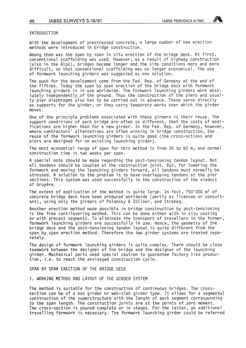
INTRODUCTION
With the development of prestressed concrete, a large number of new erectionmethods were introduced in bridge construction.Among them was the span by span in situ erection of the bridge deck. At first,conventional scaffolding was used. However, as a result of highway construction(also in the Alps), bridges became longer and the site conditions more and moredifficult, so that conventional scaffolding was no longer economical. The useof formwork launching girders was suggested as one Solution.The push for the development came from the Fed. Rep. of Germany at the end ofthe fifties. Today the span by span erection of the bridge deck with formworklaunching girders is in use worldwide. The formwork launching girders work abso-lutely independently of the ground. Thus the construction of the piers and usually
pier diaphragms also has to be carried out in advance. These serve directlyas supports for the girder, or they carry temporary works over which the girdermoves.
One of the principle problems associated with these girders is their reuse. The
support conditions of each bridge are often so different, that the costs ofmodifications are higher than for a new girder. In the Fed. Rep. of Germany, however,where contractors' alternatives are often winning in bridge construction, thereuse of the formwork launching girders is quite good (the cross-sctions andpiers are designed for an existing launching girder).The most economical ränge of span for this method is from 30 to 60 m, and normalconstruction time is two weeks per span.A special note should be made regarding the post-tensioning tendon layout. Notall tendons should be coupled at the construction Joint. But, for lowering theformwork and moving the launching girders forward, all tendons must normally bestressed. A Solution to the problem is to have overlapping tendons at the piersections. This system was used successfully in the construction of the viaductof Gruyere.The extent of application of the method is quite large. In fact, 750'000 m2 ofconcrete bridge deck have been produced worldwide (partly as licensee or Consultant),
using only the girders of Polensky & Zöllner, and Strabag.Another erection method made possible in bridge construction by post-tensioningis the free cantilevering method. This can be done either with in situ castingor with precast segments. To eliminate the transport of travellers in the former,formwork launching girders are successfully in use. Hence, the geometry of thebridge deck and the post-tensioning tendon layout is quite different from thespan by span erection method. Therefore the two girder Systems are treated sepa-rately.The design of formwork launching girders is quite complex. There should be closeteamwork between the designer of the bridge and the designer of the launchinggirder. Mechanical parts need special caution to guarantee factory like production,
i.e. to reach the envisaged construction cycle.
SPAN BY SPAN ERECTION OF THE BRIDGE DECK
1. WORKING METHOD AND LAYOUT OF THE GIRDER SYSTEM
The method is suitable for the construction of continuous bridges. The cross-section can be of a box girder or web-slab girder type. It allows for a segmentalconstruction of the superstructure with the length of each segment correspondingto the span length. The construction joints are at the points of zero moment.The cross-section is poured complete or in stages. For the latter, an additionaltravel!ing formwork is necessary. The formwork launching girder could be referred
IABSE PERIODICA 4/1981 IABSE SURVEYS S-18/81 47
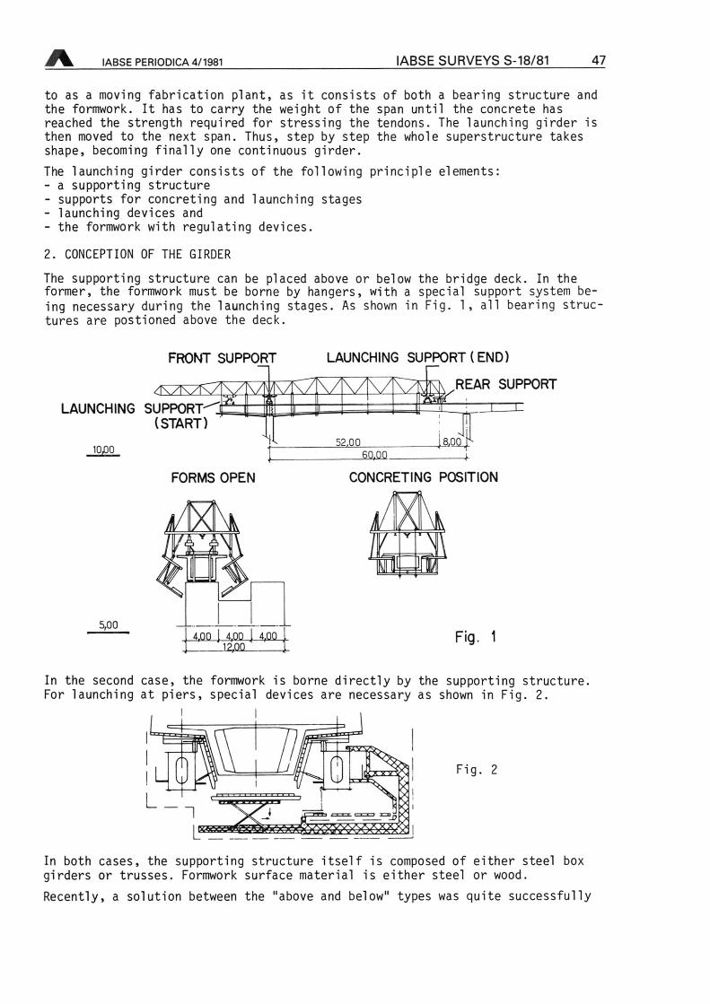
to as a moving fabrication plant, as it consists of both a bearing structure andthe formwork. It has to carry the weight of the span until the concrete hasreached the strength required for stressing the tendons. The launching girder isthen moved to the next span. Thus, step by step the whole superstructure takesshape, becoming finally one continuous girder.The launching girder consists of the following principle elements:- a supporting structure- supports for concreting and launching stages- launching devices and- the formwork with regulating devices.
2. CONCEPTION OF THE GIRDER
The supporting structure can be placed above or below the bridge deck. In theformer, the formwork must be borne by hangers, with a special support system being
necessary during the launching stages. As shown in Fig. 1, all bearing structures
are postioned above the deck.
FRONT SUPPORT
LAUNCHING SUPPORT(START)
LAUNCHING SUPPORT (END)
.REAR SUPPORT
10,00
s =m1
UqoX52,0060.00
FORMS OPEN
5,004.00 I 4.00 1 4.00
12,00
CONCRETING POSITION
Fig. 1
In the second case, the formwork is borne directly by the supporting structure.For launching at piers, special devices are necessary as shown in Fig. 2.
i I
Fig. 2
=4=
iL
In both cases, the supporting structure itself is composed of either steel boxgirders or trusses. Formwork surface material is either steel or wood.
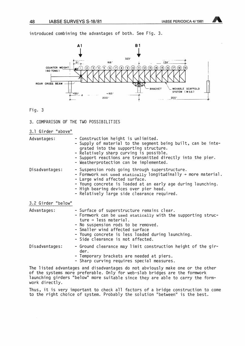
Recently, a Solution between the "above and below" types was quite successfully
48 IABSE SURVEYS S-18/81 IABSE PERIODICA 4/1981
introduced combining the advantages of both. See Fig. 3.
B1AI
523
68'
»EIGHT| 1^,(7) (i) (i)l?,^ (5) (7) (ä)(l) @@©©@@©(!9COUNTER
[60 TONS 1
BRACKET ^MOVABLE SCAFFOLDSYSTEM (M SS
~!65f
2QQ200
REAR CROSS BEAM
Fig. 3
3. COMPARISON OF THE TWO POSSIBILITIES
3.1 Girder "above"
Advantages:
Disadvantages:
- Construction height is unlimited.- Supply of material to the segment being built, can be
integrated into the supporting structure.- Relatively sharp curving is possible.- Support reactions are transmitted directly into the pier.- Weatherprotection can be implemented.
- Suspension rods going through superstructure.- Formwork not used statically longitudinally ¦*¦ more material.- Large wind affected surface.- Young concrete is loaded at an early age during launching.- High bearing devices over pier head.- Relatively large side clearance required.
3.2 Girder "below"
Advantages: - Surface of superstructure remains clear.- Formwork can be used statically with the supporting structure
¦+ less material- No Suspension rods to be removed.- Smaller wind affected surface- Young concrete is less loaded during launching.- Side clearance is not affected.
Disadvantages: - Ground clearance may limit construction height of the gir¬der.
- Temporary brackets are needed at piers.- Sharp curving requires special measures.
The listed advantages and disadvantages do not abviously make one or the otherof the Systems more preferable. Only for web-slab bridges are the formworklaunching girders "below" more suitable since they are able to carry the formwork
directly.Thus, it is very important to check all factors of a bridge construction to cometo the right choice of system. Probably the Solution "between" is the best.
IABSE PERIODICA 4/1981 IABSE SURVEYS S-18/81 49
3.3 Weight of Girders
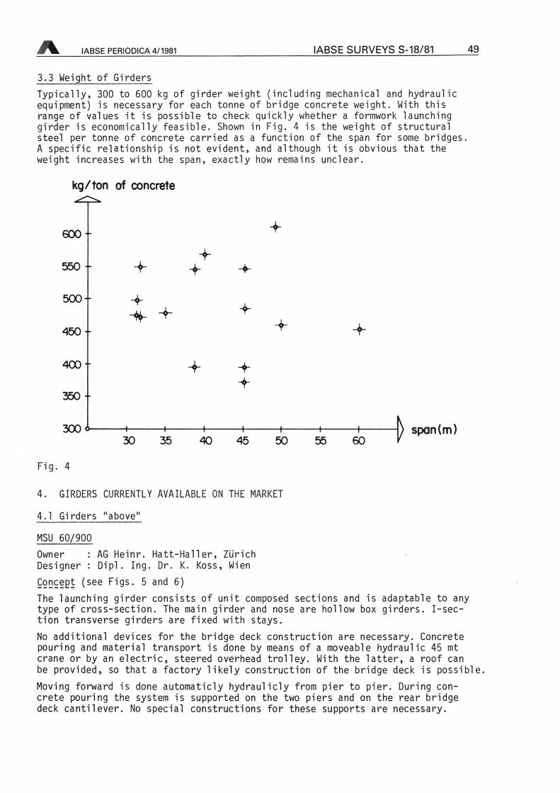
Typically, 300 to 600 kg of girder weight (including mechanical and hydraulicequipment) is necessary for each tonne of bridge concrete weight. With thisränge of values it is possible to check quickly whether a formwork launchinggirder is economically feasible. Shown in Fig. 4 is the weight of structuralsteel per tonne of concrete carried as a function of the span for some bridges.A specific relationship is not evident, and although it is obvious that theweight increases with the span, exactly how remains unclear.
kg/ton of concrete
«XX
550 ¦ +500-
450-+
400-
350-
300« i 1 —i—
++
+
+
+
V
+
+ +
30 35 40 45 50 55 60 } span(m)
Fig. 4
4. GIRDERS CURRENTLY AVAILABLE ON THE MARKET
4.1 Girders "above"
MSU 60/900
Owner : AG Heinr. Hatt-Haller, ZürichDesigner : Dipl. Ing. Dr. K. Koss, Wien
Concept (see Figs. 5 and 6)
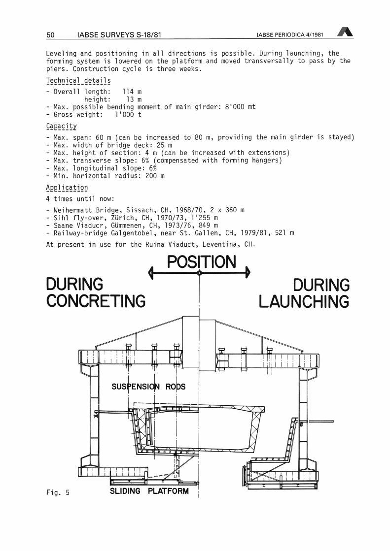
The launching girder consists of unit composed sections and is adaptable to anytype of cross-section. The main girder and nose are hollow box girders. I-sec-tion transverse girders are fixed with stays.No additional devices for the bridge deck construction are necessary. Concretepouring and material transport is done by means of a moveable hydraulic 45 mtcrane or by an electric, steered overhead trolley. With the latter, a roof canbe provided, so that a factory likely construction of the bridge deck is possible.Moving forward is done automaticly hydraulicly from pier to pier. Duringconcrete pouring the system is supported on the two piers and on the rear bridgedeck cantilever. No special constructions for these supports are necessary.
50 IABSE SURVEYS S-18/81 IABSE PERIODICA 4/1981
Leveling and positioning in all directions is possible. During launching, theforming system is lowered on the platform and moved transversally to pass by thepiers. Construction cycle is three weeks.
I§9bGX§I.d§tai^ls- Overall length: 114 m
height: 13 m
- Max. possible bending moment of main girder: 8'000 mt- Gross weight: V000 tCagacity
- Max. span: 60 m (can be increased to 80 m, providing the main girder is stayed)- Max. width of bridge deck: 25 m
- Max. height of section: 4 m (can be increased with extensions)- Max. transverse slope: 6% (compensated with forming hangers)- Max. longitudinal slope: 6%
- Min. horizontal radius: 200 m
Application4 times until now:
- Weihermatt Bridge, Sissach, CH, 1968/70, 2 x 360 m
- Sihl fly-over, Zürich, CH, 1970/73, V255 m
- Saane Viaducr, Gümmenen, CH, 1973/76, 849 m
- Railway-bridge Galgentobel, near St. Gallen, CH, 1979/81, 521 m
At present in use for the Ruina Viaduct, Leventina, CH.
DURINGCONCRETING
POSITION< ^ >
fI I i lll
DURINGLAUNCHING
SUsj'ENSlOjN ROpS
£a i,
ES
^^3
Er 3^iiiE
t s i i ; i- ; S
Fig. 5 SLIDING PLATFORM
* » " " "
ffl
IABSE PERIODICA 4/1981 IABSE SURVEYS S-18/81 51
^Vl._ I 6 U V l
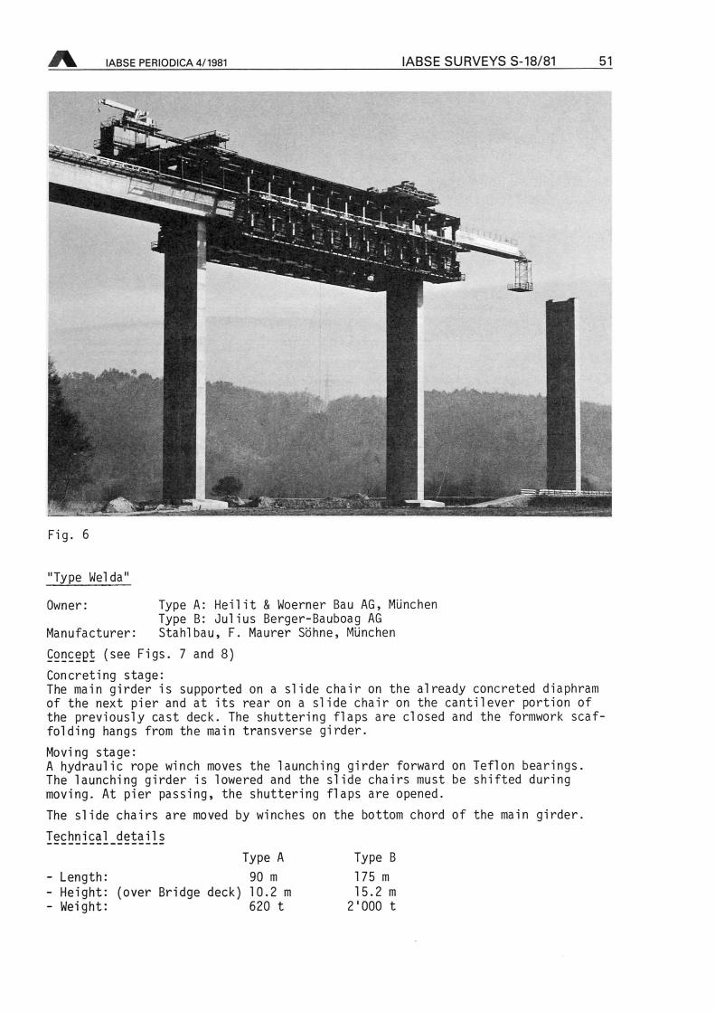
Fig. 6
"Type Welda"
Owner: Type A: Heilit & Woerner Bau AG, MünchenType B: Julius Berger-Bauboag AG
Stahlbau, F. Maurer Söhne, MünchenManufacturer
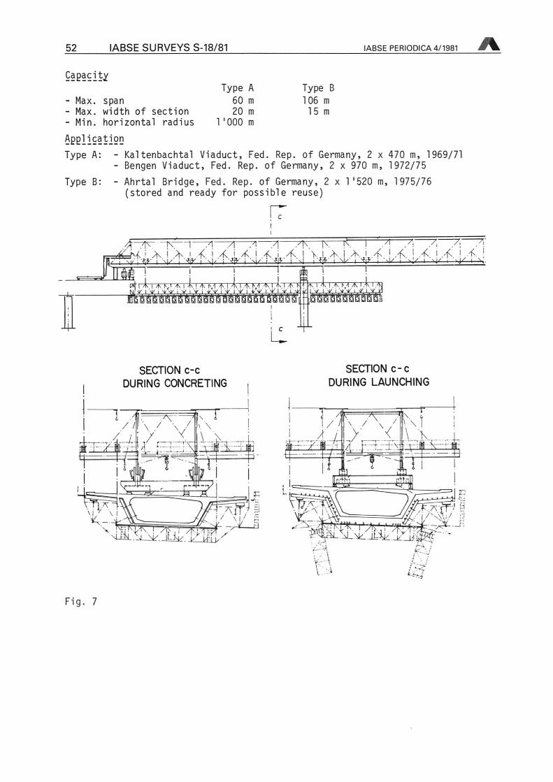
Concept (see Figs. 7 and 8)
Concreting stage:The main girder is supported on a slide chair on the already concreted diaphramof the next pier and at its rear on a slide chair on the cantilever portion ofthe previously cast deck. The shuttering flaps are closed and the formworkscaffolding hangs from the main transverse girder.Moving stage:A hydraulic rope winch moves the launching girder forward on Teflon bearings.The launching girder is lowered and the slide chairs must be shifted duringmoving. At pier passing, the shuttering flaps are opened.
The slide chairs are moved by winches on the bottom chord of the main girder.I§9t]!]J9§l_d§tail§
Type A Type B
- Length: 90 m 175 m
- Height: (over Bridge deck) 10.2 m 15.2 m
- Weight: 620 t 2'000 t
52 IABSE SURVEYS S-18/81 IABSE PERIODICA 4/1981
CapacityType A Type B
- Max. span 60 m 106 m
- Max. width of section 20 m 15m- Min. horizontal radius 1'000 m
ApplicationType A: - Kaitenbachtal Viaduct, Fed. Rep. of Germany, 2 x 470 m, 1969/71
- Bengen Viaduct, Fed. Rep. of Germany, 2 x 970 m, 1972/75
Type B: - Ahrtal Bridge, Fed. Rep. of Germany, 2 x 1'520 m, 1975/76(stored and ready for possible reuse)
rrXX7T1" ~7] yl\ |\ i< r -7| 7 7. 7, 7;
}\
-A 7\ 71"
=fcM. ; X * 1 4. ' 4. [ <¦< X l X 1 V,X I X 1 X X. ; X. 1 X. ' X |
DUP*("| k | A kl A 1 A l A i\4 A I ^ I A M A I It
Li
if)
4-
A I A K -4 A 1 A I <f31 -y 1 .vV 1 y. 1 v ki
SECTION c-cDURING CONCRETING
SECTION c-cDURING LAUNCHING
"TWx^fv\\lügfc ijQJliE
o:-S gfe -' __k_gm JV HJMA IX.,
M-iiL.XXrf. jLi^. V \&X
Tf.lz-AX-X:' f tt ¦ U-:. J ._ -.-
\H s.
T* n
T 1 ,F A ff >' W
i/X\\i/ d^-7^ ^X'^'Hfcx^WflLiü*: £%c YJim<r- -,
1 z>\X isii
Fig. 7
IABSE PERIODICA 4/1981 IABSE SURVEYS S-18/81 53
"»¦'»v*Sfc*\V
» > "»*
M
a »?
*ia6 s» *> I *tep*5> Ä
l•̂•S<
¦-¦ ¦¦-. -¦
Fig. 8
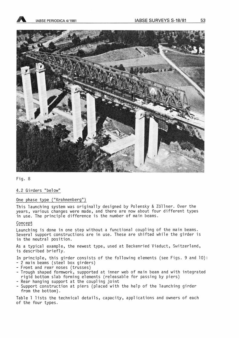
4.2 Girders "below"
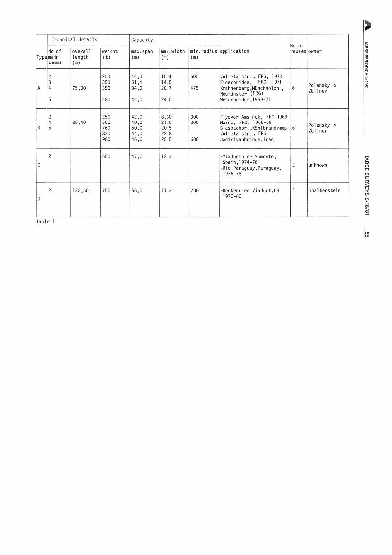
One phase type ("Krahnenberg")This launching system was originally designed by Polensky & Zöllner. Over theyears, various changes were made, and there are now about four different typesin use. The principle difference is the number of main beams.
Concept
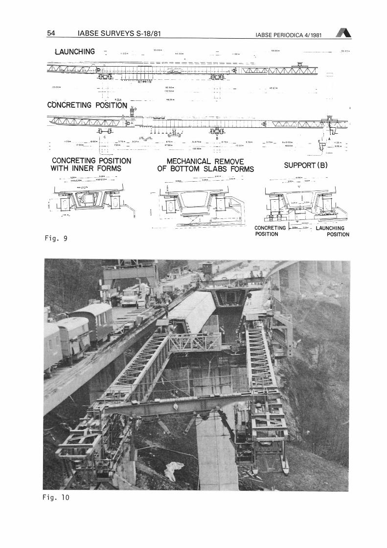
Launching is done in one step without a functional coupling of the main beams.Several support constructions are in use. These are shifted while the girder isin the neutral position.As a typicai example, the newest type, used at Beckenried Viaduct, Switzerland,is described briefly.In principle, this girder consists of the following elements (see Figs. 9 and 10):- 2 main beams (steel box girders)- Front and rear noses (trusses)- Trough shaped formwork, supported at inner web of main beam and with integrated
rigid bottom slab forming elements (releasable for passing by piers)- Rear hanging support at the coupling Joint- Support construction at piers (placed with the help of the launching girder
from the bottom).Table 1 lists the technical details, capacity, applications and owners of eachof the four types.
54 IABSE SURVEYS S-18/81 IABSE PERIODICA 4/1981
LAUNCHING
Jggflt 11; 11111 j-" -r^< VKZEZF.' •' /,ÄX _TEliRaf
"JKjCt
CONCRETING POSITION
' I I ' 4- ¦
CONCRETING POSITIONWITH INNER FORMS
Ui-eüa-'
MECHANICAL REMOVEOF BOTTOM SLABS FORMS
4* \r ,r ^\/T\ ' - I%_^-
Ü2
SUPPORT(B)
Fig. 9
LAUNCHINGPOSITION
CONCRETINGPOSITION
i* *>*.>-,
in*El»
¦--'-VJ £
V.
«Pi£3
.1
ITV«¦<
tfr 4»«V|
Fig. 10
Type
Technical details Capacity
applicationNo.ofreuses ownerNo of
mainbeams
overalllength(ra)
weight(t)
max.span(ra)
max.width(m)
min.radius(m)
A
2
3
4
5
75,00
200350350
480
44,051,434,0
44,0
10,414,520,7
24,0
600
475
Volmetalstr., FRG, 1973
Eiderbridge, FRG, 1971
Krahnenberg.Münchholzh.,Neumünster (FRG)
Weserbridge,1969-71
6 Polensky &
Zöllner
B
2
45
85,40250500760830980
42,040,050,044,046,0
8,3021,020,522,825,5
300300
600
Flyover Amsinck, FRG,1969Mainz, FRG, 1966-68Blasbachbr..KöhlbrandrampVolmetalstr. FRG
Jadiriyahbridge.Iraq
6 Polensky &'
Zöllner
C
2 650 47,0 12,3 -Viaducto de Somonte,Spain,1974-76
-Rio Paraguay,Paraguay,1976-78
2 unknown
D
2 132,50 750 56,0 11,3 700 -Beckenried Viaduct,CH1970-80
1 Spaltenstein
Table 1
OlOl
56 IABSE SURVEYS S-18/81 IABSE PERIODICA 4/1981
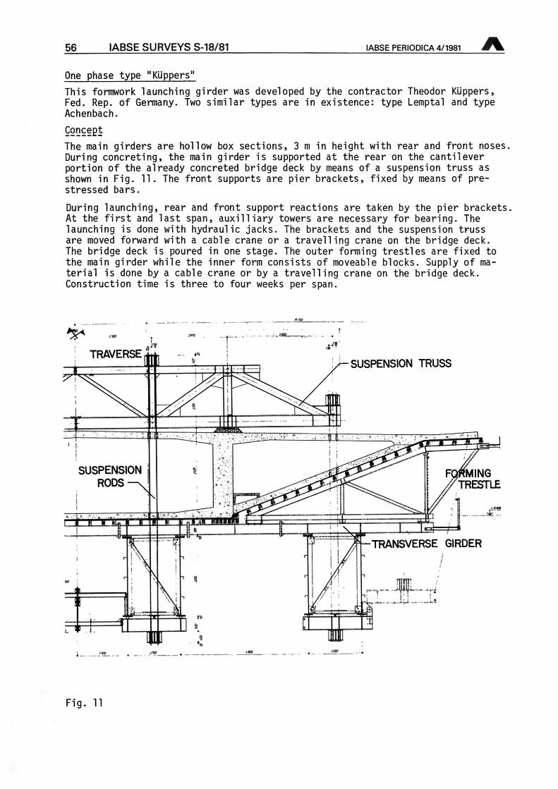
One phase type "Küppers"
This formwork launching girder was developed by the contractor Theodor Küppers,Fed. Rep. of Germany. Two similar types are in existence: type Lemptal and typeAchenbach.
Concept
The main girders are hollow box sections, 3 m in height with rear and front noses.During concreting, the main girder is supported at the rear on the cantileverportion of the already concreted bridge deck by means of a Suspension truss asshown in Fig. 11. The front supports are pier brackets, fixed by means ofprestressed bars.
During launching, rear and front support reactions are taken by the pier brackets.At the first and last span, auxilliary towers are necessary for bearing. Thelaunching is done with hydraulic jacks. The brackets and the Suspension trussare moved forward with a cable crane or a travelling crane on the bridge deck.The bridge deck is poured in one stage. The outer forming trestles are fixed tothe main girder while the inner form consists of moveable blocks. Supply ofmaterial is done by a cable crane or by a travelling crane on the bridge deck.Construction time is three to four weeks per span.
SUSPENSION TRUSS
V rTRAVERSE„I
'/
2^ n E_JL_i
SUSPENSIONRODS-n
MINGTRESTLE
-ihMM noimBZ!
•w TRANSVERSE GIRDER
ii
/\
t
i.Sü=
19rrr IIj
Fig. 11
IABSE PERIODICA 4/1981 IABSE SURVEYS S-18/81 57
Technical_detai]^s- Overall length: 98 m
- Gross weight : 600 t (for two main beams)
Capacity- Max. span: 48 m
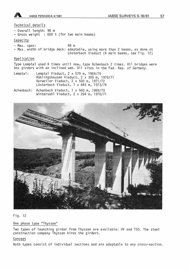
- Max. width of bridge deck: adaptable, using more than 2 beams, as done atLösterbach Viaduct (4 main beams, see Fig. 12)
ApplicationType Lemptal used 4 times until now, type Achenbach 2 times. All bridges werebox girders with an inclined web. All sites in the Fed. Rep. of Germany.
Lemptal: Lemptal Viaduct, 2 x 579 m, 1969/70Rüblingshausen Viaduct, 2 x 300 m, 1970/71Karweiler Viaduct, 2 x 500 m, 1971/72Lösterbach Viaduct, 1 x 645 m, 1973/74
Achenbach: Achenbach Viaduct, 1 x 560 m, 1969/70Wintersohl Viaduct, 2 x 264 m, 1970/71
Jf*
Z-r<r!
>.. -*
k "%
2m\ j. P.1M&
v\
Fig. 12
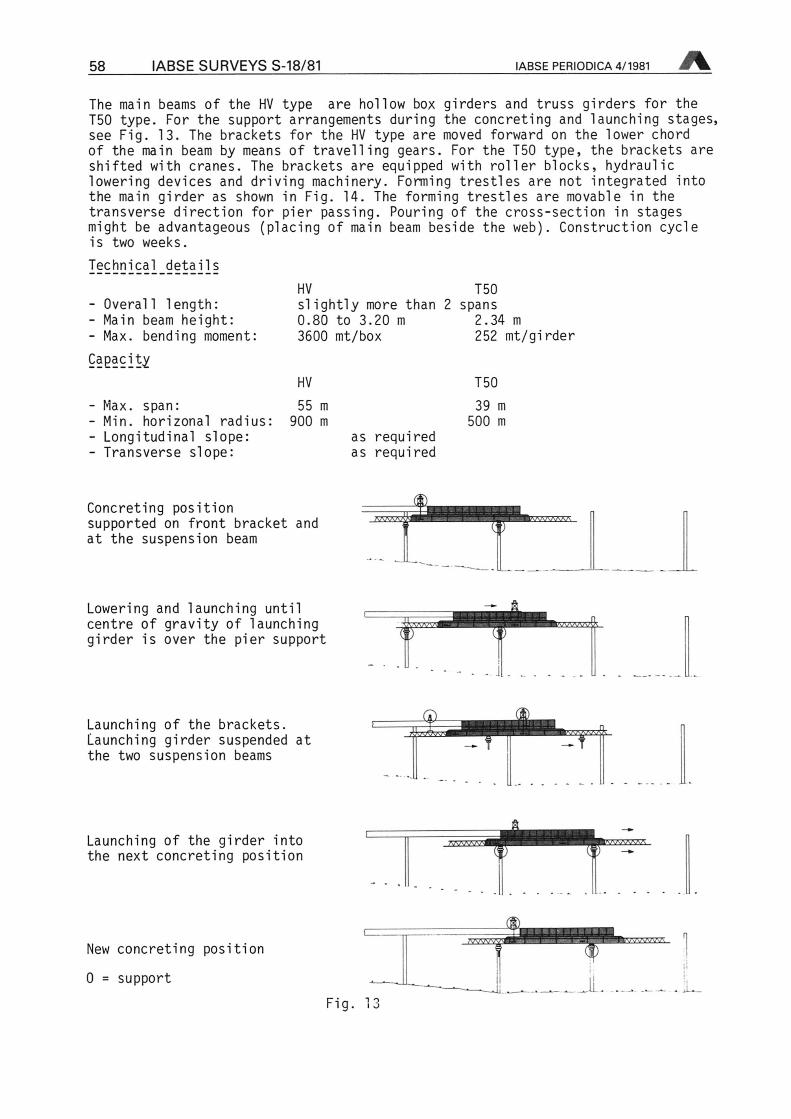
One phase type "Thyssen"
Two types of launching girder from Thyssen are aconstruction Company Thyssen hires the girders.Concept
types consist of individual sections aBoth
vailable: HV and T50. The steel
nd are adaptable to any cross-section.
58 IABSE SURVEYS S-18/81 IABSE PERIODICA 4/1981
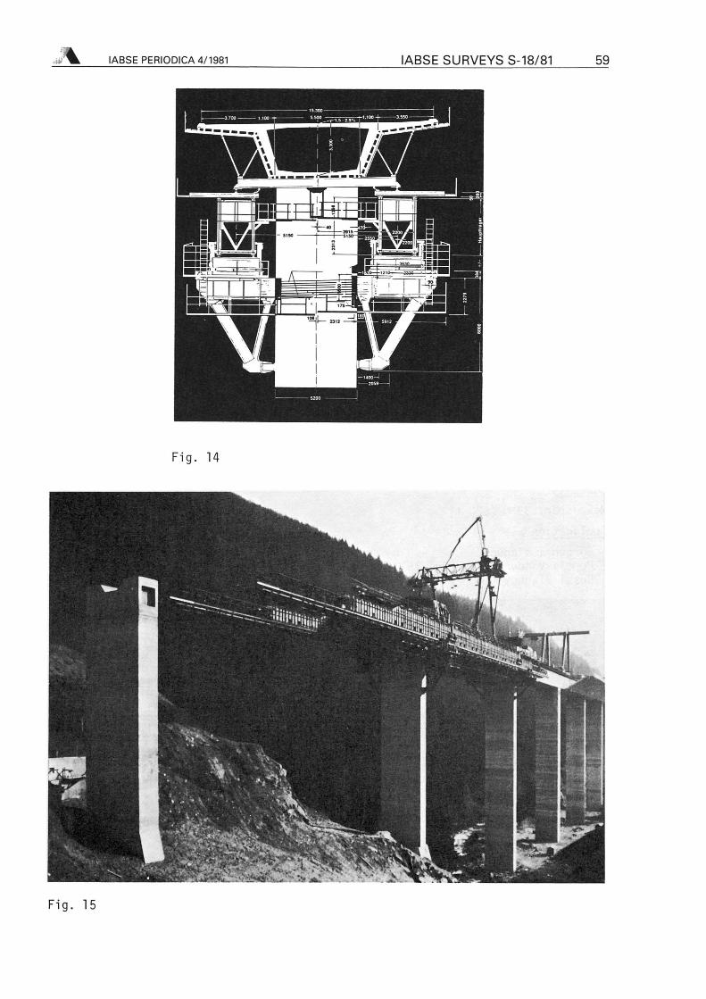
The main beams of the HV
T50 type. For the supportsee Fig. 13. The bracketsof the main beam by meansshifted with cranes. Thelowering devices and drivthe main girder as showntransverse direction formight be advantageous (plis two weeks.
Technical details
Overall length:Main beam height:Max. bending moment:
type are hollow box girders and truss girders for thearrangements during the concreting and launching stages,for the HV type are moved forward on the lower chordof travelling gears. For the T50 type, the brackets are
brackets are equipped with roller blocks, hydraulicing machinery. Forming trestles are not integrated intoin Fig. 14. The forming trestles are movable in thepier passing. Pouring of the cross-section in stagesacing of main beam beside the web). Construction cycle
HV T50slightly more than 2 spans0.80 to 3.20 m 2.34 m
3600 mt/box 252 mt/girderCapacity
Max. span:Min. horizonal radius:Longitudinal slope:Transverse slope:
HV T50
55 m 39 m
900 m
as requiredas required
500 m
Concreting positionsupported on front bracket andat the Suspension beam
Lowering and launching untilcentre of gravity of launchinggirder is over the pier support
I
oi
Launching of the brackets.Launching girder suspended atthe two Suspension beams
-Q.
¦rrf
Launching of the girder intothe next concreting position
New concreting position
0 support
Fig.
"^;
.JLi i - .ji-
;% IABSE PERIODICA 4/1981 IABSE SURVEYS S-18/81 59
SBm
-Ji-J
kJ
Ja
Fig. 14
1
;;
;rr-**
Fig. 15
60 IABSE SURVEYS S-18/81 IABSE PERIODICA 4/1981
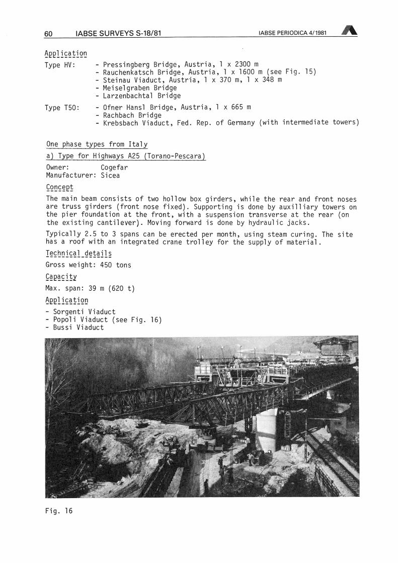
ApplicationType HV:
Type T50:
- Pressingberg Bridge, Austria, 1 x 2300 m
- Rauchenkatsch Bridge, Austria, 1 x 1600 m (see Fig. 15)- Steinau Viaduct, Austria, 1 x 370 m, 1 x 348 m
- Meisei graben Bridge- Larzenbachtal Bridge
- Ofner Hansl Bridge, Austria, 1 x 665 m
- Rachbach Bridge- Krebsbach Viaduct, Fed. Rep. of Germany (with intermediate towers)
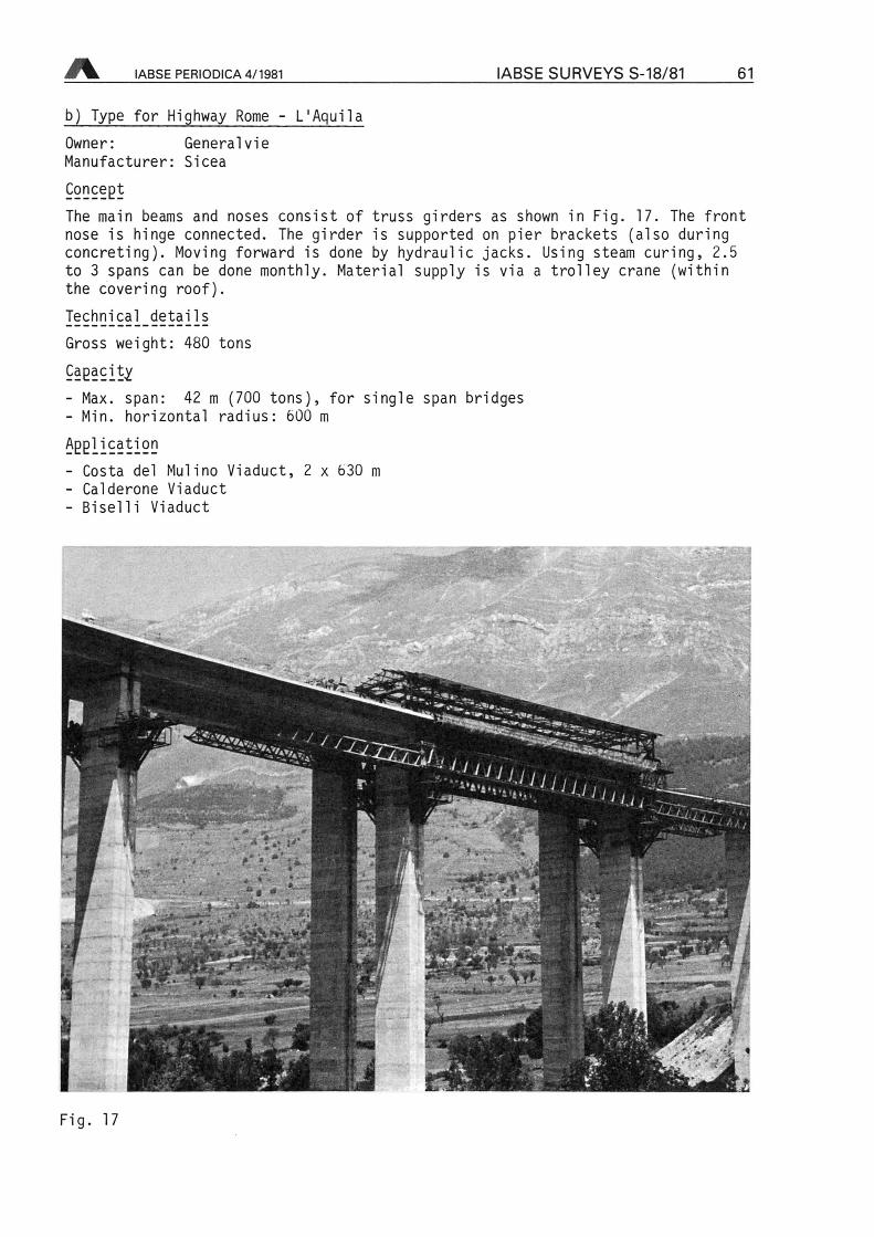
One phase types from Italya) Type for Highways A25 (Torano-Pescara)Owner: CogefarManufacturer: Sicea
ConceptThe main beam consists of two hollow box girders, while the rear and front nosesare truss girders (front nose fixed). Supporting is done by auxilliary towers onthe pier foundation at the front, with a Suspension transverse at the rear (onthe existing cantilever). Moving forward is done by hydraulic jacks.Typically 2.5 to 3 spans can be erected per month, using steam curing. The sitehas a roof with an integrated crane trolley for the supply of material.I§9bDl93l_detailsGross weight: 450 tons
CapacityMax. span: 39 m (620 t)Application- Sorgenti Viaduct- Popoli Viaduct (see Fig. 16)- Bussi Viaduct
Xni-
¦ü£M
m
-¦¦ffr.
Fig. 16
IABSE PERIODICA 4/1981 IABSE SURVEYS S-18/81 61
b) Type for Highway Rome - L'AquilaOwner: GeneralvieManufacturer: Sicea
Concept
The main beams and noses consist of truss girders as shown in Fig. 17. The frontnose is hinge connected. The girder is supported on pier brackets (also duringconcreting). Moving forward is done by hydraulic jacks. Using steam curing, 2.5to 3 spans can be done monthly. Material supply is via a trolley crane (withinthe covering roof).Technical detailsGross weight: 480 tons
Capacity
- Max. span: 42 m (700 tons), for Single span bridges- Min. horizontal radius: 600 m
Application- Costa del Mulino Viaduct, 2 x 630 m
- Calderone Viaduct- Biselli Viaduct
«Aja
XX'J,
~£*L
mj,ri& ¦*-
.»¦*
**lau
Wjz-
¦ -.-^v
Fig. 17
62 IABSE SURVEYS S-18/81 IABSE PERIODICA 4/1981
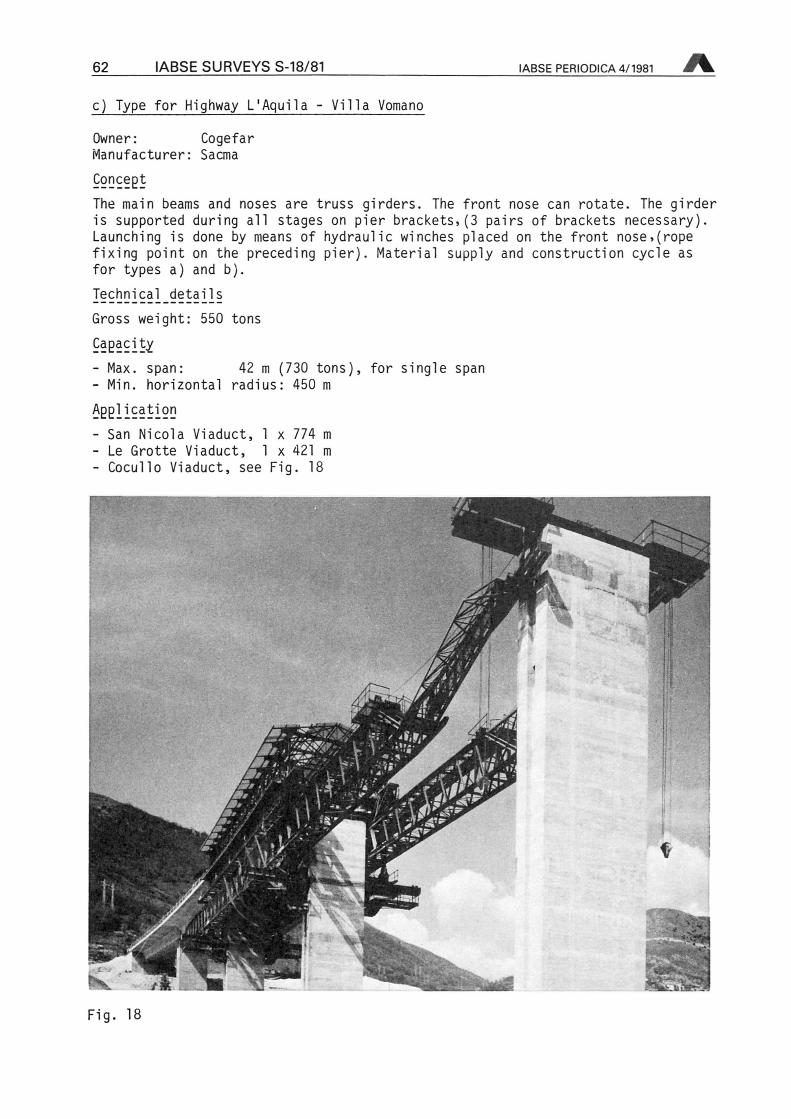
c) Type for Highway L'Aquila - Villa Vomano
Owner: CogefarManufacturer: Sacma
Concept
The main beams and noses are truss girders. The front nose can rotate. The girderis supported during all stages on pier brackets,(3 pairs of brackets necessary).Launching is done by means of hydraulic winches placed on the front nose,(ropefixing point on the preceding pier). Material supply and construction cycle asfor types a) and b).
I?chnical^ detailsGross weight: 550 tons
Capacity
- Max. span: 42 m (730 tons]- Min. horizontal radius: 450 m
Application- San Nicola Viaduct, 1 x 774 m
- Le Grotte Viaduct, 1 x 421 m
- Cocullo Viaduct, see Fig. 18
for Single span
^
VFig. li
IABSE PERIODICA 4/1981 IABSE SURVEYS S-18/81 63
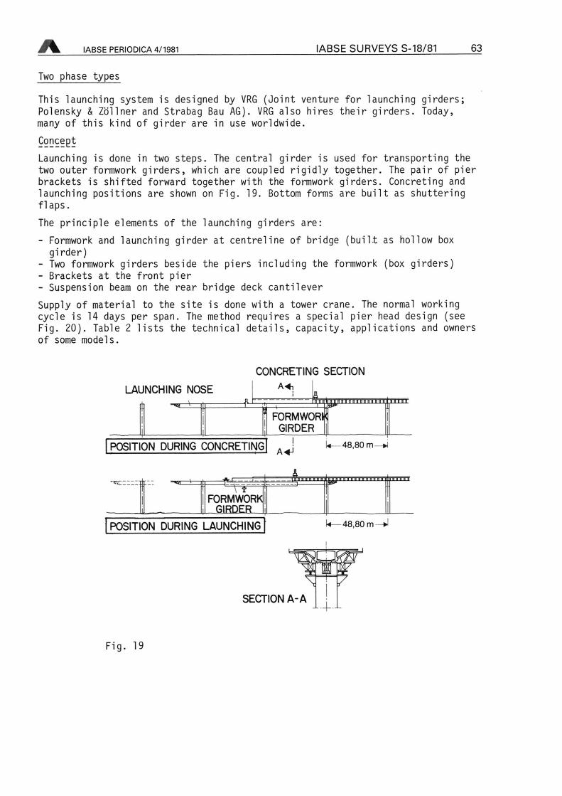
Two phase types
This launching system is designed by VRG (Joint venture for launching girders;Polensky & Zöllner and Strabag Bau AG). VRG also hires their girders. Today,many of this kind of girder are in use worldwide.
Concept
Launching is done in two Steps. The central girder is used for transporting thetwo outer formwork girders, which are coupled rigidly together. The pair of pierbrackets is shifted forward together with the formwork girders. Concreting and
launching positions are shown on Fig. 19. Bottom forms are built as shutteringflaps.The principle elements of the launching girders are:
- Formwork and launching girder at centreline of bridge (built as hollow box
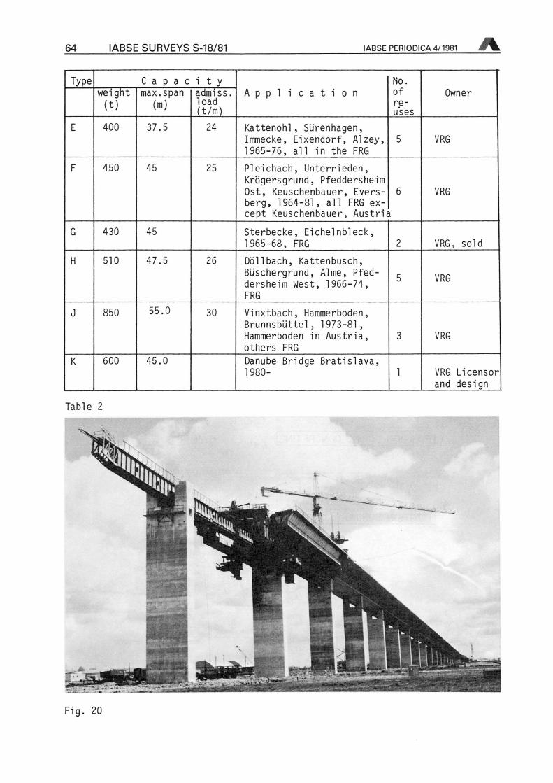
girder)- Two formwork girders beside the piers including the formwork (box girders)- Brackets at the front pier- Suspension beam on the rear bridge deck cantileverSupply of material to the site is done with a tower crane. The normal workingcycle is 14 days per span. The method requires a special pier head design (seeFig. 20). Table 2 lists the technical details, capacity, applications and ownersof some modeis.
LAUNCHING NOSE
h -« > il —
CONCRETING SECTION
1 FORMWORlfi
GIRDER
n'EriniinninniiTi irnnr
POSITION DURING CONCRETINGi
A-*J 48,80 m
m^XX^FORMWOR
GIRDEEL
48,80 m -tJPOSITION DURING LAUNCHING
7SECTION A-A
Fig. 19
64 IABSE SURVEYS S-18/81 IABSE PERIODICA 4/1981
Type C a p a c i t yApplication
No.of
reuses
Ownerweight(t)
max.span(ra)
admiss.load(t/m)
E 400 37.5 24 Kattenohl, Sürenhagen,Immecke, Eixendorf, Alzey,1965-76, all in the FRG
5 VRG
F 450 45 25 Pleichach, Unterrieden,Krögersgrund, PfeddersheimOst, Keuschenbauer, Evers- 6
berg, 1964-81, all FRG
except Keuschenbauer, Austria
VRG
G 430 45 Sterbecke, Eichelnbleck,1965-68, FRG 2 VRG, soid
H 510 47.5 26 Döllbach, Kattenbusch,Büschergrund, Alme,Pfeddersheim West, 1966-74,FRG
5 VRG
J 850 55.0 30 Vinxtbach, Hammerboden,Brunnsbüttel, 1973-81,Hammerboden in Austria,others FRG
3 VRG
K 600 45.0 Danube Bridge Bratislava,1980- 1 VRG Licensor
and design
Table 2
v^ ^
fic?
Fig. 20
IABSE PERIODICA 4/1981 IABSE SURVEYS S-18/81 65
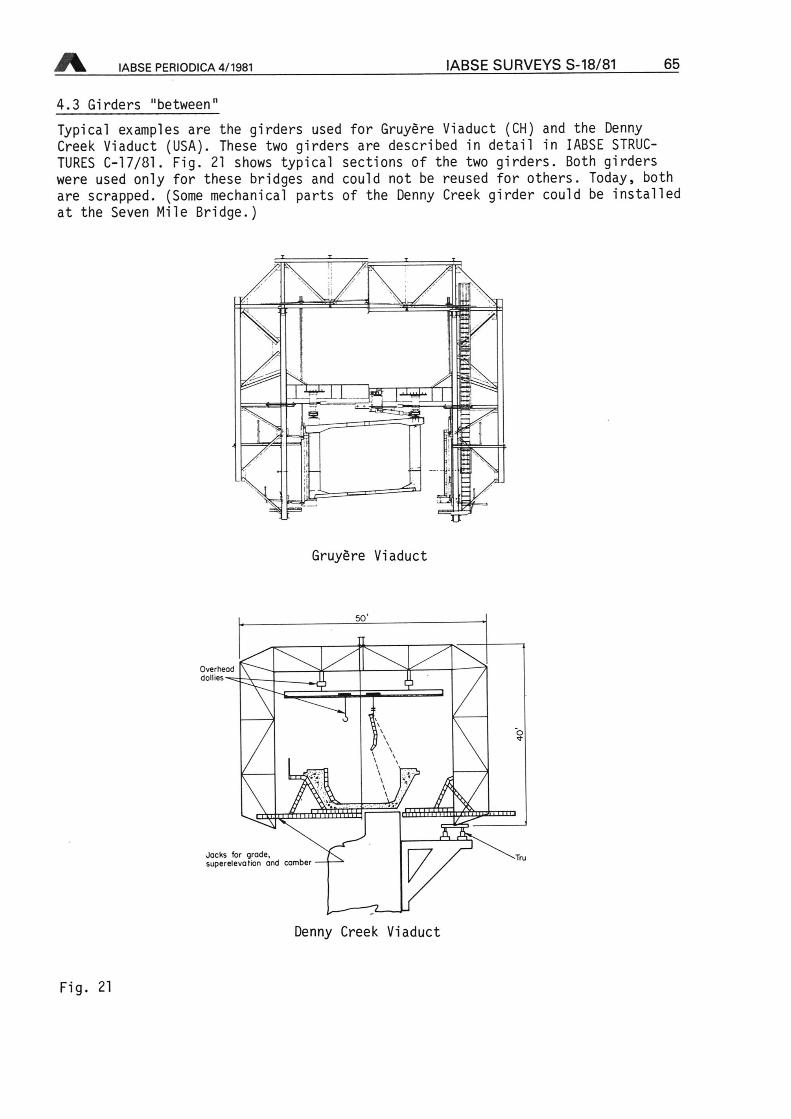
4.3 Girders "between"
Typicai examples are the girders used for Gruyere Viaduct (CH) and the DennyCreek Viaduct (USA). These two girders are described in detail in IABSE STRUCTURES
C-17/81. Fig. 21 shows typicai sections of the two girders. Both girderswere used only for these bridges and could not be reused for others. Today, bothare scrapped. (Some mechanical parts of the Denny Creek girder could be installedat the Seven Mile Bridge.)
T^n:XtlL I ilujj"
—
a
Gruyere Viaduct
OverheaCdomes
hmm
v.Jacks for grade,superelevotion and camber
Denny Creek Viaduct
Fig. 21
66 IABSE SURVEYS S-18/81 IABSE PERIODICA 4/1981
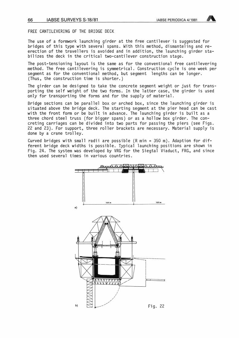
FREE CANTILEVERING OF THE BRIDGE DECK
The use of a formwork launching girder at the free cantilever is suggested forbridges of this type with several spans. With this method, dismanteling and re-erection of the travellers is avoided and in addition, the launching girder sta-bilizes the deck in the critical two-cantilever construction stage.The post-tensioning layout is the same as for the conventional free cantileveringmethod. The free cantilevering is symmetrical. Construction cycle is one week persegment as for the conventional method, but segment lengths can be longer.(Thus, the construction time is shorter.)The girder can be designed to take the concrete segment weight or just for trans-porting the seif weight of the two forms. In the latter case, the girder is usedonly for transporting the forms and for the supply of material.
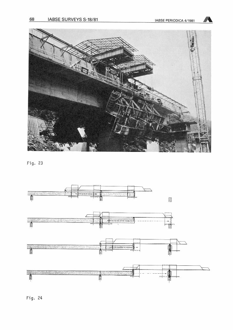
Bridge sections can be parallel box or arched box, since the launching girder issituated above the bridge deck. The starting segment at the pier head can be castwith the front form or be built in advance. The launching girder is built as a
three chord steel truss (for bigger spans) or as a hollow box girder. The
concreting carriages can be divided into two parts for passing the piers (see Figs.22 and 23). For support, three roller brackets are necessary. Material supply isdone by a crane trolley.Curved bridges with small radii are possible (R min 350 m). Adaption fordifferent bridge deck widths is possible. Typicai launching positions are shown inFig. 24. The System was developed by VRG for the Siegtal Viaduct, FRG, and sincethen used several times in various countries.
rtt\.^^XÄXA\
3
.:>k-'-J
RSr--Q--ih~Hk-2>J
Fig. 22

IABSE PERIODICA 4/1981 IABSE SURVEYS S-18/81 67
Table 3 lists the details of serval versions of formwork launching girders ofthis type.
Type Technical details Application No.of
reuses
Owner
weight(t)
length(m)
max.span(m)
segmentlength(m)
L 560
750
135 105
70
10
10
Siegtal Viaduct Eiserfeld,
1966-69, FRG
Köhlbrandramps, 1971-73FRG
2Polensky& Zöllner
M 465 100 10 Savio Viaduct, Italy,1978-80
1
N 350 86 69 6.5 Gmünd Viaduct, Austria,1974-76Donnergraben Bridge,Austria, 1977-79St. Pellegrino Viaduct,CH, 1981-
3 Pedretti
0 365 101 5.0 Gutachtal Bridge, FRG,1979-81
1 Polensky& Zöllner
P 70.8 Larzenbach Viaduct,Austria, 1977-79
1
84.5 Tonegawa Bridge, Japan,1981-
1
Table 3
68 IABSE SURVEYS S-18/81 IABSE PERIODICA 4/1981
¥•¦
>!lk4W\ü
^ff« •».
«W-, I
-
1 fe*^Ua
«m
Fig. 23
..¦... ¦
fil
¦ t*M =* x^
z^T I X 43F
t
Fig. 24