Embed Size (px)
Citation preview
// Table of content FeaturesBenefitsSolutionsBasic components
2247
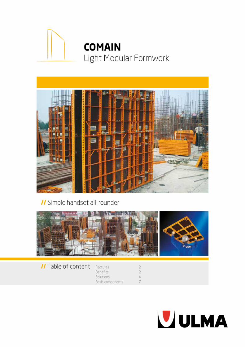
// Simple handset all-rounder
COMAINLight Modular Formwork
2
COMAIN Light Modular Formwork
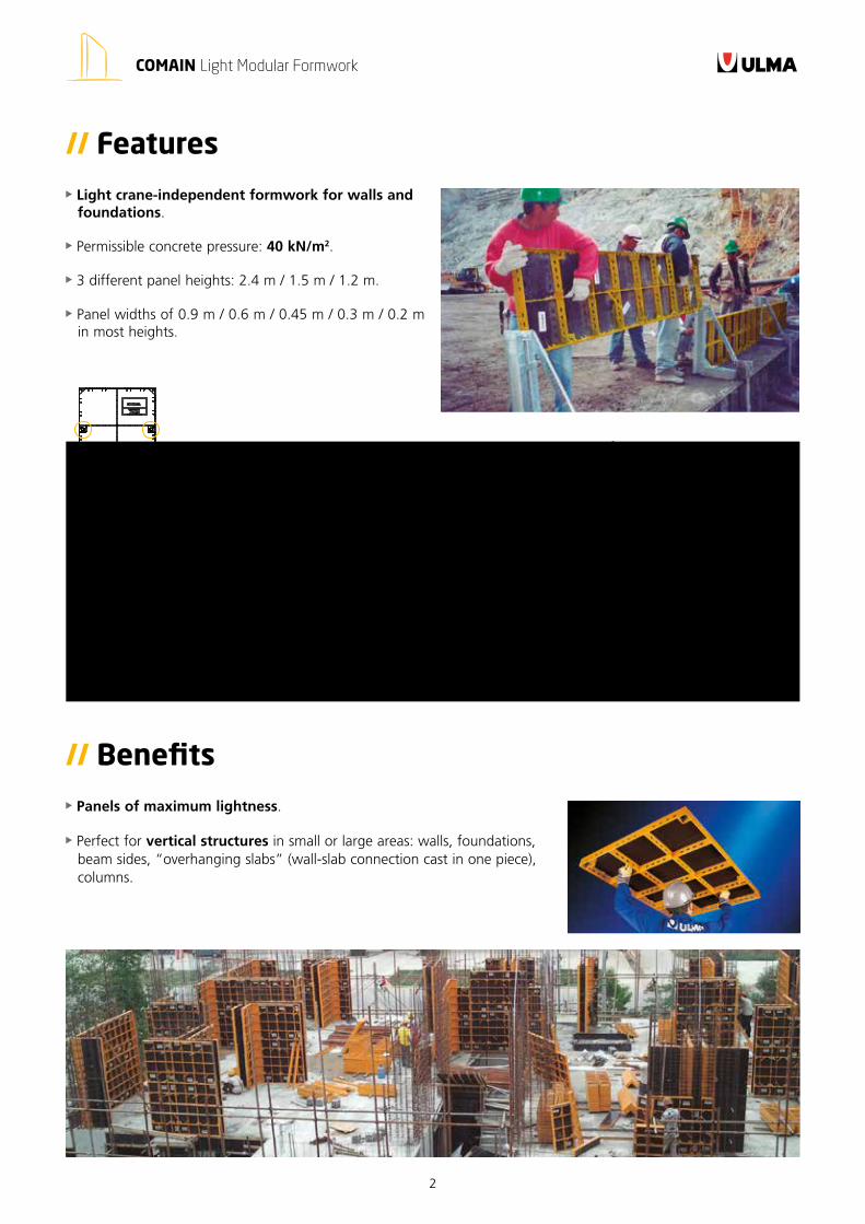
// Features
Light crane-independent formwork for walls and foundations.
Permissible concrete pressure: 40 kN/m2.
3 different panel heights: 2.4 m / 1.5 m / 1.2 m.
Panel widths of 0.9 m / 0.6 m / 0.45 m / 0.3 m / 0.2 m in most heights.
Panels of maximum lightness.
Perfect for vertical structures in small or large areas: walls, foundations, beam sides, “overhanging slabs” (wall-slab connection cast in one piece), columns.
// Benefits
3
COMAIN Light Modular Formwork
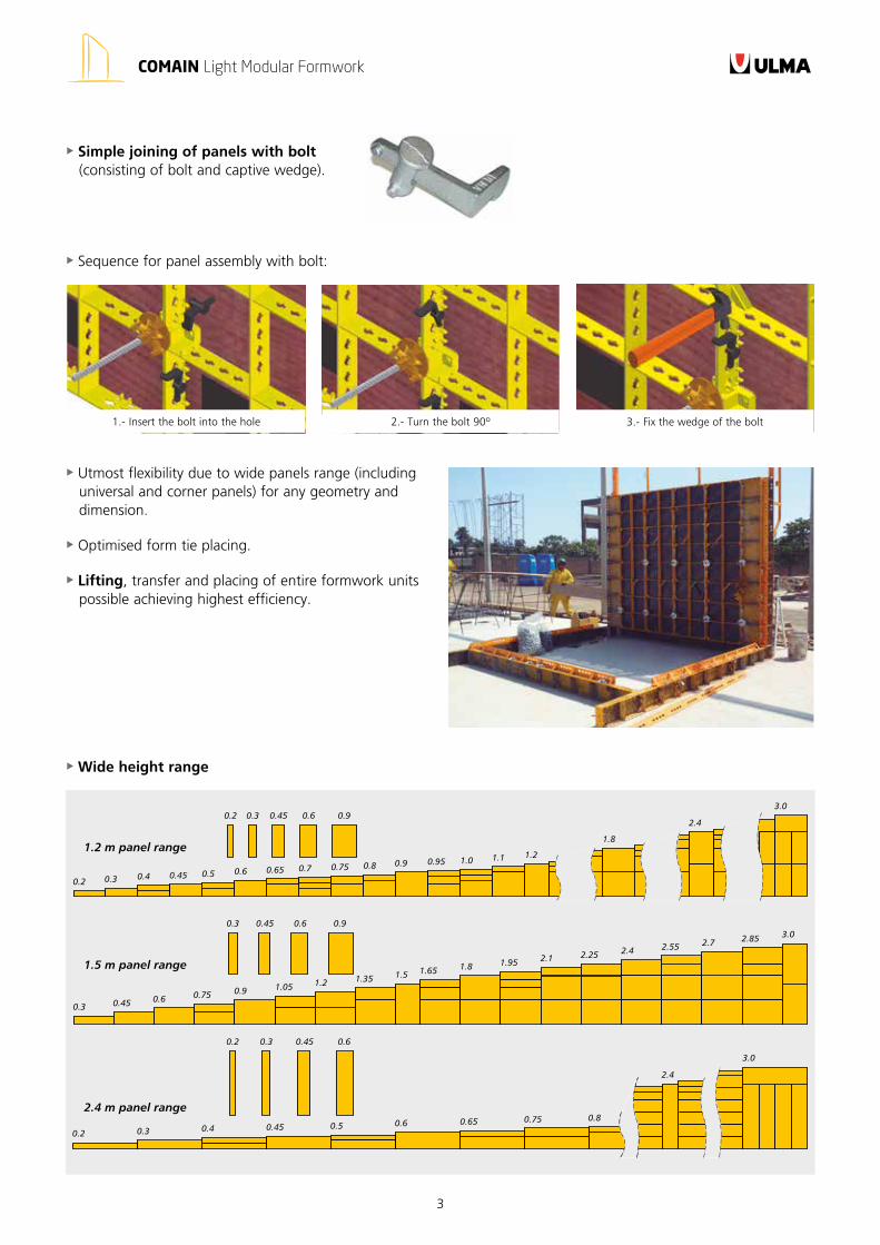
1.2 m panel range
1.5 m panel range
2.4 m panel range
0.2 0.3 0.4 0.45 0.5 0.6 0.65 0.7 0.80.75 0.9 0.95 1.0 1.1 1.2
1.8
2.4
3.0
0.3 0.45 0.6 0.75 0.9 1.05 1.2 1.35 1.5 1.65 1.8 1.95 2.1 2.25 2.4 2.55 2.7 2.85 3.0
3.0
2.4
0.8
0.2 0.3 0.4 0.45 0.5 0.6 0.65 0.75
0.2 0.3 0.45 0.6 0.9
0.3 0.45 0.6 0.9
0.2 0.3 0.45 0.6
Simple joining of panels with bolt (consisting of bolt and captive wedge).
1.- Insert the bolt into the hole 2.- Turn the bolt 90º 3.- Fix the wedge of the bolt
Sequence for panel assembly with bolt:
Utmost flexibility due to wide panels range (including universal and corner panels) for any geometry and dimension.
Optimised form tie placing.
Lifting, transfer and placing of entire formwork units possible achieving highest efficiency.
Wide height range
4
COMAIN Light Modular Formwork
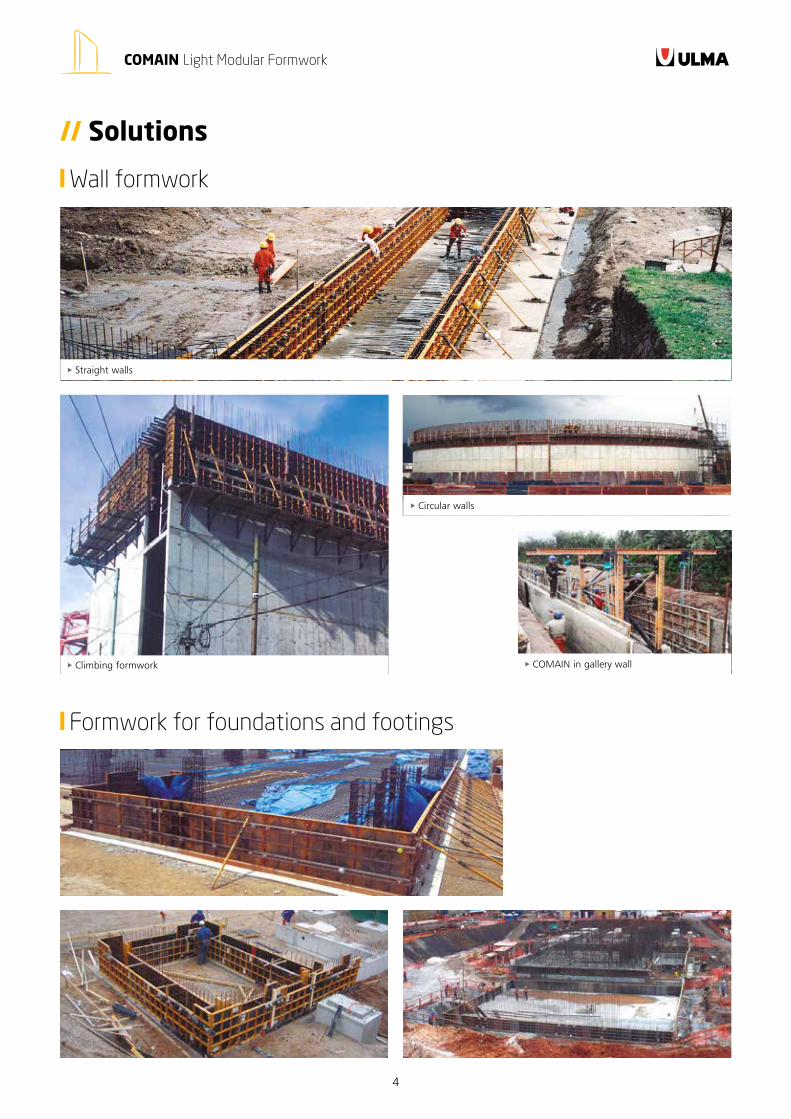
Climbing formwork
Straight walls
Circular walls
// Solutions
Wall formwork
Formwork for foundations and footings
COMAIN in gallery wall
5
COMAIN Light Modular Formwork
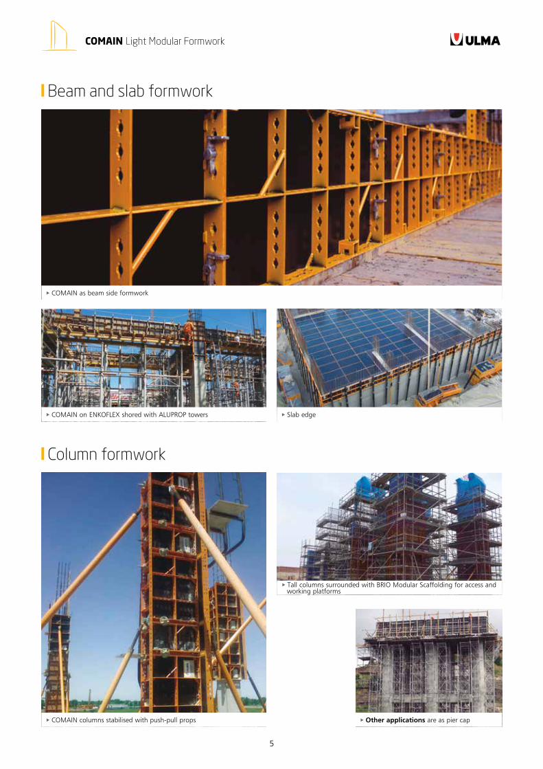
Beam and slab formwork
Column formwork
COMAIN as beam side formwork
Slab edge COMAIN on ENKOFLEX shored with ALUPROP towers
COMAIN columns stabilised with push-pull props
Tall columns surrounded with BRIO Modular Scaffolding for access and working platforms
Other applications are as pier cap
6
COMAIN Light Modular Formwork
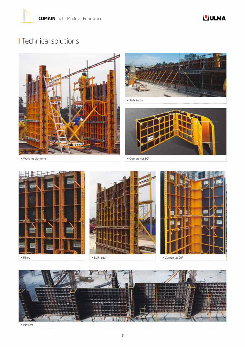
Technical solutions
Working platforms
Stabilisation
Corners not 90º
Pilasters
Bulkhead Fillers Corners at 90º
7
COMAIN Light Modular Formwork
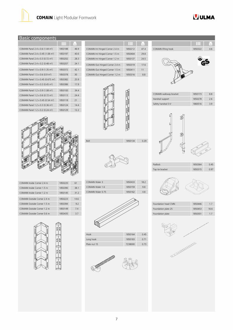
COMAIN Panel 2.4 x 0.6 (1.44 m2) 1850188 46.9
COMAIN Panel 2.4 x 0.45 (1.08 m2) 1850197 40.6
COMAIN Panel 2.4 x 0.3 (0.72 m2) 1850202 28.3
COMAIN Panel 2.4 x 0.2 (0.48 m2) 1850207 24.1
COMAIN Panel 1.5 x 0.9 (1.35 m2) 1850372 42.1
COMAIN Panel 1.5 x 0.6 (0.9 m2) 1850378 30
COMAIN Panel 1.5 x 0.45 (0.675 m2) 1850382 25.9
COMAIN Panel 1.5 x 0.3 (0.45 m2) 1850386 17.9
COMAIN Panel 1.2 x 0.9 (1.08 m2) 1850100 34.4
COMAIN Panel 1.2 x 0.6 (0.72 m2) 1850113 24.4
COMAIN Panel 1.2 x 0.45 (0.54 m2) 1850118 21
COMAIN Panel 1.2 x 0.3 (0.36 m2) 1850124 14.4
COMAIN Panel 1.2 x 0.2 (0.24 m2) 1850129 12.2
COMAIN Inside Corner 2.4 m 1850220 61
COMAIN Inside Corner 1.5 m 1850390 38.1
COMAIN Inside Corner 1.2 m 1850145 31.2
COMAIN Outside Corner 2.4 m 1850223 14.6
COMAIN Outside Corner 1.5 m 1850394 9.2
COMAIN Outside Corner 1.2 m 1850149 7.4
COMAIN Outside Corner 0.6 m 1850435 3.7
COMAIN lifting hook 1850322 4.6
COMAIN walkway bracket 1850173 8.8
Handrail support 1850278 2.6
Safety handrail S-V 1860516 3.9
Padlock 1850364 0.45
Top tie bracket 1850315 0.97
Foundation head CMN 1850446 1.7
Foundation plate 25 1850453 16.6
Foundation plate 1850301 1.7
COMAIN Int Hinged Corner 2.4 m 1850212 47.4
COMAIN Int Hinged Corner 1.5 m 1850404 29.8
COMAIN Int Hinged Corner 1.2 m 1850137 24.5
COMAIN Out Hinged Corner 2.4 m 1850319 17.6
COMAIN Out Hinged Corner 1.5 m 1850411 11
COMAIN Out Hinged Corner 1.2 m 1850316 8.8
Bolt 1850134 0.29
COMAIN Waler 3 1850433 18.2
COMAIN Waler 1.6 1850159 9.8
COMAIN Waler 0.75 1850162 4.8
Hook 1850164 0.45
Long hook 1850183 0.71
Plate nut 15 7238000 0.73
kg kgkg
Basic components
ULMA C y E, S. Coop.Ps. Otadui, 3 - P.O. 1320560 Oñati, SpainT. +34 943 034 900F. +34 943 034 920
Any safety provisions as directed by the appropriate governing agencies must be observed when using our products. The pictures in this document are snapshots of situations at different stages of assembly, and therefore are not complete images. For the purpose of safety, they should not be deemed as definitive. All of the indications regarding safety and operations contained in this document, and the data on stress and loads should be respected. ULMA’s Technical Department must be consulted anytime that field changes alter our equipment installation drawings. The loads featured in this document, related to the basic elements of the product, are approximate. Our equipment is designed to work with accessories and elements made by our company only. Combining such equipment with other systems is not only dangerous but also voids any or all our warrantees. The company
reserves the right to introduce any modifications deemed necessary for the technical development of the product. All rights reserved. Neither all nor part of this document may be reproduced or transmitted in any way by any electronic or mechanical procedure, including photocopy, magnetic recording or any other form of information storage or retrieval system without the written permission.
© Copyright by ULMA C y E, S. Coop
IMPORTANT:
www.ulmaconstruction.com
01FDS06


