Embed Size (px)
Citation preview

07044
Edition 02/2009
GRIDFLEXAluminium Grid Slab Formwork
Assembly Instructions for Standard Configuration
OverviewOverview 1
IntroductionStandard configuration 2
Intended use 2
Safety instructions 3
Additional PERI product information 3
A Standard configurationA1 Storage and transportation 4
A2 System components 8
A3 Shuttering
Start field 10
First row 11
Second row 12
Additional rows 13
A4 Infills
Transverse infill 14
Longitudinal infill 15
Longitudinal and transverse infills 16
A5 Shuttering around columns 17
A6 Cantilevers, Guardrails 18
A7 Installation of plywood formlining 21
A8 Working and concreting scaffold 23
A9 Striking 27
A10 Maintenance and cleaning 28
TablesProp Loads, Evenness 29
Slab Props PERI PEP 10, 20, 30 30
ComponentsComponents 34
Key
Safety instructions Note Visual Check Tip
Assembly Instructions for Standard Configuration
ContentsGRIDFLEX aluminium grid slab formwork
1
1
7
5
6
Assembly Instructions for Standard Configuration
OverviewGRIDFLEX aluminium grid slab formwork
8
2
4
3c
3b
3a
9
10
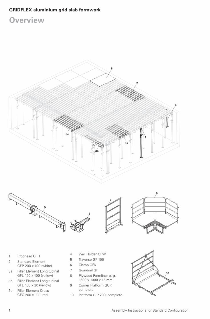
1 Prophead GFH
2 Standard Element
GFP 200 x 100 (white)
3a Filler Element Longitudinal
GFL 150 x 100 (yellow)
3b Filler Element Longitudinal
GFL 183 x 20 (yellow)
3c Filler Element Cross
GFC 200 x 100 (red)
4 Wall Holder GFW
5 Traverse GF 100
6 Clamp GFK
7 Guardrail GF
8 Plywood Formliner e. g.
1500 x 1000 x 15 mm
9 Corner Platform GCP,
complete
10 Platform GIP 200, complete
2 Assembly Instructions for Standard Configuration
GRIDFLEX aluminium grid slab formwork
Introduction
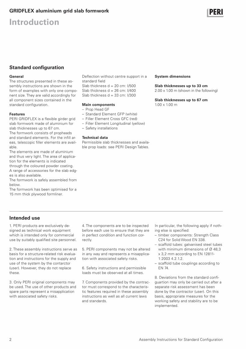
GeneralThe structures presented in these as-
sembly instructions are shown in the
form of examples with only one compo-
nent size. They are valid accordingly for
all component sizes contained in the
standard configuration.
FeaturesPERI GRIDFLEX is a flexible girder grid
slab formwork made of aluminium for
slab thicknesses up to 67 cm.
The formwork consists of propheads
and standard elements. For the infill ar-
eas, telescopic filler elements are avail-
able.
The elements are made of aluminium
and thus very light. The area of applica-
tion for the elements is indicated
through the coloured powder coating.
A range of accessories for the slab edg-
es is also available.
The formwork is safely assembled from
below.
The formwork has been optimised for a
15 mm thick plywood formliner.
Deflection without centre support in a
standard field
Slab thickness d = 20 cm: I/500
Slab thickness d = 26 cm: I/400
Slab thickness d = 33 cm: I/300
Main components– Prop Head GF
– Standard Element GFP (white)
– Filler Element Cross GFC (red)
– Filler Element Longitudinal (yellow)
– Safety installations
Technical dataPermissible slab thicknesses and availa-
ble prop loads: see PERI Design Tables.
Standard configuration
Intended use1. PERI products are exclusively de-
signed as technical work equipment
which is intended only for commercial
use by suitably qualified site personnel.
2. These assembly instructions serve as
basis for a structure-related risk evalua-
tion and instructions for the supply and
use of the system by the contarctor
(user). However, they do not replace
these.
3. Only PERI original components may
be used. The use of other products and
spare parts represent a misapplication
with associated safety risks.
4. The components are to be inspected
before each use to ensure that they are
in perfect condition and function cor-
rectly.
5. PERI components may not be altered
in any way and represents a misapplica-
tion with associated safety risks.
6. Safety instructions and permissible
loads must be observed at all times.
7. Components provided by the contrac-
tor must correspond to the characteris-
tic features required in these assembly
instructions as well as all current laws
and standards.
In particular, the following apply if noth-
ing else is specified:
– timber components: Strength Class
C24 for Solid Wood EN 338.
– scaffold tubes: galvanised steel tubes
with minimum dimensions of Ø 48,3
x 3,2 mm according to EN 12811-
1:2003 4.2.1.2.
– scaffold tube couplings according to
EN 74.
8. Deviations from the standard confi-
guartion may only be carried out after a
separate risk assessment has been
done by the contractor (user). On this
basis, appropriate measures for the
working safety and stability are to be
implemented.
System dimensions
Slab thicknesses up to 33 cm2.00 x 1.00 m (shown in the following)
Slab thicknesses up to 67 cm1.00 x 1.00 m

3Assembly Instructions for Standard Configuration
GRIDFLEX aluminium grid slab formwork
Introduction
Safety instructions
– GRIDFLEX brochure
– PERI design tables
– “Instructions for Use” for pallet lifting
trolley
– “Instructions for Use” for pallets and
stacking devices
General1. Deviations from the standard configu-
ration and/or intended use present a
potential safety risk.
2. All country-specific laws, standards
and other safety regulations are to be
taken into account when our products
are used.
3. During unfavourable weather condi-
tions, suitable precautions and meas-
ures are to be taken in order to guaran-
tee working safety and stability.
4. The contractor (user) must ensure
the stability throughout all phases of
construction. He must ensure and veri-
fy that all occuring loads are safely
transferred.
5. The contractor has to provide safe
working areas for site personnel which
are to be reached via safe access
means. Areas of risk must be cordoned
off and clearly marked. Hatches and
openings on accessible working areas
must be kept closed during working
operations.
6. In order to ensure better understand-
ibility, detailed descriptions are partly
incomplete. The safety installations
which have possibily not been shown in
these detailed descriptions must never-
theless be available.
Storage and transportation1. Do not drop the components.
2. Store and transport components so
that no unintentional change in their po-
sition is possible. Detach lifting gear
from the lowered units only if these are
in a stable position and no unintentional
change is possible.
3. When moving, components are to be
picked up and set down so that any un-
intentional toppling over, falling apart,
slipping or rolling is avoided.
4. Use only suitable load-carrying equip-
ment to move the components as well
as the designated load-bearing points.
5. During the lifting and moving proce-
dure, ensure all loose parts are re-
moved or secured.
6. During the moving procedure, always
use a guide rope.
7. Move components only on clean, flat
and sufficiently load-bearing surfaces.
System-specific1. Retract components only when the
concrete has sufficiently hardened and
the person in charge has given the go-
ahead for striking to take place.
2. Anchoring is to take place only if the
anchorage has sufficient concrete
strength.
3. During striking, do not tear off the
formwork elements with the crane.
4. The existing prop loads (see tables)
must be safely transferred by means of
sufficiently load-bearing slab props or
tower systems.
5. GRIDFLEX platforms are classified in
Load Class 2 (permissible load of
150 kg/m²). They are available as work-
ing and safety scaffold.
6. If heavy objects are supported on
the formwork, the load-bearing capacity
must be taken into consideration.
7. Cantilevers may only be accessed
after bracing has been mounted.
8. The horizontal fixed position of the
slab formwork must be guaranteed.
This is given with circumferential walls
and pre-concreted beams. Otherwise
the transfer of the horizontal loads
must be guaranteed by means of other
measures supplied by the contractor,
e.g. bracing.
Load assumptions for horizontal loads
in accordance with DIN EN 12812.
Additional PERI product information
4
A1 Storage and transportation
Assembly Instructions for Standard Configuration
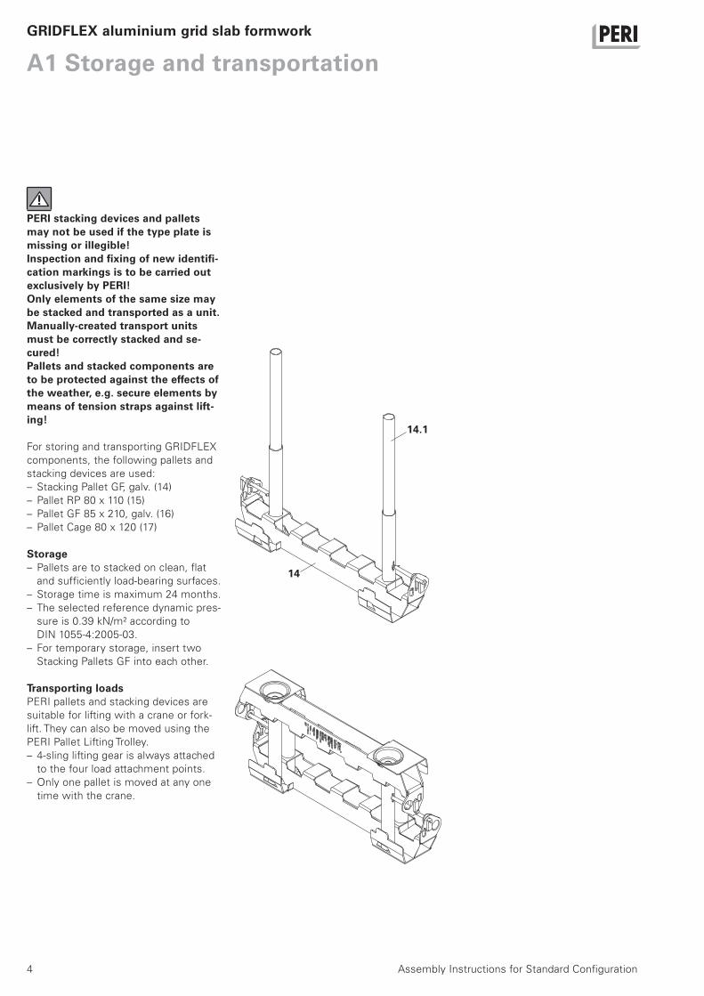
PERI stacking devices and pallets may not be used if the type plate is missing or illegible!Inspection and fixing of new identifi-cation markings is to be carried out exclusively by PERI!Only elements of the same size may be stacked and transported as a unit.Manually-created transport units must be correctly stacked and se-cured!Pallets and stacked components are to be protected against the effects of the weather, e.g. secure elements by means of tension straps against lift-ing!
For storing and transporting GRIDFLEX
components, the following pallets and
stacking devices are used:
– Stacking Pallet GF, galv. (14)
– Pallet RP 80 x 110 (15)
– Pallet GF 85 x 210, galv. (16)
– Pallet Cage 80 x 120 (17)
Storage– Pallets are to stacked on clean, flat
and sufficiently load-bearing surfaces.
– Storage time is maximum 24 months.
– The selected reference dynamic pres-
sure is 0.39 kN/m² according to
DIN 1055-4:2005-03.
– For temporary storage, insert two
Stacking Pallets GF into each other.
Transporting loadsPERI pallets and stacking devices are
suitable for lifting with a crane or fork-
lift. They can also be moved using the
PERI Pallet Lifting Trolley.
– 4-sling lifting gear is always attached
to the four load attachment points.
– Only one pallet is moved at any one
time with the crane.
GRIDFLEX aluminium grid slab formwork
14.1
14
5Assembly Instructions for Standard Configuration
A1 Storage and transportationGRIDFLEX aluminium grid slab formwork
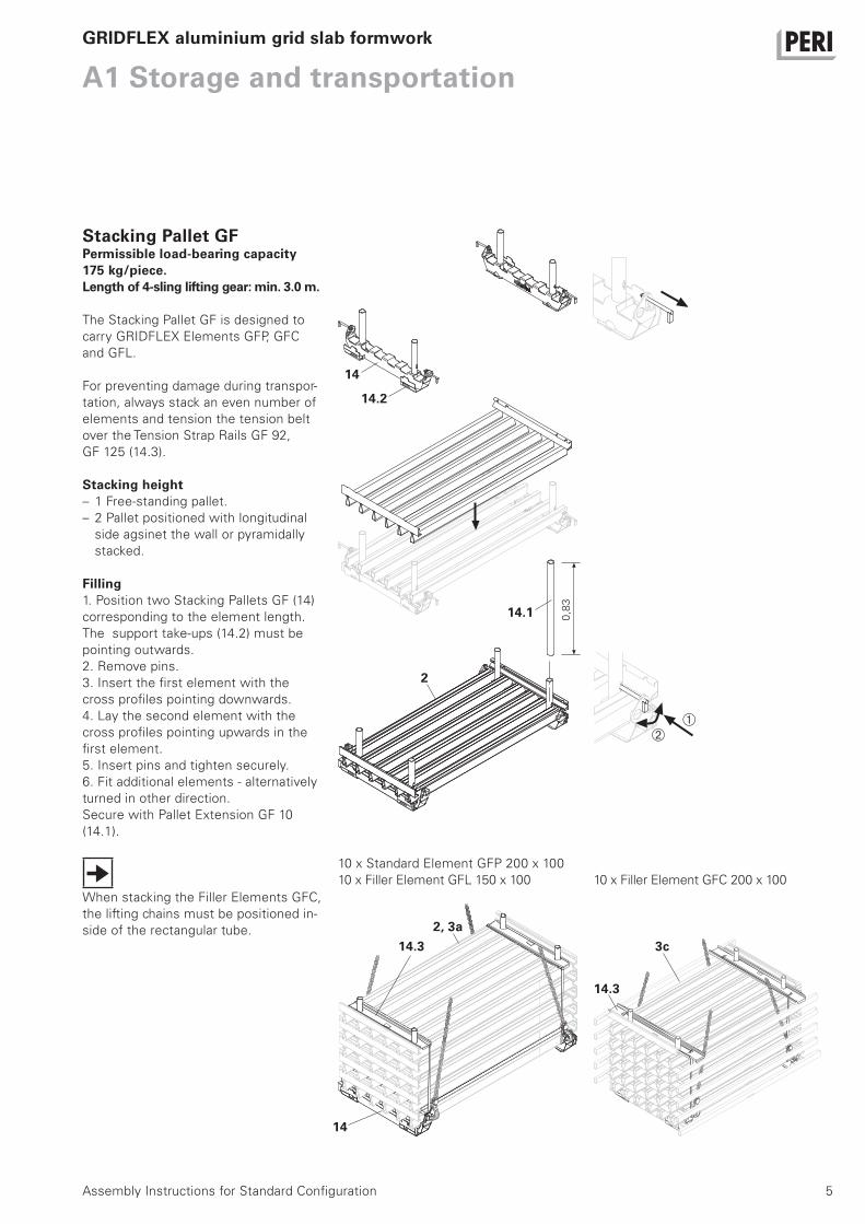
Stacking Pallet GFPermissible load-bearing capacity 175 kg/piece.Length of 4-sling lifting gear: min. 3.0 m.
The Stacking Pallet GF is designed to
carry GRIDFLEX Elements GFP, GFC
and GFL.
For preventing damage during transpor-
tation, always stack an even number of
elements and tension the tension belt
over the Tension Strap Rails GF 92,
GF 125 (14.3).
Stacking height– 1 Free-standing pallet.
– 2 Pallet positioned with longitudinal
side agsinet the wall or pyramidally
stacked.
Filling1. Position two Stacking Pallets GF (14)
corresponding to the element length.
The support take-ups (14.2) must be
pointing outwards.
2. Remove pins.
3. Insert the first element with the
cross profiles pointing downwards.
4. Lay the second element with the
cross profiles pointing upwards in the
first element.
5. Insert pins and tighten securely.
6. Fit additional elements - alternatively
turned in other direction.
Secure with Pallet Extension GF 10
(14.1).
When stacking the Filler Elements GFC,
the lifting chains must be positioned in-
side of the rectangular tube.
14
14.32, 3a
0,8
3
14
2
14.3
3c
10 x Standard Element GFP 200 x 100
10 x Filler Element GFL 150 x 100 10 x Filler Element GFC 200 x 100
14.2
14.1
6
A1 Storage and transportation
Assembly Instructions for Standard Configuration
GRIDFLEX aluminium grid slab formwork
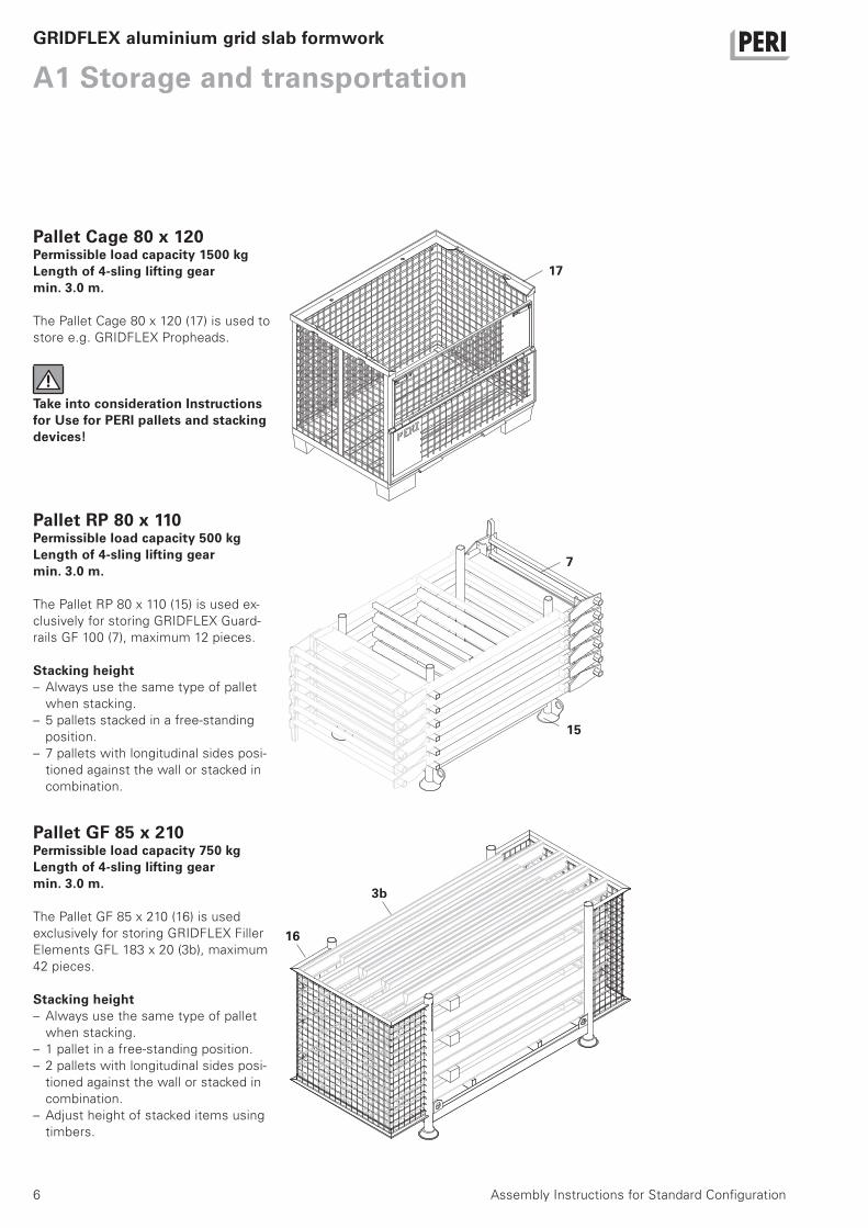
Pallet RP 80 x 110Permissible load capacity 500 kgLength of 4-sling lifting gear min. 3.0 m.
The Pallet RP 80 x 110 (15) is used ex-
clusively for storing GRIDFLEX Guard-
rails GF 100 (7), maximum 12 pieces.
Stacking height– Always use the same type of pallet
when stacking.
– 5 pallets stacked in a free-standing
position.
– 7 pallets with longitudinal sides posi-
tioned against the wall or stacked in
combination.
Pallet GF 85 x 210Permissible load capacity 750 kgLength of 4-sling lifting gear min. 3.0 m.
The Pallet GF 85 x 210 (16) is used
exclusively for storing GRIDFLEX Filler
Elements GFL 183 x 20 (3b), maximum
42 pieces.
Stacking height– Always use the same type of pallet
when stacking.
– 1 pallet in a free-standing position.
– 2 pallets with longitudinal sides posi-
tioned against the wall or stacked in
combination.
– Adjust height of stacked items using
timbers.
7
16
3b
15
Pallet Cage 80 x 120Permissible load capacity 1500 kgLength of 4-sling lifting gear min. 3.0 m.
The Pallet Cage 80 x 120 (17) is used to
store e.g. GRIDFLEX Propheads.
Take into consideration Instructions for Use for PERI pallets and stacking devices!
17
7Assembly Instructions for Standard Configuration
A1 Storage and transportationGRIDFLEX aluminium grid slab formwork
EC Declaration of Conformityin accordance with EC Directive 98/37/EC
Appendix II A
We hereby declare that the following product corresponds to the relevant,
fundamental safety and health requirements of the respective EC Directive on the
basis of its development and design, as well as the version available on the market.
In the case of any changes made to the product which have not been agreed to
by us, this declaration is no longer valid.
Stacking Pallet GF Item no. 110939
Pallet RP 80 x 110 Item no. 111396
Pallet GF 85 x 210 Item no. 111738
Relevant EC Directives:
EC Machine Guidelines 98/37/EEC
Applied harmonised standards:
EN 13155
National standards and technical specifications applied:
DIN 1055, DIN 4421, DIN 18800, BGR 234, BGR 500
PERI GmbHP.O. Box 12 6489259 Weissenhorn www.peri.com
Weissenhorn, 01.09.2008Dipl.-Ing. Manfred RathfelderHead of Research & Development
8 Assembly Instructions for Standard Configuration
A2 System components
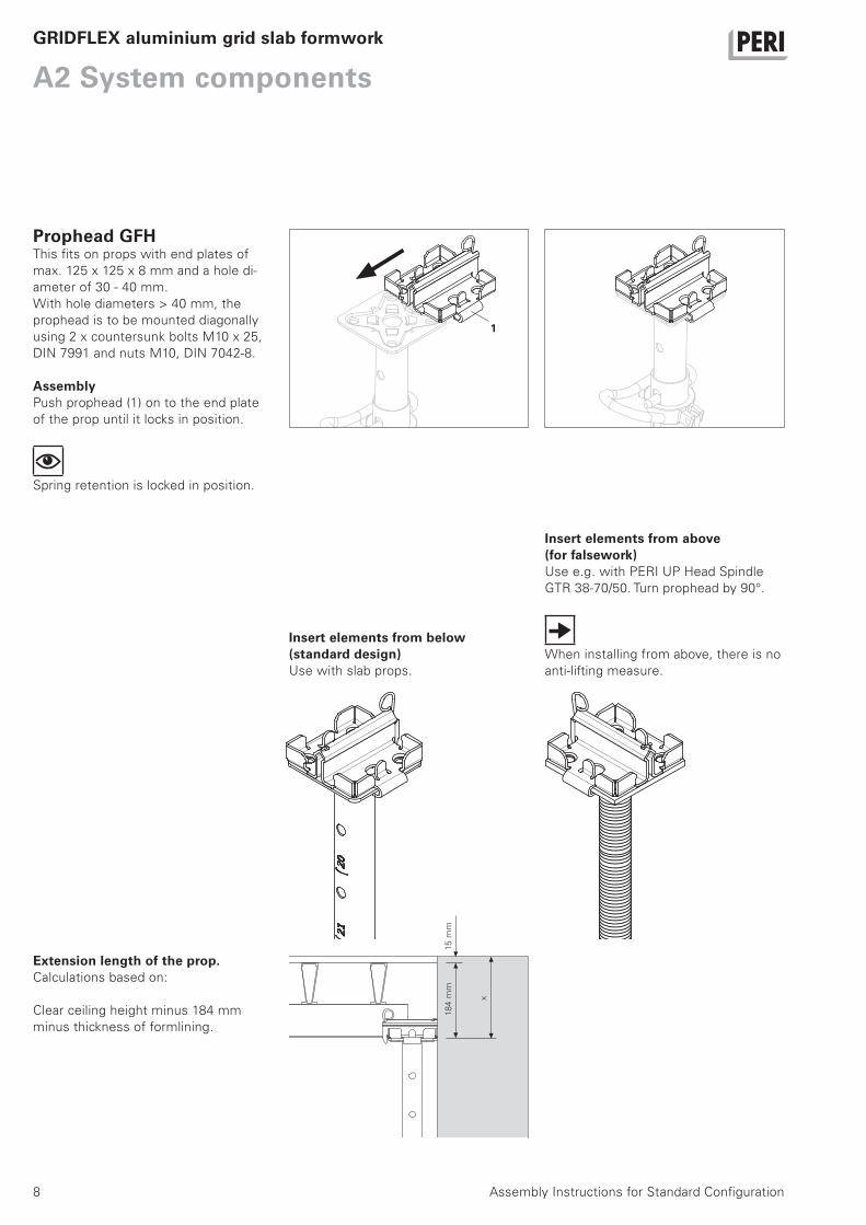
Prophead GFHThis fits on props with end plates of
max. 125 x 125 x 8 mm and a hole di-
ameter of 30 - 40 mm.
With hole diameters > 40 mm, the
prophead is to be mounted diagonally
using 2 x countersunk bolts M10 x 25,
DIN 7991 and nuts M10, DIN 7042-8.
AssemblyPush prophead (1) on to the end plate
of the prop until it locks in position.
Spring retention is locked in position.
GRIDFLEX aluminium grid slab formwork
1
18
4 m
m15
mm
x
Extension length of the prop.Calculations based on:
Clear ceiling height minus 184 mm
minus thickness of formlining.
Insert elements from below (standard design)Use with slab props.
Insert elements from above (for falsework)Use e.g. with PERI UP Head Spindle
GTR 38-70/50. Turn prophead by 90°.
When installing from above, there is no
anti-lifting measure.

9Assembly Instructions for Standard Configuration
A2 System componentsGRIDFLEX aluminium grid slab formwork
11
Shuttering Aid GFAThe Shuttering Aid GFA (11) is used for
assembling and dismantling GRIDFLEX
elements.
Adjustable in 7.5 cm increments.
Wall Holder GFW
The area to be formed may not be accessed before the formwork has been horizontally anchored!
The Wall Holder GFW is used to hold
the slab formwork in a horizontal posi-
tion during assembly. It is mounted in
longitudinal and lateral directions.
Install Wall Holder GFW in the start
field in both directions. Turn the respec-
tive Wall Holder End upwards.
Install the Wall Holder GFW so that it
can be adjusted.
Assembly1. Push tie rod with Wingnut Pivot Plate
through the available tie hole.
2. Bring Wall Holder GFW (4) in position
and tension by means of the Wingnut
Pivot Plate.
3. Cover protruding tie rods with pro-
tective caps.
4
4

10 Assembly Instructions for Standard Configuration
A3 ShutteringGRIDFLEX aluminium grid slab formwork
General informationThe illustrations and grid dimensions
apply to slab thicknesses with
d ≤ 33 cm.
For slab thicknesses ≤ 67 cm:
see Design Tables.
The longitudinal side of the element
runs in the direction of the longer wall.
Install props so that the G-hook can be
accessed and secured without any diffi-
culty.
Start field1. Position two props with propheads
(1) and secure with tripod, 1.0 m spac-
ing.
2. Attach Standard Element GFP (2),
white.
3. Swivel upwards using the shuttering
aid (11) and set down on the shuttering
aid itself.
4. Place third prop with prophead (1) at
an angle on the element end from the
inside and bring in a vertical position
from the outside, 2.0 m spacing.
Remove shuttering aid.
The start field is complete.
As an alternative, the start field can
also be braced using Frames PRK
instaed of with tripods.
Remove two pallet extensions to en-
sure easier removal of the elements
from the pallet.
First row– Tripods can be re-used on additional
elements one at a time.
– Work always takes place one row af-
ter the other in a lateral direction.
2,0 m
1
11
1
2
1
1,0 m
2,0 m8 cm
1,0
m6
cm 4
lateral
11Assembly Instructions for Standard Configuration
A3 ShutteringGRIDFLEX aluminium grid slab formwork
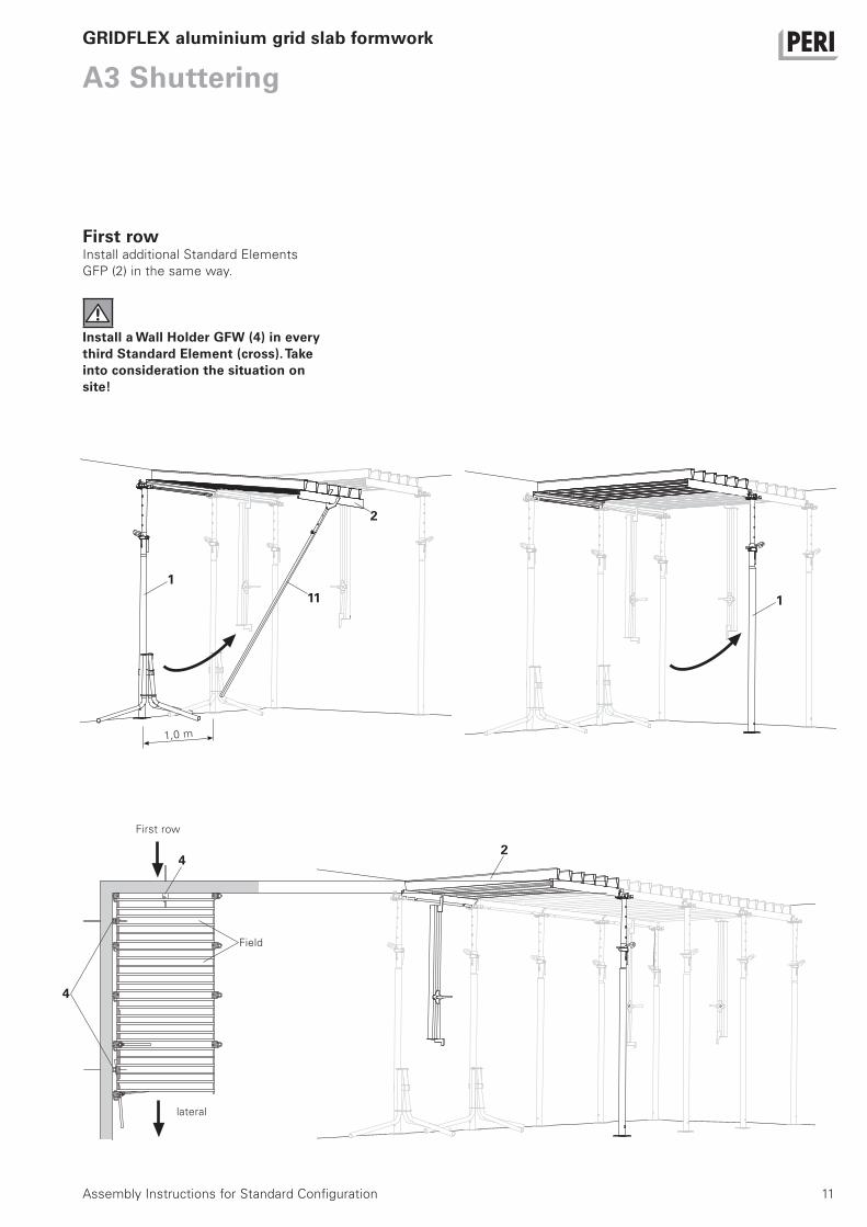
First rowInstall additional Standard Elements
GFP (2) in the same way.
Install a Wall Holder GFW (4) in every third Standard Element (cross).Take into consideration the situation on site!
1
111
2
24
4
Field
First row
1,0 m
lateral

12
A3 Shuttering
Assembly Instructions for Standard Configuration
Second row1. Attach Standard Element GFP (2).
GRIDFLEX aluminium grid slab formwork
2. Swivel up the first Standard Element
GFP with the Shuttering Aid GFA and
set down on the shuttering aid itself.
3. Place prop with prophead (1) at an
angle on the element end from the in-
side and bring in a vertical position from
the outside, 2.0 m spacing.
Remove shuttering aid.
4. Swivel up the second Standard Ele-
ment GFP with the Shuttering Aid GFA
and set down on the shuttering aid it-
self.
5. Swivel in prop with prophead (1) on
the element end in both standard ele-
ments and bring in a vertical position.
6. Assemble additional Standard Ele-
ments GFP (2) in the same way.
1
1
2
2
2
2,0 m
13Assembly Instructions for Standard Configuration
A3 ShutteringGRIDFLEX aluminium grid slab formwork
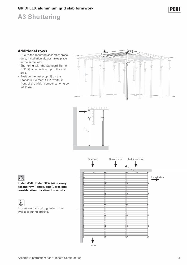
Additional rows– Due to the recurring assembly proce-
dure, installation always takes place
in the same way.
– Shuttering with the Standard Element
GFP (2) is carried out up to the infill
area.
– Position the last prop (1) on the
Standard Elelment GFP (white) in
front of the width compensation (see
Infills A4).
Install Wall Holder GFW (4) in every second row (longitudinal).Take into consideration the situation on site.
Ensure empty Stacking Pallet GF is
available during striking.
First row
Longitudinal
2
4
1
Second row Additional rows
Cross
14
A4 Infills
Assembly Instructions for Standard Configuration
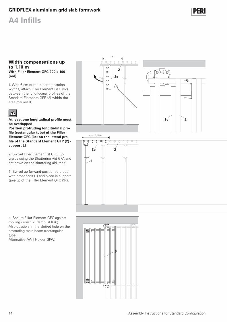
Width compensations up to 1.10 mWith Filler Element GFC 200 x 100 (red)
1. With 6 cm or more compensation
widths, attach Filler Element GFC (3c)
between the longitudinal profiles of the
Standard Elements GFP (2) within the
area marked X.
At least one longitudinal profile must be overlapped!Position protruding longitudinal pro-file (rectangular tube) of the Filler Element GFC (3c) on the lateral pro-file of the Standard Element GFP (2) - support L!
2. Swivel Filler Element GFC (3) up-
wards using the Shuttering Aid GFA and
set down on the shuttering aid itself.
3. Swivel up forward-positioned props
with propheads (1) and place in support
take-up of the Filler Element GFC (3c).
GRIDFLEX aluminium grid slab formwork
4. Secure Filler Element GFC against
moving - use 1 x Clamp GFK (6).
Also possible in the slotted hole on the
protruding main beam (rectangular
tube).
Alternative: Wall Holder GFW.
2
3c
max. 1,10 m
2
1
3c
6
3c
L
X
2
15Assembly Instructions for Standard Configuration
A4 InfillsGRIDFLEX aluminium grid slab formwork
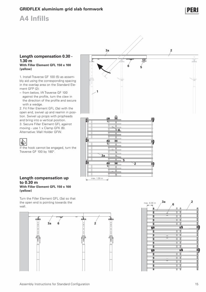
Length compensation 0.30 - 1.30 mWith Filler Element GFL 150 x 100 (yellow)
1. Install Traverse GF 100 (5) as assem-
bly aid using the corresponding spacing
in the overlap area on the Standard Ele-
ment GFP (2):
– from below, lift Traverse GF 100
against the profile, turn the claw in
the direction of the profile and secure
with a wedge.
2. Fit Filler Element GFL (3a) with the
open end, swivel up and reamin in posi-
tion. Swivel up props with propheads
and bring into a vertical position.
3. Secure Filler Element GFL against
moving - use 1 x Clamp GFK (6).
Alternative: Wall Holder GFW.
If the hook cannot be engaged, turn the
Traverse GF 100 by 180°.
2
1
6
3a
5
Length compensation up to 0.30 mWith Filler Element GFL 150 x 100 (yellow)
Turn the Filler Element GFL (3a) so that
the open end is pointing towards the
wall.
max. 0.30 m
6
max. 1.30 m
5
6
3a
3a 2
23a6
2
16
A4 Infills
Assembly Instructions for Standard Configuration
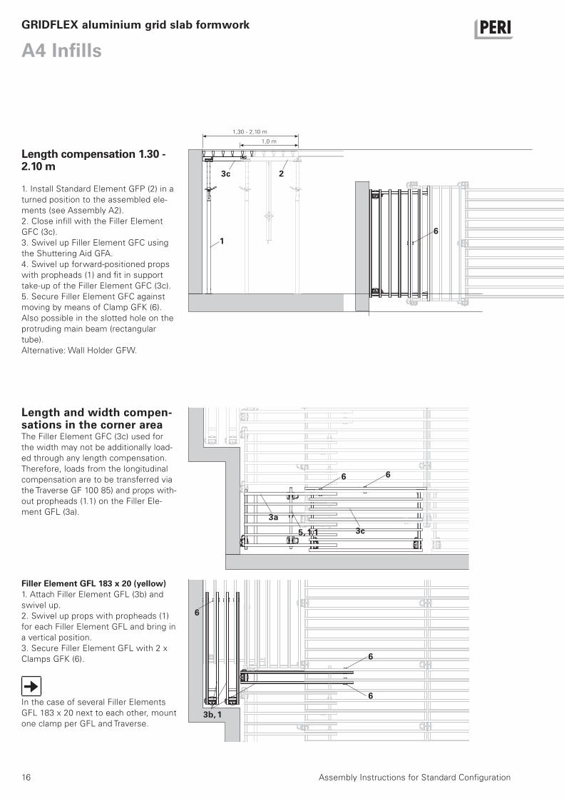
Length compensation 1.30 - 2.10 m
1. Install Standard Element GFP (2) in a
turned position to the assembled ele-
ments (see Assembly A2).
2. Close infill with the Filler Element
GFC (3c).
3. Swivel up Filler Element GFC using
the Shuttering Aid GFA.
4. Swivel up forward-positioned props
with propheads (1) and fit in support
take-up of the Filler Element GFC (3c).
5. Secure Filler Element GFC against
moving by means of Clamp GFK (6).
Also possible in the slotted hole on the
protruding main beam (rectangular
tube).
Alternative: Wall Holder GFW.
GRIDFLEX aluminium grid slab formwork
1,30 - 2,10 m
1,0 m
2
6
3c5, 1.1
3a
3b, 1
6
Filler Element GFL 183 x 20 (yellow)1. Attach Filler Element GFL (3b) and
swivel up.
2. Swivel up props with propheads (1)
for each Filler Element GFL and bring in
a vertical position.
3. Secure Filler Element GFL with 2 x
Clamps GFK (6).
In the case of several Filler Elements
GFL 183 x 20 next to each other, mount
one clamp per GFL and Traverse.
Length and width compen-sations in the corner areaThe Filler Element GFC (3c) used for
the width may not be additionally load-
ed through any length compensation.
Therefore, loads from the longitudinal
compensation are to be transferred via
the Traverse GF 100 85) and props with-
out propheads (1.1) on the Filler Ele-
ment GFL (3a).
1
3c
66
6
6
17Assembly Instructions for Standard Configuration
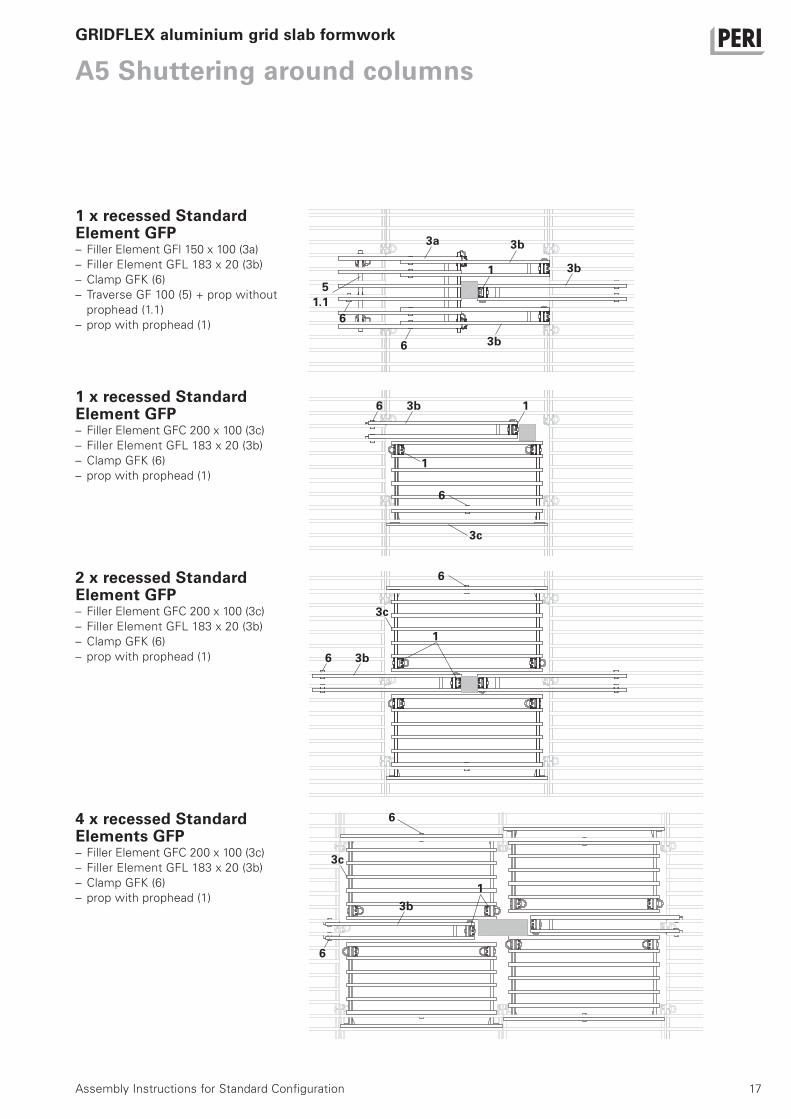
A5 Shuttering around columns
1 x recessed Standard Element GFP – Filler Element GFl 150 x 100 (3a)
– Filler Element GFL 183 x 20 (3b)
– Clamp GFK (6)
– Traverse GF 100 (5) + prop without
prophead (1.1)
– prop with prophead (1)
GRIDFLEX aluminium grid slab formwork
2 x recessed Standard Element GFP– Filler Element GFC 200 x 100 (3c)
– Filler Element GFL 183 x 20 (3b)
– Clamp GFK (6)
– prop with prophead (1)
4 x recessed Standard Elements GFP– Filler Element GFC 200 x 100 (3c)
– Filler Element GFL 183 x 20 (3b)
– Clamp GFK (6)
– prop with prophead (1)
1 x recessed Standard Element GFP– Filler Element GFC 200 x 100 (3c)
– Filler Element GFL 183 x 20 (3b)
– Clamp GFK (6)
– prop with prophead (1)
51.1
3c
3b
13b6
1
6
6
6
1
3b
3b
6
6
3a
3b6
3b
6
3c
1
3c
1

18 Assembly Instructions for Standard Configuration
A6 Cantilevers, GuardrailsGRIDFLEX aluminium grid slab formwork
General
The area to be formed may not be accessed before the formwork has been horizontally anchored!The cantilevers may not be accessed before the bracing has been form-locked mounted!
Bracing– Ensure correct spacings
– Install longitudinal and lateral bracing
in the fields
Longitudinally with Tension Sleeve
GFO (12)
Laterally, chain wrapped around the
cross beam
CantileversDepending on the situation, the slab
edge can be formed using different sys-
tem components,
e.g. with:
– Filler Element GFL 150 x 100 (3a)
– Guardrail GF (7)
– Traverse GF 100 (5) + prop without
prophead (1.1)
– Bracing (12.1)
or– Standard Element GFP 200 x 100 (2)
– Guardrail GF (7)
– Traverse GF 100 (5) + prop without
prophead (1.1)
– Bracing (12.1)
Key:
2
5
7
Longitudinal Lateral
2 fields 4.5 fields 4.5 fields
Schematic view
4.5
fie
lds
4.5
fie
lds
2 f
ield
s
GFP GFL
≤ 5
0≥
36
≤ 2
0
12.1
Area of influence
e.g. slab d = 26 cm
Bracing
73a
1.1
12
19Assembly Instructions for Standard Configuration
A6 Cantilevers, GuardrailsGRIDFLEX aluminium grid slab formwork
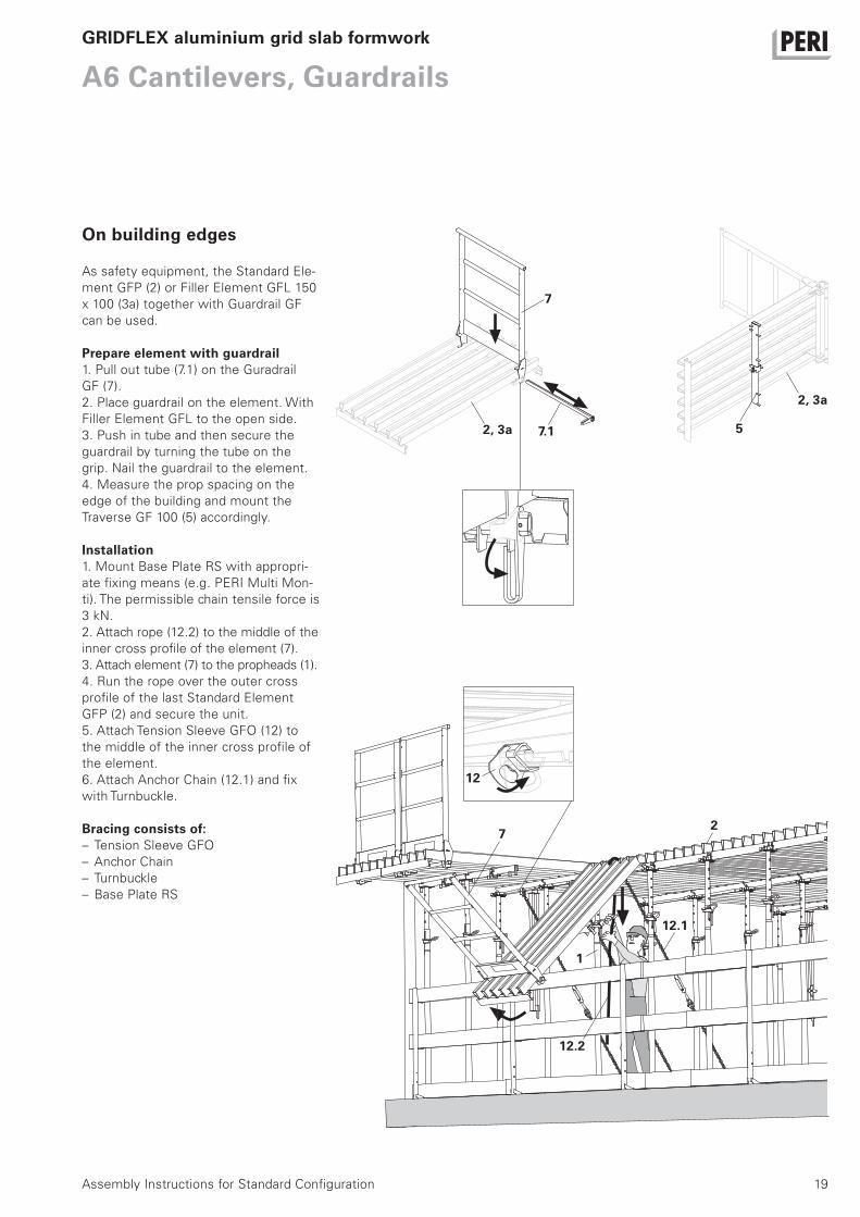
On building edges
As safety equipment, the Standard Ele-
ment GFP (2) or Filler Element GFL 150
x 100 (3a) together with Guardrail GF
can be used.
Prepare element with guardrail1. Pull out tube (7.1) on the Guradrail
GF (7).
2. Place guardrail on the element. With
Filler Element GFL to the open side.
3. Push in tube and then secure the
guardrail by turning the tube on the
grip. Nail the guardrail to the element.
4. Measure the prop spacing on the
edge of the building and mount the
Traverse GF 100 (5) accordingly.
Installation1. Mount Base Plate RS with appropri-
ate fixing means (e.g. PERI Multi Mon-
ti). The permissible chain tensile force is
3 kN.
2. Attach rope (12.2) to the middle of the
inner cross profile of the element (7).
3. Attach element (7) to the propheads (1).
4. Run the rope over the outer cross
profile of the last Standard Element
GFP (2) and secure the unit.
5. Attach Tension Sleeve GFO (12) to
the middle of the inner cross profile of
the element.
6. Attach Anchor Chain (12.1) and fix
with Turnbuckle.
Bracing consists of:– Tension Sleeve GFO
– Anchor Chain
– Turnbuckle
– Base Plate RS
7
2, 3a 7.1 5
2, 3a
12
7
12.2
12.1
2
1

20
A6 Cantilevers, Guardrails
Assembly Instructions for Standard Configuration
7. Swivel up guardrail unit (7) on the Traverse GF 100 (5) using the Shutter-ing Aid GFA (11).8. Take up and support two Traverse GF 100 with the prop without prophead (1.1).9. Remove rope.
GRIDFLEX aluminium grid slab formwork
max. 50 cm
55
7
On the casting segmentsMount the guardrail unit (7) as de-scribed in “Preparing Element with Guardrail”.
h/2 ± 20≥ 36
11
≥ 20
h
7
1.1
21Assembly Instructions for Standard Configuration
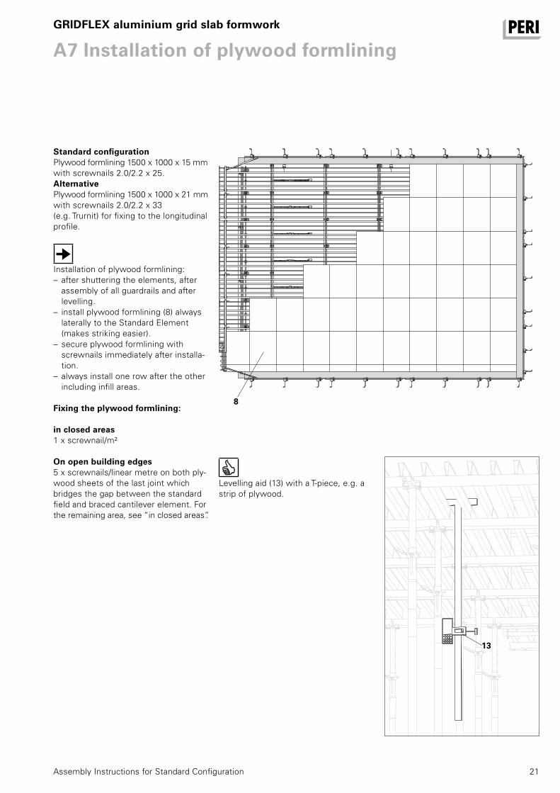
A7 Installation of plywood formliningGRIDFLEX aluminium grid slab formwork
Standard configurationPlywood formlining 1500 x 1000 x 15 mm with screwnails 2.0/2.2 x 25.AlternativePlywood formlining 1500 x 1000 x 21 mm with screwnails 2.0/2.2 x 33(e.g. Trurnit) for fixing to the longitudinal profile.
Installation of plywood formlining:– after shuttering the elements, after
assembly of all guardrails and after levelling.
– install plywood formlining (8) always laterally to the Standard Element (makes striking easier).
– secure plywood formlining with screwnails immediately after installa-tion.
– always install one row after the other including infill areas.
Fixing the plywood formlining:
in closed areas1 x screwnail/m²
On open building edges5 x screwnails/linear metre on both ply-wood sheets of the last joint which bridges the gap between the standard field and braced cantilever element. For the remaining area, see “in closed areas”.
8
13
Levelling aid (13) with a T-piece, e.g. a strip of plywood.
22 Assembly Instructions for Standard Configuration
A7 Installation of plywood formlining
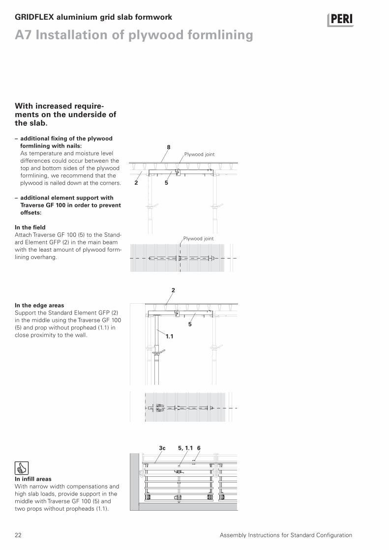
With increased require-ments on the underside of the slab.
– additional fixing of the plywood formlining with nails:As temperature and moisture level
differences could occur between the
top and bottom sides of the plywood
formlining, we recommend that the
plywood is nailed down at the corners.
– additional element support with Traverse GF 100 in order to prevent offsets:
In the fieldAttach Traverse GF 100 (5) to the Stand-
ard Element GFP (2) in the main beam
with the least amount of plywood form-
lining overhang.
GRIDFLEX aluminium grid slab formwork
8
In the edge areasSupport the Standard Element GFP (2)
in the middle using the Traverse GF 100
(5) and prop without prophead (1.1) in
close proximity to the wall.
In infill areasWith narrow width compensations and
high slab loads, provide support in the
middle with Traverse GF 100 (5) and
two props without propheads (1.1).
2 5
2
5
1.1
Plywood joint
Plywood joint
3c 5, 1.1 6

23
A8 Working and concreting scaffold
Assembly Instructions for Standard Configuration
Corner Platform GCPPermissible load 150 kg/m²
Corner Platform GCP (9) for circular and
cornered columns with cross-sections
from 20 - 50 cm on the building corners.
GRIDFLEX aluminium grid slab formwork
9
Preparing the platforms1. Fold out supports (9.1) and lock in
place.
2. Turn platform around, attach 3-sling
lifting gear and lift.
3. Insert Platform Guardrail (9.2) and
connect with each other.
9.1
9.2
9.1
24 Assembly Instructions for Standard Configuration
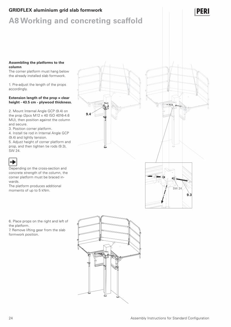
A8 Working and concreting scaffoldGRIDFLEX aluminium grid slab formwork
Assembling the platforms to the columnThe corner platform must hang below
the already installed slab formwork.
1. Pre-adjust the length of the props
accordingly.
Extension length of the prop = clear height - 43.5 cm - plywood thickness.
2. Mount Internal Angle GCP (9.4) on
the prop (2pcs M12 x 40 ISO 4016-4.6
MU), then position against the column
and secure.
3. Position corner platform.
4. Install tie rod in Internal Angle GCP
(9.4) and lightly tension.
5. Adjust height of corner platform and
prop, and then tighten tie rods (9.3),
SW 24.
Depending on the cross-section and
concrete strength of the column, the
corner platform must be braced in-
wards.
The platform produces additional
moments of up to 5 kNm.
9.4
9.3
SW 24
6. Place props on the right and left of
the platform.
7. Remove lifting gear from the slab
formwork position.
25
A8 Working and concreting scaffold
Assembly Instructions for Standard Configuration
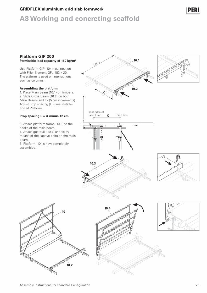
Platform GIP 200Permissble load capacity of 150 kg/m²
Use Platform GIP (10) in connection
with Filler Element GFL 183 x 20.
The plaform is used on interruptions
such as columns.
Assembling the platform1. Place Main Beam (10.1) on timbers.
2. Slide Cross Beam (10.2) on both
Main Beams and fix (5 cm increments).
Adjust prop spacing (L) - see Installa-
tion of Platform.
Prop spacing L = X minus 12 cm
3. Attach platform frame (10.3) to the
hooks of the main beam.
4. Attach guardrail (10.4) and fix by
means of the captive bolts on the main
beam.
5. Platform (10) is now completely
assembled.
GRIDFLEX aluminium grid slab formwork
10.2
10.3
10.4
1,80 m
L
10.1
XFront edge of
the column Prop axis
10
10.2
26 Assembly Instructions for Standard Configuration
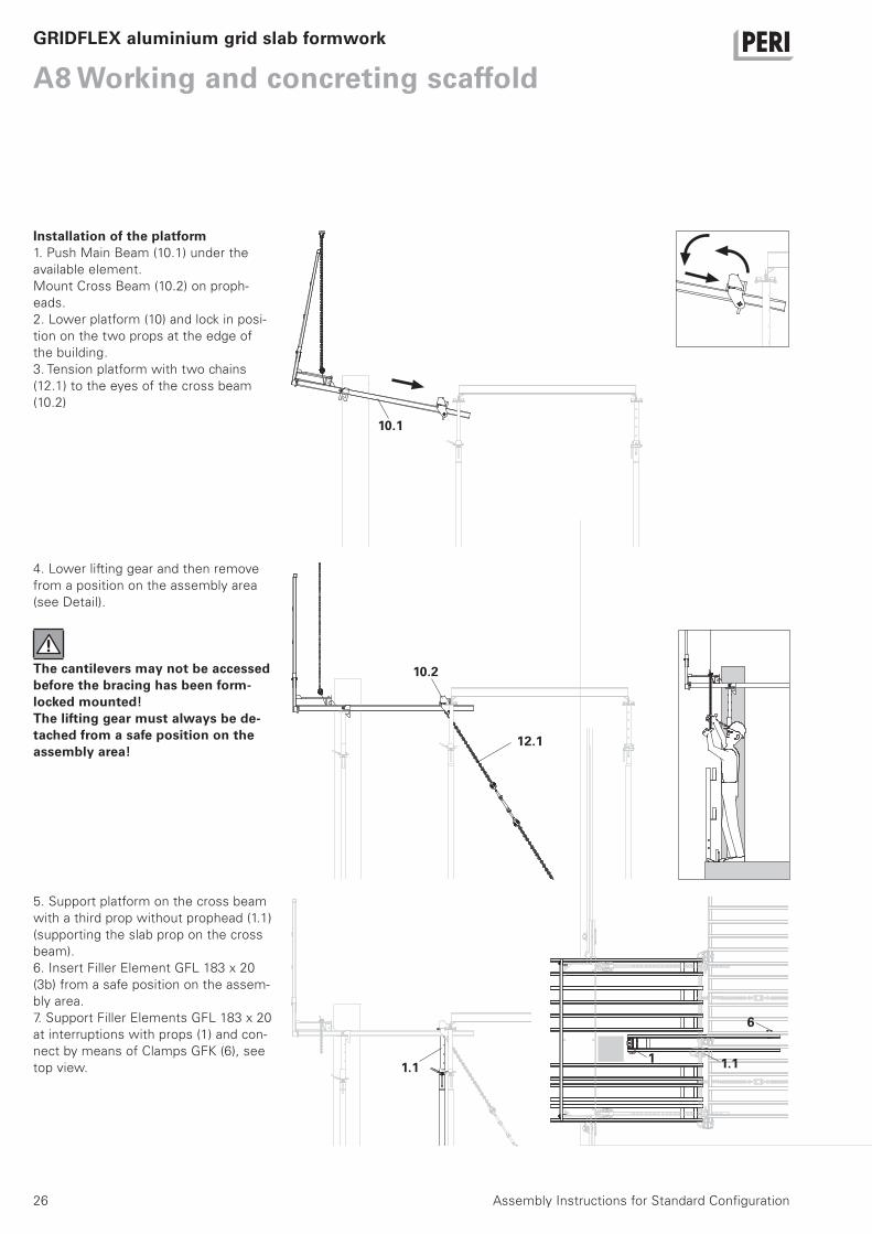
A8 Working and concreting scaffoldGRIDFLEX aluminium grid slab formwork
Installation of the platform1. Push Main Beam (10.1) under the
available element.
Mount Cross Beam (10.2) on proph-
eads.
2. Lower platform (10) and lock in posi-
tion on the two props at the edge of
the building.
3. Tension platform with two chains
(12.1) to the eyes of the cross beam
(10.2)
5. Support platform on the cross beam
with a third prop without prophead (1.1)
(supporting the slab prop on the cross
beam).
6. Insert Filler Element GFL 183 x 20
(3b) from a safe position on the assem-
bly area.
7. Support Filler Elements GFL 183 x 20
at interruptions with props (1) and con-
nect by means of Clamps GFK (6), see
top view.
10.1
12.1
1
10.2
1.1
6
4. Lower lifting gear and then remove
from a position on the assembly area
(see Detail).
The cantilevers may not be accessed before the bracing has been form-locked mounted!The lifting gear must always be de-tached from a safe position on the assembly area!
1.1
27Assembly Instructions for Standard Configuration
A9 StrikingGRIDFLEX aluminium grid slab formwork
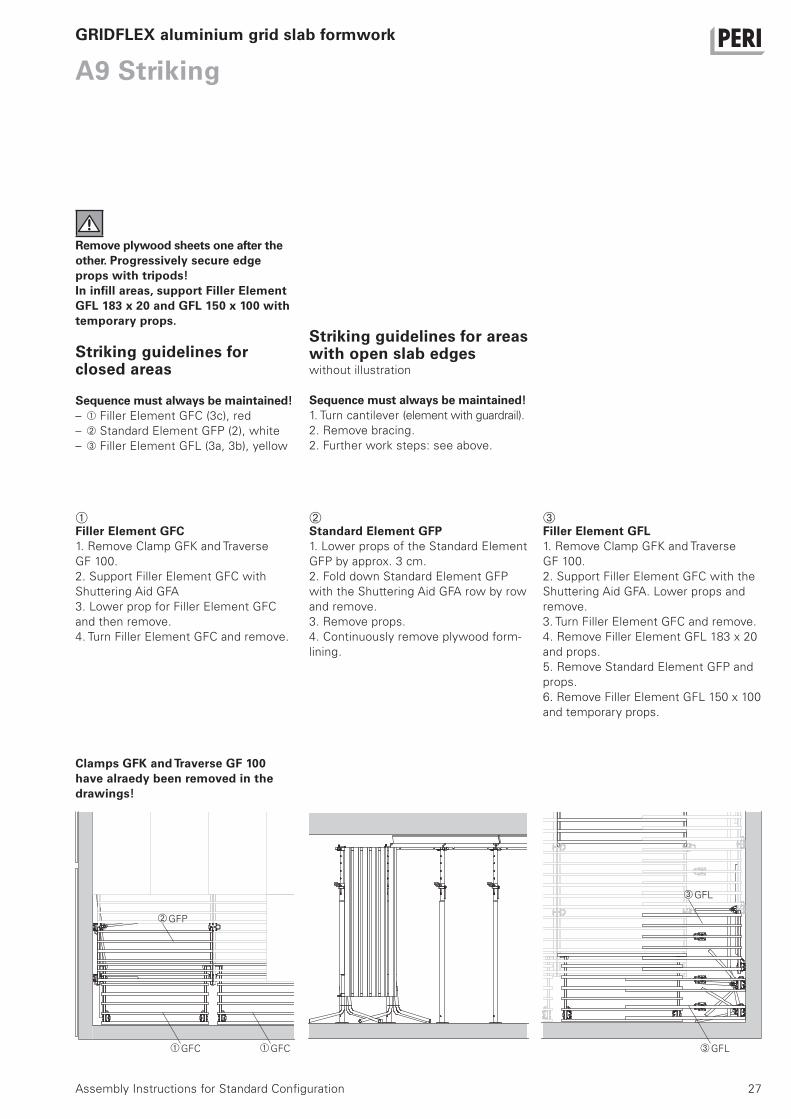
Remove plywood sheets one after the other. Progressively secure edge props with tripods!In infill areas, support Filler Element GFL 183 x 20 and GFL 150 x 100 with temporary props.
Striking guidelines for closed areas
Sequence must always be maintained!– Filler Element GFC (3c), red
– Standard Element GFP (2), white
– Filler Element GFL (3a, 3b), yellow
GFC
GFP
Striking guidelines for areas with open slab edgeswithout illustration
Sequence must always be maintained!1. Turn cantilever (element with guardrail).
2. Remove bracing.
2. Further work steps: see above.
GFC GFL
GFL
Clamps GFK and Traverse GF 100 have alraedy been removed in the drawings!
Standard Element GFP1. Lower props of the Standard Element
GFP by approx. 3 cm.
2. Fold down Standard Element GFP
with the Shuttering Aid GFA row by row
and remove.
3. Remove props.
4. Continuously remove plywood form-
lining.
Filler Element GFL1. Remove Clamp GFK and Traverse
GF 100.
2. Support Filler Element GFC with the
Shuttering Aid GFA. Lower props and
remove.
3. Turn Filler Element GFC and remove.
4. Remove Filler Element GFL 183 x 20
and props.
5. Remove Standard Element GFP and
props.
6. Remove Filler Element GFL 150 x 100
and temporary props.
Filler Element GFC1. Remove Clamp GFK and Traverse
GF 100.
2. Support Filler Element GFC with
Shuttering Aid GFA
3. Lower prop for Filler Element GFC
and then remove.
4. Turn Filler Element GFC and remove.

28 Assembly Instructions for Standard Configuration
A10 Maintenance and cleaning
Careful handling of the formwork is required in order to maintain the value and operational readiness of the equipment over a long period of time.
Maintenance tips1. Concrete vibrator with rubber end
cap reduces the risk of damage to the
formlining.
2. Spacers used for the reinforcement
with large contact surfaces prevent im-
pressions forming on the formlining.
3. Use support timbers if placing heavy
objects in order to prevent impressions
and damage to the formlining.
4. Spray components with PERI Bio
Clean before every use and clean the
rear side of the formwork with water
immediately after concreting.
5. Spray moving parts, if required, with
PERI Bio Clean.
6. PERI pallets and stacking pallets are
available to provide suitable protection
during transportation.
Due to the powder coating, cleaning
requirements are kept to a minimum.
GRIDFLEX aluminium grid slab formwork
29
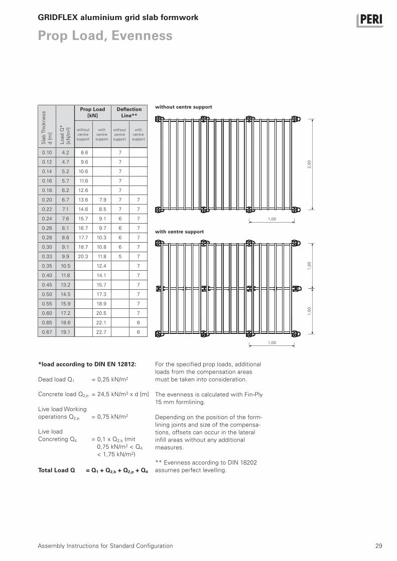
0.10 4.2 8.6 7
0.12 4.7 9.6 7
0.14 5.2 10.6 7
0.16 5.7 11.6 7
0.18 6.2 12.6 7
0.20 6.7 13.6 7.9 7 7
0.22 7.1 14.6 8.5 7 7
0.24 7.6 15.7 9.1 6 7
0.26 8.1 16.7 9.7 6 7
0.28 8.6 17.7 10.3 6 7
0.30 9.1 18.7 10.8 6 7
0.33 9.9 20.3 11.8 5 7
0.35 10.5 12.4 7
0.40 11.8 14.1 7
0.45 13.2 15.7 7
0.50 14.5 17.3 7
0.55 15.9 18.9 7
0.60 17.2 20.5 7
0.65 18.6 22.1 6
0.67 19.1 22.7 6
Assembly Instructions for Standard Configuration
Prop Load, EvennessGRIDFLEX aluminium grid slab formwork
*load according to DIN EN 12812:
Dead load Q1
Concrete load Q2,b
Live load Working
operations Q2,p
Live load
Concreting Q4
= 0,25 kN/m2
= 24,5 kN/m3 x d [m]
= 0,75 kN/m2
= 0,1 x Q2,b (mit
0,75 kN/m2 < Q4
< 1,75 kN/m2)
without centre support
with centre support
Prop Load[kN]
Deflection Line**
with
centre
support
with
centre
support
Sla
b T
hic
kn
ess
d [
m]
Lo
ad
Q*
[kN
/m²]
For the specified prop loads, additional
loads from the compensation areas
must be taken into consideration.
The evenness is calculated with Fin-Ply
15 mm formlining.
Depending on the position of the form-
lining joints and size of the compensa-
tions, offsets can occur in the lateral
infill areas without any additional
measures.
** Evenness according to DIN 18202
assumes perfect levelling.
2,0
0
1,00
1,00
1,0
01
,00
Total Load Q = Q1 + Q2,b + Q2,p + Q4
without
centre
support
without
centre
support
30
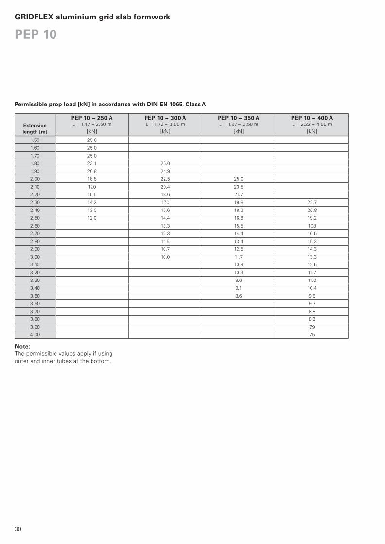
PEP 10 – 250 AL = 1.47 – 2.50 m
[kN]
PEP 10 – 300 AL = 1.72 – 3.00 m
[kN]
PEP 10 – 350 AL = 1.97 – 3.50 m
[kN]
PEP 10 – 400 AL = 2.22 – 4.00 m
[kN]
1.50 25.0
1.60 25.0
1.70 25.0
1.80 23.1 25.0
1.90 20.8 24.9
2.00 18.8 22.5 25.0
2.10 17.0 20.4 23.8
2.20 15.5 18.6 21.7
2.30 14.2 17.0 19.8 22.7
2.40 13.0 15.6 18.2 20.8
2.50 12.0 14.4 16.8 19.2
2.60 13.3 15.5 17.8
2.70 12.3 14.4 16.5
2.80 11.5 13.4 15.3
2.90 10.7 12.5 14.3
3.00 10.0 11.7 13.3
3.10 10.9 12.5
3.20 10.3 11.7
3.30 9.6 11.0
3.40 9.1 10.4
3.50 8.6 9.8
3.60 9.3
3.70 8.8
3.80 8.3
3.90 7.9
4.00 7.5
Note:The permissible values apply if using
outer and inner tubes at the bottom.
Permissible prop load [kN] in accordance with DIN EN 1065, Class A
Extension length [m]
PEP 10GRIDFLEX aluminium grid slab formwork

31
PEP 20 N 260*L = 1.51 – 2.60 m
PEP 20 – 300PEP 20 N 300*L = 1.71 – 3.00 m
PEP 20 – 350PEP 20 N 350*L = 1.96 – 3.50 m
PEP 20 – 400PEP 20 G 410*L = 2.21 – 4.00 m
PEP 20 – 500
L = 2.71 – 5.00
1.60 35.0 35.0
1.70 35.0 35.0
1.80 35.0 35.0 35.0 35.0
1.90 35.0 35.0 35.0 35.0
2.00 33.5 35.0 35.0 35.0 35.0 35.0
2.10 31.9 35.0 32.2 35.0 35.0 35.0
2.20 30.9 35.0 30.5 35.0 35.0 35.0
2.30 29.8 35.0 29.0 35.0 35.0 35.0 35.0 35.0
2.40 28.6 35.0 27.8 35.0 35.0 35.0 35.0 35.0
2.50 27.1 32.9 26.9 35.0 35.0 35.0 35.0 35.0
2.60 24.8 29.4 26.1 35.0 33.8 35.0 35.0 35.0
2.70 24.9 31.7 32.4 35.0 35.0 35.0
2.80 23.3 28.5 31.2 35.0 35.0 35.0 35.0 35.0
2.90 21.6 25.7 30.2 35.0 35.0 35.0 35.0 35.0
3.00 20.0 23.2 29.2 35.0 35.0 35.0 35.0 35.0
3.10 27.5 34.6 33.6 35.0 35.0 35.0
3.20 25.7 31.5 32.5 35.0 35.0 35.0
3.30 24.1 28.8 31.2 35.0 35.0 35.0
3.40 22.4 26.4 29.6 35.0 35.0 35.0
3.50 20.7 24.1 27.8 33.9 35.0 35.0
3.60 26.1 31.2 35.0 35.0
3.70 24.5 28.9 35.0 35.0
3.80 23.0 26.8 35.0 35.0
3.90 21.6 24.8 35.0 35.0
4.00 20.1 22.8 34.2 35.0
4.10 32.3 35.0
4.20 30.6 35.0
4.30 28.9 34.0
4.40 27.4 31.9
4.50 26.0 29.9
4.60 24.6 28.1
4.70 23.4 26.4
4.80 22.1 24.9
4.90 20.9 23.4
5.00 20.0 21.8
Permissible Prop Load [kN] according to the Type Test
Exte
nsio
n
Le
ng
th [
m]
Outer TubeBottom
Inner TubeBottom
Outer TubeBottom
Inner Tube Bottom
Outer TubeBottom
Inner Tube Bottom
Outer TubeBottom
Inner Tube Bottom
Outer TubeBottom
Inner Tube Bottom
All PEP 20 Props conform with DIN EN
1065 class D with a permissible load for
the entire extension range of minimum
20 kN.
All PEP 20 Props clamped in the Table
Swivel Head or UNIPORTAL Head fitted
to PERI tableforms have a permissible
load of minimum 30 kN over the entire
extension range.
*For the N and G Props the application
Inner Tube at Bottom is only possible
with PERI Slab Tables or SKYDECK
(bolted head).
PEP 20GRIDFLEX aluminium grid slab formwork
32
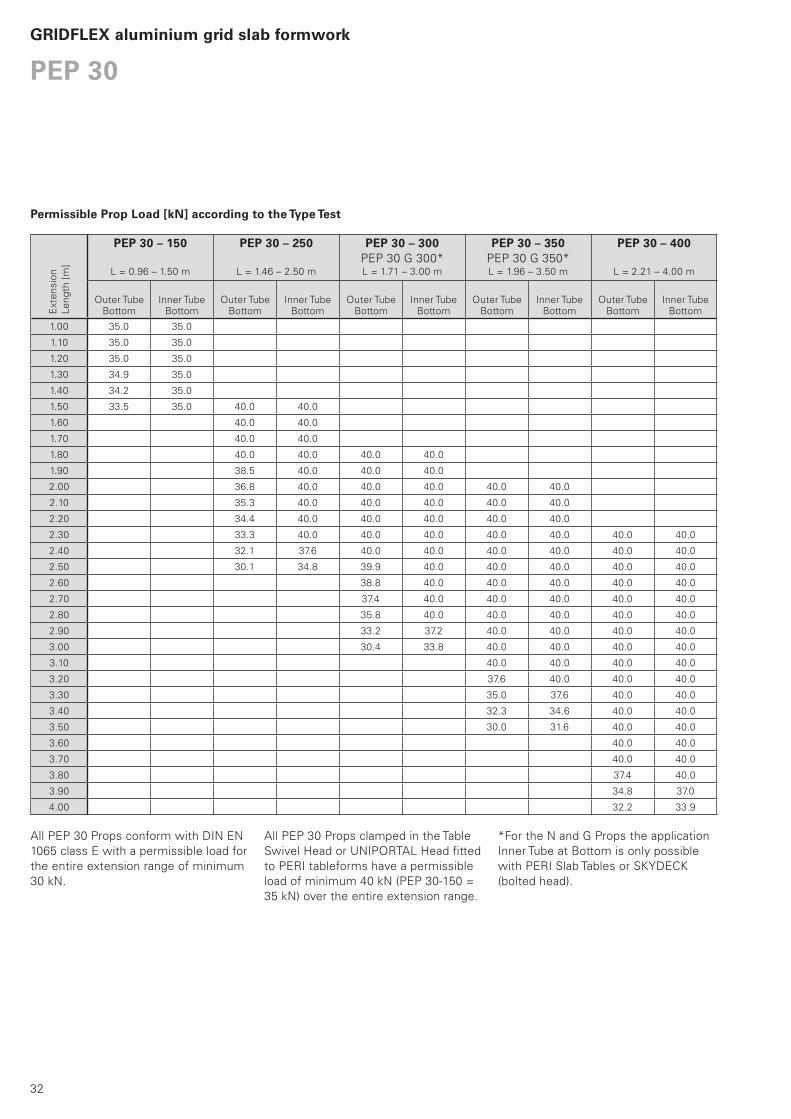
PEP 30 – 150
L = 0.96 – 1.50 m
PEP 30 – 250
L = 1.46 – 2.50 m
PEP 30 – 300PEP 30 G 300*L = 1.71 – 3.00 m
PEP 30 – 350PEP 30 G 350*L = 1.96 – 3.50 m
PEP 30 – 400
L = 2.21 – 4.00 m
1.00 35.0 35.0
1.10 35.0 35.0
1.20 35.0 35.0
1.30 34.9 35.0
1.40 34.2 35.0
1.50 33.5 35.0 40.0 40.0
1.60 40.0 40.0
1.70 40.0 40.0
1.80 40.0 40.0 40.0 40.0
1.90 38.5 40.0 40.0 40.0
2.00 36.8 40.0 40.0 40.0 40.0 40.0
2.10 35.3 40.0 40.0 40.0 40.0 40.0
2.20 34.4 40.0 40.0 40.0 40.0 40.0
2.30 33.3 40.0 40.0 40.0 40.0 40.0 40.0 40.0
2.40 32.1 37.6 40.0 40.0 40.0 40.0 40.0 40.0
2.50 30.1 34.8 39.9 40.0 40.0 40.0 40.0 40.0
2.60 38.8 40.0 40.0 40.0 40.0 40.0
2.70 37.4 40.0 40.0 40.0 40.0 40.0
2.80 35.8 40.0 40.0 40.0 40.0 40.0
2.90 33.2 37.2 40.0 40.0 40.0 40.0
3.00 30.4 33.8 40.0 40.0 40.0 40.0
3.10 40.0 40.0 40.0 40.0
3.20 37.6 40.0 40.0 40.0
3.30 35.0 37.6 40.0 40.0
3.40 32.3 34.6 40.0 40.0
3.50 30.0 31.6 40.0 40.0
3.60 40.0 40.0
3.70 40.0 40.0
3.80 37.4 40.0
3.90 34.8 37.0
4.00 32.2 33.9
Permissible Prop Load [kN] according to the Type Test
Exte
nsio
n
Le
ng
th [
m]
Outer TubeBottom
Inner Tube Bottom
Outer Tube Bottom
Inner Tube Bottom
Outer Tube Bottom
Inner Tube Bottom
Outer Tube Bottom
Inner Tube Bottom
Outer Tube Bottom
Inner Tube Bottom
All PEP 30 Props conform with DIN EN
1065 class E with a permissible load for
the entire extension range of minimum
30 kN.
All PEP 30 Props clamped in the Table
Swivel Head or UNIPORTAL Head fitted
to PERI tableforms have a permissible
load of minimum 40 kN (PEP 30-150 =
35 kN) over the entire extension range.
*For the N and G Props the application
Inner Tube at Bottom is only possible
with PERI Slab Tables or SKYDECK
(bolted head).
PEP 30GRIDFLEX aluminium grid slab formwork

33
34
Item no. Weight kg
GRIDFLEX aluminium grid slab formwork
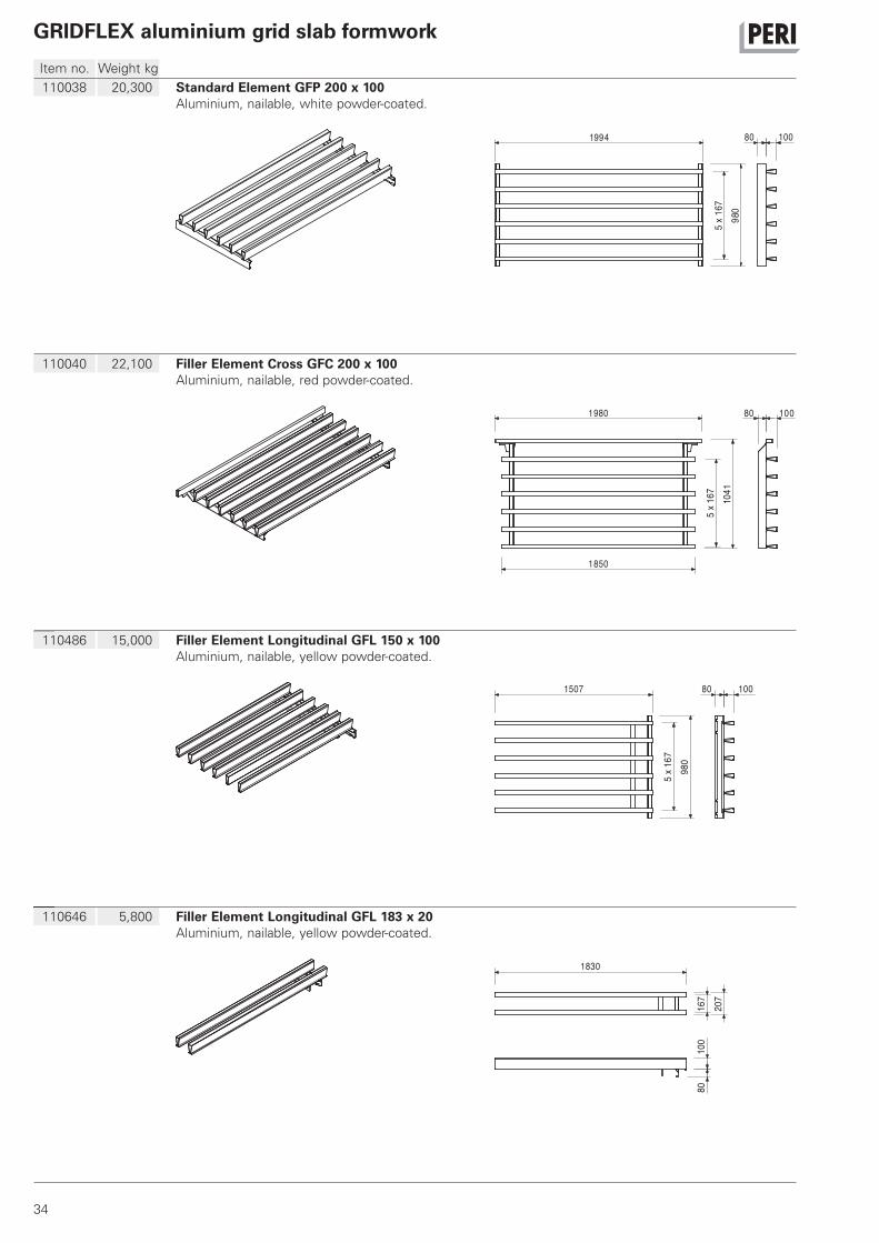
110038 20,300 Standard Element GFP 200 x 100Aluminium, nailable, white powder-coated.
980
1994
5x
167
80 100
110040 22,100 Filler Element Cross GFC 200 x 100Aluminium, nailable, red powder-coated.
1041
5x
167
1980
1850
80 100
110486 15,000 Filler Element Longitudinal GFL 150 x 100Aluminium, nailable, yellow powder-coated.
980
1507
5x
167
80 100
110646 5,800 Filler Element Longitudinal GFL 183 x 20Aluminium, nailable, yellow powder-coated.
1830
167
207
100
80
35
Item no. Weight kg
GRIDFLEX aluminium grid slab formwork
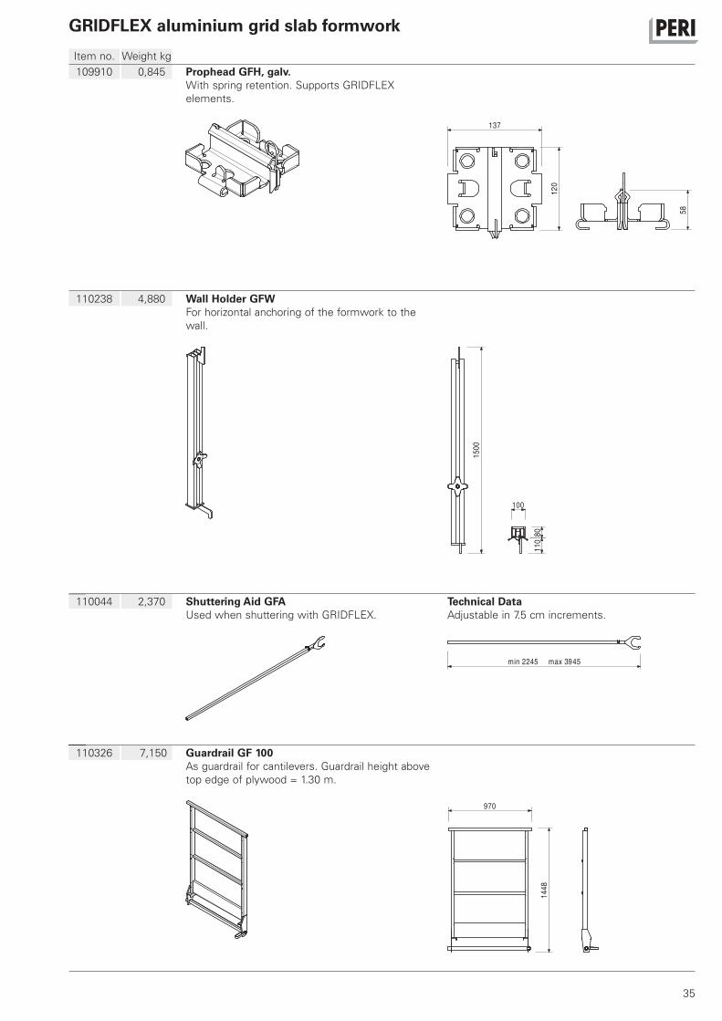
109910 0,845 Prophead GFH, galv.With spring retention. Supports GRIDFLEX
elements.
137
120
58
110238 4,880 Wall Holder GFWFor horizontal anchoring of the formwork to the
wall.
1500
100
8011
0
110044 2,370 Shuttering Aid GFAUsed when shuttering with GRIDFLEX.
Technical DataAdjustable in 7.5 cm increments.
2245min max 3945
110326 7,150 Guardrail GF 100As guardrail for cantilevers. Guardrail height above
top edge of plywood = 1.30 m.
1448
970
36
Item no. Weight kg
GRIDFLEX aluminium grid slab formwork
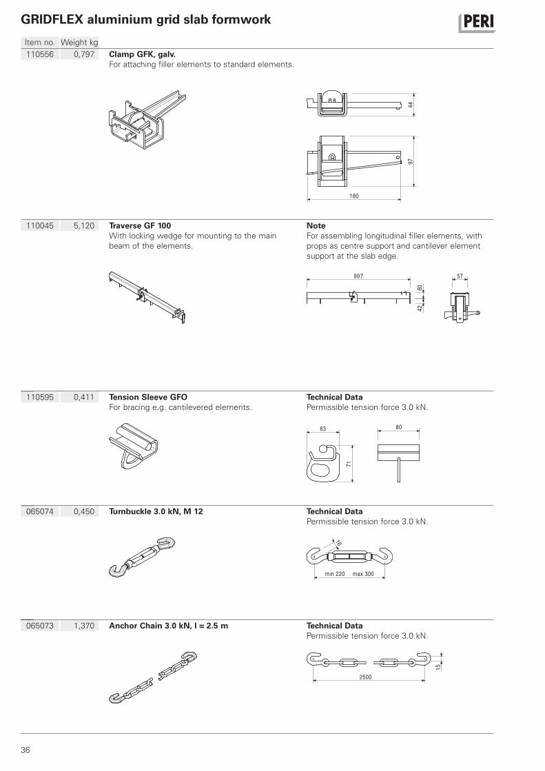
110556 0,797 Clamp GFK, galv.For attaching filler elements to standard elements.
9744
180
110045 5,120 Traverse GF 100With locking wedge for mounting to the main
beam of the elements.
NoteFor assembling longitudinal filler elements, with
props as centre support and cantilever element
support at the slab edge.
997
4260
57
110595 0,411 Tension Sleeve GFOFor bracing e.g. cantilevered elements.
Technical DataPermissible tension force 3.0 kN.
63 80
71
065074 0,450 Turnbuckle 3.0 kN, M 12 Technical DataPermissible tension force 3.0 kN.
min 220 max 300
16
065073 1,370 Anchor Chain 3.0 kN, l = 2.5 m Technical DataPermissible tension force 3.0 kN.
2500
15
37
Item no. Weight kg
GRIDFLEX aluminium grid slab formwork
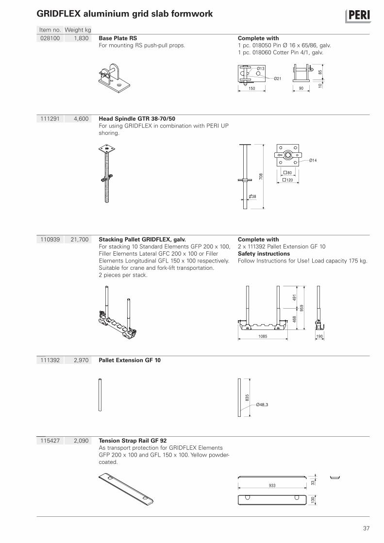
028100 1,830 Base Plate RSFor mounting RS push-pull props.
Complete with1 pc. 018050 Pin Ø 16 x 65/86, galv.
1 pc. 018060 Cotter Pin 4/1, galv.
150 90 1085
Ø21
Ø13
111291 4,600 Head Spindle GTR 38-70/50For using GRIDFLEX in combination with PERI UP
shoring.
708
38
80
120
Ø14
110939 21,700 Stacking Pallet GRIDFLEX, galv.For stacking 10 Standard Elements GFP 200 x 100,
Filler Elements Lateral GFC 200 x 100 or Filler
Elements Longitudinal GFL 150 x 100 respectively.
Suitable for crane and fork-lift transportation.
2 pieces per stack.
Complete with2 x 111392 Pallet Extension GF 10
Safety instructionsFollow Instructions for Use! Load capacity 175 kg.
1085 190
468
491
959
111392 2,970 Pallet Extension GF 10
835
Ø48,3
115427 2,090 Tension Strap Rail GF 92As transport protection for GRIDFLEX Elements
GFP 200 x 100 and GFL 150 x 100. Yellow powder-
coated.
933 3313
0
38
Item no. Weight kg
GRIDFLEX aluminium grid slab formwork
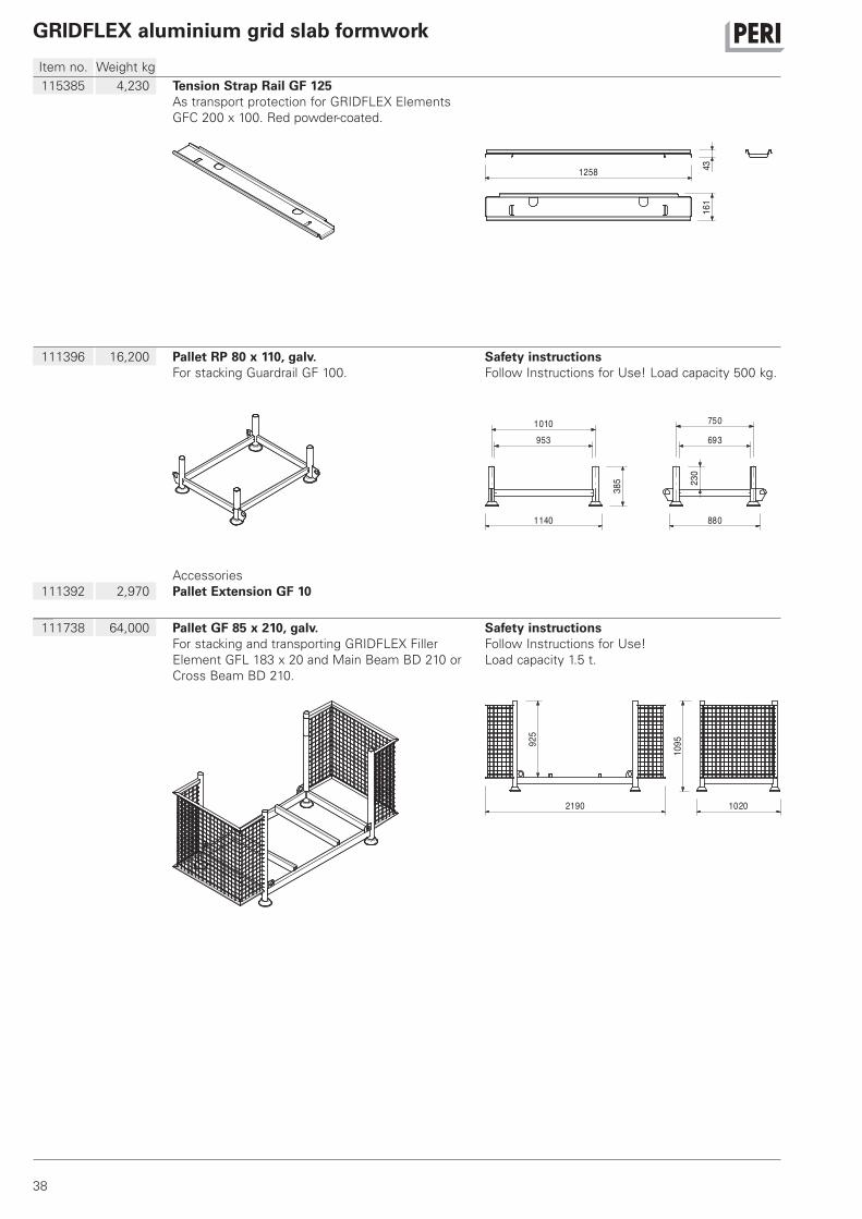
115385 4,230 Tension Strap Rail GF 125As transport protection for GRIDFLEX Elements
GFC 200 x 100. Red powder-coated.
1258 4316
1
111396 16,200 Pallet RP 80 x 110, galv.For stacking Guardrail GF 100.
Safety instructionsFollow Instructions for Use! Load capacity 500 kg.
953
1140 880
693
1010 750
385 23
0
111392 2,970
Accessories
Pallet Extension GF 10
111738 64,000 Pallet GF 85 x 210, galv.For stacking and transporting GRIDFLEX Filler
Element GFL 183 x 20 and Main Beam BD 210 or
Cross Beam BD 210.
Safety instructionsFollow Instructions for Use!
Load capacity 1.5 t.
2190
925
1095
1020
39
Item no. Weight kg
GRIDFLEX aluminium grid slab formwork
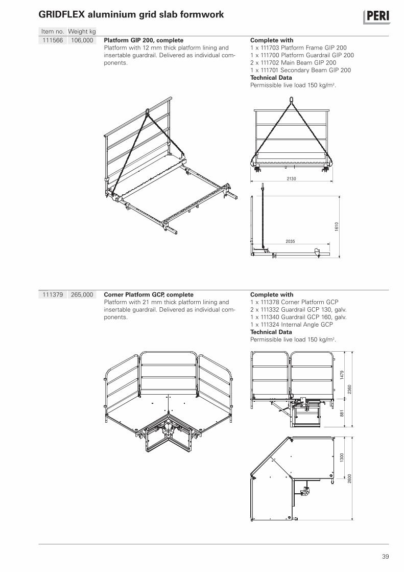
111566 106,000 Platform GIP 200, completePlatform with 12 mm thick platform lining and
insertable guardrail. Delivered as individual com-
ponents.
Complete with1 x 111703 Platform Frame GIP 200
1 x 111700 Platform Guardrail GIP 200
2 x 111702 Main Beam GIP 200
1 x 111701 Secondary Beam GIP 200
Technical DataPermissible live load 150 kg/m2.
2130
1610
2035
111379 265,000 Corner Platform GCP, completePlatform with 21 mm thick platform lining and
insertable guardrail. Delivered as individual com-
ponents.
Complete with1 x 111378 Corner Platform GCP
2 x 111332 Guardrail GCP 130, galv.
1 x 111340 Guardrail GCP 160, galv.
1 x 111324 Internal Angle GCP
Technical DataPermissible live load 150 kg/m2.
2600
1479
2360
881
1300


42
02 PERI S.A.S.
Zone Industrielle Nord
34-36 rue des Frères Lumière
77109 Meaux Cedex [email protected]
www.peri.fr
03 PERI AG
Aspstraße 17
8472 Ohringen [email protected]
www.peri.ch
04 PERI S.A. Sociedad
Unipersonal
Ctra. Paracuellos -
Fuente el Saz km. 18,9
Cno. de Malatones, km. 0,5
28110 Algete/Madrid [email protected]
www.peri.es
05 N.V. PERI S.A.
Industriepark
Nijverheidsstraat 6 PB 54
1840 Londerzeel [email protected]
www.peri.be
06 PERI B.V.
v. Leeuwenhoekweg 23
Postbus 304
5480 AH-Schijndel [email protected]
www.peri.nl
07 PERI Formwork Systems, Inc.
7135 Dorsey Run Road
Elkridge, MD 21075 [email protected]
www.peri-usa.com
08 PT Beton Perkasa Wijaksana
P.O. Box 3737
Jakarta 10210 [email protected]
www.peri.de
09 PERI S.p.A.
Via G. Pascoli, 4
20060 Basiano (MI) [email protected]
www.peri.it
10 PERI Japan K.K.
7F Hakozaki 314 Building,
31-4 Hakozaki-cho,
Nihonbashi Chuo-ku
Tokyo 103-0015 [email protected]
www.perijapan.jp
11 PERI Ltd.
Market Harborough Road
Clifton upon Dunsmore
Rugby, CV23 0AN [email protected]
www.peri.ltd.uk
12 PERI Kalıp ve İskeleleri
San. ve Tic. Ltd. Sti.
Çakmaklı Mahallesi
Akçaburgaz Cad.
72. Sokak No: 23
Kıraç - Büyükçekmece/ Istanbul 34500 [email protected]
www.peri.com.tr
13 PERI Kft.
Zádor u. 4.
1181 Budapest [email protected]
www.peri.hu
14 PERI Formwork Malaysia
Sdn. Bhd.
Unit 19-07-4, Level 7
PNB Damansara
19 Lorong Dungun
Damansara Heights
50490 Kuala Lumpur [email protected]
www.perimalaysia.com
15 PERI ASIA Pte. Ltd
Formwork Pte. Ltd.
No. 1 Sims Lane # 06-10
Singapore 387355 [email protected]
www.periasia.com
16 PERI Ges.mbH
Traisenstraße 3
3134 Nußdorf ob der Traisen [email protected]
www.peri.at
17 PERI spol. s r.o.
Průmyslová 392
252 42 Jesenice [email protected]
www.peri.cz
18 PERI Danmark A/S
forskalling og stillads
Greve Main 26
2670 Greve [email protected]
www.peri.dk
19 PERI Suomi Ltd. Oy
Hakakalliontie 5
05460 Hyvinkää [email protected]
www.perisuomi.fi
20 PERI NORGE AS
Dråpen 9
3036 Drammen [email protected]
www.peri.no
21 PERI Polska Sp. z o.o.
ul. Stołeczna 62
05-860 Płochocin [email protected]
www.peri.pl.pl
22 PERIform SVERIGE AB
Montörgatan 4-6
Box 9073
30013 Halmstad [email protected]
www.periform.se
23 PERI (Korea) Ltd.
8-9th Fl., Yuseong Bldg.
830-67, Yeoksam-dong,
Kangnam-ku,
Seoul 135-080 [email protected]
www.perikorea.com
24 PERIcofragens Lda.
Cofragens e Andaimes
Rua Cesário Verde,
nº 5 - 3º Esq.
Linda-a-Pastora 2790-326 Queijas [email protected]
www.peri.pt
25 PERI S.A.
Ruta Nacional N°. 9, km 47,5
(Panamericana Ramal Escobar)
(1625) Escobar/Prov. Bs. As. [email protected]
www.peri.com.ar
26 PERI Formas e
Escoramentos Ltda.
Rodovia Raposo Tavares,
km 41
Colinas Bandeirante
CEP 06730-000 Vargem Grande Paulista São Paulo [email protected]
www.peribrasil.com.br
27 PERI Chile Ltda.
C/José de San Martin N° 104
Parque Industrial Los
Libertadores
Colina, Santiago de Chile [email protected]
www.peri.cl
28 PERI România SRL
Calea Bucureşti nr. 2B
077015 Baloteşti - ILFOV [email protected]
www.peri.ro
29 PERI SLOWENIEN
Goran Opalic
Obrežna 137
2000 Maribor [email protected]
www.peri.de
30 PERI spol. s r.o.
Šamorínska 18
903 01 Senec [email protected]
www.peri.sk
31 PERI Australia Pty. Ltd.
116 Glendenning Road
Glendenning NSW 2761 [email protected]
www.periaus.com.au
32 PERI AS
Valdmäe 8
Tänassilma Tehnopark
76401 Saku vald Harjumaa
www.peri.ee
2
1
3
4
5
6
9
11
12
1316
17
18
19
20
22
21
24
2829
30
32
33
34
38
41
42
46
48
52
53
61
01 PERI GmbH Rudolf-Diesel-Strasse
89264 Weissenhorn
www.peri.com
France
Switzerland
Spain
Belgium/Luxembourg
Netherlands
USA
Indonesia
Italy
Japan
United Kingdom/Ireland
Turkey
Hungary
Malaysia
Singapore
Austria
Czech Republic
Denmark
Finland
Norway
Poland
Sweden
Korea
Portugal
Argentina
Brazil
Chile
Romania
Slovania
Slovakia
Australia
Estonia
PERI International

43
33 PERI Hellas Ltd.
Sokratous Str.
5th kil. Koropi-Varis Ave.
P. O. Box 407
194 00 Koropi [email protected]
www.perihellas.gr
34 PERI SIA
Granita 26
1057 Riga [email protected]
www.peri-latvija.lv
35 PERI (L.L.C.)
Brashy Building,
Office No. 212
Shk. Zayed Road
P.O. Box 27933
Dubai [email protected]
www.perime.com
36 PERI Formwork Systems, Inc.
45 Nixon Road
Bolton, Ontario L7E 1K1 [email protected]
www.peri.ca
37 PERI GmbH
Lebanon Representative
Office
AYA Commercial Center,
7th floor,
Dora Highway,
Beirut P.O. Box 90 416 Jdeidet
www.peri.de
38 PERI UAB
Titnago st. 19
02300 Vilnius [email protected]
www.peri.lt
39 PERI S.A.
Route de Rabat, km. 5
Piste de Beni Touzine
Tanger [email protected]
www.peri.de
40 PERI Formwork
Engineering Ltd
16 Moshe Dayan st.,
P.O. Box 10202
Petach Tikva,
49002 Israel [email protected]
www.peri.co.il
41 PERI BULGARIA EOOD
Kv. Vragdebna
m. Nova Machala Nr. 46
1839 – Sofia [email protected]
www.peri.bg
42 MEST ltd.,
Fornubudum 5
220 Hafnarfjordur [email protected]
www.mest.is
43 TOO PERI Kazakhstan
Rubenstein Street 10
(Corner Dostyk Str. 7)
050010 Almaty [email protected]
www.peri.kz
44 OOO PERI
8 Etage, OOO PERI Buro
Krasnaya Presnya Str. 24
123022 Moskau [email protected]
www.peri.ru
45 PERI Wiehahn (Pty.) Ltd.
P.O. Box 2668
Bellville 7535 [email protected]
www.periwiehahn.co.za
46 TOW PERI Ukraina
23, M. Raskowa Str., B. 822
02002 Kiew [email protected]
www.peri.ua
47 PERI GmbH
Egypt Branch Office
24 A, Obour Gardens,
4th Floor, apt. # 1
Salah Salem Street
11361 Heliopolis Cairo [email protected]
www.peri.com.eg
48 PERI Oplate d.o.o.
Jurija Gagarina 81
11070 Novi Beograd [email protected]
www.peri.co.yu
49 PERI Cimbras y Andamios,
S.A. de C.V.
Parque de las Américas
KM 3.5 Carretera
Jorobas – Tula
Huehuetoca
Estado de México, C.P. 54680 [email protected]
www.peri.com.mx
50 PERI Kalıp ve İskeleleri
Baku Branch Office
28 May Küç. Ev 72 Menzil 27
Baku [email protected]
www.peri.com.tr
51 PERI Kalıp ve İskeleleri
Aşgabat Branch Office
Göroglu Sokak No. 130, Kat 2
744035 Aşgabat [email protected]
www.peri.com.tr
52 PERI Belarus
Pr. Nesawisimosti 11
Kopus-2 Zimmer: 526,528
220030 Minsk [email protected]
www.peri.com.tr
53 PERI oplate i skele d.o.o.
Dolenica 20
10 250 Donji Stupnik/ Zagreb [email protected]
www.peri.com.hr
54 PERI GmbH
Iran Branch Office
Flat 27, 5th floor, KAVE BLVD,
Building No. 4
P.O. Box 1939793669
Teheran-Iran [email protected]
www.peri.ir
55 PERI (India) Pvt Ltd
717 Palm Springs
Palm Court
Malad Link Road
Malad (West)
Mumbai – 400064 [email protected]
www.peri.in
56 PERI Jordan
Saad 5 Center, 4th Floor
Office No. 404
Al Madineh
Al Munawara Street
P.O. Box 367
11947 Amman [email protected]
www.peri.de
57 PERI Kuwait
Arraya Center, 29th Floor
Al-Shuhada Street, Sharq
P.O. Box 1060 Safat
13011 Kuwait [email protected]
www.peri.de
58 PERI Saudi Arabia
33 AL-Batraa Street
AL -Shurbatiy Building
AL - Bughdadiah AL -
Gharbiah Distrect
6th Floor, Flat # 61
P.O. Box 11641
Jeddah [email protected]
www.peri.de
59 PERI Qatar LLC
P.O. Box 24133
Doha [email protected]
www.peri.de
60 Société PERI S.A.S.
Bureau de liaison d‘Alger
50 bis, Route de Gué
de Constantine
Hai El Badr (ex Apreval)
Immeuble FADLI
Kouba - Alger [email protected]
www.peri.fr
61 Autostrada TIRANE-DURRES
Km 2 Rr dytesore
ne krah te Vodafonit
Perballe ARDENOS FUSHE -
MEZES TIRANE
Tirane / ALBANIA [email protected]
www.peri.com.tr
62 Av. Defensores
del Morro 2074
Chorrillos
Lima
Peru [email protected]
7
8
10
1415
23
25
26
27 31
35
36
3739 40
43
44
45
4749
50 51
54
595558
5760 56
62
Greece
Latvia
United Arab Emirates
Canada
Libanon
Lithuania
Marocco
Israel
Bulgaria
Iceland
Kazakhstan
Russian Federation
South Africa
Ukraine
Egypt
Serbia
Mexico
Azerbaijan
Turkmenistan
Belorussia
Croatia
Iran
India
Jordan
Kuwait
Saudi Arabia
Qatar
Algeria
Albania
Peru

D e
02
/20
09
2m
a
Art
. N
r.:
79
24
76
©
Co
pyri
gh
t by P
ER
I G
mb
H
Wall FormworkPanel Formwork
Girder Formwork
Circular Formwork
Facade Formwork
Brace Frame
Column FormworkSquare
Rectangular
Circular
Slab FormworkPanel Formwork
Beam Grid Formwork
Girder Formwork
Slab Table
Beam Formwork
Shoring SystemsSteel Slab Props
Aluminium Slab Props
Tower Systems
Heavy-Duty Props
Climbing SystemsClimbing Scaffold
Self-Climbing System
Climbing Protection Panel
Platform Systems
Scaffold, Stairways, Working PlatformsFacade Scaffold
Working Platform
Weather Protection Roof
Stairway Access
Bridge and Tunnel FormworkCantilevered Parapet Carriage
Cantilevered Parapet Platform
Engineer’s Construction Kit
ServicesFormwork Assembly
Cleaning / Repairs
Formwork Planning
Software
Statics
Special Constructions
Additional Systems
Plywood
Formwork Girders
Stopend Systems
Pallets
Transportation Containers
PERI GmbHFormwork Scaffolding EngineeringP.O. Box 1264
89259 Weissenhorn
Germany
Tel +49 (0)73 09.9 50- 0
Fax +49 (0)73 09.9 51- 0
www.peri.com
PERI Product Range