Embed Size (px)
Citation preview

Proceedings of the International Association for Shell and Spatial Structures (IASS) Symposium 2009, Valencia Evolution and Trends in Design, Analysis and Construction of Shell and Spatial Structures
28 September – 2 October 2009, Universidad Politecnica de Valencia, Spain Alberto DOMINGO and Carlos LAZARO (eds.)
An analytical model for Tensairity girders
Rolf H. LUCHSINGER*, Uwe TEUTSCHa
* Empa, Center for Synergetic Structures Ueberlandstrasse 129, CH-8600 Duebendorf, Switzerland
a ETH, Institute of Structural Engineering, Wolfgang-Pauli-Strasse 15, CH-8093, Zurich, Switzerland
Abstract An analytical model for the deflection of a symmetric, spindle shaped Tensairity girder under homogenous load is proposed which can be solved analytically. The results are compared to FEM predictions for a specific Tensairity girder. Further simplifications of the analytical solution lead to a simple relation for the deflection of the Tensairity girder, which reveals the importance of the elasticity of the chords relative to the air pressure in the inflated hull. Such simple models are crucial to understand the basic principles of Tensairity and provide the engineer with easy rules to estimate the load-deflection behaviour of this new light weight structure. Keywords: Tensairity, inflatable structures, bending, analytical models
1. Introduction Tensairity is a new structural concept where an inflated hull is combined with compression and tension members in a synergetic way (Luchsinger et al. [1]). First applications in civil engineering such as roof and bridge structures have been successfully realised with Tensairity. Recently, intensive research was conducted with Tensairity structures. Luchsinger and Crettol [2] have subjected spindle shaped Tensairity girders to local bending loads and the deformation behaviour was compared to FEM predictions. Plagianakos et al. [3] have investigated spindle shaped Tensairity columns subjected to axial compressive loads. In both studies, measurements were made at different air pressure levels as a major focus of these investigations was the influence of the air pressure on the structural behaviour of Tensairity. An increase in stiffness with increasing pressure was
2771

Proceedings of the International Association for Shell and Spatial Structures (IASS) Symposium 2009, Valencia Evolution and Trends in Design, Analysis and Construction of Shell and Spatial Structures
observed with a trend to saturation for higher pressure values. Recently, the role of fabric webs inside Tensairity columns was investigated by Wever et al. [4]. In order to understand the structural behaviour of Tensairity, simple analytical models are of great importance. Such a model was proposed by Wever et al. [4] for the stiffness of a Tensairity column under axial compression. Based on the solution of a 4’th order ordinary differential equation, a simple relation for the axial displacement as a function of the slenderness of the spindle, the span, the chord stiffness and the air pressure was deduced. Initial work for bending of Tensairity girders was conducted by Huguenot [5]. Here we propose an analytical model for the behaviour of symmetric spindle shaped Tensairity girders subjected to homogeneous bending load. The topic is elaborated in more detail in an ongoing PhD thesis by Teutsch [6].
Figure 1: Basic set up of the spindle shaped Tensairity girder.
2. Analytical model for symmetric spindle shaped Tensairity girders The construction of the spindle shaped Tensairity girder is shown in Figure 1. The girder consists of an upper and a lower parabolic chord, which are separated by a spindle shaped inflated hull. The chords are assumed to be connected to the hull. The central idea is to model the inflated hull of the Tensairity structure as an elastic foundation for the chords with the modulus of the foundation being a function of the air pressure (Plagianakos et al. [3]). In this model, we assume the bending stiffness of the chords to be very small so that it can be neglected. The homogeneous load acts on the upper chord leading to a deformation of the chord and the inflated hull and thus to a load transfer to the lower chord. Thus, the girder is described by two coupled equations for the deflections of the upper and lower chords w1 and w2, respectively.
2772

Proceedings of the International Association for Shell and Spatial Structures (IASS) Symposium 2009, Valencia Evolution and Trends in Design, Analysis and Construction of Shell and Spatial Structures
qwwkwdxdGwz
dxdH =−⋅+⋅−+⋅ )()( 2112
2
112
2 (1a)
0)()( 2122
2
222
2
=−⋅−⋅−+⋅− wwkwdxdGwz
dxdH (1b)
where H is the horizontal force component, G the shear stiffness of the elastic foundation, k the modulus of the elastic foundation and q the homogenously distributed load. The shear stiffness G is assumed to be constant. The modulus of the foundation is proportional to the air pressure p and given for the problem at hand by (Luchsinger et al. [1])
2pk ⋅= π (2)
The two chords have a parabolic shape
1 , 12
2
2
1 ⎟⎟⎠
⎞⎜⎜⎝
⎛⎟⎠⎞
⎜⎝⎛−⋅=⎟
⎟⎠
⎞⎜⎜⎝
⎛⎟⎠⎞
⎜⎝⎛−⋅−=
lxfz
lxfz (3)
Solving Eq. (1a) for w2 and by insertion in Eq. (1b) one obtains the 4th order differential equation
22221
2
2241
4
)(4
)(2
lHGfHk
dxwd
HGkG
dxwd
⋅−⋅Δ⋅⋅=⋅
−⋅⋅− (4)
with
0HHH −=Δ (5)
flqH⋅⋅=
4
2
0 (6)
Enforcing symmetry (w(-x)=w(x)) and the boundary conditions w1(l) = w2(l) = 0, one finds
2773

Proceedings of the International Association for Shell and Spatial Structures (IASS) Symposium 2009, Valencia Evolution and Trends in Design, Analysis and Construction of Shell and Spatial Structures
3
21
20
1 2)cosh( CxCxCw +⋅+⋅⋅=
λλ (7)
23
2
12022
2)cosh(1
lkfH
kqCx
kGHCx
kGHCw
⋅⋅⋅+−+⎟⎟
⎠
⎞⎜⎜⎝
⎛+−⋅+⋅⋅⎟
⎠⎞
⎜⎝⎛ +−⋅= λ
λ (8)
2222
22
213
212
21
0
2 , )(2
21
2 , )cosh()(
2)cosh(
HGkG
lGHfHlqlCC
lGfHC
llGHfHlq
lCC
−⋅⋅=
⋅⋅−⋅⋅−⋅−⎟⎟
⎠
⎞⎜⎜⎝
⎛−⋅=
⋅⋅⋅Δ=
⋅⋅⋅−⋅⋅−⋅+
⋅−=
λλλ
λλ (9)
The horizontal force H is determined by the constraint that the horizontal displacement of the ends of the two chords has to be identical
AElHdxw
lfdxw
lf
AElH ll
⋅⋅−⋅⋅⋅=⋅⋅⋅−
⋅⋅
∫∫0
220
1222 (10)
with E the Young’s modulus and A the cross sectional area of the two identical chords. The integrals are evaluated to
lClClCdxwl
⋅+⋅+⋅⋅=⋅∫ 3
31
30
01 6
)sinh(λ
λ (11)
lkfH
klqlCl
kGHlC
kGHlCdxw
l
⋅⋅⋅+⋅−⋅+⎟⎟
⎠
⎞⎜⎜⎝
⎛+−⋅⋅+⎟
⎠⎞
⎜⎝⎛ +−⋅⋅⋅=⋅∫
26
1)sinh(3
2
120
02 λλ
λ (12)
Eq. (10) is solved numerically in iterative steps.
3. Example: Deformation of a Tensairity spindle with 5m span As an example we consider a symmetric spindle shaped Tensairity column with 5 m span (l = 2.5m) and a slenderness 10 corresponding to f = 0.25m. The rectangular cross section of the two identical aluminum chords is 3cm x 1cm (EA = 20.7 MN). Such a girder was
2774

Proceedings of the International Association for Shell and Spatial Structures (IASS) Symposium 2009, Valencia Evolution and Trends in Design, Analysis and Construction of Shell and Spatial Structures
experimentally and numerically studied under point load by Luchsinger and Crettol [2]. Loads up to 500 N/m and air pressure values up to 450 mbar are considered. In order to calculate w1 and w2, the shear stiffness of the elastic foundation needs to be specified. In lack of a model we assume that it is proportional to the pressure. The pressure dependent part of the shear stiffness of an airbeam is SpG ⋅= with p the air pressure and S the cross sectional area of the beam (Topping [7]). Adopting this model, we set
2fpG ⋅⋅= π neglecting the variation of the cross sectional area along the length of the spindle. In Figure 2, w1 and w2 are shown for p = 150 mbar and q = 200 N/m. For comparison, predictions of a detailed FEM model of the spindle including material properties of the hull as well as the bending stiffness of the chords are shown. In view of the approximations of the analytical model, a remarkable correspondence between the analytical results and the FEM results is found both for w1 and w2.
Figure 2: Analytical deflection of the chords compared to FEM results.
The influence of G on the deformation has been investigated by a parameter study. As it turns out both w1 and w2 do depend only very weakly on G provided that H<G. For H=G the parameter λ (Eq. (9)) has a singularity and for H>G a complex number is found for λ leading to undulating deflections patterns for w1 which are not observed in experiments.
0 0.5 1 1.5 2 2.5-2
-1
0
1
2
3
x 10-3 p=150 mbar, q=200 N/m
x [m]
w [m
]
w1-anaw1-FEMw2-anaw2-FEM
2775

Proceedings of the International Association for Shell and Spatial Structures (IASS) Symposium 2009, Valencia Evolution and Trends in Design, Analysis and Construction of Shell and Spatial Structures
Thus, one might state that the proposed model is only valid for H<G while the exact value for G is not critical. Nevertheless, the true nature of G in Tensairity needs to be investigated in more detail especially in combination with the bending stiffness of the chords. This is subject of further studies.
4. Simplified analytical model For the Tensairity girder of the example above, further simplifications can be made by a detailed study of the various terms of Eqs. (7) and (8). One finds that the deformation at mid span can be approximated as
31 )0( Cw ≈ (13)
kqC
lkfH
kqCw
⋅−≈
⋅⋅⋅+−≈
22)0( 32
032
(14)
with H≈H0. As can be seen from Figure 2, w1 and w2 are fairly constant along the length of the spindle. Thus, the integrals can be approximated as
lCdxwl
⋅≈⋅∫ 30
1 (15)
klqlCdxw
l
⋅⋅−⋅≈⋅∫ 23
02
(16)
and Eq. (10) can be solved for C3. As a final result, one finds
kqLw ⋅+⋅⋅⋅=
41
41)0(1 γε (17)
kqLw ⋅−⋅⋅⋅=
41
41)0(2 γε (18)
where the span L=2l, the strain ε and the slenderness γ have been introduced
AEH⋅
= 0ε , f
L⋅
=2
γ (19)
2776
Proceedings of the International Association for Shell and Spatial Structures (IASS) Symposium 2009, Valencia Evolution and Trends in Design, Analysis and Construction of Shell and Spatial Structures
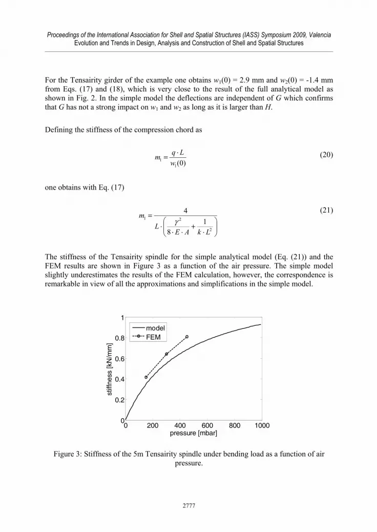
For the Tensairity girder of the example one obtains w1(0) = 2.9 mm and w2(0) = -1.4 mm from Eqs. (17) and (18), which is very close to the result of the full analytical model as shown in Fig. 2. In the simple model the deflections are independent of G which confirms that G has not a strong impact on w1 and w2 as long as it is larger than H. Defining the stiffness of the compression chord as
)0(11 w
Lqm ⋅= (20)
one obtains with Eq. (17)
⎟⎟⎠
⎞⎜⎜⎝
⎛⋅
+⋅⋅
⋅=
2
21 18
4
LkAEL
mγ
(21)
The stiffness of the Tensairity spindle for the simple analytical model (Eq. (21)) and the FEM results are shown in Figure 3 as a function of the air pressure. The simple model slightly underestimates the results of the FEM calculation, however, the correspondence is remarkable in view of all the approximations and simplifications in the simple model.
Figure 3: Stiffness of the 5m Tensairity spindle under bending load as a function of air pressure.
0 200 400 600 800 10000
0.2
0.4
0.6
0.8
1
pressure [mbar]
stiff
ness
[kN
/mm
]
modelFEM
2777

Proceedings of the International Association for Shell and Spatial Structures (IASS) Symposium 2009, Valencia Evolution and Trends in Design, Analysis and Construction of Shell and Spatial Structures
The two summands in the denominator of m1 are equal for
22
16LAEpb ⋅⋅⋅⋅=
γπ (22)
corresponding to a pressure of 430 mbar for the girder at hand. Thus, for air pressure values smaller than pb, the deformation of the upper chord is dominated by the deformation of the elastic foundation while for higher pressure values the elasticity of the chords is dominant.
4. Conclusions An analytical model is proposed for symmetric spindle shaped Tensairity girders subjected to homogenous bending load. The inflated body of the Tensairity structure is modeled as an elastic foundation with shear stiffness. The bending stiffness of the chords is neglected. The two coupled ordinary differential equations can be solved analytically. It is found that the shear stiffness of the elastic foundation is very important to stabilize the compression chord, however, its exact value is not very important as long as it is larger than the horizontal force. A comparison of the analytical deflections with FEM results shows a good agreement for a specific Tensairity spindle. The analytical model is further simplified by neglecting minor terms. The deflection at mid span is found to be the sum of two terms, one due to the elasticity of the chords and one due to the deformation of the inflated body which depends on the air pressure. The stiffness given by the simple model is found to be in good agreement with FEM prediction for various air pressure values. Further studies will include the role of the bending stiffness of the chords, the exact nature of the shear stiffness of the elastic foundation and detailed comparisons with experimental data.
Acknowledgement We thank Cédric Galliot for providing the FEM results. The financial support of Festo is gratefully acknowledged.
References [1] Luchsinger R.H., Pedretti A., Steingruber P., Pedretti M., The new structural concept
Tensairity: Basic principles. Progress in Structural Engineering, Mechanics and Computations, London, A.A. Balkema Publishers, 2004
2778

Proceedings of the International Association for Shell and Spatial Structures (IASS) Symposium 2009, Valencia Evolution and Trends in Design, Analysis and Construction of Shell and Spatial Structures
[2] Luchsinger, R.H., and Crettol, R., Experimental and numerical study of spindle shaped Tensairity girders. International Journal of Space Structures, 2006; 21(3); 119-130.
[3] Plagianakos, T.S., Teutsch, U., Crettol, R., and Luchsinger, R.H., Static response of a spindle-shaped Tensairity column to axial compression. Engineering Structures, 2009, doi:10.1016/j.engstruct.2009.02.028
[4] Wever, T.E., Plagianakos, T.S., Luchsinger, R.H. and Marti, P., Effect of fabric webs on the static response of spindle-shaped Tensairity columns. Under review.
[5] Huguenot, D., Zur Berechnung von Tensairity-Trägern, Master thesis, ETH Zurich, 2008.
[6] Teutsch, U., Tragverhalten und Bemessung von Tensairity Trägern, PhD thesis, ETH Zurich, in preparation.
[7] Topping, A.D., Shear deflections and buckling characteristics of inflated members. Journal of Aircraft, 1964; 1(5); 289-292.
2779


