Embed Size (px)
Citation preview
APPLIED
ARTICLE IN PRESS
www.elsevier.com/locate/apenergy
Applied Energy xxx (2004) xxx–xxxENERGY
Performance prediction of avapour-compression heat-pump
Adnan S€ozen a,*, Erol Arcaklio�glu b, Ali Erisen b,M. Ali Akc�ayol c
a Mechanical Education Department, Technical Education Faculty, Gazi University,
06503 Teknikokullar, Ankara, Turkeyb Mechanical Engineering Department, Engineering Faculty, Kırıkkale University,
71450 Kırıkkale, Turkeyc Computer Engineering Department, Engineering and Architecture Faculty,
Gazi University, 06570 Maltepe, Ankara, Turkey
Accepted 18 December 2003
Abstract
The performance of the heat pump was predicted using a fuzzy-logic controller under
various working-conditions and mixing ratios of R12/R22 refrigerant mixtures, instead of
requiring an expensive and time consuming experimental study [Int. J. Ref. 13 (1990) 163].
Fuzzy-logic’s linguistic terms provide a feasible method for defining the performance of the
heat pump. Input data for the fuzzy logic are mixing ratio, evaporator-inlet temperature and
condenser pressure. In the comparison of performance, results obtained via analytic equations
and by means of the fuzzy-logic controller, the coefficient of performance (COP), and rational
efficiency (RE) for all working situations differ by less than 1.5% and 1%, respectively. The
statistical coefficient of multiple determinations (R2-value) equals to 0.9988 for both the COP
and the RE. With these results, we believe that fuzzy logic can be used for the accurate pre-
diction of the COP and the RE of the heat pump.
� 2004 Elsevier Ltd. All rights reserved.
Keywords: Heat pump; Performance; Fuzzy logic; Prediction
*Corresponding author. Tel.: +90-312-212-6820; fax: +90-312-212-0059.
E-mail address: [email protected] (A. S€ozen).
0306-2619/$ - see front matter � 2004 Elsevier Ltd. All rights reserved.
doi:10.1016/j.apenergy.2003.12.013

2 A. S€ozen et al. / Applied Energy xxx (2004) xxx–xxx
ARTICLE IN PRESS
1. Introduction
Exact theoretical performance analysis of the heat pump is too complex due to the
equations of the thermodynamic properties of the working fluid and the simulation
programs [1]. Therefore, as the thermodynamic analysis requires many variables, a
fuzzy-logic controller is used. Classical control methods can be implemented in well-defined systems to achieve good performance-predictions for the systems. To control
a system, an accurate mathematical model of its behaviour has to be obtained.
Systems with non-linear behavioural structures cannot be easily modeled. Fuzzy-
logic control has adaptive characteristics, which can achieve robust responses to
uncertainties, parameter variations, and load disturbances. Fuzzy logic, or fuzzy-set
theory, was the first presented by Zadeh [2]. Since the introduction of fuzzy logic,
many researchers have studied modeling of complex systems, and fuzzy-logic con-
trollers have been used to control ill-defined, non-linear, or imprecise systems [2–5].During the past decade, fuzzy logic has found a variety of applications in various
fields ranging from industrial-process control [6] to medical diagnosis [7], and to
securities in trading [8]. Most notably, a fuzzy-logic system has been applied to
control non-linear, time-varying, ill-defined systems [6], to control systems whose
dynamics are exactly known, such as servomotor position control [9,10] and robot-
arm control [11], and to manage complex decision-making or diagnosis systems [8,9].
Quail and Adnan [12] have described fuzzy-logic applications in dozens of household
appliances and Takagi [13] has presented a large suite of electronic components inthe general area of image-processing equipment. Camera manufacturers have ap-
plied fuzzy logic to decide upon which object, in the field-of-view, the camera should
be focused, and then to control the auto-focus mechanism to focus on that object
[14]. Fuzzy-logic controllers have been applied to electrical machines to control
speed and position successfully. A fuzzy-logic controller has been developed for a
brushless direct-current motor [15]. Cheok and Ertugrul [16] have described a fuzzy-
logic controller for a switched-reluctance motor.
In this study, we conducted experiments on the vapour-compression heat-pumpusing different ratios of R12/R22 refrigerant mixtures. The conducted experiments
and corresponding calculated coefficient of performance (COP) and rational effi-
ciency (RE) results are used in the application of a fuzzy-logic controller. After-
wards, we briefly describe the fuzzy logic. Subsequently, we calculated the COP and
the RE of the pump using numerical methods, as explained in Section 3, while
Section 4 describes the modeling of the system with fuzzy logic and finally Section 5
contains the results and conclusions.
2. Fuzzy-logic controller
Fuzzy-logic explains the operational laws by means of linguistic (rather than
complex mathematical) equations. Since it is difficult to model many systems accu-
rately with these complex equations, usage of traditional control methods are gen-
erally not viable. But, fuzzy-logic’s linguistic terms provide a feasible method for

Rule Base
Decisionmaking logic
Database
DefuzzificationFuzzification
Fuzzy inference
Inputs Outputs
Fig. 1. Fuzzy-logic controller block diagram.
A. S€ozen et al. / Applied Energy xxx (2004) xxx–xxx 3
ARTICLE IN PRESS
defining the operational characteristics of such systems [6]. The main advantage of
the fuzzy logic is that it does not require a complex mathematical model and thus, it
has the advantage of using relatively simple mathematical calculations for the rule
processing [17]. In addition, it has been shown that the fast universal computationscheme corresponds exactly to the operations in fuzzy-logic methods using max–min
composition [18]. In a fuzzy-logic controller, the dynamic behaviour of a fuzzy
system is characterized by a set of linguistic-description rules based on expert
knowledge [19]. The expert knowledge is usually in the form of:
IF (input1 is big) and/or (input2 is small)� � �(inputN is medium) THEN
(output1 is negative big) and (output2 is positive small)� � �(outputM is
zero).
Basically, fuzzy-control rules provide a convenient way for expressing control
policy and domain knowledge. Furthermore, several linguistic variables might be
involved in the antecedents (before then) and the conclusions (after then) of these
rules. Fuzzy-logic controllers can be considered as a special class of symbolic con-
trollers. The configuration of the fuzzy-logic controller block diagram is shown in
Fig. 1. The three features of symbolic controllers are fuzzification, fuzzy inference
and defuzzification. In the fuzzification step, the real variables are translated intolinguistic variables by using fuzzy-set theory. In the fuzzy-inference step, ‘‘if-then’’
rules, that define the system behaviour, are evaluated. The defuzzification step
translates the linguistic result obtained from the fuzzy inference into again a real
value by using the rule base provided.
2.1. Fuzzification
Multiple measured crisp inputs first have to be mapped into fuzzy-membershipfunctions. This process is called fuzzification [20]. The fuzzification process requires a
good understanding of all the variables. Fuzzy-logic’s linguistic terms are most often
expressed in the form of logical implications, such as If-Then rules [6]. These rules

m
u
1
Val1 Val2 Val3
1
uVal1 Val2 Val3 Val4
1
u
m
Xp
w
m
(a) (b) (c)
Fig. 2. Triangle (a), trapezoid (b), and bell (c) membership functions.
4 A. S€ozen et al. / Applied Energy xxx (2004) xxx–xxx
ARTICLE IN PRESS
define a range of values known as fuzzy-membership functions. These may be in theform of a triangle, a trapezoid, a bell (as seen in Fig. 2) or another appropriate form.
lðuiÞ is a membership function, which is used to calculate the membership degree of
the crisp input value. The range of lðuiÞ is between zero and unity [20].
Triangle membership function is defined by Eq. (1). Val1, Val2, and Val3 define
triangle membership functions’ limits
lðuiÞ ¼
ui � Val1
Val2� Val1; Val16 ui 6Val2;
Val3� uiVal3� Val2
; Val26 ui 6Val3;
0; otherwise:
8>>>>><>>>>>:
ð1Þ
Trapezoid membership function is defined by Eq. (2). Val1, Val2, Val3, and Val4
define the trapezoid membership functions’ limits
lðuiÞ ¼
ui � Val1
Val2� Val1; Val16 ui 6Val2;
1; Val2 < ui < Val3;
Val4� uiVal4� Val3
; Val36 ui 6Val4;
0; otherwise:
8>>>>>>>>><>>>>>>>>>:
ð2Þ
Bell membership functions are defined by parameters Xp, w and m as follows:
lðuiÞ ¼ 1 1
,þ jui � Xpj
w
� �2m!; ð3Þ
where Xp is the mid-point, and w is the width of the bell function. mP 1, anddescribes the convexity of the bell function.
The inputs of the fuzzy controller are expressed in several linguistic levels. An
example can be seen in Fig. 3. These levels can be described as positive big (PB),

µNB NM NS Z PS PM PB
input0
1
-30 -20 -10 0 10 20 307.5
0.25
0.75
Fig. 3. Seven levels of fuzzy membership function.
A. S€ozen et al. / Applied Energy xxx (2004) xxx–xxx 5
ARTICLE IN PRESS
positive medium (PM), positive small (PS), zero (Z), negative small (NS), negativemedium (NM), negative big (NB), or another. Each level is described by a fuzzy set.
The linguistic-variable input allows for the translation of a measured input into its
linguistic description. For example, a measured input of 7.5 is translated into the
linguistic variable of (0.25*Z, 0.75*PS) which can be interpret as ‘‘positive small or
may be zero’’. An input of 7.5 is a member in the fuzzy sets of the terms:-
• positive small to the degree of 0.75,
• zero to the degree of 0.25.
Membership degree is calculated by using a triangle membership function as definedby Eq. (1).
In general, experience and expertise are required for the implementation of
fuzzification in complex systems.
2.2. Fuzzy inference
The second phase of the fuzzy-logic controller is its fuzzy inference where the
knowledge base and the decision-making logic reside [21]. The rule base and thedatabase form the knowledge base. The database contains descriptions of the input
and output variables. In this study, parameters of the membership functions for the
input and output variables are stored in the database. The count of data in the
database depends on how many inputs and outputs are used for the fuzzy-logic
controller and how many fuzzy sets are used in each input and output. The decision-
making logic evaluates the control rules. The control rule base can be developed to
relate the output actions of the controller to the obtained inputs. Fuzzy inference
uses linguistic terms (fuzzy sets), selected by fuzzification, for producing outputlinguistic terms by using the rule base. The rule base contains if-then rules between
inputs and output.
2.3. Defuzzification
The outputs of the inference mechanism are fuzzy-output variables. The fuzzy-
logic controller must convert its internal fuzzy-output variables into crisp values, so
that the actual system can use these variables. This conversion is called defuzzifi-cation [22]. One may perform this operation in several ways. One of the most
common ways is the use of the height method.
6 A. S€ozen et al. / Applied Energy xxx (2004) xxx–xxx
ARTICLE IN PRESS
In the height method [23], the centroid of each membership function for each rule
is firstly evaluated [19]. The final output, U0, is then calculated as the average of the
individual centroids, weighted by their heights as follows:
U0 ¼Pn
i¼1 uilðuiÞPni¼1 lðuiÞ
; ð4Þ
where lðuiÞ is the minimum/maximum (depend on and/or operator) value of the
membership degree of input values.
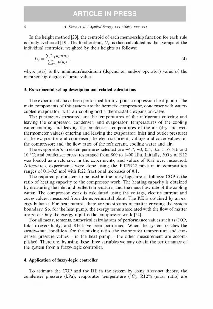
3. Experimental set-up description and related calculations
The experiments have been performed for a vapour-compression heat pump. The
main components of this system are the hermetic compressor, condenser with water-
cooled evaporator, with air cooling and a thermostatic expansion-valve.
The parameters measured are the temperatures of the refrigerant entering and
leaving the compressor, condenser, and evaporator; temperatures of the cooling
water entering and leaving the condenser; temperatures of the air (dry and wet-
thermometer values) entering and leaving the evaporator; inlet and outlet pressuresof the evaporator and condenser; the electric current, voltage and cosu values for
the compressor; and the flow rates of the refrigerant, cooling water and air.
The evaporator’s inlet-temperatures selected are )4.7, )3, 0.5, 3.5, 5, 6, 8.6 and
10 �C; and condenser pressures ranged from 800 to 1400 kPa. Initially, 500 g of R12
was loaded as a reference in the experiments, and values of R12 were measured.
Afterwards, experiments were done using the R12/R22 mixture in composition
ranges of 0.1–0.5 mol with R22 fractional increases of 0.1.
The required parameters to be used in the fuzzy logic are as follows: COP is theratio of heating capacity to the compressor work. The heating capacity is obtained
by measuring the inlet and outlet temperatures and the mass-flow rate of the cooling
water. The compressor work is calculated using the voltage, electric current and
cosu values, measured from the experimental plant. The RE is obtained by an ex-
ergy balance. For heat pumps, there are no streams of matter crossing the system
boundary. So, for the heat pump, the exergy terms associated with the flow of matter
are zero. Only the exergy input is the compressor work [24].
For all measurements, numerical calculations of performance values such as COP,total irreversibility, and RE have been performed. When the system reaches the
steady-state condition, for the mixing ratio, the evaporator temperature and con-
denser pressure values – in the heat pump – the other measurement are accom-
plished. Therefore, by using these three variables we may obtain the performance of
the system from a fuzzy-logic controller.
4. Application of fuzzy-logic controller
To estimate the COP and the RE in the system by using fuzzy-set theory, the
condenser pressure (kPa), evaporator temperature (�C), R12% (mass ratio) are

Rule Base
Database
Generation ofinferencerelations
Fuzzification Decisionmaking
DefuzzificationCrisp inputvariables
Fuzzy inputvariables
Fuzzy outputvariables
Crisp outputvariables
R12%,kPa,˚C dRE, dCOP
Fig. 4. The configuration of the fuzzy-logic estimator.
µ
700 1400800 900 1000 1100 1200 1300
Membership functions of kPa
-4.7 10.0-3.0 0.5 3.5 5.0 6.0 8.6
Membership functions of °C
0.5 0.6 0.7 0.8 0.9 1.0
Membership functions of R12%
µ
4.104 7.919
Membership functions of COP
µ
0.5202 0.9398
Membership functions of RE
Fig. 5. The membership functions of kPa, �C, R12%, COP and RE variables.
A. S€ozen et al. / Applied Energy xxx (2004) xxx–xxx 7
ARTICLE IN PRESS

8 A. S€ozen et al. / Applied Energy xxx (2004) xxx–xxx
ARTICLE IN PRESS
employed. The fuzzy estimator is designed to process fuzzy-quantities only. There-
fore, the crisp input values of kPa, �C and R12% must be converted to fuzzy sets
before being used. This process is called the fuzzification operation. Fuzzy outputs
were calculated using the max–min composition method. Then crisp outputs of the
COP and the RE were determined by the centre-of-gravity method.
The inputs and outputs of the fuzzy estimator are expressed in several linguisticlevels. Each level is described by a fuzzy set. Fig. 4 shows the configuration of the
fuzzy block.
Fuzzy-input variables are kPa, �C, R12% and fuzzy-output variables COP and
RE. Eight linguistic levels for kPa, �C, 6 linguistic levels for R12%, as well as 26
linguistic levels for COP and RE have been chosen. In this study, a total of 254
experimentally-obtained values are stored in the database: among these there are
24 for kPa, 24 for �C, 18 for R12%, 78 for COP and 78 for RE. The mem-
bership functions of the fuzzy variables (kPa,�C, R12%, COP, RE) are shown inFig. 5.
To explore the effectiveness of the proposed modeling, the results obtained from
fuzzy-based modeling and experimental data have been compared.
5. Results and conclusions
Figs. 6 and 7 show a parity plot between the compressibility factors generated byexperimental data and those computed by fuzzy logic for the COP, and the RE for
all working parameters, respectively. R2-values obtained are equal to 0.9988 for both
the COP and the RE.
R2 = 0.9988
3.000
4.000
5.000
6.000
7.000
8.000
9.000
10.000
11.000
3.000 4.000 5.000 6.000 7.000 8.000 9.000 10.000 11.000
Predicted Value (COP)
Act
ual
Dat
a (C
OP
)
Fig. 6. Comparison of the actual data and fuzzy logic results for the COP.

R2 = 0.9988
0.5000
0.5500
0.6000
0.6500
0.7000
0.7500
0.8000
0.8500
0.9000
0.9500
1.0000
0.5000 0.5500 0.6000 0.6500 0.7000 0.7500 0.8000 0.8500 0.9000 0.9500 1.0000
Predicted Value (RE)
Act
ual
Dat
a (R
E)
Fig. 7. Comparison of the actual data and fuzzy logic results for the RE.
A. S€ozen et al. / Applied Energy xxx (2004) xxx–xxx 9
ARTICLE IN PRESS
It is clear that the fuzzy-logic model gives a very accurate representation of the
statistical coefficient of multiple determinations (R2-value) over the full range of
operating conditions. The standard deviations of COP and RE in Figs. 8–23 indicate
the high accuracy of the fuzzy logic. The maximum percentage difference between the
simulated and predicted results is 1%. Consequently, we believe that fuzzy logic can
be used successfully for this type of prediction.
Since performance values obtained by analytical functions are very close to thecalculated values by using the fuzzy-logic controller, they cannot easily be
Fig. 8. Variation of the dCOP with R12% at different condenser pressures for Te ¼ �4:7 �C.

Fig. 9. Variation of the dCOP with R12% at different condenser pressures for Te ¼ �3 �C.
Fig. 10. Variation of the dCOP with R12% at different condenser pressures for Te ¼ 0:5 �C.
10 A. S€ozen et al. / Applied Energy xxx (2004) xxx–xxx
ARTICLE IN PRESS
graphically shown together. For this reason, the following parameters (Eqs. (5) and
(6)) have been calculated as deviations in values, and these have been shown
graphically:

Fig. 12. Variation of the dCOP with R12% at different condenser pressures for Te ¼ 5 �C.
Fig. 11. Variation of the dCOP with R12% at different condenser pressures for Te ¼ 3:5 �C.
A. S€ozen et al. / Applied Energy xxx (2004) xxx–xxx 11
ARTICLE IN PRESS
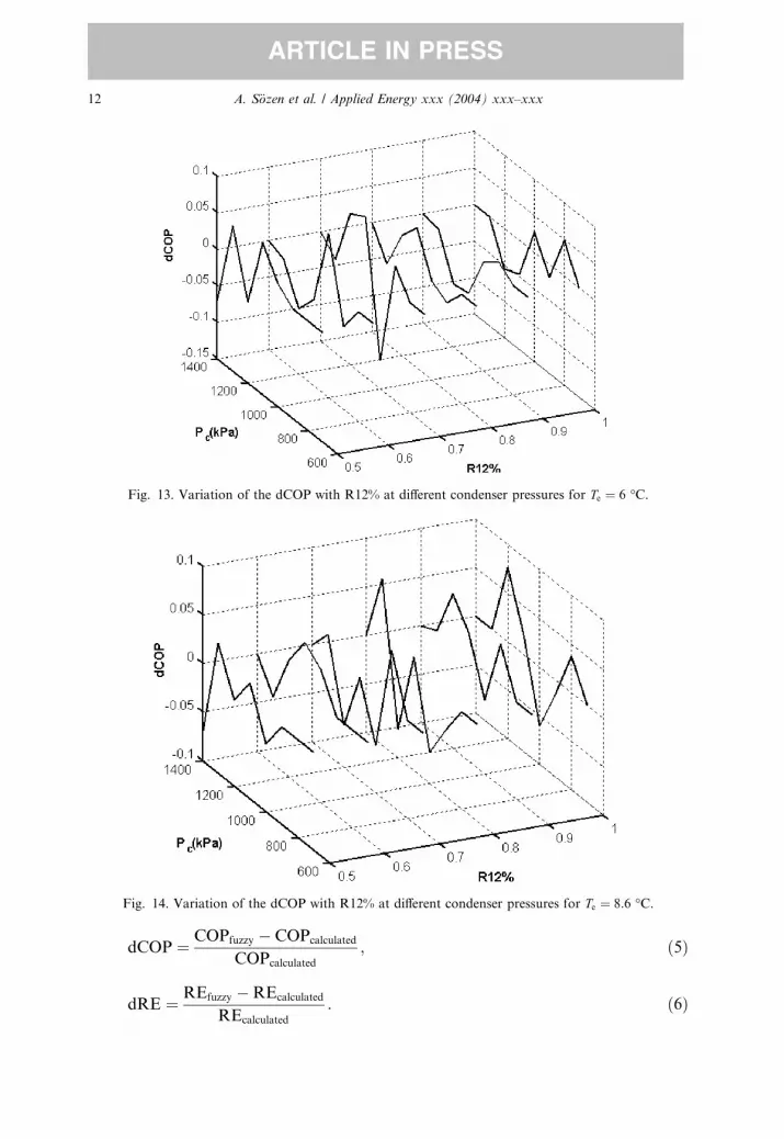
Fig. 14. Variation of the dCOP with R12% at different condenser pressures for Te ¼ 8:6 �C.
Fig. 13. Variation of the dCOP with R12% at different condenser pressures for Te ¼ 6 �C.
12 A. S€ozen et al. / Applied Energy xxx (2004) xxx–xxx
ARTICLE IN PRESS
dCOP ¼ COPfuzzy � COPcalculated
COPcalculated
; ð5Þ
dRE ¼ REfuzzy �REcalculated
REcalculated
: ð6Þ

Fig. 16. Variation of the dRE with R12% at different condenser pressures for Te ¼ �4:7 �C.
Fig. 15. Variation of the dCOP with R12% at different condenser pressures for Te ¼ 10 �C.
A. S€ozen et al. / Applied Energy xxx (2004) xxx–xxx 13
ARTICLE IN PRESS
Values of the deviation in the coefficient of performance (dCOP) are given in Figs. 8–
15 for different working-temperatures. According to the results obtained, deviations
in coefficient of performance of the system are in the range 0.5–1.5% at different

Fig. 18. Variation of the dRE with R12% at different condenser pressures for Te ¼ 0:5 �C.
Fig. 17. Variation of the dRE with R12% at different condenser pressures for Te ¼ �3 �C.
14 A. S€ozen et al. / Applied Energy xxx (2004) xxx–xxx
ARTICLE IN PRESS
working temperatures. Maximum and minimum deviations of COP are given in
Table 1.
Deviations in rational efficiency (dRE) are given in Figs. 16–23 for different
working-temperatures. According to the results obtained, deviations in rational

Fig. 20. Variation of the dRE with R12% at different condenser pressures for Te ¼ 5 �C.
Fig. 19. Variation of the dRE with R12% at different condenser pressures for Te ¼ 3:5 �C.
A. S€ozen et al. / Applied Energy xxx (2004) xxx–xxx 15
ARTICLE IN PRESS
efficiency of the system are in the range 0.5–1% at different working temperatures.
Maximum and minimum deviations of RE are given in Table 2.
Use of the fuzzy-logic controller in a refrigeration system shows that simulation
values can be obtained with a simple approach instead of experimental studies.

Fig. 22. Variation of the dRE with R12% at different condenser pressures for Te ¼ 8:6 �C.
Fig. 21. Variation of the dRE with R12% at different condenser pressures for Te ¼ 6 �C.
16 A. S€ozen et al. / Applied Energy xxx (2004) xxx–xxx
ARTICLE IN PRESS
The advantages of fuzzy logic are speed of calculation, simplicity and capability of
learning from examples. All of these advantages have been observed in our appli-
cation. These features enable us to use fuzzy logic for thermal systems and will help

Table 1
Maximum and minimum deviations of COP
R12% Pc (kPa) Te (�C) COP COPFLC dCOP
Minimum 0.7 1000 6.0 6.893 7.004 )0.111Maximum 1.0 1200 0.5 4.963 4.868 0.095
Table 2
Maximum and minimum deviation values of RE
R12% Pc (kPa) Te (�C) RE REFLC dRE
Minimum 0.8 1000 3.5 0.7959 0.8055 )0.0096Maximum 0.7 1300 5.0 0.6295 0.6210 0.0085
Fig. 23. Variation of the dRE with R12% at different condenser pressures for Te ¼ 10 �C.
A. S€ozen et al. / Applied Energy xxx (2004) xxx–xxx 17
ARTICLE IN PRESS
those studying in this field. So, experimental studies can be reduced to a minimum
where the use of fuzzy logic is appropriate. Therefore, in other applications,involving heat pumps, the use of the fuzzy logic in similar circumstances can be
recommended as a test-bed.
References
[1] Didion DA, Bivens DB. Role of refrigerant mixtures as alternatives to CFCs. Int J Ref 1990;13:163–
75.
[2] Zadeh LA. In: Fuzzy sets, information and control, vol. 8. New York: Academic Press; 1965. p. 338–
53.

18 A. S€ozen et al. / Applied Energy xxx (2004) xxx–xxx
ARTICLE IN PRESS
[3] Zadeh LA. Outline of a new approach to the analysis of complex systems and decision processes.
IEEE Trans Syst Man Cybernet 1973;(January) Proceeding, pp. 270–280.
[4] Sousa CD, Bose BK. A fuzzy-set theory based control of a phase-controlled converter DC machine
drive. IEEE Trans Ind Appl 1994:34–44.
[5] Adcock TA. What is fuzzy logic? An overview of the latest control methodology. TI Application
Report, January; 1993. p. 1–7.
[6] Sugeno M, editor. Industrial applications of fuzzy control. Amsterdam: North-Holland; 1985.
[7] Lee CC. Fuzzy logic in control systems: fuzzy-logic controller – Part I&II. IEEE Trans Syst Man
Cybernet 1990;20(2):404–35.
[8] Zadeh LA. Fuzzy logic. IEEE Comput Mag 1988;(April):83–93.
[9] Self KL. Fuzzy logic design. IEEE Spectrum 1990;27(November):42–4, and 105.
[10] Li YF, Lan CC. Development of fuzzy algorithms for servo systems. IEEE Contr Syst Mag
1989;(April):65–72.
[11] Scharf EM, Mandic NJ. The application of a fuzzy controller to the control of a multi-degree-freedom
robot arm. In: Sugeno M, editor. Industrial application of fuzzy control. Amsterdam: North-Holland;
1985. p. 41–62.
[12] Quail S, Adnan S. State of the art in household appliances using fuzzy logic. In: Yen J, Langari R,
Zadeh L, editors. Proceedings of the Second International Workshop – Industrial Fuzzy-Control and
Intelligent Systems. College Station, TX: IEEE Press; 1992. p. 204–13.
[13] Takagi H. Survey: fuzzy-logic applications to image processing equipment. In: Yen J, Langari R,
Zadeh L, editors. Proceedings of the Second International Workshop – Industrial Fuzzy-Control and
Intelligent Systems. College Station, TX: IEEE Press; 1992. p. 1–9.
[14] Shingu T, Nishimori E. Fuzzy-based automatic focusing system for a compact camera. In:
Proceedings of the International Fuzzy Systems Association Congress, Seattle, WA; 1989. p. 436–9.
[15] Akcayol MA, Cetin A, Elmas C. An educational tool for fuzzy-logic controlled BDCM. IEEE Trans
Educ 2002;45(1):33–42.
[16] Cheok AD, Ertugrul N. Use of fuzzy logic for modelling, estimation and prediction in switched
reluctance-motor drives. IEEE Trans Ind Electron 1999;46(6):150–7.
[17] Wang LX. Adaptive fuzzy systems and control: design and stability analysis. Englewood Cliffs, NJ:
Prentice-Hall; 1994.
[18] Lea R, Kreinovich V. Intelligent control makes sense even without expert knowledge: an explanation.
In: Proceedings of APIC’95, El-Paso, TX; 1995. p. 140–5.
[19] Fuller R. Neural fuzzy systems. Abo: Abo Akadami; 1995.
[20] Klir GJ, Folger TA. Fuzzy sets, uncertainty and information. Englewood Cliffs, NJ: Prentice-Hall;
1988.
[21] Vas P. Artificial-intelligence-based electrical machines and drives. New York: Oxford University
Press; 1999.
[22] Shulz S. Equations of state for ammonia–water for use with computers. IIR, Meeting Commission II,
Washington; 1971.
[23] Babuska R. Fuzzy modelling for control. Boston: Kluwer Academic Publishers; 1998.
[24] Kotas TJ. The exergy method of thermal-plant analysis. London: Butterworths; 1990.


