Embed Size (px)
Citation preview
SMART3 PUMP
User and Maintenance Manual
Original instructions
IITTAALLIIAA
DDrrooppssaa SSppAA
tt.. ++3399 0022--225500779911
ff..++3399 0022--2255007799776677
UU..KK..
DDrrooppssaa ((UUKK)) LLttdd
tt.. ++4444 ((00))11778844--443311117777
ff.. ++4444 ((00))11778844--443388559988
GGEERRMMAANNIIAA
DDrrooppssaa GGmmbbHH
tt.. ++4499 ((00))221111--339944--001111
ff.. ++4499 ((00))221111--339944--001133
FFRRAANNCCIIAA
DDrrooppssaa AAmmee
tt.. ++3333 ((00))11--33999933--00003333
ff.. ++3333 ((00))11--33998866--22663366
CCIINNAA
DDrrooppssaa LLuubbrriiccaattiioonn SSyysstteemmss
((SShhaanngghhaaii)) CCoo.. LLttdd
tt.. ++8866 ((002211)) 6677774400227755
ff.. ++8866 ((002211)) 6677774400220055
UU..SS..AA..
DDrrooppssaa CCoorrppoorraattiioonn
tt.. ++11 558866--556666--11554400
ff.. ++11 558866--556666--11554411
AAUUSSTTRRAALLIIAA
DDrrooppssaa AAuussttrraalliiaa LLttdd..
tt.. ++6611 ((0022))--99993388--66664444
ff.. ++6611 ((00))22--99993388--66661111
BBRRAASSIILLEE
DDrrooppssaa ddoo BBrraassiill IInndd.. ee
CCoomm.. LLttaa
tt.. ++5555 ((00))1111--556633--1100000077
ff.. ++5555 ((00))1111--556633--1199440088
Manual drawn up in accordance with C2194IE– WK 32/13 EC Directive 06/42
http://www.dropsa.com
TABLE OF CONTENTS
1. INTRODUCTION 2. GENERAL DESCRIPTION 3. PRODUCT-MACHINE IDENTIFICATION 4. TECHNICAL SPECIFICATIONS 5. MACHINE COMPONENTS 6. TYPES OF PRODUCTS 7. UNPACKING AND INSTALLATION 8. INSTRUCTIONS FOR USE 9. TROUBLESHOOTING 10. MAINTENANCE PROCEDURE 11. DISPOSAL 12. ORDERING INFORMATION 13. DIMENSIONS 14. HANDLING AND TRANSPORTATION 15. OPERATING HAZARDS
NOSOLOHERRAMIENTAS
2
1. INTRODUCTION
This User and Maintenance Manual refer to Dropsa’s “SMART3 “ Oil lubrication Pump for oil and fluid grease. You can find additional copies and newer revisions of this document from our website http://www.dropsa.com. Alternatively contact one of our Sales Offices. This manual contains important information on health and safety issues for the personnel. It is recommended to attentively read this manual and carefully keep it in good condition so that it is always available to personnel requiring to consult it.
2. GENERAL DESCRIPTION
SMART3 is a compact and versatile electric gear pump package particularly suited for machine tool and work centre lubrication systems using 33V injector systems. The versatility of this product is thanks to a wide range of electric motor and the fact it is available with a Dropsa optical switch that can work with both oil and fluid greases. The lubrication cycle can be determined either externally by a host PLC or by selecting a model with the built in controller board that will operate and monitor the system accordingly.
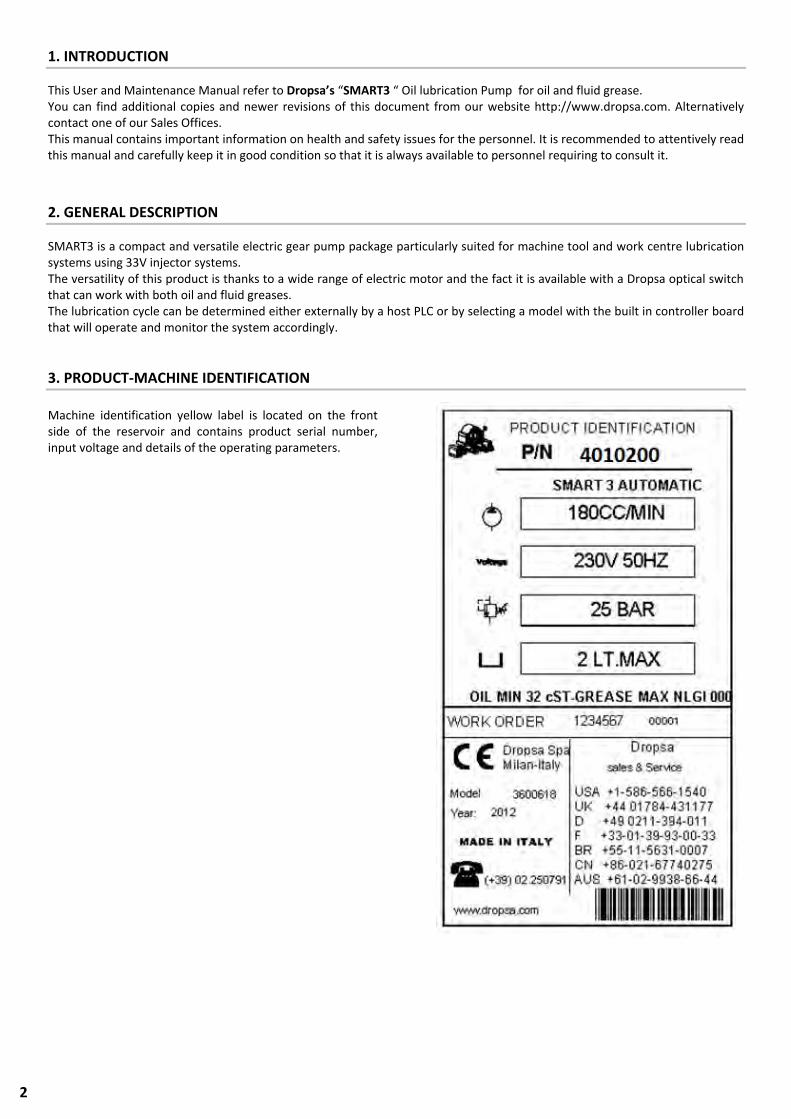
3. PRODUCT-MACHINE IDENTIFICATION
Machine identification yellow label is located on the front side of the reservoir and contains product serial number, input voltage and details of the operating parameters.
3
4. TECHNICAL SPECIFICATIONS
Note. The specifications refer to the temperature of use of +20°C (+68°F) (1) 2800 rpm with no load * If a different or special lubricant product is used, please contact Dropsa to ensure its suitability.
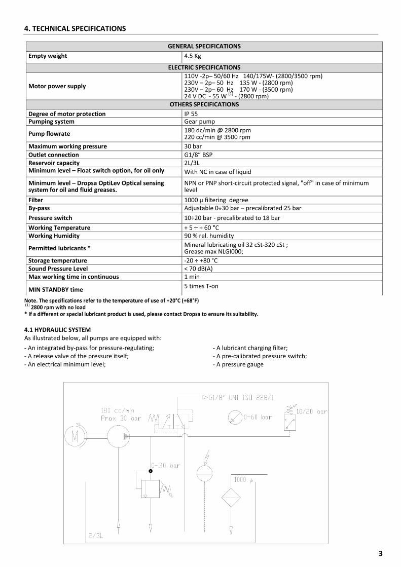
4.1 HYDRAULIC SYSTEM As illustrated below, all pumps are equipped with:
- An integrated by-pass for pressure-regulating; - A release valve of the pressure itself; - An electrical minimum level;
- A lubricant charging filter; - A pre-calibrated pressure switch; - A pressure gauge
GENERAL SPECIFICATIONS
Empty weight 4.5 Kg
ELECTRIC SPECIFICATIONS
Motor power supply
110V -2p– 50/60 Hz 140/175W- (2800/3500 rpm) 230V – 2p– 50 Hz 135 W - (2800 rpm) 230V – 2p– 60 Hz 170 W - (3500 rpm) 24 V DC - 55 W (1) - (2800 rpm)
OTHERS SPECIFICATIONS
Degree of motor protection IP 55 Pumping system Gear pump
Pump flowrate 180 dc/min @ 2800 rpm 220 cc/min @ 3500 rpm
Maximum working pressure 30 bar
Outlet connection G1/8” BSP Reservoir capacity 2L/3L Minimum level – Float switch option, for oil only
With NC in case of liquid
Minimum level – Dropsa OptiLev Optical sensing system for oil and fluid greases.
NPN or PNP short-circuit protected signal, "off" in case of minimum level
Filter 1000 µ filtering degree By-pass Adjustable 0÷30 bar – precalibrated 25 bar
Pressure switch 10÷20 bar - precalibrated to 18 bar
Working Temperature + 5 + 60 C Working Humidity 90 % rel. humidity
Permitted lubricants * Mineral lubricating oil 32 cSt-320 cSt ; Grease max NLGI000;
Storage temperature -20 +80 °C Sound Pressure Level < 70 dB(A) Max working time in continuous 1 min
MIN STANDBY time 5 times T-on
4
5. PUMP COMPONENTS
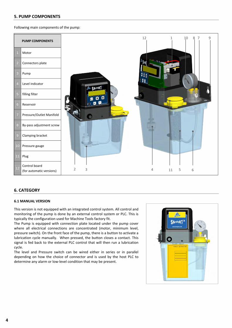
Following main components of the pump:
6. CATEGORY
6.1 MANUAL VERSION
This version is not equipped with an integrated control system. All control and monitoring of the pump is done by an external control system or PLC. This is typically the configuration used for Machine Tools factory fit. The Pump is equipped with connection plate located under the pump cover where all electrical connections are concentrated (motor, minimum level, pressure switch). On the front face of the pump, there is a button to activate a lubrication cycle manually. When pressed, the button closes a contact. This signal is fed back to the external PLC control that will then run a lubrication cycle. The level and Pressure switch can be wired either in series or in parallel depending on how the choice of connector and is used by the host PLC to determine any alarm or low-level condition that may be present.
PUMP COMPONENTS
1 Motor
2 Connectors plate
3 Pump
4 Level indicator
5 filling filter
6 Reservoir
7 Pressure/Outlet Manifold
8 By-pass adjustment screw
9 Clamping bracket
10 Pressure gauge
11 Plug
12 Control board
(for automatic versions)
1
2 3 4 5 6
7 8 9
11
10 12
5
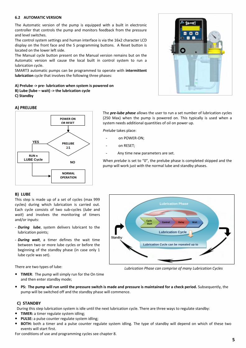
6.2 AUTOMATIC VERSION
The Automatic version of the pump is equipped with a built in electronic controller that controls the pump and monitors feedback from the pressure and level switches. The control system settings and human interface is via the 16x2 character LCD display on the front face and the 5 programming buttons. A Reset button is located on the lower left side. The Manual cycle button present on the Manual version remains but on the Automatic version will cause the local built in control system to run a lubrication cycle. SMART3 automatic pumps can be programmed to operate with intermittent lubrication cycle that involves the following three phases: A) Prelube -> pre- lubrication when system is powered on B) Lube (lube – wait) -> the lubrication cycle C) Standby
A) PRELUBE The pre-lube phase allows the user to run a set number of lubrication cycles (250 Max) when the pump is powered on. This typically is used when a system needs additional quantities of oil on power up.
Prelube takes place:
- on POWER-ON;
- on RESET;
- Any time new parameters are set.
When prelube is set to “0”, the prelube phase is completed skipped and the pump will work just with the normal lube and standby phases.
B) LUBE This step is made up of a set of cycles (max 999 cycles) during which lubrication is carried out. Each cycle consists of two sub-cycles (lube and wait) and involves the monitoring of timers and/or inputs:
- During lube, system delivers lubricant to the lubrication points;
- During wait, a timer defines the wait time between two or more lube cycles or before the beginning of the standby phase (in case only 1 lube cycle was set).
There are two types of lube:
TIMER: The pump will simply run for the On time and then enter standby mode;
PS: The pump will run until the pressure switch is made and pressure is maintained for a check period. Subsequently, the pump will be switched off and the standby phase will commence.
C) STANDBY During this step lubrication system is idle until the next lubrication cycle. There are three ways to regulate standby: TIMER: a timer regulate system idling; PULSE: a pulse counter regulate system idling; BOTH: both a timer and a pulse counter regulate system idling. The type of standby will depend on which of these two
events will start first. For conditions of use and programming cycles see chapter 8.
Cycle Start
Control
Delay
Wait
Lubrication Phase
Lubrication Cycle
Lubrication Cycle can be repeated up to 250 times.
Lubrication Phase can comprise of many Lubrication Cycles
PRELUBE
1
YES
RUN n LUBE Cycle
NO
NORMAL OPERATION
POWER ON OR RESET
6
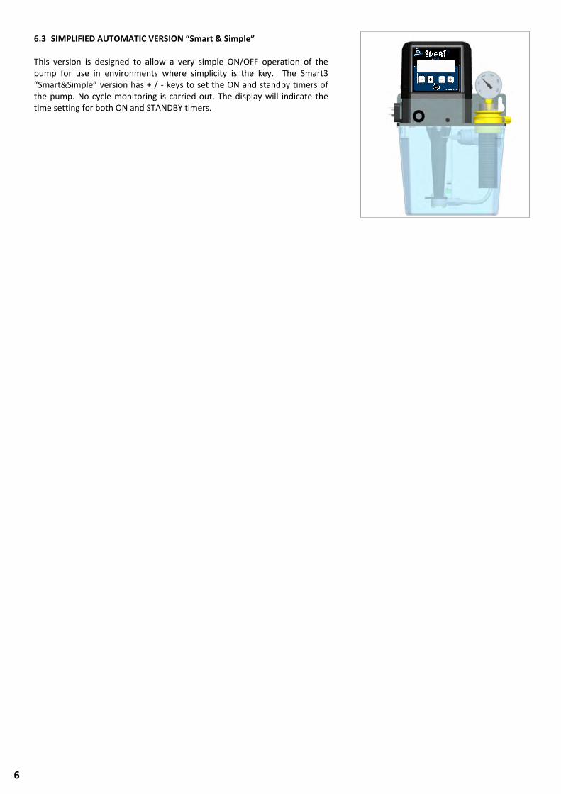
6.3 SIMPLIFIED AUTOMATIC VERSION “Smart & Simple”
This version is designed to allow a very simple ON/OFF operation of the pump for use in environments where simplicity is the key. The Smart3 “Smart&Simple” version has + / - keys to set the ON and standby timers of the pump. No cycle monitoring is carried out. The display will indicate the time setting for both ON and STANDBY timers.
7
6.4 ELECTRICAL CONNECTIONS
6.4.1 Manual version
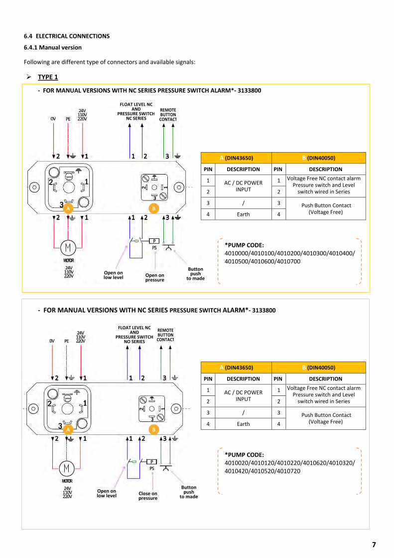
Following are different type of connectors and available signals: TYPE 1
- FOR MANUAL VERSIONS WITH NC SERIES PRESSURE SWITCH ALARM*- 3133800
- FOR MANUAL VERSIONS WITH NC SERIES PRESSURE SWITCH ALARM*- 3133800
*PUMP CODE: 4010000/4010100/4010200/4010300/4010400/4010500/4010600/4010700
A (DIN43650) B (DIN40050)
PIN DESCRIPTION PIN DESCRIPTION
1 AC / DC POWER INPUT
1 Voltage Free NC contact alarm Pressure switch and Level
switch wired in Series
2 2
3 / 3 Push Button Contact (Voltage Free) 4 Earth 4
FLOAT LEVEL NC AND
PRESSURE SWITCH NC SERIES
REMOTE BUTTON CONTACT
Open on low level Open on
pressure
Button push
to made
*PUMP CODE: 4010020/4010120/4010220/4010620/4010320/4010420/4010520/4010720
A (DIN43650) B (DIN40050)
PIN DESCRIPTION PIN DESCRIPTION
1 AC / DC POWER INPUT
1 Voltage Free NC contact alarm Pressure switch and Level
switch wired in Series
2 2
3 / 3 Push Button Contact (Voltage Free) 4 Earth 4
FLOAT LEVEL NC AND
PRESSURE SWITCH NO SERIES
REMOTE BUTTON CONTACT
Open on low level Close on
pressure
Button push
to made
8
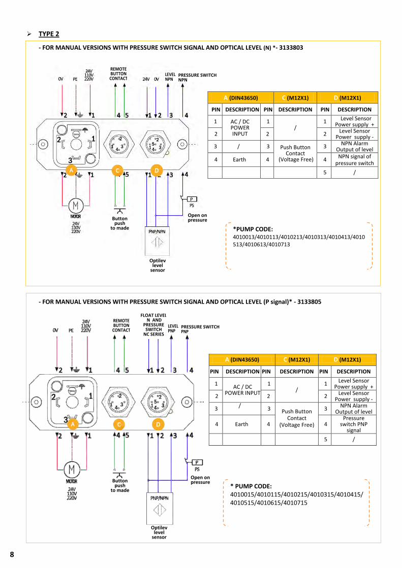
TYPE 2
- FOR MANUAL VERSIONS WITH PRESSURE SWITCH SIGNAL AND OPTICAL LEVEL (N) *- 3133803
- FOR MANUAL VERSIONS WITH PRESSURE SWITCH SIGNAL AND OPTICAL LEVEL (P signal)* - 3133805
A (DIN43650) C (M12X1) D (M12X1)
PIN DESCRIPTION PIN DESCRIPTION PIN DESCRIPTION
1 AC / DC
POWER INPUT
1 /
1 Level Sensor Power supply +
2 2 2 Level Sensor Power supply -
3 / 3 Push Button
Contact (Voltage Free)
3 NPN Alarm Output of level
4 Earth 4 4 Pressure
switch PNP signal
5 /
A (DIN43650) C (M12X1) D (M12X1)
PIN DESCRIPTION PIN DESCRIPTION PIN DESCRIPTION
1 AC / DC POWER INPUT
1 /
1 Level Sensor Power supply +
2 2 2 Level Sensor Power supply -
3 / 3 Push Button Contact
(Voltage Free)
3 NPN Alarm Output of level
4 Earth 4 4 NPN signal of
pressure switch 5 /
*PUMP CODE: 4010013/4010113/4010213/4010313/4010413/4010513/4010613/4010713
LEVEL NPN
Optilev level
sensor
PRESSURE SWITCH NPN
REMOTE BUTTON CONTACT
Button push
to made
Open on pressure
Pulsante Aperto in pressione
Sensore livello ottico
LEVEL PNP
PRESSURE SWITCH PNP
REMOTE BUTTON CONTACT
FLOAT LEVEL N AND
PRESSURE SWITCH
NC SERIES
Optilev level
sensor
Button push
to made
Open on pressure
* PUMP CODE: 4010015/4010115/4010215/4010315/4010415/4010515/4010615/4010715
9
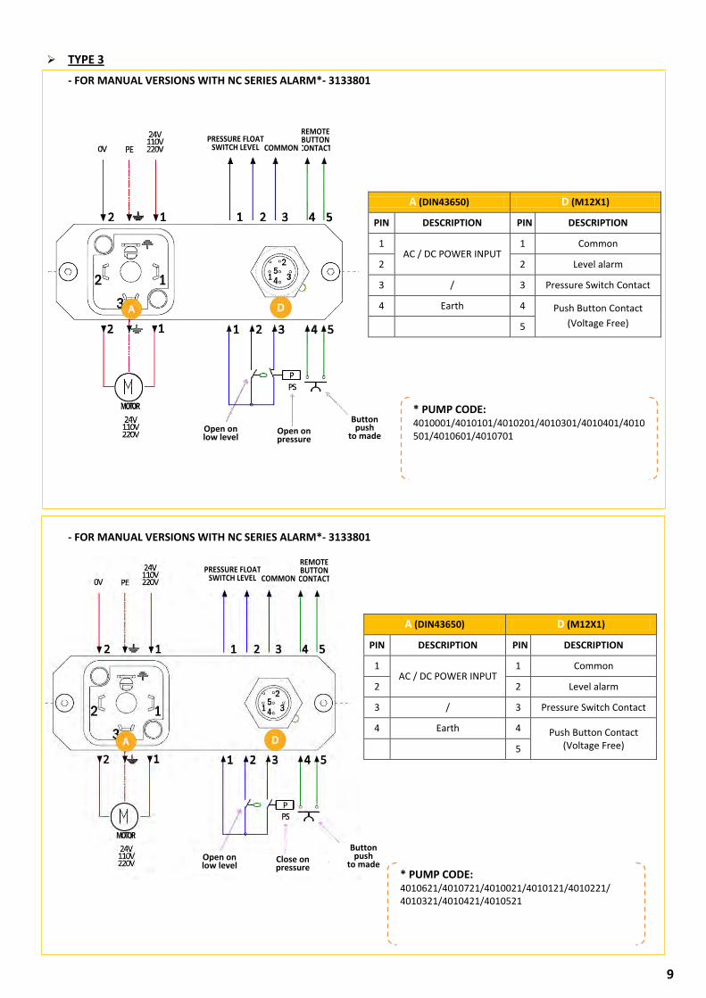
TYPE 3
- FOR MANUAL VERSIONS WITH NC SERIES ALARM*- 3133801
- FOR MANUAL VERSIONS WITH NC SERIES ALARM*- 3133801
A (DIN43650) D (M12X1)
PIN DESCRIPTION PIN DESCRIPTION
1 AC / DC POWER INPUT
1 Common
2 2 Level alarm
3 / 3 Pressure Switch Contact
4 Earth 4 Push Button Contact
(Voltage Free) 5
* PUMP CODE: 4010001/4010101/4010201/4010301/4010401/4010501/4010601/4010701
REMOTE BUTTON CONTACT COMMON
PRESSURE FLOAT SWITCH LEVEL
Button push
to made Open on low level
Open on pressure
REMOTE BUTTON CONTACT COMMON
PRESSURE FLOAT SWITCH LEVEL
Button push
to made Open on low level
Close on pressure
A (DIN43650) D (M12X1)
PIN DESCRIPTION PIN DESCRIPTION
1 AC / DC POWER INPUT
1 Common
2 2 Level alarm
3 / 3 Pressure Switch Contact
4 Earth 4 Push Button Contact (Voltage Free) 5
* PUMP CODE: 4010621/4010721/4010021/4010121/4010221/ 4010321/4010421/4010521
10
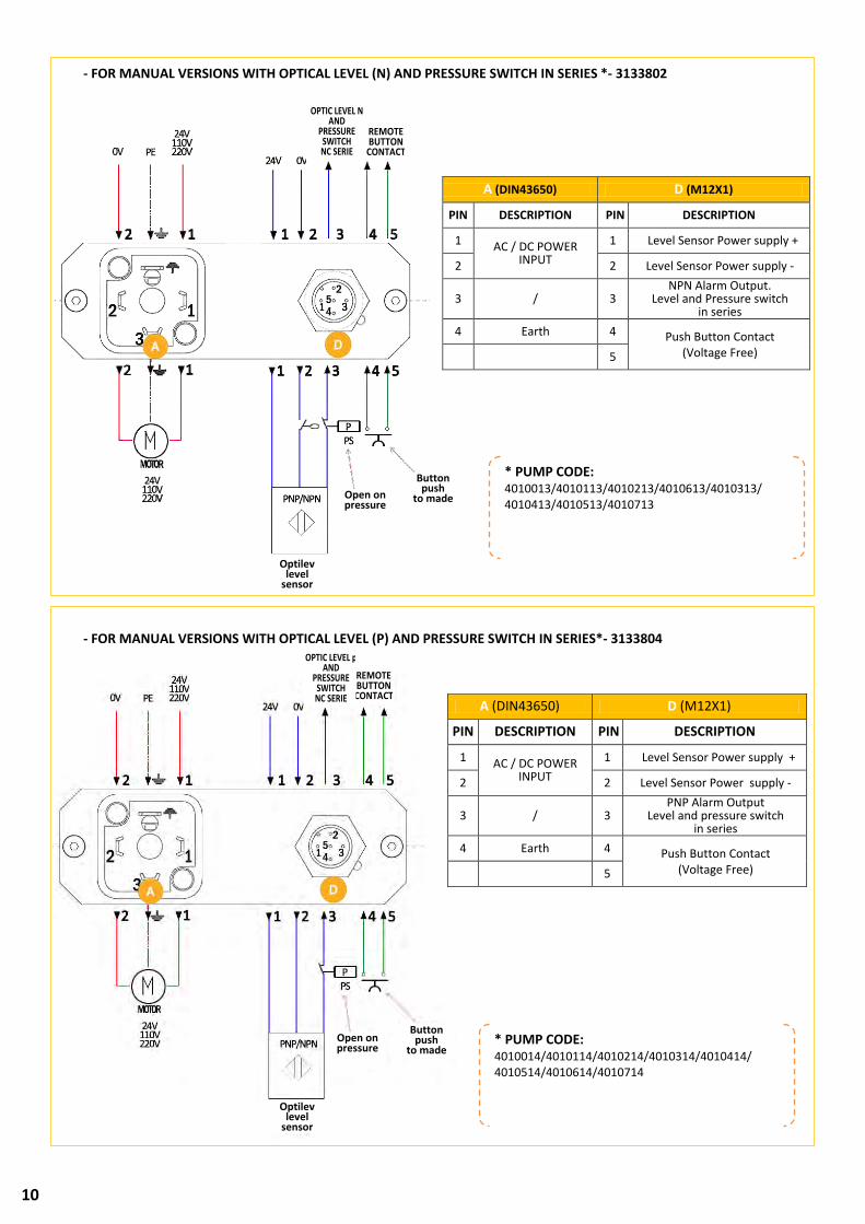
- FOR MANUAL VERSIONS WITH OPTICAL LEVEL (N) AND PRESSURE SWITCH IN SERIES *- 3133802
- FOR MANUAL VERSIONS WITH OPTICAL LEVEL (P) AND PRESSURE SWITCH IN SERIES*- 3133804
A (DIN43650) D (M12X1)
PIN DESCRIPTION PIN DESCRIPTION
1 AC / DC POWER INPUT
1 Level Sensor Power supply +
2 2 Level Sensor Power supply -
3 / 3 NPN Alarm Output.
Level and Pressure switch in series
4 Earth 4 Push Button Contact (Voltage Free) 5
REMOTE BUTTON CONTACT
Button push
to made Open on pressure
A (DIN43650) D (M12X1)
PIN DESCRIPTION PIN DESCRIPTION
1 AC / DC POWER INPUT
1 Level Sensor Power supply +
2 2 Level Sensor Power supply -
3 / 3 PNP Alarm Output
Level and pressure switch in series
4 Earth 4 Push Button Contact (Voltage Free) 5
* PUMP CODE: 4010013/4010113/4010213/4010613/4010313/ 4010413/4010513/4010713
* PUMP CODE: 4010014/4010114/4010214/4010314/4010414/ 4010514/4010614/4010714
Button push
to made Open on pressure
Optilev level
sensor
REMOTE BUTTON CONTACT
OPTIC LEVEL N AND
PRESSURE SWITCH NC SERIE
Optilev level
sensor
OPTIC LEVEL p AND
PRESSURE SWITCH NC SERIE

11
6.4.2 Full automatic version - 3133806*
TYPE 2
6.4.3 “Smart & Simple” AND AUTOMATIC VERSION - 3133807
TYPE 3
A (DIN43650) D (M12X1)
PIN DESCRIPTION PIN DESCRIPTION
1 AC / DC POWER INPUT
1 Alarm Relay – Common
2 2 Alarm Relay - NC
3 /
3 Alarm Relay - NO
4 Earth 4 /
A (DIN43650) C (M12X1) D (M12X1)
PIN DESCRIPTION PIN DESCRIPTION PIN DESCRIPTION
1 AC / DC
POWER INPUT
1 Alarm Relay –
Common 1 Counter Power
+
2 2 Alarm Relay -
NC contact 2 Counter (N / P)
/ INPUT suspend
3 /
3 Alarm Relay - NO contact 3
Power counter -
4 Earth 4 4 /
5 /
ALARM CONTACT
COUNTER IMPUT
* PUMP CODE: 4011019/4011119/4011219/4011319/4011419/4011519/4011619/4011719
* PUMP CODE: 4011018/4011118/4011218/4011318/4011418/4011518/4012018/4012118/4012218/4012318/4012418/4012518/4011618/4011718/4012618/4012718
ALARM CONTACT
12
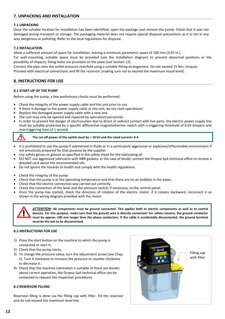
7. UNPACKING AND INSTALLATION
7.1 UNPACKING Once the suitable location for installation has been identified, open the package and remove the pump. Check that it was not damaged during transport or storage. The packaging material does not require special disposal precautions as it is not in any way dangerous or polluting. Refer to the local regulations for disposal. 7.2 INSTALLATION Allow a sufficient amount of space for installation, leaving a minimum parametric space of 100 mm (3,93 in.). For wall-mounting, suitable space must be provided (see the installation diagram) to prevent abnormal positions or the possibility of impacts; fixing holes are provided on the plate (see Section 12). Connect the pipe onto the outlet pressure manifold using a suitable fitting arrangement. Do not exceed 15 Nm. torques. Proceed with electrical connections and fill the reservoir (making sure not to exceed the maximum visual level).
8. INSTRUCTIONS FOR USE
8.1 START-UP OF THE PUMP
Before using the pump, a few preliminary checks must be performed:
Check the integrity of the power supply cable and the unit prior to use. If there is damage to the power supply cable or the unit, do not start operations! Replace the damaged power supply cable with a new one. The unit may only be opened and repaired by specialized personnel. In order to prevent the danger of electrocution due to direct or indirect contact with live parts, the electric power supply line
must be suitably protected by a specific differential magnetothermic switch with a triggering threshold of 0.03 Ampere and max triggering time of 1 second.
It is prohibited to use the pump if submersed in fluids or in a particularly aggressive or explosive/inflammable environment if
not previously prepared for that purpose by the supplier. Use safety gloves or glasses as specified in the safety sheet for the lubricating oil DO NOT use aggressive lubricants with NBR gaskets. In the case of doubt, contact the Dropsa SpA technical office to receive a
detailed card about the recommended oils. Do not ignore the hazards to health and comply with the health regulations.
Check the integrity of the pump Check that the pump is at the operating temperature and that there are no air bubbles in the pipes. Check that the electric connection was carried out correctly. Check the connection of the level and the pressure switch, if necessary, to the control panel. Once the pump has started, check the direction of rotation of the electric motor: if it rotates backward, reconnect it as
shown in the wiring diagram provided with the motor.
8.2 INSTRUCTIONS FOR USE 1) Press the start button on the machine to which the pump is
connected or start it; 2) Check that the pump starts; 3) To change the pressure value, turn the adjustment screw (see Chap.
5). Turn it clockwise to increase the pressure or counter clockwise to decrease it;
4) Check that the machine lubrication is suitable (if there are doubts about correct operation, the Dropsa SpA technical office can be contacted to request the inspection procedure).
8.3 RESERVOIR FILLING Reservoir filling is done via the filling cap with filter. Fill the reservoir and do not exceed the maximum level line.
ATTENTION: All components must be ground connected. This applies both to electric components as well as to control
devices. For this purpose, make sure that the ground wire is directly connected. For safety reasons, the ground conductor must be approx. 100 mm longer than the phase conductors. If the cable is accidentally disconnected, the ground terminal must be the last to be disconnected.
The cut-off power of the switch must be = 10 kV and the rated current= 4 A
Filling cap with filter
13
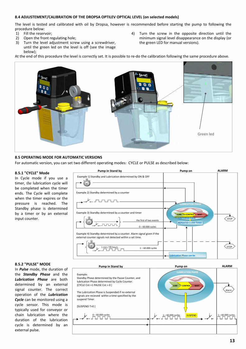
8.4 ADJUSTEMENT/CALIBRATION OF THE DROPSA OPTILEV OPTICAL LEVEL (on selected models)
The level is tested and calibrated with oil by Dropsa, however is recommended before starting the pump to following the procedure below: 1) Fill the reservoir; 2) Open the front regulating hole; 3) Turn the level adjustment screw using a screwdriver,
until the green led on the level is off (see the image below);
4) Turn the screw in the opposite direction until the minimum signal level disappearance on the display (or the green LED for manual versions).
At the end of this procedure the level is correctly set. It is possible to re-do the calibration following the same procedure above. 8.5 OPERATING MODE FOR AUTOMATIC VERSIONS
For automatic version, you can set two different operating modes: CYCLE or PULSE as described below: 8.5.1 "CYCLE" Mode In Cycle mode if you use a timer, the lubrication cycle will be completed when the timer ends. The Cycle will complete when the timer expires or the pressure is reached. The Standby phase is determined by a timer or by an external input counter. 8.5.2 "PULSE" MODE In Pulse mode, the duration of the Standby Phase and the Lubrication Phase are both determined by an external signal counter. The correct operation of the Lubrication Cycle can be monitored using a cycle sensor. This mode is typically used for conveyor or chain lubrication where the duration of the lubrication cycle is determined by an external pulse.
0-60.000 cicli RIPETUTO 1-250 volte
LUBRICATION PHASE
REPEATED 1-250 Times
Lubrication Phase can be repeated
STOP
LUBE CONTROL WAIT
STOP
Lubrication Cycle
1 min / 99 hours
Example 4) Standby determined by a counter. Alarm signal given if the external counter signals not detected within a set time.
Example 1) Standby and Lubrication determined by ON & OFF Timer
Example 2) Standby determined by a counter
Example 3) Standby determined by a counter and timer combination.
the first of two events
0 – 60.000 cycles
1 – 60.000 cycles
Pump in Stand by Pump on ALARM
Example: Standby Phase determined by the Pause Counter, and lubrication Phase determined by Cycle Counter. [CYCLE Cnt >1 PAUSE Cnt > 0 ] The Lubrication Phase is Suspended if no external signals are recieved within a time specified by the suspend Timer. [SUSPEND T>0 ]
LUBRICATION PHASE
LUBE CONTROL WAIT
Alarm
Pump in Stand by Pump on ALARM
0 – 60.000 cycles
1 – 60.000 cycles
1 – 60.000 cycles
Green led
14
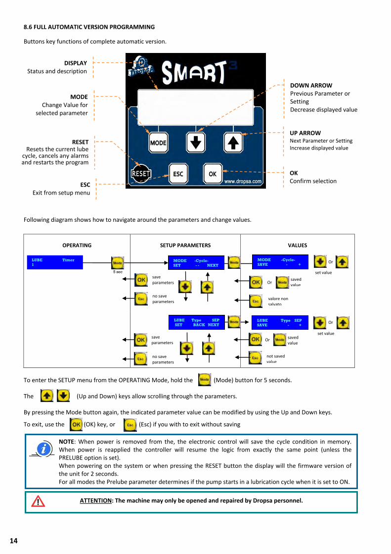
8.6 FULL AUTOMATIC VERSION PROGRAMMING
Buttons key functions of complete automatic version.
Following diagram shows how to navigate around the parameters and change values.
OPERATING
SETUP PARAMETERS
VALUES
To enter the SETUP menu from the OPERATING Mode, hold the (Mode) button for 5 seconds. The (Up and Down) keys allow scrolling through the parameters. By pressing the Mode button again, the indicated parameter value can be modified by using the Up and Down keys.
To exit, use the (OK) key, or (Esc) if you with to exit without saving
FASE DI LUBRIFICAZIONE
ATTENTION: The machine may only be opened and repaired by Dropsa personnel.
NOTE: When power is removed from the, the electronic control will save the cycle condition in memory. When power is reapplied the controller will resume the logic from exactly the same point (unless the PRELUBE option is set). When powering on the system or when pressing the RESET button the display will the firmware version of the unit for 2 seconds. For all modes the Prelube parameter determines if the pump starts in a lubrication cycle when it is set to ON.
LUBE Timer
1
01m56s STOP 5 sec
MODE -Cycle-
SET - - NEXT
MODE -Cycle-
SAVE - +
Or
set value
save parameters
no save parameters
save parameters
no save parameters
Or
saved value
valore non salvato
LUBE Type SEP
SAVE - +
Or
set value
Or
not saved value
saved value
LUBE Type SEP
SET BACK NEXT
+
DISPLAY Status and description
MODE Change Value for
selected parameter
RESET Resets the current lube
cycle, cancels any alarms and restarts the program
OK Confirm selection
DOWN ARROW Previous Parameter or Setting Decrease displayed value
UP ARROW Next Parameter or Setting Increase displayed value
ESC Exit from setup menu
15
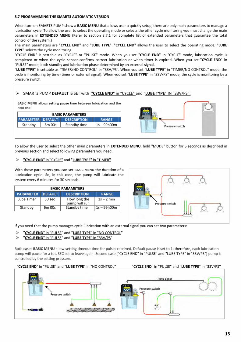
8.7 PROGRAMMING THE SMART3 AUTOMATIC VERSION
When turn on SMART3 PUMP show a BASIC MENU that allows user a quickly setup, there are only main parameters to manage a lubrication cycle. To allow the user to select the operating mode or selects the other cycle monitoring you must change the main parameters in EXTENDED MENU (Refer to section 8.7.1 for complete list of extended parameters that guarantee the total control of the system.) The main parameters are "CYCLE END" and "LUBE TYPE". "CYCLE END" allows the user to select the operating mode; "LUBE TYPE" selects the cycle monitoring. "CYCLE END" is settable as "CYCLE" or "PULSE" mode. When you set "CYCLE END" in "CYCLE" mode, lubrication cycle is completed or when the cycle sensor confirms correct lubrication or when timer is expired. When you set "CYCLE END" in "PULSE" mode, both standby and lubrication phase determined by an external signal. "LUBE TYPE" is settable as "TIMER/NO CONTROL" or "33V/PS". When you set "LUBE TYPE" in "TIMER/NO CONTROL" mode, the cycle is monitoring by time (timer or external signal). When you set "LUBE TYPE" in "33V/PS" mode, the cycle is monitoring by a pressure switch.
SMART3 PUMP DEFAULT IS SET with "CYCLE END" in "CYCLE" and "LUBE TYPE" IN "33V/PS":
BASIC MENU allows setting pause time between lubrication and the next one.
BASIC PARAMETERS
PARAMETER DEFAULT DESCRIPTION RANGE
Standby 6m 00s Standby time 1s – 99h00m
To allow the user to select the other main parameters in EXTENDED MENU, hold "MODE" button for 5 seconds as described in previous section and select following parameters you need.
"CYCLE END" in "CYCLE" and "LUBE TYPE" in "TIMER" With these parameters you can set BASIC MENU the duration of a lubrication cycle. So, in this case, the pump will lubricate the system every 6 minutes for 30 seconds.
If you need that the pump manages cycle lubrication with an external signal you can set two parameters:
"CYCLE END" in "PULSE" and "LUBE TYPE" in "NO CONTROL" "CYCLE END" in "PULSE" and "LUBE TYPE" in "33V/PS"
Both cases BASIC MENU allow setting timeout time for pulses received. Default pause is set to 1, therefore, each lubrication pump will pause for a tot. SEC set to leave again. Second case ("CYCLE END" in "PULSE" and "LUBE TYPE" in "33V/PS") pump is controlled by the setting pressure.
"CYCLE END" in "PULSE" and "LUBE TYPE" in "NO CONTROL" "CYCLE END" in "PULSE" and "LUBE TYPE" in "33V/PS"
BASIC PARAMETERS
PARAMETER DEFAULT DESCRIPTION RANGE Lube Timer 30 sec How long the
pump will run 1s – 2 min
Standby 6m 00s Standby time 1s – 99h00m
Pressure switch
Pressure switch
Pressure switch
Pressure switch
16
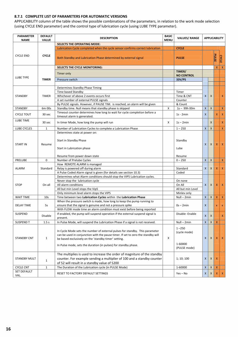
8.7.1 COMPLETE LIST OF PARAMETERS FOR AUTOMATIC VERSIONS APPLICABILITY column of the table shows the possible combinations of the parameters, in relation to the work mode selection (using CYCLE END parameter) and the control type of lubrication cycle (using LUBE TYPE parameter).
PARAMETER NAME
DEFAULT VALUE
DESCRIPTION BASIC MENU
VALUES/ RANGE APPLICABILITY
CYCLE END
CYCLE
SELECTS THE OPERATING MODE:
Lubrication Cycle completed when the cycle sensor confirms correct lubrication CYCLE
CY
CLE
Both Standby and Lubrication Phase determined by external signal
PULSE
PU
LSE
LUBE TYPE
TIMER
SELECTS THE CYCLE MONITORING: X X
Timer only TIMER/
NO CONTROL
Pressure switch 33V/PS
STANDBY TIMER
Determines Standby Phase Timing
X X X
Time based Standby Timer
Whichever of above 2 events occurs first Time & CNT
A set number of external PULSE signals Counter
By PULSE signals. However, if PAUSE TIM. is reached, an alarm will be given & Count
STANDBY 6m 00s Standby time. Null means that standby phase is skipped X 1s – 99h 00m X X X
CYCLE TOUT 30 sec Timeout counter determines how long to wait for cycle completion before a timeout alarm is generated.
1s - 2min X X X
LUBE TIME
30 sec In timer Mode, how long the pump will run X 1s – 2min X X
LUBE CYCLES 1 Number of Lubrication Cycles to complete a Lubrication Phase 1 – 250 X X X
START IN Resume
Determines state at power on: Start in Standby Phase Start in Lubrication phase Resume from power down state
Standby Lube Resume
X X X X
PRELUBE 0 Number of Prelube Cycles 0 – 250 X X X
ALARM Standard
How REMOTE ALARM is managed
X X X X Relay is powered off during alarm Standard
A Pulse Coded Alarm signal is given (for details see section 10.3) Coded
STOP On all
Determines what Alarm conditions should stop the VIP5 Lubrication cycles.
X X X X
Never stop the lubrication cycle On none
All alarm conditions On All
All but min Level stops the Vip5 All but min Level
Only minimum level alarm stops the VIP5 Minlev only
WAIT TIME 10s Time between two Lubrication Cycles within the Lubrication Phase Null – 2min X X X X
DELAY TIME 5s
When the pressure switch is made, how long to keep the pump running to ensure that the signal is genuine and not a pressure spike
0s – 2min X x x
With FLOW mode time an alarm condition must exist before being reported
SUSPEND
Disable If enabled, the pump will suspend operation if the external suspend signal is present.
Disable -Enable
X X X
SUSPEND T 1.5 s In Pulse Mode, will suspend the Lubrication Phase if a signal is not received. Null – 2min X X X
STANDBY CNT 1
In Cycle Mode sets the number of external pulses for standby. This parameter can be used in conjunction with the pause timer. If set to zero the standby will be based exclusively on the ‘standby timer’ setting.
In Pulse mode, sets the duration (in pulses) for standby phase.
X
1 –250 (cycle mode) 1-60000 (PULSE mode)
X X X
X
STANDBY MULT
1
The multiplies is used to increase the order of magniture of the standby counter. For example sending a multiplier of 100 and a standby counter of 52 will result in a standby value of 5200
1; 10; 100 X X X
CYCLE CNT 1 The Duration of the Lubrication cycle (in PULSE Mode) 1-60000 X X X
SET DEFAULT VAL.
RESET TO FACTORY DEFAULT SETTINGS Yes – No X X X X
17
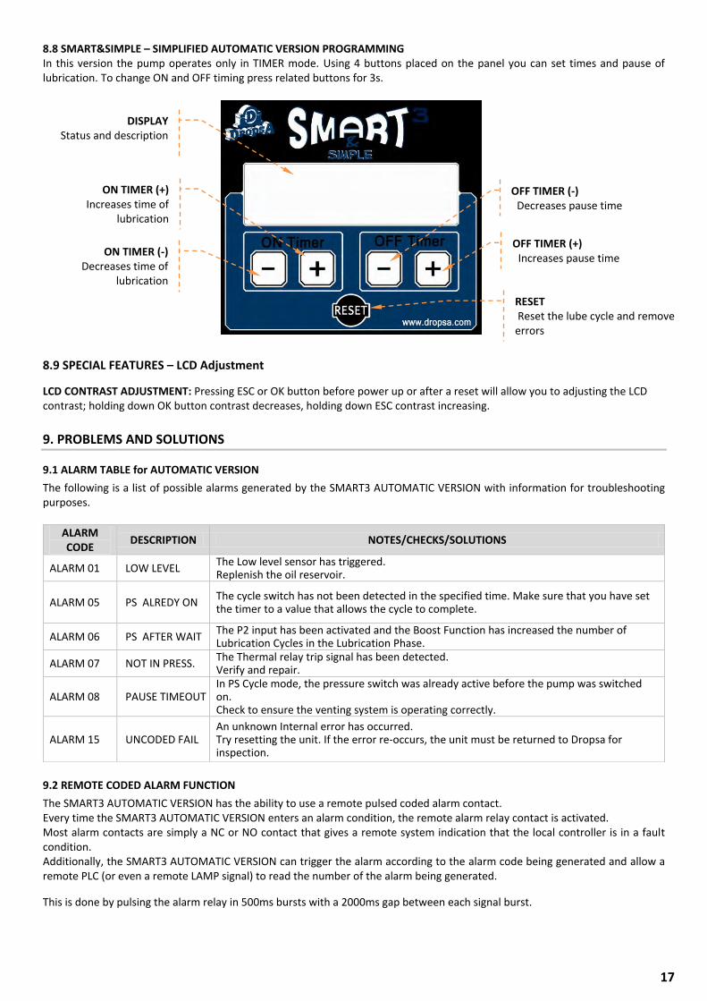
8.8 SMART&SIMPLE – SIMPLIFIED AUTOMATIC VERSION PROGRAMMING In this version the pump operates only in TIMER mode. Using 4 buttons placed on the panel you can set times and pause of lubrication. To change ON and OFF timing press related buttons for 3s.
8.9 SPECIAL FEATURES – LCD Adjustment
LCD CONTRAST ADJUSTMENT: Pressing ESC or OK button before power up or after a reset will allow you to adjusting the LCD contrast; holding down OK button contrast decreases, holding down ESC contrast increasing.
9. PROBLEMS AND SOLUTIONS
9.1 ALARM TABLE for AUTOMATIC VERSION
The following is a list of possible alarms generated by the SMART3 AUTOMATIC VERSION with information for troubleshooting purposes.
9.2 REMOTE CODED ALARM FUNCTION
The SMART3 AUTOMATIC VERSION has the ability to use a remote pulsed coded alarm contact. Every time the SMART3 AUTOMATIC VERSION enters an alarm condition, the remote alarm relay contact is activated. Most alarm contacts are simply a NC or NO contact that gives a remote system indication that the local controller is in a fault condition. Additionally, the SMART3 AUTOMATIC VERSION can trigger the alarm according to the alarm code being generated and allow a remote PLC (or even a remote LAMP signal) to read the number of the alarm being generated.
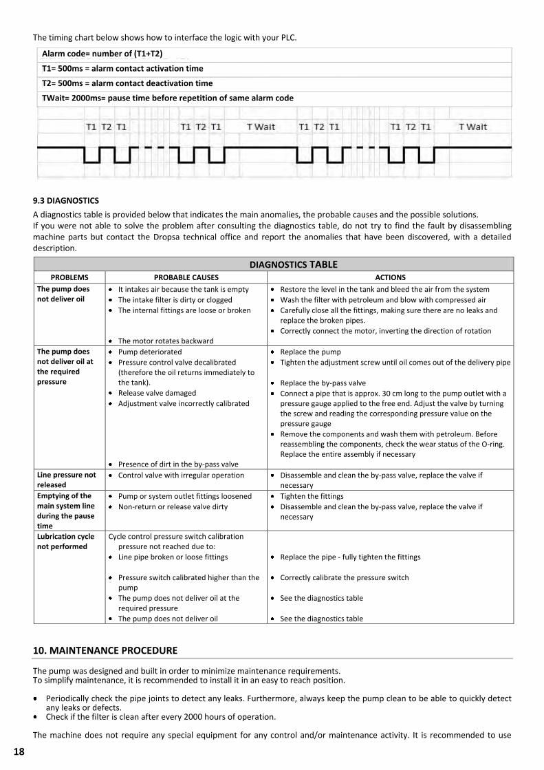
This is done by pulsing the alarm relay in 500ms bursts with a 2000ms gap between each signal burst.
ALARM CODE
DESCRIPTION NOTES/CHECKS/SOLUTIONS
ALARM 01 LOW LEVEL The Low level sensor has triggered. Replenish the oil reservoir.
ALARM 05 PS ALREDY ON The cycle switch has not been detected in the specified time. Make sure that you have set the timer to a value that allows the cycle to complete.
ALARM 06 PS AFTER WAIT The P2 input has been activated and the Boost Function has increased the number of Lubrication Cycles in the Lubrication Phase.
ALARM 07 NOT IN PRESS. The Thermal relay trip signal has been detected. Verify and repair.
ALARM 08 PAUSE TIMEOUT In PS Cycle mode, the pressure switch was already active before the pump was switched on. Check to ensure the venting system is operating correctly.
ALARM 15 UNCODED FAIL An unknown Internal error has occurred. Try resetting the unit. If the error re-occurs, the unit must be returned to Dropsa for inspection.
DISPLAY Status and description
ON TIMER (-) Decreases time of
lubrication
ON TIMER (+) Increases time of
lubrication
OFF TIMER (-) Decreases pause time
OFF TIMER (+) Increases pause time
RESET Reset the lube cycle and remove errors
18
The timing chart below shows how to interface the logic with your PLC.
9.3 DIAGNOSTICS
A diagnostics table is provided below that indicates the main anomalies, the probable causes and the possible solutions. If you were not able to solve the problem after consulting the diagnostics table, do not try to find the fault by disassembling machine parts but contact the Dropsa technical office and report the anomalies that have been discovered, with a detailed description.
10. MAINTENANCE PROCEDURE
The pump was designed and built in order to minimize maintenance requirements. To simplify maintenance, it is recommended to install it in an easy to reach position.
Periodically check the pipe joints to detect any leaks. Furthermore, always keep the pump clean to be able to quickly detect any leaks or defects.
Check if the filter is clean after every 2000 hours of operation.
The machine does not require any special equipment for any control and/or maintenance activity. It is recommended to use
DIAGNOSTICS TABLE PROBLEMS PROBABLE CAUSES ACTIONS
The pump does not deliver oil
It intakes air because the tank is empty
The intake filter is dirty or clogged
The internal fittings are loose or broken
The motor rotates backward
Restore the level in the tank and bleed the air from the system
Wash the filter with petroleum and blow with compressed air
Carefully close all the fittings, making sure there are no leaks and replace the broken pipes.
Correctly connect the motor, inverting the direction of rotation
The pump does not deliver oil at the required pressure
Pump deteriorated
Pressure control valve decalibrated (therefore the oil returns immediately to the tank).
Release valve damaged
Adjustment valve incorrectly calibrated
Presence of dirt in the by-pass valve
Replace the pump
Tighten the adjustment screw until oil comes out of the delivery pipe
Replace the by-pass valve
Connect a pipe that is approx. 30 cm long to the pump outlet with a pressure gauge applied to the free end. Adjust the valve by turning the screw and reading the corresponding pressure value on the pressure gauge
Remove the components and wash them with petroleum. Before reassembling the components, check the wear status of the O-ring. Replace the entire assembly if necessary
Line pressure not released
Control valve with irregular operation Disassemble and clean the by-pass valve, replace the valve if necessary
Emptying of the main system line during the pause time
Pump or system outlet fittings loosened
Non-return or release valve dirty
Tighten the fittings
Disassemble and clean the by-pass valve, replace the valve if necessary
Lubrication cycle not performed
Cycle control pressure switch calibration pressure not reached due to:
Line pipe broken or loose fittings
Pressure switch calibrated higher than the pump
The pump does not deliver oil at the required pressure
The pump does not deliver oil
Replace the pipe - fully tighten the fittings
Correctly calibrate the pressure switch
See the diagnostics table
See the diagnostics table
Alarm code= number of (T1+T2)
T1= 500ms = alarm contact activation time
T2= 500ms = alarm contact deactivation time
TWait= 2000ms= pause time before repetition of same alarm code
19
tools and personal protective devices suitable for use (gloves) and that are in good condition according to current regulations to prevent damage to people or machine parts.
In the case of doubts and/or problems that cannot be solved, do not try to discover the reason by disassembling machine parts, but contact the DROPSA S.p.A technical office.
11. DISPOSAL
During machine maintenance, or if it is demolished, do not dispose of the polluting parts in an improper manner. Refer to the local regulations for their correct disposal. When demolishing the machine, the identification plate and all other documents must be destroyed.
ATTENTION: Make sure that the electric and hydraulic power supplies are disconnected before carrying out any
maintenance work.
20
12. ORDER INFORMATION
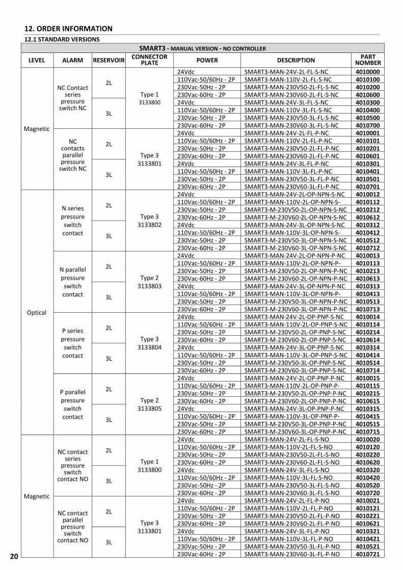
12.1 STANDARD VERSIONS
SMART3 - MANUAL VERSION - NO CONTROLLER
LEVEL ALARM RESERVOIR CONNECTOR
PLATE POWER DESCRIPTION PART
NOMBER
Magnetic
NC Contact series
pressure switch NC
2L
Type 1 3133800
24Vdc SMART3-MAN-24V-2L-FL-S-NC 4010000 110Vac-50/60Hz - 2P SMART3-MAN-110V-2L-FL-S-NC 4010100 230Vac-50Hz - 2P SMART3-MAN-230V50-2L-FL-S-NC 4010200 230Vac-60Hz - 2P SMART3-MAN-230V60-2L-FL-S-NC 4010600
3L
24Vdc SMART3-MAN-24V-3L-FL-S-NC 4010300 110Vac-50/60Hz - 2P SMART3-MAN-110V-3L-FL-S-NC 4010400 230Vac-50Hz - 2P SMART3-MAN-230V50-3L-FL-S-NC 4010500 230Vac-60Hz - 2P SMART3-MAN-230V60-3L-FL-S-NC 4010700
NC contacts parallel
pressure switch NC
2L
Type 3 3133801
24Vdc SMART3-MAN-24V-2L-FL-P-NC 4010001 110Vac-50/60Hz - 2P SMART3-MAN-110V-2L-FL-P-NC 4010101 230Vac-50Hz - 2P SMART3-MAN-230V50-2L-FL-P-NC 4010201 230Vac-60Hz - 2P SMART3-MAN-230V60-2L-FL-P-NC 4010601
3L
24Vdc SMART3-MAN-24V-3L-FL-P-NC 4010301 110Vac-50/60Hz - 2P SMART3-MAN-110V-3L-FL-P-NC 4010401 230Vac-50Hz - 2P SMART3-MAN-230V50-3L-FL-P-NC 4010501 230Vac-60Hz - 2P SMART3-MAN-230V60-3L-FL-P-NC 4010701
Optical
N series pressure
switch contact
2L
Type 3 3133802
24Vdc SMART3-MAN-24V-2L-OP-NPN-S-NC 4010012 110Vac-50/60Hz - 2P SMART3-MAN-110V-2L-OP-NPN-S-
NC 4010112
230Vac-50Hz - 2P SMART3-M-230V50-2L-OP-NPN-S-NC 4010212 230Vac-60Hz - 2P SMART3-M-230V60-2L-OP-NPN-S-NC 4010612
3L
24Vdc SMART3-MAN-24V-3L-OP-NPN-S-NC 4010312 110Vac-50/60Hz - 2P SMART3-MAN-110V-3L-OP-NPN-S-
NC 4010412
230Vac-50Hz - 2P SMART3-M-230V50-3L-OP-NPN-S-NC 4010512 230Vac-60Hz - 2P SMART3-M-230V60-3L-OP-NPN-S-NC 4010712
N parallel pressure
switch contact
2L
Type 2 3133803
24Vdc SMART3-MAN-24V-2L-OP-NPN-P-NC 4010013 110Vac-50/60Hz - 2P SMART3-MAN-110V-2L-OP-NPN-P-
NC 4010113
230Vac-50Hz - 2P SMART3-M-230V50-2L-OP-NPN-P-NC 4010213 230Vac-60Hz - 2P SMART3-M-230V60-2L-OP-NPN-P-NC 4010613
3L
24Vdc SMART3-MAN-24V-3L-OP-NPN-P-NC 4010313 110Vac-50/60Hz - 2P SMART3-MAN-110V-3L-OP-NPN-P-
NC 4010413
230Vac-50Hz - 2P SMART3-M-230V50-3L-OP-NPN-P-NC 4010513 230Vac-60Hz - 2P SMART3-M-230V60-3L-OP-NPN-P-NC 4010713
P series pressure
switch contact
2L
Type 3 3133804
24Vdc SMART3-MAN-24V-2L-OP-PNP-S-NC 4010014 110Vac-50/60Hz - 2P SMART3-MAN-110V-2L-OP-PNP-S-NC 4010114 230Vac-50Hz - 2P SMART3-M-230V50-2L-OP-PNP-S-NC 4010214 230Vac-60Hz - 2P SMART3-M-230V60-2L-OP-PNP-S-NC 4010614
3L
24Vdc SMART3-MAN-24V-3L-OP-PNP-S-NC 4010314 110Vac-50/60Hz - 2P SMART3-MAN-110V-3L-OP-PNP-S-NC 4010414 230Vac-50Hz - 2P SMART3-M-230V50-3L-OP-PNP-S-NC 4010514 230Vac-60Hz - 2P SMART3-M-230V60-3L-OP-PNP-S-NC 4010714
P parallel pressure
switch contact
2L
Type 2 3133805
24Vdc SMART3-MAN-24V-2L-OP-PNP-P-NC 4010015 110Vac-50/60Hz - 2P SMART3-MAN-110V-2L-OP-PNP-P-
NC 4010115
230Vac-50Hz - 2P SMART3-M-230V50-2L-OP-PNP-P-NC 4010215 230Vac-60Hz - 2P SMART3-M-230V60-2L-OP-PNP-P-NC 4010615
3L
24Vdc SMART3-MAN-24V-3L-OP-PNP-P-NC 4010315 110Vac-50/60Hz - 2P SMART3-MAN-110V-3L-OP-PNP-P-
NC 4010415
230Vac-50Hz - 2P SMART3-M-230V50-3L-OP-PNP-P-NC 4010515 230Vac-60Hz - 2P SMART3-M-230V60-3L-OP-PNP-P-NC 4010715
Magnetic
NC contact series
pressure switch
contact NO
2L
Type 1 3133800
24Vdc SMART3-MAN-24V-2L-FL-S-NO 4010020 110Vac-50/60Hz - 2P SMART3-MAN-110V-2L-FL-S-NO 4010120 230Vac-50Hz - 2P SMART3-MAN-230V50-2L-FL-S-NO 4010220 230Vac-60Hz - 2P SMART3-MAN-230V60-2L-FL-S-NO 4010620
3L
24Vdc SMART3-MAN-24V-3L-FL-S-NO 4010320 110Vac-50/60Hz - 2P SMART3-MAN-110V-3L-FL-S-NO 4010420 230Vac-50Hz - 2P SMART3-MAN-230V50-3L-FL-S-NO 4010520 230Vac-60Hz - 2P SMART3-MAN-230V60-3L-FL-S-NO 4010720
NC contact parallel
pressure switch
contact NO
2L
Type 3 3133801
24Vdc SMART3-MAN-24V-2L-FL-P-NO 4010021 110Vac-50/60Hz - 2P SMART3-MAN-110V-2L-FL-P-NO 4010121 230Vac-50Hz - 2P SMART3-MAN-230V50-2L-FL-P-NO 4010221 230Vac-60Hz - 2P SMART3-MAN-230V60-2L-FL-P-NO 4010621
3L
24Vdc SMART3-MAN-24V-3L-FL-P-NO 4010321 110Vac-50/60Hz - 2P SMART3-MAN-110V-3L-FL-P-NO 4010421 230Vac-50Hz - 2P SMART3-MAN-230V50-3L-FL-P-NO 4010521 230Vac-60Hz - 2P SMART3-MAN-230V60-3L-FL-P-NO 4010721
21
N.B. The following specifications apply for all models: Bypass calibration pressure 25 bar; Pressure switch 18 bar; Pressure gauge 0 – 100 bar.
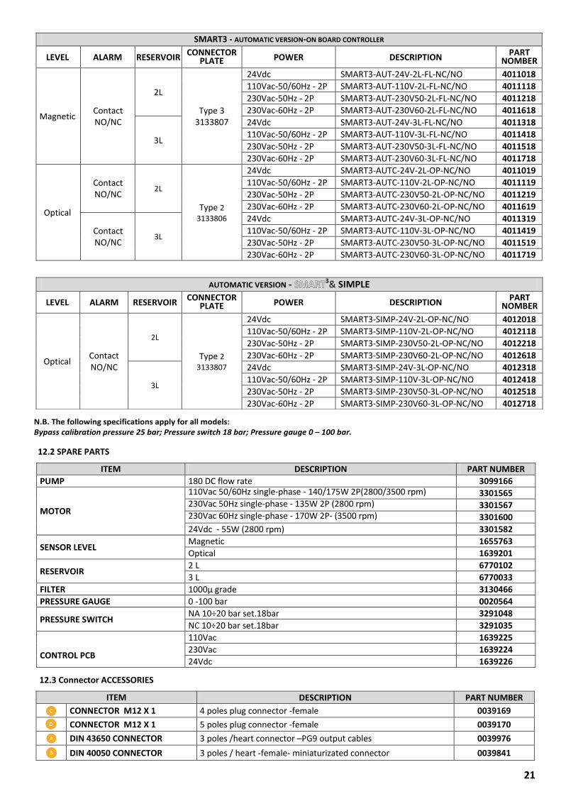
12.3 Connector ACCESSORIES
ITEM DESCRIPTION PART NUMBER
CONNECTOR M12 X 1 4 poles plug connector -female 0039169
CONNECTOR M12 X 1 5 poles plug connector -female 0039170
DIN 43650 CONNECTOR 3 poles /heart connector –PG9 output cables 0039976
DIN 40050 CONNECTOR 3 poles / heart -female- miniaturizated connector 0039841
12.2 SPARE PARTS
ITEM DESCRIPTION PART NUMBER
PUMP 180 DC flow rate 3099166
MOTOR
110Vac 50/60Hz single-phase - 140/175W 2P(2800/3500 rpm) 3301565 230Vac 50Hz single-phase - 135W 2P (2800 rpm)
3301567 230Vac 60Hz single-phase - 170W 2P- (3500 rpm)
3301600
24Vdc - 55W (2800 rpm) 3301582
SENSOR LEVEL Magnetic 1655763
Optical 1639201
RESERVOIR 2 L 6770102
3 L 6770033
FILTER 1000µ grade 3130466
PRESSURE GAUGE 0 -100 bar 0020564
PRESSURE SWITCH NA 10÷20 bar set.18bar 3291048
NC 10÷20 bar set.18bar 3291035
CONTROL PCB
110Vac 1639225
230Vac 1639224
24Vdc 1639226
SMART3 - AUTOMATIC VERSION-ON BOARD CONTROLLER
LEVEL ALARM RESERVOIR CONNECTOR
PLATE POWER DESCRIPTION PART
NOMBER
Magnetic Contact NO/NC
2L
Type 3 3133807
24Vdc SMART3-AUT-24V-2L-FL-NC/NO 4011018
110Vac-50/60Hz - 2P SMART3-AUT-110V-2L-FL-NC/NO 4011118
230Vac-50Hz - 2P SMART3-AUT-230V50-2L-FL-NC/NO 4011218
230Vac-60Hz - 2P SMART3-AUT-230V60-2L-FL-NC/NO 4011618
3L
24Vdc SMART3-AUT-24V-3L-FL-NC/NO 4011318
110Vac-50/60Hz - 2P SMART3-AUT-110V-3L-FL-NC/NO 4011418
230Vac-50Hz - 2P SMART3-AUT-230V50-3L-FL-NC/NO 4011518
230Vac-60Hz - 2P SMART3-AUT-230V60-3L-FL-NC/NO 4011718
Optical
Contact NO/NC
2L
Type 2
3133806
24Vdc SMART3-AUTC-24V-2L-OP-NC/NO 4011019
110Vac-50/60Hz - 2P SMART3-AUTC-110V-2L-OP-NC/NO 4011119
230Vac-50Hz - 2P SMART3-AUTC-230V50-2L-OP-NC/NO 4011219
230Vac-60Hz - 2P SMART3-AUTC-230V60-2L-OP-NC/NO 4011619
Contact NO/NC
3L
24Vdc SMART3-AUTC-24V-3L-OP-NC/NO 4011319
110Vac-50/60Hz - 2P SMART3-AUTC-110V-3L-OP-NC/NO 4011419
230Vac-50Hz - 2P SMART3-AUTC-230V50-3L-OP-NC/NO 4011519
230Vac-60Hz - 2P SMART3-AUTC-230V60-3L-OP-NC/NO 4011719
AUTOMATIC VERSION - SMART3& SIMPLE
LEVEL ALARM RESERVOIR CONNECTOR
PLATE POWER DESCRIPTION PART
NOMBER
Optical Contact NO/NC
2L
Type 2
3133807
24Vdc SMART3-SIMP-24V-2L-OP-NC/NO 4012018
110Vac-50/60Hz - 2P SMART3-SIMP-110V-2L-OP-NC/NO 4012118
230Vac-50Hz - 2P SMART3-SIMP-230V50-2L-OP-NC/NO 4012218
230Vac-60Hz - 2P SMART3-SIMP-230V60-2L-OP-NC/NO 4012618
3L
24Vdc SMART3-SIMP-24V-3L-OP-NC/NO 4012318
110Vac-50/60Hz - 2P SMART3-SIMP-110V-3L-OP-NC/NO 4012418
230Vac-50Hz - 2P SMART3-SIMP-230V50-3L-OP-NC/NO 4012518
230Vac-60Hz - 2P SMART3-SIMP-230V60-3L-OP-NC/NO 4012718
22
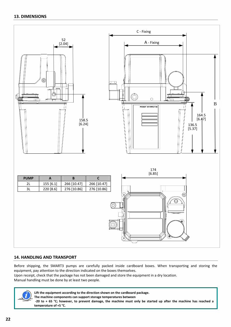
13. DIMENSIONS
14. HANDLING AND TRANSPORT
Before shipping, the SMART3 pumps are carefully packed inside cardboard boxes. When transporting and storing the equipment, pay attention to the direction indicated on the boxes themselves. Upon receipt, check that the package has not been damaged and store the equipment in a dry location. Manual handling must be done by at least two people.
Lift the equipment according to the direction shown on the cardboard package. The machine components can support storage temperatures between -20 to + 65 °C; however, to prevent damage, the machine must only be started up after the machine has reached a temperature of +5 °C.
C - Fixing
52 [2.04]
136.5 [5.37]
164.5 [6.47]
B
158.5 [6.24]
A - Fixing
174 [6.85]
PUMP A B C
2L 155 [6.1] 266 [10.47] 266 [10.47]
3L 220 [8.6] 276 [10.86] 276 [10.86]
23
15. PRECAUTIONS FOR USE
The warnings about the risks involved in using a pump for lubricants must be read. The operator must understand its operation and clearly understand the hazards connected to pumping pressurized grease. Therefore we recommend the following:
Check the chemical compatibility of the material with which the pump is built with the fluid to be pumped (see chap. 4). An incorrect selection could cause, in addition to damaging the pumps and pipes, serious risks for people (spillage of irritating products that are harmful to health) and for the environment.
Never exceed the maximum operating pressure permitted for the pump and the components connected to it. In the case of doubt, refer to the data specified on the machine plate.
Only use original spare parts.
If components must be replaced with others, make sure they are suitable for operating at the pump's maximum operating pressure.
Note: Personnel must use protective devices, garments and tools in compliance with current standards with regard to the location and the use of the pump both during work as well as during maintenance operations.
Power supply Any type of intervention must not be carried out before unplugging the machine from power supply. Make sure that no one can start it up again during the intervention. All the installed electric and electronic equipment, reservoirs and basic components must be grounded. Flammability The lubricant generally used in lubrication systems is not normally flammable. However, it is advised to avoid contact with extremely hot substances or naked flames. Pressure Prior to any intervention, check the absence of residual pressure in any branch of the lubricant circuit as it may cause oil sprays when disassembling components or fittings. After long periods of inactivity, check the seal of all the parts subject to pressure. Do not subject the fittings, pipes and pressurized parts to violent impacts. Damaged flexible pipes or fittings are DANGEROUS and must be replaced. Only original spare parts should be used. Noise
Under normal operating conditions, noise emission does not exceed 70 dB “A” at a distance of 1 metre (39.3 inches) from the pump.
(1) The use of the pump with grease with a consistency NLGI000 must be assessed on a case by case basis given the extreme difference in the sliding properties of the compound, which depends both on the viscosity of the base oil as well as the soaps and additives that are used. The use of the pump with grease with a consistency NLGI000 must be assessed on a case by case basis given the extreme difference in the sliding properties of the compound, which depends both on the viscosity of the base oil as well as the soaps and additives that are used. * A comparison table is provided between the classification of NLGI lubricants (National Lubricating Grease Institute) and the ASTM classification (American Society for Testing and Materials) for greases for the values that concern the pump.
GREASES NLGI ASTM 000 445 – 475
For further information about the technical specifications and the safety measures to adopt, refer to the product safety sheet (Directive 93/112/EEC) relative to the type of lubricant selected and supplied by the manufacturer.
ATTENTION: The warnings about the risks involved in using a pump for lubricants must be read. The user must understand its operation using the user and maintenance manual.
ATTENTION! Never try to stop or deviate any leaks with your hands or other body parts.
NOTE: The pump was designed to operate with lubricants with a maximum rating NLGI 000. (1)
Use lubricants that are compatible with NBR gaskets. Any internal residual lubricant used for assembly and testing purposes is 32 cSt oil
24
15.1 GUIDELINES FOR USE
Compliance with the essential safety requirements and the provisions specified in the machine directive was checked by filling out prepared check lists that are contained in the technical file. Two types of lists were used:
Risk assessment (UNI EN ISO 14121-1).
Compliance with the essential safety requirements Machine Directive –EC 06/42).
The risks that were not completely eliminated, but considered acceptable, are specified below:
Electrocution: this can only occur in the case of serious user incompetence.
Use of unsuitable lubricant: the types of fluids that are not compatible with correct pump operation are listed below.*
Contact with harmful fluids.
FLUIDS THAT ARE NOT PERMITTED FLUIDS RISKS
Lubricants with abrasive additives wear of the components inside the pump
Lubricants with silicone additives Pump seizure
Petrol – solvents – inflammable liquids Fire – explosion – damage to the gaskets
Corrosive products Pump corrosion - damage to people
Water Pump oxidation
Food substances They would be contaminated * For more detailed information regarding product compatibility with particular fluids, contact the Dropsa S.p.A. technical office


